/

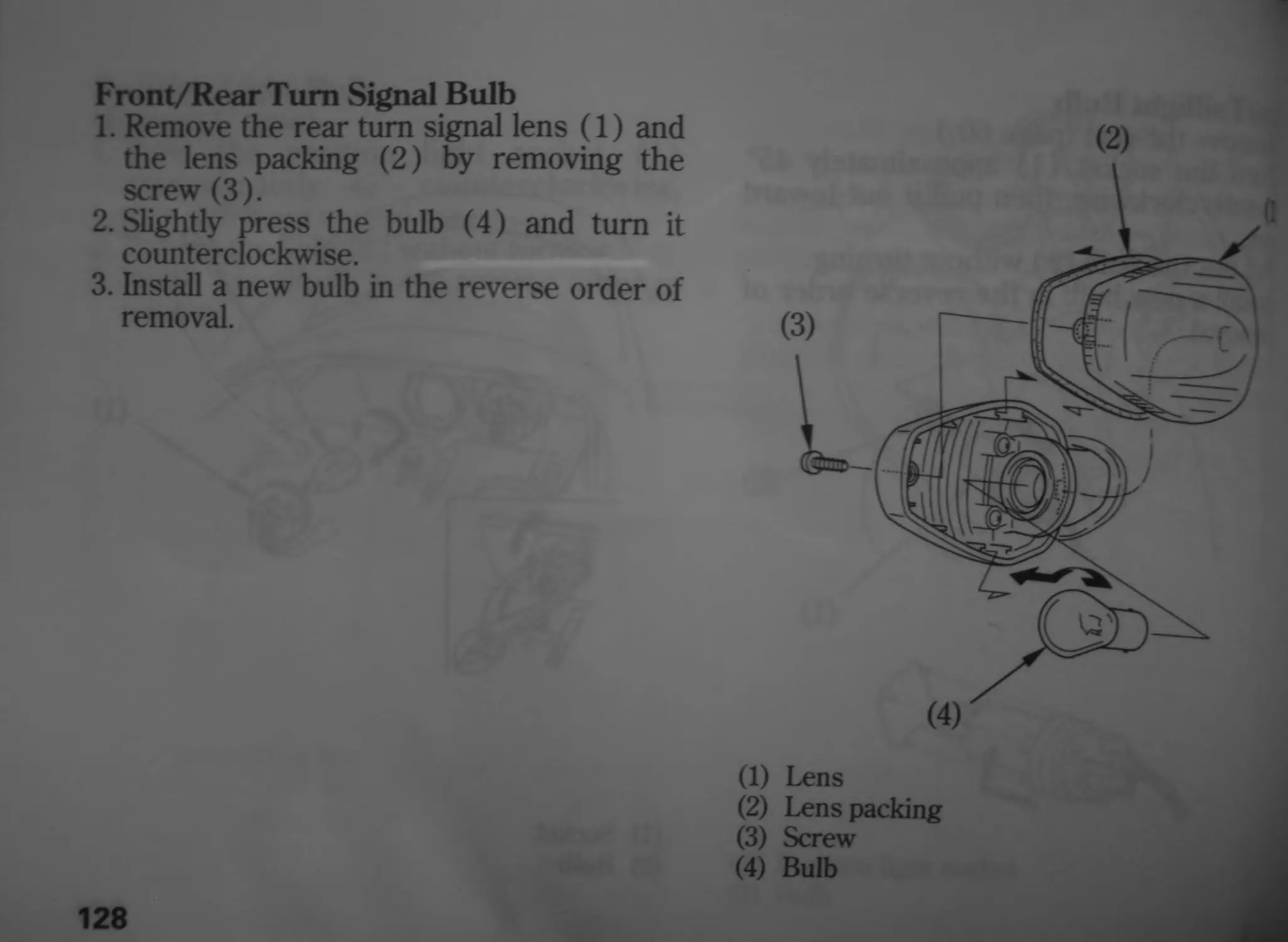
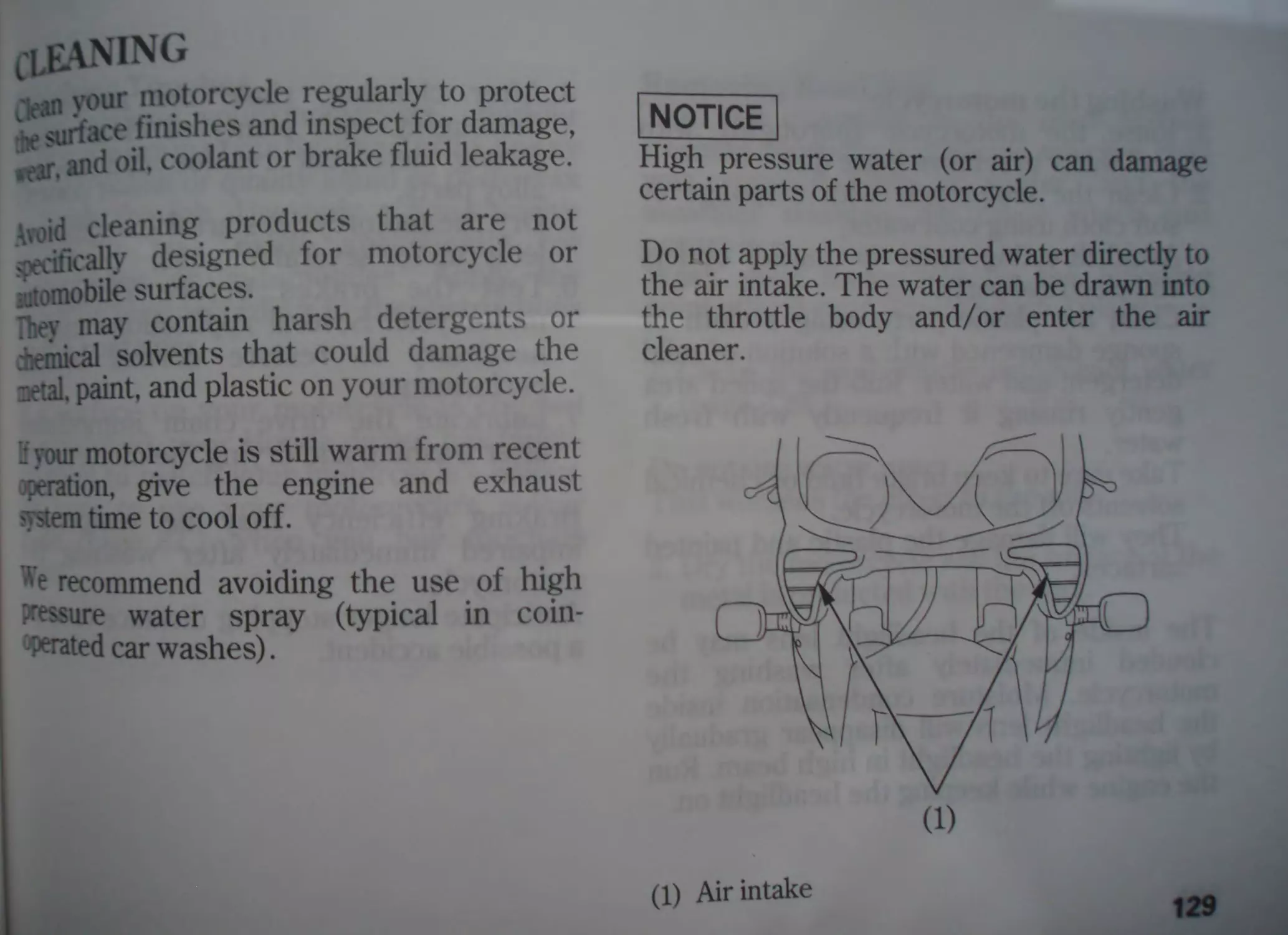

Теги: motorcycles manual cars
Год: 2003

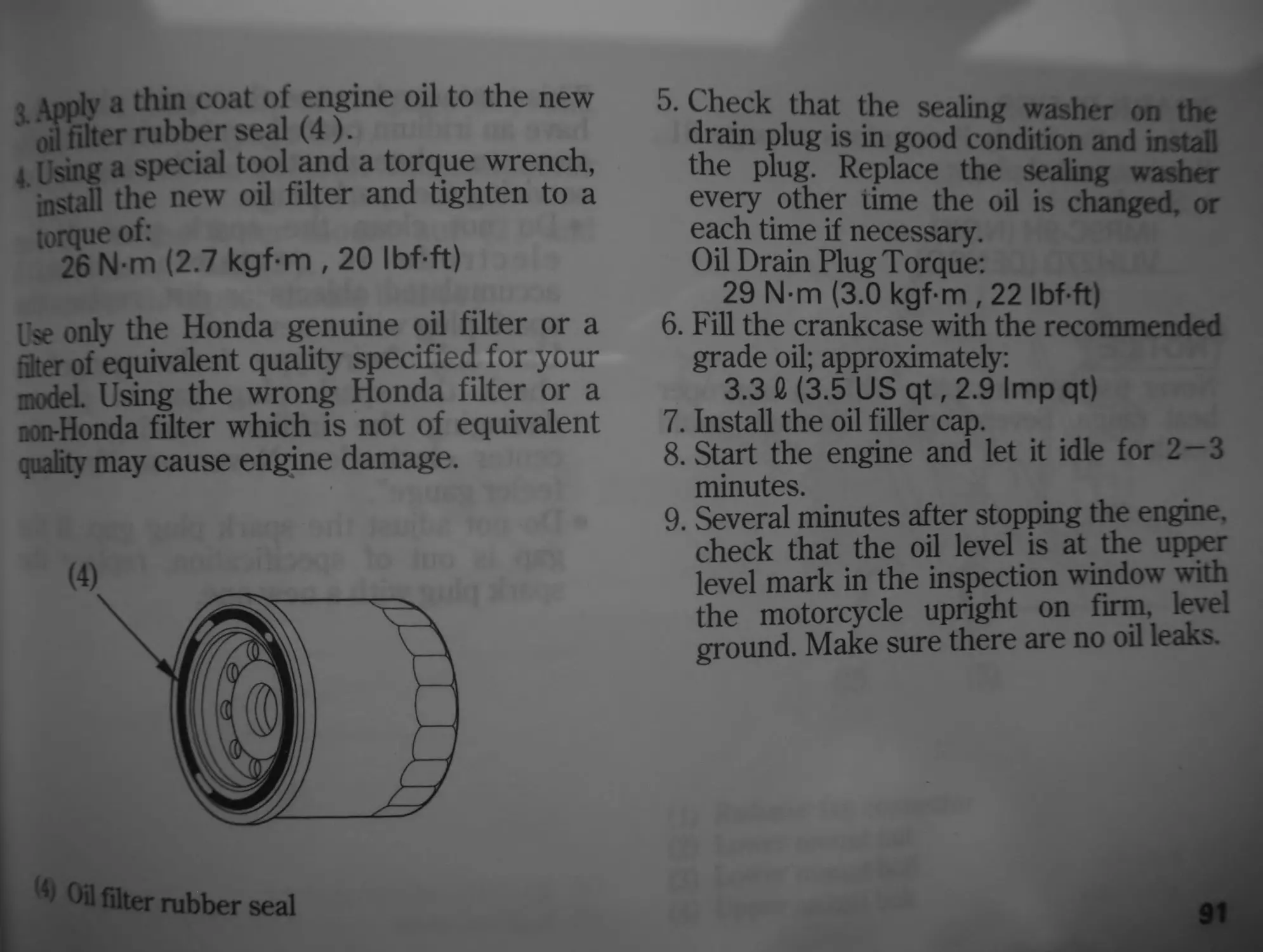
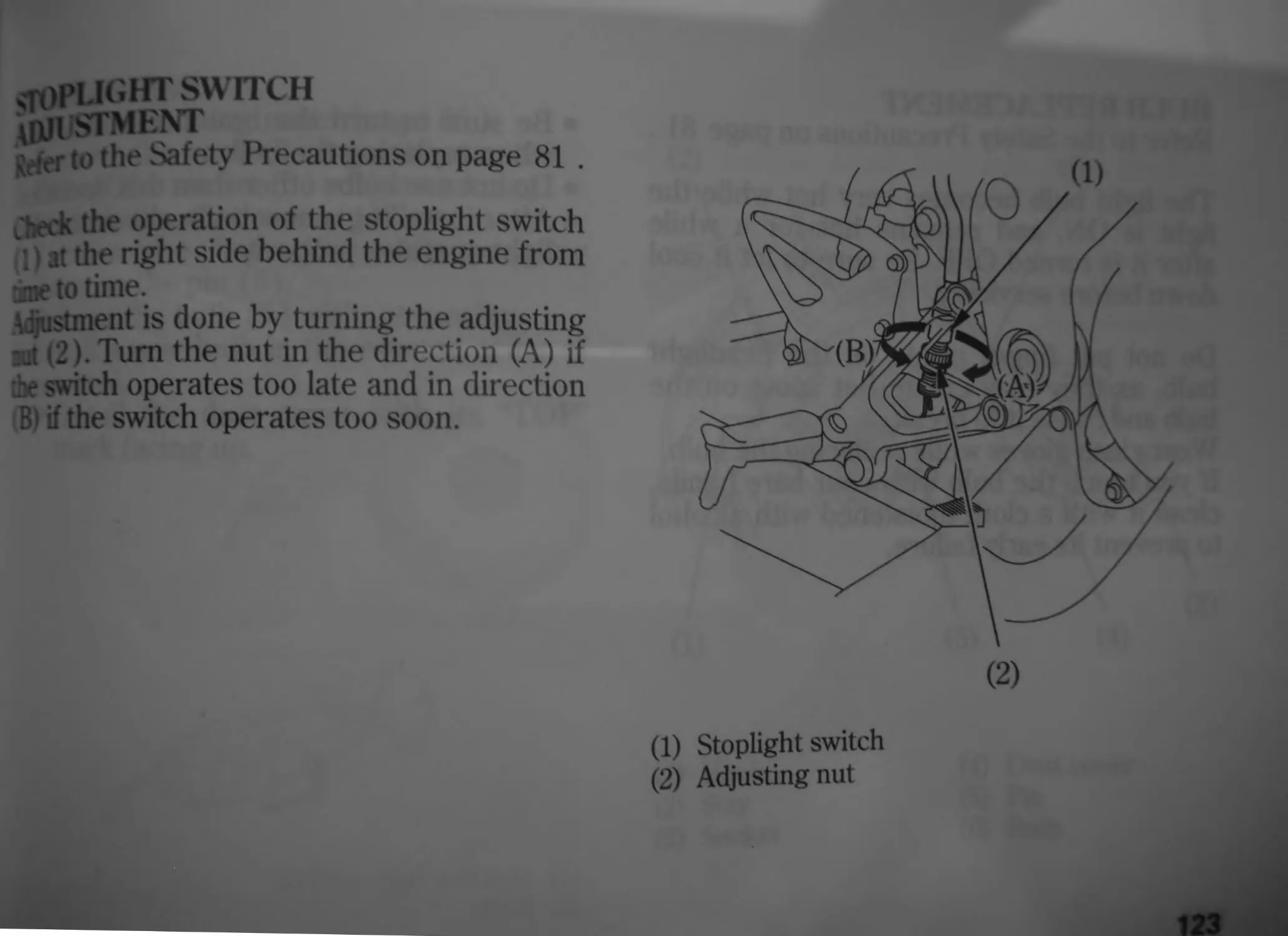
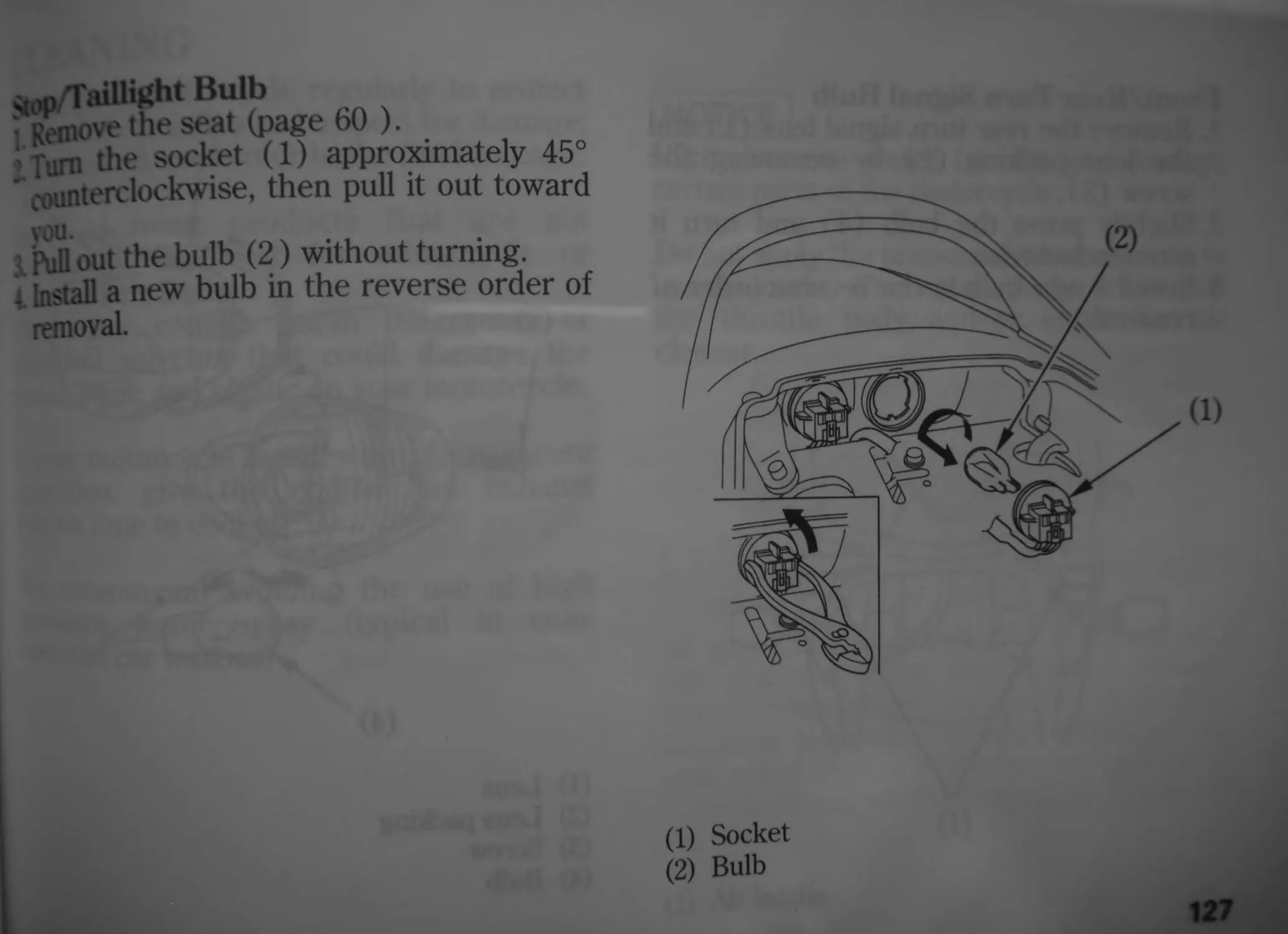
Текст
HONDA
OWNER’S MANUAL
MANUEL DU CONDUCTEUR
FAHRER-HANDBUCH
CBR6OOF
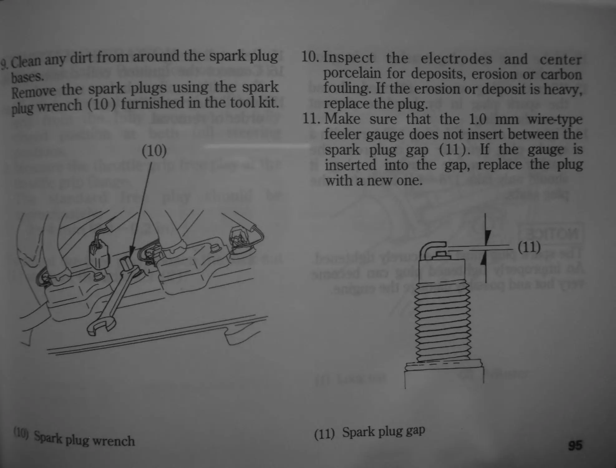
CBR6OOF4i
Honda CBR600F/F4i
OWNER’S MANUAL
MANUEL DU CONDUCTEUR
FAHRER-HANDBUCH
© Honda Motor Co., Ltd. 2003
IMPORTANT INFORMATION
• OPERATOR AND PASSENGER
This motorcycle is designed to carry the operator and one passenger. Never exceed the
maximum weight capacity as shown on the accessories and loading label.
• ON-ROAD USE
This motorcycle is designed to be used only on the road.
• READ THIS OWNER’S MANUAL CAREFULLY
Pay special attention to the safety messages that appear throughout the manual. These
messages are fully explained in the “A Few Words About Safety” section which appears
before the Contents page.
This manual should be considered a permanent part of the motorcycle and should remain
with the motorcycle when resold.
All information in this publication is based °” production
available at the time of approval for printing. Honda Motor Co L d• jejer^s the
right to make changes at any time without no ice an w
obligation. . ___.
No part of this publication may be reproduced without written permission.
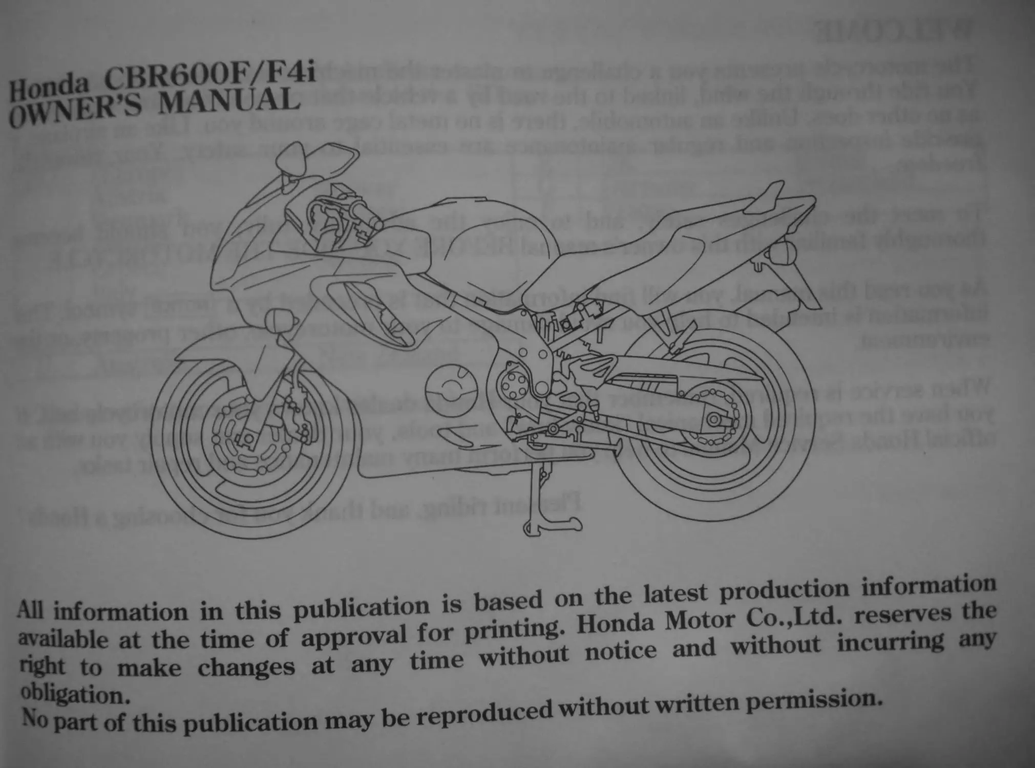
WELCOME
The motorcycle presents you a challenge to master the machine, a challenge to adventure.
You ride through the wind, linked to the road by a vehicle that responds to your commands
as no other does. Unlike an automobile, there is no metal cage around you. Like an airplane, a
pre-ride inspection and regular maintenance are essential to your safety. Your reward is
freedom.
To meet the challenges safely, and to enjoy the adventure fully, you should become
thoroughly familiar with this owners manual BEFORE YOU RIDE THE MOTORCYCLE.
As you read this manual, you will find information that is preceded by a notice ? symbol. This
information is intended to help you avoid damage to your motorcycle, other property, or the
environment.
When service is required, remember that your Honda dealer knows your motorcycle best. If
you have the required mechanical “know-how” and tools, your dealer can supply you with an
official Honda Service Manual to help you perform many maintenance and repair tasks.
Pleasant riding, and thank you for choosing a Honda !
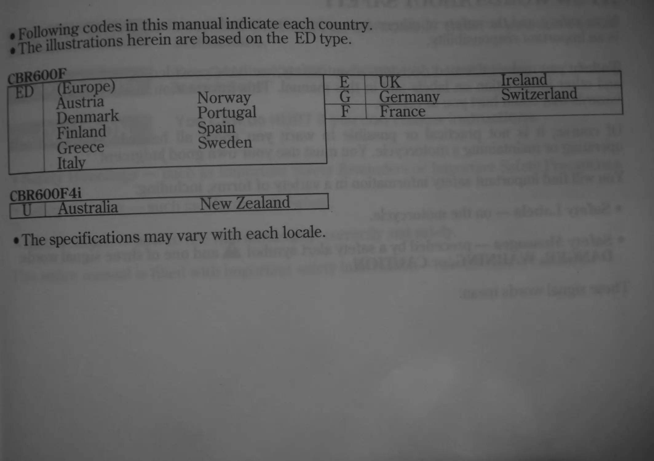
Following codes in this manual indicate each country.
The illustrations herein are based on the ED type.
Denmark
Finland
Greece
Italy
Norway
Portugal
Spain
Sweden
~E~~ __UK Ireland
G Germany Switzerland
F b rance
CBR600F4i
U Australia
New Zealand
• The specifications may vary with each locale.
A FEW WORDS ABOUT SAFETY
Your safety, and the safety of others, is very important. And operating this motorcycle safely
is an important responsibility. ♦
To help vou make informed decisions about safety, we have provided operating procedures
and other information on labels and in this manual. This information alerts you to potential
hazards that could hurt you or others.
Of course, it is not practical or possible to warn you about all hazards associated with
operating or maintaining a motorcycle. You must use your own good judgment.
You will find important safety information in a variety of forms, including:
• Safety' Labels — on the motorcycle.
• Safety' Messages — preceded by a safety alert svmbol Jk and one of three signal words:
DANGER, WARNING, or CAUTION.
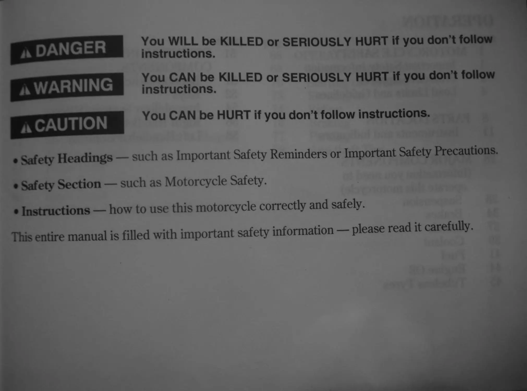
These signal words mean:
a DANGER
WARNING
Л CAUTION
fnstr!2tionte KILLED Or SERIOUSLY HURT if you don’t follow
instructions. KILLED or SERIOUSLY HURT if you don’t follow
You CAN be HURT if you don’t follow instructions.
• Safety Headings — such as Important Safety Reminders or Important Safety Precautions.
• Safety Section — such as Motorcycle Safety.
• Instructions — how to use this motorcycle correctly and safely.
This entire manual is filled with important safety information — please read it carefully.
OPERATION
’’’Г MOTORCYCLE SAFETY
I Important Safety Information
2 Protective Apparel
4 Load Limits and Guidelines
8 PARTS LOCATION
11 Instruments and Indicators
28 MAJOR COMPONENTS
(Information you need to
operate this motorcycle)
28 Suspension
34 Brakes
37 Clutch
39 Coolant
41 Fuel
44 Engine Oil
I ubeless Tyres
page
51 ESSENTIAL INDIVIDUAL
COMPONENTS
51 Ignition Switch
52 Keys
54 Immobilizer System (HISS)
56 Right Handlebar Controls
58 Left Handlebar Controls
21 & Si 2 S£1
FEATURES
(Not required for operation)
Steering Lock
Seat
Helmet Holder
Document Bag
Storage Compartment for U-Shaped
Anti-theft Lock
Front Cowl
Inner Cowl
Inner Panel
Headlight Aim Vertical Adjustment
page
68 OPERATION
68 Pre-ride Inspection
70 Starting the Engine
73 Running-in
74 Riding
76 Braking
77 Parking
78 Anti-theft Tips
MAINTENANCE
W
79
79
80
81
82
85
86
87
88
92
97
98
99
100
106
107
108
109
116
118
120
123
124
Maintenance Safety
Safety Precautions
Maintenance Schedule
Tool Kit
Serial Numbers
Colour Label
Engine Oil
Spark Plugs
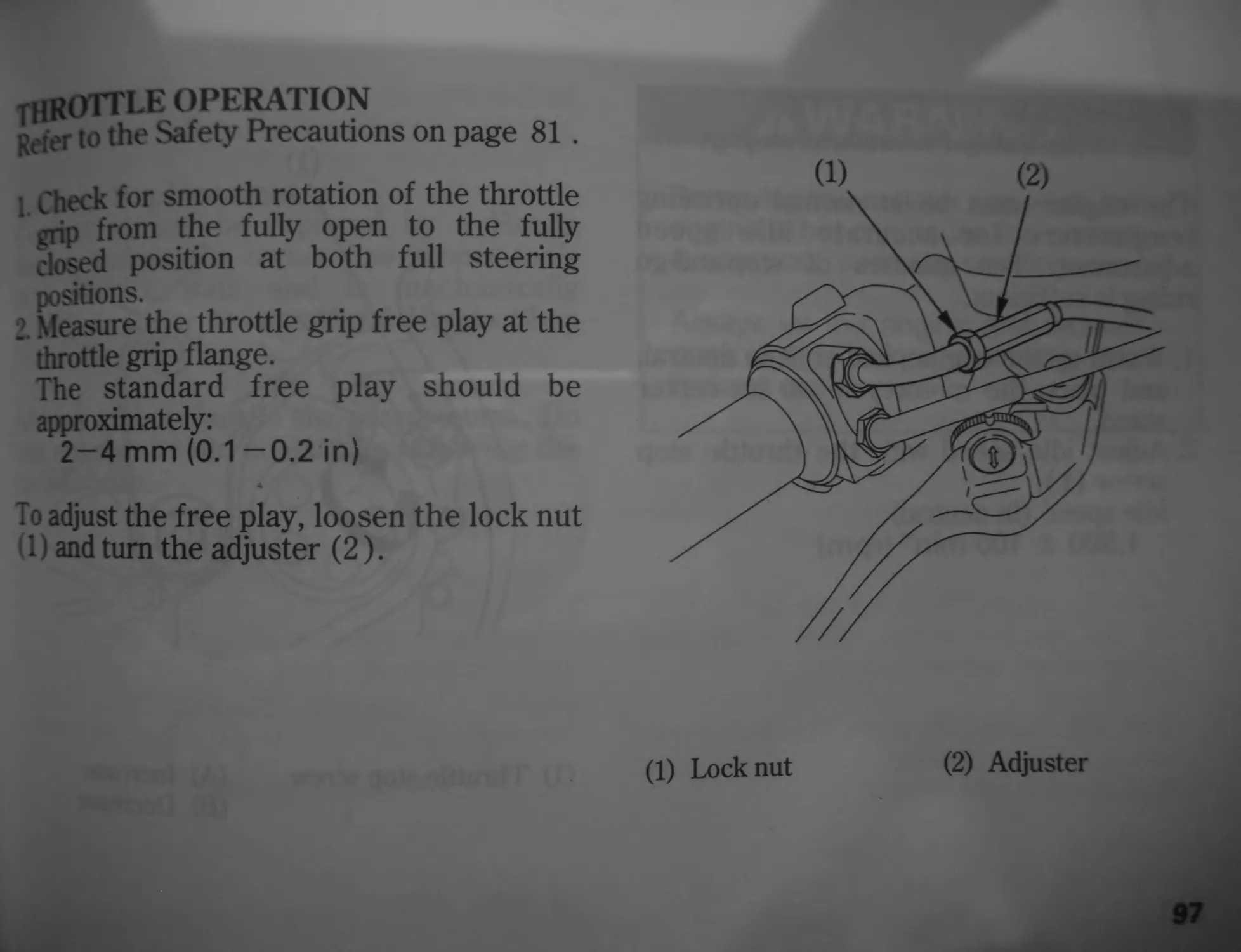
Throttle Operation
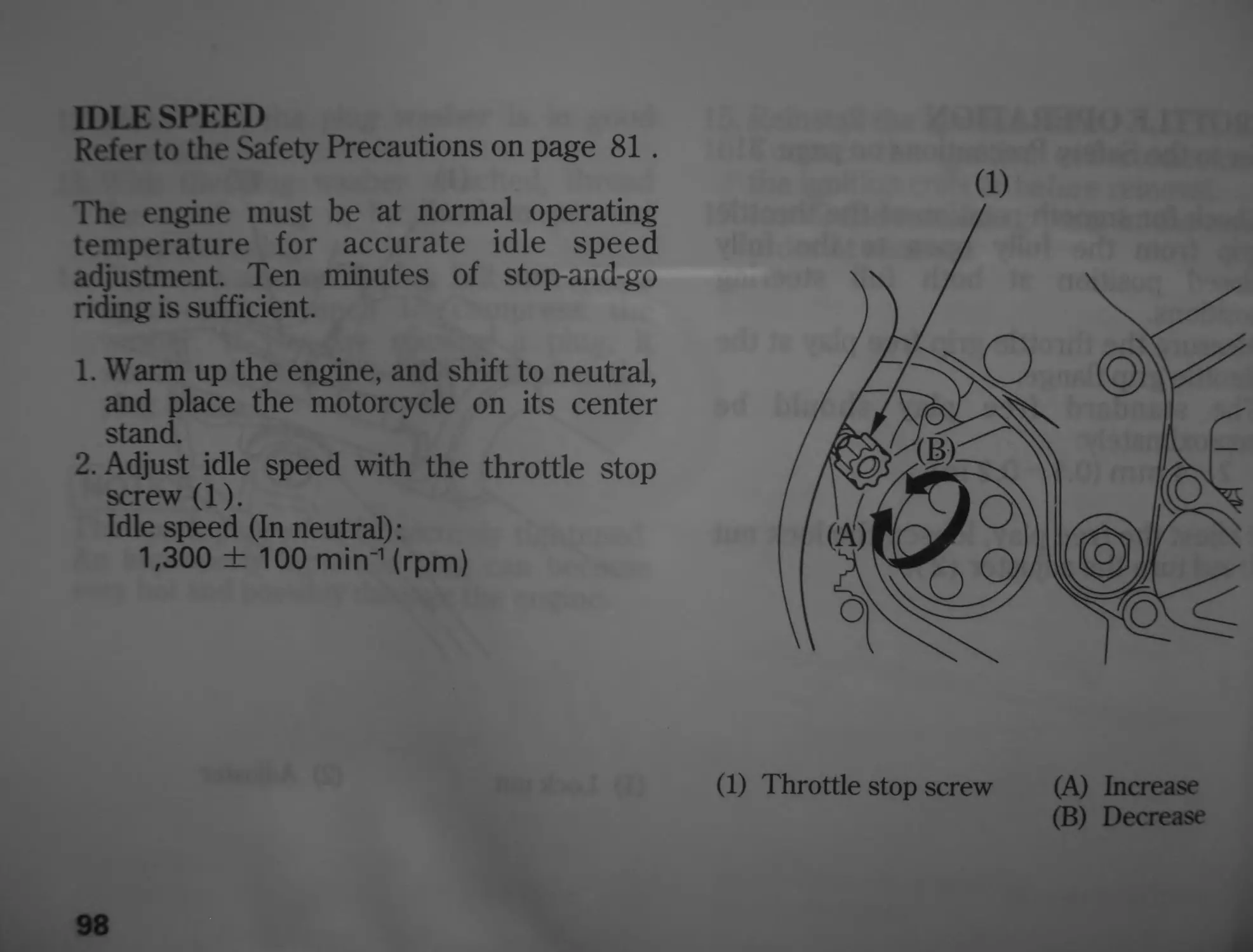
Idle Speed
Coolant
Drive Chain
Drive Chain Slider
Front and Rear Suspension
Inspection
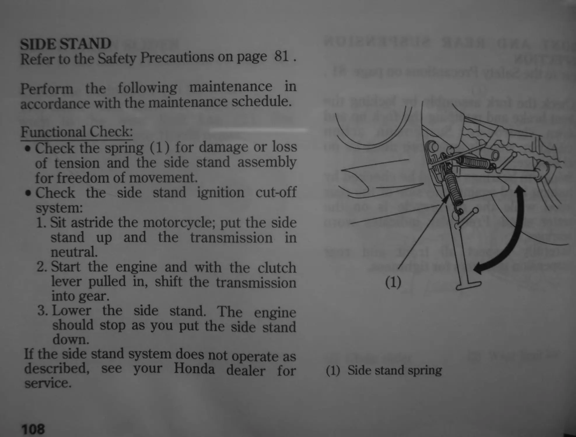
Side Stand
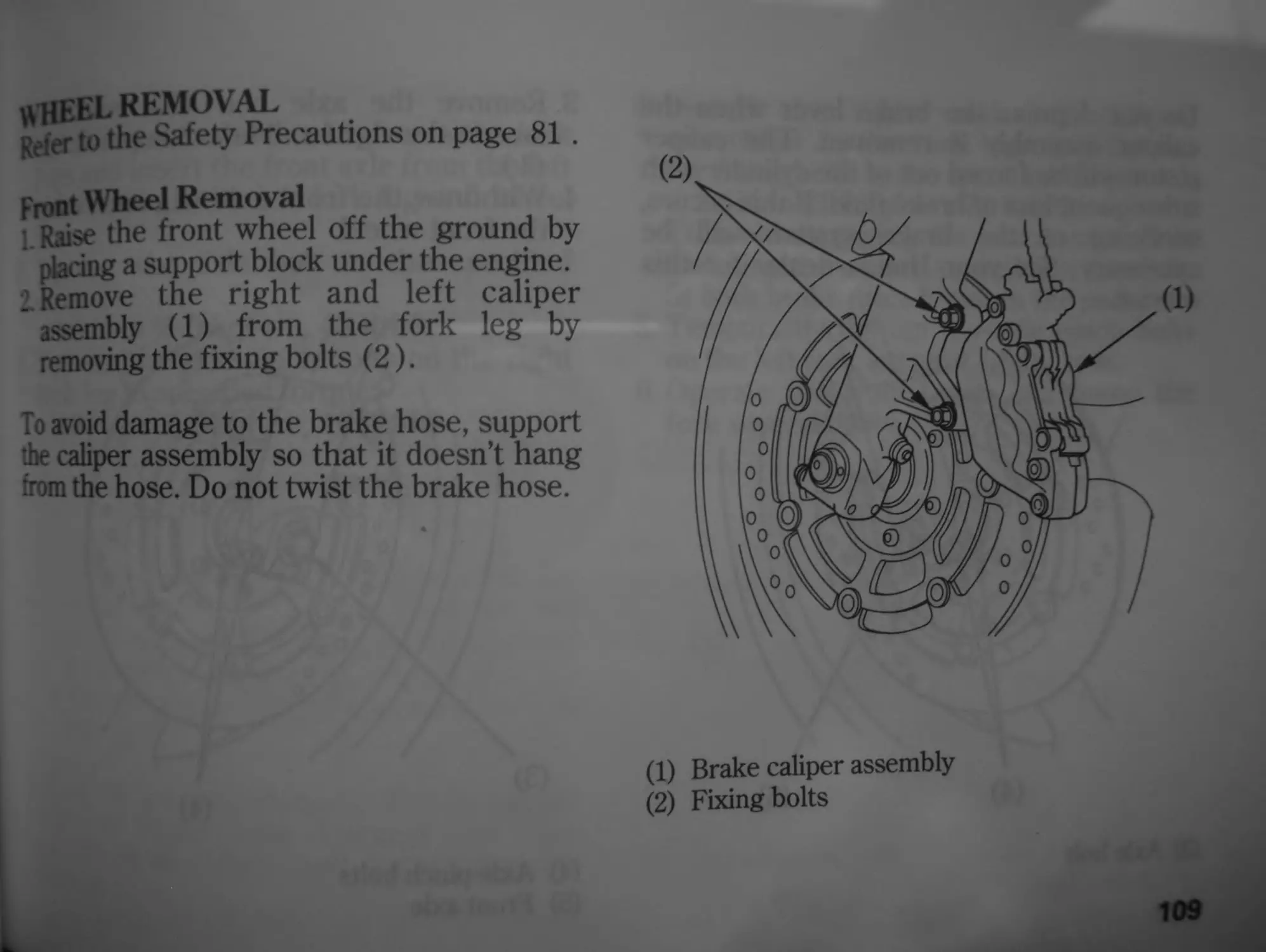
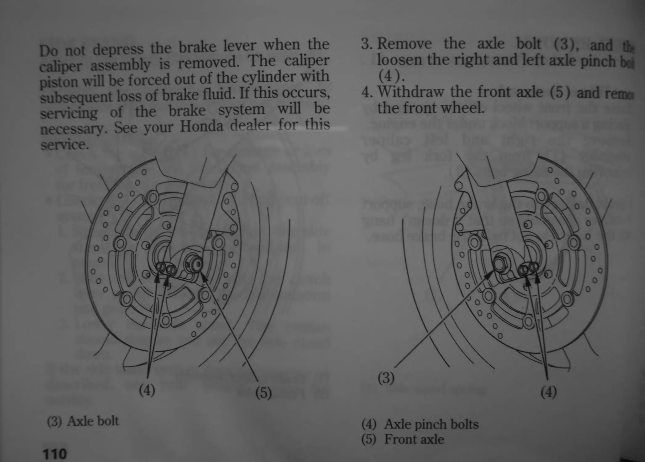
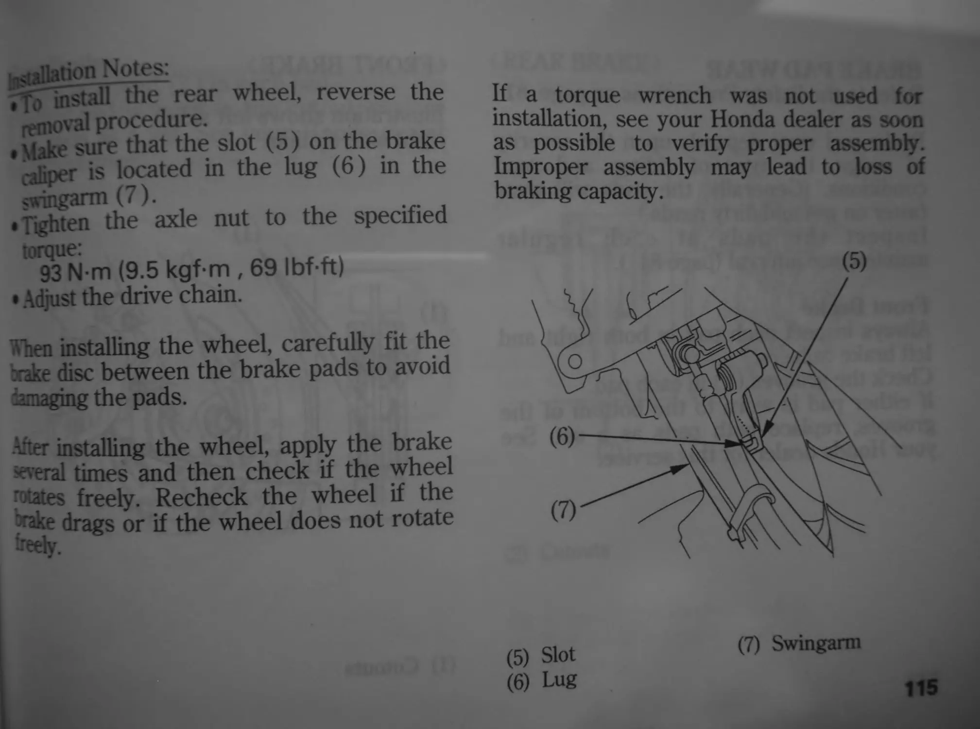
Wheel Removal
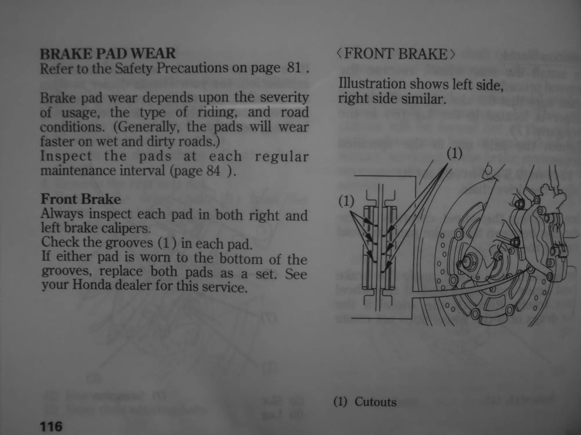
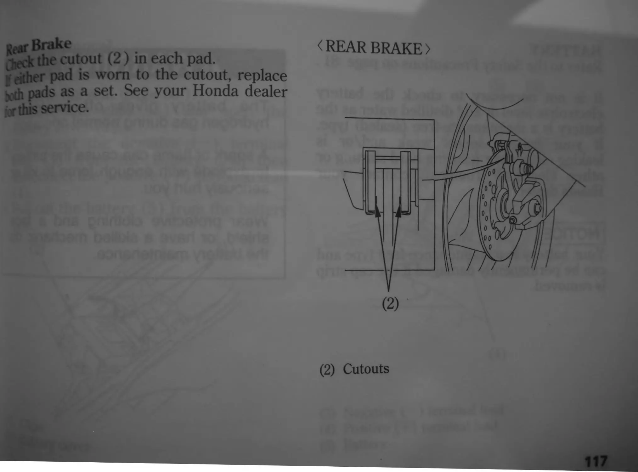
Brake Pad Wear
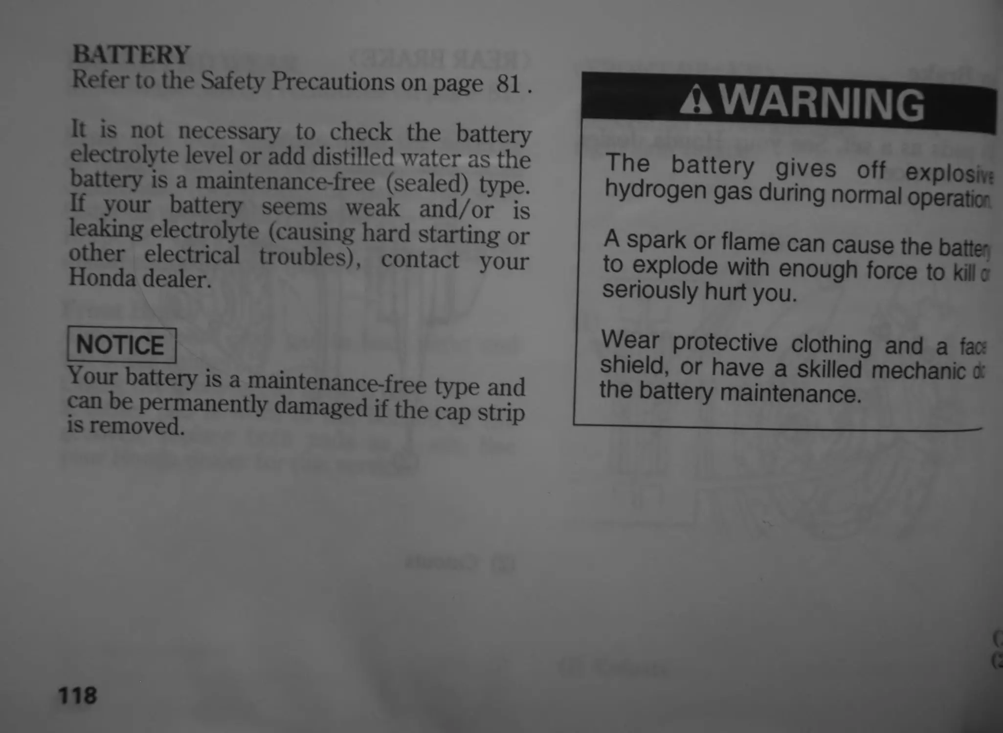
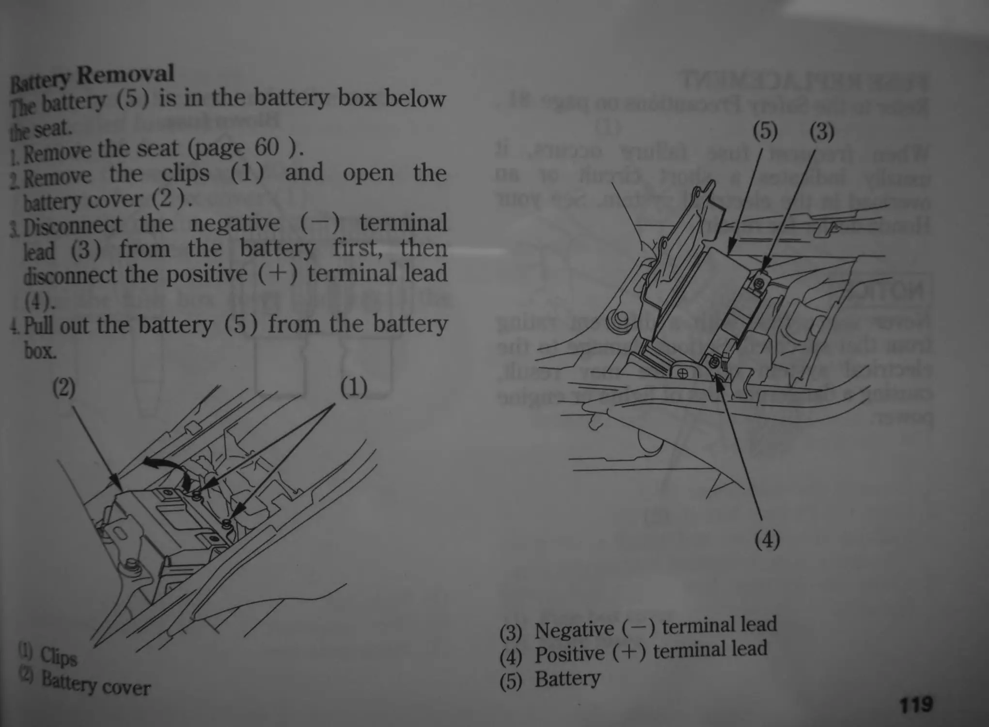
Battery
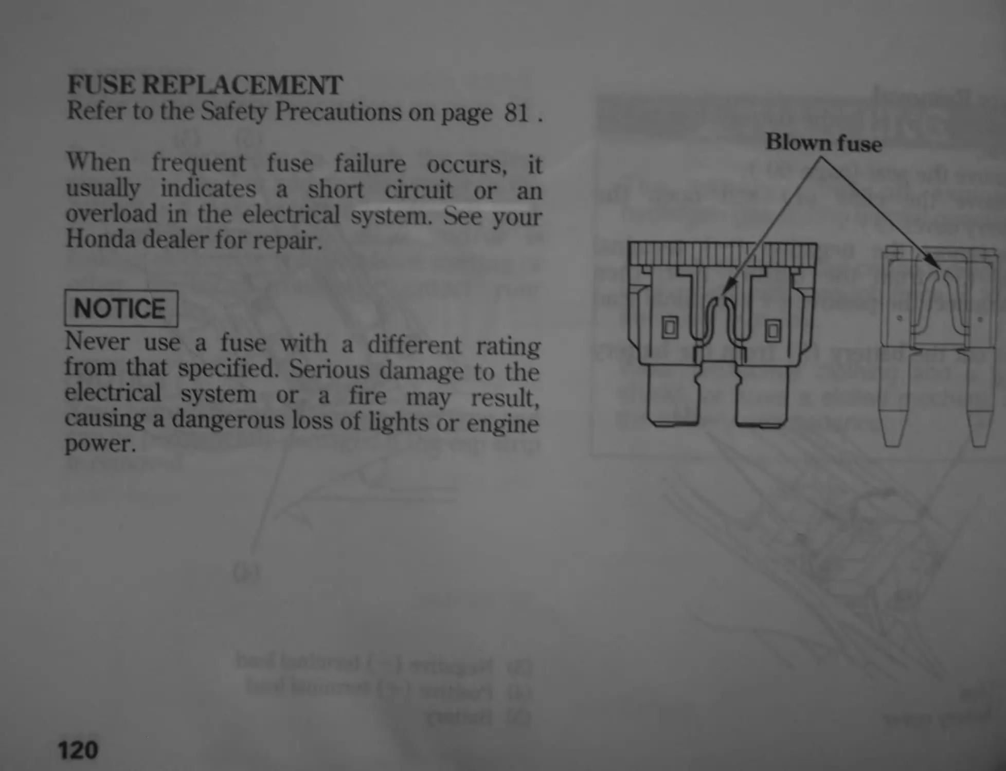
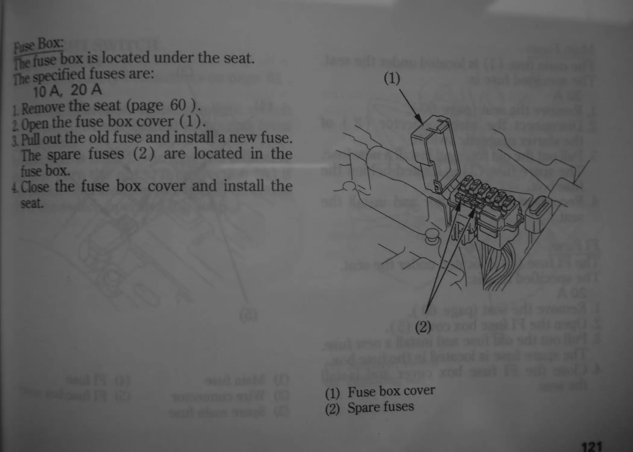
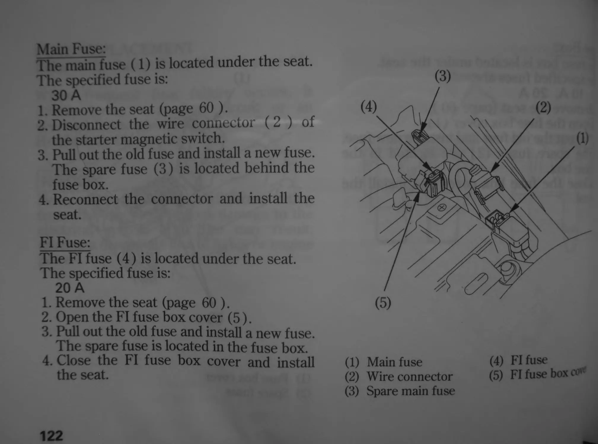
Fuse Replacement
Stoplight Switch Adjustment
Bulb Replacement
page
129 CLEANING
133 STORAGE GUIDE
133 Storage
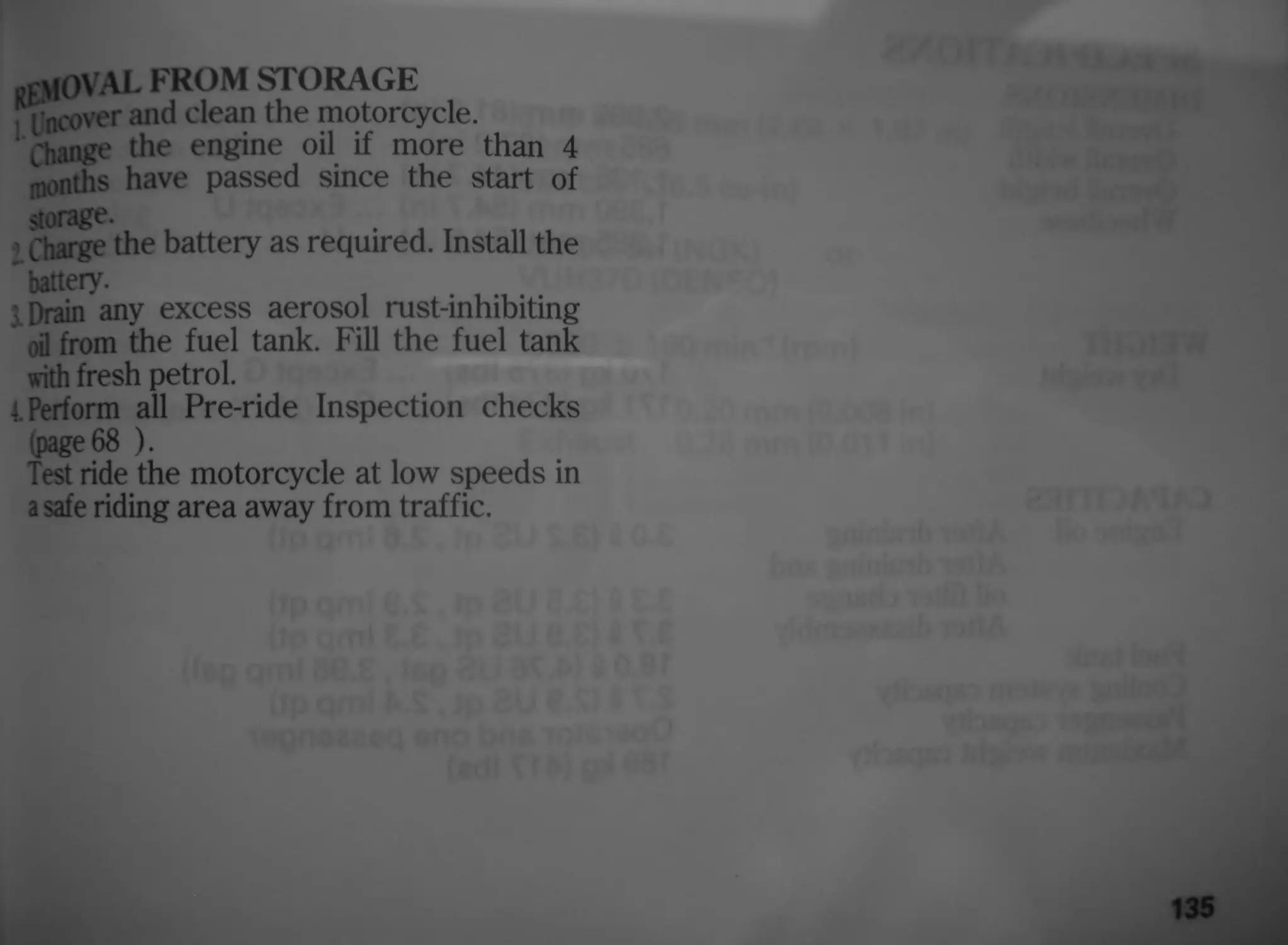
135 Removal from Storage
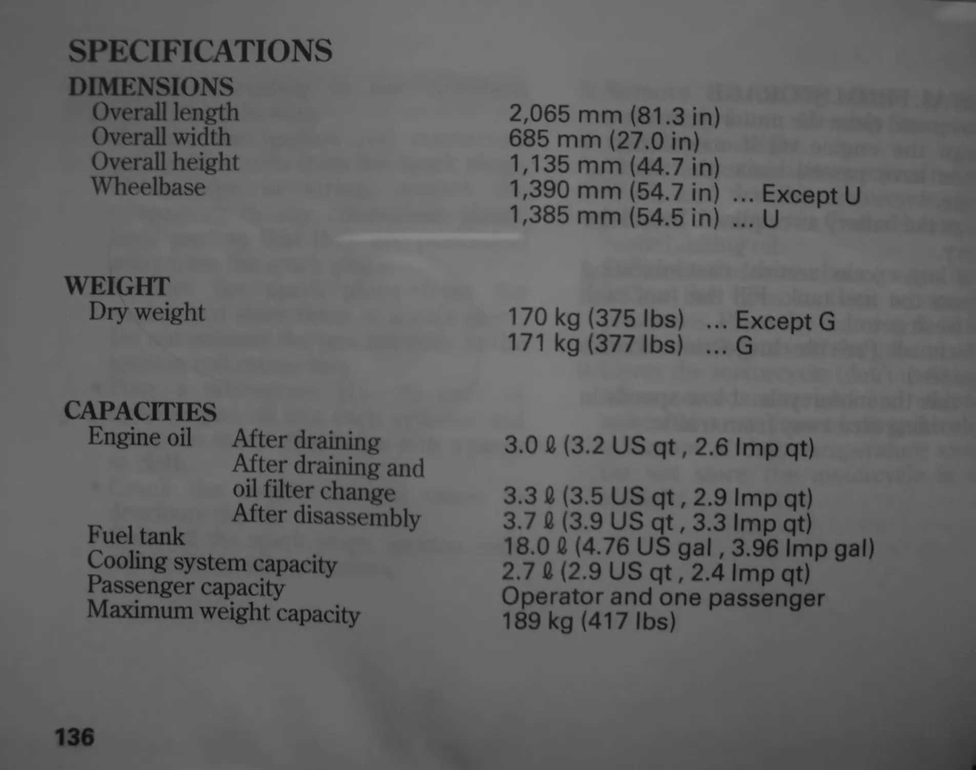
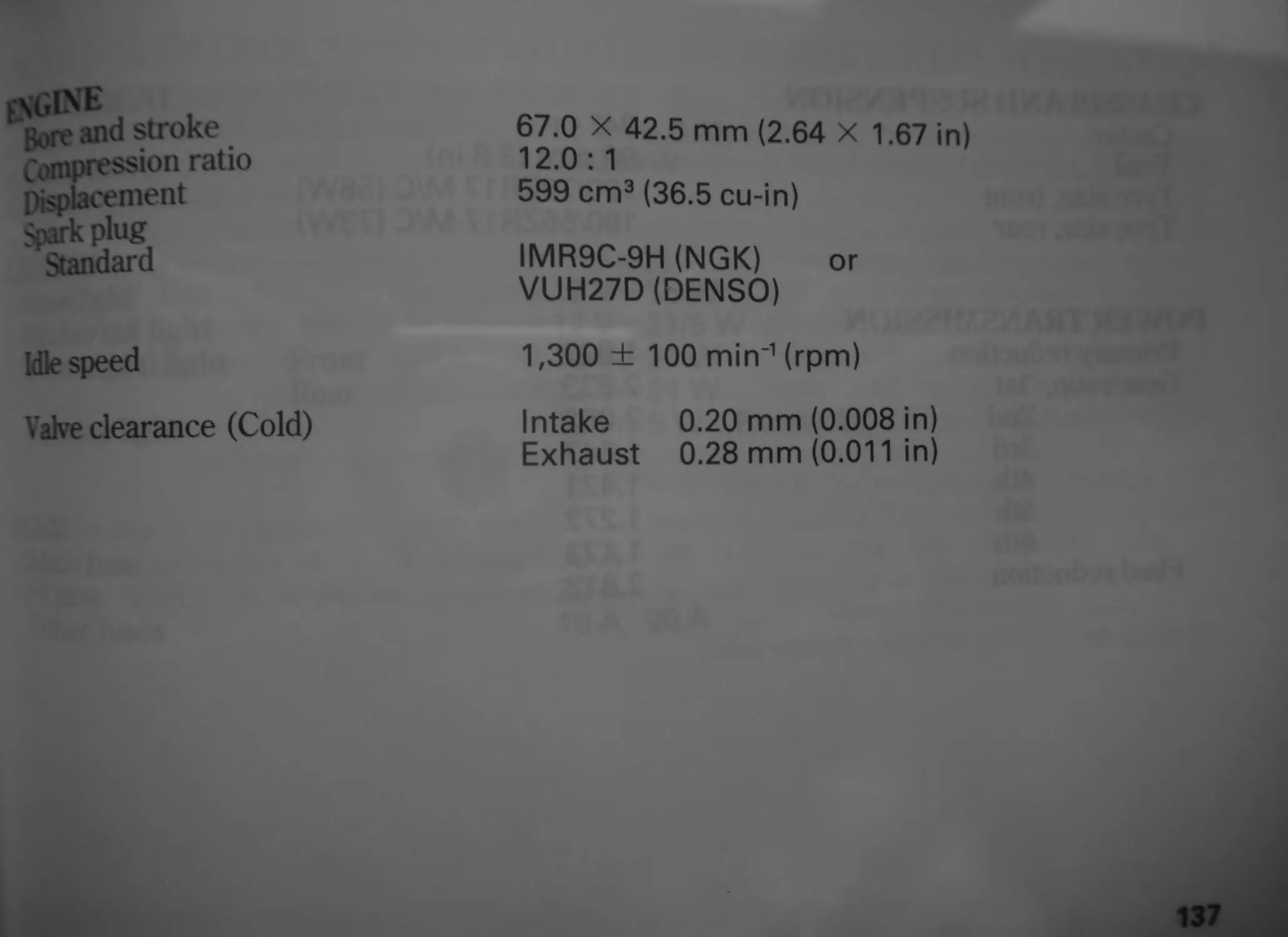
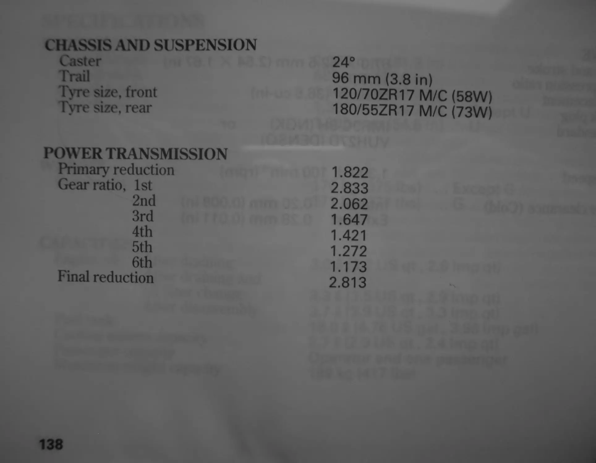
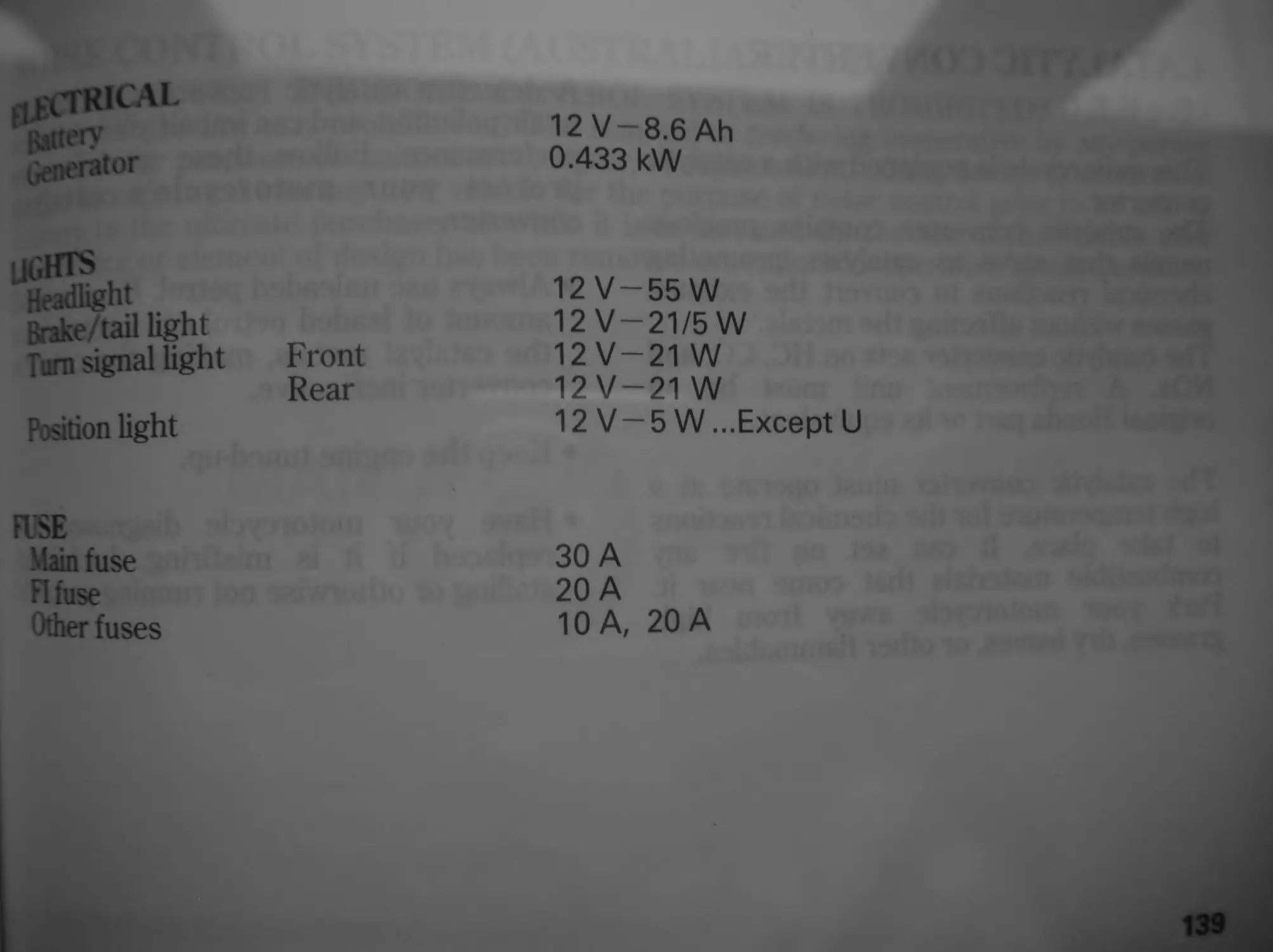
136 SPECIFICATIONS
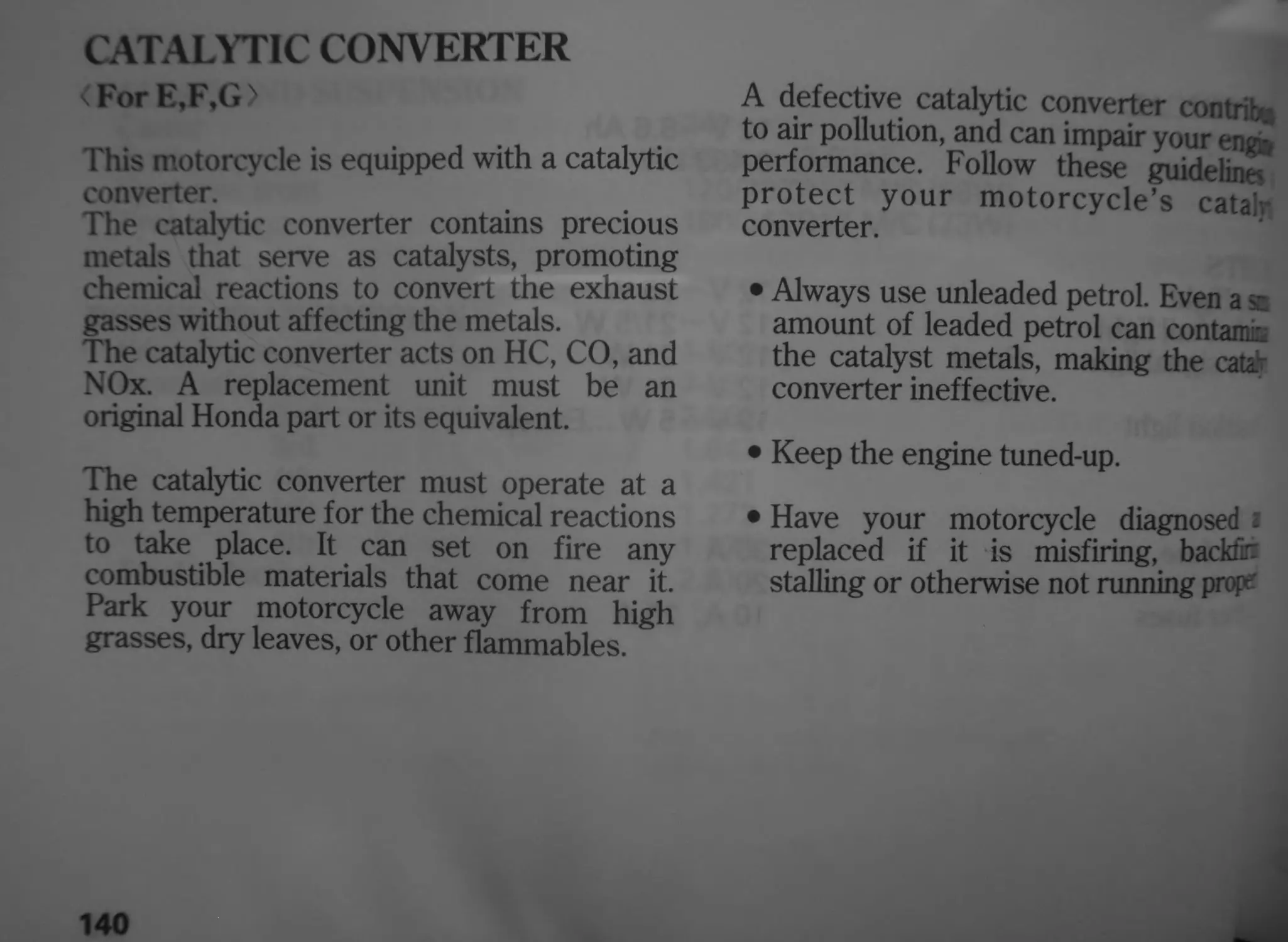
140 CATALYTIC CONVERTER
141 NOISE CONTROL SYSTEM
(AUSTRALIA ONLY)
MOTORCYCLE SAFETY
IMPORTANT SAFETY INFORMATION
Your motorcycle can provide many years of
service and pleasure — if you take
responsibility for your own safety and
understand the challenges that you can
meet on the road.
There is much that you can do to protect
yourself when you ride. You’ll find many
helpful recommendations throughout this
manual. Following are a few that we
consider most important.
.Always Wear a Helmet
It’s a proven fact: helmets significantly
reduce the number and severity of head
injuries. So always wear an approved
motorcycle helmet and make sure your
passenger does the same. We also
recommend that you wear eye protection,
sturdy boots, gloves, and other protective
gear (page 2 ).
Make Yourself Easy to See
Some drivers do not see motorcycles
because they are not looking for them. To
make yourself more visible, wear bright
reflective clothing, position yourself so
other drivers can see you, signal before
turning or changing lanes, and use your
horn when it will help others notice you.
Ride Within Your Limits
Pushing the limits is another major cause of
motorcycle accidents. Never ride beyond
your personal abilities or faster than
conditions warrant. Remember that alcohol,
drugs, fatigue and inattention can
significantly reduce your ability to make
good judgements and ride safely.
Keep Your Bike in Safe Condition
For safe riding, it’s important to inspect
your motorcycle before every ride and
perform all recommended maintenance.
Never exceed load limits, and only use
accessories that have been approved by
Honda for this motorcycle. See page 4 for
more details.
Don’t Drink and Ride
.Alcohol and riding don’t mix. Even one
drink can reduce your ability to respond to
changing conditions, and your reaction time
gets worse with every additional drink. So
don’t drink and ride, and don’t let your
friends drink and ride either.
2
PROTECTIVE APPAREL
For your safety, we strongly recommend
that you always wear an approved
motorcycle helmet, eye protection, boots,
gloves, long pants, and a long-sleeved shirt
or jacket whenever you ride. Although
complete protection is not possible, wearing
proper gear can reduce the chance of injury
when you ride.
Following are suggestions to help you
choose proper gear.
A WARNING
Not wearing a helmet increases the
chance of serious injury or death in a
crash.
Be sure you and your passenger
always wear a helmet, eye protection
and other protective apparel when you
ride.
Helmets and Eye Protection
Your helmet is your most important piece of
riding gear because it offers the best
protection against head injuries. A helmet
should fit your head comfortably and
securely. A bright-coloured helmet can
make you more noticeable in traffic, as can
reflective strips.
An open-face helmet offers some protection,
but a full-face helmet offers more. Always
wear a face shield or goggles to protect
your eyes and help your vision.
Additional Riding Gear
In addition to a helmet and eye protection,
we also recommend:
• Sturdy boots with non-slip soles to help
protect your feet and ankles.
• Leather gloves to keep your hands warm
and help prevent blisters, cuts, burns and
bruises.
• A motorcycle riding suit or jacket for
comfort as well as protection. Bright-
coloured and reflective clothing can help
make you more noticeable in traffic. Be
sure to avoid loose clothes that could get
caught on any part of your motorcycle.
3
LOAD LIMITSAND GUIDELINES
Your motorcycle has been designed to carry
you and one passenger. When you carry a
passenger, you may feel some difference
during acceleration and braking. But so long
as you keep your motorcycle well-
maintained, with good tyres and brakes, you
can safely carry loads within the given limits
and guidelines.
However, exceeding the weight limit or
carrying an unbalanced load can seriously
affect your motorcycle’s handling, braking
and stability. Non-Honda accessories,
improper modifications, and poor
maintenance can also reduce your safety
margin.
The following pages give more specific
information on loading, accessories and
modifications.
Loading
How much weight you put on your
motorcycle, and how you load it, are
important to your safety. Anytime you ride
with a passenger or cargo you should be
aware of the following information.
A WARNING
Overloading or improper loading can
cause a crash and you can be
seriously hurt or killed.
Follow all load limits and other loading
guidelines in this manual.
Load Limits
Following are the load limits for your
motorcycle:
Maximum weight capacity:
189 kg (417 lbs)
Includes the weight of the rider,
passenger, all cargo and all accessories
Maximum cargo weight:
27 kg (60 lbs)
The weight of added accessories will reduce
the maximum cargo weight you can carry.
Loading Guidelines
Your motorcycle is primarily intended for
transporting you and a passenger. You may
wish to secure a jacket or other small items
to the seat when you are not riding with a
passenger.
If you wish to carry more cargo, check with
your Honda dealer for advice, and be sure
to read the information regarding
accessories on page 6 .
Improperly loading your motorcycle can
affect its stability and handling. Even if your
motorcycle is properly loaded, you should
ride at reduced speeds and never exceed
130 km/h (80 mph) when carrying cargo.
Follow these guidelines whenever you carry
a passenger or cargo:
• Check that both tyres are properly
inflated.
• If you change your normal load, you may
need to adjust the front suspension (page
28 ) and the rear suspension (page 31).
• To prevent loose items from creating a
hazard, make sure that all cargo is
securely tied down before you ride away.
• Place cargo weight as close to the center
of the motorcycle as possible.
• Balance cargo weight evenly on both
sides.
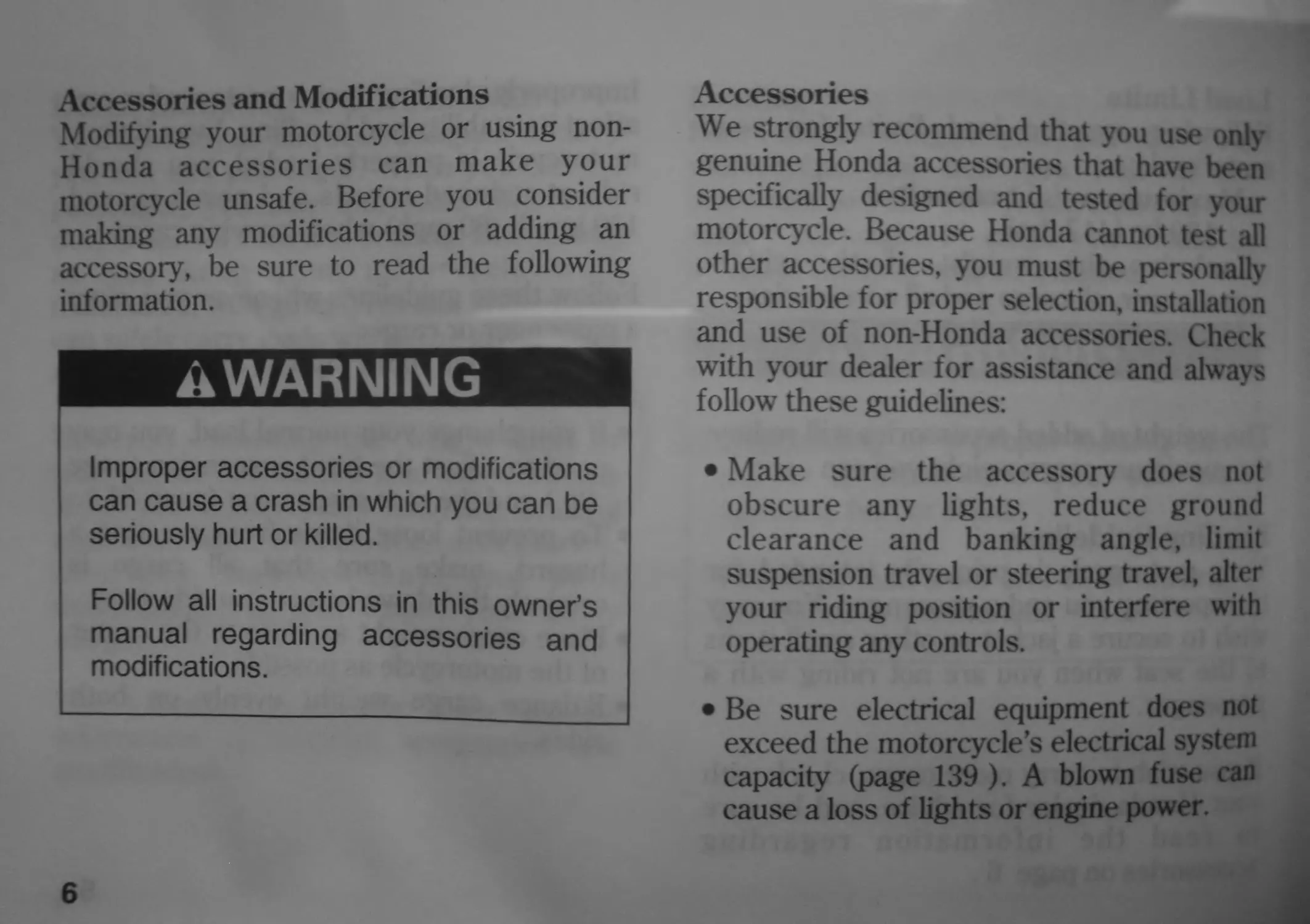
Accessories and Modifications
Modifying your motorcycle or using non-
Honda accessories can make your
motorcycle unsafe. Before you consider
making any modifications or adding an
accessory, be sure to read the following
information.
A WARNING
Improper accessories or modifications
can cause a crash in which you can be
seriously hurt or killed.
Follow all instructions in this owner’s
manual regarding accessories and
modifications.
6
Accessories
We strongly recommend that you use only
genuine Honda accessories that have been
specifically designed and tested for your
motorcycle. Because Honda cannot test all
other accessories, you must be personally
responsible for proper selection, installation
and use of non-Honda accessories. Check
with your dealer for assistance and always
follow these guidelines:
• Make sure the accessory does not
obscure any lights, reduce ground
clearance and banking angle, limit
suspension travel or steering travel, alter
your riding position or interfere with
operating any controls.
• Be sure electrical equipment does not
exceed the motorcycle’s electrical system
capacity (page 139 ). A blown fuse can
cause a loss of lights or engine power.
Do not pull a trailer or sidecar with your
motorcycle. This motorcycle was not
designed for these attachments, and their
use can seriously impair your motorcycle’s
handling.
Modifications
We strongly advise you not to remove any
original equipment or modify your
motorcycle in any way that would change its
design or operation. Such changes could
seriously impair your motorcycle’s handling,
stability and braking, making it unsafe to
ride.
Removing or modifying your lights,
mufflers, emission control system or other
equipment can also make your motorcycle
illegal.
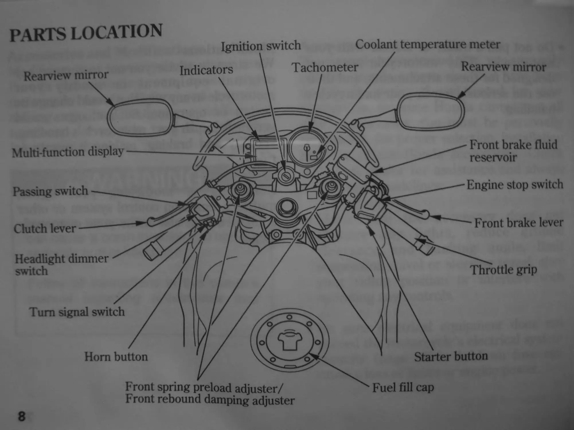
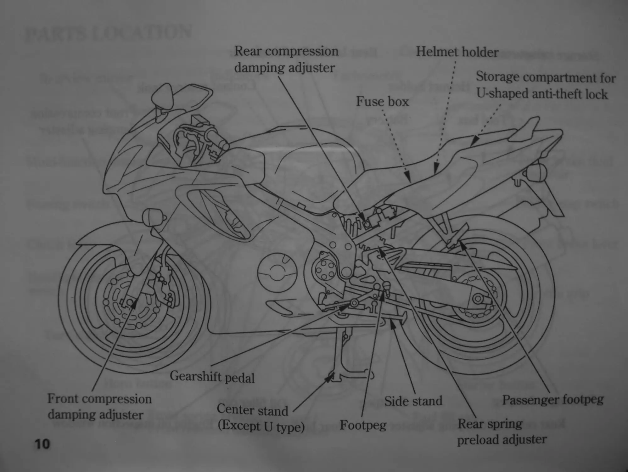
PARTS LOCATION
Ignition switch Coolant temperature meter
Tachometer Rearview mirror
Multi-function display
Indicators
Rearview mirror
Passing switch
Clutch lever
Turn signal switch
Headlight dimmer
switch
Engine stop switch
Front brake lever
Hom button
Starter button
Fuel fill cap
Front brake fluid
reservoir
Front spring preload adjuster/
Front rebound damping adjuster
Throttle grip
8
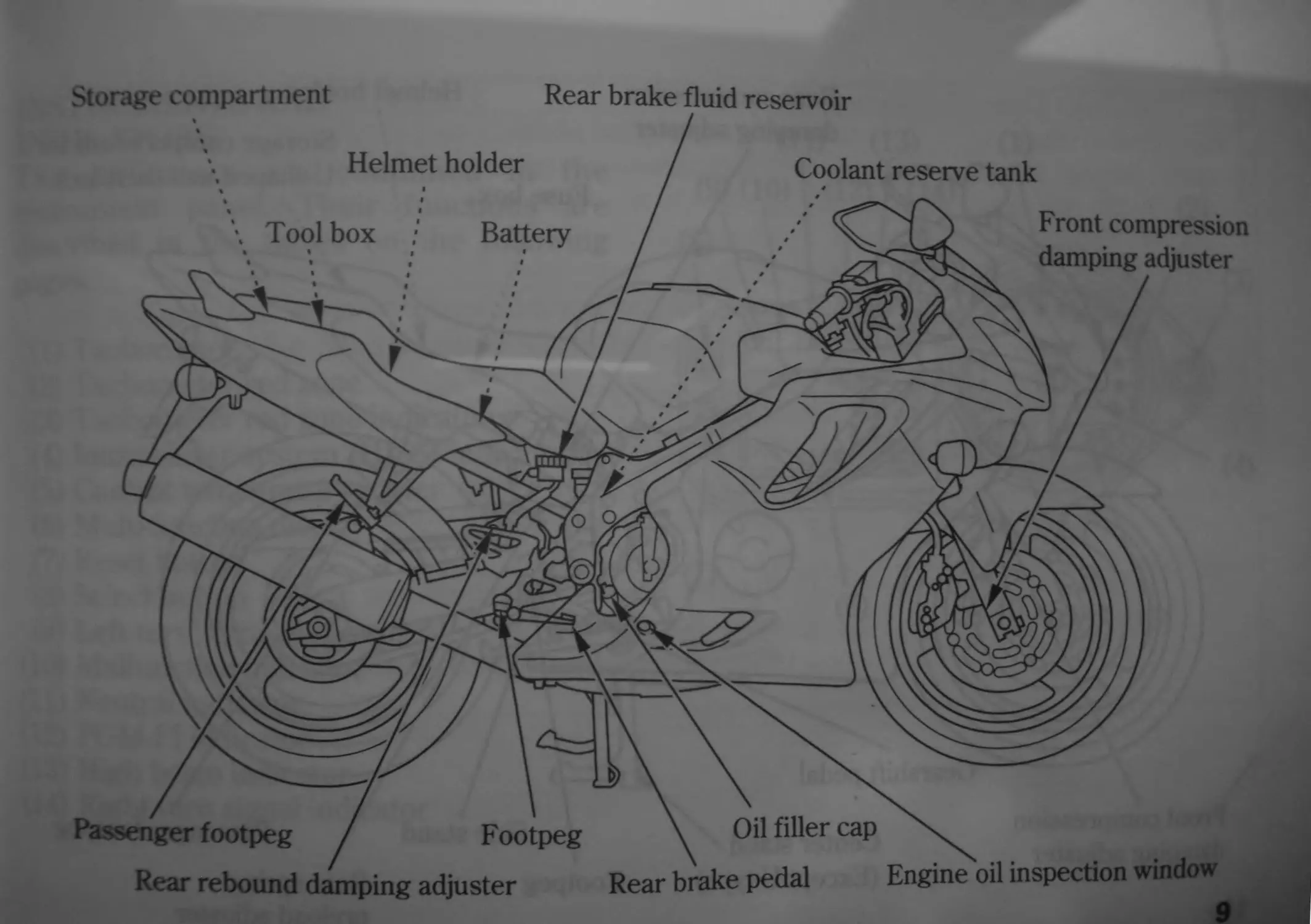
Rear brake fluid reservoir
Storage compartment
4 / Helmet holder / \ Tool box • Battery / f f / / /1 * T f "г л/ у' Passenger footpeg / Footpeg \ Coolant reserve tank • — / ] j Front compression damping adjuster 9 'хЧ ’Г / \ \ \A / * \ ~ 'ж / Oil filler cap
Rear rebound damping adjuster
Rear brake pedal Engine oil inspection window
Helmet holder
Fuse box
Rear compression
damping adjuster
Storage compartment for
U-shaped anti-theft lock
Gearshift pedal
Side stand
Front compression
damping adjuster
Passenger footpeg
Rear spring
preload adjuster
Center stand
(Except U type) Footpeg
10
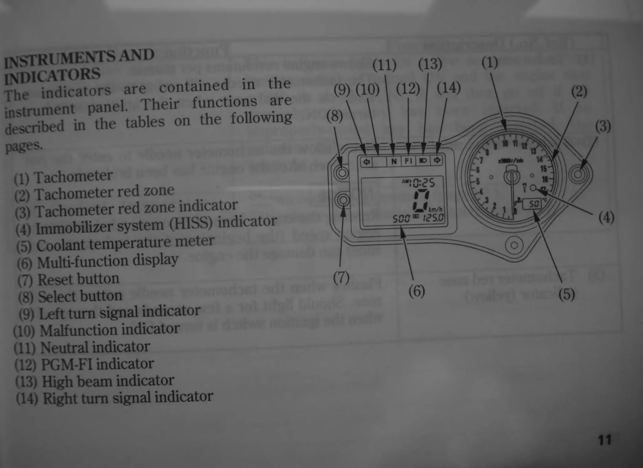
instrumentsand
INDICATORS
The indicators are contained in the
instrument panel. Their functions are
described in the tables on the following
pages.
(1) Tachometer
(2) Tachometer red zone
(3) Tachometer red zone indicator
(4) Immobilizer system (HISS) indicator
(5) Coolant temperature meter
(6) Multi-function display
(7) Reset button
(8) Select button
(9) Left turn signal indicator
(10) Malfunction indicator
(11) Neutral indicator
(12) PGM-FI indicator
(13) High beam indicator
< 14) Right turn signal indicator
11
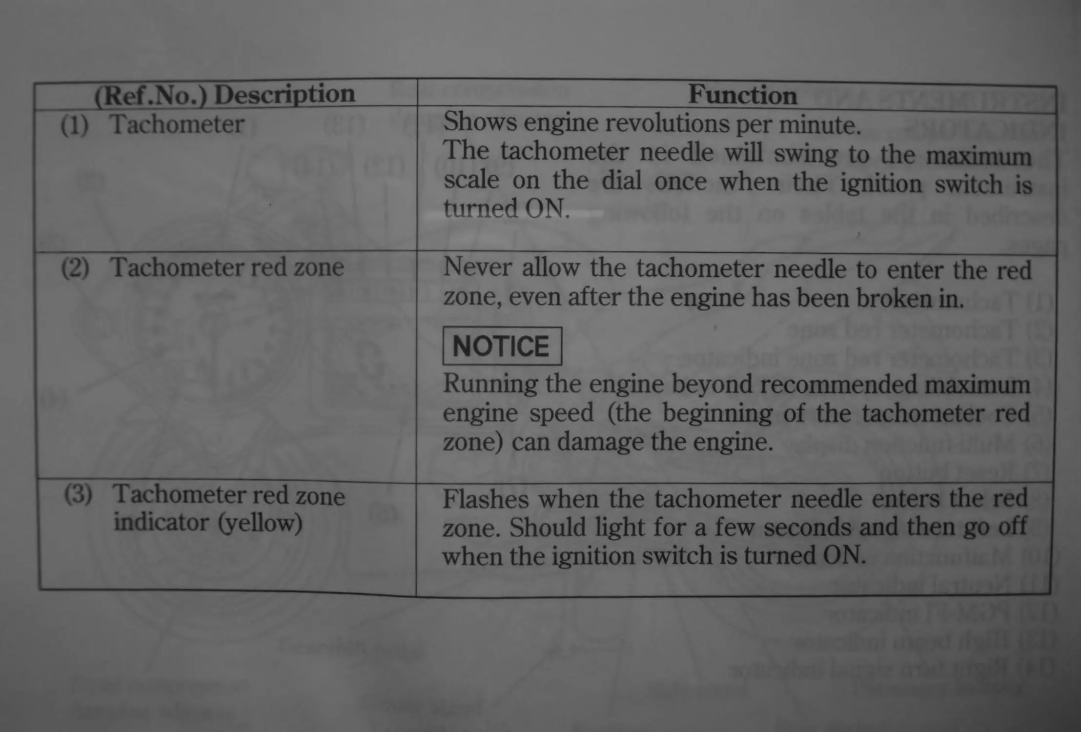
(Ref .No.) Description Function
(1) Tachometer Shows engine revolutions per minute. The tachometer needle will swing to the maximum scale on the dial once when the ignition switch is turned ON. J
(2) Tachometer red zone Never allow the tachometer needle to enter the red zone, even after the engine has been broken in. NOTICE Running the engine beyond recommended maximum engine speed (the beginning of the tachometer red zone) can damage the engine.
(3) Tachometer red zone indicator (yellow) Flashes when the tachometer needle enters the red zone. Should light for a few seconds and then go off when the ignition switch is turned ON.
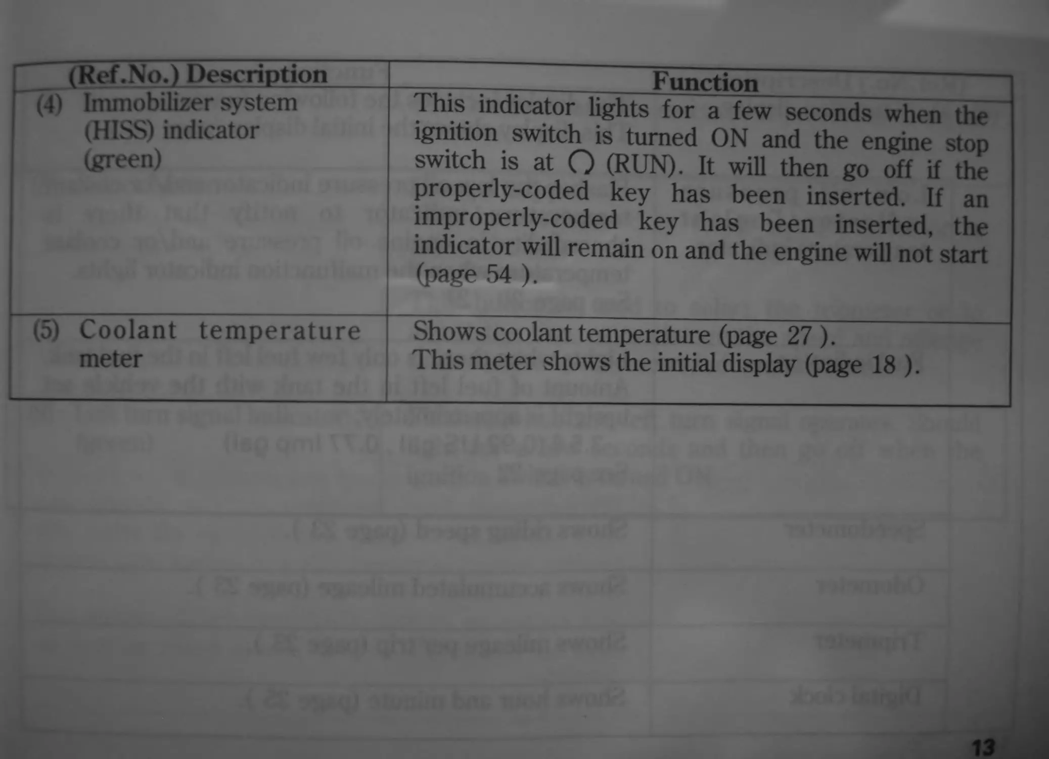
(Ref .Np.J Description
(4) Immobilizer system
(HISS) indicator
(green)
(5) Coolant temperature
meter
___________________Function___________________
This indicator lights for a few seconds when the
ignition switch is turned ON and the engine stop
switch is at Q (RUN). It will then go off if the
properly-coded key has been inserted. If an
improperly-coded key has been inserted, the
indicator will remain on and the engine will not start
(page 54 ).
Shows coolant temperature (page 27 ).
This meter shows the initial display (page 18 ).
13
(Ref .No.) Description
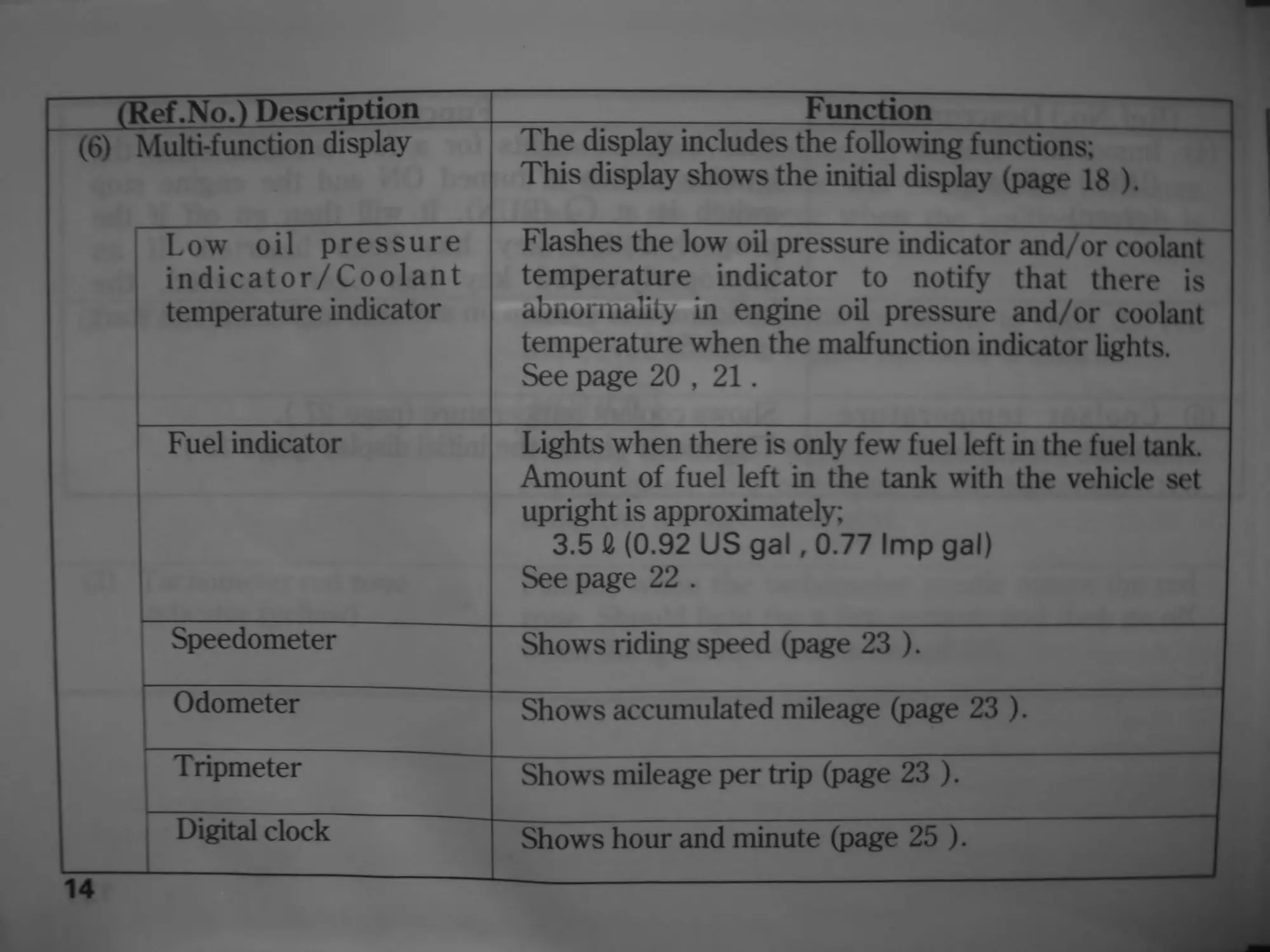
(6) Multi-function display
_____________________Function _________
The display includes the following functions;
This display shows the initial display (page 18 ).
Low oil pressure
indicator/Coolant
temperature indicator
Flashes the low oil pressure indicator and/or coolant
temperature indicator to notify that there is
abnormality in engine oil pressure and/or coolant
temperature when the malfunction indicator lights.
See page 20 , 21.
Fuel indicator
Lights when there is only few fuel left in the fuel tank.
Amount of fuel left in the tank with the vehicle set
upright is approximately;
3.5 £ (0.92 US gal, 0.77 Imp gal)
See page 22 .
Speedometer
Shows riding speed (page 23 ).
Odometer
Shows accumulated mileage (page 23 ).
Tripmeter
Shows mileage per trip (page 23 ).
Digital clock
Shows hour and minute (page 25 ).
14
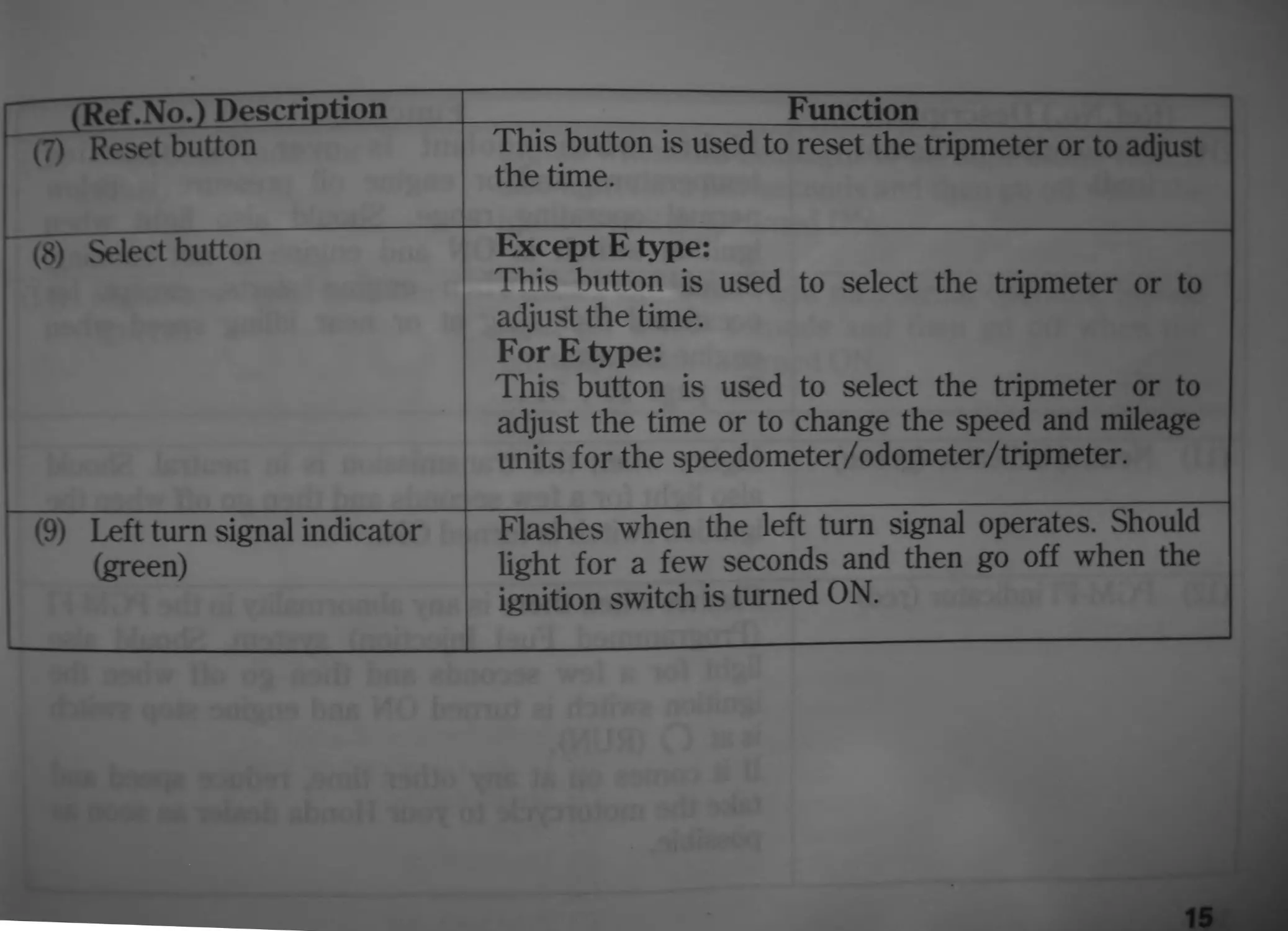
(Ref.No.) Description Function
(7) Reset button This button is used to reset the tripmeter or to adjust the time.
~ (8) Select button Except E type: This button is used to select the tripmeter or to adjust the time. For E type: This button is used to select the tripmeter or to adjust the time or to change the speed and mileage units for the speedometer/odometer/tripmeter.
(9) Left turn signal indicator (green) Flashes when the left turn signal operates. Should light for a few seconds and then go off when the ignition switch is turned ON.
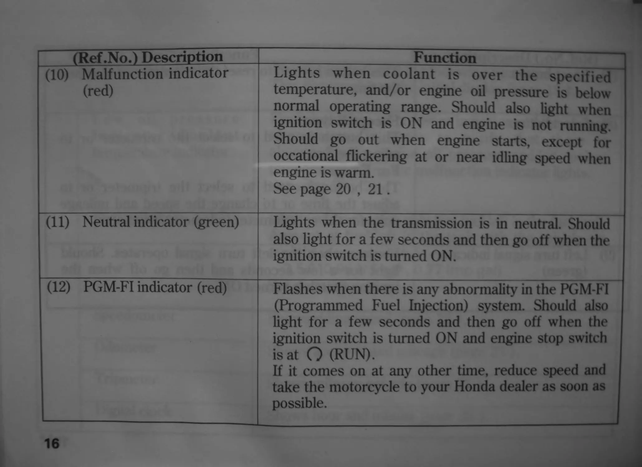
(Ref .No.) Description Function
(10) Malfunction indicator (red) Lights when coolant is over the specified temperature, and/or engine oil pressure is below normal operating range. Should also light when ignition switch is ON and engine is not running. Should go out when engine starts, except for occational flickering at or near idling speed when engine is warm. See page 20 , 21. 1
(11) Neutral indicator (green) Lights when the transmission is in neutral. Should also light for a few seconds and then go off when the ignition switch is turned ON.
(12) PGM-FI indicator (red) Flashes when there is any abnormality in the PGM-FI (Programmed Fuel Injection) system. Should also light for a few seconds and then go off when the ignition switch is turned ON and engine stop switch is at О (RUN). If it comes on at any other time, reduce speed and take the motorcycle to your Honda dealer as soon as possible.
16
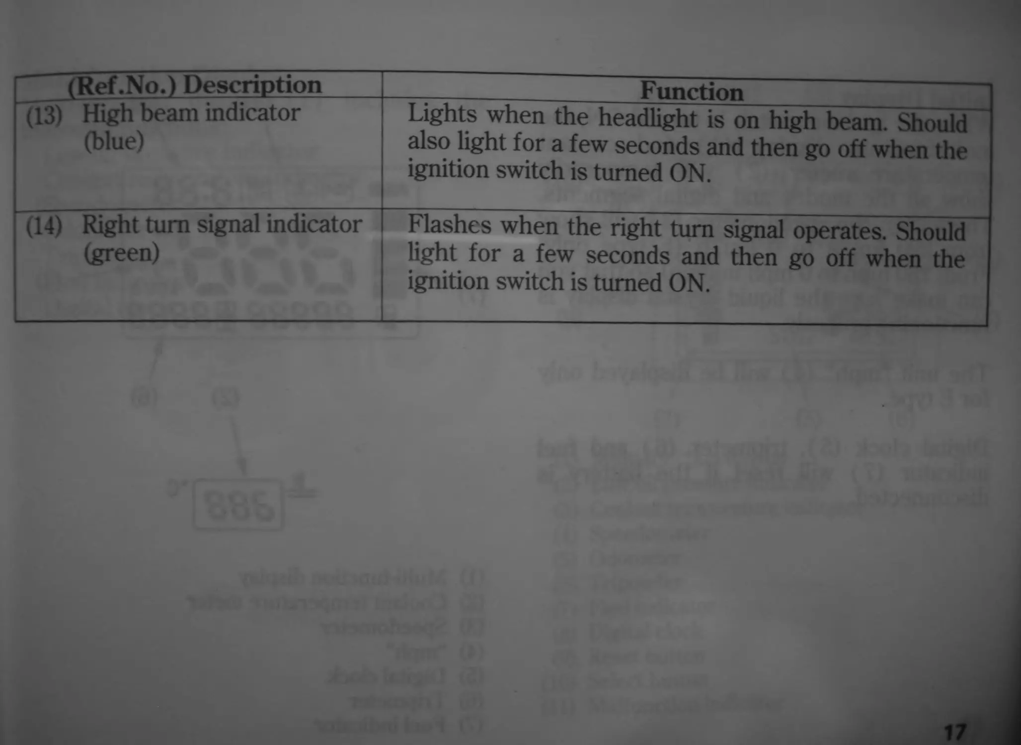
(13) High beam indicator
(blue)
____________________Function___________________
Lights when the headlight is on high beam. Should
also light for a few seconds and then go off when the
ignition switch is turned ON.
(14) Right turn signal indicator
(green)
Flashes when the right turn signal operates. Should
light for a few seconds and then go off when the
ignition switch is turned ON.
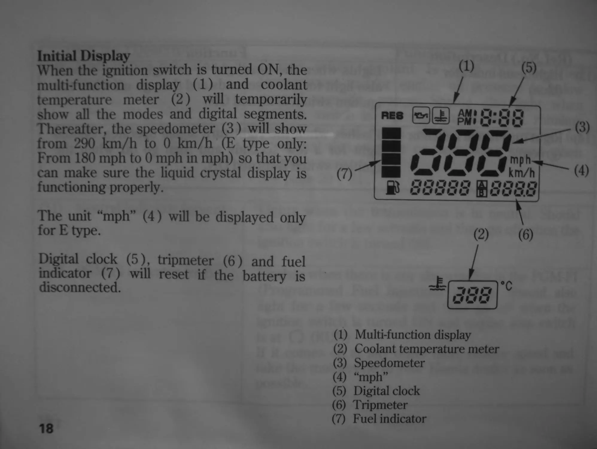
Initial Display
When the ignition switch is turned ON, the
multifunction display (1) and coolant
temperature meter (2) will temporarily
show all the modes and digital segments.
Thereafter, the speedometer (3) will show
from 290 km/h to 0 km/h (E type only:
From 180 mph to 0 mph in mph) so that you
can make sure the liquid crystal display is
functioning properly.
The unit “mph” (4) will be displayed only
for E type.
Digital clock (5), tripmeter (6) and fuel
indicator (7) will reset if the battery is
disconnected.
18
(1)
(5)
(1) Multi-function display
(2) Coolant temperature meter
(3) Speedometer
(4) “mph”
(5) Digital clock
(6) Tripmeter
(7) Fuel indicator
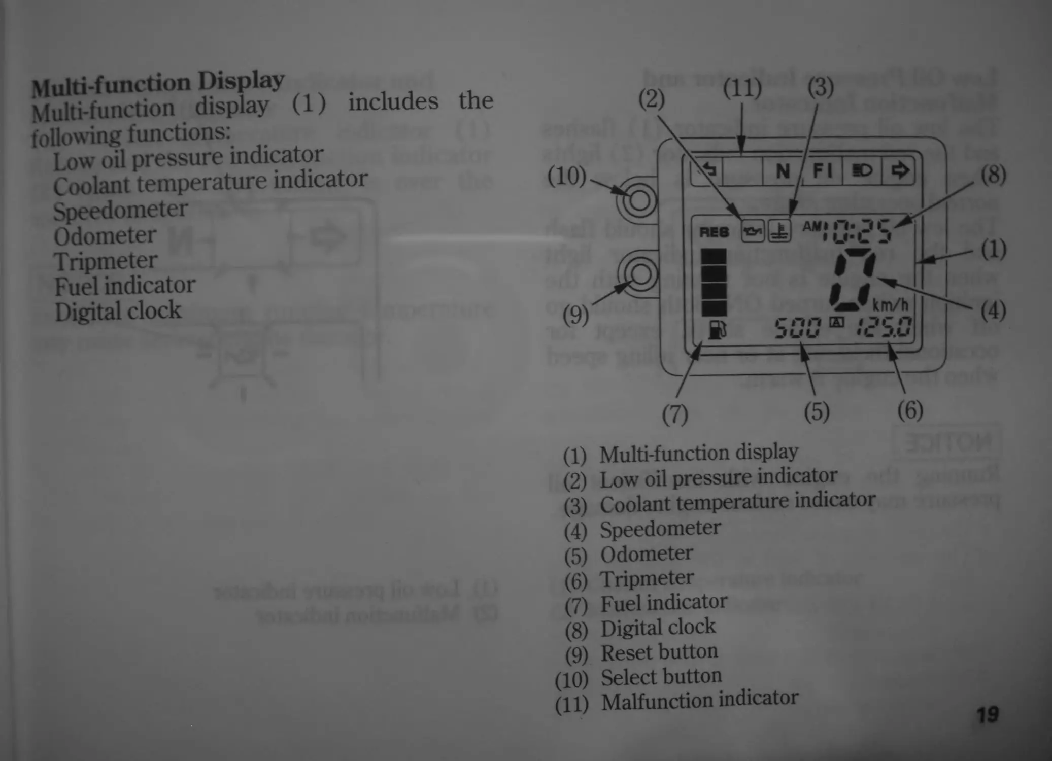
Multi-function Display
Multi-function display (1) includes the
following functions:
Low oil pressure indicator
Coolant temperature indicator
Speedometer
Odometer
Tripmeter
Fuel indicator
Digital clock
(1) Multi-function display
(2) Low oil pressure indicator
(3) Coolant temperature indicator
(4) Speedometer
(5) Odometer
(6) Tripmeter
(7) Fuel indicator
(8) Digital clock
(9) Reset button
(10) Select button
(11) Malfunction indicator
19
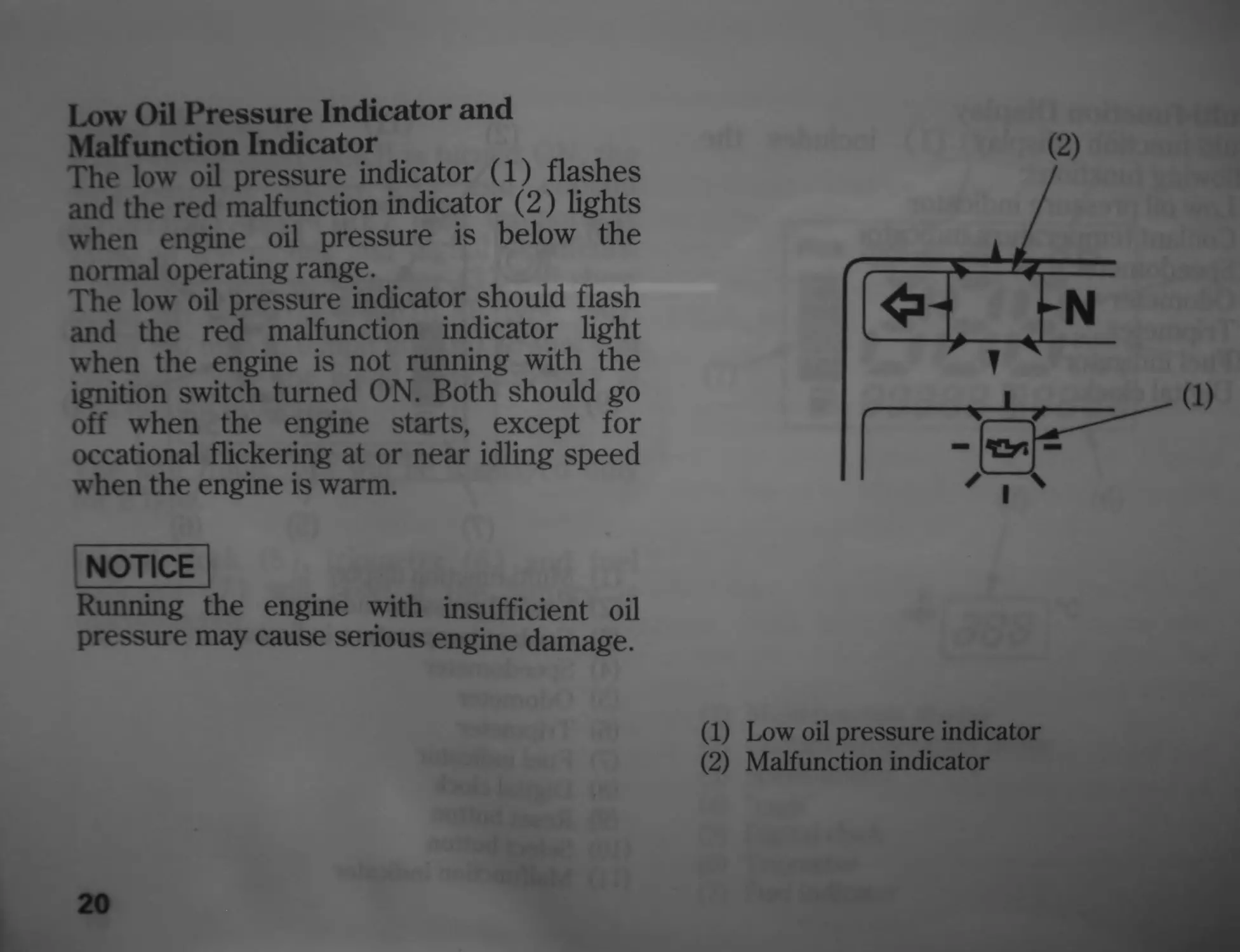
Low Oil Pressure Indicator and
Malfunction Indicator
The low oil pressure indicator (1) flashes
and the red malfunction indicator (2) lights
when engine oil pressure is below the
normal operating range.
The low oil pressure indicator should flash
and the red malfunction indicator light
when the engine is not running with the
ignition switch turned ON. Both should go
off when the engine starts, except for
occational flickering at or near idling speed
when the engine is warm.
NOTICE
Running the engine with insufficient oil
pressure may cause serious engine damage.
20
(2)
(1) Low oil pressure indicator
(2) Malfunction indicator
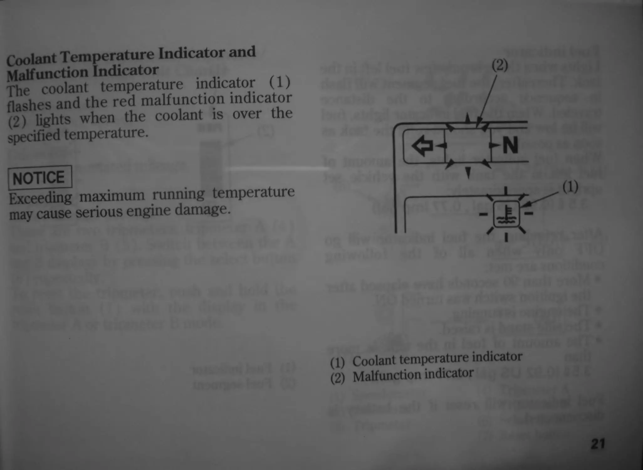
Coolant Temperature Indicator and
Malfunction Indicator
The coolant temperature indicator (1)
flashes and the red malfunction indicator
(2) lights when the coolant is over the
specified temperature.
NOTICE
Exceeding maximum running temperature
may cause serious engine damage.
(1) Coolant temperature indicator
(2) Malfunction indicator
21
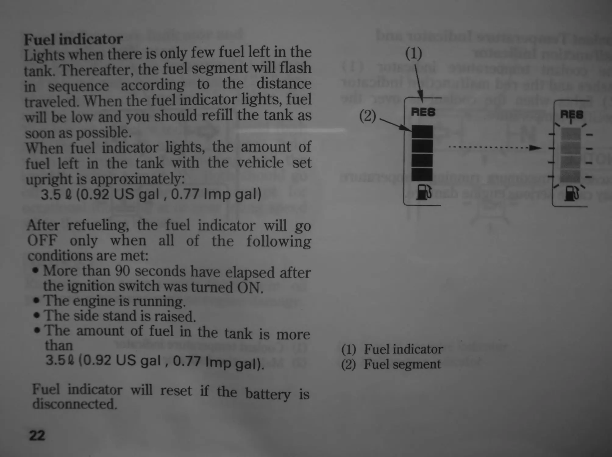
Fuel indicator
Lights when there is only few fuel left in the
tank. Thereafter, the fuel segment will flash
in sequence according to the distance
traveled. When the fuel indicator lights, fuel
will be low and you should refill the tank as
soon as possible.
When fuel indicator lights, the amount of
fuel left in the tank with the vehicle set
upright is approximately:
3.5 fi (0.92 US gal, 0.77 Imp gal)
After refueling, the fuel indicator will go
OFF only when all of the following
conditions are met:
• More than 90 seconds have elapsed after
the ignition switch was turned ON.
• The engine is running.
• The side stand is raised.
• The amount of fuel in the tank is more
than
3.5fl (0.92 US gal, 0.77 Imp gal).
Fuel indicator will reset if the battery is
disconnected.
(1) Fuel indicator
(2) Fuel segment
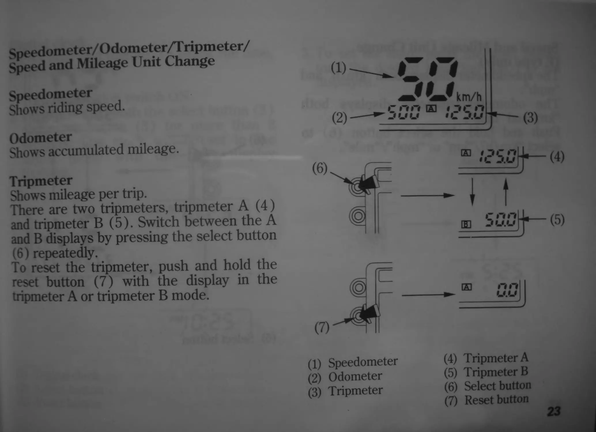
Speedometer/Odometer/Tripmeter/
Speed and Mileage Unit Change
Speedometer
Shows riding speed.
Odometer
Shows accumulated mileage.
Tripmeter
Shows mileage per trip.
There are two tripmeters, tripmeter A (4)
and tripmeter В (5). Switch between the A
and В displays by pressing the select button
(6) repeatedly.
To reset the tripmeter, push and hold the
reset button (7) with the display in the
tripmeter A or tripmeter В mode.
<»- с
km/h
(2) —^-fuu »::>u
(3)
(1) Speedometer
(2) Odometer
(3) Tripmeter
(4) Tripmeter A
(5) Tripmeter В
(6) Select button
(7) Reset button
23
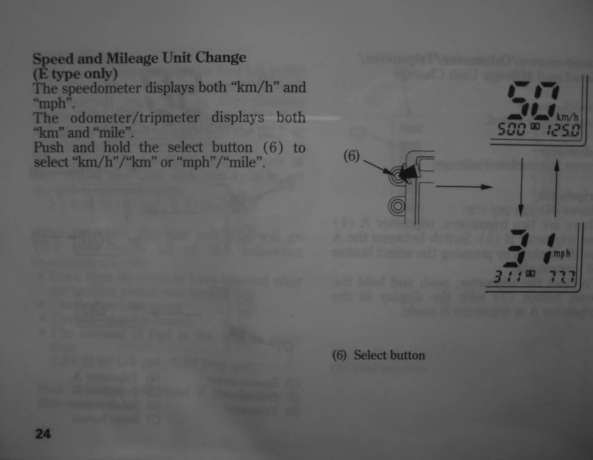
Speed and Mileage Unit Change
(E type only)
The speedometer displays both “km/h” and
“mph".
The odometer/tripmeter displays both
“km” and “mile”.
Push and hold the select button (6) to
select “km/h”/“km” or “mph”/“mile”
24
(6) Select button
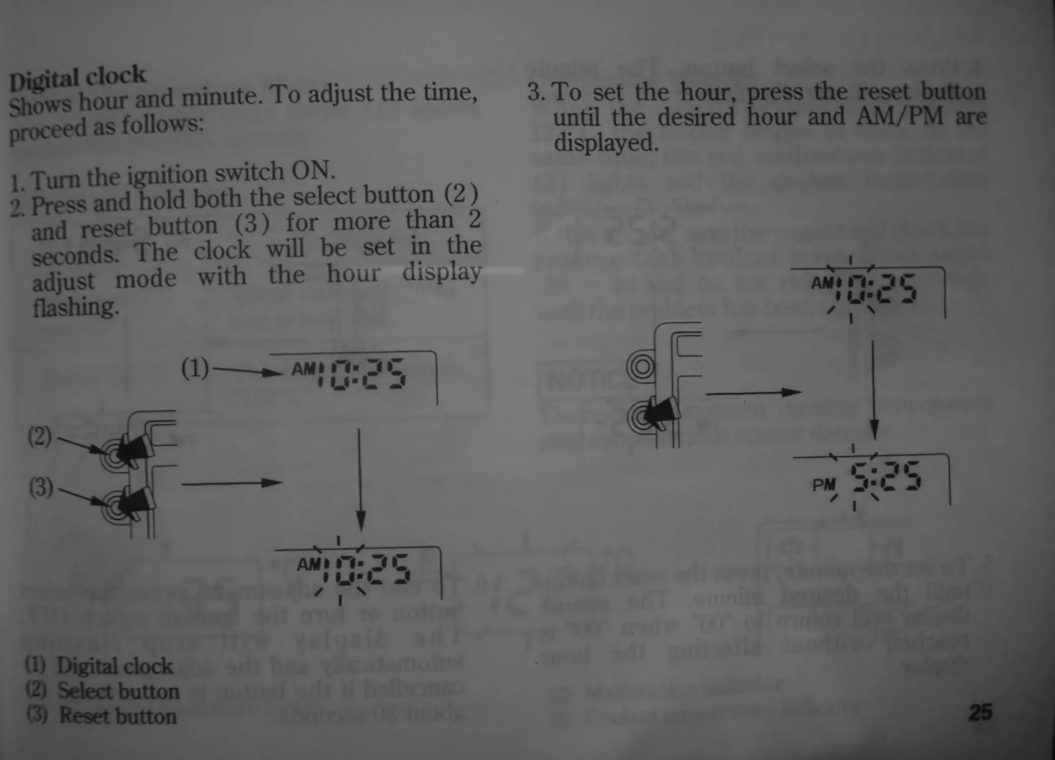
Digital clock
Shows hour and minute. To adjust the time,
proceed as follows:
1. Turn the ignition switch ON.
2. Press and hold both the select button (2)
and reset button (3) for more than 2
seconds. The clock will be set in the
adjust mode with the hour display
flashing.
(b Digital clock
(2) Select button
(3) Reset button
3. To set the hour, press the reset button
until the desired hour and AM/PM are
displayed.
25
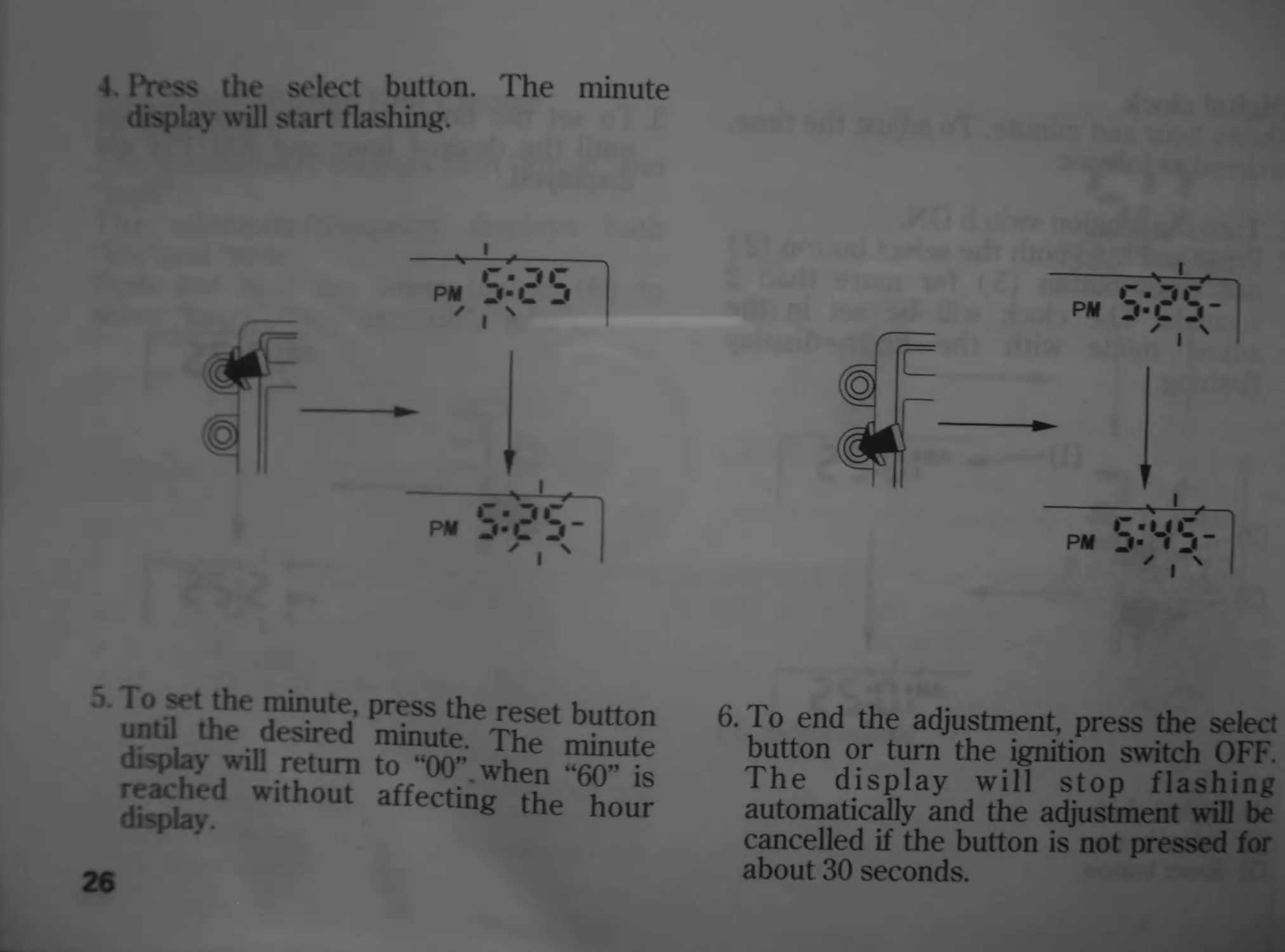
4. Press the select button. The minute
display will start flashing.
5. To set the minute, press the reset button
until the desired minute. The minute
display will return to “00”. when “60” is
reached without affecting the hour
display.
26
6. To end the adjustment, press the select
button or turn the ignition switch OFF.
The display will stop flashing
automatically and the adjustment will be
cancelled if the button is not pressed for
about 30 seconds.
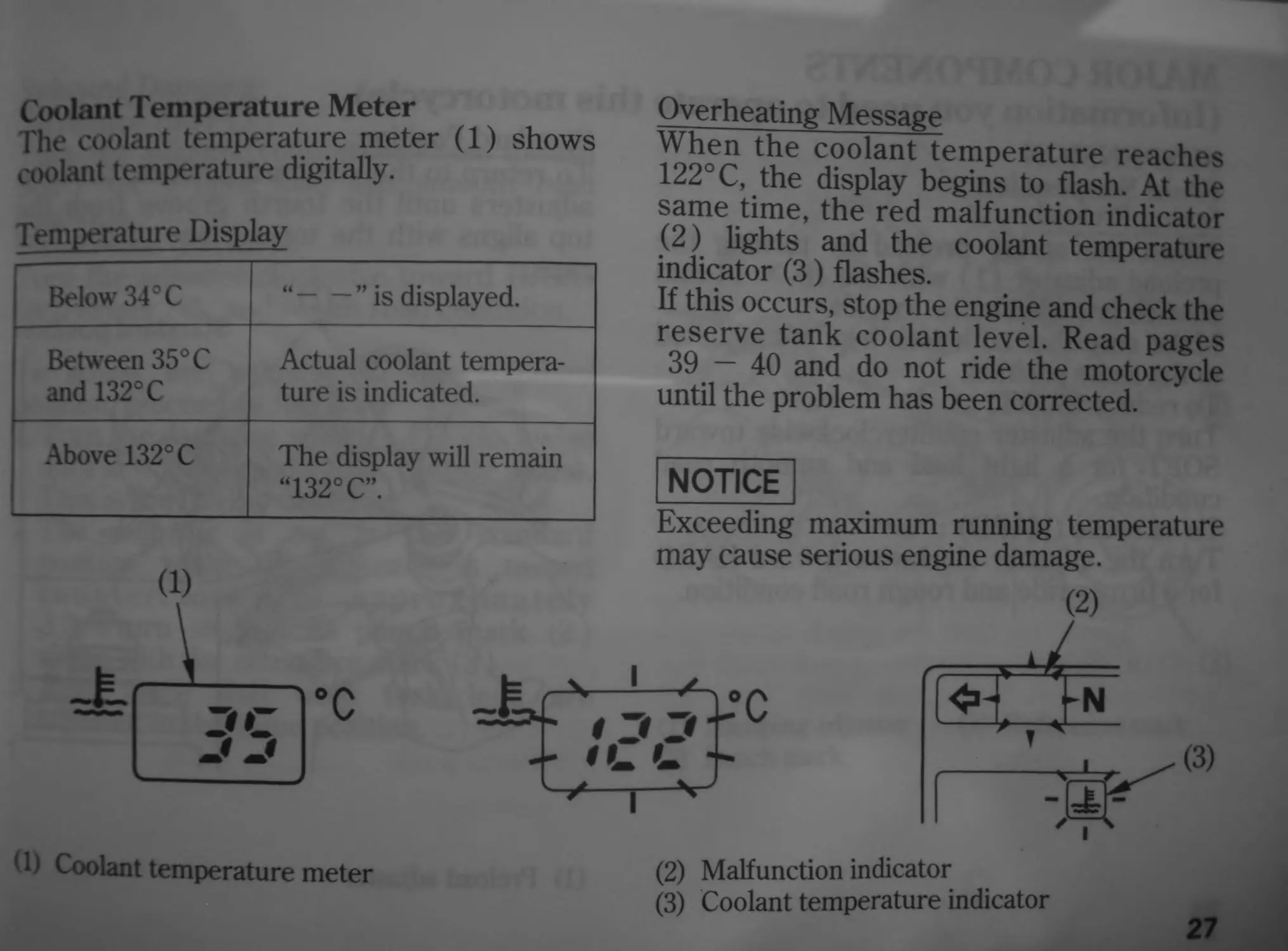
Coolant Temperature Meter
The coolant temperature meter (1) shows
coolant temperature digitally.
Temperature Display
Below 34° C “ ” is displayed.
Between 35° C and 132°C Actual coolant tempera- ture is indicated.
Above 132° C The display will remain “132° C”.
(1) Coolant temperature meter
Overheating Message
When the coolant temperature reaches
122° C, the display begins to flash. At the
same time, the red malfunction indicator
(2) lights and the coolant temperature
indicator (3) flashes.
If this occurs, stop the engine and check the
reserve tank coolant level. Read pages
39 — 40 and do not ride the motorcycle
until the problem has been corrected.
NOTICE
Exceeding maximum running temperature
may cause serious engine damage.
(2) Malfunction indicator
(3) Coolant temperature indicator
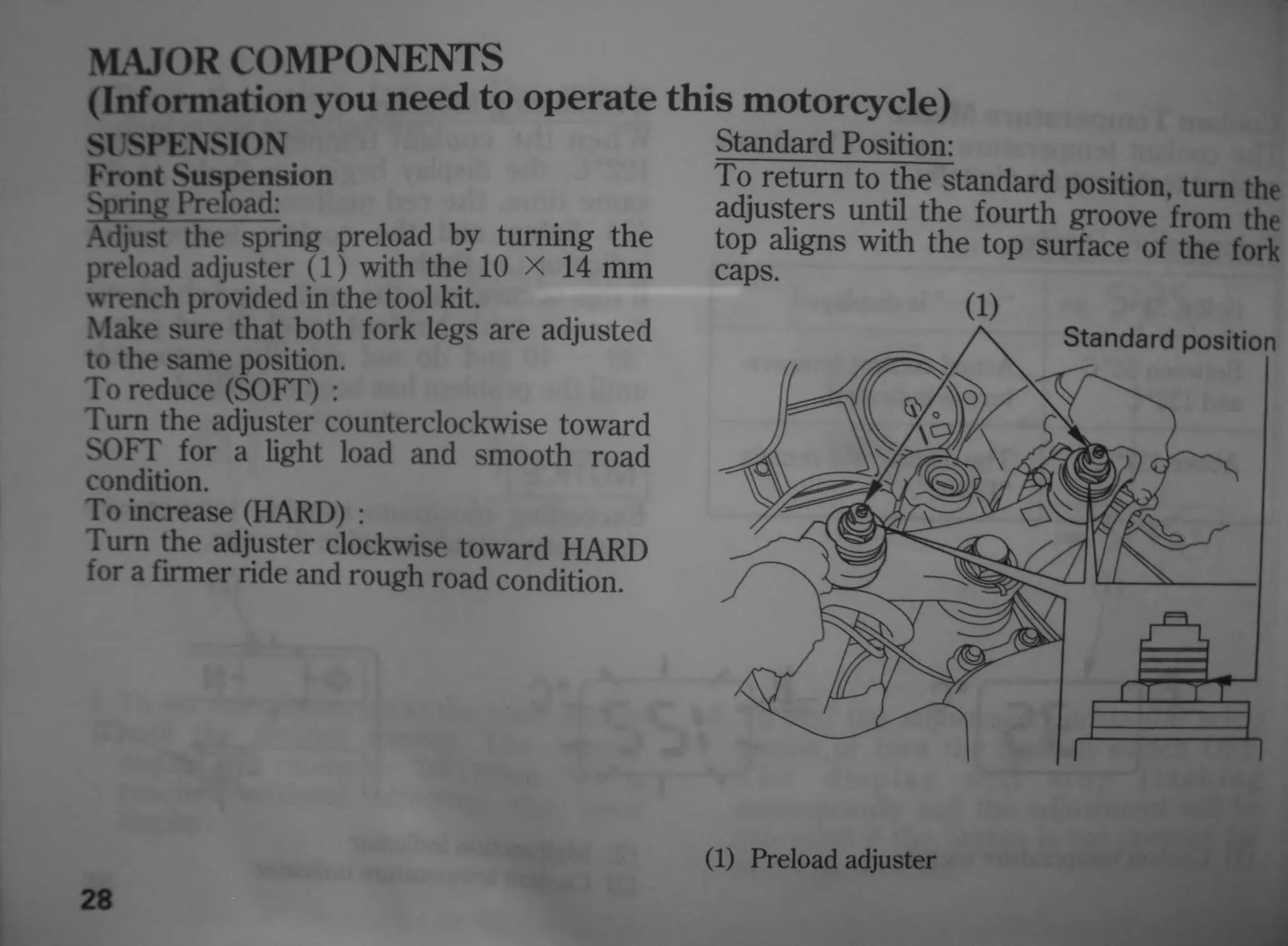
MAJOR COMPONENTS
(Information you
SUSPENSION
Front Suspension
Spring Preload:
Adjust the spring preload by turning the
preload adjuster (1) with the 10 X 14 mm
wrench provided in the tool kit.
Make sure that both fork legs are adjusted
to the same position.
To reduce (SOFT) :
Turn the adjuster counterclockwise toward
SOFT for a light load and smooth road
condition.
To increase (HARD) :
Turn the adjuster clockwise toward HARD
for a firmer ride and rough road condition.
need to operate this motorcycle)
Standard Position:
To return to the standard position, turn the
adjusters until the fourth groove from the
top aligns with the top surface of the fork
caps.
(1)
(1) Preload adjuster
28
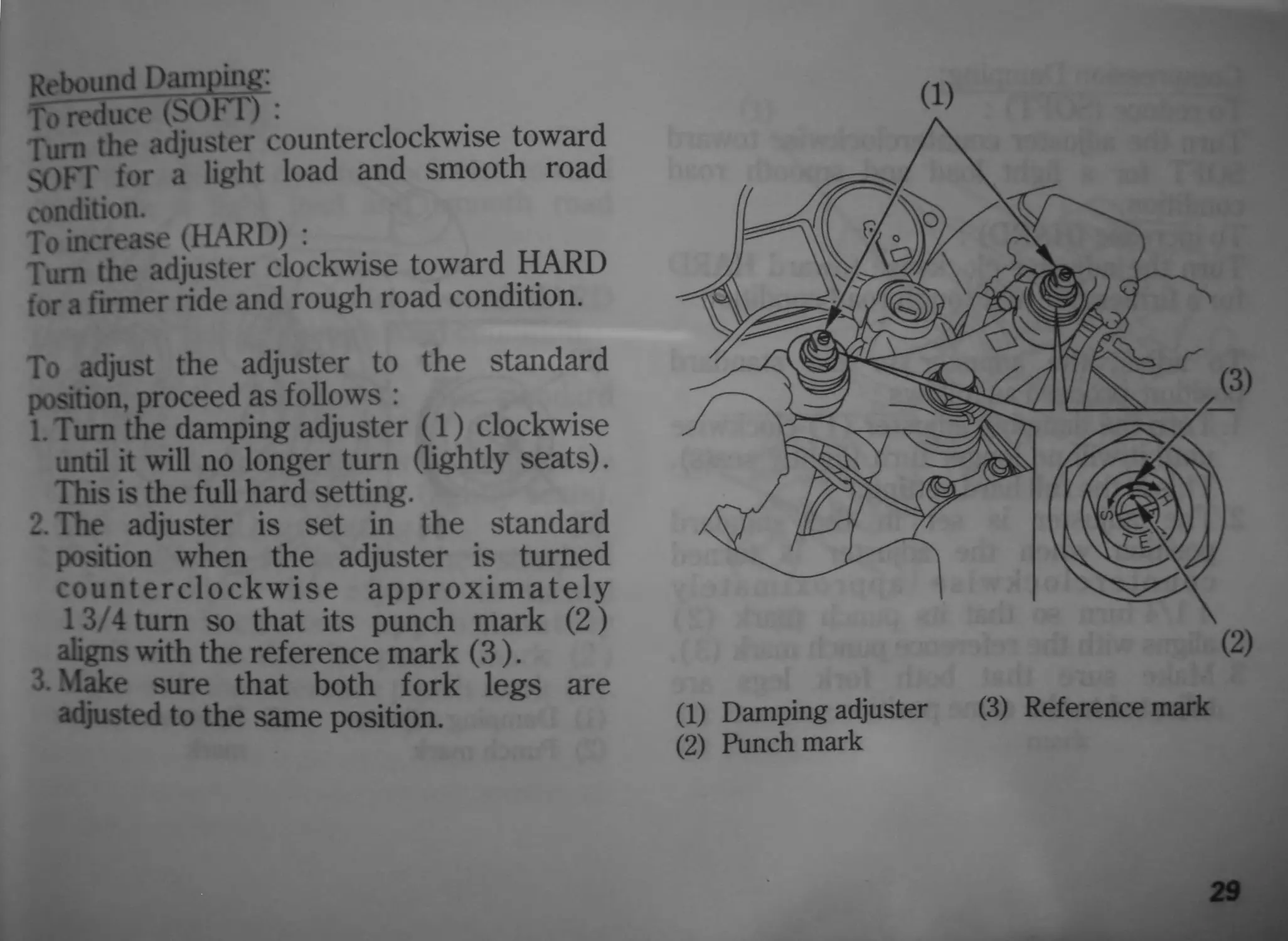
Rebound Damping:
Го reduce (SOFT) : .
Turn the adjuster counterclockwise toward
SOFT for a light load and smooth road
condition.
To increase (HARD) :
Turn the adjuster clockwise toward HARD
for a firmer ride and rough road condition.
To adjust the adjuster to the standard
position, proceed as follows :
l. Tum the damping adjuster (1) clockwise
until it will no longer turn (lightly seats).
This is the full hard setting.
2. The adjuster is set in the standard
position when the adjuster is turned
counterclockwise approximately
13/4 turn so that its punch mark (2)
aligns with the reference mark (3).
3. Make sure that both fork legs are
adjusted to the same position.
(1)
(1) Damping adjuster (3) Reference mark
(2) Punch mark
29
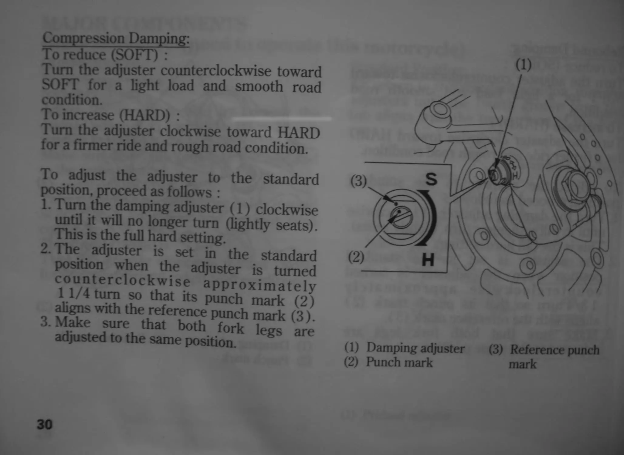
Compression Damping:
To reduce (SOFT) :
Turn the adjuster counterclockwise toward
SOFT for a light load and smooth road
condition.
To increase (HARD) :
Turn the adjuster clockwise toward HARD
for a firmer ride and rough road condition.
To adjust the adjuster to the standard
position, proceed as follows :
1. Turn the damping adjuster (1) clockwise
until it will no longer turn (lightly seats).
This is the full hard setting.
2. The adjuster is set in the standard
position when the adjuster is turned
counterclockwise approximately
1 1/4 turn so that its punch mark (2)
aligns with the reference punch mark (3).
3. Make sure that both fork legs are
adjusted to the same position.
(1) Damping adjuster (3) Reference punch
(2) Punch mark mark
30
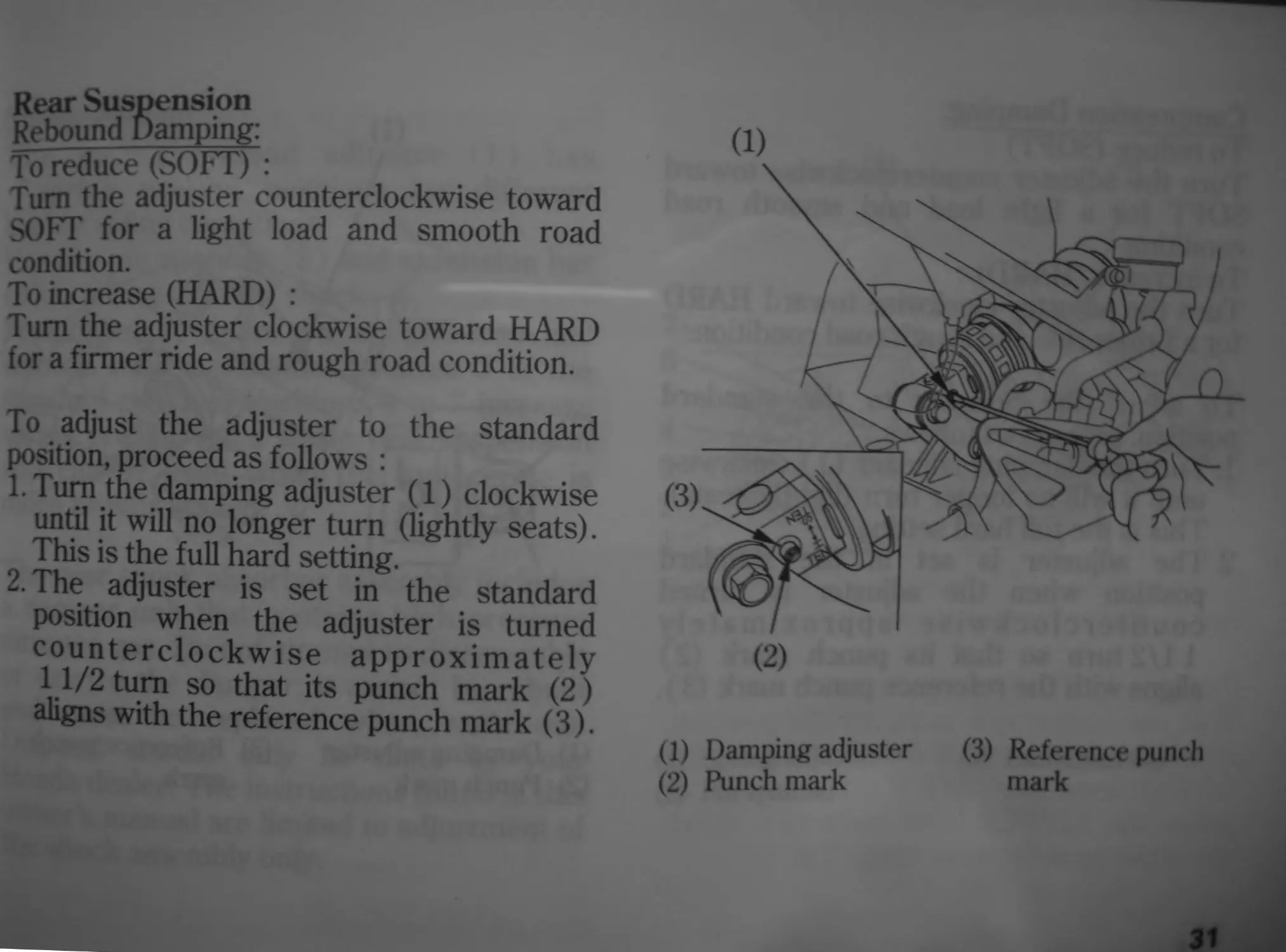
Rear Suspension
Rebound Damping:
To reduce (SOFT) :
Turn the adjuster counterclockwise toward
SOFT for a light load and smooth road
condition.
To increase (HARD) :
Turn the adjuster clockwise toward HARD
for a firmer ride and rough road condition.
To adjust the adjuster to the standard
position, proceed as follows :
l .Tum the damping adjuster (1) clockwise
until it will no longer turn (lightly seats).
This is the full hard setting.
2 . The adjuster is set in the standard
position when the adjuster is turned
counterclockwise approximately
11/2 turn so that its punch mark (2)
aligns with the reference punch mark (3).
(1)
(1) Damping adjuster
(2) Punch mark
(3) Reference punch
mark
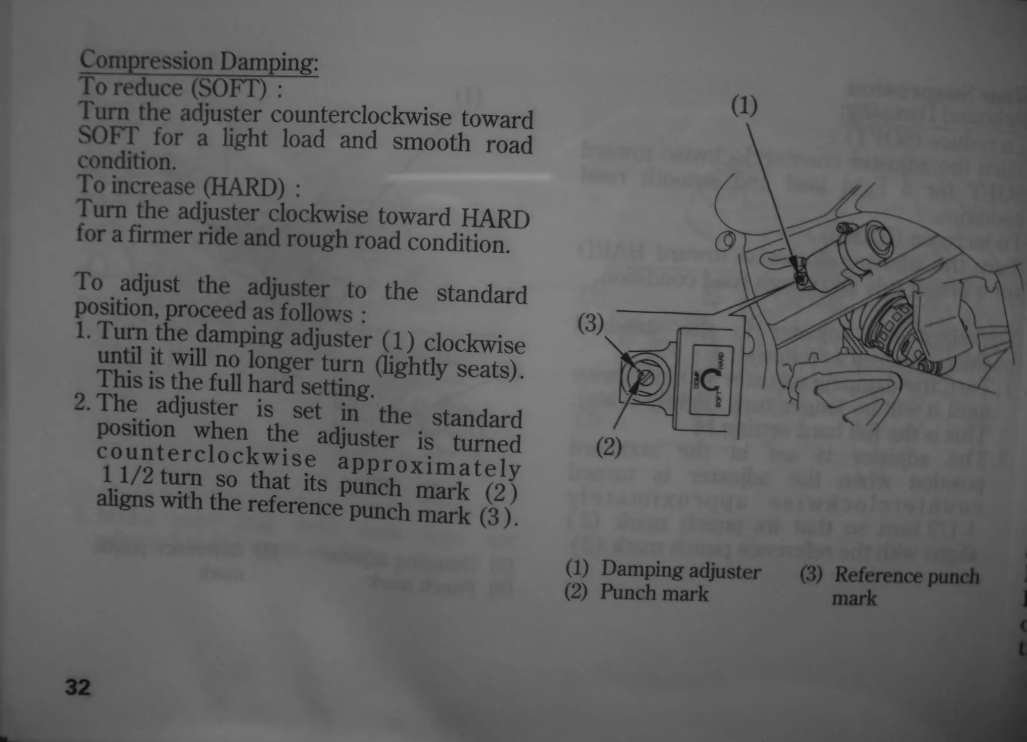
Compression Damping:
To reduce (SOFT) :
Turn the adjuster counterclockwise toward
SOFT for a light load and smooth road
condition.
To increase (HARD) :
Turn the adjuster clockwise toward HARD
for a firmer ride and rough road condition.
To adjust the adjuster to the standard
position, proceed as follows :
1. Turn the damping adjuster (1) clockwise
until it will no longer turn (lightly seats).
This is the full hard setting.
2. The adjuster is set in the standard
position when the adjuster is turned
counterclockwise approximately
11/2 turn so that its punch mark (2)
aligns with the reference punch mark (3).
32
(1) Damping adjuster (3) Reference punch
(2) Punch mark mark
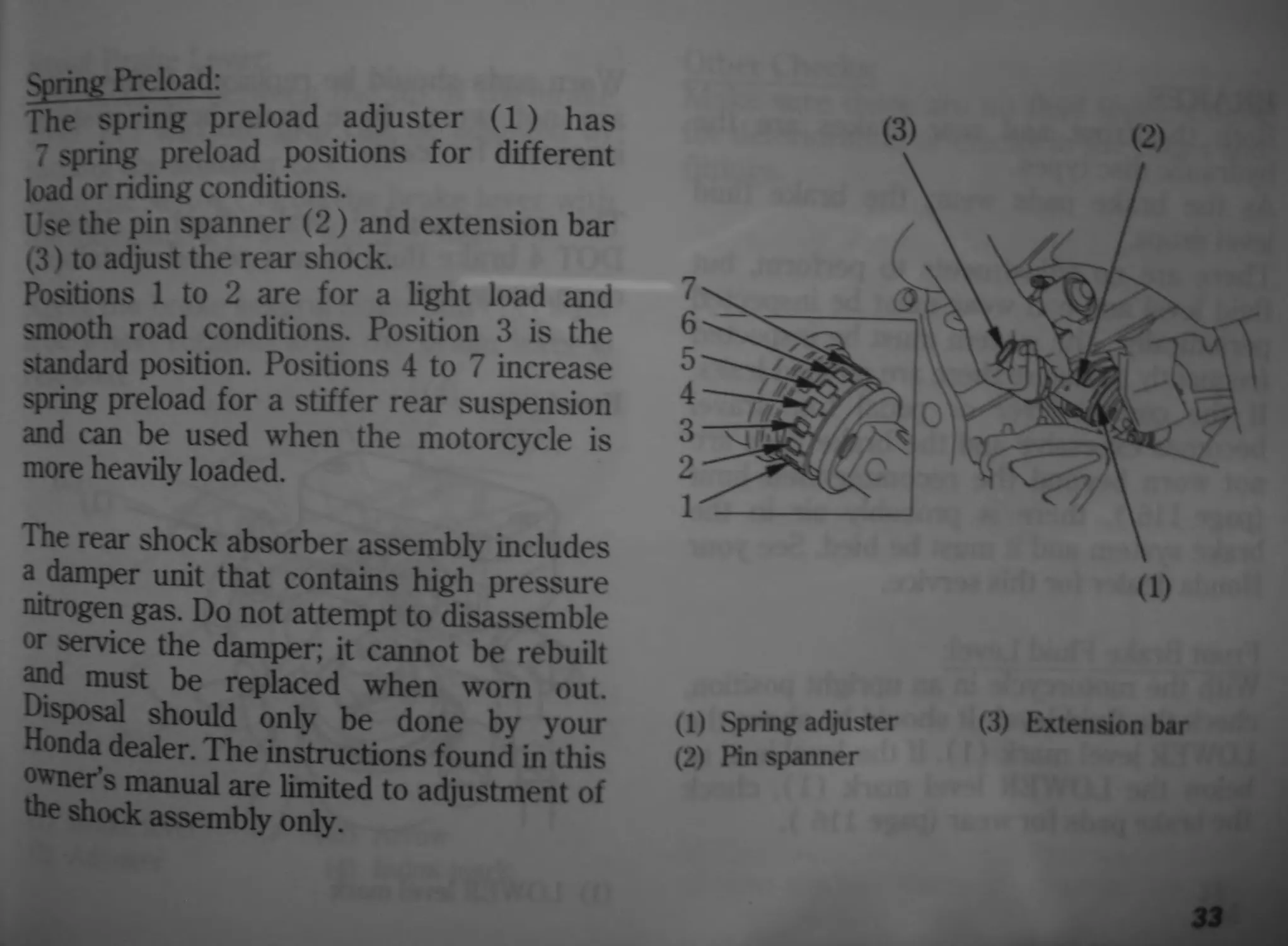
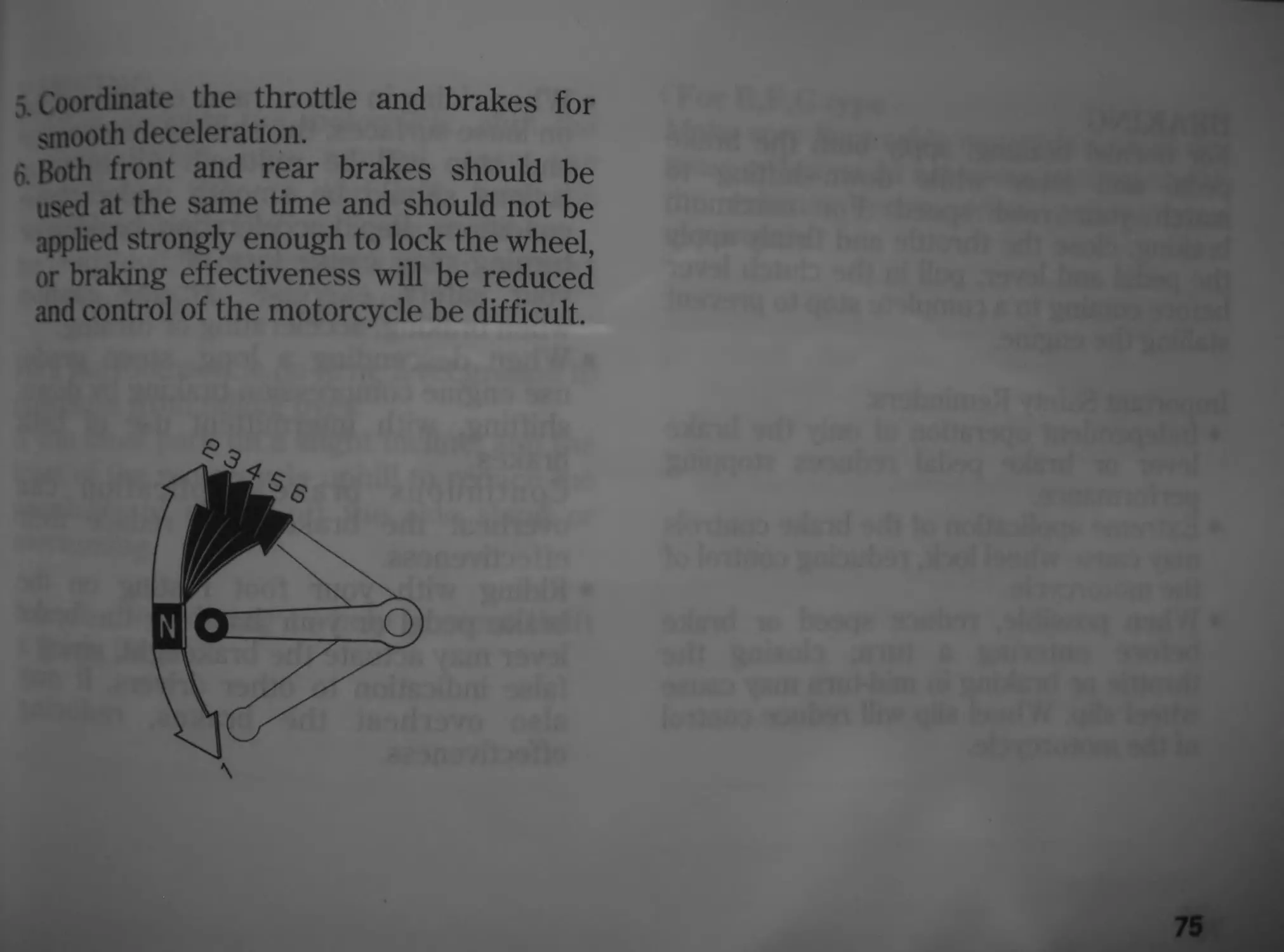
Spring Preload:
The spring preload adjuster (1) has
7 spring preload positions for different
load or riding conditions.
Use the pin spanner (2) and extension bar
(3) to adjust the rear shock.
Positions 1 to 2 are for a light load and
smooth road conditions. Position 3 is the
standard position. Positions 4 to 7 increase
spring preload for a stiffer rear suspension
and can be used when the motorcycle is
more heavily loaded.
The rear shock absorber assembly includes
a damper unit that contains high pressure
nitrogen gas. Do not attempt to disassemble
or service the damper; it cannot be rebuilt
and must be replaced when worn out.
Disposal should only be done by your
Honda dealer. The instructions found in this
°^ner s manual limited to adjustment of
the shock assembly only.
(3)
(2)
(1) Spring adjuster
(2) Pin spanner
(3) Extension bar
33
BRAKES
Both the front and rear brakes are the
hydraulic disc types.
As the brake pads wear, the brake fluid
level drops.
There are no adjustments to perform, but
fluid level and pad wear must be inspected
periodically. The system must be inspected
frequently to ensure there are no fluid leaks.
If the control lever or pedal free travel
becomes excessive and the brake pads are
not worn beyond the recommended limit
(page 116 ), there is probably air in the
brake system and it must be bled. See your
Honda dealer for this service.
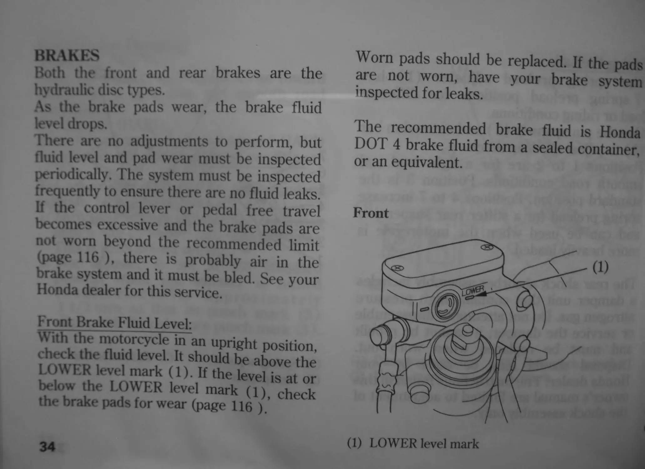
Front Brake Fluid Level:
With the motorcycle in an upright position,
check the fluid level. It should be above the
LOWER level mark (1). If the level is at or
below the LOWER level mark (1), check
the brake pads for wear (page 116 ).
34
Worn pads should be replaced. If the pads
are not worn, have your brake system
inspected for leaks.
The recommended brake fluid is Honda
DOT 4 brake fluid from a sealed container,
or an equivalent.
Front
(1) LOWER level mark
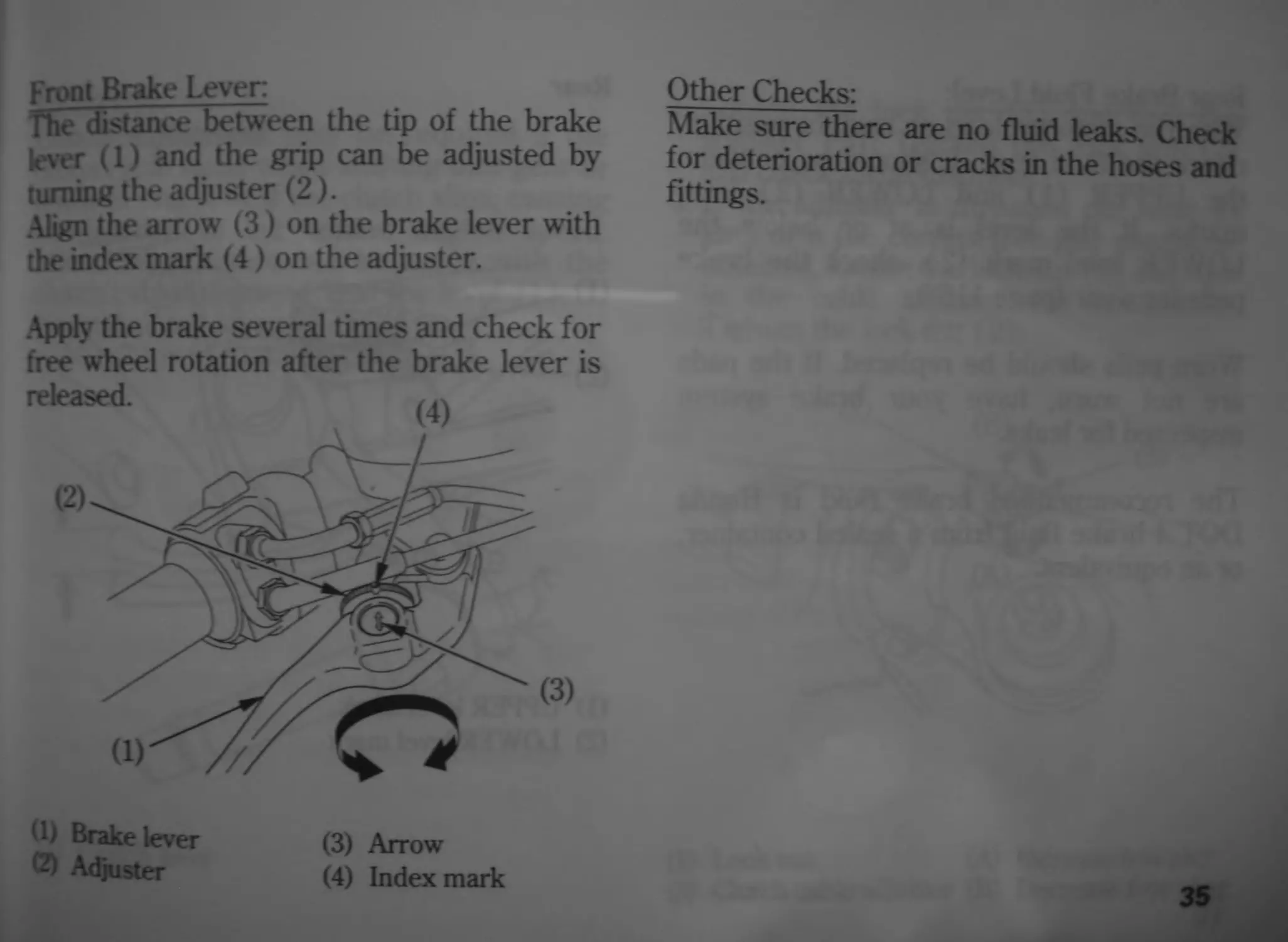
Front Brake Lever:
The distance between the tip of the brake
lever (1) and the grip can be adjusted by
turning the adjuster (2 ).
.Align the arrow (3) on the brake lever with
the index mark (4) on the adjuster.
Apply the brake several times and check for
free wheel rotation after the brake lever is
(1) Brake lever
(2) Adjuster
(3) Arrow
(4) Index mark
Other Checks:
Make sure there are no fluid leaks. Check
for deterioration or cracks in the hoses and
fittings.
35
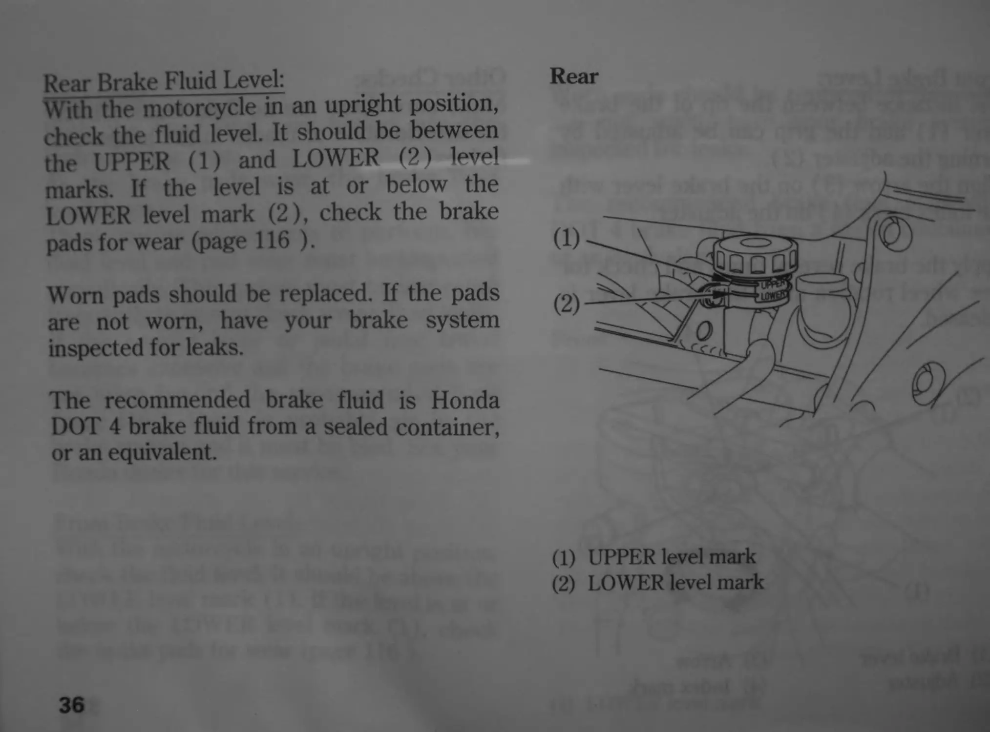
Rear Brake Fluid Level:
With the motorcycle in an upright position,
check the fluid level. It should be between
the UPPER (1) and LOWER (2) level
marks. If the level is at or below the
LOWER level mark (2), check the brake
pads for wear (page 116).
Worn pads should be replaced. If the pads
are not worn, have your brake system
inspected for leaks.
The recommended brake fluid is Honda
DOT 4 brake fluid from a sealed container,
or an equivalent.
36
Rear
(1) UPPER level mark
(2) LOWER level mark
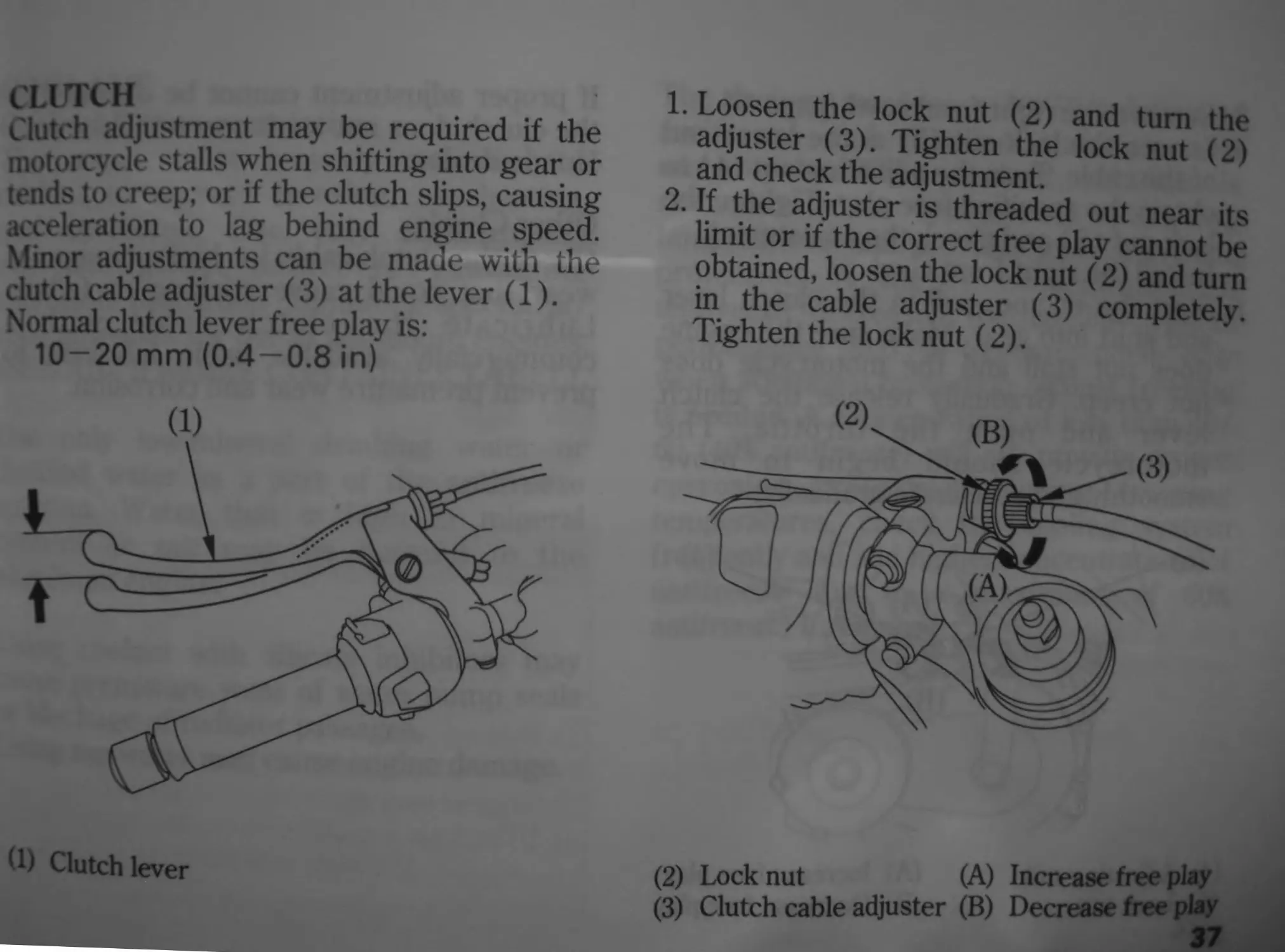
CLUTCH
Clutch adjustment may be required if the
motorcycle stalls when shifting into gear or
tends to creep; or if the clutch slips, causing
acceleration to lag behind engine speed.
Minor adjustments can be made with the
clutch cable adjuster (3) at the lever (1).
Normal clutch lever free play is:
10-20 mm (0.4—0.8 in)
(1) Clutch lever
1. Loosen the lock nut (2) and turn the
adjuster (3). Tighten the lock nut (2)
and check the adjustment.
2. If the adjuster is threaded out near its
limit or if the correct free play cannot be
obtained, loosen the lock nut (2) and turn
in the cable adjuster (3) completely.
Tighten the lock nut (2).
(2) Locknut (A) Increase free play
(3) Clutch cable adjuster (B) Decrease free play
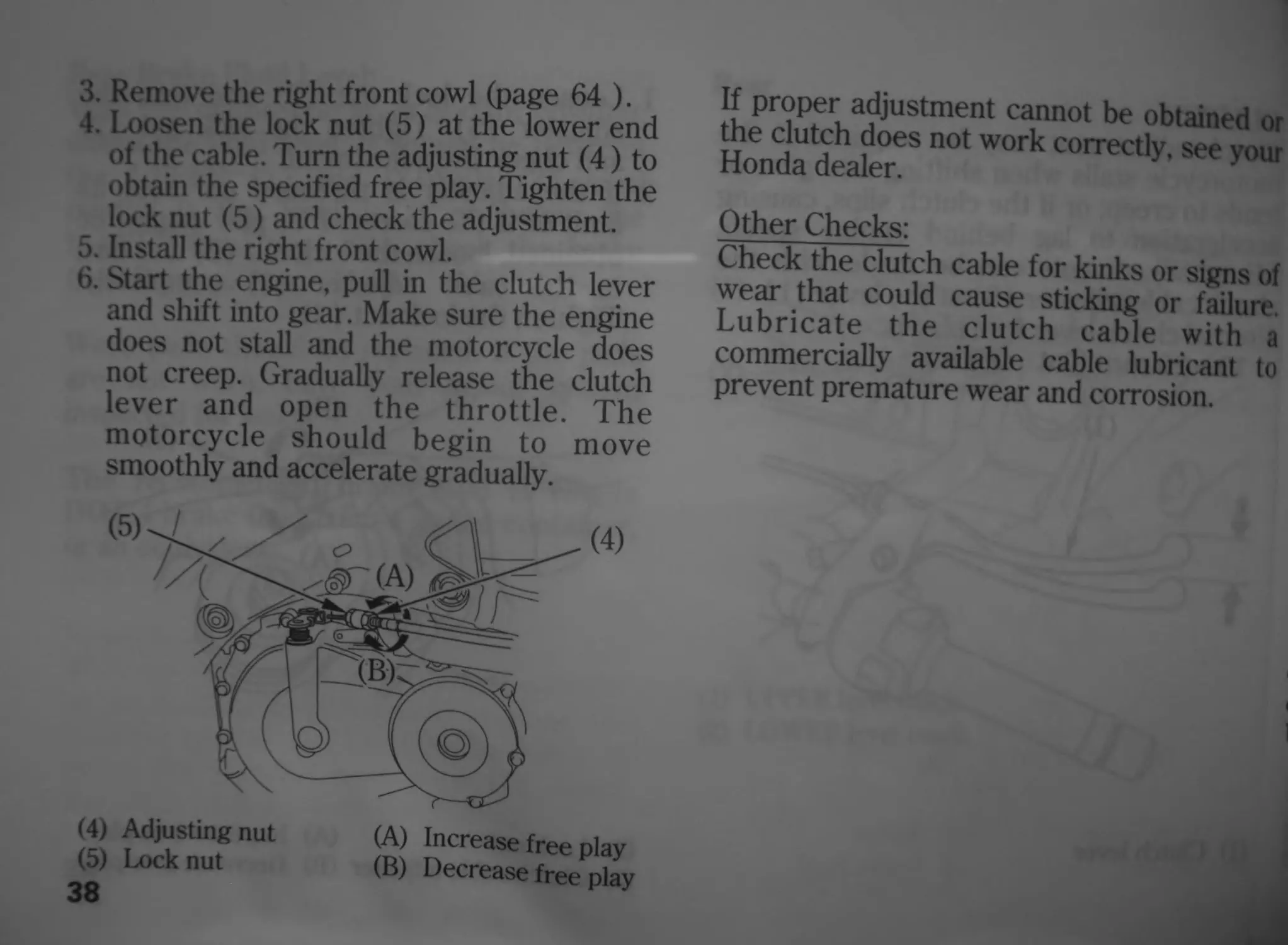
3. Remove the right front cowl (page 64 ).
4. Loosen the lock nut (5) at the lower end
of the cable. Turn the adjusting nut (4) to
obtain the specified free play. Tighten the
lock nut (5) and check the adjustment.
5. Install the right front cowl.
6. Start the engine, pull in the clutch lever
and shift into gear. Make sure the engine
does not stall and the motorcycle does
not creep. Gradually release the clutch
lever and open the throttle. The
motorcycle should begin to move
smoothly and accelerate gradually.
(4) Adjusting nut
(5) Lock nut
38
(A) Increase free play
(B) Decrease free play
If proper adjustment cannot be obtained or
the clutch does not work correctly, see your
Honda dealer.
Other Checks:
Check the clutch cable for kinks or signs of
wear that could cause sticking or failure.
Lubricate the clutch cable with a
commercially available cable lubricant to
prevent premature wear and corrosion.
(XK)LANT
Coolant Recommendation
The owner must properly maintain the
coolant to prevent freezing, overheating,
and corrosion. Use only high quality
ethylene glycol antifreeze containing
corrosion protection inhibitors specifically
recommended for use in aluminum engines.
(SEE ANTIFREEZE CONTAINER LABEL).
Use only low-mineral drinking water or
distilled water as a part of the antifreeze
solution. Water that is high in mineral
content or salt may be harmful to the
aluminum engine.
I sing coolant with silicate inhibitors may
cause premature wear of water pump seals
or blockage of radiator passages.
1- sing tap water may cause engine damage.
The factory provides a 50/50 solution of
antifreeze and distilled water in this
motorcycle. This coolant solution is
recommended for most operating
temperatures and provides good corrosion
protection. A higher concentration of
antifreeze decreases the cooling system
performance and is recommended only
when additional protection against freezing
is needed. A concentration of less than 40/
60 (40% antifreeze) will not provide proper
corrosion protection. During freezing
temperatures, check the cooling system
frequently and add higher concentrations of
antifreeze (up to a maximum of 60%
antifreeze) if required.
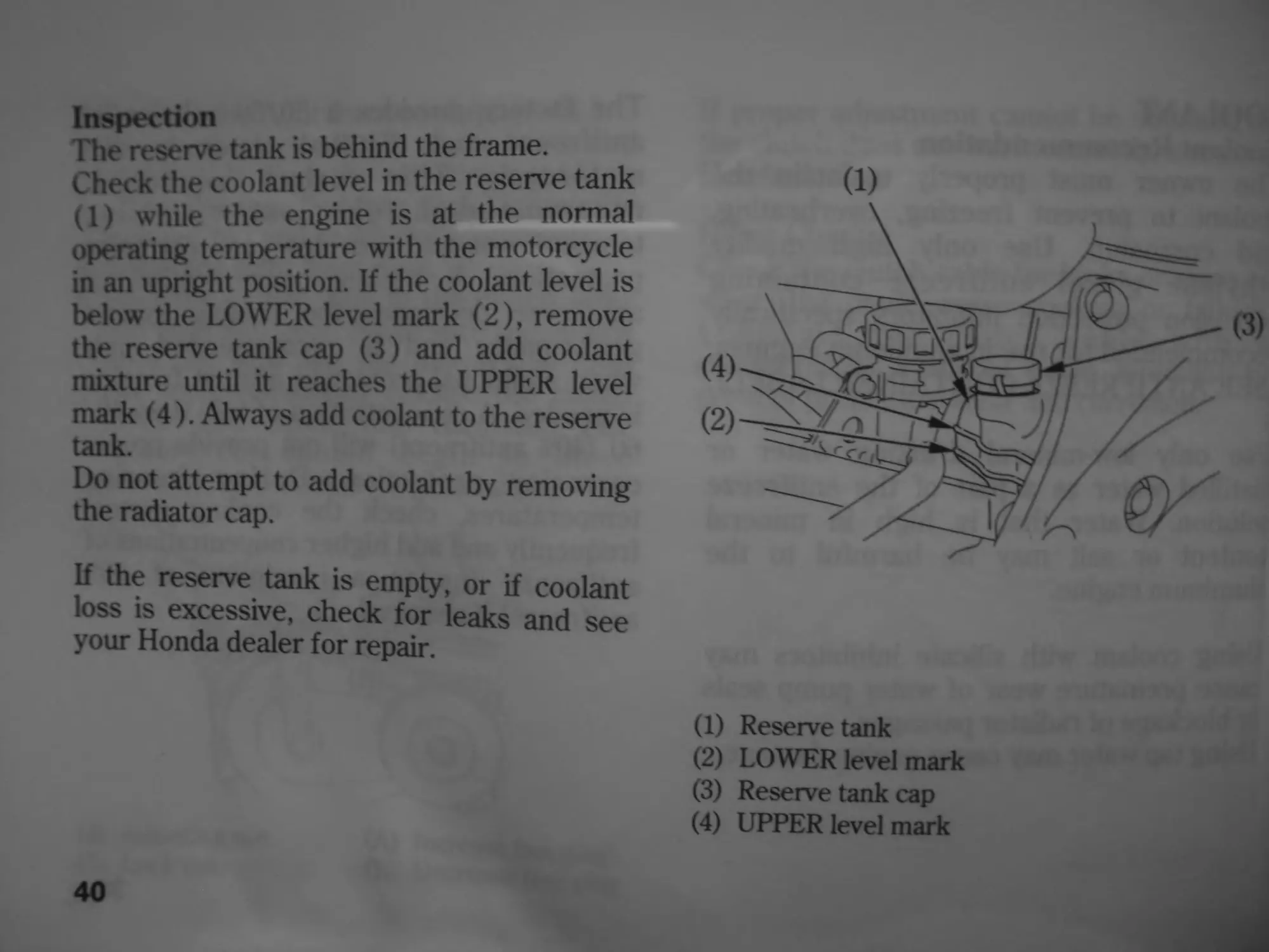
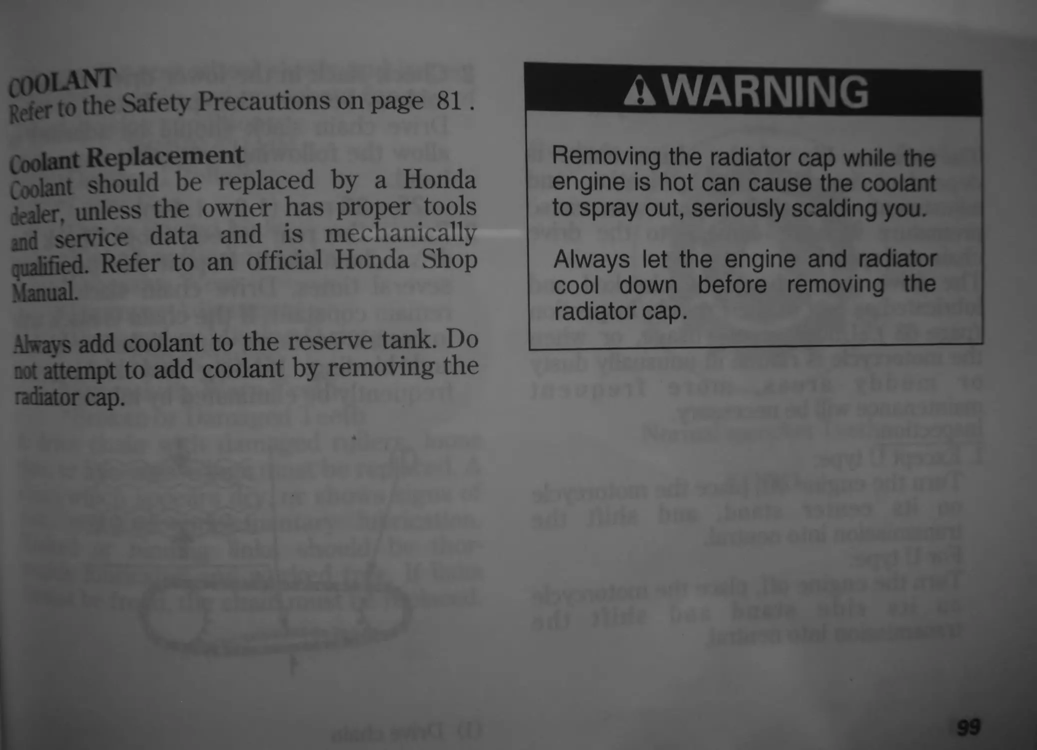
Inspection
The reserve tank is behind the frame.
Check the coolant level in the reserve tank
(1) while the engine is at the normal
operating temperature with the motorcycle
in an upright position. If the coolant level is
below the LOWER level mark (2), remove
the reserve tank cap (3) and add coolant
mixture until it reaches the UPPER level
mark (4). Always add coolant to the reserve
tank.
Do not attempt to add coolant by removing
the radiator cap.
If the reserve tank is empty, or if coolant
loss is excessive, check for leaks and see
your Honda dealer for repair.
40
(1)
(1) Reserve tank
(2) LOWER level mark
(3) Reserve tank cap
(4) UPPER level mark
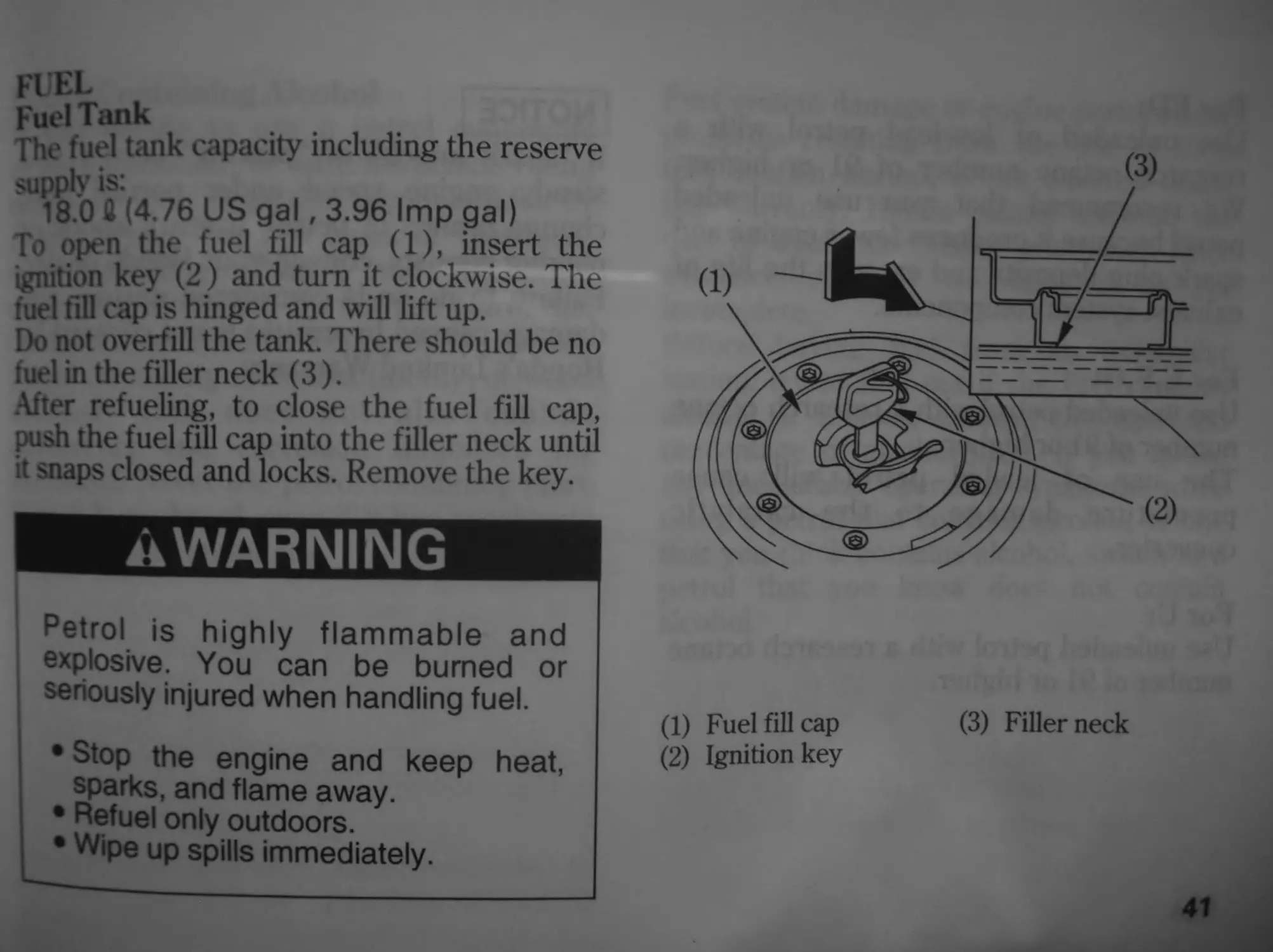
FUEL
Fuel Tank
The fuel tank capacity including the reserve
supplv is:
18.0 ft (4.76 US gal, 3.96 Imp gal)
To open the fuel fill cap (1), insert the
ignition key (2) and turn it clockwise. The
fuel fill cap is hinged and will lift up.
Do not overfill the tank. There should be no
fuel in the filler neck (3).
Alter refueling, to close the fuel fill cap,
push the fuel fill cap into the filler neck until
it snaps closed and locks. Remove the key.
..WARNING
Petrol is highly flammable and
explosive. You can be burned or
seriously injured when handling fuel.
• Stop the engine and keep heat,
sparks, and flame away.
• Refuel only outdoors.
• Wipe up spills immediately.
(3)
(1) Fuel fill cap
(2) Ignition key
(3) Filler neck
41
For ED:
Use unleaded or low-lead petrol with a
research octane number of 91 or higher.
We recommend that you use unleaded
petrol because it produces fewer engine and
spark plug deposits and extends the life of
exhaust system components.
For E,F,G:
Use unleaded petrol with a research octane
number of 91 or higher.
1 he use of leaded petrol will cause
premature damage to the catalytic
converter.
ForU:
I se unleaded petrol with a research octane
number of 91 or higher.
42
NOTICE
If “spark knock” or “pinking" occurs at a
steady engine speed under normal load,
change brands of petrol. If spark knock or
pinking persists, consult your Honda dealer.
Failure to do so is considered misuse, and
damage caused by misuse is not covered by
Honda’s Limited Warranty.
Petrol Containing Alcohol
11 you decide to use a petrol containing
ik-ohol (gasohol), be sure it’s octane rating
л least as high as that recommended by
Honda. There are two types of “gasohol”:
one containing ethanol, and the other
containing methanol. Do not use petrol that
contains more than 10 % ethanol. Do not use
petrol containing methanol (methyl or wood
alcohol) that does not also contain
cosolvents and corrosion inhibitors for
methanol. Never use petrol containing more
than 5 % methanol, even if it has cosolvents
and corrosion inhibitors.
Fuel system damage or engine performance
problems resulting from the use of fuels
that contain alcohol is not covered under
the warranty. Honda cannot endorse the
use of fuels containing methanol since
evidence of their suitability is as yet
incomplete.
Before buying fuel from an unfamiliar
station, try to find out if the fuel contains
alcohol. If it does, confirm the type and
percentage of alcohol used. If you notice
any undesirable operating symptoms while
using a petrol that contains alcohol, or one
that you think contains alcohol, switch to a
petrol that you know does not contain
alcohol.
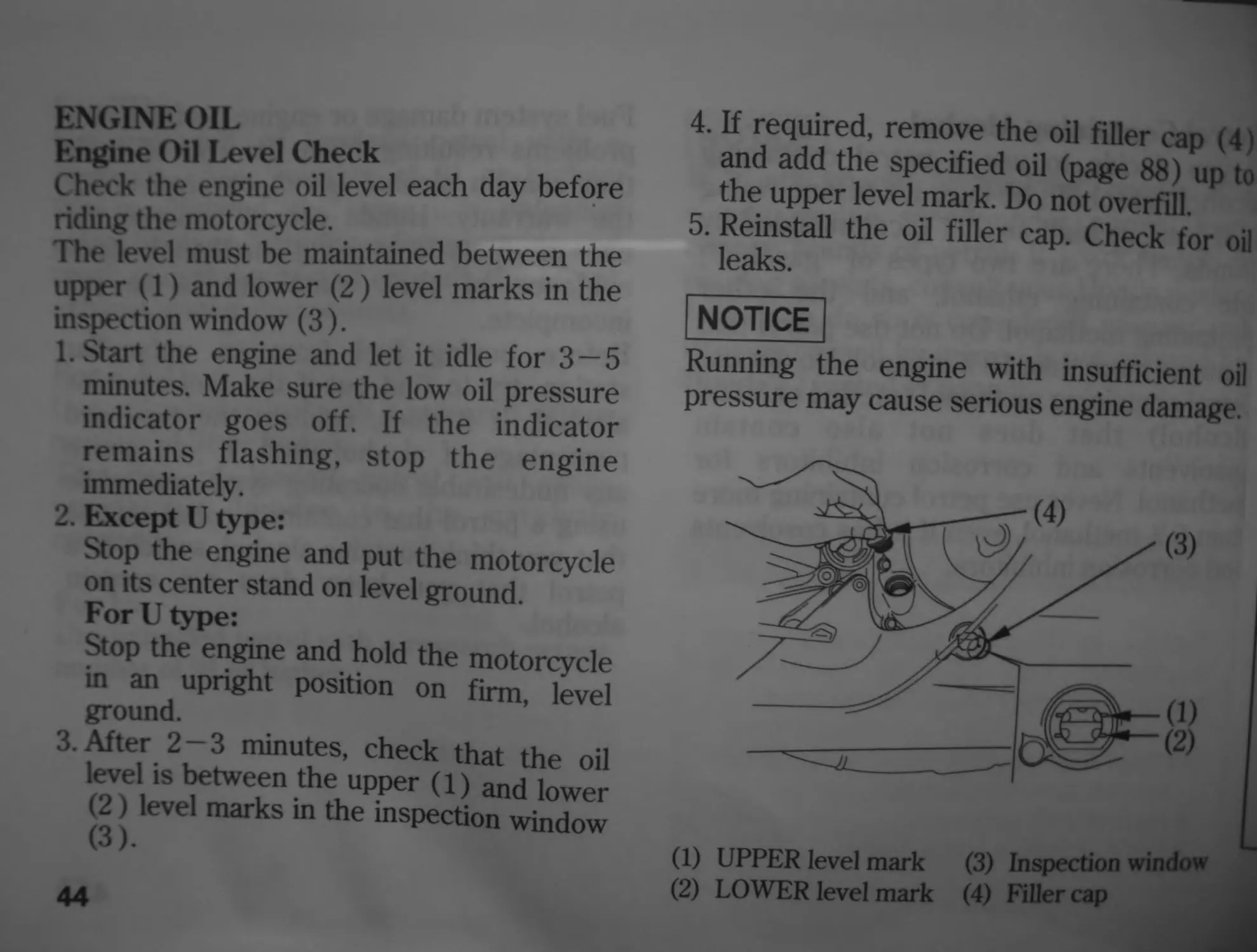
ENGINE OIL
Engine Oil Level Check
Check the engine oil level each day before
riding the motorcycle.
The level must be maintained between the
upper (1) and lower (2) level marks in the
inspection window (3).
1. Start the engine and let it idle for 3 — 5
minutes. Make sure the low oil pressure
indicator goes off. If the indicator
remains flashing, stop the engine
immediately.
2. Except U type:
Stop the engine and put the motorcycle
on its center stand on level ground.
For U type:
Stop the engine and hold the motorcycle
in an upright position on firm, level
ground.
3. After 2-3 minutes, check that the oil
level is between the upper (1) and lower
(2) level marks in the inspection window
(3).
44
4. If required, remove the oil filler cap (4)
and add the specified oil (page 88) up to
the upper level mark. Do not overfill.
5. Reinstall the oil filler cap. Check for oil
leaks.
NOTICE
Running the engine with insufficient oil
pressure may cause serious engine damage.
(1) UPPER level mark (3) Inspection window
(2) LOWER level mark (4) Filler cap
TUBELESS TYRES
To safely operate your motorcycle, your
tyres must be the proper type and size, in
good condition with adequate tread, and
correctly inflated for the load you are
earning. The following pages give more
detailed information on how and when to
check your air pressure, how to inspect
your tyres for damage, and what to do when
your tyres need to be repaired or replaced.
^WARNING
Using tyres that are excessively worn
or improperly inflated can cause a
crash in which you can be seriously
hurt or killed.
Follow all instructions in this owner’s
Manual regarding tyre inflation and
Maintenance.
Air Pressure
Keeping your tyres properly inflated
provides the best combination of handling,
tread life and riding comfort. Generally,
underinflated tyres wear unevenly,
adversely affect handling, and are more
likely to fail from being overheated.
Overinflated tyres make your motorcycle
ride more harshly, are more prone to
damage from road hazards, and wear
unevenly.
We recommend that you visually check
your tyres before every ride and use a
gauge to measure air pressure at least once
a month or any time you think the tyres
might be low.
Tubeless tyres have some self-sealing
ability if they are punctured. However,
because leakage is often very slow, you
should look closely for punctures whenever
a tyre is not fully inflated.
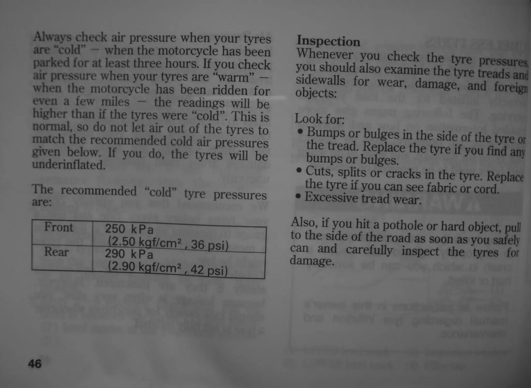
Always check air pressure when your tyres
are "cold” when the motorcycle has been
parked for at least three hours. If you check
air pressure when your tyres are “warm” —
when the motorcycle has been ridden for
even a few miles - the readings will be
higher than if the tyres were “cold”. This is
normal, so do not let air out of the tyres to
match the recommended cold air pressures
given below. If you do, the tyres will be
underinflated.
The recommended “cold” tyre pressures
are:
Front 250 kPa (2.50 kflf/cm2 , 36 psi)
Rear 290 kPa (2.90 kgf/cm2 .,42 psi)
46
Inspection
Whenever you check the tyre pressures
you should also examine the tyre treads anc
sidewalls for wear, damage, and foreigr
objects:
Look for:
• Bumps or bulges in the side of the tyre or
the tread. Replace the tyre if you find any
bumps or bulges.
• Cuts, splits or cracks in the tyre. Replace
the tyre if you can see fabric or cord.
• Excessive tread wear.
Also, if you hit a pothole or hard object, pull
to the side of the road as soon as you safely
can and carefully inspect the tyres for
damage.
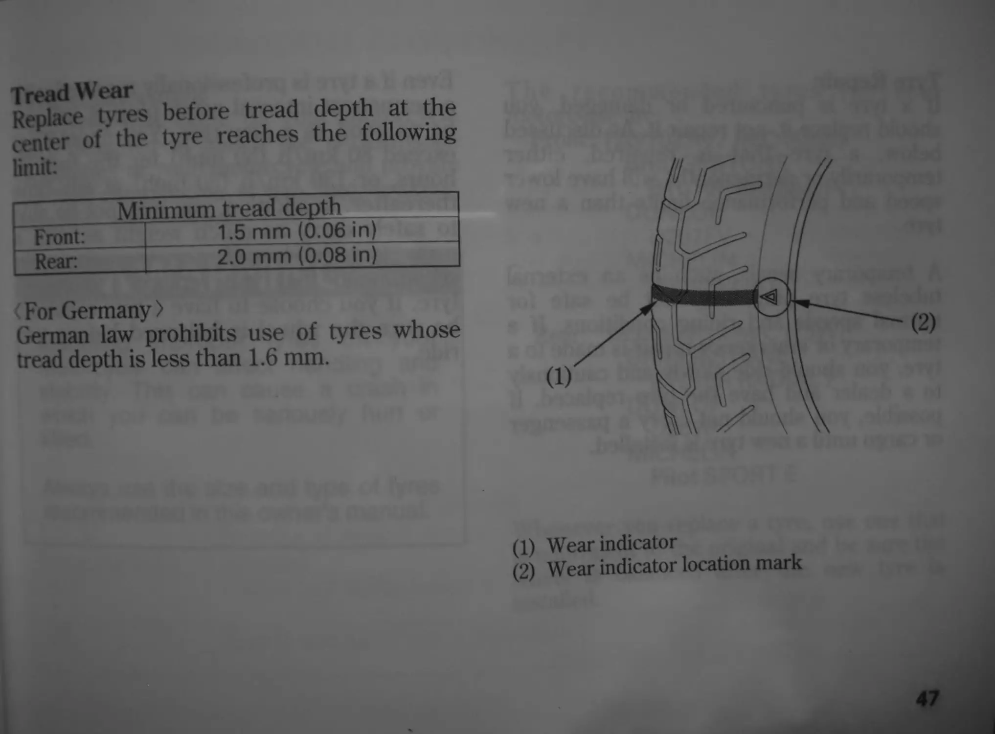
Tread Wear
Replace tyres before tread depth at the
center of the tyre reaches the following
limit:
Minimum tread depth
Front: 1.5 mm (0.06 in)
Rear. 2.0 mm (0.08 in)
< For Germany >
German law prohibits use of tyres whose
tread depth is less than 1.6 mm.
(1) Wear indicator
(2) Wear indicator location mark
47
Tyre Repair
If' a tyre is punctured or damaged, you
should replace it, not repair it. As discussed
below, a tyre that is repaired, either
temporarily or permanently, will have lower
speed and performance limits than a new
tyre.
A temporary repair, such as an external
tubeless tyre plug, may not be safe for
normal speeds and riding conditions. If a
temporary or emergency repair is made to a
tyre, you should ride slowly and cautiously
to a dealer and have the tyre replaced. If
possible, you should not carry a passenger
or cargo until a new tyre is installed.
48
Even if a tyre is professionally repaired with
a permanent internal patch plug, it will not
be as good as a new tyre. You should not
exceed 80 km/h (50 mph) for the first 24
hours, or 130 km/h (80 mph) at any time
thereafter. In addition, you may not be able
to safely carry as much weight as with a
new tyre. Therefore, we strongly
recommend that you replace a damaged
tyre. If you choose to have a tyre repaired,
be sure the wheel is balanced before you
ride.
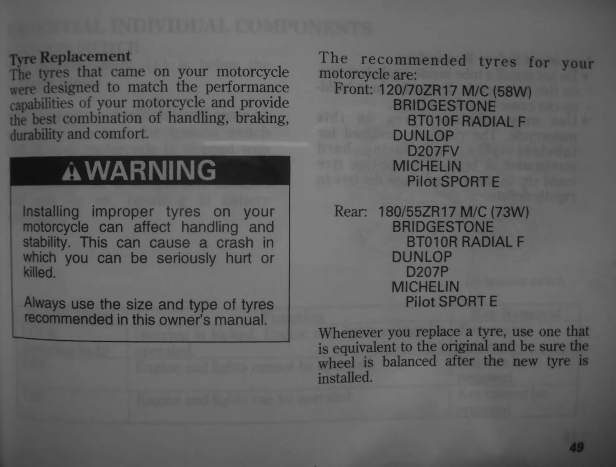
Tyre Replacement
The tyres that came on your motorcycle
were designed to match the performance
capabilities of your motorcycle and provide
the best combination of handling, braking,
durability and comfort.
AWARNING
Installing improper tyres on your
motorcycle can affect handling and
stability. This can cause a crash in
which you can be seriously hurt or
killed.
Always use the size and type of tyres
recommended in this owner’s manual.
The recommended tyres for your
motorcycle are:
Front: 120/70ZR17 М/С (58W)
BRIDGESTONE
BT01 OF RADIAL F
DUNLOP
D207FV
MICHELIN
Pilot SPORT E
Rear: 180/55ZR17 М/С (73W)
BRIDGESTONE
BT010R RADIAL F
DUNLOP
D207P
MICHELIN
Pilot SPORT E
Whenever you replace a tyre, use one that
is equivalent to the original and be sure the
wheel is balanced after the new tyre is
installed.
Important Safety Reminders
• Do not install a tube inside a tubeless tyre
on this motorcycle. Excessive heat build-
up can cause the tube to burst.
• Use only tubeless tyres on this
motorcycle. The rims are designed for
tubeless tyres, and during hard
acceleration or braking, a tube-type tyre
could slip on the rim and cause the tyre to
rapidly deflate.
50
ESSENTIAL INDIVIDUAL COMPONENTS
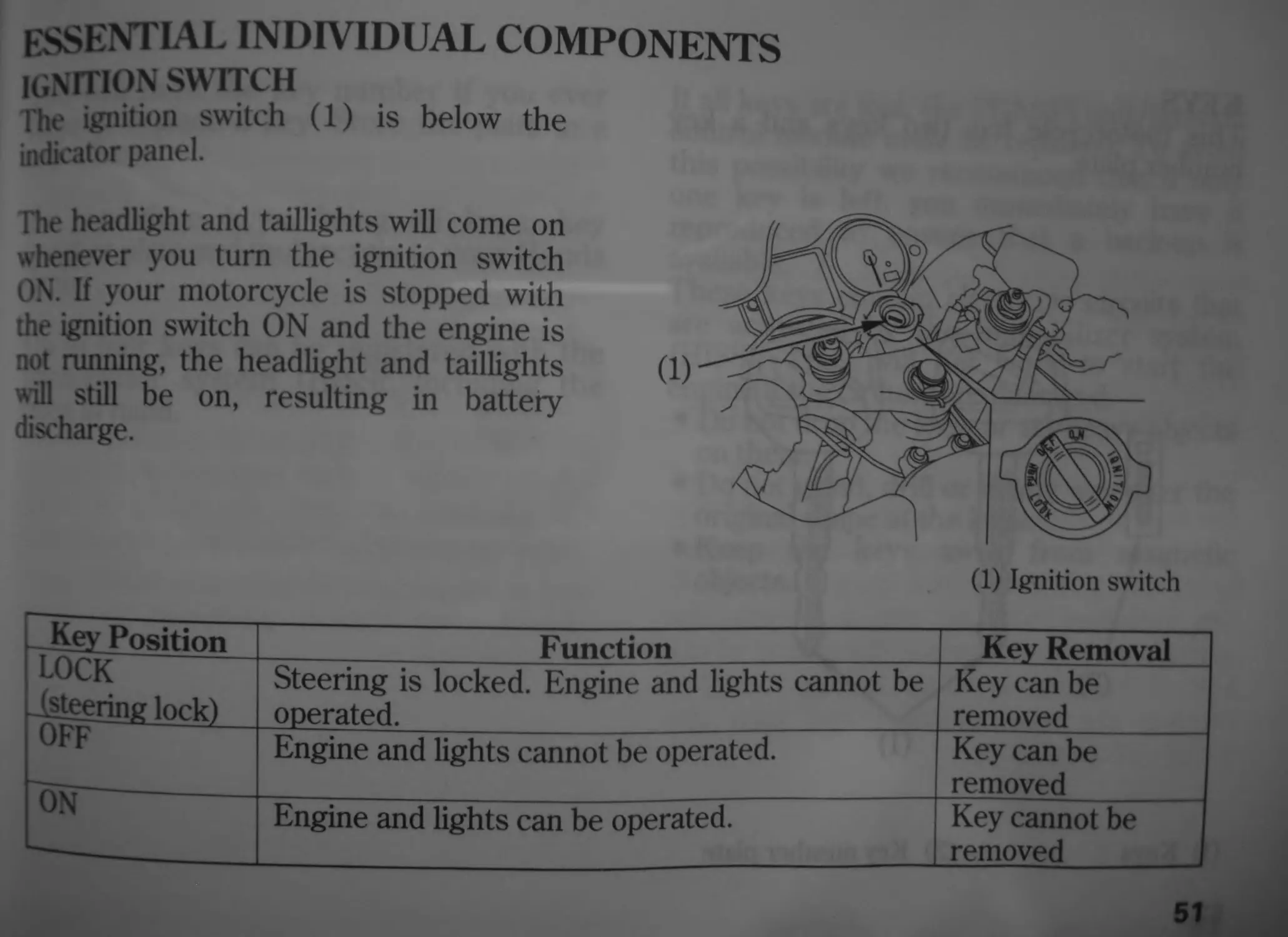
IGNITION SWITCH 1
The ignition switch (1) is below the
indicator panel.
The headlight and taillights will come on
whenever you turn the ignition switch
ON. If your motorcycle is stopped with
the ignition switch ON and the engine is
not running, the headlight and taillights
will still be on, resulting in battery
discharge.
(1) Ignition switch
. Key Position Function Key Removal
LOCK -(steering lock) Steering is locked. Engine and lights cannot be operated. Key can be removed
OFF Engine and lights cannot be operated. Key can be removed
ON Engine and lights can be operated. Key cannot be removed
51
KEYS
This motorcycle has two keys and a key
number plate.
(2) Key number plate
(1) Keys
52
You will need the key number if you ever
have to replace a key. Store the plate in a
safe place.
To reproduce keys, bring all keys, key
number plate and motorcycle to your Honda
dealer.
Up to four keys can be registered with the
immobilizer system (HISS), including the
ones in hand.
If all keys are lost, the PGM-FI unit/ignition
control module must be replaced. To avoid
this possibility we recommend that if only
one key is left, you immediately have it
reproduced to ensure that a back-up is
available.
These keys contain electronic circuits that
are activated by the immobilizer system
(HISS). They will not work to start the
engine if the circuits are damaged.
• Do not drop the keys or set heavy objects
on them.
• Do not grind, drill or in any way alter the
original shape of the keys.
• Keep the keys away from magnetic
objects.
IMMOBILIZER SYSTEM (HISS)
HISS is the abbreviation of Honda Ignition
Security System.
The immobilizer system (HISS) protects
your motorcycle from theft. A properly-
coded key must be used in the ignition
switch for the engine to start. If an
improperly-coded key (or other device) is
used the engine’s starting circuit is disabled.
When the ignition switch is turned ON and
the engine stop switch is at “ О ” (RUN),
the immobilizer system (HISS) indicator
lights for a few seconds, then goes off. If
the indicator remains on, it means the
system does not recognize the coding of the
key. Turn the ignition switch to OFF,
remove the key, reinsert and turn the
switch ON again.
54
If the system repeatedly does not recognize
the coding of your key, contact your Honda
dealer.
• The system may not recognize the key’s
coding if any other immobilizer key is
near the ignition switch. To make sure
the system recognizes the key code, keep
each immobilizer key on a separate ring.
• Do not attempt to alter the immobilizer
system (HISS) or add other devices to it
Electrical problems could result, making
it impossible to start your motorcycle.
• If all keys are lost, the PGM-FI unit/
ignition control module must be replaced
FC Directives
This immobilizer system complies with the
R X' TTE (Radio equipment and telecommu-
nications terminal equipment and the
mutual recognition of their conformity)
Directive.
(£ 0891 ©
The declaration of conformity to R & TTE
Directive is provided to the owner at the
time of purchase. The declaration of
conformity should be kept at a safe place.
When the declaration of conformity is lost
or is not provided, contact your Honda
dealer.
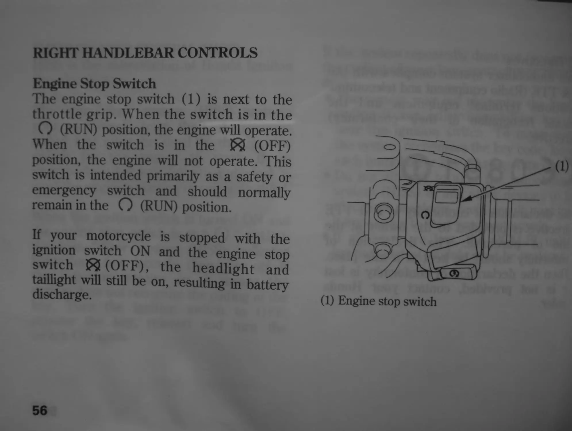
RIGHT HANDLEBAR CONTROLS
Engine Stop Switch
The engine stop switch (1) is next to the
throttle grip. When the switch is in the
О (RUN) position, the engine will operate.
When the switch is in the 53 (OFF)
position, the engine will not operate. This
switch is intended primarily as a safety or
emergency switch and should normally
remain in the О (RUN) position.
If your motorcycle is stopped with the
ignition switch ON and the engine stop
switch 53 (OFF), the headlight and
taillight will still be on, resulting in battery
discharge.
56
(1) Engine stop switch
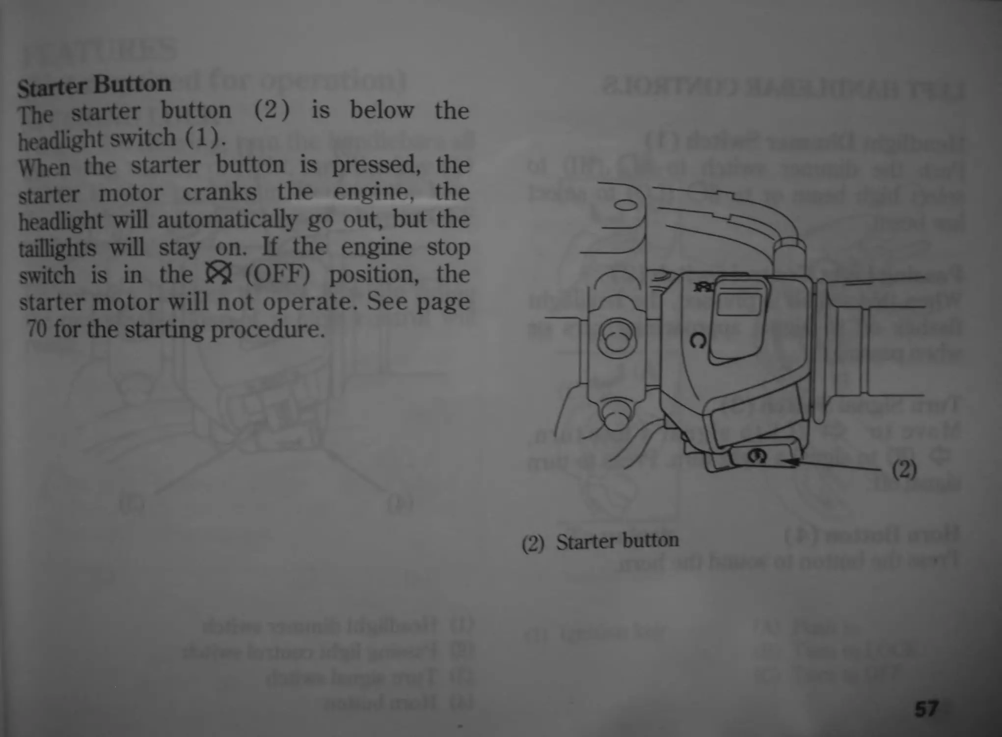
Starter Button
The starter button (2) is below the
headlight switch (1).
When the starter button is pressed, the
starter motor cranks the engine, the
headlight will automatically go out, but the
taillights will stay on. If the engine stop
switch is in the & (OFF) position, the
starter motor will not operate. See page
70 for the starting procedure.
(2) Starter button
57
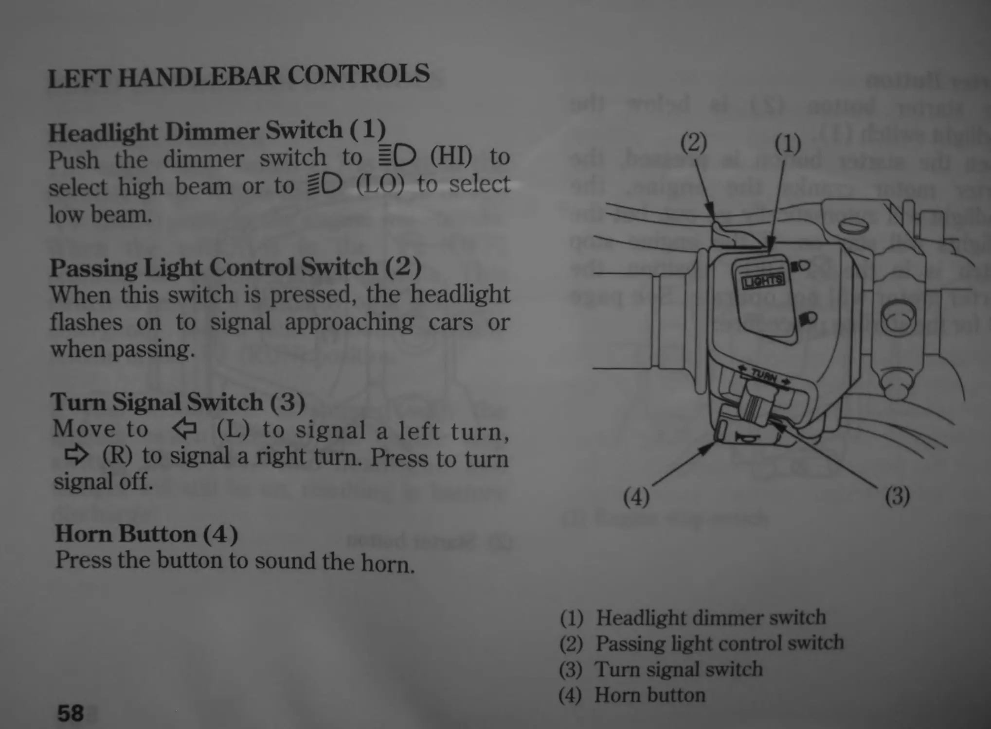
LEFT HANDLEBAR CONTROLS
Headlight Dimmer Switch (1)^
Push the dimmer switch to =D (HI) to
select high beam or to 11D (LO) to select
low beam.
Passing Light Control Switch (2)
When this switch is pressed, the headlight
flashes on to signal approaching cars or
when passing.
Turn Signal Switch (3)
Move to <□ (L) to signal a left turn,
t£> (R) to signal a right turn. Press to turn
signal off.
Hom Button (4)
Press the button to sound the horn.
58
(2) (1)
(1) Headlight dimmer switch
(2) Passing light control switch
(3) Turn signal switch
(4) Horn button
features
(Not required for operation)
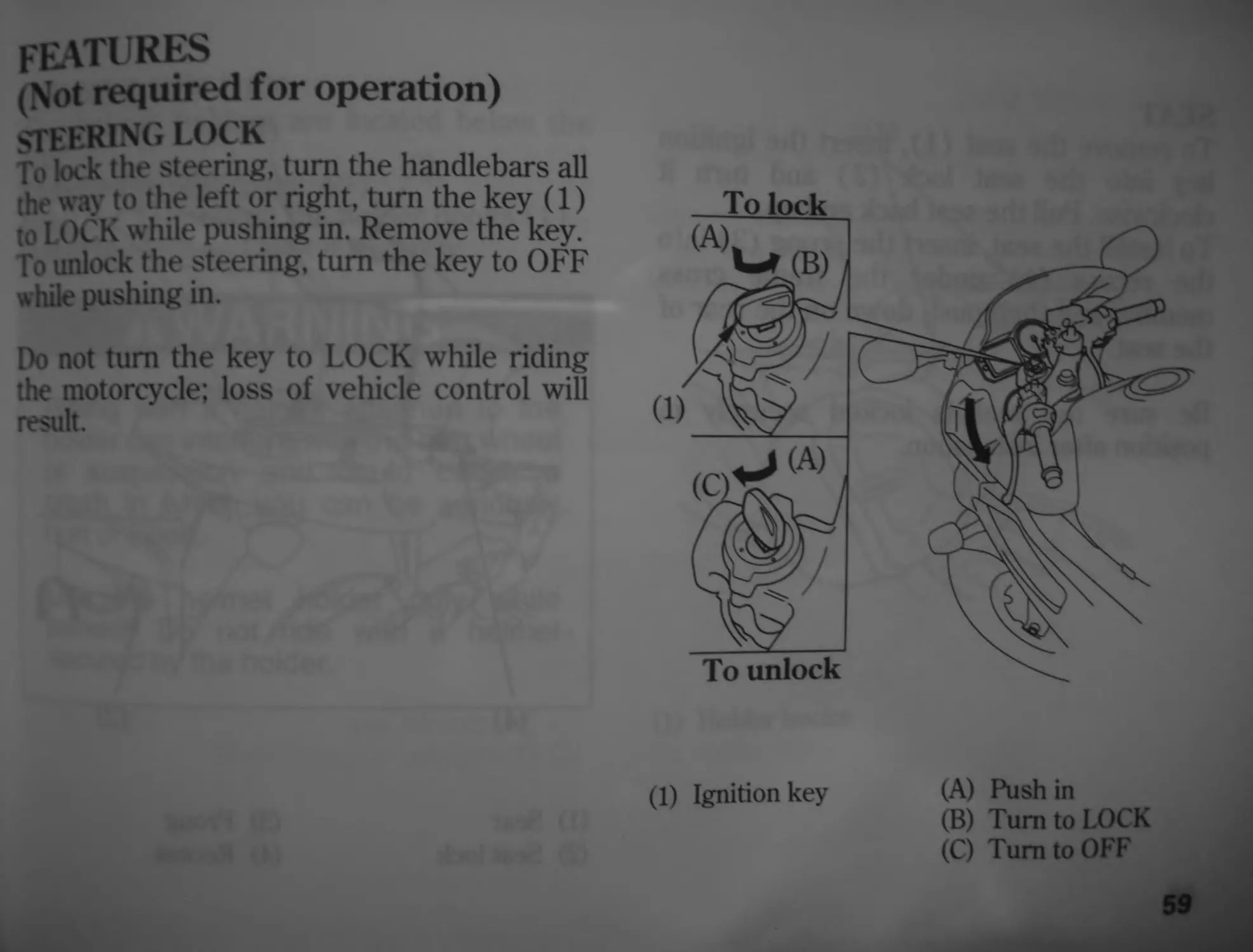
STEERING LOCK
To lock the steering, turn the handlebars all
the way to the left or right, turn the key (1)
to LOCK while pushing in. Remove the key.
Го unlock the steering, turn the key to OFF
while pushing in.
Do not turn the key to LOCK while riding
the motorcycle; loss of vehicle control will
result.
(1) Ignition key
(A) Push in
(B) Turn to LOCK
(C) Turn to OFF
59
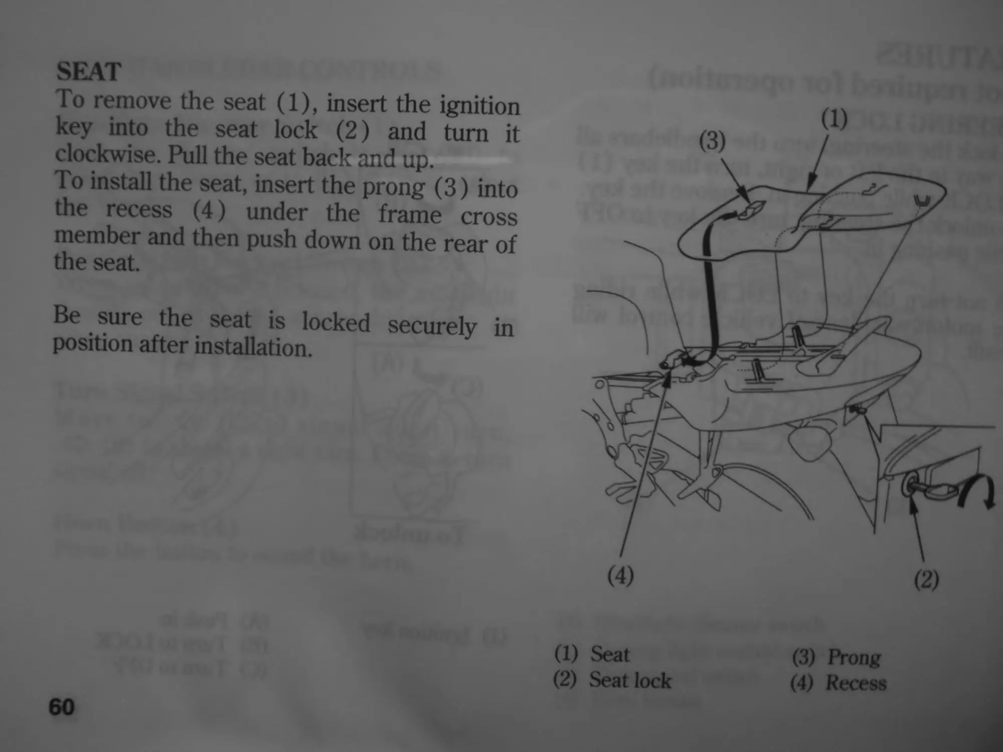
SEAT
To remove the seat (1), insert the ignition
key into the seat lock (2) and turn it
clockwise. Pull the seat back and up.
To install the seat, insert the prong (3) into
the recess (4) under the frame cross
member and then push down on the rear of
the seat.
Be sure the seat is locked
position after installation.
securely in
60
(1) Seat
(2) Seat lock
(3) Prong
(4) Recess
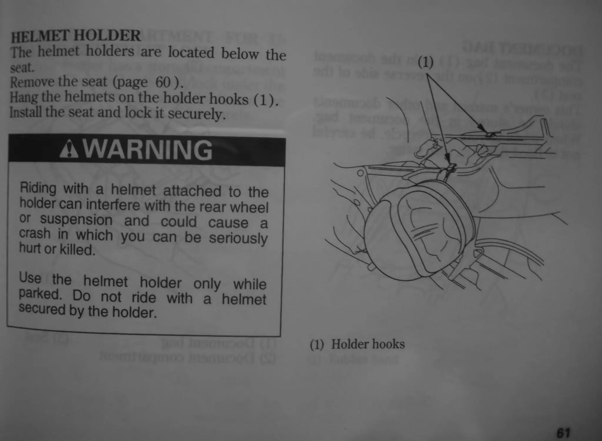
HELMET HOLDER
The helmet holders are located below the
seat.
Remove the seat (page 60).
Hang the helmets on the holder hooks (1).
Install the seat and lock it securely.
A WARNING
Riding with a helmet attached to the
holder can interfere with the rear wheel
or suspension and could cause a
crash in which you can be seriously
hurt or killed.
Use the helmet holder only while
parked. Do not ride with a helmet
secured by the holder.
(1)
(1) Holder hooks
61
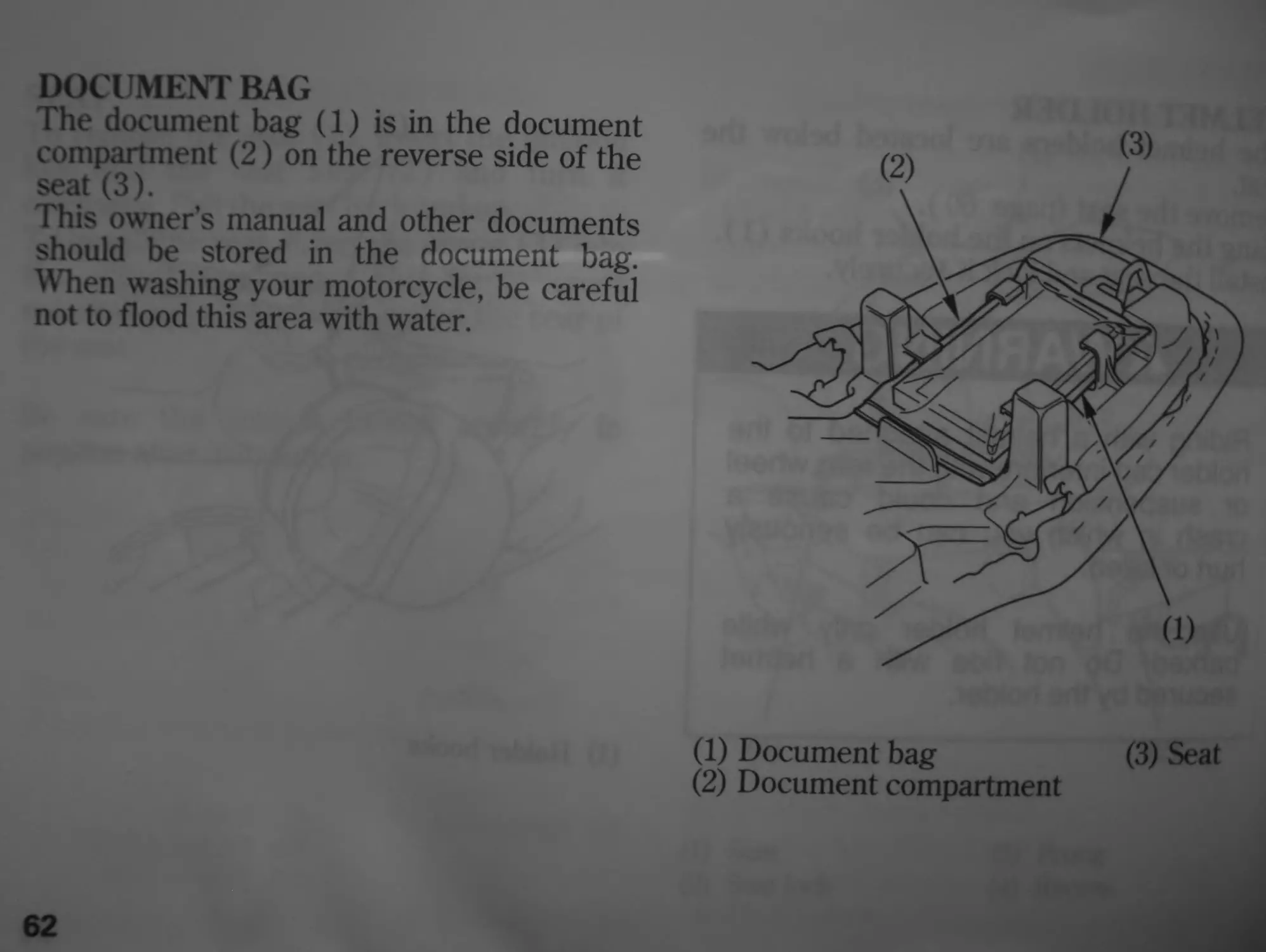
DOCUMENT BAG
The document bag (1) is in the document
compartment (2) on the reverse side of the
seat (3).
This owner’s manual and other documents
should be stored in the document bag.
When washing your motorcycle, be careful
not to flood this area with water.
62
(1) Document bag (3) Seat
(2) Document compartment
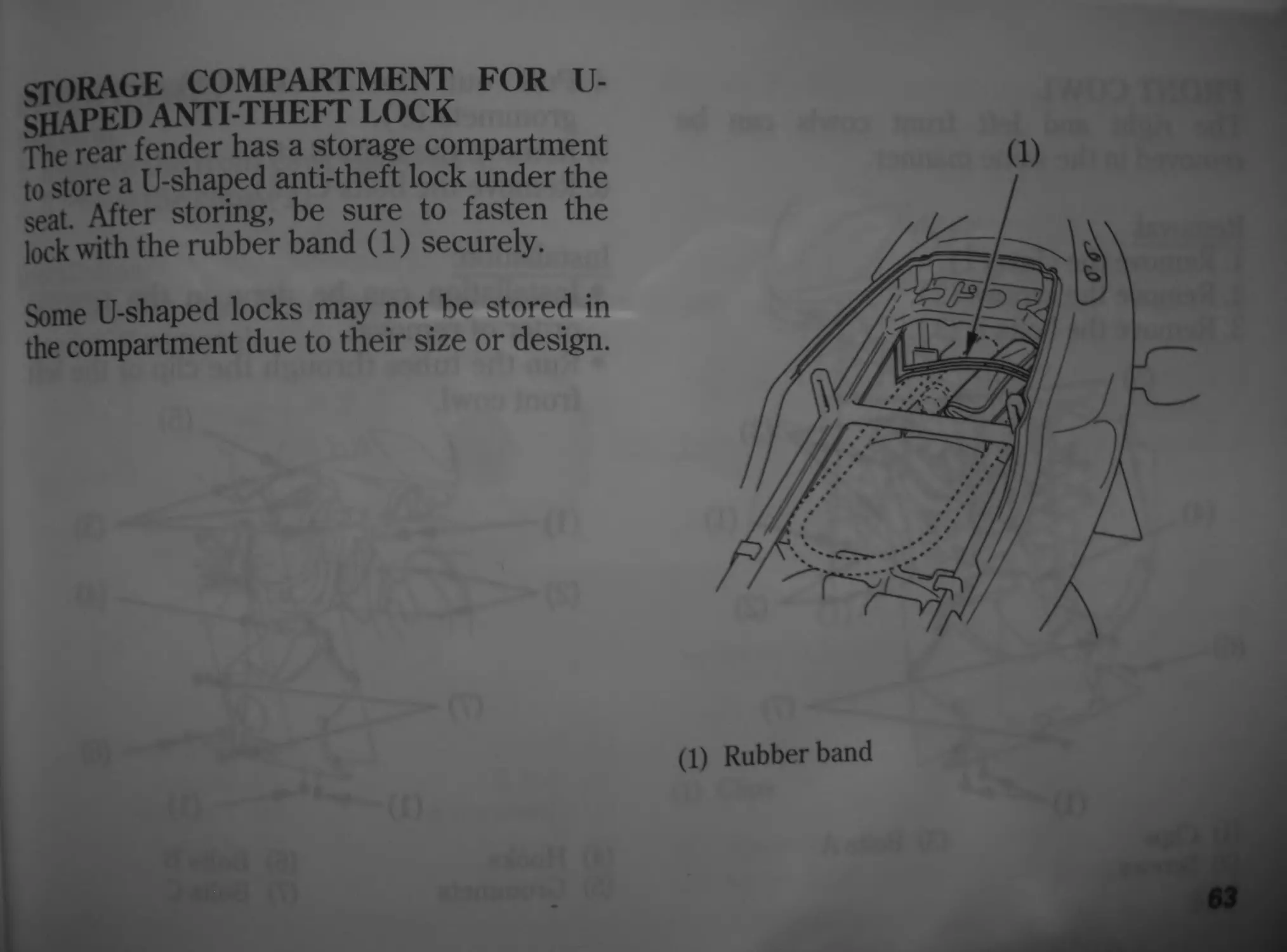
crORAGE COMPARTMENT FOR U-
SKAPED ANTI-THEFT LOCK
The rear fender has a storage compartment
t0 store a U-shaped anti-theft lock under the
seat After storing, be sure to fasten the
lock with the rubber band (1) securely.
Some U-shaped locks may not be stored in
the compartment due to their size or design.
(1) Rubber band
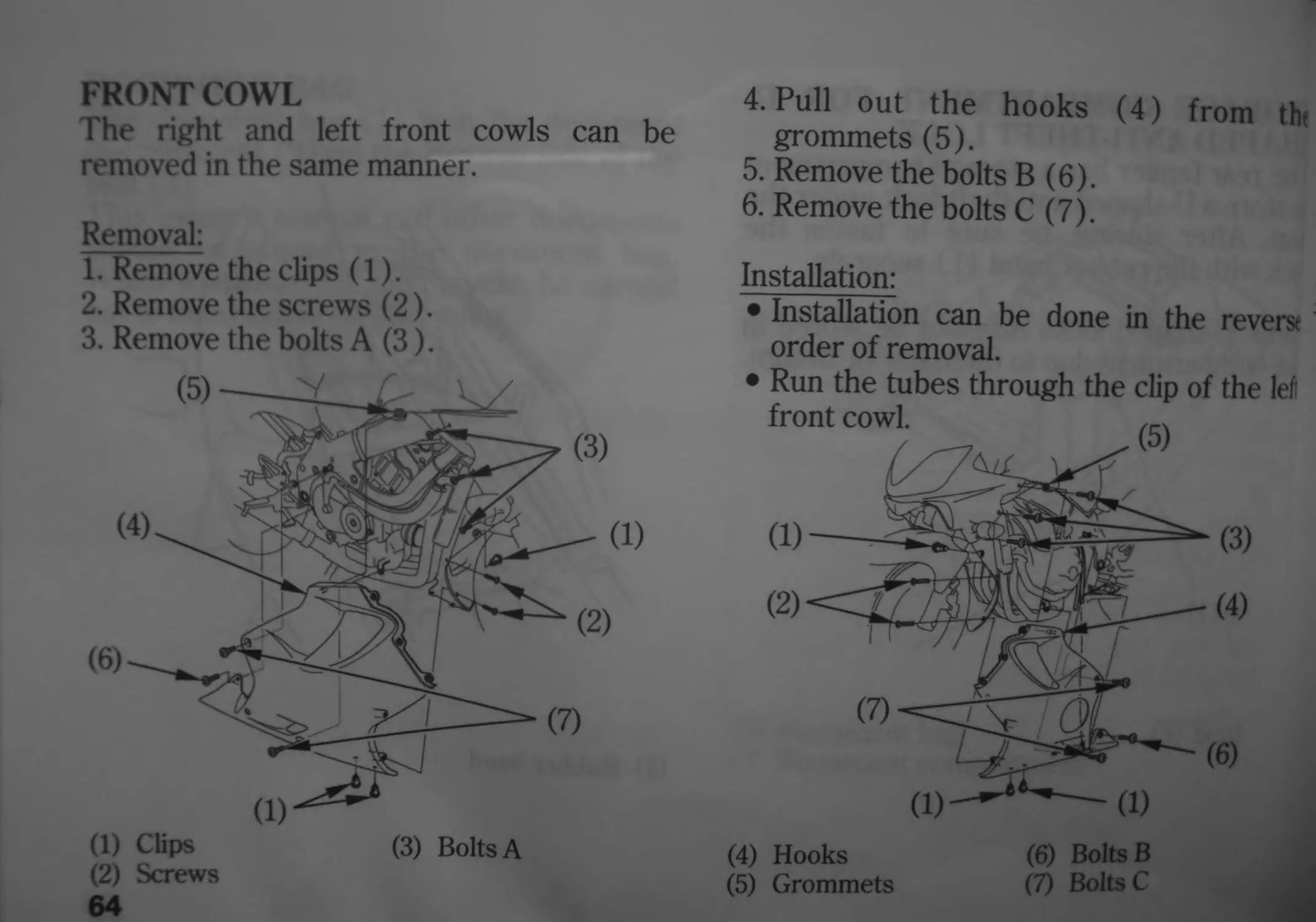
FRONT COWL
The right and left front cowls can be
removed in the same manner.
Removal:
1. Remove the clips (1).
2. Remove the screws (2).
3. Remove the bolts A (3).
64
4. Pull out the hooks (4) from th
grommets (5).
5. Remove the bolts В (6).
6. Remove the bolts C (7).
Installation:
• Installation can be done in the revere
order of removal.
• Run the tubes through the clip of the lef
(4) Hooks (6) Bolts В
(5) Grommets (7) Bolts C
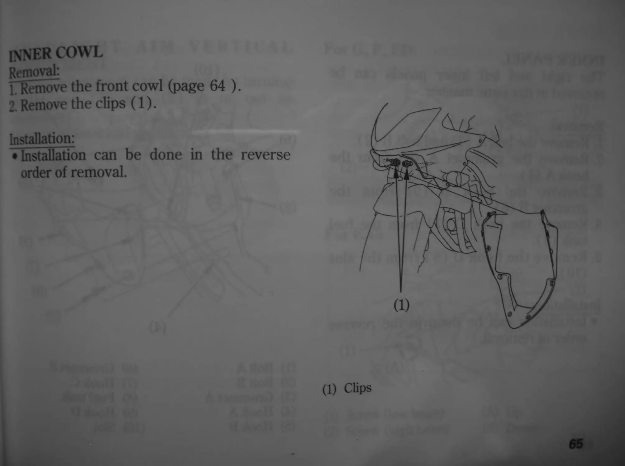
inner cowl
Removal:
ITRemove the front cowl (page 64 ).
2. Remove the clips (1).
Installation:
• Installation can be done in the reverse
order of removal.
(1) Clips
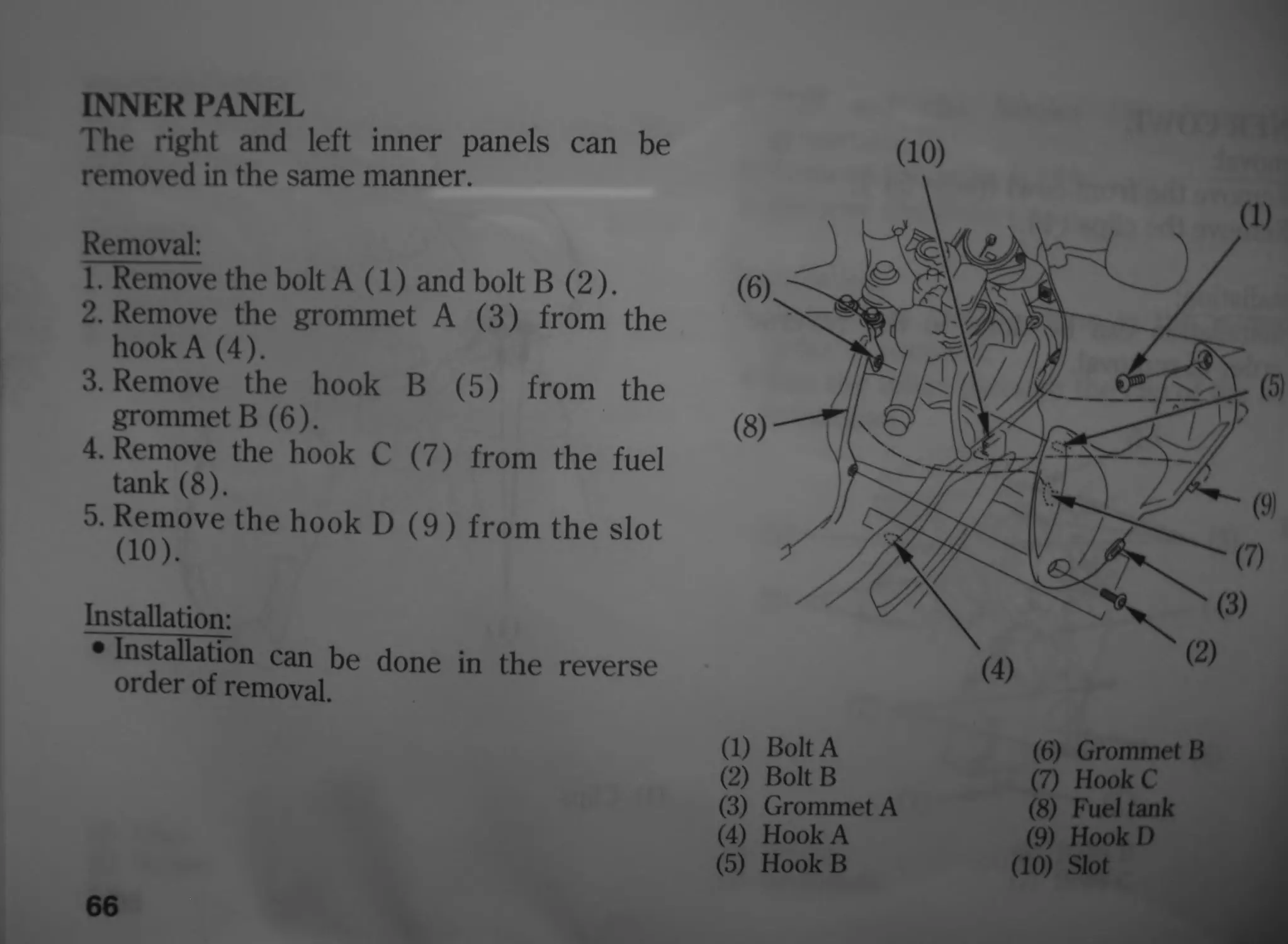
INNER PANEL
The right and left inner panels can be
removed in the same manner.
Removal:
1. Remove the bolt A (1) and bolt В (2).
2. Remove the grommet A (3) from the
hook A (4).
3. Remove the hook В (5) from the
grommet В (6).
4. Remove the hook C (7) from the fuel
tank (8).
5. Remove the hook D (9) from the slot
(10).
Installation:
• Installation can be done in the reverse
order of removal.
66
(10)
(6)<SUS3I (1) Bolt А (2) Bolt В (3) Grommet А (4) Hook А (5) Hook В МШрМ ) / Л/ж___«г7^Х о MW (9! ; Х^(3) (4) ® (6) Grommet В (7) Hook С (8) Fuel tank (9) HookD (10) Slot
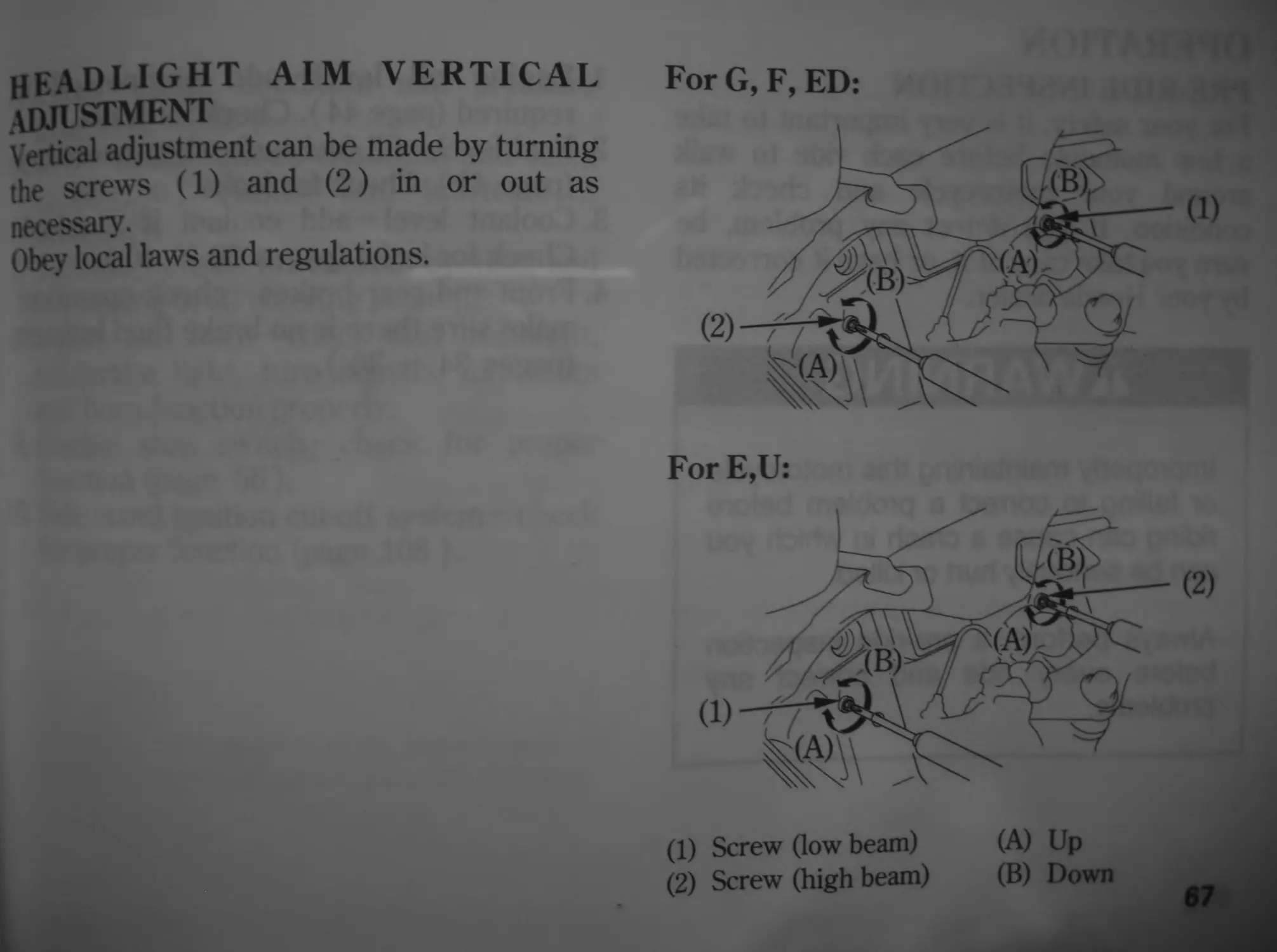
HEADLIGHT AIM VERTICAL
adjustment
Vertical adjustment can be made by turning
the screws (1) and (2) in or out as
necessary.
Obey local laws and regulations.
For E,U:
(1) Screw (low beam) (A) Up
(2) Screw (high beam) (B) Down
67
OPERATION
PRE-RIDE INSPECTION
For your safety, it is very important to take
a few moments before each ride to walk
around your motorcycle and check its
condition. If you detect any problem, be
sure you take care of it, or have it corrected
by your Honda dealer.
A WARNING
Improperly maintaining this motorcycle
or failing to correct a problem before
riding can cause a crash in which you
can be seriously hurt or killed.
Always perform a pre-ride inspection
before every ride and correct any
problems.
68
1. Engine oil level—add engine oil i
required (page 44). Check for leaks.
2. Fuel level—fill fuel tank when necessar
(page 41). Check for leaks.
3. Coolant level—add coolant if required
Check for leaks (pages 39 — 40 ).
4. Front and rear brakes—check operation
make sure there is no brake fluid leakage
(pages 34 — 36 ).
li
5. Tyres-check condition and pressure
(pages 45 — 50 ).
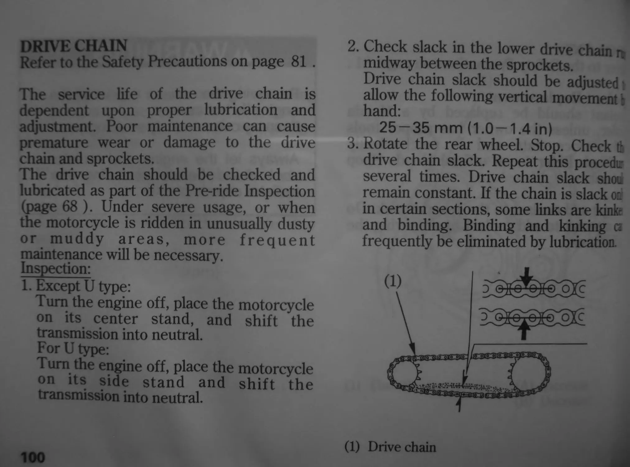
6. Drive chain — check condition and slack
(page 100). Adjust and lubricate if
necessary.
7. Throttle—check for smooth opening and
full closing in all steering positions.
8. Lights and horn —check that headlight,
tail/brake light, turn signals, indicators
and horn function properly.
9. Engine stop switch—check for proper
function (page 56).
10. Side stand ignition cut-off system—check
for proper function (page 108 ).
STARTING THE ENGINE
Always follow the proper starting procedure
described below.
This motorcycle is equipped with a side
stand ignition cut-off system. The engine
cannot be started if the side stand is down,
unless the transmission is in neutral. If the
side stand is up, the engine can be started in
neutral or in gear with the clutch lever
pulled in. After starting with the side stand
down, the engine will shut off if the
transmission is put in gear before raising
the side stand.
For E,F,G type:
To protect the catalytic converter in your
motorcycle’s exhaust system, avoid
extending idling and the use of leaded
petrol.
70
Your motorcycle’s exhaust contain
poisonous carbon monoxide gas. Higi
levels of carbon monoxide can collec
rapidly in enclosed areas such as a garage
Do not run the engine with the garage doo
closed. Even with the door open, run the
engine only long enough to move you
motorcycle out of the garage.
Do not use the electric starter for more thai
5 seconds at a time. Release the startei
button for approximately 10 seconds befon
pressing it again.
preparation
Before starting, insert the key, turn the
ignition switch ON and confirm the
following:
• The transmission is in NEUTRAL
(neutral indicator light ON).
• The engine stop switch is at О (RUN).
• The red malfunction indicator is ON.
• The low oil pressure indicator is flashing.
• The PGM-FI indicator is OFF.
• The immobilizer system (HISS) indicator
is OFF.
The low oil pressure indicator should go off
a few seconds after the engine starts. If the
light stays flashing, stop the engine
^mediately and check the engine oil level.
noticej
Crating the engine with insufficient oil
pressure can cause serious engine damage.
Starting Procedure
This motorcycle has a fuel-injected engine
with an automatic fast idle. Follow the
procedure indicated below.
Any Air Temperature
• Press the starter button with the throttle
completely closed.
The engine will not start if the throttle is
fully open (because the electronic control
module cuts off the fuel supply).
Flooded Engine
If the engine fails to start after repeated
attempts, it may be flooded.
1. Leave the engine stop switch set to
О (RUN).
2. Open throttle fully.
3. Press the starter button for 5 seconds.
4. Follow the normal starting procedure.
5. If the engine starts with unstable idle,
open the throttle slightly.
If the engine does not start, wait for 10
seconds, then follow steps 1 — 4 again.
72
Ignition Cut Off
Your motorcycle is designed to
automatically stop the engine and fuel pumj
if the motorcycle is overturned (a banking
sensor cuts off the ignition system). Before
restarting the engine, you must turn the
ignition switch to the OFF position and then
back to ON.
Rl rNNING-IN
Иеф assure your motorcycle’s future
reliability and performance by payine extra
K0®SXyourided',ri"e,h',i«
“,hro,lfe
RIDING
Review Motorcycle Safety (pages 1 — 7 )
before you ride.
Make sure you understand the function of
the side stand mechanism. (See MAIN-
TENANCE SCHEDULE on page 84 and
explanation for SIDE STAND on page 108).
<For E,F,G type>
Make sure flammable materials such as dry
grass or leaves do not come in contact with
the exhaust system when riding, idling, or
parking your motorcycle.
1. After the engine has been warmed up,
the motorcycle is ready for riding.
2. While the engine is idling, pull in the
clutch lever and depress the gearshift
pedal to shift into 1st (low) gear.
3. Slowly release the clutch lever and at th
same time gradually increase engint
speed by opening the throttle
Coordination of the throttle and clutd
lever will assure a smooth positive start.
4. When the motorcycle attains a moderatt
speed, close the throttle, pull in the clutd
lever and shift to 2nd gear by raising th
gearshift pedal.
This sequence is repeated to progres
sively shift to 3rd, 4th, 5th and 6th (top
gear.
5. Coordinate the throttle and brakes for
smooth deceleration.
6. Both front and rear brakes should be
used at the same time and should not be
applied strongly enough to lock the wheel,
or braking effectiveness will be reduced
and control of the motorcycle be difficult.
BRAKING
For normal braking, apply both the brake
pedal and lever while down-shifting to
match your road speed. For maximum
braking, close the throttle and firmly apply
the pedal and lever; pull in the clutch lever
before coming to a complete stop to prevent
stalling the engine.
Important Safety Reminders:
• Independent operation of only the brake
lever or brake pedal reduces stopping
performance.
• Extreme application of the brake controls
may cause wheel lock, reducing control of
the motorcycle.
• When possible, reduce speed or brake
before entering a turn; closing the
throttle or braking in mid-turn may cause
wheel slip. Wheel slip will reduce control
of the motorcycle.
76
When riding in wet or rainy conditions, о
on loose surfaces, the ability to maneuve
and stop will be reduced. All of you
actions should be smooth under thesr
conditions. Rapid acceleration, braking a
turning may cause loss of control. Foj
your safety, exercise extreme cautioi
when braking, accelerating or turning.
When descending a long, steep grade
use engine compression braking by down
shifting, with intermittent use of both
brakes.
Continuous brake application cat
overheat the brakes and reduce their
effectiveness.
Riding with your foot resting on th
brake pedal or your hand on the brak
lever may actuate the brakelight, giving*
false indication to other drivers. It may
also overheat the brakes, reducing
effectiveness.
PARKING
1 After stopping the motorcycle, shift the
transmission into neutral, turn the
handlebar fully to the left, turn the
ignition switch OFF and remove the key.
2. Use the side or center stand to support
the motorcycle while parked.
Park the motorcycle on firm, level ground to
prevent it from falling over.
If you must park on a slight incline, aim the
front of the motorcycle uphill to reduce the
possibility of rolling off the side stand or
overturning.
3. Lock the steering to help prevent theft
(page 59 ).
<For E,F,G type>
Make sure flammable materials such as dry
grass or leaves do not come in contact with
the exhaust system when parking your
motorcycle.
77
ANTI-THEFT TIPS
1. Always lock the steering and never leave
the key in the ignition switch. This
sounds simple but people do forget.
2. Be sure the registration information for
your motorcycle is accurate and current.
3. Park your motorcycle in a locked garage
whenever possible.
4. Use an additional anti-theft device of
good quality.
5. Put your name, address, and phone
number in this Owner’s Manual and keep
it on your motorcycles at all times.
Many times stolen motorcycles are
identified by information in the Owner’s
Manuals that are still with them.
NAME:____________________
ADDRESS:____________________________
PHONE NO:_____________
78
MAINTENANCE
THE IMPORTANCE OF
MAINTENANCE
A well-maintained motorcycle is essential
for safe, economical and trouble-free riding.
It will also help reduce air pollution.
To help you properly care for your
motorcycle, the following pages include a
Maintenance Schedule and a Maintenance
Record for regularly scheduled
maintenance.
These instructions are based on the
assumption that the motorcycle will be used
exclusively for its designed purpose.
Sustained high speed operation or operation
in unusually wet or dusty conditions will
require more frequent service than
specified in the Maintenance Schedule.
Consult your Honda dealer for
recommendations applicable to your
individual needs and use.
If your motorcycle overturns or becomes
involved in a crash, be sure your Honda
dealer inspects all major parts, even if you
are able to make some repairs.
^WARNING
Improperly maintaining this motorcycle
or failing to correct a problem before
you ride can cause a crash in which
you can be seriously hurt or killed.
Always follow the inspection and
maintenance recommendations and
schedules in this owner’s manual.
79
MAINTENANCE SAFETY
This section includes instructions on some
important maintenance tasks. You can
perform some of these tasks with the tools
provided — if you have basic mechanical
skills.
Other tasks that are more difficult and
require special tools are best performed by
professionals. Wheel removal should
normally be handled only by a Honda
technician or other qualified mechanic;
instructions are included in this manual only
to assist in emergency service.
Some of the most important safety
precautions follow. However, we cannot
warn you of every conceivable hazard that
can arise in performing maintenance. Only
you can decide whether or not you should
perform a given task.
80
WARNING
Failure to properly follow maintenance
instructions and precautions can
cause you to be seriously hurt or killed.
Always follow the procedures and
precautions in this owner’s manual.
S.XFETY PRECAUTIONS
• Make sure the engine is off before you
begin any maintenance or repairs. This
will help eliminate several potential
hazards:
• Carbon monoxide poisoning from
engine exhaust.
Be sure there is adequate ventilation
whenever you operate the engine.
• Bums from hot parts.
Let the engine and exhaust system cool
before touching.
• Injury from moving parts.
Do not run the engine unless instructed
to do so.
• Read the instructions before you begin,
and make sure you have the tools and
skills required.
•To help prevent the motorcycle from
falling over, park it on a firm, level
surface, using the center stand or a
maintenance stand to provide support.
• Io reduce the possibility of a fire or
explosion, be careful when working
around petrol or batteries. Use only
nonflammable solvent, not petrol, to clean
parts. Keep cigarettes, sparks and flames
away from the battery and all fuel-related
parts.
Remember that your Honda dealer knows
your motorcycle best and is fully equipped
to maintain and repair it.
To ensure the best quality and reliability,
use only new genuine Honda parts or their
equivalents for repair and replacement.
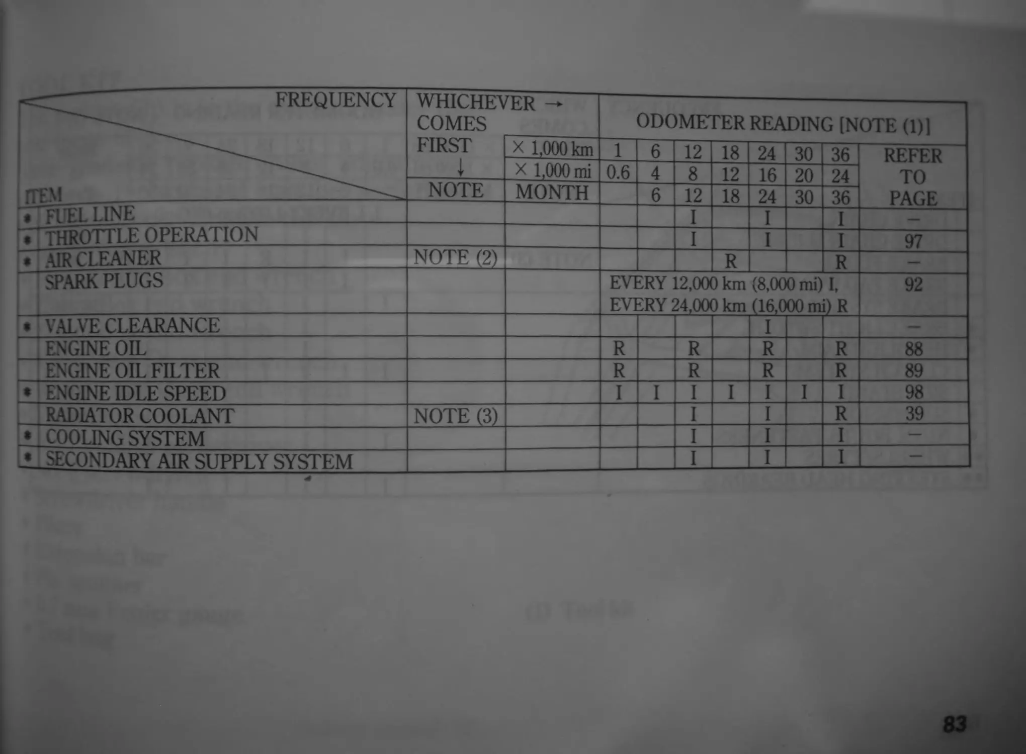
MAINTENANCE SCHEDULE
Perform the Pre-ride Inspection (page 68 ) at each scheduled maintenance period.
I: INSPECT AND CLEAN, ADJUST, LUBRICATE OR REPLACE IF NECESSARY
C: CLEAN R: REPLACE A: ADJUST L: LUBRICATE
The following Maintenance Schedule specifies all maintenance required to keep your motorcycle in peak operating
condition. Maintenance work should be performed in accordance with standards and specifications of Honda Ы
properly trained and equipped technicians. Your Honda dealer meets all of these requirements.
♦ Should be serviced by your Honda dealer, unless the owner has proper tools and service data and is mechanically
qualified. Refer to the Official Honda Shop Manual.
♦♦In the interest of safety, we recommend these items be serviced only by your Honda dealer.
Honda recommends that your Honda dealer should road test your motorcycle after each periodic maintenance is
carried out.
NOTES: (1) At higher odometer readings, repeat at the frequency interval established here.
(2) Service more frequently if the motorcycle is ridden in unusually wet or dusty areas.
(3) Replace every 2 years, or at indicated odometer interval, whichever comes first. Replacement require
mechanical skill.
82
frequency WHICHEV COMES FIRST rER -> ODOMETER READING [NOTE (1)1
_X 1,000 km 1 6 12 18 24 30 36 REFER
L X 1,000 mi 0.6 4 8 12 16 20 24 TO
ITEM NOTE MONTH 6 12 18 24 30 36 PAGE
♦ "FUEL line I I I
• Throttle operation JTZ_Z I I I 97
• AIR CLEANER NOTE (2) R R
"SPARKPLUGS EVI EVI iRY 12.0CM sRY 24,00 J km (8,00 3 km (16,0 0 mi) I, 00 mi) R 92
• VALVE CLEARANCE I —
ENGINE OIL R R R R 88
•— ENGINE OIL FILTER R R R R 89
• ENGINE IDLE SPEED I I I I I I I 98
RADIATOR COOLANT NOTE (3) I I R 39
♦ COOLING SYSTEM I I I
t SECONDARY AIR SUPPLY SYSTEM I I I —
83
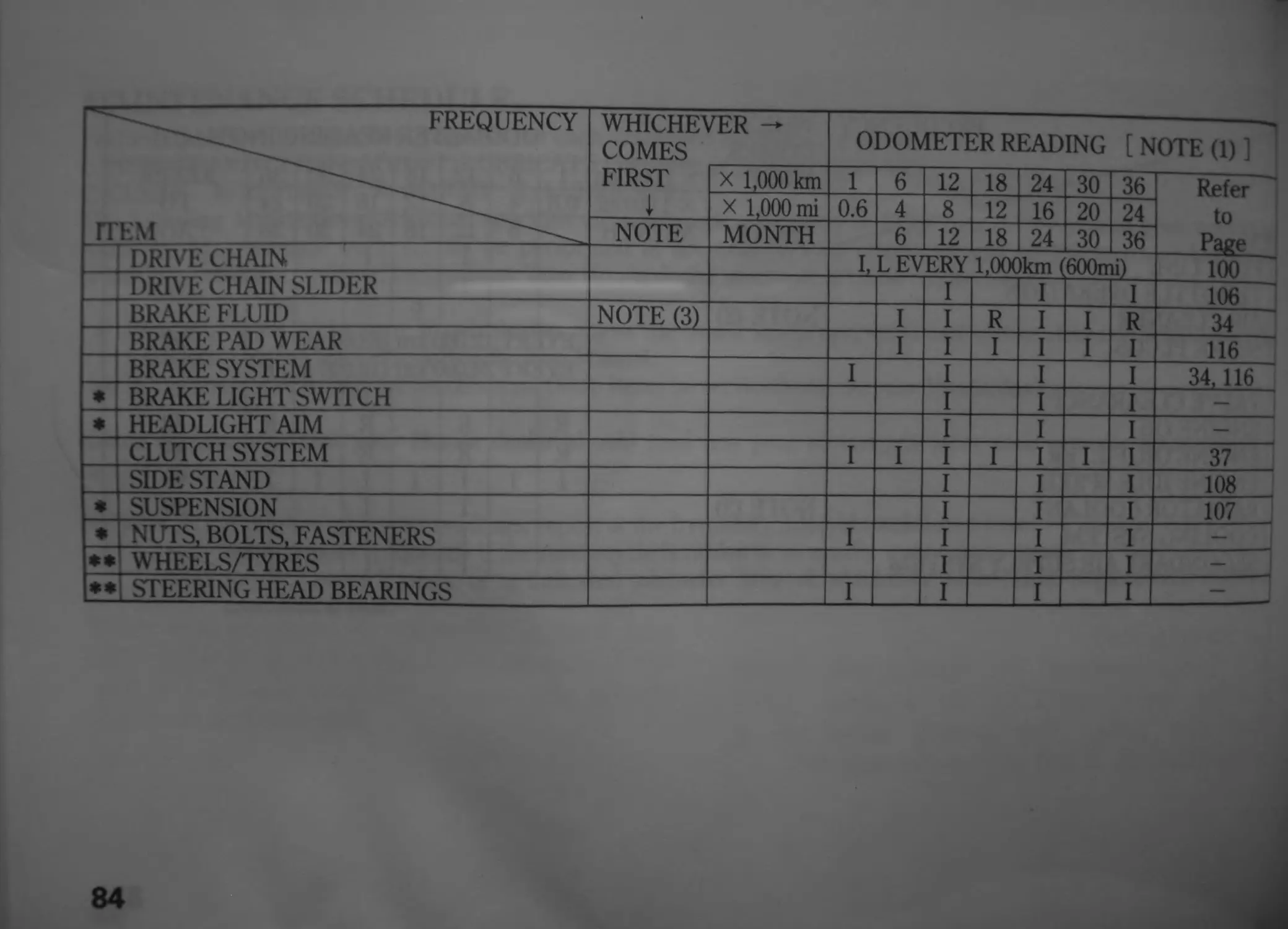
FREQUENCY WHICHEVER -* COMES ODOMETER READING [ NOTE (1) ]
FIRST X 1,000 km 1 6 12 18 24 30 36 Refer
I X 1,000 mi 0.6 4 8 12 16 20 24 to
ITEM NOTE MONTH 6 12 18 24 30 36 Page
DRIVE CHAIN I, L EVERY 1,000km (600mi) 100
DRIVE CHAIN SLIDER I I I 106
BRAKE FLUID NOTE (3) I I R I I R 34
BRAKE PAD WEAR I I I I I I 116
BRAKE SYSTEM I I I I 34,116
♦ BRAKE LIGHT SWITCH I I I - 1
* HEADLIGHT AIM I I I
CLUTCH SYSTEM" I I I I I I I 37
SIDE STAND I I I 108
* SUSPENSION I I I 107
* NUTS, BOLTS, FASTENERS I I I I —
•* WHEELS/TYRES I I I —
♦ ♦ STEERING HEAD BEARINGS I I I I —
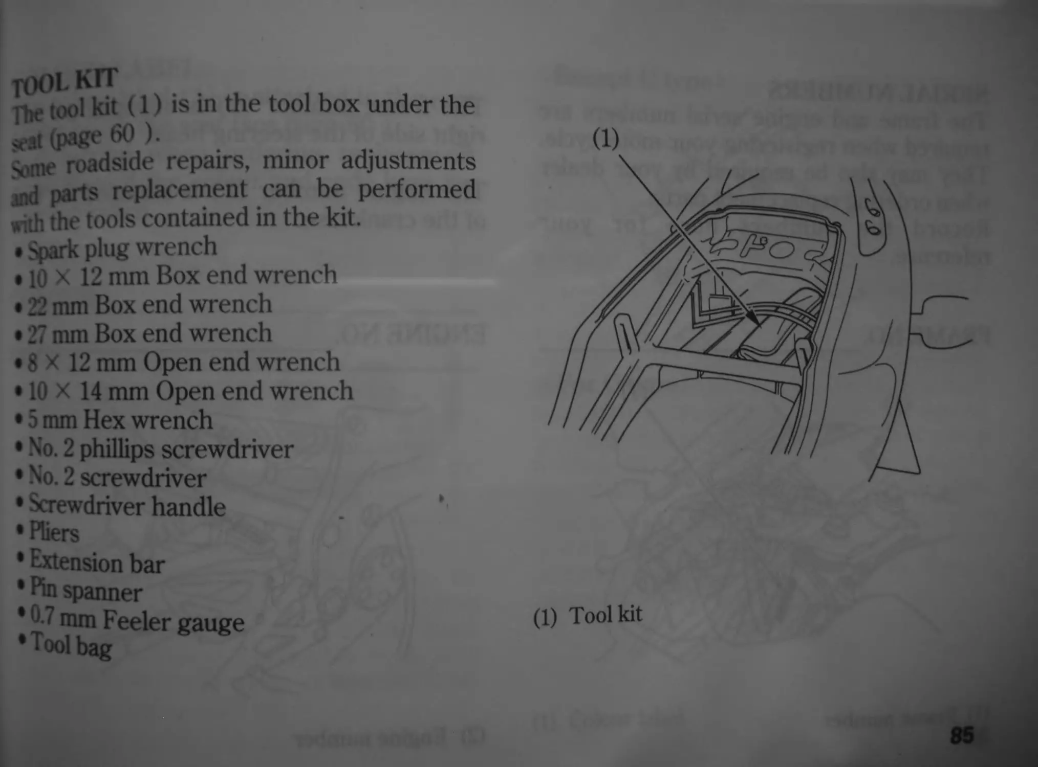
f(M)t кгг
rhe tool kit (1) is in the tool box under the
srf (page 60 ).
4,,ne roadside repairs, minor adjustments
md parts replacement can be performed
with the tools contained in the kit.
• Spark plug wrench
• 10 X 12 mm Box end wrench
• 22 mm Box end wrench
• 27 mm Box end wrench
• 8 X 12 mm Open end wrench
• 10 X 14 mm Open end wrench
• 5 mm Hex wrench
• No. 2 phillips screwdriver
• No. 2 screwdriver
• Screwdriver handle
•Pliers
• Extension bar
• Pin spanner
• 0.7 mm Feeler gauge
•Tool bag
(1)
(1) Toolkit
85
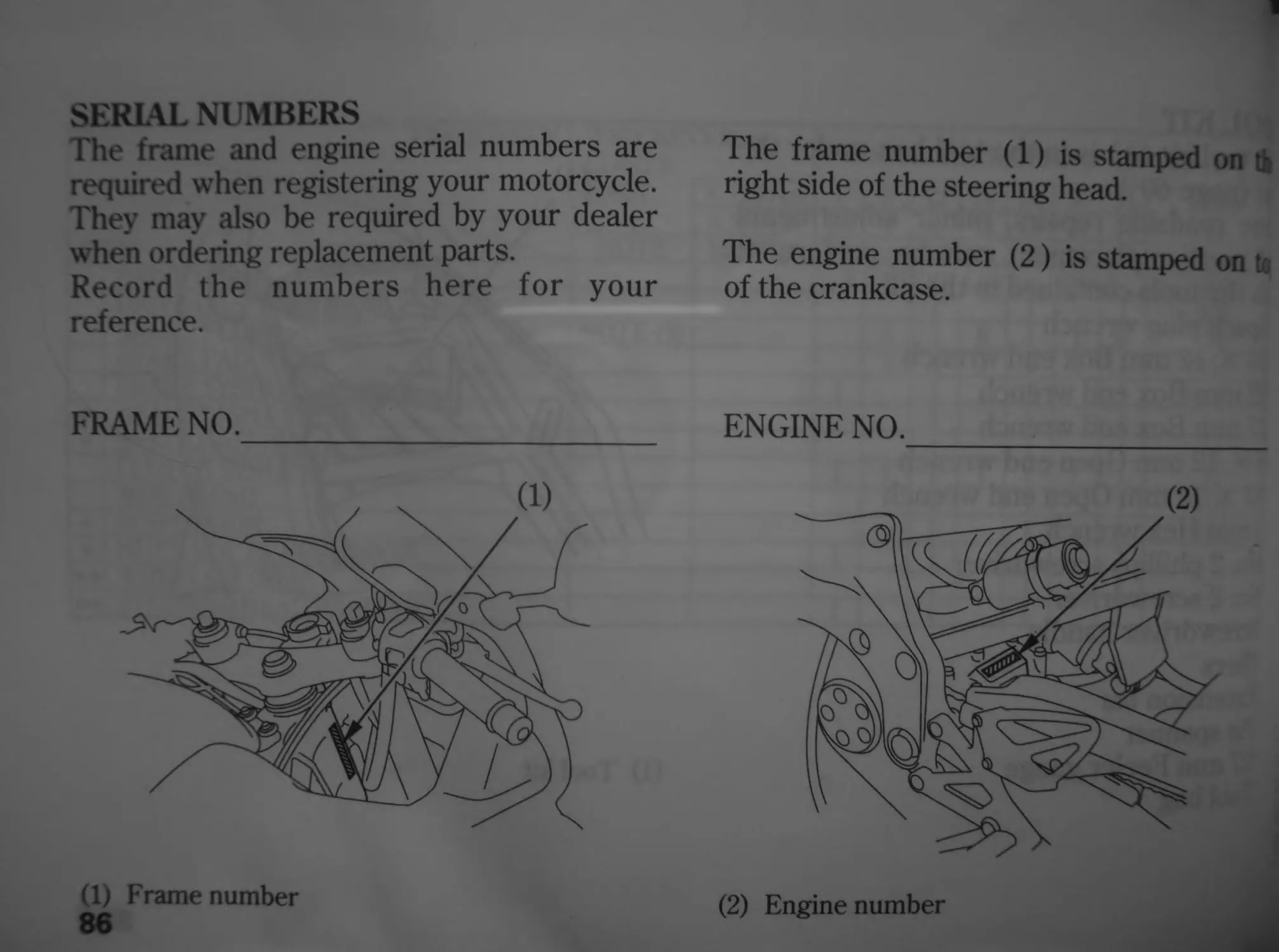
SERIAL NUMBERS
The frame and engine serial numbers are
required when registering your motorcycle.
They may also be required by your dealer
when ordering replacement parts.
Record the numbers here for your
reference.
FRAME NO.__________________
(1) Frame number
86
The frame number (1) is stamped on tb
right side of the steering head.
The engine number (2) is stamped on u
of the crankcase.
ENGINE NO.__________________
(2) Engine number
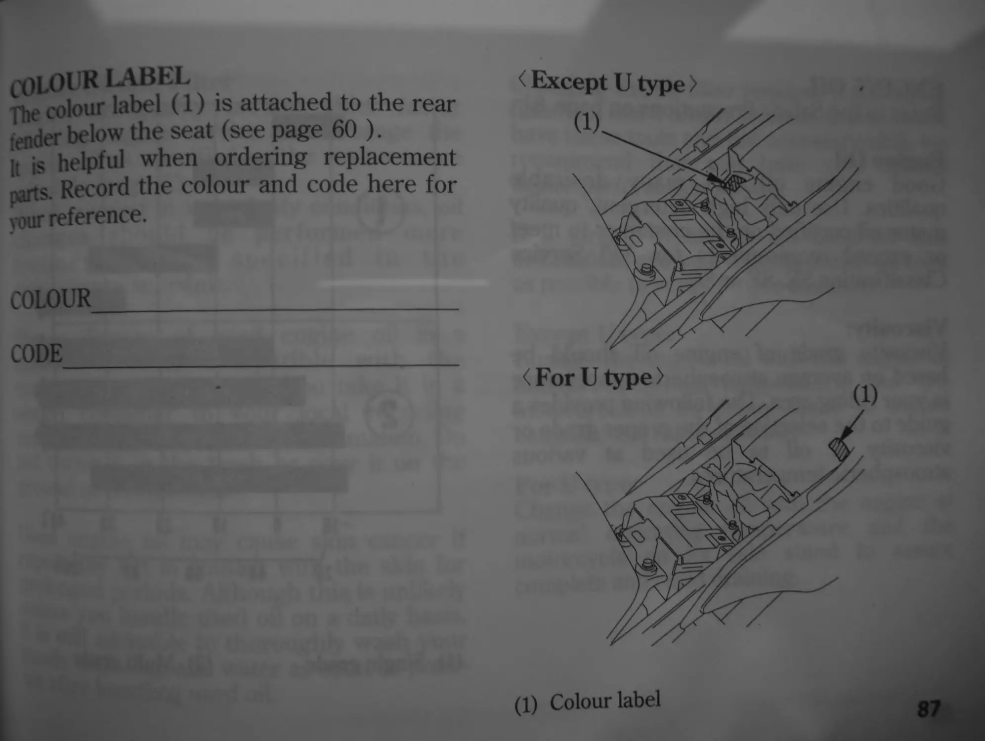
coloi r label
The colour label (1) is attached to the rear
fender below the seat (see page 60 ).
It is helpful when ordering replacement
parts. Record the colour and code here for
vour reference.
COLOUR_____________________
CODE
< Except U type >
(1) Colour label
87
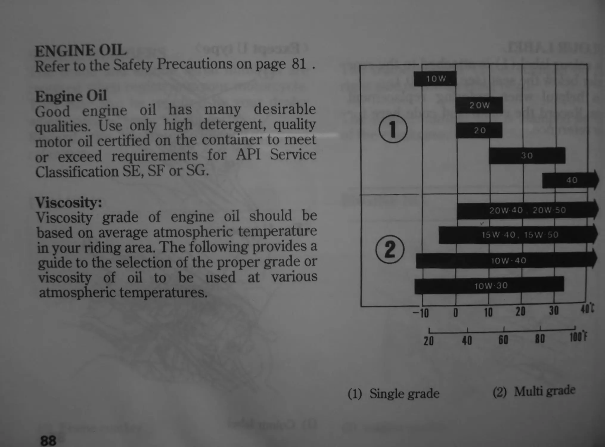
ENGINE OIL
Refer to the Safety Precautions on page 81 .
Engine Oil
Good engine oil has many desirable
qualities. Use only high detergent, quality
motor oil certified on the container to meet
or exceed requirements for API Service
Classification SE, SF or SG.
Viscosity:
Viscosity grade of engine oil should be
based on average atmospheric temperature
in your riding area. The following provides a
guide to the selection of the proper grade or
viscosity of oil to be used at various
atmospheric temperatures.
20 40II60II8011iflO'F
(1) Single grade
(2) Multi grade
b raiine Oil and Filter
EXb oil quality is the chief factor
affecting engine service life. Change the
4i£ine oil as specified in the maintenance
Schedule (page 83 ).
When running in very dusty conditions, oil
changes should be performed more
frequently than specified in the
maintenance schedule.
Please dispose of used engine oil in a
manner that is compatible with the
environment. We suggest you take it in a
sealed container to your local recycling
center or service station for reclamation. Do
not throw it in the trash or pour it on the
ground or down a drain.
l-sed engine oil may cause skin cancer if
repeatedly left in contact with the skin for
ponged periods. Although this is unlikely
^ss you handle used oil on a daily basis,
still advisable to thoroughly wash your
^ds with soap and water as soon as possi-
after handling used oil.
Changing the oil filter requires a special oil
niter tool and a torque wrench. If you do not
have these tools and the necessary skill, we
recommend that you have your Honda
dealer perform this service.
If a torque wrench is not used for this
installation, see your Honda dealer as soon
as possible to verify proper assembly.
Except U type:
Change the engine oil with the engine at
normal operating temperature and the
motorcycle on its center stand to assure
complete and rapid draining.
For U type:
Change the engine oil with the engine at
normal operating temperature and the
motorcycle on its side stand to assure
complete and rapid draining.
89
1. To drain the oil, remove the oil filler cap
and crankcase drain plug (1) and sealing
washer (2).
(1) Crankcase drain plug (2) Sealing washer
90
2. Remove the oil filter (3) with a fife
wrench and let the remaining oil drain at
Discard the oil filter.
(3) Oil filter
; Appb a 1^п coat °f engine oil to the new
oil filter rubber seal (4).
; [sing a special tool and a torque wrench,
install the new oil filter and tighten to a
torque of:
26N-m(2.7 kgf-m , 20 lbf-ft)
Use only the Honda genuine oil filter or a
filter of equivalent quality specified for your
model. Using the wrong Honda filter or a
non-Honda filter which is not of equivalent
quality may cause engine damage.
‘b Oil filter rubber seal
5. Check that the sealing washer on the
drain plug is in good condition and install
the plug. Replace the sealing washer
every other time the oil is changed, or
each time if necessary.
Oil Drain Plug Torque:
29 N-m (3.0 kgf-m , 22 lbf-ft)
6. Fill the crankcase with the recommended
grade oil; approximately:
3.3 fi (3.5 US qt, 2.9 Imp qt)
7. Install the oil filler cap.
8. Start the engine and let it idle for 2—3
minutes.
9. Several minutes after stopping the engine,
check that the oil level is at the upper
level mark in the inspection window with
the motorcycle upright on firm, level
ground. Make sure there are no oil leaks.
SPARK PLUGS
Refer to the Safety Precautions on page 81 .
Recommended plugs:
Standard:
IMR9C-9H (NGK) or
VUH27D (DENSO)
NOTICE
Never use a spark plug with an improper
heat range. Severe engine damage could
result.
This motorcycle uses the spark plugs th
have an iridium coated center electrode. •
sure to observe the following wh
servicing the spark plugs.
• Do not clean the spark plug. If c
electrode is contaminated w:
accumulated objects or dirt, replace :•
spark plug with a new one.
• Use only “wire-type feeler gauge"
check the spark plug gap to preve
damaging the iridium coating of c
center electrodes. Never use “leaf-ty
feeler gauge”.
• Do not adjust the spark plug gap. If t
gap is out of specification, replace и
spark plug with a new one.
Remove the tront cowl (page 64) and
the inner cowl (page 65 ).
Disconnect the radiator fan connector
(D-
1 Remove the lower mount nut (2) and
lower mount bolt (3).
4. Remove the upper mount bolt (4).___
(1) Radiator fan connector
(2) Lower mount nut
(3) Lower mount bolt
(4) Upper mount bolt
5. Move the radiator (5) out of the way and
remove the grommet (6) from the hook
(7).
6. Pull the radiator toward the front.
7. Disconnect the ignition coil connects
(8).
8. Disconnect the ignition coils (9 ) fro
the spark plugs.
(8) Ignition coil connectors
(9) Ignition coils
9 Clean any dirt from around the spark plug
bases.
Remove the spark plugs using the spark
plug wrench (10) furnished in the tool kit.
(10)
bpark plug wrench
10. Inspect the electrodes and center
porcelain for deposits, erosion or carbon
fouling. If the erosion or deposit is heavy,
replace the plug.
11. Make sure that the 1.0 mm wire-type
feeler gauge does not insert between the
spark plug gap (11). If the gauge is
inserted into the gap, replace the plug
with a new one.
(11) Spark plug gap
12. Make sure the plug washer is in good
condition.
13. With the plug washer attached, thread
the spark plug in by hand to prevent
cross-threading.
14. Tighten a new spark plug 1/2 turn with a
spark plug wrench to compress the
washer. If you are reusing a plug, it
should only take 1/8—1/4 turn after the
plug seats.
NOTICE
The spark plug must be securely tightened.
An improperly tightened plug can become
very hot and possibly damage the engine.
96
15. Reinstall the ignition coils.
16. Connect the ignition coil connectors :
the ignition coils as before removal.
17. Install the remaining parts in the reven
order of removal.
rHROTTLE OPERATION
Refer to the Safety Precautions on page 81 .
1 Check for smooth rotation of the throttle
grip from the fully open to the fully
closed position at both full steering
positions.
2 . Measure the throttle grip free play at the
throttle grip flange.
The standard free play should be
approximately:
2-4 mm (0.1 —0.2 in)
*
To adjust the free play, loosen the lock nut
11) and turn the adjuster (2).
(1)
(2)
(1) Locknut
IDLE SPEED
Refer to the Safety Precautions on page 81 .
The engine must be at normal operating
temperature for accurate idle speed
adjustment. Ten minutes of stop-and-go
riding is sufficient.
1. Warm up the engine, and shift to neutral,
and place the motorcycle on its center
stand.
2. Adjust idle speed with the throttle stop
screw (1).
Idle speed (In neutral):
1,300 ± 100 min"1 (rpm)
98
(1)
(1) Throttle stop screw
(A) Increase
(B) Decrease
tOOlAXT
Refer to the Safety Precautions on page 81.
Coolant Replacement
Coolant should be replaced by a Honda
dealer, unless the owner has proper tools
and service data and is mechanically
qualified. Refer to an official Honda Shop
Manual.
Always add coolant to the reserve tank. Do
not attempt to add coolant by removing the
radiator cap.
«WARNING
Removing the radiator cap while the
engine is hot can cause the coolant
to spray out, seriously scalding you.
Always let the engine and radiator
cool down before removing the
radiator cap.
DRIVE CHAIN
Refer to the Safety Precautions on page 81 .
The service life of the drive chain is
dependent upon proper lubrication and
adjustment. Poor maintenance can cause
premature wear or damage to the drive
chain and sprockets.
The drive chain should be checked and
lubricated as part of the Pre-ride Inspection
(page 68 ). Under severe usage, or when
the motorcycle is ridden in unusually dusty
or muddy areas, more frequent
maintenance will be necessary.
Inspection:
1. Except U type:
Turn the engine off, place the motorcycle
on its center stand, and shift the
transmission into neutral.
For U type:
Turn the engine off, place the motorcycle
on its side stand and shift the
transmission into neutral.
100
2. Check slack in the lower drive chain rt
midway between the sprockets.
Drive chain slack should be adjusted
allow the following vertical movement:
hand:
25 — 35 mm (1.0 —1.4 in)
3. Rotate the rear wheel. Stop. Check th
drive chain slack. Repeat this procedir
several times. Drive chain slack shot
remain constant. If the chain is slack ol
in certain sections, some links are kink-
and binding. Binding and kinking a
frequently be eliminated by lubrication.
(1) Drive chain
4 Rotate the rear wheel slowly and inspect
the drive chain and sprockets for any of
the following conditions:
DRIVE CHAIN
* Damaged Rollers
‘Loose Pins
*Dry or Rusted Links
‘Kinked or Binding Links
‘Excessive Wear
‘Improper Adjustment
‘Damaged or Missing O-rings
SPROCKETS
‘Excessively Worn Teeth
*Broken or Damaged Teeth
A drive chain with damaged rollers, loose
Pbs, or missing О-rings must be replaced. A
chain which appears dry, or shows signs of
Jjst. requires supplementary lubrication,
or binding links should be thor-
jughly lubricated and worked free. If links
cannot be freed, the chain must be replaced.
Damaged sprocket
Teeth
Replace
Replace
Normal sprocket Teeth
Worn sprocket
Teeth
GOOD
101
Adjustment:
Drive chain slack should be checked and
adjusted, if necessary, every 1,000 km (600
miles). When operated at sustained high
speeds or under conditions of frequent
rapid acceleration, the chain may require
more frequent adjustment.
(1) Axle nut (3) Scale
(2) Adjusting bolt (4) Index mark
102
If the drive chain requires adjustment, t-
procedure is as follows:
1. Except U type:
Place the motorcycle on its center su
with the transmission in neutral and _•
ignition switch off.
For U type:
Place the motorcycle on its side star
with the transmission in neutral and t
ignition switch off.
2. Loosen the axle nut (1).
3. Turn both adjusting bolts (2) an eq--
number of turns until the correct dr
chain slack is obtained. Turn "
adjusting bolts counterclockwise
tighten the chain, or clockwise to prov?:
more slack. Adjust the chain slack a:
point midway between the drive sproo
and the rear wheel sprocket. Rotate
rear wheel and recheck slack at oth
sections of the chain.
Chain slack should be:
25-35 mm (1.0—1.4 in)
• Check the rear axle alignment by
confirming the scale (3) on the drive
chain adjusters against the index marks
Ц) on the swingarm.
Both left and right scales should
correspond. If the axle is misaligned, turn
the left or right adjusting bolt until the
scales correspond on both side of
swingarm and recheck chain slack.
5. Tighten the axle nut to specified torque.
Axle nut torque:
93 N-m (9.5 kgf-m , 69 lbf-ft)
If a torque wrench is not used for this
installation, see your Honda dealer as soon
« possible to verify proper assembly.
A.
7 Tighten the adjusting bolts lightly.
Wear Inspection:
Check the chain wear label when adjusting
the chain. If the red zone (6) on the label
aligns with the index mark (5) on the
swingarm after the chain has been adjusted
to the proper slack, the chain is excessively
worn and must be replaced. The proper
«blade IQ*
25—35 mm (1.0 —1.4 in)
Damage to the bottom part of the frame
may be caused by excessive drive chain
slack of more than:
50 mm (2.0 in)
Replacement chain:
DID 525HV
or
RK525ROZ1
This motorcycle has a staked master link
drive chain which requires a special tool for
cutting and staking. Do not use an ordinary
master link with this chain. See your Honda
dealer.
(5) Index mark
(6) Red zone
104
l ubrication and Cleaning:
[^bncate every 1,000 km (600 miles) or
sooner if chain appears dry.
The drive chain on this motorcycle is
equipped with small O-rings between the
link plates. These О-rings retain grease
inside the chain to improve its service life.
The О-rings in this chain can be damaged
by steam cleaning, high pressure washers,
and certain solvents. Clean the side surfaces
of the chain with a dry cloth. Do not brush
the rubber О-rings. Brushing will damage
them. Wipe dry and lubricate only with SAE
80 or 90 gear oil. Commercial chain lubri-
cants may contain solvents which could
damage the rubber O-rings.
105
DRIV E CHAIN SLIDER
Refer to the Safety Precautions on page 81 .
Check die chain slider (1) for wear.
The chain slider must be replaced if it is
worn to the wear limit line (2). For
replacement, see your Honda dealer.
106
(1)
(1) Chain slider
(2) Wear limit line
FRONT and rear suspension
ASPECTION
Refer to the Safety Precautions on page 81 .
Check the fork assembly by locking the
front brake and pumping the fork up and
down vigorously. Suspension action
should be smooth and there must be no
oil leakage.
2. Swingarm bearings should be checked by
pushing hard against the side of the rear
wheel while the motorcycle is on the
center stand. Free play indicates worn
bearings.
3. Carefully inspect all front and rear
suspension fasteners for tightness.
SIDE STAND
Refer to the Safety Precautions on page 81.
Perform the following maintenance in
accordance with the maintenance schedule.
Functional Check:
• Check the spring (1) for damage or loss
of tension and the side stand assembly
for freedom of movement.
• Check the side stand ignition cut-off
system:
1. Sit astride the motorcycle; put the side
stand up and the transmission in
neutral.
2. Start the engine and with the clutch
lever pulled in, shift the transmission
into gear.
3. Lower the side stand. The engine
should stop as you put the side stand
down.
If the side stand system does not operate as
described, see your Honda dealer for
service.
108
WHEEL REMOVAL
Refer to the Safety Precautions on page 81 .
Front Wheel Removal
Raise the front wheel off the ground by
placing a support block under the engine.
2. Remove the right and left caliper
assembly (1) from the fork leg by
removing the fixing bolts (2).
To avoid damage to the brake hose, support
the caliper assembly so that it doesn’t hang
from the hose. Do not twist the brake hose.
(2)
(1) Brake caliper assembly
(2) Fixing bolts
109
Do not depress the brake lever when the
caliper assembly is removed. The caliper
piston will be forced out of the cylinder with
subsequent loss of brake fluid. If this occurs,
senicing of the brake system will be
necessary. See your Honda dealer for this
senice. __ ____
3. Remove the axle bolt (3), and the
loosen the right and left axle pinch bo<
(4).
4. Withdraw the front axle (5) and rema
the front wheel.
(3) Axle bolt
110
моОвЬоп:
position the front wheel between the fork
xys and insert the front axle from the left
side, through the left fork leg and wheel
hub.
Tiehten the axle bolt to the specified
torque:
59 Nm (6.0 kgf-m , 43 Ibf-ft)
Tighten the axle pinch bolts on the right
fork leg to specified torque:
22 Nm (2.2 kgf-m , 16 lbf-ft)
4. Install the right and left caliper
assemblies to the fork legs and tighten
the fixing bolts to the specified torque:
30 N-m (3.1 kgf-m, 22 lbf-ft)
To avoid damaging the brake pads while
installing the caliper assemblies, carefully
fit both brake discs between the pads.
5. Temporarily tighten the axle pinch bolts
on the left fork leg until lightly seat.
6. Operate the front brake and pump the
fork several times.
7. Measure the clearance (6) between each
surface of the left brake disc ( 7 ) and the
left brake caliper body ( 8) (not brake
pads) with a 0.7 mm (0.028 in) feeler
gauge (9 ) (see illustration).
(6) Clearance
(7) Brake disc
112
(8) Caliper body
(9) Feeler gauge
x If the feeler gauge inserts easily, tighten
' left axle pinch bolts (3) to the
specified torque:
22 N m (2.2 kgf-m , 16 Ibf-ft)
[f the feeler gauge cannot be inserted
easily, pull the left fork outward or push
inward to adjust the clearance. Then
tighten the left axle pinch bolts to the
specified torque.
After installing the wheel, apply the
brakes several times, then recheck the
both discs for caliper body (not brake
pads) to disc clearance. Do not operate
the motorcycle without adequate
clearance.
• Check for free wheel rotation after the
brake lever is released. Recheck the
wheel if the brake drags or if the wheel
does not rotate freely.
•Verify proper brake operation before
riding.
failure to provide adequate disc to caliper
joy (not brake pads) clearance may dam-
the brake discs and impair braking
If the torque wrench was not used for
installation, see your Honda dealer as soon
as possible to verify proper assembly.
Improper assembly may lead to loss of
braking capacity.
113
Rear Wheel Removal
1. Except U type:
Place the motorcycle on its center stand.
For U type:
Raise the rear wheel off the ground by
placing a support block under the engine.
2. Loosen the rear axle nut (1).
3. Loosen the drive chain adjusting bolts
(2).
4. Remove the rear axle nut.
5. Remove the drive chain (3) from the
driven sprocket by pushing the rear
wheel forward.
(1) Rear axle nut
(2) Drive chain adjusting bolts
114
6. Remove the axle shaft (4), side collar i
rear wheel from the swingarm.
Do not depress the brake pedal while
wheel is off the motorcycle. The cair
pistons will be forced out of the cyfini
with subsequent loss of brake fluid. If :
occurs, servicing of the brake system wil
necessary. See your Honda dealer for.
service.
(3) Drive chain
(4) Axle shaft
Nation Notes:
rfoTnstall the rear wheel, reverse the
removal procedure.
• Make sure that the slot (5) on the brake
caliper is located in the lug (6) in the
swingarm (7).
• Tighten the axle nut to the specified
torque:
93 N-m (9.5 kgf-m , 69 lbf-ft)
• Adjust the drive chain.
л nen installing the wheel, carefully fit the
brake disc between the brake pads to avoid
iamaging the pads.
After installing the wheel, apply the brake
*veral times and then check if the wheel
• jiates freely. Recheck the wheel if the
brake drags or if the wheel does not rotate
freely.
If a torque wrench was not used for
installation, see your Honda dealer as soon
as possible to verify proper assembly.
Improper assembly may lead to loss of
braking capacity.
(5) Slot
(6) Lug
(7) Swingarm
115
BRAKE PAD WEAR
Refer to the Safety Precautions on page 81 .
Brake pad wear depends upon the severity
of usage, the type of riding, and road
conditions. (Generally, the pads will wear
faster on wet and dirty roads.)
Inspect the pads at each regular
maintenance interval (page 84 ).
Front Brake
Always inspect each pad in both right and
left brake calipers.
Check the grooves (1) in each pad.
If either pad is worn to the bottom of the
grooves, replace both pads as a set. See
your Honda dealer for this service.
116
< FRONT BRAKE >
Illustration shows left side,
right side similar.
(1) Cutouts
йсйг Brake
;уск the cutout (2) in each pad.
’• either pad is worn to the cutout, replace
sxh pads as a set. See your Honda dealer
xthis service.
< REAR BRAKE >
(2) Cutouts
BATTERY
Refer to the Safety Precautions on page 81.
It is not necessary to check the battery
electrolyte level or add distilled water as the
battery is a maintenance-free (sealed) type.
If your battery seems weak and/or is
leaking electrolyte (causing hard starting or
other electrical troubles), contact your
Honda dealer.
NOTICE
Your battery is a maintenance-free type and
can be permanently damaged if the cap strip
is removed.
118
A WARNING
The battery gives off explosive
hydrogen gas during normal operatic
A spark or flame can cause the batte'
to explode with enough force to kill a
seriously hurt you.
Wear protective clothing and a fac=
shield, or have a skilled mechanic c:
the battery maintenance.
Ratten Removal
fhe battery (5) is in the battery box below
iheseat.
Remove the seat (page 60 ).
. Remove the clips (1) and open the
batten’cover (2).
Disconnect the negative (-) terminal
lead (3) from the battery first, then
disconnect the positive (+) terminal lead
(4).
4. Pull out the battery (5) from the battery
box.
(5) (3)
(4)
(3) Negative (-) terminal lead
(4) Positive (+) terminal lead
(5) Battery
119
Fl SE REPLACEMENT
Refer to the Safety Precautions on page 81 .
When frequent fuse failure occurs, it
usually indicates a short circuit or an
overload in the electrical system. See your
Honda dealer for repair.
NOTICE
Never use a fuse with a different rating
from that specified. Serious damage to the
electrical system or a fire may result,
causing a dangerous loss of lights or engine
power.
120
Blown fuse
fu^Box-
fuse box is located under the seat.
fhe specified fuses are:
10 A, 20 A
; Remove the seat (page 60 ).
2. Open the fuse box cover (1).
1 Pull out the old fuse and install a new fuse.
The spare fuses (2) are located in the
fuse box.
4. Close the fuse box cover and install the
seat.
(1)
(2)
(1) Fuse box cover
(2) Spare fuses
Main Fuse:
The main fuse (1) is located under the seat.
The specified fuse is:
30 A
1. Remove the seat (page 60 ).
2. Disconnect the wire connector (2 ) of
the starter magnetic switch.
3. Pull out the old fuse and install a new fuse.
The spare fuse (3) is located behind the
fuse box.
4. Reconnect the connector and install the
seat.
FI Fuse:
The FI fuse (4) is located under the seat.
The specified fuse is:
20 A
1. Remove the seat (page 60 ).
2. Open the FI fuse box cover (5).
3. Pull out the old fuse and install a new fuse.
The spare fuse is located in the fuse box.
4. Close the FI fuse box cover and install
the seat.
122
(3)
(1) Main fuse (4) FI fuse
(2) Wire connector (5) FI fuse box
(3) Spare main fuse
^PLIGHT SWITCH
yUVSTMENT
^fer to the Safety Precautions on page 81 .
Check the operation of the stoplight switch
1) at the right side behind the engine from
ineto time.
Adjustment is done by turning the adjusting
nut (2). Turn the nut in the direction (A) if
die switch operates too late and in direction
B) if the switch operates too soon.
(2)
(1) Stoplight switch
(2) Adjusting nut
BULB REPLACEMENT
Refer to the Safety Precautions on page 81 .
The light bulb becomes very hot while the
light is ON, and remains hot for a while
after it is turned OFF. Be sure to let it cool
down before servicing.
Do not put finger prints on the headlight
bulb, as they may create hot spots on the
bulb and cause it to break.
Wear clean gloves while replacing the bulb.
If you touch the bulb with your bare hands,
clean it with a cloth moistened with alcohol
to prevent its early failure.
124
Be sure to turn the ignition switch (;
when replacing the bulb.
Do not use bulbs other than that specif»
After installing a new bulb, check that:
light operates properly.
Headlight Bulb
Remove the inner panel (page 66 ).
> Remove the hook (1) from the stay (2).
Pull off the socket (3) without turning.
4. Remove the dust cover (4).
; Remove the bulb (6) while pressing
‘ down on the pin (5).
- Pull out the bulb (6) without turning.
' Install a new bulb in the reverse order of
removal.
• Install the dust cover with its ‘TOP”
mark facing up.
(2)
(6)
(1) Hook (4) Dust cover
(2) Stay (5) Pin
(3) Socket (6) Bulb
125
Position Light Bulb
(Except IJ type)
1. Turn the position light socket (1)
approximately 45° counterclockwise,
then pull it out toward you.
2. Pull out the bulb (2) without turning.
3. Install a new bulb in the reverse order of
removal.
126
(1) Position light socket
(2) Bulb
Stop/TailliiJh1 Bulb
• Remove the seat (page 60 ).
; Turn the socket (1) approximately 45°
counterclockwise, then pull it out toward
you.
A Pull out the bulb (2) without turning.
4. Install a new bulb in the reverse order of
removal.
(1) Socket
(2) Bulb
127
Front/RearTum Signal Bulb
1. Remove the rear turn signal lens (1) and
the lens packing (2) by removing the
screw (3).
2. Slightly press the bulb (4) and turn it
counterclockwise.
3. Install a new bulb in the reverse order of
removal.
128
(4)
(1) Lens
(2) Lens packing
(3) Screw
(4) Bulb
cleaning
'jean your motorcycle regularly to protect
^surface finishes and inspect for damage,
*ear. and oil, coolant or brake fluid leakage.
Avoid cleaning products that are not
specifically designed for motorcycle or
jiomobile surfaces.
They may contain harsh detergents or
chemical solvents that could damage the
□etal, paint, and plastic on your motorcycle.
2 your motorcycle is still warm from recent
operation, give the engine and exhaust
system time to cool off.
recommend avoiding the use of high
pressure water spray (typical in coin-
crated car washes).
NOTICE
High pressure water (or air) can damage
certain parts of the motorcycle.
Do not apply the pressured water directly to
the air intake. The water can be drawn into
the throttle body and/or enter the air
cleaner.
(1) Air intake
129
Washing the motorcycle
1. Rinse the motorcycle thoroughly with
cool water to remove loose dirt.
2. Clean the motorcycle with a sponge or
soft cloth using cool water.
Avoid directing water to muffler outlets
and electrical parts.
3. Clean the plastic parts using a cloth or
sponge dampened with a solution of mild
detergent and water. Rub the soiled area
gently rinsing it frequently with fresh
water.
Take care to keep brake fluid or chemical
solvents off the motorcycle.
They will damage the plastic and painted
surfaces.
The inside of the headlight lens may be
clouded immediately after washing the
motorcycle. Moisture condensation inside
the headlight lens will disappear gradually
by lighting the headlight in high beam. Run
the engine while keeping the headlight on.
130
4. After cleaning, rinse the motoro
thoroughly with plenty of clean wa
Strong detergent residue can con»
alloy parts.
5. Dry the motorcycle, start the engine, г
let it run for several minutes.
6. Test the brakes before riding :
motorcycle. Several applications may
necessary to restore normal brat
performance.
7. Lubricate the drive chain immedix
after washing and drying the motorcyo
Braking efficiency may be temporr
impaired immediately after washing -
motorcycle.
Anticipate longer stopping distance to a
a possible accident.
finishing Touches
Ler washing your motorcycle, consider
a commercially-available spray
•ieaner polish or quality liquid or paste wax
? finish the job. Use only a non-abrasive
polish or wax made specifically for
motorcycles or automobiles. Apply the
polish or wax according to the instructions
on the container.
If a surface on your motorcycle is chipped
г scratched, your Honda dealer has touch-
up paint to match your motorcycle’s colour.
He sure to use your motorcycle’s colour
code (page 87) when you buy touch-up
paint.
Removing Road Salt
The salt contained in the road surface
freezing prevention medicine which a road
was sprayed with in winter, and the
seawater becomes the cause which rust
occurs in.
Wash your motorcycle by the following
point after it runs through such a place.
1. Clean the motorcycle using cool water
(page 129 ).
Do not use warm water.
This worsens the effect of the salt.
2. Dry the motorcycle and the surface of the
metal is protected with the wax.
Painted Aluminum Wheel Maintenance
Aluminum may corrode from contact with
dirt, mud, or road salt. Clean the wheels
after riding through any of these
substances. Use a wet sponge and mild
detergent. Avoid stiff brushes, steel wool, or
cleaners containing abrasives or chemical
compounds.
After washing, rinse with plenty of water
and dry with a clean cloth.
Apply touch-up paint to the wheels where
damage has resulted.
132
STORAGE Gl IDE
fended storage, such as for winter,
Quires that you take certain steps to
^juce the effects of deterioration from
. ,n41$e of the motorcycle. In addition,
- oessary repairs should be made BEFORE
Coring the motorcycle; otherwise, these
Repairs may be forgotten by the time the
motorcycle is removed from storage.
STORAGE
Change the engine oil and filter.
.Make sure the cooling system is filled
with a 50/50 % antifreeze solution.
з Empty the fuel tank into an approved
petrol container using a commercially
available hand siphon or an equivalent
method. Spray the inside of the tank with
an aerosol rust-inhibiting oil.
Reinstall the fuel fill cap on the tank.
A WARNING
Petrol is highly flammable and
explosive. You can be burned or
seriously injured when handling fuel.
• Stop the engine and keep heat,
sparks, and flame away.
• Refuel only outdoors.
• Wipe up spills immediately.
4. To prevent rusting in the cylinders,
perform the following:
• Remove the ignition coil connectors
and ignition coils from the spark plugs.
Using tape or string, secure the
connectors to any convenient plastic
body part so that they are positioned
away from the spark plugs.
• Remove the spark plugs from the
engine and store them in a safe place.
Do not connect the ignition coils to the
ignition coil connectors.
• Pour a tablespoon (15—20 cm3) of
clean engine oil into each cylinder and
cover the spark plug holes with a piece
of cloth.
• Crank the engine several times to
distribute the oil.
• Reinstall the spark plugs, ignition coils
and ignition coil connectors.
134
5. Remove the battery. Store in an *
protected from freezing temperate
and direct sunlight.
Slow charge the battery once a month
6. Wash and dry the motorcycle. Wax
painted surfaces. Coat chrome т
rustinhibiting oil.
7. Lubricate the drive chain (page 105).
8. Inflate the tyres to their recommen:
pressures. Place the motorcycle on bloc
to raise both tyres off the ground.
9. Cover the motorcycle (don’t use plastk
other coated materials) and store in
unheated area, free of dampness wit
minimum of daily temperature varia:
Do not store the motorcycle in dir-
sunlight.
rFMOVAL from storage
Incover and clean the motorcycle.
Change the engine oil if more than 4
months have passed since the start of
storage.
. Charge the battery as required. Install the
" battery.
3. Drain any excess aerosol rust-inhibiting
oil from the fuel tank. Fill the fuel tank
with fresh petrol.
I Perform all Pre-ride Inspection checks
(page 68 ).
Test ride the motorcycle at low speeds in
a safe riding area away from traffic.
SPECIFICATIONS
DIMENSIONS
Overall length
Overall width
Overall height
Wheelbase
WEIGHT
Dry weight
CAPACITIES
Engine oil After draining
After draining and
oil filter change
After disassembly
Fuel tank
Cooling system capacity
Passenger capacity
Maximum weight capacity
136
2,065 mm (81.3 in)
685 mm (27.0 in)
1,135 mm (44.7 in)
1,390 mm (54.7 in) ... Except U
1,385 mm (54.5 in) ... U
170 kg (375 lbs) ... Except G
171 kg (377 lbs) ... G
3.0 fl (3.2 US qt, 2.6 Imp qt)
3.3 fl (3.5 US qt, 2.9 Imp qt)
3.7 ft (3.9 US qt, 3.3 Imp qt)
18.0 fl (4.76 US gal, 3.96 Imp gal)
2.7 ft (2.9 US qt, 2.4 Imp qt)
Operator and one passenger
189 kg (417 lbs)
ENGINE
Bore and stroke
Compression ratio
Displacement
Spark plug
Standard
67.0 X 42.5 mm (2.64 X 1.67 in)
12.0:1
599 cm3 (36.5 cu-in)
IMR9C-9H (NGK) or
VUH27D (DENSO)
Idle speed
Valve clearance (Cold)
1,300 ± 100 min-1 (rpm)
Intake 0.20 mm (0.008 in)
Exhaust 0.28 mm (0.011 in)
CH ASSIS AND SUSPENSION
Caster
Trail
Tyre size, front
Tyre size, rear
POWER TRANSMISSION
Primary reduction
Gear ratio, 1st
2nd
3rd
4th
5th
6th
Final reduction
138
24°
96 mm (3.8 in)
120/70ZR17 М/С (58W)
180/55ZR17 М/С (73W)
1.822
2.833
2.062
1.647
1.421
1.272
1.173
2.813
jUCTRICAL
Battery
Generator
12 V —8.6 Ah
0.433 kW
LIGHTS
Headlight
Brake/tail light
Turn signal light Front
Rear
Position light
12 V-55W
12 V-21/5W
12 V-21 W
12 V-21 W
12 V — 5 W ...Except U
USE
Main fuse
FI fuse
Other fuses
30 A
20 A
10 A, 20 A
CATALYTIC CONVERTER
<For E,F»G>
This motorcycle is equipped with a catalytic
converter.
The catalytic converter contains precious
metals that serve as catalysts, promoting
chemical reactions to convert the exhaust
gasses without affecting the metals.
The catalytic converter acts on HC, CO, and
NOx. A replacement unit must be an
original Honda part or its equivalent.
The catalytic converter must operate at a
high temperature for the chemical reactions
to take place. It can set on fire any
combustible materials that come near it.
Park your motorcycle away from high
grasses, dry leaves, or other flammables.
140
A defective catalytic converter contrb.
to air pollution, and can impair your engi»
performance. Follow these guideline*
protect your motorcycle’s catair
converter.
• Always use unleaded petrol. Even a se
amount of leaded petrol can contamc
the catalyst metals, making the catak
converter ineffective.
• Keep the engine tuned-up.
• Have your motorcycle diagnosed *
replaced if it is misfiring, backfir
stalling or otherwise not running prop?
VOISE CONTROL SYSTEM (AUSTRALIA UN. v
tampering with the NOISE CONTROI qvqtcw
•anted that the law may prohibit: (a) The removal trJV8 PP0HIBITED: Owners are
xher than for purposes of maintenance, repair rrlni J ermg lnoPerative by any per^n
jesign incorporated into any new vehicle for the nn ei?ent’ of апУ device or element of
*?' to the ultimate purchaser or »lul° I, l',™W P™ Ms™, *
ях-h device or element of design has been removed от rendered it eUSe-°f the Vehicle after
GBR60QF
ообн-Mdwzoeoo
CBR600F4i
(U)
CBR600F
(E.F.G)
HONDA
The Power of Dreams
37MBW650
00X37-MBW-6500
EC) GE) 2000.2003.12.4
----- PRINTED IN JAPAN