/

Теги: weapons

Текст
п м/м
MOUNTAIN GUN
NATIONAL FORGE & ORDNANCE CO.
IRVINE, WARREN COUNTY, PENNA, U.S.A.
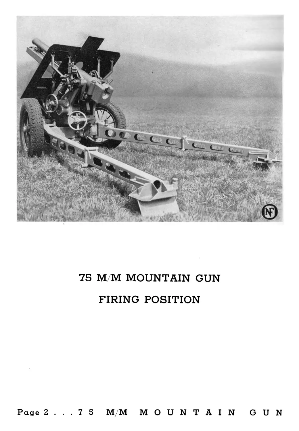
75 M/M MOUNTAIN GUN
FIRING POSITION
Page 2 ... 7 5 M/M MOUNTAIN GUN
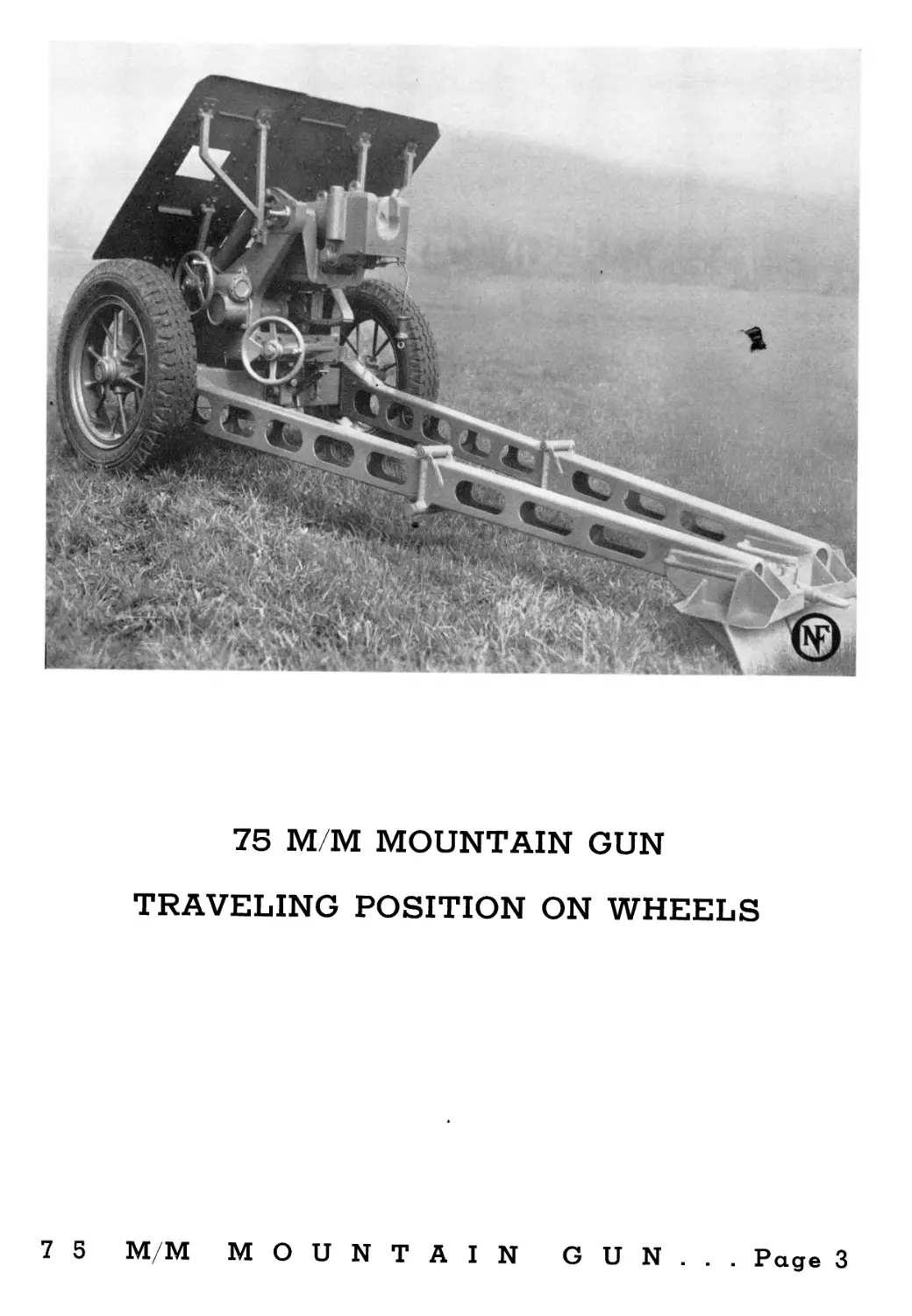
75 MM MOUNTAIN GUN
TRAVELING POSITION ON WHEELS
7 5 M/M MOUNTAIN GUN... Page 3
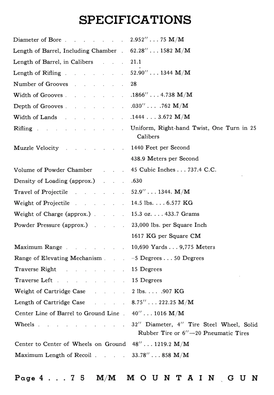
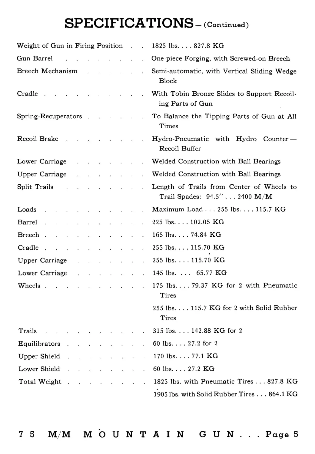
SPECIFICATIONS
Diameter of Bore.....................
Length of Barrel, Including Chamber .
Length of Barrel, in Calibers
Length of Rifling....................
Number of Grooves....................
Width of Grooves.....................
Depth of Grooves.....................
Width of Lands.......................
Rifling..............................
Muzzle Velocity......................
Volume of Powder Chamber
Density of Loading (approx.)
Travel of Projectile.................
Weight of Projectile.................
Weight of Charge (approx.) ....
Powder Pressure (approx.) ....
Maximum Range........................
Range of Elevating Mechanism .
Traverse Right.......................
Traverse Left........................
Weight of Cartridge Case ....
Length of Cartridge Case ....
Center Line of Barrel to Ground Line .
Wheels...............................
Center to Center of Wheels on Ground
Maximum Length of Recoil ....
2.952" ... 75 M/M
62.28" . . . 1582 M/M
21.1
52.90" . . . 1344 M/M
28
.1866" . . . 4.738 M/M
.030" . . . .762 M/M
.1444 . . . 3.672 M/M
Uniform, Right-hand Twist, One Turn in 25
Calibers
1440 Feet per Second
438.9 Meters per Second
45 Cubic Inches . . . 737.4 C.C.
.630
52.9" . . . 1344. M/M
14.5 lbs. . . . 6.577 KG
15.3 oz. . . . 433.7 Grams
23,000 lbs. per Square Inch
1617 KG per Square CM
10,690 Yards . . . 9,775 Meters
-5 Degrees ... 50 Degrees
15 Degrees
15 Degrees
2 lbs.....907 KG
8.75" . . . 222.25 M/M
40" . . . 1016 M/M
32" Diameter, 4" Tire Steel Wheel, Solid
Rubber Tire or 6"—20 Pneumatic Tires
48" . . . 1219.2 M/M
33.78" ... 858 M/M
Page 4 ... 7 5 M/M MOUNTAIN GUN
SPECIFICATIONS — (Continued)
Weight of Gun in Firing Position
Gun Barrel...........................
Breech Mechanism.....................
Cradle...............................
Spring-Recuperators..................
Recoil Brake.........................
Lower Carriage.......................
Upper Carriage.......................
Split Trails.........................
Loads ...............................
Barrel...............................
Breech...............................
Cradle...............................
Upper Carriage.......................
Lower Carriage.......................
Wheels...............................
Trails
Equilibrators
Upper Shield
Lower Shield
Total Weight
1825 lbs. . . . 827.8 KG
One-piece Forging, with Screwed-on Breech
Semi-automatic, with Vertical Sliding Wedge
Block
With Tobin Bronze Slides to Support Recoil-
ing Parts of Gun
To Balance the Tipping Parts of Gun at All
Times
Hydro-Pneumatic with Hydro Counter —
Recoil Buffer
Welded Construction with Ball Bearings
Welded Construction with Ball Bearings
Length of Trails from Center of Wheels to
Trail Spades: 94.5" . . . 2400 M/M
Maximum Load . . . 255 lbs. . . . 115.7 KG
225 lbs. . . . 102.05 KG
165 lbs. . . . 74.84 KG
255 lbs. . . . 115.70 KG
255 lbs. . . . 115.70 KG
145 lbs. . . . 65.77 KG
175 lbs. . . . 79.37 KG for 2 with Pneumatic
Tires
255 lbs. . . . 115.7 KG for 2 with Solid Rubber
Tires
315 lbs. . . . 142.88 KG for 2
60 lbs. . . . 27.2 for 2
170 lbs. . . . 77.1 KG
60 lbs. . . . 27.2 KG
1825 lbs. with Pneumatic Tires . . . 827.8 KG
1905 lbs. with Solid Rubber Tires . . . 864.1 KG
7 5 M/M MOUNTAIN GUN... Page 5
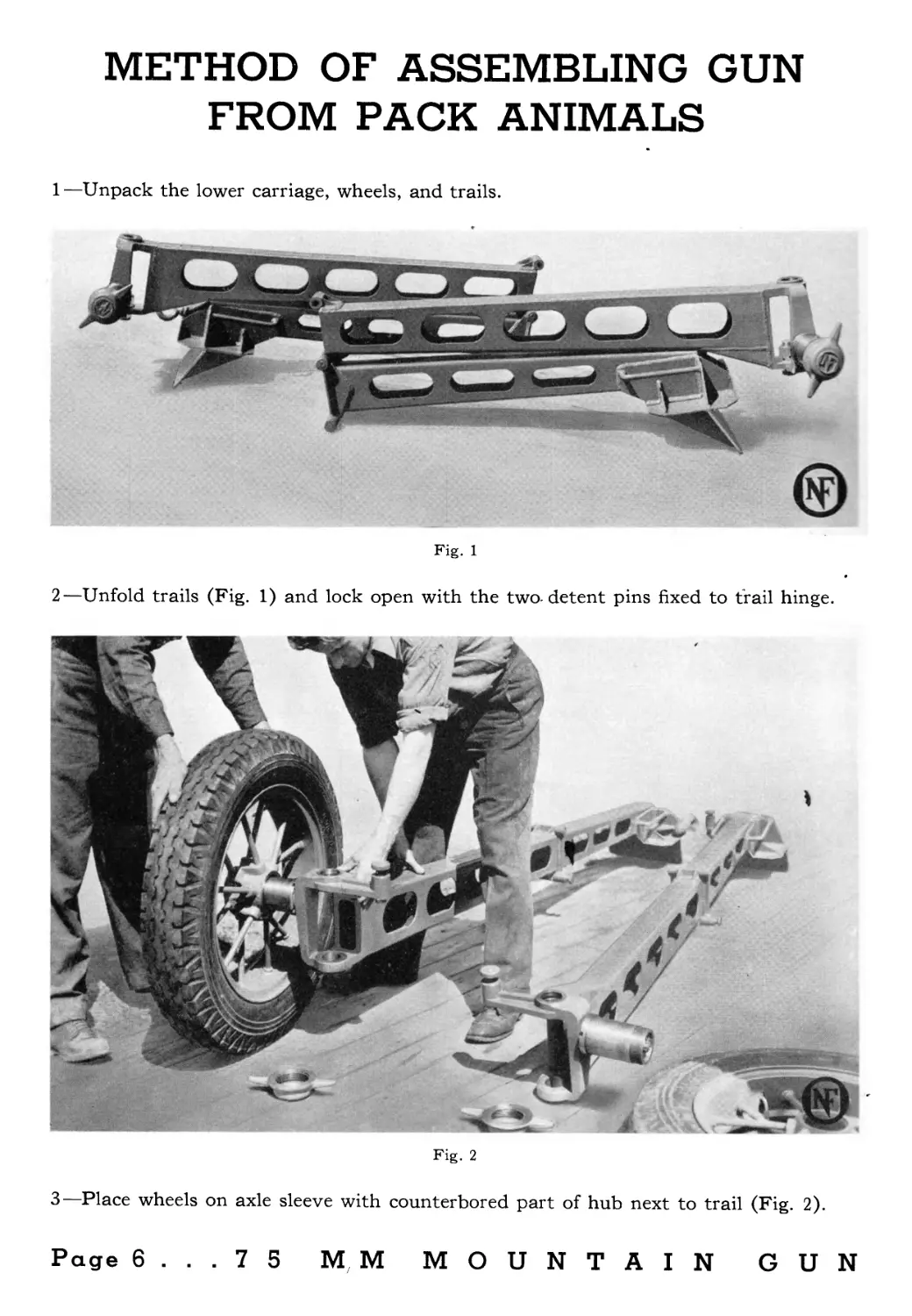
METHOD OF ASSEMBLING GUN
FROM PACK ANIMALS
1—Unpack the lower carriage, wheels, and trails.
Fig. 1
2—Unfold trails (Fig. 1) and lock open with the two-detent pins fixed to trail hinge.
Fig. 2
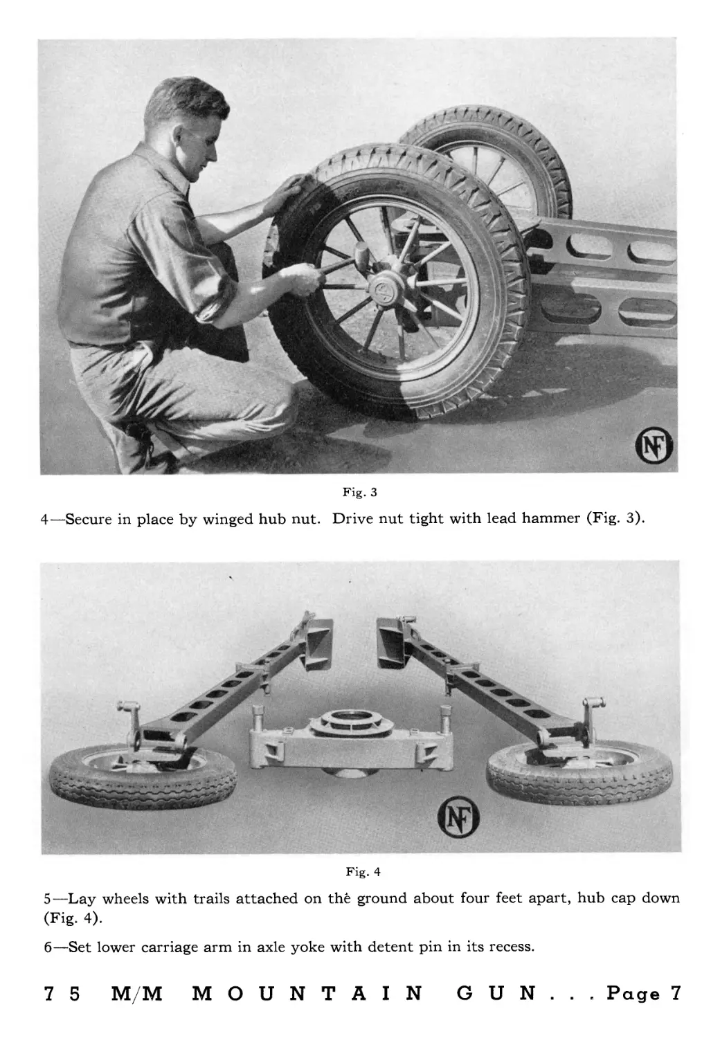
3—Place wheels on axle sleeve with counterbored part of hub next to trail (Fig. 2).
Page 6. ..75 MM MOUNTAIN GUN
Fig. 3
4—Secure in place by winged hub nut.
Drive nut tight with lead hammer (Fig. 3).
Fig. 4
5—Lay wheels with trails attached on the ground about four feet apart, hub cap down
(Fig. 4).
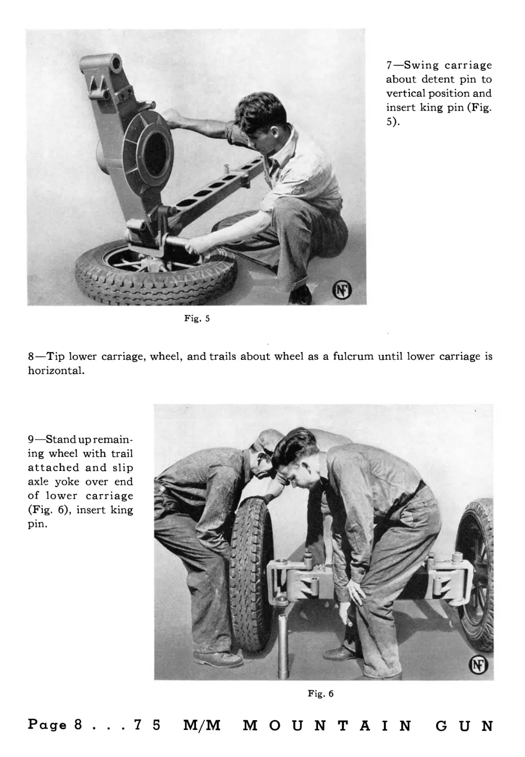
6—Set lower carriage arm in axle yoke with detent pin in its recess.
7 5 M/M MOUNTAIN GUN... Page 7
7—Swing carriage
about detent pin to
vertical position and
insert king pin (Fig.
5).
Fig. 5
8—Tip lower carriage, wheel, and trails about wheel as a fulcrum until lower carriage is
horizontal.
9 —Stand up remain-
ing wheel with trail
attached and slip
axle yoke over end
of lower carriage
(Fig. 6), insert king
pin.
Fig. 6
Page 8 ... 7 5 M/M MOUNTAIN GUN
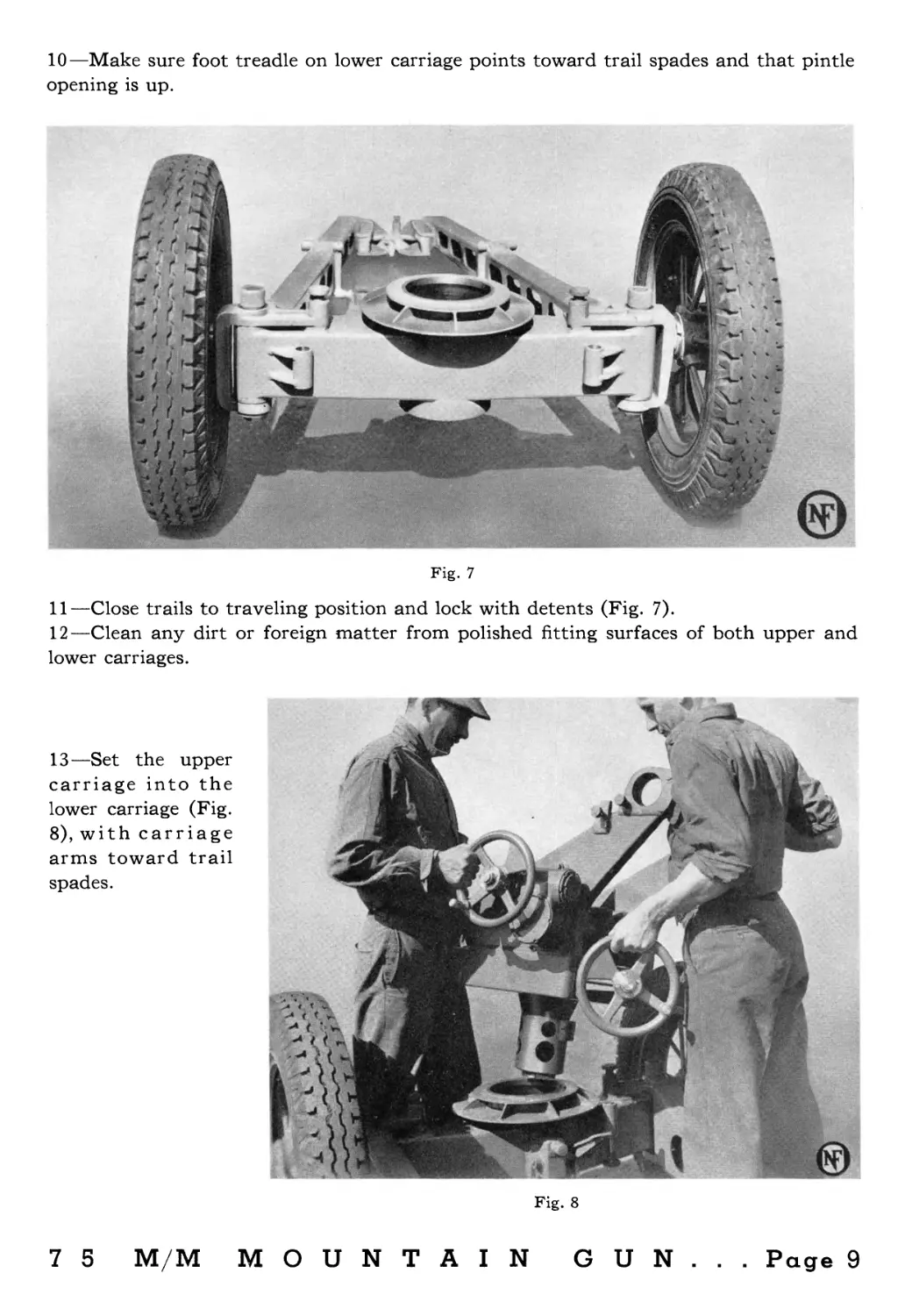
10—Make sure foot treadle on lower carriage points toward trail spades and that pintle
opening is up.
Fig. 7
11—Close trails to traveling position and lock with detents (Fig. 7).
12—Clean any dirt or foreign matter from polished fitting surfaces of both upper and
lower carriages.
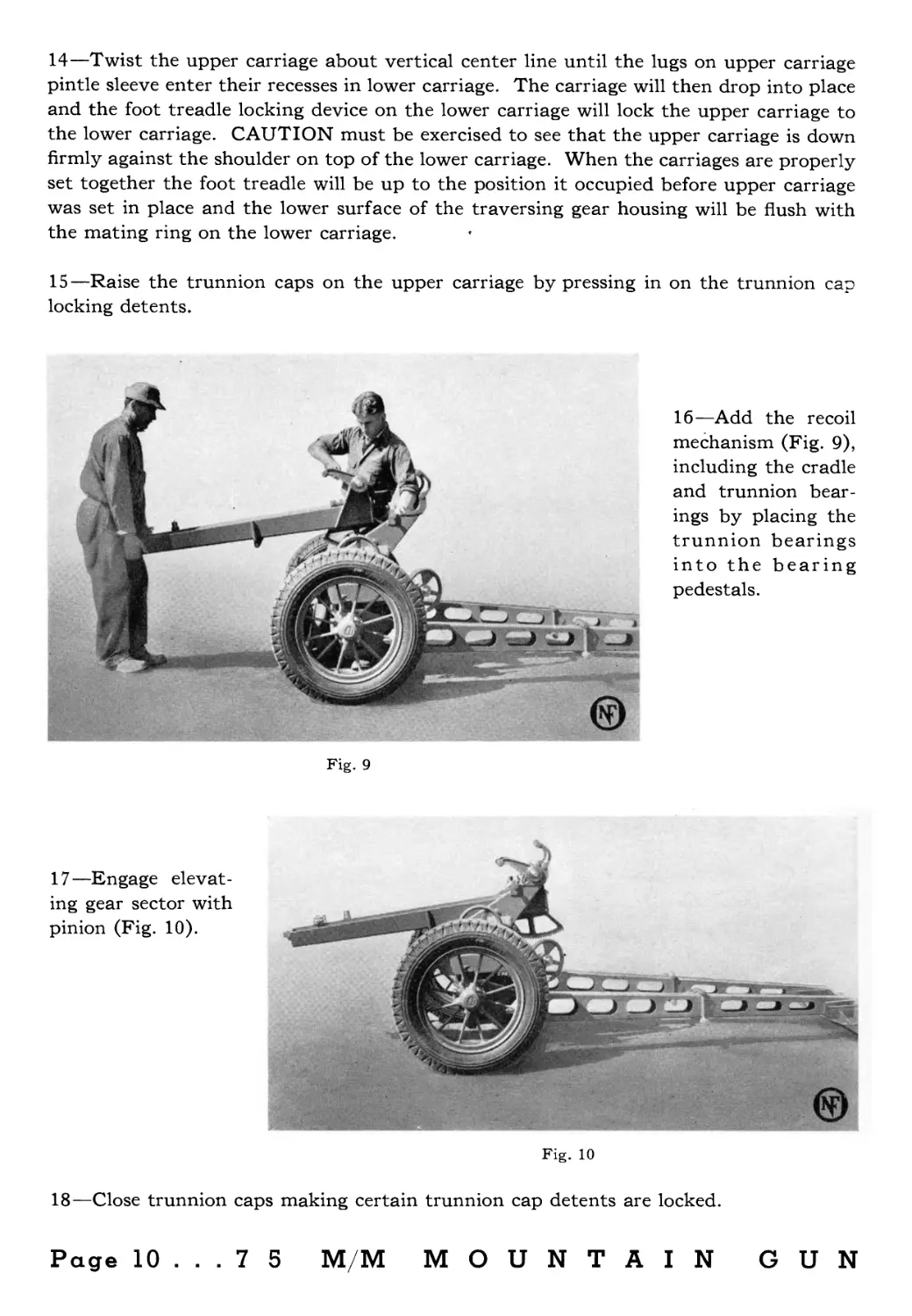
13—Set the upper
carriage into the
lower carriage (Fig.
8), with carriage
arms toward trail
spades.
Fig. 8
7 5 M/M MOUNTAIN GUN... Page 9
14—Twist the upper carriage about vertical center line until the lugs on upper carriage
pintle sleeve enter their recesses in lower carriage. The carriage will then drop into place
and the foot treadle locking device on the lower carriage will lock the upper carriage to
the lower carriage. CAUTION must be exercised to see that the upper carriage is down
firmly against the shoulder on top of the lower carriage. When the carriages are properly
set together the foot treadle will be up to the position it occupied before upper carriage
was set in place and the lower surface of the traversing gear housing will be flush with
the mating ring on the lower carriage.
15—Raise the trunnion caps on the upper carriage by pressing in on the trunnion cap
locking detents.
Fig. 9
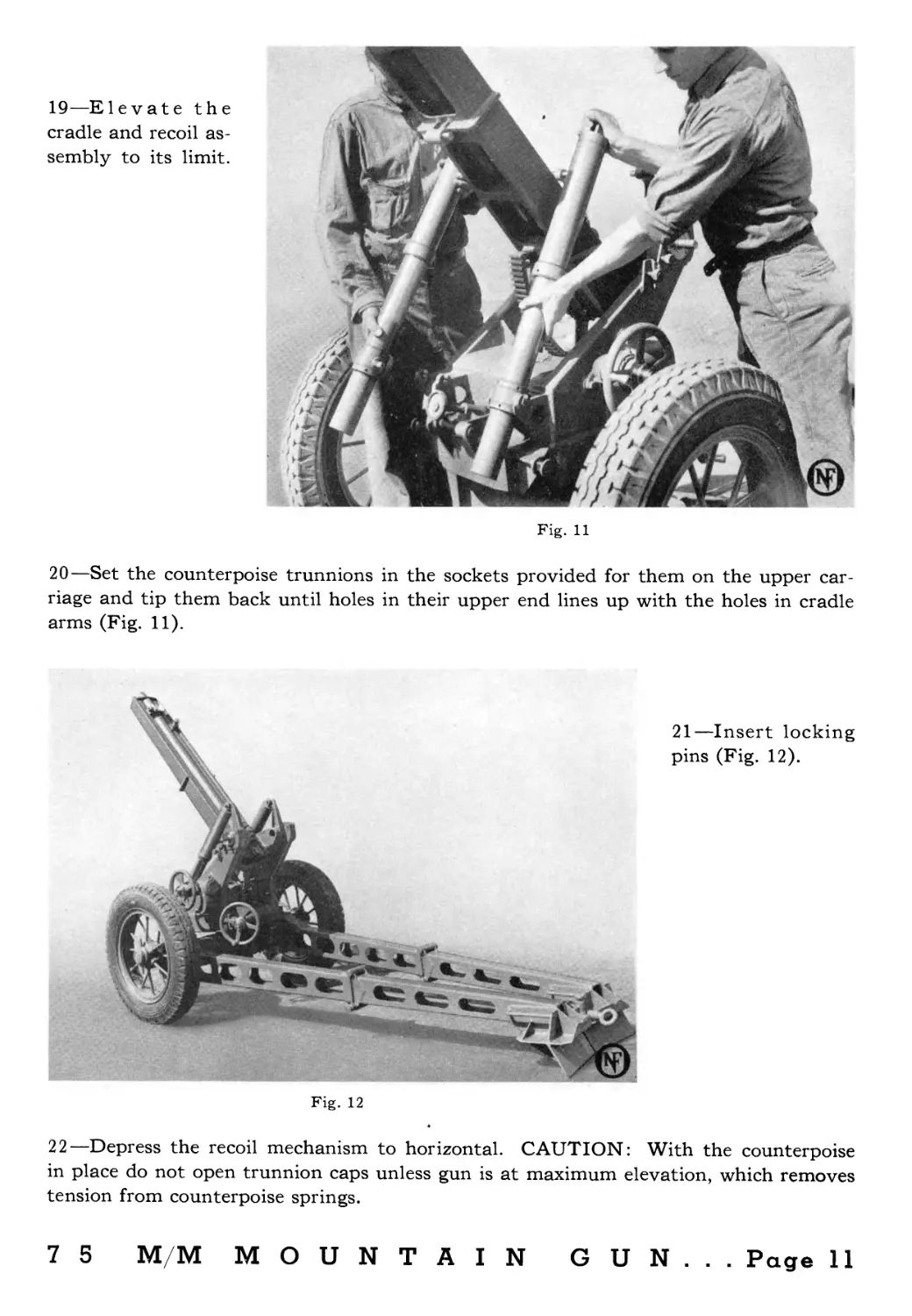
16—Add the recoil
mechanism (Fig. 9),
including the cradle
and trunnion bear-
ings by placing the
trunnion bearings
into the bearing
pedestals.
17—Engage elevat-
ing gear sector with
pinion (Fig. 10).
Fig. 10
18—Close trunnion caps making certain trunnion cap detents are locked.
Page 10 ... 7 5 M/M MOUNTAIN GUN
19—Elevate the
cradle and recoil as-
sembly to its limit.
Fig. 11
20—Set the counterpoise trunnions in the sockets provided for them on the upper car-
riage and tip them back until holes in their upper end lines up with the holes in cradle
arms (Fig. 11).
Fig. 12
21—Insert locking
pins (Fig. 12).
22—Depress the recoil mechanism to horizontal. CAUTION: With the counterpoise
in place do not open trunnion caps unless gun is at maximum elevation, which removes
tension from counterpoise springs.
7 5 M/M MOUNTAIN GUN... Page 11
Fig. 13
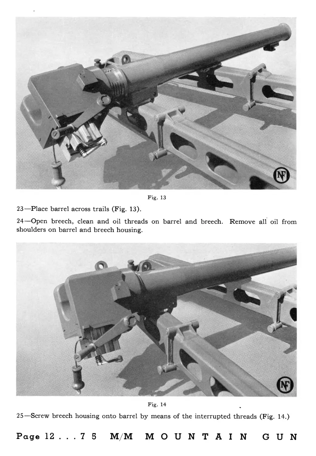
23—Place barrel across trails (Fig. 13).
24—Open breech, clean and oil threads on barrel and breech. Remove all oil from
shoulders on barrel and breech housing.
Fig. 14
25—Screw breech housing onto barrel by means of the interrupted threads (Fig. 14.)
Page 12 ... 7 5 M/M MOUNTAIN GUN
26—Hold barrel from turning and set breech housing securely on barrel by giving it a
quick turn. '
27—Place lifting bars through lifting eye on breech and through eye near muzzle.
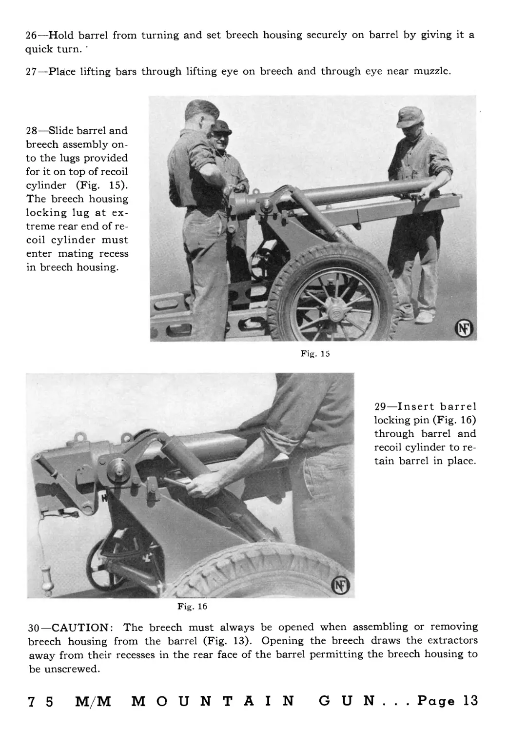
28—Slide barrel and
breech assembly on-
to the lugs provided
for it on top of recoil
cylinder (Fig. 15).
The breech housing
locking lug at ex-
treme rear end of re-
coil cylinder must
enter mating recess
in breech housing.
Fig. 15
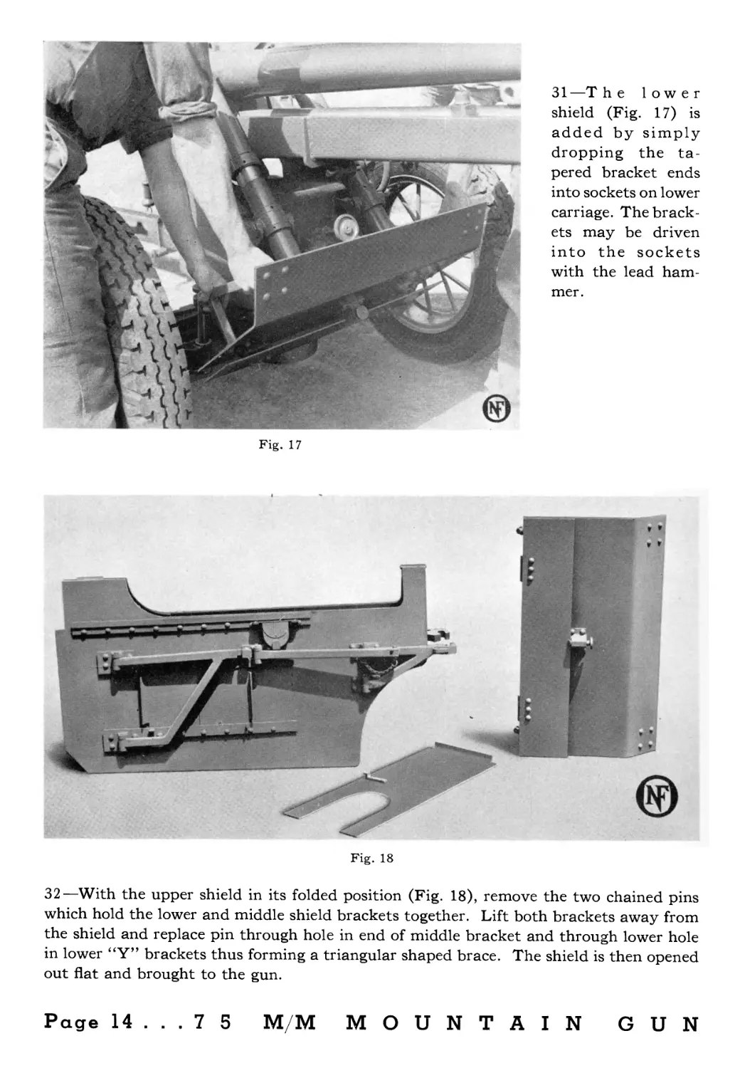
Fig. 16
29—Insert barrel
locking pin (Fig. 16)
through barrel and
recoil cylinder to re-
tain barrel in place.
30—CAUTION: The breech must always be opened when assembling or removing
breech housing from the barrel (Fig. 13). Opening the breech draws the extractors
away from their recesses in the rear face of the barrel permitting the breech housing to
be unscrewed.
7 5 M/M MOUNTAIN GUN... Page 13
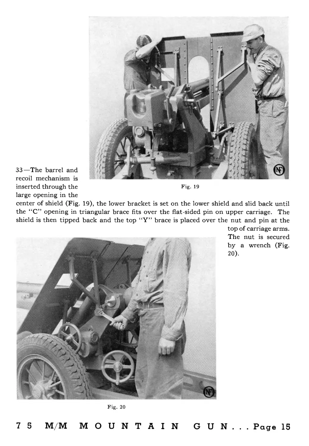
Fig. 17
31 —T he lower
shield (Fig. 17) is
added by simply
dropping the ta-
pered bracket ends
into sockets on lower
carriage. The brack-
ets may be driven
into the sockets
with the lead ham-
mer.
Fig. 18
32—With the upper shield in its folded position (Fig. 18), remove the two chained pins
which hold the lower and middle shield brackets together. Lift both brackets away from
the shield and replace pin through hole in end of middle bracket and through lower hole
in lower “Y” brackets thus forming a triangular shaped brace. The shield is then opened
out flat and brought to the gun.
Page 14 ... 7 5 M/M MOUNTAIN GUN
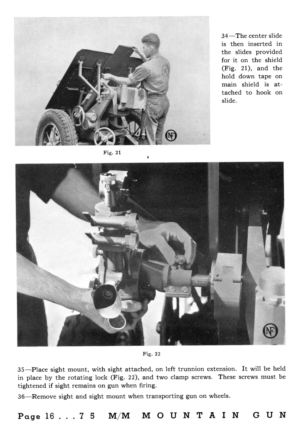
33—The barrel and
recoil mechanism is
inserted through the Fig. 19
large opening in the
center of shield (Fig. 19), the lower bracket is set on the lower shield and slid back until
the “C” opening in triangular brace fits over the flat-sided pin on upper carriage. The
shield is then tipped back and the top “Y” brace is placed over the nut and pin at the
Fig. 20
top of carriage arms.
The nut is secured
by a wrench (Fig.
20).
7 5 M/M MOUNTAIN GUN... Page 15
Fig. 21
34—The center slide
is then inserted in
the slides provided
for it on the shield
(Fig. 21), and the
hold down tape on
main shield is at-
tached to hook on
slide.
Fig. 22
35—Place sight mount, with sight attached, on left trunnion extension. It will be held
in place by the rotating lock (Fig. 22), and two clamp screws. These screws must be
tightened if sight remains on gun when firing.
36—Remove sight and sight mount when transporting gun on wheels.
Page 16 ... 7 5 M/M MOUNTAIN GUN
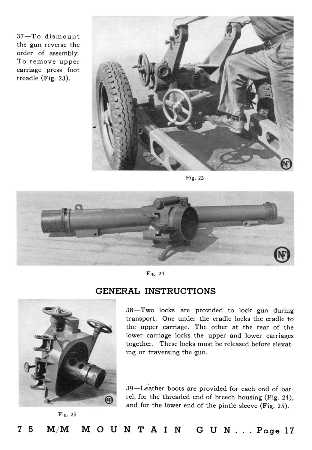
37—To dismount
the gun reverse the
order of assembly.
To remove upper
carriage press foot
treadle (Fig. 23).
Fig. 23
Fig. 24
GENERAL INSTRUCTIONS
Fig. 25
38—Two locks are provided to lock gun during
transport. One under the cradle locks the cradle to
the upper carriage. The other at the rear of the
lower carriage locks the upper and lower carriages
together. These locks must be released before elevat-
ing or traversing the gun.
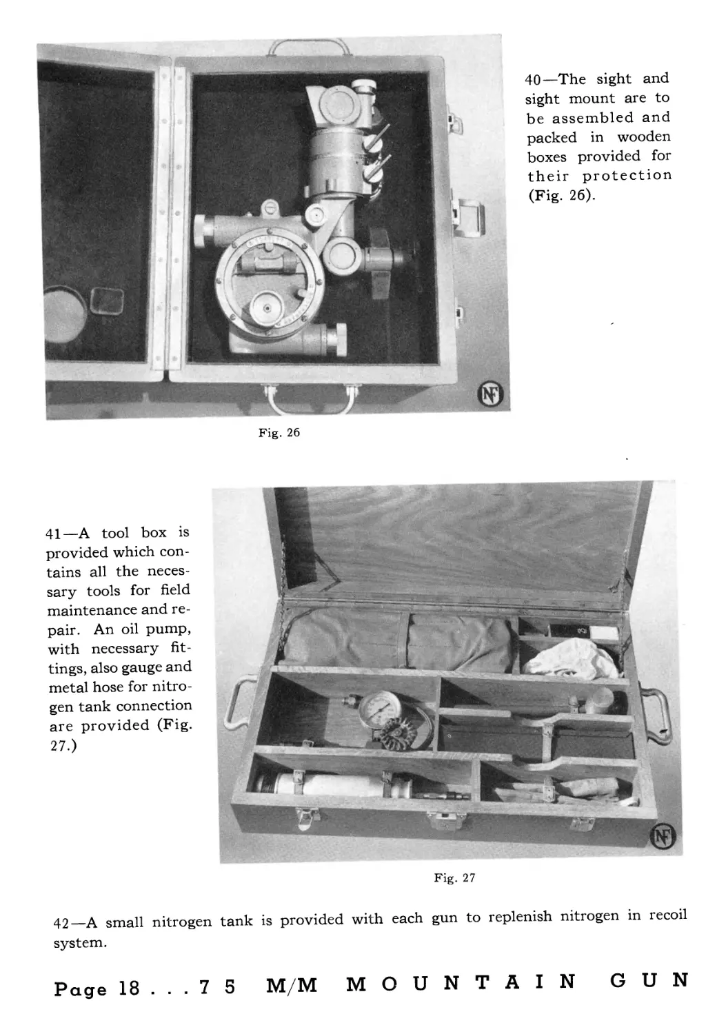
39—Leather boots are provided for each end of bar-
rel, for the threaded end of breech housing (Fig. 24),
and for the lower end of the pintle sleeve (Fig. 25).
7 5 M/M MOUNTAIN GUN... Page 17
Fig. 26
40—The sight and
sight mount are to
be assembled and
packed in wooden
boxes provided for
their protection
(Fig. 26).
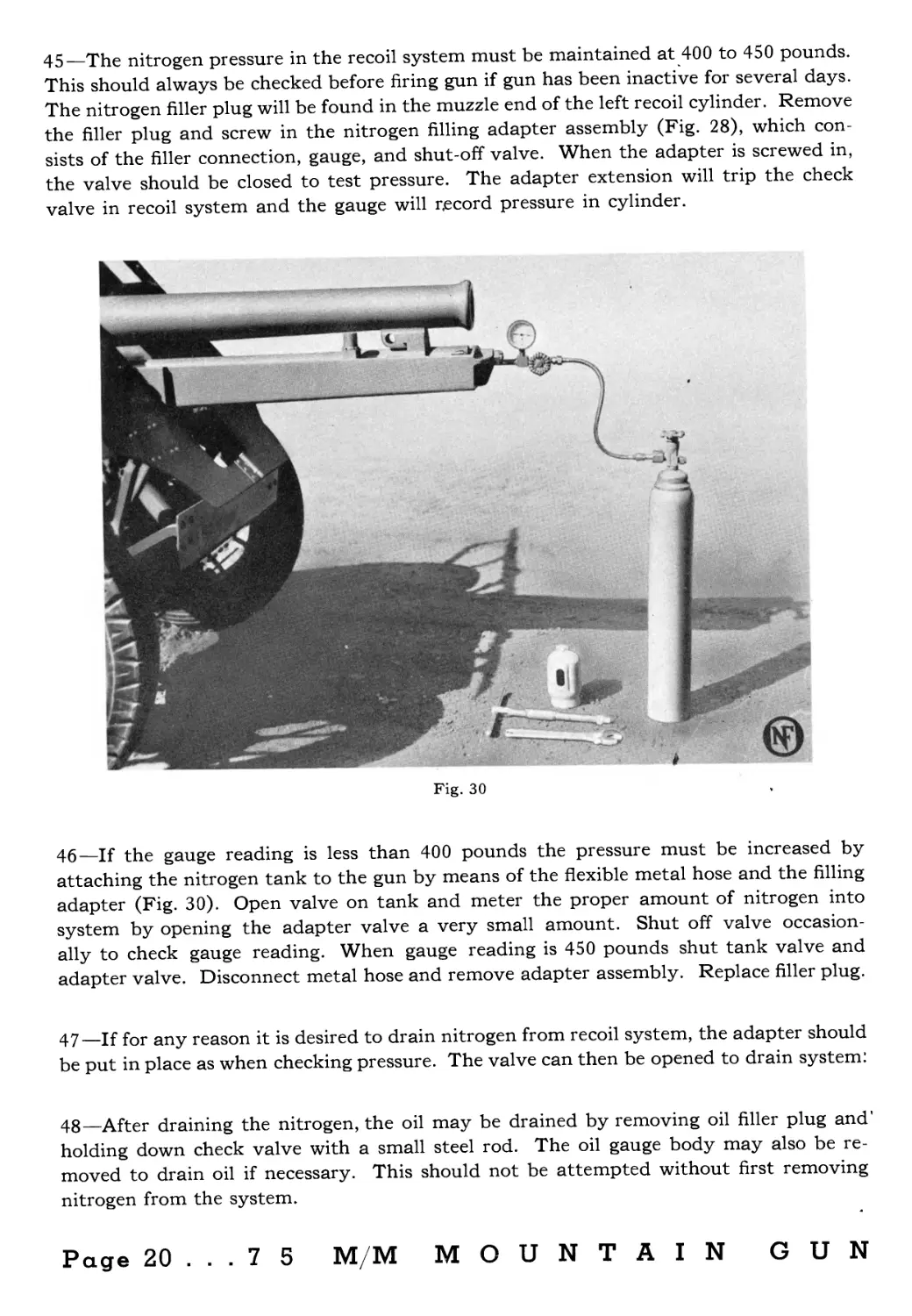
41—A tool box is
provided which con-
tains all the neces-
sary tools for field
maintenance and re-
pair. An oil pump,
with necessary fit-
tings, also gauge and
metal hose for nitro-
gen tank connection
are provided (Fig.
27.)
Fig. 27
42—A small nitrogen tank is provided with each gun to replenish nitrogen in recoil
system.
Page 18 ... 7 5 M/M MOUNTAIN GUN
45—The nitrogen pressure in the recoil system must be maintained at 400 to 450 pounds.
This should always be checked before firing gun if gun has been inactive for several days.
The nitrogen filler plug will be found in the muzzle end of the left recoil cylinder. Remove
the filler plug and screw in the nitrogen filling adapter assembly (Fig. 28), which con-
sists of the filler connection, gauge, and shut-off valve. When the adapter is screwed in,
the valve should be closed to test pressure. The adapter extension will trip the check
valve in recoil system and the gauge will record pressure in cylinder.
Fig. 30
46—If the gauge reading is less than 400 pounds the pressure must be increased by
attaching the nitrogen tank to the gun by means of the flexible metal hose and the filling
adapter (Fig. 30). Open valve on tank and meter the proper amount of nitrogen into
system by opening the adapter valve a very small amount. Shut off valve occasion-
ally to check gauge reading. When gauge reading is 450 pounds shut tank valve and
adapter valve. Disconnect metal hose and remove adapter assembly. Replace filler plug.
47—If for any reason it is desired to drain nitrogen from recoil system, the adapter should
be put in place as when checking pressure. The valve can then be opened to drain system!
48—After draining the nitrogen, the oil may be drained by removing oil filler plug and
holding down check valve with a small steel rod. The oil gauge body may also be re-
moved to drain oil if necessary. This should not be attempted without first removing
nitrogen from the system.
Page 20 ... 7 5 M/M MOUNTAIN GUN
111111111111111111111111111111111111111111111111111111111111111111111111111111111111111111111111111111111111111111111111111111111Ш
METHOD OF PACKING
75 M/M MOUNTAIN GUN
ON
PACK ANIMALS
1Ш1Н111111111Н1111111111111111111111Н1Н111111Н11111НШ11111111НЖ111111Н11Н111111111111111111Н111111Н11Н1Н11ШН111Ш11Н1Н11111Н11Н11Н1Ш1Н11НН11Н11Н1Н11Н1111111111ШШ1111111Н1Н111111Н11Ш1111111111111!11!Н111111111111!1111
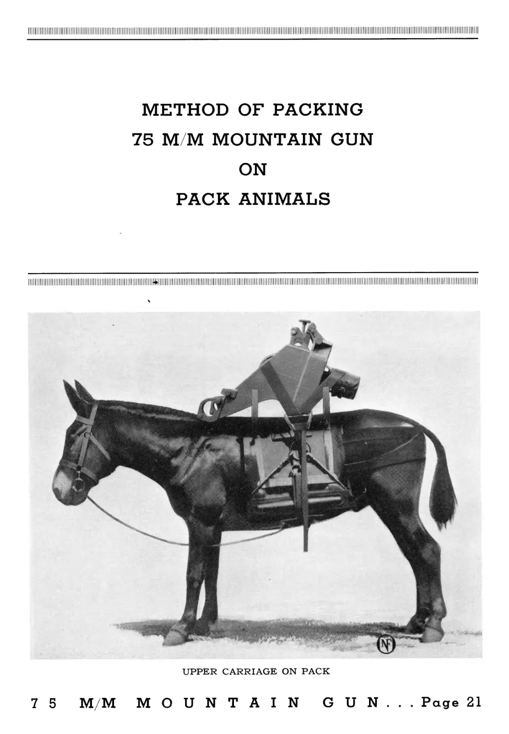
UPPER CARRIAGE ON PACK
7 5 M/M MOUNTAIN GUN... Page 21
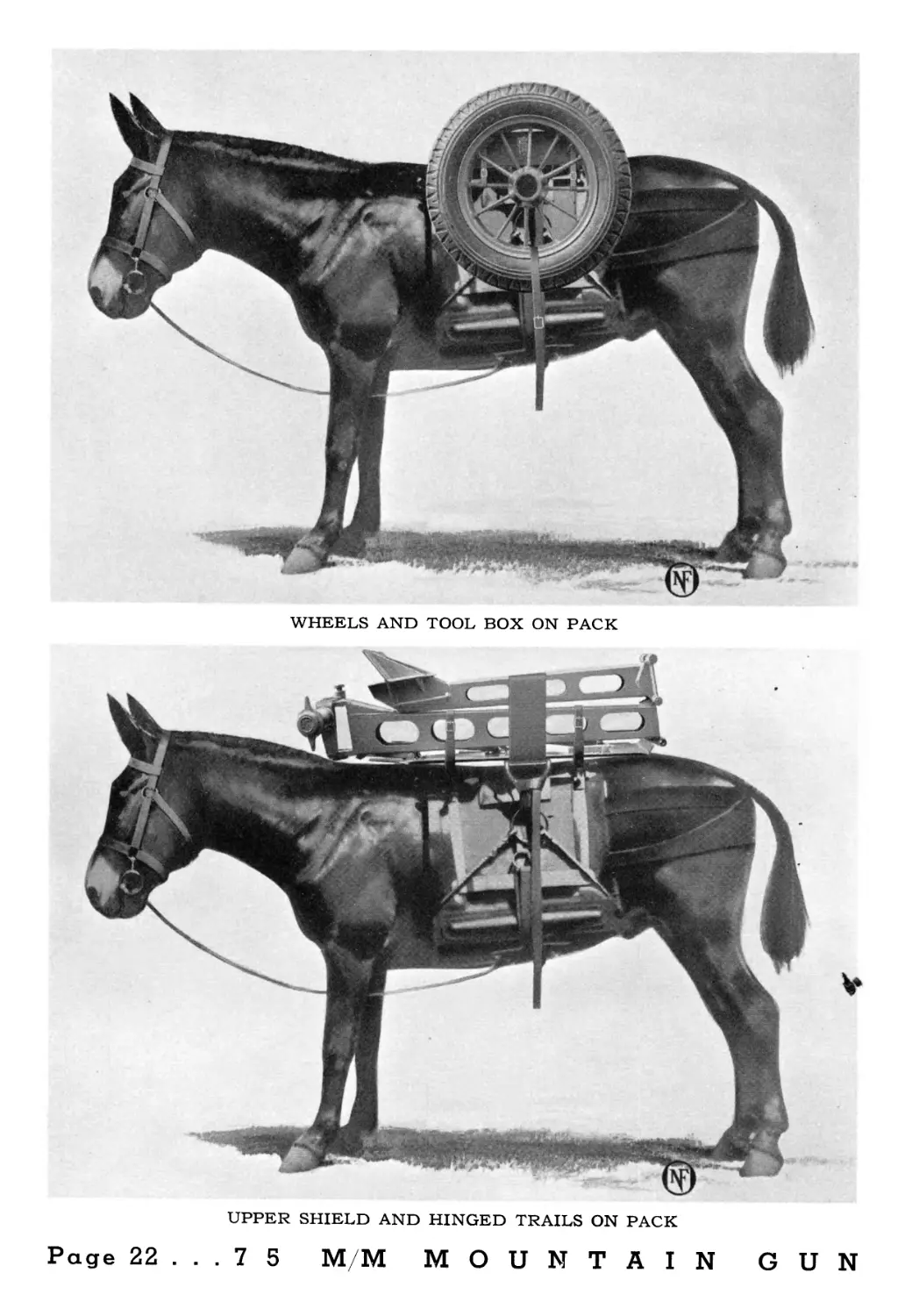
WHEELS AND TOOL BOX ON PACK
UPPER SHIELD AND HINGED TRAILS ON PACK
Page 22 ... 7 5 M/M MOUNTAIN GUN
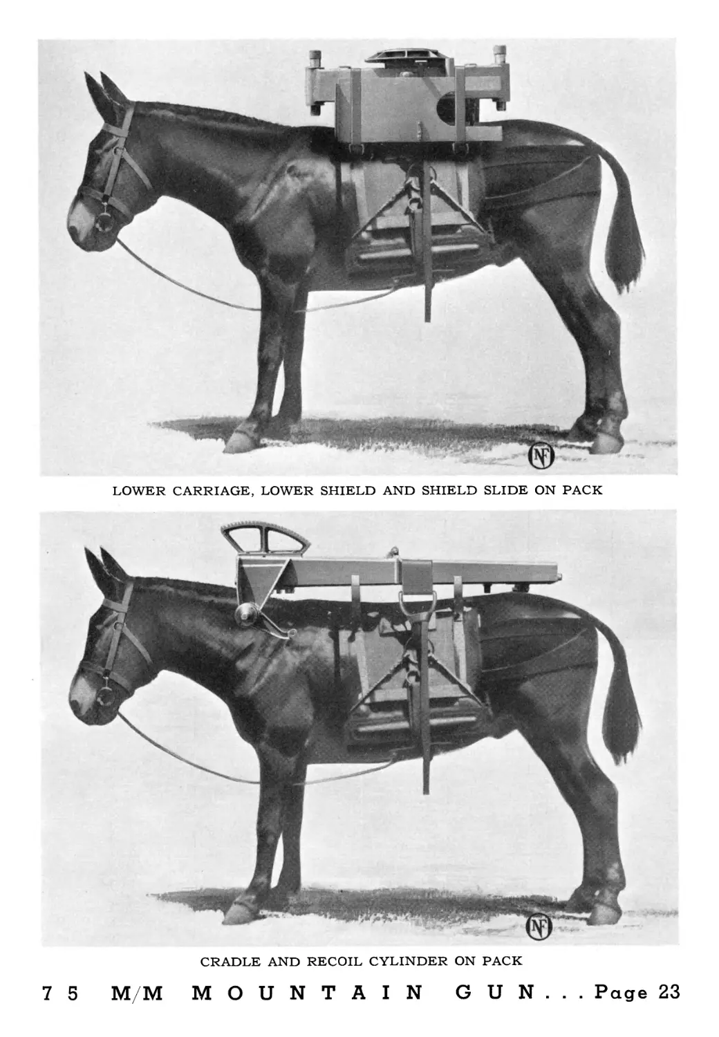
LOWER CARRIAGE, LOWER SHIELD AND SHIELD SLIDE ON PACK
CRADLE AND RECOIL CYLINDER ON PACK
7 5 M/M MOUNTAIN GUN... Page 23
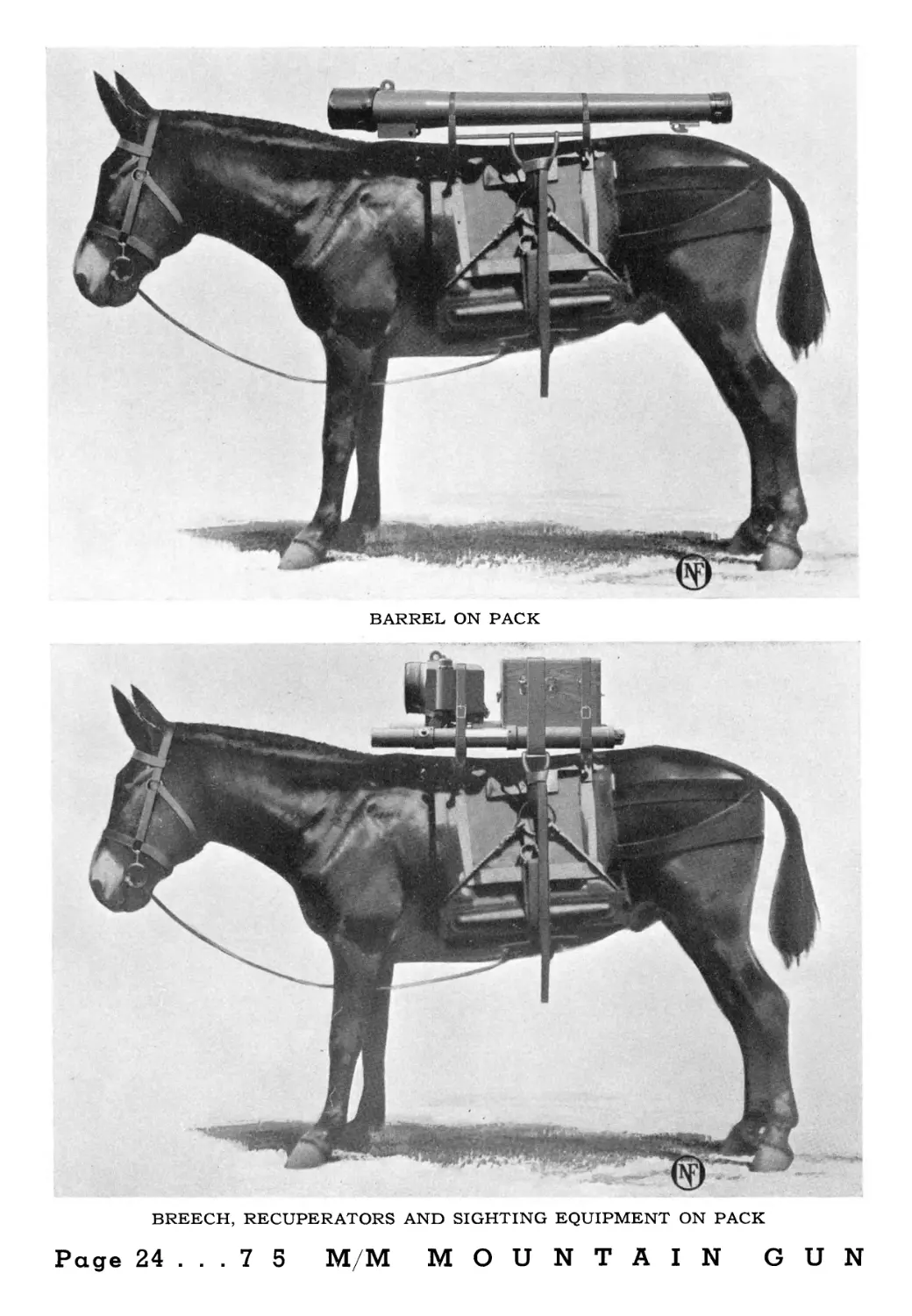
BARREL ON PACK
BREECH, RECUPERATORS AND SIGHTING EQUIPMENT ON PACK
Page 24 ... 7 5 M/M MOUNTAIN GUN
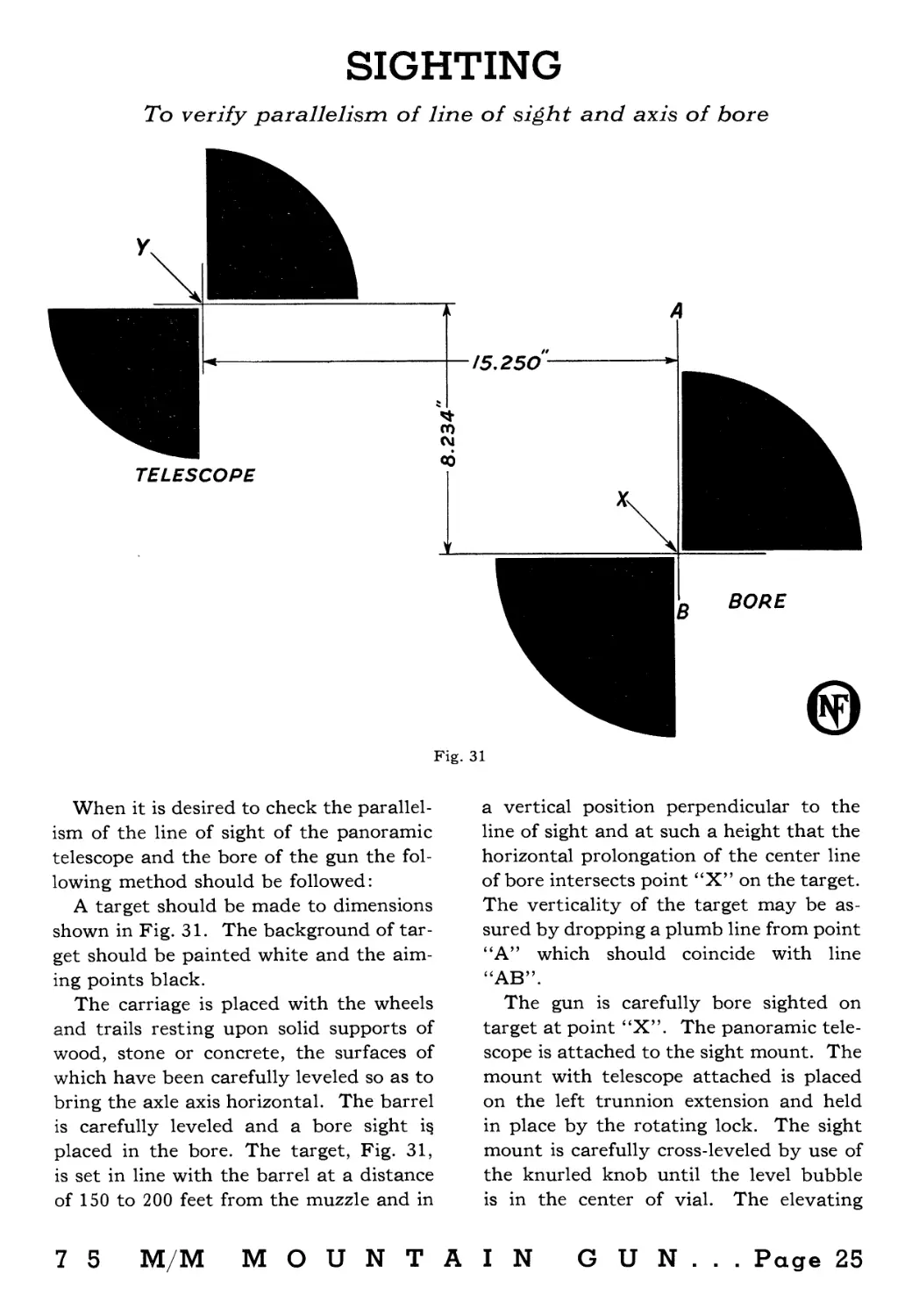
SIGHTING
To verify parallelism of line of sight and axis of bore
Fig. 31
When it is desired to check the parallel-
ism of the line of sight of the panoramic
telescope and the bore of the gun the fol-
lowing method should be followed:
A target should be made to dimensions
shown in Fig. 31. The background of tar-
get should be painted white and the aim-
ing points black.
The carriage is placed with the wheels
and trails resting upon solid supports of
wood, stone or concrete, the surfaces of
which have been carefully leveled so as to
bring the axle axis horizontal. The barrel
is carefully leveled and a bore sight i§
placed in the bore. The target, Fig. 31,
is set in line with the barrel at a distance
of 150 to 200 feet from the muzzle and in
7 5 M/M M О U N T A
a vertical position perpendicular to the
line of sight and at such a height that the
horizontal prolongation of the center line
of bore intersects point “X” on the target.
The verticality of the target may be as-
sured by dropping a plumb line from point
“A” which should coincide with line
“AB”.
The gun is carefully bore sighted on
target at point “X”. The panoramic tele-
scope is attached to the sight mount. The
mount with telescope attached is placed
on the left trunnion extension and held
in place by the rotating lock. The sight
mount is carefully cross-leveled by use of
the knurled knob until the level bubble
is in the center of vial. The elevating
IN GUN... Page 25
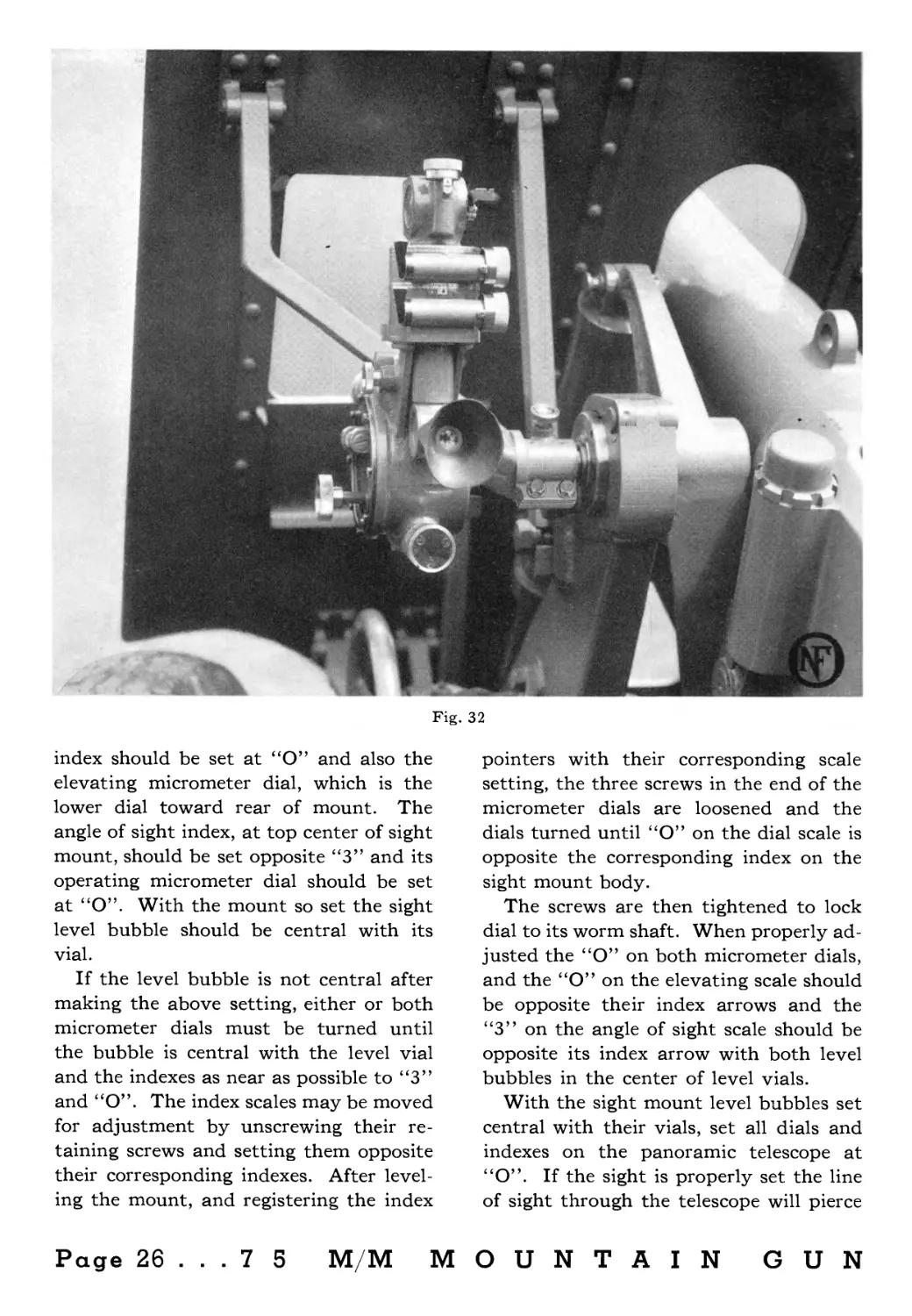
Fig. 32
index should be set at “O” and also the
elevating micrometer dial, which is the
lower dial toward rear of mount. The
angle of sight index, at top center of sight
mount, should be set opposite “3” and its
operating micrometer dial should be set
at “O”. With the mount so set the sight
level bubble should be central with its
vial.
If the level bubble is not central after
making the above setting, either or both
micrometer dials must be turned until
the bubble is central with the level vial
and the indexes as near as possible to “3”
and “O”. The index scales may be moved
for adjustment by unscrewing their re-
taining screws and setting them opposite
their corresponding indexes. After level-
ing the mount, and registering the index
pointers with their corresponding scale
setting, the three screws in the end of the
micrometer dials are loosened and the
dials turned until “O” on the dial scale is
opposite the corresponding index on the
sight mount body.
The screws are then tightened to lock
dial to its worm shaft. When properly ad-
justed the “O” on both micrometer dials,
and the “O” on the elevating scale should
be opposite their index arrows and the
“3” on the angle of sight scale should be
opposite its index arrow with both level
bubbles in the center of level vials.
With the sight mount level bubbles set
central with their vials, set all dials and
indexes on the panoramic telescope at
“O”. If the sight is properly set the line
of sight through the telescope will pierce
Page 26 ... 7 5 M/M MOUNTAIN GUN
the target at the point “Y”. If the line
of sight through the telescope does not
terminate at point “Y” the telescope must
be adjusted.
If the line of sight is at the correct
height but off to either side of the vertical
line through “Y”, the correction should
be made in the telescope. Set the cross
hairs of the telescope on the target by
rotating the lower micrometer dial. Loosen
the three screws in the dial retaining disc
and set dial “O” to coincide with its indi-
cator on the sight body. If necessary the
index plate, below the lower circular in-
dex, may also be adjusted by loosening
the two index retaining screws. It should
be noted that the upper horizontal mi-
crometer dial should also be set at “O”
and the index opposite “O” on the upper
circular scale when making adjustments.
If the line of sight of the telescope is
correct horizontally, but the cross hairs
are above or below the aiming point “Y”,
the telescope should be so adjusted by
use of the rotating head micrometer dial,
which is the vertical dial at top of tele-
scope, until the line of sight through tele-
scope pierces point “Y”. The three screws
on top of the micrometer dial may be
loosened and the dial set with its “O”
opposite its mating indicator. Tighten
screws and check line of sight to verify
setting. The scale on the peep sight arm
shows elevation in hundreds of mils. The
“O” on this scale and the “O” on the dial
should be set opposite, their mating in-
dexes with the line of sight through tele-
scope piercing point “Y” on target.
Fig. 33
7 5 M/M MOUNTAIN GUN... Page 27
р
<р
ф
со
00
СП
S
S
S
о
а
а
н
>
2
Q
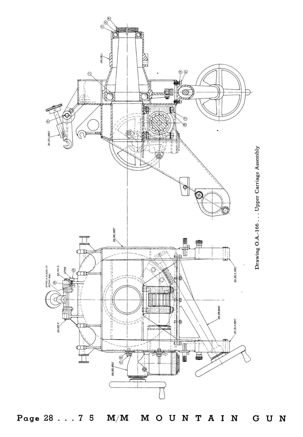
Drawing О.А.-166 . . . Upper Carriage Assembly
С
2
FIRING MECHANISM
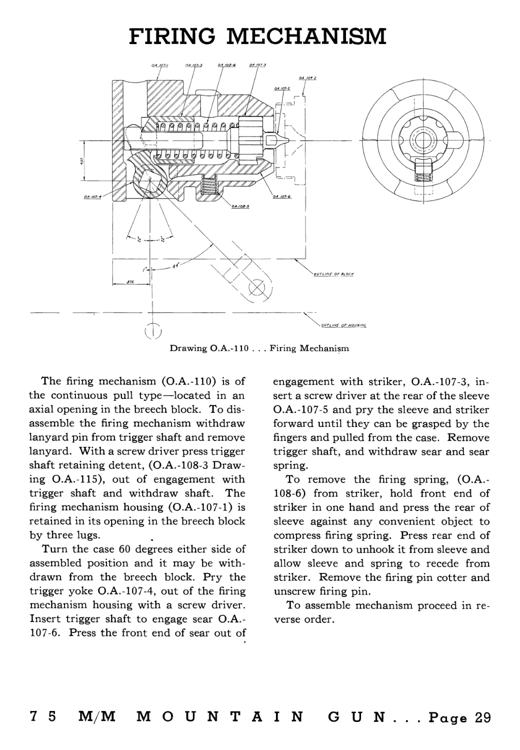
Drawing O.A.-llO . . . Firing Mechanism
The firing mechanism (O.A.-llO) is of
the continuous pull type—located in an
axial opening in the breech block. To dis-
assemble the firing mechanism withdraw
lanyard pin from trigger shaft and remove
lanyard. With a screw driver press trigger
shaft retaining detent, (O.A.-108-3 Draw-
ing O.A.-115), out of engagement with
trigger shaft and withdraw shaft. The
firing mechanism housing (O.A.-107-1) is
retained in its opening in the breech block
by three lugs.
Turn the case 60 degrees either side of
assembled position and it may be with-
drawn from the breech block. Pry the
trigger yoke O.A.-107-4, out of the firing
mechanism housing with a screw driver.
Insert trigger shaft to engage sear O.A.-
107-6. Press the front end of sear out of
engagement with striker, O.A.-107-3, in-
sert a screw driver at the rear of the sleeve
O.A.-107-5 and pry the sleeve and striker
forward until they can be grasped by the
fingers and pulled from the case. Remove
trigger shaft, and withdraw sear and sear
spring.
To remove the firing spring, (O.A.-
108-6) from striker, hold front end of
striker in one hand and press the rear of
sleeve against any convenient object to
compress firing spring. Press rear end of
striker down to unhook it from sleeve and
allow sleeve and spring to recede from
striker. Remove the firing pin cotter and
unscrew firing pin.
To assemble mechanism proceed in re-
verse order.
7 5 M/M MOUNTAIN GUN... Page 29
Page 30 ... 7 5 M/M MOUNTAIN
a
a
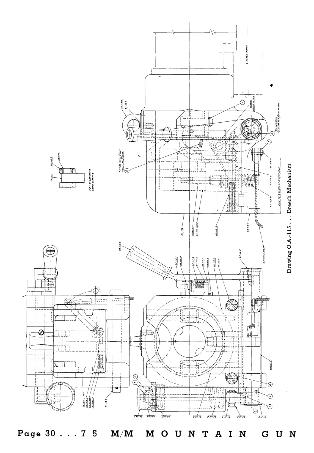
Drawing O.A.-115 . . . Breech Mechanism
5!
BREECH MECHANISM
The breech mechanism, (O.A.-115), is
of the vertical sliding wedge type, semi-
automatic.
To open the breech pull the operating
handle, (O.A.-112-1), on right side of
breech housing to the rear until the ex-
tractors, (O.A.-113-4 and 5) lock the
breech block open (down), the handle
should then be returned to its original
position and locked by the handle latch,
(O.A.-114-5). When a round of ammuni-
tion is inserted the cartridge case head
trips the extractors, allowing the breech
block to return to its closed position under
action of breech closing spring, (O.A.-
114-6).
To remove breech block from the breech
housing remove the breech closing spring
cap O.A.-114-7 and unscrew spring ad-
justing nut to relieve spring tension. With-
draw operating crank pin O.A.-111-2 and
closing spring with attached parts. Re-
move lanyard pin O.A.-108-1 and with-
draw lanyard. Pull cotter pin from end
of locking plate key O.A.-112-5 and drive
out key, slide locking plate O.A.-112-4 to
the rear and remove it from bottom of
breech housing (O.A.-105). Rotate handle
to rear to unlock it from its latch. Move
operating crank O.A.-lll-l to rear to re-
move it from its bearings. A slight rota-
tion of handle and movement to the rear
of the crank will allow the rollers on inner
crank arm to be removed from the “T”
slot in bottom of the breech block. Re-
move the crank, and the block may then
be pushed out of the breech housing from
the top. The extractors can then be
removed from their slots.
The firing mechanism may be with-
drawn either before or after removing the
block from breech housing. Method of
removing firing mechanism from block is
described under “Firing Mechanism”.
The operating handle latch may be dis-
mounted from the side of breech housing
by removing the cotter pin at the lower
end of key O.A.-114-2 and driving out the
key. Drive the latch assembly to the rear
to release it from its dovetail. The plunger
O.A.-114-5 and spring O.A.-114-3 are
retained by the headed pin O.A.-114-4
which fits into the flat recess on the side
of the plunger. Press the top of plunger
against any convenient object to compress
the spring and with a small screw driver
or pin against the outer end of the retain-
ing pin, it may be pushed out of the hous-
ing. The spring and plunger may then
be removed, by gradually releasing the
pressure on the spring. They can then be
removed from the housing.
To assemble proceed in reverse order.
7 5 M/M MOUNTAIN GUN... Page 31
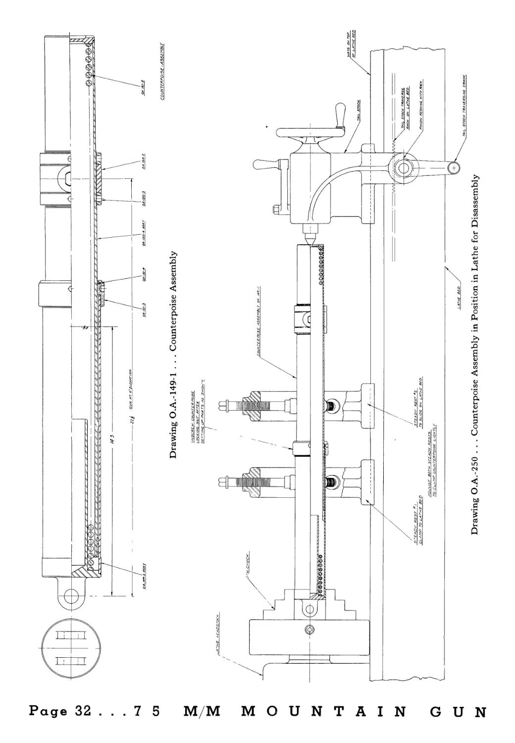
COUNTERPOISE -ASSEMBLY
Drawing O.A.-149-1 . . . Counterpoise Assembly
Drawing O.A.-250 . . . Counterpoise Assembly in Position in Lathe for Disassembly
2
COUNTERPOISE
To disassemble counterpoise assembly
(O.A.-149-1), place it in a lathe between
jaw chuck and tail stock centers and
guided by the two steady rests as shown
on O.A.-250.
Steady rest No. 1 is lightly clamped to
the outer sleeve of counterpoise and se-
curely clamped to lathe bed. The steady
rest No. 2 is lightly clamped to inner sleeve
of counterpoise and secured to the lathe
bed loosely enough to slide freely on the
bed as is the tail stock.
The counterpoise spring with the count-
erpoise extended as shown is under a pres-
sure of about 350 lbs. and therefore to
prevent injury to the personnel, caution
must be exercised when assembling and
disassembling this unit. Unscrew the
counterpoise locking nut and allow inner
sleeve, steady rest No. 2 and the tail stock
to slide to the right, using the tail stock
traversing crank to control the operation.
As the inner sleeve is withdrawn from the
outer sleeve, the spring will become ex-
posed and should be held from deflecting
to either side by hand. At the point
where the spring may tend to deflect its
load has, of course, been greatly reduced.
To assemble the counterpoise proceed
in reverse order.
7 5 M/M MOUNTAIN GUN... Page 33
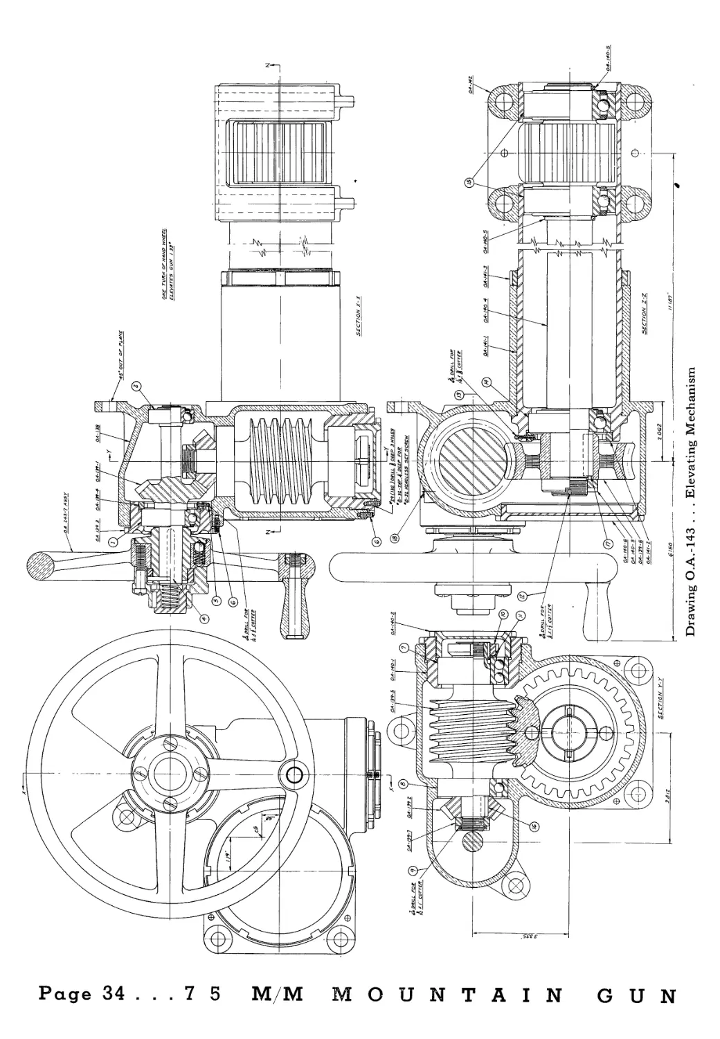
Drawing O.A.-143 . . . Elevating Mechanism
Page 34 ... 7 5 MM MOUNTAIN GUN
ELEVATING MECHANISM
The elevating mechanism is located on
the left side of gun, secured to upper car-
riage by four cap screws. The eccentric
housing which supports the elevating
pinion is clamped at its inner end by four
cap screws. By removing these eight cap
screws the assembly may be removed
from the carriage.
The assembly is shown on O.A.-143 and
consists of a hand wheel, with overrunning
clutch, a pair of bevel reduction gears, a
self-locking worm and worm gear and
elevating pinion, housed in an aluminum
case and equipped with ball bearings. The
hand wheel may be locked to the shaft by
pressing in on the locking jaw at the hub
center.
To adjust the bevel gears, remove the
oil filler plug at top of housing. Unscrew
the locking screws which lock sleeve
O.A.-140-1 and retainer O.A.-139-3 in
place. If only a slight adjustment is nec-
essary it may be made by retainer O.A.-
139-3. If the back edges of the teeth are
not flush as observed by looking through
the oil filler hole, then the sleeve O.A.-
140-1 must be turned until they are, and
at the same time maintaining the proper
backlash, which should be just enough to
allow bevel gears to turn freely without
any perceptible looseness.
The worm wheel may be adjusted to
the worm by rotating the eccentric sleeve
O.A.-141-1 and locking it in place with
lock nut O.A.-141-3.
If it is desired to remove the parts from
the housing, the following method should
be employed. Unscrew sleeve O.A.-140-1
from the casing which will draw the worm
(O.A.-139-5), bearings and bevel pinion
(O.A.-139-2) to the rear far enough to be
lifted out of housing by hand. The hand
wheel with its shaft, bevel gear O.A.-
139-1, and bearings may be removed as
a unit by removing the locking screw and
unscrewing retainer (O.A.-139-3) which
will draw the assembly out of the housing.
The worm wheel, eccentric sleeve, ele-
vating shaft, with pinion, and bearings
may be removed as a unit from the hous-
ing, by removing cover, O.A.-140-6 and
unscrewing the sleeve locking nut, O.A.-
141-3 and loosening the two lower clamp
screws in the eccentric sleeve clamp, O.A.-
142. When removing the cover, O.A.-
140-6, a pail should be at hand to catch
the oil contained in the housing. These
parts run in a bath of oil and when as-
sembling, the oil should be replaced. The
worm wheel may be pulled from the shaft
after removing nut, O.A.-140-3. The bear-
ing adjacent to the worm wheel is retained
by ring, O.A.-141-2. The shaft and pinion
with the two pinion bearings may be
shoved out of the eccentric sleeve from
the worm gear end.
To assemble the mechanism reverse the
procedure outlined above; adjust the worm
wheel to the worm and adjust the bevel
gears as previously described. Lock the
parts in place and fill housing with light
gear oil to the height of the bottom of the
hand wheel shaft. This lubricates all gears
and bearings in the case. The two large
bearings on either side of elevating pinion
are packed with lubricant and require no
oiling.
One turn of hand wheel elevates gun
1.33 degrees.
7 5 M/M MOUNTAIN GUN... Page 35
на
р
ip
ф
GO
03
К1
03
S
S
о
с
з
-з
>
1-4
3
Q
С
3
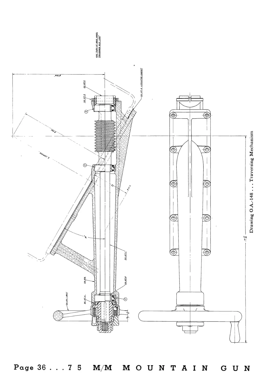
Drawing О.А.-148 . . . Traversing Mechanism
TRAVERSING MECHANISM
The traversing mechanism, (O.A.-148),
is secured to the rear face of the upper
carriage gear housing by ten cap screws
and two dowel pins. It consists of a worm
mounted on self-lubricated ball bearings,
inclosed in an aluminum housing. A hand
wheel at the outer end is provided with
an overrunning clutch and a locking mech-
anism to lock the hand wheel to the shaft
if so desired. The worm meshes with a
sector on the pintle sleeve which in turn
is keyed to the lower carriage. One turn
of the hand wheel traverses gun 1% de-
grees. Any axial looseness that may de-
velop may be taken up by means of the
adjusting sleeve, O.A.-147-2 and the lock-
ing nut O.A.-147-3.
To disassemble, remove the assembly
from the upper carriage. Remove the
four screws in hand wheel hub and the
hub cap, jaw and spring. Drive out the
tapered pin and remove hand wheel as-
sembled to its hub. Unscrew adjusting
sleeve, O.A.-147-2 and lock nut O.A.-
147-3. The shaft with the two bearings
at the worm may be driven out of the
housing from the hand wheel end. The
bearing at the hand wheel end of housing
may be removed by unscrewing the ring
O.A.-147-4 and pushing the bearing out
from the opposite end of the housing.
To assemble proceed in reverse order.
To adjust the worm to the worm wheel
a laminated gasket is provided between
the gear case and the traversing gear hous-
ing. As wear occurs any backlash between
the worm and worm wheel may be re-
moved by peeling off a lamination from
the gasket, and replacing the traversing
gear. If backlash still occurs after tight-
ening cap screws an additional lamination
may have to be removed.
7 5 M/M MOUNTAIN GUN... Page 37
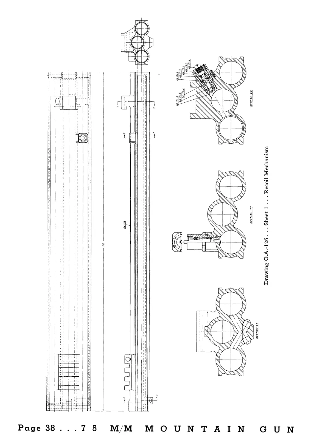
RECOIL MECHANISM
DESCRIPTION AND ADJUSTMENT
The recoil mechanism, O.A.-126 is of
the hydro-pneumatic type consisting of
three cylinders bored in a single forging.
The center cylinder contains the recoil
piston, piston rod and packing glands.
An adjustable respirator valve, (O.A.-
120-4), is located in the center cylinder
at the breech end.
The right hand cylinder contains the
floating piston, oil gauge, (O.A.-122-5),
and recoil regulator, (O.A.-123-4).
The left cylinder is an air reservoir and
is connected by a by-pass to the rear end
of the floating piston cylinder. The for-
ward end of the left cylinder contains the
nitrogen filling valve, (O.A.-121-5).
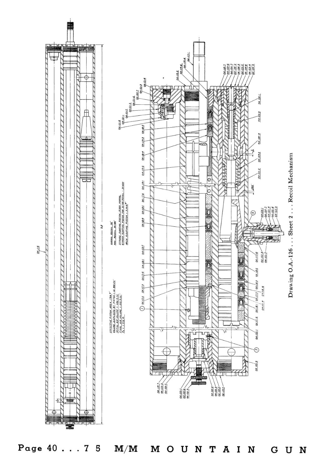
In recoil the recoil cylinders (O.A.-116)
slide to the rear with the barrel, being
guided in grooves in the cradle. The piston
and rod are fastened to the front of the
cradle and do not move. As the gun re-
coils the oil at the front end of the main
piston is forced through the passage lead-
ing into the regulator, opening the recoil
valve O.A.-124-4 against spring O.A.-123-2
until end of valve strikes lip on end of
control mechanism housing (O.A.-123-4).
The oil forces the floating piston along its
cylinder, against nitrogen pressure of 450
pounds per square inch. The recoiling
parts are thus brought to rest by the
throttling of the oil through the recoil
valve, the resistance offered to the float-
ing piston by the nitrogen and friction of
the parts.
The gun is returned to battery by the
aid of the compressed nitrogen behind the
floating piston, which pushes the piston ,
back and forces the oil into the regulator
and as the balanced recoil valve is closed
due to action of its spring, the oil pushes
the counter recoil valve O.A.-124-1 open
until the end of its stem strikes bottom in
7 5 M/M M О U N T A
the stop O.A.-124-2. The oil then flows
through the communicating passage into
the recoil cylinder forcing the recoil piston
back to the rear of its cylinder, and at the
same time compressing the air, which dur-
ing recoil was drawn in through the res-
pirator valve O.A.-120-4. The compres-
sion of this air cushions the return of the
parts. Varying the amount of leakage
past the valve by means of adjusting
screw O.A.-120-5 alters the cushioning
effect.
The length of recoil may be increased
by increasing the length of stroke of recoil
valve. To increase stroke, loosen follower
O.A.-123-6 and unscrew regulator sleeve,
O.A.-123-5 a fraction of a turn. One com-
plete turn will open valve .083". The
normal stroke of this valve is .065. If this
setting does not give 32" of recoil the
opening must be increased by unscrewing
the sleeve (O.A.-123-5) about И of a turn
and again checking length of recoil. The
maximum length of recoil is 33.78" which
is controlled by the sleeve O.A.-119-2 and
spring O.A.-119-1. The sleeve slides over
the communicating passage between recoil
cylinder and regulator, cutting off the flow
of oil. Any additional load is absorbed
by the buffer spring O.A.-119-1.
The counter recoil valve stroke may be
adjusted by loosening the follower (O.A.-
124-3) and screwing the stop (O.A.-124-2)
in by means of a screw driver, to shorten
valve stroke. To lengthen valve stroke
unscrew the stop. Hold stop in place and
tighten follower with socket wrench. One
turn of stop alters valve stroke .055".
The normal valve stroke is .220 inch.
The tool box contains a set of socket
wrenches with which to make these ad-
justments.
The recoil system holds 85 cubic inches
IN GUN... Page 39
Drawing О.А.-126 . . . Sheet 2 . . . Recoil Mechanism
Й!
of oil (about 1И quarts). However, 1%
quarts is the maximum amount to be used
when refilling.
The cylindrical projection of the front
end of floating piston nut, O.A.-122-2 acts
as a valve to retard the movement of gun
into battery when oil level in system is
low, thus giving warning to the gunners
in case the oil gauge position has not been
noticed.
minor adjustments should be attempted
in the field. If for any reason the system
does not function properly it should be
disassembled in the ordnance repair shop.
To remove the main piston rod and
piston assembly from the center cylinder,
the respirator O.A.-120-1 should be re-
moved from the breach end of cylinder,
also the copper gasket O.A.-120-7. The
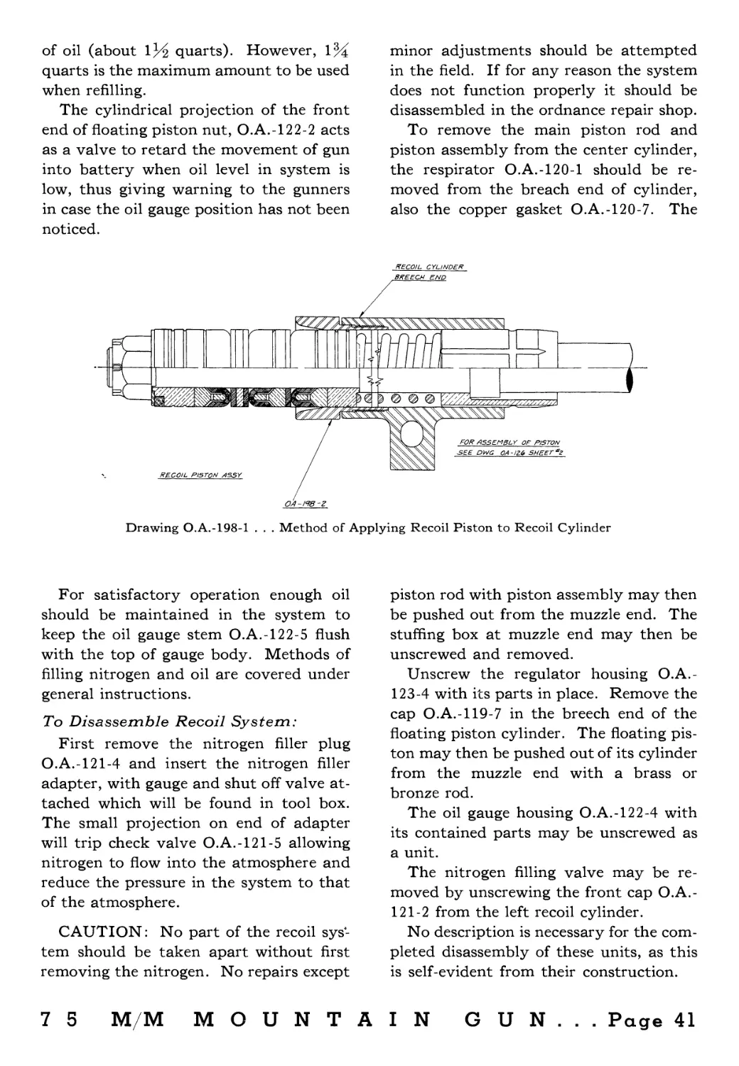
Drawing O.A.-198-1 . . . Method of Applying Recoil Piston to Recoil Cylinder
For satisfactory operation enough oil
should be maintained in the system to
keep the oil gauge stem O.A.-122-5 flush
with the top of gauge body. Methods of
filling nitrogen and oil are covered under
general instructions.
To Disassemble Recoil System:
First remove the nitrogen filler plug
O.A.-121-4 and insert the nitrogen filler
adapter, with gauge and shut off valve at-
tached which will be found in tool box.
The small projection on end of adapter
will trip check valve O.A.-121-5 allowing
nitrogen to flow into the atmosphere and
reduce the pressure in the system to that
of the atmosphere.
CAUTION: No part of the recoil sys-
tem should be taken apart without first
removing the nitrogen. No repairs except
piston rod with piston assembly may then
be pushed out from the muzzle end. The
stuffing box at muzzle end may then be
unscrewed and removed.
Unscrew the regulator housing O.A.-
123-4 with its parts in place. Remove the
cap O.A.-119-7 in the breech end of the
floating piston cylinder. The floating pis-
ton may then be pushed out of its cylinder
from the muzzle end with a brass or
bronze rod.
The oil gauge housing O.A.-122-4 with
its contained parts may be unscrewed as
a unit.
The nitrogen filling valve may be re-
moved by unscrewing the front cap O.A.-
121-2 from the left recoil cylinder.
No description is necessary for the com-
pleted disassembly of these units, as this
is self-evident from their construction.
7 5 M/M MOUNTAIN GUN... Page 41
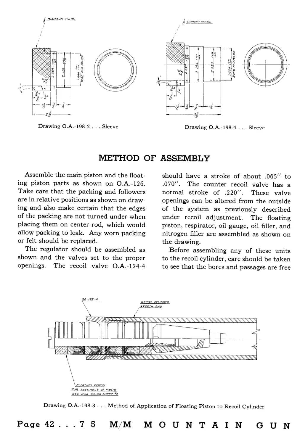
Drawing O.A.-198-2 . . . Sleeve
Drawing O.A.-198-4 . . . Sleeve
METHOD OF ASSEMBLY
Assemble the main piston and the float-
ing piston parts as shown on O.A.-126.
Take care that the packing and followers
are in relative positions as shown on draw-
ing and also make certain that the edges
of the packing are not turned under when
placing them on center rod, which would
allow packing to leak. Any worn packing
or felt should be replaced.
The regulator should be assembled as
shown and the valves set to the proper
openings. The recoil valve O.A.-124-4
should have a stroke of about .065" to
.070". The counter recoil valve has a
normal stroke of .220". These valve
openings can be altered from the outside
of the system as previously described
under recoil adjustment. The floating
piston, respirator, oil gauge, oil filler, and
nitrogen filler are assembled as shown on
the drawing.
Before assembling any of these units
to the recoil cylinder, care should be taken
to see that the bores and passages are free
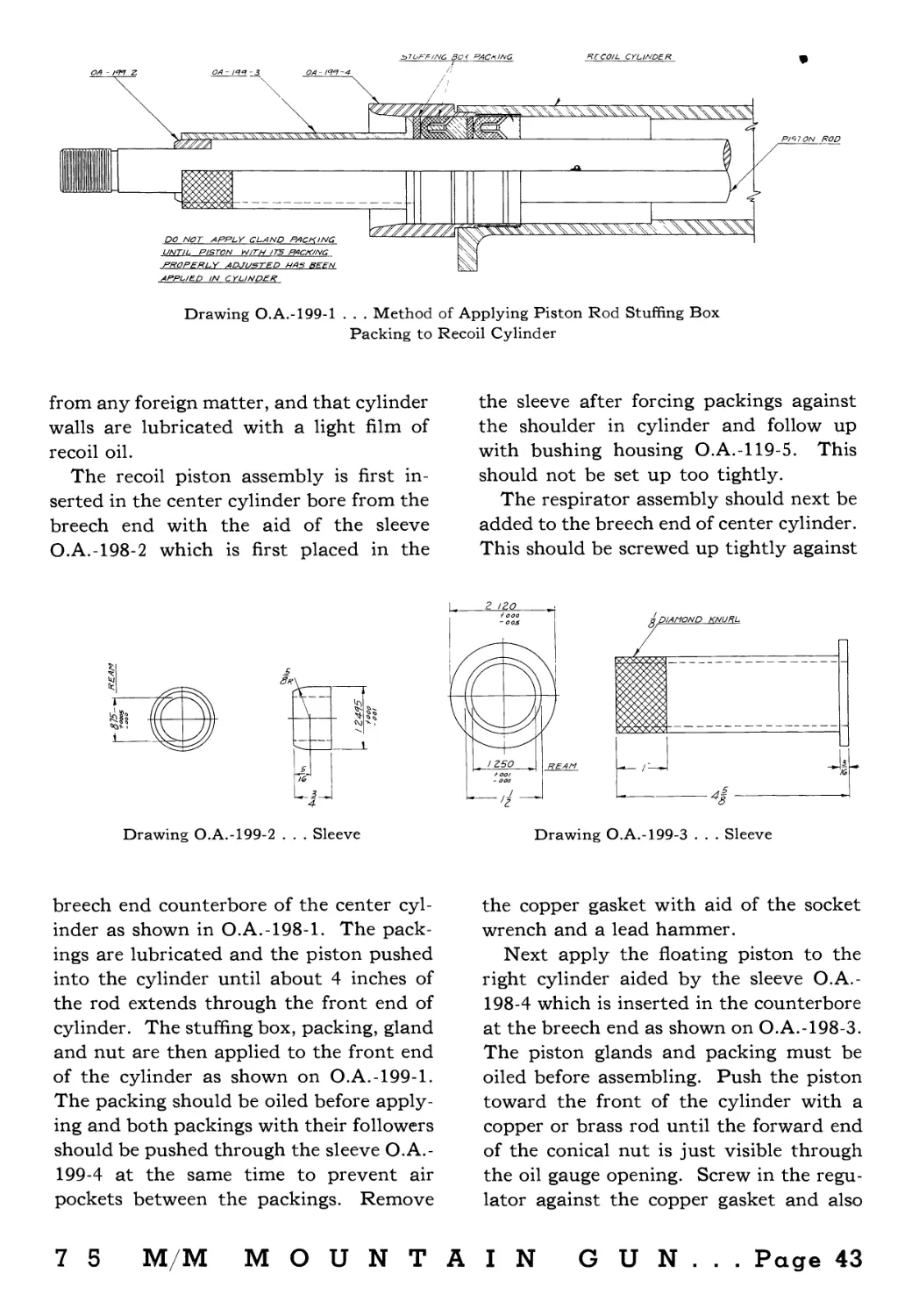
FOR ASSETMBL Y OF PARTS
SEE DW6, OA-I2C, SHEET *2
Drawing O.A.-198-3 . . . Method of Application of Floating Piston to Recoil Cylinder
Page 42 ... 7 5 M/M MOUNTAIN GUN
50 < RACKING
RECOIL CYLINDER
Drawing O.A.-199-1 . . . Method of Applying Piston Rod Stuffing Box
Packing to Recoil Cylinder
from any foreign matter, and that cylinder
walls are lubricated with a light film of
recoil oil.
The recoil piston assembly is first in-
serted in the center cylinder bore from the
breech end with the aid of the sleeve
O.A.-198-2 which is first placed in the
the sleeve after forcing packings against
the shoulder in cylinder and follow up
with bushing housing O.A.-119-5. This
should not be set up too tightly.
The respirator assembly should next be
added to the breech end of center cylinder.
This should be screwed up tightly against
Drawing O.A.-199-2 . . . Sleeve
Drawing O.A.-199-3 . . . Sleeve
breech end counterbore of the center cyl-
inder as shown in O.A.-198-1. The pack-
ings are lubricated and the piston pushed
into the cylinder until about 4 inches of
the rod extends through the front end of
cylinder. The stuffing box, packing, gland
and nut are then applied to the front end
of the cylinder as shown on O.A.-199-1.
The packing should be oiled before apply-
ing and both packings with their followers
should be pushed through the sleeve O.A.-
199-4 at the same time to prevent air
pockets between the packings. Remove
the copper gasket with aid of the socket
wrench and a lead hammer.
Next apply the floating piston to the
right cylinder aided by the sleeve O.A.-
198-4 which is inserted in the counterbore
at the breech end as shown on O.A.-198-3.
The piston glands and packing must be
oiled before assembling. Push the piston
toward the front of the cylinder with a
copper or brass rod until the forward end
of the conical nut is just visible through
the oil gauge opening. Screw in the regu-
lator against the copper gasket and also
7 5 M/M MOUNTAIN GUN... Page 43
the plug (О.A.-119-7) in breech end
against its copper gasket. Set both up
tightly with the socket wrench and lead
hammer. Screw in the oil gauge body and
its contained parts, the oil filler assembly,
and the front cap containing the nitrogen
filling valve. Make certain these are se-
curely tightened against their gaskets.
The system is then ready to charge with
oil and nitrogen as previously described.
The gun is then ready to be fired. Any
minor adjustments to vary the recoil or
counter recoil may then be made as pre-
viously described.
Use special recoil oil furnished with gun.
Additional oil may be obtained from the
National Forge & Ordnance Company.
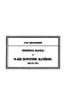
Drawing O.A.-199-4 . . . Sleeve
Page 44 ... 7 5 M/M MOUNTAIN GUN