/


Теги: weapons military affairs patent
Год: 1943
Текст
March 2, 1943. g. tauschek
FIREARMS AND AMMUNITION THEREFOR
Filed Oct. 22, 1938
2,313,030
INVENTOR
Patented Mar. 2, 1943
2313,030
UNITED STATES PATENT OFFICE
2,313,030
FIREARM AND AMMUNITION THEREFOR
Gustav Tauschek, New York, N. Y.;- vested in the
Alien Property Custodian
Application October 22,1938, Serial No. 236,465
In Austria October 22, 1937
- 14 Claims.
W invention relates to a fire-arm of the kind
in which projectiles are fired by gas-pressure
fSpm a barrel and has for its object a new kind
of firing the arm by means of an electric igni-
tion bridge. Other objects of the present inven-
tion will be evident as the description progresses.
One mode of carrying out the present inven-
tion is illustrated by way of example in the ac-
companying drawing.
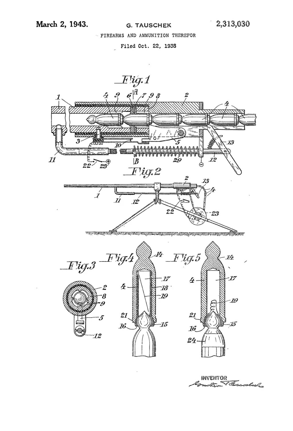
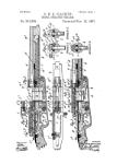
Fig. 1 is a longitudinal section of a gun em-
bodying my invention; Fig. 2 is a view of the gun
in firing position; Fig. 3 is a cross section on line.
A—В of Fig. 1; Figs. 4 and 5 are longitudinal
sections of two forms of my novel ammunition.
The barrel I is fitted into the electrically in-
sulated part of a casing 2 and is fixed therein by
a screw 3. The projectiles 4, which are succes-
sively inter-connected to form a projectile-
train, are pushed through the casing 2 and into
the barrel I to such extent, that the first projec-
tile is disposed in the barrel I. A fireproof insu-
lating and packing ring 6 as well as a washer 7
and a guide-sleeve 8 are arranged between the
barrel I and the casing 2, while the second pro-
jectile, which is secured by a pawl 5 pivoted to
the casing 2, rests in the’free space within the
members 6,1 and 8. The inside diameter of the
sleeve 8 and of the rear end of the barrel is larger
than corresponds to the outside diameter of the
projectiles and the projectiles are adapted to rest
on .ribs 9, projecting into said sleeve and rear
end*if the barrel and thus give a good contact.
Tjhe pawl 5 controls a contact 10 in such a
manner, that an electric current passes by way
of the latter and the screw 3 to the barrel 1 in
the engaged position of the pawl 5 only.
Further a tube И is secured to the barrel I
and forces back a rod 12 during the discharge
of the projectile from the barrel, whereby the
projectile-train is fed forward the extent of a
projectile by a feed-lever 13, pivoted to the end
of the rod 12. The latter is subjected to the ac-
tion of a spring 29 which, whenever the gas-pres-
sure ceases in the barrel, pushes forward the rod
12 and thereby advances the projectile-train, so
that the next projectile is fed into its firing po-
sition.
The projectile-train consists of a number of
interconnected projectiles, which may be con-
structed for instance as shown in Fig. 4 or 5
and by means of grooves 18 and extensions 15
are united to form a flexible chain of projectiles.
The projectiles are insulated from one another by
means of paper or like insertions 16. In the
construction illustrated in Fig. 4, the hollow
chamber П of the projectile, which serves for
the reception of the gun-powder charge, is lined
with a cardboard sleeve 18 provided with an ig-
nition bridging wire 19, which interconnects the
two adjacent projectiles in the manner as lllus-
5
15
20
25
30
35
40
45
50
55
60
(Cl. 42—3)
trated. The cardboard sleeve 18 also prevents it,
that the pointed end 20 of the projectile is forced
into the chamber 17 of the projectile. For this
object, in the construction illustrated in Fig. 5,
the gun-powder chamber 17 is narrower and
the bridging wire 19 is coiled and located in front
of the projectile-end 20. A primer may be glued
to the bridging wire in known manner. The pro-
jectiles are provided with a guide-collar 21,
which engages the spiral grooves of the barrel,
and therefore the projectiles may be made of a
comparatively hard material (for instance soft
steel), so that the force of percussion is increased
very considerably.
The projectiles may be coated with a narrow
strip of insulating varnish or the like 24 in order
to prevent the flow of the current from the bar-
rel 1 to the projectile resting in the sleeve 8, in
case any carbon residues may have been depos-
ited on the packing ring 6.
The fire-arm is operated in the following man-
ner:
. The projectile-train is pushed so far Into the
gun until the projectile is located in the barrel
and now an electric contact 22’ls closed, so that
the electric current flows from a battery 23 by way
of the contacts 22 and 10 to the barrel -1 and to
the projectile located in the latter, and now the
current passes by way of the Ignition bridge to
the next projectile and over the pawl' 5 back to
the battery. Thereby the gun-powder charge is
ignited by the bridging wire 19 and thus the first
projectile is fired. The projectile-train is fed
forward by -the action of the members И, 12
and 13, and as soon as the pawl 5 engages the
back of the following projectile, the ignition-con-
tact and so forth are re-established until the
contact 22 is opened again, so that firing ceases.
As shown Fig. 2, the projectile-train 4 may
be wound up on a drum, which may carry the ig-
nition battery 23, so that drum and battery may
be replaced at the same time. A pocket battery
is quite satisfactory for the Ignition. However
the gun may be connected to any convenient
source of current.
I claim:
1. A fire-arm comprising a barrel, means for
holding a plurality of projectiles and charges in
tandem on the longitudinal axis of the barrel,
means for holding one of said projectlies in a po-
sition in which it closes the barrel behind the
projectile which is in the firing position, an elec-
tric ignition circuit connected with the barrel
and adapted to be closed by two of the connected
projectiles for firing the projectile which Is In the
firing position, and means for feeding the pro-
jectiles forwardly In the barrel to bring one pro-
jectile into the firing position and another pro-
jectile into the position in which the barrel is
closed as successive shots are fired.
2,313,030
2
2. A fire-arm comprising a barrel, means for
holding a plurality of connected projectiles in
tandem on the longitudinal axis of the barrel,
means for holding the second projectile in a po-
sition in which it closes the barrel behind the
foremost projectile which is in the firing position,
an electric ignition circuit connected with the
barrel and adapted to be closed by the foremost
and the second projectiles for firing the fore-
most projectile, and means for feeding the pro-
jectiles forwardly in the barrel to bring the fore-
most projectile into firing position and the next
projectile Into the position in which the barrel
is closed as successive shots are fired.
3. Fire-arm ammunition comprising a plural-
ity of chambered projectiles connected in tandem
fashion, the connection being of such character
as to enable the projectile located in front to de-
tach itself from the projectile in the rear upon
the firing of such front projectile, electrical ig-
niting means* located within each projectile, a
propelling charge contained in the chamber of
each projectile and connections permitting a cur-
rent to travel from one projectile to .the electrical
Igniting means of the next projectile ahead, to
ignite the propelling charge therein. •
4. In a plurality of projectiles In tandem fash-
ion for fire-arms, means on each projectile for
engaging the adjacent projectile to form a train
of connected projectiles, an ignition wire in each
projectile and electrically connecting the adja-
cent projectile, and means on each projectile
adapted to be engaged by members of a fire-arm
for holding one of said projectiles In the posi-
tion In which It closes the barrel of the fire-arm
and for feeding the projectiles forwardly in the
barrel.
5. In a plurality of projectiles In tandem fash-
ion for fire-arms, a compartment In each pro-
jectlie containing an electric fuse and a propel-
ling charge, means including an insulating
means on each projectlie for engaging the adja-
cent projectile to form a train of connected pro-
jectiles and means on each projectile adapted to
be engaged by members of a fire-arm for hold-
ing one of said projectlies in the position in
which it closes the barrel of the fire-arm and for
feeding the projectiles forwardly in the barrel.
6. In a plurality of projectiles in tandem fash-
ion for fire-arms, a compartment in each projec-
tile, means carrying an electric fuse located in
said compartment, a propelling charge in said
compartment, means including an insulating
means on each projectile for engaging the adja-
cent projectile to form a train of connected pro-
jectiles and means on each projectile adapted to
be engaged by members of a fire-arm for hold-
ing one of said projectiles in the position in which
it closes the barrel of the fire-arm and for feed-
ing the projectiles forwardly in the barrel.
7. Fire-arm ammunition comprising a plural-
ity of projectiles connected in tandem fashion,
means for holding propelling charges and elec-
trical igniting means between said projectiles and
means for establishing electric contact between
adjacent projectiles by means of the igniting
means.
8. In a plurality of projectiles in tandem fash-
ion for fire-arms, an electrically insulating coat
covering part of each projectile, means including
the insulating coat for connecting adjacent pro-
jectiles to form a train of mechanically connect-
ed but electrically insulated projectiles, and
means on each projectile adapted to be engaged
by members of the fire-arm for feeding the pro-
5 jectile forwardly in the barrel of the fire-arm.
9. A fire-arm comprising a barrel, adapted to
receive two projectiles with propelling charges
and electrical igniting means, means for hold-
ing the second of said projectiles in a position in
10 which it closes the breech of the barrel behind
the first projectile which is in firing position, and
means for applying a difference of electrical po-
tential between the projectiles for operating the
electrical igniting means to fire the first of said
15 projectiles through the barrel.
10. A fire-arm comprising a barrel, means tpr
feeding a plurality of projectiles, charges and
electrical igniting means in tandem forwardlyJh
the barrel, an electric circuit connected with the
20 barrel and adapted to be closed by the foremost
projectile when the projectile comes into firing
position for igniting the charge and firing the
projectile and means for holding the second pro-
jectile in a position, in which it closes the breech
23 of the barrel while the foremost projectile is
fired.
11. A fire-arm comprising a barrel, means for
feeding a plurality of projectiles, charges and
electrical igniting means in tandem forwardly
30 in the barrel, an electric circuit connected with
the barrel and adapted to be closed by the fore-
most projectile when the projectile comes into
firing position for igniting the charge and firing
the projectile, means for holding the second pro-
35 jectile in a position in which it closes the breech
of the barrel while the foremost projectile is
fired, and means operated automatically every
time a shot is fired, for actuating the feeding
means.
40 12. A fire-arm comprising a barrel, means for
holding a plurality of projectiles, charges and
electrical igniting means in tandem on the longi-
tudinal axis of the barrel, means for transmitting
current to said igniting means and means for: ef-
45 fecting relative lengthwise movement of the pro-
jectiles to establish successively an operative re-
lation between the said current transmij^hg
means and the several electrical igniting metais
for successively firinfc projectiles through the
50 barrel.
13. A fire-arm comprising a barrel, means for
feeding a plurality of projectiles, charges and
electrical igniting means in tandem forwardly in
the barrel, an electric circuit connected with the
55 barrel and adapted to be closed by the electrical
igniting means of the foremost projectile when
the projectile comes into firing position for ignit-
ing the charge and firing the projectile through
the barrel, and means for controlling said circuit
co in step with the operation of said feeding means.
14. A fire-arm comprising a barrel, means for
feeding a plurality of projectiles, charges and
electrical igniting means in tandem forwardly in
the barrel, an electric circuit connected with the
65 barrel and adapted to be closed by the electrical
igniting means of the foremost projectile when
the projectile comes into firing position for ignit-
ing the charge and firing the projectile through
the barrel, and manually operated means for
70 controlling said circuit.
GUSTAV TAUSCHEK.