/


Текст
Solutions to
'. Irodov
Problems in
General Physics
Volume I
Mechanics t Heat t Electrodynamics
SECOND EDITION
ABHAY KUMAR SINGH
Director
Abhay's I.I.T. Physics Teaching Centre
Patna-6
CBS PUBLISHERS & DISTRIBUTORS
4596/1 A, 11 DARYAGANJ, NEW DELHI -110 002 (INDIA)
Dedicated to
my Teacher
Prof. (Dr.) J. Thaknr
(Department of Physics,
Patna University,
Patna-4)
ISBN :81-239-0399-5
First Edition: 1995
Reprint: 1997
Second Edition: 1998
Reprint: 2000
Reprint: 2001
Reprint: 2002
Reprint: 2003
Reprint: 2004
Reprint: 2005
Copyright © Author & Publisher
All rights reserved. No part of this book may- be reproduced or
transmitted in any form or by any means, electronic or mechanical,
including photocopying, recording, or any information storage arid
retrieval system without permission, in writing, from the publisher.
Published by S.K. Jain for CBS Publishers & Distributors,
4596/1 A, 11 Darya Ganj, New Delhi - 110 002 (India)
Printed at :
India Binding House, Delhi - 110 032
FOREWORD
Science, in general, and physics, in particular, have evolved out of man's quest to know beyond
unknowns. Matter, radiation and their mutual interactions are basically studied in physics.
Essentially, this is an experimental science. By observing appropriate phenomena in nature one
arrives at a set of rules which goes to establish some basic fundamental concepts. Entire physics
rests on them. Mere knowledge of them is however not enough. Ability to apply them to real
day-to-day problems is required. Prof. Irodov's book contains one such set of numerical
exercises spread over a wide spectrum of physical disciplines. Some of the problems of the book
long appeared to be notorious to pose serious challenges to students as well as to their teachers.
This book by Prof. Singh on the solutions of problems of Irodov's book, at the outset, seems
to remove the sense of awe which at one time prevailed. Traditionally a difficult exercise to
solve continues to draw the attention of concerned persons over a sufficiently long time. Once
a logical solution for it becomes available, the difficulties associated with its solutions are
forgotten very soon. This statement is not only valid for the solutions of simple physical problems
but also to various physical phenomena.
Nevertheless, Prof. Singh's attempt to write a book of this magnitude deserves an all out
praise. His ways of solving problems are elegant, straight forward, simple and direct. By writing
this book he has definitely contributed to the cause of physics education. A word of advice to
its users is however necessary. The solution to a particular problem as given in this book is
never to be consulted unless an all out effort in solving it independently has been already made.
Only by such judicious uses of this book one would be able to reap better benefits out of it.
As a teacher who has taught physics and who has been in touch with physics curricula
at LIT., Delhi for over thirty years, I earnestly feel that this book will certainly be of benefit
to younger students in their formative years.
Dr. Dilip Kumar Roy
Professor of Physics
Indian Institute of Technology, Delhi
New Delhi-110016.
FOREWORD
A. proper understanding of the physical laws and principles that govern nature require
solutions of related problems which exemplify the principle in question and leads to a
better grasp of the principles involved. It is only through experiments or through solutions
of multifarious problem-oriented questions can a student master the intricacies and fall
outs of a physical law. According to Ira M. Freeman, professor of physics of the state
university of new Jersy at Rutgers and author of "physic—principles and Insights" —
"In certain situations mathematical formulation actually promotes intuitive understand-
understanding Sometimes a mathematical formulation is not feasible, so that ordinary language
must take the place of mathematics in both roles. However, Mathematics is far more
rigorous and its concepts more precise than those of language. Any science that is able
to make extensive use of mathematical symbolism and procedures is justly called an exact
science". I.E. Irodov's problems in General Physics fulfills such a need. This book
originally published in Russia contains about 1900 problems on mechanics, thermody-
thermodynamics, molecular physics, electrodynamics, waves and oscillations, optics, atomic and
nuclear physics. The bookjias survived the test of class room for many years as is evident
from its number of reprint editions, which have appeared since the first English edition
of 1981, including an Indian Edition at affordable price for Indian students.
Abhay Kumar Singh's present book containing solutions to Dr. I.E. Irodov's Problems
in General Physics is a welcome attempt to develop a student's problem solving skills.
Tlie book should be very useful for the students studying a general course in physics and
also in developing their skills to answer questions normally encountered in national level
entrance examinations conducted each year by various bodies for admissions to profes-
professional colleges in science and technology.
B.P. PAL
Professor of Physics
LIT., Delhi
PREFACE TO THE SECOND EDITION
Nothing succeeds like success, they say, Now, consequent upon the warm
welcome on the part of students and the teaching fraternity this revised and
enlarged edition of this volume is before you. In order to make it more up-to-date
and viable, a large number of problems have been streamlined with special focus
on the complicated and ticklish ones, to cater to the needs of the aspiring students.
I extend my deep sense of gratitude to all those who have directly or
indirectly engineered the cause of its existing status in the book world.
Patna
June 1997 Abhay Kumar Singh
PREFACE TO THE FIRST EDITION
When you invisage to write a book of solutions to problems, one pertinent question crops up
in the mind that—why solution! Is this to prove one's erudition? My only defence against
this is that the solution is a challenge to save the scientific man hours by channelizing thoughts
in a right direction.
The book entitled "Problems in General Physics" authored by I.E. Irodov (a noted
Russian physicist and mathematician) contains 1877 intriguing problems divided into six
chapters.
After the acceptance of my first book "Problems in Physics", published by Wiley
Eastern Limited, I have got the courage to acknowledge the fact that good and honest
ultimately win in the market place. This stimulation provided me insight to come up with mv
second attempt—"Solutions to I.E. Irodov's Problems in General Physics."
This first volume encompasses solutions of first three chapters containing 1052
problems. Although a large number of problems can be solved by different methods, I have
adopted standard methods and in many of the problems with helping hints for other methods.
In the solutions of chapter three, the emf of a cell is represented by § (xi) in contrast
to the notation used in figures and in the problem book, due to some printing difficulty.
I am thankful to my students Mr. Omprakash, Miss Neera and Miss Punam for their
valuable co-operation even In my hard days while authoring the present book. I am also
thankful to my younger sister Prof. Ranju Singh, my younger brother Mr. Ratan Kumar Singh,
my junior friend Miss Anupama Bharti, other well wishers and friends for their emotional
support. At last and above all I am grateful to my Ma and Pappaji for their blessings and
encouragement.
ABHAY KUMAR SINGH
CONTENTS
Foreword iii
Preface to the second edition v
Preface to the first edition vi
PART ONE
PHYSICAL FUNDAMENTALS OF MECHANICS
1.1 Kinematics 1-34
1.2 The Fundamental Equation of Dynamics 35-65
1.3 Laws of Conservation of Energy, Momemtum, and Angular Momentum 66-101
1.4 Universal Gravitation 102-117
1.5 Dynamics of a Solid Body 118-143
1.6 Elastic Deformations of a Solid Body 144-155
1.7 Hydrodynamics 156-167
1.8 Relativistic Mechanics 168-183
PART TWO
THERMODYNAMICS AND MOLECULAR PHYSICS
2.1 Equation of the Gas State. Processes 184-195
2.2 The first Law of Thermodynamics. Heat Capacity 196-212
2.3 Kinetic theory of Gases. Boltzmann's Law and Maxwell's Distribution 213-226
2.4 The Second Law of Thermodynamics. Entropy 227-241
2.5 Liquids. Capillary Effects 242-247
2.6 Phase Transformations 248-256
2.7 Transport Phenomena 257-266
PART THREE
ELECTRODYNAMICS
3.1 Constant Electric Field in Vacuum 267-288
3.2 Conductors and Dielectrics in an Electric Reid 289-305
3.3 Electric Capacitance. Energy of an Electric Field 306-324
3.4 Electric Current 325-353
3.5 Constant Magnetic Field. Magnetics 354-379
3.6 Electromagnetic Induction. Maxwell's Equations 380-407
3.7 Motion of Chaiged Particles in Electric and Magnetic Fields 408-424
PART ONE
PHYSICAL FUNDAMENTALS OF MECHANICS
1.1 KINEMATICS
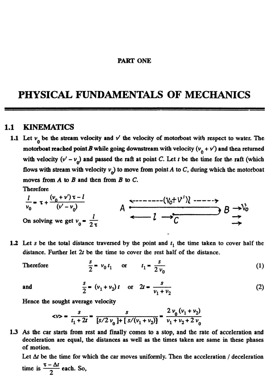
1.1 Let v be the stream velocity and v' the velocity of motorboat with respect to water. The
motorboat reached point B while going downstream with velocity (v + v') and then returned
with velocity (v' - v) and passed the raft at point C Let t be the time for the raft (which
flows with stream with velocity v^) to move from point A to C, during which the motorboat
moves from A to B and then from B to C.
Therefore
On solving we get v ■ -—
1/ & v
1.2 Let 5 be the total distance traversed by the point and tx the time taken to cover half the
distance. Further let 2f be the time to cover the rest half of the distance.
Therefore f - vori or h' TT C1)
Z L Vq
and x- (vi + v^r or 2f« —-— B)
Hence the sought average velocity
s s
13 As the car starts from rest and finally comes to a stop, and the rate of acceleration and
deceleration are equal, the distances as well as the times taken are same in these phases
of motion.
Let At be the time for which the car moves uniformly. Then the acceleration / deceleration
tune is —-— each. So,
or
<v>x
I (x - Af)'
2W 4
(x-AQ
—-—L
Hence
Af* x
V 1-
wx
15 s.
1.4 (a) Sought average velocity
s
<v> - -
t
200 cm
—
zus
10 cm/s
20
(b) For the maximum velocity, — should be
ds
maximum. From the figure — is maximum for
all points on the line ac9 thus the sought
maximum velocity becomes average velocity
for the line ac and is equal to :
6c 100 cm
ab 4s
mmm
—rf
■■Mi
-*•
>
■**
Maw
11
VI
,'YJ
/I
/
/
4/
b
M
■■■
Ml
10
20t,S
25 cm/s
(c) Time r0 should be such that corresponding to it the slope — should pass through the
ds s
point O (origin), to satisfy the relationship -^ * —. From figure the tangent at point d
at t0
passes through the origin and thus corresponding time t« /0 - 16 s.
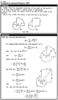
1.5 Xet the particles collide at the point A (Fig.), whose position vector is r^(say). If t be the
time taken by each particle to reach at point A, from triangle law of vector addition :
-* A
V
SO,
Vt
therefore, f= , _* -,.
lv2-vil
From Eqs. A) and B)
B)
1 2 2 2 V
I1* -*
V2-Vl
o
*7
n
or,
rl~r2
r v
I rl " r2 I I V2 ~ Vl I
77, which is the sought relationship.
X
1.6 We^have
v ■v-v0
A)
From the vector diagram [of Eq. A)] and using properties of triangle
and
or
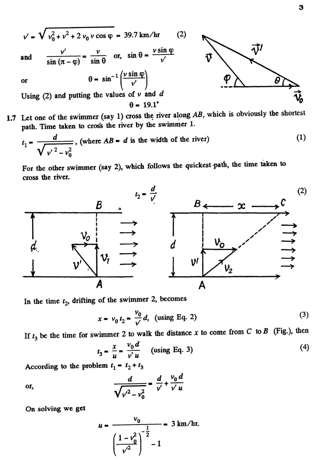
V Vq + v2 + 2 v0 v cos <p - 39.7 km/hr
. A v sin cp
or, sin 8* j-*-
B)
sin (ji - cp) sin 6
. _ i (v sin
Using B) and putting the values of v and d
8 - 19.r
1.7 Let one of the swimmer (say 1) cross the river along AB, which is obviously the shortest
path. Time taken to cross the river by the swimmer 1.
, (where AB • d is the width of the river)
Vv'2-V20
A)
For the other swimmer (say 2), which follows the quickest path, the time taken to
cross the river.
B
B)
B
■*■
X
i.
i
s
V
In the time t2, drifting of the swimmer 2, becomes
Vn
Xm V2- 77* («sing Eq. 2)
C)
If r3 be the time for swimmer 2 to walk the distance x to come from C to B (Fig.), then
(using Eq. 3)
fe-i
vii
According to the problem fx « t2 +
or,
On solving we get
Vv'2 -
u
3 km/hr.
(l-vt)
0
-1
1.8 Let / be the distance covered by the boat A along the river as well as by the boat B acre
the river. Let v0 be the stream velocity and v' the velocity of each boat with respect
water. Therefore time taken by the boat A in its journey
/ /
v' + v0 v' - v0
and for the boat B
Hence,
On substitution
2/
'o
Vv'2-vg Vti2-1
1-8
I where r\ = —
1.9 Let v0 be the stream velocity and v' the velocity of boat with respect to water. A
— ■ T] ■ 2 > 0, some drifting of boat is inevitable.
Let v* make an angle 0 with flow direction. (Fig.), then the time taken to cross the rive
t * . . - (where d is the width of the river)
v sin 0 v
In this time interval, the drifting of the boat
jc* (v'cos0 + v
>' cos 0 + vj , . . - (cot 0 + ti cosec 0) d
^ v sin 0
For jc • (minimum drifting)
dQ
(cot 0 + K] cosec 0) * 0, which yields
cos 0 - - — « - —
n 2
I
Hence, 0 - 120°
1.10 The solution of this problem becomes simple in the frame attached with one of the bodies.
Let the body thrown straight up be 1 and the other body be 2, then for the body 1 in the
frame of 2 from the kinematic equation for constant acceleration :
r12" r0A2) + v0A2)
or,
But
(because wu~ 0 and r^U)- 0)
' A)
- v
So, from properties of triangle
0A2)
- V v2 + v2-2vovocos(ji/2-0o)
Hence, the sought distance
£|- voV2(l-sin0) r= 22m.
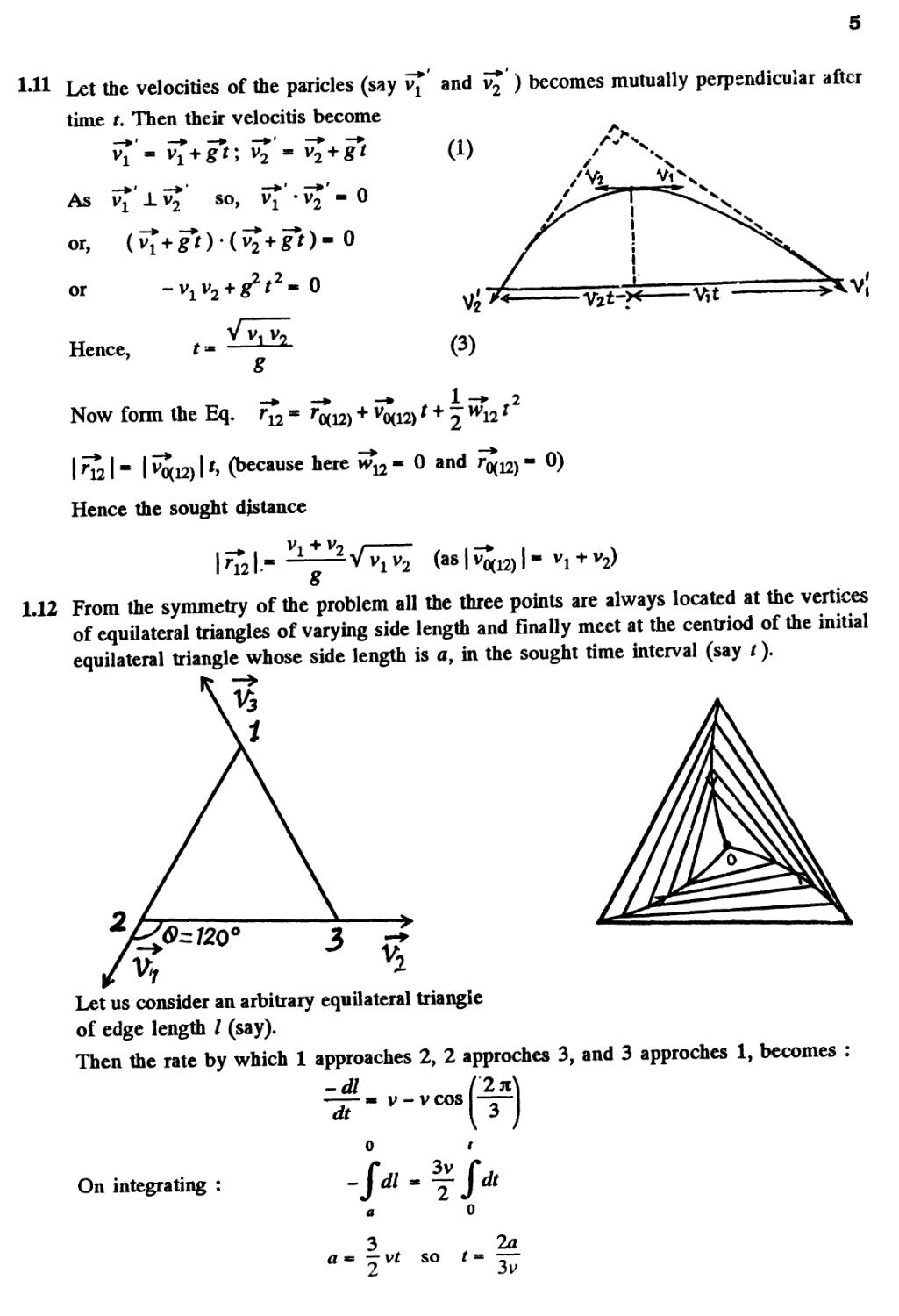
-11 Let the velocities of the paricles (say vl and v2 ) becomes mutually perpendicular after
time t. Then their velocitis become
As v1 lv2 so, v1 •
or,
0
0
or
0
■Vttr**
Hence,
V vi
g
C)
Now form the Eq. r12 -
1 *
t + — >v12
^21" I ^12) I *> (because here m^ - 0 and
Hence the sought distance
0)
8
(as I v
'0A2)
V2)
1.12 From the symmetry of the problem all the three points are always located at the vertices
of equilateral triangles of varying side length and finally meet at the centriod of the initial
equilateral triangle whose side length is a, in the sought time interval (say t).
6^720°
Let us consider an arbitrary equilateral triangle
of edge length / (say).
Then the rate by which 1 approaches 2, 2 approches 3, and 3 approches 1, becomes :
-dl
dt
V - VCOS
On integrating :
3v
2
a
a
3
vt so t
2a
—
6
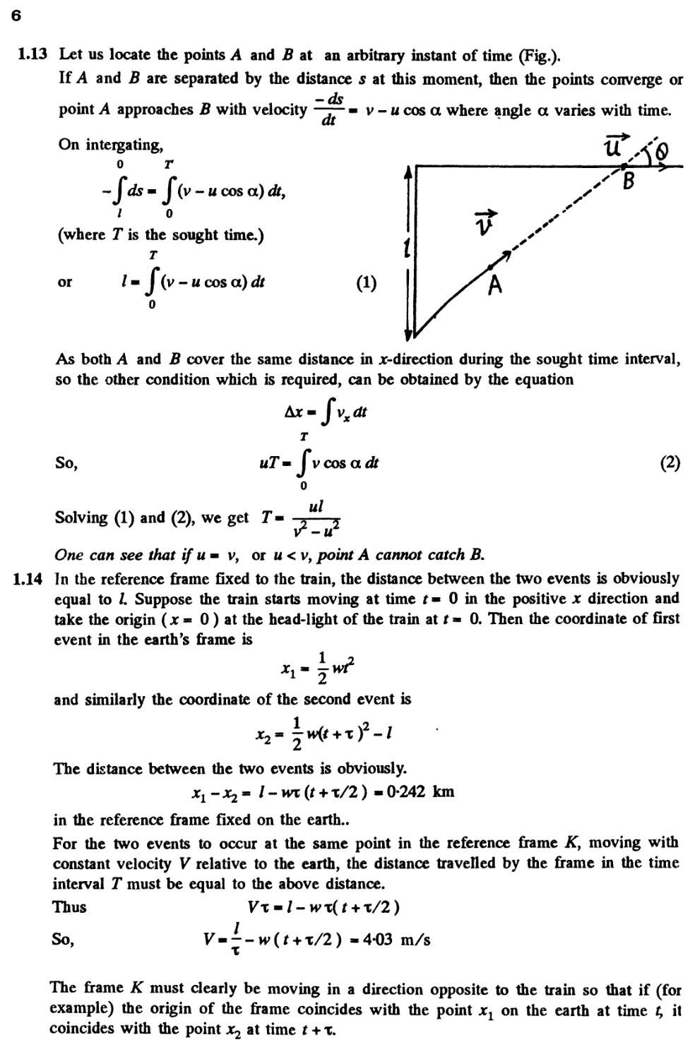
1.13 Let us locate the points A and B at an arbitrary instant of time (Fig.).
If A and B are separated by the distance s at this moment, then the points converge or
-ds
point A approaches B with velocity —r- - v - u cos a where angle a varies with time.
On intergating,
0 r
- J ds « J (v - u cos a) dt9
1 o
(where T is the sought time.)
T
t
or
/« J (v - u cos a) df
As both A and 2? cover the same distance in jt-direction during the sought time interval,
so the other condition which is required, can be obtained by the equation
So,
Solving A) and B), we get T
*x-fvxdt
T
uT» I vcos adit
o
ul
B)
-5
One can see that ifu~v, or u < v, point A cannot catch B.
1.14 In the reference frame Gxed to the train, the distance between the two events is obviously
equal to /. Suppose the train starts moving at time t« 0 in the positive x direction and
take the origin (x - 0) at the head-light of the train at t» 0. Then the coordinate of first
event in the earth's frame is
and similarly the coordinate of the second event is
The distance between the two events is obviously.
-0-242 km
in the reference frame fixed on the earth..
For the two events to occur at the same point in the reference frame Ky moving with
constant velocity V relative to the earth, the distance travelled by the frame in the time
interval T must be equal to the above distance.
Thus Vx - / - wx( t + x/2)
/
x
So,
4-03 m/s
The frame K must clearly be moving in a direction opposite to the train so that if (for
example) the origin of the frame coincides with the point xl on the earth at time t, it
coincides with the point x2 at time t + x.
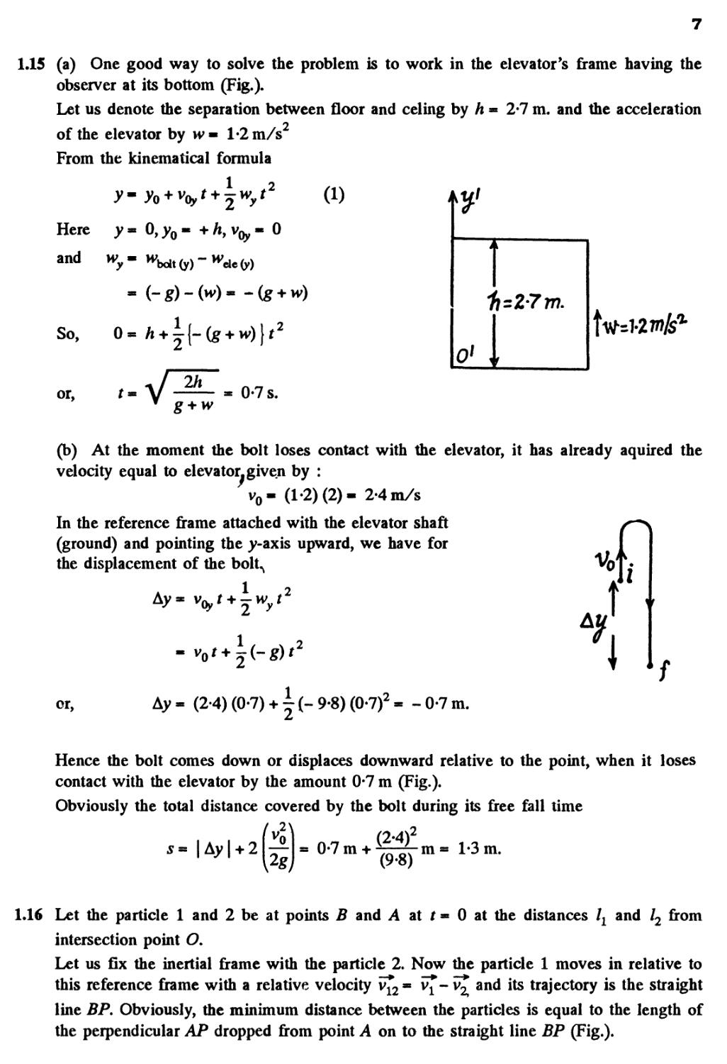
1.15 (a) One good way to solve the problem is to work in the elevator's frame having the
observer at its bottom (Fig.).
Let us denote the separation between floor and celing by h - 2-7 m. and the acceleration
of the elevator by *v« 1-2 m/s
From the kinematical formula
±v2
A)
Here
and
O,yo
'Qy
0
So, 0
or,
0-7 s.
(b) At the moment the bolt loses contact with the elevator, it has already aquired the
velocity equal to elevator, given by :
v0- A-2) B)- 2-4 m/s
In the reference frame attached with the elevator shaft
(ground) and pointing the y-axis upward, we have for ^
the displacement of the bolt^ v0T*
1 i
t
V
1
f
\
or,
Ay « B-4) @-7) + \ (- 9-8) @-7J * - 0-7 m.
Hence the bolt comes down or displaces downward relative to the point, when it loses
contact with the elevator by the amount 0-7 m (Fig.).
Obviously the total distance covered by the bolt during its free fall time
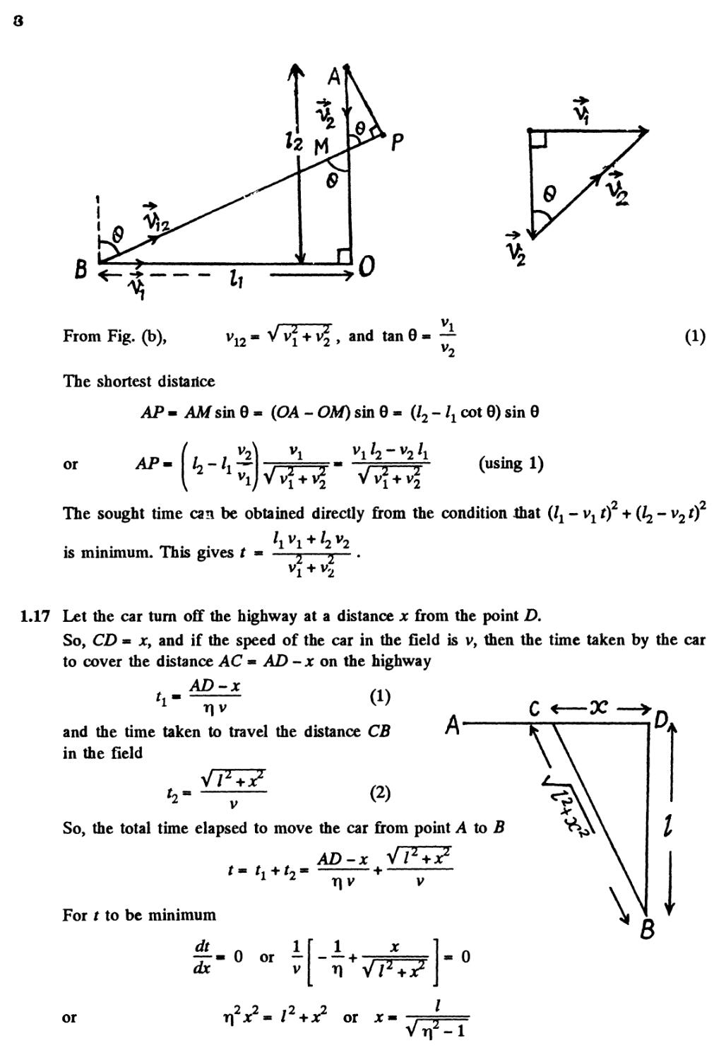
1.16 Let the particle 1 and 2 be at points B and A at t - 0 at the distances lx and l2 from
intersection point O.
Let us fix the inertial frame with the particle 2. Now the particle 1 moves in relative to
this reference frame with a relative velocity i£2- vj*- v£ and its trajectory is the straight
line BP. Obviously, the minimum distance between the particles is equal to the length of
the perpendicular AP dropped from point A on to the straight line BP (Fig.).
B
From Fig. (b), v12 - V v\ + v2 , and tan 0 - —
The shortest distance
AP- AM sinG- (OA - GM) sin 0 - (/2 -/x cot 0) sin 0
or
AP
Vvf
(using 1)
The sought time can be obtained directly from the condition that (lx -vlt) + (^- v20
is minimum. This gives t - —* *— .
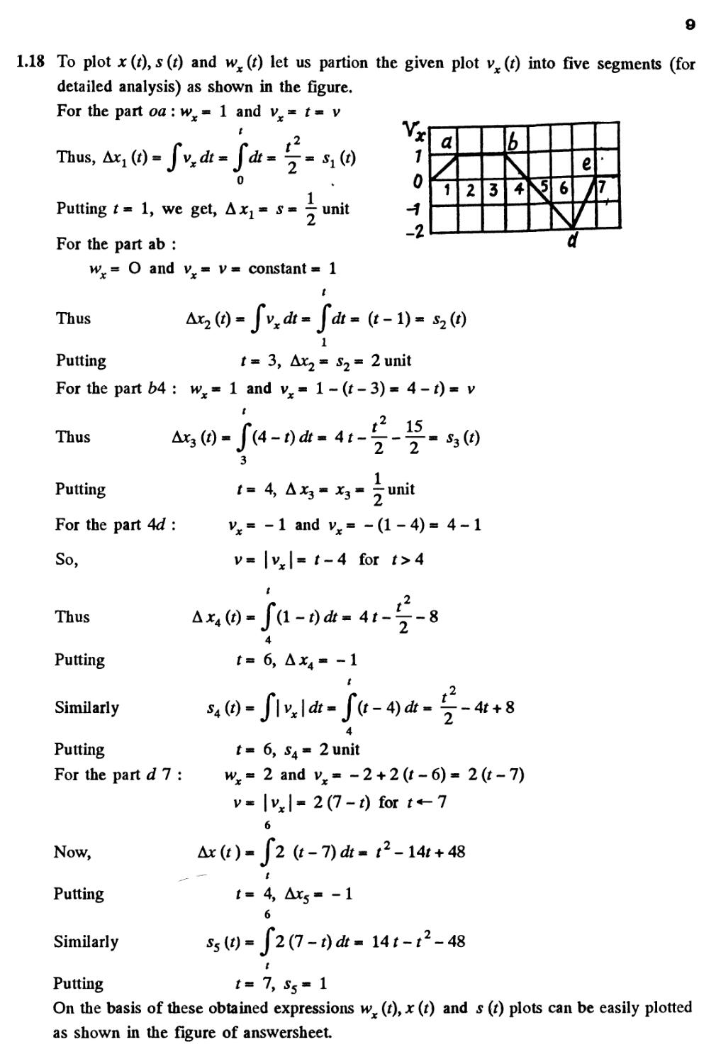
1.17 Let the car turn off the highway at a distance x from the point D.
So, CD = jc, and if the speed of the car in the field is v, then the time taken by the car
to cover the distance AC - AD - x on the highway
and the time taken to travel the distance CB
in the field
B)
So, the total time elapsed to move the car from point A to B
AD-x yfWi
x\ v
For t to be minimum
, - 0 or -
ax v
0
or
t|2jc2» /2+jc2 or jc
9
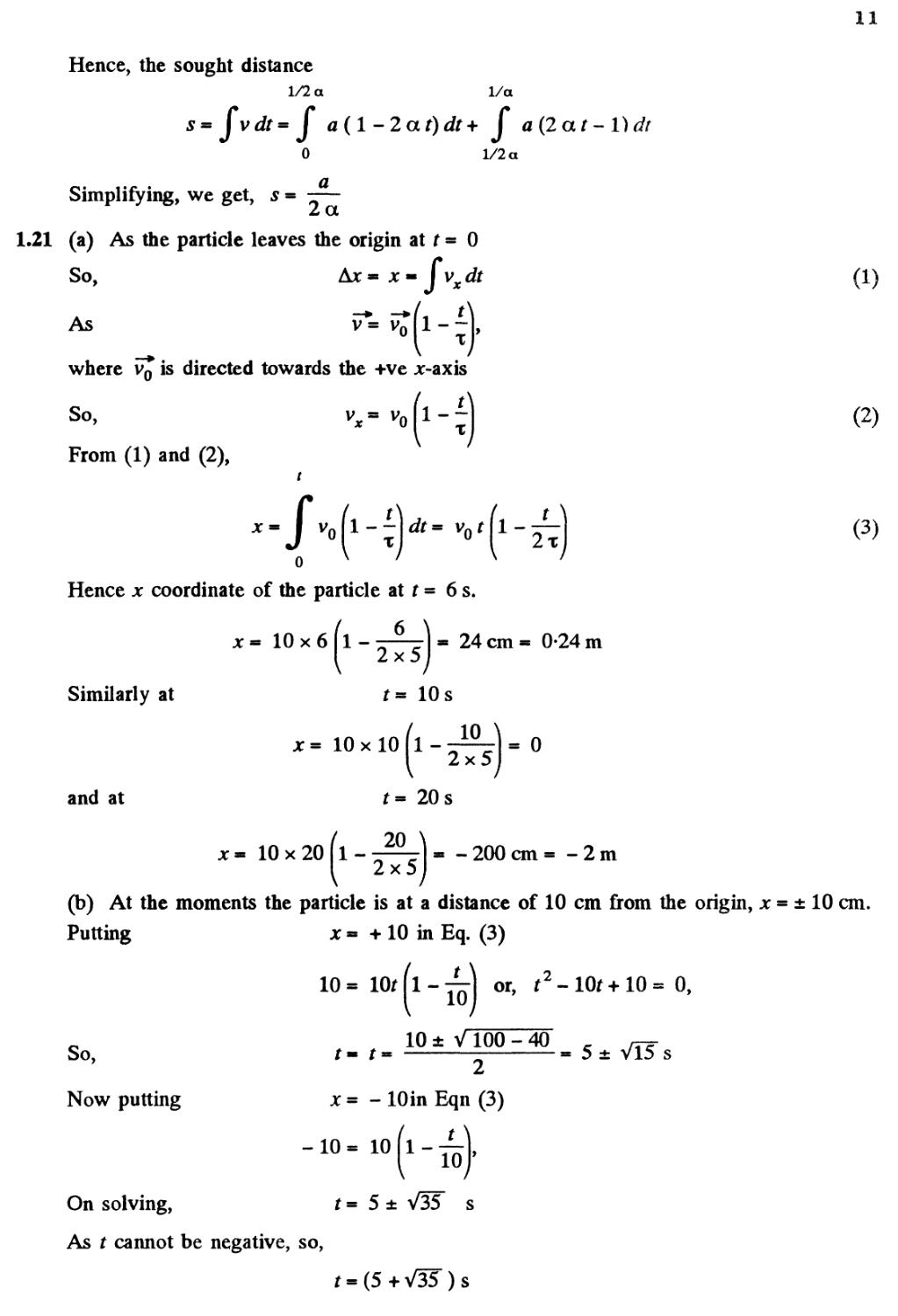
1.18 To plot x (t\ s (t) and wx (t) let us partion the given plot vx (t) into five segments (for
detailed analysis) as shown in the figure.
For the part oa : w =* 1 and v * t - v
Thus,
Putting f= 1, we get,
For the part ab :
o
y- sx(t)
1 .t
— unit
7
mmmtmmt
1
2
MM
3
4
6
s
t
A7'
= O and v = v= constants 1
Thus
Putting f= 3, Ax2= 52» 2 unit
For the part b4 : w^ ■ 1 and vx - 1 - (t - 3) ■ 4 -1) ■ v
.2
Thus
Putting
For the part 4d :
So,
Thus
Putting
Similarly
15
1
f = 4, A jc3 - x3 - — unit
x m - 1 and vx = - A - 4) - 4-1
« t-4 for ^>4
Ax4(t)-f(l-t)dt
r- 6, A*4= -1
Putting
For the part d 7 :
Now,
Putting
t- 6, *4»
wx" 2 and
v-|v,|-
6
Ax@-/2 (r
t= 4, Ax5
: 2 unit
Vxm ~2
2G-0
-7)A-
s - 1
+ 2
for
r2-
(r-6)« 2(r-7)
r<-7
14r + 48
Similarly
Putting
s5[t)- f 2G-t)dtm \4t-t2-
48
t- 7, s.
On the basis of these obtained expressions w^ (f), jc (r) and 5 (t) plots can be easily plotted
as shown in the figure of answersheet
10
1.19 (a) Mean velocity
Total distance covered
50 cm/s A)
Time elapsed
m £ xR
f" X
(b) Modulus of mean velocity vector
2R
\<v>\
32 cm/s B)
At x
(c) Let the point moves from i to f along the half circle (Fig.) and v0 and v be the spe
at the points respectively.
dt " W*
We have
or, v * v0 + wt t (as wt is constant, according to the problem)
t
So,
0
So, from A) and C)
xR
x
Now the modulus of the mean vector of total acceleration
w>
o
Ar
(see Fig.)
Using D) in E), we get :
w>
x2
1.20 (a) we have
So,
and
(b) From the equation
r - a t A - a t)
v«-«a{l-2a0
w
a
-at),
0, at t * 0 and also at r = Ar
a
So, the sought time Ar =
a
As
So,
v- \v]
2at)
a A - 2 a t)
forf >
1
2a
1
2a
11
Hence, the sought distance
1/2 a I/a
s = f v dt= J a(l-2at)dt+ J a B at
0 1/2 a
Ddt
Simplifying, we get, s -
a
2a
1.21 (a) As the particle leaves the origin at t = 0
So,
Ajc - x « J vx dt
As
V= Vr
x
where v0 is directed towards the +ve x-axis
So,
From A) and B),
T
0
1-
2x
Hence x coordinate of the particle at t = 6 s.
10x6 1-
2x5
24cm= 0-24 m
Similarly at
jc= 10x10
10 s
1-
10
2x5
= 0
and at
20 s
10x20 1-
20
2x5
-200 cm = -2m
A)
B)
C)
(b) At the moments the particle is at a distance of 10 cm from the origin, x = ± 10 cm.
Putting x m + 10 in Eq. C)
10=
10t(l-j^\ or, f2-10f+10=0,
So,
Now putting
10 ± V 100 - 40
,.,«
x = - lOin Eqn C)
s
On solving, t - 5 ± V35T
As t cannot be negative, so,
)s
12
Hence the particle is at a distance of 10 cm from the origin at three moments of time
t m 5 ± VU s, 5 + V3F s
(c) We have
So,
So
v-vo[l--
f or t s x
for t > x
t* x m v0 r A -
and
vox [1 + A - ftJ] /2 for t >x
4
(A)
And f or t - 8 s
o
8
0 x ' 5
On integrating and simplifying, we get
s m 34 cm.
On the basis of Eqs. C) and D), x (t) and s (t) plots can be drawn as shown in the answer
sheet
1.22 As particle is in unidirectional motion it is directed along the Jt-axis all the time. As at
t = 0, x = 0
So,
Therefore,
or,
Ax= jc= s9 and
v= aVx - aVs
dv a ds
a
As,
w
dt 2Vs dt 2 Vs
a v aaVs ot^
2Vs 2Vs ~
dv c^
dt" 2
A)
On integrating,
^-dt or, v* ^-
B)
o
0
13
(b) Let s be the time to cover first s m of the path. From the Eq.
s = Jv dt
s =
2 2
(using 2)
o
or
The mean velocity of particle
2\S/a
/*
iVs/a
1.23 According to the problem
or,
a vv (as v decreases with time)
-I Vv dv- aj ds
o
On integrating we get s - — Vq
Again according to the problem
/2
dv
dt
avv or -
or,
J
dv
a\dt
Thus
a
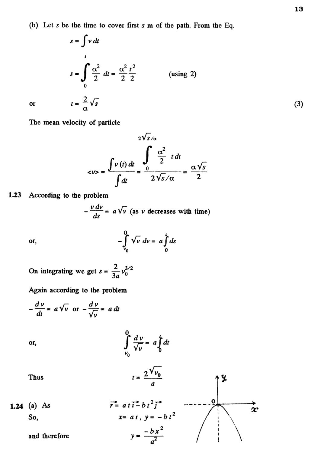
1.24 (a) As
So,
and therefore
r*= att^-bt /*
x= atyy= -bt
-bx2
a
C)
14
which is Eq. of a parabola, whose graph is shown in the Fig.
(b) As r^ ati^-bt2j~*
= ai-2bt) A)
So, v=
Diff. Eq. A) w.r.t. time, we get
So, | v?
(c) cos a
v w
or, cos a =
so, tan a >
2bt
or, a= tan *
2bt
(d) The mean velocity vector
< v > - — ai-btj
fdt t
Hence, I < v*> I - Va^+ (-btJ - VaJTbTtJ
1.25 (a) We have
x- at and y - a t A - a t) A)
Hence, y (x) becomes,
y = I 1 I « x - — x (parabola)
a ^ a j a
(b) Diiferentiating Eq. A) we get
vx = a and vy = a A - 2 a f) B)
15
So,
;
Diff. Eq. B) with respect to time
wx= 0 and wy = -2aa
So, w« V wx2 + m^2 - 2aa
(c) From Eqs. B) and C)
We have v^« a j"+ a ( 1 - 2a r ) 7"* and i?« 2 a a F
So, cos - =
4
4 V2 vm> aVl + (l-2aroJ2aa
On simplifying. 1 - 2 a r0 « ±1
As, r0 * 0 , r0 m —
1.26 Differentiating motion law : jc * a sin co r, y * a(l-coscot), with respect to time,
v = a co cos cor, v » a co sin cor
•* •
So, v^ a co cos cor J+ acosincorj* A)
and v - a co * Const B)
Differentiating Eq. A) with respect to time
w ■ -r-- -a co smcori + aco cos cor; C)
at
(a) The distance s traversed by the point during the time x is given by
s - J v dr«Jacocfr«acox (using 2)
0 0
(b) Taking inner product of v and w
We get, v • w * (a co cos cor i + a co sin cor; )• (a co sin cor ( - i) + a co cos cor -; )
So, v^ hT« - a2 co2 sin cor cos cor + a2 co3 sin cor cos cor - 0
Thus, vtL v?, i.e., the angle between velocity vector and acceleration vector equals —.
1.27 Accordiing to the problem
dVx dVv
So, w,- -^r- 0 and wr- -^- -w A)
Differentiating Eq. of trajectory, y* ajc-fejc2, with respect to time
^2bx
dt dt dt
16
So,
dt
a
x-0
dx
dt
*-0
Again differentiating with respect to time
2" 7^£\2_
dt1 dt
* J
2bx
dt
or,
-w- a(Q)-2b
or,
dt
-2bx(Q) (using 1)
(using
Using C) in B)
dy_
dt
x- 0
•VI
Hence, the velocity of the particle at the origin
v =
Hence,
c-
1.28 As the body is under gravity of constant accelration g, it's velocity vector and displacemen
vectors are:
^ T' (i;
and
V + \gt2 (F*« OaU = 0)
So, <v> over the first t seconds
C)
Hence from Eq. C), <v> over the first t seconds
D)
For evaluating tt take
or, v
2 V
0 Lt=o)
But we have v = v0 at ^ - 0 and
Also at t - x (Fig.) (also from energy conservation)
B;
Vo
17
Hence using this propety in Eq. E)
As
x * 0, so, x « -
Putting this value of x in Eq. D), the average velocity over the time of flight
" V0~g 2
g
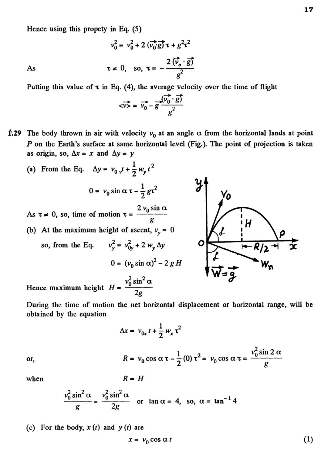
1,29 The body thrown in air with velocity v0 at an angle a from the horizontal lands at point
P on the Earth's surface at same horizontal level (Fig.). The point of projection is taken
as origin, so, Ax = x and Ay - y
(a) From the Eq. Ay - v0 J + T w t2
0
1
vosinax--gx
As x * 0, so, time of motion x =
2 v0 sin a
8
(b) At the maximum height of ascent, vy = 0
so, from the Eq.
+ 2 w Ay
0= (v0sinaJ-2g/f
q sin2 a
t\
Hence maximum height
During the time of motion the net horizontal displacement or horizontal range, will be
obtained by the equation
or,
when
1 i
= v0cosax- — @)x = v0cosax =
sin 2 a
sin2
2 sin2
sin2 a v2 sin2 a
g
2g
or tan a = 4, so, a = tan" * 4
(c) For the body, x (t) and y (f) are
x = v0 cos a
18
1 9
and y* vosinar--gr B)
Hence putting the value of t from A) into B) we get,
i ■
vosina
a
2 I v0 cos a
x tana-
2 2
2vftcos a
0
Which is the sought equation of trajectory i.e. y (x)
(d) As the body thrown in air follows a curve, it has some normal acceleration at all the
moments of time during it's motion in air.
At the initial point (x ■ 0, y ■ 0), from the equation :
w* = ~R y (w^ere ^ is the radius of curvature)
vo
v
g cos a - — (see Fig.) or Ro
Ro v °7 u g cos a
At the peak point v = 0, v = vx ■ v0 cos a and the angential acceleration is zero.
Now from the Eq. wn
R
cos2 a Vq cos2 a
Note : We may use the formula of curvature radius of a trajectory y (x\ to solve
part (d)y
?
(dy/dx)
1.30 We have, vx = v0 cos a, vy = v0 sin a - gt
As vj t wr all the moments of time.
Thus v2= v,2-2gfvosina + g2f2
Now, wf= ^
Hence | wt\
Now V^/ V224
v *
or wM - g — (where vv
n vr V x
19
As
t v* > during time of motion
On the basis of obtained expressions or facts the sought plots can be drawn as shown in
the figure of answer sheet
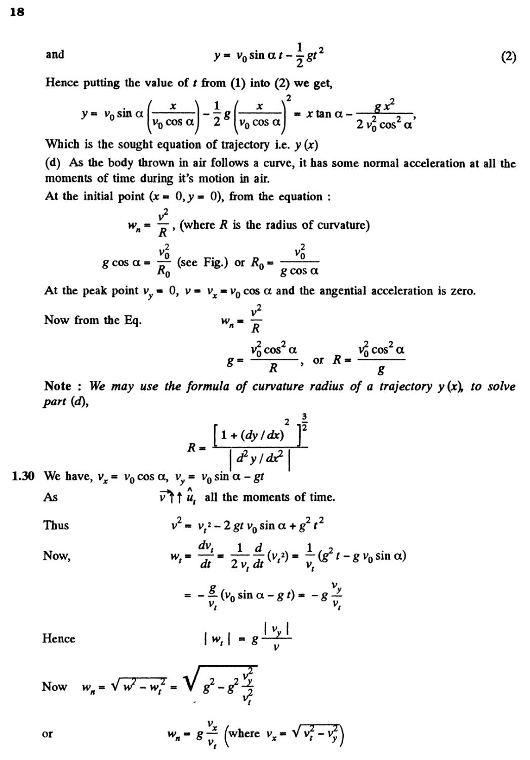
1.31 The ball strikes the inclined plane (Ox) at point O (origin) with velocity v0 = V 2gh A)
As the ball elastically rebounds, it recalls with same velocity v0, at the same angle a from
the normal or y axis (Fig.). Let the ball strikes the incline second time at P, which is at
a distance / (say) from the point Oy along the incline. From the equation
1 ... .2
1 2
0 * v0 cos a x - — g cos a r
where x is the time of motion of ball in air
while moving from O to P.
As
0, so, x =
2v,
8
B)
Now from the equation.
X — Vq^ t + M
1 . 2
v0 sin a x + y g sin a x
SO,
vosina
f2
\
'o
4 v0 sin a
g
(using 2)
Hence the sought distance, / -
1.32 Total time of motion
2 v0 sin a
8
sin a
o
Sh sui a (Using Eq. 1)
or
9-8
and horizontal range
R = v0cos ax or cos a
From Eqs. A) and B)
2 v0 2 x 240
/? 5100 _ 85_
v0 x * 240 x * 4 x
A)
B)
On simplifying
D80J +Dx2J
x4 - 2400 x2 + 1083750 = 0
20
Solving for x we get :
2 2400 ± V 1425000 2400 ± 1194
Thus
x - 42-39 s - 0-71 min and
x * 24-55 s « 0-41 min depending on the angle a.
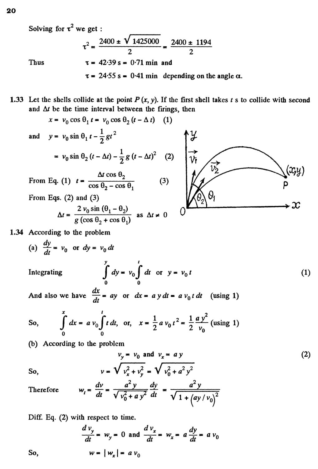
1.33 Let the shells collide at the point P (jc, y). If the first shell takes t s to collide With second
and Ar be the time interval between the firings, then
x - v0 cos Q11 - v0 cos 02 (t - A t) A)
1 2
B) Vr
and
From Eq. A) t
v 7
Arcos 0,
cos 02 - cos
C)
From Eqs. B) and C)
2 v0 sin @X - 02)
g (cos 02 + cos 0X
1.34 According to the problem
as
0
00
v0 or dy = vodt
Integrating
y
s
0
or
And also we have — - ay or dx=*aydt~avotdt (using 1)
x t 2
/r i 2 10 v
d^=avojr^r, or, *«-avor ---^-(using 1)
0 0 U
(b) According to the problem
vy- v0 and v^- ay
So,
Therefore
2 2
ay
Jv a y dfy
/ ss s — ^ —ll-
r dt Vu? + flv2 t/r
l + /ay/vo\
Diff. Eq. B) with respect to time.
d v
dv
jc t/y
0 and -^— - vvv - a -f- - a vn
Jr * ^ °
(i)
B)
So,
av
0
21
Hence
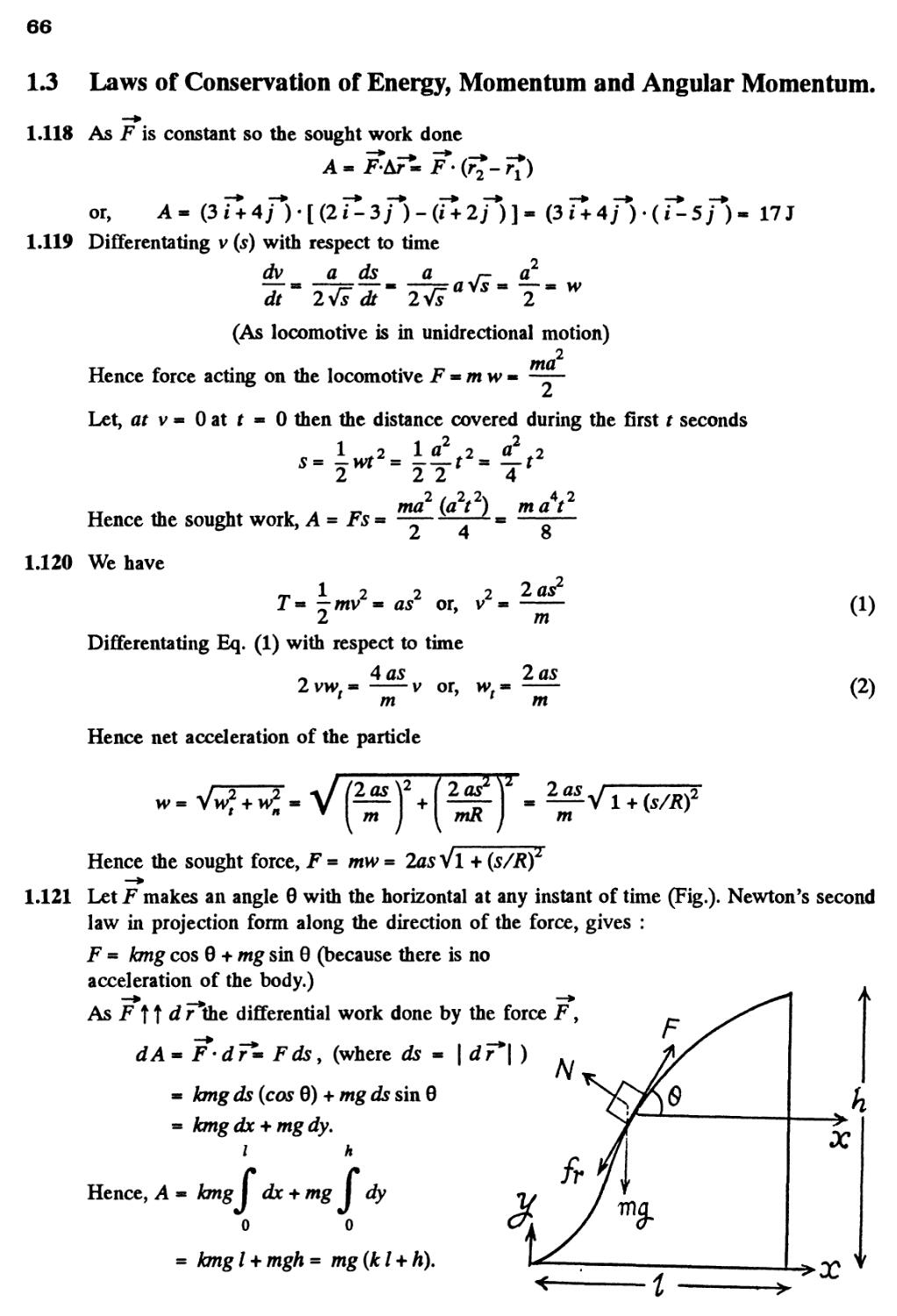
1.35 (a) The velocity vector of the particle
v * a i + fox;
SO,
From A) J dx - a j dt or, jc - at B)
o o
And dy~ bxdt= batdt
y t
Integrating J dy - ab \tdt or, y= —abt2 C)
o o
From Eqs. B) and C), we get, y^—x2 D)
(b) The curvature radius of trajectory y (jc) is :
3
(dyldx) '
2 12
b 2
Let us differentiate the path Eq. y - — jc with respect to *,
dy b Sy b
-f-m —x and —*rm - F)
dx a dx2 ^
From Eqs. E) and F), the sought curvature radius :
3
2 12
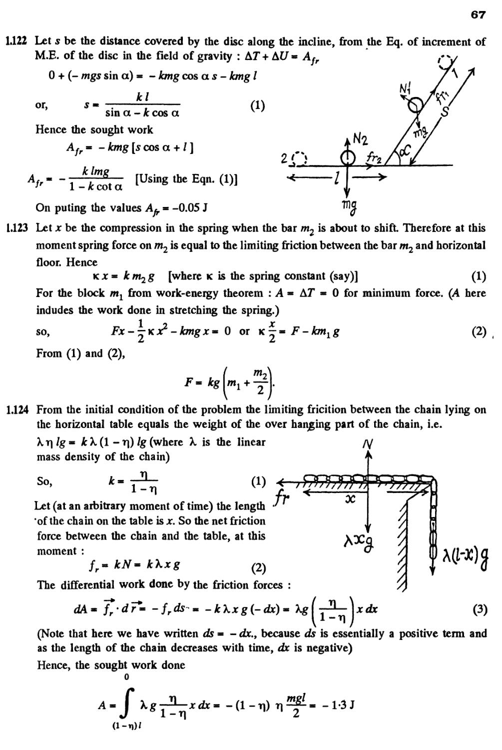
L36 In accordance with the problem
But wt - —r~ or vav
wt = a • x
So,
or, vdv** ai-dr= adx (because a is directed towards the jc-axis)
V JC
So, \vdv= a\ dx
Hence v ■ 2ox or, v - Vlax
22
1.37 The velocity of the partide v « at
So, —- wtm a A)
2 2 2
And wn- j- ±1- (usingv«ar) B)
From * « f v dr
t
a\vdt~ -at2
o
*2
From Eqs. B) and C) wH
t . .,.n
Hence w * V v?l + y?i
I2 - 0-8 m/s2
1.38 According to the problem
2
ForvW, ^--5-
Integrating this equation from v0^ vi v and 0 £ t£ f
o
2
N jw for v (s), - ~~ * — , Integrating this equation from v0 s v ^ v and 0 s s s s
SO, | —- -~| ^y or, In ~
vo
Hence v- voe"^ B)
(b) The normal acceleration of the point
R
2)
And as accordance with the problem
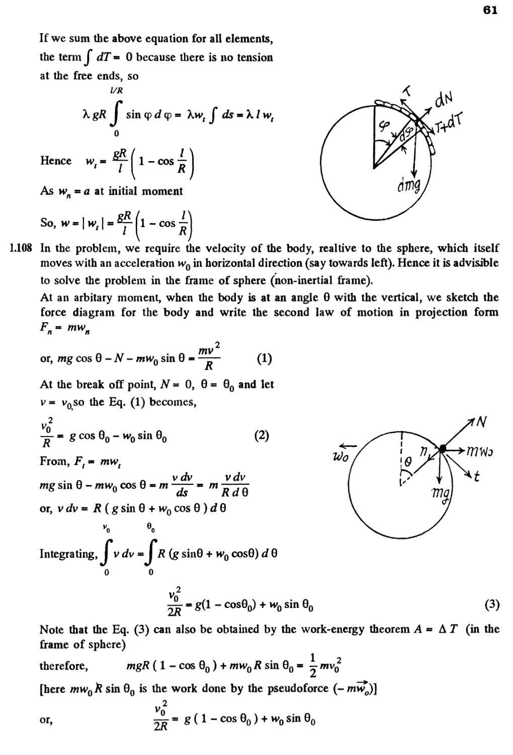
l- \wn\ and
A
n
so,
V2
23
1.39 From the equation v * a Vs
dv a ds a /-a2
T * "zn= T * ^= avs » —, and
A 2VJdr 2Vs 2
v2 a2*
As ^ is a positive constant, the speed of the particle increases with time, and the tangential
acceleration vector and velocity vector coincides in direction.
Hence the angle between v and w is equal to between wti*t an w, and a can be found
by means of the formula : tan a = jr « =
1^1 a2/2
1.40 From the equation / - a sin go t
dl
v« a o) cos cor
So, w,- —« -a co sin cor, and A)
v2 a2 oJ cos2 o) f
(a) At the point / * 0, sin co t - 0 and cos co t« ± 1 so, cor - 0, n etc.
co2
a2-2
Hence w~ wH
Similarly at / - ± a9 sin cor * ± 1 and cos cor = 0, so, wn * 0
i i 2
Hence w « | ^ | * a o>
1.41 As w, = a and at t ■ 0, the point is at rest
1 2
So, v(r) and s(t) are, v* ar and .s* —at A)
Let i? be the curvature radius, then
v2 a2r2 2
But according to the problem
wn-bt*
So, 6r4= 4
Therefore w - Vm£ + m£ - V a2 + Bas/RJ - Va2 + ( 4 6j2 / a2J (using 2)
Hence w = a V 1 + D 6s2/a3J
24
1.42 (a) Let us differentiate twice the path equation y (x) with respect to time.
dy
-f-
dt
lax
dx (fy
— ; —*r
dt dt2
2a
dt
dt
dlx
2
Since the particle moves uniformly, its acceleration at all points of the path is normal and
at the point x * 0 it coincides with the direction of derivative d2y/dt2. Keeping in mind
that at the point x * 0, —
We get
dx
dt
dt
v,
2
n
x- 0
So,
2 V 1
Wn.2av-j, or R--
Note that we can also calculate it from the formula of problem A.35 b)
(b) Differentiating the equation of the trajectory with respect to time we see that
, 2 dx 2 dV rx /1\
bx**ay*~° A)
which implies that the vector (b xi + a yj) is normal to the velocity vector
V
the normal and the normal component of acceleration is clearly
= — f*+ -*£) which, of course, is along the tangent. Thus the former vactor is along
,2
b x
dt2 dt1
on using
Wn " ( b V ♦ a V I/2
/i / | /t|. At jc « 0,y* ± t and so at x = 0
x- 0
Differentiating A)
'(*
A
fit)
= 0
Also from A)
0 at x - 0
So
I — I « ± v (since tangential velocity is constant « v )
Thus
dt2
and
This gives R * a2/b
25
1.43 Let us fix the co-ordinate system at the point O as shown in the figure, such that the
radius vector F*bf point A makes an angle 0 with x axis at the moment shown.
Note that the radius vector of the particle A
rotates clockwise and we here take line ox as
reference line, so in this case obviously the
taking
angular velocity co * ""~7~
anticlockwise sense of angular displacement as
positive.
Also from the geometry of the triangle OAC
R r
sin 0 sin (n - 2 0)
Let us write,
or, r « 2 R cos 0.
0
Differentiating with respect to time.
at
or
or, v- 2R
dt
at
[sin20i-cos20;]
~dFJ
or, v*« 2R a) (sin 2 0 T- cos2qJ
So, |v| or v« 2o)jR«0-4m/.s.
dv
As a) is constant, v is also constant and wt * — * 0
So,
w* w.
Alternate : From the Fig. the angular velocity of the point A, with respect to centre of
the circle C becomes
dBQ)
-dQ)
2 co = constant
dt y dt
Thus we have the problem of finding the velocity and acceleration of a particle moving
along a circle of radius R with constant angular velocity 2 co.
Hence v* 2coi? and
Bco/Q2 2
n R R
1.44 Differentiating (p (t) with respect to time
dtp
dt
For fixed axis rotation, the speed of the point A:
toz- 2at
A)
v«toi?« 2atR or R
2at
B)
26
Differentiating with respect to time
dv
wtm —* 2aR= ~, (using 1)
But
So,
R v/2at
2 a tv (using 2)
1.45 The shell acquires a constant angular acceleration at the same time as it accelerates linearly.
The two are related by (assuming both are constant)
/ 2nn
Where w = linear acceleration and 0 =_angular acceleration
Then, co « V2-02n;n« V2-yB3inJ
But
2
CO
2w/, hence finally
231/1 V
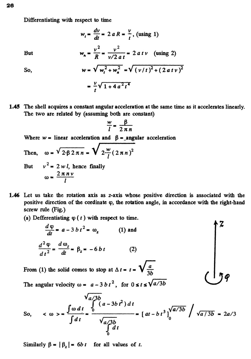
1,46 Let us take the rotation axis as z-axis whose positive direction is associated with the
positive direction of the cordinate <p, the rotation angle, in accordance with the right-hand
screw rule (Fig.)
(a) Defferentiating <p (t) with respect to time.
-~* a - 3 bt2 = co,
dt z
A) and
d2<p
dt2
dt
B)
From A) the solid comes to stop at A t * t
The angular velocity co* a-3bt29 for 0st
So,
< co >
f(a-3bt)dt
Similarly 0 - | 0 | - 6fr f for all values of
27
So, <p
(b) From Eq. B) Pz* -66f
So,
Hence P« (PJ / I » 2V3a&
1.47 Angle a is related with | wt | and wH by means of the fomula :
tana* :—r, where w* co R and wJ« QR A)
where R is the radius of the circle which an arbitrary point of the body circumscribes.
From the given equation p « -r— ■ at (here p * -r— > as P is positive for all values of
Integrating within the limit f Jco = a \ tdt or, cosra^
/i2f4
bo,
2
and |wr|« PA-
Putting the values of | wt \ and wH in Eq. A), we get,
a2tAR/4 at3
tan a * =— ■ —r- or, t
atR 4
1.48 In accordance with the problem, Pz < 0
\D\* 1
— tan a
1/3
Thus - -t— ■ A: VaT, where A: is proportionality constant
or, - I -,==m k I dt or, vco - vcoo - •*?- A)
V to i 2
When co ■ 0, total time of rotation t ■ r
28
Average angular velocity < a) >
I
J7
Hence < co >
@
0
12
o
1.49 We have to * co0 - a cp ~
Integratin this Eq. within its limit for (cp) t
d cp
(o0-/
/:(p J
dt or, In
(xr
0
0),
.2.2
dt
co0/3
Hence
(b) From the Eq., (o * co0 -* it(p and Eq. A) or by differentiating Eq. A)
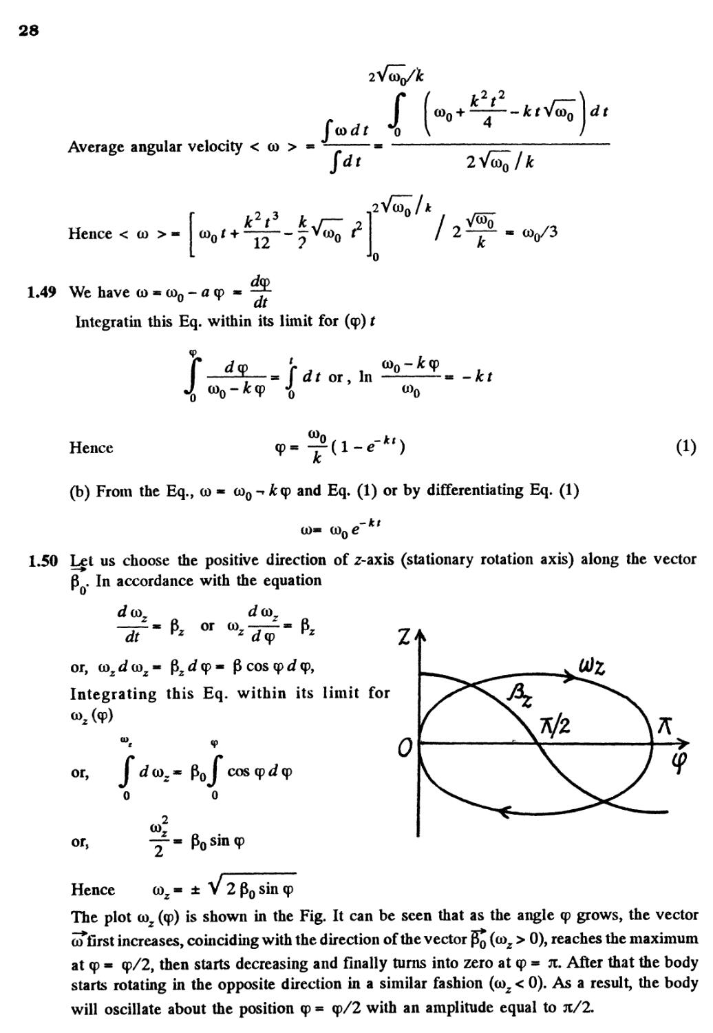
1.50 Let us choose the positive direction of z-axis (stationary rotation axis) along the vector
. In accordance with the equation
dm.
or
dt rz " ™z dy nz Z^K
or, toz d (oz - Pz J cp * P cos cp d cp,
Integrating this Eq. within its limit for
to
or, I rfaJ* poj coscpdcp
o
o
0)
or,
Y* Posin(P
Hence coz * ± V 2 po sin cp
The plot (oz (cp) is shown in the Fig. It can be seen that as the angle cp grows, the vector
of first increases, coinciding with the direction of the vector j^ (coz > 0), reaches the maximum
at cp * cp/2, then starts decreasing and finally turns into zero at cp » n. After that the body
starts rotating in the opposite direction in a similar fashion (coz < 0). As a result, the body
will oscillate about the position cp « cp/2 with an amplitude equal to jc/2.
29
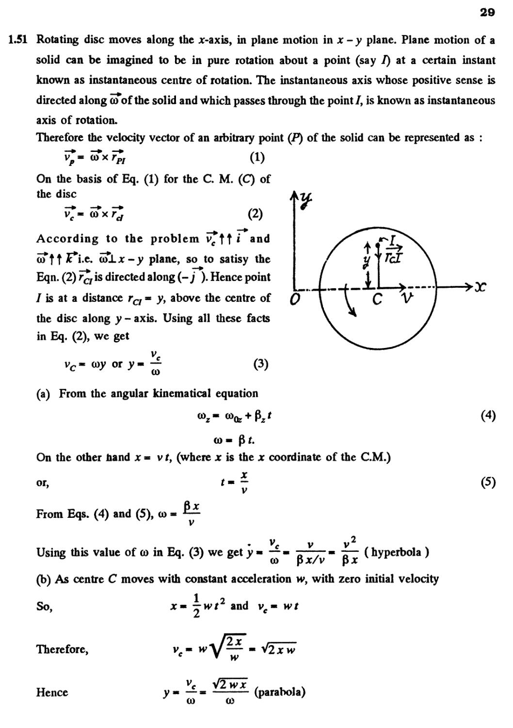
1.51 Rotating disc moves along the x-axis, in plane motion in x - y plane. Plane motion of a
solid can be imagined to be in pure rotation about a point (say 7) at a certain instant
known as instantaneous centre of rotation. The instantaneous axis whose positive sense is
directed along co of the solid and which passes through the point/, is known as instantaneous
axis of rotation.
Therefore the velocity vector of an arbitrary point (P) of the solid can be represented as :
coxr
p/
A)
On the basis of Eq. A) for the C. M. (C) of
the disc
c a V /
According to the problem vctt*
QJTtt^*i'c« (&±-x-y plane, so to satisy the
Eqn. B) r£7 is directed along (- j ). Hence point
/ is at a distance rCI = yy above the centre of
the disc along y - axis. Using all these facts
in Eq. B), we get
0
or y« —
c
@
C)
(a) From the angular kinematical equation
co-
On the other hand x * v f, (where x is the x coordinate of the CM.)
or.
From Eqs. D) and E), co
Using this value of co in Eq. C) we get y • —
co
( hyperbola )
1 2
—wt and vc« wt
(b) As centre C moves with constant acceleration w, with zero initial velocity
So,
Therefore,
Hence
vc- w
co
co
V2jc
(parabola)
E)
30
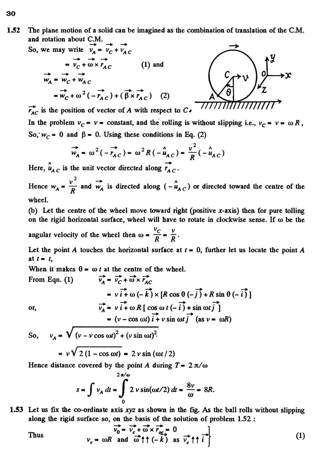
1.52 The plane motion of a solid can be imagined as the combination of translation of the CM.
and rotation about CM.
So, we may write vA
(l)and ' x "*
" 0]
WAm WC+WAC
B)
is the position of vector of A with respect to C*
In the problem vc = v = constant, and the rolling is without slipping i.e., vc = v = coi?,
So,' wc ■ 0 and p * 0. Using these conditions in Eq. B)
A —*
Here, wA c is the unit vector directed along rA c.
Hence h>a * — and wA is directed along (- uA c ) or directed toward the centre of the
wheel.
(b) Let the centre of the wheel move toward right (positive Jt-axis) then for pure tolling
on the rigid horizontal surface, wheel will have to rotate in clockwise sense. If co be the
vc v
angular velocity of the wheel then a) * — * —.
Xv Xv
Let the point A touches the horizontal surface at t * 0, further let us locate the point A
at t * f,
When it makes 0 = co f at the centre of the wheel.
From Eqn. A) v^ * v£ + of x ^
or, vA « v i + co R \ cos co t (- i) + sin
* (v - cos cor) i + v sin cor / (asv* oaR)
So, v. * V (v - v cos cor) + (v sin corJ
- vV 2(l-coscof) « 2vsin(cor/2)
Hence distance covered by the point A during T« 2 tc/co
2 v sin(cof/2) dr - —
co
0
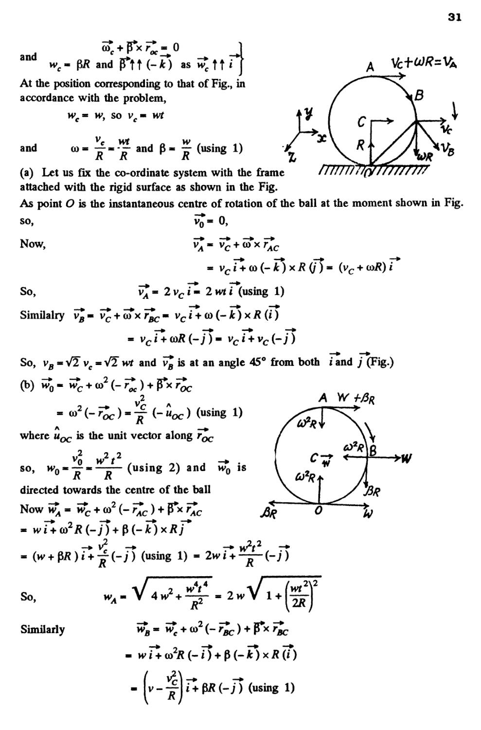
1.53 Let us fix the co-ordinate axis xyz as shown in the fig. As the ball rolls without slipping
along the rigid surface so, on the basis of the solution of problem 1.52 :
vn * v. + co x r ■ * 0
Thus D . -♦* a t J\ -•
v * (oR and co j t (- *) as v
31
and
and
At the position corresponding to that of Fig., in
accordance with the problem,
M> « W9 SO V « Wt
and
co----and p
(using 1)
/77J777
(a) Let us fix the co-ordinate system with the frame
attached with the rigid surface as shown in the Fig.
As point 0 is the instantaneous centre of rotation of the ball at the moment shown in Fig.
so,
Vo«O,
Now,
So,
Similalry
2vci
» 9 9
vc i + co (- k) x R (j ) * (vc +
i (using 1)
+ of x r^, ■ vc i + co (- A:) x R (i)
So, vB * V2 vc * V2 >vt and v£ is at an angle 45° from both i and ; (Fig.)
oc
- u
oc
where uoc is the unit vector along roc
2 2 2
so, w>0«~«^— (using 2) and
is
directed towards the centre of the ball
Now w
wc + co2 (-
— (-;) (using 1)
R
So,
Similarly
V 4>V + r-
2>v
2\2
H-co2i? (-i) + P (-T) xR (T)
V-
-;) (using 1)
32
w-
R
—w w
i + w(-j) (using 2)
So,
yB
V
2\2
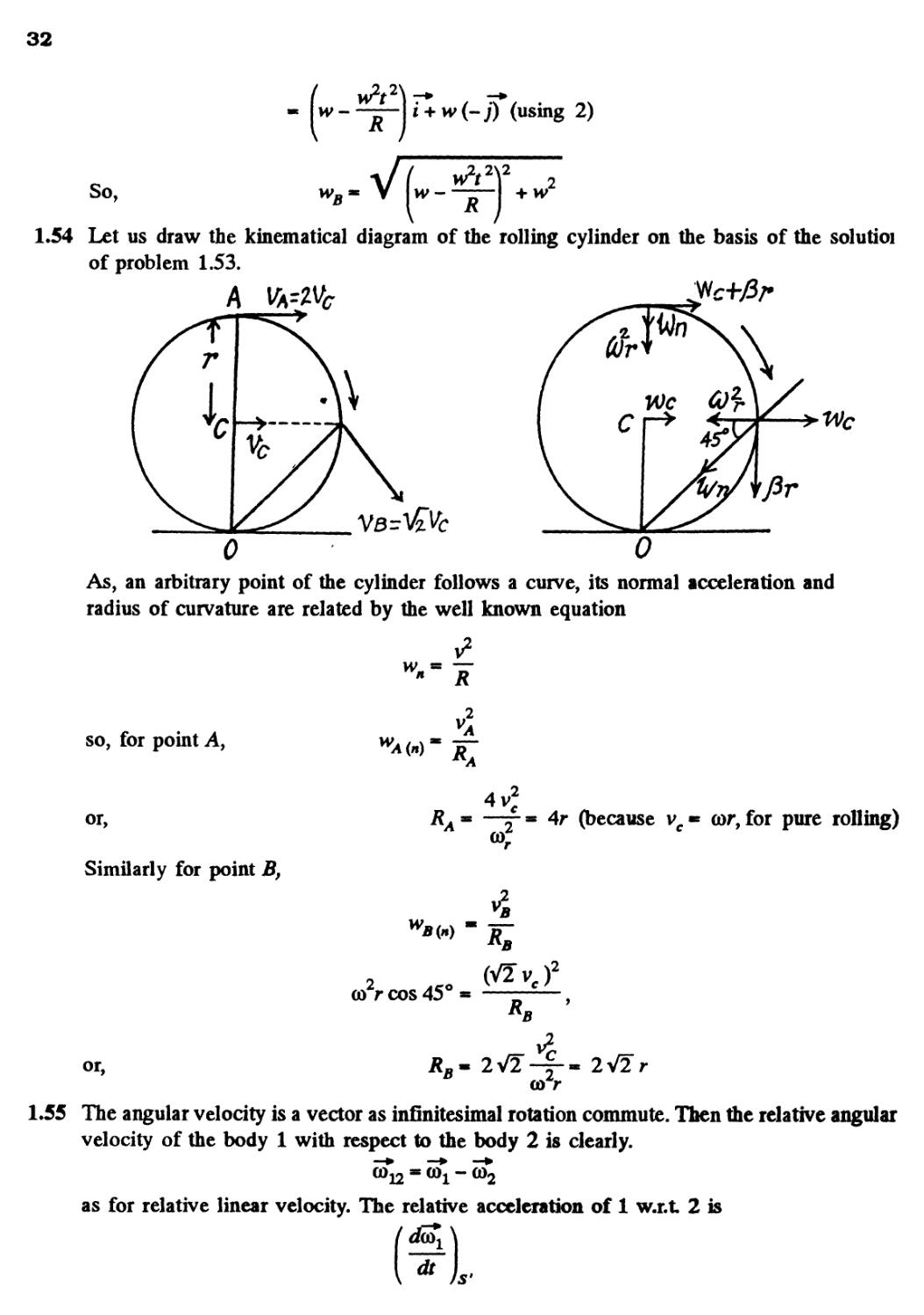
1.54 Let us draw the kinematical diagram of the rolling cylinder on the basis of the solutioi
of problem 1.53.
0 0
As, an arbitrary point of the cylinder follows a curve, its normal acceleration and
radius of curvature are related by the well known equation
v2
so, for point A,
or,
Similarly for point B,
W,
;2
c
(because vc« cor, for pure rolling)
w
■<•>
2
co r cos 45
co r
1.55 The angular velocity is a vector as infinitesimal rotation commute. Then the relative angular
velocity of the body 1 with respect to the body 2 is clearly.
- co
as for relative linear velocity. The relative acceleration of 1 w.r.t 2 is
dT
33
where S' is a frame corotating with the second body and 5 is a space fixed frame with
origin coinciding with the point of intersection of the two axes,
but
r
dt
aJ x
Since 5 ' rotates with angular velocity w2 . However
with constant angular velocity in space, thus
dt
0 as the first body rotates
Is
co1 x co2.
Note that for any vector 5f the relation in space forced frame (k) and a frame (k) rotating
with angular velocity oTis
dt
dt
ICC > ""* 1 "
.5ft We have a) « ati + bt j
So, (o
A)
(o- V (atJ + (fr2J , thus, *,,,_ 1Os
Differentiating Eq. A) with respect to time
7.81 rad/s
dm i-*
—« ai +
2btj
B)
So,
and
(b)
V a2 + B
rad/s
cos a
@
Putting the values of (a) and (&);and taking t * 10s, we get
a- 17°
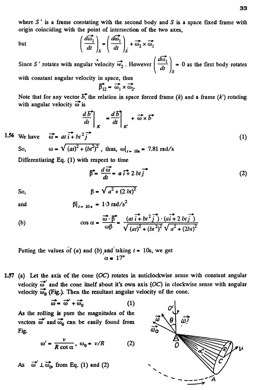
1.57 (a) Let the axis of the cone (OC) rotates in anticlockwise sense with constant angular
velocity oT and the cone itself about it's own axis (OC) in clockwise sense with angular
velocity co^ (Fig.). Then the resultant angular velocity of the cone.
As the rolling is pure the magnitudes of the
vectors <o andco0 can be easily found from *<J \rJ (&'!
Fig. ^O
a)'- V , (o0- v/fl B) 0
H cot a u v y u
As a) X (Oq, from Eq. A) and B)
A
34
co
U
/? cot a
(b) Vector of angular acceleration
p
Rcosa
2-3 rad/s
7
(as co * constant.)
The vector co*j which rotates about the OO' axis with the angular velocity co*, retains i
magnitude. This increment in the time interval dt is equal to
I d co01» co0* co' dt or in vector form d co0 » (co x co0) dt.
Thus P** co* x co*)
The magnitude of the vector jTis equal to
p » co' co0 (as co X co0
So,
P
V V v
— « —r tan a ~ 2-3 rad/s
RcotaR R2
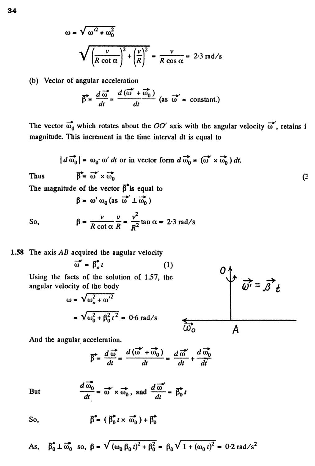
1.58 The axis AB acquired the angular velocity
A)
Using the facts of the solution of 1.57, the
angular velocity of the body
co» Vco? + co/2
0-6 rad/s
And the angular acceleration.
0
=^ t
But
'o
to x co0, and
dt
So,
As, P^lco*3 so, p« V (co0 po 02 + Po
0-2 rad/s2
35
THE FUNDAMENTAL EQUATION OF DYNAMICS
Let R be the constant upward thurst on the aerostat of mass my coming down with a
constant acceleration w. Applying Newton's second law of motion for the aerostat in
projection form
Fy - mwy
mg-R* mw
Now, if Am be the mass, to be dumped, then using the Eq. Fy = mwy
R-(m- Am) g « (m - Am) w>
From Eqs. A) and B), we get, Am *
B)
1.60 Let us write the fundamental equation of dynamics for all the three blocks in terms of
projections, having taken the positive direction of x and y axes as shown in Fig; and using
the fact that kinematical relation between the accelerations is such that the blocks move
with same value of acceleration (say w)
mow
B)
and T2-km2g* m2w C)
The simultaneous solution of Eqs. A), B) and
C) yields,
g
i
T,
and
ut f ft
\
/
/
fxnfff'rtrf'
fr
W'$
77?2
*
fn.
As the block m0 moves down with acceleration w, so in vector form
1.61 Let us indicate the positive direction of jr-axis along the incline (Fig.). Figures show the
force diagram for the blocks.
Let, R be the force of interaction between the bars and they are obviously sliding down
with the same constant acceleration w.
36
Newton's second law of motion in projection form along jc-axis for the blocks gives :
m1gsina-k1m1g cos a + R « m1 w A)
m2 g sin a - R - k^ m2 g cos a « m2 w B)
Solving Eqs. A) and B) simultaneously, we get
1 ^1 * ^ ^2
w * g sin a - g cos a and
cos a
(b) when the blocks just slide down the plane, w « 0, so from Eqn. C)
1 1 2 2
g sin a - g cos a * 0
Ifl + /W
* +
or, (m! + /W2) sin a * (kx mx + k>± m2) cos a
Hence tan a =
1.62 Case 1. When the body is launched up :
Let fc be the coefficeint of friction, u the velocity of projection and / the distance traversed
along the incline. Retarding force on the block - mg sin a + kmgcosa and hence the
retardation - g sin a + kg cos a.
Using the equation of particle kinematics along the incline,
0* w2-2(gsina + JfcgcosaO
' 2(gsina + A:gcosa)
and 0 « u - (g sin a + kg cos a) t
or, u « (g sin a + kg cos a) t B)
Using B) in A) / - \r (g sin a + kg cos a) t2 C)
Case B). When the block comes downward, the net force on the body
« mg sin a - km g cos a and hence its acceleration « g sin a - k g cos a
Let, t be the time required then,
/= |(gsina-*gcosa)r'2 D)
From Eqs. C) and D)
since -A: cos a
sin a + k cos a
But — - — (according to the question),
Hence on solving we get
a» 016
1)
37
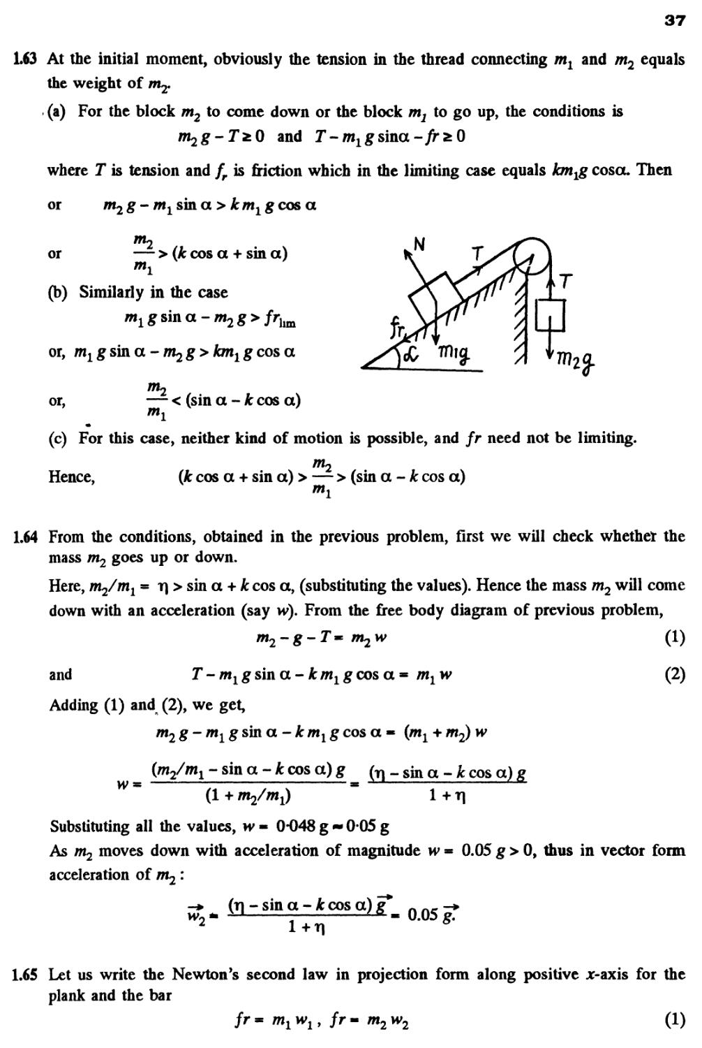
1.63 At the initial moment, obviously the tension in the thread connecting ml and m2 equals
the weight of m2.
. (a) For the block m2 to come down or the block m2 to go up, the conditions is
and J-
where T is tension and fr is friction which in the limiting case equals long coscl Then
or m2g-m1 sin a > km1gcosa
or
> (k cos a + sin a)
(b) Similarly in the case
or, m1 g sin a - m^ g > km1 g cos a
or,
< (sin a - k cos a)
(c) For this case, neither kind of motion is possible, and fr need not be limiting.
Hence,
2
(k cos a + sin a) > — > (sin a - k cos a)
mi
1.64 From the conditions, obtained in the previous problem, first we will check whethet the
mass m2 goes up or down.
Here, m2/m1 * r\ > sin a + k cos a, (substituting the values). Hence the mass m2 will come
down with an acceleration (say w). From the free body diagram of previous problem,
and T - ml g sin a - km1 g cos a * m1 w
Adding A) and B), we get,
m2g-m1gsh\a-kmlg cos a - (ml + m2) w
{m2/mx - sin a - k cos a) g fa _ sm a _ k cos a)
B)
A + m^/m^ 1 + T|
Substituting all the values, w- 0-048g-005g
As m2 moves down with acceleration of magnitude w = 0.05 g > 0, thus in vector form
acceleration of m2:
1 +T|
1.65 Let us write the Newton's second law in projection form along positive Jt-axis for the
plank and the bar
/r- mxwl9 fr~ m2w2 A)
38
At the initial moment, fr represents the static
friction, and as the force F grows so does the
friction force fr, but up to it's limiting value
i.e. fr =*
Unless this value is reached, both bodies moves
as a single body with equal acceleration. But
as soon as the force fr reaches the limit, the 777////////////////////////
bar starts sliding over the plank i.e. w2 2 vvr
Substituting here the values of wx and h>2 taken from Eq. A) and taking into account that
km2
fr= km^ g, we obtain, (at -km2g)/m2z g, were the sign "=" corresponds to the moment
m
t0 (say)
Hence,
If
t £ tQy then
km2g
(constant), and
On this basis
m>2» (at-km2g)/m2
(t) and w2 (r), plots are as shown in the figure of answersheet.
1.66 Let us designate the x-axis (Fig.) and apply Fx* mwx for body A :
mgsina-ifcmgcosa* mw
or, w = g sin a - kg cos a
Now, from kinematical equation :
/seca- 0 + (l/2)wr2
or,
(using Eq. A)).
i.e.
t* V 2 /sec a/(sin a - Jtcos a)g
« V 2 // (sin 2 a/2 - kcos1 a) g
j ( sin 2 a , 2 )
a\ —-—-kcos a
da
0
2 cos 2 a
+ 2k cos a sin a - 0
N
or,
tan2a- -T=>a« 49°
k
and putting the values of a, k and / in Eq. B) we get tain * Is.
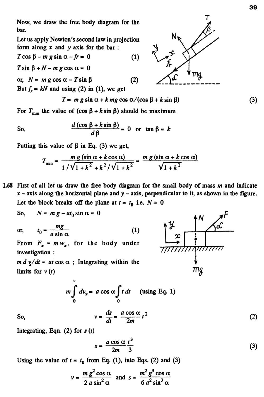
1.67 Let us fix the x - y co-ordinate system to the wedge, taking the x - axis up, along the
incline and the y - axis perpendicular to it (Fig.).
39
Now, we draw the free body diagram for the
bar.
Let us apply Newton's second law in projection
form along x and y axis for the bar :
Tcosp-mgsina-/r» 0 A)
Jsinp +N-mgcosa« 0
or, N=* mgcosa-JsinP B)
But fr** kN and using B) in A), we get
J« m g sin a + kmg cos a/(cos P
For T the value of (cos P + it sin P) should be maximum
C)
So,
d (cos ft + fcsin ft)
0 or tan P « k
Putting this value of P in Eq. C) we get,
_, m g (sin a + &cos a)
mm
i/Vi+*:2+jfc2/Vi+jfc2
m g (sin a + k cos a)
VTTP"
1.68 First of all let us draw the free body diagram for the small body of mass m and indicate
x - axis along the horizontal plane and y - axis, perpendicular to it, as shown in the figure.
Let the block breaks off the plane at t * t0 i.e. N ■ 0
So,
or.
/wg-afosina« 0
mg
A)
a sin a
From Fx ■ mwxy for the body under
investigation :
m d yj/dt = at cos a ; Integrating within the
limits for v (t)
V
ml dvx» a cos a I tdt (using Eq. 1)
So,
ds a cos a 2
F* 2m
B)
Integrating, Eqn. B) for s (t)
a cos a t
* 2m 3
Using the value of t« r0 from Eq. A), into Eqs. B) and C)
C)
m g~ cos a , m2 g3 cos a
2 a sin2 a
and 5-
6 a2 sin3 a
40
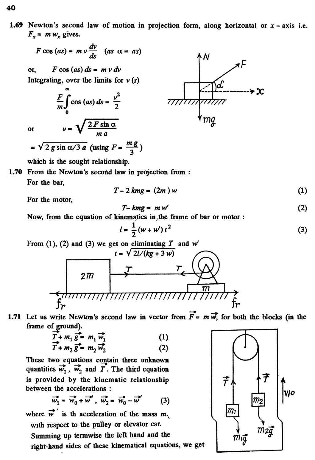
1.69 Newton's second law of motion in projection form, along horizontal or x - axis i.e.
Fx = mwx gives.
dv
F cos (as) « m v — (as a * as)
as
or, F cos (as) ds* mvdv
Integrating, over the limits for v (s)
00
—J cos (as) ds « y
or
v
sin a
ma
- V2gsina/3fl (using ^
which is the sought relationship.
1.70 From the Newton's second law in projection from :
For the bar,
T-2kmg~ Bm)w
For the motor,
T-kmg= mW
Now, from the equation of kinematics in the frame of bar or motor :
A)
B)
C)
From A), B) and C) we get on eliminating T and W
t~ V71/{kg + 3w)
fr ' w-»..fr
1.71 Let us write Newton's second law in vector from F ** mwt for both the blocks (in the
frame ofcround).
2T+ /wxg*~ r"i *i A)
T*+m2g*-m2w2 B)
These two equations contain three unknown
quantities vv^, \v2 and T. The third equation
is provided by the kinematic relationship
between the accelerations :
M^« Wq + W y M^« Wq-W C)
p i
where w is th acceleration of the mass mv
with respect to the pulley or elevator car.
Summing up termwise the left hand and the
right-hand sides of these kinematical equations, we get
7772
T
Vjo
N
41
= 2w
0
D)
The simultaneous solution of Eqs*(l), B) and D) yields
x - m2) g*+2m2w0
mum2
Using this result in Eq. C), we get,
0*1 "*"
and
2 m^ m
0*1 "*"
Using the results in Eq. C) we get v?
GT-
(b) obviously the force exerted by the pulley on the celing of the car
4m1m2
F=-27=
Note : one could also solve this problem in the frame of elevator car.
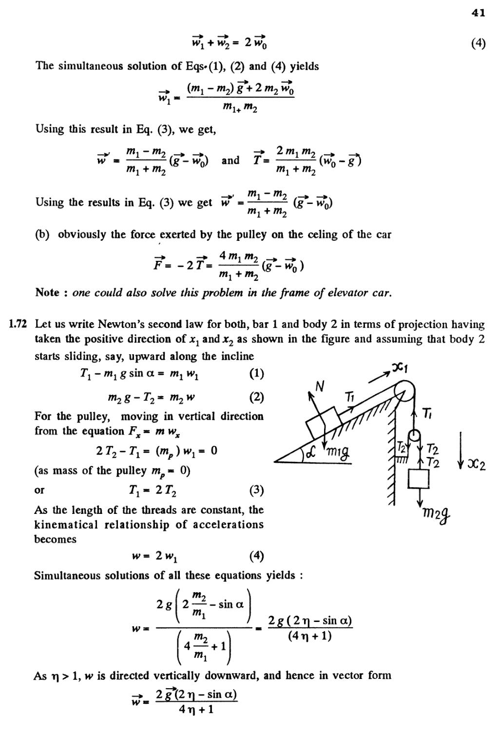
1.72 Let us write Newton's second law for both, bar 1 and body 2 in terms of projection having
taken the positive direction of xx and x2 as shown in the figure and assuming that body 2
starts sliding, say, upward along the incline
Tl-mlg sin a = m1w1
m2w
A)
B)
For the pulley, moving in vertical direction
from the equation Fx» ntwx
(as mass of the pulley mp - 0)
or 7\« 2 T2 C)
As the length of the threads are constant, the
kinematical relationship of accelerations
becomes
w- 2wx D)
Simultaneous solutions of all these equations yields :
N
w
2g
f
2
(
4
tn
"*2
mi
——
0*1
\
-sin a
+ 1
2 g B T] - sin a)
As T| > 1, iv is directed vertically downward, and hence in vector form
2 g*B T] - sin a)
w
42
1.73 Let us write Newton's second law for masses ml and m2 and moving pully in vertical
direction along positive x - axis (Fig.) :
8 -
m
or
m2g-T = m2w2x
TX-2T= 0(asm = 0)
T, « 2J
A)
B)
////////V77/77
C)
Again using Newton's second law in projection
form for mass m0 along positive x1 direction
(Fig.), we get
Tx - m0 w0 D)
The kinematical relationship between the
accelerations of masses gives in terms of
projection on the x - axis
Wlx + W2x " ^ W>0 E)
Simultaneous solution of the obtained five equations yields
[4 m1 m2 + m0 {m1 - m^) ] g
In vector form
/
/
/
/
/
x
a
1.74 As the thread is not tied with my so if there were no friction between the thread and the
ball m, the tension in the thread would be zero and as a result both bodies will have free
fall motion. Obviously in the given problem it is the friction force exerted by the ball on
the thread, which becomes the tension in the thread. From the condition or language of
the problem wM>wm and as both are directed downward so, relative acceleration of
M - wM-wm and is directed downward. Kinematical equation for the ball in the frame
of rod in projection form along upward direction gives :
///////,
•2 A) 7v\
Newton's second law in projection form along
vertically down direction for both, rod and ball
gives,
Mg-fr-MwM B)
mg-fr- mwm C)
Multiplying Eq. B) by m and Eq. C) by M
and then subtracting Eq. C) from B) and after
using Eq. A) we get
2lMm
-TP a
I
T
fr
(M-m)t
43
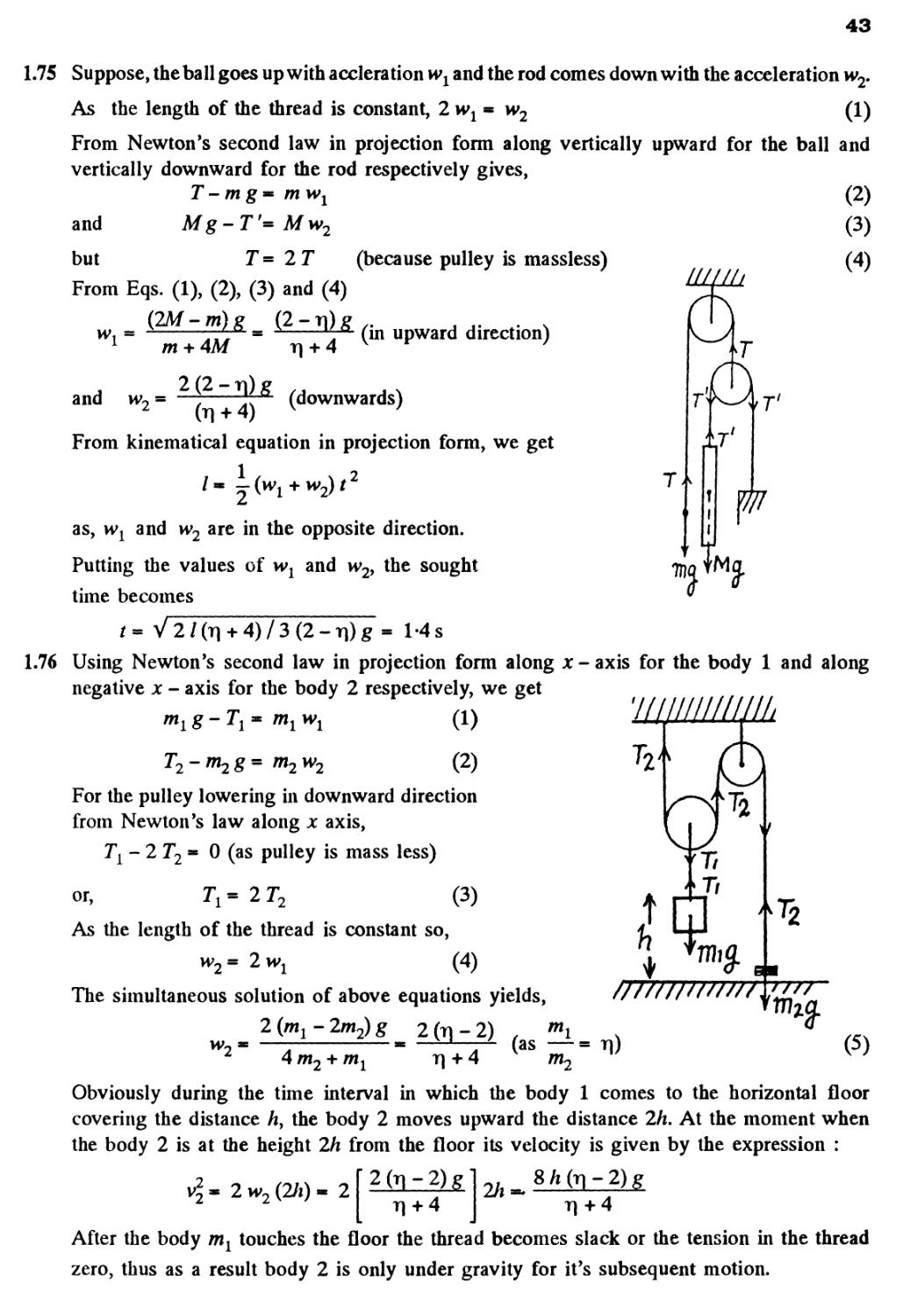
1.75 Suppose, the ball goes up with accleration wx and the rod comes down with the acceleration w2.
As the length of the thread is constant, 2wp w2 A)
From Newton's second law in projection form along vertically upward for the ball and
vertically downward for the rod respectively gives,
T - m g * mwl
and Mg - T'= Mw2
but T = 2 T (because pulley is massless)
From Eqs. A), B), C) and D)
B-TQg
B)
C)
D)
m + AM
r| + 4
(in upward direction)
and
(downwards)
From kinematical equation in projection form, we get
T
as, wx and w2 are in the opposite direction.
Putting the values of xvx and w2> the sought
time becomes
T
TM fM
/=V2/(T] + 4)/3B-T])g= 1 -4 s
1.76 Using Newton's second law in projection form along x - axis for the body 1 and along
negative x - axis for the body 2 respectively, we get
m1w1
A)
For the pulley lowering in downward direction
from Newton's law along x axis,
< 0 (as pulley is mass less)
7,-21.
or, 7\ = 2 T2 C)
As the length of the thread is constant so,
h>2=
D)
The simultaneous solution of above equations yields,
2 (m2 - 2m2) g 2 (ti - 2) , "*i
//////////////
4 m
+ 4
(as
m
E)
v2 ~r i**] ij tt #f»2
Obviously during the time interval in which the body 1 comes to the horizontal floor
covering the distance hy the body 2 moves upward the distance 2h. At the moment when
the body 2 is at the height 2/i from the floor its velocity is given by the expression :
2 w2 B/*) - 2
T] + 4
T] +4
After the body m1 touches the floor the thread becomes slack or the tension in the thread
zero, thus as a result body 2 is only under gravity for it's subsequent motion.
44
Owing to the velocity v2 at that moment or at the height 2h from the floor, the body 2
further goes up under gravity by the distance,
2g r| + 4
Thus the sought maximum height attained by the body 2 :
4hQn - 2) 6r\h
+ 4
H
2h
(Tl + 4)
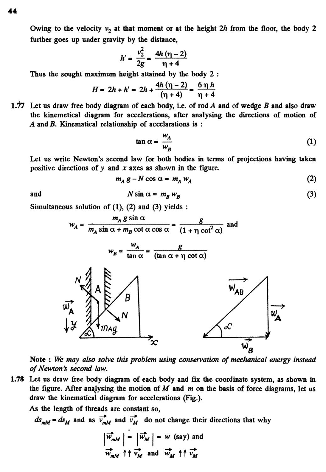
Let us draw free body diagram of each body, i.e. of rod A and of wedge B and also draw
the kinemetical diagram for accelerations, after analysing the directions of motion of
A and B. Kinematical relationship of accelerations is :
tana
w
B
Let us write Newton's second law for both bodies in terms of projections having taken
positive directions of y and x axes as shown in the figure.
mAg-Ncos a * n*AwA (?)
and
Nswa = ?nBwB
Simultaneous solution of A), B) and C) yields :
mA g sin a «
mA sin a + mB cot a cos a A + t| cot2 a)
and
C)
tan a (tan a + r\ cot a)
Note : We may also solve this problem using conservation of mechanical energy instead
of Newton's second law.
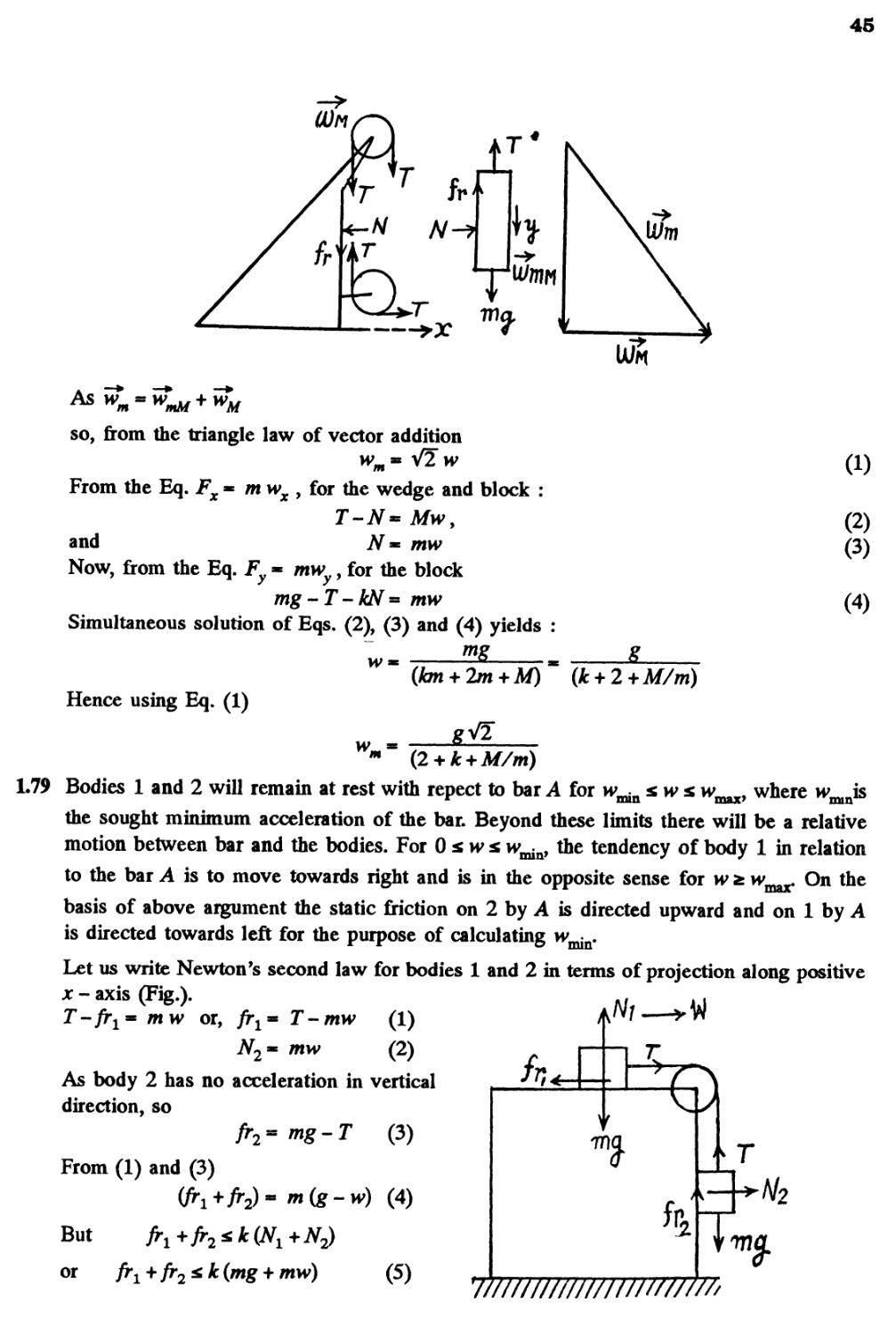
1.78 Let us draw free body diagram of each body and fix the coordinate system, as shown in
the figure. After analysing the motion of M and m on the basis of force diagrams, let us
draw the kinematical diagram for accelerations (Fig.).
As the length of threads are constant so,
dsmM « dsM and as vmM and vM do not change their directions that why
w
mM
w*M I * w (say) and
fmM
TT vm an<* WM tt Y
45
U/ro
so, from the triangle law of vector addition
wm=* yflw
From the Eq. Fx « mwx > for the wedge and block :
T-N= Mwy
and N *= mw
Now, from the Eq. Fy « mw , for the block
mg-T-kN = mw
Simultaneous solution of Eqs. B), C) and D) yields :
mg
A)
B)
C)
D)
w
(bn + 2m+M) (k + 2 +M/m)
Hence using Eq. A)
w
M
1.79 Bodies 1 and 2 will remain at rest with repect to bar A for wa^n zwz
where
the sought minimum acceleration of the bar. Beyond these limits there will be a relative
motion between bar and the bodies. For Osn'i w^, the tendency of body 1 in relation
to the bar A is to move towards right and is in the opposite sense for w fc m^. On the
basis of above argument the static friction on 2 by A is directed upward and on 1 by A
is directed towards left for the purpose of calculating w^.
Let us write Newton's second law for bodies 1 and 2 in terms of projection along positive
x - axis (Fig.).
T-frx = mw or, frx= T-mw A)
N2 « mw B)
As body 2 has no acceleration in vertical
direction, so
fc-mg-T C)
From A) and C)
But frl +fr2 * k (Nx
or fr1+fr2*k (mg + mw)
E)
7/////////////////////////
46
From D) and E)
m(g-w)
or w
A+*)
Hence
mm
N
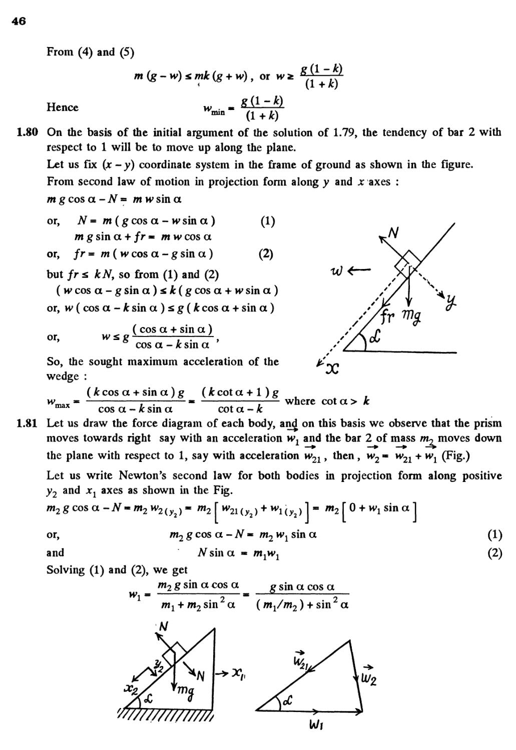
1.80 On the basis of the initial argument of the solution of 1.79, the tendency of bar 2 with
respect to 1 will be to move up along the plane.
Let us fix (jc - y) coordinate system in the frame of ground as shown in the figure.
From second law of motion in projection form along y and x axes :
m g cos a-N= m wsin a
or, N = m(g cos a - w sin a ) A)
m g sin a + fr * m w cos a
or, fr-m(w cos a - g sin a ) B)
but fr x kN, so from A) and B)
( w cos a- gsina)* k(g cos a + w sin a )
or, w ( cos a-fcsina)sg(fc cos a + sin a)
( cos a + sin a)
' cos a - k sin a '
So, the sought maximum acceleration of the
wedge :
(k cos a + sin a) g (k cot a + 1) g
x
max
where cot a > k
cos a - k sin a cot a - k
1.81 Let us draw the force diagram of each body, and on this basis we observe that the prism
moves towards right say with an acceleration wl and the bar 2 of mass w, moves down
the plane with respect to 1, say with acceleration w21, then, w2 « w21 + wx (Fig.)
Let us write Newton's second law for both bodies in projection form along positive
y2 and xx axes as shown in the Fig.
m2g cos a -AT- m2w2{yj= m2 I w2i{y2) + wHy2)\ " m2 \ ° + wi sina 1
or, m2 g cos a-N= m2w1 sin a A)
and N sin a « 0*1*^ B)
Solving A) and B), we get
m2 g sin a cos a g sin a cos a
(m1/m2) + sin a
mx + m2 sin a
47
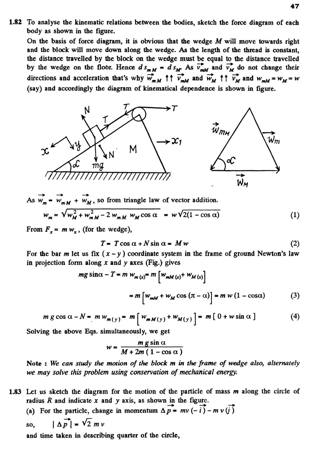
1.82 To analyse the kinematic relations between the bodies, sketch the force diagram of each
body as shown in the figure.
On the basis of force diagram, it is obvious that the wedge M will move towards right
and the block will move down along the wedge. As the length of the thread is constant,
the distance travelled by the block on the wedge must be equal to the distance travelled
by the wedge on the floor. Hence dsmM « ds^. As v^ and v*M do not change their
directions and acceleration that's why w*mM TT v^a/ an(* ™m TT V
(say) and accordingly the diagram of kinematical dependence is shown in figure.
anc^ wmMssWMssW
v//////////////////////////
m
VtM
As w
m
+ wu, so from triangle law of vector addition.
-2wmMwMco&a
*vV2(l-cosa)
A)
From Fx = m wx, (for the wedge),
J* Jcosa+^sina* Mw B)
For the bar m let us fix (x - y) coordinate system in the frame of ground Newton's law
in projection form along x and y axes (Fig.) gives
mg sinct - T - m wm
m
^ w]
m w A - cosa)
mgcos a-N» mwn
Solving the above Eqs. simultaneously, we get
_ fflgsina
C)
D)
2m(l-cosa)
Note : We can study the motion of the block m in the frame of wedge also, alternately
we may solve this problem using conservation of mechanical energy.
1.83 Let us sketch the diagram for the motion of the particle of mass m along the circle of
radius R and indicate x and y axis, as shown in the figure.
(a) For the particle, change in momentum A/? * mv (- i) - m v (/)
so, | A/T| * Vz mv
and time taken in describing quarter of the circle,
48
Hence, < F > =
(b) In this case
Pi = 0 and
xR
2v
A?
At
2>/2mv2
so
mwtt
Hence,
« mw>,
1.84 While moving in a loop, normal reaction exerted by the flyer on the loop at different
points and uncompensated weight if any contribute to the weight of flyer at those points.
(a) When the aircraft is at the lowermost point, Newton's second law of motion in projection
form Fn = m wn gives
2
N-mg =
mv
~R
or , N = mg +
m v
R
= 2-09 kN
(b) When it is at the upper most point, again
from Fn - mwn we get
N" + mg
R
N -
-mg*= 0-7kN
(c) When the aircraft is at the middle point of the loop, again fromFn- mwK
m v
= ^-» 1-4 kN
g
The uncompensated weight is mg. Thus effective weight = VW +m g =l-56kN acts
obliquely.
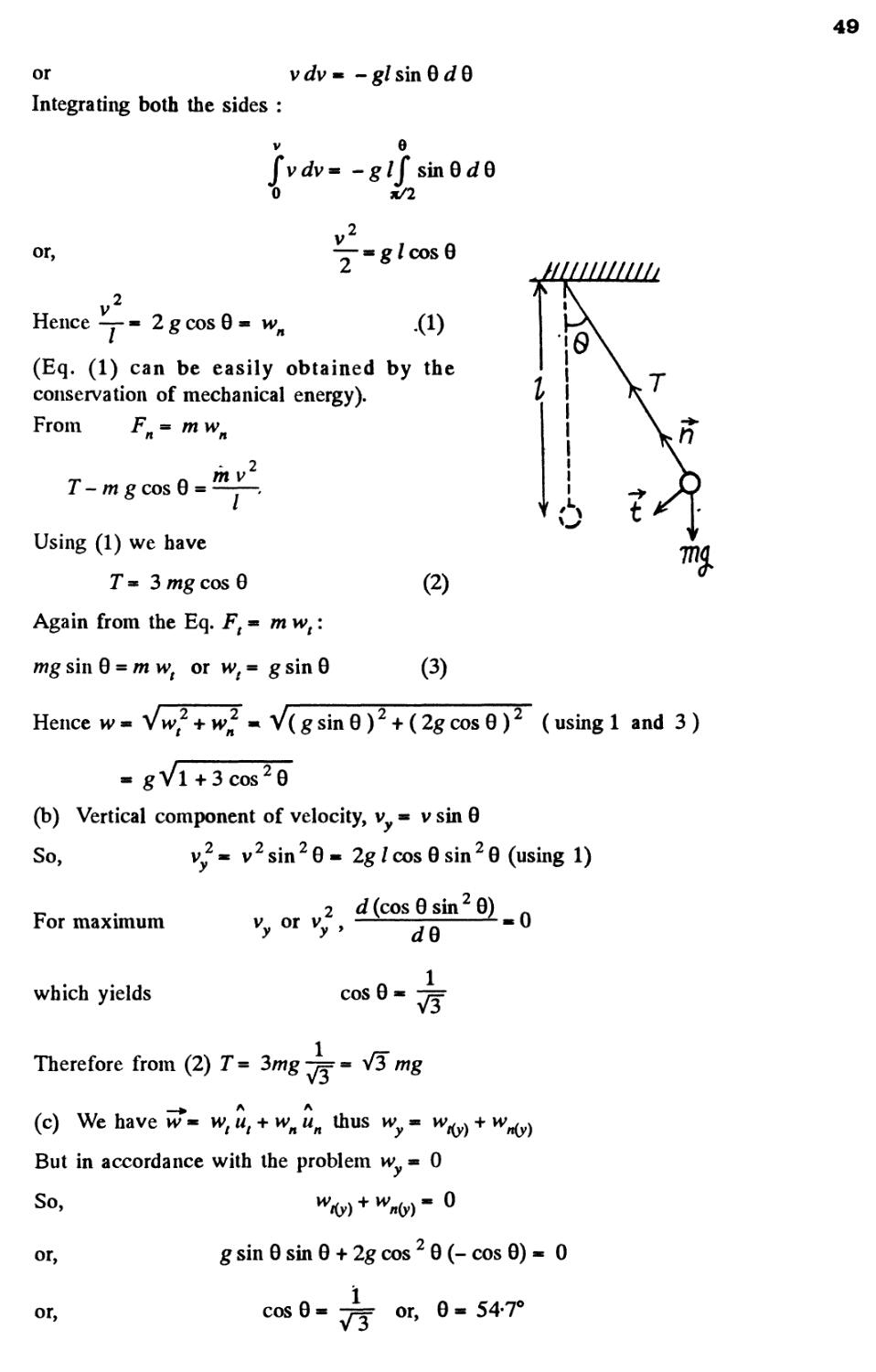
.85 Let us depict the forces acting on the small sphere m, (at an arbitrary position when the
thread makes an angle 0 from the vertical) and write equation F = m w via projection on
A A
the unit vectors ut and un. From Ft = m wn we have
. Q dv
mg sin 0 * m —
vdv
v dv
ds
(as vertical is refrence line of angular position)
49
or vdv* -glsin
Integrating both the sides :
v 6
fvdv* -g/f sin 9dQ
0 a/2
or,
— - g I cos 9
Hence — » 2 g cos 9 - wn
(Eq. A) can be easily obtained by the
conservation of mechanical energy).
From Fn - mwn
T -mg cos 9 =
m v
I
Using A) we have
T = 3 mg cos 9
Again from the Eq. Ft - m tv,:
wg sin 9 = m wt or vvf = g sin 9
B)
C)
HI 11IIIII II*
Hence w - V wr2 + n>n2 * V (g sin 9 J + Bg cos 9 J (using 1 and 3 )
* gVl+3cos29
(b) Vertical component of velocity, v ■ v sin 9
So,
.2-2
For maximum
Vy = vzsinz9- 2g / cos 9 sin z 9 (using 1)
2 d (cos 9 sin 9)
which yields
cos 9
V3
Therefore from B) T = 3wg -j= - VT mg
wt ut + wn un thus
n un
(c) We have hT- wt ut ^
But in accordance with the problem w = 0
+ w
n(y)
or,
g sin 9 sin 9 + 2g cos 2 9 (- cos 9) - 9
or,
cos 9
or, 9-54T
50
1.86 The ball has only normal acceleration at the lowest position and only tangential acceleration
at any of the extreme position. Let v be the speed of the ball at its lowest position and /
be the length of the thread, then according to the problem
y-gsina A)
where a is the maximum deflection angle
From Newton's law in projection form : Ft * mwt
dv
7////////////A
or, - g I sin 0 d 0 - v dv
On integrating both the sides within their limits.
a 0
-g/J sin0d0« J
o
v dv
or, v2 = 2gl A - cos a) B)
Note : Eq. B) can easily be obtained by the conservation of mechanical energy of the
ball in the uniform field of gravity.
From Eqs. A) and B) with 0 * a
2g/ A - cos a) * lg cos a
or,
cos a * — so, a * 53*
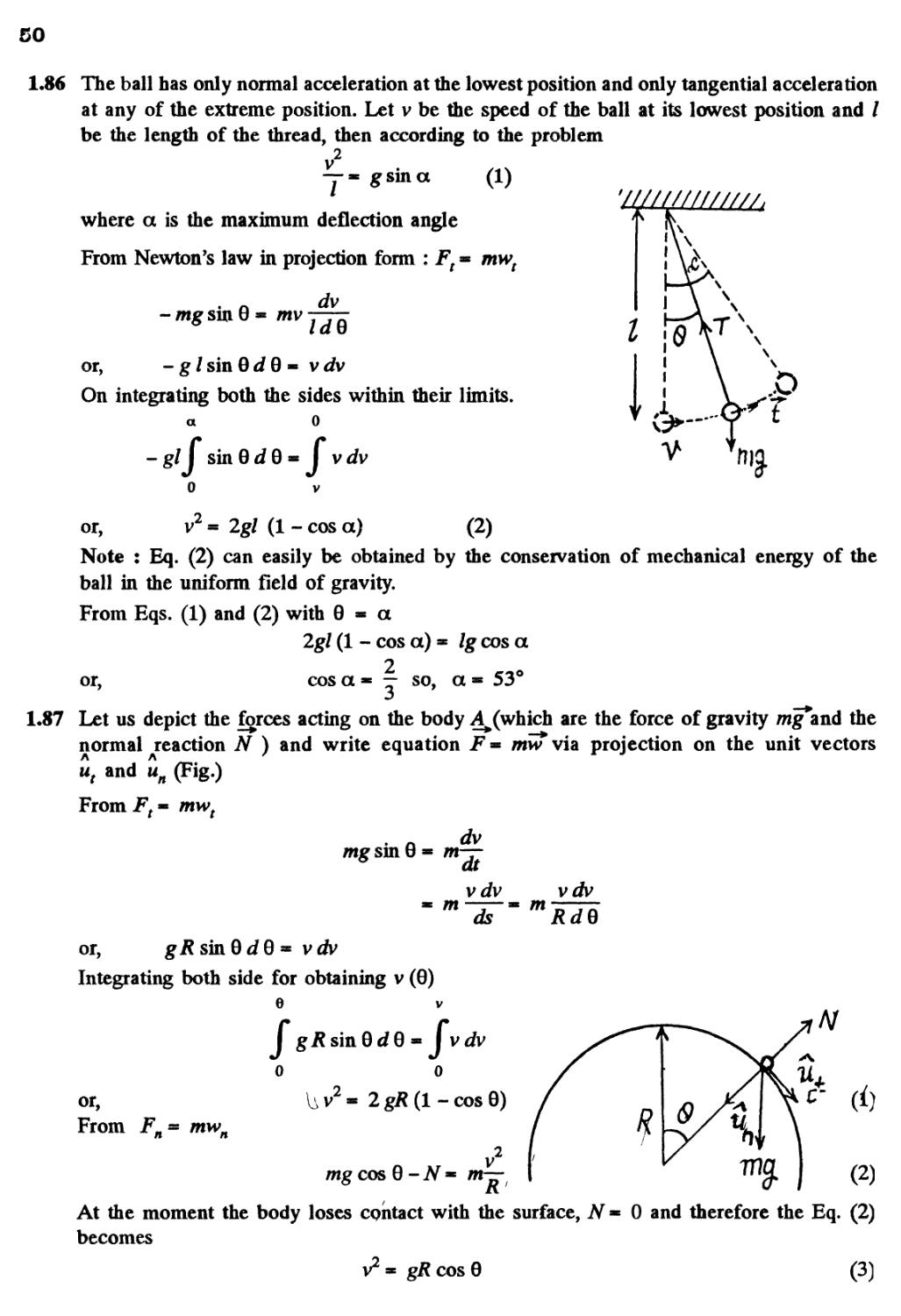
1.87 Let us depict the forces acting on the body A^(which are the force of gravity mg and the
normal reaction N ) and write equation F= mw via projection on the unit vectors
u, and un (Fig.)
From Ft» mwt
or,
gRsinQdB =
mg sin I
vdv
Integrating both side for obtaining v
or,
e
J gRsinBdQ
0
From Fn = mwn
Uv2- 2g*
mgcos 0
9« m
* m
0)
V
-/'
0
dt
vdv
ds
dv
A - cos 0)
v2
mR
vdv
mRdQ
/
/
f
f
1/
1
<9
B)
At the moment the body loses contact with the surface, N
becomes
v2 * gR cos 0
0 and therefore the Eq. B)
C)
51
where v and 0 correspond to the moment when the body loses contact with the surface.
-l
Solving Eqs. A) and C) we obtain cos 0 « - or, 0 - cos B/3) and v - V 2gR/3 .
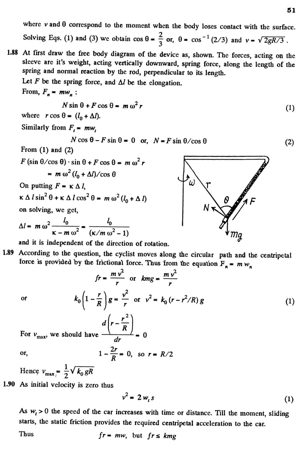
1.88 At first draw the free body diagram of the device as, shown. The forces, acting on the
sleeve are it's weight, acting vertically downward, spring force, along the length of the
spring and normal reaction by the rod, perpendicular to its length.
Let F be the spring force, and A/ be the elongation.
From, Fn ■ mwn :
#sm0+,Fcos0« mco2r
where r cos 0 * (/0 + A/).
Similarly from Ft « mwt
NcosQ-FsinQ* 0 or, N - F sin 0/cos 0
From A) and B)
F (sin 0/cos 0) • sin 0 + F cos 0 - m co r
- m to2 (/0 + A/)/cos 8
On putting F « k A /,
KA/sin20 + KA/cos20* mco2(/0 + A
on solving, we get,
A/= ma/
o
I
0
<r
A)
B)
k - m co (k//w co - 1)
and it is independent of the direction of rotation.
1.89 According to the question, the cyclist moves along the circular path and the centripetal
force is provided by the frictional force. Thus from the equation Fn « m vvn
mv
or
mv
or
or v =
A)
For vmax, we should have
or,
/ r2s
0
-^-» 0, so r- /?/2
K
1.90 As initial velocity is zero thus
2wts
A)
As wt > 0 the speed of the car increases with time or distance. Till the moment, sliding
starts, the static friction provides the required centripetal acceleration to the car.
Thus /r* /mv, but frz kmg
52
So, w2 & k2g2 or,
or,
Hence
vmax
max 1 / /fcp \
so, from Eqn. A), the sought distance 5 « -— «~'yj-fi- -1 * 60 m.
, 2 I iv, I
1.91 Since the car follows a curve, so the maximum velocity at which it can ride without sliding
at the point of minimum radius of curvature is the sought velocity and obviously in this
case the static friction between the car and the road is limiting.
Hence from the equation F - mw
mv2
kmg * -—r— or vi VkRg
so v^ - Vfc/^g. A)
We know that, radius of curvature for a curve at any point (x, y) is given as,
f 1 + (dy/dxf ]3/2
((fy)/dx2
For the given curve,
B)
a
■ — cos I —
ax a la
2
and
d y -a . x
dx2 a
2
Substituting this value in B) we get,
[1 + (a2/a2) cos2 (jc/a) ]3/2
(a/a2) sin (*/a)
*^^ *V1P
For the minimum /?, — ■ —
' a 2
and therefore, corresponding radius of curvature
Hence from A) and B)
1.92 The sought tensile stress acts on each element of the chain. Hence divide the chain into
small, similar elements so that each element may be assumed as a particle. We consider
one such element of mass dmy which subtends angle d a at the centre. The chain moves
along a circle of known radius R with a known angular speed co and certain forces act on
it We have to find one of these forces.
From Newton's second law in projection form, Fx * mwx We get
2 Jsin (da/2) - dN cos 0 - dma?R
and from Fz « mwz we get
dN sinQ = gdm
Then putting dm » mda/2 n and sin (da/2) * da/2 and solving, we get,
m(@2£+gcote)
2jc
53
1.93 Let, us consider a small element of the thread and draw free body diagram for this element,
(a) Applying Newton's second law of motion in projection form, Fn - mwn for this element,
(T+ dT)sm(dQ/2) + Tsm(dQ/2) -dN- dm«>2R- 0
27 sin (d 9/2)- dN9 [negelecting the term(dT sin d Q/2) ]
. dB djl
2
or,
or,
dN, as
A)
Also, dfr- kdN
From Eqs. A) and B),
dT)-T- dT
kTdO- dT or
dT
kdQ
In this case Q**n so,
T
2
or, or, In — = k n
C)
So,
1 . T2 1
as
m2 g
m
B)
T+dT
m.
(b) When — * y\, Svhich is greater than r]^ the blocks will move with same value of
m
acceleration, (say w) and clearly m2 moves downward. From Newton's second law in
projection form (downward for m2 and upward for mx) we get :
and
m2g-J2- m2w
T1-m1gm mxw
D)
E)
54
Also
= T»o
F)
Simultaneous solution of Eqs. D), E) and F) yields
(m2 -
g
g
as
= T]
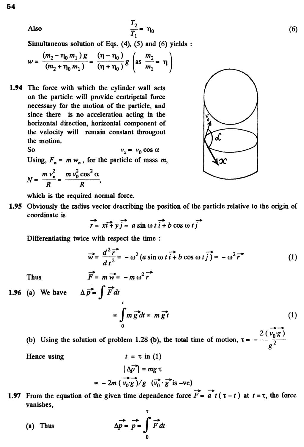
1.94 The force with which the cylinder wall acts
on the particle will provide centripetal force
necessary for the motion of the particle, and
since there is no acceleration acting in the
horizontal direction, horizontal component of
the velocity will remain constant througout
the motion.
So
v0 cos a
* ^—^
ru ^
h^ ^
\oc
Using, Fn = mwnt for the particle of mass m,
2 2 2
mvx mv0 cos a
= ~R~~ = R '
which is the required normal force.
1.95 Obviously the radius vector describing the position of the particle relative to the origin of
coordinate is
r = xT% yj = a sin co t i + b cos co tj
Differentiating twice with respect the time :
,2-
—=■
dt2
= - co2 (a sin co t i + b cos co t j) =
- co2 F
A)
Thus
1.96 (a) We have
F = mw= -mco r
f
F^dt
jmg*dt
mgt
A)
0
(b) Using the solution of problem 1.28 (b), the total time of motion, x =
2(vo-g)
Hence using
t = x in A)
=mgx
-2m(vo-g)/g
1.97 From the equation of the given time dependence force F
vanishes,
- a t(x-t) at f = x, the force
(a) Thus
/>« I Fdt
4
0
55
or,
but
-t)dt
ax'
o
p « m v so v
ax
6m
(b) Again from the equation F
dt
or, aXtx-t2)dt'= mdv*
Integrating within the limits for v\t),
t V*
\ a\tx-t2)dt- ml
or,
Thus
0
—I
a_
m
2 3
ml dv
o
a*i2 Ix _ t
m 2
[x t . .
v- --- I for t* x
m \ 2 3
Hence distance covered during the time interval t - x,
o
f
J
2 3
m 12
1.98 We have F - F{
or
On integrating,
When
jsin
m
— i7
CO
cor
dT
dt *
r
-cos
Fosin
cor + C,
r- 0,
cor or mdv*
(where C is
v*0, so C»
« ,Fosincordr
integration a
mco
-* o
Hence, v = cos cor +
mco m co
ii
As I cos cor £ 1 so, v « A - cos cor)
1 mco
56
Thus s
o
fvd,
Fot F0sin(ot Fo .
(cor-sincor)
mco mco
(Figure in the answer sheet).
1.99 According to the problem, the force acting on the particle of mass m is, F * Fo cos (of
dv*~~* —* M)
So, m —7- * Fn cos (of or d v « — cos (at
m
Integrating, within the limits.
V t
/F C -
dv*= — I cos (of dt or v = —— sin (at
m J m(a
o o
It is clear from equation A), that after starting at f « 0, the particle comes to rest fro
the first time at f * —.
O)
From Eq. A), v * I vl - —^- sin (at for f £ — B)
n v ' ■ ■ m(a (o v '
Thus during the time interval f = jc/(o, the sought distance
2F
I sin (of dt
ntw J
maJ
From Eq. A)
max m(a
— as | sin (of |
d v "~*
1.100 (a) From the problem F » -rv so m — * - rv
Thus m~TXi -rv
or, — » -—df
On integrating lnv = - — t + C
But at f * 0, v * v0, so, C « In v(
v r -£.
or, In — = - — f or, v = v0 e m
Thus for f -* oo, v * 0
(b) We have m — **-rv so dv* — ds
K ' dt m
57
Integrating within the given limits to obtain v (s):
V S
/j r C. rs ,^.
av--- Ids or v-v0-— A)
°
Thus for v - 0,
/wv0
total
/\t* ^ mdv dv - r
(c) Let we have ■ -rv or — ■ —
v ' v v m
i m — I dt y or, In ■ - —
J v m J T| v0 m
or,
•/ v m «
0
-m ln(l/Ti)
bo f * a "• ■
r r
Now, average velocity over this time interval,
„ * 1
fvdt o
<V>" /* "
1.101 According to the problem
dv , :
nt~7"~* -kv
Integrating, withing the limits,
p t
0
To finu the valu6 of /:, rewrite
dv , j
ds
On integrating
rf
m i
—lnri
r
or,
m
r«
V
dt
dv
V2'
m
k
--
VO(T1-1)
-**
(vo-v)
vov
k A
— ds
m
v
So,
Putting the value of k from
vo
B) in
^ __
* ■■
m
A),
*(
II
u
u
ln~
V
we
vln
>
am
get
v)
■MM
V
B)
1.102 From Newton's second law for the bar in projection from, Fx= mwx along x direction
we get
mg sin a - kmg cos a - mw
or,
or,
or,
dv / t \
v — - gsma- axg cos a, (as k - ax),
v dv m (g sin a - axg cos a) dx
V X
\ v dv ■ g J (sin a - x cos a ) dx
o
0
So, —= g (sin a jc - — a cos a )
^> ^>
From A) v = 0 at either
2
jc = 0, or jc = — tan a
a
As the motion of the bar is unidirectional it
stops after going through a distance of
2
A)
tan a.
a
From A), for vmax,
— (sin ax - — a cos a ) * 0, which yields jc - — tan a
dx 2 J a
Hence, the maximum velocity will be at the distance, jc - tan a/a
Putting this value of jc in A) the maximum velocity,
max
A/gsinatana
a
1.103 Since, the applied force is proportional to the time and the frictional force also exists, the
motion does not start just after applying the force. The body starts its motion when F
equals the limiting friction.
Let the motion start after time r0 , then
or,
a
So, for t = £ r0, the body remains at rest and for t > t0 obviously
t = a (t- t0) or, mdv** a(t- tG)dt
Integrating, and noting v = 0 at t » t0, we have for t > tQ
I mdv= a I (t -10
)dt or v =
a
0
Thus
c* «•
1.104 While going upward, from Newton's second law in vertical direction :
vdv , .9. vdv
m
ds
kv ) or
-ds
m
At the maximum height /*, the speed v = 0, so
0 h
f
Integrating and solving, we get,
m
2>
m8 j
59
A)
When the body falls downward, the net force acting on the body in downward direction
equals (mg-kv2),
Hence net acceleration, in downward direction, according to second law of motion
vdv kv2 vdv .
g-— or, -- ds
ds
m
m
Thus
/vdv
p-ifcv2,
g-kv /m
o d o
Jds
Integrating and putting the value of h from A), we get,
/ VTTI
vo/mg.
1.105 Let us fix x - y co-ordinate system to the given plane, taking Jt-axis in the direction along
which the force vector was oriented at the moment t * 0, then the fundamental equation
of dynamics expressed via the projection on x and y-axes gives,
F cos co t« m
and
F sin cor* m
dt
dv..
dt
(a) Using the condition v@) « 0, we obtain v.
F .
x met)
sin cor
and
B)
C)
V m ( 1 - COS @ t )
y mco
D)
Hence,
V + V •
vx y
2F
ffllO
sin
60
(b) It is seen from this that the velocity v
turns into zero after the time interval Af,
which can be found from the relation,
co — = Jt. Consequentely,
the sought distance, is
fvdt
SF
o
moo
Average velocity, < v >
0
2n/a>
So, <v>
mco
sin
o
~\dtj Bjio))- -
4F
1.106 The acceleration of the disc along the plane is determined by the projection of the force
of gravity on this plane Fx - mg sin a and the friction force fr « kmg cos a. In our case
k = tan a and therefore
fr * Fx * mg sin a
Let us find the projection of the acceleration
on the derection of the tangent to the trajectory
and on the x-axis :
mwt= Fx cos qp - fr « mg sin a ( cos qp - 1)
m wx « Fx- fr cos cp « mg sin a A- cos cp )
It is seen fromthis that wt ■ - wx, which means
that the velocity v and its projection vx differ
only by a constant value C which does not
change with time, i.e.
where vx * v cos cp. The constant C is found from the initial condition v = v0, whence
C « v0 since (p « — initially. Finally we obtain
v = v0 / A + cos qp).
In the cource of time cp -* 0 and v -> Vq/2. (Motion then is unaccelerated.)
1.107 Let us consider an element of length ds at an angle qp from the vertical diameter. As the
speed of this element is zero at initial instant of time, it's centripetal acceleration is zero,
and hence, dN- Xds cos qp= 0, where X is the linear mass density of the chain Let
T and T+dT be the tension at the upper and the lower ends of ds. we have from,
= mwt
or,
= Xdswt
61
If we sum the above equation for all elements,
the term J dT = 0 because there is no tension
at the free ends, so
l/R
"KgR I sin cp d op - Xwt f
o
Hence
i
As wn = a at initial moment
So, w - I wt
1.108 In the problem, we require the velocity of the body, realtive to the sphere, which itself
moves with an acceleration w0 in horizontal direction (say towards left). Hence it is ad visible
to solve the problem in the frame of sphere (non-inertial frame).
At an arbitary moment, when the body is at an angle 0 with the vertical, we sketch the
force diagram for the body and write the second law of motion in projection form
n
n
mv
or, mg cos 8 - N - mw0 sin 8 - —jr- A)
At the break off point, N - 0, 8 = 80 and let
v* v0so the Eq. A) becomes,
From, Ft - mwt
. vdv vdv
mg sin 8 - mw0 cos 8 « m —r— - m
or, v dv = R (g sin 8 + w0 cos 8 ) d 8
e
0
Integrating, I v dv = I R (g sinO + m>0 cos8) J 8
0
0
- cos90) + wQ sin 8
0
C)
Note that the Eq. C) can also be obtained by the work-energy theorem A= AJ (in the
frame of sphere)
1 i
therefore, mgR A - cos 80) + mwQR sin 80 *
[here mwQk sin 80 is the work done by the pseudoforce (- mwo)]
or,
2R
= g A - cos 80) + w0 sin 80
62
Solving Eqs. B) and C) we get,
v0 * y/2gR/3 and
Hence
o
, where k * —
g
1.109 This is not central force problem unless the path is a circle about the said point. Rather
here Ft (tangential force) vanishes. Thus equation of motion becomes,
vtm vo" constant
and,
mv
o
— for
We can consider the latter equation as the equilibrium under two forces. When the motion
is perturbed, we write r - r0 + x and the net force acting on the particle is,
2
0
— A
r*
nx
1 —
m voI _ x
0
m v,
o
0
mv,
This is opposite to the displacement xy if n < 1-
— A
force while is the1 inward directed external force).
is an outward directed centrifugul
1.110 There are two forces on the sleeve, the weight Fx and the centrifugal force F2* We resolve
both forces into tangential and normal component then the net downward tangential force
on the sleeve is,
mgsinG
1-
(D2R
8
cos 8
This vanishes for 0= Oand for
8 « 80 - cos
-l
g_
, which is real if
> g. If co2jR < g, then 1 -
co2/?
g
cos 8
7nu)zRS/7?O=Fz
r/: m$CosQ+mu)tRSi7)°'
is always positive for small values of 8 and ,
hence the net tangential force near 0=0 Q;
opposes any displacement away from it. '
0 = 0 is then stable.
2
If co R> gy 1 cos8 is negative for small
8 near 8*0 and 0 = 0 is then unstable.
However 8 « 80 is stable because the force tends to bring the sleeve near the equilibrium
position 8 = 9q.
If co R = gy the two positions coincide and becomes a stable equilibrium point.
63
1.111 Define the axes as shown with z along the local vertical, x due east and y due north. (We
assume we are in the northern hemisphere). Then the Coriolis force has the components.
Fcor* -2m(o)xv)
>z sinG) i - vx cosQj + vx cosG k 1
rhen the direction in which tn<
2mo> (v^ cosG - vz sinQ) i
2mco I v%, cosG - v,
le gun is fired is due north. Thus the
equation of motion (neglecting centrifugal forces) are
x = 2/nco (vy sincp - vz coscp), y * 0 and z = -g CO
Integrating we get y * v (constant), z « -gt
* 2
and x - 2co v sincp t + cog f coscp
Finally,
2
r si
sincp+ r-
coscp
Now v » gr in the present case, so,
x** covsincp| —| « cosinqp
*• 7 cm (to the east).
1.112 The disc exerts three forces which are mutually perpendicular. They are the reaction of
the weight, mg, vertically upward, the Coriolis force 2mv' co perpendicular to the plane of
the vertical and along the diameter, and mco r outward along the diameter. The resultant
force is,
F= m V i + co4 r2 + Bv' co):
1.113 The sleeve is free to slide along the rod AB. Thus only the centrifugal force acts on it.
The equation is,
2 u dr
mv ■ mco r where v * —
dt
so,
or,
Butv* v —* —| -v
dr dry 2
— v * --co r + constant
v0 being the initial velocity when r = 0. The Coriolis force is then,
2mco Vvq + co2 r2 = 2mco2 r Vl + v2/co2 r2
2-83 N on putting the values.
64
1.114 The disc OBAC is rotating with angular
velocity co about the axis OO' passing through
the edge point O. The equation of motion in
rotating frame is,
mw
M
o1
B
where F^ is the resultant inertial fore ^pseudo
force) which is the vector sum of centrifugal
and Coriolis forces.
(a) At A, Ffo vanishes. Thus 0 * - 2mco2 Rn + 2mv' co n
A
where n is the inward drawn unit vector to the centre from the point in question, here A.
Thus, v'- co/?
so,
(b) AtB
V'2 V'2 2 _
w= —* — ■ co /?.
Fk - mcoz OC +
its magnitude is mco \4R - r , where r * OB.
1.115 The equation of motion in the rotating coordinate system is,
mw * F + mco2/?+ 2m(v xco)
Now, v** R 6 £T+/? sin0 cp ?
and
w
cos
-w' sin 0 e
e
9
0 7? 6 /? sin 6 <p
co cos 0 - co sin 0 0
2m
« e£((oR sin 0 9) + wR sul 8 cos 6 9 ^e"" ^ ® cos ®
Now on the sphere,
+ (R 6' - R sin 0 cos 0 cp2)
+ (i? sin 0<p* + 2/? cos 0 6 (j>) i*
Thus the equation of motion are,
m(-RQ2-R sin2 0 cp2) * N- mg cos 0 + mco2/? sin2 0 + 2m(oR sin2 0 cp
m (/? 0 - iR sin 0 cos 0 <p ) * mg sin 0 + mco /? sin 0 cos 0 + 2mco R sin 0 cos 0 cp
mORsinOcp'+ 2J? cos 0 6<p)« -2mcoi?6cos0
From the third equation, we get, <p » - co
A result that is easy to understant by considering the motion in non-rotating frame. The
eliminating cp we get,
m/?02* mgcosQ-N
m R 6' * mg sin 0
Integrating the last equation,
^2« mg(l-cos0)
65
Hence
N - C - 2 cos 9) mg
-12
So the body must fly off for 0 * 0O « cos " -, exactly as if the sphere were nonrotating.
2 /s"" 2
Now, at this point Fcf * centrifugal force * mco R sin 80 * y- mco R
Fcor= Vco2i?292cos29 + (co2R2Jsin20 x2m
x2m« \
3 co2/*
1.116 (a) When the train is moving along a meridian only the Coriolis force has a lateral
component and its magnitude (see the previous problem) is,
2m co v cos 0 « 2m co sin X
So,
(Here we have put R 6 -* v)
54000 VT
86400" 3600 X 2
2 x 2000 x 103XT-TTX-rrrr-x
* 3-77 kN, (we write Xfor the latitude)
(b) The resultant of the inertial forces acting
on the train is, _^
Fw * - 2minR 6 cos 0 i£
+ (mco2 /? sin 0 cos 0 + 2m co R sin 0 cos 0 cp) i
+ (mw2 R sin2 0 + 2m co i? sin2 0 cp ) i*
This vanishes if 6=0, cp « - — co
Thus v *= v e , v * -
(We write X. for the latitude here)
Thus the train must move from the east to west along the 60* parallel with a speed,
* 115-8 m/s « 417 km/hr
(o/?cosX tx^ZTx
2 4 8-64
1.117 We go to the equation given in 1.111. Here vy « 0 so we can take y * 0, thus we get for
the motion in the x z plane.
and
Integrating,
x * - 2co vz cos 0
z - -g
2*
2
JC - CO g COS <pt
So
'2*'
Tcogcoscp/3* ~cogcoscp| —
3/2
COS
There is thus a displacement to the east of
|x~^64x500xlx
** 26 cm.
66
1.3 Laws of Conservation of Energy, Momentum and Angular Momentum.
1.118 As F is constant so the sought work done
or, A-
1.119 Differentating v (s) with respect to time
dv a ds a
dt 2Vs dt 2Vs
C r
( i^s
17 J
a2
2
(As locomotive is in unidrectional motion)
Hence force acting on the locomotive F * m w
ma
Hence the sought work, A= Fs
mg2 (a2/2)
2 4
Let, ar v - 0 at t - 0 then the distance covered during the first t seconds
maY
8
las2
m
2 as
m
1.120 We have
or, v
A)
Differentating Eq. A) with respect to time
2vm\
4 as
m
v or, >vr
B)
Hence net acceleration of the particle
h> =
'2<w\2
m
2 or r 2 as
mR
m
V 1
Hence the sought force, F = mw = 2as Vl + (s/R)z
1.121 Let i7 makes an angle 6 with the horizontal at any instant of time (Fig.). Newton's second
law in projection form along the direction of the force, gives :
F = kmg cos 0 + mg sin 8 (because there is no
acceleration of the body.)
As F | T d r*the differential work done by the force F,
dA= F-dr*= Fds, (where ds * | dr*\ )
= kmg ds (cos Q) + mgds sin 6
F
N
■ kmgdx + mgdy.
I h
kmg I dx + mg I dy
Hence, A - A7wg | or + mg
o o
= kmgl + mgh= mg(kl
67
1.122 Let s be the distance covered by the disc along the incline, from the Eq. of increment of
M.E. of the disc in the field of gravity : AT + tJJ * Afr
0 + (- mgs sin a) * - kmg cos a s - kmg I
kl
or, s« -7- .
sin a - k cos a
Hence the sought work
Ajr * - kmg [s cos a + / ]
klmg
A)
[Using the Eqn. A)]
u - -0.05 J
*r 1 - k cot a
On puting the values
1.123 Let x be the compression in the spring when the bar m2 is about to shift Therefore at this
moment spring force on m2 is equal to the limiting friction between the bar m2 and horizontal
floor. Hence
kx * km2g [where k is the spring constant (say)] A)
For the block m1 from work-eneigy theorem : A * A7 * 0 for minimum force. (A here
indudes the work done in stretching the spring.)
1 2 x
so, Fx- — kxr-kmgjc* 0 or k — * F-kmlg B)
From A) and B),
F= kg
1.124 From the initial condition of the problem the limiting fricition between the chain lying on
the horizontal table equals the weight of the over hanging part of the chain, i.e.
X r\ Ig * k X A - rj) Ig (where X is the linear j\J
mass density of the chain)
So,
a)
Let (at an arbitrary moment of time) the length
'of the chain on the table is x. So the net friction
force between the chain and the table, at this
moment :
/r« kN= kkxg B)
The differential work done by the friction forces
dA
-k\xg(-dx)
C)
(Note that here we have written ds * - dx., because ds is essentially a positive term and
as the length of the chain decreases with time, dx is negative)
Hence, the sought work done
o
J x8T^{xdx= -A-^ ^
68
1.125 The velocity of the body, t seconds after the begining of the motion becomes
v** v*+ g*i. The power developed by the gravity (m g*) at that moment, is
mjrv*= mOT' Vo + g2'K8 mg (gf - v0 sin a) A)
As nig* is a constant force, so the average power
x x
where Ar is the net displacement of the body during time of flight
As, nig^l Ar* so <P> * 0
1.126 We have wn - ^* at2, or, v - VaT ty
t is defined to start from the begining of motion from rest
So, m>,« — * vaR
—* —^ A A A
Instantaneous power, P~F-v= m(wtut + wnut ) • (va/? rMr ),
A A
(where w, and ut are unit vectors along the direction of tangent (velocity) and normal
respectively)
So, P« mwtVaRt= maRt
Hence the sought average power
t t
ma
J
o
/
o
Hence <P> «
maRt2 maRt
It 2
1.127 Let the body m acquire the horizontal velocity v0 along positive x - axis at the point O.
(a) Velocity of the body t seconds after the begining of the motion,
r-^+sr*-(v0-*gor* (i)
Instantaneous power P - F • v - (- kmg i )'(vo-kgt)i=* - long (v0 - kgt)
From Eq. A), the time of motion x * v^/kg
Hence sought average power during the time of motion
T
I
- kmg (v0 -kgt)dt
<P> m = - —|-^ = - 2 W (On substitution)
X £*
From Fx * mwx
-kmg= mwx= mvx-£
or, vxdvx= -kgdx * - agxdx
69
To find v (x), let us integrate the above equation
J vxdvx~ - a8 j xdx or, v2- v^-a
A)
Now, P= jp'v** -majcgVvQ-agjc2 B)
For maximum power, — (vv 0x - Xgx ) « 0 which yields x - ,
Putting this value of jc, in Eq. B) we get,
1.128 Centrifugal force of inertia is directed outward along radial line, thus the sought work
r2
A= \ mco2rdr= -mco2(r\-r^\ = 0-20T (On substitution)
1.129 Since the springs are connected in series, the combination may be treated as a single spring
of spring constant
Kl
From the equation of increment of M.E., A T + A U * A
ext
1 . .i 1
A, or, A
_ .». —• -«, -~.», .«. _
t2/
A/
2
1.130 First, let us find the total height of ascent At the beginning and the end of the path of
velocity of the body is equal to zero, and therefore the increment of the kinetic energy of
the body is also equal to zero. On the other hand, in according with work-energy theorem
AT is equal to the algebraic sum of the works A performed by all the forces, i.e. by the
force JF and gravity, over this path. However, since AT=» 0 then A = 0. Taking into
account that the upward direction is assumed to coincide with the positive direction of the
y - axis, we can write
(i7 + /ngj' d r** I (F -
o o
h
88 w# I A - 2 ay) dy * mgh A - a/i) * 0.
o
whence h « I/a.
The work performed by the force F over the first half of the ascent is
h/2 h/2
c c
Ap** I Fvdy** 2mg I A - ay) dy « 3 mg/4a.
J y J
o o
The corresponding increment of the potential energy is
A G= mgh/2- mg/2a.
70
dU
1.131 From the equation Fr » - — we get Fr
2a bj\
r3%2
2a
(a) we have at r » r0, the particle is in equilibrium position. i.e. Fr - 0 so, r0 - —
To check, whether the position is steady (the position of stable equilibrium), we have to
satisfy
d2U
dr
We have
d2U
dr2
la
>0
r6a 261
r4"V
Putting the value of r « r0 « ~,we get
b
d2U b4
dr
So,
8a:
, (as a and b are positive constant)
d2U
dr2
8a:
which indicates that the potential eneigy of the system is minimum, hence this position
is steady.
(b) We have
dr
dF.
2a b 1
r
3 """r2
For F, to be maximum, -r— - 0
ar
3a -fc3
So, r - y and then Fr(max) -
As Fr is negative, the force is attractive.
1.132 (a) We have
ATT
• - 2 a x and
7
ay
So, F» 2axi-2$yi and, F
For a central force, r x F « 0
Here, rxF~ (xi+yj )x(-2xxxi-2$yj )
Hence the force is not a central force,
(b) As
So,
A)
According to the problem
F - 2 V a2 x2 + p2 y2 * C (constant)
71
or,
x2 v2 C2
or, —+ ^r- — « A; (say)
p2 a2 2a2p2 y
Therefore the surfaces for which F is constant is an ellipse.
For an equipotential surface U is constant
So, a jc + p y » Co (constant)
x2 y2
or, /— + -y=m —~* Ko(constant)
VP2 Va2 a P
Hence the equipotential surface is also an ellipse.
1.133 Let us calculate the work performed by the forces of each field over the path from a
certain point 1 (xx, yx) to another certain point 2 (x2, y2)
*2
(i) dA « F• dr*** ayi'dr^ aydx or, A * a I y<£t
(ii) dA « F -dr~ (axi + byi ) • dr « axdx +
2 2
Hence A * I a xdx + I bydy
In the first case, the integral depends on the function of type y (jc), i.e. on the shape of
the path. Consequently, the first field of force is not potential. In the second case, both
the integrals do not depend on the shape of the path. They are defined only by the coordinate
of the initial and final points of the path, therefore the second field of force is potential.
1.134 Let s be the sought distance, then from the equation of increment of M.E.
AJ+AC/- A/r
1 i\
0 - -r mvn + (+ mgs sina)« - kmg cos a s
, 2 /
or, s** — I (sin a + k cos a)
-kmvn
Hence Afr ■ - kmg cos a s
2 (k + tan a)
1.135 Velocity of the body at height /*, vh - \2gjH- h), horizontally (from the figure given in
the problem). Time taken in falling through the distance h.
t« Y -—
(as initial vertical component of the velocity is zero.)
Now s= vht
72
For
W
(Hh ~ h2)« 0, which yields h « y
Putting this value of /* in the expression obtained for s, we get,
1.136 To complete a smooth vertical track of radius Ry the minimum height at which a particle
starts, must be equal to — R (one can proved it from energy conservation). Thus in our
problem body could not reach the upper most point of the vertical track of radius R/2.
Let the particle A leave the track at some point O with speed v (Fig.). Now from energy
conservation for the body A in the field of gravity :
mg
+ sin 8)
1 2
or, v2 - gh A - sin 8) A)
From Newton's second law for the particle at
the point O\ F * mw ,
N + mg sin 0
mv
(A/2) A
But, at the point O the normal reaction N - 0
So,
2
sin 0
B)
From C) and D), sin 0 ■ r- and v -
After leaving the track at 0, the particle A comes in air and further goes up and at maximum
height of it's trajectory in air, it's velocity (say v') becomes horizontal (Fig.). Hence, the
sought velocity of A at this point
vcos(9O-0)« vsin6« j
1.137 Let, the point of suspension be shifted with velocity vA in the horizontal direction towards
left then in the rest frame of point of suspension the ball starts with same velocity horizontally
towards right Let us work in this, frame. From Newton's second law in projection form
towards the point of suspension at the upper most point (say B) :
mv
mv
iivy n rr»v
mg+T- — or, T- —
B
-mg
Condition required, to complete the vertical circle is that 7"i0. But
A)
B)
mg
So,
C)
73
From A), B) and C)
j^ -mgfcO or, vA* V5g/
From the equation Fn * rnn^ at point C
\T vc
mv
D) \
Again from energy conservation
From D) and E)
1 2 1 2 ,
- -mvc + mgl
T- 3mg
E)
1.138 Since the tension is always perpendicular to the velocity vector, the work done by the
tension force will be zero. Hence, according to the work energy theorem, the kinetic energy
or velocity of the disc will remain constant during it's motion. Hence, the sought time
f = —, where s is the total distance traversed by the small disc during it's motion.
Now, at an arbitary position (Fig.)
ds* (lo-RQ)dQ,
l/R
SO, S
0
or,
r
s * — -
R 2R2 2R
Hence, the required time, t
I
1A
2Rv
o
It should be clearly understood that the only uncompensated force acting on the disc A
in this case is the tension T, of the thread. It is easy to see that there is no point here,
relative to which the moment of force T is invarible in the process of motion. Hence
conservation of angular momentum is not applicable here.
1.139 Suppose that A/ is the elongation of the rubbler cord. Then from energy conservation,
- 0(as AJ« 0)
or,
or,
1^
2
0
~k A/2-/nghl-mgl
4*
0
74
or.
A/
V
4 x y
V
1+V 1±
2 k/
mg
Since the value
So,
2k/
1 +:r:r:- is certainly greater than 1, hence negative sign is avoided.
mg
A/ =
1 +
v
\
2 k/
1.140 When the thread PA is burnt, obviously the speed of the bars will be equal at any instant
of time until it breaks off. Let v be the speed of each block and 0 be the angle, which
the elongated spring makes with the vertical at the moment, when the bar A breaks off
the plane. At this stage the elongation in the spring.
A/* /Osec0-/O = /O(sec0-1) A)
Since the problem is concerned with position and there are no forces other than conservative
forces, the mechanical energy of the system (both bars + spring) in the field of gravity is
conserved, i.e. AT + AU « 0
So, 2
From Newton's second law in projection form
along vertical direction :
mg = N+kIo(sec0-1)cos 0
But, at the moment of break off, N « 0.
Hence, k /o (sec 0-1) cos 0 - mg
k /0 - mg
0
B)
or,
cos 0
i0
C)
Taking k * , simultaneous solutionNof B) and C) yields :
WO
V
32
1-7 m/s.
1.141 Obviously the elongation in the cord, A/ * /0 (sec 0 - 1), at the moment the sliding first
starts and at the moment horizontal projection of spring force equals the limiting friction.
So, kx A/ sin 0 - kN A)
(where kx is the elastic constant).
From Newton's law in projection foim along
vertical direction :
or,
From A) and B),
mg.
N- mg - Kj A/ cos 0
A/ sin 8 * k (mg - kx A/ cos
75
bng
1 A/ sm 0 + k A/ cos 0
From the equation of the increment of
mechanical energy : AG+AT* Afr
or.
7r
or,
hngU
2A/(sin6+A:cos0)
bng L (sec 0 -
Thus Afr ■ u— ~- 0 09 J (on substitution)
fr 2 (sin 0-it cos 0) v ;
1.142 Let the deformation in the spring be A/, when the rod AB has attained the angular velocity co.
From the second law of motion in projection form Fn * mwn .
~ ma) L
kA/= mo>2(/0 + A0 or, A/*- ^
k -mo
From the energy equation, A^ » ^r
1 2
On solving
mco /0
k -ma)
mo2 /02
K-mco
~, where
ma)
£» A — Tl) K-
1.143 We know that acceleration of centre of mass of the system is given by the expression.
m
w,
Since
Now from Newton's second law F - mw, for
the bodies ml and m2 respectively.
and T+m2g- m2\v2= -m2wx C)
Solving B) and C)
1 2'2- D)
y//////
76
Thus from A), B) and D),
(m1 + m2)
1.144 As the closed system consisting two particles
ml and of m2 is initially at rest the CM. of
the system will remain at rest. Further as
m2 « mj/2, the CM. of the system divides the
line joining m1 and m2 at all the moments of
time in the ratio 1 : 2. In addition to it the
total linear momentum of the system at all the
times is zero. So, pT * - 5t and therefore the
velocities of m1 and m2 are also directed in
opposite sense. Bearing in mind all these thing,
the sought trajectory is as shown in the figure.
1.145 First of all, it is clear that the chain does not
move in the vertical direction during the
uniform rotation. This means that the vertical
component of the tension T balances gravity.
As for the horizontal component of the tension
7, it is constant in magnitude and permanently
directed toward the rotation axis. It follows from
this that the CM. of the chain, the point C,
travels along horizontal circle of radius p (say).
Therefore we have,
T cos 0 - mg and T sin 0 - mto p
Thus
and
gtan0 no
p » a—-— ~ 0-8 cm
(O
mg
cos 0
- 5N
7T?2
1.146 (a) Let us draw free body diagram and write Newton's
second law in terms of projection along vertical and
horizontal direction respectively.
N cos a-mg + fr sin a ■ 0
fr cos a - N sin a - mo /
A)
B)
From A) and B)
sin a
fr cos a -
cos a
(- fr sin a + mg) = moo /
r
77
So, /r« mg
CD2/
sin a + cos a = 6N C)
g '
(b) For rolling, without sliding,
/rs JfcN
but, N' - mg cos a-mco2/sina
co2/
mg I sin a + cos a
k( mgcos a - m co /sin a ) [Using C)]
g
Rearranging, we get,
m co / ( cos a + fcsina) ss: (A: mg cos a - mg sin a )
Thus to 2S V g (it - tan a)/A + k tan a ) / = 2 rad/s
1.147 (a) Total kinetic energy in frame K' is
This is minimum with respect to variation in V, when
- 0, i.e. mt ( vT- V*J + m9 ( vT- v") - 0
or y» -v
ml + m2
Hence, it is the frame of CM. in which kinetic energy of a system is minimum.
(b) Linear momentum of the particle 1 in the K' or C frame
~^ *. w /n^ /712 w k.
mxm2
or, px » M- ( vi ~ V2 )> wnere> M- - ■ reduced mass
Similarly, p2 = fi ( v2 - vx
So, |^|= |ft|-|>- |iv^ where, vrd = |v^-i^| C)
Now the total kinetic energy of the system in the C frame is
f-T+f- 2—+ -2-
1 2 2x 2m2 2 ji
Hence
78
1.148 To find the relationship between the values of the mechanical energy of a system in the
K and C reference frames, let us begin with the kinetic eneigy T of the system. The
velocity of the i-th particle in the K frame may be represented as v^« vj+ v£. Now we
can write
Since in the C frame Y mi vi * 0, the previous expression takes the form
J» J+~/wv£* J+ ~ m V (since according to the problem vc - V) A)
2 2m'V'
Since the internal potential eneigy U of a system depends only on its configuration,
the magnitude U is the same in all refrence frames. Adding U to the left and right
hand sides of Eq. A), we obtain the sought relationship
E- E + ^rmV2
1.149 As initially U - U * 0, so, E - J
From the solution of 1.147 (b)
As
Thus J- |
1.150 Velocity of masses mx and m2, after r seconds are respectively.
Hence the final momentum of the system,
^> (where,
And radius vector, a>« vtt + zrwit
» c c 2 c
1^
— a
2*
= Vo^ + T^2» where v£* X
79
1.151 After releasing the bar 2 acquires the velocity v2, obtained by the energy, conservation :
1 2
2*K
(i)
Thus the sought velocity of CM.
1.152 Let us consider both blocks and spring as the physical system. The centre of mass of the
system moves with acceleration a - towards right Let us work in the frame of
nt + tn
tn
centre of mass. As this frame is a non-inertial frame (accelerated with respect to the
ground) we have to apply a pseudo force ml a towards left on the block m1 and m2 a
towards left on the block
As the center of mass is at rest in this frame,
the blocks move in opposite directions and
come to instantaneous rest at some instant. The
elongation of the spring will be maximum or
minimum at this instant. Assume that the block
m1 is displaced by the distance x1 and the block
m2 through a distance x2 from the initial
positions.
From the energy equation in the frame of CM.
A T+ U-A^ .
(where
Here,
V77777777777777777777
also includes the work done by the pseudo forces)
A7*0, U^^k(x1+x2J and
W
act
mlF
mx +
ml & ( Xl + X2
or,
So,
1., ,2 mibi+x^F
-k(xx+x2) * — ^^
Or» Xl
2mlF
k (/Wj + m2)
Hence the maximum separation between the blocks equals
2miF
0 k (ml + m2)
Obviously the minimum sepation corresponds to zero elongation and is equal to /0
1.153 (a) The initial compression in the spring A/ must be such that after burning of the thread,
the upper cube rises to a height that produces a tension in the spring that is atleast equal
to the weight of the lower cube. Actually, the spring will first go from its compressed
80
state to its natural length and then get elongated beyond this natural length. Let / be the
maximum elongation produced under these circumstances.
Then
Kl-mg A)
Now, from energy conservation,
B)
(Because at maximum elongation of the spring, the speed of upper cube becomes zero)
From A) and B),
-mg
K
2 2mgM
A/ - —
K
r
K2
0 Or, A/
. ,
Therefore, acceptable solution of A/ equals
K
(b) Let v the velocity of upper cube at the position (say, at C ) when the low.er block
breaks off the floor, then from energy conservation.
or,
(where / * mg/K and A /
32
ntv + 0
At the position C, the velocity of CM; vc
(spring+ two cubes) further rises up to
Now, from energy conservation,
B)
— —Let, the CM. of the system
JL
Bm)gArC2
7C1 2g 8g k
But, uptil position C, the CM. of the system
has already elevated by,
(A/ + /) m + 0 4mg
^
■B
At
k
Hence, the net displacement of the CM. of
the system, in Upward direction
. 8m£
K 7
1.154 Due to ejection of mass from a moving system (which moves due to inertia) in a direction
perpendicular to it, the velocity of moving system does not change. The momentum change
being adjusted by the forces on the rails. Hence in our problem velocities of buggies
change only due to the entrance of the man coming from the other buggy. From the
81
Solving A) and B), we get
mv , Mv
and
1 M-m 2 M-m
As Vi 11 v and vT
So, v, - /w v and
1 (M-m) °"u K2 (M-m)
1.155 From momentum conservation, for the system "rear buggy with man"
From momentum conservation, for the system (front buggy + man coming from rear buggy)
MvTh ~~ ~~ ^
So, v»=
+ 77
m M+m
PuttingThe value of v£ from A), we get
1.156 (i) Let v^ be the velocity of the buggy after both man jump off simultaneously. For the
closed system (two men + buggy), from the conservation of linear momentum,
- 0
or,
77r
M+2m
A)
(ii) Let v be the velocity of buggy with man, when one man jump off the buggy. For
the closed system (buggy with one man + other man) from the conservation of linear
momentum :
0- (M + m) v* + m E% v*) B)
Let v£be the sought velocity of the buggy when the second man jump off the buggy; then
from conservation of linear momentum of the system (buggy + one man) :
C)
Solving equations B) and C) we get
mBM+3m)i/
(M
From A) and D)
V2 m
— - 1 +
Hence v2 > vx
1.157 The descending part of the chain is in free fall, it has speed v * \2gh at the instant, all
its points have descended a distance y. The length of the chain which lands on the floor
during the differential time interval dt following this instant is vdt.
82
For the incoming chain element on the floor : ■
From dpy « Fv dt (where y - axis is directed down) j
0-(kvdt)v- Fydt <k
or Fy= -\v2= -2\gy g
Hence, the force exerted on the falling chain
equals X v and is directed upward. Therefore
from third law the force exerted by the falling <
chain on the table at the same instant of QH.~~^
time becomes X v2 and is directed downward. ^
Since a length of chain of weight (kyg) already lies on the table the total force on the
floor is Bkyg) + (kyg) m CXyg) or the weight of a length 3y of chain.
1.158 Velocity of the ball, with which it hits the slab, v « v2gh
v 1
After first impact, v' * ev (upward) but according to the problem v'« -,so e* - A)
and momentum, imparted to the slab,
-» mv - (- mv') m mv A + e)
Similarly, velocity of the ball after second impact,
v" * ev' = e v
And momentum imparted « m (v\+ v" ) * m A + e) ev
Again, momentum imparted during third impact,
« m A + e) e v, and so on,
Hence, net momentum, imparted * mv A + e) + mve A + e) + mve A + e) + ...
- mv ~ £, (from summation of G.P.)
A-e)
- V2g*7 -J-- m y/2gh I fa + 1)/ (ri - 1) (Using Eq. 1)
1--
= 0*2 kg m/s. (On substitution)
1.159 (a) Since the resistance of water is negligibly small, the resultant of all external forces
acting on the system "a man and a raft" is equal to zero. This means that the position of
the CM. of the given system does not change in the process of motion.
i.e. r£~ constant or, Ar£- 0 i.e. "V mi Arp- 0
or, m^A^+Ar^+MAr£ = 0
Thus, m(r+/)+M/« 0, or,
(b) As net external force on "man-raft" system is equal to zero, therefore the momentum
of this system does not change,
So, 0- m[v*(r) + i£(r)] £
83
1.159 (a) Since the resistance of water is negligibly small, the resultant of all external forces
acting on the system "a man and a raft" is equal to aero. This means that the position of
the CM. of the given system does not change in the process of motion.
i.e. rc « constant or, Arc » 0 i.e.
mi
or,
Thus,
m
m
, or,
m +M
(b) As net external force on "man-raft" system is equal to zero, therefore the momentum
of this system does not change,
So, 0 * m [ v*' @ + v%(t) ] +
m v\t)
or,
m+M
A)
As v (t) or v2 (t) is along horizontal direction, thus the sought force on the raft
Mm dv* (t)
m + M dt
Note : we may get the result of part (a), if we integrate Eq. A) over the time of motion
of man or raft.
dt
1.160 In the refrence frame fixed to the pulley axis
the location of CM. of the given system is
described by the radius vector
m
2M
But
and
Thus A r,
ml"
2M
Note : one may also solve this problem using momentum conservation.
1.161 Velocity of cannon as well as that of shell equals v 2 gl sin a down the inclined plane
taken as the positive x - axis. From the linear impulse momentum theorem in projection
form along x - axis for the system (connon + shell) i.e. Apx -
p cos a - M Vzg/sina « Mg sin a A t (as mass of the shell is neligible)
pcosa -A/V 2 gl sin a
or, At- * ——:
Mg sin a
1.162 From conservation of momentum, for the system (bullet + body) along the initial direction
of bullet
mv0 * (m + M) v, or, v
mv.
o
m+Af
84
1.163 When the disc breaks off the body My its velocity towards right (along jc-axis) equals the
velocity of the body M, and let the disc's velocity'in upward direction (along y-axis) at
that moment be v'
From conservation of momentum, along jc-axis for the system (disc + body)
mv
wv- (m+M)v* or v' * T7 A)
* x m+M v 7
And from energy conservation, for the same system in the field of gravity :
-mv2 = -(m+M) v'l + ~mvt2y + mgh! ,
where h' is the height of break off point from initial level. So,
-mv - -(m+M) rM + m\+2mvy*mgt using A)
Also, if h" is the height of the disc, from the break-off point,
then, v'2y - 2 gh"
Hence, the total height, raised from the initial level
Mv2
2g(M+m)
1.164 (a) When the disc slides and comes to a plank, it has a velocity equal to v = ^2gh>
to friction between the disc and the plank the disc slows down and after some time the
disc moves in one piece with the plank with velocity v' (say).
From the momentum conservation for the system (disc + plank) along horizontal towards
right :
mv
mv- (m+M)vf or v' = —
m +M
Now from the equation of the increment of total mechanical energy of a system :
- (M + m) v'2 - ^mv2 - Afr
1 m2v2 1 2
or, —(M+m) T-—mv - Air
(m+MJ 2 fr
so,
Hence,
2
m
M + m
- m
A
■fr
where u* rr» reduced mass
I m+M
85
(b) We look at the problem from a frame in which the hill is moving (together with the
disc on it) to the right with speed il Then in this frame the speed of the disc when it just
gets onto the plank is, by the law of addition of velocities, v = w + y/lgh. Similarly the
common speed of the plank and the disc when they move together is
m + M
Then as above A *. « — (m + M)v2 - — mvz - ^rMu
Z* JL JL
1
u y2izh + — 2sh
m+M 3 (m+MJ
2v« . .,., u2-~m2uV2g7T-mg/i
We see that A- is independent of u and is in fact just - \i g h as in (a). Thus the result
obtained does not depend on the choice of reference frame.
Do note however that it will be in correct to apply "conservation of enegy" formula in
the frame in which the hill is moving. The energy carried by the hill is not negligible
in this frame. See also the next problem.
1.165 In a frame moving relative to the earth, one has to include the kinetic energy of the earth
as well as earth's acceleration to be able to apply conservation of energy to the problem.
In a reference frame falling to the earth with velocity v0, the stone is initially going up
with velocity v0 and so is the earth. The final velocity of the stone is 0 = vo - gt and
that of the earth is vo + — gt (M is the mass of the earth), from Newton's third law,
where t = time of fall. From conservation of energy
2
1 2 1 ..r 2 , 1 ..r/ rn
-mvQ + ~Mv0 + mgh = -M v0 +
u 1 2
Hence ~v0
m +
I
u
mgh
Negecting — in comparison with 1, we get
2
v20 « 2gh or vo « W2gh
The point is this in earth's rest frame the effect of earth's accleration is of order — and
M
can be neglected but in a frame moving with respect to the earth the effect of earth's
acceleration must be kept because it is of order one (i.e. large).
1.166 From conservation of momentum, for the closed system "both colliding particles"
/WjVj + m2v2 = (m1 + m2) v
-* !? 2? lCit2/) + 2D7t6*) r r r
or, v* ~ LJ-z—1-j£ -= i + 2j-4k
Hence | v] = VI +4 + 16 m/s = 4*6 m/s
86
1.167 For perfectly inelastic collision, in the CM. frame, final kinetic energy of the colliding
system (both spheres) becomes zero. Hence initial kinetic energy of the system in CM.
frame completely turns into the internal energy @ of the formed body. Hence
- 1 ._► -+.2
2i
1 ._* _*,2
Now from energy conservation AJ«-j2«-~|iv1-v2 ,
In lab frame the same result is obtained as
1.168 (a) Let the initial and final velocities of ml and m2 are u± , u2 and v, v2 respectively.
Then from conservation of momentum along horizontal and vertical directions, we get :
m
m2 v2 cos 9
A)
and m1v1 = m2v2 sin 8 B)
Squaring (i) and B) and then adding them,
Now, from kinetic eneigy conservation,
1 .2 1 .2 . 1 .2
C)
or, m (ul - v\)
i(«2 + v2) [Using C)]
or,
or,
Z
n
*t
ft
(VA
kj
■ vl
i /
2
So, fraction of kinetic energy lost by the particle 1,
1 2 1
IM 2
2 x x
-m.
1-
(b) When the collision occurs head on,
[Using D)]
m1v1 +
and from conservation of kinetic energy,
D)
E)
A)
87
1
1
2
L vj +
2
1
2
mv2 + -m
(«i - ViJ 1
/Wo
2
n
L1
[Using E)]
or,
-1
m
or,
Fraction of kinetic energy, lost
F)
1-
m1-m2
4/WJ/W2
[Using F)]
1.169 (a) When the particles fly apart in opposite direction with equal velocities (say v), then
from conservatin of momentum,
m1 u + 0 * (m2 - m^) v A)
and from conservation of kinetic energy,
1 2 1 7
or,
From £q. A) and B),
m2-m1
or,
m22-3
/W2 ■ 0
B)
Hence —- -- as m. k 0
m2 3 2
(b) When they fly apart symmetrically relative to the initial motion direction with the
angle of divergence 0 » 60°,
From conservation of momentum, along horizontal and vertical direction,
mi ui * mi vicos @/2)+ m2 V2 cos @/2) (x)
mx vx sin @/2) ~ m2 v2 sin @/2)
and
or,
Now, from conservation of kinetic energy,
m2 v2
B)
C)
From A) and B),
mx ux« cos @/2)
/W2
2 wx V! cos @/2)
88
ffln TH
So, ux - 2vx cos @/2)
From B), C), and D)
4 mx cos2 F/2) v\ - /»! vj
or, 4 cos2 F/2) * 1 + —
m2
D)
2v2
ivi
m
or,
and putting the value of 6, we get, — « 2
1.170 If (v^jV^) are the instantaneous velocity components of the incident ball and
( v^, v2 ) are the velocity components of the struck ball at the same moment, then since
there are no external impulsive forces (i.e. other than the mutual interaction of the balls)
We have u sina * v-,.. , v~ ■ 0
m u cosa * m vu + m
The impulsive force of mutual interaction satisfies
d g . F
(JF is along the x axis as the balls are smooth. Thus Y component of momentum is not
transferred.) Since loss of K.E. is stored as deformation energy D, we have
2 1
-mu - ^
-mw2cos2a-
2
" 9— m w cos a - m v^ - (mucosa- mv^)
— F 2m2wcosavljK -
1 * m (
We see that D is maximum when
w2cos2a
w cosa
cosa
and
D
mu2cos2a
max
D,
rj^. max 1 2 1
Then r\ * -—— « — cos a * ~
1^ 4
On substiuting a » 45*
x:
89
1.171 From the conservation of linear momentum of the shell just before and after its fragmentation
3^«i£+i£+i£ A)
where v1, v£ and v^ are the velocities of its fragments.
From the eneigy conservation 3r|v2 * v2 + v2 + v2 B)
Now i£or v^. ■ v^- v£ « v^- v* C)
where v£ ■ v*= velocity of the CM. of the fragments the velocity of the shell. Obviously
in the CM. frame the linear momentum of a system is equal to zero, so
vT+v2 + v3*0 D)
Using C) and D) in B), we get
3r|v2 * (v + v^J + (v + v£J + (v*- v[- v^f « 3V2 + 2v 2 + 2v 2 + 2 v v£
or, 2v2 + 2v1v2cos6 + 2v2 + 3(l-T|)v2«0 E)
If we have had used v2 * - vx - v3, then Eq. 5 were contain v3 instead of v2 and so on.
The problem being symmetrical we can look for the maximum of any one. Obviously it
will be the same for each.
For v^to be real in Eq. E)
4 vIcos26 *8Bv?, + 3 A -ti) v2) or 6(r\ - ljv2 * D - cos29)v\
So, v2i v A/ ' vi v or
Hence v2(max)« 1^1^ - v + V2(ri - 1) v - v(l + ^Uy\ - 1)) - 1 km/s
Thus owing to the symmetry

Vl(max) " V2(max) = V3(max) s V f1 + V2(t| - 1))
l(max) " V2(max) = V
1.172 Since, the collision is head on, the particle 1 will continue moving along the same line
as before the collision, but there will be a change in the magnitude of it's velocity vector.
Let it starts moving with velocity vx and particle 2 with v2 after collision, then from the
conservation of momentum
mu * mvl + mv2 or, u « vx + v2 A)
And from the condition, given,
T, 1
or, vJ + v^-d-T,)^ B)
From A) and B),
2 2 2
or, v\ + «2 - 2 uvj + vj » A - tj) tf
90
or,
So,
0
Vi-2ii±
- 8ti u
Positive sign gives the velocity of the 2nd particle which lies ahead. The negative sign is
correct for vl .
So, vx « — u A - VI -2t] ) * 5 m/s will continue moving in the same direction.
Note that vx ■ 0 if r| = 0 as it must.
1.173 Since, no external impulsive force is effective on the system "M + m", its total momentum
along any direction will remain conserved.
So from px ■ const.
mu « Af vx cos 9 or, vx ■ —
Mcos 8
and from p - const
mv
M
x sin G or, v2- — vt sin G = u tan G, [using A)]
Final kinetic energy of the system
And initial kinetic energy of the system- — mu
Tf - J.
So, % change = -^— x 100
-mw2tan29 + -M
2 2
2
cos2 9
1 2
— mu
1
12
xlOO
2M
xlOO
/
I
X
and putting the values of 9 and — , we get % of change in kinetic energy* - 40 %
M
1.174 (a) Let the particles m^ and m2 move with velocities vx and v2 respectively. On the basis
of solution of problem 1.147 (b)
91
As
v1lv2
So, p « [i Vvj + v\ where \x
(b) Again from 1.147 (b)
ttl\ + fifty
So,
1.175 From conservation of momentum
Pi = Pi +
so (pi "Pi ) ■
V /
From conservation of energy
' cosOj + px
El
2m,
Pi
,2
2/Wi
P2_
2m,
Eliminating p2' we get
0
1 +
m,
- 2/?1'jp1cos01
1-
L
This quadratic equation for/?]/ has a real solution in terms ofp1 and cos Bx only if
1-
m
2>
or
sin2
or sin 0t ^ +
1
or sin 0, ^
L
This clearly implies (since only + sign makes sense) that
. Q m2
ml
1.176 From the symmetry of the problem, the velocity of the disc A will be directed either in
the initial direction or opposite to it just after the impact Let the velocity of the disc A
after the collision be v' and be directed towards right after the collision. It is also clear
from the symmetry of problem that the discs B and C have equal speed (say v") in the
directions, shown. From the condition of the problem,
d
' ^ so, sin0« V4-ti2 12
cos 0
so> sin 0 V4ti 12 A)
For the three discs, system, from the conservation of linear momentum in the symmetry
direction (towards right)
2m v"sin0 + mv' or, v* 2v"sin0 + v' B)
92
From the definition of the coefficeint of restitution, we have for the discs A and B (or C)
= v" - v' sin 0
v sin 0 - 0
But e = 1, for perfectly elastic collision,
So, v sin 0 = v ' - v' sin 0
C)
From B) and C),
in2
v =
v A - 2 sin2 0)
in2
A+2 sin2 0)
6-rf
Hence we have,
{using A)}
- 2)
6-n
Therefore, the disc A will recoil if r\ < V2 and stop if r\ = vT.
Note : One caw write the equations of momentum conservation along the direction per-
perpendicular to the initial direction of disc A and the consevation of kinetic energy instead
of the equation of restitution.
1.177 (a) Let a molecule comes with velocity v^to strike another stationary molecule and just
^ ^i
after collision their velocities become v x and v 2 respectively. As the mass of the each
molecule is same, conservation of linear momentum and conservation of kinetic energy
for the system (both molecules) respectively gives :
and
2
A'
From the property of vector addition it is obvious from the obtained Eqs. that
JL v
—>
v 2 = 0
ill
(b) Due to the loss of kinetic energy in inelastic collision vx > v\ + v'2
^» —>'
so, v x • v 2 > 0 and therefore angle of divergence < 90°.
1.178 Suppose that at time t, the rocket has the mass m and the velocity v*, relative to the
reference frame, employed. Now consider the inertial frame moving with the velocity that
the rocket has at the given moment. In this reference frame, the momentum increament
that the rocket & ejected gas system acquires during time dt is,
—*» * — > —> -■*
dp * md v + \kdtu= F dt
—>•
dv
or,
m
dt
F- [xu
or,
mw = F - \xu
93
1.179 According to the question,/7* Oandfx * - dm/dt so the equation for this system becomes,
dv* dm -»
m ~~~r~m ~~r~ u
dt dt
As dv*f i u* so, mdv= -udm.
Integrating within the limits :
m
*/*■-/
dm v
— or — « In —
m u m
0 m
mQ
Thus, v= win —
m
As dvrL u, so in vector form v • - u In —
m
1.180 According to the question, F (external force) = 0
o dv dm ->
So, m~7~» —7~w
As
so, in scalar form, mdv** -udm
wdt dm
9 u m
Integrating within the limits for m (i)
m
wt I dm v , m
— = - I — or, — - -In —
u J m u m0
mo
Hence, m ■ mQ e " (m*/m ^
1.181 As i7 = 0, from the equation of dynamics of a body with variable mass;
dv -+dm ,-> -*dm ...
m-_« w _-. or dv* u — A)
dt dt m v '
Now £/v*t |w*and since ifX vTwe must have | dv*\ = voda (because v0 is constant)
Where d a is the angle by which the spaceship .turns in time dt.
- dm . . u dm
So, - w — « vn a a or, a a -
v0 m
u C dm u .
or, a * I — * — In
v0 J m v0
m
mQ
m
94
1.182 We have — = - \i or,
at
- \idt
Integrating
I dm« - ji I dt or,
m « m0 -
0
As w*= 0 so, from the equation of variable mass system :
(m0 - \it) — m F or, — - hT»
or,
o
0
Hence
— In
'o
mo-\it
1.183 Let the car be moving in a reference frame to which the hopper is fixed and at any instant
of time, let its mass be m and velocity v.
Then from the general equation, for variable mass system.
dv* 7T -*dm
m —7"* F + u —7-
dt dt
We write the equation, for our system as,
dv -^ -*dm -> -h
m -7- = F - v -7- as, u * - v
dt dt '
So
and
But
so,
dt
(mv) - I?
Ft
v * — on integration,
m
m * m
0
A)
Thus the sought acceleration, w
dt
m
0
1 +
m
0
1.184 Let the length of the chain inside the smooth horizontal tube at an arbitrary instant is x.
From the equation,
dm
mw - F + u
dt
95
as
IT- 0, T\ T w> for thc chain inside tbe
m
T where X* y
Similarly for the overhanging part,
IT« 0
Thus mw» F
or \hw= "khg-T
From A) and B),
or,
B)
or,
dv
[As the length of the chain inside the tube decreases with time, ds
. dx
-dx.]
or,
-gh
x + h
o
Integrating,
r Lf &
J vdv~ -8hJ xTh
or,
1.185 Force moment relative to point 0 ;
r
at
lot
Let the angle between M and N,
45° at
Then
M-N*
72
So, 2 *2 r04 « a2 + b2 r04 or, r0 - yf±{* h cannot be negative)
It is also obvious from the figure that the angle a is equal to 45* at the moment ,0,
when a =
i.e. f
0
and JV-
96
1.186
= mvogt sin
-mv0gt2 cos a (-k ):
Thus M @
mv0 g t cos a
Thus angular momentum at maximum height
i.e. at t-
T v0 sin a
M\\\
Alternate :
2
/ 3
g
. 2
sin a cos a * 37 kg - m /s
////// /////////VT
M@)«0so, M(t)
j (rxmg)
o
0
±?<2
00/7
1.187 (a) The disc experiences gravity, the force of
reaction of the horizontal surface, and the force
R of reaction of the wall at the moment of the
impact against it. The first two forces
counter-balance each other, leaving only the
force R. It's moment relative to any point of
the line along which the vector R acts or along
normal to the wall is equal to zero and therefore
the angular momentum of the disc relative to
any of these points does not change in the given
process.
(b) During the course of collision with wall
the position of disc is same and is equal to
r , Obviously the increment in linear
momentum of the ball Ap * 2mv cos a n
Here, AAf - r^.xAp^ 2mvl cos a n and directed normally emerging from the plane of
figure
Thus | AM|= 2mv/cosa
1.188 (a) The ball is under the influence of forces T and m g*at all the moments of time, while
moving along a horizontal circle. Obviously the vertical component of T balance m g and
97
so the net moment of these two about any point becoems zero. The horizontal component
of T, which provides the centripetal acceleration to ball is already directed toward the
centre (C) of the horizontal circle, thus its moment about the point C equals zero at all
the moments of time. Hence the net moment of the force acting on the ball about point
C equals zero and that's why the angular mommetum of the ball is conserved about the
horizontal circle.
(b) Let a be the angle which the thread forms
with the vertical.
Now from equation of particle dynamics :
Tcosa* mg and Tsina* moo /sina
Hence on solving cos a « -4- A)
CO /
As | M | is constant in magnitude so from figure.
| AM |* 2Mcos a where
M- \M,\- \Mf\ -
- |r£xmv*|« mvl/as i^l
Thus| A M | = 2mvl cos a = 2 mco / sin a cos a
CO
(using 1).
1.189 During the free fall time t» x = y — , the reference point O moves in hoizontal direction
>
(say towards right) by the distance Vx. In the translating frame as M (O) * 0, so
(-Vxi + hj)xm[gxj-Vi]
-mVg%2'h + mVh(+'k)
1(9)
-mVg
mVh(+k) * -
Hence
1.190 The Coriolis force is.B/n v* x S
Here co is along the z-axis (vertical). The moving disc is moving with velocity v0 which
is constant. The motion is along the jc-axis say. Then the Coriolis force is along y-axis
and has the magnitude 2m v0 to. At time t> the distance of the centre of moving disc from
O is VqT (along jc-axis). Thus the torque N due to the coriolis force is
N * 2m v0 o)*VqT along the z-axis.
98
Hence equating this to —7-
dM _ 2 «*- 22
"T"" 2/wv0cof or Af = mvQ(ot + constant.
The constant is irrelevant and may be put equal to zero if the disc is originally set in
motion from the point O.
This discussion is approximate. The Coriolis force will cause the disc to swerve from
straight line motion and thus cause deviation from the above formula which will be substantial
for large t.
1.191 If r = radial velocity of the particle then the total energy of the particle at any instant is
where the second term is the kinetic energy of angular motion about the centre O. Then
the extreme values of r are determined by r - 0 and solving the resulting quadratic equation
we get
?
m
Ik
From this we see that
E - Hr\ + r2) B)
where r1 is the minimum distance from O and r2 is the maximum distance. Then
2jfcr2
Hence, m « —j~
Note : Eq. A) can be derived from the standard expression for kinetic energy and angular
momentum in plane poler coordinates :
2 *
M = angular momentum = mr 8
1.192 The swinging sphere experiences two forces : The gravitational force and the tension of
the thread. Now, it is clear from the condition, given in the problem, that the moment of
these forces about the vertical axis, passing through the point of suspension Nz - 0. Con-
Consequently, the angular momentum Mz of the sphere relative to the given axis (z) is constant.
Thus mv0 (/ sin 0)« mvl A)
where m is the mass of the sphere and v is it s velocity in the position, when the thread
forms an angle — with the vertical. Mechanical energy is also conserved, as the sphere is
99
under the influence if only one other force, i.e. tension, which does not perform any work,
as it is always perpendicular to the velocity.
So,
From A) and B), we get,
j mvjj + mg I cos 9 = j mv2
B)
vo= V2g//cos 9
1.193 Forces, acting on the mass m are shown in the figure. A&N** mg* the net torque of these
two forces about any fixed point must be equal to zero. Tension T, acting on the mass m
is a central force, which is always directed towards the centre O. Hence the moment of
force T is also zero about the point O and therefore the angular momentum of the particle
m is conserved about O.
Let, the angular velocity of the particle be co, when the separation between hole and
particle m is r, then from the conservation of momentum about the point 0, :
or
co =
Now, from the second law of motion for m,
J= F= m(o2r
Hence the sought tension;
m cog r*r
m tog r04
r r
1.194 On the given system the weight of the body m is the only force whose moment is effective
about the axis of pulley. Let us take the sense of co of the pulley at an arbitrary instant
as the positive sense of axis of rotation (z-axis)
(t)-fNzdt
As
Mz@)-0, so,
Mz
So,
Mz (t) m J mgRdt** mgRt
o
1.195 Let the point of contact of sphere at initial
moment (f= 0) be at 0. At an arbitrary
moment, the forces acting on the sphere are
shown in the figure. We have normal reaction
Mr - mg sin a and both pass through same line
and the force of static friction passes through
the point O, thus the moment about point O
becomes zero. Hence mg sin a is the only force
which has effectivejorque about point O, and
is given by |^|« mgRsina normally
emerging from the plane of figure.
AsM(f= 0)- 0, so, AM= M(t) = JNdt
Hence, M (t) ** Nt= mgR sin at
100
Let position vectors of the particles of the system be r^and r* with respect to the points
O and O' respectively. Then we have,
where f£ is the radius vector of O' with respect to O.
Now, the angular momentum of the system relative to the point O can be written as follows;
or, M - M + /r^x/A, where, p*= T j?* B)
From B), if the total linear momentum of the system, />*= 0, then its angular momen-
momentum does not depend on the choice of the point O.
Note that in the CM. frame, the system of particles, as a whole is at rest
1.197 On the basis of solution of problem 1.196, we have concluded that; "in the CM. frame,
the angular momentum of system of particles is independent of the choice of the point,
relative to which it is determined" and in accordance with the problem, this is denoted
We denote the angular momentum of the system of particles, relative to the point O, by
M. Since the internal and proper angular momentum M, in the CM. frame, does not depend
on the choice of the point O\ this point may be taken coincident with the point O of the
£-frame, at a given moment of time. Then at that moment, the radius vectors of all the
particles, in both reference frames, are equal (rt = r~) and the velocities are related by
the equation,
-* ** -*
where v^ is the velocity of CM. frame, relative to the £-frame. Consequently, we may
write,
or, M- M+m/r^xv^V as Y mJ\- mK> wncre m== A mi-
or, M-
,
1.198 From conservation of linear momentum along the direction of incident ball for the system
consists with colliding ball and phhere
mv0 = mv' + j v1 A)
where v' and v1 are the velocities of ball and sphere 1 respectively after collision. (Remember
that the collision is head on).
As the collision is perfectly elastic, from the definition of co-efficeint of restitution,
i or, v'- vx- -v0 B)
0-v0
101
Solving A) and B), we get,
4v,
-, directed towards right.
In the CM. frame of spheres 1 and 2 (Fig.)
Also, r
lc
As rlc JL
so,
, thus # -
/ m/2 4v0 A"
2 2
(where n is the unit vector in the sense of r\c xjp^)
mvol
Hence M = —-—
L199 In the CM. frame of the system (both the discs + spring), the linear momentum of the
discs are related by the relation, p1» -p^ at all the moments of time,
where, p« « p0 « p = u v^t
And the total kinetic energy of the system,
J* i u vi, [See solution of 1.147 (b)]
Bearing in mind that at the moment of maximum deformation of the spring, the projection
of v^j along the length of the spring becomes zero, i.e. v^^ * 0.
The conservation of mechanical energy of the considered system in the CM. frame gives.
Now from the conservation of angular momentum of the system about the CM.,
2 2
m
or,
Vo
-1
- V,
i
0
, as x « I
o
B)
Using B) in A),
o
or,
1-
^ 2r x2)
1 "■ "I + TT
or,
, [neglecting
As
x * 0, thus jc
^
kL
102
1.4 UNIVERSAL GRAVITATION
1.200 We have
Mv2 yMmA
or r
Thus
v
CD* -
ym
v2
(Here m, is the mass of the Sun.)
So T
2jtx6-67xl01xl-97xl0
30
1-94 x 10' sec - 225 days.
v3 C4-9 x 10³K
(The answer is incorrectly written in terms of the planetary mass M)
1.201 For any planet
,, yMm.
or @
So,
(a) Thus
So
—
00
rv
3/2
(b)
5-24.
2/3
2*
So
(Y ms r9 B
.273
or,
Bnyms
2/3
where T* 12 years, m^- mass of ths Sun.
Putting the values we get Vj * 12-97 km/s
vj Bnyms)
Acceleration ■ —-■
\fh
2-15 xlO km/s2
103
1.202 Semi-major axis* (r + R)/2
r + R
It is sufficient to consider the motion be along a circle of semi-major axis —~— for T
does not depend on eccentricity.
3/2
r + R
2n\ 2
\
Hence T* \ —- nV(r + RK/2vms
Vym, s
(again ms is the mass of the Sun)
1.203 We can think of the body as moving in a very elongated orbit of maximum distance R
and minimum distance 0 so semi major axis « R/2. Hence if x is the time of fall then
or x * Tl 4V2 * 365 / 4V2 = 64-5 days.
1.204 y^
If the distances are scaled down, R decreases by a factor r\ and so does ms . Hence
T does not change.
1.205 The double star can be replaced by a single star of mass moving about the centre
of mass subjected to the force y m1 m21 r . Then
_. 2nr3/2 2nr3/2
1 =
ym1m2/ —
1 z ml-¥m.
So r3/2
or,
2/3
73 = VyA/(J/2 jiJ
1.206 (a) The gravitational potential due to m1 at the point of location of m2 :
00 00
So, G,, « m9 V,
21 " ' r 2
Similarly JJ ~ - -
104
Hence
Un-U21- u
ym1m2
^^•* ^^mmm^mm *^m *^ ^^m
(b) Choose the location of the point mass as the origin. Then the potential erfeigy dU of
M
an element of mass dM = -fdx of the rod in the field of the point mass is
dU=-ym -ydx —
I x
where x is the distance between the element and the point (Note that the rod and the
point mass are on a straight line.) If then a is the distance of the nearer end of the rod
from the point mass.
t
J
X
a + l
mM\ dx M, (. I)
— m- ym— In 1 + -
x I \ a
The force of interaction is
F = -
da
mM
1
1
ymM
Minus sign means attraction.
1.207 As the planet is under central force (gravitational interaction), its angular momentum is
conserved about the Sun (which is situated at one of the focii of the ellipse)
So,
mv1rl- mv2r2 or,
A)
From the conservation of mechanical eneigy of the system (Sun + planet),
ymsm i 2 ymsm 1 2
or,
Thus,
^ [Using A)]
v2- V2 y ms rx / r2 (rx
B)
Hence
M * mv2r2= m V 2
2r2
105
1.208 From the previous problem, if rx , r2 are the maximum and minimum distances from the
sun to the planet and vx , v2 are the corresponding velocities, then, say,
1 2 ymms
2 2 r2
ymms
ymm.
T1~ r2
Y"™
rl+ r2
of L
where 2d = major axis * rt + r2. The same result can also be obtained directly by writing
an equation analogous to Eq A) of problem 1.191.
1\J2 vnttti
(Here M is angular momentum of the planet and m is its mass). For extreme position
r m 0 and we get the quadratic
The sum of the two roots of this equation are
ymms
Thus
ymms
£ m - -—— « constant
la
1209 From the conservtion of angular momentum about the Sun.
/wvorosina» mv1r1^ /wv2r2 or, v1r1
From conservation of mechanical energy,
ymsm _ _1 2 1
v2 r2 * v0 r2 sin a
or,
or,
yms
(Using 1)
vo-
'2 + 2YmJr1-v2r2sina- 0
So,
-2ym.±
^ sin2
W VQ^sin2a
ro[l±Vl-B-r])r]sin2a]
b
where "H = v§ fo / Y m,s» (wjs the mass of the Sun).
A)
106
1.210 At the minimum separation with the Sun, the cosmic body's velocity is perpendicular to
its position vector relative to the Sun. If rain be the sought minimum distance, from con-
conservation of angular momentum about the Sun (C).
mvo/« mvr^ or, v-
min
(i)
From conservation of mechanical energy of the system (sun + cosmic body),
1 2 ymsm 1 2
+ 2
So,
or,
So,
2
min
..2
'mm
(using 1)
2^2
2 ,2
min
- 2y
m2 + 4v02 v02 I2
Hence, taking positive root
1.211 Suppose that the sphere has a radius equal to a. We may imagine that the sphere is made
up of concentric thin spherical shells (layers) with radii ranging from 0 to a\ and each
spherical layer is made up of elementry bands (rings). Let us first calculate potential due
to an elementry band of a spherjcal layer at the point of location of the point mass m (say
point P) (Fig.). As all the points of the band are located at the distance / from the point
P, so,
.„_ UK
(where mass of the band)
< JM
Bx a sin 8) (a dB)
B)
And
tdM\ . Q ..
—r- sin0 d&
I2- a2 + r2-2areosQ C)
I
Differentiating Eq. C), we get
arsinQdQ
D)
Hence using above equations
E)
107
Now integrating this Eq. over the whole spherical layer
J
r-a
So
ydM
r
F)
Equation F) demonstrates that the potential produced by a thin uniform spherical layer
outside the layer is such as if the whole mass of the layer were concentrated at it's centre;
Hence the potential due to the sphere at point P\
yM ,-
*-J— G)
r
This expression is similar to that of Eq. F)
Hence thte sought potential energy of gravitational interaction of the particle m and the
sphere,
yMm
(b) Using the Eq.,
G'--*r
(using Eq. 7)
So G* --^r and F-/wG*--L-irr (8)
r r
1.212 (The problem has already a dear hint in the answer sheet of the problem book). Here we
adopt a different method.
Let m be the mass of the spherical layer, wich
is imagined to be made up of rings. At a point
inside the spherical layer at distance r from
the centre, the gravitational potential due to a
ring element of radius a equals,
- ^p- dl (see Eq. E) of solution of 1.211)
s», ,.;«,._£(•„._=
a-r
Hence Gr - -
Hence gravitational field strength as well as field force becomes zero, inside a thin sphereical
layer.
1.213 One can imagine that the uniform hemisphere is made up of thin hemispherical layers of
radii ranging from 0 to R. Let us consider such a layer (Fig.). Potential at point O, due
to this layer is,
108
, ydm 3yM , ,
d cp = - J = - ' a rdry where
T D ^
4ji;r
dr
(This is because all points of each hemispherical shell are equidistant from O.)
Hence, cp« fd<p=* ~
R
o
2R
M
Hence, the work done by the gravitational field
force on the particle of mass m, to remove it
to infinity is given by the formula **,
A = mqp, since <p - 0 at infinity.
Hence the sought work,
3ymM
(The work done by the external agent is -A)
1.214 In the solution of problem 1.211, we have obtained cp and G due to a uniform shpere, at
a distance r from it's centre outside it We have from Eqs. G) and (8) of 1.211,
<P
- s— and G « - ±-r- r
r r3
(A)
Accordance with the Eq. A) of the solution of 1.212, potential due to a spherical shell of
radius a, at any point, inside it becomes
yM
qp
a
Const, and Gr
0
(B)
For a point (say P) which lies inside the uniform solid sphere, the potential (p at that point
may be represented as a sum.
inside
where qpt is the potential of a solid sphere having radius r and qp2 is the potential of the
layer of radii r and R. In accordance with equation (A)
Y / M £ 3\ yM 2
tPl="r(D/3)ni?33ICr )"~ R3'
The potential qp2 produced by the layer (thick shell) is the same at all points inside it. The
potential cp2 *s easiest to calculate, for the point positioned at the layer's centre. Using
Eq. (B)
R
<P2= "
where dM -
M
D/3) nR
4jir dr
CM
R
rdr
is the mass of a thin layer between the radii r and r + dr.
Thus
. ..
inside
(C)
109
From the Eq.
dr
n
Cr
r
or
yMr
4
M
(where p = , is the density of the sphere)
4 n^
(D)
The plots qp (r) and G (r) for a uniform sphere of radius R are shown in figure of answersheet.
Alternate : Like Gauss's theorem of electrostatics, one can derive Gauss's theorem for
gravitation in the form
§
GdS- -
. For calculation of G at a point
inside the sphere at a distance r from its centre, let us consider a Gaussian surface of
radius r, Then,
R
R
Hence,
G» -
as p
D/3) nR
00
So, cp =
r r R
Integrating and summing up, we get,
3-
And from Gauss's theorem for outside it :
-4xyM or
00
Thus
1.215 Treating the cavity as negative mass of density - p in a uniform sphere density + p and
using the superposition principle, the sought field strength is :
or
jT + -jY*(-p) FT
(where r^ and r_ are the position vectors of
an orbitrary point P inside the cavity with
respect to centre of sphere and cavity
respectively.)
4 -^ -♦ 4
Thus
110
1.216 We partition the solid sphere into thin spherical layers and consider a layer of thickness
dr lying at a distance r from the centre of the ball. Each spherical layer presses on the
layers within it The considered layer is attracted to the part of the sphere lying within it
(the outer part does not act on the layer). Hence for the considered layer
r2* dF
nr2drp)
or, dPAnr
(where p is the mean density of sphere)
or,
Thus
(The pressure.must vanish at r = R.)
or, p - |/l - (r*/K2)) yM2/nR4, Putting p - M/D/3) **3
Putting r « 0, we have the pressure at sphere's centre, and treating it as the Earth where
3 3 2
mean density is equal to p - 5*5 x 10 kg/m and R ■ 64 x 10 km
we have, p - 1-73 x 1011 Pa or 1-72 x 106 atms.
1.217 (a) Since the potential at each point of a spherical surface (shell) is constant and is equal
to qp« - ^r-, [as we have in Eq. A) of solution of problem 1.212]
We obtain in accordance with the equation
17 = -J^mcp* -<pf dm
HI)
R
m
ym2
" 22?
1 .
(The factor — is needed otherwise contribution of different mass elements is counted twice.)
(b) In this case the potential inside the sphere depends only on r (see Eq. (C) of the
solution of problem 1.214)
-2 \
<P
3 ym
2R
1-
3R
Here dm is the mass of an elementry spherical layer confined between the radii
r and r + dr:
dm** Djtr2drp)»
r2dr
Ill
U~ 2J
Cm
R3
r2dr «
3 ym
2R
.2 \
1-
3R
After integrating, we get
5 R
1,218 Let co
V
r •
circular frequency of the satellite in the outer oibit,
co,
-v
yM,
(r-Ar)
- m circular frequency of the satellite in the inner orbit
So, relative angular velocity « o>0 ± eo where - sign is to be taken when the satellites are
moving in the same sense and + sign if they are moving in opposite sense.
Hence, time between closest approaches
2n
2n
coo± co
3/2
2r
4-5 days F * 0)
0-80 hour F - 2)
where 6 is 0 in the first case and 2 in the second case.
219
yM 6-67x10 nx 5-96 xlO24
IT F-37 x 106J
R
2x22
24 x 3600 x 7
6-37 x 106 - 0-034 m/s2
VMs 6-67 xlO^ 1-97 xlO30 .. lft.3 /2
and @3- —2—- 7 t*z— - 5-9^x10 m/s
A.
Then
A49-50 x 106 x 103J
: co2 : co3 - 1: 0-0034 : 0-0006
1.220 Let h be the sought height in the first case, so
99 g yM
ioo ass
yM
112
99 / h\~2
From the statement of the problem, it is obvious that in this case h«R
„ 99 (. 2h\ . R /6400 „.
111115 Too" (x-*j or h' So" (W1™- 32km
(j (
In the other case if h' be the sought height, than
j) ot2m[l+i)
From the language of the problem, in this case ti is not very small in comparision with R.
Therefore in this case we cannot use the approximation adopted in the previous case.
Here, A + j) -2* So, ~«±V2-1
As -ve sign is not acceptable
h'= (V2 -1)*- (V2 -1N400km * 2650km
1.221 Let the mass of the body be m and let it go upto a height h.
From conservation of mechanical energy of the system
1 2
Using *—j- * g, in above equation and on solving we get,
1.222 Gravitational pull provides the required centripetal acceleration to the satelile. Thus if h
be the sought distance, we have
mv2 ymM ,D .. 2 w
so, ——tt« -1 =■ or, (/? + /*) v = vM
or, Rv2 + hv2= gR29 as g
2R2-n 2
Hence «• - ^
v2
1.223 A satellite that hovers above the earth's equator and corotates with it moving from the
west to east with the diurnal angular velocity of the earth appears stationary to an observer
on the earth. It is called geostationary. For this calculation we may neglect the annual
motion of the earth as well as all other influences. Then, by Newton's law,
2
yMm I 2jt
113
where M = mass of the earth, T = 86400 seconds = period of daily rotation of the earth
and r = distance of the satellite from the centre of the earth. Then
Substitution of M = 5-96 x 1024 kg gives
r - 4-220 x 104 km
The instantaneous velocity with respect to an inertial frame fixed to the centre of the earth
at that moment will be
Y )r- 3-07 km/s
and the acceleration will be the centripetal acceleration.
^ r» 0-223 m/s2
1.224 We know from the previous problem that a satellite moving west to east at a distance
R « 2-00 x 104 km from the centre of the earth will be fevolving round the earth with an
angular velocity faster than the earth's diurnal angualr velocity. Let
(o = angular velocity of the satellite
2n
o>0 « -=• = anuglar velocity of the earth. Then
2k
GO - O>n -
U X
as the relative angular velocity with respect to earth. Now by Newton's law
_. 2*-2
So,
Substitution gives
M* 6-27 xlO24 kg
1225 Tne velocity of the satellite in the inertial space fixed frame is y ±— east to west. With
respect to the Earth fixed frame, from the v^ * v^- (h^ x rf the velocity is
* 7-03 km/s
Here M is the mass of the earth and T is its period of rotation about its own axis.
114
It would be -
2?i R
T * R
To find the acceleration we note the formula
, if the satellite were moving from west to east.
Here i7 * -
nt
* -v —» -v —»
/? and v 1 co and v x a) is directed towards the centre of the Earth.
Thus
2nR
2n_
T
2k
T
toward the earth's rotation axis
lit
4-94 m/s on substitution.
1226 From the well known relationship between the velocities of a particle w.r.t a space fixed
frame (iQ rotating frame (IC) v-v +(wxr)
v 1 * v ""
Thus kinetic energy of the satellite in the earth's frame
2jti?2
Obviously when the s^Uite moves in opposite sense comared to the rotation of the Earth
its velocity relative to the same frame would be
2iC
And kinetic energy
2 - 2m*'*m 2m
2jiR
B)
From A) and B)
T'
+—j
V-
231R
C)
Now from Newton's second law
yMm m v2
Using D) and C)
R
or v
VgR
D)
T2
231R
•27 nearly (Using Appendices)
115
1.227 For a satellite in a circular orbit about any massive body, the following relation holds
between kinetic, potential & total energy :
J«-£, U = 1E A)
Thus since total mechanical energy must decrease due to resistance of the cosmic dust,
the kintetic energy will increase and the satellite will 'fall', We see then, by work energy
theorm
o j. 2 j otrfr dv
So, mvav - av vat or, -=-
m v2
Now from Netow's law at an arbitray radius r from the moon's centre.
v2 vM
— si-^- or v
r
- /vM
V—
v r
(M is the mass of the moon.) Then
V--
where £= moon's radius. So
7 x
ax
m
0
f()^^^
where g is moon's gravity. The averaging implied by Eq. A) (for nondrcular orbits) makes
the result approximate.
1.228 From Newton's second law
2
or vo* V jT " 1*67km/s
mv0
From conservation of mechanical energy
0 or, ve« Y ^5. » 2-37 km/s2 B)
116
In Eq. A) and B), M and R are the mass of the moon and its radius. In Eq. A) if M and
R represent the mass of the earth and its radius, then, using appendices, we can easily get
v0* 7-9 km/s and vc= 11-2 km/s.
1.229 In a parabolic orbit, E - 0
o 1 2 yMm n r^^ /yM

So 2mV' J?~* °r V" ^V
where M - mass of the Moon, R « its radius. (This is just the escape velocity.)
On the other hand in orbit
2d yMm
mvf R = ' o or vf
f R2 f
Thus Av= A-V2) V3^ " -°*70 km/s-
1.230 From 1.228 for the Earth surface
and ve
Thus the sought additional velocity
XV
This 'kick' in velocity must be given along the direction of motion of the satellite in its
orbit
1,231 Let r be the sought distance, then
yM 2
or Tlr
or
(nR-ry r
nR
yfnr- (nR-r) orr« ™ « 3-8 x 10⁴ km.
V T| + 1
1.232 Between the earth and the moon, the potential energy of the spaceship will have a maximum
at the point where the attractions of the earth and the moon balance each other. This
maximum RE. is approximately zero. We can also neglect the contribution of either body
to the p.E. of the spaceship sufficiently near the other body. Then the minimum energy
that must be imparted to the spaceship to cross the maximum of the RE. is clearly (using
E to denote the earth)
117
With this eneigy the spaceship will cross over the hump in the P.E. and coast down the
hill of p.E. towards the moon and crashland on it. What the problem seeks is the minimum
eneigy reguired for softlanding. That reguies the use of rockets to loving about the braking
of the spaceship and since the kinetic energy of the gases ejected from the rocket will
always be positive, the total eneigy required for softlanding is greater than that required
for crashlanding. To calculate this eneigy we assume that the rockets are used fairly close
to the moon when the spaceship has nealy attained its terminal velocity on the moon
2yMo
— where Mo is the mass of the moon and Ro is its radius. In general
dE = vdp and since the speed of the ejected gases is not less than the speed of the rocket,
and momentum transfered to the ejected gases must equal the momentum of the spaceship
the energy E of the gass ejected is not less than the kinetic energy of spaceship
Addding the two we get the minimum work done on the ejected gases to bring about
the softlanding.
« ym
On substitution we get 1-3 x 10⁸ kJ.
1.233 Assume first that the attraction of the earth can be neglected. Then the minimum velocity,
that must be imparted to the body to escape from the Sun's pull, is, as in 1-230, equal to
where v\ « yMs/rtr** radius of the earth's orbit, Ms « mass of the Sun.
In the actual case near the earth, the pull of the Sun is small and does not change much
over distances, which are several times the radius of the Earth. The velocity v3 in question
is that which overcomes the earth's pull with sufficient velocity to escape the Sun's pull.
Thus
where R « radius of the earth, ME * mass of the earth.
Writing vx2 « yME /R, we get
16-6 km/s
118
1.5 DYNAMICS OF A SOLID BODY
1.234 Since, motion of the rod is purely translational, net torque about the CM. of the rod
should be equal to zero.
For the translational motion of rod.
F mwe
B)
From A) and B)
2oF2
qj i
1/2 F2 * mwc
1.235 Sought momentN* FxF- (ai + bj)x(Ai
and arm of the force /« -=•
1.236 Relative to point 0, the net moment of force :
- abT+AB{-T)~ (ab-AB)T A)
Resultant of the external force
F-F^ + ^« AJ+bV B)
As N'F = 0 (as N±F) so the sought arm / of the force F
ab-AB
/- N/F-
1.237 por coplanar forces, about any point in the same plane, \ rL x Fi
(where Ftut * Y Fi * resultant force) or, N^ * r x
Thus length of the arm, / *
Here obviously [F^ | = IF and it is directed toward right along AC. Take the origin at C. Then
about C,
N~ I yfl aF + -j^F- VJaF 1 directed normally into the plane of figure.
(Here a = side of the square.)
Thus N= F-j= directed into the plane of the figure.
Hence /- V '■ Jjf - j
Thus the point of application of force is at the mid point of the side BC.
119
1.238 (a) Consider a strip of length dx at a perpendicular distance x from the axis about which
we have to find the moment of inertia of the rod. The elemental mass of the rod equals
dm* -rdx
Moment of inertia of this element about the axis
dmx2** -y2
Thus, moment of inertia of the rod, as a whole
about the given axis
J J
m
(b) Let us imagine the plane of plate as xy
plane taking the origin at the intersection point
of the sides of the plate (Fig.).
Obviously Ix- J dmy2
o
X
dx
ma
Similarly
mb
Hence from perpendicular axis theorem
which is the sought moment of inertia.
1.239 (a) Consider an elementry disc of thickness dx. Moment of inertia of this element about
the 2 -axis, passing through its CM.
dl.
(dm)R
pSdx
R
2 ■ 2
where p = density of the material of the plate
and S = area of cross section of the plate.
Thus the sought moment of inertia
b
d2
dx* ^?Sb
nR2\
120
putting all the vallues we get, Iz» 2- gnvm
(b) Consider an element disc of radius r and
thickness dx at a distance x from the point
0. Then r-x tana and volume of the disc
« nx2lan2adx
Hence, its mass dm « n x tana dx-p (where A
1 2 i
p * density of the cone - m/— nR h) p
Moment of inertia of this element, about the
axis OAy
r2
dl= dm —
( n x tan a dx )
2 2
x tan a
h
Thus the sought moment of inertia /
tan a I x
dx.
dx
0
n pR A-h
4
as tana = —
h
Hence
3m R
10
/
2 /
putting p
h
! .240 (a) Let us consider a lamina of an arbitrary shape and indicate by 1,2 and 3, three axes
coinciding with jc, y and z - axes and the plane of lamina as x -y plane.
Now, moment of inertia of a point mass about
x - axis, dlx » dm y
Thus moment of inertia of the lamina about
this axis, lx- f dmy
Similarly,' Iy - Cdmx
and Iz = J dmr 2
= fdm(x2+y2) as r- Vx7Ty7
Thus, Iz - Ix + Iy or, I3 «
(b) Let us take the plane of the disc as x -y plane and origin to the centre of the disc
(Fig.) From the symmetry Ix « Iy. Let us consider a ring element of radius r and thickness
dry then the moment of inertia of the ring element about the y - axis.
xCO
121
dlz= dmr2
^
Thus the moment of inertia of the disc about
z- axis
2m f 3 .
~~T I r dr
R J
mR
o
But we have
Thus
2
mR
dx
1.241 For simplicity let us use a mathematical trick. We consider the portion of the given disc
as the superposition of two- complete discs (without holes), one of positive density and
radius R and other of negative density but of same magnitude and radius R/2.
As (area) a (mass), the respective masses of the considered discs are
Dm/3) and (-ml3) respectively, and these masses can be imagined to be situated at
their respective centers (CM). Let us take point O as origin and point x - axis towards
right Obviously the CM. of the shaded position of given shape lies on the x - axis. Hence
the CM. (C) of the shaded portion is given by
(-m/3)(-£/2)+Dm/3H R
* * ~6
Thus CM. of the shape is at a distance R/6
from point O toward x - axis
Using parallel axis theorem and bearing in mind
that the moment of inertia of a complete
homogeneous disc of radius m0 and radius r0
equals — m0 r^. The moment of inetia of the
small disc of mass (- m / 3) and radius R/2
about the axis passing through point C and
perpendicular to the plane of the disc
2
*x
Similarly
\mR
mR'
27
Thus the sought moment of inertia,
15
he
2-'
122
1.242 Moment of inertia of the shaded portion, about the axis passing through it's certre,
/4 3 \ 3
7*r P r
24
Now, \fR « r + dr> the shaded portion becomes
a shell, which is the required shape to calculate
the moment of inertia.
Now,
_
5 3
7™ n p / r +5r ar
Neglecting higher terms.
2 2
r - —
1.243 (a) Net force which is effective on the system (cylinder M + body m ) is the weight of
the body m in a uniform gravitational field, which is a constant. Thus the initial acceleration
of the body m is also constant.
From the conservation of mechanical energy of the said system in the uniform field of
gravity at time t« A t : AT+ AG « 0
or
or.
— ( 2m + M) v - mg A/i« 0 [ as v « co/? at all times ]
But v
Hence using it in Eq. A), we get
— ( 2m + M ) 2w ish - mg tJt
0 or w
From the kinematical relationship,
2mg
R Bm+M)R
Thus the sought angular velocity of the cylinder
gt
(b) Sought kinetic energy.
2
- —
i
A)
123
1244 For equilibrium of the disc and axle
2J« mg or J« mg/2
As the disc unwinds, it has an angular acceleration C given by
27> mgr
/ * /
/p« 27> or
The corresponding linear acceleration is
mgr
Since the disc remains stationary under the
combined action of this acceleration and the
acceleration (-w) of the bar which is
transmitted to the axle, we must have
mgr2
wrm
o
1245 Let the rod be deviated through an angle qp'from its initial position at an arbitrary instant
of time, measured relative to the initial position in the positive direction. From the equation
of the increment of the mechanical energy of the system.
AT- A
or,
or,
2 3
co
= I jP/ coscp dcp = jF7 sincp
Thus,
co
V6F sincp
Ml
1.246 First of all, let us sketch free body diagram of each body. Since the cylinder is rotating
and massive, the tension will be different in both the sections' of threads. From Newton's
law in projection form for the bodies mx and m2 and noting that wx - w2 ■ w = $R> (as
no thread slipping), we have (m1 > m2)
■ mxw= mx
and T2-m2g= m2w A)
Now from the equation of rotational dynamics
of a solid about stationary axis of rotation, i.e.
Nz- I Pz, for the cylinder.
or, (T^T^R- /p - mtf2p/2 B)
Simultaneous solution of the above equations yields
(mx - m2 ) g Ti mi (m + 4m,
and
2
m
R I m1 + m2 + y
T2 m2(m + 4m1
124
1.247 As the systenr(m + ml + m2) is under constant forces, the acceleration of body m1 an
m2 is constant In addition to it the velocities and accelerations of bodies ml and m^ ai
equal in magnitude (say v and w) because the length of the thread is constant
From the equation of increament of mechanical energy i.e. AJ + AC/* Afrf at time t whe
block m1 is distance h below from initial position corresponding to t« 0,
2 1
2
2\ V2
R
-m2gh~ -
(as angular velocity co = v/R for no slipping of thread.)
But
So using it in A), we get
2wh
w
2(m2-kml)g
m + 2 (m
m
B.
Thus the work done by the friction force on ml
11
A/r* -hngh* -kmgl -wt
km^m^km^g t .
- " m + 2(m + m ) (USmg 2*'
1.248 In the problem, the rigid body is in translation equlibnum but there is an angular retardation.
We first sketch the free body diagram of the cylinder. Obviously the friction forces, acting
on the cylinder, are kinetic. From the condition of translational equlibrium for the cylinder,
+ JW2; N2~
Hence,
AT,
mg .
mg
For pure rotation *of the cylinder about its
rotation axis, Nz « /Pz
or, -kNiR-kN^- mR
2'
kmgR A + k) mR
or, -
or,
Now, from the kinematical equation,
0) « @0 + 2p2 A qp we have,
y//////
Acp
because a) - 0
125
Hence, the sought number of turns,
n
2k" %nk(l+k)g
1.249 It is the moment of friction force which brings the disc to rest The force of friction is
applied to each section of the disc, and since these sections lie at different distances from
the axis, the moments of the forces of friction differ from section to section.
To find Nz> where z is the axis of rotation of the disc let us partition the disc into thin
rings (Fig.). The force of friction acting on the considered element
dfr = kBnrdro)g> (where a is the density of the disc)
The moment of this force of friction is
m -rdfr* -2nkogr2dr
Integrating with respect to r from zero to Ry we get
R
Nz= -2nkog \r2dr= --nkogR*.
o
For the rotation of the disc about the stationary
axis z, from the equation N =
-jKkogR3
or .
2 rz " rz 3R
Thus from the angular kinematical equation
1.250 According to the question,
Integrating,
I^" -b/co or, Z*-^:* -kdt
dt V(o
kt
or,
@ =
k2t2
4/2
- —9— + (o0, (Noting that at t = 0, (o =
Let the flywheel stops at t * tQ then from Eq. A), t0 =
Hence sought average angular velocity
< @ >
0
'k2t2
4/:
+ CO,
dt
CO,
0
126
dM.
1.251 Let us use the equation , z « ^relative to the axis through O
A)
For this purpose, let us find the angular momentum of the system Mz about the given
rotation axis and the corresponding torque N^ The angular momentum is
Mz * Tec + mvR
/W/i
2
m
0^2
[where /= —R and v* coi? (no cord slipping)]
4*
So,
dMz
IT
fMR
mR
B)
The downward pull of gravity on the overhanging part is the only external force,
which exerts a torque about the z -axis, passing through O and is given by,
Hence from the equation
dt
(MR
z* JX8R
Thus,
2mgx
>0
Note : We may solve this problem using conservation of mechanical energy of the system
(cylinder + thread) in the uniform field of gravity.
1.252 (a) Let us indicate the forces acting on the sphere and their points of application. Choose
positive direction of x and cp (rotation angle) along the incline in downward direction and
in the sense of oT(for undirectional rotation) respectively. Now from equations of dynamics
of rigid body i.e. Fx - mwa and Ncz « Ic Pz we get :
mg sin a -/r« mw
and
But /r* kmg cosa
In addition, the absence of slipping provides
the kinematical realtionship between the
accelerations :
w= $R D)
The simultaneous solution of all the four
equations yields :
2 2
k cos a ^ — sin a, or k ^ — tan a
(b) Solving Eqs. A) and B) [of part (a)], we get :
N
A)
B)
C)
127
As the sphere starts at t
axis, for pure rolling
wc« -gsina.
0 along positive x
vc@
E)
Hence the sought kinetic energy
as a) * v/R)
1.253 (a) Let us indicate the forces and their points of application for the cylinder. Choosing
the positive direction for x and cp as shown in the figure, we write the equation of motion
of the cylinder axis and the equation of moments in the CM. frame relative to that axis
i.e. from equation Fx - mwc and Nz « Ic pr
n 2
mg-2J- mwc; 2TR -
As there is no slipping of thread on the cylinder
we- ptf
From these three equations
T« ^L« 13N, p« ~£« 5xl02rad/s2
(b) we have
So, wc * —g > 0 or, in vector form
'2
3
1.254 Let us depict the forces and their points of application corresponding to the cylinder attached
with the elevator. Newton's second law for solid in vector form in the frame of elevator,
gives :
2T + /ng*+ m (- m^) * mw A)
The equation of moment in the CM. frame
relative to the cylinder axis i.e. from
2TR
mR
P
mR2 W
2 r 2 R
[as thread does not slip on the cylinder, w'
128
or,
As A)
so in vector form
mw
mw
B)
Solving Eqs. A) and B), w
/ ^ w
— (g - w>0) and sought force
1.255 Let us depict the forces and their points of application for the spool. Choosing the positive
direction for x and cp as shown in the fig., we apply Fx = mw^ and Nc*« Ic §z and get
mg sin a - T= mw; Tr « /p
"Notice that if a point of a solid in plane motion
is connected with a thread, the projection of
velocity vector of the solid's point of contact
along the length of the thread equals the velocity
of the other end of the thread (if it is not
slacked)"
Thus in our problem, v ■ v0 but v0 = 0,
hence point P is the instantaneous centre of
rotation of zero velocity for the spool. Therefore
vc = cor and subsequently wc « Pr.
Solving the equations simultaneously, we get
g sin a 2
w = — — = 1*6 m/s
1 +
mr
1.256 Let us sketch the force diagram for solid cylinder and apply Newton's second law in
projection form along x and y axes (Fig.) :
i + fc = rnwc A)
and
0
or N1+N2= mg + F B)
Now choosing positive direction of qp as shown
in the figure and using N(
we get
mR2
cz » Ic
[as for pure rolling wc
]. In addition to,
D)
S2E7
129
Solving the Eqs., we get
3Jcmg_
B-3*)'
3*mg
2-3*
and
w
c(max)
m
mg
2-3*
2-3*
1.257 (a) Let us choose the positive direction of the rotation angle cp, such that wa and pz have
identical signs (Fig.). Equation of motion, Fx - mw^ and Ncz = Ic P2 gives :
Fcos a-fr= mw^ifrR-Fr* /CP2 = ymR2 p2
In the absence of the slipping of the spool w = p R
From the three equations wcx
(b) As static friction (fr) does not work on
the spool, from the equation of the increment
of mechanical energy A^ = AT.
.2 . •■■ .. .„ r> 2
R
•cx- Tm(l+yJ>v It-wc
lC0SCC " J
F [cos a - (r/R) 1 , r
vv = —' ——\ f J , where cos a > —
c (l) ' /?
A)
2 m A + y)
Note\that at cos a - r/R, there is no rolling and for cos a < r/R , wcx < 0, *'.e f/*e spool
will move towards negative x-axis and rotate in anticlockwise sense.
1.258 For the cylinder from the equation N ~ /p about its stationary axis of rotation.
„ r or p = — A)
2 v mr K '
For the rotation of the lower cylinder from the
equation Ncz - /c P2
mr2 , , 4T
2 mr
Now for the translational motion of lower
cylinder from the Eq. Fx - mwa :
As there is no slipping of threads on the
cylinders :
C)
130
Simultaneous solution of A), B) and C) yields
1.259 L*t us depict the forces acting on the pulley
and weight A, and indicate positive direction
for x and qp as shown in the figure. For the
cylinder from the equation Fx= m $ and
Ncz=
TA-2T-Mwc
and
For the weight A from the equation
A)
B)
mWx
C)
As there is no slipping of the threads on the
pulleys.
wa
wc+ 2 P* " wc+ 2 wc " 3
Simultaneous solutions of above four equations
gives :
\M+9m
1.260 (a) For the translational motion of the system (mx+ m^)y from the equation : Fx
-T ■" V./Wi + "*2\ "'a "'> ^c -* ' \"*1 **" "*2' \ /
Now for the rotational motion of cylinder from the equation :
m.r1 2F
Fr= -4—P or pr« —
2 K K mi
B)
But
c + P r»
Ifly tfl^ (/Hj +
C)
(b) From the equation of increment of mechanical energy : AT =
Here AT- 7@, so, T(t)~ A^
As force F is constant and is directed along Jt-axis the sought work done.
A^ = Fx
(where x is the displacement of the point of application of the force F during time interval t)
131
(I
F\ —
I 2
2m1(m1
(using Eq. C)
Alternate : T(t) = TtnuulMM (t) + T (t)
T(t)
2
m2)
Ft
m2)
2 mj
m2)
1,261 Choosing the positive direction for x and qp as shown in Fig, let us we write the equation
of motion for the sphere Fx « mwcx and Ncz * Ic
jt ■*/Wo Wo i //•/'■t/Wo r p
(vv2 is the acceleration of the CM. of sphere.)
For the plank from the Eq. Fx ■ mwx
In addition, the condition for the absence of
slipping of the sphere yields the kinematical
relation between the accelerations :
Simultaneous solution of the four equations yields :
F . 2
l
and w-
1.262 (a) Let us depict the forces acting on the cylinder and their point of applications for the
cylinder and indicate positive direction of x and qp as shown in the figure. From the
equations for the plane motion of a solid Fx « mwcx and
kmg** mw^ or wCJC= kg
2
-kmgR
mR
or pz« -
R
A)
B)
Let the cylinder starts pure rolling at t * tQ after
releasing on the horizontal floor at r - 0.
From the angular kinematical equation
co « co ■+
or
CO
C)
From the equation of the linear kinematics,
/77//77j
ex
ocx
or
D)
132
But at the moment t = tQy when pure rolling starts vc =
so,
lo
Thus
3kg
(b) As the cylinder pick, up speed till it starts rolling, the point of contact has a purely
1 2
translatory movement equal to — wc fjj in the forward directions but there is also a backward
Jit
1 2
movement of the point of contact of magnitude (co0 x0 - — p t0) R. Because of slipping
4br
the net displacement is backwards. The total work done is then,
Ab = kmg
= kmg
kmg
3kg
(OqR
6
The same result can also be obtained by the work-energy theorem,
A J.
1.263 Let us write the equation of motion for the centre of the sphere at the moment of breaking-off:
mv /(R + r)« mg cos 0,
where v is the velocity of the centre of the sphere at that moment, and 6 is the corresponding
angle (Fig.). The velocity v can be found from the energy conservation law :
m
gh= - mv2 + - /co2,
where / is the moment of inertia of the sphere
relative to the axis passing through the sphere's
2 2
centre, i.e. / = ~ mr . In addition,
v = cor; h = (/* + r) A - cos 0).
From these four equations we obtain
co» Vl0g(/UrI7r2.
1.264 Since the cylinder moves without sliding, the centre of the cylinder rotates about the point
Oy while passing through the common edge of the planes. In other words, the point O
becomes the foot of the instantaneous axis of rotation of the cylinder.
It at any instant during this motion the velocity of the CM. is v1 when the angle (shown
in the figure) is p, we have
mv.
mg cos p -N,
133
where N is the normal reaction of the edge
or,
gtf cos p -
m
. A)
From the energy conservation law,
But
mR4
mR2 « |mK2,
77//////////0
(from the parallel axis theorem)
Thus,
From A) and B)
N
aC
gi?(l-cosp)
B)
The angle p in this equation is clearly smaller than or equal to a so putting p = a we get
where No is the corresponding reaction. Note that N
this turning if No > 0. Hence, v0 must be less than
o. No jumping occurs during
max
G cos a - 4)
1.265 Clearly the tendency of bouncing of the hoop will be maximum when the small body A,
will be at the highest point of the hoop during its rolling motion. Let the velocity of CM.
of the hoop equal v at this position. The static friction does no work on the hoop, so from
conservation of mechanical energy; Ex « E2
2 2
-mgR= imBvJ + JW + imW~| +mgR
or,
or,
3v2« \%-2gR
A)
From the equation Fn « mwn for body A at final position 2 :
~| R
B)
134
As the hoop has no acceleration in vertical direction, so for the hoop,
N + JST-mg C)
From Eqs. B) and C),
tn v
?f D)
As the hoop does not bounce, N 2t 0 E)
So from Eqs. A), D) and E),
or
3R *
Hence vo£
1.266 Since the lower part of the belt is in contact with the rigid floor, velocity of this part
becomes zero. The crawler moves with velocity v, hence the velocity of upper part of the
belt becomes 2v by the rolling condition and kinetic energy of upper part
1 lm\ 2 2
= — \ — \ Bv) = mv , which is also the sought kinetic energy, assuming that the length of
the belt is much larger than the radius of the wheels.
1.267 The sphere has two types of motion, one is the rotation about its own axis and the other
is motion in a circle of radius R. Hence the sought kinetic energy
\l\<»l (i)
where /x is the moment of inertia about its own axis, and I2 is the moment of inertia about
the vertical axis, passing through 0,
But, /x * -^mr and 72 ■ -^mr + mR (using parallel axis theorem,) B)
In addition to
<*>!-■: and <°2 » J
Using B) and C) in A), we get T' « j- mv2
10
1 +
1R
2
1.268 For a point mass of mass dm, looked at from C rotating frame, the equation is
■pi —> n y/ —>' ►
dmw = f + dmu> r +2dm(v xco)
y
where r = radius vector in the rotating frame with respect to rotation axis and
v * velocity in the same frame. The total centrifugal force is clearly
Rc is the radius vector of the CM. of the body with respect to rotation axis, also
where we have used the definitions
mRc= y. dmr and mvc - \ dmv
135
1.269 Consider a small element of length dx at a distance x from the point C, which is rotating
in a circle of radius r ■ x sin 0
rm
Now, mass of the element ■ y \dx
So, centrifugal force acting on this element
- I -r] dx oJ x sin 0 and moment of this force
about C,
\dN\ = (j\ dx (o2x sinQ-X cose
2/
and hence, total moment
1/2
J
0
1.270 Let us consider the system in a frame rotating with the rod. In this frame, the rod is at
rest and experiences not only the gravitational force m g and the reaction force R, but also
the centrifugal force Fcf.
In the considered frame, from the condition of equilibrium i.e. NOz = 0
or, NCf « mg — sin 0
where Ncf is the moment of centrifugal force
about O. To calculate Ncf , let us consider an
element of length dx, situated at a distance x
from the point O. This element is subjected to
a horizontal pseudo force
■ 9
dx(o x sin 0.
The moment of this pseudo force about the
axis of rotation through the point O is
dN
cf
-y I dx eo2 x sin 0 x cos 0
—-— sin 0 cos 0 x dx
So
xr Tmco
7vcyr ■ I —j—
sin 0 cos
mco2/2
sin 0 cos 0
0
It follows from Eqs. A) and B) that,
cos 0
2o>2/
or 0 = cos
3g
2 oo2/
B)
C)
136
1.271 When the cube is given an initial velocity on
the table in some direction (as shown) it
acquires an angular momentum about an axis
on the table perpendicular to the initial velocity
and (say) just below the C.G.. This angular
momentum will disappear when the cube stops
and this can only by due to a torque. Frictional
forces cannot do this by themselves because
they act in the plain containing the axis. But
if the force of normal reaction act eccentrically
(as shown), their torque can bring about the
vanishing of the angular momentum. We can
calculate the distance Ax between the point of
application of the normal reaction and the C.G.
of the cube as follows. Take the moment about
C.G. of all the forces. This must vanish because
the cube does not turn or tumble on the table.
Then if the force of friction is fr
/r |=JVAjc
But N = mg and fr « kmgy so
Ax= ka/2
1.272 In the process of motion of the given system the kinetic energy and the angular momentum
relative to rotation axis do not vary. Hence, it follows that
Initial
angular
momentum
Initial
velocity
Axis ± to the
initial velocity
on the table
1M
1
2,2
l
1M/
CO
(co is the final angular velocity of the rod)
and
Ml
Ml
co,
co
From these equations we obtain
co
co0/|l +
3M)
M
and
v'« co0// Vl+3m/M
1.273 Due to hitting of the ball, the angular impulse received by the rod about the CM. is equal
(i)
to p —. If co is the angular velocity acquired by the rod, we have
ml2 pi 6p
Hm2 OXWml
In the frame of CM., the rod is rotating about an axis passing through its mid point with
the angular velocity co. Hence the force exerted by one half on the other = mass of one
half x acceleration of CM. of that part, in the frame of CM.
m
8 2ml
= 9N
137
1.274 (a) In the process of motion of the given system the kinetic energy and the angular
momentum relative to rotation axis do not vary. Hence it follows that
1 2 1 ,2 1
—mv - — mv +-r
fMl2)
CO
and
I fl Mi
co
From these equations we obtain
3m -AM
3m* AM
As V t t v^so in vector form v
v. and co
4v
/(l+4m/3A/)
3m-4M
3m + AM
(b) Obviously the sought force provides the centripetal acceleration to the CM. of the
rod and is
Afto2i-
8Mv
2 / A + 4M/3m f
1.275 (a) About the axis of rotation of the rod, the angular momentum of the system is conserved.
Thus if the velocity of the flying bullet is v.
mvl
ml1*
Ml
2 N
CO
CO
mv
M
3
3mv
Ml
as m « M
Now from the conservation of mechanical energy of-the system (rod with bullet) in the
uniform field of gravity
If ,2
2\ml
Ml
2 ^
a)
— A-cosa )
B)
[because CM. of rod raises by the height — A - cosa) ]
Solving A) and B), we get
M\^ II
m
. a
m2"
(b) Sought Ap
m (o>/) + M
f Ml
-mv
I
where. co/ is the velocdty of the bullet and o> — equals the velocity of CM. of the rod
after the impact. Putting the value of v and co we get
Ap — — mv « M
This is caused by the reaction at the hinge on the upper end.
138
(c) Let the rod starts swinging with angular velocity g>', in this case. Then, like part (a)
<Ml2
mvx-
7MX
I
a) or o) «
, 3mvjc
Ml
Final momentum is
mjceo
, r ,M, M ,, 3 x
0 f L Li
So,
This vanishes for
Pf-Pi-mvl—-!
1.276 (a) As force F on the body is radial so its angular momentum about the axis becomes
zero and the angular momentum of the system about the given axis is conserved. Thus
MR
G>0 + m oH R
MR
go or
oo0i 1 +
2m
(b) From the equation of the increment of the mechanical energy of the system :
AJ-A
1MR2
MR
act
Putting the value of go from part (a) and solving we get
1 +
2m
M
1.277 (a) Let z be the rotation axis of disc and qp be its rotation angle in accordance with
right-hand screw rule (Fig.), (qp and qp' are to be measured in the same sense algebraically.)
As Mz of the system (disc + man) is conserved and Mz^ initUd ^« 0, we have at any instant,
or,
m2/2
dtp'
On integrating
or,
0
m
m2/2
dip'
A)
This gives the total angle of rotation of the disc.
139
(b) Fron
dtp
dt
i Eq
(i)
«i )
m2
dtp
dt
ml
v'(r)
J?
\ / \ /
Differentiating with respect to time
d2tp
dt2
If1+
1 dv'(t)
R
Thus the sought force moment from the Eq. Nz= I $a
1 rf v; (r)
dt
/W2
Hence
R dt
m1m2R dv'(t)
2m1 + m
dt
1.278 (a) Frome the law of conservation of angular momentum of the system relative to vertical
axis z, it follows that:
Hence
A)
Not that for (oz > 0, the corresponding vector to coincides with the poitive direction to the
z axis, and vice versa. As both discs rotates about the same vertical axis z, thus in vector
form.
11 x x / > 1 2.
However, the problem makes sense only if o>1 11 &>2 or a^ t A o>2
(b) From the equation of increment of mechanical energy of a system: A,r
i 1 r i 1
AT.
2
Using Eq. A)
1.279 For the closed system (disc + rod), the angular momentum is conserved about any axis.
Thus from the conservation of angular momentum of the system about the rotation axis
of rod passing through its CM. gives :
I , Tim/
U
A)
140
(v' is the final velocity of the disc and to angular velocity of the rod)
For the closed system linear momentum is also
conserved. Hence
mv - mv' + Y] mvc B)
(where vc is the velocity of CM. of the rod)
From Eqs A) and B) we get
vc * — and v - v' * r\vc
Applying conservation of kinetic energy, as the collision is elastic
1 2 1 ,2 1 2 1 y\fnl 2
2 1
+-
C)
or
Then
0 0 0
v - V » 4t|vc and hence v + v' » 4vc
, 4-Y]
4 + T1
v and a)
12 v
7
D
1
Vectorially, noting that we have taken v parallel to v
So, J7* « 0 for T| « 4 and w* 1 f v for r| > 4
c
1.280 See the\ diagram in the book (Fig. 1.72)
(a) When the shaft BB' is turned through 90° the platform must start turning with angular
velocity Q so that the angular momentum remains constant. Here
70(o0 or,
The work performed by the motor is therefore
/OoH
2 2
If the shaft is turned through 180°, angular velocity of the sphere changes sign. Thus from
conservation of angular momentum,
/Q-/Oo>0» /Oo>0
(Here - /0 co0 is the complete angular momentum of the sphere i. e. we assume that the
angular velocity of the sphere is just - co0). Then
and the work done must be,
1^
2
2 1
2
2_I
0 2
2 2
141
(b) In the case (a), first part, the angular momentum vector of the sphere is precessing
with angular velocity Q. Thus a torque,
co
0
i
is needed.
o
1.281 The total centrifugal force can be calculated by,
2 » 1 t
co xdx= -rmlQ@
o
Then for equilibrium,
/
and,
= ^m/nco2
/0
Thus rx vanishes, when
CO
o
= 6 rad/s
Then T2~ mgj - 25 N
72*
0
A
0
B
Tng
cr
1.282 See the diagram in the book (Fig. 1.71).
(a) The angular velocity co*about OO' can be resolved into a component parallel to the
rod and a component co sin0 perpendicular to the rod through C. The component parallel
to the rod does not contribute so the angular momentum
1 7
M * / co sin0 » — m I co sin0
12
Also, Mz= Msin0= — m/2cosin20
This can be obtained directly also,
(b) The modulus of M does not change but
—> —>
the modulus of the change of M is | A M \.
AM| - 2Msin(9O-0)« ^- m 12 co sin20
(c) Here Mx = McosB = /co sin0 cos0
Now
dM
dt
= 7cosin0cos0
CO dt
—r
dt
1
24
1 ,2 2.2^
= ^rm/ co sin 0
24
as A/ precesses with angular velocity co.
142
1.283 Here M= /co is along the symmetry axis. It has two components, the part /cocosG
constant and the part M1« Jco sin0 presesses, then
dM
dt
I a) sinB to' » mg/ sinB
or,
eo'« precession frequency
0-7 jad/s
(b) This force is the centripetal force due to precession. It acts inward and has the magnitude
ma)'2/sin6 - 12mN.
p* is the distance of the i th element from the axis. This is the force that the table will
exert on the top. See the diagram in the answer sheet
t
1.284 See the diagram in the book (Fig. 1.73).
1 2
The moment of inertia of the disc about its symmentry axis is —■ m R . If the angulai
velocity of the disc is to then the angular momentum is —mR co. The precession frequency
being 2k n,
we have
dM
dt
1 2
— mR eo x 2nn
2
This must equal m (g + w) /, the effective gravitational torques (g being replaced by
g + w in the elevator). Thus,
143
1.285 The effective g is Vg + w inclined at angle tan" — with the vertical. Then with reference
to the new " vertical" we proceed as in problem 1-283. Thus
, ml\g2 + w2
a)' * -T « 0-8 rad/s.
7@
The vector o> forms an angle 0 « tan" — « 6° with the normal vertical.
g
2 2
1.286 The moment of inertia of the sphere is -=mR and hence the value of angular momentum
2 2
is —mR a). Since it precesses at speed co' the torque required is
So, F'« |mK2G>o>'// - 300N
(The force F' must be vertical.)
1 2 1 2
1.287 The moment of inertia is — mr and angular momentum is — mr co. The axle oscillates
about a horizontal axis making an instantaneous angle.
qp= qpmsin —
This means that there is a variable precession with a rate of precession ~. The maximum
qpm
value of this is —=—. When the angle between the axle and the axis is at its maximum
value, a torque /to Q
1 2 ^m pm
- -mr a) —^r~= ^ acts on it.
The corresponding gyroscopic force will be -— = 90 N
1.288 The revolutions per minute of the flywheel being «, the angular momentum of the flywheel
v
is / x 2jw. The rate of precession is —
R.
ThxxsN « 2nINV/R - 5-97 kN. m.
1.289 As in the previous problem a couple 2nInv/R must come in play. This can be done if a
force, ——— acts on the rails in opposite directions in addition to the centrifugal and other
Rl
forces. The force on the outer rail is increased and that on the inner rail decreased.
The additional force in this case has the magnitude 1*4 kN. m.
144
1.6 ELASTIC DEFORMATIONS OF A SOLID BODY
) or —« a At
A)
1.290 Variation of length with temperature is given by
1,-/0A+
But e-f,
Thus a ■ aAtEy which is the sought stress of pressure.
Putting the value of a and E from Appendix and taking Ar = 100°C, we get
a * 2-2 x 10³ atm.
1.291 (a) Consider a transverse section of the tube and concentrate on an element which subtends
an angle Aqp at the centre. The forces acting on a portion of length A/ on the element are
A) tensile forces side ways of magnitude oArAl.
The resultant of these is
2oArAlsin
oArAlAq)
radially towards the cente.
B) The force due to fluid pressure « prAtpAl
Ar
Since these balance, we get Pmvxm crm —
where a_ is the maximum tensile force.
Putting the values we get p
max
19-7 atmos.
(b) Consider an element of area dS « n(r A8/2 ) about z -axis chosen arbitrarily. There
are tangential tensile forces all around the ring of the cap. Their resultant is
o
2n\ r
A9
Ar
. A9
Hence in the limit
rAG 2
or
2omAr
m
39-5 atmos.
1.292 Let us consider an element of rod at a distance x from its rotation axis (Fig.). From
Newton's second law in projection form directed towards the rotation axis
-dT =
On integrating
- T
j(x>2xdx
moJjc2 , x
— — + C (constant)
145
But at
Thus
Hence
Thus
±-or free end,
0
WOJ/
8
_
-*max
8
.
Condition required for the problem is
Hence the sought number of r p s
nm
SL
= J_ A/— [using the table n - 0-8 x 10²rps ]
2k nl v p
1293 Let us consider an element of the ring (Fig.). From Newton's law Fn
element, we get,
TdQ = ( zr- dQ \(o 2 r [see solution of 1.93or 1.92}
mwn for this
So,
Condition for the problem is
T
m
m(j>2r
m
or @ ** —r~ ~T
' "" Jir2BJtrp) pr
Thus sought number of rps
n
Usinc the table of appendices n - 23rps
1.294 LI! point O desenS by the disUnce x (Fig.). From the condition of equihbnum of pa*.
O. ,
+ x2 A)
Now,
£ o- c£ or J- c£jt —
2
( a here is stress and e is strain.)
146
In addition to it,
V(//2)
e =
1/2
From Eqs. A), B) and C)
x
x-
as x < < I
Vuff
So,
mgl
—°-
2/
1/3
or, jc= /
mg
2nEd
= 2-5 cm
1.295 Let us consider an element of the rod at a distance x from the free end (Fig.). For the
considered element T - T' are internal restoring forces which produce elongation and
dT provides the acceleration to the element. For the element from Newton's law :
m
dT « (dm) w «
As free end has zero tension, on integrating the above expression,
T<& — - -r
I Jm
4/*
Elongation in the considered element of lenght dx :
a
-
Thus total elengation
Hence the sought strain
SEl
a
I
E-L
2SE
1.296 Let us consider an element of the rod at a distance r from it's rotation axis. As the element
rotates in a horizontal circle of radius r, we have from Newton's second law in projection
form directed toward the axis of rotation :
- (dm)co2r
or,
-dT
fm , \ 2 m 2 j
ydr (o r* -r-co rdr
147
At the free end tension becomes zero. Integrating the above experession we get, thus
Thus
m>?(l2-r2)
I
nnx> I
\-r-
l2
Elongation in elemental length dr is given by :
(where S is the cross sectional area of the rod and T is the tension in the rod at the
considered element)
or,
2SE I
Thus the sought elongation
dr
I
2SE
o
\-r-
1
dr
dr
or,
ma?I 21 (SI p) 2
2SE 3 3SE
1 D CO /
@
3 E
(where p is the density of the copper.)
1.297 Volume of a solid cylinder
r21
^r x2rArl rcr^A/ 2Ar A/
SO, -7^ ■
But longitudinal strain A/// and accompanying lateral strain A r/r are related as
Ar A/
Using B) in A), we get :
AV A/
V * /
A/ -
/ * E
(Because the increment in the length of cylinder A/ is negative)
AV -F
V * I
But
So,
A - 2 |x)
A)
B)
C)
148
Thus, AV - —^ A - 2 \x)
E
Negative sign means that the volume of the cylinder has decreased.
1.298 (a) As free end has zero tension, thus the tension in the rod at a vestical distance y from
its lower end
T- ^gy (l)
Let dl be the elongation of the element of length dy> then
T Tnsydy
- T^dy= z\ _/ - pgydy/E (where p is the density of the copper)
SE SIE
Thus the sought elongation
a/
Ja/- pgf^f- \pgi2/E B)
(b) If the longitudinal (tensile) strain is e * —, the accompanying lateral (compressive)
strain is given by
e' - — - - |A e C)
Then since V * Jir/we have
AV 2A r A/
« A - 2|*) j [Using C)]
where — is given in part (a), \x is the Poisson ratio for copper.
1.299 Consider a cube of unit length before pressure is applied. The pressure acts on each face.
The pressures on the opposite faces constitute a tensile stress producing longitudianl com-
compression and lateral extension. The compressions is ^ and the lateral extension is \i ^
E t
The net result is a compression
*z A - 2[x) in each side.
E
tt &V ty,. * x ^ r AV oAl
Hence — = - -±r A - 2 \x) because from symmetry — = 3 —
149
(b) Let us consider a cube under an equal compressive stress a, acting on all its faces.
CO
Then,
volume strain = -
ky
where A: is the bulk modulus of elasticity.
So
5L ^ °
km E
or,
[i * — if £ and P are both to remain positive.
1300 A beam clamped at one end and supporting an applied load at the free end is called a
cantilever. The theory of cantilevers is discussed in advanced text book on mechanics. The
key result is that elastic forces in the beam generate a couple, whose moment, called the
moment of resistances, balances the external bending moment due to weight of the beam,
load etc. The moment of resistance, also called internal bending moment (I.B.M) is given
by
I.B.M. = EI/R
Here R is the radius of curvature of the beam at the representative point (jc, y). I is called
the geometrical moment of inertia
of the cross section relative to the axis passing through the netural layer which remains
unstretched. (Fig.l.). The section of the beam beyond P exerts the bending moment
N(x) and we have,
If there is no load other than that due to the
weight of the beam, then
where p = density of steel.
Hence, at x « 0
L 2
Z
I
'ds
2EI
Here b = width of the beam perpendicular to paper.
A/2
Also, /
-A/2
HCnCe>l«|0- E#
12*
@.121 km)
150
1.301 We use the equation given above and use the result that when y is small
Thus
m Thus _
R dx2 ' dx2 EJ
(a) Here N(x)= N0\s a constant. Then integration gives,
dy
dx"
But \a\ " 0 f°r ^ " 0> so Ci * 0- Integrating again,
7 2EI
where we have used y * 0 for x « 0 to set the constant of integration at zero. This is the
equation of a parabola. The sag of the free end is
" y{x" '" 2EI
(b) In this case N(x)- F(l- x) because the load F at the extremity is balanced by a
similar force at F directed upward and they constitute a couple. Then
dll.l
dx2" El ■
t , .. dy F(lx-x2/2) _
Integrating, ^ y—^ '- + C1
As before Cx = 0. Integrating again, using y » 0 for x « 0
llx2 x3\
- here X
Ft
El 3 El
Here for a square cross section
a/2
=\
-a/2
= a4/12.
1302 One can think of it as analogous to the previous
case but with a beam of length 1/2 loaded
upward by a force F/2. ^
F I 1
On using the last result of the previous problem. "
1 2
1.303 (a) In this case N(x)= —pgbh(l-x) where b = width of the girder.
Also / - b h3/12. Then,
151
Integrating,
using
Thus
d y pgbh 2
12 ^" 2 (/
dx
0 fpr jc * 0. Again integrating
6pg
Eh2
fl2x2
Ixl j[_
3 +12
X =
4a_i ±)
2 3 + 12
6pg/4 3 3pg/4
12*
(b) As before, £/ —f-« JV (jc) where JV (jc) is the bending moment due to section PB.
dx1
This bending moment is clearly
IX
AT
J
w
2lz-2xU
w
(Here w = p g b h is weight of the beam per unit length)
dy
Now integrating, El -£-~ w
x2i
or since -*-= 0 for x « /, cn = w/3/3
rjc jc r
0
Integrating again, Ely** w
24 6
As y = 0 for jc * 0, cx * 0. From this we find
24
1304 The deflection of the plate can be noticed by going to a co- rotating frame. In this frame
each element of the plate experiences a pseudo force proportional to its mass. These
forces have a moment which constitutes the bending moment of the problem. To calculate
this moment we note that the acceleration of an element at a distance § from the axis is
a = § p and the moment of the forces exerted by the section between x and / is
152
N
From the fundamental equation
jp/*P(/3-*3).
A/2
The moment of inertia /
lh:
Idz
neutral surface (i.e. the surface which contains lines which are neither
stretched nor compressed) is a vertical plane here and z is perpendicular to it.
dx
Eh
- A Integrating
Eh
Since
dy
-f- = 0 , for x * 0, c2 * 0. Integrating again,
4pp
I)'+ ^
c2 * 0 because y « 0 for jc * 0
Thus
1305 (a) Consider a hollow cylinder of length /, outer radius r + Ar inner radius r, fixed at one
end and twisted at the other by means of a couple of moment N. The angular displacement
cp, at a distance / from the fixed end, is proportional to both / and jY. Consider an element
of length dx at the twisted end. It is moved by an angle cp as shown. A vertical section
is also shown and the twisting of the parallelopipe of length / and area Ar dx under the
action of the twisting couple can be discussed by elementary means. If / is the tangential
force generated then shearing stress is f/Ardx and this must equal
G0
Hence,
9 since 0
/» GArdx~-*-.
The force / has moment fr about the axis and so the total moment is
153
(b) For a solid cylinder we must integrate over r. Thus
xt \ 2nr3 drq>G nrAGqp
J / 2/
o
1.306 Clearly JV
/In? dr
I
<pG
327
d./2
using
G« 81GPa = 84x10
10
N
m
= 5x 10m, ^= 3x 10~2m
71
71
cp * 2*0° * — radians, / = 3 m
31 X 84 X 31
32x3x90
<625-81)xlON-m
= 0-5033 x 103 N-m « 0-5 k N-m
1.307 The maximum power that can be transmitted by means of a shaft rotating about its axis
is clearly N co where N is the moment of the couple producing the maximum permissible
torsion, (p. Thus
~ . (o =* 16-9 kw
2/
1308 Consider an elementary ring of width dr at a distant r from the axis. The part outside
exerts a couple N + -r- dr on this ring while the part inside exerts a couple N in the
opposite direction. We have for equilibrium
dN^
dr
154
where dl is the moment of inertia of the elementary ring, p is the angular acceleration
and minus sign is needed because the couple N (r) decreases, with distance vanshing at
the outer radius, N (r^ « 0. Now
dl
m
Inrdr r4
Thus
dN
r5dr
or,
N * T / 2 2x (r2 " r )> on integration
dr
1309 We assume that the deformation is wholly due to external load, neglecting the effect of
the weight of the rod (see next problem). Then a well known formula says,
elastic energy per unit volume
- —stress x strain »-o£
This gives ——Ez ~ 0-04 kJ for the total deformation energy.
2 p
1310 When a rod is deformed by its own weight the stress increases as one moves up, the
stretching force being the weight of the portion below the element considered.
The stress on the element dx is
pnr2(l-x)g/nr2~ pg(l-x)
The extension of the element is
kdx= d&x= p g(l-x) dx/E jq
1 2
Integrating A/ * -pg/ /E is the extension of
the whole rod. The elastic energy of the element
is
Integrating
AC/- l
l-x
m
155
1.311 The work done to make a loop out of a steel band appears as the elastic energy of the
loop and may be calculated from the same.
If the length of the band is £ the radius of the loop R - -—. Now consider an element
2 jc
ABCD of the loop. The elastic energy of this element can be calculated by the same sort
of arguments as used to derive the formula for internal bending moment. Consider a fibre
at a distance z from the neutral surface PQ. This fibre experiences a force/? and undergoes
ds Z
an extension ds where ds = Zdyy while PQ * s * R d (p. Thus strain — = —. If a is the
s R
cross sectional area of the fibre, the elastic energy associated with it is
_. 2
2
Rdq> a
Summing over all the fibres we get
Ely v 72 E Idy
YiTZaZ=
For the whole loop this gives,
ing I dcp- 2 ji,
B
using
EIk _ 2EIn
R
I
6/2
Now
So the energy is
-6/2
1 K2Ehb3
12
= 0-08 kJ
1.312 When the rod is twisted through an angle 8, a couple
21
9 appears to resist this. Work done in twisting the rod by an angle cp is
then
N(Q)
nr G
——— cp2 = 7 J on putting the values.
o
3 i
1.313 The energy between radii r and r + dr is, iJy differentiation, —-t—G cp
Its density is
k r dr G cp2 _ 1
2nrdrl I
,2 2
1.314 The energy density is as usual 1/2 stress x strain. Stress is the pressure p g h. Strain is
x p gh by defination of p. Thus
1 2 3
u = — p (p g/i) - 23-5 kJ/m on putting the values.
156
1.7 HYDRODYNAMICS
1315 Between 1 and 2 fluid particles are in nearly circular motion and therefore have centripetal
acceleration. The force for this acceleration, like for any other situation in an ideal fluid,
can only come from the pressure variation along the line joining 1 and 2. This requires
that pressure at 1 should be greater than the pressure at 2 i.e.
Pl>P2
so that the fluid particles can have required acceleration. If there is no turbulence, the
motion can be taken as irrotational. Then by considering
0
along the circuit shown we infer that
V2>V1
(The portion of the circuit near 1 and 2 are
streamlines while the other two arms are at
right angle to streamlines)
In an incompressible liquid we also have div v - 0
By electrostatic analogy we then find that the density of streamlines is proportional to the
velocity at that point.
1316 From the conservation of mass
Ml - V2*2
But Sx < S2 as shown in the figure of the problem, therefore
vi > vi
As every streamline is horizontal between 1 & 2, Bernoulli theorem becomes
constant, which gives
A)
P + 2 Py2
P\ < Pi as vl > V2
As the difference in height of the water column is M, therefore
Pi -Pi "
B)
From Bernoulli theorem between points 1 and 2 of a streamline
Pi +
/>2 +
1
or,
2
.2 2
/^2 " /^l " j P (V1 " ^
or p g A /i - - p (vx -
using A) in C), we get
C) (using Eq. 2)
12 V C-2 ^2
J2 ~ °1
Hence the sought volume of water flowing per see
157
1.317 Applying Bernoulli's theorem for the point A and B,
Pa = Pb + 2 p y2 as> Va = °
or> ^" P *
So,
B
-V
2A/ip0g
Thus, rate of flow of gas, Q « Sv« S
W2A/*p0g
P
The gas flows over the tube past it at B. But at A the gas becomes stationary as the gas
will move into the tube which already contains gas.
P 1 2
In applying Bernoulli's theorem we should remember that — + — v + gz is constant along
P ^
a streamline. In the present case, we are really applying Bernoulli's theorem somewhat
indirectly. The streamline at A is not the streamline at B. Nevertheless the result is correct.
To be convinced of this, we need only apply Bernoull's theorem to the streamline that
goes through A by comparing the situation at A with that above B on the same level. In
steady conditions, this agrees with the result derived because there cannot be a transverse
pressure differential.
1.318 Since, the density of water is greater than that of kerosene oil, it will collect at the bottom.
Now, pressure due to water level equals hlp1g and pressure due to kerosene oil level
equals h^ p2 g. So, net pressure becomes hx px g + h2 p2 g.
From Bernoulli's theorem, this pressure energy
will be converted into kinetic energy while
flowing through the whole A.
i.e. hx px g + h2 p2 g = - Pi v
Hence v
h± + h2
£2
Pi
g « 3 m/s
f\ ' — '~~ ~~ — — — ~
1.319 Let, H be the total height of water column and the hole is made at a height h from the
bottom.
Then from Bernoulli's theorem ~* ~
1
-pv
(H-h)pg
or, v= \(H-h) 2g, which is directed horizontally.
For the horizontal range, / * v t
158
xt c • t d (Hh-A) n
Now, for maximum /, —— - « 0
an
which yields
h * -t" * 25 cm.
1*320 Let the velocity of the water jet, near the orifice be v', then applying BemouUis theorem,
1 2 . 1 2
APS + Pv
or, v'«Vv2-2g/i0 A)
Here the pressure term on both sides is the same and equal to atmospheric pressure. (In
the problem book Fig. should be more clear.)
Now, if it rises upto a height h, then at this height, whole of its kinetic* energy will be
converted into potential energy. So,
pgh
A
or
- 20 cm, [using Eq. A)]
1*321 Water flows through the small clearance into the orifice. Let d be the clearance. Then
from the equation of continuity
or v^pvr.v^ A)
where vt, v2 and v are respectively the inward
radial velocities of the fluid at 1, 2 and 3.
Now by Bernoulli's theorem just before 2 and
just after it in the clearance
//////////////A///////////////S
Applying the same theorem at 3 and 1 we find
that this also equals
p+ -
C)
(since the pressure in the orifice is p0 )
B) Z$V
From Eqs. B) and C) we also hence
D)
and
P - Po + TPvi
1 -
[Using A) and D)]
159
\z\ \ht forct, *cfcft& «a fot piston Y>t F and foe lengfo oi foe cylinder be I.
Then, work done - Fl A)
£^WVjv&% ^tmnXVV* ^tottm lot points
A and B,p~ -pv2 where p is the density
and v is the velocity at point B. Now, force
on the piston,
B)
where A is the cross section area of piston.
Also, discharge through the orifice during time
interval t - Svt and this is equal to the volume
of the cylinder, i.e.,
5
V- Svt or v
From Eq. A), B) and C) work done
—
St
C)
(as Aim V)
1323 Let at any moment of time, water level in the vessel be H then speed of flow of water
through the orifice, at that moment will be
v» y/lgH
In the time interval dt, the volume of water ejected through orifice,
dV- svdt
On the other hand, the volume of water in the vessel at time t equal!
V-SH
Differentiating C) with respect to time,
A)
B)
D)
Eqs. B) and D)
C All
SdH* svdt or rfr* —==r,frOmr2)
o
Integrating,
V2h
Thus,
s
g
1324 In a rotating frame (with constant angular velocity) the Eulerian equation is
2p(v*' x 3) + poJr*« p
dt
In the frame of rotating tube the liquid in the "column^ is practically static because the
orifice is sufficiently small. Thus the Eulerian Eq. in projection form along 7* (which is
160
the position vector
reduces to
of an arbitrary liquid element of lenth dr relative to the rotation axis)
or,
so,
dr
dp " p<o2 rdr
p r
f dp = pio2 /
0
t
A
0
*—
r
i
r >l
Thus
A)
Hence the pressure at the end B just before the orifice i.e.
applying BemouU's theorem at the orifice for the points just inside and outside of
the end B
/>„ + 5 P «>2 B / * - *2)
So,
1.325 The Euler's equation is p -j- -
wherC V
• •
y whcrc z
Now
But
ar
> sr
we consider the steady (i.e. dV7dt - 0)jQow of an incompressible fluid then p
and as the motion is irrotational Curl v*- 0
So from A) and B) p V f \ v2\ - - V (p + p
B)
constant.
or,
Hence
-pv2
- 0
constant.
1 326 Let the velocity of water, flowing through A be vA and that through B be v, then discharging
rate through A - QA - 5 vA and similarly through B - S v,
Now, force of reaction at A,
161
Hence, the net force,
F= PS(v2A-v2B) as F^UK A)
Applying Bernoulli's theorem to the liquid
flowing out of A we get
Po
and similarly at B
Po + 2
Po + PS
Po
Hence
Thus
A/tpg
= 2pgSA/t - 0-50 N
1.327 Consider an element of height dy at a distance y from the top. The velocity of the fluid
coming out of the element is
v=* Vlgy
The force of reaction dF due to this is dF« p dA v , as in the previous problem,
= p(bdyJgy
Integrating
F= pgb J lydy
h-l
2
pgblBh-l)
(The slit runs from a depth h-l to a depth A from the top.)
1328 Let the velocity of water flowing through the tube at a certain instant of time be u, thtn
u *
n 2
-^r, where Q is the rate of flow of water and ji r is the cross section area of the tube.
nr
-I
x
0
From impulse momentum theorem, for the stream of water striking the tube corner, in
jc-direction in the time interval dt, ~
Fxdt= -pQudt or Fx« - p Qu *^~
and similarly, F ** pQu 2Z
Therefore, the force exerted on the water stream ^.
by the tube, ^
F* -pQui + pQuj pi
According to third law, the reaction forcj on —;i
the tube's wall by the stream equals (-F) -y
- pQui-pQuj. ^7
Hence, the sought moment of force about 0 IT
becomes ~H
\
N- l(-i)*(pQui-pQuj)- pQulk
nr
Ik
and
\N\
0-70 N-m
nr
162
1329 Suppose the radius at A is R and it decreases uniformaly to r at B where S
s * nr . Assume also that the semi vertical angle at 0 is a. Then
R r y
wmmm mm —— mm %**m
nR and
So
JR-r
(x -
xy2u
where y is the radius at the point P distant x from the vertex O. Suppose the velocity with
which the liquid flows out is V at A, v at B and u at P. Then by the equation of continuity
The velocity v of efflux is given by
v * VJgh
and Bernoulli's theorem gives
.2 1
1
Pn + T
A) +
where /? is the pressure at P and /?0 is the
atmospheric pressure which is the pressure just
outside of B. The force on the nozzle tending
to pull it out is then
"~-l A
B «— I j
0
= J
Lz
X Lt
We have subtracted p0 which is the force due to atmosphenic pressure the factor sin 6
gives horizontal component of the force and ds is the length of the element of nozzle
surface, ds-dx sec 6 and
R-r
tan 6
Thus
R
JCp
1 -
npv
2 1
R — r
dx
R
jt(i?2 - r2J)
R
* pgh (S - s)r/S * 6-02 N on putting the values.
Note : If we try to calculate F from the momentum change of the liquid flowing out w<
will be wrong even as regards the sign of the force.
There is of course the effect of pressure at S and s but quantitative derivation of F fron
Newton's law is difficult.
163
(fa) —• —♦ —» —4
1330 The Euler's equation is p —* f-Vp in the space fixed frame where /* -pgk
downward. We assume incompressible fluid so p is constant.
Then / = - V (pg z) where z is the height vertically upwards from some fixed origin. We
go to rotating frame where the equation becomes
p —* -V(p + pgz) + pco r + 2p(v
the additional terms on the right are the well known coriolis and centrifugal forces. In the
frame rotating with the liquid v * 0 so
= 0
or p + ojez-T-oco^r** constant
On the free surface p = constant, thus
0J JZ «. *
— r^ + constant
2
If we choose the origin at point r ■ 0 (i.e. the axis) of the free surface then "cosntant" = 0 and
CO 7
z= —r (The paraboloid of revolution)
At the bottom z = constant
So ^= -pco r + constant
lfp=p0 on the axis at the bottom, then
P-
1331 When the disc rotates the fiiild in contact with, corotates but the fluid in contact with the
walls of the cavity does not rotate. A velocity gradient is then setup leading to viscous forces.
At a distance r from the axis the linear velocity is co r so there is a velocity gradient
-r- both in the upper and lower clearance. The corresponding force on the element whose
radial width is dr is
tj 2jirdr — (from the formular F ■ J\A — )
The torque due to this force is
* . or
r\ Ircrdr -7- r
h
2nd the net torque considering both the upper and lower clearance is
R
2 J r\2ju*drj-
* Jl/?4COT|//j
So power developed is
P * nRWr\/h * 9 • 05 W (on putting the values).
(As instructed end effects i.e. rotation of fluid in the clearance r > R has been neglected.)
164
1332 Let us consider a coaxial cylinder of radius r and thickness dry then force of friction or
dv
viscous force on this elemental layer, F» 2nrly\—.
dr
This force must be constant from layer to layer so that steady motion may be possible.
FJr
r
Integrating,
or,
2 7i I r\dv.
A)
dv
0
or,
Putting
F\n
S
S
2nlv\v B)
r = Rv we get
Fin — * 2 7t lr\ v0
R2
ijt__I-LLJi
\
From B) by C) we get,
V= Vf
In r/R2
0 In R/R2
Note : The force F is supplied by the agency which tries to carry the inner cylinder with
velocity v0 .
1.333 (a) Let us consider an elemental cylinder of radius r and thickness dr then from Newton's
formula
, d(o „ , 2 dw>
xrlnr — ^ 2tzIr\r —
1 dr * dr
and moment of this force acting on the element,
or,
dr
2 ji / t^ do * N -j
r
dr
B)
As in the previous problem N is constant when
conditions are steady
(O
Integrating,
Till] I dlD« N I —
o
or,
Putting
i / N
C)
co « co2 , we get
2 Jl / T] C02 * -Z"
D)
165
From C) and D),
2R2
@ « @,
(b) From Eq. D),
N
R\ r2
R\R2
1334 (a) Let dV be the volume flowing per second through the cylindrical shell of thickness
dr then,
dV= - Bnrdr) v0
and the total volume,
/
1
\
R2
f
r -
R
1 r3'
r - —
K ji
4 * °
2
(b) Let, dE be the kinetic energy, within the above cylindrical shell. Then
dT= -
2
Ulxrldrp)v2
L,
1±L r-
R2
dr
Hence, total energy of the fluid,
R
T-
0
2r3 ri'
R2 RA.
nR2plv20
(c) Here frictional force is the shearing force on the tube, exerted by the fluid, which
1 C^V
equals - r] S —.
Given,
So,
v= v,
o
And at
dv
166
Then, viscous force is given by, F « - t| BnRl) | —
/
(d) Taking a cylindrical shell of thickness dr and radius r viscous force,
2 dv
Let Ap be the pressure difference, then net force on the element = Ap Jt r + 2 ji tj / r —
But, since the flow is steady, F^ * 0
a dr
or, A
* =
nr1
1.335 The loss of pressure head in travelling a distance / is seen from the middle section to be
h2- /*! - 10 cm. Since h2 - hx « hx in our problem and /f3 - /^ ■ 15 cm « 5 + /i2 - ^i >
we see that a pressure head of 5 cm remains incompensated and must be converted into
kinetic energy, the liquid flowing out. Thus
v2
= pg A h where A h « /i3 -
Thus v« \2gAh m 1 m/s
1.336 We know that, Reynold's number (Re) is defined as, Re* pv l/x\y where v is the velocity
/ is the characteristic length and r\ the coefficient of viscosity. In the case of circular cross
section the chracteristic length is the diameter of cross-section dy and v is taken as average
velocity of flow of liquid.
pd1v1
N R (Rld' b t f th i d) where vx is the velocity
at distance jcx
and similarly, Re « -
From equation of continuity, A
or, ji 7^ Vi — Ji /
TJ
1V1"
P2V2
SO
A2
or
€\
V2
d2V2
rlm <hV1r2
-a Ax
e"aA)C (as ^2-^- Ax)
Thus tt~« e « 5
1.337 We know that Reynold's number for turbulent flow is greater than that on laminar flow
,_, pvd 2p1v1r1 2p2v2r2
Now, (/Qz = fjj- « —— and (Re)t -
167
But, (/g, * (/Q,
Pi vlrl ^2
so v2 - * 5 |i m/s on putting the values.
— p2 r2 Ti
vp0 d
1338 We have f? « and v is given by
ti
(p * density of lead, p0 * density of glycerine.)
2 , 7 1 / v
' 18^(p~Po)g
v
,1/3
and d * [9 T|vp0 (p - Pq) g ] * 5-2 mm on putting the values.
1339 m—- /ng-6jiTirv
6 k 11 r
or T" +
dt m
f 6 jc ti r
+kVmgk-
ktdv . ht ht d ia ft
or e -p + lce v*ge or -z-e v«ge
or vefe« £-eh + C or v-7 + Ce"fe (where C is const.)
A: A: x
Since v- 0 for r- 0, 0 - f + C
So C~ - f
k
Thus
The steady state velocity is ~.
v differs from f- by n where e""fa* n
k
or
1
k
4
3
6
n
»
n
r«
Tir
n
4^p
18 ti
Thus . , ^8ti 18
We have neglected buoyancy in olive oil.
168
1.8 RELATIVISTIC MECHANICS
1.340 From the formula for length contraction
c2 ,
So,
v_
c4
v- cVtiB-ti)
1.341 (a) In the frame in which the triangle is at rest the space coordinates of the vertices are
@00),
a
a
2 ' 29
a
a
2 y 2>
, all measured at the same time t. In the moving
frame the corresponding coordinates at time t' are
A : « 0, 0), B :
'2'
2'
The perimeter P is then
1/2
ij = fl/l+V4-3p2
(b) The coordinates in the first frame are shown at time u The coordinates in the moving
frame are,
@,0,0)
A:(vf',0,0),B:(|Vl-p2+vt', a
The perimeter P is then
1 /O
, C : (aVl - p2 + W , O,o
x 2* a(Vl-p2 +V4-p2 j here p =
V
c
1342 In the rest frame, the coordinates of the ends of the rod in terms of proper length /0
A : @,0,0) B : (/0 cos0o , lQ sin0o , 0)
at time u In the laboratory frame the coordinates at time /' are
A : (vtf, 0,0), B : f/0 cos0o V1 - p2 + vt\ lo sin0o, 0 j
169
Therefore we can write,
/ cos 60 - /0 cos60 VI - p2 and / sin 6 * /0 sin60
Hence /02« (/2)
or,
v i-p2
1343 In the frame K in which the cone is at rest the coordinates of A are @,0,0) and of B are
(/*, h tan 0, 0). In the frame ICt which is moving with velocity v along the axis of the cone,
the coordinates of A and B at time t' are
A : (- vt\ 0,0), B : (Wl-p2 - vt\ h tan 6, o'
Thus the taper angle in the frame K is
S M Ml
♦ a> tan 0
tan0 «
B
and the lateral surface area is,
5» n h'2 sec0; tan0;
1-P'
Here So~ nh sec6 tanG is the lateral surface area in the rest frame and
h'- ZtVl-p2 , p- v/c.
1344 Because of time dilation, a moving clock reads less time. We write,
fVl-p2,
Thus,
or,
1345 In the frame K the length / of the rod is related to the time of flight A/ by
/« vAf
In the reference frame fixed to the rod (frame AT')the proper length /0 of the rod is
given by
But
Vi_62 Vi_82>
170
Thus,
VA/
Vl-
p
So
At'
or
and
/0« cV(A/'J-(AO
1346 The distance travelled ii} the laboratory frame of reference is vA t where v is the velocity
of the particle. But by time dilation
Af- \ So v- cVl-(AVA02
VI - vVc2
Thus the distance traversed is
1347 (a) If x0 is the proper life time of the muon the life time in the moving frame is
VI - vVc
and hence /
VI - vVc
Thus
xo«fvnv7?
(The words "from the muon's stand point" are not part of any standard terminology)
1348 In the frame K in which the particles are at rest, their positions are A and B whose
coordinates may be taken as,
A : @,0,0),B- (Io,0,0)
In the frame K' with respect to which K is moving with a velocity v the coordinates of
A and B at time t' in the moving frame are
A - « 0,0) B - (l0 Vl-P2 + vt\ 0,0l
Suppose B hits a stationary taiget in K after
t'B while A hits it after time tB + A/. Then,
So,
vAf
Zo
1349 In the reference frame fixed to the ruler the rod is moving with a velocity v and suffers
Lorentz contraction. If /0 is the proper length of the rod, its measured length will be
!- /0Vl-p2,
c
171
In the reference frame fixed to the rod the ruler suffers Lorentz contraction and we must
have
Vl - P2 - /0 thus /0
and
1-p
Ax,
or v«c
Vl-
Ax,
1350 The coordinates of the ends of the rods in the frame fixed to the left rod are shown.
The points B and D coincides when
* cx-vt0 or ro« -^
The points A and E coincide when
0
/oVl-p2 -vh>
Thus A/
8
D
or
-1
*o
= 1-p2- 1-
(O-\>tfi0)
From this
2 c2 At/I
o
1351 In Kq, the rest frame of the particles, the events corresponding to the decay of the particles
are,
A : @,0,0,0) and @,/q, 0,0) - B
In the reference frame Ky the corresponding coordintes are by Lorentz transformation
A: @,0,0,0), B:
lo
:2Vl-P2'Vl-p2
,0,0
Now
by Lorentz Fitzgerald contraction formula. Thus the time lag of the decay time of B is
vl vl
* 3. .2
B decays later (B is the forward particle in the direction of motion)
1352 (a) In the reference frame K with respect to which the rod is moving with velocity v, the
coordinates of A and B are
172
Thus l-xA-xB-v(rA-rB)
So /,
Vl - vVc2
± /o-
(since jca - xB can be either + /„ or -
Thus v (tA - tB) - (± 1 -Vl-vVc2)/
i.e. tA -tR= —
A /I y
1-
c f
A
-+■
or tB-tA= -^11 h
1353 At the instant the picture is taken the coordintes of A, B, A', B' in the rest frame of AB
are
A : @,0,0,0) fl B'
O O-
B': @,0,0, 0)
:O
.0,0)
In this frame the coordinates of B' at other times are B': (t, vr, 0, 0). So B' is opposite to
'o
B at time t (B) - —. In the frame in which B', A' is at rest the time corresponding this
is by Lorentz tranfonnation.
t° (B'
c2
Similarly in the rest frame of A,B, te coordinates of A at other times are
- —2 + Vty 0, 0
c
A' is opposite to A at time f (A)
The corresponding time in the frame in which A', B1 are at rest is
L
1.354 By Lorentz transformation t'
t-
vx
173
So at time
If x > 01' < 0, if x < 0, f' > 0 and we get the diagram given below "in terms of theJC-clock".
The situation in terms of the K! clock is reversed.
1355 Suppose x (t) is the locus of points in the frame K at which the readings of the clocks of
both reference system are permanently identical, then by Lorentz transformation
t'
VI - V2/c2
t-
Vx (t))
So differentiating x (t)
Let
tan/i8, 0^ 8<oo, Then
x(t)
tan/t6
(l-Vl-tan/t28
cos/t8
sin/t 8
1-
cos h 6
cos /i 8 - 1
- /
V
cos /i 8 - 1
c tan/t —
• (tan /t 8 is a monotonically increasing function of 8)
1356 We can take the coordinates of the two events to be
A : @,0,0, 0) B : (Ar, a, 0, 0)
For B to be the effect and A to be cause we must have Ar >
In the moving frame the coordinates of A and B become
A:@,0,0,0),fl:
L Y(a-7Ar),0,0
where y
Since
(AT'J-4
c
At-
we must have A/' >
174
1357 (a) The four-dimensional interval between A and B (assuming Ay * Az » 0) is :
52-32* 16 units
Therefore the time interval between these two events in the reference frame in which the
events occurred at the same place is
c (''« -fA)m vTo7 = 4 m
or
(b) The four dimensional interval between
A and C is (assuming Ay * Az * 0)
32-52= -16
Ct
7
6
5
4
3
Z
So the distance between the two events in the frame *
in which they are simultaneous is 4 units = 4m. 0
1.358 By the velocity addition formula
4
i
a|
I 3
r 4
B
1 5 t
C
v -V
x
1-
Vv '
r vx
vyVl-V2/c2
1-
v V
x r
X
and
v + v
1-
v 7
1359 (a) By definition the velocity of apporach is
dx2
^preach"
in the reference frame K .
(b) The relative velocity is obtained by the transformation law
l - (- v2)
1360 The velocity of one of the rods in the reference frame fixed to the other rod is
Vag v + v 2v
1 +
The length of the moving rod in this frame is
0
2J
+ P2)
1361 The approach velocity is defined by
-* dr? dr7
v approach
in the laboratory frame. So Vapproach- vv2 + w
175
On the other hand, the relative velocity can be obtained by using the velocity addition
formula and has the components
r
A
so
vxv2
1362 The components of the velocity of the unstable particle in the frame K are
c /
so the velocity relative to K is
2T/2
The life time in this frame dilates to
c2 c2
and the distance traversed is
v'2-(v'2V2)/c:
¥'
0Vi-v7c2Vi-v'2/c2
1363 In the frame K the components of the velocity of the particle are
v cos 8 - V
1-
vVcos 8
v sin 8 Vl - V2/c2
vV
1 - —y cos 8
Hence, tan 8 = —f- - ——
v' v cos 8 - V
- V2
i9
v
1364 In K! the coordinates of A and B are
A : (f\ 0, - v' f', 0); B : (f\ /, - v' t'y 0)
After performing Lorentz transformation to the frame K we get
', Vl\
V' t'
- V' tf
0 z- 0
By translating t' -* tf j-, we can write
the coordinates of B as B :t= y t'
176
c2
Vt'y
c
,z- 0
Thus
Ar* /
V-
(v2)
v'W
Hence
tan 8'
v'V
/y
dt
1.365
v v + M>d!f
In ^ the velocities at time f and t + dt are respectively v and v + M>*fr along x - axis which
is parallel to the vector V. In the frame K' moving with velocity V with respect to Ky the
velocities are respectively,
v-V . v + wdt-V
and
vV
a- 1 - (V +
V
r
-
The latter velocity is written as
v-V
wdt
v-V wV
v-V
l_v' l-v~ 11-^
c c
Also by Lorentz transformation
1-
J
dt
f ^-^^:/c2 , 1 - vV/c
Vi - y2/c2 Vi -
Thus the acceleration in the K' frame is
w
dt'
'-7'
f V2)
3/2
(b) In the K frame the velocities of the particle at the time / and t + di are repectively
@, v, 0) and @, v + wdt> 0)
where V is along jc-axis. In the IC frame the velocities are
M
and (- V, (v + wdi) Vl - V2/c2 , (A respectively
177
Thus the acceleration
w
dt'
» w
We have used dt'
dt
along the y-axis.
Vl -
1366 In the instantaneous rest frame v * V and
w
w
3/2
(from 1.365a)
c2
So,
3/2
w'df
is constant by assumption. Thus integration gives
W t
Integrating once again x
W
1367 The boost time x0 in the reference frame fixed to the rocket is related to the time x elapsed
on the earth by
dt
0
0
1 +
1/2
dt
(Wx)/c
dt
o
>'tV
./^ - —7 In
ViTF w
1368 m
m,
Vl-p:
For
1369 We define the density p in the frame K in such a way that pdxdydz is the rest mass
dmQ of the element That is pdxdydz- p0 dx0 dyQ dz0 , where p0 is the proper density
> ^0 are tne dimensions of the element in the rest frame Kq. Now
dy- dy0, dz- dz0, dxm dx
178
if the frame K is moving with velocity, v relative to the frame KQ. Thus
Po
Defining r\ by p = p0 A + y\)
We get 1 + r\
or
1370 We have
V.-4
or, -=■ - 1
2
mov
or,
= J
A+r,J A+rj)
lo
or
A
2 2
moc +p
2 2
p +moc
or
So
C - V
■
1-
/
1
+
K p
c\
/
2
/
-1/2
x!00%
1371 By definition of r\>
mov
v2 1
T]mov or 1 - ■ ""T
or
v* c
xl00%
1372 The work done is equal to change in kinetic energy which is different in the two cases
Classically i.e. in nonrelativistic mechanics, the change in kinetic energy is
2
i-m0 c2 (@-8J - @-6J \- ^moc20-28 - 044 m0 c:
Relativistically it is,
mQc
moc
Vl - @-8J Vl - @-6J °*6 °*8
= 0-416 m0c2= 0-42 m0c2
m0c2 A-666-1-250)
178
1.373
2moc4
or
or
*— as — f»r 1 — —— as —
•2 2 Ot r2 4
c
V3
v VF .
— « —— • i.e. v « c —
c 2 2
1374 Relativistically
So
Thus
But Classically
Hence if
, fic/ * y
27
SO
3 7
4^^
7 4
<7£
moc
2 3
the velocity f) is given by the classical formula with an error less than £.
1.375 From the formula
mQC
> P
Vl-v2/c2
we find E2 - c2p2 + m^ c4 or (/w0 c2 + 7J = c2/?2 + /Wq c4
or
c2/ i.
1376 Let the total force exerted by the beam on the target surface be F and the power liberated
there be P. Then, using the result of the previous problem we see
/
since /
Np
being the number of particles striking the target per second. Also,
P= N
moc
Vl-v2/c2
-/woc
= -T
These will be, respectively, equal to the pressure and power developed per unit area of
the target if / is current density.
180
1.377 In the frame fixed to the sphere :- The momentum transferred to the eastically scattered
particle is
2mv
1-
The density of the moving element is, from 1.369, n
and the momentum transferred per unit time per unit area is
,, 2 mv 1
p * the pressure * —z== n —z=
2mnv2
c2
In the frame fixed to the gas :- When the sphere hits a stationary particle, the latter recoils
with a velocity
v +v 2v
i V
cr
m-2v
The momentum transferred is
1 + v2/?
2mv
and the pressure is
. 2mv
n • v
1-
l-
1.378 The equation of motion is
mov
Integrating
v/c
1-
Vi-p3
moc
~, using v* 0 for t» 0
or,
Frt
2 ot> v
or x
fJ Vi2 + kCJ F
c + constant
or using jc » 0 at t« 0, we get, x
/ 2\2
m0c
161
1379 x « Va2 + c f,
SO X * V =
c2t
or,
V.-4
^- Thus d
c2 >
moc
1.380 jr_ £-
dt
OT0V
vr:
/w,
0
Vi-
m0 -j v • v
Thus
* w
vi-p-
, IV* V, IV, V
_ p2)
2K/2
1381 By definition,
c2 mQ c
E = m0
vx cmodx
where ds
Thus,
2 2
c dt
dx is the invariant interval
dx' (dx - Vdt)
d!z- 0)
Vl - V2/c2
F,
1382 For a photon moving in the x direction
> Py
In the moving frame, e'
Note that
1383 As before
e 1 1-8
lf "T7
or
3c
E =
dt
dx_
ds
182
Similarly
Then
Ql
py=m»cds>
dz
- m2c4
(c
ds2
- dy2-d?) 24.. . ,
-« moc is invariant
1384 (b) & (a) In the CM frame, the total momentum is zero, Thus
V
c
Vj(r+2moc2)
2mQc'
V
where we have used the result of problem A.375)
Then
Vl - V2/c2
VT-
2m0c2
Total energy in the CM frame is
2
2m0c
Vl - V2/c2
= 2m,
0c2V 1—
2/w0 C
V2m0c2G + 2m0c2) m T+2mQc:
So
2m
-1
0
Also 2
:4 = V2m0 c2 G + 2m0 c2) ,
2moc27, or p* \ h
VBm0 c2 + 7J - rB/w0 c2 + 7) = V2m0 c2 Bm0 c2 + 7) = c V2m0 Bm0 c2 + 7)
Also
+ 2m0 c2
1386 Let 7* = kinetic energy of a proton striking another stationary particle of the same rest
mass. Then, combined kinetic energy in the CM frame
2moc4
r
2m0c2
-1
2Ty
f T
moc
+ 1
1 +
2m0c2
moc
183
1387 We have
m0c2y
0
Hence
(m0 cz - Erf - cLp\ « (E2 + E3¥ -
l c4
m2) c - 2m0 c2 Ex
The L.H.S. = (ml c4 - £xJ - c
The R.H.S. is an invariant We can evaluate it in any frame. Choose the CM frame of the
particles 2 and 3.
In this frame R.H.S. = (E'2 + E\f = (m2 ^ m^f c4
Thus
or 2mQc
/n3Jc4
f O
K.
or
2 2 2
+ ml - (m2 -r m3)
2m0
1388 The velocity of ejected gases is u realtive to the rocket. In an earth centred frame it is
v - u
1-
vu
7
in the direction of the rocket The momentum conservation equation then reads
(m + dm) (v + dv) +
v -u
(- dm) - mv
or
mdv-
v - u
c2
- V
= 0
Here - dm is the mass of the ejected gases, so
- u +
mdv -
= 0, or mdv + u
' 2^
V
dm= 0
(neglecting 1 - —z since w is non- relativistic.)
Integrating (p= -|,
_p
u I dm n t 1-t
I —- 0, In -g
m 1-P
The constant * — In m0 since
0 initially.
u/c
Thus
i-
fe
m
o
.u/c
m « constant
m
o
PART TWO
THERMODYNAMICS AND MOLECULAR PHYSICS
2.1 EQUATION OF THE GAS STATE • PROCESSES
2.1 Let rnl and m2 be the masses of the gas in the vessel before and after the gas is released*
Hence mass of the gas released,
Now from ideal gas equation
R R
T dV
as V and T are same before and after the release of the gas.
R R
so, (px -p2) V= (m1-m2) jjT0= Am — To
Am ^ j^r- A)
We also know p « p — T so, —-=- - — B)
M RTo Po
(where p0 « standard atmospheric pressure and TQ - 273 K)
From Eqs. A) and B) we get
Am= pV-^-= l-3x30x^L 30g
Po 1
2.2 Let m1 be the mass of the gas enclosed.
Then, P\V= vx R Tx
When heated, some gas, passes into the evacuated vessel till pressure difference becomes
Ap. Let p\ and p'2 be the pressure on the two sides of the valve. Then
p\V= v\RT2 and
185
fPlV p\V\
RT2
or p2
Pi
T, T2
But,
So,
P'l-P'2
Pl
or,
Pl
2
PlT2
(PlT2
-p'2-Ap
0-08 atm
2.3 Let the mixture contain vx and v2 moles of H2 and He respectively. If molecular weights
of H2 and Hc are Mx and M2, then respective masses in the mixture are equal to
Therefore, for the total mass of the mixture we get,
m =* m1 + m2 or m » vx Jl/j + v2 M2 A)
Also, if v is the total number of moles of the mixture in the vessels, then we know,
B)
v =
v
Solving A) and B) for vx and v2, we get,
(vM2-m) m-
l= M2-M1 '
M2-Mx
Therefore, we get m,
1
(v M2 - m)
1- M2-Mt
and m
(m - v Mx)
-y^ ——
M2-Mx
or,
x (v M2 - m)
(m - v Mx
One can also express the above result in terms of the effective molecular weight M of the
mixture, defined as,
m= RT
v
Thus,
Using the data and table, we get :
M2-M 1-M/M2
3-0 g and, — = 0-50
186
2.4 We know, for the mixture, N2 and CO2 (being regarded as ideal gases, their mixture too
behaves like an ideal gas)
pV=vRT, so pQV~ vRT
where, v is the total number of moles of the gases (mixture) present and V is the volume
of the vessel. If vx and v2 are number of moles of N2 and CO2 respectively present in
the mixture, then
v - vx + v2
Now number of moles of N2 and CO2 is, by definition, given by
/Wj m2
v^-and, v2-_
where, m1 is the mass of N2 (Moleculer weight = Mx) in the mixture and m2 is the mass
of CO2 (Molecular weight = M^) in the mixture.
Therefore density of the mixture is given by
V (vRT/P0)
pQ mx + m2 pQ (ml + m^ Mx M2
RT vx + v2
■ 1-5 kg/m on substitution
(a) The mixture contains vx, v2 and v3 moles of O2> N2 and CO2 respectively. Then the
totai number of moles of the mixture
v - v1 + v2 + v3
We know, ideal gas equation for the mixture
pV- vRT or
A 2 3)
or, p - — » 1-968 atm on substitution
(b) Mass of oxygen (O2) present in the mixture : m1 * VjMj^
Mass of nitrogen (N2) present in the mixture : m2 » v2 M2
Mass of carbon dioxide (CO2) present in the mixture : m3 - v3 M3
So, mass of the mixture
m = m1 + m2 + m3= vx Mr + v2 M2 + v
., . . -Al_ . ,, mass of the mixture
Moleculer mass of the mixture : M -
Vl + V2 + V3
total number of moles
36-7 g/mol. on substitution
187
2.6 Let px and p2 be the pressure in the upper and lower part of the cylinder respectively at
temperature Jq. At the equilibrium position for the piston :
+
pxS
But
So,
p2S or,
p2 (m is the mass of the piston.)
RTn
Pi * —v" (where Vq is the initial volume of the lower part)
RT0
0
or,
mg
Let T be the sought temperature and at this temperature the volume of the lower part
becomes V, then according to the problem the volume of the upper part becomes r\f V
Hence,
From A) and B).
RTC
mg RT
S * V
1 ~Zj
--T or, T
o
1--1V
vM-6
11'
As, the total volume must be constant,
V0(l+tl)« V(l+T]') or, V
Putting the value of V in Eq. C), we get
A+tT)
T0(r\2-l)r]'
= 0-42 kK
2.7 Let pj be the density after the first stroke. The the mass remains constant
, or,
Similarly, if p2 is the density after second stroke
or, p2
Pi
Po
In this way after nth stroke.
n
p«
V+AV
Po
Since pressure a density,
B)
188
f V \"
~y—77? Po (because temperature is constant)
It is required by — to be —
Po i\
i ( v \n
tt lnri
Hence n = — '
lnll+^y
m RT
2.8 From the ideal gas equation p » — —
d£_ RT dm
dt^ MV dt
In each stroke, volume v of the gas is ejected, where v is given by
V r
In case of continuous ejection, if (tfi^j) corresponds to mass of gas in the vessel at time
/, then mN is the mass at time t + At, where A/, is the time in which volume v of the gas
has come out. The rate of evacuation is therefore — i.e.
At
_ v V m{t + At) - m(t)
m(t + At)
In the limit At - 0, we get
i/ rim
B)
m
From A) and B)
dp C mRT C dp C ,
-JL- = — s — — n or -*- = — — a/
rfr FMF Vp p V
o
/dp C f
p VJ
Integrating | ^= -^ | <* or In f-. --I
Thus p - /?£f a/v
2.9 Let p be the instantaneous density, then instantaneous mass = V . In a short interval dt
the volume is increased by Cdt.
So, " Vp= (V + Cdt) (p + dp)
(because mass remains constant in a short interval dt)
189
so,
dp C ,
—*-» - —dt
p V
Since pressure a density -*- - -irzdt
p V
or
f-
J
V*'
or
r-£ln
— In— 1-0 min
C ri
2.10 The physical system consists of one mole of gas confined in the smooth vertical tube. Let
m1 and m2 be the masses of upper and lower pistons and Sx and S2 are their respective
areas.
For the lower piston
or,
Similarly for the upper piston
■ Ps\>
A)
/
/
JLLU.
or, T« (p-po)S1-m1g
From A) and B)
~Po)
B)
i+ m2>
or,
so,
h
\r
//7T
A
/
y
/
mg
p - -t"c" +Po ~ constant
From the gas law, p V- vRT
vR AT (because p is constant)
So,
Hence,
AT
AS 1= RAT,
0-9K
2.11 (a)
~ po-a(-j)
(as, V= RT/p for one mole of gas)
For T —v
dp
must be zero
190
which yields,
Po
B)
Hence,
max
SO
In —, and J
P P
3\R
max
dT
For T the condition is — - 0 , which yields
Po
* Po
In —
P
A)
Hence using this value of p in Eq. A), we get
max
2.12 J»
o
R2T2
(as, V» RT/p for one mole of gas)
So,
For
' dT
'Which givcS
T - 2T0
From A) and B), we get,
2RVETT;
A)
B)
2.13 Consider a thin layer at a height h and thickness dh. Lttp and dp +p be the pressure on
the two sides of the layer. The mass of the layer is Sdhp. Equating vertical downward
force to the upward force acting on the layer.
pS
So,
dh
A)
But, p* -£r/*r,wehaverf/?« ^rr
M M
or, ~MdTss PgM
So,
ah
That means, temperature of air drops by 34°C at a height of 1 km above bottom.
191
2.14 We have, ^« - pg (See 2.13) A)
But, from p - Cpn (where C is, a const) -J- - Crip" B)
We have from gas low p « p — J, so using B)
P " P^T> °r T" ~RCp
n -1
Thus,
But, =
dh dp dp dh
Thus ^
/? RT
Integrating, we get
C)
rc("-1)p 7^Fi
M
2.15 We have, dp - - pgdh and from gas law p « -=^= /? A)
(where p0 is the pressure at the surface of the Earth.)
P Poe > •
[Under standard condition, p0 « 1 atm, T ■ 273 K
Pressure at a height of 5 atm « 1 x e^*9****™^4*273 m Q>5 atm
Pressure in a mine at a depth of 5 km = 1 x e" M x 9'81 x (" 5000>/8314 x m = 2 atm.]
2.16 We have dp « -pgdh but from gas law /? = 77^^
Thus djP = $RT at const, temperature
M
So,
p
Integrating within limits
J P J RT
192
in-
p0 RT
So,
m Po
Pn
(a) Given T» 273% — « e
Thus h « -T-r-lne l * 8 km.
(b) J * 273° K and
0.01 or ■£- - 0.99
Po Po
Thus h - - 77- In -^ - 0.09 km on substitution
-Mfc Po
2.17 From the Barometric formula, we have
P m Poe
and from gas law p « *-—
RF
So, at constant temperature from these two Eqs.
J*MH1 A)
£q. A) shows that density varies with height in the same manner as pressure. Let us
consider the mass element of the gas contained in the coltimn.
Hence the sought mass,
h
Mpo» | -Mrh/RT » i'O** /^ _ -M**/Rr\
j e
0
2.18 As the gravitational field is constant the centre of gravity and the centre of mass are same.
The location of CM.
00 00
\ hdm I hpdh
CO 00
J dm I pdh
0 0
But from Barometric formula and gas law p « p0 e" 8
193
a
J h(e-Mgh/RT)dh
So,
o
a
C
RT
Mg
dh
o
2.19 (a) We know that the variation of pressure with height of a fluid is given by
But from gas law p = -t^RT or, r D_
M Kl
From these two Eqs.
or,
A)
-Mgdh
p " J?ro(l-«A)
Integrating,
/d^ -M£ C dh
p * RT0J A-ahY
we get
0
Hence,
Po
p = p0 A - a/i)
». Obvionsly /i<: —
(b) Proceed up to Eq. A) of part (a), and then put T
in the same fashion to get
Po
TQ A + a h) and proceed further
f ahf*/aRTo
2.20 Let us consider the mass element of the gas
(thin layer) in the cylinder at a distance r from
its open end as shown in the figure.
Using Newton's second law for the element
n
dp)S-pS= (pSdr)co2r
or, dp** p co2rdr = *~:co2rdr
RT
194
So,
dp
7
Mco
rdr or'
I dp
J 7
0
P M(O 0
Thus,
?.21 For an ideal gas law
*'M*T
So, p- 0082x 300 x -~~-atms - 279-5 atmosphere
For Vander Waal gas Eq.
p + —j\ (V-vb)' vRT, where V
or,
av2 mRT/M am2
V-vb
mb V2M
M-pb
2.22 (a)
r RT
a
(The pressure is less for a Vander Waal gas than for an ideal gas)
or,
<* A +
RT
or,
, (here V^ is the molar volume.)
1-35 x 1-1 x A-0-039)
0-082 x @-139)
(b) The corresponding pressure is
a RT JL
a
a
1-35 0-961
195
So,
or.
Pi'Pi
R(T2-TX)
P2-P1
V-b
or, b=V-
P2-P1
Also,
P2"Pl_ _£
1 ~ V:
1 T -
i2
or,
Tr2 T —T
V i2 ^1
a
-Pi
T2-Tx
Using Tx - 300 K, px - 90 atms, J2 - 350 K, p2 « 110 atm, 7« 0-250 litre
a * 1-87atm. litreVmole2, b* 0045 litre/mole
2.24 P
RT
a
7
or,
7 W;
RTVd-2a(V-by
V2(V-b)
-1
\RTV3-2a(V-bJl
2.25 For an ideal gas k0
RT
Now k
RTV
21
-1
2 %-
RTV
Now
1-
K>K
2a 1
., to leading order in a,
2a 2b a
RTV>T °r T<hR
If a, b do not vary much with temperature, then the effect at high temperature is clearly
determined by b and its effect is repulsive so compressibility is less.
196
2.2 THE FIRST LAW OF THERMODYNAMICS. HEAT CAPACITY
2.26 Internal energy of air, treating as an ideal gas
M v My-1 y-
R co
Using Cv « 7, since Cn - Cv - R and -rf- * y
K y - 1 p v Cy
Thus at constant pressure U » constant, because the volume of the room is a constant.
Puting the value ofp =*patm and V in Eq. A), we get 17* 10 MJ.
2.27 From energy conservation
Ut + i(vM)v2 - £7,
or, At/ - \vMv2 A)
But from U = v r, AC/ = AT (trom the previous problem) B)
Hence from Eqs. A) and B).
2.28 On opening the valve, the air will flow from the vessel at heigher pressure to the vessel
at lower pressure till both vessels have the same air pressure. If this air pressure is p, the
total volume of the air in the two vessels will be (V1 + V^). Also if v1 and v2 be the
number of moles of air initially in the two vessels, we have
Pi Vi = vi *ri and Pi V2 - V2 RT2 (!)
After the air is mixed up, the total number of moles are (v1 + v2) and the mixture is at
•temperature T.
Hence P^ + VJ* (v1+v2)/?J B)
Let us look at the two portions of air as one single system. Since this system is contained
in a thermally insulated vessel, no heat exchange is involved in the process. That is, total
heat transfer for the combined system Q-0
Moreover, this combined system does not perform mechanical work either. The walls of
the containers are rigid and there are no pistons etc to be pushed, looking at the total
system, we know A = 0.
Hence, internal energy of the combined system does not change in the process. Initially
energy of the combined system is equal to the sum of internal energies of the two portions
of air :
197
Final internal energy of (nx + n2) moles of air at temperature T is given by
(v1 + v2)/?r
Therefore, Ui «■ £/* implies :
Vi + v2 * (px V^i) + (ft V2/T2) = '
From B), therefore, final pressure is given by :
This process in an example of free adiabatic expansion of ideal gas.
2.29 By the first law of thermodynamics,
G.« &U + A
Here A » 0, as the volume remains constant,
So, Q= AU= ~-AT
From gas law, p0 V= vRT0
VAT
Hence amount of heat lost = - AU = 0.25 kJ
2.30 By the first law of thermodynamics Q = AC/ + A
p AF A
But At/ » *-—— * ——- (as p is constant)
y1 y-lv 7
2.31 Under isobaric process A = pAF= i? AT (as v = 1) = 0*6 kJ
From the first law of thermodynamics
= lkJ
D A T
Again increment in internal energy AU = , for v = 1
y-1
Tin. fi-^AT-^: or Y- ^-|^= 1-6
2.32 Let v » 2 moles of the gas. In the first phase, under isochoric process, Ax« 0, therefore
from gas law if pressure is reduced n times so that temperature i.e. new temperature
becomes
Now from first law of thermodynamics
= 'JIT
198
vR (To T\ v^ro(l-H)
"y-iU"°r «(y-i)
\ /
During the second phase (under isobaric process),
A2«/>A7- vR&T
Thus from first law of thermodynamics :
G2- AC/2+A2-^^+vi?Ar
Y -1
vRT0(n-
Y-l n(Y-D
Hence the total amount of heat absorbed
vRTQ A - n) vRT0(n
-l)y
"(Y-l)
2.33 Total no. of moles of the mixture v - vx + v2
At a certain temperature, U» Ux + U2 or v Cv
Thus
V
Similarly
v
+ v,
Y2
Thus
ZL
R
v, r +
pttVio\is problem
R
Y2
15-23/mo\e.K
199
and
Yi -
Y2 ~
23-85 J/mole. K
Now molar mass of the mixture (M)
Total mass
20 + 7
Total number of moles 1 1
36
Hence
cv * -~r * 0-42 J/g -K and cp
M
0-66 J/g-K
2.35 Let S be the area of the piston and F be the force exerted by the external agent
Then, F +pS « p0S (Fig.) at an arbitrary instant of time. Here p is the pressure at the
instant the volume is V. (Initially the pressure inside is
A (Work done by the agent)» \ F dx
»/(Po-/>)S<&-/(Po-/>)^
o
^o -fp*iy
-/
= vRT(r\ -l-\nr))= RT(r\-l-\ny\) (For v * 1 mole)
2.36 Let the agent move the piston to the right by r. In equilibirium position,
PlS+F0gm,mP2S> Or> Fagent* &2
Work done by the agent in an infinitesmal change dx is
(p2-Pi)Sdx- ip2-p^
By applying pV» constant, for the two parts,
P i (Vo + Sx) * p0 Vo a nd p2 G0 - Sx) * /?0 Vo
So,
(wherc
When the volume of the left end is r\ times the volume of the right end
(Vo + V) - ri G0 - V), or,
200
o
0
0
P0 Vo [ In (V2 - V2) - In V02 ]
lnJ
(r\-l >
+ 1
V,
0
-In V2
. - in k0
In
4ti
+ 1)'
In
1)'
2.37 In the isothermal process, heat transfer to the gas is given by
2 /!
For r\ * — - —
^ Pi
In the isochoric process, A « 0
Thus heat transfer to the gas is given by
vR
But
P2 ^o
Pi' T
vCvAJ
, or,
AT for C,
for yi * —
or,
Thus, net heat transfer to the gas
so,
vR
vR
Y-l
-DJn
or,
or,
or,
o
vRZ
y « 1 +
0
6-1
-lnt]
80 x 103
1-4
3 x 8-314 x 273
2.38 (a) From ideal gas law p
fyR
kT
where k
-In 6
vR'
V
For isochoric process, obviously k « constant, thus/7 ■ JfcT, represents a straight line passing
through the origin and its slope becomes k.
For isobaric process/? - constant, thus on/? - T curve, it is a horizontal straight line parallel
to T- axis, if T is along horizontal (or x - axis)
For isothermal process, J* constant, thus on/? - T curve, it represents a vertical straight
line if T is taken along horizontal (or x - axis)
For adiabatic process Typx'y- constant
After diffrentiating, we get (l-y)p~ydp- Ty + yp1~y * Ty~x • dT« 0
201
dT 1-y
-Y
The approximate plots of isochoric, isobaric, isothermal, and adiabatic processess are drawn
in the answersheet.
(b) As p is not considered as variable, we have from ideal gas law
y« —T* ifrfwhereifc'-: —
P \ P
On V - T co-ordinate system let us, take T along x - axis.
For isochoric process F = constant, thus k'« constant and F« k'T obviously represents a
straight line pa sing through the origin of the co-ordinate system and kf is its slope.
For isothermal process J« constant. Thus on the stated co- ordinate system it represents
a straight line parallel to the V-axis.
For adiabatic process TVy~ « constant
After differentiating, we get (y - 1) VydV- J+ VY dT- 0
dV (_±_) V
dT' "
The approximate plots of isochoric, isobaric, isothermal and adiabatic processess are drawn
in the answer sheet
2.39 According to T-p relation in adiabatic process, T1'- kpy~ (where k*= constant)
and
So,
-•o
P2\
for ti ■ —
Pi
Hence
290xl0A4"iyi4- 0-56kK
(b) Using the solution of part (a), sought work done
y-1 y-1 \
5.61 kJ (on substitution)
2.40 Let (p0, Vq, Tq) be the initial state of the gas.
-vRAT
We know
Y-1
(work done by the gas)
But from the equation TVy'1 * constant, we get AT- To fr\y~ - 1 \
Thus
Y-1
On the other hand, we know A^ ■ vRT0 In j—j = - vR To In r\ (work done by the gas)
Thus
^adia
(Y-l)lnT] 0-4 x In 5
1-4
202
2.41 Since here the piston is conducting and it is moved slowly the temperature on the two
sides increases and maintained at the same value.
Elementary work done by the agent = Work done in compression - Work done in expansion
i.e. dA» p2 dV-p1 dV» (p2 -px) dV
where p1 and p2 are pressures at any instant of the gas on expansion and compression
side respectively.
From the gas law px (Vo + Sx) » vRT and p2 (VQ - Sx)« vRTy for each section
(x is the displacement of the piston towards section 2)
So,
P2 "Pi m vRT
2Sx
vRT
2V
V02 - V2
(as Sx - V)
So
vRT
2V
- v2
Also, from the first law of thermodynamics
= -dU= -iv-^—dT (as dQ - 0)
y- 1
D
So, work done on the gas = - dA » 2v dT
Thus
R
or,
Y-1
dT
vRT
2V-dV
V2-V2>
VdV
When the left end is r\ times the volume of
the right end.
(Vo + V) = T) (Vo - V) or ^
On integrating
dT
T
VdV
o
o
or
\n4r- (Y-1)
0
Y-1
In Vo - In V02 < 1-
Hence
r=
1-
fa-1)
"h + i
2
V /
f(r, + IJ )
4n
m
1
2
o
203
2.42 From energy conservation as in the derivation of Bernoullis theorem it reads
P 1 2
+ tv +gz + u + Qd » constant A)
P 2
In the Eq. A) u is the internal energy per unit mass and in this case is the thermal energy
per unit mass of the gas. As the gas vessel is thermally insulated Qd ■ 0, also in our case.
Just inside the vessel u ■ —— « -rrz -7 also *- » -rr * Inside the vessel v « 0 also. Just
M M(y-l) p M
outside />«0, and u « 0. Ingeneral gz is not very significant for gases.
Thus applying Eq. A) just inside and outside the hole, we get
P
RT RT m yRT
M M (y-1)
„ 2 2y RT A / 2yRT m u t
Hence v * —J — or, v * y -77-7 77 * 3.22 km/s.
M(y-
Note : The velocity here is the velocity of hydrodynamic flow of the gas into vaccum.
This requires that the diameter of the hole is not too small (D > mean free path /). In the
opposite case (D <<l) the flow is called effusion. Then the above result does not apply
and kinetic theory methods are needed.
2.43 The differential work done by the gas
dA- pdV« ^-f--^dJ- -vRdT
as pV- v/?Jand V- j\
t+at
So, A - - J vRdT = - \RAT
T
From the first law of thermodynamics
y-1
R AT^- (for v = 1 mole)
y1
R AT^
y-1 y-1
2.44 According to the problem : AaU or dA = aU (where a is proportionality constant)
avRdT /1X
or, /k/K= A)
From ideal gas law, pV *= vRT, on differentiating
pdV +Vdp= v i? JT B)
204
Thus from A) and B)
pdV
(pdV+ Vdp)
or, pdV(k - 1) + kVdp « 0 (where k
Y-l
another constant)
or,
0
or, pdVn + Vic^p * 0 (where
k-1
ratio)
Dividing both the sides by pV
dV dp n
V p
On integrating n In V + In />« In C (where C is constant)
or, In (pV") - In C or, pV* - C (const.)
2.45 In the polytropic process work done by the gas
vR[r,-7>]
(where Tt and T* are initial and final temperature of the gas like in adiabatic process)
vR
and Ac/* —
By the first law of thermodynamics Q « AJ7 + A
(Tf-T)vR
1
Y-l «-
v/? [n -
According to definition of molar heat capacity when number of moles
v = 1 and AT= 1 then Q - Molar heat capacity.
Here, Cn« , R(?~Y\, <0 for l<n<y
n (/i - 1) (y - 1)
2.46 j^t the process be polytropic according to the law pVn = constant
Thus,
So,
or,
Pfi
\ J /
p
a
or In P = n In a or n
In a
In the polytropic process molar heat capacity is given by
205
R(n-y) _R R_
R Ring , lnB
7-7-^—: , where n* 7-^
Y - 1 In P - In a In a
c ^ 8-314 8-314 In 4 .„_,
n 1*66 - 1 In 8 - In 4
2.47 (a) Increment of internal energy for A7*, becomes
ATT vRAT RAT ~, T/ , , x
AC/= 7-= 7= -324J(as v= 1 mole)
Y-l Y-l
From first law of thermodynamics
ATT A RAT RAT HUM
* A U + A* 7- 7* Oil kJ
Y-1 n-1
(b) Sought work done, An - f pdV= I —
(where /jV"- k= PiV?- pf
1-n 1-n
* 0-43 kJ (as v « 1 mole)
7 7
n- 1 «-1
2.48 LaW of thc process is /? * a V or /?V~ * * a
so the process is polytropic of index n - - 1
As /? = aV so, ^ =^ a Vq and py = a tj Vq
(a) Increment of the internal energy is given by
y-l
(b) Work done by the gas is given by
. PjVj -PfVf a Vg - ail Vo • 1] Vo
«-l " -1-1
1 - 2
2a o(y] " J
(c) Molar heat capacity is given by
(-1-Y)
(n-l)(Y-l) (- 1 - 1) (y - 1) 2y-l
206
2.49 (a) AU- -^yAJ and Q- vCnAT
where Cn is the molar heat capacity in the process. It is given that Q - - AU
So, CAT- -2- AT, or C R
y-1—' ~» y-l
(b) By the first law of thermodynamics, dQ » dU + dA,
or,
2vCndT = pdV, or, ^-^+ /wJY = 0
2RV vRT
So-
f^^^-O, or, ^-^2- constant
(c) ^^g^^
But from part (a), we have Cn - -
Y-l
__ R (nj)R ... ...
Thus . ' . '——which yields
Y-l (n - 1) (y - 1)
1+Y
"- 2
From part (b); we know TV™~ ^ - constant
So, -^r * \T7"\ * ti^^2 (where T is the final temperature)
t \yoj
Work done by the gas for one mole is given by
2RT0[l-i\ll-iyi]
n-1 Y-l
2.50 Given p** aTa (for one mole of gas)
/nlA"a
So, pT ■ a or, p
or, p1~av~a^ aR~a or, pV^*'^* constant
polytropic exponent n ■
(a) In the polytropic process for one mole of gas :
. RtsI RAT
1 - n I. a
RAT (l-a)
a-1
(b) Molar heat capacity is given by
R R R R R
Y-l _^_!
7? (l-a)
207
2.51 Given LT« aVa
or,
aVa, or,
aV
or,
or
s —
Cv pV
Ra
pV
1-a
Ra
constant * a (y - 1)
as
y-l
So polytropric index n ■ 1 - a.
(a) Work done by the gas is given by
Hence
4 -vfl AT , ArT vRAT
A « — and Ac/ ■ r-
n-1 y-l
-ALT (y-l) ALT (y-l)
n-1 a
'By the first law of thermodynamics, Q * ALT + A
(as n * 1 - a)
= ALT +
ALT(y-l)
a
= ALT
(b) Molar heat capacity is given by
R R R
1 +
y-1
R
y-1 n-1 y-1 1-a-l
R R
— (as n * 1 - a)
y-1 a
2.52 (a) By the first law .of thermodynamics
dQ= dU+dA- vCvdT+pdV
Molar specific heat according to definition
dQ CvdT+pdV
vdT
vdT
vRT
_
We have
T=Toe
aV
aV
After differentiating, we get dT * aToe -dV
So,
Hence
t
a Toe
RToe
Cv+ C,
v aVTQeav ]
(b) Process is p= poe
aV
RT
208
So, C= C
2.53 Using 2.52
(a) C =
We havep
Therefore
RTdV
V dT
or,
r u a v xr
je -V
R
a RT
R
poea A+aV)
(for onc molc of
^y or, /?I=jp0Vr+a
RdT-podV, So,
Hence
P0
1 +
a
R
' R
R +
aR yR aR
(b) Work done is given by
= C
R
{P2X2 Pill
R R
(for one mole)
Y-l
(Po +
- (p0 + ^
By the first law of thermodynamics Q « AC/+A
Y-l
Y-l
. 2
+ a In —
2.54 (a) Heat capacity is given by
RT dV
C m Cv + — — (see solution of 2.52)
v +
We have
or,
T T
-- —
a a
After differentiating, we get,
dV J^
dT~ a
209
Hence
RT 1
a
R
y - 1
(b) Given J * Jo + aV
As T* *~ for one mole of gas
a
= oR
aV
Now
(for one mole)
2
7
1
aCv(V2-V0
By the first law of thermodynamics Q
cxR
Y-
AU
1 +
1
Y-l
Y2
2.55
Heat capacity is given by C * CK+ ~77~~pp
(a) Given C - CK +
So, Cv+aJ-Cv+ —— or, jdT=
Integrating both sides, we get — J - In V + In Co - In VC0, Co is a constant
Or,
<b)C
V-Co- ear//e or V-eaT/R
constant
210
. „ _ RTdV _ RTdV
and C=CV + —— so, Cv——
T^-pVor' ^-^T or> v
Integrating both sides, we get — 3—- - In T + In Co « In
PP-1
So, lnJ.C0«--g- rC0«e-^v or, Je^^- -^-- constant
pV u Co
TD'TT
(c) C« Cv + flp and C» c
So, Cv+flp«Cv+ —— so, <*P~-ydf
RT RTdV, RT f , * x
or, <i — * — — (as p - — for one mole of gas)
or, ^- a or, <*V« oiiJ or, dT"- —
y
So,r « — + constant or V - cJ « constant
a
2.56 (a) By the first law of thermodynamics A « Q - AG
or, - CdJ - CvdJ * (C - Cv) dl (for one mole)
Given C - ~
So,
a In tj-CVTO fa-1) - alnt) + rOl-1)
»-?£
♦»-?£♦*
Given
or,
or,
or,
Integrating both sides,
C*
i
a
we
a y
R
Y-l
dV
V
get
so C
1 d
RT* 1
a ,7
N ai
RTdV^
/ ' RJ2
1 dT
Y — 1 T
[y — 1) a
a
r
ir
r
211
or,
or,
or,
or,
2.57 The work done is
if RT
RK pV
RK
constant
*t
V2-b
RT\n T7 , -h a
Vb
2.58 (a) The increment in the internal energy is
Atf-
dV
But from second law
dV
On the other hand
P"
T
RT a
-P
V-b
or, 7
So, AU« a
(b) From the first law
RT , C
and \
a
fJL
AU* RT\n
V2-b
2.59 (a) From the first law for an adiabatic
dQ= dU+pdV =
From the previous problem
'dU\
0
dU
ar
dV
dV-
a
So,
0
212
This equation can be integrated if we assume that Cv and b are constant then
R dV dT . /?
, or, lnJ+—ln(V-
v
constant
or,
(b) We use
Jl/C.
rftf
Now,
So along constantp,
Thus
On differentiating, 0
- constant
v2
Cp- Cv+
^
or,
df
(V-bf V2
RT/V-b
RT la
(V-bf V3
RT
V-b
R
dT
V-b
and
C -
R
1_2*(V-&)'
2.60 From the first law
Q - Uf-Ui+A** 0, as the vessels are themally insulated.
As this is free expansion, A » 0, so, C/^ » C/,.
tix2
But #XV
So,
-aV2v
or,
Substitution gives AT- - 3 K
2.61 Q= Uf-U.+A** Uf-Uiy (as A » 0 in free expansion).
So at constant temperature.
-«v2
0'33 kJ from the given data.
213
23 KINETIC THEORY OF GASES. BOLTZMANN'S LAW AND
MAXWELL'S DISTRIBUTION
2.62 From the formula
nkT
n
4xlQ-15xl-01xl05
1-38 xKT^x 300
per m*
lx 1011 perm3
105 per ex
Mean distance between molecules
A0~5c.c.I/3-
- 0-2 mm.
2.63 After dissociation each N2 molecule becomes two A^-atoms and so contributes, 2x3 degrees
of freedom. Thus the number of moles becomes
m ,* x j mRT ,* v
-A+ti) and p - — A + T!)
Here M is the molecular weight in grams of NT
2.64 Let nx » number density of He atoms, n2 - number density of N2 molecules
Then p « nx mi + n2 m2
where m1« mass of He atom, m2 « mass of N2 molecule also p « (nx + n2) kT
From these two equations we get
2--SL
kT m*
i
2.65 p
nvx2mv cos QxdA cos 0
dA
2 mnv* cos 0
2.66 From the formula
V p p
If i = number of degrees of freedom of the gas then
= CV + RT and
■
j-RT
.2 .2
1 + — or t = r
i Y-l
2.67
yRT
M
, and
SO,
sound
rms
214
fa) For monoatomic gases i - 3
sound
v ▼ 9
rms *
Vf- °-75
(b) For rigid diatomic molecules i - 5
sound
V
rms
2.68 For a general noncollinear, nonplanar molecule
3 3
mean energy - - k T (translational) + - kT (rotational) + C N - 6) kT (vibrational)
■ CiV^ - 3) kT per molecule
3
For linear molecules, mean energy » —kT (translational)
+ kT (rotational) + CN - 5) kT (vibrational)
3 N - — I kT per molecule
Translational energy is a fraction
1
and
1
in the two cases.
2.69 (a) A diatomic molecule has 2 translational, 2 rotational and one vibrational degrees of
freedom. The corresponding energy per mole is
3 1
~J?7, (for translational) +2x —RTy (for rotational)
+ 1 xRT, (for vibrational) » -RT
Thus,
2*' and Y* C
9
7
(b) For linear N- atomic molecules energy per mole
3N - - \RT as before
So,
3N-j\R
6AT-3
(c) For noncollinear N- atomic molecules
3N
Cv - 3 (N - 1) R as betore B68) y
3AT-
2_ N-2/3
3* AT-1
2.70 In the isobaric process, work done is
A « />^/w « RdT per mole.
On the other hand heat transferred Q - C
Now C =* CiV - 2) i? for non-coil inear molecules and C
— IR for linear molecules
Thus
non collinear
A
Q
215
1
linear
For monoatomic gases, cp - — and — ■ -z
2.71 Given specific heats cp, cv (per unit mass)
R
M(c-cv)~ R or, M
cp 2 2 2c
Also y ■ " — + h os> *m
Cv
20-7 29 7
C » =—-R v* -=—. 1-4 . —
v 8-3 ' Y 20-7 5
i- 5
(b) In the process pZ» const
- const, So 2 — - — - 0
Thus Cd7- CvdT+pdV
or C« CK+2rt« \ — \R So
Hence i - 3 (monoatomic)
2.73 Obviously
3 5
(Since a monoatomic gas has Cv» —/? and a diatomic gas has Cv» —/?. [The diatomic
molecule is rigid so no vibration])
lc 3 5
R p~ 2
HenCC Y"i 3Yl + 5Y2
2.74 The internal energy of the molecules are
216
where v - velocity of the vessel, N = number of molecules, each of mass m. When the
vessel is stopped, internal energy becomes — mN <u >
1 2
So there is an increase in internal energy of Af/= —mNv. This will give rise to a rise
in temperature of
A7-
i'
mNv2
iR
there being no flow of heat This change of temperature will lead to an excess pressure
flA7 mNv2
V - iV
and finally ^ = ^~ - 2-2 %
p iRT
where M = molecular weight of N2, i ■ number of degrees of freedom of ^2
2.75 (a) From the equipartition theorem
6 x 1(T21 J; and vrmy« \^^ - V£^L - 0-47km/s
(b) In equilibrium the mean kinetic energy of the droplet will be equal to that of a molecule.
/ 2 k T
or v_-3V-£4£- -015m/s
5 7
2,76 Here i ■ 5, Cv- —R, y « •=■ given
2 D
3RT
Now in an adiabatic process
TVy -1 _ j yM m constant or 7 T^2 - constant
M
— 7
2 ^
or Vrj"- K or V
2.77 Here Cv- ^^i?(i- 5 here)
The gas must be expanded r\ times, i.e 7-6 times.
5
2M
m= mass of the gas, M= molecular weight If vrms increases rj times, the temperature will
have increased r\ times. This will require (neglecting expansion of the vessels) a heat flow
of amount
~R{ri2-l)T. 10 kJ.
217
2.78 The root mean square angular velocity is given by
1 2 i
—/co - 2x- kT B degrees of rotations)
or co - V^ - 6-3 x 10¹² rad/s
2.79 Under compression, the temperature will rise
TVy~1= constant, 7V27';* constant
or, r (if * V^'- To VJJ" or, T-xf2"
So mean kinetic energy of rotation per molecule in the compressed state
kT - k 70 ri^1' - 0-72 x 100 J
2.80 No. of collisions ■ -n <v> « v
4
vT v' «' <v'> 1
Now, —* ■ —
V « <V> T|
(When the gas is expanded r| times, n decreases by a factor r|). Also
mV) -TV or r»Ti F so, — ■ —ri - ti <
v ^
i.e. collisions decrease by a factor y\ ~7~ , i - 5 here.
In a polytropic process pVn » constant., where n is called the polytropic index. For this
process
pVn m constant or TVn "x » constant
Then dQ= CdT= dU+pdV= CvdT+pdV
- -RdT + — dV= -RdT-——RdT= T-—T
2 K Z /I — 1 Z W- 1
/
• *
Now C- R so 7--^
1 i , i-2
or, -—7 - r- - 1 - ~7r~ or
v'
Now —
1 i~l
1 /1V-2 /1V-2 dzl
PI PI
ti «-2 times - —~r times
2*52
218
2.82 If a is the polytropic index then
pVa » constant, TVa
Now
Hence
Then
v " n <v> " V ▼ 7
1 1 t
7 - - — or a » -1
a-1 2
constant
-1/2
-1/2
2 + 2
2.83 v.
45 km/s,
51 km/s and v__- v
rms Y p
km/s
2.84 (a) The formula is
4 2 -«2j . V
i/ e dut where u * —
Now Prob
J
rf/(«)
(b) Prob
v- v.
rmr
<6r|
0-0166
Prob
Prob
rms
<5r|
u
-vr
4
e
2
2
12 V3 .
00185
219
2.
T-T
Av
- 384K
(b) Clearly v is the most probable speed at this temperature. So
V m
v or 7
mv
342 K
2.86 (a) We have,
vl 2 / 2 V2 2/2
v: v:
2 2/ 2 o OkT
1/ — V / V 2 £*r\l
i 2' p Of
2 2
V
(In
So
7- ———~- - 330K
vi
2A:ln-~
(b) F (v)
x — I — comes from F (v) dv - J / (w),
£iv
Thus
P2
m
m
T| now
mv
or
-r-Tlnri
o
Thus
m
2.87
nty
N
o
Av =
N
363 K
1 —
2
2 2
-v/v
o }
222 2
V -v/v v
3/2
« lnm^v. /mir
vl ~ 3it7 ^-—- , Putting the values we get v - 1-60 km/s
220
2.89 dN(v)
N4v2dv _vV
For a given range v to v + dv (i.e. given v and dv ) tbis is maximum when
0
-4
2 2
- V /V
or,
o .. Thus .
2 p m 3
2.90
3/2
Thus dn(v)=N
2.91 <v > = 0 by symmetry
00
00
00
|vj ^ ~ 2«F dvxj I e ut dvx = I vx e ikt dvx J I
- mv
2kT dv.
— 00
0
0
0
00
00
du/Je
du
o
0
oo
00
Vf !>
o
o
2Vjc
2.92
00
A)/
'V
2
mv
oo
v**
o
00
00
m
xe
-X
Jl
2VJC
-x
dx
2Vjc
m
m
2.93 Here vdA = No. of molecules bitting an area dA of the wall per second
00
-JdN(vx)
vxdA
221
or,
00
1/2 mv
m
00
1/2
o
n BkT\ -u .
hn
where <v> «
2.94 Let, dn (vx) » n
1/2
m \ -mv~/2MTi
*' " ' 2 ji *7 ' " *
be the number of molecules per unit volume with x component of velocity in the range
vx to
Then
00
I 2mvx'vxdn(vx)
o
00
1/2
2mvtn
00
o 1 2*7 f 2 -«2
- 2mn—r= I ire
yfn m J
o
00
4=nkT- \
-x
dx
00
2.95
3/2
2nkT
mv
e~?kT Anv dv —
0
00
3/2
m
1 2kT C
^T I
2 m J
-X
e~xdx
o
m \ I 2m \
J16 m?t\
n2 MTJ
n<v>
222
3/2
2.96 dN(v)-N
m
2nkT
or,
e 4 ji v dv
3/2
v dN(t) J
dt
iTtkT
dz
Now,
or,
1 2 dv 1
e« -mv so — ■ —
2 ae mv
3/2
dt
2jtifc7J
/n
VJt
i.e.
VJl
The most probable kinetic energy is given from
i -1/2
dt
_
> 2
kT
The corresponding velocity is v
"/r
V
2.97 The mean kinetic energy is
00
0
Thus
o
kT
E/2)
C/2)
2
VJt
-3/2
3/2
26
If 6 ti - 1% this gives 0-9 %
00
2.98
-3/2
oo
e (e0 » Jt7)
223
(In evaluating the integral, we have taken out Ve" as Ve^ since the integral is dominated
by the lower limit.)
2.99 (a) F(v)-Av3e"mv2/2tr
For the most probable value of the velocity
'2kT
This should be compared with the value v » "^ for the Maxwellian distribution.
1 2
(b) In terms of energy, 8 - — mv
3 ^-mv
AB*
F (e) - Av* e
3/2
=mAe
V2me m2
From this the probable energy comes out as follows : F (e) - 0 implies
. o or
2.100 The number of molecules reaching a unit area of wall at angle between 6 and 0 + dQ to
its normal per unit time is
v <■ oo
dv « I dn (v) —^ v cos 0
J 4jt
v- 0
00
3/2
c-mv/2*r v3 dvsin G cos 9 d 9 x 2 n
0 N 7
/2tr \1/2
n\ sin0cos0d0
I mn J
2.101 Similarly the number of molecules reaching the wall (per unit area of the wall with velocities
in the interval v to v + dv per unit time is
6- x/2
dv » I J/i (v) —— v cos 0
J 4ji
e. o
224
6- n/2
2 jt
e- o
3/2 2
iinO cos9 dQ x 2;t
3/2
iTikTj
2.102 If the force exerted is F then the law of variation of concentration with height reads
-FZ/kT « „ Fbh/kT _ t? Wlnii .^20
n(Z)-noe-FZ/kT So, ^ eFAMT or F- ^^ - 9 x 100 N
2.103 Here F- f ^Apg» ^^ or Na= 6*Tlnl\
6 #* a fA
In the problem, -*- = 1*39 here
mg 9-8 m/s2A p = 0-2 x 10³kg/m3
5m, J = 4 x 10m,g = 9-8 m/s2, A p = 0-2 x 10³kg/m
and /? = 8-31 J/k
^ xr 6x8-31 x 290 x In 2 1A26 r-^ in23 , -l
Hence, Nn = ——ttttzxr—t x 10 = 6-36 x 10 mole
* jt; x 64 x 9-8 200 x 4
concetration of
TTF^f Ho M
concentration ofJV2 u e~Mn
So more ^2 at ^e bottom,
1.39 here
/
21O^ /# \ -mtgh/kt ,,\ -m.gh/kT
^*
They are equal at a height h where — - e*hlmi-mJ'kT
tr In n, - In «,
or n =
g mi - m
2.106 At a temperature J the concentration n(s) varies with height according to
~mgz/kT
nQe
00
This means that the cylinder contains I 11B ) dz
o
00
«oitr
dz =
mg
o
particles per unit area of the base. Clearly this cannot change. Thus n0 kT** po= pressure
at the bottom of the cylinder must not change with change of temperature.
225
00
oo
2.107
mgze
-mgz/kt
dz
xe"xdx
o
00
kT
o
00
-mgz/kT
-X
e ----dz I e~ dx
o o
When there are many kinds of molecules, this formula holds for each kind and the
average energy
kT
if,
where /f. a. fractional concentration of each kind at the ground level.
2.108 The constant acceleration is equivalent to a pseudo force wherein a concentration gradient
is set up. Then
= 1-11
v\KT
"'- MAl "Mj
2.109 In a centrifuge rotating with angular velocity co about an axis, there is a centrifugal acceleration
co r where r is the radial distance from the axis. In a fluid if there are suspended colloidal
particles they experience an additional force. If m is the mass of each particle then its
volume is — and the excess force on this particle is
P
— (p - p0) co r outward corresponding to a potential energy - ^^(p - p0) to r
This gives rise to a concentration variation
m
n (r) - n0 exp +
Thus
where
Thus
2pkT
M
m M X£
k RyM
M*
m is the molecular weight
2pRT\ny\
(P - Po)
2.110 The potential energy associated with each molecule is : - — m co2 r2
and there is a concentration variation
Thus
n (r) = «0 exp
r|« exp
mco
2fcT
= «oexp
2RT
2RT
or co
v
2RT
Ml2
226
Using M= 12 + 32= 44gm, /= 100cm, R - 8-31 x 107
we get go = 280 radians per second.
300,
2.111 Here n (r) = «0 exp
f 2\
ar
' kT
(a) The number of molecules located at the distance between r and r + dr is
2 / "^
4nr drn(r)» 4nn0exp
r2dr
• •
1S
n
or>
If
(c) The fraction of molecules lying between r and r + dr is
(raP'/kT)
00
J 4 7ir2drn0exp (- ar2/kT)
o
00
00
J 47ir2dr
exp
AT
T
n(
exp (- x)
Thus
3/2
3/2
a
So
n(r)« N
a
nkT
2
1/2
drexp
exp
kT
(-a
ar2\
kT
1
2\
/
2\
r
/
3/2 ..
2.112
When J decreases r| times «@) « n0 will increase T| times.
Write l/= ar or
so
A U
5. so
exp
a 2VU iVaU
The most probable value of U is given by
l/2\
(
\
dU\dU
0
U
2VJ7
exp
or,
pr
From 2.111 (b), the potential energy at the most probable distance is kT.
227
2.4 THE SECOND LAW OF THERMODYNAMICS. ENTROPY
2.113 The efficiency is given by
T
>Ti
Now in the two cases the efficiencies are
facrcascd
, T2 decreased
Thus
2.114 For H2 , y - j
vi " P2 V2>
p, v;, Pi
Define n by V3 ■ n V2
Pa v*
Pa vj
Thenp$=
so
17 » Pi V? so V^-t- 711-T»1-T or V^
Also
2 /-v
3 1-
Finally
p2
(b) Define nbyp3- —
1-7
0-242
-^n or
So we get the formulae here by n -* n y in the previous case
Tl-l-rt177" -l-»~7-0-18
2.115 Used as a refrigerator, the refrigerating
efficiency of a heat engine is given by
1-
where T| is the efficiency of the heat engine.
228
2.116 Given V2 - n Vx, V4 = n V3
Qx = Heat taken at the upper temperature
- RTX In n + R T2 In n - /? G\ + T2) In «
1
/T* \ v — 1
Ji
Now
or V,
Similarly V5
Thus B2 * neat ejected at the lower temperature « - /? J3 In —
In
in
rr^
1
n
v'2/
Thus
1-
2J,
2.117 fi '
(T2 - T3)
(p2 -
ThUS T] = 1 - jtj^
^1 (Pi -
On the other hand,
V2Y, p3 VI - p4 V? also V2 - n
VI
Thus
P2»\ P*
and T| * 1 - n1, with y » —for N2 this is r|
0-602
2.118 Ql - -fPl (V2-
P2
So
Nowpj * np2,
P2
pi <y2 -
or Vs * n
* 1
so ri = 1 • «
i-i
229
2.119 Since the absolute temperature of the gas rises n times both in the isochoric heating and
in the isobaric expansion
Pi " nP2 aiu* ^2 " n ^i •
Ci - Gii + fin
where Qn = Cp (« - 1) 7\ and j212 - Cv Tx
Heat rejected is
G'2 = Q'21 + e'22 where
Thus T|
C'9
Gi
1-
/1 - 1 + v [l - —
1 «
- 1-
777j
>
77
n
ny
2.120 (a) Here p2
/>0
-1
But
VJ or,
Q'
RTt
0
Y-l
Inn
In
Temp n To
AV,
adiahaJUc
P1.V1
Pojh
Qa
isofhermat
_ In n _
Thus ti - 1 , on using Cv
n1 v
y-l
(b) Here V2 - «VX, Pl Vx -
and />! (n K^ - p0 Vj
or
or
Thus
—
lnw
7o
adiabcttic
isothermat
•To
230
2.121 Here the isothermal process proceeds at the maximum temperature instead of at the minimum
temperature of the cycle as in 2.120.
adubatk
adiabatic
V
0?)
(Po,Vo,To)
isothermal
(PhV,Jo)
(a) Here pl Vx
Pi vi ~ Po vo or Pi vi
i.e.
Or V, « VnrtY-l
1- Yony
V, RT«
T0U-±
CVTO Inn-
Thus
C'2
-
(b) Here V2 - -^,/>„ Vo -/>i ^i
rt-?7Y „ VS-1*-^7 or Vx- «(Y/Y-1}70
7,
0
n
n« C
Thus
1-
n\nn
2.122 The section from (pl9 Vv To) to (p2, 72, Tq/w) is a polytropic process of index a. We shall
assume that the conesponding speciflc heat C is + ve.
Here, dQ = CdT= CvdT+pdV
Now/?Va« constant or TV01"
constant.
sopdV=
Then C
We have px Vx
a-l
a-l
Y-l a-l
RT0 PlVx
n n
PO V0 = P\ Vl * nPi V2> PO V0
isothermal
\ L Poly tropic of
\ V
231
PiV?~PiV? or
n
or
1 1
or
m fty-l" a-lVt
0
Now<2'2
In n
Thus
tj- 1-
nlnn
2.123
adiabatic
To, Vo,To
(a) Here Q'2 = C.
Along the adiabatic line
n
so
oo
n
or,
^-i). Thus n- i-
1 T
o
n
s
,7-1
Y(")
.7-1
n^ - Jo), fix - C^ • 7\ (n - 1)
7
Along the adiabatic line TV1" » constant
i0 y0
T
n
Thus
or
nY-l
2.124
PofVo,To
77' vo'rr
Vo,Tot)
Po,Vo,To
(O.)
(b)
232
00 Q'
i|, Q'\- RT0\nn, Q\= CVTO
c.
\
1--
n
\
So
r
n
1-
1 +
- 1-
win ft n- 1 + (y - l)n\nn
So
2.125 We have
!'!- x/?Tolnv,
Cl
r0 (n
1-
q
'»
in n
"
- 1 + (y - 1) In n
2= C^IoCx-lJG^ G'i + G"i a^
> cvr0(x-i)
as well as Q1 = g/ + Q" and
e2' - e2"
SO Tl- 1
Cv(x-l)+/?lnv
1-
- 1 (x- l)lnv
X-1 . . X-1
+ x ln v x In v +
Y-l
2.126 Here g/' = C^Iq (x - 1), Q'l
"
and
in addition to we have
i - Ci' + &" and
2' - e2"+q2'"
So n = 1 - -r- = 1 -
Ci
X-1 +
= 1 —
1--
T-1 +
T-1
xln
hvn
7o
(x - 1) ln n
1 - —|x ln« xlnn
Y(t-D
Y-l
233
2.127 Because of the linearity of the section
B C whose equation is
Po vo
We have ~» v or v» Vt
v
Here Q- CVTO(Vt - 1),
Q
nt
Vr"
Qi
Thus Q'2 - g + Q'
T
7^1
Along BC, the specific heat C is given by
CdT=
1_
2
dT
Thus
y-I Vx"
Finally
Vx +1
l)(Vx +1)
2.128 We write Claussius inequality in the form
0
where <f B is the heat transefened to the system but d2 Q is heat rejected by the system,
both are +ve and this explains the minus sign before <f2 Q,
In this inequality '
> T> Trmn and we can write
IPS
•/ ■* mar •/
T IT
max *^ nun
< o
Thus
_Cl_< _Cj_ ^ ?^n<
T T T
max min max
2
or
max
• carnot
2.129 We consider an infinitesimal carnot cycle with isothermal process at temperatures
T + dT and T.
Let bA be the work done in the cycle and 6B, be the heat received at the higher temperature.
Then by Carnot *s theorem
234
6A dT
" T
On the other hand 6A » dpdV« |^| dTdV
while
dUn +pdV
fdU)
dV
+P
dV
Hence
2.130 (a) In an isochoric process the entropy change will be
V+dv
CvdT
For carbon dioxide y - 1*30
so, AS= 19-2 Joule/°K-mole
(b) For an isobaric process,
Inn
Cplnf
» 25 Joule/'IC-mole
2.131 In an isothermal expansion
AS- vR\n
-f-
SO,
eLS/VR m 2.0 tjmes
\
\
\
t
isotherm
\
\
\
2.132
2.132 The entropy change depends on the final & initial states only, so we can calculate it
directly along the isotherm, it is AS = 2/? Inn = 20J/°K
(assuming that the final volume is n times the inital volume)
2.133 If the initial temperature is Jo and volume is Vo then in adiabatic expansion.
so,
Tx where n* —
Vx being the volume at the end of the adiabatic process. There is no entropy change in
this process. Next the gas is compressed isobarically and the net entropy change is
AS
m
M
cMai
235
But
So
* Vo
T —m T n~y
or
or
In — « - 77 C_ In n « - 77
n M * My-1
lnw « -9-7J/K
2.134 The entropy change depends on the initial and
final state only so can be calculated for any
process whatsoever.
We choose to evaluate the entropy change along
the pair of lines shown above. Then
/
dT
■ h
Po,Va]b
^ = —Y (y In a - In p)« - 11 -5^-
2.135 To calculate the required entropy difference we only have to calculate the entropy difference
for a process in which the state of the gas in vessel 1 is changed to that in vessel 2.
A5- v
f T.
c
vR
lna-
Y-l
With y= f > «= 2 and p= 1-5, v= 1-2,
this gives A5 - 0-85 Joule/°K
■Mr
2.136 For the polytropic process with index n
p V « constant
Along this process (See 2.122)
1 1 \ n-y
R
XT.
So
236
2.137 The process in question may be written as
P V
Po vo
where a is a constant and /?0, Vo are some reference values. For this process (see 2.127)
the specific heat is
Along the line volume increases a times then so does the pressure. The temperature must
then increase a times. Thus
yR
Y+1
7iT
if
46-1 Joule/°K
2.138 Let (pv VJ be a reference point on the line
P - Po - aV
and let (p, V) be any other point.
The entropy difference
AS« S(p,V)-
For an exetremum of A5
dV
or
or
V -
0
or
YPo
m
This gives a maximum of AS because
^ AS
dV2
+ 1)
<0
(Note :- a maximum of AS is a maximum of S (p> V))
2.139 Along the process line : S » a7+ Cvln T
dS
or the specific heat is : C » 7-^= « aJ+
On the other hand :
CdT* CvdT + pdV for an ideal gas.
Thus,
dTdT
237
or
Using
— — = dT or, —In 7+constant- T
a V a
R V
J- Jo when V- Vo, we get, J- TQ + —In —
0
2.140 For a Vander Waal gas
(V-b)- RT
The entropy change along an isotherm can be calculated from
AS
as}
dV
dV
It follows from B.129) that
V~b
assuming a, !> to be known constants.
Thus
AS- R\n
Vx-b
T
,i2
2.141
We use, AS
as'
dV
'T-
-6
T
assuming Cv, a,b to be known constants.
2.142 We can take S -* 0 as T-* 0 Then
T T
f
f
f
0 0
2.143 AS
T mJ T
T
r yx-6
238
2.144 Here
aSn or S =
1
i-1
n
Then
Clearly
2.145 We know,
n a"n n
C < 0 if n < 0.
5-5
o
CdT
T
o
assuming C to be a known constant.
!S - 5,v
Then
2.146 (a) C= T
T
(b)
(c) W= AQ-AU
Since for an ideal gas Cv is constant
and At/-
(U does not depend on V)
2.147 (a) We have from the definition
B-1 TdS = area under the curve
To (Sj - So)
z>
Thus, using
T!= 1-
12.
n'
1+1
21,
1 —
n- 1
0
2 In
(b) HcrcQi- ^-E1-50)(ri + r0)
1
1-
2Ti
7, + Jo 70-7! n + 1
T
OO
So,7b
239
2.148 In this case, called free expansion no work is done and no heat is exchanged. So internal
energy must remain unchanged U* « £/,-. For an ideal gas this implies constant temperature
Tf ■ Tp The process is irreversible but the entropy change can be calculated by considering
a reversible isothermal process. Then, as before
J ^» I
- vRlnn - 20-1 J/K
2.149 The process consists of two parts. The first part is free expansion in which U* ■ t/(-. The
second part is adiabatic compression in which work done results in change of internal
energy. Obviously,
vo
0= UF-Uf+fpdV, Vr 2V0
vf
Now in the first part p* ■ — p^ V*» 2VQ, because there is no change of temperature,
In the second part, p V- -pQ BV0f - 27" 1p0 Vj
4mt
V
pdV
2 V,
o
■1-7
Y ■ ~ 2V.
o
R T
Thus A 17- Up-Ui = —~-BY-l)
The entropy change AS = AS'/ + AS/7
tSj = /? In 2 and ZiuS1^ = 0 as the process is reversible adiabatic. Thus AS = /? In 2.
2.150 In all adiabatic processes
by virtue of the first law of thermodynamics. Thus,
For a slow process, A' = I pdV where for a quasistatic adiabatic process pVy = constant.
On the other hand for a fast process the external work done is A" < A'. In fact A" » 0
for free expansion. Thus U'* (slow) <U"* (fast)
Since U depends on temperature only, T* < T'*
Consequently, p", >p'f
(From the ideal gas equation pV = RT)
240
2.151 Let Vx - Vo, V2 - n Vo
Since the temperature is the same, the required entropy change can be calculated by con-
considering isothermal expansion of the gas in either parts into trie whole vessel.
Vl + ^2 Vl + ^2
Thus AS- AS7+AS/7« vtR\n \ + v2mn \ 2
- vxRIn A + n) + v2l* In ^-^ - 51 J/K
2.152 Let c1« speciGc heat of copper specific heat of water = c2
To 97 + 273
Then AS- I ^ I n^c2 In — -mlcx In —
7 + 273 rQ
Tq is found from
280 m«> Co + 370 mi c,
o - 280) - mx q C70 - Jo) or To
using cx - 0-39 J/g °K, c2 - 448 J/g °K,
To ~ 300°K and A5 - 28-4 - 24-5 « 3-9 J / °K
2.153 For an ideal gas the internal energy depends on temperature only. We can consider the
process in question to be one of simultaneous free expansion. Then the total energy
17= UX^U2. Since
T, +72
Ux= CvTlf U2= CVT29 U« l£v and iJ^ + T^ll is the final temperature. The
entropy change is obtained by considering isochoric processes because in effect, the gas
remains confined to its vessel.
/
' T
AS- I -i=- - I C=£-« Cvln
Since (Tx + TJ2 * (Tx -72J + 4T1T2, AS > 0
2.154 (a) Each atom has a probability — to be in either campartment Thus
(b) Typical atomic velocity at room temperature is^ 10 cm/s so it takes an atom
10" sec to cross the vessel. This is the relevant time scale for our problem. Let
T = 10 ~ sec, then in time t there will be t/T crossing or arrangements of the atoms.
will be large enough to produce the given arrangement if
- 2 ^ 1 or JV^
x
2 ^ 1 or JV^ r^r
x In 2
241
2.155 The statistical weight is
. m 10x9x8x7x6^
C"n" n i —» " 8x4x3x2
The probability distribution is
Nc 2~"« 252x20» 24-6%
2.156 The probabilites that the half A contains n molecules is
Nl 1~N
2.157 The probability of one molecule being confined to the marked volume is
V
We can choose this molecule in many (Nc ) ways. The probability that n molecules get
confined to the marked volume is cearly
2.158 In a sphere of diameter d there are
N** -—£- Wq molecules
where n0 * Loschmidt's number = No. of molecules per unit volume A cc) under NTP.
The relative fluctuation in this number is
w Vn i
" N
6
or —r * -r *r «« or ar ■ r or
\
/
= 0-41
The average number of molecules in this sphere is —y » 10
2.159 For a monoatomic gas CK» —R per mole
The entropy change in the process is
AS- S-So ' " A7^
^0
Now from the Boltzmann equation
5- JHnQ
3x6 2
T— x 10
300 ■ 1013 * 1021
Thus the statistical weight increases by this factor.
242
2.5 LIQUIDS. CAPILLARY EFFECTS
2.160
(a)
'3
4x490xl0'3 N
1-5 x 10"*
(b) The soap bubble has two surfaces
, ^ <n6N ^
1*307x10 —r- 13 atmosphere
m2 m2
so
8a
8x45
— 3 -t »•> .. -t n — 3
3x10
-3
x 10 « 1-2 x 10 "^ atomsphere.
2.161 The pressure just inside the hole will be less than the outside pressure by 4 a/d. This can
support a height h of Hg where
, 4a , 4a
pg*.T or *- —
4 x 490 x 10
200
13-6 x 103x 9-8x 70x 10
136 x 70
- -21 m of Hg
2.162 By Boyle's law
or
d) 3 U
1-
3B
f
(
8a
-1)
Thus
2.163 The pressure has terms due to hydrostatic pressure and capillarity and they add
P ' Po + PS* +
/. 5x9-8xlO3 4x-73xl0
1 +
4x10
-6
x 10 " 51 atoms » 2-22 atom.
2.164 By Boyle's law
or
4a\ n
4a
ji
6
or
g p » 4-98 meter of water
243
2.165 Clearly
p g » 4 a | cos 9
An
x d2 pg
11 mm
2.166 In a capillary with diameter d = 0-5 mm water
will rise to a height
2a 4a
1
~mm mm— ~—m
I
4 x 73 x 10
-3
;r
103x9-8x0-5xl0
'3
59'6 mm
Since this is greater than the height
( = 25 mm) of the tube, a meniscus of radius
R will be formed at the top of the tube, where
R
2a
2 x 73 x 10
-3
103 x 9-8 x 25 x 10
-3
«* 0'6mm
2.167 Initially the pressure of air in the cppillary is p0 and it's length is /. When submerged
under water, the pressure of air in the portion above water must be p0 + 4-r, since the
level of water inside the capillary is the same as the level outside. Thus by Boyle's law
4a>
Pol
or
4a
(/-.*)= pox or
I
1 +
4a
2.168 We have by Boyle's law
\Po -
4 a cos 0'
. f
or,
Hence,
4 a cos 9 . /^o
3 P8*
a
pg/i
/-A
l-h
d
4 cos 0
2.169 Suppose the liquid rises to a height A. Then the total energy of the liquid in the capillary
is
h x P^ x T"
- di)ah
Minimising E we get
h
4a
- di)
6 cm.
244
2.170 Let h be the height of the water level at a
distance x from the edge. Then the total eneigy
of water in the wedge above the level outside is.
E= I xbydx-h- pg^-2| dxh-acosO
J 2 J
r i
J 2
2 ~ 2 a cos 9 ,
-2 —h
xpgby
2
2 a cos 0'
*Pgocp
rp,. . . . . . 2 a cos 0
Inis is minimum when h «
xpgby
2.171 From the equation of continuity
/
1_
2
!*-
4 a2 cos2 8
JC
-ar-v
or
We then apply Bernoulli's theorem
v +
constant
P 2
The pressure p differs from the atmospheric pressure by capillary effects. At the upper
section
2a
neglecting ihc curvature in the vertical plane. Thus,
2a 2 no.
i*
1
4 2
V
or
n4-l
Finally, the liquid coming out per second is,
2.172 The radius of curvature of the drop is R1 at the upper end of the drop and R2 at the lower
end. Then the pressure inside the drop is pQ + — at the top end and pQ + — at the bottom
/<! R2
end. Hence
2a
2a
or
2a(R2-R{)
h 1
To a first approximation/?!- /?2- — so R2-R1& — pg/t3/a. » 0-20
mm
if
/t - 2-3 mm, a = 73 mN/m
245
2.173 We must first calculate the pressure difference inside the film from that outside. This is
Here 2 rx |cos 9 |« h and r2 „ - /? the radius
of the tablet and can be neglected. Thus the
total force exerted by mercury drop on the upper
glass plate is
2 Jt/?2 a [cos 8 |
h
typically
We should put hi n for h because the tablet is compresed n times. Then since Hg is nearly,
incompressible, tvR h = constants so R -» /tv^T. Thus,
, , ir 2jii?2a|cos9| 2
total force * r-* n
h
Part of the force is needed to keep the Hg in the shape of a table rather than in the shape
of infinitely thin sheet. This part can be calculated being putting n » 1 above. Thus
2jt/?2a|cosG| 2 nR2 a | cos
=
or
wg +
m
_
2 jc /? a jcos 91, 2 ,v n«,
= —' l (rr - 1) « 0-7 kg
hg
2.174 The pressure inside the film is less than that outside by an amount a (— + — I where
rx and r2 are the principal radii of curvature of the meniscus. One of these is small being
given by /*» 2^ cos 9 while the other is large and will be ignored. Then
p » . a where ^ « area of the water film between the plates.
h
XT A Ml _
Now A = — so F
when 9 (the angle of contact) = 0
2.175 This is analogous to the previous problem except that : A = nR"
2nR2a nA
- « 0*6 kN
So
h
2.176 The energy of the liquid between the plates is
2
1
2a
2 a2/
7
pgd
This energy is minimum when, h
2a
and
2 a2/
the minimum potential energy is then Exmn = -
The force of attraction between the plates can be obtained from this as
min
3d
2 a2/
Pg
(minus sign means the force is attractive.)
Thus
Fm _
13N
246
2.177 Suppose the radius of the bubble is x at some instant. Then the pressure inside is
4a
p0 + —. The flow through the capillary is by Poiseuille's equation,
Cnr4 4a . idx
%x\l x dt
Jir4a
Integrating —z—j-t« K (R - x ) where we have used the fact thaij t» 0 where x » R.
This gives t - — 4 as the life time of the bubble corresponding to x = 0
ar
2.178 If the liquid rises to a height ti, the energy of the liquid column becomes
rr 2» h - , 1 /i^a\ 2?i a
£« pgnrh- — -2nrha** — pgn\rh-2—
This is minimum when rh « and that is relevant height to which water must rise.
98
At this point,
2 jia
2?ia2
Since .E « 0 in the absence of surface tension a heat Q « must have been liberated.
Pg
2.179 (a) The free energy per unit area being a,
iiad2 -
(b) P» 2nad because the soap bubble has two surfaces. Substitution gives
F » 10 jaJ
2.180 When two mercury drops each of diameter d merge, the resulting drop has diameter dx
where ^d^^dsx2 or, dx-
The increase in free energy is
AF- n22/sd2a-2nd2a« 2nd2a B"y3- 1) - -1-43
2.181 Work must be done to stretch the soap Him and compress the air inside. The former is
simply 2ax4jtl* « SnR a, there being two sides of the film. To get the latter we
note that the compression is isothermal and work done is
v ■ v
4a)
pdV where VQp0« />o + ~£
V m V.
i 0
•v;
4 Jt
3
4a
Po R
and minus sign is needed becaue we are calculating work done on the system. Thus since
pV remains constants, the work done is
Va
£ pVln
V Po
So A'- ZnR2a+pV\rv£-
Po
247
2.182 When heat is given to a soap bubble the temperature of the air inside rises and the bubble
expands but unless the bubble bursts, the amount of air inside does not change. Further
we shall neglect the variation of the surface tension with temperature. Then from the gas
equations
Po
4a\ 4
Differentiating
or
Now from the first law
or
— r3 « vR 7, v = Constant
3r
4nr dr = vRdT
vRdT
Po
8a
3r
vCvdT+
vRdT
3r
C= C
4a
r
8a
P037
4aN
r
using
2.183 Consider an infinitesimal Carnot cycle with isothenns at 7- dT and 7. Let A be the work
da
done during the cycle. Then
A« [aG-</7)-aG)]6a« -
Where 6a is the change in the area of film
(we are considering only one surface).
T-dT
Then tj =
dT
fir
by Carnot therom.
or
qoo
or q= -T
T dT
2.184 As before we can calculate the heat required. It, is taking into account two sides of the
soap film
da
6ax2
dT
Thus
da
da*
Now AF= 2a6a so, At/- AF + TA5- 2|a- r-j=l 5o
248
2.6 PHASE TRANSFORMATIONS
2.185 The condensation takes place at constant pressure and temperature and the work done is
pAV
where AV is the volume of the condensed vapour in the vapour phase. It is
pAV= ^RT = 120-6 J
M
where M« 18 gm is the molecular weight of water.
2.186 The specific volume of water (the liquid) will be written as Vv Since Vv> > Vlt most of
the weight is due to water. Thus if rnl is mass of the liquid and mv that of the vapour then
or V- mV, = mv (Vv - V,)
So m = — 77T** 20 gm in the present case. Its volume is m V ■ 1*01
V 1
2.187 The volume of the condensed vapour was originally Vo- V at temperature J= 373 K.
Its mass will be given by
m Mp (Vo - V)
P (^o - ^0 ■ Tjr^ or m" Wt ™ ^ ^m w^ere P * atmospheric pressure
2.188 We let Vt« specific volume of liquid. Vv = NVt** specific volume of vapour.
Let V= Original volume of the vapour. Then
pV V V
So (Ar-l)mfV> V 1-- - -(w-1) or T| - --y-1' ^7-7
In the case when the final volume of the substance corresponds to the midpoint of a
horizontal portion of the isothermal line in the py v diagram, the final volume must be
Yi
A + N) — per unit mass of the substance. Of this the volume of the liquid is V^/2 per unit
total mass of the substance.
Thus T| = —
2.189 From the first law of thermodynamics
A17 + j4= Q= mq
where q is the specific latent heat of vaporization
RT
Now A = jp(Vv-V/)/w= m^r
M
I RT\
Thus A£/= m #- —
1 M
t
For water this gives « 2*08 x 106 Joules.
249
2.190 Some of the heat used in heating water to the boiling temperature
J= 100°C = 373 K The remaining heat
» g-mcAJ
(c » specific heat of water, AJ« 100 K) is used to create vapour. If the piston rises to
a height h then the volume of vapour will be - ^(neglecting water). Its mass will be
p0 sh p0 sh Mq
x M and heat of vapourization will be —~—. To this must b^ added the work
Kl RT
done in creating the saturated vapour - posh. Thus
^
RT
( o)
quantity of saturated vapour must condense to heat the water to boiling
point J= 373°K
(Here c » specific heat of water, To « 295 K « initial water temperature).
The work done in lowering the piston will then be
mc(T-T0) RT
q * M
RT
since work done per unit mass of the condensed vapour is p V » —
M
—RT
2.192 ^- AD Pv2a Pv 4a M
Given AP- --- -x_
- x t,^. r.^
4aiii
or
For water a» 73 dynes/cm, M« l»8gm, p,« gm/cc, J* 300K, and with r\~ 001, we
get
dm 0-2J
2.193 In equilibrium the number of "liquid" molecules evaporoting must equals the number of
"vapour" molecules condensing. By kinetic theory, this number is
1 -/8 kT
1 4
Its mass is
1 4 4 v Jt m
VkT , „+/ m
» r\nkT y -—77
' °*35
where/?0 is atmospheric pressure and T= 373 K and M = molecular weight of water.
250
2.194 Here we must assume that \l is also the rate at which the tungsten filament loses mass
when in an atmosphere of its own vapour at this temperature and that r\ (of the previous
problem) •» 1. Then
RT - 0-9 nPa
M
from the previous problem where p = pressure of the saturated vapour.
2.195 From the Vander Waals equation
RT a
pm V-b" v2
where V=* Volume of one gm mole of the substances.
For water V« 18 c.c. per mole « 1-8 x 10" litre per mole
a =■ 5'47 atmos
litre2
mole2
If molecular attraction vanished the equation will be
w RT
for the same specific volume. Thus
a 5*47 a a
A/? = —j = "T5—TIT x 10 atmos •» VI x 10 atmos
2.196 The internal pressure being —j, the work done in condensation is
v
£L JL
This by assumption is Mq, M being the molecular weight and Vx, V being the molar
volumes of the liquid and gas.
Thus p, = —~ « ^r?-« p q
V2 Vi
where p is the density of the liquid. For water p» « 3*3 x 10 atm
2.197 The Vandar Waal's equation can be written as (for one mole)
RT a
At the critical point Mh and
BVt
T
dV
2
vanish. Thus
T
n RT 2a RT la
0 « n + —r or
(V-b? V* (V-bf V
2RT 6 a RT 3a
" (V-bK VA °r (V-bK" V4
251
Solving these simultaneously we get on division
MCr
This is the critical molar volume. Putting this back
2a _ 8a
Finally
Per
From these we see that
4
f
b2
lTCr
Pc
27 b3
a
b v2
VMCr
> Vmo>
0T 1Cr
4a
" 27b2
a/9b
27
a
9b
3
bR
2 w
a
27 b2
RZ
Cr
Sa/27b 8
2.198
Cr
a/27
R?Cr
Thus
and
8 a/27 b Sb
= R
k2m 64a
27
Cr
0^082 x 304
73x8
= 0 043 litre/mol
Per
or a
64
3-59
atm-litre"
2.199 Specific volume is molar volume divided by molecular weight. Thus
yMCr 3RTCr 3 x -082x562 litre 471£c
Cr~ M " SMpc ' 8x78x47 g * g
2.200
a
M
(Vm -b)-RT
a
or
ym~b 8 T
V,
or
a
Per Vl
MCr
V -
8
3T'
where
or
When
Jt =
m
, X
AfCr
Cr
27 fc
i
3
8
3
8
12 and v » -, x » - x 24 x - » -
2.201 (a) The ciritical Volume VMCr is the maximum volume in the liquid phase and the mimmum
volume in the gaseous. Thus
1000
rpax
18
x 3 x -030 litre - 5 litre
252
(b) The critical pressure is the maximum possible pressure in the vapour phase in equilibrium
with liquid phase. Thus
5-47
/W" JiT2~ 27x-03x-03- 22&toM»l*«
2.202 'cr- 21 bR
8
3-62
27 -043 x -082
M 44
Pcr - 36 - 3 x 43
- 304K
gm/c.c. » 0-34gm/c.c.
2.203 The vessel is such that either vapour or liquid of mass m occupies it at critical point. Then
its volume will be
VCr M
g
The corresponding volume in liquid phase at room temperature is
where p = density of liquid ether at room tmeperature. Thus
V
using the given data (and p ■ 720gm per litre)
2.204 We apply the relation (J» constant)
pdV
«/
to the cycle 1234531.
Here & dS=& dU« 0
So £ pdV= 0
This implies that the areas I and II are equal.
This reasoning is inapplicable to the cycle 1231,
for example. This cycle is irreversible because
it involves the irreversible transition from a
single phase to a two-phase state at the point 3.
v
2.205 When a portion of supercool water turns into ice some heat is liberated, which should
heat it upto ice point. Neglecting the variation of specific heat of water, the fraction of
water turning inot ice is clearly
where c » specific heat of water and q •» latent heat of fusion of ice, Clearly
- 1 at t » - 80°C
253
2.206 From the Claussius-Clapeyron (C-C)equations
q12
qui& the specific latent heat absorbed in 1 -* 2 A = solid, 2 = liquid)
273 x -091 . atmxcm3xK
_ x I -
333 joule
3 x
latmxcm 2L_ « lO, AJ= --0075K
Joule Joule
2.207 Here 1 = liquid, 2 = Steam
T/f fe 2250 0-9
2.208 From C-C equations
dp
TV2
Assuming the saturated vapour to be ideal gas
jr- g. n-
and />« /?0 11 + —^ AJU 1-04 atmosphere
2.209 From C-C equation, neglecting the voolume of the liquid
dp <?i2 Mq
p Mq dT
Now pV= -r;RT or m « ^L for a perfect gas
So —» - "zr (V is Const = specific volume)
254
2.210 From C-C equation
dp
rv
Mq
Integrating lnp - constant -
KT
So
Po exP
This is reasonable for \T - Jo| « To, and far below critical temperature.
2.211 As before B.206) the lowering of melting point is given by
-—— p
The superheated ice will then melt in part. The fraction that will melt is
- —p ~ -03
2.212 (a) The equations of the transition lines are
log/? = 9-05 -
: Solid gas
1310
6-78 - : Liquid gas
At the triple point they intersect Thus
490
or 1
490
2-27
- 216 K
corresponding p^ is 5.14 atmosphere.
In the formula logp = a-- we compare 6 with the corresponding term in the equation
in 2.210. Then
^^ So, 2-303-
or,
^sublimation
"liquid-gas ~"
2-303 x 1800 x 8-31
44
2-303 x 1310 x 8-31
44
R
783 J/gm
= 570J/gm
Finally
- liquid ~ 213 J/gm on subtraction
2.213
f
J
m
255
qm
2.214 AS- ^
•H+4-181nif~8-56J/°K
2.215 c « specific heat of copper « 0-39 ^Suppose all ice does not melt, then
heat rejected = 90 x 0-39 (90 - 0) - 3159 J
heat gained by ice * 50 x 209 x 3 + x x 333
Thus x= 8-5 gm
The hypothesis is correct and final temperature will be 7= 273K.
Hence change in entropy of copper piece
273
- me In ^ « - 10 J/K
363
2.216 (a) Here t2 = 60°C. Suppose the final temperature is t °C. Then
heat lost by water = m2 c (t2 - t)
heat gained by ice * mlqm^mlc{t- t^ , if all ice melts
In this case ml qm « m2 x 448 F0 - t)t for ml * m2
So the final temperature will be 0°C and only some ice will melt.
Then 100 x 448 F0) - m\ x 333
m\ » 75-3 gm « amount of ice that will melt
Finally
A5- 75-
AS =
* m2
" m2C
3^
2/
T2
~+100x
+ nt2 c
Ti m
T2
4-
In
-
273
181nSf
T
T2
8-8 J/K
(b) If m2ct2>m1 qm then all ice will melt as one can check and the final temperature
can be obtained like this
m2c G2 - T) = m1 qm^mlc G- Tx)
(/W2 72 + m1 Tx) c-m1qm« (m^+ /»2) cT
nuqm
* 2 + lfIlil" -
or 7- — « 280 K
m1q ( 7
and AS- -zr- + c rn^n —-m2ln
7
19 J/K
256
2.217 AS- - .
where
1 1
« 0-2245 + 0-2564 - 0-48 J/K
2.218 When heat dQ is given to the vapour its temperature will change by dT> pressure by dp
and volume by dV, it being assumed that the vapour remains saturated.
Then by C-C equation
on the other hand, pY « rr
M
vapour »VUq), or dp
RT
So pdV + Vdp-^f,
Hence ^"^ s (m " f)
finally dQ= CdT= dU+pdV'
(Cp, Cv refer to unit mass here). Thus
For water Cp - —*- • -^ with y * 1-32 and M - 18
So Cp« l-90J/gmK
and C» -443J/gm°K- -74J/moleK
2.219 The required entropy change can be calculated along a process in which the water is
heated from Tx to T2 and then allowed to evaporate. The entropy change for this is
where q « specific latent heat of vaporization.
257
2.1 TRANSPORT PHENOMENA
2.220 (a) The fraction of gas molecules which traverses distances exceeding the mean free path
without collision is just the probability to traverse the distance s « X without collision.
Thus
(b) This probability is
2.221 From the formula
P- e
-1- I- 0-37
0-23
or X
A/
lnr]
2.222 (a) Let P (t) ■ probability of no collision in the interval @,0- Then
- P(t)(l-adt)
or
dt
- -a.P(t) or P(t)m e
-at
where we have used JP @) » 1
(b) The mean interval between collision is also the mean interval of no collision. Then
00
-at
te~aidt
oo
i rB)
a T A)
a
-at
dt
0
1223 , x . 1 kT
(a) X» -7= 5— - -==—
yflnd2n Sin
1-38
273
V2?i@-37xl0-9Jxl05
6-2xlO"8m
X 6-2xlO~8
t« a — s= -136 ns
> 454
X - 6.2 x 10⁶ m
(b) T] ■ 1-36 x 104 s - 3-8 hours
2.224 The mean distance between molecules is of the order
22-4 x 10
-3
6-0 xlO23
x 10 "9 meters » 3-34 x 10 ~9 meters
This is about 18.5 times smaller than the mean free path calculated in 2.223 (a) above.
2.225 We know that the Vander Waal's constant b is four times the molecular volume. Thus
/ 3b
Hence
^-^ or d-
6
f kT N
A
2/3
258
2.226 The volodty of sound in N2 is
so,
2.227 (a) \>l if p<
Now <-fc7, for O, ofOis 0-7 Pa.
(b) The corresponding n is obtained by dividing by JfcT and is 1-84 x 1020 per
3 14 ^ /
m » 1*84 per c.c. and the corresponding mean distance is "TTj.
n
lO
@484I/3 x 10
< - 1*8 x 10" m ~ 048 urn.
5
2^28 (a) v - -
-V2xd2n<v>= -74x 1010s"l (see 2.223)
(b) Total number of collisions is
-nv « l-OxlO^scm
Note, the factor — • When two molecules collide we must not count it twice.
1.129 (a)
d is a constant and n is a constant for an isochoric process so X is constant for an isochoric
process.
(b) X» ~t= ^ — aTfor an isobaric process.
y/ld2P
<v> Vf 1 .
v « —r— a -zr ■ = for an isobaric process.
2.230 (a) In an isochoric process X is constant and
v a Vf aVpV aVp a Vn
kT
(b) X» -7= 5— must decrease n times in an isothermal process and v must increase
V2d2
n times because <v > is constant in an isothermal process.
2.231 (a) XaJ
Thus XaVand
But in an adiabatic process |y - —here
7VY " * « constant so TV2''5 •■ constant
or
(b) Xa-
P
— ap~Uy
But of—I - constant or — ap~Uy or
\P) P
Thus
M. M.
xJL ill
(c) XaV
But TV^5- constant or VaT'5/2
Thus Xa7/2
2.232 In the polytropic process of index n
pVH « constant, TV* "l - constant and /?x" R T* - constant
(a) KaV
1/2 1-w -»♦!
va
* V
T
- V
2 7- 7 2
(b) Xa-, TnapH~l or Tapx'n
w p>
so Xa/j7*
<v> /> i-1+.L 111
—r— a-4-»a/7 2 2
T
(c) Xaj,
"nl
259
260
2.233 (a) The number of collisions between the ;nolecules in a unit volume is
1 1 A2 2
2 V2 V2
This remains constant in the poly process pV~d « constant
Using B.122) the molar specific heat for the polytropic process
pVa« constant,
is
^l 4j ^2 4
It can also be written as —R A+20 where i - 5
Vr i
(b) In this case -jt- - constant and so pV » constant
It can also be written as — (i + 1)
2.234 We can assume that all molecules, incident on the hole, leak out. Then,
, dt dt
or dn- -n A ,„ « -n —
4v/S <v> x
Integrating n « w0 e~t/x. Hence <v > =
2.235 If the temperature of the compartment 2 is rj times more than that of compartment 1, it
must contain — times less number of molecules since pressure must be the same when
the big hole is open. If M » mass of the gas in 1 than the mass of the gas in 2 must be
—. So immediately after the big hole is closed.
M o M
ni
o m o
' n
mVx\
where m - mass of each molecule and n\, n2 are concentrations in 1 and 2. After the
big hole is closed the pressures will differ and concentration will become nl and n2 where
M
1 * m Vr\
On the other hand
nl <V1 > " n2 <V2 > ^e* nl = ^H n2
261
Thus
So ru** ru i
2.236 We know
Thus r] changing a times implies T changing a2times.
On the other hand
TT kT
3 Vjtw V2xd2p
Thus 2) changing P times means changing p times
So p must change — times
2.237 Da —
n
(a) Z) will increase n times
r) will remain constant if T is constant
3/2 1/2
Thus D will increase n times, t] will increase n times, if/? is constant
2.238
In an adiabatic process
TVy~ « constant, or 7« V "^
Now V is decreased — times. Thus
H1 --4/5
So D decreases «4/ times and r) increase n times.
2.239 (a)
Thus D remains constant in the process pV3 = constant
So polytropic index n «■ 3
(b) r\aVfaVpV
262
So r] remains constant in the isothermal process
pV= constant, «« 1, here
(c) Heat conductivity k ■ r\ Cv
and Cy is a constant for the ideal gas
Thus n » 1 here also,
2.240
mkT 1
or
Jl*
3 x 18-9
xlOc
4 x 8-31 x 273 x 10~3l
1/4
10
2*241 k « — <v > X p cv
3x18
4 x 834 x 273'
Jt3 x -36
x 36 x 10
- 0178nm
46
8kT
mn yf2nd2n
mn
v
Cvis the specific heat capacity which is — I. Now Cv is the same for all monoatomic
M
gases such as He and A. Thus
tea
SMd
or
8-7
4
1-658- 1-7
2.242 In this case
A-A
or
2RAR
or
To decrease Nv n times T] must be decreased n times. Nqw v\ does not depend on pressure
until the pressure is so low that the mean free path equals, say, — A& Then the mean free
path is fixed and r\ decreases with pressure. The mean free path equals — A/? when
V2nd2n0
(nn ■ concentration)
263
Corresponding pressure is p0
yflkT
nd'&R
The sought pressure is n times less
p- ^ » 707 x
10
-23
nd nAR
10-18xl0
071 Pa
The answer is qualitative and depends on the choice — A/? for the mean free path.
2.243 We neglect the moment of inertia of the gas in a shell. Then the moment of friction forces
on a unit length of the cylinder must be a constant as a function of r.
So,
- 3 d(ti t x
2 Jt r ri -7- » iVi or co (r) ■ -
1 1^
and
co =
4 JlTj
A 1)
or T]
2.244 We consider two adjoining layers. The angular velocity gradient is —. So the moment of
the frictional force is
co
h
C
r -2Krdr"r\r-r
nr\a co
2h
o
2.245 In the ultrararefied gas we must determine r\ by taking X « — h. Then
I
3
r8itr
2 *T 3
2M
so,
2.246 Take an infinitesimal section of length dfc and apply Poiseuilles equation to this. Then
dV_ -n a4 dp
From the formula
or
dt
dt
pV-
pdV-
8t] 5x
RT —
'M
RT .
naA M pdp
8r)RT dx
This equation implies that if the flow is isothermal then p -*- must be a constant and so
equals
Thus,
d2-d2
P2 Pi
2/
in magnitude.
naM \p\-p\
\6i\RT T~
264
2.247 Let 7* temperature of the interface.
Then heat flowing from left = heat flowing into right in equilibrium.
Thus, Ki-V
T-T2
U
or 7
/ rp
'l
I *
J
h \
2,248 We have
or
h
T
'l
>us result
Ki
'i
M
l2
7
n
K
K2
i +
1
7
r-r2
'2 •
K2J2
'2
7,-7,
or k
/l^2
Kt -K-
2.249 By definition the heat flux (per unit area) is
— = -a-T-ln7= constant =
ax dx
In 71/72
;—
Integrating
In
where 7X « temperature at the end x * 0
x/7
So
7= 7\
J2]
and
a In 7/72
2.250 Suppose the chunks have temperatures Tv 72 at time t and 7X - dTx, 72 + aT2 at time
dt + t.
Thus
xdT^ C2dT2
2)
where A7« 7^7
Hence
A7-
where —
x
KS
I
268
2.251 Q « k:
dx
a*
~3A dx
, (A « constant)
Thus
or using
« constant - y ( 1^ - i2
r- r,
= 7\ at jc= 0
or
r r
3/2
3/2
7
^ T \3/2
v y
-1
J
2/3
2.252
R3/2jT3/2
-1
Then from the previous problem
2//?3/2(J23/2-J13/2)
9x3/2d2VMNAl '
3 here.
2.253 ^ this pressure and average temparature « 27°C ■ 300K « T
♦ r2)
2330 x 10 ~5m = 23-3mm > > 5-0mm = /
The gas is ultrathin and we write X = — / here
Then
dT
/
where
1
-
3
1
-
2
MP R
x
and
where < v >
. We have used J2 - 7\ « —-— here.
266
dT A
2.254 In equilibrium 2jitk—« -A- constant So 7» B--—In r
n dr 2jik
But 7=7^ when r« /?x and 7« J2. when r
2i r
From this we find 7 « 7< + -— In —
2.255 In equilibrium 4jir k—« -A» constant
4jtk r
Using T- T± when r- i?j and T- T2 w^en r
T2-Ti
R2
2.256 The heat flux vector is - k grad T and its divergence equals w. Thus
id/ dJ\ w. t. .. . .. #
or r-—=-—-in cylmdncal coordinates.
r dr\ dr j k j
or i-2>+Alnr- —r
2
Since I is finite at r - 0, A » 0. Also J* Jo at r - R
so 5= ro + -^-
u 4k
Thus J- T0 + -£-
u 4k
r here is the distance from the axis of wire (axial radius).
2.257 Here again
v2r« -~
K
So in spherical polar coordinates,
t r ■— = -— or r —- -t—r +A
d J k dr 3k
or 75rr
r ok
Again A ^= 0 and B = Jo + —R
° u 6k
so finally 7= To+ ^-
PART THREE
ELECTRODYNAMICS
3.1 CONSTANT ELECTRIC FIELD IN VACUUM
3.1 Fd (for electorns)
Thus
Similarly
4 K e0 r
r
(for electrons)
4 n e0 y nC
~19CJ
A-602 x 10 "X'C)
4x10
9x10'
x 6-67 x 10 " n m3 / (kg • s2) x (9-11 x 10 " 31 kg)
— (for proton)
9CJ
A-602 x 10-1VC)
1 x 1036
9 x 10'
- 11
-27
x 6-67 x 10 "lL mV(kg • sz) x A-672 x 10 " z/ kg)
For F^ » F.
<L
r2
or ■**■■ V4 3X eft y
9x10"
3.2 Total number of atotns in the sphere of mass 1 gm
86 x 10 ~10 C/kg
1 x 6023 x 1023
63-54
,23
So the total nuclear charge X » —T^Ta x 1*6 x 10~19 x 29
Now the charge on the sphere - Total nuclear charge - Total electronic charge
268
Hence force of interaction between these two spheres,
1
[4-398 x 102]2
9 x
19.348 N .
4jie0 i2
33 Let the balls be deviated by an angle 6, from the vertical when separtion between them
equals x.
Applying Newton's second law of motion for any one of the sphere, we get,
T cos 0 « mg A)
B)
and
JsinG- Fe
From the Eqs. A) and B)
Fe
tanG- —
mg
But from the figure
x x
tan 6
2/
as x«l D)
or
l_
2/
From Eqs. C) and D)
mgx
11
Thus
Differentiating Eqn. E) with respect to time
2 Jt £0 mg jt
E)
dt
I
dx
dt
According to the problem — - v - a/Vx (approach velocity is — )
B n e0 mg J
so, jr
I
a
dq 3
3.4 Let us choose coordinate axes as shown in the
figure and fix three charges, qt, q2 and q3
having position vectors rl9 r2 and r3
respectively.
Now, for the equilibrium of q3
- 0
269
or,
ft
because
or,
or,
Also for the equilibrium of
r2""r3
rl""r3
I r2 - r3 I lrl-r3l
0
or,
ft =
-ft
r2""rl
Substituting the value of rj we get,
-ftft
3.5 When the charge <?0 is placed at the centre of
the ring, the wire get stretched and the extra
tension, produced in the wire, will balance the
electric force due to the charge q0. Let the
tension produced in the wire, after placing the
charge qo> be J. From Newton's second law
in projection form Fl
1
mw
n.
TdQ-
4ne
0 r
2nr
or,
3.6 Sought field strength
dQ - (dm)Oy
J-
8 jt2 e
0
« 4'5 kV/m on putting the values.
3.7 Let us fix the coordinate system by taking the point of intersection of the diagonals as
the origin and let k be directed normally, emerging from the plane of figure.
h fild
Hence the sought field strength :
270
li + xk
-<?
t -q lj+xk | q (j)
4 Jl 60 (I2 + X2f/2 4jt60 A2+X2K/2
-4
A,00)
Thus £ =
3.8 From the symmetry of the problem the sought field.
E= \ dEx
W
where the projection of field strength along
x - axis due to an elemental charge is
da cos § qRcosQdQ
dE^ - ^ -
4 Jt
je/2
Hence
£ =
jt/2
3.9 From the symmetry of the condition, it is clear that, the field along the normal will be
zero
i.e. En = 0 and E - El
da
Now
cos 0
But
Hence
dq = p dx and cos 0 =
£ =
0
2
otE =
(/2+/?2K/2
and for /» R, the ring behaves like a point
charge, reducing the field to the value,
1 q
E ~
4jte0 I2
271
dE
For £maY, we should have —rr = 0
max' £1
0 or
0
Thus / = -= and £
V2 max
3.10 The electric potential at a distance x from the given ring is given by,
( \ 4 4
Hence, the field strength along jc-axis (which is the net field strength in *our case),
_ 4 1 qx
dx
4 n e0 (R 2 + x2 )
3/2
4?ie
0
1 + —
2
X
3/2
-1
4 Jie
0
3 R2 3 R*
Z v O y
• ]
Neglecting the higher power of R/x, as jc » jR.
3qR2
8?180jc4'
Note : Instead of cp (jc), we may write E (x) directly using 3.9
3.11 From the solution of 3.9, the electric field strength due to ring at a point on its axis (say
is) at distance x from the centre of the ring is given by :
qx
E(x)-
2 + x2f/2
And from symmetry E at every point on the axis is directed along the x-axis (Fig.).
Let us consider an element (dx) on thread which
carries the charge (kdx). The electric force
experienced by the element in the field of ring.
=
4jieo(/*2+x2K/2
Thus the sought interaction
Xqxdx
3/2
On integrating we get, F =
272
3.12 (a) The given charge distribution is shown in Fig. The symmetry of this distribution
implies that vector E at the point O is directed to the right, and its magnitude is equal to
—> —>
the sum of the projection onto the direction of E of vectors dE from elementary charges
dq. The projection of vector dE onto vector E is
dE cos qp =
cos qp,
where dq = KR dtp - Xq R cos cp dcp.
Integrating A) over cp between 0 and 2 jc we
find the magnitude of the vector E:
^0 , P
= — I
4 x E0RJ
0
2 j
cos cp a cp
It should be noted that this integral is evaluated
in the most simple way if we take into account
that <cos2 qp > = 1/2. Then
2k
1 V
cos cp d cp «■ <cos cp> 2 n « jl
0
(b) Take an element S at an azimuthal angle cp from the jc-axis, the element subtending
an angle d cp at the centre.
The elementary field at P due to the element is
Xq cos opdcpR
^ z— alone SP with components
4mo(x2+R2) 6
cos cp d cp R
where
x { cos 0 along OP, sin 0 along OS }
cos 0
(x2 + R 2
The component along OP vanishes on integration as I cos cp d cp « 0
o
The component alon OS can be broken into the parts along OX and OY with
Xo R 2 cos qp d qp
2 2 3/2 x { cos ^ a^onS OX, sin cp along
On integration, the part along OY vanishes.
Finally
s
For x»R
E =
4e
0
2
4 Jt e0 x:
where p =
273
3.13 (a) It is clear from symmetry considerations that vector E must be directed as shown in
the figure. This shows the way of solving this problem : we must find the component
dEr of the field created by the element dl of the rod, having the charge dq and then
integrate the result over all the elements of the rod. In this case
1 Xdl
dE cosa
nEo r\
cosa,
whereX = ~- is the linear charge density. Let us reduce this equation of the fonn convenient
for integration. Figure shows that dl cos a « r0 d a and r0
cos n
Consequently,
dE
X r0 d a
4 jc eor
cos a d a
r 4 n eo r\
This expression can be easily integrated :
dl
E = -i 2 I cos a d a = 2 sin an
4 jc tor J 4 ji e0 r u
o
where a0 is the maximum value of the angle a,
sin a
Thus
[sole
o- a
, E~
that i
NaK?
q/2a 2
4 ji e0 r -
in this case
a
Ja2 + r
also E
2 4?ti
q
4 jceo
r2
q
'^a2 + r2
for r »t
for r » a as of the field of a point charge.
(b) Let, us consider the element of length dl at a distance / from the centre of the rod,
as shown in the figure. fy
Then field at P, due to this element. f i va \ y
\dl ^l^ V P
4mo(r-l
f
if the element lies on the side, shown in the
diagram, and dE
other side.
4 jc £0 (r + /)'
if it lies on
Hence E= I dE« I ^-h
J J 4jieo(r-/J
o o
On integrating and putting X » ^-, we get, £
r
4 n e
0
For
r» a,
274
3.14 The problem is reduced to finding Ex and E viz. the projections of E in Fig, where it is
assumed that X > 0.
Let us start with Ex. The contribution to Ex from the charge element of the segment dx is
1 "kdx .
n
4jte
0
A)
w
Let us reduce this expression to the form convenient for integration. In our case,
dx= r da/cos a, r = y/cosa. Then
X
dE.
sin a d a.
* 4;ieo;y
Integrating this expression over a between
0 and Jt/2, we find
Ex= X/4jte0y.
In order to find the projection Ey it is
sufficient to recall that dEv differs from dEx
in that sin a in A) is simply replaced
by cos a.
This gives
dE « (X cos a d a )/4 Jt e0 y and E = X/4 Jt e0 y.
We have obtained an interesting result :
Ex = E independently of y,
i.e. E is oriented at the angle of 45° to the rod. The modulus of E is
3.15 (a) Using the solution of 3.14, the net electric field strength at the point O due to straight
parts of the thread equals zero. For the curved part (arc) let us derive a general expression
i.e. let us calculate the field strength at the centre of arc of radius R and linear charge
density X and which subtends angle 90 at the centre.
From the symmetry the sought field strength
will be directed along the bisector of the angle
0O and is given by
V2
-e/2
X (R dQ)
4m0R2
a
2
In our problem 0O = Jt/2, thus the field strength
due to the turned part at the point
V2 k f . f . _
= — which is also the sought result.
dE
(b) Using the solution of 3.14 (a), net field strength at O due to stright parts equals
V2
2 n tQR
and is directed vertically down. Now using the solution of 3.15
275
(a), field strength due to the given curved part (semi-circle) at the point O becomes
— and is directed vertically upward. Hence the sought net field strengh becomes
zero.
3.16 Given charge distribution on the surface_o = a • r* is shown in the figure. Symmetry of
this distribution implies that the sought E at the centre O of the sphere is opposite to a
dq= o B x r sin 9) r d 9 = (?• r*) 2 ji r2 sin 9 d 9 - 2 ji a r3 sin 9 co^ d 9
Again frgm symmetry, field strength due to any ring element dE is also opposite to
a i.e. dE \\ a. Hence
dq r cos 9
4 jt e0 (r sin 9 + r cos 9)
B Jt a r3 sin 9 cos 9 d 9) r cos 9 (- a*)
sing the result of 3.9)
4 ji e0 r"
a
- a r
2e
sin 9 cos2 d 9
o
Thus
j
^r f si
e0 J
o
sin 9 cos2 9dQ
7?" a r 2 a r
Integrating, we get E * - — j « - —
3.17 We start from two charged spherical balls eadj of radius R with equal and opposite charge
densities + p and - p. The centre of the balls are at + — and- — respectively so the
z* z*
equation of their surfaces are
-* a
a to be small. The distance between
* R or r - -cos9* /? and r + -^089* R, considering
the two surfaces in the radial direction at angle 9 is
acos9 | and does not depend on the azimuthal angle. It is seen from the diagram that
the surface of the sphere has in effect a surface density o = o0 cos9 when
o0 = pa.
Inside any uniformly charged spherical ball, the field is radial and has the magnitude given
by Gauss's theorm
4ji 3
-j-r p/e0
or
In vector notation, using the fact the V must
be measured from the centre of the ball, we
get, for the present case
E -
P
3e
o
-*■ a
r+2
276
"Or*
0 = 3eo*
When E*is the unit vector along the polar axis from which 0 is measured.
3.18 Let us consider an elemental spherical shell of thickness dr. Thus surface charge density
of the shell a = p dr = (a*- r*) dr.
Thus using the solution of 3.16, field strength due to this sperical shell
a r
3 e
dr
o
Hence the sought field strength
E= -
3e
rdr = -
0
o
6e0*
3.19 From the solution of 3.14 field strength at a perpendicular distance r < R from its left end
4 Jt eor
4 Jt eor
Here er is a unit vector along radial direction.
Let us consider an elemental surface, dS = dy dz
flux of E (r) over the element dS is given by
C)
dz(r dQ) a
figure. Thus
E-dS
4 jieor
4 Jt eor
(r
4jte
drdQ(
0
2x
The sought flux, $ = - 7-^— \ dr \ d 9 = - ^.
& 4jt£0J J 2e0
0 0
If we have taken dS | T (- i )> then <E> were
XR
2e0
Hence
1*1
XR
2e
0
3.20 Let us consider an elemental surface area as shown in the figure. Then flux of the vector
E through the elemental area,
EdS= EdS
dS
(r d 9) dr
2ql r dr dQ
4jteo(r2
3/2
277
where Eo= ^ r— is magnitude of
4jteo(/ +r )
field strength due to any point charge at the
point of location of considered elemental area.
Thus <£>
^J {/+l2f/2 J
o o
R
2flL
4
lx 2 Jt I rdr
■ / 2 12\
'0
o
1-
It can also be solved by considering a ring element or by using solid angle.
3.21 Let us consider a ring element of radius x and thickness dxy as shown in the figure. Now,
flux over the considered element,
d <£>=£*•dS** E_dS cos 9 ^ ^
But Er =
or
0
from Gauss's theorem,
r0
and dS * 2nxdx , cos 9 = —
r
Thus
3e
o
r
P ri
J7
0
Hence sought flux
V J?2 J2
■ — I xdx
3e0 J
2;ipro(tf2-r2)
p r
0
3e
o
3e
o
2
-r0)
o
3.22 The field at P due to the threads at A and B are both of magnitude
and directed along AP and BP. The resultant is along OP with
2 X cos 9 \x
n2
/4)
'0
2Vx
+/
0
2Vx
This is maximum when x = 1/2 and then £ = £,
max
JC 8
ft
278
3.23 Take a section of the cylinder perpendicular to its axis through the point where the electric
field is to be calculated. (All points on the axis are equivalent.) Consider an element S
with azimuthal angle cp. The length of the element is R^d(pyR being the radius of cross
section of the cylinder. The element itself is a section of an infinite strip. The electric field
at O due to this strip is ^- ^^ R ACO
o0 cos cp (R dtp)
2ne0R
along SO
This can be resolved into
a0 cos cp d cp
2 Jt e
o
cos cp along OX towards O
sincp along YO
On integration the component along YO
vanishes. What remains is
a0cos
a
2;te
o
o
'0
along XO i.e. along the direction cp = jl
3.24 Since the field is axisymmetric (as the field
^\H^&YS&$ ^fe^fcfi lament), we conclude
that the flux through the sphere of radius R is
equal to the flux through the lateral surface of
a cylinder having the same radius and the height
2Rt as arranged in the figure.
Now,
But
Thus
E-dS- ErS
E --
tr R
-5- %2itR-2R- 4naR
R R
3.25 (a) Let us consider a sphere of radius r < R then charge, inclosed by the considered sphere,
4nr2 Po(l-j)dr
A)
o
o
Now, applying Gauss' theorem,
E 4nr2= q'wclosed y (Where E is the projection of electric field along the radial line.)
f c
or,
Po
--bUr
o
3e
o
r -
4R
279
And for a point, outside the sphere r > R.
R
I 4;tr dr p0 11 - — (as there is no charge outside the ball)
o \ '
inclosed
Again from Gauss' theorem,
Er4nr*
4nrdr
r_
R
0
or,
Po
r2e
0
*}
R_
4R
Po*:
12 r
(b) As-magnitude of electric field decreases with increasing r for r > Ry field will bo
maximum for r < R. Now, for Er to be maximum,
dr
4R
= 0 or
3r
or r= rm= —
Hence
Po*
max
'0
3.26 Let the charge carried by the sphere be qy then using Gauss' theorem for a spherical surface
having radius r > Ry we can write.
2 ^inclosed
losed q 1 I a
0 e0 zQJr
On integrating we get,
2
fcQ Z, fcQ
The intensity E does not depend on r when
the experession in the parentheses is equal to
zero. Hence
2
q = 2no.R and
2e
0
3.27 Let us consider a spherical layer of radius r and thickness dry having its centre coinciding
with the centre of the system. Then using Gauss' theorem for this surface,
r2=
pdV
0
o
ar'4 71 r2dr
f
o
0
280
After integration
4nr4
3 eoa
or,
3 ea r
Now when a r < < 1, Er« -—
And wnen ar > > 1, Er**
I
3 e0 a rA
3.28 Using Gauss theorem we can easily show that the electric field strength within a uniformly
charged sphere is E = -^—
13 e0
The cavity, in our problem, may be considered
as the superposition of two balls, one with the
charge density p and the other with - p.
Let P be a point inside the cavity such that its
position vector with respect to the centre of
cavity be r_ and with respect to the centre of
the ball r\. Then from the principle of
superposition, field inside the cavity, at an
arbitrary point P,
3e,
a
Note : Obtained expression for E shows that it is valid regardless of the ratio between
the radii of the sphere and the distance between their centres.
3.29 Let us consider a cylinderical Gaussian surface of radius r and height h inside an infinitely
long charged cylinder with charge density p. Now from Gauss theorem :
T? i j ^inclosed
(where Er is the field inside the cylinder at a
distance r from its axis.)
- . pJir h
or, Er2nrh= or Er
2e
0
Now, using the method of 3.28 field at a point
', inside the cavity, is
F-
o
a
o
281
3.30 The arrangement of the rings are as shown in the figure. Now, potential at the point 1,
- potential at 1 due to the ring 1 + potential at 1 due to the ring 2.
4ke0R 4 K eo
Similarly, the potential at point 2,
CP2" 4^R+^T
Hence, the sought potential difference,
Q . -q
- cp2 * Acp * 2
4ke0R 4 ji e0 (/?2 + a2)
1/2
1-
Vl + (a/RJ
3.31 We know from Gauss theorem that the electric field due to an infinietly long straight wire,
at a perpendicular distance r from it equals, Er « . So, the work done is
/
Erdr
r
(where x is perpendicular distance from the thread by which point 1 is removed from it.)
A(Pi2
Hence
2jte
o
3.32 Let us consider a ring element as shown in the figure. Then the charge, carried by the
element, dq = B Jt R sin 0) R d 0 a,
Hence, the potential due to the considered element at the centre of the hemisphere,
1 dq 2koR sin 0a*0 oR . Q ,Q
-_» » -—sin 0a 0
2e0
4 Jie
o
So potential due to the whole hemisphere
a/2
oR
Ro C .
*-2T0J S1
0
sin 0 d 0
2e
o
Now from the symmetry of the problem, net
electric field of the hemisphere is directed
towards the negative y-axis. We have
a
,_ 1 dqcosQ
at -
y 4 Jt e0
2 2e
sin 0 cos 0 dQ
o
re/2
re/2
Thus E
— fsi
2e0 J Sl
o
sin 0 cos 6 d
a C .
= -— I si
4e0J
a
sin 2 0 d 0 = -^--, along YO
4e
o
282
3.33 Let us consider an elementary ring of thickness
dy and radius y as shown in the figure. Then
potential at a point P, at distance / from the
centre of the disc, is
olnydy
dtp
1/2
Hence potential due to the whole disc,
R
/olnydy
4*eo(y2W2
From symmetry
2e
0
(VTT
{R/iy -
E>--dl
o
2e
o
11
o
0
1-
V.,
(R/l)
when /
0, <p « -—, E = -— and when l»R ,
<P
4e0/
3.34 By definition, the potential in the case of a surface charge distribution is defined by integral
qp ^ I jn order to simplify integration, we shall choose the area element dS
4ji£0J r
in the form of a part of the ring of radius r and width dr in (Fig.). Then dS = 29 r dry
r - 2R cos 8 and dr ■ - 2/? sin 0 d 0. After substituting these expressions into integral
^p
4 jt e
o
odS
, we obtain the expression for qp at the point O:
o
» _°A fesin
k e0 J
We integrate by parts,
denoting 0 « a and sin 9 J 9
) sin 0 d 8 « - 8 cos 0
+/cos 0 J 0 « - 0 cos 0 + sin 0
which gives -1 after substituting the limits of
integration. As a result, we obtain
cp = oR/ti £o.
233
3.35 In accordance with the problem <p * a - r
Thus from the equation : E • - V
~[axi + a j + zk ] = -<
-^(axx)i + -(ayy)j + -{axz)k
3.36 (a) Given, <p - a (x2 -
So,
The sought shape of field lines is as shown in the figure (a) of answersheet assuming
a>0:
(b) Since qp « axy
So, £"= -Vqp* -ayi-axj
Plot as shown in the figure (b) of answersheet
3.37 Given, qp - a (x2 + /) + fez2
So, £*« -Vqp= -[2axT+2ayf+2bzT]
Hence
Shape of the equipotential surface :
^ ^ ^ ry 0 0
Put p* xi+yj or p = jc +>^
Then the equipotential surface has the equation
a p + b z ■ constant = qp
If a > 0, b > 0 then qp > 0 and the equation of the equipotential surface is
qp/a qp/6
which is an ellipse in p, z coordinates. In three dimensions the surface is an ellipsoid of
revolution with semi- axis Vcp/a , Vqp/a , Vqp/£.
If a > 0, ft < 0 then qp can be fc 0. If qp > 0 then the equation is
This is a single cavity hyperboloid of revolution about z axis. If cp = 0 then
0
or
is the equation of a right circular cone.
If qp < 0 then the equation can be written as
- « p2
or
|cp|/a
This is a two cavity hyperboloid of revolution about z-axis.
284
3.38 From Gauss' theorem intensity at a point, inside the sphere at a distance r from the centre
is given by, Er
■^— and outside it, is given by Er » ~.
3 e0 . 4 n e0 r
(a) Potential at the centre of the sphere,
R
00
00
<Po
E-d7
3e
o
o
0
4 ji e0 r
>dr=3s2
'0
as
as p
3_q_\
4nR
(b) Now, potential at any point, inside the sphere, at a distance r from it s centre.
R
00
i-rdr
3e0
J 4?ie0 r2
On integration : cp (r)
1-
<Po
1-
3.39 Let two charges +# and -^ be separated by a distance /. Then electric potential at a point
at distance r>> I from this dipole,
+£.
4 ji e0 r+ 4 ji e0 r_ 4 ji e(
0 r+
But r _ - r + -
From Eqs. A) and B),
/ cos 9 p cos 9
0 r_
/ cos 9 and r+ r_
'0
- r
2 z
4 Jt e0 r 4 Jt e0 r
3
4?te0r
where p is magnitude of electric moment vector.
xt zr dW 2/? COS 9
Now, Er« - - ^
4 ji e0 r
and
dcp /? sin 9
8
4jie0r3
So £=
4?ie0r
V4cos29 +sin29
3.40 From the results, obtained in the previous problem,
p sin 9
2/? cos 9
—^- 5- and £fi
431 e0r3 e
4 31
From the given figure, it is clear that,
Ez =
cos 9 - EQ sin 9
4 n e0 r
C cos2 9-1)
A)
285
and
When
So
jr c • a r a 3/? sin 9 cos 9
EL ■ Er sin 9 + £0 cos 9 = —— x—
4 jc e0 r
ELp,
EL and
3 cos 9=1 and cos 9 =
9
1
V3
Thus ELp at the points located on the lateral surface of the cone, having its axis, coinciding
with the direction of z-axis and semi vertex angle 9 = cos 1 / V3.
3.41 Let us assume that the dipole is at the centre of the one equipotential surface which is
spherical (Fig.). On an equipotential surface the net electric field strength along the tangent
of it becomes zero. Thus
psin 9
- En sin 9 + Ea = 9 or - 2sn sin 9 +
'0
o
4 jc e0 r3
= 9
1/3
Hence
Alternate : Potential at the point, near the dipole is given by,
cp = —-*--—r - EQ • F+ constant,
4 n e0 r
'0
cos 9 + Const
For cp to be constant,
4 ji e0 r
j-E0= 0 or,
4 jc e0 r
.1/3
Thus
3.42 Let P be a point, at distace r » I and at an angle to 9 the vector / (Fig.).
Thus E at P
K r + 2 X
2 jc e0
F+//2
r+2
2JC8
0
2
i ^
r + ■—- + r I cos 9 /•+---/•/ cos 9
4 4
2 jce
o
2/r
r2 r3
Hence E
2 jc e
cos 9
, r »/
0
286
Also,
<P
2 m,
r/cos8
X/cosO
2xe0r
3.43 The potential can be calculated by superposition. Choose the plane of the upper ring as
x * 1/2 and that of the lower ring as x = - 1/2.
Then
<P
4*eo[#
4 Jt e
0
(x + //2J V1
4 ji e0 [i?2 + x2 - Ir]172 4 ji e0 [R2 + jc2 +
2
1-
bc
qlx
4 n e0 (R2 + x2)
J72
For
The electric field is E - -
4
■f T-
4jteo(*2+*2K/2 2(i?2+;c2M/2
2
572
For
M»/?f ,£:-
4 ji e0 (i?2 + jc2)
The plot is as given in the book.
3.44 The field of a pair of oppositely charged sheets with holes can by superposition be reduced
to that of a pair of unifosm opposite charged sheets and discs with opposite charges. Now
the charged sheets do not contribute any field outside them. Thus using the result of the
previous problem
(-q) \2nrdrx
4*zo(r2+x2)
2K/2
«2 2
R +x
oxl
4 en
y3/2
oxl
2e,
dcp a I
~ dx" ~ 2 e
o
(R2 +
3/2
olR
The plot is as shown in the answersheet.
287
3.45 For x> 0 we can use the result as given above and write
~ ±
al
2 En
1-
1/2
for the solution that vanishes at a. There is a discontinuity in potential for | x\ * 0. The
solution for negative x is obtained by o -+ -o. Thus
olx
1/2
+ constant
Hence ignoring the jump
olR
►2 ^ v2x3/2
for large [*| cp <■ ±
to 2e0 (/T + xl)
P j r P
and £«-
j (where p ** nR o I)
3.46 HereE
0 and
a/
(a) /Talong the thread.
E does not change as the point of observation is moved along the thread.
F- 0
(b) p along rT
On
3ieor
(c) /Talong
2;te0r2 8 2jte0r2'
3.47 Force on a dipole of moment p is given by,
a?
9 a/
In our problem, field, due to a dipole at a distance /, where a dipole is placed,
P
Hence, the force of interaction,
2jie0/3
,- 24xlO6N
3.48 -dcp» £• Jr^ a(ydx+xdy)** ad(xy)
On integrating, cp = - a xy + C
3.49 - F ^
or,
2axydx-¥a(j^ -y2)dy ad (j^ y) - ay2 dy
288
On integrating, we get,
/ 2
3
3.50 Given, again
- dcp * E • dr=* (ayi + (ax + bz)j + byk)* (dx i + dyj +
= a (y dx + ax Jy) + b (z dy + y dz) * ad (x y) + bd (yz)
On integrating,
cp = - (a xy + b yz) + C
3.51 Field intensity along jc-axis.
*" 3 ax2 A)
dx
Then using Gauss's theorem in differential from
e0
so, p (x) = 6a e0 jc.
3.52 In the space between the plates we have the Poisson equation
d2q>_ _Po
dx2 ~ e0
or, cp« --—jc2+Ajc+5
where p0 is the constant space charge density between the plates.
We can choose cp @) = 0 so B = 0
Po ^2 A q> Po
Then w (d) = A cp = AJ - -^^ or, A = —-r- + ^
2g ^ 2
Now £---1^*—^-^-° forx-0
dx e0
if A- ^ + ^-- 0
d 2e0
2 e0 Acp
then p0 =
eo
Also E {d) =
3.53 Field intensity is along radial line and is
£ §JE. _ 2 a r A)
From the Gauss' theorem,
eo,
where dq is the charge contained between the sphere of radii r and r + dr.
r
Hence 4;tr2£r» 4jit2 x (-2ar) - — JV2 p (r')dr' B)
0 o
Differentiating B) p = - 6 £0 a
289
3.2 CONDUCTORS AND DIELECTRICS IN AN ELECTRIC FIELD
3.54 When the ball is charged, for the equilibrium
of ball, electric force on it must counter balance
the excess spring force, exerted, on the ball
due to the extension in the spring.
or.
" ~ ■ k jc, (The force on the charge
4*eoB/J iK
q might be considered as arised from attraction
by the electrical image)
or,# = 4/ Vji e0 k x ,
sought charge on the sphere.
/777T777
im
\ ©-
3.55 By definition, the work of this force done upon an elementry displacement dx (Fig.) is
given by
dA~
4 Jt £0 Bxy
where the expression for the force is obtained
with the help of the image method. Integrating
this equation over x between / and oo, we find
00
A = -
16
0
dx
jc2
l_
16 n e0 / *
3.56 (a) Using the concept of electrical image, it is clear that the magnitude of the force acting
on each charge,
4 n e0 / 4 n e0
• 8jte0/2
(b) Also, from the figure, magnitude of
electrical field strength at P
1 \_q_
T
1-
n
5V5 I Jteo/2
3.57 Using the concept of electrical image, it is easily
seen that the force on the charge q is,
_ ^ , hs£
4jie0 B/J 4 n e0 B V2 Q2
BVI-l)^2
f
0
I
I
f/77T/////
32 Jt 60 /
(It is attractive)
-i \L J
1 *
290
3.58 Using the concept of electrical image, force on the dipole p*
dE
dE
F » p —r, where E is field at the location of
j?*due to (-
or, \F
as, \E\
dE_
dl
32*e0/4
z
3*59 To find the surface charge density, we must know the electric field at the point P (Fig.)
which is at a distance r from the point O .
Using the image mirror method, the field at P,
E- 2£cosct« 2 2—5-« 3~—5
4ke0x x 2keoA +r
Now from Gauss' theorem the surface charge
density on conductor is connected with the
electric field near its surface (in vaccum)
through the relation a « e0 Eny where En is the
projection of E onto the outward normal n^with
respect to the conductor).
As our field strength E 11 «Tso
3M (a) The force F1 on unit length of the thread is given by
where Ex is the field at the thread due to image
charge :
E, -
B1)
Thus
4m0l
minus singn means that the force is one of
attraction.
(b) There is an image thread with charge
density- X behind the conducting plane. We
calculate the electric field on the conductor. It is
E(x)-EAx)
I
I
on considering the thread and its image.
Thus
291
3.61 (a) AtO,
EAO) « 2
00
2ktol
So
2*/
/"Kdx
4*eo(*2 + r2) (** +
(x2 + r2) (x2 + r2I72 27te0
00
00
4
> on putting
.2 2
I
Hence a(r)- b0E,
3.62 It can be easily seen that in accordance with the image method, a charge -q must be
located on a similar ring but on the other side of the conducting plane. (Fig.) at the same
perpendicular distance. From the solution of 3.9 net electric field at O,
(- /0 where «*is
outward normal with respect to the conducting
plane.
rt
Now
Hence a
where minus sign indicates that the induced
carge is opposite in sign to that of charge
q>0.
3/2
-4
3.63 Potential qp is the same for all the points of the sphere. Thus we calculate its value at the
centre O of the sphere. Thus we can calculate its value at the centre O of the sphere,
because only for this point, it can be calculated in the most simple way.
292
where the first term is the potential of the charge
qy while the second is the potential due to the
charges induced on the surface of the sphere.
But since all induced charges are at the same
distance equal to the radius of the circle from
the point C and the total induced charge is
equal to zero, cp' * 0, as well. Thus equation
A) is reduced to the form,
<P
4JI£O /
3.64 As the sphere has conducting layers, charge
-q is induced on the inner surface of the sphere
q and consequently charge + q is induced on
the outer layer as the sphere as a whole is
uncharged.
Hence, the potential at O is given by,
<Po =
+4isU
4 n e0 r 4 n e0 R1 4m0R2
It should be noticed that the potential can be
found in such a simple way only at 0, since
all the induced charges are at the same distance
from this point, and their distribution, (which
is unknown to us), does not play any role.
3.65 Potential at the inside sphere,
V
a 4 ji e0 a 4m0b
Obviously
When
%m 4,i
And when r £ b
= 0 for
b_
a
by
= 1 - - / r, using Eq. A).
3ie0r 4?ie0l aj j ^ iw
4jie0r
4 Jt 60 1 r a
3.66 (a) As the metallic plates 1 and 4 are isolated and conncted by means of a conductor,
(Pi = cp4. Plates 2 and 3 have the same amount of positive and negative charges and due
to induction, plates 1 and 4 are respectively negatively and positively charged and in
addition to it all the four plates are located a small but at equal distance d relative to each
293
other, the magnitude of electric field strength between 1-2 and 3 - 4 are both equal in
magnitude and direction (say E). Let E' be the field strength between the plates 2 and 3,
which is directed form 2 to 3. Hence E \ \ E (Fig.).
According to the problem
E'd- Acp- cp2-cp3 A) o
In addition to
T 1 T4
or, 0- - Ed + Acp -Ed
or, Acp* 2Ed or E
Hence
Acp
2d
B)
(b) Since E a a, we can state that according to equation B) for part (a) the charge on
the pla^te 2 is divided into two parts; such that 1 / 3 rd of it lies on the upper side and
2 / 3 rd on its lower face.
Thus charge density of upper face of plate 2 or of plate 1 or plate 4 and lower face of
e0 Acp
- and charge density of lower face of 2 or upper face of 3
3a = eo£
a' » e0 E » e(
Acp
3 e0 Acp
Hence the net charge density of plate 2 or 3 becomes o + o'' - ^r~> which is obvious
2d
from the argument
3.67 The problem of point charge between two conducting planes is more easily tackled (if we
want only the total charge induced on the planes) if we replace the point charge by a
uniformly charged plane sheet
Let a be the charge density on this sheet and Ex, E2 outward electric field on the two
sides of this sheet.
i lien i-t ■% ~ "*^9
The conducting planes will be assumed to be
grounded. Then Ex x = E2(l- *).
Hence
— (/ - x), E2 = -—x
( ), 2
e0 / e0
This means that the induced charge density on
the plane conductors are
(f) - -jx
Hence
- ^(/ -x\ q2** - y x
294
3.68 Near the conductor E - £« —
This field can be written as the sum of two parts Ex and E2. Ex is the electric field due
to an infinitesimal area dS.
Very near it
a
27
The remaining part contributes E2
o
27
on
o
both sides. In calculating the force on the
element dS we drop E1 (because it is a
self-force.) Thus
.2
dF_
dS
a
27
a
0
3.69 The total force on the hemisphere is
n/2
2
S
O
2e
cosQ-lnRs'mQRdQ
o
o
n/2
*R2o2 C
2e0 J
cos 9 sin 8 d G
o
X2X
4__\ 2*
3.70 We know that the force acting on the area element dS of a conductor is,
d?= \oldS A)
It follows from symmetry considerations that
the resultant force F is directed along thez-axis,
and hence it can be represented as the sum
(integral) of the projection of elementary forces
A) onto the z-axis :
dFz - dF cos 9 B)
For simplicity let us consider an element area
dS = 2nRsinQRdG(Fig.). Now considering
that E * a/e0. Equation B) takes the from
71 O2R2 . f
» sin t
'0
cos3 G J cos G
295
Integrating this expression over the half sphere (i.e. with respect to cos 0 between 1 and 0),
we obtain F' ■ F = —~—
4e0
nop
3.71 The total polarization isP ■= (e - 1) e0 JE. This must equals —rrr- where nois the concemtation
of water molecules. Thus
2-93 x 10 on putting the values
3.72 From the general formula
E « (-, where r * / and r* f f
4jte0 /3>
This will cause the induction of a dipole moment.
Thus the force,
/3 a/4^e0 /3 " 4jt2e0/7
3.73 The electric field E at distance x from the centre of the ring is,
4 Jt e0 (FT + jO
The induced dipole moment is p** fizQE -
4 Jt (tf2 + jc2)
The force on this molecule is
± R
This vanishes for x ■ "T^ (apart from * ■ 0, jc « oo)
It is maximum when
= 0
or, (/?2-2jc2)(/?2+x2)-4x!2(^2 + x2)-8jc2(/?2-2jc2)- 0
or,
/*4-13*2/*2 + 10x4= 0 or, *2= ^-(l3± Vl29 \
^—V13 ± Vl29 (on either side), Plot of Fx{x) is as shown in the answersheet.
296
3.74 Inside the ball
Also
Also,
3.75
*= D or
q = -
fn ~p si c*
conductor
e -
e
j or,
1
JL
4jc
/
e - 1 q r
e-1
a
o
e-1
a
a » - P
a
This is the surface density of bound charges.
3.76 From the solution of the previous problem q'-
charge on the interior surface of the
conductor
fodS= -5_!
Since the dielectric as a whole is neutral there must be a total charge equal to
e-1
outer
= +
q on the outer surface of the dielectric.
3.77 (a) Positive extraneous charge is distributed uniformly over the internal surface layer. Let
a0 be the surface density of the charge.
Clearly, E = 0, for r<a
For a < r
e0 E x 4 Jt r2 = 4 Jt a2 a0 by Gauss theorem.
eoe I r
or,
For r > by similarly
r> b
Now,
So by integration from infinity where qp (oo) = 0,
eor
297
a <r <b cp
eer
, B is a constant
a0a2/i i\ a0a2
or by continuity, cp« 1 — — —I +
tot [r b)
For r < a. cp * A * Constant
, a<r<b
By continuity, cp
o0a
eoe [a b) eob
(b) Positive extraneous charge is distributed uniformly over the internal volume of the
dielectric
Let p0 « Volume density of the charge in the dielectric, for a < r < b.
£-0, r<a
e0 e 4
— (r3 - a3) p0, ( a < r < b )
or,
Po
—
3 e0 e
or.
By integration,
r , " a ) Po c
E » =— for r >
3eor2
-« JPo
3e0r
for r
or,
qp» J5-
Po
3e0e
By continuity
or.
b3-a
po=B-
Po
3efte
o
62 a3^
B
Po
3e0e
-«3)
a
3V
Finally
Po
3 e0 e I 2
2 e0 e
,r<a
On the basis of obtained expressions E (r) and (cp) (r) can be plotted as shown in the
answer-sheet.
298
3.78 Let the field in the dielectric be E making an angle a with nTihen we have the boundary
conditions,
Eo cos a0 = e E cos a and Eo sin c0 = £ sin a
So E = Eo V sin a0 + -^ cos2 a0 and tan a « e tan a0
e
In the dielectric the normal component of the
induction vector is
Dn =
a= e0£0cosa0
e0 Eo cos a0
or,
a =
e0£0cosa0
e-1
3.79 From the previous problem,a' = e0 -—— Eo cos 8
n
Bo
^ Length I
(a)
6
(b)
D
(eo£osin0 - e 60JE0sin9) = - (e - 1) eoEo /sin 9
— dDx
3.80 (a) divZ)= —— = p and D = p/
dx
e e
, l<d and
o
and <p(x)
0
constant for l> d
, / > ^ then cp (jc)
0
0
2e
by continuity.
On the basis of obtained expressions Ex (x) and cp (jc) can be plotted as shown in the figure
of answersheet.
(b) p' - - div P = - div (e -1) eo£ = - p
(e-D
o' - Pin-p2n> wnere n *s the normal from 1 to 2.
- Pln, (P2 - 0 as 2 is vacuum.)
299
3.81
I d 2
'/■" P
A = 0 as Dr rt oo at r - 0 /Thus,
3 e e
o
For
By continuity of Dr at r = /? ; B
so,
3e0r>
C * +
and cp = -
2
6 e e
o
5+ r
3 e0 6 e e0
, by continuity of op.
See answer sheet for graphs of E (r) and cp (r)
-♦ 1 ^ f r3
0>) p'
3.82 Because there is a discontinuity in polarization at the boundary of the dielectric disc, a
bound surface charge appears, which is the source of the electric field inside and outside
the disc.
We have for the electric field at the origin.
Jo'dS ^
4 71 e0 r3
where r « radius vector to the origin from the element dS.
300
a' « P » P cos 8 on the curved surface
n
(Pn =0on the flat surface.)
Here 0 « angle between r and P
By symmetry, E will be parallel to P. Thus
2*
Em -
Pcos8i?
8
o
where, r » /? if d « /?.
So,
Em -
and
Pd
4e0R
3.83. Since there are no free extraneous charges anywhere
-> dDx
divD« —-- 0 or, £> - Constant
dx x
But
D' - 0 at oo , so, D » 0, every where.
Thus,
£-3
1
d2
So,
<P
+ constant
Hence,
cp (+ d) - cp (- d)
2PQd
4P0d
3.84 (a) We have Dx * D2> or, e
Also,
or>
Hence,
e + 1
and El
o
and
e + 1
(b) Dj » D2> or, e
o
o
Thus,
— and
eo£o
301
3.85 (a) Constant voltage acros the plates;
3.86
(b) Constant charge across the plates;
Ex(l
0 or El
At the interface of the dielectric and vacuum,
Elt
The electric field must be radial and
A
Elm E2
,a<r<b
eoer
Now, q
4
^
e
or,
cD
o
e + 1
3.87 In air the forces are as shown. In AT-oil,
F'-* F'« F/z and mg->mg 1-
Po
Since the inclinations do not change
Po
— si —
e p
or,
or,
Po
P
P- Po
T
where p0 is the density of K-oil and p that of the material of which the balls are made.
3.88 Within the ball the electric field can be resolved into normal and tangential components.
En m Eco&B,Et* E sin 9
Then, Dn ■ tt0E cos 9
and
e0£cos8
or, a'» (e - 1) e0E cos 9
so>
and total charge of one sign,
302
J (e-
tzR2e0 (e - \)E
o
(Since we are interested in the total charge of one sign we must intergrate co§ 6 from 0
to 1 only).
3.89 The charge is at A in the medium 1 and has an image point at A' in the medium 2. The
electric field in the medium 1 is due to the actual charge q at A and the image charge
q' at A'. The electric field in 2 is due to a corrected charge c[ at A. Thus on the boundary
between 1 and 2,
In
COS 0 -
4 neor
COS 0
'2n A 2
4 Jieor
it , 2
4 Jt eor
cos 0
sin 0 +
4?ie
sul
0
sin 0
The boundary conditions are
and E
u
*q"m q-q'
q"-q + q'
So,
.it
e-1
(a) The surface density of the bound charge on the surface of the dielectric
2/i
e-1
cos 0 » -
2;ir
00
Total bound charge
. e-1 f I
1S>-—[?J 23C(/2 +
o
3/2 £ + l
3.90 The force on the pdint charge q is due to the bound charges. This can be calculated from
the field at this charge after extracting out the self field. This image field is
e -1 q
E:
imagc
+ l4;ieoB0:
Thus,
e-1
16jte0/2
303
3.91 E.
q'r2
4ttp r 4 ir »• *
4 *
, P in 2
where
—-*
e + 1
'» a" -a
In the limit / -> 0
4 jt e0 r 2 ji e0 A + e) r
j, in either part
Thus,
£.
2 Jt e0 A + e) r2
2 Jt e0 A + e) r
D
2 Jt e0 A + e) r2
x «
1 in vacuum
e in dielectric
3.92 E
4 jt e0 e r2 4 Jt e0 r{
i-^; P in 2
p 4 Jt e0 r23
; P in 1
Using the boundary conditions,
2t
This implies
q-E q' = q" and g + e q' » e
So,
Then, as earlier',
1
e +1 e
3.93 To calculate the electric field, first we note that an image charge will be needed to ensure
that the electric field on the metal boundary is normal to the surface.
304
The image charge must have magnitude -
so that the tangential component of the electric
field may vanish. Now,
'0
_2J
2 cos 6
2 n e0 e r3
Then P.
This is the density of bound charge on the
surface.
3.94 Since the condenser plates are connected,
E1h+E2{d-h)= 0
3.95
3.96
and
or,
o
Ph
1 = £0E2
&2
Thus, E2d- —« 0, or, E2
8
Ph
o
1 i d
Given P« ar^ where r^ distance from the axis. The space density of charges is given
by, p' = - div P m - 2a
On using. div 7*= — —(r^r^1" 2
In a uniformly charged sphere,
7* Po -+
3e
or,
o
3e
o
The total electric field is
3e
o
Por~
p0
where p 6 r « - P (dipole moment is defined
with its direction being from the -ve charge
to +ve charge.)
The potential outside is _+
cp =
4 ji e0 I r
- 6r| I' 4 ji e0 r3 '
4jc ^ »
where p0 » - — /? p0 dr is the total dipole moment.
305
3.97 The electric field Eo in a spherical cavity ki a uniform dielectric of permittivity e is related
to the far away field E, in the following mannerjmagine the cavity to be filled up with
the dielectric. Then there will be a uniform field E everywhere and a polarization P, given
by,
Now take out the sphere making the cavity,
the_£lectric field inside the sphere will be
P
3e
0
By superposition. Eo - -— « E
3e0
'///777,
3.98 By superposition the field E inside the baj^ is given by
-* -* P
3.99
0
On the other hand, if the sphere is not too small, the macroscopic equation
P = (e - 1) ZqE must hold. Thus,
£|l + |(e-l)|-£0 or,
3E,
Also
This is to be handled by the same trick as in 3.96. We have effectively a two dimensional
situation. For a uniform cylinder full of charge with charge density p0 (charge per unit
volume), the electric field E at an inside point is along the (cylindrical) radius vector 7
and equal to,
7* 1 —
o
hence, Er - -— r
Therefore the polarized cylinder can be thought of as two equal and opposite charge dis-
distributions displaced with respect to each other
1 ^1 ,-+ ^ 1 ,— ?
Since P = - p 6 r. (direction of electric dipole moment vector being from the negative
charge to positive charge .)
3.100 As in 3.98, we write F= £^ - —
2e0
using here the result of the foregoing problem.
Also
So,
E\—r— I- £0, or, £
and P-
306
3.3 ELECTRIC CAPACITANCE ENERGY OF AN ELECTRIC FIELD
3.101 Let us mentally impart a charge q on the conductor, then
00
H 2dr+ \ 1 2dr
0er J 4jie0r
R,
4 Jieoe
4 Jteoe
Hence the sought capacitance,
q q 4 n e0 e
4xz0R2
C =
4 n e0 e
R
3.102 From the symmetry of the problem, the voltage across each capacitor, Aqp « \/2 and
charge on each capacitor q « C § / 2 in the absence of dielectric.
Now when the dielectric is Glled up in one of the capacitors, the equivalent capacitance
of the system,
and the potential difference across the capacitor, which is filled with dielectric,
Ce
A(p'
But
m
eC A + e) Ce A + e)
tpaE
1
So, as cp decreases t- A + e) times, the field strength also decreases by the same factor
and flow of charge,Aq « q' - q
A + e)
_£ l
25 2
(e + 1)
3.103 (a) As it is series combination of two capacitors,
or, C
eo5
K* Cq Gj J On Co
(b) Let, a be the initial surface charge density,
then density of bound charge on the boundary
plane.
o'-all--=-|-o
1
E2
/
» a
307
But,
a-
cv
s
So,
3.104 (a) We point the jt-axis lowards right and place the origin on the left hand side plate.
The left plate is assumed to be positively charged.
Since e varies linearly, we can write,
z(x) = a + bx
where a and b can be determined from the boundary condition. We have
e = ex at x = 0 and e = e2 at x = dy
Thus,
e2-
1
Now potential difference between the plates
d d
qp. — qp_ = I E-dr= I —dx
o
I
a
od
o e
o
e2-
In —
Hence, the sought capacitance,C =
- SL _
oS
+ — cp__
In
and the space density of bound charges is
Sde2(x)
3.105 Let, us mentally impart a charge q to the conductor. Now potential difference between the
plates,
cp+ - cp_ * I E - dr
_ I ._—
m £X IT P
Hence, the sought capacitance,
^ In
4nz0a
In /
300
3.106 Let X be the linear chaige density then,
E m
At Jt
a /\i £i
and,
'2m
(i)
B)
t oq z\2 c2
The breakdown in either case will occur at the smaller value of r for a simultaneous
breakdown of both dielectrics.
From A) and B)
2>
fe the sought relationship.
3.107 Let, X be the linear charge density then, the sought potential difference,
/X f X
2 x e0 e2 r J 2 3i e0 e2 r
ih
Now, as, E1R1e< E2 R2 e2> so
+ — In R3/R2
82
is the maximum acceptable value, and for values greater than E1 Rx
will take place,
Henctf, the maximum potential difference between the plates,
EXRX l " ~ ~ 1
34QS Let us suppose that linear charge density of
the wires be X then, the potential difference,
V+ - "V- " <P " (" V)" 2 cp. The intensity of the
electric field created by one of the wires at a
distance x from its axis can be easily found
with the help of the Gauss's theorem,
X
X f b-a
In
b-a
Then, cp - I E dx
a
Hence, capacitance, per unit length,
a
lnfe/a
dielectric breakdowB
309
3.109 The field in the region between the conducting plane and the wire can ht obtained by
using an oppositely charged wire as an image on the other side.
Then the potential difference between the wire
and the plane,
Acp « I E - dr
b
I
2 ji e0 r 2 n e0 Bb - r)
dr
2jte0
2 Jt e0
In
a 2 Jt e,
26-a
In
o
26 -a
a
In —, as b» a
2 Jt e0 a
Hence, the sought mutual capacitance of the system per unit length of the wire
2 Tit
o
Acp In 26/a
3.110 When 6 » a, the charge distribution on each
spherical conductor is practically unaffected by
the presence of the other conductor. Then, the
potential cp+ (cp_ ) on the positive (respectively
negative) charged conductor is
q
I
Thus cp+ -
and C
2jte0ea.
Note : if we require terms which depend on —, we have to take account of distribution
of charge on the conductors.
3.111 As in 3.109 we apply the method of image.
Then the potentical difference between the
+vely charged sphere and the conducting plane
is one half the nominal potential difference
between the sphere and its image and is
1
Thus
C =
Acp
. for
a.
310
3.112
<=>
(a) Since <px = <pB and cp2 - <pA
The arrangement of capacitors shown in the problem is equivalent to the arrangement
shown in the Fig.
c
c
c
and hence the capacitance between A and B is,
C=
(B) From the symmetry of the problem, there is no P.d. between D and E.. So, the
combination reduces to a simple arrangement shown in the Fig and hence the net capacitance,
'0
C C
y+2- c
3.113 (a) In the given arrangement, we have three
E0S
capacitors of equal capacitance C = —r~ and
the first and third plates are at the same
potential.
Hence, we can resolve the network into a simple
form using series and parallel grouping of
capacitors, as shown in the figure.
Thus the equivalent capacitance
0
2
~ 3
311
(b) Let us mentally impart the charges +q and -q to the plates 1 and 2 and then distribute
them to other plates using charge conservation and electric induction. (Fig.)*
As the potential difference between the plates 1 and 2 is zero,
ft ft
(wherc
or, ?2 = 2ql9
The potential difference between A and B,
Hence the sought capacitane,
3eo5
0 cp q2/C 2qx/C 2 2d
3.114 Amount of charge, that the capacitor of capacitance Cx can withstand, q1 = Cx V1 and
similarly the charge, that the capacitor of capacitance C2 can withstand, q2 = C2 V2. But
in series combination, charge on both the capacitors will be same, so, qm&x> that the combination
can withstand = Cx Vv
as C1 V1 < C2 V2, from the numerical data, given.
Now, net capacitance of the system,
and hence, V.
r "max
max •-» /
ft
Co-
1 L J
c c
C1U2
~=r = 9kV
3.115 Let us distribute the charges, as shown in the figure.
Now, we know that in a closed circuit, - Acp * 0
-So, in the loop, DCFED,
ft
or,
Again in the loop DGHED,
A 1^
W ^2
A)
B)
D
312
Using Eqs. A) and B), we get
Now,
1
2
or,
3C
+ 1
T| + 3 T| + 1
10 V
3.11* The infinite circuit, may be reduced to the circuit, shown in the Fig. where, Co is the net
capacitance of the combination.
1 1 1 C
C + Cn C C
0
Solving the quadratic,
we get,
o
C, taking only +ve value as Co can not be negative.
3.117 Let, us make the charge distribution, as shown in the figure.
C2
Now,
or,
Hence, voltage across the capacitor
and voltage ao-oss the capacitor, C2
C,= 5 V
3.118 Let |j > \ly then using - Acp - 0 in the closed
circuit, (Fig.) -ff - ff
Cx C2
or,
D
313
Hence the RD. accross the left and right plates
of capacitors,
q
and similarly
.d + C
3.119 Taking benefit of trie foregoing problem, the amount of charge on each capacitor
3.120 Make the charge distribution, as shown in the figure. In the circuit, 12561.
- Acp = 0 yields -
4
c c
-S- 0 or,
and in the circuit 13461,
or,
o C,
Now
- cpB
_ fc
c2 c3 -
x + C2) (C3 + C4)
It becomes zero, when
(C2C3-C1C4)= 0. or
3.121 Let, the charge ^ flows through the connecting wires, then at the state of equilibrium,
charge distribution will be as shown in the Fig. In the closed circuit 12341, using
-Aqp= 0
-HCV-4)
or, q =
= 006 mC
C,
(l/Cx + 1/C2 +
3.122 Initially, charge on the capacitor Cl or C2,
—, as they are in series combination (Fig.-a)
12
314
when the switch is closed, in the circuit CDEFC from - Acp * 0, /(Fig. b )
-pr- 0 or
And in the closed loop BCFAB from - Acp = 0
Cx C2
A)
B)
J+1o
Cr
I
From A) and B) qx = 0
Now, charge flown through section 1 «
and charge flown through section 2= - q1- q = -
3.123 When the switch is open, (Fig-a)
,1
St-
■in
I
and when the switch is closed,
a, = £ C, and q0 = ^ C,
Hence, the flow of charge, due to the shortening of switch,
\ Ci - C2
through section 1 = qx- qo= ? C} ^ — = - 24 u C
through the section 2 = - q2- (%) =
- C
= - 36
and through the section 3 = q2-(q2- qj - 0 = ^ (C2 - Cx) = - 60
lH,
ll
- =
315
3.124 First of all, make the charge distribution, as shown in the figure.
In the loop 12341, using - Acp » 0
-0 A)
Similarly, in the loop 61456, using - Acp - 0
C
-I2-O
B)
From Eqs. A) and B) we have
— +1
Hence,
3.125 In the loop ABDEA, using - Aqp =
+ Qi
- 0
0
A)
Similarly in the loop ODEF, O
-=r- 0
B) f
Solving Eqs. A) and B), we get,
C2 "
Cl C1
Now, (Pi - cp0 = <Pi - - —-p, , as (cp0 = 0)
4 8
1
f 3
0
And using the symmetry, cp2 =
and
The answers have wrong sign in the book.
3.126 Taking the advantage of symmetry of the problem charge distribution may be made, as
shown in the figure.
In the loop, 12561, - Acp - 0
316
or
C
C
or
<7i_ C1 (C3 + C2)
q2 ^ 2 v 1 3/
A)
Now, capacitance of the network,
q2
C
B)
From Eqs. A) and B)
1
2 Cx C2 + C3 (Cx + C2)
Ci + C2 + 2 C3
3.127 (a) Interaction energy of any two point charges qx and q2 is given by
is the separation between the charges.
4 jc e0 r
where r
n
a
L I
i
i
i
H
Hence, interaction energy of the system,
n2 n2
2
4 ji e0 a 4 ji e0
4 Jc e0 a 4 jc e0 (V2
and
- 2
3teoa 4jieo« 4xeo(V2a)
Vlq2
4 jc e0 a
317
3.128 As the chain is of infinite length any two charge of same sign will occur symmetrically
to any other charge of opposite sign.
So, interaction energy of each charge with all the others,
.111
U= -2
But
and putting x - 1 we get In 2
up to
up to oo
00
A)
From Eqs. A) and B),
U
1 1 1
l-2 + l
--2<72ln2
4 Jieoa
up to
00
B)
3.129 Using electrical image method, interaction energy of the charge q with those induced on
the plane.
U
4 Jt e0 B1) 8 Jt e0 /
3.130 Consider the interaction energy of one of the balls (say 1) and thin spherical shell of the
other. This interaction energy can be written as fdyq
- f . ^
J 4jie
J
(r) q1 r2 sin 0 d 0 dr
2eo(/
2lr cos 0)
1/2
Ur
^—jdr \ dxp2(r)
l-r
:4nr2drp2(r)
Jt e0 / ri
Hence finally integrating
00
0
J 4n
3.131 Charge contained in the capacitor of capacitance C1 is q
in it :
x qp and the energy, stored
2C1 2
Now, when the capacitors are connected in parallel, equivalent capacitance of the system,
C = Cx + C2 and hence, energy stored in the system :
318
U.
c,V
2 (C + C \
V 1 1/
So, increment in the energy,
ci «P2 / 1
, as charge remains conserved during the process.
AU
1 ^
c
l
2 (Cx + C2)
- 0-03 mJ
3.132 The charge on the condensers in position 1 are as shown. Here
q
and
Hence,
+ %)
o
o
c + c
1}
c
or,
o
C0 + 2C
o
CO)
After the switch is thrown to position 2, the charges change as shown in (Fig-b).
A charge q0 has flown in the right loop through the two condensers and a charge q0
through the cell, Because of the symmetry of the problem there is no change in the energy
stored in the condensers. Thus
H (Heat produced) = Energy delivered by the cell
C0 + 2C
3.133 Initially, the charge on the right plate orthe capacitor, q= C (^ -%2) and finally, when
switched to the position, 2. charge on the same plate of capacitor ;
So, ^
Now, from energy conservation,
AU + Heat liberated » A ^^ where AC/ is the electrical energy.
319
+ Heat liberated =
as only the cell with e.m.f. ^ is responsible for redistribution of the charge. So,
1 o
C 6, So - - C &; + Heat liberated - C
1 2
Hence heat liberated » -C^
3.134 Self energy of each shell is given by ^p, where cp is the potential of the shell, created
only by the charge q, on it.
Hence, self energy of the shells 1 and 2 are :
The interaction energy between the charged shells equals charge q of one shell, multiplied
by the potential cp, created by other shell, at the point of location of charge q.
So,
- fli
Hence, total enegy of the system,
4 Jie
o
2R,
3.135 Electric fields inside and outside the sphere with the help of Gauss theorem :
Sought self energy of the ball
00
0
Hence,
U
4nto5R
and
3.136 (a) By the expression I — e0sE2dV= I — se0E24nr2dr, for a spherical layer.
To find the electrostatic energy inside the dielectric layer, we have to integrate the upper
expression in the limit [a, b]
b
.2
u
1 f
2e°eJ
4 n £0 e
4 Jir2dr
i
8 Jt e0 e
1.1
a b
27 mJ
320
3.137 As the field is conservative total work done by the field force,
2 4jte
0
1
R
8jte
O
3.138 Initially, energy of the system,
Ui s ^ + W12 where, Wx is the self energy
and W12 is the mutual energy.
So,
«'-\
<l%
and on expansion, energy of the system,
Z, ^r JC £q ■t\<j ^r JC £i
Now, work done by the field force, A equals the decrement in the electrical energy,
q (q0 + q/2) ( \ \\
i.e.
A-
4 jc e
0
Alternate : The work of electric forces is equal to the decrease in electric energy of the
system,
A = U--Uf
In order to find the difference Ui - Up we note that upon expansion of the shell, the electric
field and hence the energy localized in it, changed only in the hatched spherical layer
consequently (Fig.)»
h- vf
2
where Ex and E2 are the field intensities (in the hatched region at a distance r from the
centre of the system) before and after the expansion of the shell. By using Gauss' theorem,
we find
1 4 jc e<
and
o r
As a result of integration, we obtain
4 jc e0 r2
4 jc e
0
321
3.139 Energy of the charged sphere of radius r, from the equation
Um i !„__£ q2
If the radius of the shell changes by dr then work done is
4Tcr2Fudr = - dU = ^/SnE0r2
Thus sought force per unit area,
D n M2 .
a
4 Jt r (8 ji e0 r ) 4;irx8jte0r 2 e0
3.140 Initially, there will be induced charges of magnitude -q and +# on the inner and outer
surface of the spherical layer respectively. Hence, the total electrical energy of the system
is the sum of self energies of spherical shells, having radii a and b, and their mutual
energies including the point charge q.
-qq
qq
-qq
or
8
;o
1 1
Finally, charge q is at infinity hence, Ur= 0
Now, work done by the agent = increment in the energy
urut
8jie
o
n
a
3.141 (a) Sought work is equivalent to the work performed against the electric field created by
one plate, holding at rest and to bring the other plate away. Therefore the required work,
A
agent
where E ■ -— is the intensity of the field created by one plate at the location of other.
Z E
0
So,
a
Alternate : A ext = AU (as field is potential)
2eo5
£* Cr» kJ ^O Crv kJ
(b) When voltage is kept const., the force acing on each plate of capacitor will depend
on the distance between the plates.
So, elementary work done by agent, in its displacement over a distance dxy relative to the
other,
dA= -F^dx
But,
S o(x) and o(x) =
z0V
Hence,
2
OX —
x1 x2
322
Alternate : From energy Conservation,
or
1
2
0
0
V2+A
agent
So
eo5V2
agent
*2
■ m
3.142 (a) When metal plate of thickness r\d is inserted inside the capacitor, capacitance of the
system becomes Cn -
0
Now, initially, charge on the capacitor, qQ « Co V - 7; r
a A - r|)
Finally, capacitance of the capacitor, C «
As the source is disconnected, charge on the plates will remain same during the process.
Now, from energy conservation,
- U: = A . (as cell does no work)
2
0
or, ~ ^_ *~ ~ ^— ■* a
agent
2
2 C 2C
0
agent
Hence A
agent
n _q-T1)i
c c
2 (i -
mJ
(b) Initially, capacitance of the system is given by,
Ce
Ce
r (this is the capacitance of two capacitors in series)
-e) + ev r r '
So, charge on the plate, q0 ■ C0V
Capacitance of the capacitor, after the glass plate has been removed equals C
From energy conservation,
c c,
1 C V2 e ti (e - 1)
2[e-r1(e-l)]2
0-8 mJ
3.143 When the capactior which is immersed in water is connected to a constant voltage source,
it gets charged. Suppose a0 is the free charge density on the condenser plates. Because
water is a dielectric, bound charges also appear in it Let a' be the surface density of
bound charges. (Because of homogeneity of the medium and uniformity of the field when
we ignore edge effects no volume density of bound charges exists.) The electric field due
II fT
to free charges only —; that due to bound charges is — and the total electric field is
a
0
ee,
. Recalling that the sign of bound charges is opposite of the free charges, we have
323
ao ao a' , / e -1 \
— = or, a = a0
ee0 eo eo I e /
Because of the field that exists due to the free charges (not the total field; the field due
to the bound charges must be excluded for this purpose as they only give rise to self
energy effects), there is a force attracting the bound charges to the near by plates. This
force is
1 ,ao (e - 1) a02
ttO — =* -^ u per unit area.
2 e0 2ee0
The factor — needs an explanation. Normally the force on a test charge is qE in an
electric field E. But if the charge itself is produced by the electric filed then the force
must be constructed bit by bit and is
■I
q{ E') dE
o
if q(E') <xE ' then we get
This factor of — is well known. For example the energy of a dipole of moment p in an
electric field Eo is -p -EQ while the energy per unit volume of a linear dielectric in an
electric field is - — P • Eo where P is the polarization vector (i.e. dipole moment per unit
volume). Now the force per unit area manifests ifself as excess pressure of the liquid.
V °o
Noting that -r = —
d 660
eoe(e - 1)V2
We get A p = *
2?
Substitution, using e = 81 for water, gives Ap - 7-17 k Pa ■ 0-07 atm.
3.144 One way of doing this problem will be exactly as in the previous case so let us try an
alternative method based on energy. Suppose the liquid rises by a distance h. Then let us
calculate the extra energy of the liquid as a sum of polarization energy and the ordinary
gravitiational energy. The latter is
If a is the free charge surface density on the plate, the bound charge density is, from the
previous problem,
a = a
This is also the volume density of induced dipole moment i.e. Polarization. Then the
energy is, as before
1 -1 , a -(e-l)a2
2 ° £° 2 ° e0" 2e0e
324
and the total polarization energy is
0
Then, total energy is
The actual height to which the liquid rises is determined from the formula
§
This gives h « -^—i-L2_
2eoepg
3.145 We know that energy of a capacitor,U »
Hence, from .F =
—
dx
we have,
dc I
dx I
Now, since </« iJ, the capacitance of the given capacitor can be calculated by the formula
of a parallel plate capacitor. Therefore, if the dielectric is introduced upto a depth x and
the length of the capacitor is /, we have,
j-qERx 2xRto(l-x)
+
d
From A) and B), we get,
3.146 When the capacitor is kept at a constant potential difference V, the work performed by
the moment of electrostatic forces between the plates when the inner moveable plate is
rotated by an angle rfcp equals the increase in the potential energy of the system. This
comes about because when charges are made, charges flow from the battery to keep the
potential constant and the amount of the work done by these charges is twice in magnitude
and opposite in sign to the change in the energy of the capacitor Thus
Nz • a-
5cp
Now the capacitor can be thought of as made up two parts (with and without the dielectric)
in parallel.
Thus . ^J .
2rf 2rf
as the area of a sector of angle qp is -K2 ep. Differentiation then gives
(e-1)
The negative sign of Nz indicates that the moment of the
force is acting clockwise (i.e. trying to suck in the* dielectric).
325
3.4 ELECTRIC CURRENT
3.147 The convection current is
dt
here, dq** Xdxy where X is the linear charge density.
But, from the Gauss' theorem, electric field at the surface of the cylinder,
X
Hence, substituting the value of X and subsequently of dq in Eqs. A), we get
2E Jt Eft adx
1 T
dt
- 2ne0Eav, as -7*- v
3.148 Since d « r, the capacitance of the given capacitor can be calculated using the formula
for a parallel plate capacitor. Therefore if the water (permittivity e) is introduced up to a
height x and the capacitor is of length /, we have,
eeo-2 Jt rx e0 (/ - x) 2 Jtr e0 2 nr
C +
-
d d
Hence charge on the plate at that instant, q = CV
Again we know that the electric current intensity,
dq_ d(CV)
dt dt
Veo2Krd(sx + l-x) V2nre0
" d dt " d ^"^ dt
dx
But, --v.
2jtreo(e-lO
So, ' °
3.149 We have, Rt - /?0 A + o/),(l)
where /?, and i?0 are resistances at f C and 0° C respectively and a is the mean temperature
coefficient of resistance.
So, /?! - Ro A + ax r) and /?2 - r\ Ro A + a2 r)
(a) In case of series combination, R = 2/?,
so R= R1 + R2= Ro [A + T|) + (ax + T] a2) t] A)
B)
1 +T]
326
Comparing Eqs. A) and B), we conclude that temperature co-efficient of resistance of the
circuit, a2 + r\ a2
a =
1 +T|
(b) In parallel combination
= R' A + a' r), where R'
Now, neglecting the terms, proportional to the product of temperature coefficients, as being
very small, we get,
a'«
3.150 (a) The currents are as shown. From Ohm's law applied between 1 and 7 via 1487 (say)
/
J/+2J2
Thus,
R
(b) Between 1 and 2 from the loop 14321,
Ix R « 2I2R+I3R or, /x » /3 + 2/2
From the loop 48734,
2
or,
so
Or
A —j"
Then, (/x + 2/2) R e =
or
(c) Between 1 and 3
From the loop 15621
^
^R or,
Then,
*hReq
I2R+I2R
Hence,
(o
3.151 Total resistance of the circuit will be independent of the number of cells,
327
R
B
Rx
B
if
R.
(RX + 2R)R
R+2R+R
or, R2 + 2RRX-2R2 = 0
On solving and rejecting the negative root of the quadratic equation, we have,
Rx-R
3.152 Let Ro be the resistance of the network,
iA
'VWW
Ri
Ro <=> **>
B
0 2 ^
then, i?0 = — — or Rq-RQR1-R1R2
0
On solving we get,
VP
1+4-^
6Q
328
3.153 Suppose that the voltage V is applied between the points A and B then
= 7fl=7
where R is resistance of whole the grid, /, the current through the grid and 70, the current
through the segment AS. Now from symmetry, 1/4 is the part of the current, flowing
through all the four wire segments, meeting at the point A and similarly the amount of
current flowing through the wires, meeting at B is also 7/4. Thus a current 7/2 flows
through the conductor AS, i.e.
Hence,
3.154 Let us mentally isolate a thin cylindrical layer
of inner and outer radii r and r + dr
respectively. As lines of current at all the points
of this layer are perpendicular to it, such a
layer can be treated as a cylindrical conductor
of thickness dr and cross-sectional area
2 ji rl. So, we have,
dr dr
dR
Sir)
- P
rl
and integrating between the limits, we get,
R " ■ b
I
S
+
■i «•
I
3.155 Let us mentally isolate a thin spherical layer of inner and outer radii r and r + dr. Lines
of current at all the points of the this layer are perpendicular to it and therefore such a
layer can be treated as a spherical conductor of thickness dr and cross sectional area
4 ji r . So
dr
A)
And integrating A) between the limits [a, ft], we get,
a ft
Now, for ft -* oo, we have
4
3.156 In our system, resistance of the medium R
where p is the resistivity of the medium
4*
a
i
ft
The current
4*
9
a
1"
ft
329
a i . -dq d(C w) ^dq>
Also, i m —*■ = - v T' » - C -f-,
Jr A J* '
So, equating A) and B) we get,
dw
j = j» - C j , as capacitance is constant.
at at at
B)
±-
a
or,
At
4ji
a
or,
in
Hence, resistivity of the medium,
At 4 nab
Cp(b-a)
4 Jt At ab
3.157 Let us mentally impart the charge +^ and -q to the balls respectively. The electric field
strength at the surface of a ball will be determined only by its own charge and the charge
can be considered to be uniformly distributed over the surface, because the other ball is
at infinite distance. Magnitude of the field strength is given by,
So, current density j » — ^
P 4 ji e0 a2
and electric current
4na =
2 £_
p4m0a4
But, potential difference between the balls,
Peo
Hence, the sought resistance,
qp+ - qp_ 2#/4 Jt e0 a
0
3.158 (a) The potential in the unshaded region beyond the conductor as the potential of the given
charge and its image and has the form
cp = A
rl r2
where rv r2 are \he distances of the point from
the charge and its image. The potential has
been taken to be zero on the conducting plane
and on the ball
--^ -7
<S"^ 1' '
330
So A m Va> In this calculation the conditions a « I is used to ignore the variation of
cp over the ball.
The electric field at P can be calculated similarly. The charge on the ball is
Q -
and
Va
r
cosO
2aW
Then i = — E * —5- normal to the plane.
P pr3
(b) The total current flowing into the conducting plane is
(On putting >» =
Inxdxj ■
0 0
+/2)
2alV
77
2
ao
_ 2nalV C
p~ J
dy 4mV
f
R » -h
Hence
3.159 (a) The wires themselves will be assumed to
be perfect conductors so the resistance is
entirely due to the medium. If the wire is of
length Ly the resistance R of the medium is
a ■=- because different sections of the wire are
connected in parallel (by the medium) rather
than in series. Thus if /^ is the resistance per
unit length of the wire then R « R^/L. Unit
of Rl is ohm-meter.
The potential at a point P is by symmetry and
superposition
(for / » a)
A , ri
~r In —
2 a
A
2
a
A *i
-=- In —
V A a
Then qpx = — = — In — (for the potential of 1)
331
or,
and
A - - VAn -
a
ln
We then calculate the field at a point P which is equidistant from 1 & 2 and at a distance
r from both :
Then
—j— f-lx 2sin0
2 ln//fl I r
VI 1
2 In I/a
and
(b) Near either wire
and
Then
Which gives
3.160 Let us mentally impart the charges
Then capacitance of the network,
oE - -
p 21n//a
1
21n//a a
V V
R K
In I/a
and -q to the plates of the capacitor.
1
ee
0
<P
A)
Now, electric current,
Hence, using A) in B), we get,
ee,
as 7t f ^
B)
Cq?
= —^
1-5 ji A
-o P eeo
3.161 Let us mentally impart charges +9 and -q to the conductors. As the medium is poorly
conducting, the surfaces of the conductors are equipotential and the field configuration is
same as in the absence of the medium.
Let us surround, for example, the positively charged conductor, by a closed surface 5, just
containing the conductor,
; as ; f t
then,
1 /
jdS
JoEndS
and
So,
<P
<P
0
RC = — = p ee0
a u
332
3.162 The dielectric ends in a conductor. It is given that on one side (the dielectric side) the
electric displacement D is as shown. Within the conductor, at any point A, there can be
no normal component of electric field. For if there were such a field, a current will flow
towards depositing charge there which in turn will set up countering electric field causing
the normal component to vanish. Then by Gauss theorem, we easily derive
a « Dn « D cos a where a is the surface charge density at A.
The tangential component is determined from
the circulation theorem
E-dr= 0
It must be continuous across the surface of the
conductor. Thus, inside the conductor there is
a tangential electric field of magnitude, d)t)eCtV\C 77
Dsina
eoe
at A .
This implies a current, by Ohm's law, of
JD since
^(Conductor)
3.163 The resistance of a layer of the medium, of thickness dx and at a distance x from the first
plate of the capacitor is given by,
o(x) S K)
Now, since a varies linearly with the distance from the plate. It may be represented as,
x , at a distance x from any one of the plate.
From Eq. A)
dR
a
_dx
x S
/
or,
R. 1 f dx
S J o2 - ax
0 a, + ;—
°2
In —
r In
S (a2 - a,) o
Hence,
. V
l~ R-
°2
din —
a.
3.164 By charge conservation, current j, leaving the medium A) must enter the medium B).
Thus
j cos ax = j2 cos 0L2
m F
Another relation follows from
333
which is a consequence
of/
E dr- 0
Thus—jjSincij- —j2 sin
ai a2
B)
or,
tan ax tan
a1
tan
(t)
or,
o
J,
3.165 The electric field in conductor 1 is
and that in 2 is
Applying Gauss' theorem to a small cylindrical pill-box at the boundary.
Thus,
nR
°m eo (P2"Pi)
'0
and charge at the boundary- e0 (p2 -
3.166 We hawtJE1 dx+E
<idi- V
and by current conservation
1
Pi 1
- i-£
" P2 2
Thus,
Pi ^1 + p2
di
2 Pi d\ + P2 ^2
At the boundary between the two dielectrics,
o »
3.167 By current conservation
E(x) E(x) + dE(x)
+ p2d:
(x)
(e2 p2 -
dx
p (x) p(x) + dp(x) dp (x)
This has the solution,
£(*)- Cp(jc)-
+v
I
334
Hence charge induced in the slice per unit area
da = zo-[{z(x) + dz(x)}{p(x) + dp(x)}-t (x) p (x) ] = e0-d[e (x) p (x) ]
Thus, dQ= told[e(x)p(x)]
Hence total charge induced, is by integration,
3.168 As in the previous problem
- Cp(jc)- C(p0+Plx)
frl - 1) Po
where p0 + px d = r] p0 or,
d
By integration V= J Cp(x)dx =
o
711118 C -
Thus volume density of charge present in the medium
dQ
Sdx
= tQdE (x)/dx
2e0 V (r\ - 1) Po
X -
3.169 (a) Consider a cylinder of unit length and divide it into shells of radius r and thickness
dr Different sections are in parallel. For a typical section,
/ 1 \
1
2jc r dr 2 jc r dr
(a/r2)
\ /
Integrating,
i<12a2jca
_ 2 jca t ^ _2
or, R1 = —2~", where 5= jc/c
(b) Suppose the electric filed inside is Ez = Eo ( Z axis is along the axiz of the conductor).
This electric field cannot depend on r in steady conditions when other components of E
are absent, otherwise one violates the circulation theorem
§
E-dr = 0
The current through a section between radii (r + dr, r) is
1 3 E
Inrdr ^ E « 2jtr d
oc/r
Thus / = - - ^ £
0
2 oc
Hence E = —x— when S = jlR2
2
335
3.170 The formula is,
or.
or,
C
or,
1 -e
-t/RC
0
-t/RC
Hence, t = RC In
Thus t = 0.6 \aS.
o
Vo-V
In 10, if V= 0-9
3.171 The charge decays according to the foumula
Here, RC « mean life = Half-life/ln 2
So, half life= J= RC In2
But,
Hei\ce, p =
13
7-x = 1.4xlO"Q-m
In 2
3.172 Suppose ^ is the charge at time t. Initially q = C §, at
Then at time f,
0.
But,i
So
= - -p (- si
(- sign because charge decreases)
Z
-IR
0
RC
or,
or,
dt
ae
t1]/*c-
l
R
q=
+Ae
-tr\/RC
, from gr = c | at r = 0
Hence,
Finally,
»■ ^
-t^/RC
3.173 Let r * internal resistance of the battery. We shall take the resistance of the ammeter to
be = 0 and that of voltmeter to be G.
Initially.^- |_/r,/-
336
After the voltmeter is shunted
r +
RG
R + G
(Voltmeter)
B)
and
r +
RG
r + G
(Ammeter)
C)
R + G
From B) and C) we have
From A) and D)
r\
r + G
R
— = r + G - r\r or G = rir
Then A) gives the required reading
r\ r\ +1
3.174 Assume the current flow, as shown. Then potentials are as shown. Thus,
or,
And
So,
qp2
i
Rf
= -4V
t '
D)
3.175 Let, us consider the current i, flowing through the circuit, as shown in the figure.
Applying loop rule for the circuit, - A cp = 0
« 0
or, i{Rx+R{+R)
or,
Now, if
i =
- cp2 = 0
0
2
^
or,
and
R2+R+Rx
or, /? * R1 - /?2, which is not possible as R2 >
Thus, cp2 - cp3 * -
337
or,
So,
3.176 (a) Current, i
R « R2-Rv which is the required resistance.
oc, as |- aR (given)
w^-^ii?= naR - naR= 0
3.177 As the capacitor is fully charged, no current
flows through it So, current
L(as
And hence,
t -12 + iR
T
A
-0-5V
3.178 Let us make the current distribution, as shown in the figure.
Current i * |—— (using loop rule)
So, current through the resistor Rv
_D pp - 1-2 A
R Aj + R /V2 + i\j R2
and siinilary, current through the resistor R2,
0-8 A
xR
o
3.179 Total resistance'
/-x
0
/-x
0
IR+xR
0
R
o
IR+xR
0
Vo
V
338
Then V
xR
°IR+xR
o
xR
0
'0Rx/<
IR+Rox\l
/
For
R»R0}Vm Voy
3.180 Let us connect a load of resistance K between the points A and B (Fig.)
From the loop rule, A qp = 0, we obtain
- 'i*i A)
and
i/t
-12 - (i-ii
or i(«+^- xa
Solving Eqs. A) and B), we get
%l^l + ?2*2
*l+*2
R +
^1^2
Rx+R2
So
R + R
C)
o
where
I
Rx + R
and R
o
Rx + R
1 T JV2 xxl T JV2
Thus one can replace the given arrangement of the cells by a single cell having the
emf £n and internal resistance Rn.
3.181 Make the current distribution, as shown in the
diagram.
Now, in the loop 12341, applying - Acp = 0
iR + ixRx + %x- 0 A)
and in the loop 23562,
tt-fe + fi-i!)/^- 0 B)
Solving A) and B), we obtain current through
the resistance Rt
1.
-ll-f-
2/
3
RRl+RR
0-02 A
and it is directed from left to the right
3.182 At first indicate the currents in the branches using charge conservation (which also includes
the point rule).
In the loops 1BA 61 and B34AB from the & . A i
loop rule, - A cp » 0, we get, respectively
til
r*
0 B)
On solving Eqs A) and B), we obtain
« 006A
A-S
Ri
Thus cpA - qp5
0-9 V
339
3.183 Indicate the currents in all the branches using charge conservation as shown in the figure.
Applying loop rule, - A<p = 0 in the loops 1A781, 1B681 and B456B, respectively, we
get
R2 k 6 , 5
'3*3 +'1*2 -lo = 0
(i) 6,—e
B) and
C) £*4=
Solving Eqs. A), B) and C),
we get the sought current
1-
-ir)
R2 R3
to A
B
3
T%
3.184 Indicate the currents in all the branches using charge conservation as shown in the figure.
Applying the loop rule (- A (p - 0) in the loops
12341 and 15781, we get
-0 A)
and
Solving Eqs. A) and B), we get
B)
8
t (/t
R
1
Hence, the sought p.d.
Si
= -1 V
3.185 Let us distribute the currents in the paths as
shown in the figure.
Now, (Pi - <p2 ■ iR\ + *i^2 A)
B)
and ^ - cp3 » iRx +
Simplifying Eqs. A) and B) we get
+ R2
0-2 A
3.186 Current is as shown. From Kirchhoff's Second law
?2 V3
k+h
340
Eliminating i2
Hence
R R
l-3
■MB
3
/?3(/?1+/?2)-JR1(/?3+/?4)
On substitution we get i3 «1*OA from C to D
3.187 From the symmetry of the problem, cunent
flow is indicated, as shown in the figure.
Now, cpA - cpa - i\ r + (i - ix)R A)
In the loop 12561, from - A cp « 0
- - L r » 0
or,
B)
Equivalent resistance between the terminals
A and B using A) and B),
o
3.188 Let, at any moment of time, charge on the plates be
across the capacitor, cp « q/C A)
Now, from charge conservation,
4
and -q respectively, then voltage
where
B)
In the loop 65146, using - A cp • 0.
C)
[using A) and B)]
In the loop 25632, using — A <p — 0
- 0 or, ijJt-
-t-
D)
341
From A) and B),
dt
or,
da
E)
On integrating the expression E) between suitable limits,
9
/
C
or> -2
o
Thus
- e
3.189 (a) As current i is linear function of time, and at t = 0 and At, it equals i0 and zero
respectively, it may be represented as,
Thus
o
o
So,
Hence,
The heat generated.
Af Af
A/
o
0
,2
(b) Obviously the current through the coil is given by
00 00
Then charge
0
0
So,
At
And hence, heat generated in the circuit in the time interval t [0,
00
00
0
0
2At
142
M90 The equivalent circuit may be drawn as in the figure.
Resistance of the network * RQ + \R/3)
Let, us assume that e.m.f. of the cell is §, then
current
Ro + (R/3)
Now, thermal power, generated in the circuit
P= i2R/3
o + (R/3)
dP
(R/3)
For P to be maximum, ^r- * 0, which yields
= 3R0
S>Rt
3.191 We assume current conservation but not KirchhofTs second law. Then thermal power
dissipated is o
22
u -
Rx+R
The resistances being positive we see that the power dissipated is minimum when
R,
This corresponds to usual distribution of currents over resistance joined is parallel,
3.192 Let, internal resistance of the cell be r, then
-ir A)
where i is the current in the circuit. We know
that thermal power generated in the battery.
Q = ?' B)
Putting r from A) in B), we obtain,
Q = (| - V) i = 0-6 W
In a battery work is done by electric forces
(whose origin lies in the chemical processes
going on inside the cell). The work so done
is stored and used in the electric circuit outside.
Its magnitude just equals the power used in
the electric circuit We can say that net power
developed by the electric forces is
=-2-0W
2
R
Minus sign means that this is generated not consumed.
343
3.193 As far as motor is concerned the power delivered is dissipated and can.be represented by
a load, Ro . Thus
V
2
and P- I2R0
^
(*„+*)
This is maximum when Ro = R and the current
/ is then
The maximum power delivered is
4R
V2 V2
The power input is -=—— and its value when P is maximum is —
R + Rq 2a
The efficiency then is — « 50%
3.194 If the wire diameter decreases by 6 then by the information given
V2
P * Power input * — * heat lost through the surface, H.
R
Now, H <* A - 6) like the surface area and
V2
So, ■£- A - 6J - A A - 6) or, V2 A - 6) - constant
But V«l+T] so A+ T]J A - 6) - Const - 1
Thus 6 - 2 T| - 2%
3.195 The equation of heat balance is
Put
So,
or,
or,
where A
C 9 + fc § « —
d
is a constant. Clearly
|- 0 at r= 0,
r2
,^
SO
or,
i
A
,,2
V2
CR'
kt/c
+ A
V2
V
'" C^R
and hence,
344
3.196 Let, WA-<pB** <p
Now, thermal power generated in the resistance Rxf
R,
i'2R.
^
Rn R^ Rn + R.
For P to be independent of R3
dP
R
x>
A—*
«
dR.
R.
- 0, which yeilds
12 Q
3.197 Indicate the currents in the circuit as shown in the figure.
Appying loop rule in the closed loop 12561, - Acp = Owe get
ii*-!! + «!-<> A)
and in the loop 23452,
(i-i1)JR2 + %2-»1JR- 0 B) 6
Solving A) and B), we get,
So, thermal power, generated in the resistance R,
P- L2R
For P to be maximum,
R R^ + R-^ R2 + RR
dP
R
0, which fields
R
"T&
Hence,
3.198 Let, there are x number of cells, connected in series in each of the n parallel groups
then, n x = N or, x * —
Now, for any one of the loop, consisting of x
cells and the resistor R> from loop rule
Soyi
iR + —jcr-
n
N
n
0
xr
R + —
n
Nr
n2
, using A)
345
Heat generated in the resistor Ry
•2 „
n2R+NR
R
and for Q to be maximum.-j6-» 0, which yields
3.199 When switch 1 is closed, maximum charge accumulated on the capacitor,
and when switch 2 is closed, at any arbitrary
instant of time,
because capacitor is discharging.
or, I —dq- -
9.
o
Integrating, we get
In
nax
or,
(max
Differentiating with respect to time,
max
or,
i (r) =
Negative sign is ignored, as we are not interested in the direction of the current,
thus,
B)
B)
C)
When the switch (Sw) is at the position 1, the charge (maximum) accumalated on the
capacitor is,
When the Sw is thrown to position 2, the capacitor starts discharging and as a result the
electric energy stored in the capacitor totally turns into heat energy tho' the resistors R1
and R2 (during a very long interval of time). Thus from the energy conservation, the total
heat liberated tho' the resistors.
H - U:
- = i
2C 2
346
During the process of discharging of the capacitor, the current tho' the resistors R1 and
R2 is the same at all the moments of time, thus
Ht « Rt and H2 oc R2
So, H*x
3.200 When the plate is absent the capacity of the condenser is
c d
When it is present, the capacity is
Cm
(a) The energy increment is clearly.
2 2 2(l-rO
(b) The charge on the plate is
CV
q.« initially and fy- CV finally.
CVr\ CV2r\
A charge l has flown through the battery charging it and withdrawing — l units
of energy from the system into the battery. The energy of the capacitor has decreased by
1 CV2t\
just half of this. The remaining half i.e. —— l must be the work done by the external
agent in withdrawing the plate. This ensures conservation of energy.
3.201 Initially, capacitance of the system = Ce.
1 2
So, initial energy of the system : Ut ■ ~ (C e) V
1 2
and finally, energy of the capacitor : Uf** -^C V
Hence capacitance eneigy increment,
V2- -\ CV1 (e - 1)- -0-5mJ
From energy conservation
AU' Acdl+Aagmt
(as there is no heat liberation)
But A^= (Cf-C^V2- (C-Ce)V2-
347
A - e) V- 0-5 m J
3.202 If Co is the initial capacitance of the condenser before water rises in it then
1 2 zo2lnR
ui " 2C°V ' where C° * ~
(R is the mean radius and / is the length of the capacitor plates.)
Suppose the liquid rises to a height h in it. Then the capacitance of the condenser is
+ (e - 1) A)
and energy of the capacitor and the liquid (including both gravitational and electrosatic
contributions) is
i Ea2nR u
±^ + pgBxRhd) |
If the capacitor were not connected to a battery this energy would have to be minimized.
But the capacitor is connected to the battery and, in effect, the potential energy of the
whole system has to be minimized. Suppose we increase h by 5/t. Then the energy of the
capacitor and the liquid increases by
bh
2d
(e-l)V2 + pgBnRd)h
and that of the cell diminishes by the quantity Acdl which is the product of charge
flown and V
e0 BnR) ~
bh ° V, (e - 1) V2
d
In equilibrium, the two must balance; so
e0 (e - 1) V2
2d
0 (e - l)V7
pgdh
Hence h ■
3.203 (a) Let us mentally islolate a thin spherical layer with inner and outer radii
r and r + dr respectively. Lines of current at all the points of this layer are perpendicular
to it and therefore such a layer can be treated as a spherical conductor of thickness dr
ry
and cross sectional area 4 ji r . Now, we know that resistance,
dr dr
S(r) r4nr:
Integrating expression A) between the limits,
348
o
b
or,
_£_
a
Capacitance of the network,C
111
a b
and
also,
q~ Cqp
' where g is the charge
at any arbitrary moment
Ry as capacitor is discharging.
From Eqs. B), C), D) and E) we get,
1 1
P
4 jieoe
a'b
a
or.
Integrating
■ MM* *»#• ^kJ
0
dt
pee0
B)
C)
D)
E)
Hence q « #0 e p eo8
(b) From energy conservation heat generated, during the spreading of the charge,
H » £7. - Uf [because A^ « 0]
2 _ _ _2
2 4 ft eoe
8 ji eoe
3.204 (a) Let, at any moment of time, charge on the plates be (qQ - q) then current through
the resistor, i = -
or,
dt
, because the capacitor is discharging.
Now, applying loop rule in the circuit,
or,
or,
dq 1
— —
349
At t** 0, q** 0 and at f« x, q** q
So,
In
-x
Thus ? = qo(\-e~x/RC\- 018mC
(b) Amount of heat generated = decrement in capacitance energy
2 C 2
2 C
RC
82 mJ
3.205 Let, at any moment of time, charge flown be q then current i =
Applying loop rule in the circuit, - Aq> - 0, we get
• 0
dqm-
dt
or,
dq
R
CV0-2q RC
dt
RC
*c
CV0-2q
So'ln-cvf-=-2
or,
Hence, /- §« 2
Now, heat lib era led,
for 0 £ t * t
dt
2
RC
——
R
00
= J i2Rdt=
o
RC
3.206 jn a rotating frame, to first order in co, the main effect is a coriolis force
This unbalanced force will cause electrons to react by setting up a magnetic field B so
that the magnetic force e v*x B balances the coriolis force.
Thus
The flux associated with this is
£ ^* —* ^ 2/n —*
r— B = co or, B = - — co
2m e
Nxr2B= Nxr2 — co
350
where N ■ is the number of turns of the ring. If co changes (and there is time for
the electron to rearrange) then B also changes and so does <3>. An emf will be induced
and a current will flow. This is
—co/jR
e
The total charge flowing through the ballastic galvanometer, as the ring is stopped, is
2m
e
Nnr2/ — <o/R
e_ INnrO) /car
' m~ qR = qR
3.207 Let, n0 be the total number of electorns then, total momentum of electorns,
A)
Now, /- PSxvd- ^-Sxvd. ^vd B)
Here Sx = Cross sectional area, p = electron charge density, V = volume of sample
From A) and B)
p- — IU 0-40 jaNs
e
3.208 By definition
nevd= j (where vd is the drift velocity, n is number density of electrons.)
ml
tk l
Then x - —
vd J
So distance actually travelled
nel < v >
Sm < v>x- :
(<v> = mean velocity of thermal motion of an electron)
3.209 Let, n be the volume density of electrons, then from / - p Sx vd,
/» neSx | <v*> | « neSx-
neSJ
So, t~ —j—- 3 pis.
(b) Sum of electric forces
_* ~-*
(nv) eE\= \nS lepjl where p is resistivity of the material.
- nSlep-** nelpl* 1-0|iN
351
3.210 From Gauss theorem field strength at a surface of a cylindrical shape equals,
X
, where X is the linear charge density.
Now,
Also,
or,
1 2
2mcv or» v
dq-Xdx so,
dx
/= Xv or,
V
using A)
Hence
2*7
32V/m
(b) For the point, inside the solid charged cylinder, applying Gauss' theorem,
or,
2nrhE
_2 _r«
So,from
or,
Hence,
r * f ^
I -aq)« I
J J 2m0R
<Pi 0
rdr
r2
2
0
4 JC8
0
- 0-80 V
3.211 Between the plates <p - a je
4/3
or,
dx
4
3
4
ax
- - p/e0
or,
p- -
-2/3
Let the charge on the electron be - e,
352
1 2
then -zmv -ecp= Const. = 0,
as the electron is initially emitted with neligible energy.
2 qp
V « ^ V
m
m ▼ m
-2/3
so, ;= _pv=
(/ is measued from the anode to cathode, so the - ve sign.)
V
3.212 E = -
So by the definition of the mobility
+ V
and
(The negative ions move towards the anode and the positive ion towards the cathode and
the total current is the sum of the currents due to them.)
On the other hand, in equilibrium n+ - n_
I
So, n+= n_= / (wJ + m0) d
— * 2-3xl08cm~3
3.213 Velocity = mobility x field
or, v = m — sin co r, which is positive for 0 & co t £ ji
So, maximum displacement in one direction is
2uV0
0
20
At co= coo, *„„- /, so, /m - /
2«V0
Thus m-
3.214 When the current is saturated, all the ions, produced, reach the plate.
—~ • sat , <n9 -3 -1
Then, n- - — - 6 x 10 cm s
ev
(Both positive ions and negative ions are counted here)
The equation of balance is, -r- ■ ni - rn
353
The first term on the right is the production rate and the second term is the recombination
ry
rate which by the usual statistical arguments is proportional to n (= no of positive ions
x no. of -ve ion). In equilibrium,
dt
so, neq - V — - 6 x 107 cm
3.215 Initially n~ n0- Vn. /r
Since we can assume that the long exposure to the ionizer has caused equilibrium to be
set up. Afer the ionizer is switched off,
dn 2
dt
dn 1
or rdt= -—r, or, rt- — +constant
n2 n
nil
But n - nft at t - 0, so, rt
n n0
The concentration will decrease by a factor r) when
n0
iil
or, /a= = ■ 13 ms
3.216 Ions produced will cause charge to decay. Clearly,
r\CV~ decrease of charge* n^Adt" —j
q)
or, f * « " 4-6 days
n^ed
Note, that niy here, is the number of ion pairs produced.
3.217 If v « number of electrons moving to the anode at distance x, then
dv ax
-r~-av or v - vne
dx u
Assuming saturation, /= evoead
3.218 Since the electrons are produced unifonnly through the volume, the total current attaining
saturation is clearly,
d
o
Thus, j= — = en.
I ■ (ead-l
A Ma
354
3.5 CONSTANT MAGNETIC FIELD. MAGNETICS
3.219 (a) From the Biot - Savart law,
dB
Mo .dlxr
-— i ——, so
4jt r3
77
Mo . (RdQ)R
From the symmetry
dlLr)
B
-f
J
dB-
R
Mo
6-3
o
(b) From Biot-Savart's law :
B
— tj -^ (here r-J?
So,
4jc
<Ux
R+f
dlxx
Since Jc*is a constant vector and \R | is also constant
So, <P dlxx*~ Uf dl >
C -* —* £ —
and <Q dlxR** <f Rdln
0 [because (P
V J
Here n isa unit vector perpendicular to the plane containing the current loop (Fig.) and
in the direction of x
Thus we get
Mo 2nR2i
3/2
n
3JE20 As L AOB * ±1-, OC or perpendicular distance of any segment from centre equals
R cos ~ . Now magnetic induction at O, due to the right current carrying element AB
n
4k
2sin
(From Biot- Savart's law, the magnetic field at O due to any section such as Ad is perpendicular
to the plane of the figure and has the magnitude.)
355
B
f
. dx
4jt
4n
jRcos -
n
cosG -
cos— sec 8
n
Rcos—
n
— 2sin—
Jt n
As there are n number of sides and magnetic induction vectors, due to each side at 0,
are equal in magnitude and direction. So,
B
ni
o
4?t
jRcos
2 sin — • n
n
n
Mo m A n , c
-—r- tan — and for n -» «>
2ji R n
B° 2RLJ
tan
n
2 it
3.221 We know that magnetic induction due to a straight current carrying wire at any point, at
a perpendicular distance from it is given by :
An r l 2 f
where r is the perpendicular distance of the wire from the point, considered, and 6X is the
angle between the line, joining the upper point of straight wire to the considered point
and the perpendicular drawn to the wire and 62 that from the lower point of the straight
wire.
Here,
An
(d/2)sin|
P
COS t" + COS T
and
BA
An
(d/2) cos
sin *• + sin
Hence, the magnitude of total magnetic
induction at O,
Ai
d/2
cos -J* sin ^
+
. q> &
sm2 "*2
Jt d sin cp
010 mT
358
3.222 Magnetic induction due to the arc segment at O,
and magnetic induction due to the line segment
at O,
Ho i r^ . ,
So, total magnetic induction at O,
*
— [jt - cp + tan cp] « 28 [i T
I
3.223 (a) From the Biot-Savart law,
So, magnetic field induction due to the segment 1 at Oy
also B2 = J34» 0, as d/tf
and
Hence, i?0» B1+B2+B3+ B4
' 2 ji-(p
(b) Here, ^
Ho i . .co
* - — — sin 45 ,
3 4% b
d Ho 1 . -co
BA« — 7- sin 45°,
4 4 6
4jt
z,
5
/(a?
4
/
b
'/
f
and
So, Bo
0
1
Anal
A fsin45o+-^-tsin45° + 0
Anb Anb
2a + b
357
3.224 The thin walled tube with a longitudinal slit can be considered equivalent to a full tube
and a strip carrying the same current density in the opposite direction. Inside the tube, the
former does not contribute so the total magnetic field is simply that due to the strip. It is
B
(I/2nR)h
r
where r is the distance of the field point from the strip.
3.225 First of all let us find out the direction of vector B at point O. For this purpose, we divide
the entire conductor into elementary fragments with current di It is obvious that the sum
of any two symmetric fragments gives a resultant along JSTshown in the figure and con-
consequently, vector B will also be directed as shown
~" j dB sin cp A)
0
di sincp
So,
B
2nR
Ho
2k2 R
o
Hence
i sin op a cp, as di= — aw
\i0i/n2R
3.226 (a) From symmetry
- 0+ A D „
4jiJ?
(b) From symmetry
4 R
Bx+B2+B3
Ho i Ho / 3ji
/? 2
Ho i
1 +
(c) From symmetry
3.227 B
Q
1
or,
2-0 ji T, (using 3.221)
358
3.228 (a)
B1+B2+B3
So,
(b) 5
Mo <
So,
0-34
(c) Here using the law of parallel resistances
So,
Hence
Thus B
o
Thus,
-1, and *!« -i
An #
011 ^i T
3.229 (a) We apply circulation theorem as shown. The current is vertically upwards in the plane
and the magnetic field is horizontal and parallel to the plane.
IV
T dfc 2Bl
or, B
(b) Each plane contributes \iQ — between the
planes and outside the plane that cancel.
Thus
f \iQi between the plane
0 outside.
359
3.230 We assume that the current flows perpendicular
to the plane of the paper, by circulation theorem,
IBdl- \L0Bxdl)j
or,
\ioxjy
Outside, 2Bdl- \ioBddl)j
or, B » \i0 dj | x\ st d.
3.231 It is easy to convince oneself that both in the regions. 1 and 2, there can only be a circuital
magnetic field (i.e. the component B^. Any radial field in region 1 or any Bz away from
the current plane will imply a violation of Gauss' law of magnetostatics, B must obviously
be symmetrical about the straight wire. Then in 1,
or,
In 2,
B.
2nr
B9-2nr- 0, or
3.232 On the axis,/?
0
i?, along the axis.
1
00
00
Thus,
I B-dr* I Bxdx= r
— 00
Jdx
(R2 + x2K/2
— 00
Ho/tf
x/2
;
-a/2
sec t
5 f-f-, on putting x
5 sec 0
fltanG
3C/2
-K/2
00
The physical interpretation of this result is that J Bx dx can be thought of as the circulation
— 00
of B over a closed loop by imaging that the two ends of the axis are connected, by a line
at infinity (e.g. a semicircle of infinite radius).
3.233 By circulation theorem inside the conductor
r2 or,
1 -r
i.e.,
Similarly outside the conductor,
360
- \iojz7tR2 or,
R
So,
2.234 We can think of the given current which will
be assumed uniform, as arising due to a negative
current, flowing in the cavity, superimposed
on the true current, everywhere including the
cavity. Then from the previous problem, by
superposition.
If / vanishes so that the cavity is concentric
with the conductor, there is no magnetic field
in the cavity.
3,235 By Circulation theorem,
By • 2 ji r - \i0 j j (r') x 2 ji r' dr'
or using B - fcrainside the stream,
<p
bra + 1- VL0fj(r')r'dr'
So by differentiation,
Hence,
(a + 1) bra - (i0; (r) r
■
3.236 On the surface of the solenoid there is a surface current density
—♦ A
» nle
A ^,
Then,
k
o
where r0 is the vector from the current element to the field point, which is the centre of
the solenoid,
Now, - ew x rZ« R ez
-1/2
Thus,
B- B.
Vo*! -» D2 I dz
—A—x2jc^ I —=—7T
4* J (R +2T)
-1/2
3/2
361
tan
2R
cos ad a (on putting z = R tan a)
-tan
-l /
2R
1/2
ina= \ionl
3.237 We proceed exactly as in the previous problem. Then (a) the magnetic induction on the
axis at a distance x from one end is clearly,
00
00
V*nl _ d2 f dz 1 td2 C dz
4» J [«2 + (z-jcJ]3/2 2^° J (z2 + /?
0 x
a/2
1 f
2^onI J
1
-\ionl
tan
*
1-
x> 0 menas that the field point is outside the solenoid. B then falls with x. x < 0 means
that the field point gets more and more inside the solenoid. B then increases with (x) and
eventually becomes constant, equal to \ionl. The B -x graph is as given in the answer
script.
(b) We have,
B
o
1-
VF+
0
or,
VR2+x2
1-2ti
Since r| is small (~ 1%), x0 must be negative. Thus xQ « - |jc0 |
and
1-2ti
or,
2Vt|A-ti)
3.238 If the strip is tightly wound, it must have a pitch of h. This means that the current will
flow obliquely, partly along e and partly along e^ Obviously, the surface current density
is,
h
h
362
By comparision with the case of a solenoid and a hollow straight conductor, we see that
field inside the coil
(Cf. B m \xonl).
Outside, only the other term contributes, so
or,
Note - Surface current density is defined as current flowing normally acrpss a unit length
over a surface.
3.239 Suppose a is the radius of cross section of the core. The winding has a pitch 27iR/Ny so
the surface current density is
J*m 2itR/N *1+
where e± is a unit vector along the cross section of the core and e2 is a unit vector along
its length.
The magnetic field inside the cross section of the core is due to first term above, and is
given by
B^2jtR = \i0NI
(NI is total current due to the above surface current (first term.))
Thus, B^ = \i0NI/2nR.
The magnetic field at the centre of the core can be obtained from the basic formula.
dB
dS and is due to the second term.
0
So,
or,
M^ J_ C ±
4 ji 2tui J ^:
Rd(p x 2na
B.
2R
The ratio of the two magnetic field, is ■ —
Jt
3.240 We need the flux through the shaded area.
Now by Ampere's theorem;
B
= \x0
3t/v
or,
B
The flux through the shaded region is,
363
R
o
R
R2 4*
3.241 Using 3.237, the magnetic field is given by,
1-
At the end,£« —\ionl= "zBq, where Bo
is the field deep inside the solenoid. Thus,
$ = — [i0 nfS = %/2y where ^> = [i0 nIS
is the flux of the vector B through the cross section deep inside the solenid.
3.242 Byljzr* \x0NI
or,
B
<p
Then,
rss
4 jc
In T], where t] - b/a
3.243 Magnetic moment of a current loop is given by pm - «i S (where « is the number of
j- 2 ^0 i
turns and 5, the cross sectional area.) In our problem, n = 1, 5 = jri? and 5 = T"B"
L K
So,
m
2kBR
3,244 Take an element of length rd 6 containing — • rdQ turns. Its magnetic moment is
normal to the plane of cross section. We resolve it along OA and OB. The moment along
OA integrates to
n
jvd o A
4 cos -
0
0
while that along OB gives
31
/Nd2I 1 i
— srnedQ--Nd I
B
o
364
3.245 (a) From Biot-Savart's law, the magnetic induction due to a circular current carrying wire
loop at its centre is given by,
The plane spiral is made up of concentric circular loops, having different radii, varying
from a to b. Therefore, the total magnetic induction at the centre,
(i)
where — i is the contribution of one turn of radius r and dN is the number of turns in
2r
the interval (r, r + dr)
N
J 2r
i.e.
b-a
Substituting in equation A) and integrating the result over r between a and b, we obtain,
s
In —
^nr dr — _ .,r In
2r (b-a) 2(b-a) a
(b) The magnetic moment of a turn of radius r is pm = inr and of all turns,
b
C au C • N 7iiN(bsa2
2 N A 7iiN(bs-a2)
r dr = ——7 :—L
b
dr 7:
b-a 3 (b-a)
a
$.246 (a) Let us take a ring element of radius r and thickness dr, then charge on the ring element.,
dq- a 271 rdr
and current, due to this element, at - •* — - a co r dr
2 ji
II st'
So, magnetic induction at the centre, due to this element : dB ■ —
r C \i0o<x>rdr \i0
and hence, from symmetry : B - J dB - I — o
0
(b) Magnetic moment of the element, considered,
dpm = (di) Ttr2 = a co rfr ji r2 = o 71 (o r3 dr
Hence, the sought magnetic moment,
ajicor3dr-acoji~
4
4~
0
365
3.247 As only the outer surface of the sphere is charged, consider the element as a ring, as
shown in the figure.
The equivalent current due to the ring element,
7T-
2jc
B nr sin 9 rd 9) a
and magnetic induction due to this loop element
at the centre of the sphere, O,
.„ l*o ,. 2 n r sin 6 r sin 6
cus m — ai
4
„. sin2 9
di
r° 4ji r
[Using 3.219 (b) ]
Hence, the total magnetic induction due to the
sphere at the centre, Oy
n/2
TSivQ
J
B
S'-f
in2
2 n r2 sin 9 d 9 sin2 9 a
2jt
[using A)]
0
Hence,
B-
1*0 a cor
4*
- 29pT
o
3.248 The magnetic moment must clearly be along the axis of rotation. Consider a volume
element dV It contains a charge
4n/3R
to revolve around the axis and constitute a current.
dV. The rotation of the sphere causes this charge
rffx
CO
Its magnetic moment will be
So the total magnetic moment is
R n
A-88 I I —^rsinOdQx
0 0
The mechanical moment is
cor2sin29
co
4
, So, §
3.249 Because of polarization a space charge is present within the cylinder. It's density is
p « - div P^« - 2a
Since the cylinder as a whole is neutral a surface charge density a must be present on
the surface of the cylinder also. This has the magnitude (algebraically)
366
a x 2tlR - 2 a nR 2 or, a
When the cylinder rotates, currents are set up which give rise to magnetic fields. The
contribution of p and a can be calculated separately and then added.
For the surface chaige the current is (for a particular element)
CO ?
aRx 2nRdxx — - aR (odx
2k
Its contribution to the magnetic field at the centre is
\i0R2(aR2<x)dx)
2(x2+R2)s/2
and the total magnetic field is
- 00 00
/VL0R2(aR2a>dx) n0a*4co C dx
m _.________— I ___________
_ , 9 _»9v 3/9 <"> I , 9
00 — 00
As for the volume chaige density consider a circle of radius r, radial thickness dr and
length dx.
The current is- 2a x 2 k r dr dx x — • -2ardra)dx
2n
The total magnetic field due to the volume charge distribution is
2+ r2f/2
R oo R oo
^r I dx 2 n r co ^^—r-^r « - I a ja0 co r dr I dx (jc + r )
J 2(jr + r) ^ J
0-oo v/ 0 -oo
R
/9
a ji0 cor dr x 2 * - ji0 a co R so, B * 2^ + Bv - 0
o
3.250 Force of magnetic interaction,/7,^ « e (io< J5 )
Where, D ^ ^
So,
___ _£
4?i r3
1 er
And Feu= &= e
\Fmag\ 2 M
« v
„ \mag\ 2
Hence, -» — « - v un eft
IF I lc
- 1-OOxlO
367
3.251 (a) The magnetic field at O is only due to the
curved path, as for the line element, dl ]*\ rJ
Hencc>
Thus
= 0-20 N/m
(b) In this part, magnetic induction B at O
will be effective only due to the two semi
infinite segments of wire. Hence
B= 2-
Jt/
4*1-
(-*)
nsm2("*)
Thus force per unit length,
Til
3.252 Each element of length dl experiences a force BIdL This causes a tension T in the wire.
For equilibrium,
Tda= BIdl,
where da is the angle subtended by the element
at the centre.
BIdl
Then,
7=
do.
= BIR
The wire experiences a stress
BIR
nd2/4
This must equals the breaking stress om for
rupture. Thus,
T
B
7i d2 o
m
max
4IR
3.253 The Ampere forces on the sides OP and O' P are directed along the same line, in opposite
directions and have equal values, hence the net force as well as the net torque of these
forces about the axis OO' is zero. The Ampere-force on the segment PP and the cor-
corresponding moment of this force about the axis OO' is effective and is deflecting in nature.
368
In equilibrium (in the dotted position) the
deflecting torque must be equal to the restoring
torque, developed due to the weight of the
shape.
Let, the length of each side be / and p be
the density of the material then,
UB (/ cos G) = (SI p) gtrsin G + {S I p) g --sin 0
+ (S/p)g/sin8
or,
Hence,
B
2Spg/2sin9
tan 9
3.254 We know that the torque acting on a magnetic dipole.
But, pm « i 5 n, where n is the normal on the plane of the loop and is directed in the
direction of advancement of a right handed screw, if we rotate the screw in the sense of
current in the loop.
On passing a current through the coil, this torque ///////
acting on the magnetic dipol, is counterbalanced kj
by the moment of additional weight, about 0.
Hence, the direction of current in the loop must '*^ I it)
be in the direction, shown in the figure.
p^xB - - / x Amg
or, NiSB** A/wg/
kmgl
\
I
o
s
So,
B
NiS
0-4 T on putting the values.
3.255 (a) As is clear from the condition, Ampere's forces on the sides B) and D) are equal in
magnitude but opposite in direction. Hence the net effective force on the frame is the
resultant of the forces, experienced by the sides A) and C).
Now, the Ampere force on A),
Ho "'
F, - -r-
o
2k
r
and that on C),
«o*
2it
■1 + 21
So, the resultant force on the frame
« Fl - F3, (as they are opposite in nature.)
369
0-40 >iN.
(b) Work done in turning the frame through some angle, A * fi d 4> ■ i C^ - <$,), where
<$f is the flux through the frame in final position, and <£-, that in the the initial position.
Here, I ^/l " I 3>J - <$ and <bi - -
so, A<I> - 2 <I> and A - i 2 <£>
Hence, A » 2i I
;
a
In
2ji r x [ 2r\ -1
3.256 There are excess surface charges on each wire (irrespective of whether the cunent is
flowing through them or not). Hence in addition to the magnetic force Fm, we must take
into account the electric force F^ Suppose that an excess charge X corresponds to a unit
length of the wire, then electric force exerted per unit length of the wire by other wire
can be found with the help of Gauss's theorem.
4 n e0 / 4 n e0
where / is the distance between the axes of
the wires. The magnetic force acting per unit
length of the wire can be found with the help
of the theorem on circulation of vector B
•p
m 4*
2i2 \*~ Fe
where i is the current in the wire. B)
*
Now, from the relation,
X * C <p, where C is the capacitance of the wires per unit lengths and is given in problem
3.108 and qp = iR
or, i-JEL C)
rj X mR v '
Dividing B) by A) and then substuting the value of — from C), we get,
A.
Up (In TlJ
The resultant force of interaction vanishes when this ratio equals unity. This is possible
when R= Rq, where
370
0
3.257 Use 3.225
The magnetic field due to the conductor with semicircular cross section is
B =
n2R
Then
3.258 We know that Ampere's force per unit length on a wire element in a magnetic field is
given by.
—* . A A A
dFn = i(nxB) where n is the unit vector along the direction of current. A)
Now, let us take an element of the conductor
i2, as shown in the figure. This wire element
is in the magnetic field, produced by the current
ii9 which is directed normally into the sheet
of the paper and its magnitude is given by,
Ho A
B
2nr
B)
From Eqs. A) and B)
A . .* - . A
dFn = — dr{nxB\ (because the current through the element equals — dr
Ho A A dr
r
Hence the magnetic force on the conductor :
a + b
So,
dFn = r±J-l?L towards left (as n lrB ).
n 2jt b - v
n
-«i In I rlr
^T1 I —
(towards left)
. —7— in —
2k b a
h
(towards left).
Then according to the Newton's third law the magnitude of sought magnetic interaction
force
In
+ b
a
3.259 By the circulation theorem B = \x0 i,
where i = current per unit length flowing along the plane perpendicular to the paper. Currents
flow in the opposite sense in the two planes and produce the given field B by superposition.
The field due to one of the plates is just —B. The force on the plate is,
1 B?
— B x ix Length x Breadth - -— per unit area.
2 2\i0
(Recall the formula F = Bit on a straight wire)
371
B
lf1 +n2
3.260 (a) The external field must be —-—, which when superposed with the internal field
—— (of opposite sign on the two sides of the plate) must give actual field. Now
2
*l-*2 1 •
or,
Thus,
F-
(b) Here, the external field must be
Bx-B2
Br
Pl+B2
upward with an internal field, —-—, upward
on the left and downward on the right Thus,
i =
t • D D ^ D d
and F= —
(c) Our boundary condition following from
Gauss' law is, Bx cos 9j « B2 cos 92.
where
i - current per unit length.
2
The external field parallel to the plate must be -
(The perpendicular component Bx cos Bj, does
not matter since the corresponding force is
tangential)
B* sin2 Ql - B2 sin2 92
Thus, F = ^ per unit area
0
per unit area.
The direction of the current in the plane
conductor is perpendicular to the paper and
beyond the drawing.
3.261 The Current density is —, where L is the length
of the section. The difference in pressure
produced must be,
1 IB
= —7- x B x (abL)/ab - —
aL a
sin
'\ >\
/1
- B2 sin 92
a
372
3.2B Let t - thickness of the wall of the cylinder. Then,
J= 1/2 nRt along z axis. The magnetic field due to this at a distance r
III-- < r < R + -I is given by,
r2-[R-'
or>
Now, F= I JxBdV
I
*♦*
RL~ 2nRL 3 8n2R2t2r
2nRL
x 2 71 rLdr
8
M2 f
3.243 When self-forces are involved, a typical factor of — comes into play. For example, the
£*
force on a current carrying straight wire in a magnetic induction B is BIL If the magnetic
induction B is due to the current itself then the force can be written as,
0
If B (/') a /', then this becomes, F - | B (I) 11
In the present case, B(T)= \ionl and this acts on nl ampere turns per unit length, so,
F 1.
Area 2
Ixnlxlxl 1 2r'
Ho" 7
pressure /?
3.244 The magnetic induction B in the solenoid is given by B - |i0 n/. The force on an element
dl of the current carrying conductor is,
This is radially outwards. The factor — is explained above.
373
To relate dF to the tensile strength F{im we
proceed as follows. Consider the equilibrium
of the element dl. The longitudinal forces F
have a radial component equal to,
^-- FdQ
1 2
Thus using dl** RdQ, F = -r\ionl R
This equals Flim when
,/- /h-.- V
lim * \ionR
Note that Flim, here, is actually a force and not a stress.
3.265 Resistance of the liquid between the plates
Voltage between the plates = Ed = v Bd,
Current through the plates -
pd
Power, generated, in the external resistance R,
v2B2d2R
v2B2d2
v2B2d2
+ sVr
R
1/4
1/2
This is maximum when R
and P.
max
sVr
v2B2Sd
4p
+ 2
3.266 The electrons in the conductor are drifting with a speed of,
xR2ne'
where e = magnitude of the charge on the electron, n = concentration of the conduction
electorns.
The magnetic field inside the conductor due to this current is given by,
B*r) - *r
It
mo or> V ^
A radial electric field vB must come into being in equilibrium. Its P.D. is,
R
■2
Acp - I =— « dr - r
J xR2ne2xR2 KR2
ne
mo
431
4nR ne
o
374
3.267 Here,^ = — and ; = ne vd
—
JD
200xl04j~-xlT
2
jB m2
so, n= •<-=■ = 7z
« 2-5 x 1028 per m3 - 2-5 x 10²² per c.c.
Atomic weight of Na being 23 and its density « 1, molar volume is 23 c.c. Thus number
c 4. -4.1 .6x10 ~ * + r»22
of atoms per unit volume is ——— = 2*6 x 10 per c.c.
Thus there is almost one conduction electron per atom.'
„ . ,o o , f. ... ..... dirft velocity v
3.268 By definition, mobility = —J—: or ji - —
Electric field component causing this drift EL
On other hand,
EL 1 3 2
£ = v5 - —, as given so, \x « —— « 3-2 x 10 m /(V • s)
3.269 Due to the straight conductor, Bm =
We use the formula, F = (p^- V) B
(a) The vector jj£ is parallel to the straight conductor.
because neither the direction nor the magnitude of B depends on z
(b) The vector pm is oriented along the radius vector r
The direction of B at r + dr is parallel to the direction at r. Thus only the cp component
of F will survive.
* Pm dr 2jir
(c) The vector/*^ coincides in direction with the magnetic field, produced by the conductor
carrying current /
2jt
375
3.270 Fx =
But,
cft
°°>
3.271
Vm dx x
X ~ A —
F —
Ho
'f
J
1-2
Rdl
(J + Ri)
Jt A J
6 Jt R Ipm x
* R Y2
T7 — P
r " ^2ot
= ^2^
3/2
ZJ
a/
a
dl
2
•
Mo
n
Pirn
/3
rp 2
— -
K/2
r*-» —» 2 '
r5
- 3 H0i'lmi'2m
O 14
3.272 From 3.270, for x » R,
-5
x 2x3
-1mK
or, i « -1
3.273
^_= 2x3xl(rJrx(l(rim)
2" l-26xl0-6xA0-2mL
5'^ = 5 cos a,
//', = —B sin a,
1 Ho -
B't=
B'
H'
SO,
3.114
(a)/
9 nN
X
B
\x sin a + cos a
<iS= -(P J-dS, since
Vaccum
£-d£= 0
Now / is nonvanishing only in the bottom naif of the sphere.
d!,H>
376
Here, 5' « B cos G, H' - — 5sin0, 5' - \iBsinQ, H'~ — cos G
71
Mo
1--) and
Mo
Only Jn contributes the surface integral and
-S
n
lower lower x
(b) ^ F-rfrt. {Bt-B't)l=
r
3.275 Inside the cylindrical wire there is an external current of density —=-. This gives a magnetic
txR
field H^ with
—7T or,
R2 '
MMo u-1 /r Y/r
From this Btn = T and / = -^ =■ = ——T = Magnetization.
Hence total volume molecular current is,
r- R
The surface current is obtained by using the equivalence of the surface current density to
Jx nf this gives rise to a surface current density in the z-direction of -
The total molecular surface current is,
The two currents have opposite signs.
3.276 We can obtain the form of the curves, required here, by qualitative arguments.
From y H-dh* /,
we get H (x » 0) - H (x « 0) - nl
Then B (x » 0) - \i\ionl
B(x -<0)= \ionl
Also,
B(x<0)= \i0H(x<0)
/ (jc < 0) - 0
B is continuous at x = 0, if is not These give the required curves as shown in the answer-
sheet.
377
3.277 The lines of the B as well as H field are circles around the wire. Thus
nr
Hx xr+H2TLr= I or,
Also
Thus
1= \i2H2[i0=
= B2= B
H,
\i2 nr
and
B
3.278 The medium I is vacuum and contains a circular current carrying coil with current /. The
medium II is a magnetic with permeability \i. The boundary is the plane z- 0 and the
coil is in the plane z = /.To find the magnetic induction, we note that the effect of the
magnetic medium can be written as due to an image coil in II as far as the medium I is
concerned. On the other hand, the induction in II can be written as due to the coil in I,
carrying a different current. It is sufficient to consider the far away fields and ensure that
the boundary conditions are satisfied there. Now for actual coil in medium /,
Bx
Br
X
I
2p cos 0'
W
PmSm
so, B2 =
where
B cos 0 - sin 0 ) and 2T
(- 3 sin 0' cos 0')
pm = / (jt or), a = radius of the coil.
Similarly due to the image coil,
Bz =
B cos2 0' - sin2 0'), Bx =
C sin 0' cos 0'), p'm = /' (* a2 )
As far as the medium II is concerned, we write similarly
- B cos2 0' - sin2 0'), Bx =
= I"{na2)
378
The boundary conditions are, pm +p'm - p"m (from Bu
~Pm+P'm= -\p"m (from Hlt = 7^)
Thus,
/"
/,
7 /, r f /
Ji + 1 |A + 1
In the limit, when the coil is on the boundary, the magnetic field enverywhere can be
obtained by taking the current to be —^—/. Thus, B = —+ Bn
3.279 We use the fact that within an isolated uniformly magnetized ball,
Hr - - J/3,
, where J is the magnetization vector. Then in a uniform magnetic
field with induction BQy we have by superposition,
or, ^ + 2^ 3^
also,
3.280 The coercive force Hc is just the magnetic field within the cylinder. This is by circulation
theorem, Hc = f = 6 Wm
(from (y H-d7*= /, total current, considering a rectangular contour.)
3.281 We use
0
Neglecting the fringing of the lines of force,
we write this as
+ —b= 0
or,
101 A/m
The sense of H is opposite to B
3.282 Here,* H-dl= NI or,
J
tt
Hence, pi =
3.283 One has to draw the graph of \i =
\i0NI-Bb
JD
, so,
= 3700
NI\iQ-Bb
versus if from the given graph. The \x - H graph
starts out horizontally, and then rises steeply at about H = 0-04 k A/m before falling agian.
It is easy to check that \i « 10,000.
379
3.284 From the theorem on circulation of vector H .
B b
d + — -
\i0
or,
A-51-0-987)i/,
where B is in Tesla and H in kA/m. Besides, S and H are interrelated as in the Fig. 3.76
of the text. Thus we have to solve for B, H graphically by simultaneously drawing the
two curves (the hysterisis curve and the straight line, given above) and find the point of
intersection. It is at
H~ 0-26 kA/m, B - 1-25 T
Then,
3.285 From the formula,
\x
- 4000.
Thus
-£- f (IW)B
dV
or since B is predominantly along the jc-axis,
\x\x0
3.286 The force in question is,
dx
since B is essentiatlly in the x-direction.
So,
x
dx
d
dxK
This is maximum when its derivative vanishes
2 x2
i.e.
16 a2 x2 - 4 a « 0, or, jc
ot
V4a
The maximum force is,
So,
X
VB2 - 3-6 x 10
3.287
dB
\x0
This force is attractive and an equal force must be applied for balance. The work done
by applied forces is,
X'L
. i. y VB2
X' 0
380
3.6 ELECTROMAGNETIC INDUCTION. MAXWELL'S EQUATIONS
3.288 Obviously, from Lenz's law, the induced current and hence the induced e.m.f. in the loop
is anticlockwise.
From Faraday's law of electromagnetic indcution,
Here,
and from
Hence,
dt
= BdS = -2Bxdyy
a
using
t
at
wy
3.289 Let us assume, B is directed into the plane of the loop. Then the motional e.m.f.
I
dl
= vBl
and directed in the same of (v x B) (Fig.)
So,
Bvl
L2
As J?! and R2 are in parallel connections.
R1R2
RrtRz
3.290 (a) As the metal disc rotates, any free electron also rotates with it with same angular
velocity co, and that's why an electron must have an acceleration co2r directed towards the
disc's centre, where t is separation of the electron from the centre of the disc. We know
from Newton's second law that if a particle has some acceleration then there must be a
net effecetive force on it in the direction of acceleration. We also know that a charged
particle can be influenced by two fields electric and magnetic. In our problem magnetic
field is absent hence we reach at the conslusion that there is an electric field near any
electron and is directed opposite to the acceleration of the electron.
If E be the electric field strength at a distance r from the centre of the disc, we have from
Newton's second law.
= mw
n
„ 2 „ m co2 r
eE= m r co , or, E =
and the potential difference,
as
0
0
381
Thus
- A <p - — y = 30 IlV
(b) When field B is present, by definition, of motional e.m.f. :
2
dr
Hence the sought potential difference,
J ~
J -
> (aS V= COT)
0
Thus
<Prim-<Pcen= <P =
o
1
a2= 20 mV
eB
(In general co < — so we can neglect the effect discussed in A) here).
3.291 By definition,
So,
A A 0
But, v = cor, where r is the perpendicular distance of the point from A.
10 mV
Hence, I E-dr*= I -<&Brdr= ---(nBd2= -
a o
This result can be generalized to a wire AC of arbitary planar shape. We have
c c c
J F- d?= - J ( ?x F) • dr = - f ((co x O x iT) • dT
--/
d being AC and r being measured from A.
3.292 Flux at any moment of time,
where cp is the sector angle, enclosed by the field.
Now, magnitude of induced e.m.f. is given by,
382
~dt
BR2dq>
BR
co,
2 dt
where co is the angular velocity of the disc. But as it starts rotating from rest at t - 0 with
an angular acceleration p its angular velocity co (t) = fit. So,
in 2
According to Lenz law the first half cycle current in the loop is in anticlockwise sense,
and in subsequent half cycle it is in clockwise sense.
2
Thus in general, |^ « (- 1)
nBR
t9 where n in number of half revolutions.
The plot ^ (f), where tn = V2 k n/$ is shown in the answer sheet
3.293 Field, due to the current canying wire in the region, right to it, is directed into the plane
of the paper and its magnitude is given by,
B = -— where r is the perpendicular distance from the wire.
2k r r r
As B is same along the length of the rod thus motional e.m.f.
2
and it is directed in the sense of (v*x B )
So, current (induced) in the loop,
m R 2 nRr
3.294 Field, due to the current carrying wire, at a perpendicular distance x from it is given by,
Motional e.m.f is given by
dl
There will be no induced e.m.f. in the segments B) and D)
as, v*^ t d I and magnitude of e.m.f. induced in 1 and 3, will be
(a + x)}
respectively, and their sense will be in the direction of (v*x B).
So, e.m.f., induced in the network = 61-69 fas 5i >
av\ioi
2k
1 1
x a+x
2kx(ci+x)
383
3.295 As the rod rotates, an emf.
dtl
is induced in it The net current in the conductor is then
R
A magnetic force will then act on the conductor of magnitude BI per unit length. Its
direction will be normal to B and the rod and its torque will be
R
dxBx
Obviously both magnetic and mechanical torque acting on the CM. of the rod must be
equal but opposite in sense. Then
for equilibrium at constant co
or,
R
mgR
D Or
2
2
mga sin cor
sin cor
(a3B2 co + 2 mgR sin co r)
2 aB 2 aB
(The answer given in the book is incorrect dimensionally.)
3.296 From Lenz's law, the current through the connector
is directed form A to B. Here |^ = vBl between
A and B
where v is the velocity of the rod at any moment.
For the rod, from Fx = mwx
or, mg sin a - HB - mw
For steady state, acceleration of the rod must
be equal to zero.
Hence, mg sin a = i IB A)
But,
R
From A) and B) v -
vBl
R
mg sin a R
B212
3.297 From Lenz *s 1 aw, the current through the copper
bar is directed from 1 to 2 or in other words,
the induced crrrent in the circuit is in clockwise
sense.
Potential difference across the capacitor plates,
C
or> <1 " C
384
Hence, the induced current in the loop,
dt ~ dt
But the variation of magnetic flux through the loop is caused by the movement of the bar.
So, the induced e.m.f. ^ = B Iv
and,
Hence,
dt
dt
dt
= CBlw
Now, the forces acting on the bars are the weight and the Ampere's force, where
Famp= HB(CBlw) B= Cl2B2w.
From Newton's second law, for the rod, Fx = mwx
or,
mg sin a - C I2B2 w = mw
Hence
w =
mgsina
Cl2B2 +
gsina
m
1.298 Flux of By at an arbitrary moment of time t :
B -S « B —— cos co ty
From Faraday's law, induced e.m.f., §^
dt
/ 2 \
Bn — cos co r
\
/
dt
B na co .
z sm co t.
and induced current,
in
Bit a
2R
Now thermal power, generated in the circuit, at the moment t = t:
2
' 2 \
B%a co
— sin co t
R
and mean thermal power generated,
1 r 2
— I sin co t dt
R J
0
dt
2R
a2 B
0
Note : The claculation of ^n which can also be checked by using motional emf is correct
even though the conductor is not a closed semicircle , for the flux linked to the rectangular
part containing the resistance R is not changing. The answer given in the book is off by
a factor 1/4.
385
3.299 The flux through the coil changes sign. Initially it is BS per turn.
Finally it is - BS per turn. Now if flux is <$ at an intermediate state then the current at
that moment will be
-N
dt
R
So charge that flows during a sudden turning of the coil is
q= [idt= -^[<D-(-<D)]« 2NBS/R
J R
Hence,
1 qR
2NS
0-5 T on putting the values.
3.300 According to Ohm's law and Faraday's law of induction, the current i0 appearing in the
frame, during its rotation, is determined by the formula,
Ldl
o
^ dt dt
Hence, the required amount of electricity (charge) is,
fio
dt- -
3>2-
Since the frame has been stopped after rotation,
the current in it vanishes, and hence A /0 = 0.
It remains for us to find the increment of the
flux A<$> through the frame
Let us choose the nonnal n to the plane of the
frame, for instance, so that in the final position,
n*is directed behind the plane of the figure
(along B ).
* Then it can be easily seen that in the final position, <$>2 > 0> while in the initial position,
$x < 0 (the normal is opposite to B ), and A <£ turns out to be simply equal to the fulx
through the surface bounded by the final and initial positions of the frame :
b + a
A <£>
<£>2 +
jl - J B a dr,
b-a
where B is a function of r, whose form can be easily found with the help of the theorem
of circulation. Finally omitting the minus sign, we obtain,
A<X> Mo a 11 b + a
3301 As By due to the straight current carrying wire, varies along the rod (connector) and enters
linerarly so, to make the calculations simple, B is made constant by taking its average
value in the range [a, b].
386
b b
r D . r h0 h .
I Bdr I dr
J J 2n r
b b
fdr Jdr
or,
lo t b
2 ji (b - fl) fl
(a) The flux of B changes through the loop due to the movement of the connector. According
to Lenz's law, the current in the loop will be anticlockwise. The magnitude of motional
e.m.f.,
,- v<B>(b-a)
2it (b-a)
So, induced current
b ,,
a
n
r*
2ji
•
IT
In
Ho .
2 7t
(b) The force required to maintain the constant velocity of the connector must be the
magnitude equal to that of Ampere's acting on the connector, but in opposite direction.
So,
o:/ "in
lQ
2xR
a
(b-a)
«b
- a) a
v H .
ln~
a
, and will be directed as shown in the (Fig.)
3302 (a) The flux through the loop changes due to the movement of the rod AB. Recording to
Lenz's law current should be anticlockwise in sense as we have assumed B is directed
into the plane of the loop. The motion e.m.f |^(r) * Blv
and induced current L
in
vBl
R
From Newton's law in projection form Fx= mwx
vdv
But
So,
Off^
vB2/2 dv
—-—*- mv —
R dx
387
o
or,
/. mR C . wR
ax « - o o I dv or, jc - —r—
52/2J 52/
'o
(b) From equation of energy conservation; Ef - Ei + Heat liberated
1.
2
o
+ Heat liberated -0 + 0
So, heat liberated = — m v0
3.303 With the help of the calculation, done in the previous problem, Ampere's force on the
connector,
-* vB2l2
Famn * —n— directed towards left.
amp fl
Now from Newton's second law, A
dv
2l2
So,
vB2l
—-
R
dv
—
dt
or, I dt- m I
dv
B ®
^- ^ ,
R
> n
0
0 F-
or,
Thus
m
B2l2
1-e
In
R
-tB2l2\ RF
Rm
B2l2
3304 According to Lenz, the sense of induced e.m.f. is such that it opposes the cause of change
of flux. In our problem, magnetic field is directed away from the reader and is diminishing.
(a)
(b)
So, in figure (a), in the round conductor, it is clockwise and there is no current in the
connector
In figure (b) in the outside conductor, clockwise.
388
In figure (c) in both the conductor, clockwise; and there is no current in the connector to
obey the charge conservation.
In figure (d) in the left side of the figure, clockwise.
3.305 The loops are connected in such a way that if the current is clockwise in one, it is anticlockwise
in the other. Hence the e.m.f. in loop b opposes the e.m.f. in loop a.
d 2 id
e.m.f. in loop a ■ — (a B) - a -~ (Bo sin cor)
Similarly, e.m.f. in loop b = b Bo co cos cor.
Hence, net e.m.f. in the circuit «■ (a - b ) Bo co cos cor, as both the e.m.f *s are in opposite
sense, and resistance of the circuit = 4 (a + b) p
Therefore, the amplitude of the current
(a2 - b2) Bo co
4 (a + b) p
0-5 A.
3.306 The flat shape is made up of concentric loops, having different radii, varying from 0 to
a.
Let us consider an elementary loop of radius r, then e.m.f. induced due to this loop
= n r J5 co cos cor.
°
dt
and the total induced e.m.f.,
a
/ (*r2B0<x>coso)t)dN, A)
o
where ji r 2 co cos cor is the contribution of one turn of radius r and dN is the number of
turns in the interval [r, r + dr\
So, dN- @)dr B)
a 2
/2 tf tzBq(o cos co tN a
- (jt r B0<n cos cor) — dr « r
0
1 2
Maximum value of e.m.f. amplitude ^^ = — nB0(&Na
3.307 The flux through the loop changes due to the variation in B with time and also due to the
movement of the corinector.
So,
d(B-S)
dt
dips)
dt
as 5 and B are coll iniear
1 2
But, 5, after r sec. of beginning of motion « J5r, and S becomes = l — wt , as connector
starts moving from rest with a constant acceleration w.
So,
389
3.308 We use B - \xQ n I
Then, from the law of electromagnetic induction
/
dt
So, for r < a
2 1
E 2 % r - - % r \ionl or, E - - — |i0 n r /. (where / - dl/dt)
For r>a
Jt # ™" Jl U pin f* J ^*> CD *i)
The meaning of minus sign can be deduced from Lenz's law.
3.309 The e.m.f. induced in the turn is \ionln —
m_ . . . 71 d
The resistance is -— p.
\xon!Sd
So, the current is = 2 m A, where p is the resistivity of copper.
4p
3.310 The changing magnetic field will induce an e.m.f. in the ring, which is obviously equal,
in the two parts by symmetry (the e.m.f. induced by electromagnetic induction does not
depend on resistance). The current, that will flow due to this, will be different in the two
parts. This will cause an acceleration of charge, leading to the setting up of an electric
field E which has opposite sign in the two parts. Thus,
^= rl and, ~ + 7ia
where % is the total induced e.m.f. From this,
and
2%a
2
But by Faraday's law,^ - Tea b
so, E= -rah
2
rahr
2 rj + 1
3.311 Go to the rotating frame with an instantaneous angular velocity aT(f). In this frame, a
Coriofis force, 2m v x co (t)
acts which must be balanced by the magnetic force, e v*x B (t\
Thus, c^W38 -7T~B(t) .
2 m
(It is assumed that a?is small and varies slowly, so co and co can be neglected.)
390
3.312 The solenoid has an inductance,
L = \i0 n2 x b 2 /,
where n = number of turns of the solenoid per unit length. When the solenoid is connected
to the source an e.m.f. is set up, which, because of the inductance and resistance, rises
slowly, according to the equation,
This has the well known solution,
/-jfd-e-'*1).
Corresponding to this current, an e.m.f. is induced in the ring. Its magnetic field
dF
dl
-tR/L ,4 -tR/L
dF , 2 2 2
B - fi0 n I in the solenoid, produces a force per unit length, -jf = B i = \i0 n Ka 11/r
2*a2V2
RL
acting on each segment of the ring. This force is zero initially and zero for large t. Its
maximum value is for some finite t. The maximum value of
N2
- tR/L \ L I -L _ - tR/L
So
dF.
max
2 T72
a V
dl
4rRlb
3.313 The amount of heat generated in the loop during a small time interval dt,
So,
f/Rdt, but,
dQ-
K
and hence, the amount of heat, generated in the loop during the time interval 0 to t.
;
Bat-ax)
R
a2x3
0
3.314 Take an elementary ring of radius r and width dr.
' 2
The e.m.f. induced in this elementary ring is n r p.
Now the conductance of this ring is.
R
hdr
p2nr
so
hrdr
2p
Integrating we get the total current,
b
J
hrdr h p (b2 - a2)
T^P= 4p
391
2 11
3.315 Given Z, * \xQn V~ \xon lonR , where R is the radius of the solenoid.
Thus,
So, length of the wire required is,
v
4nLl0
/= nlo2nR = V - 010km.
3316 From the previous problem, we know that,
VL14K
/' = length of the wire needed- V , where / ■ length of solenoid here.
Po''
Now, R = -—, (where S = area of crossection of the wire. Also m = p S V)
, RS Rm
Thus,
Po PPo
where p0 = resistivity of copper and p = its density.
c ,. Rm LI
Equating, = —7-—
PPo H-o'4 ^
^0 mR
or,
4 jr pp0 /
3.317 The current at time t is given by,
The steady state value is, 70 - —•
R
and ^
r-L-lnr=^ or> '•-itar^-1'491
3.318 The time constant x is given by
1 1
x - —- —
P05
where, p0 - resistivity, /0 - length of the winding wire, S - cross section of the wire.
But m « / p0 5
Z,
So eliminating 5,x = ^
'0 ppo/o
m/p/0
392
From problem 3.315 l0 =
(note the interchange of / and /0 because of difference in notation here.)
mL , m
Thus,
x =
\io4x
PPo —L
PPo/
0-7 ms,
3.319 Between the cables, where a<r<b> the magnetic field H satisfies
So
lf,2*r-J or,
B.
r-
The associated flux per unit length
is,<I> = I —
J 2nr
x 1 x dr =
r= a
In —
Hence, the inductance per unit length L1 = — = ——In r\9 Where r] = —
We get L1 - 0-26
3.320 Within the solenoid,//-2 nr= NI or ff
B -
and the flux,^ =
= N
— JS/J I
2n J r
Finally,
«■
flln 1 + r
6
3.321 Neglecting end effects the magnetic field B,
between the plates, which is mainly parallel
to the plates, is B = ^ —
(For a derivation see 3.229 b)
Thus, the associated flux per unit length of the
plates is,
<$>= |io~x/ixl =
b
-1 x /.
\
j^ = inductance per unit length = \i0 — « 25 nH/m.
393
3.322 For a single current carrying wire,/? - ~— (r > a). For the double line cable, with current,
flowing in opposite directions, in the two conductors,
, between the cables, by superposition. The associated flux is,
d-a
C
I
J
drxl M. d Ho. T .fl .
In — = — In ri x /, per unit length
an
n r nan
Ho
Hence, JL = —\nr\
1 n
is the inductance per unit length.
3.323 In a superconductor there is no resistance, Hence,
T dl
L — = +
dt dt
So integrating,
na2B
because A<$> = Of - ^, Of = n a2 B, Ot = 0
Also, the work done is, A = J '%Idt = I I dt
dt
- l T T2- l
\T C
V H
3.324 In a solenoid, the inductance Z, = HM-qW V= |i Ho—-—,
where S - area of cross section of the solenoid, / - its length, V - 57, N = nl ■ total number
of turns.
When the length of the solenoid is increased, for example, by pulling it, its inductance
will decrease. If the current remains unchanged, the flux, linked to the solenoid, will also
decrease. An induced e.m.f. will then come into play, which by Lenz's law will try to
oppose the decrease of flux, for example, by increasing the current. In the superconducting
state the flux will not change and so,
= constant
Hence, - = j-, or, /= Io - = Io A +11)
3.325 The flux linked to the ring can not change on transition to the superconduction state, for
reasons, similar to that given above. Thus a current / must be induced in the ring, where,
3> na2B naB
L /. 8a_^
/
ft Sa ^
In —-
r
b
/
394
3326 We write the equation of the circuit as,
r\ dt
for t £ 0. The current at t - 0 just after inductance is changed, is
i - "H d ' so ^at ^e ^ux through the inductance is unchanged.
We look for a solution of the above equation in the form
i= A+Be
-t/c
L
Substituting C - — ,J5- t| - 1,A - ^
Thus,
- lj e
-t)Rt/L
di
3.327 Clearly, Lj(= R(I-i) =?-/?/
So, ZLj
This equation has the solution (as in 3.312)
1 <^>
R
T-i
7
R
3.328 The equations are,
Li
Then, jt (I1i1-Z2i2)= 0
or, Lli1-L2i2SSi constant
But initially at t - 0, ix - ^ ™ ^
so constant must be zero and at all times,
L2
h =
i
5
In the final steady atate, current must obviously be ix + i2 - ■?■ . Thus in steady state
3.329 Here,J5
at a distance r from the wire. The flux through the frame is obtained as,
2 it
In
a
Thus, Z,12 =
*
12
a
395
3.330 Here also, B » -— and
2 nr
Thus,
/ fhdr
N
[i\iohN
a
3.331 The direct calculation of the flux 3>2 is a rather complicated problem, since the configuration
of the field itself is complicated. However, the application of the reciprocity theorem
simplifies the solution of the problem. Indeed, let the same current / flow through loop
2. Then the magnetic flux created by this current through loop 1 can be easily found.
Magnetic induction at the centre of the loop, : B =
2b
So, flux throug loop 1, : <£>12 =
2b
and from reciprocity theorem,
<Pl2 " *21 > *21 =
'21 1
2-
\iQjia i
2b
So,
Mo
3332 Let pm be the magnetic moment of the magnet M. Then the magnetic field due to this
magnet is,
n / trtn
r r
The flux associated with this, when the magnet is along the axis at a distance x from the
centre, is
3 (pf- r) f
4 Ji.
- ^o r 2ji
where,<l>2= -—p I —■=—
*n *J (x +
0
and
3 1*0A
HP,
m
f l
So,
a'
2 (x2 + a2f/2
/ 2 2V
(* +P)
3/2
PjSf 2n
n J (x +
o
A _ 1
396
When the flux changes, an e.m.f. - N ^~r- is induced and a current - — ZL-r- flows. The
dt R dt
total charge qy flowing, as the magnet is removed to infinity from x = 0 is,
or,
3.333 If a current / flows in one of the coils, the magnetic field at the centre of the other coil
is,
2aqR
B
\xoa2l
3/2
2/
, as /» a.
The flux associated with the second coil is then approximately \x0 jc a 1/2 I
Hence,
\x0 na
dl,
3.334 When the current in one of the loop is 7: = at, an e.m.f. L12—7—= L12a, is induced i
the other loop. Then if the current in the other loop is 72 we must have,
This familiar equation has the solution,
-tR
L12 ex / L \
I2 = —-— 1 - e 2 which is the required current
R
3.335 Initially, after a steady current is set up, the current is flowing as shown.
In steady condition i20 = ^ , i10 = -~ •
a Ro
When the switch is disconnected, the current
through Ro changes from i10 to the right, to
i20 to the left. (The current in the inductance
cannot change suddenly.). We then have the
equation,
dL
In == U.
dt
This equation has the solution /
The heat dissipated in the coil is,
L
I
Sw
R.
0
0
+ KoyLdt
Rl™ *2(R + R0)~ 2R(R+R0)
397
3.336 To find the magnetic field energy we recall that the flux varies linearly with current Thus,
when the flux is 3> for current i, we can write <(> = A L The total energy inclosed in the
field, when the current is /, is
[\idt= f
J * J
W [\idt f N^
J * J dt
N A i di
o
The characteristic factor — appears in this way.
3.337 We apply circulation theorem,
H-2nb- NIy or, H» NI/2nb.
Thus the total energy,
%2a2 b BE.
Given N,/, b we know Hy and can find out B from the B -H curve. Then W can be
calculated.
3.338 From 6 H-dr*= NIy
B_
Mo
NI
Also, B ■ u,iinH. Thus, H = r
^ ^u nd+\xb
Since B is continuous across the gap, B is given by,
NI
B
in the magnetic and the gap.
«2
^—xSxb
(b) The flux is
So,
Energy wise; total energy
B2
M- j 2 u
398
The Ly found in the one way, agrees with that, found in the other way. Note that, in
calculating the flux, we do not consider the field in the gap, since it is not linked to the
winding. But the total energy includes that of the gap.
3.339 When the cylinder with a linear charge density
X rotates with a circular frequency co, a surface
current density (charge / length x time) of
.
is set up.
The direction of the surface current is normal
to the plane of paper at Q and the contribution
of this current to the magnetic field at P is
dB
dS where e
is the
direction of the current. In magnitude,
|i^<r^= r, since £*is normal to r*and the
direction of dB is as shown.
It's component, dB» cancels out by cylindrical
symmetry. The component that survives is,
dBn
;
cos 0
J
dQ-
where we have used
dS cos 0
d Q and I d Q = 4 jt, the total solid angle around any
point.
The magnetic field vanishes outside the cylinder by similar argument.
The total energy per unit length of the cylinder is,
8%
a
3.340 wE = -£0£ , for the electric field,
l
w
B for the magnetic field.
B
Thus,
when
3.341 The electric field at P is,
B
3 x 10⁸ V/m
ql
.2
3/2
399
To get the magnetic field, note that the rotating ring constitutes a current i
the corresponding magnetic field at P is,
q co/2 ji, and
B.
a2 i
3/2 •
Thus,
W
M
f qlx2 )
4 Jt e0 ji0 a i
1
f I
a2 co
w
or,
M
fE
2 4 /i
e0 \x0 co a //
P
3342 The total energy of the magnetic field is,
BB dV-irl J-BdV.
The second term can be interpreted as the energy of magnetization, and has the density
-\rt
3.343 (a) In series, the current I flows through both coils, and the total e.m.f. induced, when
the current changes is,
f
dt
dt
or,
(b) In parallel, the current flowing through either coil is, — and the e.m.f. induced is
Equating this to -Z/ —, we find V = —L
at 2
3344 We use
So,
3345 The interaction energy is
1 C ,-*,2 1 C
2 H-o J II 2 \i0 J
1 f-*-*„„
_ ■ D . D Ji/
■ ■I *■ ^
Here, if 5X is the magnetic field produced by the first of the current carrying loops, and
B2y that of the second one, then the magnetic field due to both the loops will be Bx + B2-
400
3.346 We can think of the smaller coil as constituting a magnet of dipole moment,
Its direction is normal to the loop and makes an angle 6 with the direction of the magnetic
field, due to the bigger loop. This magnetic Geld is,
= 2b
The interaction energy has the magnitude,
I tx/ I ^oA^2 2 Q
' I" ~~Th—n cos
Its sign depends on the sense of the currents.
3.347 (a) There is a radial outward conduction current Let Q be the instantaneous charge on
the inner sphere, then,
•a 2 dQ r* 1 dQ a
/ x 4 n r = - -f- or, / = z -r~ r-
J dt J 4nr2 dt
dD d
On the other hand Ad = -— = -r
x/d dt dt
( Q
A
r - -j
n a
(b) At the given moment, E - 3 r r
4 ^c e0 e r
and by Ohm's lawj ^
P 4 3t e0 e p r
Then,
4 jc e0 e
, *r\ ir, ~i m -~ -— COS V7
and
r eoe P
The surface integral must be -ve because jd, being opposite of;, is inward.
3.348 Here also we see that neglecting edge effects, jd~ -;. Thus Maxwell's equations reduce
to,div 1?= 0, Curl H** 0, 5*- \iH
A general solution of this equation is B - constant » Bo - Bo can be thought of as an
extraneous magnetic field. If it is zero, B = 0.
3.349 Given / = Im sin cor. We see that
I Im
or, D - —- cos cor, so, Em = is the amplitude of the electric field and is
7V/cm
401
3350 The electric field between the plates can be written as,
Vm . Vm
E « Re —£ el w \ instead of —j- cos <ot
a a
This gives rise to a conduction current,
and a displacement current,
3D
Jd~ IF" Reeoel>(°-f el<of
The total current is,
jT » -j-vo2 + (e0 e coJ cos (co r + a)
where, tan a
a
co
on taking the real part of the resultant.
The corresponding magnetic field is obtained by using circulation theorem,
r=* nr2jT
or, H - #m cos (cor + a), where, #m * ^ltV?+ (e0 e co):
3351 Inside the solenoid, there is a magnetic field,
B
n Im sin
Since this varies in time there is an associated electric field. This is obtained by using,
Edr
dt J
BdS
For
r< R,2%rE= -B-nr2, or,
Br
2
For
r>
2r
The associated displacement current density is,
dE \-*oBr/2
The answer, given in the book, is dimensionally incorrect without the factor
3352 In the non-relativistic limit
4 k e0 r"
(a) On a straight line coinciding with the charge path,
Jdm e0
BE q
dt " 4%
r3
, fusing,
V
dt
- v.
402
But in this case, r » - v and v - » v? so, y^ « —^-
4 3T
(b) In this case,r » 0, as, r*L v^Thus,
4;ir
3353 We have, £^
4 ji e0
then j4m — . e0 —- ——f—5^j(a -2r)
This is maximum, when x « jc^ « 0, and minimum at some other value. The maximum
displacement current density is
4]tfl3
To check this we calculate •—— ;
dx
This vanishes for x - 0 and for * » y -• a. The latter is easily shown to be a smaller
local minimum (negative maximum).
3354 We use Maxwell's equations in the form,
when the conduction current vanishes at the site.
We know that,
—T~ V
JQ» Ti£—2 ji A - cos 6),
4 Jt e
where, 2ji A - cos 9) is the solid angle, formed by the disc like surface, at the charge.
X —* —*■ 1
Thus, G> B-dr= 2xaB~ j\ioq-smQ-d
On the other hand,* * a cot 0
differentiating and using — = - v,
v = a cosec 0 0
\i0 q v r sin 9
Thus, 2*« ,
43i r3
This can be written as, B
403
—"W 9
and if - -j1 — (The sense has to be checked independently.)
3355 (a) If F= lB{t\ then,
Curl £ = Z^E- * 0.
So, E cannot vanish.
(b) Here also, curl E * 0, so E cannot be uniform.
(c) Suppose for instance, E » a*f (t)
where 5* is spatially and temporally fixed vector. Then - — = curl E = 0. Generally
speaking this contradicts the other equation curl H'- —- * 0 for in this case the left
hand side is time independent but RHS. depends on time. The only exception is when
/ (t) is linear function. Then a uniform field E can be time dependent.
3356 From the equation Curl H - ;
at
We get on taking divergence of both sides
^ "-* _
-— div D = div/
But div Z) = p and hence div ; + ^ ■ 0
ot
3357 From Vx£ = -
ot
we get on taking divergence
0= - — di
dt
This is compatible with div B « 0
3358 A rotating magnetic field can be represented by,
Bx = 2?0 cos co t; 5^ ■ Bo sin cor and Bz « 5^
Then curl, /?■-
So, - (Curl E )x = - co ^0 sin cor = - y
- (Curl E )y * co J50 cos cor « cofi^ and - (Curl £ )z * 0
Hence, Curl E » - ccTx ^ ,
where, co » e3 co .
404
3359 Consider a particle with charge ey moving with velocity v? in frame K. It experiences a
force F = ev*x It
In the frame K*> moving with velocity irrelative to Kt the particle is at rest. This means
that there must be an electric field E in K, so that the particle experinces a force,
Thus, F- ^x?
3360 Within the plate, there will appear a (v*x B) force, which will cause charges inside the
plate to drift, until a countervailing electric field is set up. This electric field is related to
B, by E ** eBt since vScB are mutually perpendicular, and E is perpendicular to both.
The charge density ± a, on the force of the plate, producing this electric field, is given
by
E* ~ or o«e0v5« 0-40pC/m2
3361 Choose ccTtT B along the z-axis, and choose rj*as the cylindrical polar radius vector of
a reference point (perpendicular distance from the axis). This point has the velocity,
v - co x r,
and experiences a (vxB) force, which must be counterbalanced by an electric field,
E » - (ccTx r"} x B » - (oT- B ) rt
There must appear a space charge density,
p » e0 div E » - 2 e0 <o- B » - 8 pC/m
Since the cylinder, as a whole is electrically neutral, the surface of the cylinder must
acquire a positive charge of surface density,
2e0(co-2?)jia _*-♦ 2
a = + » eft a co • B » + -2 pC/m
2«a ° r
3362 In the reference frame K, moving with the particle,
XD —
£f u B-vxE/c => 0.
Here, v^« velocity of K\ relative to the K frame, in which the particle has velocity
Clearly, Vq " vTFrom the second equation,
C
2
jteo ,3
405
3363 Suppose, there is only electric field Ey inX. Then in K'y considering nonrelativistic velocity
v xE
E'B'- 0
So,
In the relativistic case,
E1
\\" E\\
El
V 1 - vVc2
B
B1
- v*x E/c
Vl -
Now,
' • 5' - £'„ • 5'n + £'x • B\ - 0, since
\-B\" - Et • (yx
3.364 lnK,B- b^f^r, b
- vVc2)
constant
0
A A
In
A A
The electric field is radial (r^ xi+yj ).
3365
Z^ A A
= a-^r*= (xi+yj
r
In
The magnetic lines are circular.
v xE arxv
c2 ' c2?
2 , 2
3366 In the non relativistic limit, we neglect v /c and write,
EL m EL + v x B
'± * 5± - vxE/cA
These two equations can be combined to give,
3367 Choose E in the direction of the z-axis, E ■ @,0, E). The frame K! is moving with velocity
v * (v sin a, 0, v cos a), in the x - z plane. Then in the frame K'y
E n m Ew B Km 0
The vector along v is e
is,
Vi - vw x vr^
(sin a, 0, cos a) and the perpendicular vector in the x-z plane
/= (- cos a, 0, sin a),
406
(a) Thus using E = E cos a e + E sin a /,
E\\ - E cos a and E „ - , =,
" " Vl - vVc2
So
£'-£
Vi=
cos2 a
1-P
and tana'
tan a
Vl - vVc2
(b) fi'n = 0, 2?'x -
Vi-
B'
pjgsina
c Vl - P2
3368 Choose 5 in the z direction, and the velocity v^» (v sin a, 0, v cos a) in the x - z plane,
then in the K' frame,
vxB
1 V 1 - vVc2
B
1 Vl - vVc2
We find similarly, E'
c p B sin a
Vi - p
Br= B
A/1 -
V
i-P
tan a'
tana
3.369 (a) We see that,
'„ • B\ + £'± • 5'±
v xE
2
1 " 2
C
1
~* ~~* /—'
£■. • 5, — (v'
xB
2
- V
X XJ
) • (v x
7c2
E
xl
2
-7
But,
- A CB -D -A DBCy
2\
1-
so,
(b) £'2 -
| - c2 B'\ + ^'i - c2 B'
407
2 -2 n2 ^
- C D\\ +
V2
2
vx£
c2
' 2
^ J - \ (?*x £x
c
1-
1-
.2\
I
= E2-c2B2,
since,
3370 In this case, E * B ** 0, as the fields are mutually perpendicular. Also,
2 c252 20 x 108 f
E2 -
- 20 x 108 f—| is - ve.
Thus, we can find a frame, in which E' = 0, and
B'= -\c2B2-E2 » fi
c
A/ S2 -%/
Vl--f7 = 0-20 VI-
4xlO4
3xl08x2xl0
= 015 mT
3371 Suppose the charge q moves in the positive direction of the jc-axis of the frame K. Let
us go over to the moving frame K\ at whose origin the charge is at rest. We take the
x and x' axes of the two frames to be coincident, and the y &.yf axes, to be parallel.
In the K' frame, E
4;ie0 r'3 '
and this has the following components,
4 ^c e
4 % e
0 r y 4 % e0 r'
Now let us go back to the frame K. At the moment, when the origins of the two frames
coincide, we take t * 0. Then,
x = r cos 0
jc' y 1 - -jT , y = r
sin 0 = y'
Also,
E=E'E=E'Hl-v2/c2
From these equations, r
,2 r2 A - P2 sin2 0)
E =
2 . 2^3/2
4*eor3(l-p2sin26)
P2K/2
f A
4 Jt e0 r3 A - p2 sin2 0K/2
J
408
3.7 MOTION OF CHARGED PARTICLES IN ELECTRIC AND
MAGNETIC FIELDS
3372 Let the electron leave the negative plate of the capacitor at time t = 0
AS
* dxy i r
and, therefore, the acceleration of the electron,
eE eat dv_ eat_
m ml ' dt ml
or,
o o
But, from s = J vdt.
/, ea C » 1 ea 2 ^\
ml J y y 2 ml v y
, 1 ea C 7 j ea?
I ■ ~ —T \ t dt= -—r or, f
2 m/ J 6 m/
6m/2N
ea
o
Putting the value of t in A),
leaFml2Y (9 aleV
2 1
2 ml[ ea J 12 m
™ 16km/s.
3.373 The electric field inside the capacitor varies with time as,
E= at.
Hence, electric force on the proton,
F" eat
and subsequently, acceleration of the proton,
eat
m
Now, if t is the time elapsed during the motion of the proton between the plates, then
t = —, as no acceleration is effective in this direction. (Here v is velocity along the length
Vii "
of the plate.)
dvL
From kinematics, —r— - w
j dvL « J wdt,
so,
0 0
(as initially, the component of velocity in the direction, X to plates, was zero.)
409
/ea t
ml
2 eal2
or „ -
2m 2m
o
vl eal2
Now, tan a
vn 2mvi
i
eal2 ■ BeV\* ,
as vM - I 1 , from energy conservation.
m
2
m
- A/ ~
4
3.374 The equation of motion is,
dv dv q
d m
Integrating
\ 2 Q 1 2
— v - -1- (£ft jc - — ojc ) = constant.
2 m v 2
But initially v - 0 when x - 0, so "constant" = 0
Thus, v
m
' 1
2
\
Thus,v = 0, again for x
m
The corresponding acceleration is,
m
3.375 From the law of relativistic conservation cf energy
2
= mnc .
as the electron is at rest (v - 0 for x - 0) initially.
Thus clearly T= eEx.
2
or,
or,
l-(vz/c') =
v V (m0 (
c
ct-fcdt
m
moc
c2 + e
m0c2
-/
oc
+ eEx
ExJ - ml cA
+ eEx
\l( 2 F \2 2 4
410
The "constant" - 0, at r - 0, for x « 0,
So, cf-
Finally, using J=
it
ceE
As before, T** eEx
Now in linear motion,
q c4 .
+2m0c) or,
V7(T+2/w0c2)
mow v
dt
Vl -
Vl - v2/c2 A -
m
0
A - vVc2)
moc
w
So,
3.377 The equations are,
i
dt
Hence,
m
o
1 +
r )
-3
= 0 and
Vl - v2/c2
eE
VW/c2
Also, by energy conservation,
= constant
Vl - (v^/c2) Vl-
+ e£y
Dividing
voeo
TO0C
o
Vl -
Vl -
Also,
Thus,
"constant" = 0 as vy - 0 at f
m
0
c eEt + constant.
0.
Integrating again,
1
2 1 2 2
+ constant.
- m0 c + constani
411
"constant" = 0, as y = 0, at t = 0.
e £ tf - (ey EJ + 2e0
or,
or,
Hence,
and
q ~ eo
ceEt = V (e0 + eEyf - 6q
also, v
tan9
v.
3.378 From the figure,
sma= —
m v
/n v
As radius of the arc R - —— > where v is the
qB
velocity of the particle, when it enteres into
the field. From initial condition of the problem,
qV= —mv2 or, v
Hence, sin a =
dgB
m
= dB
2mV
m
and a s sin
-l
dB
v
2mV
30°, on putting the values.
3.379 (a) For motion along a circle, the magnetic force acted on the particle, will provide the
centripetal force, necessary for its circular motion.
i.e.
mv
~R
and the period of revolution,J
evB or, v
2ji
CO
eBR
m
2%m
eB
(b) Generally,
dj?_ d_
' <* = <*'Vl - (v2/c2)" Vl-(v2/c2)'
For transverse motion, v • v = 0 so,
mov
mov
m
o
3/2
mov
m
o
Vl - (v2 / c2)
here.
412
Thus,
m0v2
rVl-(v2/c2)
B ev or,
v/c
Ber
Vl - (v2 / c2) mo
or,
c
Ber
Finally,,
2 Jim
o
eB
2 -2 . __J2 J2
r2 + mo
3.380 (a) As before,/? - B qr.
(b)
(c)
using the result for v from the previous problem.
3.381 From C.279),
j_
Jt e
(relativistic), T.
2 Jim,
0 c2eB
(nonrelativistic),
Here,
Thus,
Now,
m0c2/Vl-v2/c2 - E
67
—
> W-K.E.)
, so,
3.382 T=
(The given potential difference is not large enough to cause significant deviations from
the nonrelativistic formula).
Thus,
m
So,
Now,
and
Pitch
m
cos a, v±
sin a
m
m
p- V«T"
Be
.Bev, or, r=
2 Jim
Be
cos a - 2
mv
cos a
413
3383 The charged particles will traverse a helical trajectory and will be focussed on the axis
after traversing a number of turms. Thus
/ 2 ji/w ( 1 v 2 Tun
vA
qB1
qB,
So,
Hence,
n n +1
i
/
B2-Bx
lion
v0 q (B2 - Bx
or,
m
or,
3.384 Let us take the point A as the origin O and the axis of the solenoid as z-axis. At an
arbitrary moment of time let us resolve the velocity of electron into its two rectangular
components, v.i along the axis and v£ to the axis of solenoid. We know the magnetic
force does no work, so the kinetic energy as well as the speed of the electron | v± | will
remain constant in the x-y plane. Thus v£ can change only its direction as shown in the
Fig.. Vii will remain constant as it is parallel to B.
Thus at t = t
vx = vL cos cor = v sin a cos cor,
and
v± sin cor « v sin a sin co r
u eB
vr = v cos a , where co = —
z m
As at r = 0, we have x = y = z = 0, so the motion law of the electron is.
z =
vcosar
vsina
CO
vsina
co
smco r
(cos cor
- 1)
(The equation of the helix)
On the screen,
/, so r =
vcosa
Then,
2 2 2 2 v^ sin* a /. co/
r « x + v - ^ 1 - cos
co
vcos a
r =
2 v sin a
co
sin
co/
2 v cos a
eB
sin a
sm
2 mv cos a
414
3.385 Choose the wire along the z-axis, and the initial direction of the electron, along the jc-axis.
Then the magnetic field in' the x - z plane is along the y-axis and outside the wire it is,
-0, if y-0)
The motion must be confined to the x-z plane. Then the equations of motion are,
d
Multiplying the first equation by vx and the second by vz and then adding,
v dvr
dt z dt
or, v2 + v2 - v2 , say, or, vz - V vg - v\
dx m u x 2nx
_ dx
°r> /~r J 2 Jim a:
V2
on usingjV^ = v0 , if x = a (i.e. initially).
Now, v^ = 0, when x = jcm,
so, xM= aev° , where 6 =
m
2iun
3.386 Inside the capacitor, the electric field follows a — law, and so the potential can be written as
_ V lnr/a -V 1
^ \nb/a ' Inb/ar'
Here r is the distance from the axis of the capacitor.
A1 mv2 qV 1 2
Also, = 7—^- or mv
r \nbIar r
= 7^or mv \
r \nbIar r \nbIa
On the other hand,
mv - 4 5 r in the magnetic field.
Thus, v = ——:—7-7— and -^ = tt- =
BrXnbla m Br
:77 and tt ^1
BrXnbla m Br B2r2ln(b/a)
415
dvx dv.
dv.
3.387 The equations of motion are,
dvy
t —f-« qE and
These equations can be solved easily.
First, vy -
Then, v2x + v2z = constant - v\ as before.
In fact, vx = v0 cos cor and vz « v0 sin cor as one can check.
Integrating again and using x=z=0, atf=O
m
x » — sin cor, z = — A - cos cor)
co co
Thus.
2 = 0 for
n
At that instant, yn = ^- x —=-.— x n2 x
Also,
2n
co
2K2mEn2
tan an = —, (vz = 0 at this moment)
0 gB 1
X -*—X
'o
^f^rn <?£ m 2jtn 2nEn
3.388 The equation of the trajectory is,
)t), y = ^r^2 as before see C.384).
Now on the screen x = /, so
y y
x = — sin cor, z = — A - cos coi
CO CO
co/ . _ i co/
sin cor« — or, cor- sin —
At that moment,
qE I . _ico/
'sin —
so,
and
CO/
0
sui
. -v/2mco2y
ui V =r^-
qE
vo0 . 2 cor
—2 sin -—
2
- sin
. \/2 q B2y
in V —*;—z-
Em
2
For small
CO
' . - 1 CO/
sm —
f cor
/tan---
2
or,
^2y_
2^~ T" /
2mE
z2
qB2i
. z is a parabola.
416
3389 In crossed field,
eE = evBy so v= -
B
Then^F = force exerted on the plate = - x m — * ——
F e B eB
3*390 When the electric field is switched off, the path followed by the particle will be helical,
and pitch, A/ = v J, (where v is the velocity of the particle, parallel to B> and J, the
time period of revolution.)
= v cos (90 - cp) T ■ v sin cp T
2 Jim / _ 2ji
■= v sin cp —— as i» ——
v qB \ qB
A)
Now, when both the fields were present, qE - qvB sin (90 - qp), as no net force was effective
on the system.
or, v = ■—— B)
B cos qp
From A) and B), A/ ■ •=• —— tan cp « 6 cm.
3 qB
3.391 When there is no deviation, _^ _+
-qE** q(v*xB )
or, in scalar from, £■ vfi(as vl5) or, v « — A)
Now, when the magnetic field is switched on, let the deviation in the field be *. Then,
where t is the time required to pass through this region.
also, f= —
v
Thus x
lfqvB)
2
m
2 r>2
£\ _ 1 q a'B
2m
B)
For the region where the field is absent, velocity in upward direction
J
m J m
32* ?
Now, Ax - x
m
q qB b . i b bB /A.
- ^ —=— when /'-—-—- D)
m E v r
From B) and D),
Ax-^
or,
2 m E m E
2Ebx
3.392 (a) The equation of motion is,
m
dt
■^ ^ a
f j k
.
Now, v x B
0 0
So, the equation becomes,
qBvy dv
iBy-jBx
m
vv, and ~= 0
dt mm* dt
417
Here, vx - i , v• - y, vz - z. The last equation is easy to integrate;
vz - constant - 0,
since vz is zero initially. Thus integrating again,
z« constant" 0,
and motion is confined to the x - y plane. We now multiply the second equation by i and
add to the first equation.
we get the equation,
dt
. E
B
m
This equation after being multiplied by e'^can be rewritten as,
~(§e )= icoe B
and integrated at once to give,
where C and a are two real constants. Taking real and imaginary parts.
vxss "^ + C cos (co r + a) and vy « - C sin (cor + a)^
£
Since vy = 0, when r = 0, we can take a = 0, then vx = 0 at r = 0 gives, C = - —
and we get,
is £
vx « -- A - cos cor) and v• ■ — sin cor.
Integrating again and using x -
El sin
(
0, at r » 0, we get
E
This is the equation of a cycloid.
(b) The velocity is zero, when cor « 2 n Jt. We see that
- ff) B-2coscor)
418
or,
ds
dt
IE
——
B
sin
cor
——
2
The quantity inside the modulus is positive for 0 < cor < 2 ji. Thus we can drop the modulus
and write for the distance traversed between two successive zeroes of velocity.
4£
1 - cos
cor
Putting
cof= 2ji, we get
SmE
coB
(c) The drift velocity is in the Jt-direction and has the magnitude,
B%
- A - cos cor)
3.393 When a current / flows along the axis, a magnetic field B = is set up where
2 2 2
p - x + y . In terms of components,
\iolx
9
2 Jt p'
and B«0
Suppose a p.d. V is set up between the inner cathode and the outer anode. This means a
potential function of the form
Inp/fr
as one can check by solving Laplace equation.
The electric field corresponding to this is,
Vx „ Vy
p2\na/b
0.
The equations of motion are,
d_
dt
Jtmvy
\e\Vz .MM...
p2\na/b 2 ji p2
\e\Vy
xz
p2\na/b
and
d
— tnv
dt z
i
-\e
2 Jt p"
-|e|y--lnp
z 7i at
(- | e |) is the charge on the electron.
Integrating the last equation,
mv.
-\e
| e | —— In p / a « mz.
2k
419
since vz « 0 where p « a. We now substitute this z in the other two equations to get
e\V
In a /b m \2n
e\V \e
m
Inp/b
xx + yy
P2
a
b
e\V \e\
mmmmm
m
v /
<
J p
Integrating and using v ■ 0, at p = b> we get,
1^
2
e\V
a b 2m
In
£l
The RHS must be positive, for all a > p > b. The condition for this is,
2
i a
lnb
2 m 2jt
and the magnetic field is along the
3.394 This differs from the previous problem in (a
z-direction. Thus Bx = By « 0, Bz = B
Assuming as usual the charge of the electron to be - | e \, we write the equation of motion
dt
\e\Vx d Ifi^ . |n.
p"ln
a
and
dt z
0
The motion is confined to the plane z = 0. Eliminating B from the first two equations,
d A i\ \e\V xx+yy
dt[2 ) \nb/a p2
or,
i-»- I
In p/a
In6/fl
so, as expected, since magnetic forces do not work,
^:
m
, at p
420
On the other hand, eliminating V, we also get,
Jtm(xvy-yvx)= \e\B(xx + yy)
t \ \e\B 2 ♦ *
i.e. m> - yvj « 1-rJ— p + constant
y x 2m
2m
The constant is easily evaluated, since v is zero at p - a. Thus,
At p- bt (xvy-yvjs vb
Thus, vb * L|L^ (b2 - a2)
or,
or, B z
3395 The equations are as in 3.392.
= v cos cor -:L- v^. and —
dt m y dt m m x dt
with co « -L—, % - v + iv , we get,
? = 1 — co cos (at - 1 co E
dt B *
or multiplying by ela>tf
or integrating,
or,
since S-Oatr-0, C--^.
Thus, 1- i^J sincor + ^'0
m Em • m
or, v^ = — cor sin cor and vy * — sin cor + — cor cos cor
Integrating again,
x - —r (sin cor - cor cos cor), y « ^— r sin cor.
2co2 2co
421
qEm
where a - , and we have used x « y - 0, at t« 0.
The trajectory is an unwinding spiral.
3396 We know that for a charged particle (proton) in a magnetic field,
mv
« B 4v or mv » Ber
r
But, co -
m
Thus E** —mv2= -
So, AE = roco2rAr = 4
On the other hand AE = 2 eV, where V is the effective acceleration voltage, across the
Dees, there being two crossings per revolution. So,
2jt2v2mrAr/e
tnv
3.397 (a) From = Bev, or, mv =
and
(b) From
2jt =
CO
2nr
V
7
2m
12MeV
we get, /_j- t^ —V?" - 15 MHz
3.398 (a) The total time of acceleration is,
where n is the number of passages of the Dees.
But, 7= neV=
D2 2 2
Ber
2m
or,
n B2er2 nBr2 k2 mv r2
So, t - -r-— x - - —— - 30 \i s
e5/m 2mV 2V eV
(b) The distance covered is, s = V v« * 9—
But, v
n
So, s=V-^t 7 v» = v^-t |v«(fti-v^!»3/2
2mv2 Z^ v 2rov2 ^ v 2wv2 3
422
But, n
B2e2r2 _ 2jt2mvV
2eVm" eV
rn 4 ji3 v2 mr2
Thus, 5- r-jT - 1-24 km
Z JT T ft
3.399 In the nth orbit, = n 7n= -• We ignore the rest mass of the electron and write
vn v
vrt« c. Also W« cp= cBern.
Thus,
rt c. Also W cp cBern.
2kW n
Bee2
2jiWv _
or, n - r— - 9
2
3.400 The basic condition is the relativistic equation,
mv2 _ wov D
= 5ov, or, /wv = . = = Bar.
Vl - vV2
Or calling, co = —" ,
m
o
we get, co = — -, con
c2
is the radius of the instantaneous orbit.
The time of acceleration is,
N N N
t

2vb" Zj ton" Zj qBc2'
rt- 1 rt» 1 n
N is the number of crossing of either Dee.
2 nAW
But, T^ = m0 c + —~—, there being two crossings of the Dees per revolution.
So, t- > —4 +
V 7imo<
Also, rss rN — m "" TIF* ^—d~
" (oN 7i dN 2qBc
423
Hence finally, co
co0
AW2 N<
y A^B2c'
m
co0 co0
V
(AW?
m qBAW
Jl 7W0 C
3.401 When the magnetic field is being set up in the solenoid, and electric field will be induced
in it, this will accelerate the charged particle. If B is the rate, at which the magnetic field
is increasing, then.
2 ' 1 '
ji r f? = 2nrE or E = ~^r^
Thus, m~Ts" 9*r^7> or v*
After the field is set up, the particle will execute a circular motion of radius p, where
mv = Bqp, or p = — r
3.402 The increment in energy per revolution is e <t>, so the number of revolutions is,
W
The distance traversed is, s = 2 nrN
3.403 On the one hand,
meE
dt 2xr dt 2xr dt
o
On the other ,
p = B (r) er, r - constant.
so, &L=erftB(r)merB(r)
Hence, erB (r) - -—it r2~r<B>
' K 2nr dt
So, i(||
This equations is most easily satisfied by taking B (r0) - y < 5 >.
ro
1 1 f
3.404 The condition, B (r0) - ~ < 5 > * ~J
,2
0
0
424
or, B (r^ « -j f Brdr
This gives r0.
In the present case,
ro
°o
ro«
3.405 The induced electric field (or eddy current field) is given by,
r
0
Hence,
r
dE 1_£
dt
This vanishes for r = r0 by the betatron condition, where r0 is the radius of the equilibrium
orbit
3.406 From the betatron condition,
dB
Thus, 4<B> r
dt Ar
d<B>
d& z
and "" «r
d
dt dt At
So, energy increment per revolution is,
2n?eB
e dt - Ar
3.407 (a) Even in the relatjvistic case, we know that: p = Ber
Thus, W= y/c2p2 + ml c4 - m0c2 - m0 c2 Nl + iB
(b) The distance traversed is,
W WAt
2nr2eB/At
on using the result of the previous problem.