/


Текст
©LEVEL*
AD
Ю
СО
ф
ф
TECHNICAL REPORT ARBR L-TR-O22Z1
IMPACT DYNAMICS: THEORY AND EXPERIMENT
J. A. Zukas
October 1980
US ARMY ARMAMENT RESEARCH AND DEVELOPMENT COMMAND
BALLISTIC RESEARCH LABORATORY
ABERDEEN PROVING GROUND. MARYLAND
Approved for public release; distribution unlimited.
Destroy this report when it is no longer, needed.
Do not return it to the originator.
Secondary distribution of this report by originating
or sponsoring activity is prohibited.
Additional copies of this report nay be obtained
fron the National Technical Information Service,
U.S. Department of Commerce, Springfield, Virginia
22151.
The findings in this report are not to be construed as
an official Department of the Army position, unless
so designated by other authorized documents.
The иве of trade‘патов or manufacturers' nanes in. thie reoort
does not constitute indorsement of arty oomereial product.
UNCLASSIFIED
SECURITY CLASSIFICATION OF THIS PAGE (When Data Battered)
REPORT DOCUMENTATION PAGE READ INSTRUCTIONS BEFORE COMPLETING FORM
1. REPORT HUMBER 2. GOVT ACCESSION NO. TECHNICAL REPORT ARBRL-TR-02271 X> 3. RECIPIENT'S CATALOG NUMBER
4. TITLE (and Subtitle) ' IMPACT DYNAMICS: THEORY AND EXPERIMENT 5. TYPE OF REPORT a PERIOD COVERED Final
6. PERFORMING ORG. REPORT NUMBER
7. AUTHOR(e) J. A. Zukas 8. CONTRACT OR GRANT NUMBERfe)
9. PERFORMING ORGANIZATION NAME ANO AOORESS U.S. Army Ballistic Research Laboratory (ATTN: DRDAR-BLT) Aberdeen Proving Ground, MD 21005 10. PROGRAM ELEMENT. PROJECT. TASK AREA a WORK UNIT NUMBERS ' 1L162618AH80
It. CONTROLLING OFFICE NAME ANO AOORESS U.S. Army Armament Research and Development Command U.S. Army Ballistic Research Laboratory (ATTN: DRDAR-BL) Aberdeen Proving Groundf МП 21005 12. REPORT OATE OCTOBER 1980
13. NUMBER OF PAGES 67
14. MONITORING AGENCY NAME Л ADDRESSfl/ dlfferwit from Controlling Office) IS. SECURITY CLASS, (of thia report) UNCLASSIFIED
15«. declassification/downgrading SCHEDULE
16. DISTRIBUTION STATEMENT (of thia Report) Approved for public release, distribution unlimited.
17. DISTRIBUTION STATEMENT (o( tha abstract entered In Block 20, If different from Report)
18. SUPPLEMENTARY NOTES
19. KEY WORDS (Continue /ап ravaraa aide if nacoaaary and Identify by block number) Impact Dynamics Wave Propagation Terminal Ballistics Impulse Loading Dynamic Fracture Structural Dynamics Penetration 5 Perforation
20. ABSTRACT (Continue on rararaa aide tt nacaaaary and Identity by block number) (П1Ь) A review is presented of the state of the art in the analysis of materials and structures subjected to intense impulsive loading. Emphasis is placed on th( penetration and perforation of solids and current developmt its in three-dimensioi- al finite element and finite difference simulation of impact phenomena. The need for adequate characterization of material response and failure at high strain rates is emphasized and current capabilities highlighted. An assessment is made of anticipated developments and advances in high speed computers, high (continued)
DO .Ж» M73 I .ON OF t NOV SS IS OBSOLETE
UNCLASSIFIED
SECURITY CLASSIFICATION OF THIS PAGE (Whan Data Entered)
UNCLASSIFIED________________________
SECURITY CLASSIFICATION OF THIS PAOKfiniM Data BitafMO
strain rate materials characterization, and in numerical simulation techniques
which will contribute to improved design and reduced vulnerability of materials
and structures to impact loading.
IINCI.ASS III l.li
SECURITY CLASSIFICATION OF THIS PAGrWimi IihI- I ..<•
TABLE OF CONTENTS
Page
LIST OF ILLUSTRATIONS.....................................5
I. INTRODUCTION ............................................ n
k. General...........................................7
B. Penetration § Perforation of Solids...............9
II. NUMERICAL SIMULATION OF IMPACT PHENOMENA ............... 17
A. General Considerations ......................... 17
B. Discretization Methods ......................... 21
C. Mesh Descriptions................................23
D. Temporal Integration Schemes ................... 25
E. Computer Resource Requirements ................. 28
F. Material Model...................................29
III. CURRENT CODE CAPABILITIES...............................32
A. Two-Dimensional Lagrangian Codes ............... 32
B. Two-Dimensional Eulerian Codes ................. 33
C. Three-Dimensional Codes..........................35
IV. EXAMPLES.................................................37
A. Sphere Ricochet..................................37
B. Yawed Rod Impact............................... 40
C. Hydrodynamic Ram.................................42
V. COMPUTATIONAL FAILURE MODELS ........................... 43
VI. PROGNOSIS................................................48
REFERENCES...............................................53
DISTRIBUTION LIST........................................61
О
LIST OF ILLUSTRATIONS
Figure Page
1. Failure modes in impacted plates....................... H
2. Experimental test set-up of x-ray instrumentation
for obtaining peretration data for projectiles. ... 13
3. Computational process for impact simulation ............ 19
4. Lagrangian computational grid ........................... 24
5. Eulerian computational grid ............................. 26
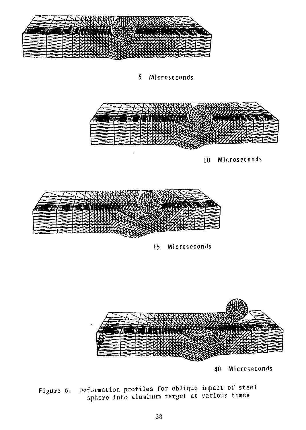
6. Deformation profiles for oblique impact of steel
sphere into aluminum target at various times................. 38
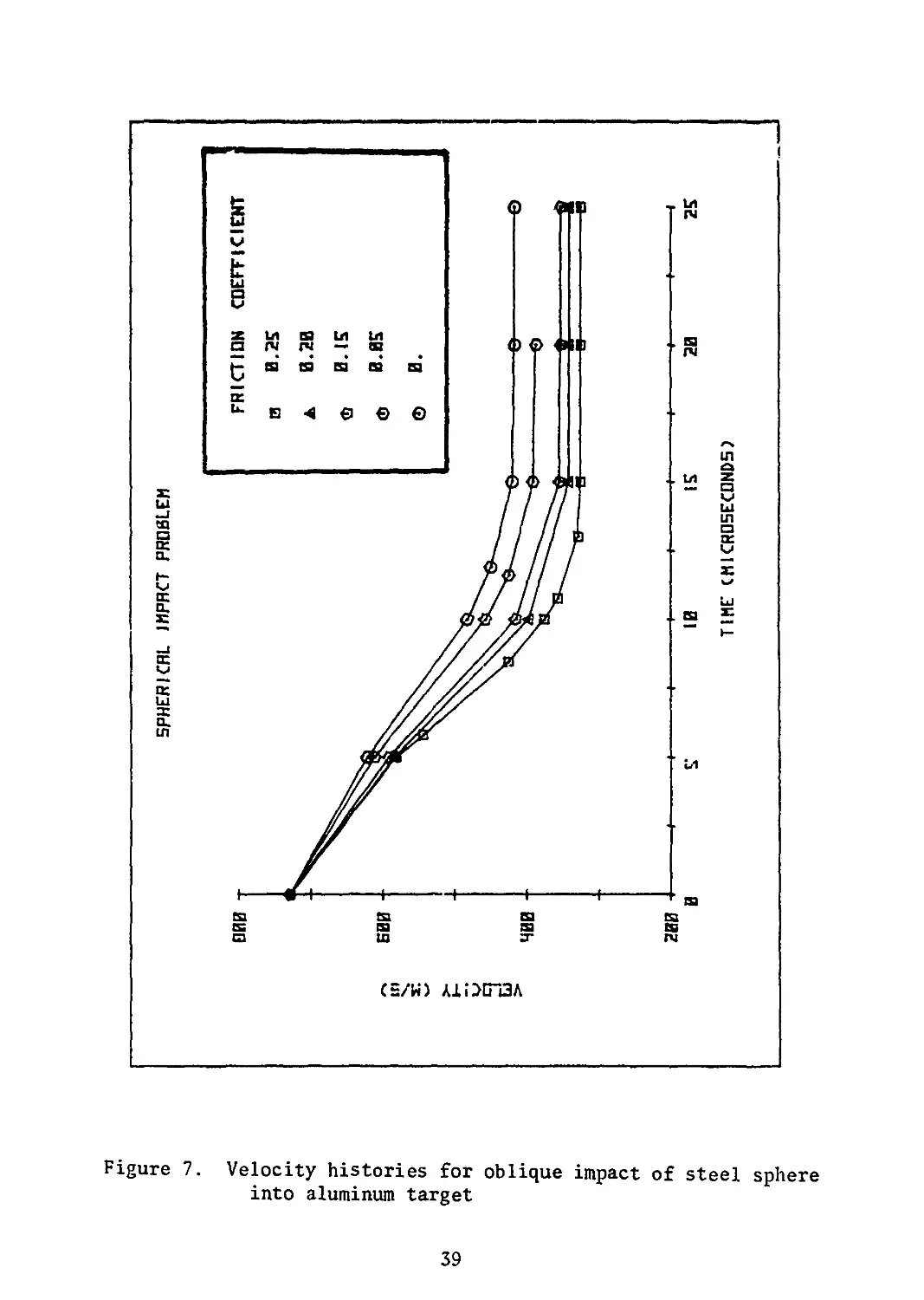
7. Velocity histories for oblique impact of steel sphere
into aluminum target......................................... 39
8. Rod deformation at various times....................... 4!
9. Deformations and pressures in fuel tank simulator
at 40 and 180 ym............................................. 44
5
HOCEDING PAG® BLANK-NOT E
I. INTRODUCTION
A. General
Situations involving impact—the collision of two or more solid
bodies— are currently receiving widespread attention. Traditionally,
the prime interest in this area has been for military applications.
However, advances in technology have placed such severe demands on
materials behavior under short-term loading that current interest in
the response of materials and structures to intense impulsive loading
centers on such problems as
- transportation safety of hazardous materials
- vehicle crashworthiness
- safety of nuclear reactor structures subjected to impact by
tornado-borne debris and aircraft collisions
- the vulnerability of military vehicles, structures, and aircraft
to impact and explosive loading
- design of lightweight armor systems
- erosion and fracture of solids due to liquid and solid particle
impacts
- protection of spacecraft from meteoroid impact
- explosive forming and welding of metals.
The study of impact phenomena involves a variety of classical discip-
plines. In the low velocity regime (<2.0 m/s) many problems fall into
the area of structural dynamics. Local . ndentations or penetrations
are strongly coupled to the overall deformation of the structure.
Frequently, the striker can be replaced, through the Hertz contact
theory [1], with an equivalent load distribution acting over a given
area in a given time and the analysis of the target performed using
conventional structural analysis techniques. Typically, loading and
response times are in the millisecond regime. As the striking velocity
increases (0.5-1.5 kin/s) the response of the structure is dominated by
the behavior of the material within a small zone (typically 2-3 pro-
jectile diameters) of the impact area. A wave description of the
phenomenon if appropriate and the influences of velocity, geometry,
material constitution, strain rate, localized plastic flow, and failure
are manifest at various stages of the impact process. Typically, loading
and reaction times are on the order of microseconds. Still further
increases in impact velocity (2-3 km/s) result in localized pressures
which exceed by an order of magnitude the strength of the material. In
effect tne colliding solids can be treated as fluids in the early stages
of impact. At ultra-high velocities (>12 km/s) energy deposition occurs
at such a high rate that an explosive vaporization of colliding materials
results.
7
Impact phenomena can be characterized in a number of ways:
according to the impact angle, the geometric and material characteristics
of the target or projectile, or striking velocity. The latter approach
is adopted in Table 1 which provides a short classification of impact
processes as a function of striking velocity, V , and strain rate, £.
The impact velocity ranges should be consideredsonly as reference points.
In fact, these transitions are extraordinarily flexible since deformation
processes under impact loading depend on a long series of parameters in
addition to impact velocity.
Table 1. Impact response of Materials
ё 108 I У1 >12 kms'1 EFFECT EXPLOSIVE IMPACT- COLLIDING SOLIDS VAPORIZED METHOD OF LOADING
106 — 3-12 kms-1 HYDRODYNAMIC - MATERIAL COMPRESSI- BILITY NOT IGNORABLE EXPLOSIVE ACCELERATION
1-3 kms"1 FLUID BEHAVIOR IN MATERIALS .‘PRESSURES APPROACH OR EXCEED MATERIAL STRENGTH; DENSITY A DOMINANT PARAMETER POWDER GUNS,GAS GUNS
104 500-1000ms’1 VISCOUS-MATERIAL STRENGTH STILL SIGNIFICANT POWDER GUNS
10Z — 50 - 500 ms"1 PRIMARILY PLASTIC MECHANICAL DEVICES, COMPRESSED AIR GUN
10° 0 г < 50ms"1 PRIMARILY ELASTIC SOME LOCAL PLASTICITY MECHANICAL DEVICES , COMPRESSED AIR GUN
A complete treatment of the impact r sponse of materials and struc-
tures would demand that account be tik^u of the geometry of interacting
bodies, elastic-plastic and shock w?/e propagation, hydrodynamic flow,
finite strains and deflections, strain rate effects, work hardening,
thermal and frictional effects, and the initiation and propagation of
failure in the colliding materials. An analytical approach would not
only be formidable but would also require a degree of material charac-
terization under high strain rate loading that could not be attained
in practice. Hence, much of the work in this field has been experimen-
tal in /ature.. Existing analytical models generally incorporate a high
degree of empiricism and focus on one or two aspects of the impact res-
ponse of solids. Extensive reviews of existing models have appeared
recently [2,3] . This paper focuses on numerical techniques for high
velocity impact (0.5-2 km/s) simulations, their current capabilities
and limitations. Some remarks about anticipated developments are also
made. For the sake of completeness, the basic mechanisms involved in
the penetration and perforation of solids are stated. Emphasis is
placed on solid-solid impacts where both loading and response times are
Jn the sub-millist-ond regime. No account is given of the impact
r-sTc.>se of composite materials. Problems dealing with blast loading or
! charge attack of structures are beyond the scope of this paper.
Penetration and Perforation of Solids
Penetration may be defined as the entrance of a projectile into a
target without completing its passage through the body [2]. This
involves either embedment or rebound of the striker and the formation of
° crater in the target. Perforation, on the other hand, implies the
complete piercing of a target by the projectile. Such processes occur
in a time frame of several to several hundred microseconds. Targets
and projectiles are deformed severely during such encounters.
Consider the events which occur in projectile and target during
impact. For purposes of this discussion, consider the projectile to be
in the form of a long rod, generally cylindrical in shape, with conical,
ogival, hemispherical or flat nose. When such a projectile strikes a
target, strong compressive waves propagate into both bodies. If the
impact velocity is sufficiently high, relief waves will propagate
inward from the lateral free surfaces of the rod and cross at the center-
line, creating a region with high tensile stress. This tensile region
can cause fracture in sufficiently brittle materials such as high strengtl
steels. This effect will be enhanced if centerline porosity or other
imperfections exist in the projectile material. For normal impacts,
the state of stress is clearly two-dimensional. For oblique incidence,
there is the additional complication of bending stresses due to the
asymmetry of the loading. Under the proper combinations of projectile
geometry, material characteristics and impact velocity, the combined
bending and tensile stresses can lead to projectile failure and ricochet.
9
The initial compression wave in the target is followed quickly by
a release wave. When the initial compressive wave reaches a free
boundary in the target, an additional release wave is generated. If
the combination of load intensity (tensile) and duration exceeds a
critical value for the target material, failure will be initiated.
Targets are best classified following the definitions in [2]. A
target is said to be:
a. semi-infinite if there is no influence of the distal boundary
on the penetration process
b. thick if there is influence of the distal boundary only after
substantial travel of the projectile into the targets
c. intermediate if the rear surface exerts considerable influence
on tne deformation process during nearly all of the penetrator motion
d. thin if stress and deformation gradients throughout its
thickness do not exist.
Impacted materials may fail in a variety of ways, the actual
mechanism depending on such variables as material properties, impact
velocity, projectile shape, method of target support, and relative
dimensions of projectile and target. Figure 1, adapted from [ 2,4] ,
shows some of the dominant modes for thin and intermediate thickness
targets. Spalling, tensile failure due to the reflection of the initial
compressive wave from the rear surface of a finite thickness plate,
is a commonplace occurrence under explosive and intense impact loads,
especially for materials stronger in compression than in tension.
Scabbing is similar in appearance, but here fracture is produced by
large deformations and its surface is determined by local inhomogeneities
and anisotropies. Fracture due to an initial stress wave exceeding a
material's ultimate strength can occur in weak, low-density targets
while radial cracking is common in materials such as ceramics where
the tensile strength is considerably lower than the compressive strength.
Pluggir1; failure has been studied extensively, both analytically and
experimentally. Impact by a blunt or hemispherically-nosed striker on
a finite thickness target at a velocity close to the ballistic limit
(the minimum velocity required for perforation) results in the formation
of a nearly cylindrical slug of approximately the same diameter as the
striker which is set in motion by the projectile. The mechanism for
plug formation has been termed "adiabatic shear banding” because of the
hard wnite bands with sharp boundaries observed by etching sections of
plates after plugging failure [5]. The generally accepted mechanism
leading to plugging failure envisions occurrence of a plastic shear
instability at tne site of a stress concentration in an othewise
uniformly straining solid. The work of plastic deformation is converted
almost entirely into heat which, because of the high deformation rates,
is unable to propagate a significant distance away from the plastic
10
DUCTILE HOLE GROWTH
Figure 1. Failure modes in impacted plates
11
zone. As a result, the temperature in the zone rises, encouraging
additional local plastic flow and concentrating the local plastic
strain still further. The process continues and results in the
propagation of a narrow band of intense plastic strain through the
material along planes of maximum shear stress or minimum strength until
unloading occurs or the material fractures. For striking velocities
exceeding the minimum perforation velocity by more than 5-10%, multiple
fragments rather than an intact plug will result. Plugging failure
is quite sensitive to the impact angle and nose shape of the projectile.
Petalling is produced by high radial and circumferential tensile
stresses after passage of the initial stress wave. The high stress
fields occur near the tip of the projectile. Bending moments created
by the forward motion of the plate material pushed by the striker cause
the characteristic deformation pattern. It is most freqeuently observed
in thin plates struck by ogival or conical bullets at relatively low
impact velocities or by blunt projectiles near the ballistic limit.
Petalling is accompanied by large plastic flows and permanent flexure.
Eventually, the tensile strength of the plate material is reached and a
star-shaped crack develops around the tip of the projectile. The
sectors so formed are then pushed back by the continuing motion of the
projectile forming petals.
For thick targets impacted by malleable materials at velocities
exceeding 1 kra/s, there is a hydrodynamic erosion and inversion of the
penetrator material against the receding face of the penetration
channel in the target. The target material is forced aside much as
though a punch were being pushed into it, although the channel is much
bigger than the penetrator diameter.
A combination of ductile failure and spalling seems to be
characteristic for the failure of thick plates of low or medium hardness.
Material failure under impact loading is a most complex process.
Even though one of the failure models depicted in Figure 1 may dominate,
a second or third mode frequently accompanies the principal failure
mode to a lesser extent.
In view of the complexity of penetration processes, it is not
surprising that the bulk of the work in this area is experimental in
nature. Terminal ballistic test techniques, aside from routine proof
tests, vary mainly in the degree of instrumentation provided and hence
the amount of data retrieved.
The most common type of ballistic test is designed to obtain
information about
a. the velocity and trajectory of the projectile prior to impact
b. changes in configuration of projectile and target due to impact
c. masses, velocities, and trajectories of fragments generated
by the impact process.
12
Projectile trajectories may be determined in a number of ways; high-
speed photography, orthogonal flash radiography or from yaw card
measurements. Yaw cards are thin paper or plastic sheets located along
the anticipated trajectory. Interaction of the projectile with the yaw
cards does not generally affect its motion. The position of the
perforations on the yaw cards determines projectile location in the
plane perpendicular to the trajectory. The shape of the perforation
allows flight orientation to be determined.
The striking velocity is determined from a measurement of transit
times over fixed distances. The time of arrival at predetermined
locations is established by the closing or opening of electrical circuits,
interruption of light beams, synchronized photography or flash
radiography of the projectile.
An example of a test setup for retrieval of penetration data for
solid (kinetic energy] projectiles is shown in Figure 2. It is a
Figure 2. Experimental test set-up of x-ray instrumentation for
obtaining penetration data for projectiles
13
typical arrangement used for small scale (65 gram or less) penetrators
at the US Army Ballistic Research Laboratory [6] and sufficiently
flexible so that changes (such as the addition of x-ray tubes or
high-speed framing cameras) can be made to accommodate a variety of
test requirements and projectile types. The x-ray system consists
of orthogonal pairs of x-ray tubes (105 or 150 kv) arranged as shown.
A time delay generator in the system pulses each tube or set of tubes
at preset intervals.
Four tubes, arranged in pairs, provide simultaneous orthogonal radio-
graphs of the projectile in free flight before target impact. The
projectile striking velocity and orientation are measured from these
radiographs.
A similar tube arrangement behind the target provides orthogonal
radiographs to supply the data needed to determine the residual
parameters. Additional tubes are usually added to view the projectile
impacting and penetrating the target. Details of testing and data
acquisition methods are given in [7-8].
In situations where fragment spray must be characterized for use in
vulnerability analyses, recovery of fragments by procedures that inflict
minimal damage to the fragments is necessary. The most common recovery
media are stacks of plywood or cane fiber board, although other methods
have been considered [9]. If there are many fragments, the task of
measuring individual fragment masses, speeds, and directions of travel
from multiply-exposed x-ray films and their correlation with recovered
fragments is formidable due to problems of identifying individual
fragments on the orthogonal film pairs. Procedures for fragment data
acquisition, reduction and reporting are in [10-11]. Examples of
typical small-scale terminal ballistics results are to be found in
[12].
Post-mortem measurements on projectile and target include
determination of the principal dimensions of the target crater such as
depth, diameter, and crater volume (or entrance and exit diameters
for a perforation) as well as the final length, diameter, and mass of
the projectile and other massive fragments. Procedures for making the
measurements are given in [8].
In summary, then, the data extracted from conventional ballistic
tests consists of the following:
a. speed and orientation of the projectile prior to impact
b. speed and orientation of major projectile pieces after
perforation
c. speed, mass, and spatial distributions of fragments behind
the target
d. hole size and mass loss in the target.
14
For advanced analytical and numerical techniques, such meager
data is insufficient to permit unambiguous establishment of the
principal mechanisms which were active during the impact process.
Advances in instrumentation techniques now permit the above data to be
supplemented with additional information. Recent developments in
cineradiography and high-speed photography [13-16] permit determina-
tion of time histories of material motion during the penetration
process. Instrumented impact tests [17-20] provide information about
surface strains in projectiles and stresses in targets during the
penetration process, information which is invaluable in validating
numerical simulation methods for penetration problems [20].
The PHERMEX facility [21] at Los Alamos Scientific Laboratory
provides another invaluable method for the study of penetration
phenomena. Essentially a 6 MEV x-ray source, it is capable of
generating extremely short duration pulses which can literally penetrate,
or "see into" some 20cm of steel, thus providing radiographs of pro-
jectile behavior within the target,. Reference [3] shows comparison of
two- and three-dimensional computational results with radiographs
obtained at the PHERMEX facility.
Impact testing can be done routinely and cheaply in small scale
(projectile weights <100g) with the techniques described above. Cost
of testing, including materials and fabrication costs, range from
$800-2000 per test depending on the amount of instrumentation and data
reduction required. Costs for full-scale testing (3-4kg projectiles)
are 5-10 times as much. Usually, a large number of data points are
required to obtain statistically meaningful results. Partially to offset
the high cost of testing and to supplement the information obtained
from experiments, recourse is made to analytical techniques.
Analytical approaches have tended to fall into three categories:
a. empirical or quasi-analytical: algebraic equations are
formulated based on correlation with a large number of experimental
data points and these are used to make predictions to guide further
experiments. Such efforts are usually closely related to tests per-
formed to discriminate between the performance characteristics of
various materials or structures for a particular design objective.
In general, these efforts do not significantly advance our understanding
of material behavior and processes and will not be considered in this
paper. A variety of such models for penetration and ricochet have
been reviewed by Recht [22]. Similarity modeling for penetration
mechanics is discussed in a chapter of the book by Baker et al [23].
15
b. approximate analytical methods: these concentrate on one
aspect of the problem (such as plugging, petalling, spall, crater
formation, etc.) by introducing simplifying assumptions into the
governing equations of continuum physics in order to reduce these
to one- or two-dimensional algebraic or differential equations. Their
solution is then attempted, frequently in the course of which additional
simplifications are introduced. With few exceptions, such analyses
tend to treat either the striker or the target as rigid and rely on
momentum or energy balance, or both. Only a few papers are concerned
with predicting the deformation of both projectile and target. Further-
more, almost all such analyses either require some empirical input or
rely on material parameters not readily available or measurable.
c. numerical methods: for a complete solution of impact problems,
one must rely on a numerical evaluation of the governing equations
of continuum physics. Finite difference and finite element methods
are capable of attacking the entire set of field equations, have greater
flexibility than various algebraic equations and can accurately model
transient phenomena. They are still approximate in nature (one solves
a set of discretized equations rather than the corresponding
differential equations) but at present, errors associated with material
properties are usually far greater than errors inherent in the
numerical methods. Current interec. centers or three-dimensional
computational schemes for wave propagation and impact studies.
While the computational approach does offer the advantages of a
complete treatment of the impact problem, with exact representation of
geometries involved and without recourse to simplifying assumptions,
it is not without its drawbacks. The price of complexity in analytical
models is an ever-increasing need for additional information about
dynamic material behavior. Advanced computational methods require
fairly detailed information about the behavior of materials at high
loading rates, especially their failure under such loading. This is
information which is only now becoming available. Hence, computer codes
are only as good as the material descriptions contained therein. Table
2 compares some of the advantages and disadvantages of three-dimensional
computer codes and full-scale experiments. These issues are discussed
more fully in the following sections and in [3]. In general, neither
the experimental nor the analytical approach alone is effective in
solving impact problems. The best results come from a judicious
combination of both.
16
Table 2. Computations Versus Experiments
Constraints
Computer Simulation
Cost
Time
I nformation
Unknowns
Typical 3D simulation costs
~$1000 for ricochet sit-
uations, */$6000 for pene-
tration simulation.
Up to one week may be needed
to grid and debug problem,
several weeks to obtain and
analyze results.
Maximal output - displace-
ments, stress, strain,
strain rate, momenta,
energies, forces, and
moments.
Results depend on material
model, material properties,
failure model.
Utility
Excellent base for con-
struction of approximate
analytical models for
parametric studies.
Field Experiments______
Typical cost for one shot
Is $7500 (Including
materials and fabrication
costs and data reduction).
Once materials have been
fabricated, one to two
shots per day can be
obtained.
Minimal - Initial and final
velocity and orientation
for projectile; residual
projectlie mass; target
hole size and mass loss.
Uncertainties In material
properties, Initial con-
ditions and boundary con-
ditions manifested as
data scatter.
Time and cost constraints
almost never permit
acquisition of data base with
enough variation of para-
meters to construct unam-
biguous models.
II. NUMERICAL SIMULATION OF IMPACT PHENOMENA
A. General Considerations
Analytical models, although limited in scope, are quite useful for
developing an appreciation for the dominant physical phenomena
occuring in a given impact situation and for sorting experimental data.
They may even be useful in making predictions, provided care is taken
not to violate the simplifying assumptions introduced in their derivation
or exceed the data base from which their empirical constants are derived.
If a complete solution to impact situations is necessary, recourse must
be made to numerical simulation. This is especially true for oblique
impacts or situations where a three-dimensional stress state is dominant
for there are virtually no models which can deal with such complexity.
Two- and three-dimensional computer codes obviate the need for various
simplifications and are capable of treating complex geometries and
loading states. However, their accuracy and utility is limited by the
material descriptions embodied in their constitutive equations. Excellent
results have been obtained for situations where material behavior is
well understood and characterized, eg, [ 24].
17
Numerical simulations of high velocity impact phenomena in two
dimensions have been performed routinely for a number of years. Current
interest centers on u.ree-dimensional simulations. The range of
problems addressed is fairly wide, including computations in the
hypervelocity regime in order to determine structural configurations
capable of protecting spacecraft against meteorite impact and study of
the erosion and fracture of missile and space vehicle heat shields
during re-entry. The bulk of the effort has been on military problems,
namely the penetration and perforation of solids and structures subjected
to kinetic energy (inert) missile and shaped charge attack as well as
the reverse problem of the design of armors against such threats.
In geophysics, computations complement the study of materials under very
high pressures and provide historical details for formation of craters
produced by meteor impact, eg, [25]. Industrial problems addressable
computationally include explosive forming, explosive welding, shock
synthesis of materials, mining, and massive earth removal.
A compact description of the computational process is shown in Figure
3. The three stages listed may be incorporated in a single computer
program, or code, or may exist as three distinct codes. At any rate,
some sort of automatic generation capability exists to provide a
detail-d computational mesh for the geometry of interest from an
abbreviated description provided by the user. This information is
coupled to a description of the materials making up the geometric
bodies by specifying appropriate parameters for the equation of state,
the stress-strain relationship used by the code in both the elastic
and plastic regimes, and the failure criteria to be used. A description
of boundary and initial conditions ends this stage of the process. The
pre-processor, as this stage is commonly called, prepares the information
in a form usable by the next part, the main processor, and also prints
or interactively displays the initial geometry and conditions for user
verification. The current crop of codes (those developed within the
last few years) tend to allow the user, via a graphics terminal, to
view the results, either complete or partial, of the pre-processor and
modify the computational grid, initial conditions, boundary conditions,
and material description.
The conservation laws for mass, momentum and energy, coupled to an
equation of state for determination of pressures, a constitutive
relationship, a failure criterion and a post-failure model are cast into
finite difference or finite element form and integrated in time in the
next phase, or main processor, using the information generated by the
pre-processor. These computations are of necessity quite long and
demanding of computer storage and except for a very few problems never
run to completion in one pass. Hence, provision is almost always
made for a restart capability, so that computations may be resumed
after interruption for physical or administrative reasons.
18
PRE-
PROCESSOR
INITIAL GEOMETRY
MATERIAL DESCRIPTION
INITIAL CONDITIONS
MAIN
PROG RAM
CONSERVATION EQUATIONS
• MASS
• MOMENTUM
• ENERGY
• ENTROPY
MATERIAL MODEL
• STRESS-STRAIN RELATION
• EQUATION OF STATE
• FAILURE CRITERION
• POST-FAILURE MODEL
POST-
PROCESSOR
• DEFORMATION, STRESS,
STRAIN , PRESSURE &
TEMPERATURE FIELDS
• VELOCITIES, ACCELERATIONS
• FORCES , MOMENTS
• ENERGIES, MOMENTA
Figure 3. Computational process for impact simulation
19
Results of the computations, or output, is generally massive. Codes
typically produce full-field descriptions of physical quantities and
material conditions (intact, failed, plastically deformed) throughout
the problem as a function of time. Output listings of two- and
three-dimensional codes can run into hundreds of pages and are impossible
to read (indeed, sometimes to carry). Recourse is therefore made to
post-processors, computer programs which prepare graphical displays of
the items of interest, ie, deformation, velocity, temperature, energy
fields at given times, and time histories of variables of interest,
etc» The degree of sophistication of these plot packages varies con-
siderably from code to code. They are also very dependent not only on
the machine on which the code is installed but also on the installation.
Transferring both code and plot package from one installation to another
can be a nontrivial task. It is not unusual for such transfers to require
several man-months of full-time effort.
The decision to use such codes should not be made lightly for in
no sense can the current crop of programs be treated as "black boxes"!
As a rule, at least three to six months effort is required before new
users can run practical problems on existing codes. During the learn-
ing period, frequent contact with the code developers or persons
experienced in their use will be required. Even after the essentials
have been mastered, pathological situations will arise which will
require guidance from experienced users and may require code modification.
Aside from the man-months expended, computational costs will be non-
negligible. However, the judicious combination of computer simulations
and experiments (which will be accompanied by efforts to characterize
candidate materials at high strain rates if such data is not already
available) can lead to considerable improvements in engineering design
with reduced manpower and computer costs.
Some examples of results which can be achieved with current
computer codes are presented further on. Throughout the following, it
should be kept in mind that computational results are directly related
to the quality of the material model in the code-the better the
description of material behavior at the strain rates vucountered
experimentally and of its failure modes at those strain rates, the
better the computational results. Improper materials characterization
leads not only to quantitatively incorrect results but frequently to
descriptions which are qualitatively incorrccc. Imperfect understand-
ing of this situation has frequently led to "...an undesirable iterative
procedure of matching imperfectly understood experiments with theoretical
computations based on incomplete models" [26]. Fortunately, this is
an area of Intense activity currently so that it is not unreasonable
to expect that within the next few years improved understanding of the
dynamic behavior of materials at ultra-high loading rates will lead to
improvement in code quantitative predictions.
20
After a brief look at various aspects of the numerical simulation
of the dynamic behavior of impacting continuous bodies, specific
characteristics of two- and three-dimensional codes will be mentioned.
One-dimensional codes and results will not be considered. For these,
the reader will be referred to an extensive literature. The primary
emphasis will be on three-dimensional methods for analysis of
impacting solids and results.
B. Discretization Methods
It is necessary in a computer analysis to replace a continuous
physical system by a discretized system. In the discretization process,
the continuum is replaced by a computational mesh. The discretization
techniques most commonly used are the finite difference and finite
element methods.
Historically, the finite difference codes came first as programs
were developed to treat hypervelocity impact situations. Later a
material strength model, usually a simple elastic-perfectly plastic
or rigid plastic model, was tacked on to the codes to treat the later
stages of hypervelocity situations or penetration problems in the
ordnance velocity regime. Finite element methods began at the opposite
end of the loading rate spectrum, being originally used to approximate
the behavior of arbitrary structures and structural systems subjected
to static loadings. Recently, finite element programs capable of
treating problems in wave propagation, large plastic flow, and fluid
flow have appeared and are taking their place with the finite
difference codes.
In the finite difference method, spatial and time grids are
constructed by replacing derivatives in the governing equations of
continuum dynamics with difference approximations. Standard techniques
for solution of large equation sets are employed to obtain spatial
solutions. Solutions in time are obtained by integration.
The finite element approach is an outgrowth of structural analysis
techniques. Here, instead of manipulating the governing equations
into differential equation form and then attempting a numerical
solution, the discretization procedure is employed from the very start.
The procedure [27] consists of:
a<> dividing the continuum by means of imaginary lines into a
finite number of regions, or elements, which are assumed to interact
only at a discrete number of points called nodes. The displacements
at these nodal points are the basic unknowns of the problem.
b. a set of functions is postulated to define displacements at
any point within an element in terms of the nodal displacement.
21
c. these displacement functions now define a state of strain within
each element. These, together with constitutive properties, then
define the state of stress.
d. a system of forces concentrated at the nodes which equilibrate
external loads is determined. This procedure results in a stiffness
relationship-equations relating internal loads, external loads, and
nodal displacements. Individual element (local) data are then
assembled into global arrays and solutions for nodal displacements are
obtained with conventional techniques for large systems of algebraic
equations. Element strains and stresses are then determined from the
nodal displacements.
As the above descriptions imply, a common property of both methods
is the local separation of the spatial dependence from the time
dependence of the dependent variable. This allows separate treatment
of the space and time grids. Time integration methods will be
mentioned shortly. Characteristics of the spatial discretization
schemes are discussed in several papers [28-55]. The following is
therefore a brief summary of their principal conclusions.
It has been shown [28] that the discrete forms of the equations of
motion of the finite element method are equivalent to those of the
finite difference method for a number of cases. Thus, since there is
no basic mathematical difference between tne two methods they should
have the same degree of accuracy in numerical computations. The main
differences lie not in the methods themselves but in the data
management structure of the computer programs which implement them.
Finite element codes have a distinct advantage in treating irregular
geometries and variations in mesh size and type. This is because in
the finite element method, the equations of motion are formulated
through nodal forces for each element and do not depend on the shape
of the neighboring mesh. In the finite difference method, equations
of motion and expressed directly in terms of the pressure gradients
of the neighboring meshes. This is not inherently a problem, but the
difference equations must be formulated separately for irregular
regions and boundaries.
Another major difference occurs in numbering of meshes. In finite
difference programs, the regularity of the mesh implicitly establishes
the connectivity information. In finite element programs, mesh
connectivity is explicitly stored, a feature which facilitates automatic
generation of complex mesh systems. This limitation can be overcome
for finite difference codes, but versatility is generally achieved
at the expense of large computer storage and CPU time.
22
Co Mesh Descriptions
The bulk of the computer codes for impact studies fall into two
categories: Lagrangian and Eulerian. Lagrangian codes follow the
motion of fixed elements of mass with the computational grid being
fixed and distorting with the material. Lagrangian methods have
several advantages:
a„ the codes are conceptually straightforward since the equations
of mass, momentum, and energy conservation are simpler due to the lack
of convective terms to represent mass flow in the coordinate frame.
Since fewer computations are required per cycle, they should be in
theory computationally faster. However, see below.
b. material interfaces and free surfaces are stationary in the
material coordinate frame, hence allowing sharp definition and
straightforward treatment of boundary conditions. It should be noted
though that fairly complex logic is required to define behavior at
material interfaces, ie, opening and closing of voids, frictional effects.
While such logic enhances the generality and applicability of the codes,
a price is paid in the number of additional computations required
per cycle, thus slowing overall run time.
c. some constitutive equations require time histories of material
behavior. In the Lagrangian method, this is easily and accurately
accounted for.
A typical example of a Lagrangian grid is shown in Figure 4.
As already mentioned, the Lagrangian computational grid distorts with
the material. Inaccuracies in the numerical approximations grow
when cells become significantly distorted due to shear or fold over
themselves resulting in negative masses. These problems can be overcome
to some extent through the use of sliding interfaces and rezoning.
Grid distortions can be reduced in some problems by use of gliding
interfaces either between different materials which can be expected
to slide over one another as the motion proceeds or in regions where
very large shears and fractures can be expected to develop. Most
sliding interface methods are based on the decomposition of
acceleration and velocity into components normal and tangential to
the interface. Motions in the normal direction are continuous
when materials are in contact but are independent when they are
separated. Tangential motions are independent when materials are
separated or the interface is frictionless, but are modified if there
is contact and a finite frictional force is present. On sliding
interfaces, frictional forces ranging between zero and infinity may
be specified. Materials at either side of an interface may separate
if a specified criterion is exceeded and may collide again if
previously separated.
23
isiKiiaisiisistia^iQioiei^isiisiisiQiiaiia
^l!ai!aiSll!ilSliaiSI!ill!il№«3ra)9ISlW
KKKKKKgBKKKgKKKKKglQi
51м£йййММ1м^йвМ|1
ttiaiMaiiaiiaiiaiBIS^gigaiSiiaiaRaiagiial
Figure 4. Lagrangian computational grid
24
When severe grid distortions cause errors in the discretization
scheme to become very large and rhe allowable time step to become very
small, recourse must be made to rezoning. A new grid is overlaid on
the old one and the rezone program maps mesh quantities of the old grid
onto the new grid such that conservation of mass, momentum, and total
energy and the constitutive relationship are satisfied. Rezone
techniques have been used quite successfully in one-dimensional codes,
especially to increase definition in regions where physical quantities
vary rapidly. For two- and three-dimensional codes, however, rezoning
is a costly and complex operation. Difficulties arise in averaging in-
ternal state variables representing material memory, since a given
new mesh may cover several old meshes each of which has experienced
a somewhat different history. Several rezoning operations may be
required before a successfully rezoned grid is obtained and the final
result is very much a function of the experience of the operator
performing the rezening. Even the most complicated and sophisticated
rezone routines have been disappointing for the two-dimensional case,
with the apparent exception of the TOODY code.
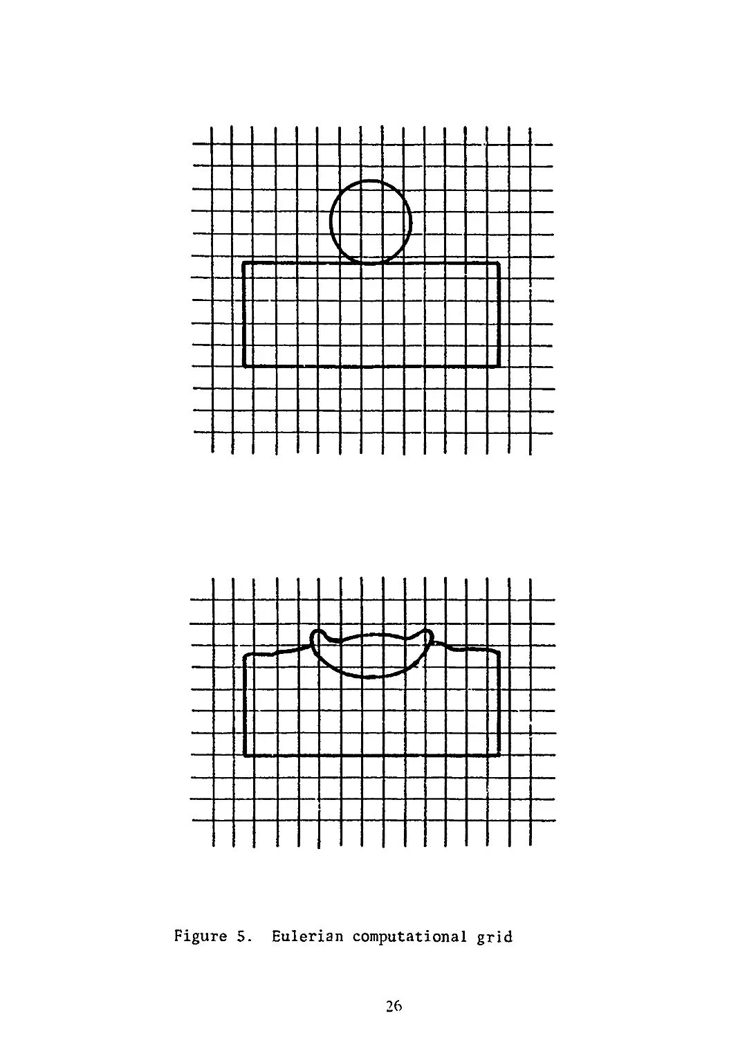
In the Eulerian approach, the computational grid is assumed fixed
in space while the continuum passes through it (Figure 5). Material
can be represented as either discrete points or as a continuum. Such
codes are ideally suited for large distortion problems but unless
Lagrangian features are incorporated, free surface motions and
material interface conditions are not accurately computed due to
diffusion. Without Lagrangian features, it is not possible to obtain
material time histories. Eulerian codes are absolutely required if
mixing of materials initially segregated is important.
Since no one computational technique can handle all situations in
impact dynamics, hybrid methods have been developed. Many variations
exist. The most common techniques include use of Lagrangian tracer
particles in Eulerian codes to accurately treat material interfaces
or use of an Eulerian method at the beginning of a computation
when gross flow and distortions are expected, then mapping to a
Lagrangian grid for completion of the calculations. Alternative
approaches include mixed Eulerian and Lagrangian computations in
parallel. Convected coordinate and hybrid methods have also been used.
These are discussed in an excellent review article by Herrmann [32].
D. Temporal Integration Schemes
Integration of the discretized equations of continuum mechanics can
be accomplished in a number of ways [28-29, 31, 36] . Commonly, the
central and forward difference schemes are employed. The methods are
called explicit if the displacements at some time t+At are independent
of the accelerations at that time. The computational flow is quite
straightforward. At any time step, the velocities and displacements
are known. The rate of deformation or the strain can be computed from
the strain-displacement relations and the stresses at that time
25
Figure 5. Eulerian computational grid
26
step are found from the constitutive relationship. The equation of motion
is then used to find the accelerations which, together wi'.h velocities,
are stepped forward in time to find new displacements and the entire
procedure is repeated once again.
The computed response may become unstable (grow without bound) in
explicit integrations unless care is taken to restrict the size of
the time step. This problem has been studied rigorously for linear
problems by Courant, Friedricks, and Levy [37] who found that in
explicit integration the computation will be stable if the time step
At satisfies the relation
At <2/X (1) z
where A is the highest natural frequency of the mesh. No rigorous
stability criterion has been determined for nonlinear problems but it
is customary to determine the time step from
where £ is the minimum mesh dimension in the computational grid, c the
sonic velocity, and к a factor chosen to be less than unity, generally
between (0.6- 0.8).
Problems involving impact at ordnance velocities (0.5-2 km/s) result
in a strong initial shock wave (alternatively, a large stress or
velocity gradient) which can lead to material failure and must be
accurately resolved. This demands fine spatial as well as temporal
resolution and results in very small time steps and a large number
of computational cycles.
Typically, for design problems, computations must be run to tens
or hundreds of wave transit times across the characteristic length
dimension of the problem. This places a severe burden on computer
resources and has spurred investigation of implicit integration
schemes.
In an implicit scheme, the displacements at any time t+At cannot
be obtained without a knowledge of the accelerations at the same
time. The relationships between velocity, displacement, and
accelerations must be combined with the equations of motion and the
resulting set of simultaneous equations solved for the displacements.
The resulting nonlinear equations are generally solved by some kind
of linearization method. Predictor-corrector schemes or trapezoidal
techniques such as the Houbolt method, as well as the Wilson 0 method and
the Newmark 8 method are popular [29, 35].
27
Most implicit methods have been shown to be unconditionally stable.
However, the price of stability is the need to solve a set of equations
at each time step. The local truncation error of most implicit and
explicit schemes is of order (At)3. While this is insignificant
for explicit schemes, it is a matter of concern for implicit methods
where the time step is so much larger.
In general, it has been found [30, 31, 36] that for wave
propagation methods, the time step for implicit methods must be about
the same as that for explicit methods in order to satisfy accuracy
requirements. Since implicit methods require considerably more
computations per cycle than explicit integrations, their use has
generally been limited to problems where the details of wave
propagation are not as significant as the overall response of the
material.
E. Computer Resource Requirements
Questions of accuracy and resolution required for dynamic stress
wave solutions are discussed in [36]. Such solutions are
characterized by a very high frequency content and adequate numerical
representation requires a large number of meshes in areas where large
stress gradients propagate. Two-dimensional computations are
routinely done with 4,000-10,000 meshes or elements. Adequate
resolution in three-dimensional problems is even more difficult to
achieve. For practical problems 20,000-50,000 meshes are not uncommon.
For high velocity impact situations, adequate information for design
purposes (projectile velocity and orientation, extent of deformation
in projectile and target, energy deposition in the target) may be
obtained with 20-25,000 meshes. Excellent correlation with experiment
was obtained for an oblique impact situation with 25,000 elements [ 3]
while the same calculation with 12,000 elements underpredicted penetration
depth by 40%. For problems involving steep gradients or advanced
failure models, even greater resolution may be required. Since most
practical problems are run with variable meshes to conserve CPU time
and computer storage, there is no a priori method for determining an
optimum grid for a given computation, although guidelines for educated
guesses exist [30, 36]. Experienced code users can generally arrive
at acceptable grids within a few iterations.
Computing costs tend to be quite high for production problems.
Running times for one-dimensional codes are measured in minutes.
For two-dimensional codes with some 5-6000 meshes or elements, running
times of several hours on CDC 7600 class machines are typical.
Three-dimensional problems will typically run from 4-10 hours or
longer. Three-dimensional problems also place severe limitations on
computer storage. It is virtually impossible to run a three dimensional
impact problem totally in-core. Thus, to permit adequate resolution,
most codes have provisions for keeping only a small portion of the
grid in core and the remaining information on a mass memory device.
28
There is still an upper limit on resolution, though. If the number
of meshes or elements is too great, the bulk of the total computer
time will be spent in data transfer and very little in advancing
computations.
As expensive as such calculations may be, they are often less
costly than full-scale experiments. Indeed, in certain situations,
experimentation may not be possible and reliance must be made on
computations. Additionally, unless the software is reasonably
efficient in permittting automated mesh generation and graphical
representation of results, the major portion of the total cost will
be associated with manpower charges incurred by analysts performing
numerical studies. An illuminating example is shown in [36].
F. Material Model
It is common in existing production codes for the study of high
velocity impact phenomena to divide the deformation behavior of metals
into volumetric and shear (deviatoric) parts. Metals undergo plastic
yielding at modest levels of deviator flow stress. This is usually
taken to be independent of pressure, so that the volumetric behavior
can be treated independently of the shear behavior.
The volumetric behavior is described in terms of an equation of
state relating pressure, volume and some thermal parameter, usually
the internal energy or temperature. The Mie-Gruneisen equation of
state is frequently used, although some codes allow a choice of
equations. In tne newer, modular, codes, equations of state can
readily be changed.
For solid-solid impacts in the 0.5-2 km/s velocity regime, only
moderate pressures (300-500 kb) are generated and these decay rapidly
to values comparable to the strength of the material. Hence, the
equation of state in impact calculations is of secondary importance.
Considerable data exists for the current crop of equations in various
compilations for most metals of interest [38-39] and additional data
can readily be obtained. Consequently, the state of the art in
equation of state is adequate for most present needs.
An incremental elastic-plastic formulation is used to describe
the shear response of metals in present finite difference and
element codes. The plasticity descriptions are usually based
assumed decomposition of the velocity strain tensor, ё, into
elastic and plastic parts
eS = ёе+ё^
together with incompressibility of the plastic part
finite
on an
(3)
(4)
29
Stress and strain tensors are divided into volumetric and deviator parts.
The volumetric parts, namely the pressure and volume, are determined
through the equation of state. The von Mises yield criterion and
the Prandtl-Reuss incremental theory are typically used to describe
plastic behavior. Since strains in problems involving penetrations are
large, questions have been raised regarding the validity of this
approach and alternatives proposed [40-41].
Plasticity models for computations have been reviewed :> Armen [42].
Generally, the plasticity models in wave propagation prodw cion codes
are relatively simple elastic-perfectly plastic descriptions following
the method formulated by Wilkins [43]. Minor modifications have been
introduced to this basic description by allowing the yield stress to
vary with the amount of plastic work, temperature, strain rate or
some combination thereof, eg, [44].
Herrmann and Lawrence [45] have recently reviewed material models
used to describe stress wave propagation in metals, polymers, composites
and porous materials. They find that for metals a perfect plasticity
approach can serve as a first order approximation for many high
strength alloys used in impact situations in the ordnance velocity regime
(0.5-2 km/s) provided care is taken to select an average dynamic value
of flow stress. Excellent results have been obtained with this
approach [24, 46-47] and it is appealing from the point of view that
the degree of dynamic material characterization required is quite low.
Also, many high strength alloys show little variation in flow stress
with strain rate and relatively low rates of strain hardening.
A priori determination of an appropriate dynamic flow scress is
another matter however. Until very recently such information was not
generally available. In a few cases, a dynamic yield stress can be
estimated from static test data but in general the understanding of
of micromechanical deformation mechanisms at very high strain rates is
so limited that estimation of dynamic properties from static data is
hazardous. This approach is best used in conjunction with dynamic
material property tests.
No one dynamic property test technique can provide . {’formation over
the range of stresses, strains, strain rates, and temperatures
encountered in high velocity impact. Several relatively simple
techniques exist however which, despite their limitations, provide
useful data for numerical computations. Methods for dynamic
characterization of materials have been reviewed by Lindholm [48].
Several methods commonly used from which a substantial body of data
exists will next be briefly described.
The split Hopkinson bar consists of a striker bar, incident bar,
transmitter bar, and associated instrumentation. The test specimen
30
is sandwiched between the incident and transmitter bar. Measurement
of the elastic waves in the pressure bars which are reflected and
transmitted by the specimen yield average stress, strain, and strain
rate as functions of time in the specimen once the specimen has reached
homogeneous deformation. This data can be manipulated to obtain a
dynamic stress-strain curve for the specimen material. The technique
can be employed in tension, torsion, and compression at strain rates
from 1()2 to 1()4 s"^ [48-53] .
Care must be taken in performing split-Hopkinson bar tests that
assumptions governing analysis of the data not be violated. The
pressure bars and specimen are assumed to be in a state of uniaxial
stress so that radial inertia effects are neglected. Care must also
be taken in selecting specimen size and lubrication of specimen-bar
interfaces to minimize end effects.
An alternate method involves the free-flight impact of identical
bars [54-56] producing a well-defined constant velocity boundary
condition and an accurate measurement of surface strain by optical
techniques employing diffraction gratings ruled directly on the
specimen. The technique was perfected by Professor James Bell of
Johns Hopkins University. For each test, a record of surface strain
and surface angle is made. From a series of such tests, Bell constructs
a dynamic stress-strain curve by first establishing that the velocity
of propagation of each increment of plastic strain is constant. This
requires measurement of strain-time profiles at several axial
positions along the length of the bar. If the average propagation
velocities are indeed found to be constant it is a sufficient condition
for the one-dimensional rate-independent theory of plasticity to
hold [57] and permits determination of stress corresponding to a
given strain to be obtained.
This technique also has a number of limitations which have been
more fully discussed elsewhere [48, 58]. Radial inertia effects near
the end of the struck specimen are unavoidable and confuse interpretation
of measurements.
Another technique, originally used by Taylor [59] and Whiffen [60],
consists of firing a short cylindrical bar against a rigid surface.
The struck end of the bar is subjected to large plastic strains and
complex stress states. However, a simple analysis [59], later
refined by Hawkyard [61], permits determination of an average dynamic
yield stress in terms of the impact velocity and the residual length
of the bar. Wilkins and Guinan [46] have examined the method
in detail using the two-dimensional HEMP code. They find that overall
agreement with experimentally determined deformation profiles can be
determined with the dynamic average flow stress so obtained and that
the flow stress for a number of materials was invariant over a limited
range of strain rates.
31
If information at higher strain rates is needed, recourse must
be made to plate impact experiments. Impact of a flat projectile
on a flat target plate produces plane stress waves in which, because
of symmetry, the strain is one-dimensional until reflections arrive
from the plate edges. Strain rates from about lo^-lo^ s“^ can be studied
with this technique. Reviews have been given by Karnes [62] and Davison
and Graham [63].
Provided care is taken to characterize materials at strain rates
appropriate to problems being considered, excellent results can be
obtained even with simple material models. The greatest limitation
on the utility of computations for studying impact processes is in
the modeling of material failure. Because of its importance, this
topic will be treated separately. Next, a brief survey is given of
the characteristics of currently popular two- and three-dimensional
computer codes together with examples of their capabilities.
One-dimensional codes and two-dimensional codes of historical interest
will not be mentioned since these have already been extensively
reviewed [26, 30-33, 64] .
III. CURRENT CODE CAPABILITIES
A. Two-dimensional Lagrangian Codes
The most prominent two-dimensional finite difference Lagrangian
codes in use today are the HEMP code, developed by Wilkins of Lawrence
Livermore Laboratories, and the TOODY/TOOREZ codes developed by
Bertholf and his colleagues at Sandia Laboratories. Both codes employ
a second order accurate finite difference representation first
developed by Wilkins [42]. They are quite similar in essential
features and capabilities. Both codes are well documented insofar
as the fundamentals are concerned [65-69]. However, there are many
versions of both codes running on a variety of machines. Potential
users are therefore well advised to obtain not only the basic
documentation but also to maintain close contacts with the users and
systems people at the computer center from which their particular
version is obtained. Many derivatives of HEMP exist, ie, the
two-dimensional member of the PISCES family of codes marketed by
Physics International through the CDC Cybernet network, CRAM and SHEP
to name a few. The differences relate primarily to features required
to implement the basic code on different machines and changes in
pre- and post-processing capability.
The finite difference equations in the HEMP (Hydrodynamic, Elastic,
Magneto § Plastic) code, employ a quadrilateral grid and may be solved
in plane coordinates or with cylindrical symmetry. Slide lines are
available which permit material motion with and without friction.
Provision is also made for the opening and closing of voids. Boundaries
may be fixed or free, stationary or moving. Both pressure and velocity
32
initial conditions may be specified. A mesh generation capability
exists so that many geometric configurations may be generated with
minimum user input. Alternatively, users may specify mesh configurations
with a fair degree of detail manually.
The HEMP code runs on a variety of computers, though most users
tend to prefer the CDC 6600 and 7600 machines. The precise configuration
of the code and size of problems which can be run depend very much on
the machine on which it is implemented.
The TOODY-TOOREZ codes are similar in the basics to HEMP. The
finite difference equations in the TOODY code are discussed in some
detail by Walsh [3<]. Like HEMP, TOODY has been used successfully on
a number of difficult practical problems. As with most production
codes, instantaneous failure criteria based on maxima or minima of field
variables were initially incorporated in the codes. Many users
however have modified these and incorporated more sophisticated failure
models to suit their particular needs.
The EPIC-2 (Elastic Plastic Impact Calculations in 2_ Dimensions)
code [70] is based on a Lagrangian finite element formulation wherein
the equations of motion are integrated directly rather than through
the traditional stiffness matrix approach. The code treats problems
involving wave propagation and elastic-plastic flow. It is arranged
to provide solutions for projectile-target impacts and explosive
detonation problems. Material descriptions are incorporated which
include the effects of strain hardening, strain rate effects, thermal
softening, fracture, and spin. Geometry generators are included to
permit quick generation of flat plates, spheres, and rods with blunt,
rounded or conical nose shapes. Multiple slide lines (no frictional
effects) are provided. A rudimentary post-processor provides plots
of initial geometry, deformed geometry, effective stress, effective
strain, pressure, and velocity fields. In addition, time-history
plots of various system parameters (energies, momenta, penetration
depth, etc.) may be obtained.
B. Two-dimensional Eulerian Codes
Two Eulerian codes currently popular for impact studies which
incorporate all the desirable features of the Eulerian description
of continuous material behavior while including features which enhance
material interface and boundary definition are HELP and HULL.
The HELP code was developed by L. J. Hageman and J. M. Walsh.
The current version [71] is a two-dimensional, multi-material first
order finite difference code which has been used extensively to solve
material flow problems in the hydrodynamic and elastic-plastic regimes.
Although the code is basically Eulerian, material interfaces and free
33
surfaces are propagated in a Lagrangian manner through the calculational
mesh as discrete interfaces across which material is not allowed to
diffuse. The material model employed in HELP includes the Tillotson
equation of state, modified to give a smooth transition between condensed
and expanded states, a deviatoric constitutive relationship, a yield
criterion defined to account for increase in strength at high pressures
and decrease in strength at elevated temperatures, and failure criteria.
Failure in tension is based on relative volume. When the relative volume
in a cell reaches a certain value greater than a specified maximum
distension, that cell is said to fail and computed tensions are zeroed
out. A failure criterion based on maximum plastic work for modeling
plugging failure is also available and has been used with reasonable
success [72]. Recently, the Stanford Research Institute nucleation
and growth model, NAG-FRAG, for ductile and brittle failure in metals
has been incorporated in HELP [73]. However, it has not been tested on
realistic problems.
The HELP code has been widely exercised and applied to a variety
of problems in the ordnance velocity and hypervelocity regimes. Some
interesting results are to be found in the paper by Sedgwick [74]. Good
results are possible with HELP although considerable experience is
required before the code can be used effectively. Its principal drawback
is a lack of modularity which can turn simple modifications (ie,
replacement of the equation of state) into major projects even for
experienced users. In addition, because of the first order accuracy
in the finite difference formulation, pathological problems are the
rule rather than the exception for situations wherein material strength
effects are dominant. A recent revision in the internal energy
algorithm [75] should help somewhat. Good results can be expected for
hypervelocity impact situations. Close association with the code
developers in the early stages of implementation and use is mandatory
for success.
The first version of the HULL finite difference code was written
in 1971 by Matuska and Durrett at the Air Force Weapons Laboratory. In
1976, the code was rewritten to permit computation of elastic-plastic
phenomena. The revision was quite extensive and the resulting code
has improved the state of the art in Eulerian methodology. Computations
with HULL can be performed for work hardening-thermal softening solids
as well as high explosives, fluids, and gases. Lagrangian passive
tracers are utilized in the code but for boundary definition HULL employs
a diffusion limiting scheme. Combined with material preferential
transport, the diffusion limiter provides sharp interface maintenance.
In place of thermal equilibrium in mixed material zones, separate species
energies are calculated. A rather novel material failure technique was
added in 1977 by Matuska. When a metal is considered to have failed,
a small but numerically significant quantity of void is inserted in the
zone. The void is allowed to grow in size in subsequent cycles until
the state of the real material in the zone no longer exceeds the failure
34
criterion. The void can completely take over a zone or neighboring
zones if the physical situation decrees such growth necessary, ie, spall.
Zone recompression can reduce the size of voids or eliminate them
altogether. Excellent results with HULL have been obtained at the Air
Force Armament Laboratory, Eglin AFB on formidable practical problems
involving penetration of thick targets and target arrays. The HULL code
runs on CDC 6600 and 7600 computers as well as Honeywell and IBM machines
and has considerable flexibility in input preparation and displays
of results. Documentation, however, is spartan [76-77]. Assistance
from experienced users or code developers is virtually mandatory until
additional documentation becomes available.
Other Eulerian codes used frequently for impact situations are DORF
[78-79] which is quite similar to HELP in capabilities and problems
and also CSQ [80-81] which is frequently used in conjunction with the
TOODY code to guide rezoning operations. Typical results are to be
found in [82].
C. Three-dimensional Codes
A number of three-dimensional codes are available. With exceptions
to be noted below, they are based on their two-dimensional predecessors,
the general features of which are described above and in review articles
[2b, 32, 64].
The Lagrangian finite difference code HEMP3D [83] is an outgrowth
of tne two-dimensional HEMP code and is designed to olve problems
in solid mechanics involving dynamic plasticity and time-dependent
material behavior. It is based on an incremental formulation for
elasto-plastic behavior, employs the von Mises yield criterion and
relies on artificial viscosity for diffusion of steep shock fronts.
Tne code has been applied to a variety of static and dynamic problems,
including fracture [84-86]. It is being extended to include sliding
surfaces for treatment of penetration problems.
TRIOIL and TRIDORF are both Eulerian three-dimensional finite
difference codes, developed by W. E. Johnson [87-88]. They have been
applied to the study of shaped charge penetration of finite thickness
plates (with the jet modeled as a rigid rod) at high obliquity as well
as other problems. Both codes are similar to their predecessors, OIL
and DORF, except that TRIDORF is a two-material code with a rigid plastic
strength formulation. Similar in spirit is METRIC, developed by
Hageman et al [89-90]. The numerical methods and material descriptions
are similar to those employed in HELP, its forerunner. The code is
not core-contained so that in theory it can provide any degree of spatial
resolution. In its initial development, METRIC relied on mixed cells
(cells containing more than one material) to establish material
boundaries. The code was eventually modified and now material interfaces
and free surfaces are defined by massless tracer particles, just as in
the HELP code.
35
Finite element methods based on Eulerian material descriptions
are under development by Reddy [91-92] and Chan et al [93]. The
latter have developed models that include visco-plastic and strain
rate effects and account for material failure. Impact is viewed as
a problem in the structural response class and the ultimate goal is
the coupling of the Eulerian impact model with a Lagrangian structural
response code such as NASTRAN.
The EPIC-3 code developed by G. R. Johnson [94-97] of Honeywell
is based on a Lagrangian finite element lumped mass formulation
employing tetrahedron elements. As with its two-dimensional analog,
EPIC-2, the equations of motion are integrated directly, bypassing
the traditional stiffness matrix approach. A fairly comprehensive
material description capability exists, allowing for strain hardening,
strain rate effects, thermal softening, and fracture. Geometry
generators are included to quickly generate flat plates and rods with
various nose shapes. Unlike conventional finite element schemes, the
first version of EPIC-3 did not require an orderly grid.
In later versions [98], the EPIC-3 code has been restructured into
three separate programs: a pre-processor, main processor, and
post-processor. All are connected by a common restart tape. Provided
that the nodal bandwidth can be core-contained, problems of unlimited
size can in theory be run. In practice, there is an upper limit to
the problem size tractable since as disc storage becomes large, there
is a tendency for the machine to spend most of its running time in
data transfers and very little in computation. Cost is also a non-
negligible constraint. For smaller problems, where all nodes can be
core-contained, an option is provided to bypass this buffering. EPIC-3
has been programmed to eventually run on fourth-generation vector
computers and should run somewhat faster than the first version on
computers which have some vectorization features.
The newer version has expanded sliding surface capability which
includes frictional effects, an improved pre-processing capability
which cuts down on user input for slide line and geometry definition
and the added capability to automatically generate solid and hollow
rods with various nose shapes as well as solid and hollow spheres.
Pressure as well as velocity initial conditions may be specified in
the updated version. Further developments [99] have resulted in
an improved post-processing package, provision for elasto-plastic
analysis of orthotropic materials, and incorporation of a material
model for treatment of impact into concrete and other geological
materials. Anisotropic features are also available in TOODY [100]
and in the HELP code [101].
Current developments in this area are noteworthy Two- and
three-dimensional codes using implicit (NIKE2D, NIKE3D) and explicit
(DYNA2D, DYNA3D) integration schemes have been developed by
J. 0. Hallquist [102-107] for solution of problems involving lar e
strains and deformations. Spatial discretization can accomplished
36
in a variety of ways. DYNA2D, for example, permits a choice of constant
stress finite elements that can be degenerated into triangular zones,
constant pressure variable node elements, nine-node Lagrangian elements
or finite difference zones based on the HEMP difference equations. A
general slide line capability is implemented that admits frictional
sliding along arbitrary, intersecting grid lines. Loading functions
admit pressure and shear loadings along a boundary, body force loadings
due to spinning and base accelerations and nodal velocity-time
histories. An impressive solution to a difficult problem (deformation
of an aluminum rod with length-'to-diameter ratio of 48 striking a
steel plate at 200 m/s and 10° obliquity) is shown in [104].
The above list is by no means complete. It serves mainly to
indicate the types of codes available and the range of problems which
can be addressed. The previously cited references should be consulted
for a more comprehensive listing and description.
It is not possible to review here the spectrum of calculations
which have been done with existing codes. Rather, in the next section,
examples of three-dimensional calculations performed at the US Army
Ballistic Research Laboratory are presented.
IV. EXAMPLES
A. Sphere Ricochet
In certain impact situations it becomes necessary to account for
the effects of friction on the motion of colliding bodies. Figure 6
shows isometric plots of EPIC-3 results for the case of an SAE 52100
steel sphere, 0.635cm in diameter, striking a 2024-T3510 aluminum
plate, 0.635cm thick at an obliquity of 60° from the plate normal at
a velocity of 720 m/s. Experimental data for this problem is
given by Backman and Finnegan [108]. The problem was first addressed
computationally by G. R. Johnson [96] with the early version of
EPIC-3 using a frictionless sliding interface. Despite a very coarse
grid, good agreement was obtained for the deformed profile of target
plate. The present calculation was done with a finer grid (5202 nodes
and 24576 elements) with the current version of EPIC-3. A computa-
tion was also made with a grid consisting of 14768 nodes and 75168
elements, but results did not differ appreciably from the identical
case with the 24576 element configuration.
The variation of projectile velocity with time and sliding friction
coefficient is shown in Figure 7. For the frictionless interface,
the computed residual velocity differs by some 38% from the value
of 303 m/s reported by Backman and Finnegan. Progressive increase
in the surface friction coefficient reduces the residual velocity of
the sphere (and imparts a correspondingly greater spin to it). At
25% friction, the computed residual velocity of 318 m/s differs by
less than 5% from that reported experimentally. The deformation
pattern in the target is little affected by the frictional interface
and is substantially the same for all cases.
37
5 Microseconds
10 Microseconds
15 Microseconds
40 Microseconds
Figure 6.
Deformation profiles for oblique impact of steel
sphere into aluminum target at various times
.33
CE/W) AIDEFBA
Figure 7. Velocity histories for oblique impact of steel sphere
into aluminum target
39
In actual fact, the surface friction effect would be a function
of the relative velocity of the impacting bodies. It is unlikely to
be significant at impact velocities >1 km/s where -very high pressures
are generated at the impact interface producing a thin layer of
material which acts as a fluid. At lower velocities and for drawing
and punching problems frictional effects can be significant. Estimates
of frictional coefficients are not easily obtained, however. In a
recent paper [109] Ghosh determined the coefficient of friction
for sheets of various materials being struck by a hemispherical steel
punch. Average values of the coefficient of friction were calculated
for a number of materials under various conditions of lubrication.
The aluminum alloys considered were 2036-T4, 3003-0, and 5182-0
aluminum. The calculated coefficient of friction for these alloys
ranged from 0.22-0.41 for the dry state and from 0.07-0.27 for test
pieces coated with Teflon and polyethylene. With these results in
mind and the close agreement with experiment for projectile residual
velocity and target deformed shape, it is proper to conclude that
EPIC-3 results are a quite reasonable approximation of the principal
features of the impact event.
All the computations were done on a CDC 7600 computer. Typical
running times for all but the fine grid problems were just under two
hours.
B. Yawed Rod Impact
It is now well established that impact encounters at large yaw
angles seriously degrade the performance of long rod strikers [110].
Knowledge of the deformations and stress states which occur under
such conditions can prove valuable in understanding rod behavior and
improving projectile design.
The specific problem considered here involves the impact of a
2024-T3510 aluminum rod (length 5.57cm, diameter 0.635cm) by a
circular plate (diameter 10.16cm, thickness 1.27cm) of rolled homo-
geneous armor at a velocity of 550 m/s. The rod was suspended by
tungsten wires in a plastic frame at an angle of 45°. A four inch
gas gun was used to launch the plate against the stationary rod. A
xenon flash source v.-as used for back lighting and the event
photographed at two microsecond intervals with a Cordin model 330
framing camera.
Figure 8 shows a comparison of experimentally recorded deformation
profiles with those computed ty EPIC-3 at two different times. A
total of 1992 nodes and 8304 tetrahedral elements were used for the
calculation. The agreement is generally excellent. For the later
time, it is seen that the curvature of the deformed portion of the
red does not quite match that shown in the framing camera
40
41
record. This is due to inadequate numerical resolution in that
portion of the rod, which experiences severe stress gradients. The
same problem was rerun doubling the number of elements in the
projectile. For this case, the computed and experimental deformation
profiles matched exactly to 24 ps, at which point the calculation was
terminated. As before, the calculation was performed on a CDC 7600
and required a little over two hours to compute rod response to 60 ps.
Material properties for the computations were obtained from the free-
flight impact experiments of Bell [111].
C. Hydrodynamic Ram
Hydrodynamic ram refers to the high pressures that are developed
when a x\uid reservoir is penetrated by a kinetic energy (KE) projectile.
Hydrodynamic ram in aircraft fuel cells can damage structural components
or rupture tank walls which in turn can lead to fuel starvation,
fire, and explosion.
The hydrodynamic ram event is generally considered to consist of
a shock phase, a drag phase, a cavitation phase, and an exit phase.
The shock phase occurs during initial impact with the fluid at which
time the projectile impulsively accelerates the fluid and generates
an intense pressure field bounded by a hemispherical shock wave.
This shock wave expands radially away from the impact point and may
produce petalling of tne entrance panel. As the projectile traverses
the fluid it transfers a portion of its momentum to the fluid as it
is decelerated due to viscous drag. If the projectile tumbles in the
fluid, a significantly larger portion of the projectile’s momentum
will be transferred to the fluid. The radial velocities imparted to
the fluid during the drag phase lead to the formation of a cavity
behind the penetrator. This is often termed the cavitation phase. As
the fluid seeks to regain its undisturbed condition, the cavity will
oscillate. The time interval during which the exit panel of the
fluid cell is perforated by the KE projectile is referred to as the
exit phase.
Kimsey [112] has employed the EPIC-2 code to study the impact of
an S7 steel rod into a cylindrical fuel cell simulator. The rod was
a right circular cylinder with a hemispherical nose, weighed 50 grams,
had a length-to-diameter ratio of 3 and was assumed to strike the
fluid-filled container normally at a velocity of 909 m/s. The outer
diameter of the container was taken to be 50.8cm, its depth was
15.2cm and the wall thickness (20-24-T3 aluminum) was 1.8mm. The
fluid was simulated as water. Sliding was permitted beiwern the
projectile and the water as well as between the water and the
interior portions of the entrance and exit panels of the simulator.
2943 nodes and 5424 triangular elements were used for the simulation.
42
Deformation and pressure profiles at 40 and 180 ps after impact
[112] are shown in Figure 9. The impulsive acceleration of the
fluid during the shock phase ( 10 ps after impact) generates peak
pressures of 280 MPa, which decay rapidly to 14 MPa and persist at
about that level during the drag phase. Petalling of the entrance
panel due to the action of the water is also evident. By 180 ps,
the exit panel has been sufficiently loaded to initiate bulging prior
to perforation. The entrance panel has been deflected considerably
and an additional cavity between the entrance panel and the water has
formed. The cavity formed behind the water was formed by permitting
total failure of elements which exceed an equivalent strain of 2.5.
No experimental data for this case was found. However, Kimsey
was able to compare the predicted residual velocity from EPIC-2 with
that determined from an empirical relationship derived on the basis
of a number of hydrodynamic ram experiments. The two values
differed by 4%.
V. COMPUTATIONAL FAILURE MODELS
The most serious limitation to extensive use of computational
techniques described above arises not from their cost or complexity
(ballistic experiments are neither less costly nor less complex)
but from the inadequacy of the models describing material failure.
Under dynamic loading, failure can occur by a variety of mechanisms
dependent on the material constitution and the state of stress,
temperature, rate of loading, and a number of other variables. The
methods and results of quasi-static fracture studies are of little
use in situations involving high rate loading.
Simple empirical failure models of varying degrees of complexity
exist. Some have been applied successfully in high velocity impact
calculations. For the most part, though, failure criteria and models
are of an ad hoc nature, lacking a micromechanical basis to treat
comprehensively problems involving brittle, ductile, and shear
failure. Different criteria apply for different inpact conditions
and there are at present no guidelines to analysts for selecting an
appropriate failure criterion under different conditions.
Computational failure models for impact loading situations are
discussed in recent review articles [113, 3] and in some depth in a
report by the National Materials Advisory Board Committee
on Materials Response to UltraHigh Loading Rates [114]. Hence, the
following remarks are intended to summarize the current state of
affairs in numerically simulating material failure. The cited
references should be consulted for additional details.
It is now generally accepted that material failure under impact
loading is a time-dependent phenomenon. Experimental observations
lead to the following conclusions about the general features of
materials failure [113]:
43
TIME 40/x*
3r
Z AXIS (cm) z AXIS (cm)
PRESSURE CONTOURS
R AXIS (cm) sbt 7*
R AXIS (cm) sift 7>
PRESSURE CONTOURS
Figure 9. Deformations and pressures in fuel tank simulator
at 40 to 180 pm
44
a. a range of damage is possible; there is no instantaneous jump
from undamaged to fully separated material.
b. damage grows as a function of time and the applied stress.
Hence, a single field variable of continuum mechanics (stress, strain,
plastic work, etc.) at any time cannot be expected to characterize
the dynamic fracture process. At least some time-integral quantity
must be used to represent the dynamic strength. Of course, if the
intensity of the applied load is so severe that the damage occurs in
negligibly short time, reasonable results may be expected from
instantaneous failure criteria.
c. as the level of damage increases, the material is weakened
and its stiffness reduced. This changes the character of the wave
propagation through the material. Ideally, this should be accounted
for in computational procedures.
d. even incipient damage levels are important since voids or
cracks, difficult though they may be to ooserve, may seriously weaken
a structure.
There are a number of failure descriptions used in current
production codes. They involve an initiation criterion and some
description of the post-failure behavior.
The simplest of the initiation criteria are based on instantaneous
values of a field variable, such as pressure, stress, strain, plastic
work, or some combination thereof. Once the criterion has been
satisfied at a given location, failure is considered to occur
instantaneously. The post-failure response can be described in a
number of ways. The failed material may be entirely removed from the
computation or be described by a modified constitutive function which
describes a weakened material.
One of the simplest of such models, for example, is the pressure
cutoff. When the hydrostatic pressure reaches a critical tensile
value (or zero), failure is assumed to occur instantaneously.
Further expansion occurs at that fixed value of pressure. If
subsequently recompression occurs, compressive pressures are again
allowed. More complicated versions of this basic approach have been
implemented. Excellent results have been obtained with critical
stress criteria [24] for hypervelocity impact situations where
dynamic tensile spall situations exist.
Time-dependent initiation criteria represent the next level of
sophistication and have been successfully applied in several situations.
One of the earliest is due to Tuler and Butcher [ 115]. Failure is
assumed to occur instantaneously when a critical value of the damage
K, defined by the integral
K=/ (c-%) dt (5)
**o
45
is reached. Here o(t) is a tensile stress pulse of arbitrary shape, a
a threshold stress level below which no significant damage will
occur regardless of stress duration and A is considered a material-
dependent parameter chosen to fit experimental data. The parameters
A, a and К . . . are taken to be material parameters which must be
determinedcfroficseparate experiments.
Criteria in which the damage accumulation is a function of the
extent of damage as well as field variables have also been devised
[116]. Here the damage accumulation function is taken to be a function
of strain, temperature, and the current damage level
К = f (e, T, K) (6)
and the post-failure description includes progressive weakening of
the material as the damage increases.
In an attempt to include micromechanical behavior in a continuum
damage model, researchers at SRI International [114, 117-119] have
developed models for ductile, brittle and shear failure. For ductile
failure damage is initiated when the average stress exceeds a tensile
pressure criterion. Brittle fracture is initiated when the maximum
normal stress exceeds a tensile threshold. Shear banding begins when
the maximum plastic shear strain exceeds a critical value. After
initiation, voids, cracks or shear bands nucleate and grow according
to experimentally determined rate equations. These equations are
determined from experiments in which sanpies are exposed to pulse
loads of varying amplitudes and durations. The samples are then
sectioned and examined metallographically to measure the microcrack,
void or shear band size and orientation distributions as a function of
the imposed stress and strain histories. Calculations are made
by storing the crack, void or shear band size and orientation
distributions for each location. These distributions serve as internal
state variables. As the damage accumulates, the stresses are relaxed
by amounts and in directions governed by the damage distribution
functions. The brittle fracture and shear banding models have been
extended to predict fragment size distributions on complete failure,
based on very simple descriptions of the coalescence of individual
flaws.
It is clearly established that the material descriptions which
most affect computational results are the flow stress and the failure
model. This latter aspect is especially evident in the computations
performed by Gupta and .Misey [20]. They used the EPIC-2 finite
element Lagrangian code and the HELP finite difference Eulerian code
to study surface strains in long rods during penetration. Computational
results with EPIC-2 in which failure was not allowed to occur showed
little resemblance to experimentally determined strain-time records.
When a failure criterion based on effective plastic strain was included,
good agreement was obtained between computed and experimentally
46
determined strain-time records. Computations with the HELP code used
a failure criterion based on a minimum allowable density ratio. In
general, better agreement with experimental results was obtained with
the finite element code using an effective plastic strain failure
criterion than with the finite difference code with failure based
on a density ratio.
For lack of any substantive theoretical guidance, most computations
are performed with the simplest available failure criteria. These
generally require the least amount of material characterization and
are easily implemented in computer codes. Too often, the failure
criterion is used as an adjustable parameter to bring into coicidence
computational and experimental results, with the ensuing argument that
the close agreement is proof of the applicability of the particular
model and data chosen. Such arguments can and should be dismissed out
of hand. This is most easily done for situations where the failure
model has no micromechanical basis. But in general the tendency to
treat material descriptors as adjustable parameters should be discouraged.
A quote from a recent paper [120] very succintly points up the fallacy
of this approach: "...the proliferation of parameters, with the aim of
providing plausible physical explanation for discrepancies between
theory and experiment, has its limitations. In this connection, we
were recently reminded of a comment attributed to the French mathemati-
cian, Cauchy, to the effect that, given four parameters, he could draw
a credible version of an elephant and given five, he could make its
tail wiggle."
Problems of accounting for dynamic material behavior and fracture
are difficult but not insurmountable, even in view of our present
limited knowledge. A practical approach is suggested in the
NMAB report [114]. It is suggested that the iterative
procedure of successive refinements involving confutations with
existing relatively simple failure descriptions, dynamic materials
characterization employing relatively simple and standardized tech-
niques such as those described in the previous section, and ballistic
test firings may produce useful results for design purposes in many
applications. The report suggests that "...rough computations,
using sinfle material models with published or even estimated material
properties, may be used in conjunction with exploratory test firings
to scope an initial design. Comparison of test data with the
predictions may reveal discrepancies which suggest refinements in the
computations or material models, and the need for some dynamic material
property measurements. Once reasonable agreement has been achieved,
another round of computations may then be performed to refine the
design. Test firings of this design might use more detailed diagnostic
instrumentation. This sequence is iterated, including successively
more detail in computational models, material property tests and
ordnance test firings, until a satisfactory design is achieved.
In this procedure, unnecessarily detailed computations, material
47
property studies or test firings are minimized; only the details
necessary to achieve a satisfactory design are included."
The ultimate solution to the problem requires development of
micromechanical failure theories through theoretical and experimental
research. It is not likely that this will occur even within the next
decade. In the interim, the iterative method described above appears
to be a practical approach for rational and cost-effective design of
materials and systems which must withstand high-intensity impact
loading.
VI. PROGNOSIS
A summary of the state of affairs is in order before hazarding a
few opinions on developments which may be anticipated in the near
future:
a. the study of impact processes encompasses a wide range of
materials responses which cross traditional academic boundaries.
Because of the complexity of rhe subject, no comprehensive solution
to impact problems in all velocity regimes exists. Analytical models
have very restricted application because of the simplifying
assumptions employed in their derivation. The bulk of the work in
this area is experimental in nature.
b. many of the ballistic tests which are performed have specific
objectives in mind. Data is gathered to satisfy those objectives.
Because of this limited scope, such experiments add little to our
knowledge of impact processes. The information collected from
routine ballistic tests concerns the initial and final states of
striker and target (too often, the latter information is obtained
from post-mortem examinations). Time and cost constraints do not
generally permit acquisition of a data base to permit e ther
development of unambiguous approximate analytical models or
confirmation or rejection of the various material descriptions used
in present computer codes. Techniques such as instrumented impact
tests and cineradiography provide time-resolved information on stress,
strain, and deformation states in colliding materials which is of
great value in assessing mechanisms governing the impact process and
developing models. At present, though, these methods are still in
their infancy and quite expensive.
c. numerical techniques offer the hope of obtaining a complete
solution to impact problems. Computational techniques have
advanced to the point where extremely difficult situations can be
analyzed quickly and cost-effectively. Typically, one-dimensional
problems can be run in minutes on computers such as the CDC 7600,
two-dimensional problems in tens of minutes to a few hours, and
three-dimensional problems in a few hours to tens of hours.
48
d. within broad limits, the geometry of a given problem poses no
barrier to computations. In situations where material failure is not
a major problem, computations with simple material models for
elastic-plastic behavior produce excellent qualitative and quantitative
results, especially when care is taken to characterize the materials
involved under dynamic conditions appropriate to the problem. A
number of standard methods are available for such characterization and
a small but growing data base for the behavior of technologically
significant alloys at high strain rates already exists.
e. hypervelocity impact situations readily lend themselves to
computations. Here, the principal factor in characterizing material
behavior is the equation of state. Excellent work in this area has
been done over the past three decades and accurate equation of state
data now exists for a wide variety of materials and loading conditions.
Good material characterization here leads to good qualitative and
quantitative results.
f. the description of dynamic material behavior, especially
material failure under high loading rates, remains the greatest single
limitation on the accuracy and utility or computer codes for
solid-solid impact situations.
g. despite lingering uncertainties about the short-duration
loading response and failure characteristics of materials, practical
solutions of an ad hoc nature for difficult problems involving material
failure can be obtained by the iterative use of computations, dynamic
material characterization and ballistic testing.
In short then, a clever analyst with access to a large computer,
dynamic materials data, and a ballistic test facility can obtain an
engineering solution to almost any problem involving the intense
impulsive loading of a material or structure, even though the solution
may be of an ad hoc nature. What refinements does the future hold
for this state of affairs?
The probable situation with regard to computing is somewhat
easier to predict. The trend in computer hardware has been towards
increased capability at ever-decreasing cost. Three-dimensional
impact simulations involving penetration or perforation of solids
can now be run in 4-10 hours of CPU time on a CDC 7600 computer.
The CRAY-1 computer, now operational at a number of sites, is
estimated to be 7-10 times faster than the CDC 7600 for comparable
problems. Further developments of large mainframes should result in
even greater increases in speed and memory capacity. Thus, hardware
developments alone should bring computing times for three-dimensional
penetration problems to under one hour of CPU time within the next
five years.
49
In addition» there is considerable activity in developing numerical
schemes which are both fast and accurate for problems involving large
stress and velocity gradients. Hallquist’s work at Lawrence Livermore
Laboratory has already been mentioned. Hicks at Sandia Laboratories
has developed a two-dimensional wave propagation code using shock
fitting techniques [121]. He has also made promising progress in
three-dimensional impact calculations. In many impact situations,
there is very little activity in a large part of the mesh. Typically,
only 5% of the mesh has significant stress or velocity gradients
which must be adequately resolved. In explicit schemes, these regions
determine the size of time step. This is then used for the entire
grid. Using operator splitting and implicit techniques, Hicks was
able to use a big time step in a large portion of the grid. In
regions of intease activity, subcycling was employed to pick up the
necessary time resolution. These methods are still experimental in
nature. However, the running time for a three-dimensional impact
problem using the above approach was approximately 1/20 that of an
explicit scheme [122]. Other methods are under development which
would use both implicit and explicit methods. Explicit integration
would be used in the early stages of impact where stress or velocity
gradients need to be resolved. As the activity then decayed and
high frequency components were no longer significant, implicit schemes
with their larger time step would then be used to obtain the overall
dynamic response of the structure. The combination of improved
hardware and innovative software development should make three-
dimensional computations routine within the next decade since their
cost will become an insignificant portion of the overall project costs.
Development of software for pre- and post-processing of
computational results will also be accelerated as CPU costs decline.
Development of interactive graphics software for automatic mesh
generation and graphical analysis of computational results is an
expensive proposition but constitutes a one-time cost, well justified
by savings of an analyst’s time. Software which places an
unnecessary burden on an analyst’s time is being gradually replaced.
Situations which were common only a few years ago where a week or
mo-.e was required to prepare input, and several weeks to analyze
the output of a two-hour computer run can no longer be logically
or economically justified.
The minicomputer will play a significant role in three-
dimensional impact computations. Minicomputers with their associated
mass storage and graphics capability can be used as hosts for
elaborate pre- and post-processing packages for production codes.
Once meshes have been generated interactively, computations may be
done in batch on a mainframe and the results returned to the
minicomputer for post-processing. Alternatively, the minicomputer
itself may be used for the computations. Although slower than
current mainframes, a minicomputer dedicated to a particular code
50
can readily be justified on the basis of cost and manpower savings.
Both the HEMP and TOODY codes will shortly be operational on mini-
computers .
The ability to routinely perform three-dimensional impact
calculations at moderate cost will fuel a demand for high strain rate
materials data and better descriptions of materials failure at high
loading rates. This should sojj; rrmlt in a substantial data bank of
dynamic properties (at strain rates up to 10^ s"^) for many materials,
similar to the situation which now exists with equation of state
data. Development of failure models with a firm micromechanical basis
will remain a formidable task. Impressive work is being done at a
number of research centers along this line and it is not unreasonable
to expect that first-order models suitable for engineering applications
for metals under impact loading may be available within a decade,
even though they are likely to be semi-empirical in nature.
Ballistic testing will remain a labor-intensive undertaking.
Little reduction in cost can be expected here, but with the
availability of advanced instrumentation techniques and the use of
minicomputers for automated data acquisition, reduction, and
reporting, both the quality and quantity of test data should be
improved considerably. This in turn will spur development of
approximate analytical techniques and refinement of material
descriptions in computer codes.
No one method-computations, ballistic testing, dynamic materials
characterization-will by itself lead to fuller understanding of the
mechanisms which govern the behavior of materials and structures
subjected to intense impulsive loading. The judicious combination
of all three can, however, lead to significant advances of our
understanding of short-time response phenomena and result in designs
capable of withstanding such severe environments. This requires a
commitment in money and time-and a fair amount of coordination-by
upper level management in both government and industry. It remains
to be seen whether the challenge will be met.
ACKNOWLEDGMENT
The author wishes to express his gratitude to Messrs.
K. D. Kimsey, G. H. Jonas, and G. Silsby for reviewing and
criticizing portions of the report. Special thanks are due to
Mrs. Helen Bolen for her diligent and meticulous preparation
of the report.
51
REFERENCES
1. Goldsmith, W., Impact, Edward Arnold, London, 1960.
2. Backman, M.E. and Goldsmith, W., "The Mechanics of Penetration
of Projectiles into Targets," Int. J. Engng. Sei,, V16, pp 1-99, 1978.
3. Jonas, G.H. and Zukas, J.A., "Mechanics of Penetration: Analysis
and Experiment," Int» J. Engng. Sci., V16, pp 879-903, 1978.
4. Backman, M.E., Terminal Ballistics, NWC TP 578, February 1976.
5. Shockey, D.A., Curran, D.R., DeCarli, P.S., "Damage in Steel
Plates From Hypervelocity Impact. I. Physical Changes and Effects
of Projectile Material," J. Appl. Phys., V46, #9, pp 3766-3775,
September 1975. •
6. Grabarek, C. and Herr, L., "X-Ray Multi-Flash System for
Measurement of Projectile Performance at the Target," BRL TN 1634,
September 1966 (AD 807619).
7. Herr, L. and Grabarek, C., "Standardizing the Evaluation of
Candidate Materials for High L/D Penetrators," ARBRL-MR-02860,
September 1978 (AD A062101).
8. Lambert, J.P. and Ringers, B.E., "Standardization of Terminal
Ballistics Testing, Data Storage and Retrieval," ARBRL-TR-02066,
May 1978. (AD A056366)
9. Wenzel, A.B. and Dean, J.K., "Behind Armor Spallation Tests,"
BRL-CR-262, September 1975. (AD B008120L)
10. Arbuckle, A.L., Her”, E.L., and Ricchiazzi, A.J.,
"A Computerized Method of Obtaining Behind-the-Target Data from
Orthogonal Flash Radiographs," BRL-MR-2264, January 1973 (AD 908362L).
11. Ringers, B.E., "Establishment of a Kinetic Energy Penetrator
Data Base and Automated Retrieval of Range Data," to appear as a
BRL Technical Report.
12. Lambert, J.P., "The Terminal Ballistics of Certain 65 Gram
Long Rod Penetrators Impacting Steel Armor Plate," ARBRL-TR-02072
May 1978. (AD A057757)
13. Bracher. R.J. and Huston, A.E., "High Speed Radiography of
Projectiles, • Proc. 12th Cong, on High Speed Photography,
1-7 August 1976, pp 532-537.
14. Hadland, R., "Techniques and Applications of Image Converter
Cameras," Proc. 13th Int, Cong, on High Speed Photography and
Photonics, 20-25 August 1978, Tokyo, Japan, pp 151-161.
15. Bracher, R.J. and Swift, H.F., "X-Ray Cinematography-An Engineering
Diagnostic Tool," Proc. ICIASF, Conf., 1979.
16. Swift, H.F., "Survey of Recent High-Speed Photographic
Developments in North America," Proc. 13th Int. Cong, on High Speed
Photography and Photonics, 20-25 August 1978, Tokyo, Japan, pp 8-19.
17. Hauver, GE., "Penetration with Instrumented Rods,"
Int. J. Engng. Sci., V16, pp 871-877, 1978.
53
18. Hauver, G.E. and Melani, A., ’’Strain-Gauge Techniques for Studies
of Rod Behavior During Penetration," to appear as a BRL Technical
Report.
19. Netherwood, P., "Rate of Penetration Measurements," to appear
as a BRL Memorandum Report.
20. Gupta, A.D. and Misey, J.J., "Comparative Evaluation of
Structural Response at High Strain Rates Using Eulerian and Lagrangian
Hydroynamic Codes," AIAA Paper 80-0403, presented at AIAA 18th
Aerospace Sciences Meeting, 14-16 January 1980, Pasadena, CA.
21. Venable, D. and Boyd, Jr., T.J., "PHERMEX Applications to Studies
of Detonation Waves and Shock Waves", Proc. 4th Int. Symp. on
Detonation, 12-15 October 1965, Naval Ordnance Laboratory, White Oak,
MD, ACR-126, US Government Printing Office, 1965.
22. Recht, R.F., "Quasi-Empirical Models of the Penetration Process,"
Joint Technical Coordinating Group for Munitions Effectiveness,
JTCG/ME Working Party for KE Penetrators, Information Exchange Meeting,
13-14 February 1973 at USA Ballistic Research Laboratories, Aberdeen
Proving Ground, MD.
23. Baker, W.E., Westine, P.S. and Dodge, F.T., Similarity Methods
in Engineering Dynamics, Spartan Books, Rochelle Park, NJ,. 1973.
24. Bertholf, L.D. et al, "Damage in Steel Plates from Hypervelocity
Impact. II. Numerical Results and Spall Measurement," J. Appl. Phys.,
V46, #9, pp 3776-3783, September 1975.
25. Roddy, D.J., Peppin, R.O., and Merrill, R.B. eds., Impact and
Explosion Cratering. Proceedings of a Symposium on Planetary
Cratering Mechanics, Flagstaff, AZ, 13-17 September 1976, Pergamon
Press, NY, 1977.
26. Mescall, J.F., "Shock Wave Propagation in Solids," Structural
Mechanics Computer Programs, ed. W. Pilkey, S. Saczalski and
H. Schaeffer, U. of Virginia Press, Charlottesville, VA, 1974.
27. Zienkiewicz, O.C., The Finite Element Method in Engineering
Science, McGraw-Hill, London, 1971.
28. Chang, J.W., "Structural Dynamics in LMFBR Containment Analysis.
A Brief Survey of Computational Methods and Codes," Proc. 4th Int.
Conf, on Structural Mechanics in Reactor Technology, Vol E, Part 1,
T.A. Jaeger and B.A. Boley, eds., North-Holland, 1977.
29. Belytschko, T., "Computer Methods in Shock and Wave Propagation
Analysis," Computing in Applied Mechanics, R. F. Hartung, ed.,
pp 139-161, AMD, V18, ASME, NY, 1977.
30. Herrmann, W. and Hicks, D.L., "Numerical Analysis Methods,"
Metallurgical Effects at High Strain Rates, ed. R.W. Rhode, B.M. Butcher,
J.R. Holland, and C.H. Karnes, Plenum Press, NY, 1973.
31. Herrmann, W., Bertholf, L.D., and Thompson, S.L., "Computational
Methods for Stress Wave Propagation in Nonlinear Solid Mechanics,"
ed. J.T. Oden, Springer-Verlag, NY, 1975.
32. Herrmann, W., "Nonlinear Transient Response of Solids,"
Shock and Vibration Computer Programs, Reviews and Summaries,
ed, W. and B. Pilkey, Shock and Vibration Information Center, Naval
Research Laboratory, Washington, DC, 1975.
54
33. Herrmann» W., Hicks, D.L., and Young, E.G., "Attenuation of Elastic-
Plastic Stress Waves," Shock Waves and the Mechanical Properties of Solids,
ed. J.J. Burke and V. Weiss, Syracuse U. Press, 1971.
34. Walsh, k.T., "Finite-Difference Methods," Dynamic Response of
Materials to Intense Impulsive Loading, ed. P.C. Chou and A.K. Hopkins,
US Government Printing Office, 1972.
35. Argyris, J.H., Doltsinis, J. St., Knudson, W.C., Vaz, L.E., and
William, K.J., "Numerical Solution of Transient Nonlinear Problems,"
Comp, Methods in Appl. Meeh, and Engr., VI7/18, pp 341-409, 1979.
36. Herrmann, W., "Current Problems in the Finite Difference Solution
of Stress Waves," Proceedings of the Workshop.on Nonlinear Waves in
Solids, T.C.T. Ting, R.J. Clinton, andf. Belytschko, eds., National
Science Fohndation, 1977.
37. Courant, R., Friedricks, K.O., and Lewy, H., "Uber die Partialien .
Differenzen-gleichungen der Matematischen Physik," Math. Ann, 100 1928.
38. Van Thiel, M., "Compendium of Shock Wave Data," Lawrence Livermore
Laboratory, UCRL-50108, V I-III, 1977.
39. Kohn, B.J., "Compilation or Hugoniot Equations of State," Air Force
Weapons Laboratory, AFWL-TR-69-38, April 1969 (AD 852300).
40. Lee, E.H., "Plastic-Wave Propagation Analysis and Elastic-Plactic
Theory at Finite Strain," Shock Waves and the Mechanical Properties of
Solids, ed. J.J. Burke and V. Weiss, Syracuse U. Press, 1970.
41. Green, A.E. and Naghdi, P.M., "A General Theory of an Elastic-
Plastic Continuum," Arch. Rational Meeh. Anal., V18, 1965.
42. Armen, H., "Assumptions, Models, and Computational Methods for
Plasticity," Computers and Structures, V10, pp 161-174, 1979.
43. Wilkins, M.L., "Calculation of Elastic-Plastic Flow," Methods in
Computational Physics, V3, ed. B. Alder, S. Fernbach, and M. Rotenberg,
Academic Press, NY 1964.
44. Johnson, G.R., Colby, D.D., and Vavrick D.J., "Further Development
of the EPIC-3 Computer Program for Three-Dimensional Analysis of
Intense Impulsive Loading," Air Force Armament Laboratory, AFATL-TR-78-81,
July 1978.
45. Herrmann, W. and Lawrence, R.J., "The Effect of Material Constitutive
Models on Stress Have Propagation Calculations," Trans. ASME,
J. Engineering Matls. and Technology, V100, pp 84-95, January 1978.
46. Wilkins, M.L. and Guinan, M.W., "Impact of Cylinders on a Rigid
Boundary," J, Appl. Phys., V94. #3, pp 1200-1206, March 1973.
47. Norris, D. M., Scudder, J. K., McMaster, W.H., and Wilkins, J.L.,
"Mechanics of Long Rod Penetration at High Obliquity," Proceedings of
the High Density Alloy Penetrator Materials Conference, Army Materials
and Mechanics Research Center, AWRC-SP-77-3, April 1977.
48. Lindholm, U.S., "High Strain Rate Testing," Techniques of Metals
Research, V5, Part 1, R.F. Bunshah, ed., Wiley, 1971.
49. Bertholf, L.D. and Karnes, C.H., "Two-Dimensional Analysis of the
Split riopkinson Pressure Bar System," J. Meeh. Phys. Solids, V23,
pp 1-19, 1975.
50. Bushan, B. and Jahsman, W.E., "Measurement of Dynamic Material
Behavior Under Nearly Uniaxial Strain Conditions," Int, J. Solids
Structures, V14, pp 739-753, 1978.
55
51. Nicholas, T., "Mechanical Properties of Structural Grades of Beryllium
at High Strain Rates," Air Force Materials Laboratory, AFML-TR-75-168,
October 1975.
52. Duffy, J., Campbell, J.D., and Hawley, R.H,, "On the Use of a
Torsional Split Hopkinson Bar to Study Rate Effects in 1100-0 Aluminum,"
J. Appl. Meeh., V38E, pp 83-91, 1971.
53. Lindholm, U.S., "Some Experiments with the Split Hopkinson Pressure
Bar," J, Meeh. Phys. Solids, V12, pp 317-335, 1964.
54. Bell, J.F., "The Dynamic Plasticity of Metals at High Strain Rates:
An Experimental Generalization," Behavior of Materials Under Dynamic
Loading, Huffington, N.J. ed., ASME, NY, 1965.
55. Bell, J.F., "On the Direct Measurement of Very Large Strain at High
Strain ''•tes," Exp. Meeh,, V7, 1967.
56. Bell, J.F., The Physics of Large Deformation of Crystalline Solids,
Springer-Verlag, NY, 1968.
57. VonKarman, T. and Duwez, P.E., "The Propagation of Plastic Deforma-
tion in Solids," J. Appl. Phys., V21, 1950.
58. Nolle, H., "Significance of Response Characteristics of Materials to
Dynamic Loading," Int. Metallurgical Revs., V19, pp 223-239, December 1974.
59. Taylor, G.I., "The Use of Flat-Ended Projectiles for Determining
Dynamic Yield Stress. I: Theoretical Considerations," Proc. Roy. Soc.
A, V194, pp 289-299, 1948.
60. Whiffen, A.C., "The Use of Flat-Ended Projectiles for Determining
Dynamic Yield Stress. II: Tests on Various Metallic Materials,"
Proc. Roy. Soc. A, V194, p 300, 1948.
61. Hawkyard, J.B., "Mushrooming of Flat-Ended Projectiles Impinging on
a Flat, Rigid Anvil," Int. J. Meeh, Sci., Vll, p 313, 1969.
62. Karnes, C.H., "The Plate Impact Configuration for Determining
Mechanical Properties of Materials at High Strain Rates," Mechanical
Behavior of Materials Under Dynamic Loads, ed. U.S. Lindholm,
Springer-Verlag, NY, 1968.
63. Davison, L. and Graham, R.A., "Shock Compression of Solids," Phys.
Reports, V55, #4, pp 257-379, October 1979.
64. vonRiesemann, W.A., Stricklin, J.A., and Haisler, W.E., "Nonlinear
Continua," Structural Mechanics Computer Programs, ed. W. Pilkey,
K. Saczalski, and H. Schaeffer, U. of Virginia Press, Charlottesville,
VA, 1974.
65. Wilkins, M.L., "Calculation of Elastic-Plastic Flow," Lawrence
Livermore Laboratory, UCRL-7322, Rev. 1, 1969.
66. Giroux, E.D., "HEMP User’s Manual," Lawrence Livermore Laboratory,
UCRL-51079, Rev. 1, 1973.
67. Bertholf, L.D. and Benzley, S.E., "TOODY II - A Computer Program for
Two-Dimensional Wave Propagation," Sandia Laboratories, SC-RR-68-41, 1969.
68. Thorne, B.J. and Holdridge, D.B., "Ibe TOOREZ Lagrangian Rezoning
Code." Sandia Laboratories, SLA-73-1057, 1974.
69. Sweble, J.W., "TOODY-IV - A Computer Program for Two-Dimensional
Wave Propagation," Sandia Laboratories, SAND-78-0552, 1978.
70. Johnson, G.R., "EPIC-2, A Computer Program for Elastic-Plastic Impact
Computations in 2 Dimensions Plus Spin," USA Ballistic Research Laboratory,
ARBRL-CR-00373, 1978 (AD A058786).
56
71. Hageman, L.J., Wilkins, D.E., Sedgwick, R.T., and Waddell, J.L.,
"HELP, A Multi-Material Eulerian Program for Compressible Fluid and
Elastic-Plastic Flows in Two Space Dimensions and Time," Systems Science
and Software, Inc., 1975.
72. Hageman, L.J. and Sedgwick, R.T., "Modification to the HELP Code for
Modeling Plugging Failure," Air Force Armament Laboratory, Contractor
Report 3SR-1009, Eglin AFB, FL, 1972.
73. Hageman, L.J. and Herrmann, R.G., "Incorporation of the NAG-FRAG
Model for Ductile and Brittle Fracture into HELP, a 2D Multi-Material
Eulerian Program," USA Ballistic Research Laboratory, ARBRL-CR-00380,
1978. (AD A062335)
74. Sedgwick, R.T., Hageman, L.J. Herrmann, R.G., and Waddell, J.L.,
"Numerical Investigations in Penetration Mechanics," Int. J. Engng. Sei,,
V16, #10-11, pp 859-870, 1978.
75. Schmitt, J.A., "A New Internal Energy Calculation for the HELP Code
and its Implications to Conical Shaped Charge Simulation," USA Ballistic
Research Laboratory, ARBRL-TR-02168, 1979. (AD A072785)
76. Durrett, R.E. and Matuska, D.A., "The HULL Code. Finite Difference
Solution to the Equations of Continuum Mechanics," Air Force Armament
Laboratory, AFATL-TR-78-125, 1978.
77. Gaby, L.P., "HULL System Guide," Air Force Weapons Laboratory,
C4-C-4041, 1978.
78. Johnson, W.E., "Code Correlation Study," Air Force Weapons
Laboratory, AFWL-TR-70-144, 1971.
79. Johnson, W.E., "Development and Application of Computer Programs to
Hypervelocity Impact," Systems, Science and Software, Inc., 3SR-749, 1971.
80. Thompson, S.L., "CSQ - A TWo-Dimensional Hydrodynamic Program with
Energy Flow and Material Strength," Sandia laboratories, SAND-74-0122,
1975.
81. Thompson, S.L., "Input Instructions for CSQ II - A Ten Material
Version of CSQ," Sandia Laboratories, RS5166/135, 1975.
82. Bertholf, L.D., Kipp, M.E., Brown, W.T., and Stevens, A.L., "Kinetic
Energy Projectile Impact on Multi-Layered Targets: TWo-Dimensional Stress
Wave Calculations," USA Ballistic Research Laboratory, ARBRL-CR-00391,
1979. (AD B037370L)
83. Wilkins, M.L., Blum, R.E., Cronshagen, E., and Grantham, P.,
"A Method for Computer Simulation of Problems in Solid Mechanics and Gas
Dynamics in Three Dimensions and Time," Lawrence Livermore Laboratory,
UCRL-51574, Rev. 1, 1975.
84. Wilkins, M.L., "Fracture Studies with Two- and Three-Dimensional
Computer Simulation Program," Proc. Conf, on Fracture Mechanics and
Technology, Hong Kong, 21-25 March 1977, Noordoff Int., Leyden.
85. Chen, Y.M. and Wilkins, M.L., "Stress Analysis of Crack Problems
with a Three-Dimensional, Time-Dependent Computer Program" Int. J. of
Fracture,V12, #4, pp 607-617, 1976.
57
86. Chen, Y.M,, "Numerical Solutions of Three-Dimensional Dynamic Crack
Problems and Simulation of Dynamic Fracture Phenomena by a ’Non-Standard*
Finite Difference Method,** Engr. Fracture Meeh., V10, pp 699-708, 1978.
87. Johnson, W.E., "TRIOIL - A Three-Dimensional Version of theOIL Code,"
General Atomic, GAMD-7310, 1967.
88. Johnson, W.E., "Three-Dimensional Computations on Penetrator-Target
Interactions," USA Ballistic Research Laboratory, BRL-CR-338, 1977.
89. Hageman, L.J., Waddell, J.L., and Herrmann, R.G., "Application of the
Multi-Material Eulerian Three-Dimensional Metric Code to Two Ballistic
Impact Situations," Systems, Science and Software, Inc., SSS-R-76-2973,
1976.
90. Hageman, L.J. ar4 Lee, E.P., "Development of Ordnance Velocity,
Multimaterial, Three-Dimensional Perforation Code for Finite Plates,"
USA Ballistic Research Laboratory, BRL-CR-305, 1976. (AD B013125L)
91. Reddy, J.N., "Hydrodynamics of Hypervelocity Impact by Finite Element
Method," Meeting Reprint #2417, ASCE National Structural Engineering
Convention, 14-18 April 1975. New Orleans, LA.
92. Reddy, J.N., "Finite Element Analysis of the Initial Stages of Hyper-
velocity Impact," Computer Methods in Appl. Meeh, and Engng., V9,
pp 47-63, 1976.
93. Chan, S.T.K., Lee, С-H., and Brashears, M.R., "Three-Dimensional
Finite Element Analysis for High Velocity Impact," NASA-CR-134933, 1975.
94. Johnson, G.R., "Analysis of Elastic-Plastic Impact Involving Severe
Distortions," J. Appl. Meeh., V98, #3, 1976.
95. Johnson, G.R., "High Velocity Impact Calculations in Three Dimensions,"
J. Appl. Meeh,, V99, #1, pp 95-100, 1977.
96. Johnson, G.R., "A New Computational Technique for Intense Impulsive
Loads," Proc. 3d Int. Symp. on Ballistic, Karlsruhe, Germany, 1977.
97. Johnson, G.R., "EPIC-3, A Computer Program for Elastic-Plastic Impact
Calculations in 3 Dimensions," USA Ballistic Research Laboratory,
98. Johnson, G.R., Colby, D.D., and Vavrick, D.J., "Further Development
of the EPIC-3 Computer Program for Three-Dimensional Analysis of Intense
Impulsive Loading," Air Force Armament Laboratory, AFATL-TR-78-81, 1978.
99. Johnson, G.R., Vavrick, D.J., and Colby, D.D., "Further Development
of EPIC-3 for Anisotropy, Sliding Surfaces, Plotting, and Material Models,"
ARBRL-CR-00429, May 1980. (AD B048305L)
100. Swegle, J.W. and Hicks, D.L., "An Anisotropic Constitutive
Equation for Use in Finite Difference Wave Propagation Calculations,"
Sandia Laboratories, SAND-79-0382, 1979.
101. Sedgwick, R.T., Waddell, J.L., Hageman, L.J., Gurtman, G.A., and
Baker, M., "Influence of ABM Material Properties on Erosion Resulting
from Particle Impact," USA Ballistic Research Laboratory,
BRL-CR-322, 1976. (AD B016036L)
102. Hallquist, J.O., "NIKE2D: An Implicit Finite-Deformation Finite
Element Code for Analyzing the Static and Dynamic Response of TWo-
Dimensional Solids," Lawrence Livermore Laboratories, UCRL-52678, 1979.
58
103. Hallquist, J.O., "DYNA2D - An Explicit Finite Element and Finite
Guide),'* Lawrence Livermore Laboratory, UCRL-52429, 1978.
104. Hallquist, J.O., '’Preliminary User's Manuals for DYNA3D and DYNAP
(Nonlinear Dynamic Analysis of Solids in Three Dimensions)," Lawrence
Livermore Laboratory, UCID-17268, Rev. 1, 1979.
10S. Hallquist, J.O., "A Numerical Treatment of Sliding Interfaces and
Impact," Computational Techniques for Interface Problems, ed. K.C.Park
and D.K. Gartling, AMD - Vol 30, ASME, NY, 1978.
106. Hallquist, J.O., "A Numerical Procedure for Three-Dimensional Impact
Problems," Preprint 2956, ASCE Fall Convention and Exhibit, San Francisco,
CA, 17-21 October 1977.
107. Hallquist, J.O., "A Procedure for the Solution of Finite-Deformation
Contact-Impact Problems by the Finite Element Method," Lawrence Livermore
Laboratory, UCRL-52066, 1976.
108, Backman, M. and Finnegan, S., "Dynamics of Oblique Impact and
Ricochet of Nondeforming Spheres Against Thin Plates," Naval Weapons Center,
109. Ghosh, A.K., "A Method for Determining the Coefficient Friction in
Punch Stretching of Sheet Metals," Int. J. Meeh. Sci., V19, pp 457-470,1977.
110. Bless, S.J., Barber, J.P., Bertke, R.S., and Switft, H.F.,
"Penetration Mechanics of Yawed Rods," Int, J. Engng. Sci., V16,
#10-11, pp 829-834, 1978.
111. Franz, Robert, Solid Mechanics Branch, BRL, private communication.
112. Kimsey, K.D., "Numerical Simulation of Hydrodynamic Ram,"
ARBRL-TR-02217, February 1980. (AD A083290)
113. Seaman, L., "Fracture and Fragmentation Under Shock Loading,"
Shock and Vibration Computer Programs, Reviews and Summaries, ed.
W. and B. Pilkey, The Shock and Vibration information tenter, 1975.
114. "Materials Response to Ultra-High Loading Rates," Report of the
Committee on Materials Response to Ultra-High Loading Rates, National
Materials Advisory Board, Publication NMAB-356, 1979.
115. Tuler, R.F. and Butcher, B.M., "A Criterion for the Time-Dependence
of Dynamic Fracture," Int. J. Fracture Meeh., V4, pp 431-437, 1968.
116. Davison, L.W., Stevens, A.L., and' Kipp, M.E., "Theory of Spall
Damage Accumulation in Ductile Metals," J, Meeh. Phys Solids,
V25, pp 11-28, 1977.
117. Seaman, L. and Shockey, D.A., "Models for Ductile and Brittle
Fracture for Two-Dimensional Propagation Calculations," Army Materials
and Mechanics Research Center, AMMRC-CTR-75-2, 1975.
118. Seaman, L. Curran, D.R., and Shockey, D.A., "Computational Models
for Ductile and Brittle Fracture," J. Appl. Phys., V47, pp 4814-4826,
1976.
119. Erhich, D.C., Seaman, L., Shockey, D.A., and Curran, D.R.,
"Development and Application of Computational Shear Band Model,"
ARBRL-CR-00416, March 1980. (AD A084029)
120. Glenn, L.A. and Janach, W., "Failure of Granite Cylinders
Under Impact Loading," Int. J. Fracture, V13, pp 301-317, 1977.
121. Hicks, D.L. and Madsen, M.M., "SKTWO: A Two-Dimensional Lagrangian
Wavecode With Shock Fitting," Sandia Laboratories, SAND-78-1806, 1979.
122. Hicks, D.L., Sandia Laboratories, private communication.
59
DISTRIBUTION LIST
No. of
Copies
Organization
No. of
Copies
Organization
12 Commander 1
Defense Technical Info Center
ATTN: DDC-DDA
Cameron Station
Alexandria, VA 22314
1 Director
Defense Advanced Research
Projects Agency 10
ATTN: Tech Info
1400 Wilson Boulevard
Arlington, VA 22209
1 Director
Defense Nuclear Agency
Arlington, VA 22209
1 Deputy Assistant Secretary
of the Army (R§D)
Department of the Army
Washington, DC 20310
2 Commander
US Army BMD Advanced
Technology Center 1
ATTN: BMDATC-M, Mr. P. Boyd
Mr. S. Brockway
PO Box 1500 '
Huntsville, AL 35807
1 HQDA (DAMA-ARP) 1
WASH DC 20310
1 HQDA (DAMA-MS)
WASH DC 20310
2 Commander 1
US Army Engineer Waterways
Experiment Station
ATTN: Dr. P. Hadala
Dr. B. Rohani
PO Box 631
Vicksburg, MS 39180
Commander
US Army Materiel Development
and Readiness Command
ATTN: DRCDMD-ST
5001 Eisenhower Avenue
Alexandria, VA 22333
Commander
US Army Armament Research
and Development Command
ATTN: DRDAR-TD, Dr. R. Weigle
DRDAR-LC, Dr. J. Frasier
DRDAR-SC, Dr. D. Gyorog
DRDAR-LCF, G. Demitrack
DRDAR-LCA,
G. Randers-Pehrson
DRDAR-SCS-M,
R. Kwatnoski
DRDAR-LCU, E. Barrieres
DRDAR-SCM, Dr. Bloore
DRDAR-TSS (2 cys)
Dover, NJ 07801
Director
US Army ARRADCOM
Benet Weapons Laboratory
ATTN: DRDAR-LCB-TL
Watervliet, NY 12189
Commander
US Army Armament Materiel
Readiness Command
ATTN: DRSAR-LEP-L, Tech Lib
Rock Island, IL 61299
Commander
US Army Aviation Research
and Development Command
ATTN: DRSAV-E
12th and Spruce Streets
St. Louis, M0 63166
61
DISTRIBUTION LIST
No. of
Copies
Organization
No. of
Copies
Organization
1 Director 6
US Army Air Mobility Research
and Development Laboratory
Ames Research Center
Moffett Field, CA 94035
1 Commander
US Army Communications Research
and Development Command
ATTN: DRDCO-PPA-SA
Fort Monmouth, NJ 07703
2
1 Commander
US Army Electronics Research
and Development Command
Technical Support Activity
ATTN: DELSD-L
Fort Monmouth, NJ 07703
3 Commander 1
US Army Missile Research and
Development Lcmmand
ATTN: DRSMI-R
DR!5M1-RBL
DRSMI-YDL
Redstone Arsenal, AL 35809
1
2 Commander
US Army Tank-Automotive Re-
search and Development Command
ATTN: DRDTA-UL
V. H. Pagano
Warren, MT 48090 3
1 Commander
TARADCOM Tank-Automotive
Systems Laboratory
ATTN: T. Dean 3
Warren, MI 48090
Director
US Army Materials and
Mechanics Research Center
ATTN: DRXMR-T, Mr. J. Bluhm
Mr. J. Mescall
Dr. M. Lenoe
R. Shea
F. Quigley
DRXMR-ATL
Watertown, MA 02172
Commander
US Army Research Office
ATTN: Dr. E. Saibel
Dr. G. Mayer
PO Box 12211
Research Triangle Park
NC 27709
Director
US Army TRADOC Systems
Analysis Activity
ATTN: ATAA-SL (Tech Lib)
White Sands Missile Range
NM 88002
Office of Naval Research
Department of the Navy
ATTN: Code ONR 439, N. Perrone
800 North Quincy Street
Arlington, VA 22217
Commander
Naval Air Systems Command
ATTN: AIR-604
Washington, DC 20360
Commander
Naval Ordnance Systems Command
Washington, DC 20360
62
DISTRIBUTION LIST
No. of
No. of
Copies Organization
Copies Organization
2 Commander 3
Naval Air Development
Center, Johnsville
Warminster, PA 18974
1 Commander
Naval Missile Center _
Point Mugu, CA 93041
2 Naval Ship Engineering Center
ATTN: J. Schell
Tech Lib
Washington, DC 20362 1
1 Commander 8 Director
David W. Taylor Naval Ship
Research 8 Development Center
Bethesda, MD 20084 _
О
2 Commander
Naval Surface Weapons Center
ATTN: Dr. W. G. Soper
Mr. N. Rupert 4
Dahlgren, VA 22448
2 Commander
Naval Surface Weapons Center
ATTN: Dr. S. Fishman .
Silver Spring, MD 20084
Director
Naval Research Laboratory
ATTN: Dr. C. Sanday
Dr. H. Pusey
Washington, DC 20375
Superintendent
Naval Postgraduate School
ATTN: Dir of Lib
Dr. R. Ball
Monterey, CA 93940
Long Beach Naval Shipyard
ATTN: R. Kessler
T. Eto
R. Fernandez
Long Beach, CA 90822
ADTC/DLJW (Mr. W. Cook)
MAJ. G. Spitale
CAPT R. Bell
Eglin AFB, FL 32542
ADTC/DLYV (Mr. J. Collins)
Mr. J. Smith
Mr. G. C. Crews
Mr. J. L. Winger
Eglin AFB, FL 32542
AFML/LLN (Dr. T. Nicholas)
Wright-Patterson AFB, OH 45433
9 Commander 10
Naval Weapons Center
ATTN: Code 31804, Mr. M. Keith
Code 326, Mr. P. Cordle
Code 3261, .
Mr. T. Zulkoski 1
Code 3181, John Morrow
Code 3261, Mr. C. Johnson
Code 3171,
Mr. B. Galloway 2
Code 3831, Mr. M. Backman
Battelle N. W. Laboratories
ATTN: G. D. Marr
PO Box 999
Richland, WA 99352
Lawrence Livermore Laboratory
P0 Box 808
ATTN: Ms. C. Westmoreland
Livermore, CA 94550
Lawrence Livermore Laboratory
P0 Box 808
Mr. R. E. Van Devender, Jr .ATTN: Dr. R. Weme
Dr. O.E.R. Heimdahl Dr. J. 0. Hallquist
China Lake, CA 93555 Livermore, CA 94550
63
DISTRIBUTION LIST
No. of
Copies Organization
6 Los Alamos Scientific Lab
ATTN: Dr. R. Karpp
Dr. J. Dienes
Dr. J. Taylor
Dr. E. Fugelso
Dr. D. E. Upham
Dr. R. Keyser
P. 0. Box 1663
Los Alamos, NM 87545
5 Sandia Laboratories
ATTN: Dr. R. Woodfin.
Dr. M. Sears
Dr. W. Herrmann
Dr. L. Bertholf
Dr. A. Chabai
Albuquerque, NM 87115
1 Headquarters
National Aeronautics and
Space Administration
Washington, DC 20546
1 Jet Propulsion Laboratory
ATTN: Dr. Ralph Chen
4800 Oak Grove Drive
Pasadena, CA 91102
1 Director
National Aeronautics and
Space Administration
Langley Research Center
Langley Station
Hampton, VA 23365
1 U.S. Geological Survey
ATTN: Dr. D. Roddy
2255 N. Gemini Drive
Flagstaff, AZ 86001
1 Aerojet Ordnance Co.
ATTN: Dr. W. B. Freeman
Dr. H. Wolfe
9236 East Hall Road
Downey, CA 90241
No. of
Copies Organization
1 Aeronautics Research
Associates of Princeton, Inc.
50 Washington Road
Princeton, NJ 08540
1 Aerospace Corporation
ATTN: Mr. L. Rubin
2350 E. El Segundo Blvd
El Segundo, CA 90009
1 AVCO Systems Div
ATTN: Chang Sheng Ting
201 Lowell Street
Wilmington, MA 01803
2 Battelle Columbus Labs
ATTN: Dr. M. F. Kanninen
Dr. G. T. Hahn
505 King Avenue
Columbus, OH 43201
2 Boeing Aerospace Company
ATTN: Mr. R. G. Blaisdell
(M.S. 40-25)
Dr. H.A. Armstrong
(MS 8C-23)
Seattle, WA 98124
2 Brunswick Corporation
ATTN: P.S. Chang
R. Grover
4300 Industrial Avenue
Lincoln, NE 68504
1 Computer Code Consultants, Inc.
ATTN: Dr. Wally Johnson
1680 Camino Redondo
Los Alamos, NM 87544
1 Dresser Center
ATTN: Dr. M. S. Chawla
P. O. Box 1407
Houston, TX 77001
64
DISTRIBUTION LIST
No. of
Copies
Organization
No. of
Copies
Organization
1 Effects Technology, Inc.
5383 Hollister Avenue
Santa Barbara, CA 93111
2 Falcon RfjD
Thor Facility
ATTN: Mr. D. Malick
Mr. J. Wilson
696 Fairmount Avenue
Baltimore, MD 21204
1 FMC Corporation
Ordnance Engineering Div
San Jose, CA 95114
1 General Atomic Co.
ATTN: R. M. Sullivan
F. H. Ho
S. Kwei
P. 0. Box 81608
San Diego, CA 92138
1 General Dynamics
ATTN: J. H. Cuadros
P. 0. Box 2507
Pomona, CA °: 4.’
1 General Elec ic Company
Armament Syst' ,<>. Dept.
Burlington, VT 05401
1 President
General Research Corporation
ATTN: Lib
McLean, VA 22101
1 Goodyear Aerospace Corporation
1210 Massillon Road
Akron, OH 44315
1 H. P. White Laboratory
3114 Scarboro Road
Street, MD 21154
4 Honeywell, Inc.
Government and Aerospace
Products Division
ATTN: Mr. J. Blackburn
Dr. G. Johnson
Mr. R. Simpson
Mr. К. H. DoeringsfeId
600 Second Street, NE
Hopkins, MN 55343
1 Hughes Aircraft Corporation
ATTN: Mr. W. Keppel
MS M-5, Bldg. 808
Tucson, AZ 85706
1 International Applied
Physics, Inc.
ATTN: Mr. H. F. Swift
7546 McEwen Road
Centerville, OH 45459
2 Kaman Sciences Corporation
ATTN: Dr. P. Snow
Dr. D. Williams
1500 Garden of the Gods Road
Colorado Springs, CO 80933
1 Lockheed Palo Alto Research
Laboratory
ATTN: Org 5230, Bldg. 201
Mr. R. Roberson
3251 Hanover Street
Palo Alto, CA 94394
1 Materials Research Lab, Inc.
1 Science Road
Glenwood, IL 60427
2 McDonnell-Douglas Astro. Co.
ATTN: Dr. L. B. Greszczuk
Dr. J. Wall
5301 Bolsa Avenue
Huntington Beach, CA 92647
65
DISTRIBUTION LIST
No. of
Copies
Organization
No. of
Copies
Organization
1 New Mexico Institute of
Mining and Technology
ATTN: TERA Group
Socorro, NM 87801
1 Northrop Corporation
ATTN: R. L. Ramkumar
3901 W. Broadway
Hawthorne, CA 90250
1 Nuclear Assurance Corporation
ATTN: T. C. Thompson
24 Executive Park West
Atlanta, GA 30245
1 Pacific Technical Corporation
ATTN: Dr. F. K. Feldmann
460 Ward Drive
Santa Barbara, CA 93105
1 Science Applications, Inc.
101 Continental Boulevard
Suite 310
El Segundo, CA 90245
1 Ship Systems, Inc.
ATTN: Dr. G. G. Erickson
11750 Sorrento Valley Road
San Diego, CA 92121
1 Systems, Science and Software
ATTN: Dr. R. Sedgwick
P. 0. Box 1620
La Jolla, CA 92038
2 TRW
ATTN: D. Ausherman
M. Bronstein
One Space Park, Rl/2120
Redondo Beach, CA 90277
1 United Technologies Rsch Ctr
ATTN: P. R. Fitzpatrick
438 Weir Street
Glastonbury, CT 06033
1 US Steel Corporation
Research Center
125 Jamison Lane
Monroeville, PA 15146
1 VPI § SU
ATTN: Dr. M. P. Kamat
106C Norris Hall
Blacksburg, VA 24061
2 Vought Corporation
ATTN: Dr. G. Hough
Dr. Paul M. Kenner
P. 0. Box 225907
Dallas, TX 75265
1 Westinghouse, Inc.
ATTN: J. Y. Fan
P. 0. Box 79
W. Mifflin, PA 15122
1 Drexel University
Department of Mechanical Eng.
ATTN: Dr. P. C. Chou
32nd and Chestnut Streets
Philadelphia, PA 19104
1 Forrestal Research Center
Aeronautical Eng Laboratory
Princeton University
ATTN: Dr. A. Eringen
Princeton, NJ 08540
3 Southwest Research Institute
Dept of Mechanical Sciences
ATTN: Dr. U. Lindholm
Dr. W. Baker
Dr. R. White
8500 Culebra Road
San Antonio, TX 78228
66
DISTRIBUTION LIST
No. of
Copies Organization
4 SRI International
ATTN: Dr. L. Seaman
Dr. L. Curran
Dr. D. Shockey
Dr. A. L. Florence
333 Ravenswood Avenue
Menlo Park, CA 94025
1 State University of New
York at Stony Brook
Department of Materials
Science and Engineering
ATTN: Dr. H. Herman
Stony Brook, NY 11790
2 University of Arizona
Civil Engineering Department
ATTN: Dr. D. A. DaDeppo
Dr. R. Richard
Tucson, AZ 85721
1 University of Arizona
School of Engineering
ATTN: Dean R. Gallagher
Tucson, AZ 85721
1 University of California
Los Angeles
ATTN: Dr. M. Ziv
Los Angeles, CA 90024
1 University of California
Department of Physics
ATTN: Dr. Harold Lewis
Santa Barbara, CA 93106
2 University of California
College of Engineering
ATTN: Prof. W. Goldsmith
Dr. A. G. Evans
Berkeley, CA 94720
No. of
Copies Organization
2 University of Delaware
Dept of Mechanical Engineering
ATTN: Prof. J. Vinson
Dean I. Greenfield
Newark, DE 19711
1 University of Denver
Denver Research Institute
ATTN: Mr. R. F. Reeht
2390 S. University Blvd.
Denver, CO 80210
2 University of Oklahoma
School of Aerospace,
Mechanical and Nuclear Eng.
ATTN: Dr. J. N. Reddy
Dr. C. W. Bert
Norman, OK 73019
1 University of Vermont
ATTN: C. Brown
201 Votey Bldg.
Burlington, VT 05405
Aberdeen Proving Ground
Dir, USAMSAA
ATTN: DRXSY-D
DRXSY-MP, H. Cohen
Cdr, USATECOM
ATTN: DRSTE-TO-F
Dir, USAMTD
ATTN: Mr. W. Pless
Mr. S. Keithley
Dir, USACSL, EA
ATTN: DRDAR-CLB-PA
Bldg. E3516
67
USER EVALUATION OF REPORT
Please take a few minutes to answer the questions below; tear out
this sheet and return it to Director, US Army Ballistic Research
Laboratory, ARRADCOM, ATTN: DRDAR-TSB, Aberdeen Proving Ground,
Maryland 21005. Your comments will provide us with information
for improving future reports.
1. BRL Report Number_______________________________________________
2. Does this report satisfy a need? (Comment on purpose, related
project, or other area of interest for which report will be used.)
3. How, specifically, is the report being used? (Information
source, design data or procedure, management procedure, source of
ideas, etc.)_______________________________________________________
4. Has the information in this report led to any quantitative
savings as far as man-hours/contract dollars saved, operating costs
avoided, efficiencies achieved, etc.? If so, please elaborate.
5. General Comments (Indicate what you think should be changed to
make this report and future reports of this type more responsive
to your needs, more usable, improve readability, etc.)
6. If you would like to be contacted by the personnel who prepared
this report to raise specific questions or discuss the topic,
please fill in the following information.
Name:______________________________________________
Telephone Number:______________________________________________
Organization Address:__________