/


Автор: Boyd R.W.
Теги: physics optics nonlinear optics optical phenomena
ISBN: 0-12-121682-9
Год: 2003


Текст
Nonlinear Optics
Second Edition
Robert W. Boyd
The Institute of Optics
University of Rochester
Rochester, New York USA
ACADEMIC
PRESS
An imprint of Elsevier Science
Amsterdam Boston London New York Oxford Paris San Diego
San Francisco Singapore Sydney Tokyo
This book is printed on acid-free paper. ©
Copyright 2003, Elsevier Science (USA).
All rights reserved.
No part of this publication may be reproduced or transmitted in any form or by any means,
electronic or mechanical, including photocopy, recording, or any information storage and
retrieval system, without permission in writing from the publisher. Requests for permission
to make copies of any part of the work should be mailed to the following address: Permis-
Permissions Department, Harcourt, Inc., 6277 Sea Harbor Drive, Orlando, Florida, 32887-6777.
ACADEMIC PRESS
An imprint of Elsevier Science
525 B Street, Suite 1900, San Diego, CA 92101-4495, USA
http://www.academicpress.com
Academic Press
An imprint of Elsevier Science
84 Theobald's Road, London WC1X 8RR, UK
http://www.academicpress.com
Library of Congress Control Number: 2002115608
International Standard Book Number: 0-12-121682-9
PRINTED IN THE UNITED STATES OF AMERICA
03 04 05 06 07 08 9 8 7 6 5 4 3 2 1
for Diane, Jessica, and John
Contents
Preface to the Second Edition xiii
Preface to the First Edition xv
1. The Nonlinear Optical Susceptibility 1
1.1. Introduction to Nonlinear Optics 1
1.2. Descriptions of Nonlinear Optical Interactions 4
1.3. Formal Definition of the Nonlinear Susceptibility 17
1.4. Nonlinear Susceptibility of a Classical Anharmonic
Oscillator 20
1.5. Properties of the Nonlinear Susceptibility 32
1.6. Time Domain Description of Optical Nonlinearities 54
1.7. Kramers-Kronig Relations in Linear and Nonlinear Optics 56
2. Wave-Equation Description of Nonlinear
Optical Interactions 67
2.1. The Wave Equation for Nonlinear Optical Media 67
2.2. The Coupled-Wave Equations for Sum-Frequency
Generation 72
2.3. The Manley-Rowe Relations 76
2.4. Sum-Frequency Generation 79
2.5. Difference-Frequency Generation and Parametric
Amplification 84
2.6. Second-Harmonic Generation 87
2.7. Phase-Matching Considerations 94
VII
viii Contents
2.8. Optical Parametric Oscillators 99
2.9. Quasi-Phase-Matching 107
2.10. Nonlinear Optical Interactions with Focused
Gaussian Beams 111
2.11. Nonlinear Optics at an Interface 117
3. Quantum-Mechanical Theory of the Nonlinear Optical
Susceptibility 129
3.1. Introduction 129
3.2. Schrodinger-Equation Calculation of the Nonlinear
Optical Susceptibility 131
3.3. Density Matrix Formalism of Quantum Mechanics 144
3.4. Perturbation Solution of the Density Matrix Equation
of Motion 151
3.5. Density Matrix Calculation of the Linear Susceptibility 154
3.6. Density Matrix Calculation of the Second-Order
Susceptibility 161
3.7. Density Matrix Calculation of the Third-Order
Susceptibility 171
3.8. Local-Field Corrections to the Nonlinear Optical
Susceptibility 176
4. The Intensity-Dependent Refractive Index 189
4.1. Descriptions of the Intensity-Dependent Refractive Index 189
4.2. Tensor Nature of the Third-Order Susceptibility 193
4.3. Nonresonant Electronic Nonlinearities 203
4.4. Nonlinearities Due to Molecular Orientation 210
4.5. Thermal Nonlinear Optical Effects 220
4.6. Semiconductor Nonlinearities 224
5. Molecular Origin of the Nonlinear Optical Response 237
5.1. Nonlinear Susceptibilities Calculated Using
Time-Independent Perturbation Theory 237
5.2. Semiempirical Models of the Nonlinear Optical
Susceptibility 243
Contents ix
5.3. Nonlinear Optical Properties of Conjugated Polymers 246
5.4. Bond-Charge Model of Nonlinear Optical Properties 248
5.5. Nonlinear Optics of Chiral Media 252
5.6. Nonlinear Optics of Liquid Crystals 255
6. Nonlinear Optics in the Two-Level Approximation 261
6.1. Introduction 261
6.2. Density Matrix Equations of Motion for a Two-Level Atom 262
6.3. Steady-State Response of a Two-Level Atom
to a Monochromatic Field 269
6.4. Optical Bloch Equations 276
6.5. Rabi Oscillations and Dressed Atomic States 283
6.6. Optical Wave Mixing in Two-Level Systems 295
7. Processes Resulting from the Intensity-Dependent
Refractive Index 311
7.1. Self-Focusing of Light and Other Self-Action Effects 311
7.2. Optical Phase Conjugation 324
7.3. Optical Bistability and Optical Switching 340
7.4. Two-Beam Coupling 350
7.5. Pulse Propagation and Temporal Solitons 356
8. Spontaneous Light Scattering and Acoustooptics 371
8.1. Features of Spontaneous Light Scattering 371
8.2. Microscopic Theory of Light Scattering 377
8.3. Thermodynamic Theory of Scalar Light Scattering 382
8.4. Acoustooptics 393
9. Stimulated Brillouin and Stimulated Rayleigh Scattering 409
9.1. Stimulated Scattering Processes 409
9.2. Electrostriction 411
9.3. Stimulated Brillouin Scattering (Induced
by Electrostriction) 416
9.4. Phase Conjugation by Stimulated Brillouin Scattering 428
x Contents
9.5. Stimulated Brillouin Scattering in Gases 433
9.6. General Theory of Stimulated Brillouin and Stimulated
Rayleigh Scattering 435
10. Stimulated Raman and Scattering and Stimulated
Rayleigh-Wing Scattering 451
10.1. The Spontaneous Raman Effect 451
10.2. Spontaneous versus Stimulated Raman Scattering 452
10.3. Stimulated Raman Scattering Described by the
Nonlinear Polarization 457
10.4. Stokes-Anti-Stokes Coupling in Stimulated
Raman Scattering 466
10.5. Stimulated Rayleigh-Wing Scattering 476
11. The Electrooptic and Photorefractive Effects 485
11.1. Introduction to the Electrooptic Effect 485
11.2. Linear Electrooptic Effect 486
11.3. Electrooptic Modulators 491
11.4. Introduction to the Photorefractive Effect 497
11.5. Photorefractive Equations of Kukhtarev et al. 499
11.6. Two-Beam Coupling in Photorefractive Materials 501
11.7. Four-Wave Mixing in Photorefractive Materials 508
12. Optically Induced Damage and Multiphoton Absorption 515
12.1. Introduction to Optical Damage 515
12.2. Avalanche-Breakdown Model 517
12.3. Influence of Laser Pulse Duration 519
12.4. Direct Photoionization 520
12.5. Multiphoton Absorption and Multiphoton Ionization 521
13. Ultrafast and Intense-Field Nonlinear Optics 533
13.1. Introduction 533
13.2. Ultrashort Pulse Propagation Equation 533
13.3. Interpretation of the Ultrashort Pulse
Propagation Equation 539
Contents xi
13.4. Intense-Field Nonlinear Optics 543
13.5. Motion of a Free Electron in a Laser Field 544
13.6. High-Harmonic Generation 547
13.7. Nonlinear Optics of Plasmas and Relativistic
Nonlinear Optics 550
13.8. Nonlinear Quantum Electrodynamics 555
Appendices
A. The Gaussian System of Units 561
B. Systems of Units in Nonlinear Optics 565
C. Relationship between Intensity and Field Strength 568
D. Physical Constants 569
Index 571
Preface to the Second Edition
In the 10 years since the publication of the first edition of this book, the field of
nonlinear optics has continued to achieve new advances both in fundamental
physics and in practical applications. Moreover, the author's fascination with
this subject has held firm over this time inerval. The present work extends the
treatment of the first edition by including a considerable body of additional
material and by making numerous small improvements in the presentation of
the material included in the first edition.
The primary differences between the first and second editions are as follows.
Two additional sections have been added to Chapter 1, which deals with the
nonlinear optical susceptibility. Section 1.6 deals with time-domain descrip-
descriptions of optical nonlinearities, and Section 1.7 deals with Kramers-Kronig
relations in nonlinear optics. In addition, a description of the symmetry prop-
properties of gallium arsenide has been added to Section 1.5.
Three sections have been added to Chapter 2, which treats wave-equation
descriptions of nonlinear optical interactions. Section 2.8 treats optical para-
parametric oscillators, Section 2.9 treats quasi-phase-matching, and Section 2.11
treats nonlinear optical surface interactions.
Two sections have been added to Chapter 4, which deals with the intensity-
dependent refractive index. Section 4.5 treats thermal nonlinearities, and
Section 4.6 treats semiconductor nonlinearities.
Chapter 5 is an entirely new chapter dealing with the molecular origin of
the nonlinear optical response. (Consequently the chapter numbers of all the
following chapters are one greater than those of the first edition.) This chap-
chapter treats electronic nonlinearities in the static approximation, semiempirical
models of the nonlinear susceptibility, the nonlinear response of conjugated
polymers, the bond charge model of optical nonlinearities, nonlinear optics of
chiral materials, and nonlinear optics of liquid crystals.
xiii
xiv Preface to the Second Edition
In Chapter 7 on processes resulting from the intensity-dependent refractive
index, the section on self-action effects (now Section 7.1) has been significantly
expanded. In addition, a description of optical switcing has been included in
Section 7,3, now entitled optical bistability and optical switching.
In Chapter 9, which deals with stimulated Brillouin scattering, a discussion
of transient effects has been included.
Chapter 12 is an entirely new chapter dealing with optical damage and
multiphoton absorption. Chapter 13 is an entirely new chapter dealing with
ultrafast and intense-field nonlinear optics.
The Appendices have been expanded to include a treatment of the Gaussian
system of units. In addition, many additional homework problems and literature
references have been added.
I would like to take this opportunity to thank my many colleagues who have
given me advice and suggestions regarding the writing of this book. In addition
to the individuals mentioned in the preface to the first edition, I would like to
thank G. S. Agarwal, P. Agostini, G. P. Agrawal, M. D. Feit, A. L. Gaeta,
D. J. Gauthier, L. V. Hau, F. Kajzar, M. Kauranen, S. G. Lukishova, A. C.
Melissinos, Q-H. Park, M. Saffman, B. W. Shore, D. D. Smith, I. A. Walmsley,
G. W. Wicks, and Z. Zyss. I especially wish to thank M. Kauranen and A. L.
Gaeta for suggesting additional homework problems and to thank A. L. Gaeta
for advice on the preparation of Section 13.2.
Preface to the First Edition
Nonlinear optics is the study of the interaction of intense laser light with mat-
matter. This book is a textbook on nonlinear optics at the level of a beginning
graduate student. The intent of the book is to provide an introduction to the
field of nonlinear optics that stresses fundamental concepts and that enables
the student to go on to perform independent research in this field. The author
has successfully used a preliminary version of this book in his course at the
University of Rochester, which is typically attended by students ranging from
seniors to advanced PhD students from disciplines that include optics, physics,
chemistry, electrical engineering, mechanical engineering, and chemical engi-
engineering. This book could be used in graduate courses in the areas of nonlinear
optics, quantum optics, quantum electronics, laser physics, electrooptics, and
modern optics. By deleting some of the more difficult sections, this book would
also be suitable for use by advanced undergraduates. On the other hand, some
of the material in the book is rather advanced and would be suitable for senior
graduate students and research scientists.
The field of nonlinear optics is now thirty years old, if we take its beginnings
to be the observation of second-harmonic generation by Franken and coworkers
in 1961. Interest in this field has grown continuously since its beginnings,
and the field of nonlinear optics now ranges from fundamental studies of
the interaction of light with matter to applications such as laser frequency
conversion and optical switching. In fact, the field of nonlinear optics has
grown so enormously that it is not possible for one book to cover all of the
topics of current interest. In addition, since I want this book to be accessible
to beginning graduate students, I have attempted to treat the topics that are
covered in a reasonably self-contained manner. This consideration also restricts
the number of topics that can be treated. My strategy in deciding what topics
xv
xvi Preface to the First Edition
to include has been to stress the fundamental aspects of nonlinear optics, and
to include applications and experimental results only as necessary to illustrate
these fundamental issues. Many of the specific topics that I have chosen to
include are those of particular historical value.
Nonlinear optics is notationally very complicated, and unfortunately much
of the notational complication is unavoidable. Because the notational aspects
of nonlinear optics have historically been very confusing, considerable effort
is made, especially in the early chapters, to explain the notational conventions.
The book uses primarily the Gaussian system of units, both to establish a
connection with the historical papers of nonlinear optics, most of which were
written using the Gaussian system, and also because the author believes that
the laws of electromagnetism are more physically transparent when written in
this system. At several places in the text (see especially the appendices at the
end of the book), tables are provided to facilitate conversion to other systems
of units.
The book is organized as follows: Chapter 1 presents an introduction to the
field of nonlinear optics from the perspective of the nonlinear susceptibility.
The nonlinear susceptibility is a quantity that is used to determine the nonlinear
polarization of a material medium in terms of the strength of an applied optical-
frequency electric field. It thus provides a framework for describing nonlinear
optical phenomena. Chapter 2 continues the description of nonlinear optics
by describing the propagation of light waves through nonlinear optical media
by means of the optical wave equation. This chapter introduces the important
concept of phase matching and presents detailed descriptions of the important
nonlinear optical phenomena of second-harmonic generation and sum- and
difference-frequency generation. Chapter 3 concludes the introductory por-
portion of the book by presenting a description of the quantum mechanical theory
of the nonlinear optical susceptibility. Simplified expressions for the nonlinear
susceptibility are first derived through use of the Schrodinger equation, and
then more accurate expressions are derived through use of the density ma-
matrix equations of motion. The density matrix formalism is itself developed in
considerable detail in this chapter in order to render this important discussion
accessible to the beginning student.
Chapters 4 through 6 deal with properties and applications of the nonlinear
refractive index. Chapter 4 introduces the topic of the nonlinear refractive in-
index. Properties, including tensor properties, of the nonlinear refractive index
are discussed in detail, and physical processes that lead to the nonlinear refrac-
refractive index, such as nonresonant electronic polarization and molecular orienta-
orientation, are described. Chapter 5 is devoted to a description of nonlinearities in the
refractive index resulting from the response of two-level atoms. Related topics
Preface to the First Edition xvii
that are discussed in this chapter include saturation, power broadening, optical
Stark shifts, Rabi oscillations, and dressed atomic states. Chapter 6 deals with
applications of the nonlinear refractive index. Topics that are included are op-
optical phase conjugation, self focusing, optical bistability, two-beam coupling,
pulse propagation, and the formation of optical solitons.
Chapters 7 through 9 deal with spontaneous and stimulated light scatter-
scattering and the related topic of acoustooptics. Chapter 7 introduces this area by
presenting a description of theories of spontaneous light scattering and by de-
describing the important practical topic of acousto-optics. Chapter 8 presents a
description of stimulated Brillouin and stimulated Rayleigh scattering. These
topics are related in that they both entail the scattering of light from material
disturbances that can be described in terms of the standard thermodynamic
variables of pressure and entropy. Also included in this chapter is a descrip-
description of phase conjugation by stimulated Brillouin scattering and a theoretical
description of stimulated Brillouin scattering in gases. Chapter 9 presents a de-
description of stimulated Raman and stimulated Rayleigh-wing scattering. These
processes are related in that they entail the scattering of light from disturbances
associated with the positions of atoms within a molecule.
The book concludes with Chapter 10, which treats the electrooptic and pho-
torefractive effects. The chapter begins with a description of the electrooptic
effect and describes how this effect can be used to fabricate light modulators.
The chapter then presents a description of the photorefractive effect, which is
a nonlinear optical interaction that results from the electrooptic effect. The use
of the photorefractive effect in two-beam coupling and in four-wave mixing is
also described.
The author wishes to acknowledge his deep appreciation for discussions
of the material in this book with his graduate students at the University of
Rochester. He is sure that he has learned as much from them as they have
from him. He also gratefully acknowledges discussions with numerous other
professional colleagues, including N. Bloembergen, D. Chemla, R. Y. Chiao, J.
H. Eberly, C. Flytzanis, J. Goldhar, G. Grynberg, J. H. Haus, R. W. Hellwarth,
K. R. MacDonald, S. Mukamel, P. Narum, M. G. Raymer, J. E. Sipe, C. R.
Stroud, Jr., C. H. Townes, H. Winful, and B. Ya. Zel'dovich. In addition, the
assistance of J. J. Maki and A. Gamliel in the preparation of the figures is
gratefully acknowledged.
Chapter 1
The Nonlinear Optical Susceptibility
1.1. Introduction to Nonlinear Optics
Nonlinear optics is the study of phenomena that occur as a consequence of
the modification of the optical properties of a material system by the presence
of light. Typically, only laser light is sufficiently intense to modify the optical
properties of a material system. In fact, the beginning of the field of nonlinear
optics is often taken to be the discovery of second-harmonic generation by
Franken et al in 1961, shortly after the demonstration of the first working
laser by Maiman in 1960. Nonlinear optical phenomena are "nonlinear" in the
sense that they occur when the response of a material system to an applied
optical field depends in a nonlinear manner upon the strength of the optical
field. For example, second-harmonic generation occurs as a result of the part of
the atomic response that depends quadratically on the strength of the applied
optical field. Consequently, the intensity of the light generated at the second-
harmonic frequency tends to increase as the square of the intensity of the
applied laser light.
In order to describe more precisely what we mean by an optical nonlinearity,
let us consider how the dipole moment per unit volume, or polarization P(r),
of a material system depends upon the strength E(t) of the applied optical
field.* In the case of conventional (i.e., linear) optics, the induced polarization
depends linearly upon the electric field strength in a manner that can often be
* Throughout the text, we use the tilde to denote a quantity that varies rapidly in time. Constant
quantities, slowly varying quantities, and Fourier amplitudes are written without the tilde. See, for
example, Eq. A.2.1).
2 1 0 The Nonlinear Optical Susceptibility
described by the relationship
(l) A.1.1)
where the constant of proportionality xA) is known as the linear susceptibility.
In nonlinear optics, the optical response can often be described by generalizing
Eq. A.1.1) by expressing the polarization P(t) as a power series in the field
strength E(t) as
P(t) = XA)E(t) + X{2)E2(t) + X0)E3(t) + • • •
A.1.2)
A) B) C)
The quantities xB) and xC) are known as the second- and third-order nonlinear
optical susceptibilities, respectively. For simplicity, we have taken the fields
P(t) and E(t) to be scalar quantities in writing Eqs. A.1.1) and A.1.2). In
Section 1.3 we show how to treat the vector nature of the fields; in such a case
XA) becomes a second-rank tensor, /B) becomes a third-rank tensor, etc. In
writing Eqs. A.1.1) and A.1.2) in the form shown, we have also assumed that
the polarization at time t depends only on the instantaneous value of the electric
field strength. The assumption that the medium responds instantaneously also
implies (through the Kramers-Kronig relations)* that the medium must be
lossless and dispersionless. We shall also see in Section 1.3 how to generalize
these equations for the case of a medium with dispersion and loss. In general,
the nonlinear susceptibilities depend on the frequencies of the applied fields,
but under our present assumption of instantaneous response we take them to
be constants.
We shall refer to P (t) = xB)E(tJ as the second-order nonlinear polar-
polarization and to P( \t) = x{3)E(tK as the third-order nonlinear polarization.
We shall see later in this section that the physical processes that occur as a
result of the second-order polarization P are distinct from those that occur
as a result of the third-order polarization P . In addition, we shall show in
Section 1.5 that second-order nonlinear optical interactions can occur only
in noncentrosymmetric crystals, that is, in crystals that do not display inver-
inversion symmetry. Since liquids, gases, amorphous solids (such as glass), and
even many crystals do display inversion symmetry, xB) vanishes identically for
such media, and consequently they cannot produce second-order nonlinear op-
optical interactions. On the other hand, third-order nonlinear optical interactions
* See, for example, Loudon A973) Chapter 4 or the discussion in Section 1.7 of the present book
for a discussion of the Kramers-Kronig relations.
1.1. Introduction to Nonlinear Optics 3
(i.e., those described by a xC) susceptibility) can occur both for centrosym-
metric and noncentrosymmetric media.
We shall see in later sections of this book how to calculate the values of the
nonlinear susceptibilities for various physical mechanisms that lead to optical
nonlinearities. For the present, we shall make a simple order-of-magnitude
estimate of the size of these quantities for the common case in which the non-
linearity is electronic in origin (see, for instance, Armstrong et ah, 1962). One
might expect that the lowest-order correction term P would be comparable to
the linear response P when the amplitude of the applied field E is of the or-
order of the characteristic atomic electric field strength Zsat = e/a 2Q, where — e is
the charge of the electron and «o = Ti2/me2 is the Bohr radius of the hydrogen
atom (here h is Planck's constant divided by 2jv , and m is the mass of the elec-
electron). Numerically, we find that 2sat = 2 x 10⁷ statvolt/cm.* We thus expect
that under conditions of nonresonant excitation the second-order susceptibility
XB) will be of the order of x (l)/Eat. For condensed matter xA) is of the order
of unity, and we hence expect that xB) will t>e °ftne order of l/£at, or that
XB) -
10"8 Cm = 5 x KT8(cm3/ergI/2 = 5x 10"8 esu. A.1.3)
statvolt
statvolt
Similarly, we expect xC) to be of the order of xAV^at» which for condensed
matter is of the order of
2
XC) ~3x 10~15 °m , =3x 105cm3/erg = 3 x 1(T15 esu. A.1.4)
statvolr
These predictions are in fact quite accurate, as one can see by comparing these
values with actual measured values of xB) (see for instance Table 1.5.3) and
XC) (see for instance Table 4.3.1). For certain purposes, it is useful to express
the second- and third-order susceptibilities in terms of fundamental physical
constants. Noting that the number density N of condensed matter is of the
order of (a0), we find that xB) ^ h4/m2e5 and xC) ^ ft8/mV°. See Boyd
A999) for further details.
The most common procedure for describing nonlinear optical phenomena is
based on expressing the polarization P(t) in terms of the applied electric field
strength E(t), as we have done in Eq. A.1.2). The reason why the polarization
plays a key role in the description of nonlinear optical phenomena is that a
* Except where otherwise noted, we use the gaussian system of units in this book. Note that in the
scientific literature the units of an electrical quantity expressed in the gaussian system are often not
given explicitly, but rather are simply said to be stated in electrostatic units (esu). As an example, in
the present instance one would say that Eat = 2 x 10⁷ esu. See also the discussion in the appendix to
this book on the conversion between the systems of units.
4 10 The Nonlinear Optical Susceptibility
time-varying polarization can act as the source of new components of the
electromagnetic field. For example, we shall see in Section 2.1 that the wave
equation in nonlinear optical media often has the form
c2 dt2 c2 dt2 ' K }
where n is the usual linear refractive index and c is the speed of light in vacuum.
We can interpret this expression as an inhomogeneous wave equation in which
the polarization P associated with the nonlinear response drives the electric
field E. This equation expresses the fact that, whenever d2P /dt2 is nonzero,
charges are being accelerated, and according to Larmor's theorem from elec-
tromagnetism accelerated charges generate electromagnetic radiation.
It should be noted that the power series expansion expressed by Eq. A.1.2)
need not necessarily converge. In such circumstances the relationship between
the material response and the applied electric field amplitude must be expressed
using different procedures. One such example is that under resonant excitation
of an atomic system, an appreciable fraction of the atoms can be removed
from the ground state. Saturation effects of this sort can be described by proce-
procedures developed in Chapter 6. Even under nonresonant conditions, Eq. A.1.2)
loses its validity if the applied laser field strength becomes comparable to the
characteristic atomic field strength £at, because of strong photoionization that
can occur under these conditions. For future reference, we note that the laser
intensity associated with a peak field strength of Eat is given by
/at = — El = 5 x 10²³ erg/cm2s = 5 x 10¹⁶ W/cm2. A.1.6)
Sir
We shall see in later sections of this book how nonlinear optical processes
display qualitatively distinct features when excited by such super-intense fields.
1.2. Descriptions of Nonlinear Optical Interactions
In the present section, we present brief qualitative descriptions of a number of
nonlinear optical interactions. In addition, for those processes that can occur
in a lossless medium, we indicate how they can be described in terms of
the nonlinear contributions to the polarization described by Eq. A.1.2).* Our
motivation is to provide the reader with an indication of the variety of nonlinear
optical phenomena that can occur. These interactions are described in greater
detail in later sections of this book. In this section we also introduce some
notational conventions and some of the basic concepts of nonlinear optics.
* Recall that Eq. A.1.2) is valid only for a medium that is lossless and dispersionless.
1.2. Descriptions of Nonlinear Optical Interactions
(a)
(b)
CO
CO
2@
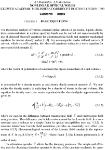
Figure 1.2.1 (a) Geometry of second-harmonic generation, (b) Energy-level dia-
diagram describing second-harmonic generation.
Second-Harmonic Generation
As an example of a nonlinear optical interaction, let us consider the process of
second-harmonic generation, which is illustrated schematically in Fig. 1.2.1.
Here a laser beam whose electric field strength is represented as
p(t\ _ FP-iut i n 91)
is incident upon a crystal for which the second-order susceptibility xB) is
nonzero. The nonlinear polarization that is created in such a crystal is given
according to Eq. A.1.2) as PB\t) = xB)E2(t) or as
PB\t) = 2xB)EE*
z.c).
A.2.2)
We see that the second-order polarization consists of a contribution at zero
frequency (the first term) and a contribution at frequency 2co (the second term).
According to the driven wave equation A.1.5), this latter contribution can
lead to the generation of radiation at the second-harmonic frequency. Note
that the first contribution in Eq. A.2.2) does not lead to the generation of
electromagnetic radiation (because its second time derivative vanishes); it leads
to a process known as optical rectification in which a static electric field is
created within the nonlinear crystal.
Under proper experimental conditions, the process of second-harmonic gen-
generation can be so efficient that nearly all of the power in the incident radiation
at frequency to is converted to radiation at the second-harmonic frequency loo.
One common use of second-harmonic generation is to convert the output of a
fixed-frequency laser to a different spectral region. For example, the Nd: YAG
laser operates in the near infrared at a wavelength of 1.06 /xm. Second-harmonic
generation is routinely used to convert the wavelength of the radiation to
0.53 ^m, in the middle of the visible spectrum.
6 10 The Nonlinear Optical Susceptibility
Second-harmonic generation can be visualized by considering the interac-
interaction in terms of the exchange of photons between the various frequency com-
components of the field. According to this picture, which is illustrated in part (b) of
Fig. 1.2.1, two photons of frequency co are destroyed and a photon of frequency
2co is simultaneously created in a single quantum-mechanical process. The
solid line in the figure represents the atomic ground state, and the dashed lines
represent what are known as virtual levels. These levels are not energy eigen-
levels of the free atom, but rather represent the combined energy of one of the
energy eigenstates of the atom and of one or more photons of the radiation field.
The theory of second-harmonic generation is developed more fully in
Section 2.6.
Sum- and Difference-Frequency Generation
Let us next consider the circumstance in which the optical field incident upon
a nonlinear optical medium characterized by a nonlinear susceptibility xB)
consists of two distinct frequency components, which we represent in the form
E(t) = Exe-icoit + E2e-i0)lt + c.c. A.2.3)
Then, assuming as in Eq. A.1.2) that the second-order contribution to the
nonlinear polarization is of the form
A.2.4)
we find that the nonlinear polarization is given by
~ B) B\ r ? —?" t ? —7' t —'( A- \t
Pit) — y ^ 'I T7 p ^'¦fJJ\ _|_ Tj p 2 i_ O C r^p
V*' / — ^, I •*-' i ^ i 9 1 ¦»-'zc'
A.2.5)
+ 2E\E\e Kx 2) + c.c.J + 2/v;[£^i^i + E2E\\
It is convenient to express this result using the notation
p{1\t) = J^ P{o)n)e-ia)n\ A.2.6)
n
where the summation extends over positive and negative frequencies con. The
complex amplitudes of the various frequency components of the nonlinear
polarization are hence given by
nn.. \ .,BO72 /QTjr»\
PBw2) = xB)^2 (SHG)'
P(a>! +co2) = 2xA)ExE2 (SFG), A.2.7)
(DFG),
+ E2E*) (OR).
1.2. Descriptions of Nonlinear Optical Interactions 7
Here we have labeled each expression by the name of the physical process
that it describes, such as second-harmonic generation (SHG), sum-frequency
generation (SFG), difference-frequency generation (DFG), and optical rectifi-
rectification (OR). Note that, in accordance with our complex notation, there is also
a response at the negative of each of the nonzero frequencies given above:
P(-2o>!) = X{2)E\\ P(-2co2) = XB)Ef,
A.2.8)
P(-a>i - co2) = 2XB)£*£2*, P(co2 - o>,) - 2XB)E2E*.
However, since each of these quantities is simply the complex conjugate of
one of the quantities given in Eq. A.2.7), it is not necessary to take explicit
account of both the positive and negative frequency components.*
We see from Eq. A.2.7) that four different nonzero frequency components
are present in the nonlinear polarization. However, typically no more than one
of these frequency components will be present with any appreciable intensity
in the radiation generated by the nonlinear optical interaction. The reason for
this behavior is that the nonlinear polarization can efficiently produce an output
signal only if a certain phase-matching condition (which is discussed in detail in
Section 2.7) is satisfied, and usually this condition cannot be satisfied for more
than one frequency component of the nonlinear polarization. Operationally,
one often chooses which frequency component will be radiated by properly
selecting the polarization of the input radiation and orientation of the nonlinear
crystal.
Sum-Frequency Generation
Let us now consider the process of sum-frequency generation, which is illus-
illustrated in Fig. 1.2.2. According to Eq. A.2.7), the complex amplitude of the
* Not all workers in nonlinear optics use our convention that the fields and polarizations are given
by Eqs. A.2.3) and A.2.6). Another common convention is to define the field amplitudes according to
E(t) = \(E[e-ia>" + E'2e-ia* +c.c),
n
where in the second expression the summation extends over all positive and negative frequencies. Using
this convention, one finds that
P'(cot
Note that these expressions differ from Eqs. A.2.7) by factors of 1/2.
(a)
1 0 The Nonlinear Optical Susceptibility
(b)
A
co.
CO,
Figure 1.2.2 Sum-frequency generation, (a) Geometry of the interaction, (b) Energy-
level description.
nonlinear polarization describing this process is given by the expression
aJ) = 2xB)E]E2. A.2.9)
In many ways the process of sum-frequency generation is analogous to that of
second-harmonic generation, except that in sum-frequency generation the two
input waves are at different frequencies. One application of sum-frequency
generation is to produce tunable radiation in the ultraviolet spectral region by
choosing one of the input waves to be the output of a fixed-frequency visible
laser and the other to be the output of a frequency-tunable visible laser. The
theory of sum-frequency generation is developed more fully in Sections 2.2
and 2.4.
Difference-Frequency Generation
The process of difference-frequency generation is described by a nonlinear
polarization of the form
P(go\ — 0J) = 2x E\E^ A.2.10)
and is illustrated in Fig. 1.2.3. Here the frequency of the generated wave is
the difference of those of the applied fields. Difference-frequency generation
can be used to produce tunable infrared radiation by mixing the output of a
frequency-tunable visible laser with that of a fixed-frequency visible laser.
Superficially, difference-frequency generation and sum-frequency genera-
generation appear to be very similar processes. However, an important difference
between the two processes can be deduced from the description of difference-
frequency generation in terms of a photon energy-level diagram (part (b) of
Fig. 1.2.3). We see that conservation of energy requires that for every photon
that is created at the difference frequency 0*3 = co\ — 002, a photon at the
higher input frequency (co\) must be destroyed and a photon at the lower input
1.2. Descriptions of Nonlinear Optical Interactions
(a) (b)
ft)
CO
Figure 1.2.3 Difference-frequency generation, (a) Geometry of the interaction,
(b) Energy-level description.
frequency (a>2) must be created. Thus, the lower-frequency input field is am-
amplified by the process of difference-frequency generation. For this reason, the
process of difference-frequency generation is also known as optical parametric
amplification. According to the photon energy-level description of difference-
frequency generation, the atom first absorbs a photon of frequency co\ and
jumps to the highest virtual level. This level decays by a two-photon emis-
emission process that is stimulated by the presence of the co2 field, which is already
present. Two-photon emission can occur even if the co2 field is not applied. The
generated fields in such a case are very much weaker, since they are created by
spontaneous two-photon emission from a virtual level. This process is known
as parametric fluorescence and has been observed experimentally (Harris et al,
1967; Byer and Harris, 1968).
The theory of difference-frequency generation is developed more fully in
Section 2.5.
Optical Parametric Oscillation
We have just seen that in the process of difference-frequency generation the
presence of radiation at frequency co2 or C03 can stimulate the emission of
additional photons at these frequencies. If the nonlinear crystal used in this
process is placed inside an optical resonator, as shown in Fig. 1.2.4, the co2
CO = CO + CO
(pump)
3
/
\ fi>2 (signal)
*
/ ¦¦*-
(idler)
Figure 1.2.4 The optical parametric oscillator. The cavity end mirrors have high
reflectivities at frequencies C02 and/or C03.
10 1 0 The Nonlinear Optical Susceptibility
and/or co^ fields can build up to large values. Such a device is known as an
optical parametric oscillator. Optical parametric oscillators are frequently used
at infrared wavelengths, where other sources of tunable radiation are not readily
available. Such a device is tunable because any frequency a>2 that is smaller
than co\ can satisfy the condition &>2 + &>3 = &>i for some frequency C03. In
practice, one controls the output frequency of an optical parametric oscillator
by adjusting the phase-matching condition, as discussed in Section 2.7. The
applied field frequency co\ is often called the pump frequency, the desired
output frequency is called the signal frequency, and the other, unwanted, output
frequency is called the idler frequency.
Third-Order Polarization
We next consider the third-order contribution to the nonlinear polarization
C) CK A.2.11)
For the general case in which the field E(t) is made up of several different
frequency components, the expression for P (t) is very complicated. For
this reason, we first consider the simple case in which the applied field is
monochromatic and is given by
E{t) = S'cos cot. A.2.12)
Then, through use of the identity cos3 cot = | cos 3cot +1 cos cot, the nonlinear
polarization can be expressed as
P°\t) = \xO)<?3 cos3cot + |xC)^3 cos cot. A.2.13)
The significance of each of the two terms in this expression is described briefly
below.
Third-Harmonic Generation
The first term in Eq. A.2.13) describes a response at frequency 3co that is
due to an applied field at frequency co. This term leads to the process of third-
harmonic generation, which is illustrated in Fig. 1.2.5. According to the photon
description of this process, shown in part (b) of the figure, three photons of
frequency co are destroyed and one photon of frequency 3co is created in each
elementary event.
(a)
1.2. Descriptions of Nonlinear Optical Interactions
(b) -.
11
CO
CO
CO
CO
CO
3o)
Figure 1.2.5 Third-harmonic generation, (a) Geometry of the interaction, (b)
Energy-level description.
Intensity-Dependent Refractive Index
The second term in Eq. A.2.13) describes a nonlinear contribution to the polar-
polarization at the frequency of the incident field; this term hence leads to a nonlinear
contribution to the refractive index experienced by a wave at frequency co. We
shall see in Section 4.1 that the refractive index in the presence of this type of
nonlinearity can be represented as
n =no+n2l A.2.14a)
where no is the usual (i.e., linear or low-intensity) refractive index, where
A.2.14b)
noc
is an optical constant that characterizes the strength of the optical nonlinearity,
and where / = (noc/Sn)^2 is the intensity of the incident wave.
Self-Focusing. One of the processes that can occur as a result of the
intensity-dependent refractive index is self-focusing, which is illustrated in
Fig. 1.2.6. This process can occur when a beam of light having a nonuniform
transverse intensity distribution propagates through a material in which ri2 is
positive. Under these conditions, the material effectively acts as a positive
lens, which causes the rays to curve toward each other. This process is of great
practical importance because the intensity at the focal spot of the self-focused
beam is usually sufficiently large to lead to optical damage of the material. The
process of self-focusing is described in greater detail in Section 7.1.
Figure 1.2.6 Self-focusing of light.
12 1 0 The Nonlinear Optical Susceptibility
Third-Order Polarization (General Case)
Let us next examine the form of the nonlinear polarization
P{3\t) = xO)E(tK A.2.15a)
induced by an applied field that consists of three frequency components:
E(t) = Exe-ia){t + E1e-i0>lt + E3e'iof3t + c.c. A.2.15b)
When we calculate E(tK, we find that the resulting expression contains 44 dif-
different frequency components, if we consider positive and negative frequencies
to be distinct. Explicitly, these frequencies are
3, {(O\ + <X>2 + CO3), (O)\ + 0J ~
(O)\ + (jl>2 — (JO2), @l>2 + <^3 — CO\)9 Bo)\ dz CO2), BcO\ ± (O3),
{2(iJ ± CO3), Bct>3 zh COi), B&>3 ± 0J)^
and the negative of each. Again representing the nonlinear polarization as
(Vn)e-ia)nt, A.2.16)
we can write the complex amplitudes of the nonlinear polarization for the
positive frequencies as
<3>J + 6E2E*
P(a>i +CO2 + m) = 6xQ)ExE2Et,, P((o\ +002- an) = 6xO)ElE2E%,
P{cox +C03- a>2) = 6xO)ElEiE*2, P(co2 + co3 - coO =
P{2cox + co2) = 3XO)E\E2, PBcoi + a>3) =
PBco2 +«,) = 3/C)£|£i, PBaJ + a>3) =
PBco3+cox) = 3xO)E23Eu PBoK+co2) = ^
PBcol - a>2) = 3X0)EJE*, P{2col - co3) = 3X('i)E\E*3,
PBco2 - a>i) = 3xO)E22E*x, PBco2 - a>3) = 3xO)E22E*3,
PBco3 - co,) = 3X{3)E32El PBco3 - aJ) = 3XC)E32E*
A.2.17)
1.2. Descriptions of Nonlinear Optical Interactions
13
(a)
co
CO
CO
coA
(b)
CO
CO
CO = CO + CO -CO
4 12 3
co.
CO
coA
Figure 1.2.7 Two of the possible mixing processes described by Eq. A.2.17) that
can occur when three input waves interact in a medium characterized by a xC)
susceptibility.
We have displayed these expressions in complete detail because it is very
instructive to study their form. In each case the frequency argument of P
is equal to the sum of the frequencies associated with the field amplitudes
appearing on the right-hand side of the equation, if we adopt the convention
that a negative frequency is to be associated with a field amplitude that appears
as a complex conjugate. Also, the numerical factor A, 3, or 6) that appears in
each term on the right-hand side of each equation is equal to the number of
distinct permutations of the field frequencies that contribute to that term.
Some of the nonlinear optical mixing processes described by Eq. A.2.17)
are illustrated in Fig. 1.2.7.
Parametric versus Nonparametric Process
All of the processes described thus far in this chapter are examples of what
are known as parametric processes. The origin of this terminology is obscure,
but the word parametric has come to denote a process in which the initial and
final quantum-mechanical states of the system are identical. Consequently, in
a parametric process population can be removed from the ground state only
for those brief intervals of time when it resides in a virtual level. According
to the uncertainty principle, population can reside in a virtual level for a time
interval of the order of T1/8E, where 8E is the energy difference between the
14 10 The Nonlinear Optical Susceptibility
virtual level and the nearest real level. Conversely, processes that do involve
the transfer of population from one real level to another are known as non-
parametric processes. The processes that we describe in the remainder of the
present section are all examples of nonparametric processes.
One difference between parametric and nonparametric processes is that para-
parametric processes can always be described by a real susceptibility; conversely,
nonparametric processes are described by a complex susceptibility by means
of a procedure described in the following section, Section 1.3. Another differ-
difference is that photon energy is always conserved in a parametric process; photon
energy need not be conserved in a nonparametric process, because energy can
be transferred to or from the material medium. For this reason, photon en-
energy level diagrams of the sort shown in Figs. 1.2.1, 1.2.2, 1.2.3, 1.2.5, and
1.2.7 to describe parametric processes play a less definitive role in describing
non-parametric processes.
As a simple example of the distinction between parametric and nonparamet-
nonparametric processes, we consider the case of the usual (linear) index of refraction.
The real part of the refractive index is a consequence of parametric processes,
whereas its imaginary part is a consequence of nonparametric processes, since
the imaginary part of the refractive index describes the absorption of radiation,
which results from the transfer of population from the atomic ground state to
an excited state.
Saturable Absorption
One example of a nonparametric nonlinear optical process is saturable absorp-
absorption. Many material systems have the property that their absorption coefficient
decreases when measured using high laser intensity. Often the dependence of
the measured absorption coefficient a on the intensity / of the incident laser
radiation is given by the expression*
" - irk- <L2-18)
where «o is the low-intensity absorption coefficient, and Is is a parameter
known as the saturation intensity.
Optical Bistability. One consequence of saturable absorption is optical bista-
bility. One way of forming a bistable optical device is to place a saturable
absorber inside a Fabry-Perot resonator, as illustrated in Fig. 1.2.8. As the
* This form is valid, for instance, for the case of homogeneous broadening of a simple atomic
transition.
1.2. Descriptions of Nonlinear Optical Interactions
15
saturable
absorber
Figure 1.2.8 Bistable optical device.
input intensity is increased, the field inside the cavity also increases, lowering
the absorption that the field experiences and thus increasing the field inten-
intensity still further. If the intensity of the incident field is subsequently lowered,
the field inside the cavity tends to remain large because the absorption of the
material system has already been reduced. A plot of the input-versus-output
characteristics thus looks qualitatively like that shown in Fig. 1.2.9. Note that
over an appreciable range of input intensities more than one output intensity
is possible. The process of optical bistability is described in greater detail in
Section 7.3.
Two-Photon Absorption
In the process of two-photon absorption, which is illustrated in Fig. 1.2.10,
an atom makes a transition from its ground state to an excited state by the
simultaneous absorption of two laser photons. The absorption cross section o
describing this process increases linearly with laser intensity according to the
relation
a = a<2>/,
A.2.19)
where aB) is a coefficient that describes two-photon absorption. (Recall that
in conventional, linear optics the absorption cross section a is a constant.)
Consequently, the atomic transition rate R due to two-photon absorption scales
Figure 1.2.9 Typical input-versus-output characteristics of a bistable optical device.
16
1 0 The Nonlinear Optical Susceptibility
CO
CO
Figure 1.2.10 Two-photon absorption,
as the square of the laser intensity, since R = crl/Tico, or as
R =
Tico
A.2.20)
Two-photon absorption is a useful spectroscopic tool for determining the po-
positions of energy levels that are not connected to the atomic ground state by a
one-photon transition. Two-photon absorption was first observed experimen-
experimentally by Kaiser and Garrett A961).
Stimulated Raman Scattering
In stimulated Raman scattering, which is illustrated in Fig. 1.2.11, a photon of
frequency co is annihilated and a photon at the Stokes shifted frequency cos =
co — cov is created, leaving the molecule (or atom) in an excited state with energy
Tio)w. The excitation energy is referred to as cov because stimulated Raman
scattering was first studied in molecular systems, where ho)w corresponds to
a vibrational energy. The efficiency of this process can be quite large, with
often 10% or more of the power of the incident light being converted to the
Stokes frequency. In contrast, the efficiency of normal or spontaneous Raman
scattering is typically many orders of magnitude smaller. Stimulated Raman
scattering is described more fully in Chapter 9.
Other stimulated scattering processes such as stimulated Brillouin scattering
and stimulated Rayleigh scattering also occur and are described more fully in
Chapter 8.
(a)
(b)
m >
Raman
medium
>
«,s=fl>-e>v (o
\
CO = CO - CO
I
CO
V
Figure 1.2.11 Stimulated Raman scattering.
1.3. Formal Definition of the Nonlinear Susceptibility 17
1.3. Formal Definition of the Nonlinear Susceptibility
Nonlinear optical interactions can be described in terms of the nonlinear po-
polarization given by Eq. A.1.2) only for a material system that is lossless and
dispersionless. In the present section, we consider the more general case of a
material with dispersion and/or loss. In this general case the nonlinear suscep-
susceptibility becomes a complex quantity relating the complex amplitudes of the
electric field and polarization.
We assume that we can represent the electric field vector of the optical wave
as the discrete sum of a number of frequency components as
n(r,O. A.3.1)
The prime on the summation sign of Eq. A.3.1) indicates that the summation
is to be taken over positive frequencies only. It is often convenient to represent
En(r, t) as the sum of its positive- and negative-frequency parts as
En=E<+)+E<->, A.3.2)
where
E^ =Ene-ia)»t A.3.3a)
and
E<-> = E«* = E*nei0)nt. A.3.3b)
By requiring E^ to be the complex conjugate of E^+) we are assured that the
quantity of E(r, t) of Eq. A.3.1) will be real, as it must be in order to represent
a physical field. It is also convenient to define the spatially slowly varying field
amplitude An by means of the relation
En=AneiKr. A.3.4)
The total electric field of Eq. A.3.1) can thus be represented in terms of these
field amplitudes by either of the expressions
E(r, 0 - Y!
" A.3.5)
On occasion, we shall express these field amplitudes using the alternative
notation
En = E(con) and An = AfaJ. A.3-6)
18 10 The Nonlinear Optical Susceptibility
In terms of this new notation, the reality condition of Eq. A.3.3b) becomes
E(-con) = E(a)n)* or A(-a)n) = A(con)*. A.3.7)
Using this new notation, we can write the total field in the more compact form
A.3.8)
where the unprimed summation symbol denotes a summation over all frequen-
frequencies, both positive and negative.
Note that according to our definition of field amplitude, the field given by
E(r, i) = ^cos(k -r-cot) A.3.9)
is represented by the complex field amplitudes
= \
E(co) = \geikr, E(-co) = \ge~i]k\ A.3.10)
or alternatively by the slowly varying amplitudes
A(g>) = \g, A(-co) = \g. A.3.11)
In either representation, factors of 1/2 appear because the physical field ampli-
amplitude g has been divided equally between the positive- and negative-frequency
components.
Using a notation similar to that of Eq. A.3.8), we can express the nonlinear
polarization as
P(r,0 = 5^P(«n)^"lW, d.3.12)
n
where, as before, the summation extends over all positive- and negative-
frequency components.
We now define the components of the second-order susceptibility tensor Xtfl
(con + (jom,(jon,a)m) as the constants of proportionality relating the amplitude
of the nonlinear polarization to the product of field amplitudes according to
Pi(CQn + (Om) = ^ XI Xijk&n + ^' <*>«> 0Jm)Ej(cOn)Ek((j0m). A.3.13)
jk (nm)
Here the indices ijk refer to the cartesian components of the fields. The no-
notation (nm) indicates that, in performing the summation over n and m, the
sum con + com is to be held fixed, although con and com are each allowed
to vary. Since the amplitude E(con) is associated with the time dependence
Qxp(—icont), and the amplitude E(com) is associated with the time dependence
Qxp(—icomt), their product E(con)E(com) is associated with the time depen-
dependence exp[—i(a)n + com)t]. Hence the product E(con)E(com) does in fact lead
1.3. Formal Definition of the Nonlinear Susceptibility 19
to a contribution to the nonlinear polarization oscillating at frequency con + com,
as the notation of Eq. A.3.13) suggests. Following convention, we have writ-
written xB) as a function of three frequency arguments. This is technically un-
unnecessary in that the first argument is always the sum of the other two. To
emphasize this fact, the susceptibility xB)(<^3> oJ,co\) is sometimes written
as xB)(&>3; ^2, co\) as a reminder that the first argument is different from the
other two; or it may be written symbolically as xB)(&>3 = (O2 + co\).
Let us examine some of the consequences of the definition of the nonlinear
susceptibility as given by Eq. A.3.13) by considering two simple examples.
1. Sum-frequency generation. We let the input field frequencies be co\ and
0J and the sum frequency be &>3, so that oj3 = oo\ + &>2- Then, by carrying
out the summation over con and com in Eq. A.3.13), we find that
jk
A.3.14)
l
This expression can be simplified by making use of the intrinsic permuta-
permutation symmetry of the nonlinear susceptibility (this symmetry is discussed
in more detail in Eq. A.5.6) below), which requires that
Xijkfom + OJn, OJm, (On) = Xikj (^m + OJn, OJn, Q)m). A.3.15)
Through use of this relation, the expression for the nonlinear polarization
becomes
i}l ja>2), A.3.16)
jk
and for the special case in which both input fields are polarized in the jc
direction the polarization becomes
Pi(co3) = 2xZi(@3,coucD2)EAo)\)EAco2)- A.3.17)
2. Second-harmonic generation. We take the input frequency as co\ and the
generated frequency as (jo3 = 2(O\. If we again perform the summation
over field frequencies in Eq. A.3.13), we obtain
Pifa) = ^x$k(<*>Q>uo>i)Ej(Q>i)Ek(a>i). A.3.18)
jk
Again assuming the special case of an input field polarization along the
x direction, this result becomes
Pi(^s) = Xux(<»3,a>i,<oi)Ex(coiJ- A.3.19)
20 1 0 The Nonlinear Optical Susceptibility
Note that a factor of two appears in Eqs. A.3.16) and A.3.17), which
describe sum-frequency generation, but not in Eqs. A.3.18) and A.3.19),
which describe second-harmonic generation. The fact that these expres-
expressions remain different even as o>2 approaches co\ is at first sight surpris-
surprising, but is a consequence of our convention that xB?(&>3, co\, @2) must
B)
approach xljk (^3, &>i, &>i) as &>i approaches 0J. Note that the expressions
for P B(jo2) and P (co\ -\-c02) that apply for the case of a dispersionless non-
nonlinear susceptibility (Eq. A.2.7)) also differ by a factor of two. Moreover,
one should expect the nonlinear polarization produced by two distinct
fields to be larger than that produced by a single field (both of the same
amplitude, say), because the total light intensity is larger in the former case.
In general, the summation over field frequencies (X^(«m)) ^n Eq. A.3.13) can
be performed formally to obtain the result
Pi(con +com) = Dj2 Xijk&n + o)m, con, com)Ej(con)Ek((om), A.3.20)
where D is known as the degeneracy factor and is equal to the number of
distinct permutations of the applied field frequencies con and com.
The expression A.3.13) defining the second-order susceptibility can readily
be generalized to higher-order interactions. In particular, the components of the
third-order susceptibility are defined as the coefficients relating the amplitudes
according to the expression
Pi(C00 +(On+ (Om) = 2^]^ ijkl
Jkl {mno) A.3.21)
xEj(coo)Ek(con)Ei(com).
We can again perform the summation over m, n, and o to obtain the result
Pi (COO +O)n+O)m) = D^2 XiJlli^O + COn + O)m, Q)o, (On, (Om)
Jhl A.3.22)
x Ej (co0) Ek {con) Ei (com),
where the degeneracy factor D represents the number of distinct permutations
of the frequencies com,con, and coo.
1.4. Nonlinear Susceptibility of a Classical Anharmonic Oscillator
The Lorentz model of the atom, which treats the atom as a harmonic oscillator,
is known to provide a very good description of the linear optical properties
of atomic vapors and of nonmetallic solids. In the present section, we extend
the Lorentz model by allowing the possibility of a nonlinearity in the restoring
1.4. Nonlinear Susceptibility of a Classical Anharmonic Oscillator 21
force exerted on the electron. The details of the analysis differ depending upon
whether or not the medium possesses inversion symmetry.* We first treat the
case of a noncentrosymmetric medium, and we find that such a medium can
give rise to a second-order optical nonlinearity. We then treat the case of a
medium that possesses a center of symmetry and find that the lowest-order
nonlinearity that can occur in this case is a third-order nonlinear susceptibility.
Our treatment is similar to that of Owyoung A971).
The primary shortcoming of the classical model of optical nonlinearities
presented here is that this model ascribes a single resonance frequency (coo) to
each atom. In contrast, the quantum-mechanical theory of the nonlinear optical
susceptibility, to be developed in Chapter 3, allows each atom to possess many
energy eigenvalues and hence more than one resonance frequency. Since the
present model allows for only one resonance frequency, it cannot properly de-
describe the complete resonance nature of the nonlinear susceptibility (such as,
for example, the possibility of simultaneous one- and two-photon resonances).
However, it provides a good description for those cases in which all of the op-
optical frequencies are considerably smaller than the lowest electronic resonance
frequency of the material system.
Noncentrosymmetric Media
For the case of noncentrosymmetric media, we take the equation of motion of
the electron coordinate x to be the form
i + 2yi + ofix + ax2 = -e£(t)/m. A.4.1)
In this equation we have assumed that the applied electric field is given by
E(t), that the charge of the electron is —e, that there is a damping force' of the
form -2myi, and that the restoring force is given by
Restoring = -ma^x - max2, A.4.2)
where a is a parameter that characterizes the strength of the nonlinearity. We
obtain this form by assuming that the restoring force is a nonlinear function
of the displacement of the electron from its equilibrium position and retaining
the linear and quadratic terms in the Taylor series expansion of the restoring
force in the displacement x. We can understand the nature of this form of the
* The role of symmetry in determining the nature of the nonlinear susceptibilty is discussed from a
more fundamental point of view in Section 1.5. See especially the treatment leading from Eq. A.5.31)
to A.5.35).
< The factor of two is introduced to make y the dipole damping rate. 2y is therefore the full width at
half maximum in angular frequency units of the atomic absorption profile in the limit of linear response.
22
1 0 The Nonlinear Optical Susceptibility
U(x)
parabola
actual
potential
parabola
Figure 1.4.1 Potential energy function for a noncentrosymmetric medium.
restoring force by noting that it corresponds to a potential energy function of
the form
U
= - /
A.4.3)
Here the first term corresponds to a harmonic potential and the second term
corresponds to an anharmonic correction term, as illustrated in Fig. 1.4.1. This
model corresponds to the physical situation of electrons in real materials, be-
because the actual potential well that the atomic electron feels is not perfectly
parabolic. The present model can describe only noncentrosymmetric media
because we have assumed that the potential energy function U of Eq. A.4.3)
contains both even and odd powers off; for a centrosymmetric medium only
even powers of x could appear, because the potential function U(x) must pos-
possess the symmetry U(x) = U(—x). For simplicity, we have written Eq. A.4.1)
in the scalar-field approximation; note that we cannot treat the tensor nature
of the nonlinear susceptibility without making explicit assumptions regarding
the symmetry properties of the material.
We assume that the applied optical field is of the form
E(t) =
¦ c.c.
A.4.4)
No general solution to Eq. A.4.1) for an applied field of the form A.4.4) is
known. However, if the applied field is sufficiently weak, the nonlinear term
ax2 will be much smaller than the linear term co^x for any displacement x
that can be induced by the field. Under this circumstance, Eq. A.4.1) can be
solved by means of a perturbation expansion. We use a procedure analogous
to that of Rayleigh-Schrodinger perturbation theory in quantum mechanics.
We replace E(t) in Eq. A.4.1) by XE(t), where X is a parameter that ranges
1.4. Nonlinear Susceptibility of a Classical Anharmonic Oscillator 23
continuously between zero and one and that will be set equal to one at the end
of the calculation. The expansion parameter X thus characterizes the strength
of the perturbation. Equation A.4.1) then becomes
i + 2yk + colx + ax2 = -XeE(t)/m. A.4.5)
We now seek a solution to Eq. A.4.5) in the form of a power series expansion
in the strength X of the perturbation, that is, a solution of the form
x = XxA) + X2xB) + X3xC) + • • •. A.4.6)
In order for Eq. A.4.6) to be a solution to Eq. A.4.5) for any value of the
coupling strength X, we require that the terms in Eq. A.4.5) proportional to X,
X2, X3, etc., each satisfy the equation separately. We find that these terms lead
respectively to the equations
= -eE(t)/m, A.4.7a)
= 0, A.4.7b)
iC) + 2yk0) + toft™ + 2aJcA)xB) = 0. A.4.7c)
We see from Eq. A.4.7a) that the lowest-order contribution jcA) is governed
by the same equation as that of the conventional (i.e., linear) Lorentz model.
Its steady-state solution is given by
jcA>(r) = x{X\(ox)e-icO2t + x(l)(co2)e-ia)]t + ex., A.4.8)
where the amplitudes x^(a>j) have the form
m £ A.4.9)
m
where we have introduced the complex denominator function
D(o)j) =cd2-co2- licojy. A.4.10)
This expression for x^(t) is now squared and substituted into Eq. A.4.7b),
which is solved to obtain the lowest-order correction term xB). The square of
iA)(/) contains the frequencies ±.2a>\, ±2aJ, ±(^>i + C02), ±(co\ — coi), and
0. To determine the response at frequency 2&>i, for instance, we must solve the
equation
24 10 The Nonlinear Optical Susceptibility
We seek a steady-state solution of the form
x{2\t) = xB)Ba)l)e-2ia)lt. A.4.12)
Substitution of Eq. A.4.12) into Eq. A.4.11) leads to the result
^B0,0= 'fl(g/wJ2£?, A.4.13)
where we have made use of the definition A.4.10) of the function D(coj).
Analogously, the amplitudes of the response at the other frequencies are found
to be
-2a{e/mJEiEl ,_ At/I
~**> = D^,-— - AA14C)
s@) i£r , 2fl(^)^2 A414d)
D@)D(coi)D(-coi) D@)D(aJ)D(-(D2)'
We next express these results in terms of the linear (/A)) and nonlinear
(XB)) susceptibilities. The linear susceptibility is defined through the relation
P{X\a>j) = x(l)(coj)E(a>j). A.4.15)
Since the linear contribution to the polarization is given by
PA)(coj) = -Nex(l)(ooj), A.4.16)
where N is the number density of atoms, we find using Eqs. A.4.8) and A.4.9)
that the linear susceptibility is given by
The nonlinear susceptibilities are calculated in an analogous manner. The
nonlinear susceptibility describing second-harmonic generation is defined by
the relation
P{2\2cox) = XB)Bcoucoucol)E(col)\ A-4.18)
where PB)B&>i) is the amplitude of the component of the nonlinear polariza-
polarization oscillating at frequency 2co\ and is defined by the relation
= -Nex{2\2coi). A.4.19)
1.4. Nonlinear Susceptibility of a Classical Anharmonic Oscillator 25
Comparison of these equations with Eq. A.4.13) gives
Through use of Eq. A.4.17), this result can be written instead in terms of the
product of linear susceptibilities as
A.4.21)
The nonlinear susceptibility for second-harmonic generation of the a>2 field
is obtained trivially from Eqs. A.4.20) and A.4.21) through the substitution
CO\ —> Cl>2-
The nonlinear susceptibility describing sum-frequency generation is ob-
obtained from the relations
P{2\a>i +a>2) = 2x{2)(coi + a>2, a>\, a>2)E(a>i)E(a>2) A.4.22)
and
P{2\o)X + @2) = -NexB\(oi + @2). A.4.23)
Note that in this case the relation defining the nonlinear susceptibility contains
a factor of two because the two input fields are distinct, as discussed in relation
to Eq. A.3.20). By comparison of these equations with A.4.14b), the nonlinear
susceptibility is seen to be given by
/0\ N(e3 /m2)a
XB)(*>i +o>2,(o1,q>2) = V ; \ A.4.24)
D(coi +)D()D()
which can be expressed in terms of the product of linear susceptibilities as
B\ ^A) A)A) A.4.25)
It can be seen by comparison of Eqs. A.4.20) and A.4.24) that, as a>2 approaches
&>i> XB)(&>i +<*>2,to>i, (*>i) approaches xB)B&>i, co\, co\).
The nonlinear susceptibilities describing the other second-order processes
are obtained in an analogous manner. For difference-frequency generation we
find that
N(e3/m2)a
0J A.4.26)
26 10 The Nonlinear Optical Susceptibility
and for optical rectification we find that
A.4.27)
The analysis just presented shows that the lowest-order nonlinear contri-
contribution to the polarization of a noncentrosymmetric material is second order
in the applied field strength. This analysis can readily be extended to include
higher-order effects. The solution to Eq. A.4.7c), for example, leads to a third-
order or xC) susceptibility, and more generally terms proportional to kn in the
expansion described by Eq. A.4.6) lead to a x^ susceptibility.
Miller's Rule
An empirical rule due to Miller (Miller, 1964; see also Garrett and Robinson,
1966) can be understood in terms of the calculation just presented. Miller noted
that the quantity
XB)(a>i+Q>2, (Qi, co2) A4 28)
X(l)(a>i+co2)x{1H<oi)x{l)(a>2)
is nearly constant for all noncentrosymmetric crystals. By comparison with
Eq. A.4.25), we see this quantity will be constant only if the combination
is nearly constant. In fact, the atomic number density TV is nearly the same
(MO22 cm) for all condensed matter, and the parameters m and e are fun-
fundamental constants. We can estimate the size of the nonlinear coefficient a by
noting that the linear and nonlinear contributions to the restoring force given
by Eq. A.4.2) would be expected to be comparable when the displacement x
of the electron from its equilibrium position is approximately equal to the size
of the atom. This distance is of the order of the separation between atoms, that
is, of the lattice constant d. This reasoning leads to the order-of-magnitude
estimate that mco^d = mad2 or that
a = ^. A.4.30)
d
Since coq and d are roughly the same for most solids, the quantity a would also
be expected to be roughly the same for all materials where it does not vanish
by reasons of symmetry.
1.4. Nonlinear Susceptibility of a Classical Anharmonic Oscillator 27
We can also use the estimate of the nonlinear coefficient a given by
Eq. A.4.30) to make an estimate of the size of the second-order susceptibility
under nonresonant conditions. If we replace D(co) by o)q in the denominator
of Eq. A.4.24), set N equal to l/d3, and set a equal to cofi/d, we find that xB)
is given approximately by
xi2) =
m^o
A.4.31)
Using the values aH = lx 1016 rad/s, d = 3 A, e = 4.8 x 1O0 statcoulomb,
and m = 9.1 x 10⁸ g, we find that
XB)~1.6x 10~8 esu, A.4.32)
which is in good agreement with the measured values presented in Table 1.5.3
of the next section.
Centrosymmetric Media
For the case of a centrosymmetric medium, we assume that the electronic
restoring force is given not by Eq. A.4.2) but rather by
^restoring = -mco^x + mbx3, A.4.33)
where b is a parameter that characterizes the strength of the nonlinearity. This
restoring force corresponds to the potential energy function
U
--/
A.4.34)
This potential function is illustrated in the Fig. 1.4.2 (for the usual case in
which b is positive) and is seen to be symmetric under the operation x —? — x,
U(x)
actual
potential
Figure 1.4.2 Potential energy function for a centrosymmetric medium.
28 1 0 The Nonlinear Optical Susceptibility
which it must be for a medium that possesses a center of inversion symmetry.
Note that — mbx4/4 is simply the lowest-order correction term to the parabolic
potential well described by the term \mco\x1. We assume that the electronic
displacement x never becomes so large that it is necessary to include higher-
order terms in the potential.
We shall see below that the lowest-order nonlinear response resulting from
the restoring force of Eq. A.4.33) is a third-order contribution to the polariza-
polarization, which can be described by a /C) susceptibility. As in the case of non-
centrosymmetric media, the tensor properties of this susceptibility cannot be
specified unless the internal symmetries of the medium are completely known.
One of the most important cases is that of a material which is isotropic (as
well as being centrosymmetric). Examples of such materials are glasses and
liquids. In such a case, we can take the restoring force to have the form
Frestoring = -mo^r + mb(f • f)f. A.4.35)
The second contribution to the restoring force must have the form shown
because it is the only form that is third-order in the displacement f and is
directed in the f direction, which is the only possible direction for an isotropic
medium.
The equation of motion for the electron displacement from equilibrium is
thus
f + 2yf + coqT ~ b$' f)? = ~eft(t)/m. A.4.36)
We assume that the applied field is given by
E@ = Eie"' + E2e~iC02t + E3e~imt + ex.; A.4.37)
we allow the field to have three distinct frequency components because this is
the most general possibility for a third-order interaction. However, the algebra
becomes very tedious if all three terms are written explicitly, and hence we
express the applied field as
E@ = 5^E(G>n)<TlW. A.4.38)
n
The method of solution is analogous to that used above for a noncentrosymmet-
ric medium. We replace E@ in Eq. A.4.36) by kE(t), where X is a parameter
that characterizes the strength of the perturbation and that is set equal to unity
at the end of the calculation. We seek a solution to Eq. A.4.36) having the form
of a power series in the parameter k:
f @ = kfA\t) + A.2fB)(f) + A3fC) + • • •. A.4.39)
1.4. Nonlinear Susceptibility of a Classical Anharmonic Oscillator 29
We insert Eq. A.4.39) into Eq. A.4.36) and require that the terms proportional
to Xn vanish separately for each value of n. We thereby find that
>
= -eE(t)/m, A.4.40a)
fB) + 2yfB) + <^fB) = 0, A.4.40b)
^c) _ b^(i). F(i))f(i) = 0 A.4.40c)
for n =1,2, and 3, respectively. Equation A.4.40a) is simply the vector version
of Eq. A.4.7a), encountered above. Its steady-state solution is
5^1)(ttnyw, A.4.41a)
n
where
D(O)
with D(a)n) given as before by D(con) = co^ — 0% — 2icony. Since the polar-
polarization at frequency con is given by
PA)(ft>n) = -7V^rA)(o)w), A.4.42)
we can describe the cartesian components of the polarization through the
relation
pV\a>n) = J2^iJ)(co^EJ(a)n)' A.4.43a)
j
Here the linear susceptibility is given by
Xij\(»n) = X(l)(o)n)8ij A.4.43b)
with xA)(&>rc) given as before by
m Ne2/m
Xa)(con) = -/-, A.4.43c)
D(con)
and where S^- is the Kronecker delta, which is defined such that <5/; = 1 for
i = j and Stj — 0 for / ^ j.
The second-order response of the system is described by Eq. A.4.40b). Since
this equation is damped but not driven, its steady-state solution vanishes, that
is,
fB)=0. A.4.44)
30 1 0 The Nonlinear Optical Susceptibility
To calculate the third-order response, we substitute the expression for fA) (t)
given by Eq. A.4.41a) into Eq. A.4.40c), which becomes
A.4.45)
Because of the summation over m, n, and p, the right-hand side of this equation
contains many different frequencies. We denote one of these frequencies by
coq = com + con + cop. The solution to Eq. A.4.45) can then be written in the
form
rC)@ = ^rC)(tw^)c"^r. A.4.46)
q
We substitute Eq. A.4.46) into Eq. A.4.45) and find that rC)(coq) is given by
/ 2 • o 2W3)/ x V- be3[E(com)-E(oon)]E(cDp)
l-coz - icjOnly + coi)r{ \coq) = - > —= —, A.4.47)
where the summation is to be carried out over frequencies com, con, and cop
with the restriction that com + con + ojp must equal coq. Since the coefficient of
rC)(^) on the left-hand side is just D(coq), we obtain
r0) _ y- be3[E(com)'E(con)]E(a)p)
^n3D()D(o)D(c)D(o)'
The amplitude of the polarization component oscillating at frequency coq then
is given in terms of this amplitude by
P<3)(a^) = -Ner°\cDq). A.4.49)
We next recall the definition of the third-order nonlinear susceptibility
A.3.21),
*fW = J2 12 xS/K, <om, con, cop)Ej((om)Ek((on)El(a)p). A.4.50)
jkl (mnp)
Since this equation contains a summation over the dummy variables m, n, and
/?, there is more than one possible choice for the expression for the nonlinear
susceptibility. An obvious choice for this expression for the susceptibility,
based on the way in which Eqs. A.4.48) and A.4.49) are written, is
XijkliUq, CDm,COn, COp) = —r— — — — -. A.4.51)
; m3D(Q)q)D(Q)m)D(cDn)D(c0p)
1.4. Nonlinear Susceptibility of a Classical Anharmonic Oscillator 31
While Eq. A.4.51) is a perfectly adequate expression for the nonlinear sus-
susceptibility, it does not explicitly show the full symmetry of the interaction in
terms of the arbitrariness of which field we call Ej (com), which we call Ek(con),
and which we call E\ (cop). It is conventional to define nonlinear susceptibilities
in a manner that displays this symmetry, which is known as intrinsic permu-
permutation symmetry. Since there are six possible permutations of the orders in
which Ej(com), Ek(con), and Ei(cop) may be taken, we define the third-order
susceptibility to be one-sixth of the sum of the six expressions analogous to
Eq. A.4.51) with the input fields taken in all possible orders. When we carry
out this prescription, we find that only three distinct contributions occur, and
that the resulting form for the nonlinear susceptibility is given by
C)
SikSji
This expression can be rewritten in terms of the linear susceptibilities at the four
different frequencies coq, com, con and cop by using Eq. A.4.43c) to eliminate
the resonance denominator factors D(co). We thereby obtain
x^ (C0q) X(l) (OJm) X(l) (cvn) X0) (CO p)]
+ StkSji + SnSjkl A.4.53)
We can estimate the value of the phenomenological constant b that appears
in this result by means of an argument analogous to that used above (see
Eq. A.4.30)) to estimate the value of the constant a that appears in the ex-
expression for xB)- We assume that the linear and nonlinear contributions to the
restoring force given by Eq. A.4.33) will become comparable in magnitude
when the displacement x is comparable to the atomic dimension d, that is,
when mcx)\d = mbd3, which implies that
b = f2. A.4.54)
Using this expression for b, we can now estimate the value of the nonlinear
susceptibility. For the case of nonresonant excitation, D(co) is approximately
equal to cofi, and hence from Eq. A.4.52) we obtain
Taking d = 3 k and coQ = 7 x 10¹⁵ rad/sec, we obtain
xC)^3xl0-14^^. A.4.56)
statvolt
32 10 The Nonlinear Optical Susceptibility
We shall see in Chapter 4 that this value is typical of the nonlinear susceptibility
of many materials.
1.5. Properties of the Nonlinear Susceptibility
In this section we study some of the formal symmetry properties of the non-
nonlinear susceptibility. Let us first see why it is important that we understand
these symmetry properties. We consider the mutual interaction of three waves
of frequencies co\, a>2, and 0K = o)\ + 0^2 - A complete description of the inter-
interaction of these waves requires that we know the nonlinear polarizations P(&>/)
influencing each of them. Since these quantities are given in general (see also
Eq. A.3.13)) by the expression
Pi((on + com) = ^2 X! Xijkt60" + wm> ^ com)Ej(con)Ek((om), A.5.1)
jk (nm)
we therefore need to determine the six tensors
Xifl&l, CO3, -CD2), Xifk(<°l> ~^2, O>3), Xi
fflljl>3> coi, C02), and
and six additional tensors in which each frequency is replaced by its negative.
In these expressions, the indices /, j, and k can independently take on the
values x,y, and z. Since each of these 12 tensors thus consists of 27 cartesian
components, as many as 324 different (complex) numbers need to be specified
in order to describe the interaction.
Fortunately, there are a number of restrictions resulting from symmetries that
relate the various components of xB\ and hence far fewer than 324 numbers
are usually needed to describe the nonlinear coupling. In this section, we study
some of these formal properties of the nonlinear susceptibility. The discussion
will deal primarily with the second-order xB) susceptibility, but can readily
be extended to xC) and higher-order susceptibilities.
Reality of the Fields
Recall that the nonlinear polarization describing the sum-frequency response
to input fields at frequencies con and o)m has been represented as
P((r, t) = Pidon + com)e-'{M"+M")! + Pii-con - <om)ei^+M-)'. A.5.2)
1.5. Properties of the Nonlinear Susceptibility 33
Since F/(r, /) is a physically measurable quantity, it must be purely real, and
hence its positive- and negative-frequency components must be related by
Pi(-a)n-a>m) = Pi(con+a>my. A.5.3)
The electric field must also be a real quantity, and its complex frequency com-
components must obey the analogous conditions:
Ej(-con) = Ej(o)n)*, A.5.4a)
Ek(-cDm) = Ek(a)m)*. A.5.4b)
Since the fields and polarization are related to each other through the second-
order susceptibility of Eq. A.5.1), we conclude that the positive- and negative-
frequency components of the susceptibility must be related according to
Xijk(-<°n ~ Mm* -M"' ~(J°rn) = Xifk^n + &>m, 00n, Q)m)*. A.5.5)
Intrinsic Permutation Symmetry
Earlier we introduced the concept of intrinsic permutation symmetry when we
rewrote the expression A.4.51) for the nonlinear susceptibility of a classical,
anharmonic oscillator in the conventional form of Eq. A.4.52). In the present
section, we treat the concept of intrinsic permutation symmetry from a more
general point of view.
According to Eq. A.5.1), one of the contributions to the nonlinear polar-
polarization Pt(con + com) is the product Xtjl^n + Q)m, (on, (om)Ej((on)Ek((om).
However, since j, k, n, and m are dummy indices, we could just as well have
written this contribution with n interchanged with m and with j interchanged
with k, that is, as Xikj&n + (om,(om, (on)Ek(com)Ej((on). These two expres-
expressions are numerically equal if we require that the nonlinear susceptibility be
unchanged by the simultaneous interchange of its last two frequency arguments
and its last two cartesian indices:
Xijkfan + <^m, (On, OJm) = Xikj i^n + 0)m, (Om, Q)n). A.5.6)
This property is known as intrinsic permutation symmetry.
Note that this symmetry condition is introduced purely as a matter of conve-
convenience. For example, we could set one member of the pair of elements shown
in Eq. A.5.6) equal to zero and double the value of the other member. Then,
when the double summation of Eq. A.5.1) was carried out, the result for the
physically meaningful quantity Pj((on + com) would be left unchanged.
This symmetry condition can also be derived from a more general point
of view using the concept of the nonlinear response function (Butcher, 1965;
Flytzanis, 1975).
34 1 0 The Nonlinear Optical Susceptibility
Symmetries for Lossless Media
Two additional symmetries of the nonlinear susceptibility tensor occur for the
case of a lossless nonlinear medium.
The first of these conditions states that for a lossless medium all of the
components of Xuli^n + o)m, wn, com) are real. This result is obeyed for the
classical anharmonic oscillator discussed in Section 1.4, as can be verified
by evaluating the expression for xB) in the limit in which all of the applied
frequencies and their sums and differences are significantly different from the
resonance frequency. The general proof that xB) is real for a lossless medium is
obtained by verifying that the quantum-mechanical expression for xB) (which
is derived in Chapter 3) is also purely real in this limit.
The second of these new symmetries is full permutation symmetry. This con-
condition states that all of the frequency arguments of the nonlinear susceptibility
can be freely interchanged, as long as the corresponding cartesian indices are
interchanged simultaneously. In permuting the frequency arguments, it must
be recalled that the first argument is always the sum of the latter two, and
thus the signs of the frequencies must be inverted when the first frequency is
interchanged with either of the latter two. Full permutation symmetry implies,
for instance, that
X;gF>3 =COi+ OJ2) = xfki(-*>\ =(Ol~ CO3). A.5.7)
However, according to Eq. A.5.5) the right-hand side of this equation is equal to
Xj^( (co\ = —oJ + C03)*, which, due to the reality of xB) for a lossless medium,
is equal to xfki^i = -0J2 + 0K). We hence conclude that
X-jlim =coY+ oj2) = X$(<»i = -0J + 03). A.5.8)
By an analogous procedure, one can show that
X$(G>3 =0I+ CO2) = X$(OJ = CO3~ (Ox). A.5.9)
A general proof of the validity of the condition of full permutation symmetry
entails verifying that the quantum-mechanical expression for xB) (which is
derived in Chapter 3) obeys this condition when all of the optical frequencies
are detuned many linewidths from the resonance frequencies of the optical
medium. Full permutation symmetry can also be deduced from a consideration
of the field energy density within a nonlinear medium, as shown below.
Field Energy Density for a Nonlinear Medium
The condition that the nonlinear susceptibility must possess full permutation
symmetry for a lossless medium can be deduced from a consideration of the
form of the electromagnetic field energy within a nonlinear medium. For the
1.5. Properties of the Nonlinear Susceptibility 35
case of a linear medium, the energy density associated with the electric field
i((on)e-iQ^t A.5.10)
is given according to Poynting's theorem as
U = i_(D . E) = -?- Y(DiEi), A.5.11)
where the angular brackets denote a time average. Since the displacement
vector is given by
where the dielectric tensor is given by
€ij((on) = &ij+47rXij\a)n), A.5.13)
we can write the energy density as
A.5.14)
Here the first term represents the energy density associated with the electric
field in vacuum and the second term represents the energy stored in the polar-
polarization of the medium.
For the case of a nonlinear medium, the expression for the electric field
energy density (Kleinman, 1962; Armstrong et al, 1962; Pershan, 1963) as-
associated with the polarization of the medium takes the more general form
U = -
+ * jLj ^2 Xdjk(~~(°n ~~ ^m* ^w Mn)E*(C0m + COn)Ej(cOm)Ek(a)n)
ijk mn
~A 2-^i 2-^Xijkiy '^o — &>n — U>m, COm, C0n, COO) (I.D.ID)
ijkl mno
x E*(com + con + coo)Ej((om)Ek((on)Ei(coo) H .
For the present, the quantities xB)'» XC)'» • • • are to be thought of simply as
coefficients in the power series expansion of U in the amplitudes of the applied
field; later these quantities will be related to the nonlinear susceptibilities. Since
the order in which the fields are multiplied together in determining U is imma-
immaterial, the quantities x(n) clearly possess full permutation symmetry, that is,
36 1 0 The Nonlinear Optical Susceptibility
their frequency arguments can be freely permuted as long as the corresponding
indices are also permuted.
In order to relate the expression A.5.15) for the energy density to the non-
nonlinear polarization, and subsequently to the nonlinear susceptibility, we use
the result that the polarization of a medium is given (Pershan, 1963; Landau
and Lifshitz, 1960) by the expression
P^COn) = . A.5.16)
dE*(a>n)
Thus, by differentiation of Eq. A.5.15), we obtain an expression for the linear
polarization as
•j((om)Ej(o)m)J A.5.17a)
j
and for the nonlinear polarization as*
Pt( \u>m + <*>n) = 22 ^t^ijk^^m ~ <*>n, C0m, COn)Ej(a)m)Ek(cOn)
jk (mn)
A.5.17b)
P^\o)m + Q)n + O)o) = ^ XI Xijkl(~0)'n -COn-Q)o,Q)m,COn, CQO)
jkl (mno)
A.5.17c)
x Ej(a)m)Ek(con)Ek(coo).
We note that these last two expressions are identical to Eqs. A.3.13) and
A.3.21), which define the nonlinear susceptibilities (except for the unimportant
fact that the quantities x(n) and x(n)/ use opposite conventions regarding the
sign of the first frequency argument). Since the quantities x(n)/ possess full
permutation symmetry, we conclude that the susceptibilities x(/7) do also. Note
that this demonstration is valid only for the case of a lossless medium, because
only in this case is the internal energy a function of state.
Klein man's Symmetry
Quite often nonlinear optical interactions involve optical waves whose fre-
frequencies cot are much smaller than the lowest resonance frequency of the
material system. Under these conditions, the nonlinear susceptibility is es-
essentially independent of frequency. For example, the expression A.4.24) for
the second-order susceptibility of an anharmonic oscillator predicts a value of
* In performing the differentiation, the prefactors |, |, \,... of Eq. A.5.15) disappear because
2, 3, 4, ... equivalent terms appear as the result the summations over the frequency arguments.
1.5. Properties of the Nonlinear Susceptibility 37
the susceptibility that is essentially independent of the frequencies of the ap-
applied waves whenever these frequencies are much smaller than the resonance
frequency ojq. Furthermore, under conditions of low-frequency excitation the
system responds essentially instantaneously to the applied field, and we have
seen in Section 1.2 that under such conditions the nonlinear polarization can
be described in the time domain by the relation
A.5.18)
where xB) can be taken to be a constant.
Since the medium is necessarily lossless whenever the applied field frequen-
frequencies cot are very much smaller than the resonance frequency coo, the condition
of full permutation symmetry A.5.7) must be valid under these circumstances.
This condition states that the indices can be permuted as long as the frequencies
are permuted simultaneously, and it leads to the conclusion that
Xifl(C03 =O)i+ OJ) = xfu(<O\ = -0J + OK) = Xkfj(<02 = ^3 ~ O)\)
= Xikj(°>2 =OJ2+O)i) = X%(OJ\ =OK
However, under the present conditions xB) does not actually depend on the
frequencies, and we can therefore permute the indices without permuting the
frequencies, leading to the result
Xijl@K =O)i+ OJ) = Xjl](OK =OJ\+ OJ) = Xkfj(OK =O)i+ OJ)
= Xa-@K = o)i+oJ) = Xj?k(oK= 0I+0J) A.5.19)
B)
= Xkji@K =O)\ +OJ).
This result is known as the Kleinman symmetry condition. It is valid whenever
dispersion of the susceptibility can be neglected.
Contracted Notation
We now introduce a notational device that is often used when the Kleinman
symmetry condition is valid. We introduce the tensor
\$ A-5-20)
and for simplicity suppress the frequency arguments. The nonlinear polariza-
polarization can then be written as
Pi(o)n+o)m) = J2J22dUkEj(o)n)Ek(o)m). A.5.21)
jk (nm)
38
1 0 The Nonlinear Optical Susceptibility
jk:
I:
11
1
22
2
33
3
23,32
4
31,
5
13
12,21
6
We now assume that dijk is symmetric in its last two indices. This assumption
is valid whenever Kleinman's symmetry condition is valid and in addition is
valid in general for second-harmonic generation, since in this case con and com
are equal. We then simplify the notation by introducing a contracted matrix du
according to the prescription
) 11 9^ ^9 ^1 1^ 19 91
A.5.22)
The nonlinear susceptibility tensor can then be represented as the 3 x 6 matrix
dn di2 di3 du d\s die
dil — ^21 ^22 ^23 ^24 ^25 ^26 • A.5.23)
^^31 ^32 ^33 ^34 <^35 ^36 _
If we now explicitly introduce the Kleinman symmetry condition, i.e., we
assert that the indices dtjk can be freely permuted, we find that not all of the
18 elements of dn are independent. For instance, we see that
and that
d\i = d\n =
du = d\r\ =
= 6
A.5.24a)
A.5.24b)
By applying this type of argument systematically, we find that du has only
10 independent elements when the Kleinman symmetry condition is valid; the
form of du under these conditions is
d\6
di5 d24 ^33 ^23
A.5.25)
We can describe the nonlinear polarization leading to second-harmonic gen-
generation in terms of du by the matrix equation
PxBa>)
PyB(O)
PzBco)
= 2
dn
dn
d22
d24 d25
'16
<^36
Ez(a)J
2Ey(o))Ez(co)
2Ex(co)Ez(co)
2Ex(co)Ey(co)
A.5.26)
1.5. Properties of the Nonlinear Susceptibility
39
When the Kleinman symmetry condition is valid, we can describe the nonlinear
polarization leading to sum-frequency generation (with co3 = co\ + co2) by the
equation
Py(co3)
=4
u
d2\ d22
d23
d25 d26
Ex(coi)Ex(co2)
Ey(COl)Ey@J)
Ez(coi)Ez(co2)
Ey(co\)Ez(co2) + Ez{o)\)Ey{(jL>2)
Ex(a>i)Ez(co2) + Ez(co{)Ex(co2)
Ex(co\)Ey(co2)
A.5.27)
As described above in relation to Eq. A.3.17), the extra factor of 2 comes from
the summation over n and m in Eq. A.3.13).
Effective Value of d (deff)
For a fixed geometry (i.e., for fixed propagation and polarization directions) it
is possible to express the nonlinear polarization giving rise to sum-frequency
generation by means of the scalar relationship
1/2
A.5.28)
A.5.29)
and analogously for second-harmonic generation by
P{2cd) = 2deffE(coJ,
where
Ijico)'
In each case, deff is obtained by evaluation of the summation ^jTjk i*1 the general
equation A.3.13).
A general prescription for calculating deff for each of the crystal classes has
been presented by Midwinter and Warner A965); see also Table 3.1 of Zernike
and Midwinter A973). They show, for example, that for a negative uniaxial
40 1 0 The Nonlinear Optical Susceptibility
crystal of crystal class 3m the effective value of d is given by the expression
dQff = d^\ sin 0 — d22cos#sin30 A.5.30a)
under conditions (known as type I conditions) such that the two lower-frequency
waves have the same polarization, and by
dcff = d22 cos2 9 cos 30 A.5.30b)
under conditions (known as type II conditions) such that the polarizations are
orthogonal. In these equations, 0 is the angle between the propagation vector
and the crystalline z axis (the optic axis), and 0 is the azimuthal angle between
the propagation vector and the xz crystalline plane.
Spatial Symmetry of the Nonlinear Medium
The form of the linear and nonlinear susceptibility tensors is constrained by
the symmetry properties of the optical medium. To see why this should be so,
let us consider a crystal for which the x and y directions are equivalent but
for which the z direction is different. By saying that the x and y directions are
equivalent, we mean that if the crystal were rotated by 90 degrees about the
z axis, the crystal structure would look identical after the rotation. The z axis
is then said to be a fourfold axis of symmetry. For such a crystal, we would
expect that the optical response would be the same for an applied optical field
polarized in either the x or the y direction, and thus, for example, that the
second-order susceptibility components Xzxl an(* X^y would be equal.
For any particular crystal, the form of the linear and nonlinear optical suscep-
susceptibilities is determined by considering the consequences of all of the symmetry
properties for that particular crystal. For this reason, it is necessary to deter-
determine what types of symmetry properties can occur in a crystalline medium. By
means of the mathematical method known as group theory, crystallographers
have found that all crystals can be classified as belonging to one of 32 possible
crystal classes depending on what is called the point group symmetry of the
crystal. The details of this classification scheme lie outside of the subject matter
of the present text.* However, by way of example, a crystal is said to belong to
point group 4 if it possesses only a fourfold axis of symmetry, to point group 3
if it possesses only a threefold axis of symmetry, and to belong to point group
3m if it possesses a threefold axis of symmetry and in addition a plane of mirror
symmetry perpendicular to this axis.
* The reader who is interested in the details should consult Buerger A963) or any of the other books
on group theory and crystal symmetry listed in the bibliography at the end of the present chapter.
1.5. Properties of the Nonlinear Susceptibility
41
Influence of Spatial Symmetry on the Linear Optical Properties
of a Material Medium
As an illustration of the consequences of spatial symmetry on the optical prop-
properties of a material system, let us first consider the restrictions that this symme-
symmetry imposes on the form of the linear susceptibility tensor xA) • The results of a
group theroretical analysis of this problem shows that five different cases are
possible depending on the symmetry properties of the material system. These
possibilities are summarized in Table 1.5.1. Each entry is labeled by the crystal
system to which the material belongs. By convention, crystals are categorized
in terms of seven possible crystal systems on the basis of the form of the crystal
lattice. (Table 1.5.2 below gives the correspondence between crystal system
and each of the 32 point groups.) For completeness, isotropic materials (such
as liquids and gases) are also included in Table 1.5.1. We see from this table
that cubic and isotropic materials are isotropic in their linear optical prop-
properties, because xA) is diagonal with equal diagonal components. All of the
Table 1.5.1 Form of the linear susceptibility
tensor xA) as determined by the symmetry
properties of the optical medium, for each of the
seven crystral classes and for isotropic materials.
Each nonvanishing element is denoted by its
cartesian indices
Triclinic
Monoclinic
Orthorhombic
Tetragonal
Trigonal
Hexagonal
Cubic
Isotropic
XX
yx
zx
XX
0
zx
XX
0
0
XX
0
0
XX
0
0
xy
yy
zy
0
yy
0
0
yy
0
0
XX
0
0
XX
0
xz
yz
zz
xz
0
zz
0 "
0
zz
0~
0
zz
0 "
0
XX
42 1 0 The Nonlinear Optical Susceptibility
other crystal systems are anisotropic in their linear optical properties (in the
sense that the polarization P need not be parallel to the applied electric field E)
and consequently display the property of birefringence. Tetragonal, trigonal,
and hexagonal crystals are said to be uniaxial crystals because there is one
particular direction (the z-axis) for which the linear optical properties display
rotational symmetry. Crystals of the triclinic, monoclinic, and orthorhombic
systems are said to be biaxial.
Influence of Inversion Symmetry on the Second-Order
Nonlinear Response
One of the symmetry properties that some but not all crystals possess is inver-
inversion symmetry. For a material system that is centrosymmetric (i.e., possesses
a center of inversion) the xB) nonlinear susceptibility must vanish identically.
Since 11 of the 32 crystal classes possess inversion symmetry, this rule is very
powerful, as it immediately eliminates all crystals belonging to these classes
from consideration for second-order nonlinear optical interactions.
Although the result that xB) vanishes for a centrosymmetric medium is
general in nature, we shall demonstrate this fact only for the special case of
second-harmonic generation in a medium that responds instantaneously to the
applied optical field. We assume that the nonlinear polarization is given by
t), A.5.31)
where the applied field is given by
E(t) = tfcos cot. A.5.32)
If we now change the sign of the applied electric field E(t), the sign of the
induced polarization P(t) must also change, because we have assumed that
the medium possesses inversion symmetry. Hence the relation A.5.31) must
be replaced by
A.5.33)
which shows that
B)£2 A.5-34)
By comparison of this result with Eq. A.5.31), we see that P(t) must equal
— P(t), which can occur only if P(t) vanishes identically. This result shows
that
XB)=0. A.5.35)
1.5. Properties of the Nonlinear Susceptibility
43
(a) E(t)
applied field
(b) P(t)
linear response
L-+
(c) P{t)
nonlinear, centrosymmetric medium
(d)
nonlinear, noncentrosymmetric medium
Figure 1.5.1 Waveforms associated with the atomic response.
This result can be understood intuitively by considering the motion of an
electron in a nonparabolic potential well. Because of the nonlinearity of the
associated restoring force, the atomic response will show significant harmonic
distortion. Part (a) of Fig. 1.5.1 shows the waveform of the incident monochro-
monochromatic electromagnetic wave of frequency co. For the case of a medium with
linear response (part b), there is no distortion of the waveform associated with
the polarization of the medium. Part (c) shows the induced polarization for the
case of a nonlinear medium that possesses a center of symmetry and whose po-
potential energy function has the form shown in Fig. 1.4.2. Although significant
44 1 0 The Nonlinear Optical Susceptibility
waveform distortion is evident, only odd harmonics of the fundamental fre-
frequency are present. For the case (part d) of a nonlinear, noncentrosymmetric
medium having a potential energy function of the form shown in Fig. 1.4.1,
both even and odd harmonics are present in the waveform associated with the
atomic response. Note also the qualitative difference between the waveforms
shown in parts (c) and (d). For the centrosymmetric medium (part c), the time-
averaged response is zero, whereas for the noncentrosymmetric medium (part
d) the time-average response is nonzero, because the medium responds dif-
differently to an electric field pointing, say, in the upward direction than to one
pointing downward.*
Influence of Spatial Symmetry on the Second-Order Susceptibility
We have just seen how inversion symmetry when present requires that the
second-order vanish identically. Any additional symmetry property of a non-
nonlinear optical medium can impose additional restrictions on the form of the
nonlinear susceptibility tensor. By explicit consideration of the symmetries
of each of the 32 crystal classes, one can determine the allowed form of the
susceptibility tensor for crystals of that class. The results of such a calculation
for the second-order nonlinear optical response, which was performed origi-
originally by Butcher A965), are presented in Table 1.5.2. Under those conditions
(described following Eq. A.5.21)) where the second-order susceptibility can
be described using contracted notation, the results presented in Table 1.5.2
can usefully be displayed graphically. These results, as adapted from Zernike
and Midwinter A973), are presented in Fig. 1.5.2. Note that the influence of
Kleinman symmetry is also described in the figure. As an example of how to
use the table, the diagram for a crystal of class 3m is meant to imply that the
form of the du matrix is
0 0 0 0 d3X -d22
-d22 d22 0 d3l 0 0
d3[ d3X d33 0 0 0
The second-order nonlinear optical susceptibilities of a number of crystals
are summarized in Table 1.5.3.
* Parts (a) and (b) of Fig. 1.5.1 are plots of the function sin cot, part (c) is a plot of the function
sin cot — 0.25 sin 3cot, and part (d) is a plot of —0.2 + sin cot + 0.2 cos loot.
1.5. Properties of the Nonlinear Susceptibility
45
Table 1.5.2 Form of the second-order susceptibility tensor for each of the 32 crystal
classes. Each element is denoted by its cartesian indices
Crystal
system
Crystal
class
Nonvanishing tensor elements
Triclinic
1 = C\
Monoclinic 2 — C2
m = C\h
2/m = C2h
Orthorhombic 222 = D2
mm2 — C2v
mmm = D2h
Tetragonal 4 = C4
422 = D4
4mm — C\v
42m = D2d
4/m = C4/2
4/mmm = D4/,
432= O
43m = Td
23 = T
m3 = Th, m3m
3 = C3
Cubic
Trigonal
Hexagonal
3m = C3v
3 = Se, 3m =
6 = C6
6 = C3h
622 = D6
6mm = Cev
6m 2 = D3h
6/m = C6h,
6/mmm = D^h
All elements are independent and nonzero
Each element vanishes
xyz, xzy, xxy, xyx, yxx, yyy, yzz, yzx, yxz, zyz,
zzy, zxy, zyx (twofold axis parallel to y)
xxx, xyy, xzz, xzx, xxz, yyz, yzy, yxy, yyx, zxx,
zyy, zzz, zzx, zxz (mirror plane perpendicular to y)
Each element vanishes
xyz,xzy, yzx, yxz, zxy, zyx
xzx, xxz, yyz, yzy, zxx, zyy,zzz
Each element vanishes
xyz = -yxz, xzy = -yzx, xzx = yzy, xxz = yyz,
zxx = zyy, zzz, zxy = —zyx
xyz = yxz, xzy = yzx, xzx = —yzy, xxz = —yyz,
zxx = — zyy, zxy = zyx
xyz = —yxz, xzy = —yzx, zxy = -zyx
xzx = yzy, xxz = yyz, zxx = zyy, zzz
xyz = yxz, xzy = yzx, zxy = zyx
Each element vanishes
Each element vanishes
xyz — —xzy = yzx = —yxz = zxy = — zyx
xyz = xzy = yzx = yxz = zxy = zyx
xyz = yzx = zxy, xzy = yxz — zyx
Oh Each element vanishes
xxx = —xyy = —yyz = —yxy, xyz = —yxz, xzy = —yzx,
xzx = yzy, xxz = yyz, yyy = — yxx = — xxy = — xyx,
zxx = zyy, zzz, zxy = — zyx
xxx = —xyy = —yyx = — yxy, xyz = — yxz,
xzy = -yzx, zxy = -zyx
xzx = yzy, xxz = yyz, zxx = zyy, zzz, yyy = —yxx =
—xxy = —xyx (mirror plane perpendicular to jc)
i Each element vanishes
xyz = — yxz, xzy = — yzx, xzx = yzy, xxz = yyz,
zxx = zyy, zzz, zxy — —zyx
xxx = — xyy = —yxy = —yyx,
yyy = —yxx = — xyx — —xxy
xyz = -yxz, xzy = -yxz, zxy = -zyx
xzx = yzy, xxz = yyz, zxx = zyy, zzz
yyy = — yxx = — xxy = —xyx
Each element vanishes
Each element vanishes
46
1 0 The Nonlinear Optical Susceptibility
Biaxial crystal classes
class 1
class 2 *.---^*"i" .
-*"v v
• ¦ *
class in ? . S*' ji\ . **#
class 222 . Nm .
class mm2 . . <,'
9-' V' •
class 3
Uniaxial crystal classes
class 3m
class 6
class 6 m 2,
Figure 1.5.2 Form of the du matrix for the 21 crystal classes that lack inversion
symmetry. Small dot: zero coefficient; large dot: nonzero coefficient; square: coeffi-
coefficient that is zero when Kleinman's symmetry condition is valid; connected symbols:
numerically equal coefficients, but the open-symbol coefficient is opposite in sign
to the closed symbol to which it is joined. Dashed connections are valid only under
Kleinman's symmetry conditions. (After Zernike and Midwinter, 1973.)
1.5. Properties of the Nonlinear Susceptibility 47
Uniaxial crystal classes (Continued)
x classes
Slass" . . . V\i • 6mm ...
6 and 4 ^ D and
4mm • *' •
' V '
classes
622 . \, . class 4
and
422
class 32 . T^^^o class 42m
•
Isotropic crystal classes
classes \. class 432
43m . \* . (all elements
and 23 .... /\ vanish)
Figure 1.5.2 (Continued)
Number of Independent Elements ofxljk(a>3, co2, &h)
We remarked above in relation to Eq. A.5.1) that as many as 324 complex
numbers must be specified in order to describe the general interaction of three
optical waves. In practice, this number is often greatly reduced.
Because of the reality of the physical fields, only half of these numbers are
independent (see Eq. A.5.5)). Furthermore, the intrinsic permutation symme-
symmetry of xB) (Eq. A.5.6)) shows that there are only 81 independent parameters.
For a lossless medium, all elements of xB) are real and the condition of full
permutation symmetry is valid, implying that only 27 of these numbers are
48 10 The Nonlinear Optical Susceptibility
Table 1.5.3 Second-order nonlinear optical susceptibilities
for several crystals
Material
Quartz
Ba2NaNb5Oi5
LiNbO3
BaTiO3
KH2PO4
(KDP)
LiIO3
GaAs
KD2PO4
(KD*P)
CdS
Ag3AsS3
(proustite)
CdGeAs2
AgGaSe2
AgSbS3
(pyrargyrite)
beta-BaB2O4
(beta barium borate)
Point group
32 = D3
mm! — C2v
3m = C3v
4mm = C*4y
42m = D2d
6 = C6
43m
42m = D2d
6mm = C(,v
3m = C3u
42m = D2d
42m = D2d
3m = C3v
du A0~9cm/statvolt)
dn =0.96
du = 0.02
d3i = -35
d32 = -35
d33 = -48
d22 = 7.4
d3i = 14
d33 = -98
d15 = -41
d3i = -43
^33 = -16
^14 = 1.2
d36 = LI
^35 = -13
^36 = -10
d36 = 406
^36 = 1-26
du = 1 26
J33 = 86
d3i = 90
d36 = 100
d22 = 68
d3l = 36
d36 = 1090
^36 = -81
d3i = 30
J22 = 32
du =4.6
Notes: Values are obtained from a variety of sources. Some of the more complete
tabulations are those of S. Singh in Handbook of Lasers, Chemical Rubber Company,
Cleveland, Ohio 1971, that of A. V. Smith, available at http://www.sandia.gov/
irnrl/XWEB1128/xxtal.htm, and the data sheets of Cleveland Crystals, Inc, avail-
available at http://www.clevelandcrystals.com.
To convert to the MKS system using the convention that P ~ dE2, multiply each
entry by47reo/C x 104) = 3.71 x 1CT15 to obtain d in units of C/V2.
To convert to the MKS system using the convention that P = €0dE2, multiply
each entry by 4ttC x 104) = 4.189 x 10~4 to obtain d in units ofm/V.
In any system of units, xB) — 2d by convention.
1.5. Properties of the Nonlinear Susceptibility
49
independent. For second-harmonic generation, contracted notation can be used,
and only 18 independent elements exist. When Kleinman's symmetry is valid,
only 10 of these elements are independent. Furthermore, any crystalline sym-
symmetries of the nonlinear material can reduce this number further.
Distinction between Noncentrosymmetric and Cubic Crystal Classes
It is worth noting that a material can possess a cubic lattice and yet be non-
noncentrosymmetric. In fact, gallium arsenide is an example of a material with
just these properties. Gallium arsenide crystallizes in what is known as the
zincblende structure (named after the well-known mineral form of zinc sul-
fide), which has crystal point group 42m. As can be seen from Table 1.5.2
or from Fig. 1.5.2, materials of the 42m crystal class possess a nonvanishing
second-order nonlinear optical response. In fact, as can be seen from Table
1.5.3, gallium arsenide has an unusually large second-order nonlinear suscep-
susceptibility. However, as the zincblende crystal structure possesses a cubic lattice,
gallium arsenide does not display birefringence. We shall see in Chapter 2
that it is necessary that a material possess adequate birefringence in order that
the phase matching condition of nonlinear optics be satisfied. Because gal-
gallium arsenide does not possess birefringence, it cannot normally participate in
phase-matched second-order interactions.
It is perhaps surprising that a material can possess the highly regular spatial
arrangement of atoms characteristic of the cubic lattice and yet be noncen-
noncentrosymmetric. This distinction can be appreciated by examination of Fig. 1.5.3,
which shows both the diamond structure (point group m3m) and the zincblende
diamond structure
zincblende structure
• C • Ga or Zn
O As or S
Figure 1.5.3 Illustration of (a) the diamond structure and (b) the zincblende struc-
structure. Both possess a cubic lattice and hence cannot display birefringence, but the carbon
structure is centrosymmetric whereas the zincblende structure is noncentrosymmetric.
50 1 0 The Nonlinear Optical Susceptibility
structure (point group 43m). One sees that the crystal lattice is the same in the
two cases, but that the arrangement of atoms within the lattice allows carbon
but not zincblende to possess a center of inversion symmetry. In detail, a point
of inversion symmetry for the diamond structure is located midway between
any two nearest-neighbor carbon atoms. This symmetry does not occur in the
zincblende structure because the nearest neighbors are of different species.
Distinction between Noncentrosymmetric and Polar Crystal Classes
As noted above, of the 32 crystal point groups, only 21 are noncentrosymmet-
noncentrosymmetric and consequently can possess a nonzero second-order susceptibility xB)-
A more restrictive condition is that certain crystal possess a permanent dipole
moment. Crystals of this sort are known as polar crystals, or as ferroelectric
crystals. This property has important technological consequences, because
crystals of this sort can display the pyroelectric effect (a change of perma-
permanent dipole moment with temperature, which can be used to construct optical
detectors)* or the photorefractive effect, which is described in greater detail
in Chapter 11. Group theoretical arguments (see, for instance, Nye, 1985)
demonstrate that the polar crystal classes are
12 3 4 6
m mm2 3m 4mm 6mm
Clearly, all polar crystal classes are noncentrosymmetric, but not all noncen-
noncentrosymmetric crystal classes are polar. This distinction can be seen straightfor-
straightforwardly by means of an example from molecular physics. Consider a molecule
with tetrahedral symmetry such as CCI4. In this molecule the four chlorine
ions are arranged on the vertices of a regular tetrahedron, which is centered on
the carbon ion. Clearly this arrangement cannot possess a permanent dipole
moment, but this structure is nonetheless noncentrosymmetric.
Influence of Spatial Symmetry on the Third-Order Nonlinear Response
The spatial symmetry of the nonlinear optical medium also restricts the form
of the third-order nonlinear optical susceptibility. The allowed form of the
susceptibility has been calculated by Butcher A965) and has been summarized
by Hellwarth A977); a minor correction to these results was later pointed out by
Shang and Hsu A987). These results are presented in Table 1.5.4. Note that for
* The operation of pyroelectric detectors is described for instance in Section 13.3 of Radiometry
and the Detection of Optical Radiation, R. W. Boyd, John Wiley & Sons, New York, 1983.
1.5. Properties of the Nonlinear Susceptibility 51
Table 1.5.4 Form of the third-order susceptibility tensor xC) for each of the crystal
classes and for isotropic materials. Each element is denoted by its cartesian indices
Isotropic
There are 21 nonzero elements, of which only 3 are independent. They are:
yyzz = zzyy = zzxx = xxzz = xxyy = yyxx,
yzyz = zyzy — zxzx = xzxz = xyxy = yxyx,
yzzy = zyyz = zxxz = xzzx = xyyx = yxxy;
and
xxxx = yyyy = zzzz = xxyy + xyxy + xyyx.
Cubic
For the two classes 23 and ra3, there are 21 nonzero elements, of which only 7 are independent.
They are:
xxxx = yyyy = zzzz,
yyzz = zzxx = xxyy,
zzyy = xxzz = yyxx,
yzyz = zxzx = xyxy,
zyzy = xzxz = yxyx,
yzzy = zxxz = xyyx,
zyyz = xzzx = yxxy.
For the three classes 432, 43m, and m3m, there 21 nonzero elements, of which only 4 are
independent. They are:
xxxx = yyyy = zzzz,
yyzz = zzyy = zzxx = xxzz = xxyy — yyxx,
yzyz = zyzy = zxzx = xzxz = xyxy = yxyx,
yzzy = zyyz = zxxz = xzzx = xyyx — yxxy.
Hexagonal
For the three classes 6, 6, and 6/m, there are 41 nonzero elements, of which only 19 are
independent. They are:
zzzz,
xxxx = yyyy = xxyy -+¦ xyyx + xyxy,
xxyy = yyxx,
xyyx = yxxy,
xyxy = yxyx,
yyzz = xxzz, xyzz = —yxzz,
zzyy = zzxx, zzxy = -zzyx,
zyyz = zxxz, zxyz = -zyxz,
yzzy = xzzx, xzzy = —yzzx,
yzyz = xzxz, xzyz = —yzxz,
zyzy = zxzx, zxzy = — zyzx,
xxxy = —yyyx = yyxy + yxyy H- xyyy,
yyxy = -XXyx,
yxyy = — xyxx,
xyyy = — yxxx.
(continues)
52 10 The Nonlinear Optical Susceptibility
Table 1.5.4 (Continued)
For the four classes 622, 6mm, 6/mmm, and 6m2, there are 21 nonzero elements, of which
only 10 are independent. They are:
ZZZZ, (
xxyy = yyxx,
xxxx = yyyy = xxyy + xyyx + xyxy, | xyyx = yxxy,
I xyxy = yxyx,
yyzz = xxzz,
zzyy = zzxx,
zyyz = zxxz,
yzzy = xzzx,
yzyz = xzxz,
zyzy = zxzx.
Trigonal
For the two classes 3 and 3, there are 73 nonzero elements, of which only 27 are independent.
They are:
ZZZZ, [
I xxyy = yyxx,
xxxx = yyyy = xxyy + xyyx + xyxy, < xyyx = yxxy,
I xyxy = yxyx,
yyzz = xxzz, xyzz = — yxzz,
zzyy = zzxx, zzxy = — zzyx,
zyyz = zxxz, zxyz = — zyxz,
yzzy = xzzx, xzzy = — yzzx,
yzyz = xzxz, xzyz = -yzxz,
zyzy = zxzx, zxzy ~ — zyzx,
xxxy = — yyyx = yyxy + yxyy + xyyy,
yyxy = — xxyx,
yxyy — — xyxx,
xyyy = -yxxx.
yyyz = — yxxz = — xyxz = — xxyz,
yyzy = — yxzx = — xyzx = — xxzy,
yzyy = — yzxx = —xzyx = — xzxy,
zyyy = — zyxx = — zxyx = — zxxy,
xxxz = — xyyz = —yxyz — —yyxz,
xxzx = — xyzy = —yxzy = —yyzx,
xzxx = — yzxy = —yzyx — —xzyy,
zxxx — —zxyy = —zyxy = —zyyx.
For the three classes 3m, 3m, and 32, there are 37 nonzero elements, of which only 14 are
independent. They are:
ZZZZ,
xxxx — yyyy = xxyy + xyyx + xyxy,
xxyy = yyxx,
xyyx = yxxy,
xyxy = yxyx,
1.5. Properties of the Nonlinear Susceptibility 53
Table 1.5.4 (Continued)
yyzz = xxzz, xxxz = -xyyz = -yxyz = -yyxz,
zzyy = zzxx, xxzx = — xyzy ~ —yxzy = —yyzx,
zyyz — zxxz, xzxx = — xzyy ~ —yzxy = — yzyx,
yzzy = xzzx, zxxx = -zxyy = -z;y*;y = -zyy*,
^z^z = jczjcz,
^y^y = zxzx.
Tetragonal
For the three classes 4, 4, and 4//w, there are 41 nonzero elements, of which only 21 are
independent. They are:
xxxx = yyyy, zzzz,
zzxx = zzyy, xyzz = —yxzz, xxyy — yyxx, xxxy = — yyyx,
xxzz = zzyy, zzxy = —zzyx, xyxy = yxyx, xxyx = — yyxy,
zxzx = zyzy, xzyz = —yzxz, xyyx — yxxy, xyxx = — yxyy,
xzxz = yzyz, zxzy = —zyzx, yxxx = —xyyy,
zxxz = zyyz, zxyz = -zyxz,
xzzx = yzzy, xzzy = —yzzx.
For the four classes 422, 4mm, 4/mmm, and 42m, there are 21 nonzero elements, of which only
11 are independent. They are:
xxxx = yyyy, zzzz,
yyzz = xxzz, yzzy = xzzx xxyy = yyxx,
zzyy = zzxx, yzyz = xzxz xyxy = yxyx,
zyyz = zxxz, zyzy = zxzx xyyx = yxxy.
Monoclinic
For the three classes 2, m, and 2/m, there are 41 independent nonzero elements, consisting of:
3 elements with indices all equal,
18 elements with indices equal in pairs,
12 elements with indices having two y's one x, and one z,
4 elements with indices having three x's and one z,
4 elements with indices having three z's and one x.
Orthorhombic
For all three classes, 222, mm2, and mmm, there are 21 independent nonzero elements,
consisting of:
3 elements with indices all equal,
18 elements with indices equal in pairs,
Triclinic
For both classes, 1 and 1, there are 81 independent nonzero elements.
54 1 0 The Nonlinear Optical Susceptibility
the important special case of an isotropic optical material, the results presented
in Table 1.5.4 agree with the result derived explicitly in the discussion of the
nonlinear refractive index in Section 4.2.
1.6. Time-Domain Description of Optical Nonlinearities
In the preceding sections, we described optical nonlinearities in terms of the
response of an optical material to one or more essentially monochromatic ap-
applied fields. We found that the nonlinear polarization thereby produced consists
of a discrete summation of frequency components at the harmonics and the
sums and differences of the frequencies present in the applied field. In partic-
particular, we described the nonlinear response in the frequency domain by relating
the frequency components P(co) of the nonlinear polarization to those of the
applied optical field, E(cof).
It is also possible to describe optical nonlinearities directly in the time do-
domain by considering the polarization P(t) that is produced by some arbitrary
applied field E(t). These two methods of description are entirely equivalent,
although description in the time domain is more convenient for certain types
of problems, such as those involving applied fields in the form of short pulses,
whereas description in the frequency domain is more convenient when each
input field is nearly monochromatic.
Let us first consider the special case of a material that displays purely linear
response. We can describe the polarization induced in such a material by
/•OO
P(l\t)= / R{l){x)E(t-x)dx. A.6.1)
Jo
Here R^(x) is the linear response function, which gives the contribution to
the polarization produced at time t by an electric field applied at the earlier
time t — x. The total polarization is obtained by integrating these contributions
over all previous times r. In writing Eq. A.6.1) as shown, with the lower limit
of integration set equal to zero and not to —oo, we have assumed that /?A)(r)
obeys the causality condition R(l)(x) = 0 for r < 0. This condition expresses
the fact that P (t) depends only on past and not on future values of E(t).
Equation A.6.1) can be transformed to the frequency domain by introducing
the Fourier transforms of the various quantities that appear in this equation.
We adopt the following definition of the Fourier transform:
/•OO
E((o) = / E(t)eia)tdt A.6.2a)
J —oo
E(t) = — / E(a))e-ia)tdco A.6.2b)
1.6. Time-Domain Description of Optical Nonlinearities 55
with analogous definitions for other quantities. By introducing Eq. A.6.2b)
into Eq. A.6.1), we obtain
-ia)(t-z)
= rdx r^Ri
Jo J-oo ^7T
f00 dco Z100 m
= / — / dxR{X){T)eia)TE{a))e~la)t A.6.3)
y.oo 2tt Jo
or
A.6.4)
where we have introduced an explicit expression for the linear susceptibility
/•oc
Xil)(co; co)= I drR{l)(r)ei(O\ A.6.5)
Jo
Equation A.6.4) gives the time-varying polarization in terms of the frequency
components of the applied field and the frequency dependent susceptibility. By
replacing the left-hand side of this equation with / PA)(&0 Qxp(—ia)t)dco/27T
and noting that the equality must be maintained for each frequency co, we
recover the usual frequency domain description of linear response:
PA)(ew) = x(l)(co; co)E(co). A.6.6)
The nonlinear response can be described by analogous procedures. The
contribution to the polarization second-order in the applied field strength is
represented as
/»OO /»OO
P<2>(?) = / dn I dx2 Ri2\zu r2)E(t - xx)E(t - t2), A.6.7)
where the causality condition requires that R{2\x\, r2) = 0 if either x\ or r2
is negative. As above, we write E(t — t\) and E(t — T2) in terms of their
Fourier transforms using Eq. A.6.2b) so that the expression for the second-
order polarization becomes
_oo lit J-o
A.6.8)
56 1 0 The Nonlinear Optical Susceptibility
where we have defined coa — co\ + a>2 and have introduced the second-order
susceptibility
/»OO /»OO
J B)i^+) A.6.9)
/»OO /»O
= / drJ
Jo Jo
This procedure can readily be generalized to higher-order susceptibilities. In
particular, we can express the third-order polarization as
~C) pdft), [°° daJ f d«3 C), ,
*r L ^ L
e~ito<rt
x E((Oi)E((O2)E((O3)e~ito<rt A.6.10)
where coG — co\ + a>2 + ^3 and where
/*OO /»OO /»OO
= / dti / ^/r2 / dr3
Jo Jo Jo
x RC)(tu t2, r3) ^^i^+^
1.7. Kramers-Kronig Relations in Linear and Nonlinear Optics
Kramers-Kronig relations are often encountered in linear optics. These condi-
conditions relate the real and imaginary parts of frequency-dependent quantities such
as the linear susceptibility. They are useful because, for instance, they allow
one to determine the real part of the susceptibility at some particular frequency
from a knowledge of the frequency dependence of the imaginary part of the
susceptibility. In this section, we review the derivation of the Kramers-Kronig
relations as they are usually formulated for a system with linear response, and
then show how Kramers-Kronig relations can be formulated to apply to some
(but not all) nonlinear optical interactions.
Kramers-Kronig Relations in Linear Optics
-f
We saw in the previous section that the linear susceptibility can be represented
as
r«oo
R(l)(r)ei{0Tdr, A.7.1)
Jo
where the lower limit of integration has been set equal to zero to reflect the
fact that /?A)(r) obeys the causality condition /?A)(r) = 0 for r < 0. Note
also (e.g., from Eq. A.6.1)) that /?A)(r) is necessarily real, since it relates two
inherently real quantities P(t) and £@- We thus deduce from Eq. A.7.1) that
,.A)/ \ ¦wO)/','^* /1 H O\
X {-co) = x \G>) - A-7.2)
1.7. Kramers—Kronig Relations in Linear and Nonlinear Optics 57
Let us examine some of the other mathematical properties of the linear sus-
susceptibility. In doing so, it is useful, as a purely mathematical artifact, to treat
the frequency wasa complex quantity co = Re co + / Im co. An important
mathematical property of x(&0 is the fact that it is analytic (i.e., single-valued
and possessing continuous derivatives) in the upper half of the complex plane,
that is, for Im co > 0. In order to demonstrate that x (co) is analytic in the upper
half plane, it is adequate to show that the integral in Eq. A.7.1) converges
everywhere in that region. We first note that the integrand in Eq. A.7.1) is of
the form /?A)(r)exp[/(Re o>)r]exp[—(Im co)r], and since /?A)(r) is every-
everywhere finite, the presence of the factor exp[—(Im co)r] is adequate to ensure
convergence of the integral for Im co > 0. For Im co = 0 (that is, along the
real axis) the integral can be shown to converge, either from a mathemati-
mathematical argument based on the fact the 7?A)(r) must be square integrable or from
the physical statement that x (co) is a measurable quantity and hence must be
finite.
To establish the Kramers-Kronig relations, we next consider the integral
CO' - CO
We adopt the convention that in expressions such as A.7.3) we are to take the
Cauchy principal value of the integral, that is,
CO' - CO S^O
CO' -CO
r xA)(a>wl
Ju+8 CO' - CO J '
, r x(a>wl A74)
J CO' CO J '
We evaluate expression A.7.3) using the techniques of contour integration,
noting that the desired integral Int is given by Int = Int(A) - lnt(B) - Int(C)
where Int(A), Int(£), and Int(C) are the path integrals of xA)(cor)/(co' - co)
over the paths shown in Fig. 1.7.1. Since xA)(V) is analytic in the upper
half plane, the only singularity of the integrand x (<*>')/(<*>' — co) in the upper
half-plane is a simple pole along the real axis at co' — co. We thus find that
Int(A) = 0 by Cauchy's theorem since its closed path of integration contains
no poles. Furthermore, Int(B) = 0 since the integration path increases as \co'\,
whereas for large \co'\ the integrand scales as x (co')/\co'\, and thus the product
will tend toward zero so long as x (co') approaches zero for sufficiently large
co'. Finally, by the residue theorem Int(C) = —nix(co). By introducing these
values into Eq. A.7.3), we obtain the result
CO — CO
58
1 0 The Nonlinear Optical Susceptibility
(a) complex co' plane
origin 0
pole P at cof = co
(b) desired path of integration
\l
(c) path A
(d) pathB
(e) pathC
Figure 1.7.1 Diagrams used in the contour integration of Eq. A.7.3). (a) shows
the complex co' plane, (b) shows the desired path of integration, and (c), (d), and (e)
show paths over which the integral can be evaluated using the techniques of contour
integration. In performing the integration the limits r\ —> oo and ri -> 0 are taken.
By separating xA)(&0 into its r^al and imaginary parts as
Re x ^\co)+i Im xA) (&>), we obtain one form of the Kramers-Kronig relations
A.7.6a)
A.7.6b)
— CO
_ l f°
n J-c
co' — co
1.7. Kramers—Kronig Relations in Linear and Nonlinear Optics 59
These integrals show how the real part of xA) can be deduced from a knowledge
of the frequency dependence of the imaginary part of x(]), and vice versa. Since
it is usually easier to measure absorption spectra than the frequency dependence
of the refractive index, it can be quite useful to make use of Eq. A.7.6a) as a
means of predicting the frequency dependence of the real part of x(I)-
The Kramers-Kronig relations can be rewritten to involve integration over
only (physically meaningful) positive frequencies. From Eq. A.7.2), we see
that
Re xa\-co) = Re xA)O) Im XO)(-^) = -Im xA)(<w). A.7.7)
We can thus rewrite Eq. A.7.6b) as follows:
T A) 1 f° RcX(l)(o)')dco' 1 [°° Re
Im {)() / /
1 f Re x (\co')dcof 1 f
Tt J-oo ft/ — 0) 7t Jo
1 r°° Rtx{X)(o)')do>f 1 /•
7r /o ^ + o) n Jo
co — co
and hence
co/ — co
/
A.7.8)
°°Rtx{l)(cof)dQ)f
Tt J0
We similarly find that
) 2 pq/Imx^W), ,
)(o>) = ~ / a i~da) •
n Jo co — o)L
Re x W(o>) = - , ;y^. A.7.9b)
Kramers-Kronig Relations in Nonlinear Optics
Relations analogous to the usual Kramers-Kronig relations for the linear re-
response can be deduced for some but not all nonlinear optical interactions. Let
us first consider a nonlinear susceptibility of the form x^\°>a\ co\, C02, C03)
with coa = co\ + a>2 + C03 and with co\, 0J, and C03 all positive and distinct.
Such a susceptibility obeys a Kramers-Kronig relation in each of the three
input frequencies, for example,
Q)( ^ l f X«,couco^co3)^ ,
X}(<0<i'> 0I, 0J,0K) = — / ¦ dco2, A.7.10)
lit J.oo 0J -0J
where 0)'o = co\ + co2 + 0K and similarly for integrals involving co[ and co'3.
The proof of this result proceeds in a manner strictly analogous to that of the
linear Kramers-Kronig relation. In particular, we note from Eq. A.6.11) that
X^\cjog\ cjl>\, 0J, 0K) is the Fourier transform of a causal response function,
and hence xC)(&>a; co\, co2, 0K) considered as a function of its three indepen-
independent variables co\, a>2, and 0K, is analytic in the region Im o)\ > 0, Im 0J > 0,
60 10 The Nonlinear Optical Susceptibility
and Im &>3 > 0. We can then perform the integration indicated on the right-hand
side of Eq. A.7.10) as a contour integration closed in the upper part of the com-
complex cc>2 plane, and obtain the indicated result. In fact, it is not at all surprising
that a Kramers-Kronig-like relation should exist for the present situation; the
expression xC)(^a; &>i, &>2> aK)E(co\)E(co2)E @K) is linear in the field £@J)
and the physical system is causal, and thus the reasoning leading to the usual
linear Kramers-Kronig relation is directly relevant to the present situation.
Note that in Eq. A.7.10), all but one of the input frequencies are held fixed.
Kramers-Kronig relations can also be formulated under more general circum-
circumstances. It can be shown (see, for instance, Section 6.2 of Hutchings et a/.,
1992) by means of a somewhat intricate argument that
do) A.7.11)
), 0J + P2C0, -..,0)n + PnO))
1 f°° X(n)@)f^ «>\ + P\°>', ™2 + P2U>', ...,Wn + Pit**')
in J_no co' - o)
where /?,• > 0 for all / and where at least one pt must be nonzero. Among the
many special cases included in Eq. A.7.11) are those involving the suscepti-
susceptibility for second-harmonic generation
X Bco; o),o)) = — / dco (L7.12)
17T J_OQ OJ'-CO
and for third-harmonic generation
X Oo)\ 0), o), 0)) — — / do) . A.7.13)
in y.oo ojf -oj
Kramers-Kronig relations can also be formulated for the induced change
in refractive index, which is described by a susceptibility of the sort
>; o), oj\, —o)\). In particular, one can show (Hutchings et aL, 1992) that
Xi3Hco';a>',cou-col)dco'
. A.7.14)
n l f°
-o)\) = — \
co'-o)
Probably the most important process for which it is not possible to form a
Kramers-Kronig relation is for the self-induced change in refractive index, that
is, for processes described by the nonlinear susceptibility xC)(&>; w, 0), -co).
Note that this susceptibility is not of the form of Eq. A.7.10) or of A.7.11),
because the first two applied frequencies are equal and because the third fre-
frequency is negative. Moreover, one can show by explicit calculation (see the
problems at the end of this chapter) that for specific model systems the real
and imaginary parts of xC) are not related in the proper manner to satisfy the
Kramers-Kronig relations.
Problems 61
To summarize the results of this section, we have seen that Kramers-Kronig
relations, which are always valid in linear optics, are valid for some but not all
nonlinear optical processes.
Problems
1. Conversion from gaussian to SI units. For proustite xffy has the value 1.3 x 10⁷
in gaussian units. What is its value in MKS units, assuming the convention that
A.7.15)
[Ans: 5.5 x lO1 m/V.]
2. Numerical estimate of nonlinear optical quantities. A laser beam of frequency co
carrying 1W of power is focused to a spot size of 30-/zm diameter in a crystal having
a refractive index of n = 2 and a second-order susceptibility of x^ = 1 x 10~7
esu. Calculate numerically the amplitude PBco) of the component of the nonlinear
polarization oscillating at frequency 2co. Estimate numerically the amplitude of the
dipole moment per atom fiBco) oscillating at frequency 2co. Compare this value
with the atomic unit of dipole moment (eao, where ao is the Bohr radius) and with
the linear response of the atom, that is, with the component fi(co) of the dipole
moment oscillating at frequency co. We shall see in the next chapter that, under the
conditions stated above, nearly all of the incident power can be converted to the
second harmonic for a 1-cm-long crystal.
[Ans: PBco) = 1.5 x 10~5 esu. Assuming that N = 1022 atoms/cm3, fiBco) = 1.5 x 10⁷
esu = 5.9 x 100^0. By comparison, P{co) = 2.9 esu and fi(co) = 2.9 x 10² esu
= 1.1 x 10⁻⁴ea0, which shows that fiBo))/fi(ca) = 5.2 x 10~6.]
3. Perturbation expansion. Explain why it is unnecessary to include the term A0x@)
in the power series of Eq. A.4.6).
4. Tensor properties of the anharmonic oscillator model. Starting from Eq.
A.4.52), relevant to a collection of isotropic, centrosymmetric, anharmonic os-
oscillators, show that the nonlinear susceptibility possesses the following tensor
properties:
X1122 = X1212 = X1221 = X1133 = X1313 = Xl331 = X2233 = X2323
= X2332 = X2211 = X2121 = X2112 = X3311 = X3131 = X3113
= X3322 = X3232 = X3223 = 3X1III = 3X2222 = 3X3333,
with all other elements vanishing. Give a simple physical argument that explains
why the vanishing elements do vanish. Also, give a simple physical argument that
62 1 0 The Nonlinear Optical Susceptibility
explains why xtjhi possesses off-diagonal tensor components, even though the
medium is isotropic.
5. Comparison of the centrosymmetric and noneentrosymmetric models. For the
noncentrosymmetric anharmonic oscillator described by Eq. A.4.1), derive an
expression for the third-order displacement xC) and consequently for the third-
order susceptibility Xn\i(ti>q, (jom,a)n, cop). Compare this result to that given by
Eq. A.4.52) for a purely centrosymmetric medium. Note that for a noncentrosym-
noncentrosymmetric medium both of these contributions can be present. Estimate the size of
each of these contributions to see which is larger.
6. Determination ofdeff. Verify Eqs. A.5.30a) and A.5.30b).
7. Formal properties of the third-order response. Section 1.5 contains a description
of some of the formal mathematical properties of the second-order susceptibility.
For the present problem, you are to determine the analogous symmetry properties
of the third-order susceptibility xC)- In your response, be sure to include the
equations analogous to Eqs. A.5.1), A.5.2), A.5.5), A.5.6), A.5.8), A.5.9), and
A.5.19).
8. Consequences of crystalline symmetry. Through explicit consideration of the
symmetry properties of each of the 32 point groups, verify the results presented in
Tables 1.5.2 and 1.5.4 and in Fig. 1.5.2.
[Notes: This problem is lengthy and requires a more detailed knowledge of group theory
and crystal symmetry than that presented in this text. For a list of recommended readings on
these subjects, see the reference list to the present chapter. For a discussion of this problem,
see also Butcher A965).]
9. Subtlety regarding crystal class 432. According to Table 1.5.2, xB) possesses
nonvanishing tensor elements for crystal class 432, but according to Fig. 1.5.2 dn
for this crystal class vanishes identically. Justify these two statements by taking
explicit account of the additional constraints that are implicit in the definition of
the du matrix.
10. Kramers-Kronig relations. Show by explicit calculation that the linear sus-
susceptibility of an optical transition modeled in the two-level approximation obeys
the Kramers-Kronig relations, but that neither the total susceptibility x nor the
third-order susceptibility x ^ obeys these relations. Explain this result by finding
the location of the poles of x and of xC) •
[Hints: xA) and xC) are given by Eqs. F.3.33) and x is given by Eq. F.3.23).]
11. Kramers-Kronig relations. For the classical anharmonic oscillator model
of Eq. A.4.20) show by explicit calculation that xB)B&>; co, co) obeys the
References 63
Kramers-Kronig relations in the form A.7.12). Show also that xB)(&>i; 0K, —0J)
does not satisfy Kramers-Kronig relations.
12. Example of the third-order response. The third-order polarization includes a
term oscillating at the fundamental frequency and given by
Assume that the field at frequency co includes two contributions that propagate in
the directions given by wavevectors ki and k2. Assume also that the second con-
contribution is sufficiently weak that it can be treated linearly. Calculate the nonlinear
polarization at the fundamental frequency and give the physical interpretation of
its different terms.
References
General References
J. A. Armstrong, N. Bloembergen, J. Ducuing, and P. S. Pershan, Phys. Rev. 127, 1918
A962).
R. W. Boyd, J. Mod. Opt. 46, 367 A999).
R. L. Byer and S. E. Harris, Phys. Rev. 168, 1064 A968).
Cleveland Crystals, Inc, 19306 Redwood Road, Cleveland, OH 44110 USA, provides
a large number of useful data sheets which may also be obtained at http://www.
clevelandcrystals.com
C. Flytzanis, in Quantum Electronics, a Treatise, Vol. 1, Part A, edited by H. Rabin and
C. L. Tang, Academic Press, New York, 1975.
P. A. Franken, A. E. Hill, C. W. Peters, and G. Weinreich, Phys. Rev. Lett. 7, 118 A961).
C. G. B. Garrett and F. N. H. Robinson, IEEE J. Quantum Electron. 2, 328 A966).
W. Kaiser and C. G. B. Garrett, Phys. Rev. Lett. 7, 229 A961).
D. A. Kleinman, Phys. Rev. 126, 1977 A962).
S. E. Harris, M. K. Oshman, and R. L. Byer, Phys. Rev. Lett. 18, 732 A967).
R. W. Hellwarth, Prog. Quantum Electron. 5, 1 A977).
L. D. Landau and E. M. Lifshitz, Electrodynamics of Continuous Media, Pergamon, New
York, 1960, Section 10.
T. H. Maiman, Nature 187, 493 A960).
J. E. Midwinter and J. Warner, Brit. J. Appl. Phys. 16, 1135 A965).
R. C. Miller, Appl. Phys. Lett. 5, 17 A964).
A. Owyoung, The Origins of the Nonlinear Refractive Indices of Liquids and Glasses, Ph.D.
dissertation, California Institute of Technology, 1971.
P. S. Pershan, Phys. Rev. 130, 919 A963).
C. C. Shang and H. Hsu, IEEE J. Quantum Electron. 23, 177 A987).
Y R. Shen, Phys. Rev. 167, 818 A968).
S. Singh, in Handbook of Lasers, Chemical Rubber Co., Cleveland, OH, 1971.
64 1 0 The Nonlinear Optical Susceptibility
Smith, A. V., SNLO, a public-domain nonlinear optics data base which can be obtained at
http://www.sandia.gov/imrl/XWEB 1128/xxtal.htm
Books on Nonlinear Optics
G. P. Agrawal, Nonlinear Fiber Optics, Academic Press, Boston, 1989.
S. A. Akhmanov and R. V. Khokhlov, Problems of Nonlinear Optics, Gordon and Breach,
New York, 1972.
G. C. Baldwin, An Introduction to Nonlinear Optics, Plenum Press, New York, 1969.
N. Bloembergen, Nonlinear Optics, Benjamin, New York, 1964.
P. N. Butcher, Nonlinear Optical Phenomena, Ohio State University, 1965.
P. N. Butcher and D. Cotter, The Elements of Nonlinear Optics, Cambridge University Press,
1990.
N. B. Delone, Fundamentals of Nonlinear Optics of Atomic Gases, Wiley, New York, 1988.
D. C. Hannah, M. A. Yuratich, and D. Cotter, Nonlinear Optics of Free Atoms and Molecules,
Springer-Verlag, Berlin, 1979.
F. A. Hopf and G. I. Stegeman, Applied Classical Electrodynamics, Vol. I: Linear Optics,
Wiley, New York, 1985; Vol. 2: Nonlinear Optics, Wiley, New York, 1986.
D. N. Klyshko, Photons and Nonlinear Optics, Gordon and Breach, New York, 1988.
M. D. Levenson and S. Kano, Introduction to Nonlinear Laser Spectroscopy, Academic
Press, Boston, 1988.
R. Loudon, The Quantum Theory of Light, Clarendon Press, Oxford, 1983.
A. C. Newell and J. V. Moloney, Nonlinear Optics, Addison-Wesley, Redwood City, CA,
1992.
J. F. Reintjes, Nonlinear Optical Parametric Processes in Liquids and Gases, Academic
Press, Orlando, FL, 1984.
E. G. Sauter, Nonlinear Optics, Wiley, New York, 1996.
M. Schubert and B. Wilhelmi, Nonlinear Optics and Quantum Electronics, Wiley, New
York, 1986.
Y. R. Shen, The Principles of Nonlinear Optics, Wiley, New York, 1984.
R. L. Sutherland, Handbook of Nonlinear Optics, Marcel Dekker, Inc., New York, 1996.
A. Yariv, Quantum Electronics, Wiley, New York, 1975.
F. Zernike and J. E. Midwinter, Applied Nonlinear Optics, Wiley, New York, 1973.
Books on Group Theory and Crystal Symmetry
S. Bhagavantan, Crystal Symmetry and Physical Properties, Academic Press, London, 1966.
W. L. Bond, Crystal Technology, Wiley, New York, 1976.
M. J. Buerger, Elementary Crystallography, Wiley, New York, 1963.
J. F. Nye, The Physical Properties of Crystals, Clarendon Press, Oxford, 1985.
F. C. Phillips, An Introduction to Crystallography, Wiley, New York, 1976.
M. Tinkham, Group Theory and Quantum Mechanics, McGraw-Hill, New York, 1964.
References 65
Kramers-Kronig Relations
F. Bassani and S. Scandolo, Phys. Rev. B 44, 8446, 1991.
P. N. Butcher and D. Cotter, The Elements of Nonlinear Optics, Cambridge University Press,
Cambridge, UK, 1990, Appendix 8.
W. J. Caspers, Phys. Rev. 133, A1249 A964).
D. C. Hutchings, M. Sheik-Bahae, D. J. Hagan, and E. W. Van Stryland, Optical Quantum
Electron. 24, 1 A992).
S. M. Kogan, Sov. Phys. JETP 16, 217 A963).
L. D. Landau and E. M. Lifshitz, Electrodynamics of Continuous Media, Pergamon Press,
Oxford, 1960, Section 62.
R. Loudon, Quantum Theory of Light, Second Edition, Clarendon Press, Oxford, 1983.
K. E. Peiponen, E. M. Vartiainen, and T. Asakura, pp. 57-94, in Progress in Optics, Vol. 37,
edited by E. Wolf, Elsevier Science BV, 1997.
P. J. Price, Phys. Rev., 130, 1792 A963).
F. L. Ridener, Jr. and R. H. Good, Jr., Phys. Rev. B 10, 4980 A974) and Phys. Rev. B 11,
2768 A975).
F. Smet and A van Groenendael, Phys. Rev. A 19, 334 A979).
Chapter 2
Wave-Equation Description
of Nonlinear Optical Interactions
2.1. The Wave Equation for Nonlinear Optical Media
We have seen in the last chapter how nonlinearity in the response of a material
system to an intense laser field can cause the polarization of the medium to
develop new frequency components not present in the incident radiation field.
These new frequency components of the polarization act as sources of new
frequency components of the electromagnetic field. In the present chapter,
we examine how Maxwell's equations describe the generation of these new
components of the field, and more generally we see how the various frequency
components of the field become coupled by the nonlinear interaction.
Before developing the mathematical theory of these effects, we shall give
a simple physical picture of how these frequency components are generated.
For definiteness, we consider the case of sum-frequency generation as shown
in part (a) of Fig. 2.1.1, where the input fields are at frequency co\ and a>2-
Because of nonlinearities in the atomic response, each atom develops an oscil-
oscillating dipole moment which contains a component at frequency co\ + qj2- An
isolated atom would radiate at this frequency in the form of a dipole radiation
pattern, as shown symbolically in part (b) of the figure. However, any material
sample contains an enormous number N of atomic dipoles, each oscillating
with a phase that is determined by the phases of the incident fields. If the
relative phasing of these dipoles is correct, the field radiated by each dipole
will add constructively in the forward direction, leading to radiation in the
form of a well-defined beam, as illustrated in part (c) of the figure. The system
67
68 2 0 Wave-Equation Description of Nonlinear Optical Interactions
(a)
fi)
(b)
(C)
Figure 2.1.1 Sum-frequency generation.
will act as a phased array of dipoles when a certain condition, known as the
phase-matching condition (see Eq. B.2.15) in the next section), is satisfied.
Under these conditions, the electric field strength of the radiation emitted in
the forward direction will be TV times larger than that due to any one atom, and
consequently the intensity will be N2 times as large.
Let us now consider the form of the wave equation for the propagation of
light through a nonlinear optical medium. We begin with Maxwell's equations,
which we write in gaussian units in the form*
B.1.1)
B.1.2)
c dt '
~ c dt c
* Throughout the text we use a tilde to denote a quantity that varies rapidly in time.
B.1.3)
B.1.4)
2.1. The Wave Equation for Nonlinear Optical Media 69
We are primarily interested in the solution of these equations in regions of
space that contain no free charges, so that
p = 0, B.1.5)
and that contain no free currents, so that
1 = 0. B.1.6)
We assume that the material is nonmagnetic, so that
B = H. B.1.7)
However, we allow the material to be nonlinear in the sense that the fields D
and E are related by
B.1.8)
where in general the polarization vector P depends nonlinearly upon the local
value of the electric field strength E.
We now proceed to derive the optical wave equation in the usual manner.
We take the curl of the curl-E Maxwell equation B.1.3), interchange the order
of space and time derivatives on the right-hand side of the resulting equation,
and use Eqs. B.1.4), B.1.6), and B.1.7) to replace VxBby (l/c)(dD/dt)9
to obtain the equation
~ 1 d2 ~
V x V x E + ——-D = 0. B.1.9a)
cz at1
We now use Eq. B.1.8) to eliminate D from this equation, and we thereby
obtain the expression
'«'««+?S«-7F <219b>
This is the most general form of the wave equation in nonlinear optics. Under
certain conditions it can be simplified. For example, by using an identity from
vector calculus, we can write the first term on the left-hand side of Eq. B.1.9b)
as
V x V xE = V(V-E)-V2E, B.1.10)
In the linear optics of isotropic source-free media, the first term on the right-
hand side of this equation vanishes because the Maxwell equation V • D = 0
implies that V • E = 0. However, in nonlinear optics this term is generally non-
vanishing even for isotropic materials, as a consequence of the more general re-
relation B.1.8) between D and E. Fortunately, in nonlinear optics the first term on
the right-hand side of Eq. B.1.10) can usually be dropped for cases of interest.
70 2 0 Wave-Equation Description of Nonlinear Optical Interactions
For example, if E is of the form of a transverse, infinite plane wave, V • E van-
vanishes identically. More generally, the first term can often be shown to be small,
even when it does not vanish identically, especially when the slowly-varying
amplitude approximation (see Section 2.2) is valid. For the remainder of this
book, we shall usually assume that the contribution of V(V • E) in Eq. B.1.10)
is negligible so that the wave equation can be taken to have the form
v*+^|U _. ai.n)
cL dtz cl at1
It is often convenient to split P into its linear and nonlinear parts as
P = P^+PNL. B.1.12)
Here PA) is the part of P that depends linearly on the electric field strength
E. We can similarly decompose the displacement field D into its linear and
nonlinear parts as
D = DA) + 4ttPnl, B.1.13a)
where the linear part is given by
DA) =E + 4ttPA). B.1.13b)
In terms of this quantity, the wave equation B.1.11) becomes
9~ 1 3D^ 4;raP
-V2E+ -—— = ~ — ^r^- B.1.14)
c2 dt2 c2 dt2
To see why this form of the wave equation is useful, let us first consider the case
of a lossless, dispersionless medium. We can then express the relation between
DA) and E in terms of a real, frequency-independent dielectric tensor eA) as
DA) = eA).E. B.1.15a)
For the case of an isotropic material, this relation reduces to simply
DA) =6A)E, B.1.15b)
where €A) is a scalar quantity. For this (simpler) case of an isotropic, disper-
dispersionless material, the wave equation B.1.14) becomes
This equation has the form of a driven (i.e., inhomogeneous) wave equation;
the nonlinear response of the medium acts as a source term which appears
on the right-hand side of this equation. In the absence of this source term,
2.1. The Wave Equation for Nonlinear Optical Media 71
Eq. B.1.16) admits solutions of the form of free waves propagating with
velocity c/n, where n = [eA)]]/2 is the (linear) index of refraction.
For the case of a dispersive medium, we must consider each frequency com-
component of the field separately. We represent the electric, linear displacement,
and polarization fields as the sums of their various frequency components:
n(r,O, B.1.17a)
i1)(r,0, B.1.17b)
PNL(r, t) = J2 Pf (r, t), B.1.17c)
where the summation is to be performed over positive field frequencies only,
and we represent each frequency component in terms of its complex amplitude
as
En(r, 0 = En(r)e-i0Jnt + c.c, B.1.18a)
D^(r, t) = D(nl)(r)e-i0Jnt + c.c, B.1.18b)
pNL(r, t) = P*L(r)e~'w + c.c. B.1.18c)
If dissipation can be neglected, the relationship between D^!) and En can be ex-
expressed in terms of a real, frequency-dependent dielectric tensor according to
Di1)(r,O = cA)((wn).En(r,O. B.1.19)
When Eqs. B.1.17a) through B.1.19) are introduced into Eq. B.1.14), we
obtain a wave equation analogous to B.1.16) that is valid for each frequency
component of the field:
VE + B120)
The general case of a dissipative medium is treated by allowing the dielec-
dielectric tensor to be a complex quantity that relates the complex field amplitudes
according to
D^1)(r) = 6A)(o)/1).En(r). B.1.21)
This expression, along with Eqs. B.1.17) and B.1.18), can be introduced into
the wave equation B.1.14), to obtain
-V2En(r) - ^W -En(r) = ^PflNL(r). B.1.22)
72 2 0 Wave-Equation Description of Nonlinear Optical Interactions
CO,
3 1 2
Figure 2.2.1 Sum-frequency generation.
2.2. The Coupled-Wave Equations for Sum-Frequency Generation
We next study how the nonlinear optical wave equation that we derived in the
previous section can be used to describe specific nonlinear optical interactions.
In particular, we consider sum-frequency generation in a lossless nonlinear
optical medium involving collimated, monochromatic, continuous-wave input
beams. We assume the configuration shown in Fig. 2.2.1, where the applied
waves fall onto the nonlinear medium at normal incidence. For simplicity, we
ignore double refraction effects. The treatment given here can be generalized
straightforwardly to include nonnormal incidence and double refraction.*
The wave equation in the form B.1.20) must hold for each frequency compo-
component of the field and in particular for the sum-frequency component at frequency
@3. In the absence of a nonlinear source term, the solution to this equation for
a plane wave at frequency &>3 propagating in the +z direction is
¦ c.c,
wheret
£3 =
1/2
B.2.1)
B.2.2)
and where the amplitude of the wave A3 is a constant. We expect on physical
grounds that, when the nonlinear source term is not too large, the solution to
Eq. B.1.20) will still be of the form of Eq. B.2.1), except that A3 will become
a slowly varying function of z. We hence adopt Eq. B.2.1) with A3 taken to be
a function of z as the form of the trial solution to the wave equation B.1.20)
in the presence of the nonlinear source term.
We represent the nonlinear source term appearing in Eq. B.1.20) as
P3(z, t) = P3e~icO3t + c.c, B.2.3)
* See, for example, Shen A984), Chapter 6.
1 For convenience, we are working in the scalar field approximation;
index appropriate to the state of polarization of the 0K wave.
represents the refractive
2.2. The Coupled-Wave Equations for Sum-Frequency Generation
where according to Eq. A.5.28)
P3=4deffE]E2.
If we represent the applied fields as
E((z, t) = Eie"iaHt + ex.,
with
£,. =A(eikiZ, i = 1,2,
the amplitude of the nonlinear polarization can be written as
P3 = 4
i = 1, 2,
73
B.2.4)
B.2.5)
B.2.6)
:1+/C2)Z. B.2.7)
We now substitute Eqs. B.2.1), B.2.3), and B.2.7) into the wave equation
B.1.20). Since the fields depend only on the longitudinal coordinate z, we can
replace V2 by d2/dz2. We then obtain
[d2A3
2ik
dA3
—
dz
iLft^r
+ c.c.
B.2.8)
A\A2e
i[(ki+k2)z-aj3t]
+ CX.
Since k2 = e^(co3)col/c2, the third and fourth terms on the left-hand side of
this expression cancel. Note that we can drop the complex conjugate terms
from each side and still maintain the equality. We can then cancel the factor
Qxp(—ico3t) on each side and write the resulting equation as
B.2.9)
dz2 ' ""* dz
It is usually permissible to neglect the first term on the left-hand side of this
equation on the grounds that it is very much smaller than the second. This
approximation is known as the slowly-varying amplitude approximation and
is valid whenever
B.2.10)
d2A3
dz2
«
dA3
dz
This condition requires that the fractional change in A3 in a distance of the
order of an optical wavelength must be much smaller than unity. When this
approximation is made, Eq. B.2.9) becomes
dA3
k3c2
2irico3
JAkz
B.2.11)
n3c
-p3e
,iAkz
74 2 0 Wave-Equation Description oi HonWnear Optical Interactions
where we have introduced the quantity
Ak = kx + k2-k3, B.2.12)
which is called the wavevector (or momentum) mismatch. Equation B.2.11) is
known as a coupled-amplitude equation, because it shows how the amplitude
of the &>3 wave varies as a consequence of its coupling to the co\ and cx>2 waves.
Tn general, the spatial variation of the co\ and co2 waves must also be taken
into consideration, and we can derive analogous equations for the co\ and co2
fields by repeating the derivation given above for each of these frequencies.
We hence find two additional coupled-amplitude equations given by
dz k\c2
and
dz k2c2
Note that, in writing these equations in the forms shown, we have assumed
that the medium is lossless. For a lossless medium, no explicit loss terms
need be included in these equations, and furthermore we can make use of
the condition of full permutation symmetry (Eq. A.5.8)) to conclude that the
coupling coefficient has the same value deff in each equation.
Phase-Matching Considerations
For simplicity, let us first assume that the amplitudes A\ and A2 of the input
fields can be taken as constants on the right-hand side of Eq. B.2.11). This
assumption is valid whenever the conversion of the input fields into the sum-
frequency field is not too large. We note that, for the special case
A* = 0, B.2.15)
the amplitude A3 of the sum-frequency wave increases linearly with z, and
consequently that its intensity increases quadratically with z. The condition
B.2.15) is known as the condition of perfect phase matching. When this con-
condition is fulfilled, the generated wave maintains a fixed phase relation with
respect to the nonlinear polarization and is able to extract energy most effi-
efficiently from the incident waves. From a microscopic point of view, when the
condition B.2.15) is fulfilled the individual atomic dipoles that constitute the
material system are properly phased so that the field emitted by each dipole adds
coherently in the forward direction. The total power radiated by the ensemble of
atomic dipoles thus scales as the square of the number of atoms that participate.
2.2. The Coupled-Wave Equations for Sum-Frequency Generation 75
When the condition B.2.15) is not satisfied, the intensity of the emitted
radiation is smaller than for the case of Ak = 0. The amplitude of the sum-
frequency F03) field at the exit plane of the nonlinear medium is given in this
case by integrating Eq. B.2.11) from z = 0 to z = L, yielding
fL i
I e
iAkz, _
az —
he2 Jo he2 V *A*
B.2.16)
The intensity of the cd3 wave is given by the magnitude of the time-averaged
Poynting vector, which for our definition of field amplitude is given by
Ii = ^\Ai\2, i = 1,2,3. B.2.17)
Lit
We thus obtain
B.2.18)
k
3C
Ait
The squared modulus that appears in this equation can be expressed as
e__l\ e___l\2L2(l cos AkL)
AkL J\ AkL ) (AkLJ
B.2.19)
_ 2sin2(AfcL/2) _ 2n
(AkL/2J
Finally, our expression for I^ can be written in terms of the intensities of the
incident fields by using Eq. B.2.17) to express | A, |2 in terms of the intensities,
yielding the result
h = effV zL2sinc2(AfcL/2), B.2.20)
where ^3 = 2ttc/co^ is the vacuum wavelength of the 0K wave. Note that the
effect of wavevector mismatch is included entirely in the factor sinc2( AifcL/2).
This factor, which is known as the phase mismatch factor, is plotted in Fig. 2.2.2.
It should be noted that the efficiency of the three-wave mixing process
decreases as \Ak\L increases, with some oscillations occurring. The reason
for this behavior is that if L is greater than approximately 1/A&, the output
wave can get out of phase with its driving polarization, and power can flow
from the 0J3 wave back into the a>\ and a>2 waves (see Eq. B.2.11)). For this
reason, one sometimes defines
Lc = 2/Ak B.2.21)
76 2 0 Wave-Equation Description of Nonlinear Optical Interactions
-3 71 0
AkL/2
Figure 2.2.2 Effects of wavevector mismatch on the efficiency of sum-frequency
generation.
to be the coherent buildup length of the interaction, so that the phase mismatch
factor in Eq. B.2.20) can be written as
sinc2(L/Lc).
B.2.22)
2.3. The Manley-Rowe Relations
Let us now consider, from a general point of view, the mutual interaction of
three optical waves propagating through a lossless nonlinear optical medium,
as illustrated in Fig. 2.3.1.
We have just derived the coupled-amplitude equations (Eqs. B.2.11) through
B.2.14)) that describes the spatial variation of the amplitude of each wave. Let
us now consider the spatial variation of the intensity associated with each of
these waves. Since
2n
B.3.1)
Figure 2.3.1 Optical waves of frequencies co\, 002, and 0K = co\ + cjo2 interact in a
lossless nonlinear optical medium.
2.3. The Manley-Rowe Relations 77
the variation of the intensity is described by
1f\ C.3.2,
Through use of this result and Eq. B.2.13), we find that the spatial variation
of the intensity of the wave at frequency oo\ is given by
dz 2n k\cl
= 4deffcol(iA3A*lA*e-iAkz + c.c.)
or by
^h \m{A3A\AXe-iAkz). B.3.3a)
dz
We similarly find that the spatial variation of the intensities of the waves at
frequencies 0J and co3 is given by
^h. = -8deffaJ Im(A3 A\A*2e-iAkz), B.3.3b)
— =
Z B.3.3c)
iAk
We see that the sign of dl\/dz is the same as that oidh/dz but is opposite to
that of dI3/dz. We also see that the direction of energy flow depends on the
relative phases of the three interacting fields.
The set of equations B.3.3a), B.3.3b), and B.3.3c) shows that the total power
flow is conserved, as expected for propagation through a lossless medium. To
demonstrate this fact, we define the total intensity as
7 = /1 + /2 + /3. B.3.4)
We then find that the spatial variation of the total intensity is given by
dl _ dh dl2 dh
dz dz dz dz B 3 -.
= -8rfeff(o>i +0J- OK)lm(A3A\A*2eiAkz) = 0,
where we have made use of Eqs. B.3.3a), B.3.3b), and B.3.3c) and where the
last equality follows from the fact that co3 = co\ + 0J-
The set of equations B.3.3a), B.3.3b), and B.3.3c) also implies that
'(A) '(A) '(*). B3.6,
dz\co\J dz\cjo2j dz\oKJ
78 2 0 Wave-Equation Description of Nonlinear Optical Interactions
as can be verified by inspection. These equalities are known as the Manley-
Rowe relations (Manley and Rowe, 1959). Since the energy of a photon of
frequency co; is Ticoi, the quantity ///&>,- that appears in these relations is pro-
proportional to the intensity of the wave measured in photons per unit area per
unit time. The Manley-Rowe relations can alternatively be expressed as
d
dz
Il + ll)=O, f(^+*)-0. £(±-±)-0. B.3.7)
0) CO J dz\O) / d\CO ) J
These equations can be formally integrated to obtain the three conserved quan-
quantities (conserved in the sense that they are spatially invariant) M\, M2, and M3,
which are given by
= — + —, M2 = — + —,
0J 0K 0)\ CtK
M3 = — - —. B.3.8)
6l)j Ol>2
These relations tell us that the rate at which photons at frequency o)\ are
created is equal to the rate at which photons at frequency 0J are created and is
equal to the rate at which photons at frequency 0K are destroyed. This result can
be understood intuitively by means of the energy level description of a three-
wave mixing process, which is shown in Figure 2.3.2. This diagram shows that,
for a lossless medium, the creation of an o>\ photon must be accompanied by
the creation of an 0J photon and the annihilation of an 0K photon. It seems at
first sight surprising that the Manley-Rowe relations should be consistent with
this quantum-mechanical interpretation, when our derivation of these relations
appears to be entirely classical. Note, however, that our derivation implicitly
assumes that the nonlinear susceptibility possesses full permutation symmetry
in that we have taken the coupling constant Jeff to have the same value in
each of the coupled-amplitude equations B.2.11), B.2.13), and B.2.14). We
remarked earlier (following Eq. A.5.9)) that in a sense the condition of full
permutation symmetry is a consequence of the laws of quantum mechanics.
Figure 2.3.2 Photon description of the interaction of three optical waves.
2.4. Sum-Frequency Generation 79
2.4. Sum-Frequency Generation
In Section 2.2, we treated the process of sum-frequency generation in the
simple limit in which the two input fields are undepleted by the nonlinear
interaction. In the present section, we treat this process more generally. We
assume the configuration shown in Fig. 2.4.1.
The coupled-amplitude equations describing this interaction were derived
above and appear as Eqs. B.2.11) through B.2.14). These equations can be
solved exactly in terms of the Jacobi elliptic functions. We shall not present the
details of this solution, because the method is very similar to the one that we
use in Section 2.6 to treat second-harmonic generation. Details can be found
in Armstrong et al A962); see also Problem 2 at the end of this chapter.
Instead, we treat the somewhat simpler (but more illustrative) case in which
one of the applied fields (taken to be at frequency co2) is strong, but the other
field (at frequency co\) is weak. This situation would apply to the conversion of
a weak infrared signal of frequency a>\ to a visible frequency C03 by mixing with
an intense laser beam of frequency a>2 (see, for example, Boyd and Townes,
1977). This process is known as upconversion, because in this process the
information-bearing beam is converted to a higher frequency. Usually optical-
frequency waves are easier to detect with good sensitivity than are infrared
waves. Since we can assume that the amplitude A2 of the field at frequency co2
is unaffected by the interaction, we can take A2 as a constant in the coupled-
amplitude equations (Eqs. B.2.11) through B.2.14)), which then reduce to the
simpler set
dM "**, B.4.1a)
dz
= K3Aie+iAkz, B.4.1b)
dz
where we have introduced the quantities
Sjticold
\c2
BA2a)
Figure 2.4.1 Sum-frequency generation. Typically, no input field is applied at fre-
frequency 0K.
80 2 0 Wave-Equation Description of Nonlinear Optical Interactions
and
Ak = kl+k2-k3. B.4.2b)
The solution to Eqs. B.4.1) is particularly simple if we set Ak = 0, and we
first treat this case. We take the derivative of Eq. B.4.1a) to obtain
*£-*^. B.43,
d2 d
We now use Eq. B.4.1b) to eliminate dA^/dz from the right-hand side of this
equation to obtain an equation involving only A\(z):
^ = -«2Au B.4.4)
where we have introduced the positive coupling coefficient k2 defined by
*£. B45)
The general solution to Eq. B.4.4) is
A\(z) — B cos kz + C sin kz. B.4.6a)
We now obtain the form of A3(z) through use of Eq. B.4.1a), which shows
that A3(z) = (dAi/dz)/Ku or
A3(z) = sin kz H cos/cz. B.4.6b)
We next find the solution that satisfies the appropriate boundary conditions.
We assume that the &>3 field is not present at the input, so that the boundary con-
conditions become A3@) = 0 with A\ @) specified. We find from Eq. B.4.6b) that
the boundary condition A3@) = 0 implies that C = 0, and from Eq. B.4.6a)
that B — A i @). The solution for the ci>\ field is thus given by
Ax(z) - Ax @) cos kz B.4.7)
and for the &>3 field by
A3(z) = ~Ax@)^- sin/cz. B.4.8)
To simplify the form of this equation we express the ratio k/K\ as follows:
k\C2 /«iO>3 \ |
(kik3)l/2c2
2.4. Sum-Frequency Generation
2
81
Figure 2.4.2 Variation of | A\ \2 and | A312 for the case of perfect phase matching in
the undepleted-pump approximation.
The ratio |A2I/AI can be represented as
\A2\ A2 |A2| A2\A2\
A2 At
\A2\
A2
\A2\
where (jJ denotes the phase of A2. We hence find that
1/2
i n. 1 i u^ »
A3(z) = i
n3Q)iJ
The nature of the solution given by Eqs. B.4.7) and B.4.9) is illustrated in
Fig. 2.4.2.
Let us next solve Eqs. B.4.1) for the general case of arbitrary wave vector
mismatch. We seek a solution to these equations of the form
Ai(z) = (Feigz + Ge~igz)e~iAkz/2, B.4.10)
A3(z) = (Ceigz + De~igz)eiAkz/2, B.4.11)
where g gives the rate of spatial variation of the fields and where C, D, F, and
G are constants whose values depend on the boundary conditions. We take this
form for the trial solution because we expect the co\ and co3 waves to display
the same spatial variation, since they are coupled together. We separate out
the factors e±lAkz^2 because doing so simplifies the final form of the solution.
Equations B.4.10) and B.4.11) are now substituted into Eq. B.4.1a), to obtain
(igFeigz - igGe-i8Z)e-(l/2)iAkz - ^i
= {KxCeigz
Ge~igz)e^l/2)iAkz
B.4.12)
Since this equation must hold for all values of z, the terms that vary as elgz
and e~lgz must each maintain the equality separately; the coefficients of these
terms thus must be related by
F(ig-±iAk) = KXC, B.4.13)
~G(ig + iiAJfc) = KXD. B.4.14)
82 2 0 Wave-Equation Description of Nonlinear Optical Interactions
In a similar fashion, we find by substituting the trial solution into Eq. B.4.1b)
that
(igCeigz - igDe-igz)eil/2)iAkz + \i Ak(Ceigz + De-igz)e(l/2)iAkz
B.4.15)
= (K3Feigz + K3Ge-igz)e{l/2)iAkz,
and in order for this equation to hold for all values of z, the coefficients must
satisfy
B.4.16)
-D(ig - \iAk) = K3G. B.4.17)
Equations B.4.13) and B.4.16) constitute simultaneous equations for F and
C. We write these equations in matrix form as
\-\Ak) -Kx
-K3 i(g+'
A solution to this set of equations exists only if the determinant of the matrix
of coefficients vanishes, i.e., if
g2 = -KxK3 + \Ak2. B.4.18)
As before (cf. Eq. B.4.5)), we introduce the positive quantity k2 = — K\K3,
so that we can express the solution to Eq. B.4.18) as
B.4.19)
In determining g we take only the positive square root in the foregoing expres-
expression, since our trial solution B.4.10) and B.4.11) explicitly contains both the
e^gz and e~gz spatial variations.
The general solution to our original set of equations B.4.1) is given by
Eqs. B.4.10) and B.4.11) with g given by Eq. B.4.19). We evaluate the arbi-
arbitrary constants C, D, F, and G appearing in the general solution by applying
appropriate boundary conditions. We assume that the fields A\ and A3 are
specified at the input plane z = 0 of the nonlinear medium, so that A\ @) and
A3@) are known. Then, by evaluating Eqs. B.4.10) and B.4.11) at z = 0, we
find that
Ai@) = F + G, B.4.20)
A3@) = C + D. B.4.21)
Equations B.4.13) and B.4.14) give two additional relations among the quanti-
quantities C, Z>, F, and G. Consequently there are four independent linear equations
relating the four quantities C, D, F, and G, and their simultaneous solution
2.4. Sum-Frequency Generation
83
specifies these four quantities. The values of C, D, F, and G thereby obtained
are introduced into the trial solution B.4.10) and B.4.11) to obtain the solution
that meets the boundary conditions. This solution is given by
i(O)jsinszl<
,-(l/2)iA*z
B.4.22)
8 ) J
B.4.23)
In order to interpret this result, let us consider the special case in which no
sum-frequency field is incident on the medium, so that /bCO) = 0. Equation
B.4.23) then reduces to
A3(z) = ^
8
and the intensity of the generated wave is proportional to
gz,
B.4.24)
B.4.25)
where g is given as before by Eq. B.4.19). We note that the characteristic scale
length g~x of the interaction becomes shorter as Ak increases. However, as
Ak increases the maximum intensity of the generated wave decreases. Since,
according to Eq. B.4.25), the intensity of the generated wave is inversely
proportional to g2, we see that as Ak is increased the maximum intensity of
the generated wave is decreased by the factor k2/(k2 + \ Ak2). This sort of
behavior is illustrated in Fig. 2.4.3, in which the predictions of Eq. B.4.25) are
displayed graphically.
AVAAXXA
Figure 2.4.3 Spatial variation of the sum-frequency wave in the undepleted-pump
approximation.
84 2 0 Wave-Equation Description of Nonlinear Optical Interactions
2.5. Difference-Frequency Generation and Parametric
Amplification
Let us now consider the situation shown in Fig. 2.5.1, in which optical waves
at frequencies co^ and a>] interact in a lossless nonlinear optical medium to
produce an output wave at the difference frequency a>2 = 0K — co\. For sim-
simplicity, we assume that the 003 wave is a strong wave (i.e., is undepleted by the
nonlinear interaction, so that we can treat A3 as being essentially constant),
and for the present we assume that no field at frequency a>2 is incident on the
medium.
The coupled-amplitude equations describing this interaction are obtained
by a method analogous to that used in Section 2.2 to obtain the equations
describing sum-frequency generation and have the form
dz
dA2
~dz
-
k2c2
where
Aifc = h ~ h - k2.
B.5.1a)
B.5.1b)
B.5.2)
We first solve these equations for the case of perfect phase matching, that
is, Ak = 0. We differentiate Eq. B.5.1b) with respect to z and introduce the
complex conjugate of Eq. B.5.1a) to eliminate dA\jdz from the right-hand
side. We thereby obtain the equation
where we have introduced the coupling constant
Figure 2.5.1 Difference-frequency generation. Typically, no input field is applied at
frequency 0J-
2.5. Difference-Frequency Generation and Parametric Amplification 85
1
Figure 2.5.2 Spatial evolution of A\ and A2 for difference-frequency generation for
the case Ak = 0 in the constant-pump approximation.
The general solution to this equation is
A2(z) = C sinh/cz + D cosh kz,
B.5.5)
where C and D are integration constants whose values depend on the boundary
conditions.
We now assume the boundary conditions
A2@) = 0, Ai@) arbitrary.
B.5.6)
The solution to Eqs. B.5. la) and B.5. lb) that meets these boundary conditions
is readily found to be
A\(z) = Ai@) cosh kz,
A2(*) = i|
1/2
A3
B.5.7)
B.5.8)
\n2coij \A3\
The nature of this solution is shown in Fig. 2.5.2. Note that both the a>\ and
the oJ fields experience monotonic growth and that each grows asymptotically
(i.e., for kz ^> 1) as eKz. We see from the form of the solution that the co\ field
retains its initial phase and is simply amplified by the interaction, while the
generated wave at frequency co2 has a phase that depends both on that of the
pump wave and on that of the co\ wave. This behavior of monotonic growth of
both waves is qualitatively dissimilar from that of sum-frequency generation,
where oscillatory behavior occurs.
The reason for the different behavior in this case can be understood intu-
intuitively in terms of the energy level diagram shown in Fig. 2.5.3. We can think of
diagram (a) as showing how the presence of a field at frequency co\ stimulates
the downward transition that leads to the generation of the co2 field. Likewise,
diagram (b) shows that the co2 field stimulates the generation of the a>\ field.
Hence the generation of the co\ field reinforces the generation of the co2 field,
and vice versa, leading to the exponential growth of each wave.
86 2 0 Wave-Equation Description of Nonlinear Optical Interactions
(a)
(b)
co.
co,
CO
Figure 2.5.3 Difference-frequency generation.
Since the a>\ field is amplified by the process of difference-frequency gener-
generation, which is a parametric process, this process is also known as parametric
amplification. In this language, one says that the signal wave (the oo\ wave) is
amplified by the nonlinear mixing process, and an idler wave (at 002 = 003 — co\)
is generated by the process. If mirrors that are highly reflecting at frequencies
co\ and/or ct>2 are placed on either side of the nonlinear medium to form an
optical resonator, oscillation can occur as a consequence of the gain of the
parametric amplification process. Such a device is known as a parametric
oscillator.
The first cw optical parametric oscillator was built by Giordmaine and Miller
in 1965. The theory of parametric amplification and parametric oscillators has
been reviewed by Byer and Herbst A977).
The solution to the coupled-amplitude equations B.5.1) for the general case
of arbitrary Ak ^ 0 makes a good exercise for the reader (see Problem 4 at the
end of this chapter). The solution for the case of arbitrary boundary conditions
(i.e., both Ai@) and A2@) specified) is given by
V
gz -
g
-A*@)sinh gz]eiMz/\
8 J
A2(z) =
-At@)sinh
B.5.9a)
B.5.9b)
where the coefficient g (which is not the same as that of Eq. B.4.19)) is given
by
/A/t\2V
B.5.10a)
2.6. Second-Harmonic Generation
87
with
Kj =
B.5.10b)
2.6. Second-Harmonic Generation
In this section we present a mathematical description of the process of second-
harmonic generation, shown symbolically in Fig. 2.6.1. We assume that the
medium is lossless both at the fundamental frequency a>\ and at the second-
harmonic frequency a>2 = 2oo\, so that the nonlinear susceptibility obeys the
condition of full permutation symmetry. Our discussion closely follows that
of one of the first theoretical treatments of second-harmonic generation (Arm-
(Armstrong ef al, 1962).
We take the total electric field within the nonlinear medium to be given by
£ , B.6.1)
where each component is expressed in terms of a complex amplitude Ej(z)
and slowly varying amplitude Aj(z) according to
Ej(z, t) — Ej(z)e~ia)jt + c.c, B.6.2)
where
and where the wave number and refractive index are given by
kj = njcoj/c, nj = [e(l\coj)]l/2. B.6.4)
We assume that each frequency component of the electric field obeys the driven
wave equation (see also Eq. B.1.20))
;}2e\ ell) (rn .\ ft1 P . An a2
U M-j » c y(JU j J U IZi i ^JL U ~*
dz2
dt2
B.6.5)
Figure 2.6.1 Second-harmonic generation.
88 2 0 Wave-Equation Description of Nonlinear Optical Interactions
The nonlinear polarization is represented as
PNL(z, t) = P^z, t) + P2(z, t) B.6.6)
with
Pj(z, t) = Pj(z)e~iMJt + c.c, j = 1, 2. B.6.7)
The expressions for Pj are given according to Eqs. A.5.28) and A.5.29) by
Pi(z) = 4deSE2E* = 4deSA2A*le«k2-kl)z B.6.8)
and
P2(z) = 2d&E\ = 2dtnA\e2ik^. B.6.9)
Note that the degeneracy factor appearing in these two expressions are different.
We obtain coupled-amplitude equations for the two frequency components
by methods analogous to those used in Section 2.2 in deriving the coupled-
amplitude equations for sum-frequency generation. We find that
d_M = -~~i-™AA*e-***z BA10)
dz k\c2
and
dz k2c2
where
Ak = 2k} -k2. B.6.12)
In the undepleted-pump approximation (i.e., A\ constant), Eq. B.6.11) can be
integrated immediately to obtain an expression for the spatial dependence of
the second-harmonic field amplitude. More generally, the pair of coupled equa-
equations must be solved simultaneously. To do so, it is convenient to work with
the modulus and phase of each of the field amplitudes rather than with the
complex quantities themselves. It is also convenient to express these ampli-
amplitudes in dimensionless form. We thus write the complex, slowly varying field
amplitudes as
1/2
\ uxe{*\ B.6.13)
B.6.14)
(
\n2c
2.6. Second-Harmonic Generation 89
Here we have introduced the total intensity of the two waves,
/ = /i+/2, B.6.15)
where the intensity of each wave is given by
Ij = ^-\Aj\2. B.6.16)
As a consequence of the Manley-Rowe relations, the total intensity / is a
constant. The new field amplitudes u\ and u2 are defined in such a manner that
u\ + u\ is also a conserved (i.e., spatially invariant) quantity normalized such
that
B.6.17)
We next introduce a normalized distance parameter
S=z/l, B.6.18)
where
1/2 1
B.6.19)
&7TQ)\deff
is the characteristic distance over which the fields exchange energy. We also
introduce the relative phase of the interacting fields,
0 = 20i - 02 + Akz, B.6.20)
and a normalized phase mismatch parameter
As = Akl. B.6.21)
The quantities w;, 07, f, and As defined in Eqs. B.6.13) through B.6.21) are
now introduced into the coupled-amplitude equations B.6.10) and B.6.11),
which reduce after straightforward (but lengthy) algebra to the set of coupled
equations for the three real quantities u\,u2, and 6:
— =uxu2sin0, B.6.22)
du2 9
= -u\ sin6>, B.6.23)
d9 cosO d , 7 x
— = As + (lnufu2). B.6.24)
d£ sinO d£
This set of equations has been solved under general conditions by Armstrong
et al. We shall return later to a discussion of the general solution, but for now
we assume the case of perfect phase matching so that A A: and hence As vanish.
90 2 0 Wave-Equation Description of Nonlinear Optical Interactions
It is easy to verify by direct differentiation that, for As = 0, Eq. B.6.24) can
be rewritten as
— ln(cos0n?K2) =0. B.6.25)
Hence the quantity ln(cos 0u\u2) is a constant, which we call In F, so that the
solution to Eq. B.6.25) can be expressed as
u2u2cos 0 = F, B.6.26)
where the constant F is independent of the normalized propagation distance
f. The value of F can be determined from the known values of u\, u2, and 0
at the entrance face to the nonlinear medium f = 0.
We have thus found two conserved quantities: u\ + u\ (according to Eq.
B.6.17)) and u2u2 cos 0 (according to Eq. B.6.26)). These conserved quan-
quantities can be used to decouple the set of equations B.6.22)-B.6.24). Equa-
Equation B.6.23), for instance, can be written using Eq. B.6.17) and the identity
sin2 0 -h cos2 0 = 1 as
jl = ±A - u22)(l - cos2 0)V2. B.6.27)
Equations B.6.26) and B.6.17) are next used to express cos2 0 in terms of the
conserved quantity F and the unknown function u2\ the resulting expression
is substituted into Eq. B.6.27), which becomes
B.6.28)
This result is simplified algebraically to give
^Ul _i_IVi 2\2 2 t-211/2
u2—= ±[(i - u22) 4-r2] ,
or
^ = ±2[(l-ulJul-r']i/2. B.6.29)
This equation is of a standard form, whose solution can be expressed in terms
of the Jacobi elliptic functions. An example of the solution for one particular
choice of initial conditions is illustrated in Fig. 2.6.2. Note that, in general, the
fundamental and second-harmonic fields interchange energy periodically.
The solution of Eq. B.6.29) becomes particularly simple for the special case
in which the constant F is equal to zero. The condition F = 0 occurs whenever
the amplitude of either of the two input fields is equal to zero or whenever the
2.6. Second-Harmonic Generation
91
1 -
I
g
3
Figure 2.6.2 Typical solution to Eq. B.6.29), after Armstrong et al A962).
fields are initially phased so that cos 0=0. We note that since F is a conserved
quantity, it is then equal to zero for all values of f, which in general requires
(see Eq. B.6.26)) that
cos (9 = 0.
For definiteness, we assume that
sin<9 = -1
B.6.30a)
B.6.30b)
(rather than +1). We hence see that the relative phase of the interacting fields
is spatially invariant for the case of F = 0. In addition, when F = 0 the
coupled-amplitude equations take on the relatively simple forms
= —U\U2
B.6.31)
= u\. B.6.32)
This second equation can be transformed through use of Eq. B.6.17) to obtain
^ = 1 - 4
whose solution is
where f o is a constant of integration.
We now assume that the initial conditions are
m@) = l, M2@)=0.
B.6.33)
B.6.34)
B.6.35)
92 2 0 Wave-Equation Description of Nonlinear Optical Interactions
These conditions imply that no second-harmonic light is incident on the non-
nonlinear crystal, as is the case in most experiments. Then, since tanhO = 0, we
see that the integration constant fo *s equal to 0 and hence that
U2(O = tanhf. B.6.36)
The amplitude u \ of the fundamental wave is found through use of Eq. B.6.32)
(or through use of Eq. B.6.17)) to be given by
= sech£.
B.6.37)
Recall that £ = z/l. For the case in which only the fundamental field is present
at z = 0, the length parameter of Eq. B.6.19) is given by
/ =
(nln2)y2c
B.6.38)
The solution given by Eqs. B.6.36) and B.6.37) is shown graphically in Fig.
2.6.3. We see that all of the incident radiation is converted into the second
harmonic in the limit f -> oo. In addition, we note that tanh(f + fo) has the
same asymptotic behavior for any finite value of fo- Thus, whenever F is equal
to zero, all of the radiation at the fundamental frequency will eventually be
converted to the second harmonic, for any initial ratio of u\ tou2.
As mentioned above, Armstrong et al have also solved the coupled-
amplitude equations describing second-harmonic generation for arbitrary A/c.
They find that the solution can be expressed in terms of elliptic integrals. We
shall not reproduce their derivation here; instead we summarize their results
¦8
a
73
0
0 12 3
normalized propagation distance, f = z / £
Figure 2.6.3 Spatial variations of the fundamental and second-harmonic field
amplitudes for the case of perfect phase matching and the boundary condition w2@)= 0.
2.6. Second-Harmonic Generation
93
1 -
Figure 2.6.4 Effect of wavevector mismatch on the efficiency of second-harmonic
generation.
graphically in Fig. 2.6.4 for the case in which no radiation is incident at the
second-harmonic frequency. We see from the figure that the effect of a nonzero
propagation-vector mismatch is to lower the conversion efficiency.
As an illustration of how to apply the formulas derived in this section, we
estimate the conversion efficiency for second-harmonic generation attainable
using typical cw lasers. We first estimate the numerical value of the parameter
f given by Eqs. B.6.18) and B.6.38) at the plane z = L, where L is the length
of the nonlinear crystal. We assume that the incident laser beam carries power
P and is focused to a spot size w0 at the center of the crystal. The field strength
Ai can then be estimated by the expression
n.c 2
B.6.39)
We assume that the beam is optimally focused in the sense that the focal spot
size wo is chosen so that the depth b of the focal region is equal to the length
L of the crystal, that is,*
fes
B.6.40)
where X\ denotes the wavelength of the incident wave in vacuum. From Eqs.
B.6.39) and B.6.40), the laser field amplitude under conditions of optimum
* See also the discussion of nonlinear interactions involving focused gaussian beams presented in
Section 2.10.
94 2 0 Wave-Equation Description of Nonlinear Optical Interactions
focusing is seen to be given by
and hence the parameter f = L/l is given through use of Eq. B.6.38) by
K = (l024n °*LP) . B.6.42)
Typical values of the parameters appearing in this equation are deff =1x10 8
esu, L = 1 cm, P = 1 W = 1 x 10⁷ erg/sec, X = 0.5 x 10~4 cm, and w = 2,
which lead to the value f = 0.14. The efficiency 77 for conversion of power
from the co\ wave to the co2 wave can be defined by
B.6.43)
and from Eq. B.6.36), we see that for the values given above, r\ is of the order
of 2%.
2.7. Phase-Matching Considerations
We saw in Section 2.2 that for sum-frequency generation involving undepleted
input beams, the intensity of the generated field at frequency cd$ = co\ + co2
varies with the wavevector mismatch
Ak = k{ -\-k2-k3 B.7.1)
according to
sin2(A)tL/2)
<>
This expression predicts a dramatic decrease in the efficiency of the sum-
frequency generation when the condition of perfect phase matching, Ak = 0,
is not satisfied.
Behavior of the sort predicted by Eq. B.7.2) was first observed experimen-
experimentally by Maker et al. A962) and is illustrated in Fig. 2.7.1. Their experiment
involved focusing the output of a pulsed ruby laser into a single crystal of
quartz and measuring how the intensity of the second-harmonic signal varied
as the crystal was rotated, thus varying the effective path length L through
the crystal. The wavevector mismatch Ak was nonzero and approximately the
same for all orientations used in their experiment.
(a)
2.7. Phase-Matching Considerations
, blue - pass filter
95
ruby laser beam
•5
quartz crystal
photomultiplier
(b)
-40 -20 0 20 40
crystal orientation 0 (degrees)
Figure 2.7.1 (a) Experimental setup of Maker et al. (b) Their experimental results.
For nonlinear mixing processes that are sufficiently efficient to lead to
depletion of the input beams, the functional dependence of the efficiency of
the process on the phase mismatch is no longer given by Eq. B.7.2). However,
even in this case the efficient generation of the output field requires that the
condition Ak = 0 be maintained.
The phase-matching condition Ak = 0 is often difficult to achieve because
the refractive index of materials that are lossless in the range co\ to 003 (we
assume that co\ < a>2 < 0K) shows an effect known as normal dispersion:
the refractive index is an increasing function of frequency. As a result, the
condition for perfect phase matching with collinear beams,
where
n\C0\ -\-n2CO2 =
CO\ + Cl>2 = 0K,
B.7.3)
B.7.4)
cannot be achieved. For the case of second-harmonic generation, with a>\ =
ct>3 = 2a>i, these conditions require that
n(o)\) =nBcoi),
B.7.5)
96 2 0 Wave-Equation Description of Nonlinear Optical Interactions
which is clearly not possible when n(co) increases monotonically with co. For
the case of sum-frequency generation, the argument is slightly more compli-
complicated, but the conclusion is the same. To show that phase matching is not
possible in this case, we first rewrite Eq. B.7.3) as
ni(Oi+n2aJ
n3 = . B.7.6)
This result is now used to express the refractive index difference n3 — ni as
n\co\ + n2GC>2 — JI2CO3 n\OL)\ — ri2{(o?> — 0J) n\O)\ — H2(jO\
n3-n2 = = = ,
@3 a>3 0K
or finally as
(x)\
n3-n2 = (nl~n2) — . B.7.7)
@3
For normal dispersion, n3 must be greater than ri2, and hence the left-hand side
of this equation must be positive. However, ri2 must also be greater than n\,
showing that the right-hand side must be negative, which demonstrates that
Eq. B.7.7) cannot possess a solution.
In principle, it is possible to achieve the phase-matching condition by
making use of anomalous dispersion, that is, the decrease in refractive index
with increasing frequency that occurs near an absorption feature. However, the
most common procedure for achieving phase matching is to make use of the
birefringence displayed by many crystals. Birefringence is the dependence of
the refractive index on the direction of polarization of the optical radiation.
Not all crystals display birefringence; in particular, crystals belonging to the
cubic crystal system are optically isotropic (i.e., show no birefringence) and
thus are not phase-matchable.
The linear optical properties of the various crystal systems are summarized
in Table 2.7.1.
Table 2.7.1 Linear optical classification of the
various crystal systems
System Linear optical classification
Triclinic, monoclinic, Biaxial
orthorhombic
Trigonal, tetragonal, Uniaxial
hexagonal
Cubic Isotropic
2.7. Phase-Matching Considerations
97
x
i
frequency, co
Figure 2.7.2 Dispersion of the refractive indices of a negative uniaxial crystal. For
the opposite case of a positive uniaxial crystal, the extraordinary index ne is greater
than the ordinary index no.
In order to achieve phase matching through the use of birefringent crystals,
the highest-frequency wave 0J3 = co\ +0J is polarized in the direction that gives
it the lower of the two possible refractive indices. For the case of a negative
uniaxial crystal, as in the example shown in Fig. 2.7.2, this choice corresponds
to the extraordinary polarization. There are two choices for the polarizations of
the lower-frequency waves. Midwinter and Warner A965) define type I phase
matching to be the case in which the two lower-frequency waves have the same
polarization, and type II to be the case where the polarizations are orthogonal.
The possibilities are summarized in Table 2.7.2. No assumptions regarding
the relative magnitudes of co\ and co2 are implied by the classification scheme.
However, for type II phase matching it is easier to achieve the phase-matching
condition (i.e., less birefringence is required) if 0J > co\ for the choice of co\
and 0J used in writing the table. Also, independent of the relative magnitudes
of co\ and a>2, type I phase matching is easier to achieve than type II.
Careful control of the refractive indices at each of the three optical frequen-
frequencies is required in order to establish the phase-matching condition (Ak = 0).
Typically phase matching is achieved by one of two methods: angle tuning and
temperature tuning.
Table 2.7
crystals
Type I i
Type II j
.2 Phase-matching
Positive uniaxial
(ne > no)
methods for uniaxial
Negative uniaxial
(ne < no)
98
2 0 Wave-Equation Description of Nonlinear Optical Interactions
@
• ordinary
2co
t extraordinary
Figure 2.7.3 Geometry of angle-tuned phase matching of second-harmonic genera-
generation.
Angle Tuning
This method involves precise angular orientation of the crystal with respect
to the propagation direction of the incident light. It is most simply described
for the case of a uniaxial crystal, and the following discussion will be restricted
to this case. Uniaxial crystals are characterized by a particular direction known
as the optic axis (or c axis or z axis). Light polarized perpendicular to the
plane containing the propagation vector k and the optic axis is the ordinary
polarization. Such light experiences a refractive index no called the ordinary
refractive index. Light polarized in the plane containing k and the optic axis
is the extraordinary polarization and experiences a refractive index ne@) that
depends on the angle 0 between the optic axis and k according to the relation*
1
sin 0
cos2<9
ne@J
B.7.8)
Here ne is the principal value of the extraordinary refractive index. Note that
ne(9) is equal to the principal value he for 0 = 90 degrees and is equal to no
for 0=0. Phase matching is achieved by adjusting the angle 0 to achieve the
value of ne{6) for which the condition AA: = 0 is satisfied.
As an illustration of angle phase matching, we consider the case of type
I second-harmonic generation in a negative uniaxial crystal, as shown in
Fig. 2.7.3. Since ne is less than no for a negative uniaxial crystal, one chooses
the fundamental to be an ordinary wave and the second harmonic to be an ex-
extraordinary wave, in order that the birefringence of the material can compensate
for the dispersion. The phase-matching condition B.7.5) then becomes
or
neBco,0) =no(
sin2 0 cos2 0
+
1
heBcoJ noBcaJ n0(coJ'
B.7.9)
B.7.10)
* For a derivation of this relation, see, for example, Born and Wolf A975), Section 14.3; Klein
A970), Eq. A1.160a); or Zernike and Midwinter A973), Eq. A.26).
2.8. Optical Parametric Oscillators 99
In order to simplify this equation, we replace cos2 0 by 1 — sin2 6 and solve
for sin2 0 to obtain
1 1
B.7.11)
neBcoJ noBcoJ
This equation shows how the crystal should be oriented in order to achieve the
phase-matching condition. Note that under arbitrary conditions this equation
does not necessarily possess a solution for a physically meaningful orientation
angle 0. For example, if for some material the dispersion in the linear refractive
index is too large or the birefringence is too small, the right-hand side of this
equation can have a magnitude larger than unity and consequently the equation
will have no solution.
Temperature Tuning
There is one serious drawback to the use of angle tuning. Whenever the angle
6 between the propagation direction and the optic axis has a value other than
0 or 90 degrees, the Poynting vector S and the propagation vector k are not
parallel for extraordinary rays. As a result, ordinary and extraordinary rays
With parallel propagation vectors quickly diverge from one another as they
propagate through the crystal. This walkoff effect limits the spatial overlap of
the two waves and decreases the efficiency of any nonlinear mixing process
involving such waves.
For some crystals, notably lithium niobate, the amount of birefringence is
strongly temperature-dependent. As a result, it is possible to phase-match the
mixing process by holding 0 fixed at 90 degrees and varying the temperature
of the crystal. The temperature dependence of the refractive indices of lithium
niobate has been given by Hobden and Warner A966).
2.8. Optical Parametric Oscillators
We noted earlier in Section 2.5 that the process of difference-frequency gener-
generation necessarily leads to the amplification of the lower-frequency input field.
This amplification process is known as optical parametric amplification, and
the gain resulting from this process can be used to construct a device known
as an optical parametric oscillator (OPO). Some of these issues are summa-
summarized in Fig. 2.8.1. Part (a) of the figure shows that in generating the difference
frequency &>/ = cop — cos, the lower-frequency input wave cos is amplified.
Conventionally, cop is known as the pump frequency, oos the signal frequency,
100 2 0 Wave-Equation Description of Nonlinear Optical Interactions
(a)
COp=CO3
Ri, R2
Figure 2.8.1 (a) Relationship between difference-frequency generation and optical
parametric amplification, (b) The gain associated with the process of optical parametric
amplification can be used to construct the device shown, which is known as an optical
parametric oscillator.
and coi the idler frequency. The gain associated with the process of optical
parametric amplification can in the presence of feedback produce oscillation,
as shown in part (b) of the figure. If the end mirrors of this device are highly re-
reflecting at both frequencies cos and cot, the device is known as a doubly resonant
oscillator; if they are highly reflecting at cos or co( but not at both, the device
is known as a singly resonant oscillator. Note that when an OPO is operated
near the point of degeneracy (cos = cot) it tends to operate as a doubly resonant
oscillator.* The optical parametric oscillator has proven to be a versatile source
of frequency-tunable radiation throughout the infrared, visible, and ultraviolet
spectral regions. It can produce either a continuous-wave output or pulses of
nanosecond, picosecond, or femtosecond duration.
Let us recall how to calculate the gain of the process of optical parametric am-
amplification. For convenience, we label the pump, signal, and idler frequencies
as (Op = a>3, cos = a)], and &>; = a>2. We take the coupled amplitude equations
to have the form (see also Eqs. B.5.1))
~dz
A3A$e
iAkz
dA
2 ojuw2u A A*eiAkz
dz
where A A: = k3 — k\ — k^ These equations possess the solution
iAk
B.8.1a)
B.8.1b)
cosh^z - *-^ sinhgz ) H A2@) sinhgz elAkz/2,
o J
A2(z) = A2@) [ cosh gz - l——sinh gz) + — A*@) sinh gz el
L V 28 / g J
B.8.2a)
Akz/2
B.8.2b)
* In principle, polarization effects can be used to suppress cavity feedback for either the signal or
idler wave for the case of type-II phase matching.
2.8. Optical Parametric Oscillators 101
where we have introduced the quantities
f^ and k, = ^f^. B.8.3)
KC
For the special case of perfect phase matching (Ak = 0) and under the assump-
assumption that the input amplitude of field A2 vanishes (A2@) = 0), the solution
reduces to
A{(z) = A^O)coshgz => ±Ai@)exp(gz) B.8.4a)
A2(z) = i (U^\ A. At@)sinhgz => O(l)Al@)exp(gz). B.8.4b)
\n2coij |A3|
In each expression, the last form gives the asymptotic value for large z, and the
symbol 0A) means of the order of unity. One sees that asymptotically both
waves experience exponential growth, with an amplitude gain coefficient of g.
Threshold for Parametric Oscillation
We next consider the threshold condition for the establishment of parametric
oscillation. We treat the device shown in Fig. 2.8.1b, in which the two end
mirrors are assumed to be indentical but are allowed to have different (intensity)
reflectivities R\ and R2 at the signal and idler frequencies.
As a first approximation, we express the threshold condition as a statement
that the fractional energy gain per pass must equal the fractional energy loss
per pass. Under the assumptions of exact cavity resonance, of perfect phase
matching (Ak = 0), and that the cavity is doubly resonant with the same reflec-
reflectivity at the signal and idler frequencies (that is, R\ = R2 = R, A - R) < 1),
this condition can be expressed as
(e2gL - 1) = 2A - R). B.8.5)
Under the realistic condition that the single-pass exponential gain 2gL is not
large compared to unity, this condition becomes
gL = l-R. B.8.6)
This is the threshold condition first formulated by Giordmaine and Miller
A965).
The threshold condition for optical parametric oscillation can be formulated
more generally as a statement that the fields within the resonator must replicate
themselves each round trip. For arbitrary end-mirror reflectivities at the signal
and idler frequencies, this condition can be expressed, again assuming perfect
102 2 0 Wave-Equation Description of Nonlinear Optical Interactions
phase matching, as
A^O) = | Ai@)coshgL + — A$@) sinhgLIA - lx), B.8.7a)
A*@)coshgL + -2- Ai@)sinhgL A - /2), B.8.7b)
£ J
where /,• = 1 — Rie~aiL is the fractional amplitude loss per pass, o?f- being
the absorption coefficient of the crystal at frequency &>,. By requiring that
Eqs. B.8.7) be satisfied simultaneously, we find the threshold condition to be
cosh gL = 1 + llh . B.8.8)
2-/1-/2
The threshold conditions for both doubly resonant oscillators and singly res-
resonant oscillators are contained in this result. The doubly resonant oscillator is
described by taking the limit of low loss for both the signal and idler waves
(h, /2 <3C 1). In this limit, cosh gL can be approximated by 1 + \ g2L2, leading
to the conclusion that the threshold condition for a doubly resonant oscillator is
g2L2 = hh, B.8.9)
in consistency with Eq. B.8.6).
The threshold condition for a singly resonant oscillator can be obtained by
assuming that there is no feedback for the idler frequency, that is, that l2 = 1.
If we assume low loss for the signal frequency (that is, l\ <£C 1), the threshold
condition becomes
g2L2 = 2Ii. B.8.10)
Note that the threshold value of gL for a singly resonant oscillator is larger than
that of the doubly resonant oscillator by a factor of B/12I/2. Despite this fact, it
is usually desirable to configure optical parametric oscillators to be singly res-
resonant because of their increased stability, for reasons that are explained below.
For simplicity, the treatment of this subsection has assumed the case of
perfect phase matching. It is easy to show that the threshold condition for the
case Ak ^ 0 can be obtained by replacing g2 by g2 sine2 AkL/2 in Eqs. B.8.9)
and B.8.10).
Wavelength Tuning of an OPO
The condition of energy conservation cds -f- cot = (op allows any frequency
cos smaller than cop to be generated by an optical parametric oscillator. The
output frequency cos can be controlled through the phase-matching condition
2.8. Optical Parametric Oscillators 103
~ 10 MHz— -100 GHz
Avc ~ 1 GHz
Figure 2.8.2 Schematic representation of the gain spectrum (the broad curve) and
cavity mode structure of an OPO. Note that typically many cavity modes lie beneath
the gain profile of the OPO.
Ak = 0, which invariably can be satisfied for at most one pair of frequencies
cos and cot. The output frequency bandwidth can often be narrowed by placing
wavelength-selective items (such as etalons) inside the OPO cavity.
The principles of phase matching were described earlier in Section 2.7.
Recall that phase matching can be achieved either by varying the orientation
of the nonlinear crystal (angle phase matching) or by varying the temperature
of the crystal.
Influence of Cavity Mode Structure on OPO Tuning
Let us next take a more detailed look at the tuning characteristics of an OPO.
We shall see that both the tuning and stability characteristics of an OPO are
very different for the singly resonant and doubly resonant cases.
Note first that under typical conditions the cavity mode spacing and cavity
resonance width tend to be much smaller than the width of the gain curve of
the optical parametric amplification process. This circumstance is illustrated
in Fig. 2.8.2.* Let us next consider which of these cavity modes will actually
undergo oscillation.
For the case of a singly resonant oscillator (displayed in part a of Fig. 2.8.3),
the situation is relatively simple. Oscillation occurs on the cavity mode closest
to the peak of the gain curve. Note also that (barring mechanical instabili-
instabilities, etc.) oscillation will occur on only one cavity mode. The reason for this
* This example assumes that the cavity length Lc is 15 cm so that the cavity mode spacing Avc =
c/2Lc is 1 GHz, that the cavity finesse & is 100 so that the linewidth associated with each mode is
" = 10 MHz, and that the width of the gain curve is 100 GHz. This gain linewidth is estimated by
assuming that AkL (which is zero at the center of the gain line and where L is the crystal length) drops
to the value n at the edge of the gain line. If we then assume that Ak changes with signal frequency
because of material dispersion, and that dn/dv is of the order of 10~15 sec, we obtain 100 GHz as the
gain bandwidth.
104 2 0 Wave-Equation Description of Nonlinear Optical Interactions
(a) , >~-- frequency for which Ak = 0
L
¦? cos
OPO oscillates on nearest cavity mode
(b)
frequency for which Ak = 0
->~ ox
(where cos + COi = cop) OPO oscillates here! I
Figure 2.8.3 (a) Symbolic representation of the mode structure of a singly resonant
OPO. (b) Symbolic representation of the mode structure of a doubly resonant OPO.
The signal-frequency and idler-frequency axes increase in opposite directions, such
that at each horizontal point cos + cot has the fixed value cop. Thus any point on the axis
represents a point where the energy conservation relation cos + co; — cop is satisfied,
although only at points where signal and idler modes occur at the same horizontal point
is the double-resonance condition satisfied.
behavior is that once oscillation commences on the cavity mode closest to the
peak of the gain curve, the pump power is depleted, thus lowering the gain to
the value of the loss for this mode. By assumption, the gain will be smaller at
the frequencies of the other cavity modes, and thus these modes will be below
threshold for oscillation. This behavior is very much analogous to that of a
homogeneously broadened laser, which tends to oscillate on a single-cavity
mode.
Consider now the different situation of a doubly resonant oscillator (Fig.
2.8.3b). For a doubly resonant oscillator, oscillation is very much favored
under conditions such that a signal and its corresponding idler mode can si-
simultaneously support oscillation. Note from the figure that neither of these
modes is necessarily the mode closest to the peak of the gain curve (which
occurs at Ak — 0). As a consequence doubly resonant oscillators tend not
to tune smoothly. Moreover, such devices tend not to run stably, because, for
example, small fluctuations in the pump frequency or the cavity length L can
lead to disproportionately large variations in the signal frequency.
2.8. Optical Parametric Oscillators 105
The argument just presented, based on the structure of Fig. 2.8.3b, presup-
presupposes that the cavity modes are not equally spaced. In fact, it is easy to show
that the cavity mode spacing for a cavity of length Lc filled with a dispersive
medium is given by
Avc = —- — where n(g) = n + v — B.8.11)
nw 2LC dv
(see problems 7 and 8 at the end of this chapter), which clearly is not a constant
as a function of frequency. Here n^ is known as the group index.
Let us next examine more quantitatively the effect described pictorially in
Fig. 2.8.3b. We first estimate the characteristic frequency separation 8co
between the peak of the gain curve and the frequency of actual oscillation.
To do so, it is convenient to introduce the quantity
Aco = cop- cos(m) - co^m) B.8.12)
where co^m) is one of the signal cavity mode frequencies and similarly for
cot(m\ Clearly, oscillation can occur only for a pair of modes such that Aco ^ 0
(or more precisely where Aco <^ 8coc where 8coc is the spectral width of the
cavity resonance). Note next that in jumping by one cavity mode for both cos
and a>i, the quantity Aco will change by the amount
»?-f\ B.8.13)
We next estimate the value of the frequncy separation 8co by noting that it
corresponds to a change in Aco from its value near the point Ak = 0 to its
value (^ 0) at the oscillation point. Unless the length of the OPO cavity is
actively controlled, the value of Aco near Ak = 0 can be as large as one-half
of a typical mode spacing or
1 / 2nc \ nc
where n^ is some typical value of the group index. The number of modes
between the peak of the gain curve and the actual operating point under this
situation is thus of the order of
G?)
w=w B-8-15)
and the characteristic frequency separation 8w is thus given by
So) = AcocN ~ 2*C N = — . , l , , . B.8.16)
2n^L 2L{^f)
f
Note that this shift can be very large for n^ «* nf .
106 2 0 Wave-Equation Description of Nonlinear Optical Interactions
The model just presented can be used to estimate an important quantity,
the operational linewidth <WOPO) of the oscillator. We noted above that in
principle an OPO should oscillate on a single cavity mode. However, because
of unavoidable technical noise, an OPO might be expected to oscillate (si-
(simultaneously or sequentially) on many different cavity modes. The technical
noise might be in the form of mechanical vibrations of the OPO cavity, lead-
leading to a jitter of amount 8coc in the resonance frequency of each cavity mode.
Alternatively, the technical noise might be in the form of the spectral breadth
Scop of the pump radiation. Whichever effect is larger might be expected to
dominate, and thus that the effective value of the technical noise is given by
Sojeff = rnax(8coc, 8cop). Analogously to Eq. B.8.15), one then expects that
the number of modes that undergo oscillation is given by
max(8cap, 8coc)
• B.8.17)
S(Aco) 8(Aco)
Consequently, the the OPO linewidth is expected to be
Ea/OPO) = NopoAcoc = , , g—— maxE^, 8coc). B.8.18)
Tig tig
o o
Note that (unless extreme care, such as active stabilization, is employed) the
linewidth of an OPO tends to be much greater than that of the pump field or
that of the bare OPO cavity.
Equation B.8.18) has important implications in the design of OPOs. Note
that this expression formally diverges at the point of degeneracy for a type-I
(but not a type-II) OPO. The narrower linewidth of a type-II OPO than for a
type-I OPO constructed of the same material has been observed in practice by
Bosenberg and Tang A990).
We conclude this section with a brief historical summary of progress in
the development of OPOs. The first operating OPO was demonstrated by
Giordmaine and Miller A965); it utilized the nonlinear optical response of
lithium niobate and worked in the pulsed regime. Continuous-wave oper-
operation of an OPO was demonstrated by Smith et al A968) and utilized a
Ba2NaNb5Oj5 nonlinear crystal. Interest in the development of OPOs was
renewed in the 1980s as a consequence of the availability of new nonlinear
materials such as /3-BaB2C>4 (beta-barium borate or BBO), LiB^Os (lithium
borate or LBO), and KTiOPO4 (KTP), which possessed high nonlinearity,
high resistance to laser damage, and large birefringence. These materials led
to the rapid development of new OPO capabilities, such as continuous tun-
ability from 0.42 to 2.3 /xm in a BBO OPO with conversion efficiencies as
large as 32% (Bosenberg et al, 1989), and OPOs that can produce tunable
2.9. Quasi-Phase-Matching
107
femtosecond pulses in KTP (Edelstein et ai, 1989). The use of quasi-phase-
matching in periodically poled lithium niobate has also been utilized to produce
novel OPOs.
2.9. Quasi-Phase-Matching
The previous section describes techniques that utilize the birefringence of an
optical material to achieve the phase-matching condition of nonlinear optics.
This condition must be maintained for the efficient generation of new frequency
components in any nonlinear optical interaction. However, there are circum-
circumstances under which these techniques are not suitable. For instance, a particu-
particular material may possess no birefringence (an example is gallium arsenide) or
may possess insufficient birefringence to compensate for the dispersion of the
linear refractive indices over the wavelength range of interest. The problem of
insufficient birefringence becomes increasingly acute at shorter wavelengths,
because (as illustrated very schematically in Fig. 2.7.2) the refractive index of
a given material tends to increase rapidly with frequency at high frequencies,
whereas the birefringence (that is, the difference between the ordinary and
extraordinary refractive indices) tends to be more nearly constant. Another
circumstance under which birefringence phase matching cannot be used is
when a particular application require the use of the J33 nonlinear coefficient,
which tends to be much larger than the off-diagonal coefficients. However, the
J33 nonlinear coefficient can be accessed only if all the interacting waves are
polarized in the same direction. Under this circumstance, even if birefringence
is present it cannot be used to compensate for dispersion.
There is a technique known as quasi-phase-matching that can be used when
normal phase matching cannot be implemented. The idea of quasi-phase-
matching is illustrated in Fig. 2.9.1, which shows both a single crystal of
(a)
t
t
1
t
1
t
(b)
Figure 2.9.1 Schematic representations of a second-order nonlinear optical material
in the form of (a) a homogeneous single crystal and (b) a periodically poled material
in which the positive c axis alternates in orientation with period A.
108 2 0 Wave-Equation Description of Nonlinear Optical Interactions
(a) with perfect phase-matching -
(b) with quasi-phase-matching«
(c) with a wavevector
mismatch
0
4
z / Lcoh
Figure 2.9.2 Comparison of the spatial variation of the field amplitude of the gener-
generated wave in a nonlinear optical interaction for three different phase matching condi-
conditions: Curve (a) assumes that the phase matching condition is perfectly satisfied, and
consequently the field amplitude grows linearly with propagation distance. Curve (c)
assumes that the wavevector mismatch Ak is nonzero, and consequently the field am-
amplitude of the generated wave oscillates periodically with distance. Curve (b) assumes
the case of a quasi-phase-matched interaction, in which the orientation of the positive c
axis is periodically modulated with a period of twice the coherent buildup length Lcoh,
in order to compensate for the influence of wavevector mismatch. In this case the field
amplitude grows monotonically with propagation distance, although less rapidly than
in the case of a perfectly phase-matched interaction.
nonlinear optical material (part a) and a periodically poled material (part b).
A periodically poled material is a structure that has been fabricated in such a
manner that the orientation of one of the crystalline axes, often the c axis of a
ferroelectric material, is inverted periodically as a function of postion within
the material. An inversion in the direction of the c axis has the consequence
of inverting the sign of the nonlinear coupling coefficient Jeff. This periodic
alternation of the sign of </eff can compensate for a nonzero wavevector mis-
mismatch Ak. The nature of this effect is illustrated in Fig. 2.9.2. Part (a) of
this figure shows that, in a perfectly phase matched interaction in an ordinary
single-crystal nonlinear optical material, the field strength of the generated
wave grows linearly with propagation distance. In the presence of a wavevec-
wavevector mismatch (part c), the field amplitude of the generated wave oscillates with
propagation distance. The nature of quasi-phase-matching is shown in part
2.9. Quasi-Phase-Matching 109
(b) of this figure. Here it is assumed that the period A of the alternation of the
crystalline axis has been set equal to twice the coherent buildup length Lcoh of
the nonlinear interaction. Then, each time the field amplitude of the generated
wave is about to begin to decrease as a consequence of the wavevector mis-
mismatch, a reversal of the sign of Jeff occurs which allows the field amplitude to
continue to grow monotonically.
A mathematical description of quasi-phase-matching can be formulated as
follows. We let d(z) denote the spatial dependence of the nonlinear coupling
coefficient. In the example shown in part (b) of Fig. 2.9.1, d(z) is simply the
square-wave function which can be represented as
d(z) = deff sign[cosB;rz/A)]; B.9.1)
more complicated spatial variations are also possible. In this equation, deff
denotes the nonlinear coefficient of the homogeneous material. The spatial
variation of the nonlinear coefficient leads to a modification of the coupled
amplitude equations describing the nonlinear optical interaction. The nature of
the modification can be deduced by noting that in the derivation of the coupled
amplitude equations, the constant quantity deff appearing in Eq. B.2.7) must
be replaced by the spatially varying quantity d(z). It is useful to describe this
spatial variation of d(z) in terms of a Fourier series as
m=oo
d(z)=deff ^2 Gmexp(ikmz), B.9.2)
m—~ oo
where km =27tm/A is the grating vector associated with the mth Fourier com-
component of d(z). For the form of modulation given in the example of Eq. B.9.1),
the coefficients Gm are readily shown to be given by
Gm = B/nut) sin(m7r/2), B.9.3)
from which it follows that the fundamental amplitude G i is given by G \ = 2/tt .
Coupled amplitude equations are now derived as in Section 2.2. In performing
this derivation, one assumes that one particular Fourier component of d(z)
provides the dominant coupling among the interacting waves. After making
the slowly varying amplitude approximation, one obtains the set of equations
~iAkQZ B.9.4a)
dz n\c
dz
"AxA2ei^kQZ B.9 Ac)
dz
110 2 0 Wave-Equation Description of Nonlinear Optical Interactions
where cIq is the nonlinear coupling coefficient which depends on the Fourier
order m according to
dQ = (UffCn B.9.5)
and where the wavevector mismatch for order m is given by
AkQ=ki+k2-k3-km. B.9.6)
Note that these coupled amplitude equations are formally identical to those
derived above (that is, Eqs. B.2.11), B.2.13), and B.2.14)) for a homogeneous
material, but they involve modified values of the nonlinear coupling coefficient
Jeff and wavevector mismatch Ak. Because of the tendency for dQ to decrease
with increasing values of m (see Eq. B.9.3)), it is most desirable to achive quasi-
phase-matching through use of a first-order (m = 1) interaction for which
AkQ =kl+k2-k3- In IK, dQ = B/n)dtn. {2.9.1)
From the first of these relations, we see that the optimum period for the quasi-
phase-matched structure is given by
A = 2Lcoh = 27T/(ki +k2- k3). B.9.8)
As a numerical example, LCOh is equal to 3.4 /xm for second-harmonic gener-
generation of radiation at a wavelength of 1.06 //m in lithium niobate.
A number of different approaches have been proposed for the fabrication of
quasi-phase-matched structures. The idea of quasi-phase-matching originates
in a very early paper by Armstrong et al A962), who suggest slicing a nonlinear
optical medium into thin segments and rotating alternating segments by 180 de-
degrees. This approach while feasible is hampered by the required thinness of the
individual layers. More recent work has involved the study of techniques that
lead to the growth of crystals with a periodic alternation in the orientation of the
crystalline c axis or techniques that allow the orientation of the c axis to be in-
inverted locally in an existing crystal. Progress in this field is reviewed by Byer
A997). A particularly promising approach, which originated with Yamada
et al. A993), is the use of a static electric field to invert the orientation of the
ferroelectric domains (and consequently of the crystalline c axis) in a thin sam-
sample of lithium niobate. In this approach, a metallic electrode pattern in the form
of long stripes is deposited on the top surface a lithium niobate crystal, whereas
the bottom surface is uniformly coated to act as a ground plane. A static electric
field of the order of 21 kV/mm is then applied to the material, which leads to
domain reversal only of the material directly under the top electrode. Khanarian
et al. A990) have demonstrated that polymeric materials can be periodi-
periodically poled by the application of a static electric field. Quasi-phase-matched
2.10. Nonlinear Optical Interactions with Focused Gaussian Beams 111
materials offer promise for many applications of nonlinear optics, some of
which are outlined in the review of Byer A997).
2.10. Nonlinear Optical Interactions with Focused
Gaussian Beams
In the past several sections we have treated nonlinear optical interactions in
the approximation in which all of the interacting waves are taken to be infinite
plane waves. However, in practice, the incident radiation is usually focused into
the nonlinear optical medium in order to increase its intensity and hence to in-
increase the efficiency of the nonlinear optical process. This section explores the
nature of nonlinear optical interactions that are excited by focused laser beams.
Paraxial Wave Equation
We assume that each frequency component of the beam obeys a wave equation
of the form of Eq. B.1.20), and thus is given by
We next represent the electric field En and polarization Pn as
En(r, t) = An(ry (*"z-fl*° + c.c, B.10.2a)
Pn(r, t) = pn(ry (*«z-a)"') + c.c. B.10.2b)
Here we allow En and Pn to represent non-plane waves by allowing the complex
amplitudes An and pn to be spatially varying quantities. In addition, we allow
the possibility of a wave vector mismatch by allowing the wavevector of Pn to be
different from that of En. We next substitute Eqs. B.10.2) into B.10.1). Since
we have specified the z direction as the dominant direction of propagation of
the wave En, it is useful to express the laplacian operator as V2 = d2/dz2 + V^,
where the transverse laplacian is given by v£ = 32/dx2-\-32/dy2 in rectangular
coordinates and is given by V2 = (l/r)(d/dr)(rd/dr) + (l/rJ92/902 in
cylindrical coordinates. As in the derivation of Eq. B.2.11), we now make the
slowly-varying amplitude approximation, that is, we assume that the variation
of An with z occurs only over distances much larger than an optical wavelength.
We hence find that Eq. B.10.1) becomes
2ikn9-^ + VlK = -l^Pne'^, B.10.3)
112 2 0 Wave-Equation Description of Nonlinear Optical Interactions
where Ak = k'n — kn. This result is known as the paraxial wave equation,
because the approximation of neglecting the contribution d2A/dz2 on the left-
hand side is justifiable insofar as the wave En is propagating primarily along
the z axis.
Gaussian Beams
Let us first study the nature of the solution to Eq. B.10.3) for the case of the
free propagation of an optical wave, that is, for the case in which the source
term containing pn vanishes. The paraxial wave equation is solved in such a
case by a beam having a transverse intensity distribution that is everywhere a
gaussian and that can be represented as (Kogelnik and Li, 1966)
> z) = tfJ!*_e-r*Mz?eikr>/2R(z)eWz)9 B.10.4a)
w(z)
where
w(z) = wo[l + (kz/nwlJ]l/2 B.10.4b)
represents the l/e radius of the field distribution, where
R(Z) = z[l + (nwl/kzJ] B.10.4c)
represents the radius of curvature of the optical wavefront, and where
= -arctan (kz/nwl) B.10.4d)
represents the spatial variation of the phase of the wave (measured with respect
to that of an infinite plane wave). In these formulas, w0 represents the beam
waist radius (that is, the value of w at the plane z = 0), and k = 2nc/no)
represents the wavelength of the radiation in the medium. The angular diver-
divergence of the beam in the far field is given by Off = kjn w^. The nature of this
solution is illustrated in Fig. 2.10.1.
For theoretical work it is often convenient to represent the gaussian beam in
the more compact (but less intuitive) form (see Problem 10 at the end of the
chapter)
A(r, z) = —ft—e-'2^1^. B.10.5a)
1 + i'C
Here*
B.10.5b)
* Note that the quantity £ defined here bears no relation to the quantity £ introduced in Eq. B.6.18)
in our discussion of second-harmonic generation.
2.10. Nonlinear Optical Interactions with Focused Gaussian Beams 113
(a)
|
lie
2w(z)
2w(z)
(b)
phasefront
z = 0
(c)
Figure 2.10.1 (a) Field amplitude distribution of a gaussian laser beam, (b) Variation
of the beam radius w and wavefront radius of curvature R with position z. (c) Relation
between the beam waist radius and the confocal parameter b.
is a dimensionless longitudinal coordinate defined in terms of the confocal
parameter
b = Inwl/k =
B.10.5c)
which, as illustrated in part (c) of Fig. 2.10.1, is a measure of the longitudinal
extent of the focal region of the gaussian beam. The total power & carried
by a gaussian laser beam can be calculated by integrating over the transverse
intensity distribution of the beam. Since £? = / / Inrdr, where the intensity
is given by / = (nc/2n)\A\2, we find that
B.10.6)
114 2 0 Wave-Equation Description of Nonlinear Optical Interactions
Harmonic Generation Using Focused Gaussian Beams
Let us now treat harmonic generation excited by a gaussian fundamental beam.
For generality, we consider the generation of the qth harmonic. According to
Eq. B.10.3), the amplitude Aq of the coq = qco frequency component of the
optical field must obey the equation
2'*'1T + V'^ = -^-X^AW"* B.10.7)
where Ak = qk\ — kq and where we have set the complex amplitude pq of
the nonlinear polarization equal to pq = x^Aj. Here x^q) is tne nonlinear
susceptibility describing gth-harmonic generation, i.e., x^q) — X^(qu> — <*> +
o)-\ \-co), and A\ is the complex amplitude of the fundamental wave, which
according to Eq. B.10.5a) can be represented as
Al(r, z) = -^rrW^, B.10.8)
We work in the constant-pump approximation. We solve Eq. B.10.7) by
adopting the trial solution
where &fq(z) is a function of z. One might guess this form for the trial so-
solution because its radial dependence is identical to that of the source term in
Eq. B.10.7). Note also that (ignoring the spatial variation of £?q(z)) the trial
solution corresponds to a beam with the same confocal parameter as the fun-
fundamental beam B.10.8); this behavior makes sense in that the harmonic wave
is generated coherently over a region whose longitudinal extent is equal to
that of the fundamental wave. If the trial solution B.10.9) is substituted into
Eq. B.10.7), we find that it satisfies this equation so long as srfq(z) obeys the
(ordinary) differential equation
dz nc
This equation can be integrated directly to obtain
s/(z) = ^-x{q)^Uq(Ak, zo, z), B.10.11a)
where
,z ei^z'dz>
B.io.nb)
2.10. Nonlinear Optical Interactions with Focused Gaussian Beams 115
and where z0 represents the value of z at the entrance to the nonlinear medium.
We see that the harmonic radiation is generated with a confocal parameter
equal to that of the incident laser beam. Hence the beam waist radius of the qth
harmonic radiation is ql/1 times smaller than that of the incident beam, and
the far-field diffraction angle % = X/nwo is q111 times smaller than that of
the incident laser beam. We have solved Eq. B.10.7) by guessing the correct
form (Eq. B.10.9)) for the trial solution; a constructive solution to Eq. B.10.7)
has been presented by Kleinman et al A966) for second-harmonic generation
and by Ward and New A969) for the general case of gth-harmonic generation.
The integral appearing in Eq. B.10.11b) can be evaluated analytically for
certain special cases. One such case in the plane-wave limit, where b ^>
|zol, |z|. In this limit the integral reduces to
rz JAkz _ JAkza
Jq(Ak, zo, z) = / eiAkz'dzf = — , B.10.12a)
which implies that
\Jq(Ak, zo, z)\2 = L2sinc2f ^) B.10.12b)
where L = z — Zo is the length of the interaction region.
The opposite limiting case is that in which the fundamental wave is focused
tightly within the interior of the nonlinear medium; this condition implies
that zo = —\zo\, z — |z|, and b <£ \zo\, |z|. In this limit the integral in Eq.
B.10.11b) can be approximated by replacing the upper limit of integration by
infinity, that is,
eiAk
'dzr
This integral can be evaluated by means of a straightforward contour integra-
integration. One finds that
Jq(Ak,zo,z) =
0, Afc < 0,
B.10.13b)
b In (bAlc\<I-2r-bAk/2 ku q
2 D-2)! V 2 / t ' U*
This functional form is illustrated for the case of third-harmonic genera-
generation (q — 3) in Fig. 2.10.2. We find the somewhat surprising result that the
efficiency of third-harmonic generation in the tight-focusing limit vanishes
identically for the case of perfect phase matching (AA: = 0) and is maximized
through the use of a positive wavevector mismatch. This behavior can be under-
understood in terms of the phase shift of n radians that any beam of light experiences
in passing through its focus. This effect is known as the phase anomaly and
116 2 0 Wave-Equation Description of Nonlinear Optical Interactions
1.2
0.6
0.0
—
-
i i
i
\ -
\
-10
0
bAk
10
Figure 2.10.2 Dependence of the phase-matching factor J3 for third-harmonic gen-
generation on the normalized confocal parameter bAk, in the tight-focusing limit.
was first studied systematically by Gouy A890). For the case of nonlinear
optics, this effect has important consequences over and above the phase shift
imparted to the transmitted light beam, because in general the nonlinear polar-
polarization p = x {q)A\ will experience a phase shift that is q times larger than that
experienced by the incident wave of amplitude A \. Consequently the nonlinear
polarization will be unable to couple efficiently to the generated wave of
amplitude Aq unless a wavevector mismatch Ak is introduced to compen-
compensate for the phase shift due to the passage of the incident wave through its
focus. The reason why A/: should be positive in order for this compensation
to occur can be understood intuitively in terms of the argument presented in
Fig. 2.10.3.
Boyd and Kleinman A968) have considered how to adjust the focus of the
incident laser beam to optimize the efficiency of second-harmonic generation.
They find that the highest efficiency is obtained when beam walkoff effects
(mentioned in Section 2.7) are negligible, when the incident laser beam is
focused so that the beam waist is located at the center of the crystal and the
ratio L/b is equal to 2.84, and when the wavevector mismatch is set equal
to Ak = 3.2/L. In this case, the power generated at the second-harmonic
frequency is equal to
B.10.14)
In addition, Boyd and Kleinman show heuristically that other parametric pro-
processes, such as sum- and difference-frequency generation, are optimized by
choosing the same confocal parameter for both input waves and applying the
same criteria used to optimize second-harmonic generation.
2.11. Nonlinear Optics at an Interface 117
(a) > > ^ >
(b)
Figure 2.10.3 Illustration of why a positive value of Ak is desirable in harmonic
generation with focused laser beams, (a) Wavevector diagram for third-harmonic gener-
generation with Ak positive. Even though the process is phase mismatched, the fundamental
beam contains an angular spread of wavevectors and the phase-matched process illus-
illustrated in (b) can occur with high efficiency, (c) Conversely, for Ak negative, efficient
harmonic generation cannot occur.
2.11. Nonlinear Optics at an Interface
There are certain nonlinear optical processes associated with the interface
between two dissimilar optical materials. Two such examples are shown sche-
schematically in Fig. 2.11.1. Part (a) shows an optical wave falling onto a second-
order nonlinear optical material. We saw earlier (in Section 2.6) how to predict
the amplitude of the second-harmonic wave generated in the forward direction.
But in fact a weaker second-harmonic wave is generated in reflection at the
interface separating the two materials. We shall see in the present section how
to predict the intensity of this reflected harmonic wave. Part (b) of the figure
shows a wave falling onto a centrosymmetric nonlinear optical material. Such
a material cannot possess a bulk second-order nonlinear optical susceptibility,
but the presence of the interface breaks the inversion symmetry for a thin
region (of the order of one molecular diameter in thickness) near the interface,
and this thin layer can emit a second-harmonic wave. The intensity of the light
emitted by this surface layer depends sensitively on the structural properties of
the surface and especially upon the presence of molecules absorbed onto the
surface. For this reason surface second-harmonic generation is an important
diagnostic method in surface science.
Let us now consider in greater detail the situation considered in part (a) of
Fig. 2.11.1. We assume that the wave at the fundamental frequency incident
118 2 0 Wave-Equation Description of Nonlinear Optical Interactions
(a)
CO
(b)
centrosymmetric material
symmetry broken
at surface
CO
Figure 2.11.1 Illustration of second-harmonic generation in reflection at the surface
of (a) a second-order nonlinear optical material and (b) a centrosymmetric nonlinear
optical material.
on the interface can be described by
Ef-(r, 0 = Ei(a>i)e-iQ)lt + c.c. where Ei(co() = A/(^)
B.11.1)
This wave will be partially reflected and partially transmitted into the nonlinear
optical material. Let us represent the transmitted component as
i)eikTMr, B.11.2)
where the amplitude AT(a);) and propagation direction kT(a)i) can be deter-
determined from the standard Fresnel equations of linear optics. For simplicity,
in the present discussion we ignore the effects of birefringence; we note that
birefringence vanishes identically in crytals (such as GaAs) that are noncen-
trosymmetric yet possess a cubic lattice. The transmitted fundamental wave
will create a nonlinear polarization at frequency cos — 2&>/ within the medium
which we represent as
P(r, t) = P e~ia)st + c.c. where P = p e
iks{eOs)'T
and p =
B.11.3)
and where k5 (cos) = 2k^ (coj ).
The details of the ensuing analysis differ depending upon whether p is
parallel or perpendicular to the plane of incidence. Here we treat only the
case of p perpendicular to the plane of incidence; a treatment of the other
case can be found for instance in Bloembergen and Pershan A962) or in
2.11. Nonlinear Optics at an Interface 119
Shen A984). As described by Eq. B.1.22), this nonlinear polarization will
give rise to radiation at the second-harmonic frequency cos. The generation of
this radiation is governed by the equation
V2E (a>s) + [€(a>s) co;/c2] E (cos) = -An (a>2s/c2) p± eik°r B.11 A)
where pj_ is the component of p perpendicular to the plane of incidence. The
formal solution to this equation consists of any particular solution plus a general
solution to the homogeneous version of this equation obtained by setting its
right-hand side equal to zero. It turns out that we can meet all of the appropriate
boundary conditions by assuming that the homogeneous solution is an infinite
plane wave of as yet unspecified amplitude A (cos) and wavevector k^ (cos). We
thus represent the solution to Eq. B.11.4) as
4_ 2 / 2
ET (cos) = A (<os) e^>* + '/C p± e^r9 B.11.5)
\ks\2 - \kT(cos)\2
where \kT(cos)\2 = €t(&>s) co2/c2; as mentioned above, the direction ofkT(cos)
is at present undetermined. The electromagnetic boundary conditions at the
interface require that the components of E and of H tangential to the plane of
the interface be continuous. These boundary conditions can be satisfied only
if we postulate the existence of a reflected, second-harmonic wave which we
represent as
ER(cos) = AR(cos)eikRMr. B.11.6)
In order that the boundary conditions be met at each point along the interface,
it is necessary that the nonlinear polarization of wavevector ky = 2kT(cot),
the transmitted second-harmonic wave of wavevector kr(cos), and the re-
reflected second-harmonic wave of wavevector k^(^) have identical wavevec-
wavevector components along the plane of the interface. This situation is illustrated in
Fig. 2.11.2, where we let x be a coordinate measured along the interface in the
plane of incidence and let z denote a coordinate measured perpendicular to the
plane of incidence. We thus require that
k?x=k*{a>s)=kTx(a>s) B.11.7)
(note that ksx = 2&J(&>,)). Furthermore, we can express the magnitude of each
of the propagation vectors in terms of the dielectric constant of each medium as
kT(cos) - €1t/2(o)s)cds/c, B.11.8a)
kR(cos) = €r/2(cds)o)s/c, B.11.8b)
ki(coi)=eR/2(ooi)a)i/c, B.11.8c)
120 2 0 Wave-Equation Description of Nonlinear Optical Interactions
(a)
kR(cos)
kT(cos)
(b)
kT((Ds)
Figure 2.11.2 (a) Geometry showing the creation of a transmitted and reflected
second-harmonic wave at the surface of a second-order nonlinear optical material,
(b) Definition of the electric and magnetic field vectors for the case in which P is
perpendicular to the plane of incidence.
where eR denotes the dielectric constant of the linear, incident medium and €T
denotes the linear dielectric constant of the nonlinear medium. For mathemati-
mathematical convenience, we also introduce a fictitious dielectric constant €s associated
with the nonlinear polarization defined such that
ks = £ls/2cos/c. B.11.9)
From Eqs. B.11.7) through B.11.9) we can readily determine expressions
relating the angles 0/, 0R,0s, and QT (see Fig. 2.11.2), which are given by
€R\coi) sin 6t = elR/2(cos) sin 6R = €lJ\(os) sin 0s = €ls/2 sin 9S. B.11.10)
This equation can be considered to be the nonlinear optical generalization of
Snell's law.
We next apply explicitly the boundary conditions at the interface between
the linear and nonlinear medium. According to Eq. B.11.5), this component
will lead to the generation of an electric field in the E± = Ey direction, and
in accordance with Maxwell's equations the associated magnetic field will lie
2.11. Nonlinear Optics at an Interface 121
in the xz plane (see part b of Fig. 2.11.2). The continuity of the tangential
components of E and H then leads to the equations
Ey: Al =
Hx: -€r2((os)AIcos0r = €lT/2(a)s)A7Lcos0T B.11.11)
l/2/[€s - €T((os)].
These equations are readily solved simultaneously to obtain expression for A*
and A]_. These expressions are then introduced into Eqs. B.11.5) and B.11.6)
to find that the transmitted and reflected fields are given by
R _
s) cos 0T +€lJ2(a)s)cos0R][€lT/2((os)cos0T +€ls/
M'r B.11.12a)
ET = 47tP± liKr _
s)cos0T + ^\cos)cos0R J
B.11.12b)
The transmitted second-harmonic wave is thus composed of a homogeneous
wave with propagation vector kr and an inhomogeneous wave with propaga-
propagation vector ks. We see from Fig. 2.11.2 that ks — kT must lie in the z direction
and is given by
k, - kT = Akz = (cos/c)^1/2 cosGs - €lT/2(cos) cosGT]t B.11.13)
If this result is introduced into Eq. B.11.12b), we can express the transmitted
field in the form
±+ 2kT(cos) { Ak )\
B.11.14)
= AT e^TM-r
This equation has the form of a plane wave with a spatially varying amplitude;
the spatial variation is a manifestation of imperfect phase matching of the non-
nonlinear optical interaction. The present formalism demonstrates that the origin of
the spatial variation is the interference of the homogeneous and inhomogeneous
solutions of the driven wave equation.
122 2 0 Wave-Equation Description of Nonlinear Optical Interactions
Let us interpret further the result given by Eq. B.11.14). Let us assume that
Akz is much smaller than unity for all propagation distances z of interest. We
then find that, correct to first order in Ak, the amplitude of the transmitted
wave is given by
We see that the amplitude of the generated wave thus grows linearly from its
boundary value A*. We also see from Eq. B.11.12a) that Aj will be given to
order of magnitude by
AR^-n-^ B.11.16)
where e is some characteristic value of the dielectric constant of the region near
the interface. On the basis of this result, Eq. B.11.15) can be approximated as
Ar _ _W±[l _ 2ikT{(os)z\. B.11.17)
This result shows that the surface term makes a contribution comparable to
that of the bulk term for a thickness t given by
t = k/4n. B.11.18)
Let us next examine the situation of Fig. 2.11.1b, which considers harmonic
generation at the interface between two centrosymmetric media. An accurate
treatment of such a situation would require that we know the nonlinear opti-
optical properties of the region near the interface at a molecular level, which is
not possible at the present level of description (because we can rigorously de-
deduce macroscopic properties from microscopic properties, but not vice versa).
Nonetheless, we can make an order-of-magnitude estimate of the amplitude
of the reflected wave for typical materials. Let us model the interface between
two centrosymmetric materials as possessing a second-order susceptibility xB)
confined to a thickness of the order of a molecular dimension a$. Here xB)
is a typical value of the second-order susceptibility of a noncentrosymmetric
material. This assumption taken in conjunction with Eq. B.11.18) leads to the
prediction
T Anao T
A ^(centrosymmetric) = A ^(noncentrosymmetric)
X B.11.19)
~ 10~3 A ^(noncentrosymmetric).
This result is in agreement with the predictions of more detailed models (see,
for instance, Mizrahi and Sipe, 1988).
Problems 123
Problems
1. Infrared upconversion. One means of detecting infrared radiation is to first con-
convert the infrared radiation to the visible by the process of sum-frequency generation.
Assume that infrared radiation of frequency a>\ is mixed with an intense laser beam
of frequency a>2 to form the upconverted signal at frequency co^ = co\ + 0J- Derive
a formula that shows how the quantum efficiency for converting infrared photons
to visible photons depends on the length L and nonlinear coefficient deff of the
mixing crystal, and on the phase mismatch Ak. Estimate numerically the value
of the quantum efficiency for upconversion of 10-/zm infrared radiation using a
1-cm-long proustite crystal, 1 W of laser power at a wavelength of 0.65 /xm, and
the case of perfect phase matching and optimum focusing.
[Ans.: rjQ = 2%.]
2. Sum-frequency generation. Solve the coupled-wave equations describing sum-
frequency generation (Eqs. B.2.11) through B.2.14)) for the case of perfect phase
matching (Ak = 0) but without making the approximation of Section 2.4 that the
amplitude of the (jo2 wave can be taken to be constant.
[Hint: This problem is very challenging. For help, see Armstrong et al A962).]
3. Systems of units. Rewrite each of the displayed equations in Sections 2.1 through
2.3 in the SI system of units.
4. Difference-frequency generation. Solve the coupled-amplitude equations
describing difference-frequency generation in the constant-pump limit, and thereby
verify Eqs. B.5.9) of the text. Assume that co\ + a>2 = &>3, where the amplitude A3
of the C03 pump wave is constant, that the medium is lossless at each of the optical
frequencies, that the momentum mismatch Ak is arbitrary, and that in general there
can be an input signal at each of the frequencies co\ and C02. Interpret your results
by sketching representative cases of the solution and by taking special limiting
cases such as that of perfect phase matching and of only two input fields.
5. Second-harmonic generation. Verify that Eq. B.6.29) possesses solutions of
the sort shown in Fig. 2.6.2.
6. Second-harmonic generation. Solve the coupled amplitude equations for the
case of second-harmonic generation with the initial conditions A2 = 0 but A\
arbitrary at z = 0. Assume that Ak is arbitrary. Sketch how |AB&>)|2 varies with
z for several values of Ak, and hence verify the results shown in Fig. 2.6.4.
7. Mode structure of an optical cavity. Verify Eq. B.8.11).
[Ans.: Assume that the refractive index n is a function of v and require that an integral
number m of half wavelengths fit within the cavity of length Lc. Thus mX/2 = Lc or, since
124 2 0 Wave-Equation Description of Nonlinear Optical Interactions
A = c/nv, we obtain nv = cm/2Lc. We want to determine the frequency separation of
adjacent modes. Thus A(nv) — A(cm/2LC) where A refers to the change in the indicated
quantity between adjacent modes. Note that A(nv) = nAv+vAn =nAy+v (dn /dv)Av =
[n + v(dn/dv)]Av and that A(cm/2LC) = c/2LcA{m) = c/2Lc. Thus
C Vn C
Av = = —?- =
2Lc(n + vdn/dv) 2LC 2n8Lc
where vg = c/[n + v(dn/dv)] is the usual expression for the group velocity and where
ng = w + v(dn/dv) is the group index.]
8. Mode structure of an optical cavity. Generalize the result of the previous prob-
problem to the situation in which the cavity length is L but the material medium has
length Lc < L.
9. Quasi-phase-matching. Generalize the discussion of the text leading from Eq.
B.9.1) to Eq. B.9.6) by allowing the lengths of the inverted and noninverted sec-
sections of nonlinear optical material to be different. Let A be the period of the struc-
structure and / be the length of the inverted region. Show how each of the equations in
this range is modified by this different assumption, and comment explicitly on the
resulting modification to the value of dq and to the condition for the establishment
of quasi-phase-matching.
10. Gaussian laser beams. Verify that Eqs. B.10.4a) and B.10.5a) are equivalent
descriptions of a gaussian laser beam, and verify that they satisfy the paraxial wave
Eq. B.10.3).
11. Gaussian laser beams. Verify the statement made in the text that the trial
solution given by Eq. B.10.9) satisfies the paraxial wave equation in the form of Eq.
B.10.7) if the amplitude srfq (z) satisfies the ordinary differential equation B.10.10).
12. Phase matching with focused beams. Evaluate the integral appearing in
Eq. B.10.13a) and thereby verify Eq. B.10.13b).
13. Third-harmonic generation. Assuming the condition of perfect phase match-
matching, derive and solve exactly the coupled-amplitude equations describing third-
harmonic generation. You may assume that the nonlinear optical material is
lossless. Include in your analysis the processes described by the two susceptibility
elements xC)C&>; co, co, co) and xC)(&>; 3&>, —co, -co). Calculate the intensity of
the third harmonic wave as a function of the length of the interaction region for the
following two situations: (a) In the limit in which the undepleted pump approx-
approximation is valid, (b) For the general case in which the pump intensity cannot be
assumed to remain constant.
14. Poynting's theorem. Derive the form of Poynting's theorem valid for a non-
nonlinear optical material for which D = E + 4ttP with P = x(i)E + XB)E2 +
XC)E3. Assume that the material is nonmagnetic in the sense that B = H.
Problems 125
15. Backward second-harmonic generation. Part (c) of Fig. 2.1.1 implies that
second-harmonic generation is radiated in the forward but is not appreciable ra-
radiated in the backward direction. Verify that this conclusion is in fact correct by
deriving the coupled amplitude equation for a second-harmonic field propagating
in the backward direction, and show that the amplitude of this wave can never
become appreciable. (Note that a more rigorous calculation that reaches the same
conclusion is presented in Section 2.11.)
16. Second-harmonic generation. Consider the process of second-harmonic gen-
generation both with Ak — 0 and Ak ^ 0 in a lossless material. State the con-
conditions under which the following types of behavior occur: (i) The fundamental
and second-harmonic fields periodically exchange energy, (ii) The second har-
harmonic field asymptotically acquires all of the energy, (iii) The fundamental field
asymptotically acquires all of the energy, (iv) Part of the energy resides in each
component, and this fraction does not vary with z.
17. Manley-Rowe relations. Derive the Manley-Rowe relations for the process
of second-harmonic generation. The derivation is analogous to that presented in
Section 2.3 for the process of sum-frequency generation.
18. Phase-matching requirements. Explain why processes such as second-
harmonic generation can be efficient only if the phase-matching relation Ak = 0
is satisfied, whereas no such requirement occurs for the case of two-photon ab-
absorption.
19. Cascaded optical nonlinearities. The intent of this problem is to develop an
understanding of the phenomenon known as cascaded optical nonlinearities. By
cascaded optical nonlinearities, one means that, through propagation, a second-
order nonlinearity can mimic a third-order nonlinearity. In particular, in this prob-
problem you are to calculate the phase shift acquired by an optical wave in propagating
through a second-order nonlinear optical material under conditions of nearly phase-
matched second-harmonic generation, and to determine the conditions under which
the phase shift acquired by the fundamental wave is approximately proportional
to the product of the path length and the intensity.
To proceed, start for example with Eqs. B.6.10) and B.6.11), and show that one
can eliminate A2 to obtain the equation
_ r2(l - 2|A1/A0|2M1 = 0
where Pisa constant (give an expression for it) and Ao is the incident value of the
fundamental field. Show that under proper conditions (give specifics) the solution
to this equation corresponds to a wave whose phase increases linearly with the
length L of the nonlinear material and with the intensity / of the incident wave.
126 2 0 Wave-Equation Description of Nonlinear Optical Interactions
References
Sections 2.1 through 2.7
J. A. Armstrong, N. Bloembergen, J. Duelling, and P. S. Pershan, Phys. Rev. 127, 1918
A962).
M. Born and E. Wolf, Principles of Optics, Pergamon Press, Oxford, 1975.
R. W. Boyd and C H. Townes, Appl. Phys. Lett. 31, 440 A977).
R. L. Byer and R. L. Herbst, in Tunable Infrared Generation, Y. R. Shen, ed., Springer-
Verlag, Berlin, 1977.
J. A. Giordmaine and R. C. Miller, Phys. Rev. Lett. 14, 973 A965); Appl. Phys. Lett. 9, 298
A966).
M. V. Hobden and J. Warner, Phys. Lett 22, 243 A966).
M. V. Klein, Optics, Wiley, New York, 1970.
P. D. Maker, R. W. Terhune, M. Nisenoff, and C. M. Savage, Phys. Rev. Lett. 8, 21
A962).
J. M. Manley and H. E. Rowe, Proc. IRE 47, 2115 A959).
J. E. Midwinter and J. Warner, Brit. J. Appl. Phys. 16, 1135 A965).
Y. R. Shen, The Principles of Nonlinear Optics, Wiley, New York, 1984.
F. Zernike and J. E. Midwinter, Applied Nonlinear Optics, Wiley, New York, 1973.
Nonlinear Optical Interactions with Focused Gaussian Beams
G. C. Bjorklund, IEEE J. Quantum Electron, QE-11, 287 A975).
G. D. Boyd and D. A. Kleinman, J. Appl Phys. 39, 3597 A968).
C. R. Gouy, Acad. Sci. Paris 110, 1251 A890).
D. A. Kleinman, A. Ashkin, and G. D. Boyd, Phys. Rev. 145, 338 A966).
H. Kogelnik and T. Li, Appl. Opt. 5, 1550 A966).
R. B. Miles and S. E. Harris, IEEE J. Quantum Electron. QE-9, 470 A973).
J. F. Ward and G. H. C. New, Phys. Rev. 185, 57 A969).
Optical Parametric Oscillators
W. R. Bosenberg, W. S. Pelouch, and C. L. Tang, Appl. Phys. Lett 55, 1952 A989).
W. R. Bosenberg and C. L. Tang, Appl. Phys. Lett 56, 1819 A990).
R. L. Byer, H. Rabin, and C. L. Tang, eds., Treatise in Quantum Electronics, Academic
Press, New York, 1973.
M. Ebrahimzadeh and M. H. Dunn, in Handbook of Optics IV, 2nd ed., McGraw-Hill,
New York, 2001.
D. C. Edelstein, E. S. Wachman, and C. L. Tang, Appl. Phys. Lett 54, 1728 A989).
J. A. Giordmaine and R. C. Miller, Phys. Rev. Lett. 14, 973 A965).
J. A. Giordmaine and R. C. Miller, Appl. Phys. Lett. 9, 298 A966).
L. E. Myers, R. C. Eckardt, M. M. Fejer, R. L. Byer, W. R. Bosenberg, and J. W. Pierce,
J. Opt Soc. Am. B 12, 2102 A995).
References 127
R. G. Smith, J. E. Geusic, J. H. Levinstein, J. J. Rubin, S. Singh, and L. G. van Uitent, Appl.
Phys. Lett. 12, 308 A968).
U. Simon and F. K. Tittel, in Methods of Experimental Physics, Vol. Ill, R. G. Hulet and
F. B. Dunning, eds., Academic Press, San Diego, 1994.
Quasi-Phase-Matching
R. L. Byer, J. Nonlinear Opt Phys. Mater. 6, 549, 1997.
M. M. Fejer, G. A. Magel, D. H. Jundt, and R. L. Byer, IEEE J. Quantum Electron. 28,
2631 A992).
G. Khanarian, R. A. Norwood, D. Haas, B. Feuer, and D. Karim, Appl. Phys. Lett. 57, 977
A990).
M. Yamada, N. Nada, M. Saitoh, and K. Watanabe, Appl. Phys. Lett. 62, 435 A993).
Nonlinear Optics at an Interface
N. Bloembergen and P. S. Pershan, Phys. Rev. 128, 602 A962).
Y. R. Shen, The Principles of Nonlinear Optics, Wiley-Interscience, New York, 1984. See
especially Section 6.4.
V. Mizrahi and J. E. Sipe, J. Opt. Soc. Am. B 5, 660 A988).
Chapter 3
Quantum-Mechanical Theory
of the Nonlinear Optical
Susceptibility
3.1. Introduction
In this chapter, we use the laws of quantum mechanics to derive explicit expres-
expressions for the nonlinear optical susceptibility. The motivation for obtaining these
expressions is threefold: A) these expressions display the functional form of the
nonlinear optical susceptibility and hence show how the susceptibility depends
on material parameters such as dipole transition moments and atomic energy
levels, B) these expressions display the internal symmetries of the suscep-
susceptibility, and C) these expressions can be used to obtain predictions of the
numerical values of the nonlinear susceptibilities. These numerical predic-
predictions are particularly reliable for the case of atomic vapors, because the atomic
parameters (such as atomic energy levels and dipole transition moments) that
appear in the quantum-mechanical expressions are often known with high ac-
accuracy. In addition, since the energy levels of free atoms are very sharp (as
opposed to the case of most solids, where allowed energies have the form of
broad bands), it is possible to obtain very large values of the nonlinear sus-
susceptibility through the technique of resonance enhancement. The idea behind
resonance enhancement of the nonlinear optical susceptibility is shown sche-
schematically in Fig. 3.1.1 for the case of third-harmonic generation. In part (a)
of this figure, we show the process of third-harmonic generation in terms of
the virtual levels introduced in Chapter 1. In part (b) we also show real atomic
levels, indicated by solid horizontal lines. If one of the real atomic levels is
nearly coincident with one of the virtual levels of the indicated process, the
129
130 3 0 Quantum-Mechanical Theory of Nonlinear Optical Susceptibility
(a) (b)
Figure 3.1.1 Third-harmonic generation described in terms of virtual levels (a) and
with real atomic levels indicated (b).
coupling between the radiation and the atom is particularly strong and the
nonlinear optical susceptibility becomes large.
Three possible strategies for enhancing the efficiency of third-harmonic
generation through the technique of resonance enhancement are illustrated in
Fig. 3.1.2. In part (a), the one-photon transition is nearly resonant, in part (b)
the two-photon transition is nearly resonant, and in part (c) the three-photon
transition is nearly resonant. The formulas derived later in this chapter demon-
demonstrate that all three procedures are equally effective at increasing the value of
the third-order nonlinear susceptibility. However, the method shown in part
(b) is usually the preferred way in which to generate the third-harmonic field
with high efficiency, for the following reason: For the case of a one-photon
resonance (part a), the incident field experiences linear absorption and is rapidly
attenuated as it propagates through the medium. Similarly, for the case of the
three-photon resonance (part c), the generated field experiences linear absorp-
absorption. However, for the case of a two-photon resonance (part b), there is no
linear absorption to limit the efficiency of the process.
(a)
(b)
(c)
Figure 3.1.2 Three strategies for enhancing the process of third-harmonic
generation.
3.2. Schrodinger-Equation Calculation 131
3.2. Schrodinger Equation Calculation of the Nonlinear
Optical Susceptibility
In this section, we present a derivation of the nonlinear optical susceptibility
based on quantum-mechanical perturbation theory of the atomic wave func-
function. The expressions that we derive using this formalism can be used to make
accurate predictions of the nonresonant response of atomic and molecular sys-
systems. Relaxation processes, which are important for the case of near-resonant
excitation, cannot be adequately described by this formalism. Relaxation pro-
processes are discussed later in this chapter in connection with the density matrix
formulation of the theory of the nonlinear optical susceptibility. Even though
the density matrix formalism provides results that are more generally valid,
the calculation of the nonlinear susceptibility is much more complicated when
performed using this method. For this reason, we first present a calculation of
the nonlinear susceptibility based on the properties of the atomic wavefunc-
tion, since this method is somewhat simpler and for this reason gives a clearer
picture of the underlying physics of the nonlinear interaction.
One of the fundamental assumption of quantum mechanics is that all of
the properties of the atomic system can be described in terms of the atomic
wavefunction i/f(r, r), which is the solution to the time-dependent Schrodinger
equation
in^ = Hx/f. C.2.1)
Here H is the Hamiltonian operator
H = H0 + V(t), C.2.2)
which is written as the sum of the Hamiltonian Ho for a free atom and an
interaction Hamiltonian, V(t), which describes the interaction of the atom
with the electromagnetic field. We usually take the interaction Hamiltonian to
be of the form
V(O = -A-E(r), C.2.3)
where jl = —er is the electric dipole moment operator and — e is the charge of
the electron, and where we assume that E(t) can be represented as a discrete
sum of (positive and negative) frequency components as
(a>p)*-/ft^ C.2.4)
132 3 0 Quantum-Mechanical Theory of Nonlinear Optical Susceptibility
Energy Eigen states
For the case in which no external field is applied to the atom, the Hamiltonian H
is simply equal to Hq, and Schrodinger's equation C.2.1) possesses solutions in
the form of energy eigenstates. These states are also known as stationary states,
because the time of evolution of these states is given by a simple exponential
phase factor. These states have the form
^(r, t) = un(Y)e~icOnt. C.2.5a)
By substituting this form into the Schrodinger equation C.2.1), we find that
the spatially varying part of the wavefunction un (r) must satisfy the eigenvalue
equation (known as the time-independent Schrodinger equation)
Houn(v) = Enun(r), C.2.5b)
where En — hcon. For future convenience, we assume that these solutions
are chosen in such a manner that they constitute a complete, orthonormal set
satisfying the condition
*mund\ = hmn. C.2.6)
Perturbation Solution to Schrodinger's Equation
For the general case in which the atom is exposed to an electromagnetic field,
Schrodinger's equation C.2.1) usually cannot be solved exactly. In such cases,
it is often adequate to solve Schrodinger's equation through the use of per-
perturbation theory. In order to solve Eq. C.2.1) systematically in terms of a
perturbation expansion, we replace the Hamiltonian C.2.2) by
H = HO+X9(t), C.2.7)
where A. is a continuously varying parameter ranging from zero to unity that
characterizes the strength of the interaction; the value X = 1 corresponds to the
actual physical situation. We now seek a solution to Schrodinger's equation in
the form of a power series in k:
^(r, 0 = V@)(r, 0 + A^A)(r, t) + ^V2)(r, *) + •••. C.2.8)
By requiring that the solution be of this form for any value of A, we assure that
f(^ will be that part of the solution which is of order N in the interaction
energy V. We now introduce Eq. C.2.8) into Eq. C.2.1) and require that all
terms proportional to k^N) satisfy the equality separately. We thereby obtain
3.2. Schrodinger-Equation Calculation 133
the set of equations
in-^~ = Hoif(O\ C.2.9a)
at
B\I/(N)
ih—— = #oV(A° + Vf{N~l\ N = 1, 2, 3 .... C.2.9b)
dt
Equation C.2,9a) is simply Schrodinger's equation for the atom in the absence
of its interaction with the applied field; we assume for definiteness that initially
the atom is in state g (typically the ground state) so that the solution to this
equation is
tA@)(r, t) = ug(r)e-iE't/n. C.2.10)
The remaining equations in the perturbation expansion (Eq. C.2.9b)) are solved
by making use of the fact that the energy eigenfunctions for the free atom
constitute a complete set of basis functions, in terms of which any function
can be expanded. In particular, we represent the Nth-order contribution to the
wavefunction ^rw(r, t) as the sum
^W(r, 0 = ^^(OuiWe-'"". C.2.11)
/
Here a\N) (t) gives the probability amplitude that, to Nth order in the perturba-
perturbation, the atom is in energy eigenstate / at time t. If Eq. C.2.11) is substituted
into Eq. C.2.9b), we find that the probability amplitudes obey the system of
equations
^2N) J>r1} *-1'**', C.2.12)
where the dot denotes a total time derivative. This equation relates all of the
probability amplitudes of order N to all of the amplitudes of order N — 1. To
simplify this equation, we multiply each side from the left by w^ and we inte-
integrate the resulting equation over all space. Then through use of the orthonor-
mality condition C.2.6), we obtain the equation
= an
1
where comi = com — coi and where we have introduced the matrix elements of
the perturbing Hamiltonian, which are defined by
Vmi = (um\V\ui) = fu^Vuidh. C.2.14)
The form of Eq. C.2.13) demonstrates the usefulness of the perturbation tech-
technique; once the probability amplitudes of order N — 1 are determined, the
134 3 0 Quantum-Mechanical Theory of Nonlinear Optical Susceptibility
amplitudes of the next higher order (N) can be obtained by straightforward
time integration. In particular, we find that
%\t) = (ih)-1 T f dt'Vl(t')ajN-1\t')ei*'"-"
a%\t) = (ih)-1 T f dt'Vml(t')ajN-1\t')ei*'"-"' C.2.15)
We shall eventually be interested in determining the linear, second-order,
and third-order optical susceptibilities. To do so, we shall require explicit
expressions for the probability amplitudes up to third order in the perturbation
expansion. We now determine the form of these amplitudes.
To determine the first-order amplitudes a£\t), we set a\ ) in Eq. C.2.15)
equal to Sig (corresponding to an atom known to be in state g in zeroth order)
and, through use of Eqs. C.2.3) and C.2.4), replace Vmi{tr) by — ^ [iml •
E(cop)exp(—icoptf), where fiml = f u*m fi uid3r is known as the electric dipole
transition moment. We next evaluate the integral appearing in Eq. C.2.15) and
assume that the contribution from the lower limit of integration vanishes; we
thereby find that
« I Y ^'E(Q)p)e^-^. C.2.16)
We next determine the second-order correction to the probability amplitude
by using Eq. C.2.15) once again, but with TV set equal to 2. We introduce
Eq. C.2.16) for a^ into the right-hand side of this equation and perform the
integration to find that
[^'EK)][^-EK)],^-,n-.. C 217)
~ <»p)
Analogously, through an additional use of Eq. C.2.15), we find that the third-
order correction to the probability amplitude is given by
LYY
^ Mr w favg -Up-U>q- C0r)@)ng - COp - COq){Q)mg - COp)
X ei(ojvg-cop-a)q-a)r)t^ C.2.18)
Linear Susceptibility
Let us now use the results just obtained to determine the linear optical properties
of a material system. The expectation value of the electric dipole moment is
given by
(p) = WAIVO, C.2.19)
3.2. Schrodinger-Equation Calculation 135
We find that the lowest-order contribution to (p) (i.e., the contribution linear
in the applied field amplitude) is given by
(p<V(^0)l/WA)H(^A)l/^@)}* C-2-20)
where V"@) is given by Eq. C.2.10) and x//^ is given by Eqs. C.2.11) and
C.2.16). By substituting these forms into Eq. C.2.20) we find that
(D\ = I
/
p m
C.2.21)
In writing Eq. C.2.21) in the form shown, we have formally allowed the
possibility that the transition frequency comg is a complex quantity. We have
done this because a crude way of incorporating damping phenomena into the
theory is to take comg to be the complex quantity comg = co^g —i Tm /2, where aPmg
is the (real) transition frequency and Vm is the population decay rate of the upper
level m. This procedure is not totally acceptable, because it cannot describe the
cascade of population among the excited states nor can it describe dephasing
processes that are not accompanied by the transfer of population. Nonetheless,
for the remainder of the present section, we shall allow the transition frequency
to be a complex quantity in order to provide an indication of how damping
effects could be incorporated into the present theory.
Equation C.2.21) is written as a summation over all positive and negative
field frequencies cop. This result is easier to interpret if we formally replace
(op by — (op in the second term, in which case the expression becomes
C.2.22)
We next use this result to calculate the form of the linear susceptibilty. We
take the linear polarization to be PA) — 7V(pA)), where TV is the number density
of atoms. We next express the polarization in terms of its complex amplitude as
PA) = Ylp PA) (cop)exp(—icQpt). Finally, we introduce the linear susceptibility
defined through the relation Pfl)(cop) = J^j Xij}Ej(cop). We thereby find that
CO*+COr'
136 3 0 Quantum-Mechanical Theory of Nonlinear Optical Susceptibility
(a)
— m
A
CO
(b)
CO
Figure 3.2.1 The resonant (a) and antiresonant (b) contributions to the linear sus-
susceptibility of Eq. C.2.23).
The first and second terms in Eq. C.2.23) can be interpreted as the resonant
and antiresonant contributions to the susceptibility, as illustrated in Fig. 3.2.1.
In this figure we have indicated where level m would have to be located in
order for the corresponding term to become resonant. Note that if g denotes
the ground state, it is impossible for the second term to become resonant, which
is why it is called the antiresonant contribution.
Second-Order Susceptibility
The expression for the second-order susceptibility is derived in a manner anal-
analogous to that used for the linear susceptibility. The second-order contribution
(i.e., the contribution second order in V) to the induced dipole moment per
atom is given by
{^) = {^\^2)) + {^m\mw)+{fB)mr0)), 0.2.24)
where V^0) is given by Eq. C.2.10), and x//A) and ^B) are given by Eqs.
C.2.11), C.2.16), and C.2.17). We find that (pB)) is given explicitly by
~i{(Op+Q)q)t
(o>* -coq)(comg -cop)
C.2.25)
(C0*g - CDq)(cO*mg - COq - COq)
As in the case of the linear susceptibility, this equation can be rendered more
transparent by replacing coq by — coq in the second term and by replacing coq
by — coq and cop by — cop in the third term; these substitutions are permis-
permissible because the expression is to be summed over frequencies cop and coq.
3.2. Schrodinger-Equation Calculation 137
We thereby obtain the result
(~B)\
yy
+
We next take the second-order polarization to be PB) = Af (pB)) and repre-
represent it in terms of its frequency components as PB) = J^ PB) (a)r)exp(—icort).
We also introduce the standard definition of the second-order susceptibility (see
also Eq. A.3.13)):
Pi2) = X! J2 Xijk&P +C01>a>q> C0p)Ej(C0q)Ek(C0p)
jk (pq)
and find that the second-order susceptibility is given by
coq,
In this expression, the symbol £?l denotes the intrinsic permutation operator.
This operator tells us to average the expression that follows it over both per-
permutations of the frequencies cop and coq of the applied fields. The cartesian
indices j and k are to be permuted simultaneously. We introduce the intrinsic
permutation operator into Eq. C.2.27) to ensure that the resulting expression
obeys the condition of intrinsic permutation symmetry, as described in the dis-
discussion of Eqs. A.4.52) and A.5.6). The nature of the expression C.2.27) for
the second-order susceptibility can be understood in terms of the energy level
diagrams shown in Fig. 3.2.2, which show where the levels m and n would
have to be located in order for each term in the expression to become resonant.
The quantum-mechanical expression for the second-order susceptibility ac-
actually comprises six terms; through use of the intrinsic permutation operator
^/, we have been able to express the susceptibility in the form C.2.27),
in which only three terms are displayed explicitly. For the case of highly
138 3 0 Quantum-Mechanical Theory of Nonlinear Optical Susceptibility
CO
CO
- n
- i - i— m
CO
CO
CO
CO
- n
m
Figure 3.2.2 Resonant structure of the three terms of the second-order susceptibility
of Eq. C.2.27).
nonresonant excitation, such that the resonance frequencies comg and cong can
be taken to be real quantities, the expression for xB) can be simplified still
further. In particular, under such circumstances Eq. C.2.27) can be expressed
as
(cong -coa)(comg -cop)
C.2.28)
where coG = cop + coq. Here we have introduced the full permutation operator,
£?F defined such that the expression that follows it is to be summed over all
permutations of the frequencies a)p,ooq, and — coa, that is, over all input and
output frequencies. The cartesian indices are to be permuted along with the
frequencies. The final result is then to be divided by the number of permutations
of the input frequencies. The equivalence of Eqs. C.2.27) and C.2.28) can be
verified by explicitly expanding the right-hand side of each equation into all
six terms. The six permutations denoted by the operator g?F are
(-OV, (Oq, C0p)
(Oa, C0p, CDq), (C0q, -COG, COp),
, -COa,COq), ((Op, COq, -0)ff).
, COp, -Q
Since we can express the nonlinear susceptibility in the form of Eq. C.2.28), we
have proven the statement made in Section 1.5 that the nonlinear susceptibility
of a lossless medium possesses full permutation symmetry.
Third-Order Susceptibility
We now calculate the third-order susceptibility. The dipole moment per atom,
correct to third order in perturbation theory, is given by
C.2.29)
3.2. Schrodinger-Equation Calculation 139
Formulas for y@), irw, f{2\ fC), are given by Eqs. C.2.10), C.2.11),
C.2.16), C.2.17), and C.2.18). We thus find that
t
pqr mnv
Vgv[^vn ' E((Or)][/JLnm • E((Oq)][pmg • E((Op)]
((Ovg -(Or-(Oq~ (Op)((Ong ~COq - (Op)((Omg - (Op)
—i{cOp+a)q+cor)t
//vg • E(o)r)]*fxvn[/ABW • E(^)][/xwg • E(^)]
((O*g - (Or)((Ong — (Oq — (Op)((Omg - (Op)
iKWp-TWq Wr)l C.2.30)
- (Op)
- (Or - (Oq - O)p)
)'
Since the expression is summed over all positive and negative values of cop, coq,
and (or, we can replace these quantities by their negatives in those expressions
where the complex conjugate of a field amplitude appears. We thereby obtain
the expression
\p / h3
pqr mnv
/j, [fjivn - E(cor)][fjinm - E((oq)][fimg - E(cop)]
(@vg -C0r-@q- @p)(@ng -COq- (Op){(Omg - (Op)
ugv - E((or)]fjLvn[/j,nm • E((oq)][fJLmg • E((op)]
((O* + COr)((Ong -(Oq- C0p)(@mg - (Op)
C.2.31)
\lim2.E{(op)\
((O*g + C0r)((O*g +(Or+ (Oq)((Omg - (Op)
[pgv - E((Or)][lJbvn • E((Oq)][fJLnm - E((Op)]fjimg
(CO* + C0r)(@* +C0r+ COq) (CO* + (Or + (Oq + COp
y)
x e—i(eop+(oq+ct)r)t
140 3 0 Quantum-Mechanical Theory of Nonlinear Optical Susceptibility
We now use this result to calculate the third-order susceptibility: We let
P<3> = N(p0)) = ^PC)(^)exp(-/^OandintroducethedefinitionA.3.21)
of the third-order susceptibility:
coq
(or) =
hij (pqr)
We thereby obtain the result
cop)EJ(a)r)Ei(coq)Eh(cop).
0vg - COr - COq - Q)p)((Ong ~ COq - COp)(cOmg ~ COp)
I I II It ii
C.2.32)
(C0*g + C0r){C0ng - COq- COp)(cOmg ~ COp)
j i k h
{co*vg + cor)(co*g + cor+ coq)(comg - cop)
j ui h k
\co*vg + C0r)(C0*g + COr + C0q)(C0^g + COr + COq + CO/,)
Here we have again made use of the intrinsic permutation operator ^7 defined
following Eq. C.2.27). The complete expression for the third-order susceptibil-
susceptibility actually contains 24 terms, of which only four are displayed explicitly in Eq.
C.2.33); the others can be obtained through permutations of the frequencies
(and cartesian indices) of the applied fields. The locations of the resonances
in the displayed terms of this expression are illustrated in Fig. 3.2.3.
As in the case of the second-order susceptibility, the expression for xC) can
be written very compactly for the case of highly nonresonant excitation such
that the imaginary parts of the resonant frequencies (recall that coig —
v - - —
(O
r
n - - -
A
@
q
m— -
- - - T - n
A
CD
CO
m
@
CO
(O
@
q
- - - n
CO
(O
r
V
@
q
- - - n
- m
Figure 3.2.3 Locations of the resonances of each term in the expression C.2.32) for
the third-order susceptibility.
3.2. Schrodinger-Equation Calculation 141
co? — iTi/2) can be ignored. In this case, the expression for xC) can be written
as
C.2.33)
= & V
^3 F m^v ^8 ~~ ^(^ng -COq- LOp)(cOmg - COp) '
where coa = cop + coq +cor and where we have made use of the full permutation
operator 8?F defined following Eq. C.2.28).
Third-Harmonic Generation in Alkali Metal Vapors
As an example of the use of Eq. C.2.33), we next calculate the nonlinear op-
optical susceptibility describing third-harmonic generation in a vapor of sodium
atoms. Except for minor changes in notation, our treatment is similar to the
original treatment of Miles and Harris A973). We assume that the incident
radiation is linearly polarized in the z direction. Consequently, the nonlinear
polarization will have only a z component, and we can suppress the tensor
nature of the nonlinear interaction. If we represent the applied field as
E(r, t) = Ei(r)e~i(Ot + c.c, C.2.34)
we find that the nonlinear polarization can be represented as
P(r, 0 = P3(r)e~i3o)t + c.c, C.2.35)
where
P^v) = x0)Oco)E\ C.2.36)
(with xC)C&>) = xC)C&> = co -\- co + co)) and where the nonlinear suscepti-
susceptibility describing third-harmonic generation is given, ignoring damping effects,
by
XO)CCO) = -s
( + )( 2){ )
(covg
(cOvg
g — 3co)(cc
+ (O)((Ong
+ 0D)((Ong
}ng
1
1
1
- 2co)(comg
2co)(comg -
2co)(comg -
-co)
CO)
CO)
1
(covg + co)(cong + 2co)(comg
142 3 0 Quantum-Mechanical Theory of Nonlinear Optical Susceptibility
(a)
>
2?
L 5s-
4s-
(b)
= 5d= 5f=
5P 4d 4f
4p— 3d—
3p
- 3s-
Figure 3.2.4 (a) Energy-level diagram of the sodium atom, (b) The third-harmonic
generation process.
Equation C.2.37) can be readily evaluated through use of the known energy
level structure and dipole transition moments of the sodium atom. Figure 3.2.4
shows an energy level diagram of the low-lying states of the sodium atom
and a photon energy level diagram describing the process of third-harmonic
generation. We see that only the first contribution to Eq. C.2.37) can become
fully resonant. This term becomes fully resonant when co is nearly equal to
comg, 2co is nearly equal to cong, and 3co is nearly equal to covg. In performing the
summation over excited levels ra, n, and v, the only levels that contribute are
those that obey the selection rules for electric dipole transitions. In particular,
since the ground state is an s state, the matrix element ixmg will be nonzero
only if m denotes a p state. Similarly, since m denotes a p state, the matrix
element jxnm will be nonzero only if n denotes an s state. In either case,
v must denote a p state, since only in this case can both yivn and \xgv be
nonzero. The two types of coupling schemes that contribute to xC) are shown in
Fig. 3.2.5.
Through use of tabulated values of the matrix elements for the sodium atom,
Miles and Harris have calculated numerically the value of xC) as a function of
the frequency co of the incident laser field. The results of this calculation are
shown in Fig. 3.2.6. A number of strong resonances in the nonlinear suscepti-
susceptibility are evident. Each such resonance is labeled by the quantum number of
the level and the type of resonance that leads to the resonance enhancement.
The peak labeled 3pCco), for example, is due to a three-photon resonance
with the 3p level of sodium. Miles and Harris also presented experimental
results that confirm predictions of their theory. Because atomic vapors are
3.2. Schrodinger-Equation Calculation
(b)
143
Figure 3.2.5 Two coupling schemes that contribute to the third-order susceptibility.
centrosymmetric, they cannot produce a second-order response. Nonetheless,
the present of a static electric field can break the inversion symmetry of the ma-
material medium, allowing processes such as sum-frequency generation to occur.
These effects can be particularly large if the optical fields excite the high-
lying Rydberg levels of an atomic system. The details of this process have
4s 5s
Bco) B©)
3p
(co)
3p
Cco).
4p
10
10
-36
0.6
incident wavelength
Figure 3.2.6 The nonlinear susceptibility describing third-harmonic generation in
atomic sodium vapor plotted versus the wavelength of the fundamental radiation (after
Miles and Harris, 1973).
144 3 0 Quantum-Mechanical Theory of Nonlinear Optical Susceptibility
been described theoretically by Boyd and Xiang A982), with experimental
confirmation presented by Gauthier et al. A983) and Boyd et al A984).
3.3. Density Matrix Formalism of Quantum Mechanics
In the present section through Section 3.7, we calculate the nonlinear optical
susceptibility through use of the density matrix formulation of quantum me-
mechanics. We use this formalism because it is capable of treating effects, such as
collisional broadening of the atomic resonances, that cannot be treated by the
simple theoretical formalism based on the atomic wave function. It is important
that the formalism be capable of treating collisional effects for the following
reasons: We saw in the last section that the nonlinear response will be par-
particularly large when the incident laser frequency or one of its harmonics (or,
more generally, when the sum or difference of the applied field frequencies)
is tuned close to one of the resonance frequencies of the atomic system. For
those cases in which the detuning from resonance is comparable to or less than
the width of the resonance, it is necessary that the theory include a treatment
of the physical processes that produce the line broadening.
Let us begin by reviewing how the density matrix formalism follows from
the basic laws of quantum mechanics.* If a quantum-mechanical system (such
as an atom) is known to be in a particular quantum-mechanical state which
we designate s, we can describe all of the physical properties of the system in
terms of the wavefunction V^(r, 0 appropriate to this state. This wavefunction
obeys the Schrodinger equation
ot
C 3
where H denotes the Hamiltonian operator of the system. We assume that H
can be represented as
H = H0 + V(t), C.3.2)
where Ho is the Hamiltonian for a free atom and V (t) represents the interaction
energy. In order to determine how the wavefunction evolves in time, it is often
helpful to make explicit use of the fact that the energy eigenstates of the free-
atom Hamiltonian Ho form a complete set of basis functions. We can hence
* The reader who is already familiar with the density matrix formalism can skip directly to Sec-
Section 3.4.
3.3. Density Matrix Formalism of Quantum Mechanics 145
represent the wavefunction of state s as
where, as in Section 3.2, the functions un(r) are the energy eigensolutions to
the time-independent Schrodinger equation
Houn(r) = Enun(r) C.3.4)
and are assumed to be orthonormal in that they obey the relation
u*m(r)un(r)d3r = 8mn. C.3.5)
The expansion coefficient Csn(t) gives the probability amplitude that the atom,
which is known to be in state 5, is in energy eigenstate n at time t. The time
evolution of }//s (r, t) can be specified in terms of the time evolution of each of
the expansion coefficient Csn{t). To determine how these coefficients evolve in
time, we introduce the expansion equation C.3.3) into Schrodinger's equation
C.3.1) to obtain
ih E ^J^uni?) = ]T Csn(t)Hun(v). C.3.6)
Each side of this equation involves a summation over all of the energy eigen-
states of the system. In order to simplify this equation, we multiply each side
from the left by u*m(r) and integrate over all space. The summation on the
left-hand side of the resulting equation reduces to a single term through use
of the orthogonality condition of Eq. C.3.5). The right-hand side is simplified
by introducing the matrix elements of the Hamiltonian operator H, defined
through
Hmn = I u*m(r)Hun(r)d3r. C.3.7)
We thereby obtain the result
J2 mnCSn{t). C.3.8)
This equation is entirely equivalent to the Schrodinger equation C.3.1), but is
written in terms of the probability amplitudes Csn(t).
The expectation value of any observable quantity can be calculated in terms
of the wavefunction of the system. A basic postulate of quantum mechanics
146 3 0 Quantum-Mechanical Theory of Nonlinear Optical Susceptibility
states that any observable quantity A is associated with a Hermitian operator
A. The expectation value of A is then obtained according to the prescription
(A) = / \l/*Aifsd3r. C.3.9)
Here the angular brackets denote a quantum-mechanical average. This rela-
relationship is conveniently written in Dirac notation as
(A) = Ws\A\1rs) = (s\A\s). C.3.10)
where we shall alternatively use \\j/s)or\s) to denote the state s. The expectation
value (A) can also be expressed in terms of the probability amplitudes Csn(t)
by introducing Eq. C.3.3) into Eq. C.3.9) to obtain
£*C A™, C.3.11)
where we have introduced the matrix elements Amn of the operator A, defined
through
-/-¦
Amn = (um\A\un) = / u*mAund3r. C.3.12)
As long as the initial state of the system and the Hamiltonian operator H for
the system are known, the formalism described above by Eqs. C.3.1) through
C.3.12) is capable of providing a complete description of the time evolution of
the system and of all of its observable properties. However, there are circum-
circumstances under which the state of the system is not known in a precise manner.
An example is a collection of atoms in an atomic vapor, where the atoms can
interact with one another by means of collisions. Each time a collision occurs,
the wave function of each interacting atom is modified. If the collisions are
sufficiently weak, the modification may involve only an overall change in the
phase of the wave function. However, since it is computationally infeasible to
keep track of the phase of each atom within the atomic vapor, from a practical
point of view the state of each atom is not known.
Under such circumstances, where the precise state of the system is unknown,
the density matrix formalism can be used to describe the system in a statistical
sense. Let us denote by p{s) the probability that the system is in the state s.
The quantity p(s) is to be understood as a classical rather than a quantum-
mechanical probability. Hence p(s) simply reflects our lack of knowledge of
the actual quantum-mechanical state of the system; it is not a consequence
of any sort of quantum-mechanical uncertainty relation. In terms of p(s), we
3.3. Density Matrix Formalism of Quantum Mechanics 147
define the elements of the density matrix of the system by
WmCn' C'3'13)
s
This relation can also be written symbolically as
pnm = C*mCn, C.3.14)
where the overbar denotes an ensemble average, that is, an average over all
of the possible states of the system. In either form, the indices n and ra are
understood to run over all of the energy eigenstates of the system.
The elements of the density matrix have the following physical interpre-
interpretation: The diagonal elements pnn give the probability that the system is in
energy eigenstate n. The off-diagonal elements have a somewhat more ab-
abstract interpretation: pnm gives the "coherence" between levels n and ra, in the
sense that pnm will be nonzero only if the system is in a coherent superposition
of energy eigenstate n and ra. We show below that the off-diagonal elements
of the density matrix are, in certain circumstances, proportional to the induced
electric dipole moment of the atom.
The density matrix is useful because it can be used to calculate the ex-
expectation value of any observable quantity. Since the expectation value of an
observable quantity A for a system known to be in the quantum state s is given
according to Eq, C.3.11) by (A) = J2mn C^*C* Amn, the expectation value for
the case in which the exact state of the system is not known is obtained by
averaging Eq. C.3.11) over all possible states of the system, to yield
15*CsnAmn. C.3.15)
The notation used on the left-hand side of this equation means that we are
calculating the ensemble average of the quantum-mechanical expectation value
of the observable quantity A.* Through use of Eq. C.3.13), this quantity can
alternatively be expressed as
JA) = ^2pnmAmn. C.3.16)
nm
The double summation in the equation can be simplified as follows:
/PnmAmn = / ( / \pnm&mn = }{pA)nn = tr(pA),
* In later sections of this chapter, we shall follow conventional notation and omit the overbar from
expressions such as (A), allowing the angular brackets to denote both a quantum and a classical average.
148 3 0 Quantum-Mechanical Theory of Nonlinear Optical Susceptibility
where we have introduced the trace operation, which is defined for any operator
M by tr M = Yin Mnn. The expectation value of A is hence given by
(A)=tr(/SA). C.3.17)
The notation used in these equations is that p denotes the density operator,
whose n, m matrix component is denoted pnm\ pk denotes the product of p
with the operator A; and (pA)nn denotes the n, n component of the matrix
representation of this product.
We have just seen that the expectation value of any observable quantity
can be determined straightforwardly in terms of the density matrix. In order
to determine how any expectation value evolves in time, it is thus necessary
only to determine how the density matrix itself evolves in time. By direct time
differentiation of Eq. C.3.13), we obtain
^ dp{s)
Pnm = l^—^CmCn
For the present, let us assume that p(s) does not vary in time, so that the
first term in this expression vanishes. We can then evaluate the second term
straightforwardly by using Schrodinger's equation for the time evolution of
the probability amplitudes equation C.3.8). From this equation we obtain the
expressions
dt n r
__ l rs V^ tj* rs* — l rs V^ u rs*
t, n L^t mv v tj n Z-^f m v
" dt
V V
These results are now substituted into Eq. C.3.18) (with the first term on the
right-hand side omitted) to obtain
y AM. \)ffl V^ yy* V^ \) ¦*¦ I fTX) I • \ *-^ • *-^ • -*- S)
The right-hand side of this equation can be written more compactly by intro-
introducing the form C.3.13) for the density matrix to obtain
Pnm - ~ Y^(PnvHvm - Hnvpvm). C.3.20)
Finally, the summation over v can be performed formally to write this result
as
Pnm = ~(pH - Hp)nm = —[H, p]nm. C.3.21)
3.3. Density Matrix Formalism of Quantum Mechanics 149
We have written the last form in terms of the commutator, defined for any two
operators A and B by [A, B] = AB - BA.
Equation C.3.21) describes how the density matrix evolves in time as the
result of interactions that are included in the Hamiltonian H. However, as
mentioned above, there are certain interactions (such as those resulting from
collisions between atoms) that cannot conveniently be included in a Hamil-
Hamiltonian description. Such interactions can lead to a change in the state of the
system, and hence to a nonvanishing value of dp(s)/dt. We include such effects
in the formalism by adding phenomenological damping terms to the equation
of motion C.3.21). There is more than one way to model such decay processes.
For the most part, we shall model such processes by taking the density matrix
equations to have the form
Pnm = yt^' finm ~ Ynm(pnm ~ P^)' C.3.22)
Here the second term on the right-hand side is a phenomenological damping
term, which indicates that pnm relaxes to its equilibrium value p^j, at rate ynm.
Since ynm is a decay rate, we assume that ynm = ymn. In addition, we make
the physical assumption that
p?m=0 for n^m. C.3.23)
We are hence assuming that in thermal equilibrium the excited states of the
system may contain population (i.e., p^Jj can be nonzero) but that thermal
excitation, which is expected to be an incoherent process, cannot produce any
coherent superpositions of atomic states (pnm = 0 for n ^ m).
An alternative method of describing decay phenomena is to assume that
the off-diagonal elements of the density matrix are damped in the manner
described above, but to describe the damping of the diagonal elements by
allowing population to decay from higher-lying levels to lower-lying levels. In
such a case, the density matrix equations of motion are given by
Pnm = -i?l~l[H, p]nm ~ YnmPnm, "> ^ m, C.3.24a)
Pnn = -lTl~l[H, p]nn + ]P ^nrnPrnm ~ ^ ^mnPnn- C.3.24b)
Em>En Em<En
Here Tnm gives the rate per atom at which population decays from level m to
level n, and, as above, ynm gives the damping rate of the pnm coherence.
The damping rates ynm for the off-diagonal elements of the density ma-
matrix are not entirely independent of the damping rates of the diagonal ele-
elements. In fact, under quite general conditions the off-diagonal elements can be
150 3 0 Quantum-Mechanical Theory of Nonlinear Optical Susceptibility
represented as
ynm = \{Tn + Tm) + YnOm- C-3.25)
Here, Tn and Tm denote the total decay rates of population out of levels n and
m, respectively. In the notation of Eq. C.3.24b), for example, Tn is given by
the expression
n' (En,<En)
The quantity y^ in Eq. C.3.25) is the dipole dephasing rate due to processes
(such as elastic collisions) that are not associated with the transfer of pop-
population; y^ is sometimes called the proper dephasing rate. To see why Eq.
C.3.25) depends upon the population decay rates in the manner indicated, we
note that if level n has lifetime rn = 1/ Fn, the probability to be in level n must
decay as
|Cn(OI2 = |Cn@)|Vr"', C.3.27)
and hence the probability amplitude must vary in time as
Cn(t) = Cn@)e-ia)nte-r"t/2. C.3.28)
Likewise, the probability amplitude of being in level m must vary as
Cm(t) = Cm@)e-io>»te-r'"t/2. C.3.29)
Thus the coherence between the two levels must vary as
C*(t)Cm(t) = C;@)Cm@)^^^-(r"+r-)r/2. C.3.30)
But since the ensemble average of C*Cm is just pmn, whose damping rate is
denoted ymn, it follows that
Ymn=l2(rn + rm). C.3.31)
Example: Two-Level Atom
As an example of the use of the density matrix formalism, we apply it to the
simple case illustrated in Fig. 3.3.1, in which only the two atomic states a
and b interact appreciably with the incident optical field. The wavefunction
CO
Figure 3.3.1 A two-level atom.
3.4. Perturbation Solution of the Density Matrix Equation of Motion 151
describing state s of such an atom is given by
^(r, t) = Csa(t)ua(r) + Csb(t)ub(r), C.3.32)
and hence the density matrix describing the atom is the two-by-two matrix
given explicitly by
^QQ C^Ct
C.3.33)
cbc*a cbc*b\
The matrix representation of the dipole moment operator is
ro ,;i
L f^ba U J
C.3.34)
where /jL(j = /jL*t = —e(i \z\j), —e is the electron charge, and z is the position
operator for the electron. We have set the diagonal elements of the dipole
moment operator equal to zero on the basis of the implicit assumption that
states a and b have definite parity, in which case (a\r\a) and (b\r\b) vanish
identically as a consequence of symmetry considerations. The expectation
value of the dipole moment is given according to Eq. C.3.17) by (ft) = tr(pjl).
Explicitly, pfi is represented as
[Paa A^~j!~ 0 Jlabl _ \ Pab^ba Paa^abl A. ?. ?.<\
Pba PbbW^ba 0 J IPbb^ba Pba^ab J
and hence the expectation value of the induced dipole moment is given by
(/X) = tr(/3£) = pabfJLba + Pbafiab' C.3.36)
As stated in connection with Eq. C.3.14), the expectation value of the dipole
moment is seen to depend upon the off-diagonal elements of the density matrix.
The density matrix treatment of the two-level atom is developed more fully
in Chapter 6.
3.4. Perturbation Solution of the Density
Matrix Equation of Motion
In the last section, we saw that the density matrix equation of motion with the
phenomenological inclusion of damping is given by
Pnm = —[H, p]nm ~ Ynm{pnm ~ PnV)' C.4.1)
In general, this equation cannot be solved exactly for physical systems of
interest, and for this reason we develop a perturbative technique for solving it.
152 3 0 Quantum-Mechanical Theory of Nonlinear Optical Susceptibility
This technique presupposes that, as in Eq. C.3.2) in the preceding section, the
Hamiltonian can be split into two parts as
H = H0 + V(t), C.4.2)
where Hq represents the Hamiltonian of the free atom and V(t) represents
the energy of interaction of the atom with the externally applied radiation
field. This interaction is assumed to be weak in the sense that the expectation
value and matrix elements of V are much smaller than the expectation value
of Ho. We usually assume that this interaction energy is given adequately by
the electric dipole approximation as
V = -A-E(O, C.4.3)
where (i = —ex denotes the electric dipole moment operator of the atom.
However, for generality and for compactness of notation, we shall introduce
Eq. C.4.3) only when necessary.
When Eq. C.4.2) is introduced into Eq. C.4.1), the commutator [H, p] splits
into two terms. We examine first the commutator of Ho with p. We assume
that the states n represent the energy eigenfunctions un of the unperturbed
Hamiltonian if o and hence satisfy the equation H$un = Enun. (See also Eq.
C.3.4).) As a consequence, the matrix representation of Ho is diagonal, that is,
H0,nm = En8nm. C.4.4)
The commutator can thus be expanded as
[Ho, p]nm =
- pnv8vmEm) C.4.5)
For future convenience, we define the transition frequency (in angular fre-
frequency units) as
Mnm = • C.4.6)
Through use of Eqs. C.4.2), C.4.5), and C.4.6), the density matrix equation
of motion C.4.1) thus becomes
Pnm = -iVnmPnm ~ ~[V, p]nm ~ Ynm{pnm ~ Pnm)' C.4.7)
3.4. Perturbation Solution of the Density Matrix Equation of Motion 153
We can also expand the commutator of V with p to obtain the density matrix
equation of motion in the form*
Pnm = -i^nmPnm ~ ~ /^(KvPvm ~~ PnvVvm) ~ Ynm(Pnm ~ P&n%) • C.4.8)
For most problems of physical interest, Eq. C.4.8) cannot be solved analyti-
analytically. We therefore seek a solution in the form of a perturbation expansion. In
order to carry out this procedure, we replace V/7 in Eq. C.4.8) by XVtj, where
X is a parameter ranging between zero and one that characterizes the strength
of the perturbation. The value X — 1 is taken to represent the actual physical
situation. We now seek a solution to Eq. C.4.8) in the form of a power series
in X, that is,
„ ~@) _i_ -\ _A) I -\2 _B) _j_ SI A Q\
pnm — Prim ' Pnm •" Pn ' * * " • yD.^r.Z/)
We require that Eq. C.4.9) be a solution of Eq. C.4.8) for any value of the
parameter X. In order for this condition to hold, the coefficients of each power
of X must satisfy Eq. C.4.8) separately. We thereby obtain the set of equations
• @) • ^ ~@) ,. /~@) _.eq \ /o a i no\
p^m = —lCOnmp^ — Ynm\Pnrn — Pnm)'1 yJAA\J3.)
pM = -(iconm + Ynm)P(l) - ifi~l[V, P@)]nm. C.4.10b)
Pirn = -iJCOnm + Ynm)P^ " i^l[V9 p(l)]nm, C.4.10c)
etc. This system of equations can now be integrated directly, since, if the set
of equations is solved in the order shown, each equation contains only linear
homogeneous terms and inhomogeneous terms that are already known.
Equation C.4.10a) describes the time evolution of the system in the absence
of any external field. We take the steady-state solution to this equation to be
plo2=p2 C.4.11a)
where (for reasons given earlier; see Eq. C.3.23))
p^=0 for n^m. C.4.11b)
* In this section, we are describing the time evolution of the system in the Schrodinger picture. It
is sometimes convenient to describe the time evolution instead in the interaction picture. To find the
analogous equation of motion in the interaction picture, we define new quantities anm and a^m through
Pnm = ®nm€ Pnm = ®nm€ m •
In terms of these new quantities, Eq. C.4.8) becomes
O/rni = — - 2J[Vr|IVOrvw,e"lW — anvela>vmt Vvrn] - ynm((Jnm ~ &nm)-
154 3 0 Quantum-Mechanical Theory of Nonlinear Optical Susceptibility
Now that pj® is known, Eq. C.4.10b) can be integrated. In order to do so, we
make a change of variables by representing p^ as
^(l)//\ CO) (t\s1 — (itonm+Ynm)t (O A 1 O\
Pnm\ ) — «m v /^ * ^J.^.l^j
The derivative p^ can be represented in terms of S^ as
p<» = -(iojnm + ynm)S^e^^+y^' + sO>e-e^+^». C.4.13)
These forms are substituted into Eq. C.4.10b), which then becomes
i5 1/ C.4.14)
and which can be integrated to give
J -oo "
This expression is now substituted back into Eq. C.4.12) to obtain
pW@ = f ^[V(O, p^]nme^^+ynm)(tf-t) df C.4.16)
J—oo ft
In similar fashion, all of the higher-order corrections to the density matrix
can be obtained. These expressions are formally identical to Eq. C.4.16). The
expression for p^}, for example, is obtained by replacing p@) with p{q~X) on
the right-hand side of Eq. C.4.16).
3.5. Density Matrix Calculation of the Linear Susceptibility
As a first application of the perturbation solution to the density matrix equations
of motion, we calculate the linear susceptibility of an atomic system. The
relevant starting equation for this calculation is Eq. C.4.16), which we write
in the form
ff -i
J—oo ft
As before, the interaction Hamiltonian is given by Eq. C.4.3) as
V(f') = -A-E(f'), C.5.2)
and we assume that the unperturbed density matrix is given by (see also Eqs.
C.4.11))
pfl =Q for n ^ m. C.5.3)
We represent the applied field as
E@ = VEk)r^. C.5.4)
3.5. Density Matrix Calculation of the Linear Susceptibility 155
The first step is to obtain an explicit expression for the commutator appearing
in Eq. C.5.1):
C.5.5)
Here the second form is obtained by introducing V{t) explicitly from Eq.
C.5.2), and the third form is obtained by performing the summation over all
v and utilizing the condition C.5.3). This expression for the commutator is
introduced into Eq. C.5.1) to obtain
' f
J-
(t')e^+y^''dt'. C.5.6)
We next introduce Eq. C.5.4) for E(t) to obtain
x e
(iconm+ynm)t I e[i(*)nm
J ~ oo
P C.5.7)
-cop)+ynm]t'
The second line of this expression can be evaluated explicitly as
eieopt
Ynn
Ynm
-, C.5.8)
and p^ is hence seen to be given by
Pnm KPmm Pnn )
We next use this result to calculate the expectation value of the induced
dipole moment*:
C.5.10)
nm p \U>nm U>p) l/nm
* Here and throughout the remainder of this chapter we are omitting the bar over quantities such as
</i) for simplicity of notation. Hence the angular brackets are meant to imply both a quantum and an
ensemble average.
156 3 0 Quantum-Mechanical Theory of Nonlinear Optical Susceptibility
We decompose (fi(t)) into its frequency components according to
J^(fx(cop))e-i^t C.5.11)
p
and define the linear susceptibility tensor %A)(&0 by the equation
PK) = N{fjL((op)) = %A)K) -E(eop), C.5.12)
where N denotes the atomic number density. By comparing this equation with
Eq. C.5.10), we find that the linear susceptibility is given by
h{ ) a513)
The result given by Eqs. C.5.12) and C.5.13) can be written in cartesian
component form as
Pt(cop) = N(to(o>P)) = Y,Xi?(vp)Ej(cop) C.5.14)
j
with
Xij ((Op) ~ h 2s \pmm Pnn ) , x _ • ' ^^-^)
n nm \Wnm ~~ (vp) lYnm
We see that the linear susceptibility is proportional to the population difference
Pmm ~ P™* hence if levels m and n contain equal populations, the m -> n
transition does not contribute to the linear susceptibility.
Equation C.5.15) is an extremely compact way of representing the linear
susceptibility. At times it is more intuitive to express the susceptibility in an
expanded form. We first rewrite Eq. C.5.15) as
A)/ x _ ^_ V^ @) l^mnl1"™ —\^ /3(Q) ^^
i fa
Xij <*V>- h faP™{Mnm-<op)-iynm h faP»» {Mnm-cop)-iynm-
C.5.16)
We next interchange the dummy indices n and m in the second summation, so
that the two summations can be recombined as
II II II II
(a)nm - cop) - iynm (comn - cop) ~ iymn _
C.5.17)
We now use the fact that comn = —conm and ynm = ymn to write this result as
Lt LJLyiwi kAj *- LA/vyti
+
Onm ~ (Op) ~ iynm (o)nm + COp) + iynm _
C.5.18)
3.5. Density Matrix Calculation of the Linear Susceptibility
157
In order to interpret this result, let us first make the simplifying assumption
that all of the population is in one level (typically the ground state), which we
denote as level a. Mathematically, this assumption can be stated as
^ = 1, P(l=0 for m±a.
We now perform the summation over m in Eq. C.5.18) to obtain
na ~ COp) ~ iyn
Ona + O)p) + I Y
1
I Yna J
C.5.19)
C.5.20)
We see that for positive frequencies (i.e., for cop > 0), only the first term can
become resonant. The second term is known as the antiresonant or counter-
rotating term. We can often drop the second term, especially when cop is close
to one of the resonance frequencies of the atom. Let us assume that cop is nearly
resonant with the transition frequency cona. Then to good approximation the
linear susceptibility is given by
v.A)/V,> ^ _ N VanVna _ N i j (^na ~ (Op) + *'Yna A,5 21)
Tl aH Ua (CDna — (OpJ + Yna
(C0na - COp) - lYn
The real and imaginary parts of this expression are shown in Fig. 3.5.1. We
see that the imaginary part of Xij has the form of a Lorentzian line shape with
a linewidth (full width at half maximum) equal to 2yna.
Si
Figure 3.5.1 Resonance nature of the linear susceptibility.
158 3 0 Quantum-Mechanical Theory of Nonlinear Optical Susceptibility
Linear Dispersion Theory
Since linear dispersion theory plays a key role in our understanding of optical
phenomena, the remainder of this section is devoted to the interpretation of the
results derived above. Let us first specialize our results to the case of an isotropic
material. As a consequence of symmetry considerations, P must then be parallel
to E in such a medium, and we can therefore express the linear susceptibility
as the scalar quantity XA)O) defined through P(co) = xA)(&>)E(&>), which is
given by
l \
(cona -0))-i Ynci @)na + 0)) + i Yna .
C.5.22)
For simplicity we are assuming the case of a nondegenerate ground state (e.g.,
7 = 0). We have included the factor of | in the numerator of this expression
for the following reason: The summation over n includes all of the magnetic
sublevels of the atomic excited states. However, on average only one-third of
the a —? n transitions will have their dipole transition moments parallel to
the polarization vector of the incident field, and hence only one-third of these
transitions contribute effectively to the susceptibility.
It is useful to introduce the oscillator strength of the a —? n transition. This
quantity is defined by
_ 2ma)na\vna\2
3he2
Standard books on quantum mechanics (see, for example, Bethe and Salpeter,
1977) show that this quantity obeys the oscillator strength sum rule, that is,
na = 1. C.5.24)
If a is the atomic ground state, the frequency a)na is necessarily positive, and
the sum rule hence shows that the oscillator strength is a positive quantity
bounded by unity, that is, 0 < fna < 1. The expression C.5.22) for the linear
susceptibility can be written in terms of the oscillator strength as
1 1
2m(Ona I (C0na -0))- lYna (C0na + CO) + I Yna .
C.5.25)
3.5. Density Matrix Calculation of the Linear Susceptibility 159
In the latter form, the expression in square brackets is formally identical to
the expression for the linear susceptibility predicted by the classical Lorentz
model of the atom (see also Eq. A.4.17)). We see that the quantum-mechanical
prediction differs from that of the Lorentz model only in that in the quantum-
mechanical theory there can be more than one resonance frequency cona. The
strength of each such transition is given by the value of the oscillator strength.
Let us next see how to calculate the refractive index and absorption coeffi-
coefficient. The refractive index n(co) is related to the linear dielectric constant €(co)
and linear susceptibility xA)(<*>) through
n(co) = yfeico) = V'l + 4ttxA)(co) ~ 1 + 2nxA)(co). C.5.26)
In obtaining the last expression, we have assumed that the medium is suffi-
sufficiently dilute (i.e., N sufficiently small) that An xA) <3C 1. For the remainder of
the present section, we shall assume that this assumption is valid, both so that
we can use Eq. C.5.26) as written and also so that we can ignore local-field cor-
corrections (cf. Section 3.8). The significance of the refractive index n(co) is that
the propagation of a plane wave through the material system is described by
E(z, t) = EQei(kz-wt) + ex., C.5.27)
where the propagation constant k is given by
k = n(co)co/c. C.5.28)
Hence the intensity / = (nc/4n)(E(z, tJ) of this wave varies with position
in the medium according to
I(Z) = Ioe-az, C.5.29)
where the absorption coefficient a is given by
a = In'co/'c, C.5.30)
and where we have defined the real and imaginary parts of the refractive
index as n(co) = n' + in". Alternatively, through use of Eq. C.5.26), we can
represent the absorption coefficient in terms of the susceptibility as
a =47zxa)"co/c, C.5.31a)
where xA)(<o) = xA)/ + i"xA)". Through use of Eq. C.5.25), we find that the
absorption coefficient of the material system is given by
160 3 0 Quantum-Mechanical Theory of Nonlinear Optical Susceptibility
It is often useful to describe the response of a material system to an applied
field in terms of microscopic rather than macroscopic quantities. We define
the atomic polarizability ofA)(&>) as the coefficient relating the induced dipole
moment (fj,(co)) and the applied field *
(fi(co)) = aA)(co)E(co). C.5.32)
The susceptibility and polarizability are related (when local-field corrections
can be ignored) through
, C.5.33)
and we hence find from Eq. C.5.22) that the polarizability is given by
y \\iina\2\ + - 1.
n L Kfl -CO) - lYna {COna + CO) + \yna J
C.5.34)
Another microscopic quantity that is often encountered is the absorption cross
section a, which is defined through the relation
a = a/N. C.5.35)
The cross section can hence be interpreted as the effective area of an atom for
removing radiation from an incident beam of light. By comparison with Eqs.
C.5.31a) and C.5.33), we see that the absorption cross section is related to the
atomic polarizability o?A) = aA)/ + /aA)// through
a = A7Ta{l)"a)/c. C.536)
Equation C.5.34) shows how the polarizability can be calculated in terms
of the transition frequencies cona, the dipole transition moments i±na, and the
dipole dephasing rates yna. The transition frequencies and dipole moments are
inherent properties of any atomic system and can be obtained either by solv-
solving Schrodinger's equation for the atom or through laboratory measurement.
The dipole dephasing rate, however, depends not only on the inherent atomic
properties but also upon the local environment. We saw in Eq. C.3.25) that the
dipole dephasing rate ymn can be represented as
Ynm = i(rn + rm) + y£. C.5.37)
Next we calculate the maximum values that the polarizability and absorption
cross section can attain. We consider the case of resonant excitation (co = cona)
of some excited level n. We find, through use of Eq. C.5.34) and dropping the
nonresonant contribution, that the polarizability is purely imaginary and is
* Note that a denotes the absorption coefficient and aA) denotes the polarizability.
3.6. Density Matrix Calculation of the Second-Order Susceptibility 161
given by
We have let n' designate the state associated with level n that is excited by
the incident light. Note that the factor of | no longer appears in Eq. C.5.38),
because we have performed the summation over all states (i.e., magnetic sub-
levels) of level n. The polarizability will take on its maximum possible value
if yn'a is as small as possible, which according to Eq. C.5.37) occurs when
y™\ — o. If a is the atomic ground state, as we have been assuming, its decay
rate Va must vanish, and hence the minimum possible value of yn>a is \Tn>.
The population decay rate out of state n' is usually dominated by spontaneous
emission. If state n! can decay only to the ground state, this decay rate is equal
to the Einstein A coefficient and is given by
Tn/ = \ C^39)
3nc3
If yn,a = ipw/ is inserted into Eq. C.5.38), we find that the maximum possible
value that the polarizability can possess is
We find the value of the absorption cross section associated with this value of
the polarizability through use of Eq. C.5.36):
3k2
<W T. C.5.41)
lit
These results show that under resonant excitation an atomic system possesses
an effective linear dimension approximately equal to an optical wavelength.
3.6. Density Matrix Calculation of the Second-Order Susceptibility
In this section we calculate the second-order (i.e., xB)) susceptibility of an
atomic system. We present the calculation in considerable detail, for the follow-
following two reasons: A) the second-order susceptibility is intrinsically important
for many applications; and B) the calculation of the third-order susceptibil-
susceptibility proceeds along lines that are analogous to those followed by the present
derivation. However, the expression for the third-order susceptibility x ^ is so
complicated (it contains 48 terms) that it is infeasible to show all of the steps
in the calculation of xC). Thus the present development serves as a template
for the calculation of higher-order susceptibilities.
162 3 0 Quantum-Mechanical Theory of Nonlinear Optical Susceptibility
From the perturbation expansion C.4.16), the general result for the second-
order correction to p is given by
M) __ -(iajnm+ynm)t
f Zi[y,pA)]n
J-oo "
[]nm C.6.1)
-oo "
where the commutator can be expressed (by analogy with Eq. C.5.5)) as
C-6.2)
In order to evaluate this commutator, the first-order solution given by Eq.
C.5,9) is written with changes in the dummy indices as
.A) = h-l (p@) _ @)\
and as
The applied optical field E(r) is expressed as
(^)^. C.6.5)
The commutator of Eq. C.6.2) thus becomes
\v pAI = -/r1 V (>o(O) - p@))
L ' ^ Jnm ^ ^ )
(a)vm -o)q) -iyvn
pq (V™ ~ <
t^
This expression is now inserted into Eq. C.6.1), and the integration is per-
performed to obtain
nB) _
/ , / J
v pq
nm -(Op- (Oq) - iynm][((Ovm ~ (Op) ~ lYvm
OJ ) I I
- (Op) - iYnv] J
)nm -(op- coq) - iynm][((on
{'o'+w')t • C-6-7)
v pq
3.6. Density Matrix Calculation of the Second-Order Susceptibility 163
We have given the complicated expression in curly braces the label Knmv
because it appears in many subsequent equations.
We next calculate the expectation value of the atomic dipole moment, which
(according to Eq. C.3.16)) is given by
nmfJ>mn- C.6.8)
We are interested in the various frequency components of (/i), whose complex
amplitudes (/z(a>r)) are defined through
<£> = J2W^r))e-i(Ort. C.6.9)
r
Then, in particular, the complex amplitude of the component of the atomic
dipole moment oscillating at frequency cop + coq is given by
(MK + Oq)) =Y112 Knmv»mm C-6.10)
nmv (pq)
and consequently the complex amplitude of the component of the nonlinear
polarization oscillating at frequency cop + coq is given by
PB)(C0p + COq) = N(ll(CDp + COq)) =N^J2 Knmv^mn- C-6.11)
nmv (pq)
We define the nonlinear susceptibility through the equation
ijk&p + °><i> *V a>p)Ej(a)q)Ek(cop), C.6.12)
jk (pq)
using the same notation as that used earlier (see also Eq. A.3.13)). By com-
comparison of Eqs. C.6.7), C.6.11), and C.6.12), we obtain a tentative expression
for the susceptibility tensor given by
BY
El ( @) _ (oy
j \Pmm Pvv ,
mnv I
(a)
[(conm -cop- coq) - iynm][(covm - cop) - iyvm]
\ w nn) ^^ -cop- coq) ~ iynm][(ft>nv - cop) - iynv]
C.6.13)
We have labeled the two terms that appear in this expression (a) and (b) so that
we can keep track of how these terms contribute to our final expression for the
second-order susceptibility.
164 3 0 Quantum-Mechanical Theory of Nonlinear Optical Susceptibility
Equation C.6.13) can be used in conjunction with Eq. C.6.12) to make
proper predictions of the nonlinear polarization, which is a physically mean-
meaningful quantity. However, Eq. C.6.13) does not possess intrinsic permutation
symmetry (cf. Section 1.5), which we require the susceptibility to possess.
We therefore define the nonlinear susceptibility to be one-half the sum of
the right-hand side of Eq. C.6.13) with an analogous expression obtained by
simultaneously interchanging cop with (oq and j with k. We thereby obtain the
result
B) N
Xtjk y^P + vq,(oq, (op) = ^2
nm -cop- coq) - iynm][(covm - cop) - iyvm]
K X>
p
i ,, k ,, J
[((Onm -0)p- (Oq) - iynm][((Ovm - (Oq) - lYvm\
HH L \.{(Onm -(Op- (Oq) ~ iynm][((Onv ~ (Op) - iynv]
— iYnm\[((Onv ~ (Oq) ~ iynv] J J
[((Onm -0)p-0)q)
C.6.14)
This expression displays intrinsic permutation symmetry and gives the
nonlinear susceptibility in a reasonably compact fashion. It is clear from
its form that certain contributions to the susceptibility vanish when two of
the levels associated with the contribution contain equal populations. We
shall examine the nature of this cancellation in greater detail later (see Eq.
C.6.17)). Note that the population differences that appear in this expression
are always associated with the two levels separated by a one-photon reso-
resonance, as we can see by inspection of the detuning factors that appear in the
denominator.
The expression for the second-order nonlinear susceptibility can be rewrit-
rewritten in several different forms, all of which are equivalent, but which provide
different insights in to the resonant nature of the nonlinear coupling. Since the
indices m, n, and v are summed over, they constitute dummy indices. We can
therefore replace the indices v, n, and m in the last two terms of Eq. C.6.15)
by m, v, and n, respectively, so that the population difference term is the same
as that of the first two terms. We thereby recast the second-order susceptibility
3.6. Density Matrix Calculation of the Second-Order Susceptibility 165
into the form
mnv
i j k
[(conm
[(C0vn
n col
-COp
-COp
i
-COq) -
-COq) - i
i
j
k
k
j
jm COp
m -COq,
i -COp)
,) iYvm]
) -lYvm]
~ lYvm]
1
. .
77::T77::\- @2)
[{COvn -COp- COq) - iyvn][(c0vm - COq) - iyvm] J
We can make this result more transparent by making another change in
dummy indices: we replace indices m, v, and n by /, m, and n, respectively. In
addition, we replace coim, coin, and aw by -comu -coni, and -conm, respectively,
whenever one of them appears. Also, we reorder the product of matrix elements
in the numerator so that the subscripts n, m, and / are "chained" in the sense
shown, and thereby obtain the result
Imn
- iYnl][(cOml -COp) - i)
i ., k .. J
[{coni -cop- coq) - iyni\[{comi - coq) ~ iymi\
[(conm + cop + coq) + iynm][(comi - cop) - iyml]
k i j \
[(C0nm + COp + COq) + iynm][(C0ml - COq) - *>„,/]]'
One way of interpreting this result is to consider where levels /, m, and n
would have to be located in order for each of the terms to become resonant.
The positions of these energies are illustrated in Fig. 3.6.1. For definiteness, we
have drawn the figure with cop and coq positive. In each case the magnitude of
the contribution to the nonlinear susceptibility is proportional to the population
difference between levels / and m.
166 3 0 Quantum-Mechanical Theory of Nonlinear Optical Susceptibility
CO
CO
CO
CO
CO
m
\
Ob
t— m
CO
CO
(a2)
(b,)
(b2)
Figure 3.6.1 The resonance structure of Eq. C.6.16).
In order to illustrate how to apply Eq. C.6.16) and in order to examine the
nature of the cancellation that can occur when more than one of the atomic
levels contains population, we consider the simple three-level atomic sys-
system illustrated in Fig. 3.6.2. We assume that only levels a, b, and c interact
appreciably with the optical fields, and that the applied field at frequency co\ is
nearly resonant with the a —? b transition, the applied field at frequency o>i is
nearly resonant with the b -> c transition, and the generated field frequency
<jl>3=cl>i-\- 0J is nearly resonant with the c —? a transition. If we now perform
the summation over the dummy indices /, m, and n in Eq. C.6.16) and retain
only those terms in which both factors in the denominator are resonant, we
find that the nonlinear susceptibility is given by
j ,,k
[(o)ca - &>3) - i
[(<oca
- iyba\
}
i J k ~| l
i/ciC'^cb'/ba j I /o si i n\
- oK) - iyCa][(cocb - co2) - iyCb]\\'
Figure 3.6.2 Three-level atomic system.
3.6. Density Matrix Calculation of the Second-Order Susceptibility 167
Here the first term comes from the first term in Eq. C.6.16), and the second
term comes from the last (fourth) term in Eq. C.6.16). Note that the first term
vanishes if p®J = pf^ and that the second term vanishes if pf^ = p®\ If all
three populations are equal, the resonant contribution vanishes identically.
For some purposes it is useful to express the general result C.6.16) for the
second-order susceptibility in terms of a summation over populations rather
than a summation over population differences. In order to cast the suscepti-
susceptibility in such a form, we change the dummy indices /, m, and n to n, /, and m
in the summation containing p^, but leave them unchanged in the summation
containing p\^. We thereby obtain the result
2Tl tfn U(«»/ - MP -Oq)- iYnlMVml ~ V p) ~ I]
¦ ftlnftnmftml / \
+ :—— : (a2)
[{(Oni - (Op- (Oq) - lYnl\Y((Oml ~ (Oq) ~ lYmll
k i j
+ TZ In nm ml ^ ^
[((Omn - (Op- (Oq) ~ iymn\[((Onl + (Op) + lYnll
j i k
, ft I n 1^ nm 1^ ml / /\
+ — : — ; —— (a2)
[((omn - (op - (oq) - iymn][((Dni + (oq) + iyni\
j i lc
¦ ftlnftnmftml zu \
+ — : : r~^ ttt ; :—r v°\)
+
r/ i i \ i • lr/ i \i*T ^1^
, ^In^nm^ml I /w \
[{(Oml +(Op+ (Oq) + iyml][((Dnl + (Oq) + !>„/] J
C.6.18)
As before, we can interpret this result by considering the conditions under
which each term of the equation can become resonant. Figure 3.6.3 shows
where the energy levels /, m, and n would have to be located in order for each
term to become resonant, under the assumption the cop and coq are both positive.
Note that the unprimed diagrams are the same as those of Fig. 3.6.1 (which
[((Dnl
[{(Omn
[((Dmn
[(Conm
[((Dnm
[((Oml
- (Op- (Oq)
~(Op- (Oq)
A
- (Op ~(Oq)
!
+ (Op +(Oq)
/
+
,k
lYnl][((Dml -
i j
iYmn\[((Onl ~\
i k
iYmn\[((Onl 4
i k
i ft nm ft ml
I Ynm\[((Oml ~
j i
+ (op + (oq) + iymi][((Dni +
ftlnftnmftml
(Dq) ~
~(Op) H
~(Oq) 4
~(Dp) ~
-(Oq) -
(Dp) +
lYml\
-lYnl\
-lYnl\
-iYml]
-iYml]
lYnl]
1
168 3 0 Quantum-Mechanical Theory of Nonlinear Optical Susceptibility
CO
m
CO
v
CO
- - - m
CO
(a2)
CO
m
CO
— n
CO
CO
p
— n
(b.Ma'J
CO
n
CO
>
CO
q
>
CO
p
— I
V
- -n
K
- m
(b'2)
Figure 3.6.3 The resonances of Eq. C.6.18).
represents Eq. C.6.16)), but that diagrams b[ and bf2 represent new resonances
not present in Fig. 3.6.1.
Another way of making sense of the general eight-term expression for / ^
Eq. C.6.18) is to keep track of how the density matrix is modified in each order
of perturbation theory. Through examination of Eqs. C.6.1) through C.6.7),
we find that the terms of type a, a\ b, b' occur as the result of the following
perturbation expansion:
(a): PZ
(b): p<®
p{2)
rum'
(a'): /><°>
pB)
"urn"
C.6.19)
However, in writing Eq. C.6.18) in the displayed form, we have changed the
dummy indices appearing in it. In terms of these new indices, the perturbation
expansion is
(a): p/r
(b): pT
pI?
(a'): /O;(;0)
(b'): pf
ft?
C.6.20)
3.6. Density Matrix Calculation of the Second-Order Susceptibility 169
Note that the various terms differ in whether it is the left or right index that
is changed by each elementary interaction and by the order in which such a
modification occurs.
A convenient way of keeping track of the order in which the elementary
interactions occur is by means of double-sided Feynman diagrams. These
diagrams represent the way in which the density operator is modified by the
interaction of the atom with the laser field. We represent the density operator
as
C.6.21)
where \\fr) represents the ket vector for some state of the system, {\jr\ (the bra
vector) represents the Hermitian adjoint of (x//\, and the overbar represents an
ensemble average. The elements of the density matrix are related to the density
operator p through the equation
Pnm = (n\p\m).
C.6.22)
Figure 3.6.4 gives a pictorial description of the modification of the density
matrix as indicated by the expressions C.6.20). The left-hand side of each
diagram indicates the time evolution of |^r), and the right-hand side indicates
(O
n
nn
I
(a2)
\j
m
(a')
\j
con
\COn
(a'2)
m
con
m
\J
n\co
a.;)
\m
Figure 3.6.4 Double-sided Feynman diagrams.
m
170 3 0 Quantum-Mechanical Theory of Nonlinear Optical Susceptibility
the time evolution of (i//\, with time increasing vertically upward. Each in-
interaction with the applied field is indicated by a solid arrow labeled by the
field frequency. The trace operation, which corresponds to calculating the out-
output field, is indicated by the wavy arrow.* It should be noted that there are
several different conventions concerning the rules for drawing double-sided
Feynman diagrams (Yee and Gustafson, 1978;Prior, 1984; Boyd and Mukamel,
1984).
XB) in the Limit of Nonresonant Excitation
When all of the frequencies (op, (oq, and cop + coq differ significantly from
any resonance frequency of the atomic system, the imaginary contributions to
the denominators in Eq. C.6.18) can be ignored. In this case, the expression
for /B) can be simplified. In particular, terms (af2) and (b\) can be combined
into a single term, and similarly for terms (a[) and {bi). We note that the
numerators of terms (a'2) and (b\) are identical, and that their denominators
can be combined as follows:
1 1
((Omn -(Op- (Oq)((Oni + (Oq) (-(Omn + (Op + (Oq)((Omi - (Op)
i r
+- ^ ft)OT/ - (Op
-(Op - (Oni ~
>nl —(Oql
nl ~ (Op) J
((Omn - (Op- (Oq)l((Oni + (Oq)((Omi - (Op]
O^mn ~@p-@q
C.6.23)
((Omn -(Op- (Oq)\_((Oni + (Oq)((Omi - (Op)
_ 1
(Ct)nl +(Oq)((Omi ~(Op)'
The same procedure can be performed on terms (a[) and (£2); the only differ-
difference between this case and the one treated in Eq. C.6.23) is that cop and coq
have switched roles. The frequency dependence is thus
1 C.6.24)
((Oni +(Op)((Oml -(Oq)
* In drawing Fig. 3.6.4, we have implicitly assumed that all of the applied field frequencies are
positive, which corresponds to the absorption of an incident photon. The interaction with a negative
field frequency which corresponds to the emission of a photon, is sometimes indicated by a solid arrow
pointing diagonally upward and away from (rather than towards) the central double line.
3.7. Density Matrix Calculation of the Third-Order Susceptibility 171
The expression for xB) in the off-resonance case thus becomes
i k J
- COp - C0q)(C0mi - <
II I I ^ II
C0q
+ C0q)(C0nl
(bi)
I r~inr~nmt~mi i ,, , .
{C0ml + COp + C0q)(C0nl +C0q)\ 2
C.6.25)
Note that only six terms appear in this expression for the off-resonance
susceptibility, whereas eight terms appear in the general expression of Eq.
C.6.18). One can verify by explicit calculation that Eq. C.6.25) satisfies the
condition of full permutation symmetry (see also Eq. A.5.7)). In addition, one
can see by inspection that Eq. C.6.25) is identical to the result obtained above
(Eq. C.2.27)) based on perturbation theory of the atomic wavefunction.
There are several diagrammatic methods that can be used to interpret this
expression. One of the simplest is to plot the photon energies on an atomic
energy-level diagram. This method displays the conditions under which each
contribution can become resonant. The results of such an analysis gives ex-
exactly the same diagrams displayed in Fig. 3.6.3. Equation C.6.25) can also be
understood in terms of a diagrammatic approach introduced by Ward A965).
3.7. Density Matrix Calculation of the Third-Order Susceptibility
The third-order correction to the density matrix is given by the perturbation
expansion of Eq. C.4.16) as
f ZL rt/,/5B)l e^+Y-*'dt\ C.7.1)
J-OQ n
172 3 0 Quantum-Mechanical Theory of Nonlinear Optical Susceptibility
where the commutator can be represented explicitly as
[*• P{1\m = - £ KvPfJ - P{n^vm) ¦ E@- C-7.2)
y
Expressions for p^ and p^j are available from Eq. C.6.7). Since these ex-
expressions are very complicated, we use the abbreviated notation introduced
there:
/ pq
where
=
- iyvm\[{coim - o)p) - iyim]
C.7.4)
?i2 [{o)vm - o)p - coq) - iyvm][(covi - (Dp) - iyvi]
and
where
Dnv -cop- o)q) - iynvM(coiv - cDp) - iyiv]
C.7.6)
/i2 [((Onv -0>p- 0>q) - lYnv][@>nl ~ ^>p) ~ lYnl\
We also represent the electric field as
E^r)e-i0Jrt. C.7.7)
The commutator thus becomes
vl pqr
C.7.8)
3.7. Density Matrix Calculation of the Third-Order Susceptibility 173
The integration of Eq. C.7.1) with the commutator given by Eq. C.7.8) can
now be performed. We obtain
^C) __ \ \ I r"nv
vl pqr I (^nm ~~ &>p — Q)q — CVr) — lynm
C.7.9)
(conm -cop-coq- cor) - iynn
The nonlinear polarization oscillating at frequency cop + coq + cor is given by
P((Op +COq+ O)r) = N(fJL((Op + COq + Q)r)), C.7.10)
where
I^ ^)^lW. C.7.11)
We express the nonlinear polarization in terms of the third-order susceptibility
defined by (see also Eq. A.3.21))
Pk(<0p + Mq + U>r) = ^^ Xkjih&P + ^ + Wr> ^r, <*V &>/?)
/zz; pqr
C.7.12)
X £y (^r)^/ (C0g)Eh ((Op).
By combining Eqs. C.7.9) through C.7.12), we find that the third-order sus-
susceptibility is given by
N ^
-(Or,(Or,(Oq,(Op) = 7%&1 2^
nmvl
(p@) _ p(°)\ ^ j i h
mm II mn nv vl lm ^
I [(C0nm— COp— C0q — C0r) — iynmWitOvrn— C0p~ C0q) — iYvm\[.(c0lm~ C0p) — /)
\J1 V^-L mn nv lm—vl (b)
[(cOnm— COp— COq~ COr) — iynm][((DVm— (Op— C0q) — //pm][(^y/ — C0p) — iyvf\
(nM — n^\ nk nJ ,il nh
l^v Pll ) rlmn^mflnlfliv ((;)
[((onm— cop- coq - cor) - iynm][((onv - cop - coq) - iynv][((oiv ~ cop) - iyiv]
[((onm- cop- coq- cor) - iynm][(conv-cop-coq) - iynv][(o)ni- cop) -iyni\.
C.7.13)
Here we have again made use of the intrinsic permutation operator ^7, whose
meaning is that everything to the right of it is to be averaged over all possible
174 3 0 Quantum-Mechanical Theory of Nonlinear Optical Susceptibility
permutations of the input frequencies q)p, ooq, and cor, with the cartesian in-
indices h, i, j permuted simultaneously. Next, we rewrite this equation as eight
separate terms by changing the dummy indices so that / is always the index
of p\{}. We also require that only positive resonance frequencies appear if the
energies are ordered so that Ev > En > Em > £/, and we arrange the matrix
elements so that they appear in "natural" order, / -> m —> n -> v (reading
right to left). We obtain
kjih&P +Mq+COr,COr,Q)q,Q)p) = ^^j^
vnml
( }
[ [(o>vi -cop-coq- cor) - iyvi][(coni -cop- coq) - iyni][(comi - cop) - iymi]
-I —— ml (a2)
[{conv -cop-coq -cor) -iynv][(comv -cop - coq) - iymv][(c0vi + cop) + iyvi]
i k j h
[(oonv -cop-coq -cor) -iynv][(covm +cop +coq) + iyvm][(comi -cop)-iymi]
h i k j
_| v—vn—run—tn (b2)
[(comv -cop-coq- cor) - iymn][(coni +cop+ coq) + iyni][(covi + cop) -f iyvi]
[(covn +(op+(oq+ cor) + iyvn][(o)ni ~cop- coq) - iyni][(comi - cop) - iyml]
h j k i
_j ly.— nm ml (c2)
[(conm +cop+coq + cor) + iynm][(comv - cop — coq) - iymv][(covi + cop) + iyvi]
i j k h
-j (dj)
[(conm -\-cOp-\-coq + cor) + iynm][((ovm + cop + coq) + iymv][(comi -cop) — iymi\
+ 77 ^Iv^vn^^ml _ _ I ^
' , -\-coq +cor) + iymi\[(coni ~\-cop + coq) + iyni\[\covi -\-cop) + iyvi\ J
C.7.14)
For the general case in which cop,(oq, and cor are distinct, six permutations of
the field frequencies occur, and hence the expression for x ^ consists of 48
different terms once the permutation operator «^7 is expanded. The resonance
structure of this expression can be understood in terms of the energy level
diagrams shown in Fig. 3.7.1. Furthermore, the nature of the perturbation ex-
expansion leading to Eq. C.7.14) can be understood in terms of the double-sided
Feynman diagrams shown in Fig. 3.7.2.
3.7. Density Matrix Calculation of the Third-Order Susceptibility 175
v
ft)
CO
CO
(a,)
CO
CO
CO
(a2)
_T n
A
CO
— --I m
CO *
CO
(b,)
•'t
>
ft)
p
w>
q
m
(b2)
0
q
CO
(c.)
CO
CO
ft)
(c2)
L - n
- 7 - t m
A
CO
CO
CO
(d,)
- - v
A
L - n
CO
CO
CO
- n
- m
Figure 3.7.1 The resonance structure of the expression C.7.14) for the third-order
nonlinear susceptibility.
We saw in Section 3.2 that the general expression for the third-order suscep-
susceptibility calculated using perturbation theory applied to the atomic wavefunction
contained 24 terms. Equation C.2.33) shows four of these terms explicitly; the
other terms are obtained from the six permutations of the frequencies of the
applied field. It can be shown that Eq. C.7.14) reduces to Eq. C.2.33) in
the limit of nonresonant excitation, where the imaginary contributions (iyap)
appearing in Eq. C.7.14) can be ignored. One can demonstrate this fact by
means of a calculation similar to that used to derive Eq. C.6.24), which ap-
applies to the case of the second-order susceptibility (see Problem 5 at the end
of this chapter).
In fact, even in the general case in which the imaginary contributions / yap
appearing in Eq. C.7.14) are retained, it is possible to rewrite the 48-term
expression C.7.14) in the form of the 24-term expression C.2.33), by allowing
the coefficient of each of the 24 terms to be weakly frequency-dependent. These
frequency-dependent coefficients usually display resonances at frequencies
other than those that appear in Fig. 3.7.1, and these new resonances occur only if
176 3 0 Quantum-Mechanical Theory of Nonlinear Optical Susceptibility
CO
CO
I I
co / m
q
<v
CO
CO
V V
(a2)
CO
CO
V V
(b,)
\C0
CO
n n
m
(bj
co
CO
(c,)
CO
n n
m
\C0
(c2)
co
n n
m
(d2)
.CO
Figure 3.7.2 Double-sided Feynman diagrams associated with the various terms in
Eq. C.7.14).
the line-broadening mechanism is collisional (rather than radiative). The nature
of these collision-induced resonances has been discussed by Bloembergen et ah
A978), Prior A984), and Rothberg A987).
3.8. Local-Field Corrections to the Nonlinear
Optical Susceptibility
The treatment of the nonlinear optical susceptibility presented thus far has made
the implicit assumption that the electric field acting on each atom or molecule is
the macroscopic electric field that appears in Maxwell's equations. In general,
one has to distinguish between the macroscopic electric field and the effective
electric field that each atom experiences, which is also known as the Lorentz
local field. The distinction between these two fields is important except for the
case of a medium that is so dilute that its linear dielectric constant is nearly
equal to unity.
3.8. Local-Field Corrections to the Nonlinear Optical Susceptibility 177
Local-Field Effects in Linear Optics
Let us first review the theory of local field effects in linear optics. The electric
field E that appears in Maxwell's equations in the form of Eqs. B.1.1) through
B.1.8) is known as the macroscopic or Maxwell field. This field is obtained
by performing a spatial average of the actual (or microscopic) electric field
over a region of space whose linear dimensions are of the order of at least
several atomic diameters. It is useful to perform such an average to smooth
out the wild variations in electric field that occur in the immediate vicinity
of the atomic nuclei and electrons. The macroscopic electric field thus has
contributions from sources external to the material system and from the dipole
moments of all of the dipoles that constitute the system.
Let us now see how to calculate the dipole moment induced in a representa-
representative molecule contained within the material system. We assume for simplicity
that the medium is lossless and dispersionless, so that we can conveniently
represent the fields as time-varying quantities rather than having to introduce
complex field amplitudes. We let E represent the macroscopic field and P
the polarization within the bulk of the material. Furthermore, we represent the
dipole moment induced in a typical molecule as
- u^loc»
C.8.1)
where a is the usual linear polarizability and where Eioc is the local field,
that is, the effective electric field that acts on the molecule. The local field is
the field resulting from all external sources and from all molecules within the
sample except the one under consideration.
We calculate this field through use of a procedure described by Lorentz
A952). We imagine drawing a small sphere centered on the molecule under
consideration, as shown in Fig. 3.8.1. This sphere is assumed to be sufficiently
large that it contains many atoms. The electric field produced at the center
of the sphere by molecules contained within the sphere (not including the
molecule at the center) will tend to cancel, and for the case of a liquid, gas, or
cubic crystal, this cancellation can be shown to be exact. We can then imagine
removing these molecules from the sphere, leaving only the molecule under
>
E
P
Figure 3.8.1 Calculation of the Lorentz local field.
178 3 0 Quantum-Mechanical Theory of Nonlinear Optical Susceptibility
consideration, which is then located at the center of an evacuated sphere within
an otherwise uniformly polarized medium. It is then a simple problem in elec-
electrostatics to calculate the value of the field at the center of the sphere. The field,
which we identify as the Lorentz local field, is given by (see also Born and
Wolf, 1975, Section 2.3, or Jackson, 1975, Section 4.5)
Eloc = E + |;rP. C.8.2)
By definition, the polarization of the material is given by
P = Afp, C.8.3)
where N is the number density of atoms and p is the dipole moment per atom,
which under the present circumstances is given by Eq. C.8.1). By combining
Eqs. C.8.1) through C.8.3), we find that the polarization and macroscopic field
are related by
P = Ate(E+f7rP). C.8.4)
It is useful to express this result in terms of the linear susceptibility xA), defined
by
P = XA)E. C.8.5)
If we substitute this expression for P into Eq. C.8.4) and solve the resulting
equation for /A\ we find that
T C.8.6)
For the usual case in which the polarizability a is positive, we see that the
susceptibility is larger than the value Na predicted by theories that ignore
local-field corrections. We also see that the susceptibility increases with N
more rapidly than linearly.
Alternatively, we can express the result given by Eq. C.8.6) in terms of the
linear dielectric constant
6A) = 1+4ttxA). C.8.7)
If the left-hand side of Eq. C.8.6) is replaced by xA) = (eA) - 1)/4tt and the
resulting equation is rearranged so that its right-hand side is linear in a, we
find that the dielectric constant is given by the expression
6(D _ i 4
C-Oa)
3.8. Local-Field Corrections to the Nonlinear Optical Susceptibility 179
This equation (often with eA) replaced by n2) is known as the Lorentz-Lorenz
law. Note that, through rearrangement, Eq. C.8.8a) can be written as
^ ' <3.8.8b)
3 \-\nNa
Equation C.8.6) can thus be expressed as
6(D i 2
XA) = Na. C.8.8c)
This result shows that xA) is larger than Na by the factor (eA) + 2)/3. The
factor (eA) 4- 2)/3 can thus be interpreted as the local-field correction factor
for the linear susceptibility.
Local-Field Effects in Nonlinear Optics
In the nonlinear-optical case, the Lorentz local field is still given by Eq. C.8.2),
but the polarization now has both linear and nonlinear contributions:
P = PL + PNL. C.8.9)
We represent the linear contribution as
PL = NaEloc. C.8.10)
Note that this contribution is linear in the sense that it is linear in the strength
of the local field. In general it is not linear in the strength of the macroscopic
field. We next introduce Eqs. C.8.2) and C.8.9) into this equation to obtain
PL = Na(E + f ttPl + |;rPNL). C.8.11)
We now solve this equation for PL and use Eqs. C.8.6) and C.8.7) to express
the factor Na that appears in the resulting expression in terms of the linear
dielectric constant. We thereby obtain
6(D _ 1
PL = (E+ UPNL). C.8.12)
Next we consider the displacement vector
D = E + 4;rP = E + 4ttPl + 4ttPnl. C.8.13)
If the expression C.8.12) for the linear polarization is substituted into this
expression, we obtain
D = eA>E + An {^±l\v^. C.8.14)
180 3 0 Quantum-Mechanical Theory of Nonlinear Optical Susceptibility
We see that the second term is not simply 47rPNL, as might have been ex-
expected, but that the nonlinear polarization appears multiplied by the factor
(eA) + 2)/3. We recall that in the derivation of the polarization-driven wave
equation of nonlinear optics, a nonlinear source term appears when the second
time derivative of D is calculated (see, for example, Eq. B.1.9a)). As a con-
consequence of Eq. C.8.14), we see that the nonlinear source term is actually the
nonlinear polarization PNL multiplied by the factor (eA) + 2)/3. To emphasize
this point, Bloembergen A965) introduces the nonlinear source polarization
defined by
C.8.15)
so that Eq. C.8.14) can be expressed as
D = £A)E4-4ttPnls. C.8.16)
When the derivation of the wave equation is carried out as in Section 2.1 using
this expression for D, we obtain the result
This result shows how local-field corrections are incorporated into the wave
equation.
The distinction between the local and macroscopic fields also arises in that
the field that induces a dipole moment in each atom is the local field, whereas by
definition the nonlinear susceptibility relates the nonlinear source polarization
to the macroscopic field. To good approximation, we can relate the local and
macroscopic fields by replacing P by PL in Eq. C.8.2) to obtain
or
:i) +2\~
Eloc=(^—I- E. C.8.18)
We now apply the results of Eqs. C.8.17) and C.8.18) to the case of second-
order nonlinear interactions. We define the nonlinear susceptibility by means
of the equation (see also Eq. A.3.13))
^jjn), C.8.19)
jk (mn)
3.8. Local-Field Corrections to the Nonlinear Optical Susceptibility 181
where
rLs^A)(^+^)+2\ NL(^+^ C_8_20)
and where the quantities Ej(com) represent macroscopic fields. The nonlinear
polarization (i.e., the second-order contribution to the dipole moment per unit
volume) can be represented as
jk (mn)
C.8.21)
where the proportionality constant /?/;* is known as the second-order hyper-
polarizability. The local fields appearing in this expression are related to the
macroscopic fields according to Eq. C.8.18), which we now rewrite as
Efc(com) = (^^^^EjicDm). C.8.22)
By combining Eqs. C.8.19) through C.8.22), we find that the nonlinear sus-
susceptibility can be represented as
Xijki^m + Ct)n, COm, COn)
m + con, com, (Dn)Npijk(Q)m + con, com, ojn), C.8.23)
where
C"°" 7»>+2)(^^)(^±j)
C.8.24)
gives the local-field correction factor for the second-order susceptibility. For
example, Eq. C.6.18) for xB) should be multiplied by this factor to obtain the
correct expression including local-field effects.
This result is readily generalized to higher-order nonlinear interaction. For
example, the expression for xC) obtained ignoring local-field corrections
should be multiplied by the factor
+ OJm + O)n, O)i, (Om, COn) =
3
C.8.25)
Our derivation of the form of the local-field correction factor has essentially
followed the procedure of Bloembergen A965). The nature of local-field cor-
corrections in nonlinear optics can be understood from a very different point of
182 3 0 Quantum-Mechanical Theory of Nonlinear Optical Susceptibility
view introduced by Mizrahi and Sipe A986). This method has the desirable
feature that, unlike the procedure described above, it does not require that we
maintain the somewhat arbitrary distinction between the nonlinear polariza-
polarization and the nonlinear source polarization. For simplicity, we describe this
procedure only for the case of third-harmonic generation in the scalar field
approximation. We assume that the total polarization (including both linear
and nonlinear contributions) at the third-harmonic frequency is given by
PCco) = NaCco)ElocCco) + NyCco, co, co, co)E3oc(co), C.8.26)
where a Cco) is the linear polarizability for radiation at frequency 3co and where
yCco, co, co, co) is the hyperpolarizability leading to third-harmonic genera-
generation. We next use Eqs. C.8.2) and C.8.18) to rewrite Eq. C.8.26) as
PCco) = NaCco) [ECco) + \nPCco)}
C.8.27)
+ NyCco, co, co, co)l I E3(co).
This equation is now solved algebraically for PCco) to obtain
D/. ^ NaCto)ECto) NyCco,co,co,co) (€{X)(co) + 2\3 3
PCco) = -A 1 -A Eyco) .
1 - \nNaCco) 1 - \nNaCco) \ 3 )
C.8.28)
We can identify the first and second terms of this expression as the linear and
third-order polarizations, which we represent as
= x(l\3co)ECco) + xC)C^ co co co)E(coK
PCco) = x(l\3co)ECco) + xC)C^, co, co, co)E(coK, C.8.29)
where (in agreement with the unusual Lorentz-Lorenz law) the linear suscep-
susceptibility is given by
N^ , C.8.30)
and where the third-order susceptibility is given by
X{3)Cco, a), co,co) = l y3 ' I I v ~y ' 1 NyCco, co, co, co).
C.8.31)
We have made use of Eq. C.8.8b) in writing Eq. C.8.31) in the form shown.
Note that the result C.8.31) agrees with the previous result described by Eq.
C.8.25).
Problems 183
Experimental results demonstrating the influence of local-field effects on the
linear and nonlinear optical response have been presented by Maki etal. A991).
The analysis given above has assumed that the material is homogenous in its
structural properties. The analysis of local-field effects in composite materials
comprised of two or more consituents is an area of active current research. In
a composite material, the local electric field can vary considerably in space,
and this effect can lead to an overall enhancement of the nonlineaar optical
response. These effects have been described by Fischer et al. A995) and by
Nelson and Boyd A999).
Problems
1. Estimate of the refractive index of an atomic vapor. Starting (for instance) from
Eq. C.5.20), perform an estimate of the magnitude of the on-resonance absorp-
absorption coefficient of a dense atomic vapor assuming that the atomic number density
is N = 1017 cm, that /x = 2.5eao, that the transition vacuum wavelength is
0.6 /im, and that the transition is homogeneously broadened with a linewidth
(FWHM) of 10 GHz. Under the same conditions, calculate the maximum value
of the real part of the refractive index near the peak of the absorption line. (These
values are realistic under laboratory conditions. See for instance J. J. Maki et al,
1991.)
[Ans.: a = 8 x 104 cm, n(max) = 1.2]
2. Estimate of the refractive index of glass. Starting (for instance) from Eq. C.5.20),
perform an estimate of the magnitude of the real part of the refractive index of
glass at visible wavelengths. Choose realistic values for the atomic number density,
dipole transition moment, and detuning from resonance.
3. Permutation symmetry of the nonlinear susceptibility. Show that Eq. C.6.25)
possesses full permutation symmetry.
4. Resonant nonlinear optical response. Derive, using the density matrix formal-
formalism, an expression for the resonant contribution to the third-order susceptibility
XC) describing third-harmonic generation as illustrated below. Assume that, in
thermal equilibrium, all of the population resides in the ground state. Note that
since all input frequencies are equal and since only the resonant contribution is
required, the answer will consist of one term and not 48 terms, which occur for
the most general case of xC) • Work this problem by starting with the perturbation
expansion C.4.16) derived in the text and specializing the ensuing derivation to
the interaction shown in the figure.
[Ans, ^^.^ ^-w-^-tt-L^-*-^
184 3 0 Quantum-Mechanical Theory of Nonlinear Optical Susceptibility
>
0)
CO
>
CO
\
3co
5. Model calculation of the nonlinear susceptibility. Consider the mutual interac-
interaction of four optical fields as illustrated in the figure below. Assume that all of the
fields have the same linear polarization and that in thermal equilibrium all of the
population is contained in level a. Assume that the waves are tuned sufficiently
closely to the indicated resonances that only these contributions to the nonlinear
interaction need be taken into account.
You may work this problem either by specializing the general result of Eq. C.7.14)
to the interaction shown in the figure or by repeating the derivation given in the
text and specializing at each step to this interaction.
(a) Calculate the four nonlinear susceptibilities
X^ \o)\ = 0K + 0L — 0J), X^ ^(^2 =0K+0L—0I)
that describe the four-wave mixing process, and determine the conditions under
which these quantities are equal.
(b) In addition, calculate the nonlinear susceptibilities
Xi3)(o)l=o)l
OJ — 0J),
=0J+ O)-O)\)
that describe two-photon absorption of the coy and oJ fields, and determine the
conditions under which they are equal. [Experimental investigation of some of the
effects described by these quantities is reported by Malcuit et al, Phys. Rev. Lett.
55, 1086 A985).]
Problems
185
6. Generalization of Problems 4 and 5. Repeat the calculation of the resonant
contributions to xC) for the cases studied in Problems 4 and 5 for the more general
situation in which each of the levels can contain population in thermal equilibrium.
Interpret your results.
[Note: The solution to this problem is very lengthy.]
7. Pressure-induced resonances in nonlinear optics. Verify the statement made in
the text that Eq. C.7.14) reduces to Eq. C.2.33) in the limit in which damping
effects are negligible. Show also that, even when damping is not negligible, the
general 48-term expression for xC) can be cast into an expression containing 24
terms, 12 of which contain "pressure-induced" resonances.
8. Electromagnetically induced transparency. The goal of this problem is to de-
determine how the linear susceptibility xA)B&>i + coc) and the nonlinear opti-
optical susceptibility xC)(&>sum = a)\ + co\ + coc) are modified when the field at
frequency coc is a strong saturating field. What we shall find is that under appro-
appropriate circumstances the presence of the strong field can significantly decrease the
(unwanted) linear absorption experienced by the sum frequency field while leaving
the magnitude of the nonlinear response relatively unaffected. Work this problem
by determining how the atomic wavefunction is modified by the presence of the
applied laser fields, using the coupling scheme shown in the accompanying figure.
Note that level b is appreciably detuned from a one-photon resonance, but that all
other excited states are excited at a near resonance frequency.
+ co.
For the determination of xA)Bo>i + coc), assume that the applied laser field has
the form
E{t) =
c.c.
C.8.32)
186 3 0 Quantum-Mechanical Theory of Nonlinear Optical Susceptibility
and determine how the wavefunction is modified correct to first order in the pertur-
perturbation induced by the field £sum but correct to all orders in Ec. For the determination
of xC)(^sum = (O\ + co\ + <jl>c), assume that the applied laser field has the form
E(t) = Eie-icOlt + Ece~ia>ct + c.c. C.8.33)
and determine how the wavefunction is modified correct to second order in the
perturbation induced by the field E\ but correct to all orders in Ec. Include the
effects of damping into your calculation by assuming that population can decay
out of level j with a decay rate of 2yy.
Note that for appropriate values of yc and y^, linear absorption of the sum-
frequency radiation can be dramatically reduced by the application of the saturating
field, while leaving the nonlinear susceptibility relatively unchanged (S. E. Harris,
J. E. Field, and A. Imamoglu, Phys. Rev. Lett. 64, 1107 A990).)
[Alternatively, this problem can be solved by means of the density matrix for-
formalism, in which case the effects of damping can be included by introducing
separate dipole decay rates and population decay rates.]
References
Quantum Mechanics
H. A. Bethe and E. E. Salpeter, Quantum Mechanics of One- and Two-Electron Atoms,
Plenum, New York, 1977.
E. Merzbacher, Quantum Mechanics, Wiley, New York, 1970.
M. Sargent III, M. O. Scully, and W. E. Lamb, Jr., Laser Physics, Addison-Wesley, Reading,
MA, 1974.
Quantum-Mechanical Theories of the Nonlinear
Optical Susceptibility
J. A. Armstrong, N. Bloembergen, J. Ducuing, and P. S. Pershan, Phys. Rev. 127, 1918
A962).
N. Bloembergen, Nonlinear Optics, Benjamin, New York, 1965.
N. Bloembergen and Y. R. Shen, Phys. Rev. 133, A37 A964).
N. Bloembergen, H. Lotem, and R. T. Lynch, Jr., Indian J. PureAppl. Phys. 16, 151 A978).
R. W. Boyd and S. Mukamel, Phys. Rev. A29, 1973 A984).
R. W. Boyd and L.-Q. Xiang, IEEE J. Quantum Electron. 18, 1242 A982).
R. W. Boyd, D. J. Gauthier, J. Krasinski, and M. S. Malcuit, IEEE J. Quantum Electron.
20, 1074 A984).
P. N. Butcher, Nonlinear Optical Phenomena, Ohio State University, 1965.
J. Ducuing, in Quantum Optics (R. J. Glauber, ed.), Academic Press, New York, 1969.
References 187
C. Flytzanis, in Quantum Electronics, a Treatise, Vol. 1, Part A (H. Rabin and C. L. Tang,
eds.), Academic Press, New York, 1975.
D. J. Gauthier, J. Krasinski, and R. W. Boyd, Opt. Lett. 8, 211 A983).
D. C. Hanna, M. A. Yuratich, and D. Cotter, Nonlinear Optics of Free Atoms and Molecules,
Springer-Verlag, Berlin, 1979.
D. Marcuse, Principles of Quantum Electronics, Academic Press, New York, 1980.
R. B. Miles and S. E. Harris, IEEE J. Quantum Electron. 9, 470 A973).
B. J. Orr and J. F. Ward, Mol Phys. 20, 513 A971).
Y. Prior, IEEEJ. Quantum Electron. 20, 37 A984).
L. Rothberg, in Progress in Optics XXIV (E. Wolf, ed.), Elsevier, 1987.
Y R. Shen, Principles of Nonlinear Optics, Wiley, New York, 1984.
J. F. Ward, Rev. Mod. Phys. 37, 1 A965).
T. K. Yee and T. K. Gustafson, Phys. Rev. A18, 1597 A978).
Local-Field Effects
M. Born and E. Wolf, Principles of Optics, Pergamon Press, Oxford, 1975.
G. L. Fischer, R. W. Boyd, R. J. Gehr, S. A. Jenekhe, J. A. Osaheni, J. E. Sipe, and L. A.
Weller-Brophy, Phys. Rev. Lett. 74, 1871 A995).
J. D. Jackson, Classical Electrodynamics, Wiley, New York, 1975.
H. A. Lorentz, The Theory of Electrons, Dover, New York, 1952.
J. J. Maki, M. S. Malcuit, J. E. Sipe, and R. W. Boyd, Phys. Rev. Lett. 68, 972 A991).
V. Mizrahi and J. E. Sipe, Phys. Rev. B34, 3700 A986).
R. L. Nelson and R. W Boyd, Appl. Phys. Lett. 74, 2417 A999).
Chapter 4
The Intensity-Dependent
Refractive Index
The refractive index of many optical materials depends upon the intensity of
the light used to measure the refractive index. In this chapter, we examine
some of the mathematical descriptions of the nonlinear refractive index and
examine some of the physical processes that give rise to this effect. In the
following chapter, we study the intensity-dependent refractive index resulting
from the resonant response of an atomic system, and in Chapter 6 we study
some physical processes that result from the nonlinear refractive index.
4.1. Descriptions of the Intensity-Dependent Refractive Index
The refractive index of many materials can be described by the relation
n=no + n2(E2), D.1.1)
where no represents the usual, weak-field refractive index and H2 is a new
optical constant (sometimes called the second-order index of refraction) that
gives the rate at which the refractive index increases with increasing opti-
optical intensity.* The angular brackets surrounding the quantity E2 represent a
* We place a bar over the symbol ri2 to prevent confusion with a different definition of W2, introduced
in Eq. D.1.15) below. In accordance with conventional usage, the bar will be omitted in cases where
little chance of confusion is likely.
189
190 4 0 The Intensity-Dependent Refractive Index
time average. Thus, if the optical field is of the form
E(t) = E(co)e~icot + c.c, D.1.2)
so that
(E(tJ) = 2E{co)E(cof = 2\E(co)\\ D.1.3)
we find that
n=no + 2n2\E(cD)\2. D.1.4)
The change in refractive index described by Eq. D.1.1) or D.1.4) is sometimes
called the optical Kerr effect, by analogy with the traditional Kerr electrooptic
effect, in which the refractive index of a material changes by an amount that
is proportional to the square of the strength of an applied static electric field.
Of course, the interaction of a beam of light with a nonlinear optical medium
can also be described in terms of the nonlinear polarization. The part of the
nonlinear polarization that influences the propagation of a beam of frequency
co is
PNL(co) = 3XC)(co = co + to- co)\E(co)\2E(co). D.1.5)
For simplicity we are assuming here that the light is linearly polarized and are
suppressing the tensor indices of xC); the tensor nature of xC) is addressed
explicitly in the following section. The total polarization of the material system
is then described by
PTOT(co) = X(l)E(co) + 3XC)\E(co)\2E(co) = XesE(co), D.1.6)
where we have introduced the effective susceptibility
Xeff = XO) + 3xC)|£(^)|2. D.1.7)
In order to relate the nonlinear susceptibility xC) to the nonlinear refractive
index n2, we note that it is generally true that
rc2 = l+4;rxeff, D.1.8)
and by introducing Eq. D.1.4) on the left-hand side and Eq. D.1.7) on the
right-hand side of this equation we find that
[n0 + 2h2\E(to)\2f = 1 +4ttxA) + 12ttxC)\E(co)\2. D.1.9)
Correct to terms of order \E(co)\2, this expression when expanded becomes
n2+4n0ti2\E(a))\2 = A +4ttxA)) + [12ttxC) IE(co)\2l which shows that the
4.1. Descriptions of the Intensity-Dependent Refractive Index 191
E(co) e*™-
(a)
E(co)
(b)
(strong wave)
E(co)
E(co')
(probe wave)
Figure 4.1.1 Two ways of measuring the intensity-dependent refractive index. In
part (a), a strong beam of light modifies its own propagation, whereas in part (b), a
strong beam of light influences the propagation of a weak beam.
linear and nonlinear refractive indices are related to the linear and nonlinear
susceptibilities by
and
n2 =
3nXC)
n0
D.1.10)
D.1.11)
The discussion just given has implicitly assumed that the refractive index
is measured using a single laser beam, as shown in part (a) of Fig. 4.1.1.
Another way of measuring the intensity-dependent refractive index is to use
two separate beams, as illustrated in part (b) of the figure. Here the presence
of the strong beam of amplitude E(co) leads to a modification of the refractive
index experienced by a weak probe wave of amplitude E(co'). The nonlinear
polarization affecting the probe wave is given by
PNL(co') =
= co'
CD- q))\E(cd)\2E(co'). D.1.12)
Note that the degeneracy factor F) for this case is twice as large as that for the
single-beam case of Eq. D.1.5). In fact, for the two-beam case the degeneracy
factor is equal to 6 even if cof is equal to co, because the probe beam is physically
distinguishable from the strong pump beam owing to its different direction of
propagation. The probe wave hence experiences a refractive index given by
»- (cross) it--/ \ 12
D.1.13)
192 4 0 The intensity-Dependent Refractive Index
where
-(cross)
2 — . v^t.i.ity
Note that the nonlinear coefficient rc2Cross) describing cross-coupling effects is
twice as large as the coefficient h2 of Eq. D.1.11) which describes self-action
effects. Hence a strong wave affects the refractive index of a weak wave of
the same frequency twice as much as it affects its own refractive index. This
effect (for the case in which n2 is positive) is known as weak-wave retardation
(Chiao et al., 1966).
An alternative way of defining the intensity-dependent refractive index* is
by means of the equation
D.1.15)
where / denotes the time-averaged intensity of the optical field, given by
I = ^\E(cd)\2. D.1.16)
lit
Since the total refractive index n must be the same using either description of
the nonlinear contribution, we see by comparing Eqs. D.1.4) and D.1.15) that
2h2\E(co)\2=n2l, D.1.17)
and hence that h2 and n2 are related by
4tt
n2 = n2, D.1.18)
noc
where we have made use of Eq. D.1.16). If Eq. D.1.11) is introduced into this
expression, we find that n2 is related to /C) by
D.1.19)
It is often convenient to measure / in units of W/cm2, in which case n2 is
measured in units of cm2/W. We then find that numerically
cm2\ 12tt2 7 n, 0.0395 n,
) 10V3)() = — XC)(esu). D.1.20)
n2 (
) ^10V
Some of the physical processes that can produce a nonlinear change in the
refractive index are listed in Table 4.1.1, along with typical values of n2, of
* For definiteness, we are treating the single-beam case of part (a) of Fig. 4.1.1. The extension to
the two-beam case is straightforward.
4.2. Tensor Nature of the Third-Order Susceptibility 193
Table 4.1.1 Typical values of the nonlinear refractive indexa
Mechanism
Electronic polarization
Molecular orientation
Electrostriction
Saturated atomic absorption
Thermal effects
Photorefractive effectb
n2
(cm2/W)
io-16
io-14
io-14
io-i°
1(T6
(large)
yC)
Aim
(esu)
io-14
io-12
io-12
10~8
io-4
(large)
Response time
(sec)
io-15
10-12
io-9
10-8
io-3
(intensity-dependent)
a For linearly polarized light.
b The photorefractive effect often leads to a very strong nonlinear response. This response usually cannot be
described in terms of a /C) (or an n2) nonlinear susceptibility, because the nonlinear polarization does not depend
on the applied field strength in the same manner as the other mechanisms listed.
XC\ and of the characteristic time scale for the nonlinear response to develop.
Electronic polarization, molecular orientation, and thermal effects are dis-
discussed in the present chapter, saturated absorption is discussed in Chapter 7,
electrostriction is discussed in Chapter 9, and the photorefractive effect is
described in Chapter 11.
In Table 4.1.2 the experimentally measured values of the nonlinear sus-
susceptibility are presented for several materials. Some of the methods that are
used to measure the nonlinear susceptibility have been reviewed by Hellwarth
A977). As an example of the use of Table 4.1.2, note that for carbon disulfide
the value of n2 is approximately 3 x 104 cm2/W. Thus, a laser beam of
intensity / = 1 MW/cm2 can produce a refractive index change of 3 x 10~8.
Even though this change is rather small, refractive index changes of this order
of magnitude can lead to dramatic nonlinear optical effects (some of which
are described in Chapter 7) for the case of phase-matched nonlinear optical
interactions.
4.2. Tensor Nature of the Third-Order Susceptibility
The third-order susceptibility Xtjli *s a fourth-rank tensor, and thus is described
in terms of 81 separate elements. For crystalline solids with low symmetry,
all 81 of these elements are independent and can be nonzero (Butcher, 1965).
However, for materials possessing a higher degree of spatial symmetry, the
number of independent elements is very much reduced; as we show below,
there are only three independent elements for an isotropic material.
Let us see how to determine the tensor nature of the third-order susceptibility
for the case of an isotropic material such as a glass, a liquid, or a vapor. We begin
194
4 0 The Intensity-Dependent Refractive Index
Table 4.1.2 Third-order nonlinear optical coefficients of various materials"
Material
Crystals
A12O3
CdS
Diamond
GaAs
Ge
LiF
Si
TiO2
ZnSe
Glasses
Fused silica
AS2S3 glass
BK-7
BSC
Pb Bi gallate :
SF-55
SF-59
Nanoparticles
CdSSe in glass
CS 3-68 glass
Gold in glass
Polymers
Polydiacetylenes
PTS
PTS
9BCMU
4BCMU
Liquids
Acetone
Benzene
Carbon disulfide ;
ecu
Diiodomethane ]
Ethanol 1
Methanol ]
Nitrobenzene ]
Water 1
Other materials
Air 1
Ag
Au
wo
1.8
2.34
2.42
3.47
4.0
1.4
3.4
2.48
2.7
1.47
2.4
1.52
1.51
2.3
1.73
1.953
1.5
1.5
1.5
1.56
1.36
1.5
1.63
1.45
1.69
1.36
L33
1.56
1.33
L.0003
XC)(esu)
2.2 x 10⁻¹⁴
7.0 x 10⁻¹²
1.8 x 10⁻¹³
1.0 x 10⁻¹⁰
4.0 x IO-11
4.4 x 10⁻¹⁵
2.0 x 10⁻¹°
1.5 x 10⁻¹²
4.4 x IO-12
1.8 x IO-14
2.9 x 10-n
2.0 x 10⁻¹⁴
3.6 x 10⁻¹⁴
1.6 x IO-12
1.5 x 10⁻¹³
3.1 x 10³
1.0 x IO-12
1.3 x 10⁻⁸
1.5 x 10~8
6 x 10⁻¹⁰
-4 x 10⁻⁸
-9.2 x IO-12
1.1 x IO-13
6.8 x 10⁻¹⁴
2.2 x IO-12
8.0 x 10⁴
1.1 x IO-12
3.6 x 10-'4
3.1 x 10⁻¹⁴
4.1 x 10⁻¹²
1.8 x 10⁻¹⁴
1.2 x IO-17
2.0 x IO-11
5.4 x 10-n
«2(cm2/W)
2.9 x IO-16
5.1 x 10⁻¹⁴
1.3 x 10⁻¹⁵
3.3 x IO-13
9.9 x 10⁻¹⁴
9.0 x 10-n
2.7 x 10⁻¹⁴
9.4 x 10⁻¹⁵
3.0 x 10⁻¹⁴
3.2 x 10~16
2.0 x 10⁻¹³
3.4 x 10⁻¹⁶
6.4 x 10~16
1.3 x 10-H
2.0 x 10⁻¹⁵
3.3 x 10⁵
1.8 x 10⁻¹⁴
2.3 x 10⁻¹°
2.6 x 100
3. x IO-12
-2 x 10⁻¹°
1.9 x 10⁻¹°
-1.5 x 10~13
2.4 x 10⁻¹⁵
1.2 x 10⁻¹⁵
3.2 x 10⁻¹⁴
1.5 x 10⁻¹⁵
1.5 x 10⁻¹⁴
7.7 x IO-16
6.9 x 10~16
6.7 x 10⁻¹⁴
4.1 x 10~16
5.0 x IO-19
Comments and references6
1
1,1.06/im
1
1,1.06/zm
2,THG|xC)l
1
2,THG|xC)l
1
1,1.06 ^m
1
3
1
1
4
1
1
3, nonres.
3, res.
3, res.
5, nonres.
6, res.
7, |«2l, res.
8, nonres, fi =
0.01 cm/MW
9
9
9, r = 2 psec
9
9
9
9
9
9
10
2,THG|xC)l
2,THGIxC)l
4.2. Tensor Nature of the Third-Order Susceptibility 195
Table 4.1.2 (Continued)
Vacuum
Cold atoms
Fluorescein dye
in glass
1
1.0
1.5
2.4 x 1(T33
5.1
2 + 2/
1.0 x 1(T34
0.2
0.035A+/)
11
12, (EITBEC)
13, t =0.1j
a This table assumes the definition of the third-order susceptibility xC) used in this book, as given for instance
by Eq. A.1.2) or by Eq. A.3.21). This definition is consistent with that introduced by N. Bloembergen {Nonlinear
Optics, Benjamin, New York, 1964). Some workers use an alternative definition which renders their values four times
smaller. In compiling this table we have converted the literature values when necessary to the present definition.
The quantity n2 is the coefficient of the intensity-dependent refractive index which is defined such that n = n0+«2 /,
where n0 is the linear refractive index and / is the laser intensity. The relation between «2 and /C) is consequently
«2 = 12tt2xCVwo- When the intensity is measured in W/cm2 and xC) is measured in electrostatic units (esu), that
is, in cm2 statvoft, the relation between «2 and ^C) becomes /72(cm2/ W) = 0.0395 /C)(esu)/«Q. The quantity JS
is the coefficient describing two-photon absorption.
b References for Table 4.1.2: A) L. L. Chase and E. W. Van Stryland, Section 8.1 of CRC Handbook of Laser
Science and Technology, CRC Press, Boca Raton, FL, 1995; B) N. Bloembergen et al, Opt. Commun. 1, 195 A969);
C) E. M. Vogel et al, Phys. Chem. Glasses 32, 231 A991); D) D. W. Hall et al, Appl. Phys. Lett. 54, 1293 A989);
E) B. L. Lawrence et al, Electron. Lett. 30, 447 A994); F) G. M. Carter et al, Appl. Phys. Lett, 47, 457 A985); G)
S. Molyneux, A. K. Kar, B. S. Wherrett, T. L. Axon and D. Bloor, Opt. Lett. 18, 2093 A993); (8) J. E. Erlich et al,
J. Mod. Opt. 40, 2151 A993); (9) R. L. Sutherland, Handbook of Nonlinear Optics, Chapter 8, Marcel Dekker, Inc.,
New York, 1996; A0) D. M. Pennington et al, Phys. Rev. A 39, 3003 A989); A1) H. Euler and B. Kockel, Naturwiss
enschaften 23, 246 A935); A2) L. V. Hau et al, Nature 397, 594 A999); A3) M. A. Kramer, W. R. Tompkin, and
R. W. Boyd, Phys. Rev. A 34, 2026 A986).
by considering the general case in which the applied frequencies are arbitrary,
and we represent the susceptibility as Xijki = Xuli (^4 — ^1 + ^2 + 0J3). Since
each of the coordinate axes must be equivalent in an isotropic material, it is
clear that the susceptibility possesses the following symmetry properties:
X1111 = X2222 = X3333, D.2.1a)
X1122 = X1133 = X2211 = X2233 = X3311 = X3322, D.2.1b)
X1212 = X1313 = X2323 = X2121 = X3131 = X3232, D.2.1c)
X1221 = X1331 = X2112 = X2332 = X3113 = X3223- D.2. Id)
One can also see that the 21 elements listed are the only nonzero elements of
XC), because these are the only elements that possess the property that any
cartesian index A,2, or 3) that appears at least once appears an even number of
times. An index cannot appear an odd number of times, because, for example,
X1222 would give the response in the Jci direction due to a field applied in the
X2 direction. This response must vanish in an isotropic material, because there
is no reason why the response should be in the +Jci direction rather than in the
—x\ direction.
196 4 0 The Intensity-Dependent Refractive Index
The four types of nonzero elements appearing in Eqs. D.2.1) are not inde-
independent of one another, and in fact are related by the equation
Xllll = X1122 + X1212 + X1221- D.2.2)
One can deduce this result by requiring that the predicted value of the nonlinear
polarization be the same when calculated in two different coordinate systems
that are rotated with respect to each other by an arbitrary amount. A rotation of
45 degrees about the £3 axis is a convenient choice for deriving this relation.
The results given by Eqs. D.2.1) and D.2.2) can be used to express the nonlinear
susceptibility in the compact form
Xijki = Xnn&ij&ki + Xnn&ik&ji + Xmx&n&jk- D.2.3)
This form shows that the third-order susceptibility has three independent ele-
elements for the general case in which the field frequencies are arbitrary.
Let us first specialize this result to the case of third-harmonic generation,
where the frequency dependence of the susceptibility is taken as XijkiOa) =
co + co + co). As a consequence of the intrinsic permutation symmetry of the
nonlinear susceptibility, the elements of the susceptibility tensor are related by
X1122 = X1212 = X1221 and hence Eq. D.2.3) becomes
= co + co + co) — XnnOco = co + co + co)
D.2.4)
Hence there is only one independent element of the susceptibility tensor de-
describing third-harmonic generation.
We next apply the result given in Eq. D.2.3) to the nonlinear refractive index,
that is, we consider the choice of frequencies given by Xijki(<*> = co + co — co).
For this choice of frequencies, the condition of intrinsic permutation symmetry
requires that X1122 be equal to X1212, and hence Xijki can be represented by
= co + co-co) = X\m(co = co-\-co- co)(8ij8ki + 8ik8ji)
D.2.5)
+ Xl22l(<^> = CO + CO- C0)(8u8jk).
The nonlinear polarization leading to the nonlinear refractive index is given in
terms of the nonlinear susceptibility by (see also Eq. A.3.21))
Pt(co) = 3 ^2 Xijkiico = co + co- co)Ej(co)Ek(co)Ei(-co). D.2.6)
jki
If we introduce Eq. D.2.6) into this equation, we find that
Pi = 6Xii22^(E • E*) + 3xi22i£*(E • E). D.2.7)
4.2. Tensor Nature of the Third-Order Susceptibility
197
This equation can be written entirely in vector form as
P - 6xii22(E • E*)E + 3xi22i(E • E)E*.
D.2.8)
Following the notation of Maker and Terhune A965), we introduce the coef-
coefficients
A = 6x1122 (or A = 3xii22 +
and
D.2.9a)
D.2.9b)
in terms of which the nonlinear polarization of Eq. D.2.8) can be written as
P = A(E • E*)E + ±fl(E • E)E*. D.2.10)
We see that the nonlinear polarization consists of two contributions. These con-
contributions have very different physical characters, since the first contribution
has the vector nature of E whereas the second contribution has the vector nature
of E*. The first contribution thus produces a nonlinear polarization with the
same handedness as E, whereas the second contribution produces a nonlinear
polarization with the opposite handedness. The consequences of this behavior
on the propagation of a beam of light through a nonlinear optical medium are
described below.
The origin of the different physical characters of the two contributions to P
can be understood in terms of the energy level diagrams shown in Fig. 4.2.1.
Here part (a) illustrates one-photon-resonant contributions to the nonlinear
coupling. We will show in Eq. D.3.14) that processes of this sort contribute
only to the coefficient A. Part (b) of the figure illustrates two-photon-resonant
processes, which in general contribute to both the coefficients A and B (see Eqs.
D.3.13) and D.3.14)). However, under certain circumstances, such as those
described later in connection with Fig. 7.2.9, two-photon-resonant processes
contribute only to the coefficient B.
(a)
(b)
Figure 4.2.1 Diagrams (a) and (b) represent the resonant contributions to the non-
nonlinear coefficients A and B, respectively.
198 4 0 The Intensity-Dependent Refractive Index
For some purposes, it is useful to describe the nonlinear polarization not by
Eq. D.2.10) but rather in terms of an effective linear susceptibility defined by
means of the relationship
j
Then, as can be verified by direct substitution, Eqs. D.2.10) and D.2.11) lead
to identical predictions for the nonlinear polarization if the effective linear
susceptibility is given by
X/f° = A'(E • E*)8ij + \B\EiE* + E*Ej), D.2.12a)
where
A' = A - \B = 6x1122 - 3X1221 D.2.12b)
and
5'= 5 = 6*1221. D.2.12c)
The results given in Eq. D.2.10) or in Eqs. D.2.12) show that the nonlinear
susceptibility tensor describing the nonlinear refractive index of an isotropic
material possesses only two independent elements. The relative magnitude
of these two coefficients depends upon the nature of the physical process that
produces the optical nonlinearity. For some of the physical mechanisms leading
to a nonlinear refractive index, these ratios are given by
B/A = 6, B'/Af = -3 for molecular orientation, D.2.13a)
B/A=l, B'/Af= 2 for nonresonant electronic response, D.2.13b)
B/A = 0, B'lA' = 0 for electrostriction. D.2.13c)
These conclusions will be justified in the discussion that follows; see especially
Eq. D.4.37) for the case of molecular orientation, Eq. D.3.14) for nonresonant
electronic response of bound electrons, and Eq. (9.2.15) for electrostriction.
Note also that A is equal to B by definition whenever the Kleinman symmetry
condition is valid.
The trace of the effective susceptibility is given by
Tr Xij = J2 Xu = &A' + W • E*- D*2-14)
i
Hence, Tr xtj vanishes for the molecular orientation mechanism; the reason
for this behavior is discussed in connection with Eq. D.4.56). For the resonant
response of an atomic transition, the ratio of B to A depends upon the angular
4.2. Tensor Nature of the Third-Order Susceptibility
199
momentum quantum numbers of the two atomic levels. Formulas for A and B
for such a case have been presented by Saikan and Kiguchi A982).
Propagation through Isotropic Nonlinear Media
Let us next consider the propagation of a beam of light through a material
whose nonlinear optical properties are described by Eq. D.2.10). As we show
below, only linearly or circularly polarized light is transmitted through such
a medium with its state of polarization unchanged. When elliptically polar-
polarized light propagates through such a medium, the orientation of the polariza-
polarization ellipse rotates as a function of propagation distance due to the nonlinear
interaction.
Let us consider a beam of arbitrary polarization propagating in the positive
z direction. The electric field vector of such a beam can always be decomposed
into a linear combination of left- and right-hand circular components as
E = £+<r+ + £_<r_, D.2.15)
where the circular-polarization unit vectors are illustrated in Fig. 4.2.2 and are
defined by
x±iy
cr± =
D.2.16)
By convention, <x+ corresponds to left-hand circular and a_ to right-hand
circular polarization (for a beam propagating in the positive z direction).
We now introduce the decomposition D.2.15) into Eq. D.2.10). We find,
using the identities
cr± = crT, cr± - cr± = 0,
that the products E* • E and E • E become
E* E = (E\&\ + E*_&*_) - (£+<x+ +
^ x
Figure 4.2.2 The o+ and a_ circular polarizations.
200 4 0 The Intensity-Dependent Refractive Index
and
E E = (£+<r+ + £_<r^) • (£+<x+ + £_<x_) = £+£_ + £_£+ = 2E+E_,
so that Eq. D.2.10) can be written as
If we now represent Pnl in terms of its circular components as
PNL = P+O-+ + P_<r_, D.2.18)
we find that the coefficient P+ is given by
P+ = A(\E+\2 + \E.\2)E+ + B(E+E-.)E*_
= A(\E+\2 + |£_|2)£+ + B\E.\2E+ D.2.19a)
and similarly that
P- = A\E_\2E_ + (A + B)\E+\2E_. D.2.19b)
These results can be summarized as
P± = X±LE±, D.2.20a)
where we have introduced the effective nonlinear susceptibilities
X2h = A\E±\2 + (A + B)\E^\2. D.2.20b)
The expressions D.2.15) and D.2.18) for the field and nonlinear polarization
are now introduced into the wave equation,
V2E(z, t) = ^ ^y-^- + ^~^pNL' D.2.21)
where E(z, t) — Eexp(—icot) 4- c.c. and P(z, t) — Pexp(—/twr) + c.c. We
next decompose Eq. D.2.21) into its <r+ and <r_ components. Since, according
to Eq. D.2.20a), P± is proportional to E±, the two terms on the right-hand side
of the resulting equation can be combined into a single term, so that the wave
equation for each circular component becomes
where
4ff> 0)NL- D.2.22b)
4.2. Tensor Nature of the Third-Order Susceptibility 201
This equation possesses solutions of the form of plane waves propagating with
the phase velocity c/n±, where n± = [e^]1/2. Letting n^ = 6A), we find that
l l + (A
= n2(\ + %[A\E±\2 + (A 2
V n
n
o
and hence that
n± - n0 + — [A|£±|2 + (A + B)|£T|2]. D.2.23)
We see that the left- and right-circular components of the beam propagate
with different phase velocities. The difference in their refractive indices is given
by
An = n+ - n. - ^(|£_|2 - |£+|2). D.2.24)
n0
Note that this difference depends upon the value of the coefficient B but not
that of the coefficient A. Since the left- and right-hand circular components
propagate with different phase velocities, the polarization ellipse of the light
will rotate as the beam propagates through the nonlinear medium; a similar
effect occurs in the linear optics of optically active materials.
In order to determine the angle of rotation, we express the field amplitude
as
E(z) = E+&+ + £_(X_ ++
D.2.25)
_ (^ eH\/2)&n<0z/cfr _^_ £_e-i(\/2)Ancoz/cfi. \^i(l/2)(/i++n_)a>z/c
We now introduce the mean propagation constant km = \(n+ + n-)co/c and
the angle
= \An-z, D.2.26a)
CO
c
in terms of which Eq. D.2.26) becomes
E(z) = (A+d+e1"* + A-&-e-w)eikmZ. D.2.26b)
As illustrated in Fig. 4.2.3, this equation describes a wave whose polarization
ellipse is the same as that of the incident wave, but rotated through the angle 0
(measured clockwise in the xy plane, in conformity with the sign convention
for rotation angles in optical activity). This conclusion can be demonstrated
202
4 0 The Intensity-Dependent Refractive Index
incident transmitted
Figure 4.2.3 Polarization ellipses of the incident and transmitted waves.
by noting that
D.2.27)
where x' and f are polarization unit vectors in a new coordinate system, that
is,
x = xcosO - ysinO,
y — x
D.2.28a)
D.2.28b)
Measurement of the rotation angle 0 provides a sensitive method for deter-
determining the nonlinear coefficient B (see also Eqs. D.2.24) and D.2.26a)). For
the case of propagation through an atomic vapor, saturation effects can lead to
interesting new phenomena including polarization rotation through an angle
that, for a broad range of intensities, is nearly independent of the laser intensity;
see Davis et al A992) for details.
As mentioned above, there are two cases in which the polarization ellipse
does not rotate. One case is that of circularly polarized light. In this case only
one of the d± components is present, and we see from Eq. D.2.23) that the
change in refractive index is given by
^circular = —A\E\2, (A.229)
n0
which clearly depends on the coefficient A but not upon the coefficient B.
The other case in which there is no rotation is that of linearly polarized light.
Since linearly polarized light is a combination of equal amounts of left- and
right-hand circular components (i.e., \E-\2 = |£+|2), we see directly from
Eq. D.2.24) that the index difference An vanishes. If we let E denote the total
field amplitude of the linearly polarized radiation, so that \E\2 = 2|£'+|2 =
2|£_|2, we find from Eq. D.2.23) that for linearly polarized light the change
in refractive index is given by
2tt , ! x o
^linear = (A + \B)\E\Z. D.2.30)
n0
4.3. Nonresonant Electronic Nonlinearities 203
Note that this change depends on the coefficients A — 6/1122 and B = 6x1221
as A + ^B, which according to Eqs. D.2.2) and D.2.9a,b) is equal to 3xiin-
We see from Eqs. D.2.29) and D.2.30) that, for the usual case in which A and
B have the same sign, linearly polarized light experiences a larger nonlinear
change in refractive index than does circularly polarized light. In general the
relative change in refractive index, <$ttiinear/<$ftcircuiar> *s equal to 1 + B/2A,
which for the mechanisms described after Eq. D.2.10) becomes
4 for molecular orientation,
f for nonresonant electronic nonlinearities, D.2.31)
oft circular
2
1 for electrostriction.
For the case of two laser beams counterpropagating through a nonlinear
material, the theoretical analysis is far more complex than that just presented
for the single-beam situation, and a variety of additional phenomena can occur,
including polarization bistability and polarization instabilities including chaos.
These effects have been described theoretically by Gaeta et al. A987) and have
been observed experimentally by Gauthier et al. A988, 1990).
4.3. Nonresonant Electronic Nonlinearities
Nonresonant electronic nonlinearities occur as the result of the nonlinear res-
response of bound electrons to an applied optical field. This nonlinearity usually
is not particularly large (xC) ~ 10~14 esu is typical), but is of considerable
importance because it is present in all dielectric materials. Furthermore, re-
recent work has shown that certain organic nonlinear optical materials (such as
polydiacetylene) can have nonresonant third-order susceptibilities as large as
10~9 esu due to the response of delocalized tx electrons.
Nonresonant electronic nonlinearities are extremely fast, since they involve
only virtual processes. The characteristic response time of this process is the
time required for the electron cloud to become distorted in response to an
applied optical field. This response time can be estimated as the orbital period
of the electron in its motion about the nucleus, which according to the Bohr
model of the atom is given by
r -•
where ao = 0.5 x 10~8 cm is the Bohr radius of the atom and v ~ c/137 is a
typical electronic velocity. We hence find that r ^ 10~16 s.
204 4 0 The Intensity-Dependent Refractive Index
Classical, Anharmonic Oscillator Model of Electronic Nonlinearities
A simple model of electronic nonlinearities is the classical, anharmonic oscil-
oscillator model described in Section 1.4. According to this model, one assumes
that the potential well binding the electron to the atomic nucleus deviates from
the parabolic potential of the usual Lorentz model. We approximate the actual
potential well as
U{v) = \mco2\v\2-\mb\r\\ D.3.1)
where b is a phenomenological nonlinear constant whose value is of the order
of co^/d2, where d is a typical atomic dimension. By solving the equation of
motion for an electron in such a potential well, we obtain expression A.4.52)
for the third-order susceptibility. When applied to the case of the nonlinear
refractive index, this expression becomes
8u8jk]
where D(co) = coq — co2 — 2icoy. In the notation of Maker and Terhune
(Eq. D.2.10)), this result implies that
A = B = iD2(X(y D33)
Hence, according to the classical, anharmonic oscillator model of electronic
nonlinearities, A is equal to B for any value of the optical field frequency
(whether resonant or nonresonant). For the case of far-off-resonant excitation
(i.e., oo <^C &>oX we can replace D(oo) by co^ in Eq. D.3.2). If in addition we set
b equal to col/d2, we find that
D.3.4)
For the typical values N = 4x 1022cm~3,d = 3x 10~8cm,ando;o = 7x 10¹⁵
rad/s, we find that xC) - 2 x 10"4 esu.
Quantum-Mechanical Model of Nonresonant
Electronic Nonlinearities
Let us now calculate the third-order susceptibility describing the nonlinear
refractive index using the laws of quantum mechanics. Since we are interested
primarily in the case of nonresonant excitation, we make use of the expression
4.3. Nonresonant Electronic Nonlinearities 205
for the nonlinear susceptibility in the form given by Eq. C.2.33), that is,
D-3.5)
ng - Q)a)(CDmg - CDq -
where coa = cor + coq + cop. We want to apply this expression to the case
of the nonlinear refractive index, with the frequencies arranged as xlnh
{oo, co, co, -co) = Xkjihi^ = co-\-co — co). One sees that Eq. D.3.6) appears to
have divergent contributions for this choice of frequencies, because the factor
comg —coq—cOp in the denominator vanishes when the dummy index m is equal
to g and when cop = —coq = ±co. However, in fact this divergence exists in
appearance only (Orr and Ward, 1971; Hanna, Yuratich, and Cotter, 1979); one
can readily rearrange Eq. D.3.6) into a form where no divergence appears. We
first rewrite Eq. D.3.6) as
C)
-V *>«*X 1. D.3.6)
^ (cong - coG)(coq + top)(o)ig - cop)J
Here the prime on the first summation indicates that the terms corresponding to
m = g are to be omitted from the summation over m; these terms are displayed
explicitly in the second summation. The second summation, which appears to
be divergent for coq = —cop, is now rearranged. We make use of the identity
~XY ~ (X + Y)Y + (X + Y)X'
with X = coq + (op and Y = coig — cop, to express Eq. D.3.6) as
((O~. CO*-. CO^. Ci)n) =
n3
i . ,h
Xkjih(C°o,COr,COq,COp) = -j
LtZ (cong - coa)(comg - coq - a
y ^^^^s^ig D 3 8)
^ (C0ng - C0G)(C0ig + C0q){C0lg - C0p) \
206 4 0 The Intensity-Dependent Refractive Index
in addition to the contribution
However, this additional contribution vanishes, because for every term of the
form
7 y***Wg D.3.10a)
(cong - coa)(coig + coq){coq + cop)
that appears in Eq. D.3.9), there is another term with the dummy summation
indices n and / interchanged, with the pair (—coa, k) interchanged with (coq, /),
and with the pair (cop, h) interchanged with (cor, j)\ this term is of the form
D.3.10b)
(coig + coq){cong - toa)(cor - coff)
Since coo = cop+coq+cor, it follows that (coq + cop) = — (o>r — &>a), and hence
the expression D.3.10a) and D.3.10b) are equal in magnitude but opposite in
sign. The expression D.3.8) for the nonlinear susceptibility is thus equivalent
to Eq. D.3.6), but is more useful for our present purpose because no apparent
divergences are present.
We now specialize Eq. D.3.8) to the case of the nonlinear refractive index
with the choice of frequencies given by x[j]h((Oi co, co, -co). When we expand
the permutation operator &F, we find that each displayed term in Eq. D.3.8)
actually represents 24 terms. The resonance nature of each such term can be
analyzed by means of diagrams of the sort shown in Fig. 3.2.3.* Rather than
considering all 48 terms of the expanded version of Eq. D.3.8), let us consider
only the nearly resonant terms, which would be expected to make the largest
contributions to xC)- One finds, after detailed analysis of Eq. D.3.8), that the
resonant contribution to the nonlinear susceptibility is given by
( ) S( )
/ uk uh ul uJ -A- nk nh nJ //' -i- uh uk ul ni -L "h "k "i "l
x U-
Kf^ {C0ng ~ CO)(cOmg ~ 2co)(cOig - CO)
(cong - co)(coig - co)(coig -co) J
D.3.11)
* Note, however, that Fig. 3.2.3 as drawn presupposes that the three input frequencies are all positive,
whereas for the case of the nonlinear refractive index two of the input frequencies are positive and one
is negative.
(a)
m —A
4.3. Nonresonant Electronic Nonlinearities
(b)
207
j (or 0
i (or;)
- - ^ - n
h (or k)
k (or /i)
>
* (or j)
y
h (or k)
>
j (or i)
>
- — n
k (or h)
f
Figure 4.3.1 Resonance nature of the first (a) and second (b) summations of
Eq. D.3.11).
Here the first summation represents two-photon-resonant processes and the
second summation represents one-photon-resonant processes, in the sense
illustrated in Fig. 4.3.1.
We can use Eq. D.3.11) to obtain explicit expressions for the resonant con-
contributions to the nonvanishing elements of the nonlinear susceptibility tensor
for an isotropic medium. We find, for example, that X\ 111 (<*> = <*> + co — co) is
given by
Xini =
IN
~ CO)
2N
D.3.12)
y
3ft3 ^ (cong - co)(coig - to)(toig -
Note that both one- and two-photon-resonant terms contribute to this expres-
expression. When co is smaller than any resonant frequency of the material system, the
two-photon contribution (the first term) tends to be positive. This contribution
is positive because, in the presence of an applied optical field, there is some
nonzero probability that the atom will reside in an excited state (state / or n as
Fig. 4.3.1a is drawn). Since the (linear) polarizability of an atom in an excited
state tends to be larger than that of an atom in the ground state, the effective
polarizability of an atom is increased by the presence of an intense optical
field; consequently this contribution to /C) is positive. On the other hand, the
one-photon contribution to xmi (the second term of Eq. D.3.13)) is always
negative when co is smaller than any resonance frequency of the material sys-
system, because the product of matrix elements that appears in the numerator
of this term is positive definite. We can understand this result from the point
of view that the origin of one-photon-resonant contributions to the nonlin-
nonlinear susceptibility is saturation of the atomic response, which in the present
case corresponds to a decrease of the positive linear susceptibility. We can
also understand this result as a consequence of the ac Stark effect, which (as
208
4 0 The Intensity-Dependent Refractive Index
CO
V.
Figure 4.3.2 For co < coig the ac Stark effect leads to an increase in the energy
separation of the ground and excited states.
we shall see in Section 6.5) leads to an intensity-dependent increase in the
separation of the lower and upper levels and consequently to a diminished
optical response, as illustrated in Fig. 4.3.2.
In a similar fashion, we find that the resonant contribution to X1221 (or to ^B
in the notation of Maker and Terhune) is given by
2 AT ,
X1221 = --3 > 7
3 h ^
- CO)
D.3.13)
The one-photon-resonant terms do not contribute to x 1221? since these terms
involve the summation of the product of two matrix elements of the sort fixgi/JiJg,
and this contribution always vanishes.*
We also find that the resonant contribution to X1122 (or to ~A) is given by
g ~ vKVmg - 2co)@)lg -CO)
Y1199 —~ j
3 *? l^n
3 ^ (cong - co)(coig - co)(coig - co)'
XC) in the Low-Frequency Limit
In practice, one is often interested in determining the value of the third-order
susceptibility under highly nonresonant conditions, that is, for the case in
which the optical frequency is very much smaller than any resonance frequency
of the atomic system. An example would be the nonlinear response of an
insulating solid to visible radiation. In such cases, each of the terms in the
expansion of the permutation operator in Eq. D.3.8) makes a comparable
contribution to the nonlinear susceptibility, and no simplification such as those
leading to Eqs. D.3.11) through D.3.14) is possible. It is an experimental
* To see that this contribution vanishes, choose x to be the quantization axis. Then if fixgl is nonzero,
liygl must vanish, and vice versa.
4.3. Nonresonant Electronic Nonlinearities 209
fact that in the low-frequency limit both X1122 and X1221 (and consequently
X1111 — 2xii22 + X1221) are positive in sign for the vast majority of optical
materials. Also, the Kleinman symmetry condition becomes relevant under
conditions of low-frequency excitation, which implies that X1122 is equal to
X1221, or that B is equal to A in the notation of Maker and Terhune.
We can use She results of the quantum-mechanical model to make an order-
of~magnitude prediction of the value of the nonresonant third-order suscep-
susceptibility. If we assume that the optical frequency 00 is much smaller than all
atomic resonance frequencies, we find from Eq. D.3.6) that the nonresonant
value of the nonlinear optical susceptibility is given by
X01 -
where [i is a typical value of the dipole matrix element and coo is a typical
value of the atomic resonance frequency. It should be noted that while the
predictions of the classical model D.3.4) and the quantum-mechanical model
D.3.15) show different functional dependences on the displayed variables,
the two expressions are in fact equal if we identify d with the Bohr radius
clq = h2 /me2, fi with the atomic unit of electric dipole moment — eao, and a>o
with the Rydberg constant in angular frequency units, coo = me4/2Ti3. Hence,
the quantum-mechanical model also predicts that the third-order susceptibility
is of the order of magnitude of 2 x 10~14 esu. The measured values of xC) and
ri2 for several materials that display nonresonant electronic nonlinearities are
given in Table 4.3.1.
Table 4.3.1 Nonlinear optical coefficient for mater-
materials showing electronic nonlinearities^
Material X1111 (esu) n2(esu)
Diamond 15 x 1(T14 9 x 10³
Yttrium aluminum garnet 6 x 10~14 3 x 10~13
Sapphire 3 x 10⁴ 2 x 10³
Borosilicate crown glass 2.5 x 10⁴ 1.5 x 10~13
Fused silica 2 x 1(T14 1.2 x 1(T13
CaF2 1.6 xlO4 1 x 10~13
LiF 1 x 100 0.6 x 10~13
a Values are obtained from optical frequency mixing experiments and
hence do not include electrostrictive contributions, since electrstriction is
a slow process that cannot respond at optical frequencies. The value of h2
is calculated as «2 = 3^xiin/rto- (Adapted from R. W. Hellwarth A977),
Tables 7.1 and 9.1.)
210 4 0 The Intensity-Dependent Refractive Index
4.4. Nonlinearities Due to Molecular Orientation
Liquids that are composed of anisotropic molecules (i.e., molecules having
an anisotropic polarizability tensor) typically possess a large value of n^. The
origin of this nonlinearity is the tendency of molecules to become aligned in
the electric field of an applied optical wave. The optical wave then experiences
a modified value of the refractive index because the average polarizability per
molecule has been changed by the molecular alignment.
Consider, for example, the case of carbon disulfide (CS2), which is illustrated
in part (a) of Fig. 4.4.1. Carbon disulfide is a cigar-shaped molecule (i.e., a
prolate spheroid), and consequently the polarizability #3 experienced by an
optical field that is parallel to the symmetry axis is larger than the polarizability
a\ experienced by a field that is perpendicular to its symmetry axis, that is,
a3 > a\. D.4.1)
Consider now what happens when such a molecule is subjected to a dc elec-
electric field, as shown in part (b) of the figure. Since o?3 is larger than a\, the
component of the induced dipole moment along the molecular axis will be dis-
disproportionately long. The induced dipole moment p thus will not be parallel
to E, but will be offset from it in the direction of the symmetry axis. A torque
r = p x E D.4.2)
will thus be exerted on the molecule. This torque is directed in such a manner
as to twist the molecule into alignment with the applied electric field.
The tendency of the molecule to become aligned in the applied electric field
is counteracted by thermal agitation, which tends to randomize the molecular
orientation. We calculate the mean degree of molecular orientation through use
of the Boltzmann factor. In order to do so, we first calculate the potential energy
Figure 4.4.1 (a) A prolate spheroidal molecule, such as carbon disulfide. (b) The
dipole moment p induced by an electric field E.
4.4. Nonlinearities Due to Molecular Orientation
211
of the molecule in the applied electric field. If the applied field is changed by
an amount dE, the orientational potential energy is changed by the amount
dU = -p • dE = -p3 dE3 - p\ dE\,
D.4.3)
where we have decomposed E into its components along the molecular axis
(£3) and perpendicular to the molecular axis (E\). Since
and
we find that
dU = —a3E3 dE3 — ot\E\ dE\,
which can be integrated to give
U = -\(a,Ei+axE\).
D.4.4)
D.4.5)
D.4.6)
D.4.7)
If we now introduce the angle 0 between E and the molecular axis (see
Fig. 4.4.1b), we find that the orientational potential energy is given by
U = -±
-ai)E2cos20.
D.4.8)
Since a3 — a\ has been assumed to be positive, this result shows that the
potential energy is lower when the molecule axis is parallel to E than when it
is perpendicular to E, as illustrated in Fig. 4.4.2.
Our discussion thus far has assumed that the applied field is static. We now
allow the field to vary in time at an optical frequency. For simplicity we assume
that the light is linearly polarized; the general case of elliptical polarization is
treated at the end of the present section. We thus replace E in Eq. D.4.9) by
A
\J
lower potential higher potential
energy energy
Figure 4.4.2 Alignment energy of a molecule.
212 4 0 The Intensity-Dependent Refractive Index
the time-varying scalar quantity E(t). The square of E will contain frequency
components near zero frequency and components at approximately twice the
optical frequency co. Since orientational relaxation times for molecules are
typically of the order of a few picoseconds, the molecular orientation can
respond to the frequency components near zero frequencyjbut not to those
near 2co. We can thus formally replace E2 in Eq. D.4.9) by E2, where the bar
denotes a time average over many cycles of the optical field.
We now calculate the intensity-dependent refractive index for such a
medium. For simplicity, we first ignore local-field corrections, in which case
the refractive index is given by
n2 = 1 + Anx = 1 + 4nN{a), D.4.9)
where TV is the number density of molecules and where (a) denotes the ex-
expectation value of the molecular polarizability experienced by the incident
radiation. To obtain an expression for {a), we note that the mean orientational
potential energy is given by (U) = — \\E\2(a), which by comparison with the
average of Eq. D.4.9) shows that
{a) = a3(cos20) +(*i(sin2#) = ttl + (a3 - ai)(cos2(9). D.4.10)
Here (cos2 0) denotes the expectation value of cos2 0 in thermal equilibrium
and is given in terms of the Boltzmann distribution as
>~ JdQcxp[-U@)/kT] ' DAU)
where f dQ denotes an integration over all solid angles. For convenience, we
introduce the intensity parameter
J = ±(a3-a1)I2/kT, D.4.12)
and let dQ = 2jt sin 0dO. We then find that (cos2 0) is given by
0 f* cos2 0 expG cos2 #)sin OdO
(cos20) = J-^— £1— : . D.4.13)
/0 exp(J cos2 0) sin OdO
Equations D.4.9) through D.4.13) can be used to determine the refractive index
experienced by fields of arbitrary intensity E2.
Let us first calculate the refractive index experienced by a weak optical field,
by taking the limit /—?(). For this case we find that the average of cos2 0 is
given by
0 /!f cos2 0 sin OdO ,
(cos2 0)o = Jo „ . = |, D.4.14)
Jo sin OdO
4.4. Nonlinearities Due to Molecular Orientation 213
and that according to Eq. D.4.10) the mean polarizability is given by
(a>o = |a3 + fai. D.4.15)
Using Eq. D.4.9), we find that the refractive index is given by
n2 = 1 + 4nN(±a3 + § en). D.4.16)
Note that this result makes good physical sense: in the absence of interactions
that tend to align the molecules, the mean polarizability is equal to one-third
of that associated with the direction of the symmetry axis of the molecule plus
two-thirds of that associated with directions perpendicular to this axis.
For the general case in which an intense optical field is applied, we find from
Eqs. D.4.9) and D.4.10) that the refractive index is given by
n2 = l+47riV|ai + (a3 - ai)(cos20)], D.4.17)
and hence by comparison with Eq. D.4.16) that the square of the refractive
index changes by the amount
n2 - n2 = \nN{\ax + (a3 - «0(cos2 0) - \a3]
D.4.18)
B \)
Since n2—n\ is usually very much smaller than n\, we can express the left-hand
side of this equation as
n2 - n\ — (n - no)(n + no) ~ 2no(n - n0)
and hence find that the refractive index can be expressed as
n=no + 8n, D.4.19)
where the nonlinear change in refractive index is given by
8n=n-no = -^—(a3 -aO((cos20) - \). D.4.20)
The quantity (cos2#), given by Eq. D.4.13), can be calculated in terms
of a tabulated function (the Dawson integral). Figure 4.4.3 shows_a plot
of (cos2 0) — | as a function of the intensity parameter/ = ^(a3—a\)E2/kT.
In order to obtain an explicit formula for the change in refractive index, we
expand the exponentials appearing in Eq. D.4.13) and integrate the resulting
expression term by term. We find that
1 47 8J2
2) = _ + _ + __ + .... DA21)
214
4 0 The Intensity-Dependent Refractive Index
O o"
O 3
complete alignment
10
15
kT
20
Figure 4.4.3 Variation of the quantity ({cos20} — |), which is proportional to the
nonlinear change in refractive index 5n, with the intensity parameter J. Note that for
J < 5, 8n increases nearly linearly with J.
Dropping all terms but the first two, we find from D.4.20) that the change in
the refractive index due to the nonlinear interaction is given by
AnN
8n = -—(a3 ¦
2
We can express this result as
47
45
8n =
An N
45 no
'¦ — ¦ DA22)
where the second-order nonlinear refractive index is given by
AnN
n2 =
45«0 If
D.4.23)
D.4.24)
Note that n-i is positive both for the case a3 > ai (the case that we have been
considering explicitly) and for the opposite case where a3 < ot\. The reason for
this behavior is that the torque experienced by the molecule is always directed
in a manner that tends to align the molecule so that the light sees a larger value
of the polarizability.
A more accurate prediction of the nonlinear refractive index is obtained by
including the effects of local-field corrections. We begin with the Lorentz-
Lorentz law (see also Eq. C.8.8a)),
D.4.25)
4.4. Nonlinearities Due to Molecular Orientation 215
instead of the approximate relationship D.4.9). By repeating the derivation
leading to Eq. D.4.24) with Eq. D.4.9) replaced by Eq. D.4.25) and with
E2 replaced by the square of the Lorentz local field (see the discussion of
Section 3.8), we find that the second-order nonlinear refractive index is given
by
\ . IrT * DA26)
\ 3 / kT
Note that this result is consistent with the general prescription given in
Section 3.8, which states that local-field effects can be included by multi-
multiplying the results obtained in the absence of local field corrections (that is,
Eq. D.4.24)) by the local-field correction factor 3fC) = [(n2 + 2)/3]4 of
Eq. C.8.25).
Finally, we quote some numerical values relevant to the material carbon
disulfide. The maximum possible value of 8n is 0.58 and would correspond to
a complete alignment of the molecules. The value J = 1 corresponds to a field
strength of E ^ 3 x 10⁷ V7cm. The value of n2 is hence equal to 1.3 x 10~n
esu. Through use of Eq. D.1.18) and the value no = 1-63, we can convert this
result to the value n2 = 3x 10~14 cm2/W.
Tensor Properties of xC) for the Molecular Orientation Effect
Let us now consider the nonlinear response of a collection of anisotropic
molecules to light of arbitrary polarization. Close et al A966) have shown
that the mean polarizability in thermal equilibrium for a molecule whose three
principal polarizabilities a, b, and c are distinct can be represented as
(aij)=a8ij + yij, D.4.27)
where the linear contribution to the mean polarizability is given by
a = \(a + b + c), D.4.28)
and where the lowest-order nonlinear correction term is given by
Yij = C £><M,7 - SijS^E^iOE^it). D.4.29)
ki
Here the constant C is given by
fr-W + ^ + C-*, ,4.4.30)
and Eloc denotes the Lorentz local field. In the appendix to this section, we
derive the result given by Eqs. D.4.27) through D.4.30) for the special case
of an axially symmetric molecule; the derivation for the general case is left as
216 4 0 The Intensity-Dependent Refractive Index
an exercise to the reader. Next, we use these results to determine the form of
the third-order susceptibility tensor. We first ignore local-field corrections and
replace El£c(t) by the microscopic electric field Ek(t), which we represent as
Ek(t) = Eke~i(tJt + c.c. D.4.31)
The electric-field-dependent factor appearing in Eq. D.4.29) thus becomes
7{t) = Ek E? + El Ei. D.4.32)
Since we are ignoring local-field corrections, we can assume that the polariza-
polarization is given by
Pi = Y,N{aij)Ej D.4.33)
j
and hence that the third-order contribution to the polarization is given by
P^ = Nj2YijEj- D-4.34)
j
By introducing the form for ytj given by Eqs. D.4.29) and D.4.32) into this
expression, we find that
/>C) = NC J^O^Ji ~ SijSkl)(EkE; + ElEt)Eh
jki
which can be written entirely in vector form as
PC) = NC[3(E • E*)E + 3(E • E)E* - (E • E*)E - (E • E*)EJ
D.4.35)
= NC[(E • E*)E + 3(E • E)E*].
This result can be rewritten using the notation of Maker and Terhune (see also
Eq. D.2.10)) as
PC) = A(E • E*)E + \B(E • E)E*, D.4.36)
where the coefficients A and B are given by B = 6A = 6NC, which through
use of the expression D.4.30) for C becomes
ISkT
D.437,
This result shows that for the molecular orientation effect the ratio B/A is equal
to 6, a result quoted earlier without proof (in D.2.13a)). As in Eq. D.4.26),
local-field corrections can be included in the present formalism by replacing
Eq. D.4.37) by
D.4.38)
15kT
4.4. Nonlinearities Due to Molecular Orientation
217
Appendix to Section 4.4
The derivation that we presented above of the vector form of the nonlinear
polarization due to the molecular orientation effect presupposed the validity of
the starting equations D.4.27) through D.4.30). Here we derive these starting
equations for the special case of an axially symmetric molecule. The derivation
follows closely that of Owyoung A971).
Consider an axially symmetric molecule whose polarizability tensor in the
principal-axis coordinate system is described by
D.4.39)
We need to express a[. in a space-fixed (laboratory) coordinate system. The
orientation of the molecule in this system can be described by the three Euler
angles 9,0, and \\r illustrated in Fig. 4.4.4. Here 9 is the polar angle and 0 is the
azimuthal angle. The angle \fr specifies the rotation angle about the molecular
c*3 axis; for the present case of a symmetric molecule (ot\ — «2) this angle need
not be specified. In the space-fixed coordinate system, the polarizability tensor
is given by
0
0
0
0
0
0
«3
or @,0) =
D.4.40)
Figure 4.4.4 Definition of the Euler angles.
218 4 0 The Intensity-Dependent Refractive Index
where A is the transformation matrix
— cos \{f sin — cos 0 cos 0 sin 0 cos ^ cos 0 — cos 0 sin 0 sin \js sin v^ sin 0
sin V' sin 0 — cos 9 cos 0 cos \j/ — sin i/r cos 0 — cos 0 sin 0 cos i/r cosi/rsin#
sin (9 cos 0 sin 0 sin 0 cos #
D.4.41)
and AT is its transpose. Through use of Eqs. D.4.39) through D.4.41) we find
that
cc@, 0)
+ («3 — a\) sin2 # cos2 0 (a^ — ot\) sin2 6 sin0 («3 — ai)cos# sin0 cos0
«i + («3 — ai)sin2#sin20 («3 — «i)cos^ sin# cos0
(«3 — ai)sin^cos^sin0 c
D.4.42)
Note that this expression for the polarizability tensor in the laboratory coor-
coordinate system is independent of \js, since a is symmetric with respect to its
principal axes 1 and 2.
We now calculate the mean polarizability in thermal equilibrium for an
ensemble of such molecules in the presence of an applied electric field. The
probability density that a given molecule will have its major axis oriented at
angles @, <p) is given by
exp[-£/(fl, </>)/kT] ...
DA43)
where the orientational energy is given by
U@, 0) = -{ 2^aki@, (j))El°c(t)E}oc(t). D.4.44)
kl
The ensemble-averaged polarizability is then given by
(dij) = / dQaij@,(f>)P@,(l>). D.4.45)
We assume that the ratio U@, </>)/kT is much smaller than unity, so that the
exponentials can be approximated as
-. D.4.46)
4.4. Nonlinearities Due to Molecular Orientation
219
Equations D.4.42)-D.4.45) can then be combined to give
/
/ dn + 22 E"{t£f{t) I akl(a, </>)dn
J u J
D.4.47)
We note that / dQ = An and that the second term in the denominator is much
smaller than the first. We thus expand the reciprocal of the denominator as a
power series in the ratio of the second to the first terms and find that to lowest
order
The integrations can be performed explicitly. We let
d (cos 6>)
J Jo J-]
and find that
//»Z7T /» J
where
We also find that
/
dQ
—otij@,
(as-atf-ha2 for i=j=k = l,
2_2_(a3_aiJ for / = </#fc = Zj
^(a3 - QfiJ for i = A: ^ j = I
or / = I ^ 7 = k.
These results can be combined to represent the polarizability as
(ctij) = (ctij)o +
kl
2kT
D.4.49)
D.4.50)
DA51)
~ (<Xij)o(<*ki)o), D.4.53)
220 4 0 The Intensity-Dependent Refractive Index
which can be written as
(aij)=a8ij + Yij, D.4.54)
where
H \J h [§y j j] D.4.55)
hi ZKi
Note that since El£°(t) and El°c(t) appear in this last expression only as a
symmetric product, we can replace the terms within the parentheses by 28ik8ji.
We thus obtain the desired form
x2"° " - 5,-/5*/). D.4.56)
Note that y/7 is traceless, that is, that J^. ]/;, = 0. Intuitively, we expect
Yij to be traceless, since in applying an optical field to the medium we have
not "added" any new polarizability to it; we have simply "rearranged" the
polarizability that was initially present among the various tensor components.
4.5. Thermal Nonlinear Optical Effects
Thermal processes can lead to large (and often unwanted) nonlinear optical
effects. The origin of thermal nonlinear optical effects is that some fraction
of the incident laser power is absorbed in passing through an optical material.
The temperature of the illuminated portion of the material consequently in-
increases, which leads to a change in the refractive index of the material. For
gases, the refractive index invariably decreases with increasing temperature
(at constant pressure), but for condensed matter the refractive index can either
increase or decrease with changes in temperature, depending upon details of
the internal structure of the material. The time scale for changes in the tem-
temperature of the material can be quite long (of the order of seconds), and conse-
consequently thermal effects often lead to strongly time-dependent nonlinear optical
phenomena.
Thermal effects can be described mathematically by assuming that the re-
refractive index h varies with temperature according to *
* As elsewhere in this text, a tilde is used to designate an explicitly time-dependent quantity.
4.5. Thermal Nonlinear Optical Effects 221
Table 4.5.1 Thermal properties of various optical materials
Material
Diamond
Ethanol
Fused silica
Sodium chloride
Water (liquid)
Airc
(PoC) (J/cm3)a
1.76
1.91
1.67
1.95
4.2
1.2 x IO-3
K (W/mK)
660
0.168
1.4
6.4
0.56
26 x 10-3
dn/dT (K-y
1.2 x 10⁻⁵
-3.6 x IO-5
-1.0 x IO-6
a (pqC) is the heat capacity per unit volume and k is the thermal conductivity. More
extensive listings of these quantities can be found in the CRC Handbook of Chemistry and
Physics, Section D, and in the American Institute of Physics Handbook, Section 4.
b dn/dT is the temperature coefficient of the refractive index. It can be either positive
or negative, and for condensed matter typically lies in the range ±3 x 10~5 K. See for
instance the American Institute of Physics Handbook, Section 6b.
c C is measured at constant pressure. Values are quoted at STP. Under other conditions,
the values of these quantities can be found by noting that to good approximation (poC)
is proportional to the density, k is independent of the density, and that for any ideal gas
dn/dT = -{n - \)/T.
where the quantity (dn/dT) describes the temperature dependence of the
refractive index of a given material and where t\ designates the laser-induced
change in temperature. We assume that t\ obeys the heat-transport equation
(PoC)—- - KV2f{ = al(r). D.5.2)
ot
Here (poC) denotes the heat capacity per unit volume, k denotes the thermal
conductivity, and a denotes the linear absorption coefficient of the material. We
express the heat capacity in the form (poC) because most handbooks tabulate
the material density po and the heat capacity per unit mass C rather than their
product (pqC), which is the quantity of direct relevance in the present context.
Representative values of dn/dT, (poC), and k are shown in Table 4.5.1.
Equation D.5.2) can be solved as a boundary value problem for any specific
physical circumstance, and hence the refractive index at any point in space
can be found from Eq. D.5.1). Note that thermal nonlinear optical effects are
nonlocal, because the change in refractive index at some given point will in
general depend on the laser intensity at other nearby points. For our present
purposes, let us make some simple numerical estimates of the magnitude of the
thermal contribution to the change in refractive index for the situation shown
in Fig. 4.5.1. We assume that a circular laser beam of intensity Iq and radius
R (and consequently power P = 7tR2Io) falls onto a slab of optical material
of thickness L and absorption coefficient a.
Let us first estimate the response time r associated with the change in tem-
temperature for this situation. We take r to be some measure of the time taken
222 4 0 The Intensity-Dependent Refractive Index
power P or
i
energy Q h L
Figure 4.5.1 Geometry for the description of thermal nonlinear optical effects.
for the temperature distribution to reach its new steady state after the laser
field is suddenly switched on or switched off. For definiteness we assume the
latter situation. We then estimate x by approximating dt\/dt in Eq. D.5.2)
by T\/x and by approximating V27\ as Tx/R2. Equation D.5.2) then becomes
(poC)Tx/x ^ kTi/R2, from which it follows that
(PoC)R2
x « . D.5.3)
K
We can estimate numerically the response time r for condensed matter by
adopting the typical values (p0C) = 106 J/m3 K, k = 1 W/m K, and R =
1 mm, and thus find that t % 1 s. Even for a tightly collimated beam with
R = 10 /zm, one finds that x ^ 100 /xs. These response times are much
longer than the pulse duration T produced by most pulsed lasers. One thus
reaches the conclusion that, in the consideration of thermal effects, the power
(or alternatively the intensity) is the relevant quantity for continuous-wave laser
beams, but that the pulse energy Q = PT (or alternatively the fluence, the
energy per unit cross-sectional area) is the relevant quantity in the consideration
of pulsed lasers.
Thermal Nonlinearities with Continuous-Wave Laser Beams
We have just seen that the analysis of thermal effects in nonlinear optics is
different for continuous wave than for pulsed radiation. Let us consider first the
case of continuous-wave radiation. Under steady-state conditions the equation
of heat transport then reduces to
-KV2f{ =a/(r). D.5.4)
This equation can be solved explicitly for any assumed laser profile 7(r). For
our present purposes it suffices to make an order-of-magnitude estimate of the
maximum temperature rise 71(max) at the center of the laser beam. To do so, we
replace V2fj by -T^/R2, and thereby find that
rOnax) = -_^ {455)
4.5. Thermal Nonlinear Optical Effects 223
where /(max) is the laser intensity at the center of the laser beam. Then from
Eq. D.5.1) we estimate the maximum change in refractive index as
dn\aI(max)R2
)^r- D-5-6)
We can express this change in terms of an effective nonlinear refractive index
coefficient nf] defined through An = nf )/(max) to obtain
_ (dn\aR2
<4-5'7)
Note that this quantity is geometry-dependent (through the R2 factor) and hence
is not an intrinsic property of an optical material. Nonetheless, it provides a use-
useful way of quantifying the magnitude of thermal nonlinear optical effects. If we
estimate its size through use of the values (dn/dT) = 10~5 K, a = 1 cm,
R = 1 mm, and k = 1 W/m K, we find that nf] = 10 cm2/W. By way of
comparison, recall that for fused silica n^ = 3 x 10~16 cm2/W. Even for a much
smaller beam size (R — 10 /xm) and a much smaller absorption coefficient
(a = 0.01 cm"!), we still obtain a relatively large thermal nonlinear coefficient
of n^ — 10~n cm2/W. The conclusion to be drawn from these numbers is
clear: thermal effects are usually the dominant nonlinear optical mechanism for
continuous-wave laser beams. Recent experimental investigations of thermal
nonlinear optical effects in gases have been reported by Bentley et al B000).
Thermal Nonlinearities with Pulsed Laser Beams
As mentioned earlier, for most pulsed lasers the induced change in refractive
index is proportional to the pulse energy Q = / P(t)dt rather than to the
instantaneous power P (t) (or alternatively it is proportional to the pulse fluence
F = f I(t)dt rather than to the pulse intensity I(t)). For this reason, it is not
possible to describe the change in refractive index in terms of a quantity such as
nf^. Rather, Ah increases (or decreases) monotonically during the time extent
of the laser pulse. Nonetheless one can develop simple criteria for determining
the conditions under which thermal nonlinear optical effects are important. In
particular, let us consider the conditions under which the thermal change in
refractive index
An(th) = (<^.
224 4 0 The Intensity-Dependent Refractive Index
will be greater than or equal to the change resulting from the electronic response
An(el) =n{fl. D.5.9)
We estimate the maximum change in temperature ri(max) induced by the laser
beam as follows: For a short laser pulse (pulse duration tp much shorter than
the thermal response time r of Eq. D.5.3)), the heat transport equation D.5.2)
reduces to
^a/(r); D.5.10)
ot
we have dropped the term —kV2T\ because in a time tp <^C r at most a negli-
negligible fraction of the absorbed energy can diffuse out of the interaction region.
By approximating dfi/dt as 7\(max)/'/» we find that
D.5.11)
By combining Eqs. D.5.8) through D.5.11), we find that the thermal contribu-
contribution to the change in refractive index will exceed the electronic contribution if
the laser pulse duration satisfies the inequality
> -i ^»~> D.5.12)
(dn/dT) a
If we evaluate this expression assuming the typical values n^ = 3 x 10⁶
cm2/W, (p0C) = 1 x 10⁶ J/m3 K, (dn/dT) = 1 x lO^K, a = 1 cm,
we find that the condition for the importance of thermal effects becomes
tP > 30psec. D.5.13)
We thus see that thermal effects are likely to make a contribution to the non-
nonlinear optical response for all but the shortest (tp <^C 30 psec) laser pulses.
4.6. Semiconductor Nonlinearities
Semiconductor materials play an important role in nonlinear optics both be-
because they produce large nonlinear optical responses and because these ma-
materials lend themselves to the construction of integrated devices in which
electronic, semiconductor laser, and nonlinear optical components are all con-
constructed on a single semiconductor substrate.
A key feature of semiconductor materials is that their allowed electronic
energy states take the form of broad bands separated by forbidden regions.
The filled or nearly filled bands are known as valence bands and the empty
4.6. Semiconductor Nonlinearities
225
(a)
CB
VB
(b)
i
(c)
Figure 4.6.1 (a) The valence band (VB) are conduction band (CB) of a semicon-
semiconductor are separated by energy Eg. For hco > Eg (b), the nonlinear response results
from the transfer of electrons to the conductions band, whereas for hco < Eg (c), the
nonlinear response involves virtual transitions.
or nearly empty bands are known as conduction bands. The energy separation
between the highest valance band and the lowest conduction band is known as
the band-gap energy Eg. These concepts are illustrated in Fig. 4.6.1 a. A crucial
distinction associated with the nonlinear optical properties of a semiconductor
material is whether the photon energy hco of the laser field is greater than
or smaller than the band-gap energy. For hco > Eg, as illustrated in part (b)
of the figure, the nonlinear response results from the transfer of electrons to
the conduction band, leading to a modification of the optical properties of the
material. For the opposite case hco < Eg the nonlinear response is essentially
instantaneous and occurs as the result of parametric processes involving virtual
levels. We treat these two situations separately.
Nonlinearities Resulting from Band-to-Band Transitions
For hco > Eg, the nonlinear response occurs as the result of band-to-band
transitions. For all but the shortest laser pulses, the nonlinear response can be
described in terms of the conduction band population NC9 which can be taken
to obey a rate equation of the form
dNc
dt
OLl
hco
D.6.1)
where a is the absorption coefficient of the material at the laser frequency, 7VC(O)
is the conduction band electron population in thermal equilibrium, and rR is
the electron-hole recombination time. In steady state this equation possesses
the solution
Nc =
hco
D.6.2)
226 4 0 The Intensity-Dependent Refractive Index
However, for the common situation in which the laser pulse duration is shorter
than the material response time rR, the conduction-band electron density in-
increases monotonically during the laser pulse.
The change in electron concentration described by Eq. D.6.1) leads to a
change in the optical properties by means of several different mechanisms,
which we now describe.
Free-Electron Response. To first approximation, electrons in the conduction
band can be considered to respond freely to an applied optical field. The free
electron contribution to the dielectric constant is well known (see Eq. A3.7.3))
and has the form
(° D.6.3)
co(a> -Mr)'
where €q is the contribution to the dielectric constant from all other medi-
medium s™q r02p is the square of the plasma frequency and is given by co2p =
47tNce2/m, and r is an optical response time which in general is not equal to
xr and is typically much shorter than it. Since Nc increases with laser intensity,
€(d)) is seen to decrease with laser intensity. In the steady-state limit, we can
derive an expression for the change in the real part of the refractive index given
by
An = ri2l where ft 2 = -. D.6.4)
nQtn hoc*5
Note that ft 2 is proportional to co~3. One thus expects this mechanism to become
dominant at long wavelengths. If we evaluate this expression using the char-
characteristic values m = 0.1 me (note that m in Eq. D.6.4) is the effective mass
of the conduction-band electron), no = 3.5, a = 104 cm, Tico — 0.75 eV,
rr = 10 nsec, we find that n^ = 3 x 10~6 cm2/W, a reasonably large value.
Modification of Optical Properties by Plasma Screening Effects. A direct con-
consequence of the presence of electrons in the semiconductor conduction band
is that the material becomes weakly conducting. As a result, charges can flow
to shield any unbalanced free charges, and the Coulomb interaction between
charged particles becomes effectively weakened. In the classical limit in which
the electrons obey a Maxwell-Boltzmann distribution, the screened potential
energy between two point particles of charge e becomes
e2
V = — e~K\ D.6.5)
er
4.6. Semiconductor Nonlinearities 227
where € is the (real) dielectric constant of the semiconductor material and
where
D.6.6)
is the Debye-Hiickel screening wavenumber.
One consequence of the reduction of the strength of the Coulomb interaction
is that excitonic features can disappear at high conduction-band electron den-
densities. Let us recall briefly the nature of excitonic features in semiconductors.
An electron in the conduction band will feel a force of attraction to a hole in
the valence band as the result of their Coulomb interaction. This attraction can
be sufficiently strong that the pair forms a bound state known as an exciton.
Excitonic energy levels typically lie slightly below the edge of the conduction
band, at an energy given by
En = Ec~ R*/n\ D.6.7)
where n is the principal quantum number, Ec is the energy of the bottom of the
conduction band, and R* = h2Bmra^)~l is the effective Rydberg constant.
Here mr is the reduced mass of the electron-hole pair and a^ = 47zh2(mre2)~l
is the effective first Bohr radius. Often only the lowest exciton states contribute
significantly to the semiconductor absorption spectrum; the situation in which
only the n = 1 state is visible is shown in Fig. 4.6.2a. In the presence of a laser
beam sufficiently intense to place an appreciable population of electrons into
the conduction band, plasma screening effects can lead to the disappearance
of these excitonic resonances, leading to an absorption spectrum of the sort
shown in part (b) of the figure. Let Aa denote the amount by which the
absorption coefficient has changed because of the presence of the optical field.
The change in absorption coefficient is accompanied by a change in refractive
index. This change can be calculated by means of the Kramers-Kronig relations
(see Section 1.7), which in the present context we write in the form
c f°° Aa(co')d(o'
An(co) = - / az. D-6.8)
where the principal part of the integral is to be taken. The change in refractive
index is shown symbolically in part (c) of Fig. 4.6.2. Note that An is positive
on the high-frequency side of the exciton resonance and is negative on the
low-frequency side. However, the change in refractive index is appreciable
only over a narrow range of frequency on either side of the exact resonance.
228
4 0 The Intensity-Dependent Refractive Index
o
o
&
8 0
•8
22
8
Jo
4>
(a)
exciton
band edge
frequency co
(b)
band edge
frequency co
(c)
band edge
u frequency co
Figure 4.6.2 Typical low-temperature absorption spectrum of a semiconductor in
the absense (a) and in the presence (b) of an appreciable number of optically excited
conduction band electrons, (c) The modification of the refractive index associated with
the optically induced change in absorption coefficient.
Change of Optical Properties Due to Band-Filling Effects. As electrons are
transferred from the valence band to the conduction band, the absorption coeffi-
coefficient of a semiconductor must decrease. This effect is in many ways analogous
to saturation effects in atomic systems, as described in Chapter 6, but in the
present case with the added complexity that the electrons must obey the Pauli
principle and thus must occupy a range of energies within the conduction band.
This process leads to a lowering of the refractive index for frequencies below
the band edge and a raising of the refractive index for frequencies above the
band edge. The sense of the change in refractive index is thus the same as that
for a two-level atom. The change in refractive index resulting from band filling
4.6. Semiconductor Nonlinearities
229
can be calculated more precisely by means of a Kramers-Kronig analysis of
the sort described in the previous paragraph; details are described, for instance,
by Peyghambarian et al A993), Section 13-4.
Change in Optical Properties Due to Band-Gap Renormalization. For reasons
that are rather subtle (exchange and Coulomb correlations), the band-gap en-
energy of most semiconductors decreases at high concentrations of conduction
band electrons, with a resulting change in the optical properties.
Nonlinearities Involving Virtual Transitions
Let us next consider the nonlinear response of a semiconductor or insulator
under the condition hco < Eg9 as illustrated in part (a) of Fig. 4.6.3. In this
situation, the photon energy is too small to allow single-photon absorption to
populate the conduction band, and the nonlinear response involves virtual pro-
processes such as those shown in parts (b) and (c) of the figure. The "two-photon"
process of part (b) usually is much larger than the "one-photon" process of part
(c) except for photon energies hco approaching the band-gap energy Eg. In the
approximation in which only the two-photon process of part (b) is considered,
a simple model can be developed to describe the nonlinear response of the
material. We will not present the details here, which involve some consider-
considerations of the band theory of solids that lie outside the scope of the present
work. Sheik-Bahae et al. A990,1991) show that the nonlinear refractive index
coefficient defined such that An = nil can be expressed as
n2 = K
D.6.9)
where Ep = 21 eV, K can be considered to be a single free parameter whose
value is found empirically to be 3.1 x 10³ in units such that Ep and Eg are
(a)
(b)
(c)
CB
hco
VB
11
till
Figure 4.6.3 (a) For hco < Eg, the nonlinear response involves virtual transitions.
Under many circumstances, virtual two-photon processes (b) make a larger contribu-
contribution to the nonlinear response than do one-photon processes (c).
230
4 0 The Intensity-Dependent Refractive Index
measured in eV and n2 is measured in cm2/W, and where G2 is the universal
function
-2 + 6x - 3x2 - x3 - h4 - h
G2(x) =
2A - 2xK'2&(\ - 2x)
D.6.10)
where &(y) is the Heaviside step function defined such that ®(y) =0 for
y < 0 and G(y) = 1 for y > 0. In the same approximation, the two-photon
absorption coefficient defined such that a = c*o + fil is given by
^^F2Bk/£s)
where F2 is the universal function
Bx-
F2Bx) =
for
D.6.11)
D.6.12)
and F2Bx) = 0 otherwise. These functional forms are illustrated in Fig. 4.6.4.
Note that the process of two-photon absoption vanishes for hco < ~Eg for
reasons of energetics. Note also that the nonlinear refractive index peaks at
hco/Eg « 0.54, vanishes at hco/Eg % 0.69, and is negative for hco/Eg > 0.69.
Note also from Eq. D.6.9) that n2 scales as E~A. Thus narrow band-gap
0.08
0.04
-0.04
F2 (normalized TPA coefficient)
G2 (normalized n2 coefficient)
0
1.0
0.5
x = hco I Eg
Figure 4.6.4 Variation of the nonlinear refraction coefficient n2 and the two-photon-
absorption coefficient with photon energy ha> according to the model of Sheik-Bahae
etal A990).
LLJ
4.6. Semiconductor Nonlinearities
10 b\t i i i
231
p- 10 2z
Figure 4.6.5 Comparison of the predictions (solid line) of the model of Sheik-Bahae
et al. A990) with measured values (data points) of the nonlinear refraction parameter
ft2 for a variety of materials.
semiconductors are expected to produce a much larger nonlinear response than
large band-gap semiconductors. These predictions are in very good agreement
with experimental results; see for instance Fig. 4.6.5.
In general, both the slow, band-to-band nonlinearities considered earlier and
the instantaneous nonlinearities considered here occur simultaneously. Said
et al. A992) have studied several semiconductors under conditions such that
both processes occur simultaneously, and they find that the change in refractive
index is well described by the equation
An = ri2l + crr7Vc,
D.6.13)
where as usual n2 gives the instantaneous nonlinear response and where or is
the change in refractive index per unit conduction band electron density. Their
measured values of these quantitites as well as the two-photon-absorption
coefficient are given in Table 4.6.1.
232 4 0 The Intensity-Dependent Refractive Index
Table 4.6.1 Nonlinear optical coefficients of several
semiconductors
Semiconductor p(cm/GW) n2 (cm2/W) ar (cm-3)
ZnSe at532nm 5.8 -6.8 x 1(T14 -0.8 x 1(T21
GaAs at 1064 nm 26 -4.1 x 10~13 -6.5 x 10~21
CdTe at 1064 nm 26 -3 x 10~13 -5 x 10~21
ZnTe at 1064 nm 4.2 1.2 x 10³ -0.75 x 10~21
After Said et al. A992).
Problems
1. ri2for a lossy medium. Generalize the derivation of Eq. D.1.19) to allow the
linear refractive index to be a complex quantity «o-
[Ans: Replace n\ in the denominator of Eq. D.1.19) by h0 Re«0.]
2. Tensor properties of x^ far an isotropic medium. Derive Eq. D.2.2).
3. Ellipse rotation. A 1-cm-long sample of carbon disulfide is illuminated by
elliptically polarized light of intensity 7 = 1 MW/cm2. Determine how the angle
through which the polarization ellipse is rotated depends upon the ellipticity of
the light, and calculate numerically the maximum value of the rotation angle.
Quantify the ellipticity in terms of the parameter <5(— 1 < 8 < 1) which defines
the polarization unit vector through the relation
„ _ x -f iSf
[Hint: The third-order nonlinear optical response of carbon disulfide is due mainly to molec-
molecular orientation.]
4. Sign ofxC) • Verify the statement made in the text that the first term in expression
D.3.13) is positive whenever a> is smaller than any resonance frequency of the
atomic system.
5. Tensor properties of the molecular orientation effect. Derive the result given
by Eqs. D.4.27) through D.4.30) for the general case in which a, b, and c are all
distinct.
[This problem is extremely challenging.]
6. Thermal nonlinearities. In Section 4.5, we basically used dimensional analysis
to make an order-of-magnitude estimate of the size of thermal nonlinearities. In
this problem, we consider a situation in which the equation of heat transport can
be solved exactly.
Problems 233
Consider a laser beam of diameter D\ and power P propagating through a long glass
rod of diameter D2. The outer surface of the glass rod is held at the fixed temperature
To. Assume steady-state conditions, and make the simplifying assumption that
the transverse intensity profile of the laser beam is uniform. Determine the local
temperature T at each point within the glass rod and determine the maximum
change in refractive index. Evaluate numerically for realistic conditions.
7. Nonlinearity due to the magnetic force. Consider a plane electromagnetic wave
incident upon an electron. If the field is strong enough, the electron will acquire
sufficient velocity that the magnetic force F^ = (—e/c)\ x B has a noticeable
effect on its motion. This is one source of the nonlinear electronic response,
(a) Show that for an optical plane wave with electric field E = x
^Eoe1^1"^ + c.c.) the electromagnetic force on an electron is
FEM = -e(E0e
c.c.)fxA -
How large (order of magnitude) can x/c become for a free electron in a beam with
a peak intensity of 1017 W/cm2?
(b) Derive expressions for x ^ Bco) and xB) @) for a collection of free electrons in
terms of the electron number density N. (You may assume there are no "frictional"
forces.) In what direction(s) will light at 2co be emitted?
(c) Derive expressions for xC)(&0 and xC)C&>).
(d) Good conductors can often be modeled using the free electron model. Assuming
the magnetic force is the only source of optical nonlinearity, make a numerical
estimate (order of magnitude) of xC) (co) for gold.
8. Nonlinear phase shift of a focused gaussian beam. Derive an expression for
the nonlinear phase shift experienced by a focused gaussian laser beam of beam-
waist radius w$ carrying power P in passing through a nonlinear optical material
characterized by a nonlinear refractive index /12. Perform this calculation by inte-
integrating the on-axis intensity from z = —00 to z = +00. Comment on the accuracy
of this method of calculation, and speculate regarding computational methods that
could provide a more accurate prediction of the nonlinear phase shift.
9. Nonlinear phase shift of a focused gaussian beam. Assuming the validity of
the procedure used in the previous question, determine numerically the nonlinear
phase shift that can be obtained by a focused gaussian laser beam in propagating
through optical glass, when the power of the beam is adjusted to be just below the
laser damage threshold. Assume initially that the glass is a plate 1 cm thick, but
also describe how the phase shift scales with the thickness of the glass plate. For
definiteness, assume that bulk (not surface) damage is the limiting process. Take
/(damage) = 10 GW/cm2.
234 4 0 The Intensity-Dependent Refractive Index
10. Nonlinear phase shift of a focused gaussian beam. Same as the previous
problem, but assume that surface damage is the limiting process.
References
General References
R. G. Brewer, J. R. Lifshitz, E. Garmire, R. Y. Chiao, and C. H. Townes, Phys. Rev. 166,
326 A968).
R. L. Carman, R. Y. Chiao, and P. L. Kelley, Phys. Rev. Lett. 17, 1281 A966).
R. Y. Chiao and J. Godine, Phys. Rev. 185, 430 A969).
R. Y. Chiao, P. L. Kelley, and E. Garmire, Phys. Rev. Lett. 17, 1158 A966).
D. H. Close, C. R. Giuliano, R. W. Hellwarth, L. D. Hess, and F. J. McClung, IEEE J.
Quantum Electron, 2, 553 A966).
D. C. Hanna, M. A. Yuratich, and D. Cotter, Nonlinear Optics of Free Atoms and Molecules,
Springer-Verlag, Berlin, 1979.
R. W. Hellwarth, Prog. Quantum Electron. 5, 1-68 A977).
R. Landauer, Phys. Lett. 25A, 416 A967).
B. J. Orr and J. F. Ward, Mol. Phys. 20, 513 A971).
A. Owyoung, The Origins of the Nonlinear Refractive Indices of Liquids and Glasses, Ph.D.
dissertation, California Institute of Technology, 1971.
O. Svelto, in Progress in Optics VII, (E. Wolf, ed.), North Holland, Amsterdam, 1974.
Tensor Nature of the Third-Order Susceptibility
P. N. Butcher, Nonlinear Optical Phenomena, Ohio State University, 1965.
W. V. Davis, A. L. Gaeta, and R. W. Boyd, Opt. Lett. 17, 1304 A992).
A. L. Gaeta, R. W. Boyd, J. R. Ackerhalt, and P. W. Milonni, Phys. Rev. Lett. 58, 2432
A987).
D. J. Gauthier, M. S. Malcuit, and R. W. Boyd, Phys. Rev. Lett. 61, 1827 A988).
D. J. Gauthier, M. S. Malcuit, A. L. Gaeta, and R. W. Boyd, Phys. Rev. Lett. 64,1721 A990).
P. D. Maker and R. W. Terhune, Phys. Rev. 137, A801 A965).
P. D. Maker, R. W. Terhune, and C. M. Savage, Phys. Rev. Lett. 12, 507 A964).
S. Saikan and M. Kiguchi, Opt. Lett. 7, 555 A982).
Thermal Nonlinear Optical Effects
S. J. Bentley, R. W Boyd, W. E. Butler, and A. C. Melissinos, Opt. Lett. 25, 1192 B000).
V. I. Bespalov, A. A. Betin, E. A. Zhukov, O. V. Mitropol'sky, and, N. Y. Rusov IEEE J.
Quantum Electron. 25, 360 A989).
H. J. Hoffman, J. Opt. Soc. Am. B 3, 253 A986).
G. Martin and R. W. Hellwarth, Appl. Phys. Lett. 34, 371 A979).
J. O. Tochio, W. Sibbett, and D. J. Bradley, Opt. Commun. 37, 67 A981).
References 235
Semiconductor Nonlinearities
P. N. Butcher and D. Cotter, The Elements of Nonlinear Optics, Cambridge University Press,
Cambridge, UK, 1990, Chapter 8.
CRC Handbook of Laser Science and Technology, Supplement 2, Optical Materials (M. J.
Weber, ed.), CRC Press, Boca Raton, FL, Chapter 8. 1995.
t F. Hache, D. Ricard, C. Flytzanis, and U. Kreibig, Appl. Phys. A 47, 347 A988).
N. Peyghambarian and S. W. Koch, in Nonlinear Photonics (H. M. Gibbs, G. Khitrova, and
N. Peyghambarian, eds.), Springer Series in Electronics and Photonics, Vol. 30, 1990.
N. Peyghambarian, S. W. Koch, and A. Mysyrowicz, Introduction to Semiconductor Optics,
Prentice Hall, Englewood Cliffs, NJ, 1993.
A. A. Said, M. Sheik-Bahae, D. J. Hagan, T. H. Wei, J. Wang, J. Young, and E. W. Van
Stryland, 7. Opt. Soc. Am. B 9, 405 A992).
M. Sheik-Bahae, D. J. Hagan, and E. W. Van Stryland, Phys. Rev. Lett. 65, 96 A990).
M. Sheik-Bahae, D. C. Hutchings, D. J. Hagan, and E. W. Van Stryland, IEEE J. Quantum
Electron. 21, 1296A991).
Chapter 5
Molecular Origin of the Nonlinear
Optical Response
Earlier, in Chapter 3, we presented a general quantum-mechanical theory of the
nonlinear optical susceptibility. This calculation was based on time-dependent
perturbation theory and led to explicit predictions for the complete frequency
dependence of the linear and nonlinear optical susceptibilities. Unfortunately,
however, these quantum-mechanical expressions are typically far too compli-
complicated to be of use for practical calculations.
In the present chapter we review some of the simpler approaches that have
been implemented to develop an understanding of the nonlinear optical char-
characteristics of various materials. Many of these approaches are based on under-
understanding the optical properties at the molecular level. In the present chapter
we also present brief descriptions of the nonlinear optical charactristics of
conjugated polymers, of chiral molecules, and of liquid crystal materials.
5.1. Nonlinear Susceptibilities Calculated Using Time-Independent
Perturbation Theory
One approach to the practical calculation of nonlinear optical susceptibili-
susceptibilities is based on the use of time-independent perturbation theory (Jha and
Bloembergen, 1968). The motivation for using this approach is that time-
independent perturbation theory is usually much easier to implement that time-
dependent perturbation theory. The justification of the use of this approach is
that one is often interested in the study of nonlinear optical interactions in the
237
238 5 0 Molecular Origin of the Nonlinear Optical Response
highly nonresonant limit co <^ coq (where co is the optical frequency and a>o is
the resonance frequency of the material system), in order to avoid absorption
losses. For w « ^o, the optical field can to good approximation take to be a
quasi-static quantity.
To see how this method proceeds, let us represent the polarization of a
material system in the usual form*
P = X(l)E + xi2)E2 + XO)E3 + • • •. E.1.1)
We can then calculate the energy stored in polarizing the medium as
= - !E P(E')dE' = -\
JO Z
The significance of this result is that it shows that if we know Wasa function
of E (either by calculation or, for instance, from Stark effect measurements),
we can use this knowledge to deduce the various orders of susceptibility x(w)-
For instance, if we know Wasa power series in E we can determine the
susceptibilities asT
x0-« = -n^-. E.1.3)
More generally, even if the power series expansion is not known, the nonlinear
susceptibilities can be obtained through differentiation as
X
(n-\) _
dnw
(n- 1)! dEn
E.1.4)
£=0
Before turning our attention to the general quantum-mechanical calculation of
W(n\ let us see how to apply the result given by Eq. E.1.3) to the special case
of the hydrogen atom.
Hydrogen Atom
From considerations of the Stark effect, it is well known how to calculate the
ground state energy w of the hydrogen atom as a function of the strength E of
an applied electric field (Sewell, 1949; Schiff, 1968). We shall not present the
* As a notational convention, in the present discussion we retain the tilde over P and E both for
slowly varying (quasi-static) and for fully static fields.
T For time-varying fields, Eq. E.1.3) still holds, but with W^ and En replaced by their time
averages, that is, by (W(n)) and (En). For E = Ee~i(Ot +c.c, one finds that E = 2E cos(cot +<£), and
En = TEn cosn (cot + </>), so that (En) = 2nEn (cos" (cot + 0)). Note that (cos2(cot + (f>)) = 1/2 and
{cos4 (cot + <p)) =3/8.
5.1. Nonlinear Susceptibilities Calculated 239
details of the calculation here, both because they are readily available in the
scientific literature and because the simplest method for obtaining this result
makes use of the special symmetry properties of the hydrogen atom and does
not readily generalize to other situations. One finds that
w 1 9 / E \2 3555 / E x4
2R 2 4\E,J 64 V^at,
where R = e2h2/mc2 = 13.6 eV is the Rydberg constant and where E&t =
e/a% — m2e5/h4 = 5.14 x 10⁹ V/cm is the atomic unit of electric field strength.
We now let W = Nw where N is the number density of atoms and introduce
Eq. E.1.5) into Eq. E.1.3). We thus find that
9
XA) = Na where a = - a0 , E.1.6a)
2
3555 a 7
yC) = Ny where y = %-, E.1.6b)
16 e6
where #o = h2/me2 is the Bohr radius. Note that these results conform with
standard scaling laws for nonresonant polarizabilities
a ~ atomic volume V, E.1.7a)
y ~ Vv\ E.1.7b)
General Expression for the Nonlinear Susceptibility
in the Quasi-Static Limit
A standard problem in quantum mechanics involves determining how the
energy of some state \\jrn) of an atomic system is modified in response to
a perturbation of the atom. To treat this problem mathematically, we assume
that the Hamiltonian of the system can be represented as
H = H0 + V, E.1.8)
where Hq represents the total energy of the free atom and V represents the
quasi-static perturbation due to some external field. For the problem at hand
we assume that
V = -jXE, E.1.9)
where /x = —^Jc is the electric dipole moment operator and E is an applied quasi
static field. We require that the atomic wavefunction obey the time-independent
Schrodinger equation
= WnWn). E.1.10)
240 5 0 Molecular Origin of the Nonlinear Optical Response
For most situations of interest Eqs. E.1.8)—E.1.10) cannot be solved in closed
form, and must be solved using perturbation theory. One represents the energy
wn and state vector \\/rn) as power series in the perturbation as
wn = w^ + w™ + w™ + • • •, E.1.11a)
Wn) = |O+ knA))+ t™) +'"' E.1.11b)
The details of the procedure are well documented in the scientific literature;
see for instance Dalgarno A961). One finds that the energies are given by
w™ =eE{n\x\n), E.1.12a)
B) 2£2V^ (n\x\s)(s\x\n)
s ws wn
WO) e3g3V-' {n\x\s)(s\x\t)(t\x\n)
The prime following each summation symbol indicates that the state n is to be
omitted from the indicated summation. Through use of these expressions one
can deduce explicit forms for the linear and nonlinear susceptibilities. We let
W = Nw, assume that the state of interest is the ground state g, and make use
of Eqs. E.1.3) to find that
2e2
vC)_\r,. ,,_,, _ ^e I V^ XgUXutXtsXSg r-\ Xg,X,gXgsXS
A —''/. y— Yxxxx — ~T" I 7 /
E.1.13c)
5.1. Nonlinear Susceptibilities Calculated
241
(a)
g
(b)
g
Figure 5.1.1 Schematic representation of the two terms appearing in Eq. E.1.13c).
where Ticosg =
— uA°\ etc. We see that xC) naturally decomposes into
the sum of two terms, which can be represented schematically in terms of the
two diagrams shown in Fig. 5.1.1. Note that this result is entirely consistent
with the predictions of the model of the nonlinear susceptibility based on time-
dependent perturbation theory (see Eq. D.3.12)), but is more simply predicted
by the present formalism.
Equations E.1.13) constitute the quantum-mechanical predictions for the
static values of the linear and nonlinear susceptibilities. Evaluation of these
expressions can be quite demanding, as it requires knowledge of all of the
resonance frequencies and dipole transition moments connecting to the atomic
ground state. Several approximations can be made to simplify these expres-
expressions. One example is the Unsold approximation, which entails replacing each
resonance frequency (e.g., cosg) by some average transition frequency coo. The
expression E.1.13a) for the linear polarizability then becomes
E.1.14)
nco0 s
We formally rewrite this expression as
a = — (g\xOx\g) where O = J^\s)(s\. E.1.15)
We now replace O by the unrestricted sum
E.1.16)
which we justify by noting that for states of fixed parity (g|jc|g) vanishes, and
hence it is immaterial whether or not the state g is included in the sum over all
s. We next note that
= 1
E.1.17)
242 5 0 Molecular Origin of the Nonlinear Optical Response
by the closure assumption of quantum mechanics. We thus find that
a = — (x2). E.1.18a)
Tl
This results shows that the linear susceptibility is proportional to the electric
quadrupole moment of the ground-state electron distribution. We can apply
similar reasoning to the simplification of the expressions for the second- and
third-order nonlinear coefficients to find that
3e3 ,
P = —o-^yix3), E.1.18b)
4^ 4 0 0
-—-[(x4)-2(x2J]. E.1.18c)
These results show that the hyperpolarizabilities can be interpreted as measures
of various higher-order moments of the ground state electron distribution. Note
that the linear polarizability and hyperpolarizabilities increase rapidly with the
physical dimensions of the electron cloud associated with the atomic ground
state. Note further that Eqs. E.1.18a) and E.1.18c) can be combined to express
y in the intriguing form
where g=|^-l-2|. E.1.19)
Here g is a dimensionless quantity (known in statistics as the kurtosis) that pro-
provides a measure of the normalized fourth moment of the ground-state electron
distribution.
These expressions can be simplified still further by noting that within the
context of the present model the average transition frequency coq can itself be
represented in terms of the moments of x. We start with the Thomas-Reiche-
Kuhn sum rule (see, for instance, Eq. 61.1 of Bethe and Salpeter, 1977), which
states that
^ Y\ cokg\xkg\2 = Z, E.1.20)
n k
where Z is the number of optically active electrons. If we now replace cokg by
the average transition frequency a>o and perform the summation over k in the
same manner as in the derivation of Eq. E.1.18a), we obtain
ZTi
5.2. Semiempirical Models of the Nonlinear Optical Susceptibility 243
This expression for co0 can now be introduced into Eqs. E.1.18) to obtain
a = lgVJ, E.1.22a)
Zn
^£<*2>V>, E.1.22b)
x2K({x4}-2(x2J). E.1.22c)
Note that these formulas can be used to infer scaling laws relating the optical
constants to the characteristic size L of a molecule. In particular, one finds
that a ~ L4, /3 ~ L7> and y ~ L10. Note the important result that nonlinear
coefficients increase rapidly with the size of a molecule. Note also that a is a
measure of the electric quadrupole moment of the ground-state electron dis-
distribution, /} is a measure of the octopole moment of the ground-state electron
distribution, and y depends on both the hexadecimal pole and the quadrupole
moment of the electron ground-state electron distribution.*
5.2. Semiempirical Models of the Nonlinear Optical Susceptibility
We noted earlier in Section 1.4 that Miller's rule can be successfully used
to predict the second-order nonlinear optical properties of a broad range of
materials. Miller's rule can be generalized to third-order nonlinear optical
interactions, where it takes the form
XCW o>s9 @2,0H = AxAW)xAWxAWxAWi), E.2.1)
where 004 = co\ -\-c02+&>3 and A is a quantity which is assumed to be frequency
independent and nearly the same for all materials. Wynne A969) has shown
that this generalization of Miller's rule is valid for certain optical materials,
such as ionic crystals. However, this generalization is not universally valid.
Wang A970) has proposed a different relation that seems to be more gener-
generally valid. Wang's relation is formulated for the nonlinear optical response in
the quasi-static limit and states that
C) = Q, (x(i)J where Q, = gyNcSncoo, E.2.2)
* There is an additional contribution to the hyperpolarizability f3 resulting from the difference in
permanent dipole moment between the ground and excited states. This contribution is not accounted
for by the present model.
244 5 0 Molecular Origin of the Nonlinear Optical Response
where 7Veff is the product of the molecular number density with the oscilla-
oscillator strength, coq is an average transition frequency, and g' is a dimensionless
parameter of the order of unity which is assumed to be nearly the same for all
materials. Wang has shown empirically that the predictions of Eq. E.2.2) are
accurate both for low-pressure gases (where Miller's rule does not make accu-
accurate predictions) and for ionic crystals (where Miller's rule does make accurate
predictions). By comparison of this relation with Eq. E.1.19), we see that gf
is intimately related to the kurtosis of the ground-state electron distribution.
There does not seem to be any simple physical argument for why the quantity
g' should be the same for all materials.
Model of Bollng, Glass, and Owyoung
The formula (Eq. 5.2.2) of Wang serves as a starting point for the model of Bol-
ing, Glass, and Owyoung A978), which allows one to predict the nonlinear re-
refractive index constant n^ on the basis of linear optical properties. One assumes
that the linear refractive index is described by the Lorentz-Lorenz law (see
Eq. C,8.8a)) and Lorentz oscillator model (see Eq. A.4.17) or Eq. C.5.25)) as
where / is the oscillator strength of the transition making the dominant contri-
contribution to the optical properties. Note that by measuring the refractive index as a
function of frequency it is possible through use of these equations to determine
both the resonance frequency coo and the effective number density Nf. The
nonlinear refractive index is determined from the standard set of equations
n2c
E.2.4a)
E.2.4b)
Equation E.2.4b) is the microscopic form of Wang's formula E.2.3b), where
g is considered to be a free parameter. If Eq. E.2.3a) is solved for <*, which
is then introduced into Eq. E.2.4b), and use is made of Eqs. E.2.4a), we find
5.2. Semiempirical Models of the Nonlinear Optical Susceptibility 245
that the expression for n2 is given by
n2 = ' v ' ^ • E.2.5)
3n2chcoo(Nf)
This equation gives a prediction for n2 in terms of the linear refractive index
n, the quantities coq and (Nf) which (as described above) can be deduced
from the dispersion in the refractive index, and the combination (gf), which is
considered to be a constant quantity for a broad range of optical materials. The
value (gf) = 3 is found empirically to give good agreement with measured
values. A comparison of the predictions of this model with measured values
of n2 has been performed by Adair et al A989), and some of their results are
shown in Fig. 5.2.1. The two theoretical curves shown in this figure correspond
to two different choices of the parameter (gf) of Eq. E.2.5). Lenz et al B000)
have described a model related to that of Boling, Glass, and Owyoung that
100
3
CO
CD
CO
T
o
3
CO
cti
CD
10
LLGG
GGG
LAP(y)
LAP (x&z)
CdF2
KCI
BeAI2O4
— SrTiO3
ZnO(c)
ZnO(a)
2 ^^- KTP (x&y)
CaWO4
YAIO3
SiO2(e)
SiO2(o)
CaCO3(e;
BaF,
SrR
KF
\
NaF
Fluoride
Chloride
Bromide
• Oxide
o Sulfide
1 10 100
Calculated n2 A0~13 esu)
Figure 5.2.1 Comparison of the predictions of Eq. E.2.5) with experimental results.
After Adair et al A989).
246 5 0 Molecular Origin of the Nonlinear Optical Response
has good predictive value for describing the nonlinear optical properties of
chalcogenide glasses.
5.3. Nonlinear Optical Properties of Conjugated Polymers
Certain polymers known as conjugated polymers can possess an extremely
large nonlinear optical response. For example, a certain form of polydiacety-
lene known as PTS possesses a third-order susceptibility of 2.5 x 10~10 esu, as
compared to the value of 1.9 x 10~12 esu for carbon disulfide. In this section
some of the properties of conjugated polymers are described.
A polymer is said to be conjugated if it contains alternating single and double
(or single and triple) bonds. Alternatively, a polymer is said to saturated if it
contains only single bonds. A special class of conjugated polymers is the
polyenes, which are molecules that contain many double bonds.
Part (a) of Fig. 5.3.1 shows the structure of poly acetylene, a typical chainlike
conjugated polymer. According to convention, the single lines in this diagram
represent single bonds and double lines represent double bonds. A single bond
always has the structure of a a bond, which is shown schematically in part (b)
of the figure. In contrast, a double bond consists of a a bond and a ix bond, as
shown in part (c) of the figure. A n bond is made up of the overlap of two p
orbitals, one from each atom that is connected by the bond.
The optical response of a bonds is very different from that of n bonds for
the following reason: a electrons (that is, electrons contained in a a bond)
tend to be localized in space. In contrast, n electrons tend to be delocalized.
Because n electrons are delocalized, they tend to be less tightly bound and to
respond more freely to an applied optical field, and thus tend to produce larger
linear and nonlinear optical responses.
it electrons tend to be delocalized in the sense that a given electron can be
found anywhere along the polymer chain. They are delocalized because (unlike
the a electrons) they tend to be located at some distance from the symmetry
axis. In addition, even though one conventionally draws a polymer chain in the
form shown in part (a) of the figure, for a long chain it would be equally valid
to exchange the locations of the single and double bonds, as shown in part (d)
of the figure. The actual form of the polymer chain is thus a superposition of
the two configurations shown in the figure. This perspective is reinforced by
noting that p orbitals extend both to the left and to the right of each carbon
atom, and thus there is considerable arbitrariness as to which bonds we should
call single bonds and which we should call double bonds. Thus the actual
electron distribution might look more like that shown in part (e) of the figure.
5.3. Nonlinear Optical Properties of Conjugated Polymers 247
(a)
c—c=c—c=c—c=c
(b) C — C
obond
(c) C = C
(d)
(e)
v a electron x n electron
Figure 5.3.1 (a) Two common representations of a conjugated chain-like polymer,
(b) Standard representation of a single bond (left) and a schematic representation of the
electron charge distribution of the single bond (right), (c) Standard representation of a
double bond (left) and a schematic represntation of the electron charge distribution of
the double bond (right), (d) Two representations of the same polymer chain with the
locations of the single and double bonds interchanged, suggesting the arbitrariness of
which bond is called the single bond and which a double bond in an actual polymer
chain, (e) Representation of the charge distribution of a conjugated chainlike polymer.
As an abstraction, one can model the it electrons of a conjugated chain-
like polymer as being entirely free to move in a one-dimensional square well
potential whose length L is that of the polymer chain. Rustagi and Ducuing
performed such a calculation in 1974 and found that the linear and third-order
polarizabilities are given by
8L3 256L5
Y 45 <%
where M is the number of electrons per unit length and where a0 is the Bohr
radius. (See also Problem 3 at the end of this chapter.) It should be noted that
the linear optical response increases rapidly with the length L of the polymer
248
5 0 Molecular Origin of the Nonlinear Optical Response
10"
5 10
i-32
i
N
I
I
§
1
-33
10
i-34
10
,-35 .
10
i-36
1
10 20
number of double bonds
Figure 5.3.2 Measured dependence of the value of the hyperpolarizability /mi on
the number of double bonds in the molecule. The data are from Hermann and Ducuing
A974) and the straight line has a slope of 5 in accordance with Eq. E.3.1).
chain, and that the nonlinear optical response increases even more rapidly. Of
course, for condensed matter the number of polymer chains per unit volume N
will decrease with increasing chain length L, so the susceptibilities xA) and
XC) will increase less rapidly with L than the dependences given by Eq. E.3.1).
Nonetheless, the present model predicts that conjugated polymers in the form
of long chains should possess extremely large values of the nonlinear optical
susceptibility. Some experimental results that confirm the L5 dependence of
the hyperpolarizability are shown in Fig. 5.3.2.
5.4. Bond-Charge Model of Nonlinear Optical Properties
In a collection of free atoms, the natural basis set for describing the optical
properties of the atomic system is the energy eigenstates of the individual
atoms. However, when atoms are arranged into a crystal lattice, it becomes
more natural to think of the outer electrons as being localized within the bonds
that confine the atoms into the solid. (The inner-core electrons are so tightly
bound that they make negligible contribution to the optical response in any
case.) Extensive evidence shows that one can ascribe a linear polarizability,
5.4. Bond-Charge Model of Nonlinear Optical Properties 249
(a) h-
%
@
H® '¦
8r
Figure 5.4.1 The bond-charge model applied to a chemical bond between con-
constituents A and B. Parts (b) and (c) show how the charge moves in response to applied
electric fields.
and higher-order polarizabilities, to each bond in a molecule or crystalline
solid. This evidence also shows that the polarizability of one bond is reason-
reasonably unaffected by the nature of nearby bonds. Thus the susceptibility of a
complex system can be predicted by summing (taking proper account of their
orientation) the response of the various bonds present in the material. Bond
hyperpolarizabilities can be determined either experimentally or by one of
several different theoretical approaches.
The bond-charge model is illustrated in Fig. 5.4.1. Part (a) of this figure
shows a bond connecting atoms A and B. As an idealization, the bond is
considered to be a point charge of charge q located between the two ions. Here
ta and rB are the covalent radii of atoms A and B and d = rA + rB is known
as the bond length. According to Levine A973), the bond charge is given by
q=env(l/€ + \fc), E.4.1)
where nv is the number of electrons per bond, € is the static dielectric constant
of the material, and fc is the fractional degree of covalency of the bond.
Part (b) of Fig. 5.4.1 shows how the bond charge q moves in the presence of
an electric field E that is applied parallel to the bond axis. The charge is seen
to move by an amount Sr = ct\\E/q, where a\\ in the polarizability measured
along the bond axis, and consequently the ion-to-bond-charge distances rA and
rB change by amounts
-ArA = ArB = 8r = c^E/q. E.4.2)
250 5 0 Molecular Origin of the Nonlinear Optical Response
Part (c) of the figure shows how the bond charge moves when E is applied
perpendicular to the bond axis. In this case 8r = a_\_E/q, and to lowest order
the distances rA and rB change by amounts
8r2 a2 E2
Ar = = ± E.4.3a)
2rA 2rAq2
8r2 a2{ E2
2rB 2rBq2
E.4.3b)
We see that a field parallel to the bond axis can induce a linear change in the
distances rA and rB, but that a field perpendicular to the axis can induce only
a second-order change in these quantities.
Let us now see how to make quantitative predictions using the bond-charge
model (Chemla et al, 1974). According to Phillips A967) and Van Vechten
A969), the (linear) bond polarizability can be represented as
E2
a = !((*,, + 2ol) = BaoKD -§, E.4.4)
where a0 = h2/me2, E$ = me4/2h2, D is a numerical factor of the order of
unity, and Eg is the mean energy gap associated with the bond. This quantity
can be represented as
E] = E\ + C2, E.4.5)
where Eh is the homopolar contribution given by
Eh =40d~25, E.4.6a)
and where C is the heteropolar contribution given by
) E.4.6b)
rA rBJ
where zA and zB are the number of valence electrons on atoms A and B,
respectively, and where exp(—kR) is the Thomas-Fermi screening factor, with
R = ±(rA + rB) = ^d. The numerical factor in Eq. E.4.6a) presupposes that
d is measured in angstroms and Eh in electron volts.
The bond-charge model ascribes the nonlinear optical response of a material
system to the variation of the bond polarizability ottj induced by an applied
5.4. Bond-Charge Model of Nonlinear Optical Properties 251
field Ej. Explicitly one expresses the bond dipole moment as
= (anH Ei + frjkEjEi + yijkiEjEkEi + • • •. E.4.7)
Let us now see how to calculate the hyperpolarizabilities /^ and Yijki- Since
our model assumes that the bonds are axially symmetric, the only nonvanishing
components of the hyperpolarizabilities are
P\\ =Pzzz> P± = Pxzx, E.4.8a)
Y\\ = Yzzzz, Y± = Yxxxx, Y\\± = Yzzxx, E.4.8b)
where we have assumed that z lies along the bond axis. We next note that, as a
consequence of Eq. E.4.3), a transverse field E± cannot produce a first-order
(or in fact any odd order) change in cttj, that is
I » ay =0 forq odd. E.4.9)
We also note that the present model obeys Kleinman symmetry, since it does
not consider the frequency dependence of any of the optical properties. Because
of Kleinman symmetry, we can express fi± = daxx/dEz as
P± = ¥jr> E-4-10)
which vanishes by Eq. E.4.9). We likewise find that
o/r=0. E.4.11)
We thus deduce that the only nonvanishing components are /?y, yy, and y±,
which can be expressed as
ft = |^ = 3^-, E.4.12a)
dt\\ dt\\
d2an 3 d2a
Y\\ = T7T = 2 ^2' E.4.12b)
d2a± 3 d2a
Y± = Je^ = 4Je^' EA12C)
252 5 0 Molecular Origin of the Nonlinear Optical Response
Table 5.4.1 Representative bond hyper-
hyperpolarizabilities y in units of 10~36 esua
Bond
C-Cl
C-H
O-H
C-C
C=C
C-O
C=O
X= 1.064/xm
0.90 ± 0.04
0.05 ± 0.04
0.42 ± 0.02
0.32 ± 0.42
1.03 ±1.52
0.24 ±0.19
0.82 ±1.1
A. = 1.907 Aim
0.7725
-0.0275
0.5531
0.6211.
0.61
0.30
0.99
a After Kajzar and Messier A985).
The equations just presented provide the basis of the bond-charge model. The
application of this model requires extensive numerical computation which
will not be reproduced here. In brief summary, the quantities Eh and C of
Eqs. E.4.6) are developed in power series in the applied fields £|| and E±_
through use of Eqs. E.4.2) and E.43). Expression E.4.4) for a can then be
expressed in a power series in the applied field, and the hyperpolarizabilities can
be extracted from this power series expression through use of Eqs. E.4.12).
Finally, susceptibilities Xijl anc* Xtjli are determined by summing over all
bonds in a unit volume, taking account of the orientation of each particu-
particular bond. This model has been shown to provide good predictive value. For
instance, Chemla et al A974) have found that this model provides —30% ac-
accuracy in calculating the third-order nonlinear optical response for Ge, Si, and
GaAs. Table 5.4.1 gives values of some measured bond hyperpolarizabiliaties.
In addition Levine A973) provides extensive tables comparing the predictions
of this model with experimental results.
5.5. Nonlinear Optics of Chiral Media
Special considerations apply to the analysis of the nonlinear optical properties
of a medium composed of a collection of chiral molecules. A chiral molecule
is a molecule with a "handedness," that is, the mirror image of such a molecule
looks different from the molecule itself. By way of example, simple molecules
such as CS2, H2O, CH4 are achiral (that is, are not chiral); however, many
organic molecules including simple sugars such as dextrose are chiral.
In the field of linear optics, it is well known that chiral media lead to the
property of optical activity, that is, the rotation of the direction of linear
5.5. Nonlinear Optics of Chiral Media
253
Figure 5.5.1 (a) A collection of right-handed spirals and (b) a collection of left-
handed spirals. Each medium is isotropic (looks the same in all directions), but neither
possesses a center of inversion symmetry.
polarization of a light beam as it propagates through such a material. (See,
for instance, Jenkins and White, 1976.) A material is said to be dextrorota-
dextrorotatory if the direction of the polarization rotates in a clockwise sense as the
beam propagates; if the polarization rotates counterclockwise, the medium is
said to be levorotatory. Two molecules that are mirror images of each other
are said to be enantiomers. An equal mixture of two enantiomers is said
to be a racemic mixture. Optical activity obviously vanishes for a racemic
mixture.
Let us now turn to a discussion of the nonlinear optical properties of chiral
materials. A liquid composed of chiral molecules is isotropic but nonetheless
noncentrosymmetric (see Fig. 5.5.1), and thus it can possess a second-order
nonlinear optical response. As we shall see, such a medium can produce sum-
or difference-frequency generation, but not second-harmonic generation, and
moreover can produce sum- or difference-frequency generation only if the two
input beams are non-collinear. The theory of second-order processes in chiral
media was developed by Giordmaine A965) and was confirmed experimentally
by Rentzipis et ah A966). More recent research on the nonlinear optics of chiral
media includes that of Verbiest et al. A998).
Let us now turn to a theoretical description of second-order processes in
chiral materials. We represent the second-order polarization induced in such a
material as
Pi
E.5.1)
where Ej represents a field at frequency co\ and Fk represents a field at fre-
frequency cl>2 (which can be a negative frequency). We now formally rewrite
Eq. E.5.1) as
EkFj)
- EkFj), E.5.2)
jk
jk
254
5 0 Molecular Origin of the Nonlinear Optical Response
where S^k and A^k denote the symmetric and antisymmetric parts of Xijl and
are given by
E.5.3a)
E.5.3b)
Note that Atjk vanishes for second-harmonic generation or more generally
whenever the Kleinman symmetry condition is valid.
The tensor properties of the tensors S^k and A^k can be deduced using
methods analogous to those described in Section 1.5. For the case of an isotropic
but noncentrosymmetric medium (which corresponds to point group oo oo) one
finds that S^k vanishes identically and that the only nonvanishing elements of
Aijk are
Al23 =
Consequently the nonlinear polarization can be expressed as
P = A123E x F.
E.5.4)
E.5.5)
The experimental setup used by Rentzipis et al. to study these effects is
shown in Fig. 5.5.2. The two input beams are at different frequencies, as re-
required for A123 to be nonzero. In addition, they are orthogonally polarized to en-
ensure that E x F is nonzero and are noncollinear to ensure that P has a transverse
component. Generation of a sum-frequency signal at 2314 A was observed for
both dextrorotatory and levorotatory forms of arabinose, but no signal was ob-
observed when the cell contained a racemic mixture of the two forms. The mea-
measured value of A123 was 0.9 x 10~10 esu; for comparison note that d\\ (quartz) =
1.15 x 10~9 esu. A detailed reexamination of the second-order nonlinear optical
properties of this system has been presented by Belkin et al. B001).
347 nm
694 nm
to photodetector
231 nm
* cell containing arabinose
Figure 5.5.2 Experimental setup to observe sum-frequency generation in an iso-
isotropic, chiral medium.
5.6. Nonlinear Optics of Liquid Crystals 255
5.6. Nonlinear Optics of Liquid Crystals
Liquid crystal materials often display large nonlinear optical effects. The time
scale for the development of such effects is often quite long (perhaps as long
as milliseconds), but even response times this long are adequate for many
applications.
Liquid crystals are composed of large, anisotropic molecules. Above a cer-
certain transition temperature, which varies significantly among various liquid
crystal materials but which might typically be 100°C, these materials exist
in an isotropic phase in which they behave like ordinary liquids. Below this
transition temperature, liquid crystals exist in a mesotropic phase in which
the orientation of adjacent molecules becomes highly correlated, giving rise
to the name liquid crystal. At still lower temperatures liquid crystal materials
undergo another phase transition and behave as ordinary solids.
Several different types of order can occur in the mesotrophic phase. Two of
the most common are the nematic phase and the chiral nematic phase (which
is also known as the cholesteric phase), which are illustrated in Fig. 5.6.1.
Liquid crystalline materials possess strong nonlinear optical effects in both
the isotropic and mesotropic phases.
In the isotropic phase, liquid crystal materials display a molecular- orien-
orientation nonlinear response of the sort described in Section 4.4, but typically
with a much larger magnitude which is strongly temperature dependent. In
one particular case, Hanson et al. A977) find that the nonlinear coefficient hi
(a) (b)
I
Figure 5.6.1 Two examples of ordered-phases (mesophases or mesotropic phases)
of liquid crystals, (a) In the nematic phase, the molecules are randomly distributed
in space but are aligned such that the long axis of each molecule points in the same
direction, known as the director, (b) In the chiral nematic phase, the molecules in each
plane are aligned as in the nematic phase, but the director orientation rotates between
successive planes.
256
5 0 Molecular Origin of the Nonlinear Optical Response
and the response time r are given by
6.35 x 10"9
n2 =
e
T -T*
,2800/ r(°K)
esu K,
r =
T -T*
7x HrnnsK,
T > T*,
T > T*,
E.6.1)
E.6.2)
where T* = 77°C is the liquid-crystal transition temperature. In the range of
temperatures 130 to 80°C, n2 ranges from 12 to 237 x 10~n esu and r varies
from 1 to 72 nsec. These hi values are 10 to 200 times larger than those of
carbon disulfide.
Liquid crystal materials possess even stronger nonlinear optical properties
in the mesophase. Once again, the mechanism is one of molecular orientation,
but in this case the interaction involves the collective orientation of many
interacting molecules. The effective nonlinear response can be as much as 109
times larger than that of carbon disulfide.
Experimental studies of nonlinear optical processes in nematic liquid crys-
crystals are often performed with the molecules anchored at the walls of the cell
that contains the liquid crystal material, as shown in Fig. 5.6.2.
The analysis of such a situation proceeds by considering the angle 0 + P
between the director and the propagation vector k of the laser beam. Here P
is this angle in the absence of the laser field and 0 is the reorientation angle
induced by the laser beam. It can be shown (Khoo, 1995) that this quantity
obeys the relation (for definiteness we assume the geometry of Fig. 5.6.2b)
Kl
E.6.3)
(a)
(b) surfactant layer
rubbed surface
rubbed surface
laser beam
Figure 5.6.2 Typical cell configurations for studying optical processes in nematic
liquid crystals, (a) Planar alignment: The molecules are induced to anchor at the upper
and lower glass walls by rubbing these surfaces to induce small scratches into which
the molecules attach, (b) Homeotropic alignment: A surfactant is applied to the cell
windows to induce the molecules to align perpendicular to the plane of the window.
Problems
257
Figure 5.6.3 Nature of director reorientation and typical molecular alignment of a
homeotropic-alignment, nematic-liquid-crystal cell in the presence of an intense laser
beam.
Here K\ is an elastic constant of the liquid crystal and n0 and ne are the ordinary
and extraordinary values of the refractive index of the nematic liquid crystal
in the absence of the influence of the incident laser beam. This equation is to
be solved subject to the boundary conditions at the input (z = 0) and output
(z = d) planes of the cell. Khoo A995) shows that if this procedure is carried
through one finds that the director orientation might have the form shown in
Fig. 5.6.3 and that the resulting change in refractive index, averaged over the
length of the cell, can be expressed as An = n2l where
n2 =
(n2e-n20J sin2B/3) d2
2AKxc
E.6.4)
This expression can be evaluated for the conditions d = 100/zm,w2 —n\ = 0.6,
Kx = 10(cgs), fi = 45°, giving
n2 = 5 x 10 cm2/W.
E.6.5)
Problems
1. Stark shift in hydrogen. Verify Eq. E.1.5).
2. Nonlinear response of the square-well potential Making use of the formalism
of Section 5.1, calculate the linear and third-order susceptibilities of a collection
of electrons confined in a one-dimensional, infinitely deep, square-well potential.
Note that this calculation constitutes a simple model of the optical response of a
conjugated polymer. (Hint: See Rustagi and Ducuing, 1974.)
3. Classical calculation of the second-order response ofchiral materials. Consider
an anharmonic oscillator for which the potential is of the form
V = Ukax2 + kby2 + kcz2) + Axyz.
258 5 0 Molecular Origin of the Nonlinear Optical Response
Calculate the response of such an oscillator to an applied field of the form
E@ = Exe-i0)lt + E2e~i0Jt + c.c.
Then by assuming that there is a randomly oriented distribution of such oscillators,
derive an expression for xB) of such a material. Does it possess both symmetric
and antisymmetric contributions? Show that the antisymmetric contribution can
be expressed as
P = xnlEi x E2.
References
Books on Molecular Nonlinear Optics
D. S. Chemla and J. Zyss, Nonlinear Optical Properties of Organic Molecules and Crystals,
Vols. 1 and 2, Academic Press, New York, 1987.
M. G. Kuzyk and C. W. Dirk, eds., Characterization Techniques and Tabulation for Organic
Nonlinear Optical Materials, Marcel Dekker, Inc., 1998.
P. N. Prasad and D. J. Williams, Introduction of Nonlinear Opitcal Effects in Molecules and
Polymers, John Wiley and Sons, New York, 1991.
Section 5.1. Nonlinear Susceptibility... Time-Independent
Perturbation Theory
H. A. Bethe and E. A. Salpeter, Quantum Mechanics of One- and Two-Electron Atoms,
Plenum, New York, 1977.
A. Dalgarno, in Quantum Theory (D. R. Bates, ed.), Academic Press, New York, 1961.
J. Ducuing, in Proceedings of the International School of Physics "Enrico Fermi," Course
LXIV(N. Bloembergen, ed.), North Holland, Amsterdam, 1977.
S. S. Jha and N. Bloembergen, Phys. Rev. 171, 891 A968).
G. L. Sewell, Proc. Cam. Phil. Soc. 45, 678 A949).
L. I. Schiff, Quantum Mechanics, 3rd ed., McGraw Hill, New York, 1968. See especially
Eq. C3.9).
Section 5.2. Semiempirical Models
R. Adair, L. L. Chase, and S. A. Payne, Phys. Rev. B 39, 3337 A989).
N. L. Boling, A. J. Glass, and A. Owyoung, IEEE J. Quantum Electron 14, 601 A978).
G. Lenz, J. Zimmermann, T. Katsufuji, M. E. Lines, H. Y. Hwang, S. Spalter, R. E. Slusher,
and S.-W. Cheong, Opt. Lett. 25, 254 B000).
C. C. Wang, Phys. Rev. B 2, 2045 A970).
J. J. Wynne, Phys. Rev. 178, 1295 A969).
References 259
Section 5.3. Nonlinear Optics of Conjugated Polymers
W. J. Blau, H. J. Byrne, D. J. Cardin, T. J. Dennis, J. P. Hare, H. W. Kroto, R. Taylor, and
D. R. M. Walton, Phys. Rev. Lett. 67,1423 A991); see also R. J. Knize and J. P. Partanen,
Phys. Rev. Lett. 68, 2704 A992) and Z. H. Kafafi, F. J. Bartoli, J. R. Lindle, and R. G. S.
Pong, Phys. Rev. Lett, 68, 2705 A992).
J. Ducuing, in Procedings of the International School of Physics, "Enrico Fermi," Course
LXIV(N. Bloembergen, ed.), North Holland, Amsterdam, 1977.
J. P. Hermann and J. Ducuing, J. Appl. Phys. 45, 5100 A974).
K. C. Rustagi and J. Ducuing, Opt. Commun. 10, 258 A974).
Section 5.4. Bond Charge Model
D. S. Chemla, Phys. Rev. Lett. 26, 1441 A971).
D. S. Chemla, R. F. Begley, and R. L. Byer, IEEE Jr. Quantum Electron. 10, 71 A974).
F. Kajzar and J. Messier, Phys. Rev. A 32, 2352 A985).
B. F. Levine, Phys. Rev. Lett. 22, 787 A969).
B. F. Levine, Phys. Rev. B 7, 2600 A973).
J. C. Phillips, Phys. Rev. Lett. 19, 415 A967).
J. A. Van Vechten, Phys. Rev. 182, 891 A969).
Section 5.5. Nonlinear Optics of Chiral Media
M. A. Belkin, S. H. Han, X. Wei, and Y. R. Shen, Phys. Rev. Lett. 87, 113001 B001).
J. A. Giordmaine, Phys. Rev. 138, A1599 A965).
F. A. Jenkins and H. E. White, Fundamentals of Optics, McGraw-Hill, New York, 1976.
P. M. Rentzipis, J. A. Giordmaine, and K. W. Wecht, Phys. Rev. Lett. 16, 792 A966).
T. Verbiest, S. Van Elshocht, M. Kauranen, L. Hellemans, J. Snauwaert, C. Nuckolls, T. J.
Katz, and A. Persoons, Science 282, 913 A998).
Section 5.6. Liquid Crystal Nonlinear Optics
E. G. Hanson, Y. R. Shen, and G. K. L. Wang, Appl. Phys. 14, 65 A977).
I. C. Khoo, Liquid Crystals, John Wiley, New York, 1995.
I. C. Khoo and Y. R. Shen, Opt. Eng. 24, 579 A985).
M. Peccianti, A. De Rossi, G. Assanto, A. De Luca, C. Umeton, and I. C. Khoo,
Appl. Phys. Lett. 77, 7 B000).
G. K. L. Wang and Y. R. Shen, Phys. Rev. Lett. 30, 895 A973) and Phys. Rev. A 10, 1277
A974).
Chapter 6
Nonlinear Optics in the Two-Level
Approximation
6.1. Introduction
Our treatment of nonlinear optics in the previous chapters has for the most
part made use of power series expansions to relate the response of a material
system to the strength of the applied optical field. In simple cases, this relation
can be taken to be of the form
P(t) = X(l)E(t) + XB)E(tJ + xC)E(tK + .... F.1.1)
However, there are circumstances under which such a power series expansion
does not converge, and under such circumstances different methods must be
employed to describe nonlinear optical effects. One example is that of a sat-
urable absorber, where the absorption coefficient a is related to the intensity
/ = nc\E\2/2n of the applied optical field by the relation
where or0 is the weak-field absorption coefficient and Is is an optical constant
called the saturation intensity. We can expand this equation in a power series
to obtain
a = £KO[1 - (///,) + (I/IsJ ~ UI Is? + •••]• F.1.3)
However, this series converges only for / < Is, and hence only in this limit can
saturable absorption be described by means of a power series of the sort given
by Eq. F.1.1).
261
262 6 0 Nonlinear Optics in the Two-Level Approximation
It is primarily under conditions such that a transition of the material system
is resonantly excited that perturbation techniques fail to provide an adequate
description of the response of the system to an applied optical field. However,
under such conditions it is usually adequate to deal only with the two atomic
levels that are resonantly connected by the optical field. The increased com-
complexity entailed in describing the atomic system in a nonperturbative manner
is thus compensated in part by the ability to make the two-level approxima-
approximation. When only two levels are included in the theoretical analysis, there is
no need to perform the sums over all atomic states that appear in the general
quantum-mechanical expressions for xC) given in Chapter 3.
In the present chapter we shall for the most part study how a monochromatic
beam of frequency to interacts with a collection of two-level atoms. The treat-
treatment is thus an extension of that of chapter 4, which treated the interaction of
a monochromatic beam with a nonlinear medium in terms of the third-order
susceptibility xC)(&> — u> + co — (jo).ln addition, in the last two sections of
the present chapter we generalize the treatment by studying nondegenerate
four-wave mixing involving a collection of two-level atoms.
Even though the two-level model ignores many of the features present in real
atomic systems, there is still an enormous richness in the physical processes
that are described within the two-level approximation. Some of the processes
that can occur and that are described in the present chapter include saturation
effects, power broadening, Rabi oscillations, and optical Stark shifts. Parallel
treatments of optical nonlinearities in two-level atoms can be found in the books
of Allen and Eberly A975) and Cohen-Tannoudji, Dupont-Roc, and Grynberg
A989) and in the reviews of Sargent A978) and Boyd and Sargent A988).
6.2. Density Matrix Equations of Motion for a Two-Level Atom
We first consider the density matrix equations of motion for a two-level system
in the absence of damping effects. Since damping mechanisms can be very
different under different physical conditions, there is no unique way to include
damping in the model. The present treatment thus serves as a starting point for
the inclusion of damping by any mechanism.
The interaction we are treating is illustrated in Fig. 6.2.1. The lower atomic
level is denoted a and the upper level b. We represent the Hamiltonian for this
system as
H = H0 + V(t), F.2.1)
where Ho denotes the atomic Hamiltonian and V(t) denotes the energy of
interaction of the atom with the electromagnetic field. We denote the energies
6.2. Density Matrix Equations of Motion for a Two-Level Atom 263
b
CO
Figure 6.2.1 Near-resonant excitation of a two-level atom.
of the states a and b as
Ea = Ticoa and Et = ha>t. F.2.2)
The Hamiltonian Ho can thus be represented by the diagonal matrix whose
elements are given by
Ho,nm = En8nm. F.2.3)
We assume that the interaction energy can be adequately described in the
electric dipole approximation, in which case the interaction Hamiltonian has
the form
V(t) = -frE(t). F.2.4)
We also assume that the atomic wave functions corresponding to states a and
b have definite parity so that the diagonal matrix elements of /x vanish, that is,
we assume that ixaa = \xbb — 0 and hence that
Vaa = Vbb = 0. F.2.5)
The only nonvanishing elements of V are hence Vba and Vab, which are given
explicitly by
Vba = v;h = -HbaEit). F.2.6)
We describe the state of this system by means of the density matrix, which
is given explicitly by
_ [" Paa Pabl
L Pba Pbb J
F.2.7)
where pba = Pab- The time evolution of the density matrix is given, still in the
absense of damping effects, by Eq. C.3.21) as
—i /v —i*
Pnm = TIB* P\nm = —[(Hp)nm - (pH)nm]
"_. h F.2.8)
— ~T~ / ^HnvPvm ~ PnvHvm)'
264 6 0 Nonlinear Optics in the Two-Level Approximation
We now introduce the decomposition of the Hamiltonian into atomic and
interaction parts (Eqs. F.2.1)) into this expression to obtain
Pnm
= -itenmPnm ~ ~ / (VnvPvm - AzvKm), F.2.9)
where we have introduced the transition frequency conm = (En — Em)h. For
the case of the two-level atom, the indices ft, m, and v can take on the values
a or b only, and the equations of motion for the density matrix elements are
given explicitly as
Pba = -i<»baPba + T^baipbb ~ Paa), F.2.10a)
Pbb = T(VbaPab - PbaVab), F.2.10b)
Paa = ^(VabPba ~ Pab^ba)- F.2.10c)
It can be seen by inspection that
Pbb + Paa =0, F.2.11)
which shows that the total population pbb + Paa is a conserved quantity. From
the definition of the density matrix, we know that the diagonal elements of p
represent probabilities of occupation, and hence that
Paa + Pbb = I- F.2.12)
No separate equation of motion is required for pab, because of the relation
Pab — Pba'
Equations F.2.10) constitute the density matrix equations of motion for a
two-level atom in the absence of relaxation processes. These equations provide
an adequate description of resonant nonlinear optical processes under condi-
conditions where relaxation processes can be neglected, such as excitation with short
pulses whose duration is much less than the material relaxation times. We next
see how these equations are modified in the presence of relaxation processes.
Closed Two-Level Atom
Let us first consider relaxation processes of the sort illustrated schematically in
Fig. 6.2.2. We assume that the upper level b decays to the lower level at a rate
Tba and therefore that the lifetime of the upper level is given by T\ = 1/ F^.
Typically, the decay of the upper level would be due to spontaneous emission.
This system is called closed, because any population that leaves the upper
6.2. Density Matrix Equations of Motion for a Two-Level Atom 265
Figure 6.2.2 Relaxation processes of the closed two-level atom.
level enters the lower level. We also assume that the atomic dipole moment
is dephased in the characteristic time T2, leading to a transition linewidth (for
weak applied fields) of characteristic width yba = 1/T2.*
We can describe these relaxation processes mathematically by adding decay
terms phenomenologically to Eqs. F.2.10); the modified equations are given by
Pba = ~(icobapba + — )pba + -Vba(pbb - paa)> F.2.13a)
Pbb = -^ - T(Vbapab - pbaVab), F.2.13b)
Paa = ~T + T(VbaPab ~ PbaVab)- F.2.13c)
We can see by inspection that the condition
Pbb + Paa =0 F.2.14)
is still satisfied.
Since Eq. F.2.13a) depends on the populations pbb and paa only in terms
of the population difference, pbb — paa, it is useful to consider the equation of
motion satisfied by this difference. We subtract Eq. F.2.13c) from Eq. F.2.13b)
to find that
~r(Pbb - Paa) = —^ ~ -riVbaPab ~ PbaVab). F.2.15)
The first term on the right-hand side can be rewritten using the relation 2pbb =
(Pbb — Paa) + 1 (which follows from Eq. F.2.12)) to obtain
d . . (Pbb ~ Paa) + 1 2/
-riPbb - Paa) = = —(VbaPab ~ PbaVab)- F.2.16)
at T\ n
This relation is often generalized by allowing the possibility that the population
difference (pbb — paa)eq in thermal equilibrium can have some value other
* In fact, one can see from Eq. F.3.25) that the full width at half maximum in angular frequency
units of the absorption line in the limit of weak fields is equal
266 6 0 Nonlinear Optics in the Two-Level Approximation
than — 1, the value taken above by assuming that only downward spontaneous
transitions could occur. This generalized version of Eq. F.2.16) is given by
d (pbb ~ Pact) ~ (Pbb ~ Paaf* 2l
-T:\Pbb - Paa) = = —{VbaPab ~ Pba^ab)-
at T\ n
F.2.17)
We therefore see that for a closed two-level system the density matrix equations
of motion reduce to just two coupled equations, Eqs. F.2.13a) and F.2.17).
In order to justify the choice of relaxation terms used in Eqs. F.2.13a) and
F.2.17), let us examine the nature of the solutions to these equations in the
absence of an applied field, i.e., for Vba = 0. The solution to Eq. F.2.17) is
Pbb(t) - PaaiO = (Pbb ~ Paafq + {[Pbb@) - Paa@)] - (Pbb - PaafV^.
F.2.18)
This equation shows that the population inversion pbb(t) — paa @ relaxes from
its initial value Pbb(fy — Paa@) to its equilibrium value (pbb — Paa)eq in a time
of the order of T\. For this reason, T\ is called the population relaxation time.
Similarly, the solution to Eq. F.2.13a) for the case Vba = 0 is of the form
Pba(t) = pba@)e-(i^+l/T^. F.2.19)
We can interpret this result more directly by considering the expectation value
of the induced dipole moment, which is given by
(A@) = V-abPbait) + HbaPabit) = ^abPba@)e-(io)b^l/T^ + C.C.
F.2.20)
= [liabPba@)e-ia>b*t+c.c.]e-t/T2.
This result shows that, for an undriven atom, the dipole moment oscillates at
frequency coba and decays to zero in the characteristic time T2, which is hence
known as the dipole dephasing time.
For reasons that were discussed in relation to Eq. C.3.25), T\ and T2 are
related to the collisional dephasing rate yc by
^ ^ Yc- F.2.21a)
For an atomic vapor, yc is usually described accurately by the formula
Yc = CSN + CfNf, F.2.21b)
where TV is the number density of atoms having resonance frequency a)ba,
and Nf is the number density of any "foreign" atoms of a different atomic
6.2. Density Matrix Equations of Motion for a Two-Level Atom 267
species having a different resonance frequency. The parameters Cs and Cf
are coefficients describing self-broadening and foreign-gas broadening, re-
respectively. As an example, for the resonance line (i.e., the 3s -> 3p transi-
transition) of atomic sodium, T\ is equal to 16 nsec, Cs — 1.50 x 10~7cm3/sec,
and, for the case of foreign-gas broadening by collisions with argon atoms,
Cf = 2.53 x 10~9cm3/sec. The values of T\, Cs, and Cf for other transitions
are tabulated, for example, by Miles and Harris A973).
Open Two-Level Atom
The open two-level atom is shown schematically in Fig. 6.2.3. Here the upper
and lower levels are allowed to exchange population with associated reservoir
levels. These levels might, for example, be magnetic sublevels or hyperfine
levels associated with states a and b. The system is called open because the
population that leaves the upper level does not necessarily enter the lower
level. This model is often encountered in connection with laser theory, in
which case the upper level or both levels are assumed to acquire population at
some controllable pump rates, which we take to be kb and Xa for levels b and
a, respectively. In order to account for relaxation and pumping processes of
the sort just described, the density matrix equations F.2.10) are modified to
become
Pba = -\iOba + —
Pba = -\iOba + — )pba + -Vbaipbb ~ Paa), F.2.22a)
Pbb = *>b - Fb(pbb - PbT) - r(VbaPab - PbaVab), F.2.22b)
Paa =K~ ra(paa ~ P%) + ^(VbaPab ~ Pba^ab) F.2.22c)
N b
b
y pump rate
reservoir
levels
Figure 6.2.3 Relaxation processes for the open two-level atom.
268 6 0 Nonlinear Optics in the Two-Level Approximation
Note that in this case the total population contained in the two levels a and b
is not conserved, and that in general all three equations must be considered.
The relaxation rates are related to the collisional dephasing rate yc and popu-
population rates Ft and Fa by
1= i(r* + rfl) + yc. F.2.23)
Two-Level Atom with a Non-Radiatively Coupled Third Level
The energy level scheme shown in Fig. 6.2.4 is often used to model a saturable
absorber. Population spontaneously leaves the optically excited level b at a rate
Tfctf + n,c, where Fba is the rate of decay to the ground state a, and Fbc is the
rate of decay to level c. Level c acts as a trap level; population decays from
level c back to the ground state at a rate Fca. In addition, any dipole moment
associated with the transition between levels a and b is damped at a rate yba.
These relaxation processes are modeled by modifying Eqs. F.2.10) to
Pba = ~(i0>ba + Yba)Pba + ~Vba(pbb ~ Paa), F.2.24a)
pbb =
Pec =
Paa =
— (Xba +
^be Pbb —
TbaPbb +
^ be) Pbb
rcaPcc,
FcaPcc '
-^(VbaPal
f -(VbaPab
> ~ PbaVab),
-pbavab).
F.2.24b)
F.2.24c)
F.2.24d)
It can be seen by inspection that the population in the three levels is conserved,
that is, that
Paa + Pbb + Pec = 0.
Figure 6.2.4 Relaxation processes for a two-level atom with a non-radiatively cou-
coupled third level.
6.3. Steady-State Response of a Two-Level Atom 269
6.3. Steady-State Response of a Two-Level Atom
to a Monochromatic Field
We next examine the nature of the solution to the density matrix equations of
motion for a two-level atom in the presence of a monochromatic, steady-state
field. For definiteness, we treat the case of a closed two-level atom, although our
results would be qualitatively similar for any of the models described above
(see Problem 1 at the end of this chapter). For the closed two-level atomic
system, the density matrix equations were shown above (Eqs. F.2.13a) and
F.2.17)) to be of the form
— Pba = -\iC0ba + — )pba + ^Vbaiphb ~ Paa), F.3.1)
d (pbb ~ Paa) ~ (Pbb ~ Paa)Cq 21
-TKPbb ~ Paa) = = —(VbaPab ~ PbaVab)-
at l\ n
F.3.2)
In the electric dipole approximation, the interaction Hamiltonian for an applied
field in the form of a monochromatic wave of frequency co is given by
V = -tLE(t) = -jl(Ee-icot + E*eia)t), F.3.3)
and the matrix elements of the interaction Hamiltonian are then given by
Vba = -Hba(Ee-icot + E*ei0)t). F.3.4)
Equations F.3.1) and F.3.2) cannot be solved exactly for Vba given by
Eq. F.3.4). However, they can be solved in an approximation known as the
rotating wave approximation. We recall from the discussion of Eq. F.2.20) that,
in the absence of a driving field, pta tends to evolve in time as exp(—i<jobat).
For this reason, when co is approximately equal to a>ba9 the part of V&fl that
oscillates as e~ia)t acts as a far more effective driving term for pba than does
the part that oscillates as ei(Ot. It is thus a good approximation to take Vba not
as Eq. F.3.4) but instead as
Vba = -ILbaEe-1**. F.3.5)
This approximation is called the rotating wave approximation. Within this
approximation, the density matrix equations of motion F.3.1) and F.3.2)
270 6 0 Nonlinear Optics in the Two-Level Approximation
become
d (¦ M l\ l P -><«( ^ (flto
~TPba — ~| lU)ba -\- — \pba ~ —\XbatLe (pbb — Paa), (O.J.O)
dt v t2J n
d (pbb - Paa) ~ (Pbb - Paa)Gq
-r(Pbb - Paa) = ~
dt l\
F.3.7)
1 ' ~ -'""Pah ~ HabE*eiMpba).
Note that (in the rotating wave approximation) pba is driven only at nearly its
resonance frequency coba, and pbb — paa is driven only at nearly zero frequency,
which is its natural frequency.
We next find the steady-state solution to Eqs. F.3.6) and F.3.7), that is, the
solution that is valid long after the transients associated with the turn-on of
the driving field have died out. We do so by introducing the slowly varying
quantity aba, defined by
pba(t) = ciba(t)e-iMt. F.3.8)
Equations F.3.6) and F.3.7) then become
—aba = i(co - caba) - — \aba - -fibaE(pbb - paa), F.3.9)
at i T2] n
d f . {pbb ~ Paa)~(pbb - PaaTq 2/
— \Pbb — Paa) = ~ h —\l^ba^^ab ~ ^ab& ^ba)-
dt T\ h
F.3.10)
The steady-state solution can now be obtained by setting the left-hand sides
of Eqs. F.3.9) and F.3.10) equal to zero. We thereby obtain two coupled
equations, which we solve algebraically to obtain
(Pbb - A*«)eq[l + (a> - cQbaJTJ]
-int VbaEe(pbb- paa)
e im
-int VbaEe(pbb paa)
Pba = obae im = — . F.3.12)
n(co-coba + i/T2)
We now use this result to calculate the polarization (i.e., the dipole moment
per unit volume), which is given in terms of the off-diagonal elements of the
density matrix by
P(t) = N(fl) - NTr(pfo = N(nabpba + nbapah), F.3.13)
where TV is the number density of atoms. We introduce the complex amplitude
6.3. Steady-State Response of a Two-Level Atom 271
P of the polarization through the relation
P(t) = Pe~icot +c.c, F.3.14)
and we define the susceptibility x as the constant of proportionality relating
P and E according to
P = XE. F.3.15)
We hence find from Eqs. F.3.12) through F.3.15) that the susceptibility is
given by
N\flba\2(pbb - paa) ,*o i*x
X = T7 , ./7,. > F.3.16)
where /)^ — /?^ is given by Eq. F.3.11). We introduce this expression for
Pbb — Paa into Eq. F.3.16) and rationalize the denominator to obtain the result
= N(Pbb - Paayq\Hba\2(C0 - (Otq ~ i / T2)TJ/% g ^
Note that this expression gives the total susceptibility, including both its linear
and nonlinear contributions.
We next introduce new notation to simplify this expression for the suscep-
susceptibility. We introduce the quantity
Q = 2\iiba\\E\/h, F.3.18)
which is known as the on-resonance Rabi frequency, and the quantity
A=co-coba, F.3.19)
which is known as the detuning factor, so that the susceptibility can be
expressed as
X = [tf 0* - ^>Wf], + Afj;^r7,- F.3.20)
Next, we express the combination of factors set off in square brackets in terms of
the normal (i.e., linear) absorption coefficient of the material system, which is a
directly measurable quantity. The absorption coefficient is given in general by
a = — Imn = — Im[(l + 4ttxI/2], F.3.21a)
c c
and whenever the condition |x I ^C 1 is valid, the absorption coefficient can be
expressed by
I F.3.21b)
272 6 0 Nonlinear Optics in the Two-Level Approximation
If we let «o(A) denote the absorption coefficient experienced by a weak
optical wave detuned from the atomic resonance by an amount A, we find
by ignoring the contribution Q2T\T2 to the denominator of Eq. F.3.20) that
ao(A) can be expressed as
/M ofo@) /*q oi n
ao(A) = TTZ^T F3-22a)
where the unsaturated, line-center absorption coefficient is given by
a0@) = -^S-hfipu, - PaaWllbafjX F.3.22b)
By introducing this last expression into Eq. F.3.20), we find that the suscep-
susceptibility can be expressed as
«o(O) A7-, -1
X 4ncoba/c 1 + A2T2 + ^2rT' { ' ' '
In order to interpret this result, it is useful to express the susceptibility as
X = x' + ix" with its real and imaginary parts given by
«o(O)
4ncoba/c Jl + tfT^ 1 + A2r22/A
«q@)
2y K" }
We see from these expressions that, even in the presence of an intense laser
field, xr nas a standard dispersive lineshape and x" has aLorentzian lineshape.
However, each of these lines has been broadened with respect to its weak-field
width by the factor A + Q2T\ T2)l/2. In particular, the width of the absorption
line (full width at half maximum) is given by
A^fwhm = —A + ft2^I72. F.3.25)
h
The tendency of spectral lines to become broadened when measured using
intense optical fields is known as power broadening. We also see (e.g., from
Eq. F.3.24b)) that the line center value of x" (and consequently of the absorp-
absorption coefficient a) is decreased with respect to its weak-field value by the factor
A + £22T\T2)l/2. The tendency of the absorption to decrease when measured
using intense optical fields is known as saturation. This behavior is illustrated
in Fig. 6.3.1.
It is convenient to define, by means of the relation
Q2TXT2 = -^L F.3.26)
6.3. Steady-State Response of a Two-Level Atom
0.5
273
-0.5
E 0.5 -
0.0 -
2
i
i
\T2 = 2 \s
j
*
1
1
^
-
2 =4
-10
-5
10
Figure 6.3.1 Real and imaginary parts of the susceptibility x (in units ofa0c/4na)ba)
plotted as functions of the optical frequency co for several values of the saturation
parameter ft2 T\ T2,
the quantity E°, which is known as the line-center saturation field strength.
Through use of Eq. F.3.18) we find that E° is given explicitly by
F.3.27)
The expression F.3.23) for the susceptibility can be rewritten in terms of the
saturation field strength as
-c*o(O)
AT2 - i
47TCOba/c
F.3.28)
We see from this expression that the significance of E° is that the absorption
experienced by an optical wave tuned to line center (which is proportional
to Imx evaluated at A = 0) drops to one-half its weak-field value when the
optical field has a strength of 2?°. We can analogously define a saturation field
strength for a wave of arbitrary detuning, which we denote E*, by means of
274 6 0 Nonlinear Optics in the Two-Level Approximation
the relation
£f|2 = |£°|2(l + A2r22). F.3.29)
We then see from Eq. F.3.28) that Im x drops to one-half its weak-field value
when a field of detuning A has a field strength of E*.
It is also useful to define the saturation intensity for a wave at line center
(assuming that \n - 1| < 1) as
I° = ^-\E°S\\ F.3.30)
and the saturation intensity for a wave of arbitrary detuning as
£
if = -£- £f 2 = /o(i + A2r22). F.3.31)
In order to relate our present treatment of the nonlinear optical susceptibility
to the perturbative treatment that we have used in the previous chapters, we
next calculate the first- and third-order contributions to the susceptibility of
a collection of two-level atoms. By performing a power series expansion of
Eq. F.3.28) in the quantity \E\2/\E°\2 and retaining only the first and second
terms, we find that the susceptibility can be approximated as
-«o(O) /
~ Ancoba/c\\
^-'^-t,^). <«.32)
We now equate this expression with the usual power series expansion x =
XA) + 3xC)|£2| (where xC) = XC)(&> = co + to - to)) to find that the first-
and third-order susceptibilities are given by
-ao(O) AT2-i
47t(oba/cl + A2T2
«o(Q)
For some purposes, it is useful to express the nonlinear susceptibility in
terms of the line-center saturation intensity as
XK ' =
ttO(O)
F.3.34a)
s
or, through use of Eqs. F.3.22a) and F.3.31), in terms of the saturation intensity
and absorption coefficient at the laser frequency as
-«0(A) A7W
247T2COba/c2 ISA
6.3. Steady-State Response of a Two-Level Atom 275
Note also that the third-order susceptibility can be related to the linear suscep-
susceptibility by
_y(D _y(D
XC) = ?-t^—7 = -JL^- F-3.35)
Furthermore, through use of Eqs. F.3.22b) and F.3.27), the first- and third-
order susceptibilities can be expressed in terms of microscopic quantities as
F.3.36a)
x<3> = -\N{pbb - Paar\^a\4T[T/ ATl* F.3.36b)
n3 (i + A2r22J
In the limit &T2 » 1, the expression for xC) reduces to
O) l f±?l F.3.37)
Let us consider the magnitudes of some of the physical quantities we have
introduced in this section. Since (for n = 1) the intensity of an optical wave with
field strength E is given by / = c\E\2/2n, the Rabi frequency of Eq. F.3.18)
can be expressed as
B.^(^f. F.3.38,
n \ c J
Assuming that \fiba\ = 2.5eao = 5.5 x 10~18 esu (as it is for the 3^ —? 3/7
transition of atomic sodium) and that / is measured in W/cm2, this relationship
gives the numerical result
^[rad/sec] = 2ttA x 109)I ) . F.3.39)
Hence, whenever the intensity / exceeds 127 W/cm2, Q/2n is greater than
1 GHz, which is a typical value of the Doppler-broadened linewidth of an
atomic transition; such intensities are available from the focused output of
even low-power, cw lasers.
The saturation intensity of an atomic transition can be quite small. Again
using \/JLba\ = 5.5 x 10~18 esu, and assuming that 7\ = 16 nsec (the value for
the 3/7 -> 3s transition of atomic sodium) and that T2/ T\ = 2 (the ratio for a
radiatively broadened transition; see Eq. F.2.21a)), we find from Eq. F.3.30)
that
= 5.27 x 10⁴ -9- = 5.27 ^. F.3.40)
cm2 sec cm2
276 6 0 Nonlinear Optics in the Two-Level Approximation
Lastly, let us consider the magnitude of xC) under conditions of the near-
resonant excitation of an atomic transition. We take the typical values N = 1014
cm, (pbb - paa)eq = -1, iiba = 5.5 x 10~18 esu, A = co - coba = 2jtc
A cm) = 6n x 1010 rad/sec, and T2/T1 = 2, in which case we find from
Eq. F.3.37) that xC) = 1 -5 x 10~8 esu. Note that this value is very much larger
than the values of the nonresonant susceptibilities discussed in Chapter 4.
6.4. Optical Bloch Equations
In the previous two sections, we have treated the response of a two-level atom to
an applied optical field by working directly with the density matrix equations of
motion. We chose to work with the density matrix equations in order to establish
a connection with the calculation of the second- and third-order susceptibilities
presented in Chapter 3. However, in theoretical quantum optics the response
of a two-level atom is often treated through use of the optical Bloch equations
or through related theoretical formalisms. Although these various formalisms
are equivalent in their predictions, the equations of motion look very different
within different formalisms, and consequently different intuition regarding the
nature of resonant optical nonlinearities is obtained. In this section, we review
several of these formalisms.
We have seen (Eqs. F.3.9) and F.3.10)) that the density matrix equations
describing the interaction of a closed two-level atomic system with the optical
field,
E(t) = E(t)e~im + c.c, F.4.1)
can be written in the rotating wave approximation as
paa)> F.4.2a)
T^ba = i((o - coba) - — \aba - -
at L T2J n
d . ^ (Pbb ~ Paa) - (Pbb - PaaYq , 2l
~f(Pbb - Paa) = ~ V ~T'\^baEGab - [Xabt Oba),
(Pbb ~ Paa) - (Pbb - PaaYq , 2l
F.4.2b)
where the slowly varying, off-diagonal density matrix component aba(t) is
defined by
Pba(t) = (Tba(t)e-iaa. F.4.3)
The form of Eqs. F.4.2) can be greatly simplified by introducing the following
quantities:
6.4. Optical Bloch Equations 277
1. The population inversions
w = Pbb- Paa and weq = (pbb - paa)eq F.4.4a)
2. The detuning of the optical field from resonance,*
A = co — coba F.4.4b)
3. The atom-field coupling constant
k = 2jxba/h F.4.4c)
We also drop the subscripts on aba for compactness. The density matrix
equations of motion F.4.2) then take the simpler form
—a — I /A \o — UkEw, F.4.5a)
dt \ T2J
£w = _w~wq + i(jcEa* _ K Vcr). F.4.5b)
dt T\
It is instructive to consider the equation of motion satisfied by the complex
amplitude of the induced dipole moment. We first note that the expectation
value of the induced dipole moment is given by
(A) = PbaVab + Pabllha = ^ba/^abe~ia>t + Cfab/XbaelCOt. F.4.6)
If we define the complex amplitude p of the dipole moment (/x) through the
relation
((i) = pe-iwt+c.c., F.4.7)
we find by comparison with Eq. F.4.6) that
P = ObalJLab- F.4.8)
Equations F.4.5) can hence be rewritten in terms of the dipole amplitude p as
dp ( 1 \ h ~
j ^,'A Jp i\K\2
1 \ h ~
- -Jp - ji\K\2Ew, F.4.9a)
These equations illustrate the nature of the coupling between the atom and
the optical field. Note that they are linear in the atomic variables p and w
and in the applied field amplitude E. However, the coupling is parametric: the
dipole moment p is driven by a term that depends on the product of E with
* Note that some authors use the opposite sign convention for A.
278 6 0 Nonlinear Optics in the Two-Level Approximation
the inversion w, and likewise the inversion is driven by a term that depends on
the product of E with p.
For those cases in which the field amplitude E can be taken to be a real
quantity, the density matrix equations F.4.5) can be simplified in a different
way. We assume that the phase convention for describing the atomic energy
eigenstates has been chosen such that \±ba and hence k are real quantities. It
is then useful to express the density matrix element a in terms of two real
quantities u and v as
a = \{u-iv). F.4.10)
The factor of one-half and the minus sign are used here to conform with conven-
convention (Allen and Eberly, 1975). This definition is introduced into Eq. F.4.5a),
which becomes
— (w — iv) = (/A )(w — iv) — iicEw.
dt \ T2)
This equation can be separated into its real and imaginary parts as
d u
—u = Av , F.4.11a)
dt T2
d v
— v = -Aw VkEw. F.4.11b)
dt T2
Similarly, Eq. F.4.5b) becomes
d w - weq
— w = kEv. F.4.11c)
dt T\
The set F.4.11) is known as the optical Bloch equations.
We next show that in the absence of relaxation processes (i.e., in the limit
T\, T2 —> oo) the variables w, v, and w obey the conservation law
U2 + U2 + W2 = lm F.4.12)
First, we note that the time derivative of u2 + v2 + w2 vanishes:
d 9 9 7 du dv dw
— (u~ + v + w) = 2w (- 2v f- 2w —
dt dt dt dt
- 2i/Am + 2vkEw - 2wkEv F.4.13)
= 0,
where we have used Eqs. F.4.11) in obtaining expressions for the time deriva-
derivatives. We hence see that u2 + v2 + w2 is a constant. Next, we note that before
the optical field is applied the atom must be in its ground state and hence that
w = — 1 and u = v = 0 (as there can be no probability amplitude to be in
6.4. Optical Bloch Equations 279
the upper level). In this case we see that u2 + v2 + w2 is equal to 1, but since
the quantity u2 + v2 + w2 is conserved, it must have this value at all times.
We also note that since all of the damping terms in Eqs. F.4.11) have negative
signs associated with them, it must generally be true that
F.4.14)
Harmonic Oscillator Form of the Density Matrix Equations
Still different intuition regarding the nature of resonant optical nonlinearities
can be obtained by considering the equation of motion satisfied by the expec-
expectation value of the dipole moment induced by the applied field (rather than
considering the equation satisfied by its complex amplitude). This quantity is
given by
M = (#) = pbafiab + c.c. F.4.15)
For simplicity of notation, we have introduced the new symbol M rather than
continuing to use (/x). Note that M is a real quantity that oscillates at an optical
frequency.
We take the density matrix equations of motion in the form
/ 1 \ i
ba = -yicoba + y )Pba ~ v
/ 1 \ i
Pba = -yicoba + y )Pba ~ v^baEw, F.4.16a)
W - w*l 4E
w = — Im(fjLabpba), F.4.16b)
Tx fi
where the dot denotes a time derivative. These equations follow from Eqs.
F.2.6), F.2.13a), and F.2.17) and the definition w = Pbb — Paa- Here E is
the real, time-varying optical field; note that we have not made the rotating-
wave approximation. We find by direct time differentiation of Eq. F.4.15) and
subsequent use of Eq. F.4.16a) that the time derivative of M is given by
= Pba flab +
+ — JPba^ab ~ ^ \^ba \2Ew + C.C. F.4.17)
\iC0ba + — )
= -\iC0ba + — )PbaVab + C.C.
We have dropped the second term in the second-to-last form because it is
imaginary and disappears when added to its complex conjugate. Next, we
calculate the second time derivative of M by taking the time derivative of
280 6 0 Nonlinear Optics in the Two-Level Approximation
Eq. F.4.17) and introducing expression F.4.16a) for pba-
M = -\i(Oba + — JP
+ — J PbaVab + ft[ia)ba + — j \fiba \2Ew + C.C.
or
= -^L + ^ + j^PbaH^ - ^lM.J2£u, + c.c. F.4.18)
If we now introduce Eqs. F.4.15) and F.4.17) into this expression, we find
that M obeys the equation
iC/f
T la 2^H F.4.19)
Since cola is much larger than 1/T22 in all physically realistic circumstances,
we can drop the first term on the right-hand side of this expression to obtain
the result
+ Iti + J^m = J^L^fEw. F.4.20)
This is the equation of a damped, driven harmonic oscillator. Note that the
driving term is proportional to the product of the applied field strength E(t)
with the inversion w.
We next consider the equation of motion satisfied by the inversion w. In
order to simplify Eq. F.4.16b), we need an explicit expression for Im(p^ fiab) •
To find such an expression, we rewrite Eq. F.4.17) as
M = - icOba + — )
M = - icOba + — )pbaVab + C.C.
~ C.C.) - —(PbaVab + C.C.) F.4.21)
M
which shows that
2cOba
F.4.22)
6.4. Optical Bloch Equations 281
This result is now introduced into Eq. F.4.16b), which becomes
yj _ id^ 2E ( ~ M
T\ h(Dba \ T2,
Since M oscillates at an optical frequency (which is much larger than
the term M/ T2 can be omitted, yielding the result
w = -W~W*q - T^Eti. F.4.24)
T\ ho)ba
We see that the inversion w is driven by the product of E with M, which is
proportional to the part of M that is 90 degrees out of phase with E. We also
see that w relaxes to its equilibrium value weq (which is typically equal to — 1)
in a time of the order of T\.
Equations F.4.20) and F.4.24) provide a description of the two-level atomic
system. Note that each equation is linear in the atomic variables M and w. The
origin of the nonlinear response of atomic systems lies in the fact that the
coupling to the optical field depends parametrically on the atomic variables.
A linear harmonic oscillator, for example, would be described by Eq. F.4.20)
with the inversion w held fixed at the value — 1. The fact that the coupling
depends on the inversion w, whose value depends on the applied field strength
as described by Eq. F.4.24), leads to nonlinearities.
Adiabatic Following Limit
The treatment of Section 6.3 considered the steady-state response of a two-
level atom to a cw laser field. The adiabatic following limit (Grischkowsky,
1970) is another limit in which it is relatively easy to obtain solutions to the
density matrix equations of motion. The nature of the adiabatic following
approximation is as follows: We assume that the optical field is in the form of
a pulse whose length xp obeys the condition
tp<£TuT2; F.4.25)
we thus assume that essentially no relaxation occurs during the extent of the
optical pulse. In addition, we assume that the laser is detuned sufficiently far
from resonance that
\(o - o)ba\ » T2~\ T'\ iLbaE/h, F.4.26)
that is, we assume that the detuning is greater than the transition linewidth,
that no Fourier component of the pulse extends to the transition frequency,
and that the transition is not power-broadened into resonance with the pulse.
282 6 0 Nonlinear Optics in the Two-Level Approximation
These conditions ensure that no appreciable population is excited to the upper
level by the laser pulse.
To simplify the following analysis, we introduce the (complex) Rabi
frequency
Q(t) = 2fibaE(t)/Ti F.4.27)
where E(t) gives the time evolution of the pulse envelope. The density matrix
equations of motion F.4.5) then become, in the limit T\ —? oo, T^ —? oo,
do i
— = iAa - UQw, F.4.28a)
dt l
— = -i(Q*o - «a*). F.4.28b)
dt
We note that the quantity w2 + 4<j<j* is a constant of the motion whose value
is given by
w2(t)+4\a(t)\2 = 1. F.4.29)
This conclusion is verified by means of a derivation analogous to that leading
to Eq. F.4.12).
We now make the adiabatic following approximation, that is, we assume that
for all times the atomic response is nearly in steady state with the applied field.
We thus set da/dt and dw/dt equal to zero in Eqs. F.4.28). The simultaneous
solution of these equations (which in fact is just the solution to F.4.28a)) is
given by
(j@ = ———. F.4.30)
Since w (t) is a real quantity, this result shows that a (t) is always in phase with
the driving field Q(t). We now combine Eqs. F.4.29) and F.4.30) to obtain
the equation
F431)
which can be solved for w(t) to obtain
-IAI
w(t) = ' . F.4.32)
Va2 I^(OI2
6.5. Rabi Oscillations and Dressed Atomic States 283
This expression can now be substituted back into Eq. F.4.30) to obtain the
result
A ^£2@
or (r) = . F.4.33)
|A|yA2 |^()|2
We now use these results to deduce the value of the nonlinear susceptibility.
AsinEqs. F.3.11) through F.3.17), the polarization P is related to a (t) (recall
that a —oia) through
P = N/xaba, F.4.34)
which through use of Eq. F.4.33) becomes
b F.4.35)
I^(OI2
Our derivation has assumed that the condition | A | ^> | Q | is valid. We can thus
expand Eq. F.4.35) in a power series in the small quantity |£2|/A to obtain
Aft —\N[iab AQ 1 / 1 \Q\2
The contribution to P that is third-order in the applied field is thus given by
-\E\2E, F.4.37)
where, in obtaining the second form, we have used the fact that Q = 2ixbaE/h.
By convention, the coefficient of \E\2E is 3xC\ and hence we find that
XC) = Yy~. F.4.38)
Note that this prediction is identical to that of the steady-state theory
(Eq. F.3.37)) in the limit AT2 ^> 1 for the case of a radiatively broadened
transition (i.e., T2/T1 = 2) for which (pbb — paa)Qq = — 1.
6.5. Rabi Oscillations and Dressed Atomic States
In this section we consider the response of a two-level atom to an optical
field sufficiently intense to remove a significant fraction of the population
from the atomic ground state. One might think that only consequence of a
field this intense would be to lower the overall response of the atom. Such
is not the case, however. Stark shifts induced by the laser field profoundly
modify the energy-level structure of the atom, leading to new resonances in the
284 6 0 Nonlinear Optics in the Two-Level Approximation
optical susceptibility. In the present section, we explore some of the processes
that occur in the presence of a strong driving field.
Rabi Solution of the Schrodinger Equation
Let us consider the solution to the Schrodinger equation for a two-level atom
in the presence of an intense optical field.* We describe the state of the system
in terms of the atomic wave function \J/, which obeys the Schrodinger equation
d\lr
ih-f = Hir F.5.1)
ot
with the Hamiltonian operator H given by
fi V F.5.2)
Here Ho represents the Hamiltonian of a free atom, and V (t) represents the
energy of interaction with the applied field. In the electric dipole approxima-
approximation, V (t) is given by
V(t) = pLE(t), F.5.3)
where the dipole moment operator is given by \x = —ef.
We assume that the applied field is given by E(t) = Ee~lcot+ c.c. with E
constant, and that the field is nearly resonant with an allowed transition between
the atomic ground state a and some other level fo, as shown in Fig. 6.2.1. Since
the effect of the interaction is to mix states a and b, the atomic wavefunction
in the presence of the applied field can be represented as
1r(r, 0 = Ca{t)ua{r)e-ia)at + Cb(t)ub(r)e'ia)bt. F.5.4)
Here ua(r)e~l0)at represents the wavefunction of the atomic ground state a,
and Ub(t)e~l(Obt represents the wavefunction of the excited state b. We assume
that these wavefunctions are orthonormal in the sense that
J3rW*(r)Wy(r) = ^7. F.5.5)
The quantities Ca(t) and Cb(t) that appear in Eq. F.5.4) can be interpreted
as the probability amplitudes that at time t the atom is in state a or state b,
respectively.
We next derive the equations of motion for Ca(t) and Cb(t), using methods
analogous to those used in Section 3.2. By introducing Eq. F.5.4) into the
Schrodinger equation F.5.1), multiplying the resulting equation by «*, and
* See also Sargent et al A974), p. 26, or Dicke and Wittke A960), p. 203.
6.5. Rabi Oscillations and Dressed Atomic States 285
integrating this equation over all space, we find that
Ca = ^CbVate-***-', F.5.6)
in
where we have introduced the resonance frequency coba = cob — coa and the
interaction matrix element
= V*a = jd3ru*a
Vub. F.5.7)
Similarly, by multiplying instead by ul and again integrating over all space,
we find that
Cu — C Vu eia)bat F 5 8^
ih
We now explicitly introduce the form of the interaction Hamiltonian and
represent the interaction matrix elements as
V*b = Vba = -iibaE(t) = -iiba(Ee-ilot + E*eia)t). F.5.9)
Equations F.5.6) and F.5.8) then become
Ca = Zt^.cb(E*e~i{a)ba~Q))t + E*e"i{@ba+<o)t) F.5.10a)
ih v '
and
Cb = Zl^ca(Eei(ti)ba-w)t + E*ei{a)ba+a))t). F.5.10b)
in
We next make the rotating wave approximation, that is, we drop the rapidly
oscillating second terms in these equations and retain only the first terms.* We
also introduce the detuning factor
A = co-(Dba. F.5.11)
The coupled equations F.5.10) then reduce to the set
Zbeits>\ F.5.12a)
_ . t ^ae-iAt. F.5.12b)
n
This set of equations can be readily solved by adopting a trial solution of
the form
Ca = Ke~kt. F.5.13)
* See also the discussion preceding Eq. F.3.5).
286 6 0 Nonlinear Optics in the Two-Level Approximation
This expression is introduced into Eq. F.5.12a), which shows that Q, must be
of the form
^L F.5.14)
This form for Cb and the trial solution F.5.13) for Ca are now introduced into
Eq. F.5.12b), which shows that the characteristic frequency X must obey the
equation
'^|2|£|2 F.5.15)
Ti
The solutions of this equation are given by
A.± = -±A±±n', F.5.16)
where we have introduced the generalized (or detuned) Rabi frequency
2 + A2I/2 F.5.17)
and where, as before, £2 = 2/j,baE/h denotes the complex Rabi frequency. The
general solution to Eqs. F.5.12) for Ca(t) can thus be expressed as
Ca(t) = e(l/2)iAt(A+e-^2)iQrt + A_eA/2)ln''), F.5.18a)
where A+ and A_ are constants of integration whose values depend on the
initial conditions. The corresponding expression for Cb(t) is obtained by in-
introducing this result into Eq. F.5.12a):
Cb(t) = =^%e^
^ F.5.18b)
A +
Equations F.5.18) give the general solution to Eqs. F.5.12). Next, we find
the specific solution for two different sets of initial conditions.
Solution for an Atom Initially in the Ground State
One realistic set of initial conditions is that of an atom known to be in the
ground state at time t = 0, so that
Cfl@) = 1 and Cb@) = 0. F.5.19)
Equation F.5.18a) evaluated at t = 0 then shows that
A+ + A_ = l, F.5.20)
6.5. Rabi Oscillations and Dressed Atomic States 287
while Eq. F.5.18b) evaluated at t = 0 shows that
(A - £2')A+ + (A + Qf)A- = 0. F.5.21)
These equations are solved algebraically to find that
nf + a
A+ = l-A_ = -^^. F.5.22)
The probability amplitudes Ca(t) and Cb(t) are now determined by intro-
introducing these expressions for A+ and A_ into Eqs. F.5.18), to obtain
F.5.23)
and
F.5.24)
The probability that the atom is in level a at time f is hence given by
\Ca\2 = cos2(i^) + ~ sin2(i^), F.5.25)
while the probability of being in level b is given by
|O|2
2 = ^sin2(±Q't). F.5.26)
Note that (since Qa = \Q\2 + A2)
2 2 = h F.5.27)
which shows that probability is conserved.
For the case of exact resonance (A = 0), Eqs. F.5.25) and F.5.26) reduce
to
\Ca\2 = cos2(\\Q\t), F.5.28a)
F.5.28b)
and the probabilities oscillate between zero and one in the simple manner
illustrated in Fig. 6.5.1. Note that, since the probability amplitude Ca oscillates
at angular frequency | Q | /2, the probability \Ca\2 oscillates at angular frequency
288
6 0 Nonlinear Optics in the Two-Level Approximation
1
0
Figure 6.5.1 Rabi oscillations of the populations in the ground (|CJ2) and excited
2 states for the case of exact resonance (A = 0).
| £21, that is, at the Rabi frequency. As the detuning A is increased, the angular
frequency at which the population oscillates increases, since the generalized
Rabi frequency is given by Qf = [\Q\2 + A2]I/2, but the amplitude of the
oscillation decreases, as shown in Fig. 6.5.2.
Next we calculate the expectation value of the atomic dipole moment for an
atom known to be in the atomic ground state at time t = 0. This quantity is
given by
(A) -
F.5.29)
where ^r(r, 0 is given by Eq. F.5.4). We assume as before that (a\jl\a) =
(b\ jl\b) = 0, and we denote the nonvanishing matrix elements of A by
F.5.30)
F.5.31)
= (a\p,\b) = (b\p,\a)* = ii*ba.
We thus find that the induced dipole moment is given by
0
A=0
t
Figure 6.5.2 Rabi oscillations of the excited state population for two values of A =
O)-COba.
6.5. Rabi Oscillations and Dressed Atomic States
or, introducing Eqs. F.5.23) and F.5.24) for Ca and C^, by
289
1 /A
F.5.32)
c.c.
This result shows that the atomic dipole oscillates not only at the driving
frequency co but also at the Rabi sideband frequencies co + Q' and co — Qf.
We can understand the origin of this effect by considering the frequencies
that are present in the atomic wavefunction. We recall that the wavefunction
is given by Eq. F.5.4), where (according to Eqs. F.5.23) and F.5.24)) Ca(t)
contains frequencies — ^(A ± £0 and Q>@ contains frequencies ^(A ± Q').
Figure 6.5.3 shows graphically the frequencies that are present in the atomic
wavefunction. Note that the frequencies at which the atomic dipole oscillates
(a)
CO i
b
CO
co
. A
CO
a \
A A
weak field
A A
co-Q.'
CO
CO
co + Q'
strong field
±
Q,'
±
Q'
CO --zl
a 2
1 1
(O -\&-\
a 2 2
(b)
G>,
CO
>
CO
CO
~V
—' >
co-Q.'
CO
CO
>
4
f >
\
t
a 2 2
+^A—^
a 2 2
weak field strong field
Figure 6.5.3 Frequency spectrum of the atomic wavefunction given by Eq. F.5.6)
(with Ca(t) and Cb(t) given by Eqs. F.5.28) and F.5.29)) for the case of (a) positive
detuning (A > 0) and (b) negative detuning (A < 0).
290 6 0 Nonlinear Optics in the Two-Level Approximation
correspond to differences of the various frequency components of the
wavefunction.
Dressed States
Another important solution to the Schrodinger equation for a two-level atom
is that corresponding to the dressed atomic states (Autler and Townes, 1955;
Cohen-Tannoudji and Reynaud, 1977). The characteristic feature of these states
is that the probability to be in atomic level a (or b) is constant in time. As a
consequence, the probability amplitudes Ca{t) and Cb(t) can depend on time
only in terms of exponential phase factors. Recall, however, that in general
Ca{t) and Cb(t) are given by Eqs. F.5.18).
There are two ways in which the solution of Eqs. F.5.18) can lead to time-
independent probabilities of occupancy for levels a and b. One such solution,
which we designate as ^+, corresponds to the case in which the integration
constants A+ and A_ have the values
A+ = 1, A_ = 0 (for V+); F.5.33a)
the other solution, which we designate as ^-, corresponds to the case in which
A+ = 0, A__ = 1 (for \j/_). F.5.33b)
Explicitly, the atomic wavefunction corresponding to each of these solutions
is given, through use of Eqs. F.5.4), F.5.18), and F.5.33), as
= N±La(r)txp[-i(coa - |A ± l£2'
F.5.34)
±A±±i
where N± is a normalization constant. The value of this constant is determined
by requiring that
i3r = 1. F.5.35)
By introducing Eq. F.5.34) into this expression and performing the integra-
integrations, we find that
I^V±|2 | 1 + ^1^ I = 1- F-5-36)
For future convenience, we choose the phases of N± such that N± are given
by
F.5.37)
6.5. Rabi Oscillations and Dressed Atomic States 291
The normalized dressed-state wavefunctions are hence given by
F.5.38)
We next examine some of the properties of the dressed states. The probability
amplitude for an atom in the dressed state \jr± to be in the atomic level a is
given by
and hence the probability of finding the atom in the state a is given by
Similarly, the probability amplitude of finding the atom in state b is given by
and hence the probability of finding the atom in the state b is given by
2 = ^|A F.5.42)
Note that these probabilities of occupancy are indeed constant in time; in this
sense the dressed states constitute the stationary states of the coupled atom-
field system.
The dressed states \(r± are solutions of Schrodinger's equation in the presence
of the total Hamiltonian H = H§-\- V(t). Thus, if the system is known to be
in state \/r+ (or i/r_) at the time t = 0, the system will remain in this state,
even though the system is subject to the interaction Hamiltonian V. They are
stationary states in the sense mentioned above, that the probability of finding
the atom in either of the atomic states a or b is constant in time. Although the
states \j/± are stationary states, they are not energy eigenstates, because the
Hamiltonian H depends explicitly on time.
It is easy to demonstrate that the dressed states are orthogonal, that is, that
<Vr+hM=0. F.5.43)
292
6 0 Nonlinear Optics in the Two-Level Approximation
The expectation value of the induced dipole moment for an atom in a dressed
state is given by
Q
F.5.44)
Thus the induced dipole moment of an atom in a dressed state oscillates only
at the driving frequency. However, the dipole transition moment between the
dressed states is nonzero:
F.5.45)
The properties of the dressed states are summarized in the frequency level
diagram shown for the case of positive A in Fig. 6.5.4a and for the case of
negative A in Fig. 6.5.4b.
Next, we consider the limiting form of the dressed states for the case of a
weak applied field, i.e., for |£2| <g | A|. In this limit, we can approximate the
generalized Rabi frequency Q' as
^|AiA + 2^j-
F.5.46)
(a)
0),
0)
b
CO
A
..A.
CO
a \
I
(b)
0)
a
@
CO
t
weak field strong field weak field strong field
Figure 6.5.4 The dressed atomic states \ls+ and V^- for A positive (a) and negative (b).
6.5. Rabi Oscillations and Dressed Atomic States
293
(a)
CO
CO
(b) °>b
CO
Figure 6.5.5 The weak field limit of the dressed states \fr+ and \(r_ for the case of
(a) positive and (b) negative detuning A.
Using this result, we can approximate the dressed-state wavefunctions of
Eq. F.5.38) for the case of positive A as
F.5.47a)
F.5.47b)
We note that in this limit i//+ is primarily \jra and ^_ is primarily tyh. The
smaller contribution to ^+ can be identified with the virtual level induced by
the transition. For the case of negative A, we obtain
— _ . unc
-i(coa-A)t
2A
ube
-icobt
F.5.48a)
F.5.48b)
Now \j/+ is primarily ^, and \j/- is primarily x//a. These results are illustrated
in Fig. 6.5.5. Note that these results have been anticipated in drawing certain
of the levels as dashed lines in the weak-field limit of the diagrams shown in
Figs. 6.5.3 and 6.5.4.
Inclusion of Relaxation Phenomena
In the absence of damping phenomena, it is adequate to treat the response of a
two-level atom to an applied optical field by solving Schrodinger's equation for
the time evolution of the wavefunction. We have seen that under such circum-
circumstances the population inversion oscillates at the generalized Rabi frequency
Q' = (Q2 + A2I/2. If damping effects are present, we expect that these Rabi
oscillations will eventually become damped out and that the population dif-
difference will approach some steady-state value. In order to treat this behavior,
we need to solve the density matrix equations of motion with the inclusion of
294 6 0 Nonlinear Optics in the Two-Level Approximation
damping effects. We take the density matrix equations in the form
p = I /A )p \u\2Ew, F.5.49a)
w + l 2/
w = — -
F.5.49b)
and we assume that at t = 0 the atom is in its ground state, that is, that
p@) = 0, w@) = -1, F.5.50)
and that the field E(t) is turned on at t = 0 and oscillates harmonically there-
thereafter (i.e., E = 0 for t < 0, E = constant for r > 0).
Equations F.5.49) can be solved in general under the conditions given above
(see Problem 4 at the end of this chapter). For the special case in which T\ = T2,
the form of the solution is considerably simpler than in the general case. The
solution to Eqs. F.5.49) for the population inversion for this special case is
given by
w(t) = wo~ A + wo) cos Qlte'tlTl cos Qlt + —— sin Q!t , F.5.51a)
L Q'Ti J
-A + A%2)
where
w0 =
F.5.51b)
The nature of this solution is shown in Fig. 6.5.6. Note that the Rabi oscillations
are damped out in a time of the order of T2. Once the Rabi oscillations have
damped out, the system enters one of the dressed states of the coupled atom-
field system.
In summary, we have just seen that, in the absence of damping effects,
the population inversion of a strongly driven two-level atom oscillates at the
generalized Rabi frequency Q' = (Q2 -b A2I/2 and that consequently the
w
o
-1
Figure 6.5.6 Damped Rabi oscillations.
6.6. Optical Wave Mixing in Two-Level Systems 295
induced dipole moment oscillates at the applied frequency co and also at the
Rabi sideband frequencies co ± Q\ In the presence of dephasing processes, the
Rabi oscillations die out in a characteristic time given by the dipole dephasing
time T2. Hence, Rabi oscillations are not present in the steady state.
In the following section, we explore the nature of the response of the atom
to a strong field at frequency co and a weak field at frequency co + 8. If the
frequency difference 8 (or its negative — 8) between these two fields is nearly
equal to the generalized Rabi frequency £2\ the beat frequency between the two
applied fields can act as a source term to drive the Rabi oscillation. We shall find
that, in the presence of such a field, the population difference oscillates at the
beat frequency <5, and that the induced dipole moment contains the frequency
components co and co ± 8.
6.6. Optical Wave Mixing in Two-Level Systems
In the present section we consider the response of a collection of two-level
atoms to the simultaneous presence of a strong optical field (which we call the
pump field) and one or more weak optical fields (which we call probe fields).
These latter fields are considered weak in the sense that they alone cannot
saturate the response of the atomic system.
An example of such an occurrence is saturation spectroscopy, using a setup
of the sort shown in Fig. 6.6.1. In such an experiment, one determines how
the response of the medium to the probe wave is modified by the presence of
the pump wave. Typically, one might measure the transmission of the probe
wave as a function of the frequency co and intensity of the pump wave and
of the frequency detuning 8 between the pump and probe waves. The results
of such experiments can be used to obtain information regarding the dipole
transition moments and the relaxation times T\ and 72.
Another example of the interactions considered in this section is the multi-
wave mixing experiment shown in part (a) of Fig. 6.6.2. Here the pump wave
(strong pump wave)
co
co + 8
atomic w + (
vapor
(weak probe wave)
Figure 6.6.1 Saturation spectroscopy setup.
measure transmission
of probe wave
296 6 0 Nonlinear Optics in the Two-Level Approximation
(a) M^x
co
atomic
vapor
co +
> (o
co-8
(b)
(O
@ + 8
@
@-8
Figure 6.6.2 (a) Forward four-wave mixing, (b) Energy-level description of the
four-wave mixing process, drawn for clarity for the case in which 8 is negative.
at frequency co and the probe wave at frequency co + 8 are copropagating (or
nearly copropagating) through the medium. For this geometry, the four-wave
mixing process shown in part (b) of the figure becomes phase-matched (or
nearly phase-matched), and this process leads to the generation of the sym-
symmetric sideband at frequency co — 8.
At low intensities of the pump laser, the response of the atomic system at
the frequencies co + 8 and co — 8 can be calculated using perturbation theory
of the sort developed in Chapter 3. In this limit, one finds that the absorption
(and dispersion) experienced by the probe wave in the geometry of Fig. 6.6.1 is
somewhat reduced by the presence of the pump wave. One also finds that, for
the geometry of Fig. 6.6.2, the intensity of the generated sideband at frequency
co — 8 increases quadratically as the pump intensity is increased.
In this section we show that the character of these nonlinear processes is
profoundly modified when the intensity of the pump laser is increased to the
extent that perturbation theory is not sufficient to describe the interaction.
These higher-order processes become important when the Rabi frequency £2
associated with the pump field is greater than both the detuning A of the pump
wave from the atomic resonance and the transition linewidth 1/ T2. Under this
condition, the atomic energy levels are strongly modified by the pump field,
leading to new resonances in the absorptive and mixing responses. In particular,
we shall find that these new resonances can be excited when the pump-probe
detuning 8 is approximately equal to ±Q\ where Qf is the generalized Rabi
frequency.
6.6. Optical Wave Mixing in Two-Level Systems 297
Solution of the Density Matrix Equations for a Two-Level Atom
in the Presence of Pump and Probe Fields
We have seen in Section 6.4 that the dynamical behavior of a two-level atom
in the presence of the optical field
E(t) = Ee~ia)t + c.c. F.6.1)
can be described in terms of equations of motion for the population inversion
w = pbb- paa and the complex dipole amplitude p = \iab^ba, which is related
to the expectation value p(t) of the atomic dipole moment by
p(t) = pe~i(Ot + c.c. F.6.2)
The equations of motion for p and w are given explicitly by
^ = f/A - ^]p - l-\nba\2Ew, F.6.3)
dw
~dt =
where A = co — o)ba. For
the applied optical field as
w- weq
the problem
+
at
- E
4
- 1m(pE
n
hand, we
Ae~i8\
*),
represent
F.6.4)
the amplitude of
F.6.5)
where we assume that \E\ \ <£ \Eo\. By introducing Eq. F.6.5) into Eq. F.6.1),
we find that the electric field can alternatively be expressed as
E(t) = E0e-ioa + Eie-*0*** + c.c; F.6.6)
hence Eo and E\ represent the complex amplitudes of the pump and probe
waves, respectively.
Equations F.6.3) and F.6.4) cannot readily be solved exactly for the field
given in Eq. F.6.5). Instead, our strategy will be to find a solution that is exact
for an applied strong field Eo and is correct to lowest order in the amplitude E\
of the weak field. We hence require that the steady-state solution of Eqs. F.6.3)
and F.6.4) be of the form
p = po + pie~i8t + p-iei8t F.6.7)
and
w = wo + wxe~i8t + w-iei8t', F.6.8)
where /?o and wq denote the solution for the case in which only the pump
field Eq is present, and where the other terms are assumed to be small in the
298 6 0 Nonlinear Optics in the Two-Level Approximation
sense that
\Pil \P-i\ « \Po\, \u>iI, l^-iI <£ \wo\. F.6.9)
Note that, to lowest order in the amplitude E\ of the probe field, 0 and ±8
are the only frequencies that can be present in the solution of Eqs. F.6.3)
and F.6.4). Note also that, in order for w(t) to be a real quantity, w-\ must
be equal to w*. Hence w(t) is of the form w(t) — wo + 2|u>i| cos(8t + 0),
where 0 is the phase of w. Thus, in the simultaneous presence of pump and
probe fields, the population difference oscillates harmonically at the pump-
probe frequency difference, and w\ represents the complex amplitude of the
population oscillation.
We now introduce the trial solution F.6.7) and F.6.8) into the density
matrix equations F.6.3) and F.6.4) and equate terms with the same time
dependence. In accordance with our perturbation assumptions, we drop any
term that contains the product of more than one small quantity. Then, for ex-
example, the zero-frequency part of the equation of motion for dipole amplitude,
Eq. F.6.3), becomes
( X\ l 2
O=[iA-~jpo--\^a\Eowo,
whose solution is
ft \^ba\ E()Wo
po = : . F.6.10)
Likewise, the part of Eq. 6.6.3) oscillating as el8t is
-iSpi = I iA- — Ipi - -
V t2j n
which can be solved to obtain
ft~ \f^ba\2(EoW\ + E\Wo)
pi = ; F.6.11)
(A — 8) + 1/T2
the part of Eq. F.6.3) oscillating as el8t is
iSp-i = (/A - — )/7_i - -\iiba\2(EoW-\),
which can be solved to obtain
F.6.12)
(A-«) + i/r2
Next, we consider the solution of the inversion equation F.6.4). We introduce
the trial solution F.6.7) and F.6.8) into this equation. The zero-frequency part
6.6. Optical Wave Mixing in Two-Level Systems 299
of the resulting expression is
0 = _^—^L- + _ lm(p0£*). F.6.13)
We now introduce the expression F.6.10) for po into this expression to obtain
A~l/- " F.6.14)
A2 + i/r22'
where we have introduced the on-resonance Rabi frequency Q. = 2\\xE\h. We
now solve Eq. F.6.14) algebraically for wq to obtain
u,eq(i + a2T22)
w0 = )—- ±2—. F.6.15)
1 +A2r2 + f22rr
We next consider the oscillating part of Eq. F.6.4). The part of Im(pE*)
oscillating at frequencies ±<5 is given by
Im(pE*) =
^iSt + piE*e~i&t + p_,£5«'*' F.6.16)
m - p\EoeiSt - pU^
where in obtaining the second form we have used the identity Im z = (z —
z*)/2i. We now introduce this result into Eq. F.6.4). The part of the resulting
expression which varies as el8t is
—w\ 2/
-iSwi = — -—(piE0 - p0Ei - p_xE0).
T{ h
This expression is solved for w\ to obtain
= 2.(PlEopg£1Kl£o)
i + i/Ti
We similarly find from the part of Eq. F.6.4) oscillating as el8t that
w = 2»-'(pf£o-^r-p-.gg), F.6.18)
Note that w-\ = w*9 as required from the condition that w(t) as given by
Eq. F.6.8) be real.
At this point we have a set of six coupled equations [F.6.10), F.6.11),
F.6.12), F.6.15), F.6.17), F.6.18)] forthe six quantities p0, pu P-\, w0, wu
w-\. We note that w$ is given by Eq. F.6.15) in terms of known quantities. Our
strategy will thus be to solve next for w\, since the other unknown quantities
300 6 0 Nonlinear Optics in the Two-Level Approximation
are simply related to wo and w\. We thus introduce the expressions for p\, p0,
and p-\ into Eq, F.6.17), which becomes
l~ n2
\Eq\2w\ E\EqWq EiEqWo \Eq\2w\
A + S + i/T2 A~i/T2 A-8-i/T2
This equation is now solved algebraically for wi, yielding
7 r^-ii* - A + //r2)F + 2i/r2)
A - i/T2
Wl (8-}- i/T})(8 - A + i/T2)(A + 5
F.6.19)
The combination of terms that appears in the denominator of this expression
appears repeatedly in the subsequent equations. For convenience we define the
quantity
?2,
F.6.20)
so that Eq. F.6.19) can be written as
Note that w\ (and consequently p\ and p_i) shows a resonance whenever
the pump wave is tuned to line center so that A = 0, or whenever a zero occurs
in the function D(8). We thus examine the resonance nature of the function
D(8). We first consider the limit Q,2 -? 0, that is, the xC) perturbation theory
limit. In this limit D(8) is automatically factored into the product of three terms
as
D(8) = U + j\U - A + ~ Va + 8 + j\ F.6.22)
and we see by inspection that zeros of D(8) occur near
S = 0,±A. F.6.23)
The positions of these frequencies are indicated in part (a) of Fig. 6.6.3.
However, inspection of Eq. F.6.21) shows that no resonance in w\ occurs
at 8 = A, because the factor 8 — A + i/T2 in the numerator exactly cancels
the same factor in the denominator. However, a resonance occurs near 8 = A
6.6. Optical Wave Mixing in Two-Level Systems
(a)
301
A
1
/8 = -A
-5 = 0
CO
(b)
CO
co-Q'
CO
Figure 6.6.3 Resonances in the response of a two-level atom to pump and probe
fields, as given by the function D(8), (a) in the limit Q2 —? 0, and (b) in the general
case.
when the term containing Q2 in Eq. F.6.20) is not ignored. xE) is the lowest-
order contribution to this resonance.
In the general case in which Q2 is not small, the full form of Eq. F.6.20)
must be used. In order to determine its resonance structure, we write D(8) in
terms of its real and imaginary parts as
1 2
282
—
i 2
Q2
—
T2
1
F.6.24)
r, T2 T2 TXT2
where we have introduced the detuned Rabi frequency Qf = (Q2 + A2I/2.
We see by inspection that the real part of D vanishes for
F.6.25)
If we now assume that QfT2 is much greater than unity, these three reso-
resonances will be well separated, and we can describe their properties separately.
In this limit, the function D(8) becomes
'82- A2 282-Q2"
D(8) = 8(82 -
T2
F.6.26)
302 6 0 Nonlinear Optics in the Two-Level Approximation
and the three resonances occur at
<S = 0, ±S2'. F.6.27)
Near the resonance at 8 = 0, and D(8) can be approximated as
D(8) = -Q/2(8 + iT0), F.6.28a)
where
represents the width of this resonance. Likewise, near the resonances at
8 = =f £2', D(8) can be approximated as
D(8) = 2ft/2[(<$ ± Q;) + iT±], F.6.29a)
where
represents the width of these resonances. Note that the positions of these reso-
resonances can be understood in terms of the energies of the dressed atomic states,
as illustrated in Fig. 6.6.3b. Note also that, for the case of weak optical ex-
excitation (i.e., for Q2 <^ A2), Fo approaches the population decay rate 1/Ti,
and F± approach the dipole dephasing rate 1/72. In the limit of strong optical
excitation (i.e., for Q2 ^> A2), Fo approaches the limit 1/T2 and F± approach
the limit £(l/7i + l/T2).
We next calculate the response of the atomic dipole at the sideband frequen-
frequencies ±8. We introduce the expression F.6.19) for w\ into Eq. F.6.11) for p\
and obtain
P1 =
>-A + i/T2)(8 + 2i/T2)/(A-i/T2)
x 1
[ (8 + i/T{)(8 - A + i/r2)(A + <5 + i/Ti) - n2(S + i
F.6.30)
Written in this form, we see that the response at the probe frequency co + 8
can be considered to be the sum of two contributions. The first is the result
of the zero-frequency part of the population difference w. The second is the
result of population oscillations. The first term is resonant only at 8 = —A,
whereas the second term contains the additional resonances associated with the
6.6. Optical Wave Mixing in Two-Level Systems 303
function D(8). Sargent A978) has pointed out that the second term obeys the
relation
, ?(8 - A + i/T2)(8 + 2i/T2)
(8 + i/Tx)(8 - A + i/T2)(A + 8 + i/T2) - Q2(8 + i/T2)
F.6.31)
Thus, the second term, which results from population oscillations, does not
modify the integrated absorption of the atom in the presence of a pump field;
it simply leads to a spectral redistribution of probe-wave absorption.
A certain simplification of Eq. F.6.30) can be obtained by combining the
two terms algebraically so that p\ can be expressed as
P\ =
F.6.32)
Finally, we calculate the response at the sideband opposite to the applied
probe wave through use of Eqs. F.6.12) and F.6.21) and the fact that w-\ =
w*, as noted in the discussion following Eq. F.6.18). We obtain the result
- i/T2){-8 + 2i/72)
. F.6.33)
Nonlinear Susceptibility and Coupled-Amplitude Equations
Let us now use these results to determine the forms of the nonlinear polarization
and the nonlinear susceptibility. Since p\ is the complex amplitude of the dipole
moment at frequency co + 8 induced by a probe wave at this frequency, the
polarization at this frequency is P(co + 8) = Np\. If we set P(co + 8) equal
to Xeff (^ + 8)E\, we find that xeff\co + 8) = Np\/E\, or through use of
Eq. F.6.32) that
A , i\ l
8 1
F.6.34)
We have called this quantity an effective linear susceptibility because it de-
depends on the intensity of the pump wave. Similarly, the part of the nonlinear
polarization oscillating at frequency co — 8 is given by Pico — 8) = Np-\. If
we set this quantity equal to 3xe(ffl> -8 = co + a)-(a) + 8)]EqE*, we find
304 6 0 Nonlinear Optics in the Two-Level Approximation
through use of Eq. F.6.33) that
on : ,4^ ~ A -i/T2)(~S + 2i/T2)
2NwO\tlba\ A -U ,-/T
F.6.35)
We have called this quantity an effective third-order susceptibility, because it
too depends on the laser intensity.
The calculation just presented has assumed that E\ (the field at frequency
co + 8) is the only weak wave that is present. However, for the geometry of
Fig. 6.5.2, a weak wave at frequency co — 8 is generated by the interaction, and
the response of the medium to this wave must also be taken into consideration.
If we let E-\ denote the complex amplitude of this new wave, we find that we
can represent the total response of the medium through the equations
P(co + 8) = xe(ff(^ + *)Ei + 3xe(ff [co + 8 = oj + cd-(co- 8)]E2OE*_V
F.6.36a)
P(co - 8) = xe(ffV - 8)E_{ + 3Xe(ffV -8 = co + co-{co + 8)]E2E\.
F.6.36b)
Formulas for the new quantities xe(ff (^ — 8) and x^t [to+ 8 = co + co — (co — 8)]
can be obtained by formally replacing 8 by —8 in Eqs. F.6.34) and F.6.35).
The nonlinear response of the medium as described by Eqs. F.6.36) will of
course influence the propagation of the weak waves at frequencies co±8. We
can describe the propagation of these waves by means of coupled-amplitude
equations that we derive using methods described in Chapter 2. We introduce
the slowly varying amplitudes A±\ of the weak waves by means of the equation
E±i = A±xeik±lZ, F.6.37a)
where the propagation constant is given by
k±{ = n±l {co ± S)/c. F.6.37b)
Here n±\ is the real part of the refraction index experienced by each of the
sidebands and is given by
n2±l = 1 +4tt Rexe(ff(^±<5). F.6.37c)
We now introduce the nonlinear polarization of Eqs. F.6.36) and the field de-
decomposition of Eq. F.6.37a) into the wave equation in the form of Eq. B.1.22),
and assume the validity of the slowly-varying amplitude approximation.
6.6. Optical Wave Mixing in Two-Level Systems 305
We find that the slowly varying amplitudes must obey the set of coupled
equations
dAl - A ' <*{eiAkz F.6.38a)
F.6.38b)
dz
where we have introduced the nonlinear absorption coefficients
CO zb S n\
a±l = -In Imxe(ff(^ ± 8), F.6.39a)
n±\c
the nonlinear coupling coefficients
K±\ = -6ni- xiffV ±S = cd + co-(cot <S)]Aq, F.6.39b)
n±\c
and the wavevector mismatch
Ak = 2k0 -k{- jfc_i, F.6.39c)
where ko is the magnitude of the wavevector of the pump wave.* The coupled
wave equations given by Eqs. F.6.38) can be solved explicitly for arbitrary
boundary conditions. We shall not present the solution here; it is formally
equivalent to the solution presented in Chapter 10 to the equations describ-
describing Stokes-anti-Stokes coupling in stimulated Raman scattering. The nature
of the solution to Eqs. F.6.38) for the case of a two-level atomic system
has been described in detail by Boyd et al. A981). These authors find that
significant amplification of the A\ and A-\ waves can occur in the near-
forward direction as a consequence of the four-wave mixing processes de-
described by Eqs. F.6.38). They also find that the gain is particularly large when
the detuning S (or its negative —8) is approximately equal to the generalized
Rabi frequency Qf. These effects have been studied experimentally by Harter
etal A981).
Let us consider the nature of the solutions of Eqs. F.6.38) for the special
case of the geometry shown in Fig. 6.6.1. For this geometry, because of the
large angle 0 between the pump and probe beams, the magnitude Ak of the
* We have arbitrarily placed the real part of xe(ff in n±i and the imaginary part in a±\. We could
equivalently have placed all of xeff in a complex absorption coefficient a±\ and set Ak equal to zero,
or could have placed all of x^ in a complex refraction index n±\ and set a±\ equal to zero. We have
chosen the present convention because it illustrates most clearly the separate effects of absorption and
of wavevector mismatch.
306
6 0 Nonlinear Optics in the Two-Level Approximation
wavevector mismatch is very large, and as a result the coupled-amplitude
equations F.6.38a) and F.6.38b) decouple into the two equations
^ = -«_1A_1. F.6.40)
dz dz
Recall that a±\ denotes the absorption coefficient experienced by the probe
wave at frequency co± 8, and that a±\ depends on the probe-pump detuning
E, on the detuning A of the pump wave from the atomic resonance, and on the
intensity / of the pump wave.
The dependence of oi\ on the probe-pump detuning 8 is illustrated for one
representative case in part (a) of Fig. 6.6.4. We see that three features appear
in the probe absorption spectrum. One of these features is centered on the
laser frequency, and the other two occur at the Rabi sidebands of the laser
frequency, that is, they occur at frequencies detuned from the laser frequency
by the generalized Rabi frequency Q' = (Q2 + A2I/2 associated with the
atomic response. Note that ot\ can become negative for two of these features;
(a)
o
•s
AC
-a1 o a
pump - probe detuning, <5
(b)
CO
CO
flt\
1
\
f
CQ + D'
TP RL AC
Figure 6.6.4 (a) Absorption spectrum of a probe wave in the presence of a strong
pump wave for the case A T2 = —3, QT2 = 8, and T2/T\ = 2. (b) Each of the features
in the spectrum shown in part (a) is identified by the corresponding transition between
dressed states of the atom. TP denotes the three-photon resonance, RL denotes the
Rayleigh resonance, and AC denotes the ac-Stark-shifted atomic resonance.
Problems 307
the gain associated with these features was predicted by Mollow A972) and
has been observed experimentally by Wu et al. A977) and by Gruneisen et al.
A988, 1989). The gain feature that occurs near 8 = 0 can be considered to
be a form of stimulated Rayleigh scattering (see also Chapter 9). The gain
associated with these features has been utilized to construct optical parametric
oscillators (Grandclement etal, 1987).
Part (b) of Fig. 6.6.4 shows the origin of each of the features shown in part
(a). The leftmost portion of this figure shows how the dressed states of the
atom are related to the unperturbed atomic energy states. The next diagram,
labeled TP, shows the origin of the three-photon resonance. Here the atom
makes a transition from the lowest dressed level to the highest dressed level
by the simultaneous absorption of two pump photons and the emission of a
photon at the Rabi sideband frequency co — £2'. This process can amplify a
wave at the Rabi sideband frequency, as indicated by the region of negative
absorption labeled TP in part (a). The third diagram of part (b), labeled RL,
shows the origin of the stimulated Rayleigh resonance. The Rayleigh resonance
corresponds to a transition from the lower level of the lower doublet to the upper
doublet. Each of these transitions is centered on the frequency of the pump
laser. The final diagram of part (b) of the figure, labeled AC, corresponds to the
usual absorptive resonance of the atom as modified by the ac Stark effect. For
the sign of the detuning used in the diagram, the atomic absorption is shifted
to higher frequencies. Note that this last feature can lead only to absorption,
whereas the first two features can lead to amplification. The theory of optical
wave mixing has been generalized by Agarwal and Boyd A988) to treat the
quantum nature of the optical field; this theory shows how quantum fluctuations
can initiate the the four-wave mixing process described in this section.
Problems
1. Alternative relaxation models. Determine how the saturated absorption of an
atomic transition depends on the intensity of the incident (monochromatic) laser
field for the case of an open two-level atom and for a two-level atom with a non-
radiatively coupled intermediate level, and compare these results with those derived
in Section 6.3 for a closed two-level atom.
2. xC) for an impurity-doped solid. One is often interested in determining the
third-order susceptibility of a collection of two-level atoms contained in a medium
of constant (i.e., wavelength-independent and non-intensity-dependent) refractive
index no. Show that the third-order susceptibility of such a system is given by
Eq. F.3.36b) in the form shown, or by Eq. F.3.33b) with a factor of n0 introduced
308 6 0 Nonlinear Optics in the Two-Level Approximation
in the numerator, or by Eq. F.3.34a) or F.3.34b) with a factor of n\ introduced in
the numerator. In cases in which 7°, 79A, or c*o(A) appears in the expression, it is
to be understood that the expressions F.3.30) and F.3.31) for 7° and ISA should
each be multiplied by a factor of no and the expression F.3.22b) for ao(O) should
be divided by a factor of no.
3. Orthogonality of dressed states. Verify Eq. F.5.43).
4. Damping of Rabi oscillations. The intent of this problem is to determine the
influence of T\- and 72-type relaxation processes on Rabi oscillations of the sort
predicted by the solution to the Schrodinger equation for an atom in the presence
of an intense, near-resonant driving field. In particular, you are to solve the Bloch
equation in the form of Eqs. F.5.49) for the time evolution of an atom known to be
in the ground state at time t = 0 and subject to a field Ee~iQ)t+ c.c. that is turned
on at time t = 0. In addition, sketch the behavior of w and of p as functions of
time.
[Hint: At a certain point in the calculation, the mathematical complexity will be markedly
reduced by assuming that T\ = 7^. Make this simplification only when it becomes
necessary.]
5. Response times. Consider the question of estimating the response time of non-
resonant electronic nonlinearities of the sort described in Section 4.3. Student A
argues that it is well known that the response time under such conditions is of the
order of the reciprocal of the detuning of the laser field from the nearest atomic
resonance. Student B argues that only relaxation processes can allow a system to
enter the steady state, and that consequently the response time is of the order of
the longer of T\ and T2, that is, is of the order of T\. Who is right, and in what
sense is each of them correct?
[Hint: Consider how the graph shown in Fig. 6.5.6 and the analogous graph of p(t) would
look in the limit of A ^> Q, AT2 ^> 1.] [Partial answer: The nonlinearity turns on in a time
A but does not reach its steady-state value until a time of the order of T\.]
6. Identity pertaining to population oscillations. Verify Eq. F.6.31).
References
G. S. Agarwal and R. W. Boyd, Phys. Rev. A 38, 4019 A988).
L. D. Allen and J. H. Eberly, Optical Resonance and Two-Level Atoms, Wiley, New York,
1975.
S. H. Autler and C. H. Townes, Phys. Rev. 100, 703 A955).
R. W. Boyd, M. G. Raymer, P. Narum, and D. J. Harter, Phys. Rev. A24, 411 A981).
R. W. Boyd and M. Sargent III, J. Opt. Soc. Am. B, 5, 1 A988).
References 309
C. Cohen-Tannoudji and S. Reynaud, /. Phys. BIO, A977); 10,365 A977); 10,2311 A977).
C. Cohen-Tannoudji, J. Dupont-Roc, and G. Grynberg, Photons and Atoms, Wiley,
New York, 1989; Atom-Photon Interactions, Wiley, New York, 1991.
R. H. Dicke and J. P. Wittke, Introduction to Quantum Mechanics, Addison-Wesley,
Reading, MA, 1960.
D. Grandclement, G. Grynberg, and M. Pinard, Phys. Rev. Lett., 59, 44 A987); see also
D. Grandclement, D. Pinard, and G. Grynberg, IEEEJ. Quantum Electron, 25,580 A989).
D. Grischkowsky, Phys. Rev. Lett. 24, 866 A970); see also D. Grischkowsky and J. A.
Armstrong, Phys. Rev. A6, 1566 A972); D. Grischkowsky, Phys. Rev. A7, 2096 A973);
D. Grischkowsky, E. Courtens, and J. A. Armstrong, Phys. Rev. Lett. 31, 422 A973).
M. T. Gruneisen, K. R. MacDonald, and R. W. Boyd, J. Opt. Soc. Am. B5,123 A988); M. T.
Gruneisen, K. R. MacDonald, A. L. Gaeta, R. W. Boyd, and D. J. Harter, Phys. Rev. A40,
3464 A989).
D. J. Harter, P. Narum, M. G. Raymer, and R. W. Boyd, Phys. Rev. Lett. 46, 1192 A981).
R. B. Miles and S. E. Harris, IEEEJ. Quantum Electron. 9, 470 A973).
B. R. Mollow, Phys. Rev. AS, 2217 A972).
M. Sargent III, Phys. Rep. 43, 223 A978).
M. Sargent III, M. O. Scully, and W. E. Lamb, Jr., Laser Physics, Addison-Wesley, Reading,
MA, 1974.
F. Y. Wu, S. Ezekiel, M. Ducloy, and B. R. Mollow, Phys. Rev. Lett. 38, 1077 A977).
Chapter 7
Processes Resulting from the
Intensity-Dependent Refractive Index
In this chapter, we explore several processes that occur as a result of the
nonlinear refractive index.
7.1. Self-Focusing of Light and Other Self-Action Effects
Self-focusing of light is the process in which an intense beam of light modifies
the optical properties of a material medium in such a manner that the beam
is caused to come to a focus within the material. This circumstance is shown
schematically in Fig. 7.1.1a. Here we have assumed that ri2 is positive. As a
result, the laser beam induces a refractive index variation within the material
with a larger refractive index at the center of the beam than at its periphery.
Thus the material acts as if it were a positive lens, causing the beam to come
to a focus within the material. More generally, one refers to self-action effects
as effects in which a beam of light modifies its own propagation by means of
the nonlinear response of a material medium.
Another self-action effects is the self-trapping of light, which is illustrated in
Fig. 7.1. lb. In this process a beam of light propagates with a constant diameter
as a consequence of an exact balance between self-focusing and diffraction
effects. An analysis of this circumstance, which is presented below, shows that
self-trapping can occur only if the power carried by the beam is exactly equal
to the so-called critical power for self-trapping
°, G.1.1)
311
312 7 <> Processes Resulting from the Intensity-Dependent Refractive Index
(a)
(b)
(c)
Figure 7.1.1 Schematic illustration of three self-action effects: (a) self-focusing of
light, (b) self-trapping of light, and (c) laser beam filamentation, showing the transverse
distribution of intensity of a beam that has undergone filamentation.
where A.o is the vacuum wavelength of the laser radiation. This line of reasoning
leads to the conclusion that self-focusing can occur only if the beam power P
is greater than Pcr,
The final self-action effect shown in Fig. 7.1.1 as part (c) is laser beam
filamentation. This process occurs only for P ^> Pcr and leads to the breakup
of the beam into many components each carrying approximately power Pcr.
This process occurs as a consequence of the growth of imperfections of the
laser wavefront by means of forward four-wave mixing amplification.
Let us begin our analysis of self-action effects by developing a simple model
of the self-focusing process. For the present, we ignore the effects of diffraction;
these effects are introduced below. The neglect of diffraction is justified if the
beam diameter and/or beam intensity is sufficiently large. Figure 7.1.2 shows a
collimated beam of light of characteristic radius w$ and an on-axis intensity /o
falling onto a nonlinear optical material for which ri2 is positive. We describe
7.1. Self-Focusing of Light and Other Self-Action Effects
313
Figure 7.1.2 Prediction of the self-focusing distance zSf by means of Fermat's prin-
principle. The curved ray trajectories within the nonlinear material are approximated as
straight lines.
the location of the self-focus through use of Fermat's principle, which states
that the optical path length f n(r)dl of all rays traveling from a wavefront
at the input face to the self-focus must be equal. As a first estimate, we take
the refractive index along the marginal ray to be the linear refractive index no
of the medium and the refractive index along the central ray to be no + n2lo.
Fermat's principle then tells us that
n2l) zSf = n0Zsf/ cos 0sf.
G.L2)
If we approximate cos 0Sf as 1 - ^
we find that
: and solve the resulting expression for 0Sf,
G.1.3)
This quantity is known as the self-focusing angle and in general can be inter-
interpreted as the characteristic angle through which a beam of light is deviated as
a consequence of self-action effects. The ratio n2l/no of nonlinear to linear
refractive index is invariably a very small quantity. As the self-focusing angle
varies as the square root of this quantity, it can be large enough to be appre-
appreciable. In terms of the self-focusing angle, we can calculate the characteristic
self-focusing distance as zSf = wo/Osf or as
Zsf =
» Per),
G.1.4)
where in writing the result in the second form we have made use of expression
G.1.1).
The derivation leading to the result given by Eq. G.1.4) ignores the effects
of diffraction, and thus might be expected to be valid when self-action effects
314 7 0 Processes Resulting from the Intensity-Dependent Refractive Index
overwhelm those of diffraction, that is, for P ^> Pcr. For smaller laser powers,
the self-focusing distance can be estimated by arguing that the beam conver-
convergence angle is reduced by diffraction effects and is given by 6 = @s2f — 0jifI/2,
where
0dif = O.6Uo//io<* C7-1-5)
is the diffraction angle of a beam of diameter d and vacuum wavelength k0.
Then, once again arguing that zSf = wq/0, we find that
Yariv A975) has shown that for the still more general case in which the
beam has arbitrary power and arbitrary beam-waist position, the distance from
the entrance face to the position of the self-focus is given by the formula
Zsf =
\kw2
G.1.7)
where k = noco/c. The beam radius parameters w and wo (which have their
conventional meanings) and zmin are defined in Fig. 7.1.3.
Self-Trapping of Light
Let us next consider the conditions under which self-trapping of light can occur.
One expects self-trapping to occur when the tendency of a beam to spread
as a consequence of diffraction is precisely balanced by the tendency of the
beam to contract as a consequence of self-focusing effects. The condition
for self-trapping can thus be expressed mathematically as a statement that the
diffraction angle of Eq. G.1.5) be equal to the self-focusing angle of Eq. G.1.3),
that is, that
0dif =
G.1.8)
^ Zmin ^1
Figure 7.1.3 Definition of the parameters w, wq, and
unmodified by the nonlinear interaction.
m/n. The rays are shown as
7.1. Self-Focusing of Light and Other Self-Action Effects
315
By introducing Eqs. G.1.3) and G.1.5) into this equality, we find that self-
trapping will occur only if the intensity of the light within the filament is given
by
/ =
G.1.9)
Since the power contained in such a filament is given by P = Gt/4)d2I, we
also see that self-trapping occurs only if the power contained in the beam has
the critical value
G.1.10)
This result was stated above (Eq. G.1.1)) without proof. Note that according to
the present model, a self-trapped filament can have any beam diameter d, and
that for any value of d the power contained in the filament has the same value,
given by Eq. G.1.10). The value of the numerical coefficient appearing in this
formula depends on the detailed assumptions of the mathematical model of self-
focusing; this point has been discussed in detail by Fibich and Gaeta B000).
The process of laser beam self trapping can be described perhaps more phys-
physically in terms of an argument presented by Chiao et al. A964). One makes the
simplifying assumption that the laser beam has a flat-top intensity distribution,
as shown in Fig. 7.1.4a. The refractive index distribution within the nonlinear
medium then has the form shown in part (b) of the figure, which shows a cut
(a)
(b)
/(r)
n = n + 8n
J
e'
Figure 7.1.4 (a) Radial intensity distribution of the laser beam, (b) A ray of light
incident on the boundary formed by the edge of the laser beam.
316 7 0 Processes Resulting from the Intensity-Dependent Refractive Index
through the medium that includes the symmetry axis of the laser beam. Here
the refractive index of the bulk of the material is denoted by no and the refrac-
refractive index of that part of the medium exposed to the laser beam is denoted by
no + 8n, where 8n is the nonlinear contribution to the refractive index. Also,
shown in part (b) of the figure is a ray of light incident on the boundary between
the two regions. It is one ray of the bundle that makes up the laser beam. This
ray will remain trapped within the laser beam if it undergoes total internal
reflection at the boundary between the two regions. Total internal reflection
occurs if 9 is less than the critical angle #o for total internal reflection, which
is given by the equation
cos00 = ——. G.1.11)
n0 + 8n
Since 8n is very much smaller than no for most nonlinear optical materials, and
consequently 90 is much smaller than unity, Eq. G.1.11) can be approximated
by
which shows that the critical angle is related to the nonlinear change in refrac-
refractive index by
Oo = B8n/no)l/2. G.1.12)
A laser beam of diameter d will contain rays within a cone whose maximum
angular extent is of the order of magnitude of characteristic diffraction angle
0dif = O.6lko/nod, where Ao is the wavelength of the light in vacuum. We
expect that self-trapping will occur if total internal reflection occurs for all
of the rays contained within the beam, that is, if 9$a = #o- By comparing
Eqs. G.1.12) and G.1.5), we see that self-trapping will occur if
8n = \no(O.6lko/dnoJ, G.1.13a)
or equivalently, if
d = O.6lkoBno8ny]/2. G.1.13b)
If we now replace 8n by ^2/, we see that the diameter of a self-trapped filament
is related to the intensity of the light within the filament by
d = O.6UoBnon2/)/2. G.1.14)
7.1. Self-Focusing of Light and Other Self-Action Effects 317
The power contained in a filament whose diameter is given by Eq. G.1.14) is
as before given by
Note that the power, not the intensity, of the laser beam is crucial in determining
whether self-focusing will occur.
When the power P greatly exceeds the critical power PCT and self-focusing
does occur, the beam will usually break up into several filaments, each of
which contains power Pcr. The theory of filament formation has been described
by Bespalov and Talanov A966) and is described more fully in a following
subsection.
It is instructive to determine the numerical values of the various physical
quantities introdcued in this section. For carbon disulfide (CS2), ft 2 for linearly
polarized light is equal to 3.2 x 10~14 cm2/W, no is equal to 1.7, and Pcv at
a wavelength of 1 /xm is equal to 27 kW. For typical crystals and glasses, 722
is in the range 5 x 10~16 to 5 x 105 cm2/W and PCT is in the range 0.2 to
2 MW. We can also estimate the self-focusing distance of Eq. G.1.4). A fairly
modest jg-switched Nd: YAG laser operating at a wavelength of 1.06 /im might
produce an output pulse containing 10 mJ of energy with a pulse duration of
10 nsec, and hence with a peak power of the order of 1 MW. If we take wq
equal to 100 /xm, Eq. G.1.4) predicts that zSf =1 cm for carbon disulfide.
Mathematical Description of Self-Action Effects
The treatment of self-action effects just presented has been of a somewhat qual-
qualitative nature. Self-action effects can be described more rigorously by means
of the nonlinear optical wave equation.
For the present we consider steady-state conditions only, as would apply
for excitation with a continuous-wave laser beam. The paraxial wave equation
under these conditions is given by
dA ~ co2
2ik0— + V2 A = -4;r — Pnl, G.1.16)
dz c2
where for a purely third-order nonlinear optical response the amplitude of the
nonlinear polarization is given by
PNL = 3xC)|A|2A. G.1.17)
Steady-state self trapping can be described by these equations.
We consider first the solution of Eqs. G.1.16) and G.1.17) for a beam that
is allowed to vary in only one transverse dimension. Such a situation could be
318 7 0 Processes Resulting from the Intensity-Dependent Refractive Index
realized experimentally by studying self-action effects of light constrained to
propagate in a planar waveguide. In this case these equations reduce to
^ ^4 D\A\2A G.1.18)
dz dx2 c2
where A is now a function of x and z only. This equation possesses a solution
of the form
A(jc, z) = Ao sech(x/xo)eiyz, G.1.19)
where the width of the field distribution is given by
1
x0 = -Jno/2n2\Ao\2 G.1.20)
kQ
and the rate of nonlinear phase acquisition is given by
y=kon2\Ao\2/no, G.1.21)
where, as in Section 4.1, n2 = 3^xC)/^o- The solution given by Eq. G.1.19)
is sometimes referred to as a spatial soliton, because it describes a field that
can propagate for long distances with an invariant transverse profile. Behavior
of this sort has been observed experimentally by Barthelemy et al. A985) and
by Aitchison et al A991).
For a beam that varies in both transverse directions, Eqs. G.1.16) and G.1.17)
cannot be solved analytically and only numerical results are known. The
lowest-order solution for a beam with cylindrical symmetry was reported by
Chiao et al. A964) and is of the form of a bell-shaped curve of approximately
gaussian shape. Detailed analysis shows that in two transverse dimensions
spatial solitons are unstable in a pure Kerr medium (that is, one described by
an n2 nonlinearity), but that they can propagate stably in a saturable nonlinear
medium. Such behavior has been observed experimentally by Bjorkholm and
Ashkin A974). Higher-order solutions have been reported by Haus A966).
Laser Beam Filamentation
We mentioned above that filamentation occurs as a consequence of the growth
by forward four-wave-mixing amplification of irregularities initially present on
the laser wavefront. This occurrence is illustrated schematically in Fig. 7.1.5.
Filamentation typically leads to the generation of a beam with a random in-
intensity distribution, of the sort shown in part (c) of Fig. 7.1.1. However, under
certain circumstances, the filamentation process can produce beams with a
transverse structure in the form of highly regular geometrical patters; see for
instance Bennink et al B002).
7.1. Self-Focusing of Light and Other Self-Action Effects
319
Figure 7.1.5 Illustration of laser beam filamentation by the growth of wavefront
perturbations.
Let us now present a mathematical description of the process of laser beam
filamentation. Our derivation follows closely that of the original description
of Bespalov and Talanov A966). We begin by expressing the field within the
nonlinear medium as (see also Fig. 7.1.6)
£(r, t) = E(r)e~ia)t + c.c, G.1.22)
where it is convenient to express the electric field amplitude as the sum of three
plane-wave components as
E(r) = Eo(r) + E{(r)
= [A0(z)
= [A0(z) + Ai(r) + A-X(r)]eikz
G.1.23)
where k = hqcjo/c. Also E$ represents the strong central component of the
laser field and E\ and E-\ represent weak, symmetrically displaced spatial
sidemodes; at various points in the calculation it will prove useful to introduce
the related quantities Ao, A±\ and a±\. The latter quantities are defined in rela-
relation to the transverse component q of the optical wavevector of the off-axis
modes. We next calculate the nonlinear polarization in the usual manner:
= 3Xi3)\E\2E==P0
G.1.24)
Figure 7.1.6 (a) Filamentation occurs by the growth of the spatial sidemodes E\
and E-\ at the expense of the strong central component Eq. (b) Wavevectors of the
interacting waves.
320 7 0 Processes Resulting from the Intensity-Dependent Refractive Index
where the part of the polarization that is phase matched to the strong central
component is given by
Po = 3XC)\Eo\2Eo = 3XC)|Ao|2Ao^ = poeikz, G.1.25)
and where the part of the polarization that is phase matched to the sidemodes
is given by
P±1 = 3XC) B|£0|2£±1 + E20E^) = p±xeikz. G.1.26)
Let us first solve the wave equation for the spatial evolution of Aq, which is
given by
^ i ^*. G.1.27)
dz C2
The solution of this equation is
A0(z) = Ameiy\ G.1.28)
where
= 6nco*
denotes the spatial rate of nonlinear phase acquisition and where for simplicity,
and without loss of generality, we assume that Aoo is a real quantity. This solu-
solution expresses the expected result that the strong central component simply
acquires a nonlinear phase shift as it propagates. We now use this result with
Eq. G.1.26) to find that the part of the nonlinear polarization which couples to
the sidemodes is given by
P±\ = 3X w[2|Aoo|M±i + AzooeZiyzA*Tl\. G.1.30)
We next consider the wave equation for the off-axis modes. Starting with
2ik—— + V2A±i = - n°^ p±i, G.1.31)
o z c
we introduce A±\ = a±\ exp(±/q • r) and expression G.1.30) for P±\ to obtain
-a*e2iyz]. G.1.32)
oz cL
This equation is now rearranged, and expression G.1.29) for y is introduced
to obtain
^ ^ i + <,e2iyz) G.1.33)
7.1. Self-Focusing of Light and Other Self-Action Effects
321
We next perform a change of variables to remove the unwanted exponential
phase factor appearing in the last term in this equation. In particular, we define
a±i =a'±leiYZ. G.1.34)
G.1.35)
In terms of the new "primed" variables, Eq. G.1.33) becomes
—a'±l =i{y- q2/2k)af±x + iya'*x.
az
This set of equations now possesses constant coefficients and can be solved
directly. Perhaps the simplest way to solve these equations is to express them
in matrix form as
dz
Hy-P)
G.1.36)
where ft = q1 /2k. We seek the eigensolutions of this equation, that is, solutions
of the form
<(z)J
XVO).
G.1.37)
This assumed solution is substituted into Eq. G.1.36) which then becomes
i(y-/3)-A
-iy
iy
a'i(O)
= 0.
G.1.38)
This equation possesses nonvanishing solutions only if the determinant of the
two-by-two matrix appearing in this equation vanishes. This condition leads
to the result that
-P). G.1.39)
Note that this system of equations can produce gain (Re A > 0) only for
y > |j8, which shows immediately that ni must be positive in order for fil-
amentation to occur. More explicitly, Fig. 7.1.7 shows a plot of the forward-
four-wave-mixing gain coefficient A as a function of the transverse wavevector
magnitude q. We see that the maximum gain is numerically equal to the non-
nonlinear phase shift y experienced by the pump wave. We also see that the gain
vanishes for all values of q greater than gmax — 2^/ky and reaches its maximum
value for wavevector qopi = qmax/V2. There is consequently a characteristic
angle at which the filamentation process occurs, which is given by
G.1.40)
322 7 0 Processes Resulting from the Intensity-Dependent Refractive Index
0
0
1
Figure 7.1.7 Variation of the gain coefficient A of the forward four-wave mixing
process that leads to laser-beam filamentation with transverse wavevector magniture q.
This angle has a direct physical interpretation, as described originally by Chiao
et al. A966). In particular #opt is the direction in which the near-forward four-
wave-mixing process becomes phase matched, when account is taken of the
nonlinear contributions to the wavevectors of the on- and off-axis waves.
It is extremely instructive to calculate the characteristic power carried by
each of the filaments created by the filamentation process. This power P^ is of
the order of the initial intensity / of the laser beam times the characteristic cross
sectional area of one of the filaments. If we identify this area with the square
of the characteristic transverse distance scale associated with the filamentation
process, that is, with w\^ = (n/qJ, we find that
G.1.41)
which is of the same order of magnitude as the critical power for self focusing
PCY introduced in Eq. G.1.1). We thus see that the filamentation process is one in
which the laser beam breaks up into a large number of individual components,
each of which carries power of the order of Pcr.
Conditions for the Occurrence of Filamentation. Let us next determine the
conditions under which laser filamentation is expected to occur. This is actually
a quite subtle question, for at least two reasons. First, filamentation grows from
perturbation initially present on the laser wavefront, and thus a very clear laser
beam will have a much higher filamentation threshold than a "dirty" beam.
Second, whereas the gain of the filamentation process depends directly on laser
intensity, the properties of whole-beam self-focusing depend on the intensity
and beam spot size in a more complicated manner.
7.1. Self-Focusing of Light and Other Self-Action Effects 323
To address this question, let us define a filamentation distance zm by
^2^vac^^m = G, where G is a numerical factor (of the order of 3 to 10)
that quantifies the level of gain that must be present in order for filamentation
to occur. Clearly
^ G.1.42)
n2kvacl
This distance is to be compared to the self-focusing distance
(see Eq. G.1.4) derived earlier), with PCT — n(O.6lJ\l/&nori2. The condition
for the occurrence of filamentation then can be stated as zm < L, where L is the
interaction path length, and zm < zSf- These conditions state that the filament
process must occur within the length of the interaction region, and that the
competing process of whole-beam self-focusing does not occur. Note that zm
decreases more rapidly with increasing laser power (or intensity) than does zsf,
and thus filamentation can always be induced through use of a sufficiently large
laser power. Let us calculate the value of the laser power under conditions such
that zm is exactly equal to zSf. We find, using Eq. G.1.43) in the limit P ^> Pcr,
that
P/Pcr = 4G2. G.1.44)
For the representative value G = 5, we find that filamentation is expected only
for
P > 100Pcr. G.1.45)
Self-Action Effects with Pulsed Laser Beams
For simplicity, the preceding discussion has dealt with continuous-wave laser
beams. Self-action effects are quite different in character when excited using
pulsed radiation. Here some general comments are presented. A more detailed
account of self-action effects when excited by ultrashort optical pulses is pre-
presented in a later chapter.
Moving Focus Model. The moving focus model was developed by Loy and
Shen A973) to describe the properties of self-focusing when excited with
nanosecond laser pulses. To understand this model, one notes that for pulsed
radiation, the self-focusing distance zsf of Eq. G.1.4) (that is, the distance
from the input face of the nonlinear medium to the self-focus point) will vary
324 7 0 Processes Resulting from the Intensity-Dependent Refractive Index
according to the value of the instantaneous intensity I(t) at the input face.
Thus the focal point will sweep through the material as it follows the temporal
evolution of the pulse intensity. Under many circumstances, damage will occur
at the point of peak intensity, and thus the damage tracks observed by early
works (Hercher, 1964) can be interpreted as the locus of focal points for all
values of the input intensity I(t). Some aspects of the moving focus model are
quite subtle. For instance, because of transit time effects, there are typically
two self-focal points within the material at any given time. One of these occurs
closer to the entrance face of the material and is a consequence of intense light
near the peak of the pulse, whereas another focus occurs at greater distances into
the material and occurs as a consequence of earlier, weaker parts of the pulse.
Transient Self-Focusing. Transient self-focusing occurs when the laser pulse
duration rp is comparable to or shorter than the turn-on time of the material
response. In this situation, the nonlinear response develops during the time
extent of the laser pulse, and consequently the nonlinear response is stronger
for the trailing edge of the pulse than for the leading edge. Thus the trailing
edge is more strongly self-focused than is the leading edge, leading to signif-
significant distortion of the pulse intensity distribtion in both space and time. This
process has been described in detail by Shen A975). Transient self-focusing
can be observed through use of picosecond laser pulses propagating through
liquids in which the dominant nonlinearity is the molecular orientation effect.
7.2. Optical Phase Conjugation
Optical phase conjugation is a process that can be used to remove effects of
aberrations from certain types of optical systems. The nature of the phase
conjugation process is illustrated in Fig. 7.2.1. Part (a) of the figure shows
an optical wave falling at normal incidence onto an ordinary metallic mirror.
We see that the most advanced portion of the incident wavefront remains the
most advanced after reflection has occurred. Part (b) of the figure shows the
same wavefront falling onto a phase-conjugate mirror. In this case the most
advanced portion turns into the most retarded portion in the reflection process.
For this reason, optical phase conjugation is sometimes referred to as wave-
wavefront reversal. Note, however, that the wavefront is reversed only with respect
to normal geometrical reflection; in fact the generated wavefront exactly repli-
replicates the incident wavefront but propagates in the opposite direction. For this
reason, optical phase conjugation is sometimes referred to as the generation of
a time-reversed wavefront.
(a)
7.2. Optical Phase Conjugation
(b)
325
Figure 7.2.1 Reflection from (a) an ordinary mirror and (b) a phase-conj ugate mirror.
The reason why the process illustrated in part (b) of Fig. 7.2.1 is called phase
conjugation can be understood by introducing a mathematical description of
the process. We represent the wave incident on the phase-conjugate mirror
(called the signal wave) as
E,(r, 0 = Es(r)e-i(Ot + c.c. G.2.1)
When illuminated by such a wave, a phase-conjugate mirror produces a
reflected wave, called the phase-conjugate wave, described by
Ec(r, t) = rE*(r)e~ia)t + c.c, G.2.2)
where r represents the amplitude reflection coefficient of the mirror. In order
to determine the significance of replacing E5 (r) by E* (r) in the reflection
process, it is useful to represent Es (r) as the product
E (r) — f A OV/ks'r A 2 V\
where es represents the polarization unit vector, As (r) the slowly varying field
amplitude, and ks the mean wavevector of the incident light. The complex
conjugate of Eq. G.2.3) is given explicitly by
E5*(r) - €5*A;(r)^-/ks-r. G.2.4)
We thus see that the action of an ideal phase-conjugate mirror is threefold:
1. The complex polarization unit vector of the incident radiation is replaced
by its complex conjugate. For example, right-hand circular light remains
right-hand circular in reflection from a phase-conjugate mirror rather than
being converted into left-hand circular light, as is the case in reflection at
normal incidence from a metallic mirror.
326 7 0 Processes Resulting from the Intensity-Dependent Refractive Index
aberrating
medium
aberrating
medium
Figure 7.2.2 Aberration correction by optical phase conjugation.
2. As(r) is replaced by A*(r), implying that the wavefront is reversed in the
sense illustrated in Fig. 7.2.1b.*
3. ks is replaced by —ks, showing that the incident wave is reflected back into
its direction of incidence. From the point of view of ray optics, this result
shows that each ray of the incident beam is precisely reflected back onto
itself.
Note further that Eqs. G.2.1) through G.2.4) imply that
Ec(r,O=rEs(r,-O.
G.2.5)
This result shows that the phase conjugation process can be thought of as the
generation of a time-reversed wavefront.
It is important to note that the description given here refers to an ideal phase-
conjugate mirror. Many physical devices that are ordinarily known as phase-
conjugate mirrors are imperfect either in the sense that they do not possess all
three properties listed above or in the sense that they possess these properties
only approximately. For example, many phase-conjugate mirrors are highly
imperfect in their polarization properties, even though they are nearly perfect
in their ability to perform wavefront reversal.
Aberration Correction by Phase Conjugation
The process of phase conjugation is able to remove the effects of aberrations
under conditions such that a beam of light passes twice in opposite directions
through an aberrating medium. The reason why optical phase conjugation
leads to aberration correction is illustrated in Fig. 7.2.2. Here an initially plane
wavefront propagates through an aberrating medium. The aberration may be
* Because of this property, the phase conjugation process displays special quantum noise charac-
characteristics. These characteristics have been described by Gaeta and Boyd A988).
7.2. Optical Phase Conjugation 327
Figure 7.2.3 Conjugate waves propagating through an inhomogeneous optical
medium.
due to turbulence in the earth's atmosphere, inhomogeneities in the refractive
index of a piece of glass, or a poorly designed optical system. The wavefront of
the light leaving the medium therefore becomes distorted in the manner shown
schematically in the figure. If this aberrated wavefront is now allowed to fall
onto a phase-conjugate mirror, a conjugate wavefront will be generated, and
the sense of the wavefront distortion will be inverted in this reflected wave. As
a result, when this wavefront passes through the aberrating medium again, an
undistorted output wave will emerge.
Let us now see how to demonstrate mathematically that optical phase con-
conjugation leads to aberration correction. (Our treatment here is similar to that
of Yariv and Fisher in Fisher, 1983.) We consider a wave E(r, t) propagating
through a lossless material of nonuniform refractive index n(r) = |>(r)]1/2,
as shown in Fig. 7.2.3.
We assume that the spatial variation of e(r) occurs on a scale that is much
larger than an optical wavelength. The optical field in this region must obey
the wave equation, which we write in the form
!«•* G.2.6)
cl dtz
We represent the field propagating to the right through this region as
E(r, t) = A(ry (*z-atf) + ex., G.2.7)
where the field amplitude A(r) is assumed to be a slowly varying function of r.
Since we have singled out the z direction as the mean direction of propagation,
it is convenient to express the laplacian operator which appears in Eq. G.2.6) as
V2 = —+ V2, G.2.8)
oz
where V^ = d2/dx2 + d2/dy2 is called the transverse laplacian. Equations
G.2.7) and G.2.8) are now introduced into Eq. G.2.6), which becomes
+2ik™=0. G.2.9)
$z
328 7 0 Processes Resulting from the Intensity-Dependent Refractive Index
In writing this equation in the form shown, we have omitted the term d2 A/dz2
because A(r) has been assumed to be slowly varying. Since this equation is
generally valid, so is its complex conjugate, which is given explicitly by
* -2ik—- = 0. G.2.10)
However, this equation describes the wave
£c(r,r) = A*(ryRz-fltf)+c.c, G.2.11)
which is a wave propagating in the negative z direction whose complex
amplitude is everywhere the complex conjugate of the forward-going wave.
This proof shows that if the phase-conjugate mirror can generate a backward-
going wave whose amplitude is the complex conjugate of that of the forward-
going wave at any one plane (say the input face of the mirror), then the field
amplitude of the backward-going wave will be the complex conjugate of that of
the forward-going wave at all points in front of the mirror. In particular, if the
forward-going wave is a plane wave before entering the aberrating medium,
then the backward-going (i.e., conjugate) wave emerging from the aberrating
medium will also be a plane wave.
The phase conjugation process is directly suited for removing the effects
of aberrations in double pass, but under special circumstances can be used to
perform single-pass aberration correction; see for instance MacDonald et al.
A988).
Phase Conjugation by Degenerate Four-Wave Mixing
Let us now consider a physical process that can produce a phase conjugate
wavefront. It has been shown by Hellwarth A977) and by Yariv and Pepper
A977) that the phase conjugate of an incident wave can be created by the
process of degenerate four-wave mixing (DFWM) using the geometry shown
in Fig. 7.2.4. This four-wave mixing process is degenerate in the sense that
(pump)
A (conjugate)
(signal) - medium
nonlinear optical
A1 (pump) ^ = Q ^ = L
Figure 7.2.4 Geometry of phase conjugation by degenerate four-wave mixing.
7.2. Optical Phase Conjugation 329
all four interacting waves have the same frequency. In this process, a lossless
nonlinear medium characterized by a third-order nonlinear susceptibility xC)
is illuminated by two strong counterpropagating pump waves E\ and E2 and
by a signal wave £3. The pump waves are usually taken to be plane waves,
although in principle they can possess any wavefront structure as long as their
amplitudes are complex conjugates of one another. The signal wave is allowed
to have an arbitrary wavefront. In this section we show that, as a result of
the nonlinear coupling between these waves, a new wave £4 is created that is
the phase conjugate of £3. We also derive an expression (Eq. G.2.37b)) that
describes the efficiency with which the conjugate wave is generated.
Since the mathematical development that follows is somewhat involved, it
is useful to consider first in simple terms why the interaction illustrated in
Fig. 7.2.4 leads to the generation of a conjugate wavefront. We represent the
four interacting waves by
Ei(r,t) = Ei(r)e~iMt^c.c.
G.2.12)
for i — 1, 2, 3, 4, where the A, (r) are slowly varying quantities. The nonlinear
polarization produced within the medium by the three input waves will have,
in addition to a large number of other terms, a term of the form
pnl = 6xQ)ElElE* = 6xC)A1A2A3V(kl+k2-k3)-r. G.2.13)
Since we have assumed that the pump waves E\ and E2 are counterpropagating,
their wavevectors are related by
ki + k2 = 0, G.2.14)
and hence Eq. G.2.13) becomes
C>-/k3 r. G.2.15)
We see that this contribution to the nonlinear polarization has a spatial depen-
dependence that allows it to act as a phase-matched source term for a conjugate wave
(£4) having wavevector —k3, and hence we see that the wavevectors of the
signal and conjugate waves are related by
k3 + k4 = 0. G.2.16)
The field amplitude of the wave generated by the nonlinear polarization
of Eq. G.2.15) will be proportional to A\A2A^ This wave will be the phase
conjugate of A3 whenever the phase of the product A1A2 is spatially invariant,
either because A\ and A2 both represent plane waves and hence are each
330 7 0 Processes Resulting from the Intensity-Dependent Refractive Index
constant or because A\ and A2 are phase conjugates of one another (because
if A2 is proportional to A*, then A\ A2 will be proportional to the real quantity
|A,|2).
We can also understand the interaction shown in Fig. 7.2.4 from the following
point of view. The incoming signal wave of amplitude A3 interferes with one
of the pump waves (e.g., the forward-going pump wave of amplitude A\)
to form a spatially varying intensity distribution. As a consequence of the
nonlinear response of the medium, a refractive index variation accompanies
this interference pattern. This variation acts as a volume diffraction grating,
which scatters the other pump wave to form the outgoing conjugate wave of
amplitude A4.
Let us now treat the degenerate four-wave mixing process more rigorously.
The total field amplitude within the nonlinear medium is given by
E = E\ + E2 + £3 + £4. G.2.17)
This field produces a nonlinear polarization within the medium, which is given
by
P = 3xO)E2E* G.2.18)
where xC) = XC)(&> = <*> + (*> ~ <*>). The product E2E* that appears on the
right-hand side of this equation contains a large number of terms with different
spatial dependences. Those terms with spatial dependence of the form
eikir for i = l,2,3,4 G.2.19)
are particularly important because they can act as phase-matched source terms
for one of the four interacting waves. The polarization amplitudes associated
with these phase-matched contributions are as follows:
Px = 3XO)[E2XE*X + 2EXE2E* + 2EXE3E\ + 2EXE4E\ + 2E3E4E*2\
P2 = 3XO)[E2E* + 2E2EXE\ + 2E2E3E; + 2E2EAE\ + 2E3EAE\\,
P3 = 3xC)[E2E; + 2E3EXE\ + 2E3E2E\ + 2E3EAE\ + 2ElE2E*4],
p4 = 3xC)[E24E; + 2EAEXE\ + 2E4E2E; + 2E4E3E; + 2EXE2E;].
G.2.20)
We next assume that the fields E3 and E4 are much weaker than the pump
fields E\ and E2. In the above expressions we therefore drop those terms that
7.2. Optical Phase Conjugation 331
contain more than one weak-field amplitude. We hence obtain
Pl=3XC)[E2lE*l+2ElE2E*],
l
G.2.21)
2E3E2E* + 2EXE2E\\
PA = 3xt \ ;
Note that, at the present level of approximation, the £3 and£ fields are each
driven by a polarization that depends on the amplitudes of all of the fields, but
that the polarizations driving the E\ and E2 fields depend only upon E\ and
£2 themselves. We thus consider first the problem of calculating the spatial
evolution of the pump field amplitudes E\ and E2. We can then later use these
known amplitudes when we calculate the spatial evolution of the signal and
conjugate waves.
We assume that each of the interacting waves obeys the wave equation in
the form
V^, = ^ft. G.2.22,
c2 dt2 c2 dt2
We now introduce Eqs. G.2.12) and G.2.21) into this equation and make
the slowly-varying amplitude approximation. Also, we let z! be the spatial
coordinate measured in the direction of propagation of the E\ field, and we
assume for simplicity that the pump waves have plane wavefronts. We then
find that the pump field A\ must obey the equation
which, after simplification, becomes
6nuo +
dz nc
We similarly find that the backward-going pump wave is described by the
equation
dz nc
332 7 0 Processes Resulting from the Intensity-Dependent Refractive Index
Since k\ and k2 are real quantities, these equations show that A\ and A2
each undergo phase shifts as they propagate through the nonlinear medium.
The phase shift experienced by each wave depends both on its own intensity
and on that of the other wave. Note that each wave shifts the phase of the
other wave by twice as much as it shifts its own phase, in consistency with the
general result described in the discussion following Eq. D.1.14). These phase
shifts can induce a phase mismatch into the process that generates the phase-
conjugate signal. Note that since only the phases (and not the amplitudes) of
the pump waves are affected by the nonlinear coupling, the quantities |A]|2
and | A2 \2 are spatially invariant, and hence the quantities k\ and k2 that appear
in Eqs. G.2.23) are in fact constants. These equations can therefore be solved
directly to obtain
Z', G.2.24a)
A2(z) = A2{0)e~iK2Z'. G.2.24b)
The product A\A2 that appears in the expression G.2.15) for the nonlinear
polarization responsible for producing the phase-conjugate wave therefore
varies spatially as
Ax(zf)A2(z') = Ai@)A2@)ei{K*-K2)z'', G.2.25)
the factor el(<K] ~Kl)z> shows the effect of wavevector mismatch. If the two pump
beams have equal intensities, so that tc\ =fc2, the product A\A2 becomes spa-
spatially invariant, so that
Ai(z')A2(z') = Al@)A2@), G.2.26)
and in this case the interaction is perfectly phase-matched. We shall henceforth
assume that the pump intensities are equal.
We next consider the coupled-amplitude equations describing the signal
and conjugate fields, E3 and £4. We assume for simplicity that the incident
signal wave has plane wavefronts. This is actually not a restrictive assumption,
because an arbitrary signal field can be decomposed into plane-wave compo-
components, each of which will couple to a plane-wave component of the conjugate
field E4. Under this assumption, the wave equation G.2.22) applied to the
signal and conjugate fields leads to the coupled-amplitude equations
dA3
dz nc
(LAa Unico
nc
\A2\2)A4 + AXA2AH G.2.27b)
7.2. Optical Phase Conjugation 333
For convenience, we write these equations as
dA3
dA4
G.2.28a)
= -ifc3A4 - iKAt G.2.28b)
az
where we have introduced the coupling coefficients
*3 = —X^flA^ + IA,!2), G.2.29a)
nc
K = l^xC)AlA2. G.2.29b)
nc
The set of equations G.2.28) can be simplified through a change of variables.
We let
A3 = A'3eiK3Z, G.2.30a)
A4 = A'Ae~iK'\ G.2.30b)
Note that the primed and unprimed variables coincide at the input face of the
interaction region, that is, at the plane z = 0. We introduce these relations into
Eq. G.2.28a), which becomes
• k, U.Z dA3 i«z • ./ i«z
dz
or
dA'
dz
We similarly find that Eq. G.2.28b) becomes
dAf
= iicA7. G.2.31a)
//cA3. G.2.31b)
This set of equations shows why degenerate four-wave mixing leads to phase
conjugation: The generated field Af4 is driven only by the complex conjugate of
the input field amplitude. We note that this set of equations is formally identical
to the set that we would have obtained if we had taken the driving polarizations
of Eq. G.2.21) to be simply
p1==p2 = 0, P3 = 6XO)ElE2E*4, P4 = 6XO)ElE2E*, G.2.32)
that is, if we had ignored the modification of the pump waves due to the non-
nonlinear interaction.
334 7 0 Processes Resulting from the Intensity-Dependent Refractive Index
Next, we solve the set of equations G.2.31). We take the derivative of Eq.
G.2.31b) with respect to z and introduce Eq. G.2.31a) to obtain*
^ + k|2A; = 0. G.2.33)
This result shows that the spatial dependence of Af4 must be of the form
A'4(z) = £sin|/c|z +Ccos|/c|z. G.2.34)
In order to determine the constants B and C, we must specify the boundary
conditions for each of the two weak waves at their respective input planes. In
particular, we assume that A3*@) and A4(L) are specified. In this case, the
solution of Eq. G.2.33) is
i|/c| sin|/c|z cos[\k\(z - L)]
A3*(z) = —— A4(L) -\ —; A3*@), G.2.35a)
k cos\k\L cos\k\L
cosklz iK sin[\K\(z- L)]
A4(z) = —— A4(L) - — — A3*@). G.2.35b)
cos\k\L \k\ cos\k\L
However, for the case of four-wave mixing for optical phase conjugation, we
can usually assume that there is no conjugate wave injected into the medium
at z = L, that is, we can assume that
A'4(L) = 0. G.2.36)
Furthermore, we are usually interested only in the output values of the two
interacting fields. These output field amplitudes are then given by
A'3*(L) = -**pt, G.2.37a)
i k
K@) = —(tan \K\L)A'f@). G.2.37b)
Note that the transmitted signal wave A3*(L) is always more intense than
the incident wave. Note also that the output conjugate wave A^O) can have
any intensity ranging from zero to infinity, the actual value depending on the
particular value of \k \L. The reflectivity of a phase-conjugate mirror based on
degenerate four-wave mixing can exceed 100% because the mirror is actively
pumped by externally applied waves, which can supply energy.
From the point of view of energetics, we can describe the process of
degenerate four-wave mixing as a process in which one photon from each of the
* We are assuming throughout this discussion that xC) and hence k are real; we have written the
equation in the form shown for generality and for consistency with other cases where k is complex.
(a)
7.2. Optical Phase Conjugation
(b) (c)
335
4
Figure 7.2.5 Parts (a) and (b) are energy-level diagrams describing two different in-
interactions that can lead to phase conjugation by degenerate four-wave mixing. In either
case, the interaction involves the simultaneous annihilation of two pump photons with
the creation of signal and conjugate photons. Diagram (a) describes the dominant inter-
interaction if the applied field frequency is nearly resonant with a one-photon transition of
the material system, whereas (b) describes the dominant interaction under conditions of
two-photon-resonant excitation. Part (c) shows the wavevectors of the four interacting
waves. Since ki + k2 — k3 — k4 = 0, the process is perfectly phase-matched.
pump waves is annihilated and one photon is added to each of the signal and
conjugate waves, as shown in Fig. 7.2.5. Hence, the conjugate wave A4 is cre-
created, and the signal wave A3 is amplified. The degenerate four-wave mixing
process with counterpropagating pump waves is automatically phase-matched
(when the two pump waves have equal intensity or whenever we can ignore
the nonlinear phase shifts experienced by each wave). We see that this is true
because no phase-mismatch terms of the sort e±l Akz appear on the right-hand
sides of Eqs. G.2.31). The fact that degenerate four-wave mixing in the phase
conjugation geometry is automatically phase-matched has a very simple phys-
physical interpretation. Since this process entails the annihilation of two pump
photons and the creation of a signal and conjugate photon, the total input en-
energy is 2ha) and the total input momentum is h (k\ + k2) = 0; likewise the total
output energy is 2hco and the total output momentum is Ti(k^ +1*4) = 0. If the
two pump beams are not exactly counterpropagating, then ft (ki + k2) does not
vanish and the phase-matching condition is not automatically satisfied.
The first experimental demonstration of phase conjugation by degenerate
four-wave mixing was performed by Bloom and Bjorklund A977). Their
experimental setup is shown in Fig. 7.2.6. They observed that the presence
of the aberrating glass plate did not lower the resolution of the system when
the mirror was aligned to retroreflect the pump laser beam onto itself. However,
when this mirror was partially misaligned, the return beam passed through a
different portion of the aberrating glass and the resolution of the system was
degraded.
336 7 0 Processes Resulting from the Intensity-Dependent Refractive Index
CS2 cell
±
pump laser
] — aberrating glass
to camera
7
1 test pattern
weak laser beam
Figure 7.2.6 Experimental setup for studying phase conjugation by degenerate four-
wave mixing.
Degenerate four-wave mixing is usually performed using the geometry of
Fig. 7.2.4, although it can also be performed using the surface nonlinearity of
the interface between a linear and nonlinear medium; see for instance Maki
etal A992) for details.
Polarization Properties of Phase Conjugation
Our discussion thus far has treated phase conjugation in the scalar approxima-
approximation and has shown that phase conjugation can be used to remove the effects
of wavefront aberrations. It is often desirable that phase conjugation be able
to remove the effects of polarization distortions as well. An example is shown
in Fig. 7.2.7. Here a beam of light that initially is linearly polarized passes
through a stressed optical component. As a result of stress-induced birefrin-
birefringence, the state of polarization of the beam becomes distorted nonuniformly
over the cross section of the beam. This beam then falls onto a phase-conjugate
mirror. If this mirror is ideal in the sense that the polarization unit vector e of
the incident light is replaced by its complex conjugate in the reflected beam,
the effects of the polarization distortion will be removed in the second pass
7.2. Optical Phase Conjugation
337
linput polarization
linear
f stressed optical
component
v
A
output polarization
linear
depolarized
radiation
Figure 7.2.7 Polarization properties of phase conjugation.
through the stressed optical component, and the beam will be returned to its
initial state of linear polarization. A phase-conjugate mirror that produces a
reflected beam that is both a wavefront conjugate and a polarization conjugate
is often called a vector phase-conjugate mirror.
In order to describe the polarization properties of the degenerate four-wave
mixing process, we consider the geometry shown in Fig. 7.2.8, where F, B,
and S denote the amplitudes of the forward- and backward-going pump waves
and of the signal wave, respectively. The total applied field is thus given by
E = F + B + S. G.2.38)
We assume that the angle 9 between the signal and forward-going pump wave
is much smaller than unity, so that only the x and y components of the incident
fields have appreciable amplitudes. We also assume that the nonlinear optical
material is isotropic, so that the third-order nonlinear optical susceptibility
Xuli = Xulifa = oj + co-co) is given by Eq. D.2.5) as
G.2.39)
isotropic nonlinear
medium
Figure 7.2.8 Geometry of vector phase conjugation.
338 7 0 Processes Resulting from the Intensity-Dependent Refractive Index
and so that the nonlinear polarization can be expressed as
P = 6xii22(E • E*)E + 3xi22i(E • E)E*
G.2.40)
= A(E-E*)E+|£(E.E)E*.
If we now introduce Eq. G.2.38) into Eq. G.2.40), we find that the phase-
matched contribution to the nonlinear polarization that acts as a source for the
conjugate wave is given by
=6[xnnBxFx+xmiByFy Xu2i(BxFy + ByFx)
l(BF BF) BF B
G.2.41)
where xim = ^Xii22 + Xmi- The polarization properties of the phase-
conjugation process will be ideal (i.e., vector phase conjugation will be ob-
obtained) whenever the two-by-two transfer matrix of Eq. G.2.41) is a multiple
of the identity matrix. Under these conditions, both cartesian components of
the incident field are reflected with equal efficiency and no coupling between
orthogonal components occurs.
There are two different ways in which the matrix in Eq. G.2.41) can be made
to reduce to a multiple of the identity matrix. One way is for A = 6/1122 to
vanish identically. In this case Eq. G.2.41) becomes
G.2.42)
and hence the nonlinear polarization is proportional to the complex conjugate
of the signal amplitude for any choice of the polarization vectors of the pump
waves. This result can be understood directly in terms of Eq. G.2.40), which
shows that P has the vector character of E* whenever X1122 vanishes. However,
X1122 (or A) vanishes identically only under very unusual circumstances. The
only known case for this condition to occur is that of degenerate four-wave
mixing in an atomic system utilizing a two-photon resonance between certain
atomic states. This situation has been analyzed by Grynberg A984) and stud-
studied experimentally by Malcuit et al. A988). The analysis can be described
most simply for the case of a transition between two S states of an atom with
zero electron spin. The four-wave mixing process can then be described graph-
graphically by the diagram shown in Fig. 7.2.9. Since the lower and upper levels each
possess zero angular momentum, the sum of the angular momenta of the signal
7.2. Optical Phase Conjugation
S
339
backward pump
forward pump
signal
conjugate
Figure 7.2.9 Phase conjugation by degenerate four-wave mixing using a two-photon
transition.
and conjugate photons must be zero, and this condition implies that the polar-
polarization unit vectors of the two waves must be related by complex conjugation.
For most physical mechanisms giving rise to optical nonlinearities, the coef-
coefficient A does not vanish. (Recall that for molecular orientation B/A = 6, for
electrostriction B/A = 0, and for nonresonant electronic response B/A = 1.)
For the general case in which A is not equal to 0, vector phase conjugation
in the geometry in Fig. 7.2.8 can be obtained only when the pump waves are
circularly polarized and counterrotating. By counterrotating, we mean that if
the forward-going wave is described by
(z, t) =
x —
J{kz-<ot)
C.C,
then the backward-going wave is described by
G.2.43a)
G.2.43b)
These waves are counterrotating in the sense that, for any fixed value of z, F
rotates clockwise in time in the xy plane and B rotates counterclockwise in time.
However, both waves are right-hand circularly polarized, since, by convention,
the handedness of a wave is the sense of rotation as determined when looking
into the beam.
In the notation of Eq. G.2.41), the amplitudes of the fields described by Eqs.
G.2.43) are given by
Jkz
^~ikz
J? *k
G.2.44)
340 7 0 Processes Resulting from the Intensity-Dependent Refractive Index
and hence Eq. G.2.41) becomes
We see that the transfer matrix is again a multiple of the identity matrix and
hence that the nonlinear polarization vector is proportional to the complex
conjugate of the signal field vector. The fact that degenerate four-wave mixing
excited by counterrotating pump waves leads to vector phase conjugation was
predicted theoretically by Zel'dovich and Shkunov A979) and was verified
experimentally by Martin et al A980).
The reason why degenerate four-wave mixing with counterrotating pump
waves leads to vector phase conjugation can be understood in terms of the
conservation of linear and angular momentum. As described above, phase
conjugation can be visualized as a process in which one photon from each
pump wave is annihilated and a signal and conjugate photon are simultaneously
created. Since the pump waves are counterpropagating and counterrotating, the
total linear and angular momenta of the two input photons must vanish. Then
conservation of linear and angular momentum requires that the conjugate wave
must be emitted in a direction opposite to the direction of propagation of the
signal wave and that its polarization vector must rotate in a sense opposite to
that of the signal wave.
7.3. Optical Bistability and Optical Switching
Certain nonlinear optical systems can possess more than one output state for
a given input state. The term optical bistability refers to the situation in which
two different output intensities are possible for a given input intensity, and the
more general term optical multistability is used to describe the circumstance
in which two or more stable output states are possible. Interest in optical
bistability stems from its potential usefulness as a switch for use in optical
communication and in optical computing.
Optical bistability was first described theoretically by Szoke et al. A969)
and was first observed experimentally by Gibbs et al. A976). The bistable
optical device described in these works consists of a nonlinear medium placed
inside of a Fabry-Perot resonator. Such a device is illustrated schematically in
Fig. 7.3.1. Here A\ denotes the field amplitude of the incident wave, A\ denotes
that of the reflected wave, A2 and A'2 denote the amplitudes of the forward- and
backward-going waves within the interferometer, and A3 denotes the amplitude
of the transmitted wave. The cavity mirrors are assumed to be identical and
7.3. Optical Bistability and Optical Switching
341
I
Figure 7.3.1 Bistable optical device in the form of a Fabry-Perot interferometer
containing a nonlinear medium.
lossless, with amplitude reflectance p and transmittance r which are related
to the intensity reflectance R and transmittance T through
with
R = \p\2 and T = |r|
R + T = 1.
G.3.1a)
G.3.1b)
The incident and internal fields are related to each other through boundary
conditions of the form
A2 =
pAf2.
G.3.2a)
G.3.2b)
In these equations, we assume that the field amplitudes are measured at the
inner surface of the left-hand mirror. The propagation constant k — nco/c and
intensity absorption coefficient a are taken to be real quantities, which include
both their linear and nonlinear contributions. In writing Eq. G.3.2a) in the
form shown, we have implicitly made the mean-field approximation, that is,
we have assumed that the quantities k and a are spatially invariant; if such
is not the case, the exponent should be replaced by JjJ dz[2ik(z) - a(z)l- For
simplicity we also assume that the nonlinear material and the medium surround
the resonator have the same linear refractive indices.
Equations G.3.2) can be solved algebraically by eliminating A'2 to obtain
G3'3)
which is known as Airy's equation and which describes the properties of a
Fabry-Perot interferometer. If k or a (or both) is a sufficiently nonlinear func-
function of the intensity of the light within the interferometer, this equation predicts
bistability in the intensity of the transmitted wave. In general, both k and a
can display nonlinear behavior; however, we an obtain a better understanding
342 7 0 Processes Resulting from the Intensity-Dependent Refractive Index
of the nature of optical bistability by considering in turn the limiting cases in
which either the absorptive or the refractive contribution dominates.
Absorptive Bistability
Let us first examine the case in which only the absorption coefficient a
depends nonlinearly on the field intensity. The wavevector magnitude k is
hence assumed to be constant. To simplify the following analysis, we assume
that the mirror separation / is adjusted so that the cavity is tuned to resonance
with the applied field; in such a case the factor p2e2lkl that appears in the
denominator of Eq. G.3.3) is equal to the real quantity R. We also assume
that al <^C 1, so that we can ignore the spatial variation of the intensity of the
field inside the cavity, which justifies the use of the mean-field approximation.
Under these conditions, Airy's equation G.3.3) reduces to
The analogous equation relating the incident and circulating intensities // =
(n/c27t)\Ai\2 is given by
"W G35)
This equation can be simplified by introducing the dimensionless parameter
C (known as the cooperation number),
which becomes (since 1 + C = A - R + Rotl)/(l - R) = [1 - R(l -al)]/T)
h - ?o ()
We now assume that the absorption coefficient a and hence the value of the
parameter C depend upon the intensity of the light within the interferometer.
For simplicity, we assume that the absorption coefficient obeys the relation
valid for a two-level saturable absorber,
a = a° , G.3.8)
I + I/Is
where «o denotes the unsaturated absorption coefficient, / the local value of
the intensity, and Is the saturation intensity. For simplicity we also ignore the
standing-wave nature of the field within the interferometer and take / equal to
h + 1*2 ^ 2/2. It is only approximately valid to ignore standing-wave effects
7.3. Optical Bistability and Optical Switching
nonlinear medium
343
Figure 7.3.2 Bistable optical device in the form of a traveling wave interferometer
containing a nonlinear medium.
for the interferometer of Fig. 7.3.1, but it is strictly valid for the traveling-wave
interferometer shown in Fig. 7.3,2. Under the assumption that the absorption
coefficient depends on the intensity of the internal fields according to Eq. G.3.8)
with / = 2/2, the parameter C is given by
C =
1 +
G.3.9)
with Co = Raol/(l - /?). The relation between h and I2 given by Eq. G.3.7)
can be rewritten using this expression for C as
Finally, the output intensity I3 is related to I2 by
h = Ti2.
G.3.10)
G.3.11)
The input-output relation implied by Eqs. G.3.10) and G.3.11) is illustrated
graphically in Fig. 7.3.3 for several different values of the weak-field parameter
Co. For Co greater than 8, more than one output intensity can occur for certain
values of the input intensity, which shows that the system possesses multiple
solutions.
The input-output characteristics for a system showing optical bistability are
shown schematically in Fig. 7.3.4a. The portion of the curve that has negative
slope is shown by a dashed line. This portion corresponds to the branch of the
solution to Eq. G.3.10) for which the output intensity increases as the input
intensity decreases. As might be expected on intuitive grounds, and as can be
verified by means of a linear stability analysis, this branch of the solution is
unstable; if the system is initially in this state, it will rapidly switch to one of
the stable solutions through the growth of small perturbations.
344 7 0 Processes Resulting from the Intensity-Dependent Refractive Index
100
«« 50
r\
u
-
c
o
//
i
= 0
A
(
¦#,
V/
10 (|5 >
i
/ s / / / -
/
i
75
150
TIJ2
Figure 7.3.3 The input-output relation for a bistable optical device described by
Eqs. G.3.10) and G.3.11).
(a) /
(b) /
l b h 1
Figure 7.3.4 Schematic representation of the input-output characteristics of a
system showing optical bistability.
7.3. Optical Bistability and Optical Switching 345
The solution shown in Fig. 13 Adi displays hysteresis in the following sense.
We imagine that the input intensity I\ is initially zero and is slowly increased.
As I\ is increased from zero to Ih (the high jump point), the output intensity is
given by the lower branch of the solution, that is, by the segment terminated
by points a and b. As the input intensity is increased still further, the output
intensity must jump to point c and trace out that portion of the curve labeled
c-d. If the intensity is now slowly decreased, the system will remain on the
upper branch and the output intensity will be given by the curve segment e~d.
As the input intensity passes through the value // (the low jump point), the
system makes a transition to point / and traces out the curve of f-a as the
input intensity is decreased to zero.
The use of such a device as an optical switch is illustrated in part (b) of
Fig. 7.3.4. If the input intensity is held fixed at the value Ib (the bias intensity),
the two stable output points indicated by the filled dots are possible. The state
of the system can be used to store binary information. The system can be forced
to make a transition to the upper state by injecting a pulse of light so that the
total input intensity exceeds h\ the system can be forced to make a transition
to the lower state by momentarily blocking the input beam.
Refractive Bistability
Let us now consider the case in which the absorption coefficient vanishes but
in which the refractive index n depends nonlinearly on the optical intensity.
For a = 0, Eq. G.3.3) becomes
X ^- G3A2)
In obtaining the second form of this equation, we have written p2 in terms of
its amplitude and phase as
p2 = Rei4> G.3.13)
and have introduced the total phase shift 8 acquired in a round trip through the
cavity. This phase shift is the sum
8 = 80 + 82 G.3.14)
of a linear contribution
and a nonlinear contribution
CO
-l G.3.15)
c
CO
82 = 2n2I-l, G.3.16)
r.
346 7 0 Processes Resulting from the Intensity-Dependent Refractive Index
where
/ = I2 + I2 ^2/2. G.3.17)
Equation G.3.12) can be used to relate the intensities // = (nc/2n)\A, |2 of
the incident and internal fields as
77, 77,
A - Rei8)(l - Re~i8)
Th
A -RJ+4Rsin2±8 *
h/T
R2-2Rcos8
G.3.18)
which shows that
h
h
G.3.19)
where, according to Eqs. G.3.14) though G.3.17), the phase shift is given by
8 = 80 + Dn2col/c) 72. G.3.20)
In order to determine the conditions under which bistability can occur, we
solve Eqs. G.3.19) and G.3.20) for the internal intensity h as a function of
the incident intensity h • This procedure is readily performed graphically by
plotting each side of Eq. G.3.19) as a function of h. Such a plot is shown in
Fig. 7.3.5. We see that the system can possess one, three, five, or more solutions
/ (arbitrary units)
Figure 7.3.5 Graphical solution to Eq. G.3.19). The oscillatory curve represents the
right-hand side of this equation, and the straight lines labeled a though c represent the
left-hand side for increasing values of the input intensity I\.
7.3. Optical Bistability and Optical Switching
347
optional
control
field
. \
> ^
signal field, Es
X
\
r, t
\
n = A20 +
/
/
ZLLZ
n = n0
r, t
\
>
\
output 1
\ *
f
output 2
Figure 7.3.6 Configuration of an all-optical switch in the form of a Mach-Zehnder
interferometer containing a nonlinear element. The input signal field is routed to either
output 1 or 2 depending on its intensity and/or on the intensity of the control field.
depending on the value of I\. For the case in which three solutions exist for the
range of input intensities I\ that are available, a plot of 1^ versus I\ looks very
much like the curves shown in Fig. 7.3.4. Hence, the qualitative discussion of
optical bistability given above is applicable in this case as well.
More detailed treatments of optical bistability can be found in Lugiato A984)
and Gibbs A985).
Optical Switching
Let us now analyze a prototypical all-optical switching device, as illustrated in
Fig. 7.3.6. For simplicity, in the present analysis we assume that only a signal
field is applied to the device; we shall show that this signal beam is directed
to one or the other of the output ports depending on its intensity. Such an
application of this device is illustrated in Fig. 7.3.7. A more general situation,
in which both signal and control fields are applied to the device, can be treated
by a similar but somewhat more complicated calculation, with the conclusion
that the control field can be used to route the signal beam to either output port.
We assume that a signal field of amplitude Es is incident upon the device and
that the beam splitters are symmetric (have the same amplitude and reflection
coefficients r and t for beams incident on the beam splitter from either side)
with coefficients given by*
r = i^/R t = Vf G.3.21)
* This form of the beam-splitter relation ensures that the transfer characteristics obey a unitarity
condition or equivalently that they obey the Stokes relations.
348 7 0 Processes Resulting from the Intensity-Dependent Refractive Index
input field
(signal)
J~LTL
LTL
output 1 /
output 2
Figure 7.3.7 Illustration of the use of the device of Fig. 7.3.6 (without a control
field) as a pulse sorter.
with
R + T = 1.
The field at output port 1 is then seen to be given by
Ex = Es(rt + rtei(hh)
where
G.3.22)
G.3.23)
= n2(co/c)IL = n2(co/c)\t\2(n0c/2n)\Es\2L. G.3.24)
The intensity at output port 1 is thus proportional to
\Ei\2 = |£,|2|r|2|/|2(
We similarly find that the output at port 2 is given by
Fo — F (r2 A-12 pi(^\
with an intensity proportional to
\E2\2 = \ES\2[R2 + T2- 2RTcos<hiL\-
G.3.25)
G.3.26)
G.3.27)
7.3. Optical testability and Optical Switching
349
c
o
output 1
Figure 7.3.8 Plot of the transfer relations described by Eqs. G.3.25) and G.3.27).
Note that
— I T7 I2
G.3.28)
as required by conservation of energy. These relations are illustrated in
Fig. 7.3.8 and lead to the sort of behavior shown qualitatively in Fig. 7.3.7.
Even though the calculation just presented is somewhat simplistic in that it
considers the situation in which there is only a single input beam, it illustrates
a crucial point: a nonlinear phase shift of n radians is required to produce
high-contrast all-optical switching. The requirement that the nonlinear phase
shift be as large as tt radians is generic to a broad class of all-optical switching
devices.
Let us therefore examine more carefully the conditions under which a non-
nonlinear phase shift of n radians can be achieved. Let us first examine the conse-
consequences of using a nonlinear optical material that displays linear absorption.
Under this circumstance the nonlinear phase shift is given by
= n2(co/c) / I(z)dz
f
Jo
where
Straightforward integration leads to the result
where
Note that
- e
~aL
a
L for<*L«;l,
I/a for aL ^> 1.
G.3.29)
G.3.30)
G.3.31a)
G.3.31b)
G.3.32a)
G.3.32b)
350 7 0 Processes Resulting from the Intensity-Dependent Refractive Index
(a)
(b)
/S/S//////S/////
(c)
///////S//////S/
Figure 7.3.9 Two-photon absorption (shown in a) can be prevented by utilizing a
material (b) such that the laser frequency lies below the half-band-gap energy. This
strategy, however, precludes the use of one-photon-resonant nonlinearities (c).
Thus for a strongly absorbing nonlinear optical material the effective inter-
interaction length can be much shorter than the physical length of the nonlinear
medium. We also note that optical damage (see also Chapter 11) imposes a
limit on how large a value of /o can be used for a particular material. Thus
certain material cannot even in principle be used for all-optical switching.
When the optical material displays two-photon absorption as well as linear
absorption, the absorption coefficient appearing in Eq. G.3.30) should be
replaced by
a = a0
G.3.33)
where ft is the two-photon absorption coefficient.
Two-photon absorption is often a significant problem in the design of all-
optical switching devices because it occurs at the same order of nonlinearly
as the intensity-dependent refractive index ni (because these processes are
proportional to the imaginary and real parts of xC) respectively). Two-photon
absorption can be eliminated entirely by choosing a material for which the
lowest-lying excited state lies more than Ihco above the ground state, as illus-
illustrated schematically in Fig. 7.3.9.
A good summary of all-optical switching has been presented by Stegeman
and Miller A993).
7.4. Two-Beam Coupling
Let us consider the situation shown in Fig. 7.4.1, in which two beams of light
(which in general have different frequencies) interact in a nonlinear material.
Under certain conditions, the two beams interact in such a manner that energy is
transferred from one beam to the other; this phenomenon is known as two-beam
coupling. Two-beam coupling is a process that is automatically phase-matched.
7.4. Two-Beam Coupling
351
nonlinear
medium
Figure 7.4.1 Two-beam coupling.
Consequently the efficiency of the process does not depend critically upon the
angle 6 between the two beams. The reason why this process is automatically
phase-matched will be clarified by the following analysis; for the present it
is perhaps helpful to note that the origin of two-beam coupling is that the
refractive index experienced by either wave is modified by the intensity of the
other wave.
Two-beam coupling occurs under several different circumstances in non-
nonlinear optics. We saw in Chapter 6 that the nonlinear response of a two-level
atom to pump and probe fields can lead to amplification of the probe wave.
Furthermore, we shall see in Chapters 9 and 10 that gain occurs for various scat-
scattering processes such as stimulated Brillouin scattering and stimulated Raman
scattering. Furthermore, in Chapter 11 we shall see that two-beam coupling
occurs in many photorefractive materials. In the present section, we examine
two-beam coupling from a general point of view that elucidates the conditions
under which such energy transfer can occur. Our analysis is similar to that of
Silberberg and Bar-Joseph A982, 1984).
We describe the total optical field within the nonlinear medium as
, 0 =
c.c,
G.4.1)
where ki = nocot/c, with no denoting the linear part of the refractive index
experienced by each wave. We now consider the intensity distribution asso-
associated with the interference between the two waves. The intensity is given in
general by
/ = ~ T\ A.4.2)
Arc
where the overbar denotes an average over a time interval of many optical
periods. The intensity distribution for E given by Eq. G.4.1) is hence given by
G.4.3)
noc
~2n'
A2A*2 + [A,
352 7 0 Processes Resulting from the Intensity-Dependent Refractive Index
phase velocity
<5>0 <5<0
Figure 7.4.2 Interference pattern formed by two interacting waves.
where we have introduced the wavevector difference (or "grating" wavevector)
q = ki - k2 G.4.4a)
and the frequency difference
&=coi- co2. G.4,4b)
For the geometry of Fig. 7.4.1, the interference pattern has the form shown
in Fig. 7.4.2, where we have assumed that |S| <$C co\- Note that the pattern
moves upward for 8 > 0, moves downward for 8 < 0, and is stationary for
8=0.
A particularly simple example is the special case in which 0 = 180 degrees.
Then, again assuming that |<5| «wi,we find that the wavevector difference is
given approximately by
q ~ -2k2
and hence that the intensity distribution is given by
G.4.5)
if {1 + [A}A*2ei(-2kz-s>) + c.c.]}. G.4.6)
The interference pattern is hence of the form shown in Fig. 7.4.3. If 5 is positive,
the interference pattern moves to the left, and if 8 is negative it moves to the
right, in either case with phase velocity \S\/2k.
Since the material system is nonlinear, a refractive index variation accom-
accompanies this intensity variation. Each wave is scattered by this index variation,
or grating. We shall show below that no energy transfer accompanies this
interaction for the case of a nonlinear material that responds instantaneously
to the applied field. In order to allow the possibility of energy transfer, we
assume that the nonlinear part of the refractive index (hnl) obeys a Debye
Figure 7.4.3 Interference pattern formed by two counterpropagating beams.
7.4. Two-Beam Coupling 353
relaxation equation of the form
dnNL
G.4.7)
dt
Note that this equation predicts that, in steady state, the nonlinear contribution
to the refractive index is given simply by nNL = n2l, in consistency with
Eq. D.1.15). However, under transient conditions it predicts that the nonlin-
earity develops in a time interval of the order of r.
Equation G.4.7) can be solved (for example, by the method of variation of
parameters or by the Green's function method) to give the result
m Cl
nNL = - I(tf)e(t~t)/Tdtf. G.4.8)
^ J—oo
The expression G.4.3) for the intensity /(/) is next introduced into this equa-
equation. We find, for example, that the part of I(t) that varies as e~l8t leads to an
integral of the form
f e-ibt'e{t'-t)/Tdt' = e't/T f e^+W'dt' = —*——. G.4.9)
J-oo J~oo -i& +1A
Equation G.4.8) hence shows that the nonlinear contribution to the refractive
index is given by
"nl =
J
G.4.10)
Because of the complex nature of the denominators, the refractive index vari-
variation is not in general in phase with the intensity distribution.
In order to determine the degree of coupling between the two fields, we
require that the field given by Eq. G.4.1) satisfy the wave equation
where we take the refractive index to have the form
n — n0 + rcNL. G.4.12)
We make the physical assumption that |hnlI <3C no, in which case it is a good
approximation to express n2 as
n2 = Wq + 2/1o«nl- G.4.13)
Let us consider the part of Eq. G.4.11) that shows a spatial and temporal
dependence given by exp[/(k2 • r — co2t)]. Using Eqs. G.4.1), G.4.10), and
354 7 0 Processes Resulting from the Intensity-Dependent Refractive Index
G.4.13), we find that this portion of Eq. G.4.11) is given by
d2A2 dA2 ,-> nicjol A
dz2 dz C2
G.4.14)
Note that the origin of the last term on the right-hand side is the scattering of the
field Ai exp[/(ki • r—(O\t)] from the time-varying refractive index distribution
(i.e., the moving grating)
n*r p-i(q>r-8t)
—n2A\A2-
2tt z M z 1+i«t '
whereas the origin of the first term on the right-hand side is the scattering of
the field A2 exp [z(k2 • r — co2t)] from the stationary refractive index variation
We next drop the first term on the left-hand side of Eq. G.4.14) by making
the slowly-varying amplitude approximation, and we note that the third and
fourth terms exactly cancel. The equation then reduces to
^, G.4.15)
lit 1 + i8r
where, to good approximation, we have replaced co\ and co2 by co. We now
calculate the rate of change of intensity of the co2 field. We introduce the
intensities
h = n^A,A\ and h = ^A2A*2 G.4.16)
Lit Z7T
and note that the spatial variation of I2 is given by
i) G.4.H,
GA18)
dz 2
We then find from Eqs. G.4.15) through G.4.17) that
Note that only the last term on the right-hand side of Eq. G.4.15) contributes
to energy transfer.
For the case of a positive value of n2 (for example, for the molecular orien-
orientation Kerr effect, for electrostriction, for a two-level atom with the optical
7.4. Two-Beam Coupling
355
0.5
0.0
-0.5
i i
r i i
i i
-20
-10
10
20
Figure 7.4.4 Frequency dependence of the gain for two-beam coupling.
frequencies above the resonance frequency), Eq. G.4.18) predicts gain for
positive 8, i.e., for 0J < co\. The frequency dependence of Eq. G.4.18) is
shown in Fig. 7.4.4.
Note that the a>2 wave experiences maximum gain for 6r = 1, in which case
Eq. G.4.18) becomes
dl2 co
— = w2-/1/2.
dz c
G.4.19)
Note also from Eq. G.4A 8) that in the limit of an infinitely fast nonlinearity,
that is, in the limit r —> 0, the coupling of intensity between the two waves
vanishes. The reason for this behavior is that only the imaginary part of the
(total) refractive index can lead to a change in intensity of the oJ wave. We
see from Eq. G.4.10) that (for a real n2) the only way in which nNL can be-
become complex is if r is nonzero. When r is nonzero, the response can lag in
phase behind the driving term, leading to a complex value of the nonlinear
contribution to the refractive index.
The theory just presented predicts that there will be no energy coupling if
the product 8t vanishes, either because the nonlinearity has a fast response
or because the input waves are at the same frequency. However, two-beam
coupling can occur in certain photorefractive crystals even between beams of
the same frequency (Feinberg, 1983). In such cases, energy transfer occurs
as a result of a spatial phase shift between the nonlinear index grating and
the optical intensity distribution. The direction of energy flow depends upon
the orientation of the wave vectors of the optical beams with respect to some
symmetry axis of the photorefractive crystal. The photorefractive effect is
described in greater detail in Chapter 11.
356 7 0 Processes Resulting from the Intensity-Dependent Refractive Index
7.5. Pulse Propagation and Temporal Solitons
In this section we study some of the nonlinear optical effects that can occur
when short optical pulses propagate through dispersive nonlinear optical
media. We shall see that the spectral content of the pulse can become modi-
modified by the nonlinear optical process of self-phase modulation. This process is
especially important for pulses of high peak intensity. We shall also see that
(even for the case of a medium with a linear response) the shape of the pulse
can become modified by means of propagation effects such as dispersion of
the group velocity within the medium. This process is especially important for
very short optical pulses, which necessarily have a broad spectrum. In general,
self-phase modulation and group-velocity dispersion occur simultaneously,
and both tend to modify the shape of the optical pulse. However, under certain
circumstances, which are described below, an exact cancellation of these two
effects can occur, allowing a special type of pulse known as an optical soliton
to propagate through large distances with no change in shape.
Self-Phase Modulation
Self-phase modulation is the change in the phase of an optical pulse resulting
from the nonlinearity of the refractive index of the material medium. In order
to understand the origin of this effect, let us consider the propagation of the
optical pulse
E(z, t) = A(z, ry^-0 + c.c. G.5.1)
through a medium characterized by a nonlinear refractive index of the sort
G.5.2)
where I(t) = (noc/2n)\A(z, t)\2. Note that for the present we are assuming
that the medium can respond essentially instantaneously to the pulse intensity.
We also assume that the nonlinear medium is sufficiently short that no reshaping
of the optical pulse can occur within the medium; the only effect of the medium
is to change the phase of the transmitted pulse by the amount
0nl(O = -n2I(t)co0L/c. G.5.3)
As a result of the time-varying phase of the wave, the spectrum of the
transmitted pulse will be modified and typically will be broader than that of
the incident pulse. From a formal point of view, we can determine the spectral
7.5. Pulse Propagation and Temporal Solitons 357
content of the transmitted pulse by calculating its energy spectrum
2
S(eo) =
G.5.4)
However, it is more intuitive to describe the spectral content of the transmitted
pulse by introducing the concept of the instantaneous frequency co(t) of the
pulse, which is described by
oo(t) = cD0 + 8co(t) G.5.5a)
where
Sco(t) = ^</>nl(O G.5.5b)
denotes the variation of the instantaneous frequency. The instantaneous fre-
frequency is a well-defined concept and is given by Eqs. G.5.5) whenever the
amplitude A(t) varies slowly compared to an optical period.
As an example of the use of these formulas, we consider the case illustrated
in part (a) of Fig. 7.5.1, in which the pulse shape is given by the form
= /osech2(r/r0). . G.5.6)
We then find from Eq. G.5.3) that the nonlinear phase shift is given by
= -n2 — LI0 sech2(r/r0), G.5.7)
c
c
and from Eq. G.5.5b) that the change in instantaneous frequency is given by
Sco(t) = 2n2 — L/o seclr(r/ro) tanh(f/r0). G.5.8)
The variation in the instantaneous frequency is illustrated in part (b) of
Fig. 7.5.1, under the assumption that n2 is positive. We see that the leading
edge of the pulse is shifted to lower frequencies and that the trailing edge is
shifted to higher frequencies. This conclusion is summarized schematically in
part (c) of the figure. The maximum value of the frequency shift is of the order
of
a * (max)
£&>max — ——, where A^xJl^ — ^2— hL. G.5.9)
r0 c
We expect that spectral broadening due to self-phase modulation will be
important whenever 8com2iX exceeds the spectral width of the incident pulse,
which for the case of a smooth pulse is of the order of I/to. We thus expect
self-phase modulation to be important whenever A</>^ > 2tt .
358 7 0 Processes Resulting from the Intensity-Dependent Refractive Index
(a) I(t)
(b)
Sco(t) i>
(c)
I
Figure 7.5.1 (a) Time dependence of the incident pulse, (b) Change in instan-
instantaneous frequency of the transmitted pulse, (c) Experimental arrangement to observe
self-phase modulation.
Self-phase modulation of the sort just described was studied initially by
Brewer A967), by Shimizu A967), and by Cheung et al A968).
Pulse Propagation Equation
Let us next consider the equations that govern the propagation of the pulse
E(z, t) = A(z, t)ei(koZ~Mot) + ex., G.5.10)
where ko = n\in(cDo)ci>o/c, through a dispersive, nonlinear optical medium. In
particular, we seek an equation that describes how the pulse envelope function
A(z,t) propagates through the medium. We begin with the wave equation in
the form (see also Eq. B.1.9a))
d2E
i dD _
G.5.11)
where D represents the total displacement field, including both linear and non-
nonlinear contributions. We now introduce the Fourier transforms of E(z, t) and
7.5. Pulse Propagation and Temporal Solitons 359
, t) by the equations
f°° ¦ tdco ~ f°° ¦ tdco
E(z,t)= I E(z,co)e-Ul"--, D(z,t)= D(z,co)e-Ia" — .
J—oo ^ J—oo ^"R
G.5.12)
The Fourier amplitudes E(z, co) and D(z, co) are related by
D(z, co) = e(co)E(z, co), G.5.13)
where €(co) is the effective dielectric constant that describes both the linear
and nonlinear contributions to the response.
Equations G.5.12) and G.5.13) are now introduced into the wave equation
G.5.11), which leads to the result that each Fourier component of the field
must obey the equation
7 — + €((o)%E(z, co) = 0. G.5.14)
oz* cz
We now write this equation in terms of the Fourier transform of A (z,t), which
is given by
/»OO
A(z,co')= A(z,t)eioi''dt, G.5.15)
J — OO
and which is related to E(z, co) by
E(z,co) = A(z,co- coQ)eikoZ + A*(z, co + co0) e~ikoZ
^A(z,co-co0)eikoz, G.5.16)
where the second, approximate form is obtained by noting that a quantity such
as A(z, t) which varies slowly in time cannot possess high-frequency Fourier
components. This expression for E(z, co) is now introduced into Eq. G.5.14),
and the slowly-varying amplitude approximation is made, so that the term
containing 32A/3z2 can be dropped. One obtains
3A , ~ Ox
2ik0—- + (k2 - kl)A = 0, G.5.17)
oz
where
k(co) = y/c(co)co/c. G.5.18)
In practice, k typically differs from ko by only a small fraction amount, and
thus to good approximation k2 — k$ can be replaced by 2ko(k — ko), so that
360 7 0 Processes Resulting from the Intensity-Dependent Refractive Index
Eq. G.5.17) becomes
dA(z,co - coo)
- i(k - ko)A(z, co - coq) = 0.
G.5.19)
Recall that the propagation constant k depends both on the frequency and
(through the intensity dependence of e) on the intensity of the optical wave.
It is often adequate to describe this dependence in terms of a truncated power
series expansion of the form
k = ko + A&nl + k\(co — coq) + \k2(to — cd0J. G.5.20)
In this expression, we have introduced the nonlinear contribution to the prop-
propagation constant, given by
A&nl — Atinl^o/c — n2l(Oo/c, G.5.21)
with / = [n\in(coo)c/2n]\A(z, t)\2, and have introduced the quantities
ki = [-—) = - niin(co
\do>J<o=QH L
co
dco
vg(co0)
and
k2 =
do)
G.5.22)
G.5.23)
Here k\ is the reciprocal of the group velocity, and k2 is a measure of the dis-
dispersion of the group velocity. As illustrated in Fig. 7.5.2, the long-wavelength
components of an optical pulse propagate faster than the short-wavelength
components when the group velocity dispersion parameter k2 is positive, and
vice versa.
Figure 7.5.2 Pulse spreading resulting from group velocity dispersion.
7.5. Pulse Propagation and Temporal Solitons 361
The expression G.5.20) for k is next introduced into the reduced wave
equation G.5.19), which becomes
iAkNLA - ikx (co - co0)A - Uk2{co - aHJA = 0. G.5.24)
3z l
This equation is now transformed from the frequency domain to the time
domain. To do so, we multiply each term by the factor exp[—i(co — coo)t] and
integrate the resulting equation over all values of co — &>0- We evaluate the
resulting integrals as follows:
A(z, co - a,o)e-^-"o)'^_Z^ = A(Z, t), G.5.25a)
-oo 2;r
, co -
In
G.5.25b)
f
at
- a>0JA(z, co - ^)g-|'<»-fl*>'£/(ft) m) = ~A(z, /). G.5.25c)
27T 9f^
Equation G.5.24) then becomes
dA dA i d2A
— + ki— + /fcTT - i A^A = 0. G.5.26)
This equation can be simplified by means of a coordinate transformation. In
particular we introduce the retarded time r by the substitution
r = t- — =t-k\z, G.5.27)
and we describe the optical pulse by the function As(z, t), which is related to
the function A(z, t) by
As{z,x) = A{z,t). G.5.28)
We next use the chain rule of differentiation to show that
dA = dA + Mi!l = dA _ tlMi, G.5.29a)
3z 3^ 3r 3z 3z 3r '
dA 8Asdz dAsdr 8AS „
362 7 0 Processes Resulting from the Intensity-Dependent Refractive Index
and analogously that d2A/dt2 = d2As/dr2. These expressions are now intro-
introduced into Eq. G.5.26), which becomes
^ \^ = 0. G.5.30)
Finally, we express the nonlinear contribution to the propagation constant as
AkNL^n2^I=n-^lAA^y\AA2, G.5.31)
c 2n
so that Eq. G.5.30) can be expressed as
p ^ As. G.5.32)
dz dr2
This equation describes the propagation of optical pulses through dispersive,
nonlinear optical media. Note that the second term on the left-hand side shows
how pulses tend to spread because of group velocity dispersion, and that the
term on the right-hand side shows how pulses tend to spread because of self-
phase modulation. Equation G.5.32) is sometimes referred to as the nonlinear
Schrodinger equation.
Temporal Optical Soli tons
Note from the form of the pulse propagation equation G.5.32) that it is possible
for the effects of group velocity dispersion to compensate for the effects of
self-phase modulation. In fact, under appropriate circumstances the degree of
compensation can be complete, and optical pulses can propagate through a
dispersive, nonlinear optical medium with an invariant shape. Such pulses are
known as temporal optical solitons.
As an example of a soliton, note that Eq. G.5.32) is solved identically by a
pulse whose amplitude is of the form
As(z, t) = A°s sech(T/ro)eiKZ G.5.33a)
where the pulse amplitude A® and pulse width ro must be related according to
K| 4 ^ G.5.33b)
and where
k = -k2/2r2 = l2y\A0s\2 G.5.33c)
represents the phase shift experienced by the pulse upon propagation. One
can verify by direct substitution that Eqs. G.5.33) do in fact satisfy the pulse
propagation equation G.5.32) (see Problem 15 at the end of this chapter).
7.5. Pulse Propagation and Temporal Solitons
363
Note that condition G.5.33b) shows that ^ and n^ must have opposite signs
in order for Eq. G.5.33a) to represent a physical pulse in which the intensity
\A®\2 and the square of the pulse width Tq are both positive. We can see
from Eq. G.5.32) that in fact ki and y must have opposite signs in order for
group velocity dispersion to compensate for self-phase modulation (because
A~l(d2As/dz2) will be negative near the peak of the pulse, where the factor
|AJ2A5 is most important).
Expressions G.5.33) give what is known as the fundamental soliton solution
to the pulse propagation equation G.5.32). Higher-order soliton solutions also
are known. These solutions were first obtained through use of inverse scattering
methods by Zakharov and Shabat A972) and are described in more detail by
Agrawal A989).
One circumstance under which ki and y have opposite signs occurs in fused-
silica optical fibers. In this case, the nonlinearity in the refractive index occurs
as the result of electronic polarization, and ri2 is consequently positive. The
group velocity dispersion parameter ^ is positive for visible light, but becomes
negative for wavelengths longer than approximately 1.3 /zm. This effect is
illustrated in Fig. 7.5.3, in which the linear refractive index n\in and the group
index ng = c/vg are plotted as functions of the vacuum wavelength of the
incident radiation. Optical solitons of the sort described by Eq. G.5.33a) have
been observed by Mollenauer et al. A980) in the propagation of light pulses
at a wavelength of 1.55 /xm obtained from a color center laser.
1
a
1.49
1.48
1.47
1.46
1.45
1.44
- \
-
-
i
1 1 1 1 1 1 1 1 1 1
0,5
1.6
1.0
wavelength (jim)
Figure 7.5.3 Dependence of the linear refractive index «/,-„ and the group index
ng = c/Vg on the vacuum wavelength for fused silica.
364 7 0 Processes Resulting from the Intensity-Dependent Refractive Index
Problems
1. Spatial solitons. Verify that Eqs. G.1.19) through G.1.21) do indeed satisfy
Eq. G.1.18).
2. Self-focusing and filamentation. Read carefully the subsection that includes
Eqs. G.1.42) through G.1.45) and write a short essay (one or two paragraphs)
describing how you would proceed to observe filamentation in the laboratory mak-
making use of a laser pulse of 10 nsec duration (assumed for simplicity to have a square-
top time evolution) and making use of the nonlinear response of carbon disulfide.
Describe issues such as the pulse energy that is required, the length of the interac-
interaction region you would use, and the focusing characteristics of your laser beam.
3. Z-scan. In this problem we shall develop a mathematical description of the
z-scan procedure for measuring the nonlinear refractive index. The basis of this
procedure is that a sample is translated longitudinally through the beam-waist
region of a focused gaussian laser beam, and the variation of the on-axis intensity
in the far field is measured as a function of sample position. The on-axis intensity
in the far field is usually determined by measuring the power transmitted through
a small aperture placed on the system axis. The variation of measured power with
sample position is found to be proportional to the nonlinear phase shift experienced
in passing through the sample, and from this measured phase shift the value of n2
of the sample can be determined from the known sample thickness L and laser
intensity at the sample.
In detail, you are to derive an expression for the dependence of the fractional
change in on-axis intensity A/// on the sample position z relative to the position zo
of the beam waist of the incident laser beam. This expression will also depend on the
values of M2, of L, and on the parameters of the incident laser beam. For simplicity,
assume that the sample is thin both in the sense that L is much smaller than the
confocal parameter b of the incident laser beam and in that the maximum nonlinear
phase shift acquired in passing through the sample is much smaller than unity.
Here are some suggestions on how to proceed. Begin with the expression for
a gaussian laser beam. Determine first how the beam will be modified in passing
thought the nonlinear material. Note that under the assumed conditions the beam
diameter at the sample will be unchanged, but that the wavefront curvature will be
modified by nonlinear refraction. Note that the modified beam itself approximates
a gaussian beam, but with a different value of the wavefront radius of curvature.
By assuming that this beam propagates according to the same laws that govern the
propagation of a gaussian beam, determine its on-axis intensity in the far field as
a function of z — zo-
Problems 365
Note that a more detailed analysis of the z-scan procedure (Sheik-Bahae et al,
IEEEJ. Quantum Electron. 26, 760, A990)) leads to the somewhat different result
^>/* G534)
+ 9)' '-^*>>/*' G-534)
where Omax is the nonlinear phase shift on-axis when the sample is at the beam
waist of the incident laser beam. Plot the functional dependence of both your result
and the literature result.
4. Optical phase conjugation. Solve the following coupled equations for the
boundary conditions that A3@) and A^{L) are arbitrary:
dA3
dz
dA4
= -a3A3 - /K4A
= (X4A4 + IK.\ A3.
dz
(These equations generalize Eqs. G.2.31) and describe four-wave mixing in the
usual phase conjugation geometry for the case of a lossy medium.)
5. Optical phase conjugation. Same as Problem 1, but with the inclusion of phase-
mismatch factors so that the coupled equations are given by
, = a4A4 + //c3*A\e lAkz
dz
where Ak = (ki + k2 - k3 — k4) • z, and ki and k2 are the wavevectors of the
two pump waves.
6. Optical phase conjugation. Derive an expression for the phase-conjugate reflec-
reflectivity obtained by degenerate four-wave mixing utilizing the nonlinear response
of a collection of "two-level" atoms. You may make the rotating wave and slowly-
varying amplitude approximations and may assume that the amplitudes of the
strong pump waves are not modified by the nonlinear interaction.
[Hint: This problem can be solved using the formalism developed in Section 6.3. This prob-
problem has been solved in the scientific literature, and the solution is given by R. L. Abrams
and R. C. Lind, Opt. Lett. 2, 94 A978) and 3, 205 A978).]
7. Polarization properties of phase conjugation. Verify Eq. G.2.41).
8. Optical bistability. The discussion of absorptive optical bistability presented in
the text assumed that the incident laser frequency was tuned to a cavity resonance.
366 7 0 Processes Resulting from the Intensity-Dependent Refractive Index
Generalize this treatment by allowing the cavity to be mistuned from resonance,
so that the factor p2e2lkl appearing in the denominator of Eq. G.3.3) can be set
equal to Rel8°, where 8q is the cavity mistuning in radians.
[Ans.: Eq. G.3.10) must be replaced by
= h
1-2/? 1-
l+2/2//J \ 1+2/2/7,
Examination of this expression shows that larger values of Co and I2 are required in order
to obtain optical bistability for So ^ 0.]
9. Optical bistability. The treatment of absorptive bistability given in the text as-
assumed that the absorption decreased with increasing laser intensity according to
a = .
In fact, many saturable absorbers are imperfect in that they do not saturate all the
way to zero; the absorption can better be represented by
where a\ is constant. How large can ce\ be (for given o?o) and still allow the
occurrence of bistability? Use the same approximations used in the text, namely
that a <c 1 and that the cavity is tuned to exact resonance. How are the requirements
on the intensity of the incident laser beam modified by a nonzero value of a\ ?
10. Optical bistability. By means of a graphical analysis of the sort illustrated in
Fig. 7.3.5, make a plot of the transmitted intensity h as a function of the incident
intensity I\. Note that more than two stable solutions can occur for a device that
displays refractive bistability.
11. Optical bistability. Consider refractive bistability in a nonlinear Fabry-Perot
interferometer. Assume that the nonlinear material also displays (linear) absorp-
absorption. How are the intensity requirements for switching modified by the inclusion of
loss, and how large can the absorption be and still alllow the existence of bistability ?
12. Two-beam coupling. According to Section 7.4, the equations governing the
growth of two beams subject to two-beam coupling can be written
dz
Problems 367
Solve this system for h(z) in terms of /2@) and the total intensity I = Ix + I2.
(This is not difficult, but you may need to refer to a textbook on differential equa-
equations.) Make a sketch of h{z) for the cases ft > 0 and fi < 0. What is /?, both
mathematically and physically?
13. Self-phase modulation. The analysis of self-phase modulation that led to
Fig. 7.5.1 assumed that the medium had instantaneous response and that the tem-
temporal evolution of the pulse had a symmetric waveform. In this case the spectrum
of the pulse is seen to broaden symmetrically. How is the spectrum modified for
a medium with a sluggish response (given, for example, by Eq. G.4.7) with r
much longer than the pulse duration)? How is the spectrum modified if the pulse
waveform is not symmetric (a sawtooth waveform, for example)?
14. Pulse propagation. How is the pulse propagation equation G.5.32) modified
if the quantity k2 — k^ is not approximated by 2ko(k — ko), as was done in going
from Eq. G.5.18) to Eq. G.5.19)?
[Ans.: k2 in Eq. G.5.32) must be replaced by (k] + 2kok2)/2ko.}
Why is it that this new equation seems to predict that pulses will spread as they
propagate, even when both k^ and y vanish?
15. Temporal solitons. Verify that the solution given by Eqs. G.5.33) does in fact
satisfy the pulse propagation equation G.5.32).
16. Temporal solitons. Calculate the peak power and energy of an optical soliton
with r0 = 10 psec propagating in a silica-core optical fiber of 8 /xm core diameter
at a wavelength of 1.55 /xm.
[Solution: Using the typical values k2 = —20 psec2/km and n2 = 3 x 10~16 cm2/W, we
find that P = 80 mW and Q = 0.8 pJ. Note also that the full width of the pulse measured
at half intensity points is equal to 1.76r0.]
17. Self-induced transparency. Optical solitons can also be formed as a conse-
consequence of the resonant nonlinear optical response of a collection of two-level
atoms. Show that, in the absence of damping effects and for the case of exact
resonance, the equations describing the propagation of an optical pulse through
such a medium are of the form
dA idA ijricoN
dp i 9 ~ dw —4/ ~
-f = --\n\2Aw, = Ap
dt n at n
368 7 0 Processes Resulting from the Intensity-Dependent Refractive Index
(where the atomic response is described as in Section 6.4). Show that these equa-
equations yield soliton-like solutions of the form
n
A(z, t) = sech
w(z,t) = -1 +2 sech2
p(z, t) = — j/zsech tanh
\ To / \ TO /
as long as the pulse width and pulse velocity are related by
c 2nN ii2o)Tq
v Ti
What is the value (and the significance) of the quantity
(For the case of an inhomogeneously broadened medium, the equations are still
satisfied by a sech pulse, but the relation between v and r0 is different. See, for
example, Allen and Eberly, 1975.)
18. Modulational instability. The intent of this problem is to determine the condi-
conditions under which the propagation of a monochromatic laser field inside an optical
fiber is unstable to the growth of new frequency components. Base your analysis on
the nonlinear Schrodinger equation (NLSE) in the form of Eq. G.5.32). First note
that the solution to the NLSE to an input in the form of a cw monochromatic wave
is the input field multiplied by an exponential phase factor describing a nonlinear
phase shift.
One next wants to determine if this solution is stable to growth of weak perturba-
perturbations. Assume that the total field within the fiber has the form of the strong compo-
component of amplitude Ao and frequency co and two weak sidebands symmetrically dis-
displaced by frequency 8 such that the total field within the fiber can be represented as
A(z, r) = Ao(z) + Al(z)e-i8T + A2(z)ei8z.
Derive the differential equations satisfied by each of the field amplitudes by lin-
linearizing the equations in A\ and A2. Note that A \ and A2 are coupled by four-wave
mixing interactions. Determine the conditions for instability to occur by determin-
determining when the simultaneous solution to the equations for the A\ and A2 fields will
experience exponential growth. For what relative sign of n2 and k2 can this instabil-
instability exist? Sketch the dependence of the gain on the sideband detuning 8 for various
values of the pump amplitude Ao. Also determine the "eigenvector" associated
with the exponentially growing solution, that is, the particular linear combination
References 369
of A\ and A 2 that experiences exponential growth. Describe the nature of the
modulation present on the transmitted field for this particular eigenvector.
Thought question: Why does your solution depend on the group velocity, not the
phase velocity, considering that we have analyzed this situation under continuous-
wave conditions?
References
Section 7. 7 Self-Focusing of Light and Other Self-Action Effects
J. S. Aitchison et al, J. Opt. Soc. Am. B 8, 1290 A991).
S. A. Akhmanov, R. V. Khokhlov and A. P. Sukhorukov, in Laser Handbook (F. T. Arecchi
and E. O. Schulz-Dubois, eds.), North-Holland, 1972.
A. Barthelemy, S. Maneuf, and C. Froehly, Opt. Commun. 55, 201 A985).
V. I. Bespalov and V. I. Talanov, JETP Lett. 3, 471 A966).
R. S. Bennink, V. Wong, A. M. Marino, D. L. Aronstein, R. W. Boyd, C. R. Stroud, Jr., S.
Lukishova, and D. J. Gauthier, Phys. Rev. Lett. 88, 113901 B002).
J. E. Bjorkholm and A. Ashkin, Phys, Rev. Lett. 32, 129 A974).
R. Y. Chiao, E. Garmire, and C. H. Townes, Phys. Rev. Lett. 13, 479 A964).
R. Y. Chiao, P. L. Kelley, and E. Garmire, Phys. Rev. Lett. 17, 1158 A966).
G. Fibich and A. L. Gaeta, Opt. Lett. 25, 335 B000).
H. A. Haus, A/7/7/. Phys. Lett. 8, 128 A966).
M. Hercher, J. Opt. Soc. Am. 54, 563 A964).
P. L. Kelly, Phys. Rev. Lett. 15, 1005 A965).
M. M. T. Loy and Y. R. Shen, IEEE J. Quantum Electron. 9, 409 A973).
J. H. Marburger, Prog. Quantum Electron 4, 35 A975).
Y. R. Shen, Prog. Quantum Electron 4, 1 A975).
O. Svelto, in Progress in Optics XII (E. Wolf, ed.), North-Holland, 1974.
A. Yariv, Quantum Electronics, Wiley, New York, 1975, p. 498.
Section 7.2 Optical Phase Conjugation
D. M. Bloom and G. C. Bjorklund, Appl. Phys. Lett. 31, 592 A977).
R. W. Boyd and G. Grynberg, "Optical Phase Conjugation," in Contemporary Nonlinear
Optics (G. P. Agrawal and R. W. Boyd, eds.), Academic Press, Boston, 1992.
R. A. Fisher, ed., Optical Phase Conjugation, Academic Press, New York, 1983.
A. L. Gaeta and R. W. Boyd, Phys. Rev. Lett. 60, 2618 A988).
R. W. Hellwarth, / Opt. Soc. Am. 67, 1 A977).
K. R. MacDonald, W. R. Tompkin, and R. W. Boyd, Opt. Lett. 13, 663 A988).
J. J. Maki, W. V. Davis, R. W. Boyd, and J. E. Sipe, Phys. Rev. A 46, 7155 A992).
A. Yariv and D. M. Pepper, Opt. Lett. 1, 16 A977).
B. Ya. Zel'dovich, N. F. Pilipetsky and V. V. Shkunov, Principles of Phase Conjugation,
Springer-Verlag, Berlin, 1985.
370 7 0 Processes Resulting from the Intensity-Dependent Refractive Index
Polarization Properties of Phase Conjugation.
M. Ducloy and D. Bloch, Phys. Rev. A30, 3107 A984).
G. Grynberg, Opt. Commun. 48, 432 A984).
M. Kauranen, D. J. Gauthier, M. S. Malcuit, and R. W. Boyd, Phys. Rev. A 40, 1908 A989).
M. S. Malcuit, D. J. Gauthier, and R. W. Boyd, Opt. Lett. 13, 663 A988).
G. Martin, L. K. Lam, and R. W. Hellwarth, Opt. Lett. 5, 186 A980).
S. Saikan, /. Opt. Soc. Am. 68, 1185 A978).
S. Saikan, J. Opt. Soc. Am. 72, 515 A982).
S. Saikan and M. Kiguchi, Opt. Lett. 7, 555 A982).
W. R. Tompkin, M. S. Malcuit, R. W. Boyd, and J. E. Sipe, J. Opt. Soc. Am. B 6, 757 A989).
B. Ya. Zel'dovich and V. V. Shkunov, Sov. J. Quantum Electron, 9, 379 A979).
Section 7.3 Optical Bistability
H. M. Gibbs, Optical Bistability, Academic Press, New York, 1985.
H. M. Gibbs, S. L. McCall and T. N. Venkatesan, Phys. Rev. Lett. 36, 113 A976).
L. A. Lugiato, 'Theory of Optical Bistability," in Progress in Optics XXI (E. Wolf, ed.),
North-Holland, 1984.
G. I. Stegeman and A. Miller, "Physics of All-Optical Switching Devices," in Photonic
Switching, Vol. 1, J. E. Midwinter, ed., Academic Press, Boston, 1993.
A. Szoke, V. Daneu, J. Goldhar and N. A. Kurnit, Appl. Phys. Lett. 15, 376 A969).
Section 7.4 Two-Beam Coupling
J. Feinberg, in Optical Phase Conjugation (R. A. Fisher, ed.), Academic Press, New York,
1983.
Y. Silberberg and I. Bar-Joseph, Phys. Rev. Lett. 48, 1541 A982).
Y. Silberberg and I. Bar-Joseph, J. Opt. Soc. Am. B 1, 662 A984).
Section 7.5 Pulse Propagation and Temporal Solitons
G. P. Agrawal, Nonlinear Fiber Optics, Academic Press, Boston, 1989.
L. D. Allen and J. H. Eberly, Optical Resonance and Two-Level Atoms, Wiley, New York,
1975.
R. G. Brewer, Phys. Rev. Lett. 19, 8 A967).
A. C. Cheung, D. M. Rank, R. Y. Chiao, and C. H. Townes, Phys. Rev. Lett. 20, 786 A968).
L. F. Mollenauer, R. H. Stolen, and J. P. Gordon, Phys. Rev. Lett. 45, 1095 A980).
F. Shimizu, Phys. Rev. Lett. 19, 1097 A967).
V. E. Zakharov and A. B. Shabat, Sov. Phys. JETP 34, 63 A972).
Chapter 8
Spontaneous Light Scattering
and Acoustooptics
8.1. Features of Spontaneous Light Scattering
In this chapter, we describe spontaneous light scattering; Chapters 8 and 9
present descriptions of various stimulated light scattering processes. By spon-
spontaneous light scattering, we mean light scattering under conditions such that
the optical properties of the material system are unmodified by the presence
of the incident light beam. We shall see in the following two chapters that
the character of the light-scattering process is profoundly modified whenever
the intensity of the incident light is sufficiently large to modify the optical
properties of the material system.
Let us first consider the light scattering experiment illustrated in part (a) of
Fig. 8.1.1. Under the most general circumstances, the spectrum of the scattered
light has the form shown in part (b) of the figure, in which Raman, Brillouin,
Rayleigh, and Rayleigh-wing features are present. By definition, those com-
components of the scattered light that are shifted to lower frequencies are known
as Stokes components, and those components that are shifted to higher fre-
frequencies are known as anti-Stokes components. Table 8.1.1 lists some of the
physical processes that can lead to light scattering of the sort shown in the
figure and gives some of the physical parameters that describe these processes.
One of the processes is Raman scattering. Raman scattering results from the
interaction of light with the vibrational modes of the molecules constituting
the scattering medium. Raman scattering can equivalently be described as the
scattering of light from optical phonons.
371
372
8 0 Spontaneous Light Scattering and Acoustooptics
(a)
(b)
scattering medium
incident beam
frequency v
Stokes
Raman Rayleigh
ft wing
scattered light
—*- ami-Stokes
Rayleigh
'Brillouin
Raman
, A
Figure 8.1.1 Spontaneous light scattering, (a) Experimental setup, (b) Typical
observed spectrum.
Brillouin scattering is the scattering of light from sound waves, that is, from
propagating pressure (and hence density) waves. Brillouin scattering can also
be considered to be the scattering of light from acoustic phonons.
Rayleigh scattering (or Rayleigh-center scattering) is the scattering of light
from nonpropagating density fluctuations. Formally, it can be described as
scattering from entropy fluctuations. It is known as quasielastic scattering
because it induces, no frequency shift.
Rayleigh-wing scattering (that is, scattering in the wing of the Rayleigh line)
is scattering from fluctuations in the orientation of anisotropic molecules. Since
the molecular reorientation process is very rapid, this component is spectrally
Table 8.1.1 Typical values of the parameters describing several
light-scattering processes
Process
Raman
Brillouin
Rayleigh
Rayleigh-wing
Shift
(cm-1)
1000
0.1
0
0
Linewidth
(cm-1)
5
5 x 10⁻³
5 x 10⁻⁴
5
Relaxation time
(sec)
io-12
io-9
io-8
io-12
Gain0
(cm/MW)
5 x 10⁻³
io-2
io-4
io-3
Gain of the stimulated version of the process.
8.1. Features of Spontaneous Light Scattering
373
A/2sin0
transmitted
beam
incident
plane
wave
scattered
beam
Figure 8.1.2 Light scattering cannot occur in a completely homogeneous medium.
very broad. Rayleigh-wing scattering does not occur for molecules with an
isotropic polarizability tensor.
Fluctuations as the Origin of Light Scattering
Light scattering occurs as a consequence of fluctuations in the optical prop-
properties of a material medium; a completely homogeneous material can scatter
light only in the forward direction (see, for example, Fabelinskii, 1968). This
conclusion can be demonstrated with the aid of Fig. 8.1.2, which shows a com-
completely homogeneous medium being illuminated by a plane wave. We suppose
that the volume element d V\ scatters light into the 0 direction. However, for any
direction except the exact forward direction @ = 0) there must be a nearby
volume element (labeled dV2) whose scattered field interferes destructively
with that from dV\. Since the same argument can be applied to any volume
element in the medium, we conclude that there can be no scattering in any
direction except 0=0. Scattering in the direction 0 = 0 is known as coher-
coherent forward scattering and is the origin of the index of refraction. (See, for
example, the discussion in Section 31 of Feynman et al, 1963.)
Note that the argument that scattering cannot occur (except in the forward
direction) requires that the medium be completely homogeneous. Scatter-
Scattering can occur as the result of fluctuations in any of the optical properties
of the medium. For example, if the density of the medium is nonuniform,
then the total number of molecules in the volume element dV\ may not be
equal to the number of molecules in dV2, and consequently the destructive
interference between the fields scattered by these two elements will not be
exact.
374 8 0 Spontaneous Light Scattering and Acoustooptics
Since light scattering results from fluctuations in the optical properties of a
material medium, it is useful to represent the dielectric tensor of the medium
(which for simplicity we assume to be isotropic in its average properties) as
(Landau and Lifshitz, 1960)
€ik=€08ik + A€ik, (8.1.1)
where eo represents the mean dielectric constant of the medium and where
Aetk represents the (temporally and/or spatially varying) fluctuations in the
dielectric tensor that lead to light scattering. It is convenient to decompose the
fluctuation Ae^ in the dielectric tensor into the sum of a scalar contribution
AeStk and a (traceless) tensor contribution Ae^ as
A€ik = Ae8ik + A€$. (8.1.2)
The scalar contribution Ae arises from fluctuations in thermodynamic quan-
quantities such as the pressure, entropy, density, or temperature. In a chemical
solution it also has a contribution from fluctuations in concentration. Scatter-
Scattering that results from Ae is called scalar light scattering; examples of scalar
light scattering include Brillouin and Rayleigh scattering.
Scattering that results from Ae^ is called tensor light scattering. The
tensor Ae^} can be taken to be traceless (i.e., ^ Ae^° == 0), since the scalar
contribution Ae has been separated out. It is useful to express Ae\k as
A4> = A^> + A4\ (8.1.3)
where Ae^ is the symmetric part of Ae^ (symmetric in the sense that Ae^ =
Ae^f) and gives rise to Rayleigh-wing scattering, and where Ae^} is the
antisymmetric part of Ae^} (that is, Ae\f = -Ae^f) and gives rise to Raman
scattering.
It can be shown that the fluctuations Ae, Ae^\ and Ae^} are statistically
independent. Scattering due to Ae^} is called depolarized scattering, because
in general the degree of polarization in the scattered light is smaller than that
of the incident light.
Scattering Coefficient
A quantity that is used to describe the efficiency of the scattering process is the
scattering coefficient R, which is defined in terms of the quantities shown in
Fig. 8.1.3. Here a beam of light of intensity Iq illuminates a scattering region of
volume V, and the intensity Is of the scattered light is measured at a distance
L from the interaction region. It is reasonable to assume that the intensity of
the scattered light increases linearly with the intensity /q of the incident light
8.1. Features of Spontaneous Light Scattering
scattering volume, V
I
375
scattering angle, 6
distance, L
Figure 8.1.3 Quantities used to define the scattering coefficient.
and with the volume V of the interaction region, and that it obeys the inverse
square law with respect to the distance L to the point of observation. We can
hence represent Is as
IoRV
Is =
L2
(8.1.4)
where the constant of proportionality R is known as the scattering coefficient.
We now assume that the scattered light falls onto a small detector of projected
area dA. The power hitting the detector is given by dP = IsdA. Since the
detector subtends a solid angle at the scattering region given by dQ = dA/L2,
the scattered power per unit solid angle is given by dP/dQ = ISL2, or by
(8.1.5)
Either Eq. (8.1.4) or (8.1.5) can be taken as the definition of the scattering
coefficient. For scattering of visible light through an angle of 90 degrees, R
has the value 2 x 10~8 cm for air and 1 x 10~6 cm for water.
Scattering Cross Section
It is also useful to define the scattering cross section. We consider a beam of
intensity 70 falling onto an individual molecule, as shown in Fig. 8.1.4. We
let P denote the total power of the radiation scattered by this molecule. We
assume that P increases linearly with 7q according to
P =
(8.1.6)
where the constant of proportionality o is known as the total scattering cross
section. Since Iq has the dimensions of power per unit area, we see that o has
the dimensions of an area, which is why it is called a cross section. The cross
section can be interpreted as the effective geometrical area of the molecule for
removing light from the incident beam.
376 8 0 Spontaneous Light Scattering and Acoustooptics
Figure 8.1.4 Scattering of light by a molecule.
We also define a differential cross section. Rather than describing the total
scattered power, this quantity describes the power dP scattered in some partic-
particular direction into the element of solid angle dQ. We assume that the scattered
power per unit solid angle, dP /dQ, increases linearly with the incident inten-
intensity according to
where da/dQ is known as the differential cross section. Clearly, since P is
equal to J(dP/dQ)dQ, it follows from Eqs. (8.1.6) and (8.1.7) that
f da
o — \ —
J4ndQ
dQ. (8.1.8)
Let us next see how to relate the differential scattering cross section to the
scattering coefficient. If each of the jY molecules contained in the volume
V of Fig. 8.1.3 scatters independently, then the total power per unit solid
angle of the scattered light will be Jf times larger than the result given in
Eq. (8.1.7). Consequently, by comparison with Eq. (8.1.5), we see that the
scattering coefficient is given by
One should be wary about taking this equation to be a general result. Re-
Recall that a completely homogeneous medium does not scatter light at all,
which implies that for such a medium R would be equal to zero and not to
{jYI V)(dcr/dQ). In the next section we examine the conditions under which it
is valid to assume that each molecule scatters independently. As a general rule,
Eq. (8.1.9) is valid for dilute media and is entirely invalid for condensed matter.
8.2. Microscopic Theory of Light Scattering 377
8.2, Microscopic Theory of Light Scattering
Let us now consider light scattering in terms of the field scattered by each
molecule contained within the interaction region. Such a treatment is particu-
particularly well suited for the case of scattering from a dilute gas, where collective
effects due to the interaction of the various molecules are relatively unim-
unimportant. (Light scattering from condensed matter is more conveniently treated
using the thermodynamic formalism presented in the next section.) As illus-
illustrated in Fig. 8.2.1, we assume that the optical field
E = Eoe-i(Dt + c.c. (8.2.1)
of intensity /o = (nc/27z)\Eo\2 is incident on a molecule whose linear dimen-
dimensions are assumed to be much smaller than the wavelength of light. In response
to the applied field, the molecule develops the dipole moment
p = a(co)E0e~ia)t + c.c, (8.2.2)
where a(co) is the polarizability of the particle. Explicit formulas for «(&>) for
certain types of scatterers are given below, but for reasons of generality we
leave the form of a (co) unspecified for the present.
As a consequence of the time-varying dipole moment given by Eq. (8.2.2),
the particle will radiate. The intensity of this radiation at a distance L from the
scatterer is given by the magnitude of the Poynting vector (see, for example,
Jackson, 1982, Section 9.2) as
n('p2) . 2 nooA\a(oo)\2 \E0\2 ,
1 - sinz 0 = ——- sin2 0. (8.2.3)
The angular brackets in the first form imply that the time average of the en-
enclosed quantity is to be taken. As shown in Fig. 8.2.1, 0 is the angle between
the induced dipole moment of the particle and the direction r to the point of
observation.
induced dipole
polarization ^ of scatterer
direction
Figure 8.2.1 Geometry of light scattering from an individual molecule.
378 8 0 Spontaneous Light Scattering and Acoustooptics
We next use Eq. (8.2.3) to derive an expression for the differential scattering
cross section. As in the derivation of Eq. (8.1.5), the scattered power per unit
solid angle is given by dP/dQ — JSL2. We introduce the differential cross
section of Eq. (8.1.7), da/dQ = (dP/dQ)/I0 = IsL2/I0, which through use
ofEq. (8.2.3) becomes
da co4 oi
-- = —\a(cD)\2sm2<t). (8.2.4)
dQ c4
We note that this expression for the differential cross section da/dQ predicts
a sin2 4> dependence for any functional form for a(co). This result is a conse-
consequence of our assumption that the scattering particle is small compared to an
optical wavelength and hence that the scattering is due solely to electric dipole
and not to higher-order multipole processes. Since the angular dependence of
da/dQ is contained entirely in the sin2 0 term, we can immediately obtain an
expression for the total scattering cross section by integrating da/dQ over all
solid angles, yielding
J4jT dQ 3 c4
(8.2.5)
In deriving Eq. (8.2.4) for the differential scattering cross section, we as-
assumed that the incident light was linearly polarized, and for convenience we
took the direction of polarization to lie in the plane of Fig. 8.2.1. For this
direction of polarization, the scattering angle 0 and the angle 0 of Eq. (8.2.3)
are related by 6 + 0 = 90 degrees, and hence for this direction of polarization
Eq. (8.2.4) can be expressed in terms of the scattering angle as
=C^\a(oj)\2cos20, (8.2.6)
c4
Other types of polarization can be treated by allowing the incident field to have
a component perpendicular to the plane of Fig. 8.2.1. For this component 0 is
equal to 90 degrees for any value of the scattering angle 0, and hence for this
component the differential cross section is given by
\dQJs c4
(8.2.7)
for any value of 0. Since unpolarized light consists of equal intensities in
the two orthogonal polarization directions, the differential cross section for
unpolarized light is obtained by averaging Eqs. (8.2.6) and (8.2.7), giving
a\ co4
— I = — \a(o))\2\(l +cosz0). (8.2.8)
^ / unpolarized C
8.2. Microscopic Theory of Light Scattering
379
As an example of the use of these equations, we consider scattering from an
atom whose optical properties can be described by the Lorentz model of the
atom (that is, we model the atom as a simple harmonic oscillator). According to
Eqs. A.4.17) and A.4.10) and the relation of / (co) = Na(co), the polarizability
of such an atom is given by
e2/m
a(co) =
COX
— co2 —
licoy '
(8.2.9)
where coq is the resonance frequency and y is the dipole damping rate. Through
use of this expression, the total scattering cross section given by Eq. (8.2.5)
becomes
3 \^)
co4
(co2 - co2J + 4co2y2'
(8.2.10)
The frequency dependence of the scattering cross section predicted by this
equation is illustrated in Fig. 8.2.2. Equation (8.2.10) can be simplified under
several different limiting conditions. In particular, we find that
a —
a =
8jt
T
In
mc2
a —
me1
V
cot
co2
(coo - coJ + y2
for ox^coq, (8.2.11a)
for co ^
(8.2.11b)
for co^coq. (8.2.11c)
0 f^
(O
o
frequency, 0)
Figure 8.2.2 Frequency dependence of the scattering cross section of a Lorentz
oscillator.
380 8 0 Spontaneous Light Scattering and Acoustooptics
Equation (8.2.11a) shows that the scattering cross section increases as the
fourth power of the optical frequency co in the limit w « ^o- This result leads,
for example, to the prediction that the sky is blue, since the shorter wavelengths
of sunlight are scattered far more efficiently in the earth's atmosphere than are
the longer wavelengths. Scattering in this limit is often known as Rayleigh
scattering. Equation (8.2.1 lb) shows that near the atomic resonance frequency
the dependence of the scattering cross section on the optical frequency has a
Lorentzian lineshape. Equation (8.2. lie) shows that for very large frequencies
the scattering cross section approaches a constant value. This value is of the
order of the square of the "classical" electron radius, re — e2/me1. Scattering
in this limit is known as Thompson scattering.
As a second example of the application of Eq. (8.2.5), we consider scattering
from a collection of small dielectric spheres. We take €\ to be the dielectric
constant of the material within each sphere and 6 to be that of the surrounding
medium. We assume that each sphere is small in the sense that its radius a
is much smaller than the wavelength of the incident radiation. We can then
calculate the polarizability of each sphere using the laws of electrostatics. It is
straightforward to show (see, for example, Stratton, 1941, or Jackson, 1982)
that the polarizability is given by the expression
a = ^^-a\ (8.2.12)
Note that a depends upon frequency only through any possible frequency
dependence of € or of €\. Through use of Eq. (8.2.5), we find that the scattering
cross section is given by
3 C4
Note that, as in the low-frequency limit of the Lorentz atom, the cross section
scales as the fourth power of the frequency. Note also that the cross section
scales as the square of the volume of each particle.
Let us now consider the rather subtle problem of calculating the total
intensity of the light scattered from a collection of molecules. We recall from
the discussion of Fig. 8.1.2 that only the fluctuations in the optical properties
of the medium can lead to light scattering. As shown in Fig. 8.2.3, we divide
the total scattering volume V into a large number of identical small regions of
volume V'. We assume that V is sufficiently small that all of the molecules
within V radiate essentially in phase. The intensity of the light emitted by the
atoms in V in some particular direction can thus be represented as
Iv = v2Imoh (8.2.14)
8.2. Microscopic Theory of Light Scattering
381
Figure 8.2.3 Light scattering from a collection of molecules.
where v represents the number of molecules in V' and /moi denotes the intensity
of the light scattering by a single molecule.
We next calculate the total intensity of the scattered radiation from the entire
volume V. We recall from the discussion of Section 8.1 that, for each volume
element V', there will be another element whose radiated field tends to inter-
interfere destructively with that from V\ Insofar as each volume element contains
exactly the same number of molecules, the cancellation will be complete. How-
However, any deviation of v from its mean value v can lead to a net intensity of the
scattered radiation. The contribution to the net scattered intensity from volume
element V is thus given by Av2/moi, where Av2 = v2 — v2. The intensity of
the radiation scattered from the total volume V is then given by
Iy = /m
aAv*-,
(8.2.15)
where the last factor V/ V gives the total number of regions of volume V
contained within the interaction volume V. This result shows how the total
scattered intensity Iy depends upon the fluctuations in the number density of
molecules. We see that the scattered intensity Iy vanishes if the fluctuation
Ay2 vanishes.
For the case of a medium sufficiently dilute that the locations of the individual
molecules are uncorrelated (that is, for an ideal gas), we can readily calculate
the mean fluctuation Av2 in the number of particles. If TV denotes the mean
number density of particles, then the mean number of particles in V' is given
by
v = NV,
and the mean fluctuation is given by
Av2 = v2 — v2 = v,
(8.2.16)
(8.2.17)
where the last equality follows from the properties of the Poisson probability
distribution, which are obeyed by uncorrelated particles. We hence find from
382 8 0 Spontaneous Light Scattering and Acoustooptics
Eqs. (8.2.15) through (8.2.17) that
Iy = Vyflmol = NVImol = jKInoL (8.2.18)
Hence, for an ideal gas the total intensity is simply the intensity of the light
scattered by a single molecule multiplied by the total number of molecules,
jY = NV. Consequently the scattering coefficient R and differential cross
section da/dQ introduced in Section 8.1 are related by Eq. (8.1.9), that is, by
da
R = N — . (8.2.19)
dil
By introducing Eq. (8.2.4) into this expression, we find that the scattering
coefficient is given by
4
R = N^-\a(oo)\2sin2(l). (8.2.20)
c4
If the scattering medium is sufficiently dilute that its refractive index can be
represented as
n = l+27TNa(co), (8.2.21)
Equation (8.2.20) can be rewritten as
tf^^sin^. (8.2.22)
4 4tzN
This result can be used to determine the number density TV of molecules in a
gaseous sample in terms of two optical constants: the refractive index n and
scattering coefficient R at a fixed angle 0. In fact, the first accurate measure-
measurement of Loschmidt's number (the number density of molecules at standard
temperature and pressure, No = 2.7 x 1019 cm) was performed through
application of Eq. (8.2.22).
8.3. Thermodynamic Theory of Scalar Light Scattering
We next develop a macroscopic description of the light scattering process. We
consider the case in which light scattering occurs as the result of fluctuations in
the (scalar) dielectric constant and in which these fluctuations are themselves
the result of fluctuations in thermodynamic variables, such as the material
density and temperature. We assume, as in Fig. 8.2.3 in the preceding section,
that the scattering volume V can be divided into a number of smaller volumes
V' having the property that all atoms in V radiate essentially in phase in the 6
direction. We let Ae denote the fluctuation of the dielectric constant averaged
over the volume V. Since e = 1 + 47rx, the fluctuation in the susceptibility
is then given by A/ = Ae/4jt. Because of this change in the susceptibility.
8.3. Thermodynamic Theory of Scalar Light Scattering 383
the volume V develops the additional polarization
^ (8.3.1)
An
and hence the additional dipole moment
p = VP = Vf—E0. (8.3.2)
An
The intensity Is = (nc/An)(E^) of the radiation emitted by this oscillating
dipole moment is obtained by introducing Eq. (8.3.2) into Eq. (8.2.3), to obtain
where, as before, (j) is the angle between p and the direction to the point of
observation, and where we have introduced the intensity /q = (nc/An)(Efy
of the incident light. Equation (8.3.3) gives the intensity of the light scattered
from one cell. The total intensity from all the cells is V/ V times as large, since
the fluctuations in the dielectric constant for different cells are uncorrelated.
We next need to calculate the mean square fluctuation in the dielectric con-
constant, (Ae2), for any one cell. We take the density p and temperature T as
the independent thermodynamic variables. We then express the change in the
dielectric constant as
To good accuracy (the error is estimated to be of the order of 2%; see Fabelinskii,
1968), we can usually ignore the second term, since the dielectric constant typ-
typically depends much more strongly on density than on temperature.* We thus
find
which can be expressed as
(A,2) = y2 <^>, (8.3.5)
Pi
where p0 denotes the mean density of the material and where we have intro-
introduced the electrostrictive constant ye, which is defined by '
de
* For this reason, it is not crucial that we retain the subscript T on de/dp.
t The reason why ye is called the electrostrictive constant will be described in Section 9.1.
384 8 0 Spontaneous Light Scattering and Acoustooptics
The quantity (Ap2)/pQ appearing in Eq. (8.3.5) can be calculated using the
laws of statistical mechanics. The result (see, for example, Fabelinskii, 1968,
Appendix I, Eq. 1.13; or Landau and Lifshitz, 1969) is
(8.3.7)
Po
where
= --(—)
v\dp)T
is the isothermal compressibility. Note that the result given by Eq. (8.3.7)
(whose proof is outside the subject area of this book) makes sense: fluctuations
are driven by thermal excitation; the larger the compressibility, the larger will
be the resulting excursion; and the smaller the volume under consideration,
the easier it is to change its mean density.
By introducing Eqs. (8.3.5) and (8.3.7) into Eq. (8.3.3) and multiplying the
result by the total number of cells, V/ V\ we find that the total intensity of the
scattered radiation is given by
CkT i2 0- (83*9a)
We can use this result to find that the scattering coefficient R defined by
Eq. (8.1.4) is given by
4
ay
ay o ~
R = TnmyeCTkT sin2tf>. (8.3.9b)
Ideal Gas
As an example, let us apply the result given by Eq. (8.3.9a) to light scattering
from an ideal gas, for which the equation of state is of the form
pV = jKkT, (8.3.10)
where J/ denotes the total number of molecules in the gas. We then find that
(dV/dp)T = —jVkT/p2 and hence that the isothermal compressibility is
given by
^i * (,.3.,,,
Vp2 p JY kT
We next assume that 6 — 1 is linearly proportional to p, so that we can represent
6 as 6 = 1 + Ap for some constant A. We hence find that de/dp = A, or that
83. Thermodynamic Theory of Scalar Light Scattering 385
d€/dp = (e — l)/p, and that the electrostrictive constant is given by
ye = €~l. (8.3.12)
If we now introduce Eqs. (8.3.11) and (8.3.12) into Eq. (8.3.9a), we find that
the scattered intensity can be expressed as
\6n2L2c4 N
where we have introduced the mean density of particles N = JVIV. Through
use of Eq. (8.1.4), we can write this result in terms of the scattering coefficient
as
(8.3.14)
Note that, since € — 1 is equal to 2(n — 1) for a dilute gas (i.e., for 6 — 1 <^C 1),
this result is in agreement with the prediction of the microscopic model of light
scattering for an ideal gas, given by Eq. (8.2.22).
Spectrum of the Scattered Light
The analysis just presented has led to an explicit prediction (8.3.9a) for the total
intensity of the light scattered as the result of the fluctuations in the density (and
hence the dielectric constant) of a material system in thermal equilibrium. In
order to determine the spectrum of the scattered light, we have to examine the
dynamical behavior of the density fluctuations that give rise to light scattering.
As before (see the discussion associated with Eq. (8.3.4)), we represent the
fluctuation in the dielectric constant as
(8.3.15)
We now choose the entropy s and pressure p to be the independent thermody-
namic variables. We can then represent the variation in density, Ap, as
\s. (8.3.16)
Here the first term describes adiabatic density fluctuations (that is, acoustic
waves) and leads to Brillouin scattering. The second term describes isobaric
density fluctuations (that is, entropy or temperature fluctuations) and leads to
Rayleigh-center scattering. The two contributions to Ap are quite different in
character and lead to very different spectral distributions of the scattered light,
because (as we shall see) the equations of motion for Ap and As are very
different.
386 8 0 Spontaneous Light Scattering and Acoustooptics
Brillouin Scattering
The equation of motion for a pressure wave is well known from the field of
acoustics and is given by (see, e.g., Fabelinskii, 1968, Section 34.9)
^^ = 0. (8.3.17)
3*2 dt ^
Here v denotes the velocity of sound, which is given in terms of thermodynamic
variables by
(8.3.18)
The equation for the velocity of sound is conveniently expressed in terms of
the compressibility C or in terms of its reciprocal, the bulk modulus K, which
are defined by
c = i; = -77ir = -^r- (8-3-19)
K V dp p dp
The compressibility can be measured either at constant temperature or at con-
constant entropy. The two values of the compressibility, denoted respectively as
CT and C5, are related by
^ = — = Y, (8.3.20)
Cs Cy
where cp is the specific heat (i.e., the heat capacity per unit mass, whose units
are erg/g K) at constant pressure, cy is the specific heat at constant volume,
and where their ratio y is known as the adiabatic index. The velocity of sound
as defined by Eq. (8.3.18) can thus be written as
y2 = ^1 = J_ (8 3 21)
P Csp
An important special case of the use of this formula is that of an ideal gas,
for which the equation of state is given by Eq. (8.3.10) and the isothermal
compressibility is given by Eq. (8.3.11). The adiabatic compressibility is thus
given by Cs = CT/y = 1/yp. We hence find from Eq. (8.3.21) that the
velocity of sound is given by
y(^y( (8.,.22)
where jjl denotes the molecular mass. We thus see that the velocity of sound is
of the order of the mean thermal velocity of the molecules of the gas.
8.3. Thermodynamic Theory of Scalar Light Scattering 387
Table 8.3.1
velocities
Material
Gases
Dry air
He
H2
Water vapor
Liquids
CS2
CC14
Ethanol
Water
Solids
Fused silica
Lucite
Typical sound
v (cm/sec)
3.31 x 10⁴
9.65 x 10⁴
12.84 x 10⁴
4.94 x 10⁴
1.15 x 10⁵
0.93 x 10⁵
1.21 x 10⁵
1.50 x 10⁵
5.97 x 10⁵
2.68 x 10⁵
The velocity of sound for some common optical materials is listed in
Table 8.3.1.
The parameter F' appearing in the wave equation (8.3.17) is a damping
parameter that can be shown to be expressible as
1
^(Y ~ 1I
(8.3.23)
where rjs is the shear viscosity coefficient, r\b is the bulk viscosity coefficient,
and k is the thermal conductivity. For most materials of interest in optics, the
last contribution to F' is much smaller than the first two. Conventions involving
the naming of the viscosity coefficients are discussed briefly in the Appendix
to Section 9.6.
As an illustration of the nature of the acoustic wave equation (8.3.17), we
consider the propagation of the wave
Ap = Apei{qz-Qt) + c.c. (8.3.24)
through an acoustic medium. By substituting this form into the acoustic wave
equation, we find that q and Q must be related by a dispersion relation of the
form
Sl2=q2(v2-iar'). (8.3.25)
We can rewrite this relation as
Q2/v2 q2/ inr\
( > (8326)
388 8 0 Spontaneous Light Scattering and Acoustooptics
which shows that
$~- + —, (8.3.27)
v 2v
where we have introduced the phonon decay rate
F = T'q1. (8.3.28)
We find by introducing the form for q given by Eq. (8.3.27) into Eq. (8.3.24)
that the intensity of the acoustic wave varies spatially as
|A/?(z)|2 = |Ap@)|2e~°^, (8.3.29)
where we have introduced the sound absorption coefficient
as = = -. (8.3.30)
v v
It is also useful to define the phonon lifetime as
tp = ^ = -4^. (8.3.31)
Next, we calculate the rate at which light is scattered out of a beam of light by
these acoustic waves. We assume that the incident optical field is described by
E0(z, t) = Eoei{k-r-Mt) + c.c, (8.3.32)
and that the scattered field obeys the driven wave equation
(S3.33,
c2 dt2 c2 dt2
We take the polarization P of the medium to be given by Eq. (8.3.1) with
the variation Ae in dielectric constant given by Eq. (8.3.15), that is, we take
p = (d€/dp)ApE0/4n. We take the variation in density to be given by the first
contribution to Eq. (8.3.16), that is, by Ap = (dp/dp)Ap, where Ap denotes
the incremental pressure. We thus find that
! (8.3.34)
= —YeCsAp(r,t)E0(z,t),
4n
where we have introduced the adiabatic compressibility Cs of Eq. (8.3.19) and
the electrostrictive constant of Eq. (8.3.6). We take a typical component of
the thermally excited pressure disturbance within the interaction region to be
given by
Ap(r, t) = Ap ei(q-r-Qt) + c.c. (8.3.35)
8.3. Thermodynamic Theory of Scalar Light Scattering 389
By combining Eqs. (8.3.33) through (8.3.35), we find that the scattered field
must obey the wave equation
c2 (8.3.36)
(co + QJE0Ap ^(k + q).r-i(o, + n)r + c c ]
The first term in this expression leads to Stokes scattering; the second to anti-
Stokes scattering. We study these two contributions in turn.
Stokes Scattering (First Term in Eq. (8.3.36))
The polarization is seen to have a component with wavevector
k' = k - q (8.3.37)
and frequency
co' = co-Q, (8.3.38)
where the frequency co and wavevector k of the incident optical field are related
according to
co = \k\c/n, (8.3.39)
and where the frequency Q and wavevector q of the acoustic wave are related
according to
Q = \q\v. (8.3.40)
This component of the polarization can couple efficiently to the scattered
optical wave only if its frequency co' and wavevector k' are related by the
dispersion relation for optical waves, namely
co' = \k'\c/n. (8.3.41)
In order for Eqs. (8.3.37) through (8.3.41) to be satisfied simultaneously,
the sound wave frequency and wavevector must each have a particular value
for any scattering direction. For the case of scattering at the angle 0, we must
have the situation illustrated in Fig. 8.3.1. Part (a) of this figure shows the
relative orientations of the wavevectors of the incident and scattered fields.
Part (b) illustrates Eq. (8.3.37) and shows how the wavevector of the acoustic
disturbance is related to those of the incident and scattered optical radiation.
Since |k| is very nearly equal to |k'| (because Q is much smaller than co),
diagram (b) shows that
|q|=2|k|sin@/2). (8.3.42)
390 8 0 Spontaneous Light Scattering and Acoustooptics
(a) (b)
k'
0
' = k-q
e
(c)
sound wave
k, @
Figure 8.3.1 Illustration of Stokes scattering.
The dispersion relation (8.3.40) then shows that the acoustic frequency is given
by
Q = 2|k|v sin((9/2) = 2nco- sin@/2).
(8.3.43)
We note that the Stokes shift Q is equal to zero for forward scattering and
is maximum for backscattering (i.e., for 0 =180 degrees). The maximum fre-
frequency shift is thus given by
= 2n-co.
c
(8.3.44)
For (jo/lit =3x 10¹⁴ Hz (i.e., at k = 1 /zm), v = 1 x 105 cm/sec (a typical
value), and n =1.5, we obtain QmSLX/2n = 3 x 10⁹ Hz.
Stokes scattering can be visualized as the scattering of light from a retreating
acoustic wave, as illustrated in part (c) of Fig. 8.3.1.
Anti-Stokes Scattering (Second Term in Eq. (83.36))
The analysis here is analogous to that for Stokes scattering. The polarization
is seen to have a component with wavevector
(8.3.45)
and frequency
co = co +
(8.3.46)
8.3. Thermodynamic Theory of Scalar Light Scattering
(a) (b)
k'
e
391
(c)
k' = k+q
sound wave
k, co
Figure 8.3.2 Illustration of anti-Stokes scattering.
where, as before, cv = \k\c/n and Q = \q\v. This component of the polariza-
polarization can couple efficiently to an electromagnetic wave only if co1 and |k'| are
related by cof = \kf\c/n. We again assume that 0 denotes the scattering angle,
as illustrated in Fig. 8.3.2. The condition (8.3.45) is illustrated as part (b) of
the figure. Since (as before) |k| is very nearly equal to |k'|, the length of the
acoustic wavevector is given by
|q|=2|k|sin@/2).
Hence, by Eq. (8.3.40), the acoustic frequency is given by
Q = 2nco-sinF/2).
c
(8.3.47)
(8.3.48)
Anti-Stokes scattering can be visualized as scattering from an oncoming sound
wave, as shown in part (c) of Fig. 8.3.2.
We have thus far ignored attenuation of the acoustic wave in our analysis.
If we include this effect, we find that the light scattered into direction 0 is not
monochromatic but has a spread in angular frequency whose width (FWHM)
is given by
8co = l/rp = T'q2
which becomes, through use of Eq. (8.3.42),
(8.3.49)
Sco = 4r'|k|2 sin2F»/2) = 4n2r'— sin2F»/2). (8.3.50)
392 8 0 Spontaneous Light Scattering and Acoustooptics
a—H
CO
Figure 8.3.3 Spectrum showing Brillouin and Ray lei gh scattering.
For the case of backscattering F = 180 degrees), 8oj/2tz is typically of the
order of 100 MHz for organic liquids. Since the acoustic frequency is given by
Eq. (8.3.43), we see that the ratio of the linewidth to the Brillouin frequency
shift is given by
^ ^ (8.3.51)
s
Q vc
The spectrum of the scattered light has the form shown in Fig. 8.3.3.
Rayleigh Center Scattering
We now consider the contribution to Ap (and hence to Ae) resulting from
isobaric density fluctuations, which are described by the second term in
Eq. (8.3.16) and are proportional to the entropy fluctuation AS. Entropy fluc-
fluctuations are described by the same equation as that describing temperature
variations:
dAs ~
pcp kV2As = 0, (8.3.52)
ot
where, as before, cp denotes the specific heat at constant pressure, and where k
denotes the thermal conductivity. Note that these fluctuations obey a diffusion
equation and not a wave equation. A solution to the diffusion equation (8.3.52)
is
-8te-iq-r, (8.3.53)
where the damping rate of the entropy disturbance is given by
8 = — q2. (8.3.54)
We see that, unlike pressure waves, entropy waves do not propagate. As a result,
the nonlinear polarization proportional to As can give rise only to an unshifted
component of the scattered light. The width (FWHM) of this component is
given by 8coc = 8, that is, by
4/c
S(oc = |k|2 sin2@/2). (8.3.55)
pcP
8.4. Acoustooptics 393
As a representative case, for liquid water k = 6 mW/cm K, p = 1 g/cm3,
cp = 4.2 J/g K, and the predicted width of the central component for backscat-
tering @ = 180 degrees) of radiation at 500 nm is 8a)c/2n = 1.4 x 10⁷ Hz.
It can be shown (Fabelinskii, 1968, Eq. 5.39) that the relative intensities of
the Brillouin and Rayleigh center components are given by
u = cj^ = _ L
21 b cv
Here Ic denotes the integrated intensity of the central component, and /# that of
either of the Brillouin components. This result is known as the Landau-Placzek
relation.
8.4. Acoustooptics
The analysis just given of the scattering of light from sound waves can be
applied to the situation in which the sound wave is applied to the interaction re-
region externally by means of a transducer. Such acoustooptic devices are useful
as intensity or frequency modulators for laser beams or as beam deflectors.
Acoustooptic devices are commonly classified as falling into one of two
regimes, each of which will be discussed in greater detail below. These regimes
are as follows:
Bragg scattering. This type of scattering occurs for the case of interac-
interaction lengths that are sufficiently long that phase-matching considerations
become important. Bragg scattering leads to a single diffracted beam.
The name is given by analogy to the scattering of X-rays from the atomic
planes in a crystal. Bragg scattering can lead to an appreciable scattering
efficiency (>50%).
Raman-Nath scattering. This type of scattering occurs in cells with a short
interaction length. Phase-matching considerations are not important, and
several scattered orders are usually present.
We shall first consider the case of Bragg scattering of light waves; a more
precise statement of the conditions under which each type of scattering occurs
is given below in connection with the discussion of Raman-Nath scattering.
Bragg Scattering of Light by Sound Waves
The operation of a typical Bragg scattering cell is shown schematically in
Fig. 8.4.1. A traveling acoustic wave of frequency Q and wavelength A =
2tv v/ £2 (where v denotes the velocity of sound) is established in the scattering
medium. The density variation associated with this acoustic wave produces
394
8 0 Spontaneous Light Scattering and Acoustooptics
A
input beam
scattered beam
_, co
transmitted beam
transducer —
I— if input at frequency Q
Figure 8.4.1 Bragg-type acoustooptic modulator.
a variation in the dielectrc constant of the medium, and the incident optical
wave scatters from this variation. Although the amplitude of the wave scattered
from each acoustic wavefront is typically rather small, the total scattered field
can become quite intense if the various contributions add in phase to produce
constructive interference. The condition for this to occur is obtained with the
help of the construction shown in Fig. 8.4.2 and is given by the relation
X = 2Asin<9,
(8.4.1)
where X is the wavelength of light in the medium. This condition is known as
the Bragg condition. It ensures that the path length difference between rays
that reflect from successive acoustic maxima is equal to an optical wavelength.
In a typical acoustic-optic device, relevant parameters might be v = 1.5 x 10⁵
cm/sec and Q/2n = 200 MHz, which imply that the acoustic wavelength is
equal to A = 2nv/ Q = 7.5 /xm. If the optical wavelength is 0.5 /xm, we see
from Eq. (8.4.1) that sin 6 = 1/30 and hence that the deflection angle is given
by 20 = 4 degrees.
A sinO
Figure 8.4.2 The Bragg condition for acoustooptic scattering.
8.4. Acoustooptics
395
The Bragg condition given by Eq. (8.4.1) can alternatively be understood
as a phase-matching condition. If ki denotes the wavevector of the incident
optical wave, k2 that of the diffracted optical wave, and q that of the acoustic
wave, the Bragg condition can be seen with the help of Fig. 8.4.3a to be a
statement that
k2 = ki + q.
(8.4.2)
By comparison with the analysis of Section 8.3 for spontaneous Brillouin
scattering (and as shown explicitly below), we can see that the frequency of
the scattered beam is shifted upward to
= CO\ + Q.
(8.4.3)
Since Q is much less than co\, we see that &>2 is approximately equal to co\9 and
hence that |k2| — |ki |. The configuration shown in Fig. 8.4.1 shows the case
in which the acoustic wave is advancing toward the incident optical wave. For
the case of a sound wave propagating in the opposite direction, Eqs. (8.4.2)
and (8.4.3) must be replaced by
k2 = ki - q,
co2 = co\ — Q.
(8.4.4a)
(8.4.4b)
Figures 8.4.1 and 8.4.2 are unchanged except for the reversal of the direction of
the sound velocity vector, although Fig. 8.4.3a must be replaced by Fig. 8.4.3b.
Bragg scattering of light by sound waves can be treated theoretically by
considering the time-varying change A € in the dielectric constant induced by
the acoustic density variation Ap. It is usually adequate to assume that A£
scales linearly with Ap, so that
de Ap
= — Ap = ye .
dp A)
(8.4.5)
Here po denotes the mean density of the material, and ye denotes the elec-
trostrictive constant defined by Eq. (8.3.6). Equation (8.4.5) applies rigorously
Figure 8.4.3 The Bragg condition described as a phase-matching relation.
396
8 0 Spontaneous Light Scattering and Acoustooptics
to the case of liquids, and it predicts the correct qualitative behavior for all
materials. For the case of anisotropic materials, the change in the optical
properties is described more precisely by means of a tensor relation, which
conventionally is given by
[A(€
(8.4.6)
u
where the quantity pijki is known as the strain-optic tensor and where
(8.4.7)
is the strain tensor, in which dk is the k component of the displacement of a
particle from its equilibrium position. Whenever the change in the inverse of
the dielectric tensor F")// given by the right-hand side of Eq. (8.4.6) is small,
the change in the dielectric tensor €tj is given by
(8.4.8)
jk
Our theoretical treatment of Bragg scattering assumes the geometry shown
in Fig. 8.4.4. The interaction of the incident field
Ex = Axei{kl'r'mt) + c.c. (8.4.9)
with the acoustic wave of wavevector q produces the diffracted wave
E2 = A2ei(k2'r'M2t) + c.c. (8.4.10)
with co2 = oo\ + Q. The interaction is assumed to be nearly Bragg-matched
(i.e., phase-matched) in the sense that
k2 ~
(8.4.11)
Figure 8.4.4 Geometry of a Bragg-type acoustooptic modulator.
8.4. Acoustooptics 397
The variation of the dielectric constant induced by the acoustic wave is repre-
represented as
A6 = A€eiiq'T~Qt) + ex., (8.4.12)
where the complex amplitude Ae is given by Ae = yeAp/po under those
conditions where the change in dielectric constant is accurately predicted by
Eq. (8.4.5). More generally, for anisotropic interactions, Ae is the amplitude
of the appropriate tensor component of Ae/y given by Eq. (8.4.6). The total
optical field E = E\ + E2 is required to satisfy the wave equation
^^o, (SAB)
where n denotes the refractive index of the material in the absence of the
acoustic wave. Since according to Eq. (8.4.12) Ae oscillates at frequency £2,
it couples the optical waves of frequencies co\ and cd2 = co\ + Q.
We first consider the portion of Eq. (8.4.13) that oscillates at frequency co\.
This part is given by
^x 42(k2-kl-<*)r = 0. (8.4.14)
c2 c2
This equation can be simplified in the following manner: A) we introduce the
slowly-varying amplitude approximation, which entails ignoring the second-
order derivatives, B) we note that A\ depends only on x and not on z, since the
interaction is invariant to a translation in the z direction, and so we set dAi/dz
equal to 0, and C) we note that k\x + k\z = n2coj/c2. Equation (8.4.14) thus
becomes
2iklx— = -^f A2A6V(k2-kl-«)r. (8.4.15)
dx c2
Next, we note that the propagation vector mismatch k2 — ki — q = — Ak
can have a nonzero component only in the x direction, because the geometry
we are considering has infinite extent in the z direction, and the z component
of the k wavevector mismatch must therefore vanish. We thus see that
(k2 - kj - q) r = -A**, (8.4.16)
and hence that Eq. (8.4.15) can be written as
398 8 0 Spontaneous Light Scattering and Acoustooptics
By a completely analogous derivation, we find that the portion of the wave
equation (8.4.13) that describes a wave at frequency co2 is given by
^ ^. (8.4.18)
dx 2k2x
Finally, we note that since co\ — a>2 = co and k\x — k2x = kx, the coupled
equations (8.4.17) and (8.4.18) can be written as
— =iKA2e-iAkx, (8.4.19a)
dx
=iK*AleiMx, (8.4.19b)
dx
where we have introduced the coupling constant
The solution to these coupled-amplitude equations is particularly simple for
the case in which E\ is incident at the Bragg angle. In this case, the interaction
is perfectly phase-matched, so that Ak = 0, and hence Eqs. (8.4.19b) reduce
to the set
d-^ = iKA2, ^ = ,VA, (8.4.21)
dx dx
These equations are easily solved using methods similar to those introduced
in Chapter 2. The solution appropriate to the boundary conditions illustrated
in Fig. 8.4.4 is
Ai(jc) = Ai@)cos(k|jc), (8.4.22a)
IK*
A2(x) = —Ai@) sin(|*:|jc). (8.4.22b)
kl
Note that these solutions obey the relation
2 2 2 (8.4.23)
which shows that the energy of the optical field is conserved in the Bragg scat-
scattering process (since we have assumed that Q <3C co). We define the diffraction
efficiency of the Bragg scattering process to be the ratio of the output intensity
of the a>2 wave to the input intensity of the co\ wave, and we find that the
diffraction efficiency is given by
8.4. Acoustooptics
399
For practical purposes, it is useful to express the coupling constant k defined
by Eq. (8.4.20) in terms of the intensity (i.e., power per unit area) of the acoustic
wave. The intensity of a sound wave is given by the relation
I = Kv
(Ap2)
Pi
= 2Kv
Ap
A)
(8.4.25)
where, as before, K = 1/C is the bulk modulus, v is the sound velocity, and
Ap is the complex amplitude of the density disturbance associated with the
acoustic wave. It follows from Eq. (8.4.5) that Ae is equal to yeAp/p, and
hence the acoustic intensity can be written as / = 2Kv \ Ae \2/y^. The coupling
constant \k\ (see Eq. (8.4.20)) can thus be expressed as
K =
.(.
2nccosO\2Kv)
(8.4.26)
where we have replaced kx by n(a)/c) cosQ.
As an example, we evaluate Eq. (8.4.26) for the case of Bragg scattering in
water, which is characterized by the following physical constants: n = 1.33,
ye = 0.82, v = 1.5 x 105 cm/sec, and K = 2.19 x 1010 cm2/dyne. We as-
assume that cos 0 ~ 1, as is usually the case; that the vacuum optical wavelength
is 0.5 jLim, so that co = 3.8 x 10¹⁵ rad/sec; and that the acoustic intensity is
1.0 W/cm2 (as might be obtained using 1 W of acoustic power and an acous-
acoustic beam diameter of approximately 1 cm), or / = 107 erg/cm2sec. Under
these conditions, Eq. (8.4.26) gives the value \k\ = 1.5 cm. According to
Eq. (8.4.24), 100% conversion of the incident beam into the diffracted beam
is predicted for \k\L = n/2, or under the present conditions for a path length
through the acoustic beam of L = 1.0 cm.
For the case in which the incident beam does not intercept the acoustic
wavefronts at the Bragg angle, the theoretical analysis is more complicated
because the wavevector mismatch Ak does not vanish. The phase-matching
diagrams for the cases of Bragg-angle and non-Bragg-angle incidence are
contrasted in Fig. 8.4.5. As discussed in connection with Eq. (8.4.16), the
Figure 8.4.5 Wavevector diagrams for (a) incidence at the Bragg angle, so that Ak =
0, and (b) non-Bragg-angle incidence, so that Ak ^ 0.
400 8 0 Spontaneous Light Scattering and Acoustooptics
wavevector mismatch can have a component only in the x direction, since the
medium is assumed to have infinite extent in the z direction.
We first determine the relationship between the wavevector mismatch Ak
and the angle of incidence 0\. We note that the x and z components of the
vectors of diagram (b) obey the relations
k cos 0i - k cos 02 = Ak, (8.4.27a)
k sin #i + k sin 02 = q, (8.4.27b)
where we have let k\ cz k2 = k. We note that if the angle of incidence 0\ is
equal to the Bragg angle
^ = sin-1^=sin-1^, (8.4.28)
then Eqs. (8.4.27b) imply that the diffraction angle 02 is also equal to Ob and
that Ak — 0. For the case in which the light is not incident at the Bragg angle,
we set
01 = 0B + A0, (8.4.29a)
where we assume that A0 <3C 1. We note that Eq. (8.4.27b) will be satisfied so
long as
02 = 0B - A0. (8.4.29b)
These values of 0\ and 02 are now introduced into Eq. (8.4.27a). The cosine
functions are expanded to lowest order in A0 as
cos@B ± A0) = cos0B =f (sin0B)A0,
and we obtain Bk sin0s)A0 = Ak, which through use of Eq. (8.4.28) shows
that the wavevector mismatch Ak that occurs as the result of an angular mis-
misalignment A0 is given by
Ak = -AOq. (8.4.30)
We next solve Eqs. (8.4.19b) for arbitrary values of Ait. The solution for the
case in which no field at frequency co2 is applied externally is
Ai(x) = e~i{l/2)AkxAi@)(cossx +i^sinsx\ (8.4.31a)
A2(x) = iV A/2)A**Ai@)— sinsx, (8.4.31b)
s
where
2 2 (lJ (8.4.32)
8.4. Acoustooptics
401
The diffraction efficiency for arbitrary Ak is now given by
" l^i@)l2
(8.4.33)
We see that for Ak ^ 0 the maximum efficiency is always less than 100%. Let
us examine the rate at which the efficiency decreases as the phase mismatch
Ak is increased. We expand rj(Ak) as a power series in Ak as
t](Ak) = r)@) + Ak
d(Ak)
1
d(AkJ
+ .... (8.4.34)
By calculating these derivatives, we find that, correct to second order in Ak,
the efficiency is given by
ri(Ak) = t]@)\ 1
L
4\k\2 \
sin(|/c|L)
where
rj(O) = sin2(|/c|L).
(8.4.35a)
(8.4.35b)
One common use of the Bragg acoustooptic effect is to produce an amplitude-
modulated laser beam, as illustrated in Fig. 8.4.6. In such a device, the fre-
frequency of the electrical signal that is fed to the acoustic transducer is held
fixed, but the amplitude of this wave is modulated. As a result, the depth of
modulation of the acoustic grating is varied, leading to a modulation of the
intensity of the scattered wave.
Another application of Bragg acoustooptic scattering is to produce a beam
deflector (Fig. 8.4.7). In such a device, the frequency Q of the electrical signal
that is fed to the acoustic transducer is allowed to vary. As a result, the acoustic
wavelength A varies, and hence the diffraction angle #2 given by Eq. (8.4.29b)
incident
beam
transducer
diffracted beam
(intensity modulated)
_ amplitude modulated
electrical signal
Figure 8.4.6 Acoustooptic amplitude modulator.
402
8 0 Spontaneous Light Scattering and Acoustooptlcs
incident
beam
transducer
diffracted
beam
electrical signal of
variable frequency £2
Figure 8.4.7 Acoustooptic beam deflector. The angle 62 depends on the frequency
of Q of the electrical signal.
can be controlled. It should be noted that the diffraction efficiency given by
Eq. (8.4.33) decreases for diffraction at angles different from the Bragg angle,
and this effect places limitations on the range of deflection angles that are
achievable by means of this technique.
Raman-Nath Effect
The description of Bragg scattering given in the preceding subsection implicitly
assumed that the width L of the interaction region was sufficiently large that an
incident ray of light would interact with a large number of acoustic wavefronts.
As illustrated in Fig. 8.4.8, this condition requires that
Ltan#i > A,
(8.4.36)
where A is the acoustic wavelength. However, the angle of incidence 0\ must
satisfy the Bragg condition
X
" 2A
(8.4.37)
Figure 8.4.8 Illustration of the condition under which Bragg scattering occurs.
8.4. Acoustooptics
403
incident
light
diffracted
light
Figure 8.4.9 Raman-Nath diffraction.
if efficient scattering is to occur. In most cases of interest, 0\ is much smaller
than unity, and hence tan#i ^ 0\. Equation (8.4.37) can then be used to
eliminate 6\ from Eq. (8.4.36), which becomes
^ » 1. (8.4.38)
If this condition is satisfied, Bragg scattering can occur. Scattering in the
opposite limit is known as Raman-Nath scattering.
Raman-Nath scattering can be understood in terms of the diagram shown in
Fig. 8.4.9. A beam of light falls onto the scattering cell, typically at near-normal
incidence. Because of the presence of the acoustic wave, whose wavelength
is denoted A, the refractive index of the medium varies spatially with period
A. The incident light diffracts off this index grating; the characteristic angular
spread of the diffracted light is
86 = ±.
A
(8.4.39)
We now assume that the cell is sufficiently thin that multiple scattering
cannot occur. This condition can be stated as
SOL < A.
(8.4.40)
If 80 is eliminated from this inequality through use of Eq. (8.4.39), we find
that
^ < 1. (8.4.41)
We note that this condition is the opposite of the inequality (8.4.38) for the
occurrence of Bragg scattering.
404 8 0 Spontaneous Light Scattering and Acoustooptics
We now present a mathematical analysis of Raman-Nath scattering. We
assume that the acoustic wave within the scattering cell can be represented as
the density variation
Ap = Apei{qz~nt) + c.c. (8.4.42)
A refractive index variation
An = Anei{qz~Ut) + c.c. (8.4.43)
is associated with this acoustic wave. We relate the complex amplitude An of
the refractive index disturbance to the amplitude Ap of the acoustic wave as
follows: We let n = n0 + An, where n = e1/2 with e = e0 + Ae. We thus
find that no = e0 and that An = Ae/2no. We now represent Ae as Ae —
(de/dp)Ap = yeAp/po and find that An = yeAp/2nopo, and hence that
An = ??-JLm (8.4.44)
2n0A)
The ensuing analysis is simplified by representing An using real quantities;
we assume that the phase conventions are chosen such that
An(z, t) = 2An sin(qz - Sit). (8.4.45)
The electric field of the incident optical wave is represented as
r, t) = Aei(kx^° + c.c. (8.4.46)
After passing through the acoustic wave, the optical field will have experienced
a phase shift
CO CO
<j) = An-L = 2An-L sin(qz - Qt) = S sin(qz - Qt), (8.4.47)
c c
where the quantity
8 = lAncohjc (8.4.48)
is known as the modulation index. The transmitted field can hence be repre-
represented as £(r, t) — A exp[/(fcjc — cot + 0)] + c.c, or as
£(r, t) = AeM*-0"*8*™^-*2™ + c.c. (8.4.49)
We see that the transmitted field is phase-modulated in time. To determine
the consequences of this form of modulation, we note that Eq. (8.4.49) can be
transformed through use of the Bessel function identity
eiSsiny = J2 Jii&W1? (8.4.50)
/=-oo
8.4. Acoustooptics 405
k
Figure 8.4.10 Determination of the diffraction angle.
so that the transmitted field can be expressed as
oo
£(r, t) = A Y, J,(«y [(** + /*2)~(a)+/n)'] + cc. (8.4.51)
/ = -00
We see that the transmitted field is a linear superposition of plane wave compo-
components with frequencies co + IQ and wave vectors k + /q. As shown in Fig. 8.4.10
(for the case / = 2), the /th-order diffracted wave is emitted at angle
'i -T
The intensity of the light in this diffraction order is
/, = \A\2M8)\ (8.4.53)
where, as before, 8 = 2An(co/c)L. Equations (8.4.48) and (8.4.53) constitute
the Raman-Nath equations.
It is instructive to repeat this analysis for the case of a standing sound wave.
For convenience, we take the resulting modulation of the refractive index to
be of the form
n(z, t) = 2 Arc cos Qt sin qz. (8.4.54)
The phase shift induced in the optical wave is then given by
co
(p = 2An — L cos Qt sin qz
c (8.4.55)
= ScosQt sinqz,
and the transmitted optical field is given by
£r, t) = ^(**-a*+ScosQ/sintfZ) _|_ cx> (8.4.56)
We now use the Bessel function identity (8.4.50) to transform the factor
sin qz that appears in the exponent of this expression. We find that
oo
£(r, t) = A ^ Ji($ cos Qt) oxp[i(kx + Iqz) ~ icot]. (8.4.57)
t=—oo
406 8 0 Spontaneous Light Scattering and Acoustooptics
We see that once again the transmitted field is composed of plane wave com-
components; the /th diffracted order makes an angle
el~l-^ = 1^ (8.4.58)
k A
with the forward direction. The intensity of the /th order is now given by
// = \A\2Ji(8 cos QtJ. (8.4.59)
We see that in this case each component is amplitude-modulated.
Problems
1. Light scattering in air. Estimate numerically, using the Lorentz model of the
atom, the value of the scattering cross section for molecular nitrogen (N2) for
visible light at a wavelength of 500 nm. Use this result to estimate the value of
the scattering coefficient R for air at STP. Compare this value with that obtained
using Eq. (8.2.22) and the known refractive index of air. (The measured value for
90-degree scattering of unpolarized light, R%0, is approximately 2 x 10~8 cm^1.)
Also, estimate numerically the attenuation distance of light in air, that is, the
propagation distance through which the intensity falls to l/e of its initial value
due to scattering losses.
[Ans.: a = (\6tt/3)R%0 = 3x lO^cm = C3 km).]
2. Light scattering in water. Through use of Eq. (8.3.9b) and handbook values of
ye and C7, estimate numerically the value of the scattering coefficient R for liquid
water at room temperature for 90-degree scattering of visible light at a wavelength
of 500 nm. Use this result to estimate the attenuation distance of light in water.
[Ans: Using the values CT = 4.5 x 101 cm2/dyne, n = 1.33, ye = (n2 - \)(n2 + 2)/3 =
0.98, and T = 300 K, we find that R = 2.8 x lO~6sin20 cnr\ and hence that for 90-
degree scattering of unpolarized light R%0 = 1.4x 10~6 cm. Thus the attenuation constant
is given by a = A6n/3)R%0 = 2.34 x 10~5 cm = D26 m).]
3. Polarizability of a dielectric sphere. Verify Eq. (8.2.12).
4. Acoustic attenuation in water. Estimate numerically the value of the acoustic
absorption coefficient as for propagation through water at frequencies of 103, 106,
andlO9Hz.
[Ans.: The low-frequency shear viscosity coefficient of water is r\s ~ 0.01 dyne sec/cm2,
and the Stokes relation tells us that r\d = -B/3)?/,. We find that T' = 0.66 x 10~2 cm2/sec.
Sincea, = q2Ff/vandq = Q/v, where v = 1.5 x 106 cm/sec, we find that as = 7.7xlO4
cm at 1 kHz and as = 7.7 x 10~2 cm at 1 GHz.]
References 407
5. Inverse dielectric tensor. Verify Eq. (8.4.8).
6. Solution of the Bragg acoustooptics equations. Verify Eqs. (8.4.31a) through
(8.4.35b).
7. Acoustooptic beam deflector. Consider an acoustooptic beam deflector. The
incidence angle 0\ remains fixed while the acoustic frequency Q is varied to control
the deflection angle 02- Derive a formula that predicts the maximum useful deflec-
deflection angle, defined arbitrarily to be that deflection angle for which the diffraction
efficiency drops to 50% of its maximum value. Evaluate this formula numerically
for the case treated following Eq. (8.4.26), where \k\L = n/2, L = 1.1 cm, and
A = 30/zm.
[Ans.: Starting with Eq. (8.4.25), and the readily derived relation AA: = — \q 80, we find
that the efficiency drops by 50% when the incidence angle is increased by an amount
2yft\K\ [ k|Lcosk|L]1/2
60 = 1 :————
q L sm\K\L J
For the case \k\L = n/2, where the efficiency for Ak — 0 is 100%, this result simplifies to
80 = 2y/2\K\/q. For the numerical example, 280 = 0.22 degree.]
References
I. L. Fabelinskii, Molecular Scattering of Light, Plenum Press, New York, 1968.
I. L. Fabelinskii, in Progress in Optics Vol. XXXVII (E. Wolf, ed.), Elsevier, Amsterdam,
1997.
R. P. Feynman, R. B. Leighton, and M. Sands, The Feynman Lectures on Physics, Vol. I,
Addison-Wesley, Reading, MA, 1963.
J. D. Jackson, Classical Electrodynamics, Wiley, New York, 1982.
L. D. Landau and E. M. Lifshitz, Electrodynamics of Continuous Media, Addison-Wesley,
Reading, MA, 1960; see especially Chapter 14.
L. D. Landau and E. M. Lifshitz, Statistical Physics, Addison-Wesley, Reading, MA, 1969.
J. A. Stratton, Electromagnetic Theory, McGraw-Hill, New York, 1941.
A. Yariv, Quantum Electronics, Wiley, New York, 1975.
A. Yariv and P. Yeh, Optical Waves in Crystals, Wiley, New York, 1984.
Chapter 9
Stimulated Brillouin and Stimulated
Rayleigh Scattering
9.1. Stimulated Scattering Processes
We saw in Section 8.1 of the previous chapter that light scattering can occur only
as the result of fluctuations in the optical properties of a material system. A light
scattering process is said to be spontaneous if the fluctuations (typically in the
dielectric constant) that cause the light scattering are excited by thermal or by
quantum-mechanical zero-point effects. In contrast, a light scattering process
is said to be stimulated if the fluctuations are induced by the presence of the
light field. Stimulated light scattering is typically very much more efficient
than spontaneous light scattering. For example, approximately one part in 105
of the power contained in a beam of visible light would be scattered out of
the beam by spontaneous scattering in passing through 1 cm of liquid water.*
In this chapter, we shall see that when the intensity of the incident light is
sufficiently large, essentially 100% of a beam of light can be scattered in a
1-cm path as the result of stimulated scattering processes.
In the present chapter we study stimulated light scattering due to induced
density variations of a material system. The most important example of such a
process is stimulated Brillouin scattering (SBS), which is illustrated schemat-
schematically in Fig. 9.1.1. This figure shows an incident laser beam of frequency coi
scattering from the refractive index variation associated with a sound wave of
frequency Q. Since the acoustic wavefronts are moving away from the incident
* Recall that the scattering coefficient R is of the order of 10~6 cm for water.
409
410 9 0 Stimulated Brillouin and Stimulated Rayleigh Scattering
0)
Figure 9.1.1 Stimulated Brillouin scattering.
laser wave, the scattered light is shifted downward in frequency to the Stokes
frequency cos — &>l — ^- The reason why this interaction can lead to stim-
stimulated light scattering is that the interference of the laser and Stokes fields
contains a frequency component at the difference frequency coL — cos, which
of course is equal to the frequency £2 of the sound wave. The response of
the material system to this interference term can act as a source that tends to
increase the amplitude of the sound wave. Thus the beating of the laser wave
with the sound wave tends to reinforce the Stokes wave, whereas the beating
of the laser wave and Stokes waves tends to reinforce the sound wave. Under
proper circumstances, the positive feedback described by these two interac-
interactions leads to exponential growth of the amplitude of the Stokes wave. SBS
was first observed experimentally by Chiao et al A964).
There are two different physical mechanisms by which the interference of
the laser and Stokes waves can drive the acoustic wave. One mechanism is
electrostriction, that is, the tendency of materials to become more dense in
regions of high optical intensity; this process is described in detail in the
next section. The other mechanism is optical absorption. The heat evolved
by absorption in regions of high optical intensity tends to cause the material
to expand in those regions. The density variation induced by this effect can
excite an acoustic disturbance. Absorptive SBS is less commonly used than
electrostrictive SBS, since it can occur only in lossy optical media. For this
reason we shall treat the electrostrictive case first and return to the case of
absorptive coupling in Section 9.6 of this chapter.
There are two conceptually different configurations in which SBS can be
studied. One is the SBS generator shown in part (a) of Fig. 9.1.2. In this
configuration only the laser beam is applied externally, and both the Stokes
and acoustic fields grow from noise within the interaction region. The noise
process that initiates SBS is typically the scattering of laser light from thermally
generated phonons. For the generator configuration, the Stokes radiation is
created at frequencies near that for which the gain of the SBS process is
largest. We shall see in Section 9.3 how to calculate this frequency.
Part (b) of Fig. 9.1.2 shows an SBS amplifier. In this configuration both the
laser and Stokes fields are applied externally. Strong coupling occurs in this
(a)
(b)
0).
9.2
.. Electrostriction
thermal noise
phonons
^s weak Sto
seed
411
Figure 9.1.2 (a) SBS generator; (b) SBS amplifier.
case only if the frequency of the injected Stokes wave is approximately equal
to the frequency that would be created by an SBS generator.
In drawing Figs. 9.1.1 and 9.1.2, we have assumed that the laser and Stokes
waves are counterpropagating. In fact, the SBS process leads to amplification of
a Stokes wave propagating in any direction except for the propagation direction
of the laser wave.* However, SBS is usually observed only in the backwards
direction, because the spatial overlap of the laser and Stokes beams is largest
under these conditions.
9.2. Electrostriction
Electrostriction is the tendency of materials to become compressed in the
presence of an electric field. Electrostriction is of interest both as a mechanism
leading to a third-order nonlinear optical response and as a coupling mechanism
that leads to stimulated Brillouin scattering.
The origin of the effect can be explained in terms of the behavior of a
dielectric slab placed in the fringing field of a plane-parallel capacitor. As
illustrated in part (a) of Fig. 9.2.1, the slab will experience a force tending to
pull it into the region of maximum field strength. The nature of this force can
be understood either globally or locally.
We can understand the origin of the electrostrictive force from a global point
of view as being a consequence of the maximization of energy. The potential
energy per unit volume of a material located in an electric field of field strength
* We shall see in Section 9.3 that copropagating laser and Stokes waves could interact only by means
of acoustic waves of infinite wavelength, which cannot occur in a medium of finite spatial extent.
412 9 0 Stimulated Brillouin and Stimulated Rayleigh Scattering
(a)
(b)
'I'
P O
<T J)
Figure 9.2.1 Origin of electrostriction: (a) a dielectric slab near a parallel plate capa-
capacitor; (b) a molecule near a parallel plate capacitor.
E is changed with respect to its value in the absence of the field by the amount
u =
€E2
,
8tt
(9.2.1)
where e is the dielectric constant of the material. Consequently the total energy
of the system, f udV, is maximized by allowing the slab to move into the
region between the capacitor plates where the field strength is largest.
From a microscopic point of view, we can consider the force acting on an
individual molecule placed in the fringing field of the capacitor, as shown in
part (b) of Fig. 9.2.1. In the presence of the field E, the molecule develops the
dipole moment p = aE, where a is the molecular polarizability. The energy
stored in the polarization of the molecule is given by
U
aEr -dE' = -\c
= -/ p dE=-
Jo Jo
The force acting on the molecule is then given by
= -V£/ = ±
= -\aE2. (9.2.2)
(9.2.3)
We see that each molecule is pulled into the region of increasing field strength.
Next we consider the situation illustrated in Fig. 9.2.2, in which the capacitor
is immersed in the dielectric liquid. Molecules are pulled from the surrounding
medium into the region between the capacitor plates, thus increasing the density
in this region by an amount that we call Ap. We calculate the value of Ap by
means of the following argument: As a result of the increase in density of the
material, its dielectric constant changes from its origin value €q to the value
9.2. Electrostriction
413
Figure 9.2.2 Capacitor immersed in a dielectric liquid.
+ Ae, where
Ae
¦(£)"•
Consequently the field energy density changes by the amount
E2 E2 /dc\
A I I
Aw = —A€ = —I — )Ap.
87T 87T \dp I
(9.2.4)
(9.2.5)
However, according to the first law of thermodynamics, this change in energy
Am must be equal to the work Aw performed in compressing the material; the
work done per unit volume is given by
AV Ap
Aw = Pst— = -Pst —.
(9.2.6)
Here the strictive pressure pst is the contribution to the pressure of the material
that is due to the presence of the electric field. Since Aw = Aw, by equating
Eqs. (9.2.5) and (9.2.6) we find that the electrostrictive pressure is given by
(Q \ 172 Z72
where ye = p(de/dp) is known as the electrostrictive constant (see also
Eq. (8.3.6)). Since pst is negative, the total pressure is reduced in regions of
high field strength. The fluid tends to be drawn into these regions, and the den-
density is increased. We calculate the change in density as Ap = —(dp/dp)Ap,
where we equate Ap with the electrostrictive pressure of Eq. (9.2.7). We write
this result as
Ap
= -p(- ^
\P dp
= -pCPsu
(9.2.8)
414 9 0 Stimulated Brillouin and Stimulated Rayleigh Scattering
where C = p~l(dp/dp) is the compressibility. Combining this result with
Eq. (9.2.7), we find that
E2
Ap = pCye — . (9.2.9)
The derivation of this expression for Ap has implicitly assumed that the
electric field E is a static field. In such a case, the derivatives that appear in
the expressions for C and ye are to be performed with the temperature T held
constant. However, our primary interest is in the case where E represents an
optical frequency field; in such a case Eq. (9.2.9) should be replaced by
-^, (9.2.10)
o7t
where the angular brackets denote a time average over an optical period. If
E(t) contains more than one frequency component, so that (E • E) contains
both static components and hypersonic components (as in the case of SBS),
C and ye should be evaluated at constant entropy to determine the response
for the hypersonic components and at constant temperature to determine the
response for the static components.
Let us consider the modification of the optical properties of a material sys-
system that occurs as a result of electrostriction. We represent the change in the
susceptibility in the presence of an optical field as Ax = Ae/47T, where Ae
is calculated as Ce/9p) Ap, with Ap given by Eq. (9.2.10). We thus find that
^e2(E-E). (9.2.11)
For simplicity, we consider the case of the monochromatic field
= Ee~iQ)t +c.c; (9.2.12)
the case in which E(t) contains two frequency components that differ by
approximately the Brillouin frequency is treated in the following section on
SBS. Then, since (E • E) = 2E • E*, we see that
^2E.E*. (9.2.13)
The complex amplitude of the nonlinear polarization that results from this
change in the susceptibility can be represented as P = A/E, that is, as
^E\2E. (9.2.14)
If we write this result in terms of a conventional third-order susceptibility,
9.2. Electrostriction 415
defined through
P = 3x°\co = q) + cd- co)\E\2E, (9.2.15)
we find that
X{3\co = co + co-co) = -^-^CtyI (9.2.16)
For simplicity, we have suppressed the tensor nature of the nonlinear sus-
susceptibility in the foregoing discussion. However, we can see from the form of
Eq. (9.2.14) that, for an isotropic material, the nonlinear coefficients of Maker
and Terhune (see Eq. D.2.10)) have the form A = CTy2l\^n2 and B = 0.
Let us estimate numerically the value of xC) • We saw in Eq. (8.3.12) that for
a dilute gas the electrostrictive constant ye = p(9e/9p)isgivenby ye = n2 — 1.
More generally, we can estimate ye through use of the Lorentz-Lorenz law
(Eq. C.8.8a)), which leads to the prediction
Ye = (rc2-l)(n2 + 2)/3. (9.2.17)
This result shows that ye is of the order of unity for condensed matter. The com-
compressibility CT = p~x(dp/dp) is approximately equal to 10~10 cm2 dyne
for CS2 and is of the same order of magnitude for all condensed matter. We
thus find that xC)(&> = co + co — co) is of the order of 2 x 10~13 esu for con-
condensed matter. For ideal gases, the compressibility Cj is equal to l/p, where
at 1 atmosphere p = 106 dyne/cm2. The electrostrictive constant ye = n2 — 1
for air at 1 atmosphere is approximately equal to 6 x 10~4. We thus find that
XC)(&> = co + co — co) is of the order of 1 x 10~15 for gases at 1 atmosphere
of pressure.
A very useful, alternative expression for xC)(&> = co + co — co) can be
deduced from expression (9.2.16) by expressing the electrostrictive constant
through use of Eq. (9.2.17) and by expressing the compressibility in terms of
the material density and velocity of sound through use of Eq. (8.3.21), such that
Cs — l/v2p. Similarly, the isothermal compressibility is given by Cj = yCs
where y is the usual thermodynamic adiabatic index. One thus finds that
48n2 v2
(9.2.,8)
For pulses sufficiently short that heat flow during the pulse is negligible, the
factor of y in the numerator of this expression is to be replaced by unity. As
usual, the nonlinear refractive index coefficient ni for electrostriction can be
deduced from this expression and the result ni = (\2n2/n\c)xC) obtained
earlier (Eq. D.1.19)).
416 9 0 Stimulated Brillouin and Stimulated Rayleigh Scattering
In comparison with other types of optical nonlinearities, the value of xC)
resulting from electrostriction is not usually large. However, it can make an
appreciable contribution to total measured nonlinearity for certain optical mate-
materials. For the case of optical fibers, Buckland and Boyd A996,1997) found that
electrostriction can make an approximately 20% contribution to the third-order
susceptibility. Moreover, we shall see in the next section that electrostriction
provides the nonlinear coupling that leads to stimulated Brillouin scattering,
which is often an extremely strong process.
9.3. Stimulated Brillouin Scattering (Induced by Electrostriction)*
Our discussion of spontaneous Brillouin scattering in Chapter 8 presupposed
that the applied optical fields are sufficiently weak that they do not alter the
acoustic properties of the material system. Spontaneous Brillouin scattering
then results from the scattering of the incident radiation off the sound waves
that are present in thermal equilibrium.
For an incident laser field of sufficient intensity, even the spontaneously
scattered light can become quite intense. The incident and scattered light fields
can then beat together, giving rise to density and pressure variations by means
of electrostriction. The incident laser field can then scatter off the refractive
index variation that accompanies these density variations. The scattered light
will be at the Stokes frequency and will add constructively with the Stokes
radiation that produced the acoustic disturbance. In this manner, the acoustic
and Stokes waves mutually reinforce each other's growth, and each can grow to
a large amplitude. This circumstance is depicted in Fig. 9.3.1. Here an incident
wave of amplitude E\, angular frequency co\, and wavevector ki scatters off a
retreating sound wave of amplitude p, frequency £2, and wavevector q to form
a scattered wave of amplitude E2, frequency &>2, and wavevector k2 J
Let us next deduce the frequency @2 of the Stokes field that is created by the
SBS process for the case of an SBS generator (see also part (a) of Fig. 9.1.2).
Since the laser field at frequency o)\ is scattered from a retreating sound wave,
the scattered radiation will be shifted downward in frequency to
co2 = coi-Qtv (9.3.1)
* Stimulated Brillouin scattering can also be induced by absorptive effects. This less commonly
studied case is examined in Section 9.6
i We denote the field frequencies as a>i and a>2 rather than &>l and cos so that we can later apply the
results of the present treatment to the case of anti-Stokes scattering by identifying co\ with o>as and coi
with ct>L- The treatment of the present section assumes only that C02 < co\.
9.3. Stimulated Brillouin Scattering
417
Er*r\
p. fl. q ^
Figure 9.3.1 Schematic representation of the stimulated Brillouin scattering process.
Here Qb is called the Brillouin frequency, and we shall now see how to deter-
determine its value. The Brillouin frequency is related to the acoustic wavevector
qB by the phonon dispersion relation
^b = IqBlf, (9.3.2)
where v is the velocity of sound. By assumption, this sound wave is driven by
the beating of the laser and Stokes fields, and its wavevector is therefore given
by
qB = kx - k2
(9.3.3)
Since the wavevectors and frequencies of the optical waves are related in the
usual manner, that is, by |k/| = ncot/c, we can use Eq. (9.3.3) and the fact
that the laser and Stokes waves are counterpropagating to express the Brillouin
frequency of Eq. (9.3.2) as
= -7-(<^i +C02).
c/n
(9.3.4)
Equations (9.3.1) and (9.3.4) are now solved simultaneously to obtain an
expression for the Brillouin frequency in terms of the frequency co\ of the
applied field only, that is, we eliminate a>2 from these equations to obtain
QB = 1C/,W v . (9.3.5)
A^ c/n
However, since v is very much smaller than c/n for all known materials, it is
an excellent approximation to take the Brillouin frequency to be
_ 2v
c/n
At this same level of approximation, the acoustic wavevector is given by
(9.3.6)
(9.3.7)
418 9 0 Stimulated Brillouin and Stimulated Rayleigh Scattering
For the case of the SBS amplifier configuration (see part (b) of Fig. 9.1.2),
the Stokes wave is imposed externally and its frequency &>2 is known a priori.
The frequency of the driven acoustic wave will then be given by
£2 = o)\ - (jo2, (9.3.8)
which in general will be different from the Brillouin frequency of Eq. (9.3.6).
As we shall see below, the acoustic wave will be excited efficiently under
these circumstances only when a>2 is chosen such that the frequency difference
\Q — £2b I is less than or of the order of the Brillouin linewidth FB, which is
defined below in Eq. (9.3.14b).
Let us next see how to treat the nonlinear coupling among the three inter-
interacting waves. We represent the optical field within the Brillouin medium as
E(z, t) = Ei(z, t) + E2(z, t), where
Ei(z,t) = Ai(z,ry(*lZ"Wl° +c.c. (9.3.9a)
and
E2(z, t) = A2(z, t)ei{~klZ-Wlt) + c.c. (9.3.9b)
Similarly, we describe the acoustic field in terms of the material density dis-
distribution
p(z, t) = po + [p(z, t)ei(«z-Qt) + c.c], (9.3.10)
where Q = co\ — ci>2,q = 2k\, and po denotes the mean density of the medium.
We assume that the material density obeys the acoustic wave equation (see
also Eq. (8.3.17))
d-^-r^d-l-v^p = V.l (9.3.11)
where v is the velocity of sound and F'is a damping parameter given by
Eq. (8.3.23). The source term on the right-hand side of this equation consists
of the divergence of the force per unit volume f, which is given explicitly by
(E2)
f=Vpst, Pst = -yel—L. (9.3.12)
For the fields given by Eq. (9.3.9), this source term is given by
v a2
\7 . f Ye^ f 4 1 4 *J(qz-Qt) , r r "I /q o i o\
If we now introduce Eqs. (9.3.10) and (9.3.13) into the acoustic wave equation
(9.3.11) and assume that the acoustic amplitude varies slowly (if at all) in
9.3. Stimulated Brillouin Scattering 419
space and time, we obtain the result
^ fi| - Q2 - iQVB)p - 2iqv2^- = Y-^~AxA\, (9.3.14a)
^ +
ot
where we have introduced the Brillouin linewidth
TB =q2rf- (9.3.14b)
its reciprocal rp = Fg1 gives the phonon lifetime.
Equation (9.3.14a) can often be simplified substantially by omitting the last
term on its left-hand side. This term describes the propagation of phonons.
However, hypersonic phonons are strongly damped and thus propagate only
over very short distances before being absorbed.* Since the phonon propa-
propagation distance is typically small compared to the distance over which the
source term on the right-hand side of Eq. (9.3.14a) varies significantly, it is
conventional to drop the term containing dp/dz in describing SBS. This ap-
approximation can break down, however, as discussed by Chiao A965) and by
Kroll and Kelley A971). If we drop the spatial derivative term in Eq. (9.3.14a)
and assume steady-state conditions so that dp/dt also vanishes, we find that
the acoustic amplitude is given by
! Af>(9.3.15)
The spatial evolution of the optical fields is described by the wave equation
d2Et 1 d2Et An d2Pj
"a?"" (^ IP-= ^ IP"' i = h2- (93-16)
The nonlinear polarization, which acts as a source term in this equation, is
given by
P = AXE = ^E = YepE. (9.3.17)
An 47rp0
We next determine the contributions to P that can act as phase-matched source
terms for the laser and Stokes fields. These contributions are given by
Px = p^'to*-"!') + c.c, P2 = p2ei(k2Z-CO2t) + ex., (9.3.18)
where
Pi = ^-PM, P2 = J^-P*M. (9.3.19)
47TpQ 4jTp
* We can estimate this distance as follows: According to Eq. (8.3.30), the sound absorption coef-
coefficient is given by as = Fb/v, where by Eqs. (8.3.23) and (8.3.28) Fb is of the order of rjsq2/pQ.
For the typical values v = 1 x 105 cm/sec, rfs = 10~2 dyne cm/sec2, q = 4n x 104 cm, and p =
1 cm, we find that FB = 1.6 x 10⁸ sec and a~l = 6.3 jim.
420 9 0 Stimulated Brillouin and Stimulated Rayleigh Scattering
We introduce Eqs. (9.3.9) into the wave equation (9.3.16) along with Eqs.
(9.3.18) and (9.3.19), make the slowly-varying amplitude approximation, and
obtain the equations
3Ai 1 dAi io)ye
—— + — — = pA2, (9.3.20a)
dz c/n at 2ncpo
|^ ^A. (9.3.20b)
c/n at
In these equations p is given by the solution to Eq. (9.3.14a). Furthermore, we
have dropped the distinction between a>\ and a>2 by setting co = co\ ^ co2.
Let us now consider steady-state conditions. In this case the time derivatives
appearing in Eqs. (9.3.20) can be dropped, and p is given by Eq. (9.3.15). The
coupled-amplitude equations then become
dAx icoq2y2 \A2\2AX
—r~ = n —5 ~ ' (9.3.21a)
dz QTincpo Qq — Q2 — iQFs
dA2_-i<oq>y* \A^A2 {g32ib)
dz Snncpo fi| — Q2 -
We see from the form of these equations that SBS is a pure gain process, that
is, that the SBS process is automatically phase-matched. For this reason, it is
possible to introduce coupled equations for the intensities of the two interacting
optical waves. Defining the intensities as /,- = (nc/2n)A\A\, we find from
Eqs. (9.3.21) that
^T (9.3.22a)
dz
and
^ (9.3.22b)
dz
In these equations g is the SBS gain factor, which to good approximation is
given by
-»(s>.-at?<r.w (9323)
where the line-center gain factor is given by
So = Yf\ . (9.3.24)
The solution to Eqs. (9.3.22) under general conditions will be described
below. Note, however, that in the constant-pump limit I\ = constant, the
9.3. Stimulated Brillouin Scattering
421
solution to Eq. (9.3.22b) is
h(z) =
L-z)
(9.3.25)
In this limit a Stokes wave injected into the medium at z = L experiences expo-
exponential growth as it propagates through the medium. It should be noted that the
line-center gain factor g0 of Eq. (9.3.24) is independent of the laser frequency
a), because the Brillouin linewidth FB is proportional to co2 (recall that, accord-
according to Eq. (8.3.28), FB is proportional to q2 and that q is proportional to co).
An estimate of the size of go for the case of CS2 at a wavelength of 1 /xm can
be made as follows: co = 2n x 3 x 1014 rad/sec, n = 1.67, v = 1.1 x 105 cm/sec,
Po = 1.26 g/cm3, ye = 2.4, and rp = F^1 = 4 x 10~9 sec, giving g0 = 1.5 x
10~14 cm sec/erg, which in conventional laboratory units becomes go =
0.15 cm/MW. The Brillouin gain factors and spontaneous linewidths Av =
rB/27r are listed in Table 9.3.1 for a variety of materials.
The theoretical treatment just presented can also be used to describe the
propagation of a wave at the anti-Stokes frequency, &>as = coL + QB. Equa-
Equations (9.3.22) were derived for the geometry of Fig. 9.3.1 under the assumption
that co\ > C02. We can treat anti-Stokes scattering by identifying co\ with coas
and C02 with co\. We then find that the constant-pump approximation corre-
corresponds to the case hiz) = constant, and that the solution to Eq. (9.3.22a)
Table 9.3.1 Properties of stimulated Brillouin scattering for a
variety of materialsa
Substance
CS2
Acetone
Toluene
CCI4
Methanol
Ethanol
Benzene
H2O
Cyclohexane
CH4A400 atm)
Optical glasses
SiO2
(MHz)
5850
4600
5910
4390
4250
4550
6470
5690
5550
150
15,000-26,000
25,800
rB/27r
(MHz)
52.3
224
579
520
250
353
289
317
774
10
10-106
78
go
(cm/MW)
0.15
0.02
0.013
0.006
0.013
0.012
0.018
0.0048
0.0068
0.1
0.004-0.025
0.0045
gg(max)/a
(cm2/MW)
0.14
0.022
0.013
0.013
0.010
0.024
0.0008
a Values are quoted for a wavelength of 0.694 /xm. The quantity rB/27r is the full width
at half maximum in ordinary frequency units of the SBS gain spectrum. The last column
gives a parameter used to describe the process of absorptive SBS, which is discussed in
Section 9.6. To convert to other laser frequencies co, recall that ftB is proportional to co, F is
proportional to co2, go is independent of co, and gg (max) is proportional to co~3.
422 9 0 Stimulated Brillouin and Stimulated Rayleigh Scattering
is /j (z) = I\ @)e~gIlZ. Since the anti-Stokes wave at frequency a>i propagates
in the positive z direction, we see that it experiences attenuation due to the
SBS process.
Pump Depletion Effects in SBS
We have seen (Eq. (9.3.25)) that, in the approximation in which the pump
intensity is taken to be spatially invariant, the Stokes wave experiences expo-
exponential growth as it propagates through the Brillouin medium. Once the Stokes
wave has grown to an intensity comparable to that of the pump wave, signif-
significant depletion of the pump wave must occur, and under these conditions we
must solve the coupled-intensity equations (9.3.22) simultaneously in order to
describe the SBS process. We see from these equations that dl\/dz = dh/dz
and hence that
- C, (9.3.26)
where the value of the integration constant C depends on the boundary condi-
conditions. Using this result, Eq. (9.3.22b) can be expressed as
h(hlc) =~gdz' (9321)
This equation can be integrated formally as
I 2 Z y,57* = - f 8 dz\ (9.3.28)
Ji2@) nKh-T^) Jo
which implies that
Since we have specified the value of I\ at z = 0, it is convenient to express
the constant C defined by Eq. (9.3.26) as C = h @) - /2@). Equation (9.3.29)
is now solved algebraically for h(z), yielding
/2@)[/i@)/2@)] 9 3 30 .
2UJ /@) exp{£z[/@) /@)]} - /2@)'
According to Eq. (9.3.26), I\ (z) can be found in terms of this expression as
I{(Z) = I2(z) + /i@) - /2@). (9.3.30b)
Equations (9.3.30) give the spatial distribution of the field intensities in
terms of the boundary values 7i@) and /2@). However, the boundary values
that are known physically are I\ @) and h (L); see Fig. 9.3.2. In order to find the
9.3. Stimulated Brillouin Scattering
423
Figure 9.3.2 Geometry of an SBS amplifier. The boundary values /i@) and h(L)
are known.
unknown quantity /2@) in terms of the known quantities /i@) and hiL), we
set z equal to L in Eq. (9.3.30a) and write the resulting expression as follows:
I2(L) =
(9.3.31)
This expression is a transcendental equation giving the unknown quantity
/2@)//i@) in terms of the known quantities I\@) and 72(L).
The results given by Eqs. (9.3.30) and (9.3.31) can be used to analyze the
SBS amplifier shown in Fig. 9.3.2. The transfer characteristics of such an
amplifier are illustrated in Fig. 9.3.3. Here the vertical axis gives the fraction
of the laser intensity that is transferred to the Stokes wave, and the horizontal
axis is the quantity G = gl\ @)L which gives the exponential gain experienced
by a weak Stokes input. The various curves are labeled according to the ratio of
input intensities, 72(L)/7i@). For sufficiently large values of the exponential
gain, essentially complete transfer of the pump energy to the Stokes beam is
possible.
o.o -
100
50
8h@)L
Figure 9.3.3 Intensity transfer characteristics of an SBS amplifier.
424 9 0 Stimulated Brillouin and Stimulated Rayleigh Scattering
SBS Generator
For the case of an SBS generator, no Stokes field is injected externally into the
interaction region, and hence the value of the Stokes intensity near the Stokes
input face z = L is not known a priori. In this case, the SBS process is initiated
by Stokes photons that are created by spontaneous Brillouin scattering involv-
involving the laser beam near its exit plane z — L. We therefore expect that the effec-
effective Stokes input intensity h(L) will be proportional to the local value of the
laser intensity I\ (L); we designate the constant of proportionality as / so that
I2(L) = fh(L). (9.3.32)
We estimate the value of / as follows: We first consider the conditions that
apply below the threshold for the occurrence of SBS, such that the SBS reflec-
reflectivity R = /2@)//i @) is much smaller than unity. Under these conditions the
laser intensity is essentially constant throughout the medium, and the Stokes
output intensity is related to the Stokes input intensity by /2@) = h(L)eG,
where G = gI\@)L. However, since h(L) = fI\@) (because I\(z) is con-
constant), the SBS reflectivity can be expressed as
R = rS = fe°- (9333)
Laboratory experience has shown that the SBS process displays an apparent
threshold. One often defines the SBS threshold as the condition that the reflec-
reflectivity R reach some prescribed value R^\ the value R& = 0.01 is a convenient
choice. This reflectivity occurs for the specific value Gth of the gain parameter
G = gl\ @)L. For a wide variety of materials and laser wavelengths, it is found
that Gth typically lies in the fairly narrow range of 25 to 30. The actual value
of Gth for a particular situation can be deduced theoretically from a considera-
consideration of the thermal fluctuations that initiate the SBS process; see, for instance,
Boyd et al A990) for details. Since Gth is approximately 25-30, we see from
Eq. (9.3.33) that / is of the order of exp(—Gth), or approximately 10~12 to
10~1 *. An order-of-magnitude estimate based on the properties of spontaneous
scattering performed by Zel'dovich et al. A985) reaches the same conclusion.
We next calculate the SBS reflectivity R for the general case G > Gth (i.e.,
above threshold) through use of Eq. (9.3.31), which we write as
, (9.3.34)
R
/i@) exp[G(l -R)]-R
To good approximation, the term —R can be dropped from the denominator of
the right-hand side of this equation. In order to determine the ratio I2(L)/I\ @)
9.3. Stimulated Brillouin Scattering 425
that appears on the left-hand side of Eq. (9.3.34), we express Eq. (9.3.30b) as
Through use of Eq. (9.3.32) and the smallness of /, we can replace the left-
hand side of this equation by f~lI2(L). We now multiply both sides of the
resulting equation by ///i@) to obtain the result /2(L)//i@) = /(I - R).
This expression is substituted for the left-hand side of Eq. (9.3.34), which is
then solved for G, yielding the result
1 - R
(9.3.35)
where we have substituted Gth for —In/.
The nature of this solution is illustrated in Fig. 9.3.4, where the SBS reflec-
reflectivity R = 72@)//i@) is shown plotted as a function of G = gI\@)L for
the value Gth = 25. We see that essentially no Stokes light is created for G
less than Gth and that the reflectivity rises rapidly for laser intensities slightly
above this threshold value. In addition, for G ^> Gth the reflectivity asymptoti-
asymptotically approaches 100%. Well above the threshold for SBS (i.e., for G > 3Gth),
Eq. (9.3.35) can be approximated as G/G± — 1/A — R), which shows that
the SBS reflectivity in this limit can be expressed as
(for G»Gth).
(9.3.36)
Since the intensity 7] (L) of the transmitted laser beam is given by I\ (L) =
/i@)(l - /?), in the limit of validity of Eq. (9.3.36) the intensity of the
0.0 -
10
Figure 9.3.4 Dependence of the SBS reflectivity on the weak-signal gain G =
gI\@)L.
426 9 0 Stimulated Brillouin and Stimulated Rayleigh Scattering
1
0 -
zIL
Figure 9.3.5 Distribution of the laser and Stokes intensities within the interaction
region of an SBS generator.
transmitted beam is given by
(9.3.37)
here G±/gL can be interpreted as the input laser intensity at the threshold for
SBS. Hence the transmitted intensity is "clamped" at the threshold value for
the occurrence of SBS.
Once the value of the Stokes intensity at the plane z = 0 is known from
Eq. (9.3.35), the distributions of the intensities within the interaction region
can be obtained from Eqs. (9.3.20). Figure 9.3.5 shows the distribution of
intensities within an SBS generator.*
Let us estimate the minimum laser power P± required to excite SBS under
optimum conditions. We assume that a laser beam having a gaussian transverse
profile is focused tightly into a cell containing a Brillouin-active medium.
The characteristic intensity of such a beam at the beam waist is given by
/ = P/nw\, where wo is the beam waist radius. The interaction length L
is limited to the characteristic diffraction length b = 2nw\l'k of the beam.
The product G = gIL is thus given by G = 2gP/X, and by equating this
expression with the threshold value Gtn we find that the minimum laser power
required to excite SBS is of the order of
P± = ^- (9.3.38)
* Figure 9.3.5 is plotted for the case Gth = 10. The physically realistic case of G± = 25 produces
a much less interesting graph because the perceptible variation in intensities occurs in a small region
near z = 0.
9.3. Stimulated Brillouin Scattering 427
For k = 1.06 /xm, Gth = 25, and g = 0.15 cm/MW (the value for CS2) we
find that P± is equal to 9 kW. For other organic liquids the minimum power is
approximately 10 times larger.
Transient and Dynamical Features of SBS
The phonon lifetime for stimulated Brillouin scattering in liquids is of the
order of several nanoseconds. Since g-switched laser pulses have a duration
of the order of several nanoseconds, and mode-locked laser pulses can be much
shorter, it is normal for experiments on SBS to be performed in the transient
regime. The nature of transient SBS has been treated by Kroll A965), by Pohl,
Maier, and Kaiser A968), and by Pohl and Kaiser A970).
The SBS equations can be solved including the transient nature of the phonon
field. This was done first by Carman et al A970) and the results have been
summarized by Zel'dovich et al. A985). One finds that
2y/2(gIL)(rhT) rBT<gIL/2,
\lNexp(gIL) TBT>gIL/2.
(9.3.39)
Here In is the effective noise input that initiates the SBS process, gIL is the
usual single pass gain, Fb is the phonon damping rate, and T is the laser pulse
duration.
We can use this result to predict how the SBS threshold intensity /th is
increased through use of a short laser pulse. We require that in either limit given
above the single pass amplification must equal the threshold value, which we
take to be expB5). We then find that
f( + B)/B rBr < 12.5,
gl±l = (9.3.40)
[25 rBr > 12.5.
This functional dependence is illustrated in Fig. 9.3.6. Note that even for laser
pulses as long as twice the phonon lifetime, the threhold for SBS is raised by
a factor of approximately two.
The SBS process is characterized by several different time scales, including
the transit time of light through the interaction region, the laser pulse duration,
and the phonon lifetime. Consequently, the SBS process can display quite rich
dynamical effects. One of these effects is pulse compression, the tendecncy
of the SBS Stokes pulse to be shorter (at times very much shorter) than the
incident laser pulse. This process is described in Problem 5 at the end of this
chapter. When SBS is excited by a multi-longtudinal-mode laser, new types
of dynamical behavior can occur. Here the various laser modes beat together
428 9 0 Stimulated Brillouin and Stimulated Rayleigh Scattering
150
12
rn7-
Figure 9.3.6
duration T.
Dependence of the SBS threshold intensity /^ on the laser pulse
leading to modulation in time of the laser intensity within the interaction
region. This situation has been analyzed by Narum et al. A986). In addition,
the stochastic properties of SBS have been studied in considerable detail. SBS
is initiated by noise in the form of thermally excited phonons. Since the SBS
process involves nonlinear amplification (nonlinear because of pump depletion
effects) in a medium with an effectively nonlocal response (nonlocal because
the Stokes and laser fields are counterpropagating), the stochastic properties
of the SBS output can be quite different from those of the phonon noise field
that initiates SBS. These properties have been studied, for instance, by Gaeta
and Boyd A991). In addition, when SBS is excited by two counterpropagating
pump fields, it can display even more complex behavior, including instability
and chaos, as studied by Narum et al. A988), Gaeta et al. A989), and Kulagin
etal A991).
9.4. Phase Conjugation by Stimulated Brillouin Scattering
It was noted even in the earliest experiments on stimulated Brillouin scattering
(SBS) that the Stokes radiation was emitted in a highly collimated beam in the
backward direction. In fact, the Stokes radiation was found to be so well colli-
collimated that it was efficiently fed back into the exciting laser, often leading to the
generation of new spectral components in the output of the laser (Goldblatt and
Hercher, 1968). These effects were initially explained as a purely geometrical
effect resulting from the long but thin shape of the interaction region.
9.4. Phase Conjugation by Stimulated Brillouin Scattering
camera 1
i—]
aberrator
429
ruby laser
methane cell
Figure 9.4.1
scattering.
camera 2
Setup of first experiment on phase conjugation by stimulated Brillouin
The first indication that the backscattered light was in fact the phase conju-
conjugate of the input was provided by an experiment of Zel'dovich et al. A972).
The setup used in this experiment is shown in Fig. 9.4.1. The output of a single-
mode ruby laser was focused into a cell containing methane gas at a pressure
of 125 atmospheres. This cell was constructed in the shape of a cylindrical,
multimode waveguide and served to confine the radiation in the transverse
dimension. A strong SBS signal was generated from within this cell. A glass
plate that had been etched in hydrofluoric acid was placed in the incident beam
to serve as an aberrator. Two cameras were used to monitor the transverse
intensity distributions of the incident laser beam and of the Stokes return.
The results of this experiment are summarized in the photographs taken by
V. V. Ragulsky that are reproduced in Fig. 9.4.2. Part (a) of this figure shows
the laser beam shape as recorded by camera 1, and part (b) shows the Stokes
(c)
(a)
(b)
Figure 9.4.2 Results of the first experiment demonstrating SBS phase conjugation.
430
9 0 Stimulated Brillouin and Stimulated Rayleigh Scattering
Stokes
noise field
Figure 9.4.3 Origin of phase conjugation by SBS. The highly aberrated incident
wavefront produces a highly nonuniform intensity distribution (and hence a nonuniform
gain distribution) in the focal region of the lens.
beam shape as recorded by camera 2. The similarity of the spot sizes and
shapes indicates that the return beam is the phase conjugate of the incident
beam. These highly elongated beam shapes are a consequence of the unusual
mode pattern of the laser used in these experiments. Part (c) of the figure shows
the spot size recorded by camera 2 when the SBS cell had been replaced by a
conventional mirror. The spot size in this case is very much larger than that of
the incident beam; this result shows the severity of the distortions impressed
on the beam by the aberrator. Part (d) of the figure shows the spot size of the
return beam when the aberrator was removed from the beam path. This spot
size is larger than that shown in part (b). This result shows that SBS forms a
more accurate conjugate of the incident light when the beam is highly distorted
than when the beam is undistorted.*
The results of the experiment of Zel'dovich et al are somewhat surprising,
because it is not clear from inspection of the coupled-amplitude equations that
describe the SBS process why SBS should lead to phase conjugation. We recall
that the reason why degenerate four-wave mixing leads to phase conjugation
is that the source term driving the output wave A4 in the coupled-amplitude
equations describing four-wave mixing (see, for example, Eq. G.1.31b)) is
proportional to the complex conjugate of the input wave amplitude, that is, to
A3. However, for the case of SBS, Eq. (9.3.21b) shows that the output wave
amplitude A 2 is driven by a term proportional to | A\ |2A2, which contains no
information regarding the phase of the input wave A\.
The reason why SBS leads to the generation of a phase-conjugate wave is in
fact rather subtle (Zel'dovich et al, 1972; Sidorovich, 1976). As illustrated in
Fig. 9.4.3, we consider a badly aberrated optical wave that is focused into the
SBS interaction region. Since the wave is highly aberrated, a highly nonuniform
* The conclusion that SBS forms a better phase conjugate of an aberrated beam than of an unaberrated
beam is not true in all cases, and appears to be a consequence of the details of the geometry of the
experiment of Zel'dovich et al.
9.4. Phase Conjugation by Stimulated Brillouin Scattering 431
intensity distribution (i.e., a volume speckle pattern) is created in the focal
region of the wave. Since the gain experienced by the Stokes wave depends
upon the local value of the laser intensity (see, for example, Eq. (9.3.22b)), a
nonuniform gain distribution for the Stokes wave is therefore present in the
focal volume. We recall that SBS is initiated by noise, that is, by spontaneously
generated Stokes photons. The noise field that leads to SBS initially contains all
possible spatial Fourier components. However, the portion of the noise field
that experiences the maximum amplification is the portion whose intensity
distribution best matches the nonuniform gain distribution. This portion of the
noise field must have wavefronts that match those of the incident laser beam,
and hence corresponds to the phase conjugate of the incident laser field.
In order to make this argument more precise, we consider the intensity
equation satisfied by the Stokes field (see also Eq. (9.3.22b)),
dh
~ = -ghh- (9A1)
dz
Since we are now considering the case where //, and Is possess nonuniform
transverse distributions, it is useful to consider the total power in each wave
(at fixed z), defined by
= f ILdA, Ps= f IsdA,
(9.4.2)
where the integrals are to be carried out over an area large enough to include
essentially all of the power contained in each beam. Equation (9.4.1) can then
be rewritten in the form
dPs
dz
where A = f dA and where
-C, (9.4.3)
represents the normalized spatial cross-correlation function of the laser and
Stokes field intensity distributions. Here the angular brackets are defined so
that (x) = /x dA/A, where x denotes IL, Is, or the product IlIs-
We see that the power gain experienced by the Stokes wave depends not
only on the total power in the laser wave, but also on the degree of correlation
between the laser and Stokes wave intensity distributions. If IL and Is are
completely uncorrelated, so that (IlIs) = (h) (Is), the correlation function C
takes on the value unity. C is equal to unity also for the case in which both IL
and Is are spatially uniform. However, if IL and Is are correlated, for example
432 9 0 Stimulated Brillouin and Stimulated Rayleigh Scattering
because the laser and Stokes fields are phase conjugates of one another, the
correlation function can be greater than unity.
A limiting case is that in which the laser field is so badly aberrated that the
transverse variations in the complex field amplitude obey gaussian statistics. In
such a case, the probability density function for the laser intensity fluctuations
is given by (see, for example, Goodman, 1985)
P(I) = -e'lll\ (9.4.5)
The moments of this distribution are given in general by (/") = n(I)n, and in
particular the second moment is given by
(I2) = 2</>2. (9.4.6)
For that portion of the Stokes field that is the phase conjugate of the laser field,
the intensity Is will be proportional to /l, and we see from Eqs. (9.4.4) and
(9.4.6) that C will be equal to 2. Hence the exponential gain G = gPLCL/A
experienced by the phase-conjugate portion of the noise field will be two times
larger than that experienced by any other mode of the noise field. Since the
threshold for SBS corresponds to G of the order of 30, the phase-conjugate
portion of the SBS signal at threshold will be approximately expA5) times
larger than that of any other component.
On the basis of the argument just presented, we expect that high-quality phase
conjugation will occur only if a large number of speckles of the laser intensity
distribution are present within the interaction volume. We now determine the
conditions under which the number of speckles will be large. We assume that in
the focal region the incident laser field has transverse wavefront irregularities
on a distance scale as small as a. Each such region will diffract the incident
beam into a cone with a characteristic angular spread of 0 = X/a. Hence the
speckle pattern will look appreciably different after the beam has propagated
through the longitudinal distance Az such that 6Az = a. These considerations
show that Az = a2/X. We hence expect that SBS will lead to a high-quality
phase-conjugate signal only if the transverse extent of the interaction region
is much larger than a and if the longitudinal extent of the interaction region
is much longer than Az. In addition, the quality of the phase-conjugate signal
can be degraded if there is poor spatial overlap of the various spatial Fourier
components of the laser beam. For example, a highly aberrated beam will
spread with a large angular divergence 9 = X/a. If those components of the
beam with large divergence angle 0 fail to overlap the strong central portion of
the beam, they will be reflected with low efficiency, leading to a degradation
of the quality of the phase-conjugation process. To avoid the possibility of
9.5. Stimulated Brillouin Scattering in Gases 433
such effects, SBS phase conjugation is often performed using the waveguide
geometry shown in Fig. 9.4.1.
One of the applications of SBS phase conjugation is in the design of high-
power laser systems. Phase conjugation can be used to correct for aberrations
caused, for instance, by thermal stresses induced in the laser gain medium. One
example of a high-power laser system that makes use of SBS phase conjugation
to maintain control of the polarization properties of the laser output has been
described by Bowers et al A997).
9.5. Stimulated Brillouin Scattering in Gases
We next consider stimulated Brillouin scattering (SBS) in gases. As before
(Eq. (9.3.24)), the steady-state line-center gain factor for SBS is given by
^ (9-5.1)
with the electrostrictive constant ye given by Eq. (8.3.12) and with the Brillouin
linewidth given to good approximation by (see also Eqs. (8.3.23) and (9.3.14b))
FB = (Iris + rid) q2/p0. (9.5.2)
For the case of an ideal gas, we can readily predict the values of the material
parameters appearing in these equations (Loeb, 1961). First, we can assume
the validity of the Stokes relation (see also the discussion in the Appendix to
Section 9.6), which states that the shear and dilation viscosity coefficients are
related by r]d = — |^, and hence we find that
po. (9.5.3)
The shear viscosity coefficient rjs can be shown from kinetic theory to be given
by
ris = \NmvL, (9.5.4)
where TV is the atomic number density, m is the molecular mass, v is the mean
molecular velocity given by v = (SkT/nmI^2, and L is the mean free path
given by L = (\Z2nd2N)~l with d denoting the molecular diameter. We hence
find that the shear viscosity coefficient is given by
Note that the shear viscosity coefficient is independent of the molecular
number density N. The measured (and theoretical) value of the shear viscosity
434 9 0 Stimulated Brillouin and Stimulated Rayleigh Scattering
coefficient for N2 at standard temperature and pressure is r]s = 1.8 x 10~4
dyne sec/cm2.
By introducing expression (9.5.5) for the viscosity into Eq. (9.5.2) and
replacing q by Inco/c, we find that the Brillouin linewidth is given by
32 n2co2
rB = ^^ -j-
9r3/2 2
If we assume that the incident optical radiation has a wavelength A. of 1.06 /xm,
we find that the Brillouin linewidth for N2 at standard temperature and pressure
is equal to FB = 2.77 x 10⁹ rad/sec and hence that the Brillouin linewidth in
ordinary frequency units is given by <5v(FWHM) = T^/2tt = 440 MHz.
The velocity of sound t>, which appears in Eq. (9.5.1), is given for an ideal
gas by v = (ykT/mI^2, where y, the ratio of specific heats, is equal to 5/3 for
a monatomic gas and 7/5 for a diatomic gas. In addition, the electrostrictive
constant ye can be estimated as ye = p(de/dp) with (de/dp) taken as the
essentially constant quantity (e — I)/p.
The dependence of go on material parameters can be determined by com-
combining these results with Eq. (9.5.1) to obtain
However, in order to obtain a numerical estimate of go, it is often more con-
convenient to evaluate the expression (9.5.1) for go directly with the numerical
value of Fb obtained from Eq. (9.5.6). For N2 gas at standard temperature and
pressure and for a wavelength of 1.06 /xm, we take the values co = 1.8 x 10¹⁵
rad/sec, n = 1.0003, v = 3.3 x 104 cm/sec, ye = n2 - 1 = 6 x 10"\ and we
thereby obtain
g0 = 3.8x10- ^=3.8^. (9.5.8)
erg TW
Note from Eq. (9.5.7) that go scales quadratically with molecular density.
Hence, at a pressure of 100 atmospheres the gain factor of N2 is equal to go =
0.042 cm/MW, which is comparable to that of typical organic liquids.
One advantage of the use of gases as the active medium for Brillouin scat-
scattering is that the gain for SBS scales with molecular number density as TV2,
whereas the gain for stimulated Raman scattering, which is often a competing
process, scales as N (see, for example, Eqs. (9.3.19a), (9.3.19b), and (9.3.20)).
At pressures greater than 10 atmospheres, the gain for SBS typically exceeds
that of stimulated Raman scattering. Moreover, through the use of rare gases
(which have no vibrational modes), it is possible to suppress the occurrence of
stimulated Raman scattering altogether.
9.6. General Theory of Stimulated Brillouin and Rayleigh Scattering 435
Table 9.5.1 Gain factors, phonon lifetimes, and frequency shifts for
some compressed Brillouin-active gases at a wavelength of 249 nmfl
Gas
SF6
Xe
Ar
N2
CH4
P
(atm)
15.5
10
39
10
10
10
10
go
(cm/MW)
2.5 x 10⁻²
0.9 x 10⁻²
4.4 x 10⁻²
1.8 x 10~2
1.5 x 10⁻⁴
1.7 x 10⁻⁴
8 x 10⁻⁴
r
(nsec)
1
0.6
2
0.4
0.1
0.2
0.1
QB/2n
(GHz)
0.9
0.12
3
3
3
8R
(cm/MW)
3 x 10⁻⁴
2 x 10⁻⁴
0
0
3 x 10⁻⁵
1 x 10~3
a For comparison, the gain factor gR for forward stimulated Raman scattering is also listed.
(After Damzen and Hutchinson, 1983.)
Some parameters relevant to SBS at the 249 nm wavelength of the KrF laser
have been compiled by Damzen and Hutchinson A983) and are presented in
Table 9.5.1.
9.6. General Theory of Stimulated Brillouin and Stimulated
Rayleigh Scattering
In this section we develop a theoretical model that can treat both stimulated
Brillouin and stimulated Rayleigh scattering. These two effects can conve-
conveniently be treated together because they both entail the scattering of light from
inhomogeneities in thermodynamic quantities. For convenience, we choose the
temperature T and density p to be the independent thermodynamic variables.
The theory that we present incorporates both electrostrictive and absorptive
coupling of the radiation to the material system. Our analysis therefore
describes the following four scattering processes:
1. Electrostrictive stimulated Brillouin scattering. The scattering of light
from sound waves that are driven by the interference of the laser and
Stokes fields through the process of electrostriction.
2. Thermal stimulated Brillouin scattering. The scattering of light from
sound waves that are driven by the absorption and subsequent thermal-
ization of the optical energy, leading to temperature and hence to density
variations within the medium.
436 9 0 Stimulated Brillouin and Stimulated Rayleigh Scattering
3. Electrostrictive stimulated Rayleigh scattering. The scattering of light
from isobaric density fluctuations that are driven by the process of elec-
trostriction.
4. Thermal stimulated Rayleigh scattering. The scattering of light from iso-
isobaric density fluctuations that are driven by the process of optical absorp-
absorption.
Our analysis is based on the three equations of hydrodynamics (Hunt,
1955; Kaiser and Maier, 1972). The first of these equations is the equation of
continuity
-^+u,-Vp, + /5,V-u, =0, (9.6.1)
ot
where pt is the mass density of the fluid and ut is the velocity of some small
volume element of the fluid.* The second equation is the equation of momen-
momentum transfer. It is a generalization of the Navier-Stokes equation and is given
by
3u,
pt— + p,(ut ¦ V)u, =f-Vp1 + B^ + ^)V(V-ur)-?7,Vx (V x u,).
ot
(9.6.2)
Here f represents the force per unit volume of any externally imposed forces;
for the case of electrostriction, f is given by (see also Eq. (9.3.12))
f= - —V(E-E), (9.6.3)
where E denotes the instantaneous value of the time-varying applied total
electric field and ye represents the electrostrictive coupling constant
d€
Ye = p — > (9.6.4)
dp
The second term on the right-hand side of Eq. (9.6.2) denotes the force due to
the gradient of the pressure pt. In the third term, r]s denotes the shear viscosity
coefficient and rid denotes the dilational viscosity coeficient. When the Stokes
relation is satisfied, as it is for example for an ideal gas, these coefficients are
related by
r)d = -\r]s. (9.6.5)
The coefficients are defined in detail in the Appendix at the end of this section.
* The subscript t stands for total; we shall later linearize these equations to find the equations
satisfied by the linearized quantities, which we shall designate by nonsubscripted symbols.
9.6. General Theory of Stimulated Brillouin and Rayleigh Scattering 437
The last of three principal equations of hydrodynamics is the equation of
heat transport, given by
dft
ot
(9.6.6)
Here tt denotes the local value of the temperature, cv the specific heat at
constant volume, y = cp/cv the adiabatic index, fip = —p~l(dp/df)p the
thermal expansion coefficient, and Q the heat flux vector. For heat flow due to
thermal conduction, Q satisfies the equation
V Q = -/cV2fr, (9.6.7)
where k denotes the thermal conductivity. 0^ denotes the viscous energy
deposited within the medium per unit volume per unit time and is given by
iji + riddudjj), (9.6.8a)
U
where
dtj = -(— + -^\ (9.6.8b)
is the rate-of-dilation tensor. Finally, 0ext gives the energy per unit time per
unit volume delivered to the medium from external sources. Absorption of the
optical wave provides the contribution
nc ~0
0ext = a — (E2), (9.6.9)
An
to this quantity, where a is the optical absorption coefficient.
The acoustic equations are now derived by linearizing the hydrodynamic
equations about the nominal conditions of the medium. In particular, we take
A), (9.6.10a)
r0, (9.6.10b)
u, (9.6.10c)
where v denotes the velocity of sound. Note that we have assumed that the
medium is everywhere motionless in the absence of the acoustic disturbance.
We can reliably use the linearized form of the resulting equations so long as
the indicated inequalities are satisfied.
We substitute the expansions (9.6.10) into the hydrodynamic equations
(9.6.1), (9.6.2), and (9.6.6), drop any term that contains more than one small
quantity, and subtract the unperturbed, undriven solution containing only p0
Pt
ft
= A) -
= 7H
= u
-f
with
with
with
\P\
\f\
lul
438 9 0 Stimulated Brillouin and Stimulated Rayleigh Scattering
and 7b. The continuity equation (9.6.1) then becomes
M + A)v.fi = 0. (9.6.11)
ot
In order to linearize the momentum transport equation (9.6.2), we first
express the total pressure pt as
Pt = Po + P with \p\ « p0. (9.6.12)
Since we have taken T and p as the independent thermodynamic variables, we
can express p as
or as
v2
p = —(p + pPoT), (9.6.14)
Y
where we have expressed Cp/dp)T as y~l(dp/dp)s = v2/y with v2 =
(dp/dp)s representing the square of the velocity of sound, and where we have
expressed (dp/dT)p as y~x(dp/dp)s(dp/dT)p = v2fipp0/y with pp repre-
representing the thermal expansion coefficient at constant pressure. Through use of
Eq. (9.6.14), the linearized form of Eq. (9.6.2) becomes
9u v2 v2dnPo
Po— + — Vp + —^^Vr - Bfc + ^)V(V -u) + ifcV x (V x u) = f.
dt y y
(9.6.15)
Finally, the linearized form of the energy transport equation, Eq. (9.6.6),
becomes
+ (V fl) Kyf = ^ (9 6 16)
dt pp
Note that the viscous contribution to the heat input, 0^, does note contribute
in the linear approximation.
Equations (9.6.11), (9.6.15), and (9.6.16) constitute the three linearized
equations of hydrodynamics for the quantities u, p, and f. The continuity
equation in its linearized form (Eq. (9.6.11)) can be used to eliminate the vari-
variable u from the remaining two equations. To do so, we take the divergence of
the equation of momentum transfer (9.6.15) and use Eq. (9.6.11) to eliminate
9.6. General Theory of Stimulated Brillouin and Rayleigh Scattering 439
the terms containing V • u. We obtain
+ ^p + yf + (v/0 = V(|)i
dt2 y y p0 dt Sn
(9.6.17)
where we have explicitly introduced the form of f from Eq. (9.6.3). Also,
the energy transport equation (9.6.16) can then be expressed through use of
Eqs. (9.6.9) and (9.6.11) as
Of Pp af 47T
Equations (9.6.17) and (9.6.18) constitute two coupled equations for the ther-
modynamic variables p and f, and they show how these quantities are coupled
to one another and are driven by the applied optical field.
In the absence of the driving terms appearing on their right-hand sides,
Eqs. (9.6.17) and (9.6.18) allow solutions of the form of damped, freely prop-
propagating acoustic waves
F(z, t) = Fe-Q(t~z/v)e-^z + c.c. (9.6.19)
where F denotes either p or 7\ and where the sound absorption coefficient as
is given for low frequencies (Q <^C poV2/Br]s + rid)) by
Q2
ots = d B*fc + rid) + (y - 1)— |: (9.6.20)
2pov3
For details, see the article by Sette A961).
We next study the nature of the solution to Eqs. (9.6.17) and (9.6.18) in the
presence of their driving terms. We assume that the total optical field can be
represented as
E(z, t) = Axei{kiz-mt) + A2ei{-k2Z-AJt) + c.c. (9.6.21)
We first determine the response of the medium at the beat frequency between
these two applied field frequencies. This disturbance will have frequency
£1 = q)X - co2 (9.6.22)
and wavenumber
q=k!+k2 (9.6.23)
and can be taken to be of the form
p(z, t) = peiiqz~Qt) + c.c, (9.6.24)
f(z, t) = Tei(qz~Qt) + c.c. (9.6.25)
440
9 0 Stimulated Brillouin and Stimulated Rayleigh Scattering
For the present, we are interested only in the steady-state response of the
medium, and hence we assume that the amplitudes A\, A2, p, and T are time-
independent. We introduce the fields E, p, and f given by Eqs. (9.6.21) through
(9.6.25) into the coupled acoustic equations (9.6.17) and (9.6.18). The parts
of these equations that oscillate at frequency Q are given respectively by
v2q2
[
v2pppoq2
yeq2
4tt
and
Here we have introduced the Brillouin linewidth
= B??., +
/A),
AxAt (9.6.26)
(9.6.27)
(9.6.28)
whose reciprocal rp = FB is the phonon lifetime, and the Rayleigh linewidth
rR =
2icq2
(9.6.29)
whose reciprocal rR = VR] is characteristic decay time of the isobaric density
disturbances that give rise to Rayleigh scattering.
In deriving Eqs. (9.6.26) and (9.6.27) we have ignored those terms that
contain the spatial derivatives of p and T. This approximation is equivalent to
assuming that the material excitations are strongly damped and hence do not
propagate over any appreciable distances. This approximation is valid so long
as
1 8T
and
1 d2p
pdz2
1 82T
T dz2
These inequalities are usually satisfied. Recall that a similar approximation
was introduced in Section 9.3 in the derivation of Eq. (9.3.15).
We next solve Eq. (9.6.27) algebraically for T and introduce the resulting
expression into Eq. (9.6.26). We obtain the equation
= \Ye~
v2q2\
1
B Y )
iyaqv
Q. + \iyTR
2
4nAu
\iyrR
2'
i)
(9.6.30)
9.6. General Theory of Stimulated Brillouin and Rayleigh Scattering 441
where we have introduced the absorptive coupling constant
ya = ^^ (9.6.31)
with QB = qv. Equation (9.6.30) shows how the amplitude p of the acoustic
disturbance depends on the amplitudes A\ and A 2 of the two optical fields.
Both Brillouin and Rayleigh contributions to p are contained in Eq. (9.6.30).
It is an empirical fact (see, for example, Fig. 8.1.1) that the spectrum for
Brillouin scattering does not appreciably overlap that for Rayleigh scattering.
Equation (9.6.30) can thus be simplified by considering the resonant contri-
contributions to the two processes separately. First, we consider the case of stim-
stimulated Brillouin scattering (SBS). In this case £22 is approximately equal to
£2| = v2q2, and hence the denominator Q + \iy^R is nonresonant. We can
thus drop the contribution \iy TR in comparison with Q in these denominators.
Equation (9.6.30) then shows that the Brillouin contribution to p is given by
2. (9.6.32)
Pb = A ,o2 , .or22AiA2.
An(Q2 + iQT% - v2q2)
The other resonance in Eq. (9.6.30) occurs at Q = 0 and leads to stimu-
stimulated Rayleigh scattering (SRLS). For \Q\ < F#, the Brillouin denominator
Q2 + iQFb — v2q2/y is nonresonant and can be approximated by —v2q2/y.
Equation (9.6.30) thus becomes
Pr =
ye(QiJyTR) - iya
1
Aizv2
(9.6.33)
We next calculate the nonlinear polarization as
p^ = AXE = ~E = -L(|i) pE = ^pE, (9.6.34)
An An \ dp JT Anp0
where p and E are given by Eqs. (9.6.24) and (9.6.21), respectively. We rep-
represent the nonlinear polarization in terms of its complex amplitudes as
PNL = Plemz-mt) + Plei{-k2Z-a>lt) + c.c. (9.6.35)
with
Pi = -T^-P^i, Pi = T*-P*M. (9.6.36)
Anpo Anpo
This form of the nonlinear polarization is now introduced into the wave equa-
equation, which we write in the form (see also Eq. B.1.22))
- V2[Afl(r) eik"r] - '-4 An(r) e'k"r = ^Pn eik"r. (9.6.37)
cz cl
442 9 0 Stimulated Brillouin and Stimulated Rayleigh Scattering
We next make the slowly-varying amplitude approximation and find that the
field amplitudes obey the equations
(d , \ Inico
^ + 5«)* = —pi. <9-6-38a>
nc
—Inico
nx
p2, (9.6.38b)
where we have introduced the real part of the refractive index n = Re^/e and
the optical absorption coefficient a = Bco/c) Im^- Equations (9.6.38) can
be used to describe either SBS or SRLS, depending on whether form (9.6.32)
or (9.6.33) is used to determine the factor p that appears in the expression
(9.3.36) for the nonlinear polarization. Since in either case p is proportional
to the produce A\ AJ, Eqs. (9.6.38) can be written as
dAx
dz
dA2
~di
where for SBS k is given by
(9.6.39a)
(9.6.39b)
Q CO lYeVVp — IVa)
H Y Y Y (9.6.40a)
(Q2 + /^rB - v2q2)
and for SRLS is given by
KR = —^—1 ' v z / :' ^^ . (9.6.40b)
QTtponcv z\ Q + ±iFR I
We now introduce the intensities
n c
lt = —| At |2 (9.6.41)
2tt
of the two interacting optical waves and use Eqs. (9.6.39) to calculate the
spatial rate of change of the intensities as
(9.6.42a)
(9.6.42b)
(9.6.43)
dh
dz
dh
dz
where we have introduced the
= -ghh-
= -ghh +
gain factor
An
g = Re
nc
alu
al2,
K.
9.6. General Theory of Stimulated Brillouin and Rayleigh Scattering 443
For the case of SBS, we find that the gain factor can be expressed as
gB = gB+gB, (9.6.44a)
where
co2y2 1
gB = ~\ j (9.6.44b)
and
4AQ/V« (9.6.44c)
6B 2p0nvc2rB 1-
denote the electrostrictive and absorptive contributions to the SBS gain factor,
respectively. Here we have introduced the detuning from the Brillouin reso-
resonance given by AQ = QB — Q, where QB = qv = (k\ + k2)v and where
Q = oj\ - co2. The electrostrictive contribution is maximum for AQ = 0,
where it attains the value
(9.6.45)
p0nvc3rB
Since (according to Eq. (9.6.28)) Fb is proportional to q2 and hence to co2,
the gain for electrostrictive SBS is independent of the laser frequency. The
absorptive contribution is maximum for A Q = — FB/2, that is, when the
Stokes wave (at frequency 0J) is detuned by one-half the spontaneous Brillouin
linewidth FB to the low-frequency side of resonance. The maximum value of
the gain for this process is
Note that since FB is proportional to q2 and (according to Eq. (9.6.31)) ya
is proportional to q~l, the absorptive SBS gain factor is proportional to q3
and hence depends on the laser frequency as co~3. Since the gain factor for
thermal SBS is linearly proportional to the optical absorption coefficient a
(by Eqs. (9.6.31) and (9.6.46)), the gain for thermal SBS can be made to
exceed that for electrostrictive SBS by adding an absorber such as a dye to the
Brillouin-active medium. As shown in Table 9.3.1, this effect occurs roughly
for absorption coefficients greater than 1 cm.*
The spectral dependence of the two contributions to the SBS gain is shown
schematically in Fig. 9.6.1.
* The quantity gg (max) is designated go in Table 9.3.1.
444
9 0 Stimulated Brillouin and Stimulated Rayleigh Scattering
§ g3
II
§.8
A
V
1
p 2
Figure 9.6.1 Gain spectra for stimulated Brillouin scattering and stimulated
Rayleigh scattering, showing their electrostrictive and absorptive contributions. For
comparison, the spectrum of spontaneous Brillouin and Rayleigh scattering is also
shown.
For the case of stimulated Rayleigh scattering, we can express the gain factor
appearing in Eqs. (9.6.42) through use of Eqs. (9.6.40b) and (9.6.43) as
where
and
Sr —
8r =
(9.6.47)
(9A48)
(9.6.49)
denote the electrostrictive and absorptive contributions to the gain factor,
respectively. The contribution geR gives rise to electrostrictive stimulated
Rayleigh scattering. The gain factor for this process is maximum for £2 =
— Vr/2 and has the value
^^(max) =
4p0n2
(9.6.50)
9.6. General Theory of Stimulated Brillouin and Rayleigh Scattering 445
Table 9.6.1 Properties of stimulated Rayleigh scattering
for a variety of materials at a wavelength of 694 nmfl
Gain factQr Linewidth
ge(max) ga(max)/a SvR
Substance (cm/MW) (cm2/MW) (MHz)
CC14 2.6 x 1(T4 0.82 17
Methanol 8.4 x 1(T4 0.32 20
CS2 6.0 x 10~4 0.62 36
Benzene 2.2 x 10~4 0.57 24
Acetone 2.0 x 10~4 0.47 21
H2O 0.02 x 10~4 0.019 27.5
Ethanol 0.38 18
a After Kaiser and Maier A972).
Note that this quantity scales linearly with laser frequency. The absorptive con-
contribution gaR gives rise to thermal SRLS. The gain for this process is maximum
for Q — TR/2 and has the value
2 2 ,2n ' v^.^.^x.
Since F/? scales with the laser frequency as co2, ya scales as l/co, and £2b
scales as co, we see that the gain factor for thermal SRLS scales with the laser
frequency as l/co.
As can be seen from Table 9.6.1, FR is often of the order of 10 MHz, which
is much narrower than the linewidths of pulsed lasers. In such cases, laser
linewidth effects can often be treated in an approximate fashion by convolving
the gain predicted by Eqs. (9.6.48) and (9.6.49) with the laser lineshape. If the
laser linewidth Fl is much broader than FR, the maximum gain for absorptive
SRLS is then given by Eq. (9.6.51) with FR replaced by FL. Under these
conditions gaR (max) is independent of the laser frequency.
We note by inspection of Table 9.6.1 that g^(max) is very much larger than
g^(max) except for extremely small values of the absorption coefficient. The
two gains become comparable for a 2^ 10~3 cm, which occurs only for un-
unusually pure materials.
We also see by comparison of Eqs. (9.6.51) and (9.6.46) that the ratio of the
two thermal gain factors is given by
(9.6.52)
Comparison of Tables 9.3.1 and 9.6.1 shows that for a given material the
ratio FB/ FR is typically of the order of 100. Hence, when thermal stimulated
446 9 0 Stimulated Brillouin and Stimulated Rayleigh Scattering
scattering occurs, the gain for thermal SRLS is much larger than that for thermal
SBS, and most of the energy is emitted by this process.
The frequency dependence of the gain for stimulated Rayleigh scattering is
shown in Fig. 9.6.1. Note that electrostrictive SRLS gives rise to gain for Stokes
shifted light but that thermal SRLS gives rise to gain for anti-Stokes scattering
(Herman and Gray, 1967). This result can be understood from the point of view
that ri2 is positive for electrostriction but is negative for the process of heating
and subsequent thermal expansion. We saw in the discussion of two-beam
coupling presented in Section 7.4 that the lower-frequency wave experiences
gain for rc2 positive and loss for ri2 negative.
Appendix: Definition of the Viscosity Coefficients
The viscosity coefficients are defined as follows: The component ty of the
stress tensor gives the i component of the force per unit area on an area element
whose normal is in the j direction. We represent the stress tensor as
where p is the pressure and oty is the contribution to the stress tensor due to
iscosity. If we assume that atj is linearly proportional to the rate of deformation
VI
Xj dxj
we can represent 07, as
O[j "=¦ lLx\sd[j -f- TjdSij / j d^k,
k
where ^5 is the shear viscosity coefficient and r\d is the dilational viscosity
coefficient. The quantity J2k ^kk can be interpreted as follows:
In general, rjs and 77j are independent parameters. However, for certain
physical systems they are related to one another through a relationship first
formulated by Stokes. This relationship results from the assumption that the
viscous stress tensor atj is traceless. In this case the trace of ty is unaffected
by viscous effects; in other words, the mean pressure — |^Z/ fa ^s unaffected
by the effects of viscosity. The condition that 07/ is traceless implies that the
Problems 447
combination
^ an = 2r]s ]T da + 3rld Yldkk = ^2ris + 3r]d) ^2 dkk
i i k k
vanishes, or that
rid = -fffc.
This result is known as the Stokes relation.
The viscosity coefficients r]s and r]d often appear in the combination 2r\s + r\d,
as they do in Eq. (9.6.2). When the Stokes relation is satisfied, this combination
takes the value
2ris + Vd — \r)s (Stokes relation valid).
Under general conditions, such that the Stokes relation is not satisfied, one
often defines the bulk viscosity coefficient r]t> by
in terms of which the quantity 2r)s + r)d can be represented as
2*1 s + rid = \r)s + rjb (in general).
Note that r)B vanishes identically when the Stokes relation is valid, for example,
for the case of an ideal gas.
As an example of the use of these relations, we note that the Brillouin
linewidth TB introduced in Eqs. (8.3.23), (9.5.2), and (9.6.28) can be repre-
represented (ignoring the contribution due to thermal conduction) either as
or as
Problems
1. Lorentz-Lorenz prediction of the electrostrictive constant. Verify Eq. (9.2.17).
2. Angular dependence ofSBS. Generalize the discussion of Section 9.3 to allow
for an the angle 0 between the laser and Stokes propagation directions to be
arbitrary. In particular, determine how the Brillouin frequency QB, the steady-
state line-center gain factor go, and the phonon lifetime zp depend on the angle 6.
448 9 0 Stimulated Brillouin and Stimulated Rayleigh Scattering
[Ans.:
QBF) = QBF = 180°) sin (±0)
g0F) = go(O = 180°)/ sin (\0)
Tp@) = r/7(# = 180°)/sin2(^).]
3. Transverse SBS. Consider the possibility of exciting SBS in the transverse
direction by a laser beam passing through a fused-silica window at near-normal
incidence. Assume conditions appropriate to a high-energy laser. In particular,
assume that the window is 70 cm in diameter and is uniformly filled with a laser
pulse of 10-nsec duration at a wavelength of 350 nm. What is the minimum value
of the laser pulse energy for which SBS can be excited? (In fact, transverse SBS
has been observed under such conditions similar to those assumed in this problem;
see, for example, J. R. Murray, J. R. Smith, R. B. Ehrlich, D. T. Kyrazis, C. E.
Thompson, T. L. Weiland, and R. B. Wilcox, J. Opt. Soc. Am. 6, 2402 A989).)
[Ans.:~2kJ.]
4. Optical damage considerations and the study of SBS. The threshold intensity for
optical damage to fused silica is approximately 3 GW/cm2 and is of the same order
of magnitude for most optical materials. (See, for example, W. H. Lowdermilk and
D. Milam, IEEE J. Quantum Electron. 17, 1888 A981).) Use this fact and the
value of the SBS gain factor at line center quoted in Table 9.3.1 to determine the
minimum length of a cell utilizing fused-silica windows that can be used to excite
SBS in acetone with a coliimated laser beam. Assume that the laser intensity is
restricted to 50% of the threshold intensity as a safety factor to avoid damage to
the windows. If the laser pulse length is 20 nsec, what is the minimum value of
the laser pulse energy per unit area that can be used to excite SBS? (SBS is often
excited by tightly focused laser beams rather than by coliimated beams to prevent
optical damage to the windows of the cell.)
5. Pulse compression by SBS. Explain qualitatively why the Stokes radiation
excited by SBS in the backward direction can be considerable shorter in dura-
duration than the exciting radiation. How must the physical length of the interaction
region be related to the duration of the laser pulse in order to observe this effect?
Write down the coupled-amplitude equations that are needed to describe this effect,
and, if you wish, solve these equations numerically by computer. What determines
the minimum value of the duration of the output pulse?
[Hint: Pulse compression by SBS is described in the scientific literature by D. T. Hon, Opt.
Lett. 5, 516 A980) and by S. S. Gulidov, A. A. Mak, and S. B. Papernyi, JETP Lett 47, 394
A988).]
References
449
6. Brillouin-enhanced four-wave mixing. In addition to SBS, light beams can
interact in a Brillouin medium by means of the process known as Brillouin-
enhanced four-wave mixing (BEFWM), which is illustrated in the figure shown
below.
CO
co-Q
co-Q
Brillouin medium
CQ-2Q
In this process, the incoming signal wave A3 interferes with the backward-going
pump wave A^ to generate an acoustic wave propagating in the forward direc-
direction. The forward-going pump wave scatters from the acoustic wave to generate
the phase-conjugate wave A4. Since A4 is at the Stokes sideband of A\9 it also
undergoes amplification by the usual SBS process. Phase-conjugate reflectivities
much larger than 100% have been observed in the BEFWM process. Using the
general formalism outlined in Section 9.3, derive the form of the four coupled-
amplitude equations that describe BEFWM under steady-state conditions. Solve
these equations analytically in the constant-pump approximation.
[Hint: BEFWM has been discussed in the scientific literature. See, for example, M. D.
Skeldon, P. Narum, and R. W. Boyd, Opt. Lett. 12, 1211 A987).]
References
Reviews of Stimulated Light Scattering
R. W. Boyd and G. Grynberg, "Optical Phase Conjugation," in Contemporary Nonlinear
Optics (G. P. Agrawal and R. W. Boyd, eds.), Academic Press, Boston, 1992.
I. L. Fabelinskii, Molecular Scattering of Light, Plenum Press, New York, 1968.
I. L. Fabelinskii, "Stimulated Mandlestam-Brillouin Process," in Quantum Electronics: A
Treatise (H. Rabin and C. L. Tang, eds.), Vol. I, Part A, Academic Press, New York, 1975.
R. A. Fisher, ed., Optical Phase Conjugation, Academic Press, New York, 1983, especially
Chapters 6 and 7.
W. Kaiser and M. Maier, in Laser Handbook (F. T. Arecchi and E. O. Schulz-DuBois, eds.),
North-Holland, 1972.
Y R. Shen, Principles of Nonlinear Optics, Wiley, New York, 1984.
B. Ya. Zel'dovich, N. F. Pilipetsky, and V. V. Shkunov, Principles of Phase Conjugation,
Springer-Verlag, Berlin, 1985.
450 9 0 Stimulated Brillouin and Stimulated Rayleigh Scattering
Stimulated Brillouin Scattering
I. P. Batra, R. H. Enns, and D. Pohl, Phys. Stat. Sol. F) 48, 11 A971).
M. W. Bowers, R. W. Boyd, and A. K. Hankla, Opt. Lett. 22, 360 A997).
R. W. Boyd, K. Rzazewski, and P. Narum, Phys. Rev. A 42, 5514 A990).
E. L. Buckland and R. W. Boyd, Opt. Lett. 21, 1117 A996).
E. L. Buckland and R. W. Boyd, Opt. Lett. 22, 676 A997).
R. L. Carman, F. Shimizu, C. S. Wang, and N. Bloembergen, Phys. Rev. A 2, 60 A970).
R. Y. Chiao, Ph.D. dissertation, Massachusetts Institute of Technology, 1965.
R. Y. Chiao, C. H. Townes, and B. P. Stoicheff, Phys. Rev. Lett. 12, 592 A964).
E. U. Condon, in Handbook of Physics (E. U. Condon and H. Odishaw, eds.), McGraw-Hill,
New York, 1967, Chapter 1.
M. J. Damzen and H. Hutchinson, IEEE J. Quantum Electron. QE-19, 7 A983).
A. L. Gaeta and R. W. Boyd, Phys. Rev. A 44, 3205 A991).
A. L. Gaeta, M. D. Skeldon, R. W. Boyd, and P. Narum, /. Opt. Soc. Am. B 6, 1709 A989).
N. Goldblatt and M. Hercher, Phys. Rev. Lett. 20, 310 A968).
J. W. Goodman, Statistical Optics, Wiley, New York, 1985.
E. E. Hagenlocker, R. W. Minck, and W. G. Rado, Phys. Rev. 154, 226 A967).
R. M. Herman and M. A. Gray, Phys. Rev. Lett 19, 824 A967).
F. V. Hunt, J. Acoust. Soc. Am. 27, 1019 A955); see also American Institute of Physics
Handbook, McGraw-Hill, New York, 1972, pp. 3-37 ff.
N. M. Kroll, Appl. Phys. 36, 34 A965).
N. M. Kroll and P. L. Kelly, Phys. Rev. A4, 763 A971).
O. Kulagin, G. A. Pasmanik, A. L. Gaeta, T. R. Moore, G. J. Benecke, and R. W. Boyd,
J. Opt. Soc.BS, 2155A991).
H. Lamb, Hydrodynamics, Dover, New York, 1945.
L. D. Landau and E. M. Lifshitz, Fluid Mechanics, Pergamon, London, 1959.
L. B. Loeb, The Kinetic Theory of Gases, Dover, New York, 1961.
P. Narum, M. D. Skeldon, and R. W. Boyd, IEEEJ. Quantum Electron. QE-22,2161 A986).
P. Narum, M. D. Skeldon, A. L. Gaeta, and R. W. Boyd, J. Opt. Soc. Am. B 5, 623 A988).
D. Pohl and W. Kaiser, Phys. Rev. Bl, 31 A970).
D. Pohl, M. Maier, and W. Kaiser, Phys. Rev. Lett. 20, 366 A968).
D. Sette, in Handbuch der Physik, XI/1, Acoustics I (S. Fliigge, ed.), Springer-Verlag.
Berlin, 1961.
V. G. Sidorovich, Sov. Phys. Tech. Phys. 21, 1270 A976).
B. Ya. Zel'dovich, V. I. Popovichev, V. V. Ragulsky, and F. S. Faizullov, JETP Lett. 15, 109
A972).
Chapter 10
Stimulated Raman Scattering
and Stimulated Rayleigh-Wing
Scattering
10.1. The Spontaneous Raman Effect
The spontaneous Raman effect was discovered by C. V. Raman in 1928. To
observe this effect, a beam of light illuminates a material sample (which can
be a solid, liquid, or gas), and the scattered light is observed spectroscopically,
as illustrated in Fig. 10.1.1. In general, the scattered light contains frequencies
different from those of the excitation source. Those new components shifted
to lower frequencies are called Stokes components, and those shifted to higher
frequencies are called anti-Stokes components. The Stokes components are
typically orders of magnitude more intense than the anti-Stokes components.
These properties of Raman scattering can be understood through use of the
energy level diagrams shown in Fig. 10.1.2. Raman Stokes scattering con-
consists of a transition from the ground state g to the final state n by means of
an intermediate transition to a virtual level associated with excited state n'.
Raman anti-Stokes scattering entails a transition from level n to level g with
n' serving as the intermediate level. The anti-Stokes lines are typically much
weaker than the Stokes lines because, in thermal equilibrium, the population
of level n is smaller than the population in level g by the Boltzmann factor
exp(— hcong/kT).
The Raman effect has important spectroscopic applications because transi-
transitions that are one-photon forbidden can often be studied using Raman scat-
scattering. For example, the Raman transitions illustrated in Fig. 10.1.2 can occur
only if the matrix elements (g\r \nf) and (nf\r \n) are both nonzero, and this fact
451
452
10 0 Stimulated Raman and Rayleigh-Wing Scattering
incident light
(frequency co)
Raman scattering
medium
scattered light
(frequencies co and co )
Figure 10.1.1 Spontaneous Raman scattering.
(a)
(b)
CO
CO
Figure 10.1.2 Energy level diagrams describing (a) Raman Stokes scattering and
(b) Raman anti-Stokes scattering.
implies (for a material system that possesses inversion symmetry, so that the
energy eigenstates possess definite parity) that the states g and n must possess
the same parity. But under these conditions the g -> n transition is forbidden
for single-photon electric dipole transitions because the matrix element {g\r\n)
must necessarily vanish.
10.2. Spontaneous versus Stimulated Raman Scattering
The spontaneous Raman scattering process described in the previous section is
typically a rather weak process. Even for condensed matter, the scattering cross
section per unit volume for Raman Stokes scattering is only approximately
10~~6 cm. Hence, in propagating through 1 cm of the scattering medium,
only approximately 1 part in 106 of the incident radiation will be scattered into
the Stokes frequency.
However, under excitation by an intense laser beam, highly efficient scatter-
scattering can occur as a result of the stimulated version of the Raman scattering pro-
process. Stimulated Raman scattering is typically a very strong scattering process:
10% or more of the energy of the incident laser beam is often converted into
10.2. Spontaneous versus Stimulated Raman Scattering 453
the Stokes frequency. Another difference between spontaneous and stimulated
Raman scattering is that the spontaneous process leads to nearly isotropic
emission, whereas the stimulated process leads to emission in a narrow cone
in the forward and backward directions. Stimulated Raman scattering was dis-
discovered by Woodbury and Ng A962) and was described more fully by Eckardt
et al. A962). The properties of stimulated Raman scattering have been re-
reviewed by Bloembergen A967), Kaiser and Maier A972), Penzkofer et al
A979), and Raymer and Walmsley A990).
The relation between spontaneous and stimulated Raman scattering can
be understood in terms of an argument (Hellwarth, 1963) that considers the
process from the point of view of the photon occupation numbers of the various
field modes. One postulates that the probability per unit time that a photon will
be emitted into Stokes mode S is given by
Ps = DmL(ms + l). A0.2.1)
Here mL is the mean number of photons per mode in the laser radiation, ms is
the mean number of photons in Stokes mode S, and D is a proportionality con-
constant whose value depends on the physical properties of the material medium.
This functional form is assumed because the factor mi leads to the expected
linear dependence of the transition rate on the laser intensity, and the factor
ms + 1 leads to stimulated scattering through the contribution ms and to spon-
spontaneous scattering through the contribution of unity. This dependence on the
factor ms + 1 is reminiscent of the stimulated and spontaneous contributions
to the total emission rate for a single-photon transition of an atomic system as
treated by the Einstein A and B coefficients. Equation A0.2.1) can be justified
by more rigorous treatments; note, for example, that the results of the present
analysis are consistent with those of the fully quantum-mechanical treatment
of Raymer and Mostowski A981).
By the definition of Ps as a probability per unit time for emitting a photon
into mode S, the time rate of change of the mean photon occupation number for
the Stokes mode is given by dms/dt — Ps or, through use of Eq. A0.2.1), by
^ l). A0.2.2)
at
If we now assume that the Stokes mode corresponds to a wave traveling in the
positive z direction at the velocity c/n, as illustrated in Fig. 10.2.1, we see that
the time rate of change given by Eq. A0.2.2) corresponds to a spatial growth
rate given by
^ ^ U l). 00.2.3)
c/n dt c/n
454 10 0 Stimulated Raman and Rayleigh-Wing Scattering
m
L
Raman scattering
medium
^ -7
@
CO
Figure 10.2.1 Geometry describing stimulated Raman scattering.
For definiteness, Fig. 10.2.1 shows the laser and Stokes beams propagating in
the same direction; in fact, Eq. A0.2.3) applies even if the angle between the
propagation directions of the laser and Stokes waves is arbitrary, as long as z
is measured along the propagation direction of the Stokes wave.
It is instructive to consider Eq. A0.2.3) in the two opposite limits of ms <$C 1
and ms ^> 1. In the first limit, where the occupation number of the Stokes mode
is much less than unity, Eq. A0.2.3) becomes simply
^ = ~DmL (for ms « 1). A0.2.4)
dz c/n
The solution to this equation for the geometry of Fig. 10.2.1 under the assump-
assumption that the laser field is unaffected by the interaction (and hence that m^ is
independent of z) is
ms(z) = ms@) + —DmLz (for ms « 1), A0.2.5)
c/n
where ms @) denotes the photon occupation number associated with the Stokes
field at the input to the Raman medium. This limit corresponds to spontaneous
Raman scattering; the Stokes intensity increases in proportion to the length of
the Raman medium and hence to the total number of molecules contained in
the interaction region.
The opposite limiting case is that in which there are many photons in the
Stokes mode. In this case Eq. A0.2.3) becomes
^ = -LDmLms (for ms » 1), A0.2.6)
dz c/n
whose solution (again under the assumption of an undepleted input field) is
ms(z) = ms@)eGz (for ms » 1), A0.2.7)
where we have introduced the Raman gain coefficient
G = ??£. A0.2.8)
c/n
Again m s @) denotes the photon occupation number associated with the Stokes
field at the input to the Raman medium. If no field is injected into the Raman
10.2. Spontaneous versus Stimulated Raman Scattering 455
medium, m^@) represents the quantum noise associated with the vacuum state,
which is equivalent to one photon per mode. Emission of the sort described
by Eq. A0.2.7) is called stimulated Raman scattering. The Stokes intensity
is seen to grow exponentially with propagation distance through the medium,
and large values of the Stokes intensity are routinely observed at the output of
the interaction region.
We see from Eq. A0.2.8) that the Raman gain coefficient can be related
simply to the phenomenological constant D introduced earlier. However, we
see from Eq. A0.2.5) that the strength of spontaneous Raman scattering is also
proportional to D. Since the strength of spontaneous Raman scattering is often
described in terms of a scattering cross section, it is thus possible to determine
a relationship between the gain coefficient G for stimulated Raman scattering
and the cross section for spontaneous Raman scattering. This relationship is
derived as follows:
Since one laser photon is lost for each Stokes photon that is created, the
occupation number of the laser field changes as the result of spontaneous
scattering into one particular Stokes mode in accordance with the relation
dmi/dz = —dms/dz, with dms/dz given by Eq. A0.2.4). However, since
the system can radiate into a large number of Stokes modes, the total rate of
loss of laser photons is given by
—- = — Mb = , A0.2.9)
dz dz c/n
where M is the total number of modes into which the system can radiate and
where b is a geometrical factor that accounts for the fact that the angular distri-
distribution of scattered radiation may be nonuniform and hence that the scattering
rate into different Stokes modes may be different. Explicitly, b is the ratio of
the angularly averaged Stokes emission rate to the rate in the direction of the
particular Stokes mode S for which D (and hence the Raman gain coefficient)
is to be determined. If |/@, 0) \2 denotes the angular distribution of the Stokes
radiation, b is then given by
b=f\f@,4>)\2dSi/47r
1/@5,0*) I2 '
where F s, <f>s) gives the direction of the particular Stokes mode for which D
is to be determined.
The total number of Stokes modes into which the system can radiate is given
by the expression (see, for example, Boyd, 1983, Eq. C.4.4))
VcolAco
M= s A0.2.11)
7T2(c/nK
456
10 0 Stimulated Raman and Rayleigh-Wing Scattering
where V denotes the volume of the region in which the modes are defined and
where Aco denotes the linewidth of the scattered Stokes radiation. The rate of
loss of laser photons is conventionally described by the cross section a for
Raman scattering, which is defined by the relation
dmL
A0.2.12)
where N is the number density of molecules. By comparison of Eqs. A0.2.9)
and A0.2.12), we see that we can express the parameter D in terms of the cross
section a by
No(c/n)
~Mb '
A0.2.13)
This expression for £>, with M given by Eq. A0.2.11), is now substituted into
expression A0.2.8) for the Raman gain coefficient to give the result
G =
Vco2bn3
da
A0.2.14)
where in obtaining the second form we have used the definition of the spectral
density of the scattering cross section to express a in terms of its line-center
value (dcr/dco)o as
= 1 — A^.
A0.2.15)
Equation A0.2.14) gives the Raman gain coefficient in terms of the number
of laser photons per mode, mL. In order to express the gain coefficient in terms
of the laser intensity, which can be measured directly, we assume the geometry
shown in Fig. 10.2.2. The laser intensity Ii is equal to the number of photons
contained in this region multiplied by the energy per photon and divided by the
cross-sectional area of the region and by the transit time through the region,
area A
Figure 10.2.2 Geometry of the region within which the laser and Stokes modes are
defined.
10.3. Stimulated Raman Scattering 457
that is,
^, Ao.2.16)
Vn
where V = AL. Through use of this result, the Raman gain coefficient of
Eq. A0.2.14) can be expressed as
Nix2c2 /da\
G = -2inr r M^ A(m7)
It is sometimes convenient to express the Raman gain coefficient not in terms
of the spectral cross section (dcr/dco)o but in terms of the differential spectral
cross section (d2cr/dcodQ)o, where d£2 is an element of solid angle. These
quantities are related by
(ia2-18)
where b is the factor defined in Eq. A0.2.10) that accounts for the possible
nonuniform angular distribution of the scattered Stokes radiation. Through use
of this relation, Eq. A0.2.17) becomes
4n3Nc2 ( d2a
G l
'0
Some of the parameters describing stimulated Raman scattering are listed
in Table 10.2.1 for a number of materials.
10.3. Stimulated Raman Scattering Described
by the Nonlinear Polarization
Next, we develop a classical (that is, non-quantum-mechanical) model that
describes stimulated Raman scattering (Garmire et aL, 1963). We assume that
the optical radiation interacts with a vibrational mode of a molecule, as illus-
illustrated in Fig. 10.3.1. We assume that the vibrational mode can be described as
a simple harmonic oscillator of resonance frequency cov and damping constant
y, and we denote by q the deviation of the internuclear distance from its equi-
equilibrium value qo- The equation of motion describing the molecule vibration is
thus
d2q da 9 Fit)
—^ +2y— + covq = , A0.3.1)
where F(t) denotes any force that acts on the vibrational degree of freedom
and where m represents the reduced nuclear mass.
458
10 0 Stimulated Raman and Rayleigh-Wing Scattering
Table 10.2.1
Substance
Liquid O2
Liquid N2
Benzene
CS2
Nitrobenzene
Bromobenzene
Chlorobenzene
Toluene
NiNbO3
Ba2NaNb5Oi5
LiTaO3
SiO2
Methane gas
H2gas
H2 gas (rotat.)
Deuterium gas
N2gas
O2 gas
Properties of stimulated Raman
Frequency
shift i>o
(cm)
1552
2326.5
992
655.6
1345
1000
1002
1003
256
637
650
201
467
2916
4155
450
2991
2326
1555
Linewidth
Ay
(cm) A
0.117
0.067
2.15
0.50
6.6
1.9
1.6
1.94
23
20
22
scattering for several materials'*
Cross section
N(da/d£lH
O^cnr1 sec~2)
0.48 ±0.14
0.29 ± 0.09
3.06
7.55
6.4
1.5
1.5
1.1
381
231
238
A0 atm) c
(>10atm)
(>0.5 atm)
(>10atm)
A0 atm) c
A0 atm) c
Gain factor b
G/IL
(cm/GW)
14.5 ±4
16±5
2.8
24
2.1
1.5
1.9
1.2
8.9
9.4
6.7
4.4
0.8
0.66
1.5
0.5
1.1
0.071
0.016
a After Kaiser and Maier A972) and Simon and Tittel A994). All transitions are vibrational except for the
450 cm hydrogen transition which is rotational.
b Measured at 694 nm unless stated otherwise.
c Measured at 500 nm.
The key assumption of the theory is that the optical polarizability of the
molecule (which is typically predominantly electronic in origin) is not constant,
but depends on the internuclear distance according to the equation
a(t) =a0-
(r)
«"¦
A0.3.2)
Here a?o is the polarizability of a molecule in which the internuclear distance
is held fixed at its equilibrium value. According to Eq. A0.3.2), when the
E(t)
q + q(t)
o
Figure 10.3.1 Molecular description of stimulated Raman scattering.
10.3. Stimulated Raman Scattering
459
molecule is set into oscillation its polarizability will be modulated in time, and
hence the refractive index of a collection of coherently oscillating molecules
will be modulated in time in accordance with the relations
n(t) =
4jvN& (t)]l/2.
A0.3.3)
The temporal modulation of the refractive index will modify a beam of light in
passing through the medium. In particular, frequency sidebands separated from
the laser frequency by ±cov will be impressed upon the transmitted laser beam.
Next, we examine how the molecular vibrations can be driven coherently
by an applied optical field. In the presence of the optical field E(z,t), each
molecule will become polarized, and the induced dipole moment of a molecule
located at coordinate z will be given by
p(z,O=aE(z,O. A0.3.4)
The energy required to establish this oscillating dipole moment is given by
W = I(p(z, 0 -E(z, t)) = \a(E\z, 0), A0.3.5)
where the angular brackets denote a time average over an optical period. The
applied optical field hence exerts a force given by
~ dW l/da\ ~9
F = -—= - — <£2(z,0> A0.3.6)
dq 2\dqJ0
on the vibrational degree of freedom. In particular, if the applied field contains
two frequency components, Eq. A0.3.6) shows that the molecular coordinate
will experience a time-varying force at the beat frequency between the two
field components.
The origin of stimulated Raman scattering can be understood schematically
in terms of the interactions shown in Fig. 10.3.2. Part (a) of the figure shows how
(a)
C0T
(b)
0)Q = (Q -CO
S L v
CO = CO +(O
a L v
Figure 10.3.2 Stimulated Raman scattering.
460 10 0 Stimulated Raman and Rayleigh-Wing Scattering
molecular vibrations modulate the refractive index of the medium at frequency
cov and thereby impress frequency sidebands onto the laser field. Part (b) shows
how the Stokes field at frequency cos = col ~ <*>v can beat with the laser field
to produce a modulation of the total intensity of the form
I(t) = /0 + /i cos(*;L - (os)t. A0.3.7)
This modulated intensity coherently excites the molecular oscillation at fre-
frequency cov — coi — a>s. The two processes shown in parts (a) and (b) of the
figure reinforce one another in the sense that the interaction shown in part (b)
leads to a stronger molecular vibration, which by the interaction shown in part
(a) leads to a stronger Stokes field, which in turn leads to a stronger molecular
vibration.
To make these ideas quantitative, let us assume that the total optical field
can be represented as
E(z, t) = Azy(^-^0 + Asei{ksZ-ast) + c.c. A0.3.8)
According to Eq. A0.3.6) the time-varying part of the applied force is then
given by
F(z, t) = (^) [ALA*se^-^ + c.c], A0.3.9)
where we have introduced the notation
K=kL~ks and Q = coL-cos. A0.3.10)
We next find the solution to Eq. A0.3.1) with a force term of the form of
Eq. A0.3.9). We adopt a trial solution of the form
q =q(Q)ei(Kz-Qt) + c.c. A0.3.11)
We insert Eqs. A0.3.9) and A0.3.11) into Eq. A0.3.1), which becomes
-co2q(Q) - 2icvyq(Q) + co2vq(Q) = -( — ) ALA*S,
m\dqjo
and hence we find that the amplitude of the molecular vibration is given by
11^"^. (.03.12)
10.3. Stimulated Raman Scattering 461
Since the polarization of the medium is given according to Eqs. A0.3.2) and
A0.3.4) by
P(z, t) = Np(z, t) = Nd(z, t)E{z, t)
A0.3.13)
U q(z.t)\E(z,t),
9<7/o J
V
the nonlinear part of the polarization is given by
A0.3.14)
x [ALel(kLZ'a>Lt) + Asei{KsZ-Mst) +c.c.].
The nonlinear polarization is seen to contain several different frequency com-
components. The part of this expression that oscillates at frequency cos is known
as the Stokes polarization and is given by
P^L(z, t) = P(cos)eic0st + c.c. A0.3.15)
with a complex amplitude given by
P(a)S) = Nl ^ ) q*(Q)ALeiksZ. A0.3.16)
\9qJo
By introducing the expression A0.3.12) for q(£l) into this equation, we find
that the complex amplitude of the Stokes polarization is given by
A0.3.17)
We now define the Raman susceptibility through the expression
P(cos) = 6XR(cos)\AL\2AseiksZ, A0.3.18)
where for notational convenience we have introduced Xr^s) as a shortened
form of xC)(g>s = cos + coL - coL). By comparison of Eqs. A0.3.17) and
A0.3.18), we find that the Raman susceptibility is given by
Xr(o>s) = —2—: n2. ov r"' A0.3.19a)
@* - (coL - cosI + 2i(a)L - cos)y
The real and imaginary parts of Xr(&>s) = Xr(&>s) + iXr^s) are illustrated
in Fig. 10.3.3.
Near the Raman resonance, the Raman susceptibility can be approximated
as
A0
Xr(cos) =
[cos ~ (ojl -cov)]
462
10 0 Stimulated Raman and Rayleigh-Wing Scattering
Figure 10.3.3 Resonance structure of the Raman susceptibility.
Note that, at the exact Raman resonance (that is, for cos = g>l ~cov), the Raman
susceptibility is negative imaginary. (We shall see below that consequently the
Stokes wave experiences amplification.)
In order to describe explicitly the spatial evolution of the Stokes wave, we use
Eqs. A0.3.8), A0.3.15), A0.3.18), and (9.3.19) for the nonlinear polarization
for the driven wave equation B.1.16). We then find that the evolution of the
field amplitude As is given in the slowly-varying amplitude approximation by
dAs
dz
where
, cos
nsc
A0.3.20)
A0.3.21)
is the Stokes wave "absorption" coefficient. Since the imaginary part of xr (cos)
is negative, the real part of the absorption coefficient is negative, implying
that the Stokes wave actually experiences exponential growth. Note that as
depends only in the modulus of the complex amplitude of the laser field.
Raman Stokes amplification is thus a process for which the phase-matching
condition is automatically satisfied. Alternatively, Raman Stokes amplification
can be said to be a pure gain process.
We can also predict the spatial evolution of a wave at the anti-Stokes fre-
frequency through use of the results of the calculation just completed. In the
derivation of Eq. A0.3.19a), no assumptions were made regarding the sign of
coi —cos- We can thus deduce the form of the anti-Stokes susceptibility by
formally replacing cos by coa in Eq. A0.3.19a) to obtain the result
(N/6mH3a/dq)l ^^
A0.3.23)
e% - (<wl - ojaJ + 2i(coL - coa)y '
Since cos and coa are related through
col — co$ = —(coi — coa),
10.3. Stimulated Raman Scattering
463
co. -co
L v
coc or co
S a
Figure 10.3.4 Relation between Stokes and anti-Stokes Raman susceptibilities.
we see that
XR(coa) = xr(o>s)*. A0.3.24)
The relation between the Stokes and anti-Stokes Raman susceptibilities is
illustrated in Fig. 10.3.4. Near the Raman resonance, Eq. A0.3.22) can be
approximated by
^(^} = (N/l2mcov)Ca/dqJ0 3
[coa - (coL +(ov)] + iy'
and at the exact resonance the Raman susceptibility is positive imaginary. The
amplitude of the anti-Stokes wave hence obeys the propagation equation
dAa
dz
— -aaAa,
where
Cta = -
(Da
nac
A0.3.26)
A0.3.27)
For a positive imaginary Xr(^o), &a is positive real, implying that the anti-
Stokes wave experiences attenuation.
However, it is found experimentally (Terhune, 1963) that the anti-Stokes
wave is generated with appreciable efficiency, at least in certain directions. The
origin of anti-Stokes generation is an additional contribution to the nonlinear
polarization beyond that described by the Raman susceptibility of Eq. A0.3.25).
Inspection of Eq. A0.3.14) shows that there is a contribution to the anti-Stokes
polarization
z,t) = P(coa)e-laJat +c.c.
A0.3.28)
464 10 0 Stimulated Raman and Rayleigh-Wing Scattering
that depends on the Stokes amplitude and which is given by
0 co2, - £22
(Recall that Q = coL — cos = coa — u>l-) This contribution to the nonlinear
polarization can be described in terms of a four-wave mixing susceptibility
Xf(coq) = X®Hcoa — coL + coL — cos), which is defined by the relation
P(eoa) = 3xF(coa)A2LAyakL-ks)z A0.3.30)
and which is hence equal to
¦2i((oL -coa)y
We can see by comparison with Eq. A0.3.22) that
A0.3.32)
The total polarization at the anti-Stokes frequency is the sum of the contribu-
contributions described by Eqs. A0.3.22) and A0.3.31) and is hence given by
P(coa) = 6XR(coa)\AL\2Aaeik°z + 3XF(coa)A2LA^eiBk^)z. A0.3.33)
Similarly, there is a four-wave mixing contribution to the Stokes polarization
described by
(N/3m)(da/dqJ nn^/n
A0334)
2N2,ov T' A0.3.34)
co* - (col - (oar + 2i (coL - cos)y
so that the total polarization at the Stokes frequency is given by
P(o)S) = 6XR(cos)\AL\2AseiksZ + 3XF((os)A2LAyi2kL-k°)z. A0.3.35)
The Stokes four-wave mixing susceptibility is related to the Raman Stokes
susceptibility by
cos) A0.3.36)
and to the anti-Stokes susceptibility through
)*. A0.3.37)
The spatial evolution of the Stokes and anti-Stokes fields is now obtained
by introducing Eqs. A0.3.33) and A0.3.35) into the driven wave Eq. B.1.16).
We assume that the medium is optically isotropic and that the slowly-varying
amplitude and constant-pump approximations are valid. We find that the field
10.3. Stimulated Raman Scattering
465
amplitudes obey the set of coupled equations
dAs
dz
dz
= ~asAs + KSA*ae'
*JAkz
A0.3.38a)
A0.3.38b)
where we have introduced nonlinear absorption and coupling coefficients
-\2nico
67tlCOj 2
Kj = ——XF((Oj)AL,
rijC
and have defined the wavevector mismatch
j = S,a,
j = S,a
AJfc = Ak • z = BkL - ks - ka)
A0.3.39a)
A0.3.39b)
A0.3.40)
The form of Eqs. A0.3.38) shows that each of the Stokes and anti-Stokes
amplitudes is driven by a Raman gain or loss term (the first term on the right-
hand side) and by a phase-matched four-wave mixing term (the second). The
four-wave mixing term is an effective driving term only when the wavevector
mismatch Ak is small. For a material with normal dispersion, the refractive
index experienced by the laser wave is always less than the mean of those
experienced by the Stokes and anti-Stokes waves, as illustrated in part (a) of
Fig. 10.3.5. For this reason, perfect phase matching (Ak — 0) can always be
(a)
C0T
CO
(b)
L L
Figure 10.3.5 Phase-matching relations for Stokes and anti-Stokes coupling in stim-
stimulated Raman scattering.
466 10 0 Stimulated Raman and Rayleigh-Wing Scattering
achieved if the Stokes wave propagates at some nonzero angle with respect to
the laser wave, as illustrated in part (b) of the figure. For angles appreciably
different from this phase-matching angle, Ak is large, and only the first term
on the right-hand side of each of Eqs. A0.3.38) is important. For these direc-
directions, the two equations decouple, and the Stokes sideband experiences gain
and the anti-Stokes sideband experiences loss. However, for directions such
that Ak is small, both driving terms on the right-hand sides of Eqs. A0.3.38)
are important, and the two equations must be solved simultaneously. In the
next section, we shall see how to solve these equations and shall see that both
Stokes and anti-Stokes radiation can be generated in directions for which Ak
is small.
10.4. Stokes-Anti-Stokes Coupling in Stimulated
Raman Scattering
In this section, we study the nature of the solution to the equations describing
the propagation of the Stokes and anti-Stokes waves. We have just seen that
these equations are of the form
= -aiAx+KiA$eiAkz, A0.4.1a)
dz
dA*
—2. = -a* At +K*A{e-iAkz. A0.4.1b)
dz
In fact, equations of this form are commonly encountered in nonlinear optics
and also describe, for example, any forward four-wave mixing process in the
constant-pump approximation. The ensuing discussion of the solution to these
equations is simplified by first rewriting Eqs. A0.4.1) as
A0.4.2a)
A0.4.2b)
dz
from which it follows that the equations can be expressed as
KlA*2e'^\ A0.4.3a)
dz
i Ak\
* AAkz/2 ,.* a n—iAkz/2 /1 f\ a Q'u.\
^e ' = K2A]e ' . A0.4.30)
10.4. Stokes—Antl-Stokes Coupling in Stimulated Raman Scattering 467
The form of these equations suggests that we introduce the new variables F\
and F2 defined by
Fi - Aie-iAkz/2 and F* = A*eiAkz/2, A0.4.4)
so that Eqs. A0.4.3) become
d Ak
Y)^ A0.4.5a)
+ * i
, _z ^ IZ ~z- *- A0.4.5b)
We now eliminate F2* algebraically from this set of equations to obtain the
single equation
Ak\ / d \k\
A0.4.6)
We solve this equation by adopting a trial solution of the form
Fi(z) = Fi@)^, A0.4.7)
where g represents an unknown spatial growth rate. We substitute this form
into Eq. A0.4.6) and find that this equation is satisfied by the trial solution if
g satisfies the algebraic equation
g + a*2_^g + ai + ifyKl^ A0.4.8)
In general, this equation possesses two solutions, which are given by
8± = -\&\ + otl) ± \[{ax - a* + iAkf + 4/q/c*]1/2. A0.4.9)
Except for special values of a\, &2, *\, ^2, and Ak, the two values of g given
by Eq. A0.4.9) are distinct. Whenever the two values of g are distinct, the
general solution for F is given by
Fi = Ff@)eg+z + Ff@)e*-z, A0.4.10)
and hence through use of Eq. A0.4.4) we see that the general solution for A\
is of the form
Ai(z) = (Afeg+Z + A~e8-z)eiAkz/2. A0.4.11)
Here A^ and A~[ are constants of integration whose values must be determined
from the relevant boundary conditions. The general form of the solution for
A\(z) is readily found by substituting Eq. A0.4.11) into Eq. A0.4.3a), which
468 10 0 Stimulated Raman and Rayleigh-Wing Scattering
becomes
This equation is now solved for A\(z) to obtain
A*2(z)
]
A0.4.12)
If we define constants A2 and A2 by means of the equation
A*2(z) = (A+*eg+z + A2*eg-z)e-iAkz/\ A0.4.13)
we see that the amplitudes Af and Af are related by
Af = g±+ai+iAk/2^
Af KX
This equation shows how the amplitudes AJ and A+ are related in the part of
the solution that grows as exp(g+z), and similarly how the amplitudes A^~ and
A\ are related in the part of the solution that grows as exp(g_z). We can think
of Eq. A0.4.14) as specifying the eigenmodes of propagation of the Stokes
and anti-Stokes waves.
As written, Eq. A0.4.14) appears to be asymmetric with respect to the roles of
the co\ and a>2 fields. However, this asymmetry occurs in appearance only. Since
g± depends upon a\, oil, K\, K2, and Afc, the right-hand side of Eq. A0.4.14)
can be written in a variety of equivalent ways, some of which display the
symmetry of the interaction more explicitly. We next rewrite Eq. A0.4.14) in
such a manner.
One can show by explicit calculation using Eq. A0.4.9) that the quantities
g+ and g- are related by
iAk\/ iAk\
+«i + — JU- +ai + — J = -/Q/c*. A0.4.15)
In addition, one can see by inspection of Eq. A0.4.9) that their difference is
given by
g+-g- = [(«i - a\ + iAkf + 4k!/c*]1/2. A0.4.16a)
By substitution of Eq. A0.4.9) into this last equation, it follows that
g+-g- = ±Vg± + (c*i + a*)], A0.4.16b)
where on the right-hand side either both pluses or both minuses must be used.
10.4. Stokes—Anti-Stokes Coupling in Stimulated Raman Scattering 469
Furthermore, one can see from Eq. A0.4.9) that
g+ + g- = -(c*i + a*). A0.4.16c)
By rearranging this equation and adding iAk/2 to each side, it follows that
. A0.4.17a)
Through use of Eqs. A0.4.15) and A0.4.17a), Eq. A0.4.14) can be expressed
as
A^_ __ g±+ai+iAk/2 _ -tc$ kI
Af ~~ ki ~ gT+a{+iAk/2 " g±+aZ-iAk/2'
A0.4.18)
By taking the geometric mean of the last and third-last forms of this expression,
we find that the ratio Af*/Af can be written as
Af -[K(8 + a*iAk/2)\ ' A0A19)
this form shows explicitly the symmetry between the roles of the co\ and co2
fields.
Next, we find the form of the solution when the boundary conditions are
such that the input fields are known at the plane z = 0, that is, when Ai@)
and A|@) are given. We proceed by finding the values of the constants of
integration A^ and A\. Equation A0.4.11) is evaluated at z = 0 to give the
result
Ai@) = A+ + Aj~, A0.4.20a)
and Eq. A0.4.12) is evaluated at z = 0 to give the result
A;@) =
We rearrange Eq. A0.4.20a) to find that A^ = A\ @) — A|\ and we substitute
this form into Eq. A0.4.20b) to obtain
470 10 0 Stimulated Raman and Rayleigh-Wing Scattering
We solve this equation for A+ to obtain
i@). A0.4.21a)
g+-g-J \ g+~ g-
If instead we solve Eq. A0.4.20a) for A|" and substitute the result A* =
Ai@) - A~ into Eq. A0.4.20b), we find that
which can be solved for A j to obtain
A- = - (^^Wo)+(g+ + ai+'M/2U(O). A0.4.21b)
\g+-g-J V g+-g- )
The expressions A0.4.21) for the constants A~\ and A\ are now substituted
into Eqs. A0.4.11) and A0.4.12) to give the solution for the spatial evolution
of the two interacting fields in terms of their boundary values as
Ai(z) = /qA*@)-
g+-g-\L
g-ziei*kz/2 A0.4.22)
L \ z / J J
and
A*(z) = 1 l\(g+ + a, + ^) A*@) + ** A! @I
-/Mz/2. A0.4.23)
Through use of Eqs. A0.4.17), the second form can be written in terms of a2
instead of a i as
A*2(z) = —1—Jf-^_ +a* - 1-^-)a*2@) + *:2M1@)l e**
'Afe/2. A0.4.24)
Before applying the results of the derivation just performed to the case of
stimulated Raman scattering, let us make sure that the solution makes sense
by applying it to several specific limiting cases.
10.4. Stokes—Anti-Stokes Coupling In Stimulated Raman Scattering 471
Dispersionless, Nonlinear Medium without Gain or Loss
For a medium without gain (or loss), we set ot\ = ot2 = 0. Also, since the
medium is lossless and dispersionless, xC)(<^i = 2&>o — ^2) rnust equal
XC)(&>2 = 2coo — co\), and hence the product k\k\ that appears in the solution
is equal to
KxK* = 36A^|xC)(a;i = 2m _ W2)|2|Ao|45 A0A25)
which is a real, positive quantity. We allow Ak to be arbitrary, to allow the
possibility that k\ and k2 are not parallel to k0. Under these conditions, the
coupled gain coefficient of Eq. A0.4.9) reduces to
g± = ±[*,*2* - (Ak/2J]^2. A0.4.26)
We see that, so long as Ak is not too large, the root g+ will be a positive
real number corresponding to amplification, whereas the root g- will be a
negative real number corresponding to attenuation. However, if the wavevector
mismatch becomes so large that Ak2 exceeds 4k\k^ both roots will become
pure imaginary, indicating that each eigensolution shows oscillatory spatial
behavior. According to Eq. A0.4.14), the ratio of amplitudes corresponding to
each eigensolution is given by
A?
The right-hand side of this expression simplifies considerably for the case
of perfect phase matching (A& = 0) and becomes ±(/c|//ciI/2. If we also
choose our phase conventions so that Ao is purely real, we find that expression
reduces to
r^F - -m / --•, A0.4.28)
which shows that the two frequency sidebands are phased by ±7r/2 radians in
each of the eigensolutions.
Medium without a Nonlinearity
One would expect on physical grounds that, for a medium in which /C) van-
vanishes, the solution would reduce to the usual case of the free propagation of
the co\ and a>2 waves. By setting K\ = ki = 0 in Eq. A0.4.9), and assuming
for simplicity that Ak vanishes, we find that
g+ = -aX and g_ = -a*. A0.4.29)
472 10 0 Stimulated Raman and Rayleigh-Wing Scattering
The eigenamplitudes are found most readily from Eq. A0.4.19). If we assume
that K\ and ki approach zero in such a manner that /c|//ci remains finite, we
find from Eq. A0.4.19) that
A+* A~*
-4r = oo, -1- = 0- A0.4.30)
At A'
Thus the positive root corresponds to a wave at frequency a>2, which propagates
according to
Z Hz)9 A0.4.31a)
whereas the negative root corresponds to a wave at frequency co\, which prop-
propagates according to
Ai(z) = Al@)eg~z = Ai@)e~aiZ. A0.4.31b)
Stokes-Anti-Stokes Coupling in Stimulated Raman Scattering
Let us now apply this analysis to the case of stimulated Raman scattering (see
also Bloembergen and Shen, 1964). For definiteness, we associate co\ with the
Stokes frequency cos and o>2 with the anti-Stokes frequency coa. The nonlinear
absorption coefficients as and aa and coupling coefficients Ks and Ka are given
by Eqs. A0.3.39) with the nonlinear susceptibilities given by Eqs. A0.3.19b),
A0.3.25), A0.3.31), and A0.3.34). In light of the relations
Xf(cos) = XF^aT = 2Xr(o>s) = 2XR(coay A0.4.32)
among the various elements of the susceptibility, we find that the absorption
and coupling coefficients can be related to each other as follows:
) A0.4.33a)
nacosj
Ks = -ase2i<l)L, A0.4.33b)
) A0.4.33c)
nacos/
where (pL is the phase of the pump laser defined through
AL = \AL\el*L, A0.4.34)
and where the Stokes amplitude absorption coefficient is given explicitly by
as = ^sNCa/3q)HA^
2nsccov[Q)s - (col - cov) + ty]
10.4. Stokes—Anti-Stokes Coupling In Stimulated Raman Scattering 473
\
Ak
Figure 10.4.1 Dependence of the coupled gain on the wavevector mismatch.
If we now introduce the relations A0.4.33) into the expression A0.4.9) for the
coupled gain coefficient, we find the gain eigenvalues are given by
g± = -
A0.4.36)
It is usually an extremely good approximation to set the factor nscoL/naa)S
equal to unity. In this case Eq. A0.4.36) simplifies to
= ±[iasAk-(Ak/2J]l/2.
A0.4.37)
The dependence of g± on the phase mismatch is shown graphically in
Fig. 10.4.1.* Equation A0.4.37) leads to the perhaps surprising result that
the coupled gain g± vanishes in the limit of perfect phase matching. The rea-
reason for this behavior is that, for sufficiently small AA:, the anti-Stokes wave
(which normally experiences loss) is so strongly coupled to the Stokes wave
(which normally experiences gain) that it prevents the Stokes wave from grow-
growing exponentially.
It is also instructive to study the expression A0.4.37) for the coupled gain in
the limit in which \Ak\ is very large. For \Ak\ ^> \as\, Eq. A0.4.37) becomes
A0A38>
g± = ±1 — 1 -
* The graph has the same visual appearance whether the approximate form A0.4.37) or the exact
form A0.4.36) is plotted.
474 10 0 Stimulated Raman and Rayleigh-Wing Scattering
Through use of Eq. A0.4.14), we find that the ratio of sidemode amplitudes
associated with each of these gain eigenvalues is given by
*£__2_,M = ,**. (,0.4.39a)
AJ as as
^=- = 0. A0.4.39b)
As
Since we have assumed that \Ak\ is much larger than \as\9 we see that the +
mode is primarily anti-Stokes, whereas the — mode is primarily Stokes.*
Let us now examine more carefully the nature of the decreased gain that
occurs near Ak = 0. By setting AA: = 0 in the exact expression A0.4.36) for
the coupled gain, we find that the gain eigenvalues become
=0, g. = -as (l - —). A0.4.40)
. = -as (l -
Note that |g_| is much smaller than \as\ but does not vanish identically. Note
also that with the sign convention used here at resonance g- is a negative
quantity. We find from Eq. A0.4.14) that to good approximation
A
A0.4.41)
thus each eigensolution is seen to be an equal combination of Stokes and
anti-Stokes components, as mentioned in our discussion of Fig. 10.4.1.
Next, let us consider the spatial evolution of the field amplitudes under the
assumptions that AA: = 0 and that their values are known at z = 0. We find
from Eqs. A0.4.22) and A0.4.23) that
As(z) =
.(k@)^ +
1 -nscoa/na(jos [I nacos
-[A*a@)e2i<pL + A5@)]e*-4, A0.4.42a)
K(z) = l— (k@) + ^A5@),-2
l-nscoa/nacos[l nacos
2i^) A0.4.42b)
£()
nacos
* Recall that at resonance as is real and negative; hence g_ = — as — jiAk has a positive real part
and leads to amplification.
10.4. Stokes-Anti-Stokes Coupling in Stimulated Raman Scattering 475
(a)
propagation distance, z
o
propagation distance, z
Figure 10.4.2 Nature of Raman amplification for the case of perfect phase matching
(Ak = 0).
Note that, since g_ is negative, the second term in each expression experiences
exponential decay, and as z —? oo the field amplitudes approach the asymptotic
values
As(z -+ oo) =
.\Aa@)e
I -nscoa/nacosl
A*a(z -+ oo) = — \a*o@)
l-nscoa/nacosl
nacos
nacos
A0.4.43a)
. A0.4.43b)
Note that each field is amplified by the factor A — nscoa/nacos)~l. The nature
of this amplification is illustrated in part (a) of Fig. 10.4.2. We see that after
propagating through a distance of several times l/g_, the field amplitudes
attain constant values and no longer change with propagation distance.
To see why field amplitudes remain constant, it is instructive to consider
the nature of the molecule vibration in the simultaneous presence of the laser,
Stokes, and anti-Stokes fields, that is, in the field
E(Z, t) = ALei(kLZ~{OLt) + Asei{ksz-Wst) + Aaei{k«z-Wat) + ex., A0.4.44)
where kL — ks = ka — ki = K and cdl — (jos = coa — cdl = Q. The solution
to the equation of motion A0.3.1) for the molecular vibration with the force
term given by Eqs. A0.3.6) and A0.4.44) is given by
q(z, t) = q(Q)ei(Kz-Qt) +c.c,
476 10 0 Stimulated Raman and Rayleigh-Wing Scattering
where
= (l/mH«/ag)o(A.AS + AflA£)_
&>j — £22 — 2/£2y
We can see from Eqs. A0.4.43) that, once the field amplitudes have attained
their asymptotic values, the combination AiA*s+AaA*L vanishes, implying that
the amplitude q(a)) of the molecular vibration also vanishes asymptotically, as
illustrated in part (b) of Fig. 10.4.2.
10.5. Stimulated Rayleigh-Wing Scattering
Stimulated Rayleigh-wing scattering is the light-scattering process that results
from the tendency of anisotropic molecules to become aligned along the elec-
electric field vector of an optical wave. Stimulated Rayleigh-wing scattering was
described theoretically by Bloembergen and Lallemand A966) and by Chiao
et al. A966), and was observed experimentally by Mash et al. A965) and Cho
et al. A967). Other early studies were conducted by Denariez and Bret A968)
and by Foltz et al. A968).
The molecular orientation effect was described in Section 4.4 for the case in
which the applied optical field E(t) contains a single frequency component,
and it was found that the average molecular polarizability is modified by the
presence of the applied field. The molecular polarizability can be expressed as
(a)=ao + aNL, A0.5.1)
where the usual, weak-field polarizability is given by
<*o = j<*|f + f«L, A0.5.2)
where a\\ and a± denote the polarizabilities measured parallel to the perpen-
perpendicular to the symmetry axis of the molecule, respectively (see Fig. 10.5.1). In
addition, the lowest-order nonlinear contribution to the polarizability is given
by
aNL=a2{E2), A0.5.3)
where
* - §^-
In order to describe stimulated Rayleigh-wing scattering, we need to deter-
determine the response of the molecular system to an optical field that contains both
10.5. Stimulated Rayleigh-Wing Scattering 477
a.
Figure 10.5.1 Illustration of the polarizabilities of an anisotropic molecule for the
case a || > a±.
laser and Stokes components, which we describe by the equation
r, t) = ALeiikLZ-°)Lt) + A^'^-^^ + ex. A0.5.5)
For the present, we assume that the laser and Stokes waves are linearly polarized
in the same direction and are counterpropagating. The analysis for the case
in which the waves have arbitrary polarization and/or are copropagating is
somewhat more involved and is discussed briefly below.
Since the intensity, which is proportional to (£2), now contains a compo-
component at the beat frequency coi — cos, the nonlinear contribution to the mean
polarizability {a) is no longer given by Eq. A0.5.3), which was derived for the
case of a monochromatic field. We assume that, in general, c*nl is described
by the equation
A0.5.6)
at
In this equation r represents the molecular orientation relaxation time and is the
characteristic response time of the SRWS process; see Table 10.5.1 for typical
values of r. Equation A0.5.6) has the form of a Debye relaxation equation;
recall that we have studied equations of this sort in our general discussion of
two-beam coupling in Section 7.4.
If Eq. A0.5.6) is solved in steady state with E(t) given by Eq. A0.5.5), we
find that the nonlinear contribution to the polarizability of a molecule located
478
10 0 Stimulated Raman and Rayleigh-Wing Scattering
Table 10.5.1
Substance
CS2
Nitrobenzene
Bromobenzene
Chlorobenzene
Toluene
Benzene
Properties of SRWS for several materials
G
(cm/GW)
3
3
1.4
1.0
1.0
0.6
T
(psec)
2
48
15
8
2
3
Ay = l/lnz
(GHz)
80
3.3
10
20
80
53
at position z is given by
z, 0 = 2a2(ALAl
*eiqz~Qt
)
c.c, A0.5.7)
where we have introduced the wavevector magnitude q and frequency Q as-
associated with the material excitation, which are given by
q = kL+ks, Q = coL - cos.
A0.5.8)
Note that because the denominator of the second term in the expression for
&nl(z, t) is a complex quantity, the nonlinear response will in general be
shifted in phase with respect to the intensity distribution associated with the
interference of the laser and Stokes fields. We shall see below that this phase
shift is the origin of the gain of the stimulated Rayleigh-wing scattering process.
We next derive the equation describing the propagation of the Stokes field.
This derivation is formally identical to that presented in Section 7.4 in our
general discussion of two-beam coupling. To apply that treatment to the present
case, we need to determine the values of the refractive indices no and n2 that
are relevant to the problem at hand. We find that no is obtained from the usual
Lorentz-Lorenz law (see also Eq. C.8.8a)) as
nl-\
= —na0
3
A0.5.9a)
and that the nonlinear refractive index is given (see also Eqs. D.1.18) and
D.4.26)) by
n2 =
A0.5.9b)
10.5. Stimulated Rayleigh-Wing Scattering 479
Then, as in Eq. G.4.15), we find that the spatial evolution of the Stokes wave
is described by
dAs in0n2cos/A ,* , , ,*., , in0n2Q)s ALA*LAS ,in<-im
-Jr = -^(ALAL + ASAS)AS + -1—TTJ^. A0.5.10)
Here the first term on the right-hand side leads to a spatial variation of the
phase of the Stokes, whereas the second term leads to both a phase variation
and to amplification of the Stokes wave. The gain associated with stimulated
Rayleigh-wing scattering can be seen more clearly in terms of the equation
relating the intensities of the two waves, which are defined by
Jj = iT\Aj\2> J = L,S. A0.5.11)
lit
The spatial variation of the intensity of the Stokes wave is therefore described
by
^^^Mj^ 005.12)
dz lt L d d ]
Through use of Eq. A0.5.10), we can write this result as
A0.5.13)
7
dz
where we have introduced the gain factor gnw for stimated Raleigh-wing
scattering, which is given by
where £r™x) denotes the maximum value of the gain factor, which is given by
We have made use of Eqs. A0.5.4) and A0.5.9b) in obtaining the second form
of the expression for £r™x).
The frequency dependence of the gain factor for stimulated Rayleigh-wing
scattering as predicted by Eq. A0.5.14a) is illustrated in Fig. 10.5.2. We see
that amplification of the a>s wave occurs for cos < coL and that attenuation
occurs for cos > o>l- The maximum gain occurs when Q = coL — cos is equal
to 1/r.
The nature of the stimulated Rayleigh-wing scattering process is illustrated
schematically in Fig. 10.5.3. The interference of the forward-going wave of
frequency coi and wavevector magnitude ki and the backward-going wave
480
10 0 Stimulated Raman and Rayleigh-Wing Scattering
^RW'
i
-l/T
_ max
5RW
1 w
Figure 10.5.2 Frequency dependence of the gain factor for stimulated Rayleigh-
wing scattering.
of frequency cos and wavevector magnitude ks produces a fringe pattern that
moves slowly through the medium in the forward direction with phase velocity
v = Q/q. The tendency of the molecules to become aligned along the electric
field vector of the total optical wave leads to planes of maximum molecular
alignment alternating with planes of minimum molecular alignment. As men-
mentioned above, these planes are shifted in phase with respect to the maxima and
minima of the intensity distributions. The scattering of the laser field from
this periodic array of aligned molecules leads to the generation of the Stokes
wave. The scattered radiation is shifted to lower frequencies because the mate-
material disturbance causing the scattering is moving in the forward direction. The
scattering process shows gain because the generation of Stokes radiation tends
to reinforce the modulated portion of the interference pattern, which leads
to increased molecular alignment and thus to increased scattering of Stokes
radiation.
planes of maximum
molecular alignment
planes of minimum
molecular alignment
Figure 10.5.3 Nature of stimulated Rayleigh-wing scattering.
10.5. Stimulated Rayleigh-Wing Scattering 481
Polarization Properties of Stimulated Rayleigh-Wing Scattering
A theoretical analysis of the polarization properties of stimulated Rayleigh-
wing scattering has been conducted by Chiao and Godine A969). The details
of their analysis are quite complicated; here we shall simply quote some of
their principal results.
In order to treat the polarization properties of stimulated Rayleigh-wing
scattering, one must consider the tensor properties of the material response.
The analysis of Chiao and Godine presupposes that the nonlinear contribution
to the susceptibility obeys the equation of motion
r^Xik + Ax,-* = C((EiEk) - \Sik(E • E)), A0.5.15)
where, ignoring for the present local-field corrections, the proportionality con-
constant C is given by
\5kT v
Note that the trace of the right-hand side of Eq. A0.5.15) vanishes, as required
by the fact that Rayleigh-wing scattering is described by a traceless, symmetric
permittivity tensor.
By requiring that the Stokes wave obey the wave equation with a suscepti-
susceptibility given by the solution to Eq. A0.5.15), and taking account of rotation of
the pump laser polarization (see, for example, the discussion in Section 4.2),
Chiao and Godine calculate the gain factor for stimulated Rayleigh-wing scat-
scattering for arbitrary polarization of the laser and Stokes fields. Some of their
results for special polarization cases are summarized in Table 10.5.2.
For any state of polarization of the pump wave, some particular polariza-
polarization of the Stokes wave will experience maximum gain. As a consequence
of the large value of the gain required to observe stimulated light scattering
(gRwhL — 25), the light generated by stimulated Rayleigh-wing scattering
will have a polarization that is nearly equal to that for which the gain is maxi-
maximum. The relation between the laser polarization and the Stokes polarization
for which the gain is maximum is illustrated in Table 10.5.3. Note that the gen-
generated wave will be nearly, but not exactly, the polarization conjugate (in the
sense of vector phase conjugation, as discussed in Section 7.2) of the incident
laser wave. In particular, the polarization ellipse of the generated wave will be
rounder and tilted with respect to that of the laser wave.
Zel'dovich and Yakovleva A980) have studied theoretically the polariza-
polarization properties of stimulated Rayleigh-wing scattering for the case in which
482 10 0 Stimulated Raman and Rayleigh-Wing Scattering
Table 10.5.2 Dependence of the gain factor for stimulated Rayleigh-wing scattering
in the backward direction on the polarization of the laser and Stokes waves for the cases
of linear and circular polarization01
Laser polarization
Stokes polarization
O O
O O
Gain factor 1 3/4 3/2 1/6
a The arrows on the circles denote the direction in which the electric field vector rotates in time at a fixed position in
space. The gain factors are given relative to that given by Eqs. A0.5.14) for the case of linear and parallel polarization.
the pump radiation is partially polarized. They predict that essentially perfect
vector phase conjugation can be obtained by stimulated Rayleigh-wing scat-
scattering for the case in which the pump radiation is completely depolarized in the
sense that the state of polarization varies randomly over the transverse dimen-
dimensions of the laser beam. The wavefront-reconstructing properties of stimulated
Rayleigh-wing scattering have been studied experimentally by Kudriavtseva
et al A978), and the vector phase conjugation properties have been studied
experimentally by Miller et al A990).
The analysis of stimulated Rayleigh-wing scattering in the forward and near-
forward direction is much more complicated than that of backward stimulated
Rayleigh-wing scattering because the possibility of Stokes-anti-Stokes cou-
coupling (as described in Section 10.4 for stimulated Raman scattering) must be
included in the analysis. This situation has been described by Chiao et al
A966) and by Chiao and Godine A969).
Table 10.5.3 Relation between laser polarization
and the Stokes polarization experiencing maximum
gain in backward stimulated Rayleigh-wing scattering
Laser
Stokes
I 0 O
J 0 O
References 483
Problems
1. Estimation of the properties of stimulated Raman scattering. By making rea-
reasonable assumptions regarding the value of the parameter (da/dq), perform an
order-of-magnitude estimate of the gain factor for stimulated Raman scattering
for condensed matter, and compare this value with the measured values given in
Table 10.2.1.
2. Polarization properties of stimulated Ray leigh-w ing scattering. By carrying out
the prescription described in the first full paragraph following Eq. A0.5.16), verify
that the entries in Table 10.5.2 are correct.
References
Stimulated Raman Scattering
N. Bloembergen and Y. R. Shen, Phys. Rev. Lett. 12, 504 A964).
N. Bloembergen, Am. J. Phys. 35, 989 A967).
R. W. Boyd, Radiometry and the Detection of Optical Radiation, Wiley, New York, 1983.
G. Eckhardt, R. W. Hellwarth, F. J. McClung, S. E. Schwarz, D. Weiner, and E. J. Woodbury,
Phys. Rev. Lett. 9A962).
E. Garmire, F. Pandarese, and C. H. Townes, Phys. Rev. Lett. 11, 160 A963).
R. W. Hellwarth, Phys. Rev. 130, 1850 A963).
W. Kaiser and M. Maier, in Laser Handbook (F T. Arecchi and E. O. Schulz-DuBois, eds.),
North-Holland, 1972.
A. Penzkofer, A. Laubereau, and W. Kaiser, Prog. Quantum Electron. 6, 55 A979).
M. G. Raymer and J. Mostowski, Phys. Rev. A24, 1980 A981).
M. G. Raymer and I. A. Walmsley, in Progress in Optics, Vol. 28 (E. Wolf, ed.), North-
Holland, Amsterdam, 1990.
Y. R. Shen and N. Bloembergen, Phys. Rev. 137, 1787 A965).
U. Simon and F K. Tittel, in Methods of Experimental Physics, Vol. Ill (R. G. Hulet and
F B. Dunning, eds.), Academic Press, San Diego, 1994.
R. W. Terhune, Bull. Am. Phys. Soc. 8, 359 A963).
E. J. Woodbury and W. K. Ng, Proc. I.R.E. 50, 2367 A962).
Stimulated Rayleigh-Wing Scattering
N. Bloembergen and P. Lallemand, Phys. Rev. Lett. 16, 81 A966).
R. Y Chiao and J. Godine, Phys. Rev. 185, 430 A969).
R. Y Chiao, P. L. Kelley, and E. Garmire, Phys. Rev. Lett. 17, 1158 A966).
C. W Cho, N. D. Foltz, D. H. Rank, and T. A. Wiggins, Phys. Rev. Lett 18, 107 A967).
M. Denariez and G. Bret, Phys. Rev. 177, 171 A968).
484 10 0 Stimulated Raman and Rayleigh-Wing Scattering
N. D. Foltz, C. W. Cho, D. H. Rank, and T. A. Wiggins, Phys. Rev. 165, 396 A968).
A. D. Kudriavtseva, A. I. Sokolovskaia, J. Gazengel, N. Phu Xuan, and G. Rivore, Opt.
Commun. 26, 446A978).
D. I. Mash, V. V. Morozov, V. S. Starunov, and I. L. Fabelinskii, JETP Lett. 2, 25 A965).
E. J. Miller, M. S. Malcuit, and R. W. Boyd, Opt Lett. 15, 1189 A990).
B. Ya. Zel'dovich and T. V. Yakovleva, Sov. J. Quantum Electron. 10, 501 A980).
Chapter 11
The Electrooptic and Photorefractive
Effects
11.1. Introduction to the Electrooptic Effect
The electrooptic effect is the change in refractive index of a material induced
by the presence of a dc (or low-frequency) electric field.
In some materials, the change in refractive index depends linearly on the
strength of the applied electric field. This change is known as the linear elec-
electrooptic effect or Pockels effect. The linear electrooptic effect can be described
in terms of a nonlinear polarization given by
!}k j A1.1.1)
jk
Since the linear electrooptic effect can be described by a second-order nonlinear
susceptibility, it follows from the general discussion of Section 1.5 that a linear
electrooptic effect can occur only for materials that are noncentrosymmetric.
Although the linear electrooptic effect can be described in terms of a second-
order nonlinear susceptibility, a very different mathematical formalism has
historically been used to describe the electrooptic effect; this formalism is
described in Section 11.2 of this chapter.
In centrosymmetric materials (such as liquids and glasses), the lowest-order
change in the refractive index depends quadratically on the strength of the
applied dc (or low-frequency) field. This effect is known as the Kerr electrooptic
effect* or as the quadratic electrooptic effect. It can be described in terms of
* The quadratic electrooptic effect is often referred to simply as the Kerr effect. More precisely, it
is called the Kerr electrooptic effect to distinguish it from the Kerr magnetooptic effect.
485
486
110 The Electrooptic and Photorefractive Effects
a nonlinear polarization given by
Pi(co) = 3
= co + 0 + 0)Ej(co)Ek@)El@). A1.1.2)
jki
11.2. Linear Electrooptic Effect
In this section we develop a mathematical formalism that describes the linear
electrooptic effect. In an anisotropic material, the constitutive relation between
the field vectors D and E has the form
A1.2.1a)
or explicitly,
Dy
D7
€yX ^yy €y
*zx €zy €z
A1.2.1b)
For a lossless, non-optically active material, the dielectric permeability tensor
€ij is represented by a real symmetric matrix, which therefore has six indepen-
independent elements, i.e., exx, €yy, €zz, exy = €yx, zxz = €ZX1 and eyz = €zy. A general
mathematical result states that any real, symmetric matrix can be expressed
in diagonal form by means of an orthogonal transformation. Physically, this
result implies that there exists some new coordinate system (X, Y, Z), related
to the coordinate system x, y, z of Eq. A1.2.1b) by rotation of the coordinate
axes, in which Eq. A1.2.1b) has the much simpler form
A1.2.2)
This new coordinate system is known as the principal-axis system, because in
it the dielectric tensor is represented as a diagonal matrix.
We next consider the energy density per unit volume,
A1.2.3)
associated with a wave propagating through the anisotropic medium. In the
principal-axis coordinate system, the energy density can be represented as
Dx
DY
Dz
—
0
0
0
€yy
0
0
0
€ZZ
Ex
EY
Ez
11.2. Linear Electrooptic Effect 487
This result shows that the surfaces of constant energy density in D space
are ellipsoids. The shape of these ellipsoids can be described in terms of the
coordinates (X, Y, Z) themselves. If we let
1/2
/ i i
X =
A1.2.5)
Eq. A1.2.4) becomes
The surface described by this equation is known as the optical indicatrix or
as the index ellipsoid. The equation describing the index ellipsoid takes on its
simplest form in the principal-axis system; in other coordinate systems it is
given by the general expression for an ellipsoid, which we write in the form
A1.2.7)
The coefficients A/w2); are optical constants that describe the optical indicatrix
in the new coordinate system; they can be expressed in terms of the coefficients
£xx, £yy, £zz by means of the standard transformation laws for coordinate
transformations, but the exact nature of the relationship is of no interest for
our present purposes.
The index ellipsoid can be used to describe the optical properties of an
anisotropic material by means of the following procedure (Born and Wolf,
1975). For any given direction of propagation within the crystal, a plane per-
perpendicular to the propagation vector and passing through the center of the
ellipsoid is constructed. The curve formed by the intersection of this plane
with the index ellipsoid forms an ellipse. The semimajor and semiminor axes
of this ellipse give the two allowed values of the refractive index for this particu-
particular direction of propagation; the orientations of these axes give the polarization
directions of the D vector associated with these refractive indices.
We next study how the optical indicatrix is modified when the material sys-
system is subjected to a constant or low-frequency electric field. This modification
is conveniently described in terms of the impermeability tensor rjij, which is
defined by the relation
Ei=YjriijDj. A1.2.8)
488
110 The Electrooptic and Photorefractive Effects
Note that this relation is the inverse of that given by Eq. A1.2.1a), and hence
that rjij is the matrix inverse of €^-, that is, that rjij — (z~l)ij ¦ We can express
the optical indicatrix in terms of the elements of the impermeability tensor by
noting that the energy density is equal to U = (l/87r) ]T/; rjijDiDj. If we
now define coordinates x, y, z by means of relations x = Dx/(%nU)l/2, etc.,
we find that the expression for U as a function of D becomes
l = m\*2 + miy2 +
+
+
+ 2m3xz. (l 1.2.9)
By comparison of this expression for the optical indicatrix with that given by
Eq. A1.2.7), we find that
J
(/ =T]22'
A1.2.10)
We next assume that rjij can be expressed as a power series in the strength
of the components Ek of the applied electric field as
• • •. a 1.2.11)
Here rijk is the tensor that describes the linear electrooptic effect, sijki is the
tensor that describes the quadratic electrooptic effect, etc. Since the dielectric
permeability tensor €(j is real and symmetric, its inverse rjij must also be real
and symmetric, and consequently the electrooptic tensor r^k must be symmet-
symmetric in its first two indices. For this reason, it is often convenient to represent
the third-rank tensor r^k as a two-dimensional matrix rhk using contracted
notation according to the prescription
h =
0* = 11,
ij = 22,
ij = 33,
ij = 23 or 32,
ij = 13 or 31,
1 for
2 for
3 for
4 for
5 for
6 for ij = 12 or 21.
A1.2.12)
In terms of this contracted notation, we can express the lowest-order modifi-
modification of the optical constants A/rc2); that appears in expression A1.2.7) for
the optical indicatrix as
A1.2.13a)
11.2. Linear Electrooptic Effect
489
A1.2.13b)
where we have made use of Eqs. A1.2.10) and A1.2.11). This relationship can
be written explicitly as
A(l/n2)i
A(l/n2J
A(l/n2K
A(l/n2L
A(l/n2M
A(l/n2N
The quantities r/7 are known as the electrooptic coefficients and give the rate at
which the coefficients A/w2)/ change with increasing electric field strength.
We remarked earlier that the linear electrooptic effect vanishes for materials
possessing inversion symmetry. Even for materials lacking inversion symme-
symmetry, where the coefficients do not necessarily vanish, the form of rtj is restricted
by any rotational symmetry properties that the material may possess. For ex-
example, for any material (such as ADP and KDP) possessing the point group
symmetry 42m, the electrooptic coefficients must be of the form
r2\
ru
U\
rsi
re\
m
r32
U2
r52
>*62
r\3
r33
ni
r53
>*63
~EX~
Ey
F
0
0
0
•41
0
0
0
0
0
0
0
0
0
0
0
0
^63
(for class 42m),
A1.2.14)
where we have expressed rtj in the standard crystallographic coordinate sys-
system, in which the Z direction represents the optic axis of the crystal. We see
from Eq. A1.2.14) that the form of the symmetry properties of the point group
42m requires 15 of the electrooptic coefficients to vanish and two of the re-
remaining coefficients to be equal. Hence r/; possesses only two independent
elements in this case.
Similarly, the electrooptic coefficients of crystals of class 3m (such as lithium
niobate) must be of the form
A1.2.15)
0
0
0
0
^42
r22
—r22
r22
0
0
0
rl3
rn
0
0
0
(for class 3m),
490
11 0 The Electrooptic and Photorefractive Effects
and the electrooptic coefficients of crystals of the class 4mm (such as barium
titanate) must be of the form
(for class 4mm).
A1.2.16)
0 0 n3
0 0 rl3
0 0 r33
0 r42 0
r42 0 0
0 0 0
The properties of several electrooptic materials are summarized in Table
11.2.1.
Table 11.2.1 Properties of several electrooptic materials0
Material
Potassium dihydrogen phosphate,
KH2PO4 (KDP)
Potassium dideuterium phosphate,
KD2PO4 (KD*P)
Lithium niobate, LiNbO3
Lithium tantalate, LiTaO3
Barium titanate, BaTiC>3^
Strontium barium niobate,
Sro.6Bao.4Nb06 (SBN:60)
Zinc telluride, ZnTe
Point
group
42m
42m
3m
3m
4mm
4mm
43m
Electrooptic
coefficients
A02 m/V)
r4l = 8.77
m = 10.5
r4l = 8.8
r63 = 26.4
ri3 = 9.6
r22 = 6.8
r33 = 30.9
r42 = 32.6
ria = 8.4
r22 = -0.2
r33 = 30.5
rsi = 20
ri3 = 19.5
r33 = 97
r42 = 1640
ri3 = 55
r33 = 224
r42 = 80
7-41 = 4.0
Refractive
index
no = 1.514
ne = 1.472
(at 0.5461 fim)
no = 1.508
ne = 1.468
(at 0.5461 Atm)
no = 2.3410
ne = 2.2457
(at 0.5 jtiin)
n0 = 2.176
ne =2.180
(at 0.633 nm)
#10 = 2.488
ne = 2.424
(at 514 nm)
no = 2.367
ne = 2.337
(at514nm)
n0 = 2.99
(at 0.633 /xm)
a From a variety of sources. See, for example, B. J. Thompson and E. Hartfield in The Handbook
of Optics (W. G. Driscoll and W. Vaughan, eds.), McGraw-Hill, New York, 1978, and W. R. Cook, Jr.
and H. Jaffe, "Electrooptic Coefficients," in Landolt-Bornstein, New Series, Vol. II (K.-H. Hellwege,
ed.), Springer-Verlag, 1979, pp. 552-651. The electrooptic coefficients are given in the MKS units of
m/V. To convert to the cgs units of cm/statvolt each entry should be multiplied by 3 x 10⁴.
4
4 =
= 370°-
11.3. Electrooptic Modulators 491
11.3. Electrooptic Modulators
As an example of the application of the formalism developed in the last section,
we now consider how to construct an electrooptic modulator using the material
potassium dihydrogen phosphate (KDP). Of course, the analysis is formally
identical for any electrooptic material of point group 42m.
KDP is a uniaxial crystal, and hence in the absence of an applied electric
field the index ellipsoid is given in the standard crystallographic coordinate
system by the equation
X2 Y2 Z2
n2 n\ n2e
Note that this (X, Y, Z) coordinate system is the principal-axis coordinate
system in the absence of an applied electric field. If an electric field is applied
to crystal, the index ellipsoid becomes modified according to Eqs. A1.2.13b)
and A1.2.14) and takes the form
X Y2 Z
-y + -j + -j + 2r4]ExYZ + 2r4lEYXZ + 2r63EzXY = 1. A1.3.2)
o no
no no ne
Note that (since cross terms containing FZ, XZ, and XY appear in this equa-
equation) the (X, Y, Z) coordinate system is not the principal-axis coordinate
system when an electric field is applied to the crystal. Note also that the
crystal will no longer necessarily be uniaxial in the presence of a dc electric
field.
Let us now assume that the applied electric field has only a Z component,
so that Eq. A1.3.2) reduces to
X2 Y2 Z2
-T + -5- + -r + 2r63EzXY = 1. A1.3.3)
K n0 ne
This special case is often encountered in device applications. The new
principal-axis coordinate system can now be found by inspection. If we let
^ X±l Z = z, A1.3.4)
we find that Eq. A1.3.3) becomes
-=¦ + mEz )x2 + ( -5. - r63Ez )y2 + —. = 1. A1.3.5)
i2
492
11 0 The Electrooptic and Photorefractive Effects
which describes an ellipsoid in its principal-axis system. This ellipsoid can
alternatively be written as
where, in the physically realistic limit r63Ez
the refractive index are given by
nx =n0- \n
ny =
L, A1.3.6)
1, the new principal values of
A1.3.7a)
A1.3.7b)
Figure 11.3.1 shows how to construct a modulator based on the electrooptic
effect in KDP. Part (a) shows a crystal that has been cut so that the optic axis
(Z axis) is perpendicular to the plane of the entrance face, which contains
the X and Y crystalline axes. Part (b) of the figure shows the same crystal
in the presence of a longitudinal (z-directed) electric field Ez = V/L, which
is established by applying a voltage V between the front and rear faces. The
(a)
(b)
entrance face
(c)
without
applied field
with applied field
Figure 11.3.1 The electrooptic effect in KDR (a) Principal axes in the absence of an
applied field, (b) Principal axes in the presence of an applied field, (c) The intersection
of the index ellipsoid with the plane z — Z — 0.
11.3. Electrooptlc Modulators 493
principal axes (x, y, z) of the index ellipsoid in the presence of this field are also
indicated. In practice, the potential difference is applied by coating the front
and rear faces with a thin film of a conductive coating. Historically, thin layers
of gold have been used, although more recently the transparent conducting
material indium tin oxide has successfully been used.
Part (c) of Fig. 11.3.1 shows the curve formed by the intersection of the plane
perpendicular to the direction of propagation (i.e., the plane z = Z = 0) with
the index ellipsoid. For the case in which no static field is applied, the curve has
the form of a circle, showing that the refractive index has the value no for any
direction of polarization. For the case in which a field is applied, this curve has
the form of an ellipse. In drawing the figure, we have arbitrarily assumed that the
factor T63 Ez is negative; consequently the semimajor and semiminor axes of this
ellipse are along the x and y directions and have lengths nx and ny respectively.
Let us next consider a beam of light propagating in the z = Z direction
through the modulator crystal shown in Fig. 11.3.1. A wave polarized in the x
direction propagates with a different phase velocity than a wave polarized in
the y direction. In propagating through the length L of the modulator crystal,
the x and y polarization components will thus acquire the phase difference
coL
r = (ny -nx) , A1.3.8)
c
which is known as the retardation. By introducing Eqs. A1.3.7) into this ex-
expression we find that
r = -
Since Ez = V/L, this result shows that the retardation introduced by a longi-
longitudinal electrooptic modulator depends only on the voltage V applied to the
modulator and is independent of the length of the modulator. In particular, the
retardation can be represented as
n°r<*MV (n.3.9)
C
It is convenient to express this result in terms of the quantity
A1.3.10)
which is known as the half-wave voltage. Eq. A1.3.9) then becomes
494
11 0 The Electrooptic and Photorefractive Effects
r = o
n_
2
3/r
4
^ ^
n
5k
4
3k
2
2k
Figure 11.3.2 Polarization ellipses describing the light leaving the modulator of
Fig. 11.3.1 for various values of the retardation. In all cases, the input light is linearly
polarized in the vertical (X) direction.
Note that a half-wave (jt radians) of retardation is introduced when the ap-
applied voltage is equal to the half-wave voltage. Half-wave voltages of typical
electrooptic materials are of the order of 10 kV for visible light.
Since the x and y polarization components of a beam of light generally
experience different phase shifts in propagating through an electrooptic crystal,
the state of polarization of the light leaving the modulator will generally be
different from that of the incident light. Figure 11.3.2 shows how the state of
polarization of the light leaving the modular depends upon the value of the
retardation T for the case in which vertically (X) polarized light is incident on
the modulator. Note that light of any ellipticity can be produced by controlling
the voltage V applied to the modulator.
Figure 11.3.3 shows one way of constructing an intensity modulator based
on the configuration shown in Fig. 11.3.1. The incident light is passed through a
jc(fast)v
,y (slow)
out
polarizer
modulator quarter- polarizer
crystal wave plate
Figure 11.3.3 Construction of a voltage-controllable intensity modulator.
11.3. Electrooptic Modulators 495
linear polarizer whose transmission axis is oriented in the X direction. The light
then enters the modulator crystal, where its x and y polarization components
propagate with different velocities and acquire a phase difference, whose value
is given by Eq. A1.3.11). The light leaving the modulator then passes through a
quarter-wave plate oriented so that its fast and slow axes coincide with the x and
y axes of the modulator crystal, respectively. The beam of light thereby acquires
the additional retardation Tb = tt/2. For reasons that will become apparent
later, FB is called the bias retardation. The total retardation is then given by
r = n-^- + ~. A1.3.12)
Vk/2 2
In order to analyze the operation of this modulator, let us represent the electric
field of the incident radiation after passing through the initial polarizer as
E = Eing"I'atf+c.c, A1.3.13a)
where
Em = £inX=%x + y). A1.3.13b)
v 2
After the beam passes through the modulator crystal and quarter-wave plate,
the phase of the y polarization component will be shifted with respect to that of
the x polarization component by an amount I\ so that (to within an unimportant
overall phase factor) the complex field amplitude becomes
E=^(x + elTy). A1.3.14)
v 2
Only the Y = (—x + y)/\/2 component of this field will be transmitted by
the final polarizer. The field amplitude measured after this polarizer is hence
given by Eout = (E • Y)Y, or as
Eout = ^(-l+e/r)Y. A1.3.15)
If we now define the transmission T of the modulator of Fig. 11.3.3 as
M di.3.16)
I-E'inl
we find through use of Eq. A1.3.15) that the transmission is given by
r = sin2(r/2). A1.3.17)
The functional form of these transfer characteristics is shown in Fig. 11.3.4.
We see that the transmission can be made to vary from zero to one by varying
the total retardation between zero and n radians. We can also see the motiva-
motivation for inserting the quarter-wave plate into the setup of Fig. 11.3.3 in order
496
11 0 The Electrooptic and Photorefractive Effects
g
0 "
retardation, T
Figure 11.3.4 Transmission characteristics of the electrooptic modulator shown in
Fig. 11.3.3.
to establish the bias retardation FB = tt/2. For the case in which the applied
voltage V vanishes, the total retardation will be equal to the bias retardation,
and the transmission of the modulator will be 50%. Since the transmission
T varies approximately linearly with the retardation F for retardations near
F = 7T/2, the transmission will vary nearly linearly with the value V of the
applied voltage. For example, if the applied voltage is given by
V(t) = Vmsincomt,
the retardation will be given by
nVm
smcowt.
A1.3.18)
A1.3.19)
Vx/2
The transmission predicted by Eq. A1.3.17) is hence given by
7tVm .
T = *>{7
2Vx/2
¦vm
')
— - 1 + sin I —— sin o)mt ) ,
which, for n Vm/Vx/2 <^C 1, becomes
¦K'
sincomt
A1.3.20)
The electrooptic effect can also be used to construct a phase modulator for
light. For example, if the light incident on the electrooptic crystal of Fig. 11.3.1
is linearly polarized along the x (or the y) axis of the crystal, the light will prop-
propagate with its state of polarization unchanged but with its phase shifted by an
amount that depends on the value of the applied voltage. The voltage-dependent
11.4. Introduction to the Photo refractive Effect 497
part of the phase shift is hence given by
* = (»,- no)— = -n^E^L = n^V(°. (H.3.21)
c 2c 2c
11.4. Introduction to the Photorefractive Effect
The photorefractive effect is the change in refractive index of an optical material
that results from the optically induced redistribution of electrons and holes. The
photorefractive effect is quite different from most of the other nonlinear-optical
effects described in this book in that it cannot be described by a nonlinear
susceptibility x(n) for any value of n. The reason is that, under a wide range of
conditions, the change in refractive index in steady state is independent of the
intensity of the light that induces the change. Because the photorefractive effect
cannot be described by means of a nonlinear susceptibility, special methods
must be employed to describe it; these methods are described in the next
several sections. The photorefractive effect tends to give rise to a strong optical
nonlinearity; experiments are routinely performed using milliwatts of laser
power. However, the effect tends to be rather slow, with response times of
0.1 sec being typical.
The origin of the photorefractive effect is illustrated schematically in
Fig. 11.4.1. We imagine that a photorefractive crystal is illuminated by two
intersecting beams of light of the same frequency. These beams interfere to
produce the spatially modulated intensity distribution I(x) shown in the upper
graph. Free charge carriers, which we assume to be electrons, are generated
through photoionization at a rate that is proportional to the local value of the
optical intensity. These carriers can diffuse through the crystal or can drift in
response to a static electric field. Both processes are observed experimentally.
In drawing the figure we have assumed that diffusion is the dominant process,
in which case the electron density is smallest in the regions of maximum op-
optical intensity, because electrons have preferentially diffused away from these
regions. The spatially varying charge distribution p(x) gives rise to a spatially
varying electric field distribution, whose form is shown in the third graph. Note
that the maxima of the field E (x) are shifted by 90 degrees with respect to those
of the charge density distribution p(x). The reason for this behavior is that the
Maxwell equation V • D = 4np when applied to the present situation implies
that dE/dx = Aitp/e, and the spatial derivative that appears in this equation
leads to a 90-degree phase shift between E{x) and p(x). The last graph in the
figure shows the refractive index variation An(x) that is produced through the
linear electrooptic effect (Pockels effect) by the field E(x)* Note that An(x)
* In drawing the figure, we have assumed that the electrooptic coefficient is positive. Note that the
relation A(l/«2) = r^E implies that An = — ^n*reffE.
498
11 0 The Electrooptlc and Photorefractive Effects
Table 11.4.1 Properties of some photorefractive crystals0
Material
InP:Fe
GaAsrCr
LiNbO3:Fe3+
Bii2Si02o
Sro.4Bao.6Nb206
BaTiO3
KNbBO3
Useful
wavelength
range (^m)
0.85-1.3
0.8-1.8
0.4-0.7
0.4-0.7
0.4-0.6
0.4-0.9
0.4-0.7
Carrier drift
length jjltE at
E = 2 kV/cm(Atm)
3
3
<10
3
—
0.1
0.3
Td
(sec)
io-4
lO
300
IO5
IO2
102
io-3
n3refi
(pm/V)
52
43
320
82
2460
11,300
690
n3reff/edc
(pm/V)
4.1
3.3
11
1.8
4.0
4.9
14
a x is the carrier recombination time; r^ is the dielectric relaxation time in the dark. Adapted from Glass et al.
A984).
is shifted by 90 degrees with respect to the intensity distribution I(x) that
produces it. This phase shift has the important consequence that it can lead to
the transfer of energy between the two incident beams. This transfer of energy
is described in Section 11.6
The properties of some photorefractive crystals are summarized in
Table 11.4.1.
P(x)
E(x)
An(x)
Figure 11.4.1 Origin of the photorefractive effect.
11.5. Photorefractlve Equations of Kukhtarev et al.
(a) (b)
CB CB
499
K
VB
VB
Figure 11.5.1 Energy levels and populations of the model of the photorefractive
effect due to Kukhtarev et al.
11.5. Photorefractive Equations of Kukhtarev et al.
In this section we see how to describe the photorefractive effect by means
of a model (see Fig. 11.5.1) due to Kukhtarev and co-workers.* This model
presupposes that the photorefractive effect is due solely to one type of charge
carrier, which for definiteness we assume to be the electron. As illustrated in
part (a) of the figure, we assume that the crystal contains Na acceptors and Np
donors per unit volume, with Na <^ Np. We assume that the acceptor levels
are completely filled with electrons that have fallen from the donor levels,
and that these filled acceptor levels cannot be ionized by thermal or optical
effects. Thus, at temperature 7 = 0 and in the absence of an optical field, each
unit volume of the crystal contains NA ionized donors, Na electrons bound
to acceptor impurities, and Np — NA neutral donor levels that can participate
in the photorefractive effect. We further assume that electrons can be excited
thermally or optically from the donor levels into the conduction band, as il-
illustrated in part (b) of the figure. We let ne, Np, and ND denote the number
densities of conduction band electrons, ionized donors, and un-ionized donors,
respectively. Note that Np + Np must equal Np, but that Np is not necessar-
necessarily equal to ne, because some donors lose their electrons to the acceptors and
because electrons can migrate within the crystal, leading to regions that are
not electrically neutral.
We next assume that the variation in level populations can be described by
the rate equations
dt
dt
dt
A1.5.1)
A1.5.2)
* See Kukhtarev et al A977, 1979). This model is also described in several of the chapters of the
book edited by Giinter and Huignard A988).
500 110 The Electrooptic and Photorefractive Effects
where s is a constant proportional to the photoionization cross section of a
donor, /3 is the thermal generation rate, y is the recombination coefficient,
—e is the charge of the electron, and j is the electrical current density. Equa-
Equation A1.5.1) states that the ionized donor concentration can increase by thermal
ionization or photoionization of un-ionized donors and can decrease by recom-
recombination. Equation A1.5.2) states that the mobile electron concentration can
increase in any small region either because of the ionization of donor atoms
or because of the flow of electrons into the local region. The flow of current is
described by the equation
j = neeiiE + eDVne + jph, A1.5.3)
where /x is the electron mobility, D is the diffusion constant (which by the
Einstein relation is equal to kBTfx/e), and jph is the photovoltaic (also known
as the photogalvanic) contribution to the current. The last contribution results
from the tendency of the photoionization process to eject the electron in a
preferred direction in anisotropic crystals. For some materials (such as barium
titanate and bismuth silicon oxide) this contribution to j is negligible, although
for others (such as lithium niobate) it is very important. For lithium niobate jPh
has the form jph = pic, where c is a unit vector in the direction of the optic
axis of the crystal and p is a constant. The importance of the photovoltaic
current has been discussed by Glass A978).
The field E appearing in Eq. A1.5.3) is the static (or possibly low-frequency)
electric field appearing within the crystal due to any applied voltage or to any
charge separation within the crystal. It must satisfy the Maxwell equation
€dcV ¦ E = -4ne(ne + NA - N+), A1.5.4)
where 6</c is the static dielectric constant of the crystal. The modification of the
optical properties is described by assuming that the optical-frequency dielectric
constant is changed by an amount
Ae = -€2rcS\E\. A1.5.5)
For simplicity, here we are treating the dielectric properties in the scalar ap-
approximation; the tensor properties can be treated explicitly using the formal-
formalism developed in Section 11.2.* Note that the scalar form of Eq. A1.2.13a) is
A(l/e) = rCff|E|, from which Eq. A1.5.5) follows directly. The optical field
Eopt is assumed to obey the wave equation
p ^^ P = 0. A1.5.6)
* See also the calculation of reff for one particular case in Eqs. A1.6.14b) in the next section.
11.6. Two-Beam Coupling in Photorefractive Materials
501
Equations A1.5.1) through A1.5.6) constitute the photorefractive equations
of Kukhtarev et al. They have been solved in a variety of special cases and have
been found to provide an adequate description of most photorefractive phenom-
phenomena. We shall consider their solution in special cases in the next two sections.
11.6. Two-Beam Coupling in Photorefractive Materials
Under certain circumstances, two beams of light can interact in a photorefrac-
photorefractive crystal in such a manner that energy is transferred from one beam to
the other. This process, which is often known as two-beam coupling, can be
used, for example, to amplify a weak, image-bearing signal beam by means of
an intense pump beam. Exponential gains of 10 per centimeter are routinely
observed.
A typical geometry for studying two-beam coupling is shown in Fig. 11.6.1.
Signal and pump waves, of amplitudes As and Ap respectively, interfere to form
a nonuniform intensity distribution within the crystal. Because of the nonlin-
nonlinear response of the crystal, this nonuniform intensity distribution produces a
refractive index grating within the material. However, this grating is displaced
from the intensity distribution in the direction of the positive (or negative, de-
depending on the sign of the dominant charge carrier and the sign of the effective
electrooptic coefficient) crystalline c axis. As a result of this phase shift, the
light scattered from Ap and As interferes constructively with As, whereas the
light scattered from As into Ap interferes destructively with Ap, and conse-
consequently the signal wave is amplified whereas the pump wave is attenuated.
In order to describe this process mathematically, we assume that the optical
field within the crystal can be represented as
£oPt(r, t) = [Ap(z)eik*r + As(z)eiksr]e-icot + c.c. A1.6.1)
We assume that Ap (z) and As (z) are slowly varying functions of the coordinate
z. The intensity distribution of the light within the crystal can be expressed as
(attenuated)
(amplified)
Figure 11.6.1 Typical geometry for studying two-beam coupling in a photorefractive
crystal.
502 11 0 The Electrooptic and Photorefractive Effects
/ = (n0c/4n)(Elvt) or as
I = I0 + (Iieiqx+c.c.), A1.6.2a)
where
A1.6.2b)
pA;)(ep-es), and q = qx = kp - ks.
Here ep and es are the polarization unit vectors of the pump and signal waves,
which are assumed to be linearly polarized. The quantity q is known as the
grating wavevector. Note that the intensity distribution can also be described
by the expression
/ = 70[l + mcos(qx +0)], A1.6.3)
where m = 2\I\\/Io is known as the modulation index and where 0 =
In order to determine how the optical properties of the photorefractive ma-
material are modified by the presence of the pump and signal fields, we first solve
Eqs. A1.5.1) through A1.5.4) of Kukhtarev et al. to find the static electric
field E induced by the intensity distribution of Eqs. A1.6.2). This static elec-
electric field can then be used to calculate the change in the optical-frequency
dielectric constant through use of Eq. A1.5.5). Since Eqs. A1.5.1) through
A1.5.4) are nonlinear (i.e., they contain products of the unknown quantities
ne, Np, j, and E), they cannot easily be solved exactly. For this reason, we
assume that the depth of modulation m is small (i.e., |/i | <3C h) and seek an
approximate steady-state solution of Eqs. A1.5.1) through A1.5.4) in the form
E = EQ + (Exeiqx + c.c.), j = 70 + U\eiqx + ex.),
A1.6.4)
ne = ne0 + (neleiqx + c.c), N+ = N+o + {N+Xdiqx + c.c),
where E = Ex and j = jx. We assume that the quantities E\, j\, ne\, and Nm
are small in the sense that the product of any two of them can be neglected.
We next introduce Eqs. A1.6.4) into Eqs. A1.5.1) through A1.5.4) and
equate terms with common x dependences. We thereby find several sets of
equations. The set that is independent of the x coordinate depends only on the
large quantities (subscript zero) and is given (in the same order as Eqs. A1.5.1)
11.6. Two-Beam Coupling in Photorefractive Materials 503
through A1.5.4)) by
(slo-
7o
Ko
= yne0N+0,
= constant,
= ne0enE0 + ;Ph,o,
= ne0 + NA.
A1.6.5a)
A1.6.5b)
A1.6.5c)
A1.6.5d)
Equations A1.6.5a) and A1.6.5d) can be solved directly to determine the mean
electron density neo and mean ionized donor density Np0. Since in most realis-
realistic cases the inequality neo <S Na is satisfied, the densities are given simply by
N£0 = NA, A1.6.6a)
The two remaining equations A1.6.5b) and A1.6.5c) determine the mean cur-
current density jo and mean field E$. Let us assume for simplicity that the photo-
photovoltaic contribution jp^ is negligible for the material under consideration. The
value of Eq then depends on the properties of any external electric circuit to
which the crystal is connected. In the common situation in which no voltage
is externally applied to the crystal, Eq and hence 70 vanish.
We next consider the equation for the first-order quantities (quantities with
the subscript 1) by considering the portions of Eqs. A1.5.1) through A1.5.4)
with the spatial dependence elqx. The resulting equations are (we assume that
£0 = 0)
sIi(N°D - NA) - (slo + fi)N+x - yne0N^ + ynelNA, A1.6.7a)
71 =0, A1.6.7b)
-neOeEi =iqkBTnei, A1.6.7c)
iq€dcEi = -4ice(nel - N+J. A1.6.7d)
We solve these equations algebraically (again assuming that neo 4C NA) to
find that the amplitude of the spatially varying part of the static electric field
is given by
(^)( E° \ A1.6.8)
where we have introduced the characteristic field strengths
(H.6.9)
504 110 The Electrooptic and Photo refractive Effects
where Afeff = NA(Np — NA)/Np can be interpreted as an effective trap den-
density. Note that in the common circumstance where NA <3C Np, Neff is given
approximately by A^ff — NA. The quantity ED is called the diffusion field
strength and is a measure of the field strength required to inhibit the separation
of charge due to thermal agitation. The quantity Eq is called the maximum
space charge field and is a measure of the maximum electric field that can
be created by redistributing charge of mean density eNeff over the character-
characteristic distance 2n/q. Note from Eq. A1.6.8) that E\ is shifted in phase with
respect to the intensity distribution I\ and that E\ is proportional to the depth
of modulation m in the common case of /3 <$C sIq.
Recall that the change in the optical-frequency dielectric constant is propor-
proportional to the amplitude E\ of the spatially modulated component of the static
electric field. For this reason, it is often of practical interest to maximize the
value of E\. We see from Eq. A1.6.8) that E\ is proportional to the product of
the factor sl\/(slo + /?), which can be maximized by increasing the depth of
modulationm = 2|/i|//0,* with the factor ED/(\ + ED/Eq). Since each ofthe
characteristic field strengths ED and Eq depends on the grating wavevector,
this second factor can be maximized by using the optimum value of q. To show
the dependence of E\ on q, we can rewrite Eq. A1.6.8) as
^, A1.6.10a)
where
4nNe
2\1/2
Note that gopt is ofthe order of magnitude ofthe inverse ofthe Debye screening
distance.
The dependence of E\ on q is shown in Fig. 11.6.2. Note that the grating
wavevector q can be varied experimentally by controlling the angle between
the pump and signal beams, since (see Fig. 11.6.1) q is given by the formula
q = 2n-sinO. A1.6.11)
c
Through an experimental determination ofthe optimum value ofthe magnitude
of the grating wavevector, the value of the effective trap density Afeff can be
obtained through use of Eq. A1.6.10b).
Let us next calculate the spatial growth rate that the signal wave experiences
as the result of two-beam coupling in photorefractive materials. For simplicity,
* Recall, however, that the present derivation is valid only if m «: 1.
11.6. Two-Beam Coupling in Photorefractive Materials
505
1
opt
Figure 11.6.2 Dependence of the modulated component of the space charge field
on the magnitude q of the grating wavevector.
we assume that the photoionization rate sfa is much greater than the thermal
ionization rate j5 (which is the usual case in practice), so that the field amplitude
E\ of Eq. A1.6.8) can be expressed through use of Eqs. A1.6.2) as
£> =~i-
where
ED
A1.6.12a)
A1.6.12b)
-' X + Eo/E,
According to Eq. A1.5.5), this field produces a change in the dielectric constant
of amplitude Ae = —€2reffE\. For the particular geometry of Fig. 11.6.1,
the product e2reff has the form (Feinberg et ai, 1980; see also Feinberg and
MacDonald, 1989)
€ reff =
A1.6.13)
ijklm
where e\ and e^ denote the / and m cartesian components of the polarization
unit vectors of the signal and pump waves, respectively, and q^ denotes the
k cartesian component of a unit vector in the direction of the grating vector.
For crystals of point group 4mm (such as barium titanate), one finds that for
ordinary waves
reff =
and that for extraordinary waves
¦ sin(*±^)
A1.6.14a)
cos as COS <Xp +
4- n*r33 sinas sinap] sin \(as + ap).
\ (<XS + Otp)
A1.6.14b)
506 110 The Electrooptic and Photorefractive Effects
Here as and ap denote the angles between the propagation vectors of the signal
and pump waves and the positive crystalline c axis, respectively, and n is the
refractive index experienced by the beam that scatters off the grating.
Note from Table 11.2.1 that for barium titanate the electrooptic coefficient
r42 is much larger than either n3 or r33. We see from Eqs. A1.6.14) that only
through the use of light of extraordinary polarization can one utilize this large
component of the electrooptic tensor.
The change in the dielectric constant Ac = —e2reffE\ produces a nonlinear
polarization given by
pNL = f^eiq-r + CmC\As€ik..T + A^-ry A1.6.15)
Recall that q = kp — ks. The part of the nonlinear polarization having the
spatial variation exp(/ks • r) can act as a phase-matched source term for the
signal wave and is given by
"l'62:df£yA:,,^. (H.6.16a)
Likewise, the portion of PNL that can act as a phase-matched source term for
the pump wave is given by
U2rfE |A^(H.6.16b)
P ^Ase f /^; g
p 4tc 4tt \AP\2 + \AS\2
We next derive coupled-amplitude equations for the pump and signal fields
using the formalism described in Section 2.1. We define zs and zp to be dis-
distances measured along the signal and pump propagation directions. We find
that in the slowly-varying amplitude approximation the signal amplitude varies
as
^k ^l, A1.6.17a)
2ike 4tt^
dzs c2
which through use of Eq. A1.6.16a) becomes
dA* v 3 rr \AP\2AS
— = —n5rtnEm / A1.6.17b)
dzs 2c lA^p + IAJ2
We find that the intensity Is = (nc/2n) \ As \2 of the signal wave varies spatially
as dls/dzs = A*dAs/dzs + c.c, or as
^k = TJlll_, A1.6.18a)
dzs Is + Ip
11.6. Two-Beam Coupling in Photorefractive Materials 507
where*
CO o
r = -rc3reff£m. A1.6.18b)
c
A similar derivation shows that the pump intensity varies spatially as
dIP r Up
dzP
A1.6.18c)
Note that Eq. A1.6.18a) predicts that the signal intensity grows exponentially
with propagation distance in the common limit Is <3C /PJ The strong amplifi-
amplification available from photorefractive two-beam coupling allows this process
to be used for various practical applications. For the application of photore-
photorefractive two-beam coupling to the design of efficient polarizers, see Heebner
et ai B000).
The treatment of two-beam coupling given above has assumed that the sys-
system is in steady state. Two-beam coupling under transient conditions can also
be treated using the material equations of Kukhtarev et al. It has been shown
(Kukhtarev et al, 1977; Refregier et al, 1985; Valley, 1987) that, under the as-
assumption that ne <$C Np, Np <^C Np, and)8 <^C slo, the electric field amplitude
E\ obeys the equation
with Em given by Eq. A1.6.12b) and with the response time r given by
1 + ED/EM ni^nv
T = Td 1 ¦ Z7 / Z7 A1.6.20a)
1 -I- ED/Eq
where
xd = , EM = . A1.6.20b)
4nefineo q\x
* Following convention, we use the same symbol V to denote the photofrefractive gain coefficient
and the retardation of Section 11.3.
"I" Here we implicitly assuming that F is a positive quantity. If F is negative, the wave that we have
been calling the pump wave will be amplified and the wave that we have been calling the signal wave
will be attenuated. The sign of F depends on the sign of reff, which can be either positive or negative,
and on the sign of Em. Note that, according to Eqs. A1.6.9) and A1.6.12b), the sign of Em depends
upon the sign of the dominant charge carrier (our derivation has assumed the case of an electron) and
upon the sign of q, which is the x component of kp — ks. For the case of barium titanate, the dominant
charge carriers are usually holes, and the wave whose wavevector has a positive component along the
crystalline c axis is amplified.
508 110 The Electrooptic and Photorefractive Effects
Note that the photorefractive response time r scales linearly with the dielectric
relaxation time r^.* Since the mean electron density neo increases linearly with
optical intensity (see Eq. A1.6.6b)), we see that the photorefractive response
time becomes faster when the crystal is excited using high optical intensities.
We next write the coupled-amplitude equations for the pump and signal
fields in terms of the field amplitude E\ as
-^ = -^reffAsEu A1.6.21a)
dxp 2npc
8AS -co
-^ = —rQnApEx. A1.6.21b)
axs 2nsc
Equations A1.6.19) through A1.6.21) describe the transient behavior of two-
beam coupling.
11.7. Four-Wave Mixing in Photorefractive Materials
Next we consider the mutual interaction of four beams of light in a photore-
photorefractive crystal. We assume the geometry of Fig. 11.7.1. Note that the pump
beams 1 and 2 are counterpropagating, as are beams 3 and 4. Thus the interac-
interaction shown in the figure can be used to generate beam 4 as the phase conjugate
of beam 3.
The general problem of the interaction of four beams of light in a photore-
photorefractive material is very complicated, because the material response consists
of four distinct gratings, namely, one grating due to the interference of beams
1 and 3 and of 2 and 4, one grating due to the interference of beams 1 and
4 and of 2 and 3, one grating due to the inference of beams 1 and 2, and
one grating due to the interference of beams 3 and 4. However, under cer-
certain experimental situations, only one of these gratings leads to appreciable
nonlinear coupling among the beams. If one assumes that the polarizations,
propagation directions, and coherence properties of the input beams are se-
selected so that only the grating due to the interference of beams 1 and 3 and
beams 2 and 4 is important, the coupled-amplitude equations describing the
propagation of the four beams become (Cronin-Golomb et al., 1984; see also
* The dielectric relaxation time is the characteristic time in which charge imbalances neutralize
in a conducting material. The expression for the dielectric relaxation time is derived by combining
the equation of continuity dp/dt — — Vj with Ohm's law in the form j = <jE to find that dp/dt =
—crV-E = — (<t/qc)V-D = —D7tcr/€dc)p = —p/?d- By equating the electrical conductivity a with
the product neoefi, we obtain the expression for tj quoted in the text.
11.7. Four-Wave Mixing in Photo refractive Materials
509
z=0 z=l
Figure 11.7.1 Geometry of four-wave mixing in a photorefractive material.
Fischer^ a/., 1981)
dz
y_
So
y
dz
dz So
+ A2A*4)A4 + c*A2,
A2A*4)Al -
A1.7.1a)
A1.7.1b)
A1.7.1c)
dz
aA4.
In these equations, we have introduced the following quantities:
with £m given by Eq. A1.6.12b),
2c cos 0
A1.7.2a)
A1.7.2b)
and a = ^ofO/cos0, where ao is the intensity absorption coefficient of the
material and where for simplicity we have assumed that 0 = 0\ = 04.
Cronin-Golomb etal{\984) have shown that Eqs.A1.7.1) can be solved for
a large number of cases of interest. The solutions show a variety of interesting
features, including amplified reflection, self-oscillation, and bistability.
Externally Self-Pumped Phase-Conjugate Mirror
One interesting feature of four-wave mixing in photorefractive materials is
that it can be used to construct a self-pumped phase-conjugate mirror of the
sort illustrated in Fig. 11.7.2. In such a device, only the signal wave A3 is
510
110 The Electrooptic and Photorefractive Effects
Figure 11.7.2 Geometry of the externally self-pumped phase-conj ugate mirror. Only
the A3 wave is applied externally; this wave excites the oscillation of the waves A\
and A2, which act as pump waves for the four-wave mixing process that generates the
conjugate wave A4.
applied externally. Waves A\ and A2 grow from noise within the resonator that
surrounds the photorefractive crystal. Oscillation occurs because wave A\ is
amplified at the expense of wave A 3 by the process of two-beam coupling. The
output wave A4 is generated by four-wave mixing involving waves A\, A2,
and A3. Such a device was constructed by White et al A982) and is described
further by Cronin-Golomb et al A984).
Internally Self-Pumped Phase-Conjugate Mirror
Even more remarkable than the the device just described is the internally
self-pumped phase conjugate mirror, which is illustrated in Fig. 11.7.3. Once
again, only the signal wave A3 is applied externally. By means of a complicated
nonlinear process analogous to self-focusing, beams A\ and A2 are created.
Reflection of these waves at the corner of the crystal feeds these waves back
into the path of the applied wave A3. Four-wave mixing processes involving
waves Ai, A2, and A3 then create the output wave A4 as the phase conjugate
of A3. This device was first demonstrated by Feinberg A982) and analyzed
Figure 11.7.3 Geometry of the internally self-pumped phase conjugate mirror. Only
the A3 wave is applied externally; this wave excites the oscillation of the waves A]
and A2, which act as pump waves for the four-wave mixing process that generates the
conjugate wave A4.
11.7. Four-Wave Mixing in Photorefractive Materials
511
Figure 11.7.4 Geometry of the double phase-conjugate mirror. Waves A? and A3
are applied externally and need not be phase-coherent. The generated wave A1 is the
phase conjugate of A2, and the generated wave A4 is the phase conjugate of A3.
theoretically by MacDonald and Feinberg A983). Because of the complicated
nature of the coupling that occurs in this device, it can produce complicated dy-
dynamical behavior including deterministic chaos, as demonstrated by Gauthier
et al A987). Because of the ease wth which a phase-conjugate signal can be
produced in such a device, it lends itself to practical applications, such as new
types of interferometers (Gauthier et al, 1989).
Double Phase-Conjugate Mirror
Another application of four-wave mixing in photorefractive crystals is the
double phase-conjugate mirror of Fig. 11.7.4. In such a device the waves A 2 and
A3 are applied externally; these waves are assumed to be mutually incoherent,
so that no gratings are formed by their interference. The nonlinear interaction
leads to the generation of the output wave A\, which is the phase conjugate of
A2, and to the output wave A4, which is the phase conjugate of A3. However,
Ai is phase-coherent with A3, whereas A4 is phase-coherent with A2. The
double phase-conjugate mirror possesses the remarkable property that one of
the output waves can be an amplified phase-conjugate wave, even though the
two input waves are mutually incoherent.
The nature of the nonlinear coupling that produces the double phase-
conjugate mirror can be understood from the coupled-amplitude equations
A1.7.1). For simplicity, we consider the limit in which a is negligible and in
which the input waves A2 and A3 are not modified by the nonlinear interac-
interaction, so that only Eqs. A1.7.1a) and A1.7.Id) need to be considered. We see
that each output wave is driven by two terms, one of which is a two-beam-
coupling term that tends to amplify the output wave, and the other of which
is a four-wave-mixing term that causes each output to be the phase conjugate
of its input wave. It has been shown by Cronin-Golomb et al A984) and by
Weiss et al A987) that the requirement for the generation of the two output
512 11 0 The Electrooptic and Photorefractive Effects
waves is that \y \l be greater than 2. Operation of the double phase-conjugate
mirror has been demonstrated experimentally by Weiss et al. A987).
Other Applications of Photorefractive Nonlinear Optics
Because the photorefractive effect leads to a large nonlinear response, it lends
itself to a variety of applications. Many of these have applications have been
reviewed by Giinter and Huignard A988, 1989) and by Boyd and Grynberg
A992).
Problems
1. Numerical evaluation of photorefractive quantities. Consider the process of
two-beam coupling in barium titanate in the geometry of Fig. 11.6.1. Estimate
the numerical values of the physical quantities ED, Eq, Eopt, E\, rQfi, Ae, and
P. Assume that the effective trap density Neff is equal to 1012 cm, that the
thermal generation rate is negligible, that the modulation index m is 10~3, and that
0s =0p =5 degrees.
2. Transient two-beam coupling. Verify Eq. A1.6.19).
3. Relation between electrooptic and nonlinear optics tensors. Determine the
mathematical relationship between the second-order susceptibility Xtjl and the
linear electrooptic coefficient rtjk. Similarly, determine the mathematical relation-
relationship between the third-order susceptibility xjjli anc* tne quadratic electrooptic
coefficients^/-
References
Electrooptic Effect
M. Born and E. Wolf, Principles of Optics, Pergamon, London, 1975.
W. R. Cook, Jr., and J. Jaffe, "Electrooptic Coefficients," in Landolt-Bornstein, New Series,
Vol. II (K.-H. Hellwege, ed.), Springer-Verlag, Berlin, 1979, pp. 552-651.
I. P. Kaminow, An Introduction to Electrooptic Devices, Academic Press, New York, 1974.
B. J. Thompson and E. Hartfield, in Handbook of Optics (W. G. Driscoll and W. Vaughan,
eds.), McGraw-Hill, New York, 1978.
A. Yariv and P. Yeh, Optical Waves in Crystals, Wiley, New York, 1984.
Photorefractive Effect
R. W. Boyd and G. Grynberg, "Optical Phase Conjugation," in Contemporary Nonlinear
Optics (G. P. Agrawal and R. W. Boyd, eds.), Academic Press, Boston, 1992.
References 513
M. Cronin-Golomb, B. Fischer, J. O. White, and A. Yariv, IEEE J. Quantum Electron. 20,
12 A984).
J. Feinberg, Opt. Lett. 7, 486 A982).
J. Feinberg and K. R. MacDonald, in Photorefr'active Materials and Their Applications,
Vol. II (P. Gu'nter and J.-R Huignard, eds.), Springer-Verlag, Berlin, 1989.
J. Feinberg, D. Heiman, A. R. Tanguay, Jr. and R. W. Hellwarth, J. Appl. Phys. 5, 1297
A980).
B. Fischer, M. Cronin-Golomb, J. O. White, and A. Yariv, Opt. Lett. 6, 519 A981).
D. J. Gauthier, R. W. Boyd, R. K. Jungquist, J. B. Lisson, and L. L. Voci, Opt. Lett. 14, 325
A989).
D. J. Gauthier, P. Narum, and R. W. Boyd, Phys. Rev. Lett. 58, 16 A987).
A. M. Glass, Opt. Eng. 17, 470 A978).
A. M. Glass, D. von der Linde, and T. J. Negran, Appl. Phys. Lett. 25, 233 A974).
A. M. Glass, A. M. Johnson, D. H. Olson, W. Simpson, and A. A. Ballman, Appl. Phys.
Lett. 44, 948 A984).
P. Giinter and J.-P. Huignard, eds., Photorefr active Materials and Their Applications,
Springer-Verlag, Berlin, Part I, 1988; Part II, 1989.
J. E. Heebner, R. S. Bennink, R. W. Boyd, and R. A. Fisher, Opt. Lett. 25, 257 B000).
N. Kukhtarev, V. B. Markov, and S. G. Odulov, Opt. Commun. 23, 338 A977).
N. Kukhtarev, V. B. Markov, S. G. Odulov, M. S. Soskin, and V. L. Vinetskii, Ferroelectrics
22, 949-960, 961-964 A979).
K. R. MacDonald and J: Feinberg, J. Opt. Soc. Am. 73, 548 A983).
Ph. Refregier, L. Solymar, H. Rabjenbach, and J. P. Huignard, J. Appl. Phys 58, 45 A985).
G. C. Valley, J. Opt. Soc. Am. B 4, 14, 934 A987).
S. Weiss, S. Sternklar, and B. Fischer, Opt. Lett. 12, 114 A987).
J. O. White, M. Cronin-Golomb, B. Fischer, and A. Yariv, Appl. Phys. Lett. 40,450 A982).
Chapter 12
Optically Induced Damage
and Multiphoton Absorption
12.1. Introduction to Optical Damage
A topic of great practical importance is optically induced damage of opti-
optical components. Optical damage is important because it ultimately limits the
maximum amount of power that can be transmitted through a particular optical
material. Optical damage thus imposes a constraint on the efficiency of many
nonlinear optical processes, by limiting the maximum field strength E that
can be used to excite the nonlinear response without the occurrence of optical
damage. In this context, it is worth pointing out that present laser technology
can produce laser beams of sufficient intensity to exceed the damage thresholds
of all known materials.
There are several different physical mechanisms that can lead to optically
induced damage. These mechanisms, and an approximate statement of the
conditions under which each might be observed, are as follows:
• Linear absorption, leading to localized heating and cracking of the optical
material. This is the dominant damage mechanism for continuous-wave
and long-pulse (;>1 /xsec) laser beams.
• Avalanche breakdown, which is the dominant mechanism for pulsed lasers
(shorter than <:1 /xsec) for intensities in the range of 109 W/cm2 to
1012/cm2.
515
516 12 0 Optically Induced Damage and Multlphoton Absorption
• Multiphoton ionization or multiphoton dissociation of the optical mate-
material, which is the dominant mechanism for intensities in the range 1012 to
1016 W/cm2.
• Direct (single cycle) field ionization, which is the dominant mechanism
for intensities >1010 W/cm2.
We next present a more detailed description of several of these mechanisms.
Let us begin by briefly summarizing some of the basic empirical observations
regarding optical damage. When a collimated laser beam interacts with an
optical material, optical damage usually occurs at a lower threshold on the
surfaces than in the interior. This observation suggests that cracks and other
imperfections on an optical surface can serve to initiate the process of optical
damage, either by enhancing the local field strength in regions near the cracks
or by providing a source of nearly free electrons needed to initiate the avalanche
breakdown process. It is also observed (Lowdermilk and Milam, 1981) that
surface damage occurs with a lower threshold at the exiting surface than at
the entering surface of an optical material. One mechanism leading to this
behavior results from the nature of the electromagnetic boundary conditions
at a dielectric/air interface, which lead to a deenhancement in field strength at
the entering surface and an enhancement at the exiting surface. This process is
illustrated pictorially in Fig. 12.1.1. Other physical mechanisms leading to the
same sort of front/back asymmetry include the facts that A) plasma formation
which accompanies localized damage tends to shield that region from further
damage for the entering but not the exiting surface and B) diffraction from
-t
Figure 12.1.1 For a collimated laser beam, optical damage tends to occur at the
exiting surface of an optical material, because the boundary conditions on the electric
field vector lead to an deenhancement at the entering surface and an enhancement at
the exiting surface.
12.2. Avalanche-Breakdown Model 517
defects at the front surface can lead to significant intensity variation (hot spots)
at the exiting surface. This effect has been described, for instance, by Genin
et al. B000).
12,2. Avalanche-Breakdown Model
The avalanche-breakdown mechanism is believed to be the dominant damage
mechanism for most pulsed lasers. The nature of this mechanism is that a
small number No of free electrons initially present within the optical mate-
material are accelerated to high energies through their interaction with the laser
field. These electrons can then impact-ionize other atoms within the material,
thereby producing additional electrons which are subsequently accelerated by
the laser field and which eventually produce still more electrons. Some frac-
fraction of the energy imparted to each electron will lead to a localized heating
of the material, which can eventually lead to damage of the material due to
cracking or melting. The few electrons initially present within the material
are created by one of several processes, including thermal excitation, quan-
quantum mechanical tunnelling by means of the Keldysh mechanism (Ammosov
et aL, 1986), multiphoton excitation, or free electrons resulting from crystal
defects.
Let us next describe the avalanche-breakdown model in a more quantitative
manner. We note that the energy Q imparted to an electron initially at rest and
subjected to an electric field E (assumed quasistatic for present) for a time
duration t is given by
Q = eEd where d = \at2 = \{eEjm)t2 A2.2.1)
or
Q = e2E2t2/2m for t < r. A2.2.2)
This result holds for times r<r, where r is the mean time between collisions.
For longer time durations, the total energy imparted to the electron will be
given approximately by the energy imparted to the electron in time interval r
(that is, by e2E2z2/2m) multiplied by the number of such time intervals (that
is, by t/r), giving
Q = e2E2tr/2m t > r. A2.2.3)
518 12 0 Optically Induced Damage and Multiphoton Absorption
The rate at which the electron gains energy is given in this limit as*
P = — = e2E2z/2m. A2.2.4)
dt
We next assume that the density of free electrons N(t) changes in time
according to
£=^
where / is the fraction of the absorbed power P that leads to further ionization,
so that 1 — / represents the fraction that leads to heating, where W represents
the ionization threshold of the material under consideration, and where P is
given by Eq. A2.2.4). The solution to Eq. A2.2.5) is thus
fe2E2r
N(t) = Noegt where g=J . A2.2.6)
2m W
We next introduce the assumption that optical damage will occur if the electron
density N(Tp)at the end of the laser pulse of duration Tp exceeds some damage
threshold value Nth, which is often assumed to be of the order of 1018 cm.
The condition for the occurrence of laser damage can thus be expressed as
fe2E2xTp
> \n(Nth/N0). A2.2.7)
2m W
The right-hand side of this equality depends only weakly on the assumed values
of Nth and No and can be taken to have a value of the order of 30. This result
can be used to find that the threshold intensity for producing laser damage is
given by
Ith = ^(E2) = ^ -^-ln(Nth/N0). A2.2.8)
An 2n fe2rTp
If we evaluate this expression under the assumption that n % 1, W = 5 eV,
r « 1(T15 sec, Tp % 10"9 sec, and / % 0.01, we find that Ith ~ 40 GW/cm2,
in reasonable agreement with measured values.
* This result can also be deduced by noting that the rate of Joule heating of a conducting material
is given by
NP = \gE2
where jV is the number density of electrons and o is the electrical conductivity, which according to the
standard Drude formula is given by
_ (Ne2/m)r
This result constitutes a generalization of that of Eq. A2.2.4) and reduces to it in the limit cot <£ 1.
12.3. Influence of Laser Pulse Duration
12.3. Influence of Laser Pulse Duration
519
There is a well-established scaling law that relates the laser damage threshold
to the laser pulse duration Tp for pulse durations in the approximate range of
10 psec to 10 nsec. In particular, this scaling law states that the fluence (energy
per unit area) required to produce damage increases with pulse duration as T^2,
and correspondingly the intensity required to produce laser damage decreases
with pulse duration as T^1^2. This scaling law can be interpreted as a statement
that (for this range of pulse durations) optical damage depends not solely on
laser fluence or on laser intensity but rather upon their geometrical mean. Some
data illustrating this scaling law are shown in Fig. 12.3.1, and more informa-
information regarding this law can be found in Lowdermilk and Milam A981).
The Tp/2 scaling law can be understood, at least in general terms, by noting
that the avalanche-breakdown model ascribes the actual damage mechanism
to rapid localized heating of the optical material. The local temperature distri-
distribution T(r, t) obeys the heat transport equation (see also Eq. D.5.2))
ot
A2.3.1)
where /, N, and P have the same meanings as in the previous section, k is
the thermal conductivity, and pC is the heat capacity per unit volume. Let us
50
E 20
o
3
g10
CO
I
1
0.1
1000
Figure 12.3.1
1 10 100
Pulse width i(ps)
Measured dependence of laser damage threshold on laser pulse dura-
duration (Stuart et al, 1995).
520 12 0 Optically Induced Damage and Multiphoton Absorption
laser pulse
V
heat diffusion
Figure 12.3.2 Illustration of the diffusion of heat following absorption of an intense
laser pulse.
temporarily ignore the source term on the right-hand side of this equation, and
estimate the distance L over which a temperature rise AT will diffuse in a
time interval Tp. Replacing derivatives with ratios and assuming diffusion in
only one dimension, as indicated symbolically in Fig. 12.3.2, we find that
AT
AT
A2.3.2)
or that
L = (DTp)l/2
where D = k/pc is the diffusion constant. A2.3.3)
The heat deposited by the laser pulse is thus spread out over a region of dimen-
dimension L that is proportional to Tp , and the threshold for optical damage will be
raised by this same factor. Although this explanation for the Tp/2 dependence
is widely quoted, and although it leads to the observed dependence on the pulse
duration Tp, some doubt has been expressed (Bloembergen, 1997) regarding
whether values of D for typical materials are sufficiently large for thermal
diffusion to be important. Nontheless, detailed numerical calculations (Stuart
et ai, 1995, 1996) that include the effects of multiphoton ioization, Joule heat-
heating, and avalanche ionization are in good agreement with experimental results.
12.4. Direct Photoionization
In this process the laser field strength is large enough to rip electrons away
from the atomic nucleus. This process is expected to become dominant if the
peak laser field strength exceeds the atomic field strength Eat = eja\ —
6 x 10⁹ V/ctn. Fields this large are obtained at intensities of
nc
= 4 x 10¹⁶ W/cm2.
12.5. Multiphoton Absorption and Multiphoton lonization
521
For laser pulses of duration 100 fsec or longer, laser damage can occur at
much lower intensities by means of the other processes described above. Direct
photoionization is described in more detail in Chapter 13.
12.5. Multiphoton Absorption and Multiphoton lonization
In this section we calculate the rate at which multiphoton absorption pro-
processes occur. Some examples of multiphoton absorption processes are shown
schematically in Fig. 12.5.1. Two-photon absorption was first reported exper-
experimentally by Kaiser and Garrett A961).
Some of the reasons for current interest in the field of multiphoton absorption
include the following:
1. Multiphoton spectroscopy can be used to study high-lying electronic states
and states not accessible from the ground state because of selection
rules.
2. Two-photon microscopy has been used to eliminate much of the back-
background associated with imaging through highly scattering materials, both
because most materials scatter less strongly at longer wavelengths and be-
because two-photon excitation provides sensitivity only in the focal volume
of the incident laser beam. Such behavior is shown in Fig. 12.5.2.
3. Multiphoton absorption and multiphoton ionization can lead to laser dam-
damage of optical materials and be used to write permanent refractive index
structures into the interior of optical materials. See for instances the arti-
articles listed at the end of this chapter under the topic Optical Damage with
Femtosecond Laser Pulses.
T
one-photon two-photon three-photon N-photon
Figure 12.5.1 Several examples of multiphoton absorption processes.
522 12 0 Optically Induced Damage and Multiphoton Absorption
Figure 12.5.2 Fluorescence from a dye solution B0 /xM solution of fluorescein in
water) under (a) one-photon excitation and (b) two-photon excitation. Note that under
two-photon excitation, fluorescence is excited only at the focal spot of the incident
laser beam. Photographs courtesy of W. Webb.
4. Multiphoton absorption constitutes a nonlinear loss mechanism that can
limit the efficiency of nonlinear optical devices such as optical switches
(see also the discussion in Section 7.3).
In principle, we already know how to calculate multiphoton absorption rates
by means of the formulas presented earlier in Chapter 3. For instance, the
linear absorption rate is proportional to Im xA)(&0- Similarly, the two-photon
absorption rate is proportional to Im x^3)(co = co + co — co). We have already
seen how to calculate these quantities. However, the method we used to cal-
calculate xC) becomes tedious to apply to higher-order processes (e.g., xE) for
three-photon absorption, etc.). For this reason, we now develop a simpler
approach that generalizes more easily to Af-photon absorption for arbitrary N.
Theory of Single- and Multiphoton Absorption
and Fermi's Golden Rule
Let us next see how to use the laws of quantum mechanics to calculate single-
and multi-photon absorption rates. We begin by deriving the standard result for
the single-photon absorption rate, and we then generalize this result to higher-
order processes.
The calculation uses procedures similar to those used in Section 3.2 to
calculate the nonlinear optical susceptibility. We assume that the atomic
12.5. Multiphoton Absorption and Multiphoton lonization 523
wavefunction ^(r, t) obeys the time-dependent Schrodinger equation
ih y: J = H1r(r, t), A2.5.1)
ot
where the Hamiltonian H is represented as
H = H0 + V(t). A2.5.2)
Here Ho is the Hamiltonian for a free atom and
V(t) = -iXE(t) where A = -er A2.5.3)
is the interaction energy with the applied optical field. For simplicity we take
this field as a monochromatic wave of the form
E(t) = Ee'ieot +c.c. A2.5.4)
which is switched on suddenly at time t = 0.
We assume that the solutions to Schrodinger's equation for a free atom are
known, and that the wavefunctions associated with the energy eigenstates can
be represented as
r/rn(r, t) = un(r)e-io)nt where con = En/h. A2.5.5)
We see that expression A2.5.5) will satisfy Schrodinger's equation A2.5.1)
(with H set equal to Ho) if un (r) satisfies the eigenvalue equation
Houn(r) = Enun(r). A2.5.6)
We now return to the general problem of solving Schrodinger's equation in the
presence of a time-dependent interaction potential V(t):
= (ifo + V(tM(r, t). A2.5.7)
in ^
ot
Since the energy eigenstates of f/0 fonn a complete set, we can express the
solution to Eq. A2.5.7) as a linear combination of these eigenstates, that is, as
tfr(r, 0 = ^/(OK/Cr)*-1""''. A2.5.8)
We introduce Eq. A2.5.8) into Eq. A2.5.7) and find that
dd\ _i(Oit . y^ • -icoit
, jtUlTe +l v ~m ai *Ul r e
A2.5.9)
524 12 0 Optically Induced Damage and Multiphoton Absorption
where (since E{ = hcoi) clearly the second and third terms cancel. To simplify
this expression further, we multiply both sides (from the left) by w^(r) and
integrate over all space. Making use of the orthonormality condition
/¦
d5r = &mi, A2.5.10)
J
we obtain
iTi — = Y^ai(t)Vmie~i(Olm\ A2.5.11)
where o>/OT = coi - com and where
Vmi
= j u*
(r)VUl(r)d3r A2.5.12)
are the matrix elements of the interaction Hamiltonian V. Equation A2.5.11)
is a matrix form of the Schrodinger equation.
Oftentimes, as in the case at hand, Eq. A2.5.11) cannot be solved exactly
and must be solved using perturbation techniques. To this end, we introduce an
expansion parameter k which is assumed to vary continuously between zero
and one; the value k = 1 is taken to correspond to the physical situation at
hand. We replace Vm/ by kVmi in Eq. A2.5.11) and expand am(t) in powers of
the interaction as
am{t) = a^\t) + ka«\t) + k2af\t) + • • •. A2.5.13)
By equating powers of k on each side of the resulting form of Eq. A2.5.11)
we obtain the set of equations
at
= 1,2,3.... A2.5.14)
Linear Absorption
Let us first see how to use Eq. A2.5.14) to describe linear absorption. We set
N = 1 to correspond to an interaction first-order in the field. We also assume
that in the absence of the applied laser field the atom is in the state g (typically
the ground state) so that
agiO\t) = l, ^@=0 for l^g A2.5.15)
for all times /. Through use of Eqs. A2.5.3) and A2.5.4), we represent Vmg as
Vmg = ~^mg(Ee-ia)t + E*eioa). A2.5.16)
12.5. Multiphoton Absorption and Multiphoton lonization
(a) (b)
525
CO
CO
Figure 12.5.3 (a) The first term in Eq. A2.5.17) describes the process of one-photon
absorption, whereas (b) the second term describes the process of stimulated emission.
Equation A2.5.14) then becomes
da™
dt
= -(ihrltimg [Eel
This equation can be integrated to give
f
Jo
A2.5.17)
h(comg -
h((jo
mg
The resonance structure of this expression is illustrated schematically in
Fig. 12.5.3. Note that the first term in this expression can become resonant for
the process of one-photon absorption, and that (if state m lies below state g)
the second term can become resonant for the process of stimulated emission.
As our present interest is in the process of one-photon absorption, we drop the
second term from consideration. The neglect of the second term is known as
the rotating wave approximation. Since amA)@ is a probability amplitude, the
probability p^(t) that the atom is in state m at time t is given by
e>(a>mg-u)t _
A2.5.18)
n
4sm2[(comg - co)t/2] = \nmgE\2
2 (co-co)i - n2 nt)'
where
4sin2[(tomg-co)t/2\
(comg -coJ
A2.5.19)
526 12 0 Optically Induced Damage and Multiphoton Absorption
peak value = t2
-2k
2ti
0 4tt
comg-co
Figure 12.5.4 Approximation of /(f) of Eq. A2.5.20) as a Dirac delta function.
Let us examine the time dependence of this expression for large values of the
interaction time t. Note that we can express f(t) as
f(t)
= ,2/^_^\
A2.5.20)
Note further (see also Fig. 12.5.4) that the peak value of f(t) is t2, but that
the width of the central peak is of the order of 2n/t. Thus the area under the
central peak is of the order of 2n t, and for large t the function becomes highly
peaked. These facts suggest that, for large t, f(t) is proportional to t times a
Dirac delta function. In fact, it can be shown that
lim f(t) = 2ntS(com, - co).
A2.5.21)
Thus for large t the probability to be in the upper level m can be represented,
at least formally, by
A2.5.22)
This result is somewhat unphysical because of the presence of the delta function
on the right-hand side. In physically realistic situations, the transition frequency
comg is not perfectly well defined, but is spread into a continuous distribution
by various line-broadening mechanisms (Fig. 12.5.5). One often expresses this
thought by saying that the final state m is spread into a density of final states
Pf(a)mg). In the context of atomic physics, pf(comg) is often known as the
atomic lineshape function. It is defined so
Pf(ti>mg)dcomg = probability that the transition frequency
lies between comg and comg + dco
omg
mg
omg.
A2.5.23)
12.5. Multiphoton Absorption and Multiphoton lonization 527
^mg
g
Figure 12.5.5 Level m is spread into a density of states described by the function
The density of final states is normalized such that
/»OO
/ pf(comg)dcomg = 1. A2.5.24)
Jo
A well-known example of a density of final states is the Lorentzian lineshape
function
Pf(comg) = -- T/l^{rn,2 A2.5.25)
7t (co o)y + (r/2J
where comg is the line-center transition frequency and T is the full-width at
half maximum of the distribution in angular frequency units. For a transition
broadened by the finite lifetime of its upper level, T is the population decay
rate of the upper level.
For a transition characterized by a density of final states, the probability
PmHt) to be in the upper level given by Eq. A2.5.22) must be averaged over
all possible values of the transition frequency. One obtains
2n\vLmgE\2t
(* 00
¦ / pf(comg)8(comg - co)dcomg
Jo
To
n Jo
A2.5.26)
2n\ixmgE\2t
= T2 Pfi^mg = co).
The notation pf(comg = co) means that the density of final states is to be
evaluated at the frequency co of the incident laser light. Since the probability
for the atom to be in the upper level is seen to increase linearly with time, we
can define a transition rate for linear absorption by
A) p\t) 2n\iimgE\ m<™
Rmg = " = ~2 PfWmg = CO). A2.5.27)
This result is a special case of Fermi's golden rule. Linear absorption is often
described in terms of an absorption cross section cr^(co), defined such that
a^(a))I^ A2.5.28)
528 12 0 Optically Induced Damage and Multlphoton Absorption
CO
CO
Figure 12.5.6 Definition of energy levels used in the calculation of the two-photon
transition rate.
where / = (nc/2n)\E\2. By comparison with Eq. A2.5.27) we find that
\^mg\2
nc Ti2
=CO).
A2.5.29)
Two-Photon Absorption
Let us next treat the case of two-photon absorption. To do so, we need to solve
the set of equations A2.5.14) for N = 1 and N = 2to obtain the probability
amplitude anB)@ for the atom to be in level n at time t. The conventions for
labeling the various levels are shown in Fig. 12.5.6. Our strategy is to solve
Eq. A2.5.14) first for N = 1 to obtain a£X){t), which is then used on the right-
hand side of Eq. A2.5.14) with N = 2An fact, the expression we obtain for
awA)@ is identical to that of Eq. A2.5.17), obtained in our treatment of linear
absorption. We again drop the second term (which does not lead to two-photon
absorption). In addition, we express Vnm as follows:
V — _/
A2.5.30)
Here we have dropped the negative-frequency contribution to Vnm for reasons
analogous to those described above in connection with Eq. A2.5.17). We thus
obtain
d
dt n
A2.5.31)
= -0-*)-1 E
Ti(a)mg -co)
,i((ong-2a>)t
12.5. Multiphoton Absorption and Multiphoton lonization
529
We next drop the second term in square brackets, which describes the tran-
transient response of the system but does not lead to two-photon absorption. The
resulting equation can be integrated directly to obtain
-co) I cong - 2co
A2.5.32)
The calculation now proceeds analogously to that for the linear absorption.
The probability to be in level n is given by
„ 2
x a f^nmf^mg
i(comg-2co)t _
cong — 2co
?hA(tomg -co)
For large t, the expression becomes (see Eqs. A2.5.18)—A2.5.22))
„ 2
A2.5.33)
V^ hLnmhLmg1^
m h2(C0mg -CO)
2nt&{tonR -2co), A2.5.34)
and if we assume that level n is smeared into a density of states we obtain
2
2ntpf{cong = 2(o). A2.5.35)
^^(com.-co)
Since the probability for the atom to be in the upper level is seen to increase
linearly with time, we can define a transition rate for two-photon absorption
given by
R{2) = Pnjt±^ A2.5.36)
It is convenient to recast this result in terms of a two-photon cross section
defined by
We obtain
42
nlcl
x ^
- co)
A2.5.37)
pf(cong = 2co). A2.5.38)
Experimentally, two-photon cross sections are often quoted with intensities
measured in photons cm sec. With this convention, Eqs. A2.5.37) and
A2.5.38) must be replaced by
RV>=a%\(o)P where 7 =
nc
2nhco
\E\7
A2.5.39)
530
12 0 Optically Induced Damage and Multiphoton Absorption
and where
T.
h(comg - co)
pf(cong = 2co). A2.5.40)
We can perform a numerical estimate of aB) by assuming that a single level
dominates the sum in Eq. A2.5.40) and assuming that the one-photon transition
is highly nonresonant so that comg — co ^ co. We also assume that the laser
frequency is tuned to the peak of the two photon resonance, so that Pf(cong =
2co) w Bnrn)~\ where Vn is the width of level n. We then obtain
B) % ^[/W^l^ A2_5_41)
To evaluate this expression, we assume that both jinm and [img are of the order
of ea0 = 2.5 x 10⁸ esu and that Fn = 27r(l x 1013) rad/sec. We then obtain
10
_49 cm4 s
photon
2*
A2.5.42)
This value is in good order-of-magnitude agreement with those measured by
Xu and Webb A996) for a variety of molecular fluorophores. There can be
considerable variation in the values of molecular two-photon cross sections.
Drobizhev et al. B001) report a two-photon cross section as large as 1.1 x
10~46 cm4 sec/photon2 in a dendrimer molecule.
Multiphoton Absorption
The results of this section are readily generalized to higher-order processes.
One obtains, for instance, the following set of relations:
2
27tpf(comg -co),
rng
B) =
lxmgE
- CO)
2npf(cong -2co),
m l^mg
RD) =
pg
pg
ong — 2co)(comg — co)
M poison l^nm ftmg
2npf(coog -
£^ Ti4(a)og - 3co)(cong - 2co)(comg - co)
27tpf(copg - Aco),
etc.
References 531
Problems
1. Relation between the two-photon absorption cross section and xC)- Derive an
expression relating the two-photon absorption cross section a^ to the third-order
susceptibility xC). Be sure to indicate the frequency dependence of xC)-
2. Multiphoton absorption coefficients. Starting with the expressions for the rates
of one-, two-, and three-photon absorption quoted above, deduce expressions for
the one-, two-, and three-photon absorption coefficients a, /3, and y defined by the
equation
dz
Make order-of-magnitude estimates of f3 and y for condensed matter, and compare
them to typical measured values as tabulated in the scientific literature.
References
Optical Damage
M. V. Ammosov, N. B. Delone, and V. P. Krainov, Sov. Phys. JETP 64, 1191 A986).
N. Bloembergen, J. Nonlinear Opt. Phys. Materials 6, 377 A997).
D. Du, X. Liu, G. Korn, J. Squier, and G. Mourou, Appl. Phys. Lett. 64, 3071 A994).
F. Y. Genin, M. D. Feit, M. R. Kozlowski, A. M. Rubenchik, A. Salleo, and J. Yoshiyama,
Appl Opt. 39, 3654 B000).
B. C. Stuart, M. D. Feit, A. M. Rubenchik, B. W. Shore, and M. D. Perry, Phys. Rev. Lett.
74, 2248 A995).
B. C. Stuart, M. D. Feit, S. Herman, A. M. Rubenchik, B. W. Shore, and M. D. Perry, Phys.
Rev. B 53, 1749A996).
Reviews of Optical Damage
N. Bloembergen, IEEE J. Quantum Electron. 10, 375 A974).
W. H. Lowdermilk and D. Milam, IEEE J. Quantum Electron. 17, 1888 A981).
A. A. Manenkov and A. M. Prokhorov, Sov. Phys. Usp. 29, 104 A986).
Y P. Raizer, Sov. Phys. JETP 21, 1009 A965).
R. M. Wood, Laser Damage in Optical Materials, Adam Hilger, Bristol, 1986.
Optical Damage with Femtosecond Laser Pulses
K. M. Davis, K. Miura, N. Sugimoto, and K. Hirao, Opt. Lett. 21, 1729 A996).
E. N. Glezer, M. Milosavljevic, L. Huang, R. J. Finlay, T.-H. Her, J. P. Callan, and E. Mazur,
Opt. Lett. 21, 2023 A996).
532 12 0 Optically Induced Damage and Multiphoton Absorption
P. P. Pronko, S. K. Dutta, J. Squier, J. V. Rudd, D. Du, and G. Mourou, Opt. Commun. 114,
106A995).
Multiphoton Absorption
W. Denk, J. H. Strickler, and W. W. Webb, Science 248, 73 A990).
M. Drobizhev, A. Karotki, A. Rebane, and C. W Spangler, Opt. Lett. 26, 1081 B001).
W. Kaiser and C. G. B. Garrett, Phys. Rev. Lett. 7, 229 A961).
C. Xu and W. W. Webb, / Opt. Soc. Am. B 13, 481 A996).
C. Xu and W. W. Webb, Chapter 11 of Topics in Fluorescence Spectroscopy, Vol. 5: Nonlin-
Nonlinear and Two-Photon-Induced Fluorescence (J. Lakowicz, ed.), Plenum Press, New York,
1997.
Chapter 13
Ultrafast and Intense-Field
Nonlinear Optics
13.1. Introduction
There is currently great interest in the physics of ultrashort laser pulses. Recent
advances have led to the generation of laser pulses with durations of the order
of 1 attosecond. Ultrashort pulses can be used to probe the properties of matter
on extremely short time scales. Within the context of nonlinear optics, ultra-
short laser pulses are of interest for two separate reasons. The first reason is
that the nature of nonlinear optical interactions is often profoundly modified
through the use of ultrashort laser pulses. The next two sections of this chapter
treat various aspects of the resulting modifications of the nature of nonlinear
optical interactions. The second reason is that ultrashort laser pulses tend to
possess extremely high peak intensities, because laser pulse energies tend to
be established by the energy-storage capabilities of laser gain media, and thus
short laser pulses tend to have much higher peak powers than longer pulses.
The second half of this chapter is devoted to a survey of the sorts of nonlinear
optical processes that can be excited by extremely intense laser fields.
13.2. Ultrashort Pulse Propagation Equation
In this and the following section we treat aspects of the propagation of ultra-
short laser pulses through optical systems. Some physical processes that will be
included in this analysis include self-steepening leading to optical shock-wave
533
534 13 0 Ultrafast and Intense-Field Nonlinear Optics
formation, the influence of higher-order dispersion, and space-time coupling
effects. In the present section we derive a form of the pulse propagation equa-
equation relevant to the propagation of an ultrashort laser pulse through a nonlinear,
dispersive nonlinear optical medium. In many ways, this equation can be con-
considered to be a generalization of the pulse propagation equation (the so-called
nonlinear Schrodinger equation) of Section 7.5. We begin with the wave equa-
equation in the time domain (see, for instance, Eq. B.1.14)) which we express
as
7 - 1 32DA) 4n d2P
-*2« + ?-5?—-?*r <¦"¦»
We express the field quantities is terms of their Fourier transforms as
£(r, t)= f E(r, co)e-icotdco/2n, A3.2.2a)
DA)(r, t) = f DA)(r, co)e-ia)tdco/2n, A3.2.2b)
P(r, t) = f P(r, co)e-icotdco/2n, A3.2.2c)
where all of the integrals are to be performed over the range — oo to oo. We
assume that £)A)(r, co) and E(r, co) are related by the usual linear dispersion
relation as
DA)(r, co) = €(l\co)E(r, co) A3.2.3)
and that P represents the nonlinear part of the material response. By introduc-
introducing these forms into Eq. A3.2.1), we obtain a relation that can be regarded as
the wave equation in the frequency domain and which is given by
V2£(r, co) + €(l)(co)(co2/c2)E(r, co) = -D7tco2/c2)P(r, co). A3.2.4)
Our goal is to derive a wave equation for the slowly varying field amplitude
A(r, t) defined by
Z?(r, t) = A(r, t) e^*0*-0*0 + ex., A3.2.5)
where coq is the carrier frequency and ko is the linear part of the wavevector at
the carrier frequency. We represent A(r, t) in terms of its spectral content as
A(r, t) = f A(r, co) e-icotdco/2n. A3.2.6)
Note that E(r, co) and A(r, co) are related by
, co) - A(r, co - coQ)eikoZ. A3.2.7)
13.2. Ultrashort Pulse Propagation Equation 535
In terms of the quantity A(i\ co) (the slowly varying field amplitude in the
frequency domain) the wave equation A3.2.4) becomes
\ ^ ^ [ £] ^ o)e~^ A3.2.8)
where
k2(co) = €(co)(co2/c2). A3.2.9)
We next approximate k(co) as a power series in the frequency difference co — coq
as
CO j
k(a))=ko + ki(co-co0) + D where D = V^ — kn(co - co0)n A3.2.10)
so that k2(co) can be expressed as
k2(co) = ^ + 2fc0fci(<^ - cwo) + 2k0D + 2feiD(o> - co0) +k2x(co- co0J + D2.
A3.2.11)
Here D represents high-order dispersion. We have displayed explicitly the
linear term k\ (co — coo) in the power series expansion because k\ has a direct
physical interpretation as the inverse of the group velocity. We now introduce
this expression into the wave equation in the form of Eq. A3.2.8), which then
becomes
0 d2A dA
V2 A + —— + 2ik0— + 2koki(eo - co0)A + 2k0DA + 2kxD(co - co0)A
dzz dz
+ k2(co-co0JA = (-47rco2/c2)P(z,co)e-ikoZ, A3.2.12)
where we have dropped the contribution D2 because it is invariably small. We
now convert this equation back to the time domain. To do so, we multiply this
equation by exp [~-i (co — coo) t] and integrate over all values of co — coq. We
obtain
^LdlLe-i^z-^,)f A3.2.13)
cl at1
where D represents the differential operator
o n 1 92
<13214)
536 13 0 Ultrafast and Intense-Field Nonlinear Optics
We now represent the polarization in terms of its slowly varying amplitude
p(r, t) as
P(r, t) = p(r9 t)ei{kQZ-mt) + c.c. A3.2.15)
For example, for the case of a material with an instantaneous third-order
response, the polarization is given by
p(r, t) = 3/C)|A(r, t)\2A (r, t). A3.2.16)
We thus find that
7
+ —^\p\emz-(OQt)+c.c. A3.2.17a)
——\p]ei{
co0at/ J
and
2
" ,nkoz-aot) + cc (i3.2.17b)
By introducing thi§ expression into the wave equation in the form A3.2.13),
we obtain
5. A3.2.18)
Next we convert this equation to a retarded time frame specified by the coor-
coordinates z! and r defined by
z=z and r = t z = t - kxz. A3.2.19)
so that
— = — -ki— and — = —. A3.2.20)
The wave equation then becomes
3r
~ 3 o 32 1 ~ 47T^n2 / I 3 \2
2koD + 2/fciD— - t!2-^ A(r, r) = ^ 1 + - —) p.
3r 3r2J c2 \ co0dr J
A3.2.21)
13.2. Ultrashort Pulse Propagation Equation 537
We now make the slowly varying amplitude approximation (that is, we drop
the term 32/3z/2) and simplify this expression to obtain
I". 3 3 3 ~ ~ 3 ~| ~
Vi-2*! — — +2tto— +2M> + 2i*iD— U(r,
I dz 3r dz 3r|
.0
A3.2.22)
This equation can alternatively be writen as
A3.2.23)
Note that several of the terms in this equation depend upon the ratio k\/k0.
This ratio can be approximated as follows: k\/ko = v~x /(ncoo/c) = ng/(no)o).
Ignoring dispersion, ng = n, so that k]/k0 = 1/cwo- In this approximation the
wave equation becomes
1*0/7A + —
2iko—[ 1 + -- ) +2k0D( 1 + -f ) |A(r,0
A3.2.24)
which can also be expressed as
A3.2.25)
c2 V ' co0dx
This equation can be considered to be a generalization of the nonlinear
Schrodinger equation. It includes the effects of higher-order dispersion
(through the term that includes D), space-time coupling (through the pres-
presence of the differential operator on the left-hand side of the equation), and
self-steepening (through the presence of the differential operator on the right-
hand side). This form of the pulse propagation equation has been described
by Brabec and Krausz A997). It can be used to treat many types of nonlinear
response. For instance, for a material displaying an instantaneous third- and
fifth-order nonlinearity, p is given by p = 3xC)|A|2A + 10xE)|A|4A.
538 13 0 Ultrafast and Intense-Field Nonlinear Optics
This equation can also be used to treat a dispersive nonlinear material. For
ultrashort laser pulses, the value of xC) can vary appreciably for different
frequency components of the pulse. The effects of the dispersion of xC) can
be modeled in first approximation (see for instance Diels and Rudolph, 1996,
p. 139) by representing xC)(&0 = XC)(&> = co + co - co) as
dy{3)
Xi3)(co) = xC)(co0) + (o> - *>o)~. A3.2.26)
dco
where the derivative is to be evaluated at frequency coq. Thus p(co) can be
represented as
[dyC) 1
X0)(oj0) + (co- wo)^—
[dy 1
X0)(oj0) + (co- wo)^— \A(co)\2A(co). A3.2.27)
This relation can be converted to the time domain using the same procedure
as that used in going from Eq. A3.2.12) to Eq. A3.2.13). One finds that
= 3 x^icoo) + -j^i—
L dco dr J
p(r) = 3 x^icoo) + -7^*V \A\2A. A3.2.28)
|_ dco or j
This expression for p can be used directly in Eq. A3.2.24) or A3.2.25). How-
However, since Eq. A3.2.26) contains only a linear correction term in (co — coo), and
consequently Eq. A3.2.28) contains only a contribution first-order in 3/3r, for
reasons of consistency one wants to include in the resulting pulse propagation
equation only contributions first-order in 3/3r. Noting that
1 + - ) =(l + — jt) ^ f1 + ~""~)' A3-2-29)
one finds that in this approximation the pulse propagation equation is given by
A3.2.30)
Procedures for incorporating other sorts of nonlinearities into the present for-
formalism have been described by Gaeta B000).
13.3. Interpretation of the Ultrashort Pulse Propagation Equation 539
13.3. Interpretation of the Ultrashort Pulse Propagation Equation
Let us next attempt to obtain some level of intuitive understanding of the var-
various physical processes described in Eq. A3.2.24). As a first step, let us study
a simplified version of this equation obtained by ignoring the correction terms
(i/coo)d/dr by replacing the factors [1 + (i/co0)(d/dr)] by unity and by in-
including only the lowest-order contribution (known as second-order dispersion)
to D. One obtains
^ " **>£ + —*C)^) \A\AA. A3.3.1)
0 2 dr2 noc J
Written in this form, the equation leads to the interpretation that the field ampli-
amplitude A varies with propagation distance z! (the left-hand side) because of three
physical effects (the three terms on the right-hand side). The term involving the
transverse laplacian describes the spreading of the beam due to diffraction, the
term involving the second time derivative describes the temporal spreading of
the pulse due to group velocity dispersion, and the third term describes the non-
nonlinear acquisition of phase. It is useful to introduce distance scales over which
each of the terms becomes appreciable. We define these scales as follows:
£dif = \ ko^l (diffraction length), A3.3.2a)
Ldis = T2/\k2\ (dispersion length), A3.3.2b)
lnl = ° , ,,7 = ——-—- (nonlinear length). A3.3.2c)
6ttcd0x{ 3)\A\2 (co/c)n2l
In these equations w$ is a measure of the characteristic beam radius, and T is
a measure of the characteristic pulse duration. The significance of these dis-
distance scales is that for a given physical situation the process with the shortest
distance scales is expected to be dominant. For reference, note that for fused
silica at 800 nm n2 = 3.5 x 10~16 cm2/W and k2 = 446 fsec2/cm. Through
use of Eq. A3.3.2b) we see that, for a 20-fsec pulse propagating through fused
silica, Ldis is approximately 0.9 cm. Thus in propagating through 0.9 cm of
fused silica a 20-fsec pulse approximately doubles in pulse duration because
of group velocity dispersion.
Self-Steepening
Let us next examine the influence of the correction factor [1 + (i/coo) (d/dr)]
on the nonlinear source term of Eq. A3.2.25). To isolate this influence, we drop
the correction factor in other places in the equation. Also, for generality, we
540 13 0 Ultrafast and Intense-Field Nonlinear Optics
use the propagation equation in the form given by A3.2.30), which allows the
nonlinear response to be dispersive. We also transform back to the laboratory
reference frame z, t (not the z\ r frame in which the pulse is nearly station-
stationary) so that the factor k\dA/dt = (l/vg)dA/dt = (n@8)/c)dA/dt appears
explicitly in the wave equation, which takes the form
dz c dt 2k0 2 dt2 n^c
A3.3.3)
dt
o \ x (o) ) 0
We now introduce nonlinear coefficients y\ and yi defined by
6ttq)o C) 6nco0 C) / 1 co0 dxC)\
Y\ = r Vo) and y2 = X( j(^o) 1 + ~-^^ •
noc noc \ 2 x{ } dco J
A3.3.4)
Note that in the absence of dispersion y{ = y2. In terms of these quantities,
Eq. A3.3.3) can be expressed more concisely as
r
dz c dt 2£0 2 dt2 co0 dt
A3.3.5)
Next note that the time derivative in the last term can be written as
A3.3.6)
The first contribution to the last form can be identified as an intensity-dependent
contribution to the group velocity. The second contribution does not have a
simple physical interpretation, but can be considered to represent a dispersive
four-wave mixing term. To proceed we make use of Eq. A3.3.6) to express
Eq. A3.3.5) as
—- V I /\ /C2 Z~ ~T~ I Y\ I¦**¦ I ¦**¦ **¦ ^1 j.•)• I)
dz c dt 2&o 2 dt coq dt
where
W= W + ^A\^nf+nfl. A3.3.8)
COq
13.3. Interpretation of the Ultrashort Pulse Propagation Equation 541
(a) (b) (c)
z z z
Figure 13.3.1 Self-steepening and optical shock formation, (a) The incident optical
pulse is assumed to have a Gaussian time evolution, (b) After propagation through a
nonlinear medium, the pulse displays self-steepening, typically of the trailing edge,
(c) If the self-steepening becomes sufficiently pronounced that the intensity changes
instantaneously, an optical shock wave is formed.
In the last form of this relation, we have introduced the coefficient of the
intensity dependence of the group index as
* *q (B.3.9)
n\c
2xC)Oo)
We thus see that the last term in Eq. A3.3.5) leads an intensity dependence
of the group index ng as well as to the last term of Eq. A3.3.7), which as
mentioned above is a dispersive four-wave mixing contribution. We also see
from Eq. A3.3.9) that the intensity dependence of the group index depends
both on the susceptibility and on its dispersion.
The intensity dependence of the group velocity leads to the phenomena of
self-steepening and optical shock wave formation. These phenomena are illus-
illustrated in Fig. 13.3.1. Note that for the usual situation in which /iff) is positive,
the peak of the pulse is slowed down more than the edges of the pulse, leading
to steepening of the trailing edge of the pulse. If this edge becomes infinitely
steep, it is said to form an optical shock wave. Self-steepening has been de-
described by DeMartini et al. A967), by Yang and Shen A984), and by Gaeta
B000). Note also that we can define a self-steepening distance scale analogous
to these of Eqs. A3.3.2) by
Lss = ^T- A3.3.10)
For the usual situation in which n* ^ n2, Lss is much larger than LNL (because,
except for extremely short pulses, cT ^> l/ko), and thus self-steepening tends
to be difficult to observe.
Space-Time Coupling
Let us now examine the influence of space-time coupling, that is, the influ-
influence of the differential operator [1 + (i/coo) d/dr]~l on the left-hand side
of Eq. A3.2.25). We can see the significance of this effect most simply by
542 13 0 Ultrafast and Intense-Field Nonlinear Optics
considering propagation through a dispersionless, linear material so that the
wave equation becomes
+ — zr) ViA(r,0 + 2itd^-A(r,r) = 0. A3.3.11)
coodrj ^ dzf
The first term is said to represent space-time coupling because it involves both
temporal and spatial derivatives of the field amplitude. To examine the sig-
significance of this mathematical form, it is convenient to rewrite this equation
as
V2 A(r, t)+(\ + —-p\2iko^-fA(r, t) = 0. A3.3.12)
Let us first consider the somewhat artificial example of a field of the form
A(r, 0 = a(r)e~i8a)t; such a field is a monochromatic field at frequency &>0 +
Sco. We substitute this form into Eq. A3.3.12) and obtain
+ —Jiko^-a(r) = 0, A3.3.13)
coo/ dzf
which can alternatively be expressed as
V2±a(r) + 2i(k0 + 8k\-^a(r) = 0 A3.3.14)
where 8k = ko (8co/a>o). This wave thus diffracts as a wave of frequency
o)q + 8 co rather than a wave of frequency coq. More generally, for the case of an
ultrashort pulse, the operator [1 + (i/coo)d/dr] describes the fact that different
frequency components of the pulse diffract into different cone angles. Thus,
after propagation different frequency components will have different radial
dependences. These effects and their implications for self-focusing have been
described by Rothenberg A992).
Supercontinuum Generation
When a short intense pulse propagates through a nonlinear optical medium, it
often undergoes significant spectral broadening. This effect was first reported
by Alfano and Shapiro A970). The amount of broadening can be very sig-
significant. For instance, using an 80-fsec pulse of peak intensity ^1014 W/cm2
propagating through 0.5 mm of ethylene glycol, Fork et al A983) observed a
broadened spectrum extending from 0.4 coq to 3.3 too, where a>o is the central
frequency of the input laser pulse. Supercontinuum generation has also been
observed in gases (Corkum et ah, 1986). Many models have been introduced
over the years in attempts to explain supercontinuum generation. At present,
13.4. Intense-Field Nonlinear Optics 543
it appears that pulse self-steepening (Yang and Shen, 1984) leading to opti-
optical shock-wave formation (Gaeta, 2000) is the physical mechanism leading to
supercontinuum generation.
13.4. Intense-Field Nonlinear Optics
Most nonlinear optical phenomena* can be described by assuming that the
material polarization can be expanded as a power series in the applied electric
field amplitude. This relation in its simplest form is given by
P(t) = xA)£@ + Xi2)E(tJ + xC)£(O3 + • • •. A3.4.1)
However, for sufficiently large field strengths, this power series expansion need
not converge. We saw in Chapter 6 that under resonant conditions this power-
series description breaks down if the Rabi frequency £2 = /HbaE/h associated
with the interaction of the laser field with the atom becomes comparable to
1/Ti, where T\ is the atomic excited-state lifetime. Even under highly non-
resonant conditions, Eq. A3.6.1) can become invalid. This breakdown will
certainly occur if the laser field amplitude E becomes comparable to or larger
than the atomic field strength
£at = -L = —r^- ~, = 2 x 10⁷ statvolt/cm = 6 x 10⁹ V/cm, A3.4.2)
flg (Ti2/me2J
which corresponds to an intensity oft
/at = — El = 4 x 10¹⁶ W/cm2. A3.4.3)
In fact, lasers that can produce intensities larger than 1020 W/cm2 are presently
available (Mourou et al, 1998). In this chapter we explore some of the physical
phenomena that can occur through use of fields this intense.
Let us consider briefly the conceptual framework one might use to describe
intense-field nonlinear optics. Recall that the quantum-mechanical calculation
of the nonlinear optical susceptibility presented in Chapter 3 presupposes that
the Hamiltonian of an atom in the presence of a laser field is of the form
H = #0 + V@, A3.4.4)
where Ho is the Hamiltonian of an isolated atom and V(t) = —fxE(t) represents
the interaction energy of the atom with the laser field. Schrodinger's equation
* The photorefractive effect of Chapter 11 being an obvious exception.
' Here we take the peak field strength of the optical wave, which we assume to be linearly polarized,
to be £at.
544 13 0 Ultrafast and Intense-Field Nonlinear Optics
is then solved for this Hamiltonian through use of perturbation theory under
the assumption V(t) <£C Ho. For the case of intense-field nonlinear optics, the
nature of this inequality is the reverse, that is, the interaction energy V(t) is
much larger than Ho. This observation suggests that it should prove useful to
begin our study of intense-field nonlinear optics by considering the motion of
a free electron in an intense laser field.
13.5. Motion of a Free Electron in a Laser Field
Let us initially ignore both relativistic effects and the influence of the magnetic
field associated with the laser beam. We assume the laser beam to be linearly
polarized and of the form E(f) = E(t)x, where E(t) = Ee~ia)t+ c.c. The
equation of motion of the electron is then given by
mi = -eE(t) or mi = -eEe~i(x)t + c.c, A3.5.1)
which leads to the solution
x(t)=xe~ia)t +c.c. A3.5.2)
where
x = eE/mco2. A3.5.3)
The time-averaged kinetic energy associated with this motion is given by K =
^m(x(tJ) or, since
i{t) = (-icox)ei@t + c.c, A3.5.4)
by
K = ~ = ^f. A3.5.5)
mcoz Amco1
This energy is known as the jitter energy (as it is associated with the oscillation
of the electron about its equilibrium position) or as the ponderomotive energy
(Kibble, 1966). This energy can be appreciable. By way of example, consider
a laser field of wavelength 1.06 /im. One finds by numerical evaluation that
the ponderomotive energy is equal to 13.6 eV (a typical atomic energy) for
/ = 1.3 x 10¹⁴ W/cm2, is equal to 4.2 keV for / = /at (which is given by
Eq. A3.4.3)), and is equal to me2 = 500 keV for / = 4.8 x 10¹⁸ W/cm2.
The equation of motion A3.5.1) and its solution A3.5.2) are linear in the laser
field amplitude. Both magnetic and relativistic effects can induce nonlinearity
in the electronic response. Let us first consider briefly the influence of magnetic
13.5. Motion of a Free Electron in a Laser Field 545
effects; see also Problem 1 at the end of this chapter for a more detailed
analysis. The electric field of Eq. A3.5.1) has a magnetic field associated with
it. Assuming propagation in the z direction, this magnetic field is of the form
B(t) — B(t)y, where B(t) = Bel(Ot + c.c. and where, assuming propagation
in vacuum, B — E. Since according to Eq. A3.5.4) the electron has a velocity
in the x direction, it will experience a magnetic force F — (v/c) x B in the z
direction. The equation of motion for the z component of the velocity is thus
mi = \(-l—\-i(Ot + c.c}[Be-i0* + c.c.]. A3.5.6)
The right-hand side of this equation consists of terms at zero frequency and at
frequencies ±2co. When Eq. A3.5.6) is solved, one find that the z-component
of the electron motion consists of oscillations at frequency 2co and amplitude
eEB/m2co3 superposed on a uniform drift velocity. The velocity associated
with this motion leads to a magnetic force in the x direction at frequency 3co.
In similar manner, all harmonics of the laser frequency appear in the atomic
motion.*
As noted above, relativistic effects also lead to nonlinearities in the atomic
response. The origin of this effect is the relativistic change in electron mass
that occurs when the electron velocity becomes comparable to the speed of
light c. The resulting motion can be described in a relatively straightforward
manner. Landau and Lifshitz A960) show that for a linearly polarized laser
beam of peak field strength Eq, i.e., E = Eocos(cot — coz/c), the electron
moves in a figure-8 pattern superposed on a uniform translational motion in
the z-direction. In the reference frame moving with the uniform translational
velocity, the electron motion can be described the equations
where
= COS T]
CO
n =
P =
v'2 =
y =
co(t -
eEo/y
m2c2^
0
z/c),
' CO,
Ve2E
Z 8co
lllo?.
sin 2^,
A3.5.7)
A3.5.8a)
A3.5.8b)
A3.5.8c)
For circularly polarized radiation described by Ey = Eocos(cot — coz/c),
Ex = Eo sin(cot — coz/c), the electron moves with uniform angular velocity in
* This conclusion arises, for instance, as a generalization of the results of Problem 7 of Chapter 4.
546
13 0 Ultrafast and Intense-Field Nonlinear Optics
(a)
A
V
Figure 13.5.1 Motion of a free electron in (a) a linearly polarized laser field and (b)
a circularly polarized field. Note that for linearly polarized light the motion is in the
xz plane and that for circularly polarized light is in the xy plane.
a circle of radius ecEo/yco2', this motion can be described by the equations
x = — cos cot,
CO
y = — smcot,
CO
A3.5.9)
where ft has the same definition as above. These conclusions are summarized in
Fig. 13.5.1. More detailed treatments of the motion of a free electron in a laser
field can be found in Sarachik and Schappert A970) and in Castillo-Herrara
and Johnston A993).
It is convenient to introduce a dimensionless parameter a to quantify the
strength of the applied laser field. This parameter can be interpreted as the
Lorentz-invariant, dimensionless vector potential and is defined by the relation
K
e2E2
me2 m2c2co2
A3.5.10)
This relation can also be expressed as
a = — -
2 Ir0k2
it me
,3 '
A3.5.11)
where ro = e2/me2 is the classical electron radius, X = 27tc/co is the vacuum
wavelength of the laser radiation, and / = (c/Stt)E2 is the laser intensity. The
interpretation of the parameter a is that a2 <$C 1 is the nonrelativistic regime,
a2 ^ 1 is the relativisitic regime, and a2 ^> 1 is the ultrarelativistic regime.
13.6. High-Harmonic Generation 547
13.6. High-Harmonic Generation
High-harmonic generation is a dramatic process in which an intense laser
beam* illuminates an atomic medium and all odd harmonics qco of the laser
frequency co up to some cutoff order #max are emitted in the forward direction.
It is found that most of the harmonics are emitted with comparable efficiency.
This observation demonstrates that high-harmonic generation is not a pertur-
bative (i.e., is not a x^q)) process. For a perturbative process each successively
higher order would be expected to be emitted with a smaller efficiency. Har-
Harmonic orders as large as q — 221 have been observed (Chang et aL, 1999).
High-harmonic generation is typically observed using laser intensities in the
range 1014-1016 W/cm2.
Many of the features of high-harmonic generation can be understood in
terms of a model due to Corkum A993). One imagines an atom in the pres-
presence of a linearly polarized laser field sufficiently intense to ionize the atom.
Even though the electron kinetic energy K might greatly exceed the ioniza-
tion potential IP of the atom, because of the oscillatory nature of the optical
field the electron will follow an oscillatory trajectory that returns it to the
atomic nucleus once each optical period, as illustrated in Fig. 13.6.1. Because
of the 1/r2 nature of the nuclear Coulomb potential, the electron will feel
an appreciable force and thus an acceleration only when it is very close to
the nucleus. The radiated field is proportional to the instantaneous accelera-
acceleration, and the field radiated by any individual electron will thus consist of a
sequence of pulses separated by the optical period of the fundamental laser
field. However, in a collection of atoms, roughly half of the ejected elec-
electrons will be emitted near the positive maximum of the oscillating laser field
and half near the negative maximum, and consequently the emitted radia-
radiation will consist of a sequence of pulses separated by half the optical pe-
period of the fundamental laser field. These pulses are mutually coherent, and
thus the spectrum of the emitted radiation is the Fourier transform of this
pulse train, which is a series of components separated by twice the laser fre-
frequency. Thus only odd harmonics are emitted, in consistency with the gen-
general symmetry properties of centrosymmetric material media, as described in
Section 1.5.
Arguments based on energetics can be used to estimate the maximum
harmonic order qmax. The process of high-harmonic generation is illustrated
* Intense in the sense that the ponderomotive energy K is much larger than the ionization poten-
potential //>.
548 13 0 Ultrafast and Intense-Field Nonlinear Optics
atomic core
atomic core U1
(b)
Erad
—*-1 V*— half optical period = n/a>
AAAAAAA .
(c)
S(co)
—?! H— twic
A A A A A A a a
\
twice laser frequency =
Figure 13.6.1 (a) Trajectory of an electron immediately following ionization. The
electron experiences the intense laser field, and thus oscillates at frequency co. It emits
a brief pulse of radiation each time it passes near the atomic core. The radiation from a
collection of such electrons thus has the form shown in (b). The spectrum of the emitted
radiation is determined by the square of the Fourier transform of the pulse train, and
thus has the form shown in (c).
symbolically in Fig. 13.6.2. The energy available to the emitted photon is the
sum of the available kinetic energy of the electron less the (negative) ionization
energy of the atom. This line of reasoning might suggest that qm3LX hco — K + /p,
but detailed calculations show that the coefficient of the kinetic energy term is
in fact 3.17, so that
¦a. O 1 ^7 ~V \ T /1 O ZT 1 \
^max n(O = J.I IK + lp. A J.O.I)
This prediction is in good agreement with laboratory data.
We conclude this section with a brief historical summary of progress in the
field of intense-field nonlinear optics and high-harmonic generation. In 1979,
Agostini et al. reported the observation of a phenomenon that has come to
be called above-threshold ionization (ATI). This group measured the energy
spectra of electrons produced by photoionization and observed multiple peaks
13.6. High-Harmonic Generation
549
3.17 times the jitter
energy of the electron
ionization potential of atom
Figure 13.6.2 Schematic representation of the empirical relation Ticoqmax = 3.17 K-\-
Ip . The numerical factor of 3.17 is a consequence of detailed analysis of the dynamics
of an electron interacting simultaneously with an external laser field and the atomic
core.
separated by the photon energy hco. This observation attracted great theoretical
interest because according to current theoretical models based on lowest-order
perturbation theory only one peak associated with the minimum number of
photons needed to produce ionization was expected to be present. More recent
work has included the possibility of double ionization in which two electons
are ejected as part of the photoionization process (Walker et al., 1994). One
of the earliest observations of high-harmonic generation was that of Ferray
et al. A988), who observed up to the 33rd harmonic with laser intensities
as large as 1013 W/cm2 using Ar, Kr, and Xe gases (Fig. 13.6.3). Kulander
and Shore A989) presented one of the first successful computer models of
high-harmonic generation. L'Huillier and Balcou A993) observed HHG using
pulses of 1 psec duration and intensities as large as 1015 W/cm2, and observed
harmonics up to the 135th order in Ne. Corkum A993) presented the theoretical
model of HHG described in the previous two paragraphs. Nearly simultane-
simultaneously, Schafer et al A993) presented similar ideas along with experimental
data. Lewenstein et al A994) presented a fully quantum-mechanical theory
of HHG that clarified the underlying physics and produced quantitative pre-
predictions. Chang et al A997) reported HHG in He excited by 26-fsec laser
pulses from a Ti:sapphire laser system operating at 800 nm. They observed
harmonic peaks up to a maximum of the 221st order and unresolved structure
up to an energy D60 eV or 2.7 nm wavelength) corresponding to the 297th
order. Slightly shorter wavelengths (X = 2.5 nm, hv = 500 eV) have been
observed by Schnurer et al A998). Durfee et al A999) have shown how to
phase match the process of HHG by propagating the laser beam through a
gas-filled capillary waveguide.
550
13 0 Ultrafast and Intense-Field Nonlinear Optics
I,
23 27 31 35
Harmonic order
Figure 13.6.3 Experimental data of Ferray et al. A988) illustrating high-harmonic
generation.
13.7. Nonlinear Optics of Plasmas and Relativistic
Nonlinear Optics
A plasma is a partially or fully ionized gas. Plasmas play an important role in
nonlinear optics in two different ways: A) Nonlinear optical processes such
as multiphoton ionization can create a plasma. The optical properties of the
material system are thereby modified even by the linear response of the plasma.
B) A plasma (no matter how it is generated) can respond in an intrinsically
nonlinear manner to an applied optical field. In the present section we briefly
survey both sorts of nonlinear optical response.
Let us first consider the process of plasma formation. We let Ne denote the
number of free electrons per unit volume and Nt the corresponding number of
positive ions. We also let NT denote the total number of atoms present, both
ionized and un-ionized. We assume that these quantities obey the rate equation
A3.7.1)
Here ct(JV) is the N-photon absorption cross section (see also Section 12.5) and
r is the electron-ion recombination rate. For short laser pulses of the sort often
13.7. Nonlinear Optics of Plasmas and Relativistic Nonlinear Optics 551
used to study plasma nonlinearities, recombination is an unlikely event and
the last term in this equation can usually be ignored. In this case, the electron
density increases monotonically during the laser pulse.
Let us next consider the (linear) optical properties of a plasma. We found
above (Eqs. A3.5.2) and A3.5.3)) that the position of an electron in the field
E(t) = Ee~lQ)t + c.c. will vary according to x(t) = xe~lcot + c.c. where
x — eE/mco2. The dipole moment associated with this response is p(t) =
pe-icot _^_ c c _ —ex(t). The polarizability a(co) defined by p = a(co)E is
thus given by
e2
a(co) = -. A3.7.2)
mcoL
The dielectric constant of a collection of such electrons is thus given by
AnNe2
€ = 1 + 47tNa(co) = 1 —, A3.7.3)
mco1
which is often expressed as
, = 1-4, where a? = *^ A3.7.4)
coz y m
and where cop is known as the plasma frequency. For TV sufficiently small that
co2p < co2 (an underdense plasma), the dielectric constant is positive, n — *j€
is real, and light waves can propagate. Conversely, for TV sufficiently large that
co2 > co2 (an overdense plasma), the dielectric constant is negative, n = y/e
is imaginary, and light waves cannot propagate.
By way of comparison we recall that for a bound electron the linear polar-
polarizability is given (see Eq. A.4.17) and note that xA)(&>) = Na(co)) by
ct(o>) = 2 C\/m' . , A3.7.5)
(Oq — coz — 2icoy
which in the highly nonresonant limit co <^C coo reduces to
e2
abound = o- A3.7.6)
Note that the polarizability of a free electron is opposite in sign and (for the
common situation co <£ coo) much larger in magnitude than that of a bound
electron. Thus the process of plasma formation makes a large negative contri-
contribution to the refractive index. Note also that we have ignored the contribution
of the ionic core to the polarizability because it is very much smaller than the
electronic contribution because the mass of the ion is much larger than that of
the electron.
552 13 0 Ultrafast and Intense-Field Nonlinear Optics
Let us next consider nonlinear optical effects that occur within a plasma.
There are two primary mechanisms of nonlinearity: (a) ponderomotive effects
and B) relativistic effects.
Ponderomotive effects result from the tendency of charged particles such
as electrons to be expelled from regions of high field strength. These effects
are important only for laser pulses sufficiently long in duration for particle
motion to be important. Ponderomotive effects share an identical origin with
the electrostrictive effects described in Section 9.2; the effect is simply given
a different name in the context of plasma nonlinearities. Despite the fact that
a(co) is negative for a free electron (the ponderomotive case) but positive
for bulk matter (the electrostrictive case), both effects lead to an increase
in refractive index. In the ponderomotive case, the electron, which makes a
negative contribution to the refractive index, is expelled from the laser beam,
leading to an increase in refractive index.
Another mechanism of nonlinearity in plasmas is relativistic effects. In a
sufficiently intense laser beam (/ ^ 1018 W/cm2) a free electron can be ac-
accelerated to relativistic velocities in a half optical period. This conclusion can
be reached by equating the ponderomotive energy K of Section 13.5 with the
value me2, or can be reached in a more intuitive fashion by noting that a field
of strength
£rei = 2mc2/ke A3.7.7)
will accelerate an electron to relativistic velocities in a half optical period
(because A/2 is the distance traveled by a relativistic particle in a time l/2v),
and further noting that the corresponding intensity / = (c/8;r)£r2el is of the
order of 1018 W/cm2.
Even when the electron velocity is considerably less than velocity of light
in vacuum c, appreciable nonlinear effects can be induced by the relativistic
change in the electron mass, that is, the change in electron mass from m to ym
where
y = , l „ ¦ A3.7.8)
y/\ - v2/c2
The value of the plasma frequency and consequently the refractive index of
the plasma is thereby modified such that
^ A3.7.9)
ycoz
where as before co2p = 4nNe2/m. Detailed analysis (MaxetaL, 1974;Sprangle
et al, 1987) shows that the value of the relativistic factor y to be used in
13.7. Nonlinear Optics of Plasmas and Relativistic Nonlinear Optics 553
Eq. A3.7.9) is given in general (that is, even in the strongly relativistic limit)
by the expression
y2 = 1 + 4-^2 A3.7.10)
where Eq is the peak field amplitude of the incident laser field. In writing this
result in the form shown, we have assumed that the transverse contribution
to the velocity is much larger than the longitudinal component. Note that (by
comparison of Eq. A3.7.10) with Eqs. A3.5.4), A3.5.3), and A3.7.8)) the
correct expression for the dielectric constant is obtained if the peak electron
velocity is used in conjunction with Eq. A3.7.8) to determine the value of y
to be used in Eq. A3.7.9).
We next calculate the nonlinear coefficient ni by determining the lowest-
order change in refractive index. The relativistic factor y is given by the square
root of expression A3.7.10), which to lowest order becomes
1 e2E2
^ !+ A3.7.11)
2 m2co2c2
where the parameter x has been introduced for future convenience. We can
thus write Eq. A3.7.9 ) as
A3.7.12)
7
CO1
where n\ — 1 — co2p/co2. We can thus express n as
1 <
n ~ n0 + ~ x = no + n2L A3.7.13)
2fto &>
Setting / = (noc/87r)£{), we find that
2nco2e2
-rVW- A3-7.14)
This expression gives the relativistic contribution to the nonlinear refractive
index. Note that this process is purely relativistic: Planck's constant does not
appear in this expression. Note further that expression A3.7.14) can be rewrit-
rewritten in the intuitively revealing form
554 13 0 Ultrafast and Intense-Field Nonlinear Optics
where k — 2nc/co and r0 = e2/mc2 = 2.6 x 10~13 is the classical elec-
electron radius. The term in square brackets can be intepreted as the fundamental
relativistic unit of nonlinear refractive index, that is, an area (A.2) divided by
the fundamental unit of power Prei (the electron rest mass me2 divided by the
transit time of light across the classical radius of the electron). Numerically
we find (in mks units) that
^ @.5xl0*)A.6xl0-">) 92.,1O9W 3716
Prel (ro/c) B.6 x 10-«/3 x
At a wavelength of k = 1 /xm, one thus finds that
COP\2( 10-'2 \
U/ \9.2xl0V -
m
W
A3.7.17)
2;rn2
On the basis of the expression for «2 just derived, one can calculate the
critical power for self-focusing in a plasma. Since in general the expression
for the critical power is given by Eq. G.1.10) as
@.61J7rA.2 k2
Per = —^ ^ ~Q , A3.7.18)
8 on0n2
we find through use of Eq. A3.7.14) that
2 ( ^Y A3.7.19)
P« jn0c()() 6j(
4 \ e J \copj \co
An expression for the critical power was first derived by Sprangle et al A987)
using slightly different assumptions, yielding a similar expression but with the
factor (tt/4) in the first form replaced by 2 and thus the numerical factor 6.7 in
the second form replaced by 17. Relativistic self-focusing has been observed
experimentally by Monot et al A995). Note further that Eq. A3.7.19) can be
reexpressed in the suggestive form
4
Here, as in Eq. A3.7.16), the last factor denotes the relativistic unit of laser
power.
13.8. Nonlinear Quantum Electrodynamics 555
13.8. Nonlinear Quantum Electrodynamics
We saw in the last section that there is a characteristic field strength ET&\ =
2mc2/eX at which relativistic effects become important. There is another field
strength £qed at which effects associated with the quantum vacuum become
important. This field strength is defined by the relations
Eqed = » where Xc = —. A3.8.1)
e%c me
HereXc = 3.6xlO~n cm is the (reduced) Compton wavelength of the electron.
The Compton wavelength is one measure of the size of the electron in the sense
that the position of the electron cannot be localized to an accuracy better than
Xc.* The QED field strength is thus a measure of the field strength required to
accelerate an electron to relativistic velocities in a distance of the order of the
size of the electron. Consequently a field of this magnitude is large enough to
lead to the spontaneous creation of electron-positron pairs.
The QED field strength is numerically given by
£qed = 1.32 x 10¹⁶ V/cm = 4.4 x 10¹³ statvolt/cm. A3.8.2)
The intensity of a wave whose peak field amplitude is equal to £qed is conse-
consequently
/qed = ^-£oed = 4 x !029 W/cm2. A3.8.3)
This value exceeds the intensity that can be produced by the most power-
powerful lasers currently available. From a different perspective, /qEd designates
the largest laser intensity that could possibly be produced, in that any larger
laser intensity would essentially be instantaneously absorbed as the result of
electron-positron creation. Nonetheless, in the rest frame of a relativisitic
electron of energy E, produced for example by a particle accelerator, the
intensity of a laser beam is greatly increased by relativistic effects. This in-
increase occurs because the electric field strength in the electron rest frame is
larger than the field in the laboratory frame by the factor y = E/mc2. In fact,
electron-positron pair creation resulting from the interaction of a relativistic
* This conclusion follows as a consequence of the time-energy uncertainty relation which we take
in the form AE At ,> Ti. We take the energy uncertainty to be the rest energy of an electron AE = me2
and we set the time uncertainty to At = Ax/c. We thus find that the minimum uncertainty in position
is Ax = Ti/mc; we take this length as the definition of the reduced Compton wavelength kc. This result
can be understood more intuitively by noting that a photon of wavelength shorter than ~ kc would have
an energy sufficiently large to create an electron-positron pair, thus rendering moot the question of the
location of the original electron.
556 13 0 Ultrafast and Intense-Field Nonlinear Optics
electron with a laser beam has been observed experimentally (Burke et ai,
1997).
Nonlinear quantum electrodynamic effects have been predicted even for
field strengths considerably smaller than £qed- Euler and Kockel A935) have
shown that there is an intrinsic nonlinearity to the electromagnetic vacuum
which leads to a field-dependent dielectric tensor of the form
e4h
dk = *ik + — rjV(E2 - B2)8ik + IBtBkl A3.8.4)
4541
45nm4c
Note that the term containing (E2 — B2) vanishes for electromagnetic plane
waves in vacuum, because of the relation |E| = |B|. The dielectric response
relevant to plane-wave laser beams is thus
le4h
die = Sik + — j-j BtBk, A3.8.5)
45nm4c7
which can be expressed as
Tic
This form of the expression shows that indeed the nonlinear response of the
vacuum becomes appreciable only for B ;> £qED.
Since the magnetic field (rather than the electric field) appears in the expres-
expression for the dielectric response, the tensor properties of the nonlinearity of the
vacuum are different from those of most other optical nonlinearities. None-
Nonetheless, by suppressing the tensor nature of the response, one can describe
the nonlinearity in terms of a standard third-order susceptibility, and such a de-
description is useful for comparing the size of this effect with that of other nonlin-
nonlinear optical processes. Since D = eE = E + 4nP, we see that DNL = 4ttPnl
or that (working in the time domain, making use of Eq. A3.8.6), and now ex-
explicitly indicating time-dependent quantities by a tilde)
Since B = E, we find that
7 e2 1
XC) = =— = 1.44 x 1(T32 esu. A3.8.8)
1807T2/zc£2
Recall for comparison that, for CS2, xC) = 1.9 x 10~12 esu. Alternatively,
the nonlinear refractive index coefficient is given by n^ = A27T2/c)xC) or by
n2 = 5.6 x 104 cm2/W. A3.8.9)
References 557
We saw earlier in Chapter 7 that strong self-action effects are expected only
if the power of a laser beam exceeds the critical power for self-focusing
P A3.8.10)
We find by combining Eqs. A3.8.9) and A3.8.10) that at a wavelength of 1
Pcr = 4.4x 1024W, A3.8.11)
which is considerably larger than the power of any laser source currently
contemplated.
Problem
1. Consider the nonrelativistic motion of a free electron in the laser field E(z, t) =
Eo cos cot x, B(z, 0 = Bo cos cot y with Bo — Eq. Assume that the electron is
injected into the field at rest at position x = 0, y = 0 at time to.
(a) Solve the equation of motion for the electron and thereby determine x (t), y(t),
z(t), vx(t), vy(t), and vz(t) for all t > to. Plot the trajectory of the electron of the
electron motion, both in the laboratory frame and in a reference frame in which
the electron is on average at rest (specify what frame this is). Note that some of
these results depend on the value of to\ for those that do, show plots for several
different values of t.
(b) Ignoring the magnetic contribution, calculate the peak and time-averaged ki-
kinetic energy of the electron.
(c) Repeat for circular polarization.
References
Sections 13.1 through 13.3: Ultrafast Nonlinear Optics
R. R. Alfano and S. L. Shapiro, Phys. Rev. Lett. 24, 592 A970).
T. Brabec and F. Krausz, Phys. Rev. Lett. 78, 3282 A997).
P. B. Corkum, C. Rolland, and T. Srinivasan-Rao, Phys. Rev. Lett. 57, 2268 A986).
F. DeMartini, C. H. Townes, T. K. Gustafson, and P. L. Kelley, Phys. Rev. 164, 312 A967).
J.-C. Diels and W. Rudolph, Ultmshort Laser Pulse Phenomena, Academic Press, San
Diego, 1996.
R. L. Fork, C. V. Shank, C. Hirlimann, R. Yen, and W. J. Tomlinson, Opt. Lett 8, 1 A983).
A. L. Gaeta, Phys. Rev. Lett. 84, 3582 B000).
J. E. Rothenberg, Opt. Lett. 17, 1340 A992).
G. Yang and Y. R. Shen, Opt. Lett. 9, 510 A984).
558 13 0 Ultrafast and Intense-Field Nonlinear Optics
Sections 13.4 and 13.5: Intense-Field Nonlinear Optics and Motion
of a Free Electron
C. I. Castillo-Herrara and T. W. Johnston, IEEE Trans. Plasma Sci. 21, 125 A993).
T. W. B. Kibble, Phys. Rev. Lett. 16, 1054 A966).
L. D. Landau and E. M. Lifshitz, Classical Theory of Fields, Section 48, Pergamon Press,
Oxford, 1960.
G. A. Mourou, C. P. J. Baity, and M. D. Perry, Phys. Today, January, 22 A998).
E. S. Sarachik and G. T. Schappert, Phys. Rev. D 1, 2738 A970).
Section 13.6: High-Harmonic Generation
P. Agostini, F. Fabre, G. Mainfray, G. Petite, and N. K. Rahman, Phys. Rev. Lett. 42, 1127
A979).
Z. Chang, A. Rundquist, H. Wang, M. M. Murnane, and H. C. Kapteyn, Phys. Rev. Lett. 79,
2967 A997) and 82, 2006 A999).
P. B. Corkum, Phys. Rev. Lett. 71, 1994 A993).
C. G. Durfee III, A. R. Rundquist, S. Backus, C.e Herne, M. M. Murnane, and H. C. Kapteyn,
Phys. Rev. Lett. 83, 2187 A999).
M. Ferray, A. L'Huillier, X. F. Li, L. A. Lompre, G. Mainfray, and C. Manus, J. Phys. B,
21,L31A988).
K. C. Kulander and B. W. Shore, Phys. Rev. Lett. 62, 524 A989).
M. Lewenstein, Ph. Balcou, M. Yu. Ivanov, A. L'Huillier, and P. B. Corkum, Phys. Rev. A
49,2117A994).
A. L'Huillier and Ph. Balcou, Phys. Rev. Lett. 70, 774 A993).
X. Li, A. L'Huillier, M. Ferrey, L. Lompre, G. Mainfrey, and C. Magnus, J. Phys. B 21, L31
A989).
M. Schnurer, Ch. Spielmann, P. Wobrauschek, C. Streli, N. H. Burnett, C. Kan, K. Ferencz,
R. Koppitsch, Z. Cheng, T. Brabec, and F. Krausz, Phys. Rev. Lett. 80, 3236 A998).
K. J. Schafer, B. Yang, L. F. DiMauro, and K. C. Kulander, Phys. Rev. Lett. 70,1599 A993).
B. Walker, B. Sheely, L. F. DiMauro, P. Agostini, K. J. Schafer, and K. C. Kulander, Phys.
Rev. Lett. 73, 1127A994).
Section 13.7: Nonlinear Optics of Plasmas and Relativistic
Nonlinear Optics
C. E. Max, J. Arons, and A. B. Langdon, Phys. Rev. Lett. 33, 209 A974).
P. Monot, T. Auguste, P. Gibbon, F. Jakober, and G. Mainfray, A. Dulieu, M. Louis-Jacquet,
G. Malka, and J. L. Miquel, Phys. Rev. Lett. 74, 2953 A995).
P. Sprangle, C.-M. Tang, and E. Esarez, IEEE Trans. Plasma Sci. 15, 145 A987).
R. Wagner, S.-Y Chen, A. Maksemchak, and D. Umstadter, Phys. Rev. Lett. 78,3125 A997).
References 559
Section 13.8: Nonlinear Quantum Electrodynamics
D. L. Burke, R. C. Field, G. Horton-Smith, J. E. Spencer, D. Walz, S. C. Berridge,
W. M. Bugg, K. Shmakov, A. W. Weidemann, C. Bula, K. T. McDonald, E. J. Prebys,
C. Bamber, S. J. Boege, T. Koffas, T. Kotseroglou, A. C. Melissinos, D. D. Meyerhofer,
D. A. Reis, and W. Ragg, Phys. Rev. Lett. 79, 1626 A997).
H. Euler and K. Kockel, Naturwiss. 23, 246 A935).
Appendices
Appendix A. The Gaussian System of Units
In this appendix we review briefly the basic equations of electromagnetism
when written in the gaussian system of units. Conversion between the gaussian
and SI (i.e., rationalized MKSA) systems of units is summarized in an addi-
additional appendix. The intent of this appendix is to establish notation and not to
present a rigorous exposition of electromagnetic theory.
In the gaussian system, mechanical properties are measured in cgs units,
that is, distance is measured in centimeters (cm), mass in grams (g), and time
in seconds (s). The unit of force is thus the g cm/sec2, known as a dyne, and
the unit of energy is the g cm2/sec2, known as the erg. The fundamental elec-
electrical unit is a unit of charge, known either as the statcoulomb or simply as
the electrostatic unit of charge. It is defined such that the force between two
charged point particles, each containing 1 statcoulomb of charge and separated
by 1 centimeter, is 1 dyne. More generally, the force between two charged par-
particles of charges q\ and q^ separated by the directed distance r = rv where f
is a unit vector in the r direction is given by
F=«ff. (A.1)
r2
The unit of current is thus the statcoulomb/sec, which is known as the statam-
pere, or simply as the electrostatic unit of current. The unit of electrical potential
(i.e., potential energy per unit charge) is the erg/statcoulomb, also known as
the statvolt.
561
562 Appendices
In the gaussian system, Maxwell's equations have the form
VxE = -~ (A.2a)
c dt
VxH= -—+ —J, (A.2b)
c dt c
V • B = 0, (A.2c)
(A.2d)
A remarkable feature of the gaussian system is that the four primary field
vectors (i.e., the electric field E, the electric displacement field D, the magnetic
induction B, and the magnetic intensity H, as well as the polarization vector
P and the magnetization vector M, which will be introduced shortly) all have
the same dimensions, i.e.,
[E] - [D] = [B] = [H] = [D] = [M]
statvolt statcoulomb t /erg\1/2
= = = = gauss = oersted = —- . (A.3)
cm cm2 \cm3/
By convention the name gauss is used only in reference to the field B and oersted
only with the field H. The two additional quantities appearing in Maxwell's
equations are the free charge density p, measured in units of statcoulomb/cm3,
and the free current density J, measured in units of statampere/cm2. Under
many circumstances J is given by the expression
J = jE, (A.4)
which can be considered to be a microscopic form of Ohm's law, where a is
the electrical conductivity, whose units are inverse seconds.
The relationships among the four electromagnetic field vectors are known
as the constitutive relations. These relations, even in the presence of nonlin-
earities, have the form
D = E + 4ttP, (A.5a)
H = B - 4ttM. (A.5b)
The manner in which the response of a material medium can lead to a nonlinear
dependence of P upon E is of course the subject of this book. For the limiting
case of a purely linear response, the relationships can be expressed (assuming
an isotropic medium for notational simplicity) as
P = XA)E, (A.6a)
M = xi1}H. (A.6b)
Appendix A. The Gaussian System of Units 563
Note that the linear electric susceptibility xA) and the linear magnetic suscepti-
susceptibility x^ are dimensionless quantities. If we now introduce the linear dielectric
constant €A) (also known as the dielectric permittivity) and the linear magnetic
permeability /zA), both of which are dimensionless and are defined by
D = 6A)E, (A.7a)
B - /4!}H, (A.7b)
we find by consistency of Eqs. (A.5a)-(A.7a) and (A.5b)-(A.7b) that
€{l) = 1+4ttxA), (A.8a)
A) i1). (A.8b)
The fields E and B (rather than D and H) are usually taken to constitute
the fundamental electromagnetic fields. For example, the force on a particle
of charge q moving at velocity v through an electromagnetic field is given by
(A.9)
Poynting's theorem can be derived from Maxwell's equations in the follow-
following manner. We begin with the vector identity
V • (E x H) = H • (V x E) - E • (V x H) (A.10)
and introduce expressions for V x E and V x H from the Maxwell equations
(A.2a) and (A.2b), to obtain
-^ V • (E x H) + -J- |~H • ^ + E • ^ 1 = - J • E. (A. 11)
An An \_ dt dt j
Assuming for simplicity the case of a purely linear response, the second term
on the left-hand side of this equation can be expressed as du/dt, where
u = — (E-D + B-H) (A.12)
Sn
represents the energy density of the electromagnetic field. We also introduce
the Poynting vector
S = ExH, (A.13)
An
which gives the rate at which electromagnetic energy passes through a unit
area whose normal is in the direction of S. Equation (A. 11) can then be written
as
at
564 Appendices
where J • E gives the rate per unit volume at which energy is lost to the field
through Joule heating.
A wave equation for the electric field can be derived from Maxwell's equa-
equations, as described in Section 2.1, and for a linear, isotropic nonmagnetic (i.e.,
\x = 1) medium that is free of sources has the form
This equation possesses solutions in the form of infinite plane waves, that is,
E = EoeI'(k'r-flH+c.c., (A. 16)
where k and co must be related by
k = nco/c where n = v^ and k = |k|.
The magnetic field associated with this wave has the form
B = BoeI"(k'r~fl*) + c.c. (A.17)
Note that, in accordance with the convention followed in the book, factors of
| are not included in these expressions. From Maxwell's equations, one can
deduce that Eo, Bo, and k are mutually orthogonal and that the magnitudes of
Eo and Bo are related by
n|Eol = |B0|. (A. 18)
In considering the energy relations associated with a time-varying field, it is
useful to introduce a time-averaged Poynting vector (S) and a time-averaged
energy density (w). Through use of Eqs. (A.16)-(A.18), we find that these
quantities are given by
(S) = ^|£0|2k, (A.19a)
n2
(u) = —\E0\\ (A.19b)
Lit
where k is a unit vector in the k direction. In this book the magnitude of the
time-averaged Poynting vector is called the intensity / = | (S) | and is given by
/ = (nc/27T)\E0\2.
References
J. D. Jackson, Classical Electrodynamics, 2nd ed, Wiley, New York, 1975.
J. B. Marion and M. A. Heald, Classical Electromagnetic Radiation, Academic Press,
New York, 1980.
E. M. Purcell, Electricity and Magnetism, McGraw-Hill, New York, 1965.
Appendix B. Systems of Units in Nonlinear Optics 565
Appendix B. Systems of Units in Nonlinear Optics
There are several different systems of units that are commonly used in nonlinear
optics. In this appendix we describe these different systems and show how to
convert among them. For simplicity we restrict the discussion to a medium
with instantaneous response so that the nonlinear susceptibilities can be taken
to be dispersionless. Clearly the rules derived here for conversion among the
systems of units are the same for a dispersive medium.
In the gaussian system of units, the polarization P(t) is related to the field
strength E(t) by the equation
P(t) = xil)E(t) + xB)E2(t) + x0)E3(t) + .->. (B.I)
In the gaussian system, all of the fields E, P9 D, B, H, and M have the same
units; in particular, the units of P and E are given by
= m = statvolt = statcoulomb = / erg \^
cm cm2 \cm3/
Consequently, we see from Eq. (B. 1) that the dimensions of the susceptibilities
are as follows:
XA) is dimensionless, (B.3a)
= I -^r ) , (B.3b)
cm2 / erg
2- = (^\ . (B.3c)
statvolt2 \cmj/
The units of the nonlinear susceptibilities are often not stated explicitly in the
gaussian system of units; one rather simply states that the value is given in
electrostatic units (esu).
There are two different conventions in use regarding the units of the sus-
susceptibilities in the MKS system. The most common convention is to replace
Eq.(B.l)by
P(t) = €0 [xa)E(O + XB)E2(t) + xC)E3(t) + • • •] (B.4)
where
60 = 8.85 x 10² F/m (B.5)
566 Appendices
denotes the permittivity of free space. Since the units of P and E in the MKS
system are
[P] = ^2> (B.6a)
m2
[£] = -, (B.6b)
m
and since 1 farad is equal to 1 coulomb per volt, it follows that the units of the
susceptibilities are as follows:
X^ is dimensionless, (B.7a)
The other convention within the MKS system of units is to replace Eq. (B.I)
with
P(t) = eox{l)E(t) + X{Z)Ez(t) + X{3)E\t) + • • •. (B.8)
We shall refer to this as the alternative MKS definition in the following discus-
discussion. Since the units of P, E, and 60 are still given by Eqs. (B.6a-b), it follows
that the dimensions of the susceptibilities are as follows:
XA) is dimensionless, (B.9a)
[X<2I = £, (B.9b)
(B.9c)
— — V ^
Conversion among the Systems
In order to facilitate conversion among the three systems introduced above,
we express the three defining relations (B.I), (B.4), and (B.8) in the following
forms:
P(t) - xWE(t) \l + ^P- + *-|^ + • • • 1 (gaussian), (B.I')
L xA) xA) J
Pit) = eoX0)E(t) 1 + ^^ + ^^ + .- • • (MKS),
Appendix B. Systems of Units in Nonlinear Optics 567
P(t) = toX{l)E(t) \l + ^-^ + ^1^1 + ... 1 (MKS; at). (B.8')
L A) A) J
The power series shown in square brackets must be identical in each of these
equations. However, the values of E, xA)> XB\ and XC) are different in
different systems. In particular, from Eqs. (B.2) and (B.5) and the fact that
1 statvolt = 300 V, we find that
£(MKS) = 3 x 10⁴£(gaussian). (B.10)
To determine how the linear susceptibilities in the gaussian and MKS systems
are related, we make use of the fact that for a linear medium the displacement
is given in the gaussian system by
D = E+4nP = E(\ +47rxA)), (B.I la)
and in the MKS system by
D = e0E + P = €0£(l + X0))- (B-1 lb)
We thus find that
XA)(MKS) = 4nx{l) (gaussian). (B.12)
Using Eqs. (B.10) and (B.I la-b), and requiring that the power series of Eqs.
(B. lr), (B.4;), and (B.87) be identical, we find that the nonlinear susceptibilities
in our three systems of unit are related by
4tz
XB)(MKS, Eq. (B.4)) = ——- /®(gaussian)
3 X 10 (B.13)
= 4.189 x l(T4x<2)(gaussian),
/B)(MKS; alt. Eq. (B.8)) = -^J- X{2)(gaussian)
3 X 10 (B.14)
= 3.71 x 10⁵xB)(gaussian),
Att
XC)(MKS, Eq. (B.4)) = ^ x0)(gaussian)
= 1.40 x 10~8xC)(gaussian),
XC)(MKS; alt. Eq. (B.8)) = ^ xC)(gaussian)
= 1.24 x 10⁹xC)(gaussian).
568 Appendices
Appendix C Relationship between Intensity and Field Strength
In the gaussian system of units, the intensity associated with the field
E(t) = Ee~ia)t +c.c. (C.I)
is
/ = £- \E\\ (C.2)
lit
where n is the refractive index, c = 3x 1010 cm/sec is the speed of light in
vacuum, / is measured in erg/cm2 sec, and E is measured in statvolts/cm.
In the MKS system, the intensity of the field described by Eq. (B.I) is given
by
\f ^\\ (C.3)
where €0 = 8.85 x 10~12 F/m, {i0 = An x 10 H/m, and Zo = 377 Q. I is
measured in W/m2, and E is measured in V/m. Using these relations we can
obtain the results shown in Table C.I. As a numerical example, a pulsed laser
of modest energy might produce a pulse energy or Q = 1 mJ with a pulse
duration of T — 10 nsec. The peak laser power would then be of the order of
P = Q/T = 100 kW. If this beam is focused to a spot size of wo = 100 /im,
the pulse intensity will be / = P/nwl ~ 0.3 GW/cm2.
Table C.I
Conventional CGS MKS
/
1 W/cm2
1 kW/cm2
1 MW/cm2
1 GM/cm2
1 TW/cm2
/
(erg/cm2 sec)
107
1010
1013
1016
1019
E
(statvolt/cm)
0.0458
1.45
45.8
1.45 x 10³
4.85 x 10⁴
/
(W/m2)
104
107
1010
1013
1016
E
(V/m)
1.37 x 10³
4.34 x 10⁴
1.37 x 10⁶
4.34 x 10⁷
1.37 x 10⁹
Appendix D. Physical Constants
Appendix D. Physical Constants
569
Constant
Speed of light in vacuum
Elementary charge
Avogadro number
Electron rest mass
Proton rest mass
Planck constant
Fine structure constant*7
Compton wavelength of
electron
Rydberg constant
Bohr radius
Electron radius*7
Bohr magneton*7
Nuclear magneton*7
Gas constant
Volume, mole of ideal gas
Boltzmann constant
Stefan-Boltzmann constant
Gravitational constant
Electron volt
Symbol
c
e
NA
m = me
mp
h
h = h/2n
a = e2/hc
Xc = h/mc
Roo = me4/2h2
a0 = Ti2/me2
re = e2 /me2
fxs = eh/2mec
UN = eh/2mpc
R
Vo
kB
G
G
eV
Value
2.998
4.803
1.602
6.023
9.109
1.673
6.626
1.054
1/137
2.426
1.09737
5.2.92
2.818
9.273
5.051
8.314
2.241
1.381
5.670
6.670
1.602
CGS*
1010 cm/sec
100 esu
1023 mol
lO8 g
104g
107 erg sec
lO7 erg sec
—
10-1° cm
105 cm
10~9 cm
103 cm
10-2i erg/G
1.4MHz/G
104 erg/G
107 erg/Km
104 cm3
10~16 erg/K
10~5 erg/cm2 sec K4
10"8dynecm2/g2
10-12 erg
MKSa
108 m/sec
io-i9c
1023 mol
10-3! kg
107 kg
10-34Jsec
104 J sec
—
1O2 m
107 m-i
10-n m
IO-15 m
104 J/T
10-27 J/T
10° J/K mole
10-2 m3
103 J/K
10-8 W/m2 K4
10-n Nm2/kg2
10-i9J
a Abbreviations: C, coulombs; mol, molecules; g, grams; J, joules; N, newtons; G, gauss; T, teslas.
b Defining equation is shown in the gaussian CGS system of units.
Physical constants specific to the MKS system
Constant
Symbol0
Value*
Permittivity of free space
Permeability of free space
Velocity of light in free space
Impedance of free space
£0
8.85 x IO-12 F/m
4tt x 10-7 H/m
2.997 x 10⁸ m/sec
377 ^2
Abbreviations: F, farad = coulomb/volt, H, henry = weber/ampere.
570 Appendices
Conversion between the systems
1 m =100 cm
1 kg = 1000 g
1 newton = 105 dynes
1 joule = 107 erg
1 coulomb = 2.998 x 10⁹ statcoulomb
1 volt = 1/299.8 statvolt
lohm = 1.139 x 10² sec/cm
1 tesla = 104 gaussa
1 farad = 0.899 x 1012 cm
1 henry = 1.113 x 10~12 sec2/cm
a Here 1 tesla = 1 weber/m2; 1 gauss = 1
oersted.
Index
Aberrations, 430-431
Aberration correction, 324-328, 429
Absorption,
multiphoton, 530, 550
one-photon, 160, 525
two-photon, 528, 529, 531
Absorption coefficient
of light, 437
calculated quantum mechanically, 159, 271,
305
of sound, 388, 406, 419, 439
Absorption cross section
N-photon, 530, 550
one-photon, 160
two-photon, 529, 531
Acceptors, 499
Acetone, 194
Acoustooptics, 393-406
Adiabatic following, 281
Air, 194,221,387,406
Airy's equation, 341
Amplifier (stimulated Brillouin scattering),
410,423
Amplitude modulator, acoustooptic, 401, 406
Analytic functions, 57
Angle-tuned phase matching, 98
Anharmonic oscillator model, 20-32
centrosymmetric media, 27-32, 204
noncentrosymmetric media, 21-27
Anisotropic molecules, 210
Anomalous dispersion, 96
Anti-resonant contribution, 136, 157
Anti-Stokes scattering, 371-372,
390-391,451
Apparent divergence, 205-206
Arabinose, 254
Argon, 435
Atomic unit of electric field strength, 3-4, 239,
520, 543
Atomic polarizability (linear), 160
Avalanche breakdown mechanism, 515,
517-518
Atomic vapors, nonlinear optics of, 129,
141-144,266
B
Bands, energy, 224
Band-filling effects, 228
Band-gap energy, 225
Band-to-band transitions, 225
Barium titanate, 48, 490, 498, 500, 505-506
Beam deflector, acoustooptic, 402, 407
Benzene, 194,421,478
Bessel function, 404
Biaxial crystals, 46
Birefringence, 42, 49, 96, 107 .
Bloch equations, optical, 276-283
Boltzmann factor, 210, 451
Boltzmann distribution, 212
Bond-charge model of optical properties, 248
Bonds, a, and n, 246
single and double, 247
Boundary conditions, 119
Bragg scattering (of light by sound waves),
393^02, 407
Brillouin frequency, 417
Brillouin linewidth, 418-419, 433
Brillouin scattering,
spontaneous, 371-372, 374, 386-393
stimulated, 16, 351, 409^50, 416-447
Bulk modulus, 386
571
572
Index
Carbon disulfide, 193, 194, 256, 317, 387, 421,
458, 478, 556
Carbon tetrachloride, 50, 194, 387, 421
Cascaded optical nonlinearities, 125
Cauchy's theorem, 57
Causality, 54, 56, 59
Centrosymmetric media, 43, 49, 62
Chaos (in stimulated Brillouin scattering),
428
Chiral materials, 252, 257
Chiral nematic liquid crystal, 255
Circular polarization, 199
Closure condition of quantum mechanics,
242
Coherent buildup length, 76, 108
Collisonal dephasing, 144, 146, 150, 266, 268
Collision-induced resonances, 176, 185
Compressibility, 384, 386, 414-415
Commutator, quantum mechanical, 149, 152,
155, 162, 172
Compton wavelength, 555
Conduction band, 224
Constitutive relations, 562
Continuity equation, 436
Confocal parameter, 113-114
Contour integration, 57, 60
Constant-pump approximation, 85, 114
Contracted notation, 37, 488
Conversion efficiency, 93
Conversion between systems of units, 565-567,
570
Counterpropagating waves, 329, 411
Counterrotating term, 157
Coupled-amplitude equations,
for difference-frequency generation, 84
for forward four-wave mixing with two-level
atoms, 303
for photorefractive media, 505, 508
for second-harmonic generation, 88
for stimulated Brillouin and Rayleigh
scattering, 442
for Stokes and anti-Stokes waves in
stimulated Raman scattering, 465
for sum-frequency generation, 72, 79
with quasi-phase-matching, 109
Cross correlation, 431
Cross coupling (contrasted with self coupling),
192
Crystal systems, 41
Cubic (crystal), 41, 45, 49, 51
D
Damping, quantum mechanical,
phenomenological, 149
of sound waves, 387
Debye-Huckel screening, 227, 504
Debye relaxation model, 352, 477
Degeneracy factor, 20, 191
Determinant (of matrix) 82, 321
Denominator function, 23
Density of final states, 526
Density matrix,
diagonal elements of, 147, 263
equation of motion for, 151-153, 276
formulation of quantum mechanics,
144-151
off-diagonal elements of, 147, 151
Dextrorotatory, 253
Dextrose, 252
Diamond, 194, 209, 221
Diamond structure, 49
Dielectric constant, 563
Dielectric permittivity, 563
tensor, 486
Dielectric relaxation time, 498, 508
Difference-frequency generation, 6-9, 25,
84-86, 99, 123, 253
Diffusion, 392, 497, 520
diffusion field strength, 504
Diffusion constant, 500, 520
Diffraction, 314, 539
diffraction length, 539
Dipole dephasing rate (time Ti), 150, 160,
265-268
Dipoles, radiation from, 68
Dipole moment operator, matrix representation
of, 151
Dipole moment, induced, 155, 160, 163, 266,
288,297, 377
Dirac delta function, 526
Dirac notation, 146
Director (of liquid crystal), 257
Dispersion (of refractive index), 97, 534
dispersion length, 539
Dispersion theory, linear, 158-161
Dispersionless medium, 2, 4, 70, 356,
538
Dispersive lineshape, 272
Dispersive medium, 71, 534
Dissipative medium, 71, 232
Donors, 499
Doppler broadening, 275
Index
573
Doubly resonant optical parametric oscillator,
100, 102-105
Dressed states (atomic), 290-295, 307
Drude model, 518
Effective value of d coefficient, 39, 62, 109
Effective value of electrooptic r coefficient, 505
Effective susceptibility, 198
Einstein A coefficient, 161
Electric-dipole approximation, 152, 263, 269,
284
Electromagnetically induced transparency, 185
Electron-ion recombination rate, 550
Electron-positron pair creation, 555
Electronic nonlinearities, nonresonant, 3, 193,
198,203-209,224
quantum mechanical treatment of, 205-209
low-frequency limit, 208-209
Electrooptic effect, 485^97
linear, 485,486-491
quadratic, 485, 488
Electrooptic modulators, 491^97
Electrostriction, 193, 198, 203, 410, 411-416,
552
electrostrictive constant, 383, 413, 433, 436
electrostrictive stimulated Brillouin and
Ralleigh scattering, 435^-46
Enantiomers, 253
Energy density (of optical field), 34-36, 238,
413, 563-564
Energy eigenstates, 132
Energy transfer (between optical beams),
350-355
Equation of state (thermodynamics), 384
Ethanol, 194,221,387,421
Excitons, 227
Expansion coefficients, 145
Expectation value, quantum mechanical, 147,
151
Exponential growth, 101
Extraordinary polarization, 98, 505
Fabry-Perot interferometer, 341
Feedback, 100
Fermat's principle, 313
Fermi's golden rule, 527
Ferroelectric materials, 50
Feynman diagrams, 169, 176
Figure-eight motion, 545
Filamentation, 312, 317-323, 364
Fluctuations
adiabatic and isobaric fluctuations, 385
entropy fluctuations, 392
relation to light scattering, 373-374, 381
Fluence, 222
Foreign-gas broadening, 267
Four-wave mixing, 13
Brillouin-enhanced, 449
contribution to stimulated Raman scattering,
464
degenerate, 328-340, 430
forward, 296, 321
photorefractive, 508-512
Fourier transform, 54, 358-359, 534
Free-electron response,
in semiconductors, 226
in vacuum, 544-546
Frequency-domain, 54-61
Full permutation symmetry, 34, 37, 78, 87, 138,
171,183
Gain factor,
coupled gain of eigensolution, 467-473
for stimulated Brillouin scattering, 420-421,
433, 435, 443
for stimulated Rayleigh scattering, 445
for stimulated Rayleigh-wing scattering,
478^80
Gain process, 355, 420, 462
Gallium arsenide, 48-50, 118, 194, 232, 498
Gauss (unit of magnetic field), 562
Gaussian laser beams, 111-117, 124
focused, 233-234, 426
Gaussian statistics, 432
Gaussian system of units, 3, 61, 561-564
Generator (stimulated Brillouin scattering),
424-428
contrasted with amplifier, 410
Germanium, 194
Grating wavevector, 352, 502
Group index and group velocity, 105, 356, 360,
535
intensity dependence of, 541
Group velocity dispersion, 356, 360, 362, 539
high-order, 534-537
Group theory, 40
574
Index
H
Half-wave voltage, 493
Hamiltonian (quantum mechanical operator),
131, 145, 146, 151, 239, 262, 269, 523
Harmonic distortion, 43
Harmonic generation, 114
Harmonic oscillator form of density matrix
equations, 279-281
Heat capacity, 221
Heat transport equation, 221-222, 437
Hermitian operator, 146
Hexagonal (crystal), 41, 45, 51
High-harmonic generation, 547-549
Homeotropic alignment, 256
Hydrogen, 238
Hyperbolic secant pulse, 357, 362
Hyperpolarizability, 181,242
bond, 249-250
Hysteresis, 345
I
Ideal gas, 381-382, 384-386
Idler wave, 9, 86, 99
Impurity-doped solid, 307
Index ellipsoid, 487, 492
Instantaneous frequency, 357
Instantaneous response, 2, 37
Intense-field nonlinear optics, 453-557
Intensity, relation to field strength, 564,
568
Intensity modulator, 494
Intensity-dependent refractive index,
basic properties of, 11, 189-193
by electrostriction, 415
by molecular orientation effect, 214
by nonlinear quantum electrodynamics, 556
nonresonant electronic, 203-209
of isotropic materials, 196
of relativistic plasma, 553
of semiconductors, 229, 231
of two-level atom, 274-276
Interfaces, nonlinear optics of, 117-122
Interaction picture, 153
Interference, 352
destructive, 373
Intrinsic permutation symmetry, 19, 33,
164, 196
Inversion symmetry, 42, 253
Isotropic materials, 41, 51, 158, 207
nonlinear, propagation through, 199-203
j
Jacobi elliptic functions, 90
Jitter energy, 544
Joule heating, 518
KDP, 48, 489
KTP, 106
Keldysh mechanism, 517
Kerr effect,
electrooptic, 485
optical, 190
Kleinman symmetry, 36-38, 44, 46, 198, 251,
254
Kramers-Kronig relations, 2, 56-61, 62, 227
Kurtosis, 242
Landau-Placzek relation, 393
Laplacian differential operator, 111, 327
transverse laplacian, 327
Levorotatory, 253
Lifetime, 71,264,543
Linear dispersion theory, 158-161
Linewidth(ofOPO), 106
Liquids, 210, 255-257
Liquid crystals, 237
Lithium niobate, 48, 106, 110, 489, 498, 500
Local field effects, 159, 176-183, 215
Lorentz local field, 176
Lorentz-Lorenz law, 179, 214, 244, 415, 447,
478
Lorentz model (of atom), 20, 159, 244, 379
Lorentzian Iineshape, 157, 272, 380, 527
Lossless medium, 2, 4, 34, 70, 76, 87
M
Mach-Zehnder interferometer, 347
Magnetic nonlinearities, 544
Magnetic permeability, 563
Maker and Terhune (A and B) notation,
197-198,204,208,415
Manley-Rowe relations, 76-78, 89, 125
Matrix elements, quantum mechanical, 133, 146,
269, 524
Maxwell-Boltzmann distribution, 226
Maxwell's equations, 67-68, 120, 562
Index
575
Maxwell field, 177
Mean-field approximation, 341
Methanol, 194,421
Miller's rule, 26, 243
Mobility, 500
Mode structure (of OPO), 103, 105, 123
Modulation index, 502
Modulational instability, 368
Molecular orientation effect, 193, 198, 203,
210-220
potential energy of orientation, 211
Monoclinic (crystal), 41, 45, 53
Moving focus model (of self focusing), 323
Multiphoton absorption, 517, 521-530
Multiphoton ionization and dissociation, 516,
550
N
Navier-Stokes equation, 436
Negative-frequency components, 7, 17
Nematic phase, 255
Nitrogen, 435, 458, 458
Noncentrosymmetric media, 2, 43, 49-50, 62,
253
Nonlinear scale length, 539
Nonlinear Schrodinger equation, 362, 537
Nonlocal response, 221
Nonresonant excitation, 170
Normal dispersion, 95
o
Octopole moment, 243
Oersted (unit of magnetic fields, 562
Ohm's law, 562
Optical activity, 252
Optical bistability, 14-15, 340-347, 365-366
absorptive, 342-345
refractive, 345-347
Optical damage, 448, 515-521
threshold for, 518
Optical indicatrix, 487
Optical parametric oscillation, 9, 86, 99-107
Optical shock waves, 533, 541
Optical switching, 345, 347-350
Optical rectification, 5-7, 26
Optimum focusing (in SHG), 116
Ordinary polarization, 98, 505
Orthonormality condition, 132, 133, 145, 308,
524
Orthogonal transformation, 486
Orthorhombic (crystal), 41, 45, 53
Oscillator strength, 158
sum rule for, 158,242
Overdense (plasma), 551
Parametric and nonparametric processes, 13-14,
86
Parametric amplification, 9, 84-87, 99
Parametric fluorescence, 9
Paraxial wave equation, 111,317
Parity, definite or fixed, 151, 241, 263
Pauli principle, 228
Periodic poling, 107
Perturbation theory, applied to
atomic wavefunction, 132-134, 524-530
classical anharmonic oscillator, 22-32, 61
density matrix, 151-154
photorefractive equations, 502-508
time independent response, 237-238
Phase of focused Gaussian beam, 112
Phase shift (as origin of two-beam coupling),
350-355, 498
Phase conjugation, 324-340, 365
aberration correction by, 324-328
by stimulated Brillouin scattering, 428-433
photorefractive, 509-512
polarization properties of, 336-340, 364
vector, 337
Phase-matching,
and near-forward four-wave mixing, 322
and Stokes-anti-Stokes coupling in stimulated
Raman scattering, 465
as the Bragg condition, 395
automatically satisfied, 125, 420, 462
in difference frequency generation, 84
in optical parametric oscillation, 102
in optical phase conjugation by four-wave
mixing, 329-330, 335
in second harmonic generation, 87-92
in sum frequency generation, 7, 68, 74-76
in surface interactions, 121
methods of achieving, 94-99
quasi-phase-matching, 107-111, 124
with focused gaussian beams, 114-117, 124
Photorefractive effect, 50, 193, 351, 355,
497-512
Phonon lifetime, 388, 419, 435
Photon occupation number, 453-456
576
Index
Photon energy-level description of nonlinear
optical interactions, 6, 8, 9, 11, 78, 335
Photovoltaic current, 500
Physical constants, 569
Planar alignment (of liquid crystal), 256
Plasma frequency, 226, 551-552
Plasma nonlinearities, 550-552
Plasma screening effects, 226
Pockels effect, 485, 497
Point groups, 41
Poisson probability distribution, 381
Polar materials, 50
Polarizability, 160
Polarization (of matter), 1-4
Raman-anti-Stokes, 463
Raman-Stokes, 461
third-order, 10-12
Polarization (of light)
and light scattering, 378
polarization ellipse vs. retardation, 494
polarization unit vector, 325, 336
Polydiacetylene, 194, 246
Polymers, conjugated, 237, 246
Ponderomotive
effects, 552
energy, 544
Population decay rate (time), 149, 161, 264, 266,
268
Population inversion, 266, 277, 297
Power broadening, 262, 272
Power series expansion, 2
Poynting theorem, 35, 124, 563
Poynting vector, 75, 563-564
Principal axis system, 486, 492
Probability amplitude, 134, 284
Pulse compression (by stimulated Brillouin
scattering), 448
Pulse propagation, 356-363, 367
for ultrashort pulses, 533-543
Pump depletion (in stimulated Brillouin
scattering), 422
Pulse duration, laser damage dependence on,
519-520
Quadrupole moment, 242-243
Quantum mechanics, 129-176
Quantum electrodynamics, nonlinear, 555-557
Quartz, 48
Quasi-phase-matching 107-111, 124
Rabi frequency, 271, 275, 282, 299, 306, 543
Rabi oscillations, 262, 283-295
damped, 294, 308
Rabi sidebands, 306
Racemic mixtures, 253
Raman scattering,
spontaneous, 371-372, 451-452
stimulated, 16,351,451-483
Raman-Nath scattering (in acoustooptics), 393,
402^06
Rate equations,
for plasma formation, 550
photorefractive, 499
semiconductor, 225
Rate-of-dilation tensor, 437
Rayleigh resonance (of two-level atom), 307
Rayleigh scattering,
spontaneous, 371-372, 374, 380, 392
stimulated, 16, 435-447
Rayleigh-wing scattering
spontaneous, 371-372
stimulated, 476^82
polarization properties of, 481-483
Reality of physical fields, 32
Recombination, electron-hole, 225
Reflection, nonlinear optics in, 117-122
Refractive index, calculated quantum
mechanically, 159, 183,304
Relativistic effects, 544-545, 552-554
relativistic change in mass, 552
relativistic factor gamma, 552-553
Relaxation processes, 264, 268, 307
Relaxation time, 372
Residue theorem, 57
Resonant excitation 4, 136, 157
Resonance enhancement, 130, 165-168, 175,
183
Resonance, one-, two-, and three-photon, 130,
207, 229
Response time, 193, 203, 222, 256, 308, 353,
478, 497, 507
Retardation (electrooptic), 493
Retarded time, 361, 536
Rotating wave approximation, 269, 276, 525
Rotation of the polarization ellipse, 201-202,
232
Rydberg,
constant, 239
levels (of atom), 143
index
577
Sapphire, 209
Saturation, 4, 262, 272
saturation intensity, 14, 274-275
saturation spectroscopy, 295
Saturable absorption, 14, 193, 261, 268
Saturated bond, 246
Scattering (of light)
cross section, 375-376, 380
from moving grating, 354
scalar, 374
scattering coefficient, 374-375, 384
spontaneous, 371-393
tensor, 374
Schrodinger equation, 131, 144, 148, 239, 284,
523
Schrodinger picture, 153
Second-harmonic generation, 1, 5-7, 19, 24, 60,
87-94, 118, 123, 125
Self-action effects, 311-324
Self-broadening (of atomic resonance), 267
Self-focusing, 11, 311-324, 364
critical power for, 315, 554
for nonlinear quantum electrodynamics,
557
for relativistic response, 554
self focusing angle, 313
transient, 324
Self-induced transparency, 367
Self-phase modulation, 356-357, 362, 367
Self-steepening, 533, 537, 539-541
Self-trapping, 311, 312, 314-317
Semiconductor nonlinearities, 224-232
Sidebands, 459
Silica, fused, 194, 209, 221, 387, 421, 458
Silicon, 194
Simultaneous equations, 82
Singly resonant optical parametric oscillator,
100, 102-105
Slowly-vary ing amplitude approximation, 73,
109, 111,325,331,537
Sodium vapor, 142-143, 267, 275
Solitons,
spatial, 318, 364
temporal, 356-363, 367
Sound, velocity of, 386-387, 434
Space-charge field strength, 504-505
Space-time coupling, 534, 537,
541-542
Spatial symmetries, 40-54, 62
Specific heat, 392
Speckle, 431-432
Spontaneous emission, 161, 264
Spontaneous and stimulated light scattering
contrasted, 452^457
Square-well potential, 247, 257
Stark effect,
as origin of nonlinear response, 208
of hydrogen, 238, 257
optical frequency, 262
Statcoulomb, 561
Stimulated emission, 525
Stochastic properties (of stimulated Brillouin
scattering) 428
Stokes scattering, 371-372, 389-390, 416, 451
Stokes-anti-Stokes coupling, 466-476
Stokes relations,
for reflection and transmission coefficients,
347
for viscosity, 436
Strain-optic tensor, 396
Sum-frequency generation, 6-8, 19, 25, 68,
72-76, 79-83, 96, 123, 143, 253
Supercontinuum generation, 542-543
Surface nonlinear optics, 117-122
Susceptibility,
in quasi-static limit, 239
linear, 2,41,55,
calculated using wavefunction, 134-135
calculated using density matrix, 154-157,
nonlinear, 1, 17-20, 32, 271
of two-level atom, 271-276
Raman, 461-466
second-order, 2-3, 18, 44-50,
calculated using wavefunction, 136-138
calculate using density matrix, 161-171
third-order, 2-3, 20, 27-32, 50-54,
calculate using wavefunction, 138-141
calculate using density matrix, 171-176
Systems of units, 123
Temperature-tuned phase matching, 99
Tensor properties, 2, 18, 61, 254
of isotropic materials, 193-199
of the molecular orientation effect, 215-220,
232
Tetragonal (crystals), 41, 45, 53
Thermal conductivity, 221, 392
Thermal equilibrium, 212, 265
578
Index
Thermal nonlinear optical effects, 193, 220-224,
232
thermal stimulated Brillouin and Ralleigh
scattering, 435^46
Thermody namic s
and light scattering, 382-393
first law of, 413
Threshold condition,
for laser damage, 518
for optical parametric oscillation, 101
for stimulated Brillouin scattering, 425,
427-428
Third-harmonic generation, 10, 60, 115, 124,
129, 141-144
in isotropic medium, 196
Thomas-Fermi screening, 250
Thompson scattering, 380
Three-photon resonance (of two-level atom), 307
Time-domain description, 54-61
Titanium dioxide, 194
Total internal reflection, 316
Triclinic (crystal), 41, 45, 53
Trap level, 268
Trap density, 504
Trigonal (crystal), 41, 45, 51
Two-beam coupling,
in sluggish Kerr medium, 350-355, 366
photorefractive, 501-508
transient, 507, 512
Two-level atom, 228
density matrix treatment of, 150, 262-276
Two-level approximation, 261
Two-photon absorption, 15, 230, 350, 528-530
Two-photon microscopy, 521
Type I and type II phase matching, 40, 97
u
Ultrafast nonlinear optics, 533-543
Ultrashort laser pulses, 533
Undepleted-pump approximation, 83, 88
Underdense (plasma), 551
Unsold approximation, 241
Upconversion, 79, 123
Uniaxial crystals, 46, 97, 491
Valence band, 224
Vector potential, dimensionless, 546
Vibrations, molecular, 457^461
Virtual transitions, 6, 229
Viscosity, 387, 433, 436, 446^47
w
Water, 194, 221, 387, 393, 406, 421
Wave equation (for light), 67, 69, 353
acoustic, 387,418
Wavefront radius of curvature, 112
Wavefunction, 131, 144, 263, 284, 523
Wavelength tuning (of optical parametric
oscillator), 102
Wavevector mismatch, 74, 81,
108-110,305
Zincblende structure, 49
Z-scan, 364