/


Автор: Rajput R. K.
Теги: engineering mechanics mechanical engineering katson books publisher mechanical measurements
Год: 2013


Текст
1.
1.1 .
, 1.2.
l.3 .
f.4 .
1.5 .
1.6 .
GENERAL CONCEPTS .......................... 1 -31
Introduc tion to M ea ure ment and
In ·trumentation ... .. ...... ... ...... ........ ..... .......... 1
1. 1. l . Mea uremem ... . .... ........ . .. . ............. .. 1
1. 1. 2 . In ~trumentation ... ...... .......... ...... ...... 3
Significance of Measurements ...... ....... ....... 3
Standard of Mea urement . .... ... ... .. ............. 3
S.I . Units and Conver ion factor . .. .. ........... 4
Mechanical Measuremen ts ...... .... ... ..... .. .... 13
Method of Mea urement ........ ... ... ...... ... ... 14
L7. Modes of Mea urement ........ .. .... ... .. .......... 15
1.8. Generalised Meas uremen t ystem a nd
its Functional Elements ...... ....... ..... ........... 16
1.9. Instruments ...... ... .. .. .. ... ... ..... .. .... .... ... ......... 19
1.9.1. Introduction .. ........ ... ...... .. ........ ..... 19
1.9 .2 . Classification o f i nstruments ....... . 19
1. 9 .3 . Factors relating to selection of
ins truments .... ...... ........................ 23
1.9.4. F un ctions of in struments ........ ...... 23
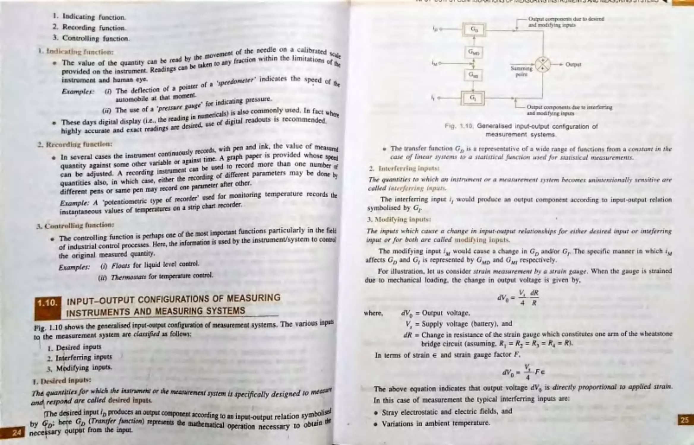
1.10. Input-out put Configurations of Measuring
Instruments and M easuring systems .......... 24
1.11 . Applications of Mea urement Systems ..... 26
Highlights ............... ................................ ... 27
O~jective Type Questions .......................... 28
Theoretical Questions ............................... 30
2. STATIC AND DYNAMIC
CHARACTERISTICS OF
INSTRUMENTS
............................
32-98
2.1. Introduction ........... ........ ...... .... ....... ...... ... .. 32
2.2. Definitions Relating to Measuring
Instruments ...... ... .. .. ... ......... ....... .... ............ 3 2
CONTENTS
.3 Static Characteri tics ... .. .... .................... .... 34
2.3.1. Accuracy, error and correction .... 34
2.3.2. Static calibration ......................... .. 38
2.3.3. Range and span ............................. 38
2.3 .4. Scale readability ... ...... ................ .. 39
2.3.5. Repeatability and reproducibility 40
2.3 .6 . Drift ... .... .......... .... ...... ........... ......... 40
2.3.7. Accuracy and precision ................ 41
2.3 .8. Sensitivity ..................................... 41
2.3 .9. Linearity ........................ ........... .. ... 43
2 .3.10. Hysteresis ...................................... 44
2.3 .11 . Threshold and resolution .......... .... 44
. , 2.3.12. Dead zone and dead time .............. 46
2.3.13. Loading effects .... ... .. ......... .... ..... .. 46
2.3 .14. Noise ..... ... .. ... ... ...... ............ ... .. .... .. 50
2.4 Dynamic Characteristics ........... ... .... ... ...... . 51
2.4.1. Dynamic re sponse ...................... ... 51
2.4.2. Dynamic characteristics of a
measurement system ..................... 52
2.4.3. Dynamic analysi of measurement
systems ...... .......... ........... .... ....... .... 53
2.4 .4 . Zero, first and second order
system ................. ......................... 54
2.4.4.1. Zero-order systems ......... 54
2.4.4.2. First-order systems ......... 55
2.4 .4 .3 . Second-order systems .... 56
,. 2 .4 .5 . First-order system responses ......... 57
-'2.4. 6 . Second-order system responses .... 62
Highlights .... .............................................. 85
Objective Type Questions .......................... 87
Theoretical Questions ............................... 94
Unsolved Examples ................... ............. 96
Vi CONTENTS
3.
.l
1..:..
-'· .
A.
4.
4.1 .
ERRORS IN MEASUREMENTS, ........ 99-142
Introduction ............................................... 99
Limiting (or Guarantee) Errors ......... ..... .... 99
Type. of E1rnrs ......................................... 105
3.3.1. Gros en-or ........................... .. ..... 106
.3 .2 . Sy. t matic error ...... ................... 106
3.3 .3. Random errors ............................. 107
Sources of Error ....................... ............... 108
Statistical Analysi of Test Data ... ........... 108
3.5 .1. Statistical a erages ..................... 109
3.5 .2. Di persion from mean ................. 110
3.5 .3. Be t value from a sample
of reading ....... .................... ........ 111
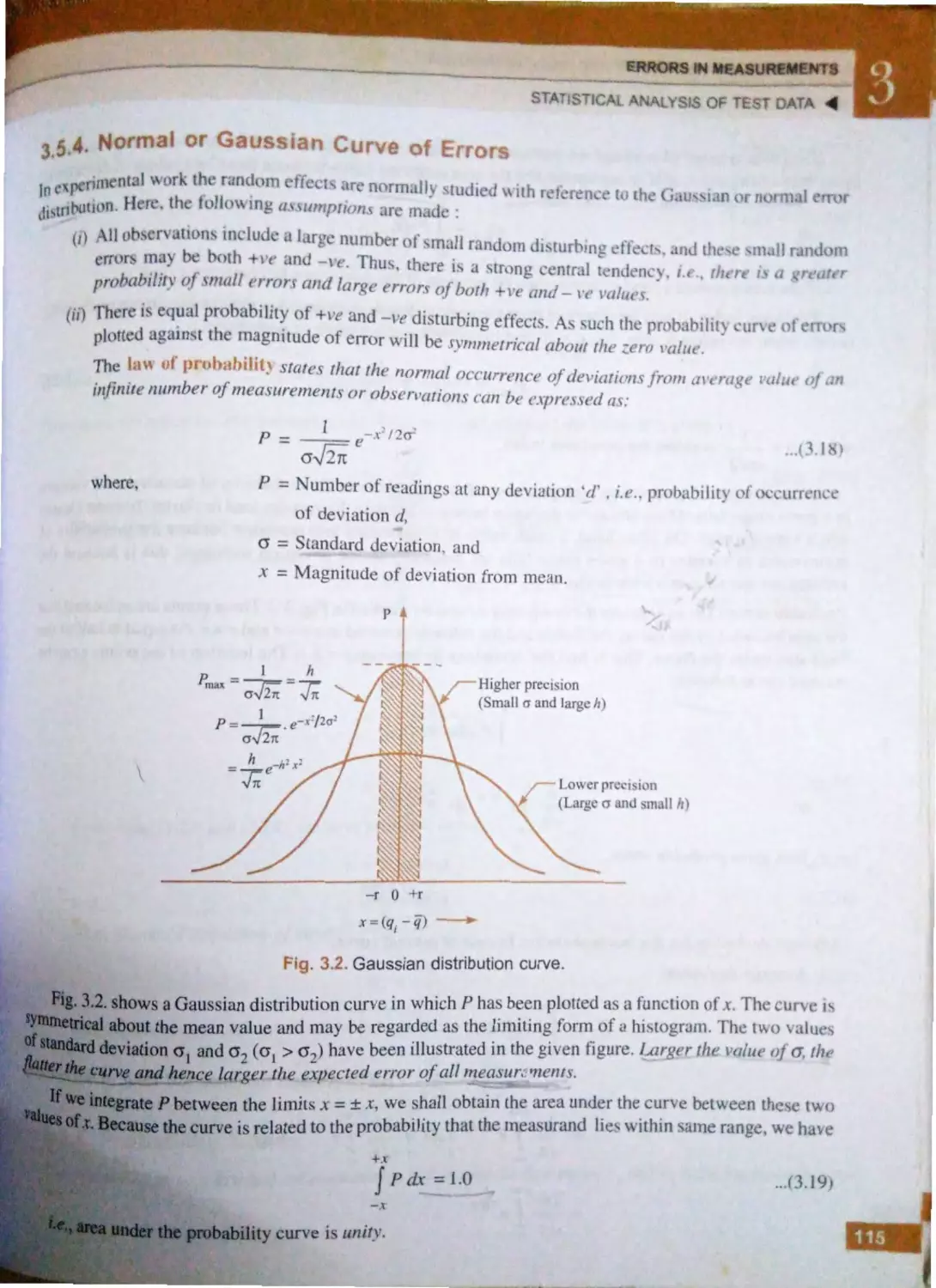
3.5 .4. Normal or Gau sian curve
of rrors .......... ............................. 115
3.5.5. Probability table ........................ 117
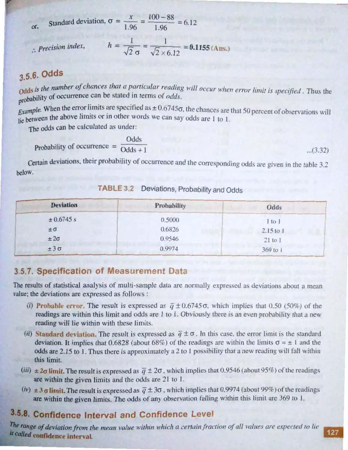
3.5 .6. Odds ............................................ 127
3.5.7. Specification of measurement
data .............................................. 127
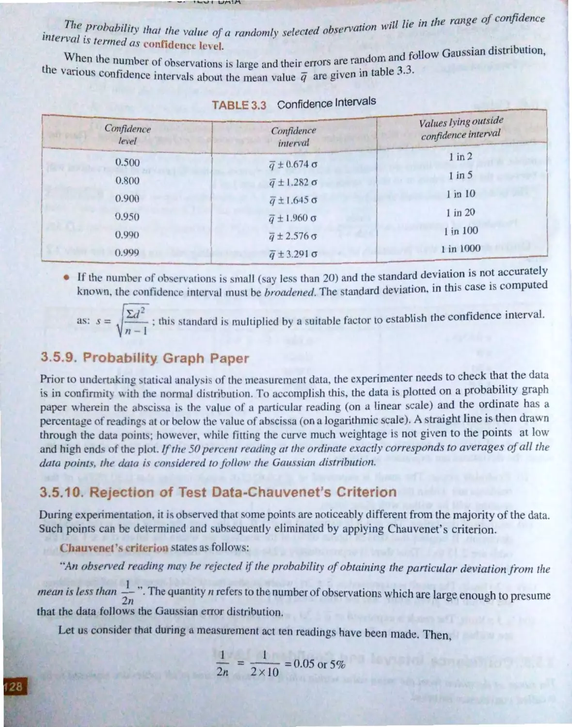
3.5.8. Confidence interval and
confidence level .......................... 127
3.5 .9 . Probability graph paper .............. 128
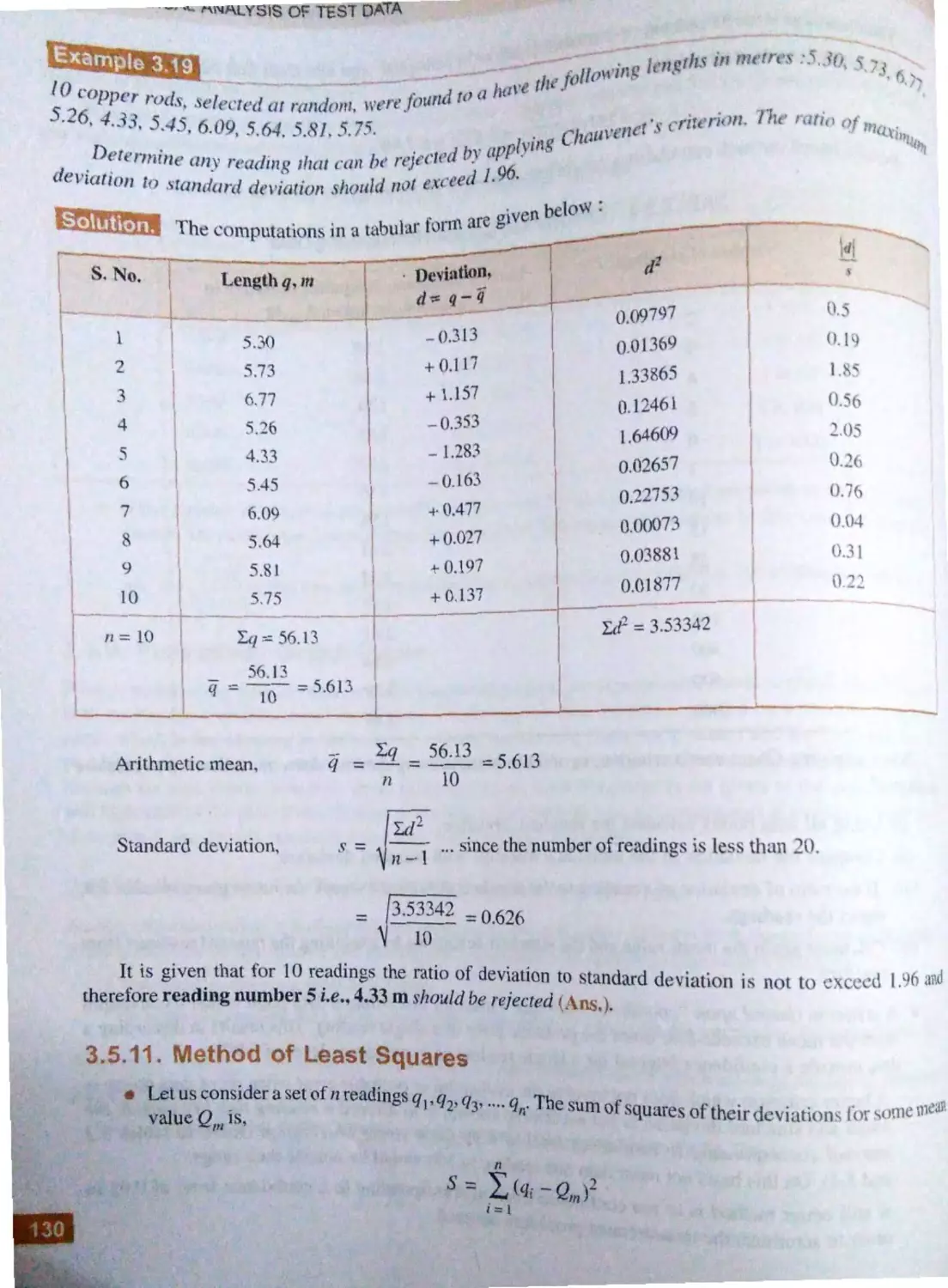
3.5.10. Rejection of test data-Chauvenet's
criterion ....................................... 128
3.5.11. Method of least squares .......... .... 130
Highlights ................................................ 135
Objective Type Questions ............. ......... .. 136
Theoretical Questions ............................. 139
Unsolved Examples ................................. 140
METROLOGY
.. .. ... ... ... ... .. ... ... 143-373
General Concepts .................................... 144
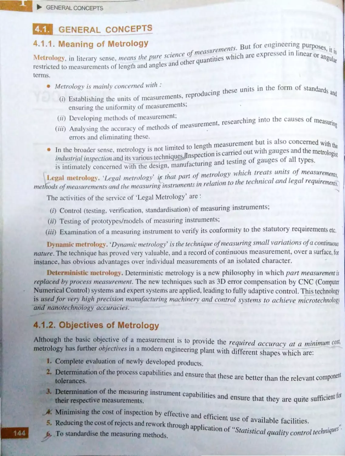
4.1 .1 . Meaning of metrology ........ ........ 144
4.1 .2 . Objectives of metrology ............. 144
4.1 .3 . Necessity and importance of
metrology .... .................... .. ........ .. 145
4.1.4. Dimensional accuracy ................. 145
4.1.5 . Precision measurement-Its need . 145
4.1 .6 . Quality control-metrology as a
means to achleve ......................... 146
4.1 .7 . Standards of measurements ..... .. .. 147
_4 .1.7 .1 . Line standard ................ 147
4.1 .7.2. End standard ................. 149
4.1.7 .3. Wavelength standard ... 150
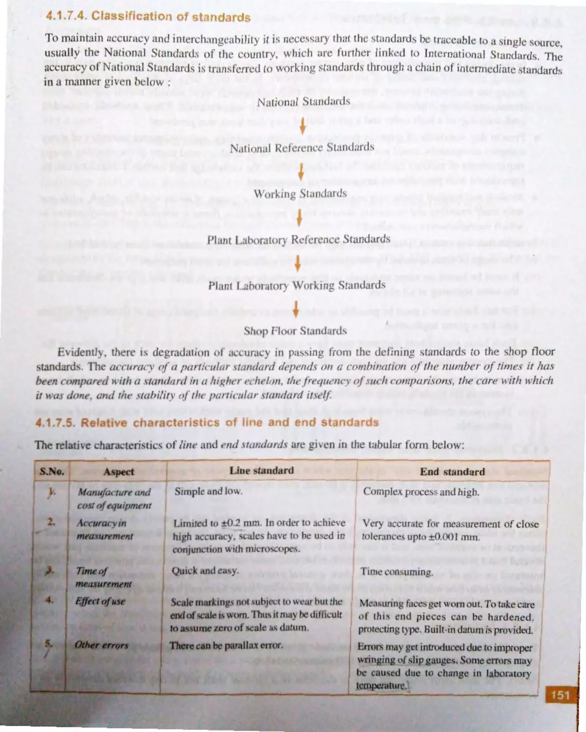
4.1. 7 .4. Cla ,sification of
standards .. .......... ......... .. 151
4.1 .7 .5. Relative characteri tics
of Line and End
standard..... •.... ·· ·...... ·.. ··
151
f 1.8 . Limits fits and tolerance ............. 152
4.l .8 .1 . General aspects ..... ........ 152
4_1_8
_
2, Nominal size and basic
dimensions ........ .... ....... l52
4.1.8.3 . Definitions .................... 15 2
4.1 .8.4 . Basi s of fit (or limit)
system ....... ...... .............. 155
4 . l .8 .5. Systems of specifying
tolerances ..................... l 55
4 . l .8 .6 . Designation of holes,
shafts and fits ..... ... ... .. ... 156
4_1.8
. 7. Commonly used holes
and shafts ... ...... .. ........... 157
4.1 .8 .8 . The Newall system ....... 157
4 .1 .8 .9 . ISO system of limits and
fits ........... ...... ... ............. 157
4.1.8 .10. Types of fits .................. 157
4.1 .8.11 . Concept of interchange-
ability ..... ........ ....... ....... 158
4.1.9 . Methods of achieving precision
and accuracy ............................... 159
4.1 .10. Sources of errors .......................... 159
4.1.11 . Classification of measuring
instruments .................................. 161
4.1.12 . Classification of methods of
measurements ... ........................... 162
4.1 .13. Selection of instruments ............. 162
4.1 .14. Standardising organisations ....... 162
4.1.15. International System of Units (SI) 163
4.1.16. Gauges ......................................... 165
4.1.16.1 . Classification of
gauges .......................... 165
4 . 1 .16.2. Description of some
commonly used
gauges .......................... 165
4.2. Principles of Measuring Ii:istruments ....... I 69
4.2 .1. Definitions .................................. 169
4.2 .2. Classification of measuring
equipment ................................... 171
4.2 .3 . Technical specifications of
·
·
172
measunng mstruments .............. ..
l... li'lll ipl', 1)1 Ill (.'hll\i.d
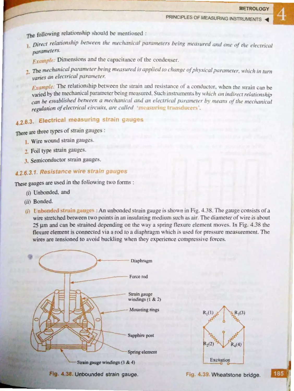
m~asnri11' im,ll'llttH·tlf, . . ....... ....... I n
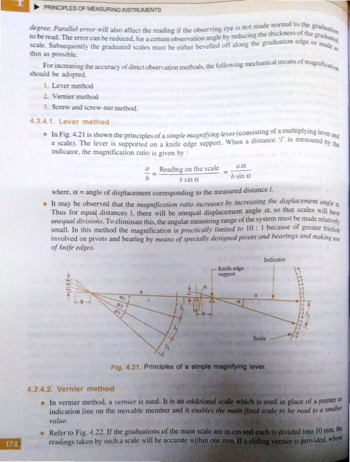
L-· t1. Ll <rIn thod ........,. ... .. l71
· L ·· 111ic- m tht d............. IM
l..Lt 'vr ·w awl screw-nt11
m ·thod .................. ...... .. I I
L l,5. Prin<.:ipl •. ·
of opti ·ul in.· tn1m uh I /(1
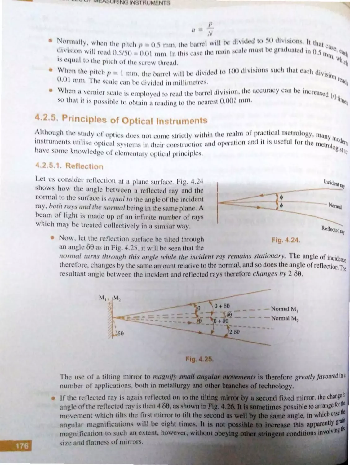
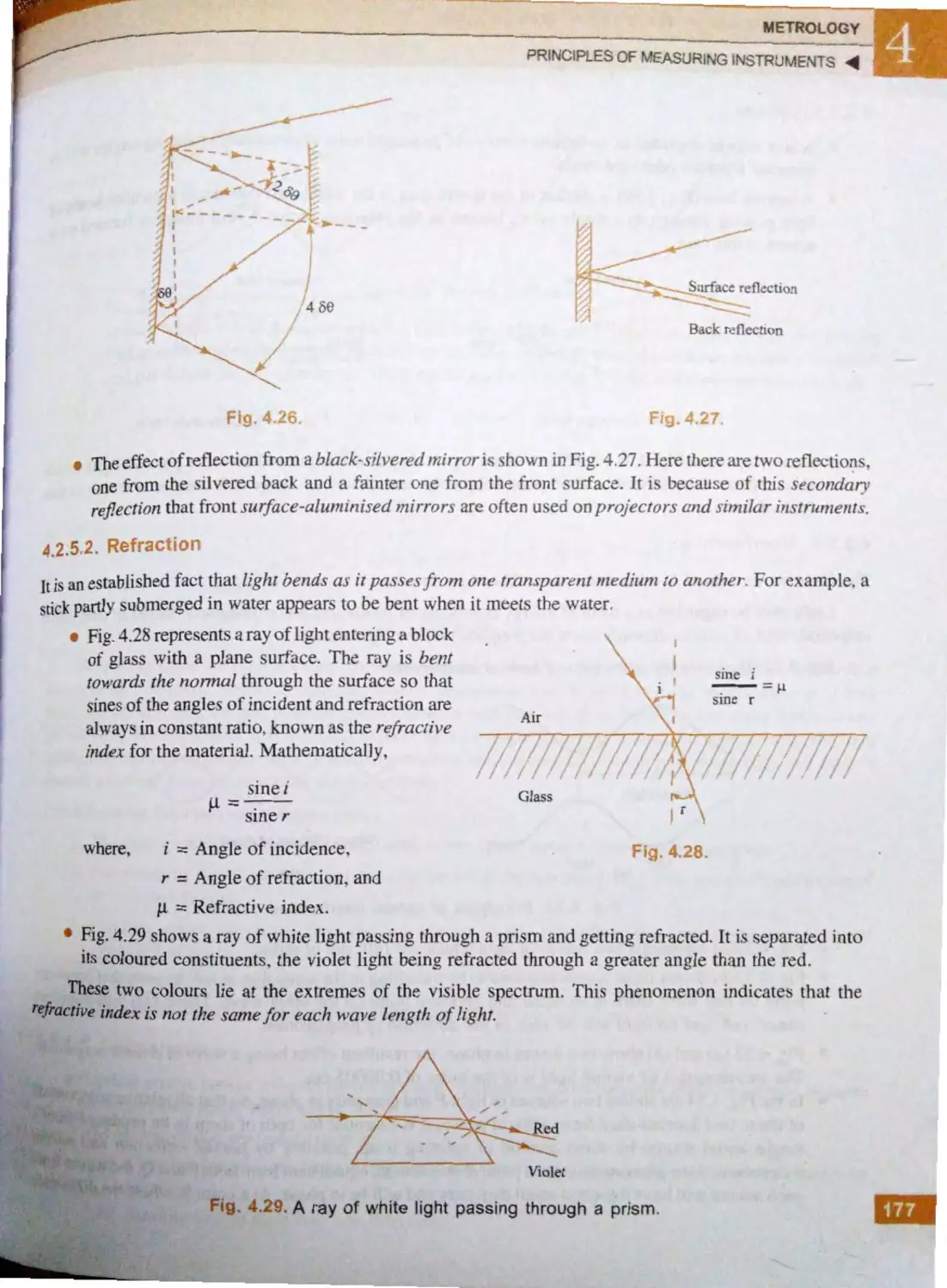
· L2... I .. R fl· ·tion ............. ,... .. . I l(,
I frnct ion ........ .. ... ...... I . tr,
] PllS 'S ......... , ......... ........ 17'K
-L..,.5.4. Int ·rf re n , , ................... I / 't',
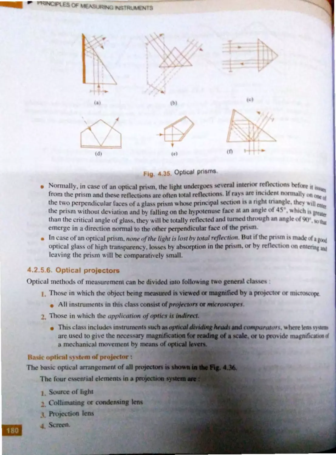
· ... ... 5. Opt il.:al pnl-im .. ...... ........ 17')
. ..6 . Optil .11 1mi ' ·ti..1r s ......... I HO
~rincipl ·s or 1' ·trim ! n1l·a. u, in1,
lllS(l'Ullk'lll. ................ . ..... ......... . .. I H
i. _. 6 .1 Transl' Hmation of
en·r•y ...... ..... .... ............ 182
.2.6 .~.
· 11 intion orcl ·ctrical
pa an, ·tt rs .. ......... ... ...... f 8
.2.6.3. Ell'~tri<.:a l 111 usurinp
~trai n ' tllJt'S .. .. . ........ ... lX
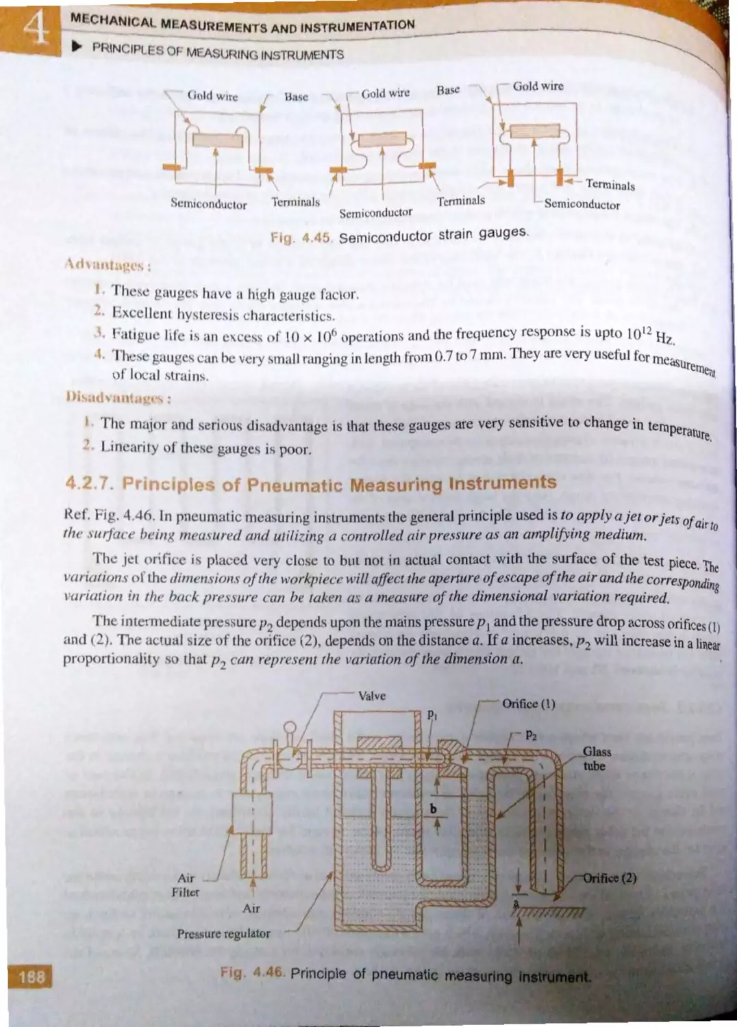
4..7. Pri nciples of pneu in a ti · mea~rn ini>
111 llUJllcnts ...................... ............ 188
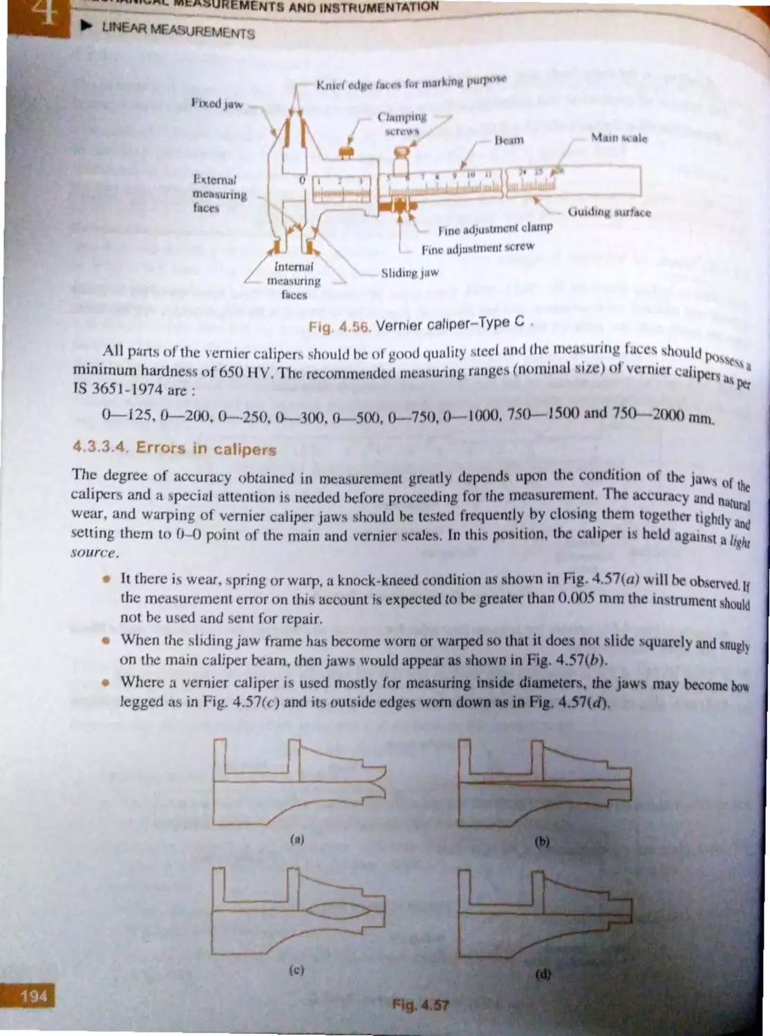
Lin ar M a: urcments ..... ......................... J 8<J
4..3.1. En in ·cr 's sl ' ·I ru l .................... I 89
4.
·-·
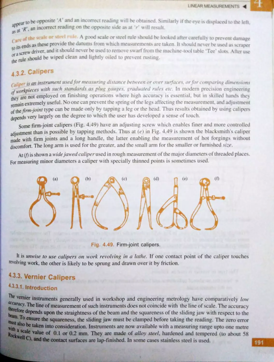
alip rs ... ................ ................... I ) I
.3 ._.
t.:rni r calipers ..... ..... ................. I ) I
4.3 .3 . l. Introduction .. .......... ..... 19 1
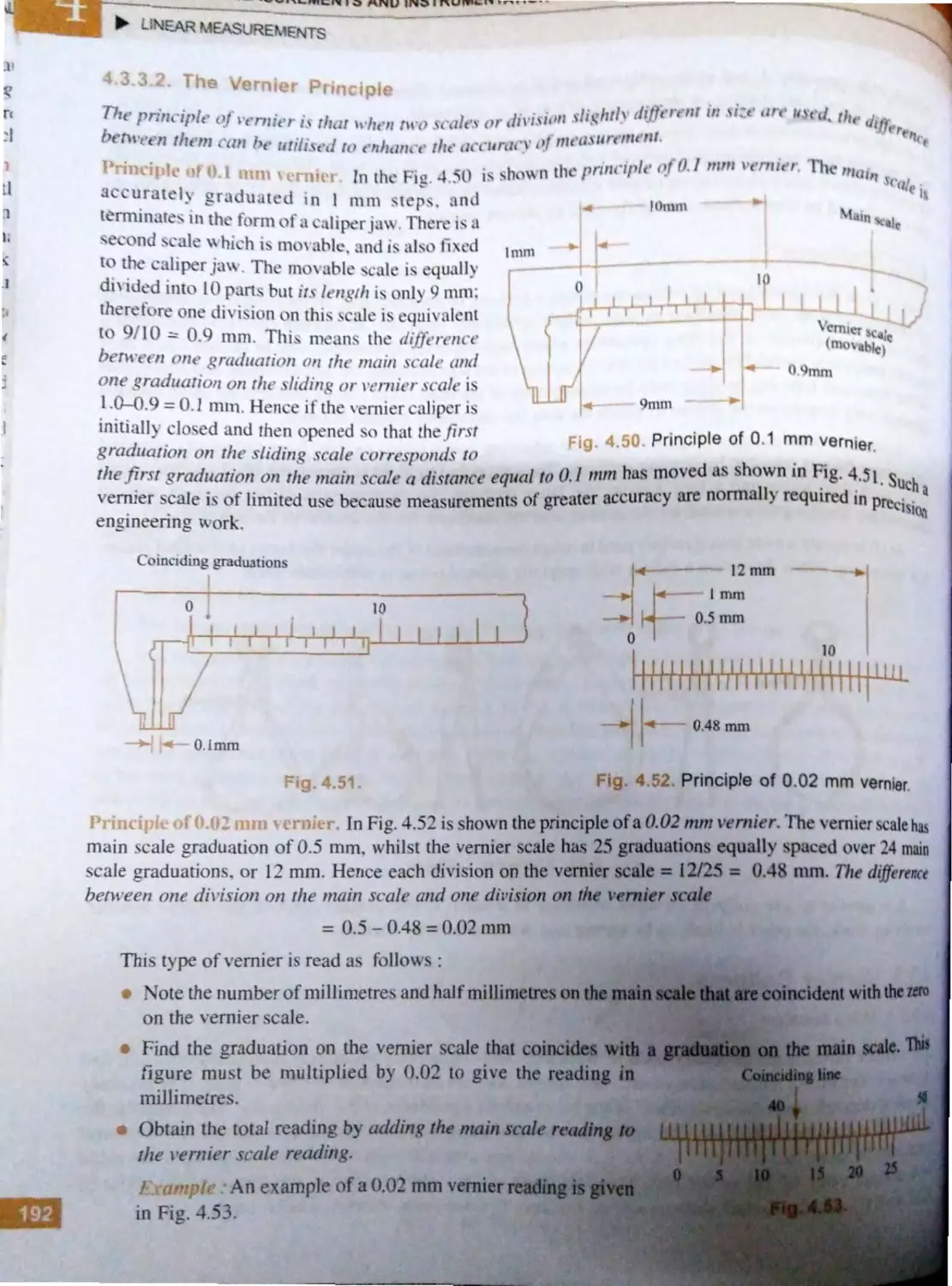
4.3.3.2. Th .. Vcrni~ r prin ·ip lc ... 192
4.
.3.
.
Type. or Vcrni<:r
calip rs ..... .... ......... ..... .. 19]
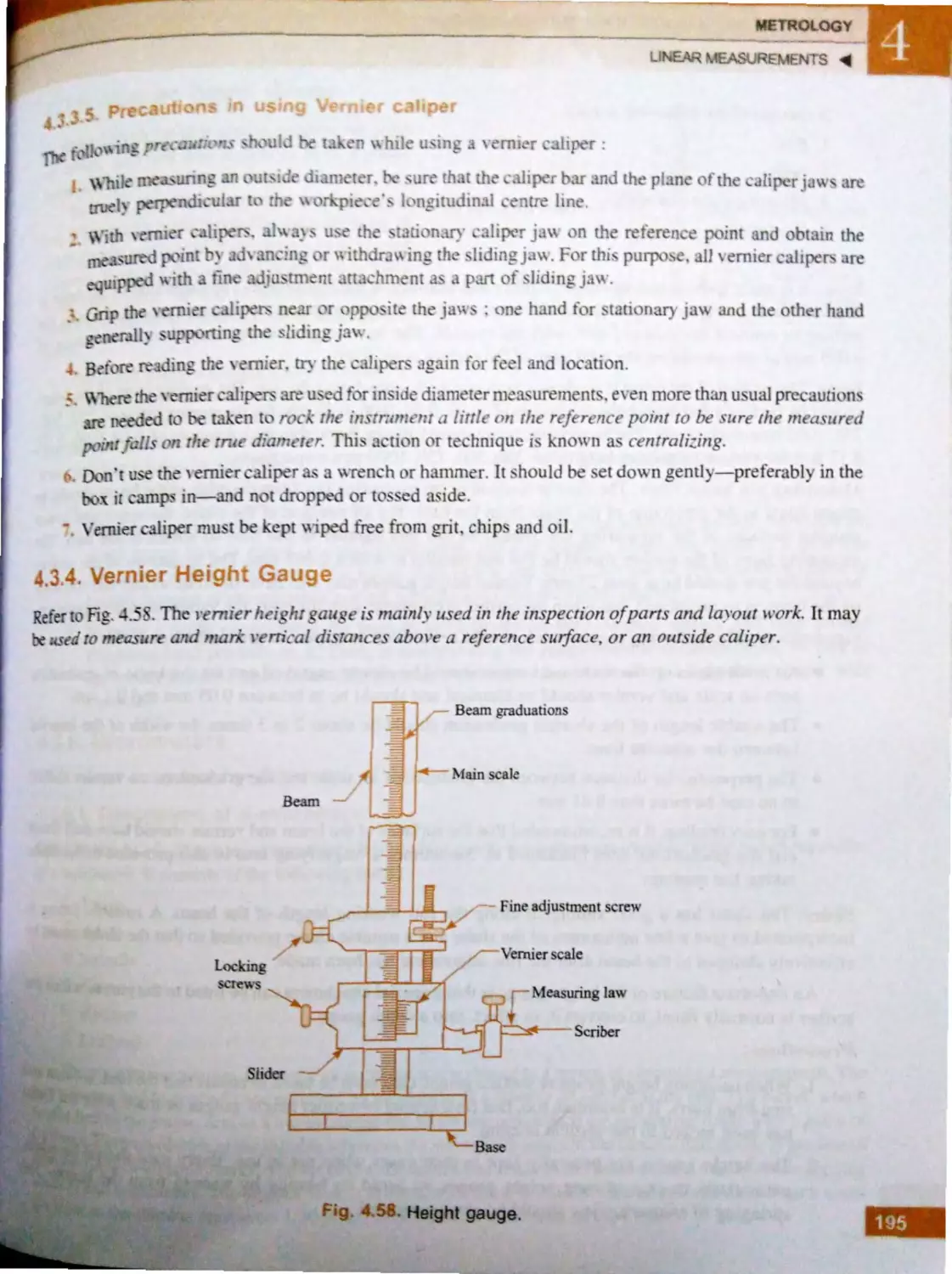
4.3.3.4. ErTo rs in a lip .. rs .. .... ..... 194
4.3.3.5. Pr cauti )OS in usi n r
Vernier caliper .............. 195
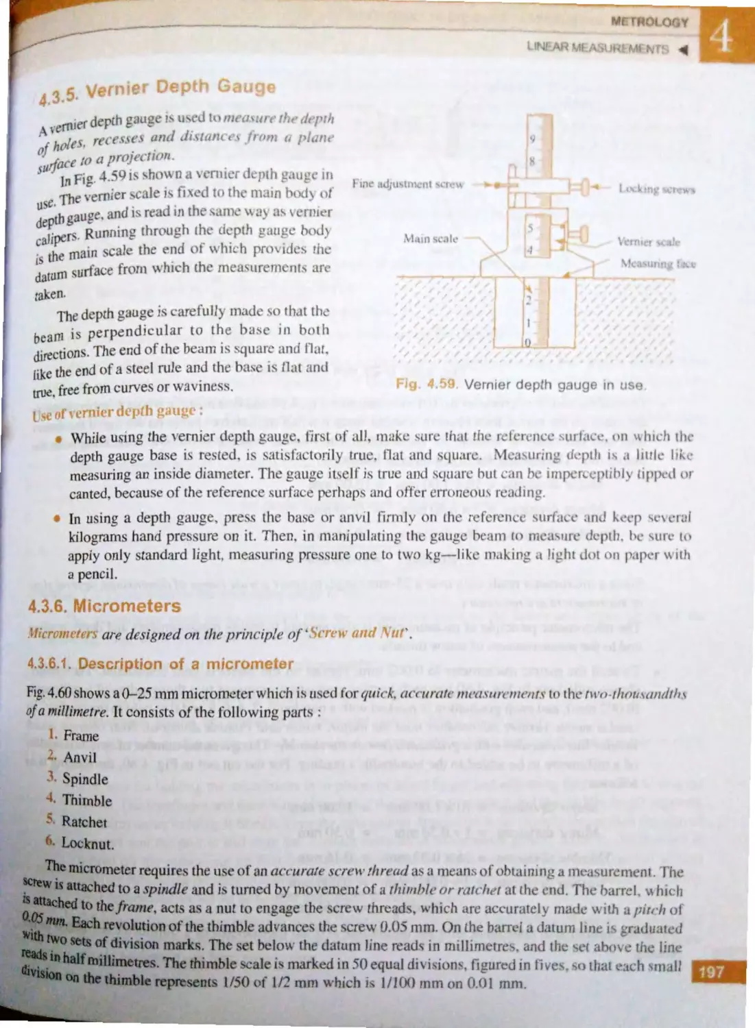
4,,3.4. Vernier h igh t gaug ... .. .... ......... 195
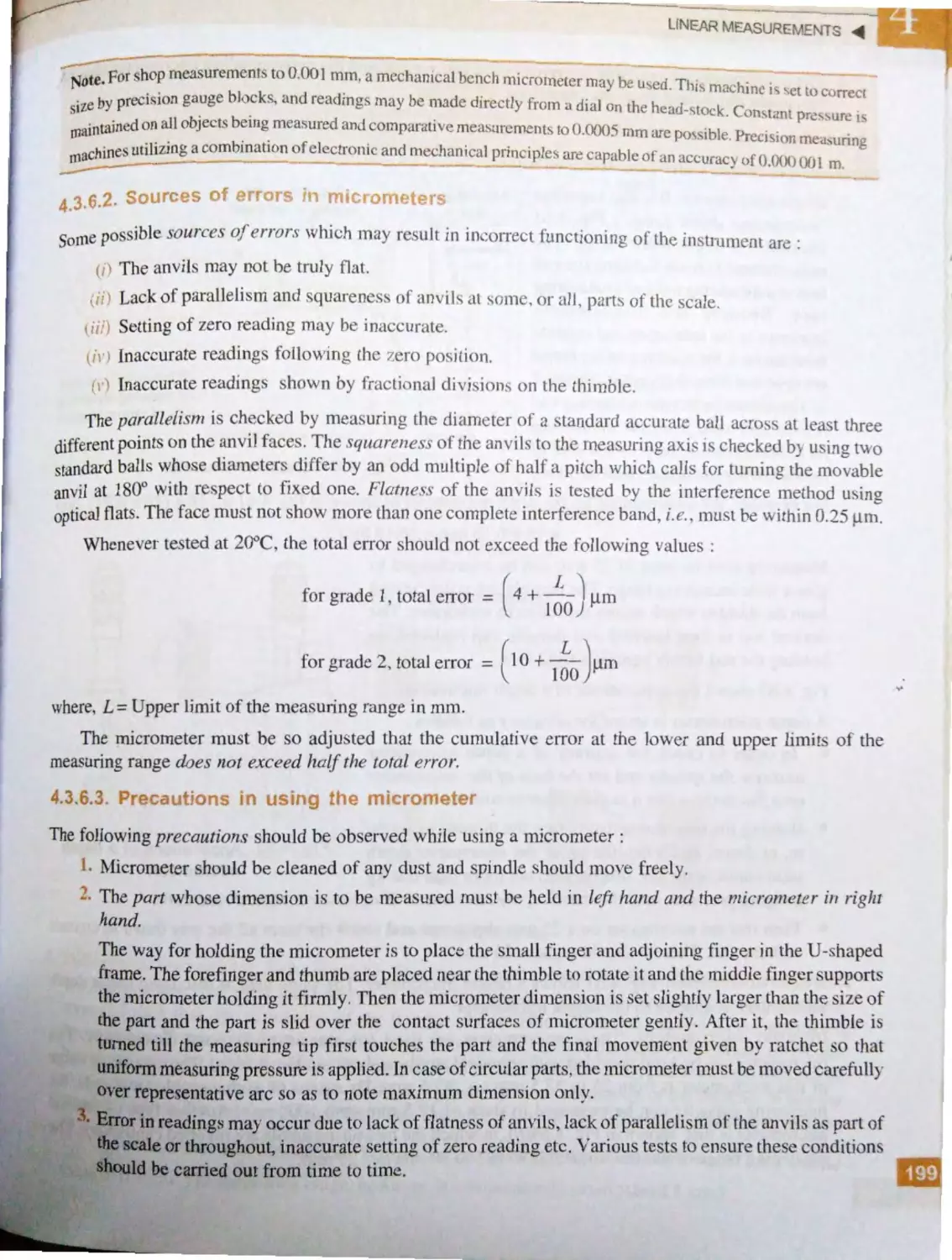
4.3.5. Vern ier de pth ga uge .... ... ...... ....... 197
4.3 .6 . Mi c rom tcr.............. .... .... ... ..... ... 197
4.3.6 .J. D ·scriprion of u
mi crom eter ...... ... .... ... .. .. 197
4.3.6.2. S ur csoferrors in
micro met r · ...... .... .... .... J99
4.3.6.3. Precautions in usin g the
micrometer .................. .. 199
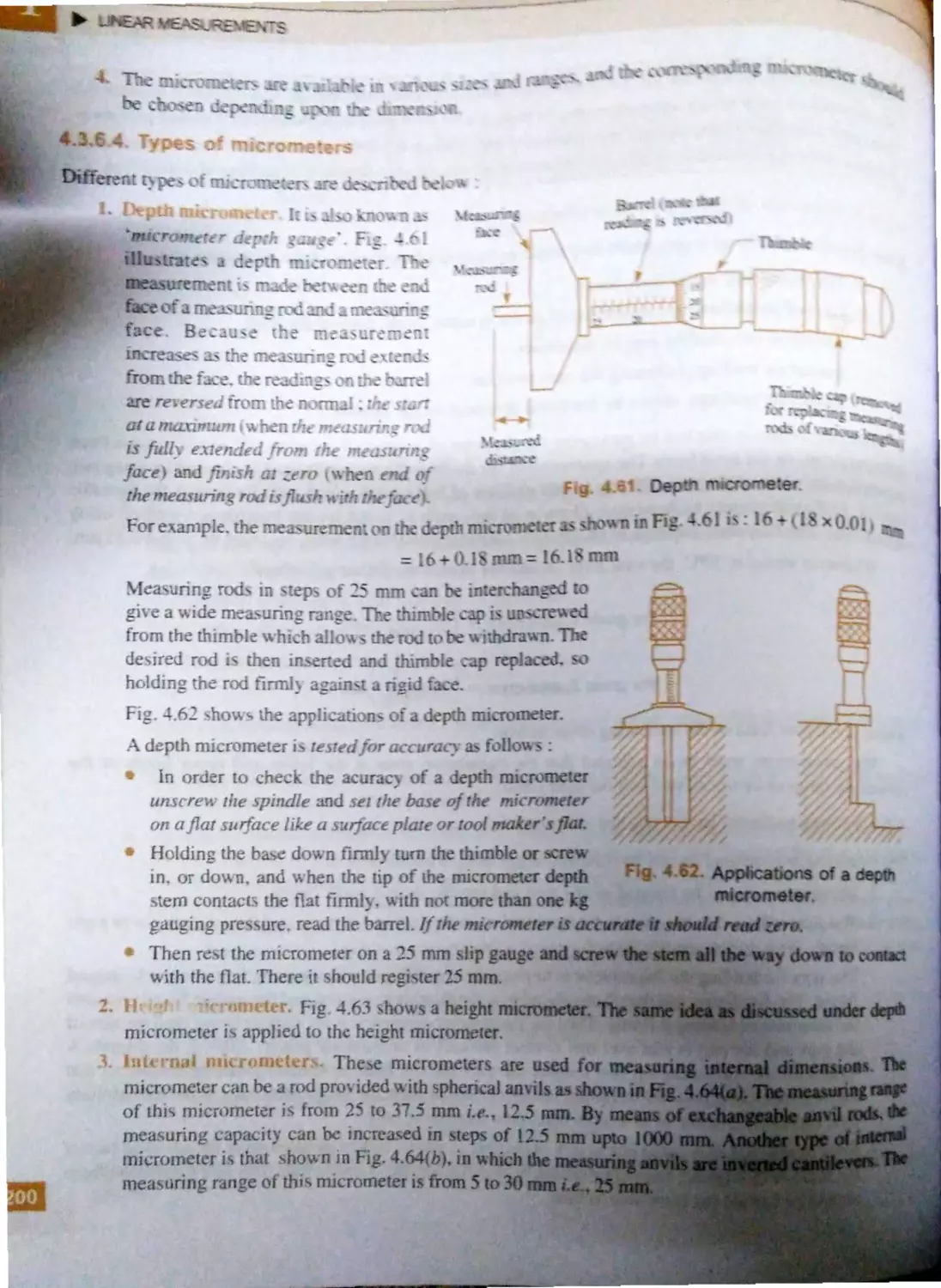
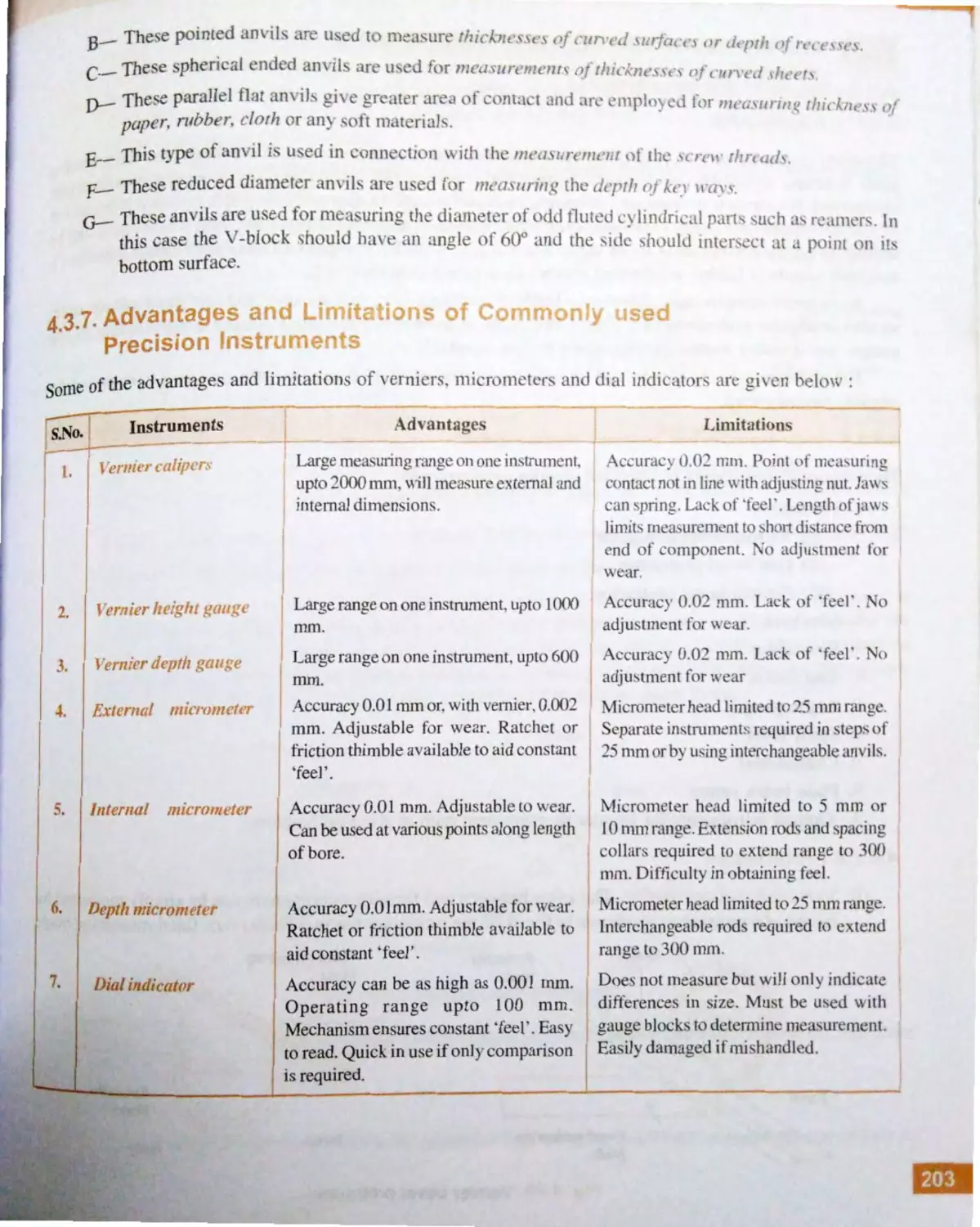
4.3 .6 .4. Type of micr meters .. . 200
4.3.7. Advantages and limitations of
commonly used precision
jnstruments ...................... ,. . . . . . .. . . . 203
r,In ·',
VII
,.
i\111uJiu :ind 'JHJJ , 1 , w11t11·111 1 r,, ,, ,,,,.,,., %'J4
1J, I,. I . A1w1d·11 ir1 ·1110, 11,, 1,1 · ,
.,,111,,·,•· ;. <vi
I~,/1,I f. I,,1Iq,11, 1 I1'111 .
,.,,,
, ;)}1
4,tl.J .2, ft1 IJ1,H<:1 I' ji,1{11,Vt fr
101 ;~ ll 1•1 J<'Jtl ,,,.,,.,, ,,.,,
;)4
tl,,4.' ,
'J'HJ •J IJI( ;JI 11".0 l·t 1. ,
,••••, ,,., ,
?, (J
44..,I, <htf1' ''1j(,Jl:iJ ·1 ·
,m,, ,, /4ir,
4A.7. ." .. 'I',,,, 'j IHl 'I l lflf'
Ill' ti lltJII 1Jl•, ,.,, ,,,.,,,,,., ,, 2' %
•
1 ·('1 ·w 'I ltw:1d M ·a·,1J111wnt •., ..,.,.,,,.,,, ,. Z.2(J
4.. I . hllrlldu<. lioH , ... .... ,,.., . . , .,,,.,, .,.,,,, 2'L. <J
IJ .1.
.
c'la•1 ,i ii( :111, ,n ,,f 1hr (,Id' .o,,,, ...... i:z f.
J:l "tll' 11·1: ol ;11w J ltt.:}.s J, ,..,.,, .
..
'Z2
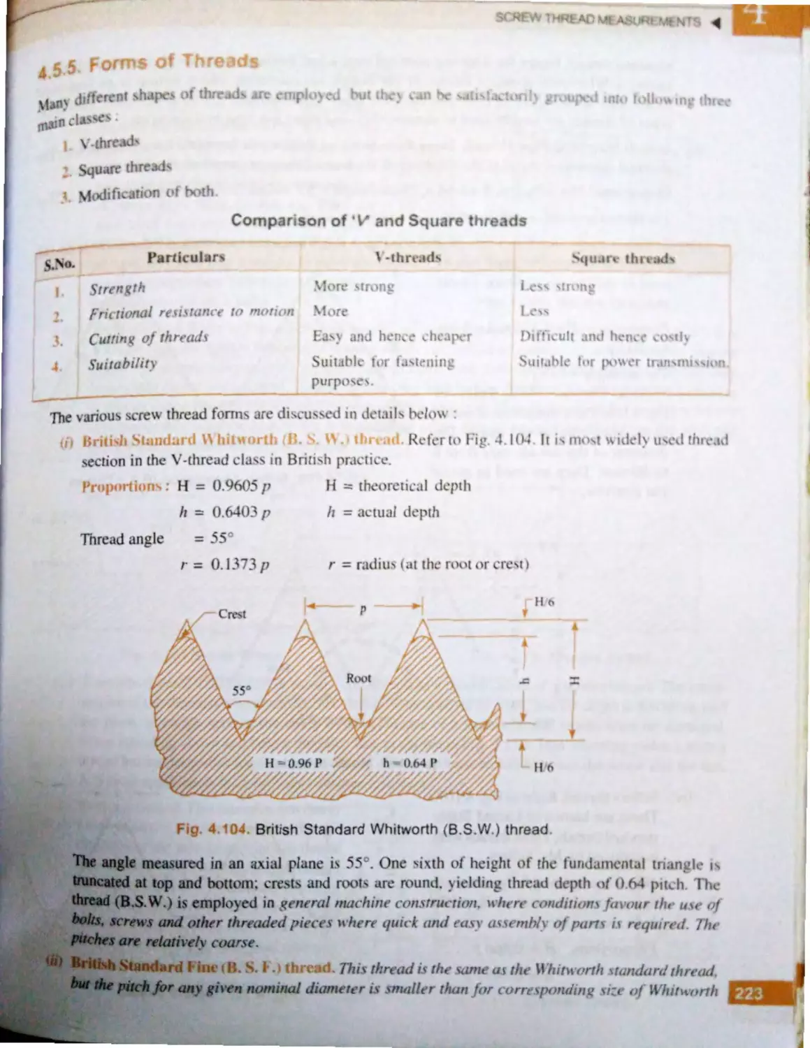
, 'pc :tJH .it,, 11 '. , ,fa •,,;re N 11111,; J , 222
•
J ,r m'> qi 11,,·ad·, ,.. _
,,,.,,, .. ,.. ,., .. ., ,. 22'
4. A I•, ror inLhn·ad ,.
........... ,, .. ,,,,. 22(,
4.5. 7. M ·a 1,UJ'lll , tlr Ill ~fll', (Jf :
.., ·
·w 1l1r •~d ................................ 22(,
..7. t. Lxt ·n wl ,<..
•wth··
JI )(
.,,..,.,. ...... 227
.5.7.2. l11l ·nwl.ere Nth ead
Il l · :,urc;J} ·t t ............... 2' 5
..8. S r ·w thr ·ad 1au , .., .. ........ ..... ...,. 23k
,..
icm M •, sur ·inent .. .............. , ................ 241
4AI. l11lroduc.,t io r1 ................................ 241
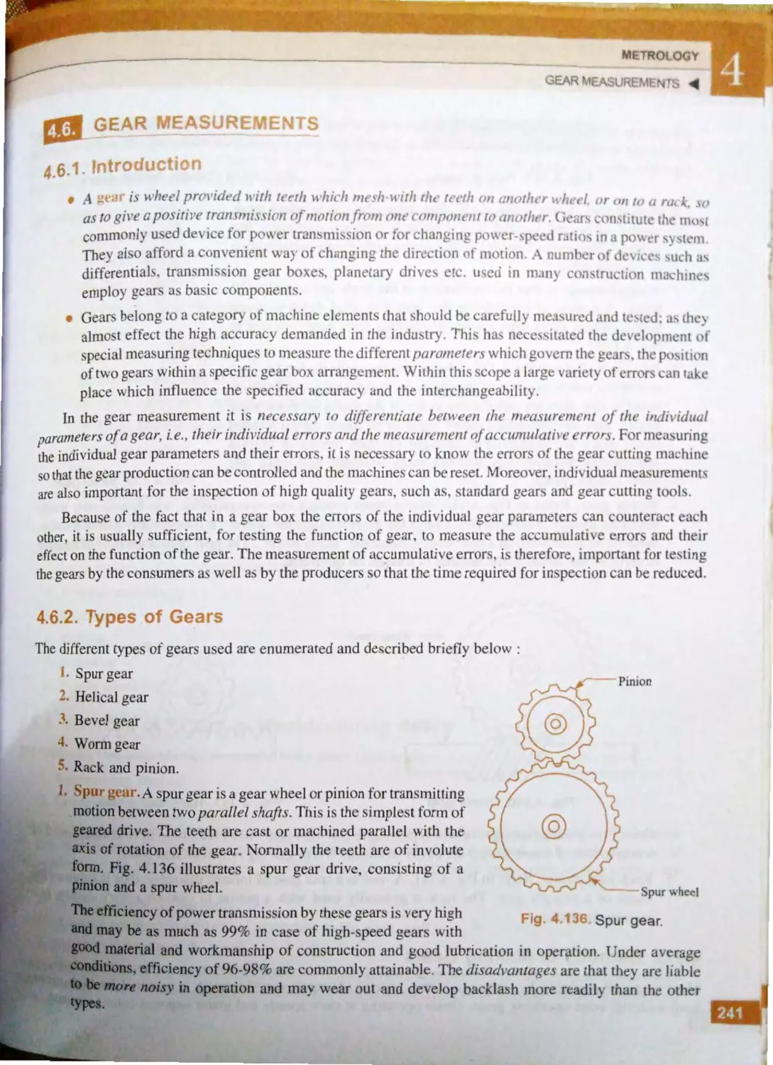
4.(,.2. Typ •~ of ,,c· n, ............................. 24 1
4.6 .
.
Mc1hc,<h, f
· kin,ge"r~,
....... ,,,. 242
4.6.4. So ircc!-. ol ·r o ~ in
manu fact uri
1car•; .................... 243
4.6.5. f orms >f μca r tee th ...................... 244
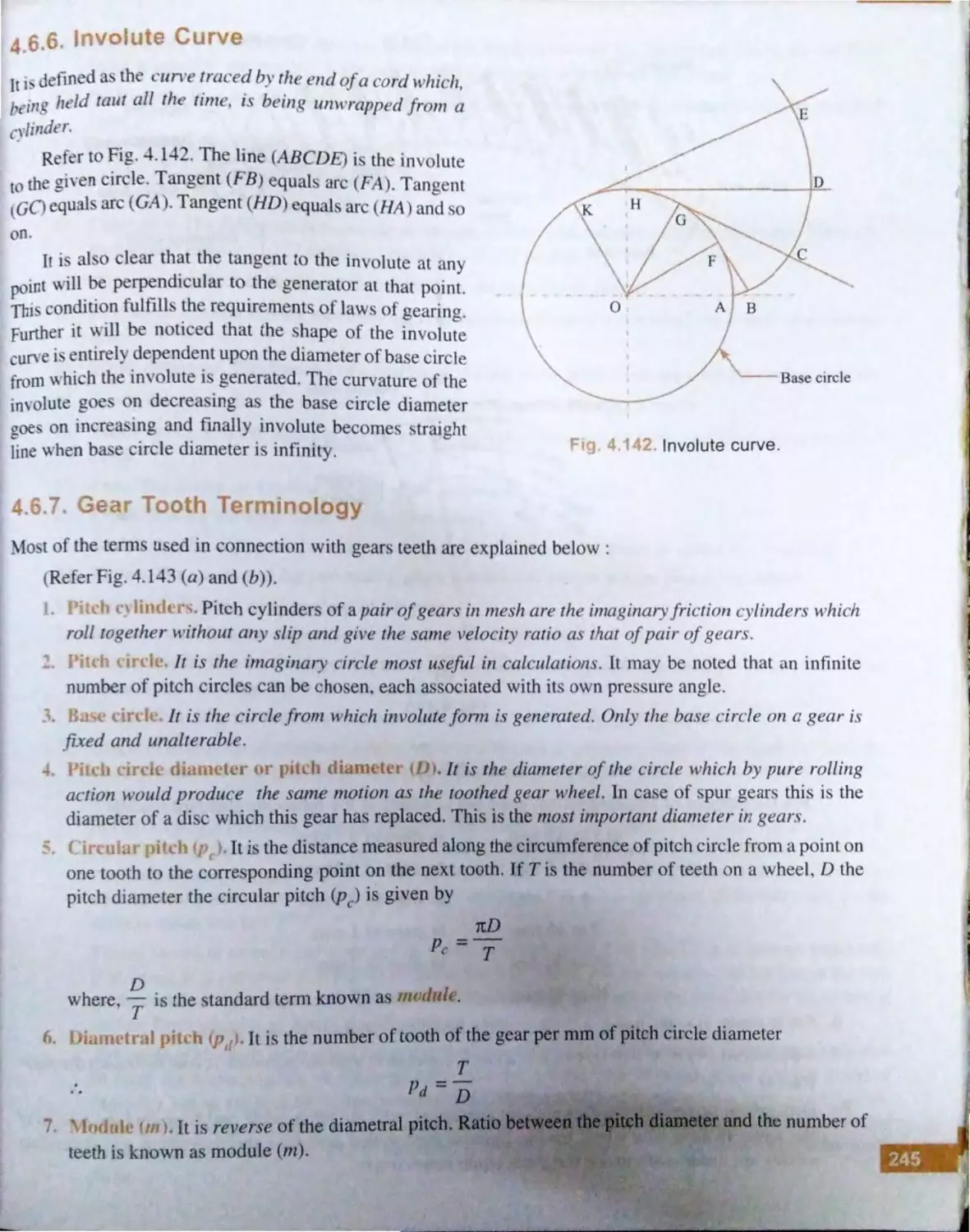
4. ).6. Involute curv · ....... .. ...... , .. ... .. ...... 245
4 .(1 .7. (,car CJOlh te rm inology ...... ... ..... 245
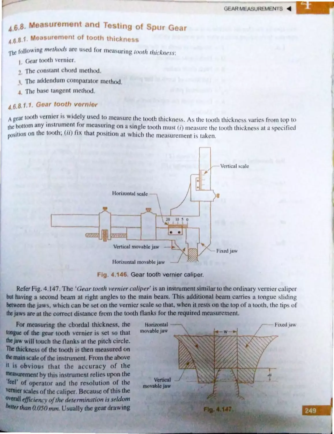
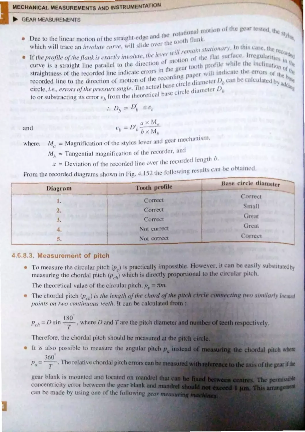
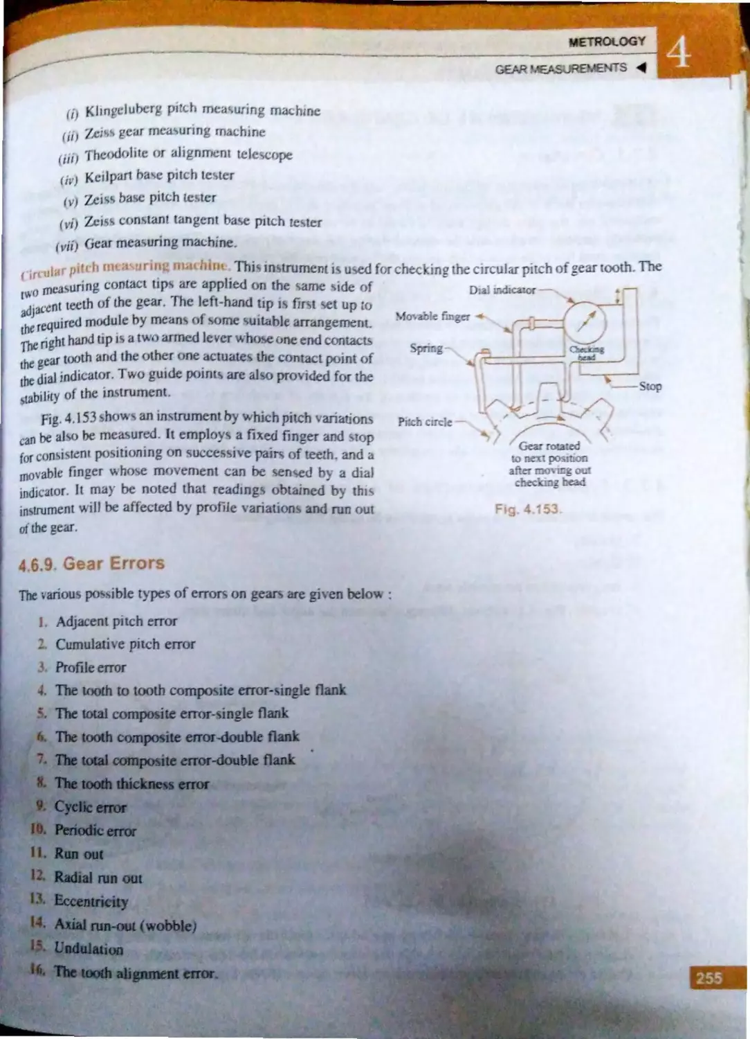
.6.8. Measurement and tc~ting f
1i pur 1 ca r .......... .......... .. ........ .. ...... 249
4 6.8. 1. Measurement of woth
thickne~s ........ ..... .. ... . .... 249
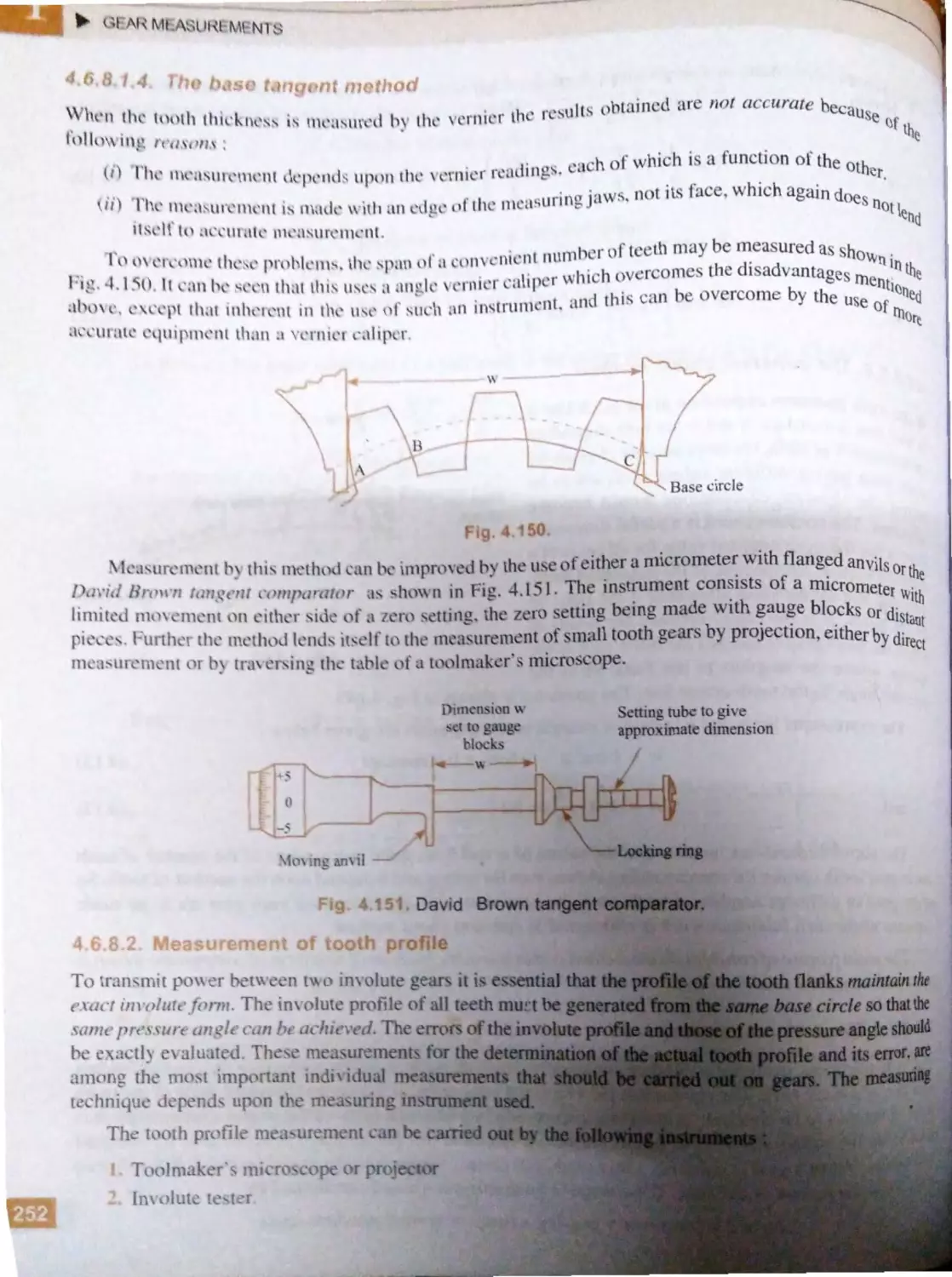
4.6.8.2. Measurement f tooth
profile .. ... ................. ..... 252
4.6 .8 .3. Mea~urement f pitch ... 254
4. 6 .9. Gear errors .. ... .......... .................... 255
. 7 Mea sur ement of ircularity .................... 256
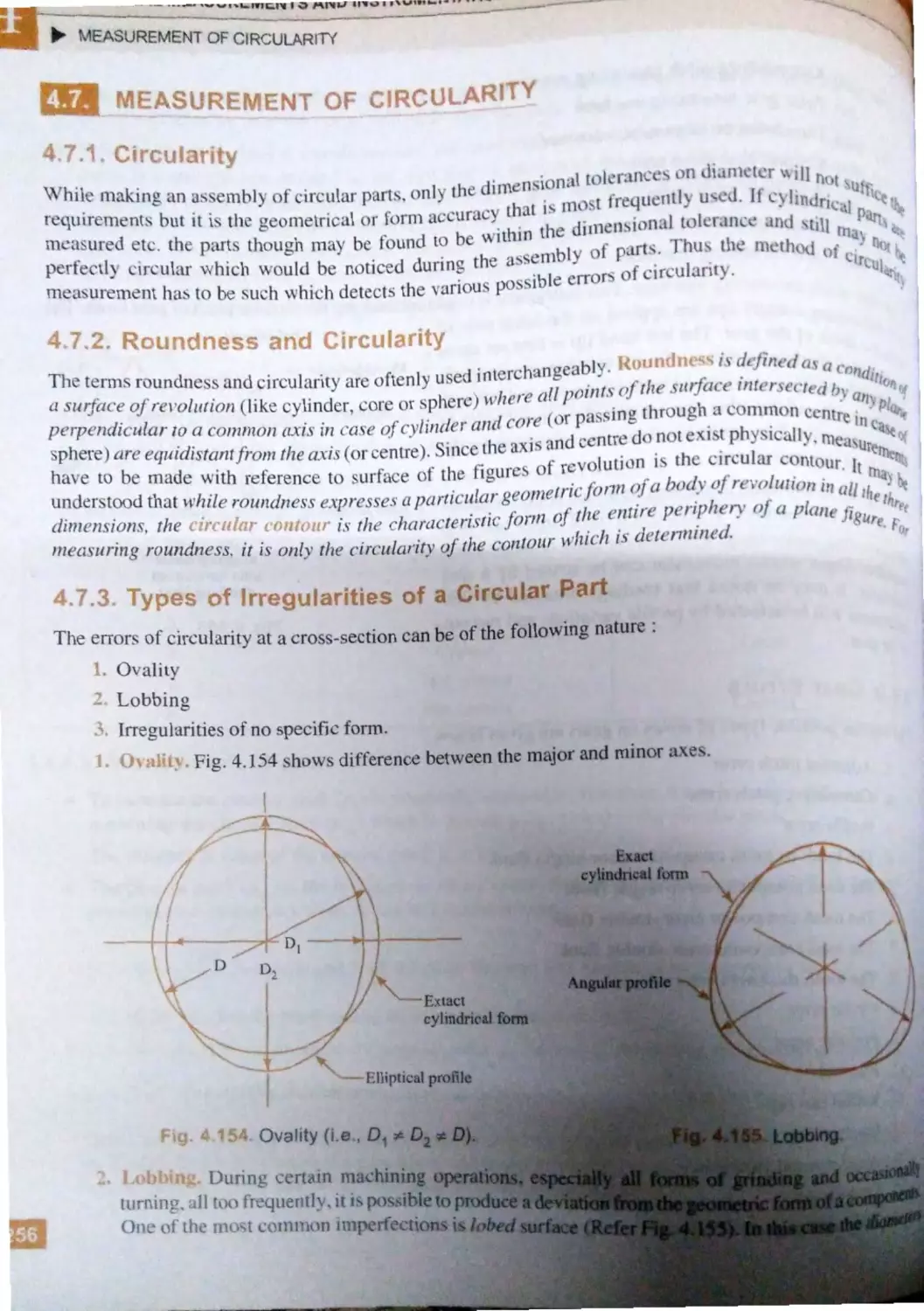
4.7. J. ircularity ............................... .... 256
4.7 .2 . Roundnes s and cfrcularity .......... 256
4.7 .3 . Types of i1Tcgularities of a
circu l ar part ...........................00••· 256
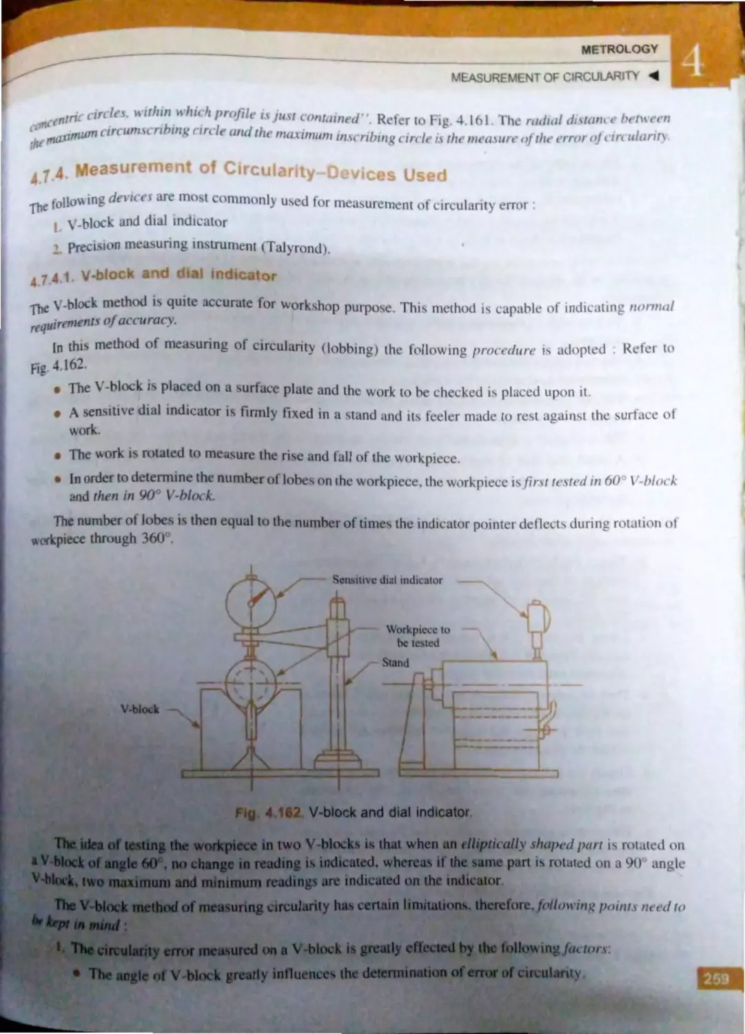
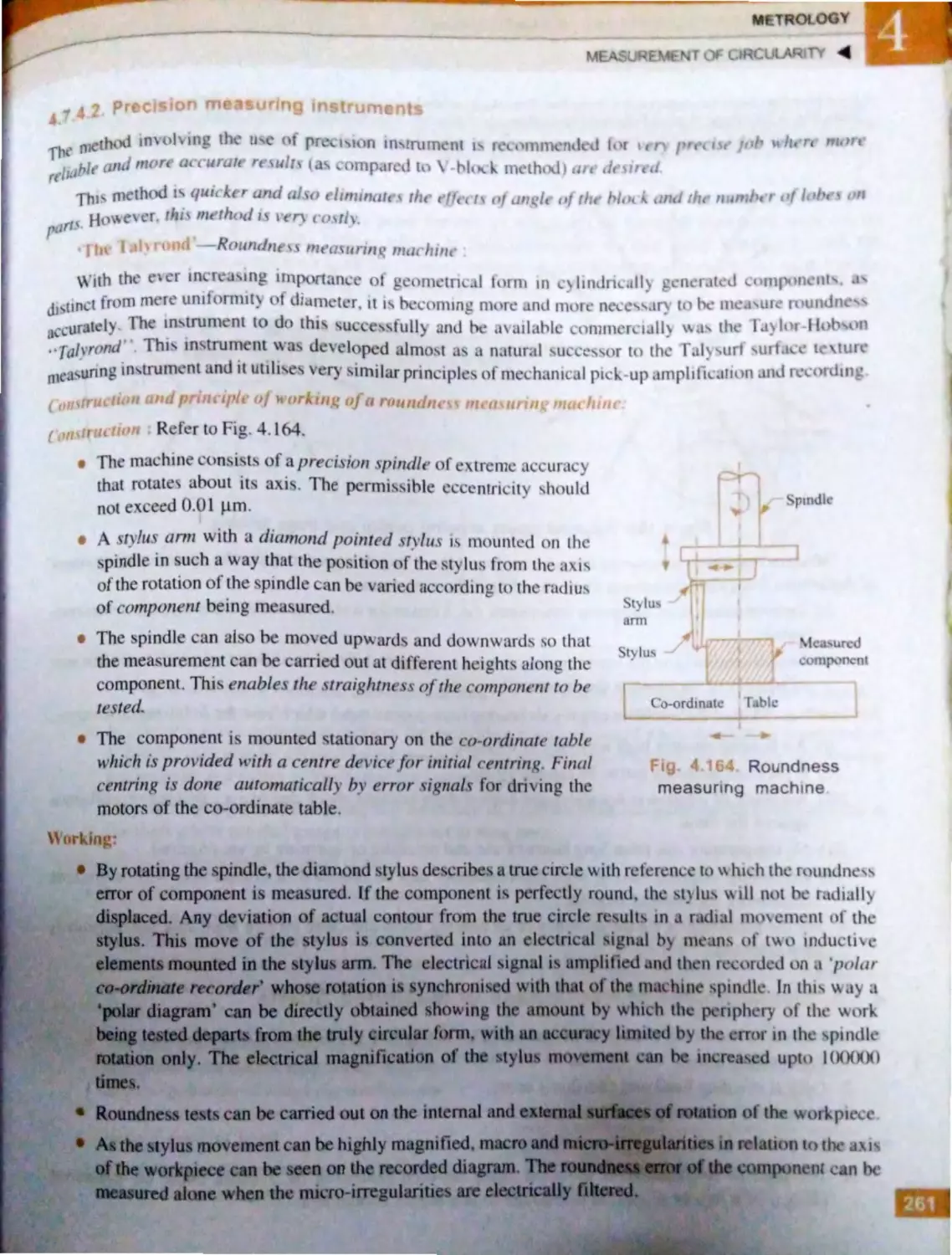
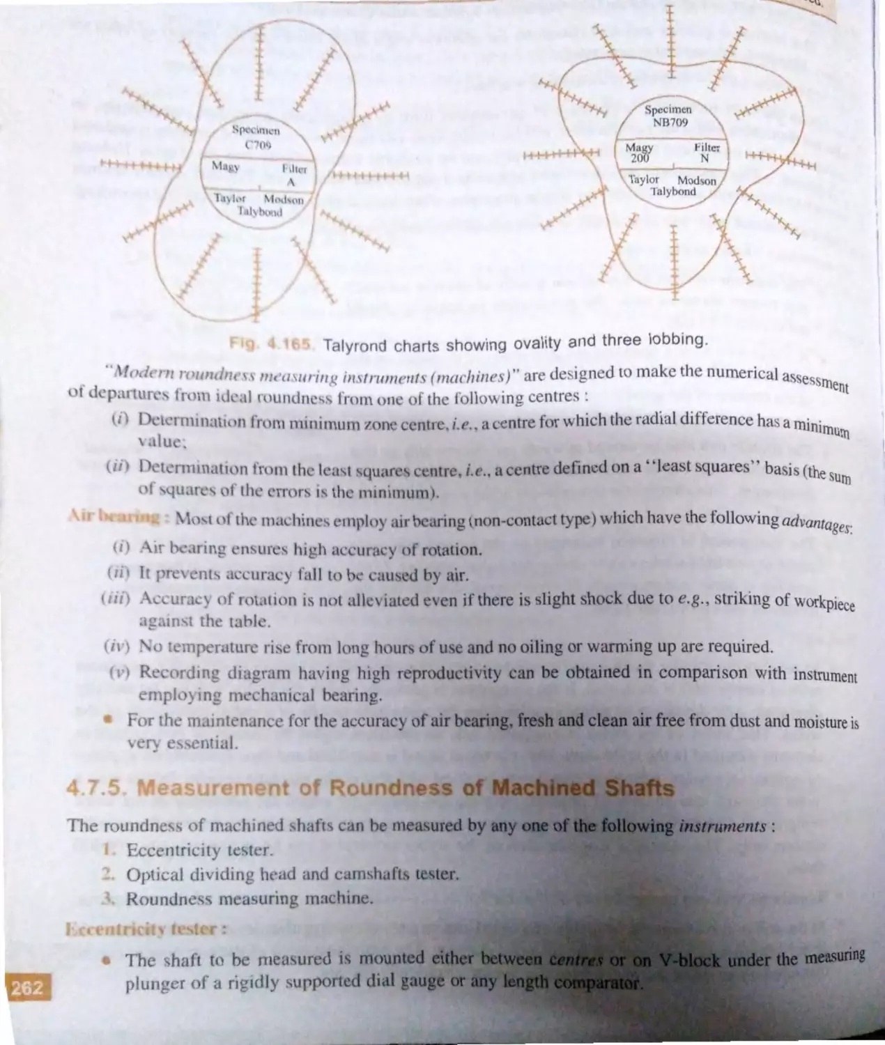
4.7 .4 . Measurement of circularity-
devices used .......................
4
... . .........
).
-L' .~.L Di· l ind, ·t11 r ............... _
1
➔
..,
comp·
·tt
r .... ........ ........ 2 7
. 5.3. ig
tc r ......... 1 6
.(
.:
.4. Joh
1kmor· . ..
2l
1.8.5.- .
ivmtg!-anddis-
' J ·antae-' ·
·m
·hanic, I
......... ......... 27
4 ..6. pti a]
4.(
.6. l.
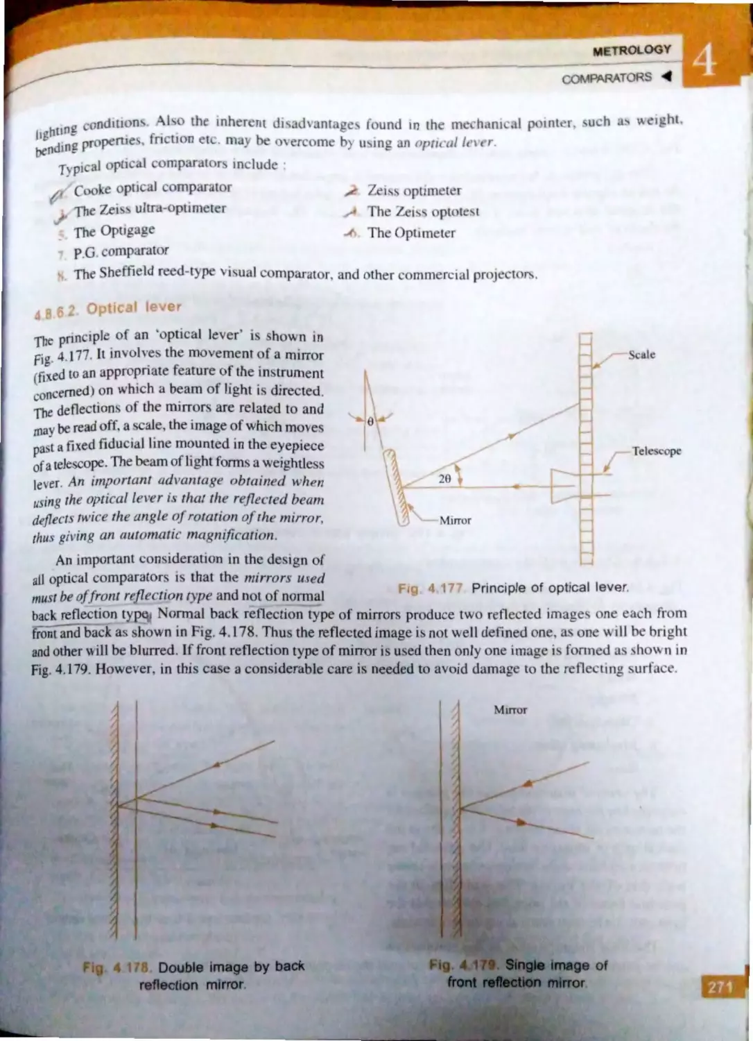
.6..... ptic4' l k, er .................. 27 1
4. .6.3. imple pti ·a l
comparator ..................... 27 _
4.8.6.4 . ook pti al
comparato ............ .. ....... 272
4 ..6 .5 . Zei~ optimet r .............. 27 3
4 ..6.6. The Zei ultra -
optim ter ... .... ................ 273
4.8.6.7. d ntage~ , nd di.auvan-
tage of opti al
c mparat r~ ....... ... ... ...... _7
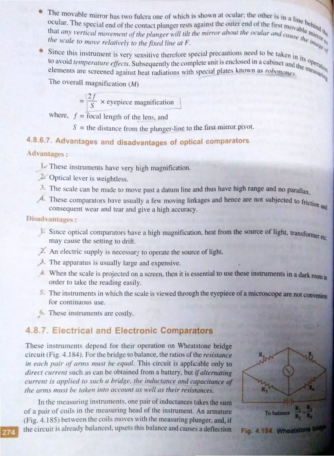
4. .7. El ctrical and electroni
comparator ..... ........ .................. .. 274
4.8. 7 .1. El ctrical comparator ... 27 5
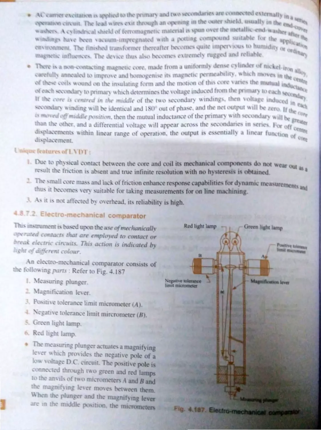
4..7.2 . El ctro-m chani J
comp rat or ... .... ...... ... .... . 76
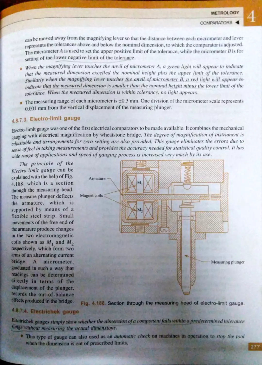
4 ..7 .3. Ele<.· tro-Jimit gaug .. ..... . 277
4..7 .4 . I ctrichek auge.-
. .... .... ... 77
4..7.5.
4.8 .7 .6. lectronic m a uring
quipm nl .... .......... . ... . .. .
..L
fini h
.. .... .
-.t- .9. _. l
- l.9. _ .....
.
.4. h
~·1m e ~n
lcn1th
t> tur
.9.6. lndicati 1n f ·u f
·
mb)I. u
4. .7.
4.10. pti ·al
4. J0. l. lntro<lu ·ri n ................°" •••
. j( ....
. JO.•.
. 10.
4.10.
4. IO._·-·
Itm·ntt.ls<fk..Jt
4.10.6. olJim tor ... ............... ............... 1 ·
4.10. - .
, utoc Him t r....... ........ - ...... ... ..
J11
4.1
.
trJl htne~ ". · fatne, .
quarns,nd
Parnileli m
... . .. ..... . .. . ... . .... ... ..... ......
-. 1l
..Ul.l. In rodu ti n .......... .............. ... ..... 31]
.+.1 l ,l,, .
trai Ohtnes. .................. . .............. _1 Ll
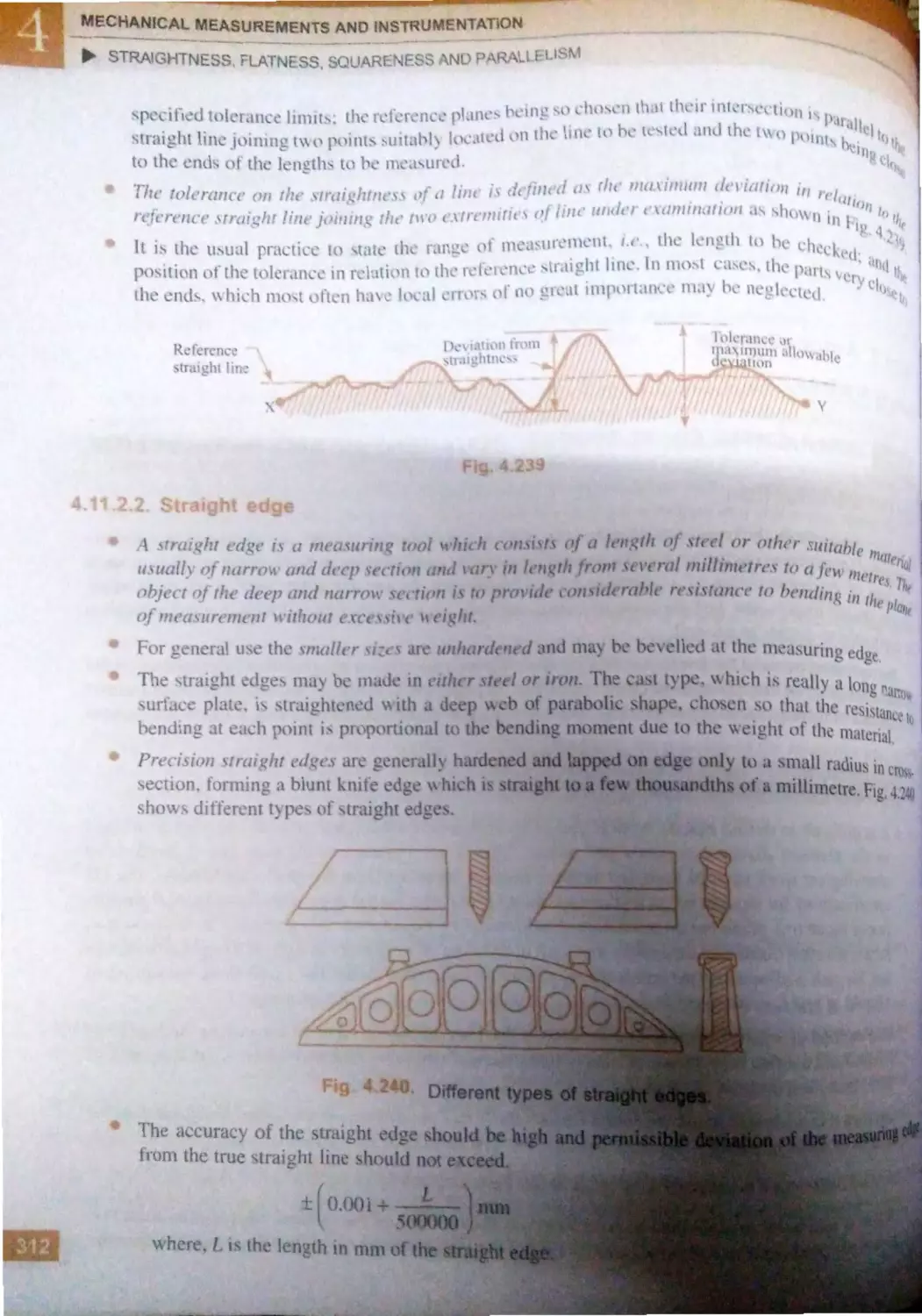
4.11 .2.1. Definition of , traightnc ..
of line in two plan ~.
.. .. 311
4.1 l.2.
.
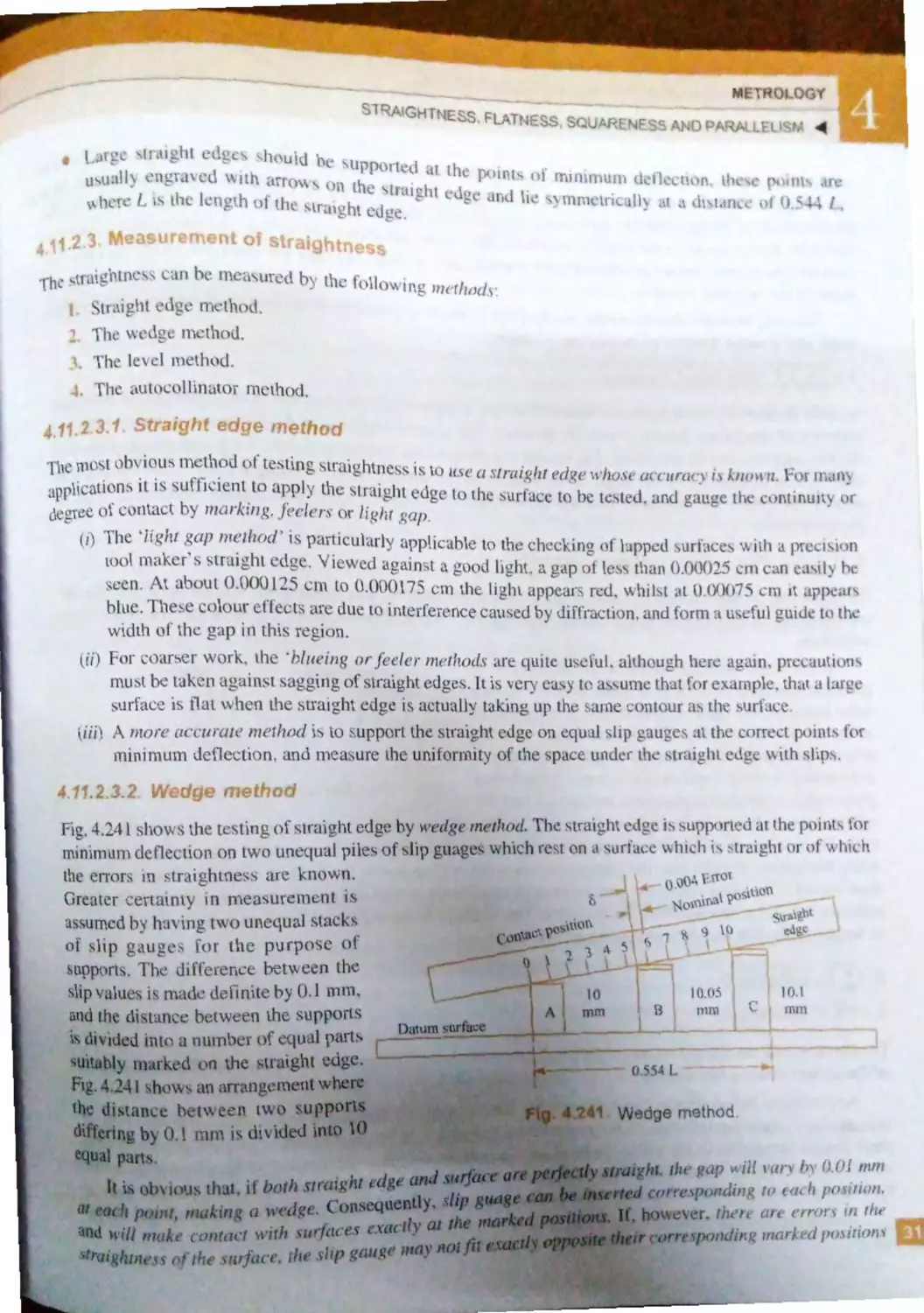
traight edge ..... .... ....... 312
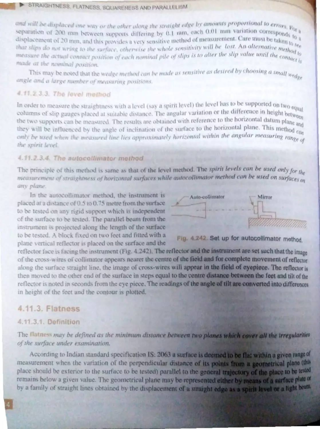
4 . 11 .2.3. Mea ·urement of
traightn s ..... .. ........ ... 313
4.1 1. 3 . Flatne s ............. ........................ 314
4 .11 .3 .1 . Definition ..... .. ............. 314
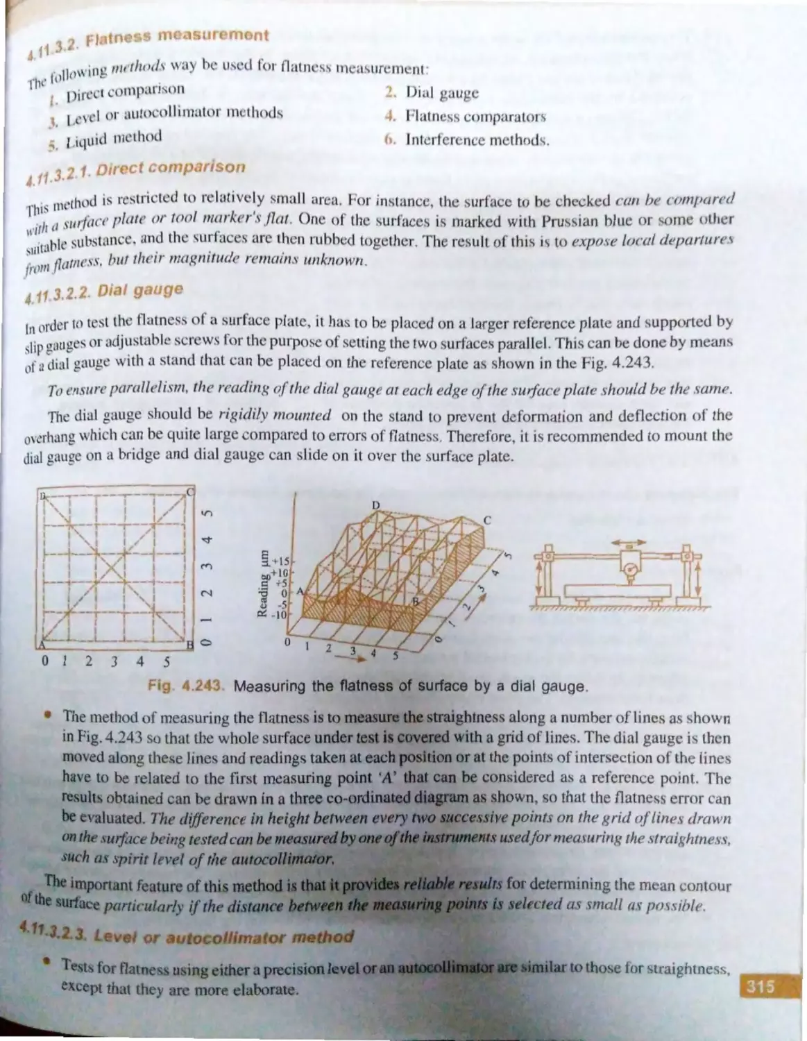
4.11.3 .2 . Flatness mea urernent.. 315
4 .11 .4 . Squareness ................................... 319
4.11 .4 .l . Engineer's squares ...... . 3 I 9
4.11 .4 .2 . Indicator method ...... ... 320
4.11 .4 .3 . Autocollimator
methods ....................... 321
4.11.5 . Parallelism ................................... 321
4.11.5 . 1 Different ca e of
paralleli rn of lines
and plane ... ............ ... .. 322
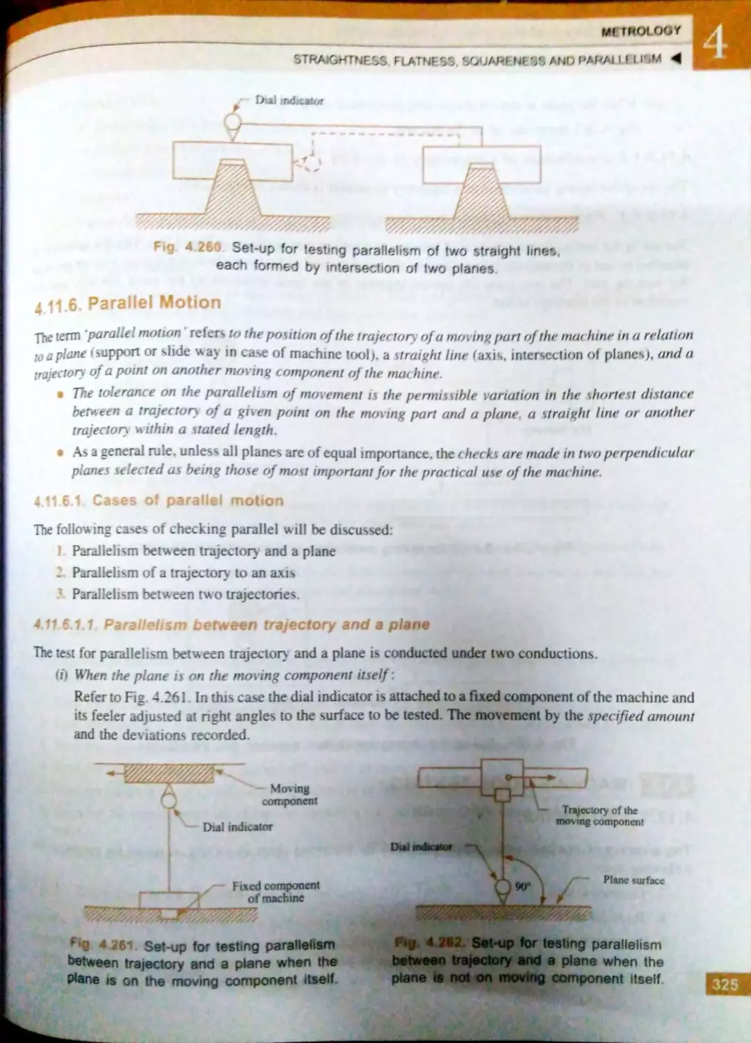
4.11.6 . Parallel motion ............................ 325
4.11 .6 .1 Ca e of parallel
motion ............. ............ 325
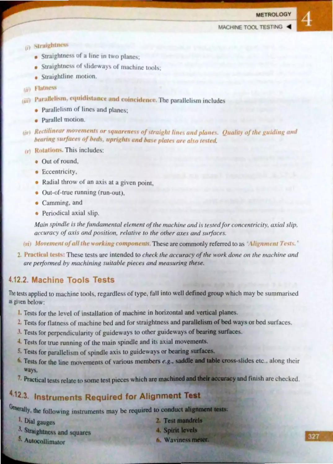
4.12. Machine Tool Testing .................. ... ........ 326
4.12.1 . Introduction ................................ 326
4.12.2 . Machine tool tests ........ ..... ..... ..... 327
4.12 .3. Instruments required for alignment
test .............................................. . 327
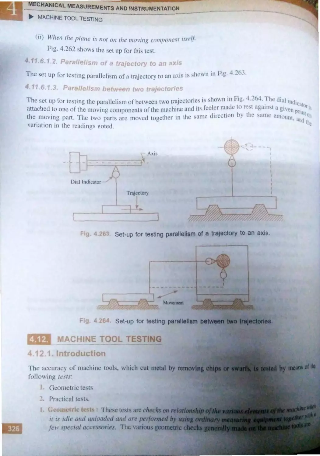
4.12 .4 . Alignment tests on lathe ............. 328
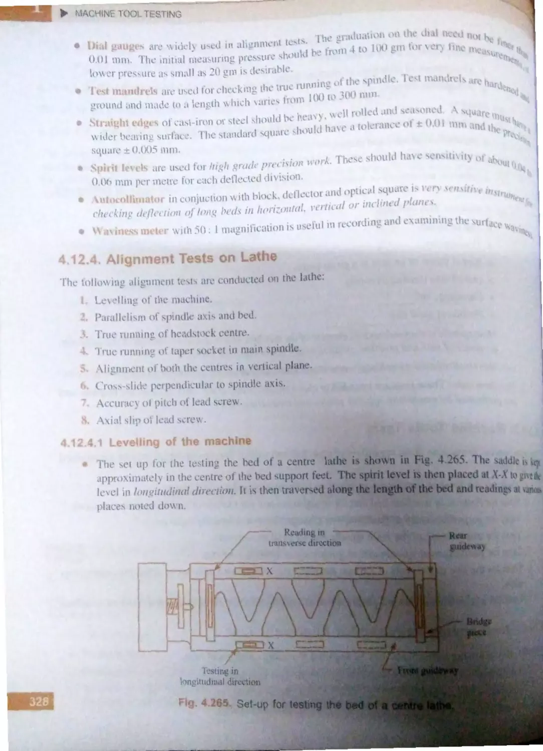
4.12 .4 .1 . Levelling of the
machine ....................... 328
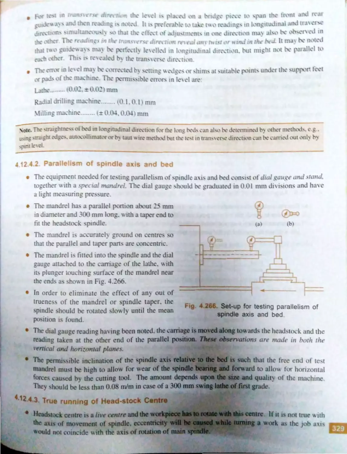
4.12 .4 .2 . Parallelism of spindle
axis and bed ................. 329
4.12 .4 .3 . True running of
head-stock centre ......... 329
4.12 .4 .4 . True running of taper
socket in main
spindle ......................... 330
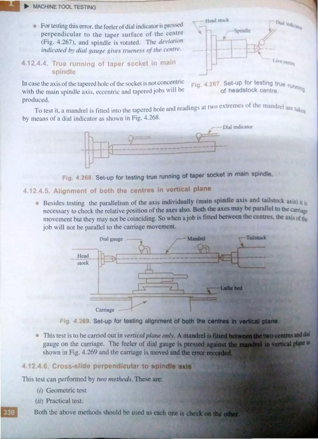
4.12 .4 .5 . Alignment of both the
centres in vertical
plane ............................ 330
4.12 .4.6 . Cross-slide perpendicular
to spindle axis .............. 330
. t 24, . , ( ·ur.c~ol'pnrhJJt
l
4.t ~-
.
ii1{1pl)
It ..lU
4.12 . . Ali nm ·nt t '"l ()ft dtitf11.1 •
m ·1c hint-;
... ..
.. .. ....
...
.. ...
. ....
-
~ L,•
4. ' - ·~.l. Itrnml'nth onpIIJ1
tYIedillin~madii ..s '
4.l .
·"·
hnm ·n tl ~t nt1r1fial
dnllin<1 rnadltn ·
..... , ..
·J
..J-.1
.6. Iinmnttest\t11
mill in 1 ma ·hin e ....... .. ..... ......... 3 7
4.12.6.l . E~ccntricity ol l \l n .ii
diamet r .. ...... ..... .. ... ..
7
4.12 .6 .2. Tru, unnin 7 of it t 'lll'll
tap r ............... .. .. ..... .... . : ~ !
4. J2.6.3. Work tubl · ~urfac · 1amtk I
with arb r rbin ' tm an.b
overann ........ .. ... .. .... .. ... ~ ~
4.12.6.4 . Surface par~llcl with
longituJinaJ movern ·nt J38
4. l2 .6 .5 . Traver: mov '111 ·nt paraJl ·I
with spindle axi~ . ... .. .. .. ,
.
(J
4.12.6.6. entral T-sll t, parnll •I
with lon gitudinal
mo cm nt .................... ~. 9
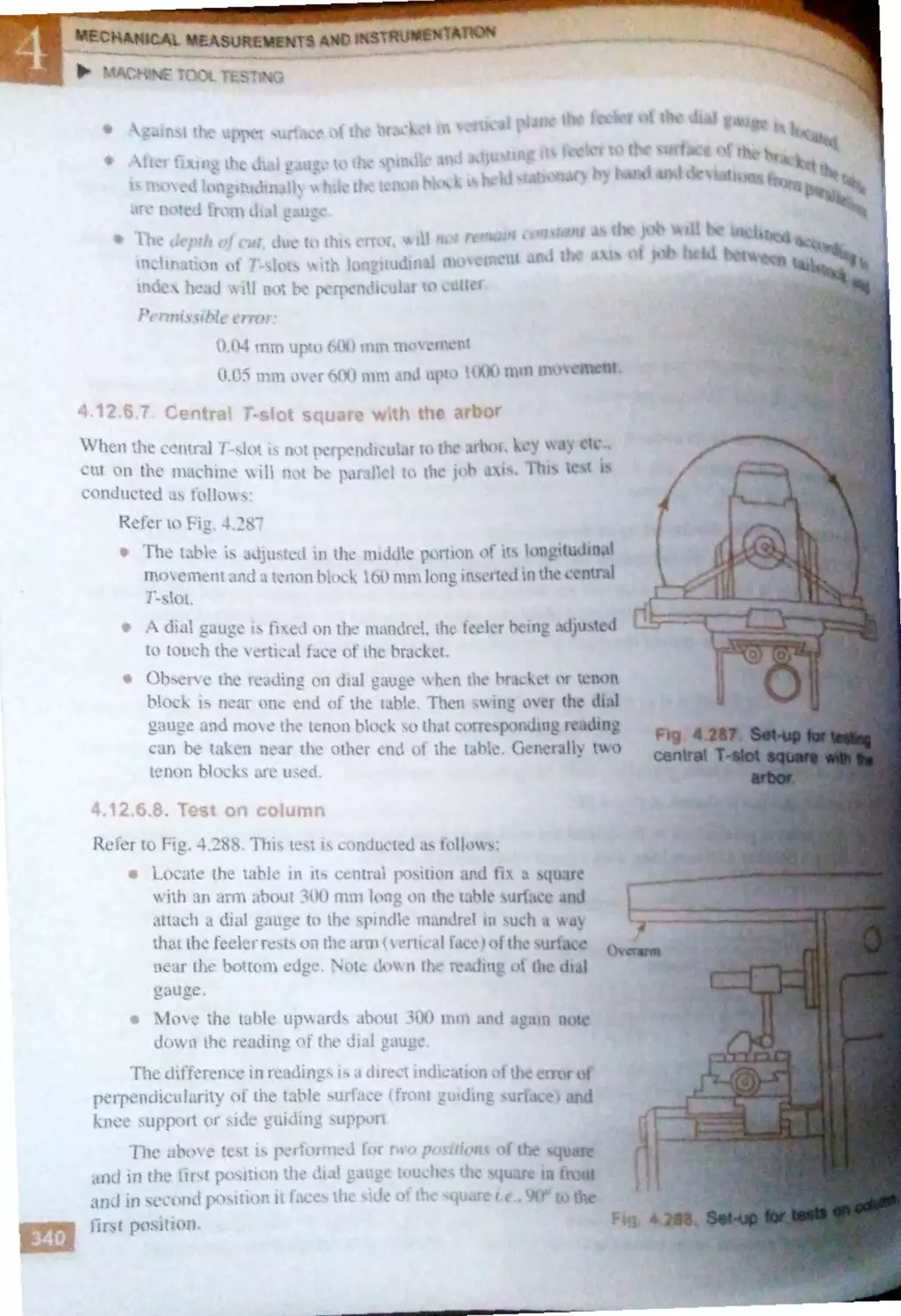
4.12.6.7.
ntral T-. Jot square ith
the arbor ...................... . ~ 40
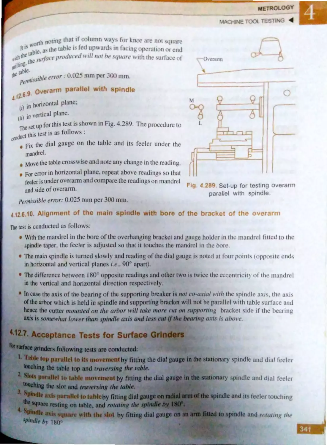
4.12 .6 .8 . Te ·ton column ............ . 40
4.12 .6 .9 . Ov rarn1 pnrall J with
spindle ......................... 341
4.12.6.10. li 0 nm nt f th • main
pindlc with bor of th- .
bracket fth ov rnrm .34l
4.12 .7 . Ac pt ·m t t forsltlface
grinder. ..................................... 341
4. L . . 8 . Practical t sts ........... ................... 342
4.13 . Miscellany
................................. .... 342
4.1
. I . Profile projector ... ........ ...... ... . .. .. . . 2
4.13.2 . Co-ordinate measurin ma 'hin
(CMM) ......... .......... .................. 34.,
4.13.3. Combination set ........ , ................. 344
4.13.4 . Surface plat ................................ 344
4.13.5. Precaution and care/maint n· n
of commonly used measurin
in truments .................................. 4
········ ··· •···· ·· ·· ·" ····· · -
)
n ..... ... .. .. ......... .............. .... ... .. . 7--l
-Trn·du' r
······ ······· · ·•· ····· ...... . ....... .. . . ...... .. ... 75
6
:.4.1.
rtrandu·ere..... _7
El tro-
r
.... . ........
_7
hani.m
.... . ...
0
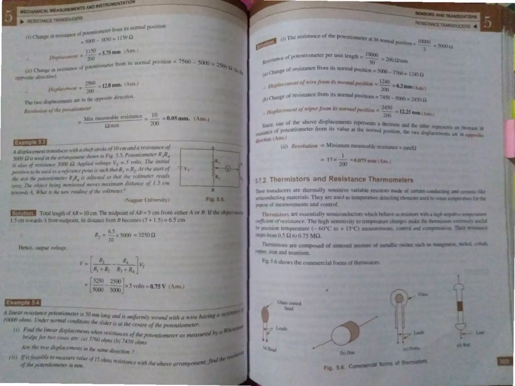
R·i.tancTra
... .. ...... ... ....... ... .. . 3
0
-.7.1.
p tenti
.. ...... ... . .... ..... ..... ...
.I
5.7.2. Th rm·
nd r :,,j ·urn
therm n1 ters ............ .. ........ .. ....... .
5..3.
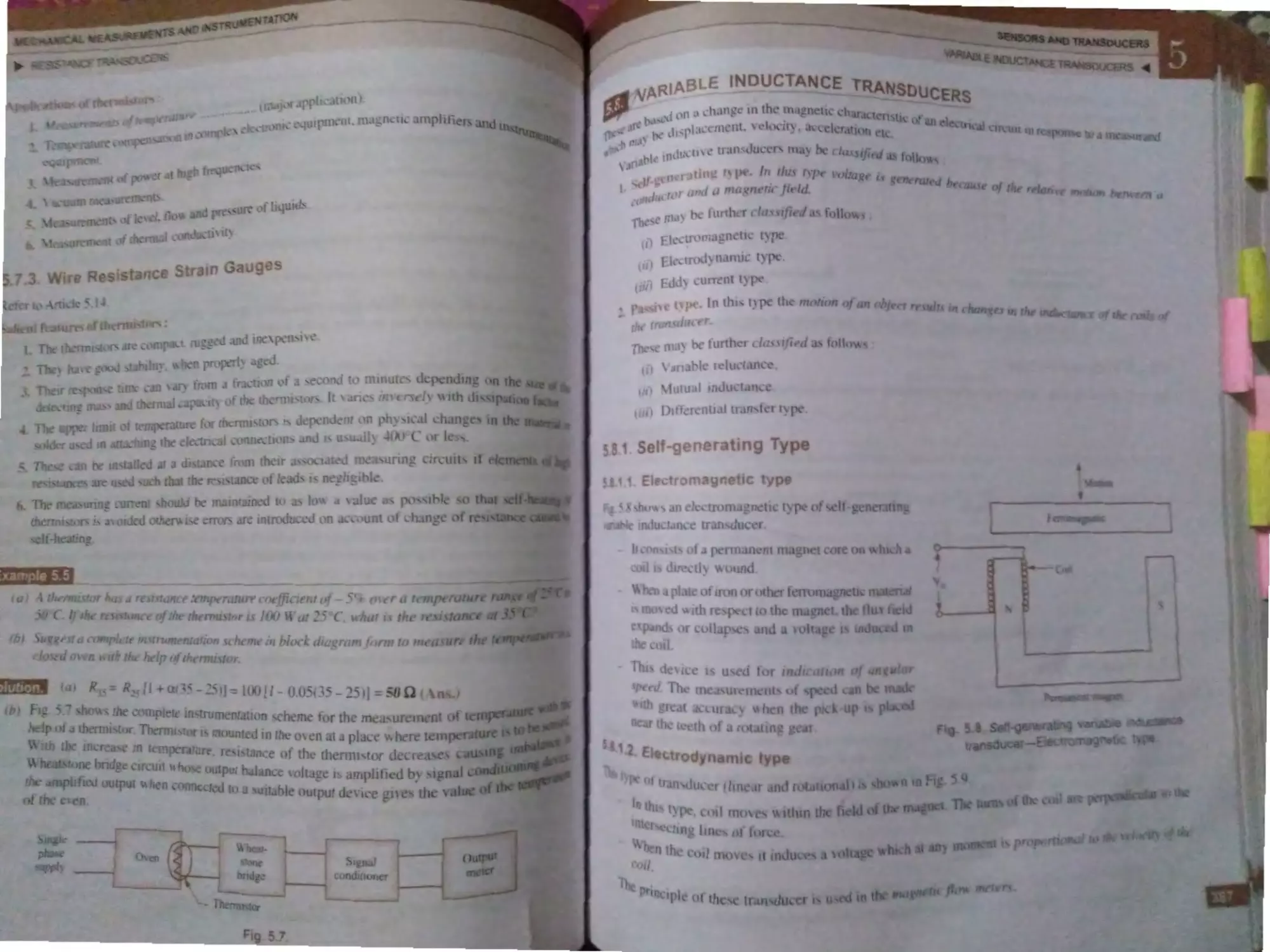
· ariab1e lndu tan Tr n , due r ........... .
·-.
.1 . If- n rating type ........... .........
.
. J.1. El tromagn ti · type ... 3
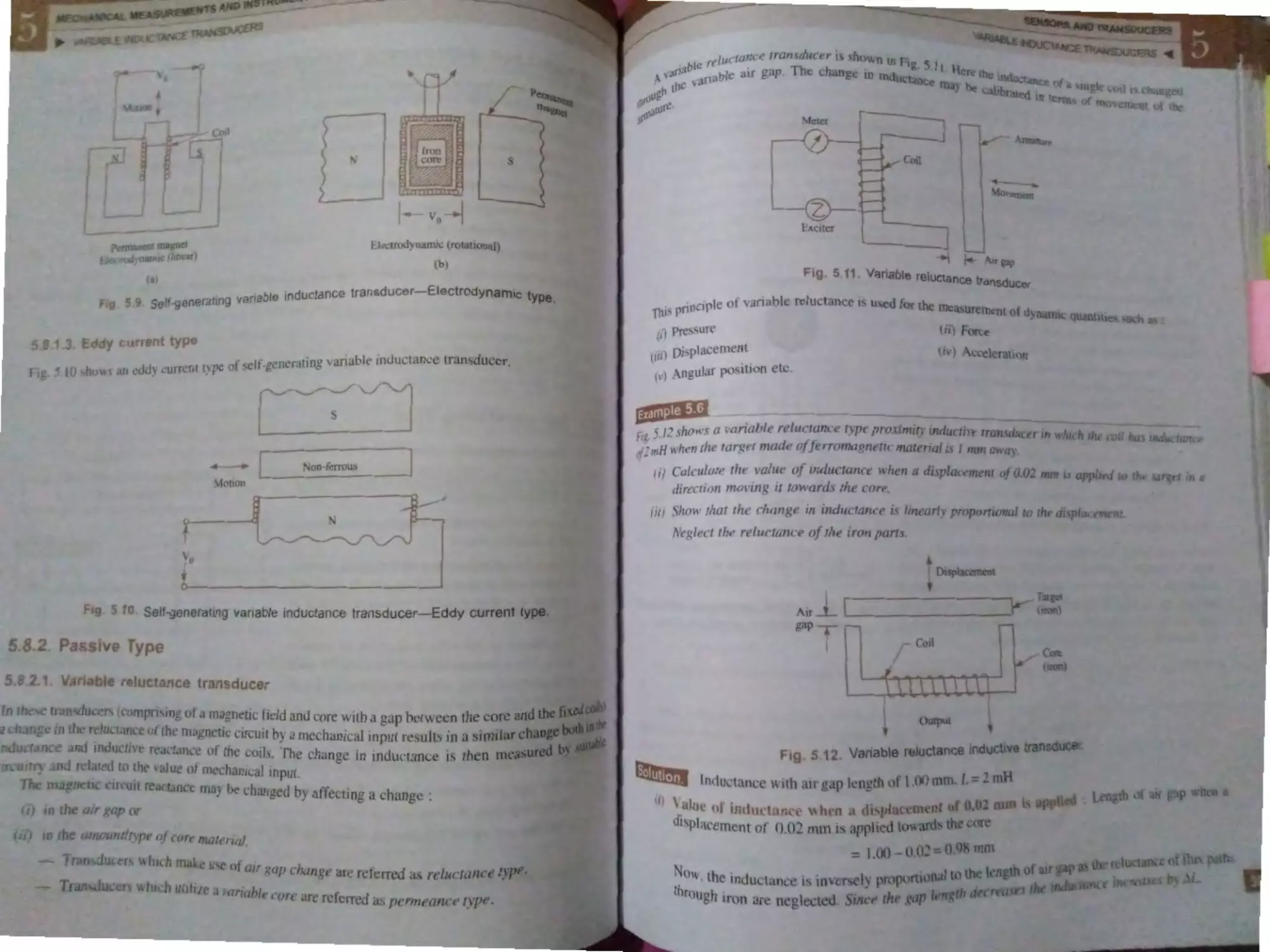
5..1.2. El trod nami t pe ....
_
5.8.1. ~. Eddy urr nt t pe ......... _
,..
. 2. Pru i t_pe .......... ......... ............. 3
5.8 ..l.
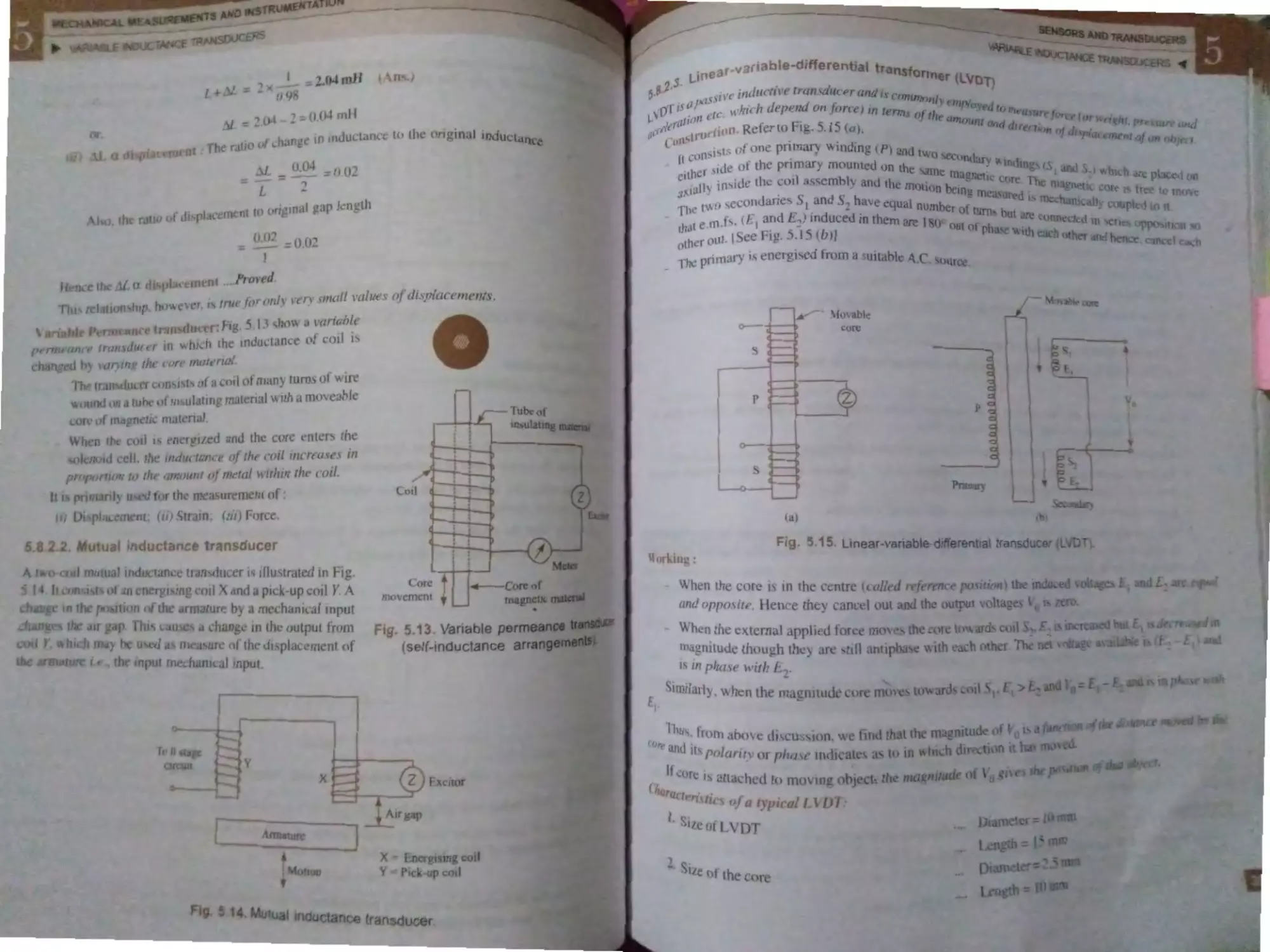
'ariablrlutne
tran ducer ... .. ............. ..
-.l
. f ).....
•l,.
•I
..
.,I
~.1l h
:.1. ..
-
. 1• ......
.l~
·.- .
~-. 14. truin
.14.l.
,.l
·-·
11,ortialQ ·
..... .. .... ........
l n oll'ed · ampler .... .....,., . ..... .... . ..
S NAL CO DfOONING AND
OAT. TRANSMISSION .................... 429-454
Intr )duction ...... .. ....... .... .......................... 4 ~9
.~.
Func tion . f Signal Conditionino
Equipment .. .. ...... .. .. ........................... ...... 4 _ O
.
A mp1ificnti n ............. ......................... . ... 432
6A. Ty p , f Amplifier. .......................... ...... . 433
...
1echani al mplifier · ........ ..... ...... .. ....... 433
,<i. Fluid Amplifier.·
...... ..... . .. .. ... . .. ............ .... 433
Opt ic a l amplifier ..... .... .. ... ... ................... 434
6. . Ele tri caJ and EI ctronic Ampli fiers .. ... .. 434
6.8 . l . De irable characteri s tics of
eJ ctronic am plifier ....... .. ... ....... 434
6.8.2 . Electronic amplification gain ..... 434
6. .3 . A .C . and D.C . amplifiers ............. 436
6 .8.4 . Modulated and unmodul ated
signals ......................................... 436
6.8 .5 . Integrated circui t (ICs) ....... ........ 437
6.8 .6 . Operational amplifier (Op-amp) 437
6.8.6.1. Op -amp description ...... 438
6.8.6.2. Applications of Op-amp 439
6.8 .6.3 . Op -amp circuit used in
in trumentation ............ 439
6.8.7 . Attenuator .................................. 443
6.8 .8 . Filters
.................................. . ...
444
6.8.9. Input circuitry ............................. 445
6. 9. Signal Tran mission ................................ 446
6.9.l . Mechanical transrni sion ............ 447
6.9 .2 . Hydraulic transmission ............... 447
6.9.3 . Pneumatic transmi ion .............. 448
6.9 .4 . Magnetic transmission ................ 448
6.9.5 . Electric type of transmitters ........ 448
6. J0. Converters
..................... . ................ 449
6. ll. Telemetring
.... .. ............... .......... .... ... 449
Highlights
...................................... 450
Objective Type Qu estions ........... ...... .. ..... 450
Theoretical Questions ............. ... .......... ... 453
7. DISPLAY DEVICES AND
RECORDERS
........................ 455-498
7. . Introduction ............................................. 455
7. 2. EiectricaJ Indicating Instruments ............ 456
7 3. Essential Features of Indicating
Instruments .... .......................................... 458
A.
7.5.
CONTENTS xi
•
-1
•
4)9
7.3.l. Ddl etJn_ u ~ 1·e ... .. ..... ...... ... .... .
·
7.3 .2 . Conlrolli~g devic ·s
.. . ... ..... ........
5
Dr1n1p1·n 1 d ~ j~cs .... .. •• .. ·............ ..itO
7.3.J.
-
. 463
nalog l nstrum ·nb ...... ... ...... ••.. .. •..... ·..
7.4 l . Mo ing-iron in trumcnts
( mmcler anJ oltrn t --rsJ ......... 46_
7.4.1 . l. Altrnction type .. ... .. ..... . 4('L
7.4.1.2. R pulsion type ... .. ........ 464
7.4 . 1.3. Advantage<; and disad n-
tage:- .
of moving-iron
in~trumcnt~ ............... .. .. 465
7.4 .1 .4 . Source. of error .......... .. . 465
7.4.2. Moving-coil in . trum nt s ............ 466
7.4.2 . 1. Pe1manent- mag n e l moving-
coil type (PM MC)
instruments ... ........... ..... 466
7.4.2 .2 . Electrodynamic or dyna-
mometer in truments .. .. 473
7.4.3. Rectifier instruments .............. ..... 477
7.4.4 . Wattmeter ....... ..... ...... .............. .. 479
7.4 .5 . Megger ...................................... 480
7.4 .6 . EJectronic in ulation te ter ......... 481
7.4.7 . Multimeter (AYO) ........... ............ 48 l
7.4 .8 . Electronic voltmeter ............... ... 482
Digital In trument ..... .... .......... .. ............. 483
7 .5 .1 . Light emitting diode (LED) ........ 483
7.5.2 . Liquid crystal di pla (LCD) .... 4 5
7.5.3 . Numerical indicator tube (NIT). 485
7 .5.4 . Hot film bar tube ..................... ... 486
7.5 .5. Digclampter ................... ..... ...... ... 486
7.5.6. Digital tachometer for r .p.m .
mea urement. ................. ........... .. 486
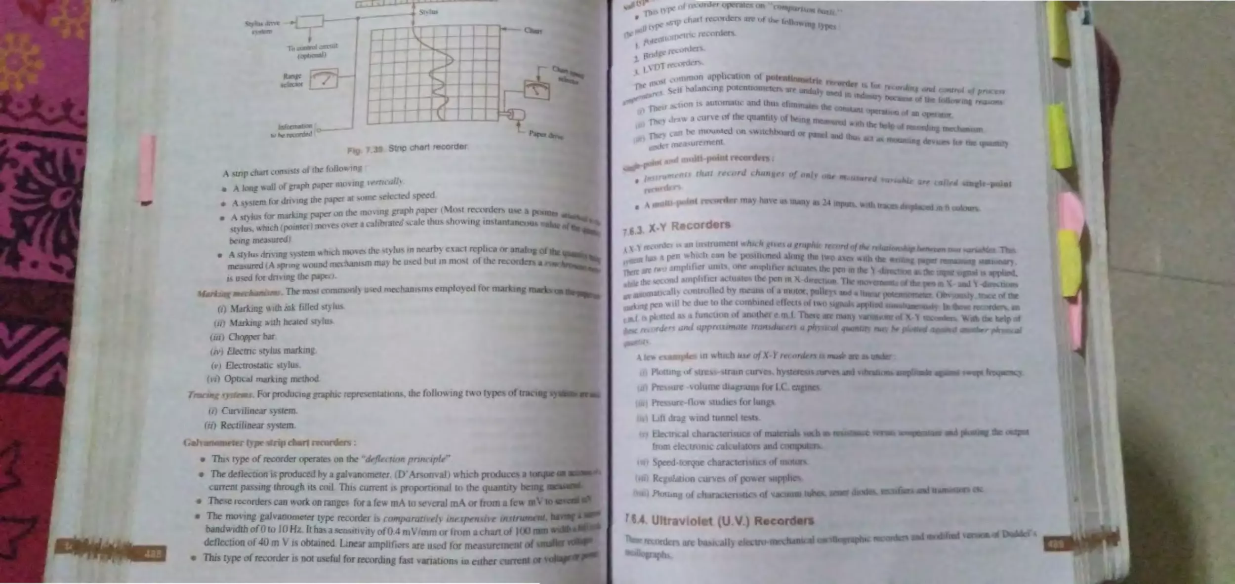
7.6. Recorder ................... .. ........... .......... .... ... 487
7.6 . l. Types of recorders ....................... 487
(
7.6.2 . Strip chart recorder .... .... ............ 487
7.6 .3 . X -Y recorders .............................. 489
7.6.4 . Ultraviolet recorder ................... 489
7.6 .5. Magnetic tape recorder .... ........ .. 490
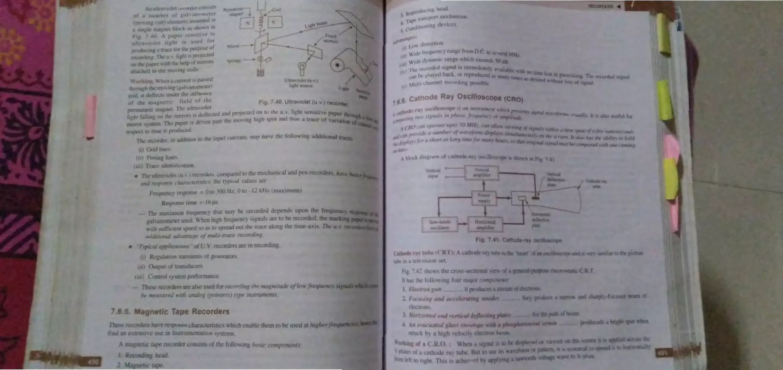
7.6 .6 . Cathode ray oscilloscope
(C.R .0 .)
....................................... 49 l
Highlights ................ ............. ................... 494
Objective Type Questions ........................ 495
Theoretical Questions ............................. 498
····· ····· ........ .... .
•
•
•
•
..
..
•
•
•
•
•
..
•
•
••
•
~....f
......... ......... .
~ ••••
Jl tlTl( !Tlt..'l I .. .............. ... ..
·
n ial m·m m1Ltcr. ...... ..... .. .
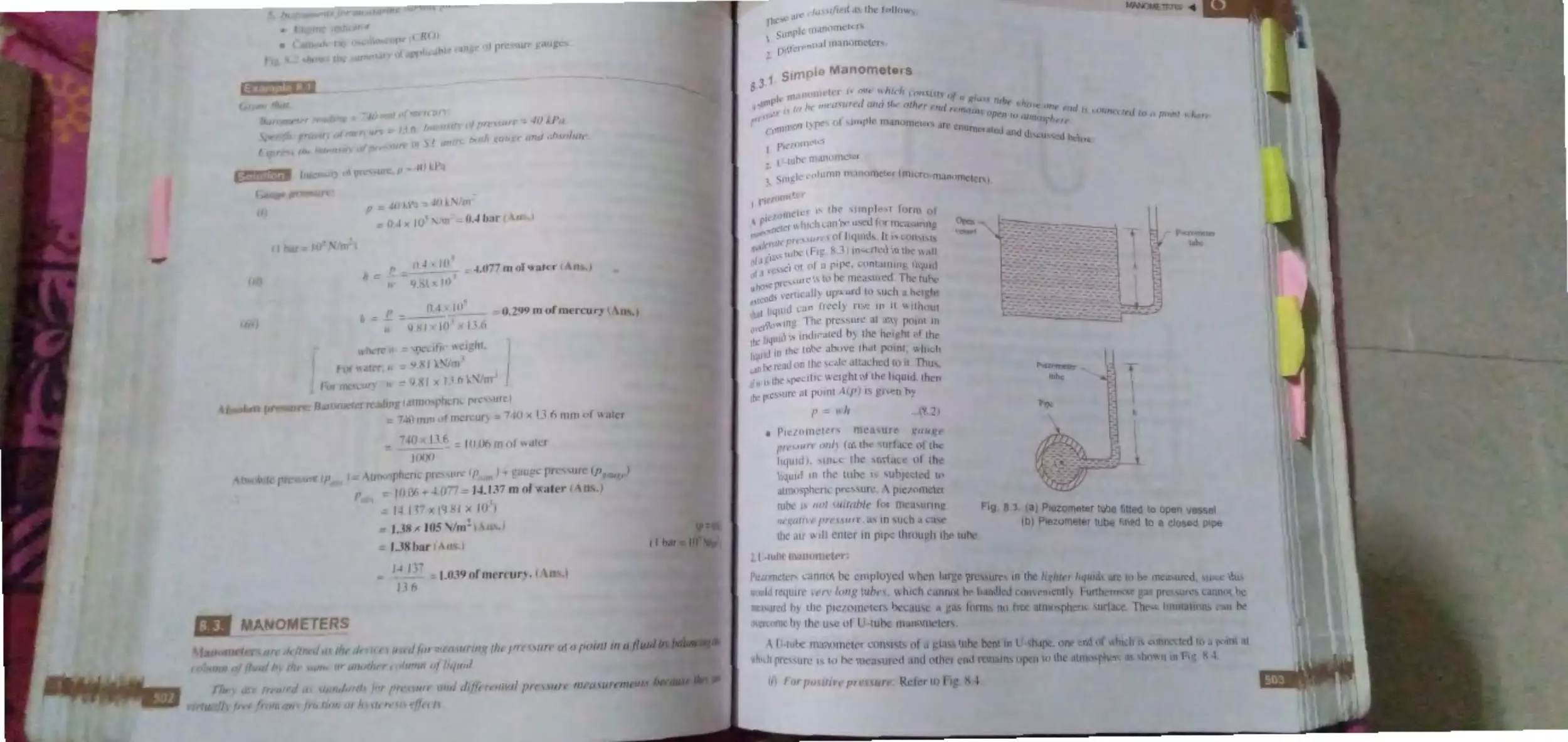
/.J .: . M till m ·tric Ii 1u1d ......... ............ 5 J
__
. 4. 1 - d antao ,~ dnd limitation >f
n an )111 tcr ................................. :- 1 -t.
Bell Gau~
-..
........ ......... . ...........................
514
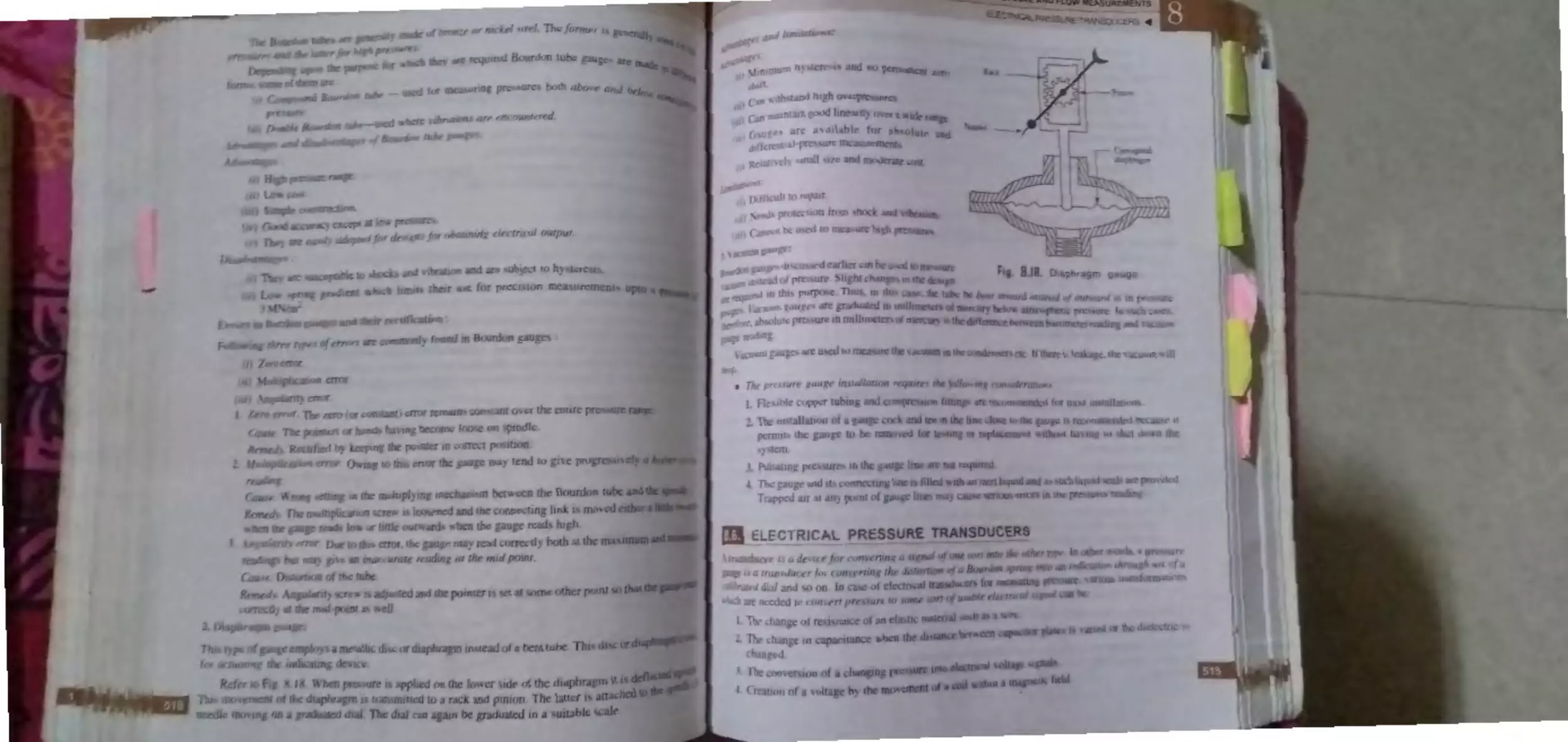
8.:. M chanical Ciuuge<-.
................................ . 5 14
8.5. l. E!a'-;tic pre~ . ure de, 1c1 t\ ............ : I :'i
8.5.2 . Pre . ·urc g:augc1.,
..........................
517
8.6. Electrical Pr s ure Tran- .duc ·r -,
..... ... .......
5I<
8.6.1. Re...,i. lance typ · pres ur~
tran du ·er...,
..................................
520
8.6.2 . Pressure-, olt, ge transducer~
(Potentiom ter de ic s) .............. 521
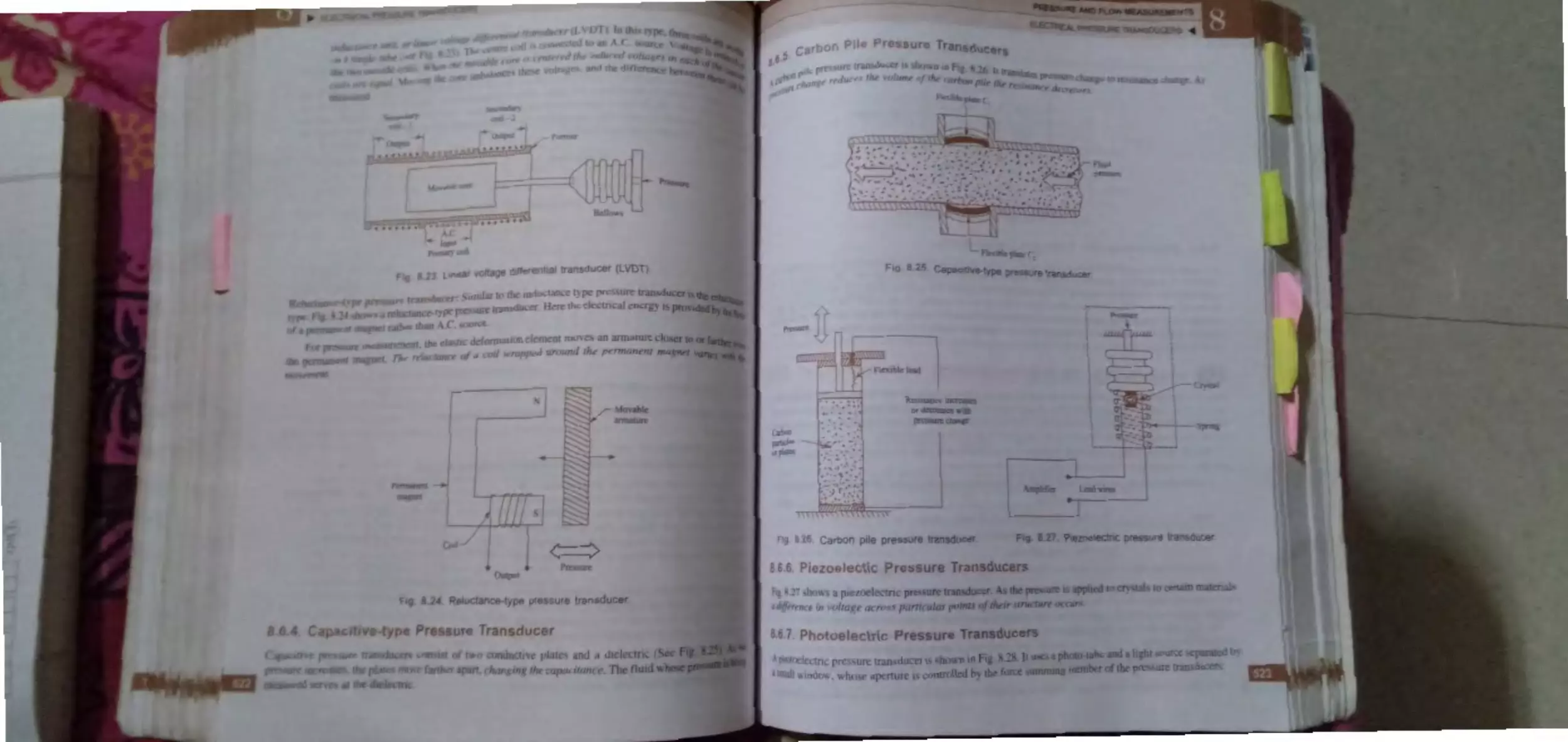
8.6.3 . Induct:.mcc-typ prcssur
transducer .................................... 521
8.6 .4 . Capacitiv -type pre:surc
tran . ducer ..................... ..... ........ .. 522
8.6 . 5. Carbon pipe pre. sure tran ·ducer. 523
8.6 .6. Piezoelectric pre. sure transducer 523
8.6.7 . Photoelectric pre. sure
transducers .................................. 523
8.6 .8 . Electromagnetic pres. ure
tran . ducer ..... ... ... ... ... .. ........ ... .... 524
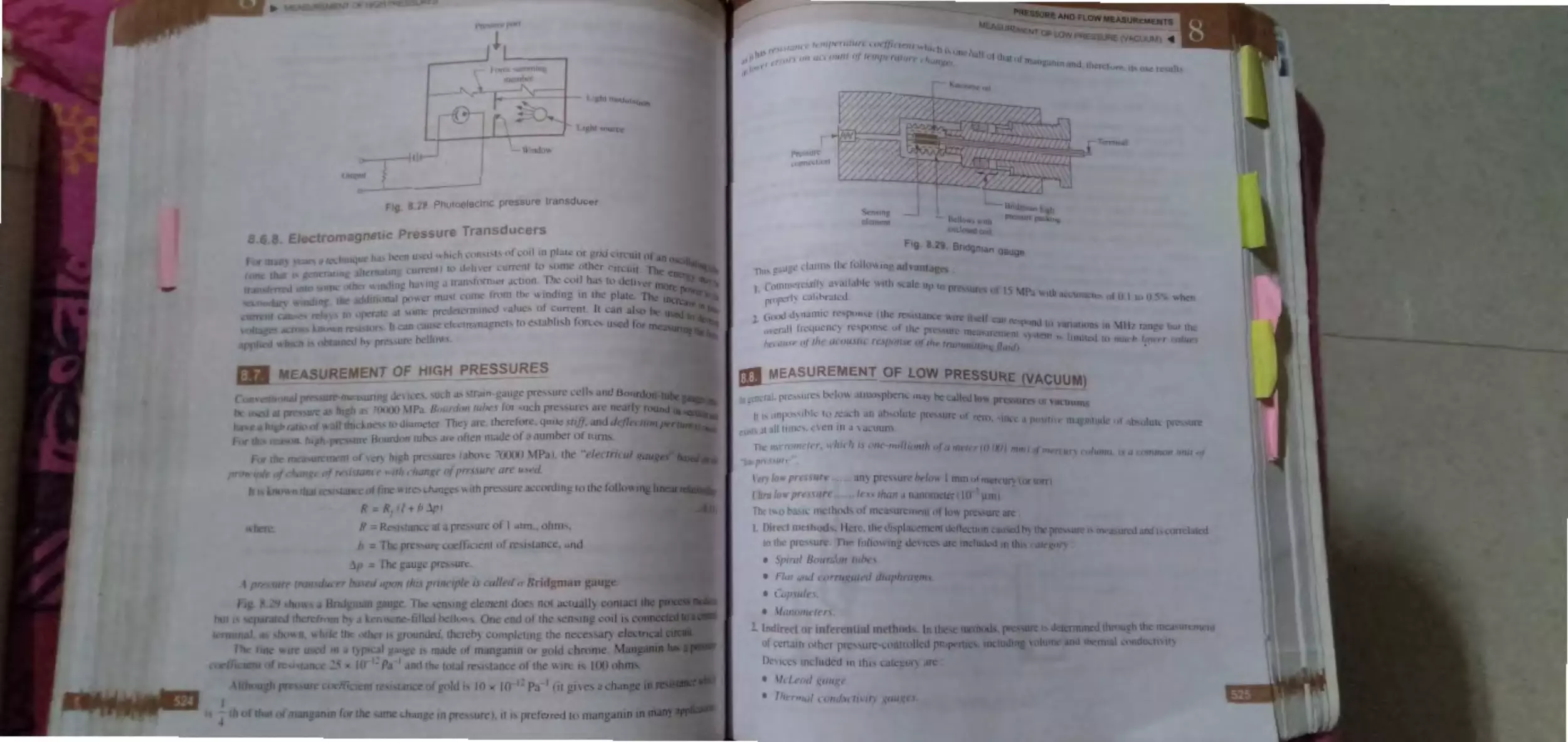
8.7 Measurement of High Pre sures ...... ........ 524
8.8. Mea urement of Low Pre~su re (Vacuum) 52
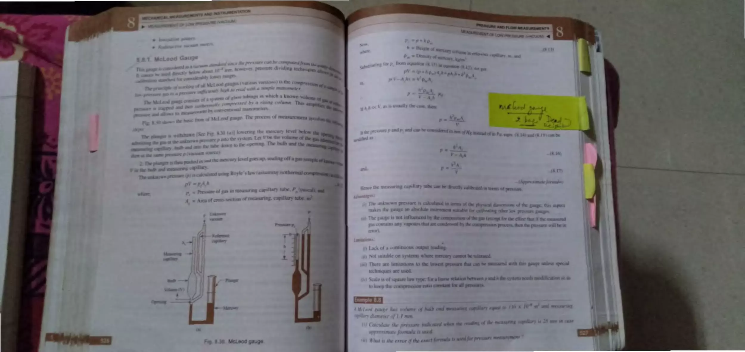
8.8.l. Mcleod gauge ......... ..... ............... 526
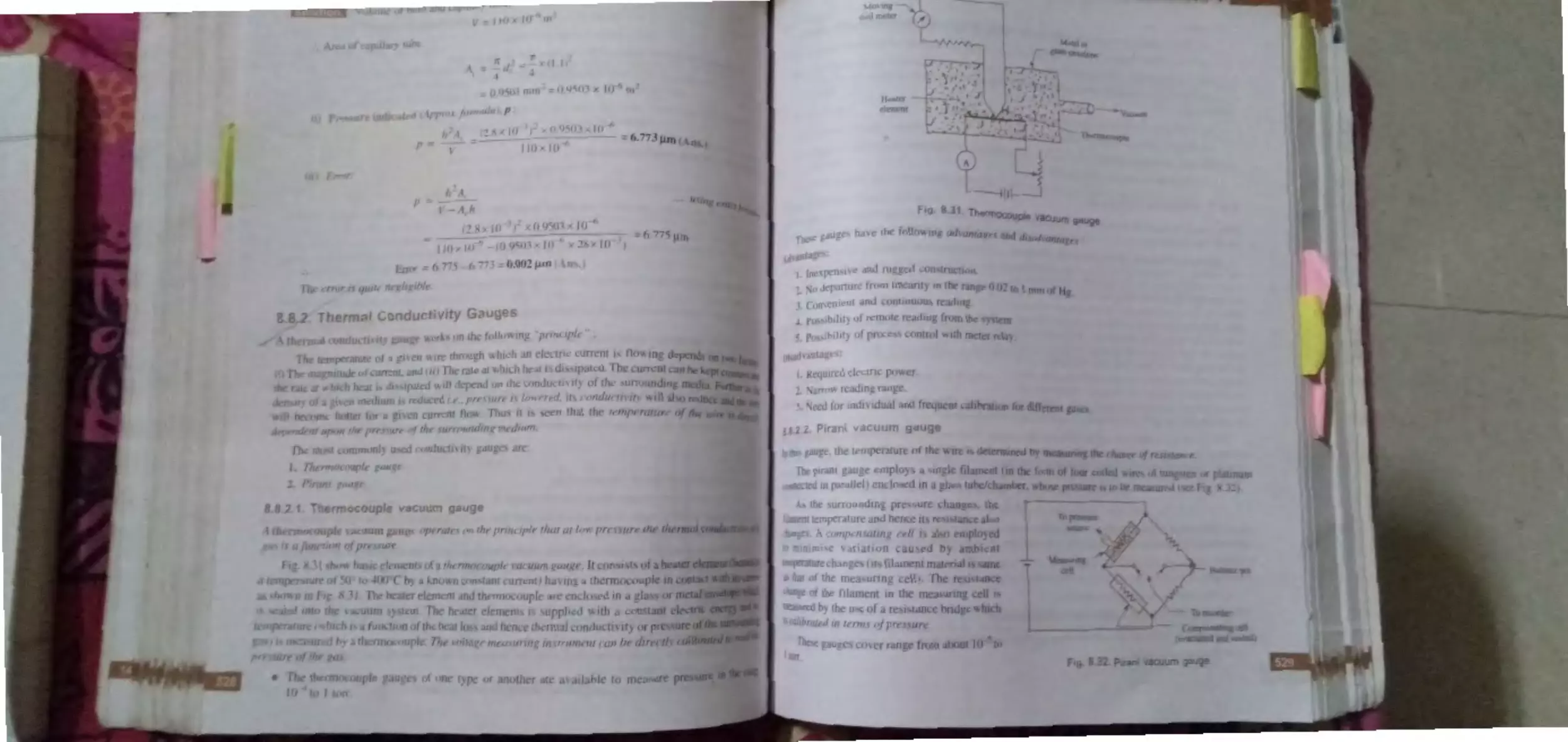
8.8.2 . Thermal conducti ity gauges ..... 528
8.8 .2 .1 . Thermo ouple vacuum
gauge ............................ 5:...8
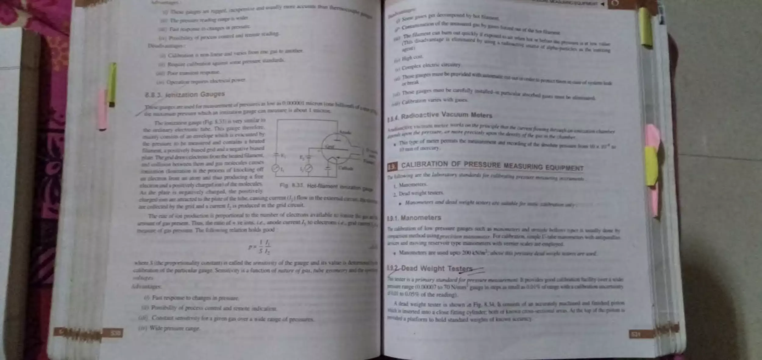
8.8.2.2. Pirani acuum gauge .... 529
8.8.3. Ionization gaug , ........................ 5 0
8.8.4. Radioacti c acuum meter ........ 5 _ l
8.9 . CaJibration of Pressure Mea urino
E.
quipment ...................................... ......... :3 l
8.9.1. Manometer~ ...... .. ............... ........ ..
-
l
8.9.2. D adw i...,btte,t ·r.
.... .......... .......
~31
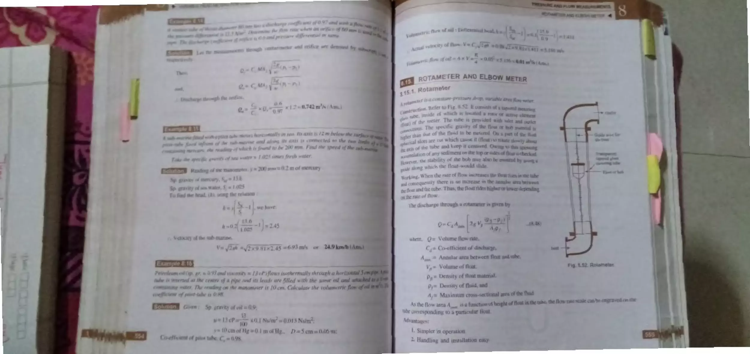
• R<tamtc.ran
.1 . r otamet
8.I
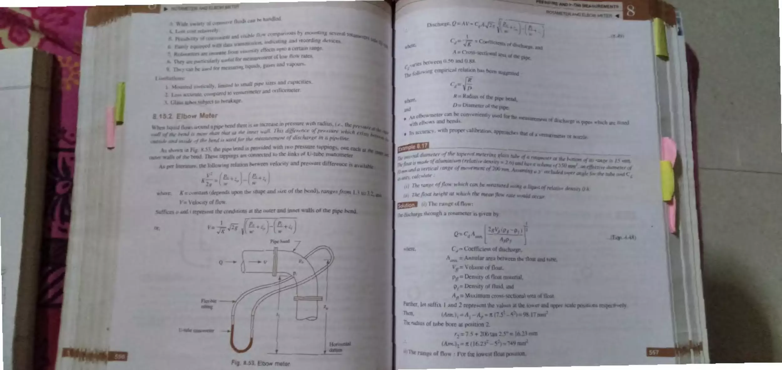
.2. Elh \\. mek r ... ... .................... .. : .
.1
.
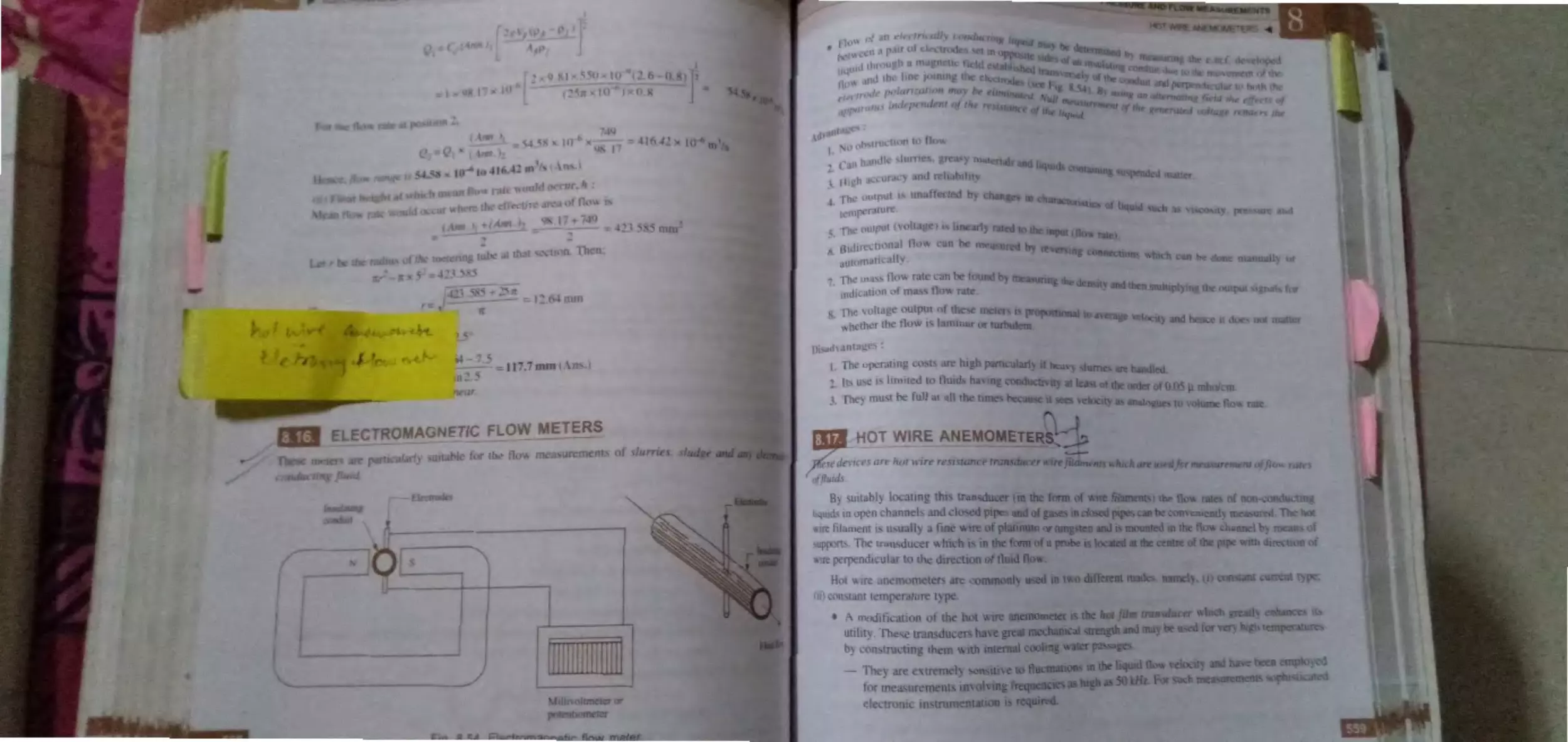
El 'ctrom·
_ncti·l\
H.17 HotWjre
)lll t·r
..........................
8. Cum.-: nt and urbin Ill\.:
·r
... ....... .... .... ..
8.1
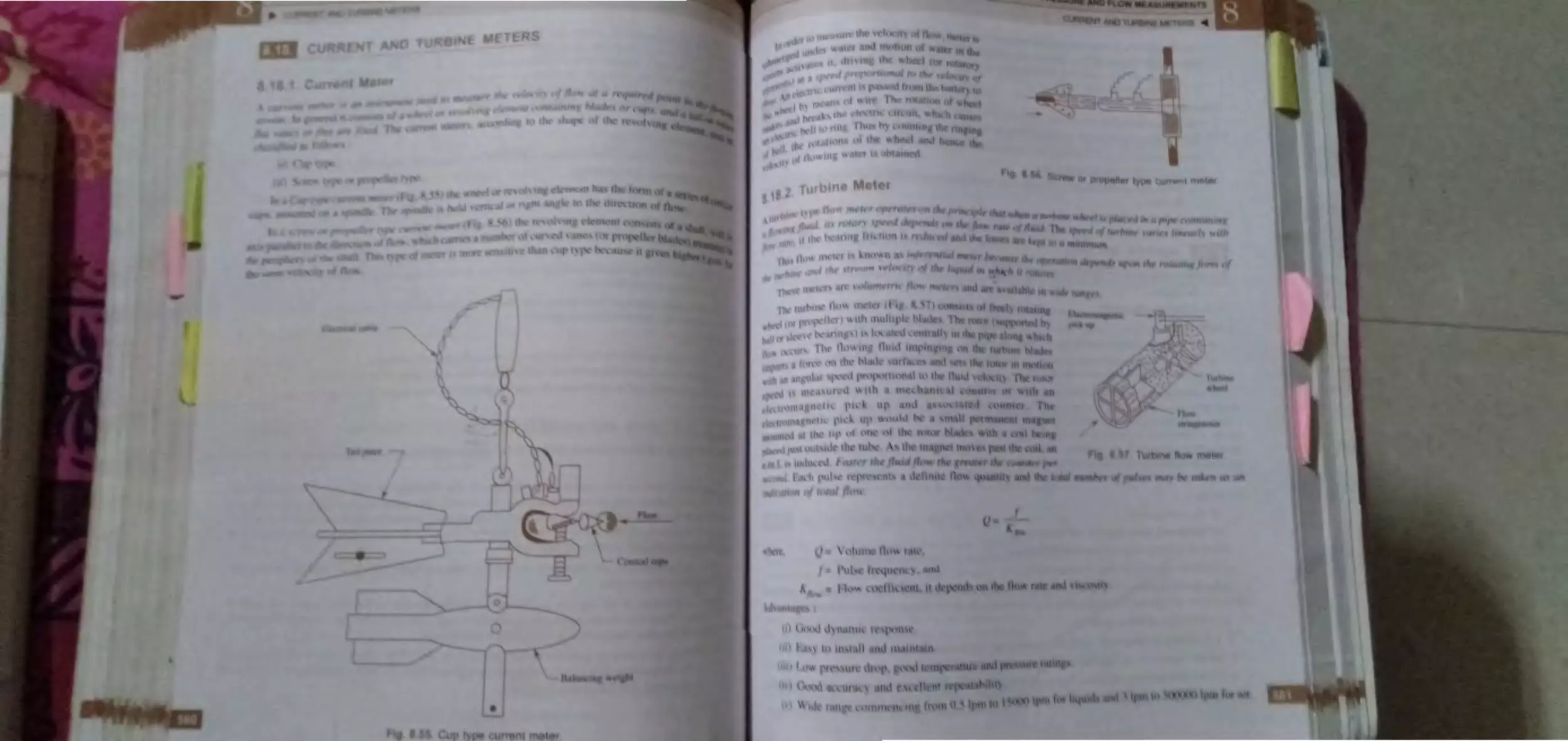
. 1. Cu ff n m t "r .. ...... ........ .. ........ ... 60
. 18.2. Turbin n
8.19. ort' ·, ete r: ...................... .... ............ ...
8.20. ltra~ nic
tt!r ...........................
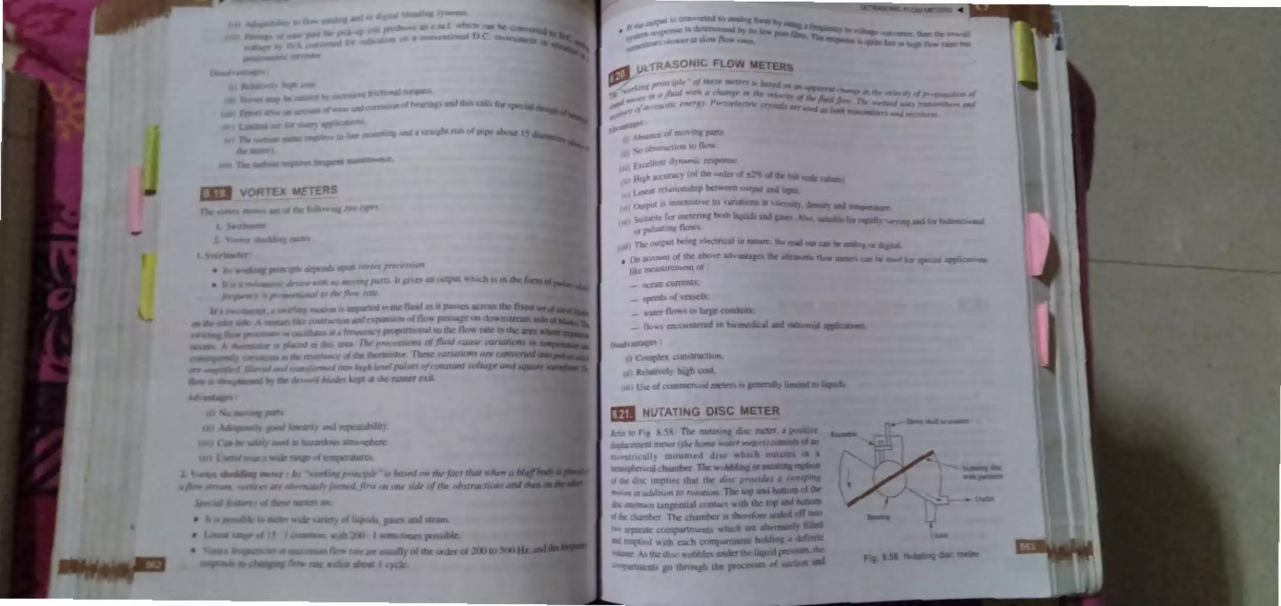
8.21. utating
er ......... . .................... .
8.22. Rotary Van
r ................................ ..
.2,.Lbeum
.................. ...
8.2. Flow \i ·u
~ ...................
·ti:
Hi1;Jz/;ghr · ... .......... ................................. .
Tlicoretil al
Un:ofr d E.wmplcs ......... .. ...... .............. . , 576
9. TEMPERATURE
MEASUREMENTS
9.1. Introduction ..... .. .... .. ............ .. .. .., .. ... .... ... 571.J
9.2. The lnt rnational Pra 'tiv I ·mp )r, tur
Scale ........ .. ...................................... , . . . .
()
9h . T "mperJture
9.
.
E ·pc.m ion Therm lm kr .... .. .......... .......
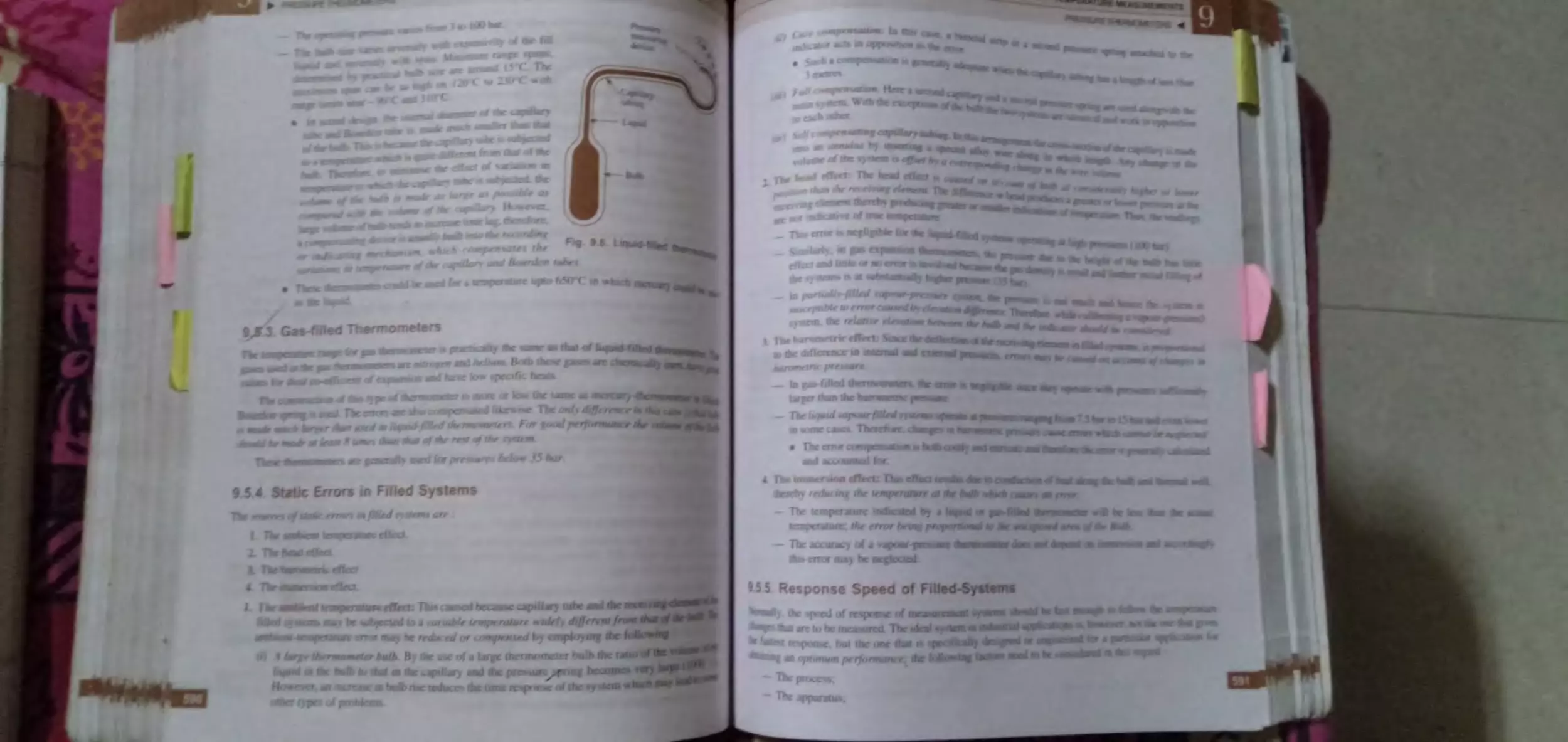
9. .1 . Liquid-111 -0 "
r ..... .
9.
·-·
Bi t· lli
et t ............
Pr~ .ureTh rm 11ct r ............•.... ... .... .. .. :
t .5.1.
ur pre ur tlkrm
r .....
l.
·-·l..
:)
)}
l)
·· ·· · ·· ·· ·· ·· ·· ·············
{,t) l
. .. . ... ............. ... ( {) _
'lll~l(
.nit1 )fl, in
07
1(7
. , · ·· · ·············· 610
,·,,·
... . ....... .. ... ........ .........
6ll
.... ....... ..... ................ ..
1_
QUE
........................ 617-646
I..
0
J••.•
0. ),
CONTENTS xi
I(). _. ~
f . •1LL'h ni ·.11 ta~hom~tcr 6- 1
10.2. -
~.1
.., 1• ·tricdl tach 111 'ler .. 62...,
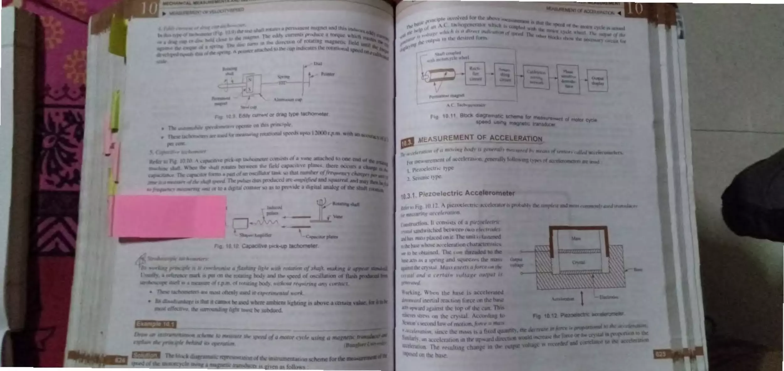
. k .1~ur 't1kn nf, ccdcration .......... ... ... 6- -
HU. I.. Pil•,w :I ·t.:tri • ·1c ·elcromet ~r ... ..... 6 _5
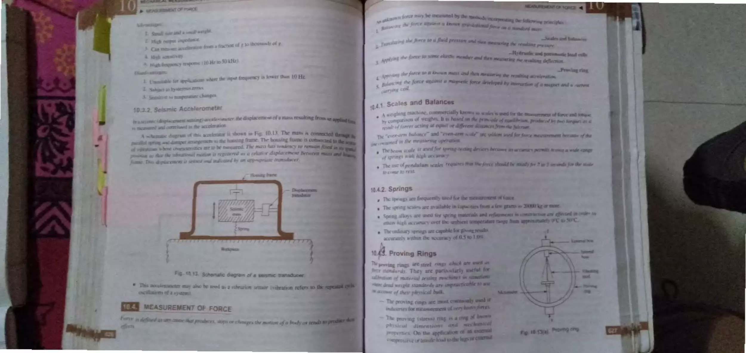
I0. · ..... . S •i:nu ttLcekromctcr ......... ...... .. 626
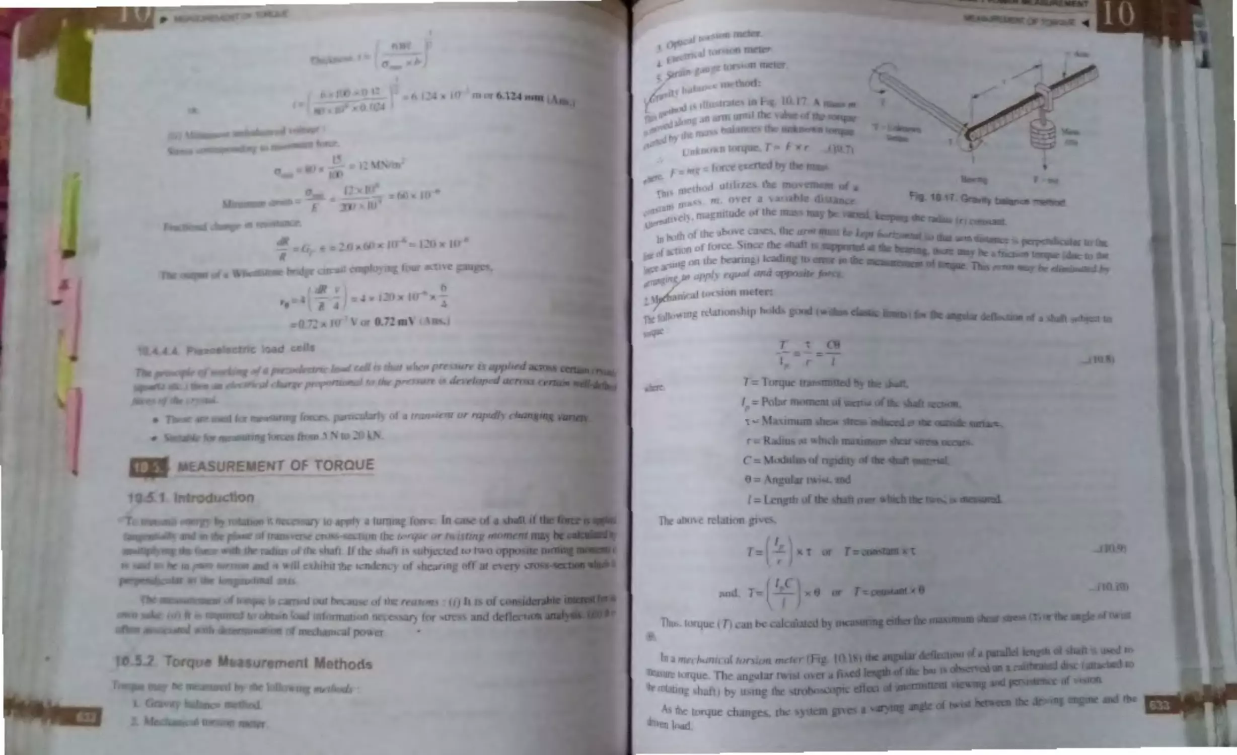
M';I, Ult'lll nlorhm: · ............................. 6_ 1
W.LI . S ·al :-, a11d halane·
.. ...... ...... .. ... ..
627
10. .2.,' iinp:~
.. ... .. ..... ...........................
6-7
·
6~7
ln...i .. . [ rO\,lllg rrng~ ... .. .. .. ... . ......... .........
-
I 0.4 .4 . l t ad c It. .. .. .. .. ...... ........... .... ....... 62c
10.4A. l. Hydrnulic load c JI ...... 628
I 0.4 .4 .2. Pncnmaric load celJ ...... 629
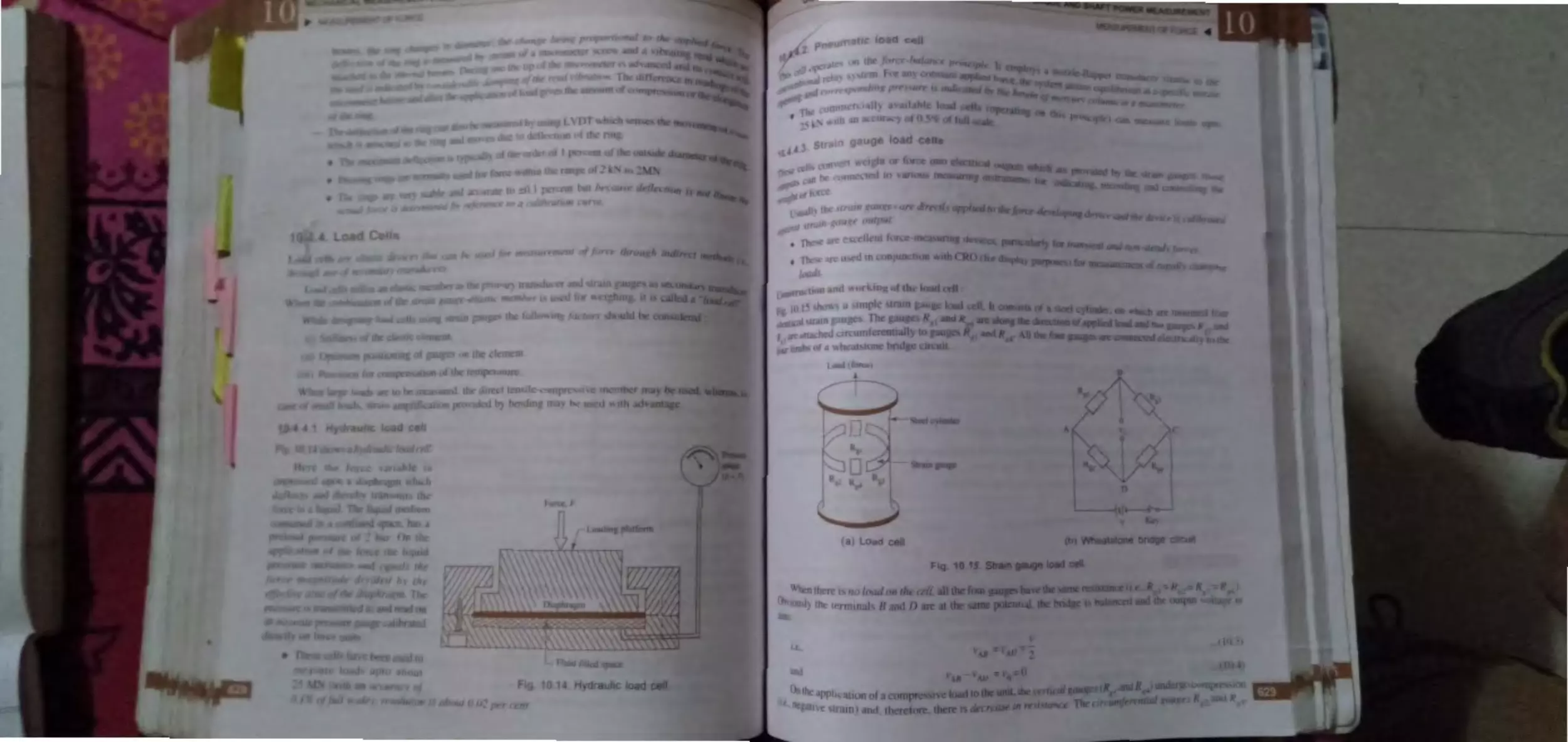
I0.4 .4.3. Strain gauge load cells. 629
l0.4.4.4. Piewelcctric load cell .. 6 2
M ~,1 , ur 'ment of Torque .... ............ .......... 63 2
I0.) . l . Intr duction ............................ .. .. 6. - ,2
10.5 . ~ . Torque measurem nt m thods .... 632
Measurement of Shaft Power ..... .......... .... 636
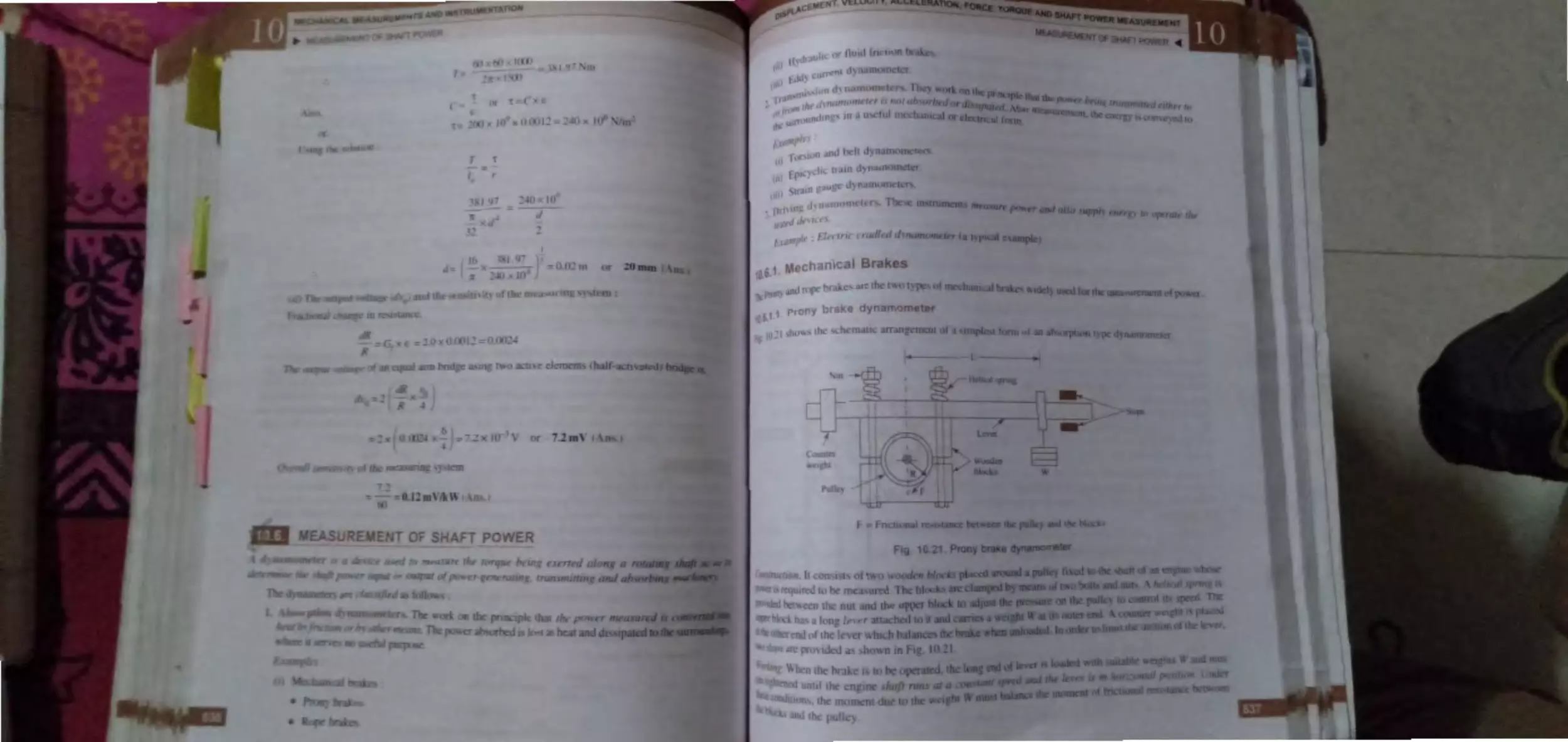
I 0.6 .1 . M chanical brake, ...................... 63 7
10.6. l . l . Prony brake
dynamom ter .. .............. 63 7
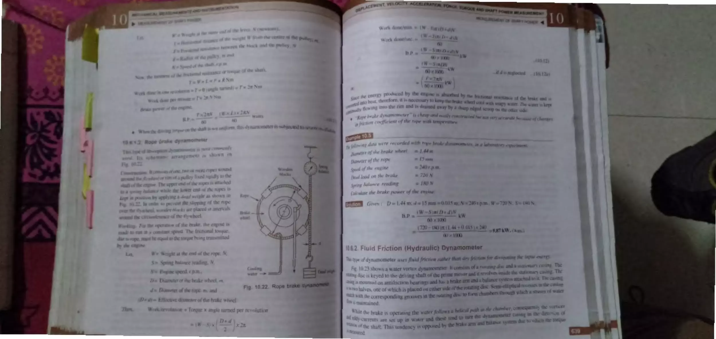
l ).6 .1 .-. Rope brake
dynamometer ... ... ...... .. .. 63 8
10.6.2. Fluid friction (hydraulic)
dynamometer ........................ .. .... 639
10.6 .
.
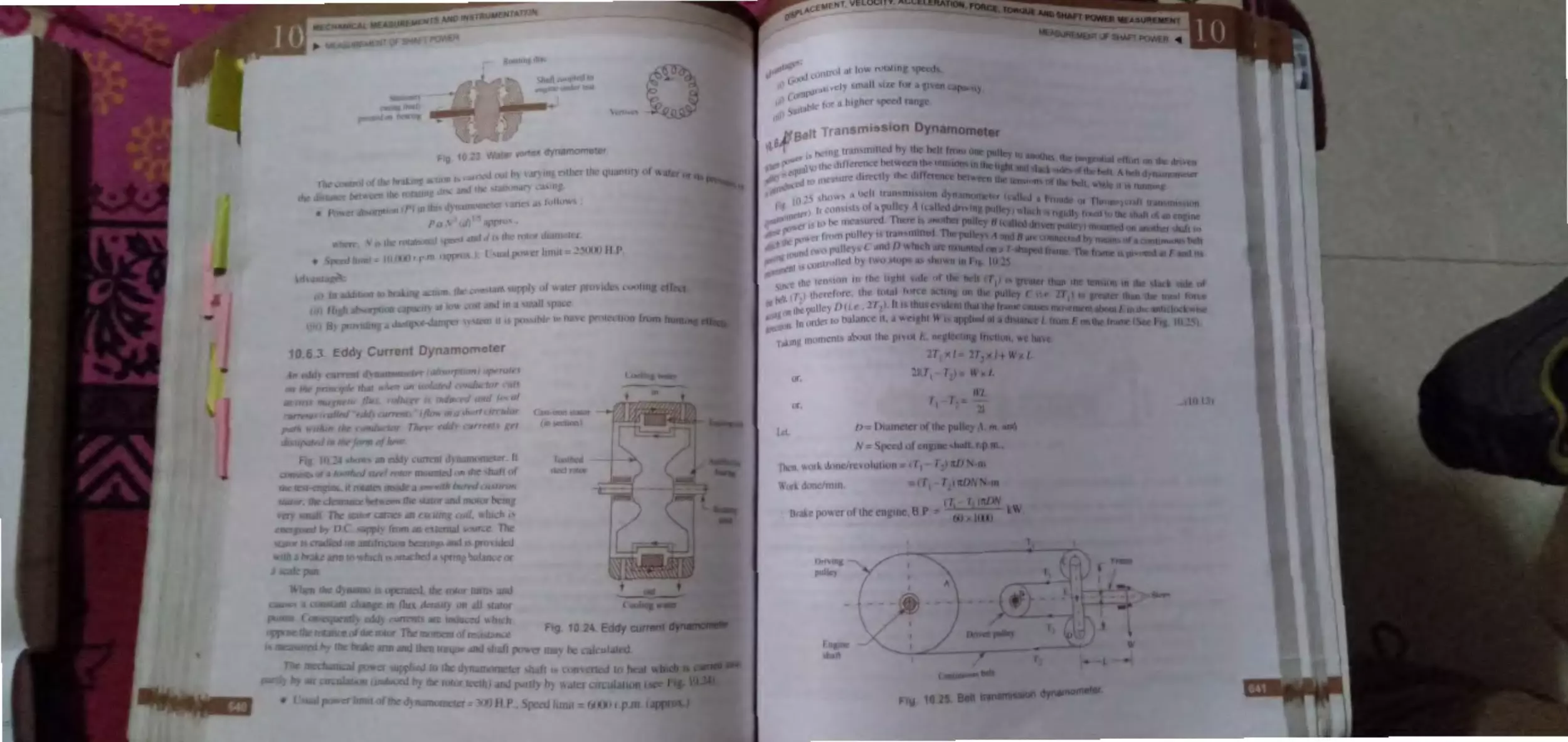
Edd cun-ent dynamom ter ... ... ... 640
I0.6.-L
B It transmission dynamomet r . 641
I0.6.5. D.C. d namom teL ....~ .......... . ..... 642
10.6.6. B L Gibson fla h light tor ion
d narnometer ................ .......... .. .. 642
Hi~hlighr ............. ...... .... ....... .... .... .... ...... 643
Obj ctiFe Type Que tions ....... ... . .. ..... ..... . 643
Theoretic zl Qu 'Stions ............. .. .............. 646
11. MISCELLANEOUS
MEASUREMENTS ........................ 647-708
I1. I. train Mea. urement an d Strain Gauge, .. 647
1i .1.1 . Introduction ......... ....................... 64 7
17
I l.1 .2 . Technique of train
1)
d .......... ... 19
t flinLar, "l ity..619
. f ·1n,=-ulnr lo ·i t. ' 6~0
measm·ement ............................... 648
11.1.3. R equi rements of a strain gauge ... 648
1 l.1 .4 . M chanica] train gauges .. ......... 649
l l.1.5 . Optical train gauge .................. 649
11.1 .6. Electrical train gauges ............... 649
•
•
CIHLlPmi
GENERAL CONCEP1S
•
•
1.1. Introduction to measurement and instrumentation-Measurement- Instrumentation ;
1.2. Significance of measurements ; 1.3. Standards of measurement , 1.4. S .I . units and conversion
factors; 1.5. Mechanical measurements; 1.6. Methods of measurement; 1.7. Modes of measurement;
1.8 . Generalised maasurremen~ system and its functional elements; 1.9. lnstruments-lntroductioh-
Classiflcatlon of lhstruments- Factors relating to selection of instruments- Functions of instruments;
1.10 . Input-output configurations of measuring instruments and measuring systems; 1.11 . Applications
of measurement systems- Highlights- Objective Type Questions- Theoretical Questions.
•
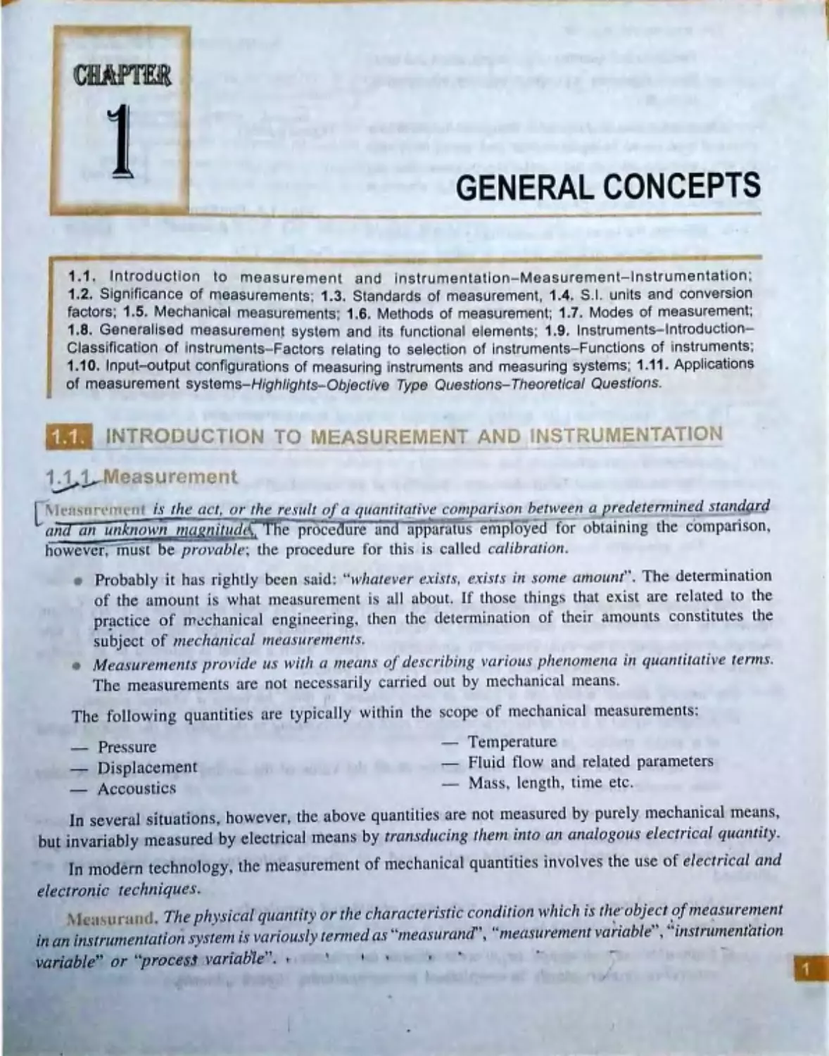
1.1~~ easure1nent
't¢
L'\ ..••as,11·(~ ,e i ~ r ~z e,.gct ,_ . .~ ,- rli e result of a quantitqfiVf! co~pari s·on ~etwee ,1 a predetermirz eq staridarll
~n? atz I
unkno~,n ~ggg _piJ.uJl 1e proce ure an appar atu s employed for obtaining the comparison ,
howev er ; must be pro vable; th e procedur e for thi s is called cal·ibration.
Probably it has rightly been said: '' what eve r ex ist.~, exists in som e amoitnt'' . The determination
of tl1e amount is what measureme nt is all about. If tho se things that exist are rel ated to the
pr!lctice of mechanical e ngineering , th en the determination of their amounts con stitute s the
subject of m echanical ,nea s urem ents .
•
Measureme ,ie~· provide us wir/1 a rn ea,i s of deJ·cribing vcl ri ous pl1. enorn e11a iti quan.titative te rms .
The measurements are not necessarily carried ou,t by mech anical mean s .
The following quantities are typically within the scope of me chanic al measurements:
--
Prressure
Displacement
Accoustics
Temperature
Fluid flow and related parameters
Mass, length , ti1ne etc.
in several situations, however, the above qu•antities are not measured by purely mechanical means ,
out invariably measulied by electrical means by trant,·ducing then1 into an analogous electrical quantity~
•
In modetn technology, fue measurement of mechanica1 quantities involves the use of el ectrical and
electronic t~chniques.
.
McHsur~1,1,1 . The physical qua,itity or the character.istic condition whicl1 is th~·object ,of1neq.surement
in an instrumentati0n sy~,tem is variou~·ly termed as ''tneasi1.rand!' , ''measurernent variable'' , ''instru,nentation
vaniable'~ 01 ~'p:r:ocesJ va niable''. •
•
•
,
,
...
·
-
...
•
•
I
,
•
•
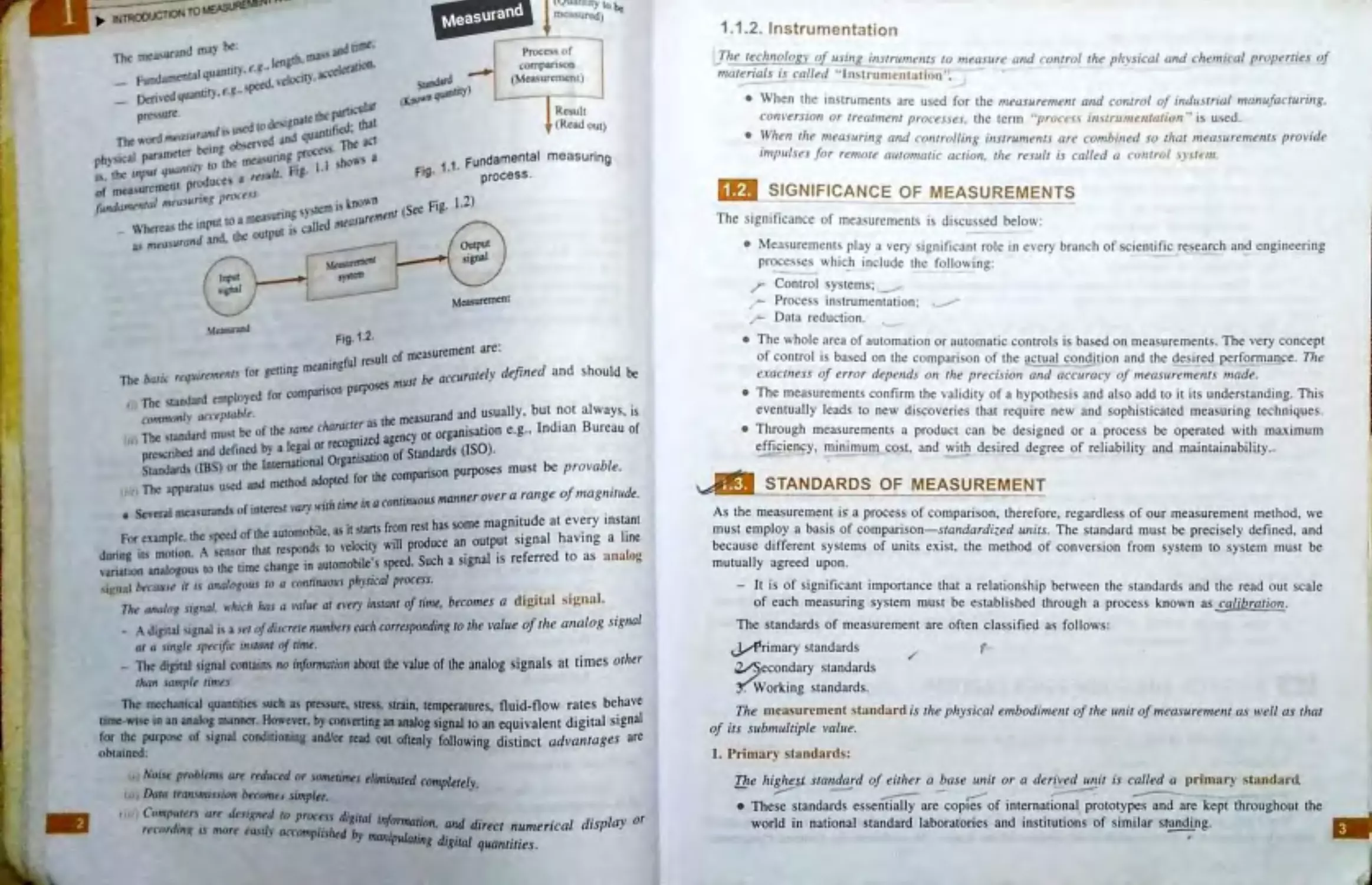
Procc , of
compa.ruon
( 1~ \UfCmt:Ot)
1 1 Fundamental
f ig. · · process.
measuring
~~, -,,.(il)COf
t>'iCCID
Fig. 1.2 -
1.2)
Mc:a9ffdl"ICOI
f easur~ment are:
.
meaningful rc~ult o m
The Jx11ic rt•,p11 re,nrntr for getting
-
" be accur01el)· dtftned a nd should be
•
0 purposes mu.11
The st.ind.ard emplo)cJ for companso
'
'"'";
11,,,1
,. cJ(',-~
1,r"blt.
the measurand and usually. but ~ot a lways, is
d.lrd mu1;1 be or' the same character as
or organisation e .g ., lnd1an Bureau of
, The: ,un
_
.
1 al or recogmud agency
pre\Cribtd 311d Jct1ned b} u cg_
isation of Standards (1S0) .
Sta~ (IBS) or the lntemauonal Orpn
•son purposes must be provable.
d··- ·'
_ ............~adoptedforthecompan
Th ann:untu, u~ iUIU mcuwu
if
.
d
(t,
c ,.,.
.
.
.
us manner over a range o 111agn1tu e.
r.
t • .... u•r'th lunt U1 Q cont1nuo
• Sc\'etal mta'iurJnds o tnttrCS 'a,., . .
.
.
.
fl est bas some magnitude at every in stant
For example. the peed of the automobile. as itls~ ~lml prroduce an output signal having a line
.
•
A
that responds to vc ooty w1
during 1tr. mouon.
!tCn..:i,or
.
b'l ,
..,. ..,. Such a signal is referred to as analog
\·aria11on analogou) to the time change ,n :iutomo I c_s st"'..v •
~..nJl b,cu"'" it ts analn,qnur r,, a fnnrinuous physical proctss.
,,.ht' anu/ao si,rnal, llh,rh hat a v,J/iw at n 'tT)' instant of limt, becon,es a digital ~ignal.
,,
"
.
.
.
al
_
A Jj~ial ,;ignal j1; a jtl af duerttt numbtrs each co"tspondzng to the va lue oftire arialog szgn ·
01 a rin,qle specific ,nttnnl of tilnt.
The digital signal contain, no infomration about the value of the analog signals at times other
than sampl, tim.r.,
The mechanical quantitie\ such ti pr~ -irc. stress, train. temperatures, fluid-flow rates behave
time•WIIC in an analog manner. However. by converting an analog signal to an cquivaJent digital signal
for the purpoltC of . iinaJ conduioning and/or read out oftenly following distinct ad,,antages are
obtained:
•
, J Nui" problr.ms an rtductd or JOmttimts elimUUll~ complerely.
< , Da111 tramnussian ~< "omtli simpler.
Computtn ar, dcsrgnt"d ro prore.u digital ln/"""'1Jio
.
recordini ,.s mnrt rasil) acromplishff by
.
n. ~ direct nun1er1 cal
manlpulalmg digital quantities.
displa)' or
1.1.2 . Ins trume ntation
. ,, .The tE!J.1lQ!2.K1. of LtJittR. u1 srr11n1e11rs ro ,neaJure a11d control the plt)'Sical and che111i< al r> ropenie~· of
n1arer1als i r ctilled " (n~lrt1me ntalic>n ".
• Whe n the instrument~ are u cd for the rneasuren1ent m,d co111rol of industrial ,n ,i11,ift1<:tt1 ri11g,
co111·ers1or, or 1rear1r1ent processes. the term " procei, 111 ~tr11n1r11tatiu11 ·• Jl) u,ed.
• \Vhe11 tl1e 11,easi,ring a,,d co111rol li11g ir1srn ,n1e11rs are co111bined so rl,at n1casure111e11r:r p ro 1·id<!
i111pulses f or re111<1le auron,aric acrio11, rl,e result is called a c.·,, , ,rr ol \)'\l('t11.
·1.2 . SIGNIFICANCE OF MEASUREMENTS
--
-
-
The sig nifi cance of measure ments il) discus)ed below :
• Mea surement s play a very signifi cant role in every branch of scientific r~ e nrch and e ngin ee ring
processes whic h i nclude th e fol lo\vi ng:
,r Control systems; _
,,-
Proce in strum ent ati on: _.. ,
-
Data redu cti on.
•
• Th e whole area of a ut omation or automatic control s is ba sed on mea sure ments. The very concept
of control is based on the compa riso n of the actual co ngi tion and the des ired performance . Tlie
e:racrn ess of error depends on tlie precision a11d accuracy of 1neasure111e111s ,nade.
• The meas urements co nftrrn the va lidi ty of a hypothesis and al so add to it its understanding. Thi s
eventually leads to new disco veri es that requ ire ne\V and sophisticated measuring techniques .
• Through measurem e nts a product can be designed or a process be operated \Vith ma,ximum
efficiency, minimum co t, and \vith desired degree of reliability and maintainability.
-
-
•
•
~ STANDARDS OF MEASUREMENT
As the measurement is a proces s of com pari son. therefore, regardless of our measurement metJ1od . we
mu st employ a basis of compari son-standardized u11i1s. The standard mu st be precisely defined , and
because different systems of units exist. the method of conve rsion fro m sys tem to ysten1 must be
mutually agreed upon.
-
It is of significant imp ortan ce thnt a relationship between the standards and th e read out scale
of each measuring system mu t be es tabli shed through a process known as _calib rq ripn_.
The stand ard s of me as urement are often classi fied as follo\v s:
J_ .A1rimary standards
/
f-
.
~ e c ondary tandard s
Y:Working stand ards .
Tl,e 111eas ureme nt s tandard is rl,e ph)•sical en1bodi111 enr of r/1e 11nir of111easure111e11t as well as that
of its subn,ultiple val,,e.
1. Primnrv standards:
•
Tlze /1ig/1esJ. sta11dard of eirl,er a base u11it or a derived ,,nit is called a primnn · . tand11rd
.......
-
.....,,,,,,,,,-
-
-
-----
.
~
-
~
__,.---
---
~
,,,
#'
• These standards essentially are copies of international prototypes and are kept throughout the
world in national standard Jaboratories and institutions of si milar st-anding.
,
'
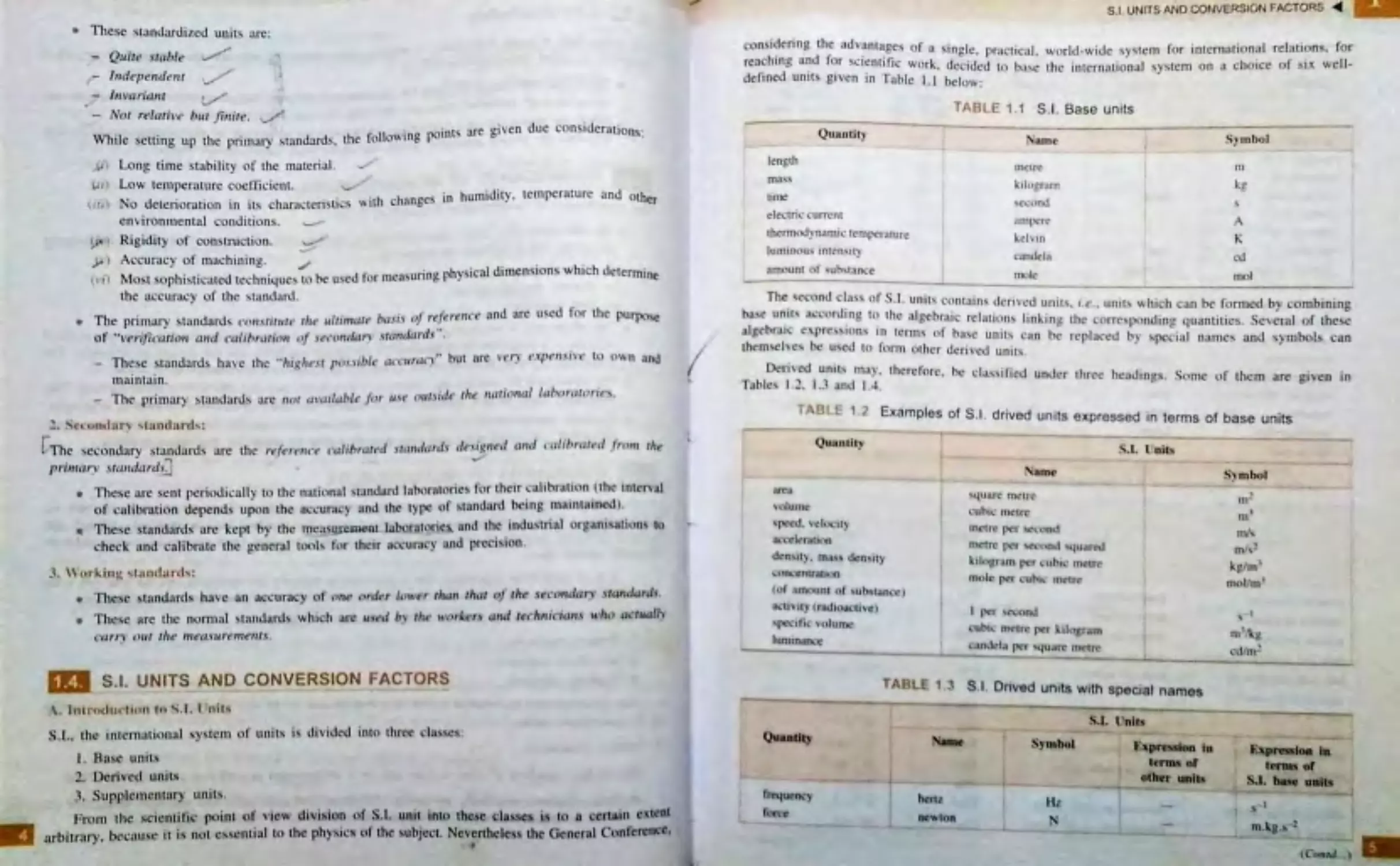
• These ~tondurdilell unit. l\re:
-
Q11ite src,blt•
•
/11 \:{lriant
v·
-
No, relc,ti,·t• 1,u1 fi,,itt• . Ji
\Vhile setting up the prin1t\~ ·
standard~.
the follo,ving ptlint. are given due considerations:
I
4
(IlII
•
I.,4 •
,
Loni tin1e ~ tnbility of tl,e material.
Lo"' tcn,pcrnturc coe fficient .
'-"
No d<!teriorntion in it., chan1ctl'n tics
-
•
en\ 1ronmentnl c.~ondition~.
Rigidity of construction.
.._.,
_,,
./
_, ,,.
,, ith change$ in humidity. temperature and other
Ac:curac)r of n,u chining .
✓
Most sophisticated tcchniqu~ t\.1 ht: u~ed for ,n~a!.uring phy sical dimension~ ,vh1 ch determine
the :1ccur.1cy of the :- tandarJ.
• The prin1ury ~tandnrlb ,,,,,,,,,i1u1c!' tit« • 11/1,,nar,· ba~, .\ vj rtfr:rc•nrc.· and are u~cd for the PU'"Jl<'- . .c
of ..vt•r11i<'r1li1>n ,1,1 ,i l·c1lif1r,1tiot1 t>/ .,t ·c ·undtJn Jtt1rrtlt1rd,· " ,
-
Thes~ stundard:-.
have chc ··J,i.~ ht•.,1 pt>J,, 1l1/f! a, l'"''-'"".. but nn· ' '<'')'
1
•\JJr11., ,,.<' tel o,, n .i.nd
muintuin .
-
The prin1ary ~tantlurd s uru ,,,,, ,,,.,,,/,,/•le' j,,r u,c · c111tJi<lt· tht• 11atio ,u1l lt1br,rt1l1J1 tt ~
! .. ' t • 410,t11r, .. _, a,,riar{l,:
rTllt ~c..:tlnclury st-undunt:-
/>ri ,,,,,rv ,\tn11,l11r,l. , ~
.
-
ur~ the ,·, · (<'r< nc ~, . t t1libra1, · ,i 111,ul,1 ,J, cif' ., i g11r,I ,111d ,·, 1li /,rc11,•d .fr,,,n 11,t:
..,
•
Thl"SC nae sent f>t! t ii>di~ ~1lly lt> th~ n .1t1on ,t ,tandurJ latmr:1t,.,ric ~ for their ..:nlibrut1,1n l thc 1ntcnll1
l"lf ~n lit,ratiun dept?.nd, upon 1h~ nt:curac~ ;ind th~ tyre of ~tanclan:t lR·ing n1111nt :,incd).
•
T lt~$e ~tnndurtl are kC(ll hy the 111c. 1~Ul'CJ1k.'nt lubor:lt,1rirs. Jnd the indu,tn ul Of!!;1n1,ution~ t ,>
· heck and cnlibrt\ll' the ~l:ltt• n,1 l\>f'll!- tl"1r their a ('\tra"') ' and preci:..ion .
. \. \\ c,r1'.i 11 1t , t.t11clnrd,:
• 11\cst> st:1ndnrcl, ha\ c an :i~curucy ot ,,,,,, ,,rJc-r /11\\ ·rr ,~1 11 rh,11 ,,f tlict .\«1 t>ttcl,,r,· s tw,dard(.
• '1'ltl''~ nre the norn,ul :.landunl, ,vhach an· 11,«·d /,, tilt· " 'r>r!,•r., ,,,.J tc•cl1ri,,·,,,,1., ,, ·It<> ,1,·tiwll,
, 'tifl'\' ()Ill ti,,• ltlt'(l.\lll '<•ttlP-flI, .
•
1.4 . S.I. UNITS AND CONVERSION FACTORS
I. Hu~~ unit,.
:?. l>oriv~tl u11i t.-.
.,. S upplc1nont ury
t- ..r«)m tl•lC ~c ie n1ifit" ptlint l>f ,•,cw &J1vi1'ion of S. I. unit intll t~' I .C cla~t - is ltl 8 crrtain txtclll
arhitrury. bt'cn,1?-i ~ i1 is nut e~icn1.ial tu the phy~ics t,f the subJcct. Ncvcnhc-lc . s the General Conten:nc:c.
,
..
•
•
S.I UNITS AND COt.SVERSION FACTORS ◄
con 1dering lhc advantage~ of
nct
.
1
,n., "n·• r,.
,••
'fj· 0
~•ng lc. pr;1c1ical. v .~
a rld-,v idc ,y. -, 1c!n1 fo r inl~rnotiunal relt1ti()n11. ror
re
::-- " u 1,lr sc 1cnt1 Jc \York d, .d
.1
d
efined unit, oiv. . T
·
cci cu lo ba,c thl.' .' intcrnalion:11 ,ystern on ;.1 choice ,,r ~•x wcll-
e en •n u.blc 1. 1 below:
f
I
Qllilntit)
nme
clt"Cln"· C\111\.'l\l
1hcm,,'ldyn,tm1c t<"n1pc1a1 urc
lunnnou, 1n1en!o.tl\.
. uno unc ot ...ub,1.111cc
TABLE 1.1 S .I . Base units
'l\fl)l.'
n1e1rc
kilopr-.i n1
,ecund
,1n1pcn.•
kct, ,n
cintlel.1
mole
S)1obol
m
kg
..
1-\
K
<:d
1.2 Exnmplos of S.I . drlved units expressed rn terms of base units
--
Quanllty
an-.,
, ,,tμu,c
,pc~d. ,~!.'I.ti)
1k,"CIt.·r .n~ 1,n
dcn,1l). 111.,,, di·n,,ty
,1ni.:cn1rJhun
(ol uuount of , u~ l.snc.::e 1
,4u.1rc ,u,,u c
~ uh11. n\clt~
1nr1r,· J)\·r ~ i.11nd
IIICll'C J 'I ~ ,.,n,1'-ttuJn.-,1
~ l ln~turn pt·r 11h11.• lllc-tn·
1na,IL· per ~ut, 1. _
Ill~ 11 .
-
-
. ,I.lTni1,
-
-
S"mhol
•
..
nt·
I\\\
rn/,
m,._'
kfltn '
fn(lfl rn I
• "ll\ ll) lf.WHl .&cll'!C)
I p..·r '{" nnJ
'~"'• lie \'olurnc
,
~ub11. n1ctrc ~• ~,h, r,1111
,
tun11n.mcc
n, '\.~
-
------------l
l~- -~ . uhl,•la pc, "tUo1tc nt<ln·
=:
-
""'' "':
__ _ _....,! ...__ __ -
-
-
TABLE 1... S I. Or,ved unit& with special names
•
nm
•
s•
s•a
--- --- --
,--------~-----,----------
S.I. l1nlh
N&JK
hcru
IW\\IOft
Symbol
•~PR•IMO ta
t era11 er
otlter units
,__ __...,. ,.,~,-~ ~
-
-
-
~la
tc,aa. .t
S-1 .
llldb
..
SIU
NIT S ANO CONVERSION FACTORS
GENERAL CONCEPTS
-
-
....
-
QuaaUt-y
-- --
-
-
Esprcs.,1011 In
,_
-
-
-
£xpress100
NUM
s ,•anbol
tem lS of
te11ns 1,
other unJts
s
or
I
.I.b~
-
.-
UllJta
.
I
tJrt's ure
Pa
Nl m2
n,-1
.kg.s-2
I
'
pu.~ 41
I
S .I. UNITS ANO CONVERSION FACTORS ◄
-
.
I .l . nit.,;
Quantll,,
-
-
,._
-
-
--
•
a nrue
Symhol
Expr~ . !>ion in
lerni.s ol
en~!'@,) , w ork.
-
-
S.J. hnse unit.Ii
qua11tity of
hon-c: J)O\\ er
joule
J
N .ID
n1
2.kg .5
-2
radia.n, n~.
'
qWlntil\· of
•
el~ lricil\'
J/s,
n1
2/kg.s -a
I
\\-an
,v
..
I electric charge
colournb
C
A.s
.A
elt!ctric ren.-. ion.
eleetric potential
I'
W/A
n1
2.kg. s --l ,A-l
volt
V
cupaciranee
farad
F
CN
m-2
.kg-t _s4
~ lectric resL~umce
I'
ohnl
n
VIA
m-2kg -3
·-
.s
.A-2
conducmncc
•
s
AN
m-2
.kg-ls3 I
s 1emens
.
-A~
magnetic fluA
weber
Wb
v.s .
m2.kg.s-2.A- I
magnetic flux density
tesla
T
\Vb/m2
kg.s..,2.A-1
inductance
henry
H
Wb/A
m2k g .s-2.A-2
lu minous fl ux
lumen
bn
-
cd.sr
illuminunce
lu:x
Ix
-
m-2
.cd.sr .
-
penni1tlvi ly
farad per 1nc1rc
•
-
I
current den,i1y
F/m
ni-l.kg-1
.~,'.A2
om~rc per i.qu.1rc metre
mn8Jlellc field , trcngth
Alm2
-
ampere per me1er
penneabiIi ty
Nm
-
henry per metre
molar e nergy
Him
k.,
.,
I joule per mole
m. !?,-::>--.A- ·
molarheat cap:u:ity
J/mol
m-2
.kg., -2
.moi-1
Joule per mole kelvin
J/(mol .K}
m-2
.kg.s-2
.K-1
.moJ-1
The S.I. u
•
•
•
.
~ 1LS assigned lo Lh1rd clnss called "S
.
,,.
-
units or as denved unit~. Refer Table I.S and l .
6
~pplementnry untLS may be regarded either as base
•
Quantity
S~I. Units
-
~
-
-
-
Name
I
Symb ol
pl ane angle
radian
f
rad
solid angle
steradian
j
I
sr
TABLE 1·5 S .I . Supplem entary units
TABLE 1.4 Examples of S .I . derived units expresse.d by means of special names
TABLE 1 .6
emen ry units
Examples of S.I. derived units formed by using s uppl
ta
•
-
'
S.l. Vnits
•
-
Quantity
Name
Symbol
Expression in
,,
tenns of
I'
S.I. base ,,nits
Quantity
S.L U nits
l
I
Nam,~
I
Symbol
ang ular velocity
raruan pe r seco nd
ang ul ar acceleration
rad/s
radian per second squared
I
rad/s2
dynamic viscosi 1y
pascal second
Pa.s
m-1
.kg.s-1
'
moment of force
metre oe.wton
N.m
m-2
. kg.s- 1
s urface tension
newton per metre
Nim
I;
kg.s- 2
heat fl ux density, irradiance
watt per: sq uare me tre
W/m2
kg.s -2
heat capaoity; entropy
jo ule per kelvin
J/K
m-2
.kg.s -1
. K-1
specific heat capacity.
specific entropy
joule per lcilogram kelvi n
J/(kg.K)
m-2 .s -2.g -1
speeifie energy
jo ule per kilogram
J/kg
m -2.s -2
I
thermal co nductivity
watt per metre kevin
W/(m. K)
m-1
.kg.s-3
.K-1
-
energy density
joule per cubic metre
J/m3
m-1
.kg,s-2
'
e lectric fi eld strength
volt per metre
Vim
m.kg .s2 .A- 1
I'
e lectric charge density
coloumb per cu'brc metre
CJm2
'-
m-3 .s .A
efeclric fl ux d ensity
colo umb per square metre
CJm3
m-2
.s .A
(Contd.. , )
ra.ruant intensity
watt per steraru an
W/sr
radiance
watt per saure metre steradian
W-m-2 .srl
l
-
Factor
Prefix
Symbol
i
-
Fact or
'
Prefix
I
I
Symbol
1ot2
I
tera
T
10-1
I
109
~
deci
a
I
giga
G
10-2
centi
106
.-
C
mega
M
J0-3
milli
I
103
m
,
kilo
k
l~
I
•
102
nucro
μ
hec10
h
10-9
nano
101
~
da
fl
10-12
•
pico
p
r
10- •s
'
fasnto
l
f
10- 18
all()
a
•
TABLE 1.7 S.I. prefixes
•
•
•
I
•
I
l of thennodynamic tempcr.ilt1re of th e triple~
273 16
•
..._ .
1.
nt• n .. it v in the perpendicular direction , of a SUrfact N
th~ c-an cl.a ,, ,,~ um1nou 1 ,
.,•
"'
I
f bl L 1-. . Av at 3 temlV'rature of freezing platinum under a p~
:a --- Jii.CUarc rnctrc IJ iJ w: ... 1,vu.,
r-
Hll).lJIXJ
I( I. 1~ nc ,,,n per ..quarc metre.
'fhc m,,I.: i, the a1n,1unt of ,ub,uinee of a y~1cm " 'hich conuii_ns as man y elemc~
·
oo12 i-,.,
•·arbon 11 When the mo le 1s used . the elemcn12r1.
en11t, ~
u-, thcrt ure att.1m, ,n
.
"'~· ...
-·
.
.
·-1
·
..___
t- --•
. . - · • m ay be- atom molecules. ions. electron s. other particles er
cn11t1e~ nUJ ~C ,111,;
pee, 1cu IUIU
•
~ tfted JtnUP1' tJf Ul!h particl~.
The nidaan i ~ the plane angle between two radii of a circle that c ut off on the cirdc
,n at\: equal in lt"n1th to the radiu .
.
~ -· The _ter.uhan is the M>lid angle which having its \fertcx ~ the _centre of a spbm.
CUI ,, ( an aRa tlf the ~urfk~ of the !iphcre cqu:il to that of a square with S1des of length equal
ta> the nadiu of the phcrc.
I ( 'ttj~~ _:
~~t•
. ~ newtnn cN) ,, a dcri~cd unit of force and is defined as the unit of force per second~
when titting on• m•~' of l kilogram gi- .:e s it an acc(:clerntion of one metre per second per second. SUl(r
,;eek, atiaft due to an~IY equal 9,81 mJs1: one kilogrmn force equals 9.81 newtons.
.. ,,. _.,
. T he ioule ,J, , a derived umt of energy, work or q~antity of heat and is defined :
it-. .,ort, done ~ a totce of one ne~ act 10 ~ to cause a dis~lac_ement of one metre. ~
defined mr c■pac;t)' to do wotk. A urut of cneray an nuclear physics as the electron vol~ (eV) rl
i c:lefiaed a lhe ca«SY aained by an electron in rising through a pptential d1f(erencc
••• mil.
I eV • 1.6021 x 10"19
~-
•
1 -n. wad <W) ii a •• of power (i.e .. 11te of doing work)
•
Power m.., . •
(or &Yl in_joules
time in secon&
Thu, I "ntl equ..11, I J<lule/- .ec .
I kilo\vott-hour (k\\ h> = 1000 \\.ill -hour-
= 3600000 JOU le- .
'1•
1
h ll,I , The coulon1b (C) ,, the deri ved unit ot ch=.1rf!c. Jl 1-. ucfin~d a., the qt1c11111r. _
"' el,•c·r, tciti
pnr,i11fl o ;:ive.n puint in a r1 rc1111 ...,,/, en a c1,rrn11 of I A 1, 111urnru1nc ·d fi,r I ,.·c 11nd.
where.
Q =cho rge in <.:<>ul otnb , .
/ ::: current 1n ampere,. and
t = time in ,ccon<h.
Q=I ·I
I coulomb repreM:nt, 6 .24 x 10 1h electron .
<Jhn, The oh1n (fl) i~ the unit of electric re istnncc und ,. _
de lined a c; tht· r t#\ista11 c.c i r1 \t l1 ic-}1a c.·cJ11,4;fa111
c urrer11 of I A ge11c r<1tes /, ear ,11 rite rate rif I \V{llt.
' -;il 111t: 11. The siemen is a unit o f electric conductance (i.e . . reciprocnl of r~i ~usnc:e ). Jf a ci"rcuit ha., a
resistance of 5 ohm . its conductance ic.. 0.2 'l iemens. A n1ort! commonly w.ed name for ~ic1nen is
ITUIO (U).
\ olt. The vo lt i a unit of potential di fference and electromotive fo rce . JI i~ dt:fincd a~ the <liffere11ct·
of pote111ia/ across a resistance of I ohm COrr)·i11g <1 curre111 of J a111pere.
llcrtz. The hertz (Hz) i a unit of frequency l Hz = I cycle per econd.
Itl,1-. . . .: -,,,,,\t r . lt is a practical unit of mechanical output. BHP (Briti tl horse po\\1er or brake horse
power) equals 746 \Vatts. The metric horse po\,·e r equals 735.5 \varts. To avoid con fus ion between BHP
and metric horse power, the mecbanicru output of machine · in S.I . units. i expres ed in \,,atL~ o r
kilowatts.
The salient features of S ~l . units are as follows:
l. Tt is a coherent syste m of units. Le.• product or quotient of a ny t,vo ba. e quantities re ults in
a unit resul1:1nt quantity. Fo r e.°'ample. unit length divided by unit time gi es unit velocity.
2. lt is a rationalised . ystem o f units, applicable to both. magnetism and electricity.
. ,. It is a non-gravatio nnl system o f units. ft clearly distinguishes between the units of mass and
,veight (force) ,vhicb nre kilogram and newton respectively.
4. All the units of the system can be derived from the base and supplementary units .
5. The decimal relationship between units of same quantity n1akes possible to express any small
or large quantity as a power of 10.
6. For any quantity there is one and only one S.l. unit. For example. Joule is the unit of energy
of aJJ forms such as mechanical, heat, chemical, electricaf and nuclear. Howeveri. kWh will also
continue to be used as unit of electrical ~nergy.
,\d,•ant.lt!.es or S.I . { 11its:
1. Units for many different quantities are related tfirough a series of simple and basic relationsbip.
2. Being an absolute system, it avoids the use of factor •g~ i~e . . acceleration due to gravity in
several expressions in physics and engineering. which had been a nuisance in all numericals in
physic-s and engineering.
~ Be•ng
•
..,·
d t "_ . of rationali sed JvfKSA sy~tem .
•
0 r.iuon.u,,cd sy~rem . it cn t- urcs u.LJ the o vo? 0e~·" '
1
n the
field, o f electriciL}' · mag netis1n. clecrricnl engineenng nod
electrons . .
4. Joul~ is the onJ) sole unit of energy of all forms n_nd " 'alt is lhe ole unit of power hence a I
of labour is saved in calculadu~.
Ot
5. J_t i~ a . coherent .!>Y'<tcm of units and mvolves only decimnJ co-efficients. Hence it is very
convenient and gu.ick ~v~tem for cuJcuJations .
<,. Jn elcctJicity. a1J the pra~tj<.:al uniL, like volL otrm. ampere. henry. farad, coulomb. j o ule and w
accepted in iodu. try antl labor3tories all over the " forld for ,vei l over a century have beco art
ub~olute in the,r own ri ght in lhe SJ. system without the need for any more prac ci caJ uni:e
IJi~ad,·antal-!e- . :
l . The non-S .J. Lime! units 'minute· and •hour· will still continue to be used until the clocks
w:.rches are u!J chungcd to kilo ~econds and mega seconds ere.
and
2. The .b~se unit kilogram ( kg) includes O prefix, which creates an ambiguity in the use
multiplrerb with grJJTJ .
of
3. ~( ~~i~ for energy. po\ver and pressure (i.e. . jouJe. watt and pascal) are too s_mall to be expressed
• 0 s cience a,nd rechnology and. therefore. in s uch cases the use of larger uni ts, s uch as MJ kW
k'Pa will have ro be made.
'
•
it. There ~lrt! di~ficulties with regard to developing ne\v S.r . units fo r apparent and reactive ener .
while Joule 1 • the uccepted unit for active energy in SJ. systems.
gy
0. ( :()fJ \ ~n,i<>O f·'Ul'tf)r'S
J. f -nrce:
I ne"•con = kg.m/sec2 = 0.012 kgf
I kgf=9.81N
J bar = 750.05 mm Hg =0.9869 atm = tOS N/m2
= J03 kg/m-sec2
I Nim = I pascal = I0-5 bar = J0-2 kg/m-sec2
Jntrn =760mmHg=l.03kgf/cm2=J.01325bar
= 1.01325 x JCP N/m2
""1. '''(>rk. Energ__\i or H eat:
•
J Joule :: I newton metre = I watt-sec
= 2.7778 x J0-7 kW-h = 0.239 caJ
= 0.239 x 10⁻³ kcal
I cal =4.I84 jouJe
= 1.)622 x Jo-6 kWh
I kcal =4.J84x J03joule =427kgfm
= 1.1622 x 10⁻³ kWh
J kWh = 8.6042 x 1(>3 cal = 860.42 kcal
= 3.6 x 10⁶joules
I
J kgf-m =
427 kcal = 9.81jouJes
•
•
I
•
I
I
..
l watt =I joule/sec =0.86 kcal/h
I h.p. = 75 m kgf/sec. = 0.1757 kcal/sec.
= 735.5 \Vall
l k\V = 1000 W:lllS = 860 kcaJ/h
5. Specific t,cat:
l kcal/kg-°K = 4184 joulc./kg -K
6. Thermal conducti,
0
ity :
1 \\1atl/m-K = 0 .8598 kcal/h-m -°C
I kcal/h-m -°C = l .16123 watt/n1-K
= J.16 123 joules/s-m -K .
7. Heal transfer co-efficient:
l ,vatt/m2-K = 0 .86 kcaJ/m2-b -°C
1 kcal/ m2-h -°C =1.163 \Vatr/m2-K
.
The foll o\l,1in g conversion factors may be us ed to con vert the quanlities in no n S .I . units into S .I .
units.
To convert
"
a ngstroms
atmospheres
bars
Btu
Btu
circular mil s
cubic feet
dy nes
ergs
ergs
feet
foot-pounds
foot-po un ds
gauss
grams (force)
horse power (metric)
lines/sq. inc h
Maxwell
mho
,.
•
micron
miles
mils
pouoclals
-
..
To
m
k g/m2
kg/m2
joules
kWh
newtons
joules
kWh
m
joule-s
kg-m
resta
newton
watts
tesla
webers
•
s1emens
metre
km.
an
newton
I•
-
-
M ultip ly by
10-10
1033 2
1.02 X 10⁴
1054.8
2 .928 X lo-4
•
5.067 X 10⁻¹⁰
0 .02831
10-5
10- 1
0.2778 X 10⁻¹³
0.3048
1.356
0. 1383
Jo-'
9.807 X 10⁻³
735.5
).55 X 10-5
10-s
l
10-6
L.609
2.54 X J0-3
0.1383
.
[ To convert
-
To
.~ ---
___
,_
.. ___
J.il og,r -Jlll
~
~t ipty by
0 .454
0.448
47.878
6894.43
•
pound-;
()<)Und-. ( ron:e)
p<>und-./ ,(J. ft .
pounds/,q . inch
newton"
.,
1 fm-
·on .i·nS.I .Units
l• ress •
·
·
·
c· nst·~11~ nnd ~~p
~· Jr,lfJOr lanl f.11~llll'l•rtn~ ( _t
·
...
S-1 units
I
~ 1 .K.S- system
Engineering cons tants, _ _!----~---;------)~;:~:~--- --
and expr~ons
_
I
I kg-m/N-sec
2
IV
_,
f--
·-
I 9.81 kg-m/kgf-sw
848 x 9.81 = 8341 J/kg-moJ•.•i,
.
.uue
ox0
K
~·I\
0 _j8 kgf-m/kg mole-<>
kf
981
2. universaJ gal- constant
o-.
(:. J
·g
-m=
•
joules)
3. Gu.s constant (R)
4. Specific heat (for air)
5. Flow through nozzle--E .xit
velocity (C2)
6. Refrigeration I ion
7. Heat transfer
The Stefan Bo lLZIDann
Law is given by
for air
c = 0.17 kcaJ/kg-° K
I
c = 0.24 kcaJ/kg-<>K
,.
91.5 u where U is in kcal
= 50 kcal/min
Q = crT'kcaJ/m2-b
where a= 4.9 x 1~ kcal/h-m
1- °K
4
8314
.
29
= 287 Joules/kg-K
for air
C =0.17X4.814
I'
= 0 .71 128 kJ/kg-K
c,.=0.24 x 4.184 =1 kJ/kg-K
44.7 Ju \Yhere U is in kJ
= 2 10 kJ/min
Q =oT4 kJ/m2-h
where CJ = 5.67 x to-8 W/m2K.•
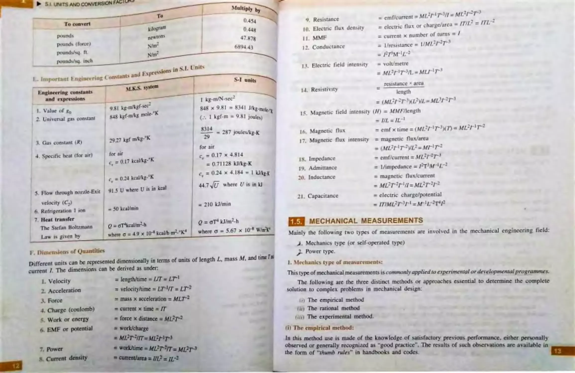
i,· . Oi 1 11 ~n:>i,,ns of Quantities
Different units can be represented dimensionally in terms of units of length L. mass M, and time T•
current /. The dimensions can be derived as under:
J . Velocity
= length/time =UT= L,
1
2. Aceeleration
3. Force
- 4_ Charge (coulomb)
5. Work or energy
6 . EMF er potential
7. Power
s. Current density
= velocity/time = LT-1/T = L,2
= mass x acceleration= MLT-2
= current x time = rr
= force x distance = ML2,2
= work/charge
=ML2r'l1rc =m2i-1r-3
= work/time= ML2r-2rr, = ML2T-3
= current/area= I/L2 = IL -2
9. Resistance
ro. Eleccric flu x density
=emf/c urrent= ML2, 1r--3I / =- M l? .J-
213
=elecuic Oux or charge/area = IT/l 1. = /TL-? .
=current x number of turns = I
= I/resistance = 1IML
1
f-
2
t3
TJ. MMF
12. Conductance
= !2T3rvr-• L-2
1.,. Electric field inten s ity = volt/metre
=ML2,1
,
3/L =MLJ- 11 3
•
resistance x area
L-t . Resis tivity
length
-
-
= (ML2, 21 3)(L2)/L=Ml31 21 3
Js. Magnetic fie ld in tensity (H) = N/MF/leagtb
= /IL=IL-1
16. Magnetic flu x
= emfx time=(ML2r
1
,
3
)(1) = ML
2
r
1
r-
2
J 7. Magneti c flux intens ity = magnetic flu x/area
= (ML1J- 11 2)/L2 = Mr1r-2
18. Impedance
= emf/current = ML
2
r2
,
3
19. Admittance
= I/ impedance= J2T3M -
1
L-
2
20. Inductance
= mag netic flux / current
=ML2,2
,
1//= ML21 2J-2
21. Capaci tance
= e lectric charge/potential
= fTIML2, 3J-1
=M- 1L- 2T4!2
-
MECHANICAL MEASUREMENTS
Mainly the following two cypes of meas urements are involved in the mechanical engineering field :
.J . Mechanics type (or self-operated rype)
}· Po\ver ty pe.
1. .\ .Jechanics t)' pe of m ea~ urements :
This type ofmechanical measurements is com111011l)1 appliedto experirnen1al orde'}elopmenral program111es.
The following are the three distinct methods or approache..s essential to deteanine the complete
solution to complex problems in mechanical design:
<1) The empirical method
cii) The rational method
•
t ;,, > The experimental method .
(i) T he empirical m ethod :
In this method use is made of the knowledge of s atisfactory previous performance, eitbe.i: personally
observed or generaJJy recognized as ..good practice... The results of s uch observations are available in
the form of •·thu,nb rules" in handbooks and codes.
13
'
11111: HQ)SQF
• Thimlhodh
.
~ :ill'-' in case of complex ystem •
.
e
.
o" c, er. c·ann or be rebed upon es,---
~
.
, des·
smce lhi me•L.oct 1- de . .
.
1L-A~
upon lhe Judgement of Lhe de- 1g nc r
1&11.
ur
o
-Stgn 2_s mainy ~
·
ii, '! he r ation.it mc-tb<ld :
Thi method i~ s tric:tJ} based upon well established scientific la\\' and relationsb ip .
• The rational method has a ' ~ f)· Jimjtc:d scope in arcJ!S of mechanical_eng i~e ~ng o th~ , . t
mcxhanic: and thermod}rnantics.. \\-ilere the a,·aiJ3biJity of la\\ and re) au o nsh1p~ i s r.ithcr ~
!iii, T he e, perimmt.af method:
·
ln the e,cpnjment.aJ d~ign method. the componenJ is designed ~-' · trial and _e " o r b~ed ~n eXis-,;,,
kno ~·l .edge and tM d~.rig,zed component is put 0 11 IM job . The mal are earned out intelLigenuy I
the interpretati on of the error is done " isely.
~
The e.°'"perime nlal design. infuc L requires the greatest application of engineering ingenuity.
2. Po"tt ~ -pe of ~le3Sllremeo~-:
These t)-pcs of measurements arc g eneral/)' used for monitoring ofoperational nzeasuremenr in co,u,-.
S)'JTem.
'ol
• 1ne entire area of au.1omarion and control is based upon power l)pe of measurement.s .
Q METHODS OF MEASUREMENT
The b~oag. class ification of methods of measurement is as foUo\\·s:
~ 1 comparison methods
.. . Indirect comparison methods.
J. Dir ttl comp.arfson method :
1n th.is metb:od the parameter to be measured is direcr!J· compared y.·iJh mher a primary· o r a secoruJar,
n~~
.
Di.feet comparison is quite commonly used for
ren:1enJts of length. However. for measweoll: ■
of mass the problem becomes much more intricate since iI is just 001 possible for human beinp ID
dis tinguish between \\1ide margins of ma s , .
•
Generali) . th:i method is not aJ\\·ays the most accurate or the best. it is no t sensitive enoup
also.
2. Jndir..-et c.:omparisf,n method:
ln this method the comparison i.s done with a sumdard through the use of a calibrat.t'd system.
These il»ethocb for me-45u.rements are used in th~ cases where lbe desired parameter to be
meaaor-ed i ~ diffi<·u/1 ro be mellJured dir-ectl)·, bur ii has got $0~ corr,/ation in tM some otl,a
partnnel4r H,·/uch can be e~il>· measured.
l::xampl-e: The eJiminat1on of bacteria in milk is directJ)' dependent upoo its temperature. Thus dr:
b~teria ~Jiminarion can ~ meaMlred indirectJ)· by measurin~ thL 1en,perat.url' of ,Ju milk.
-
In indir« I ~urement~ an e1npiricol relation is generally established between IM metulVOIIII'
a ctual/_ 11uuif' a,ul tlu: re Jults rho! ar~ desired.
• Wht:n che primary purpose of mak1og a mea-.11rewcm is co decemu~ quaJily of a produc:', •
'fUa4it~· sbowd be measured direcd>·· Huwe~er. in Ci5e direc.."t 11-eas11remear: is not~ . dlllt
indJr~,., mt,-, , .ure .oc:e 1 ~h<Mlld be made
··~--- -· ......--___ -------
• Tht• r11eas11rc.•111enr l \Jten1f
,n c,ist, rt!menr
·
U.Jt!d ' '' er1(l111,•,:n11g applic:nrio11 1ne1k c use of i11d irect n1t11hoth for
ptirpc,feJ
-
A me uren1ent ,,. lem
.
.
metbured \\' ·.i.
'
con,, t., o t a 1ra11ldt1c111l( elt 1nt>111 \, hich con ven, 1he quJnt,t) ' to be
tu, an ano/oqous J
/ Th'
IIi
.
means j11 the r, d
1.r:,,,, ·
'' ,,gna J ter being proce cd by orne i 111,: rn1ediate
n e to the end de\ice!> \\ h1ch pro, ,de t11e r;easurernent re ufL,;.
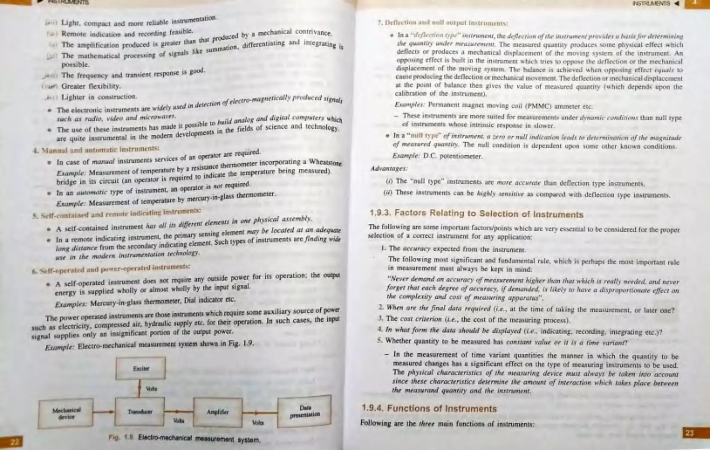
ffl MODE§ _9 F MEASUREMENT
Follo wing are the rl,ree mode, of
measurement
, ,J.,Pri mat) mea oremenc..
. ; .,' l_,.SecondaI) measurement ·
·'· Tertiat)· me.!! urement,.
I. Prima r) ffil· .t ~u rlmtnr,:
• In th1 c~e che SOLt"ltt 1
. . r eference srcmdards:.
,·a ltt' n/ a para1ttt>tcr ,s detcm 1111rd b_, con,paring it direct/)· i,·ith
• There • no cun,·er.~t<>n of mca.~ urand in ienn, of length.
/ _tum •/, \,-
t
I
•
,
~ffe~ huremenr of rime b)' counting the number of ,rroke of a clock
tr ' arcingof[\\olenehr h d
.
.
.
~i
"'
"
en erermanang the len~th of an object ,, ilh a ruJer.
(JJ ' arching of I\\o colou~ \\hen Judging ihe rempera~ure of o rt:d hor teeI.
1. ~ und:ir) n11:a., urc.:tnco(,:
TM indirec_t measureme,,rs in, ol,•i,,g .
1
-
one tran.r a tio11. tire called ' l'l·ond ur,
f.XUlll/J /c ,
_
•
Olt-a Urt:Ol l' nl~
,,, The pre <iUre measurement by manometers.
,,
The temperature me as urement by mercury- ,·n-gla,
rhc nnomeren..
.~.
fC:rti I~ lllt:J'IUrt U1eO(<,;
TM indirect nzeasurements tnl-'Ol vino •
r,
t•vn CrJn ver:ri{Jnf' art• rail ed te-rti"'--
1-Au,,,of ,
.
-
-
-
-
-
... .'
m J,ur emc-n l
•
..
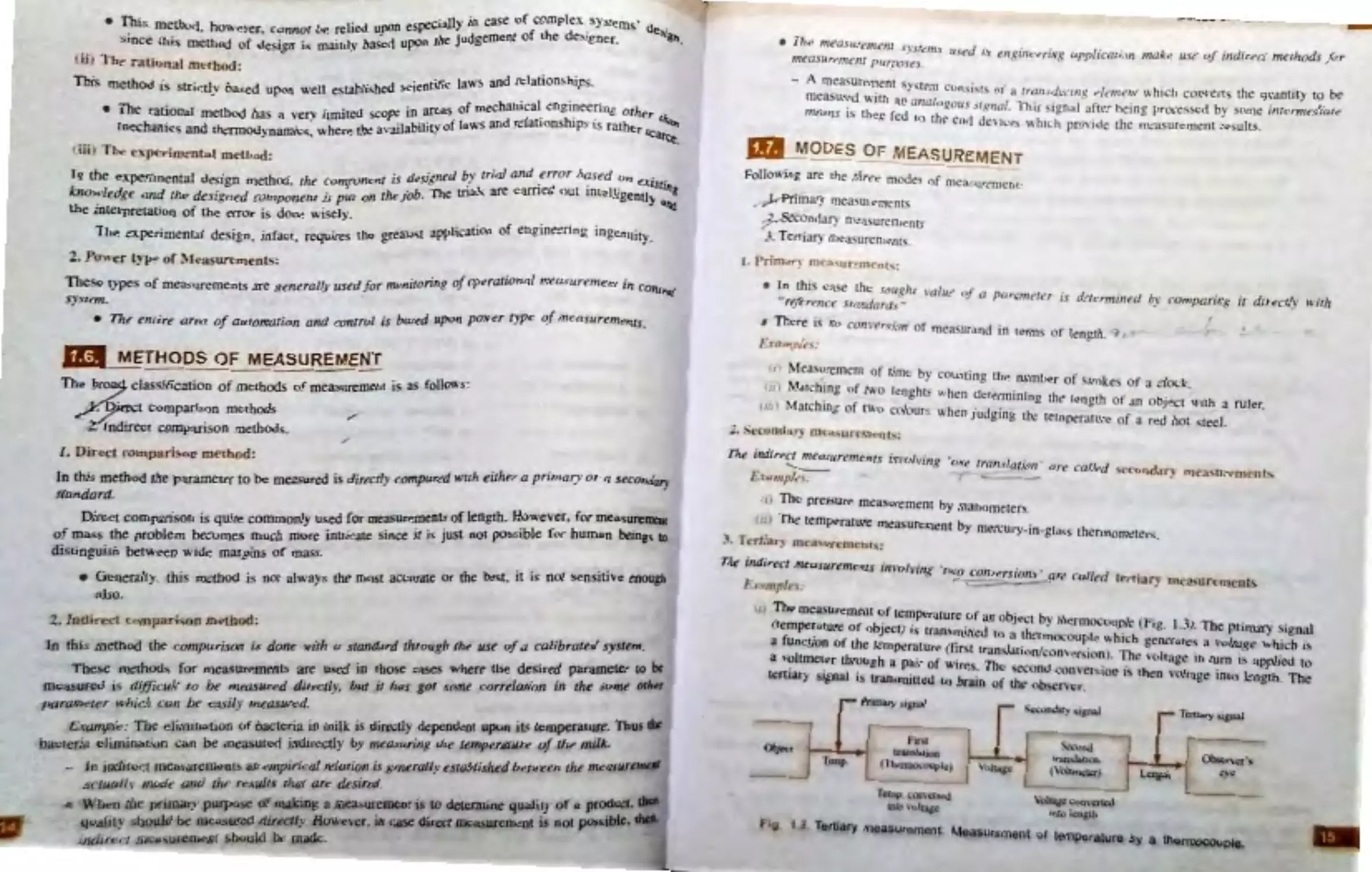
The mea\uremcot of remperaLUre o f an o bjec t h \' therm
•
.
.
(Lemperdrure of o bject ) i\ tran,m ·,, d
h"
ocou plc (Fig. l .J J. The pnl1lar)• ignal
a func tion of the temptrature (fir:r ~ ro ta ~ ;;noc◊upl~ ~h1 h generate~ a ,·oltage whic h •~
a voltmeter throu"h a pa,r of w,·...e
rThan\ a11tJ con,c:r,ion,. Th~ \ ohugc in rum •~ applied t~
.
~•
•· ~-
e ,;econJ ·on,
·
h
~ruary ignaJ i) lrdJl mitred ro bra,n o f the! ob ~~er _t .!~1o n • l en voltaie iolc> length. ll1e
Temp
Pnma,y , 1p..J
flN
tran.lclto0
(The,,,..,. •11,pk)
Tatip tcM\ffltd
UJ1u \t1J1.
I \r,1~
'
I
~
~ SltPl,11
~
·onJ
lranJ.Clon
(\\.llDUdcrt
~
-
-
\ohap COD\cncd
l1\k'llcaath
Tertiary maaaoremen1. Mea1urament or temperature by a
Tct"l1.11)' , ipal
I Ob.cncr·Jo
~
--
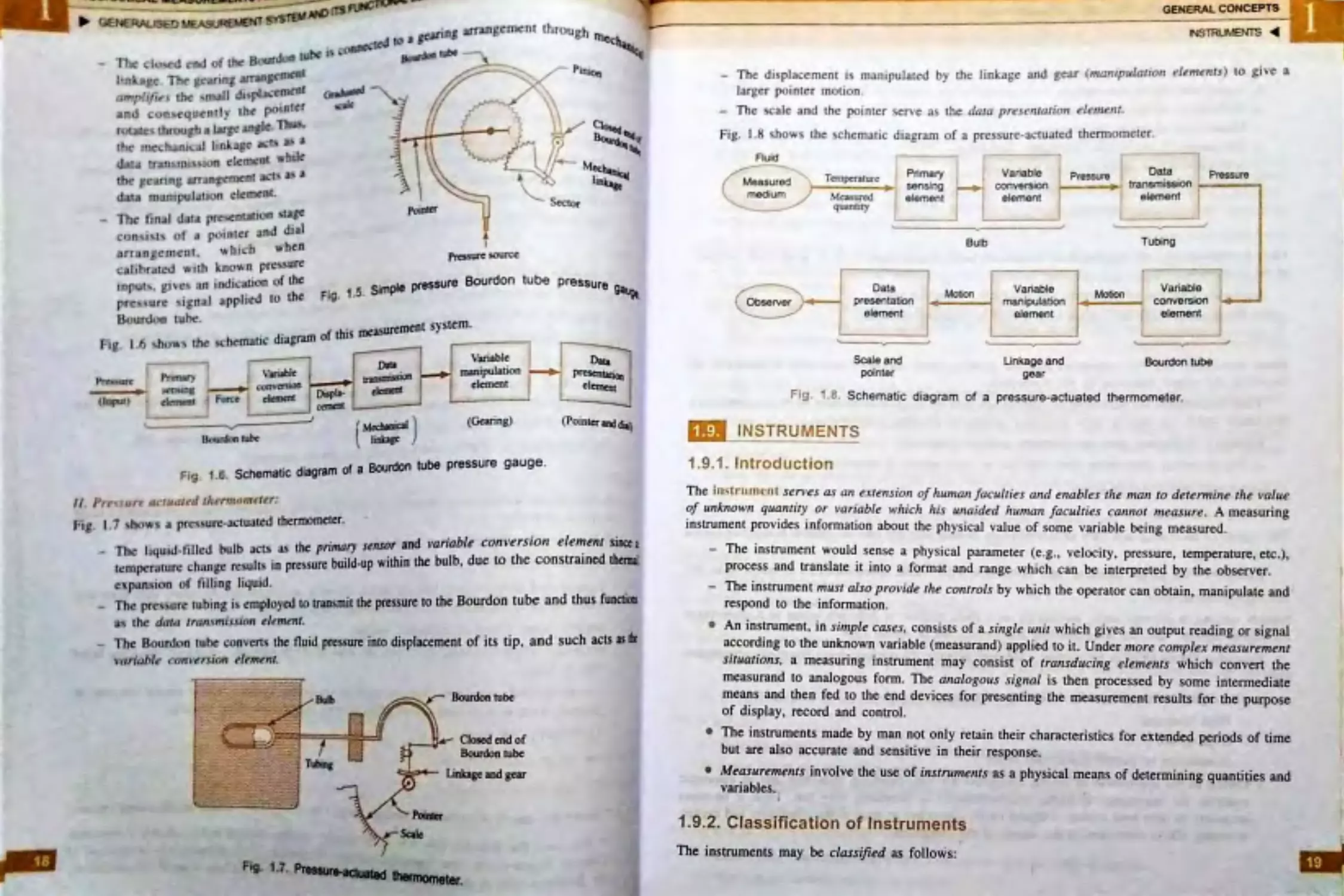
p bt:Nt:KALl~tD MEASUKf:Nlt N' ~T
~I~··· ,... ·-.. -
be pre •ure gtluge.
.
.
.,. b uBourdontu
.
(i , The n1easure111ent of st11t1c pres ure Y .
.
ft b rna ns of an elcctnc tach o1neter.
.
•
d of a rotat1n.g . sl1n Y
.
, , i The n1easure1nent of the spe~
ld t·tke-S place 1s ct1Ucd the l r .1,, \lu
•\ tion of n1eusur"1
•
tr
Tbe unit of a 1111.!as uring systcn1 ,,·here tnln!i a
or tr:111, ltttc,r .
d the)' include the ,vh o \e mn
.
.,,
·
f'\' s)r, ten1s an
.
.
..
.
gc or
•
•
Majority of n,eas ure1nent systen1 .u-e tcrtlU •
.
.
1 and clectro-pneu111au c 1nstru1nentli.
.
.
.
.
.
l~tro-n1echan1ca
me.chan1cul . e lectncal, pneumanc e
.
.
·ar egories:
di ,·d •d i11to foll(}\\'tng tu O <
Mea:sure1nent-s may al . o be 'i e
.
.
de,·i ce co111ac1s the co ntrolled mediu
.
, r ofthe n1eusunng ·
rn.
t . t ~t,1\t.,c.:t l) J>l: . ln this case the senso
.
r tl1e controlled medium.
h
or dc>e'\ 1101 co111ac
~-
,011-~ ontact l) pe. Here t .e sens
•
.
d otl1ers.
.
• I radioactive an
•
Non -contact mea · urements tnclude op11ca •
.
1.8 .
MEASURE
MENT SYSTEM AND ITS F1JNCTi0NAL
GENERALlSED •
ElE MENTS
-
___ __ ______
.
-
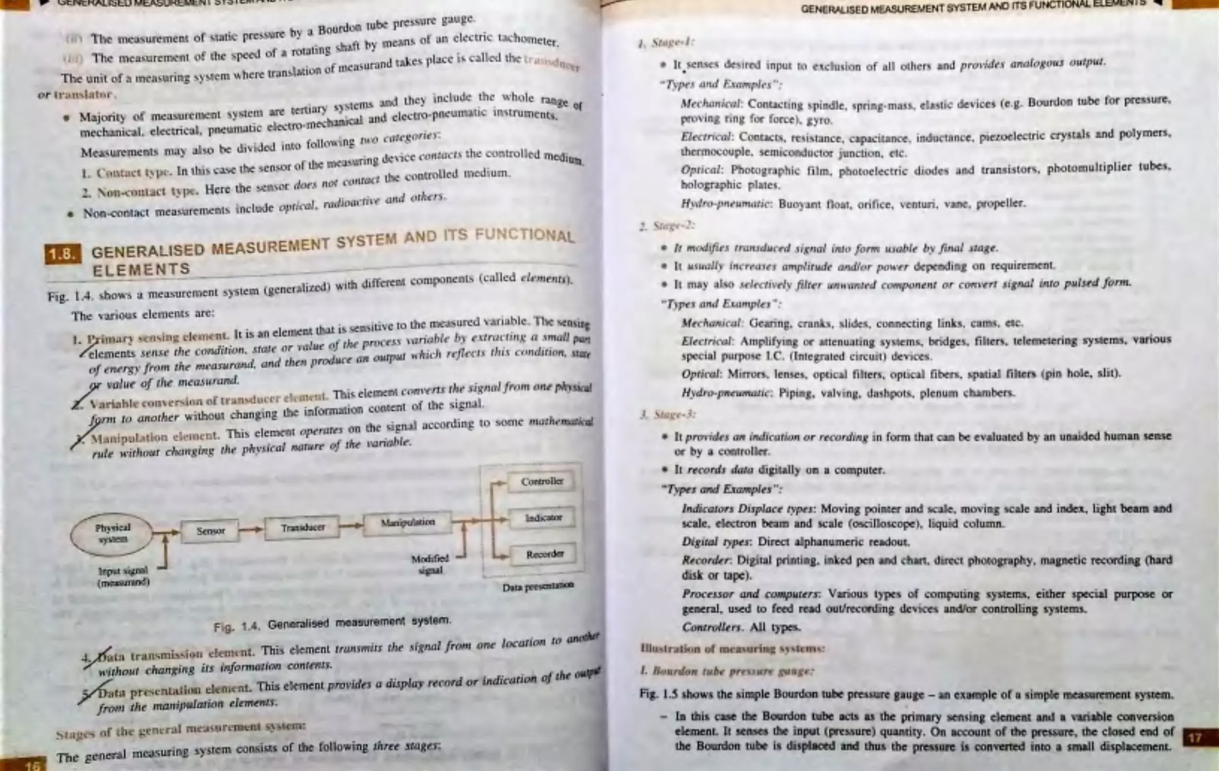
d \vith different cornponentc; (called ele111e111s).
1..:1. sho\YS a measurement system (generali ze )
Fig.
-.
The vari o us elements are:
·
blT
.
,
·,n·ve to the measured var1a e . he ~ensing
I•
element that 1s sen.
.
t J::itn.1ri sensin g ele-1nenl. t ts an
/
cess variable bv e.-r rra ct111g a snwll pa,r
·
·
••
\'alue o r ie pro
·
.
..
elen1entS se11 se tire condtt1on. state or
J outpi,r ,,,lzich rej1ects 1l11 s co11d111 on. ltarr
of enttrgy from the nzeasurand. and then pr uce an
value of 1l1e n,easurand..
Th' 1
ment converts rh e sig11al f ro,n 011e ph)•siral
•
.
••
tnt>1\ t
isee
•
ariuhlc co11vcrs.1ot1oftran du.cer cl . _,
.
content of the s ignal.
•m hangino the t1u ormauo n
/j m1 10 anotlier Wt out c
e
h . . , , a c c ording to son1e marlzemarical
·
t nt operates on t e Sign'"
\lanipula ti<»l eiem ent. This e en1e
h.
'abl"'
·
·
I ·I a111r•oifte,an
~.
n,le ,virl1out clianging the P iys,,ca n
t
Rtiysical
system
Input signal
(measurand>
I
l
•
-
Transducc:r a
-
~ lAl l••r-
_H
I ..f 1.•- -in11lation
Scnsor
, c,___
_
___
JL_-
Modified
signal
Fig. 1
_
4 _ Generalised measurement system .
•
•
•
•
•
•
•
•
•
•
•
•
•
•
•
t
.... -
Controller
-
-
Indicator
Recorder
-
.
•
·--
--
•
Data p.escntatioD
4. at.a tran fillb I
c
.
:.r . ut changing its infomwt1on contents.
__ ..-1
wur,o
.
d . d " tion ofthe o,,,r-
t. element. 'Ibis element provides a d1splay recori or in ica
ata pr-e. .,;tnt.'l ttm
fr-c ,11 the manipulation elements.
~ ta ut.•s of the general measur~ruent S)~rem:
,:,
~
I A~~ uring srstem consists of the following three stages:
The gener,a m~
•
GENERALISED MEASUREMENT SYSTEM ANO rrs FUNCTIONAL EU:Mt:N I:) ~
/. .\t11,.:v-l :
•
It.senses desired inp ut to exc lu sion of all oLhers ttnd provides analogous o utput .
" T)ipes and Exanipfes ":
Mechanical : Con tacting spindle. s pring- mn.ss . elasti c devi ces (e.g. Bourdon tube for pressure,
pro,•ing ring for force). gyro.
Electrical : Co nta cts , resi. tance . capa citance. inductan ce . piezoelectri c cry stal s and polymerS,
thermocouple . semiconductor junctio n. etc.
Optical : Photog raphic film . photoelectric diodes and transistors . photomultiplier tubeS,
holographic pl ates .
Hydro-pne11n1atic: Buoyant fl oat, orifi ce. ve nturi . vane, pro peller .
• It modifies trwisduced signal into /om, ,,sable by final slage.
• lt usual/)· increases ampli111de and/or polver depending on requirement.
• It may also sclec tivel)' filtf!r un1i1anted con1pone111 or convert signal into pulsed form.
" T)·pes and £.xan,ples " :
Mecl1w1ic,1l: Gearing. cranks, slides. connecting links. cams. etc.
Electrical : Amplify1ng or attenuating systems, bridges . filters. telemetering system s. vari.ous
special purpo e I .C . (Integrated circuit) devices.
Optical: Mirrors. len ses . optical filters. o ptical fibers , s patial filters (pin hole. silt).
H)·dro -pne untaJic: Piping, valving, da.-i hpot s . plenum chambers .
3 tu~,• 1:
• It pro '1ides an indication or recordl'ng in form that can be evalu ated by an unaided human sense
or by a controller.
• It records daza digitally o n a computer.
.. Types and Examples":
lndicalo rs Displace types: Moving pointer and scale. moving scale and index. light beam and
scale. electron beam and scale (oscilloscope), liquid column.
Digital types: Direct alphanumeric readout
Recorder. Digital printing, inked pen and chan. direct photography. magnetic rcconiing (hard
disk or tape) .
Processor and compuzers: Various types of computing system~ either s pecial purpose or
general~ used to feed read out/rec-0rding de-vices and/or controlling systems.
Comroll~rs . All types.
lllll!itration of mc~ uring ~~ , lcOl:\.!
I. B o11rdo11 tube pre:, ,,,re f:11t1.r .:1•:
Fig. 1.5 shows the simple Bourdon tube pressure gauge - an example of a simple measumnent system.
•
-
In this case the Bourdon tube acts as the primary sensing clement and a variable eonvcrsion
elemenL It senses the input (presswc) quantity. On account of the pressure, the closed end of
the Bourdon tube i$ displaced and thus the pJ'CSSUl'e is convettcd into a small displacomenL
•
__,..
___.._ :
~ rue ;..:
~
l)&)UtdlJobabc
(MoJwcal )
1m• ■F
I
''
.
Mec11a-: . .
\
I~
PiCf$1Ue lOW'tC
(Gearing)
......._ Sector
tube pressure 9aug._
Daia
~
clcmcur
(Pointer IDd dial)
Fig. 1.6.
Schematic diagram of a BourdOn tube pressure gauge.
JI. Pr,• ur~ ,1r11,,11 d t/lc'Tml1tn~tt r:
Fig. I .7 ~ht,w'l a pres)Ure-actuatcd tbennOmeter. ·
.
.
•
-
aclb as the rifnary strrsor and variable conversion elemenr smce a
-
The l1qu1J -t1lled bulb
.
P.
'thin the b lb due to the constrained thermi
r.«:mper.iture chnnge ruul~ 1n pr~surc build-up w1
u,
cxpan.1 -ion of filling liquid .
.
The pre,~ure tubing i'- employed to rransmit the pressure to the Bourdon tube and thus fuOCUOII
a,.. _.
the dat,1 tran.tmiuion elemntt.
-
The Bourdon tu be conven.1 the fluid presspre into di$J>laccmcnt of its tip, and such acts as*
,·a n'ablt1 rn,11•,r si,,n t/rm,nr.
Bourdon tube
Closed end of
Bourdon tube
Linbge and gear
GENERAl. CONCEPTS
◄
-
Th e di splacement i~ manipulated by the linkage and gear (1nan1pula1io11 t!ll'nre,rts) to give a
larger pointe r ,n otion .
-
The scale and the pointer serve as the data presentation ele1nl!111.
Fig. 1.8 s hows the ~chematic d iagram o f a press ure-actuated thermo m eter.
Fluid
Meaaurod \
medium/
--
Observer
--,
Tcmpcn1curc
Prtmary
sensing
•
Measured
element
quanucy
Data
presentatlon
element
ScaJe and
pointer
I
~
I
Bulb
-
Variable
conversion
r
element
I
Variable
manipulatio n
eJement
Unkage and
gear
-,
P~ssu ~
Da~
Pressu~
- -- 4~ ~• transmission ......___,
[ elem:nt I
Tubing
,-
-1
I Variable
converslon ...,_ ., .
element
Bourdon tube
Fig. 1 .8 . Schematic diagram of a pressure-actuated thermometer.
-
INSTRUMENTS
1.9.1 . Introduction
The in lrurnent serves as an e;crension of l,unian faculties and enables the man to determine the l'alue
of unknow11 quantity or variable lv/1ich his unaided human fac,,lries cannot measure . A measuring
instrument provides information about the physical val ue of some variable being me asured .
-
The instrum ent would sense a physical parameter (e .g ., velocity, pressure, tempcra.ture, etc .),
process .and translate it into a format a.nd range which can be interpreted by the observer.
-
The instrument must also provide the controls by which the operator can obtain, manipulate and
respond to the information .
• An instrument. in simple cases. consists of a s ingle wiit which gives an output reading or signal
according to the unknown variable (measurand) applied to it. Under more complex measurement
situations, a measuring instrument may consist of transducing elements whi'Ch convert the
measurand to analogous form. The analogous sign.al is then processed by some intermediate
means and then fed to the end devices for presenting the mea surement results for the purpose
of display, record and control
• The instruments made by man not only retain their characteristics for extended periods of time
but are also accurate and sensitive in their respons.e .
• Measurements involve the use of instruments as a physic.al mean s of determining quantities and
variables.
'
1.9.2. Classificat ion of Instruments
The instruments may be classified as follows:
•
i
I
Suremenl in t e nrt f ofpl1ysica /
. ,uidtr ,nea
c01r,
,l
0/1 /I' •" 1:r:•1·: ,., .
.
,ftht qlJIJlll1f)
I
h 1111Jrn11dt o,
Thrf r tnstnmitntc H'~" I e
- ·• -nt t,3.lance .
·.-h'5 l,UJ•.,..
,Jf tht lffJlrumc-nL
ter and .R ,yJeJE'•
rd ;_nstirurions.
£.x,ompl,, : T.sng(ol gslvanome
J r.x-apl in standa
,,ddom ust
• The~ , nsUUJ]]Cllts art
.
•
mtasurtd
. , 1 fl'« ,,,,,!arr ,n11ru111r11t•.
.,.,. quaniil)' J ,eurg
can only be meas,qt:d ~
l'
cttd that me
arr so constru
nl
Th#,r ~n.ftrwn~nJJ w ,ndil'attd U)' iht inftrum~
.
.
an absOlute instrument or another ~
, 1 hJl 'ln·1n1 rlu- ,,urpnt11 .arc C'alibrartd by comparl:s;•: absolute instrUment.
The,c ,n ~rrumc
. t,e,en calibrated ag
an srrumcn 1 ~bich h.i already
presswc gauge etc.
I . Voll.meta- .
g:las!t thermomelCf.
.
htrt of measureme111.
E.r,,mp t,.
d ·ilk u.st m tl'tf) JP
-·•"~ in uuments fin w
• The ..eca,~1
.,
Yo It>'' 11nd d11<rt.il in!!trunicnt. ,:
.,...,,. "
(.1
.,,
111,>1: i,, trr1m11n1, :
.
,
1.:
and can taJce on infinite number of \ale
,.
.
.
conunuous ,asruon
The ,ig.nals of 311 annJog urul vary in a
in a 31\.en range.
.
t watch s~lfometer of an automobilc.ll
and volunelers. wn s
J .,...~
E.xampl,s: F~I gauge. ammeters
ti,' IJ1. it,,! ,nrr,umt n1 :
ti.
ber of different val ues in a given ,.,
•
•
i,s and taking on a 1rute num
S1gna_1
~_
vary~n& UI d1Jndcre~ntp~ponding insuuments are of digital type.
are d11(ftol r,Rnals a
co
•
n a scorddl
E.
'
Odometer of an automobile, caJibrated balance of a platform scale. timer o
etc.
_ -wmp,,s:
• The digiraJ devices have the folJowing advan1aga:
-
High acc uracy;
-
High !.peed;
-
Elimination of human operational mors.
utr1fJI
• O\.in a to the application of digital computcn for data handJing, reduction and in. 1~
controls, the imponance of digital instnoM111a1ion is increasing very fast . Thus, ~ ~
nccnsary to have both analoa·IO-digitaJ (AID) conveners at input to the computers
ro-anaJog lD/A) con~aten lf the output of lhe computers.
-
GENERAL CONCEPTS
~'TRUM:NTS ◄
, ;, .ll l 'rl1a111rul i11,tr111111 •1tfi:
• These 1n1iU1Jment1. are very reliable for ~tatic and stable condition,.
• They are unable to rec;pood rapidly to the mea.suremenLS of dynamic and tran,ient conditi ons
due 10 the f ac1 that they have moving part., that are rigid, heavy and bulk)' and consequently
have a large ma ss. tvfass present.s inertia problems and hence these ioslrument., can not faithfuJJy
follow the rapid changes which are in- .olved in dynamic in5trumen1s.
• Most of the mechanjcaJ in5 trum ents cause noise pollution .
(i,J l~lectr1t·t1I i11• tr11111,•111s.
• The electrical methods of indicating the output of detectors are more rapid tlicm that of
mecl1a11ical methods.
• Unfortunately an electrical system normally depends upon a mechanical meter as nn indica6ng
device. Thi s mechanjcaJ movement has some inertia due to which the frequenc_v response of
•
these instruments is poor.
(iii) Electronic i11'irru11ie1115:
• Most of the scientific and industrial instruments require very fas, re sponses. Such requirements
cannot be met with by mechanical and electrical instruments .
• These instruments use semiconductor devices. In electronic devices. since the onlv 1noven1ent
•
involved is that of electro ns, the resp onse ti,ne is extreme/)1 small ov.1ing to very srnall i11ertia
of electrons.
• With the use of electronic devices very ~i,eak signals can be detected b)• usi11g pre-amplifiers
and amplifiers.
Compari on bet,,een mechanical and electrical/electronic instruments:
Adi•a11tages a11d di~advantages of 111eclur11ica/ i11str11111enls:
Advantages:
(11 Simple in design and use.
f1i) More durable due to rugged construction.
( 111 J Relatively cheaper in cost
f;I\ ') For operation of the instruments, no external power supplies are required.
(1·) Quite reliable and accurate for the measurement of parameters which are stable and non-variant
with time.
(Pi) Long history of development and successful use.
Disnd,·a ntages:
. ,.(,) Poor frequency response to dynamic and transient measurements.
~ ii) Large forces are required to overcome mechanical friction.
(iii) Incompatibility when remote indication or control is needed .
/71 ·) Cause noise pollution.
Adva,,tages of electrical/electro,1ic techniq11es of measurements:
,/.,fi) Less power consumption and less load on the system being measured.
<ii) Non-contact measurements are poss ible.
'-/
•
~1
.
uumentation.
Light. compttct and more rel iable ins
.
.
Remote: indication and recording fcnsible.oduced by a mechanJcal contnvancc.
h that pr
·
·
d.t
·
The amplification produced is g_reater '
11
~
mati on. differentiating nn 10 egratJng is
•
.
of signoJ s hke sum
The malhen1aticaJ proc ~ 1ng
t
po~~ible .
.
ood
•
1 response as g ·
The frequency and trnns1en
t ,_,,,
Greater nexibility.
·"'',
Lighter in con~rruc tion .
.
if /ectro•magnetically prod,,ced sig nals
.
' used in detectiono e
•
The electronic in struments are 1t1i del)
sucli as radio, video and microwaves.
.
build analog and digital computers Which
f Lb • truments has m:ide it possible to . th fields of science and techn ology.
•
The use o
ese ans .·
developments 10 e
are quire instrumental 1n the modem
4 1un11. , a nd .1t1tn111 a t1c in,tnunentc;:
are required.
.
.
of an operator
.
•
In cnse of nU111ual instruments services
.
th rmometer incorporaong a Wheatstone
b resistance e
.
ed)
c:-ample . Meas urement of temperature ~ a
. d i cate the temperature being measur .
C,..A·
•
•
.
wred to 1n
·
bridge in its circuit (an operator is reg
·s not required.
f.
nt an operator 1
•
Jn an automatic type o instrU me '
.
glass thennometer.
b mercury•1n •
Example: Meas uremen t of temperature y
. u· :. .tin" in,trun1ents;
s. s~,r.' -c1ntain d :.ind remote ,n ,c.
"'
11
,·n o ne physical a ssembly.
II . difjerent e emen s
•
A seJ f.contained in strument has a its .
.
1 ment nury be located at an adequate
r a remote indicating instrument, the pnmary sens an
5
g ehetypes of instruments are finding wide
•
n
·
di ti g element uc
Ion distance from the secondary ,n ca O
•
u regin the modem instrumentation technology.
.
'• ,.,_ . ._ l f-tt"''r,ited :.lnd pr>uer•opcratcd inc;tr umcnt.c;:
&
•
,
.7 1,;
,..
•
'de wer ,or its operation; the output
.
ent does not require any outs1 po
•
A self- ~ perated _instromlJ
almost wholly by the input signal.
energy •~ s upplied wh o Y or
M ry .n glass thermometer, Dial indicator etc.
Examples: ercu - 1
-
.
.
f power
h instrUments which req uire some aux1J1ary source o
The powc~ ~perated inrw~~c ~ts :~yed~: supply etc. for their operation . In s uch cases, the input
b as electr1 c1ty compres~ air,
"~c 1 "upplie~ oniy an insignificant ponion of the output power.
~,gna ;>
•
9
Example: Blectro-mechanrcal measurement system shown 1n Fig. J• •
~
-
I
-
-
•
f
11,u;al
1.....
Amplifier
.
.
'"
Volt,
Volta
•
-
Ftg, , . 9 Eleclto-mechanlcal measurement system.
,-
·-
-
___--,
D,t.l
prmentatlon
fNSTRU\IENTS ◄
7. Dcnection and null out1>ut instrun1~nts:
• In a ··dcflect1on tJ·p," instru11ienr, the deflection of1/1e 111.rtrume,u JJrovides a basis for lleter111i11i11g
the q1,anrity under 1neasureme111. The measured quanlity produces some physical effect whi ch
defle.cts or produ ces a mechan ical displacement of Lhe moving .system of the instrument. An
opposing effect is bui lt in the in strument whi ch tries to oppo se the deflection or Lhe mechani cal
di splacement of Lhe moving system . The balance j achieved whe n opposin g effect ec111als to
cau se produ cing lhe deflection or mechanical movement. Th e defl ection or mechanjcal displacement
at the point of balance then gives the va lue of measured quantity {\vhich depe nd~ upon lhe
calibration of the instru1nent).
£ra111ples: Perma nent magnet movi ng coil (PMMC) ammeter etc .
-
Th ese in struments are more s uited for me as urements under dyna,nic condi1io ns than null type
of instruments whose intrin sic re sponse in slowe r.
• In a "null t~·pr'' ofinstru,nent, a zero or null indication leads to deter111i11a1ion ofthe n1ag1iiti1de
of n1easured quantity. The null condition is dependent upon so me other known conditions.
E~~a,nple: D.C. potentiometer.
Advantages:
(1) The "null type" instruments are more acc,,rate Lhan defl ection type in struments.
(ii) Th ese instrumen ts can be highly sensitive as co mpared ,v ith defl ection type in stru ments.
1.9 .3. Factors Relating to Selection of Instruments
The following are some important fac tors/point s which are very essential to be co nsidered fo r Lhe proper
selection of a correct instrument for any application :
l. The accuracy expected from the in strument.
The foll owi ng mos t signifi cant and fundamental rule , which is perhaps the most imponanr rul e
in measurement must always be kept in mind :
"Never demand an accuracy ofmeasi,re111ent higlzer titan tl1a1 wlzich is real!>• 11eeded, and 11ever
forget that each degree ofaccuracy, ifdemanded, is likely to Jiave a dispropor1io11ate effect on
the complexity and cost of measuring apparatus".
2. When are the final da ta required (i.e. , at the time of taking the measurement . or later one?
3. The cost criterion (i.e . • the cost of the measuring process) .
~- In what form the data should be di splayed (i.e ., indi cating. rec ording, integrating etc .)?
.
5. Whether quantity to be meas ured has constanr value or it is a tin1e varim1t?
-
In the meas urement of time variant qu antities the manner in which the quantity to be
measured changes has a significant effect o n the type of meas uring in struments to be used.
The physical characterisrics of the n1easuri11g device musr al,vays be taken i1110 accounr
since these characteristics detennine tlz e amount of inreractinn whicli takes place between
the measurand quantity and lhe instn,ment.
1.9.4 . Functions of Instruments
Following are the three mai n func tions of in slruments:
I . lndicating function .
2. Recording function.
3. ControUiog function .
J.. lr:tiiratitt(! fnnctinn:
nl of the needl e on a ca librated
b (he ,noveme
.th. h J.
.
scaic
• The value of 1be quantity can be read Y tak to any fraction wi i_n
I e imitations of the
pr-0 vidcd on the instrument Reading s can be ·en
instrument and human eye.
, ttdomt ttr' indicates lhe peed of
.
f painter of a sp
·
the
Examples: (i) The deflecu on o a
automobile at lhat moment • (i r indicating pressure.
.
Th
f ·pressure gauge o
(11) euseoa
. aJs) is also commonly used. ln fact Wh
th diog in oumenc
.
ere
• These day s digital displa)' (Le. ,
·.erea
·--"
of digital readou ts 1s recommended.
din are desi~. use
highly accurate and exact rea gs
2. Rttt,rdint functi,ln:
.th
and ink the valu e of
.
l records. w1 pen
'
measured
• In several cases the instrumen1 ~nanuous !nst time- A graph paper is provided whose SJ>Ctd
quanticy against some other vanable or ag be ___ _, .a
10 record more than one number of
d"
.
trUJJ1ent can ~
can be adjusted. A rccor ing 1°:5 · recording of different parameters may be done by
quantities also, in which case, ealher the
eter after other.
different pens or same pen may re.cord one param
.
.
.
.
f rder • used for morutonng temperature records the
&le: A 'potent1ometnc type o reco . chart recorder.
ins tantaneous values of temperatures on -a stnp
,
3. C ontrol ling function:
.
.
.
.
fu .•
• perhaps one of the most impartant funcnons pamcularly m the field
• The concrollU1g nctaon is
.
·
.
ti
.
•
1
H the information is used by the 1nstrumen system to control
of andustnal contro processes. ere,
the original measured quantity.
Examples: (1) Floats for l.iquid level conttol.
(i1) Thermostats for temperature control
INPUT-OUTPUT CONFIGURATIONS OF MEASURING
INSTRUMENTS AND MEASURING SYSTEMS
Fig. 1.1 o shows the generalised input-output confijUlltion of measurement systems. The various inputs
to the meas11rcment system arc classified as follows :
\ J. Desired inputs
2 ln~rferring inputs •
•
I
3. Modifying inputs.
•
•
1. Ol•c,ired input1t:
TM quant~ties / or which the inst~or the measurement system is specifically designed to measurt
a~respolld are called desired inputs.
by o•
,Dfro the.
mathematical operation necessary to obtaJJI
nece sary ,utput m
mput .
,,
IIGoI
1
~-
G~1D
•
,
1 Output componcnLS due to destred
t and modifying inputs
___,....___ _
' ~1 o---
3
+
S
.
,
l • Output
wnm1ng
G~u
point
.
;
o,
Fig. 1 10
._ _ Output components due to interferring
and modifying inp uts
Genera lised input-output configuration of
measurem ent systems .
• The transfer function G0 is a representative of a \..Vide range of functions from a constant in th e
case of linear systenzs ro a sratistical f unction used for statistical rneasurem ents.
2. lntcrferring inputs :
The quantities to lvhich an instn,menr or a n1easuremenr sysren1 beco,11es unintentional/)1sensitive are
called irzterferri,,g ir1p11t 'i.
The interferring input i1 \vo uld produce an output component according to input-output re lation
symboli sed by Gr
3. 1\lodifying inputs :
,
The inputs wlzich cause a cha,ige in input-output relationships f or either desired inpur or inteferring
inp1,t or for borh are called n1odif) ing input .
The modifying. input i, .
1 would cau se a change in G0 and/or G1. The specific manner in \..Vhich i,..,
affects G0 and G1 1s represented by G, .
10 and G,.
11 res pectively.
For illustration, let us consider st rain measure,nenr by a srrain gauge. When the gauge is strained
due to mechanicaJ loadi ng, the change in outp ut voltage is given by,
Vs dR
dVo=4.R
where,
dV0 = Output voltage,
•
Vs = Supply voltage (battery), and
dR = Change in resi stance of the strai n gauge which constitutes one arm of the wheatstone
bridge circuit (assuming , R1 =R2 =R3 =R4 =R).
In terms of strain e and strain gauge factor F.
~
dV0= - •Fe
4
The above equation indicates that output voltage dV0 is directly proportional to applied strain.
In this case of measurement the cypical interferring inputs are:
• Stray electrostatic and electric fields, and
'
• Variations in ambient temperature .
.
ot gives an output even th ough th
1
Tbe a~ove mentioned effects cause drift and lh_e
1"5
°:°~ough the desired input (strain e-) ic
e ement mJght not have been subjected to an}' load ,.e.. ev ·
s
zero.
.
.
el1'ect of spun·ous inpuls on the i ndicar
The following methods are used to n.ullifi.· or reduce the 'JJ '
e<J
outp1u of an i11strun1enr :
J. Signal filtering.
2.. Compensation by opposing inpu ts .
3. Output correction.
•
U
.
.
.
te feedback device.
4. sc of high ampl1ficaoon and stable/accura
..
1 to the desired inpu t (Exa
-
Uf.
.
.
berently sens1nve on y
.
mp/e:
::.- .
se o •_nstrument clements which a.re •~
.
rv low temperature coefficient of resi stan
The strain gauge may be made ofa matenal with a ve ,
CC
and temperature independent gauge factor).
.. AP P L ICATIONS OF MEASUREMENT SYSTEM_S
.
.
ed ~ the following appl1ca1,ons :
The instruments and measurement systems are employ
or
·
I . Monitoring of processes and operations
2. Control of processes and operations.
.l . Experimental engineering analysis.
1. \rlonitorin~ of proces- and operotion.s:
In these types of applications the measuring mscruments simpl}' indicaJe the value or conditi.on of
parameter under study and do not st.rve any conirol Junction.
E.mmples: (1) Water and electric energy meters installed in homes.
(ir) An ammeter or a voltmeter indicates the value of current or voltage being monitored
at a particular instant.
2.
·o ntrol ,,r proc·C);)~ and operation :
There is a strong association between measurements and control. The instruments find a very useful
application in automatic control systems.
•
A common example is the typical tefrigeratioo sy5tem which employs a thermostatic control.
A temperature measuring device (often a bimetallic clement) senses the room temperature, thus
providing the information necessary for proper functionlng of the control syst.em .
3. (Aperin1cntal enitiuecring analy is:
The engineering problems can be solved by theoretical u well as experimentaJ methods; several
applications require the use of both the methods .
Following are die uses of experimental engineering analysis:
(,) To determine system parametm, variaBJe and performance indices.
(iij T~ formulate the generalised empirical relationships in cases here .... _
.
·cal
backing.
w
uu;'re IS no proper tbeoreb
(iii) 'Fo te&t the validity of tlieoretical predictions.
(iv) To solve mathematiC,8.1 relationslups with the help of enalogics..
-
HIGHUGHl'S ◄ ,l...." -'-• -
I A,1easuren1enr i the ac t., or the res ult of a quantitative comparison between a predetermined
standard and an unkn own magnjtude. Measurements provide us v.1ilh a means of describing
various phen omena in a quantitative terms.
::!. The physical quantity or the characteristi c conditi on \vh icb is the object of measurement in
an instrumenLntion system is variously termed as "n1eas1,ra11d" ,
0
,,iec1sure,nent variable".
"ins1rumen1a1io n varit1ble" or "process variable".
~
• The rechoology of using ,n truments to meas ure and control the physical and chemical properties
of materials is cnJled "insrnunentation ".
·.
The "n1easLuen1en1 standard" i.s the physical embodiment of the unit of measurement as well
as that of its submultiple value.
:-. The highest standard of either a base unit or a deri ved unit is called a "primary1standard". The
"secondary standards'' are the referenee caJjbra1ed standards designated and calibrated from th.e
primary standards. " \Vorking standards '' are the normal standards whjcb are osed by the workers
and rechnicians ,vho actually carry out the measurements .
t The ~ •o type of meac; uremenl!; involved in the mechanical engineering field are: (,) Mechanics
(or self-operated type). and (ii) Power type.
. , Methods of measurements are: (i) Direct meth od. (ii) Indirect method.
-
lo direct con,parison r11 ethod the parameter to be measured is directly compared with either
a primary or a secondary standard.
-
In indirect con1parison merh od the co mparison is done with a standard through the use of
a caJibrated system.
8. The three modes of measurement are :
(i) Primary measurements
(i,) Secondary meas urements. and
(iir) Tertiary measurements.
~ A gencraJiscd measurement system consists of the following components/clements:
(i) Primary sensing clement
(ii) Variable conversion or tran sducer element
(ii,) ManipuJarion element
(iv) Data transmission element
(v) Data presentation element .
JO. The "inst~nt" serves as an extension of human faculties and enables the man to determine
the Yalue of unknown quantity or variable which bis unaided human facilities cannot measure.
11 . The instruments may be classified as follows:
(1) Absolute and .secondary instrument~
(/1) Analog and digital instrument.'l
(iii) Mechanical, electrical and electronic instruments
(Iv) Manual and automatic instruments
STATIC AND DYNAMIC
CHARACTERISTICS OF INSTRUMENTS
.
.
struments; 2.3. Sta ·c cha racteri sti cs : ~
De~ bol,s relating_
0
measurmg ~ span-Scale re ad abil ity- Repea tability a d
·c
cahb at ron- ~~n
~=~siti v rty- Li nea r ity- Hyst eresi s-Thresho ld a
a cy ~nd p re c i.s:1 o effects-Noise; 2.4. Dyna mic ch aracteri stics : ~
ad time-loading
t system-' Dynamic' anaJysis of measure
•
cllaracteris ·cs of
8
measu ~~der systems-First-ord er s y stems-seconci
o,
a nd second order s y~~ - order system responses-W orked Examples_
-order syste~ re spons ti I Questions-Unsolved Ex amples
Type Questions- Th eore ca
·
c,o
-
-
-.
--
.
.
' b d b means of quantitative qualities termed ,
neofanIntrumenr
1
.
descn be k Y d O into the s ub areas of sta tic characteristics
. the·echarateri tic ha,mgbeen ro en ow
-
.
clwra teri tic .
,
.
·stem " here the quantities to be meas ured are _constanJ _(I/
•
1'l,ro~
penain to a. . b ed on dynamic relations (invo lving rapidly varyu:
an loM:ly with tim . Pe,fomwnce cnte':a . as
,uiJi f constitute yunmic cl1aracrenst1cs.
.
q
.
th ality f measurement under dynam,:
The tatk flaracte ristic . in a real sense also mfluence e q~
o
.
.
l effects in otberwist
:}nditions but these ch aracteri stic (static) shmi _up as non-l ~n~ar o;;:a1zst1ca ts would make CM
li near differential eq uati on s gi ing the dynarruc charactensncs.
e~e e{e:pproach is to tTtl1
. diffi n ntial equation anal ticall unmanageable and so the conventwnainfluence the dynaroi
'he two a pe t ofthe problem separately. Thu_s, eyen though these effects I the effects of ~
~ ha iaur, the differe ntial equations of dynarruc performance generally neg .ect
fri tion backfa h, hy teresis, statistical scatter etc.
.
..noJJ
•
.
.
.
uperimpos1 f!.E_.
The m •erall perf.omumce of ~n .instrumenJ is judged by a serm uantztative s
,
stalk 4Jll,ldynamic character:isoc.s.
3. or e<.·
ic 1 . The revision applied io the cliticai value so du:irthe final re,s,,.; .Jr obtained impro. e _ the
worth of zhe result is called .- ,
,·· ·e1
,
-t
,
all 1..1 r,,r It is rhe difference ~ the scale reading and the true ., a ue.
-
When the instrument· proper!_ designed and correctl; adjusted the
itenbiah1erroc·
very rate.
a g . The region between the limits within which an instrument rs desi n d to <Jpe rate for
measuring, indicating or recording a physical quantity is called the , a: ~ ofthe t ..s . ~u m ;L_
6 . e, it · · . The ratio of output response to a specified chan e in the inpu is called t
!••zt..
• The minimum change in the measured variable which prodaces an eff, tiv e re ponse of the
in trument is called ' Resolution sensitiviry". Ii is al-o called "discrimination...
• The lowest le ·eJ of measured ariable which produ e effecti ·e respo e of rhe in trumeot i~
called "Threshold sensitivity''.
-:.
~ cal · ·en "ti it~ , It is defined as The ratio of a change in scale reading iO the corre pon in
change in pointer deflection.
cal re dabi i : . The cale readability (in analog in trumen indicates the closeness ,,-itb ~ · ·ch
the scale can be read.
9. epe tahi it• . It is defined as the variation ofscale reading; it is random in nature.
• It is a measure ofcloseness with ·which a gi,·en input can be measured <R-·er and O\·er a a · .
10. . ccurac. • It may be defined as confom1il) H"ith o r closeness 10 an accep ied standard rabte (,ro
value).
• Accuracy of an i nstrumen t i influen ed b fac tors like tati e rror. dynami c error. rep roducibilir..•,
dead zone.
11. l:ncertaint~. Uncertainty denotes the ran ge oferror, i.e ., the region in whi hone gue es the e rror
to be.
13.
Pr ecis ion . It re fers to the degree ofagreement \\i thin a group measurements..
• It is usually ex pre ed in terms of the dev iation in m easuremem.
Drift. ~ g_radual departure of the insm,ment output 01·er a p ri q · tilt e ;_Jim i
unrelated to change s in fn p ut~ opera t ing conditions or lead is ca ed
14. Line- ri~ or on-l'nearit. • Deviation of transducer owp,a c ,,n-e from a pecified 1rai h lir. .
The 'non-linearity" may be: (i) Temiinal linearity (deviation fr m a straight line !hrougb th
points· (ii) Best-fit linearity (de iation from the straig ht line -which give m inimum erro - .
and minus.
1-.
Dd
ea zo ne . It is the range within ,~ ·hich v~riajJk_ an 1 (_lry l-t' itl1ou1 bein d ,: t_ed.
16. Dead tun . !J . .i!__rhe t ime befoFe the in rrumeJJJ (>egbz.s to re. p o nd flf!er t h e ~
_uc
been cha!!_ged.
·
17. P d of pon ' The quickness of an insErumenr to read the me ured variab/ is
re po11. c.
I . Reprod11dbilit . Th£ degre e ofcl..senns With whkh tJ,nam,vah,,, ofa rurid,t, ,_ .,. he llleSSJtre
at different times is called r produ 'bility.
..
·
19. Tolerance. lt is the range ofinaCCMracy wlaieh can be tol~l'l'Jkd in ~asurem ms.
20. Back! h. It is clefined as the
•
Ge,Jlc1'row h w/ti,:h .
'//'Pf a-
~ stem may?ii"mov«J iliOfM ~ wiluut~ap;,~ fore ot neooo,. t
-
in Q ,..., -, _,;..~
·
:
--- ~
11.
2.
that i necessary just to initiate motio
·
o 1 ( c,.ru tie frteti, n ,. fl is the Jorce or torque
.
.
nfronz re
.
·
-
.
enerated m a measuring system which
sr.
(J e . It ma be defined extraneous dlsturbance g
convey
meaningful information w.r .t. desired signal.
l1o
fll. STAT'C CHARACTERISTICS
M
t· noreorlesscon tant·orva ·
easurenumt of' anp/ication in which parameter ofinteres. ts
1
,
,
'
nes very slo
'J r,
·
(
"accuracy'
' error" "
W/y
with rime are called tatic meas ureme n . A set of critena ~ - ~. .
'
'
reproducibi[i
"drift'. "seroilh it)·", "'dead zone") that provide meaningful descnptt0n ofmeasurements under static conaiti:;
are called 1o;tatj h.arac en, ·c .
The main statu: cha ract ristics mav be summed up as follows:
(i,j Accuracy
,
. fit) Sen itivity
<iii) Repmducibi.lity
(iv) Drift
(v) Static error
(vi) Dead zone.
2.3~1 . Accuracy1 Errors and Correction
A ce racy:
ft · the degree of correctne with which a measuring means yields the " true value" with reference to
accepted engineering standards.
Accuracy i determined as the maximum amount by which the re ult differs from the true val ue (the
a 'erage of an infinite number of measured val ues when the average deviation due to the various contri buting
facto tend to zero . It is almost impossible to detennine experimentally the true value. The true value is nor
indicared by any m easurement system due to the loading effects, lags and mechanical problems (e.g ., wear,
hy tere i, ,wise pick-up etc.)
Accuracy ofthe mea ured signal depe nd s upon the following factors:
•
Variation of the signal being measured;
Intrinsic accuracy of the in trument itself;
.•
Accuracy of the observer;
•
Whether or not the quantity is being truly impressed upon the instrument.
Errors:
The accuracy of any meas urement system is measured in terms of its errors. Since it is impossible to measure
the true value of a quantity, as s uch, an approximation of the "true value" obtained by sufficiently extended
eries of mea urements and also taking into parameters and conditions to which corrections may be applied.
we obtain, what is called the " besr-measured value" of the quantity. The difference between the best measu~ed
i•a/ue and the rrue value of the quantity is known as.static error.
The absolute vafue of error does not indicate precisely the accuracy of measurements. It is the re/~ire
s tatic error w hich provides the quality of measurement\ The relative static err~
n_e4-.E§. th~ rauoof
absolute s.tar{c erc0te lP the tm:1 valu o the qf;!!l_ntitJ_ undp re~urement)
Let,
V, 11
= Measured value of quantity,
v, = True value of quantity,
E.r = Static (or absolute) error of measurement, and
E, = Rela~ive static error.
I
Then ,
E=V -V
S
lll
I
and.
E = Absolute error = Er
r
True value
1⁄2
or, %age relati ve error,% Er = Er x 100
~~~
~=~-~
= Vm-Er'~
or,
V+E·V =V
r
rr
m
or
V=~
t
l +Er
However, when Er is small , Er<< 1,
Eqn . (2.4) may be wrinen as :
. . .(2.1)
... (2.2)
{2.3)
... [Fromeqn. (2.l )]
• [From eqn. (2.2)]
... (2.4)
VI=vm(l-Er)
.. .(2.5)
• The error may be ei ther +ve or-ve . For +ve tatic errors the instrument reads high whereas it reads low
for -ve ta tic error .
Correction:
T~ diftereuc.e b.etween the true. va lu e and th e measured value ofa quantity i called atic. correction (C,J.
i.e .,
Cs=v,-V"'(=- Es)
...(2.6)
Eqn . (2.6) i~di~at~s th~t the tatic correction of the in trument reading is of the same magnitude a the
error, but opposLte m sign (1.e . C = - E)
I
'
S
J'•
"
ccuracy" may be expressed as:
- , , ,,(i) Point accuracy, or
jj,i) Percent of scale range, or
<j,>i) Percent qf true vaJue.
(t) Point accuracy. In this case the accuracy of an in trument 1•
stated for one or more points in a range.
I: amplt! :
(a) A given thermometer may be stated to read ±_Q.2°C between 50cc and 100cc :
(b) A scale of length may be read within± 0.2 mm.
-
.
(ii) Percent ofscale ra ng e. H h
::::,:rr(or is c~:~ ~~ed onJt:e
1
:is of maximum value of the cale.
Max. scale value
... (2.7)
Eqn . (2.7) refers to the intrin ic accuracy of the in rru
.
personal performance.
ment itself and doe not include procedural or
(ii1) Percem of true value . In this case the absolute e
f
.
.
value of the unknown quantity.
rror o measurement is expre sed as %age of true
(
V-V.J
.
%Error= ~ x100
-
Here, with a drop in true value, the size or error decreases.
i.e. ,
. .. (2.8)
-
I thi-.
t
pt ion f accuracy. the percentage error is the m aximum for an
.
y POtnt ·
mq um'4:m rnn e.
in the
n · rcent accur· c1 <m the basis of actual scale or full - cale reading ar e nonnalJy used
I~
nee h·h ·
to e-.
enr a n . urades and do not i nclude proced ural or personne peuorma
w ,c is ac tually inc "P~1
t • error.
lucteq ~
or.
or.
lf'r n ad.\· 112.68 V. lj the true -vai~fe ofthe vo ltage is 112.6 V. d etermine the following: ----
( i) Th,• static rmr.
(ii) The staiic -c .1rrec tionfor the voltm ter.
~n = IJ2.68volts; V1
= 112 .6 volts.
E_t = Vm - V,=112.68-112.6=+0.0SV (Ans.)
tt•)1.,
·,:
1
= - £,=-0.08V !Ans.)
-ds 92.35 ° and the static correct ion given in the correction curve is - 0.07°C. Determ i11t
he t .mperature.
vm=92.35°C; c,= - 0.07°C.
E_, = vm-vi
-
cs =vm- vi
V, = Vm+C5
[·: C1=- E,
[...Eqn .(2~1
= 92.35 -0 .07 = 92.28°C (Ans.)
-
-
--------·
--
-
-
---
l
,.r2 65 V The true valueef•
itulkating instrument with a scale range of0-5.0 V slwws a vo tage OJ •
•
2. 70 }' ()/J.\.
nd
.
?
(i) H,hat are the values of absolute error a
correction.
.
1
ii) £.qn, . the erro-r a .r a function ofthe true value and full scale deflection.
Given: v,w = 2.65 V; V, = 2.70
iJ
E = V - V =2.65-2.70=-0.0SV {, n .J
J
m
I
tio(.
C~:: -E.,=-(-0.05)• 0.0SV ( ns.>
STATIC ANO DYNAMIC CHARACTERISTICS OF INSTRUMENTS
STATIC CHARACTERISTICS ◄
(ii) .Kdatin: error, I\
As a function of the true value :
Es -0.05
Er==~=
2
_
70
=0.0185, or, 1.85% (, rh.l
As a function of full scale deflection:
E_ Es
-0.05
r-(
5
.0 -0) =-
5
-
=-0.01, or, -1% ( n,.,
----------
--
-----·----
A press~re indicator showed a reading as 42 bar on a scale range of0-50 bar. Ifthe true value --::47.4 b:r,
determine :
(i) Static error,
(ii) Static correction, and
( iii) Relative static error.
ii#JmiM,i Given: Vm = 42 bar; V, = 41.4 bar; Scale range= 0-50 bar
(z) Static error, E
1
:
Es = Vm-V,=42-41 .4bar=+0.6bar (Ans.)
(ii) Static correction, ('
1
:
Vs = -Es=-(+0.6) = -0.6bar (Ans.)
(iii) Relathc error, E ,:
EEs0.6
, = -V. =- - =0.0145 orl.45% ( \ns.)
1
41.4
h❖lul-lrtfl1
A press~re gauge ofrange 50 bar is stated to have an error of±0. 15 bar when calibrated by the manufacturer.
Determine:
(i) The percentage error on the basis ofmaximum scale value.
(ii) The possible error as a percentage ofthe indicated va lue when a reading of IO bar is obtained in
a test.
f..-fflmiM,M Given: Pressure range= 50 bar; Error=± 0.15 bar
(i) Percentage error on the basis ofmaximum scale value
0.15
= ±-- X 100 =0.3% !Am; .)
50
(ii) Percentage error on the basis ofindicated value of 10 bar pressure
0.15
= ±-X 100 =1.5% (An.-. )
IO
The above results indicate that the pressure gauge is more unreliable at the tower end ofits gauge.
ffiMtMtCl ____ ______ ______
---
__
A ' ·. tem compri si~g a tran sm:C;;;a reiay cmd a rereiver element has be en used to measure the
a r m ote point. {fthe pecified acc;iracy limits for transmi rter, rela y and receiver are within± 0.i ~ess11re QJ
and ::t 0. 9~ , e tirn a re the maximwn possible error and root-square ac uracy ofthe m easurement ' :!: l .4%
sys tetn .
Maximumpo sible error(lea taccuracy)=± (0.3 +1.4 +0.9)= ± 2.6% ( ns.1
Lea t root-square accuracy or root-sum square error
=± ✓(0. 3)2+(l.4)2+(0.9)2 =±1.69 % (\ns. )
The a bo e result indicate that the error i po sibly a large a ± 2.6% but probably not la
rger than
± 1.69%.
•
In an in trument y tern. root-s 711 a re acc ura cy is mo.re ju tifiable because i: i 11 01 probabl e th at I/
the elemellls of rhe ")', tun 11·i/l have the greate r srat1 error at rhe same po1111 and ar the same tirn:.
2 .3 .2 . Static Calibration
' t · ti · " i r.1tim1 ; · a p roc ss by ,rhic/1 all rhe ta lic p_e,for111011 cc _haracteristic. are obtained ;11 011 rm
ni' another In gene ral . ' latk -calibrat-ion refer to a situaLi on in whi h all inputs , whether d s irable. in terfering
"If 11cdif ir c ·ept one an: kept ut 'ome co n 'tant aJu ' . Then the one input under tudy is varied over .om~
range of constant aJue ' . whi h cau e · the output( ·) t vary over omc range of l.'.On. tant valuei-. Thu, an
output-1111 ut refa rim1 ·h ip is dev l peel whi h comprise o stari calibration m lid under rh<' stared ronstam
c nditimJ ,' <~( all_r/, e oth.,. i11putsl
•
he pm ~, ur of nlib ration in vol cs a compari ·on of Lhe pa1ticular inst rum -' Ill with either:
(i) a primary tandard,
ii) a S( ei111dary standard 1\'ith a h(~lier <1<'<'ur: icy th III till instnmu nr to ht· coli/ /'<lt ,•d. r>r
,;;,:) an ilu11r11mt'1ll t1_{ k110H· 1i" ac ·ura y
II\ k'
·
alihru t 'd ~unin. t s Hn rcfl.'l" n ·i. .: instrume nt s ll'hi ·Ii bLll't
higbc •r ,11·
1m1 'llts in turn mu:-. t h -- '• 1librat ·d :t l.!ai n st instru m·nl of,till
'
imar st:uulard or ;igain~ t l ther srnndnt ls of kn \\'fl a· un, ·i
, ,m, ,~1i1 fl (tfi(' im-rtw-n ·nt. nnd id t1t1 f) and li,l a ll tlw ,,c1., iN1 • inruts.
.
•
~)f \\hl
s~il It whi ·h 1Jf th' iflput. will /I<-'
.,i:nifi, a111 rn th ~'I p.h • 1nn11 l
.
lihrnt rd.
:lppaT ,1O1 s ct-ml will 1!11 111 · 1<1 , . 1y II rlt1 si,mi ll',Ult t,,1 w., <•i ·cr ti,, • , 111 ,\t s r ,niJ
y. I t\ ,C\l s-t{lfrdnttJs 11 111 a:mr ·n hint m
/011 r/1< ,/tJit
:-ll1m:. v:irvin 01h:.1 .• und · ·o rdin•' th· t 111pul(. ' · cl 1·
'
l.\ ,
sm111':Hr. tdi · · 1~nt·
ti.' l ,, ·rJndu
STATIC ANO D---vNAMIC CHAftACTl:RlSTICS OF INST-RU M ENTS
STATIC CHARACTERISTICS ◄
The instrume11t ,pall is given by , smax - s111i11'
The above definitions appl y both to ana log as we ll as digital instruments .
I- rror calibr-1tion c ur t'.
•
It i an error curve which can be used for correcting in strument reading. ·.
• The cur e i pl o tt ed by ca lib rating the instrument again ta suitable &tandurd at a number of points on
the sca le.
I· ampk,: (i} Range: 2kN/m2 to 50 kN/m2 :
Span:50-2 =48kN/m2
(ii) Range : -5°C to 90°C ;
Span:90-(-5)=95°C.
• While detem1ining th e range or the in~trurncnt
the ftequ ncy rang, must be taken into
con . idcrntion . '' Frequen cy range" i. defined
a. n -que11cic rJ1 er 11 •hich mcas11re11w11rs ca11
be pe1for111 ed with u specifi ed degree of
aCCUIW.) '.
11n 1h . movin ir<m voltn1ct ·r ma ha cu angc
of 0-120 rang· und 0- 1_5 1:-11 fr 'quency range
, ithana·eurac of0-5or lp·r cnt offull ~rnlc
rcuding .
20
40
60
RO
Met1\111ed ,a .riable (<;;- pan) --+ -
Ft . 2 1. Error calibration cu rve .
100
c is l·a/1hmt1 •d har to 60 hat . '1111' U<'<'ttran- i ,· ~p,•1·i{i('(/ within ± o._ v
I erc·e, 1r ofin I rumen~
1e 11 u /\inw111 ~taric crrvr ?
·
0.J I ll'n·
R d bihty
~ ~ Jahility I'-
r ·q11 ·nt l u..,rd 111 .l.n,tl\\' I) p;: 11f in,t, um •nts. / ;11 li< ' ,llfS the dt•\rtt s.~ wlrh
11ll 1.Jt/0/,1, 1 IV/ (' ()
'11 ,,,fl/I,.,,,tWIh,•II td.
Th· r \ .ld,1b1lit,, d 'I t11. _h
llf)1._\I\ m.1n. fi11 Inn :--H ·h :,s:
--
d
rod
I
.
111
,
1
r., p,oducibilit_v is s n c b ul lb ·y are applied in diff
rep ·ara >1 11,
,
~
-e rent
J vhen the ome inp ut i.s applied r
.
.
p rtwnv tu Jh C'/u1l!llt' H of 011t f'Ul re<ll 111 K' l
.
epet u, vel
h
.
d (ons same 111stmme11t and obse
Y
o n P('no,/ of tmu: 1t. 11h 1hc ame m •a,urement co11 1 1
'
rver, same
'1'
,1 0 11 ond r m1w l onditm111 of u.H' mai111ained tlt ro 11 gho11t .
, da1r w th cl11.1enes1 of output rl'adi11J: for th e ~a me inpu~ ~vhen
th
erc are change s
<1Htrcnwnt , ()b t•rtl!r. mca 111 n11g ins1rum e11t , loc acion , cond1t w11s of u se and tim e of
1 · on 1mtf,, 1i r •d K, adual depan11re of the in strum ent out put over a period of tim e that is unrela ted 10
luu g , .\ i1 t. ·,ww. op rarinx conditions or load.
n in!\ mm · u t b :-.aid to have no ddft if it reproduces same readings at different times for same variation
10 m asur d vanable.
1h drift may be cau '\ed by the following /ac tors:
i) H1 h mechanical tre s · deve loped in ome part of instrume nts and ystems.
)ii W arand \enr.
(iii) M " hanical ibration s .
th) • .:mperatur changes.
(,) .'tray de.ctr1c and magnetic field .
_t 1•1J The rmal e. m .fs.
1hem10meters and th ermocouples" due to the contamination ofthe metal
and a chan ,e in iH atomi or metallurgical structure.
[)ri
ur in " flow meters" due to wear and erosion of the orifice plate, nozzle or venturimeter.
f)rift may be da.s ·(lfrd a. follow s:
2.Spandrift;
3. Zonal drift.
c He~ -:,No drift ~f 1he whole of in. trument ca lib ration graduall y shifts over by the sa me amoun t.
It rna • be du to p nnanent set or slippage a nd can be corrected by shifting pointer position.
~ the ,-~ librat;
011
J,om ze ro upwards changes propo rt io nall y, it is call ed "s pan (or sensitivity) drift"·
_
It
I
y b •du to hange in , pring gradient etc.
.z
ift"
the d rift f) ccurs only o\'er o portion of span ofan instrum ent. it is ca ll ed "zonal drr ·
annot t,e
Wiren
-
drif .
d.bl
.
.
.
.
l
arent and c
_
ft mdu strial in stniinenl. ,
t1sanuneJra equantity mce1t1srareyapp
ea.,.. ifv co mpen sated or.
.
nee·
_
,
r s v''"'" · lowlv a nll ca n be c hecke d onl b periodic inspection and mtnntentJ
D1 1/I occu
"'.,
'
2.3.7. Accurac a dPr isi
\ccural , . The closeness with which an mstrum ent read1 11 g a pp10ac he~ the tnt<' value <f rlw <JlWlllit\' hein•,
meas ured is ca lled an·11r< L •• Ac c uracy is determined a<, the maximum amount hv v.h1ch the re ult Jifkn, fr 1m
the trU e valu e. Acc uracy of an i11 trume nt is inf1u e nced by factor- . li ke static nm. dynamic cnor, repr Jncibilit_ .
d~ zone .
Pn:cbum. The te~m ' preci e' means clearly or sharply defin ed. Preci,ion is; a mea ure uf reproducihi/11y of
~.!!f!!l~/,,S. It 1s usually expres ed in term of the deviation in mea-, urt!ment
-
.
~1g11ifirn_111 Jir>11re i_s an indi cation of the pre cision ofmeasurement . Significant fig ure, com cy actual
in form ati o n regarding the magnitude of precision .
Foll owing c, mn{. ll''> will illustrate the difference in me aning of the two te rm s acc ura cy and pre( ision:
(I) Let us consi d er the case of an ammeter having high preci ion which can take readings to l / 150 of an
amp~re, but has a wro ng zero adjustment. ow we can take reading to l/150 of an ampe re which are
co_ns1stent and clearly defined since the ammeter is precise as eve r. However, the readings tak en with
thi s ammeter are not accurate, since they do not confirm to truth becau e of faulty adjustm ent of
zero .
(ii) Tak_e _the case of a micr~m eter which i normal in every re pe~ t but its anvil i displaced from its true
positmn. When the read1~gs are taken by thi in trume nt, these would be clearly defined and consistent
and we wou~d _sa ~ that mic rome~er is as precise as ever. However, the readi ngs do n ot con form to the
truth as anvil is di splaced from 1t true position. Thu , the readings taken by thi micrometer are not
accurate .
• It is worth n9ting that preci sion is a nece ssary prerequi sit e to acc ura cy but it doe
accurac y.
not gua ran tee
2.3 .8 . Sensitivity
Th e rat io of the mag nitude of output signal to th .
.
quanti ty bei ng meas ured is called sens ithily.
e input signal or respon se of meas uring system to th e
It is represented by the slope of the c alibration c u rve if the o rdin ate are expressed in actual
't
When th l'b
·
um s.
-
e ca 1 rauon curve is linear (Fig. 2 .2a), the sensitiv · ·
·
-
curve is non-linear (Fig. 2 .2b) the sen sitiv ity is different at ~
7fts con st~n t. Ho:"1ever , if the cahbration
various points .
1
e re nt pom ts, bemg the slope of curve at
Slatic sensitivity , in general, is defined as:
Static se n sitivity (S) = Infinitesimal change in outp).lt
Infinitesimal ch ange in input
Similarly, Inverse sensiti vity or fi efl.e ction fa t r or sc al e factor= M;
Mo
.. .(2.7)
... (2.8)
• The
'·' ·
se nsitiv ity of an ins trum ent should be high and thus the
to the value being mea sured.
range should not be high in compari on
• Sensitivity has a wide range of
being investigated.
.and these depend upon the instrument or measuremeat sy tern
fnru1. A, ---
lnpu A,
Fig . 2 2. Stauc ensitlvity.
Th~ follo'tl mg po;nt\ arc i\:orth no1i11~ :
In ca ·e the fonn of input to anJ ou tpur from th mea.'>ur men t y-; tcm used with e lcct1ical/ le troni
equipm nt is !'>ame. th e term ,, ; i, u ed in'itead o s,nsiridt,\.
The incvastt 10 dLplac:em~nt with Lhe o tical and me hanical instrum n1 is described h the term
,l )f,ft i\fl.
Wh n the inpu1or o utput ~igna l i~ chan~mR - ...·uh mnc, the t -m1 t
i. used <i n place of the term. unsitfrif\-,
0111 or amplijic-01ion-w hi
describe a r latj om,hip bctwe n output. nd input).
A pre sure gauf? . which ha. lim>ar calibration urve, has radiu rd f al /in c. 9 Jmm an Ipre s111 oj - ro
to 60 pascal<; fr di. played O\'er a11 arc of300 . De1t!,-mi11e th e senswrirr of1he ,?auge u. a raric> of ale le, 1
to pre sure.
Full cale deflection = 300 · = 3
7t
X-
1
-
=-
rad .
5n
Length of scale =
3x O-= 1501tmm
Sens
..
.
Scale length
ltiVJty = --------=- --
CaJibrar.ion pr _ure
1501r
= 60 = 2.51.t mm/Pa <.\
••J
J,z a Wheatstone bridge. a c hange of6Q in the itnlawwn a:rm ofih brid-- e
-is re;uired 10 produc~ a ch,all
in deflection of2.4 mm ofthe gatvan.ometer, Determine:
(t) Sell ·itivity; (ii) Deflection factor.
Given :Magnitude of output response= 2.4 m~
:ind,
Ma gnitude r>f input = 6 [J,
(i) •I ii '{\
(1i)
2.
= 0.4 mm/0
()
~
1
-
2.50/mm
2.4
'.,
pl't!Slllre mea.111ring .\ _\ ·st em cmnt\l\ of a pic-:: . rwlc1 ·tri1 Iran ,J1w<' r, a chur~,, amrli ,,:rand an ultra v i<)let
charge n corder. //u 1r 11•111itil'ittc are n.8 pClhctr, 0.0012 VlpC a11 d 16 mm/V re p!cti~ · eh: /Jt:terr;iint the
defk 11011 011 th, chart (or a 11 r ' \\Ur< clu111~e nf jJ /Jw .
-
\ 1lh th t' dt..'mcnh ,Lrran 11.:d in - .erie,. th~ m ·e rall \ett\illru · of the mea ur1ng :,: · tern r ·,
= Scn:-1tn1ty of pic1 >dcctrk tr-in,ducer (5 11 Y en ith·it~· of he charge a plifier
.\.,J x. n 11, v ,t y uf' ultra v,olct t liargt: 1c- ·1 rder (.Ci
1
)
11(
V
mm
li8 - xo.oo
..
-
;<16 -- =018~
bai
p
··•
l:i,1r
~~ng~or fl ttp~t - 1 >n.tl
Change or input ,i nal
·en 1tn·11y
r,
D/7ectwn 011 rhc lhart
= (U4X x 20-= 6.96 mm
2
anr
Tl ahi/1n to reprodw·p th
e trai •ht line equatio n.
.t
. It.n
"
PP db)
Theiinearu·· · l
I
u sanp ' a mea1un, ri 111tn imum dc!v:w•o,i ,,
me (drawn by using th
h~,1
'
alib
e met uu of lea...,, qu· r-c tn 111 th, !!i
a 1 "1th, c,zi
·
~i a1.1 n urve and a trai ht lin J ·\.\n trom rh~ ur,~·n
n meth ofle st uar
·
n ..ilibT:Lli Tl
n~ depanur from sLrai~hr lint ,. lmic,,1\hi t
. Th n n-linearity m •
uch l.h I llo\'- i;,. a
(i) Vi. OU flu-
r1.: ep:
\llJ-o
-l inear I It nt in th" m ':.t<;U1 ·r
·nt ,J • ·i.:c:
iut
frJ 11k: el ti atwr tt\:\:t..,
111 th
Tv;
li·
► STATIC CHAAACTE.RISTlCS
.'
oniderdtobeon
l 10 input) 1
eofthebe
.
r atJv p1op0ruona
Thisi •o, becau etheconver io f ,st
,
,..
, (i.e. . ou t~ut I. i:or'rne urernent , . tem1-'ty i very convenient. However itn rorna
h
l
.
s of an in t.rUme
f·putquan1
•
may 1..
caracen1c
0
.
g valut' o in
.
lly lead to inac curacy· an
·
uc
·ale readmg to the corn! pon in
.
ur doe not e enua
'
tn&lrumeni
unders tood that a non-linear tieba
10
be highly accurate as ever .
h vino non-linear calib rauon curve may
ach other. it i better to keep the non -Ii .
e
.
.
related clo ely 10 e
neanty
Since accuracy and hneant) are .
11 errors.
"bl
.
. toreultin ma
a ·mallaspo 1esous
.
.1
.
H· eresis
;1; d
h
d value within rhe spe_cz.,.e
_
rang e i ~ en approaching th
The ma imum diffe rence · m ou1p u1 at any meas u~e
.
ut ,nay be remied a h ·steres1 .
·
e
point first l~ ith iticrea ing and 1he11 with decreasmg mp
.
.
·
ct ·«
t output effects when loading and unloading. It is non
ft i" a phenomenon which how tueren
·
coincidence of loading and unloading curve~ -
.
.
.
.
(loading and unloading) for an in strument which has no
Fig 2 4(a) ·hows output and input cur e.
nl d'
·
.·
·
d
1
:-i; arts The non-coincidence of\oading and u oa mg curves 1s on account of
nct1on ue to s1wngp .
internol-f .r .ic.tia11 or hysteresis dampin .
Fig .
2
. 4(b) how · the input-output relations of instrument which do not have internal friction but
ha c external liding friction.
Input ~
(a)
Fig. 2.4. Hysteresis effects.
t
(b)
The numerical value of hy. teresis can be specified in t
f.h
.
t and is usuallY
•
01
iffi ll l
erms o e1t er output or rnpu
given as 1,,age o , sea e.
• Hystere si re ul from the presence ofirreversibl h
.
.
.
e P e,wmenon such as :
-
Mechanical fncuon ;
lack motion in bearings ;
-
Magneti and thermal effects.
2.3 11 . Thr ho d and Resolution
J rec,I:
The minimum \,altte below which no output ch
.. urtl!
ll
.;,
.
angecanbedt
.F
jJJSl~!lO
i,u· reasedgradua YJromie.ro1scalledthe hrC!·hold if . eected when the input o, an t1]il))JJ'~
alue of input which i. necessary to cause a detectab; the instrument. Thus threshold defines the
.
e change from zer.o
t.
_
In a digital system, threshold is the input c;ignal ne ce ary to cau ·e ont: l a.;c significant digit of th1;;
output reading to change .
Threshold may be caused by backlash or internal rwise .
Resolution or Ui..,crimination :
When the input is slowly increased/ram some arbitra ry (11on-:: .ero ) input value. it i ob erved that the output
does nof change at all until a certain increment i exceeded; thi incrPm ent i called
1
or
cliscrirnirwtion of the instrument. Thus resolution define the ~mallest change of input for which there will be
achangeof OUU,}ll. ~
-- :-j; case of analog instruments, the resolution i determined by the observer's abi lity to judge the
position of a pointer on a cale. Resolution i usually reckoned to be no better than ±0.2 of the
smallest divi sion of the scale.
-
In case of digital instruments , resolution is determined by the number of neon t ube . taken to . hO\V the
measured valu e.
• Threshold defines the smalle st measurable input while the resolution defines the smalles t
measurable input c hange.
•
" Threshold " and '' resolution " may be expressed as an actual value or as a fraction or percentage
offull scale value.
1#:Ei11Htiflll
A transducer measu:es a range of 0-200 N force with a resolution of 0.15 percent ofJullcaz-:-ihat i.;-the
smallest change wluch can be measured by this transducer?
l-1MBM,i Given:
Range of force : 0-200 N
Re solution
: 0.15% offull scale
Smallest change which can be measured
_
0.15 x
2
-
100
00 =0.3N (Ans.I
U£Ei,,i4tlfJ
Determine the resolution of a movi
·t
.
-------
ng coi voltmeter having a unifonn scale with 50 d' . .
.
h
d
.
.
1
Lvis10ns, t e full scale
rea mgis50Vand-
•+
••.
lo
OJ a scale dzvzszon can be estimated with fi . d
.
a air egree of certainty.
~ttiM,i One scale di · ·
_
50
v1s1on _ -
=1v
50
R esolution =
1
~ x1 =0.lV {Ans.)
Detern ·
h
·
.
une t e resolution ofad' .
l
.
reading is 9.999 V
zglta voltmeter wluch has read-out
O
____ .,___
-
---
.
range to 9999 counts and its full scale
ffiffllf.ia,W R z ·
--. . .i .a.::_n_l'II
eso .utzon of the dig1·ta1 l
vo tmeter
►
dZ
do d Ti01
••
1 111
q11 ,mtltY for
R,_•fer to ' ~t"
-
Tiu /ar•>e!.t chull}!. t' <if
11
P J·" ti•1t<
r~·
-··
.
,-.
.
(f'/7/IC .,. .,
which rlten. t mi mupu1 o(th t' i11~ir11me,a 1
01 ,;q,ich
·
.
.
• th i11 •mun
.
'i
]tmu.1 o· 'lll'du l (nctWO'"
..
<T"fOl tS
.
.
·uJ't" •· •nr d vine
does not nll w pointt!r ro mo e ull i,
tt:1c
d v loped I o r om.c rh friction loss.
.
ill
I ·I 11d /1\'.\terc; ,.
... Dt:•ad -:o -ne •· is ·mo·ed b~ · back m ,_q_
·
11.C in rrwmmr.}
D·tic:
.
urement ystem
Refer H.l Fig. 2 .5 . Tlie rime requi red by a men di Tt•rmed
to b gin 10 respond to a chcm Ge in th e mra uratl!. •tnnnenl
.
2 5 Dead zone and dead time.
Fig.··
h • before the in
d
as d,•
·
. It repre ·ents Le time
.
been change •
begin to re •pond after th e mea ured qu antity has
----
i#:ElnHntlH ---------8
-00 ;--
C [Fthe dead zone in it i 0.11 percent ofspan ,
---
.
..
.
300°C to
.
:.J
The calibratio11 range ofa certam P) 1ometer
1
b ,+o re it is dece cted.
I·hmightoccur ep
de/ermine th e t mperaturt! change w uc
00 300=S00°C
J-i§t!m i,i
Span of the P. rometer =
-
~ xSOO :::0.55 °C
Dead zone =
100
·
is detected. l n~. )
Hence. a chang e of0.ss oc must occur before ,c
2.3 .13. Load'ng ffects
..
.
an mi ion anddete tion hould
.
al en ino- cond1t1omng, tr
U nder ideal •ondition an element u ed for 1~
:,, h uld not use any energy or take le t energy
.
.
.
lTh enmgelementso
.
al
ct·. .h
not chanoe/di •tort the ongmal 1gna .
e
.
d Ho" e er. under pracuc con 1t1on , n as
0
th
neter bemo- measure
·
·
fh
from the proce . o as not to cha~ge e parm
.
e
rem re ult in ariably i11 extractwn ~ t e energy
be n o b-Sen d that the introducuon of an. elemen~
10
a Y . d' t rt.ion ma take the form of art e1111ario11,
d.
·
I O foinal signal. Thi 1. 0
•
.
.
from th ) stem thereb 1siorrmg tie ' 0
h.d
.
1 ea urements become 1mposs1ble .
.
•
pl.
,J;F, t~Conequentlyt 1ea m
1s,· n · ifonn d1 tornon. ias 5 11J' e ~-
•
/ -r.
•
ailed the
1•
· gnal in und1stortet. :.1orm L
incapability of the sr~1em to Jaitlifully mea sure cie mput I
• 1..{[hi.:: _ r ~ ult in loading errur .
"1'hrouf!,h 1•ariahlr., '' , abo called tlow vuri:-th lcs or pcrvariablc 'l, a c thQ c whj c:h c~n be pcc 1f'icd
nncl m ·a tll't:d at Ont• pni111 i11 a .Ipac_' " · Thc!. c arc c xlen-.ivc variiibl - .
in th i.i.:n<,c, th, t th ·tr
magnitt,d • d ·p 'nc:b, upon lh ·xtcnt of tho '>yst •m taking part in Lhc ·nergy 1ran. f ·r .
''A rv.,:. voriobl<', " , al so ca\kLI dfort vari able~ nn<l tnrnwari ahl ,.., · re 1ho-, whi h c· 1 b<· r,
·i J'i ed
by two points i11 a spare; u~uully one point b u reference point. 1 hc, e arc inton ive v~triable
whose magnitude i-, ind •pend m or the me<lium being ·c:in i.icl red .
All ol;ject ill a mecu11remc11t system or an y dynamirnf 1yItem in vofre a measurand or defined rel ation;hip
betW en an "across variable" and a "through varzabk".
~(• •('. i ll'
ln some in truments w h e n input ignal is appltcd to them un der .,1a1il 1.:on d itions. thi.; output 5ignal 1-. a
faithful repre . nlation of th e input ~i0 na l. But when th e 1n <;tr ument · arc 5ubjected to dynamic condiiions
(i.e ., going fr m on~ tead state to an ther one) they produce loading effect . ince energy i required to
perfonn the ·e o~ernt1 o n '.
nd cr uch co ndition!'. con ept, of ~tati <,liff nt.:i,s and static comptiam:e Ii n ado(
the con ept of 1mpetlan e and ad m it t a nce need to be intro<luc cl.
It ma be undcr 'tood th at w /11/ e impedanct> and admittance are concemed 1'\,ilh
and compliance a re concerned wi th ,
•r•_Ir;1•
, nt c. , in general,i~defined a·:
K=
cro . s vari:.1ble
~ J(Through vaiiabk) dt
... (2.9
an · is cl fined as inver e of stiffne<;s (a admittance. i . invcr e of impedance) i given b),
C=
g
... (2.10)
(a) Discuss the con ce pt of impeda nce loading and imp dcmc ma ce/J ing a. applied w a mewureme,u
system.
(b) An unknow,i re sistance is co11n ected in erie \\'ith a millia mm ter ofvery m ll im ern ! re ist mce.
A voltmeter with inte rnal re i.Ha 11 ce 125 kf2 i cnnn ted acro. s th 11 nk1 101rn n-·
itane.
Detemiine th e loading error wh en:
(i) The voltmeter and millimmneta reaJ /80 V llll 6 m.A re. p ecrfrely.
(ii) Th e ame voltmeter and milli amme tt!r wit/1 mother rc ,;isca nc r •a I 60 \ 1
and 1. 1 mA re pecrivel~.
Comment upon th re. ult. .
Inagcncrali,dmea ur m nt ystem,thesening ' n1en
th
ndition. ~tat
·:i lue oft
ariablc b ntracting a small part ifenergy from the mca ura
npr·"s".
l whi
thi. condition. stat, or value of the mea urand. Due to thi
xtra ·tic•n t
rand
disturbed by th~ meagurcmcnl a t and con~equ 'r\tl a perfe~t
tb ~()m·s
ally i
,._ .
r p lt·11 : (i) The reading ho n by the hand tach m1;;ter woult
·
ith hkh it is
pre . sed against the shaft; (ii) milliamm lcr we uld intn tiu udditil
change the t1 w of urrent b a ·ignificant umount.
~ Source
Load
(Traosdllctr)
(Re Order)
.
2_6
_Loading effect of recorder 00 th
f J9·
transducer element.
8
n.
V= _z__y
... (ii)
,. ••
I
z, +Z
Inid Jl ' .i l l 'i.\\henimpedanc loadingi z-ero(i.t .. Z=O),eqn.(ii)tran formstoeqn. (i)]
fl. (itl, 11 may be obsemd that for the loading effect 10 be minimal, the following conditions
.
1 1ed:
(1) z;nransduc rnnpedance) houldbesmo!l.
1i,) l 1imped.1n • of th m uring de ice) must be high.Otis due to this reason that vacuum tube
oltmet r: havmg an internal .resi
totheruneofIOMQareu edinthe mea urementofthe
l1age).
Th /J'' ·er dl<lfrer, d from the transducer to the external load,
p = ....!....
z
for V from eqn. (iiJI
I
i.e .,
or,
or,
or,
dP_2[ -2
-
1)
dZ - V (Z1+Z) xl+Zx(-2)(Z1+Z) =0
(Z, + Z)-2
-
2Z(Z; +Z)-3
=0
I -2Z(Zi+Zr1 = 0
(Z;+Z)- 22 =0
or,
Z=Z;
.. .(iii)
Eqn. (iii) indicates that maximum power will be delivered from the transducer when the impedance ot lhe
external load just matches it internal impedance. Thi~ aspect is referred to as ,; , ye
in
electrical circuits.
If,
Then ,
Z;=R; and Z=R
R
V1=--, and,R=R,.
R,+R
(b) Refer to Fig. 2 .7 . Given : Internal resistance of the ?-
voltmeter, R v = 125 kQ;
T
Readings of voltmeter and ammeter in two cases:
(t) 180V,6mA; (ii)60V,1.2A
\
V
I
I
Mith· mmetcr
Voltmeter / ff
~
= 125k0
(t) Total resistance of the circuit,
!------------
V
180
R7 = -= --- =30kQ
I 6x10⁻³
Fl2.
Since the milliammeter is stated to have negligible resistance, the total resistance as calculated above
equals the apparent resistance (Rapp,) of the resistor.
i.e .,
Rappl. = 30 kQ
The actual value of resistance of the resistor is obtained from the condition that voltmeter is connected
in parallel with the resistor, i.e.,
or,
or,
= RyxRv =30x125 = 39
.4?4 kO
Rael.
RV-Ry 125-30
Percentage loading error =
Rael.
-
R appl.
39.474-30 X lQO _
=
39.474
-
24% ~ns.)
60
Total resistance, Rr = l.2 = 500
R.,,,. = 500
5ox12s
::: 50.02 n
Rr x R1· == ~(-0/1()()0)
Ract == ~ 125- :,
~ :::0.04% lt\OS·)
Percentae:e loading error ==
50.02
F
•
Iddthat"
•
;n a high resistance
rom the above result Jt may be cone u e
·
ss two pDtnts '-''
.
.
is connected aero .
isleading voltage reading.
•
When a vo ltmeter with high internal res 1stance
the voiuneter gives m
.
.
.
•
.
.
.
.
·
bl and therefore,
low resistance czrcuu
crrcua, the.loadiuo effect I apprec1a e
•
ted across a
'
e
•
when connec
•
The same voltmeter has a negligible loadmg error
and it give more reliable rolrage reading.
2.3 .14. Noise
·.
if interest in an electrical or
ti current or voltage
0
.
· mposed upon the
·<,isc is a spurious currenr or voltage extraneous to ie
.
nwanted signal supen
fu1·fi
ation Ins an u
electronic circuit. It doe not convey any use m orm
·
· r expected value.
ignal of interest thereby causing a deviation of the output from
1
s
.,
a ti o. This ratio should be
.
l . !led ·gnal to noise r
The ratio ofdesired signal to the unwanted s1gna is ca
Input signal
large in any measurement ystem.
(without noise)
The noi e may be broadly classified as follows:
(i) Generated noi e:
(ii) Conducted noi e;
(iii) Radiated noise.
Refer ro Fig . 2 .8. It hows a block diagram of an amplifier for
Ilustration of different types of noise signal s.
Power supply
Output
(Signal+ noise)
;) Generated noise:
Fig. 2.8 . Block diagram of an
amplifier for illustration of different
•
The internally generated noise is on acco unt of components
types of noise signals .
like re istor , capacitors, transistors, etc.
•
The temperature dependent noi se in a resistor (which increases with internal heating (I2 R loss) or with
an increase in the ambient temperature is called "Johnso n noise".
1
•
The w ideband noise, produced within a resistor, due to vibrations produced by the thermal effects,
covering a wide frequency range is called "White noise".
The internally generated noise in resistor can be reduced by:
(a) lowering the internal temperature ;
(b) using special film and glass substrate .
The internally generated noise in semiconductor and vacuum tube devices on account of random
movement of charges is cal1ed •·shot noise" . It is difficult to reduce this type of noise; however, it can
,e reduced to some extent by the use of selective filtering.
he internally generated _noise may al~o be caus~ by the changing electric fields in the region
~ we en plates of a capacitor ~nd ~hangmg magnetic fields around in an inductor. In this case noise
yial bas a fi~e d frequency (smce fi_elds change in orderly manner) and aJ such its ma •tude can be
Juced by usmg a filter tuned to this frequency.
gm
(ii condu ted no·s ·:
This type of noise may be caused by the power su l ( h
.
.
random deviations .
pp y to t e amplifier) which may have, ripple or
• 50 Hz power supply and the harmonic s contained in il a
fth
noise.
re one o e common sources for conducted
• It can be reduced by u ing filter in the leads to trap out the noise.
(iii) R, di ted. ooi · ·:
Radiated noi e con ists of unwanted signal (relating to electric or magnetic fi Jd
ct· b
.
.
dth
J'fi).
.
.
.
1e or1sttuanesmthe
enviroronents aroun
e amp 1 1er which are radiated mto the rnterior of the amplifier.
• The electromagnetic impul e radiated from ignition wiring of spark plugs are one of the common
ources of radiated noise.
• It can be reduced by proper shielding.
DYNAMIC CHA ACTERISTICS
When an instrument i required to measure a time-varying ·proces. variable. one ha to be con emed with
"dynamic characteristics", these characteristics quantify the dynamic relation between the input and output.
2.4 .1 . Dyna ic Respons
The eval~ation _of the ~bility of a system to faithfully transmit and pre ent all the pertinent information
me u e m the mput szgnal and to exclude all else, is called the
.
The behaviour of the syst~m when inputs vary with time (i.e . . inputs are dynamic in nawre) and O does
the output, is called .
•
·
.
Such a respon e in measurement . y terns i found to cur in
industrial, aerospace and biologica l application .
The dynamic inputs are of two types :
(i) Steady state periodic ; i i) Transient.
The "steady state periodic" quantity is one who e magnitude has a definite repeating time, whereas the
time variation of a "transient" magnitude does not repeat.
• The response of a measurement system subjected to a time varying input an be diYided into the
following two parts:
(i) Steady state response; (ii) Tran.ient re pon e.
·•Steady nat re t,
1 imply the re pon e when time reaches infinity .
'1ra,ni ,u . ·. pou · ' in measurement sy tern , is defined as the part of pons which g to zero as
time becomes large.
•
riodi 11.
input
A purely sinusoidal input like the A.C . voltage with a frequency of O Hz.
or
-
A complex time varying repetitive input which i a combination oftheftmdamental and harmonics.
When the systems are subjected to periodicalJy varying inputs, they exhibit in their re pon ea magnitude
and Phase relation hip which is different from that of the input ignal because of the energy swrage element .
(iI
1
.
, . defined •th rapidity with which
'"' 11
J
urtd quantity.
.~
_,,asurement S)' I m to ch iges
pons o1 a,, ....
.
r,ia or r sisrance.
tlall ' • Ill
.
•
,pe:
.
,..., .
ponse of the measurement . y tern
• unng Jag u~"
d ql'
anrin.• has occurred.
m asur
..,
.
tb
Urement tern begins after a dead
ponseof em
.
d
·
red uan
tity varies at a fast rate the ead tlme
If the measu q
f thi
fth
stem The measurement Jag o
s type
onnan\;o ey
.
be'
d
of fraction of a econd and hence can
z~nore .
.
1M•stem indicates changes m the measured
whichameasuremen .,_.
.
h
.
.
ab'l' f the sy tem to reproduce the output m t e
cret rothe 11ryo
also ailed .. m ur . unt error'', is the differeru:e betwee~ the
ith time and the value indicat.td by the measurement sy tem ifno
po1nkr mo\'ts beyond the steady state is called oi er. hoot.
,
,J 11 1ep input of RO bar ro a p;e sung;;;,;;, the-;;;inter swings to pressure of82.5 bar
re,;J r 13 b r. Der.ermine :
11 ,, thr tJu e uadmg ond apress ii a.! a perc-ffllagt ofthe final reading.
l~ gau~.
5- l.3=12•
L.
J.2
Per,enlil e. P nr11,ot.::
-xJOO=
l.3
7.3.·o
Th dyn mi
mic
fmau mm
dom. in anal y 1.•
tud, int •1 ll<'\mgTY.,,
to111 ,11 1h
i:.
I.
In this th input ·
·
pphdtoI
nt,).lt:mandth
a, ;,
Jun iion oftim~.
icre~
:
to differen t l )
ut s.
·
tun ·m
in.
i
ed, t dtf~
rvnl of u
I
li at1on flh ·1
ii
th a-
pur
ig
arinr
,1.hion wi
time and th er fo
o(
1111.:all:
t:•
Con
ently the performance of a
tern can be anal) sed (in th e tim dl'
iIh,11mgth
following tandard tesr signal /inpw
·
(i) Step input ;
(ii) Ramp input;
(iii)Parabolic input ;
(iv) Impulse input.
2. Fr quen() domain anal_ k
This type ofanal sis ofas stempenain to 1he steady rar re pons o the y,;h m -o a . inu ~,n v.l ·,,p,41. Ht r .
the system is subjected to a sinu oidaJ input and the y tern re·pon i. tudi d ·ith 'r ,, enc, a · the
independent variable.
• Frequency response . It is the maximum frequ n . of the mea ured vanabl th· t an in:trume
capable of following without error. The u uaJ requiremem i that th frequ en y of m ea ur o
not exceed 60 per cent of the natural frequen y of the measuring in _trumen .
Standard test ·gna · mp s :
The most common standard input u ed for dynamic analy is are di cu ed below:
1. Step f unction :
Refer to Fig. 2 .9(a). It is a sudden change from one steady value to another.
It is mathematically represented by the relation hip:
x=0
at t<O
X=Xe
at t~0
where xe is a constant value of the input signal xi.
• The "transient response" indicates the capacity of the sy tem to cope with change!> in the inpw
signal.
2. Ramp or li11ear function :
In this case, the input varies linearly with time.
This input is mathematically represented as:
x=O at t<O
at ,~o
time relationship.
fv
,.
cl ft a.m nfth , ·a bilit_
·o th . ·• t •mtorespond10inpuri
g
l
l+BI
·
Ipamtr-.
fth ytern,
rd rk.
ur
nt .y.tern and
ifi oy the alu
th power of n.
0
oftheirutrument and , st m .
f D-operator fi
L... J
J.
-
lnpul in f, nnati, n
1h, q11<111011 i lhta.i nct.J hy punin ,i - (J 11, t
i., ..
" I,, - JI,I,
yufm(.Il}
o,
I,, -==
11,.l, -
1,
0
ih1• U'to•ord r )'Hem I ·lumut ' ri\cd onl v bi tlw \fat, · 1't1\/t11·1 11
,,u,umct J. th' mlue f wliich ;., ·
obta in ed thro u,<h th p ro eH {)f rar,c: rnlibrcmo11
I.' amplt 11 , ,." (Jfli ,
• Mechanical lever ;
Ampl ifier<;:
• Potent iometer (It gi es an utput hage , hich b pro rti na1 to wiper" d i,plal:em nn Ne.
2.4.4.2.Firt-or nr ys m
Fig.2 .ll ,how theblockdia amofa ·Fi l-order stem·.
The behaviour of a fir ·t-ord r y tern i. iven by
following fi rst- rder diffe ren tia l equal.ion:
di
i,.....--► l ,
A -.!!.+ Al =Bl
1
dr
OO
''
... (2.J4
F g. 2.11 Block diagram for Fir t-order
(Thi equation i obtain db} in erting n = I in the gen ral equ ti n).
Eqn. (2.14)may be writt n in Landard Crma follow. :
~d/o+I =Bo/.
A0 dt
a
u1
or,
di
-r -o+f =SI;
dr
0
-r = ~ =Timecon.tant and
Ao
wh re,
S=
80
=Sen ' iti ity.
Ao
Using D-operator, we get:
[ where. D =!!_ and
dt
tDI +/0
::: SI;
10('tD+l)- /
1
system.
.. J2
15)
I
10 -~
-
-
1+i.v
or,
1;
fi t-order system.
,.,
0 ,for rs
of ,rans/tr operw
Equation (2.17) gives the randard form
.. ,(2.17)
Vetocity of a true falling m!l5 :
•
Air pres · ure build-up in bellow ;
.
thermometers;
•
1easurement of temperature by mercury-in-glas
•
Thenni tors and thermocouple ;
•
Re istanc -capacitance network .
2.4 .4 .3 . Seco d-order systems
.
.
f •s econd -order
Fig. 2 .12 how the block diagram O
1,
sy tern ':
The behaviour of a second-order y5rem ~s given
by the follow ing differential equation (obtained by
putting n = 2 in the general equation) ;
Fig.21
.., _Block diagram for Second-order
system .
d2lo Adlo+Al
A2 --+ 'l
"oo
dt2
dt
Dividing the above equation by A0 • we have:
Let,
Azd2lo+~dlo+Io - BoI
Ao dr2 Aodt
- Ao'
"'• = ~ =Undamped nanrral noquency. rad/s ,
y = _A_1 _ = Damping ratio. dimensionless , and
2M
s=
80
=Static sensitivity or teady-state gain.
Ao
Then, by substituting these values in eqn. 2 .19 (a), we get
....!_ d2lo + 2y _dlo +I
~. dt2 @,.
dt O =SJ,
or, in tenns of O-operator, we have:
( D2 +2yD+1k •
~ ' r-..,..
... (2.18)
.. . (1. 19a)
... (2.20)
. •• (2.21)
DYNAMIC CHARACTERISTICS ◄
EJ.tHll/1/f. of,,. n ml-order~ -:tt•m :
• Pie zoelectri c pic k-up;
• Spring-m ass ystern (used for acceleration and force measuremen ts):
• Pen c ontrol system o n X-Y plotters;
• U. V. galvanometer. etc.
Dampin raw :
In the design of instruments a term which is very frequently used j the " damping ratio'' (·t) defined as the
ratio of the actual 'alue of coefficient of viscous fri tiot in movement and the value required to pro.duce
critical damping.
i.e.,
Thi dimen ionle tern1 i very u eful because to de rmine ·L value, it is n
•
·
of A I' Ao and A2 may be known . In practice it is 1ot easy to determine ccurate
!-
Further, even if the e values are known. they do not in
1f whe
tru
over or critically damped , si n e a numerical cat ulati
perf nned
fi
de igners find ·'damping ratio" as a very c nvenicnt
he amount
g
mo ement.
The term damping rati o (y) nd tmdertiamp ed natu raljreq11 n ~v <O,,) i
picture of the re pon e of an in. trument and both o th qu ntitie, rev 1)
easily do away with quantiti A , 1 and 0.
2.4.5.Firt rd SytmR
on
The c m plete olution of an quation which de ribel> th d_ namk l
followi ng two part :
Itcorrepond~totht: ·orrn orrr ni 1r pon -
When S ( tatic . en itivity ot ~teady
mathc
I
.p<>ll. .
1.. =
f,
tD
uaL 1ilty,
t:
lffrnc nd din tr(The
indh
mngin
.. .(2. )
0\
1t
m= --
111_t, 111dnd input .
·•tt alu)
z . = 1+tm-11,
,,.
=(1_tD+t nruinTrandhigher /1
a L p f ·on tant m gnitude: i differential equals zero. and ub quentl y, we get
lj =\I--rD)Ji=/,
...(~
T r.al re pon = Tran ient response + ready tate respon e
I,, = Ae-c!t + SI;
..~\
Th on ant .- \. i v lusted from the initial conditions as follow :
I,
l =0,
/0 =-0
0 =A+SI; or. A=- SI;
l=-Ie-t/t+/.
n
I
I
~
-
Tran 'mt
IUlldy
or.
/0 =I;(I-e-dt)
... (...
or,
I
:.e.. = Cl -t-l/t)
I,
. .. . in non-dimensionalfi"
tu \ lt:ilh t ,tp input ):
oil
(iz The speed of re. pon e relate to th~ tirn
low.whre a malltrep
naat
Irg~mdicm ,that re. p n ·e ott ·ystemi,
a \;umt d} nam,c mea uremcnt ) effort. ho Id i... :1,~c.
u~ in order l get ~oou delt., •(i.,•., fr,r
.. ~R~.
.
u ut:maue10111rnm1 eth ,alu oft
,u
Ito ·tg.2.13. ,. hicbhow th lime1•ponc .
1
Jt '1 firt-.t-orc.1 r •. ,tc m to a . rep..fo ut ·hen
l=T ...E.
-(I -1
·I
-
-
e )=0.632 . Thu. thc-tim
t
1
c:omtan <r),jor a ri tm: e,pont ntiof/unctwn , 1s de-fin ti
a. th rim to reach 63.2 ,ti of it, teady
. rat
aluc. The time constant. for a
deca. i11g function v ould corr ''-pond to
th tim tak n to faU to 36. o ofil'i initial .4
Dyn m~ ·nor
1•0/ue .
j
ii') Dynamic error (i.e., verti~al differ nee
-
o63~ J,
btwentheinputandoutputrepcmc l
~~~- -
Output ,- :\p( me
IT ~,.(I-e''"i
u c),
Ed> =I-I
I
I
=1,- l ,(1 -e_th
=_I,e-tlt
Em.
=- e-J/t
or.
1,
...L.31)
...(2.32
I,,
Time
F,g. 2 L Time response of a first-order
system to tep input.
.....
(111 dime11 ionle s form)
(v) In c e the measurand ha an in1tial value of / imtiitl at t = 0. then I.he output. l,, at any 1n~t&nt tis
0
ien
by:
lo = l, [l- e-t't] +l,niual e-rlt
or,
/(I = I;+ (/tn!Unl - I ,) (?-tit
... (2.33 r
(l'z) The p eel re pon e of a ystcm i defined in term of setrling rime (11 i time taken by the ,;;ystern to
rea h and remain \! ithin a certain percentage tolerance b nd of the final ~1eady tate va lue ). , mall r
the etling time, fa~ ter i the respon e. Typical value of to! ranee band nr 2% and -% ,ettling limes.
For unit tep input, the output reache the values gi en in Table 2.1 m variou interval. of rime. Thi
table also how the per unit dynami c error at different interval of time.
TABLE 2.1 Per unit output and dynamic error for a step input for a first-order system .
0
2
3
4
5
Perunitoutput(/0
/IJ
0
0.632
0.865
0.950
0.982
0.993
1.000
Per u~it d~oamic err!r (E<I/ ~
l.000
0.368
0.135
0.050
0.018
0.007
0
Thu , S% settling time means that the y tem ba s reached its pe ified value aft r a time which i
the time constant (Table 2.1 ).
-1"+ e
I= t-
d
-
'!- 'fl'()
I
d1
· bed by the rel~. .:
-. ion
...2.)
. ..(
.
5)
... (2.36)
...(- .37)
... (2.3 a)
o
•J
I=J-1-e•
.
L
or,
o
:stem to a ramp mpu
bov. the time response of a first-order s.
Fig, - .14
I'he dynamic error,
£11)·. = Ii-Io
= \)ft- ['Jli-
+ '1ft e-:ft]
-1!-;
\jf! -
'te
=
-
----. ---,
sreaiJy T-ransiscnt
1- e-dt:
...{238)
.. . (239)
- ~- (in dimensionless form)
Salient J:eatures (with ramp input) :
(i) the term 'lf't being independent of time
continues to exist and so it is called the
steady s t ate error. The term 'fl't e~111
gradually decreases with time and hence is
called the transiem. e"or.
t=t
Tunc,t _..
Fig. 2 . 14 . Time response of a fist-order
system to a ramp input.
Since the steady state error is directly proportional tot (time constant), therefore, the larger tbe
value ofJ the larger will be the magnitude oflhc error.
When1' is made small the transient error decreasarapidly; this implies, that the system attains the
stea(ly state at a faster pace.
(iii file-output ~~ curve ~
I$ behind the inp;utl CllFVe b¥ .a constant amount known
U YNAMIC CHARACTERISTICS ◄
.'.\.. ·nu
l
The rrequenc analysi o~ a sy _te rn pe n ai n~ to ll:e st~ady tate re sponse of the ystem to a sinusoidal input. lo
thi analy is , the y _tern 1 subJe_c ted ~o ~ m u ~1dal ~n put and the system response studied with frequency as
the independent ana~le. T he mu 01d ts a umqu e input signal, and the resulti ng output signal for a linear
s tero is inu oidal m the teady tate . However, the output signal differs from the input waveform .in
amplitude and phase.
In order to determi ne the frequency re pon e of inusoidal input to a first-order system, let u replace the
traDSfer operator D by a factor jro in the input/output relation hip; then we get:
!_g_ =
_l_ =
__
l_
/1
1+ D-t 1+ jffi't
where,
(1) = Input frequen y, rad/s, and
In a frequency re ponse the following two quantitie are of
interest : Refer to Fi g. 2 .15 .
(I) Amplitude ratio or modulus ( ~; } It p~e cribe the size
of the output amplitude relative to the mput amplitude
(ii) Phase s h ift o f outpu t relative to input.
For the first-order sy tern represented by the equation (2.40),
Modulus = ✓1 + ((t)t)2
Argument/Phase angle = tan-
1(c.ot)
.. . (2.41)
Salient features (with sinusoidal input): Refer to Fig. 2.16.
. .. (2.40
1S
--&
-
x
~
a:tis
g .15
(l) When a system is subjected to a s inu so idal input wi~ frequency ffi, its output will als? be sinust~
but the magnitude of the output amplitude neces anly may not be the same (a the mpu.t on ·
ratio of the amplitude (often called a ttenuation) i given as :
.. .(242)
Input amplitude
I t frequency and co rre spon ding output frequency.
Ag. 2.16. Relationship between an npu
(if)
IC CHARACTERISTICS
d ,eases .
.
!itude ratio ec .
. and the phase difference
.
.
t uency. the amP
. - th the input;
Thi4S, wah the increase m mput fr◄ q
.
be in p!JSSe Wl
tnece anly
The output fr<1m the system may 00
... (2.43)
i gi •_en by:
-
-
tan-l (cot)
1t
o
~ (phase angle) -
1
1gis- or45•
_
_
the phase a 4
hl d the input. When w- t
time constant, therefore,
-
ve md•cate:-.
that output lags be n
.
.
l depends upon rhe time period t should
uriog dyoanuc JJ1pu . . be small, the
A) the accuracy of an instrument meas
. for phase shift to
smaller the timt! constant, greater che accuracy.
be maJ l.
.
b the relations :
.
·
I are 111ven Y
.
,1,)
ti,i) hen th e input and output signa
i:r
.
(l)I+q>)==zAsin(wt+'Y '
l = A.jnrot.andlo=Bsm(
1
red as follow :
Then the amplitude ratio may be repre en
.. . (2.44)
I
II
z
K = ,; =Ji+ (rot)
2
.
K- l) we must use an instrument
.
.
·•bout any attenuanon ( -
In order to produce amplitude of smewave Wh
Jz2
-1
who~etim con rant,'t' = ---•
(J}
2.4.
.
S c nd-order System Responses
_
.
.
..
.t
the homogeneous equation 1s given by :
ens1nv1 y,
fo c ase of ryp1cal secon d-order sys tem having , unit static
!.E-
1
11
~[0
~
]D' +(!:JD+ I
-
[_l D2 +( 21JD+ 1]10 =I;
((J}n)2
(J)n
or,
... (2.45)
(where, y = damping ratio)
,.r ,
~ . • •4 n ,.,, 'POO!>t ( co mplimentary function). It is obtained from the auxiliary equation by replacing
D (U an fer operator) by an algebraic variable and putting I; equal to zero; we get the auxiliary equation as:
J_s2+3.r .s+1 =0
w; Wn
The root- . ar e;
or,
.. . (2.46)
The transient solution has the accepted form ,
10,1= Aes,1+Besif
where, A and B = Arbitrary constants to be determined from initial condition , and
Sps
2
= Roots of the auxiliary equation ( The roots may be real and different, real and equal or imaginary
and that determine s the nature of transient response of the system).
The response of the system is of the following three type depending upon the roots of the characteristic
equations :
(,) Overdamped systems.
(ii) CriticaUy-damped system .
(iii) Under-damped systems.
(i) Ov er-damped ,\ystem'i In this case 'Y > 1 and the roots are real and unequal .
• There is hea vy damping and the system responds to the final steady-state value without any
oscillations b~t in a slu ggish manner.
•
No overshoot in step re sponse and no "resonance" (resonance refers to the output ignal greater
in magnitude than the ideal output) in the frequency response.
• The overdamped systems, owing to their sluggish response, are usually unsuitable for several
control applications.
(il) Critically-damp ed Systems. In this case "( = 1 and the roots are real and equal .
• The system has a quick and smooth response to the final szeady state value without any
oscillations.
No overshoot in the step response and no resonance in the frequency response.
(iii) Under-damped syst ems. For an undamped system y < 1 and roots of the characteri tic equation are
a complex conjugate pair; these are given as:
SI, S2 = -yro11 ± jffi11 ✓(1 -y -)
= -"(0)11 ±jffid
... (2.47)
where, rod= ro11
,J(1 - y-) ;this quantity is called ' ' damped natural frequency" of the system (This
is the frequency at which the damped system freely oscillates when disturbed)
• Such systems take a long time to reach steady srate, buLhave quick initial response .
• In these systems, there are oscillations in the step response and resonance effects in the frequency
response for values of y < 0. 707.
• Majority of instruments and control systems are generally underdamped (light damping).
(b) The steady state respons e (particular integral). It is given by:
(
-
1
-D
2
+
2
'Y D+1)10 .s = I;
~ Oln
inpu ·
Tune _ ..
_
_,,, ......c.... system to astep input
. Time 11tsponse of a S8W11U"V 'UQ•
the input I, t
"
·a1 ual zero and we have:
. tep of on tant magnitude, iLli diuerenu eq
'· -(1-:0)',=1,
:•Th mplete r pon
/(1 =l(J +10.1
1r
f11 ::::1,Ai''+Bt1
Por the tinder-d mpcd y m, the comple conjugate pair of roots are given by:
f1,
: -"f(l). ±jo>d
It>= 1
1
+Ae-<"fG.+JG).)r +Be-<"lfl',-}G),)r
Rcpt ·i n th mple ponenti I by · and cosines, we get:
10 • Ii H '-' (A m,t1+B inU>dt)
initial ondittons,
ft0
I0
•
... (2.49)
.. . (2.50)
.. . (2.51)
Inrunt
h
I= 1,(1-, - .,,IC ."'•'
the tran iem re pon
a e ond-or
tor Y', rh e curve indicare the O\er hom w
tM y tem.
~mer •ewirharedu
ID., t --
Fig. 2 .18. Transient response of a second -order system to a unit step function input
for different values of damping factor y.
2. Sin u soidal (Harmonic , ; npu ·
... ('~ .
_)
tval es
tpi !n
When a sinusoidal input is given to the system its steady state response is detennined by replacing the
operator D by jw in the input/output relationship, as given below:
where,
1_=
----- --
-
co~
I;
_!_D2+2yD+l - D2+2yc.onD+co~
(.l)~
(.l)n
(jco)2 + 2yc.on (jc.o) + co~
ro = Input frequency in rad/s , and
j=✓-1
CO2
n
The denominator is a complex number having:
,----------=
Modulus = .J(cco~ -c .o
2
)
2
+(2yc.onc.o)
2
]
-1 { 2yc.onco1
Argument = tan
-
2 --2
(l)n -(I)
: . The amplitude ratio,
.. .(2.53)
. ... (2.54)
... (2.55)
perfect
response
,esponae of a seeonck>rder system .
00 A. frequenc io
mplitude ratio ➔ 0~
Phase lag ➔ 1K
iii)Whenfrequen yrtio=I:
Amplitud ratio-+ 00 in undamped:, r, m ('y-0)
Phacl.ag➔-90°inallthesy.terns.
This condhion is known a "resonance'' and can re ul1 m de r ,ctire oscillation in ligh ty dam/ d
.
stem.
(iv Whe n th ampliwde ratio is unity for all frequencie the requtncy r, sponse is consukr d to be
ideal. The nearest re ponse to tbis effect i achieved wh n the ·a!ue f "( ( · mpin ratio) lies
between 0 .6 and .7 for both the step and sinusoidal inpu
FIRST-O DER YSTE S
(a) How is th e order of the /em detennined ?
(b) The f ollm ing equation charac1erises the dynamic respon ·e o a 1emperat11re mt'a uring in.\lrument:
d/0
dr = C(l;-lo)
where,
/0
= lndi med temperature,
/
1
= lnpw temp rarure, and
C = A numerical cons tant.
(i) Dete nnine th e t ransfer op r tor fonn of the equation.
(ii) What i the order ofthe syst m ?
l-1fl@f,11I (b) Given equation= ~; = C U;-Ic,)
ti> Tr-u1 ·f , (•p •ra
The given equation can be rewritten as:
or
_!-_ . dlo = l;-lo
Cdt
_!-_ . dlo+Io =I;
Cdt
dloll
't.-+0::i
or,
dt
or,
(1D+l)10 == l;
1be transfer operator fonn of the equation is given by:
lo__! _ _
T = <10+n
I
l
(where, t = time constant== C)
2
/,,
.;
l, 1)'
!.u
I, (l
()
V
-
,(
4
mrn ., fer operat r i,
to t order ofthe hi ,Jie.-. i
11m1Jt1rufir.\f•ord r lystem- t mperatu re measu r m enr by a rhe mwl m ea suring
,rrh rrno mtpl }.
th th'rmal
ll
1r tht:1m0<·oup l ),
hc.-1 ml tn , ·uri n elem nt.
~tel" o ·tfi i·nt.
. t h •rttlJl dt ll'I nt. and
.he;t
flu inti) th el ·ment ,~.
Q=M(8, - 80)
thclrnnt
d80
= mc--
dt
Q Th_l
Medium
meas uring clement
temperaturC 81
te mpe rature 80
Fig. 2 .21 . Thermal ele ment.
...(i)
. .. (ii)
thl<tl fhu1fo
run\.;; th r t ot nth lpy ga in by the lement therefore , eq uating (i) and (ii)
dA1
me-- = hA(8,- 8,,)
dt
~.d8,1 +8 =a,
Mdl
'td6., +8 =81
dt
"
s time cvro ran t oft
m.
CTeR!STICS OF INATROME T-J
-- -- -- -- -- i-,...
W0RKE EXAMPt.ES ◄
d
Interm ofD-opcrator(wh reD=di ),we av :
('tD l.)00 = 0,
or,
tD-t I
..
ReqN1red equation.
which is an equation of fi st-ont r. r 1 •
A thermometer, ideali ed as afirsr-order system with a time constant 7, 2 2
i..
,,Jd
.
.
ifl60oCfi ooc
<'J
•
- <'Con<.s . 11mu nlyg1ve1 an
mput o
rom
.
(i) What will be the reading ofthe thermometer af ter /.2 second!) ?
(ii) Determine its reading if it 1s initially held at 20°c.
g•,mjf.jal Given : I;= I60°C;t = l .2 s: 't = 2.2 s; /mual =20°C.
<i) Thcn1 omctN '
.
rI ~••
r
.2:
We know that,
Io=Ip-e-tfr)
= 160 [1 -e- -" l.2!2,2>1= 67.27°C
(ii) Thermometer·., re· dir• ;, ·
1ii111:t· at:?l(
For a ste p input from 2O°C to l 60°C. we have:
lo= I,+(/iruual- l,)e-1/1
160 + (20- 160) e-<I. 212
-
2>
.)
160 + (20-160) x 0.5796 = 78.86° C '.\.n-;.
1#$h,Hufl1'i
... [Eqn. (2.30)J
... . [Eqn. (2. 32)1
A temperature sensing device can be modelled as a first-order system with a time constant of5 second~. It is
suddenly subjected to a step input of30°C - 160 °C. Calculate the tempera ture ind icated by the device after
JO seconds after th e start of the process.
l-1!1ffiiM,N Given ·
't =5 .].
..
=30°C / .=l60°C·t=10s
·
' 1maal
.
'
1
•
•
Temperature after 10 seconds is calcul ated as fo llo ws :
lo = l;+(/intial - l) e-rlt
... (Eqn . (2 .33)]
160+(30- 160)e-
1015
160 - 130 x 0.1353 = 142.4°C (An .)
A temperature sen sitive tra nsducer when subjected to sudden temperature change take s 9 seconds to reach
equilibrium conditions (Three t ime constants). Calculate the tim e taken by the transducer to read halfof the
temperature difference.
BIWit•& Time taken to reach equilibrium condition= 3-r = 9 s (Given)
Time constant,
9
t =-=3s
3
.
calculated as fo llows:
d rence ,s
(
WORKED E)(.AMPLES
:r,tUfC di1 1e
...
Eqn. (2.30)l
halfoft}lete~
duce! to read
.tit )
Time taken by the trans
_
IJ._1-~
[0- 1
../ft
~::: 1- e
or.
Ji
_tf3
0.5:::1-e
/3:::2
or,
e...d3 ::: o.5 or.
~.1
or.
1 ::: 2.oss
--
__
~
,:;; ;,;;; constant of 4.8 seconds .
_
--
---:-- ~
,o.z96{}/'~ a abeFore the step ch ange is 90.Q,
•
••
-
-
re gain OJ
s1stance J'
if l"
.
-
-
r has a steady sta If its stable re
12 seconds o app icatwn of st ep
A re isumce temperature dete ct;so oc in temperature .dfind its value after
11 is subjected to a s tep ch~nge o ·on for resistance an
write down th e time- domain equatt
input.
.
f sistance
perature
Step input in terms o red tate gain x change of te~
.. .... . c: of resistance.
= Steays
.
ut tn te, ,.._...
.
6
x
80::: 23 .68 0 step mp
e value of initial resistance must be
= O.29
.
for resistance, th
.
.
domain equauon
.
Jn order to detenmne the ume
... . Time domain equation
added to it.
l -4/4.8) +90 (An .)
R = 23,68( -e
t.e.,
,
:. The value of resistance at t = 12 s,
- 1 2/4 .8) +90 =111,740 (.\n .)
R12 = 23 .68 (1-e
_
.._
__
-
--d
-.
-
-; ;i;quid bath maintained at
•
-
-
,
dd ly plunge mto
.
-
ature of 150c LS SU en
ad ' if 750c Determine :
A themtom11te r initially at a temper ds h themiometer indicated a re mg o
.
J40"C. Afte r a time interval of4 secon , t e
(i ) The time cons tant/or the thermomete~ .
ant· comment upon this result.
(ii) The intlicated temperature after five times canst ,
I
-1soc [.::;140PC, t::4s;Io=75oC. ·
initl11I-
'
1
tf>t rno <' r;t:
.
'
'li
o
r
.
d' d te perature is given
When a fir t--order system is subjected to astep input from linitial to Ii, them icate m
by ttte relation :
1
- tl't
.. . (Eqn. (2.33))
lo= I,+V1nit1a1- ,)e
75 = 140 +(15- 140 )e-411
75-140
t-4/'t :s -- =0.S2
or.
15-140
or.
etl'c = 1.923
Takinl lo.a on both &idea. we get:
4
iiI Indicatedtemp rature· terfi ctim ·sCQ st· nt / .
')'
Substituting the v al ue in the above equation, we get
10 = 140+(15- 140)e-5,Jt
= 140 + (15 -140) e-5
= 139.16°C ,
Comments: After a time interval equivalent to five times con stants the th
.
.
.
.
.
d.
.
.
'
'
e rm o meter reaches the equilibrium
condmon (z. e ., 1t m 1cates a temperature which 1s approximately equal to th
.
.
e maximum step input).
(d@·iuf#Ji
--- -
-
--
-
--
-
A temperature sensitive transducer used to measure the temperature 0 ~ afurnace ha . b
-
-
.-
d-1
.
d
.
d
.
.
.
.
'J
. s een1 ea zse asafint-
order system sub1ecte to ramp znput. If the maxzmum permissible error in temperature me .
.
o
z
h•
a.\uremem ;5
limited to 3.9 C calcu a te t e time constant of the tran sducer when the furnace temperature increa 5es at the
rate of0.2°Cls.
rm,mtf.U'I Give n : Dynammic error, Edy. = 3.9°C; slope; 'V = 0.2°C/s.
For the ramp input, the input signal varies linearly with time U; - \jlt) and the dynamic or mea uremem
error,
E = \jl'C
-
\\f'C e-r It
dy.
.......,
~
Steady
Transient
... [Eqn . (2.38Jl
Since the trans ient error gradually vanishes with time, we have:
Edy.= '\j1t
Time constant,
Edy.
3.9
-c=-
=-
=19.5 s
'V
0.2
n.)
i#Mi11MCflM
-
-
-
-
---
--- ---
-
·
A balloon (weather) carrying a temp erature sensing device (offirst-order, time constant 8 seconds) rises
through the atmosphere at 5 mis. It supplies information about temperature and altitude th rough radio
signals. At 2500 m height, a temperature indication of30° Chas been received. Ifthe temperature varies with
altitude at a uniform rate of 0.0l1°C/m, d etermine the true altitude at which 30°C temperature occur .
i-tiMM,i Time constant of temperature sen s ing device, -c = 8 s
Rate of rise ofthe balloon = 5 mis
Temperature indicated at an altitude of 2500 m = 30°C
Rate of temperature variation with altitude = 0 .01 1°C/ m
True altitude at 30°C :
Rate of change of temperature with time y = 0.Ql 1 x 5 = 0.055 °C/s
For a ramp signal applied to a first-order system, the error, when transien t oscillatio ns die away,
Edy. = 'lf't = 0.055 x 8 = 0.44°C
E·
l'd 0,4440
rrormamp1tue=O.Oll= m
..n
-
--®
I
I
~=
1
l,
l+(W't)Z
0
00
01 7 rad.I
= --=====~ = 0.8467I n .l
J +(0.01257x50)2
Pha e. htl = t.an - '(wt) c tan-1 (0.01257 x 50) = 32.150 or 0.561 rad .
l
h'f.d'
Time lag= -
pha. es Itrn ra 1an
w
l
- --x0.561 =44.63s ( ns .,
0.01257
Dunn a pamcular ,~ror't!S'i, th air temperature cycle at the rate of 1 cycle every 4 minutes. The time
<.on l u o th lnnpnatun mea uring device is 20 seconds. Determine:
f 1) 'flt writ/Jton in tlzr indicated temperatu re iftrue (input) temperature has a sinusoidal variation of
.:t 2 cc.
(1i) T/, lime h. 'K•hirh the maximum reading oft~ thermometer lags the true maximum value.
and.
,
The
Air t mpration variation = I cycle every 4 minutes
Tim con,t nt ofthedevice t =20
,. 1n oidal variation of the input. I; = :t: 25°C
I= 4 minutes
1
l
1
f=1
=~=
240
cycles/s
1
CO = 2,;j: lJtX i4o' =0.0262 radJs
. ... [F.qn, (2.42)
wh~,
I,, =
utput •m
;r· turc rt~ in<licar d ..
t,=
rue t mpe
\: "Y thl! th nnom tcr
ra ture, anu
,
<I> = Phase la = tan 1(cor)
ubstituting th va lue of wand 1 (calculate{! . '- - -
.
auvvcJinthe,bo '
.
Io
I
a vc equation, we get:
7; == ✓1+(0.02o2 x2Q)2 =0
·
886
lo = ± 25 x 0.886::: ± 22.lS"C
'J'• I (. ..,. ·«•r ,,
(II.)
(i) dC:.tIH n.
,
1
Phase lag = ran - 1fonJ
or,
41> = tan- '<0.0262 x 20) = 27 650
The lag in seconds
·
or 0.4826 rad .
l
== -x pha eJag in radian
(I)
1
= Q.0262 x 0.4 82 6 =18.42 seconds , u .)
-- ---
A.first-order instrument ha ving an input oifsinew-;;:--
1
•
.
-
-
-
---
-
-
e pa tern 1s required to mea
•
1.h
response of 120 cycles per second. If an amplitude .
sure szgna s 1ut frequency
inaccuracy of 4 percent is
.
·bt Il
maximum time constant and time lag at 90 cycles per second.
permzssi e, ca cu are the
f..tiftiiM,i
Now,
Given : Input frequency= 120 cycles per second; Amplitude inaccuracy pennissible = 4% .
ro == 21tf=2rc x 120== 754rad./
l\:faximum time constant 1 :
Corresponding to 4% amplitude inaccuracy, the amplitude ratio of output and input signals is
(1- ,~) =0.96 .
For a first-order instrument; the amplitude ratio is given as :
or,
Io = -~==
Ii ✓1 +((J)'t)2
0.96 =
1
✓Cl+ 754t)
2
(1 + 754t)2 = ( -1-)2 =1.085
0.96
I+ 754t = 1.0416
t =5.517X10-SS( n-.
'
'
1I~. l90yI'i1>erseeod:
We know that, for a sinusoidal input,
cl> = tan- 1(CO't)= tan- 1(21tx90x5.517x 10-
5
)
= 1.787° or 0 .03119
Time lag= !_. x phase lag in radian
(1)
-
1
- x0.03119 = 5.515 x 10⁻⁵ s (Ans.)
21tx 90
The temperature ofa furna ce is found to vary sinusoidally between 520°C and 580°C with a periodic time of
50 seconds. A thermocouple sy stem with a time constant of JO seconds is employed to measure the furnace
temperature. Determine:
(i) The maximum and minimum values that will be indicated by the thermocouple.
(ii) The phase shift and the corresponding time lag between the tempera ture signals and the thermocouple
input signals.
Given :R ange of variation of temperatu re = 520° to 580°C
Periodic ti me. t = 50 seconds
Time constant of the thermocouple system, 't = 10 seconds,
11JT (! ma imum and minimum values of the temperature :
580 +
520
0°C
.h
rdf30
The temperature wo uld oscillate about the mean val ue of
2
=55
,wit anampttueo
0
•
Angular frequency of oscillation ,
27t 27t
ro=21tf=t
=
50
= 0 .1256 rad/s
The amplitude rati o, after the transient effects die away, is given by:
lo
I
1
I = -=== = -===== = 0.6229
i
✓i +(ro't)2 .J1 +(0.1256xl0)2
lo= 0.6229 x 30 = 18.7°C
: . Maximum tempera ture
= 550 + 18.7 = 568.7°C (Ans.)
Mini.mum temperature
= 550-18.7 = 531.3°C (Ans. )
,;;, 'base shift an time Jag:
Phase shift = tan-
1(CO't)
= tan-
1
(0.1256 x 10) = S1.47°, or, 0.898 rad (Ans .)
T.I
l ha hif"
·
1meag= - xp ses tmradian
(1)
l
=
0
_
1256
x0.898 =7.tss (Ans.)
"
V N\t:U l::.XAMPLES ◄
fig. z.22 shows the variati on of actual and indicated
temperatures of fumance.
580°----
i568.7° - -
-
-
-
Input
,
r
Output
I
I
I
~
~ 550° r;----~
~\~7'.: _!
. 1 2;5s~
-
w ~} _'~/__ __:i
i
'
50/
75
~ 5~~;: -------------- d,/ Timo(t),, -
-
-
-
-
-
-
-
-
-
~: ~Os----
j
I
Fig. 2.22. Variation of actual and indi t d
ca e temperatures of furnance .
Afirst-order ins trumen t is subjected to a sinusoidal input giv b 1 .
-
-
---
-----
--·
ifO3
en yreatzon.I
-
035.25frh .
has a time con stant o . second, develop an expression fi th
·
,~ · srn t.Jtezns1rnment
or e corresponding output .
lmlffiff.i'll Given : Sinusoidal input relation, Ii = 0.35 sin 25 t
Time constant of the instrument , 't = 0.3 s.
E>. - pression for the output:
The amplitude ratio, after the transient effects die away , is given as:
1__
1
1
/.
-
= r====== =0.132
1
✓l + (CO't)
2
.J1+(2.5x 0.3)2
:. Magn itude of output,
(Here , co= 25 from the given relation)
Phase shift,
10 = 0.132 x magnitude of input
= 0.132 X *0.35 = 0.0462
4> = tan-
1 (CO't)
= tan-
1(25 x0.3) =82.4°
(* from the given relation)
10
= 0.0462 sin (25t - 82.4°)
... (Required expression ) 1 11 .)
A thermometer (its glas s b ulb protected by a well) is subjected to a temperature which is changing ± 20°
every 120 seconds . The measurement system may be idealised by a double capacity sys1em i1 ith tim e constant
of 18 seconds for the b u lb and 36 seconds for the well.
Determine the maximum value oftempera ture-indicated by th e thermometer. After how much rime of the
actual occurrence of temperature, it will be indicated by the instmment (i.e ., time lag) ?
11-• -• -A....H""•tii••- Given: Rate of change of temperature : ± 20° e ery 120 secou ds
r·
une constant for the bulb = 18 seconds
Tune constant for the well = 36 seconds.
► WORKED EXAMPLES
• imum, tu ofth · pt:'r
The amplitude ratio ll/l;) for a double capacit . y ·tem i gi en ·
IO = ---;:::===x
1
I; ✓l +(oYt1)
1
✓l + ID'T
2
and, the angle of lag,
From the given data :
q> = tan-
1
( ID"t
1) +tan-1
t(t)'t ~)
ro =-TC/= -1t = ~ =0. 236rnd./
t
L
(t)'tl = 0.0- 36 X 18 = 0.9425
(1)'t2 =0.Q5__ X36=l. 5
= 0.-
x0.466=0.41
:. Maximum indicated temperature
= ±20x0. l ::::j:6.82°
Tine- la_:
i#iit1i4tltJ
Angle of lag = tan- 1(0.94_5 + an -
1(1. 5)
=4 .30+2.05=l05.
0
r1. 9rd
.
1
I
Timelag(d la ) = -xan2
(1)
fI ,,. tin d)
1
= --xl. 39 =35.12
0.0 236
An input of 2 sin 2t + 0.5 sin JOt is applre.d to a.fir. t -<>
Find the oU.lpia.
l-1flfuh i,i Given : Input equation :
I;=2in21+0.5inlOt
Time constant, t = 0.3
Outpul: The output of the instrument to an input 2 in 2t + 0.5 in l 0, ,ben nme
/
I
.
{2t
-I
0=J
nn -Ian (2x0.3 J
I + (2x0.3)2
Jt
= O.857 sla(2t-JU6 +UM
-
7
0.3
fi,sr-ord r tem having a rime on.Han, o/ 0 1 _
A
2·2t+02
o
·
.) uJnt/ o
·
,tltltion: I,:. m
.
co r.
v,•lop wz .\pr er io11
tocttom,,u,.a
Jo, th, co , r p•,1ll:/m
Given : R lation fo ll wed bv th.
I
•
"l na :/ -=_~in .:.1
runecon tanl fth ·yt m.T:::lJ15
0.2 \; ijl
'Jbe concePf of
·
r function
8
·newv or
fdi rt:
en,.
givetl inpUt n
1n the toll
"l
Ii= 2 in ~t-(
further, the first- rde r me ·unn
ngthes
rpo ition principle.
for the inu idal in put :
a nirud
Ph
I;= -.in~1
ut ut,I,, -
• for the inu ·01cLI 111p ut.
16
I,-
0.., ~mI t+1t)
njrud of utput = O2 x
Phase h1ft, o = tan 1(wn _
Output, fu == . 0.128
,
0 eraJI outpul lu = 1.91 6
0I11..,
► WORKED EXAMPLES
The forces acting on the mass are :
(z) As both ends of the spring are free to move, therefore,
Spring force = Spring stiffness x displacement of one end
of the spring relative to other
= k (xi-xJ, acting downward.
(i1) One end of the dashpot fixed; there is a reaction force acting in the
upward direction.
Damping force = Damping coefficient x velocity
dxo
Cdx-
dt
For translational systems, the Newton's law states that,
or,
d2
x
L Force = Mass x acceleration = m --f
dt
dx0
k(x• -x )-Cd -
I
O
dt
Fig. 2.23. Spring-mass
system .
d
d2
(whereD= -
, andD2= -
2
)
dt
dt
or,
X;=(iD
2
+~dD+I)x0
which is an equation of second-order type. (Ans.)
Comparing the above expression with the standard second-order form, we have:
Undamped natural frequency,
and
or,
i#i@·)@§j
ron=If
2-y
=Cd
ron
k
D.
.
Cdron
Cd If
amprngratio,y=--= -
-
2k
2km
Cd
1=2&
. . . Required equation
.. .Required equation.
I
(a) Write down the expressions describing the motion oflinear and rotatio I d · l
1~vstems of
lbe aecond~order.
na isp acemen .r
5 g. Calculate th
frequency ofth
where,
smmtM,1 (a) • The expression fort
---------- .. -· ., __ ._L,I i::IQ-llvU-'Ll::-S 1---
lnear displacement (s pnn·
g-mass -dam )
di/
per system i given by:
m--.£..+C dlo
di
r-~ -+kJ -==kl
m = Mass (kg),
t
dt
O
i
Cd = Viscou s damping f,
k = Spring stiffness (Nt;e (Ns/m),
1o = Output reading, an: '
I; = Input reading.
• For the rotational system the
'
expression may be .
2
Wntten as·
d~
&
.
1-, -+Cd-o +qi :::.a/1··
dr
dt
O
1
.. .(i)
where,
J :::. Inertia (kg m2), and
.
q == Torsional stiffness
Comparing these expressions witll d'fti
.
·
I erent1al equation in the
1 d2/
tandard form,
-
· --2..+2y dI
2
2-
· -..£..+/
ron dt
(.0
11
dt
o==!1, weget:
Natural frequency, w . :::. If- g
"
-
-
-
,asthecasem b
m
J
aye.ill.I
(b) Given : m:::. 4 .5 o · Percent
.
.
o,
age mcrease required - 15%
Usmg subscripts 1 and 2 for initial d
-
o.
an final values re pectively, we have:
k
and,
But,
"1⁄2 ::: m1 x(<.onl )2
(.On2
O>n2 = l.lS <.onl
•······· (Gfren)
(
)
2
-
(.On!
"72 - ml X ~ ==0.7561111
•n
·
(.011I
·· rercenr,
age reduction in mass
= ( "'1 ~m, )= c-~.756}100 =24.4% n .
-- --
--
-------
-- --
'Siem follows the differential equation given below:
2
d lo +3dlo +30! =JO/.
dt2
dt
O
I
J, are the output and input quantities re pecrively. Detennine th following:
(iiii Lari sms itidry.
in:) Time c n. ta nt.
The ·tandard form of th differential equation of a
ond-ord r 'Y tern is given as:
_!_ .d~lo+2y.dlo+lo =kIi
... (!)
co; dt2 con dt
Since the term 1
0
in eqn. (i) h , a unit coefficient, therefore to recast the given equation in the st
andard
f rm, let u di ide it throughout by 30; we get:
_!,__ d2lo +I_ dlo + lo =Ii
30dr2 10dt
Comparing eqns. (i) and (ii), we get:
oi = 30; 21 = __!_ =0.l;k=l
n
(On
10
Natural frequency. con = £o = 5.477 rad.ls
(i} })amping rati , y :
or,
2y
co
= 0.1 ,Or"(=f X0.1
(On
5.477
y = --xO.l =0.274
2
~ii. 0a peel n tur-al freq11enc• • rod :
cod= con ✓i-1 = 5.477 ✓1-0.2742 =5.267rad/s 1.\n.. . )
set --itl it; :
{i r . f>n.: nt;'t:
Static sensitiv-ity, k = 1 1.
•1
't = J_ =_I_ =0.1826s .:ru.
con.
5.4n
.. . (ii)
The following dala pertain 10 a torque sensing transducer connected to the shaft afan electric motor w hich
dmes.ak>ad:
.
'JRpUI torque =- . Sinu_so~ with freq,,mcy t10ry°18 at 1.95 radJs: Maximum permissible error ==
± 8 percml: MmMnt ofmema of load. J = 0.14 kg nr; Torsional constant of the shaft, q = J.22 Nm/rad.
Calaila1e l1rL follo•,.in:g:
' ,.~~-
{;ii) [)amp ti natural f req11rn cy.
(iv) Tfml' rv11srr1111 of th e sys r, •m .
Given : co = 1.95 rad .ls; Ma
.
rol frc 1ucn ) , ro,,;
· P nnLsiblc error = + 8<1⁄4. 1
_
01
,
-
'·
-
·
4 kg nr;Cf= 1.22 m/rad.
CO = {q_(T:n
11
fi - VcG4 = 2.9Srad/s 1An .)
ii) Damping ratio, y:
Al o normalized freque ncy ratio,.= ~ _ 1.95
0
'
-
--
= .661
(011
2.75
Corresponding t m ax imum pennis ible e rror of+ S% th
.
.
.
ratio (M) i pre·cribed by the relation:
-
c • e amplitud e ratio ts 1.08. Further the amplitude
or,
or,
M=
1
.Jo- r
2
) + (2yr)2
l.08 =
l
✓o - 0.661 :?.)2 + (2yx0.66t)2
l
Jo.311 + l.747y
0.317+ l.747 y- = (-
1
-)
2
= 0.857
l.08
Y=0.555(n..l
{iii) Damped o aturt I frequency, roi
cod = ro,,.J1-/
= 2.95.JL- (0.555 )- =2..t54rad/s t n ·.•
fi Time con tant, t :
't=_!__=
-
1
-
= 0.339 f.
co,.
2.9 -
Discus the time doma in parameter., for th e resp onse of ·t p inpw 10 • •mnd-;;de-;-;_ .,t" n.
(bJ When a step input wa iven to a sec0111-order w rem. th m a, ur mcm1s rt'\'t' l d ti 1rhe :.· l m
had an o,·ershoot of 12 per cell/ in a ri e timt1 o/0.2 _ .\ cond. Der ' t-min •:
(i) £Jfectfre dampin , ra l i o.
Unaamp d naJural frequ ncy of 11! . sy -iem.
In an under-damped y tern. the time domain parameter of inr~ . 1 llf' (Refer l F,_g . 2..- 4):
► WOFU<EO EXAMPLES
p urtilully rcnrh
\-alu .
{ii) Ho' f ru,t th. <.yi-tel'll tmW, IO follo· ' he :irplicd
in m1
(rii) H
ln percrnta
or,
thl' LI/ti( 1 qmrc(J
ri,caJ,o~,mi_·,m.
th time t quirid(ortht! ) ,1 m
o J(J()',i oJ it. (irwl 1· 111/f' .
1 th tim('taktnfrinat'1tht
nl,m;{).
Ri 1im1 U,I
II;
(p
In ......::.. j
l<JO
-
2.12 =
-
7f'Y
J-y
sy
:s
ir} l n< n ·d1,11
I•
I un IJl<l 11,IIfwJII
I,
/,a, 11 fl(l/1 11 nl
•
, rf, fr ,n,11
OJ 1hul·1a1H1
(1I
l7
7H,
;I
ur.
The
+r-_
r+ LS
r-0.~
r+
\\i y= . 1.theourpu1woudnr,·crbe1.1-n" nt
o.
=
✓ -r2).:
.;.. 2
·0.62 XI' ,;
at,
l+r
4
-
Y +1.5
r4- 0.462r-0.29=0
or,
or.
r=
.904
= 1.:9
/<0.46-):! + -4 x 0..~9 = O. I
::!
f=ft1xr=800x0.904-=723cp
Thu • fu~-deviation remains 1th in 12 per cent of outpu f r the fr, qunt _· r atig e O- 723 cps- .
r,
ii:fitd&Mil
A unit amplit ude s inusoidal input 5ignal having a frequency of 0.6 Hz i gil n t o a cond-vrd r CQlttr<A
.•
,·
,
l~
8
svste.m -ofrran:.ff -er fim. cnon: -
=
,
'
.
.
Ii
o- +4D+20
Develop a11 exp ,re icn. for zhe s.r .eady state respon..1:e of the , stem and tkttrmin£ the corre pondin '
'output ampU(ude, out~:ut frequency and phase log.
, Lifli!ip#i ■· Frequency, OJ= 2n/= 2u 0.6;:: 3.77 ndf:
.
.As. the mttUOidal uqmt signal bas -a unit amplitude. therebe~
I,. = 1sin 3.T1t,
Putting D =jro in the !!iv n relation. \\ get:
~
l,
'-
:::. ~ -J
')• .,.._.
-
--- --
'
.77/+ _f)
8
-
l-L~ lt-l
::
Toe en minawr ha a m g-nirud lf
Phase lag.
==l
II.c5
11--=69-I.1r,,
0. ~,4
I
= --X I =049'-i
__ t)~
-
:. Th· reqmred .·p ion for th t ulput in tht' _rnu. >id.if for , "
I,,= O..i95 , in 13.77t-
rre ponding output amplitude = O 9 I r •
-J
•
~ <.,I !1p1'tt
•
Output frequenty =3.77 rad.1 1
1be talic chararrer fatic. \ perl::i.in to •. ) 1 •
slowly with tim e. The ma.in _ta ti ch•
kauacy, ensilhity, r ep roduc
11ae relative static error i! d fin
emem.
nee bet een
ckparture o th 1-n .~
t
ing condition. r load .
-
► HIGHLIGHTS
10.
11.
12.
13.
14.
]5.
16.
17.
18.
19.
20.
21.
22.
23.
.
lh true alu,. of th qmrntit bei ng
The closeness with whi . h an in trument reading approache
mea ured is called accu ra cy.
Preci ion is a measure of reproducibility of measurements.
.
Th.
.
I
,
fmtn'uongs :t mto
e ratio of the magnitude of the output signal to the input 1gna or r spon e ( · ~
*
the quantity being meas ured is called sensitivity.
The ability to reproduce the input characteristics symmetrically is call d linearity.
.
·t"d n1 when
The maximum · differences in output at any measured value withm the speci ie ra g
...
approaching the point first increasing and then with decreasing input may be termed an hy ter · z
.·
The minimum value below which no output change can be detected when the input of an in ' trument
is increased gradually from zero is called the threshold of an in strument.
Threshold defines the smallest measurable input while the resolution defines the smallest measurable
input change.
The largest change of input quantity for which there is no output of the instrument is termed as dead
zone.
The time required by a measurement system to begin to respond to a change in the mea urement i -
called dead time.
The incapability of the system to faithfully measure the input signal in undistorted form is called the
loading effect.
Noise is a spurious current or voltage extraneous to the current or voltage of interest in an electrical
or electronic circuit.
''Dynamic characteristics'' quantify the dynamic relation between the input and output.
The evaluation of the ability of a system to faithfully transmit and present all th e pertinent information
included in the input signal and to exclude all else, is called response.
The behaviour of the system when inputs vary with time (i.e ., inputs are dynamic in nature) and so
does the output is called dynamic response.
24. Response of a measurement system may be:
(i) Transient response; (ii) Steady state response.
25. The rapidity with which a measurement system responds to changes in the measured quantity is
called the speed of response or ''responsiveness''.
26. Measuring lag refers to retardation or delay in the response of a measurement system to changes in
measured quantity.
27. Fidelity is defined as the degree to which the measurement system indicates changes in the measured
quantity without any dynamic error.
28. The dynamic error or measurement error is the difference between the true value of the quantity
changing with time and the value indicated by the measurement system if no static error is assumed.
29.
"Examples" of the systems:
(z) Zero-order systems: Mechanical levers, amplifiers etc.
(ii) First-order systems: Velocity of a free falling mass~ air pressure build-up in bellows, thennistors
and thermocouples etc.
(iii) Second-order systems: Piezoelectric pick-ups, spting-mass system, pen control system on X-Y
plotters etc.
30. Damping ratio (y) is defined. as the ratio of the actual value of coefficient of viscous friction in
movement and the value reqmred to produce critical damping.
.
E0
are inheren in e proce
m"' ,·n,.., a
are ID e.
'0error im rta.~ar
e
..' offina re l .
prec· ion of
·ery Pfil4 and
nginru
anu a ..uri g.
penspo
men the a curac...
·
e erated o be :ithin a certain perce .tage
to pecify the de ·iation.s rom the nominal ·aiue o ~apart·
anumonsfrom the speci ed ·alue are defined as J
defined as the ratio of the error to the speci zed r
Q = The pe ified quanti ., or rue
fl-a = The actual or erroneou qua
error= Qa- Q5 =OQJ
·"e limitin error al o called a ura . '
.
E=Qa -Qs = oQ
r
QJ
Q
ftlil:alllat!'e limiting error,
%E =E xlOO
r
r
ponent has a relative limiting error - Er. then limi ·oo -
E 1b ifthe pecified magnitude of re- i tori
·· thalimit'n__ e
·
or willliebet een the limit l00± i.e. 96ohm and f
istor uarantees i value. to lie bet een 96 and 1 oh
/.s I er t '111 offull scale deflection. !f the true power
limitin, rt a
twe
2. to
;l
rc tiofill ·a
,di
11ll,tieLinitm, . nr'
u'
:. The value of flo being measur d L ,
Q=Q/1±E;)=1.25x10--ljO± .(6)
== 1.25x10⁻⁶±0.075xI))m3/s
:Hence, Percentage limiting error,
~ E = ± 0.075x10-o
r
1.25X 10-6 X 100 =±6%
comments. From above r~sults we observe that when the meter reading i J1 sc~ le aluc , t
25 x 10-6ro
3
/s the flow met~ 18 fuarant~e~ ~o have a ~imiting error of± 3 ~, but w hen the meter i r adin it
nalf scale valu~ ~f 1?5 x IO m Is, the h~u~~ error 1 ± 6 %. Thus when reading L hal ed, the limitin rror
is doubled. This md1cat~s th.at the percent hmitmg error will be greater if mall er val ues are r ad by h m ter.
Therefore, while selec!1~g mstruments,. special care should be taken a re gard the range~ the , lu
0
measured should not lie m the lower thzrd of the range. Hence, as far a poss ible, mete r h ich \.! ill read
their scale should be used.
Resultant error of a device composed of several component :
A measuring instrument/device/system may be formed by combining everal component , each h:n in it
limiting error. The limiting error of the combination can be computed in the following way dep nding on
how the various components are connected in the total system:
When two or more quantities, each having a limiting error, are combined, it is advantageou · t be able to comp t
the limiting error of the combination. The limiting error can be easily found by con idering the relative increment ofthe
function ifthe.final result is in the form ofan algebraic equation.
(i) Whe11 the final result is either s·um ord1fference o,foutputs oj rnriou compone, t ':
Let, q
1
,q
2
, q3, .••..•.. . . qn = Outputs of each device, and
Q = The final result;
Then, Q (sum or difference)= q 1 ± q2 ± q3 ± .................. ± qn,
and,
.. . (3.1)
Equation (3.1) shows that the resultant limiting error in this case is equal to the sum of th e product..
formed by multiplying the individual relative errors by the ratio of each term of the f unction.
(ii) Whe,i the r esult is either product or quotient ofoutput o.f various components :
In this case,
Q=q1xq2xq3x....qn
or,
Q=q+q2+q3+....qn
or,
oQ = ±(0</1+0</2+0</3+....... &i.1
Q
~~~~)
... (3.2)
9.tb.erwords the relative limiting error ofsystem is the sum ofrelative errors ofall de vices/components.
lh n.
····]
Tht thr ··
1
r•si'f
nR
·
r;, "J• 1 and R3 hav, the following ratings :
R, = !J±43⁄4,R2=6 Q±4%;R3=45Q±4%
l t .rmin the ji)I/ ·wing :
i) limitin>- "
ilu · of th ;J resultant resistance.
ii)P·r
. . nt limitin~ r, or of scrh s ,o,nbination of resistan es.
Gil 'n:
R1=25Q+4%
R =65fl+4%
R:i =45 0+4%.
(
.:ul .. 11
Th valusofth r ·itance are:
R1= 25±_i_X25=25±1.0Q
100
R2=65±_i_x65 =65±2.6Q
100
4
R3 = 45±-x45 =45±1.8Q
.
100
The limiting value of resultant resistance,
R=(25+65+45)±(LO+2.6+1.8)=(1 5±5.4 Q
Magnitude of resistance = 135 0 and , error=± 5.4 0 ! n •
(i·)
·ct ui•1g•ro·ctcsce·or
n· ·o
Percent limiting error of the combination
5.4
= ±-xlOO =±4%
135
...
3.)
A power meter and ammeter are used to measure resistance ofan unknown re istance. Find hi? limit in}? n mr
in the measurement of resistance when the limiting errors in the mea urement of pow rand current r ±
1.2% and 0.8% respectively.
Sofutiori .. , Given: Limiting error in the measurement of pow er (P) = BP = 1.2~
p
Limiting error in the measurement of current (I)= 01 = 0.8%
I
e
~
'~
Ljnntin er((J( 'n
·.
l)elermine the mo~nitude o the unf.11/1"1. re .i· ta,v;, 1. - IJ 4; 11,t,✓J 1h ,, l1rr111 nf' nn, , ,,, pNt n. 1 11t1/ I m 11hm
'(Jr he unJur.o n re i tanc e,.
l'miting
J.
limiting e"or in ohm = -
/ IJ=
f/j
i.e ., The guaranteed alue of re i"i tan e are bet 'leRn 4134 '. e .
ti6Jil
E,ample 3.6
ACtlllliJever beam oflength l. idth banddepth d i ·u sed to mea~u re the f()rr;PJ- . 1he defle1~·tion i r, ea ur, d
·
t111LVDT ofaccuracy± 0.1 mm. The length , width and depth are meaH red to an au urar,, 1Jf - 1J OJ mm
•
1Ulleir vahu!1 are 45111m, 4.5 mm and 0 .9 mm re pec tivel . "'h modulu , rl{ ngidit/ i knfJ { n aaurat 11,
~- I/the deflection noted wa.s 1.8 mm, determine the error in fo re mearnred.
3Ebd3
F=
.
·y
12/
E=
'odulus ofela ticity; b =width, d = depth, and
I = length ofthe beam;
y = deflection.
l'lle lUJU1ing en-or in force F · ~
8F±~+~+
-
F~Ebd
-
(02+~ +3x~ 3
-
±\. 4.S
o.9
:;:: ±(0.2 +0.00222+o.o 3J+
= ±0.2917%
d
·
·
,f tating haft. T1t ow )U p
· namomet r is used to measure the output power O a ro
fi li< wing relation:
wh re
_
21tx9.81FLR kW
p-
6
t xlO
F = For ·eat the end of torque arm (kg),
L = Length of torque ann (mm),
R = Number of revolutions during time t, and
t == Time for test run (s).
The given test data are :
F=4.26±0.02kg;L=382±1.2mm;
R =J192±1.0 revolutions; t=60+0.50s
T he e rror · are limiting (absolute) errors.
Dete miine:
( i) The magnitude of power.
(ii) The magnitude of the limiting error in the computed power.
Given: F=4.26±0.02kg; L=382±1.2mm~R =1192±1.0revolution ~ t=6 +o.:o ·
p = 21tx9.81xFLR kW
tX106
... (Given )
Inserting the various values in the above expression, we get:
P = 21tx9.81x4.26x382xl192 _
60
x
106
-l.993kW
(
Total per unit error in computed power,
&P == ±(&F+&L +&R +ot\
P
\FL Rt)
-
--+-+-+
_
±(0.02 1.2 1 .0 0.S0J
4.26 382 1192 60
= ± (0-00469 + 0-00314 + 0.00084 + 0.00833) =± 0.017
~'--~----
1 mitm , aror in :ompat d power
BP=±0.017 x P = ± 0.017 x 1.993 = 0.0339 kW
P=1.993±0.0339kW . l
,) How ar , 'known errors" treated?
(b) During a t ~. t the ·urrent was measured as 26.5 A flowing in a re istor of0.12 Q. Later on it ►HIS
di , vaed that the ammeter reading was low by 1.1% and the marked re. istance Ha. hi/h /: . ·
0.25%.
Determine the true power as a percentage of the power that was original/. calculared.
(< > 'nm n r o s. When theerrorofquantity or an instrumentisknown, th ff ctofthis en' r
,ti n ombined with errors can be computed in a manner similar to the combination of th limiting rror. .
~ w v r, the difference i that in case of known errors the signs of relative errors are given and must b ·
pr erved in the calculations.
(b) True valu e of cun-ent I= 26.5(1 + 0.011) = 26.791 A
True val ue of resistance R = 0.12 (1 - 0.0025) = 0.1197 Q
True value of power= PR= (26.791)2
x 0.1197 = 85.916 W
Measured value of power= (26.5)2 x 0.12 = 84.27 W
T
85.916
rue power
x100 = --x100=101.9%
Measured power
84.27
Altematively :
Power,P = PR
.
oP
81 oR
Total relative error = -
=2.-
+-
True power
Measured power
TYPES OF E RORS
P
IR
= 2(- 0 .011) + 0.0025 = - 0.0195
1
=------
1 + relative error
1
= ---- =101.9%
1-0 .0195
In measurement systems, the errors c o uld originate from several sources. Broadly these may be cla sifted as
follow:
Y- Gross errors
Systematic errors :
(i) Instrumental errors
{ii) Environmental errors
Observational errors
ll#a'Dlne"ars.
d recording and calculating·
tll nts an
1l·
. resui
.
,, inrddin instru
ross errors comp ete y' yet one sh ts ot
., 'll ht'tlJuml Iti,J1~"
rminat the
0u1u
.•~jhl to 1
t~
'i
,' I'
11
ttl·ri.
,
the ·e may occur in different a
..
1·b) slflC
tn(\"
si~irno.
unnoticed.
"\(nt\.
d. th
ti'O 1w,m.\ :
dt' ng the data
.
. nd recor
·
the r ,:,dtn '
.
ta n f r the quantity bemg measured.
1, avoid gross errors but much would d
e~
1
h the r petition of the experiment and are caused by s14, 1
i
t and r petiti e ob ervation of the measurand made :
I at d m a urements under different conditio ns or :.t
n ir I.· diffi rem method.
-· i, 11 , , 1al or observational errors.
1
intrumnt.
· ldin of ~up
.,
port pen or p inter drag and hystere 1
'n'
e
•
f..
t the 111an •
xce s1ve netton a ·
m nt.
·llary
, ction•
ttraction nd imperfect rareia
.
With ~ei"....l 'O>•
•
•
1l of tllt
t to the actual zero pos1t1°
RRORS ◄
·i) Non..uniform divi. i n f th ·. nJ ,
jtiO B nt or dfatort d p )int,~r .
Thn,. 11hl rrrsdlrht
ithtim{ >th·• • uuh• ':irl ,h'Cf>Y·rdur1r •if1..
•
, 10d in.trorn·nt
'd1n.11 11 in lff t
·ymay·iv· ro·ou
r~
'·.
,J n,
ult
ht! th
, tal,
,u
taI"'"11
.
ddire ti n
I'he mo t
('Omm<Jn ar . 1( he
ror.,tt·
i)Fritio · ·
·
..
n n m trument mo · mc:nt.
.~1
.)Backahinthem emnt
.in)Paralla rror btwen. inter nd.~l,
.iF"..
.
.
mttvd1men10n ofth pint rand.. al
H ~tere in lati member .
th.
M chanical vibration .
OFER
Be ides the ·
-
-
.
h j al natt111
,
errors so far enumerated (of the physical and m c ·an
.
re ·ult from the faulty calibration of a measuring y tern , th rr c an f
·
·
J·
.
.
1 e'ul in orm 1tiut.
0 s • t1sdefinedasany signalthatdoe notcon1- l J•
-
Noiesignals/errorscanbereducdtoami :11 nl I~hr uhti ri·
components, hielding and i olation of t1 •,1 1r(, m .a unn · t m.
ii espo sefm .Itisdefinedasthetimetakenb. th instrum ntto·h w6
·""' •
to a step input. Thi factor contribute to the uncertainty f th m u m nt.
·;;)·
1m•l'"-~,r.~ .. .. . .. . . In the desi~ of the in trument, ertain in itabl fa ·t ~ 1 ·h
e,
resolving power lead to uncertainty of measurement .
·v 1t rg., exchanged h , · ntcractim . As earlier pointed out, whene er th
the measuring system is extracted from the measurand the value · th 1·
leaser extent. This alteration is dependent upon the capacity of th y:t m.
<y) T ·ans1 iss·o
. During the transmi sion of information from the prir ry r , tr
~ndicator, the signal may be attenuated due to any of the following re
n
It may suffer lo s through leakage;
It may be absorbed or otherwise consumed in the communi
It may be distorted by resonance, attenuation or delay ph n m n n t ·
on various signal component.
(Ji)D fro ·tio ofm...sur·ngs stem.Theexample of m ty · f
ri r4:ti n hiht curin
measuring system and result in as a source of error in mea ·ur m nt ar
Change in resistance of a circuit element thr ugh train reli ;
Alteration of thermocouple characteri tics through oxidizing r r du in
mpl,·
Weakening of a permanent magnet.
1 J'it) . mhient influences on measuring sy ter "·
<ri ·;, Ern rs of ob, ·crvation and interpr t· tion.
·
. nd random errors are evaluated and tud' db
•.
·t n,1-,~
The systematic a
ie Y tatillcalproc dure whichm· e r .
to state from a limited group of ~a~ the most p~able value of a quantit , the prob ble unc
i-ty o. i
U·on and the probable hnuts of uncertamty of the be t value that
bede. ed
h dal.1 ,
observa
,
can
nv
r<m
.
.1.
I(tr"'(' ,.,·,1,111 ,fm•a.111
-m,111.d ,on•und,, id·nli·1
lJIS ",·111.•,.
\I!l/>I,·,, ,,".
lpl I ' ·t , ,·11,·ar, 1d m ·,,,,1r<·Hu1111,\ o u ,,; , ,,, ,,11a111it. , an tak, ·n
l,,, u ,·111t /if. ;., , ·1 11 msr ,11111 11ts. ti~,1 ,ir,·nr 1,p ,vs of nu . urem "Ill
'· Iht·t 'P· iflestd 1.: nutfll,ll 1iili:-,;1.• r suhby,'impl m· k111
ll ' ~at H • ttiit rn ·111 , pt1w1.·dw ·, kd niqur and s:tmt', hs rv ·r.
'tlu · 1Jfth·quantity ond r 11w:1suit·in ·nt. 1 ·sl: .fa uld h· ·on<lu't <l u'ing a:
1niqu 'S .1
.·
·
p riow11t. · as pr.1L·ti ·:1hl •. fl sh )Hid t und rs t od that th
Illairi r tlf co11cl't11.sttltsarc1.)1I
·1lid I< r 1nul ti-sa mpl
.
Wh n t rnl mul(~$: mpl ll :1. 1· ati1.)ns nr •takl n
perim ntull. th 'rt is a · ·uttt r of th· < .t\t ·1 ahrnll
tll
ntnil atu .on> ~)rth Ill tlh I: pr'S ·ntill
th re·ultin th" {i..lnn ra hi~t , r ·nn
·llso ·alkd a
Ji·,quen). di~tril uti II rnrn ). ~l Im:. hist )llram (I 'i •.
•.1)i api t rinl rpr . ntaliun ,.)fthl' tl'st 1:tta
wh reth rdinat ·indi"at th~mun ·rof>b r 'd
t
readin · fa particular 1 alul·. With m tv and mor~
....
I
I
1
dtatak nat,"mal r and :mall'r in-remtnts. th'
1...
hi togram finall chan s int a 'Ill< otlt ·1m't '. The !
0
/
moothur i 'mmeu-ial ithr-. pcttoth"
entral alue.
i) Ii Ill
T/1( Jll(Sf
probabl valu 1m ')a ured ,arialI'
(, ariat ) i· the aritlm1 tic ,man <f the
number of r: adill s tak •11. W arriv"' at
the be t appro imation if th numb r of
I
I
I
Fi
Quantity ......
3 . Histogram.
reading d'f th am quantit ar
r larg . Th m an is comput d by summing all the values and
dividingbyth numbr fmaurmnt.Ifq1,lh_, q
....
q11 be the set of measured value s of a
quantity then the arithm ti mean q will b given by,
ql+q-, +q +...+qn lf
q=
-
-
= - £..Jq;
n
n i=l
.. .(3.4)
ri me n( ,.l\ .).Iti defineda thenthrootoftheproductofnterm .
Geom tri mean (G.M.) = ~ql •q •q3 ..... qn
. .. (3.5)
• ~ middle value of a set of an "odd" number of readings, if variables are arranged in
r is call d the , ~•d: . . For an ' even'' number of readings the median is the arithmetic
C ntral readings.
3
.
q
ccur. ,no.· t J
'
l\.1t <" . The value of the variable tlwt
O
e rnea. ure '-
.
ve the thre
•
For a symmetrical distribution cur
'~7:ode' are equal.
.2.
Lt
.
.
dbutth
alues are disp ,
The property which denotes the extent to which th e
di~persion or stored or sea
l
.
hmeaurement.pr ' ,'a
ispersion from Mean
involved mt e
•
· h nfidn
A large dispersion indicates that some factors
sured quanut Wlt
.
.
.
·
ate the mea
control and therefore 1t becomes difficult to estim
1
. h•sthediffer11·eI
.
.
.
.
theRangewuc z
The simplest possible measure of dispersion is
least values of data
.th
.
.
h arithmetic mean OJ t , r<m ,
(1.) 0
b d readmgfrom t e
fd'
bl
eviation. The departure ofthe o serve
.
bdandthato reamg1_
<
is termed as deviation . Let the deviation of reading 91 e 1
Then,
and,
dl=ql -q
d2=q2-q
dn=qn-q
-
L(qn - dn)
q=----
n
Algebraic sum ofdeviations = d1+ d2+d3+.... +dn
= (q1- q)+(q2- q)+(q3- q)+···(qn - q)
= (q+q+q+...+q)-nq=0
1
2
3
n
Thus, the algebraic sum ofdeviations is zero.
... ( .6)
... (3. )
The above mathematical result implies that the deviations can be positive a H . / / as n ,ative.
(ii) A verag
·
f on. It is defined as the sum of the absolute values of de iation s divided b the
n·umber of readings.
Average deviation may be expressed as
d = Id1 I+Id2 I+Id3 I+........+Idn I
n
= !:ldl
f lqi -qi
or, £..i
n
i==l
n
... (3. )
The average deviation is taken as a measure of accuracy of m
.
ea urement.
•
The average deviation is an indication of the pre'cisz·o
~-rh.
.
rnaking the
·
hl
·
·
n°J t eznstruments ued1n
measurements. Hig y precise instruments yield a low
.
.
dings.
average devzatwn benveen rea
··
ard deviation. "Standard deviation" (or "mean
.
1
-~"'~j'of
square de · ·
") f · f.... te nu TJ,JJV'
defined as the square root ofthe sum if h . . .
vzatwn o anmmi_.
itvth
·
gs.
0
t e individual deviations squared dcvidet ;
O=
::;:
...
..9
,.
·
n'is~· \7hnth,numhrfoh~ "t:V,hn:is
n
b
lo\lii ifitis/··sthw20th
-
BuL 1hen the number
varian ei
Yi·f·fini
rfati-ivnb:
th
nd rd f ,,; 1tio11 i. calIt'd
i·=
tandar d vi ti n)-
...,
=
3.53.Bes a efrmaSa leoReaing
Let. qb=Thebetvalue appro·ima 1)thetrue,alue fr ma t fr ..
-
...(. .H)
.. . ~,ll)
.. ..(_. l2)
Then the de, iation r indi idual mponent err r.
d.=q.-
q
hre,i=12,3,...n
l
I
Thideviationma be+,. ,::ro r-1·
.
... .(3.n)
i=l
i=l
Incaseofabest valu the um ofde iati n qual t - ro.
n
2,qi-qb =O
... (3.14)
i=l
lf
h.h .th .hm.
qb= -
..LJqi.\1' 1 1
ant etl, mean.
ni=l
mean ma be int rpreted a the be t ·alue around whi ch the chance. of error being
d. =q.-qb
I
l
ATISTICAL ANALYSIS OF TEST DATA
Squaring both sides, we have:
2
22
2
d. =q.
-
q.qb + qb
l
l
I
Sum of the square of de viations ,
11
n
n
L,dl =L,qf-2qbL,qi+nqi
... (3.15)
i=l
i=l
i=l
he sum of the quar of d viation s, corresponding to the be st value would be minimum . _
This condition
can b obtained by s tting the deviation w .r.t, qb equal to zero ;
·
i. •·
d:Jtdf] =0
... (3.16)
r,
d[
11
2
n
2]
-
L,q; - 2qbL,CJi+nqb =0
dqb i-1
i=l
s all the q/ ·ar · n ·tant, th differentiation gives:
n
-
2I,q;+2nqb =0
i=l
1n
qb= -·
L, qi
n i=l
... (3.17)
whi h i. a in th · rithmctic m an. Ob i usly. th arithmetic mean i the most probable value or the best
i·alu wl i h <Il l <an obtain from a set of u·auered measurement data.
By u in, a i ronu)t r: ·rew the following readings were taken of a certain physical length:
1.34. J , , 1.56, 1.47, 1.42 1.44, 1.5 , 1.4 , 1.40, 1.59 mm
.
umi tha1 on!. random rrors ar pre ent, calculate the following :
( i Aritlm tic mean.
(ii A1.r g de\'ia1im,
iii).raidadd ·iat·n, md
J t n : R adin of h mic rometer crew= 1.34, 1.38, 1.56, 1.47, 1.42 , 1.44, 1.53, 1.48 , 1.40,
1.59mm.
e n ➔Vt that arithmetic mean,
1n
'I
=-L,q;
n'=I
::: _q___l +_q __ _ ...;;..::;..___,;q;..:,4_+ _q.:.:::5~+:-:q~6~+.._.!.q7.!._+~q~8..:.+~q,!.?.....:+:..:q!!l,Y..0
10
1.34+1.38+1.56+1.47+1
=---------__;~~...:.:.~.l..:=
... (Eqn. 3.1)
STATISTICAL ANALY fS OF TEST DATA ◄
rage evia ion : From eqn. (3.6), the deviation are :
dl=ql -q =1.34-1.461=- 0.121
dz=q2-q =1.38 -1.461=- 0.081
d3=q3-q =1.56 -1.461=+0.099
d4=q4-q =1.47-1.461=+0.009
d5=q5-q =1.42 -1.461=- 0.041
d6=q6-q =1.44 -1.461=-0.021
d7 =q7- q =1.53- 1.461=+0.069
d8 = qg-q =1.48- 1.461=+ 0.019
d9=q9-q =1.40-1.461=-0.061
dlO=qIO-q =1.59-1.461=0.129
:. Average deviation ,
d = L ~dIlor ;tjq;~qjJ
0.121 +0.081 +0.099 +0.009 +0.041 +0.021 + 0.069 +0.019 +0.061 + 0.129
=--- ----------------- --- - ---
10
= 0.065 {Ans.)
It may be noted that for calculation of average deviations, the signs of deviations are not considered.
(iii) Standard deviation : Since the number of readings is 10, which is less than 20 therefore equat ion
(3.10) is used for calculation of standard deviation.
or,s=
~
Standard deviations, s = v~ _
. .. [Eqn. (3 .10)]
(-0.121)2 +(-0 .081)2 + (+0.099)2 + (0.009/ + (-0 .041)2 +(-0.021)2 +(+0.069)2 +(0.019)2
+(- 0 .061) 2
+(0. 129) 2
(10 -1)
{o.o5869
= ~~ = 0.0807 mm (Ans.)
(iv) Variance :
Variance, V = s
2 =(0.0807)2 = 0.00651 mm
2
(Ans.)
--
-
·-
--
--
-
ents turned in the circuit for resonance and the values of resonant frequency in kHz were
3,415,426,411,423,416
f i'i) Slandard i iation and
(iv arian · ,
Solution.
A ritf1meti mean.
lu.or,
Iq
ii= -==
1l
= 419.25 kHz
·erage deviation : The de iiations are :
.
'l
-
-
412-419.2
d=ql-q
-
l
9-,5-+
.
-
-
4'>8 - 41
·""
-
d,., == q2- q
-
~
-
-
,,
-4 19.25:::: 1.1-
d3=q3 -q =4~3
d4 = q4 -"q =4lS-4l9.2S: -
.2
41925- +6.75 z
d- = q5 -7j =426-
·
-
s
41925- 15kHz
d6 =% -q =411..,.
.
-
-
·--
d7 = q7 -q =423-419.25=+3.75
dg = q8- q =416-419.25=- 3.-S
: . Average de viation,
d=r\d\
n
= 5.75kHz
(For the calculation of average deviation, the
od\iatiot aren r
iii Standard deviation : Since the number of r ading · i
.
hihi,I
1 u ed for calculation of tandard deviation.
or,s=
{-7 .25)2 +(+8.75)2
+(+3.75y- +
-4.25
= 6.54kHz
Variance, V::: 2 ::: 6.54 =
where,
r
P
l -r~1
-,""i
=--e.
-v
a✓'ln
P = Number of reading at any d viati n 'd , i.e . probabiJit
of de iation d
a = Standard deviation , and
x = Magnitude of deviation from mean.
p
I
h
Pmax = cr.fi;. = J;.
p=I
. e-x~/2a2
crFrr
_
h -h2x2
-7ne
-rO+r
Fig . 3.2 . Gauss ian distribution curve .
-·a/u., t~
•t
.... t
urr't '
&· 3.2. shows a Gaussian distributi on curve in which P has been plotted as a function of x. Th cur i ,
:::,l~n·icaJ about the mean value and may be regarded as the limiting form of a hi. togram. he two , lues
ddeviation o-
1
and cr2 (cr
1
> cr 2) h ave been illustrated in the given figure. Larger the valu r~f o: th
. CIU'Ve and hence la,rg er th e expected error ofall measur,-: 'nent .
integrate P between the li mjts x = ± x, we hall obtain the area under the cur e betwe n the , two
Bocause the curve is related to the probability that the measurand lie within ame range, we ha e
+x
fP dx _:LO _..
. .. (3.1
-x
ility curve is unity.
STATISTICAL ANAl:.YSIS Of TEST DATA.
1·ht
tra ·ti n
If th
db unit th ntftC
·
nme:t.
1
•
e total number of readinus are repre ente y def the urve
ing between x I and-1⁄2 will be r~resenr d by the area un
X1
•
•
~fallbet . 0 ..
f the dev iat1on
lf the area between x and x is 0.6, then 60 per cent o
.
function tha them·
•
1
2
1d·stributton
.-•
·
Precision index. It may be observed from t)le nonna I .
a1ue of probab1ht I
occurs when dev_iation is zero, i.e ., q = q and t)le correspondlllg
1
h
Prnax:= ~ == ~
i.e .,
and -
nnumpr
where, h =
1r,;: is called the precision index.
crv2
A
1
b se the probability of oc urr n
fv· .
.
.
arge value of h represents high precision of the d ta ecau
.
tes tendtoclu, er b
ariat
1~ a given range falls off rapidly as the deviation increases because
th
evana.. b
h
mel'
·
-
-
1 rec1s1on ecaueteprb ·•
mto a narrow range. On other hand, a small value of h represents ow P .
.
.
.
a ihry
occ~rrences of variates in a given ranue falls off gradually as the deviauon mcrea e ; th1 I b au· tht
V
--
o
~s a!e spread over a wide range.
Probable error : Let us consider the two points - rand + r marked in Fig. 3 .2 · The e poi~t ar
l atdth
the area bounded by the curve, the X-axis and the ordinates erected at x = - r and x =. + r
I
equal t half of tht
total area under the curve. That is half the deviations lie between x = ± r. The location of the point r an
worked out as follows:
or,
This gives probable error,
r
Jp .dx
-r
1
2
h'J -li2 x2
1
~e dx
'\J'IT, -r
2
0.4769
r= ---
h
Average deviatio~ !or the.normal c rv.e : In case of n~J~urve
Average d~viation,
'
+oo
d = J\x\fdx
. .. (3.21)
h+~
(Ix I represents the numerical alue of deviaUonl
=·
C Je-h2x1. x.dx - 2h +Joo h1. "
'\J1t
-
-
-
x-
-00
.Ji e x.dx
0
2h+
00
2
-
J-h ..
--
e"
~0
r'r
=
Jf'.h.
/(
()
= _!!_[~]
Ii
l
1t-h
h ✓1t
r
r
:::::
::::
0.4769 1C
0.845 ,
-
,.
i. ..
d=
0.84..
St·indard deviation for the norm·ll l'Un•t\; We know that, standard deviation cr is given by:
cr = )'f.d•
.
,,
Following a method simihr to that follow d abov , w have:
or,
2h +f
a---
-
✓rr, 0
l
cr- --
-
✓2h
r
=----
0.4769x ✓2
r
=--
0.6745 .,
From eqns. (3.22) and (3.24) we have probable error,
r = 0.8453d
and,
r =0.6745a
.,
-
Also, Standard devitation of mean
I
Q'
\(Jm = J;i
St.andard deviation of standard deviation,
wher,,.
(I
.. . (3.22
. .. . fEqn. (3.9)1
. .. (3.23)
. .. (3.24)
. .. (3.25)
. .. (3.26)
... (3.27)
. .. (3.28)
.. ,, ., . .,, ..,._individual measurement to fall within the deviations x 1 and x2 from the mean is given
h
l
_
f the raw data. Since the evaluation of
·
'P mt-rh= Jiandth r,an alueqmybknown rom
.
th int rul L a ·umb'•r,on1c and ,t Ii( u ta:k, hen.
• oh I Tt hhl •i; have been prepared from wh1-ch the
ilu trr,n.b~tlllit· unht,fir ti 1•ad ff.
Lt
\.
CT
.
:::0.)
p\"1,- '2) ::::pVp••)
e wriu ...n as:
l }J,
-)
=--
e
Jin Y,
.
I = ✓2ht1
.)~=✓
2hX2
12) dy
\,
lv,
P,1,Y2) = _ l
_
J (e), - _v'12 dv --- f e(-/12) .dy
Jin()
~ Jin()
... (3.29)
... (3.30)
E· 1 ..:h < the two int r · l: in ~quation (3. O i a functi on of a single parameter Yi or Y2· Therefore,
pr b·bili v.
P(o ·)
_
l J<-//2)d
,,, ---e
y
.
Jin 0
... (3.31)
The r suit. f thi int gral ar gi en in Table 3.1 and can be used to compute the proability between the
limit. . and x"l. Tabulat d value of the integral repre ent the area under the normalised Gaussian error curve
for .
1
=0·nd y-=ya ~h wninFig.~.3.
A. the curve i symm trical th ame table may be used for- ve deviations replacing y by-yin equation
3. 1 in e he alue of proability i not affected by thi substitution.
-
Suppo. e we are required to find the probability that the deviation lies between ± cr. For the + ve
deviation cr
y=q-q=cr=l
(j
(j
The table 3.1 indicates the probability value P = 0.3413 for y = I .O . Due to symmetrical nature of the error
curve, an equal probability would exi t for the deviations to lie between - cr and 0 . Hence the probability that
deviation lie between± cr works out to be 2 x 0.3413 = 0.6826.
0. 99
0.499-
0. 99
0. 99
0. 999
0. 999
t·
.1 ProbabH.ity Tables
tL019
l·-
57
0.2 73
. 40c-
().4_ . ..
0.4. 70
0.44
-
0.4
0.46
0.4 71
0.4901
0.04
O,Ot60
0.0~ i::.,7
o.oc 4)
0.13 l
0.1700
0.... 4
().350
o. ·1129
0.39 -5
0.40 9
0.425 l
0.4"' c 2
0 .449-
0.4591
1 0.4671
0.05
0.0199
0.05
O.OQ 7
0.1368
0.1736
0.208
0.24. ... .
0...734
0.3023
0.3 89
0..51
0. 749
o._ 944
I 0.411s
I
I 0.4265
I 0.4394
I
0.4505
0.4599
0.4678
0.4738 0.4744
I 0.4793 0.4798
0.4838 0.4842
I
0.4875 0.4878
0.4904 0.4906
0.06
0.0239
0.0636
0.1026
0. l406
0.1772
0.2123
0.2454
0.2764
0.3051
0.3315
0 .3554
0.3770
0.3962
0.4131
0.4279
I 0.4406
0.4515
0.4608
I 0.4686
I
I 0.4750
0.4803
I o.4846
I o.4881
I 0.4909
. 4925 0.4927 0.4929 0.4931
0. 943 0.4945 0.4946 0.4948
0.4951 0.4959 I 0.4960 o.496 t
o.496
o.4969 I 0.4910 0.4911
0.4977 0.4911 I 0.4978 0.4979
0.49 3 I 0.4984 I 0.4984 0.4985
0.4988 1 0.4988 I 0.4989 0.4989
0. 991
0.4991 0.4992 0.4992 0.499_
0.4994
0.4994 0.4994 0.4994 0.4994
0. 996 0 .4996 0.4996 0.4996 0.4996
0. 997
0.4997 0.4997 0.4997 0.4997
().07
0 .0279
0.0675
0.1064
0.1443
0.1808
0.2157
0.2486
0.2794
0.3079
0.3340
0.3577
0.3790
0.3980
0.4147
0.4292
0.4418
0.68
0.0. 19
0.0714
0.110
0.1480
0.1844
0.2190
0.2518
0.2823
0.3106
0. 365
0.3599
0.3810
0.3997
0.4J 62
0.4306
0.4430
?~~?- J
o.o59I
0.0754 I
0.1,1I
. l517
0.1819 l
0.2224
0,_549
0.2852
0.3133
0.3389
0. 621
0.3830
0.4015
0.4177
0.4319
0.4441
0.4525 0.4535
0.4545
0.4616 0.4625 0.4633
0.4693 0.4700
0.4706
0.4756 I 0.4762 1 0.4767
0.4808 0.4812
0.4817
0.4850
0.4884
0.49ll
I 0.4932
0.4949
0.4962
0.497_
0.4980
0.4985
0.4989
0.4992
0.4995
0.4996
0.4997
0.4 54
0.4887
0.4913
0.4934
0.495 l
0.4963
0.4973
0.4980
0.4986
0.4990
I 0.4993
I 0.4995
I
I 0.4996
0.4998
0.4857
0.4890
0.4916
0.4936
0.4952
0.4964
0.4974
0.498 l
0.4986
0.4990
0.4993
0.4995
0.49 7
0.4998
0.4998
0.4998 0.4998 0.4998 0.4998
0.4998 0.4998
0.49 \
0.4999 \
0. 999 0 .4999 0.4999 0.4999 0.4999
0.4999 I 0.4999
I
0.4999
0.4999 0.4999 0.4999 0.4999
0.4999 \ 0.4999 I 0.4999 \ liR..
____________
. ...._
·
_
o._
499
_
9--L. _o
_.4
_9
_
9_9
-i -_
o._
49_9
_
9,_J,,,,_
o_
.4_99
_
9__,J,_o_
.4
_
9_99
_.J...-
o_
. s_oo
_o
____
:_o
__
.s
_
oo~
o.sooo _J
1
......
-
Further, 1 tit be r ·quired to find th prnb· ble or whj hr p • ·.
nt. th· 1nvrval '
1
.
out.th;ircu,in
which Hes half of the chta. Thi. corresponds to ~ym1 tri<;aJ awa ahu it th m •'H1 wl Hch ha · a _v ~ <- of.
0.5.Onlyhalfofthi area He~ tothe rightofy Oand ace<,dindyw·10(kto th val · >f
1
~
1
th
pr bability table that corresp ,nds to 0.25. The c r sp< ndin vaJu of Y - 0,674 at '
·r,t<lm t~Jy
the probable error js giv en by : Probabl e error = 0 .6745 cr
-3
-2
-
1
y
0
X
O'
Shad ed area P
y
p=_J
_fi ·y2J2). dy
✓'2n 0
2
3
Fig . 3 .3 . Graphical representation of probability.
While measuring a temperature the following ten readings were recorded:
39.6, 39.9, 39. 7, 39.9, 40.0, 39.8, 39.9, 39.8, 40.4 and 39. 7°C.
Calculate the fallowing :
(i) The mean,
(ii) The standard deviation,
(iii) The probable error of one reading,
(iv) The probable error of mean, and
(v) The range.
Solution . The statistical values of the given data are computed with the help of the following table;
Observation number
Temperature reading, °C
Deviation,
(q)
d= q-q
d2
1
39.6
- 0.27
0.0729
2
39.9
+ 0.03
0.0009
3
39.7
-0 .17
0.0289
4
39.9
+ 0.03
0.0009
5
40.0
+ 0.13
0.0169
_J
6
39.8
-0.07
0.0049
--
(Contd ... )
1
8
9
10
11 ::: 10
Temperature reading,
0
(,
(q)
39.9
J9.>s
40.4
39.7
tq :::: 398 .7
!q 398.7
"ii = -;-=10=39.87
t aimofCh'r •, diug;
,nThemt'lt
fii
rdd,·i
~
-
u.2
s=
/1-1)
{9-"441
= vw -1=0.22oc
D viation,
d= 4-q
+ 0.03
-
0 .07
+ 0.53
-
0.17
n
r1 = 0.6745 =0.f745x0.22 =0.1.. °C
l)l uu:
r1
0.15
r==r
=
r;;:;--; = ().05 °C
m
-vn -1
- vl0-1
Rang = 40.4-39 .6 =0.8°C
Example 3.12
0.0009
0. ){)49
<J.2WJ'J
(J.()289
'Ld2 = 0.441
In a It l temperature measurements of temperature were made 100 times with artatw in apparatu · a, i
procedure . Aft r applyinf? the corrections the following results were obtained :
Temptrature °C
197 198
199
Frtl{Uhlcy ofOccurren c
2
4
10
Calculate the foilowing :
(i) Arithmetic mean.
(ilJ Average deviation,
(i J 'landard deviation.
Variance,
Probable error of one reading,
fflbable error ofthe mean, and
,r••aar.d deviaJion .of the deviation.
200
24
201
36
202
14
20_ -
.
n t,eloW:
T
fi rm art.: gtv
.
·
he computations in tabular .0
.
/xd
Temperature oo
l)eviadon
Frequency
Txf
l
I(
v-x/1
J
!d :::T-~
T
!ofoccurrence,/
_...-,-, -- -~~
--- --------.
-------
_
7.54
l97
394
--
3.77
-
1L08
2
198
792
-2.77
_
17.7
4
199
10
1990
_
J.77
_
18.48
200
24
4800
- 0.77
+ 8.28
201
36
7236
+ 0.23
+ 17.22
202
14
2828
+ 1.23
+ 11.15
203
5
1015
+ 2.23
+9.69
204
3
612
+ 3.23
+ 8.46
205
2
410
+ 4.23
Total
I,T xf=
tlfx d}
n=100
== 109.6
20077
(i) Arithmetic mean :
"LT X f _ zoo77 = 200.77°C (Ans.
Arithmetic mean = -- -
100
n
(ii Average deviation :
0
= "LI/xdI_109,6
=t.096°C (Ans.)
n
100
(iii) Standard deviation :
Standard deviation , a= /Et x d
2
= ) 219-72
= 1.482°C (Ans.)
n
100
(iv) 'ariance :
Variance, V = a 2 = (1.482)2 =2.196°C (Ans.)
( v) Probable error of one reading :
Probable error of one reading,
r 1 = 0.6745cr = 0.6745 x 1.482::: 1°C (Ans.)
( .,i) Probable error of' the mean :
'i
1(°C)
rm= ✓n = .Jwo =O.l°C (Ans.)
(vii) Standard deviation of the standard deviation:
Standard deviation of the mean,
am = J,; =~ =0.148°C
.·.
Standard deviation of the standard deviation,
am 0.148
aa=✓2 =✓2
= 0.1046°C (An •
14.21
7.673
.2~
. 133
,692
31,330
0.593
l .232
0.053
1,90&
1.513
21.1&2
4 .973
24, 6
10.433
31.299
I 7.893
3 ,786
---
. r1.'( - i: m, z.i;1 rctl by (lll amm ·t r. If40% ofthe reodin<>
'ti .
-()
. A--~·;.·-·
..
I
.
t<-' o
~
•
,.,. are l ,, 1111
•
r>.J true va u '·
;-,,,,,
.
.
.
>~n"
,Um,i_ig·
ft itt ti .fi
I fe1 iation {l r th! meter.
,ft',,, i
t(lt1d'1.Yl '
.
'
d')flt·
l.1
.
1" 0rcm rrror (f1.2A.
(1
rha1t,
'J
..
11i" P
ui1
• ndad eYif(nfothemter:
(ih d'
·i.tition -cur •half th r adin° i e ?Om t· h
•
lrrnal .1strlv ·
c•··
·,-
10 o t e total readtngs have a +ve error -md
anc
a_eerr r.
id'-'rt
O°' ha
,o
11
:1tto.it1ing,..,
.
1
.
table ', it is found that orr , ponding to n ')robability f P(y) 0
tl1 JV
robab1 ity
t
o
=
.2,
f(OtP p
dard deviation,
sran
X
.
=-
=0.5248
O"
X
0.8
cr== -
=-- =1.524 (An , )
0.5248
··
Ttyofanerrorof1.2A :
•') probab1 I
(ti
y= .::, = _!.2_ =0.787
NoW,
cr 1.524
d
.
toy:::: 0.787, probability i 0.2842
rrespon ing
Co
·i·ty of an error of 1.2 A= 2 x 0.2842 = 0.5684
.
probab11
.
.
.
··
~
7 % of the readmgs are wzthzn ± 1. 2 A of the true value. (Ans.)
'fhUS about -
.- ~a--------------------------------
.
ed galvanometer was energized 100 times under the same carefully controlled experim en tal
f\11 unde rdampd maximum deflection was read in each case. The readings were distributed about a mean
d'·nsan
con 1110
219
mm and had a probable error of 2.1 mm. How many of 100 readings would you estimate
value of ·
7
exceeded 25 mm .
Deviation, x = 25 - 21.9 =3.1 mm
Probable error, r = 2.1 mm
qn 3 24 standard deviation ,
frome · ·
'
a=
r
= 2.1
=
3_1
0.6745 0.6745
.
X
3.1 lO
Ratio,y = -
=-
=
.
cr 3.1
d
.
toratioy - x
-
1 0 the area under the curve is 0.3413 (fr m tabks 3. l ).
Correspon mg
-
0
-
·
'
:. No. ofreadings having a deviation within ± 3.1 mm
= 2X0.3413X100==68
No. of readings exceeding a deviation of± 3.1 mm
= 100-68 =32
l.J
\<I• ,,,· ltt•1' '·r'tI,,u1,
q\,,'n 'l\. th 1rnmh--1 · ('fr•a tin's ht w l l ...
,
1
3')
.,.I()
,
I'
f'
.,,..
, 111111 dt.. ·/ /('( 'l/011 of ,. mm i.e.,(' J,Y -
. I)I
16,
, ;,J
Thus th numl. t r,~f r( 'll< wgs ,'.\'c't'<'< 11t,1, a 111,1. 111
,
•
·
~·
.
.
.
.,
1 0 1,ninium rods (la ,wminal length of 2/J mm;
.
ma -Jun ,,lwp was ass1g11e I th£· task to 11u1111(/orltfl' (),()() 0 Ill
.J,l . t,.1,'n /v mm. Wh,
·
•
•
,I ,()
.,
1 111d 11or 10 hr~ sma , fr rl,,.,
·
(n
tll rod length H' 1., , ·111wlart cl " ·1tlu•1· to ('.\'t'l'<'
,
•U• n,1
<
l LJ·, intoa"aupIvr,JlIt
•
•
/1.
/()()() J' ti , rod\' wr ·rt' Joo ,ong o t
·
,,
1
~
inspu:t d for 71wli1,
· omrol, rt was./< llllf 1r111 t
q1'
.
'
,
h
.: tkatimH' A H um
.
111111:
•1 ·rmi ,·1 rh,· 11111111 c,· , f r('l 11aini11 g <)000 rods wlticl, will ,·w~/orm to 1 '' spet .l,J
·
··
··
c
th 1 tire measurcm t. nt d a I co1{/<J1111s 10 U,111ssio11 no1 ·11l11/ rlistributio1 1 curv('.
·
·
·
·
.I
.
I,1T f th• Vt-' and --ve ·rrori.., ah)ut he
•
•
In 'H,~ l~ nf normal l1stnhut1011. th ·r · 1s equtl P1()1•1 )t tty O
hi.
2
()
(
I~()()() , 1,11, vc Ieng·ths~maJ!ert an
m.
nPan. Th ref )r, _000 rods ha ~ It'll 1th s gtcat ' r thun ,,., ) in111 an( .,
1O<s d
in 100 r dshav, lrn th(Tr~at rthan 0. 5mtn, th·refor·,
Th numb r fniswh rrI·ngthIi'Sbt:tw 'll Ommand20.25mm
= :moo-Looo =4000
:. Pre babilit th· t 4000 rods have a alu • rrcat.c r than 20 11m and less than 20.25 rnm ,
4000 0
I()) = l0,000 =
.
From pr babilit table ., it is found thal co rr es pondin g to a probability of P(y) =
.4,
X
)=-
::::: 1.3
. ... (From table 3. 1
cr
:. Standard d viation ,
0
= ~ =20.25-20.00 =0.25=0
_
1923
1.3
J.3
1.3
Now, for rod with nominal len gth of 19 .5 mm and 20 mm,
X
(20 - 19.5)
Y=a= 0.1923 =2
·
60
Con-esponding probability, P(y) = 0.4953
.... (From table 3.1)
:. Numj;!er of rods that have lengths between 19.5 mm and 20 mm
/
= }0000 X 0.4953 = 4953
Hence, total number of rods whose lengths lie between specified limits of 19.5 mm to 20.25 mm.
= 4000 + 4953 = 8953 (Ans.)
ki:EihMiEICd
The speed of a hydraulic turbine model, which is running at 1500 rpm, is measured by a tachomete r. The
hydraulic turbine is subject to variations in speed. For a sample of 20 readings at this speed, how many
readings would you expect between 1485 and 1515. Assume that the tachometer gives a normal set of
deviations with precision index of0.04 at 1500 r.p.m.
Given: Deviation, d = q - q =± 15 r.p.m .
h=0.04
1
O'= --
j2h
Standard deviation,
=
l
=17.68
F xo.04
X
q--q
15
y=-
=--=
--
=0.8484
cr
cr
17.68
Corresponding toy = 0.8484, as read from the probability tables
P(y) = 0.3015
Probability of an error± 15 r.p .m. = 2 x 0.3015 = 0.603
... [Eqn. ('. 7)1
. . . (From table 3.1)
Thus we expect 60% or 0.6 x 20 = 12 readings to lie between 1485 to 1515 r.p .m. r Ans.,1
et@Mfillt•
__________
_
The depth of water which had a nominal value of 15 cm, was measured with a hook. Measurement were
taken 40 times and 10 readings were found to lie outside a particular range. Assuming that the measurements
confonn to normal distribution with precision index 9 cm-
1, determine the prescribed range.
1-tiMiM,N Given: Nominal value of depth of water= 15 cm
Total number of times the measurements taken = 40
No. of measurement readings found to lie outside a particular range = 1O
Precision index, h = 9 cm-
1
Prescribe range : Probability of falling within a particular range
= (40 -10) = 0.75
40
Half of these measurements have a +ve eITor and half have a -ve error.
P(y) = 0.75 = 0.375
2
From probability tables, it is found that coITesponding to a probability
P(y) = 0.375,
y=~=q-q =1.15
O'
O'
Now, standard deviation, cr = _l_
✓2h
1
= --- = 0.0786
✓2x9
x =(q- q)=l.15x0.0786=0.0904cm
.. .. (From table 3.1)
.. . [Eqn. (3.23)]
Thus, 75 percent ofdepth measurements lie within the range (15 ± 0.0904) cm. (Ans.)
r..
•
V1lJei..· J
m
·1
.
ST
aln lat the prt•ci. ·i n it
~
·
b) An alam rin
n theJ1
(i) H wmany a ealtmn ar
din t ntt
4time.alai?
(.t.i) W
.
.
.
d'.ifm1,n,-r
,
hat, ·ill be the \·a luc ofpr i 10n 111
·
·
of?
Solution.
.
·ino n rrn l Ji:tribui
(a) The overall probability i · 0 .5 . Con 1der c
hav a +ve enor and the rest 0.25 of the measurement have a _, ,
rn.r.
.
25f.mprobabilit tbl:."
C o rr spondmg to a probability of P(y) = 0.
,ro
: . Standard deviation
Precision index.
y=~ =0.675
cr
cr=_·
_
= ~ :7.11
0.675 0.675
h-
_l_
-
l
=0.099
-
✓2 cr - ✓2x7.11
(b) (i) For a mass flow rate of 88 kg/s,
y=~=100-88 =1.69
cr
7.11
Corresponding probability P(y) = 0.45
(Ans.)
Thus, it is expected that (0.5 - 0 .45) = 0.05 or 5% of the flow mea urem nt
alarms.
Number of measurements in the month of November = 30 x 4 = 120
:. Expected false alarms= 120 x 0.05 = 6 (Ans.)
(ii) Reduced number of false alarms= .! _ x 6 = 3
2
Probability of false alarms =
1
~O = 0.025 (or 2.5%)
Probability of data to lie in the tolerant band
'
P(y) = 0.5 - 0.025 == 0.475
Corresponding to P(y) = 0.475
Y=(:)=1.96
...t
.. ·, mt·1hl .'.l)
illflli1 l rntPtdfl·
...(Fr m ·blc3ll
or,
Standard deviation, cr = 2- = IOO- 88
= 612
1.96
1.96
.
.
precision index,
..
I
I
h=✓2cr=✓2x
6
_
12
== 0.1155 (Ans.)
3_5.6. Odds
dd l·s the number of chances that a particular reading will occur when
·t·••
;.r;dTh h
Os
.
error tmtt zs speCl.Jle .
uste
robability of occurrence can be stated m terms of odds.
Ep m,nle When the error limits are specified as± 0.6745cr the chances ar·e that 50
tfb
•
.
11
xar·
.
.
.
'
percen o o servations w1
lie between the above hm1ts or 111 other words we can say odds are 1 to I.
The odds can be calculated as under:
Odds
Probability of occurrence = Odds+ 1
... (3.32)
Certain deviations, their probability of occurrence and the co1Te ponding odds are given in the table 3.2
below.
TABLE 3.2 Deviations, Probability and Odds
Deviation
Probability
Odds
-
± 0.6745 s
0.5000
1to1
±0'
0.6826
2.15 to 1
±20'
0.9546
21to1
±30'
0.9974
369to1
3.5 .7. Specification of Measurement Data
The results of statistical analysis of multi-sample data are normally expressed as deviations about a mean
value; the deviations are expressed as follows :
(i) Probable error. Tlie result is expressed a~ q ± 0.6745 a , which implies that 0.50 (50%) of the
readings are within this limit and odds are I to 1. Obviously there is an even probability that a new
reading will lie within with these limits.
(ii) Standard deviation. The result is expressed as q ±a. In this case, the error limit is the standard
deviation. It implies that 0.6828 (about 68%) of the readings are within the limits cr = ± 1 and the
odds are 2.15 to I. Thus there is approximately a 2 to 1 possibility that a new reading will fall within
this limit.
(iii) ± 2o Jimit. The result is expressed as q ± 2a, which implies that 0.9546 (about 95%) of the readings
are within the given limits and the odds are 21 to l.
-
(iv) ± 3 a limit. The result is expressed as q ± 3a, which implies that 0.9974 (about 99%) of the readings
are within the given limits. The odds of any observation falling within this limit are 369 to 1.
3.5.8 . Confide n ce In terval and Confidence Level .
~ range ofdeviation from the mean value within which a certain fraction of all values are expected to lie
11 called confidence interval.
I
I
j
II
I
ni-
...
.
·u z· in the range of confidence
·
e probalnhty that the 1 alue of a randomly selected observation wt ie
interval·
,
·
zs termed as confidence level.
.
.
.
.
W1.
d follow Gaussian d1stribut1on,
.
.
1en the number of ob ·ervations is large and their errors are raod0m an
th
e various confidence interval about the mean value q are given in table 3
·
3·
TABLE3.3 Confidence Intervals
Cor~fiden e
Confidence
Values lying outside
confidence interval
le, I
inte11 1al
---
---- ~-- ...-
---
-
lin 2
0.500
q±0.674 cr
0.800
q±1.282cr
lin5
0.900
q±I.645cr
1in 10
0.950
q±J.960 cr
lin20
0.990
q±2.576 cr
1in100
0. 99
q±3.291 cr
1 in 1000
•
If the number of b ervations is smaJJ (say Jes s than 20) and the standard deviation is n~t accurately
kn wn, the onfid nee interval mu t be broadened. The standard deviation, in this case is computed
3.5.9.
a·:
.
= ✓ui
2
; this standard is multiplied by a uitable factor to establish the confidence interval.
n-l
raph Paper
Prior to und rtaking tati al analy is of the mca. ur ment data, the experimenter needs to check that the data
is in confirmit} with the normal di, tribution. To accomplish this, the data is plotted on a probability graph
paper wherein th ab ·cis a i. the value of a particular reading (on a linear scale) and the ordinate has a
percentage of readin .. at or below the value of absci sa (on a logarithmic scale). A straight line is then drawn
through the data point. ; however, while fitting the curve much weightage is not given to the points at low
and high ends of the plot. If the 50 per ent reading at the ordinate exactly corresponds to averages ofall the
data point . the data is considered to follov1 the Gau sian. distribution.
3. 5.10. eJectio f est Data-Chauvenet's Criterion
During experimentation, it i ob erved that some point are noticeably different from the majority of the data.
Such points can be determined and sub eguently eliminated by applying Chauvenet' s criterion.
Chau , et'.
ritcrio tate as fo11o s:
"An ob. erved reading may be rejected if the probability of obtaining the particular deviation from the
mean is less than
2
~
". The quantity n refer to the number of observations which are large enough to presume
that the data follows the Gaussian enor distribution.
Let u, consider that during a measurement act ten readings have been made. Then,
1
1
2n = 2x10=0.05or5%
ea.dings with 95 percent of probability are to be accepted and le , than that can be rej cted.
'fhUS f
,.
'
onding to probab1hty
corresp
p
0.95
(y) = -2- =0.475; y = 1.96
_Results based on such calculations for different number of readings are given in table 3.4.
TABLE 3.4 Chauvenet's Criterian for Rejecting Data
Number of readings
Ratio of maximum ~cceptable deviation to
standard-deviation, d la
max
- ---
--
--
2
1.15
3
1.38
4
1.54
5
1.65
6
I.73
7
1.80
10
1.96
15
2.13
25
2.33
50
2.57
100
2.81
300
3.14
I
500
3.29
J
1000
3.48
When applying Chauvenet' s criterion, in order to eliminate any dubiou s data, the following procedure
is adopted:
(l) Using all data points calculate the standard deviation.
(ii) Compare the deviation of the indivictual readings with standard deviation.
(iii) If the ratio of deviation of a reading to the standard deviation exceeds the limits given in table 3.4,
reject the readings.
(iv) Calculate again the mean value and the standard deviations by excluding the rejected readings from
the data.
• A criterion (based upon "confidence intervals") used for discarding a data point is that its deviation
from the mean exceeds four times the probable error of a single reading. This results in discarding a
data outside a confidence interval for a single reading at a confidence level of 0.993 .
A better criterion which does not involve the evaluation of probable error when set of data points is
small and standard deviation is not accurately known, is to discard a reading that lies outside the
interval corresponding to confidence level of 0.99 for a single observation (Refer to tables 3.3
~d 3.4). On this basis not more than one reading in 100 would lie outside their range.
A still better method is to use confidence interval corresponding to a confidence level of 0.95 in
order to scrutinize the measurement procedure adopted.
----
.
,,, >th' ·n, t>fr t',::
-,,1 '.foil ~~
lO
~.
-
-
.
--
:
10£h£V
<- pper rod. ,
t>f>tdatrandom,wr·Jcund
·
r·
1
')6
. , aittrit>n , r
-~
4.... :; 4::, 6-)9 ft6, )~1· 71
chauvtn
D)~:-,
.
, .,.
-+,-.
,..•
b. .ct,db.,q,pl.in
(; r 11nm any reading that .an
·er'J· d
1
96.
d viation l< ·ta ndard deviation .·/10uld m t e e;,
·
.
n belov~
1
:
Th amputation in a tabular form ar g-~
l-V
~
.
Deviation,
,2
S.. No.
Lengthq m
~-·
-
-
d= q:_! ----
--
--
0.097 7
1
5.0
-
0.313
Q.OJ36
2
5.73
+ 0.117
1.33865
3
6.77
+ 1.157
0.12461
4
S.26
-
0.353
1.64609
4.33
-
1.28.
0.02657
6
5.45
-
0.163
0.22753
7
6.09
+ 0.477
0.00073
5.64
+ 0.027
0.03881
9
5.1
+ 0.197
10
5.75
+ 0.137
0.01877
----
I.d2 = 3.53342
n=10
I.q = 56.13
56.13
q = 10 =5.613
Arithmetic mean,
Standard deviation,
q = 'J:,q = 56.13 = 5.613
n
10
s = Jg... incethe numberofreading 1 I . than 20.
= p,53342 = 0.626
10
c.:
.l
I.
_
-
0.5
.... o-
0.2
.76
0.04
0.l
0....
--
It is oiven that for 10 readings the ratio of deviation to standard deviation i. not to ex ~tl l.96 and
0
therefore reading number 5 i.e., 4.33 m should be rejected (Ans. ).
3.5 .11 . Method of Least Squares
•
Let us con_sider a set of n readings ql' q2, q3, .... qn. The sum of quares of their deviation s fo r so me mean
value Qm 1s,
n
s=L<q;-Qrnl
i==l
STATf TlCAl
forminimizingSwithr~p ttoman alu Qm , h ,:
or.
But,
1JI
Qm=-
L, qi
11
i=1
Qm=q
.... (~ ·-,
Thus the mean value which minimize the sum of the squares of the de iation i the arithmetic mean.
• Now consider two variables u and measure o er a range of values and let u find th lin ar fun ti )n
connecting Y and x.
Let the linear function is :
v =au+b
Now let us minimize the quantity
n
S = L, [v; -(au;+ b)]2
i=1
This is accomplished by taking derivatives of S w.r .t . a and band setting them equal to zer . Thi gi
nb+aLu.=LV.
I
l
and,
bLu.+aLu? =LU.v.
I
l
Il
Solving the above eqns. (i) and (ii), we get:
a=
b=
The standard deviations may be found as :
and,
Where, 8v= P· L,(au; + b- v;)
2
n
Standard deviation of u is,
s=
u
nLu; v; - (Lu;) (Ev)
nLu; - (Lu; )2
(Lv;) (Luf) - ('fat; v;) ('f-u;)
nr.uf - (Lu; )2
...
i
...
ii)
.. . (3.34)
.. .(3.35)
...{3. 6)
... (3. 7
. .. (3.38)
. .. (3.39
"5 IA lSTtCAL ANALYStS OF TEST DATA
------
-------
------
-~-
---- --· ---- Iationship:
ll a linear re
re exp'CtedtoJo ow ·
1.8
2.2
,, =aii+b
4.6
3.2
i) Obtain the b st linear relation. and
(ii) Cal ·1tlate the standard deviation.
•
I. L'
-
1• lation ship:
t'
1
11:v=au+~.... 111ar ,
unbrf ading
n=b,
11.4
8.0
T]1
.
.
b
1
ru·e giv n below : _______T
____
:-
.
~cmutat1msm,,tauarrm,
_
u.v.
'
V,
---
3.96
l.
2.2
14.72
21.16
4.6
3.2
6.
5.2
34.32
43.56
")
6.4
57.60
81.0
l.4
8.0
91.20
129.96
L.
10.0
134.00
179.56
ru.
2
= 458.48
tv.= 35
1:u .v. = 335.8
L
1011 u ., ing equations (3.34) and (3.35), we have:
(6) X (335.8) - (46.8) X (35) = 376.8
= 0.672
a = (6) X (458.48) - (46.8) 2
560.64
/> _ (35 X (458.48) -(335.8)(46.8) = 331.36 = 0,Sgl
-
6) (458.48) - (46.8) 2
560.64
Tl e h 1li11 ar relation £s : v = 0.612u +0.591 .\ns.)
u: The computations for finding standard deviation, in a tabular form, are given
ui.
V,
au;+ b
au.+b-v.
(aui + b-v/
_,
I
l
l.8
2.2
l.8006
-0.3994
0.1595
4.6
3.2
3.6822
+ 0.4822
0.2325
6.6
5.2
5.0262
- 0 .1738
0.0302
9.
6.4
6.6390
+ 0.239
0.0571
11.4
8.0
8.2518
+ 0.2518
0.0634
13.
10.0
9.5958
-0.4074
0.166~
-; _0
_
7os7
'f.(aui+b- vi) -
dard deviation of v,
. Stan·
..
✓~I.(aU; + b- V; )
2
= ✓0·7z87 =± 0.3436 (At .)
(3.39), standard deviation of u,
froJ1J eqn.
Sv
± 0.3436
su= -
= --- =±0.511 (Ans)
a
0 .672
·
...
ns (3.36) and (3.37) the standard deviations in a and bare·
frorn eq ·
,-------
'
s=
a
n
2
Sv
n"I:,u.
-
(Lu-)2
l
l
6
=
2 x(±0.3436) =±0.0355 (Ans )
6 X 458.48 - (46.8)
..
=
2
LU ·I
458.48
2 X (±0.3436) =±0.3107(
6 X 458.48 - (46.8)
s.
iiiGMilfJ•
-----
-
-
-
--
--
---
---
-
(a) Enumerate the factors which should be considered while selecting an instrument for a specific
measurement application.
(b) The iron losses in a ferromagneti c material used in a transformer vary with frequency f ofthe supply
given to the transformer. For a particular transformer these iron losses were determined at various
frequencies with a constant flux density in the ferromagnetic material; the flux results obtained are
given below :
Frequency, f (Hz) :
Iron losses, P( mW) :
550
23
700
31
850
47
1000
61
Assuming the iron losses to have general form P = af + bf, determine the constant a and b to achieve best
fit for the four measured values, using method ofleast squares.
ffim1M;1 (a) The following/actors need to be considered for the selection of an instrument to be used for
aspecific measurement application :
l. Easy calibration.
2. Convenience and ease in reading the instrument.
3. The maximum and minimum values the input variables are expected to assume.
4. Nature of the input signal.
5. Non-interference with measuring system.
6. Accuracy expected from the instrument.
7• Cost ctjterion.
& sTM"~fic 1· ·
y-...1
app 1catton of the ,data.
eq 1 d ormofdat
egh ibl or
<b ri en:G n ralfonnP=af1· bf
p :::: ·+b
f
Th above relation may be e pre ... ed a :
v==u+b
p du==
which i a traight line relation hlp bet een \ ::: f an
50
i.e. '
u =f:
550
700
p
0.055 9
v=-
:
0.04182
0.04429
f
The computation are tabulated belo
u.
l
V;
ui~ L
550
0.04182
23
700
0.04429
31
850
0.05529
47
lOOO
0.0610
61
LU; = 3100
Iv. = 0.2024
I
:Eu.v . = 162
lI
100
0. 61
In order to find the value of a and b for the best traight line fit using the method o
use the equations (3.34 and (3.35) a follows:
n"Lu -v - - ("Lu-)("Lv -)
Q=
ll
l
I
n"Lu; - (Iu1)2
4 X 162- (3100) (0.2024) 20.56
=--------=-=--=46.}X1
4X2.514X106
-(3100)2 446000
b = (1:vJ (2.ul)- (Lu;v;) (!:ui)
n"Luf -(tu;)2
= 0.2024 X 2.514X 1Q6 -162 X 3100
4X2.514 X106 - (3100)2
6633.6
=
446000
=14 87 X lQ-3
Hence, the best fit relationship is:
P =46.l xl0~J2+14.87x10⁻³f mWt
'.l
.
0... X 10
.49xl6
.7_..., xl6
lX
, r. · · Whr11 irn livid11:tl <-·nor .~ rn li111i1 iri ~ ('ff1, r.. , th en f1a<.,t 1nn <1 I •rn,r:, of ,,mbinati >n
I
0.() I
·
/ 0.0l
(
~()
I
I()()
)
0II00
. 0rI00
i)
Wh \n individual ·rror~ ar :- .ta nd ard d~viLJtion \, then error in jndi viduaJ
mc.t ·ur m·nt\are .1⁄41nf Oand IfY,,ofI00i.e., I and I
Tl u,, r·~ullant rror =--
✓1-I :. .J2
(50
✓2
-
X100%, =0.943%( n.}
I 00)
Th limit · of th deviations from rh specified valu e are defin ed ac:, limiting erro rs or guarantee
rror..
The " laJive error j d fined as the ratio of the error to the spe cifie d (n om in al) magnitude of a
quantity.
re: Noi ; Re ponse time; Design limitations ; Energy exchanged by interaction;
·
· n of measuring ·ystem; Ambient influences on measuring systems, Error
J
·
Mod ·
luc<fth v,riahkthat "ut
• l isp r.ion( ,\fireatlor,c ttr ·sth prPrt
di
eda·uttl
ntr1v}u.
·
The d parture oflhl'.,
h, rvcd reading fr m th ari th
d viation .
Standard d vicaion of an infinit numb r of d t i d fined
3
·
th
de iati n squar d divided by the number f reading ·
1" The ,·quar · of the standard de iation is call d varian '-' ·
of de iati n:
The Hlaw ofprobability' state that the normal corr n
b pre ':Cd ::
infinite number of mea urement or ob. ervations an
1-/2<r
p----
-
cr✓2rr-
where, P = Number of reading at any deviation 'd' i.e . pr babili
cr = Standard deviation, and
·urrtn ·
x = Magnitude of deviation from mean.
14. Chauvenet's criterian state as follows : "An observed reading m· b
1
obtaining the particular deviation from the mean i les than ~ •· •
number of observations which are large enough to pre um that th d · t
distribution.
,i'',
~.--:- r,
,•~"'"
,
'r"
1. ,.
~.-~~~••,.
:~t:OBJ _EC,,TIVE TYPE QUESTIONS~,~
'
\
~•
'
a
r
~
•
'
j 1-:l.;11~ ,, -
A Choose the Correct Answer:
1. Which of the following errors can arise, as a re , ult of mi. tak sin r adin , pc rall -
inadquate highting?
(a) Construction error
(b) ran:mi,inrrr
(c) Observation error
(d)
Tran ·lation "'rr r .
2. Gearing, backlash, friction between moving parts, and al
(a) instrument errors
c e accurade are generaU
(b) interference n
(c) calibration errors
(d) .
.
3
.
.
.
interact1 n error - .
.. • Errors which may be vanahle both m magnitude and nature ( . . .
(a) hysteresis errors
po ll.tve or ne ati ·e ar
(c) systematic errors
(b ran om error.
The characteristic of an observer to read either s
.
(d) inte tion er
~
H
,cferred to a
ystemattcaUy higher or . y t m~
r HyJ
antt r
METROLOGY
4.1 . General concepts: Mean in g of metrolog y-Obj ectives of metrology-Necessity and importance of
metrology- Dimensional accu racy- Pre ci sion measu rement-Its nee ds,--Qu al ity control-Metrology as
a means to achieve-Standards of measurements- Lim its, fi ts and tole rance-Methods of ach1e ing
precision and acc uracy-Sources of errors- Classification of measuring instruments-Clas srfic ation of
methods of measu rements-Selection of instruments-Standardising orga nisati ons- In tern ation al
system of units (Sl )-Gauges ; 4.2 . Principles of measuring instruments: Defin ition s-Classification
of measuring equ ipment-Tech nical specifications of measuring instrume nts- Principle s of mecha nica l
measuring instrum ents- P ri ncipl es of optical instruments-Principles of el ectrical me ch ani ca l
instruments-Principles of pn eu matic measuring instruments ; 4.3 . Linear measurements: Eng in ee r's
steel rule- Calipers-Vernier calipers-Vernier height gauge-Vernier depth gauge-M icrometers-
Advantages and lim itation s of com monly used precision instruments; 4.4 . Angula r and tape r
measurements: Angular measu reme nts- Introduction-Instruments for angular measurements-Taper
measurement; 4.5 . Screw thread measurements: Introd uction-Classification of threads-Elements
of screw threads-Specifications of a screw thre ad - Fo rms of threads-Errors in threads,--Measur ing
elements of a screw thread- External screw thread meas urem ent-Screw thread gauges ; 4.6 . Gear
measurements: Introduction-Types of gears- Methods of ma ki ng gears-Sources of errors in
manufacturing gears-Forms of gear teeth-Involute curve- Gea r tooth terminology-Measurement and
testing of spur gear-Gear errors ; 4.7 . Measurement of circularity: Circ ul ari ty- Ro undness and
circularity-Types of irregularities of a circular part-Measureme nt of circul arity-Devi ces used-
Measurement of roundness of machined shafts ; 4.8 . Comparators: T he comparator-Desira bl e
features of a comparator-Uses of comparators-Types of comparato rs-Mech an ica l co mpa rators -
Optical comparator-Electrical and electron ic comparators-Penumati c comparators-Limit gauges-
Toolmaker's microscope-Selection of comparator ; 4.9 . Measurement of surface finish: Introducti on -
Surface texture-Methods of measuring surface finish-The sample length or cur-off length-Nu merical
evaluation of surface texture-Indication of surface roughness symbols used- Adverse effects of poor
surface; 4.10. Optical meas·uring devices: Introduction-Magnifier- Microscopes-Optical pro j ectors-
Telescopes-Collimator-Autocollimator; 4.11 . Straightness, flatness, squareness and parraUeHsm:
Introduction-Straightness-Flatness-Squareness- Parallelism-Parallel Motion ; 4.12. Machine tool
testing: Introduction-Machine tool tests-Instruments required for alignment test-Alignment test on
lathe-Alignment test on milling machine-Acceptance test for surface grinders-Practical tests;
4.13. Miscellany: Profile projector-Coordinating measuring machine (CMM)-Combination set-Surface
plate-Precautions and care/maintenance of commonly used measuring instruments-Miscell aneous
gauges-Materials and manufacture of gauges; Objective Type Questions-Theoretical Questions .
► GENERAL CONCEPTS
GENERAL CONCEPTS
---
4.1 .
. Meaning of Metrotogy
t But for engineering purpose .
f suremen 5 •
.
.
, it·
"
M<'trolooy in literary ense means the pure science ~ meant1•t '1es which are expre, d m linear or ang1i11s
"'.') '
"
'
d ther qua
·
1.4 at
re , trict d to measurements of length and angle. an °
terms.
•
Metrology i, mainly concerned with :
·t in the form of tandards
.
.
e roducing the e uni
and
(i) Establishing the units of mea urement., r P
ensuring th uniformity of measurements;
(ii) Developing method of measurement;
.
ching into the cau e of mea un·
f asurement, te ear
ng
(iii) Analy , ing the accuracy of method o me ·
error and eliminating the e.
.
.
.
.
n th measurement but 1s also concerned with the
• In the broader , en e, mctrology 1s not hmited to le g_
.
m· ed out with gauge and the metrol .
.
.
.
.
.
.
h · es spect10n 1s ca
ogist
industrtal inspection and 1t. vanou te~ mqu .
·
_
.
d t ting of gauge of all types.
is intimately concerned with the design, manufacturing an es
.
,.
·
f
logy which treats units of measureme
Legal metrology . 'Legal metrology if that part q metro
h.ldzl
.
nts,
method ofmeasurements and the mea uring instruments in relation to the tee mca an ega requtremenis .
The activitie. of the ·ervice of 'Legal Metrology' are:
(i) Control (te . ting , verification, standardisation) of measuring instrument ;
(ii) Te, ting of prototypes/models of mea uring in tru me nts;
(iii) Examination of a measuring instrument to verify it co nformity to the tatutory requirement etc.
Dynamic mdrology. 'Dynamic metrology' is the technique ofmeasuring small variations ofa continuous
nature. Th e technique has proved very valuable, and a record of conti nuou mea urement, over a urface, for
in stance, has obvio us adva ntage over individ ual measu rement s of an i elated character.
Deterministic metrology . Determi ni tic metro logy i a new phil o ophy in which part measurement is
replaced by process measurement. The new tec hn iques uch as 3D error compen ation by CNC (Co mputer
Numerical Control ) sys tems and expert sy . terns are applied, leading to full y adaptive control. This tec hn ology
i used for very high p recision manufacturing machinery and control system to achieve microtechnology
and nanotechnology accuracies.
4.1.2. Objectives of Metrology
Although the basic objective of a measurement is to prov ide the re qu · d
·
·
m cost
.
.
.
lre accuracy at a mmimu
,,
metrology hru further ob1ectz ves rn a mod ern engin eering pl ant with d'f~ t h ·
•h
1 1eren s apes wh1c are:
J. Complete evaluation of newly developed produ cts.
2. Determination of the proc ess capabiliti es and en ure that th
nt
to~rance s.
e e are better than the relevant comp one
~1t1~ ,;.~1.:11etermination of the mea uring in strument capabirt'
.
fr
their re spective measurements.
1
ies and enSure that they are quite suffi cient
0
Minimising the cost of inspection by effective and ff' ..
e ic1entuseofav ·1blf il' .
S. Reducing the cost of rejects and rework th h . .
aiaeac1t1e.
Ii
.
roug apphcat1on of ''s
·
•
.
h·ues ·
To tandardtse the measurin g method s.
tatzstzcal quality control tee niq
To maintain the accuracie of mea ur m nt.
.
To prepare de ign for all gauge and ~ peci rn p tion fi ture .
4.1.
.
ce
ya mp
C
troto
• The importance of th cience of mea urement a a tool for cientific re earch by\ ,hkh accurat , d
relia~le information can ~e obtained) wa empha ized by Galileo and Gvethe. Thi i • e . ential ;r
solving almo t all technical problems in the field of engineering in general, and in production
engineering and experimental design in particular. The de ign engineer hould not on! che • hi
design from the point of iew of trength or economical production, but he hould al o keep in mind
ho w the dimensions pecified can be checked or measured. Unfortunately, a con iderable amount of
engineering work i till being executed without realizing the importance of in pection and qualit
control for impro ing the function of product and achie ing the economical production.
• Higher productivity and accuracy i called for by the pre ent manufacturing technique . Thi annot
be achieved unles the cience of metrology i under toed introduced and applied in indu trie .
Improving the quality of production nece sitate proportional improvement of the mea uri ng accura
and marking out of components before machining and the in-proce and po t proce control of the
dimensional and geometrical accuracie of the product. Proper gauge hould be de igned and u ed
for rapid and effective inspection. Also automati n and automatic control which are the modern
trends for future developments, are based on mea urement. Mean for automatic gauging a well a for
position and displacement measurement with feedback control have to be pro ided.
4.1.4 . Dimensional Accuracy
For any particular feature of an engineering component, the degree ofaccuracy nece ary varie according
to the function ofthe feature. Considering components, generally, tho e intended for u e with aircraft engine
0r similar units will require making to a higher degree of accuracy than component for u e with uch
products as agricultural machinery. On the other hand, any component part (whate er its function may be)
must have its working features correct dimensi onally; they mu t be made to ome geometric form and be
definite in relationship to the working features of one or more mating feature or adjacent components, or
both. Whether or not a feature (e.g., a surface) works in conjunction with another mating feature, or fit
another feature without relative movement, or i merely free in air, depends upon it mechanical function.
However, either of the first two conditions may be of such vital importance that gauging or accurate mea urement
of the feature in one or more ways, proves essential. Whatever method ofdimensional control is adopted, it
can be successful only if used in conjunction with a fundamental standard of length. In other word , all
measurements are comparative. Working standards oflength are uch , in fact, only if they have been determined
relative to some ultimate standard.
4. 1.5 . Precision Measurement-Its Need
The mass production which characterises so many branches of modern engineering manufacture would be
impossible if component parts could not be produced to close dimensional tolerance (and thu made
interchangeable in motor vehicles, refrigerators and washing machines etc.) It is seldom ho we er, that the
components themselves are subjected to precision checks. It is therefore e sential that accuracy required
should be built into the machine tools, jigs and fixtures which produce them. Predsion measurement i
concerned with the precise determination of the linear, angular and non-linear function of the machine
surfaces ofthe tools and devices used to produce engineering components. Precision measurement must be
carried out on both the dies and punches of the press tools used, and provided the dimensions are within the
limits laid down the press tool can be put into production with every confidence in the acceptability of the
t,'lre,l
uu
nth 11·n•.
Part produced. It ha been ob er
nmea~ur m.n. ,
f'
.
.... 3 tu
h
dthatpr .
d·11·n 111a.hins. h tun
Hn. I~nd
ref
mac ine tool
h
h
andn10
uc a, lathe , mining ma rn
h' t01,iprop rthm,It)rh inhrnt
c
ac~uracy of th component produced u ing th abov ma in~
bk;0pHdu(
hkhi•. ,
'I
built into the machine tool and thu th op;rator or craft m n l '
,
1.. c
.
.
h.
ro-Metologyasameanstoa •
hundredperctu im11t ·ti " o ·t , chPl t .
Whenever part mu t be inspected in large numb~r .'
eall ofth difi •rivepi,-'')·. f in~
1
llot
only slow and co tly, but in addition do es not elzmznat .
.
auo be om
P ctfo 11
tends to be careless· operators become fatigued; ao<l 10 pe~tIOn _gbl e , d o f kc v o rn or 0ut of
·
'
.
d~tiepart1vana ean
unnwnmag.
adJu tmentmorefrequently. Theri kofpassmg iec v
dM
.d
,,
nnucte
·
•k becalculate. anptout.uchafu ,
wherea m a planned sampling procedure thens can
d
1t.
1
or
rnatche cannot be hundred percent in pected, since any final te t ma ~on°~ r hu ,bm t
1
d ·tru tion
of the product. Inspection is co tly and nothing i added to a pro uct t at a
:.en produ ed to
pecification .
•
Quality control (a technology) e nables an in pector to a_mple th part b in_g p~od uc ed in a
mathematical manner and to determine whether or not the entire stream of Prod0ction 1 acceptable
provided that the company i willing to allow a certain known number of defectiv part · The numbe;
of acceptable defectives i u ually taken a 3 out of 1000 part produced.
The following steps must be taken while using quality control technique
(i) Sample the stream of products .
(ii) Mea ure the desired dimensions in the ample.
(iii) Calculate the deviation of the dimensions from the mean dimen ion.
(iv) Construct a control chart.
(v) Plot succeeding data on the control chart.
•
The term 'interchangeable manufacture' implies that the parts which go into an a , mb] ma be
selected at random from large numbers of parts. In uc h a sy tern of manufactu1ing, I cti fitting i
unne c essary except where special allowances are encountered . Extreme ac ura y i not nee ~ sa,:v or
desirable, sin ce manufacturing cost increases as working limits become clo er.
I art lwuld be
made with a g reater degree of accuracy than is required by its use in a product. A balance musl be
establish ed between th e cost of manufacturing and ease of assembly.
•
A sample must be chosen without partiali ty . There are two kinds of variation in dim n ion . that may
be noted in a manufactured part: Those dLI:e to random causes and tho due to a signable causes.
Variations due to random causes a re inevitable and , for a g iven p roces and machine, cannot be
eliminated or reduced. A ssignable ca uses can be eliminated because they include factor such as poor
gauging, improper tooling, material defe cts, or poorely tra in ed worker . The control chart or quality
control technique accepts th e chance or no rm al dispersion of dimensions but signals the imp ector
when an attributable defects occurs.
•
It is important to choose the parts for inspection on an impartial ba 1·s
th . .11b
resentati ve
.
.
.
,o
eyw1 erep ,
ofthe parts bemg made. Vanous techmques are used to choose part s h b
ed Jectronic
·
bhb
, uc as yprogramm e
signals or at fixed times, ut t e est one math ematically speak •
.
.
mg, 1s on a random basis.
•
The standard deviation, a, of the dimensions of the pans inspected
b
l d. v,1erto
'
h
••h .
must e calcu ate m o,u,
construct t"he control c art, wmc zs the fundamental tool oif th
1.
d The
·
·
·
ifd'
·
e qua tty control proce ure.
~ddeviation zs a measure o isperszon ofa dimension ab t
.
.
_
ffcient
d flee of assignable causes of variation, have been obtain d ouda mean dimension. Once u ~ rhe
:r1~~~--~•IWI my be constructed. Further qilculation of .
ean
st
andard deviation calculate , Jy
is changed slightly.
a
18
neces ary only to check its value, particular
1.
of temp rallJre and rq p c r.
• Th 1et 1.definJ
ityp.
•
Thrr1.
radiati 11.
4 1.7.1.1.
tine
Yard a·frmrlykn
e. , ntial featur . It
1
dt rm,·
<'11 i·ti
· 111,
:\r' I • al ,Ltnch1 d .111
.
r l ·1rli
th lmperi I tanlardY'lrI.Fi . ..i.Iur
r nz barmad fr rn..nall 'kn \\'rla.B·uty·
copper 2
2partstinandIpartzin.Th ar,1.q.in.in 'r>s. -.
ti nh:.i a1
l
1
counter bored hol . .
-
"diamt rb_
-
'' d ep.at.,6" entr'. (1"fr
2
2
.,.__________ 3 ,,
,..
I .ird
ut
Fig 4.. • Imperial 91ar.aara yard.
"'
11it '
b fea~hcount rb re.Th~fac -'
ft
>dplu,,ae
hole for two gold plug inserted in the hole at th .
_a 'e
O
11, fthb h-~
bendin f ct .
flh·
f
b , d therefore Ile 10 then utra Pan o
, are
us w1thbaeocounter oresan '
'
.
0 0I .n diamt't --r and i 'Cline,' ar ruled n
·
·
·
hb·
·
1pport The e plug ar ·
1
•
mmnrused when t e ar i resting on,~
..
I l th fthebarandtw parallelt thebar
h
rIdf
f ach· thr Imes at nght angle to t 1e eng
0
teupperpo1s1e .aceO e
'
.
h r't
betH/ en the two central tran · r ·
as hown in Fio. 4 .l(b). The length of the yard ts defined a , t el I
01
1;
.
.
•
0
1
.
.
f th bar i constant at 62 F, and 1vhen the bar I uppot1ed on
Imes on the plugs when tie tempe,ature ~
rollers, in a specified manner, to prevent flexur ··
• The original procedure, when intercomparisons
were made between the tandard and its copie ,
was to float the bar in the mercury; but proof
that the bar could be effectively supported
on roller , w hile maintaining the previous
acc uracy, was provided by Airy. His method
[ O_D <rI~c7I
77777TTnTf,,I, =I 11, I l I/ Ii II /I 17 II}) I
Fig. 4.2 . 8-point supporting system for
imperial yard till 1922.
is shown in Fig. 4 .2 . The standard was directly
supported on eight equally spaced roller in conjunction with a special frame . The di tance between
l
the roll er s was proved by Airy to be equal to r:i---: where, n and l represent number of roller and
'\J~n~ --:_ !
length of bar respectively. This method of support was u sed for the purpose of inter-compari on un ti l
1922 when two supp orts at the Airy points were introduced . When a bar is supported sp ecifi cally at
two points symm etri call y about it centre, a con dition can be produced when the bar end lie in a
horizontal plane. With this condition the bar defl ects at its centre, but the effective error in the length
of bar is ne gligible. Applyin g Airy' formul a the specific di stance between the support i equal to
0.577 l .
4.1.7.1.2. Metre
The length of the metre is defined as the distan ce, at 0 °C between the
centre portions of pure platinum- irridium alloy (1 0 % irridium) of
102 cm tota l length-and having a c ross-section as shown in Fig. 4 .3.
The graduations are on the upper surface of web which coincides with
the neutral axis of the section.
4. 1. 7. 1.3. Sub-division of standards
The imperial standard yard and international prototype m etre defined
previously are considered to be perfect or master standards and cannot
us\lally be used for general purposes. Thu s depending upon the
importarrce--of accuracy required for the work, standards are subdivided
. into four grades.
l. Primary standards. To ensure that st.andard unit of length, i.e.
R ulings
on web
Fig . 4 .3 . International prototype
metre (Cross-section) .
yard or metre does not change its value and it is strictly followed and precisely defined there should be one
and only one material standard preserved under most careful conditions. This has no direct application to a
measuring problem encountered in engineering. These are used only at rare intervals and solely for comparison
with secondary standards.
2. Secondary standards. Secondary standards are made as nearly as possible to the primary standard with
which they are compared at intervals. Any error existing in these bars is recorded by comparison with pri m ary
standards after long intervals. These standards are distributed to a number ofplaces for safe c ustody and used
in their turn for occasional comparison with tertiary standards. These standards also act as safeg uard
against .the loss or destruction ofprimary standards.
Aifatcri hf r. condary ·ra 1 lard\: :
luvar-an llo,; cf nickel an l . t ~ci
Fu, e silica
Elinv r-an alloy of n · 'k ·l and chromiun .
All the abo 1t; mat rials have usually l'<TV low , ·ot'.ffici,• 111 t~/ lini' If,, \J1t111 ,·r@.
••
.
,·,
'
·
1•
• T"rtiar standards; rL th ·first ,\'tm, /ords to h< · 11\, •d.Jur ,,,1, ,,,,11, ,
1,1u
1,",\''\ 111
laboratones and work. hops. Th sc sh uld also be maintuincd :1s a r1.:/<'n'11C'<' /or , ·01111)(1ri.~011 011111,•n ·,tl\ ~1 llh
working standards.
•
·•
.-
·
•
1d, ·, • Th s · . tandard s ar n ·c ·ssary for 11s • in mctrolo 'Y bl oratnl'lc\ .111d "inHhi
institution . These ar derived from fundamental standards.
Sometime tandards are ]as ified a :
•
R£ference .\ · anda ·d, (used for r feren c purposes)
Calibration st,111 lmds (u ed for calibration of inspcclion and worki11, standard")
•
lnsp .,, ctim1 standards (used by inspectors)
•
Wor ·in[' .·taudard.,· (u ed by op rator. ) .
4 . 1. 7. 1.4. Characteristics of line standards
The characteristic of line standard are given below :
I. Accurate engraving on the cales can be don but it i, diffi c ult to tak e full adva nt age of this accurncy.
For example, a steel rule can be read to about ±0.2 mm of tru e dimen sio n.
2. It is easier and quicker to u e a scale over a wide range.
3. The scale markings are not ubject to wear although ignificant wea r on leadin g e nd leads lo undet~\izin g.
4. There is no 'built in' datum in a cale which would allow easy cale alignm nt with th axis of
measurement, this again leads to undersizing.
5. Scales are subjected to the parallax effect, a ource of both po itive and negative r ading errors.
6. For close tolerance length measurement (except in conjunction with micro copes) ._ cale~ arc not
convenient to be used.
4.1.7.2. End standard
End standards, in the form of the bars and slip gauges, are in general use in precision engineering as well
as in standard laboratories such as the N.P.L. (National Physical Laborato,y). Except for applications
where microscopes can be used, scales are not generally convenient for the direct measurement ofengineering
products, whereas slip gauge s are in everyday use in tool-rooms, workshops, and inspection departments
throughout the world.
A modern end standard consists fundamentally ofa block or bar ofsteel generally hardened whose end
faces are lappedflat and parallel to within a few millionth ofa cm. By the process of lapping, it size too can
be controlled very accurately. Although, from time to time, various types of end bar have been constructed,
some having flat and some seherical faces, t e_jlat, parallel faced bar is firmly established as the most
practical method of end measurement.
-·
Characteristics of end standards:
•. Highly accurate and well suited to close tolerance measurements.
~onsuming in use.
►
urn h
··
l
.
th
rrh'J df
.
{
t.
i mar
an
uu,11 · ~on.i.l f,1·\rfCt
re
tn
mmt 120mm. hc:c~rh,rdneJ.t
>f\
· rger,i1es.
d
d f)"'l 11·'111 ·ntin[,1 ·uc.tlh'\ ,, .
lip r;augc.!l re u
a~ :tan ·ir :
n,•
.
-
.
·
1
ork, in theworld.The..e w r in nt c.J by . .Johan--.om nt •\ i..:d'I\ '<.trl .1n.th
II
I
'tllth~ " ·ttll ·111" '"HI '
made f hi h-grade ca ·t
·tee/ and are lwrtlenc t 1r( 1tg 10111.
1
-
•
•
.
1.()(( .'.11 l(< r111 tul11 ,.
mt 11..ttnHl "'
ga uge enable mea ur ment to
mad tnth rnn1
'
o.
-·
c
length bar. mea ure ment range upt l _00 mm i . p )~sibl .
. The accurac of line and nd landards is affe ted h lt;Il11 ... ratur ~ h:.in .gc " ·
1
calibrated at 20 ± 1⁄20 C. l
ar i · tak n in manufactur t n ·urc that c.:hanJ" f h
to negligible proporti on .
.
.7.
.
avefeg san
In 1829 Jacqne Babinet. a French philo opher ugae ·ted that \l av 1-ngth~ o
ti·ti~ht·ti"'1t
beueda naturalandin ariableunit oflength.It,a narl a ntur latrt
"
nth1'nrti
Confere nce of Weight and Mea, ur e in Pari appro ed th d fini tion of a. ta nd ard
metre in terms ofthe avelength ofthe red radiati n- f admium. Ith ueh thi \\a. n
'HI
ofanew legalstandardoflength,it etthe eal on ork\vhichk pt ng ingfrr. num '
Material standards are liable to de !ruction and their dirn en, ion. ch mt l' .~Ii h ly u ill ii ne. llur \ ·irh
the monochromatic light we have the advantage ofcon rant i\ m ,!£: ngt/J u I in • ht w 1,·t'len ·11'1 i,
not a physical one, it need not be pre erved. This is r produ ·ible .:t mdu r I,. hr 11h. n I tit 1 .,-rm ~
reproduction can be ofthe order of I part in 100 millions. It is /J ecau ' e (/Thi. · rt' m tit u /nrem 11 imw!
standard mea ures the metre in term ofHave length ofkrypton t
Kr(· .
• Lightwavelength tandard for ometime had t b obje ·t ~ct h ·nus (fthl im ·~· ihilit off r uc in ,
pure monochromatic li ght a wave l ngth d p ncls upon the amnunr )f i . ·
tnit:im(urit inrh cl m·nt .
But now with the rapid developm ent in ate mi · n r, industr , pur i:<.tc p : f n·1tur· I
· k.r
.nt
have been produced. Krypton 85, Mercu ty 198 and '1dmi11m 1 t ar~ po::i k :our
fr·dhti n(
wavelength uitable as natural stand ard of le ngth .
4.1.7.3.1. dvantages o avel n th s andar s
The following are the advantages of u sing wa e length ta ndard
ba ic unit to defin primar tan tt · :
•~,,~J#•'···J-:,,
I. It i not influenced by effect of vari ation of en ironmental t mp ratur , pre · ur' l umidit · · nd
ageing because it i not a material standar d.
2. There i no needtostoreitunder ecurityand thu th re i n fear ofi bein de tr
of yard and metre.
I 1 easily a ailabJe to aH . tandardi ing house.-, laboratorie and indu ·, ri s.
,,.."''' "'"' ·"" ~~- .be ily tran ferred tooth r tandard .
t2lJl!t)°'1:l,Stal1d81rCJ can be u eel for making comp arati e tatement of a much higher accura y.
roducible .
· 4 .1. 7 .4. Cfassificati n of standards
To maintain accuracy and int rchangeahiJity His necessary that the standard s be traceable to a single source
usually the National Stand rd of th country, which are furth er link ed to International 'tandards. Th~
accuracy of National Standards i tran fcrr d to working standards through a chain of int ermediate sta ndards
inamannrgivnbelo ·
Nat ional Standards
Nati . nal R fcrcn · Standards
Workin r Standards
Plant Laboratory Reference Standard
Plant Laboratory Working Standard.
hop Floor tandard .
E id ntl . th re i de radation of ac uracy in pa . ing from the defining standards to the shop floor
.
andard.. Th a curac~ of a particular standard depend on a ·ombination of the number of times it has
b n ompar d with a standard in a higher e he/011, th e frequency ofsuch ·omparisons, the care with which
ir 1 · d n , and the . tahiliry <?/' the particular. tandard itself
..7 .
.
terit,coItend d
dard
The relative chara t ri. tic ~ f Zin and end tandards ar given in the tabular form below:
l.
Accuracy in
wwam ~nt
Tbtwo/
Line standard
SimpJ nd Jow .
Limit d to ±0.2 mm. In order to achjeve
high accuracy, ale · have to be u ' ed in
onjun ti n with micro ·opes.
Quick and ea ·y .
ing. n, t ubj cttowearbutthe
i worn. Thus it may be difticuJt
roof cal ' · datum.
lax
r.
End standard
Complex proces and high.
Very accurate for m a urement of close
tolerance upto ±0.00 J mm.
Time con . urning.
I
Masurin face gt mout.Totak are
, ofthi ndpiecscanb hardend,
1 protecting type. Built-in datum is pro ided.
1 Erro
i
due to improper
I
u
om rrors may
I
hange in l horator
I
•
mating. ,
.
durin
·
dime
craft
•
Pre ~ent
u, ntit_, pr ducti n, in
comple
u
uld n
·
und r.uch
requirem nt · fm emmachin b ful1l1ed wi
reproducdVIithpr iiononan numbr fcompnnc.
•
Mod ern mechanical production engineering i. ba. ed on a y t m oflimir · and Jit ',
only itself en u ring the n eces at: accuracies of mam~facwre , fomz ll s ·h du! ,r p~ ci ~cati 11 ti
which manufacturers can adh e re .
Inorderthata yternoflimit andfit ma b ,u c,.ful foll win ondition mu'tb ful1JJd:
(i Therangeof izesco eredbythe ytmmutbe uffiintform .tpurp :e.
ii Itmu tbebasedonsome tandard othate erybodyund r tand alik andagi endim..n ·i) h:..
the same meaning at all plac .
iii Foranybasic sizeitmu tbepo ibleto electfrom acarefullyde igned rang ffirth m t ·una k
one for a given application .
h) Each ba ic size of hole and haft mu t have a range oftolerance value for each of th differ :>nt fit .
( ·) The system must pro ide for both unilateral and bilateral method of app1 ing th
(, ·i) It must be possible for a manufacturer to use the y te rn to apply either a hol -ba
r haft-b'.ti
system as his manufacturing requirements may need .
( t ii) The system should cover work from high class tool and gauge work wher ery \.vjd limit f . 1ze · · 1r
permissible.
4.1 .8.2. Nominal size and basic dimensions
Nominal size . A 'nominal size' is the size which is used for pu,po e of ne r I i If. nrification. Thu s th
nominal size ofahole and shaftassemblyis60 mm, even thoughthe ba i iz ofth h I m b 60mm and
the basic size of the shaft 59.5 mm.
Basic dimension. A 'basic dimension' is the dimension, as wo rked o ut by pu r l) d sig n on id ration..
Since the ideal conditions of producing basic dirnen ion , do not i t, th bu i dimeni n._
canbetr,.tda.
theoretical or nominal size, and it has only to be approximated.
tudy of function of mac hin part
uld
reveral that it is unnecessary to attain perfection becau e ome variation in dime n ion , ho we r m 11 , can he
tolerated on size of various parts. It is, thus, general practice to specify a ba ic dimen ion and ind i ·at h.
tolerances as to how much variation in the basic dimension can b e tolerated 11 ithout affec ting th fun ·tioning
ofthe assembly into which this part will be used.
4.1..8 .3 . Definitions
The definitions given below are based on those given in IS : 919 Recommendation for Lim its and Fits for
Engineering, which is in line with the ISO recommendatfon.
•stMIIJ.. The term sho,ft refers not only to diameter of a circular haft but to an y exte rn al dimen ion on a
-
'41!d-- ~nl.
·
RftF-4
-
Th minimw1. i-eJ>t.'m i h, ;>r ti,( I{n.
.
r
1g... .
fiz Refirto ig.4. -. Th miximum.h '/h'rmiu,d or1/J'I •·•
. Refer t Fig. 4.5. TT7 differ II el erwcen th · m<t.\imwn on I mi 1imw11 Jin t uf
To
b t een th rw limit t)f ~i,.c.
Gr·1
·,
t· • The toler nc
;, cmindication<?frlwd<~r t' n ·w 'lff<er<~
de ignated by the letter IT folio
number the larger the toleranc .
b anumb r. I ran,,<rfadc.:~ar•IT t.rr
. up!() 1
Amount above
basic size
Amount below
basic size
~:~
Zero
,,,,,,,,,,,, , line =
0J. -+ --
-
+-l~... ..... ...""'+--try;,~, ~/~ . -;+--. .--
1'-'--'-L·U.U...<..." Ba ic
size
Hole
Hole
Hol e
above
of basic blow
basic
s ize
ba ic
size
ize
Fig. 4 .4.
F'g.4. .
Standard toleranC'e unit. This i the unit u e d to calc ul ate the ariou radc,
ize.
~ for,
en aJ
pper de iation. Refer to Fig. 4.6. Thi i the amount f rom the ba i -ero or., ro /in , on thf> mwimum limit
q/siteforeithera hole ora shaft. It is de ignated ES for a hole an d e f r a haft. pp jr d iali mi. a po.\itil'l
fW»W1Y when the maximum limit of ize i greater than the ba ic iz and ne ,ati e quamit I hen tJ ,
maximum limit of ize is le than the ba ic ize.
wer deviation. Refer to Fig. 4 .6 . Thi i the amount f rom basic ·i-e . or -era line to th minimum limit of
u. It is designated EI for a hole and ei for a shaft. Lower de iation i apo itil'e quantity\: hen the minimu
limits of ·
'S • gr,aterthan the basic ize and a negative quantity when the minimum limit of izc i /e , . han
►
0
rundnm ·ntal ckviati<>n
Tole 111cc
Upper
,
devia tion
Lower
d viation
Fig.4 .6.
Zero l ine
To lerance
Fnda1
·
d·, i· fion Refer Fig. 4 .6 .Thisi the devi ation, either the upper orlowerdeviation, which is the
nearest one to th e .e ro Line for either a hol e or a shaft. It fi xes the position of the tolerance zone in relation to
zero line.
1'1t. Fit m ean a degree of tightness or looseness between two mating parts to perform a definite function.
~··c:
. The d(fferen ce between th e sizes ofa hole and a shaft which are to be assembled together when the
shaft is smaller than the hole.
ter
n<' . The d(fferen ce between the size s ofa hole and a shaft which are to be assembled together when
the shaft is larger than th e hole.
·
: Refer to Fig. 4.7.
I ar"mr e fit : A clearance fit could be obtained by making the lower limit on the hole equal to or
larger than the upper limit on the shaft. Any hole and any shaft made to these tolerances would
assemble with a clearance fit with certainty.
2. ne
~nee fit · An interference fit would be obtained with equal certainty by making the lower limit
on the shaft equal to or larger than the upper limit on the hole.
Cle.a .ranee
Interference
Transition
Fig. 4.7 . Classes of fit.
3. 1 rn . ~(tion 1 , Betw en these two conditions lies a ranf?e of.fits known as tran. ition J1t. The, e ar
obtamed wh~n the upper limit on the shaft i larger than th e lower 1imit on the hole. and the low r limit
on the haft 1 smalJer than the upper limit on the hole. It must be realL eel that transition fit · exist only
a a clas. ; any actual hole and shaft mu t as emble with either a clearance r interference fit.
All<n 'ancc : The d(fference between the maximum shaft and minimum hole is known as allo wane . 1n a
clearance fit, this i the minimum clearance and i a positive allowance. ln an interference fit, it is the ·
maximum interference and is a negative allowance.
4.1.8.4. Basis of fit (or limit) system
A fit or limit sy tern consist of a series of tolerances arranged to suit a specific range of sizes and function ,
so that limits of size may be selected and given to mating components to ensure . pecific cla es of fit. Thi
system may be arranged on the following basis :
1. Hole basis ystem
2. Shaft basi system.
Hoe basis system : Refer to Fig. 4 .8 . 'Hole basis ,i,ystem ' is one in which the limits on the hole are kept
constant and the variations necessary to obtain the classes offit are arranged by varying those on the shaft.
□
'S' denotes shaft to give various fits wi th hol e
Hol e Basis System
'H' denotes ho le to give vari ou s fit s w ith shaft
Shaft Basis System
Fig . 4 .8 . Hole and shaft basis systems .
Shaft basis system : Refer to Fig. 4 .8 . ' Shaft basis system ' is one in which the limits on the shaft are kept
constant and the variations necessary to obtain the classes offit are arrange d by vary ing th e limits on the
holes.
In present day industrial practice hole ba sis system is used because a g reat many holes are produced by
standard tooling, for example, reamers drills , etc. , who se size is not adjustable. Subsequently the shaft sizes
are more readily variable about the basic size by means of turning or grinding operations. Thus the hole basis
system results in considerable reduction in reamers and other prec ision tools as compared to a shaft basis
system because in shaft basis system due to non -adjustable nature of reamers, drills etc. great variety (of
sizes) of these tools are required for producing different cla sses ofholes for one class of shaftfor obtaining
different fits.
4 .1 .8.5 . Systems of specifying tolerances
· The tolerance or the error permitted in manufacturing a particular dimension may be aJlowed to vary either on
one side of the basic size or on either side of the basic size. Accordingly two systems of specifying tolerances
exit.
~ GENERAL CONCEPTS
In the ' il lend . , 'ft 11 , tolerance i applied only in one direction,
+ 0.04
-
0.02
·
<mnl'.
40.0
or
40.0
+ 0.02
~ 0.04. .
.
d to vary in n,vo directions.
In the 1>·1a1e. · al. ysre11, of writing to lerances, a d11nens10n ts pernutte
+0.02
: ·m1111!
40.0
-
0.04
Unilateral
tolerances
0
Zero line (basic size)
~,....T-l-- -~~~~r-....1~:::..::::.::.~~....,..._ __
~i ~~
Unilateral
tolerances
Bilateral
tolerances
Unilateral
tolerances
Fig. 4 .9. Unilateral and bilateral tolerance.
• l nilate al system is more satisfactorily and realistically applied to certain machining processes where
it is common knowledge that dimensions will most likely deviate in one direction. Further, in this
system the tolerance can be revised without affecting the allowance or clearance conditions between
mating parts i.e., without changing the type of fit. This system i most commonly used in interchangeable
manufacture especially where precision fits are required.
• It is not possible, in bilateral system, to retain the same fit when tolerance is varied. The basic size
dimension of one or both of the mating parts will also have to be changed. This system clearly points
out the theoretically desired size and indicates the possible and probable d(?viations that can be
expected on each side of basic size. Bilateral tolerances help in machine setting and are used in large
scale manufacture.
4 .1 .8 .6 . Designation of holes , shafts and fits
A hole or shaft is completely described ifthe basic size, followed by the appropriate letter and by the number
of the tolerance grade, is given.
Example :
• A 25 mm H-hole with the tolerance grade IT8 is given as:
25mmH8orsimply25H8
• A 25 mmf-shaft with the tolerance grade IT7 is given as :
25 mmf 7 or simply 25f7
A 'fit' is indicated by combining the designations for both the hole and shaft with the hole designation
written first, regardless of system (i.e., hole:.basis or shaft-basis)
Example: 26 H8-f7 or
25 H8--j7 or
H8
25 /7
7
n
applic
t'i re.t Hr canh m"th quilt mall_l1:
range a ,, ilable in the "t ndard . The hok ~md 11.1ft com t nly u c.: ar~ a· f 1lh)\;
,1 , th~ full
H6.H7 H ,H ,Hll.
c11,dl0. e ,.fl g6, h6. 16, n(.p6..\6
IS:919gi'e·th m t ommonlyusedhle ,ndhft. ut 500mmforth~pur ··1.
•
•n al
engineering .
4.1.8.8. The e a I sy teI
The Newall ystem is the first standard evo1 ed in Gr at Britain to tandardi: limit: and fit ~u ti 1
till used to a certain extent although all the fit provjded by thi
·tmcanbotain\<lith
approximately the same value by election from 1916. Thi .. y tem pro idc a range of ·t arrn · '.
tran sition and interference fit for size upto 12". Ir is a ho/ ba ·i y tern, which ·ti ulat ~ lw _rad .
of holes, specified with bilateral tolerance , tog ther with 6 grade of shaft t 1eran
This system is extremely imple and i earlie t of all the sy. tern . It p cifie t few fit: and th ),
listed do not enforce to modem idea a regard their ba ic deviation . Though thi
1au· ful
purpose in the past but is not considered suitable for modern production.
• Since it is based on hole ba i sy tern, therefore, in thi system provision i made in th i-e of,h holt·
for error in wo rkmanship, and the variation to obtain the quality offit required i · allowed for on the
size ofthe shaft which has to enter the hole.
4 .1.8 .9. ISO system of limits and fits
ISO system has presently been univer ally adopted and as a matter of fact IS : 919 i a1mo. t in lin , ith thi
system.WhileISOspecifies28classesofholesdesignatedA,B,C,CD E,EF,F FG,G,H ,J J ,K,M,
, P,R.
S,T,U,V,X,Y,Z,ZA,ZB,ZCand18gradesoftoleranceexactlymatching,iththo fI O ..t ms.
Similarly ISO has 28 classes of shafts while IS : 919 pecifies on1y 25 cla e of haft. Othe r c ha ract ri.. ti ~
such as fundamental deviation and tolerance unit etc. are ame in both the y te rn .
4.1.8.10. Types of fits
Some important types of fits are discussed below:
1. Selective fit. A selective fit may be a transition or an interference fit. This typ of fit i requir d h re
the object is to make a shaft and hole with a finite and not a permi ible range on it. It i cu ' tom a ril
used for tight or interference fits where it i desired to avoid the extremes of maximum ti g htn ... o r
looseness. The ideal selective fit for the tightest class of fit would stre, the hole ju t to it , e la. ti limi t,
thereby giving the maximum holding power without overstre sing or di tarting the grain .. tru c tur .
2. Push fit. A push fit is a transition fit. It is also known as 'sung fit' and represents the clo, e t fit that
permits assembling parts by hand. With a push fit, there should be no perceptible play betw " n th
mating parts.
3. Driving tit. A driving.fit is an interference fit. When a plug or shaft is made slightly larger than the hole
into which it is to be inserted and the allowance is such that the parts can be a sembled by driving, thi
is known as a driving fit. Such fits are employed when the parts are to remain in a fixed position
relative to each other. Before assembling parts with a driving fit, the bearing surface. hould be oiled.
A hydraulic press is usually preferable for assembling.
f'llnlell10t'Ol'~;ed fit. A forced or pressed fit is an interference fit. It is the term u ed when a pin ~shaft
tiadrical part is forced into a hole of slightly smaller diameter, ordinarily by the use of
► GENERAL CONCEPTS
h
·
·
·-
'd
bl pre sure A force fit ha
ydrauhc pres or some other type of pres , capable of exert1ng a cons1 era
·,
·
·•.
·~
a larger allowance than a driving fit, and therefore requires greater pressure for assembl_mr Forced
f.
·
·
·
1cp·
·
heel axle and suntlar parts
its are restncted to parts of small and medzum stze e.g ., cran zns, car w
'
(which m ust be held very securely).
"·
' 1rinkage fit. A shrinkage fit .is an inte ,ference fit. It is obtained by making the_ internal ~ember
lightly larger than the hole in the external member. In this type of fit, the pre. sure is n?t.reqm~ · ed for
assembly but in tead the external member is heated and expanded sufficiently to penmt m, e rtl~g
th
-e
internal member easily. Then as the external part cools or is cooled by applying water ~r dry JC~, _Lt
hrinks tightly around the internal part. In general practice, a sma11er allowance for shrinkage fit t
favoured.
(l. F eezc fit : In afreezefit, in tead of heating the female member, the male member may be c?ntract~d
by cooling and subsequently allowed to expand into the female. This process uses an mdu tn~l
refrigerator giving a temperature of about -50°C, or to obtain lower temperatures the component is
cooled in liquid air (boiling point -l90°C). Examples of this proce s are in the insertion of exhau t
valve seats insert in engine cylinder heads or blocks, or in the insertion of brass bushes in variou
assemblies.
This process is convenient only for small parts as otherwise the size of the refrigerator equipment is
prohibitive or consu mption of liquid air is exces ive. However, on suitable part the process is very convenient ,
since th e temperatu re is controlled and is unlikely to damage the structure of the material in any way. A
combinatio n of freez ing and heating is also used as this enables rea onable maximum temperatures to be
used. A convenient method of reaching - 50/-60 °C without expensive equipment, and suitable for occasional
use is to cool the part in alcohol to which solid fro zen dioxide (known as 'dry ice' or 'dry cold') is add ed.
4 .1 .8 .11 . Concept of interchangeability
Intcrchangea Jility ref ers to assembling a number of unit components taken at rando m f rom sto ck so as to
build up a complete assembly without fitting o r adj ustment.
A modern motor-car, for e xample, consists of m any hundreds of separate components each of which is
manufactured in large numbers . For complete interchangeability it should be possible imply to collect at
random the constituent parts then to ass emble the whole without the use of any cutting tools and for the
assembly to function satisfact01ily.
The contacts between the various parts constitute what are termed.fits .
For correct fu nctioning of parts the fits must be good within certain limits of accuracy. It would be
possible so to choose these limits as to ensure ab solute interchangeability, and this should always be done in
the c ase of less-important fits such as bolts-fitting in bolt-holes and so on. Experience shows, however, that to
do this in the case wh ere the to lerance on the fit is very small may call for such fine limits that the cost is
excessive.
In cases like this a process known as selective assembly is used. Thus if we have a sh aft required to run in
a close fitting bearing we can arrange, du ri ng inspection , to sort the shafts into say, three grades, those near the
upper limit, those near th e middl e a nd those nearly at the bottom limit. The same se lection is made an d those
nearly at the bottom limit. The sa me se lection is made with the bearings. B y arranging to mate th e top-limit
shafts with the top-limit hol es, fo r example, we shall ensure a mu ch better assembly than if th e parts were
chosen at random. We can, infac t , increase th e limits on the compone nts and thereby very m uch red uce the
cost of production.
One ofthe objects ofinterchangeability is to make it p ossible to replace a work part, such as a complete
ball bearing, without making any adjustme nt to th e old or ne w parts. Here, of course, se lective assembly is
difficult except by actual manufacturers of th e components, and in s uch cases it is n ecessary that absolute
interchangeability should be possible.
4.1 .9. ethod of Ach ing Pr
n
c uracy
The term precision and accuracy are ac.;so iated with th e measuring process.
r c i. i ,r i. defined as th repeatability of a measuring pro •ess.
en ·· · is the agreement of the result r~f' a m ~asurement with the true value of the measured
quantity. It is the precision which is r~f immense importance in most measurements. The chief concern
is with comparing the dimen , ion of meas urement relative to each other, it being assumed that the
cale u ed for measurement i a standard and accepted one. lt would be clear fr m folJowing example.
JI , Ifa carpenter had to cut a hoard to.fit th"' shelfinto two proje ·tions in the wall, it does not
matter whether hi cale is acrurate or not, provided he uses the same scale for the measurement of
board and the distance between the prr~je l ion in the wall. Here, the precision with which he measures
too is ofimportance. Now supposing hf' had to orderfor the boardfrom the market then it is necessary
that the scale u ·ed b him and the one in market are in agreement with each other. One way to
achieve thi' i that both use the accurate scales in accordance with the standard scales. In this
a curac of scale is important and it .s hould be manufactured such that its units are in accordance
with the 'tandard units set.
•
Where er great precision j required in manufacture of mating component , they are manufactured in
a ingle plant where measurements are taken with ame standard and internal measuring precision
can achie e the de ired re uJts. If they are to be manufactured in different plants and sub equently
a embled in another the accuracy of the measurement of two plants with true standard value is
importanr.
Accuracy i affected by the factors uch a· sen se ofhearing or sense oftouch or sense ofsight. It may
be noted that no measurement can be absolutely correct; and there i · always ome error, the amount
of which depend. upon the ac uracy and de ign of the mea uring equipment employed and the skill
of operator u ing it, and upon the method adopted for the mea urement. Accurate instrument are
nece ary to achieve preci. ion and accuracy.
It i true to ay that a highly accurate instrument possesses both great sensitivity and consistency. B ut
at the ame time a in trument which i , ensiti ve and con i tent need not neces arily be accurate
becau e the tandard from which it cale i calibrated may be wrong. In such an in trument, th e error
ill be con tant at any given reading and therefore, it would be quite po sible to calibrate it
Hi her accurac can be achieved by incorporating the magnifying devices in the instrument, and
the e magnifying de ices carry with them their own inaccuracies. B y taking m a ny precautio n s w e can
make the e error extremely m al J.
An accurate measuring in trument ho uld fu lfill the following req uiremen ts :
It ~hould pos ess the requi ite and con tant acc uracy.
... .
A far a po ible, the error hould be c apable of elimination by adjus tment contai ned within the
in trument it el f.
.
Every important . o urce of inaccuracy . ho uld be known.
• When an error cannot be eliminated it hould be made a small as po ible.
"'. Wh en an error cannot be e liminate d it ho u)d be capable o f mea urement by the in , trument itself and
th e ins trument calibrated.
4.1. 1
.
o rce o Error
It i of sign ifi cant importance that, where ever possible the ource of measuring error hould be determined
a
nd due alJowan ce made for the m in the measured size of the component. Such error fall broadly into two
categori e :
ntr llable error~.
Random error~.
t atic and are controllable in both
. These errors are also known as sys em
their
·
.
d d· d if attempts are made to analys h
magmtude and stress. These can be determined an re uce ,
et ern.
Thesecanbdueto:
1 <·al·
·11·,,,.,.·
• The actual len gth of standards such as sli~ gauges an~ en~raved scales Will
vary from nominal value by sma ll amount. ometime~ th~ m
5trume~t inertia an~ ~ysteresis
effec ts Jo not let the in stru m nt translate with complete f1dehty · Often signal ~ransmiss1o n errors
such as a drop in vo lt age al n the wire between the tran sducer and the el~~tq~ meter occur. For
high orde r accuracy th se variations have po . itive ignificance and to mmnmse such variations
calibraUon curves mu t be used.
11
n The variations in the ambient conditions from internationally agreed standard
alue of 20 ° , barometric pre:~ure 760 mm of mercury , and 10 mm of mercury vapol!_r pressure,
can gi c ri~ to rrors in the measured size of the component. Temperature is by far the most
significant ( f these ambient conditio ns and due correction is needed to obtain results free from
e ror.
(l.
Error induced due to . ty1us pre sure are al so appreciable. Whenever any component
i n a~· ured under a definite sty lu s pre ure both the deformation of the workpiece surface and
def! tion f the w rkpiece ~hape wi ll occur.
.
·
The. e cnors include the errors due to parallax and the effect of misalignment
of the workp1~ce centres. I nst:ument location errors such as placing a thermometer in sunlight
hen attempting to measure air temperature also belong to this category of errors.
,·
.
!he random errors occur randomly and the specific causes of such errors cannot be
detenmn d. The hkely so urc es of thi type of error are:
'man variations in the position of etting tandards and workpiece.
Slight displ cement of level joint in the measuring instrument.
Tran. iti n fluctuation in friction in the measuring instrument.
Operat r errors in the reading cale and pointer type displa
·
d.
··
ys or m rea mg engraved scale positions .
From aho 'e it may be concluded that controllable errors a th
repetition of the experiment, whereas random errors are thos::hi~~e which ~re repeated consistently_with
and sign cannot be predicted from the knowledge 0
-rme
.
are acczdental and whose magnitude
'J
asurzng system and
d'·
Th se
two type · of errors are evaluated and tudied b statistic l
d
. co n ltzons ofmeasurement. e
limited group of data the mo . t probable value of a quant~t pr~ce ures which make it possible to state fro~ a
and the probable limits of uncertainty of the be t value t~' t e probabl~ uncertainty of a single observation,
at can be denved fro th d
_..r ,r
}<t.:
cJmpr·io1•r·m.1
meata.
Error due to vibration.
GENERAL CONCEPTS ◄
• Effect of alignment.
• Metallugical effects.
• Contact point penetra tion.
• The paraJ lax ffect.
• Gauging setup t b square.
4.1.11 . Cl
ti0
A_,
.'
-.,riu'ii.rtm
11
is any devic · that may b used to obtain a dimensional or angular measurement.
s m in.. trum nts , such as a t el ruJ , may b r d dire tly; other,, like the caliper, are used for transforming
r comparing dill ·n ion • AL
, va ious p in ' ip]e · r mp J y din obtaining mea urements. A micrometer,
for xample. utiliz 'a dif er nt principl fr ma . teel ru J or v riner calip r. Here are a number of common
rn uringintrumentsli tda <rdin,tous•:
I.
nr
R
L•n
mbinati n ,·e
mier calip r
icrom l r
. Mea uring rnachin
(a) Me hani al
' b) Optical.
.
and divider
. Protractor
/;E•
in bar
. C robin tion et
. Angl g uge block
...
Dividin head.
n
. LeeJ
binati
t
gaug
. Profit~-
r,
0
11 II
1.
• Pt·n 1m· ttl'
El. ·tri·
.
El· rltli,.._
.
La~ er:.
ur
n
fItv· d
l
.
.
.
. sur ment ·1rc
n Ir l'tSHn nw·\sttr m nts\minus mt:thois o!l1l"1
'
,. ..
1,0
: in\:1hilh ·
.
1
rrl ·
' U'l.:
'
c:1 ..l \I\ •
r' }tllr and th amount of penni ·sihle rn r. 1 r .'
.
(fth f 110,,in.. :
A :tual mc. ,sur ' t lt'nt ma mplo., · on• 1Jr mor' )tnbtnnti )tt.
l icu mt£!oIorm ·\sur m nt.
Indir ·ct nH:th )d f 111l'H, orun --nt.
Fund:. m ·ntal rn tho 1( f m -asur'tnent.
Comparison m ·thod f m 'nsur m nt.
ubstitution lll 'th d f mcnsurmc nt .
Transposition meth 1d )f m asurem nt.
7. Diff'r ntial or · mparis nm th dofm a'LJr m nt.
.
4 Nullm'thodofm a'Ur m nt.
H). Dcfle ·tion 111 thod of m a,· ur m nt.
1 lnterp lation m rhod of m asur m nt.
12.
trapolati nmthodofm a·ur m nt.
3. Cornpl mentary m thod of m a, urem nt.
ntad and contactles, m th ct of m a urement.
I ction of In trum nts
Thesel tionofin,trum nt·hastob d n ·inc thyar ablet maur th varia
·
rlhir
range. withappropriat · cura y.Th r i ,om time ana ociation b t,v nth s uantitl . ... -- u ')1: .
bpooratthelowr ndofa al, othatitmaybadi~abl t mpl ,m r tlnn n intrumntr)\)\
therangeofone variabl .a oiding 'ay,thelow rquart rofth al in ach ... ,
.
tnthr~,,ill
1
factor. to b considered. uch a frequency re ponse, liability to int ,fi r 11 • with the y r 111 , and . '
Among th . factors importan will often be attach d to th en •itivitv f th in ' trum nt. th !J._
betw nth movem ntofit·inde andth corre ponding hang in m a u~ d uamit, r it di.' ·ri1u :
rr,
· olution.
115
_International s e of it (S )
4··
was established in 1980 by the General Conference of W e ight5 and M asurc and abbrc •ht.:d a
This sy stern
,d'
·
)· 111
International . urnt m a anguages.
(SI) ('System
.
.
·
basic unit s of S.I. are given m Table 4.1
The six
TA LE 4.1 Basic S.I. units
-
---
Physical quantity
Name of unit
---
-
i--
Length
metre
Mass
kilogram
Time
second
Electric current
ampere
Thermodynamic temperature
degree-kelvin
Lumin ou s intensity
candela
TABLE 4.2 Supplementary units
-
Physical quanti ty
Name of unit
Pl ane an gle
radian
Solid angle
steradian
TABLE 4.3 S.I . Units having special names
Physical quantity
Force
Work, energy, quantity of he at
Power
Slectnc charge
otential -
citance
Name of unit
newton
joule
watt
coloum b
v olt
farad
ohm
-
S)'m bol for unit
-
-
-
-
m
ko0
K
cd
Symbol for unit
rad.
sr
Unit symbol
?
N=kgml. -
J=Nm
W=J/s
C=A.
=W/A
F= C/V
fl= V/A
(Contd. .. )
I
I
1 hy:i<: •d (Ju mlity
N um' ot onit
\J tit sy mh()t
II
.l
"lrk '-'t ndtu.' l'\n '1...'
Ma'"n tit-nu.
•\-wr
111:-nry
l\lllll'\\
Wl V8
l l.. .s/
lndu ,tan, ..
ltl·•\.~r
T •- Whltn ..
Lumi1 1.)Us fltL'
Mu~nct k nu · d ·nsit
lllurninution
lll
1 lm/ 012
Hz-
·y •\'s
I>a ::: Nim '')
Fr~qu "tH..'
hL rtz
Pr ssure
Ias·al
--
,,
I,t· ,.·sof·oh·r ·n ·yofSI1nitsar :
·
ch··u h ''sot ·ohcr • u· ot' S.l. unit.·: Ih'm v.tn '1
•
('
.)
·
i ... r•mll •ss of indu stry, trade , 01 disciplin e
"'a m s stem and unit of ll\L ·,sur .ment ar .. us.. 1 g"
··
·
,·· M.
lIti,..1
• t'h'tn pow ·rs of I0.
,11
rnimumor·t)ll ·.rsion fa·torsar•n' ·c eL o ·
"
Somt: impm· ·mt · 1lt · omu•fkd with S I. units :
No dots. commas, ct·. Hrc us dafter l symbols ..
"'Pl at thc "nd f s "nt 11 ·cs. For cxample45 rnetre
willbe rittnas-.15mandnotas451118.
Plurals ·1re nL'
- - r u. •d inc )nvc ·tion with Sl unit symb ls, for ex ampl 45 mctr 8 will be writtcn 3.1
-+5 man l not as 45 ms whi ·h would m'an 45 milli-s ·conds.
•
De imal fractions ar - always started wilh 0. For cxamp l , half metre will be writt n as 0.5 mandnota1
.5 m.
•
Muhipli ation or tim's sign''.'' . This is us d between the number to b multiplied and betweenunit
. ymhols ind rived units wh r two unit symbo ls adjoin for the purpos of clarity, :1 .g ., unit of torque
may be rill n as m.N (m tr n wton) which if written as mN can be misund rstood as rnilli newton.
All symbols and prefi s ar low rcase letter , xcept sy mbol d riv d from prop r name s likeWf0t
watt M G and T for the larg st thr e pow r-of- l Opr fixes. All 'ymbols ·hould b used to avoid an)
confu, ion.
•
No degree mark (0
) is u, ed with kelvin, th unit of temp rature. A t mp ratur interval can also ~
expre~sed in dcgr cc L iu . .
• Double pr fixes should not be u, ed e.8 ., one kilo Meg~ watt may not b written as kMW, but a, OW.
•
The expre. sion
44
per" in symbols of derived units is always indicat d by a fraction line ~
Ifmb
d''''I
''''h
m,o -; utwor
per or etter p s ould not be u. d for thi purpose.
• Only the numerator . hould be multiplied by powers of 10 in comp und derived units ano
its denominator . houl<l always r main th base unit. p r example 0.052 m/s may be puta
52 mm/s and not as 0.000052 m/ms (metre per milli second).
• Numbers may be grouped in cluster of three in both dir ctions fro th d . 1
mark and gap inaY~
.
1.
d
h
"
m e ec1ma
,
. ten~
g1ven for c anty an commas ould not b used there. For exam le.
174296 4 m may be wrtt
174 296.4 m and not 174~296.4 m.
P·
·
d.
SI
d·1
·
·
rd Iii~
•
Acco1i mg to . recommen at~on ttre ts a special name giv n to cubic centimetre and the wo
ould not be used for expressing results of high prec· ·
1
•
,
,
.
.
1s1on vo ume measurement.
Ii~
om umts which though strictly incompatible with SI .
d initiallY,
I
_
km/hr
units, have been allowe
rev nun,
•
·-----
4.1 .16. G ge
Ag,mg istoo~ orin,t1:ume~1tuse~tn11u:a~u: or · mp tr a componcm. Iti. 1 'T .cmr 1~,Jinthr:"n-.e ,Jf~m
in·trumentwh1 h,ha mgf1 edd1men·1 n,1, u.edtodet nnine hcchcrthe-.i1cof t m... •tmi 11~
11l,- ,
...
d~
orisJe sthan th ize ofth gaugeit elf.
Thetruevalueofagaugei'm asur dbyit n rnr,1i:) and ser1i "life\\hi·h.inturn. d 'Pl"nd. ,nth
workman hip and mat rial ' u d in it manufa ture. in e · ll gaut:-es ar ·ontinuall) . ul ·l:cl "<l t ah a-.;i,· ~
w ar whilein u· the .., 1 cti nofth prop rmat rial is fgreatim nan<.:e. Hipht ✓rbnn andalloyle <)/ ,r<</•.
have been the principal mat rials u, d fc r man years. These matcriols can be a 'twwl'ly machine t 10 .,hap(',
and they respond r eadily to heat treating operation ,,.,hi h increa e th ir lwrdnes and uhra.\in1 n_, , ; -1 mc:e.
Steel gauges are subjected to some d i tortion becau of the h at-treating perati 1n and their wface /wrdllt'.H
is limited. The e objection · a re l argely o vercome by the us of 'hrome platin?, or com·er1ed carhidc ll\' the
surface material. Chrome plating permits th e use of st el ha ing in rt qualities. since w ar r~ . i:tan 't: i~
obtained by the hard chromium urfa ce . This pro es. i a l o widel u ·ed in the reclai111i11~ c~lthe worn gauxe .
Cemented carbides, applied on m e tal shanks by powde r -metallurgy technique, pro idc 1h hardest wearin~
surface obtainable.
4.1 .16.1 . Classification of gauges
The following gauges represent those most commonly used in p roduction work. The clas. ificat i n i , prin c ipall ~
according to the shape or purpo e for which each i used. A complet cla. sification wo uld req uir " m r sub-
divi ions under the various heading ' .
1. Snap gauges
2. Plug gauges
3. Ring gauges
4. Length gauges
5. Form comparison gauges
6. Thickness gauges
7. Indicating gauges
8. Pneumatic gauges
9. Electric gauges
10. Electronic gauges
11 . Projecting gauges
12. Multiple dimension gauges.
4.1.16.2. De scription of some commonly used gauges
Snap gauges. A snap gauge, used in the measurement of plain external dimen ions, consi s t s of a
U-shaped frame having jaws equipped with suitable gauging ·mfaces. plain gauge has t-v o parallel jaws or
anvils which are made to some standard size and cannot be adju ted. This type of gauge i. larg ly being
replaced by adjustable gauges which provide mean of changing tolerance Letting or adju 'tino- to wear. Most
IIUgesare provided with the' 'Go'' and' 'Not Go'' feature in a ingle j aw, uch a de. ign being both satisfact ry
and rapid. The general design shown in Fig. 4 .10 has been e lected because it incorporate most of the
~ of similar gauges. It is light in weight sufficiently rigid. easy ro adjust, prm'ided with suitable
~ tfleans and is designed to permit interchangeability of as many of the part a. · pns.\ible.
tolerance for ettings on such gauges as hown in fig. 4 .10 must account for the total gauge
Wbich is cusomarily taken as l 0% of the tolerance of the part: that i. . 59c of the part tolerance for
·c.Th .ilk
'lle·t r
1l
I
.
.
u 1tl'"pnIt,I 'r'
1.1Jl'11ic l\'rtn-a oii<m,,:\ h, . 11
.
c,
~
'-'
lll "'t..
·110"till'l'. h· t:lil
~~
r·11 \•rni.;
Thl: u ·tl
Iiiit of h·p
lfJl;Ji.lC·.
f
• .4-0
ll m.
1t>all , ah: Doth~uu~el
i thnu ~l
lt1 p. k:'I.
.tn
I( n~d
,rtm·,., b
•.
J..I r
thl.' appropi i·n~ i1c or the · ·
~H
·
an
\ arnllo ~n ~
%twlcr,n'
--
r
Gu1t:1llo ,mc
~
0
0 oftokrJn I.!
0
ithi
nJ
111.' ,
ll1
__.
auge allowan ce
Ol0
25.29
000
!2.395
--000 mm
5% of tol erance
+0 .005 mm
-
0.000
Fig. 4 .1
.
Snap gauge.
th ·r de ignr.; f hnap gaug ~are . hown in Fig. 4.11, 4.12, and 4. l 3.
A plain plug gauge is an accur te cy i
lw/P . hi pro 1 i<led ·ith ~ . uitable handle for holding
be ci her ing le or douhJe ended. Double ended. plain g
n oppo,itt enrh· ,
hereas progressive gauges haVi
sf 1.naprau~
. the a11owance fi r
ipu.m
~t he cc n~idcrcd in the design.
ime n~i m f<r chcc ' in° a hol J .05j·f'J
coz
,, ,...,
'--...; I
L__)
Fig.4 .14.
18%1
' ,, r1<1S
l 'J.045 or,,)(, rnm
Other types of gauges in c lu de ring, taper thread, and thickn ess.
• Ring gauge~ (Fig. 4 .15) for outside diameters, are used in pairs, a " Go " and " ot no".
• Taper gauges re hown in Figs. 4.16 and 4.17 . Taper gau ges arc not _<li_m _c nsiona l ga uge~ bu t ra~h cr
a mean of checking in terms of degrees. Their u. e is a matter more of f1ttm g rather th an rn cas unn J.
Fig. 4 .16. Taper gauge for shafts .
Fig. 4 .15. Ring gauge.
Fig . 4 .17 . Taper gauge for holes.
A thickness or feeler gauge (Fig. 4 .18) consists of a number of thin blades and is used in ch eckin [<
clearances and for gauging in narrow places.
Dial gauges . Dial gauges or dial test indicators are used for checking flatne ss of s urfaces and para ll elism of
~ and rods. They are also used for testing the machine tools. They can also be used for mea. urement of
linear dimensions of jobs which require easy readability and moderate precision. A dial gauge is sho wn in
Fig. 4 .19. It has two pointer arms which are actuated by a rack and pinion arrangement w hich act as a
lllechanical amplifier. The rack is cut in a spindle. The spindle is made to come in contact with the
~orkpiece. The linear displacement is converted into rotary movement of the pointers. The dial is divided
mto OOequa1 divi ion , each division represents a spindle movement of 0.01 mm. For l mm movement the
~ through one complete revolution. The smaller arm registers the number of fuJI turns made by
EPTS
Graduated
arm
pindl
·
.
4. . Thickness or feeler gauge.
Fig. 4 .19. Dial gauge.
··
'
.
The e are also known as gauge blocks. A gauge block is a rectangular blo k made u,p of
hardened steel with two opposite faces separated by a de.fined distance. The faces are ground and lapped to
make them flat and parallel within fine limits.
The blocks (slip gauges) are produced in sets with which it is possible to build a tack of any required
height. The flatness and finish of the surfaces of the block is such that they are made to adhere to each
other trongly sufficient enough to keep the stack together during normal use. The proce s ofmaking
the blocks adhere is called •
.
,,
.
' Wringing' is done by first very carefully cleaning the
faces, placing them in contact as in Fig. 4 .20, pressing
them together lightly and twisting as indicated by the
arrows. Two true faces will adhere with very considerable
force. It is not a question of air pressure, but a molecular
attraction; in fact ifleft too long in contact they may be
damaged in separating them. It is quite easy to wring
ten or more slip gauges together and handle them as if
they were one piece.
Fi.
.20 .
The rectangular blocks are 9 mm x 30 mm in size upte aMP.lGNIIUlll(1.9 mm x 35 mm in ize greater
than 10 mm length. The lengths range upto 100 mm AIUl'Rlli
are graded depending upon
their minimum accuracy of flatness, paralleli fn.
The gauge blocks are classified as follows :
er
· d ~ Gauge blocks of re~
blocks. They are also used in indu tries urnAl'f!ll.i.a
"-·
•i,
, a( ~ Gauge blocks of calibdl1tllJ
desired in normal engineering practice.
gauge blocks are primarily used. in COl\18
blocks.
METROLOGY
PRINCIPLES OF MEASUR ING l~MENTS ◄
]. Grade O [ ·md II. These gauge block find exten ive u e in general engineering applicatio ns.
Grad~ 0. Gauge blocks are used fo r job where high preci ion is req uired Th
,
inspection grade.
·
e, e gauge bloch are of
Grade I. These gauge blocks are used as general purpose manu facturi no oauo ·
1...
i:, c oes 111 app 1cat1ons like
gauge, tool and componen t p rod uction.
·
Gr~de IJ: These gauge blocks a.re u sed for rough setting purp ose and checki ng of com onent
havmg wide tolerance s.
P
·
The Indian Standard Sp ecifications No. 2984- 1966 li st two se ts of gauge blocks . Th ey are given in
the table below.
TABLE : Details of Gauge Blocks according to In dian Stand ard Specifications.
Normal Set
Size (mm)
Increment (mm)
Num ber of pieces
I
1.001 -1 .009
0.001
9
1.01- 1.09
0 .01
9
1.1-1.9
0.1
9
1-9
l
9
10- 90
10
9
Total
45
Special Se t
1.001 - 1 .009
0. 001
9
1.01-14.9
0.01
49
0.5-9.5
0.5
19
10-90
10
9
Total
86
PRINCIPLES O F MEASURING INSTRUMENTS
4.2 .1. Definitions
1. Measure. Measure is the numerical evaluation of a dimen sion o r a p roperty by comparison with
standards of the same kind. If the measuring standard is provided within th e meas uring in strument ,
the measurement is referred to as a direct measurement. The result is a number who se value depend
upon the units used.
2. Compare. Compare is to judge if similar components are alike, by comparing them together. A
primary or a secondary standard is usually used for comparison and the meas urement is defin ed as
differential measurement. The result is, therefore, a numerical evaluation of th e difference between the
compared dimensions without any reference to their absolute values.
Test. Test is to ascertain that exact value of the dim e~sion o r proper(}' is 1-vithin the alloi.1 ,able
tolerance. Presenting to the nominal dimension by means of measuring tandard of the ame kind i.
..
I
It'\heauoI nto heincrea
"
dquantit..Itt alo "qua! oJe
di
res,dint rm ofh meaurdtJtWt1f't·
d
u:e b,
te al
I
nP'
"infhealu
hem
quantit., ~
fr (llltl fl (}r'f' \fJ l "
oim1d Luh ·d h~ h
,·ak ff <1r'
·
!ll
nninc h
y
ty,
/J is th{' differ m e h 1 ·un th ~indi, ·ariom ofa meawrintt in rumen! wh 11
valu of the m a~ u red qua.ntity I reached b,, increming orb_ ,J " ·reμ in t UJ quantity .
'd
The p·enc men n
re isi duetothepreJenceofdryfriction'1 tt IIa >h pr(pnr c
- ela Hic element.'> . H.. er i i particularly note in in strument havin, ela.,,tic el m n .
·
.f
·n
n
ofhyf'ttcre'ii ·n materi.a \ i~ due mainly to the presence, fintemaJ ~tre. , e . ftcan be r d <t cl· , mdd i t
by proper heat l reab ient.
. It iJ the time which elapses after a sudden chang in the m J ur. i ,1uanr it_\ un11f th ,
inst- umenJ gi e ~an ind1 cation differing from the true value by an amount I
error.
The re s pon~ time · determined by the inten;eetn . - . 11Wao:ur
line at a di- . , tance eqmd to the pennis ible v
im,trument.
.
h i\ the ability of the mea urinf u·....u
,nea.~
·urement ofa 1:ive-n quantity is rep at
indication when the same quantity i i,
limiting value~ or by the ~tandard dt,vUII·11 .1·uu.
to be ~pecified.
I)
ur .,
It is the total error ofa tMi
use . Inaccuracy is specified by two li
error the limiting value o
~"
J••{('
t••tr•>t•hli .•
"Priectnan....
"'au·urmy·• iJ the ag~etl'W1fl,
m·•l indi awm
repon··ur
f the
.
r tht
nor
'
0
hav
------ - - -----
PRINCIPL S OF MEASURING INSTRUMENTS ◄
,iutmliry. Both these tlfms ar as~o iat ·d with th m asuriu pro c ~s . rn n ,' t measurements it is the
pre •i ion lrhich is of greater import mcc.
1~.
t: •t ntC'J . In medrnni ·al inspccti m, th .. a· ·uracy of measurement is the rno ,· t impmtant aspect. It is,
therefor . t ttu t) understand th ' vari ou s factors which affc ·t il and which ar affected by it. The
accur·tc of measurement to .·om
tent is al. o dcpcndl.'.nl upon the ~ensc )f h ,~ ring or . ense of touch
or ns of~ight.
On thing is v ry certain that th r' is nothing like absolute or perfect ac uracy and th re is no in. -trum nt
, abl of teJling u, wh thcr or not w hav ot it. The phras s like dead accurat ' or ' dead right become
cttp
.
lJ.
1I
ni aningl es and t n yr at1 e v~1 u : n oth r words, no measurement can be absolute ly correct; and the re
i. ah ays some rror. _
thc amount of wh ,cl~ d ~ nd, upon the ac uracy and design of the mea uring equipment
rnplo ed and th kill of th operator u, mg Jt, and upon the me thod adopted for the measurement. Parallax
~ al ,0 ery ommon and can be taken care of by installing a mirror below the pointer.
4.2.2. Classification of Measuring Equipment
The rnea uring quipm ent can be cla sified as follows :
1. Measuring in strum ents
2. Limit gauge
3. Mea uring device
4. Mea uring machine .
1. Measuring in struments. These are the in ' truments by mean, of which a direct reading ofa dimension
or property can be taken without use of any extra attachment.
Examples :
• Vernier calipers
• Micrometers
• Slip gauges
• Dial gauges
• Speedometers
• Thermometers
• Voltmeters
• Ohm meters.
• Ampere meters.
2. Lim it gauges . These are gauges by means of which a certain dimension or a certain form can be
checked for which the gauges are designed or adjusted.
Examples :
• Go and Not-go gauges
• Thread gauges
• Taper gauges.
3• Measuring devices. These are the means of measurement by which the measured value is indicated
on a measuring head. Sometimes it is possible to register the readings on a recording device. These are
measuring devices with installed standards and others without installed standards. The latter type can
only be used for comparison.
The measuring devices can be classified according to the type of the measuring head used.
(i) Mechanical measuring devices. In these devices the magnification of the reading is done by
pure mechanical means such as levers and gears.
~ ::~ ~ -~ ~- ~t .i'tl 'Pl : Dial indicators, Passimeter, Mikrokator and Grapho test.
\'
. ( / ' \' [lll( 'II lldfi\' <' 1111p l l'tllt If,
1.)mb innti )tl r lWt' tr nHw, l'f th, ·1ht,\'l' n11. nti m ·d prinripl ·s is :ll su l ussihl •.
r/wr m · 1:urin, 1 l<Ti,· ·sin \\'ltit·h Y-r,ys tW y-ra . ~ (rndin-a ·ti t'
·lrm ' Ill s) lH' Wtras 011 ;<'
H't ,·e
I.
1 h'm u. urinn tn~ll·hin .s an: mplo .,
t for unt\:l.rsul us· in th It ·ld_ol m ·talluPy,
lHE a ... , 'l nstru ·tion l L)lumn ()rt , n and ·ont.\in th ·tr own :tnn<lurds of- m asur 1nent
inth'fwm<. fs'nl ,,mi·nmt r.' nr th 1·intrutnl:nts.
latri.· ma ·hi n
1 m ·a:urin}:, mi
h m asurintT m·t ·hin
0
urigIntrum nt
Thc·
·
·pm.nt'rquitdfo
rtainmasur m nt:houldbebasd nacurful
.
ir
·-
ati
hni....ldataand : ur e of rror ncount r d.Th scar discuss dhclow:
Iti·th' mall,tp>ssiblemluethatcanb r adonth al .Iti:importantt kn wwh thcrthe
requir d accurac.,
illb a·hi
hihra ura yit,houldb small.
• Ir i the di~ranee in mm betwetn t» o uc
·
uation on th scale. In opti al meu ·uring
equipments tt 1 ~ the appar nt distanc whi
I distanc betw n any two
ucc . ive graduations multiplied b th optical m
. It i. the product of the total nu,
m a uring capa ity of th mea uring instrum nt
t
•
• Within the graduation range. th
The r lation between the reading taken and th
:hould be a ·traight line relation. If th r i no
accuracy is not linear all <wer range. the m a urin
. It is the smallest change in th
indicated on the mea uring device. It can be m
gearing or the thread used or the friction ben11M111;;
· ale value. It give. the
~1ow for uniform accuracy.
y being measured
o 1nc th cale
METROLOGY
PRINCfPLES OF tEASU GI
ENTS ◄
,,. It j the exa tness of the indicared readings with the actual \'alue of rhe mea ured dimension r r
. \ •cura( .,.
.
.
.
·
tv It i u uall y g1 en as the percentage graduatwn error rn the form of a t lerance. It i not po ible to
proper - .
h
.
e 100% accurac .
ac ie
.,·i
It is the ratio b tween the displacement of the pointer or mark on rhe cale , mea. ured in . ~ c ale
SJ}SI1
••
dh
1·h
.
h
d1Th
...
..
..
norinmm,an tecorr ponerngcangemtemeaure vaue.
e sen lfl zty depend on the
diYl 10
.
.
ification or amplificatwn u ed.
,,wgnz
.
uring force. Ir is the force by which them asuring an ;/, plunger or tylu pres es against the pecimen
;\f~a- measured. This force can be re ponsib1e for false mea. urement due to the corre ponding defonnation
b;1~! specimen being measured a well a deformation f the element of the mea uring de ice. The mea urin
0
t is not constant all m -er the graduatfon range due to the variation of length of the spring pro iding the
force The variation of the mea uring force , hould al. o be ·pecified/mentioned.
force.
Working capacity. It i the maximum dimension and rhe maximum ·weight of the • ork piece that can be
measured b) a gi\ en device.
Free stroke . It i the movement of the mea uring spindle out ide the graduation range.
Error of measuring .·u f· ces :
• Flatne
• Squarene s
• Paralleli m.
E ror of th :traightne, s of tht- guide , a.· · :
Error of the in trument :
• Unknown y tematic error = e
1
• Standard deviation ( ingle ob er ation)
or a erage expected uncertainty = cr
and maximum expected uncertainty = 3cr
• Maximum expected inaccuracy :
Forsingleob ervationis, F =±Jef+18cr
2
,
?
18 cr
2
and, for a eries of observation is F = ± ej" + --
μ
• H~ stere. is error. It is the difference between the readings taken for one dimension in both directions
ofmovement of the measuring spindle .
• Average expected inaccuracy :
For single observation is, F
0
,, =(:e,+2<J)
a series ofobservations is, F
0
• = ±(:e, +'2J,;J
rinciples of Mechanical Measuring Instruments
a direct observation against a graduated scale it is not po sible to take readings with accuracy
tl.2S mm. Furthermore if graduations are of large width the accurac obtained will be of lower
·-n
meth _
of implem 111 ·
le ·er
·
·
n a ~nife dgc -up
. \ Then a d, ~·,.,~,...,.
indi r.h mgnifiationrti
=i ·en b;:
__
Reading on th
b-
a.a
=
b~ina
· here. a= angl o i placement orre ponding to them asured di tan el.
It m J be o erve tha the ma nification ra1io increa es b_ · increa in <.: ti i pl
Thu for equ 1 di tance /. there \\ ill be uneql.ia] di pla ement angle a. o th
unequal di ·i ion . To eliminate thi . the angular measuring range of the · t m mu l
mall. In thi method the magnification i practical/_·
limited o10:1be u
in ·o l ed on pi ·o and bearing b.,· means of pecially de i ned pi1 o and bearin
ofknife edge .
.
.21
4.2 .
rni
•
In vemjer method, a vernier i · used. It
indication line on the movable member
value.
•
Refer to Fig. 4.22. If the graduatio
readings taken by such a cale will be~
-
Knife edge
upport
I·tor
ale length quals mm but i ,' jiv1 ·d intn
lO equal di isit ns. the difference herw"' "nth
ca le di vi ·ion of the v ·rnier nnd that c,f th"
main cule will be (1.0 -
10)=l.l mm. lfthe
PRt
()
n
.5mm
ernie.r , ·:.,lei· set ,o thalit~ L --ro ·uin~idcs
with th ze.n Jin of th~ main s ale, th fir:t
lineonth erni r alewillle0.1 mm ,'hort·r
than th c01Te ,~ onding lin on th C> main , cal .
Therefor . a scale ralu ' of0.1 mm(. m be aclrie1· ed by usinR a i·emicr.
30
• When th s ·.1! i .' to b read, the reading of th' main ~ ·ul is fir:l tak~n upro the Lero m~1rk f th
vernier th _
.n the readimJ ofthe 1· mi r ,' ·ale gr uiuari< n thut coincides wirh 1/u: dh·i -i n cn them zin
scale is noted, which giv s the fra tion f the main :cale erndunti n a c rding to th :' al rnlue f rh
vernier .
• The vernier ri ncipl an aL b applied£ r in rea ing the a ·urn ·y f an~ular measurem nr .
4.2.4 .3. Screw an d screw - lUt method
Refer to Fig. 4.23. T tt: 'rew and nut con ist of the foll wing :
Fixed frame. It has two contact member or anvil. . One anvil i fi , .d and th oth r i~ m rnbl .
1
1ovable a nil. It is pro ided with a thread ed part and can b advanced b., m an of a barrel nut.
Barrel nut. The periph ery of th e barrel nut i graduated and ir ~ r acting can b taken ppo ite to a fixed
pointer.
Fixed anvil
~ Barrel
Fig. 4 .23. Screw and nut.
Scale · Th
bf
·
e num er o complete turns of the nut is indicated by mean of a ~ cale engraved on th plain part.
give:e s~ale should read zero when the anvils (fixed and movable) are in colltact. The readings of the scale
e distance between the end faces of the anvils.
If. .
~P 18 ~e P1t~h of ~e screw thread and N is the total number of equal divi ions on the ban·el nut then the
inat...l\~tttiing axial shift 'a' per movement of one division on the barrel nut is given a the cale alue of the
"""''t~HU!ellt by :
... ,
I'
~mall . , lwnthl 111 h;> o. n11n.th
_
h,l.'I I\"ill t \lo..t O 0.0IIHlll Illthi.
·~
'qlhII)th pikh1.,rthi.
'l 'l ·w thtt·:1d.
t l Illltdi1tIdIn Odi ,ioo·.tttl,,1
)'11 fl
.
•l,I.'l,
··•11, fltl 111,1H, ·al.nm~th,, Imliat dinO
,t•i,i
,
1
,
,
••
llt \
'rl
IWh,.h
\h·11 ti,
·tI
I
I' ·,ti( I t•l 1O(' di isinn s s11 ·h tlwt ac·t1 <li'
1.·P1''/'
mnt. th· hn, ll'I will lw , 1
'
'
1~i 011 .
O.Ol turn . Th· ,·
·: k · \I\ lw divhk I in 1Hillitn1.:tll'- .
t•ad\
\hnu , milrs·nilis ·rnplu'~dtormltlwImn·Idi isiu11,tht:wn11a ·anh(inT,hi cJ10.
'
thmit ispos~ihl ·tu ohtaio •11 , ulinf tl) IIH n~01 ·st0.001,n,n.
111n~s
p II1
'. \lth,,u\ h th, stud.'
r npti ·s <h'L'S 1101 ~UIHl' s tri ·ti , ithin tlw r ·a l111 of pr:,icli '. :II n1 ~1rolo y , mu11y
m·t ·
l'
·1
·
·
.
·
•·
·
I·1 ·'
·
1·I1· , l
1
t1ou
~ t\llH n ' Ult t. 1..· 01 tt -~11 s 1 ·tl'n1s in thl'ir l'()llstrul'IH)ll :ind 01 11111011 dill 1 ts us u 01 l 1· tn ·trol . rn
h•l\''
')\\l'1,,\1'l t'
.
.
'
.
()tlSll
1-
'
'
I'\ l.l' l ''ll l'llIll·1Hur t pt, 'ol pnnc1p)'S,
0
L t us (lnsid r r n· 'liou al '\ plau1..' surf:u:1... Fi . ....4
:hl.' ·shnwth an l'l
,,~· 'l.llar·Ot·tdra nndth'
Hl rmal le. lh 'surfal·1.. is<' 1ual t, lht: 1n 11 • lf th, indtknt
ra_
·. I ()f/i ray.· md 1/Jc 11ur111 ,l hl in, in th• .- ·u11 plan . A
b·un rli_htis mmk up ofuninfinil numhnofrn s
·hi ~11 m·1
· l tr·at·d 'oil·ctivl inasimilarway.
<.. v. l t th' r ·tk1..·tion surfa 'l: hL· tilled throu h
an angl 0asinFi,. ·-L.. . .it illhes t;ll thatth
,g.4.24.
Incident
ray
Nonnat
R fleeted ray
1wn11,_tl I1tr11s through this angh· u ·l,if, th,· i11cid(111t ray remains stationary. Th angle of incidence
thl!r for .
·ha1w ~ l . th :amt am )Ulll rdativ to th normal, and so docs th· an.. l • f reflection. The
·enth·in·idntand rcfl ct draysth rfore changesby280.
Th u: ~ of a tilting milTor to magnify
numb .. r of applications. hoth in m tallur
• Ifth r"fl ..ctedrayisagainrfl ctd nt
anol ofth.r fl tdrayisth n468
Fig.42
llll "111 nt whid1 tilt. the fir:t mirror to tilt th
an'-'ular magnifi ation: will b i ht ti
m·gnifi ·1tionto.uchan t nt
. izc and tlutn :s of mirror:.
Normal M1
Norm l M2
th fore greatly favoured in 8
hnology.
mirror, the change in
to arrange for the
whichc
METROLOGY
PRINCIPLES OF MEASURJNG INSTRUMENTS ◄
------
Back reflect ion
Fig. 4 .26.
Fig. 4 .27.
• The effect ofreflection from a black-silvered mirror is shown in Fig. 4 .27. Here there are two reflectior:is,
one from the silvered back and a fainter one from the front surface. It is because of this secondary
reflection that front surface-aluminised mirrors are often used on projectors and similar instruments.
4.2.5.2 . Refraction
It is an established fact that light bends as it passes from one transparent medium to another. For example, a
stick partly submerged in water appears to be bent when it meets the water.
• Fig. 4 .28 represents a ray oflight entering a block
of glass with a plane surface. The ray is bent
towards the normal through the surface so that
sines of the angles of incident and refraction are
always in constant ratio , known as the refractive
index for the material. Mathematically,
where,
sine i
μ=-. -
smer
i = Angle of incidence,
r = Angle of refraction, and
μ = Refractive index.
sine i
-- =μ
sine r
Fig. 4 .28.
• Fig. 4 .29 shows a ray of white light passing through a prism and getting refracted. It is separated into
its coloured constituents, the violet light being refracted through a greater angle than the red.
These two colours lie at the extremes of the visible spectrum. This phenomenon indicates that the
refractive index is not the same for each wave length of light.
·
Fig. 4 .29. A ray of white light passing through a prism.
Fig. .31 Cone ve lens
l i,thinn r Hth ·'ntrcthanat th --d" s _anddi crgesparallell'oh
'
.
I.
.
f
le, t\!h'
m 1t ·nlp,inthchinlth 1--n:.
,muamw~'1
rmed na8
lch
~ reen in thi
ti \'iiruin,·in th'r.
g f rransw:r. e electromagnetic waves of v r,
.
.
f th· light waves.
> hon
1 0° utofph e
(b)
Prin iples of optical interference.
ill b s en that for every
. Th .etwo willth refore
of double magnitude.
ponenU
troma
I
I
I
I
I
J
I◄I
I
I
I
(
'
'I
J
!
l
-
A --►:
I
I
Waves in pha c
Fig. 4 .33 . Waves in phase.
in path length is half a wavelength , the two waves will be out ofphase and will cancel out, causing
darkness. At still further points, such as Ton the other side of R, the paths differ by a who le waveJcng h
and the waves are in phase again. Thu s, on the screen, a series of light and dark poc:;itions are seen.
Source 'P '
~~--
-.....;: --.:::::- -
-
Screen
-
-
--
--
-
Fig. 4 .34.
Dark
Bright
S Dark
Bright
Dark
QS-PS = 1/2 A
T Bright PT- QT= ')..
Depending upon the optical set up, these interference bands (as they are called) can appear a parallel
bands or as concentric circles. These inte,ference phenomena can be used to make measurements of high
precision by utilising the fact that the path difference between two dark bands or two light bands is one
wavelength. For such work it is essential to have light of single wavelength, and, for thi purpose, the light
emitted by certain elements, such as mercury, sodium and cadmium is suitable. In metrology this light is
usually obtained from on electrical discharge lamp.
Conditions for interference oflight waves :
1. The two sources should continuously emit waves of the same wavelength or frequency.
2. For obtaining interference fringes, the amplitudes of the two interfering wave trains should be eq1:1-al
or very nearly equal.
3. The two sets of wavetrains from the two sources should either have the same phase or a constant
difference in phase.
4. The two sources should be very narrow.
5. The sources emitting a set of interference beams should be very close to each other.
4.2.s.s. Optical prism
• Optical prisms consist of solid pieces of highly transparent homogeneous glass with three or more
polished plane faces. Refer to Fig. 4 .35 .
'The optical prisms are widely used in :
tt.) Con~truction of optical measuring instrument for rectifying images whfr;h would otherwise be
inverted.
g rays of light into new directions.
I)
Light
ourc
Pruerin
!en
· g . 4 .36 . Basic optical system of projector.
The illumination required for practi all all ngin ering proj ·t r ' is a parallel be.. _ m , alld th~t ,f r th
:tree of light mu t be as n ear!) as p ossible a poin t our e, placed at th principl foLU · n · th ~< llimatin
SOL
d
"·
f
d& h.1
·C !I.
".
l
.
lens.Thename"con enser isotenue 1ort 1
n,.·
o mrator 1, amu,1mor ac'Urat"term:,n·• n
unplie that the beam from it is rendere d p ara ll el.
Theprojectionlens is alway a combination of lens , and f rm~on the s -r en a r al image fan lbj~·t
laced between it and the collimator. The ere n ma b tran Juscent in hich ctke the imag is , icw d from
~ e opposite side of the screen.
A projector may be arranged for the projection of the imag in a di rect Jin of the :er "n . u ·uall y
horizontal, or the optical path between the lens and creen may be folded up by refl cti n at miITor: c r pri: m..
For a given lens system and magnification the total length of "thro 'IA. ' a it i . call d i: fix .
Class(fication ofprojec ors : The projectors may be classified a
1. Horizontal projectors
2. Vertical projectors
3. Cabinet projectors.
1. Horizontal projector: It consists of a base ca ting on which i mount d th I n, pillar, and n . liding
carriage carrying the object to be projected. The can-iage slide parall l to the pti I (, i and nabl ,
the object to be focused. There i , of cour e, only one plane nomrnJ t th pti al
,,mhihall
sharply focused parts of the object must lie. Focusing can be r rn t Iy ontr Il d from th . re n b
a double cord, or in some cases, by an electric motor. The lamp hou s in and ollimating I n s ar
carried on two bars arranged to pivot about a vertical axi pa , in 0 thr ugh th proje · tion len. . Thi s
enables the co1limating beam to be inclined to the optical" i f r th projecti n of ere thread,. Th •
screen used for this projector is constructed of wood, and can b f vari u , iz . dep nding n th
size of field of the lenses to be used.
2~ Vertical projector: A vertical projector requires much le s pace and i more conv ni nt in perarion
in comparison to a horizontal projector. In this in trument a lens of horter focal len g th is u~ "'d . Th "
optical axis from the projection lens rises vertically and i reflected down again from a mirr r n t a
small horizontal screen. For this class of work, a field 12 mm in diameter i ufficient and th work L
mounted on centres adjacent to the screen. The mirror i usually mounted on bucket fix ed to the wan .
3• Cabinet pr~j ector : A cabinet is a self-contained type of projector which can be u ·ed al m . t an y where
Without special arrangements for erection or for reduction of general li ghting. In aJI ~u c h projector
~ optical path is folded by reflection at prisms or mirror and th e image is .fina ll I vi e wed through a
re~n ofground glass or other transluscent surface. The optical path from the projec ion Jen , passes
ltlrough the cabinet, making a compact a sembly which enable ·ome of these unit to be tran. portable.
MECHANlCAL MEASUREMENTS AND INSTRUMENTATION
-
-----~------------
► PRINCIPLES OF MEASURING INSTRUMENTS
Thi. r rm of con truction nee . itntcs ·1 comparativ ly small · er =-en, which is scld )m m( r than
0
, quar and ft n on id rably small r. To compcn, ate for thi s drawb~ck, Such in~tr~mc~ts are usua!I fi~t ~
with work-holding stage~ ·
v.. hich can be accurately d1splacec.l by mt romcters 01 s t'P 'ttug ~. enablino
1·l
, each aw·1y The ar a of such rnc·t ur
·
,
ordinat measur m nt. to be mad o er s
racnt,rnrs'
'
·
·
'"·
cm nt t:-, lar
·
t large field projector ,
ge,·
than that ;vhich can b proje red at on tune even on mos '
·
Thd
f•
1 tei· tao i Lhat rrors ofw rk canbe rt;adilym asur din relationto arn
a vantoge o micron
o,
·
·
.
.
..
.
'
a,t r
d.
•h
•
ale at the 'Creen and thi can be earned out at a lower mag111 bcat1on than w
1agram wit out u ~mg a c,
c:
,
Ollld
0th rwi , be po. sible.
. . d ·antagc · and di. ad antages of optical projection :
" d ant g s : The following are the advan tages of optical pro.1 ction (as compar d with microscopic
xamjnation) :
(i) Th pr ~ ct d image may be m asured or compared with a prepared diagram.
(ii) G nerall i wing of the er en i not limited to one observ r.
Uii) Th method reduce eye train and fatigue.
ff ad, a t gc. It occupi large space especially when it i being operated.
U s f optic, I p oin·tor ' ~ The optical projectors may be used for checking manufactured components
having pecial formed swfaces, for checking form tools, form gauge. , hobs, screws, gears and other
detail, having regular and irregular profiles.
4.2 .6 . i cipl s of Elec rical Measuring Inst uments
It i pu. ible to mea ure rnechanical parameters by electrical means. This is based on the fact that the
electrical parameter are ph) sically related to mechanical parameters of length , mass and time.
The el ctrical mea uring instrument are advantageous a, compared to any other measuring in trument
becau e of the following reasons :
(i) Simple to operate.
(ii) Po se , quick re ponse to small changes of the measured parameter.
iii) Can be u ed under severe working conditions.
(iv) High en itivity and accuracy can be achieved.
(v) The measured values in the form of electric signals can be transmitted to control rooms where they
can be registered.
Besides the e advantages, the electrical output, which can be magnifi d, without error or time lag, can be
applied to acute relay for the automatic control of p
tion on the machines.
The following are the n1;0 main electrical principl
parameter, L done :
A. Transformation ofenergy
B. Variation of an electric parameter,
.2.6.
.
Transform ·on of nergy
It is po. sible to transform any form of energy
measuring instrument .
Transducers(Tran duceri
f s follows:
_.. _
__ --
- ,.___
-
PRINCIPLES F MEASU IN tN- .
1.
• i1J tO electrical energy.
El>r1 • r
"
.
Th e are energised by an ext ma/ . our e ofener Jy. h encrg lransformati m
,,.. can be regula r d by the mechanical parameter b "ing m asur d.
· ample : Photo electric, thermal-electri r pure electri' tran . du 'er an b contr )lkd m~ · han ica ll .
1Electoa etienryan
4 2.6 .1.
.
·
chanical-electrical and electrical-el ctrical en rg · tran. due r ~ ma e us
f th" princi1,,,, £?/' mu 'll<'li.
fbeme
induction .
f
.
.
d.
thh
.
.
The principle o m agnetic m uction state
at t e magrntude ot e.m .f. (e) induc din a coil is 1n-oiwrtional
h ate 0 F change of the flux </) passing through it.
tofe"
'J
d<j>
e =--
i.e. ,
dt
The change of flux , with a c onstant magnetic field can be achieved by two way
(i) By a relative movement b etween the coil and the constant magnetic field.
(ii) By changing the magnetic resistance. To ach ieve thi mechanical work ha ~ to b , uppl i d.
•
Relatii'e mor ement hcr1t·co 1 the c >ii alt(/ comtalll 111 °11e1ic fidd :
Fig. 4.37 shows rotating induction tran sdu cer . T he magnetic fie ld can be o btained fro m a perman nt
magnet or a direct current (D.C.) coil. The relative movement can be achieved by; (i) moving the coil
with resp ect to a stationary fie ld [Fig. 4. 37 (a) ] or (ii) moving the.field with respect to the tationary
coil [Fig. 4 .37(b)].
This method can be applied for m easuring speeds beca use the dime n ion of th e coil and the inten ity
of magnetic field are kept constant and subsequently e.m .f. induced i proportio n a l to th r lati
speed between th e coil and field.
Permanent magnet
Ca ing
,;-- Coil
Coil
Permanent magnet
(a)
(b)
Fig. 4 .37 . Rotating induction transducers .
• Co11stant magnetic field a nd a stationa r~ coil :
In this case the magnetic resistance is changed. Here the magnetic flux passing through the coil i.
changed and an induced e.m .f. is to be measured which is proportional to the rate of ch a nge of the
magnetic flux.
Thus this method can be used for measuring rotational sp eed or th e acceleration.
4-2.B .1.2 . Electrical-electrical energy transducers
~
-~~ cal means, the transformation of electric energy can be regulated and controlled. Thi.
~
~
mauon 1s based on induction principle . The induced e.m.f. in a coil c an be changed by:
PRINCIPLES OF MEASURING INSTRUMENTS
Varyin the voltage of the prima, coil.
Changing the position of the secondary coil relative to the prima, ., ·
han, ing the frequency of the primary voltage .
. 1.3 . Ele .tro-kine ic energy transducers (stre min po e 1 :al
Wh n a polar liquid, ay water or methane, is forced t~ro~~h a porous disc thi. effe t occur.. ~~
liquid a p tential difference between the face of the di c 1 introduced. The generated oltage 1 mp
dir tly proportional to the differential pressure aero the face •
The u e of thi effect can be made to measure small dynamic displacement pres ure and acc.elera
0
4.2.6 .1.4 . Piezo-electric transducers
The pi zo-electric tran ducers work on the principle of mechanical-electrical energ · transformation.
Piezo-electric tran ducer can be used for measuring forces ?r. n:a11 displaceme~ts. Their ~e i pri
.
1,
limit d to dynamic measurements as the potential developed d1m1m he under tatlc measunng condi io _-
The e an be u ed a surface finish testers, vi bration pick-ups and as accelero-meters.
·
4.2.6 . 1. 5 . Thermo-electric en ergy trans ucers
•
A thermocouple is an energy transformer by which the heat energy is converted to electrical. ener
Thi transformation can be regulated or controlled by the mechanical parameter being measur ,. , ·
By heating the junction of two different metals, a potential difference at the cold end can be measu
which depends upon the metals used and upon the temperature difference between the hot and co
junctions. This principle is used for measuring temperature.
Between two parts of the same metal, where one part i elastically strained and the other i un trai
a potential difference will arise, whose value depends upon the temperature difference between
two parts as well as the elastic strain applied. This is known a the
·
. It i there£<
possible to measure the elastic strain, which is proportional to the force, b measuring the poten ·
difference.
I
I
. 2 .6 . 1.6 . Ph to-electric energy transducers
In a photo-cell or tube light energy can be transformed to electric energy. The transfonnation an be mechanic t..
controlled by :
(i) Changing the size of the illuminated area or by
(ii) Changing the intensity of light.
The various types of the photo-electric transducers are :
.
Photo-emissive tube
Vacuum photo-tubes.
Gas-filled photo-tubes.
Multiplier photo-tubes.
.
Photo-voltaic cells.
.
.6.2.
r°at,on of electrical paramm.:i...- .
Several physical parameters are related to the electric
it hould be en ured that they are simple,
hen the effect of the external phenomena
PRIN IPLES OF MEASURING INSTRUMENTS ◄
ingrltinhip.:huldb men6 nd:
, Di trd rion·hipbtwenth'me·Jwniclpar mer,.,,.-
bt in~ m 1sured m
n of the electrical
param t f'.~.
, ·,rm / :Dim n.i n an th cape --itan' ofthe nd n,er.
Th~ m ha11.i al paramet r b in mea urcd i J11/i d to hange ofphy ·ic zl paramcr or, wfzi •h in turn
-·
vari . 111 le tri alfar m rer.
::·fampl•:Thfllari n·hip tw nthe trainandr"itanc facndutr hnth traincanbe
varied b th m hani al paramet r ing m nmr d. u h in "trum n~ b whi ·h an indire r relationship
an b e. tabli h d bttw 'n a m' h mica/ and an ele rric Ipammerer by mean ofthe rn chanical
re ulation of l trical ir uit .
'Cllled • l ·a
·
2 .3. Electrical n e
4..
ri,
Threarethre tpe ftrain0aug
1. Wire wound
1. Foil t·p train -=-aug
t Semi onduct r train aug
ai
4.2.6.3.1. Re istance
train gauges
Thesegaug areu dinthet llo ingt form
z) Unbonded and
ii) Bonded.
(fl l n nd d ·t ~·'l auges :Anunbonded tr ingaugeis ho ninFig.4.38.Thegaugecon ist ofa
wire tretched between t o point in an in ulating medium uch a air. The diameter of wire is about
25 μm and an be strained depending on the way a pring fle ure element move . In Fig. 4 .38 the
fie ure element is onnected ia a rod to a diaphragm hich i u ed for pre ure mea urement. The
wire are tensioned to avoid buckling when the e perience compre i e force .
---- Force rod
-- Strain gauge
windings ( I & 2)
Mounting rings
Sapph ire post
Spring element
Fig. 4.38. Unbounded strain gauge .
Ex citation
----o
e>--. .. ..
Fig. 4 .39 . Wheatstone bridge.
\t
lt
I\
:f
ll
iS
I
l
inab1i~\., r·ut
n ill
trai
b.., I 10"' ":I.
W_h O
al I adi, applied. rh r .i,tan of.1r;1in
.
· Ju. ing ,ltl
1
bndgeirui whihr uh~inan1utut\'
ni
t\pt>P•nunlI
displacement of the order o_(" ) μm m 1_ .
b d,,,•tt.JuiThtht ' tr ·
ugt. ·
.
.
U,
.~
·{'ln \l lr,
ml
""
h
of
.0-5 mm
met
·
arri r (ba
ih
hinhetfpaprrtoa'e•thin
Theiri:ovrd
,ith a h t of thin mntcri
·
d~ul
pr ading of the wir p rmit a uniform di:tri uti no
r i..
material to the . tructure under tud . Thi p rmit g
·
train
Th m tcommon! uedformofr ·itan e tr
ar
n in Fig::. 4.40
The ize of th train gaug
arie with appli ati n. Th
nb
iall ' - mmb· mr1qu~.
U 'UaUy they are larger, but eldom more than 2.5 cm long and 1. 5 cm id ·
The re i tance ire train oauoe hould ha th f 11 ing chara teri ti to ha
d
.
b
b
r pro uc1b]e re ults :
Wire grid
Carrier (base)
Fig. 4.40.
Fig.. 1
Base
Ff .4. 2.
J The strain gauge ~h uld ha e a high rnlue or !(Oll,"C far-tor.
hiI
·
large change in re. i.lance for a particular strai n resulting in high
1 The resistan ·e t~f vlmin gau _
' e ,\hould he as l11gh a · pm ;h/e ince thi . min11mzt
;,, • unde irable vuriation >f re si~ tance in th · rn ea<iurcme n circuit.
J. The train gauge. ~r~ould hav · a !mt ~
-
_i Htm N: ~e mperu tu re u;.c:f/icinu . _
Thjs i "' sen ial < mi 1'mizc
errors on account of- t mp c rature vanat1nn s whi ch afkct tl c acctw cy >1 r wasure en t ·.
4. The train gauge should nor have an_v hy.\t resi s effect in its re.~p on\r' .
S. In order to maintain constancy of calibration uver th e e ntire; ra nge of ~tra in gauoc. it . ou l h' y
linear characteri.\tics i.e . the variation s in res i~tan cc \ ho ul<l be a lin ear fun ction Jf the trai n.
(i . The train gauges arc fr quently used for dynami c mea\ urern nt. and hence th ir frequ enc., re pon
) hould be good. The lin earity should be maintained within accu ra ·y limit.;; aver th cntfre fre u n ·
range.
4_2
_
6.3.2. Foil strain gauges
This class of train gauges i.. o~ly an ex ten _i n of the resistanc e
•re strain gauge . The strain 1s sensed wzth the help of metal
;~ls as again t metal wire s as jn wire strain gauges. Foi l gauge s
have a much greater dissipation capaci(y a compared with
wire wound gauges on account of th eir greate r surface area/or
the same volume. For thi rea on they can be use d for higher
operating temperature range . Al o the large surface area of the
foil gauges leads to better bonding. The bondedfoil gauges are
extensively used.
A typical foil gauge is hown in Fig. 4 .44. Foil type train
gauges have similar characteri stic to tho se of wire wound strai n
gauges and their gauge factor are typically the same a th at of
wire wound strain gauges. The advantage of foil type train
gauges is that they can be fabri cated economically on a mass
scale. The re sistance value of foil gauges which are commercially
available is between 50 and 1000 Q.
4.2.6.3. 3. Semiconductor s train gauges
oldered
Conne tions
Fig. 4 .44 . Foil gauge.
B
,
These gauges are used where a very higher gauges factor and a mall envelop e are required. The re i tanc
of the semiconductor changes with change jn applied strain. Metallic train gauge produce a change in the
value of resistance when strained. These two changes take place due to different phenomena. In the ca e o
metal strain gauges, the changes in the value of resistance take place mainly due to change in dimen i n
and the change in the value of resistivity of the strained material hardly contribute to the hange in th
resistance. On the other hand, the semiconductor strain gauges depend for their action upon pie-o -r si tii e
effect i.e. the change in the value of the resistance due to change in re i ti ity.
Semiconducting materials such as silicon and germanium are u ed as re isti e material for mi onduct r
~ train gauges. A typical strain gauge consist of a strain sensitive crystal material and lead that are and iched
10 _a protective matrix. The production of these gauges employs con entional semicondu tor technol g
~ g semiconducting wafers or filaments which have a thickne s of 0.05 mm and bonding them on a suitable
:mating substance, such as teflon. Gold leads are generally employed for making the contact . ome ofth
~al semiconductor strain gauges are shown in Fig. 4 .45.
M
d
M NTS AND lNSTRUMENTATION
IN TRUM NTS
Oold wire
• umi onductur
Tcnninals
--
Gold wire
f.
)
cmi co ndu ctor
Bac
Tcnninal s
Gold wire
.
--
◄ Tenninat
Semiconductor
i • 4 _4i . Se mico nductor strain gauges .
I.Th·se au shav~ahi hgaug factor.
• Ex ·cllcn( hyst resis charact ristic'.
·
Fati ru • l ife i , an ex ·ess or LO x 106 operation and the frequency response is upto 10 12 Bz.
·
Th ·s · ,au )' scan b v ·ry small ran gi ng in length from 0.7 to 7 mm. They are very useful for measure
( f local ~trains.
rnent
l>i. ' l(
major and s ric u · disadvantage is that these gauges are very sensitive to change in temperature
.
f..in arity f th sc gauge is poor.
·
2.
.
f P umatic asu ing In trument
R f. fig. 4 .46. In pneumatic meru uring instrument. the general principle used is to apply a jet orjets ofa·
}1.b
.
.
li+.,'
d"
irto
tu> su~ ace emg m "as ured and utilizing a ontrolled air pressure as an amp zJJ'mg me zum.
The j ... t rific i. placed very close to but not in actual contact with the surface of the test piece. The
variations of lhe dim nsions ofthe workpie ·e will affect the aperture ofescape ofthe air and the correspondin
variation in the back pressure can be taken as a measure of the dimensional variation required.
g
Th intermediate pr , ure p2 depends upon the mains pressurep 1 and the pressure drop across orifices(!)
antl 2). Th actua l siz of the orifice (2), depend on the distance a. If a increases, p 2 will increase in a linear
proportion Ii ty . o that p 2 can represent the variation of the dimension a.
Air
Filter
Air
Pre : ur e regulator
/§- Val_ve,_
___,..,
I
i . 4 .4 Principle of pneumatic
Th
ubl' rifi .. ,,
..
fnt
a =Areao ri1c~ l
.
1
02
::: Ar a forifice 2).
Pi == Main pre ~ur nd
Pz:::lntermdit pr:.ur.
.
P2·
When the ratio - van
P1
bet een0.4 nd .9.ther Iti n.hi
ItIin,·
l\n
a t,eloW :
P2
a,,
- =I.1 --
-
P1
2a1
•••t
.I,
4.3
.1 . Eng ·neer's Stee Rul
An engineer's steel rule i also known a · ..
,
andi alinemeauringdevice.Iti apr i~j nm a~urin
instrUment and must be treated a uch and kept in a nicely poli hed condition.
It works on the basic measuring technique of comparing an unknm -n /en th to the one pr ,,· iou ~ · ly
calibrated.
It consists of strip ofhardened steel having line graduation etched or engra ed at int n I ·f fr ti n
a standard unit of length. Depending upon the interval at which the graduation ar m d . th
l
manufactured in different sizes and style . The cale i a ailable in 150 mm. 0 mm. 00 mm and 1
mm
lengths.
Some scales are provided with ome attachments and pecial feature to ma their u
e.g..\\;1
small scales may be provided with a handle to u e it conveniently. The ma b ma
.rm.lh·1
they can be kept in pocket also. Shrink rules are the scale (u ed in foundr an patt rn makin ..... h P~ hi h
take into account the shrinkage of material after cooling.
Following are the desirable qualities of a teel rule :
(i) Good quality spring steel.
(ii) Clearly engraved lines.
(iii) Reputed make.
(iv) Metric on two edges.
(v) Thickness should be minimum.
Use of scale. To get good results it i neces ary that certain technique mu . t b followed whil u. ing ·1 :cal .
• The end ofthe scale must never be et with the edgeofthe partto b me ,ured~b au g n rail h
scale is worn out at the end and aL o it i ery difficult to line up the end f th ale ac urately ith
the part of the edge to be mea ured.
• ~scaleshouldneverbelaidflatontheparttobem a ur dbe aueiti difficultt r adth
djmension.
rrect
11 [,I\ 'pl.ti'
rr tu
Th <.le r of:.,i • ·ural:y,1hi h ··m~nhtain I ·hil makin'
d'P nd:upcn:
(i)Qualil ofth rule,an I
(ii ..kill >fth u 1.
The corr t t chniquc
r·adin th~srnlci simplIillustrt din i'·
.
7fb.
ll i.· imp rtant when makin, m •a . ur ·mrnt. with ngin r's rul to
90utothemarkonth1work. ther is th
il
n
' id \ ay~ p sitioning of th direction · · ht
\hscpo.iti ni requiredtobem asu
m
are nth upperf•lc fthe. al orst
c. Ift
·
I
toth w rk ,urt\t ,atru readingwillb btain
t
°'ye is not on this sightin Jin • but displaced to th n
th
·
Hnmi.nued
•
~
·i1hmh.ra2a
i
they are not mpl
-h
rernaine trem ly u
tth.princ fth
t~ctm~ r t'
fth mn-j intt pe
pingah.:... rl1
.
hu~r u
0
.
.
depend · \ ·ery Jargel · n
,· 1 thu,erhd~ ·--lope1a
luh.
roe finn•joint alip r Fig. 4 .4 ) ha an adju~ting sere\:\ \Vhi
fin rani
adjutmentthanipo ibleb tappinem th ,. Thusat ,)_inFi'. 4.-J.9i.•ho""nt~' bb.
.
.
madewithfirmjoint andalonghandl .th latr r 1wblmg 1hcme
t
hot
\\lll l
dicomfort.Thelong.armi uedf rthegr at r. andth :mallarm f rLhe mall rorfurni
·.
At(t)i howna1riidejawedcalip rtre inrou hm a'ur m ntofth mj rdiam~tcr 1fthr ·td d la·· .
For mea ·uring minor diameter a aJip r, ith . peciall I thinn d points i: ~ metim .... u d.
ig . 4.49. Firm-joint calipers .
Iti unwi eto u e calipers on work rewivingin a/atht.H >n' l'.
ntaclptimofthe ~aliprrlU·h
.
revo] ing work. the other i likeJy to be · prung and drawn c er it by frictic n.
4,3.3. Vernier Ca ipers
4.3
.3.1. lntrod ction
The vernier in trument generally u ed in work hop and ngineering m trolog~ hnv comparati cl Im
~- The line of mea urement of such in trum nt doe not coincid with the line of scale. Th> a ·curacy
fore depends upon the traightne of the b am and the quarene of ch ·Jiding ja\ with r . pect t >th•
0 ure the squarene • the liding jaw mu ·t be clamped bef re taking th~ reading. Th zer etTor
----- ·•-taken into con ideration. In~trument are now a ailable with a mea ·uring range upt ne m tr
of 0.1 or 0.2 mm. The are made of alloy te l, hardened and t mper >d (t about 58
tact surface are lap-fini hed. In ome case stainle · ~
teel i. U .\ed.
n
J
Ih
I
/·,,,·.,·'I ,,,Jitl\difc,. Illinh.ti. l '('icl
TI ta· ntwo('1e.·
,,
1,,1
•
,
•
\llf'i '1 l ,,u
,) ·ihn't'rh,Yunt'.·o
me.a .
·
Tn th ig.4
·nth pm, ·ipf' >
./m"\.,.iia.
i.. ---- "' ~
10nnn
rm fa "aliper jrn
u
1i-m Yahl .and·
-
d Imm
t
liper j:nv. Th m vu bl ._
·
y
dh.
p
rl
~
,
ivi
a1
ll
t
mm.Thiman
nt
b
1
raduati11onth main ·~1/e md
on
d
11onrh lidin or1•emi r calei
l.
nm.Hnifth,,miralipri"
9mm
in itial}
dandth
d that th first
raduation on th lid'
alewr pnd·to
F g. 4 .50 . Principle of 0.1 mm vernier.
th fir. t ~raduationonthemain - al adiranee qua/to0.1 mmha moveda howninFi .4.51. uc
vernier al i flimit du b cau" mea ur m nt ofgreat r a uracy are normallyrequir dinpre ,~a
Ct lOl)
ngineering \\ ork.
inc iding graduati on
I
0
10
i
IIIIIf
I I I lj1--... .... .._
_.. ... __,_- -4 - ... ... _... ..J
_..,r-- O.l mm
·g.
.
.
~1◄
12mm
=I~ ~.;:
I
10
1111111111111 11 11111 . i11 I11 L
IffI111111111 11 Il11
--1 ~-0.48 mm
Fig. 4 .52 . Principle of 0.02 mm vernier.
·..
. InFig.4.52i showntheprincipleofa0.02mmv mi r. Th erni r calehas
main caJ e graduation of 0.5 mm, whil t the vernier cale has 25 graduation
uall ·pcd
r 24 main
cale graduation or 12 mm. Hence each di i ion on the vernier seal = 12/25 = 0.4 mm. The diffi t nee
between on e division on the main scale and one divi ion on the emi r
= 0.5 -0.48=0.02mm
Thi type of ernier i read a follow :
ote the number of millimetre
on the ·ernier cale.
Find the graduation on the ernier cale that oin
figure mu t be multiplied by 0.02 to gi e th r adin
mil Ii metre~.
Obtain the total reading by adding the main scale Ii
the \'emier cale reading.
An example of a0.0 mm vernier
in Fig. 4.53.
twiththemo
Reading on the main s le upto zero of th ernier ale= 34.5 mm
The number of graduation that coincide ith th graduation on the main scale = 13th
Thisrepreent aditan eof:13x0.02=Q._6mm
Total reading = 34.5 + 0. 5 = 34.76 mm.
~mea urements usjng erni r aliper it is important to set the calipe;faces parallel to the surface
Note. hich measurements ar to be made. lncorrert re ading will re sul t if it is not done.
across w
-
-----------
----
4
_
3_3
_
3. Types of er r aliper
ding to Indian Standard IS : 3651-1974. thre type. f vernier calipers have been specified to make
Accoral and internal mea ur m nt and ar ._ h
n in Figs. 4.54, 4.55 and 4.56 respectively. All the three
extern
fr
fhb
fd·
d·
rype
are made with on
al onthe onto t e earn or irectrea mg.
Kinife edge measuring/
face for internal
measur ment ,,,
-
Beam
((-' - "'::::-- _ == = --,
-
fixed jaw
0
Internal
measuring
faces
2
3
4
5
6
7
I
Vernier scale
Clamping screw
Sliding jaw
Main scale
Depth measuring blade
Guiding surface
Vernier caliper-Type A.
•
(Fig. 4 .54) vernier has jaws on both ide for external and internal measurements, and a blade
for depth measurement.
(Fig. 4.55) is provided with jaws on one side for external and internal measurements.
C (Fig. 4 .56) has jaws on both sides for making the measurements andfor marking operations.
Clamping screw
Beam
Main scale
0
JO 11
141516
Vernier scale
Guiding surface
ExtemaJ measuring faces
Sliding jaw
Fi . 4 .5.5. Vernier caliper-Type B.
r)fl
lnterru
tn t a1;urin1
flC
f in 1dJ11,tru :nt ·I mp
hnc ljutmcnt. r
1
Sl 1di11 JIIW
Fi4
c_ Vrnircalipr-Ty C•
,g.
. ,HJ,
',lll , I
rnitm \,,
AJJ pa11s ofth ·v<;rnier c«lip •r.t.. should t I or 1(><> .I 1uHlitysl ·Iand th · rnca~urin ' L, · • ·
minimum hardn ess of 650 HY. Th rc commcn tc Irr c~1 surin' ran 1
'-
(nominul sit, ·)' 1 l·t nicr culi · r
1 651-1974are :
0- 125,
4.3. A.
200, ( 250
00,( .-500,o -750,( l000,750 1500and7<-
~000 mm .
The degree of accurai y ohwincd in measurement greatly d pends upon th on iiti< n of th jaw!-.
ofh
caJjpcrs and a sp c i al attenti n i~ needed before proceeding for the mcasurcm nt. h a rnr c nd n- t ~
we~r , and w arping o v rnicr calip er jaws should be tested fre~ucntl _y, by closin .th •~1 to th ·r ti thtl un~
settmg them to O p int the main and vernier calcs. In thts pos1t1on, the cahpcr ts h Id a a•n~t a Ii h,
source.
It there b wear, ~pring or warp, a knock-kneed condition as . hown in ig . 4. 7 a)
.I
he mcac., urcm ent err r on thi~ account is exp cted to b gr at r than 0.005 mm th in trunknt sh uld
not b used and ~cnt for repair.
When th e ~tiding jaw fram e ha~ become worn or warped so that it d . not sli . quarcl and nu ly
on th e main caliper beam, then jaw~ would appear as shown in i . 4 .57(b).
Wh ere a ve rni er caJjper is u~cd mostly for measuring in ide di
m
om 001
Jeggcd as in ig. 4.57(c) and its outside edges worn down
1----
(a)
(c)
Beam
Locking
L
m·rlli r:
th ln~ fth
are
th fe
bt ain th
r thi, pu
·
ipe are
J
tinar ja an the thrhand
n.
m
urement .e nmor thanu ualpre auti n-
mirhe rifirneepoimtobe ur th m asur.d
iqu i kn n a c ntralizing.
m r. It houldb etdo ngentl -prferabl inthe
frefr mgrit hip andoil.
m inl_\ u din the inspection ofparts and la out l ork. It ma
s ab01 . a reference surface, or an outside calip r.
Beam graduations
Main ale
Fine adju tm nt screw
Base
F•.4
. Height gauge.
► UNEAR MEASUREMENTS
fl on j st t th foll \:\fog part.
.
Ba_
.
Bam
~a: uringjawands rib r
raduati n
lid r.
·.·
·
Iti m d quit r bu t toen ur rigidityand tabilit ofth in:trum•nt.!h u~der. i
reh edlea inga urfa eroundth outsideedg ofaleat7nunwidthandan air P1,pr
"urface to onn ct th relieved part with the out id . The ba.. e i gr uo<l nd l:.1.pp d t
0.005mma..m a·ur do erth ttalpanofthe mfa conidrd.
Be· m.Th ction ofthebeam i o cho, na to nsure rigidityduringth u ·The uidin
e ith
hould be perfect! tl~t within the tol ranee of 0.02, 0.04. 0 .0 , 0.08 _m~ ~ rm asu~ ng r~n
f,o.~
750 1000 mm re... ~ect1 ely. The face ofth beam hould al o be flat w1thm t? tol ranc
f 0.04.0 .
.O
.t·
0.12 mm for vernier mea uring height of 250, 500, 750, lO00 mm r P ctt el ·
O,
"1.easuring ja" and scnbc1 . The clear projection of the rnea uring ja.~ fro~ the ~ge f th b run h Uld
atlea t equal to the projection of the beam from the ba. e. For all po. 1t1on of the shder, th upper and 1 be
.
thb
.h.0
wr
gaugrn~ urface of the mea uring jaw hould be flat and parallel to e ase to wi~ m _
.00 mm.
mea urmg ~ace of the criber hould be flat and parallel to within 0.005 mm. The _pr ~ ct~on of th riber
beyond the Jaw should be at lea t 25 mm. Vernier height gauge may also have an off. et cnb rand th
on the beam i o posi6oned that when the scriber is co-planar with the ba e, the emi r i , at z ro po iti ~~
Graduation. . The following requirements should be fulfilled in re pect of graduation · on ' al
•
All graduation on the cale and vernier hould be clearly e~graved and the thickn
of graduation
both on scale and vernier hould be identical and hould be m between 0.05 mm and 0.1 mm .
•
The visible length of the shortest graduation should be about 2 to 3 time th width f th int rval
between the adjacent line .
•
The perpendicular di tance between the graduations on scale and the graduati n on · mier hould
in no case be more than 0.01 mm.
•
For easy reading, it i recommended that the surfaces of the beam and mi r ·hould h dull finish
and the graduation lines blackened in. Sometimes a magnifying l n.
pro ided to facilitate
taking the readings
Ii e • The slider ha a good liding fit along the full workin l n th of
incorpora ted to give a fine adju tment of the slider and a -uitabl I ppr ·d
effectively clamped to the beam after the fine adjustment h
An important feature of the height gauge i that a p cial
scriber i nonnally fitted, to convert it, in effect, into ad pth
Pe utions:
t . When using any height gauge or surface gauge, care mu
free from burrs. It is essential, too, that final setting of
has been locked to the vertical column.
2 The height gauge · ure generally kept in their c
particularly in cas of long height gauge to A'IN:.uoll ·
springing of measuring jaw . hould be alwavtLM'DMIIII~
m.
·uitabl fitting ·
th tthe lid r ouldbe
rn
·erdepthg'u i1 (m·a u
·
!u (l'P r
ycrnt
..
I r • eJanddlStan··t \Ju>m " pl,71<'
ofhoe ,
.
.
surface to a pro~ awn.
.
· InFig.4.591. •h\n, vern1 r
Thevernier al i:fi' t >th
~/ili gauge, and i r ad in th sarn
Jper . Run ning through rh d pth gauge b dy
~1
hmain caletheend f\1hichpr idsth
ist ell~
datum surface from hich the m . urem nt ar
taken.
The d pth gauge i arefully mad · that the
b am i perpendicular to the bas in b th
; ections. The end of the beam is quar and flat,
liketheendofa teel rule andth ba i flatand
trUe, free from c urves or wavine .
lJ . e of, ernier depth gauge :
111 • JJJ I tllh.:1\! J,
Fi.4.
.
Vernier depth g- uge ,n u
• While using the vernier d pth gaug , fir.J of a ll , mak s ure thal the rcfrrcncc ~urfac<: , on ha:h th'
depth gauge base i re ted i ati factorily tru , fl at and sq uar . Mca"uring f' th 1. a little 11 1.·
measuring an in ide diam ter. Th gauge it lf i. tru and ·quar bul can
imp ·r 'l!p tihly tipped< 1
canted, because of the reference urfac perhap ~and off r err neous r ading.
• In using a depth gauge, pre s the ba:e or anvi] firmly on the r fcrcncc surfa,' uncJ k ep \ ., 1:rnl
kilograms handpres ure on it. Then in manipulating th gauge b am to m a. urc I plh. h~ ur · to
apply only standard light, mea uri ng pre ure on e t two kg-lik e making n li..!hl fc ton (Xlf er with
a pencil.
4.3.6. Micrometers
Micrometers are designed on the principle of Screw and Nut' .
4.3 .6.1. Description of a microme er
Fig. 4.60 shows a 0-25 mm micrometer which is u. ed for quick, a ccurate 111 1asurem l'J1I. l th fl o- rh ou.wndth,
of amillimetre. It consists of the foll owing p arts :
1. Frame
2. Anvil
3. Spindle
4. Thimble
:. Ratchet
6. Locknut.
The micrometer requires the use of an accurate crew thread as am an . of btaining a 1 a. ur m · nt. Th
:rew is attached to a spindl and i .turne d by movement of a thimble or ra t ·het at the "nd. The barrel, hich
;ached to the frame , act as a nut to engage the crew thr ad . which are accurately made wi h · pitrh of
'ttilh IM'l. Bach revolution of the th imble advane s th r w 0.05 mm. On the barr I a datum line i\ Jraduat d
~ ofdivision mark . The set beJow the datum line reads in millimetre. , and the - t , b< e tf c lin
Ul half millimetre . The thimble cale i marked in 50 qual di i.. ion . , figured in fi • es ·o that , ch m f1
·/· 'J.llmdi1Y1 OD the tbimb repre e nt 1/50 of 1/2 mm which i, l/ l 00 mm on 0.0l mm.
25
T read
cli..
o ..e
an fi tntethe ·h l number
·e
threi ahalfmillimetre · ibl nth t p f
hunotreath . 1be thimble n adin i th line in idin
darum line. The
IJ.:
" c,,,...,.....,. = lO 1.00 mm = l0.00 mm
,.
·nor
= Ix0. mm
Thimble di ·i
·on = 16 x 0.01mm
Reading
= 0.0nm
= 0.16mm
=10.66mm
Sinceami me rreai onl o ·era25-mmrange toco1erawiderangeofdim n ion ,
of micrometer are nece sary.
The micrometer prin iple of measurement i also applied to in ide me urem nt and d pth reading
and to the measuremen of screw threads.
To read the metric micrometer to 0.002 DlJ1l, emier on the barrel i n t con id red. The mi r.
ho n rolled out in Fig. .60 has each ernier graduation rep nt t o th u dth of a millimetre
0.002 mm), and each graduation is marked ith a numberO
Ot h Ipinther, ding.To
read a metric emier micrometer note the major, minor and thimble di i io .
xt ob rve which
emier line coincides ith a graduaied line on the thimbk.
nwnb4er ft o thou andth
of a millimetre to be added to the hundredth' reading.
the din ·
follows:
Major di ision = 10 x 1.00 mm
Minor divisions = l x 0.50 mm
= 0.50
Thimble di isions = 16 x 0.01 mm = 0.16
Vernier divi ions = 3 x 0.002 mm
Reading
If the vernier line coincident with the datum line is 0, -- ·
-
.. ..
reading.
LINEAR MEASURE AE
----
.
-
--
--
Note. for shop mea surements to 0 .001 mm, a mechanical bench micrometer may be used Th.,
·h.-
.
.
.
.
•
·
is mac me 1 <.et to correct
jze by prec1S1on gauge blocks, and readmgs may be made directly from a dial on the head- t k C
.
s
.
.
s oc • onstant pre. ure
. ,.,aintained on all obJect bemg measure d and com parative measurements to 0.0005 mm are p "bl p . .
.
...
.
.
.
.
.
.
.
0s 1 e. rec1 10nmea·unng
. ,.,achines ut1hzmg a combmatlon of el ectromc and mechanical principles are capable of an accura
f
O00 00
J••"=~ ---------- --
---
-·--~- .. ---h
_
c_o
.
1m.
4_3
.6.2 . Sources of errors in micrometers
Some po ssi ble sources of errors which m ay result in incorrect functioning of the instrument are:
(i) The anvils may not be trul y flat.
(ii) Lack of parallelism an d squ areness of an vils at some, or all, part of the scale.
(iii) Setting of zero reading m ay be inaccurate.
(ii') Inaccurate readings fo llowing the zero position.
(1') Inaccurate readings sh own by fractional divisions on the thimble.
The parallelism is checked by measuring the diameter of a standard accurate ball acros at least three
different points on the anvil face s. Th e squareness of the anvils to the measuring axis is checked by using two
standard ball s whose diameters differ by an odd m ultiple of half a pitch which calls for turning the movable
anvil at 180° with respect to fixed one. Flatness of the anvils is tested by the i nterference method u ing
optical flats. The face must not show more than one complete in terference band, i.e ., m ust be within 0.2 5 μm.
Whene ver tested at 20°C, the total error should not exc eed the fo ll owing valu es :
forgrade1,totalerror = (4+
1
io Jμm
for grade 2, total error = ( 10 + liOJμm
where, L = Upper limit of the measuring range in mm.
The micrometer must be so adjusted that the cumulative error at the lower and upper limit of the
measuring range does not exceed half the total error.
4.3.6.3. Precautions in using the micromete r
The following precautions should be observed while using a micrometer :
l . Micrometer should be cleaned of any dust and spindle should move freely.
2. The part whose dimension is to be measured must be held in left hand and the micrometer in right
hand.
The way for holding the micrometer is to place the small finger and adjoining finger in the U-shaped
frame. The forefinger and thumb are placed near the thimble to rotate it and the middle finger support
the micrometer holding it firmly. Then the micrometer dimension is set slightly larger than the size of
the part and the part is slid over the contact surfaces of micrometer gently. After it, the thimble is
turned till the measuring tip first touches the part and the final movement given by ratchet ~ o that
uniform measuring pressure is applied. In case of circular parts, the micrometer must be moved carefully
over representative arc so as to note maximum dimension only.
3• Error in readings may occur due to lack of flatness of anvils, lack of parallelism of the an ils as part of
the scale or throughout, inaccurate setting of zero reading etc. Various tests to ensure these condition
should be carried out from time to time.
rnorerto
unscre the ·
on aflat su
=
Holding the
m
inoron,
fth
. tern con act
1h
ga ging pre
re,
arr1.Ifhe
Thenre themirome rona2 mmlip
ithth flat.Therei h uldre iter
mm.
height mic.:rolltleti!IIL'1B
microm
to th h ight micrometer.
.
The~e micrometers
micrometer can be rod pr ided · p
ofthi~micr meter is from 2 to
mea. uring capacity can be in reased in
microm t r i that hown in Fig. 4.64(b in
mea . uring range of thi micrometer i from
a
Barrel
Mea uring spindle
Graduated scale
Fig . 4 .63 . Height micrometer.
(a)
(b)
Fig. 4 .64. Internal micrometer.
4. Differential micrometer. Refer Fig. 4 .65. This type of micrometer is used to increase the accurac. of
the micrometers. The right hand screws of different pitches p 1 (= 1. 05 mm) and p2 (= 1 mm) are
arranged such that due to rotation of the thimble, the thimble will move relative to the graduated
barrel in one direction while the movable anvil, which is not fixed to the thimble but lides in ide the
barrel, moves in the other direction. The net res ult is that the movable anvil receive a total movement
in one direction given by 1.05 - 1 .0 = 0.05 i.e., 1/20 mm per one revolution of the thimble. When the
thimble scale is divided to 50 equal div isi ons, the scale value of the differential manometer will be
·;\'i~:r;.•,,.,'.: 1
1
'<
0 :i;; 0.01 nun. If a vernier scale is pr ovided on the barrel, the micrometer would have a scaJe
of0..1 μm . The measuring range, however, is comparatively small (about 5 mm).
, uti11
mv1l
Barrel
4 .DiffrntlImiromtr.
·1
1mbl c
•
.
i r1,,
h
H·fer10Pi .4.66.Inord•rt ·nhan'Cth·ac urac rmir
di fer ·nt type~ar • c.lcsi ,0
•dinwhichth.fix•d~nvilisnotmr·lyafi cdon'butt11 s~~tt.
~c1ua1c · di·Igaug •throu •I ulc:vc: mL:ch• nism. Th •microm tcr ~n b •us·d with the dial ;u taUY10
clamp ·d as an ordinary microm ~tcr f< r ex t rnal m asurcmcnt. _Usm ' th diaJ gau , th tnicr atlv11
>rk \ a. C< mpa rator f ,r chcckin , similar compon nts. The m1cromet r can b pro id d w·th
0
tnet
anvil to improv and facilitate the mountin of the workpiece . Such a mi ·r m t r is all ct
1
•a
third
snap di"/
iau e or .\nap dial mir·romet .,,,_
'14
A
[lI augc
Mcasurin
anvils
,.
.
Micrometer with dial-gauge.
ig. 4 .67 ~how& different types of anvil in u e :
8
C
A-These anvils are fitted with hard n
I . uch cases the radius of curvature
casured.
B-The e pointed anvils ar 11. ed to mea. ur thickn ~ :sc~ ofc aTcd w.fa '( _., ord •pth ,f,.
·c., \; .•
.
c-Th e ·pherical endedan ·il ar u e fi rm asur mem:ofthic 11 J. (\'a ~ntrvtd.h~ t •
D-Theseparallelflatan 'iLgi e r at rare fc nt:.1 tandar mpl 1,.
f )rm a ·Hrbzt thi 'knc . ,~r
paper, rubbe r, cloth ran
ft mat riaL.
E-Thistypeofanvili u edinconne ti n ithth mt!aur me111l)fth .er wihread'.
F- These reduced diarnet r anviL are u ct f r mea urinJ the dcprh <~! key Ha_ , •.
G- These anvils are u ed for m ea uring th diamer r of d fluted 'ylindrical part' uch as re<- mer.. ln
this case the V-blo k hould ha an angl of6 ° and r.he ~ict sh uld int r_~
ctatapinl nit.
bottom urface.
4_3
.7 . Advantages and Limi
Precis·on lnstrume ts
omoI sed
Some of the advantages and limitations of ernier m icrometer and dial indicator~ar gi en b lo\
s.No.
Instruments
1. Vernier calipers
2. Vernier height gauge
3. Vernier depth gauge
4. External micrometer
5. Internal micrometer
6. Depth micr ometer
7.
Dial indicator
Advantages
Limitation
Largemeasuringrangeononein tmm ent I cc urac ., 0 .0 . . mm . Po int f m ea ·uring
upto 2000 mm will mea. ure e ternal and I contact n tin lin e with adju . ting nut. Jmv~
internal di men ions.
I can pring. Lack of ·feel' . L 110 th ofjm .
1
limits mea urement to ·hort di stance from
I end of component. o adju tme nt f r
/ wear.
Large range on one instrument, upto 1000 Accuracy 0.02 mm. Lack of ·feel' .
mm.
I adju tment for wear.
Large range on one instrument, upto 600
1
Accurac 0.0 _ mm . Lack of ·feel·.
o
mm.
Accuracy 0.01 mm or, with vernier, 0.002
mm. Adjustable for wear. Ratchet or
friction thimble available to aid constant
'feel'.
Accuracy 0 .01 mm. Adju table to wear.
Can be used at various points along length
of bore.
Accuracy 0.01mm. Adju table for wear.
Ratchet or friction thimble available to
aid constant 'feel'.
Accuracy can be as high a 0.001 mm.
Operating range upto 100 mm.
Mechanism ensures constant ' feel'. Easy
to read. Quick in use if only comparison
is required.
adju tinent for w ar
Micrometer head limited to 25 mm range. ,
Separate in trument required in tep. of '
25 mm orb u ·ing interchangeable an it .
Mi rometer head limited to 5 mm or
10mmrang .E ten ion rod and pacing ,
ollar required to extend range to 300
mm. Difficulty in obtajning feel.
Micrometer head limited to 25 mm rang -
.
Interchangeable rod required to e tend
range to 300 mm.
Does not measure but will only indicate
differences in ize. Must be u ed with
gauge blocks to determjn measurement.
Ea ily damaged ifmi handled.
pH) Ill'l Il\'~l,ll1
,ll
,
T
th« line II mi m,,,,J◄ ir mt 1 11 ,·m·nr 0
\ in instrum
lf,r 'lll ultrtn a:u1 1l nt:
Preratr'
i) V~rni r
tr·1·h . r
ii Dial
lp tra'tr
iii Opti..lb~ lprtr-1tcr.
in bar
in tabl ,
in
ngl
.
Spirit lev l
Clin m ter
Plain inde
ntr
Optical in trum nt for angular m asw-emlent
(ii
and rotatable or movable blade) which can be set along the faces containing the .
11
.
.
I
I h.h
.
ddf
ang e. ts body
contams a c1rcu ar sea e w 1c 1s exten e to orm one of the blades. The second blad. (
..
)· 1·d·
d
blkd·
··
l.
c rotatable
blade 1s s 1. mg an can e oc e m any P?S1t1on a ong its length to a rotating turret mounted on
the ?ody. Eit?er the b_ody or the turret carries the divided circular cale, while the other member
carnes a vernier or an mdex mark.
Figure 4.68 shows an ordinary vernier bevel protractor which is a work hop in trument having scaJe
value of 5' or 2.5 '.
)ial • vel
A dial bevel
protractor is shown in Fig. 4 .69 . With
this protractor the a n gles can be
measured to within 5 '.
In this type ofprotractor, the tu rret rotates
a circular scale that serves as a gear
actuating the dial gauge pointer. The Body
magnification ratio is made so that the
pointer rotates through one complete
revolution of every 10° of the turret
Turret -
scal e
Opening
I
I
,(
®t,':
I
/
_J
-·
.. ..
,..
jI
1
Dial gauge
Fixed meas uring
bl ade
Rotatabl e blade
scale, i.e ., for every 10° of blade angle
. D ial bevel protractor.
movement. The scale of the dial gauge is divided into 10 equal divi sion s, each i s subdivided into 12
10
so that a scale value of
12
or 5' i s obtained. The scale of the dial gauge has an opening through
which the angle in degrees is read against a fixed mark on the dial.
iii)
{~pr,t
· .or. Refer to Fig. 4 .70. A recent development of the vernier protractor is
optical bevel protractor. In this device, a glass circle divided at 10 mm intervals throughout the
circle is fitted inside the body. A small microscope is fitted throughout which the circle graduations
can be viewed. The adjustable blade is clamped to a rotating member which carries its microscope.
With the aid of microscope it is possible to read by estimation to about 2 min.
Working edge
Locking nut
Acute angle
attachment
~
Stock
· Working edge
- Blade
Body
Fig. 4 .70 . Opttcal bevel protractor.
Figure 4.71 shows some applications of the optical protractor which can also be done by any -other
type of protractor.
4.4.1,2.2. Sine bars
e bar is a tool usedfor accurate setting out of angles by arranging to convert angular measurements to
,._,Olfll,
,
.
.71 .
m
ppli
Fi .4.7
Jrincipl f ·i11 ·bar. 11 1
to toutan angl 0,w l.: ulddoso(fi. .7-
tting off a horiz ntal line AB. n ts ·rihin" an u · '/
ithameaurdradiusRandthn,' ttin )Utu rti·\I
dimnionEF.mad ,othatEf=R ,'in8. hi isquit
eailydon b,mans fth sinbar.
Sine bar IL ed in co11junctio11 with slip ,~au~ts
constitute a 11 r_) good d vice .f,,r th pr ·is
mea uremellt ofangles. inc bars ar us' J ith r
tom asur angle,\ er.' accur 1tt.ly orfor lo ·min
any H'ork to a given angl within\ ry lo'' limit·.
B
Fi..7Prinlpl fInbr.
•
Sine bars are madl: from high carbon, high ·hromium ·orro 'ion r 1 \·i ·r mt ~,
/, /I mle,wd, ~round
and tabilised. Two c lind rs of qual diam t r
tt
nls.Th'a soflhsctwo
cylinder are mutually parall l to ach oth r a
ml
H:t <li:tan · from th upper
surface of the ine bar. Th dL tanc b tw
·
i
in·hsorJO
inche in Briti h y tern. and 100 and 200 an
rnte·,tr.tc
ho c. r • ·omm n<lations
are met and maintain d by taking du
mtllluac:twre
. Th Y'l rious parts ar
hardened and stabili ed befor grin
&Pl>taJII• -'
: an<l th ylindri ul
surfaces of the roller are finish d to
Depending upon accuracy of th centr
grade of sine bar are guarante d accur
accurate upto 0.01 mm/m length.
Different form of sine bars are discu ·
•
Figure 4.73 show. a sine bar of i
attached an accurate cylind r,
the cylinder being mutually p
parallel to th .. upper surface of
a es are eparated hy a nomin
usually l 00 mm or 300 mm for
and 5 or 10 inches, for thos in
Agrad, or H>:rad .B
rade sine har. ar more
The distance between the roller forms the basis 0 r rhc de . · )
·
f,.
.
d
.
'J
.s1p,natrm1 o . we bar , Th
.
h
designate as100mmsmebarwillha e adist 11 ofl00mmt)t ,. ·
.
.
·
u.a
stn
' .ar
en 1t 1oll~rs.
• The form of the sine bar hown in Fig. 4.74 is mo'" t omm nly us d. on1,_, h
1
dfthb
d
}
"
ar drilldinth
boyo
e ar to re uce tie weight and to facilitat handling .
10''
·· -·-- ·- --t:c· 1
Fi.4.7
.
Commonly used sine bar.
• From the point of view of ease in manufacturing to ensure an exact di tance betw en the c lind r .
the form shown in Fig. 4 .75 is preferable. Also this type of ine bar can be set to a teep angl ithout
the slip gauges fouling the underside of the bar. But thi point i immaterial a the accura of ettino
appreciably decreases with steep angle and from the point of , tability al o ine bar are not generally
used for steep angles .
... .--- --_ .__
-_u
_ pper surfa-ce
__ __
E_n
_
d_f:_ac
_
e_J I Side face J
Relief holes
~
OOJ
0
Lower surface
~ - - Setting rollers
--- 100or200or300mm
Fig. 4 .75.
• In the Fig. 4 .76 is shown a most commonly used form of ine b ar in which th e roller a.r o arranged
that the their outer surfaces on one side are level with the plane to urface of the ine bar.
6c)0c)
d~000~
Fig. 4 .76.
F"g. .77.
• In Fig. 4 .77 is shown the form of sine bar which ha hollo roller who e outside diameter i equal
to the width ofthe sine bar and is used where the v1 idth of the sine bar enters into calcularion if1,rork
height.
• Figure 4.78 shows the form of the bar which is used where ordinary type cannot b u · don the t p
surface due to interrupt.
12
/)
To get accurate results, in the use of a sine bar, it is essential that: ~
~
1. The contact rollers must be ofequal diameter and true geometric
/)00U,,;J
~~~
~
~
-
1lwdist111 , • h •fH','t1.11 r/J ,111/!t't ,n, •
parulld.
di ·I 11 ·,1/, tit, · I p/1,'I
Tt ( u11 a Nu,:f'tw . ~r ,1,, , ,, ,,. 11111 .w ,,,• .11 ,, '"'" ''"''
sin,h ,r1111 It• u.:t·dintlwfnlli '111 ~
1
' •·i
,
I
'
, I /fl fl p/ 111·11 tlll,t:I .
I Measur/11 , known 111 , ,frs or lm •f1t111 : ,111 \- l'1 n (\,
''
lu~cki11g rf 1111k11ow11 1111 ,frs.
hN'kin1-: rl u11k11ow11 mi~ frs tf lw 11 1y , ·01111i m, ' III ,\',
11 I j I1111'It111-iu I Ill lll}'kOU
Fi urc .79 shows si11 • IL11 • l'I 11p rn J'. "'1't '
1
cH~ •
0
as:
,ill0 "'
/,I
/,
Wll
d.
, S'LI ,11 , .· 100 111111 or ()() u1111 d p ·11d111J' 011 th· i1,· of 1►111 ,1. <l,
r,L =Ktown 1.·tun·
h
1
-h
= Hihtsbuiltupto orr. ·tun1ountswithpr 1.ion ' ,u
· hlo~·•und
Sit1c bar
.
.1
Figure 4.80 shows how th
it.
• In such cases where comp nen
is mounted on the compon nt
rolJers is mca. ·ured by me
l.
~ adju . ting the height aug un ii
difference of the two reading b
The following precaution.Y should be
As far as possibJe longer l!l1nc 111~
ban,.
of workpiec .
nth ,in•bar,thn·inebar
·hown,th hihtovrthe
. Thisis achi vdby
ding ahtim ·Th
f>1 <.1 I vaug
i11 J ,, 1p,, . ition
2nd po~ilHm
< ncnt
o//
.
'o
c.._ - :,.f>e,
//
/
I
I
,;%'
Datum s ur face
AtJ
TIP RM·
1
Slip
1gaugcs
Fig . 4 .80 . Set up of sine bars for checking small components .
Reading R2
Dial test ga uge
Sine bar
Component
Surface plate
Fig. 4 .81.
Reading R1
Vernier
height gauge
2. The sine bar should not be used/or angle greater than 60° because any po si ble e rror in con truction
is accentuated at this Jimit.
,.
3. Accuracy of sine bar should be ensured.
·
4. A compound ang]e should not be formed by misaligning of workpiece with the sine bar. Thi s can be
avoided by attaching the sine bar and work against an angle plate.
4.4.1 .2.3. $ine table
A ine table is the development of the sine bar and the procedure of setting it at any angle is same.for sine
hrs. It has one hinged ro1ler and the slots to faci]itate work holding. A further development of this is the
CO'tltpound sine table having their axes of tilt set at right angles to each other are provided. These two tabJes
rUlOUnted on a common base and the table can be set at compound angle by resolving thi compound
into its individual angles in two planes at right angles to each other and setting each table accordingly.
a ·ne table is suitable for large work of greater heig ht , so it i made a robu st one. Usually the sine
Ml d to measure angles in two planes (i .e. , compound angles) but these are also used.for linear as
mea urement.
--k
hI·ng'ntr'
1h·'h 'anb
JUtd
, 'ft·,
i· m ~fim..,t!>It·.
3⁄4ct
1l' andfm
ntr" ~)b
thebd WithUt hv,11
n·Pin .
----
---------
Slip - -1:,::).._ -- - I
gauges
. 8 Sine centre.
F.e . '"""· :
·
a arden d te l block approximate/
·:,
ta i ery precise angle
r upiedin-tandcanbe
:rda,I
. The angle of
-et. \\ hich al o include a
in the Table 4.4 . The
in
~e
ond tep to be
r
ngle e pre ed in hole
rethn . eondinnominal
l
I
0.05
(3)
a ··n an angleof
Hable . Th
e.t
orking
faces
75 mm long 16 mm wide which has two
<
Fig. 4
. Angle gauge.
27
41I
~~----t---·~
27
built u
Method of u ··ng anJle gauge s :
-·-----
18"
9•-~--
<
<
Fig. 4.84.
G l.AR
e=26 so' 3 ,,
J
fig. 4.84 shows the correct use of angle gauges for making angle . The angle made are: 0° 9 ' 1 "and_ ·
50 ' 30".
It may be noted that each angle gauge i marked with engraved V which indicat th dir ti n f
included angle. When the angles ofindividual gauges are to be added up then the ofall should b in Iin
and when any angle is to be subtracted, its engraved V should be in other direction.
Practical applications of angle gauge :
• In engineering industries the angle gauges have been widely used for the qui k m a urem nl f
angles between the two surfaces. A frequent use of these gauge is to check whether the comp n nt
is without its off angle tolerance.
• Where the angle to be measured between the two surfaces exceed 90 degree the u of pr i~i n
square becomes essential. Figure 4.85 shows a set up to test the angle of -gauge who e in Jud d
angle is 102°.
4.4.1.2.6. Spirit level ,,
The spirit level is a simple form of mechanical measuring device. This instrument h b n u ed in
·
for many years, mainly for static levelling of machinery and other equipm nt, et
alibrated 1
in fact, an angle measuring instrument of high precision with a wide vari t f appli ation .
,---V -gauge
,,.. ------ --
0
Fig. 4 .85.
Fi . .8 Block spirit fe et
l). Th
H1
.
.
v'l
th._ t
r
"'
b unif m1.
TI
1he ll,,friltin
' }c>r
,3out-·-
mm in kn.. th.
Th.~nii·it,=
Fi_ure -l .
~h w th principl <~f pirit level.
R = Radiu of curvature of gla. L tube
S=Scaledi iioni.e.theIngthofonediiion,and
o: = Angle of tilt corr ponding to 1 di i. ion mo ement ofbubbl
Then.
s
0:=-
R
Fig .
Principl
spirit I vet.
Gen rall .. the graduation are at 2.5 mm interval and the e repre ent a tilt f 10 ' ~ nd ·
en iti ·it·ofle ·eld ..ired i l ec. per2.5 mm movementofthebubbJe.
Then.
2.5mm
10 ec. = 0.0000485 radian =
R
r.
2.5
R = 0.0000485 =51500 mm
r.
R = 51.5 m approximately.
Thu for abo e n rn ity, radiu ofcurvatureofthetube mu t be about 51.5 m anditi. ob iou,no\\
that sensiti1·ity of the spirit le\ el i goierned solely by the radius ofth tube and th ba. length ofif\ mount.
If heb elengthofany piritle elbeabout250mm thentheh · thb ·hichon endmu tberLed
for-·-
mm bubble movement i given by:
r.
h
0.0000485 = 250
h = O.~Jv-,ro..,• .,,,,, ,,.
I he aelengthbreducedto125
ent 0.006 mm.
he en iti
The a curacy of a. pirit level depends upon
.
1.2 .7.
et
unom1eu~r r . an instrument u. ·ed for ei
ti n t is pt ·b]e to chec · the an.... -,,.- ....,,.
di~.e.
on ifter nt l eJ . There at1'
and in this case ea h
.
donon ofth•tw b'iprincipl• .One·n
L
I Jirirle ,I ·rn th''- ,her,
n
de lhgn [umb-bob (or p ndulwnJ p l ldp!e '
or'trllt•
l.
oft ep
ar u ed.for ch >eking a, ~ular (Jee .. ,md r ,ti : 111.:I }
< 1 t'it..._
f1M/') um/ miilin r
Th
anal ot-. us d orsemn,inc/medra;/,,011ii borh7., ma ·!tin'Sum/(,,~1lt1r \'< 1· >n
cutte r inserts. . . ese
gr; nding machm es etc.
.
The diffe rent ty pes of clinometen a va ilable ar' :
J. v ernier dinome ter
, . Micromet ·r Jinom t r
·\ Dial c1inom ter
..
Pe ndulu m clinomet r
-.
Optical clin ometer.
The mo t commonly u ed clinometer i f Hilger and W~tt .t _· pe. The , ~r ·ular _-=-la: -.. ·al i · t( l:tlly
ddl
·s divided from 0° to 360° at 10' inter al
ub-d1v1.1nof101I ·.1blebyth~us ){an
enclose an
.
.
.
~
•I
·crometer A coarse cale figured ever 10 degree. 1. · pr 1ded out. 1d th bod tor coar~e \ · r an
opt1ca m1
·
·
.·
·ct d
t
·
te angular re ading In ome in trument
orm and quadrant arrang ment 1- pro ·1 ·
:
lwt
approx1ma
·
reading upto 1' is pos sible.
In some clinometers, there i no bubble but a graduated circle i uppor ted on acc urat a l1 b arin t:- .- an l
it is so designed that when relea ed it alway take up the po ition re lati e to the tru \' rt i al. Th· reading
is taken against the circle to an accuracy of one econd with the aid of vernier.
4.4 .1.2.8 . Plain index centre
Fundamentally index centre were meant for u e on mi ll ing machine but the) ar n \\ ' being us d for
inspection work also. Thi s is specially s uited to th o e problem
hichin ol eth meu.ur mentofalarge
number of angular dimension about a c ommon cen tre. The ork i t betw n th
ntr and ·orr ct
angular dimensions are et directly from the indexing pl ate.
To obtain wide range of angles the follo wing type of indexing m th d m:n
mplyd:
l. Single indexing
2. Differential indexing
3. Compound indexing.
4.4 .1.2.9 . Optical instruments for angular measurement
Autocollim ator. An autocollimator i an in trument de igned to m ea ure sm all angular deflecr;mH , nd
may be used in conjuction with a plane mirror or other reflecting urface. n autocollimator i. e . ntialt> an
inflnity telescope and a collimator combined into one instrument.
An autocollimator is ba ed on the principle that a collimating len s can project a nd rec i ve a parallel
hemn of light and that the reflected beam of light will change its d irect ion b_, changing the angle of the
~e reflecting the light.
Tile Autocollimator's principle is hown in Fig. 4 .88. It ho the collimator ]e n, that projects a para1Je1
::ofli~t along the optical axis of_the y tern ~n the light ource (e l~c tric bulb) i ~laced at the foc us
die collnnator Jen . A r~flector, ~h1~h can be a lip guage block , a~ o ptical flat or a mtrror i attached to
alonSUt!ace ~r~~ If th1 reflection 1s accurately normal to the optical axi . the e ffected beam will return
original mc1dent path back to the len and will be collected at a point -p · exactly at the length of
Where cros -wire are placed. Therefore the i mage of the cro wire formed b the reflec e Ji ht
✓
0
fut lllmtr.
l ·,n, ·ill 1nth'
ti\'Id\ht
·
oint 'p'. Ifth r ti tio 1. Ii htl
0th,·fl
l·hu' it:rHh
'll
S\tlistl1\ /c(
lt.
th,tthpl,itinotth fin,lim
th•lnsi·.
,
·
n·/'i:in
loft
m
th) mn·hl,,kthn,
ill
Thu·.t' rfullrn
limit ·d .
nsiti1it ,i., .• flrItr
luf
pi·,ll mt - ·
llim t -th
th d : ·1iption
.
hi
, rubul
.,
.
1
·i-, in
tl.
.
0. Th
1h n witI,
his I
ofth·an 1ula t
n<td
p< nth <l1 l'H ·c uf·
·f l ctor «>11
onl·
>rf{nth l·ns.Butif
lymissth lensandnima,·will
.
• th m'1ximum r rnot ·11t: -..s > th· r ·fl ·ctori
lOul ditiOellln'f<··1IIO1thj
Tubular
body
pl
1
d, ·ith, microm•rer~h · rur
d.
Th
e iHumin
. b a/impat1h'\ik:.
• The refl
·
·agofth,.ir ,
inlh .1⁄2m'plan· .1 lh· 1r• thm·J
•·.1
a[Oxmi
pe fitt d with
·
- pre ·c.
• Direct mea ur ment of ang] an
ofaherinntal ··
aut -collimator tele cop [ •ig. 4.
tsoIhattheh ··1
nonnal to the tele cope and th t I,.. , ..,,,,. ...,,"'
thi. p
. iti nthe
table i then rotated untjl th fa
tbm
r
who e reading remain zer . Th dif
b
ini
r
from 180° give the alu of the angl includ d
nthtwf:a
value of circular table will b th on
·
haff t. th m a·u1-ing r suit.
•
With the optical circular table hich ar imilar in prin ·ipl t the pti ·al ·lin n
·du ·
of 0.1' or 6" can be obtained.
Micrometer
Telescope
(a)
(b
Fi.
.90 .
W rkpic
ircuf·
tab
ULR
Phot - le tri . ettino- ma
.
kinl ;.n1tt- •olltmll<if.• u11r h .
""
un
.
.
adju:tment i pr , ·id d for . ttincr
en,
1 : "ilinl~ gr-
'.u
l
t;,
•
I·.
ah
/. wroelectri ·all_ ' , and , ho\vn n a n
null r~adin..! . w, fn
rep atabilit 1 • a}.o r duc1·no e f ·
·
·
h~qpt~'"t·mJn1II
,
~
at,g
mm1mum.
.
·
tting up.
Thhtl
·
.
.
.
1I .·1hi,(or ,._·L1lilraw· l 1
eP o-
-- tn auto- olhmator 1. pnnl ' LI ar , '"
an ular indexing and for hecking , mall linear displa · ~
m 'flt.·.
. t') o~ o-collnmto.Thauto-cllimatr anbeu:,,>df1..rmcau,m"lltnf nI·,nf ,
1-1 -·hich are of reflective nature. Thu newly mac hined and polisht:d surfa · ~ tll r n l'l. In . · · tt
,r
doe not refl ct then a parallel lip gauge;, wrung 10 the urface. Fig. 4
-
9~,ho\~.
th 'u_.
'ot J.lll
·ot1tn1:
to compare the angle of a precision angle plate with that bet\ een l O h c ·: )t m ~l ht~
t1
plane:
Auto- _
collimator
Hwnru1 ye
Auto- -
collimator
Fig. 4 .91 . Use of auto-collimator.
The instrument i firmly fixed in position relative to the urface plat
polygon in po ition.
•
The polygon is then removed and replaced by an an pl pl th
new reading is taken.
T he difference between the two sets of reading
between the particular pair of polygon fac
.
.2Tapr
aurmnt
.1augesr apr
A taper i te ted by using taper plug and rin
to check the di ameter at bigger end and the
correctnes of a taper. three light lines are dra
on the (male portion) plug gauge or pindl
rotated o nce or twice. If per, ian blue man
mu. t be adjusted u ntil per ian blu
r,
can be checked by a 'Go
1ar e end of the gauge where the
'-'
lipgu
Prciin
an I pht·
and the readin i tak n \\ith
tdfromthekmwnangl
l·t .
oli I rarer')
l/J 't
I'.
a
unit ure •n_;ra\
_
in-. 'lllll~·
r
tar
.
dJj
I\\ t:' '11 l
)IlI•. fh'r .·)11ltl1.
ythe ~r,
Ju
ur.
•
Th ,,
. ..t..t _, '111 '(.11 i.t ral,lf Trin\Jt
t. :t.
1n
_
.· m<. unt .. i m tht.: tap'r rin, ·rnd th
i
fth shnft ~nb
)a
pin fl\,\hi •h'"C
·un_'.· fth'
:lnft. m
(a) Solid taper sleev e gauge .
h·k fth dimn:im·1l·mJ
i s f taper ~hafts ·an
• May•· taper gum: fFi .
t osimihr,'id'm 1nb r:
ard --ntrnl t·, r aug .
l id d, ·ith at~ per work
shafthas t r ,t.
rt i: mud' , ul'h
nta t with
,loin·
(bT◄prrin
'0111 IJU m
► ANGULAR AND TAPER MEASUREMENTS
error. can be observed a ain . tan illuminated background. Error as small as O.Ol mm. or even les can b.
det tedbythi aug .
"
4.
.
.
.
T p r M a uring Instruments
.4.
.2.
.
M a ur m ntoftaper haft
A. Taper haft having a taper length not exceeding JOO mm.
Th" angl fa taper shaft nol exceeding 100 mm length can be measured by means of:
d Standard rolltrs,
,) /ipRauRe,, and
(r, Microm7I ·r.
Th taper plug gau e i. to h plac •d with it small end on a surface plate as shown in Fig. 4 .95. 1'w
pr tis roll r - of qual diam tcrs are then placed on the surface plate to contact the surface of the taper Plu
0
ft c points diam tricalJ opposite. The distance
-
-
~~ I ,...__ _
~
177 g
LIacr · th rollr. anbemasuredbythe
-r
1
•
.
I
I
rru r ml .Th sam rollersareplacedontwo
r
!
:.qual lumn · c f. lip auge of height hand the
!
l
<limrimL,acr . th•misalsomeaured.
I
l
~
i
Thl:n .
L2- L1=2h.tana,
l
i
tan a= Li,-L,
2h
r.
Fig. 4.95.
\\ h . a = Tap r angJ or half the included cone angle.
B. Taper slzc{ft , with cemre holes and having a taper length more than 100 mm.
T~ per ·h · ft: with ·entr holet and having a taper length more than 100 mm can be measured on:
in, table.
Ta p r cornparator, or
Ect· llfrici(v tester.
Th .inetable.howninFig.4.96,i
·
ti
ul·
e.inwhichtoroll
11
pl . e taper i mounted
er
n the table. The. ine table i
a . urf'.·
dadju~tdbymean ofIi
tr
ufat cfth taper hafti ma
to th
pht .Thi. t\ nbe 'h eked
moutd.nheur
ate. Th d
th height of rh . lip
lu
dbyt
•en
ce tw
.f
I'
L=
ntri •i l
fradisr 1 i
·
·
byadpthm1 r
al· maured.Tet
ry r ·hould
appl ing high pr . sur
B.I
11 ,md far,:: i
be
ing ball and Ii
do
on .u
t.T
,-,
=
-
L
withthein m I.u
th taper h
.nI
wni
t
i. rh
hk
nd rt
uht·d l .
h
a
(ll
th '-lll l!1b • th111 • 11,t ·t n ~1l 1ll.1\'t H .
•nul It l1'l t r ,\IH.i
.ll · -r.I1n• d\llti
l)\\ l l\' \)t lh.
' t Hll ':'\ 11\d i\ l.q,t I I~ 11\.I
Hll! .
lJU.'
ib. ~Itl .1:I\I
ttI(h'\ll ''I :-. tlli'·I ' 0Ilh
th
11
d
mntH- ·t
n
h.\la1t)Im"id th ta1
,ltlthi1
t·tb l
,tth,
m'l .u1tlfth
mronntIin',·td.
et-upformeasuring taperholeonthe n tbl uin int rn l d·tor
·
'l I rid~'.
nd upon
\linf r
ud
.
Thlp
rU~' in
.,
Ttrnmit
a
METROLOGY
SCREW THREAD MEASUREMENTS ◄
4_5
.2.Cla ificai nof
d
The threads may be classified as follows :
t. According to the surface on which the threads are cut :
(i) External threads
(ii) Internal threads.
The external threads are cut into the surface of a cylindrical bar.
The internal th reads are cut into the surface of the cylindrical hole of a bar or cone.
, . According to the direction of rotation of the threaded cylinder with respect to engagement or
disengagement with the other part :
(i) Right han ded thread
(ii) Left handed thread.
A right handed thread is one in which the nut must be turned in a right handed direction to screw it
on (Fig. 4 . lOI (a)). A left handed thread is one in which the nut would be screwed on by turning it to
the left (Fig. 4 .lOI(b)).
Pl
(a) Right handed thread.
3. According to number of starts : '
(z) Single start threads
(ii) Multi-start threads.
(b) Left handed thread .
Fig. 4 .10"
In a piece of work it is possible to have separate and independent threads running along it. Accordingly,
there are single threaded screw and multiple or multi-start threaded screw. The independent threads are called
starts and we may have single start, two start, three start etc. (Fig. 4 .102).
A single start threaded screw is one in which there is a movement of one thread for one complete turn
round the screw or bolt. In the multi-start threaded screw there is a movement of more than one thread. In the
case of double start thread, for one complete turn , the thread advances ,two times as if it were a single thread.
.....IL
i...
-+P,._
....., L I...
...... ,p....
\J\J\,~
~,~,~'
"'4
I
I
ifl
I/
III
''WI
I/I
"n
"'
Fig. 4 .102. (i) Single-start, (ii) Two-start, and (iii) Three-start threads.
C
h• ·rtth
•Iti·th Zar
tdimtr
.ItiaLtrmd outid
r.
· <i·~ ..... .,.-r~,.... Iti. th .m lie,tdiam t r
of a crew thread. It i. al o known a. root
or core diameter.
l'
... u
.....-
JtiOil
imaginary diameter in between the major
and minor diam ter.. md i. equal to th
major diam.eter le than wz amount equal
to the ingle depth of a thread.
F.
4.
·
c \ It i the longitudinal central line through the rew.
. It i the angle between the two ide · ofa thread m a
6.
Iti theanglebetl·reentheer tandth rooto a h
a.xis.
7.I
. It i the di tan ·e between the adjacent id
or parallel to the pitch line.
.
·
t. It i the Lant urface of the thread which connect
9.Hi·
It is the angle made by helix ofth thread at the pit h or
perpendicular to the axis.
(.
It L top surface joining the two ide
I . oo It is the bottom surface joining the
J'.
It L the disumce from a point on
measured parallel to the axis ofthe thread
Iti thedi raneeascrewthr ad
i equal to pitch and for a doublet
C
n
fa
To.peci ,a~ re 1threadth folio
h p rf, rmofthread
ize (cli a
1 mb r fstart~
Di fon >tthraru
The
0f
u
trn h
Frieio,alre ha,c t
Cuttmf( o ti r ·ad'J
uitabilit.
....
Thread angle
h=
I
purp ,
cl )\\' :
·f-rto 1~ .• l l.lti rrt
\1
in Briti h pra 'ti
H=th rtirnldepth
'1 =atu·1ldpth
=
50
r=O.I p
r=raiu:arth·nlrre'l
Fi . 4 .104. British Standard Whitworth (B.S.W.) thread
inan iaJplan i· . 5°.On ithfhihtfth
en·lt•
•
bottom; ere t and root · are i; und. i Jdine thr ·
i mplo di
machin
ri tru ·tio,. n
r thre
li her quick an
.·a
.
oar. .
·
. Thi. thraditit am a th Jhill'lrth
nominal diam t r jj m,111 1hon or corr pondin(( i- o
► SCREW HREAD MEASURE ENTS
.·;
tan_darci thread. Hen f r h vmg n mina1 ize. a >l h· \in..._·
fir hr~d·
i.:r
hamg Whit nh·tndardthred.Inth de.i ,,
n iderallon ·I 'r( )1~1 I i\ a
t
factor. u hade( nofairraftandawnmobilew rk. m hrid~ar ,10.l ?. •
n
typ ofthr ad are }argel u. dinautomob,l s.andplamma:hin J ,I i ·or~ · ,t~.
.
.
.
>it
•Theethr~d ar
- ~hit;\.rhfrm~~1 a\e/~ncfith\
nommal diameter 1 equal to the diameter ot the b r f tht.: P1P for ht h thr
1innc
P roportion : H =0.9602 p, h =0.64 p Thr ad angl =
0
radiu at th n
rn u.r::: .l
1
n
The thread i mainl u ed for ga water and team i ·ork.
··
·
h . , '-1( ·iutio ,B. · . hread.Refer to Fig. .105. Thethread ha r
are exclu ivel u edfor mall crew
used in optical in truments, clock
e tc.
Pre >or ·o
r=2/11p
: H= l.136p h=0.6p,
Thread angle= 47 1/z° .
')
'I ctric I re'
< )• Refer to
Fig. 4 .106. The e threads are in metric
units. They employ 60° angle. The
diameter of the thread ary from 6
to80mm.Theyareuedinmotor
car practice .
::c:
~M
ti
.c
'
--..:.----.----------
H/8 J
Fig.
Fig. 4 .105. British Asso ci ation (B.A.) Thread .
1vi ~
c· Refer to Fig. 4 .107.
These are known as United States
standard threads. The e threads were
introduced by Mr. Seller .
Th ey a re employedfor general IIM m>i,n
in engineering work uch
bolts, crews etc.
oru
H=0.866p
h=0.6495p
--p
\\
in ...
rn
,e
on
itiIt
a l•t
,
n.
. Acme thread.
r·
Thi thread i u. uaJI
idrda:amodifi·atin
.1ee1tK·,n of the thread i · a emi- ir Je. Th
u~ rt
·
·
h.
d
In
heicth harpuid
f
th
and bel
pit h lin
i
JO
u
·
tion. h nc Jiberal I aran
fr
ting in the
thi thr ad
mmonde ign
ad-re L tin
e i.Thii
ecup/r,·.
Fi • 1 Buttre hread.
d.
M NTATtON
E. mn 1-~ )f 1:-.
•
yflutH :~ tlrr·!·d t)• -urin ,1uid. - 1t·tit1g\lier.~ .,nJilbn 'lhm lhmismof
whi hr'a ._
th, n:trn, / r ·c ·J, l 1(· rl11t·, Iis SlHW.'ttlHl. H:-i .d.Fo fl( w r tnin. mis.ion th h1llr ~n-, tiir
', n ·in ~ s),, t)fth, sv-w)rkin,~ :ldvinra s )ftht.> stpt·H 1hr ad ith th" ~•
·u 'thot 'ceih/~thr 0
· n r ·111H lyrinn\ubrs -ri nii,:'s,\sh arin sir~n.rthl ic•that)fI.iqnlf th1 aIforu iv\n1
•:d · l'h
HH. hil t uttt..-. ·~ thc·acts ll' 1ft •nus •d fl)r trnns1nittin l' 1m)tion, in some ·; so; th ·tr 11. d .io th1..•
1
th11r
\'tV,in rd'Th. pr'\' nt m)t\(.)llbytfo:fri ·tilnwh'i •hnris\1 n 1''-' ,unioftill'sl pil :id ofth thr:vl"r
\r> ·-.,It1r lth, . I.."'srlclJan.:
. ,,m >1111( '!{powt>r.
d. AJ1
,r 1.~ttn,fl~1 rn •ntt.·rintos·I -- ·tionofuthr'adfcrm.Amon-r th'Illar.:
1lfo ti nl rth..f rmimlll in'" a apa ·it tom1k·th--h ols without unduetroubleand
r-
,.
exp \n
h m·, l. u1 tnt nt )fth .. thr ·a i should h strai~htforward.
..
.
Th forms l ~t •dshml<l nnhl,ag )dh'aringt"'l
· en th· ho lt and its nut. without unduly ex
.
Pn1ve
i: r' •i , i n cutting an ~anging.
Th thr a mJI'"' $h uld bt a· sh1rp as is consi. tt:.nt with th r quired str n th.
, tlm, i nglc, c ,w ·c large bursting far ·es 011 th nut. Again fri tion in crease as thread an
1
i1 ·re 't' • Thcr' i, · rdatil ely lirrh • f,'i ·ti m with s 1uare rhn•ads. hence their general u ·e for tra nsmiu! e
morion 11fp)W r.
g
ad
ar ·itI a tfi eimp rtant I m nts. rroronany on ofwhichcancaus rejectionof
thr ad. Th eel ment , ar : maj r. minor, and <:ffec1il e diame ters, pitch, and angle ofthe threadform. In the
routin gauging f pr du ti n thread\ all of th feat ur have to be checked, and the method of gauging
mu.. t b uch that th ar cov r d a, far a po sibl . Otherfeatures, u ·has generalform, radii at crest and
root. md mutual ·011 ·emri fry f th \'ariou diamet rs, mu t also be controlled.
Errors on th " major and minor diameter, l ill cause interfe rence wi th the mating thread, weakness of
th.,
omponent by reduClion of its root se tion or wa ll thickn ess, or reduction offlank contact,
per/zap to the po;nr of ex e 'he M akne .
•
Error on th effe ·tivc diameter will ·aus ei!her in te ,ference between the flanks or g neral slackness
and po ~ ible weakening ofthe a sembly. The effects of errors in pitch and angle of ei th er thre ad ofa
mating pair are not o apparent, although it will be obvious that pitch errors are likely to cause a
progre sive tightening and inte,ference on as sembly. Pitch and angle erro rs have a pecial significance,
and can be preci ely re lated to effective diam eter.
.5 .7
a ri g El ments of a Screw-Thread
To d ete rmi ne the accuracy of a cre w thread, it will be necessary to measure all the following :
M ajor di ameter
2. M inor di ameter
...
Effective or pitch diameter
4. Pitch
,.. . Thread angle and form.
11.
di
.
d
F' 411 2,
The first four are al mear mens1ons an must be subject to tolerances as shown in the ig · e
·
fi fi
d.
·
·
ensur
accordmg to th e cla of 1t ( me, me mm, coarse) reqmred, the object ofall thread measuremen ts is to
that these tole ran ces a re within the limits laid down.
METROLOGY
SCREW THREAD MEASUREMENTS ◄
Tolerance zone
(shaded)
Flank
I
Root -
... ..
.....
... ..
... I
]
]
]~r
"5h ~
~ ..c:
:3:
.cl
01J
.::9I
::E
0
0
::E
0
....:I
....l
....:I ::r: !
Minor
Effective
Maj or
di ameter
diameter
diameter
Fig . 4 .112 . Tolerances for minor, major and effective diameters.
4.5.7.1. External screw thread measurements
4.5.7.1.1 . Measurement of Major Diameter (Dmajo,)
The major diameter of a screw thread can be determined by using an ordin ary micrometer or, preferably, by
using a bench micrometer.
Hand micrometer. For most applications a good hand micrometer is quite suitable for mea urement of the
major diameter of external thread. However extreme care is necessary to ensure that only light p re ssure is
applied because the anvils ofthe micrometer make contact only at the points ofthe screw. Excessive pre ure
may lead to elastic deformation due to elastic compression need to be applied. It is , however, al o desirable
to check the micrometer reading on a cylindrical standard (setting gauge or standard) of approximately the
same size, so that the zero error etc. might be eliminated.
Benc h micrometer. Greater accuracy is probably obtainable ifthe major diameter is measured by a bench
micrometer' (Fig. 4 .113). A bench micrometer uses constant measuring pressure and with this machine the
error due to pitch error in the micrometer thread is avoided. In order that all measurements be made at the
same pressure, a fiducial indicator is used in place of the fixed anvil. In this machine there is no provision for
mounting the work piece between the centres and it is to be held in hand. Thi is so, because, generally the
centres ofthe work piece are not true with its diameter. This machine is used as comparator in order to avoid
any pitch error of micrometers, zero error setting etc. A calibrated setting cylinder is used as the setting
standard or gauge.
The advantage of using cylinder as setting standard and not slip gauges etc., is that it gives greater
similarity of contact at the anvils. The diameter of the setting cylinder must be nearly same as the major
- et.
Fiducial
indicator
----
Support
Box
Measuring anvils
Fig. 4 .113. Bench micrometer.
Micrometer
head
► SCREW THREAD MEASUREMENTS
The pro 'edure of mea uring major diam ter i as f 11
Th yHndri al tandard fkn n .ize i heldao<l r
[Fig. 4 .114 (a)]
dn fth mi'Tm.tcri
n leud
\\
Microm ter an i1 ~
il
Cylindrical standard
(a) Anvils being set (b) Thread being measured
ig. 4 .11
.
Measurement of major diameter.
The cylindrical standard i then replaced by threaded workpiece and again microm t r r Udin
noted [Fig. 4.l 14(b)].
Let
M 1 = Micrometer reading over cylindrical standard,
M2 = Micrometer reading over threaded workpiece major diameter
De = Diameter of cylindrical standard, and
Dmajor = Major diameter of thread.
Then, D major = D cs ± the difference between M 1 and M 2
The (+) or (-) i determined by whether the standard is a smaller or larger diam t r than th thread major
diameter.
Note. The etting gauge used for the initial reading hould alway be of imilar geom tric 1i rm t that f th part 10 be
m
·
·
li ndrical form,
a plug gauge, or rol
·
·
uldheued.
4.5. i.1.2 . easur m nt of M·nor Diameter (DminaJ
The use of external hand micrometer is rarely made to m a ure
min rdim t r crewthread.becau of
difficulty of ensuring that the measurement takes place at 90° to th thr ad axi .
For more accuracy and convenience the bench micromet r i
piece which make contact with the root of the thread
u
(made of hardened teel) are made in everal size , having sw·1taDJle A411U&l1 -.
!es than the angle of the thread to be checked. It i not
inc they are interpored between the micrometer
reading i taken [Fig. 4 .115 (a)]. The thread bein
Refer to Fig. 4 .115
Let
M 1 = Micrometer reading over cylin1del~il
M = Micrometer reading o er minor
D , = Diam ter of the cylindrical
D
= Min r diameter or the umeao~ -
(min n
·
urement. Here m
4.115. Th ~e
d with included
oftheV
hnthe
----·--- --- - - -.=..;='----..:----.. =====·=-·-
=-
·· ----,~ - ~
---.-.-
SCREW THREAD MEASUREME~~
Micrometer
anvil
i
-
;
Des
L---_ _
__.
__
i_
"-----
V-pipe
(a) Anvils being set
fl.
1/,, ~
~~
Micrometer
anvil
(t,) Thread being measured
Fig. 4 .115. Measurement of minor diameter.
Then, D (minor) = Dcs difference between M 1 and M 2.
Toe (+) or (-) is determined by whether the standard is a small or larger diameter than the thread minor
diameter.
This method of minor diameter measurement is only applicable to threads such as Whitworth and B.A.,
where there is a definite radius at the root of the thread.
Gauges for threads which are intended to make close contact at the minor diameter, which is not closely
limited, are not normally measured by this method, but are checked visually on the projector or microscope.
4.5, 7.1.3. Measurement of effective diameter (Dj
For measuring the effective diameter, one of the following methods can be used :
l. Three and two wires method.
2. The thread micrometer method.
3. Optical measurement on tool-maker microscope.
4. Axial section method.
Three and two T ·ire. :nethod. Effective diameter is measured by placing small cylinders or wires ofknown
diameter in the Vees of the thread, and measuring over the tops of the wires with a micromet~r or special
machine. These wires are made of hardened steel, and are lapped to sizes suitable for various pitches. For
each pitch of thread there is a "best size" wire; this is of such diameter that it makes contact with the flanks of
the thread on the effective diameter or pitch line. Effe,ctive diameter may be measured with any diameter of
wire which makes contact on the true flak of the thread, but values so obtained will differ from those obtained
with "best size" wires if there is any error in angle or form of
thread
Tltree-wire method. Fig. 4 .116 shows diagrammatically how three
·
may be used for measuring effective diameter. If a hand
-~, ..,~
-
---
is used, three-wires must be used, so that the micrometer
can be aligned parallel to the thread axis. With small diameter
-~ 1t-ftlll~ia it is possible to hold gauge, with wires in place, with one
~ and the micrometer in the other, although one sometimes
~ for a third hand, Other effective methods of securing the
1Vire$ include the use of grease in the thre~ds, or sticking the ends
into Plasticine or wax. In any case the wires must not
JIQIIQed. but DlUst be free to adjust themselves under the
"- Dia. of wire d
Fig. 4 .116. Three-wire method of
measuring effective diameter.
Frr 'gaugmauremnt,itibettrt
uea peciallyd,·igndDimtrMea~urin2"
Machine incorporating a ben h micr m t\! r
hichmintain.thai fthmirmtr
pindlequar.t thr dai..
Che king th fl cti ediam terwhen a · rew
i,m aur do erthreewir i,giv nbelo\fora
gen ral ca, e . From th formula obt ined
particular alue may then b in erted for any
d ir d form of thread. One ide of the thread i
h wn at Fig. 4.117.
Let
S=Ditanceoverthewire,
De = Effective diameter,
r = Radius of wire, and
d = Diameter of wire(= 2r).
Refening to Fig. 4 .117,
a
a
AD = AB cosec
2=r co ec
2
aP
a
H =DE cot
2=2
cot 2
CD=}_H=pdcota
2
4
2
and, distance over wires (S)
Hence,
aP
= De+2rcoec
2-2
== De+2r(I+co
=D,+d(l+c
S == D,+d( u. ,:"',....
From this formula we may apply the
,o
·
Refer to Fig. 4.118.
Depthofthread == 0.64p, sothatD#=D -
o. = 55°andco
a
2
a
t-+
2
Fg.4 .
... 4.0
Hence,
or,
or,
METROLOGY
SCREW THREAD MEASUREMENTS ◄
p
tI
0.
-
_
..
., _.
T-
i
.._ 55
ci
i
C\u
t
Fig. 4 .118 . Whitworth thread.
a
p
a
S(overwires) = De+d(1+cosec
2)-2
cot
2
S=D-0.64p+d(3.1657)~~ (1.921)
S =D+3.1657d -l.6 p
iCl
l
.. . (4.2)
(ii) B.A. thread: Refer to Fig. 4 .119,
or,
or,
f
Depthofthread =0.6p andDe=D - 0 .6p
a
a
9 = 471/2° ; cosec
2=2.483;cot
2 = 2.2725
(a)pa
S(overwires) =De+d l+cosec
2-2
cot
2
p
S=D -0.6p+d(3.483)-2(2.2725)
S=D+3.483d-1.736p
·---p ----
I
J
_,•--- p
_____
,
-t-~
lrj
t0.6495p
i
I
. .. (4.3)
tD
lJ
Fig. 4 .120. Metric thread.
M ldklu.1 and l\1etric : Refer to Fig. 4 .120,
Depth of ~ead = 0.6495 p,
so that De = D-0.6495 p
or
a
a.=60nnco
a
t-
= l.73-
2
(
a2)-P2cta2
= De+d l+
= D - 0.6495p+d(3)-J?_(l.732)
or
=D+ d - l.5I55p
·~)
•1
: T h form ula 4.4) for Am rica ational ~ppli~ al O to the unified thr ad whi h although
d1ffermg fr m Arn ri an thr ad in it r otha the rune effect! e diameter (D - 0 .6495 p) and the ame upPe
.
r
proporu n .
i· i · •Th abo anal iforth ffectiediamterinit relationtothe_ditanc O erwire holdgod
provided the w ire tou c he th e thr ad ome here on it traight ide, and prov ided the th read angle i corr
Thee treme of wire si ze which touch on the traight ide and which can be measure d are ho n at (a ) a:~
(c) , Fig. 4 . 12 1 . For Whitworth, B .A. and International metric the e limiting si ze are a follow :
Thread form
Whitworth
B.A .
(a) Max. wire
---
'----·
I
Metric, Unified and American
(b) " Best wire"
Fig.4. 21.
Maximum wire
0.853 p
0.13 p
1.01 p
(c) Min. wire
Minimum wire
0.506 p
0.498 p
0.505 p
Be5t' vire. If there is a possibility of the thread angle being in orrect the wire u ed hould be such as to touch
the thread exactly on the pitch line [Fig. 4 .12l(b)] and the in tion of th effective diameter from a reading
over such wires will be independent of any error in the thread an . Such wire are called the ' ~
" wire izes
and are a s follows :
Thread form
W hitw orth
B.A .
Metric, Unified and American
--------·---
----------......-.--~
-.. o-
·
The two -wire method of meas
in Fig. 4 .122.
>M UR
ii
li.m t rund·rth·wir ..
mdI rIo h thr"tdhbll•,t.ur·d.It 'lu·
p-L
..,
d
,i
'ndn>tth·
lt:
t: thtt~ I.
r,
l on fl(>tnt
ntat with
•tin ii
mi r m·terthirbl•'~ · •ro uc.lin1•
mi. meter i d c.,i ,ned t mca~ur •
tJ:-r ad within a c rtain rang >f thread pit ·h i-, ,
hr d microm
me an gienthr'dmicrmt•ris qir<.It
m aurearange fthreads fdif·rentpith\.
eachofwhich may au.e a ~Ii ht v·riati n >fanvilp,~ition >n th·
m(ill·rro inr,•. ur
.
.
.
.
hII
.
ll\
ome 1m rntr duced. r thi.-
theh stpit·hdiam,.,,11rtofollowmusm,-: t <
1
tr,n, u nn ·rom u
,. to
mea ure the pitch diameter ofa standard thr ~ad plu~ xoug r~f'th e swn ,\ i .,
a·th'rim·dtof. 'maLt'dir
then c o mpen ate for error.
<lftd
The de cripti n of remaining tw methods, viz. optj al mcasurem nt oftool-m · k mi rose
tll\d ,
ection method i beyond the , cope of this book .
4. .7.1.
.
aurmntofpith
The p itch m ea urement hould be carried out at the pitch line in th ~axial plan ' parallel to th · <1. i.s O th
screw thread. Othe rwi e, the pitch error. cannot be correctly det rmined .
t
By thread pitch gauge :
The rough measurement ofthe thread pitch can be done by means of a threadpit ·h gau ., · whichconi
o f a numbe r o f thre aded blade. of different standard pitche .
P articularly for crew thread gauges, it i very important to measure th thread pitch t 'l h1 h accu L'V
preferable do ubl e the accuracy of measuring the effective diam ter. This is du to th fa t that an y pit ch err~;
i approximate ! 1 doubled on the effective diameter.
n
By pitch measuring machine :
The accurate m ea: urement of pitch can b don on a pitch m asuring ma ·h ine ( ig. 4 .124) a. per the
following procedure :
Spherical tylus
S R W THREAD MEASUREMENTS ◄
ht> ·
~ \: 1 thn.ali ~ lllllllltullt'l 't-J ·cuti t I · ·,tr'!- .Oftla:ma •hin· .
l ht sphcrfr 11 . tylu~ lf tlw dial indi( tll r i~ :1dj11~H·d to make cont a I with t •thread fl· nh at the pitch
fint· .
·
h.JwJinIi'1tNI mount·d m;1,Hdinp.addl·simdm tlthatofa1:.ith·, wlich •anbem vedby
l t•,1i 1t- th' Ill ',t\lll inv min111111:1 'I . ·rh' . .,ddlt• mo l '<.. C U tly f nrall ) to lh • a.xi ~ of the ~en re~, nd
ti .1 h1, ·.db in :nInut <ntht·llank. of ·,1"11thwai
i·r 1111 ·t ·1
,lflllht fItl111di·,it>r:11 ' st'fIl1•aIzv1t> len111•tyls ·nragesthefirstthread
lll'rrott Itntiti
lw n• t lollowi1 , thr ad '-)pace in <,uch a
ur·a<lin1
•
·1his ·n<, Jrcc, lhat th" <,tylus i~
thrc·d a i ',1 ini iall in the fi r">t threads
1011 ·
t~rnt · 'dparail Itoth·a i ofthe crewthread.The
Io
c mi romc er.
.
iuf ectfrm m thod : The dt.: . cri t1on f thi method is heyond the
,.,, 01
tha\Cn,vtlu<dtlllf>lall.
J, ( awtin mh rmc ope 11w1g pitch nu.!, ,. 1ri11 ~ atta hmet t .
n
nd fori
al mean . u. m 1 an optical projector which may be of
mlt
to
·ai lahle , hich ar · compact and take up relatively little
l)J
ont: form f which i tool maker's micro. c pe which can
pl
1 thr·f I·ment..
.\{ In Ul':
J p,tr· Ikl beam f Jtght.
11aliml n,f nn realimag onthe.creen.
n.
n It , , nece ary to project the light beam alon the !in of
inin The ivork through the appropriate heli · an l , or by
it.
·
rkholding 1tur ,th pr~ctionlampandth len
atthfrm.Thlightra.- frmtheln
iretd
b·
f pri'im · and mi rro , bringin
rything
)th
ca ftrmapp ar nth..gr undgl
renn
mnt
made to: ·al equul t th ma nificarion flen .Thi'
ti.
·
Ufa·tthatfornis·pdfid nan 1Iplane.
·,·Ii w thn cul rinR gaug ·, p :ent more ditlicultie
p
tin_; 1..,f 'l p·
i' · nnll 'f than half th
mthd.
,\l\l,~ ,
t\\llh.1 ''\
nn1lt'·tm·t' . l'hu,
If th, min )r diam ·r·ri: la
ir•,1u
ui ,.,m·ntasshwlninFi~ .
.
· ·. m· LF,.'r 'ntnll"r iam't'f ks'than j in~h
e-
wh)S utcr,urfac~: 1r curv d n th r· iu. f -un·tu
i·un ·t'r'.andmi.romtris r (:mmn.
-- ig . -tl... illu t att:ithi
-
Rin"ug
Fig.4.1 6.
Th ·lip
nt
urin force
M uring
pindle
·~r
1l1
\\hi·hha-;ft)t~
\\' r pl"
Fig , 4.12
Th ditanceSbuiltupbythe Jipgau bl ·k
·.,nb
calculated from the foHowing guation :
p
De= +2-W
2 ota./2+k1+k2
D=ffecti diamtrt
S=Di tanc builtupb lip aug bl ~k ·.
-n tch kn WD>.
ti
I•and
4.
andth mpre··1nc
aandnothangl
aredifferent.the quai nf. ref i\ di.in•t r· ·
~. otal +dW(co CaJ2-
CLMAU ENT
SCREWT IR AD -.
7.2.
.
Th pithofanint~rnalthr·ad allh m•u ,11 I<nanyp,thr1..
a~aptrcarri 'atin harwhi·h
·anh(:in'-. •1ted 11110th·rin1,! ,th· l 111
..., t rn(
Fig. 4
.1.O,engagin viththelhr'HUintheU\UUI \·tnn r.' h~n ' a1'· i
hadtckfth ,h.
·
·
f'
·
·
'
cma lll'.
I1chwilI··· ,mm<dut•r:tl1!' ·
a,1,u~st'
·
becom scs.cntialforv ry I·rgerinrs.
Bi1r • rryin 1
\tylu
c·1i11 k
. tylu\
Threaded
ring aug
·g.4.130.
4.5. 7.2 .5 . Measurement of thr ad angle and form
The thread ang le of an internal screw thread can be measured a s fol low~ :
A moulded replica is prepared wh , c thread angle can be measure d a~ it it '-=r a · , tcma l :-.c rew th read .
The material u ed for moulds may be plastics, dental pla~te r or s ulphur. P ia tic. hav the di ad ntagt
th a t the workpiece will be heated upto l00°C.
To ensure ea sy removal of the moulded replica without screwing it ut. th height of!ht· mo uld .s hnuld
be k ept smalle r than half the minor diameter of the nut.
Since th e replica i. s ubjected to shrinkage and di tortion th refore th 11w uldin~ nw tliod doe~ not
p rovide the accuracy by which the thread pitch ha to b m a. ur d.
4.5 .8 . crew Thread Gauge
A lthoug h it is possible to mea. ure thread · by m thod
thread s in production i by the use of screw thread au
mating thread , a nd are assembled with the thread t
possible to prov ide a limiting gauge system which will co11tn31
t he limit which are laid down in the specification .
T he various types of thread gauge are d
•to
-c
•a t ; (For internal screw threads) ·
a full form plug c rew gauge , made accurately to
that all dimen. ions ar e not ]es than that minimum, J
diameter. wi ll he check d, a nd the gauge will n ur
virtual effective diam ter below the minimum.
The plug . crew gauges a r u ually mad
ground on the end'-;~ or as a built up g auge urn·rn 1r1111•
normal method of ch king
ug . taketh form ofthe
ly d·. igning th gauge it i
I.Ufll&llSI n of th thr ad witmt1
METROLOGY
SCREW THREAD MEASUREMENTS ◄
,nd , fittin, jnto a tap er ~ock t or olhcrwis · attn ·hcd. The "Go" gauge ha s a length of some dozen pitches or
e . • but '' Nor Go" n ·db· only ahout three t.h rcad8 Jong. In the use, the " Not Go" gauge may enter the work
mot n or two turn s and sti lJ b · r ·g· r<lcd as " Not Go", since the work near the upper limit i usually lightly
:~i~rn uth ed, a condition whi ch can norma ll y be permitted.
fj . 4 .131 shows various typ ·s of plu g-screws gauges.
o,i1 -sided thread plu g gauge. (Fig. 4 . 13 J (a)) arc used for nomin al diameters between 100 and
150mm.
SrnaJI r thread plu g gau cs can he douhfe -sided combining the "Go" and "Not Go" gauge as shown
in Fig. 4.D l(I).
Fi 7, 4 .131 (c) show. a " ,o" thr 'Hd au ,e and th "Go" plain cylindrical gauge.
Fig. 4. I3 J(d) show . a "Not Go" thread gaug and the "Not Go" plain cylindrical gauge.
Fig. 4 .1 l.( e) shows ext rnal thr-adcd ring gauges which are u ed to check internal threads having
n minal diamel ..r, ab< ve 150 mm.
Go
Go
(c)
(a)
0
Not-Go
Not-Go
Go
(d)
(e)
(b)
Fig. 4 .1 1 Plug screw gauges.
The thr ads on alJ types of thread limit gauges should be remo ved to the extent of at lea t one-half a
pit h o that the thread can start at its full form to minimi e the ri k of damage.
(For external screw threads) : For the production gauging of bolts, the equi alent
mating gauge are known as ring screw gauges. As in the plug screw gauges, a limit gauge y tern can be
provided by a full fonn "Go" and a " Not Go effective" ring gauge.
The 'Not Go" ring is truncated on it minor diameter, and is
cleared on it major diameter. All the factor involved are exact
counterparts of the plug gauging of internal threads . The " Go"
ring gauge ha a full form of thread, the " Not Go" gauge being
truncated on the minor diameter and cleared on the major diameter
at the root of the thread.
A "Go" thread ring gauge is shown in Fig. 4.132.
:;~p?)
,.,.
-
)
,
~•,
)
...
;,
')
)
Fig. 4 .132. "Go" thread ring gauge.
'
rtad s ap ., . u 1 t : Thread snap gauges are far widely used as compared to thread ring gauge \-vhich ha e
a limited fie)d of application. These have the advantage of being a combination of the "Go'· and " ot Go'
required for checking the upper and lower limits of the tolerance in one operation, thus redu ing the
alm·1
• time, which is particularly important for mass production.
the Pig . 4.133 and 4.134 respectively are shown the caliperthread snap gauge and roll thread nap
"·
threads on the caliper-snap gauges are provided with a relief to pr v nt interfer nc due to th
angle of the thread. The relief on the roll thread snap gauges i. pro ided du to ircular form f -~ -
►SC
t irroll r..Tura. n,pg;;u
.
or
·er th .,
11wh
n,thr rel'.lu.dfr·h
•
11t:' fl l l.l ur"
omp n~
·nt 1
1
dif 1 ulty.
• Thrad,napg<ug
re djutabl ndthe1
·nn b asil
Th adju tmentofthecalip ,. nap au ei.donebyscr u:swhil.' tf\_ r 11 nl .uua (' l
mean fe ntri pin,onwhiht\'or11r ar munteda •h\Jn10Ft~.
4·13·
J
centric in
0--
I
0
c., '
Fig . 4 . 133. Caliper thread snap gauge.
Fig . 4 134. Roll thread snap gauge .
• Fig. 4 .135 how wide range adjustable thread snap gauge·. These are u d f r ch kin th re d of
the rune pitch that have different nominal diameters. The di men ion of th "Go.. and th ·· ot Go"
si de can be adju ted with lip gauge block .
I/ ide of
adjustment
Slip gauge block
Screw thread
under test
ig. 5 135. Adju
Since a thread caliper gauge is adjustable, it i
certainty. Thi i. done with a setting plug, which i
on the upper and lower limits of the w rk.
·• ot Go" end and the thread form ,· of both n
t-go
4.a .1. Intro uc ion
• A ~ea is wheel provided with teeth which me h -with th re ,,h 011 anoth •r wheel, or on to 1 rack.
·o
as to give a positive transmission ofmotionfrorn one component to anotlw . 1ear: c u. ti tut~ tt m , t
commonly u ed device for power transmi ssi on or for changing power-sp 'ed ratio in a O •er "i sten .
They also afford a convenient way of changing the direction of motion. number f d,. 1e
• uch a.~
differentials, transmission gear boxe , planetary dri e etc. u ed in many c n ·tru ti n machin
employ gears as basic components.
• Gears belong to a category of machine elements that should be carefully mea · ured a nd tc ted: a, th
almost effect the high accuracy demanded in the indu try. Thi ha s nece · itated the d velopment
special measuring techniques to measure the different parameters which govern the gear'- the p :iti ,
of two gears within a specific gear box arrangement. Within this scope a large variety of error can tak
place which influence the specified accuracy and the interchangeability.
In the gear measurement it is necessary to differentiate between the measurement of the individual
parameters ofa gear, i.e., their individual errors and the measurement ofaccumulative errors. For mea ·uring
the individual gear parameters and their errors, it is necessary to know the errors of the gear cutting machin
so that the gear production can be controlled and the machines can be reset Moreover, individual mea.. urem nt
are also important for the inspection of high quality gears, such as, standard gear and gear cutting tool .
Because of the fact that in a gear box the errors of the individual gear parameters can counteract each
other, it is usually sufficient, for testing the function of gear, to m~asure the accumulative error and th ir
effect on the function of the gear. The measurement of ac~umulative errors, is therefore, important forte ting
the gears by the consumers as well as by the producers so tbat the time required for in pection can be reduced.
4.6.2 . Types of Gears
The different types of gears used are enumerated and descri~ed briefly below :
1. Spur gear
2. Helical gear
3. Bevel gear
4. Wormgear
5. Rack and pinion.
1. Spur gear. A spur gear is a gear wheel or pinion for transmitting
motion between two parallel shafts. This is the simplest form of
geared drive. The teeth are cast or machined parallel with the
axis of rotation of the gear. Normally the teeth are of involute
form. Fig. 4.136 illustrates a spur gear drive, consisting of a
pinion and a spur wheel.
The efficiency ofpower transmission by these gears is very high
md may be as much as 99% in case of high-speed gears with
Spur wheel
Fig. 4 .136 . Spur gear.
'10.0d material and workmanship of construction and good lubrication in operation. Under average
'tions, efficiency of 96-98% are commonly attainable. The disadvantages are that they are liable
fll'IOre noisy in operation and may wear out and develop backlash more readily than the other
~ tft.111 -.. ll fl .
al gears .
ig.
L..13,.Hlial.:->,ris n invhiht th
1ll,ith.ht, · m
r inary spur ~ar ". are
·n Ol ha 1i n and more a curate maimcnanct!
h·ttheinlinatin fth tethset upalateral
liingthi,,lteralor ialthruti tou
kn \\ n a.. Herring bone ear
honin
ic-. 4.1 _
.
·
1e ar tran mit ' moti
en
r,
·t. Ifthe :haf ar · t right angle and wheel
·
" lled it·t
• If the haft are not at right
m
all d anJ bevel g ar . Spiral toothed
rr d t __ traight toothed bevel in c rtain
the~ · , •ill run more moothly and make le
Double helical ge r
ig. 4 .13 . Bev.el gear.
t Fil:". 4 .1 -t.O.
rm gear connect two non-parallel, non-inter ecting haft
ran I . . One of the gear i ca11ed the ·worm'. It i e entially pan of a ere\\
n a ~ear , ·h eel. al I d the '"worm wheel''. The gear ratio i the ratio of numbe;
the number of thread on the worm.
orm gear.
of orm g aring in
·h I)aree ii obt·n
u ..,. ,, • ._ 1&,. Refer to Fig. 4.141 .
of rotational peed of
uiet.
~~-th it um the
.-:,U!'l't: rotary motion ildO
sand-ca t, but such gear. ar n _t effi i nt in their pow "'t~ tr~mtmi , ' i m. Die and im ~srmcnt c ,.·tin1:: of •ears ha.1.;
proved ati factory. The matenaL i r uch g a~s are l1~1 ~t d t~ I \ -temperutuP m ltin )' m =-tals and allo :~
equently these g ar" do n t ha e the wt:anng qualtt1 s t h at-tr 3 ated st l ·nars. rmni ing. ulthou( h
con
b
dl.
k.I
.
r,
e
reasonably accurat , can e u . on m mn ·mer t 1111 gc:ars Jrom sh 'J et lllt!tal.
The variou commercial method emplo d in producin° gears ar a " i 11 ws :
1. Casting:
(i) Sand ca.. ting;
(ii) Die ca ting;
(iii) Precision and in stment casting.
2. Sta mping.
3. Machining : A. Formed-tooth proces :
(i) Form cutter in milling machine;
(ii) Form cutter in broaching machine·
(iii) Form cutter in hap r.
B. Templ ate process :
C. Cutter generating process :
(i) Cutter gear in shapec
(ii) Hobbing·
(iii) Rotary cutter ·
(i,) Reciprocating cutter imulating a rack.
4. Powder me tallurgy
5. Extruding
6. Rolling
7. Grinding
8. Plastic moulding.
4.6.4. Sources of Errors in Manufacturing Gears
The foBowing two methods may be used to make gear (gear teeth) :
l. Reproducing method
2. Generating method.
ileproducing method. In this method of making gear the cutting tool i formed involute cutter, which fonns
gear teeth profiles by reproducing the hape of the cutter itself. In thi method, each tooth space is cut
ntly ofthe other tooth spaces. The various sources of errors in the gears made by this method are
~tprofile on the cutting tool.
t positioning of th tool in relation to the \ ork and
t indexing of the blank.
, In thi m thod the cutting tool (hob) form the profiles of everal teeth simultaneously
motion ofthe tool and blank. The sources of enor when gears are made by generating ·
, th·
t(h,h,,\ml,.,Hl hllm'l
l{rm f.,
.nl' th.u ·:
IL l·ri,· \h l\\th'm,c,·< 'the'/t>iHf,,,, cl:rr1i./,/Im«·, l ·hid1,,,// 'l l
i ·I.
·:fh«I ,._
·11
·le- .
lt 'lullt~ls()l' lfin·d t.·tlu· I >CU\' (,,I '11111 ),t J•
, t lli<11tt J'\' ,·ylin I r.
· m ,,whichi·tilt'I< ·us f 11 1i1lt
·1 tl
ium fth tlttt
fthpintma ·
·
·
•h n: ,l,' th
111 mi n<ft
a.
i
of th
d
Itidti
11 t ·ird
r lli
thisth
'Ur •
rnninl.,udfr
mh
nJ ·1
·urnt l in , ur- utting ma·hin ..
,' un pit·h undprc:.·ur angl •ork (ff ti t ch r.
aniflank1..f:._\t thftrm1 ontinuu. ·ur '
.
.
nin·lut t"\'kha ,'trti:)htt th.Thi: nabl:th 'cmpl in tlut fnnt
l.l ti\' "l_'
· impl ·utt r.
"Urr ntl ·.
nwhnthpit"hdrcldont atl.· tuh
i.tht\\hnpinim,witha..mallnum
ft th
u
f inh.nt th ndth t thonth
ith hi hth
ffatth tiI.
Th'
re nm ~ 11 'mlly u. I in mod rn ,rupn~an.
1·h
.
>d··om ·(>tlthma·hin.
ari u.
I.
pur ear
tmi::-ht lin
H Ii· rl, ear
traight h Ii ·
·'·
pir 8 ·ar
urv d lin
4.
'm z(0htl ~\· ·I car
5. l\'orm <!<ar p ir
Th
ma
4... vol e Curve
It is defined a the cun·e tra ·ed b ' the end ofa co rd which,
in h ld taut all the tim , i being umvrapped from a
y/i11dt?r.
Refer to Fig. 4 .142. The line (A BCDE) L the involute
t the given circle. Tangent FB) equal arc (FA). Tangent
lGC) equal arc (GA). Tangent (HD) equal arc (HA) and so
on.
0
AB
It i al o clear tl1at the tangent to the involute at any
paint will be perpendicular to the generator at that point.
Thi condition fulfill the requirements of law s of gearing .
further it ill be noticed that the hape of the involute
cu e i entire!_ dependent upon the diameter of base circle
from hi h the in olute i generated. The curvature of the
in olute g e on decrea ing a the base circle diameter
goe on increa ing and finally involute becomes traight
line when base circle diameter is infinity.
Fig . 4 .142 . Involute curve .
4. ..
r Tooth Terminology
Mo t of the term u ed in connection with gear teeth are explained below :
(Refer Fig. 4 .143 (a) and (b)).
lit d •r ·. Pitch cylinders of a pair ofgears in mesh are the imaginary friction cylinders which
roll together without any slip and give the same velocity ratio as that ofpair of gears.
2<.
· r~ c . It is the imaginary circle most useful in calculations. It may be noted that an infinite
number of pitch circles can be chosen, each associated with its own pressure angle .
3.
· · -c • It is the circle from which involute form is generated. Only the base circle on a gear is
fixed and unalterable.
r c · cc a11 1· ,r I it h diam€ter (D) . It is the diameter of the circle which by pure rolling
action would produce the same motion as the toothed gear wheel. In case of spur gears this is the
diameter of a disc which this gear has replaced. This is the most important diameter in gears.
..
L·r
· r i ~h 4 , It is the distance measured along the circumference of pitch circle from a point on
C
one tooth to the corresponding point on the next tooth. If Tis the number of teeth on a wheel, D the
pitch diameter the circular pitch (pc) is given by
D
where - is the standard term known as 11w,/11le.
'T
6. Diat 1etral pit ·h (p ) It is the number of tooth of the gear per mm of pitch circle diameter
ti•
T
pd= D
• <11 } It is reverse of the diametral pitch. Ratic,
teeth is known as module (m).
t.i. .
...
ddcndurn
ddcndurn c·
irc le
:r
flank
.
J"/' /
Wholed
tt h circle
'ircular
pitch
0
0
c..:
Dedendum L ,
Pth
Dedendum circle
Cl
B~ccircl•
1a)
Pre ss ure angle
Clearance
(b)
g. 4 .143.
T
m=-
D
andardi\ation , gear are available in the
fJ.3t (.8mm
J.0to5mm
So7mm
7to16mm
2()to30mm
301. 045 mm
in steps of 0.1
in steps of 0.lJ ,IQJJWIGI
in te
in
in
• ft i.\ the point rf contact of the two pit h in~
... ,..
11
,
1
end\ rf the teeth.
r
It is a circle concentric
the teeth. ln ca: c c,f a wheel having internal u:ci[Dol•
irde~ '1re ir ~jdc and out iue the pitch circl ~
'
'\\ t
htm.i.h
,,
It I 1I, 1,1d1i1l,hrum, ltfn ,, r, ptfc (/ /
nu ul -lI7mluh..
()
J.
,., n · I etw, jt'JJ th, ti, l,·ndum w1 Jrht a Id ·11 /11111 i,
lUJ
I•
I•
i f!'\
l.17m Iu1t.:
-
m><lllIL =0.I _ mtduI
SJ'(I '( .
/t i,· ,,, ' ,um <flht' od<hl la <( th ' fll () lll<Jtin_r S.: 1r .
II i., tit ' mi111mum di. t me h<'!Wt ,·111/1< ,;p o(a roof/, md ti, f ,Jft( n 1ti , 1 lf'
Th diam l rofaO •at·hlankb , ualtoLh pitd1ctr I <l1.1metl'rplu c,h.
1t is th t/Jickn , ., ofth , 10, rll m · ,.,11r •ti on rlt •1ntd1 circle.
1.
P•·
h i,, tlu~width oftlu r c s., l ctwt•en tit , rw , od1ace111 tee rh muwtrccl al, 111 , rh I it 1
drcl '·
I•
h actin'orworA.mg "'· a e ofrlu.•aId,11dum1.\ call•dfa ,,.
0,
·
.
It i~ th wvrki11~
·w :~1c > o(rhe de /em/um .
.. I . H~, I, The d([{c n'11 ·,, I 1w ·en rooth ·'I a ·c and rhe woth thic/...11
1 •,I/Jthe bl<.kl1h.
Pinm Th·small,,.
f th r, matin
arsi:kn \!na pinionandthelar,1er.l c ,·ht. I
3. 1opIuu ]tisth sura·c
rop vf th Rear.
2. lotto, I n Iti.th wj,, 'ofth bottom<~tthet orh.pac .
u•
f)C , lt i: th t ta/ d ptli oft orh spaa <'qua/ 10 um qfad lendum and cclc1ui11m mz Ji al ,
qua! to th v.:rJr/...ing d pth plus learanc •.
.... 6.
coh Ilel.Iti.th radiu. which 01111 t. theroolcircletoth t othproti.
... 7.
1,1 (
JCJ l
tIr
1 ' 1 I Angleofobliquityorpr: .·n1r 11)/,i Th an ,Jt btni ,11 th
tooth pro.fil ",I wh ' re it ut. the pitch ire/ and th /in joinin that poim T< rh <t ntr • of the p11 ·I,
cirl.
ln Fi . 4 .144 LFPM is the angle of obliquity (q,). 0 and
Pl and PK ar the pans of pitch circles which tou h t th
the pit h circl through P. EPF i · 'lin of action·. or "pr; . u~ Ii
wheelAandatoothonwh elBtak ,plac onthi lin PF
thp
oth r is along thi line EPF.
Thi.Lhownto n nlargdcali
ofwheelB, tth pointT.Ti alw
t thprofil · tri
gl ·. Itisbee u
moti n from w
towhelBwithc
Th angle ofobliquityd termine the ·i
tofirmth
de.A luo
bliquity, but an
0°i no
141⁄2 tooth. and undercuttin in e
·
ability to withstand ar, and i
fe
'1n<l h .
omm nta
l
·t b"l
n·
n
ofth onet th nlh
onta·t , 1
h
.,/
Ba · irclc
Q
Wh·cl B
InFi,. 4 .145
,,, Pre ure nn le
K ,.,,
Pitch circle
. 4.144
Wheel B
-
Wheel A
Fig. 4 .145
R (radju s f base circ le) Db (dia. of ba. e circle)
•o~q>=
h
=
.
.
.
RP (radiu s of pitch circle) D(d1a. f p1t ch circle)
IJh=1J COSq>
... (4.5)
H ii-, the arc distance measured around the base circle from the origin of the involute on
the woth to th cJ origin of a similar involute on the next tooth.
Base circ;umfore nc
Ba \ pitch = -------
Number of teeth
7t x dia. of base circle 7t Dcosq>
= --------=
T
T
(·: module m = ~)
. .. (4.6)
( >· Jt i found from the fundamental principle of involute, that i the locus of the
a thr ad (im<t inary J unw und from the base circle.
Math c1 a k<illy ,
lnvoluv functi n ·= tan q, - <t>
w ere, q, = Pr ·s. urc unglc.
I.
2.
Ba ic tooth proportions for lnvolu
Item
Addendum
I l ·ndum
' edhdcpth
Cfrc llH t • th thickness
f i1Jct .. radiu
,•
CJ •ar' nee
. .. (4.7)
r
r
f
'f}i, foJlf
ll'iC i f >1 tnl'i1 urin ' tooth thif'knc.H:
l
Th
nnt du rd m 'lhnd.
Th ad k:ndum <.:<1mp'lrH l< rn ·thod .
l. Th· h·
· tan ·ntrn·thHJ.
,8.1.1.
, ·ar to< th vc'.ni • i widely u c<J to rncu~urc the tooth thickncs:. As the tooth thi kne~s ari ·s from tof l )
b tl()m any w st urn ·ot fc r rnca ur1·11,
·
I
the o
·
.,
on a ~rng c tooth must (i) mca~urc th .. tooth thi cknc ~s at asp c ifi(.; d
p( ~H 10n on th e tooth; (HJ fix that r l~iti >n at which them •a~uremcnt is tak n.
Verti ca l i-ca lc
Horizontal ~calc
[_
Vertical movable jaw
-
Fixed jaw
Horizontal movable jaw
. 4 .146. Gear tooth vernier caliper.
Refer fig. 4 .147 . 1he 'Gea r tooth vernier caliper' is an instrum nt ·imilar t th ordinary ernicr caJip r
but having a second beam at right angles to the main beam. This ddition I b am carrie: u ton uc slidin
between thejaw~~ which can be s t on the vernier seal so that. wh nit r ~ on th top of atooth, the tips of
the jaw are at the correct distance from the tooth flanks for th r qui d m a. ur "m nt.
m a8uring th chordal thickn s , the
Horizontal
gue of the ar tooth vemi is set so that
movablej w
ja will touch h flank,.. at the pitch circle.
The thi knes o the ooth is then m ured on
·
1eale f th i strument. rom the above
It i1 &v· u~ that the accuracy of th
IDelllUtlmMmt by thi in trum nt ~ Ii upon the
'
I'ofo rat r ndthereolutionofthe
of th call r. Becau e ofthi the
Jene ofthe determination i eldom
""6n0.050mm. uaJlyth g rdraw'ng
Fix dJa
► GEAR MEASUREMENTS
wil] pecify the chordal thickne at ome lected tooth depth po -unn ·u ·h i: itL'h ird , t
operator from having to calculate the nominal aJue •
Let
T = Number ofteethon theg ar.
D = Pitch circle diameter.
R = Pitch circle radius,
w = Thickness of tooth at the pitch lin ,
Pd = DiametraJ pitch
h = Depth from the top of tooth, and
m = Module.
To find w : The angle subtended by a half tooth at the centre of a ear (LB in Fi . 4.14 )
= _!_of360° =90°
4
T
T
But diametr 1 ·1 h
-
No. of teeth (T)
aplC ,pd-
i.e.,
or,
or,
But,
or,
or,
or,
To ·ndh·
But,
and ,
Pitch diameter (D)
T
pd=-
D
D=.! _=2R
Pd
T
R=-
2pd
w
900
AB= -
=Rsin-
2
T
90°
w = 2Rsin-
T
T.90°
w =2x-sm-
2pd
T
T
90°
w=-sin-
pd
T
90°
w = mTsin-
T
90°
OB =Reos-=
T
-
w
r
I
h = --+----
9()
cus --
-P1 p ..,p
'
'
d
r.
or.
r.
4.6.8 .1.2 . The constant chord method
In the to th thickn
e pres ion at th pitch line it
i •cen that dimen~ion h and w are both d p ndent
onthe numberoft th. Ifalarge numb rofg ar for
aet~ahhaingdiffernt alue.ofT.aretob
r
...<il)
... (
.I l)
te ted , th eparate calculations ould become Pitch lin
-
+--_ -1⁄4 ..; .-~~ -.. -
Pit ch circle
ofrack
laboriou.. The constant ch rd i • u~eful dimen 1 n
inceith the am n minal aluefi rallgear!:)ofa
omm n
tern. irre .. p cti e of the number of teeth.
provided that the ba ·kla. h all wance b the ~amc n
all the g ar~ . lt is th chord between the points at
which th e tooth profile touc lze .\ the ba ic rack of the
. , tem. where the tangent to the flank lie at the
Fig. 4 .14
pre ·ure angle to the t oth centre line. Th geometry is , hown in Fig. 4 . 149.
The expre ions for wand h in ca:e of traight tooth . - pur gear are given b low :
w=kco,
2a
wh re. k 1~ a constant
and,
I, = m(I- ; in2aJ
l,n
Of"a I
'on
Ba ic c1rcl
... (
.I)
... (4. 13
The above expre. sion~ indicate that the valu s of w and h are quite ind pendent ( I the numb r o te th
but in gear tooth vernier the corrc~ponding expre ~ions for both wand h d pend upon the numb r of tc th .
if the gear of different number of teeth are to b m asured, the calcul ti n.-
for achgarar tob mde
parat while uch laborious work i.\ eliminated in constant hord m thod.
The main feature ofcomtant chord method is that it readily lend it If to a form <~/'comparator which i.
mort n. itive than tooth vemier.
~-8.
.1. 3 The addendum comparative method
The tooth thic ne s, using the addendum comparativ
uh that ofa ba "ic rack. The comparator jaws have t ··--· · ~- . ,.. .. _., ..
formothegartob checkd.
steel block coro 'pondin to
u to t th comparator j w~ to proper width. t th· tim t
ndum. When a gc r i. che ked. a thin tooth wiJI proj ct ~
,
hil th
ial otru .Th changeintooth
iiw = 2 x comparator readin X
-. CIJntlJW'l'ng the Rear add nclum
u angl ofthet )th
r diam tral pitch i
zero for tand rd
di will read
\,hnll,ll•
.
.
.
. , , lt, <btaincd are not accurate be
,
.
·
,u t1tHcknt, .·
l ~ tn nsm •d h~' the\' 'rtrn:r lh' tl..'SU s
caueOf
t' Ill)\\'ll\t~ , <1, { ns ·
the
i) \'l, ,
,
.
1.
, ...., hofwhichi afunctionofthe h
t\\t. ' '- ur ·m nt h.'pt nd: upnn lht: ,. rn1er r •a 111... s. ~·
0
t er.
··
' l'\
.
·
· , •1s not its face which agai d
or
1' '."
- ~,~\. t in nt b mn I ·ithau ·d 1t ufth' mcnsunngJ"
1
''Y•'
'
n °es noq
tl.' ·ll t ·\ 'l'lllat •tlh·t ·ur'\\\ •nt.
end
I'-'t'lt-~ \\
, tll's pnll m:--, th,spaHnfa 'l)ll\' ·ni·ntnirnh roftethmaybe~eauredas hown.
F1· ,,
1(l..l
.
•
1·
,
1· h o rcome~ the d1 advantag
1
nth
•·
••
·
tl,Hl
',''
I\ th:\I thts llSl'S a a1rn.l' V 'rtll ·r
·ntpl
11
.
emenue
al)
' lltia\inh't 'Illinth \l·t.'
'If su·h nn in:trum·nt and thi. can b overcome by the u e of ~neq
~h.' l.' lll ,•\t ,
tt·
I
·
·
Ore
""
1qm'ntt1ana,. rn, ,, l,lhP'- r.
o.
nlt thism •tll<. i , 11l" impn) , dh,th u. of itheramicrometerwithflangedanvils
.
.
.
f.
or the
I
,,
, r .111/1rlf)f" a..:lu,·ninFig.
- 4.15 l. The m"t~ment con. ists o a rrucrometer w·th
nr t ithr:ii,f•
_
,
.-
nine. th z ro etting bemg made with gauge blocks or dist~
c1 th< il nd:it· l t)th m · ·ur m ntof malltoothgear byprojection,eitherbyct· nt
trect
m~:ur'111tr.t··
'r:inb th t bl "f
lmak r'. mi ro ope.
t~lmi ue
h
I
I
F
are
be
t in,lute
.
pr fi1
nI.
llf m
·dual
-u rin
S tting tube to give
appro imate dimension
maintain the
the
Ti Im
r
th
nfthtlIma r·"mi
pr)~l:t r
11trm
'
r )[I, 1hithnm} drawn<ntit·
Ln
df
u
th>ftnn ·
1on 1
'- an
than on
[thtth
f
~ rmethtd\ithr
anid u
~g
1Lnce
~th'<rr·t
uch th
Inordrt
ndutttoLuei
_
tthernth
fch
roj tor thatthir e
inid.T
·alfi.tur
; 0 be provided with a locating pin nd a lampine ele men
rttion ,t
Theueofthipr1tinmthdan.1obmadtm
profile error . tooth thi k11e and the ba pit h and their d
_
ur
a
\._
uh~
\'1at1nfrmthth r
. Frthi.
eitheran curate al rthenurmetr fth
tableanb ud.B
tetp
magnification the mea uring
ur ,canbeinr
4.6.8.2.2. Involute tes er
fig. 4.152 how diagrammaticall 'The Klin lu r inv /ur r ter' u d t te t gear t
inolutecurve.I de riptinigi·enb1\\:
n
• Itconit ofadis who edwmetermutb
ire! diam ter f th gear und r te.:.t.
• Thegearbeingtetedi muntedonthe ame pindleon\!hi hthedi i fi d.
• A traight-edgei mad tocontactth di andtomov tngentiall., t it thtth dic illb
rotated without lip.
• Amagnificationlever, fittedwithadiamond tlu thtc nt ct th to thflank atth b e ir1.1..
hinged at A .
• Themoementofthe tlu
recorded.
Crests
2
3
4
Roots
magnified (....50 x) through a lever and ear m hani m and th n
Magnific tion
lever
DiC
MECHANICA M A UR M
fll►to1h•lin 'U11({ion ,ttli··tni,1f
v hi ·h will ,, a· an i11volut1' ,·11 w·.
tll
Htht pro/t/f <~I ti, )Jla11Ai, '.\O( II in 0/111 • the Li'\ '
1
'
cur ' i;,, 'l
~tmioht lin r·rail l lo th diw 11, ll_01
s · tns,oft.h• ·crd·<llin·inlrc:at• ·1cr
111
r
<llinl;tothedir cti nof111otion olJh·IT
cir·I ,i. 1
., errors r~/ thepre.\.rnr ·w1Mle. "Jhe H .iwil )ti ,
.
.
1
,
1•,n.
t > >r suhstra ·tjn, it!-,
r or (..h frorn th· ti cor ·11c~tl l' <.:II
/) = !)/'
(' I,
/J
J
and
1
l , ·,·ir· J i durni:-, 1l.
wh -r:--,
M =Ma1nificulionofti 1.;tylu ·v ·r H.Jl(
(I
M" = Tang ntial magnificatio n of th r •cord ·r. att<I
D
.
.
,, ,·
· ti ,- · c orl~cll•nrtl /J .
a==
v1attono Lherc rd u1n·ovc1
·
,u lt~ (;an I
From th recorded diagrams :-, hew1 in Fig. 4.J52 ti <..: foll,,wmμ r
Diagram
1.
2.
3.
4.
5
4.6 .8 .3 . Measurement of pitch
Correct
Corre 1
orrecl
ol corr ct
ot correct
To mea. ure the circular pitch (p, ) is practically impos ible. Howe
m ,.. a suring the chordal pitch (pr·ll) which is directly orcmoni
t
The the re tical value of the circular pitch, P, = 7tm.
•
Th chordal pitch (p"h) is the len~th of the chord o. t
points on two c ontinuou,\ u,
1
th. It can be calcul
D
.
180'
P,·h:::: Stn r' where I) and Tare the pitch
T h r fore, the chordal pitch should b
It i. als ) po~~ible to mcasur the an
• 60°
J11= --. Th rLlati cchordalpitch
gtar hlank i~ rn untcd and k
cone ntricit emr he we nth
'illl t made y u:ing on oft
ii'
rpith.
tit
I , imilmJ forn rd
(iJKJioelubrg ihma"irin m' h'm:
(it) 7.,d '> gear me' urin ' machi e
iiiJ h~ ,Jlite OJ alignment tcJe1)C[Jpe
{iv) KeHpart ba e p1tch e ter
v) 2,ejri; base pitch ter
(vi> Zet s con~tan tangen base pitch e~ter
,vii) Gear mea!>uring machine.
.
·•
•
H Thi<; i trumen
5e.d orchec
(t
•
]•
iwo measuring contact 1p. are app,1ed . t~e am ~i e 0
adjacent weth of the gear. The 1ef whand ~lp l!) fir l t up to
the re£Juired module by me<in\
me <.,uttable airaJ1gement
'f}t.e right hand tip 1 a tw armed lever hlli,e one end contac
the gear tooth and the rth:r one _actuate the contac point 0
medial indicator. Two gmde pomt~ are al provided or
stability of the im,trumen .
fig. 4.153 h w an in. trumen b hich pitch aria ·o
Pitch c
can be aJ -0 be me~ur d. It mp1o a fixed finger and .
for cc.m~i tent po iti ning n ucces ive pair f tee , and a
rno able finger wh se m emen can be sen~
., a dial
iadicator. It may be n ted that reading obtained b hi
instrUment ill be affected by pi file variation and run out
of the gear.
6..G r
The ariou po ible types of error on gear., are gi ~en be o
Adjacent pitch error
..
Cumulati e pitch error
~ Profile error
.
The tooth to tooth composite error- ingle flank
• The toc:al compo5ite error- ingle flank
The tooth composite error-double flank
COJ111POl1°
1
te en -double flank
·rcuiar pit ho ear ooth. The
Fi,4. 3.
► MEASUREMENi OF CIRCULARlTY
. 7 .3. Typ s of rregularities of a Circular Part
The error of circularity at a cro - ection can be of the following nature :
.
Ovality
2 Lobbing
3. Irregularities of no specific form.
1.
a it.. Fig. 4.154 show difference between the major and minor a e ..
F.
L010ll1tn1:!. Duri.ng certain machini
tumin •an o fr quentl_ •iti·po ibleto
On fth m stcc.m 1 nimperfecti
al
nI.r
tt
l
du
•
It1, erydif1ultund rprodu
On
ut
i
pr
R
Iit1,1<t 1rcul r (,,
ril
tl th
m
n
h1
n
rt i.4.15.lnthi
·
moulriti'
tl
p
''Th radial di tanc betw ·en the minimum cir um cribmg ir I and the ma imum in ribm
which contain the p rofile of th e su rface a t a tion p rp ndi ·ular to axi o rotation .
1 ·ulat
E identlyiti po ibletodraw v ral ircl foragiv npr fileandinf rdiffer nt ·ult .
fourtpe ofreferencecircl (de ribedblow haveb n.t ndardi dandth r .ult h uldb
cifi d
indicating th e refe rence circle adopted .
1. Max imum in cribed cir l
., Minimum circum cribed ir 1
..
Minimum zo ne cir J
4. Lea t quare ir le.
lrregul ar
profile
E act
cylinderical
form
Fig. 4 .1
.
Irregularities of no specific form .
Pr fit
V
Ftg 1 7 Maximum in scri bed circle .
um in ribt-d 1rd . Refer to Fig. 4.157. Th 1
•
i ribed ·ird i'th la
ire!
~ drawn inside the profile without cutting it. It
andradiu anbef undb
nd-
ng comp
• by mplat or compu . Th out-of-ro
·
Jecijied a· the h
1th ,
t peak above the ircle. Thi valu i n ly ui
:
ince ,. i . zero,
in,
ley in id the circl
P=Rdialditanc ofm imu
= Radial di t nee of maximu
Ml1tlim1um ru1cu11nscr
Referto
ltI
'
. ·•---a..
1
"'r-A1>0REMENTS AND INSTRUMENTATION
MEASUREMENT OF CIRCULAR11Y
-
Profile
Fig. 4 .15 . Minimum circumscribed circle.
"
l3⁄4-oftle
,r Out Of
rounr1~
' lJJ :is
Fig. 4.159. Minimum zone circl
e.
3. 1\'li ·mum ~ one circle. Refer to Fig. 4 .159. There are two concentric circles that just enclose
profile and hich have minimum radial separation. The value of out-of-roundness is the the
di ranee between the two circles. The centre of such a circle is termed as the minimum zone radia/
.
b
.
cenrr
The e circle can be found by using a template, or computed Y necessary acce sones.
e,
• ,jea
uarscir·I
. Refer Fig. 4.160. The least squares circle ~s the circl,~ which represents t
average of all the peaks and valleys, and can be defined mathematically as : The sum ofsqua . he
.
.
dfi
h.I
,es or
a suffinent number of equally spaced radial ordinates, measure rom t e czrc es to the profile h ~
minimum value.' The centre of such a circle is referred to as the 'Least square centre'. The va} as
out-of-roundnes is the radial distance of the maximum peak from this circle (SP) plus the di tanue of
.
.
~~
the maximum valley from this circle (S) i.e ., SP+ Sv.
It is very difficult to calculate the position of the least squares circle by manual.method but very ea yby
using a computer.
)~
·,
,h
, c ror o c·r ·ul 1 it~·'. The modem circularity measuring instruments are used to determin
error of circularity. These instruments make use of precise spindle on which the indicating means are carrie~
and in which turntables are provided for carrying the work. The radial variations disco ered by the instruments
are generally displayed in the form of a polar profile graph or a meter reading or both. From the polar graph
the departures from the ideal circle can be determined as ''the difference in radii between two best fitting
The circularily error
Fg
EASUR E T OF CIRCULAR!
. n riccircle,l•
1thinwhiIiprifil fajutcomaind '. R f rLoFig.4.161. h radiald1rann'l n'cen
0
~dmum ircm cribin .' c,rcl and th maxitnum m.s ribmg ir / isrhe mea ur of the erro of circ ularit_ ·
.1.
.
The ollo"ing dei re are mo t mmonl u. ed form '- ur ment f !fcularity err r:
r_ tockanddiImdiat r
Uting m trument T lyrond).
1.
0
The -block method i quite ac urate for work . hop purpo e. Thi, method i capabl of indi ating normal
l·rement ofaccuracy.
requ
In thi . method of mea uring of circularity (lobbing) the followin g procedure i ad pt d : R f r to
fig. 4 .162.
• The -block i placed on a urface plate and the work to b c hecked i placed upon it.
• A sen iti e dial indicator i firmly fixed in a . tand and it. feeler made to re ·t again:t th urt·a e f
work.
• Theworki rotatedtomeruuretheri eandfallofthew rkpi c .
• In order to determine the number of lobes on the workpiece, the workpiece i fir t te ted m 60 ° -block
and then in 90° V-block.
Th number of lobe i then equal to th number of times the indicator pointer deflect during r tati n of
workpiece through 360°.
haped part i~ r lated n
irotatd na90')an le
11 edto
Theposition ftheinstrum nti. '·. wh1:t.hcrm a:ur d nmt ·I(r n >n.
•
b.·
•
1, r quadriiat ral,p nt(_l n· l ll'
.
um J flob sonth r t tingpart(e..tn..O'"'u .t '
·
lp1
Th
··
.
.
,
,.
•rti.- 1plan..·:thepinttfc:m
e.i
.
po.1t1 n fth.111 trument,houldb inth •,un
.
..
..
.
.
ct(fh
1th th bl
·
•· · trorn -bl
thrrt·1rI
-
o k.Ifthe rrori. m a:urdatapornt 1 1
•
u:rit
influenc d by th radia l run out o f the part.
.
AIf.
·
d.t
· plun "f :rnd thl,; ·urtt · ..
hp
~ pnng.h uldalway.b kptblov the1n 1c~ r
.
.
~t\the•.
reading are 1ik ly to be aff cted by minut undulat10n. f th · urfac~ . · u h
'urtat:ttlh!\1\
• oc ln•1htaIpt'< f1·the111sur,n._.1111ml11·•"•
'
1•t
•
B.
1
"'ii~
procedur to be adopted for the m a.ur ment and dra ing oftheP lar raph nd th
cdrolth :,,./h
ircularity.
o,.
•
To tart with 12 marking equalIy . paced at angle of 30° are matle n
th
fae thewor~i
mea ur d.
The workpiec after proper leaning i then placed on V-block again ·t a rigid bl ck With a t
in between a hown in Fig. 4 .16 2.
1
~
•
The dial indicator i placed ju t abov the workpiece o that it i touching th
pie , n rlyatt
centre of the V-block.
•
The workpiece L then rotated such that the marking on the workpiece i ' b 10 th indi at r Plun
A mall trip (leaf pring) i~ fixed between the jndica tor plunger a nd the ·urfa f th part .
•
The reading of the dial indicator are noted down for all marking • Thi . i r peat d thr tirn
tol< e
the average value.
Plotth g f pol· r gra11h : In order to plot the polar graph, a suitable scale is cho en d pendino
•
(', 0,1ti,
maximum value of the reading.
Then a circle of diameter nearly 4 times the maximum
reading of the dial indicator is drawn and is divided
into 12 number of angular divisions as shown in
Fig. 4 .163.
Inside the outer circle, another concentric circle of
suitable diameter is drawn. Actually there are tandard
diameters used on polar graphs.
·
•
Then the values of indicator are plotted in radial direction
taking the smaller circle as the reference circle in o
that both positive and negative readings are p-..•--
within the prepared graph.
Finally the individual points are joined by tr....· 1-. . . a1,.........
thu s obtaining the actual profile of the me
workpiece.
•
The e rror is measured as the radial distance
the minimum circumscribing circle and the
is done by 'h it and trial method' such that rite
The act ual valu of circularity error i given b
Error me
Error = ______......,..., _
here, C = a con tant~ the vaJue of w11,~•i
V- block.
raph .
•
11tu
rte n
r lu1'1
uic·r
o 11nina
mti>d
p1r1
-
Rondn ,mtuurin muJun
With th
l
.
11rmm
d1on"'lf mmreun
1
·uJ11Thm.trunnt
:.Tafrrond ' · Tht. m trum nt
re..indm r
n
•ail hl (mm r wll
tur.t
lh
·
intrum nt'ndituttl
ii··
.
pi k-u1
rpl•1 or 1,oJ ~J
Fio. 4 . l64.
• Th machine on~i t of a pr 1 1011 pindle
u n.H;
that r tat about it.' a i. .Th penni. ibl ·c ·cntri it shoull
nle ed0.01μm.
tylu ami with adiamondpoint d rylu, 1~ me unt d n th
pindlein uchawaythatth po.itionofth .t lu. fr mtheai\
ofth rotati nofth . pindle anb ari da rdin g toth radiu~
of omponent being rn ' ur d .
• Thepindl canalob movdupward anddo n rd~,
tht
the mea urement can b arri d ut at different h ight. al ng th
comp nent. Thi . enable the ·traightn ofthe component to b
tested.
• The component i mount d tationary on the co-ordinate table
which is provided with a centre device for initial centring. Final
centring i done automatical/ 1 b , error ignah for dri ing th
motors of the co-ordinate table.
Ill
llu
arm
tlu
[
i
Ro ndness
measu ring machine
\ orking·
• By rotating th pindle the diamond ·tylu. d
·cribe · a true circl with ref
h1 hth~ r undnc
error of compon nt i. m
·
ured. If the component i. perfi tly round, the
111 n H b r..ldi~.lll
CltsOIILCed. An elev· ion of actual contour from th tru ircl f ult in
cm nt 1fth
Juiconvrtdintoa
1
•
rn<lu tt
trical ·
t
n1'p,tr
: indlc. In th
l
T ly ond cha rts showing ovality and three lobbing .
1'
· Il l('°'" in Mi,wrum e n ts (machine )" are de igned to make the numerical assessrne
· lr1umrcsfromon fthefollowingcentres:
nt
·rorn n inimum z m c ntre. i.e.. a centre for hich the radial difference has a min •
irnurn
I ast ~quar s c ~ntre, i.e ., a centre defined on a "least squares" basis (the sum
1. th minimum .
l l lht. m" · hinc s empl< air b aring {non-contact type) which have the following advantages:
·· nL. ·n un.:s hi 1h ac ·uracy of rotation.
t. acLtlr'te1falltoh cuu·dbyair.
~ un ~ ..' of r )t'\tion is not allc ·iated e n if there is slight hock due to e.g ., striking of work.piece
t•I.
mp r· tu n fr m long h ur. of use and no oiling or warming up are required.
iao:r- m ha ing high r productivity can be obtained in comparison with instrument
·n,. meh·rnicalbarin0•
for th a curacy of air bearing
and clean air free from dust and moisture is
. ential.
ity test r.
,.,
jviding h ad and c· m:hafts t t r.
m a ·uring rnachin .
The . haft to be mea:ured i. mou
plun er < a ri<1idly supported dial
clwih
ht!
rotat
nt
1
hil
ic1
th
lt
.
.
t
ft.
upprtdanrtatdnv_
nmIt.4.1
tll not ml.: i
tha
camdut
in
tmLh b
deteted uha.whn
t·
h
fmu
.
11n rn
1
indicat the tru a tu J
.
1
t
t~ nar ddu thctt•l<.
-bl k.Thetru atualerroro, anb al ulted rm
6'
0 =------
l+
e
2
F,g .
.16 . Shaft mounted between centres.
f 1 • 16 Shaft mounted on V-block .
•
In case of a wavy cylindrical urface, the measuring re ult ' obtain d hen the haft i.
~up)rtdrn
V-blocks, may al o be affected by the po ition of the crest /peak, re lativ t th~
-bl k and wht.:thcr
a crest/peak or a valley is just below the measuring plunger.
By rotating the shaft all reading will be related to a certain referen p int n the ircumfrr n ol
the shaft where the dial gauge is initially set to read zero.
OphaliidinJh ·d ·nd ,m
·1tttt•r.
• Fig. 4.168 hows the arrangem nt using the
·
hadandthe
haft
Optic I
<l1,1dm., h ai
ll
a lfll/ n 'llf l-l'ith a rand
Qrd Of
usuall I t rminating.
tn an
l1 an a iju~t blt distance ;
Jro,n
,
.
ntl ltH.Jh'- r i·mtr fa omponentand
m hani m.
lab,rllc .' 'ltJnd rJ fnn ,hth\or~in orrn,
'Lion "--lU ,,
...
, et,nd·tnl.td.
111\:a. mbl fp:rt, h"r p,trl arc rdl'.dinrhr c-roupJt.:
· mhni! LIi
irtt.1>t•IK'
pr
nt
rk.
~ptlap
•
nJ to maintain r 4ui1 .. l tnl 'IUil l: •
Iimp11mt
C
mmercial/ ' al'Oilab/ comparator, an b cla\~ift dint) th> f 11 > in 1 1•
..
M 'Chdntca1 ' mparat r .
Opti al comparat rs .
I ctri al and le troni c mparator .
Fluid di plac m nt comparator..
•
Pncumati omparat rs.
c mbination fma nifyingprinipl,ha.Iadtoth d lpmentofafe m(r t pe cfc mparal 1 .
Thar:
'•
M hani al- ptical omparator .
7 . El ctro-m chanical c mparator,.
8 MuJti- he k c mparator · etc.
A cording t th prin ·iplc · u ed for obtaining uitabl degre e of magnification of rh indi 1t111g
d vie relativ to the dza11g in the dim nsion being m a ured, the variou comparat f' ma · b clas:Uicd
as follow :
1 Mechanical comparator, .
2 Mechanical- pti al comparator .
• Electrical and electronic comparator .
.
Pneumati comparator .
Fluid di. placement comparator .
<, . Proj ction comparators.
7 Multi-check comparator..
8. Automatic g uging machine..
o r teeithronahorizontaloron v rti
·
·
mo tcommon
I prindpl and design f thc~e ref, irl)
.
entially of a ngid ba.
ith a C{ lumn
th contact point i~ a tabl fini . hcd to in
provid" .. pac : for grit or p,irtic. l )f
ccomm dating v·m u. accc~ Ott
i ating unit, and 111 tr m nts ar
or pneum ti p1in 1 k!-, .
t th c mtact pf ngcr:
fth mchani n
\ i I i, dirntot·
t 1.: 1 t pe \.:ornpnr ,101
4.:1 '
,-, I '11\a :oJn111t tllnr
loha11 s1· on Mil 1. rutot
Pd·nI(ItM'II· l
'
) I mnt l ' (Hllpa111101'
Wh, •r,·us tlt nc , .
.
.
••
k d ire e<H'tl
.
·
0111 /><ttolors or,· u.,·,·d for lti (1 lwr1, r<'('lS ton wor an c
'
<11,,is •I
.
~,
·
,,
, the mostfrequentl
V l-t 'cq
.1.
h'·
. ' .<)? ~howx th. main r ·ut111· · ~()fa plun, ·r- typ dial ,augc indicator. Th - main seal is. raduatec1 i
qt~al (~I rnmns '1.)rr1..•s1ondin to a 0.0I n m mov m •nt of th · plung r. A
· e ·ood but small d,al i: ·et in nto
tH 11n dtal lu ·e lo in Ii ·a t . th , t imh. or ·om1Jl ·tu l revolutions turned throu gh on revolution b ing equiv .. /hc
tol
1·
•
.
·
··
tu.ent
mm< plun•1.:rmov·m ·nt.To ·nabl,U •instrum nt LOb~zcn t r anyconv mcntpo. ttton, the ..
s'l
.,
I·
.
·
·
·
d',d.p·4l
main
'
0'-·
'- an l 1>tat•Iandlo·k •dintoplat-, usin th·s ·al·lokrngscrw10 icate m tg. ·69.
Ill ln •kinK
Poin ter on
'
main scale
I
G ar wheel
l'I' W
I Di 1:{ion •qu ,t
on1.· 1 • olu1ion of
tht.' 1nlin,cii
wh1dt rn Imm
\
I
Rck
/
Mnin :-cu l ·
.,,
.,,,
Oil dial r1
#
Plunger
1 Dial indicator.
i . 17 Principle of operation of a dial indicator.
Th principl ~ <~l operation of the in trument is shown in Fig. 4 .170, where it can be seen that the
plungt:r i. attached to a rack. Meshing with a gear wheel, the straight or linear motion of the rack is converted
int an an ilar or turnin motion, the movement b ing magnified by using a large gear in mesh with a small
i-, ar wh I. It is th ~ mall g ar wheel that is fitted to the main cale pointer shown in Fig. 4.170. The
m hanism d scribed above i · simple, reliable and~ ry sen itiv However this sensitivity means that great
car must be exercised when using a dial auge indi
Fi . 4.171 shows a dial gauge indicator fitted
kdinan rquirdposition.
Fig. 4.172 show · a workpiece being compared with
gaug s. With the dial gauge indicator placed
dial scale an b set to zero and locked. Movi
aero , to the workpiece, which is po ition
' etting and the face b ing checked an
h may be, for example, slip
nthe referen e face, the
indicator fitted to it)
tta.nw.r«n the original
71 Ota! gauge md, cator ttted
ch nic
or
w
Re "d com1 armor , hi ·h i\ tncll
mparat r b cau tht.: link
quirdf)f
pu.
chant ~J m
.
•
·omparat r h~ '
n in pr ~. a pindle.atta·hd
toamo ablememb r\.
Mmber m ethru1hadiamtr.,thinput
d1pla mnt.withr~pctt mmbcrB~hi ·his
fix d.
mber , i <onstrainedb fle ture strip r re d
C.tomov toB.
Th pointeri attahdtoreed D.
•
m·IIinputdipla~mnt. , produc alarg<•
angular mm·emt nt. X . of th point r on account of
·
tion
to th
·
172 Plun
lo
CI.
Ch Ol
.
.1
T ll11 ri,muntin·
lir d
i,
line
fa
nth
ra n.',
t
1i: hinc
con·tofthm ·i,
and a fixed member
flexib/ strips alternat
angle to each ther It
n
thatit ouldpi·ota \ uldabing
about the line of inte tion of the
trip .
Anarm( hichdi ide intoYtrm)
i attached to the moving member. If
the length of the arm i l and the
m
Fi \nnnl r
inmmr
Fig..175. Cross strip hinge.
di tance from the hinge pi ot to the knife edge i a th n.fi~ t tage of md n(fi ation i
a
To the extremities of the Y arm i attached a pho plwr bronz band or trip~ hich is pa d around a
drum of radius r attached to the pointer pindle. H the int r i of l ngth R, th · corzd stag of
magnification is R and the total magnifi.cm1ma,. .
r
The magnification can be changed by tigh
knife edge to plunger and thus adjusting the distallQil-1&.,a
magnification is to use drums of different radii r
dvantage :
Jt has got a bold scale and large indicator
atta hing th
uia.su-ument ~ of diff rent
nl.
hp"rt.thtr~1.
·arinth mwm,p,lrh
pll al r thL·t l.'P... ,
f mpaI,1tnr IUll)tn'(innb·in' p1 ·ntlJlth Illl\Ill
p· tt~.
im/ rrnmft. llLU-t'.\
mac )ll1pa1at , • tc .
l
l
a.
m 111l Ill mh flflhl'hlllgl: UH.I1,t
dI
u
mnt)f
ri~md l dul: t )~ho·l - .. 1 a ,1hut'>. -1 1lm
nt.
B. m unti
n-t•rr )Ut disc nth p int r ~pindl ....md maldng it m )\tt.! in lh fi Id (fa p nn..111\!nt
m
tr ding c.nh obtaind.
•. Th
rdulparIlaL
arefl 'ti strip nth· -... ·al .
Th
of th instrum nt ,~ htaim.:<l b th· u-...
)Iatn.t '0t
plungronthfrm andakeprbar nth tpofthplun r.
- ...
th pluni r11'1 ra1.c<lthefo ·
requiredinrea "butthkeprbrpprahsth magntandth ma n·u auratimbl\.\enth
tingfre in ra· ', th~a.sis1an •h th magn tin rca~
-..
·ind th
.
.5
0
Fig. 4 .176 h w d1 grammati all ' the Johanson ' Mikr kator '.
Thiintrumntu
the .impl st and m st ingeniou. mcth d f r btaining th mcch, ni ·ul
magnifi ati n d ign d by H. brams n hi h is all d bramson 11wvem e111.
•
It w rk 011 tlz prin iple o a button spinning on loop of ·rrin .
Atwi ted thin metal trip arri at th centr of it length a ry light p inter made ofthin gl .Th
two hal
ofth tripfrom thec ntr aretwi tedin oppo it directi ns, that an pull nth trip
willcau ethec ntretorotate.Oneendofth ·tripi fi dtoth adju.tabl antil v r tnpandth
other end i anchored to the pring below, one arm of which i. carri d nth n . uring plun r.
,
the measuring plunger move
either upward or downward
the eJbo act a a bell crank
le er and cau ·e twi ted trip
to change it length thu
making it further twi t or Cantilever strip
·
. Thu th pointer t the
fthtitedtrip
b
mount
ch
Llghl pornt r
al
nu lin
cd t<. th
long th
fr
lat the ampHfi ~ati n f the: in ·trur ' ··nt
~---;; -
Ir H'-
I
.h
...
p·ttth nd.
==
·het\'i·t fmid- intof trip~·1t rt
.
.
. daloncrit·nutrl 1•
l= hlenC'th ft\itdtnpmaut
e
-
·
.
th f th trip, and
= ·umb r ftum..
orth in rnane11t. . ver thin n ctan ular 'trip nw,'t e li:cd.
'J
ll%
antile\ r trip.
as
e,a c ,comparatr
areuuall heperincmpariontothrdvie,
um n t n tre uire·n., e ternal uppl "UCha lectricit rairan :l
ntafftthaurnc.
.m
ally h
line r cale which i.. ea il under to d.
f ampHf in
ll hth
variar
lOn
uull_
and mpat·ndea t handle.
are uitable f r rdinary ;vork hop condition afi<l b ing portabl can b
..
in trum nt
morm··
than th rtyp .. · Du tom r m vin part'.thefr·,ct··
·mg part
ion
an ub
le a ura y i obtained.
of the in tru ment i limited as the pointer move
.
Errr u toparall i
•iblea-the movingpointermo e o era fi ed cal
.
Th m h, ni"m of the e in trument ha more inertia and thi may au e the instrument to be
·brati n .
in movin g parts reduce the accurac on iderabl
i a I, nt . e of rnechani al omparator i that it i iery diffic ult to in orporate in rhem the
r rju f11 nr ofthe magnification. Thi i preci el the reason why electric al a nd mechanical
in r ingl_; being u ed for general purpo e application ' . The. e o mpa rat or. provide
th m gnifi ation o er a wide range a de ired.
ually ba ed on
th \·enical di
e e non gradual
mirror. will be
anbeued.
i trument i cap bl
n m ing m mber to a minim· •...,*,.~
. Frhr.he r ·iinofanillummu•
Nlt«~non ,t ,t light on a mirror th at can be tiled
t:i.lJlUM'lfR•l!r around a fi ·ed suppo rt. Th e
scale, placed in th e path of the
lfi ation . Jb: ed mirrorsand
d owing to the
chanical
the room
huoo ndtti
}lg
i,endlfl P pe
Typi aJ pt1cal ompar t r includ
ook o
m par tor
Th · ultr-optimtr
The Optigag
P.G. mparat r
ant efound10thmehantl1pmlr,suh
0"rom b uinonopr,allevr.
ptirn t r
Zei pltl
Optim ter
Th heffield r ed-typ i ual c mparat r, and ther ornrnerci 1 pr ~
0ticI
Th prin ipl e of an 'optical le er' i shown in
f ig. 4.177 . It in olve the movement of a mirror
(fi ed to an appropriate feature of the in trument
conce rned ) on which a beam of light i directed .
The deflection of the mirror. are related to and
may be read off, a cale, the image of which move
pa ta fixed fiducial line m~unted in the eyepiece
of a tele cope. The beam of hght fonn a weightle
le er . An important ad vantage obtained when
using th e optical lever i that the refle cted beam
deflects twice the angle of rotation ofthe mirror,
thu giving an automatic magnification.
An important con ideration in the de ign of
all optical comparator i that the mirrors u ed
must be offront reflection type and not of normal
~'
18
\L 20
\f.. Mirror
I 417 Principle of optical lever.
e
Tele p
back reflection ty
ormal back reflection type of mirror produce two reflected image on each fr m
ront and back a hown in Fig. 4 .178. Thus the reflected image i not well defined one, a one will b bri ght
and other will be blurred. If front reflection type of mirror is u ed then only one image i form d
' hown in
Fig. 4 .179. However, in this case a considerable care is needed to avoid damage to the refl ting urf
4 178 Double image by back
ffection mirror.
► COMPARATORS
pi~,·Icmprtor
Fie-.
. 180 shows a simpfr optical comparator for measurement r~f' linfar dimension. .
The diff r nee Llx between the two dim nsion s i s amp]jfied by the I vcr to :rjvc.; a vc tk·d
,
Day and ·rn ·ingular displaccm nt 80 of a pivot mirror. The reflected ray is dencc eel thn Fh an an ·\ ·Pf~ ' tJr ti
th original line and . ive , a reading of by 011 the scale. The maf.:n~fteation take,) pLu •e thrt
26ft 1, r11
mechanical and opti al methods.
)ltfl,/, b(,tf1
eturn
spr ng
UilUL!i/L
b
R
----w C
' ollimatcd li ght ray
LMi=r
. -;a::~ 80
T
Mirror pi vo t
.1
.
Simple optical comparator.
0
0
Fig.4.l h
ptica1 , y~tern f the C k
n 'ist~ f th foU wingpart
• Plane mi re r (t ilting mirror)
-
.
agnif -' ing le er
.
Hine
.
Ptung r
0 ~ecti
Measuring table
Ba ..
T!ze Perti al displa ·ement of the plunger i
nwgnijied by the ratio rfthe le,,er arms and cau es
r Hinge
th mirror to tilt ab ut it. hinge which Jie in the
Magnification lever
oplicat i. of bjective lens. The reflected ray ~~!g~~ng _
....,
~
_
_, Measuring table
f U on a circular. caJe ha ing a common centre
Base
\I
V
f\
I\
Plane
mirror
Column
ith that f the mirror. The scale Jies in th e
principal focus of the objecti e Jen so that the
.
fcal
Jigh spot can be . een sharp a]ong the whole scale.
F g. 4 .181 . Optical system of the cooke op
1
h otaJ ma nification of the comparator
comparator.
C' n e calculated by multipl ing the optical and the mechanical magnifications.
•
The in rum
m ~uring 1p .
Conden r
..
.
le
7. E. ep1
• The light
filter, wl,
le
a-
ho\\ n th
irr r
m
r
ntrum1.I
r
ten.pn n
..itrn o lamp
r n:.t sma ll
n th tiltin._
to
le imal
1hdifJrntt_p
d ubh: ref
111.::; f't Tl
..tk
!tin.? rm rn r
Fg
,.
Optical system of
the Zeiss opt1m eter
-..
higher d gr e
an be dealt 1th thi
ternofth in trument.ltcon1t o th foll \\ingp,rt
2 Fi·edmirr r
tric bulb ._ _ oe t green
ut ree11 light.
,hid1i
e bulb
l
p)
.
ti
F·
im ge oft
Obje ll e len'>
Grenfiltr
Green filt r
ro.
•
Th movabl"mi1Trhutwofulraon of,hihi: ·h<' nal
c.. ular.Th sp ia.l ndofth ntntplun,err:tsagn·n~rth'lHt·r nt
th t any " ~rti .ii 11'10\ m ·11t ofth<' ph111._" .,. will tilt t!zt, mirr Jf </l, , I r/J \<
the ·' <ale to 1110\'c relatfre!y to tit ,.fixed line at F.
me thi in..trum nti "r
11ttl ther,for sp•cinlpr'·nutiHtn'·dt,I t.
'nu,
to n idtemp raturc effict .Sub, qu"ntl th u)mplekuniti, t'll 'Its <linu ~· ,bi1 •t 'ltldtl~t
1mntsar er ndagain·thatradiatin· ithsp--ialphr'S ~n)Wll : nIo,, , \', t
The ' erall ma nificati n (M)
=_j__X
I
piec mag nifi nti )D
f=f al1ngthofthelen. and
= th distanc from theplung r-lin to th fir t mirr r pivt t.
a ta es and disadvantages of optical compar or
Th in trum nt s have very hi gh magnification .
.,. .
OpticIl ,eri weight!
Th , ale anb madetomo epa tadatumlin andthu, hav high rang andn)paraJla..
• Th ~ mparator ha eu,uallyafew mo inglinkag andhenceare not ubj t t thtin
n qu nt w ar and tear and give a high accuracy.
in e opti al comparators have a high magnification, heat from th
may au e the etting to drift.
n el tric upply i n ce , ary to operate the ource of light.
• The apparatu i u ua ll y large and expensive.
N"h nthe cal i projectedona creen,theniti esentialtousetheeintrum nt m d
rder to take the readi ng easil y.
The in trument in whic h th e cal e i viewed through the eyepiece of a micro~cc>oe
for continuou u e.
6 Th in trument are co tly.
8 7 ectric al nd lectronic omparators
The -e in trument depend for their operation on Wheat tone bridge
cir ui Fig. .1 4). For the bridge to balance~ the ratios of the resi tance
in each pair of amzs must be equal . Thi s circuit i applicable only to
direct current uch a can be obtained from a battery, but ifalternating
urrent is applied to such a bridge, the inductance and capacitance of
the arnz mu t be taken into account as we ll as their resistances.
In th measuring instrument , one pair of inductances take the um
fa pair f coil. in the mea uring he ad of the instrument. An mmature
(Fig. 4 .1 5) bet een the oil: move with the measuring plunger, and i
h circuit L alre dy balanced, upset this bal ance and cause a deflection
Po
intr thmtr.Thmetr1
tn
h
YIllnt,ndthr~ t. rfinmnt
(11 th overal magm 1 ation
ue
Magnificauon . of the order of x
ibrtddir tl mlJnrum
uh
l tri almthd tadJU.lln
Cmmnl u·dintrumntar :
• Ele trich k
Electricator
.
Ele triga uge
Elec tro- limi t and lectronic mea uring equipment.
-
oil
Armature
Flex ible strip
-
Coil
4.8.7.1. Electrical com ar tors
rm
- Plunger
hl(lI) I
l·hIkl
These comparators are also known as 'electro-mechanical measuring ·. stem' a th e mpLoy an
electromechanical device which converts a mechanical displacement into in ele trical input i nal.
Jectro-m
·I I i I n1t!asl:1r
y te 1 Fig. 4.186 shows block diagram ofan elementary l tr m h, ni I
measuring y tern .
The mo t popular electro-mechanical device u ed to convert mechani al di p la m nt imo l tri ·al
signal is 'Linear variable differential transformer (LVDT)•.
Readout
Ob
r
iht.·i
hi h.
canbemo edawa'fromth manifin1 'er othauhc t.t·m
repre. nt the toleranc , abo and b lO\\ th nominal 1m n 1 m.
Th mil:rometer i u'" edt t th upper po, iii hmit t.)f th L I
erting ofthel wer n gatj limit fth t lernn e.
nc<-hmiromlr,tn t
r
hth t.t
.1rah ri ' <l1u Led.
h1kthemi 11.t1et~r/Ji tor
• When the magnifying I er tou ·h ' the aniil if ,nicrumefer , a reen light i ·1/l cp1 ear r, 111di ·ar
that the measured dimen ion e · · lied th norninal h ight plu the upper limit o/ the t >I 1 umn•.
Similarly }t·hen the magnifying lever touche the anvil of micromet r B , a r d Ii ,Ju u 1/1 ,1p1 , 1r 10
indicate that the measured dimension is smaller than the nominal hei :il,t mim, .\ th ) l wer limtl th ,
tolerance. When the measured dimension is within tolerance, no light app an.
The mea~ urin g range of each micrometer i ±0.3 mm. One divi ion of the micr met r . cal repre cnh
o.001 mm from the vertical displacement of them ' uring plung r.
.7.3. El ctro-limit ga age
Electro-limit gauge wa one of the first electricaJ comparator t b made available. It c mbine. them hani al
gauging with electrical magnification by heat tone bridge. The d gree of magnification of in trum nt i'i
adjustable and arrangement for zero setting are al o provided. This gauge eliminate rile errors due to
sen e offeel in taking measurements and provide the accuracy neededfor stati ti cal qua/it ' control. It ha
wide range of applications and speed of gauging process is increased very mu h by its u e.
The principle of the
Electro-limit gauge can be
explained with the help of Fig.
Armature __
4.188, which is a section
through the measuring head.
The measure plunger deflect
Magnet coils
the armature, which i
supported by mean of a
flexible steel strip. Small
movements of the free end of
the annature produce changes
in the two electromagnetic
coils hown as M1 and M2
·vely which form two
- -• UI an alternating current
mt
Measuring plunger
electro-lim,t gauge.
intumpe•t · 1111a
pc- il'ltl. tm·n
..
Lh· d >nth
radioo ilia·11 .
a
·
n··qun
.,
.
ad.Wh n
hd·
·
d
a ured,
ofth .
e
odift d
anatt
e·
·
that f pr
The modifi d f
.
uldbyuit
tretre·ba
'alu . Th
in . trum n iaJ i ~raduated dir
tandards length 'hi h
e
tandard f \\'
th.
Buing
·
to
·
nb putt
.,,
Ii ti
intrnl
·
g
ti
,i.afl thi
.
n
· u<T·ng n un
u
Jimi
' ith high
1 tr·
a
Thm .n
11n.~.
uppl . th
'11 \rnr·n10nr lu ·, ,
r lu to ,ti 1tn,, III t1n11 .
p
Therne ham.m arr,mo th r int r i. Ii 1ht und n )t ,l:n 1tn, 10 1h1.ttion
Thmauremntunit'Un ~mdll,andthintrum m ,111ha, •
•1,ll m:1 1.t n1 I1 ,1lllHh .
n.'
piad '
.
)Theec mparat rsrqun.,
an ·trnInc-n•. ll pc-iati.e., .ma.•. •I
•tu)llK ~uppl . ·
l'hu" th
fluctuation in olt g "'f r qu
tri ~ur1I ma, ~iff·1th•1 "ull
., Heating of iL in th m a UJino umt ma cau~e 7 ro dnft an<l alt r th ·a lib i ,tti1.)11.
Ifonl afix d al Lu d""'ithamo ingp intt:rthenwithhighma n,fH:att rn a\L:I'
~ m~1ll rnnn 1
obtain d.
. The. in trUment ar u uall mor
than m ·hani al in~trum ' llb .
4.a.s. Pneumatic Comparators
Many method of n:ieasuring length and diam tcr · ha\ he n de et p •d , ut ili ~inn ·011tro ll cd all' r r~~~ ur a.
an amplifying medmm.
, The general principle i to apply a jet or j t · ofair to th e su, f ace ., h 'mg meowred. th<' J<'l orrjice., hein °J
clo e to but not in actual contact with the surfa . Variation , in i-e q[{CC't th e! aperture r~f c cap · o( 1ir. and
the corresponding variation in back pres ure is utilised ro indica te th e act ual di111c11. wn .
4.8.8 .1 . Solex pneumatic com ara or
Diagram showing the olex pneumatic comparator
is given at Fig. 4 .190.
• The operation i based on the fact that if
air under constant pres , ure e capes by
passing through two orifices the air
pressure in the space between them i
dependent on the cross-sectional area of
orifices. If one them is kept unifonn, then
the pressure will vary according to the si"'e
oftht other.
ertical metal c linder contain
hin to an
ttmof
ppcr chamber
ontrolJ·t
t:cond h, mb r
ir ....
Metal cylinder
,no,
Fig . 4 190. Solex penumatic comparator.
r ~tri ·ting jct le ~d~
OIIIO: ,JlltM;eo outsid • th c. Jinckr .
_..,...,,......... unit. whil:h ihdf ha"
r forced
.
on
Tl 11• >fll,jct.:.nd~lu~ h,1 ·h}h'1 ·I.t ·dr
~
1
au.t-
,m itIr1{I·
mtlwtti,rn 'thoI1 111
I
μ..tu!_m · rn 'Irnlo'\'\
wv k rn,tl nwa.ur 111-·111 ul' i.lfi JI
·
mtt~\\ht'h ·an IL' ~ pttrakdh) ,ar_ u1g'litmint:-- with lip,l .Ill ~.
'
Due t lh' folh)\ in~ imp )rtant chanct 'ri~tic:s th ' air gauging ha:-i r:.ipidl_
1
illl'I ·1t !
h i.-
in lq n<.1 . _.. nt )(' orcrator ski 11.
' r hi_h am1Jlj l'ication, arc f'>Ossibl .It can be used tom 'asur diam 'l ·r. I r t!l h. <.jtiar 'n , , )
1
•
~·_
.
t
.
...
.
,
;11.1.1 l
cnn ·entnc1t 1
,
tap r c~nlre listancc betw en hol'Sand other geometn cund1t1 )n .
1
JU-= -in g pre ssure s can b kept sufficient! low to pr ve nt part dc fl ecti( n.
4.
, s no ph sical contact is 1_nadc ithcr with rh _c settin g g~ ug~ or th~ part_b e in g rnea ure d, ther
1
lo · ~ofaccurn y bccau ·e f gauge wear, For th1s reason , air spindles and arr "nap gaug~ .· la'-lt \'er .
1
Als very soft part which ar easily , cratchccL can be gau ged.
·
~ Int rnal dimensions can be readily mea ured not only with rc~ pect to to leranc bo unda ri but 1
geom tric form. In oth r word whil measuring a bore it can reveal complete . tory of iz , ta- ~~
traightne ,,, chamber and beIJ mouth tc.
6. High pre ' Sure air gauging can be done with cJ aning of the parts which h lps to elimjn ate error~ d·
to dirt and foreign matter. In general high pressure gauge are ·uitab le for tho part in \\hrb
tolerances are relatively large and low pre ure air gauge are pr ferable fo r hi ghly pre i. work.
7* Dirnen ional variation throughout the length of the haft or cylinder bore ca n b xpl ored fo r out c:
roundne , taperne , concentricity, regularity and imilar condition , .
Notonlyitmeaure theactual ize,butitcanal obeuedto alvag o r izedp·
to ort out for elective a embly i.e ., it i uitable both for variable in p cti n m
ment oLiz
and attribute inspection) (Go and No Go) gauging and limit.
9 It is accurate, flexib le reliable, universal and peedy device for in pecting part in ma ... produ rion
10 It is be t uited for checking multi pl e dimensions and condition , on a part simulwn ou ly ink '
1
pos ible time. It can be used for bar 0.5 mm to 900 mm diameter having t Ieranc f 0.05 mm orl . ··
It can be easily used for on line measurement of part.. a . . th are being ma -bin d and tak oIT ·u i
action .
t 1. The total co t of the gauging head, in much less .
.8 .8 .3 . dvantage and disadvantages of pneumatic comparators
es:
• ,,1111
Pracu " ·
.
The gauging member doe not co me into contact with the part to be rnea, ur d and henc
no wear take, pJ ace on the gauging me mber.
~ It has usually very small nu mber of movi ng parts and in som ca
.
r'
, ,I~iJll
non .Thu th a·cura ~
du e to less friction and les inertia.
3 Very hi gh magnification can be achieved.
,i
1l,
r:11'
M
.
S"re. e
alldth.,C
•
hl.
~ t·r ·otn Ih
4. ea ·unng pre. · \.LI
1·vrym
an
t ~arr psmcleaningthedu:t,itan ·.
be measured.
5 Iti pibablytb b
unit.
COMPARATORS ◄
1'"ft.rm ,.hunn.:-d1amtter. trhl hr di..m terL.malI·ompardtOthe
u1pm nt . uch a a' urat pr . ur regulator.
ar r uir d~ rdiffr~nt uimensi Ib.
isth ...li.L~tut .th"nhihmgnifiationi,nce· ·aryinordrtoaoidth
rt:Jbk ~md i rath r lab rate f r many mdu trial a ppUcation .
gi n ·iz or dimen ion . However carefully the part
m thd ·m a.ur mentcouldb fundwhichcandetectanerrorfromth
m
·
1. Th ref re it i e entiaJ in engineering to allow a d finite
-
dim n. i n. Vi hi h an b a unilateral or a bilateral tolerance , within
i p rmitted to ar . Th limiting dimen ion permitted by a given
ntit. pr du ti n, int erchang ability economical production a nd
ple c mp n nu could not Lt under a y tern in which the majority of
mat
hrandth irdi
·
ar to be adju ·ted until the required
u
hi . t .:an b fulfilled 1ith th
dge that certain dimen ion can b
h
an. numberofcomp nent baedona y ternoflimit andfit.
• In m pr ducti n. it i n ces~ar t heck the dimen. ion. of the manufactured component during
proJu ~ri n. Lim1t eauge. ar u:uall u:ed. The, e gaug are of the "Go" and .. ot Go' type. The
"G ..
· i I of f/1 limit xauge · lwuld llfcr the hole or ju t pas · over the haft under the weight of the
u
·it/ out u in~ cm_,
_force. The " otGo·· ideofthegauge mu ·t not enterorpas . Theba ic or
n min 11 ;- v !ht' "Go· ·ide i th hi h limit dimen. ion ofthe shaft or the lol-v limit dimension ofthe
hole. The ba il: ize of the.. ot-Go·· :ide is loVi limit dimen.·ion of th haft or the high limit di men ion
of the hole a ho n in Fig. 4.191.
three
nth machin for g
dimen ion of the component
"
nth, ·
the· ot-G>• t
This mean
u:"dund rth}
ib matinc- part
anbe<ll'tc
.8 .10. Th
Oil
t
.It
T
mea\Urem m. a · \
th"mir
l, fr(
u
aug
t-
Pr)j 'tion re n
1tin~ kn-
stage m
other in
rn uri
Wh1 hth
ln<lth an
1h'd./ritt'fni,,a't.
llmk··.
mi1..' r
<.: 1p .~hi:miinpan
·u lar
. icr Hl1l'l ·r-..
Pri.m.
Ih
hr met
t'.
d l\l ..,
lll., \
1
1\l
'h' '1-: .il
, du,' ,t th',tnh,\ ,ll
01
I !',' d \\' 'l\\• 'l\ ,I\\tit\\IhI't.\{.til.lI)I
l ' t,t H\, 11 ,u ·,,t11 n1·nt ,11l11h~ \11•\•rn· .1 u1 10 1' •l\\ll.
11
It 1 :ilm, ~ t impo:--sibl tu \ iju tk
·n th1.· , .tt1'""
·L1~
,'.
11
{ri1 -ipl Ins st m' 1n.,1ity ,, hi h ,n ·,y s,n •k 11 ,Hit t\\t · ·1l,ul\ u, '- hut 1
l ti \ti 'Hnt ar·,tt,r t ud: t li~'. thth'S
.ti\ l s11upl1 ·ii\' tll 11. 111dl '.l ltlt uu,
1k' ·h:tni ·~1Llutth.: Lilt·r sllr·s in pr)\idill/:1IH,lI -. 11 • ,llld·' I:11: ·
1nd
~_'S{ 'm )r· 'l'~ th ., i ''\Ill
\( it. · ind':Itin I'l\l l\( 1\1,\ ' I .:1..l'I 11.,t.ll
hi~ tlh thld. withth·1
ttiL ,~ l'H.il
,\\ .ul.,t I I
11\\11\altoll
l rin ·ipl' lll'\~ l h(
.
.
hp
~
.:,ir,I.,
'l Ill
'
'
llll (
minimum w \ H' l)fWl rl-,in1) {·Hts is d It n um·11i ·in.tr
u,
·nn
i·,irl,prwid th·lll)li· t\t" '. Ths u\Intl
Ht
~uit~lbl instrum·nt. nut ·, rnmon : •n~, is alsn , 1 lhhl• ui l and .t <uhl
·d.
·1•t.•
ma·r~.
th numb-r ors·1ti.·fi I\l.'l'r:-; )rth it In. tu ·ts. an I,·o on. :hluldt
ninh 1··tu
pri· anii·liv r_, \ ·h nim·:tin_, in p·ns1v 1ui1m·nt lfthi. kin1.It·
llh 1tn 11,t 111,11ti·
inf ri1.. r L4uipment may las~ tlll .P .l.. , nmination h n it i.· n
,.
'hat is I n im1 ort,1111 i h·tli \
\\ouldearn ln' <)t'lhlirl' ·1tifi·at atkral •riluofh n :tu:
Ea h f th(' m "thous m1lo , i fnt producin° ·, :u
th sun·ac
rtfm talanlit\1illb•r adil·a1
a diff rent
t fr m such tr atm nl: ·1: 1lani.
lid
11nt rial bt: n ·1th. C\ rt·1in qualit
s rv·
·
unpl" the con liti ns impos ·don t
he ·arri db very mnll ar ·as. whibt un krtht: ·, ·tit
a high d grcc of h mog n ity. ' lasticit_
·rn I har
imp rtantefferl nb aringfri ti n.rat · tr ini
nf minute hills and vall s ,lOd wh • 1 th · nditi<.
again , t th other th · arly ,'tage, )faction, ·ill r , u
the combination has a bearin ,, this initial w..
i
condition·, after th bem·in° has .. sdtJ·,d d
Th~ rcliabilit fa pr :s or for fit and its app r n
qualityandfini:h.E nfor surf.c ..s\ hi hdonot 1
in hight str ~s dpar1s foti6u er ck, originat frc m
la~· - . urt·, c·maybem0· durablethan n..I:.fini
c slru tur •if
METROLOGY
MEASUREMENT OF SURFACE FINISH ◄
4, ,2
uac
xtu
,tt
may be defined a :
-
r
'[he
.
.
1·f
I
.
l
"t[he characte1~1st1c qua ity ~ m-~ actual s1~r:face due to small deparfL~re s from its genera geometr:ca
,
1,c•ll occurring at regular or 1rregular mtervals, tend to Form a pattern or texture on the surface •
firmwr ,
.I'
0
surface texture~ ~ary accordin_g to the machining processes used in producing it. This is certainly ~ue in
e of metal machmmg. These differences are apparent by visual examination and can be felt readily by
c: sing a finger n~il o~er the smface. _The _textu~· e of surfaces may be regular or irregular in chara~ter and ~ -ay
~ . 3 particular direct10n or be non-directional m character. Additional factor producing swface megulant1e
1te10'
l.h
.
rf·
·
d
h
l·nclude faulty too s, m erent unpe ections m the machine tools used and of course, errors ue to t e
rnaY
·
•
•
'
ersonal element. The proble~ of the _measurement of surface texture is complex, owing to the number of
p ssible variables. Therefore, m practtce, for the normal control of manufactured components, a complete
~ ~aly i is not po s.ibl~, or eve~ desirable. The difficulty i overcome mainly by specifying t?e fi~ishi_ng
proce s (such a grmdmg, lappmg, etc.) to be u ed and by stating , in standard units , the qwiltty of fimsh
required.
The problem ofthe measurement ofsurface texture i basically geometrical. Although fundamentally,
the problem i three dimen ional in character, in practice it is conveniently reduced to one of two-
dimensional geometry. This is accomplished by limiting individual mea urement to the examination
of profile of plane ection. taken through the surface being measured. It is important to make the
mea urement in the " correct' plane, which is usually in a plane approximately at right angle to the
'lay"· (or direction of the predominant markings) of the urface and, generally, it furnishe the most
efficient re ult . However, other planes may have to be developed in . pecial cases.
Prim
.. ,..,,.,,...... ., r11.~,.....
Any material being machined by chip removal proce s can't be finished
perfectly due to ome departures from ideal condition as envisaged by the de igner. Due to condition not
being ideal, the surface produced wi U have ome irregularitie ~ and the e geometrical irregularities could be
classified into following four categories:
,
.-
Irregularities arising out of inaccuracies in the machine tool itse{f (e.g ., lack of straightnes of
guideways on which toolpost is moving).
Surface irregularities ari ing due to deformation of work under the action of cutting forces and the height
of the material itself are also induced under this head.
>et:on, ord r Irregularities caused due to vibrations of any kind such as chatter marks.
I· 01
Irregularities caused by a machining itself due to characteristics of the process. This also
includes the feed marks of the cutting tool.
r r Irregularities ari . ing from the rupture of the material durin
The e irregularities of four orders can be grouped into the followin
Primary texture (or Roughnes,)
Secondary te ture.
j•
•
.
.
_. ,,.•• \f!T.... n.u,.:-, I
In this group are inclu
.
direct
·
·
lb
actwn of the cutting clement on the matena or y som
corrn(·;,..
.
.
-
~ .1n. These error. ar chiefly caused due to tool chatter i.e., 1
Order and
.
const1tute. that microgeometrical errors.
r"
_
In thi .- group are included irregularities ofc
esultin<> r,
.
J
•
er . r>Jrom rnechanicaf disturbance -mt le? generatmg set up,
ofror.\ and incJudc irrcgularitie~ of fir~t and second order and
. strai"ht
f
1·
1·J
.
-
,,
ness C,? guulei·vays and non- mear . en mot10n.
the separation of the chip.
riction, wear, or
f third and fourth
laJlrTJOW,£.·,· character
ometricul
~ 5, lack
Any ·urfac could be con ider d to be combinatjon of two form ... of avel ngths far e
3⁄4•ave/
H'm iness and mailer l-\ avelengrh for roughne s) up rimpo ed upon each ther.
etigth r
JOt
One of th probl m in mea- . uring urface fini Ii ·s to separate the waviness j,·o,-n tlu
Lay-direction of
surface pattern
Waviness
width
Fig. 4 .194.
Waviness
height
Fig. 4 .194 how the va1ious terms used in connection with su rface finish .
,ethods of Measuring Su face Finish
The urface fini h of machined part can be measured by the fo ll owing two method :
·
Surface in pection by compari on met hods
..,
Direct in trument mea urements.
.
. 1 . Surfa e Inspection by comparison methods
rouglzn
,
ess.
In comparative methods, the urface texture is assessed by observation of the surface. But these methodsare
not reliable a they can be misleading if comparis on is not made wi th surface produced by sfme techn iques.
The variou method available are:
·
Touch in pection
Scratch in pection
.
Surface photographs
1. Wallace surface dynamometer
.
Comparison with standard specimens.
4~9 .3 .1.1. T uch inspection
2. Vi sual inspection
4. Micr
1
oscopic inspection
6. Micr~ -interferometer
8. Reflected light intensity
One c an feel the distance between the peaks of the surface irregularities by touching it with fin~~r , ~:
c onditions th at thi s di stan ce i greater th an 3 mm, The feeling of the human being 'is very sensiu;ace
v ibration s, and the m aximum sensitivity can be achieved by a frequency of 360 els. Therefore the
s0
.ng8
fi ni s~ can be tested when the ~inger nail or any metallic edge slides over the surface. Surface~ ::~eeo
maximum depth of roughness of about 0.1 μm can be compared when the sliding speed of the edge
1
~
wiW
3 and 5 emfs. The judgement, whether the surface is rough or smooth, must be done in comparison
specimens having standard surface roughness.
.
tt
l r11I1II'
The main limitation of this method is that the degree ofsu,face roughness can't be assessed. A so
flo ws cannot be detected. This method can simply tell which su,face is more rough.
,9.
.1
.
v,. {J
ETROLO Y
SUEMENTFSURFCFI ◄
Und r n rrnulcon~ition~, one can i.u· li1c an<..l dif er ·nti~tcb t ~n rfac I ,,1 111g ·1 n uuhn ·. :..
·anat1 1
fnotle. ~ than 59~du t thefoct thatthehnghtne.sofLh •\urt·c "vari '"proportiun·11:. Vh n : ~~tq
~trai ,hf edge i placed o er the ·urface under te~t. the edge can. h Old illur ination t f 10( to LO It
id ,.
011fyfrmadist,nc f250mmanairgap fnotles\thanO..μmanIadi.tan ebt c·n h r a~ (r
about 70 μm .
VLual in.pection by naked eye is alway ·likely to be misleading parti ularly when ~ur a· ·~ ha in2 h1c:h
degree of surface.. fini sh are in spected. The method i , there ~ r • lirnited to rougher swfa es and remit\ mr_·
from per ·on to perso n . Mor accurate in spection ca n be don e by illuminated magnifi e r. .
4.9.3. 1.3 . c ratch in pection
In cratch inspection method, a soft material lik e lead babbit or pl as tic i . rubbed over the -. ,urfa · t
in. pected. By doing so it carries the impre ion of th e scratches on the . urfac e. which can be a_j ly i:ual t"i l;d .
4.9.3 .1.4 . Microscopic inspection
This method of measuring surface fini h is perhap · the be t method but uffe rs du e to limita1io11s th ll only a
sm all portion of the surface can be inspected at a tim e. Thu. ·everal reading are required to get an average
value.
• In thi method a ma ster fini hed surface i placed under the micro cope and om pared w ith th e . urfacc
under inspection .
In another method a straight edge is placed on the surface to be inspected a nd ab am of li ght pr j ·tt;d
at about 60 ° to the work. Thus the hadows ca~t into the , urface scratche. are magnified and urfac irre gul ariti es
can be studied.
4.9.3 .1.5 . Surface photographs
In this method magnified photographs of the urface are taken with differenc e typ of illumina1ion.
•
In case we use vertical illumination then defects like irregularitie and scrarche appear a dark
spots and flat portion of the surface appears as bright area.
• In case of oblique illumination, reverse is the case. Pho1tolln1ms
and the results assessed.
4.9.3.1.6. Micro-interference
In micro-interference method of measuring finish an optical.flat ls
illuminated by a monochromatic source of light. Interference b
Defects, i. e., scratche in the surface appear as interferenc~
bright hands. The depth of the defects is measured in le....., .. .....
4.9 .3.1.7 Ila.
e dynam om ter
Wallace surface. dynamometer is a sort offriction
ar~clamped to th bearing surface and a predetermined
to Us initial . tartmg position and allowed to swing over the
there will be les,\friction and pendulum wing fora lo r
surface fini h.
ith different i11umin atio n are compar I
'IUl on the swface to be inspected and
e tudied throuf<h a micro. cope .
n from the dark hand.\ imo th ,
t
hi h th te~Lino-
·ho ~
pendulum i hfte
uq ··.
h notin1 thal:(ilt~o
m
m h;(ii lw)suri'l .
'
't:C\
,ith, 'ut·
li4u ·mlmu·hin f d~tL\:dfor
t I' tu·t~ iii) ·urf·
_.
b·in tm1par d should h
n
iii
(\'li)
t'>
'
arie. i. . ..nif1
From me 1 ur~1
' t--
1,
•r
·
·
' Iti a ery curatem lhodbui, de.tru ti cone.
amined at a h allo v angle Ct. thu magnif ing heig ht vari' tio n: b
i,ee
.
l.
exami ned by opnca mzcro cope.
i~ utthrou hth
.
rof,
. ..imi
ti<n1:
4.9
.J.2.o·ret·
ru
taumet
The quantitative mea urement of urface roughne can be don e by th e fo ll owin g meth d :
n r.edi,1ntth>d:
(i) Cro s- section method
(ii) Light- ection method.
2. Inter ace met hod
3. St~·lus method:
(i) Stylus instruments having mechanical magnification:
• Microkarato surface roughness tester.
• Tomlinson tester
(ii) Stylus instrument having optical magnification:
• Forster surface roughness tester
• Kiesemetter te ter
(iii) Stylus instruments having electrical magnification:
• Talysurf surface roughness tester
• Phillips roughness tester
• Abbott profilograph
4 ncumatic I ea u ing thod
5. Perthen conde, r method.
4.9.3.2 . 1. Intersection method
The actual surface texture can be observed in a plane that intersect the component pe rpendi cul ar to it.
surface.
(1) Cro, ~
. c ction u thod.
• When a specimen/component is cut perpendicular to i
ace, the surface texture get de, troyed due
to defo rmation that takes place during the cutting ope_ ~ ·-~. Thi can be avoided hen a protective
layer of approximately the same hardness is applied to
before cutting either b chr mate
pJating or by ca ting of a thin layer of white metal
The speci m n, after cutting, has to be poli
a measuring microscope.
Although this method is accurate yet
~as urem ent ofthe surface roughness.
• Th de truction of a component for measU1111111 ,..,1__
surfa e replica from celluloid or g la/in~. A.IJtw:tfftllll
the microS(.,~pe . Thi method is now fl ·
by the electronic micros ope.
texture can be ob erved under
ded by maling a
ober'duntl.s
micro-~ true .ure
111, m
di·
hurfctLtu
non-detru Li'e 1ayofrndnn te·
R
Vi win
ocular
i.
Measuring principle.
•
A narrow light band i , made to inter ect the test , urface and the intersected contour )f th. su t· c · n
be ob erved by a micro cope ru hown in Fig. 4 .195. Fig. 4.196 and 4.197 · how tw po. ibI methou
of projectj ng and observing the surface texture.
i=0
9
• The angle of incidence i i
known as the
the angle of reflection O (i.e., Li
method in which the intersected contour i
The angle of incidence i is
t to the angle ofobsen,ation O
known as the •
· method.
lnte,ference microscope can be used to xamine u
irr gularitie: to be measured in terms of wav lengt
A beam of monochromatic light of known wav ten
th test ~urfa ·e. When interference occur
pattern or interference fringe. can be ob~A~l...,. ttmMli!tlh•~ki
trmge the maximum depth o..frou hne of
METROLOGY
------- ------ ------- ------ --
------
-
-
MEASURE ENT OF SURF CE FINISH ◄
houldbeuedanditmutals h' fapproximate! th retle·tivit,a'thalofthe mfa 'b ,jno·
exan1ined. The nptical flat i.· usually gil ·en a il1'er coaring t,J . uil highly rejlectfr l<' r :111j tlcc~ .
Ordinary ma hjned urfa e · h uld b o red ith a\erv thin la · •r of\'l eli1 e ually tfotributcd
0 r th , urfac to increa . e th refiecth•iry and 10 reduce th ilb .wrption <f tlte 5Wjlt · ' .
• The measuring range of urfac roughne by the interfer n e method , using amen ' hr mali~ light
of a wavelength equal to 0.6 mm, dor s not exceed 2 μm, . The low limit i· about n -fifth th~ di t~ K
betw en two ucce ive fringes which i equal to 0.05 μm
• Bad reflecting surfaces having surface roughness greater than J μm , cannot be examine I I Y the
interference method.
4_9
_
3.2 .3. Stylus method
• Thi method is largely u ed for measuring the , urface feature by using a very fine n di whi ' h can
trace the actual surface te ture and penetrate to the full depth of it s valleys.
• The stylus is made to slide over the surface being tested or it can receil'e low frequency impul es while
the surface moves re lathe to it. In both case-, the vertical movement of the needle i high I ma.s ni fi d
and can be read off on the in trument indicator or on a recorder graph who e horizontal mo ement un
also be magnified.
• Vertical magnifications are usually of the order of 1000 to 100000 time. w hil th hori zo ntal
magnification ranges between 20 and 200.
The following can affect the measuring accuracy of the stylus method.
(i) Stylus hinge
(ii) Stylus point
(iii) Mea uring force
(v) Stylus skid.
Some in truments are described below:
(iv) Speed of traverse
Talysurf Surf~cc 01 . h
s
. tc Refer Fig. 4 .198.
The various parts of the Talysurf surface roughne s te ter
are:
. , , (i) E-shape soft iron head
('ii) Stylus
(ii) Armature
· v) Cylindrical kid.
Constr u i 1: The stvlus is mounted on the armature,
which is provided at tl;e central limb of an £-shaped o/J..
~o~ head. The outer limbs of the head are provided with
two induction coils and a , mall air gap is left between the
annature and out r limbs of the head.
\ ot ia • A downward movement of the tyl
~ increase of th air gap at the econdar)'
l
...
.
ana ion of air gap and an additional altenuw·ta,◄■
~o verned by the variation ofthe impedance ofthe coi
/J<Jsitio11 of the tylus. therefore. control or modul~
• Thi, method of carri .r modulation enable trN
A cylindrical ·kid i · pro ided a: a datum and
of a motor and a gear bo . Thi provid difti
tr cedis10mm.
/
-
E- hnpcd ~oft
iron head
,
Amwturc
t primary coil and in an
be hanged a cording ro
oil whose maf.(mtude
M"'4tcemenr ,~(the ')fylu.~.
tained.
=l,:~~r~~-e by mc·m
thtcanbt
Th1.• 1-.kidlngthi, m·u.k lf·atrthnt i th..ptfhofth avi ~saida ian,n
1 avin' aJow-\id<·d I \'ramid hapt' . 1 h : pyramid . n l • j: 9ou. ml then> radiu fth
to2pm.
Th' m "asurin for·eorth
The · rti · al mn >Jltf'~,Hil
~lrlusi:-- 0 .1g.
·anb aridin~kp~fnmt000to50000tim
·
h ·dtf~·r nt p·1rt~or·1 p ~rthom ·t r !,ho
Mca.-urin ' n l tr·t
·rh~ad
lnr·ordr
fti·< n ptlle
ninFi .4 .t9Jare num rat cl
Amplifier and contr I unit
Sty lu .'
tn< uctiv coil .
'lr erhead
Amplifier &
ntr l unit
P·nre, d
rr
I 1duct1 · ·coil
'ot irnplat
Stylu
1 Perthometer.
Th· perthom t r con~i. ts >fa measuring and tracer head, an a,nplifier and con,,
•
•
•
,-Fi •
1.
ot lu(
~ pen recorder. The stylus i fi -d to a spindle on which a thm 'OJt iron Pate t mount db t ir
tdemfr-al inductive oils.
The two_ inJu ti e coil are conn~c~ed in a _wheat to~~ bridge c~rcuit which an b elect .
?alanc d_ wh nth iron plat , i.e., the tylu , 1 m the m1ddl po ·1t1on. The ~1 place_ment of th tylu ric~
m up, ettmg th balance of th circuit and in gen rating a current that flow m the diagonal onnect' re u
wheatstonc bridge ircuit which can be· mplified and reco rd d. The magnitlld ofthis current i p· r ton or
Opo,1'
o the displacement of the . tylus.
10
The perthometer i equipped with different tracer , y t m that can be . el
the mea uring conditions. Th . e are:
Pendulum type
Semi-rigid type
Free supported type with ·lip gauge blocks
Free supported type ith referenc datum plan .
,
(Fig. 4 .200 a). With the ndulum type the tracer head can adju ·'t it elf ace rdi
the surface being measured. It can be u ed for measuring both the roughnes: nd th
n
surface.
(Fig. 4.200 b). It
adju. tment of the measuring h
mea. uring the urf: ce r Uahll1etill&,
near the stylus. It requir , ther re, e
ace under t t and can nly
meses on a refer m: datum pl n J-.J
utred. Du t the larg di 1
C
dJ
Fi·
. 20 Tracer systems .
between the tylu and th kid. the parall li . m bet een the re t
( lip gauge blocks) hould b exactJ adju ted.
Jatum plan
• Another arrangement of the face upported tern i hown at Fig. .200 d) in \\ hi h the refer nc
datum plane i provided and can re ton the urface being mea ured hi]e m a uring h ad . lid n
it.
l e ., · ho 1 tt: ·The perthorneter can be u ed for measuring all paramet r. ofth . urface t , ture. Tht:
length of the traverse of the tracer head can be elected from 2 to 25 mm a cording to r quir m nt . It is
provided with six mea uring ranges with ix different amplification as given belO\ ·:
10
1000: 1
2.5
4000: l
l
10000: l
0..:.5
00: 1
0.1
00):l
The cut-off can be selected according to the measured param ter. Four h riz ntal maonifi , tion: of th
recorder available are:
l:1, lO:1.25:1and100:1
rofiom>t ~
A profilometer is most commonly u ed in
Thi is a dynamic in trument similar in pri
mounted in the pick-up unit is traversed a
in , trument record the rectified output from
indicating de\iice. Thu this re ords the ave
roughne s together with wavine. s and flaw
indication i~ obtained only when the pick-u
• Thi instrument is best uitedfor measu
T,,uullllscan
..Ini te t rw deignedby
llltlZll.fJormagnificatjon, ig. 4.201 sho
g
roU
ment of urfa equality.
pick-up. A fin ly point d tylus
byhandorbymot r<lri .Th
liftdfurtherand pmt.an
ghne ... In thi in,trum nt
found nthe .urfa . n
MEASUREMENT OF SURFACE FINfSH ◄
N:lai~:ea:u · on l ·
_
Tilting mirror
Tilting mirror
--+-
~ Forster surface roughness tester with cam .
oe
· ed jds. The te ter i to be moved by hand aero s the urface or a mechanical feeding
·
e an be used to gi e a uniform motion to the " orkpiece.
In ihi instrument the tylu i lifted and made to fall on
e urfaeunder eteitherbyacamrotatingata
cons a t speed Fig. 4 ._ 03 or b an electric magnet
. During the rapid reciprocating motion of
e•.
the ·orkpiece is ~echanically mo ed by mean
of m tor.
The oe iusofthe stylu i lOmmandthe tatic
me uring force i lg so that a compres ive tres of
6. .. · /mm2 ill be achie ed. Due to the reciprocating
motion the tylu and its kinetic energy the
~urin.... fo ce ma be double the static fo ~ The-=~;;.;.;.,,;-
ob erved to ha e pherical depre sions at
e int
·he the ~r lu fall . ' The impulse tracing
Magnification lever
Measuring
plunger
with stylus
I
/
--
Tilting mirror
method ha t e advantage that the frictional Ql&tJ;:~~- - ~~ i,B""-,' .r, ..
tangential orces acting on the stylus are minilniud
an_ grell$e layer that might cover the tut
............ .-.
not a ect the measurement. Such seue
recominended in tru method as it
ium for the t .. lus.
The measuring plunger tran mi movement to a
incident light ill be reflected to fall on a
tontinuou dark trip representing the mo e... Jl;il. , ,.:
r roughness tester with
ic magnet.
~ 11111uA1l mirror is mounted .
that film ill show a
ItI,lI
1h.1111n lth· . ltft" l 1u1•i--, t • 1
,· 1),rm
·t •rl in: ·I
·\muIll<-1Th1, ,11
11H1 \'''· ,,,,.
h,h:t
·\orn,1l~
11·not·dth,Hman.lllh •1 •
·
c·mh:lb'"··n
·,,nulUI.
:IItr l:ll ·dtnC.I
.
.
HI/ )\';lh.' (.rtll
,,
1n
Im
inht ,f th
.
lt ,,uhl' r1.un1
, d.th ,.1/11·:
/' r 't'll/ H} )\'t
I·('.
·\. .,y.·r w.
t= lt,tlnuml
,r l)t iin·1t ' ,.
, . l'll'
.
I'. '
.,
Fi
·iti,·
in t' 'r~ in. t·m
. ' \IH.i
20, Nurn ric· I ev luation of surf ce t xtur .
l=
·nuh )fr 'n
· 1rd.
=-
,_, "t+y +,., .......+,,.
JI.
.
-
.
.
.
fl
an RM.". rHnn·
=
lLt -
1-
I .._
-
-
.,I+.l1+-'.
·.. ···· + Yn
n
In pr ·tic th .~ui{·1c ur repr ,' ·nt d &raphkally .
.,·lu
m. idare
idnri31nl
urfa ·e ·uf
i
t "h n rhl: ·h.u-u
·
su
whi ·hdrn
, th...ur
l•rdi·alli
.L.A. h'm i. · mor' p
Th b·ti·: ·mbol.
60' t
linr>pr.nrn
Fi.
f th :-urf ll' 11Tcgular1tics. fl 1~
isi·the maindi. a,fra11rJ,{(l' cf 'L
.
r.
·m
, u ·h \.' 1nJnion a ~ prnduL· •d
alu~ l ro, iJc~ u worJ..al>ll' ·0111 ml.
{l
Sl iface rouglme. s p ·zti d:
A i Fig.4.212(i.ma b
A in Fig. 4.212(ii). :hall b
ipkLri ·n n
r
lhlainedh 1n p(lu
btain db
in Fig. 4.2 l 2(iii . hall he obtained ·ith ut r
cWhnon one,lui,pcifiditr~
th m;
of surface r ughne, ,.
d) If it· nece ~ar to it po. ma. nnun and minimum limit
rit
of urfac roughnc ,bth 'a.lu ,h<uldb :hown~s·n Fil• •
maximum limit at ah) ' c th minimum limit a 2.
e The pnncipal ri erion fr ughnc · Ra ma im.li~at d by h
roughnes~ gr de 1mb l · h wn belo" ·:
Roughnes Value Ra\ mm
5
25
12 .5
NL
l.
MEAU·M _T
le) .Io nthi exten i~nline,houldbe01venan ,indi·ation,·r ~t:tmg
t treatment or , tmg .
Unle ~s oth rwi. e
. tated, th numeric 1 alue ofthe rou hn"'~-
applie~to th ,urfac roughn .s after treatment of oatin .
to d in urfa e roughness both bt:fore and aft r
treatment. thi hould be e 'plained in a .uitable n t or in
accordance with Fig. 4 .215.
ld) If it i ne ~e ary to indicate the ampling length , it . hould b
elec ted from the erie given in IS: 3073 - 1967 ·A ·se smen t f
urfa e roughne ' , and the tated adjacent to the ymbol a.. shown
in Fig. 4 .216.
e) If it i nece ary to control the direction of lay, it is specifi ed by
a ·y mbol ( ee Table 4.5) added to the surface ro ughn e s symbol
/,
a shown in Fig. 4.217.
;
"
thd.t·
('l
,nn;hn ; ;;
m.s~ mboJ ,o · e 1rt>c ion o a,: The series of symbols for the
common directions of lay are specified in Table 4.5 .
i .?16
1.
[\·. Indication of machi ing al owa cc: Where it is nece ary to specify the value of th e machining allow an
thi hould be indicated on the left of the sy mbol as , ho wn in Fig. 4 .218. This value ·hould
be expre sed in millimetre , according to the ge neral ystem used for dimensionin° th
drawing.
TABLE 4 .5 Symbols for direction of lay
Symbol
Interpretation
1
Parall el to the plane of projection of the view in which the sy mbol is
-
-
ued
J. 1 Perpendicular of the plane of projection of the view in W'IUOUI0.13tmt>Ol 1
isued.
I
X I Crossed in two slant directions relative to the plane of
view in hich the symbol is u ed.
M Multi -directipnaL
Dir ction
ofly
Pi · ~ion
oIy
7
•
I- ---
·--
---
.
T
Fig. 4 .222 .
• In accordance with the general principles of
dimensioning, the symbol is only used once for a
given surface and, if possible, on the view which
carries the dimension defining the size or position
of the surface (Fig. 4 .222).
•
If the same roughness is required on all the
surfaces of a part, it is specified:
(a) Either by a note near view of the part
(Fig. 4 .223), near the title block or in the
space devoted to general notes; or
Fig.
.223.
(b) Following the part number on the drawing (Fig. 4 .224).
MfflOY
a/
I
Fi 4224
• If the same surface roughness is required on the majority of the surfaces of a part, it is specified w ith the
addition of
(a) the notation except where otherwise stated (Fig. 4.225), or
(b) a basic symbol (in brackets) without any other indication (Fig. 4 .226), or
at / All over except
v· otherwise stated
)I
.4225.
.
.
.
ft
~ fitne ·sfwpu
Uli~l
'mu
anac·ptab .u
E am1 l .s inl' rpor ting
,admahiningallo
d ill t ·tnti
in urfa
METROLOGY
MEASUREMENT OF SURFACE FINISH ◄
sy mbols
Meaning
A uiface from which the removal of material is prohibited. Thi s y mbol may al o be u ed in a
drawing relating to a production precess to indicate that a ·urface i to be left in the state re ulting
from a proceeding manufacturing proces , whether thi tate was achjeved by removal of material or
otherwise.
1h
These may be used singJy, in combination or combined with an
ropriate symbol.
apP
, ------
Symbol
Meaning
Production method: milled .
2.5
Sampling length= 2.5 mm.
Direction of Jay: perpendicular to the plane of projection of the view .
Machining allowance: 2 mm.
A note indicates the meaning of the symbol.
y
z
A note indicates the meaning of the ymbols.
Surface finish is important not only as a matter of appearan
urfaces ha a positive and prolonged effect on product w
again t each other such as a shaft turning in a beariq
unneces ary wear will take plac . The turrung
Where the roughne s; exce sive, the moving ••1■
shafts and in bearings, say on eccentric motor =~t''J.:~
25
M Ya times. the effect of tolerance is neutrali ed
· ~ micron appear on the urface of part made to 0.1
Tnating Part is concerned the operation has used u
r<>ughness . If at the , ame time the operator w r
rt workmanship but, in ca e of mating
unsuability. If the t o surface bearing
r iprocating in a gland, are too rough,
r and the piston rod like a broach.
and frere. E ce ive roughne" on
lt,illlJll~,e mea~urable ' urface fini : h
the clo fitting together of
f the tolerance in urface
in,
ti ~·n ptk.I
.
F'lf'
IllbjtIIlI)
rrt·.
rdirectmeatr,w,m.Fr amp· "
J
1 ' •as, red.
Secun I_ ·
th...o ti als temma b~tLed impl
emcntof~plung r)n~, ~ ·al . hi,11.ith..prin
Th1~
. in trument c m1monl .. u. cd b.. ngin erin° m >lfl I
clas ·
ma_\ IP c011.,ide ed a, a micn.'icopc weciall. adap,ed .f< r
1
A
a simple de,•;ce d1ic..h enables the eye to d i · an object ·/earl '.
The clo"c t di, tance at
n.ee bjct clarl,i~called
the near po int or ne· re t distance of di:tinct
·i ion and i general accepted to be 25 cm.
magnifie p rmit an object to be ·ie\ ·ed clearl Ey
b theeeatadi ancele than25cm.
The principle of the magnifier i shown in
Fig. --l-.230. Th ob·ect AB appear to the eye a
hem, gnified image PQ. upp e the fonner i
lo · ted .. cm fro1 the e •e and the latter appears
to e at a di tan e 25 cm. th °'TI the magnification
o the maenifier i.- de ·cribed a x S (i.e .• five tim s . In~~~:!
eQtAB.
Thmanificationigiena:
t ua tak~n
25 cm)
ti
OPT! AL MEASURING EVlCE ◄
.
l tll f r tht: '.\du g )1 lint , ran l ,.:ir ·ul,1r : <:al "· In m )d rn optical mea..... uring in Lruments. mitr ~1.'<.)
·•
il.l".
1tl. ~nt) tht b h ol th tn~trum "lll frH· thi ~ purpo~ ~ th ">I tical ~uTangement of th ~ mi ro. cc pc: nut
. t,ll1
-
'
'
.tf
bin' a1p.m.Ill.
ltl\\ ~l~ ~
C
.
,.
1Tnifi~r . i .lr supdi mp( sed the rt..:!-IUltant s ~l
·r~t,n,...
·
1\ ·r •pu·ce and the-:.' · nd th o}~j£ ~·tfr~,. Fig. ~.23 1
tl · . ttia rammnt1call ' the prm tpl e of rh
:-hO'' s
I::
micr cop .
The cbjcctAB is I lac din front of the obj ctive
O. and a real image f i~ is formed at CD. This, when
,. wedwithth e~ ptce£,appacatMN.Th
\l~
.
I.
.
.
latter. ,, ·hich is 1rtua ~mage, 1s m,•erted becau e
he ~y piece does not m crt, wher as the image
~ormed by the obj cti e i ' in rt d. Th effective
or final magnification of a microscope is the product
of:
(i) th magnification of objective (primary
magn(fication) and
mi s known as microscope . The fir t magnifi r j · called
E
Eye
-._
Fig . 4 .231 Principle of microscope.
(ii) the eye piec magnification (secondary magnijzcation).
If the objecti e magnifies the object five times, and the eyepiece magnifies ten time , then the effective
magnification i 5 x 10 = 50 times.
P.
.
·t·
.
CD
nmary magrn1 1cat1on = AB
MN
Secondary magnification = CD
.
.
.
.
CDMNMN
Effective magmf1cat1on = AB x CD = AB
4.10 . .2 . eneral opttc I ystem f microsco
All microscopes u ed in engineering conform to the optical principle and basic de ign, although they differ
considerably in detail and arrangement.
Ih • h.w ti\ The objective is a lens, or combination
len
of short focal length and thi form, an
enlarged real image of the object in a plane several centimet from the objective. The ,nagnification of this
image varies direct Iv with its distance from the objective, and i Inv r. el_ proportional to the focal length cf
the objective. The power of objectives used in engine ring are
high in comparison with tho:e used in
biological micro . copes . For the ob ervation of scale line , ap ·
nification offive i u ually adequate,
requiring an objective of not much le than 2. cm ,ucia1--11111111n
h the e objectives do not have to
provide high magnification. they have to be cmdlll
111,ca~ to optical ab rrations.
n p An yepiece, consisting of COJl1DJl8
ray from the fir t image, and
/onru a econd virtual imag which i
.UMII
ith r pect to the first and i~
tharcfi till in rted rel ti e to the object. For an
finally viewed has to 'cl
a~ in ome d tum uch a cro. line or profile, and
ey pi ce. l.:Oincident
\Vtth the image fonned b the objectiv .
1ncon
thR
fro t
• atn
Fo·n
.
90 T).sIi
almo.tan.·prfilevrnh re-i✓rotn; t o1· g
·mdtl·
i!--t of a micromct ·r L: 11t1 oll '
f:..nnin t:rin~ m
·t uring in:-itrumcnt r~ 1
·1
mnnul 11i roscop for th ...s ttinu ·mcl Jthn ofs ' I
·
ad·'mtag'for&nen1u. c, .-in eit1·unnece-. · r to1)0•thr u·1[0
·
l1
1
with :ome dis f 1our by man · 01 t:rat rs. particul..trl ' n th~ --
.
1
•
P
•
•
1 1tH;ular 1 '
o , er ation ov "r a prol n0 cd period 'an be vcr_ tmnrr. p,,
.
.
tra1 .. fer and th rcfocu.-ing of th ~ye m to a1wth "r obj ct. Wit a pr)
fo'lL dat infinit , on.. quently1ec<. m ·n lat1 ni. n',
.1
.33
.p
·
op
S me important mi rose pt.~.
ar cnum ~rated and dt: <.:ribc.: bdO\
I. The mi rometer mi~ro cope
2 The photo- = -ledric micro. - ~op .
Th optical micro neter
Toolmak r' micro ·c pe
-
Universal m asuring micro ope
6. Work ' hop micro cope.
ro cop
This microscope wa. th fir t ty1 c of mi roscope to
obje tive used i of low power. rarely e ceeding x5 for 2etlCrlU
magnification of x50 i. obtained, this being sufficient or
The micrometer bo , ju t beJo'-' th eyepicc , co i
bra frame mounted on . 1ide, and controlled by the micrc,rwfttlf
drum. graduat d directly to 0.00 l mm.
Thefielda enthrughthecypic
Fig. 4.232. The line, acros the field
web stretched aero~ the mo ·ing fram . n .. ..- 111 -•
webs have been used for m ny y
instruments ns setting line: and, 1th u
of thread, such • s nylon. h ve been us
som in trum nt·, :vcb , ar . till unS!!!'D.!!!I
h1ghe~1c1 ._
of work. Th
.c ale en
the fi lds pro ides a means of coun '
rev)lutions fth mi rom t rd
p 'sin('Y" on di ii1nfor ea h na\MillW
.10 3. .2. Th
• Theph
tn
·
pe h·i.: brJ l.,
1
repl. cdtheopti'J.11 pe in:tmtrnl ·rofm'1 unn~ tnKt c 'I1L'
ap
·
·her highe1.,t u · ·ura ~) 1. rcquir d.
the nam uog L, the Yi~ual ob~erYation i rcpla -~d b _, rile mor :-.t.:n tll I h )lt - tL L't k • lL
Whil u h ll h 'e. or many yt:ars. rep) ccd,isu·1l ob~ervati n, in m,rny .1p1 Ii -.ni 11 • th ·u u 111
pr i · , ,etting on an ind lin ha r quired a good deal of :;p ci:.ili~ed de\elopm nt For ,1 \Utlal 1
ignal t be emitt d b the photo-el ctric ell the light follino on it mu ·t be mt rmin nt. :-hi
intennittent itation is often produced by ome form of reg ular ch pp --r b t,h~c n th " rnrl'.~ o h ,h
and ell. In thi. micro,copethe imag oftheline b ing ob er d i•allowed to fall n a ,lil hi ·h 1
, lightly wider than the thickne of the imag .
• The main requirement of the photo-electric cell i , that it hall indicate r lati vc -. m metr ' of th lit
and line image , whichever is moving. Theo cillation tak place at th main to fr qu nc ' 0 d~ · ir J
when symmetry i achieved. this will giv an output of 100 els a, li ght pas ·e,- throu gh the , li t fir. t fr m
one ide of the line image and then th oth r. In the ·yrnmetrical po, ition the : int: , m ~ utput , ·i ll
it elf be perfectly ymm trical at l 00 cl, but if th re is any a ·ymmetry betwe n the signals fn rn one
side of the line and the other, the ·in wave will ha e larger amplitude on on id e of its a. is than the
other. Analytically th.i means that at 50 c/ component of the. ignal will h pre nt in addition l ) th
100 cl component.
• After suitable amplification the ignal is fed into the frequency, en.itive circuit which i ·
that pure 100 els signal gi e a central reading on the output meter. Po. itiv e or negat iv
of the 50 els signal gi e a d tlection to one ide or the other of the central po ition .
electronic equipment, it i comparatively ea y to provide any degree of amplific ti n.
arran ,.c.:J
mpom:nts
,'ith<thr
• The photo-electric microscope has proved to be much more rsen itive and g i, ·e
ahighr~tting
accuracy than the best optical microscope. This i largely becau the phot - l
·tri m th <..I of
averaging line po ition , taking into account all the practical in-egularities o th lin . tructur , is
much more consistent than the human eye.
4.10.3.3 .3 . The optical micrometer
• In a micrometer fitted with an optical micrometer. the eyepiece datum remain ·.fixed a nd th image is
moved optically to coincide with it. The amount by ~ihich the image more, can h measur I, thu .,
providing a micrometer reading.
• Fig. 4 .233 show the principle of a typical opti
micrometer. A parallel faced glass block i. inte
between the objective and the eyepiece ti ul
This block is pivoted so that it can tum about an
axi cro sing at right angles through the opti
axi. of the instrument. Con:idering a ingl axial
ray emanating from a point of th obj t n
optic I axi , it will p s straight throu
If the block L no rotated about '
_... .. .... ., -~
block par 11 I to it original Cll·tree1tl0ll
In the micii ope, the block h
againstfi dind inth ypicgrticul
th pio·
thi ti
th mean of opera ·
~7° th
li
d pro
Uleli tion the le mu. t
non-linear t I
mid optical d1. pl cement.
re
Graticule
4 233. Optical micrometer.
lying truly norm· l to th ,t is.
t·•mcteoand \\i11cr1 ,gc fr m th
of an ar thi - :~ale being
I
.
gmc: H nga(1 in,
fth bit k.upt)
. butftrlargr
--~t~n h ng of tilt
The uni
.n
range of applic· ti m , an
micr m
n. t ... lted
·1 - • "h1\,,
0.001mm vr
uing.., nng o 1 ) mm.
cas f the tool
mi
e.The-un·er..111>• ,
in a .. urements p rti ularly when the helix angl
The ork hop mi ro ~cope . generail ·
micromet r control. The Taylor-H b
andcanbearrangedinanumb ro·
.
0., .37.Acuac
n.Tt of am·
p
pattern utili , . th
ern
etup(n
It i difficult to a es the fficien .. o . at oln ak · r' mit:m,·c
One undoubted advan age of m a uring \ i1h an cptical d 1ic ... i. l
is in contact with the ork to introduce pos, ibl inform, tion. On th
through aberration and di .. tortio 1 in th optical . yst m it lf. Gre.a l
manufacturers to make the o 'eral1 mea.. uring efficienc., ' of their in. trum
ofmeasurement ma_ be redz ced through pitch errors in th mi ·r01m ter
ofthe graricule and the image profile. and through error in th rati ul
in the optical system.
Refer to Article 4.2.5 .6 .
1
cop
A
c (! is used to obtain enlarged view
Two kind. of tele copes available are:
s an image which i in
ways .
.
·.1. Prin 1pt
n
Fig. 4 .234 hows the prin iple of
an as tronomical telescope. Two
lenses are employed in this
in, trument. A distant object O,
concentric with the axL of th
instrument, end~ , ra~'
ofIiht
throu(. - rh the objective. The~e ray
-
---
-
-----
------
-
---
---
-
·--- --- -- --
-
OPTIC L EASURl G DEVI E
fo u ed at/and_ then after. pu ing_through thee_·epie e, emerg as a parallel b "am, ~nablin rh e ,._> of an
ar\rver to ee an image on it. The di. tanc bet een two lenses i. a distance equivalent to th · um (>f the1
or-
th'
r ·nlJeng ·.
.
•
i' The ,nagnificatron 1 equal to the ra rio of the foca l /en ths of obje ti\'e and e_, cpiec .
_
10
_
5_2 Ii nme Tel cope
lia nment tele cope instrument is used in enginee ring fo r th e aligning of bores, rn1fac ? 5, and 0 1/, er
Theae
.
·
-
011 5 on machme tool and other structures of a similar nature
0~n
.
_
10_5.2 .1. Taylo - obson alignment telescope
Thi in trument ~an be use_d to mea u~e angular alignments as well as late ral di . placement. , and for th i
purpo e the ightmg target 1s mounted m a collimating unit.
(t0_t11dion:
• The telescope has an internal-focusing optical system , similar in principle to that of the urvey r ' ~
level built into a robust steel unit having a precisely ground external diameter. The focusing knob can
be clearly seen in the optical system shown in Fig. 4.235.
Fig. 4 .2 35. Optica l system of an alignment telescope .
The collimator unit (shown in Fig. 4.236) consists of another steel tube, ground to the same diam e ter
as the telescope and containing an i1luminating y tem a graticule G2 , a collimating len ·e and
another graticule G3 . The graticule G2 is graduated with c ntral cros lines. surrounded with scale. and
concentric circle and lies exactly at the principal foeu
collimating lease . The graticul e G1
contains a central pattern of converging vee and s Vetli IIIQ(ua1te<1 cales lying in two direction s ,it
right angles.
• R ertoFig.4.237.Ifthet1 copei
adjusted to mfinity target raticule G2
Collimating lens
it with it~focu.·
• -.-.~
this targ et will
Colli mated light
(para ll el ray!->)
,9 . 4 .238. Principles of the collimator.
:_l'
4.1o.7. A toe ltim or
f .to Article 4.4.1.29.
Re er
4.11 .1. Introduction
Inmo tofthemethodsthebasi. ofm asurem nti~eithcrastraight line or a plane and the etwoqualitie are
repre ented in precision engineering by the. Lraight edge and the surface plate or table, either a. eparate unit
or as part of the con. truction of a machine tool or in. trumcnt. 1n angular measurement, the right angl
assume special importance, and there are, of course, methods for its production and mea. ur ement v hich ar
not applicable to angles in general.
The increased demand for product reliability and efficiency ha . placed a corre ·ponding empha ·i on the
geometric integrity of components and their as~embly. In engineering application\ one often come acr .
the problem. of measurement of geometrical parameters such as alignment,. Lraightne ss, flatn
quarene~ ·
etc.
4.11.2. Str ightnes
• It i difficult to define exactly what is meant hy straightn s · although a ,·traighr line ma_\ b defined
as the shortest distance between two points. This i not ti f tory be ausc an d finition for
metrological work must be such that measurement of d p
from th ideaJ can h made. The I I
specifications for traight edges and surface plates iv Ii. _, . ., . .,_
d parturcs from an ideal. traight
lin or mean true plane but do not define what ism ant by
. It L generaJiy understood that ,
for the hortest distances commonly met with in thi: type o
y of light is. traight although in
fact, i path i affected by the temperature, pressur , humi ty
. For mall area , the urface of
a liquid at rest i. consid red flat although in reality it i smllJ-IPIIOn of a sphere.
•0
thodoft·tingIon mchinbdirtr· h
~• -•--- '91fflices i by using th swfac , v.f
Ill Idandan th ri byme n ofra l'ofIi ht.Beltwa•:
IIIIIOCIS th re is a di crcpancy of
mm or di tance
Om.
trsihto r
ndiul to h
I
•~~..
~- •-, .••-
guide rail: for
from two
ithin the
m ,luna~t\1.
•
u1''.-, t 111.' s l~ ~·t th:Hti ·iri1 1'r.
.
.
l\\0 1
)int
,tt ,:i nt1ln tth··l
·:-.t • l.ud the..
R-~ r
ne-
tt, 1ght 11
ight
.
plat.i
n
l
., at
oi·
·
h
P ·eci ion 1rai 1/rt el
r
·
n. form·1gabl
. h ws dif' n::nt )pe
The , ccura o the ra·
Tom the tr c traight line .
inn
f para
inm
l\ a, urin r cdo'
t:.
hi ·h i: really a lono narr
h
) that lht: n.::i. tant.
the weight l f th matetial.
, rn· ll radiu in cro..
millim tr . Fig. ~.24/i
-
.
-
.... ____ _
--- ----
---
--
T AIGHT ESS . FLAT
lrti h1 t?d.. '!-.
\hould b
··u
•1th arr
·upprtdalhepoint ofmi
,.,
n the . lrai ...ht •dgc and Ii(;
len th of thl ~traight t:
m
-
t.: .
n
Thr .trai,.htne.scan bl: mea.ure b ,th foll ing method :
tr tight ~d
d.
...
The wedg rn th d.
•. Thl lmethd.
4 The aul collinator rn thod.
.11 .2.3.1 . Sr ight ed e method
Th n1o t ob vious method of te&tino stra1·ohtn
·
•
.
~
.
.
.
.
.
.
o
o
e t, to use a straight edRe whose accuracy L k11mrn. F r ffij
application , it 1 · ufficient _to apply the •traight edge lo the surface to be te~ted. and gau e th cc ntin uH} )r
degree of contact by marktng, f ee l rs or light gap .
(i) Th 'light ~ ap m ~thod ' i · par~icularly applicable to the checking of lapped ~urface with a prcu. ion
tool maker . straight edge. V1 wed again ta good light, a gap of le ~s than 0.00025 cm c· n a'-) ll .
seen. At about 0.000125 cm to 0.000175 cm the light appear. red , wh1l t at 0.0 75 cm it appet \
blue. The e colour effe t are due to interference cau eel by diffraction and fo rm a u · ful guhk to th ·
width of the gap in this region.
(ii) For coar:er work, the 'blueing or feeler method are quite u. efuL althou gh her aga in , pr auti n
mu t betaken again t agging of traightedge..Iti very easy to a sume thatforexample,that · lar
surface is flat when the traight edge is actually taking up the same c nt our a~ th surfac .
(iii) A more ac ·urate method i to support the traight edge on equal . lip ga uge . at th e corr ect poi nt for
minimum deflection, and measure the uniformity of the pace under the , trai ght edge wi th lip ~ .
4.11 .2.
.2.Wdgemthd
Fig. 4 .24 l shows the testing of . traight edge by wedge method. The straight e_d ge is _up~ ort ed _at th e p int · ~ o
minimum deflection on two unequal piles of slip guage. which re t n a ~urtac e \ h1ch 1\ . trat ght r of h1 ·h
the error. in straightness are known.
o .OO .\ Error
,
'1t \Otl
Greater certainty in measurement 1s
fl
o\1lina\ P
assumed by having two unequal stacks
9
\O
of slip gauges for the purpo e of
upports. The difference between the
slip alues i · made definite by 0.1 mm.
and th distance between the supports
~ divided into a number of equal parts
·
bly m ked on the ·traight edge.
Fig. .241 shows an arrangement w
tl\ di t nee betw en two up..---"'•~...;,;!'Ai.,
di nby0.1mmidiidedi
pa.
iou th t, if both srratght
king a dge. Co
k contact ith urface
rc,i hln of the urface, the slip ga
mm
--
ri
10.05 I
,
10.\
B
mm
mm
·
hi, the Rap dll iarv hv fW1 mm
orrespondin g w ew. h po ition,
ev _r titer are 1: rron in rhe
ponding marked po ., '1io11 ,.
lt tillI, clIa~· lol1· •
pp•uh~d o 1 IW1t <
I. ('t
'
Lil
11:HHH\ortlw <l 1·r·1<•Illl I Jtt,.,
W!,t h
,flt n··tulhthrn1/0I ald·t1111 •
•
tuti hm1011lalplat . 'I}i 11
111
I.I
I
.
(Otl
clll dllftt l wrt ttn ( I J (lf'I ,u or ltlt'lJ.S UYIII I ru.n
,,~,, r,f
IIlth"I. •'h
. piritI el.\ <mheus·donlyJorthe
d,i/, w 1 , limator m,•thod ,·rm ht' uw·d on \urfac ,
,, on
Stupforauto
r method.
h that the image
nt of refl ctor
e reflector i
tilt of the
ifferences
11··
flI'0
t
·
, jlnv:in I fl/t'f/l()ds wa he us 'd for flatn ss tn -a~ur •m nl:
'fll4' l1l
' . I i1·ti . mp·1rison
.
Iial,au,e
I. ,v I or uul() ·011i1nator m ·thous
4. Flatnes s comparato ~
l,
[ ,iquid m >thocl
6. Jnt.erf r ntc m thod s.
1,·c
omp ri on
.11 ..l .
·
.
~ tllcld is rcstri t ·d to r lativ ly smalJ ar ·a. For in stanc e th e l' urfacc to be checked an he ·omnared
'fht~ n,t
,
-
'
,,
~
,.
,; ,h O surfac ' plau or tool markers fla t. One of the surfaces is marked with Prussian blue or some <>th r
1
,
1
·
i·ral 1• . ub ston •. and the surfac s are th en rubbed together. The result of this is to expose /or'ai departure.~
sll
/.
•
/
.
k
.ti·om.fla lluss. hut t 1c1r ma~mtu< e remams un nown .
.
11 .3.2.2. Dial g uge
ln ord r to test l~ tlatnes. fa s_urfac plate , it ha s to be placed on a Jarger refe renc e pl ate and supported by
. li p ga ug s or adJt_istubl sc re w. {or the purpo se of set ting the two ·utfaces paraJieL This can be done by m an'-i
of a dial gu ug with a stand that can be placed on th reference plate a hown in the Fig. 4.243.
To en ure paralleli. rn, th e reading clthe dial gauge at each edge ofthe surface plate should be the same.
The dial ga ug hould be riRidily mounted on the sta nd to prevent deformation and deflection of th e
o\'erhang whi h can be quit large compared to errors of flatne s. Therefo re, it i recommended to mount th e
dial ...auge on a bridge and di al ga uge can slide on it over th e surface plate.
r--r - -T
I
I
I
I
I
t,
--
- -- r --:':f
I
I
I/I
~
I/I
-
-
✓-,
I
IM
I
I
--1
IN
-
0
0l2345
Fl.
.2 Measuring the flatness of surface by a dial gauge .
The method of measuring the flatness is to me Ill the straightness along a numb er of lines a shown
in Fig. 4 .24 so that the whole surface under te t · c
ed with a grid of line s. The dial gauge is th en
moved along these lines and readings taken at each po ition or at the points of intersection of the lines
have to be related to the first measuring point A' that can be considered as a reference poin . The
ult obtained can be drawn in a three co-ordinated ataJWtn as shown, o that the flatne , error can
be evaluated. The difference in height between every two 'flCcesstve points on the grid oflines drawn
on the surface being tested can b measur,dby
,,amwae,nts used/or measurinR the straightness,
such as spirit level ofthe autocoll
important fe tUfC Qf thi mer.no(I Ul
fhe urf: panicularly ifthe di tanc
411 lL
or toc-01/Jm
• T forflat
u i"g either prec1 1
e c pt that they are more elaborate.
ts for determin ing the m an contour
elected a small as possil It>.
ir bl
, thi~l
tit
.
· tit
i
r
di") of the ci
le··
1
I or reflN; ur mc11
1 tLe fUr>Cfa1gulc~r(),-"
1
r'J< rJ
'.
'
'
'%
C JI,._ ' tltottg lf,; th() di .
Q,..,,
a.Ro,
-------------. . .. .. .,
Network of ines for ch c .
of rectangular .Urface. in
{" 1 me., of ,urfa e.
c-
-
Di 1m.iage
-·
upp,.wt!I
STRAIGHT ESS, FLATNESS. SQUAREN ESS AN D . RALLE l
Refr~ig. -L!4._
It n,i:t: fa ar.uppon d
00thre~fi dPmtr•t ' at.it entr ·mdthe
third t n nd.Th mea~uring mil f
nrni rom t r rincli t r,i.an ngdatthe ther
end fth br.Thern> uringanviI.houldIi
onther feren pl ne ntainingth oth rthr e
Fig .
upp .rting p int , when the micrometer or dial gaug read zero .
2.5 Li 1i method
Bar comparator.
~ rneth utili -~ ~ a trough of li~uid, . uch a rnercur or oda ol ution, . upported over th plat , a~<l a f rm
f h ight gauge Ith an° erh~ngmg ~•c~orneter head having a conical point to lhe ·pindle. Th m1cr 1m:ter
~
1ead -pin~l , ~11ake ~ - ont~ twit~ ~e hq_u1d. the po ition of the contact being determin d with th _help . f i~n
ele tri a1 1nd1 ator circu1:- .
. ana~10~ m the mface are thu , compared with the true plane ot the hqmd
utface . Such method • utlh mg hqmd . are not new, and have appeared in variou · form , but 0 11 th whole
th ,y ar nor ea _Y to ~pply. and ar often of doubtful accuracy unles sometime i de oted t practi e an i
c mplete cleanlme_
·1
e~ ~red. !he t pe of in trurnent which con. ist of two jar of ater, connect d b ,
rubber tube, in h1ch vanat1on m ' ater le el betw en the jar i mea ured with micrometer dipp rs. i not
really suitable for a curate urface plate mea urement, although it is quite It efulfor levelling ofother typ >s.
4.113.2.6.I terl encem t d
Thi method i excel/ nt for checking small lapped surfaces, such as micrometer am·ils, blo k gaug s and
similar part .
The use of interference phenomena provides a very sensitil'e method of measuring f latn e ss on a
lapped and poli hed surface. The flatnes of the urface i directly compared with that of a gla.. plat ,
kno n a an optical flat or proofplane. The flatnes of uch a plate can be produced and rnea ·ured to
an accurac of a few millionth of a cm. The optical flat is placed in contact with th . urface, and th
interference patterns produced prO\ ide a highly accurare contour map of th e variation s in rh
flatness ofthe surface.
•
These are flat lenses with ery accurately polished surfac that have light-transmitting
qualit . Optical flats are usually made from natural quartz becau, e of it hardn , low co-effici nt of
expan ion, and re i tance to corrosion. The e are available from 35 to 300 mm in diamete r ith
thickne about 1/6 the diameter. It i not nec:ess,arv th t the t o surfaces of a flat be absolute ly
parallel.
The optical flat j placed on the flat urfa t
light i. reflected both from the ptical flat
and the surface being tested through the very thin la
n the two surfaces. When rlze light wm · s
a~ in phase, there; a light band; when the ar, out of,,.-
~_.,. ... _
dark band is created. It the thickne:s of the
Y r measures of light or more, an interference e
interl rence bet een th ra y: refl tcd
bottom of the flat and from the top work
ewton ·~ rings) or areas to appear.
u,fac i irre ular, the
map. The position and numbe r lmes
a,· nandextn
hi ev 11/y spiced, a nd parallel to
l tM urfaci
not i·enly Ypar ·Pd or 1/ the hand.~
e
n.anId
·iat1 )n from thi
MECHANICAL MEASU EMENTS AND INSTRUMENTATION
-
-
--
---
---~----
-------
► ST AIGHTN S , F~ESS, SQUARENE S AND PARAl.LELI M
urvature
2.2 bands
l band interval
Thm part
of wedge
w-vature
4 band~
7 U e of flats to determine curvature.
Thin part
of wedge
J band interval ·
l i . 4 .248. The principle appli d to a flatnes . interferometer is same as that of optical fl
o 1·al
upport d ov th urfac of the gauge to be tested, and is not in contact with it. Thea~ ~e
a1Ju ta
n linati n ,n two
n , so th-1t the pitch and direction of the interference fringe ma ~ 11 '
t th e:. t )osifon.
Y set
Parallel rays
B·nn
.11
4.
•
often nece sary to erify that one plane
-·~-=-~~
=---=== -=~
-=
-
-=-=== -:
-~~
--==----~~-~--
-=- -
-,
1 F ATN SS, SQUARENESS AND PARALLELISM
T '""- C/ 11 ir·: muy he re. 1, d .fi,r acr uracy hy comparing with u ri!{id /Jloc/... <quar ', for •n .
11'
1 11 0 1 ·, c: lindn or harden, I steel or of ca, t-iron. The cylind r muSI, of coL r ' b' rou,/d'
1
t~
' Id, . lkn·tivl,,art'cra
11
gu/ar block, in which the working faces are ,put "rJlll1{/ rtncf i t,-ul~
n_d) J>ar ,/l. -1 and M/I1<11"1', 11un· /Jr used. These block square· may also be us,•d for te.,tin ° the ~l/Lta;i_'P
1
•<1
t> 1 i·emcnt <fmachine wols.
fflt: 1,
au:,· -. q,wr, the block and square are plaad adja _ently, the square i~ ~lid into .
.
.
.
.
II
.
(. Ollf
ace o{ th<' /Jlo k and the ''fit', between the u111ts is stg ttec. ogwnst an ill . <l ·r
•
.
Hn?t11 (lfecJ
lrti ·t larl. ·
, 'table for checking the squareness of a block who e O
.
m lie/. It i as urned that the squareness of the block has alrea:P~s1te
b, th u. of squ, re~ etc., as otherwi 'e the full sensitivity., of~~
1
j, design d by N.P.L. an<l i · very , uitable for checking qu-
1ar b ock.
...
arene. ,
lle trip framewor · and a flat ba. e. A knife edge and ome fonn of
c ·ork as hown in Fig. 4.250.
B
A
1
h· ·iu,111
Ith·rrrnrn 1u,rn
mctlu do 1t'\lll1g qw1n•11t \\ It m,t_ h
fht.1ul\ llttn,\tlrI tuph ri ontall' nth~
. urfac plat . an<l ~ par,1 11 I l,1r1
.
.
.
t,Ct: ll bt: t \t d, unle-..
tht: urf,L • itd I lap1cd md
·
.iutt •)l!tll Jt' . 1, 1n 'id nl lly. ·
,
r go d flatn -..~ tt: tt:r inn-.. 0v n ri ght. \m· lar,pc
.
11 lnI" nu IIt.flc,r 1f '\\'hundr'dth 111 and. ofin ·Ii. othern1 <aJi,-.-..\ ima~e 1 olJoi re,
j )\\'- ('II. itfrrr,· Ill \trll11U'l1I\ H'ill /etc I ·rror <( 1/11\ order.
\
quare hi '"- · r ading: .ire ta"-.
n nn eaL:h side in turn . tru ... quar~nc b ing rcpn.:,tn t d t th1,;
1
th r admgs. Parall "li, m or the ppo"'it l'ac1::-.. l r th hlock ,., n )t c-..
enllal if th· 1 ,1<.hng ,tr
l
allfurfa'
. and tht: rn an rth four r adings taken.
• fht' mtoc Jl/imator m ' llu di ll.H
1
d in rnti11, <l square hlock le1·el, .
T11,Jl·trn o nto1•id·urfaccbtheu~eoan·u
·
lh 1~to · ig.4.2_-
lhl\ th'd
upfort ting quarn . ft, !nahind~urfa'esbytheu. oranaut c1limat r.Thea 1 ,fth 1111.:tJ"·nt
am fr m th · aut)"' litmat r form. th mca:uring datum. n opti al ~ 1uare 1 utili ·ti tot tut ntnn tl L'
i,jJt:ntbamthr ugh~- actI ' . Inthi t st.iti~as.,um dth..tlh t\\o\Urfa
fal't.>-.. .u
II t1 titit!hl
.\ tamle,, 'l I mirr r bl k \ ith a Oat ba · i~ u-,ed for the hori1ontul surface for ult~nm-= tht: ·c lrnn l t \\ tlh
l urf.
·
.
r adinc-i thu taken\ ithc llimatoratp ~ili n Th mirr r ithb..1ei thentr nfl'.n dtotht.:
, rth1l , uii'·1cl! and thl: ) ti al , quare pla cd in the angle a~ indicated . n tin· r" ,tdmJ i. thu1 tttk. n m
tti nB.Th tw aut c llimat rreading f rthetwomirrorposiuon. \\111indictt' \\h th rth~ m.. hin
urt· ,
arc a 'urately at richt ancle\. 1f not the reading will show the dire t1on md 11111. unt lt' UT( r.
qlIIIJI•i f11rI'/
( 111,1111d .111d
I11I'd(tlllH.
'ht •ml tl r ,, J()tl t~> n.,cc VC
.
uul h>r c.xtr acttn' th e
Jrt,mdr I frMn . (Jckct
[,,,<h.;n 10n pr vide<i i
ord(;f to avu,d mandn..
ci11g t11rncd 1
•·rth·
ermding
.
l t mandrel with steep taper shank.
n
tre .
.
Test mandrel be
l i. =-mploy t
" WQllw•• .,.,av· of rotation of spindle etc .. it L\
·
h·sben x
1
rib a hyperbol
f
and iv
1dA'inthepln
--u m ·tance , two
·en. on in
tatin th :p
t
hac theaxe. of11v
. of them
.1
lhc tr l Jc•1JXtrall :h~· rn
oft
an
·1he~u o·th.,t.
sh
•1
,, deint~ plne th firtpLtn
iblctth.cnd
dthe th rpl
n in Fig.
_
_ 56.
Dl·J nd,c r
Fig 4.25 6. Set for testing the parallelism of two axes .
• The di al indicator i held on a upport with a bas of ' Uitable hape, ·
thtic
repre se nting one f the two axe .
• Th dial indi atori. adju ted . o that it feeler lide along th lind r r
nt' n
The maximum deviation benveen the a. es at any point ma
maindb , ti·rr.
indicator in a direcrion perpe ndicular to the axes.
The paralle]i ·m in th perpendicular plan may be t :t d in
.11.5 .1.2. aralleli m of two planes
• Two plate an> said to be parallel, when their di.s-■-J-
su.,face and at lea ·tin two directions, and the
an agree · Ju.e .
Fi.4.
w: le et up for thi test.
The dial indicator (which i · held on a uppon with
length,a 1i th<. f lais madeto rest again It
4.11
Sut'h te . t!\ arc almo. t e ·entiaJ in te ·tin
An CL is is .wid t , be parallel to a pl.t:ute, if
hiJe mt•a. uri, g the di taru: of Ii fi,o,•., j1141N.. I
predeJermin d 1awe.
·
masurd1 ,
•,nt•·ud I n 1h d,,
lIiih,1't
}1HI pl,111
I >1 d 111dw,ttt,r
I ,I . ph111,
; .t up f r to~tinq th.: P' rnlleli m
f1wi pl'nos.
etupfortest'n th )raltIirn
ofanaxist
pie no.
1
H
'I h'
·1uptorthi~t ti.:-iho 11inh J.
.2'58.
WI1I•con<lu·t11 1til< t·tth leI·r<,1th"dialindic
1
t< i~madetot d he•
r
111111
lial indicator (held on a . uppor with' flat bu ) i m
Y
·
lcr ,tho (;fwhichtletc,ti~tobep.-rform dJ.
J\l ·a hpolllttf111·a"ur m•nt,th hortst di.t'nee i. foundby lightly n vin< th intiitori
din c. t irn1 J><'I /H'rldt<'11lc11 I< a .... , ., .
1
,., ..,
,
"
~•
.
ofh gre<testimp rtance.Thenecc ayslupfo
Thi. test i~ al )o ou lu1 ·t•·d 1·r°\ tW<> p rp n(lt'1
· t1l:•r pl! n
lh1sl.ti~~howninH1•4.59.
Set-up 1
1
Thiscti~c
c lindrirnl ru.r:face touc
1
l◄i~- 4 26(
i .\!nail. I
Cyhucr
1 ·pre. ~ nting
heai
1.
e
e e ·parall e! mar io · re er o he po itinn ofthe trajer:to r_· fJ{ a mfJ ,inx part ofthy mur,h,nr, in a relution
·oaplane po r ~}i e .a inca eofmachm ool .aH'(;J.i,,htltt (a.xi'-., jntcr~ci<m )fpfan·J,unda
,a·ec ory o a po in on ano her zo~ ·ing componen1 D the machine.
.1
17 e ol eran ce on the paralleli m o · mo ·ement i j the penni.nible variatirJn in the , horte \·t di. .tanre
be •,:ee a ,a·ecto ~ o a i en point on the ma ·mg part and a plane, a Hrai~ht line or another
1raje ci0 _
·it1i1a tated engh.
-a
. u le a] plane are of equal imponanc . he check'> are made in two perpendicular
pan
e a s bein those of moH important for th e pra( tical u \ e of the mar·hin ".
and a plane
aJe orytoanai
torie .
n
ptn
e
fo r p ra leli~m bet 'een tra tOT)' and a plane i condu ted under t o conduction~ .
ff) 'hen e p ane i o he mo ·ing component itself :
ReeroFig. .6 Inth·
the dial indicator i attached to a fixed component of the machine and
i felradjut
oh
o the urfa e to be tested. TilC
ement by the !lpecified amount
and the de ··· -tio
·
Dial indi ato
,,. -
Fix
omponcnt
Plane surf c
~---~./
ofmacbme
% ~'/
-
MECHANICAL MEASUREMENTS AND INSTRUMENTATION
► MACHINE TOOL TESTING
--~-----
(ii Wlu 11 the plane is not on the moving er. mponent irs df.
Fig. 4
-
262-how the, tupforthLtc.t.
.11.
.1.
.
Pr II li'm
tti·ct-yon.1
The t up fort sting parallelism of a trajectory to an axis i ' ~hO\ n in Fig. 4
·-
6-1.
.
1 .1.
.
en or~ctor;·s
The · ct up forte tin g the paralleli. m of between two trajcctori s i · ho 11 in Fig. 4
·-
64·Th uh] inti .
attached to one of the moving components of th e machine and its fe ler mad to n;:l'
0
•
1in,ta iv n <.~tor is
th
·
ct· t· bytl1.. ··
0
tn1
mo m part. Th two parts are moved together in the ame ir c ion
c"dmdmunt
n
.
.
.
'
lld th
v nut10n m the readings noted .
·
Axi
Dial Indicator
Trajectory
.
2 Set-up for testing parallelism of a trajectory to an axis.
Movmnt
F
Set-up for testing paralleli m
1.
du
The accuracy of machine tool , which cut metal by r
folJowmg tests:
Geometric te t.
Pr cticaJ tests.
These te. ts ar checks on
it i. id/ and unloaded and are performed
fei·v ·pecial acces mies. The various eo·tnemt~·t4
(ll
ii
• Strni
tn
ofah 1nt opla •:
<Jf ll<cwa/ <frn'c,hirc to ,)
n , ti<n.
hJ'I
• Parall eH~,
oflin~an plan .;
Parall el m< tton .
·
h paraHeli, 1
fr1 } •cli/11earm >'~, rent or1,,quarc1 e ,. oj tmiohtlit 7\ r ,u]plane . Ouali ,o th,;1 ,id"
't 1d
eai'n ·
·fir/ lfl' o/'hl'd, . 1 pri tht a, ,I ba plat'\ a ,, alw tr tcd.
r Jot un .Thi~ incJude~:
•
ut of round ,
Eccentricity
•
Radial throw of an axis at a gi en p int,
•
ut-of-true running (run-out),
• Camming , and
• Periodical ax ial lip .
Main spindle i, the fundamental element of the machine and i. tested for con entricity, axial slip.
accuracy of axis and position, relative to the other axes and surfaces .
(vi
o eme Io a I the or .11,:: comp<mc111., . The. e are commonly referred to a \Ii,, m •nt '/ c t'i . '
2. > ·acf ·· I t . ~ These test~ are intended to check the accuracy of the work done on the machine and
are performed by m.achininf: suitable pieces and mea.rnrin,: these.
4.12 .2. Mac ·ne Tools T ts
The te'its applied to machjne tools, regardles. of type , fall into well defined group which may b ummari. ed
a.\ given below:
1. Tests for the Je el of insta11ation of machine in horizontal and vertical plane ·.
. Te u for flatne s of machine bed and for ~traightness and parall Ii m of bed ay: or bed 01foce ·.
· • Te~ts for perpendicularity of guideway to other guideway of bearing urface .
~ - Te ts for true running of the main spindle and it axial movem n
•. Tc t. for parall H~m of ,pindJe axi to guideways or bearin
6. Te ts for th line mov m nts of various membe
way.
7. Practical tests relate to ome te t piece which are madliaWJ.i
d fini. hare checked.
-
123. In rum n R uired for All
follow mg m trumen may be requ ·
.
ar · \\iil u cd Ill ~ll1.!llnk'nt L'Il..... Ih .:-
·tlt
11
1
-
-
.
'"
h Ii.l ,fr111-~
tI
he tn1ltal mea. tmn~ pre -. ,u ·1 ..·
(ut
It)\ , prL · urc ;1-.,
... null,1 20gmide~· r·hl".
;ut u1,c 1 fo1 ·hlck1ng tlw lruc run, in.: - ll · llit'
md.indl1hlk~()i.l) noth\l11ch... 'ff\' r,nml()t )
111111
•
;::,
or ·a:-.Hrnn or st '1...I
- .,hnuld h ht: l\ ..
\ i h.:r bn1i 1i_1 1..,url;\L'L. I h · . tanda1d q 1;t1 h
1
ulllu
s 1uar ± lU)05 mm.
'
/11gh grwl<' J}J <' < i ion t ·orA.. Th
ti
) ) 1 11101 pt:r 1H trt' ror l' 'lt:h deflect' i divi-.i )ll.
) in L mjucuon, 1th hind:, Jetl •ctor and optit'al - ..qu · r"'
1
·
'
cl1ed.i11g dc(lc't'tion </long h( d · in /iori-:011wf. 1 · ~nicuf or int li1lt'd p/mJt
with 50: l mag 1ification i-.. u - ..eful ,n record1n!:!. a 1 i ~ minin; ll
'lhefolll)\in~aliunm ntI l ar c nductedtnthe1·th
Lev Hing, f th' machi ne.
Parnlkli m of :pind \c ,L i and bed .
•
Tru I unrnn~ or hea d'->t ck c 'ntre.
1 rue runni n1.1 ol t tpi.; r od,d in main pindte.
1 liμnmcnt )r but h tht: i.:: ntr s in vcrtilal plan
Crns. -slitk l u pe11<.licut ll" to .-pindle a. i
•
J- rcu1a . (.)flitchc.,l h~,H.l ere\'.
i'Islpollead~'re
C
Th setuptrthele,'in2:th be<lofa~ntre lathi
appro . irnat "'l. in th e ·entr of th bed support feet. Th
le el in !011gif1(( inol d ire ·tion hi· then tra er.
al-··•a.
laces n ted down .
Rcadm m
tran er dlrc
'
1t
The man
ththe
• The1an n1i
0au
l
:::: U
the
·n m FiQ.
'-'
d
e
e1l
1eLth., ith
• Inorderto limi t theeffel
uf
trune ofthemnrel r·pindletpr.th
pindl houldber tated 10\I·untilth m an
poit1nLfund.
The dial g u___ e r admg ha ing been noted. the carri
reading taken nt the other end of th parallel Po!llbC&
,·enical and hori-ontal planes.
• The permi ibl in lination of th
mandrel mu, t be high to allo for ear
force. au ed b the cutting t 1. The
They hould be le than 0.0 m/m in c
oukl not coincid
6 Set-up for testing parallelism of
spindle axis and bed.
-~
·nth
t mdlin1>t1t1c
CHtNE TOOL TE TING
F rteutingthL rr r.lh f el rofdialinJic t ri pr ~- ...
P .rp ndicular to the tap r sur ac
f the ccntr ·
tFio. 4.267), and _pindle i , rotat d. Th d viatirm
in /icated hy dial gaug g;vt! rruenes .\ of rhe centr
ninofterotin
n
Incas th " i, ofth tap r dhole ofthe socketi not concentric
ith th main s indle a:is. ecc ntric and tapered job will be
produced.
.2 Set-pfort,
·n
of h adsto
T t tit, a mandr Ii fitted into the tap1,;,red hole and readin g\ at two e tr em ~ <
by m an of a dial indi ator a.. hown in Fig. 4.268.
Dal indic tor
Set-up for testing true running of taper socket in main sp'ndl
4. 2.
Iinmtfbotht Cn
Ipln
•
Be ide te ting th parall Ii m of the axi. individually (main pindle axi and tai l < • , i ) 1
nece ary to check the re lative position ofthe axes al o. Both the axe may be parall Itot c· r • 1
movem nt but they may not be coinciding. So when a job is fitted between the centre , he u i }i
job will not be paraHel to the carriage movement.
.
2.
Carnage
.2 Set-up for testing alignment of bo
This test is to be carried out in vertical plane onl . A
gauge on the carriage. The feel er of dial gauge
shown in Fig. 4.269 and the carriage L moved
n
This te t can performed by tw o methodr;. These
(i) Geom etric test
(ii Practi cal t st.
Both he above method s
,tc1ightedg i. 14ff\ <lt)lh 'r .
-:--Ii e. ith i _
,
edghrizntalandprpndiul
• Adialg ugei:ft., dt thecd~ o th f, t pht~....,r
atthe nd ofa ...rankedbarh l intht 'huck..l that
it fr I r/plung rt u h sthe .trai;ht d~e: as .hO\vn
inFig.4.27 .The .·tri htcdg i, adju:t duntiliti~
acc urately at rieht ant,le to th pin l
_. i.by
obtaining equal di l enug r acting vh n th e. pindl
i turned through l Odeer . that i. wh n the Qau ot:,
iinpoition andBinth figur .
• The cro ...
-slide is then mo ed along it guid anying
-
'
Centre line o sllde
with it the traight edge aero . the diaJ plunger. If th
line of movement i not parall 1 t th traight dg F 'g . 4 . 0 Set-up for testing cross-slide
and, therefore , not perpendicular t th pindle a i . .
perpendicular to spindle axis .
the pointer of the dial gauge ill mov Reading are lak n o er , mea "ured length f the ·tr ieht
edge in order to determine the amount b hich th lide i. ut of quar .
(ii) Pn1 ctical test :
• Thi method consists in taking a Ii htfini h cut on a workpiece held in chuck and then checking the
straightness of a diameter a ·ro s the finished mface.
• This i done by placing a traight edge on two equal lip gauge at oppo. ite end of a diamet r nd
trying a third equal lip gauge under the traight edge near the centre of the v ·orkpie e . Thi lip
gauge should enter becau e the only penni . ible departure from , traightn i . light n avit . The
amount of concavity can be mea ured by finding the lip gauge hi h ju. _ t fit at the entr .
The dial gauge readings in the first-method and concavit mea ured b lip gaug , in th e nd method
should be converted into a figure giving the departure from traightn . per meter of i m t r.
4.12.4.7. Accuracy of p "tch of I - ad scr w
The accuracy with which threads are cut on the lathe depends upon the accurac of it 1 ad re ' . Thu it i..
very es ential that the pitch of the lead screw should be uniform throughout its l ngth. Te ~t for thi i
performed as follows :
• Po itive stop is fixed on the lathe.
• Against the stop, the length bar and sJip gauges can be locat d.
• An indicator is mounted on the carriage and first it make contact
gauges.
The initial loading of the dial gauge against the li
• The slip gauges arc then removed and carriage i
disconnected from the gear train.
• An indexing an-ang ment is utilised for rotating the lead
so that distance travelled by carriage i qual to the l n
indicator again. t the stop is noted down in this position
otherwi it can be r cord d.
A uitabl method for recording th
ewhihipl
clo toth I'
a conv nient position to n te the read.in
·n tthe cakulat d lencrth f ~lip
ft:W i
en·omfi 'OJt'n
fth di·l
arna.... e m
Th
<lr"ll11 m un
P
1<li u ..tit.. ' (
rill hr d
Pt:t nJic l· ·it
P ndi--ul· rit
T
CHIE00ES
.1 2 5,1.2. Fl"""'r'l,a1o: ... of
chekingofflame of lampino urfac tbl idnethe am w )
'fh · 'ble err
am·
pefflll
1
i\en in art, le .L..
.lI.
e
.1.
.
duidtothb
pat
fbe p rpendicularit I quar~ of drill head guide t the ba e plate i te ted: a) in a rti al plane p ing
hthe e ofboth pmdleandcolumnand b inaplaneat9 °totheplan at(a
throug ·
·
• The te ti carried out b placing the frame level with graduati n from . 3 t 0.0 mm/m n gu1d
column and ba e plate.
The error i noted b noting the difference between the reading o the two le el . Th1 error h ul d
not ex eed 0.25/1000 mm guide column for a and the guide column hould be in lined at th uppe r
end toward the front only, and 0.15/1000 mm for b) .
(It may be noted that Fig. 4 .273 how the imilar te t for the quarene of drill head guide with table, the
onJY difference being that the frame le el i to be placed on the ba e in tead of table .
, .12.5.1.4 . Perpendicularity of drill h d guide with ta le
Refer Fig. 4 .273. The procedure to conduct thi te ti exactly the ame a at (b . The permi ible error i
m
too.
4.12.5.1. Perpendi ularit of spindle I eve ith
e plate
The test check perpendicularity of pindle lee e with ba e plate i perfonned in both th plane
pei1ed
in te t 5.12 .5.1 .3 . and in the imilar manner with the difference that the frame level ar to be placed o n
spindle leeve and ba e plate.
i • .273 Set-up for testing perpend"R,lUAIII,.-. .....
• The error hould not exceed 0.25/1000 mm
column only; and 0.15/1000 mm for plane b •
Tru r
r
""111nn1111c the et up for thi te ·t.
in lined toward
12
•
7 e -u for t ting true running
of pindt t per.
F"
fla
t-upfrteting qu
urface of table t i
Pl.m
'I
l
n.LJ'aniMI'.
I'
• W r rabl i aran~ dinth~ middlep(siti n1fits i.:rci·altru I.
1IIN It(lI
'11 11htnl~
• The i.11indi·t ri m untdinth· _
indl tap 1~dhol,anditsr ,1 •rm·1dt:totou·hth'stmi'ht ti'
fitt!andradinntddtwn.
Th.:pinIti rtatedb~· l
0 thttheCel rt1Ul'h' ,'atpint 'andagainr·adingnoteddlwn.
The ifferen eoft\' reading'gi\ th rr rin quar n , fspindl .is, ithtabk:.
•
imilarre din0 ar n t ddownb,placingth 'tmi 1ht <lg in
po in n \,flt'.
The penni ~ible err r are:
F r et up LL'............. 0.0 I 00mm
For et up fM '............ 0.0 /300 mm
4.12 .5.1.10. Tot Id flection
The set up for this te t i hown in Fig. 4.278.
• The drill head and table are arranged in their middle po ition.
• Dial indicator i mounted on table with its feeler touchin the
Jo er machined urface part and pindle tock.
• Drill pindle i loaded ith the dynamom er
placed on table and the deflection of dial indicator noa•11
drill
25
32
40
. 4 .27 Set-up for testing total
deflection .
Tht.: foll )
EMENTS ANO INSTRUMENTATl?N
Pt rnu · ibl •error
\i) 0.4mm
(h) 0.6mm
(iii) 0.8 nm
(i1•} l.Omm
tl.::L' ·ir um icd out on a drilling machin
antl ~ ·m muv I wnt. p· rall l to base plate.
nt ~ 1uar with ba. e plate.
200n n
2()().3(() lm
. 0l-40
4001 m..ml h •
lat
W '-' .11 ll . a<ldle is moved along the arm, any de iation from parall ·
a1 1t dinat' on upw' rd~ toward th column, not
'L:t:<l g 0.1 h I m/m.
• his i~ tc. ted by fixin.., a dial gauge to the . pindle,
' ith th plun, -r bearing on lh • surfac of th base plate,
·md ob"'cr in thG cading as the :adJl is moved along
thL: ~\ ·m . local ir cgul ritie b ing ignor d.
Forch ·km, th pa atkhs 1 of the mm it~elf· sit rotate
o the <:olumn, r adin arc taken near the edge of th
has plak. ·ith the sadd le in three different position
0.16 t 1m/m.
vmn
d up ortlw,t ~tissh wninFig.4.280.Thete'li·perti
C lumn
Radi l
Set-up
ith
AhnzntIrdt. 1
.
F cl'
.,
.hntn1
~·
·-
t th pmdl
lfl ut....
nl
• Tll pJun....trofth di,l i rr n.::- dt
nth b1 plJt •nd , ,)U('hlint
inth 1gureb)rt·ttn th•mJl.R"JingL.knmt p)1ttn ·h~
plane of th arm.
rv.ore ding ar l k~ninth P.1l1 n ~tn°lllan
n.u1wdrtl·h
•
•
10 th plane perpend1 ul r t Lh arm.
• R ading -houldb tak nwuhthe.pim.ll mhurdiffr"'rltp tti n". nam 1.
,z 1ar10 ndr mot fit>lll
the lumn, ith the arm.fir t lmr and th n /z( h 1tpto rlu c hmm.
In an) po ition. the d partur from quar ne
huldnt
ed 0.1 nm m. and the pl n ofthe ,tnll.
mu r b uch that th bonorn of the pindle in line t \\ ard.-
th 'L lumn.
To che k the ·quarene... of th eed motion. th dial g, ug i h 'ld in rh pindl" , nh it. plunJ r
hOrizontaJ and bearing on the : rtica_l edge )fa true .. qu r 1 hi hr ~t. nth ~ plat . n \ ariatt n f th'
dialgaugereading.ath prndl1~m ,dup ndd\\n.mJur.th rrr. , hihhuldnt
0.25 romfm in th plane of th a.nn tthe. pindle inclm d tO\\ard th column tit I \ r =- n n. and 0.1
rnatrightangle·tothearm.Th tet,houldbeperf m1d"'iththe add] neart th lumn nd l
end of the arm.
4.12 6. Alignment Tes on
chine
The following te ts are perform don the milling ma hine:
J. Eccentricity of e temal diameter.
2. True running of int mal taper.
3. Work table urface parallel with arbor ri ing to ard o rarm .
Surface parallel with longitudinal movement.
:. Traver e movement parallel with . pindle axi , _
6. Central T- lot parallel with longitudinal mo ment.
7 Central T- lot square with the arbor.
8. Te ts on column.
9. Overarm parallel with pindle.
AD.llll'lnent of the main pindle with th
mm1.
Se -up for
centricity of
diameter.
r
in·
·
··
ngitu in
mmn
indk ta
·
ta
lcr adju ted
,
m
l.
th .~l
pl ne
frmit.
ror:
ui
L....lmm
m
irP~at r v
t t ~Iindl
.
Set-up far t ting ru
running of intern al t er. e
1-
para el
tothi,err r.,
>r.1ihk·
ta te
rffl•
'fhed,jlinnJr<mP•r11Jjmhl ·nthtableur,
• •ind loll 1tudunl m>t1 n a nuh:ddo n.
Ifthel'bl 1 un
plac don th
•
•
. urf•
Du· to this· aro~ the -''>Urj<u· ~ th<' ta b! w1l/.f1.uctuat up and
Id •ult r ivtll not taA equal ·ut\ 011 the;"ob "ht lz 1~
I n·11 ut
.
'cJ
·d0,, the rah/ anIth null ·d .wrja ·e ~iillnoth parallelto
(1£1 1'1/ l
thtbn .
p rm iss ible aror:
(i 0.04mmupto600mmm vcm nt.
(ii) 0.05 mm over 600 mm m v mcnt.
,
Set-up for testing surface
parallel with longitudinal mo emen .
4.12 .6.5. Traverse mov m nt para I wi h pindl axis
(i in horizontal plan ;
(ii) in vertical plan .
Refer to Fig. 4.285 for the ·et up ofth t t.
• The table is ·et in mean position and the dial gauge i 1xed on it (tabl e).
• The tabl i m ved cro -wise and any deviation on the reading ofdial gaug i n ted with el r n
one ' ide of th mandrel in horizontal plane and under the mandre l fo r err r in erticaJ plane .
• When cro s lide i . moved the depth ofcut will vary due to thi erro r.
Permissible error:
For po ition at L: 0.025 mm per 300 mm
For position at M: 0.025 mm per 300 mm
4.12 .6.6. C ntral T- lots par llel with longitudinal mov ment
The set up for thi te,t is hown in Fig. 4.286.
•
The general paralleli m of the central slot with the longitudinal movement f th tabl e i , he k d y
u ing a bracket 150 mm long with a tenon which enters the T- lot.
ral T-slots
•L
ith nar1a
alt' ·h a di.;1l
that th f·d r
narthe
gauge.
).J
-,n.
hn tin__ thati · lumn
rntqu·
t1
t·d
·
It1
1,1th'"bl1 up ar,mfatnJp"rtllHnr"nd
ttlll~e: urfac l roduc ed, ·ill nor b ~quar •Hh the ur au: t
it)ljbI1c•
ti>lc -
ihe
_
..
'ble rror. .02- 1m per~ ) mm.
perrrll r
9ovrmprI
ptndle
12.··
·
.
hori zo nt l plan
lfl in
·
aJ plan
(ii) in \,Crtl
The~etupforthi te ti h ninFig.4.2 9.Th pr ceduret
·tthi teti afoJlow :
condut;
• Fi thedialgaugeonthetableanditfi ]erundrth
mandrel.
• Mo ethetablecro- wi..eandn teany h ngeinther acting.
(·rrm
L
• For error in horizontal plan , rep at abo r acting , o that
feeler i under overarm and compar th reading on mandr I
and ide of overarm.
Fig . 4 .289 . Set-up for testing overarm
parallel with spindle
Permissible error: 0.025 mm per 300 mm.
4.12 .6.10 . Alignment of the main spindle with bore of the bracket of
orrm
The te t i conducted a follow , :
• With the mandrel in the bore of the overhanging bracket and gauge hold r in th mandr l filt d t th
spindle taper, the feeler i adju . ted o that it touche the mandrel in th bor .
• The main pindle i turned lowJy and reading of th dial gauge is noted at f ur p inb pp it nd~
in horizontal and vertical plane i.e., 90° apart).
• The difference between 180° oppo. ite readings and oth r two i · twic th
in the vertical and horizontal dir ction r pectively.
~ ntriclt_ of th mandrel
• In case the axis of the bearing of the upporting hr ak r i
of the arbor which i. held in . pindle and upportin b
hence the cutter mounted on the arbor will tak
om hat lower than pindle axi a l
nor o-axialwi1hthe.pindl ni ,th~a 1
t ill not b parall I \ith table mi·a and
upporting hrack L • ide if the h n ng
ing <. iJ is ab01·e.
r
T
th
u-360
.
,ti
sind I<1~ ' o
.
U(' kd
T.etv microm
diredin.The..ageo J
•
T
ltmin,m
t)O tnrti n.
lt)H r nral r mill pe
11\n1 Itxr millt
1 ·unn
hd
Various type
m
L.
i) eta
rH
11l
,U
(ll ll\ll
).
t-
\() t )•p.
)tjunin ithth squar"had.Th
i l :1 hdi.: of 'l lju tahl,.. length.
1:} fl> id"s ami1r gauge.
rfo, .
lumb.
this to
rand
· in~ the
ntr fa
,- 1.u,din
•
• 1 ,t.z/JIrt ,.·,1 n>ptic 11!_ •
da apl£m (.fr~ r nee.
odqu ·
- gain
\
·ne ri b.
h
nti fro defl cti ndue
__
nd
.,·c
·k. Th
·
rec
..
nda
tis.t(edat mplar:1 o1 :}1·ch rnrki. tieddurin)
F
Jl.
r scr<. ·
·on
oa·toos ertain\htherornotthe
·.
riz ntal iththelelp fale ·el.The ett
j
r
.
The top
te
1 'ay. bedr.,' •nddean. Aft r v
oi dtopC\eItc. •rro·ionan
red 1ith
den hield.
'h·.w
d
'!
ot·n,c ur
r~
ge
~t
u
e. Fe Jer- likt:r
O
A13,•p
~.
M
, .,J.!>.1-
aution
~urin In
ndVrni cali r
fom
Ch•r ifsteel rul ' sc11I endsare " om r und orun,quar' b--f re usin£_ .
u
• Th. •mlorthes·nl'shouldn·v,:rb·SLtwithe<ll! orth p,u·tto
mt'Urdb,·aueth
usu dly , om ~)ut.
Th(: s<:ak should tll.:YCr h' laid flat on the part to be ntt:asured cau b _'
in~ _
th~
0
r· uati n
rh s•ah!ar·nolindire·t
· ont·lct with th' surfal.:c { r th e part.
•
tlr vcrnkr calipt·rs then.• should h" no pla. bttw ·en th ::-lidirur ja · and th
•
The i11str,111u.:11ts sit 11/d be th orougllly clcm1cd. co ,·ere I ,rirh 111 >I ii li/ and pu in du
re
rs.
• When I ultin r any instrument on table it should not b put vi I ntl) r with a jer .
· nd outsi e)
• Themi·rom tersh1uldbe 1ipddeanund fr •fr m il. lirt.du'tandgrit.
• Theparttlbe mcasuruJmu:tbLh~Jdinlefth~u1jandmicrom t rinrighthan
the mic10m l 'r is tn pJa · the ~mall fingt:r nn I adjoinine- tne- r in th l. -
h'-
fr.,m.
arr placed ,war the thimbl' l mt 'llc it and middle fi ng "r sup rt' th micr
•
hff ever mc.asurt·mc·nt. d
~-m thl' mc~1--urin g s urfaces l1f am ii .m
.- pindle.
•
hckforz·wrt·nding.lfthereisn)rnl hl.u~e ,om"pr ·. ur
nthi le
1ero error.
•
Th> rnl'a ·uring surfac : of the anvil an<l :pin k ·ht uld
•
Itisb Her loholdthe micromettramil. whi his:taci mu·y .firmh ·6•·n ·t t
takecareofgmgmgpr ssurc m1dfindingth" on- ctp ~iti n f in l,l°'_ ·
of th other hand cuusing rotation of th spindl .
•
In case th rnicrom t "r feels gumm. an<l du t ridden an thim l
ari us parts. thorough!_ wash th m to mak them fre from d irt an th~n
•
ttckin ~- ma b du todama dth ads)fdu t
~
• Carema betak nnottoI
emicrmtr
•
anvil a: I t·tr ll tic action tak : pl
4.13 ..3.
t uge
• Toaoiddu·tanddirtth hi
• While ch eking Ion
. houl<l
aoidd.
Th zcro "rrorofm
and marking arm re t
•
Chckforr kin
.1
•
Th•
Th
h uld ' lr.d Jf1l.
bheldinth
fa-
Wh n ·hec ,.i ng f,..1r
paL~ingt r)Lghth
ua n<:.s4nln
CUl )f1' .
()f I
•
Ma.H r. in p c1ion and ,·
inendd,i.>., am·~tt'
lau
·
u·dt
prdducta·iti
'· pit
2ug
l
p
•
•
po'IIl
'ti/I '('\ '
, lt1ti11'lh
lf
tancl11dm,th ,Io
al
,,,,
Iii II till lirnild
n' wfu, ,1 \ ,houl,
d'"
1,u
,,
111111 ,-. d, ,md
,
Itk 11lHH
""
t'{l lll
Id,,, I
►MlCELLAY
i)
l ii)
s C'U} ·tbO be or t\)u type.;; :
in . lip g·tUges and angle '!:.iU
"S, all other au
1
•
•
'
'
(iii) Ch c,. 0 , ugcs
(i1•) Worhhop ga ug - .; .
-
•
1
•
, t. ~ t· >I' "H •e i: used ftJr cmztrollbtR the re.fe ,,
cw
que.·tion.
la. ter <>augc, h1ch 1~ u tun,l c 1e
·
.
.
.
•
11
f·.
.
riv calihrated and Ifs dunen um l ac ura
ill '/(IJU(Ir( Ioom. l l. JJIOJJ( ..
·
·
d.r
I·k·
·l1cr·k· {Jau 0 es and for m·bitration nwroofiei
\1
.
Ref rcrn:c aug(! 1-. ; us·
,or c U'C lfl!{ l
t'I
/")
..,
re.\en·ed for reference purpoM'S rn cm impfftion department .
. . ,.,.~~~'"' • Th check gau is u~c<l for restin~ the accurcu·) of workshop gauge ~
·
o • Th, work hop gauges are employed for general checking of comp
h gaug es di cu%cd abo ·c and earlier ar 1m inly concerned with the inspecti
,•.,
0 ener II the , (Ire u edfor rhr' manufo 11m· of the product. Gauges used for th I
di\c e·.Theeare:
(i Pc sition auge~
ii
cierg,ugc
('if Pnfile gaug ·
<h T l. 'ttinggaut.!S
,( ges mcorpora mg dial gauge. .
po.\ilion ~a ugc is med on a component for the purpo e of
ar: ;,, <orr ct f{eome1rirnl relatiom-/1ip within the ~iven tolerance .
im.1 ' o ·)lnpkx.Suchgaugesneedncln·ce
. anly be a solid form but
• c.,t G,J
·· Jcr piece. v hich nc d to be tn'->ertcd hctw en the workpiece
.
c i in erted in pc ~1t ion. ln ~< me applicatio n'> dial indicator
frl'.
ntacting the ·o r at the point to be 0 au(1ed. Such arran
nd the incrcased fficjt;n · ,.
t.:.dU~\:":-, .. A recc i · r ~aug i'l' one u. ·pd to accept number offeaz
used fr r chel kin~ components before m·. embly.
;w
·
U\ed to chffk the orm (fcvmponents.
On
od o ·tolen ncin .the form ofaprof
th~ tini h...,d mu tlie. Theadvm t· g~ofthis m thodi~lhat.a um
tie pr file. A con
od j~ t< use ordinate' which aic provid
met1 od, h
1
e .tt
al tc
e, n rmal tc., tht: surface~ \\ iJl
difficult, i not imp
,tcc
roiil s by m~:..ms of limit g·
p
gcs, ,I
ar uatt d to the profile, ar
cc,1 1p 11en .
e will a,Jp ly t ·hen frmal' profik ar-- c
ecia1 to l.ctr
g
.w.t •
·
11
time. Tltv,e
-
s
ar 10d1 cti(
nes .
tal gau
s
rn
t
.·n
·t eo
hal
Im.th 1111
11,11
I
1)1I 1)1) I 'I Ill IHlllll'I" ti I II1111 I
tiffd IIt
f lll,ll 1t:1l lo, ti l' 1n.1n11l.1
·1111 (I 1.1t1 'l's . Illu1d1·1tor · t ·twi.11 ,111 Ialu:i Jlltlth
I 111 ,tit Lt ll Ill',
.11
Ill .111 ,1hl Ii IIrlt•l<'rl I 11,1'1 '1 i:m11't '\ wul'" 'I''' rum /1 ''",,, ,11 i' oft,II
'
'"',I<f•1''
,, i11 • ,1,1111 .~ 11 ,rl, ,r ·d ''" le /1111, 111, u11 I 111 ,, •11, , w/11/, /r1/Jll( "'' ti \ IIIU //lt l' o r ,•
,,,,,nt 11 ,/ah·,
J,~htH ·i~hlI,,.,10/,,<""
1/,·,, d
lh , \,lt tt 1h 1 'th ' lll ' ",hould lult1ll 11H),t l I th lullo 1np "q111u•11w111, ·
HII in,·,,
.j)
·, /1/"
l Ill ,\J ·hi IC I,,,.,.
I't~t\It'
l'I\\. 1/ ,llld I, till.
ltl,httin,qu,r·dd
'll
l'o :1vnid I·m1 1dllm.:
·Ifl I.
lh'
,\rilll f)lH rt.tis ll\JIn_ drImanuh'lllr ol '.Ill 1 '\ a . IHllll 'Iul I:ind ti, 'll\S·clhlo :
,lrlmI.llI
ll
t Innand\l· ·I a till,..,
<•. l11 a1
•
· t.rm·tjtrit_ f
. m,111 and m <l1um si1t.: d gau 1 ..,
:i n l rauging t: H pon ·nh lo\\ , arhon ca\e-
1 i. tm• I. ll h·h thl: ad ant al s < r 1m u 111ad1111ahi/i1 . ,·w/)i/it\' mu/ ahi/itv to he
I
t o \'On;,,) clq,rh, (I / ( Ill \' l'('(f lf ir ,{/ po.\lllOII .
·m
tur ofsuch auresistomach1n themtld\Lt:·I inth ~o t\lal•t
i
ird.I
·t ing only t
ainum untofmat nalatp~ill>th h1ch
af rhard nin .
~
I
)rJ...i~th ncur uri"- dby bern h·at·d al
1
rhon ·ompound~ , whi h ur ab\orhcd mt J th . urfac • of Ill
·
h Ingthofth·proc s\anIth'temp n.llurt.:t
hic.:11 ~l el
·n
·
wcooli1il, stillin 'trburiin,bl.
r itispo.sibl tormo \.:mat1'1'\Ib ma hinin ,fr many
n ughmatrialhin Irtonlorth1:ptll'po"~inth 1mtial
Ti th arburi.· cl la _
,,,,. ha ., hccn ·ompletely remov 1 d. 'er H'
that rh thin .· ctifm <f th e th rcud it'ill not be hritf/(' and
rel1le<ed to a p ·ifi ed te m p ·rntur , u, uall about
ii. Th carbu nwd /aya ,., tlw tran~fonned
·n,rer core. ivhich ha not h 1 en pcnetwted
~~rnbod.forth WH(l' ln\ 1 (;' .
~th•
tt·tmntandI
o)lin ,whi h
ftheout rla •r, Th hard ned
rn·ha tumi11~anI
1d 11 •c (,\h ~H,\h<' ' r·, :fr,
lo"~t ·tin1P
..,
i
.
b
1,,...
~1,1
t., .,, t
L u. t :t~l': conuun.
'tli' on ·} t 11.:
...
\. .·,
e-:' Ult,: i, hardening -( >/u Ir )t. 41 the m irer ·d.
Ca., t ,'t 'el in th..-: co1diion ·for l ~l't
thi con dit io n.
m,.h!riilL .'UL'
be u: .d eith r harck ne or,: ft.
Be , idsmildanicl, l : te.d1t
·
n
de ·el )ped for spc --ific purpo.'t' and •hi
a...·
nickel, chn miwn, num mu.1s · , u IW /· ti!
~uitabl purpo. .hutthe1\\.ba·ictyr• oft1il<lA t"~
.
ro at
F r odiesoflarn •r :rau , ,nufi tor~.-
ur · '•i · n cu~ ing, ru in qu·t o-.-,.... r11.1• u
ca ting' re(' ('; lied u<rrcngth, .'ta iliry and go 1d machinoblit, l r, /() headJ •
and local hard .pot· can pla., hav ~ ~· ith rrr chrn --d f' C'-1 a
1d ,res.
The aging lfc:astings i., most import ant , nnd whik th ... r ' tu-~ i:ril i al methods
time. a ca:ting 1t:ft lying to a ru st in th _
1
ardf(ri nonthsormor a: r
0
enerally a--cept d tL th best pro p sition . Unfortunatel .. the d mand
fr .quently prcd ud the po ,. -ibi li t f ~uc h le1:urd tre· t cnt.
•
s compar d t iron ca.ting . stee l ca ting s :ir not in uch "cnenil u
butthedemandforthmwill.n dou t,incre· ,· f rJ·r.;e.ru tur
needed .
Pl·J gat .h·1r1alo,
The plating ren ten lite surface of the gaztl((' w:ry hard cou 1/ .
,.
co,-ro.\ion. In prncric the gaug is fir t machin d .e eral
a few th o u andth s oversize and the n finally ground o
depo:-, ited on plug gauges i ' us uall y ithin Lhe
....
•
Chromium plating ha. als prov d a mo:t useful mcthc
test for de tecting whether chromi um platin
w ith copper sulphate solution. This ).,ill m
110
any bare errous :urf ·e .
copp · depo~it f thL' natur,
surface, a. ' Cribed lines "how up much mored ·arty on
not more than a few mo lecules thick ,
For gauging aluminium or other mat :1ial h ,,ing an abra i e ·aclllOll;. ·
ribs, inserted in the gauging su r ac s are oft n u. ed.
Hard a.llo. ~s
of the tun ten carbide t} pe are tin ing incr wing
me .u rng m, rument·.
··
· GI ss g,rng :-i hi · the advantage f eliminmit!t< th e <.' ,.
hand.. Their dimension. are not i.tfect"d by te m1 )ratw"I:! r
e. pansion. Furtl er, when a glass naugl.: i.\ tcratdwd or clti
Jlass gauges inspite of the-ir ~o d ·eari ng qi.nlit1 es
dropped or heavily k 10 k Ley may gt t a, .m,?cd 0
fnvu,
·oni i, 1
>
6'.7r nick I ha <.:o •If1 1·nt ol r,1n 1t111 I• th,111 I
I"''·
unuirnhl o 1,,Ion>1·mI.
,
Elin ar j"n1u IiIll )lt "Uiltll I·audha~ .111
p,lllinnu,tII, 1t•11tulI IOti· It Imtaw
I.
C
u
A1.72
·
winar,.>mofth"P
·ialpro<.: ·, '\and , wthod~which ·tt1 hl· uw I for h11'h pn.·
1 1tu1 mi1rntl t 'IU1 •
foll
!'I und 01 •trol y quipment.
ofgat18r~ d . rapin r.
Inan.
Grindin g:
• Spot grindin g
Cy]indri al grindin g
•
Thr ad grindin g
• Form grindin g.
t Lapping .
I,JI: ncf ,., api1 , •
• Hand scraping is prin ·ipall used on r· a ,\·t -iron machim' bed\ and surface plate., .
• Jt i carried out with a sharp-edged scrap r, which in fr qucntly mad out ol an ol I liI·, ,r Hllld and
tonedon itsendandadjacnlfacs.L alhj hspol~ar, ~crapdoffth• ,ur w.: •Lh '"-
ht ,11 ~pot
being located hy rubbing with a r fer cncc pl an\; cout d high ly with I rw,,ia11 hlu or oth r 1111 ·
marking medium. The blu is tran sferred to th hig h spol!-, , anJ th• !-, raping pro· ,~
·on~i\l'l < r
progre.sively scraping away the blue porti ns f the surfa unt il th r • 1: ..,uffic1 nl b aring ar u all
over the surface.
( 1l'nt:rahon, th « surf': Cl - h t orth met ml · Th method of/?Cflera tion of/lat rn, /ac ch\; the u., ' oj
three such surfaces, each being scraped with referen ce to the other, was invented bv ~ir Jo"icph Whit onh .
This principle is not nece arily confin d to the proce s of scraping, but may abc h u~ d wtth lappin , r
other urfacing method.
If one imagin s two plate being craped and test d again st each th ·r unt il tht: contac.:1 ,~ obtain ·d
between them over the whole urface in all relative po. itions, they may b th h tm ly flat )r n mu h '
spherical convex and the other cone ve. In th
nc ofother mean s of testing, it i. imp !-,~ihle t <l h.:r min
the contour of each urface. If, how v r a third plat i ·craped to mat e with on of th ~uii"ac , it can th ·n h
ted again t the econd urfac .
.2
call in t c thri.::~
·
-·
If Li, <On ·ex and Mist
er. h" tact that bot •ff c
1
c . a ·h h ing t.,. kd ag..i1L't --a --h 0thc:~·
u
h1,; on ., po~ 1hlc · ndttion und~r \ h1 ·b hi· Ol.
IU•
,
.
.
f··l'-' , c1rntcflt:urfl
Sw~f ace t:ri,u/in~ 1" , l:ommon method of producing ..l ~ 11
.J
•
•
11. 11
th1(, method th• work i. nu u1tted 011 the machine table. whi h lj ,i.,·c ·. t'llf.Ul
JI
.l
,
.
l
k · t· -,1 'C'"r ..J o , > r · honz ntal plane unoe.1111e111duMil
pr ·parct \ u e,·.
he table. carrying t1c or , l"i Iu ,l•" '.
•
•
wh ·cl. hu1-ie vertical p sit ion l"i adjust "d to grind material 1rom
th 'orkpi
·
·
f 1'ts ·title · and althou
n
mac me obv1 u"ly cannot he greater than the accurac.' o
·
··
accur· cy 1. · ufftcicnt or the majonty or ordinary gauge ~ork. th re L anolber m tho
cap· ble of much h1ghcr precision. This method is .\pot !,?rinding .
Thi~ proces. i~ used to produce 1•ery accurate flat swia ·e . , . This m thod d
slide" and thu , the acc.uracy of urfacc produced is indept!ndent of accuracy
proces~ is used only for finishing operation and call prodt1Cl! a11 aCC'ura
. flatne.\!) and pw alfeli.sm.
rn thi. roce ~ the mo em nt of work is controlkd by hand and accordingly t
ery heavy and at the same time not too light abo to be di~turbed by the gnndi
upported on an accurate . u1face plate rigidly sec ured in position underne th g
work ic.; moved in all direction. and ground on one · urfacc till sparking compl
metal l ft to he removeJ by thb proce~s is around 0.05 mm and a cut not gr
the rin1"hing cut being 0.002 mm. It is also possible to suppo11 work on non-e1s,i■
hose two surface. have been ~p t ground to be flat and parallel. Aft r on
he orkpil:Ce i. turn d over for grinding the opposite fac .
Becau w: of the SJH>ltcd appearance of the ground swface, this proc
•
he procc~~- however ha~ its
, tat on . These are:
(1 Jt can u~ed only a a finishing operatio 1.
(ii) A. the movement of the 1ork is controlled <lire<.:tly by hands,
wo k and holder combined must be limited. On th oth r
li(:ht th ·rt; i\ clanger that the action of the <1 rinding wh el mi
fror th h Ider. To avoid the latt r, it is recomm nded th t
tog lhe1. should be not le :s than 1.5
~g. in weight.
'l hi
.
rh
t'-> >1t~
t e no. t m1 o, tant pncc. '>CS in the manutactur o
One importan pcm t ·hich is ( ft ·no '·rlook\; i~ that of' th
ct· ·
<l
·
con 1t1on
!fOUn .
c1 tr ~hould ) a') ~J 11 a. o:sibl , uuJ should be cou
a · Jui1a(l ch an iccid:.111 '11 blO\ . Thehr r the
ariation in po
)r ci. ion the
,ain t
·n<lin
hfIin
frthI
Jnt mal
ie\\ <n
rnt nnt1·n
•
•Th
filing an
meth
th butl
•
ll.,Ill
l f h:..ir
ml Inth
ru her. 1hi 1
.
mcth .h
pro<lu · J b. nndrn ~.
<l profil hc1n pr)du ed.
·
1.m
hi_
<.:nbe
I·nd rr r.
riu
tc
U4:-. ,
uu
T
lLt
La
•
flpnd
that
ly
·
eIppin 1
hi
au
- with e1the
dr
Inth r,1t,
armulh
ofth hId·r
d,andiu,dtrthprdult<n fc11p nnt.tnhthn1
U<iC.
mpnnt
Ingthb.r)
\ork-hIdr
Lap
Fig . 4 .296 Scheme for lapping end faces of length bar.
413 .7.3 . Ma ufactur of slip gaug s
In order that lip gauges possess certain d irable qualities the following . equ n
f
n.Lf11wd:
1. Marking the approximate ize by preliminary operation .
A pecial form of heat ~ atment to make th blocks hard and w ar r , i tant.
• An artificial and natural
oning proce to en ur stabili ing (the pr ~ of stllhili ing i appli d
vent movement of the
ph nom non known as ere )p)for th wh le lif f
·
nerally carried ut
·
dc lingth gau
u .'ivly,aftr
e tem
fi ur tage ofstabili·in ar 40° 70° 1 0°
ed
1wlyat ach ·tag .
8Dl1l'O~WllUlte requir d dimen, ion.
d·m
a beautiful finish to th . urfa .
_
.... ..... .... .. maintain d at 20 ° and ontr >II d
randlow rca. t-ir nI·p.. Th
complicated path of t ra 1 fo
(a) First ra, m n
Ian
Th ............... ::J.u::-c
Th . tandar<l meth i ...... .. ...... the lip g· u_c
angk t ne oth randth"n turnthl:m thro gl
he ........ ... ........ auc-
.
.
............... gaug 1• u d for ontr I ing th r~leren ' ... g~ u0
.. .. ........... euug i u dfor h ' ·ingcheku• ug•·1ndf
.
........... .... gaug i u d for tt ting the a curn ) of
.
........ .. .....
~tuee. ar~ u ed f r g~ncral hec UH!O
........ ..... .. i. the ommone tm t ri.If rthl.! m· nufac
.
. .... .... ..... . plating has pro e<l mo. t u!->cful m thod 1
.... . ..... .... gaugch , .. ti ad,ant,ge f lim1 ·tingth 'On'
11.
.... .. .... ..
..
. .tapmg in principal\.' u~ d
.......... .... . grinding i. comm n n clh
J•
........ .. .. ...
...,nndingpr c.!-, 1,ucdto
....... ........ i.-.
nti,11_ acuningandnotap ishi1gn,1un.
Tht.: pr ~~ o ..........
·
J tot c •au~'t
t,
............ mean th·p 1 · 'tl!t le.
lo 1imponnnt[·•ran ·t r in mctr k .;) i ...........
..
......
mtr
::--thatpart r·nt:tnlo1 ,
n e.1<-;urm=- in
n
·
... ... ... ... n
·t
t,l _
lh
111 i-..
t,
r·.e. oft,)l.
SENSORS AND TRANSDUCERS
.. e cHA ~ICAL ~ETECTOR-TRANso
,d ...
-
----
-
UCER ELE
~
--
echanical d etectoHransducer elemen•·
- ----
· ~ENTS
·
0us rn
L" may be
file ran
.
rnemt>ers/e Jem ent
enumerated anJ d1 cu~ d .is fotlc ·~
Etasuc
1. ", ,fa i;"
1,
aJ detecto rs
sen mg elements
3 '[herrn
4. Hydro-p
,
·
.
rnbe rs/c lemcnts:
neumatic elementh
1 fla~
kI
.
.
Jernents wor o n t 1e prmc1ple ofdirecr ten .·
These e
"
.
..
\ton or cornpre, ~ I .
.
1
, used to change 1orce mto displacement. The £ ll .
·_
wrz. m1dmg and 101Jwn. The e are
, ,nnab )
O O\\ mg t!last1c In b
10\ 111 '
·
em ers/elem n~ arc com111t•nl
used: (fl Proving ring (stress ring). It is a ring ofkno\\ h . .
·
'I
•
n P Y~tcal <l1men i
<l
•
.
An exte rn al tensile or compressive force appl d
.
s on an mcchruucal properue .
ie across th · ct·
whic h is proportional to that force. The distorti .
e nng iameter cause" distortion
.
onismea·uredhvmean f d.I
sensitive micrometer, or a strain gauge.
·
•
~u a 1<1 gauge,a
The prov ing ring s have been used as standards for calib t" .
.
1.
accurate m ea surement of large plastic loads. ·
ra mg ten\l e ,e tm 'mw.hine1; and {t •r
(ii) Elastic tor sion m ember. Several times torque meters make , f 1
.
.
.
.
.
.
.
u. t: o e ast1c tor s1011 memb rs ;,; hu.:h
tw1~t m proport1~n to app~ed_tor~ue and deformation i!, used as a m~asurc of torque .
(iii ) Springs. In a spnng type md1catmg scale, unknown weioht applied to the 1·re~ d f • 0
•
1
h'h. .
.
o
1: en o. "> pnni:
ca uses d1 sp acement w 1c 1s indicated by the pointer .
(iv) Bourdon tube , bellows, diaphragm. Most pressure measunng devices use either a Bourdon
tube , bellows or diaphragms. The action of these devices is based on th~ elastic defonnati on
brought about by the force resulting from pressure summauon.
2. "Mass" sensing elements·
• The ine rtia ofa concentrated mass provides another basic mechanical detector-transducer element ,
which is used in the accelerometers and vibration pick-ups and serves lo mea::.ur the cha.raeteri ;tic
of dynamic motion (e .g., displacement, velocity. acceleration, frequency , etc.) through applicauon
of Newton 's second law of motion.
• Any simple mechanically vibrating member (e. ~ . . a pendulum) would sever , a time or frequenc y
transducer , chopping the passage of time into discrete bits.
• Further the manm~eter, used for pressure measurement, abo \\Orks on the prino pl nf ma
displacement.
3· Tbermal detectors:
tem These are the devices employed to measure the temperature of solids. liquid" and gase:- .
1he) ens the
perature by employing one of the following primary effects:
(l) Change in physical state;
(ii) Change in chemi~al stat~ ·
(iii) Change in electrical properties;
(iv) Change in radiatmg ab1hl) .
The following thermal detectors are most commonly used
(i) Glass thermometers
(ii) Pre~sure gauge th nnometers
(' ..
·
h monider~
iu) Bimetallic thermometers
(M Resistance t r
(v) Thermistors
(vii Pyrometers
(vii) The
4,If ,
rmocouples.
le vt th h dro-pneunwtic n~t'lf" ,.
~ dro,pneumati r sensors: Following are the common cxamr
(aJ A.p f
'Pied to static conditions :
.
a· pl cement; 1t malv n
(i) Simple float. A simple float converts the tlui_d l~vd into 1.
for change in the density of the supporting hquid.
•
lh rth n1h chin
gof
itns n tl1tidfl
"-
ow.
NSOUC
n,n
y inlt1 111t h.1niu1l di pl,11..crnuit ,ind /or
I ,i.:.,
lllfXI llllt'' d · . 11u ,Ill ,le llH.•11 !-.t •nal
onven
,110.,.. 111 •ftm, m•m Ill u1 d ·1wn1c irt--11 um nt.11 i, Hl s_ stem :
\ '" t , ,,w;.:111/lul a11d I ht11tJ,:l',\ in pln•\i, al c1w111rir, f,,• 111 , , 1,
.
d
,
(II Urt .
I our,,,,, 11 ,,wl (.\l' f 11-: .
-,l.)
"Iii, I,' ,1111 ·, •rh an 11011 cit ,·rri1·1 I q14m111t\' intvun
Ph. I
l
'•"'""'' -[I '" _l_
'U-d:......1_
___.
Fig.5.1.Tr nsducer
.n1,1n • i m1d1,mic.tl displa~ ·cml:nl .
IFICATION OF TRANSDUCERS
l
ht''-i: ti ,tn, du
H,,H r.the
. dijft.•ren/icU ,~r
1tama1
.1 thrn1tn,rt
1
I ~~ml>
atl,rm t,11 •r
t fl'- ,,rtttcf .
I.VDr Om·
. ital ,,011 du
Z. ::i:tplll ..,., hi h Ill
rtlh lll{)UIph .ic.1P no1 non in
•fi•ulit 11 ht ed • n de:
• l,l °'"' ll
.
I· l l ,,·rz[J/£-rt \l tauc ' t 'I"' :
••
(l'
m
([) s1n1 i11 and pn:ssur
1
,1ugi:s
(ii) fh nn1 sto1 ~. 1 •si~1,m i.: lh1.:1 mom It 1
(iii) Phol lllm11Ju ti\!c 1.:cll de.
,
\ 11,;"bft-wdll tanc , t p :
...
(i) f ,i111.: ~1r variahl tr inslomll r (L \'I) n
(ii> R •lurwncc pkk- up
(iii) hldy cuncnt •au 'l' .
.t
l urlabli1 -capa ium < IJ p
(il C. ap,1 d hlf rni ,ophonl
(ii) Prc,sun: gau 1 (.;
(iii) l>H.' kl..'trk •:\llgl .
.J . I olt<tJ:c•i;t 11 ·ratit11: tvp •
(1) 'I ht: rnwcnupk
(ii) Phowrnlt,uc t:dl
(11i) R,)1,11ion.1I morion 1:Khl)llH?-fl•r
(i11) P1c101.. · I ctnc pi k- up.
5.\o/tc,t ,I,1J,,.r'P :
(i) Pokntmm t~r pc.lsition c n,,w
lohcd:
(ii) Prl'sSUrt: ,ll'lll,lfc.d \l)ltagc divid1..·r.
fohk 5 I ,hows the tnl,lsut mc1~ts \crsns 1ransduction 1,,dhod:- ..
• Whtll' ti •q·• ·,·1, ·
•
I
~
t • • mg <I partwu ar t,,m.\lll, r the inlorm<.1~ion rnu,t t
asp1.:t·ts .
(i) fhc.· mea,urand.
(ii)
hout ti folio mg
fht s •nsmg el m nt \'hich rt's(Xmds Jir ctl , to the c ••ru,umnd.
liii) Tl1 •
·
·
•
fh
c pr111c1ple ot 01 rnttllll of the trmsJuctr an l \\h ·r th· output t tran
I.
ln • l'h•
.
f'
i.: use ul r:.mgc.
TABLE 5.1 Me surements versus Transduction Method
Quantit) to
be ntt'asurcd
-
Rcshti ~
Typeof~
I{ III\
In ht 111c
( ·'I ,Ill\
l'luh k tm:
11 drtllllUll<c .
lndudt c
(, p·t Ill
11
-
lndudiv
-
Pt zoek tric
-
Magncroelecu-ic
IO
II
"'
/I/
I ll//1 r<t111r I
I
I
I
I
Rcsj It
Cupactt1
R
Rs1tlv
I
-
Phot I
-
Th nnoclectnc
Radioactive
I llumidilv I _Rcso ,;,
p citi
12.II""".
I-RIu'
I
-Capacitive
/
-
Piezoelecll'IC
-
Magnetosrnctn
-
Rd1uactive .
I
I
-
f{e 1,t1ve
Ire
-
rnuu~ll\e
I
-
P1ezocb:tnc
r'wi~: -:-:;::,:::-:~ --r.~ ~
R~a ~d•~
·o ~·~ ti~ve:· __
I
I
I
t!/ecrm , a <it· tor-t" I
-
an, ucer element th ' II
.
-
___;_ ______
'
e •0 owmg ma3or considerations need to be
ham al suitability .in tem1s of
Phy ical ILe, weight and h
untin
~ ape;
arrangement ;
.Ru dn
mtabiHty tn term t·
•uiS () ,
jt,yj y
.
J•., ,,l of 1'11:il 11,11,.,m,s 11 n
t•nvi,o,11111 11t,tl 11i1ahil11y i11 1 1111 t•I
Sl: t1 l, 1tivity to temp •r,1l11r nd
M,t 'lll lll It Id',
V1h1,1 t1<>11 , I u s t ;111d hun11d1ty ;
" 11 pply IH qllrnl y ·tc
(
fr) ,
11
•
111 ,dun I p ·1 lrn m,111c1 1111 ,m, ()f rnlih, 111011
Ul<\C)
(\
') l)l'-llld n11.:as11n111 111 1 c111;i·y uml 1•111 ,
..
I
.
•
,powtr·qu11rnnt
vuhll 1,1h1hly lo sut dl'11 l,11h11
<
procunnd
s.4, 1
· TrnduerSenitiv1ty
['ht ' ,dt1tiflr1\hip /11 rwn•n the m,•a\lffcllld mu/ fl1t tran~JU( 't'I otttput I no/ 1
1,11,1ll I
i.t'.,
Transducl!r ..,cn,1t1vity = Output signal im:rcmcnt
Mcusuran<l m ·rem 111
Scn,11tvity of a ttansdurcr \lmuld he U\lWlh m hi~h m pm. ihlt
mcasurcmcnh .
5.4 .2. Sp cification for Transducers
While sclccttng the proper transducer for any apphc tions , or ordenn th uan~dul:
,pec1f1ca t1ons should be thoroughly consid~rcd :
(i) Ran ges ava1lablc.
(u quaring sy t m.
(m) cn-.1t1v 1ty
(v) Method of cooling employed.
(vii) Maximum depth.
(ix) Output for zero rnput.
(xi) Natural frequency.
(ho) Maximum orkm t mpe tu
(l'i}Mcuntingdtii.
(viii)Lmant andh tre1
(.\) Temperature ct f tJ 1 nt of
TRQ..MECHANICAL TR~N~DUCERS
The..,c u1
.
'
larebeing10 r ingl pr
ay~ e ectncal/electromc techniques of measurem
11
•
"11
1nman r·
.
.
.
Th method cl mth 1
'
Y ields other than in electncal cngrneenng. e c
d,anta •~s:
IL
h ,temtohemeaud.
·
ess power consumption and les:- . loading t,n l
2· Friction an<l mass inertia effect:-. minimum.
' More compact instrumentation .
4· Pos , b'l•
t
si 1 1ty of non-contact mea~uremen · ·
· Goodfre u c andtran icntre.pon ·
nft
UCr
.
o.
-
lnduct1
-
Piel
tn
Flow.
1
- Re ISb~
- Cai>aciti
-
Pic.r.ocloanc
-~
l.
Ti p rat1m
- Phorodeanc
-T hennoelaa
II
- Pit.weMCIK
_
frequency response;
_
Ea..,e of ignal transmis..,ion.
Environmental suitability in terms of
(izi)
Sensitivity to temperature and self h .
.
-
eating cffect
Magnetic fields;
Vibrauon; Dust and humidity:
Supply frequency etc.
(iv ) Transducer performance in terms of calibration accuracv
(i') Desired measurement accuracy and range
•·
\'ulnerability to sudden failure.
·
po~errequiremen , ver ·dp cunad
(ri) Purchase aspects.
5
.4_ 1 . Transducer Sensitivity
Tht relationship bern-een the measurand and the tramducer output signal is refi rred to as tran'i!llw.i ~r
nthit.
Ou
.
1·
Transducer sen itivity = tput igna mer ment
Me urand increment
i. e.,
Sen iti v1ty of a tran ducer should be usually as high as po sibl m e then I become 1er to
mea.,uremenb .
5.4 . 2. Specifications for Transducers
Whi le elect ing the proper tran. ducer for any apphc:i.tion • or orderm~ the trail'
peci fi cauon hould be thoroughly con idered ·
ng available.
(u
fo 1J Sen 1tivity
h) M thod of cool mg mployoo.
( u Ma 1mum depth.
(uJ < tpu for 1..ero rnput
'
J
requ n
.
d' .. tit)!l and recording.
Fe ib1lity t)f remote tn ica
., ~ d b'-' a mcchamcaJ con trivance .
~.
than th t prouuLe J
•
•
.
mphhcatJon greater
. , ing of signab Jike summation. integration etc .
.
p:,, 1bilit) of mathemaucal proce
,
TRANSDUCERS AC!UATING_ MEC~ANISMS
.
ick-ups and signal generators. Most of the pick-ups h
Tran du ers are aho known a-, gau~e\, P
l"t
two bu He dcments:
, i) Acth ating device
tii) Tran , ducing element.
Fie· 5.2 ,how, ,ome typical actuating mechanisms
-
:
~
Corrugated diaphragms
Pressure
• Pre ure
Flat
Crrcular Bourdon rube
Corrugated Bourdon tube
'
- canttle\er
'
...-------
Straight tube
5..2 ,,.a so ce, actua•
h
g rnec an sms
RA SDUCERS
-
----
~~◄
hod of vary ing one of the quantities in ol
t,nY me,\ rrrcal resistance transducer. The,;e are vcd in the
e relations1-w..
be.1......
..&.....!
fanetC
anumberofw .
•""P can
uir UQ1gned
bil''.s onysical phenomenon.
.
"
ays m which resi taQce can be chan ed
bYaP
/ational and rotat10nal potentiometer:.,.
h
""ne ,rans
.
Ithfh
s wichWOrkonthe
.
1
•th change m eng O t e conductor can be
of change in the value of
· tnJJCC Wl
Used for m..... .,.,__
f
r~s1~'
nts .
- -- 1,;1ncnt o tntn I t1on l or rr1tan.
Jacerne
~,
d1sP
• o~uoe "i wo rk on the principle that the resist
Strain " "'
b
ance of a conduct
.
. ied. This property can e used for measurement of d' lace
or or a r-emu;:ondM<.'tor changes
,}Jen ~oau
.
.
isp ment, force and
11
sistivity of matenals changes wtth the change of te
pressure.
rne re
mperature thus cau ·
.... _
.
rty may be used for measurement of "temperatur,a"
mg a cuauge of resistance.
'fhJS prope
.
.
.
".
resistance transducer an md1cat1on of measured phys· al
.
Ina
.
.
IC quantity I given by
"··-
h
e It may be classified (as discussed above) as follows.
-
acnu11gemte
,esistanc ·
·
1 Mechanically varied resistance
_
Potentiometer
? Thennal resistance change
Resi tance thermomtters
.l Re 1stivity change
Resisrance Jtrain gm,ge.
s.7 .1. Linear and Angular Motion Potentiometers
Such potentiometers convert the linear motion or the angular motion of a rotating hllft into chaRge in
remtance. The device is a variable resistor whose resistance is varied by the IROYCfflCRl of a slider over a
re I ranee element.
-
Translatory devices have strokes from 2.5 mm to 5 mm.
-
Rotational devices have full scale rangmg from 10° to (:ff full tum.
The potentiometer shown in Fig. 5 .3 and 5.4 fonn a pan of the bridge circwt whose output
age 1
changed by the slider position.
-
The slid er is powered by the mechanical part on which the linear displacement of anp)anneasurcme
are to be made.
-
Due to arm movement, the slider mo\e over the r istance element and
the resistance. The change in resistance in rhe potennome~r is the1t an iMl
°"
morion and the direction ofmovement is indicazed l:,y whnher I~ re.sistlJIICe I l1tC
The unbalanced voltaoe i measured d1rectl or fed into an amplifier andreoordoi.
•, 1ohon
point
o-+i
e
R istance
lerncot
3. Linear motion potentiometel'
ftg 54 RoW7
1r.
,md
~ENTATION
• ,ac.aafNTS AND INSTRU
lCAL JIIEAS~ _ - -
-
S;,-- ~a :RS
►RE
..
f its normal pos1uon
11cnti,1n1 •tt·r rolll .
(l t han<>t: inn: s1,1an C ot p;.
-
11iOn
0
:::.5000 -JK'it)- -
_
~ ::5.75111111 l \n'- .l
•.
D1sp/ae lll nt - :::oo
..
-
.
, , . fr )Ill its norma.1 pos1t10n - 7560
, 'of r,,tl'Oll01!1ell:I t
(lll t hang.: in res1,1,inu:
op , ift dir <tion)
J)iplaee
h onpo\·irc- dirfftit111.
The ~rn d1:-pl:.1r:emcnt. arr in I e '
.
Rt oluti m ofti. pol ,itiom I r
~ tin. mea:,umbk resistance =_!Q_ =0.05 mm .
!1/mm
200
i#:J-htHClli -
-
-
.
.
A di~plac mcnJ trar. dll er with u .\haft stroJ.e ct 1q cm and a .re.H, wn r <~t
- wSJh ustd in rhe arnm,;:eme11t ,1hm111 in Ftg. J .5 . ~ot ntwmc t<'~ ~ /!4
•
l ,i'
·
·,Vlll n 1pfihed ro/rov, Vr = ) l'Olt . Tit 1m11a/
1 a .\o ,~ rl'\l\lLJnct vvv Jo"- n
"
·
h do~1
, •e·ren ep(11·111 i, \Itch 1har R1 = R . At rhe .)tart of
pos1t1CIII IV Uli ., t
'J
·
~
·
th 1 )I tht• por, 11rivm u r R_i4 i. ad111 ttd so that th~ 10/tmNcr read.\
zero. Tiu• al')d·t bdng monitored more.\ 11111.\imum dz,tanc of 1.5 m
rml(Jrd) A. What;, 1h1• neH re< ding of th, roltmeter?
gpur l nher.;it )
VT
(n.)
Fig55
i-1'#1fflmtl TotJJ kngih of AB= 10 .. m . The midpoint of AB= - cm from irher A or H. If the ~
J.5 1: 111 to\ urd A frnm midpoint, 1~ d1,tance irom B bel.!ornes (5 + 1.5) = 6.5 cm
R~=
6
·
5
x sO<X, = 315(1 n
•
10
Jkn 1:. ourpw rolragl,
i#9WHtltl
A lm~ar It. ' 1 ta!I< pou mit)fflt'If .r u· 50 • I
.
~--
·
·
a
l r.,-v~i ,.,,!. ,
71
Ul
n,m <lllg wul I\ rmijorm[y iiuund with a wire hm•tng
~"-' ,,
,u er normul conduwns the ~rd . J
.
.
.
_
··
l er 1 al 1 ,e centre of tlte potcntiomet r.
, 1) Fmd the Luu a, dn:pl,icemn11s l •hen
•
d/,va
bdfi
resmance,\ <>/the poremiomerer m me,1\ur~
,
n g ur flw <''1 t'} are: (n) 3760 ohmr (h) 745U ohrm
Ar,, the fl o dr ,p!a,·t ·1,1rr1t\ in the ra,
1
J.
,
1 1' lif'Clton '/
( it I If l'i ft aJtliJ,, 10 111ca rnrc 1·ti!ue of J5ohn,
s:..A dtl
aftl.e pall ,uwmeter in mm,
resisraw <' wirh rhe abm·e arrangement :;., -
----
RESISTANcE. TRAN
( ') rhe resistance or the potcnti()mc ter t.
'
a its norma l POSltton = ~!)()0(1
2-- l)()UQ
.
(t! of potl!nl iomeler per unit length== ~~' ~ _ .,
l<'-':,1~1:1°
SIJ -
.. fKJ fl/mni
gc of 1c..,istancc from ii'> normal posi tion=
5000
(£1) c11an
~ 376().: 124() U
.
la cmc 11t of wire from iH normal posittun == 1240 _ 6
2
:. 1)1\P
1(X) -
.
mm~
Ch ange of resbtance from it normal position<;_ 7450 SO<"'
tM,
-
-
N ::: 2450n
.
0 . p/acemmt ofwiper from iLs normal posititin = ~ = 12 2
~
••
I\
200
.
~mml I .I
.
.
one of the above displacements r pre m a d<X.'tea , d he
sinu!.
.
1..
I
an l other repr
1
taflCC of potentiometer rom ns va ue at the normal po illon. the t<wo di pl ce
Il•0.(11•
(ii) Rt"wlutio11 = Minimum measurnhl1: resbta,, x mm/n
I
= 15x
200
=0.075r
s.7.2. Thermistors and Resistance Thermom t rs
The tran-. ducers arc thermally sen it 1ve -. a n, hie re 1 tor
m1i:ondu ling matcrinls. They arc u. i.:d ll!\ tcmpemLure d t
porpo e of measurements and cnntrnl.
lh nni tor arc e!'>s~nti:.tlly scmicondu tors wh1 h
1e11t <if resiHan e. The high sensitivity lot m ratu
(1Tpr 1 JOO temperature (-60°C to t 15 )m U
from 0.5 !2 to 0.75 MU.
Thenni to, are l:Ompose<l of inkred 1111 ture
per, non and uranium.
Fig.
-. 6. hows the commcr ial form- . of th rmbtor
rl CO.ti
d
b)D1
th mu tors
Commerd I orm 0
I
L
uipm~nt. 1agn ·tt12 amphfic-rs and in
Strain Gauges
ct ru;ged and ine,IX'n i e.
\h n p perl) ..~ed.
~
\elf) fi m J fm,:ti n c.,f
minute
ling on the
• I ca;: .iClt) of th lh 1111i
c_ invc
.
diipti
4
mit of temperature fi r thenru tor.
ange in the
n tt:,ngthedeem I~onnectio
.
le-;
.
~.
1
Jt :i i t311:e fr m their
tat
ring cirtuit 1t et
hthtthere1tanceoflad i ne~ _
.
Thm
en
m mtruned to !F lo\\ a rnlue a, po. s1hle
themli,t
d
rrors are introduced n ·tount of change
If-he
rh
tan e tempuature coeffincnr of- 5cc m· r a r nperaru
re
rl rh rmisror i JOO n at_
-
C.what,sthe~\iu
m,mmzentation S('hem m block diagram om1 to 111t a ur th t ~
help ofihcnnisJ r.
Fig 5.7.
.
TR~NSDUCERS
.
1t n n chang.:- rn tht' tnai!netk cha
.
-
r. p.1~.:t
I•
<.:tcn'>t1 of
.,:•
b,_•(h,pl:11: n1·nt.- .eo
uy.uc el ration .
n. ln. c1rcun
- h tll,l~
_
etc,;,
ll' \ io hi. indlt.: U\'e tr.in,Ju ·er m y
c./a iji d ~ foltuv.\
•
I•I
tin J tn> . In tl,fa f\p 1·0/rag(> I
1• lu ror and a 11iag,wt1c Ji Jd.
~erztrar dbca, t of1
·"
further das~ified as folio\
(ii Ek1. ~,m :-neli l) pe.
llll Ek trodynamic t_:pe.
tiiil Edd cuiTent lYI
~-
1 ·, t, pe. In thi. ly p the 111otio11 ofan obJe<:t,., ulr in chan e nth
•trandu r.
1b m:.t) be further da . iJi d folloY.
•
\. nable rduct m e.
till fotu1l inductan •.
(111 D1tferentmJ tmn fer l)pe
s. 1. Self-generating Type
5811. El ctrom gn tic typ
ho
trom.ign tic type { f ,elf-gene~ tmc
m
n ducer.
hcon1t
·1id1
fa perman ·nt ma0 net c re on lu...h
ti) :i.- ou nd.
n plat 011ronorotherfc
.
med" ith respect to the n1.t
nd or collapses and a vol
COIL
e ice•~ u d for md,ca
pc
lCl
p
tho
Fg
It
ninFi .•
I
ithm th fi ltl oft~ ma
ovc II indu
'·
p.
ri\:lpleotthe ltaodue•tI u
mt~
r
-
LS,
,
_ _; i_.J
,__ _
PcrmanC11t lilllgnct
f-
'
/ll!IIllJ~ (l!llt:ar)
C.o1I
□ f!t&I
Electrodynamic (rotauonal)
(b)
(a)
•
.
d ctance transducer-Electrodynam,c type
f g 5 9. Self-generating variable m u
.
5 1_3 Eddy curf nt type
.
.
.
.
If
r· ri·ng vanable mductance transducer.
I ty'pe ot se -gene a
fig.510<.ho\~san ~ddycurren
• '-~----s
..-
Motion
/
Non-ferrous
?
1.....___·
~-
F,g. 5 10 Self-generating variable inductance transducer-Eddy current type.
8.2. Passive Type
5.8.2.1. V ri bf r lu tance transducer
h fixedcotl I
In tll - .c rrJ.H duccrs {comprising ol a magnetic field and core with a gap between the core and t e ~th intht
a cbance in the reiuctance oi the magnetic circuit by a mechanical input results in a similar change uitablt
inductance and inductive reactnncc of the coils. The change in inductance is then measured by 5
LU 1try and rd,!ted to the value of mechanical input.
nmgndK cir uit reactance ma) be changed by affecting a change :
ti) mtheairxapor
iii} in the amount/ope of r·ure material.
-
Transducei:\ "h1ch make u-;e of air gap chanS(e are referred a. reluctance type.
Transducer<, which ut1l11e a variable core are referred as permeance type.
-
-~AND~
.
~LE~- - -~
~ 3i'.XJC
◄
tuctance transducer 1s hown 10 ho.
51
·
ble re
Thh
·
c
-
1Hereth ·
A, aria variable air gap.
e c ange in inductance ~ay be e lnd \;t.ance of ,in ,)e i:011 J
"" uie
calib1ated in term
h((ltJ<"
~ Jture-
~fo~-
...
~
Exciter
\\
LJ
- .i ~ Airgap
Fig. 5.11. Variable reluctance transducer.
. ciple of variable reluctance ts used for the mea~urement of dvnam c
t·.
uch
This pnn
.
1 quan 111e
(I) Pressure
(ii) Force
..) Displacement
(iv) Acceleration
(Ill
(v) Angular position etc.
---
~--- -
·-- ~-
---
i •5_]2 shows a variable reluctance type pr~ximity ~nd~ctive trantducer in d1kh the cor h 1
s ind :1a»
fg. H
·hen the tar!(et made offerromagnetrc matenal 1s 1 mm awa\'.
oJ2m w
•
(i) Cal culate the value of inductance when a displacement of 0.02 mm IS applt d co l't: targ1:1 in a
direction moving it to-wards the core.
(it} Show that the change in inductance is linearly proportional w the di. pla em n
Neglect the reluctance of the iron parts.
•Displacement
♦
I ,-----------,r----Target
Airl l
lUOO)
gapT I C01l
Co
(iron)
Fig. 5 1 Variable reluctance inductive transduc .
~
fI00mm/-1mH
~ Inductance with air gap length o ·
·
·--
.
Le%th,f trgap ·en
·
(i) \ ..luc o indur• nt·t , hen a dif-ipl. cement f O.O- mn
displacement of 0.02 mm is applied to\\ nrds th 1. '0re
= 1.00-0 .02 :::0.QR mm
N
.
1tlwth kn th,)f
ow, the induct·mcc is inversrlv proportim •
tli
thr
~
·
/en•thda a
ough iron are neglected. Sinct· the 8llP
~
,I
2x....!.- =2.0-'mH (t\ n . )
/+~::;;; 0.98
~L =ZJ>4-2=0.04mH
.
.
.
f h· nge in inductance to the ongmal inductanc
i.'JT
•nt.rheralJOOC ,l
e
ill _~ =0.02
=-
-
')
L
-
·
·
, J 0·1p length
I
f d·1 n/accnienl lo ongma e'
fr,o. I 1c rauo o .,,,
_
~ :::0.02
-
l
Hn cth L(,(di pl ('ttnent ..Proved.
.
•
1
, 'or 011 /v ren• wna/1 values ofdisplacements.
Thi~ rclat1011r, .h1p how~wr , J'> rul .I'
.
.
•
F. 513 howamrwble
•
\ri'JJ
,
n tran tucer: ig .
·
s
.
.
•
h· ·h th. 1' nduct ·rnce of coil 1s
ptrm anre1ra1mlu<er ,n w 1c
e
'
chan<'etl bv t'cJT)/flg the core material.
b
,
•
Th 11 am,duccr con~i-;ts of a coil of many turns of wire
wound on a tuhe ofinsulatmg material with a moveable
co,e of rna•-ni.:tic matc,ial.
Wh 11 the coll 1~ ent>rgiled and the core enters the
JJ n 1d cell. 1he mducftmce of the coil increases in
pmponwn to thP amount olmetal within the coil.
UJ pnn nl) u ·J lot the mca~uremcnl of:
(/J Di plm.. ment ; (i1J Strain , (iii) Force .
5.8 2.2 Mutu I inductance transducer
tual inductanc1.: tran. duccr is illustrated in Fig.
of an eu rglblflg coil X and a pick-up coil Y. A
1tim1 of the armature by a mechanical input
p. Jll'> ~.su i;, a change in the output from
be u~1,;d a IDl:.U'>Ure of the displacement of
th input mcchamcal input.
fo 11 lta8e
-. . 1rcu11
0--
Armature
'
X
Core t
movement
.--core of
magnetic material
Fig. 5.13. Variable permeance tran~
(self-inductance arrangements).
X Lnerg,smg coil
Y Pick-up coil
F g. ... 4. Mu ual inductance transducer
---- -------- ~ ANDTIIANtHJUCEt•
VARLtQ_E IN
--- --
--
··· -
.
ar-variable-differential transfo
0UcTANcE TRANSDUCER ◄
.3 1.., ne
.
rmer (LVDT)
5.s .2
·ive induct11·e transducer and fa con
0 pas.\
.
,
.
mzo11/y e,n J/o . ,
,,o1 is
re w/u ch depend on force) m terni• .. h I )tdtomt'ascir•f
.
~,
·one ·
·
.,oJtea
<01r,-.•.
ocreftrtlll ction. Refer lo Fig. 5.15 (a).
mount a11d direction of da ); l<.e1g1u. prt mre' uJ
co nstru
.
.
.
Pcu memofWI ohj l1
ist s of one pnmary wmdmg (PJ and t
•
IL cons
.
wo ~econd·
.
.h
. side of the pnmary mounted on the sam
ary v.indmg-. 1s1an<l. s ) 1 .t.
e1t ei
.
·i
b
e magnetic
,-
· :: v,lll:uan;pl~edon
. l ly inside the c01 assem ly and the motion b .
core. I he magnetic C()re f
a,oa
.
eing measured .
1 rec to mO\e
Th
e two secondanes S I and S2 have equal number f
1
~ m.cchan1cally c u.p!ed to tt
dE).d d ·
otumbuta
that c.rn.fs, (£I an 2 m uce m themare 1800out of h·
.
.re connected m ene-; oppo itton so
otherout. jSee Fig. 5.15 (b)J
p asew1theachoth1:randhen..:e .c·ncei ach
The primary is energised from a suitable A.C. source.
,,.- -
Movable
s
p
s
(a)
Fig . 5 .15. Unear-variable-different1al transducer (L: ✓DT}
,\orkin g:
El
-
When the core is in the centre (called reference po\ition) the indu1;ed ol· e ~ E
and opposite. Hence they cancel out and the output voltages\ t 1 'l ~
When the external applied force move the core t \\ ard •· coil :!· £ _
magnitude though they are still antipha:e \\ ith each other The n
1 in phase with £2
.
Similarly , when the magnitude core move
Thu · from above di!->cus~ion, we find that the magnitude of\ 1 .:1 faIU r·
<ore and ·
·
·
·
ha' m
It s polarity or plw.\e indicate~ a · to in\\ h1 h d1rect10n tt
Jf core is attached to movmi! object, the magnitude of Vo ' ·
th pt
Char"u
.
.
~
en Ile of a typi.<:al L \ l)f:
lt"
• •>1zcof LVDT
Length= ." mm
2·Siz ·
,e of the core
lnth::
l IS required
rpc
4. vmltime
( The d oamu:
of applied 'li-OI
componentw
·
lunned tne\:hani JI
frequtn f the
tpp/icllboflS
I MeaMt'ment of matcnaJ thick
2 In accc.lerometen.
J Jet eog,ne '-"OOtrol 111 cl
in hot tnp or
IIJC
1J ,ult ( 11 11UII po lllonJ
(1V
rrm:tor.
IJ/ /ftorJfl,tnl111o4Y "'
/f'lll'Of Ill to IN' /.rf1fllfllll..
1 I(}(Jdi 1 m flNIlllt,,_,
,..
11
,, .:t rH ;.ii plate i
\\ ,0
(-
I-(
'::: r•
\
di,plw.:eJ p·
·
=d
urall ·I to H.!
·If thr'
-
E
-
;;-;-; · r·
Fig 51
EapIt·d
fI=
5
l
mu lbeearth~to
h;~u rdrin
n.:-pointi bo,1 .our"· o
.
l,l-1 I din_ m
~ the Joy,
dforthef. II mg
modi.fie fi r measurem nt o \'Olume, denrin- .
EEAE
CIJ/J(iC'Wlce, C = ~=--"-
d
d
o apa·itan
ap,
tethel Ju 0
--- 6
alcula1e r.he r.
ctru onsta,U
=
= -------:-:- - - - F - 13.275 p~
M.
=02 0.1
=002 mm.
Chang" m , tJ/>O< tan, e,
l.475pf,( I .)
11111t dtiUIW' ,fcapa< ,t,m <' t, Pt rum, ,. _-
ofper
c,.,mP.. tf d plac n
~ (1.47 /13. 15)
d/d - iO02/02)-::IlI1
uo \6.CIC !◄Midi Ien mh: he 1
.
(
•
..•1.
I
•
Sim. - - e the- th1w-.n sot m1~a i OOl nirn
i 0.-
rn,n .
•
rriro
of u ansdu •r,
C = ~-----:,-___
I
di pl.cem nt of0.02 mm t
,tan·
·ith d1spla ·ement ppli d
C 1ange in c-apa trance,
lhl
C/c
Ratio !::.d/d
uct!r u e tH-o qu
m2 ~hen a
·
pre sure i
sure of 800
1 62,ll
=---
(00..
pJi '
(-
"
1
d
p 1m1t11\ll. of Ill ·<ltUIII
Fl 5.19. Multiplate ca
transd~cer for measur Pleltwt
linear dtsplacern 9l11lnt or
ent.
!llc1c,E 0 =..85x JO '~I-Im.being air Er=land... _
rl'.l ol pl.11e • w bcrng w1<lth of ach plate.
II hy·
... (Substituting die•
r n ·, 1Un11g lll\lt'lll/11'11!, fun a \/WCtn'( ol 3.8 mm
I\'.
I
,•nu:,• defl<•ctio11 uj 0.25 mm 14" the di
I
J{,
( ]8() pf /)tjiJl"t' !flt' UJJf)/i< ation of p
J
if JOO /.;.If.., dNamine the, lumxe mfre'~~~!■,!,""
nof
It
du, a.
mn,.
1-
~IJ pJ: /,.
-
[()(JkHz
I
d,
1:
=
£.. _ jeA!d1
~12
1
.- --
3
-
___,_
-
~
.55
f'i
~EAld2- d1 =fis=0%65
f,..
= 0.%65x r -09665 100
1
1
t,
-
'
x
=96 65 kHz
or.
f ·11
:. Change in the frcquen~y o osc1 ator = I00 - 96.65 = 3.3S kHz I ns.)
~ZO~LECTRI~_ T~~NSDUCEBS
5
.
10_1
. Zelectric Materials
II
,
4/lle'.oe/e£"~ric 1110 • 'rial is one. in which wz electric potenr'.a/ ~ppear:i across certam urjiU:.cs of a c,. zalif
the d,men\WIH of the crystal\ an> changed b., the app/1catw11 of a mechanical fem e. This potent• l t
produced b} the d1c;placement of ex_tem~I charges. T~e e_ffcct is rever ible. 1.e., conversely, if a ,.arym
potential is apphed to the proper ax,~ ot the crystal, 1l will change the climeni.ioru of the er. llll then:
defonnmg 1t. Tht~ effect 1s known a~ piezoelectric effect.
Elements exhibiting piezoelectric qualitit:~ are sometimes known elearo-re'ii m·e d.emt'nt . Common
p1ezoclcctnc matcnals are : Ammonium dihydrogen pho\phate, Rochelle salt~. lithium sulphate. l11p0Ut u,m
tartrate, potassium dihydro~en p/w,;p/wte, quartz and ceramics A and B
There an.: two main groups of piczoclci;tric crystal :
I. \atura/ cry\ta/s ..... such as quart::. and tounnaline.
l. 4iy11tl1t'lit cry~tal ...... such as Rochelle .wit, lithium \·ulphatt, dipota sium tartrate etc·
5-10.2 . Desirable Properties of Piezoelectric Materials
lliecll'\ir,,1J/
.
.
.
·
I
•'
1· {Jropcr/te ., oJ p1czodcctnc matcna are.
(iJ Stabllity ,
(11) Ili!!h output.
li11J Im,•
.
d'
· 1:rhit1v11y to temperature .tnd hmm 1ty
(111J ll ,
.
li.: ahtl1ty to lw funned intn most de 1rable shape
!\'1tur"/ cry~ta/ cntai I th1.: tol lo\\ ing ad antage ·
lq IIi •her
·I
h"l
..
incL lani...al un<l tl1<:rnul ta t 1ty.
(ti) Ahil
1.
11 Ylo 1th ... 1ant.1 hi •h ·r th.: ses.
111) I
•
·
0\\ It:1~r
,
('
,lI.:.
t1•1 Cuud Ir
qu·ny ~,ponc.
F1 . 5.20 . P1 zo lectnc transducer
L
gtp
51
'-- .
t
K = Piez( ·ledric con~Lant,
r -= Thickn~s of the cry tal.
nd
p.::
j111m.
nd D adv ntages of Piezoelectric Transducers
• f· ccell~ .
• .. . 11ic n1knpt11m
...
i.: 1,11
'
Pft()nog raph pi ck- up .
5.
6. (artrid •c~.
.
m field (' appl, 11
,
d (rial ckan-.rng app 11111u .
7,111 ll"
•
ll, Undcr-wn tcr <let ·clHHl y tem .
i.5 111111 th i<·k qua rtz / ~iez oef,,rt,_· ic ~ayst<:I having a voltaf{e inten lly- uf O.(J55 Vm/.
,\
•<
1.rJ4 WN!nl I} thrpermtltlVlfVofquartzh,406 x JU 12 f"'m l L
I
ub;tei l tu a
pres} llrt 'J
•
•
,,
, <..a u ate·
1i} Volta i:e output.
(t ll Clwrge semiti vity of the rrystal.
81Mlfffll Given: t = 2.5 mm or 2.5 x 10 -
3
m; g=0.055 Vm/N;p =1.4M. /m", (='\E,J=-406"' lO- 1 F
(i) Vo ltage output, E:
(ii) Char
E =gtp
= o.055x2.5xw-3xt.4xIif=192.sv
"itivit_ of the cry I:
Charge sensitivity =E
O
E,g=Eg
= 40.6 X 10-l:i X 0.055
= 2.233 pC/N Ans.
Apiezoe le ctric crys tal measuring 6 mm x 6 mm x 1.8mm is used wmeasureafrme 1
00
55
Vm/N . Cal culate the force ij voltage dew/oped is 120 V
~Given:A=6mmx6mm=36xIo-<>m2:t=I mmorl8xHr-m.
For~F:
g = 0.055 \m/N.E= 120\'
We know that ,
E =glp
120=o.ossx1. xHr1xp
p=
F=pXA=l..:!12XIffX- X1
:,t.Ul UIS-
.{E.qn 56 j
=12
ct
HJ m:r=I mm
=I
10 :E=l::!x1
.)
lxl
1
x0.167xl06 =3V
1
x6C=900pC( n •I
-~
Tbl
iffect LS n cu-
trcft ldi appl
perp ndicular
.. .. here.
RH = Hall oefficient,
B = ~1agneti 1eld trength.
I = Current arried b) the pe ·men
b=Widthofthe ~pecimen longthemgn f fi
· The Hall effect may be u ed for:
1. D tennining \\ hether a ~em1conductor j- .
- t. pe r P-type.
2
· Determinin2 the carrier oncentration.
3
· Calculating -the mobility ha\ ing mea5ured th c u · It_
4. Jfagnetic field meter. The Hal I volta2e \'
8
for• ch e ~\JJ'rent 1
f
.
-
•
0
\ H measure the magnetic field B.
~ . Hal/ effect multiplier. The in trument !!i\ e an out t
tf current I made proportional to n - input
\ oltao \'
·
·
•!)Iip.
~e H1spropon10naltothepr, d t r
S,11.2
· Hau Effect Transducers
effecttran
!J'icai
sducer are th.. tran du ~i
quantitie
Co,
.
rc,a1Halle ertrand .er ae
Fi .22. Hall-effect di placement tranSduce!
u malla50U25mm anb mea ured.
an be u «J to mea ure current m aconduct
tn al connection betwe n the conductor
conductor, it
up amagnetic field around.
·
rrent . Hall effc t tran ducer i m erted in a
·o nc c ntrator. !he ro/tage produced at the output t
1grh and hen e i proportional tu the currenL.
•d at high current level ince the magnetic field
lemcnt and thus ca n ca u e output voltage~ wluc
urt> rurrnufrom leH than a mA to tlwuwnds 0/
llu . can be mea'-urcd by using Hall effect
magnetic field which is to be measured. The
dudor. The tran~duccr gives an output voltag
(BJ.
of the y!.tcm:
nd J11cc lfic11:ntmy~aryfr mplateIOpl
Fig. 5 .23.
Resistivity of the emiconductor rnatenal. p = 0.00912 Um
Flux density in the Hall model, B.. = 0.4 \\ m2
Hall co-efficient, RH = 3 55 x 10-4 m• C
HaU angle , 8H:
Re istivity ,
Alo,
or,
or,
ow.
0.00912 = E,
lx
Ex = 0.00912 Ix
E.,
RH= BJ;i- X
.
E
3.55x104 = --
0.4 lx
£ =3.55xI0-4x0 8J:c= 17 xW--"J,
Ey
tan0H = -
Ex
l.704 X J0-4 J~
=0.016
0.00912 J x-
J.1:1Mdd,I
\
.
11,11 .; 111: the I/all • o-,ffh
i /ud 1•1
intd,,nuc,u
.
r,
,1 of 15 n \ "flow,n~
,1 /1< I<•;
1r/II(1'Ii t
/,( 'tli (1l t OJlUII (.,
524
HalJ co-eH11.1ent. Ry =
Cum:nt/, .-:: 15 rn.\ = DI 'it\
-
1'immxImm.:::I
re•
-
•
Flu:< n,H).Bx - 0.4 \\b; nr
I,_
~
= 1000Alm
Curren! de11.~1t} • J = -
-
J'i 10-6
(l'imm lnun1
H-11 co-effktent I gnen by lh relatt .
E
RH= BJ
lt
E
35." X fQ-4 = Q...
E = 5:h10...t xo x l(XX}=0.1704 1m
= 0.104x(I"xIO )=0.002556\ { n I
BEIJHERM(?ELECTRIURA~~DUCE~S
T" o di 1m1f:ir metal condoctor when joined t th end nd tile t o Jun u m k put
then a small e m.f I prod 1.-'ed 1n the en: UJL The ma nitude of thrs mlraRe d pe'fld
·-•nt.~-....,~
condurwrs and the r nrpe_ra
1
1.1re differena b lit t n the rwv ;unction Thi thermoe
thennocouples for lhe measurement oftemperarure
ny number ofcombmanon o metal may be u d. T\\ 0 <:omrnonly emplo cd '
1. Iron and consranran an allo) f OpPer and ni kd;.
2. Chrome! ,an alloy ofchromium and ni kel I and alumel { n all >) of alumm1um
t'fOTOE LECTRIC TRANSDUCERS
lpl of Operation
prioC
, 13,1,
~du .:i•, opcwtc on thqm,utple rha, w~"IJ•lu
;J
Ul fl 'Ufl
.,
tt
h1,..:l ,
:1\ n ult:
..,..p
,n~ ,n,
pr/·1//,•ll
•
fl()"
~
rron may
,iI·I "
h ~n·rnteo
(
II m,y
,1r\'
0
ce hangcm)'takpl· e
rc~ 1
~ln
513.3 Cl
lel.-lnc trnn du ~rs may be iroi,~da
l Ihot nus ivc cell
. ?. Phr tmol t,11 , cell
. Ph,lt onduct1 \ e cell.
iv Cell
·h , ·nemtcs , oltage in pro
n, •hie -L
'<llmtu ,1
,h~t1..H oltaic c Us are ban;
Ill nl) use f
ta·c cell.
- 111 uitd up
.
. ,/led pi,?o•reslS1ance. Th,rc,fo,c. ""istance rain ..go, an, also koown a, pi,,o,.
'·t\' I.\ C(
,,-opt I .
J1/J I
., ,,,,
.,,,, •• ·
.
ncas
11rem,•,.11ran,d•mfor """"'rin~ ""'"' ONI ,_,,.,.,,d tr, , in ....,,. .. .. ..,,, ..
11'
I'g
r /\QI
,<¢''
ing
I
J1 many other detectors, and ltansd- , notably the !,,ad cdl,. lorqu, .,..,"-
fl'''\,..,,·. Sccon ;'.,ugcs, temperature n.son., - ~
and flow._
. •mpl") a '1,am "'" •
,, ,1nt1_·
le' pn:.., ..,ure g._
~ rn!!tll t I m111sd11ct,.
~I, •~omf,,n·
,,
of Strain Gauges
514,2 , TyP ,. u,,e.., are:
•
f ,tram g,l e
c l~~-- o
.
d -. ,train gauge:- ..
I'
r· C'·\\OUO
•
l \\tr
·
0 et·•ugc,.
•
• rrru
~u
-
f;.,il -t. P.:
·
~ ·n vauges.
onductN sU a.i e
,.-...j 0 gauge:,
~ tne'-u«
-
d
u
ha ebeendi
hth e,tr:11ng g
)there r)
\\ ire-wound tram e.a
dU
wir trangau8
'"g uge .
Hlafl H ir
rn/t\,
Fig. 5 .30 . F01l gauge
• Thech·1n
·
' uctcw,tt of foil types tram gau
urular tot
gauge f-tcto
·
'
rs , re typ1callv th
•Th
•
c rcst~t ·rnce alue of foil
meath
whthre
10oou .
ihcad
ramaRe of foil type train
the
s,4.2.3 . s
.
miconductor train g uges
•s.
emic:011(/
ta/
ltrt )r )train J:OU c deptnd for their a l
~nv
.
•
1
h
1 re tslan duetoclam: ,nT< 1tn
,
gaug
\\h ai
I11{hgau efa tora
nd
Io
nd
•
or.
l'f .
_!!!:,~_
2dD
-
lI'
[)
LJrerJI ,11am
)I = i.,,ng11utl11i.tl <trJrn
t)(,
,!D
di
-
=
ux-
[)
L
Fbr ,nl<lll ,":111J11<'n,. lh ;it,;.,, r 1\'l:111,,n,h,p ,-.111 t>.· "nllt·n J ' .
nr.
.ll.
""•re.,=, jlfl= T
j,R
~+~μ ~+_!'
RI
l.P
JR= l,
R
Tht' .. u,_,,·Jtlc"/,>r.:an 1-.: 11nUt'n "' •
= R~1,1~'-"'
Rt" ,1 ,Jml\.·~
.. h.ln~
tu
i.:Nln ·1.• du...
1 n ·e ,,1 1,1111h
10d,.m ..,
HI fL' ,t
Rc,1,tJIU.t ' '
l hJlll't dllt' lt)
plC/(.) tl. ·,1,lt\("'
elltTI
Th,· - ir,iin "u ,u;Jll) c:,pr,',,<!lt in ti:mr, of m1, ·rortr,1111; I mien, ,tr.un = t μm/111
It th'' ,·h .,n!.:. in Uu: '.Jiu<.' of n-~ 1,u1 11} of a mJtcn,11 ~1 h.:n ~,rarn.:d 1, 11t•i:fcm ,1. 1h,· !,!JU)!C factor ,:JII
ft'llTIITt'II .J ~ .
'
•
,, , ,,Jill onl} when J>t< 7o r,-,"111,· r/jec, 11 r
•
l,ltfl· (' t \}
c.h .111,(" Ill h!Si ll\111)' due: to 1\ll,11111 , .. ,1lmu~1
_, , , ,rt•· >,ll"on ', r:1110 for ,1II met:11, he, hct11cen l) ,mll O5 Th,, '"c
~
, 11'~
1 nd ,rr,11 n gauge, wh,·re the common value lor p
.
G1 '" - •ppru1.11n.i1 .CI} In .1
"'
,,1rt ,,11U
m,,on '1at1u h O "· tht" \,tllll.. ol (j J10uun1
tt>
I
"'. JIUC ot the g.a ugc ladllr vane., horn mate11al 10 11\"knul h
.
, fli,1
,,,
11,1
.,nt ,n thl.' working range ot ,trnm '"tJUllell 1
,ur
11 " r,ncrally ,c,,umcd rh., 1t
~1 11 1Un'"
.
h \alut: l'idnrmm1fJt• ,1unme11u,JI,
• 1h , ~1111g,• fc1<11>r (G,>, th, · \tram'" tlte >n,mb,·r
.
I
.
'~ru11\J1H:_,
lWT ,1 ,hre(lh/owuJou,1,)tlwdlutHW1J/
It ,p/ll/U (
rtll' of ,1u• ., 1. ' n1:tU•riaJ ,: -
r,,' ~1,I 01a1en,1l for ,rs pl'(>pCt' 1unc11011111g. mu,1 pn,sc" th~ l ol11111111g dtw.,hl,· /!l"f>' ,,,,.,
r.,:'
I 11rgh re'"'" ii)
' 11,gh μ,, ugc IJ.:H,r
'· lh ~h nwd1.n11.:.1l ,rn:ngth.
! lh~h ,· l, ·. :U11· , 1l ,t.1h1lrl)
,
1
,," remp,·1 .1t111c ,rn\lll\1ty
I> l .ll\\ h}'ll!ll' 'i,.
, l.ll\\ rticnnal c• 111 f "h ,·n Jtllllcd v. 1th <llhcr 111,1tcn,il ,
~ Gl"M.nl t:nrro~HlO ~,1~t ~rnt·e
~ : (i,x ,d ll Cldnb1hl)
ld 111~ t,•dum111,·,
i,, prof>(I moun11n i: ot tht· ,trurn p..ingt''<, till' l11llo w111~ 11c•111 ,houhl he ,t11 cti\ t, ,l\m •d
I BdOI\' m,,u1111ni,t lhc ,tr.i,n g.a u,•i; on lht' ,urla.:,·, lhc ,url,1tc mu,t ht• pr kr.,bl) dc;,1\c lb ~nwry
doth and ba,c nmt.:nal exprn,.:d
! R~mo1c the 1.mou, l1a.:e, ol g rc.".: ororl i:11· hy u"n~ . 1 o lhnr Ii~~ 11·<111n·
_l . \1>Jb the ha,·!.. ul th.: ,11;11n !lJllf'C hy 1:1111011 dipped ,n ,1tch11\C ,,n,-~. tn n1,mc 1h,1t rhe ha,;!.. 1 Ire- . : 111111
~•cJ,e CIC
~-
\ppl) J gct1CltlU, qu,u\l,t} 111 cement 1t1 the dl':uwd fl•, 1 trnu .u,d 1hr11 111,pl~ pl.IC, · the dc.10, J
gJU~t• on 11 ,mJ exec" c~ mcnt ,,nrk.:ll llUI M,11..c · ,nrc th,,1 lh, ,e" ,,., t,u "le h,·111 ,·11 t\, · ,urt:i, • ,inti
1he g:iugc. ,t an, on,• "there. Lh,ll ,hould he 1cm111t ti '"'"I thlfl , h, 11, I*' ,.,1,'. nth ·n"'l" vtu, nr
mJ) punLlun.: the pap,:, , m d ,hn1l the )!110
~-
\llo\\ the g.,ugc 10 sit !or ,II least i:1ght 111 1,·n h,1u1, h. -t,,1c 11 11w II II po ~,ht,,., ,lq,;ht "'1 ht m1 Ill 1'c
pla, ·ed h} keeping u ,tronf ruhbcr 1111 rhc j!,tll~r
h \h~rccmcnl ha, bc,·11 fully ,u1c.:<I. dwd, th,· u11111m11t\ ,,1 "11,· "' 1111 ,,tu111u ·le r:md', hi th,·• k ·tn,
lc,1d,
lm®tlJI;f
Tlit 11111~ , · /ll<'IIJI r>/t1 r, ,,,,,
111, ,·
1111 ,, ,,rn,,
1 ~,Ill(('< ulfll~ ,1 ,.,11 1r, 111 111,~ ,,f ,mull ,!111111<·1<·1 ,, ,/ I N, 1(1,, I 11g
rrr ,, .,, 11 ,111 ·, · ( 11,·,·r. ( u!t-11/u/1' 1/i, 11111\\1"1 ' ,,, ,.,,
or
or.
I
I ,- ~a nlll/t<,
10
rr of~ c ti I c ,na1rrial L ad~ana u/10\
,s20 X Jlr6 /<(
, £1 · u, tim11 <;Jre" =-WO \1\/m~ ; \1o<lulu, of el
r.~=~fJx Hr+ C
Per nmt .:hange rn re ,-1ance
Gaug<' facrorG = Per umt dwnge 1n length
G = ~R or !!.R=RG,,•
J
e
!JR= 12ox2x..! . x w -6 =-18x IO.fl!2 =48μ0 (Ans.)
5
R. = R,,ll +Uolt,- 1 ,1 )
(h.l e15
t:lllCCR,2 R_=R11 flull1 -t1.l
!lR =Ra -R, = 120x:?Ox JO""(2/JI
=-1 xIll
1
!l=48mil (\ .)
au. ed ,n " 1rurwral member 11 hen JUhJel led w
d to the stro<'lural memher, mze II a mcul wire
re JJrum gau ,. t g1111fft' fat'/or = 2J. If tlu• reJISI
the £han • m the wlu, ofrt 111wn e oftM I(
111'' Ill of
[Eq (" 1011
the , Jue ot re istaru:e of rue.lei i.i ,
(t,al'S~ , 11
-
t tnzu,(augt .3.R =RxG xe
- 110xt-12.lx(-6xl!~
f
= 79l! xH,lU=1986m1l
.h,•r,: ,, an increase of 7.986 mQ ur rh,, hd.., . of,~
Jbll' u~
.
ISi~ (A115.I
f<t
0
,.i,rorne ",re ,tram gauge. the change in value of re tstana,,
AR= 110x(2Jx(-6xl~J
= - 1120x J0-6O=-uimn
p,u, therl: " a decrease or 1.32 mO in the ~a/.., . ofthe rtsistanu. IAns.J
~stralfl ~a11gt »1111 a gau~e factor uJ~:i-d ·- · - - ~ - -~ ·- -- - -
15tlJTI'"
,
odI
I
-
e lo a steel srn,c1ure m,m/,er ub «ltd
i"''
11
,o it,\/m· . Them uusofeasunr.uf tali 2(KJGN/,rt C 1 1
s1
Loa
¢''
·
oe re 11sta11ce due to th,, applied stress C
a cu au iii,, percenrage chan11e m rhe
,,Jut ofthe ~au,
·
0 mmtnr upon 1h,, resulls
~ Given. G1 =2. Sire ., ~. a = 120MNW; E=ZOOGN/11t
Per,-cnW"• ch,ml!e in the ,alue of r i lance (AR/R):
A.ho,
Strain= ___a _l_Str_ess ..: .: .'. .) _ _
El Modulu of clusucity)
120 x !Ob
= '.!OOxlO~ =600x l!r°(6001TI1cro-•trainJ
tomment.s. The above re5ult\ indicate that a very heavy trc of 120MN/m2mults m rcs1 tance change of
on!) o 12 per cent. v . hich 1, by all means a 1•ery small change Tots may lead ro dijficul11es m meas11reme111
[.ol<er ,ire,se, produce sull lower change5 in re 1stancc which may not be pcn:q,ublc a1 all or the methods
rrqu1red 10 detect these ma} have to be highly accura1e. To overcome this d1ff1CUlty we musr use ,rram
(flJJtfl "/uch hme a /ugh gauge fa<1or and hence produce large cluatgt's m ~Ji.stance when ,train,d.
Wtlfil
{ rtram ~auge is bo11ded to a beam 11 hich ,s 12 cm long and has a cross• tcr,ooal arra of J S err?- The
trained resistance and gauge facto,· ofthe stram gauge arr 220 !land 2.2 respew tfy On rfae appbcanon
ofload the remumce ofthe gauge changes by 0.015 ,Cl If rlw III04UW a/ elasticiry for suel i.1 ~07 GN/, . ,, -
calculate.
fr/ The c/101,ge in /e1111rh of/he .I/eel beam.
t 11) The amo111t1 offorce applied to tM beam.
fl:Mm G11e,r L= 12 cm =0 t:! m;A =3 cm2 ::3.8 x lo-4 m
2
• R= l201l, G1= 2 l.~ =001~ U,
f=~fl7 G'l/m:
•
~
ac£xe:EXT
.,
.1 7~xl0-6 =bAl7x 1oor-;1m2
= f2()7XIO IX~
f~,F : CT .~ 6Al7x 1o"xl.8x lfr'N=2.438kN ( \ns.)
,
#,
-
--- --
--
-
-
\ ~u tram gaute /UJVIII~ rewtanu ef /JO JJ u mounred on a stul can11Je1•er beam at a~
~ ,::
111
fi tbr free (lu/ Th,• beam J,menuon, are 2: cm (length/ x 2.0 cm (3⁄41dth) x O.J c-m (dqn/il cf
rmb,nwnfen ,. f applted al the free end pmduce, u de}Iec1w11 of I I.Ii mm of !he free end. If th, c~
,~ , ~ u=e u Jinmd w he II. 1 ./5 _a i-alculut: tk gauge fuctur.
7i t11Unl ~ modulus for w ·cl as 2()() G.Vrrr
,
•
vwrn.R= uo0;DL,t.111.:eoftheforcefrom thefree end.x =0.12 m. I =25cm,.
02S 11:
b _;Ihm., IJ 02 ni d = OJ cm= OO<n m, Deflection. o= I 1.8 mm= 0.0118 m; AR= 0.145 n: E-:~
a
c.
rxior, <,,:
f, , ot mertlll of beam.
Cl.lllll of the tree end.
I=bd
1
= 0.02 X 0.003
1
=
45 x JC,12 m4
12
12
Ii= Fl~
.w
F= 6xJF/ _ 0 .0Jl8x3x(200xl0
9
Jx(45xl0
12
J =Z0 .JgN
I
(0.25J 3
fidnmo
1110.12 m from rhc tree end.
I =Fxt=20J9x012=245Nm
rel.• at O 2 m from the free end.
er= ' ,f ,.., :: ::f..x!!..:
~ x oocn =8167 MN/m 2
/245X10ll 2
Stram,e"'~=5!..=~_
I
E 2(111XJ09 -0408, . l(f' l
o,ugc tact<lf.
G = l!.R/R = (0 l4S/1301
1 Ill/I 0.408 >< I() , = 2.73 (An
~
11 jourlv(lrsofri·1i111n•,;<',,jfran-:du,: , -
-
-
~--- -
--
~'/ti
s pruv,d111g ru,tab/e e.tamplc, j<,r ea, h nfthem
fJ
F•R S.JJ Ri. und R~ are two 1tfent1cal Mram guugri De,
·
,hi In
h I lie Ill .1 trai11 of the'"" gaug<'• if th
.
ermmc- the output tol1a11e eg Ill tem1.1
of the c a~ b . R and Rx are equal and <'} ar, mounted'" such a •my that at any tune Jore~
trperience > '
'
upposue
(Deihl Univer.;ll~)
~ (a) (i) Resistance j/ra,n gauge. Stram gauge I a ~ 111
.
1
h
cal d15placement tnto a chan e of re .
_'e ype reststancc transducer VI ht,
· ert> a niechanr -
h
h'
SJ\tancc. Tbe resi5tancc gauge t~ ""en11ally a fmc "',re
~ '.h change, 11, reS1stance, w e!' mcc amcal y strainoo. due to ph)stc.il cftect. It ma) be
• 1a1 t,onded warn gauge
fbi unbondcd strarn gauge.
111l pote111wmerr1c pressure tra1nd11cer Th1, is a p(ltent1ometer
(ba.stcall) a van able rew,tance l which 1, made by '11 lndmg re,mance
wire around an insulated cylinder A mo,ablc electncal conta~t .
called a wiper. slides along the cyhnder. A mmable electrical
contact . called a wiper. \tides along the cylinder, toudung the wire
at one pornt on each turn . The position of the \\ 1per determme\ how
much wire. and therefore, how much re,mance. 1 ~ bct\\een the end
of the wire and the wiper A mechamcal linkage from the pres,,ure -
se ns1ng element controls the po,lllon of the \l,Jper on the
Fig. 5 .33.
potenuometer.
11111 Eleurical temperature 111.Hrumell/s. The re istance of cenam metal, change with temperature change
Resistance them10meters u1ihze th1, chaructensuc With increa.,c m tenpcrature. the electncal
re,1;tance of cenam metals mcrea;c, m direct propon10n to the ri<,e oi temperature Therefore. 1f the
electrical rc,i,tance of a wire of known .ind calibrated matenal " mea;,ured. the temperature of the
\\1re can be detern11ned Plaunum, 1.:opper and mckcl are generally u,ed m rew,tance thennometer,
1n-) 711em11.110rs. ThcrmiMor, are ,em1conducton,, made from a specific mixture of pure o,;1des of mckd.
mangane,e, copper. cobalt, tron. magnc,1um. utamum ,md nthcr metab sintered at temperature
about 982°C Their characteristics are a high temperature coefficient. u,ually negatrve. although it
can be pos111ve a, well. and the fact that thelf re,tstance 1, a funcuon of .ibsolute tempenuure
Thermistor, are available 1n a number of configuration. mo,tl) bead l}JlC - Alo can be made, mto
•4\hers.rodsetc
1, e,
dh
(bl When no ,train ts applted, both point, band dare at the ,ame potenu:i t.e .
2 an t value ot output
1olwge e
0
=o
When srram 1s applied. the re~1stance of gauge Rr, increase, and that o! Ri decre:ise
~
.
Lnder strained condition, the resi,t,u1ee of R~ , is l + R. where M h th~ ~hange m re,1st.mc~
...,..,,..._,acf R,
lllda""'malC!Jll,c1.:a,' -"
R 1-1),
R. ,,
RR
Jofpo: t d
1
• cl~ ,.hen ,mun, applied ,
I+ .1R
t,.eo =--!L~,
urrd
DR
~=Ie, = C,~e'' I\~I
ing a "ruw11ce of 150 !} a11d a ~au~<' faaor of 2 ,s ,tr.
11
x 1114' Deumam the oprt wn fi,r the <ha11ge 111 "U/p
-r ed mu ha//a:sl urcull haung a ha/10.',t remtance of 150
raulmg ()_f the true r m•.1. re{l{/mg \'0/nneter havmg mfin
11 tire o111pul 1erm1110/1 uhu1 a capacttor 1s co11nect
urnu or 5tnun (e) ma)' be mea,ured dJrectly or indi
ro rrram that 1> the umr output 1, directly proportional to
hout )93(11 the common e'lpenmenwJ procedure con51
ual gauge length Land then cakul ung the re ultmg avera
e _if _ \n ppar.llll5 . ..illeu 0Jm.,orr1£/tr w,,s used
I
•
b) I r rhe mru.t common They ha~e adm11tage1, primari
,
~er On the other hand, ,trnm- ,e n,H1ve gauging elements
llher mecharucal quan1111e, are often of"mductiw!'' type,
l1nd I!> us.ed more for special fumre pphcuuon,
• lnduc
e gaug ~re general]) more rnl{ged than res1 uve ones and
M re tech ue,
noJ c,f ume rnducll\ e gauge, are \Omclrmcs used for
rJl!lej for monuonng roll load,
hmqua 1nclude optical methods such a., .
I-I I '8f'dpftl ,ncerteromeiry
Ci 2.
=f l fJO+ 10 062811, J<r'
BV
h)G' '" t
r;I
e
nt1i r u1 voltage. A,o o
c,i,111' ,n
4
,\ ,o .. ~(1()(). -
)()
4
m621l/J;J(J-' > /~W,lt
= [40fJ+41hm(,28/lμV
u ,apo.ifor1J connrcted m ,rr,e, "'"h 0~ nj 1~ l~adt tlu, l
~ :'ro"''"t u 11/10- .. r d IIJ pa.u
'
J ( cnmpnnt nt 11 blo,l,<J u,u/ rml w
tl •' S•llnJI applied to u 1ruc rm ~ rcadm oltmeter,. 40 m(,2111 μ'v
11,eadon ti of voltmeter = r m • value of output vnhagc
40
= Jj_
- 28 .2811V. ( ns.1
■=i@IMM=i~i
n,e technulog)· of u,mg instruments to mcaaurc and coatrol lhe ~c:al 1111d
ol
I 111•tenJh •~ culled m<1rumen1atwn.
chemical propcruc
, \lode s of mea,uremcnt arc ·
•
111 rnmary measurements
(Ii) Secondary mcuumoents
111
,J Teruary measuremenll>
J A ,ran duccr is a device which C<mveru lhe enetBY from~ IO anolhcr
~ Transducer, may be cla,,1fied a.1 follows
A- 1,l AcU\e transducer,
(ii) P Ive tnmd., _
(U'l Digital lralllducen
B ti) Vanable-re ,1,tance type
C 11) V.mable-resistance type
1111) Vanable-capac1tance type
tr) Voltage-d1vtder type .
(U) Variable 111ductlntt ~
(n) Vollage-genrnbng type
OBJECTIVE TYPE QUESTIONS
Ctioose the Correct Answer:
I L\DTisa
taJ capaciuverramduccr
(bl ~IStlvctnn~
tr) mdutUvetrJJl\ducer
Id) nooeoftbem
l The \IZe of air-cored transduce~ m companson to therr U'On-corcd counter part, ts
lal smaller
(bl b1ggt'f
(cl same
L\DT\\,mdmg, are wound on
la ! ,teel ,hce1, (lammated)
1, 1 femte
1 Piezo-eleLlnc cry,tal, are used for me85urementof
la! lat1c
(bl dynamic
1 Ptczo-ele.:tnc cry taJs produce an e.mJ
<b) alununium
(d) copper
changes.
(c) Slal1C and dynanuc
(d\lltlpftldtca11ble
,·r tJmpbfica11,,n.
u, pr,,,ul,. a ,r,,aur tJufput pr,y; ,.r tliar,.
no ,rr.p,-,rr.mr mechanical co
he
,,
-
~I(
hno
I arur
s OF SIG AL CONOITIO ING EQUIPM E~ T
2. fod1fic.atJon ,w modu
.t, D;;uproc mg
,>f/r.6flg,udle el h hI ofi.cn1,thelo
Jr;firm;!uccr 1gna!1;,a,4Ju,c3dcqua:cenc,a
re1ordu111
~era! ,wau,_ thc-,,wuu '""d""=z ,.,.
• ~,p,atir,nr,,u,,tf1,rp11 11,e:rw,t,J., ,~ , - .
';:""(ft'• ll;/Jfte,
111
t,oth rhe applu:aw,n, •.* I!~ Qcer
•11
,_gr r~r1ton . pr1x:rn11;1J~ trulu auni Jnd rt:t.r.1rdJ1i
_ Irr,.,_ a( - fl'JSrrve uanuiu,err (e JI,~
andc:apac;iuvet~ !lU:'r inc
is
own ~,,lta&t ,,r cuucm· uie n<.it..uoR ii pr
_
Tlle -ac11~c: mu1wiact:r - le ,.
'-·
piezoeleCUIC cry
I do ll<Jl rec, .crcc:•
r;..,nelcctrtcaloutl)Q H' Noe- , er,ifiae
amplfic.d .
TJII: elCi~on ~ces ma)' be:
• D.C ,otuge r.owce
•_
,,,c ,ol;agc _,a,.
Fig).6.1 and 62 &how D C -' A.C ,~i..1 c~.i;;lt;:.,,..,,. .,_..,_
[!J
••
•
: Rdcr
• ~manone arm ofaWhawnne
:C~~a~
• and can
DC
aaw.oo
D C 'S '9Ml cooo ,t!O rung system.
,._
7--
DC..
F,g 62. ~C 5.<;
-
I
41}
,1 nu ""'I!I ITII I h1ht\
>II ''"" hi It n11><I, rq,xllnn 1.11111 re l\tH
tk111< ,( ll//ll<tl /hi\ , ,,,,,r ''" "'' //,, '" /1/ I,
\ < ·,,u,nc,p 111
, J;t,rl 1~ tlut 11 11tl r ,s lmlll th,· /ll<•l•l,111 n drift
u/ aJ olwa 11 1/• •mi.III ,m !hi' pwhlt•1111 ll\Crl'orntbl
11p;1" 1111. -r \\hi,h l'11111111 -1ll•
TIt,· p1' •1•1, ·t• " 11h1d1111,· e n, 1111111 ,• 1< ,1 tn L>
OlllllJ,: , \ ,t(m
11k 11111.tul:11,· 1h, • r nr n, 1 11,•q11rm 11·, , 11 th, hri
1lw drn111d11lallo111 ts plw , "1 1 ,11",
11 ih,,t
t<I ,h,1111 Ill ill<' 1,11dlt <' ,1111put
.11>ic ~.,, 1,111,, 11 ""111, ct und 1<1t l 1,·111, "hcrc 1
It 111"htu'I\ ltl th,• SI •11:11 u,11,h111111111 • 1 <JIii
11·1111
w, 1111" 11<, I,, 1t11H1 , rr.1111 <'fl nit,, h 1
,111dm11p/1/l(dtt1 111111 ir11t, u11 111 "' "' lt,1 , ,
I C,H.111(~
;1111111, 1hi., 11,11 n ti ,111 h11thc1 p111u•, 111 • und lh
P lu,h,,11111 ' ,11
«11111111 111 1111111111111,1111111, 111
I fr•r Ill <1IJl('l!/tr 1 11 t, rll
I
''\c.l ·"
<,
1/, I
AMPLIFI R
r,.:11111r 11hi:1 OIi 1ln h ;hl ul J'I IIH ,pt ot \.\t,rkin 1 11,ny he I ,u, ,<nti,rtl t..
I ~1< r h,,n1< ,d ,1111pl1l1u ·
• lnllow
l l·lull l ,1111plil1t·1
1 f)pt1,,tl .1111phll<' I .
' I Ir (Ill 11 ,11Hl l 1,, 11111111 ,1111phl11·1
[dNfl U/>NI Al MPLIFI R
n,rm~ h ·1111r,1I .1111pl1lll't 111,1y he· hnliw1 , 1111111 ,, .J , 1
,,
11,, .
,
Ir, r,
I h l ""'f1111111,I lo h I
11utpUI 1111111 om· h: v111 p1nv11lt• llw 111p111 t11 1h, nlh ' ,1 \\1, ,u in1
I \ r li11~1.:<l \t1 dh r n thL11
I ,111rl lh f/11.~ 1:111h,r11u '''"'"''",.,I
,, m1• /1f1, , II ll ", a \ y,1. -111 ,11 i:11111p1111111I lnr, ,"'11 nl th in, I 111111111.11 n,I "', 11ni1, ,,, '1«1111, "'
,,, ,. ,,,. ,, ,wn<
tt give,,.,\ l1tih "'''JINl/h u111" h> the u1d t ,,1 't ,cl(J
1 1,m1•lt ,mt/ 1 11111,111ml • ar I h ,mph ll1<l wmpnuml
IIr
I""""' mt, i,,11111 ,1/ ,11111•/1/1, u11,111 ,of, uh r" '" I I I K I •""
'
11 ,1 111111 h 'I" n1ly'"
u
'"" ur'HI, ,1, mcm 111 ,01,u
,
1~,,1
\ '''''!/'•'""" ~, , 11 /r<l/11 I\ •
,, a,,., 111,J(/U,. ,1 110 11 ,. ,,/, 1/1 , ,1J,/1/ln
ir111111 nf 11 11 •111 "K''' "
~ n/ adt.Jll/fl
../ "",lw11 •r /11 tlw
Htpl lh1 · , .u 11;1111, 1111• 11 ,ul 1111 111< 111 nil,ulmn I I 1
,.1 ,11 11d 1111h,• ,1, , ,1 , . . , , 11 1di, ,,,,,, ,,lu, hn~ II 11111\~'nw , "
, , pi"'c~11en1 m ti" """' /,,,,'"'"'I"
'"
r11111l11
n t 111111 atr 111111 ,,,1.,11un h Ill "' ,,1 ,a,1 n1d
l11,1d111
,
111h, 111,111111! J ,tfl\,
3'11, dd ,11111 . tlllltl
1,~I~h
R
phl1t 1 11
/,1111/1, d .,
111ll1111
nw, hnn11 11 u1111,hl11...111n11
Iii,/, Ill
,Ji,, \\'h1 1111 111,1II ,h,pl;I( 11 nl I t1ppll •,I 111
'"'
11 ·11111 11
ilq111d. 1lw1, ,,. , 111 1 I , , Jt ,,1~ 111 11111t th
l \111,111,i
'I\'~
.._
,•
l1)
" un't :,- \'t ,tJt\·, m ~
n
• HJl,•!!,o ,\ldl:l Ii ~7
,rt,un • , '- 1-1.n 7.1.S~dB
6.6 3 C nd O C. Amplifiers
,' , u,J.llll ('Tnph,, the l<'II•"' 1t1 • t\\l> 1, f'I.'' ,,t dc,·1n1m, ,1111plil1t·"
-,
I ~r-
, n c ,'l.~•rk-J
,p1,n .,
~.,,•
1 ( ""'I' ' ,, t>.imh"'.h.h 1, th~ run,:,· of lrn1m:m:1n hctween "'h1d1 i,. 1111111 1,n,,htlldi:
• ,. ','on,;1 r•I to ,.,tlnn ldH ~dH d,mn p<Ullh). Th,, coin; pond, 11> th~ hcqu.. nu,·, al "h h
wl~
,
\ltllp t l1UJ'hl111 .l
'""' t,~
~ •l .1• lo 7().7r, ul the 111,t\lllllllll \ ,ilu_c.
Cb< -,
1 l " lllllf'll}i r, · ,m· ,ml, wi.iM,· .,(ckell1'1X ~• ult mpul. rt·p,·t1/ll't "~""'' bu, <U, , .
u,p • r ,mt( , ht If' r "hen cumpJr.:d "1th thc11 D C cc>unlcrpJn,
lnan "Ac wnrhtkr ')'t ·m," the amplifier dntr unJ ~punou, 1101,c ,If<. ' 11 01 111,:11111,11m.1hc111a
r, IUt'n.; _1 pi.- k-up r,1,•<111•11 I< 1rn· high
• 11 . .. D c ,impl,Jitr •• .ire ,apJl>Jc ,,t 11111p/1{\l/1g 1/a//c ,'1111 II <ht/11}1111/.: 01 rapul rrpr1tll1t,
fl 11(1/
_
Ilic DC amplifin• ,~,rem," art' , •1 11 1 t11 rnlrh1a1,, ar lo» frN/Ut'llllt' and h111, · thr ah
r rc flll'T ruf'1d/1 from m. -rfottd 11111chtw11,
6 .8 .4 . Modulated and Unmodulated Signals
nils ,n y toe "111 ,r ,: · m 1hc \Cn'>C thal anJlog cleclncal ,1gn;tl conw1n, 1wtl11m; morr than rllt'
r,,,u · , u11a11n,1 of 1/r meu111rtt'III m/nrma1ttm tt~rlf
<1n the otbc1 h.,u.J . the ,1Qn~J m~~ be · 1111 ·rtf' \1 uh J , rht r "hich cons1~t~ ot a I nlrax, " 1""111
•om, /1 rtJ/1,'flt "Y 1111:h, r 1ha11 1/wr of ,i,,: ,1J(mrl A common rule of thumb i, that the fr,-qucru I mtro rh,,./J
tJt1,,1III
Jhe, a: ur,md uffocr- the< t1rner hy ,ur)·mf' ellh r th wnplit11d1' or 11-. freqm·11n
Ir, tJ ,Jormrr
the r<m,u frrq1w11n t< hl'id r ·o111tu11/ aud ,is amplt111dt- 11 1•(nll'd l,1 them, (111111,.
ll11r1,roct 111t !1111- ,11 1 1 1 \11111litu<k mo•lubtton I/Jr \ \) )
In ti, la/Irr c o1 ··Ilic< <1rru·r amphrur/1· ,, lwlr/ rrm11<m1 and 11 1jrl'q11e1wr ii 1•ar,rd /J, tlw ,nra "
flu ,, 11 ,uw11 a Ir< 'Ill nr, 1111>f111l,1fi1>u ior r \fJ
IIle m11 I lunulr.,rn- . e ,,/ AM :md f 1 tro111 fer oJ \1 •11,il, , u 1A\1 and r\1 rrulto broad< m'rn(
ClMK...Al , Al - .«Jtltt...Tl " ''JNK,N..◄ r11u1 R-' . ◄
l'X.< llJt1on, ,t, wllh ,0111c 11r:11n ~ - lUf':..
1,f\u
11
'
t1l•Jtn~~t1dll Mrn.tl 111fonnut1onl1111nth,· i, 11 d
It I' l'C\!U
l(l(uJ.lc lIIr11r
•
Ihi' ppt·r ,1t1on. wlffn t\M ,, ll\t•d. rt1ay 14.lki.: 'tVcr,11 lorm,,
rhc ,1111pk-l '' nu·,l'l y to d1,pli1y lht Clllll(· ,, •11,,t '""•~ ,I
II
(ll " tnllr tl'll' fC'' -lllt 110m 1hc CIIVl'1(11x (Jf lht.: C,.. lrlt~I
n ou I O\l'Ofl(' 0, {}\( ,111,s:raph. tllld 1tu.-1 1
Mon· l -~ !nmo nly . The 1111\t'd t11,:11al ""d nir,,,. , a n• "' dt• mot/11fotrd .. h} '"rn 11/11 o,,,,,, Jntl
/1/f(IIII/.:
• l•M clcmntlulJtlOn ,, 11101c c1m1plc, opcrallon ""'I m,,y l~ ""'"J'lh hrd th1,,wh lh c u of
J'rcqucncy disn1111m,1l11>11,
nil&ll Lh:tcc1 1o n . or
IC phu,c- lo<.k t" d loop,.
6_8
_
5_Integrated Circuits (ICP.)
Thr 1111c~rn1cd circtuls ( IC,), 11
'
th e name irnphc,, me 'roup, of rirrn11 dcm, ·n1\ cornhmctl to perform ,pec,irc
rp<l'c, . For the mo•I purt thct'lcmcnt-. ton,.1,1 of trnn\/it11n, d1Nlc ,. ,,,,11 ,,,, . nd.to le ..ere, ·nt. , "f'"n'""·
~ connrclcd ,ind pucbgcd in <ot>mrnicnl pluti m u1111,
IC- fr om the bmlclin): block, are u ell 11, con,1niu morr u,rnplc, ciru11 1 uth a,
Ddfercnllal amp hf,u ~ .
_
Mixer, (for rnmh1ning ,1 ~nal,) .
-
Tuners .
F1hcr<,.
Audio preamp,
Auto-power ,1 ,nphficrs,
\ oltare rcfercnLe,
-
Regulator, and cornparal(,r,.
-
Several digital device~
6.8 .6, Operational Amplifiers (Op-amp)
\n ••!)fr,ililm,11 ampliritr (OJJ•llmpJ 1, a /inr11r ,111n•11,1t,•rl r ,,, ,111 ii(, rhi,1 fin a,,,,.,. Ju- . /
h,~h input tmpedbm ,, and 11 /c,i. outpur zmprclanr ,,
It 1\ o called hccau,c 11 can he c111p lc, y., l 1,1
,,rr} 111 1 ll
•-
1h1ru, tum''. "mu/tip /wario11' di~ -n,ott" -,11 1r1:nu,n 1t. tl!lJ ·rmtun, n
Operalional amplifier, arc hn.:,u 1111~ rJI. J c,rcuib ttJ;,t v.orlr. QI\ ttlull\'
They arc rPlwblr• and 1twtp, ·1 11n·t
(>b, L'CJ.,I,. rm- output,
f,8
. to ,oo," JJ1 or-nmr ,
"
n ,ur~...pc. m,.m rhn rem. "e
R
~·
Op mpa n dder
R
R,
OJ
h ,httcr 11 uatcd 111p111 ,oltilgc
U oWput 'ollll•e ' ~u.u to t
• n Op-t1tt,P• tlrt' If( rmalil uv:d" dif(t r, ·11/wl/JrJ a:, rhn- fl'lld (tt dccrttl\~ ,,,,, "~""' I
(S,f/t, rd/lft
!be butler ampl lien, . :, .. .. - nti.111} ,JI!
~ ~el~ ~,1<,rmerwh1d1con,cn,u,oltJgc;1ch1g~
Ipc.
10 the ,me ,nlugc at lo\\ ,mpcdanc·e . The
~ ~u,t of a Untl} g.un buflt•r ump!lficd :.iho called a
~,/1 , r,,fl,;ner~ ~ ,hown Ill Fig 6. 10
v,
Thr usr vf unuv f(tlln bu{/f'f amp/,/1, n xreatli
•
rrdu«11f11·/oi1d,n ~t?Jj«H Ill mea111rm1en1 n11<w1 .
Fig 6.10 Unity ga,n buffer a
voltage follower tnpt,r,.,
ttn l p I r A drtJcrenuaJ amplifier, (an Op-
) , of 1.;mfi,,mt-1mportance in art instrUmenauon ') tem.
In II ha 1c fonn ll ha, l""O inputs a
nd
nutpi,r The ,,gnals u, ailat>le 10 1he two
outpu lll'e r<kntical c'[cept that the t""o W'C
I out ofph.,
with each other
Th,· ourpul volraxe oj tlu amphffrr is
pr 'Ponwnal ro rhe dijferena between the
rwo u,pur vii ~es
Fig(JIt how anOp-ampucdas.i
drffi !Tut r amplifier
lk
v0 0:GJn•-• ·J
w ~ G,1 = D1tterent1al gatn
The goal 1d := (~.
-
1Jr,calkd
S1f1nar or ,amply
ft I) be pr, ,et! th.at
R,
Fig 6.11 . Op -amp used as a diffe re nti al amplt6iJ
1 = GJi2-l1)
• rol!arrr1 arr equal. the output \Oltage 1, zero. Equal input. are kno111 n u
mode
ls'"
the input agnal 1s common to bo1h anpulS. However. an actu al practace wben
1 r ii " are :ipphed to the input,, the outpUI voltage is not exact/), equal to =t:ro (d1ffe renn' rr
f • ord r of serenJl hundred m,am olts I on account ofdifference lfl response ofth nrn mpu/5 IO
Common mod ,.am,
(J = Common mode n, d
== Com n mode mput ,1gn.al.
comnum mode n.Jc•ctum ra.tto (CMRR .•
n,c
I I dctincd a\
LMRR Gd
c;:
.. 16.:!1)
1d1:111tagf\ of d1ffcITntial nm11lilicr,:
. "hen exprc,,,,ed tn dB
l \Ol.t"tl ,, "''
•
These amplifier,, are exten\1vcly Used in equipment uch a
Z. /Jn}I" m ou/1·
dfnrm11, ,,oltmeier, and omllo,cope,.
•
The d1flcrcnt1ul amphficr ha.1 inherent rnpabilur, ·,
0
tli
The d1fferen11al amplifier con,tructmn
scd
if mtnallni: />rob/em of <lrrft
. -olrmetei amplifier.\, i.here low drr/t u '.\~rt r,or lhe tar/, ,ra,,_ of oscilln.<cop~ and eleuro111c
~
me , unporta,u
tn,1111"" nt atton umr hficr,. The 1n,trumemat1on ampl1f1er IS a dedicate
/u{h unptdnnce Thi' ht}lh common mode reJerrion mc,ke, tin am ,/ifi d ~tffcrcnttal amplifier w11h e,,rremel)
ouned Ill /ar}le c·on111w11 -mode ajf1n.1 and nor,e
r rr 'ti'\ u,e(uJ m rec« mg ,mall <1gntds
Thc,e amplifiers consist of two 1tages.
_
The ftnt Hage oflers very high mput impedance to both m
a ,ingle res1\t0r
put ignals and allow~ to set the gam w,th
Toe second slafie 1s a d1fferenttal amplifier fumty
)
connecuons all throughout
gain "''
th output, ncgauve focdhack :.tnd ground
6.8.7 . Attenuators
!\Jt,ltlcnm1tnr r.1a f3⁄4•n-pon remm·e nef3⁄4•ork and ,, used In educe th, · t tgnul lei·el /r,; a given amount
fo J number of appltcauon,, II ts nece-, al)' 10 mtroduce a ,pec,fied to" h.!twecn the wurce ~nd 11 matched
load without altenng the tmpeclance relatton hip Attenuator, may be u ed for this purpo
Attenuator may be symmetrkal or atymn~tncal. and can be utherftud or •ariable t\ fi,,d al/emwtor
•. rh constant at1e111w11on JS called apad
• Vanable attenuators are u~d a., control volumes m radio broaJrastmg ctton
• Attenuators are also used m laboratory lo obram M1ial/ value ofrnlraf(• or rnrrelll fortestmg crruw .
The attenuation 1s expre\sed mdecibtls frlBt or, m ooper The ttcnuauon otfered h) a netv.ork m
deobels 1\ given by
Attenuation an dB = 10 log,,, [ 't]
~bere, ~ as the input power and P
0
&\ the output power
The attenuator~ may be of the following t) pc,
I. Resi lance attenuator
2. Symmctncal T-attcnultor
L-T)pe attenuator.
4. it l}'p,! :Utenu:!l ,r
1623)
uchinmunn1ha" •I mo,•1ll'il11
:lltlJlli:all) l,11chc<l m th m tnu1 • I hrs re tdm
till' !\kninry Rcr:ill Bullon ,
. p!t'''II
RECORDERS
rd r rt cord., · drori< al and non-cl ( rm nl qll lltllt
.
"'
'
1 \ fl\ fl /Ulft'fl<JII
·1tw record may shm how on \ 11i.1hl \,11i s .. ti
·
.
,
'
"' l "-'-l'k1I lo
r.orhowthemput 1gnal a,1s\\1thtune.
The record serves the follow,n I ob/f< til',·. , :
(r) fl preserves the dcta1b t'f llll',1,urcmt·nt at a p.111 1,.,
111,u lit11t'.
7
ui) It pro\i<lcs at a glancl th1: mcmll rkt1tl"I.' of the yx•1forn 1:111
~l 111
111111
(ml It proHdes imnw<l1at1: tt'lll'ct i()n on the action tak 11 h) t11, llfk 'rlhll .
7.6.1 . Types of R corders
!nan in~trumc ntation system. nne of the:, important considt·rations ,, thl' llll'thod lw ,, ht\ h rh
111rc,ordctl The recording method should I • 1.011 i,tcnl with the type nf s ·,t 111. It \H I de lin ~ 1th 1
ihollyanalog .,y,tcm. then mwlo~ r, u11din~ tc·ch111q11<', ~hmtkl I~ w .nl. Whil • 1111 th 01h •r han.1 . ii th,
,)'item ha\ a dtgilal output, dtt,(ital 1ccordi11g de vin ,\ an: cmpl1\yHl.
Two types of recorder- arc :
I.Analog n-corders:
(1) Graphic recordl•rs
(a) Stnp chai1 rci.:ordt·rs
• Galvanomet('f type
• Null type
Potcntiom ~Irie n.•cord<.'n,
-
Bridge n.:c:,1rdcrs
LVDT ru:orckrs
lh) X Y rcrnrdcrs
1111
O\c11lo raphic rcnH<krs.
r1111 M·
1.
•
1 •net,~· IJ pl recorders.
"'lligitlll t(l'Ordu • l'he ahovc n~c,1rdcrs IJ'C ' di. ussed bri fl belo\\ :
Recorders
a::;:r:,...x·=~-- ------
-. .-:iuv-----:--:r;;:;:mTci~ateioiii'"7,:;::::::'."".'""':"-------------:- -ff-~ ~ - :- -:-..,.......~~
+C_"]-
+
!Ypll I 11cnm1n1cm• rc ..onlers
To ,Ullr\'I c,n:wt
I ~11 ,,rd ts
1c,ptJ- 'l
J,.ll
I \ D1 rccoro,ers.
,::;;;;;;;..J
_J
h, tton
~Zr r__{ __, 1
potenu,
lnfom,all00 ,> ---
to1"'roconk<l
Fig 7 Stnp chart recorder
A tnp chart con 1sts of rhe folJo,,ing
•
A long v.all of graph paper mc>\1n£ n m,·a/11'
•
A <y ·tern Jor dnviog the paper at ,ome ,elected peed. .
,
ari.J .n •
on t~ m,wmg graph paper (Mn,t recorder,; u a pom
• A~l}Ju,torm
g paper
0
,er 8 calibrated ,.:ale thu, ,ho11,mg Hhlanlaneou aJ
sr,,lu . "hu:h (pounerJ mo•
~ mg me3!>ured !
•
A ~tyh.1;,drivmg w,tem v.hu.:h mo,e, th.: ,t)lu, 111 nearb) ex.act repli~- a oranalo
rn,ea,,ured (A. pn;g v.ound mech.:11mm may be used t>ut m mo,t of the record
1s u~ed for dri,mg the P per)
"' 1rl.
,. IHmiS • The mo,t common I) u><.'<l mecham,m, emplo)ed for marl.:1n
(i) Marl..mg 11,ith ink filled ,t)lus
(u) Marking \\Ith heated ,t~lu
(iu) Chopper bar
/iv) Electnc st)'IU5 marl.mg
(1'1 Elecrro,tallc t}lus.
(vi) Optical marl.mg method
T.i'IU'~• qrtn- .s . For producing graphic representation . the following 111, 0 I) pe, of I 1
• nus type of recorder operates on !he ''dejle< tum pr111c1ple"
• The <reflection 1s produced by a gal~.inomerer , m · Ar om-ali which pr
current pa ~mg through tl\ coil Th, currt-n! 1 proportion I to th
• The recorder<, can worl:: on range for afew mA to ~t."ral mA r
• The mO\ing galvanometer t)pe recor<kr I compararnel, me. ~
band\l.1dthof0to JO Hz. It has a sens111~i1y ot 0.4 m\'/mm or from a
deflectJon of 40 m V t.s obtained Lme r llJTlplJltt:r 11re used for
• Thi t)pe of recorder IS not u~ful for recordmg fa t vanauons m t:J
mane a
oftheq
tcd ,,n,
An ultraviolct recorder c<>n",ts
r,f a number vt g11h·.1nnmt'IN
(moving cmli elements mounteJ in
a s,ngl magnet blod as shown in
F,g. 740
paper ,en,11i>e to
ultra, 1olet light is used for
producmt a tnu:e for the purpo,e of
rerunlmg. lbeu ., . Jight tspro1ected
on !he paper with the help of mirrors
attached IO 1he mo,1ng coils.
\.l 1..- klng. When a current is passed
through the mO\ mg (galvanometer)
cod. 1t defleci.s 1mder the mtluem:e
Permancrb1
-
!loil
m,l~r>Ct
~
LN
GJ
Mirror - ..,f
Spnng~ -►
Ulnv1olet (u.v .)
hght source
of the magnetic field of_tht'
fig. 7 .40. Ultraviolet (u .v .)
pennanenl magneL The ultrJ\'IOlel
.
.
light falling on lhe murors i~ deflected and proJected on to the u.v. light scnsiuve paper
IIIIITOI' syslem The paper 1, dri,~n past the monng high \()01 and thus a trace of
~£ f>CCI ID rnne IS produ~ -
The ~. in addition to the input currents . may have the following additional
(I) Grid lines.
(111 Timing Imes.
(iii) Trace 1dentifi<.-at1on.
• The uJtraviolet ru. v l recorders • .:ompared to the mechanical and pen recordea.
mwl 1TllfXHISe characteristics: the typical values are
Frequency response = 010 JOO Hz; 0 to -12 kHz (maximum)
Respoose rime = 16 μs
-
The maximum frequency that may be recorded depend upon the
gaJ\lllDOlllCler used. When high frequenc} signals are to be recorded, dte
wilh suff1C1ent speed so as to pread out the trace along the time-axis. 11w
additional advantage of mJ1lli-trace "carding.
•
' T_,,.,,;,:oi applicaliD,rs" ofV. . recorders are m recording.
(1) Regulalioo tranSICDI$ of generators.
tu) Output oftnmsducers
(m) Coouol ~ performance.
-
These~ - also used for llefl..;ing ,, . , m agnir~ oflow
be -11r,d with anaicJ (poinlers) r.pe instnm,ents.
7.8 .5 . Magnettc Tape Recorders
Thae ~haw~dlaracteristics which enable them robe med at
find u ~e mt' m Instrumentation systems
A mapetJC rape recon:lu coosists of the following basic co,npo,tentr.
J.l«olllfiagllead..
l.
7
.
6.6
. c athode Ray Oscllloscope (CIIO)
Acai bod .- ., OSt"illo~ope i ~ an insrnanent !Wlkll ,,.,,_
,,..panng n• " 11 gnal< "'phase. frequncy or..,,,, ., _
lfpaf ~ ....u,_ Jt II UIO UliCll'al fior
A (RO ca 11 t>f'' race 111110 50 MHz. l' .' OII allow .....
.,.drJJl f' rP ' IL '' o n11mherof1wvefnnndi6play.11n • "1'.....,Willlllitatf111npMq'e1jl!w_ ., . .,
,AtJ, ,pla_,., t ,,ra 1/wrtorlon1{ti-for""11fy1tm,s, ., ,_ ~• lt'llll!ll.ll .. ,, ._ 111t11611t,y,olioad
i,1lattr-
,.,. ._ ,.. .-.-.. ,.. ,._ ,_ .,
A t,t oc k d iagram of cathode-ray OBCilloscope ._ . ha Pia, "1.4l
Flg7.4t.~ ........
.........
...
C . - m t ubt- IC'RT}: A cathode ray. •""-f cif■•l;t, ...................,.. ....... ..
rube ll1 a telen,mn set.
Fig 7.4:! ,hows the cross-llCCtionll wafa&
It rul!, the following four maJOI' ~
I. Eltctron gun --m - -•• -- - - it producesL/ilt• #)
2. Foc usi ng aNI accelffl//tiaJ ..._ ___
... ~-.
electron~
3. Hon:ontal a,ul r rticfll ., _. , , ..
t~n
llal dgum_, ., .. . ..
struck by a high locity ~ .... _
,,.,",-""~.1,·· 'W>l-i""
\\llfking ol a ( .R.O. : When sip11 •
\ -pla~ of a cathode ray tube. But ID•
from kft to nght. This 1s achic <!'d l,y --
l'
PRESSURE AND FLOW
MEASUREMENTS
1
pressur e measurement: 8 .1 . Definition of
. struments, 8.3 . _ Manomet e rs- Simple mano pressure : 8.2 . Un its for
ir.d antages and llm1tat1on s of manometers· 8 4meters-D1fferent1al man
pressure and mea suring
Alevments-Pressure gauges , 8 .6. Electri~a· Bell gauges . 8.5. Mech::c:ts-Manometr_1c liqu1 ds-
e "sducers-Pressure - v olt ag e transduc I pressure transducers R gatuges- Ela stic pressure
tra••
..
er (potent
-
es 1s ance type
nsducer-Capac1t1ve-ty pe pressure tran d
iometer devices)-lndu t
pres su re
tra
·d
p
s ucer-Carbo .
c ance -type pressure
pressure trans ucers- hot oelectnc pressure transd n pile pressure transduce rs- P,ezoelectlc
8
7 Measurement of high pressures 8 8 Meas
ucers- Electromagnetic pressure tr n d
··
·
·
'
·
·
urement f I
a s ucers
Thermal conduct1~1ty gau~es- lonization gauges-Radioa
O
.
ow pressure (vacuum }-Mcleod gaug~
pressure measuring equ1p ment- Manometers- D d ct1ve vacuum meters , 8 .9 . Calib ration of
pressure transmitters; II. Flow measurement· 8 ~~ I weight testers 8.10. Recent trends - smart
measurement methods/d evices , 8.13. Vanabl~ hea·d ~~:d~ct,on to flow measureme nt, 8 .12. Flow
Onfice plate meter-Flow nozzles- P,tot tubes- W
.
or incompressible flu1ds - Ventu nmeter-
compressible fluids, 8 .15. Rotameter and elbow meet1rs Ra
nd
flumes . B.14 . Variable head meters for
er- otameter- Elbo
t8
now meters; 8.17. Hot wire anemometers · a 18 C t
w m. e er .16. Ele ctromagnetic
•
•
•
urren and turbi
tC
meter; 8.19 . Vortex mete rs, 8 .20. Ultrasonic flow meter 8 21 N n_e me ers- urrent meter-Turbine
meter 8.23 . Lobed impelle r flow meter 8 24 Flo s,
1· · utatmg disc meter ; 8.22. Rotary vane
.
.
·
·
·
w v,sua 1sation method H hf'
Quesl!ons-Theorettcal Questio n s- Unsolved Examples .
s- ,g ights-Ob1ect1ve Type
:·:
I. PRESSURE MEASUREMENT
I
DEFINITION OF PRESSURE
Pressure is defined a5 a force per un it area.
Pre\sures are exerted by gases, va po ur s and liquid s. The 1m, trum ent'> tha t \\-e generall 1 use. however,
record pres\ure as the difference be twee n th e two pres!-l ures. Thus , 1t h the difference bPtween the premire
exerted by afluid ofinterest and the ambient atm os ph eric prnrnre Such device.., indicate the press ure either
abo\e or below that of the atmo-; phere.
~ tmospheric pr . sure: The atmmpheric air exert.\ a normal pressure upon all surfaces with which it is in
contact, and it
1
s known as atmospheric pressure. Th e atm os ph en c pres-. , ure h also kn ow n as Barometrh
pres.111re
The atmo-. ,phet ic pressure at sea leve l (above ab~olute ze ro ) 1s ca ll ed ,tandard atmmplzeric pressure.
~Ole· To, I
.
.
man thc,e ,aluc, if the phtct undcrqu c,uon ,~ hig hcnhan ~<?a
I
•·
c ocal atmo~p hcnc pre ,,ure may he a hule lower
'nd" d
,
ofth . column ot ai r ,tandm a.
,le! and h nh
to ""'6 corre,n1) mg ecrca"c
t:
·-
I
1~ 1Cr\c.1luc,if th c placc i-.lo\ACrlhan~L_,,_ _
u""
r
lelpeclJ\ cly.
-
.Jf
/1 I:. the pr H11Tt', ,,,,a urrJ ullh Jht /trip of f'ICHlll't mc-cn 11 ru1 r: l.nu,-1,e
'JTt> \ It J. n n, a,,,mm
~
r ,,,m pht r I'' nur<" HJ th ..... 1/
,, m.u J...et.J .l, ,·ro
ra: 11\1 th~ pn•s:-W aboH or heh.,,, the loL,il 11mo"'phl.' nl· J)lt• ~"' Un\ Ince th
C' m P''-
tir...· ,,r tht.• J14111J to \.\hh.h tl1t.") ..Ill Cl,mu..·l .h. .·J ..md th.11 of , urround1n <.Ill c
u
t tilt' hqu1d " t,cJ.,11 th '"'"' .i11n.,,ph<'nL P"''~ urc thrn lh c g,,u g -
:uf tl1t· rct:l>tdl!ll hllut· md1c..1tL·, rht JitlllUflt h\ "'lu'-'h thl:: prcs.~ur1.: of lh
pr ~Jrt"., r
nrQll/Ht I'" ,wn
- ..,n
1
, J fiil'--<l,.
lhi.• pre.,urt. · hehm du a111uHplu-ru prc~u11 ( )
pn urt
11
h nt'i.:'-''
. i .r) hl e,tJhl1'h .m . .1h,olutt· JHt·.,,urL· . . ,<.Lie\\ h1 d1 h in<lt•penlh; nr
m< ph:r,cp ,urc
I'"''"" ,,je1bsol11tPZ• 'm •<11Jtll\/011/.I lll<fJlll/>1,r , i· u,1111111
nftliil
wr,dufimf' rbt. a/,w,lutt ...troo/ pre._ , ,,re J\ ft•rm,•d ll\ on •a h olutt- p
ho\\.111g 1h1.• .,eau~t• pr~,,ure v.Kuwn r~~~u,t· un<l lht' ah,o lute pre,surt.
,e
P,un=Pm'"+r :1t1J:t
.? . \ ~t: ...JJTI pre ,ore= \lmt1,phent. pre"urc- ..1h~olutt~ pre,,un:
nd total p
un· (p 1:
""
ll ,k/mrd ,11 Jiu• foru pa Will an:a al'l//1.Q "" th,· aa/1 hi ti /1111d Ill rr I ar
pt1rr. I I£ ti, wall f/l a p1peh11,
fn ,,,.
natwn prr urr 11 J,fi11,-d a the pr,•Hure that wo uld f>,, obt111n('{/ 1f'the fluid
t, ,:IT 1,. rrJT I mrmpuallr For :m mc·ompre,,1bie fluid or ga;, tl 0\\1J1 g al lo\\ \dociues, the
I,
pr. sure equal ~ "here, I 1, the , cl0<.1t! of 1he tluid flo"'.
t,1
t f ro,megauge
r
/
I
pre urc
/
t - ~/--+-'- -----'-'-
cI
I1
-
I
f pre "un: or 1.;at:uum
~I
-
£1
/
- -- ;:7 Absolute
/
/4-
'{:,/ pres,ure
I
I
I
~---L
-
.l.
1'. tcgat1ve gauge
Zero ab< l~te pr sur,
A tmm,phcnl.
pressure
• '\llannmctcr.
•
LO\\ prc,,urc g,mge~
2. r,,,rrrmtulf, for m,,tJw m am / Jug J,
1,rt'""""' I />,•ll• a11 I mm fJ/ fig to
/000 atm/llphan
•
Rouidon tube
• Diaphragm ga uge,
• Bdkl\\ pre"u rc gauge
Dead-weigh t prc,,ur c gau ge,
.l /111tr11111e111 for 111 ca, 11r111 1: /o w
t'Ul 1111111 and ultra lu11h \'cKuum
(76() torr to Ur" torr 11111/ hn ond ,
I ton= I mmoJ H11)
• Mcleod
•
Thermal co ndu cti v ity
• lon!lall on gauges.
.
Ill
IIJ
to'
.
IIJ
10
Ill
)I):\'
10
10
r"1 ~
ri\Ll.
"t~'
I,I
Ill •. t\\
10·\II
4. f111tr111n1'11/1 for mi·a11ir111i: \ '<' T)'
Jughpreiiurc, ( JIJO() atmmpltt'n' , Flg. 8 .2 . Summary of applicable range of pressu re gauge s
and abort'I
• Bourdo n tuhe
I I l:lar
Ipn
147Jf'\
Jmr n,,r, "' prt nure- = ../fJ J..Pa
,
1
", . / 1111 , \: bt th ,:,we, · 1Jt1d t1h\nlu1c.
P = - liJkl'J=40~ '- 'm
.,o~x w' Im =0Abar( n ,)
p _ O.:__':.1
~ < ;: .J.077 m of ,.ater <Ans.>
h=
- '18ixl0
r4x10'
c 0.299 m of mercury i n,.)
h=!!..
- 'IXI ,ro'xJln
1<hc11' .' ,
=
pc.1lic 11c1gh1. l
Ft,r, .Jtcr-u :9!iJk\,'/m1 .
,
1,rmcrc~-n " - •uoxIl.6I."\Im J
fl:.i m tt"Trcadmg 1,11mn,phem prc"ure1
= 1./0mmolmc1rnl)=740x136mm,,f\\~lcr
=]-10~
= J(l(Jhmol " -Jta
!()()()
It pre uretp
Atmo pherrc prc"url' Ip""' I
_
-iu '"prL ureIp,au ,I
_
100<,+4077=l •U37mof,rntcr \n,. J
I'
ANO ETERS
: f.jJ1 7x( 1)8lxlO/
a UH x JOS :'li/m 2 1\OS.)
-
J_1f! bar ( 11~ .1
,.
14..0 7 = l.039(1frnerwr)-. I \n .)
IH,
arrd, fin d (If th ,It in r II n/ r,,, mt m111111t: 1/11 pr,·1111rc ut f/ P"IIII in a /lllu/lJ1 l>alllllC
flu d h th, m m 111111//Jt'r r ,/1111111 of l1tJ11" /
tr 11rd 11• 1, 11 ,lurd /01 I''' 1101· and 1!t/f1r111t1t1I />rt\ 1111r //It'll\/// /'nit 11/1 ber<JUSf lhn
r, m 111 /1,1m1orh ,1cr, t rfl,,1,
fht""~ Jfi! , -fa\ "tiecl ac., tht.: follow ~
, . s101rk 01.1nt1JllCICr\.
()ilfcr~zitiJI 1nan nml.: lcr<.. ,
Simple Manometers
931
h' n1o uomrl(•J· l.~
Ulh ~{l11d1cm1H\t, ofa I1
\ ,.irJIP \ to ht 111, arntcd and tlw other nu[,-
R' n fllht 11 lrn\l' un,, , J
rn1\/lft I n l\flt'" of ,mplc manornctep,,
cma11n open to u.t111rnplit~'u l\ ( omicneJ toll {JOlnl Y.lwrt
cornOl"
.
arc enumcratetl and O<M;u sed he\11"
1
p,ciomrtc1
....
., l wlx manometer
l . c;ingk column manon1eter (m1tro- manomctcr, i
Ir; omt
Jl"tomt"fll
'"
the "tm pl c\t form of
\ rllflCICf\\.hJLh ~ .m he u~<l tnrm1, . ;.1. , unng
m.u;trclJC/''( , .wrn ofhqu1d" It 1<.. c.:011' . .. l\t~
~ gld" tun< (Fig . X 31 m,erted m the \\all
:, a ''"el or ol J pipe. contammg liquid
~hn,e prc,,ure IS 10 he measured The tuhe
e,iend< ,erucally ur".' ud to such a hc1gh1
ihal liquid c:in freely n,e 10 11 "-lth,rnt
0
,,rf\o" ing .The prc"ure at an) pomt Ill
Ill< liqui d is md1ca1ed h) the hci)!ht of the
liquid ,n the mhe above that point v.h,ch
,JJI i,e read on the ,c,1lr J tlachcd to 11 Thu,.
,f, "ihe ,pec1fic weigh t of the llqmcl then
the pre"ure at point l\(p) is g1\en h~
p=1tlt
.(8.21
1 1'1c1omctcr, mca,ure
~CIUK<'
r>re1.11m ,mil (.it the ,urtai:e ol the
liqu1d1 . ' >IOLt the ,urlacc ol the
hqu1d in the tuhe 1, ,uhJech:d 111
atmo,phcnl pressur, ·
\ p1e1ome1c1
tube is 1101 , uuahle for mea,urmg
llt~arn (' rrn \Hit a, tn \Uth "lJ,e
the air v.dl en tct Ill pip<: through the tuh.:
ll-tuh, m 11011, ·I I r
PtCZ('rncter ...
!Ube
1'1p,:
P czomctcr
IUhc
Fig 8.3 (a) P,ezometer tube fitted to open vessel
(b) P1ezometer tube fitted to a closed pipe
P,aomc ters ca nnot he cmplo)cd \\hen large pri:,,ure, 111 the ltc/t/N li,1111,/ ,tre to Ix me,\ urcd, ,rn,c 1\11,
~ 1uld require 1,·n /11111: 111he,. \\h 1ch L.tnnot he hamlkJ romc111entl) Furthermnr,· gn pr ,u,c, ,.mn!ll Ix
me "urcd h} th r p1c1omctcr.. hccau,c a ga~ torm, no Irce tm(l,phcm ,urta lni: · l11mt;iunn, l.in I'll!
01momc h) the u,c ot L, tu1'c 111,1nomctcr,.
,\ I, lllhc manomt:tc1 con,1,1, ol a gla\, tuhc hcnt ml -,h.1pc. nne cml nf hh:11 r, ,om,et!Ld to .i point ,11
1hKh prc">u rc 1, 10 he mea,u1cd and nthc1 end remain, open tn tl1c atm,"pli'rc a ho\\n ml t" X-1
ii) f'or I"' .1/M presmre: Reier lo I 1g ls ~
Fig 8.4 . U -tube manometer
Let A he the prnnt .u winch pre,,ure 1, to be measured.X-X 1, the datum lme a~ shown 18
Let
I,, = Height of the hght hqu,d m the lefl hmb ahovc the datum line,
h, = Height of the hea, y liquid Ill the nght hmb above the datum lme.
I, = Pressure m pipe . cxpn:,,ed m term, of head .
S, = Specific gravity of the light liquid . and
S~ = Specific gravtty of the heavy l1qu1d
The preswre, m the left limb and nght limb and datum X -X are equal (a, the prenures .i
aJ th£' raJJ11' lel' el m a corumuous homog eneou s ltqutd are t'qua/)
Pre"ure head above X-X m the:!tftlimb =h +h151
Pre,wrc head above X-X m the r1!ih1 hm/J = h2S ,
Equating the,<= two pressure . we get .
h +lz1S1 = hf2
or.
h=h2S2-h151
(111 For n -gtrJiU prn trr? · Refer to Fig 8.4(/J) .
Prc,,ure head above X-X in the left hmb = h + h 1S1 + h2S2
Pre,,ure head abo~e X- X in the nght limb= O
Equatmg these two pressures , we gei-
1, +h1s1+1,2s2 = o
or,
Ir = -(hlSI + lr2S2)
14 hluilJtl;fJ _
In a pipdm. - v .ater "f/011 In" A ;na-
,
-
d
-
-
--
--
.
o·
1wm1 ter 11 Ult> to measure the pre.nure drop for flow
TTzP d,jfel"t'mt: m /(•1l '! 11a1 f'ou d r I 2/J
.
.
d
r
_
•
110>e
_
cm. if the manometnc fliud 1s CCI find 1/u> pt.
u111t1 r em//,ofl Cl =J596 ,frm'JI'h
.
4
,,
flIId
·_ ."·
1
~ 11 1 manometrn flt11d 1.1 , hanged to rm•rcur, IP= 13~
1u 1e t le 1!Jern1ce 111 lnr/ ?
·
·
WKlMETERs ◄
hrn, =20<m=0.2m. p
_
< 11, - I 5%gt,mI
= I '\9(, x 10'kgftnl
PH,= 11 .6 x IIJ 1kglm'
Pressure drop . f:.p = Pn -i, Kh< n,
= I596xIOl x().8Ixo:!Nim~
n
•
I
= .,!JI 1N/ml nrPa=3 .13tkPa1'\ns1
Dtr diflrr<'ltCI' 111 /el'l 'i 111th macur,
·
h11g=h,o,x~
= O:!Ox 15%x10'
P11 ,
136;wi-
= 0.023-Pml>r2.347cm1 11 •1
Fig 85
--
~
1L-tul1t· 11uuro1111·ter 1.1 11 ,u / to mt'U\/lr<' the prn,ur,• fl( ,..1t1/ ., e --:,r,,
"
,
-.
llti ,nd" nm11cc1ed tn th e pip,· and the n~irr-1,mb II open 1 11 p
8''
111
II 8_ /lo11111~ in a I''!"' /111, /r s
1,,,/o• 1/u• le i·el of mac11 ry (1pc<'(/t c 1;ral'it1 = /3.6; 111 th t1 ;"~
111
"'"f'ha,, fh,· cemn· oJ 1/irp1p, 11 !OOmm
1
,-
0
/Jmh 1s /6{) mm. de1e m1111c the <1/J1olut,•i,n ·\\ur,• fl/·e ,hrr,~
1
1
1
imhl If tltr ,/iff,·, • ,r,' ofma,,.,, . /, ., .e l 1111he
Spec ifi c gravtl) ol rnl , S1,. O8:'i
Specific gra, ity of merrnr) . S, = 11 6
Height of the 011 tn the left limb,
h 1 = 160 - l(~h60mm-=0!l6m
Di fference of merc ul) level.
h: = 160mm=0 16m
i\h\Olut pn.-s urc of o il :
m III t 1rp1pt·
Let.
h1 = Gauge pre,,urc Ill the pipe m term, of head
of water, and
p = Gauge pre,,urc m term, of kN/m 2
Equau ng th e pre,,urc healh ahovc the datum hne X-X, \\~
get
h+lz/i1 =h252
or,
/z +0.06x0 .85 =0 . 16x 13.6
or.
/J =t0. 16x 13.61-10J)6x0.R5 =Z 12~m
Thepre, ,ure p 1, g1,en b),
p=11/t
= Q.81 x:.. 125kN/m1
= 20K-1 "Pa
Ab,olute prc,~u1c of UJI in \ht• tube,
Pa,,.
= !'arm + 11,m,gc
= 100+2084=120.114k.Plll
~I
Il
Fig 8.6
I : >1:<U\llNlm mS.I llntbl
anon.
h = H ~t11,,f,i,31er,1l>o cX-> ... and
11 L = Heitln ot liquid.
~- = 0.91 rxi,e X-X
Pre
had abm-e X-X 1n the left limb= hl
rebead.it,.,:·,e X-Xm then~ hmb=S,h., =0.9 h111
~ lhc rres-ure be3d .il'<"e A \, "'e i:et
hl = 0.9hw
V.'hcn lheprrs ureon the ,urface mbulh \/ 1, mcrc-. 1 . .ed h~ 20 mm of ,., .ucr, let lhe ~
:m amount equal to, Then Z-Z" the neu ,cparoru>n lc,cl
\\011,, Ax fall m separation Je,el m bulb M =ax fall m ,eparation le, el m the lunb (:
F J m -ep.u1111on It:' el m bulh J/
,.x, :lOx r
A =r200=¥1
~ Ommof
J.;:lm.=.t
l-
.
-
-
"y-l
Fl .8.7.
the J1U111.1111eter . . i, bown m h~ •
F ,u11n
m prrt\Ure 1he c!wn(e m th; liquid ln,1111
. ,, rLsrn o,r "11/ be io ,m 1/11/,,11 11 ma\' ~ ru-111 1£d
llirM pr, nur, 11 mJitau:d b\ 1/u- height ofthe /1,p ,,d
(lit Iha /,mb. A, ,uch onl> one re dmg m the
"
/1,n/, of the manomcter need I><: IJlken tor all
!hi lndmed SJllgk column mJnometer
tu) lu11rn/ 1111,::/, u•l11mn m,vwm,-rer
RefertoFig ,K
Fig
let X
1hr: ....i ,;oiumn ~ ' ROt (11111('\;t
\ he lhc· <i,llum Im,• Ill the fl' el\,,rr "'1'ell
.,,.,
I hi tlQffld uod r ;l
PlPt \ow l'lltl\llk1 tha1 1hr m,111i>t11t'ter 1 . -onnectcJ to a J'lP,: ,'(\ltllUnm 11
-
r.L
f';..- r . surr nr:,~r'l''"'"fun·c1h,•hgh11lqu1Jtupu,hth,·h,J\\'llllhc~
~l'
,t•l,e ~ noir, "et:\ l.roc,hcfallr>flhch,·a\\ lu1u1d,qllb, 1en ,ma// Thisd
o;-'. ..th ... hl - H\' hqurJ. in the ri:~rnm \\ ill c;.u1,.: ;i ~on,,cJcrJ?\k n,i: ot the h~a, >hqtud tn the
I et.
I,' = He •tu uf the u·JJUC' 0fthq·ip<" ahm~ ,\ - \'.
h, = R,,c ,,f hem) ll<JUld 1uftc1 c,rcnmcnt) 111 th, nght hmh.
61; = Fall ut """' 1,quid lc1el m tlJ, r,•,cnon
1, :,:, Pr4t,:,,.UfC
111 the ptpc, t·,prc"i'- ~d w Lt•rm:-. •Ji ht~d of wat r.
1" = CiP,)•'-CCllonaJ .irea l f tht: rc,cf\.,Jtr.
a= (."rp,,-,e,UnMI .<reJ ,,f th~ tuh..- (nght hmhJ
s, = Spl"cttic P"·""' pf h~ht liquid 111 p,pc. Jnd
.\
= Spe.:1tic gra\lt~ of thL" hea, ~ hqu,d
\~c kn"" rha; t.111 ol h<':J' y lt<jttlll m rc,en o,r I\ ,II cau,e a n,c of hca, )' hqu,tl level,.
oxh..
,1x6h =,txh. or 6h -
1
--
Let u, "'"' consider rre,,urc head, aoo,c the datum lme 7 -Z a, ,h,m n m hg. NII
Pre, ure head 111 thdeft linw = h + 1h1+ .:i/,151
Pre ,ure head m the n,~htl,ml• = (hz + Mt.\,
!:qua[mg the prc"ure head, we get
h+(h1
+ li/,)S 1 = 1h: + ol,lS2
or,
h-th"+l\hlS,- (11,+li/11S1
Bur,
= 01115
2 -\l+h~S~ h1S1
/ii,= ~
•I
h = a:hi (S, -511+'12.'i: -h,S1
a
When the area I 1, ,er) 1:irge a, compared to 11. then th(' r.ilJo -,
neglected Then the abu,e equat1t>n he, · ome,
'
h=h ~1
- h,S1
b Inclined mg!(' rolu11111manome1t:r, Thi, t)pc of man,,meter(hg 8.lJJ i, useful
,mall pre,sur,•s and 1s m,,re ,en.11/rt, ihan 1he 1•rrucal 111be t,p, Due 10 mchnauon the
the he:1\'} hqmd m the agln hmb L~ more
",
I
.L
•
/,I,
Ftg. 8 .9 . Inclined single column manometer
I Len •lh of lhc hea,) hqu,d lllo•ed ,n"
lnd111-<lloJJ 111 n •h1 limb with honton~ht lnnh
h - \ crucal n,e ot l,'lmd ID" ht hmb hu111 ''<"':;
== /,111 U
~
putung the ,ulu~ ,,f /J, m e4u.11,on RJJ. we j!ct
h =l"nU)(~~ - h,sl
~ ""' It ,olum11t>"moni, ·1,, ,- .,n~ .,,
1;rl
f1, ript, ,nt,ZUiirl~ lu1111d of \jlt c 1(,c· 1:rat1rv I) N. Tht
,.iarco ,frh ,,,rn-01r rn tlwt of1h., /unb u /flt)
1tt prr• \UT< ,n rh p111e
fa{, ,pn 1/rr Rrm1t\ <'/ "'"'1 ·un: a.t J ? 6
,
Sper,1,c irJ, 111 of l1<1u1d in the jllpe,
jX-,_
1111,: gra\ 1, ofmi.:n.:u~ . \
..,. 1,6
~~of r~~ = -- ~:;: 100
. \re.,"' ngbt hmh
a
H~i ~hl ol 1he hqu,d 111 the lcfl hmh.
'11 z .~IIOmm
H"~hl ol mc1, Uf) rn lht nih1 hmh.
h ; 500mm
Ltt.
Ji =Pr~ ,urr head mthe pipe
1 "ng 1ti.:, rel,111011
h~'; h2I.S, - StI+/12~ -
h1S1
flQ.1111
II; _!_~ ~(XJOl.h -0 l+500x13b-
~OllxO~mma( .,.l!Cr
Im
= 64+6800 2-40=6624mmofw11erar66.2 -lm f111a1er
Pre,"1re.,, = wh=<l81 x6.624=64981.N/mlorb4 U'a
p = 64.98kPa1\m.1
4I
oru I r,, ., , ., Jtr)mt'UlUTrWdf/ftlrt,r(~lll , ,, , ., _ l'r ~ -p, ,tlfl&IIIO,, . ,. . ,. (Jfffl
~ r,,nt pipe, In II simple t tnnn a ~reotial ~~of u.-
Mauatltl •~
'hose II\ o nd, :ire wnncaed to 1he pomu.. wt.e4is. -:e a( plDD1III niq11n,d Ill i.. fuuad \'QI
tn Jre th< n""' commonly u.al l)l'l'I' of~_. .. .., .
1 l tuts: d1tfcre1111.1I manomct.:r
l. lmen<'a l tuhc d,fl~re11ual m~nomctor
A~ l!l ·ASURElEHlSANtl ,- , STR UMENTATIO N
(. Lf-•
• l{CJJ h-O"'"' a J1ffi:rcnti11.I m300l 1t"t<..•r whL- ~ l "-O ~nd, are 4..t:mnt.~lCtJ \\;
pomt> A arn:t B at 111<, ,tu« /rn?i ar.d, on1,11m1111 ,.,me /1q11ul.
•Iii
111
I.et.
h = Dtlfert-rn:c ,,f n,crcul) le>el ihe3W hq111J11n 1hc l' tube
Ii, = 01'!.illc'e .:,I tbt ,-e111re ,,r -\ . trom the tnercUI)' lc,d m th~ ni:, ht t,
S r=5
= Spectfi<: gravll} ot h~u•d at the t"'o points A and B.
mh.,
·) = Spectl<• grJ1 it~ ot hea,1 h~u,J '" mcrcur~ m the l' 111 1, -,
h, = t>re,-,ure head at \. .u,d
h• = Pre, ureheldat6
\\_ ~ n ,. tb.lt ~ P"'"ures ,n I.he •efl bmb anJ nghl lnnh, alx>,e the <Ltum ltnc X x·, .arr
Pre ure ht. --ad 1n the left !nub
•-
~ h. +111 1+/1)S
Pre ,ure he d tn the nght limb
=h
8
+h1 x.\ +hxS
F.,.,ucio~ the ai-, _ne pre ,are ad,. \\e ge1
h,+th1+hi5, =f-8 +h1S 1 +h5
l>q1n,H1S1
-
L>,Uld B 1.,
~n
,1
I•
0[,
llc:an bqu1d
men:W')tS•
Fig. S 11 U-tube differential manometer
h4
-h
8
=11 15 1+Ill 1/11 +hJS1
=hr1· 1+1z.S 1tr1 1-h5 1=irl5 s,1
1 r Difkrence ot pre:-,urc head,.
h1 ''n = l,15 -51)
(.i ~llf -1 ••811,b hnwsildtft
I
8
~-
·.
L'TCnllJ m.numelcr "ho:,e l".J enc.ls ,ire ,ormec1~ - .t 1 0 ' " , da/feD!III
and Ill drlfn 111 level., arul ,mt,11 n11, ~ d,[fnrnt liquhh.
Let.
h = D,rkrence of mc,.:ul) k·1cl thca,') liqrnJI m th<' l tubL
hi - Dts1.inccofrhecentreofA fromthemercul)le, Iintherr,htlmh
I,, = D,s11ncc ol 1he ,cmrc of 8. frl'm the m~rcury l \d m the ntht l!m~
\1 ~ Spec,11 ... gr,,;,ty ofl14u11t ,11 pipe A.
~-
= Spec1trc i;ra,Jt) of hyu,d Ill pipe B,
~ AIIOPLOW~IJIIEVENTS
'= ~pcc1hL ~nvn1 ofhc"' l14wtl
M<W::l!~ ◄
h.._
-
Prev•u1c- h :it..l at t and
or ~rCljf\
h8
"
Prc.,u,c hc•d .11 Ii
(l.n:sidt."flng rhe pres,urc head~ ah..1\. .,; lhe datum hne , .
j'lf ''""' helld 111 1hc t,11 hmh
\ ~ "''ge1
-h,+1h,+h \
p,,-,,urt' ],oao.i m the riRht 1,mb
11
- ha+h~x ' ,+hxS
f.q1.1J.11ng Ulf ,1b0\ pn..· ,,u1-c nea.d . . . . \\ .e get •
·
1,, +\lz1 +/!).\ ~ lrB+I, xS. +lixS
lh, hal "'" x.\,.1-f,xS
~ /'ix S,•'1xS th, +ht\
o,1frrcn,-eofpr< urchta ,l1 ldnu/J
h,,, II.I,
~I.\
~,l+h,S, i, \
h• ht hi\ \1l+h
hS,
~
4
~ -rr11Jkd ,nanomrlt'r cmmc, red ,11th, '" 0 prmm ,\ ,nd R 111
"· " "'·1u ibfft:rt!nte 111 tnl"n.ttn lelf•I\ as,,, ,,m f ·ncJ llit ~1~ ~1~r:1nrm.. 1,w, tUJ ,,J, "/.tt . . 1fi, ,,:ra,
~ ',pecifil' tzra\11) of ml.,\, l)lj
,, 111p,r ,u, arl/u I p; ,i:
p<<tli, gra, uy of m,·rL !If\ \ = 11 t,
[)itte-rt'nl·e of men.:ur\ le, d,, h
,)0mm
l.tl
/,, hu ,., 1>11 r~ rcm.•, f pre ur ix-
llrf '
e,
l\\ern1•nilIi inI nn nfheadof\\ater and
P, P&
' cr cu c~1fpr- ~ u re,hel\\ttll1md/l
L n~ lb< relJ11on
11hi!htSS
-
l5!11l1h il'lt
1905 mm
l.905 mof" attr , rt 1
I' 1'8 h "· h .;;'._.
I'~
Pn- 'I81xI'11:"-
IHi'H.'\ ,./
= ll!.6'HPa l\.n,
ercn
mano Ir
~ . ')-pr: ''1 man<imC"tt.:r t., u ""ll tor m~:i:;unn;i ,/, 'a ''"" ..,.
~r a :011
:efcr•oftjl.8.12 hc-m,· l if~~'"' red l ,,he c,,n•.um,
~I~
1
\ ancJ /It\\ ht> d1t1er.n .. ()( J'T UI ,, I
hr
\\
I h,.
h:"s, hXs
hA h8 h xS1 h:xS. hxS
l,
4
h1~1,1
~I li.S, hS
Fig 81J
lO IM)
llu1' 1
I l!I
ha>,< 1,~
,,. :;:;,/,
h• OI C12
ch6,.?!
fqoa ung 1he l\\.(I pn:~,urt' he..id . . . , we get
I,., = hll U.12
"'
"• - l,92m1\.,. _J
s.J.3 . Manom et ric Liquids
PB= wk
11
"9klxI92
"18.~k. 1m
~ lk.8 kPa \os
Dr irablc rhuructcristic : Some ol the destrnhi, charactemue, of• man,.mernc hqu,d .,,
trl L_o"' ,apo ur prt!,;,,ure (1 t' - little: or no C\JporJl1no J.t Jmb1rnr condiuon....
f1i) ~ nn-, uck) nature
0111 Low coclfic1cnt of thermal e-xpan ... 1un (1 e m1mmum dcn'ill', chans;e- v ,; th tempt:ratutt)
(n) Lim \ t\u>,1t)
h J '\on-i ..:o rm,1H~ . nun ·p<.)1,1muu, Jnd Mahle
1,11 '\eg hgtble , urface Lcn<ion ,md ~ap,Jlan elfocts
l.1~uld~ u,ed in monoml'lcr,: l.1qu1Js 11,ed 111 m,momtlt ~- urt
I. \1 erc uri
1. Wa1cr
.l. Alc ohol and kero,ene
I. lfrrcur
• ll 1, u,eJ tor mnnHrlll~ ,·atuum, und mnJemtt prt'iSltrC\ c1[i?t1'- l 'Cl uror l arn- Hhrrr'ftll;Jtrutt
, en\lll\'lt\ I\ rr,1u11 ·ed
• fl tlm•\ n u t e1·apora1r rt·a£hh. has <1 ffm1mabh 11t1bfr dt n,m f(),ms Cl ,hurp me, ,1 to wul L\
r!t'orh \t't 'fl lln\,t\er, 11 1, l '\f'( 'll'W< , poll4lflOU~ and tmivlgdmatf'i ,,r.,. -,,rrodo nronv m, tuf t
2. \\a/er:
• Ii" u,~<l fo, mra,unng ,mall 1a,-uum,tnd ,null pre"urt•d1fk11:nccol gi, llo1> "'nh lut;h"-"""'ty
• h ha~ ujwrh \Jwrpmorncu., .
1,q•ht:.tlJ' uml read1h c1unl«ble Ho\.\\; rr Jrha.sti!'ndt 'm
um/ d1uofre ,omt.· (:tHt'\ ,n II
.JI
In
1111
II fl!
IiJ
,,11
":11
MECHANICAL GAUGES
um t ·r r,1, .. ·u, I ,,1111 rl .,,,~
1111.,t ,h· ft,1 ,,,,ttp,
nne, 1
.,nt, I." , ,
""1 l~n iii," ) r.· t1!1c,I 1111ft
a( bmn;,r or rrr d Jl<<'L The fu,., .,u I l?<"n:,r ·c
.,
!,rafJon :,.Gd :.i -e ubjecl io h~ lf:r
hc:-:r ute for prcc1 ton measurement
and !he cr,nneaing hnk I mmed enhc
ilY read wrrectly lloth at the maximum IJld
,1 tlir mu/ pmnt.
metallicd1"' or diaphragm 1n-.1e:od r,f a bent wbe Tht '11 ord1
pr
re, applied c,n th· 1 ~'-'T ulc of the diaphragm It,, de~
.: aphr.lgm 11 tr,n, illed to" r..ck and pinion The latter" ,,tt.Jchell tro die
padllaicd Jral Th<: dial C4fl aga11, be gracWated m a ~111w.b le ..ca le
,u,J/ilrl
um h) ere " and nv ~'lllanclll ,.er
,th'1 .ind h1;;h o,crpr ~
,nwn eood hnc.v -it) mer a ,.Ide, gr
~re
a, 11.table for a'- ol le nd
t1113l-pr-es,= mcawremc:
d) ,mall 1,rc and m11der.uc ,o.c
t torep.au
prota:U!ln from mod
tie uso! I<> ~ h1
em
J. P I llng pre ur in the g, ltnc e IIOI 1.:<fUtrl!!I
. C ~ ;su.;e d 11 con~ctmg hn.: Ii filled ,.nhan1ncnbqt.
Trapped air at an~ po,nt of gaa It
mi:· C31J& 1cnoust ,
[JI_ ELECTRl~A_l PRESSURE TRAN~O_UCERS
1satk~ ueJ11rco, • rt,
<duar for, 0111 rrtrng I
and -.o on In
ol
to r1111 .err pref urc
I ~ ct,~ng.: ot re j,1.anc .: of an
r ·u:-n•nt through U1C u,I.:' UI puv1\•<..n. .. . .. . 1 ..1 '" '-. H C \. .l",
(1 ner.1t1un uf u \l ha-ge '' " ·
)
s, ,t1.:m
. elc1.:tr~111l . .1gru.·ru. -
krquc baf 'It<
an<du,-rr . ... ,,
11 lie 1.11,cu"cd
f1lc ,,>Jlcn; ,- ' ,,,
lrt' tr
I R isL Ct r, pe pre,,UR' TrJO'ducet,
Z Prn,urc \'C::.J ~e t~ f'l"
~I
"" ' l}f"'
4 C"lpactlJ\C lyp<?
' i. < rtion pill" N,c
b. Pr. tX lednt 1,pc
7 PhOl.oc:e -cmc t, IX
H. flectr uruignct,c l) re
8.6 .1 . Resistance Type Pressure Transducers
•
, u-nmJu,·ers mdude:
R,, t~1u.• t)f'C J "c,:s u,cd in prt,,un; '
,-- ---- --- --
',tr.,'1 gauge,.
2. l\l<>~mg nmtacts
J. ',I.min :auge .
,
.
. t .•-:11n gm.;;,.·,, Simply a fine ",re in the fonn a gnd (_Fig.
lj !Yt \\hen the grid,, distorted. the re,1,tance (R) ot the
w,re ,hJnge a.:c,,r<lmg the fomwfa:
R = 1.!::..
A
v. bere.
= A constanl for the pJrticufar kind of\\ ire
l = Lcni,,'lh of the ,, ire. and
,I = Cro"•'cct!On ui:ea.
.
,
.•
Fig. 8.19. Stra in au
'\ the ,mun gauge 1> di,,torted by the cla,1,~
.
9ge
ddormJt,on el~ment, it- fen(?th 1s i11cremt'd and its cross-section area 1s reduced Both of these ~
men"'' the r, rutame
• ');m:e !Jttfc d1,tornon 1s required to change the resistance of a ,tram gauge thro ugh its total IDIC,11,
ryp,.: of 1rJn,ducer L'3D be used to detect verv small mm t'lnent
and. therefore. re,:i small prenure cha11ges
• Smee ~wrcnt /10\1, m the ,,train gauge. ,o me heat 11ill be
generated which mu'1 be compensated for One method of
wmpcri,ar1<,n empfu), a ,econd ,tram gauge placed close
to the measuring umt These two are u,ed in a bridge circuit
"' that the htilllnq cfft'l't of 1/re two resistire elemellls is
cm,dl,·J our and 1he only re,1'tance change m the bridge
1s due to the <leforma!Jon
\Jost ofkn. strain gJ11ge bridge, are A.C bridge,.
2. \fo•
contact ti-pe re\isl.1nre tran.sducer:
Ttus n re of tran,ducer 1s lllO\I oftc' .n u,cd w 1th bellows because of
tht lor,e required. Fig. 8.20 show, a t1p1cJI circuit for such a
rr.m J11Lcr
Frg. 8.20. Moving~
re s istance Ira~
pressure-voltage Transducer (P
.
-- '" "-" I. 1-' Rf.SSURE 1RANSOUCERS ◄
8 &.2.
otentiornete O
.
·
unplcsf of pressure-voltage tran,duce
r ev1ces)
1tl1flhe'" ..
/ ,nto an cleuncul 1·0/ra · . ru\C">apotentwmeter
01 •\\tll""l' ,,gna ,..
,
.
ge as .\h()\\'n in F10. 8 ')
. 1 hc /Wlf11tio11u:lt'r H U\l'd lo ('Onn·n
,,rr•- potenoomeccr ,hould h,1ve lmleJnciion. Lc,cr-
_e
_---1
flte
'llh thal of the bellow, ch. ·
mayheu,cdlom·t ·hh
11110nw1er "
_.
,
,
'
c '1gnal applied 10 1
,
.
a c I e n:quired m0\~mcn1 of 1he
l'-,1e f ,everal vohs . B) !he use of potentiometer meth )(I h po cn110,mcter may ~ relatively larger or thl"
ptder<'. 'I r em ote reading systems may employ senome' h·l e <tgna/ ca11 t,, sent re/a11vdv /011~ d11tance ln
1MJI en'"' ',e1er 1, brought LO the ,cro posll!on.
c an"rn '}'tem In that case !he galva~ometer ul the
Jx)tC'fltlOll
Output potcnu.al
Ptvm
f:;J
Fig. 8
-
21 - Pressure-voltage transducer
s.6.3 . Inductance-type Pressure Transducer
lnduc1ancc-typc prc,,ure tran~ducer, consL,t of the lollowmg three part,
I. Acoil
2. A movable magnetic core.
3. The elm,lic defonnation element. The element 1, attached to the core
\\'hen the pre5sure l'flries, the ele111e11t rame, 1he
,or e to mol'e wir/Ji11 the cnil An alternating current i,
pa,1ed through the coil, and as the core mo1e, the
inductance or the coil changes. The rnrrent paswn~
thro11Rh the coil increases as the inductance decreases.
Tlu1 type of tran\ducer 1s used m a rnrre111-wn1itn·, ·
n•il.
A.C
A(
To get tncrea,ed sens1t1v11y the coi l ma) be d11ided
mtot1<0. usmg a centre tap (,ee Fig. 8 .22), Thi, actuall)
pm11des two coils. As the core moves 11Nde the co1b,
lhe md11cra11ce of one coil dccremcs a.1 the 111d11cta11ce
of rhe other 111crewes.
-'-----<!I
l -rrr-
'
• A1w1her npe of i11d11cta11ce uni/ uwd J,,r
pres111re mearnrn11e111 emplovs a mutual
I
Mov~able -'
c1..lre
Fig. 8.22.
~ on ~conductmg
tube
•
--
-~~
~
BcO-
,,_. ... ,i
F g 11.2 LITTell'
e d,tferential transducer (LVDT)
_.._.,-4n,.. ar:,,wn I
ttr s,m,Iar to the octanee 1ype pre, ure transducer I the
muc= rype ~ u:msducer Herc the electncal energy "pro, Hied~
i :,c=man m:op,e1 r.itber than A C .oorce
Ille
Uff measun:mau. the cl uc defonnanon clement mmcs an armature closer I(, or fMtber
1
71te ,d,,cr,ma of a coll wrapped around thr permaneru magne1 iane ,..
Men-able
armature
F 8 24 Reluctance-type pressure tral1$ducer
c.;,ndU(.t :vc plate<. and a d1electnc /Sec Fig.
changing 1hecapau1a11a. The fluid whose
....... _n.ow __omi
bon Pile Pre sure Transducers
prcwirc trlllUduca 1 •hm•n u,
t ,~ducrt rhr rnlumr of r/Jr rn
Flcxtie,. _c
Fig. 8 25. Capacttrve-t1pe pr~e transcuce,
◄
f,g 8.26. Carbon pile pressure transducer
Fig 8 27 P ezoe!ectnc presst.re •ansduce•
8.6 .6. Piezoelectic Pressure Transducers
Fig. 827 hows a pre,oclcctnc pre sure transducer A the ix== IS apphed t:: ~ ul to ,ertam matcnal
ldi/ftrr"ce 111 ,o/tage across particular pomts of their ttni=e occun.
a6.7 Photoelectric Pressure Transducers
Apholoclectnc pres ure transducer rs hown n Fig. M 2 It u a pt, tu and at ~ t r.:e ,;q,arated
1 I 11,1ndow, whose aperture I controlled by the fcir,e urrunmg member .,fib,: pressure 1n-
'
524
f lm:4.: ummm
•ncmbcr
_
\ Efu_
l 11d11 modulation
Ugh1 ~ourcc-
J
Fig 8 28 Pholoetectrc pressure transducer
ctromagnetic Pressure Transducers
tt.:t!f Jta_ ,. ~~ n u,ed \\ hKh u~n,1,b 1lf t·oll in platl' or gnd t·1n.:uu of an
uJtcmaung current, 10 dell\er ,:urrcnl 10 ,om~ ntht~r ctn.:un . The
tht.:r "" int.lltlf! ha, mg .1 tra.n,fonnc-r adJOn . The coil hJ., tn tkli\e
. id di ! l<>nal JJO" er mu,1 come from lh~ "indmg in the plate
,
10 ,,perJIC ar \OID<' pr,-detcmuned value, of cun·ent. It
..: an
a
"n re •,tors 11 can cau,e clc.:tromagnch to e,tahh,h force, U!-<.:d
tamed r\ pre»ure t>t,11,m ,.
lll MEASUREMENT OF HIGH PRESSURES
coo, uon;il pre sure-m unngde, ,ce,. ,uLh a, ,tram-gauge pre"urc cell, and Bourdon-tuba
u d at pn:s...un- a h1..h .io, ,0000 MPa . Bourdon lllbCI for ,uch pn:"urc, are ncarl) round•
h , ~ ..i rugb rauo ot u,i!l 1l11ckne , to diameter The) are. therefore. qunc Hifj. and drtlectwn
I ,!f th, rci'>OD ht 0 h-μres.,urc Rourdon 1uht, are often made of u numher of turn,
f r 1he m=ur~ment ohef) high rrcs,urcs t.1tx,,c 7f)()O() \IP.11 . the "dl'ctncal ,:auga
1mnuple of ch ,n e ,,[rn1<1anu ",rh c 1,an~e of pr,•,wrt' ar, 11\ed
ll I l:no n thJI r,SlslJIK of tine" 1re-;change, "llh pre"ure a~cording to the following Ii
R=R d+bJ.pJ
R = Re" 1.mce al a pre"urc ol I Jim., ohm,.
/, = The pre sure cocffa:1cn1 of rc,1,1ance. and
.'lp = The gauge pre sure
arr rramducrr ba.,ed upon tlrrJ pnm rp/r 1.1 , ulled a Bridgman gauge
29 ,Jio\\, .i Bndgman gauge l1lc ensrng clement doe, not actual!) conlact the
tiur ,, p-.iratcd rhercfrom b) a keroscne-fiJkJ bellow,. One cnJ of the ,cn,in11 coil is c
te n.J
,houn. uli1le the orher 1, grounded, therch) completing the necc~, ary electncal
file lmc \\-if~ u •d IO" l\p1cal gauge I made of mangamn or gold t.:hrome. Manpllll,
,x:ffic1 nr of re I Lin e 25 x Hr 1~Pa I Jnd the rotal re,1,tJnce of the \\ ire 1s I00 ohms.
',I houl!h pre ur.- C llC ftic1cnr rcmtanL-eof g<•ld" JO x JO 1~ Pa 1(it ghe, a change in
J
4
rh or rb t of mangamn fort~ ~ . ime change rn pre sure 1, ll t\ preferred 10 manganin in
Pn:r.- .u r c
\;onnc,;:ti on
'-- Bndgm,n lul!h
ll<:lio.. , , .
1lh - .,.,. .king
1:ndostdco11
Fig 8.29 Bridgman gauge
Th•' gaug,· cla11m the h>llm'1ngad,antages
I. Commcruall) ,iv,11l.1hle "'ilh scale up 10 prc"urc, of
1~
pn>J'<'rl, cahbralcd
·
Ml'a v.,th dccura,,,.., of II\ to 11 5'n "hen
2. GooJ d} nam1c re,pon,e Oh~ resl\tancc v. ire Itself can res m
ll\erJII frequenc~ n:,pon,e of th~ prc,,un: meil\UUmcnt ~,, .cJ tu \anauon.s m \Ht, range bu1 the
he<tJltH ' o/ tht• {It ou\ltc· rnpon\t' of IJre rranmuum,: flmdJ ~ tern I hmitctl to mu, I, l!mt r ialue>
II MEASUREME!"T OFL()W_J:>_f!ESSl.!_ ~ ~. l '! ' ~t:UUM)
trg, n~ral . pre"ure, hcl1m Jlmo,phenc IO:t) be called lo" pressures or ,a-:.,;.ms
It 1, l!llf~l:- . ,1hh: h .1 rca\.:'h ~m ah:- .olute prC' ~urc ol ,crn. ''"' -=C a po\Hn <' mao
C\1
,
1
, at all t11nl.',, c\cn tn a \acuum.
c-nllu<lc of o1b olute pr~ !-.Ure
1l1e ,rw "::nt·tt·r . u -luch ~\ . .>,u·-mtllwnth of" meter (1100/ nm1J of mrrcur\ <..otumn Ii a <omm011 ·mu "f
pnnurr
\trylow pr smn
an) prc,sure h, low I mm of mercury !or torn
llira lo"· pres sure
In, 1/um ,1 nanometer I I()"' μm 1
The '"o ba, 1c method, of mca,urcment ol lov. pre sure are
I. Direct methods. I krc. the d1Splacemcn1 dcflectwn .:au"'d h) the pre,,urc is measured ant.I" correl.1tcd
to the pres,ure The folio'> mg de\lCC5 .ire mduded m th, «lle~o0
• Spiral 8011rdo11 111/Jt••
• Flat and corr11ga1etl d1t1plrra~1111 .
• Cap111/,,,.
•
\lurvm1e1,· n
2. Indirect or inferential method,. In the,e methods. pre sure I Jctermmed through th mea uremcnt
or certain other ricssure-controlkd propenie,. mcludmg ,olumc and th•rmal ,onduct1,m
Device, included 1n th1, ca1cgo!") are
•
Iii Ler,d .1:a11~<'
I 1Jwn1111/ co11tf11ct1 ••f/\· i:uu,, I
IJ 1 McLeod Gauge
n.,..., ............. --,.,,,JtudWl<••P"•--·""~'--~·-
11~llr .... dlledl> lido" al,olll l<r WIT, bo..... er. prb'llltt divicliat
..........-,iy.-.-,.i,IYlowO ~
n... - .. . s1_ . . . c1a11Mcuodp!P''1111()US-)1Sdle
......,,_,-,
11111
pw- ~ lti~II 10 read ,.,th a simpl,
n. ~,,,..._,.cla y- al r;lal4 wbin,ll 1n which at.,..
,--e
....... .-i _.
_ _ ,,-1Jr rOIIIP" ud by a risilt~ col- . 'Ills
,,__........ lil"-t,y~~-
...
* ... fiolll of McLeod ,-,e. The procas of----
..,:
11,r,.... •........ (S'« fig
JO ID)) lowenRJ Ille maairy ie-1111
.. .... ....__. paa, . - pUIIOlhe )'1ICIII• lei Vbelbe
.. .. , .. .., . . .. . . .. . dowa 11>1he openiag- 1'1le 111111,
__ ___ , ., -c,1--"'·
1.,.... ...,..., .... ~lefflgoesup.--.
......... _ . .~
.........,._"',
~ ---Boyle·
..... ,_..,
,v=1/-)
.....
,,.,~o1,---..c:apilllry ....
A, •AIDol~•----
p U.--
-
,.UI.IIILNd....
p
h
P,.
,ut,;utut•D$ for p from
p~
pl.I Ahl
lfth<JlfCNitrpandp andcai•
. ., .tifitda>
and.
"' Ladofa
·
lll) SOI swlablc oa
IW)~ 1R .
..
ltdmiquesn
Jlcltod g1111g~ #ta,
ry dialM11r ofI. I
Iii Cakulat, tit,
approxuntlk
111 1 WliatutM
lf/Jxtrrm
nJ' 1t><flIJ
As4
4
= 0 9~1Jmm -09~0•" 10
6
m
1
V1'"" (urmulo P
,
,.
ht t2 xlfl '1 ·x09~fll ~IO
p
-
-
-110X 1() t,
h'I
I' -~:=7h
<18x!O '1!xo9501
xl0
= fJ7?Sμm
= Ijry,< ,,T0950,: JO' Y2X X 10 I
E.mJr =6.77~ 6771-:0.002μm D .)
The ,rmr qu le lll'Kltgtble
8.8,2. Thermal Conductivity Gauges
woducti 11
1rnri on lhc follov. mg "pmtuplr"
perawrc ot a gi1en \\ire through \\h11:h an elccrm: current rs flo\\ing deJlelllll
n ruJeofcurrenL aml 1111 The rale at '1.hich he.It" d" rpatt:d The <:urren1caa~
h hc;it I dr ,pated '1.111 depend on the condu.:111 l!y of th~ ,urroundmg
" en mediamt reJ11<. -ed1e prnwrt trlrmaed 11,,m1du,mu , \\1llal10
~
1 ,mc hotter Jor a gi>c:n current flow TI1us II I seen that the 11'/llf'l rature uf *
drpnrdenJ upon 1hr prt'f urt' of tire mrm111ufmg m, di/Im
TIie m commonly used conductnrt} i;auge are·
I 11:nmncouple gau;:e
2I'ram vu,
8 8 2 1 Thermocouple vacuum gauge
acuum gaugl' operult r on 1he pn11r 1pf,, 1ht11 ul low pre, ure !he
'f prP ,;ure
b/rnc clemcn of aTlll'rmocoupl, v,uw1111 guul(e II con st t o
to .m-rc by a lno\\n constant current/ ha11ng a thcrmocou
lJ Tlie healer element and thermocouple arc enclosed m a gJ
acuum } tern. The hc-.aer elemenh I upplre<l with a co
1, d futK:tmn oflhe hear loss arxJ hentc th rmal cnndurn, 11y or
ii thermocouple The wltug, , ru-1111111111111111mmc111 l an be dire
• The thc:nnocouple
u
of one l)pe m unotl1er ure a,ailahle to measure
JO•,I ,rr
Heater
Frg 8 31 Thermocoupi. vacuum !llllage
'fhC"' gauges ha,e the following advantair1 1111d dl.rodwa,,,,rr,
14:
1 Jne•pens,ve anJ rugged ton !ruction
2. rso dtparture from hneDnty m the range 0.1)2 to I mm or Ht
J Con,enrcnl dnd contmuou reading
4 possibrhly of rcm<Jte rcadrng from 1he y11em
s p0s, ihrlrry of proces control \\1th meter relay.
l)ilad,antag :
1. Required electnc poy,er
2. ... arrow rcadrng range,
J. ',ecd for rndl\'l<lu.il and frequent c-. & libration for..._ s-n
gaui;c. the temperature of the wire JS delemiined i,,-. .. _ ~ uf ruiflOWe
The ptrnm gauge: emplo)S a mgle filamem (111 die bWl fA ro. emlcd . ,_ of IIUlpal or pbailllllll
u:d rn parallel) endo <l in n gla5i lllbc/ct.iber wlloae . -, . .e to be -,:d hee fig. 32
the surrounding pre ure change1 the
1emperature and hence 11~ rest!>lallce abo
A wmpemu11ng cell I a!Ml employed
IO m,nrm ,\e ,anat1on cau ed by ambient
re change (Lt filament rnalCrial 1 -
• t1:.n of the mea unng cell) The re 1stace
ge llf the filament rn the meaiuring cell JS
b) the use of a remtance bridge Mlidl
" aliorated III terms ofprl'.S!ure.
~ gaug~ CO\er range from aboul to-1
...... ,..
,.... JZ Pirlli ~ gllU9lt
rolI
J.111
,c
urcI e ertcdonthe
ong I
gel the de ,red liCt
p◄=- U•+F
\l!f .. f
,, ::,
-
.--
plunger in. b) mm ing the handle
tll •1p ro hft the paston·\IICl ~ll
rorulllton < Tbll' the cqu1lim
rrr of the ,. e,J{htr p/11 the fru
If -e
Jc 1,ond Igr.i11y,ml-
f,, = Frn..lJ dr ;;. ',. and
,
'I =Efeel
of p n-cylindcr combrn uon m-
t .:.i 1A, ck.,iends on uch fac!Ofli as p1 ton cylindLr
1 ken ... he me. n ofthr n lmdt-r and pift011 areas
surm de1, ,c.e IJ13) be calibrated wch
it,,.,
11.,,c fac ton, m,r aho reou fn,m llnenll
, n and e/a.JllC Jrformatw1t of pi Ion
t•"";J.: ,., l,11 an,/ the f/u,J Mad llfYa/ rd It
' ""..
n 11,crrof '° 1hal magnitude or the °"
/. , l tht vnportanl rhararlerlJ/u r,f IU!bmuJ,d "'1rukd and
~ rr ,,1,;ncr "'"" flrum 11au~r, ,. ~h a 3'""•' Ju,.,,,, I( 2
1 p,/JJ''~ d 1,, a tr ru af /011 w:wm n., m,Jdul.,. of ,1a.,.,_
p<T'tnl<l~t' r!um~r rn thr 11auge re lSUUJcr du, lo,,.,
\ , 10 ,nmpl,tc
rnlat,o ,i Item, ,n bl l
,Jo.rd ,~r ith thr 1, Ip of rmuonJu,i,,r ruin~
11 nbondrd •tram
'~
range of un bondcd
O I~ llraln •llh
• w,c:ir,t) ,. •
I
, n,e ,:;111g arc not ccmcn ed bu1 1mpl
ewat • 11w dnuaS
. , ,c111.ed again
'
of
,
ara.1 .ly 1111 lbe IWfai:coftMlllnleblral-.t,a_ ....,. • ~in--
•
,
nm 1hc member arc diRlctty b'lmnllell 1o- pap-.
'Jdll'f',uhldb' urcun gaug •
, Thc'IC gaug can me
c \tty wnall 11n1111.oftlieOM1rofOOI
OWIIII
ofcl>out± no
\ cry u11abk for measurmg local tr/MIU • dley se ~ 19 - of I -.
1 Almost frtt from hystcr I and cn:q,effccu
Frequency = pon upw 10•i Hz.
l ( 'henucal ly men und has gixid fa11gue
gau have
-
Ht"hcr cost, and
-
H
1t1 ny to temperature chaapl.
G1m
G1: 2:a=100
E lOO
&tram• __ _
5bal
__
_
:: IOOxto' =
II ur•
xlO
Ml = Gau&rfll:IDI'•-
x
R
Pm:entagechangein
sOOOI x I LI'
......
t
_.., _..wilfbeffl(IUJlfCdondleta.'
........................a(dlec~- TheyWl~Ibe
.. .. ... ... . U , 0111p11tof'dle 11fjqe will be amplified and Jlffll lO ..
.,,. .....~...,.. -of,,,_-.
_,.,.......,..,_.iL V.D .T
.:••---·-'··-~- -.Prtmay~,i.L-,Fon:e
iaideLV.D.T. Tbeoaplt vokaFal
.,,.....n-11n:e«..-e••
.............IIIOlioa
,, nc
tu1 lf•Jbtf accuracy.
(JIil <;elf-dragno5l1C ~
1
,.,
1 Almost no drift
M RecfucCd cablinl
(l,)Betiernoisei
[,U) E,cooOllllcaf,
11111) Ambient
1111flem<Jleadj
,,-simpler).
-
Rr
mot n he;. ,rnc more
r:- "
\'Clouly 111 "'hict, the
ck>e1t) d1 lnbutmn IICro,,
a t un-. .t1,Jn of !IC\ 'f ..l) f•lLtnf\ that
\ 1uc for u ,ucular pipe I E.l\cn ""
pl/J
μ
v'rn,
The tlov. 1 unpre<lict.1ble
[El FLOW MEASUREMENT METHODS/DEVICES
• c/a<s fi<'d a f, llow, .
e11hcr the vdumetnc tlo\\' rate directly or u.,i, meters that
n then be cafcula1<'CI v. 1th tile help of cro . sect
, 1,.iJ melhods unpl, 1/wr the fl,r., IS nu/ dm•ct/_1
,,;.,m rlt-e mt~,urrmcnt '-'/ othc. r quantltll'J ,,~ f?. pre\ ,urt' remp,:rarure
nl IfP The e me1er. ba~rc.ally captllr<'
,mpmg nctw,i. They normally coum 1he n
ul1cgra1cd tlov. Hllume The tlo"' 1, determ ·
, 11/ ~ul.llln~ d1 c m 1er.
/, .,
R1)Llr} \aDC met~r
fl I ,,hed rmpe!lc:r llo\\ melcr e~
r.
mct.:. tn Jude the followmg
luadmna
• \'anobit lieail t..nd ,anablr area ni,r,, 1
',\Cll'll,
1.umn•
• \'aria.hie velm lH' mrt, TJ
Curren• meter..
~ Anemonx tcr~ .
• rur1nblt· for, C ftWh'r{
Vane
The t<""ffi olntru, /Ion met<T apphe lo all the above mentioned dcvic,.
fl ,Jes the ubove m nt1nncd rate meters followmg ~ "JIii< ,,,..nul =tus
_
[Jectromagn lit. flow me~~
·
__
u11ra,omc nov.. meter etc
2- QuaPtnl m~ter;. rhe.se meter may be dc<iigncd for tht
n,cy may be ah,olutc or displacement IYJlC These.
mca,a,remenl of either "eight or volume
'
arc r•ner- .dly cited a, pnSllI>f mrttrs
f.xamp/r, (1) \t.·1,: /11 met~n.
-
Wctghters and traps.
(Ill Volumt:'tru mt'ters.
fank-mtating 1mpcllcr ptston pumps.
-
Nulallng piston pump for liquid.,
-
Bello"' and hquid scaled drum for gases.
-
VARIABLE HEAC> FLO~ FQ_R l~C-~ M P ~ESSIBLE f'-:UIDS
Wh en the nu,d no"' through the ob,truction meters. such a, vrnlllfllll<'lrr. onfict merer andjlow no~e . the
nu,d accekrate, and rcductmn m prc,surc takes place The pre \Ure difference before and after the obotruction
,; mra.sured h) mean of a 1.hfkrcnt1al pressure sensor and is re:ated to the rate of flow
8.13.1 . Venturcmeter
A .rnturimet r 1s u11 111strument used t" mt'asure th<' ralt of durharge in a p1fl"hnt and il ~" ~d
ptmwne11til' at d,jfamt ,ecwm, of the pipeline to known thl' dml.ur,:e lhl'rt
h "one of the mo,t 11nportant pracucal applicauons of Bernoulli • theorem. It ha, been named after the
15th century Italian n1gmar Venturi
The \ 'e nlunmcter may he u~cd is an} position. horizontal vcmcal or inclined. In onkr ID -
~ ,urc d1lleren11als (Huh,• manometers are ustd.
fl1t• ,iu of a rcnturimeta i< nprei<td in terms of 1nle1 and throat d,amettrs For cumplc, a
lOO x ISO mm venturometer hts ID a 300 mm diameter pipe and has a throat diameter of 150 mm .
A \cnturnnd~r cons"ts of following thrtt parts:
11) A ~hort converging part,
(111 nuoat. and
(111 l Diverging part
...... ---·-
lt+.:L +:: : ~._£_ +·
.ll
2,
•
__,.. ~
.a..~ • 1'2+-2
2,
... _
2•
Fm .....
.................
~
..
11
~ --rr, ,nta1nm 11 1,.p,141f1~h1a that,,,.,,. /iq, ,i,i
"
,..,11~ "' lighter liquu.1
Ld.
,, Sp. P"'ll} .,f liquid Oo>< mg through pipe. and
v., Oiffefell<-t, <>f lighter ll(!Uld column III U-tuhe.
r sl>/j,
." •--;
~
1.- i. .d 1o1,s t__, JO'I ot ditTm:aual pm.sure bcaill
0. 111
._.ea-~
-
over a long period m th<- pa,;t. their duirac-. ill
.. .. . ~ ad . -.- ,ity tbetr beha,,oor ,an be p-edidcd
o.--al low. ~ Ille} ha~ a lqh codfici<'nt of disclwgc (0.96 ID
aaf Ill_ . . , . . t1o,o ra1e5 ID pi~ ha,111g diameter., of the order
Hip
fii) ~ 111 Ila' 1arJe six they 1ft unsuitable for application
: ___, _medfoe measurement of flov. of:
ar.
-
.. ... .. ... ... processes:
_....._.-;
-a..;
-----liqlrids;
..... ...jllllidll.
1.ft.2.0IIBce ...... .....
.....
,,,...........,,. ._ .,_,_ bttn Cl/I. Dis
... ... _. _ Ille dildlllF of Ouid thruugh I pipe. h abo
.,___, a _......., _..._ aD odllrprunmy elemelds
., . . _,. . ___ .,.. ,... ...fowtypes.
' );~
i.----.
........
.....
J. ,.._.,,,_..._ • ....,halelncadadwt:fflllltl-(lfi.
J. --~ ,.,_ ...... ...Wt ......... ~
lodl\1dual wp5)
onto the ,111nular Lhamficr. <>f p1<·1ockl'ln nngs.
or 110,.
O"n IO
f
<Jrcular
cd hole
I
th rhcplf'C
TheJramcraofllk. -orifi rn.J) vary from
U
11m lhc drnmcter ul the pipe
ue I gr:m,rnll) chosrn O ~ -
A
n11al manom<'.' .tcr is ,onncctcd
at
(IIwhodlI nt ad1tanceto
I ~ 10 Z u~ lhc pipe di.uncter upstre:un
from the on/ice plate. and al cction 12)
llih~h 1 11 d iliswice of about hall lhC'
diameter of the onfice from the onfoce
manome1a
plare on the dow"'rream ,de
Fig. 8.43. Onfice meter
The JC:I commg our of the onfice plate graduall} expand, from vena contract.a to fill Illa
how 1he locat1onofvenacon1ractapomt A pan of the K f .. of the Jet 1suonvcncd into eddy
cJis 1pa11on of ellC!rgy and loss of head
l.1 .
A1 • Area of pipe at ~,r,on ( I).
V1 VcloCll}'atsecuon/lJ.
p1 ,. Pressure ar section I I /, und
A V1 and p1 are c:orrcspondmg values al o;ec11on (21
Applying Bemoufl1's cqual!on al r.ecuon II) and (21, we get
IiL~♦• p, v2
T2
-1 =!Jo.+~+l2
"
K
2g
Here , = ·1· su,ce the ptpe is hori:untal
EL+YL. El .+!i
II
2g
II
2g
or,
V
~-
i,a,_rua/1 "' ( v M ..;-;; (Pi - P2)
2g
-w lfJ1 -p2I
1-(A2 !A1 ,2
c,
A die Jef ~ out of rhe orifice, It contract, lo a minimum area A at the v
ena ~..eta. A, <";A,,
o
,.here,
K,.C,,M•
Cf
. Jl-(C AelAi)2
,.here K 1 ,ulled 1hc ~or,f,<t· flow comlan('
\d•antai:e,;:
Iii Lo\\- in,u.il co~!
(II) f.,.1sy to install.
(llll Simple and less e~pcM1ve m~a...,._ ,...,..._.,
Uvl Require, less ,pace as compared to a YeRIUrlJller«
(vl The beha\lour 1s predict.able and the iaulla - lqlll)dadl,le widt p,od lCQll'ley
(di Cnn t,c u~d in wide range ofptpc 11A11(125cm1e 150cm)
1>, drnntai:c,- .
(11311
.J8 32)
111 I ow coeffic,enl of di charge (abotlt 06 • -s,■recl 18 --.1 unity for ventunmetent.
wn,equcnrly their sen 1tiv11y 1s much loww dlaN ot vtllllallalllr.
111 l Poor pressure recovery. The overall pranre lclll- fllla<IOID M, of die diffemllial J'RSMl'C
1111) SuSlcpllhlc lo inaccuracies resulli11 from-. ---. mlCllliq.
(1vJ Since the Oat orifice tend to clos, IIIIJ • IICJl lllilllllsilr- fll lllurrin or elllnri1led
part1dcs .
(vl Owing to the lower phy ical lllftllli of the aritlM. -, •
llMly ID~ -. .pd by ~
1ran,1cnls.
Dilrcrtnce bttwttn 11 ,enturlmeter m u•..-111.,._llr.
• ,\\rnlurim tcr iudev1cewhic:b11illlllld_ . ., ._ . ._ . .
Q llleftilidflow-.
l1con 1sts,,faconverpntseeuon, .. _. ll ll lat....._ .l 0.,. _~.. ,_,. 1-11iot111e
pipe diameters. Tht is followld by•---
,._,._....... _._. ,.._.
JUM hclorc lhe venturi and11tdletbnlill.£111t..-t ■ --IOJ•dllllll'elllill- T1tr
><or!111x ofth,• renturi is lxut'd on dwl,fflOlllli I,,,.,,,. M II., . .,, _ Nlodty "-"-
111 w1 ,11 1·e/emtecl fl"w, there II a cor,upo,,tli,11,,.., ._ In dw ~ /t,a,L
• 'lhc or1ficemeter 1s an opemaa, IIIIIJaD, ..._--1 • lttt 11111 ..ttl ..lllllk • .. _. fur
inea\unng the now ofa hquid. Theoai ...afdllarifias- ,,_,.,,,11/dw,,,,___,.,..,
01th, l1q1111/ ii c unvertnJ Into kJ,wnc __ ,, ,,. ,,_ ,- . ... .... ... * o,ttce.
1133 Flow~
............
..,__,
~ ~ lor !he <TCallOll ofJCI and~- for
m or 111 !he end of I pipeline a nir1mng devices
nodWI el but a , nrurtmeter "1thou1 11 dn'C'
·
11 ,-'t l uoed 10 that JCI contracuon I noc !IC
b_ the u, of a nouk TII<! flo"' no
....., followed by • (nc. UDL 'Olllltllkd e,pan ,on back to
_. 1kflDw ,_.., --'Ywthe :tKlllofmuumum area The
....... .,,
u,.-
.... ,..
K•
Cd
113'. \ l
.~
J1-<"2'At,2 ·r c,
=t ,tic J<,v1cc cont.un no Jll"OY'- r. 11--(D,,O.f
(8 361
;.thrnouleh.i uprco urclouotfntaa._ ~ ......... .,
n,rdwhargrnu!J1tlrntofaflow110UNu...:::.•11 ..~~--=-
,,1 fbe sn11K>lhnc , of approach ID......,
.. . .... ....la<ron
11
, ) 1l1t lcn~th ot cylindrical ponioD ol .. 11111111.
,,JJ1 1ne locnnon ol the prnsurc lapl. n. ........
pipe Jo\l.n,ucam from the inlll,._., .. ..,::, .....■ -fipe ..... .....,andbalf
- n,e now nouks arc u~ually made o1.......,,
........_
....... .... ...,..,.
,,, ... ~:
(i) The)' have higher coefficaent of~. .
1
u) Cheaper and eaMer 10 install.
..d ... --.
(110 Phy ,cul length 1s IC51 ~to,,...,..,_
(M Qulle useful tor measurementolftoa,a'Nt
•
"' Widely used for high prcasuri I L tJJaa/1,,,, IC .........._
(t1J Being more rugged and lllOle ...._ .
..
mea,urement, at high velocita.
-------lle--bflew
l)i,ad1anfa!l"''
(11 Owing to poor pre sure recovery,-, ••IIIIIIIII
or"herc pre ure recovery saa-.
..........._......,_._....
(uJ A compared to onflCCIIIIIW, •
...........
1111) IJm11.Cd moderate pipe mea, aal ............. .. _
In') Higher mamtenance
!.13.4 . Pitot TubH
1c and dynanuct ol fluid ..._
nt " quue CS1Cnlial. V,,_.,
o dctenmne the !'lie of flow (
111) Tu locate 11eparallOll poillll
(u,1 To forcca.u lhe wadi« tn,m
• lru.trumen like 1111 M
f'Olnl tn lhe cbanMI OT
• lru.uumenu like 11w -,
"a~ .-r ag, ~,ladly" of
rtplionolpko(
tlocuy dis.lrlbution
for
•11111
ie,
-
-
AND INSTRUMENTATION
- ~tlll!ASUlll!:lilfl!" • ~
-
. AR ! A& E "1f'.AtFI.CYtV •OR ,~o~tPR£SS1Blfi FLUIDS
111 t!Hs p<•ml gets c!'nvcnc<l rnlo prc,sure cn('rgy caua
openrng If ig 8 451 TIie k1nl"IIC cnerl!Y · I 1>the ,lagnauon pressure
lllf
n~ III I t.• vertu.•:U h nh. to u ht.'1ghr C<Jtta '
!',e,' -"" "1<f
Il
h~J
M
-j
rT- I
y.
l!qwd ID
V.,
---
~•
r
r1
I
I
,1
;iI
l h, !!.•~
M'
--
I
\
F,g. 8 .45. Pilot lube
<\ppl}tnll flcrnaulh , tquaoon hcrnccn ,1.,gnauon r<>Jnl (S) and a prnnl (I') in the u
the il.lllC h<>nmnwl plane. "c get
Of
p.,
...
~., El.
"'
lg "'
p Pr<' ure Ul poull '[" t, . . ,1:1111· prl"s,ur<'.
\ ,k ,11· t l"'"u 'P' ,.e, trrc tltm v~lo,:11),
I', • ~t~na11011 pre ·,u, nt po111t 'S', md
,, .. I>) nam,, j'!L '' 'Ull'
• D,(krcn lx•I"' ·n ''" 'llallllll r1 ., 111'1." h,•ad (h,J and
\t,,1,.· 1~ "'"'' head th.,)
1Jil" lic:1£ln of hqmd me in th 111101 ruhc 111,h ·,uc, th' ,1.1vna11on pr
rna, lll'n asural rpa1,1tcll \\llh:1111 zom tcr{l'I X411) .
Bodi me11au~ pre, u•~ 115" 11 a t n lhlflIre su1, ,·an Ix ml' ,u1 ,I rn nde\lC!t
I brtftt 8461
It ,,m,,,1, ,,, m,, ,011( ·ntri, pltot tuhe 1, 1th ,,n unnnl,u ~p.,,--e 1n Ix-I\,
p111 t~ ha Wuwnill t\\O ,'II rnor<' h,11
. !nllC'.J JICllk'ni11,11I r ,., the Jire.:111111 ot now
fm1t 11,,1h, mu, h· ! ,1t11rc11) 1 nt•1tutx \\,11bn~m1rm.1lp1i .111uhe !fa ·
.-11 tidli ._of•~ilatk lube II will
@==---?'.-------?-
Fig. 8.46. Pitot-stat,c tube
Aft c •(S.~ -I)
s, Sp<''111c gra,ity "' manometrtc liquid. and
S ,. <;pcc11ic l,lravity ,ii the hquid fiowmg 1hmugh the p,pc
wlwn II pttnt-1uhe b pluccd in the tluid trcam the Onw along 11, ou1c1 surface ~el~ a"clcrate1\ n<l c.m
the ,iatic pre,sure tu uccrca,c. Also. the stem. which 1s pcrpemhrnlar to l),e now d11ecuon, tend: 10 produce
anc\<e,, pre,,me head. In order In take the.,;e effem into a.:count eqn. tS 37) t mootf1ed to gl\>e the acwal
.
i \'l)
•here , C,. .\ ,·nrrc,·uv< cndllncnt which take mtu account the ertcct of \lem and hem leg
nic mu;t ,ommnnlv u,c,I form nl Pnot-stauc tube known n, tl)e l'ranule Pnot tu\li 1 o <1<:,1gned that
the cfle<t ol t~m and bint I, g cancel ach other i.e., ( -= I
\d1an 1-s :
!il ,cihg1bl lo\ 11I hcllll when pitul tuhe \s in,crted in the pipe.
uil Les, ,o,tl) as compared 1,, vcnturnncter or unlicenvelm
1111) h,,~ to Ill. htll 1111<1 lt"lllll\ from the ptpch.ne.
n, d1onl,ll;l :
(1l l'o,ll ,u:111
(,,) l u,mtuhl Int ,hrt) or uck h.<1uid. ,
.
r 1 1 I5 m/ 111 iml\lllce n~a .,urablc head
{ml RC<jm1-c, 111 h lln\\ ,cl,>a;1t1es ,, a 'llll
•
o II Id n1tnlhcr cha11@'S and to dune
111·) S n Ill\ l<l lll"ll' ,l l ll ,h~1u1ban,; Ill ...e ll
.
h h ,..,,uu-e rut ll\. ,tanl tttKl0111
(I I ( .111111>t I n,e,1 "" lllllll ·1r111I njiplt~lltllll\ll w IC •• . ,
'3n Cli'Of
lll I I ,u,n lllllf' 1111tl ~ • , ll 'f 'llt<1!>1r Ill Ir II,! lit m aiid ul
n '111n11btlr whc' 1 ii, 1111tmfn 1,il wni,
1.base
I tll)I nth fundamo1tal \knioulh , C\l
, ti.m
•
/low'" IWit IIICIII' It. "mpll' nJ llntql!C de!il'1' ,,
1
1111 lluw h11l111i.:c .
of
probes ,noLlll1ed ~u
a
being the flow IO
fac do,.
·ream
eamhmfourYft-imgpam - . boner
:nto the plenWD Of the apstream probe
providing an a\'er..ge
11ST<eam pr
• one onfice ,. hicb 15
-~
from 75 mro mere~ to I~ t.: '/m
2
•
•
of ao,. for g caw. or liquid for the pipe ~i,,e for Which
can be
mdin wn l pipe= o,·er 15 mm diamcta, IO
off
I a sysicm
t do,on.
ruie
raies ,.
~1atmg from a square rOOI
:es of fJoa insUUIDffl311on and control.
,-e » a 00" dd«wr
msta!I and fig m •ctghl
through p:~ or arcular dtx.u ff"ODI 12 'i mm io 225
gl. [Jble
,. 1th elements, including. rec
8.13.5 . Weirs and Flumes
.are commonly med for open channel mnuuremenrs.
h s dam with a notched opening al the top through v, hich the hqu
u.i;,e:oufal nou:het The rate of flo
mph
pom ol the eu openmg through wfw.
d
tJo:n msialltd ID a box called st1IJ,ng Kell.
e The floot 15 placed !hat It is DOI disturbed
rbvlencr of cam.
gll a rea«r: ulcr NJICh
.!
r.;- 2
Q=
1
C,1 l 2fIH
18 40)
Fig 847 ~
oolc~
here
( t1 = Cod'flClem dischatge Id ~ wl!h the du:nenstOII!, of
etrand
01, .
The RC
8
'
Q= 1$( 2g1H tan
..,1,e:1:.
& = Angle of IIOlch
C ,-ano ,nth 8 and H.
~ vllluesare0.5
_
The \ ,oo1ch offen the w
a1 the lov.er end can
lar.!e no.. . Ho,oe-,
hed
• n,e ~e through a trapc
., .iinanpil:ar~)
41
2
1
Q= JCi L,/2gIJ{)2+ -
1
~ C,~IH;tam&
4
,
F,g g Cll T•apezo,dal
2
-
IIO!d\/...ar
n-,, A 'f.1<me l•anopencharmel ..hose uleranamm d ltarpl r,
~ npaDSJOD secuon 1>ulltng db aR pr idcd f ~ ~rmathroot
\ll7111lmF~
.50 lnlhl ~
• both
nm.
11n,
Q
C = Veruun
,.=IJ,hi
coeffi
ItJ9'i I,and
h.. -
2
IJ mt..i:.m .,mn,~- o"'-
•
'.
, ,.., ..
Q_ = 111>;_111'
Inlet
n...i
-~
F e50 .,..,.~un fl!Jtne
nu-- lawot aul ~ KJUIII foulld appl
....-r«wlllel'"°""'""'
,,,,. _ . ,., ,., _,,_"'
_
,fPQllnDII/«
• c~, J1⁄4<,i - "2>
•MlilY••illlll
a•C
r J3⁄4-(Jli-12)
.... ...., .............
[)
r,r
,1
1
;x041 Oll57m
D 2C.Omm-.02m
..... :
x0.22sOO'l4m
2
!ht d ff, rcntW manometer it rubeJ.
~ - 'ICJmm•OOSm
f~ rehe3dh1 givenby
h-f5'l. .• ,I
• 5,,
5..," Sp of grav11yof he:n-y liquid (1.e, mercury) m U-tube = 13 6.•
s,, = Sp . gravtl} of hqu1d (u, ml) flo"'mg through the pipe= o7
rn6
h-O05 O7- I)=092mofrnl
,p p! m Berooolfi equation al section •1• and •1 .· , w e get:
p,
~2
, ,_,
vi
l.1 .+z,+...:. .l -=LL+zz+~
..
2gw
2g
I ,nay t,e noud rhJII ,hflnrn/lal t,iUJlr rr,uJ
IiJJrrrnrr 11/ ,J,llum 1,,·,ul
n,. ., ft uulu,J, ,,, ,,.,,
;it Jr,u, eqn (l I reduc tu
!/,i,,, ,t, er,,,,., r,J pr
,,
<Ml <utd
h•\-
•
, -. p plylflll contlm:. y equation
2,.
7(
I lllld l
A~
Jl
,H
/1) 2
11(,
A, Jl
Spb<(l!Ullnl ,tie value QI v, and I,'"
4,r,4
lu, "'Cl"f
(II,
<i'll+ V
If, t
092 (If \·
,,1
,,
0'12 ,2,- JI!! ,I(
I~
19" nr
Katcofnow ol 01I !/ -4 V aOlflU, 4 I I.IJ?!m'I 1
,. mtl't1ffJ.IJH m'lr through a /fJ(J diam
,u e ,n prruu,,. hn1d brtt<an ,,p,rream u-r:: an,/'; fJrt[I , . , td n a;(/; mm /11/'t
' hat,
,on1raaum and .i, rlrargr /Jt 1/f,() rath
'
, ra ltmtrana • nwn ltlk wrlj ,JLnt$ of
_ .G,,r,,
Q=tl015m11, /J,, UJIJmm Oi,n
IJ,• 2<Jllmms0.2m. ( •0 6 c, 06
Itl11
"o"
4",) : 4 ~01'-oocn 54m
II,lt
A,"' 4
'Y 4 Y 0.2- :003141 ml
DiJT,rencr In pr ur~ head '.
TIit now r.ite through an onficemeter 1s given by
QK~
= f.Aof-;;<p, P.1
Herc,
K=CdM=
(•,=
06
;(J.6069
I,_( C1),o\ \-
.ii-(0 6~l)_fll7S54
~A,}Y
0.03141
Assuming L (thermal expan ,on factor) I and umututm the vanou aloes. we get
,2><9 81
-
0.015 = 0.6069 XO 007 54 {98IO(JJi - f':I
=0 0007418 .J•r,-r:1
(p1
-
p 2)= 4951.5 . /m2 or 0.5047m ofwatft't M-1
;;
OtL;._ lutt-::- lhrow~ the onfi ~
.. -.. -n"•' """"".
apllItub£m hon2
-'/,m ,ro ltJmuB 12mbrio..~
c,( th, ub mnnnr and a:,, If! a~n I conneC1ed tr, 1h, ,_
n~ of,. hlCh lJ found 10 br 200 mm. I 11ul thr .·perd oj11!1
ter 1 = OIJmm,.02mofmert:U')'
116 J
h=02: ~- J =245
eJocnv f the wb- manne .
\,. ,ligh "" ✓2x9 8lx2 45 .i::6.93rn/
Mi@
Pe ._ ,,,1 1 ,p 1rr ■ 091and~uco m = 13cPJj10K11wthumull1 through a ho
rllbr 11ti,ned at tlir , mtre of a pipe 011,J iH lead1 are filled "ith the same "ii and
'""'""'"'K 14Qll'r Thr readm,: or, the manometer If JO I'm . Cahulute the vo/UWU'tric
_, , , . pttnl-fubetJ098
11111111 G11en Sp pavnyofoJl::0.9 ,
13
II llcP=
100 xO.J N!/m2=0 .013 Ns/m2;
v=JOcmolHgsO.I mofHg.. D =5cm=005m;
('o.dfj ¥Iii JIik.if Ulbe C O98.
-
ROTAMETER AN[? ELBOW METER
815
_
1• Rotameter
4rolJII"rtcrL1urm«lll111•fJre
rdmp ~-~-
. , ., . .irurtlon. Refer to Frg 52 It UJIIMSII or• llpllllll- ...
l iul>e 1n 1de ol ,. h1ch I located a flllOr or -- ....
rl"'
1
of tlM: meter lhc tube: is provided with 1111a ad . -!el
~necm-n
. T he pec1fic gravity of the no. or Nb ..W 11
~ ighcr thall tb:Jt of 1he fluid lo be meiem1 On a 11111 al lbt n..
iphel'cal lo ure CUI ,.h, C&ll!iC 1111\oa) 10 . - C 11owty ...
~ 10~ of the 1uhe and keep II cenleffli °'"-'ID._ ~
,ccumulauon of any sediment on the 10p or lidoofe.. •dlec:W.
m,we,er. 1he wb1hl) of the bob may alto be c-.a "7 ...a
guide along \\htch the tlo !•would tide
\\orl.in::, \\'hen 1he rate of flow 1ncrcunlhr:floa-•ar•
and nn,equcntly there is n 1ncrca,,e m the --- --
!he noa1 and the tube. Thu • the float ridr.8 . .. .or._ .. ,_ ...
on me rate 11f Oow
The d1 harge 1nrough a rowneier 11 .-ti,
Q=C A r2 V <PrP1)J
d"""lgI "tf',j
wbt're. Q = \"olume flow rale,
Cd= Co-efficient or diJc:llarp.
A...,, _= Annular area between fklll adlllhe.
.,(
...
~
11 = Volumeoffloat.
Flf.lS2.Roterna8r
PJI = Density or float IJlllllrill.
Pi= Density of fluid, 111d
•\= Maximum croa-seclilal-af•lllicl
Astheflo..., a reaA.. , , , i ahmctiolloflllillll~a ...- -.1 1 1eflollt•talleeube_ .,.. .,.oalhc
!Ube c,irrc,pontling 10 a particular floll.
Ad1unlllgl'S:
I. Simpler in operation.
2. Hantllmg anti in~tallatioo •Y
-
., ,. cc,mp:mson b) mc,untm sc,eraJ r
md1taung aml r«ording de\lc
rn
effect uplo a urtam ranic
Ifo
n:ment oflo" flow rat~ .
r ,ncasunng uqu1cl,, ga
and vapours .
I red 10 m"11 pipe 11c, and apae111e
"- foontcd 'CitJc:ilh • 1IDI
,
d onfo:cmc1er
ur:ite. ,ompatcd IO veniunmcicr an
wt.: ub1ect to t,rc;iLige
8 15.2 Elbow Meter
bend lhcre i,an mcrea.sem pre ure \lo1lh md1u,.1 e., thcp
~ IJ d n""' around a pipel 1 the ~ner Kall Thz< different,• of prt•ssure which
Kall f rh,- bend ,s morr t~ 11at adfi r the measuroru111 ofd1sclrarl(e 111 a pipeline.
oun1de and in.rule nf1/,, bmu IS u.rr: 0
ho"'n UJ Fig 8_5
_
1_!he pipe bend ts pronded w11h two pressure tapping~ . on e eacla
;;ill oflhe bend. fhesc rappmgs arcconnec1ed to the links of U•tube manometer.
per J,tcrarure, the fo[Jowmg relauon between velocity and pressure difference is
V!(Pn•
Ifl+, )
A~ =- ;;+ ... /.\K ")
when:. K~constam (dt'pe71ds upon !he ~hape and S17.C of the bend), ranges from 1.3
V= \'eloc11y of flow.
uffi
O and I represent !he c-onJ111ons al the outer and inner walls of the pipe bead.
nr.
Fa1ble
tubmg
l rube manometer
u __:t
F,g . 8 .53. Elbow meter
... .._ "' "CIWIOWWEreR ◄
o,sch:rrge. Q =,n· ~ Cd i4"2; ( 1;;~-)
I
~,
(ti"' 7K = Coefficients of cbseharge, Ind
,I = Cros, -~·11ona1 area ofthe pipe
( ,;ines i,c1,.ccn 0 .56 and 0.88.
,i:e 1
,
1110 _. ini; empmcal rela11on h been U&gcsle,j
.i,,e.
llld
Di
Cd= .IJ
R = Radius of !he p,pe bend,
D = Diamctcroflhe pipe.
elbowmeter can be convcnienily ~ for the~
• ~~lh elbow\ and bemh.
of d1scharr,c m pipe
, JI , accuracy w11h proper calibra11on. apptuache,i that of I en111nmeter or nozzle
winch are fitted
~ ;~neter ofthe tapered meterin11 glan ,ubr ofa rota
he,;;; -- ~
J)tiJJJft smaden.ifalumm1um lrelatn·ederuity: 2.6Jwtd/ia3av,_,/er~'5,50 _'";" o[lrs •a,,Ke is 15 mnt
J)tflOO
1
.
,.._u,
,,,,,,..aneffectned1ame1crt1f
,o,nm anJ a ,·emcal range of mol'ement o/200 IPtnl. As.norung" :> included raper angk for the tube u.nd C
4
,Jlll flt\', calculate
111 n,,. ranl(e ofjloll' y,/uch can be mewuredNSIII/I ll llqllld of re/alive deris,ry Oil.
1111 n,e float height at which the me1111 Jim, rate would oc-cur.
CM!lmffll (iJ 1 he nrnge or now:
The discharge 1hrough a rotameler ,s given by:
I
-
[211V1<P,-P1lr
Q-CdAann
AJPr
• here,
Cd-= Cocfficient of discharge,
Aann. = Annular area between the tloat and tube,
V/1= Volume of float,
p/l= Density offloat mala'ial.
p1= Density of fluid, and
Afl= Maximum cross-sectional area of float.
.(f.qt.6.48}
Further. let ~uflh I and 2 represent the values It la lower 111d •q,per ICale posltlOIIS respectively
Then,
(Ann.) 1:A 1 -AJ' =X (7.5 2 -f)=91.17 mra2
The: ra<liu, of tube bore at position 2.
r2=7.5 +200tan2.S • 16.23mm
(An11.J 2
= it (16.2J2-S2)=749mnr
1
11 The rJnge of now : For the lowest flOlll posltlOII.
,,.
,.. 1o"t 2
lhc,no.-r .teoll!JU 1m ...
I~m~r ~4~ l(T6x
1¥11
e416.4lm'I 1 \ I
Heai.'1 .' fk-td
nrnll'WOuldll('('ur,h:
where th<' effcct1,e .irc.i of flow i,
- =(,inn'• ;iAwr_h.
..-
17::.+749 =423.5 5mm
lAt r Ile die radiw of the mctenng tube 01 that
uon . lllen:
V-l<X .:4:ZJ.5 ~
-----
r= J3:z3 · ~ + .!51<-= 1::..64 mm
I(
!.5
,4-7 5
;;Ts= 117.7 mm\ ~ns.1
war.
1
i.,w 0 1 n .,tectncall c
i,. -,wc.. -n , pair of elc.:trodea•
1
, qu,d through u magndic field
.... . .t.........,.
O<'" anJ the h~ joinina
,
....
-.
... _.._. •
._
, /, 1 , ,xleJ>Olt1rr;almn
Jar•-- ·-
... ,.... .,bcJlllidle
. ,p pt1nJlllf inJeJH'Menl of
,.,., •
fl/lwu tJf
, J,110lllJ:
.... ,,,.,,,,-.,,.,,
........rs 11w
I, :-, .,, tihSlniCUOO 10 now.
, ran hundk ,!urm:s. IRVY
~-
High accuracy and reliability
~ : 'fhC ,,utput 1s unaffected by
1cinrcraturc.
5
. n,e output (voltage) is ·
1, . a,J,re.:11onal now can be
311 wmatic~ .t11y.
7_ n,e ma." flow rate can be found llf
,ndicutit•n of ma. flow rate.
s. Th~ voltage output of these .... _
whether the now is lami111rw ........,.~ .: -,· ~ ,,e.;,.,,;.,.
Dbad,antages :
1. The operating costs are bip
2. It, use ,s limited to fluids hnilll
3. Tuey must be full at all die ~
:
_Hq'l"~W_IR_E_A _===:
se devices are hot wire re ·
ofjluuis
By suitably locating
hqwds in open channels
irire filament is usually a
supports. The transducer
Wll'C perpendicular to the ·
Hot wire anemometers
111 I constwtt temperature
• A modification of
utility. These
by con tructing
"" ...
It IINtMllar t,'pe IIU"'9fll mel9r
t' OIi llw~.._ ........___, "-"•a,,.,._n
1111
. ., . ,, , ,.ff!IIM. 1'11111...., .,,.,._ WlfW 1- .. ri """
. .___ __
...............
........................ ~,,_..,
-~-
.......
_ , , ...........
output wluch I m lhc
of,,,_,
pil.:i:>es llCIUIS lhc fix
nstream
onal to lhc flow nuc m lhe
JIOTIJ offluid causr HUUllloru I
TIIC5C anatl01U are comerted l/llQ
ul
of c,mslanJ lohage and quar€
CXJt
basrd an the fact 1hal "hen a blu bod,
ne 1de u/the obstruc11or. and thnr f1IJ
1ble
c ually ofchc: order of 200 IO 500 Hz and die....-,
lCJ
t1RA50NIC FLOW METERS
11ft ptt" tpk • oft~ e mn~,1 • baud.,,, an
,,,.,«J III a jlwJ ..uh a chang~ ur ,~
lot:
tlppa,'111 <
,
th
of
~ J -ou11u mrr81 P,r.;,rk~ru: e~ 1/y of th, /1""1 flat, The --'--~
',"""'....
·•
a,,,. d
" '1lhtr
•~•. ..,..•un,
"1.!tll
(t) , ..~ of rno,mg parts.
~ l 0 ~1onU> flrn>
1
,.,
~ c elkflt dyn3JIUC r
(IV 1-hV' accuracy (of the ordcr of tl'{ 1be fWl!iOl. • , - , •- •
~ i..n,ear relanonslup bet tt11
put and mput_
( ~ ()ulpttt 1, mscnsmvc 10 variauons m
1
5111tllble for metcnng boch Id> and
(1( pulsaung flo,,; .
l The output being elcctncal 111
• On accoun1of the above adv
11• e measurement of
_
ocean cunetllS.
_
speed o f v essels,
_
~ flows m large condwts,
_
no.. encountered m tnomcd and
[Jisad• '8I J U::e5:
(1 (omplc~ corutruCUOD.
u) Rel abvely high cost
(u1) UM: of commercial meters ,s gCIIC!llll) I;
[Bl N~TATING f?IS C METER
P.der ro F-1g . 58 The noutmg d,
tspbixmcn1 mc:tcr ( the lwme MllleTmN
cettntr1'a ll y mounted d1 c "'hicb
~
Ichamlxr The wobbhn~ or
o( !ht dlSC 1mphes that the d, c prr>l'i
aooon ,n add11wn lO ro1mwn The top
1angenual c.ornact "' uh lhc
The chamber i !hero
comparunenl5 which c
1th each comparunent
e disc '11obb~ under the h
go through
f'r and u.cc wrs
•forbodiRaiolla!
Baral
F~ 858
t ;IJf}it:1,p1 1
.,
hsf !hsf UH• 1ii!H
I··1·,tIJ·~Ijf IhfI·:2 J11..i1.tL ~jIi:~ luhi
n ·•11 -1~!. 1~
1
10ffi 1 •
,
nltlf1~ ,. Hll
I,
1
. 11n1 11rp1L Iu H1 '. t , nt:1 Hi.tll
h ftl•J,HhJ~f{I'
;1t,ffi tJ\ 1n
i p ·,1!·•·'11 ·111;, ~ l l Hi~ hh
r )-1
1
}lh {ti.~
-
l
;_~~
i!\il!~
•
11...,11t •il, I~ 1h tit !,hi
l ■ tHl,1 hii'i
.,.
!
!~.~
~m.g
i
a.
1•.1:
·~ u1s
..
~ -~-
,,,,,
I
l
hi : .l,t,i
lH If
Ir 1!/ftf. I
»ph
111 11w lugh pad,
,un
had,,graph. 1l1e
IIV varUJllOIJ.
JOO fl)('tbod ,al upon the p
"' ar, ,n rr/a1,un to chang
on , an 11Ct-'UT31e Ii)' m w,th no
wind IWUU'ls/f1r fM purpoM of re
• Th op1 al de~,cc I u,Wlle for .uual rrudu1 in turbulrnl and c
,knnn, gra,d,.,,,11 l'O ,Y rapidly as rn jlOk DL ron hocks and c-mnbus1wn
liitmi■Mhii
......... ~
,,_...,... .. ,-,.,. .. -.
Cia(lir.r__,.,,..... ._or bdaw die local~
...._•,__.atdie liqujd ID which !hey are WIIIIOCICd and MI/E
_,._.,.., __ ..__ .............
llllladlf6tmllaaf._ llJ•-«_,_aimmaar
...,...._......,,.__11111•& miaabecwlbeya,
...........
- ---~ J/1111111 ■lie
........ ,..._,....
..........
...........
..
., .,...,,,..,,,,.. .10000MPa>.....
....... ,l...ol~willtdaprA,,_.. .. .....
....."___al_,..... __
,.,_...... .,.,...,...._....,IOdlil-..,
................
,.._,...,...:,.•.-.
1
,,
1
1,,,J,rrct nt¥tha.u Dn;c,.a
Mcl..eod gauge,
n,crmal~ ....
(omz t,on pupa,
)::~;i~f~:..\:'•ft':'.:., .,
Ra(lu,act,ve v-=- . .. _
1
fllC following are the,_,,_,, _ _M.:.:i.
(,l M >mdC
(fll r)c.ldwctght~
p. FloW M a urement:
. 1h C no-- rnezumnem dnica-
,. ,. ,tnrunmetr.r ,
pamanenll y al
o. ;. p,1olfuht' con I t oh
I p1wt LallC tube both die
J. ;. ,o,ameta, a~
z. £/rmomagnt'llc flow
and any rh:ctncall)
1.1. Hot "ifl' anemnmLten • •
ra1~offlu1ds .
J4 , The .. orlc.ing pnnc1ples af,_,-...,.._
15, The working pnnciple al
propagation of MJUnd ... , . la a
16. wbedimpdluftaw--,ta
OBJEC, .
.,
',
A. Choose the Correct Answer :
L Prenure Measurement
L llcllowlt)pcOfgaug havedle .......
la) they can he med for i-.......... .. .. .
1b1 !hey can be u>Cd tor_ . ._ .,
le) lheyuonotnecdanylelllpalM8
....
1 d l drtfundhy51ere, allowdldl-••
If•___
aI
'··------.
l Thc:dliadvant;ag ohtrun ....
laJ They have a poor frecii-y ,-,-
(CJ Tory OOI be pow..ct by a.c,-
J. V .hichof1hefollowins~af
l
(ai ( f}pe
tr, Hcluhhaped
~ ~r1mea.ureu- -., ._. _
110n, 9.2. The In
Is g,.C, Expansion
men ,
tru sure th rmomete
pres
6, meters-Static error• I
ce thermometer• or
s1st11 " uple thermometera-
uple materlals-Adva
uct1on to thermal radla
ters, 9,10. Optical p
ture: 9.12. Factors Intl
te11'1P8rature measuring de
•
INTRODUCTION
l
){'rtltllrc i.\ a thcmwl \tare ofa bodv whiclt duti11•uislt.t a #tot....., _, ., __
Id....., .,
Otel(lll
•
·-o
uvunw"" a co ., . _ , . Thi tempefllUff
era bli<l) 1 prop,H1wnal to t~e stored mol ular eneraY Lt., the avenge molecular k.aneuc eaiqy of the
lk-ik\,·uk, in u -. )'tcm (A particular mol ul d
not ha a temperature. at has eneray. the pa I yllCm
1tempt•ntlllll',
Toe I rnpcm1urc muy al~o be dejin,d
, 171 ,ruas1or of the mean K.E. oftM rnol Ill, ofa ahranc,
, The degree ofhotness and coldnt ofa body or a~lfWGIIUWI on a.,, _ . . :. .
, nir driring fim·e or potential cau Ing flow ofmtrr, as latal.
/nstmm 111\ for mea.mring ordinary ttmpdl"Glllr. ,,, ., INoWN as dttrrNOlllflffl,,,. diait for IIIMllffflll
t1 hremperafUr«7 \ cm
7
known a pyrom,ttrs.
II ha., been found that a gas will not cup
lno11n lb ah\lllutt ::ero temperaturt. Th te:IDllfflilWIIII IINIIINftKI
~ olute 1em1u•rat1m•j. The point of
lu
frttzmg temperature of water.
Ah olute temperature in degree ClllltttPl•·i•
The zeroth law ofthennodynam/i pro
~ temperatures of two bodl •t • and
•TI Ilk! same a~ the temperature f ·r 'llttlMill
tt>. thennomet r It ,, brou hi into thermal
bo<h J I ti,(' tcrolh 1:1" 1
".;tl~L,thu, hbratcd Latc•r,,.hc-nan) othttbod •1
ndartl 1
'1'3tureof brid} 2
"
, J) that the 1:J<xl) •I' ha, ttaint'd equality fl{
,
um = "•th the thennOIIIC~•. 'llll,,. ,. tt> t>od) ·1· h , the 1. -mpe~
th,.- mlOIJ)eler and benn· "
1th t,oo) •
Jumn" 111 th~lll1\•m ter • · The height of
,
pie b). <a) the he1,;ht cf me;;;, ,,,:,.rn, pro('t'rn-
~ er, lherl"fore, l><'C<'ID<" at rarurr
,urementwluc-h uulm.· ,anousocher
' Tlt6,: 'll "l"Juodtrrmerho<hofu 'tl,entl(lmetrK rr ,pert, '
tbeSt ... - funct10rl! cftempcra!Ufl", a . MK! the
, ofthe ~ndmg UIClrmc1111elri,c-
1 diffi:mll kinds of~
1. Constant ,olume ga.,
.! . Cool talll pre--sure ga,
•
Alcohol or mm:,Jl)·IR•gla.- .. ,
4 Eiectne TCSL..witt
s. ThernK)c'Ollple
6 Radiaoon (pyrometer)
Jht'nn
tn 1>ropert,
Pre qire(pl
\'olume(i1
Length Ill
Rt',1,1ance (RI
EJeciromou,e force<£)
Jntensll~ ()f rad1auon (/ or J)
m_ Tt-ff _IN_T'ERNATIONAL PRACTICAL TEMPl:f3A!URE
For the calibration of lhennOmetne m ·trUmenl the c:-,enlh Ge?eral ~onf~ oa
held in 1927formularedacomeruenL ale kno"n a 1helo1<mational I ract1cal T
revised at Thuteenth General Conference m 196l. It com.t,~, of reproducible
pri1N1njixed poinrs defined b) a number ofpure .-ub tan es w11h as 1gncd values ol
With precision on ideal or perfect ga< temperature 1⁄4:31e a.~ gnen m Table 9.1 .
It seated ~ Iha! ·
-
The triple poinl represents an equihbnum
~-
I. Triplepoinlofhydrogen
.Z
Boilioe pomt ofhydrogen al 33.306 kPa
J. Normal boiling pomt of hydrogen
4. Normal boiling poml of aeon
S. Tnple point ofoxygen
6. annal boiling point ofoxygen
~ Triple point of waia-
Normal boiling pomt of water
9. Normal freezing po1111 ofantimony (anti moo. point)
ltl annal l'n!ezini poiltl of zillt' (:zinc point)
II Normal fmtzingpo,mof hw(silverpoinl)
12. Nomal m,eziag poiur ofgold (gold poiRI)
27.102
54.361
90.l
273.16
313.IS
63074
692.73
1337
·o rnial i,0 ,Jm pmnt, the tem~ • Wllidttie
~ (lr7t,0mmHg
..__.•
...._......,.._,._
\ ,-,, I frre:.m8 p<>inl "' the ~ ar
-
< and.ird a111u"phenc pre sure.
Ille-.. ,._ ..,.._ .,, .._ ~ •
J:1ble method of~
1111
S 11tCl'<l uon formterpolationforeactii-. e- ~. . . . ._ ICale_ , bedinled_ , _,
,-._rt
111
,m - l:Q_'-I ( (triplepointol'h~ •
1 tk-' i:1& 1, u -ed and a polynomial of the ...... ,__, .._ ~ lltn--.,af•~
. "'1' pcruturer
._ . ____ ~ ofllRWll'Ca,
R,=lfc,O +Al+Br+cil)
,. ~re. Ro::: R 1 ~ at the ice potlll.
, fr,1111 Cto63.-' Ct nt~ point):
r • !ti Io sedonplaruuun~~
• Ille d,:uneter of the platinum l1'le -
lie---o.o, _.
0
-.
\ front6. .~ 4 (. toHl64.4J CtGeld...i.t).
e ltc
don 1andardp1a,-._...,...__...._. ♦ m qla.
• Follo,.1ng equ 1100 betwcea e m.f . E• ........ ,
... ,.
E=a+•+d
4. bo I ..&3(.
i l re worth nodllC fir
--'91)
...('93)
• The as tMrmotnl"U!n an_,,..,.,.,,_
_
_,......., ....._ _, _
_.,
r.hen used for caJ,bration for,......_• -.i,- ........ _._,,,.. . .. . .. . .. •
starulnrd b«mue of~Z♦ I st _. _,.........
.....,._fl/*
rhermometric substanc~ 111/M.
bef 1954:
• C 111.s and Fahrenheit
•
)mbol C and F- . e respecliw:ly
temperature ·ale were 1111N •
Slandard atm~ preaae).S
J
4
H ,1, ,rtiml p, r1111 Irr
JU
op, ,. ii' r,>mel<t
6·
,,
,,
1he ummary uf~
rW
fHI
r ~JI
THERMO
Ii.ii •
n, make
............
JL
,.,
,-,,e r
""""""
i,;
' !:.
u,,n I
.
1
J~
....:
Llqu d-ln-glaH Thennomee.,
l wI<
9,4 .1
dt!_
oflhennaiaaes •
....,. ... .
------
\,,
1bJS
_,.., ...
!~I ~
~
~
L,
:: (.., z
alJ<)II
l
\,,
...,
i!f
AU,UJI
ul~
~
-1
II !he top
:$D-
!CfllJJCfa1ure
of
)-'
..;
.£ ll
1ifllt<'far
"Ei
I
;
i
iI
IJ f'rfltnl /,oi//111/
1H
l'c
a~
, nee
I.,
μ
"'i;
;
]
;
~
i:-
riea•
"
,:t
jl
z
C£!
~
Iii -
J
I-'
n
r,
~C
15
I.I
J_uJ1
l
V
I-'
J
~
j
"lhe
gar ,he .....
I
:h.dilt
(I)
1d hould be
tL,
where lllcohol ii,
N
Se:
d hould.., _•
---
•
J
"'
Hf)
"'
I-'
l!d
makmg II poulblc IO
-'
I-'
C
~
•
M
~
~
I
JhlfJI
lll~L,
~
I
..
J•tJI I fr'
u
]u:itJ
~
§
i
..
.;fh :th
,,,
I
1empera1ura
IC
,........,
f'<JfUl,le i,- ~ u,dicau DOI ~bk
fnf:ik .-o o>UUC!JOII
Raig,e bm,ced ID oilb<Jul ,nfC
Onlg iei.. . high heal .apaciry of the bulb. there 1, a umc lag
~ ~ ofr.mipualll~ and [hcrmometer response.
Aa:IIIXY oblalnable deptnds oo the msuumenr qualil). lemperalllre
rage aal rypc of ,mmer,;100.
c.-.... : ,\JdloMp. all poruons of a~ mermomcter are re~
.-
yetpNlnlHMUl ,ruotnn{Xra/1Jrei1althebulb, v .herethelargest
""' -
1. -,J Ct}llltllMd. W,rh iemperarurc ,"3fl31Jon. the tern and upper
..., if,,_.., wifl also diaogr dia,e&JOBS. rherelry altenng the available
ltqllid 1f1111% -' i. -e Ille rbemJome(er l"Clding For rh1s reason. rf max.rmum
aixax)' • 111 be .airaaed. ii V DCCessar) IO prescribe ho" a g(as.s lhermomeler
ID • ..... IO a lelllpefll(IR-
~ c.-,,1 IS obtmNd ,.Im, tN complete rJ,n-,,wmeter i, elUirrly
_.•a..,,,., _,,,eraaur mnli11111- Often. this i [l()( pms1ble, especially
.... _
--- 16liqllid
A-
flRICll« tltrrefo" IS ro cal1brou tN therm-re ,for a gnlffl
, ,, , ,, _--. Wdl tlte proper dq,th of11, . , ,mion indicaud by a KTW
- - -' * - 1 'llanlolaca accuracy i men pmcribed for this conditioa
-, 11lil ~- -" "'nuare abro/,o, lll'lifomuty #NctlllY the ,.,,,,er
,, , ,. , , ,, . _. _ ts dill ltlbjea fO IOIN va,ionon in ambiffll ecwwJiliotu.
'lle,,__ ... .. .. ..,a,,-nlfy. 1R gradualed fmroul imlllerW
_. .. __ - · - -- • - - - -lhermomef«is011lyJW1id,
____,. .illiam...,. . . .aeilconmcdfmdie.rreM~eq/Ma.
TIit
,- . . Tea Codes~ 1h11 a secondary thmnomea le
.. W••-a/fiepr-r dlennonlder (Fag. 9 2) and dial a~•
•
_. • a cnnlllla ~ die anerJ!ffll-5lelll error given by.
~ = 0000161 ,, - ti)"C
"s .....,.a/11:aiedegR-acqllivalenl toemergeut lCelD .....
, = n.r--, al die,,,_,. thmnometei. and
l ,. Jw 8Yetlp IClllpmllllC a/ expoK(I 1Cem U
.........
~ . -:u:~
I withl~----
"!Y "',;;~} factor< such •
.._
,, up<
~ Qu:ililY of u1!Trument.
-
R-"'gc ..,1 , .. , rnperature;
T. l"' of, rnmef"'°"
i,e .t type of foll-•- I f
1
~ V'l erro wluch are very .......,.. ,,,,_.. _
~~ centngradel.
1
~parual ,nr .nenaon rypc oflhennoaeten- .e - - .i .
Ill
11
~
h•~ e ,en after ronectaoa ..........
~ 1,3,e t,ecn made
- n,c cahbrauoo of hqu1d-rn -glau i--.
-
b} the ,anatwn rn rhe applial,.- ., ~
~ applied to the bulb. The raulaiasllalie ........
dLsplacementofthecolumnlllld1-ai
I
\;1111131 ,anauun m atm phenc ~ 11 •
....-.:
run e. except for the most pncuc ~
~ter I sub,ected to system., . _
j~allic Thermomellna
ta]hc thermometer diffe"1tlMII
type of thermometer two
l of differem metals an: placed
are welded together May
be used for thi pul1IIJa.
"" ,,pandmg metal and
pandmg metal. The bi
the form of a spiral or
raturr. the cul"WUIIIT
The J,flerenlim e
pomll'r to mow •
-
rckel-iron alloy1 ..,.
materials.
1 In order lO proccc:t die
m11.ell
-
,H
I type
F 11 4 Industrial rype b1metall1c th •Morn tors
y
abwtmOerranC
Crom 1;{) 5'1 for laborutury type to :2'/! for procc 1, pe
above40(JTforcontmuou du1yo,-
men find wide appltcation m U11ple thermometers ID
OJleD or close elecmcal rnntacts m the electncal heat uppty
:i- used m domestic ovens. e.lectnc iron , car wmU r lamps nd
IOI' for ambient remperawre change m the filled , tern
mchcs as tr.il::mce wheel compen
UJte imple. The 01ad , confined rn a closed
so that when the fluid I heated the pr sure
I) pe pres ure gauge
..
ofa bulb \\'luch contain bulk of the fluid Tht
uired A "apil.: .uy tube connec the bulb to a Bourdon tube
..,,,
r,c. _/ lbe5ameMlhat
/UL on. 8<,lh ~ •
<:-
'
the
rw,odpe
9 5 4. Static Errors in Filled Systems
/JJJ •oruau
I. fi,e~~d!m: Th1~caused !,ecamec:apdlary •ubc
~ IO a .anabk lmtpn1aure -. t,u/e/ d1
'
uu,d rn tt/mprn ,,1J
- ,fa urae the
llary l1!ld the f1+~
the•i
( ~omprnu:tum.c
•
,.od..-. J Cl.iw ;,po;
die': '-=1., at
-
In paruall '-{
.: :d a;x,ur pr,
nJ.$C£pllhle wrrrorrm,;s.rd/r. ~
i)'ilelll, the relall>t' efrnztum
!. J11rh rometr1cdfrct•S,::t:eI.~~~..::.- 0
io die differeoce w lllll:m.d IIIJd e~
/,,:. r (JIMtn, prenure
-
The l,quui u,pourfilled =.
m.ome ca;a. lbcref.:ire cbangi:1 ~
• The error comperc
md ll«:OWW!tl£•,r
t The muuer.
effect. Tl::.; d!
~ reducing the wmperar.tre
-
Toe letnpCratnre 1ndicaled
ltmj)ef3Wre: the error l>eillR
The act.-uracy of a wapoor _
!Ins error may be oegkaed
95..5 . Response Speed of Fil~d-Systems
die peed of ~ponse nf
a,e to be measumi The
ft'Sp()l'"..:;.e , but the one
",! an np11nv.1m performan:_ e
-
The procc ,
. The llppJratU' , ,
rr ftm .. o_cur:
~ mounung uf bulh.
d1um ctr alat
rhe JOC..tll•n of Ille bull>,
"h1ch UI<' t>uJJ, 1 e posed "'
, i=, detc--mirned cntlrcly t,y tJ,c following
•
The beat (nA5[cr . ~
iemu, of bulb and well
• n,,, .haracten>l.l
' f the l1qu1d m ,.-1ud, r>ie ckmcnl i mst.l!Jed.
The follo• iai fact
rctaung to the nu,d u1t0undmg the hulb also affect
J Thermal c.ip:,c1=·
1111 Tbcrm.al condu,-tml.)
""' Ma<> foc,ry
111) Film cocllic1ail of heal rr.msfer
The ,e1J)OIIS<. in ,eneral c!ep,,nd on the follo"mgjanor,
(II The t)pr f lbt •Y tem
111 I The bulb
17
.C
thermal well
1, ,l The- 111;1a11atioo which may be wrth or "ithout 0
become faster ,fgreater are:i ofthe bulb, exposed to the pmcas flllilL
The teSfX"I"' die bull> houW t,e large enough 10 provide adequate area to
liquid ~
11 mass hov. the re ponse fig. 9 7 hows a compam1on of
~ : .., larprThe ga,.filled y«cm has the fa It" t respon'IC and~ bqu1d filled
FI 9 l! dl.,wt the dfect of rhamaf v.ell /or proteetmg sh1cld,) on
CfJIUilkrohl ibtA't!N rhL re ponse
LIO
Ito
10
Time.•-
F,g. 9 8 Effect ol thermal wea on
thermometer re■ponM
""· I .I . Olp ell9ct In -cu,y thermometer,
In rhc mcrcUl)•fillcd system. the metalhebulbttpandabeforemer
001 ,ontract,on m the hqu1d volume 'The effect II Nlloc:aed NI a
~9 Toed1p, howe>cr.1 ncghg,blyomallforlllcpollldwpou, I
11 " ,ery c,..enual 10 have a pcnodic check on tho calillnlion of
1
. ,_wr . wh,ch affect rhe de,m,d accura,:y
I ELECTRIC- Al RESISTANCE THERMOMETER OR RElfSrANCE
TEMPER~TURE DETECTOR J
E)ectn,al method, ol temperature ~ -'IIWJ---. ducmdaefollowing reaoons
1,)The) fum1'h ,ignal !hat iHutly delected.anplifiedarlllldfor- . it purpaaa
(II) Th~y are u,ually quite accun111: whea pmperly calibnkd ad COlllpemaed.
fJerlrkal rffistanc~: The change ofeleclriatl ......_.afa.,......._e11mp& iaanolllercffec1
of the ,naeased molecular capacity aa caused byhca. ..._.- --..ntllililclllil clwaclerilbc and
rJ,e temperature mea,urements arc COAYenieMly Nilby 11ie-- ..a1.._ o(lllilllble IIIClala o(falown
char.,.temuc,. The 1hermomete~oflhiatypeaielllld-•. _. ,. _. ._ ff ll ll l-200to6'0'C.Wilh
1he1ncrea..eoftempcraturetheelectricalratllllDCeot'~if!,t-a.- ■ ai-dirDc:tproporuoo
to rlie temperature rise. Therefore. iftlw el«tric;,l """"1,i,tf/o. •of,.,,,.,.-' caibralal IIUllerial is
mt1111,red. the tt·mperature of tlw wire con 1¥ ~ U. ~ --- """~ofa mitable
m,tal /w111111 l1111h ll'mperature coe/fidenl. "Pl l ll6t~ iMbilffJ-' Mll7 to reibt corm.um anti
,wdaticm.
The vanalion of resistance R(R= .e!., wllln'Pil
., .. .. ... .Clle_ ..:tional ara
f the rlec1ncal conductor) with le~
1llit .... fll"dtatie relalionshq)
-
tul n,,: ln111ts of rrror of .i
ul n,e accur.u.) of lhc
-
the rc,., .um,e element
for
1.a) Se haling effect me ...
•
l)i1ad'. u,Ug :
(l 1lJC fC"SlaOCC lbc=
1, 1lJC) ,uffer fnm ume
uu Po tbthty of cunem I~ bet\\
l ReststanCC change due '
ground
~ RM ISTORS
/\ lhtnnistor I cnnrracrwn r,f1hr r rm
0 uramir /1le ,,m1condm rmg mnttnal.
mad,-qf
Tbenmstor., unhke met.ii •
,~ , mer dtcr,~ltli!-L
Thcnnlilors ar oftC'll ,omposcd
l?SISl1'1lJC , of 100 IO 450.000 {2 cm;
are used The met.iliac mude-\
"1th :ippropnare bmd= and h
ng or bac ed aftcrw ::d.,
Thtelecrrruu cfu:nuten!'t
t and corifiguranon nf the I
Therm, 1~ may be h
Thcrm1 to" 111.l) be u-cd
The
:ires ~Cl Ill
..........
"'-ilhul lht lmuls of •"Clll'aC'Y
form, o{ reslSIMCt' bndge IS~
S.lfle ..__ __ moll!ilhle
. .. . laeaulagCJll:IIIIS-medlOobQin•
.. ...,__
~l hc. - b.:s:lbe
, .a.o.d be ~ for
18I
r,,,,,,,,- rnuttaa Mtl___,
.. .. a{~~- abo
-·- -·- --- -=cwacycl---.g
a....,_. _-.i:
e~
-.,_..._
Ille ftt ca:::::-------- .........
rr.i~"--....._ ._ae..._.._....... _
~i -t
blc ~ .,a .a.;
---
..
~Oorl~U
..................... ..__al
• l ,rrrsroncknu~ f sulc ola- .. . .
-
lz
,caJrr.,arv,1mtM ~rliJloiitJf-- . . , . .. . . _ • I L&ca;a..._....,,.~
•
,
II}of'"°" rnlrqe(4V)D.C........,
._,
di ?RMOCOU!LE TH~"'!!
lllgh<'f rune< of =pcra!UICS Ir ...aic,;.-.~.z---
fd .JIU!\ "' thmrux:nuplr, andflT,- .• ~
•~Fw~,_. . al
g.s 1. Thermoelectric Effects
:!lefldin-ct urrentpa.,
throughapwaf...........tjil,pbg(
it,,follo"mi;fi.r effn't, = ob,;cn,m
_.,._._._..
. ,.,
. ... _.., ..__
I.
-
ro:k rlkct
1. Pein er effect
. J. Toom,on effect.
4. Joolean effoct
;. ConductJon effect.
I Sttbed effect. \\'hm IN,_
.........,_ ..,_
rrm,,r t' r ,1 f ,e/rrt~~/a,ff
Laj. IS c.a .
tl:rffm
Refono fig 9 11. For ~mall lellllllil-..........!IJI
nrnut ,.,f,a~e deirlo,xd u
4~ '=
M'=Opee
rWI dcllffiJ I"l'hr J"C(.1In n
Irg 9 12,thereI
114nm
Fig 9 12 Peltier effect
,mlar metJls rhc IK'al e,·oh edor ab,orbed In u,I111111 I,,,. prop,m
Qal[ /
Q•H ,
,oj,cd or ub,orbcJ m uml ume .- an,.
It,). ,
lu r ~oeflk1en1. anJ
/s ()1m:t 1.urrm1, J .ITlpcrc
, rhrough J ,mgle conductor ha, mg a temperature~
-=ti -
8Q rdT'
Jr
tit/
• Jnom n heat tran kr,
d.f
t,. Th
n , 1effic1 nt
1. , , FI of current through the n,nductor,
rrlatwm conn ding
pplymg th fir t and
1mpl th rrnoelednl
1t "'(I..,,, T
~
t t•7x al
6{J
Fig. 9 .13 Thomson efftd
9I·
TEMf'a!ATUflE MEASUREMENTS
~TI-£!M::>1£TERS ◄
1-rot11the hmcc4u"t1<1n,11n,ayhcn I dfuatthc1
•"nJuc1<1r ihe \cchcck ,md Pch1er ~hcicnt rn ~:'""'" COClhcient ha, been, fmcd lur mgk
lJ<1ng (c,qn 'I, 111101,, /cqn. •1 11) we ha,c
• ;un,11on between 111.o m,,tenah
Q,UI/
1111 , ,•qu,,uun rnd1c,11c, th.11 to ct the high \aluc
1
.
('I I~)
rrcnt "'ouhl he rcq111rcd
o ~ >ot.ng or hcaung " , huul<l he high nthITw,,.,
. JJ1e,U
•
J j,,11Ir1111 rfll-<l, \~h,·n the electric current nnw •hrou h ac
.
Ac,nrd,ng 10 .lt111!,· ,1 " rrlutcd a.,
g onauct r, there' a dc,.,pati- n of electrical
11¢rtl) ·
<.!,,.,1R
"here , / ,,ml R .ire the currcni and clccrncal re" lance re rcn>ely
• Th(! Joulean cl fed 1s ,rre\ <'f\lh/t• m naiurr.
.:; Colldurtion t·ffl ·,· t . When the end, ol any element
··
,. om the hot end to the cold end and I related bare mamtamed oil different tcmpcruturcs, there" heat
tr3n,fer r
y
Qc<H<J=U !Th 7,l
U = Overall con<!uctan,e,
. t'l lbl
Th= Tempcr-,llurc at hot end, and
r, = Temperature al cold end
If there is on ly one conductor of cro"-,cctional area,\, conductJvtt~ t and lcnb'1.h L. the mcrall conductance
1L0" gl\en by
kA
U=L
. . (9.171
• Tots effecl b irrei-enibii' 111 nature
9!J Thermocouple and Thermoelectric Pyrometer
Alhennocouple, tn th ,tmplc,1 form, con,1,r-of Mod, <11111larm,,tuls orulloys Khtch develop, 111 f wlten the
r,frrt"nc, and mee1.11mng 11111ctwns are at di{fert'llt temperuturr.1. The reference 1unc11on or cold Junction ,s
uiually mamtaincd at ,ome constant temperature. such u, 0 C
Fig. 9.14 ,hows a ,tmple c1rcu1t of a 1h,•mwc111111le anti remperature me<1mr111g de\"ice. In man) mdu,tnal
,n,tallatmn, 1he m,1ru1nents are equipped wllh automat1<· cnmpenwtin~ dnrcn fnr temprrattm· change< of
the reference Jtmctio11. 1/111.1 e/m1i11m111~ tire lie< 1•u111· of mmmabting thi, 111n, tion at constam temperature
\
\lcaounn11
JUDt;:tlOn
'----'-C-oppc_d~} f-➔ \ I
Rcfcrtn,e
'1c14l 2
Juncuon
,'
llotbod)
Fig 9.14 Thermocouple .
lin r and reproducible
1 mp.:r rure ch'1lle I)£ llllJt de1e,:11on
m enough to 1111'1, l nd !ti h ll"mperalU
re
w calit>r uun 11 ,thout dnft o l"r II long period
Compos,bon, Useful Temperature Range and e.m .f produced for Some
1
C
C;Pl
Tempenlllff ( Ct
l_, .,
Mu.
1700
( ..........
.. .....
•!O' "' + 1r c•~, i"---;;::;-~-;::-L - -1 _
\!i9' I♦~
.....
I...+ n)~la
,.
Pu iron\
4S
tu
+~~41Y
Pure co~
Cu 1c nstanta
tie, rombuullon ( Thennop le):
lo
7'!1)
lo
50
',IU)
1200
lOo
0
100
600
.,.
I
:!490
(0
It.Sq
.n
~2 :?'>
SW
00
"
5
-
1165
._. .
. , ~ , arrangement. th<' total output from n thcrna.coup1cs e.,.. .u •-ofrlw indn;dMaJ, m.f
• n ,c -enc , rrani;em nt prm id CT>flJidual,h IIIOtt JC'll .llfMIY 111d IS fn:quemry USN here , 1
d ,in:tltnot>lamu iubna11tial/\ la~e .1111 .f .few-, -tl(-,11,fWIPtro!IU'rtlijfunrce °""'t•!I
tht /\H> 1unct10n,.
ra!1II I combination :
, Th"arrangem ntm,t) lieusedtonbtu111e111~ -. , , _ . . tfa- . . brrof1"- .ll .\11tMfel'llliaut
the arero~e 1.-n1pau1urr of ~as fl~~ 11 ~ • - ~
0 Th~ total p0tcnual mdr ated b~ the jlOll.:iacioud, <nR lie•~ <l{dttt JU<TIOll p,Jtfflt,a
98.4. Advantages and Disadvantages of Thermocouples
lbc follo11 mg are the admma~n and J1'°""""'8~ ol the ~
Th,m1,- .:, upk, ha, a httt, r rr~
2. Th.-) h ,<' lui:her mn e afte~,._,. -
-•
J. The ,cn,mg clement of a thermocouple ca be aL1ily ....,, _,
,l Cheaper th,m rc\l,tan,:e thennometers
S hl"I wmem, nt for mea.,unng the te~•-~,..1111 .-Zot ..,.._
such the) annot be tllld for pret, toa
f
ekngth of HT •
t. ~n~. wnh gOY1
,.hrft c,::: ·tcfan-Bolwnann~a5.67x rw
,:'
1/onochromatic (sp ctrolJ nwdH ,,,,_ ZJ). 11 • . _
tnbution of the encrn radialed by a....._ M -,
~ 111 ..._ 1 11 1: tpeCtnd
cauned per um1 ,.11\elength \Ina • .. _.....::::,--•-olradiMxia
(lfllSJZtf1("'trf_ . oftbc urfacc1&med..1l
.......
._,.,.__~
thr su,faa pu i,mt 1.aulmg1h.
_ ,,, _,,,,..._pe, __of
The total cnu I\C po\locr I gi CD by
1 f.m · nonfromreal urfau~llduiriql"lle-. . e,. _ . .. . .. ._
P"Cllby
Ea COAT'
v.hcre. £=Erm l\ll)ofthe--.
(9.20
.. (921)
£m1smtr(£).lt1 defined theaNllyof.,.,._ fl/•..• -- -ll•alao.,_.•
thera1wnftheemi si,tpot>n-af• ,.,,,,.,,• ...,,..,..~ti..,~
11 e. E = £1£,,J. I~ values vana for ..................0. l fwa
W,t• I.
foraY.h1tcbod) surfaceE=Oandfor.- ,ballllll "'-0• ll-, -, --.....,_
Of V.A\Clcngth.
, lnrnum nf radiarion
, Radumon dmuty and prr 11n.
Rodin m t/J. II re/trs to all ofdw ....,...,. . . . ..... ...
lnttrrr/aJwnslup b,nt.un ~- - - -.... ...~
"-Pti ., RefkctMtyandTrM..i•ttJ::Wlllllri......
~......._..._.
1 IOta/ mcultnt rad1a11on on a swftJa,,_, . . . .,, _, _
_,,.. --
- ,.,,;
mWtm 2 anddenotedbyG)~:a1__....... .. ,_...
~ (!G
&Iran nulled through (G,J and the telllllillllrll~
Ille
• IS hoY.n ID fig. 9 .17.
J
Tmwruttcd
U.la{}
9 17 AbsorptiOn r aectK>n nd tr nsm1 ion of d1atlor.
D,J
,th l I)\6...
pl.
G +(,,-H,,- G
66Ci, C,
0
G ...G+G=(i
a...p+r~ I
,
,, (or frJCUon of mc'tdeni r.idiauon rr.insmJII d1.
wrbed 1t 1J ,om erred 11110 1111, ma/ elU'r[{\
ect!Jahsorhmgbo.J} a=I p=tl,t=O.!:>uchabod)I ailed "l>la,lbodi ,,
,'Uher r.fl , nnr transmll am part nfthe ,n< 1denr radumnn bur afuorh, fli/,
k b..xh (a - I I does not n"t Ho,. ever 1b con pl is \l'l)' 1mportanl
t r.uluunn IS tr-:in,mincd through th bod), It" called an '''Pill/"• I>,
,d t =0. and Fqn. <l 2I reduc tc,
a+p=I
ot Lr.Jnsml! unlc,s, the matmal 1, of \Cf\ thm ,cct1on. \ f,LJI bSNb l'Jduhuo
metre and m ufatof' \\llhm .i fr.i.:t1on ,;ta m1TTimctre Gia.,
,
d hqwJ, art
ercd as
ue.
ru:1dcn1 rad, tan f.ilhng on the hod) .ire rcll~·tcd. ,t "c.Jllcd .i tth,t b,,J-.
.ac:!)andt=0.
n. O .\)gen and nitrogen tand their nu turc, ,ud1.,. 1r• ha,
R,gular ('1" ','UtarJ
nnccuon
Fig. 9 .18 Regular and diffuse reflncliors
R<~" ' r rfle, 1w11 impl c that angle bet 1een the reflect d hea
I< made h) th,· m,·,dcnt rad1at1on ,. ,lh the 'iJllle normal. ReO
' lhe nonn.il I lhe surtacc ~. ,:ia!, the
, mt ,approach , ,pc,·ul r d1ar.icteP Le
•
r- m hi,.hl) poh<J,ro and mooth•
In 3 JijJu<ed rt'/1• crion. the mc1dcnt heam I reflected mall drrr IIL
,~ rough ,urfa, , nd the, rough surfo give dtffo'>Cd re:J 1100
l,ra} bo<h. If lh r:id1at ,e Jlrllpt'nt U p t <'fa bod) .ire ,.med lo be f
11,ekngth ,pcc1rum. then ,uch a bo<l) is c,1llcd ,, , 1
,,t,. ,\
,
;
um orm OT r the entire
tlbwrrt11·11• of a wrfa,,. doe, not ,an 111/h ln>rprruturc and a, , , I al Jefn. a, me "h t
=1a),_ =c,in,t:utt I
lla ' n~rh of,~. 111, ltUTI! rad, • n
\ co/ourrd bod, 1, one "ho,e ,1b,orpt , 11, ol a urfJcc ,a, c ,. lh the
1
tia' ,I
·
'
1
"' vc cnglh of rad1at1
lllllCfpt uf a black hod): A hlac·l bod) •, "" ob1ect that a!:, orbs..!/ the radiant•~
r,a,hiflll , ,urta,r
aMd. P<l<l} U = I. P = 0. t = (H o ae'U:il bod) 1 r<rfrctl) blacl. the rt.ept f black hod) i.; ~
tdal11at1on "1th I\ h1ch the rad1al1on char.idcf' ,t,c, cf real hod,e, c.in he con,..
nl , ,.tmparal.
\ bla,A /,,,c/1 h,1., lhc folio\\ mg propemes
II .it>,orb, ,111 th.:- mc1dcn1 rud1at1on talhng on II and .1( n ~ tran_,m·t or .11
reg:irdl
,- .f
" J\dcng1h and d1rcct1on;
tu It em,ts ma,,mum amount of thermal rad1at1on at all
at
mper.nure
11" h 1, a ditf11"• ,•1n11ter ( 1.e the rad1at100 m1ttcd ti, a
,nd
(J11'1der a hol)("' cndo,un: \\Ilh a 1er1 ,mall h le ;ur
,oc
Inc1dem rad1.mt cncrin pa ,c, thr;ugh the ma!l 0
f
ace and ,ome " rdlcctcd. Ho\\e1 r. mo,1 of th, e
!do
.lellon is rctlc.:tcd. Attcr ,1 numhcr cl ,uch rdle..t1
D•
lllle of lhc onetnal mudcnt encr!') t, rdlect.J ra..
·~m
H,,hlraum) thu, act, ,ef) near!) ,1, ,1 hl,,l lxxh be,
Jdi
LIO!hermal furna,c,, \\ tlh ,111:ill J(~rlur ' appro "cite J Mac lx,d) and~, •
·c~·• u'.ei!
ui,
U1\ gaug,, . thcnnom.:1as .inJ t>lh , rad11•m~tnc d ',, • ·
,
...
✓ fhtlJohlr:t1JfO
"u11.1allyktpt
id '1(C1ltlt;1nt
tcmr,oratur- . J
Fig. 9 19 Concept of a black body
I ht ,tef!lll•flr,Jt11nnno law·
The
I
talc• that rhe emi,.sJi•e fl'"•''' of 11 !,lack hodv il dirt•crlr proporrumaf to the Joun/, 1,,,,.,,, "J
ab n/ute /('lflpt'rnture
where
"h"' CIT4
lb=-Emi,sive po1>crofa black hody and
a= Stefan-Bolumann constant
"'- S.67 x JO~ W/m2 K
4
l,quall< n (\123/ ,.n be rewm'."" a,
j.9 2. Radiation Pyrometers
flJ_ ,
nu: prni.: pie th:t! the radiant energy cmiucd from a body increase, with temperature, 1, u,cd m mea ur,
te. perawrc<o pamcularly in the hirher mll/il'l,
IU-<lJallon pyromc.1er, are u-;ed m th~ following 1rtuatum.1
·
Id lf1gh 1emperawre1.
/111 Where rt i, not _possible to cont.«:t the material whose temperature 1, to b.: measured
'"'' Wilcrc furn~ce atmosrhere 1, dcmmental to thermocouple, and causes errntrc mc;l!.mcm,:nt '
ihort l1fo
h,llow,ng 1wo ·p,mrrp/,•r' urc used for crmstrw.:twn of rar.Jiatwn temperature mca,urrng J,·,,,c,
/11 1otal rndiofil,n pyrometer. In 1h1\ cil-.C the total mr/1w11 ennxy from a heated hody 1' mca .•ufcd
/fl) \tlel'f,ve l1Jr 11ar1i,1l) mdiation pyrometer. Iu llm ra,c we measure lht! ,pcc11al r~dtanl mrcn,i
1
!h r '!Ji.mt encriy fro111 the heated t,1,r.Jy
.it a //11'1'11 waw•lm!ilh
',
• 11 cl1l11cult IO build a wawcal pyro111clcr that 1, rcspon,rvc to wdra11ons o1 nil wJvdcn{!lhHf
t I nul,Jt1<111 o/ 011c- wu~elcng1h. tl1crdr,rc . pmc1ical rudu11wn prro111t'ln1 rr·11>1m1r 1o" "'"' bli~
r 1d1 ,11011 of "l'/ 'rufllnatf'ir O I 111 Ii,// mu mn1 widlh III tlw ·1111,/r• 1111,i mfrafl'd hand ,4 nidwt,nll If':' 1,
f e .,ft,JI w11lm of tlm h;,mJ, fwwt .er dcpcllth entirely on the phr;ir al c11111trur 1wn of f/,e "' ,a
lhennocoup1,:
flot
obJcct
-~ -~--±l"
rn lldh,v,,hmci,,-
Fig. 9 .20. A schematic diagram of ra<i,allon pyrometer
g,g,3. Advantages and Disadvantages of Radiation Pyrometers
f,,llo11-ing are the advw1t<1pes wul dimd,•wlffl/il'' of mduaum p,romet,•fl
\ll,antages;
(iJ Can be u,ed to mca,~re the rcmperalurc of an uhjett v.h 1~h m:,y he ,,nhcr ,tatrrnary ,,r ,mvm and
~ o adaptable to contmuow, 1ndustnal prrx-c,,ing.
g
Iii/ fJrgh speed of response
llliJ Accuracy ±2% of scale
11v1 Primarily used lo mc.i,urc tcmpcrnlurc, rn the r 1ogc 71Xt 2<XKI (. ,.here re· , ·t .incc 1hcrmomcu:r
and thcrmocourks cannol he u,cd
I. -J
Direct contact " nor necessary with the ohJcd "'host· tcrnp.,ra111rc· 1 •, to l,c me- um!
1,i) Suirablc for rnca,un11g tc111rcralurc, \there the ;1!/Jl("pl1Cnc "' 01hcr C/lvrtnnmcnt.il conrhtrnri rc,cnl
1.i11,funory opcratum of othc1 lcmpera1urc. sensing device,
lt11J kcla11~cly m<lcr~ndcnt of lhc t.hstancc hct1Aecn the mca,urinr derucnl Jnd 1hc healed h,:l(h
lh;ad1anlal(t·, .
liJ In the ,ituat1on, wht1c the temperature may he high due to opcratrn'.• rt,11l!1111,n, , , "" ' ' "~
11re,1 1m, ,1
ro protc,1 lhc 111,trunienl from owrhcatmg
(11) '!he pn•,cn<:e of <lll',l and Ji11 on the n11rrnr\ Ill Jen, ..w,e, th,' in 1rurncn1 10 rc1<I Jo< low
-~A L PY ROMETERS
I. r,ptkal 11yronlt'h-r Wflr/... I /If! 1/r,• /II 11111pf,, //,f/t /Jl/11/tH tloH aflf, , 4.\/J ( ond 1/11•, o/, '" !
,1,
~ /i,11uf// ii pruponw1111/ lo 1/w /1·111p,•1t1/t"•' of the i:lm1111~ ll'oltt r. 11,c ,1r,\11un\ ,,/ I, hi ,;1:!1 r .] lfl>Tn ,
1
"
111Mnraucr holid nr liquid) 1, mcJ\Urcd 1111d .:111p!, . ycd t,,d ,1<·mlll1C th t,IIIJ>cfll•lfe
l1i 9 21 ~h1,w , a rl11ap11ram1g f,lw11,,11I pwu1/ll'ter
Di:
, \mmetcT
lhgh
Fig 9.21 Optical pyrometer
ratron·
fbc opll, I p)TOllletcr , ,1gh1,J at the hot txxl) and f<x-u,ed
In the h.!gmnmg filamt'nl iHII apfl<!ar darl a, compared to the hac l gro und whllh 15 bnghi 1~
lwo
8) l.11) g the re<;istao,-e rRI m chc filament cm:uu m,1rc and more .:urrcnt "led into ,t. t,U filame,
bccom,-s equall~ hnght a, the ha,:lgr<>und and hence d,,appear-, .
111<' curr.-nt flo" mg 10 the filament al dus ,tage ,, mea,ured "1th the help ot an .immeier .,lud,
,al1bratcd dm:,tl} m 1enns of temperature.
If the filarn,-nc current,, further increased. the filament appears hnghtcr a., compared to the back
w 'u.:b then fool, darL
n optical p) rometer can mea.,ure temperature rangmg from 700 to ~000 C
: The opncal p)rometer ~, "1del) used for acrnraie mea.,urn11e111 ofl<'mpera1 u r,• of
funt.l<:e :
molten metals;
-
ocbcr he tcd 111.1tenah.
• Thu p,m=rer has hem 1eaepted as rhe $lt111dard meum for detcnnlllmK temperaturt< on
huerna11011a/ frmperatur, · 5wle from the xold polllt and upu a rd,
r, Fxcellent ilcCllr.lC) w1thm ~ C for the operating range 700-JOOO C
rn/ • o direct, ;,ta I 1, ne, saf) w1th the obJect whose tempera ture "' to the measured. Thus thi
of P) ro:-ictcr can be used m .· ua uo n, where the m<!a.s un ng targe t "remote and maccess1ble su.:
Jc.nace mt nor., molten metal, etc.
(11,1 Mea urement I Independent ot the d1 ranee between the tareet and m.: a,unng m,trornen1
I, i The Lll m operatmg th thermometer can be .i,qu1red read~y
ntage,;:
f Th ,o\\er mca.wrrng temperarure i, limi ted 10 700 C (The ey e 1s in en,i111e ro wa>r
t.harJCtem11 below th1~ rcmperature)
1111 0 m to the manual null-bal,mce operatllln ot th 1
read. 'or aull maric co ntrol applicat1on .
I
1
f;.:
~~
JH_
-"
z
..,.
""
.,-,
....
I
:..,
--+
-1-
+~
.dn}~H i
l
\
IzI
II
\
I
i
I
t~12 ~
ASUREMEN'T OF TEMPERAnJRE
SOURCES 0 F ERR ORS AND PRECAUTIONS IN
OF TEMPERATURE
ol
....
1bt- ,rnm Ill the r. , e{UJJffm nt ofrempera111rr· llln) nn,e due to ro1iow..
10 - . cn,rng m:I) t,e c-au ed due Ill
,r D1J.ung of fluid:
!Oil.
C"O<Jpl .. , re
-e ..--o o n 1 ,e ,. from the me.1,unng element ,urface
ID lead Wll"l 'S.
•
l'ar:lsio lhcrmoelectnc.
•
i'ar.lSIUC \~
•I
on bre:lldo, . n.
•
fmlr<I ~ ro Je3d ,. !Tl " Jllll<. ~ at different temperature
in.;truments:
•
Drop m \Oltage due to cm.'11!1 res1suoce and leakage current
4.0,
errors:
nt ofTem~niture: FolJo,.1ng are the general requirelDCIIII
for cooect lDQSUfCI!Jent of temperarurec
I. For eDIIIMt methods
tOlllaa between the testing body and the hot body.
Le.• m a s s)ofthc testing body should be mall, so Iha
DOI dtsturbed.
• JThe
body Jlrould nor reacJ chnnrcall> , . 1th the hot body, othnwise some
liber.aed or absorbed a result of chemical reaction.
c, I The condensation of vapour oo the tcsung body should be avmded, as far •
. irent belll of condensation or wet bulb effect may cause senous errors in !he
II for n-<IJIIUJCI llllt/wd
The leSIJJlg body !ihould be placed man enclosure at sensibly the same
1 t The testmg body -hoold IIOI have any abnormal nuorescent or lumisccnl
I,' If rbere are m1enemng gas (e.g ., m the case ofto1aJ radiation pyrometers), a.
"'31Cr upour ID the 1111ene11mg gas v.111 seriou Jy affect tile readings and ilr
mbe
n
FACTORS iNFlUl!NCINa
•0,e ol ,mokc or diny willdows hniag lllfalilWe
. ,-) rt,e p!C'I·calihraUon of the lllstniment.
...,._~ -W~
pe<=lll c
'
~ a .,uring temperatures m order to achie,,,e n:quiled-... f6
11 n,le 111
J.
IIQaey die foDowiag,.,,.___,
i..:ot,. ef\<
;jjlllkl
1
- ., o n · "' thdr-Jwal of thermometer fromd1uen11•-lielit..,l!tadiag.
(, · ·r. .en! ,umng and m1xmg of the fluid for a-- -
1 sul"•'
·----,--~
, :) ~per ,n,pection of the filament 1111meraay- ....._.R!pld11>--- .,:a11,iqianll8R,
l•r.l l'lllr<!r selecuon ot thermal wells; expoet,-. llelDbe..i . . .t_
( ., L,e of protccung ~h1eld around the lelllltiYC daneat tn--. die llllialian
11
'_, Thermocouple corrccuons for lead ICllllallce ad furcold,-climl ~
11
use of fine "''re thermocouple to have ■ IIIIIIIIINm 1■--lliab-.i")' ..i tow radilliml ffl'OI
1111
• Where there" fa,1 mo,ementofthegaorliqllidlllcdlen- .- 1N11,ar__.wdJ!80Uld
be 10,talled.
fl ntialCO"' idenitions to obtain acc:arw~...................,._.enws:
(il '1,mmum thermal re,1 tance at the bul> or well bq, Ille Wt dea 1111d avoid ~ of
10,ulaung film.
tu) There ,hould not be any formatioa of ea'liMd •or . - 111 11J11111a ....
(ml En,ure proper contact between the ,easor adllle s,-m ... ._ltlllplinlllle lleiag ---a.
(nl There should be no heat gain to or lal Ila hmIlle -- .g __ _, 111 a...._..
.,
1
\fake sure that there 1, flow of gas or liquid owr die bl6, ar ~ •---.,
ml FACTORS.INFLUENCING THE RESPONSE Of A TEMPERATURE.
~
NSING O~EVICE
Thr rrspcm- .e oi a temperature sensing device i.a .- .1 by Ille folawiiw
1. Thermal capacil) and thermal coad1ldhilJ flf Ille. _. . · Ul'f' ..... ,. .aJ ai iawr
1h, -nna/conduct11·inofthcelementmaltlllsfow,. .-, ... ,.p,ca;
S 111.... -, .-
cbange. fa idently. for such elements Ille,.,~ •.._,
1. Surf ceareaofthcclementperunit-tol6eeleallttt11Mr111e____. .- .•-
of heat flow mcrea.se , and cOIIIClqlll:lldy die_,.............
......_
..... _
..,... ._ .. , __
3. \ elocil), thermal capacit} and tbenal~~- -
Ila ----' •
_.g
the \·elouty, the lower the lag coefficiml tAI •....,,I
clement v.hich retards the heal flow and.-•...-.~- llad:I' . __ . ao,. Ille
t mm coefficient of heat traml'tt: W'db .....,. .
_,. .__ _
mcrea.,;c, and that re ults into a quick ~
LIBRATION OF
I. Compan 011 with pnma
Temperature Scale (Refer W
2. Compam,m Kith reliably
• The pnmal)
points etc.)
,
-
•
•
► HGH.JGHJ'S
•
The intermedi:lte pot11 ts se ~ bJished b) !!pCClficd irucrpolauon proccdun:,a,
ralibranon. the prnblelDS are [hose of icchmque attending reproduction of
po,nts aoJ n:producnon of mterpolanon methods .
•
Besides pnm.ary fixed pamts. numerous re,muiarv flXl!d porrus have been
~ ,ublunaoon of carbon dio ,de or dry ~ (- 7 5 C). the bodmg pouu of W-.
boib.ng point of ~oe £2J8"CJ.
• For man) fixed pomb comm<"rcial '"sta1ldanls are available These standaraa
ron= enclOSJDg the reierencc marcnals . Glass I used for rhe container DlllaW
iemperatum and grapmtc I used for lhe higher tcmperaiures. Integral beaaag
_
Ta 11Se 1hr f/Dlldard. the e/emzfll w be cal,hralt!d is placed in a - . .ell e:11:tmdini UIIO
cOIIUllller. nu, /u>ater u 1/ien nutted an. and rhe temperatuu· earned above ,~
refermce rufuttm,:e a,uJ held lllllil melrmg is completed. It Is then pennlaed ,a~
["";:mg po:nt is reached die temperarure stahil,ze, and remams crmslalrl a, tit,
{on;: as liquid and solid ,ire both pr<'fl 'nt I :re>eral mmures). It is churned thal acc:eracil,il'llfilll
0.1 c may be ea.iily amuned :llld that o.oi ' C may be attamed by cxem ing a_.,
Ii ft,,J•iiltli
S11ggeS1 a co,npkre Ull11"111N?nuJ110ft srhrme ta measure high temperature ofa fr,rnaot
What~ lie,, precaunons 10 be raJ;rn up ><·hile canymg out thu measure.rrw,u ~
f.i\immfii The ,)slem .. omprise • of Plaunum-Rbodmm -Platmmm t)pe theienrmc114ocoa..111ilii
2200°C) m the form of parallel thermopile
for averaging. Reference Junc11on
compen a11on is done by mean of an
isothermal block.
For greater accorac} a Junc1ion
semiconductor temperature sensor ma) be
used as sho\\11 m Fig 9.22. for t!lung Clll'e
of the drift caused by ambiciu .temperature
\'3113IJOII. The compensated output , ol!age
is amplified and IDCaiured wuh the help ofa
suitable voltage mcasunng circu!I, directly
cal1bmed in le!'lm of tcmperarur~ .
PrtCllUIIDR •
I. Reference Junction compensation is
essential.
Junction
~
lffllp.llC!IIOr
2. The thermocouple leads. hould ~ as short as possible.
- hodiermal
block
Fig 9 22.
J. The com.....,,.,;n . .
.
r- · - ~· 8 circuu should also provide compensation for any changes in lbl:
HIGHLIGHTS
I Thet~rat.
·
·
.
we is a rhcrmaJ tare of a body which distinguisher. a hol bo6J
2. Ekcrncal sensors are widely used ,..., .,ruJarl he
..- -
Y w n automauc or n:molie
3, In a bimelallic IMmumtel d'ti ·
.
er t erenual expansion of bimetallic IJtnps ii
iem,:,enr,w,e.
OBJECTIVE ; r ,- : r~
,
,_ chOOSe t correct Answers ·
,
ilDch oflhe fol lowing un arc employal .. _.. ... .. ... ...
, ...._
~ tobe
wed~
•
~..... , ... ...
ta tJ,crmOCOUpk,,
-
___,..__
, , Radiati on pyrome1Cr5
(ilil Alf.,. _
z. Apu:illd c;omtmm.lon of~•--larllSr•••-
1. ,1
im:perarurediffettncn~- -~
. ~, Large iempcralure d1ffercna,a '--••I
I
(cl , ,er cte~ofanumberofp. -
46...,.__
I Thern)aptie I
(a) a combinaUOfl of a number ofdd:::::::11•:i,~ -- ••••• •ii&llilq~lllllllllillll
(b acomb1nall0n ofa numberollbr.a
:•
,,
acombm:itionof a oumhaofddwa...- ..
,·1at•Nlfl-•"•llllllllll!lllil-•••111:.-1 11
(d) IIOIIC of lhc above
t Refmnce juncuon CCJmpCIISllbOII m111..,._ .• ..,.-i••'!:::~~,•:""'''·
1a) hardware only
...
{cJ bochh.ard11,ncandsoftware
--- --
• In J)lfflllrc thermometcrn,hen mems, ........
I cq,pcr
((,
nlcss
Pani.11 unmcn1on hquid•ia-gla. M
tfIdi,\Ji#
<•i lhcrmomcu:rc •~ DOI fuUy imaMeli
bi lhclanperawreofthc._,. .,..
) the temperature of die ....
•di lhticmpentureoldlOCIIMIJlal
llicordmg I not J>Ci"ibk wicll
fa ) hQ11ld•1n-gtas. lhtmwu •
I! 1 filled ID y 1em thenlllllll.-a
1 Measurement of displammenl '11 3 *• ti.._. 11M
10.. cement : 10.2 . Meaaurern.nt d -.air, •u• M 111 ◄llllM•llh11....,. d...,
~ ar velocity ; 10.3 . Meaau,__. ~
••••• .,..., ·• - tC11111 ..11 d
~rorneter; 1.0 .4
.
Meuurema of W• I•• al •11ritlfi .... =::-•~-=
10.5. MeasurMemehnt ~f ,:=•= :- J1C mt11u,.._ . mrll I d1:
:n •Mnl oi
.. ... .1 1 nnwer- ec anica
••*' C¥I
51"'" r -··
.
.
1•um111I &ddwr IIINIII ....., .. .,
Seit transmission dynamometer-0.C. •••■ ll ......... 111111 lcnlln ...., . .,. ..
l{,ghlights-ObJ8CtlV8 Type OuNlloN-,,,.,..., ·••• 111.
IID ~EASUREMENT OF DISPLACEMENT
10.1 .1 . Measurement of Linear Displacement
1Jntardi1placement may be measured by the following tranMlucer,:
l. Re\istive potentiometers.
2. Strain gauges .
3. Variable inductance transducen.
4. Linear variable differential transducen (LVO'O.
5. Capacitive transducers.
6. Piemelectric transducen.
7. Hall effect transducers.
8. Electronic transducers.
9. Ionization transducers.
IO. Digital transducers.
I1. Acouf,tic transducers.
..._ ~
_._. of
.-.
•---' +mtatb 'JJ--...-ex...---
• Mechanical displacement may be eutW
illfO
•
IIJaYiMa-,Vlblc CQllllaCt •tched
adjusting resistance in 8D
•
be~•' ., . lblougtl a z..coad11CW dn:ull
to the part whose di p
••-- _.,
w} Qlibnted in tamS of the
to a steady-voltage soun:e ia cc.iMIII!
,.._.,
fur a regullled supply ii
displacement. If the reiiltor
••
-••
y be a ratio-met~, o
eliminated, and with a
••"
. , ., ....,.lftD.C . and A.C . operation
potentiometer. Such comWMf,ioe4
----
,u
F 10 .1 Schema!JC diagram ol drf!'erentiaf transformer transducer with &elVO--adMllaiil
L.MartTa11 ,,rm n =regol.irf} supplied for operauon at all frequencies upw 3(X)OO Hz.
:iu= u.lth !he frequency
l.tnrartran )Jm,en ma} be mrerconnected 1n a great \'lll 'lety ofarrangements 10
oo matbemaucal funcuon of measured \ anables.
10.1 .2 Measurement of Angular Displacement
The follmo mg cransducen are used for angular di placement ·
e po1en11ome1er
2 \ mabJe 1nducu e transducm.
1 Sync~
c~p;icltJve transducer
~ Row), , ariahled1fferentJal t.ran formertRVDTJ .
6. Variable reluctance transducer.
riabk relurtJt t tr nsduc r ; Fig I0.2, sho" a \ anable reluctance tramduoer
angr;lar duplaument
L and L2 are the two identical coif connected m senes opposition. These coils are IQ
\\ lfh re pc:ct to a cam ~haped iron core that, when the core is in the null position, the
r 11/s are mne. Hence. voltage acr the two coil are 1he ame, though they are ISO-
GP
eca •
~nt from lbc null PDMbon l'aiulls
...tar .J'Y. :pl.a< emrnt "The d k" u and -~ -
1
"llo-. .. ., . """1awe """""'
~- •<J"1
~..,. __,_ ,t;.. I
- -r - pr ,p<>rtlon41 to t/u>
~,rtc:'P" IIL inpha ,. Thu the~*,,
..
__ .. -•-
FFGd!lu: diffacm
..,._ii
<>-----~-
..., - ~ ta lllllgllalude -1 dtr 11<'111
Lt..•s-, .
Oulpul
...
F,g 10.2 Vanabte reluctance ~ b .,
1111111• - -
•
m
I ..... of 8llgular dnp ■ ce -,t
•....,, . u:msd ucers , angular changes m,m ..u --ID 4...,
(nu-
.. --
:t J llllybe!C!Med.
IIifl--!'EASUREMENT OF VELOCITYISPEED
10_2
.1. Measurement of Linear Velocity
' (bcfo(lou.i ng types of transducers are used (m the malogaemahodll
i:t~mentoflmt'.anelocm (fimderivanrea*S ;I
'I-
L EJecuo-mag net,c transducers
1i) \lo~ tn!,! magnet l)pe.
(u) \fovmg emf type
2. Se1~1c ry pe transducers.
l)Ktro-magnelic tramdu~rs :
~ tltc1ro• ma l{t1 et1 c transducer ulllrze thl YOllaer ~"•
,r,d on acco unt of change m flux lirwign rr--. ,,._ dme, j,.
,r'rc ian ce Thi ~ 1s the most commooly used tt....a .c- for
IIICJSUfCl1lt nl of linear veloc1tie
(11 Mo, in g magnet I~ pe. A movmg type elec:llo-mapclic
transd ucer u se , pemianent magnl'I which ,,,-oviMs • ~
poza n~mgfi eld. Fig. 10.3 how such a tramducer. ltc,mmmafllllll
np!Jy coupled 10 the deVJce w~ velocuy is beirlg--- . T Iie
nxl is a permanent magnet which I surrounded by a coil
0.,.
lforkmg . \\ .'hen the magnet moves a voltage la indlrced • 1k aiit
Inch 1s dtrectlv proponional to 1hl velocity TIie 'foltlp ildllDed
mthe coif /placed m a magnetic field) is gm• by
fll-'IU. ...........
1'alllduc■B
e=BANV
•e
eoc V
11 here.
8 = Flux density. WbhJil.
A= Area of coil, rr?-,
N = Number oflUnl& of coll.ad
V= Relative velOCJty oflllllpll widl ~ to Cllil
The drrectw11 of motion is til'1l'muned "1 * polllrlty a/* OfllpS .......
(10 IJ
10.2)
onnan
e nu.JI) 1hmu h the a, lion ofa c-oU
111,mp<irtwnal I<• thr ,., ./oc,rv r,J 11,, coC, ......, .,
!be whole dt->tce hem~ cnntarned m 18 ~
cirCUII\\Uha~.. .
, ind, aJeJ the •'llllll' ofmtary speed or Cont"'-", ....
ed shor1 -1111enws of"""'· '
Or
- ,t r. r mearurem ,:1 of an11ular • locirv. as oj sh.,jt nther bv ll'~--
1/: period ,ifcontact, or bJ mdicatrng directly tlrl' number of~
peed
rJ
21
M chan1c I tachometers
10
2
/anil I'' ,.d /nd,cntnr Th, t.schorneter hti 111 ,n1egn1
I ,,, ,p"•'1' h ml counter with automatic dlll<."ollnccl
The p,ndlc operates when brou1ht m eon1ac1 wnh the
-
ha ft, the counter, ho,.,ever doe llOI funcuon until
thC tart nJ wind hutton I pressed IO tan the WIich
un<I engage the automatic clurch Depr mg of the
ramn g button ulw serv to wmd the s1art1ng watch.
_
The revolution counter nutomat.tcaJly get disengaged
alter a r,,cd 1n1crval. u ually J to b $CCOndr..
The 1115 ,n,mrnt ,ruJ,cut,'5 thr a,erage lflf'ed ovrr rhe ,hon
,,.,,r,·a/ , 1he dial " d,s1g11e,I to 111d,ca~ IM rotat,oMI
,,~rd J,rectl _y m r.p m
fhe,c tachonwtcrs can be used to measure ,pc:eds withm
ran ge of 20000 to )(J(J()(J r.p .m. These unn have an
Fig. 10.4. Hand speed indicator
accurJcy of I per cent of the full ~
2, /frvolutinn counter and tuner The rcvoluuon counter employ a tmung dcv,cc and counts the
number of revoluuon~ in a measured length or lllllc.. Thu, this device measures an average mtauonal
,p<cJ rather than an on,tantaneou rolallonal ,peed_
It con"'" of a worm gear "h1ch I also the wft anachmcnt and I dnven by the ,peed mm: The
,. 0 rm Jme, the ,pur gear "'h1ch 1 tum actuate the pomter on a cal1brated dial
• Such ,peed counters ure hm11ed to '°"' peed engt~ whtch permit readmg the coumer at definne
t,me interval\. The speed upto 2()()().3000 rpm. can be mca.~ sabsfactonly by a properly
de,igned and manufactured revoluuon counter
J. l acl1otcope: It con,ish of a re,olution counter 1ncorporaung a built-m•Uming device The two
componcnb are mtcgrally mounted and tan sunuhancously when the contact pomt 1s pressed again~
the mtaung ,haft. The rotatmnal speed is computed from the n:admgs of the counter and umer
Tachoscopc, can be used to measure speeds upto 5000 rpm.
4. l tntrtfugal tachometer: A centrifugal tachometer openle& on the principle that crntrifugal force u
propon11ma/ to 1/,e ~petd o} rota/Ion.
Fig . 105 ,how, the schemauc arrangement of such a tll:bomelcr. Two fly-balls (small werghts/ m
arranged ahout a centml pmdle Centtifugal fon:e developed by these rot1t1ng balls works IO compress
the ,pring a,; a funcuon of rotauonal speed and accordingly poslllOIIS a pomter
• They arc suitable to mea~ure speeds upto
40000 r p. rn and arc usually used 10 make
and break circutl for speed control
• The ace ur,u ,. of ,11ch tachometers is of
the nrda of±I%.
Other types of centrifugal typetachomderS
provide the constraining force by
atmo,phenc pre ure or gravuy msiead of
a pnng.
Mm1ns ti
tcr, = otcon
.itedt>) them chm
:c!.i, kept n ontact "'1
dtoa~atthc
. . i hmc v1hc 1100 frcquenc
nerata! d.."!X'nd' upo~ th folio" mg tv.o f.ictors
(Ill Speed
t magnet pole pr e< are u d, then the generated ,,
be eomptitctl Ir, meamnng rhe 11mrratrd e.m f
i.;, shown m Fig JO 6.
u,mmu13<0r -
(specdlObc~
.......- -~
ball
I
I,.
Fig. 10 6 0 C tachometer generator
ro he me ure<l I coupled to the arm:iturc
1 conn c!e<l aero s the hru hes to mea\ure the
orporared to frnut the current through the volt
to 1pud, the 10/tmeter mm he calthrared m terms
w1rh DC. tachomc-ter generator, due to the
hometer gener.itor
rr ~n Ill l•1g I0.7.
a taunnary armature I ~tator J and a rotatmg field
a wnary c.ml on a Llltor. commutallon
,n !ht stau nary coil I r, c11{ied and the output D.
l \Ollmctcr (~) .
&I ..
Fig. 10 .7 . AC lachomete, oenerator
,
~ ' the ,p<!cd depend, on hoth the amplitude or the voltage and
~ ,;ed as a mca, ure of the ,peed. In an A.C. tachomet.er,n1>theindM(-frequency, any one of them can be
required par.uncter.
td vohag, that is considered as the
phototlertnC' taclwmetu:
~-
10 3 ,ho"'' a photoele.tnc U1chometer.
Light
C:=i=>
Upi
-
Opa,iac ...
Fig. 10.8. PhotDeleclric tachomeler
• fl con,1st, of an opaque disc IIIOllDted on the llbaft whole tipced n to be ~ 1be di has a
number of equivalent hole around the periphay OIi oae side or die disc lhel-c ~ • IIOIJttt of bgbt (Ll
,.h,lc on the other ~•de there 1s a light IICll90r (nay be a phaloleailive device or pholo-lubc) 111 linc
,.,th II (light-source)
• On the rotation of the disc, holes and opaque porttomofdledilccome allenllury mbetwecn the light
source and the light ~ensor . When a hole c.-m --•-•liglll paacs lbrollgb die IIOlcs and
fallrnn the light - .ens or , with the rcsull tbatan_,,.,..,_ i .r ,,_lllfaf. Balwballhe~ porum
of the di!1⁄4: come- , in between. the light from lbe-. ce lllacWllldbenl:ethcR a., pabeaulpllL
Thu, "henna a fwle cnmes in lme wllh the u,r. - e w -
a p,,lar II genmlled. 1liese
pul5es arc counted/measured through• elrcflk ,,,,. ., , .
The number of pulse~ generated depeadl upon afllllowial_focfr,,s
Ill The numher of holes m the disc;
Iu) The ,haft \peed.
S11Jce the n11mha of holes are fiud. ,Jwnjw,_ tlw,.,,,.., of,-,,,,..,...,,_.
1111
dte -,,ert/ t1f
rltr ihafr only. The electronic counter ffllY ~•....•
-
. ,., .. tr.pJll.}
4d~antage. It ,~ a digital instrument.
fl' advantage. It 1s required to n,place die litllll,iampaklllicllllY •
trrors mizht creep in the output.
:J◄
•
nnan nt III net 11nd th
rrenls I f'OIIII
., I ORjll
illll of rotallll£ m 'll('!l1,;
ur md1,:a1 1hc llll,lllunal
Di.:t.l
pnrtl
, \lumlftlUD'I CUJ'
on 1h,, pnn- .· •rk
ng n,uu,onal .r,.- ed u1110 12(1(1() r r m. wi
r con,
nc ,lllached tc1 ont'
tielJ
pl tc,, there occ
,r 1;ml ,o th:11 number offrequency c
u ed arc amplifi, d anJ qu<1rrd,
to pnn 1de a dig11ii.1 analog of the
Sllapc< ;\ ficr
c.i-,,10r plata
F 10 10 Capacitive pick-up tachometer
a
r "1th rnrmwn of haft. makin
nnJ the ·peed of o<cilla1jon of
. of routmg bod). ,,,rhoUJ requim1,: anr co,.
ti:nl. used m expenm mal tiork
be used here ambient hghung 1, above a
bghl tL~I be ubdued.
ed ofa motor c
PcfTll•ncril 1~nct
,\l
facbogcncnlto<
Fig . 10 11 . Block d1agramat1c IICheme for n,ee._,..,
1of
speed using ll1egnetic lranaclucar
molor cycle
-
MEASUREMENT OF ACCELERATION
llt ..,, -rfrrurum oJ a 11w1 mg bodi n •tmt'Talh mt'lllurtd It, !Mmt of SfflSOn callftl llttdtnnn.t1,~
For me,1,urcmcnr ol .ice< lernt1on. general!) followma types of~are .-S.
I.1
~ ,nl<!kctric t~pe
,!_
~ l•t,mll" {)P<!°
10 .3.1. Piezoelectric Accelerometer
ion. II con,, ts ol ., p1t~oelectnc
J\\ itched licl\\CCO l\\Cl el er rodes
" placed on u. The uml 1s fastened
"ho,c c clcration t·haractensti
,l>1Jm~d The nm threaded to uae
, a ,pnng nd "lu I the masi 0..,.
c'T),t,1l .•\ fo," •ur r, 1fon:ron1M . ,...
d 11 cara111 , 0/1.ii;: ,,u1p111 u
dicswpltstlllll-c~ liled1rmudNcr.r
....
(-:c,m t.- a no n of g tc thoo\llnds ofg
pon~ 1!0/-lt w ~0lH1l.
~ whefC me mplll {reqllt'll!. "}' L< luwer than JO Hz.
10 3 2. Se sm1c Accelerometer
• £wsplao:IDdll5Cn.UJllla«.e/nvmnet lhedl plaamcntofamassresuttingfrom 1111
I' . ~ .ind corrclafcd w the accclcnuon.
applietlaitt
-.
schctn.1:1, dJ;q;raro of thh- acceler.ltoc I sho1&n m Fig. 10 .13. The ma ,s ronnec&ed
~lilld dmip,:r m:rangem<cnt to the hou,wg frame The hou.tjn,g frame is connected 10~1t
, ,.•
char:,.."tensn arc to ht' mc.isured. 7he muu IU1J leru/1•,w,, 10 renunn fue,J IJt ,,. .._
1t1tl11M 1/r,, l,r,..;,m,.., mon:m IS re,:.mrrd tU a rclC:•1ed1spl,u:=111 berween "1alr 1111/J~
nu d,spla,. •=· u ntMd anJ ,nd, arrd h) an q,propnall rramdMCer
---.
tramc
O,splac;e,na,I
U1l1I. - . !=
Fig 10 13· Scheina:.oe diagram of a seismic transducer
•
Tin acceleromc:ta' mm, ~ be u.sed
tlbliOlls
0
, a rem'!
3 a · .t>ra11m 1= /\ ihrauon refer, to the iq,eaal;
IID_ EASURE ENT (!F FORCE
· that prvdi,,es <1op, '"chan11,~ rhe motion OJ a bc,d1 or tends ,o~
~Ol'f<H:E ◄
411
Qlllll0" 11 force m;ry be mc=red by lllelho.h mc
n.,,~r1e1n, the foru c. mn~ a hwt.·n ,., .0 tlati
~ !tie followmg pr:: ,pl
1 _..
onaJ fore,- rm a tandard -. ,
.
Tr~'Jt81/iejoratoujluidprrt ncondrh=m ,. aimn
1
~and
K he rezulrm, pr, nne
ApPh"'~ rhr {rm:e 10 snm,• dame member anJ Ihm
.Jhdraullc-and p!lelUllalk load c
J.
lfleU nng tile rmdtmn ik]1«tllltl.
.C.
~h7ng 1hr forte /0 a l:nnM.'11 mass and then m.ra,uru,~ the rew/rin
-Pn
ring
,. /Ji!/a,U'fll/: rhe fvr<r agamJI a Mll87let1e foru dndoprd b1 Ulll'r g occelmltUJn.
carninK w1I.
·
OCtl!JII uf II ma~ and a CWT
10
_,.1. scales and Balances
• A ..,ei~D ~ machine. conmerc. .:tlly k001"n as rnl<·i 1 u.;cd for the
l>} compatLson ~,f v. eights It ll based on rik pn~, iple off't/llU r,ru, rDC3sumneat force .md wrquc
,r,ull r1(forre< acrmg al equal ordiffurn1 di. l<Ince frnm lile_(uk::::..produud r,,, ,..., .rur,,,na.- a
llle ~e,rn-arm halana~ and ~r en-arm cote~ ere e/dom uted for foru ,,,,.a
flJlll r,JUttml'd ,n the measunn~ optr<111on.
rrmnn her St' of the
• lbcbeam scale iJ ,oedjor ,pn.n
- tnttni: ,Ir""' bec:,m e u, ...,,. ,,
,wrm1ts rt:ltmJI a ,. - .,k'
11/ pnngs .. uh high acnmu.
• ~ use ofpendulum Cali's require, that lheJoru thotud be ttead for: w . ~ <erortlb 1,,r w K
ro ,,,,,,e /0 rest.
10.u. Springs
• The vnng, :ire fretjuently u ;:ct fur-~
surcrnem of for e
• ~ pring ales are a~llllable in ~apa,:;,ue. from a fell' grams lO '.!1lro or IOOl'C
• Spnng allcry arc used for pnng material- and ref111£1ffl'•rl> rn OII.Jfrl<flWII
tf!la111 higl, m·curuC\ o.er !he mbi.:nt ttmperaturt r•ngc from approum.lld. ~
•
Thcvrtfm:uy prine.
, apablefO('gi,mgre,ul5
accurate!) v.1thm 1he lll.. "Ctlrac} of O 5 m I 0'1
10 ... Proving Rings
The P ing rings are stert nng uh1d1 are 11ud a
re, <randard1 Tbe) are plrt, ularl) u eful for
Jtwn of matenal re tinJI nlll,hwi m 111Ulfion.1
re ikad .. c:ghr wndard are unpriu.1icabw r, a:
ilt:ClJlml of thrir r,hmcu! bull.
-
The pro~1ng ring arc m(> C\mllllOIII} in.td 111
uu!ustn6for me:isuremctll of I n lw1v\ fiwus.
-
The rrm ing ( trei. 1 nng
"""""'
ph\\;-a/ d1men um,
n•I
Pmren1 . On the appli
lcrll'11
~ orupr;:
orta"II le luatl
~!
yr
rio 10 13\a}. p,g,.,ing ""9
""o r,
. "hemi...
~-
✓
Fig 10 14 HydraU: 1oad cell
3 Str
I
:di <
,an be
oCIP""'fo,«
l ,ualh u,c ,rram u, 1 a~
lfl'ill"1 ,mun ~au,r ourput
• n,cs,: arc k !lent f:xce-mciasurutJI: d:,c·: .-c
l,ostrUCllon and ,. rl..ing of
fc.l 1~~ a 1mplc
~ su a mg:iugo fhcga
1 # anachcd cm:umfcrcnu
,:, ,
of a ,. hc:ltslonc bn
1. - '((on:c)
'
~R,,J
"-.:: 0 '
.
~~
(al Load cell
mdcr
Dpllp
b) Whea [One bndge er
F",g. 10 15 Stram gauge toad ce
V.'hcn ll!cre IS n" load on tlu-, ,..11 all thefour g.w ha,.: the s.nnc..,
, oce
,R
RRR,
'li,
•Ytheterr:~hB11nd[)arca1the
potrntl.ll 1hr t,nJ e ,
nttd and
,:," "llll
'
e
()
,,s 'itJ).- ,
"!:o
0uthc.ipp1icat1onofncomprc 1,elwdtot.heumttho rlh !10~ IR
'JI~ •i
'
t neg llie tramJand. theretore there1sdcu-ca.s ~111rr11 :,mrr The< numfr•,n..
1
111d
R_RK'=R dR
R,- R,,=R+dR
!_· _,.'
R_i!
-- xi'
. a11cmun.:llB. • ,,- R +R,_
i,i.:,m,+1R+μ JR,
RJR ><I
= lR- dR0-111
R
__
_ !•J!..!f!
-x,
f'olenu;ilattcrmm ID.•·w=·R +R·
"
, R+μ dR/+IR-dRl
-
_R _:L~ )( I'
-
~R -dRll -μJ
TIit dl3ngcd output , ,11a1e.
S,nce the rnirpU! ,011:ice '\J = 0 under untoa,Jed ,·ond11>on,, therefore, change in OU.-
ZL'li load t>ecomes
dR,.)
d•·o= 211 +μI[ R 4,
Qt,, ,ou.,ly, tin mlra,e IS a measure ofthL- apphed load.
The use of four ,~uc.11 str.lln gauges m each arm of the bridge prrmdes full re~
allld also m,rra e, rJ,r rrrmtm/\ ofr,U, bndgl' 21 I + μ111mr1 .
• The sir-.un g:,age load c::J~ find c,ten,I\ e us,· m tbe folio" mg '.
·i Road
le ,.~ gtnng <1e,1ces
fuJ Dr.I,. barandtool-farccd}n.uoomerers.
w I Cnmc load moru1Dr1118 et
14€44.UW·fl
T1u- fo/,(114 Jt,J,Q ,..1,iu tu strain gaugr load ull arrangrd Kuh four identu al st,_
F. '· /(J/5
Dumu:t rofdte I \:lindu=60111111; \omtnal reusUUlceo{eachgauge = 1200:
SMpp/1 .nlrar(I' , "'() i. Modulu1 of,la t"1r; for u,e/ = 200 G.\mr1, Pmuon 's ralio •
C rdme
nw ,:, ofrlu- load ul/
d=611mm=006m KI hg-auge1= 120U;
Gl=-0 , =f> \". £ =200@m2.μ =0.3
. ,•oflhCl°''drell:
~•••: l"'1d of I kN applied to lhc load cell.
~
Stre. "fo)=
load
lxl03
·
Cross-sec11ona1 -
c ~=O3,31xl(f'Ni 2
4X(0.IJ6)2
DI
Strain, e =
Stress (O)
0.3S37xto'
Modulus of elulicity ffl) '" ~ = I 7685 x to-6
I change in re"stance.
fl1<-oona
dR
R = G1x E = 2.0x 1.76&5 x 1o-6,.3 .537x lo-'>
Output voltage. <fr0 = 2(1 +μJ(~R .~
4
)
- - l<Eqn. oo .61J
=2 (I +0.3) ( 3.537 xlO◄ xt),. l3.79x lo-'>V= 13.79pV
Henc-e, the «•1ullil'lt,· of th,· lcxul crll = 13.7' 1&VlkN ( 115.I
~
--:-:-.~-;--~-----
J0.16 ,hons a srra111 tmnsducer. tntmdnl lo 1¥-IUftlfor 1/w---o//artti in IM !'WIK • /5 10
1
J\·the gauge., are electnca/ly connet:1ed so a.r IO /om, afi,11 .,,._,,, , ~ a,a ,u S.,,,ly "°"""
,~
1 ,auge Jacwr = 2, mo,/ulu., of elasncrrv ofa.tlil-r = 200GNl,,r.
s•
IIJ ,, thntre" cron the rurfoce ofrlwcmmlnff upe11byllw,., __. a= ,;;T· ..,, • 110-
b = U mm and tht' m,uimum strru at rlw J«1ion U u., lllllla1, Cldnolalt "'1t dticinn, ofdie
rant,lert'r hewn.
,.,
1 Calculate th, mm,mum unbalance volmge """--"•...,.,.••.,._llf,,,., ,._,_
Cailloll"-
l!l!!n Gn en · Range of loads/foo:es 15 JD lflD
=1:!0mm = 0.1~ m; /, = 24 mm= 0.824 m:.~
Mil
~=i;T
11 •Thttkn oflhr beam.I:
611'
Maximumst1esa.o_•--p -
-
,.
7::x I
,,
<,, I' "'IO m r(d:?.aA1111
110x I
6
x Hr"x
4
\or0.71m\
1hal K hen prt urr H ctppl,ed w:n-u c
-..ii
pra urr1 cmrlopedaomsu,_ .. .. .. ._
um or rap1dh ,hang,ng---, _
ENT OF TORQUE
a !Urn~ fore Inc.
sc:a,on the torque or fin 1mg momen
If the
r I suhJectcd to 1... o
tendcnL} of be:uin off at every
I
ufthe rea n,u It)Itisof
formation oa;
lj for ~lrt"S~ and
po~
urement Methods
mrt
J.
/4,,
.
r·~,J•
1IJ' ~"'"'
~ i,,tbC
~Ln
•
m■
'
f-lfl~ f ee
~ ~('thOd ut I IC
....
f ...
T~•
,•.
taPt in s~. m ovc-r n
,
eh nUlj;mtudc
~--
ln t,oth of the nbo,;
of acuon of force 1
,cU11g on the beann
~ gr. arrlv equal
'rn•cal torsion meter:
~ folli'",ng relauon hip hold,; good \v.
JJllUC
F' ,g 11.17 Granty bllillnce method
~ l be{adim r
die aapiar ddkctioa I
T= Trnque tranYllltled 1bc
IP= Polar moment of ,ncrua of di. ,Jiaf\ -
- r = Maxllilllm shear
lllliaced i. OIIISide !Ufacc..
C=M
occvs.
f ngidicy of 1ht aft METial.
8= ngubrt"' ·
and
l= ~ngthofthe
The abmc relauon gt
:m<l. T=l¥ xi
In a mrc lum,cal tormm mLMr
~ ure torque The angular ~ INS
~ rotating hattJ b} u. -mg die
As the torque chang~ die--•••"
in tn load.
nj: ''"" ph0tode<:U1<. C>f'
o(n,a,llJCroct!U
dlher lolled "httl.lh
,Jr,JraftrpmJ.
UIJIC' b,.,i,oecn I'll~ from lhc l"O
bi, ,gnal is proporuonal lo 1he
bnk,--e [. ID lhc shaft.
Fig. 10 .19. Eiectncal rors,on meter
By C'OIIIRIIIIIJ 1hc aoo,~ !WO . 1gnab, T and ro the power being transmitted by lbe lhlf\
c Strain-,- . !onion mdu:
fi1, 10 20 ,Jiow a general c-onfiguratmn of a ,tram gauge bridge circuit widely
-- fro,,,anHa/lll[(Ihaft.
AUol-
-
-
'----...Jrlt-----'
Fig. 10 20. Strain gauge 1ors1on-meter.
"- fotlf txindcd-wtre s1n11n pups•
d;a,nrinca//,upp<J<ll~ . Wheallle.....
_.,_,,.,....,
~ ' l, 'tllptmlUfC compcn.saled and.......
---
It
.... ...
c:(CIJII lhCO re ult, only from IOlliaal.........
. ....... ,,..,,,....., .
nthe .haftts undertomoo. _.... l 'llllf4, •■.•••
.\ \JI( ~,
0 n,,o-,diagonaluis.wliik21111i1
__
• • Rlllll l'of1M-.lkc...,_
~:,l, n,e,c 1cns1lc andc:ompn:aiw......__.~-~~aai.
' ""'
ca_ _._....... _,.
,i,d -
~:
atf3ll~n,cnt has the folio" mg ~
1
_fully iem("'m1urc compensated.
, o,,c, the ma"mum "-"ns111~,ty for a•-.....-:
; ('ro,,Jc, Juwmattc ,-ompcnsation for .................
,~uon:
0
1im,t.1ttllnld1jficult} associated widadit-tftlllil--. -
Gf111ellliltee1D
~ r ..ource and displa} arrangemea&. ••.,..,,ht
~nap
olhohaft. but m,ulaled from ti. widl-lf11ic..,dltp
!MlllilfF~
f~ ~ mcn:uf} ttllcd and transmi1 lhesipaho...._ ,. .. ._
_. ....,_
• Good ,,•wit, from the strain gau,e ......,_....., _
...
~
srram 10 produ, ea -asumbw...,, ..
~.._,..DIil
g,,e adequate output signal for 111111-. -...I
,•••,..
......_ •
•
,haft. The couphng incorpomes0111:«- .
::::i111t;1t= .......
or a commerc1al torque meter) ID wllicl..
__,.,. IO
dr,, ~ n cd that 1hey product si,J/Jdalq
lllillllllll'-lllllll._llllilr ,,.,. .. . .1liis lllae
defi;cnon produ,es large , ._
r 1lilillF-
.
•tlllll ~- -- --- --- -~ ~411i iJ.1ipliiJil~.r,.:,1i~ ...;..;;;,.;;;;.,..____
,ft runni1111 ut t1 cons1ant s~ed ti/ JSOO r.
.-t tl
an· mutf,, In t1 pair of strain B
..... .l l /jllJiMII•••
* ,W.
h~•111~~ /tt11 a 11omi11al rtsistance
0[11 hal[-aon·ated WIM!atstoiw
~ e s hart· a ma1111111m strain afO.
Ca/cu/at,· 1he following :
td The diameter of the shaft.
I,i / Tire 0111p11t roltage and tht
ln!lm Gil-m: N = tSOOr.p.m .• p
G1=2.0; v•6 ,
(1) Diamckr orthe shaft.d:
or.
m ....~
-----
.
__ ,._.,.OF!H'FTPQWEPI
(t,)J't(X
fcc 200 X IOq X O.CX!l2 -1 -IO >< J<f' ia2
Tt
;..
I
dca ~><~J =0.02m
J[ 2-JO JO
1 Tw .... fella!!t'II andthe
thit, ftM mea.suring "Yl'fflll:
~ d,_ . m res aSlaDCC.
~ =G, xe = :.oxooo12 =00024
ll
Tlt,,i..,.,....,.. u cqital a,n badge usmg [11,0 act1•-c clcmelllS ()al(.
7,
= ~ =I.UaVlkWl.\as.!
A --.er- o tlrna aMi 10 trtNSllll dtL torqw bt-Jns e:uf1Ni,.. tt
...... ...,. ,w _,.,._,.,..or..,,,. ff ,,_"er•i-ranng. t ~a,,I
Tk~-c'--fi,;lafolows·
I ...,. _
-.n. 1k -ut 011 die pri11cip1e dat tM ,,_ .
/ttwl,t{rr- . o r~«lwr- Tkpowcra,,at,cdis eta heal•
~-------~
,,~
----=-i ....
.,.,., .......
•&ape.-.
. ltcon 1stsoftwo
1~d to be mcasuml.
\\ en the Out and
ha, .i long/nv-r
oflhc lever
0\lded a!
hr.Ike I tolle
he engine.,._
momcntdae•
pulley.
T
BP=
t()
. .. .. .. .. .. .. . wqt,r<Jadit
tt.a1.2 .
_. brlllie dyuauometer
~, mo 1,01,unonb
lw..OC rraa1c-n1 1 b, ,.n 1n
c---. 11
atonc.rwoorllllffflJ/N', .' Ol llll l
--- ~a ,11111of~pullr) fitednJidl}tnlhc
..al., ___ Thtuppcr.toflheropes• anachcd
•• ...., ,__., wllllr dlr lower end ot the ropes "'
!rapt • ,_ ... ~ appiyllll • tkad 111-t:1,l ,t ao ,Jiown in
ltZ2 Ja_ . ,11>~ . ,sbJJPin,orlhempe
--ffv. -J. _ _, . l,l«kt ft placed al 1111er.al
.. .11s ....uaaua: o1111e nywbcel
.,.... Fer•~alIllebralle. the cngme ~
..,,., -
• a c.- !pNd. TIie &iclional iorquc.
.. ... .alll llealjllll ID6e lDl'qllC being l!llmmJned
.., .....
I.a
W• Weipladltnrlallhempe.N ,
...
• S,.., lllllaoe iadillg. N .
•&lple ..... r .p.111..
i, . D iaarffldiclau wheel."'·
'•Dlaal'ffllkn,pe.- . ll ld
fD••• &llaM ~ of'llle brae wlleel.
•~"To,que x angJe turned per revolution
• (W S)x( D;'')xix
({,
illtt l!1C energy produced by die
~ 1ntO hc;fl, therefore, 111
~Jly flO'ti sng !OW the nm 11111 la
,
.Rop( t,rcu"' di '"'.mnrrwtlr" u
i/1 Jnt1wn cn. -fficre111 oftltr rtJfJtl
~ ···--
., ..J<,11(111UI// data K'rrr rrcordal wta
[}taml'ltr of the brake wlwel
[)ianl(ILf 11/ the rnpt!
5pt,d of 1/J,• rngme
/)(a,I load 1111 rite bra/ct!
type of dynamomeler
Fig, 10 ~3 show aw
ng disc i~ keyed to the
1 mountc:d on anti
ohalve,, one ofwhic
v.nh the corres
•
maintained.
'hile lhe brake is
y-currents arc set
of the shaft. This
urcd
- -- - 11T S AIID IHSTflUll£NTATION
- , .AMCAL--
► ',IE
.!
Fig 10 l3 W. ,ter .orte.< dynamomot r
10
aruon
1
,
mt"d out by, .tr\ on either 1hc quantrty of v.aicr ar
The - a -ol . f tile br f,. d"' aml ,r,., ,tJtmnarv '" 1111),
the r.m:e b<'tvrccn rl~ mu g
merer ,.mes'" lo/lo"'.
• Po\\ ,r ,h,;orpll,JO 1P1 m th! Jvn.1'":1
PCI "l (,/'
•11'1 "'"
rouuon;il ,peed ""'1 d" the "'tor drarrn:ter
,.~ 'I
tlr
,
A 1• lsuaJ[lO\\crhnma.! .~ OO OJ IP
• \pc:,d riuut ,. 10000rp.m. appro ·
o.ctHm. rm: ron,l:lnl upply of \\atcr pru, ,J \ wolmg
,r, al '"" sil'lt anJ m • mall ,p:,cc
dlrnper ) rem 11 , po,sible 10 ha, rru1cc11on ~
10.6.3 . Eddy Current Oynamometer
d1
l r•ab.,orptwn,op,r.ar
pie thar KMn an w>/,.trd r,md.JJ.I ,r ut,
rt., Ru·
I ge" mdu,; :J and tOLal
"cJd,c,n,rnr.
- Jlm,.ma, rtcmular
path ,.JJ,,n the ronduam Th ,r rd.I, , ;nunr, ((l'I
tll<'J rmr,fMOI
~ .i "'°'" an edJy <lll'mll J D3fflOllJCU:r II
~ 11lnl SJ«l roror rnounled on rhe haft of
me leS!-a!j!IDC.
a :rmoorh bar•d ni.uron
the tor and motor bemg
an a,u c111J •hid! ,
an external soun:e The
on bc:trrn and I prm 1ded
.ul.1dled a r.pnng b;iJ c or
. the rocor rums nd
Ibadrnsmonall I r
= ;nduccd ,. hJCh
q,pJSe tl!i: l'OUIIOII ofthe rolor The momem ofreiJSlalllC
arm and lnen torque and
Ipo
f 11011 101
(m on1
Fig 10 24
er ma) be calcuwed.
The medJ:lnJall power ppfied 10 !he d, namometcr haft r com ertcd to
'
c.1r.u · • lf l induced the rotor re J anJ part!) b) ll.atcr cuculau
pov;a lolfrhed)
meter.o'l(()HP.Spced'1m11=6<DJr.p .m I
lf~:,J control at low rol,ilrng pecd,i
(,) (jC'-mparJllvely ,mall 11e torn given capacity
,,, ~~,i,~lc for u h1ihcr pccd range.
,...
.
eelt Trans mission Dynamornete,
10.6
r" t,eing 1rnn,11111teJ hy the belt~ one pallay II> IDOlha. Ille .... -iat effort on lhe driven
ptl'°"e
1hed1ltcrcncchctwecnrhetenam111 ......_ .... ._ . ,, l hebell Abell~
~ 1<t<1u•
1
1:~111e:i,.urc direct!) lhe differena, .,.__. _... _ofllltllalt. .inte 1111 _,
,~,~ ,ho"-' ii heh rran,m, ion dynamomewr (callad a PIVl!de or Throaeycrafl -n11111on
f•E
111
~-
It con "'" of a pullc) A !calleddriV1napulley) which 111\plly fiJecl1ollluhafl of anens1ne
~ ::, 10 he mea,ured lnerc t• anodler plllley I lllllled~ pun.y, moated an anochc,r ohaft 10
pl"
,,.erfrompullcy1 tran mined 'Thepulle,-Aaidlansc-- .it,y-ora - -bell
, iJ<hrheP'nJ 1, .. , pulley ( ind /J which a11!11'11111Ma1•1T--tllapld... _ , ,_... _llplvlllllilM EMMI lb
,_;nt, "';1, 00111 ,lied hy two topo u Ahown III Pia 10.2S
~ ,he tcn<inn in the ught 1de of the belt (T1) ii .,. .. 1111n Ille IIMion 1a tbe llacll •idr of
~ ,ace I rhcrcforc. the total force act1n1 on the pu1i.,, C (t, 2T1) •a-Iha tile tntal ron:e
.,i,eu
11
2 ullcy {)(1r•• 2/l). lt1 lhUAevidentlhlldlefrmw _____,111tllea6:locllw•
~ gon
thC
pd·r 1,, t, ,lance 11. a v.e,ght W • rq,plild • ,... _ Lfn1111 ! • 1M ,-. (See Pis I0.2S)
jjlCCUOfl· lnor c
•
TaLin~ moment ahoul the prvot f.. ne1Jec:tina fridloa. we hive
2T1x/• 2TJx/+WxL
2l(T1 -T1)a WxL
or.
IA
lfL
r, Tz• 21
{) = 1>1ame1er of the pulley A, 111 ad
t,; = 'iP<--eJ of enpm lhafl. r .p .m. .
Then. wrn k June/rcvoluuon = (T1 - Tl) KD -ID
w,.1. done/mm
= <T, -Tz) &ONN-tl
~
Brake power of the engme. B.P ."'
flO x
11.W
~·
Fig 1121.811 ...... .,......,
. llO 131
m r.,. to.16. The D
10 die maduar
IS t/isJrpat,d ut ~
lkfidd.,.,._.o1w,,,__.111r
DC
a DC_, hnta} a:1116
•
~ clence lih a pump.
-ii•--~~ .
spmloldlcD.C motorbparymg
..... . -
.,_.
..... .. taa .. far&Jlffll lilall.dle llllqS---- ■
•
.,,,,,
-
TIie
• - iad - CGII.Spiliidwg ilJftlllC ali:allll,I.
-
......,...a..ir-,--.p.AAa~--..-
...,....,.., ..,._.,.,._,
,/,(lf'ltU' 15 an ,n
.
ly d,,play a
•;i1 iactiometer. are
offer 115 clectncal
• 8'-ccler:IIIOR of a mov
gnl.n<>"" ram: may be
11
~-al~ and balances:
i,,otl alb are elastic
d]IOllJhuseofsec
r.:rQUt ina) ~
u) Gr1"1)' balance
,., ., Op(iC:ll torsion meta"
,., sunn-gauge torslOII
A ~rer i a device
~ the shaft power
~ dyn:unoroeter' .\ are c
v1iyand
~ry 111d f
" IY and slow
abmte
1ypeofkalcdll
•
forces only
dyllallllCrorcoand~
forccsand-
. t; 111111e o( lbe alxne.
~
~
COU111erama
1ng"1utal6
lhc ouq,ut ,_
nngs
mury
above