/


Теги: weapons military affairs patent
Год: 1921
Текст
1. H. EICKHOFF.
AUTOMATIC GUN.
_____________ APPLICATION FILED SEPT. 8, 1920.
1,396,949. Patented Nov. 15,1921.
1,396,949.
Т. Н. EICKHOFF.
AUTOMATIC GUN.
APPLICATION FILED SEPT. 8, 1 920.
Patented Nov. 15,1921
6 SHEETS—SHEEf 2.
Т, Н. EICKHOFF.
AUTOMATIC GUN.
APPLICATION FILED SEPT. 8, 1 920.
1,396,949. Patented Nov. 15,1921.
6 SHEETS-SHEEI i.
1,396,949.
Т, Н. EICKHOFF.
AUTOMATIC GUN.
APPLICATION FILED SEPT. 8, 1920.
Patented Nov. 15,1921.
6 SHEETS—SHEEf 4.
1,396,949.
Т. Н. EICKHOFF.
AUTOMATIC GUN.
APPLICATION FILED SEPT. 8, 1 920.
Patented Nov. 15,1921.
6 SHEETS—SHEEJ 5.
1,396,949.
Т. Н. EICKHOFF.
AUTOMATIC GUN.
APPLICATION FILED SEP.T. 8, 1 920.
Patented Nov. 15,1921.
6 SHEETS—SHtE’ 6.
UNITED STATES PATENT OFFICE.
THEODORE H. EICKHOFF, OF CLEVELAND, OHIO, ASSIGNOR TO AUTO-ORDNANCE COR-
PORATION, OF NEW YORK, N. Y., A CORPORATION OF NEW YORK.
AUTOMATIC GUN.
1,396,949. Specification of Letters Patent. Patented NOV. 15,1931.
Application filed September 8, 1920. Serial No. 408,912.
5
10
15
20
25
80
85
40
45
50
To all whom it may concern:
Be it known that I, Theodobe H. Eick-
hoee, a citizen of the United States of
America, and resident of Cleveland, in the
county of Cuyahoga and State of Giro, have
invented new and useful Improvements in
Automatic Guns, of which the following is
a specification.
This invention relates to an improvement
in guns, particularly to firearms of the
automatic or semi-automatic types, and more
particularly to improvements in lock mech-
anism and associated firing and recoil mech-
anism for such arms.
The gun comprises a lock of the type
adapted to reciprocate longitudinally as the
breech is opened and closed and to be ro-
tated into and out of locking engagement
with lock means upon the receiver. The lock
shown in the present embodiment operates
upon what is known as the “Blish angle”
defined in the patent to Blish, 1,131,319,
March 9, 1915.
It is an object of the present invention to
provide a new and improved gun of the
character described and to provide in con-
nection with such a gun an improved lock-
ing means, recoil and recoil housing means,
improved firing means and adjustable bolt
stop mechanism and to provide improved
means whereby the gun may be adjusted for
either automatic or semi-automatic fire. It
is also an object to provide new and im-
proved means for closing the receiver open-
ings and for locking the piece. Other and
further objects will appear as the descrip-
tion proceeds.
A specific embodiment is shown in the
drawings in which—
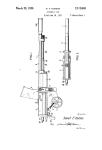
Figure 1 is a plan view of the gun, por-
tions of the barrel and stock being broken
away;
Fig. 2 is a vertical longitudinal section
of that portion of the gun shown in Fig. 1;
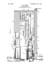
Fig. 3 is an enlarged longitudinal section
showing the firing mechanism in the fired
position;
Fig. 4 is a longitudinal section showing
the bolt stop in a raised position;
Fig. 5 is a longitudinal section showing
the bolt in the fully retracted position;
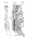
Fig. 6 is a top view of the gun;
Fig. 7 is a side view of the gun;
Fig. 8 is a cross section through the gun
at the cut out mechanism; 55
Fig. 9 is a fragmentary side view of
Fig-. 8; .
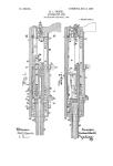
Fig. 10 is a fragmentary section showing
the cut out;
Fig. 11 is a fragmentary section showing 60
the disconnecter in the inoperative position;
Fig. 12 is a side view of the bolt stop
member;
Fig. 13 is a fragmentary section on line
13—13 of Fig. 3; 65
Fig. 14 is a fragmentary section on line
14—14 of Fig. 3;
Fig. 15 is a fragmentary section on line
15—15 of Fig. 3;
Fig. 16 is a longitudinal section of the 70
bolt sleeve;
Fig. 17 is a side view of the pusher;
Fig. 18 is a sectional view of Fig. 17;
Fig. 19 is a sectional view of the locking
sleeve; and 7 5
Fig. 20 is a development of the locking
sleeve.
The gun comprises a receiver 20, a barrel
21, stock 22, guard 23, and magazine 24.
The bolt 25 is slidably mounted in the re- 80
ceiver 20, and rotatably mounted on the bolt
is the locking sleeve 26. The actuating
handle 27 is rigidly connected to the sleeve
26 and extends outwardly through the slot
28 in the receiver 20. Screwed into the1 rear 85
end of the bolt is the bolt sleeve 29, best
shown in Fig. 16, which sleeve is kept from
rotation by the disconnecting lug 30 which
extends downward from the sleeve and is
adapted to move longitudinally in the slot 90
31 in the lower side of the receiver. Fitting
inside the bolt and bolt sleeve is the firing
pin 32, having seated upon its forward por-
tion the thrust washer 33 which is counter-
sunk to engage the enlargement 34 of the 95
firing pin. The firing'spring 35 surrounds
the firing pin, the fdrward. end bearing
against the washer 33 and its rear end
against the bolt sleeve 29. The cam pusher
member 36 partially surrounds the bolt 100
sleeve 29 and engages the rear end of the
locking sleeve 26 and it has the inwardly ex-
tending lug 37 which enacts with the longi-
tudinal slot 38 in the bolt sleeve. This lug
1,396,940
a
37 serves to restrain the cam pusher 36 from
rotation and also to engage the cocking ex-
tension 39 on the upper side of the rear end
of the firing pin. As best shown in Figs. 17
5 and 18 the lower side of the pusher is slotted
to permit passage of the disconnecting lug
30 of the bolt sleeve. As shown in Figs. 17
to 20, the engaging surfaces between the
pusher and locking sleeve comprise opposed
10 cam lugs 26' and 36'. The safety shutter 40
is fitted into the receiver 20 and is held in
place by the screw cap 41. The safety shut-
ter has forwardly extending portions adapt-
ed in one position to cover the slot 28 in the
15 receiver and to cover the lower slot in which
the disconnecter lug 30 operates, the forward
end of the latter portion abutting against the
rear of the lug
The buffer member 47 slips over the
20 washer 46 and extension 42 and the resil-
ient buffer material 48 is inclosed within
the buffer. The recoil spring 49 is con-
tained within the safety shutter and has its
forward end bearing against the cam pusher
25 36 and its rearward end bearing against the
circumferential flange 50 on the buffer mem-
ber 47. The sear 51 is pivotedly connected
at 52 to the bolt sleeve 29. The forward
end of the sear is provided with the rear-
30 wardly faced notch 53, adapted to coact
with a similar notch 54 in the lower side of
the firing pin and the lower end of the sear
is provided with a pin 55 which extends
rearwardly through an opening in the dis-
35 connecting lug 30. This pin 55 is sur-
rounded by the spring 56, the forward end
of which bears against the rear face of the
sear and the rear end of which bears against
the disconnecting lug. The forward face of
40 the lower sear arm is provided with the con-
tact member 57 adapted to contact with the
tripper 58 which latter is pivoted in the re-
ceiver on the pin 59. The tripper 58 is pro-
vided with the rearwardly facing concave
45 surface 60 adapted to coact with the contact
member 57 of the sear and the tripper is nor-
mally held in position in which it is shown in
Fig. 5 by the spring 61. The lower side of
the tripper member 58 is provided with the
60 engaging notch 62 which coacts with the
notch 63' upon the forward end of the trig-
ger bar 63. The trigger bar 63 passes
through the bearing 64 in the guard 23 and
its rearward end is engaged with the upper
55 end 65 of the trigger 66. The trigger spring
67 surrounds the trigger bar 63 rearwardly
of the bearing 64, the rear end of the spring
bearing againstthe washer 68. The forward
end of the trigger bar 63 is normally pressed
60 upward by the spring 69 seated in the recess
70 in the guard. The trigger bar 63 carries
the adjustable disconnecter 71 normally held
in the position shown in Fig. 5 by the spring
72. The lower side of the receiver is provided
65 with thd/opening 73 to permit passage of the
actuating portion 74 of the disconnecter.
The disconnecter operating member 75 is
formed with the finger piece 76 and the rear-
wardly extending portion 77. The rear end
of this portion 77 is provided with the catch 70
78 adapted to coact with the similarly shaped
notches 79 or 80 in the guard. The bolt stop
81 is pivoted upon the pin 59 and is provided
with the finger piece 82 extending downward
through the guard. This bolt stop member 75
81 has its forward end normally urged up-
ward by the spring 83, the lower end of
which bears against the guard 23 and the
upper end of which fits in the socket 84 in
the bolt stop member. This member is 80
shown in side view in Fig. 12 and consists of
two side plates cross connected by the finger
piece 82, and at 85 by the portion bearing
against the spring 83 and its forward por-
tion is cross connected by the bolt stop 85
proper 86 having the notch 87 therein. The
ejector 81' extends upward from the center
of the bolt stop and moves in the slot 25' in
the under side of the bolt. The bolt stop re-
lease 88 is pivoted in the bolt stop on the 90
pin 89 the forward portion carrying the
spring 90, the upper arm of which bears
against the under side of the bolt stop 86.
The upper portion 91 of the bolt stop re-
lease normally engages the downward ex- 95
tending portion 92 of the receiver which
maintains the release in the position shown
in Fig. 5. The magazine 24 is provided with
a follower 93 having the rearwardly extend-
ing lug 94 adapted when the magazine is 100
empty to coact with the forward portion 95
of the bolt stop release to rotate the bolt
stop release rearwardly about its pivot to
disengage the portion 91 from the receiver
portion 92. The magazine is provided with 105
the rearwardly extending lug 96 which en-
gages over the spring catch 97 to retain the
magazine in the gun. The catch 97 at its
upper end is normally pressed forward by
the spring 98 and is provided with the finger 1Ю
operating piece 99 extending downward
through the guard. The cut out 100 is car-
ried on the pin 101 having the finger piece
102 upon one end thereof. The cut out has
its lower surface squared to normally con- 115
tact with the spring 103 and its forward
surface flattened to contact with the spring
when in its operative position. The forward
end of the receiver is fitted with the receiver
lock sleeve 104 which is provided with the in- 120
terrupted threads 105 adapted to coact with
the similar threads 105' on the outer side of
the locking sleeve 26. The bolt is provided
with the customary extractor 106. The rear
sight 107 is mounted upon the upper part 125
of the receiver adjacent its rear end. The
barrel adjacent the magazine 24 is provided
with the hand guard 108 which is interiorly
cut away at 109 and which is held in place by
the band 110. The receiver cap 41 is thread- 130
1,396,949 В
\ ’
ed on the rear end of the receiver 20 and is
held against rotation by the upper end of
the bolt 111. The bolt 111 as shown in Fig.
2, is provided with the outer sleeve 112 which
5 is threaded into the housing 113 extending
downwardly from the rear end of the re-
ceiver. The lower end of this sleeve is cir-
cular in cross section and engages in a socket
in the guard 23. The sleeve 112 is provided
10 with an inner shouldered portion 114 adja-
cent its lower end and the opening through
this shouldered portion is squared in cross
section. The screw head 115 is provided
with a stem passing into the sleeve, the lower
15 part of the stem being squared to fit the
shouldered portion of the sleeve and the up-
per end of the stem being threaded to receive
the sleeve 117. The spring 116 surrounds
the median portion of the stem, its lower
20 end bearing against the shoulder 114 in the
sleeve 112 and its upper end against the
sleeve 117. The screw head 115 is hexagonal
in shape and the guard is correspondingly
countersunk to receive a portion of the head
25 and to thus prevent rotation.
In assembling the breech closure the sear
51 is placed in the sleeve 29 and its pin 52
is slipped laterally into place, the spring 56
having been placed about the pin 55. The
30 bolt sleeve 20 is slipped over the forward end
of the firing pin 32 and the firing pin spring
35 is then slipped on the firing pin and com-
pressed against the sleeve and the washer
member 33 is slipped laterally into place.
35 The locking sleeve 26 is threaded on to the
rear end of the bolt, the pusher 36 is slipped
upon the rear of the assembly and the
firing pin assembly is then slipped in through
the rear end of the bolt 25 and screwed in
40 place.
The receiver lock sleeve 104 is slipped into
the receiver through its rear end and screwed
in place. The bolt assembly is then slipped
into the receiver through the rear end, the
45 disconnecter lug 30 passing into its longi-
tudinal slot in the lower side of the receiver.
The recoil spring 49 is placed against the
rear face of the pusher 36 and the shutter
and the buffer assembly is slipped into the
50 rear end of the receiver, engaging the recoil
spring. The cap 41 is now screwed in place,
the screw sleeve 117 being held downward
against the spring 116 until the cap is fully
in place. The unit consisting of the bolt
55 stop 81, the bolt stop release 88, the spring
90, the tripper 58 and the spring 61 is in-
serted through the bottom of the receiver
and retained in place by the pivot pin 59.
The springs 98 and 103 are slipped in place
60 in the guard, the cut out 100 placed in the
guard and its pivot pin 101 inserted through
it. The disconnecter 76 is placed in the
guard and the magazine catch 97 is hung
upon its pivot. The rear end of the trigger
65 bar 63 is placed in the bearing 64 after having
the spring 67 and washer 68 placed thereon.
The disconnecter 71 is attached to the trig-
ger bar 63 by its pivot, the spring 72 being
placed about the pivot as shown. The spring
69 is inserted between the forward end of 70
the trigger bar and the guard. The trigger
65 is placed upon its pivot pin.
' The rear of the safety shutter 40 is pro-
vided with a protuberance 40' adapted to
interfit with either one of two spaced inden- 75
tations 41' in the receiver cap 41. The parts
are retained in engagement by the pressure
of the recoil spring. Referring to Fig. 2,
the gun is ready to fire with the parts in
the position shown, when the lever 45 has 80
been swung to the right to uncover the slot
28 to permit movement of the actuating'
handle 27 and to unlock the disconnecter
lug 30 and the pin 55 of the sear 51. When
in the locked condition the protuberance 85
40' is interfitted with one indentation 41'
as shown in the figure and when unlocked
it is fitted into another such indentation.
After unlocking the piece, pressure upon
the trigger 65 moves the trigger bar 63 for- 90
ward, rotating the tripper 58 about its pivot
59. Fig. 3 shows the tripper rotated and
its camming surface forcing rearwardly the
contact portion 57 of the sear 51, thus caus-
ing the sear to rotate on its pin 52 thereby 95
releasing the notch 53 in the sear from the
firing pin notch 54. The spring 35 ex-
panding between the washer 34 and bolt
sleeve 29, forces the firing pin forward and
fires the cartridge. 100
The pressure of the expanding gases in
the barrel 21 is transmitted by the bolt head
to the bearing surfaces of the threads con-
necting the locking sleeve 26 to the bolt 25,
and the locking sleeve is caused to rotate on 105
the bolt and in the receiver sleeve 104 be-
cause the helix angle of the threads between
the bolt and locking sleeve is not as great as
the helix angle of the outer interrupted
threads 105 and 105' between the locking 110
sleeve 26 and the fixed receiver sleeve 104.
The threads between the bolt and locking
sleeve- are continuous. The interrupting of
the outer threads permits the locking sleeve,
and consequently the bolt assembly, to pass 115
rearwardly in the receiver after the lock has
rotated a sufficient part of a revolution to
disengage threads 105 and 105'. These
threads are preferably placed upon what
has been referred to as the “Blish angle”, an 120
angle such that the bolt will remain locked
under high breech pressure but will auto-
matically open when the pressure is lowered
to a predetermined safe working limit.
The release of the locking sleeve from en- 125
gagement with the receiver sleeve permits
the bolt to move rearwardly in the receiver
20 against the recoil spring 49 until the
energy of recoil is absorbed or until the rear
end of the bolt sleeve 29 strikes the buffer 47. 130
1,390,949
5
10
15
20
25
30
35
40
45
50
55
60
65
4=
As the locking sleeve 26 is rotated in the
unlocking movement the cam surfaces 26'
acting on the opposed cam surfaces 36' on
the pusher 36 serve to thrust the pusher
rearwardly relatively to the bolt sleeve 29
and the bolt 25 and during this motion the
lug 37 engages the upper end 39 of the fir-
ing pin and draws the pin rearwardly to
the position for sear notch 53 again to en-
gage the firing pin notch 54, the notches
retaining the firing pin cocked when the
pusher moves forward during the closing
movement. The retracted or recoil position
of the parts is shown in Fig. 5, and the for-
ward position in Fig. 2.
The disconnecter 71 is kept from rotation
clockwise from normal position by shoul-
ders 71' which bear against the trigger bar.
The disconnection spring 72 serves to re-
turn the disconnecter to normal position
when it is rotated in the counter clockwise
direction. Since the disconnecter cannot
rotate in the clockwise direction, the discon-
nection lug 30 engaging the upper portion
74 of the disconnecter at the beginning of
the rearward movement of the breach as-
sembly forces the' disconnecter and the trig-
ger bar 63 downward against the spring 69,
the trigger bar being disconnected from the
tripper 58 as shown in Fig. 4. The tripper
58 is then returned to its normal position
by the spring 61. During the counter re-
coil movement of the bolt assembly, should
the disconnection lug 30 strike the discon-
necter 71 it is merely rotated against the
spring 72 which returns it to place after the
lug 30 passes.
Release of pressure on the trigger after
disconnection permits the spring 67 to move
the trigger bar rearwardly and swing the
trigger to normal position. The trigger bar
63 is forced upward by th,e spring 69 as
its forward end clears the tripper 58 and it
again engages the notch 62 upon the trip-
per. The parts are again in the position
shown in Fig. 2 and a second pull upon the
trigger will fire another shot and continues
the semi-automatic fire.
Moving the disconnecter operating mem-
ber 75 rearwardly by means of the finger
piece 76 until the catch 78 coacts with the
rear notch 80, the member 75 engages the
lower portion of the disconnecter 71 and
rotates that member in the counter clock-
wise direction and holds it. down against the
spring as shown in Fig. 11. The lug 30
does not now contact with the portion 74
as it moves rearwardly and the trigger bar
holds the tripper 58 tilted rearwardly. As
the closing mdvement of the bolt mechanism
is completed the contact portion 57 of
the sear engages the tripper and the lower
end of the sear is swung rearwardly re-
leasing the firing pin. This completes a
cycle of automatic action and the piece will
continue to fire until the magazine is empty
or until pressure upon the trigger is re-
leased.
The ejector 81' on the bolt stop member
81, slides in groove 25' upon the lower side 70
of the bolt and rises as the top of the groove
inclines upward at the forward end of the
bolt, the spring 83 forcing the member up-
ward until the bolt stop release 91 contacts
with the portion 92 of the receiver. As 75
the bolt closes the ejector is pressed down-
ward by contact with the top of the groove
in the bolt.
When the magazine is empty the lug 94
contacts with the part 95 of the bolt stop 80
release so that as the bolt stop rises the
upper arm 91 passes in the rear of the re-
ceiver portion 92 and the bolt stop passes
upward sufficiently for the forward end of
the bolt to be caught by the part 87 and <
the bolt thus to be retained open. The bolt
stop release may also be manually tilted by
the cut out 100 which can be turned to en-
gage the lower ehd of the bolt stop release.
The cut out is actuated by the finger piece 90
102 best shown in Figs. 8 and 9, and 10, and
is yieldably held in either position by
squared contact with the spring 103. Ex-
cept when blocked by the cut-out, a pull
upon the finger piece 82 will draw down the 96
bolt stop and release the bolt which will be
immediately closed by the power of the re-
coil spring.
The magazine is held in the piece by the
engagement of the catch 97 with the mag- 100
azine lug 96. The magazine may be re-
leased by pressing forward the lower end
99 of the catch. .
The bolt lock sleeve actuating handle 27
recoils with the bolt and has the combined 105
rotary and reciprocating movement of the
lock sleeve. During the. first part of the
opening movement the handle rotates on a
line parallel to the helix angle of the outer
threads 105 and 105', but when these threads 110
are disengaged the turning movement is -
gradually changed to a rectilinear move-
ment by contact between the handle and
the slot 28, the change being a gradual curve
as best shown in Figs. 1 and 6. The closing 115
movement is the reverse of this just de-
scribed and the curve is so designed that the
shock of changing the direction of motion
is absorbed as gradually as possible. This
absorption is aided by the. lateral thrust 120
of the interengaging cams between' the
pusher and lock sleeve.
I claim—
1. A gun comprising a receiver, breech
closing mechanism adapted to reciprocate in 125
the receiver, the breech closure comprising
a non-rotating bolt and a rotating sleeve
thereon having lugs adapted to engage with
lugs in the receiver, the engaging angle be-
tween the sleeve lugs arid the lugs in the re- 130
1,806,040
б
10
15
20
25
80
35
40
45
50
55
60
65
ceiver being inclined to the line of breech
pressure at such angles as to hold the breech
closing mechanism in closed position at high
breech pressure and to slide relatively to
each other when the pressure drops to a low
value whereby the breech closure is auto-
matically unlocked.
2. A gun comprising a receiver, breech
closing mechanism adapted to reciprocate in
the receiver, the breech closure comprising a
non-rotatii g bolt and a rotating sleeve there-
on having lugs adapted to engage with lugs
in the receiver, and an actuating arm upon
said sleeve, the actuating arm extending out-
wardly through the receiver, the engaging
angle between the sleeve lugs and the lugs
in the receiver being inclined to the line of
breech pressure at such angles as to hold the
breech closing mechanism in closed position
at high pressure and to slide relatively to
each other when the pressure drops to a low
value whereby the breech closure is auto-
matically unlocked.
3. A gun comprising a receiver, breech
closing mechanism adapted to reciprocate in
the receiver, the breech closure comprising a
non-rotating bolt and a rotating sleeve there-
on having lugs adapted to engage with lugs
in the receiver, helical connecting means be-
tween the bolt and sleeve, and the engaging
angle between the sleeve lugs and the lugs
in the receiver being so related to the angle
of the helix that the breech pressure serves
to rotate the sleeve upon the bolt.
4. A gun comprising a receiver, breech
closing mechanism adapted to reciprocate in
the receiver, the breech closure comprising a
non-rotating bolt and a rotating sleeve there-
on having lugs adapted to engage with lugs
in the receiver, helical connecting means be-
tween the bolt and sleeve, and the engaging
angle between the sleeve lugs and the lugs
in the receiver having a greater angle rela-
tive to the line of breech pressure than that
of the helix.
5. A gun comprising a receiver, breech
closing mechanism adapted to reciprocate in
the receiver, the breech closure comprising a
non-rotating bolt and a rotating sleeve there-
on having lugs adapted to engage with lugs
in the receiver, helical connecting means be-
tween the bolt and sleeve, and the engag-
ing angle between the sleeve lugs and the
lugs in-the receiver being so related to the
angle, of the helix that the breech pressure
serves to rotate the sleeve upon the bolt, the
engaging angle between the sleeve lugs and
the lugs in the receiver being inclined to the
line of breech pressure at such angles as to
hold the breech closing mechanism in closed
position at high breech pressure and to slide
relatively to each other when the pressure
drops to a low value whereby the breech
closure is automatically unlocked.
6. A gun comprising a receiver, breech
closing mechanism adapted to recipocate in
the receiver, the breech closure comprising a
non-rotating bolt and a rotating sleeve there-
on having lugs adapted to engage with the
lugs in the receiver, helical connecting means 70
between the bolt and sleeve, and the engag-
ing angle between the sleeve lugs and the
lugs in the receiver having a greater angle
relative to the line of breech pressure than
that of the helix, the engaging angle between 75
the sleeve lugs and the lugs in the receiver
being inclined to the line of breech pressure
at such angles as to hold the breech closing
mechanism in closed position at high breech
pressure and to slide relatively to each other 80
when the pressure drops to a low value
whereby the breech closure is automatically
unlocked.
7. A gun comprising a receiver, breech
closing mechanism adapted to reciprocate in 85
the receiver, the breech closure comprising a
non-rotating bolt and a rotating sleeve there-
on having lugs adapted to engage with lugs
in the receiver, and an actuating arm upon
said sleeve, the actuating arm extending out- 90
wardly through the receiver, the engaging
angle between the sleeve lugs and the lugs in
the receiver being inclined to the line of
breech pressure at such angles as to hold the
breech closing mechanism in closed position 95
at high pressure and to slide relatively to
each other when the pressure drops to a low
value whereby the breech closure is auto-
matic lly unlocked, the actuating arm mov-
ing in a slot in the receiver whereby the 100
movement of the sleeve is guided.
8. A gun comprising a receiver, breech
closing mechanism adapted to recipocate in
the receiver, the breech closure comprising a
non-rotating bolt and a rotating sleeve there- 105
on having lugs adapted to engage with lugs
in the receiver, helical connecting means be-
tween the bolt and sleeve, and the engaging
angle between the sleeve lugs and the lugs
in the receiver being so related to the angle 110
of the helix that the breech pressure serves
to rotate the sleeve upon the bolt, and an
arm extending from the sleeve and means
coacting with the arm whereby the move-
ment of the sleeve is guided while the sleeve 115
lugs and the lugs in the receiver are disen-
gaged.
9. A gun comprising a receiver, breech
closing mechanism adapted to reciprocate in
the receiver, the breech closure comprising a 120
non-rotating bolt and a rotating sleeve there-
on having lugs adapted to engage with
lugs in the receiver, helical connecting means
between the bolt and sleeve, the engaging
angle between the sleeve lugs and the lugs in 125
the receiver having a greater angle relative
to the line of breech pressure than that of
the helix, and an arm extending from the
sleeve and means coacting with the arm
whereby the movement of the sleeve is 130
в
1,396,949
5
10
15
20
25
30
35
40
45
50
55
60
guided while the sleeve lugs and the lugs in
the receiver are disengaged,
10. In a gun, a movable breech closure,
firing means associated therewith, a trigger
operatively connected to the firing means,
means adapted to contact with the breech
closure during its movement to disconnect
the trigger and firing means, and means
adapted to selectively place the disconnect-
ing means into or out of operation.
11. In a gun a movable breech closure,
firing means associated therewith, a trigger
operatively connected to the firing means,
a member adapted to contact with the breech
closure during its movement to disconnect
the trigger and firing means, and a member
adapted for manual operation and adapted
to move the disconnecter member to such
position as to be out of the path of the
breech closure.
12. In a gun a movable breech closure,
firing means associated therewith, a trigger
operatively connected to the firing means,
a member adapted to contact with the breech
closure during its movement to disconnect
the trigger and firing means, a member
adapted for manual operation and adapted
to rotate the disconnector member to such
position as to be out of the path of the
breech closure, and spring means adapted to
normally maintain the disconnecter in op-
erative position.
13. A gun comprising a receiver, breech
closing mechanism adapted to reciprocate
in the receiver, a firing member and a sear
carried by the breech closure, a tripping
member and a trigger associated with the
breech closure, the tripping member being
operatively associated with the trigger by
means of a trigger bar, a disconnecter mem-
ber carried by the bar and having a portion
adapted to extend into the reciprocatory
path of the breech closure whereby it is en-
gaged by the breech closure and the trigger
bar is disconnected from the tripper.
14. A gun comprising a receiver, breech
closing mechanism adapted to reciprocate
in the receiver, a firing member and a sear
carried by the breech closure, a tripping
member and a trigger associated with the
breech closure, the tripping member being
operatively associated with the trigger by
means of a trigger bar, a disconnecter mem-
ber carried by the bar and having a portion
adapted to extend into the reciprocatory
path of the breech closure whereby it is en-
gaged by the breech closure and the trigger
bar is disconnected from the tripper, and a
manually operable member adapted to move
the disconnecter out of the path of the
breech closure.
15. In a gun, a bolt, a bolt stop, means
normally urging the bolt stop toward opera-
tive position, means adapted to retain the
bolt stop in inoperative position, and manu-
ally operable means adapted to move the
retaining means to permit the bolt stop to
move to operative position.
16. In a gun, a bolt, a bolt stop, means
normally urging the bolt stop toward op- 70
erative position, means adapted to retain the
bolt stop in inoperative position, a maga-
zine, and a magazine follower, means upon
the follower adapted to contact with the
retaining means to move the retaining means 75
to permit the bolt stop to move to operative
position when the magazine is empty, and
manually operable means adapted to move
the retaining means to permit the bolt stop
to move to operative position. 80
17. In a gun, a receiver, a bolt,, a movable
member adjacent the bolt having a portion
adapted to move into the .path of the bolt,
resilient means urging it toward said path,
and adjustable means carried by the movable 85
member and adapted to contact with a por-
tion of the receiver to limit the movement
of the member.
18. In a gun, a receiver, a bolt, a movable
member adjacent the bolt having a portion 90
adapted to move into the path of the bolt,
resilient means urging it toward said path,
adjustable means carried by the movable
member and adapted to contact with a por-
tion of the receiver to limit the movement 95
of the member, and manually operable
means adapted to move the member away
from the path of the bolt.
19. In a gun, a receiver, a bolt, a movable
member adjacent the bolt having a portion 100
adapted to move into the path of the bolt,
resilient means urging it. toward said path,
adjustable means carried by the movable
member and adapted to contact with a por-
tion of the receiver to limit the movement 105
of the member, and manually operable
means adapted to move the adjustable means
to permit greater movement of the movable
member.
20. In a gun, a receiver, a bolt, a movable 110
member adjacent the bolt having a portion
adapted to move into the path of the bolt,
resilient means urging it toward said path,
and adjustable means carried by the mov-
able member and adapted to contact with a 115
portion of the receiver to limit the move-
ment of the member, the movable member
being adapted to act as an ejector with the
adjustable means in one position and as a
bolt stop with the adjustable means in an- 120
other position.
21. In a gun, a receiver, a bolt, a movable
member adjacent the bolt having a portion
adapted to move into the path of the bolt,
resilient means urging it toward said path, 125
and adjustable means carried by the mov-
able member and-adapted to contact with a
portion of the receiver to limit the move-
ment of the member, a magazine, a maga-
zine follower and means upon the follower 1
1,396,949
5
10
15
20
25
30
35
40
45
50
55
60
65
adapted to / contact with the adjustable
means to vary its adjustment.
22. In a gun, a receiver, a bolt, a movable
member adjacent the bolt having a portion
adapted to move into the path cf the bolt,
resilient means urging it toward said path,
and adjustable means carried by the mov-
able member and adapted to contact with a
portion of the receiver to limit the move-
ment of the member, a magazine, a maga-
zine follower and means upon the follower
adapted to contact with the adjustable mem-
ber to move it so as to permit the movable
member to move into the path of the bolt to
act as a bolt stop when the magazine is
empty.
23. In a gun, a receiver, a breech closing
mechanism movable therein, a sear carried
by said mechanism, and a shutter in the
receiver adapted to be moved to block the
sear.
24. In a gun, a receiver, a breech closing
mechanism movable therein, a sear carried
by said mechanism, and a shutter in the
receiver adapted to be moved to block the
sear, and when so moved serving also to
block the breech closing mechanism.
25. In a gun, a receiver, a breech closing
mechanism movable therein, a sear carried
by said mechanism, and a tubular shutter
rotatable in the receiver and adapted in one
position to block the sear and breech closing
mechanism.
26/ In a gun, a receiver having a slot
therein, breech closing mechanism in the
receiver having a portion extending out-
wardly through the receiver slot and a shut-
ter adapted to be moved to block the sear
and the breech mechanism and to close the
receiver slot.
27. In a gun, a receiver having a slot
therein, breech closing mechanism in the
receiver having a portion extending out-
wardly through the receiver slot and a shut-
ter adapted to be moved to close the receiver
slot, the shutter having an inwardly ex-
tending portion at its rear end adapted to
receive a recoil buffer.
28. In a gun, a receiver having a slot
therein, breech closing mechanism in the
receiver having a portion extending out-
wardly through the receiver slot and a shut-
ter adapted to be moved to close the receiver
slot, the shutter having an inwardly ex-
tending portion at its rear end adapted to
receive a recoil buffer, a recoil spring, and a
buffer housing fitting over the- buffer and
having a flange adapted to receive the thrust
of the recoil spring.
29. In a gun, a receiver having a slot
therein, breech closing mechanism in the
receiver having a portion extending out-
wardly through the receiver slot and a shut-
ter adapted to be moved to close the receiver
slot, a rear closure for the receiver having
spaced indentations in its inner face, a recoil
spring and means for transmitting the
thrust of the spring to the shutter and a
raised portion on the rear face of the shut-
ter adapted to fit in one of the indentations 70
on the receiver closure.
30. In a gun, a receiver having a slot
therein, breech closing mechanism in the
receiver having a portion extending out-
wardly through the receiver slot and a shut- 75
ter adapted to be moved to close the receiver
slot, a rear closure for the receiver having
spaced indentation^ in its inner face, a recoil
spring and means for transmitting the.
thrust of the spring to the shutter, a raised 80
portion on the rear face of the shutter
adapted to fit on one of the indentations on
the receiver closure, and a shutter operating
lever adapted to be non-rotatably interfitted
to the shutter and to extend exteriorly of the 85
receiver.
31. A gun comprising a receiver, a breech
mechanism having a non-rotating portion
and a rotating locking sleeve, a pusher in
said receiver adjacent the breech mechanism 90
and a recoil spring bearing against the
pusher, a portion of the pusher engaging the
non-rotating portion of the breech mecha-
nism to prevent rotation of the pusher.
32. A gun comprising a receiver, a breech 95
mechanism having a non-rotating portion
and a rotating locking sleeve, a firing mem-
ber carried by the breech mechanism, a non-
rotating pusher in said receiver adjacent the
breech-mechanism, a recoil spring bearing 10©
against the, pusher, a portion of the pusher
engaging the firing member to move it to
cocked position during the opening move-
ment of the breech mechanism.
33. A gun comprising a receiver, a breech 1C3
mechanism having a non-rotating portion
and a rotating locking sleeve, a firing member
carried by the breech mechanism, a non-ro-
tating pusher in said receiver adjacent the
breech mechanism, a recoil spring bearing 11©
against the pusher, interengaging means be-
tween the locking sleeve and pusher whereby
the pusher is moved rearwardly relative to
the non-rotating portion of the breech
mechanism during the opening movement Ц0
of the breech mechanism, a portion of the
pusher engaging the firing member to move
it to cocked position during the opening
movement of the breech mechanism.
34. A gun comprising a receiver, a breech 120
mechanism having a non-rotating portion
and a rotating locking sleeve, a pusher in
said receiver adjacent the breech mechanism
and a recoil spring bearing against the
pusher, a portion of the pusher engaging 120
the non-rotating portion of the breech
mechanism to prevent rotation of the pusher,
and interengaging cam surfaces upon the
pusher and the rotating breech locking mem-
ber whereby the pusher is forced rearwardly 18©
a
1,396,949
against the recoil spring during the unlock-
ing rotation of the locking sleeve, and where-
by the spring acts to assist the locking rota-
tion of the sleeve.
5 35. A gun comprising a receiver, a breech
mechanism having a non-rotating portion
and a rotating locking sleeve, a pusher in
said receiver adjacent the breech mecha-
nism and a recoil spring bearing against the
10 pusher, a portion of the pusher engaging
the non-rotating portion of the breech
mechanism to prevent rotation of the pusher,
and a forwardly extending cam lug upon the
pusher engaging a cam surface upon the
15 locking sleeve, whereby the pusher is forced
rearwardly against the recoil spring during
the unlocking rotation of the locking sleeve,
and whereby the spring acts to assist the
locking rotation of the sleeve.
20 36. A gun comprising a receiver, a breech
mechanism having a non-rotating portion
and a rotating locking sleeve, a pusher in
said receiver adjacent the breech mechanism
and a recoil spring bearing against the
25 pusher, a portion of the pusher engaging
the non-rotating portion of the breech
mechanism to prevent rotation of the pusher,
and a forwardly extending cam lug upon
the pusher engaging a cam surface upon the
30 locking sleeve, whereby the pusher is forced
, rearwardly against the recoil spring during
the unlocking rotation of the locking sleeve,
and\ whereby the spring acts to assist the
locking rotation of the sleeve, the cam sur-
faces being in engagement both when the 35
breech mechanism is in locked position and
when the breech mechanism is in unlocked
position.
37. A gun comprising a receiver, a breech
mechanism having a non-rotating portion 40
and a rotating locking sleeve, a firing mem-
ber carried by the breech mechanism, a non-
rotating pusher in said receiver adjacent
the breech mechanism, a recoil spring bear-
ing against the pusher, forwardly extending 45
cam lugs upon the pusher engaging cam
surfaces upon the locking sleeve, whereby
the pusher is forced rearwardly against the
recoil spring during the unlocking rotation
of the locking sleeve, and whereby the re- 50
coil spring acts to assist the locking rotation
of the sleeve, a portion of the pusher engag-
ing the firing member to move it to cocked
position during the opening movement of
the breech mechanism. 55
38. In a gun, a bolt, a bolt stop, means
normally urging the bolt stop toward oper-
ative position, means adapted to retain the
bolt stop in inoperative position, and man-
ually operable means adapted to move the 60
retaining means to permit the bolt stop to
move to operative position, the bolt stop
when in the inoperative position serving as
an ejector.
Signed by me at Boston, Massachusetts, 65
this 25th day of August, 1920.
THEODORE H. EICKHOFF.