/
Теги: weapons military affairs patent
Год: 1945


Текст
March 1, 1949. g. в. neidhardt 2,462,889
CARTRIDGE CASE EXTRACTOR
Filed Jan. 27, 1945
Graham ELNeidhardt,
Patented Mar. 1, 1949
2,462,889
UNITED STATES PATENT OFFICE
2,462,889
CARTRIDGE CASE EXTRACTOR
Graham B. Neidhardt, Albion, Ind.
Application January 27, 1945, Serial No. 574,947
1 Claim. (Cl. 42—25)
(Granted under the act of March 3, 1883, as
amended April 30, 1928; 370 O. G. 757)
1 2
The invention described herein may be manu-
factured and used by or for the Government for
governmental purposes without the payment to
me of any royalty thereon.
The invention relates to cartridge case ex- 5
tractors.
In some guns such as the 20 mm. aircraft can-
non. the standard extractor serves to aid in po-
sitioning the round as it is carried into the cham-
ber by the bolt to prevent the round from enter- 10
ing the chamber too far. and to extract the round
in case of misfire, it being understood that the
extraction of the empty cases is effected by the
pressure of the gases as the bolt retracts.
The conventional extractor or that illustrated 15
in Figure 1, is spring-operated and oscillates in
its cavity in the bolt. It has a square or perpen-
dicular inner lip which abuts the inner peripheral
edge of the base of the cartridge when the bolt
is in locked or firing position, there being a space 20
between the face of the bolt and the cartridge
base which is objectionable for reasons that will
be stated, and which the present invention seeks
to eliminate, and thereby improve the operation
of the gun. 25
The lip of the conventional extractor does not
maintain contact at all times with the rim of the
cartridge, and the cartridge is free to travel with
respect to the lip as in cases where the bolt, in
closing, is stopped by the face of the cartridge 30
chamber or that part of the barrel that surrounds
the chamber, the round continuing to move for-
ward until the rim of the cartridge engages the
inner lip of the extractor. This engagement, at
times is with sufficient force to tear out a portion 35
of the cartridge rim which may drop into the
mechanism and cause malfunctioning of the gun.
Again if the firing pin protrusion is the maxi-
mum allowable and the wall of the primer is the
minimum thickness allowable, a punctured 40
primer may result which is also objectionable
and likely to cause malfunctioning of the gun by
fouling the firing pin hole in the bolt and by
particles falling into the mechanism.
The usual or spring operated extractor is so ar- 45
ranged with respect to the bolt that if the round
in being fed gets ahead of the extractor the ex-
tractor may dip under the cartridge rim and
spring into proper position.
The present invention contemplates an ex- 50
tractor which is made rigid with the bolt either
by being made integral therewith or rigidly at-
tached thereto, and provided with a lip having a
“positive” angle, that is to say an inclined inner
position so that when the round is stripped from 55
the belt and fed into the chamber by the forward
action of the bolt the base of the cartridge slips
down the face of the bolt until its rim is caught
by the extractor and when the round straightens
out as it is chambered, the rim is cammed down
the inclined lip of the extractor until the base
of the cartridge is flush with the face of the bolt,
thus closing the objectionable space between the
bolt and the cartridge when the bolt is locked in
firing position.
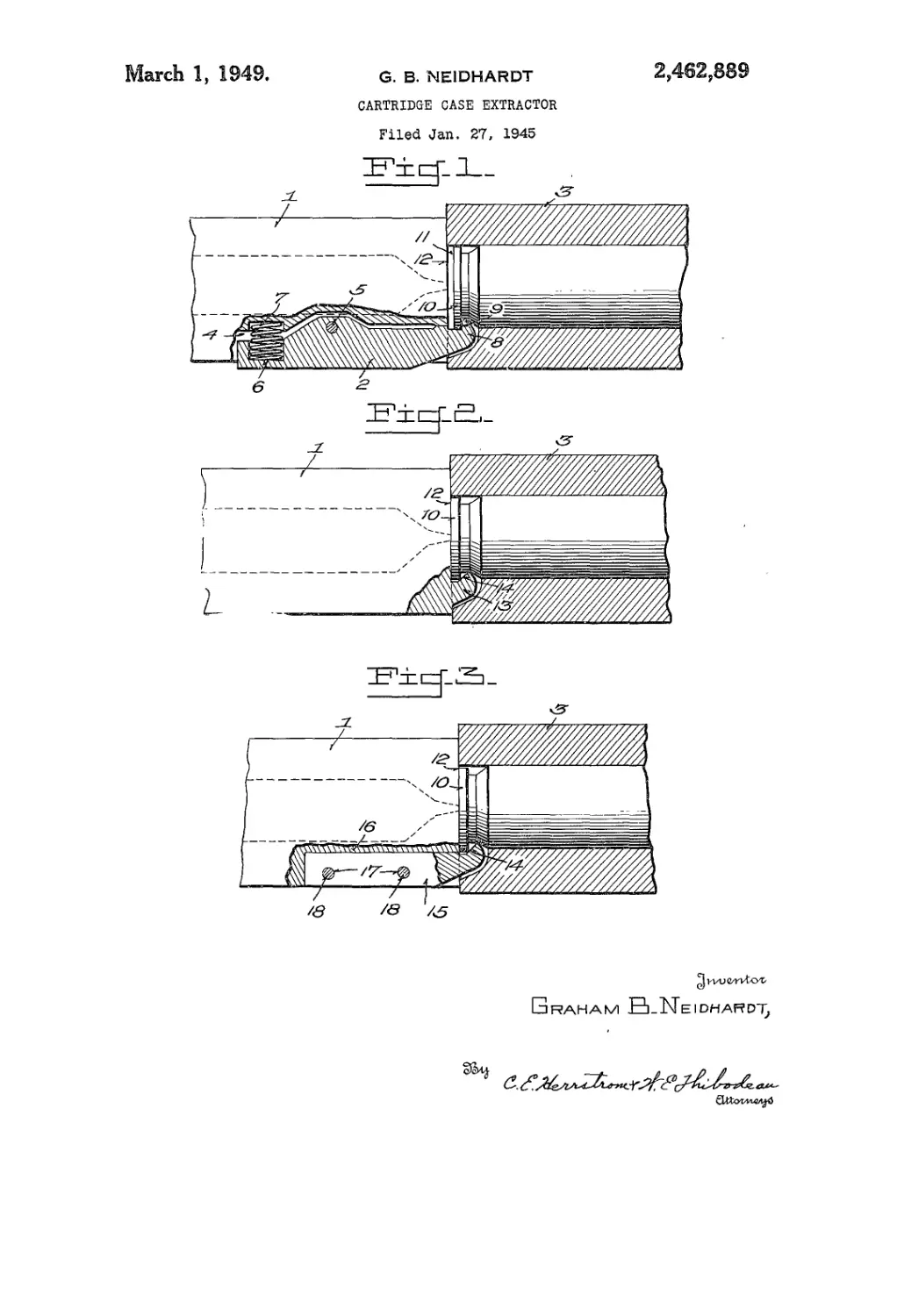
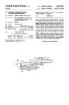
In the drawings illustrating the invention:
Figure 1 is a horizontal section of a portion of
the breech of a gun with the breech bolt and
extractor therein, in one of its positions relative
to a round shown in the cartridge chamber, the
arrangement being conventional.
Figure 2 is a similar view showing my improve-
ment.
Figure 3 is a section of a forward end of the
bolt showing a form in which the extractor is
made separable from the bolt and held in opera-
tive position by suitably positioned pins.
Referring to the drawings and particularly Fig.
1, numeral I designates the bolt and 2 the con-
ventional spring operated extractor, while 3 des-
ignates the breech portion of the gun. The ex-
tractor is rockably mounted in the cavity 4, upon
pin 5, there being in the rear end of the extractor
a socket 6, for the reception of a spring 7 exert-
ing a tendency to normally raise the front end of
the extractor. The lip 8 of the extractor is per-
pendicular or normal to the axis of the gun as
indicated at 9 and lies flush against the rim 10
of the cartridge when the bolt is in firing posi-
tion, there being at such time a space 11 between
the face 12 of the bolt and the base of the car-
tridge case. This is usual and is the construc-
tion upon which I aim to improve.
My arrangement in its preferred form is shown
in Figure 2 in which the extractor 13 is an in-
tegral part of the bolt and extends beyond its
front end a distance about the same as that which
characterizes the extractor shown in Figure 1.
Beyond the making of the extractor rigid with
the bolt the leading feature of the invention is,
as intimated, the provision of a novel lip of the
extractor, which I form with a positive angle 14
which functions as a cam to automatically cam
the cartridge back against the face of the bolt
and thus close the space between the bolt and the
cartridge, so that when the bolt is locked in fir-
ing position the base of the cartridge is flush
against the bolt. By this arrangement the dis-
tance between the end of the flring pin and
primer of the cartridge is uniform and can be
2,462,889
3
regulated to a nicety, thus preventing light blows
on the cartridge primer that cause misfire, or
the likelihood of the flring pin piercing the
primer, with the objectionable results hereinbe-
fore enumerated.
I prefer to make the extractor integral with the
bolt but it can be made rigid and at the same time
removable, as shown in Figure 3, wherein the ex-
tractor indicated by 15, is disposed in a recess 16
extending from the front of the bolt for a distance
suitable for the accommodation of the' extractor.
Transverse pin holes are provided in the bolt and
adapted to register with corresponding holes 17
in the extractor, the holes being for the reception
for pins i8 by which the extractor and bolt are
rigidly united. An advantage, of the structure is
that the extractor is replaceable in case of injury
or breakage.
As the cartridge base passes down over the face
of the bolt in straightening out while being fed in-
to the cartridge chamber, the rim of the cartridge
engages the inclined lip 14 and will be cammed
back against the- front end of the bolt, against
which it remains until the round is fired. It will
be noted that the type of cartridge case with which
the extractor is designed to be used is constructed
with a taper toward the front. This permits con-
siderable leeway and play until the moment when
the cartridge is firmly seated. There is also a
slight amount of play in the bolt and other parts
of the gun, so that in practice no difficulty is en-
countered in obtaining the proper cooperation of
the parts necessary for correct operation within
the usual range of tolerances encountered. The
radial distance between the center of the gun
bore and the bottom of lip 14 is so designed that
with the usual tolerances the base of the cartridge
is easily maintained, there being sufficient radial
play under the worst permissible conditions to
allow rim iO to move down to snug engagement
with both face i 2 of the bolt and cam surface 14
of extractor 13.
It should be noted in Figure 3 that the front
face of the extractor lip 13 is rounded, which
serves the purpose of allowing the cartridge case
to be cammed into the proper position in the event
that the round is ever fed ahead of the extractor,
which rarely occurs. This feature was success-
fully tested by the inventor who partially pre-
positioned a round in the chamber by hand and
then released the bolt from a cocked position.
The pre-positioned round was fired and extracted
successfully.
The integral extractor has other advantages
not heretofore mentioned. The extractor is much
5
10
15
20
25
30
35
40
45
50
55
4
stronger at the base of the lip owing to the posi-
tive angle, than is the conventional extractor.
Also, the integral extractor has neither extractor
spring nor pin, which in the conventional ex-
tractor are subject to breakage.
Different calibers in various types of guns may
make it desirable to vary the positive angle of
the extractor depending upon the particular
weapon. For instance, while a 45° angle in the
illustrated example of the invention would be de-
sirable in one type of gun, a 15° angle may work
better for another type of weapon, the object be-
ing in all cases to eliminate the space between the
face of the bolt and the cartridge when the bolt is
locked in flring position.
I claim:
In a machine gun, the combination of a re-
ciprocating bolt having a bolt face substantially
perpendicular to the path of movement of the bolt
and an extractor secured to said bolt, said ex-
tractor having a rigid and unyielding extension
projecting beyond the face of the bolt in a di-
rection parallel to the path of movement of the
same, said extractor extension and bolt face to-
gether providing a groove with the open' end
thereof directed toward the bolt axis, said-groove
having the-forwardly disposed side wall thereof
spaced axially of the bolt face and at an acute
angle thereto thereby providing a cam face where-
by said groove is adapted to receive a cartridge
rim, the cam face near the bottom of the groove
being dimensioned and proportioned to force and
maintain the base of the cartridge against the
bolt face.-
GRAHAM B. NEIDHARDT.
REFERENCES CITED
The following references are of record in the
file of this patent:
UNITED STATES PATENTS
Number Name Date
380,682 Holmes________________Apr. 10, 1888
1,200,685 Young_________________Oct. 10, 1916
1,544,566 Eickhoff______________July 7, 1925
1,628,226 Browning_______________May 10, 1927
1,702,063 Swebilius_____________Feb. 12, 1929
1,889,099 Loomis________________Nov. 29, 1932
FOREIGN PATENTS
Number Country Date
1,093 Great Britain________Apr. 10, 1869
1,448 Denmark______________Jan. 29, 1898
13,117 Great Britain___________________1905
637,801 Germany________________Nov. 4, 1936