/


Текст
CARTRIDGE
MANUFACTURE
CARTRIDGE
MANUFACTURE
A TREATISE COVERING THE MANUFACTURE OF
RIFLE CARTRIDGE CASES, BULLETS, POWDERS,
PRIMERS AND CARTRIDGE CLIPS, AND THE DESIGN-
ING AND MAKING OF THE TOOLS USED IN CONNEC-
TION WITH THE PRODUCTION OF CARTRIDGE CASES
AND BULLETS, TOGETHER WITH A DESCRIPTION
OF THE PRINCIPAL OPERATIONS IN THE MANU-
FACTURE OF COMBINATION PAPER AND BRASS
SHOT SHELLS
By DOUGLAS T. HAMILTON
Associate Editor of MACHINERY
Author of “Advanced Grinding Practice,”
“Automatic Screw Machine Practice,”
“Shrapnel Shell Manufacture”
“Machine Forging,” Etc.
FIRST EDITION
NEW YORK
THE INDUSTRIAL PRESS
1916
Copyright, 1916
BY
THE INDUSTRIAL PRESS
NEW YORK
PREFACE
The processes used in the manufacture of cartridges are
of interest not only to the makers of munitions of war, but
to every mechanic who is engaged in those industries in
which the drawing and forming of metal in presses is of im-
portance. The principles and operations pertaining to the
production of metal cartridges are essentially the same as
those used in hundreds of industries engaged in the manu-
facture of drawn objects for the most peaceful purposes;
and while at the present time the interest in ammunition is
paramount, the methods used for its manufacture differ in
no essential from the methods employed in the ordinary
metal working industries. The aim of this book is, there-
fore, not only to cover the various steps in the manufacture
of one of the most important of munitions of war, but also to
place on record approved methods in the drawing and form-
ing of deep metal shells for any purpose. As the processes
used in the manufacture of cartridges are probably more
highly developed than those employed in most other fields of
metal drawing, a book relating to these processes will no
doubt be found of great value in many kindred fields.
In the field for which the book is especially intended, a
record of the processes used in two leading plants for the
manufacture of cartridges—one Government arsenal and
one private concern—will require no special commendation.
A great many firms are at the present time engaged in the
manufacture of cartridges, and all mechanics occupied in
this work will find a review of the methods of leading fac-
tories both of interest and value. It will enable them to
compare their own methods with those used elsewhere, and
to make improvements when the comparison is in favor of
the methods described; and many will find suggestions for
the introduction of entirely new methods of procedure. The
340225
author, therefore, has compiled this book with the hope that
it will prove of service to the great number of men engaged
in the manufacture of cartridges and in sheet-metal draw-
ing work generally.
The book deals briefly with the design of various types of
cartridges, the explosives used in them, and then more com-
pletely with the methods for drawing brass cartridge cases
and making various types of bullets. A chapter is also in-
cluded on the manufacture of primers and on the making of
shot shells.
New York, January, 1916. D. T. H.
CONTENTS
PAGES
Chapter I.
Development of Military Rifle Cart-
ridges ............................... 1-9
Chapter IL
Explosives Used in Rifle Cartridges and
Primers ........................... 10-21
Chapter III.
Manufacture of 0.22-Caliber Rifle Rim-
fire Cartridges..................... 22-40
Chapter IV.
Manufacture of Center-fire Cartridges.. 41-60
Chapter V.
Frankford Arsenal Method of Drawing
Cartridge Cases..................... 61-74
Chapter VI.
Making Dies for Cartridge Manufacture 75-87
Chapter VII.
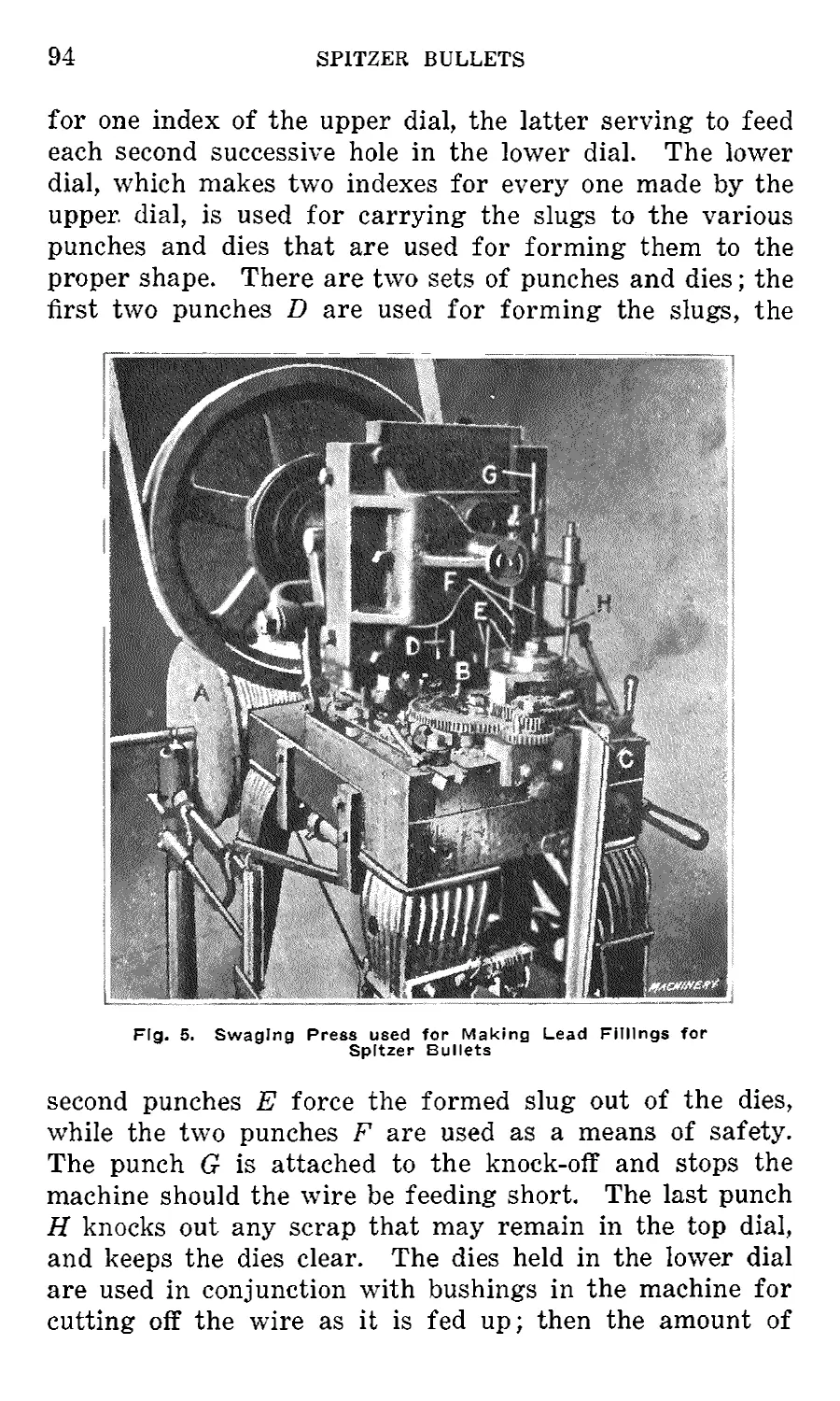
Making Spitzer Bullets.................... 88-104
Chapter VIII.
Loading and “Clipping” Cartridges. . . . 105-116
Chapter IX.
Manufacture of Shot Shells............... 117-142
Chapter X.
Manufacturing the French Military Rifle
Cartridge......................... 143-153
Chapter XI.
Manufacture of Primers............ 154-162
CARTRIDGE
MANUFACTURE
CHAPTER I
DEVELOPMENT OF MILITARY RIFLE CARTRIDGES
IN the early use of fire-arms for military purposes, the
bullets, or balls, as they were then called, and the powder
were carried separately. To load the musket, the powder
was poured in from the muzzle, then wads were inserted
and rammed, after which the spherical ball was inserted
and held in place by ramming in more wads. This process
was known as “muzzle loading,” and the arm, as a “muzzle-
loading musket.” The first important advance was made
early in the seventeenth century when Gustavus Adolphus,
king of Sweden, gave instructions that gun powder be made
up in the form of cartridges instead of being carried loose
in flasks or bandoleers. The next advance was made early
in the nineteenth century, when a percussion cap was de-
vised. This made it possible to put up the correct charge
of powder, ball, and ignition cap in the form of a paper
cartridge, and subsequently made necessary the changing
over of the musket from a muzzle to a breech loader.
The first use made of this cartridge was by a Prussian
by the name of Von Dreyse, in his needle gun. The bullet
used in this cartridge was egg-shaped, the base fitting into
a shoe or wad of compressed paper, which carried the per-
cussion cap in the opposite end. The wad was made of a
larger diameter than the bullet, and fitted the rifling of the
gun, thus imparting rotation to the bullet; but it fell to
pieces upon emerging from the bore of the gun. The pow-
der charge, bullet, and wrad, were made up in a case of
rolled paper, closed in at the rear and tied over the point of
the bullet. The needle attached to the firing mechanism
i
2 * RIFLfi CARTRIDGES
pierced the base of the paper cartridge, and, by passing
through the powder, ignited the cap. The method of ex-
plosion was, therefore, just the reverse of what it is at the
present time.
Several other types of paper cartridges were afterwards
made, but they did not prove successful. With paper cart-
ridges, it was practically impossible to seal the breech of
the gun to prevent the escape of gases without resorting to
a specially constructed breech mechanism, and endeavors
were made to produce a cartridge which would fill these
requirements.
The first brass cartridge case was invented by Col. Boxer,
in 1865, and was used in the Enfield muzzle-loading rifle
which was converted into a breech loader, adopting the
principle patented by an American, Jacob Snider. This
cartridge was made from built-up sections of rolled brass,
and carried a percussion cap in its head. Cartridge cases
made from drawn brass were not introduced into England,
except for machine gun use, until after the Egyptian cam-
paign of 1885.
Cartridge Cases. — Cartridge cases made from drawn
brass are produced by first cutting out a disk of the re-
quired diameter and thickness, forming it into a cup, and
then, by successive redrawing operations, reducing its diam-
eter and increasing the length. Upon the advent of the
small-bore, high-power rifle, the shape of the cartridge case
was changed from the straight-body type to the bottle shape.
This was done in order to increase the size of the powder
chamber without increasing the length of the case. Cart-
ridge cases were first made with flanges, but, upon the appli-
cation of clips and chargers, the rim was omitted and a
groove cut in the head instead. This allows the cartridge
cases to be packed closer together, and also prevents jam-
ming in the magazine action.
The cutting of a groove in the rim of the head, as well as
the substitution of smokeless powder in the place of black
powder, made necessary a change in the shape of the head
of the case. The first solid drawn cartridge cases were made
as shown at A, Fig. 1. The case was drawn up from a
RIFLE CARTRIDGES
3
comparatively thin blank, and to form the pocket for the
primer the metal was simply forced into the case as shown.
A case of this shape could not satisfactorily be grooved, as
the head would thereby be considerably weakened. An im-
provement was made, therefore, consisting in making the
case from a much thicker blank, and, instead of bending
in the metal at the head to form the primer pocket, the
metal was simply displaced so that the head remained solid,
as shown at B, Fig. 1. This type of cartridge case has now
been adopted by most of the principal governments.
Bullets. — As has been previously mentioned, the first
bullets were spherical in shape, as shown at A, Fig. 2, and
were fired from smooth-bored muskets. Upon the inven-
tion of the rifled gun
early in the seventeenth
century, the first suc-
cessful bullet used was
devised by a Swiss,
Major Rubin, and is
shown at B, Fig. 2. This
was still spherical in
shape, but had a copper
belt a cast completely
around, which “took”
the rifling grooves in
the gun. This bullet, however, was very erratic in flight,
and the next step was to make it egg-shaped, as shown at C.
To provide fob the expansion of the bullet, the breech was
equipped with a taper steel pin against which the bullet was
rammed from the muzzle. The ram-rod was provided with
a cavity in its end. of the same shape as the bullet, and, by
driving the latter against the tapered plug, the base end was
expanded into the rifling grooves.
The next improvement, made in 1836, which, however,
was not generally adopted, was the Grenner bullet shown
at D. This was made with an oval head and a flat base,
made hollow, and a tapered plug of wood inserted in the cav-
ity. Upon the explosion of the powder in the chamber of
the gun, the plug was driven into the soft lead bullet, ex-
4
RIFLE CARTRIDGES
panding it to fill the rifling grooves. Captain Minie, of the
French army, in 1849, produced a bullet of the shape shown
at E, in which the wooden plug was replaced by a hemi-
spherical iron cup. This cup, as was the case with the
wooden plug, served to expand the bullet into the rifling
grooves.
The first lead bullets of the shape shown at F were made
from pure lead, and, to avoid fouling of the bore of the gun,
were covered with waxed paper b. The Snider bullet of this
type was 0.489 inch in diameter, and had a length of 1.8
c
Machinery
Fig. 2. Early Development of Bullets for Military Cartridges
calibers, whereas, the Martini-Henry was 0.450 inch in
diameter, and had a length of 2.8 calibers; both weighed
480 grains. Subsequent developments consisted in a grad-
ual reduction in diameter and increase in length up to and
exceeding four calibers. The bullets were also hardened by
adding antimony and tin. Bullets made from lead and an-
timony, however, were still found to be too soft to be fired
from high-powered rifles, so that the next development con-
sisted in covering the lead core with a metal jacket, as at G.
PRINCIPAL DIMENSIONS, WEIGHTS, ETC., OF MILITARY RIFLE CARTRIDGES
Country CARTRIDGE Shape of Nose BULLET
Length of Case. Inches Total Length, Inches Weight, Grains Shape of Head Propellant Wt. of Charge, Grains Muzzle Vel-.Ft, per Sec. Chamb. Pres., Tons Sq. In. Material of Envelope Length, Inches Diam., Inches (Max.) Weight. Grains
Austria- Bulgaria . 2.06 3.0 445.0 Rim Nitrocellulose 42.44 2034 19.7 Round Steel Lubricated 1.24 0.3228 244.0
Belgium.... 2.10 3.055 441.0 Rimless Nitrocellulose 37.0 2034 19.7 Round Cupro nickel 1.205 0.31 219.0
Canada 2.21 3.05 415.0 Rim Cordite 31.5 2060 15.5 Round Cupro-nickel 1.125 0.311 215.0
Denmark... 2.28 3.0 460.0 Rim Nitrocellulose 33.95 1968 15.1 Round Cupronickel 1.187 0.323 237.0
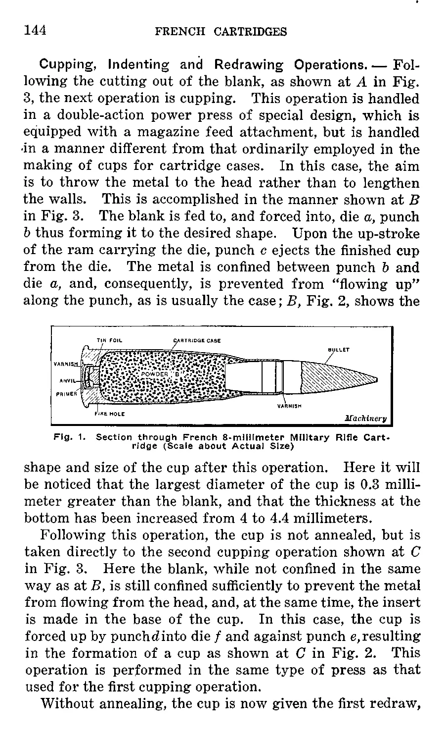
France 1.917 2.95 415.0 Rim Nitrocellulose 46.2 2380 17.75 Pointed No Envelope, Solid Copper-zine Steel, Coated with Nickel 1.625 0.327 198.0
Germany... 2.232 3.182 369.9 Rimless Nitrocellulose 48.4 2882 17.75 Pointed 1.105 0.323 154.5
Gt. Britain. 2.21 3.05 415.0 Rim Cordite 31.5 2060 15.5 Round Cupro-nickel 1.125 0.311 215.0
Greece 2.11 3.05 348.0 Rimless Nitrocellulose 36.0 2223 20.18 Round Steel, Coated withCupro-nickel 1.124 0.263 159.3
Holland.... 2.11 3.05 338.0 Rim Nitrocellulose 36.26 2433 17.75 Round Steel, Coated wi t hCupro-n ickel 1.23 0.2637 162.0
Italy 2.06 3.0 331.8 Ri mless Ballistite 30.09 32.0 31.8 2395 17.1 Round Cupro-nickel Copper Steel, Coated withCupro-nickel 1.182 0.266 163.0
Japan Portugal .. . 2.0 2.35 2.98 3.26 348.5 Senri- Rimless Rim Nitrocellulose Nitrocellulose 2396 2347 17.1 17.75 Round Ogival 1.28 1.28 0.26 0.320 162.9 155.3
Roumania. . 2.10 3.05 350.0 Rim Nitrocellulose 36.0 2400 17.75 Round Cupro-nickel 1.244 0.2637 162.0
Russia 2.11 3.025 363.0 Rim Pvroxiline 37.0 1985 17.47 Round Cupro-nickel 1.194 0.308 214.0
Spain 2.22 3 08 373.5 Rimless Nitrocellulose 38.35 2296 22.3 Round Cupro-nickel Plated Steel over Point, only 1.21 0.2843 172.8
Switzerland 2.11 3.043 424.0 Rimless Nitrocellulose 30.7 1920 17.1 Round 1.18 0.319 212.5
Turkey 2.21 3.07 416.0 Rimless Nitrocellulose 40.2 2066 19.7 Round Steel, Coated withCupro-nickel 1.212 0.311 211.3
U. S. A 1.95 3.329 392.0 'Rimless Pyrocellulose 50.0 2600 19.78 Pointed Cupro-nickel 1.08 0.3085 150.0
RIFLE CARTRIDGES
6
RIFLE CARTRIDGES
Modern Military Rifle Cartridges. — The military rifle
cartridges used by some of the principal governments are
shown in Fig. 3. This particular grouping has been
selected because of the variation in design. The main dif-
ference is in the shape of the bullet, and the total length.
The bullets, it will be noted, are all of the coated or jacketed
types, with the exception of the French; this is solid
and is made from a copper-zinc alloy. The bullet used in
the United States cartridge is a cupro-nickel jacket over a
coating of lead, hardened with antimony. The same re-
marks apply to the British, Italian, and Russian bullets.
The German bullet has a lead filling and is coated with steel,
nickel-plated; the Austrian bullet has a steel jacket which is
lubricated. Further details regarding the cartridges
adopted by the principal governments are given in the ac-
companying table.
Cupro-nickel jacketed bullets are generally employed for
military rifles and are used by the Belgian, British, Cana-
dian, Danish, Italian, Roumanian, Russian, Spanish, and
American governments. The German, Greek, Dutch, and
Turkish governments use steel envelopes coated with cupro-
nickel ; Austria uses greased steel, and Japan, copper. Bul-
lets coated with cupro-nickel are likely to set up metallic
fouling in the bore of the gun, consisting of streaks of
metal which adhere to the lands and grooves in the bore.
Bullets with greased steel envelopes do not appear to cause
metallic fouling, but they wear away the rifling in the gun
much quicker.
The bullet used in the Swiss rifle cartridge is of a pecu-
liar construction. The body is made of a hard lead alloy,
provided with a nickel-plated steel envelope covering the
point only, the remainder of the bullet being covered with
paper lubricated with vaseline. The lower portion of the
bullet which enters the cartridge case is smaller in diameter
than the jacketed portion. The wounding power of this
bullet is great, but its velocity is not as great as those pro-
vided with the full envelope.
Since the outbreak of the present war, considerable
changes have been made in the bullets used by the various
Fig. 3. Military Rifle Cartridges used by the Great Powers
RIFLE CARTRIDGES
8
RIFLE CARTRIDGES
participants. Up to the present war, Great Britain used a
round-pointed bullet, but has now adopted the pointed type.
Pointed bullets are being gradually adopted by all of the
governments, because the sharp head offers less resistance
to the air than does the rounded head. For this reason, the
pointed bullet always has a higher velocity, all other factors
remaining the same. To further reduce air resistance, the
French bullet is made with a slightly tapered rear portion.
This reduces the vacuum formed at the base of the bullet,
and, hence, makes possible an increase in velocity.
Cartridge Clips and Chargers. — Soon after the adop-
tion of the rifled gun, steps were taken to increase the
rapidity of fire. Weapons known as repeaters were the first
Fig. 4. Cartridge Chargers and Clips
really successful rifles used. These contained a supply of
cartridges which were held in a tube located beneath and
parallel with the barrel. The cartridges lay nose to base
in this tube, and, upon the operation of the breech mechan-
ism, the exploded cartridge was ejected and a fresh one
inserted automatically. The earliest weapons of this type
were the Spencer and Henry rifles patented about 1860.
With this type of rifle, it was necessary, of course, to fill
up the magazine by placing one cartridge in it at a time, and,
to facilitate loading, devices called quick loaders were de-
veloped. The first successful quick loader was known as
the “Kruka” and was developed in Russia during the Russo-
Turkish war, in 1878. This device, which was the forerun-
RIFLE CARTRIDGES
9
ner of the present charger, was attached to the side of the
stock and held ten cartridges in pockets with the base up.
The next step was made by Austria, in 1886, in which
year the Mannlicher rifle was adopted by that government,
and was provided with a box magazine. This box was
located in the rear of, and below the entrance to, the gun
chamber, and held the cartridges in a horizontal plane. A
spring-actuated platform pushed the cartridges upwards
when the bolt was operated. Another improvement made
was the application of a spring clip to facilitate the loading
of the cartridges into the magazine. This was made of
sheet steel and held five cartridges. It was pressed into
the magazine where it was retained by a catch until the
cartridges were used, after which it fell out through an
opening in the bottom of the magazine.
Chargers are used simply for convenience in carrying
and loading the cartridges in the magazine; they are
placed above the magazine, the cartridges swept out by the
thumb, and the empty charger thrown away. Clips, on the
other hand, are placed in the magazine with the cartridges
and are generally held down by a catch. The cartridges are
fed up by the magazine lever, or platform, which is made
narrow enough to pass between the sides of the clip. When
all the cartridges have been used, the clip falls out through
an opening provided in the bottom of the magazine. A
common form of charger is shown at A, Fig. 4. This is
known as the Mauser charger and consists of a thin undu-
lating flat spring that presses the cartridge forward so that
the extractor grooves in the head of the case bear firmly
against the ribs on each side of the charger. Chargers are
generally made to hold five cartridges, but some hold six. A
greater number of cartridges than this are likely to jam
when being swept out of the charger into the magazine.
The clip shown at B, Fig. 4, differs from the charger in
that it is placed directly in the magazine and remains there
until all of the cartridges are extracted, whereupon it drops
out through an opening in the bottom of the magazine.
Clips are also made with extended sides to support the cart-
ridges and prevent them from clogging in the magazine.
CHAPTER II
EXPLOSIVES USED IN RIFLE CARTRIDGES
AND PRIMERS
Explosives, in general, may be defined as substances^
either solid or liquid, which, upon the application of heat
or other causes that set up a chemical action in them, are
capable of being converted instantaneously into gases, occu-
pying a much greater volume than the original substance.
Explosives may be divided into three general classes:
1. Low, also known as progressive or propelling explo-
sives.
2. High, or detonating explosives.
3. Fulminates, or detonators.
The first class includes black gun powder, smokeless
powder, and black blasting powders. The second includes
dynamite, nitroglycerine, guncotton, picric acid, etc., and
the third includes mercury fulminate and chlorates.
Black Gun Powder. — The early history of black gun
powder is very indefinite. As far as can be ascertained,
it was first produced in England in the thirteenth century,
but was not used to any great extent until the latter part
of the eighteenth century. Berthold Schwarz, a German
monk, and Roger Bacon, an English friar, are both credited
as being the original inventors of gun powder. Roger
Bacon, in a book published by him in 1242, makes reference
to an explosive mixture containing saltpeter that “makes a
noise like thunder and flashes like lightning/’ The three
principal ingredients of black gun powder are saltpeter,
charcoal, and sulphur in about the following proportions:
saltpeter, 75 parts; charcoal, 15 parts; sulphur, 10 parts.
The relative proportions of saltpeter, charcoal, and sul-
phur used vary in different countries, and have also been
changed from time to time since the first gun powder was
manufactured. The advance seems to be along the line of
increasing the proportion of saltpeter and relatively de-
creasing the proportions of charcoal and sulphur.
' io
POWDERS
11
Charcoal is the chief combustible in powder. It must
burn freely, leaving as little light ash or residue as possible.
It must be friable and grind into a non-gritty powder. The
materials from which powder charcoal is made are dogwood,
willow, and alder. Dogwood is mainly used in the manu-
facture of powder for rifle cartridges, etc. Powder made
from dogwood charcoal burns more rapidly than that made
from willow, etc. The wood, after cutting, is stripped of
bark and allowed to season for two or three years. It is
then segregated into lots of a uniform size and charred in
cylindrical iron cases or slips, which are placed into slightly
larger cylinders set in the furnace. The slips are provided
with openings for the escape of the gases. The rate of
heating, as well as the absolute temperature attained, has a
more or less marked effect on the product. A slow rate of
heating yields more charcoal and a high temperature re-
duces the oxygen and hydrogen in the final product. When
heated for seven hours to about from 800 to 900 degrees C.
(1472 to 1652 degrees F.), the remaining hydrogen and
oxygen amount to about 2 per cent and 12 per cent, respect-
ively. The time of charring, as a rule, is from five to seven
hours. The slips are then removed from the furnace and
placed in a larger iron vessel where they are kept compara-
tively air-tight until quite cool. The charcoal is then sorted
and stored for some time before grinding. The grinding
which follows consumes several hours, and as the “dust”
passes out from the rollers it is sifted on a rotating wheel
or cylinder of fine-mesh copper wire gauze. The sifted
charcoal powder is again stored for some time before using
and is kept in closed iron vessels.
The sulphur used in the manufacture of gun powder is
generally obtained from Sicily. For complete purification,
the sulphur is first distilled and then melted and cast into
molds. It is afterwards ground into a fine powder and
sifted, as in the case of the charcoal.
Saltpeter—the common name for potassium nitrate—is
the oxygen provider in gun powder. This is a valuable salt
and, in many localities, is found in caverns or caves in
calcareous formation, but the chief commercial source of
12
POWDERS
this salt is the soil of the tropical regions, especially of the
districts in Arabia, Persia, and India, where the nitrate is
found as an efflorescence upon the surface of the ground, or
in the upper portions of the soil itself. The niter is ex-
tracted by treating the earth with water and obtaining it in
an impure state by evaporating solutions. The crude pro-
duct is purified by successive re-crystallizations. Niter is
soluble in water and much more so in hot than cold water.
The crude material is dissolved almost to the saturation
point in boiling water and, on filtering and cooling this
liquor to 30 degrees C. (86 degrees F.), almost pure niter
crystallizes out, most of the usual impurities still remaining
in solution. By rapidly cooling and agitating the niter solu-
tion, crystals are obtained of sufficient fineness for the
manufacture of powder without special grinding. Niter
contains nearly 40 per cent of oxygen, by weight, five-sixths
of which is valuable for combustion purposes.
Manufacture of Black Gun Powder. — The materials
used are weighed out separately, mixed by passing through
a sieve, and then uniformly moistened with a small quantity
of distilled water while on the bed of the incorporating mill.
This consists of two heavy iron wheels mounted so as to
run in a circular bed. The incorporation of. the material
requires about four hours. The mechanical action of the
rollers on the powder paste is a double one, not only crush-
ing, but mixing, by pushing forward and twisting sideways.
The pasty mass is deflected so that it repeatedly comes
first under one roller and then under the next by scrapers
which are set at an angle to the bed and follow each wheel.
Although the charge is wet, while in this condition, it is
possible for it to be fired either by the heat developed by
roller friction, by sparks and foreign matter, or by bits of
stone, etc. The mills are, therefore, provided with drench-
ing apparatus so that in case of one mill firing, this mill
and the one next to it will be drenched with water from the
cistern or tank immediately above the mill. The product
from the incorporation mill is termed a “mill cake.”
Upon the completion of this operation, the ingredients
are in a damp state, and are then dried and shaken to
POWDERS
13
separate them. After the pressing of the incorporated pow-
der into a “press cake,” it is broken up or granulated by
suitable machines. These are generally provided with Tobin-
bronze rollers which revolve, and through which the cake
passes. The “meal” is then pressed in a box between Tobin-
bronze plates, in layers, by means of hydraulic pressure,
the result being a “press cake.” The next operation con-
sists of granulating or converting the press cake into grain
powder. The granulating machine consists of a strong
Tobin-bronze framework carrying two pairs of toothed and
two pairs of plain Tobin-bronze rollers, and furnished with
the necessary sifting screens. The grains are next separ-
ated from the dust by passing the material through a sloped
revolving reel covered with 20-mesh copper wire. The
grains are then polished by rotating in drums alone or with
graphite, which adheres to and coats the surface of the
grain. This process is generally followed with powders
intended for small arm or moderate small ordnance use,
and graphite is seldom used, the required glaze being ob-
tained merely by the friction of the grains.
Gun powder is generally made up into different shapes of
various sizes. Prisms or prismatic powder is made by
breaking up the press cake into a moderately fine state while
still moist and pressing a certain quantity into a mold. The
mold generally employed consists of a thick plate of bronze
having a number of hexagonal perforations. Accurately
fitting plungers are so applied to the holes in the plate
that one enters the top and the other the bottom. After
the desired pressure has been applied, the top plunger is
withdrawn and the lower one pushed upward to eject the
“prism” of powder. In 1860, General T. J. Rodman sug-
gested perforating the powder prisms in order to increase
the rate of burning. The axial perforations in prism pow-
der are made by small bronze rods which pass through
the lower plunger and fit corresponding holes in the upper
one. Other shapes to which gun powder is made are accom-
plished in a somewhat similar manner. The “prismatic”
powder or other shapes, however, are not used in small
arms. Here the ordinary grain powder has been almost
14
POWDERS
universally adopted. Black gun powder, of late years, how-
ever, has been substituted by smokeless powder which gives
much better results.
Smokeless Powder. — Smokeless powder, as its name im-
plies, produces no smoke following explosion, but this
result is seldom realized due to the action of certain ingre-
dients used as necessary adjuncts. The invention of smoke-
less powder is attributed to a German chemist, Schoenbein,
who, in the year 1846, discovered a substitute called “cotton
powder” or guncotton, which he proposed to take the place
of gun powder as it had certain advantages over the latter,
due to burning without any noticeable residue and, conse-
quently, with little smoke. Smokeless powder, however,
was not satisfactorily produced in large quantities until
some time later, and several very serious accidents occurred
before its manufacture was brought to a commercial basis.
General Von Lenk, of the Austrian Artillery, succeeded in
improving considerably upon the method of manufacture
and purification. He so altered the mechanical condition
of the guncotton as to modify its rate of combustion in the
air and, therefore, to render its application possible for
military purposes. It was finally adopted by the Austrian
government in 1862.
Von Lenk’s system consisted in making guncotton from
yarn and thread of various sizes and degrees of compact-
ness, spun from long staple cotton, and then twisting and
plating the guncotton yarn in different ways. It was then
wound more or less tightly over cones or spindles of wood
or paper, and also woven into cartridges of various shapes
and sizes.
A still further improvement was made, in 1863, by Sir
Frederick Abel, whereby a practically complete purification
was obtained and the material was converted by means of
reduction to a fine state of division and subsequent com-
pression. In this form, guncotton was introduced for tor-
pedo and mine charges, but, to develop a full explosive effect,
it was necessary for the charge to be strongly confined,
which greatly reduced its range of application. All neces-
sity for confinement ceased, however, when it was discov-
POWDERS
15
«ered, in 1869, that compressed guncotton, either dry or wet,
could be fully detonated by fulminate of mercury in a
totally unconfined state. The first application of guncotton
for sporting rifle cartridge use was patented by Schultze,
in 1867. This powder consisted originally of nitrated wood
fiber impregnated with nitrates and chlorates. It was not
entirely smokeless and was never used for military purposes.
In 1885, upon the introduction of small caliber magazine
rifles, a great improvement was made in the methods of
treating nitrated cellulose, so that these substances could
be handled with safety. The improvement consisted in con-
verting it into a substance absolutely devoid of all porosity,
and was obtained by subjecting the nitrated cellulose to the
action of suitable solvents which would gelatinize it and,
upon evaporation, leave a compact homogeneous non-porous
material capable only of burning from the exterior towards
the center. The gelatinized material, before evaporation,
could, while in a plastic state, be rolled or pressed into
sheets or cords, or any other desired form. The first smoke-
less powder for military rifle use was invented by a French
chemist, Vieille, in 1884, and was used in the Lebel rifle.
It was originally a mixture of nitrocellulose and picric acid.
The picric acid, however, was subsequently abandoned and
the powder now consists of a gelatinized mixture of soluble
and insoluble nitrocelluloses.
A still further improvement was made in the manufac-
ture of smokeless powder by a Swedish engineer, Alfred
Nobel, in 1886. This powder was patented, in 1888, under
the name of “ballistite” and is still employed in some coun-
tries. This is a product combining nitrocellulose and nitro-
glycerine, which are mixed by rolling between hot rollers,
the union being promoted by employing camphor. The
camphor, however, did not remain a constant ingredient,
owing to its volatility, and resulted in alterations in the
ballistic properties of the material. This is a grave defect
in an explosive, especially when it has to stand exposure in
various climates. To overcome this objection, camphor
was abandoned and guncotton, instead of soluble nitrocotton,
wras used to obtain an explosive of uniform composition.
16
POWDERS
The final result was the production of a smokeless pro-
pulsive explosive consisting essentially of nitroglycerine
and guncotton, incorporated and gelatinized by the aid of a
solvent. A small proportion of mineral jelly was incor-
porated in the preparation to prevent “metallic fouling” in
the magazine rifle. This was also found to improve the
stability of the powder under various climatic conditions.
This explosive is known by the name of “cordite,” owing
to the cordlike form it assumes in manufacture. The first
mixture used in this explosive was composed as follows:
Nitroglycerine, 58 per cent; guncotton, 37 per cent; min-
eral jelly, 5 per cent.
After a considerable series of experiments were made, it
was found that this explosive had serious erosive qualities,
particularly in heavy ordnance, and it was found necessary
to reduce the percentage of nitroglycerine. The following
composition was substituted: Nitroglycerine, 30 per cent;
guncotton, 65 per cent; mineral jelly, 5 per cent. Within
the last few years, however, cordite has been substituted,
to some extent, by nitrocellulose and pyrocellulose smoke-
less powders. These do not have such a deteriorating effect
upon the bore of the gun and, in many other respects, are
better propellants.
Manufacture of Smokeless Powder. — The manufacture
of practically all smokeless powders is conducted generally
along the same lines. The principal operations consist of
incorporation and gelatinization of the ingredients by
means of a solvent, or by heat and pressure; converting
the gelatinized material into the desired form by pressure,
etc.; and the elimination of the solvent. The body of all
smokeless powders is cotton, and the chief ingredients, nitric
and sulphuric acids. For the first operation, or the incor-
poration and gelatinization of the ingredients, a kneading
machine is usually employed. This consists of an iron box
located on suitable supports, open at the top and provided
with removable covers, the bottom being shaped to form two
semi-circular troughs in each of which a spindle carrying
propeller-shaped blades revolves. The spindles turn in op-
posite directions, one moving at twice the speed of the
POWDERS
17
other. The blades revolve in close proximity to the bottom
of the machine, and the material is continually being
squeezed between the blades and the bottom of the machine,
and between the blades themselves as they approach each
.other along the center line. The action is, in fact, a knead-
ing one, and the machine is very similar to those used for
making dough and many other similar processes.
In the manufacture of nitrocellulose, the cotton used is
generally the short fiber which is detached from the cotton
seed rather late in the process of removal. After being
treated and purified, the cotton is run through a picker
which opens up the fiber and breaks up any lumps; it is
then thoroughly dried and ready for nitration. The most
commonly used method of nitration is to put the cotton
into a large vessel nearly filled with a mixture of nitric
acid and sulphuric acid. Sulphuric acid is used to absorb
the water developed in the process of nitration which would
otherwise too greatly dilute the nitric acid. After a few
minutes immersion, the pot is rapidly rotated by machinery
and the acid permitted to escape. The nitrated cotton is
then washed in a preliminary way and removed from the
nitrater, and repeatedly washed and boiled to remove all
traces of free acid. In the process of nitration, the cotton
does not change materially in its appearance, but becomes
somewhat rough. As the keeping qualities are dependent
upon the thoroughness with which it is purified, the specifi-
cations for powder for the U. • S. army and navy require
that the nitrocellulose shall be given, at this state of manu-
facture, at least five boilings with a change of water after
each boiling, the total time of boiling being forty hours.
Following this preliminary purification of the nitrocellu-
lose, it is cut up into shorter lengths by being repeatedly
run between cylinders carrying revolving knives, as pre-
viously described. This operation is necessary as cotton
fibers are hollow, thus making it very difficult to remove
traces of acid from the interior unless cut up into very
short lengths. After being pulped, the nitrocellulose is
given six more boilings and a change of water after each,
followed by ten cold water washings. The completed mate-
18
POWDERS
rial is known as guncotton or pyrocellulose. Before adding
the solvent, the pyrocellulose must be completely freed from
water. This is partly accomplished in a centrifugal wringer,
but is completed by compressing the pyrocellulose into a
solid block, then forcing alcohol through the compressed
mass. Some of the water is thus forced out ahead of the
alcohol and the remainder is absorbed by the alcohol, the
operation of forcing it through the block being continued
until pure alcohol appears. Ether is added to the pyrocel-
lulose thus impregnated with alcohol, the relative propor-
tions being about two parts of ether to one part of alcohol,
by volume. The amount of mixed solvent added varies
between 85 and 110 per cent of the weight of the dried
pyrocellulose. After the ether has been thoroughly incor-
porated in the kneading, the material is placed in a hydraulic
press, which forms it into cylindrical blocks about 10 inches
in diameter and 15 inches long. In this operation, the
pyrocellulose loses the appearance of cotton and takes on a
dense horny appearance, forming what is known as a “col-
loid.” The colloid is transferred to a finishing press where
it is again forced through dies and comes out in the form
' f long strips or rods which are cut to grains of the length
required. The grains are then subjected to a drying process
which removes nearly all of the solvent and leaves the sub-
stance in a suitable condition for use. The drying process
is a lengthy one, requiring from four to five months for the
larger grain powder. This process of drying, etc., has, of
late, been improved upon by the DuPont Powder Co., and
the time required to manufacture nitrocellulose has been
very greatly reduced. Upon completion, the powder is
blended and packed in air-tight boxes.
Classification of Smokeless Powders. — The form of
grain in which smokeless powder is made differs largely in
various countries. Some use flake formation, whereas
others use long strings. The flake form of smokeless pow-
der is used largely in sporting cartridges, but in military
cartridges extensive use is made of the cord type, or in
other words, “cordite.” Some countries use smokeless pow-
der in the form of tubes or cylinders, either solid or tubular.
POWDERS
19
Sporting powders are required to burn more quickly and
are generally granular in form, like old gun powder, or in
the form of very thin flakes. The color varies considerably
and depends, to a great extent, on the amount of non-explo-
sive material added in the ingredients. Pure nitrocellulose
powders are, as a rule, gray or yellow; powders in which
nitroglycerine is present vary in color from light yellow
to a deep brown; sporting powders sometimes contain color-
ing matter and are frequently coated with graphite, which
gives them a silvery gray appearance. The surface of the
flake, tube, or cord powder is usually smooth and hard. The
texture is horn-like if the powder is made from nitrocellu-
lose, but softer and of the consistency of India rubber if
containing nitroglycerine. The density of powders varies
according to the ingredients and methods of manufacture.
Unless the powders contain ingredients soluble in water,
such as metallic nitrates, they are unaffected by dampness,
and do not absorb any appreciable amount of moisture. To
insure uniformity in the ballistic properties of the finished
explosives, the blending of different batches is resorted to.
The smokeless powders in use for military small arm cart-
ridges are conveniently classed under two main headings;
1. Powder composed of nitrocellulose, either alone or with
small quantities of other explosive or non-explosive ingre-
dients. 2. Powder containing nitroglycerine in various
proportions as a further ingredient. The military small
arm powders of Class I are those used by Argentine, Aus-
tria, Belgium, Brazil, Bulgaria, China, Colombia, Denmark,
France, Germany, Holland, Japan, Mexico, Portugal, Rou-
mania, Russia, Servia, Spain, Switzerland, Turkey, United
States, and Uruguay. Class II applies to powders used by
Great Britain, Italy, and Norway.
Mercury Fulminate. — The detonating substance used in
primers and detonating caps is comprised chiefly of mercury
and fulminic acid. The salts of this acid are very explo-
sive and, when mixed with mercury, form a very suitable
substance for use in primers. The first fulminate prepared
was the fulminating silver discovered by L. G. Brugnatelli,
in 1798. He found that if silver were dissolved in
20
POWDERS
nitric acid and the solution added to spirits of wine, a -white,
highly explosive powder would be obtained. This substance
is distinguished from the black fulminating silver discov-
ered by C. L. de Berthollet, in 1788, which was obtained
by acting with ammonia on precipitated silver oxide. The
next salt to be obtained was mercuric salt, which was pre-
pared, in 1799, by Edward Charles Howard, who substi-
tuted mercury for silver in the original Brugnatelli’s pro-
cess. A similar method was that of J. Von Liebig who, in
1823, heated a mixture of alcohol, nitric acid, and mercuric
nitrate. The use of mercuric fulminate as a detonator dates
from about 1814, when the explosive cap was invented.
This is still the most common detonator, although it is
usually mixed with other substances. For a percussion cap
the British service cartridge contains 6 parts of fulminate,
6 parts of potassium chlorate, and 4 parts of antimony sul-
phide. The most common fulminate used at the present
time is made by dissolving the metal mercury in strong
nitric acid and pouring the solution into alcohol. After an
apparently violent reaction, a mass of fine grain crystals
of fulminate of mercury is produced. The crystalline pow-
der that is produced is washed with water to free it from
acid and, because of its extreme sensitiveness, is usually
kept soaked with water or alcohol until needed. One must
be very careful in handling this material; the mixing is
done on rubber-covered tables, the operator wearing rubber
shoes and gloves. One peculiar feature about this mixture
is its attack upon the teeth, causing them to blacken and
decay rapidly. For use in primers, it is usually mixed
with ground glass, the latter forming the friction element
in this explosive. It can be detonated by percussion, fric-
tion, or heat. On account of its great specific gravity, a
small volume of this substance develops a large volume of
gas. According to the usually assumed reaction, the gas
developed occupies, at ordinary temperature, a volume more
than 1340 times that of the original material. Because of
the large amount of heat developed in reaction, the volume
of the temperature at reaction is very much greater. It is
estimated that a pressure as great as 48,000 atmospheres
POWDERS
21
(700,000 pounds per square inch) is produced by the detona-
tion of mercury fulminate.
Chlorate of Potassium. — Fulminate of mercury for use
in cartridge primers has been largely superseded by
chlorate of potassium, because of the tendency of the
former to cause fouling in the bore of the gun. Chlorate
of potassium as a detonating composition is used in primers
for cartridges of the British, American, and some of the
foreign types. The common mixture of chlorate of potas-
sium includes the following ingredients:
Ingredients Per cent
Chlorate of Potassium.............. 49.6
Sulphide of Antimony............... 25.1
Glass (ground) .................... 16.6
Sulphur ............................ 8.7
This composition is much less dangerous to handle than
fulminate of mercury, both during the manufacturing
processes and also when loaded into the primer.
CHAPTER III
MANUFACTURE OF 0.22-CALIBER RIFLE RIM-FIRE
CARTRIDGES
In the manufacture of rim-fire cartridges, of which the
0.22 long-regular type of cartridge may serve as a suitable
example, the important operations are as follows: Blank-
ing, cupping, drawing, annealing, washing, drying, trim-
ming, heading, priming, loading, and inspecting. This chap-
ter describes the practice of the Dominion Cartridge Co.
in making cartridges of this size and type. A description
of the manufacture of the lead bullets used in this size of
cartridge is also included.
Cupping and Annealing. — The first operation in the
manufacture of rim-fire (RF) cartridges is to produce a
cup of the required size by means of a combination blank-
ing and cupping punch and die. The cartridges are usually
blanked and cupped at a rate of from four to six for each
stroke of the press. The cup is made from a blank sheet of
copper of the required width and thickness. Before any
drawing operation can be performed on the cups, they must
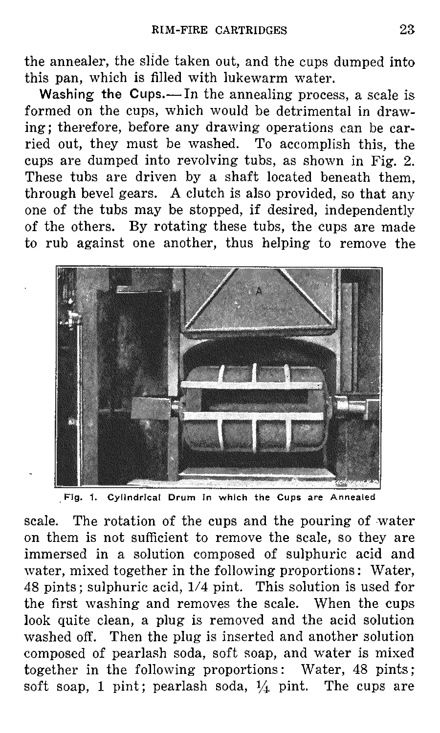
be annealed to make them ductile. The cups are placed in a
cylindrical cast-iron drum, shown in Fig. 1, which has holes,
smaller in diameter than the smallest cups annealed in it,
drilled around its periphery. These holes permit the heat
to permeate, thus annealing the cups rapidly. The cylin-
drical drum is provided with a slide or door, which is forced
in when the cups are inserted. The drum is then rolled into
the furnace, where it is rotated by means of a chain and
sprocket, driven by an overhead shaft. The door A, which
is shown in the upper position in Fig. 1, is then brought
down. Before the cups are inserted, the drum must be
heated to a cherry red. Then the cups are put in and
allowed to remain for a period of from thirty to forty min-
utes. After the cups have remained in the drum the speci-
fied time, the front door is raised and the drum rolled out.
A truck with a pan located on it is then rolled in front of
22
RIM-FIRE CARTRIDGES
23
the annealer, the slide taken out, and the cups dumped into
this pan, which is filled with lukewarm water.
Washing the Cups.—In the annealing process, a scale is
formed on the cups, which would be detrimental in draw-
ing; therefore, before any drawing operations can be car-
ried out, they must be washed. To accomplish this, the
cups are dumped into revolving tubs, as shown in Fig. 2.
These tubs are driven by a shaft located beneath them,
through bevel gears. A clutch is also provided, so that any
one of the tubs may be stopped, if desired, independently
of the others. By rotating these tubs, the cups are made
to rub against one another, thus helping to remove the
Fig. 1. Cylindrical Drum In which the Cups are Annealed
scale. The rotation of the cups and the pouring of water
on them is not sufficient to remove the scale, so they are
immersed in a solution composed of sulphuric acid and
water, mixed together in the following proportions: Water,
48 pints; sulphuric acid, 1/4 pint. This solution is used for
the first washing and removes the scale. When the cups
look quite clean, a plug is removed and the acid solution
washed off. Then the plug is inserted and another solution
composed of pearlash soda, soft soap, and water is mixed
together in the following proportions: Water, 48 pints;
soft soap, 1 pint; pearlash soda, pint. The cups are
24
RIM-FIRE CARTRIDGES
rotated in this solution for about twenty minutes, after
which they are rinsed with warm water. A sieve is located
over the hole for the plug so that the cups cannot fall out.
When the cups have been thoroughly rinsed and the water
drained off, they are put in sieves, which, in turn, are
placed in a cupboard, where they are held in racks. Steam
pipes are located beneath these racks, so that the cups are
quickly dried.
Fig. 2. Tubs used In Wash
ing the Cups after Annealing
Fig. 3. Vertical Header with
Automatic Feed
Drawing Operations. — When dry, the cups are trans-
ferred to the drawing department. Here they are put in a
pan, from which the operator removes them by means of
a vulcanite plate. This plate has a series of holes drilled
through it, which are bell-mouthed on the top, and are
slightly larger in diameter than the cups. A thin sheet-
steel plate, bent up on two sides to fit the vulcanite plate, is
slipped under it when shaking in the cups. When the cups
are shaken into the plate, the operator places it on the table
RIM-FIRE CARTRIDGES
25
A of the double-headed friction-dial drawing press shown
in Fig. 4, after which the sheet-steel plate is removed, and
the vulcanite plate lifted up, leaving the cups standing on
the table A. The operator then shoves the cups from the
table onto the friction dial B, which carries them to the
dies. These friction dials are driven through bevel gears
by a round belt, which is connected through three grooved
pulleys to the main driving pulley. The cups pass between
the guard C and spring D, the latter being vibrated by the
action of the revolving dial, which keeps the cups in con-
stant motion, thus arranging them in single file. The guard
C and the spring D approach each other as they near the
Fig. 4, Double-headed Friction-dlal Drawing Press used for
the Various Drawing Operations
dies to within a distance equal to the diameter of the cups.
The cups are carried from the dial to the dies by a finger E
connected to the bellcrank F, which, in turn, is operated
by the cam G on the end of a vertical shaft, driven from
the crankshaft through bevel gears.
The action of drawing the cups through the dies is clearly
shown in Fig. 5. The cup is carried out by the finger and
placed over the die i. The punch h then descends in it, as
shown at A, forcing it down into the die, as shown at B.
In the latter position, the case is given a mushroom shape,
and is then forced through the die, as at C, reducing it in
26
RIM-FIRE CARTRIDGES
diameter, increasing its length and decreasing the thickness
of its walls. As the cup is forced through the die, it ex-
pands slightly away from the punch, and on the upward
stroke of the press it catches on the bottom of the die, and
is stripped from the punch, dropping into a box placed
under the machine. Only one die is shown in the illustra-
Fig. 5. Diagram showing the Action of Drawing the Cups
tion, but in actual practice two drawing dies are used, one
on top of the other. The lower die is not bell-mouthed, but
is slightly tapered. In the drawing operations it is neces-
sary to lubricate the cups, so that they will not stick to the
die or punch, and for this purpose a lubricant composed of
soft soap and water is used. This is placed on the cases
while they are located on the dial, by the operator, who
Fig. 6. illustration showing the Transition from the Cup to
the Finished Cartridge
spreads the lubricant over them by means of a small cup
fastened to a handle. The punch for the drawing opera-
tions is made slightly tapered, being smaller at the lower
end, as shown in Fig. 5. This is necessary, as the explosive
material is placed near the head of the case, thus requiring
the walls to be thicker at this point than near the mouth.
RIM-FIRE CARTRIDGES
27
After the first drawing operation, the cups are taken
to the annealer, again annealed, washed, and dried, in the
manner previously described. They are then brought back
to the drawing presses for the second drawing operation.
After this, they again pass through the operations of an-
nealing, washing, and drying, after which they are taken
to the drawing presses for the third or finish-drawing
operation, that is performed as previously described.
The transition of
the cup A to the case
is clearly shown in
Fig. 6. Here the three
drawing operations
are shown at В, C, and
D, respectively. After
the three drawing op-
erations, the cases are
again washed and
dried (not annealed),
when they are taken
to the trimmers, one
of which is shown in
Fig. 7. As shown in
Fig. 6, the mouth of
the cup is not left per-
fectly straight after
the drawing opera-
tions, but has ragged
edges. Cracks also
Fig. 7. Automatic Trimming Machine for
Trimming the Cases to Length
sometimes develop in
the mouth of the case,
which make it necessary to trim off a certain amount, to
obtain a perfect case.
Trimming the Case to Length. — In the trimming oper-
ation, the cases are dumped into the hopper A, shown at
the top of the machine, Fig. 7, and pass from the latter into
the revolving drum B, to which segments, having pins C
driven into them, are fastened. These pins, which are
smaller in diameter than the inside of the case, are pointed
28
RIM-FIRE CARTRIDGES
and set at an angle. As the segments carrying the pins
rotate, the cases are agitated and drop onto the pins. The
pins now carry the cases to the top of the hopper, and as
they approach the perpendicular position, the cases drop off,
and fall into the chute D, which is connected to the machine
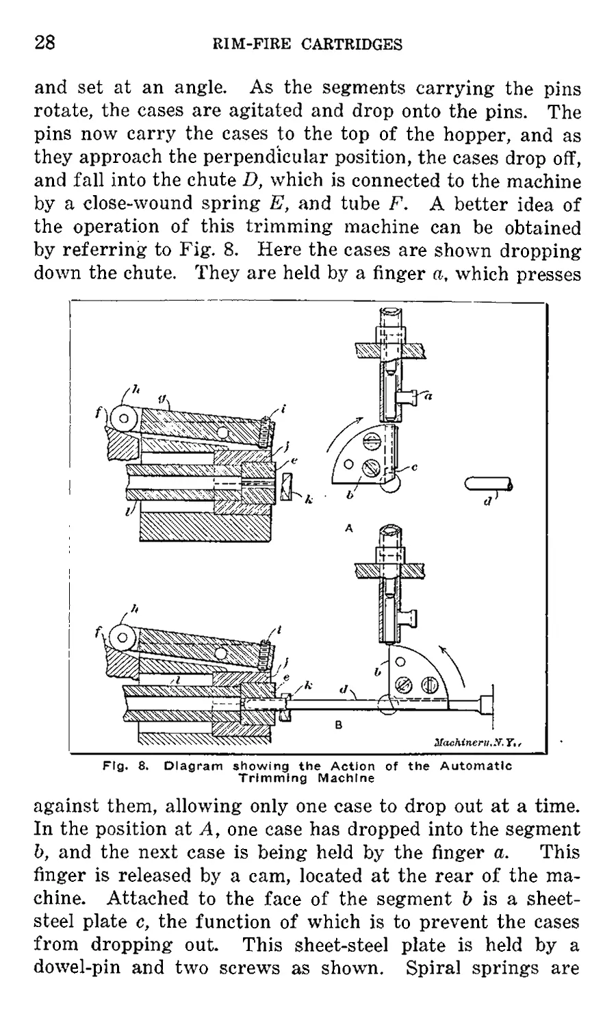
by a close-wound spring E, and tube F. A better idea of
the operation of this trimming machine can be obtained
by referring to Fig. 8. Here the cases are shown dropping
down the chute. They are held by a finger a, which presses
Fig. 8. Diagram showing the Action of the Automatic
Trimming Machine
against them, allowing only one case to drop out at a time.
In the position at A, one case has dropped into the segment
b, and the next case is being held by the finger a. This
finger is released by a cam, located at the rear of the ma-
chine. Attached to the face of the segment & is a sheet-
steel plate c, the function of which is to prevent the cases
from dropping out. This sheet-steel plate is held by a
dowel-pin and two screws as shown. Spiral springs are
RIM-FIRE CARTRIDGES
29
located under the heads of these screws, thus giving the
plate the desired tension on the case.
After the cases are located in the pocket, the segment is
revolved in the direction of the arrow, carrying the case
into the horizontal position as shown at B. The punch d
now advances and carries the case out of the pocket into
the chuck e. The chuck begins to close before the punch
reaches the end of its travel, so that the punch can force
the case in to the correct depth. The punch d is held in
a slide, actuated by an eccentric crankshaft which connects
the punch-slide G to the disk H (Fig. 7) ; the latter is driven
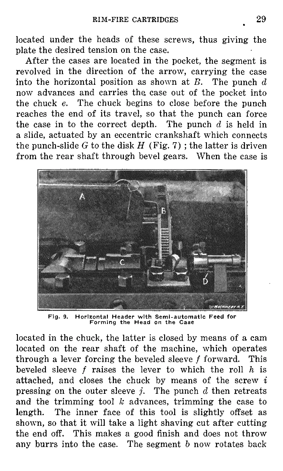
from the rear shaft through bevel gears. When the case is
Fig. 9. Horizontal Header with Semi-automatic Feed for
Forming the Head on the Case
located in the chuck, the latter is closed by means of a cam
located on the rear shaft of the machine, which operates
through a lever forcing the beveled sleeve f forward. This
beveled sleeve f raises the lever to which the roll h is
attached, and closes the chuck by means of the screw i
pressing on the outer sleeve The punch d then retreats
and the trimming tool к advances, trimming the case to
length. The inner face of this tool is slightly offset as
shown, so that it will take a light shaving cut after cutting
the end off. This makes a good finish and does not throw
any burrs into the case. The segment b now rotates back
30
RIM-FIRE CARTRIDGES
in the direction of the arrow as shown at B, into the posi-
tion as shown at A, when the cycle of operations is con-
tinued. As one case is trimmed it is forced by the follow-
ing one through the sleeve I, which passes through the spin-
dle. The cases pass through this sleeve and drop into a box
placed under the machine.
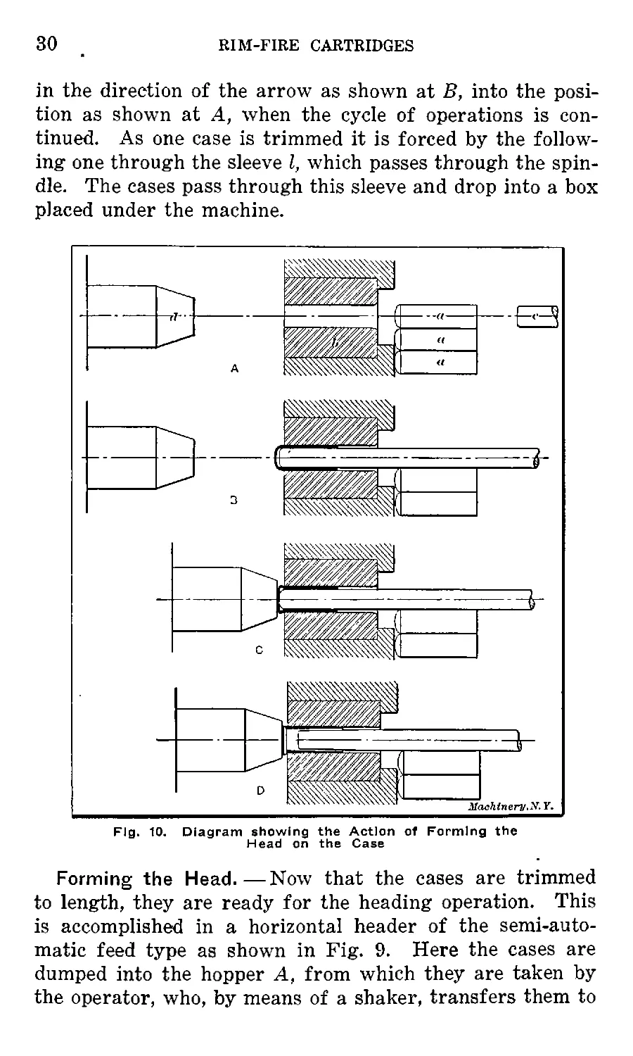
Fig. 10. Diagram showing the Action of Forming the
Head on the Case
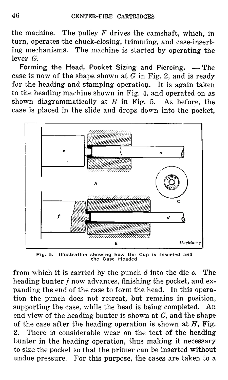
Forming the Head.—Now that the cases are trimmed
to length, they are ready for the heading operation. This
is accomplished in a horizontal header of the semi-auto-
matic feed type as shown in Fig. 9. Here the cases are
dumped into the hopper A, from which they are taken by
the operator, who, by means of a shaker, transfers them to
RIM-FIRE CARTRIDGES
31
the slide B. The cases are placed in this slide with the mouth
facing the punch-head C. As the cases come down the slide
B, they rest in a pocket, from which they are carried by the
punch into the die, where they are headed by the bunter,
held in the head D. This heading operation is interesting,
and is clearly illustrated in Fig. 10. At A are shown the
cases a located in the pocket in front of the heading die b.
The heading punch c and the bunter d are also shown back,
out of operation. At В the heading punch c has advanced
and carried the case into the die b. When in this position,
the heading bunter d advances, as shown at C, and com-
mences to form the head on the case. This action of the
heading bunter upsets the head of the case, close to the die,
so that the heading punch can be withdrawn, as shown
exaggerated at D, and the head on the case completed. The
punch and bunter now recede, and on the forward stroke
of the punch it carries another case into the die, forcing
the previously headed one out, which is deposited in a box
placed beneath the machine.
A heading machine equipped with an automatic feeding
device is shown in Fig. 3. The feeding device is similar
to that used on the automatic trimming machine shown in
Fig. 7, so that it will not be necessary to describe it further.
The feeding of the case to the die, however, is different to
that shown in Fig. 9, the case in this machine being fed by
two fingers, one of which carries it from the tube connected
with the hopper to the other finger which transfers it to the
die. This header is seldom used for 0.22 “long,” its use
being principally for heading 0.22 “short.”
Priming. —After the cases are headed, they are washed
in the tubs shown in Fig. 2 and dried. They are then taken
to the priming department. Here the cases are shaken into
plates and a charge of fulminate, which is held in a charger,
is inserted in the cases. From the charging room the cases
are taken to the priming machines, where they are placed
on a friction dial which carries them to a punch. This
punch has three grooves filed in its end, the function of
which is to distribute the fulminate to the rim of the case.
As the punch is kept rotating, it forces the powder to the
32
RIM-FIRE CARTRIDGES
rim of the case, by the action of centrifugal force, and
locates it in a manner similar to that shown at G in Fig. 6.
The fulminate is placed in the cases in a wet condition and
will not discharge easily until dry. The cases, after prim-
ing, are taken to what is called the “dry-house,” where they
are placed in sieves and left until dry in a very warm com-
partment, heated by steam. This completes the operations
on the case.
Casting the Slugs for the Bullets. — Two principal
methods are used in the manufacture of lead bullets. The
oldest one is to cast the bullets into slugs in a cast-iron mold
of the proper shape, and then swage these slugs to the
required shape in a swaging machine ; in the second method,
Fig. 11. Molds In which the Slugs for the Bullets are Cast
a lead wire is fed into a special machine which cuts and
forms the bullets to size and shape. Both methods are used
at the present time. The first method is the one employed
by the firm the practice of which is here described. The
second method is described in Chapter VII. When the
bullets are cast into the form of a slug in a cast-iron mold
and afterwards swaged to the proper shape, the slug is
cast in molds made in halves, as shown in Fig. 11. The
molten lead is kept at the required temperature in the pot A,
and is removed from it by the operator with the ladle B.
The lead is poured into the filler C, which is located on top
of the mold by guide blocks D. Then a foot lever situated
RIM-FIRE CARTRIDGES
33
beneath the machine is operated, forcing the pin E forward;
this pin, in turn, moves the filler in the direction of the
arrow, thus shearing the metal which has remained in the
filler from that which has run into the mold. The operator
now moves lever F to the left, which opens the molds and
allows the slugs to drop out. The lever F is then moved
to the right, closing the molds, and the operation is con-
tinued.
This operation is more clearly illustrated in Fig. 12,
where a section of the filler and mold are shown. At A
the filler, a is shown in line with the holes in the mold b,
when the metal is being poured in, and at В the filler is in
the position that it occupies in relation to the mold after
the metal has solidified and the foot lever is depressed. The
Fig, 12. Diagram showing how the Slugs are Cast
surplus metal which is left in the filler is tapped out into
the pot and remelted after the slugs which stick to the filler
have been scraped off.
Tumbling and Inspecting the Slugs.— The slugs as they
come from the molds have fins and burrs on them, due to
several reasons; one is that the operator does not close the
mold tightly; another, that dirt or scrap gets in between
the two halves of the mold. If the slugs were taken to the
swager in this condition, they would not pass down the
tube, so it is necessary to tumble them to remove the fins
and burrs. This is done in an ordinary tumbling barrel
which is revolved slowly. After the slugs are tumbled, they
are then dumped on a bench and inspected. In this inspec-
tion, '‘half-slugs” and imperfectly formed slugs are removed.
34
RIM-FIRE CARTRIDGES
“Half-slugs” are due to the molder not having sufficient
metal in his ladle to fill the mold. These would make im-
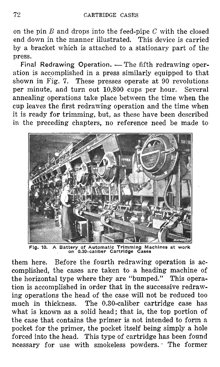
swaging machine shown in Fig. 13.
Fig. 13. Automatic Swaging Machine
which forms the Slug Into a Bullet
perfectly formed bullets of light weight.
Swaging the Bullets. —After the slugs have been in-
spected and all half-slugs or imperfectly formed ones have
been picked out, they are dumped into a hopper A (only the
lower portion of which is shown), located at the top of the
From this hopper they
drop down a tube В
into the close-wound
spring C. This spring
connects the tube В
with the pocket or re-
ceptacle D, located
over the finger-slide
E. From the pocket
the slugs are carried
to the dies by fingers,
which are held to the
slide E. This slide is
actuated by a bell-
crank G, which is
given a reciprocating
motion by a cam F,
fastened to a vertical
shaft, and driven from
the crankshaft
through bevel gears.
The slugs would not
come down the sleeve
and spring of their
own accord, so it is necessary to agitate them. This is
accomplished by fastening a yoke II to the ram of the
press, and attaching this yoke to the sleeve B. The move-
ment of the ram carries the sleeve В up and down in the
hopper, which action agitates the slugs and causes them to
drop down. The bullets are removed from the die by a
knockout connected to the ram of the machine by two
studs I.
RIM-FIRE CARTRIDGES
35
The action of swaging the bullets is more clearly shown
in Fig. 15. The swaging dies are made in two pieces and
are ground and lapped on the surfaces which come in con-
tact. At A the slug a is shown as it drops down into the
die b and is located on the die-pin c. In the position shown
at В the ram of the press has descended, carrying the punch
d into the die, which action forms the bullet. The punch,
in forming the bullet, forces the excess material out of the
vent hole provided in
the upper die. This
action is very interest-
ing, as the excess ma-
terial is gathered from
the slug and forced
out of the vent hole in
the form of short
wire. As the bullet is
formed, the ram of
the press again as-
cends and in its ascen-
sion the die-pin c is
pushed up through the
dies, carrying the base
of the bullet flush with
the top of the die. The
bullet is removed from
the top of the die by
the fingers as they
carry another slug to
the die, and falls into
the chute J, shown in
Fig. 14. Semi-automatic Loading Machine
for Seating the Bullets in the Cases
Fig. 13. This swaging operation finishes the bullet to the
exact size and also to the correct weight. The bullet for
the 0.22 long-regular weighs thirty-five grains.
Loading. — Now that the case and bullet are completed,
they are ready for loading. Both the bullets and cases are
removed to an outside building where the loading machines
are located. The cases or shells are first shaken into what
is called a “shell plate,” which has a baseplate doweled to
36
RIM-FIRE CARTRIDGES
it. The bullets are shaken into a bullet plate, and the pow-
der is then put in a charger which has holes in it register-
ing with the holes in the shell plate, and slightly smaller
in diameter than the inside of the cases. The thickness of
these charging plates governs the amount of powder that
is put in the cases. The charging plate is now located over
the shell plate and tapped slightly, causing the powder to
drop into the cases. The charger plate is then removed
and the bullet plate substituted, being located by dowels.
Both plates are now taken to the semi-automatic loader,
Fig. 14. (This loader is shown with the plates removed).
The plates are put on the table A, and held by the clamp-
bolt B. When everything is set properly, the operator
Fig. 15. Diagram showing the Action of Swaging the Bullets
presses the hand lever C, thus starting the machine. He
then steps back from the machine, as occasionally a number
of cartridges, and, in some cases, a whole plate of cartridges,
explode, making it dangerous for him to stand in close prox-
imity to the press.
The table A on which the loading plates are held is moved
forward by means of a pawl engaging in a rack, fastened
to the under side of the table. The table is moved a distance
equal to the space between a row of holes for each stroke of
the press. The pawl is actuated through a series of levers
and the arm D which is connected eccentrically to the crank-
shaft of the press. When the last row of cases in the plate
has been operated on by the row of punches E, the machine
RIM-FIRE CARTRIDGES
37
is automatically stopped by a trip lever at the back of the
machine.
A clearer idea of the method of loading the cartridges
may be obtained by referring to Fig. 16. Here at A, the
cases and bullets are shown located in the shell and bullet
plates a and b, respectively, ready for assembling, or seat-
ing; and at В the bullets and cases are shown assembled,
by the action of the seating punches c. The plates are now
removed from the press, and the slip plate d removed, when
the loaded cartridges drop out. After the bullets have been
seated in the cases, the loaded cartridges are taken to an
automatic machine, where they are crimped and cannelured.
Fig. 16. Diagram showing how the Bullets and Cases are
Assembled
Crimping and Canneluring. — Crimping the cartridges
consists in tightening the case around the bullet, as shown
at I in Fig. 6, to prevent the latter from falling out. This
operation is performed in the automatic machine shown in
Fig. 17. The loaded cartridges are dumped into the hop-
per A through which passes a belt (inclosed in the box B)
having scoops fastened to it. Theses scoops C carry the
cartridges out of the hopper up to the top of the slide D.
Here the cartridges drop out of the scoops into the slide.
The slot in this slide is slightly larger than the body of the
38
RIM-FIRE CARTRIDGES
case, but is smaller than the head, so that it is impossible
for the cases to go down the slide unless they are head up-
wards. As the cartridges come down the slide D, they come
in contact with the wheel E, which is rotated by a round
belt F. This wheel has slots cut in it, in which the cart-
ridges hang, the under sides of the heads bearing on the
periphery of the wheel, and as the latter is kept rotating it
deposits the cases on the revolving dial G. The guard L
prevents the cartridges from dropping out before they reach
the dial. As the cartridges drop out of the wheel E onto
the dial G, they are guided by the block II. The dial G
rotates in the direction of the arrow and carries the cart-
Flg. 17. Automatic Crimping and Canneluring Machine
ridges around where they are lined up by the guide I. As
they continue in their travel, they pass between the station-
ary segment block J and the revolving dial K, the action of
which rotates the cartridges and performs the crimping
and canneluring operations. As they pass around still
further, they are removed from the dial by a guide and drop
into a box. The canneluring is done by means of narrow
knurled projections formed on the edges of the dial К
and the segment block J, dial К being fastened to the dial G.
The crimping is also done by forms on the above-mentioned
parts.
RIM-FIRE CARTRIDGES
39
Greasing, Packing, and Testing. — The cartridges are
now completed, as regards the manufacturing operations,
and are ready for greasing and packing. Greasing is only
done when the bullets are made from commercially pure
lead, and not of composition of from 3 to 5 per cent tin.
When made of this composition, it is not necessary to grease
the bullets. The object of the greasing is to prevent them
from leading the bore of the rifle. The 3 to 5 per cent
composition has the same effect as the grease, but is much
cleaner and of a more finished appearance. The cannelur-
ing, as shown at I in Fig. 6, forms narrow knurled grooves
during the crimping operation for the purpose of holding
the grease. If the bullets are made from commercially
pure lead, they are shaken into plates and dipped into
molten grease. The grease just sticks in the canneluring,
leaving the remainder of the bullet practically clean—that
is, if the grease is at the proper temperature. If slightly
cooler than the correct temperature, the grease will form
in clogs on the bullet, which have to be removed by wiping
them with a rag. The shaker plates are now located on a
packing plate. This packing plate has three hundred holes
drilled through it in groups of fifty, which is the number of
cartridges put in each box. The shaker plate holds only
half the number of cartridges that the packing plate does,
so that it requires two shaker plates to fill the packing
plate.
In operation, the first shaker plate is placed over the
packing plate, and both plates are then turned over, when
the shells drop into the packing plate. The shaker plate is
then removed and a slip plate substituted for it. Another
shaker plate is placed over the packing plate and the same
operation repeated. This fills the packing plate and leaves
half of the cartridges in the plate with their heads up, while
the other half are reversed. The cartridges are now re-
moved from the packing plate and placed in a slide pro-
vided with compartments, from which they are removed
and placed in boxes. This packing arrangement is semi-
automatic, and is considerably quicker than packing by
hand.
40 RIM-FIRE CARTRIDGES
Even though the cartridges have passed by all the in-
spections necessary for the manufacturing operations, they
are still not ready to ship, but have to pass through a rigid
test. A number, picked at random, are taken to the testing
department where the tester in charge tests them for accu-
racy. There are various methods of testing the accuracy
of the cartridge. One is to locate the rifle in a stock which
holds it rigidly. The sight is then located accurately over
the bull’s eye, the trigger pulled, and the result noted. The
cartridge is also tested for accuracy by off-hand shooting,
and other similar tests.
CHAPTER IV
MANUFACTURE OF CENTER-FIRE CARTRIDGES
The greater number of military cartridges used at the
present time by the various governments are about 0.30
caliber. This size is also used for many sporting rifle
cartridges because of the high velocity and penetrating
power and the comparatively flat trajectory that can be
obtained. In the present chapter, the practice of the
Dominion Cartridge Co. in the manufacture of 0.30-30 Win-
chester cartridges is described.
Chief Requirements of a High-velocity Rifle Cartridge. —
Among the chief factors governing the accuracy with which
a bullet strikes a target may be mentioned: 1. The rifling
in the barrel; 2. The nature and the amount of charge be-
hind the missile; 3. The shape and equilibrium of the bul-
let. The rifling and the explosive charge behind the bullet
have a direct effect on the velocity, and also govern the
height of the trajectory curve. Theoretically, it is impos-
sible for a bullet to travel through the air in a straight
path, but with the high-powered rifles, considering a range
of one hundred yards, the height of the trajectory curve at
fifty yards is very slight. In the case of the cartridge to be
described, for example, the height of the trajectory curve'
at fifty yards is only 1.280 inch. The shape of the bullet has
not such a pronounced effect on its accuracy as has its
equilibrium—that is to say, if a bullet does not balance
properly on its axis, it is impossible for it to travel in a
straight path. This is one of the problems a manufacturer
of cartridges has to deal with, and is, in all probability,
one of the most difficult to master.
Probably the best-known American high-powered rifles ♦
using smokeless powders are the 0.30-30 Springfield, Win-
chester, Marlin, and Savage rifles. The bullet for the cart-
ridges used in these rifles is made in three distinct patterns,
viz., the full metal-cased or hard-point, the part metal-
cased or soft-point, and the mushroom or hollow-point. The
41
42
CENTER-FIRE CARTRIDGES
first-named of these is used more particularly for military
purposes, while the two latter types are used for hunting
and sporting purposes in general. The soft-point bullet
which weighs about 170 grains is the type most commonly
used for hunting purposes. When fired, this bullet has a
muzzle velocity of approximately 2000 feet per second—a
rate of 23 miles per minute.
First Operations. — The case for the 0.30-30 cartridge is
received in the form of a cup, as shown at A in Figs. 1 and
2. These cups are taken to the annealer, shown in Fig. 1,
Fig. 1. Evolution from the Cup to the Finished Cartridge
Chapter III, where they are annealed, "washed, and dried,
as previously described. When dry, the cups are taken to
the friction-dial drawing press shown in Fig. 3, where they
are placed on the stationary table A, from which they are
removed by means of a shaker to the revolving dial B. This
drawing press is similar to that shown in Fig. 4, Chapter
III, except that it is single-headed. After the cup has
passed through two drawing operations, as shown at В and
C in Figs. 1 and 2, it is ready for the inserting or indenting
operation.
Rough-forming the Pocket for the Primer. —The
case for the 0.30-30 Winchester cartridge is made
with a solid head, which is not the case with cart-
ridges of smaller size, in which, as a rule, smoke-
less powders are not used. The solid head is nec-
essary to withstand the high pressure developed
by smokeless powders. After the second drawing
operation, the cup is not annealed, but is taken di-
rectly from the drawing presses to the headers, one
of which is shown in Fig. 4. The header is used
for inserting the pocket as well as forming the
head. The principle on which this header works
is similar to that of the horiontal header shown
in Fig. 9, Chapter III. The method used in rough-
forming the pocket is clearly shown at A in Fig. 5.
As the case comes down the slide of the header
shown in Fig. 4, it is located in a pocket, from
which it is carried by the punch a, Fig. 5, into the
die b. Here it is held by the punch while the in-
serting bunter advances and forms the pocket.
Both punch and bunter then retreat, and, on the
forward stroke of the ram carrying the punch, the
case previously inserted is forced out of the die, as
the punch carries another case in. The die b is
made a good fit for the case, which, when pushed
through, expands and is stripped from the punch.
44
CENTER-FIRE CARTRIDGES
Third and Fourth Drawing Operations.— Thecaseisnot
annealed after the second drawing operation, and it is nec-
essary to do this before it can pass through the successive
drawing operations. The cases are taken to the annealer,
annealed, washed, and dried, and brought back to the draw-
ing presses. The cases are now of considerable length, and
it is not advisable to perform the third and fourth drawing
Fig. 3. Friction-dial Drawing Press for Drawing the Cups
operations in the press shown in Fig. 3, as they would not
stand up properly on the dial. For these operations, a
ratchet-dial drawing press is used, the design of the dial
of which is somewhat similar to the dial of the swaging
machine shown in Fig. 16. After the third drawing opera-
tion the cases are again annealed, washed, and dried, and
then pass through a fourth drawing operation. (F, Fig. 2.)
CENTER-FIRE CARTRIDGES
45
Trimming the Cases to Length. — As shown at F in Fig.
2, the top edge of the case is extremely ragged. Cracks
develop in the mouth of the case which make it necessary
to remove a certain amount to obtain a good finish. This
is accomplished in the semi-automatic trimming machine
shown in Fig. 6. Here the cases are placed in the slide A
by the operator, from which they pass into a pocket at the
base of the slide. From the pocket they are carried into
the chuck by means of the punch В held in the punch-head C,
which is actuated by an eccentric crankshaft. The chuck
begins to close before the punch reaches the limit of its
Fig. 4. Horizontal .Header of the Semi-automatic Feed Type
for Inserting the Cup and Forming the Head on the Case
travel, thus allowing the punch to insert the case to the
desired depth. The chuck is closed by means of a cam (not
shown) at the rear of the machine,, operating a clutch,
which, in turn, forces a sleeve forward, thus closing the
chuck. The tool-slide D carrying the trimming tool E, is
now brought forward, and trims the case to the desired
length. As the trimming tool E advances, the punch В
retreats from the case. The chuck is now opened, and the
punch advances carrying in another case, which forces the
previously trimmed one into a hollow sleeve. This hollow
sleeve passes through the spindle of the machine, the trim-
med cases dropping through it into a box placed beneath
46
CENTER-FIRE CARTRIDGES
the machine. The pulley F drives the camshaft, which, in
turn, operates the chuck-closing, trimming, and case-insert-
ing mechanisms. The machine is started by operating the
lever G.
Forming the Head, Pocket Sizing and Piercing. —The
case is now of the shape shown at G in Fig. 2, and is ready
for the heading and stamping operation. It is again taken
to the heading machine shown in Fig. 4, and operated on as
shown diagrammatically at В in Fig. 5. As before, the
case is placed in the slide and drops down into the pocket,
Fig. 5. illustration showing how the Cup is inserted and
the Case Headed
from which it is carried by the punch d into the die e. The
heading bunter f now advances, finishing the pocket, and ex-
panding the end of the case to form the head. In this opera-
tion the punch does not retreat, but remains in position,
supporting the case, while the head is being completed. An
end view of the heading bunter is shown at C, and the shape
of the case after the heading operation is shown at H, Fig.
2. There is considerable wear on the teat of the heading
bunter in the heading operation, thus making it necessary
to size the pocket so that the primer can be inserted without
undue pressure. For this purpose, the cases are taken to a
CENTER-FIRE CARTRIDGES
47
sizing machine of the ratchet-dial type, where they are
placed on pins driven into this dial, and pass successively
under a piercing and a pocket-forming punch. The pierced
case is not shown in Fig. 1, but may be seen at I in Fig. 2,
where all the other operations on the case are also more
clearly shown.
Mouth Annealing. — When the pocket has been sized and
the hole pierced in the case, thus making an opening so that
the powder can be exploded by the discharge of the primer,
the cases are taken to a “mouth annealer.” This machine,
which is shown in Fig. 7, anneals the cases for about two-
Fig. 6. Trlmnflng Machine of the Semi-automatic Feed Type
for Trimming the Cases to Length
thirds of their length. The cases are placed in a verti-
cal position, resting on their heads on the revolving dial A,
which is rotating in the direction of the arrow. They pass
around on this dial between the guard В and the spring C.
This spring is given a vibrating motion by the action of the
revolving dial, thus agitating the cases and arranging them
in single file, so that each case will be exposed to the flame.
As the cases are carried around on this dial they pass in
front of two gas burners D and E, where the mouth of the
case is annealed. Gasoline is used as a fuel, being pumped
into the burners at the desired pressure by a pump located
at the right of the annealer, but which is not shown in the
48
CENTER-FIRE CARTRIDGES
illustration. The speed at which this dial revolves is such
that the cases remain in front of the burners long enough
to be sufficiently annealed. They are then removed from
the dial by a wire F which pushes them off into a box,
where they are allowed to cool gradually.
Reducing. — The reason for annealing the mouth of the
case is to make it soft, so that it can be reduced on the mouth
without cracking or folding. Before the cases are reduced,
they are oiled with a rag which has lard oil spread over it.
They are then taken to the machine shown in Fig. 8, which
is a reducing press of the ratchet-dial type. Here they are
Fig. 7. Frlction-dlal Mouth Annealer
dumped into a box placed in front of the machine, from
which they are removed by the operator and placed in the
holes in the ratchet dial A. This dial is driven by a finger
B, which is held to a dovetailed slide C, the slide being act-
uated by the lever F, which is connected eccentrically to the
crankshaft. The holes in the dial A are larger at the front
end. The dial is made in this manner so that the heads can
be inserted in the larger hole, and, as the dial revolves, the
friction between the head of the case and the base of the
machine draws the case back into the smaller portion of
the hole. When the case is in this position, it cannot be
removed by the reducing dies, should they stick to the case.
CENTER-FIRE CARTRIDGES
49
The friction between the head of the case and the bed of
the machine, however, cannot be relied upon to locate the
cases properly, so a spring pad is placed in the bed of the
press, over which the cases pass before reaching the first
reducing die.
The ram of this machine is made to hold two reducing
dies. The first boss D holds what is called the breaking-
down die, which only passes down a certain distance over
the mouth of the case, __ ______
while the second boss
E holds the reducing
die. This latter die
travels down practi-
cally the whole length
of the case, and gives
it a tapering shape.
The action of reduc-
ing is more clearly
shown in Fig. 9, where
the dies are located in
the relative positions
that they occupy when
in the machine. The
breaking-down die is
shown at A while the
reducing die is shown
at B. It is necessary
in this
support
the case
ing, and for this pur-
pose punches a and b are inserted in the die, as shown, to
prevent the case from folding.
Verifying. — From the reducing machine the cases are
transferred to the verifying machine shown in Fig. 10.
Here they are placed by the operator in verifying dies, six-
teen of which are held in the ratchet dial A by spanner nuts
B. This ratchet dial A is actuated in the same manner as
that of the reducing press. As the cases pass around, the
operation to
the inside of
while reduC- 8- Ratchet-dial Reducing Press for
50
CENTER-FIRE CARTRIDGES
punch C seats them in the verifying dies, and as they pass
around still further, the punch D forces them down into
the die until the under side of the head of the case rests on
top of it. As the ratchet dial continues in its travel, a
“knockout” placed beneath'the dial lifts the ejector pins,
which forces the case up out of the die to a sufficient
height, so that the pick-up E can grip it. As each case is
picked up, it forces the preceding one up through a brass
tube from which it falls out at F into the chute G. This
pick-up is operated by a lever H fulcrumed to the ram of
the machine and pivoted to a bracket 7, which is fastened
Fig. 9. Showing how the Mouth of the Case is Reduced
to the uprights of the machine. The end of the lever which
operates the pick-up is rounded, so that it “rolls” freely
between the projections J formed on the pick-up spindle K.
This verifying operation reduces the cases on the mouth
to the correct diameter, as shown at K, Fig. 2. Small pins
or knockouts are used to support the mouth of the case
while being reduced, acting on the same principle as those
shown in Fig.. 9.
Trimming. — After the cases have been verified, they are
removed to the washing-room, where they are put into the
revolving tubs shown in Fig. 2, Chapter III, washed, dried,
and then brought to the trimming department. The opera-
CENTER-FIRE CARTRIDGES
51
Fig. 10. Verifying Machine in which the
Reducing of the Case is Completed
tions now to be performed on the case are trimming the
head, trimming the case to the proper length, and burring
the mouth so that'the bullet can be easily inserted. The
trimming machine for performing these operations is shown
in Fig. 11. The cases are placed in the slide A by the oper-
ator, from which they pass into a pocket B, the head of the
case facing the punch C, as shown. The drum D to which
cams are attached actuates the slide E, carrying the punch
C, which, in turn,
forces the case into
the revolving chuck F.
This chuck is made in
two pieces, and is clos-
ed by split rings
operated upon by a
cam, attached to the
main driving shaft be-
neath the machine.
The chuck is, rotated
by a belt G, which
runs on the pulley H.
Now that the cases
are held in the chuck,
a cam attached to the
driving shaft carries a
slide I forward, in
which is held a trim-
ming-tool holder Л.
Circular forming tools
are held in this tool-
holder for trimming
the head of the case,
Fig. 2. A group of
hanging on the hopper at J, to the left of the illustration.
At the same time that the slide carrying the head-trimming
tool is being advanced, the slide К also advances, carrying
a trimming tool, which trims the case to length. This trim-
ming tool is similar to that shown in Fig. 8, Chapter III.
As soon as the case is trimmed to length, the mouth-trim-
giving it the appearance as at L,
these circular tools may be seen
52
CENTER-FIRE CARTRIDGES
ming tool L advances and trims the mouth of the case.
This tool is made from %-inch drill rod.
After the trimming operations are completed, the chuck
is automatically opened, and the punch M advances carry-
ing the case out of the chuck, from which it drops into the
chute N, and thence into a box O. The snap-gage used for
gaging the head and length of the case in this operation
is shown at P. It is of the ordinary type of combination
snap- and ring-gage. Gage P is only used when setting-up
the machine, and testing at the beginning of each box of
cases. After the cases come from this machine, they are
Fig. 11. Trimming Machine for Trimming the Head and Mouth,
and for Trimming the Case to the Desired Length
deposited on a bench, where an operator passes them
through a snap-gage shown in Fig. 12, which is attached to
the bench. This gage is so constructed that it is impossi-
ble to pass a case through the hole A and into the box, with-
out first passing the head of the case through the slide of
the gage. If any cases are found to have large heads, they
are put to one side and again pass through the trimming
operation, so that all cases that pass this inspection have
heads of the correct diameter.
Inserting the Primers and Inspecting. — The cases are
now transferred from the trimming department to the
priming machines, one of which is shown in Fig. 13, where
CENTER-FIRE CARTRIDGES
53
they are placed in hollow pins A, twelve of which are driven
into a dial B, fastened to a ratchet dial C. This ratchet dial
is driven in a manner similar to the other ratchet dials pre-
viously described. As the operator places the cases in the
hollow pins A, they pass around under a punch (not
shown) which is held in the boss D. This acts as an emer-
gency punch to insure that all the cases have been pierced.
A plate E acts as a guard to prevent the emergency punch
from pulling the cases off the pins. However, this plate E
is not relied upon exclusively, a punch F which is held in
the ram of the press being used for seating the cases prop-
Fig. 12. Snap-gage used on the Bench for Gaging the
Head of the Case
erly in the hollow pins. The primers are shaken into small
vulcanite plates, from which they are transferred .to the
table G, located at the rear of the machine. A friction dial,
which is operated by a round belt driven from the main
crankshaft, rotates just in front of this table. The opera-
tor now shoves the primers from the table onto the friction
dial, which carries them around between two guards. This
action of feeding the primers is similar to the action of the
friction-dial drawing press, shown in Fig. 3. A finger H
held on a slide carries one primer at a time out from the
dial, and holds it central with the pocket in the case. The
54
CENTER-FIRE CARTRIDGES
so war we picK-up jaws can pass
get a good grip on the case. The
Fig. 13. Priming Machine for Inserting
the Primer In the Pocket of the Case
punch I now descends, and carries the primer out of the
finger, seating it in the pocket. As the dial passes around
still further, the pick-up J descends, lifting the cases from
the pins, and transfers them to a box in a manner similar
to that shown in Fig. 10.
As can be seen in the illustration, the pins A are tapered
down over the head and
reason for using hollow
pins instead of the or-
dinary solid pins for
this operation is that
the mouth of the case
is considerably small-
er than the upper part
of the body. This
makes it necessary to
put the cases in hol-
low pins, so that they
will not be able to
“wobble” when the
primer is inserted, as
would be the case if
solid pins were used.
After the primers
have been inserted in
the pockets of the
cases, they are trans-
ferred to a bench
where an operator, by
means of a smalt
straightedge which
is rubbed across the top of the case, tests the primers to
see whether any of them project above the face of the
head. If a primer projects, a bright spot is noticed; this
primer must be knocked out and another one inserted.
Slugs for Bullets.— The bullet referred to in the follow7
ing is of the so-called “soft-point” type, and consists of a
lead center which is partially enveloped by a metal case.
The soft-point bullet is also known as the “mushroom” bul-
CENTER-FIRE CARTRIDGES
55
let, and is used chiefly for sporting purposes. For mili-
tary purposes, a cupro-nickel or steel case completely en-
velops the lead bullet, so that there is no mushrooming
effect when an object is penetrated. This completely en-
veloped lead bullet when pointed is known as a “spitzer” bul-
let. The manufacture of this type is described in Chapter
VII. The various stages through which the soft-nose bullet
passes during its manufacture are illustrated in Fig. 14,
where A is the slug as obtained from the molds. These slugs
are cast in molds of a design similar to those shown in Fig.
11, Chapter III, but, of course, the forms in the molds are of
the desired shape. The slugs are removed from the mold-
ing department to a tumbling barrel, where they are tum-
bled for a considerable length of time to remove the fins;
Fig. 14. Operations performed on the Lead Filling before and
-after Assembling In the Metal Case
then they are dumped into the hopper of an automatic swag-
ing machine, similar to that shown in Fig. 13, Chapter III,
and come out in the form shown at B, Fig. 14. This finishes
the operation on the lead center.
Drawing and Trimming the Metal Case. — The metal
case, which is shown assembled on the lead center at C, D,
and E in Fig. 14, is made from copper and is nickel-plated
after it has been trimmed to the desired length. This case
for the bullet comes in the form of a cup and passes through
three drawing operations, and the annealing, washing, and
drying operations, as described in Chapter HI, regarding
the shell for the 0.22 “long.” The same class of machines
is also used for the various operations on this case.
When the case is completed, that is, after the drawing and
trimming operations are performed, the case and the lead
56
CENTER-FIRE CARTRIDGES
centers are transferred to the loading department. Here the
lead centers are shaken into one plate while the copper cases
are shaken into another. These plates are now assembled
over each other, the plate holding the cases being on top,
and a slip-plate is put under them. The three plates are
then placed in the loading machine, Fig. 15. Seating
punches A are held to the ram of this machine and, as the
lever В is pulled down, the ram descends, and the seating
punches force the
cases out of the plate
C over the lead cen-
ters held in the plate
D. These seating
punches are made so
that they pass into the
holes in the shell plate.
The bullet plate or
“center holder” is
made to give the bul-
let the shape shown
at C, Fig. 14. The
bullets as now form-
ed are again transfer-
red to the swaging de-
partment, where the
operator places them
on the table A of the
machine shown in Fig.
16, from which they
are put in the ratchet
dial B, the lead point
dial passes around, the
C seats the bullet properly in it, and as it con-
in its rotary movement, the punch D forces the
out of the dial into a die. This die gives the
the shape shown at D, Fig. 14, and also makes it
Fig. 15. Hand Loading Machine for
Loading the Cartridge
extending downward. As the
punch
tinues
bullet
bullet
symmetrical, so that it will balance properly on its axis. It
might here be mentioned that the finishing of the bullet in
one die insures this result. As the ram of the press ascends,
CENTER-FIRE CARTRIDGES
57
Fig. 16. Swaging Machine for Forming the
Lead Filling and the Metal Case
to the Desired Shape
it carries upward two rods connected with the knockout
motion under the press, which, in turn, force a punch up
through the die, the action of which again transfers the
bullet from the die to the dial B. Just as the bullet is lo-
cated in the dial, the latter is revolved and the punch E
forces the bullet out of the dial into a chute, from which it
is deposited into a box.
Forming Knurled Grooves. — The next operation on the
bullet is the forming
of the knurled grooves
shown a,t E, Fig. 14.
The knurling of these
grooves is accom-
plished in the canne-
luring machine shown
in Fig. 17. The bul-
lets are dumped on the
dial A, from which
they are removed by
the о p e r a to r and
placed in a vertical
position on the revolv-
ing dial B. Attached
to the revolving dial В
is a dial C, which has
two knurled projec-
tions on its periphery.
Back of dial C is a
segment D, which also
has two knurled pro-
jections on its face.
As the bullets pass around on the dial В in the direction of
the arrow, they are rotated by the action of the dial C
revolving against the stationary segment D. This action
forms the knurled grooves entirely around their peripheries.
As the dial carries the bullets around still further, they are
>^emoved from it by means of a guide E, and are dropped
^hto a box placed under the machine. The object of this
canneluring operation is to form a groove in the bullet so
58
CENTER-FIRE CARTRIDGES
that the top of the case can be turned in, thus holding the
bullet more securely in the case. After the canneluring op-
eration, the bullets are taken to the swaging machine in Fig.
16, and again pass through the operation of swaging, the
same die being used as before. This is to correct any eccen-
tricity of the bullet which might have been caused by
canneluring.
Loading.— The case and bullet are now ready for as-
sembling or loading, and are transferred to one of the ex-
plosive departments where this operation is accomplished.
The cases are put into one plate and the bullets into another.
Fig. 17. Canneluring Machine for Forming the Grooves
in the Bullet
Then the desired amount of powder is shaken into a charger,
which is located over the shell plate and rapped slightly,
thus depositing the powder in the cases. The shell plate
containing the cases and the bullet plate are removed to the
loading machine shown in Fig. 15. Here the shell plate is
put into the slide, the bullet plate located on top of it by
means of dowels, and the handle В pulled down, carrying
down the ram of the press to which the seating punches
are fastened. These seating punches force the bullets out
of the bullet plate and locate them in the cases. The plates
are then removed and the loaded cartridges dumped out.
A different shell plate is used in this operation.
CENTER-FIRE CARTRIDGES
59
Crimping. — The loaded cartridges are now transferred
to the crimping machine, Fig. 18, in which the top of the
case is tightened around the bullet. The operator dumps
the cartridges into a box, which is held on the brackets A
in front of the machine. He then removes the cartridges
from the box and places them in the holes in the dial B.
This dial rotates to the left, and as the cartridges come be-
low the punch C, the bullet is seated in the case to the cor-
rect depth. Two
bosses E are provided
on the ram of this ma-
chine. Both bosses,
however, are not used
for crimping, as this
machine is also used
as a reducing press,
when both bosses are
necessary. The crimp-
ing die can be held in
either boss, but is held
preferably in the one
to the left. This die is
made so that it passes
over the bullet and
turns the case in the
groove, thus tightening
the case securely on
the bullet. As the
cases pass around still
further, they are re-
moved from the dial
Fig. 18. Crimping Machine for Tightening
the Cartridge Case on the Bullet
after Loading
by the wire F and are deposited in a box under the machine.
Spring pads are also used under this dial, the purpose of
which was explained in connection with the reducing press
shown in Fig. 8.
Testing and Packing. — The cartridges are now finished
as regards the manufacturing operations, but they are not
ready for the market until they pass through a rigid in-
spection. This inspection consists in testing for accuracy,
60
CENTER-FIRE CARTRIDGES
velocity, and penetration. The accuracy of the cartridge is
tested by means of shooting the bullets at various ranges
for which the cartridges are adapted. This is done both by
off-hand shooting, and also by locating the rifle in stocks,
sighting it directly over the bull’s-eye, firing it, and then
noting the results. The velocity of the cartridge is deter-
mined by means of an instrument called the chronograph.
This is an electrical instrument which operates in the fol-
lowing manner: The recording mechanism is connected
with a wire, which is held just in front of the muzzle of the
gun from which the cartridge is to be fired. Another wire
is placed in front of the target and connected to the chrono-
graph by an electric circuit. When the apparatus is ad-
justed, a signal is given for the cartridge to be fired. As
the bullet leaves the muzzle of the gun, it cuts the first wire
which is connected to the chronograph, and the latter com-
mences to record the flight of the bullet. When the bullet
strikes the target, it breaks the electric circuit connected
with the chronograph, and the instrument instantly stops
registering. The recording apparatus shows the time taken
by the bullet in traveling from the gun to the target, and as
this distance is always known, it is an easy matter to deter-
mine the velocity in feet per second.
The cartridge is tested for penetration by shooting the
bullets into boards of a given thickness. Pine boards, %-
inch thick, are, as a rule, used for this purpose. The
penetration of the 0.30-30 soft-nose bullet, which is de-
scribed in this chapter, is eleven boards, at a distance of 15
feet. If the cartridge does not pass this inspection satisfac-
torily, the cause is ascertained and rectified before any are
shipped. These cartridges are packed by hand in boxes
which hold twenty-five. The boxes are then put in cases
holding 5000 cartridges.
CHAPTER V
FRANKFORD ARSENAL METHOD OF DRAWING
CARTRIDGE CASES
The two preceding chapters describe the methods used
by the Dominion Cartridge Co. in producing metallic cart-
ridges. The present chapter deals with the methods fol-
lowed by the Frankford Arsenal, Philadelphia, Pa., in draw-
ing. 1. Sequence of Redrawing Operations on a 0.30-callber Cartridge
Case, and Tools used
ing the cases for 0.30-caliber cartridges. In the following
chapter, the tools used for the drawing operations will also
be described in detail.
Making the Cups for Cartridge Cases.— The first oper-
ation in the making of a cartridge case is to produce a cup,
then by successive redrawing operations this cup is reduced
in diameter and extended to the required length. Fig. 1
shows the various steps in the sequence of redrawing oper-
ations following that of making the cup. From this illus-
tration it can be seen that five operations are necessary
to bring the case to the required length—these are called
si
62
CARTRIDGE CASES
redrawing operations because the work accomplished con-
sists in reducing and redrawing a piece that has already
been drawn to cup form. The press used for making the
cups from which cartridge cases are made is shown in Fig.
2. It is of the double-action type, and carries four punches
and dies, thus making four cups at each stroke. This punch
press operates at 100 revolutions per minute, producing 400
cups a minute, or 24,000 cups per hour. The type of blank-
ing and cupping dies used in this machine are shown dia-
grammatically in Fig. 3, which gives a comprehensive idea
of the action that takes place in the formation of the cup.
Fig. 2. Making the Cups, Four at one Stroke of the Press,
at the Rate of 24,000 per Hour
At A the blanking punch is shown in contact with the top
face of the brass sheet. At В the blanking punch has cut
out a disk of the required size and carried it down to the
first shoulder in the combination blanking, cupping, and
drawing die. At C the combination cupping and drawing
punch has come into operation and has started to form the
blank to cup shape; and at D the blank has been forced
completely through the die and has been given the first
drawing operation.
The sheet stock is held on the roll A located to the right
of the machine shown in Fig. 2, and is drawn into the press
under the blanking and drawing punches by means of feed-
Fig. 3. Progressive Steps In the Bianking, Cupping, and First Drawing Operations on the Cartridge Case
rolls. After the stock passes through the rolls B,
it is oiled by means of a rag saturated with lard
oil that is contained in the tank C. The sheet is fed
« a distance equal to the diameter of the blank plus
the width of the web for each stroke of the press
(see Fig. 4), and after it has been started by the
operator, who uses the handwheel feed shown, it is
carried on automatically by feed-rolls located at
64
CARTRIDGE CASES
both ends of the throat of the press. As the sheet from
which the blanks have been sheared protrudes from the left-
hand end of the machine, it passes through a shearing die,
which, in conjunction with a knife operated by a crank and
connecting lever held on the extreme end of the crankshaft,
cuts off the scrap, enabling it to be packed in boxes. The
chief reason for cutting up the stock in this manner is to
avoid having it pile up around the machine and also to en-
able it to be more easily removed.
—oo2$Soo
SlSooq
-1.200 " -ADVANCE OF SHEET PER STROKE OF PH ESS
Machinery
Fig. 4. Manner of laying out Combination Blanking, Cupping, and
Drawing Dies in Order to Economize in Stock
The manner in which the dies and punches are laid out
in order to economize in stock is shown in Fig. 4. By, refer-
ring to the upper diagram in this illustration, it will be seen
that the centers of the four dies are located in a “diamond”
shape, thus reducing the width of the sheet required and
securing the most satisfactory lay-out for the punches and
dies. The condition of the sheet after the press has made
four strokes is shown in the lower portion of the illustra-
tion, which indicates the process in cutting out the blanks.
CARTRIDGE CASES
65
Setting Drawing Punches and Dies. — To set drawing
punches and dies properly requires considerable experience,
as this is a difficult task under the most favorable condi-
tions. The dies and punches are usually aligned with each
other by setting them in the approximately correct position,
then running through a few cups and noting the results.
In the type of die-holder shown in Fig. 5, it is not neces-
sary, of course, to reset the dies when they have been re-
moved for grinding, if proper attention has been paid when
they were first set up. This is not the case, however, with
redrawing dies, as will be explained later. One peculiar
point in making cups that causes considerable trouble is
that it is practically impossible to produce a cup with a
straight top; that is, one in which the metal is drawn to the
same extent on one side as it is on the other. The reason
for a cup drawing irregularly in this manner is not due in
all cases to inaccurate setting of the punches and dies, but
generally to a variation in the thickness of the sheet from
which the blank is cut out. It is a peculiar fact, but never-
theless true, that it is practically impossible to roll sheet
metal uniform in thickness; that is to say, the sheet is
thicker in the center than it is at the outer edges. The
66
CARTRIDGE CASES
reason given for this is that the rolls, even though they are
8 or 10 inches in diameter, spring to a slight extent in the
center—where they are unsupported—and thus produce a
sheet of varying thickness throughout its width. Another
difficulty experienced in making cups is the striking of hard
Fig. 6. Drawing Press used for First, Second, and Third
Redrawing Operations—Four Cups per stroke at the
Rate of 24,000 per Hour
spots in the metal. It is obvious, of course, that if the stock
is not of a uniform hardness, the softest spot or portion
will draw much more than the harder portion, and, hence,
a cup having one side longer than the other will be obtained.
Not only will the top edge be irregular, but the walls will
CARTRIDGE CASES
67
also be of uneven thickness. It is claimed by those who
have had experience in this work that it is impossible to
rectify any defect of this kind in the succeeding redraw-
ing operations. When a cup is once started with a wall of
unequal thickness, this condition prevails until the final
drawing operation, so that it will easily be seen that great
care must be exercised in making the walls of the cup of
uniform thickness if a satisfactory product is to be obtained.
Annealing and Redrawing Operations. — After the cups
are made, it is the general practice to anneal, wash, and dry
them as described in Chapter III. Then they are ready for
the first redrawing, or second drawing operation. The tem-
perature to which the cup is heated for annealing varies
from 1200 to 1220 degrees F. The manner of handling the
cups after they have been annealed, washed, and dried, is to
carry them in trucks, which are lifted from the floor of the
annealing room to a track located above the drawing presses.
These trucks are provided with false bottoms and are run
along the track until they are directly over the hopper which
feeds the cups to the punch press. The false bottom is then
removed, allowing the cups to drop from the chute into the
hopper A of the drawing press, Fig. 6, from which they are
removed by a feeding device consisting of a wheel in which
pins В are set at an angle of about 45 degrees with its hori-
zontal axis. These pins are pointed, enabling the case to be
located on them, mouth first. The pins are rotated inside
the hopper so that they catch the cups and deposit them in
close-wound spring tubes C. These tubes pass from the
hopper down to the feeding slides of the drawing press,
and as the cases drop out of the tubes they are caught
by fingers held on the slides and carried over into line with
the dies and punches. When the slides have advanced to
their extreme forward positions, the punches descend and
force the cups through the drawing dies, depositing them in
a box located under the press. The slides are operated from
the crankshaft through bevel gears and a connecting-rod
that transmits power down to a horizontal shaft carrying
a series of four cams. These cams are in contact with rol-
lers held in the feeding slides and thus transmit the desired
68
CARTRIDGE CASES
movement to them. The rolls are held in contact with the
cams by coil springs. The machine shown in Fig. 6 oper-
ates at 100 revolutions per minute, and as four cups are
drawn per stroke, it is evident that this machine has a
productive capacity of 24,000 cups per hour. The drawing
Fig. 7. Duplex Drawing Press performing Fourth Redrawing
Operation and turning out 10,800 Cups per Hour
press shown in this illustration is used for performing the
first, second, and third redrawing operations, shown with
the die and punch used at A, B, and C in Fig. 1.
Fourth and Fifth Redrawing Operations.— The fourth
and fifth redrawing operations on the case are handled in
CARTRIDGE CASES
69
machines of a type similar to that shown in Fig. 7, which
are provided with only two punches and dies instead of
four, as was the case with the machine shown in Fig. 6.
The feeding of the cases to the slide that carries them to
the dies is practically identical with that shown in Fig. 6,
but the slide is operated in a different manner. In this par-
ticular machine the slides A, which serve as a means for
carrying the cups from the feeding tubes В over into line
with the drawing dies, are actuated in their movement by
means of a bellcrank lever receiving power from a cam
held on the crankshaft C of the press. While the cases are
fed to the punch with the mouth up, it sometimes happens
that one will pass down the feeding tubes to the slide the
wrong way, that is with the bottom up. Now should such a
case be allowed to pass over into line with the die, it would
mean that the punch would be broken and the die either
broken or damaged to such an extent that it would be un-
fitted for use. It is not uncommon also to have cases pass
down to the slide that are dented or otherwise defective
which would prevent them from feeding into the die prop-
erly. Should such a case pass down the feeding tubes and
stick in one of the slides, it would mean that the punch
would come down on the slide and break, not only putting
the machine out of commission for a time, but perhaps
causing serious injury to the attendant as well.
In order to provide against such accidents, an ingenious
tripping device is applied to this machine. This device,
while comparatively simple in construction, is positive in
its action, and has been the means of saving a great deal of
money in the cost of dies and tools. It also enables one
attendant to run four instead of two machines. Essentially,
this device consists of a projecting stud held in the crank-
shaft of the press, and which when the feeding slide is oper-
ating normally passes through a slot cut in a lever that is
connected with the bellcrank lever operating the slide. Now
if, for any reason, the slide should be prevented from mak-
ing a complete forward or backward stroke, this projecting
pin would not pass through the slot in the lever mentioned,
but would force the lever out, knocking out the lever D,
70
CARTRIDGE CASES
which transmits a movement through the links E and F and
bellcrank G down to the tripping lever H, This knocks the
clutch operating lever I off the catch—throwing in the
clutch and stopping the operation of the press. It can there-
fore be seen that this tripping device is of simple construc-
tion, but is effective, owing to the fact that when the slide
Fig. 8. Cup delivered to Feed-pipe C In Regular Way
does not complete its movement the clutch is thrown in
before the ram of the press reaches the top of the stroke
so that the machine is stopped before it has a chance to
complete another stroke.
Feed Chute for Drawing Press. —Another interesting
device for preventing the breakage of punches and dies
is shown in Figs. 8 and 9. The press on which this device
CARTRIDGE CASES
71
is used is employed in performing a drawing operation
on the cups shown in the illustration. These cups enter the
chute A from a hopper and pass down at high velocity;
when the bottom of the cup strikes the pin В the cup re-
bounds and drops into the feed-pipe C, which leads to the
feed fingers of the press. It is necessary to have the cups
feed into the press with the closed end down, as shown in
Fig. 8. It sometimes happens, however, that a cup enters
Fig. 9. Inverted Cup In Act of Turning Over Before Entering
Feed-pipe
the chute A in an inverted position, as shown in Fig. 9. If
the cup reached the die in this position, it would result in
breaking the drawing punch. Fig. 9 shows how this is
avoided. The cup enters the chute A and slides down until
it catches on the pin B. Thus it cannot rebound, but swings
72
CARTRIDGE CASES
on the pin В and drops into the feed-pipe C with the closed
end down in the manner illustrated. This device is carried
by a bracket which is attached to a stationary part of the
press.
Final Redrawing Operation. —The fifth redrawing oper-
ation is accomplished in a press similarly equipped to that
shown in Fig. 7. These presses operate at 90 revolutions
per minute, and turn out 10,800 cups per hour. Several
annealing operations take place between the time when the
cup leaves the first redrawing operation and the time when
it is ready for trimming, but, as these have been described
in the preceding chapters, no reference need be made to
Fig. 10. A Battery of Automatic Trimming Machines at work
on 0.30-caliber Cartridge Cases
them here. Before the fourth redrawing operation is ac-
complished, the cases are taken to a heading machine of
the horizontal type where they are “bumped.” This opera-
tion is accomplished in order that in the successive redraw-
ing operations the head of the case will not be reduced too
much in thickness. The 0.30-caliber cartridge case has
what is known as a solid head; that is, the top portion of
the case that contains the primer is not intended to form a
pocket for the primer, the pocket itself being simply a hole
forced into the head. This type of cartridge has been found
ncessary for use with smokeless powders.' The former
CARTRIDGE CASES
73
method used in making 0.30-caliber cartridge cases was to
form the pocket by forcing in the head which was very little
thicker than the sides of the case near the head. This con-
struction, however, was found to be too weak for smoke-
less powders, as the head would blow off. The “bumping”
is a very simple operation, and is somewhat similar to head-
ing except that the punch is perfectly flat and simply gives
the case a blow, upsetting it slightly and flattening it so
that in the two final redrawing operations—fourth and fifth
—the metal at the head is not stretched to any appreciable
extent. The cartridge case is now ready for trimming.
Fig. 11. Closer View of One of the Automatic Trimming
Machines shown tn Fig. 10
Trimming a Cartridge Case to the Exact Length. — As
mentioned, it is practically impossible to draw a case that
will not have an irregular top edge and that will not become
distorted or cracked to some extent at the edge. This makes
it necessary to draw the case much longer than actually
required, and to trim off the surplus material. The re-
moval of this excess amount of stock is accomplished in
machines that are operated automatically. A battery of
these trimming machines at work on 0.30-caliber cartridge
cases is shown in Fig. 10, while Fig. 11 shows a closer view
74
CARTRIDGE CASES
of one of the machines and gives a clear idea of its working
mechanism. As will be seen upon reference to Fig. 10,
these trimming machines are arranged in such a manner
that the various hoppers can be filled from an overhead
conveying system. This arrangement consists of a track
similar to that used in the drawing press department pre-
viously referred to, and enables one man to attend to an
entire line of presses. The track accommodates a truck in
which the cases are carted along the line and from which
they are ejected through a false bottom, dropping into the
hoppers located over the machines. The feeding of the
cases down to the trimmer is accomplished by the same
type of hopper as previously described, but the subsequent
handling is somewhat different. As the case descends from
the hopper, it passes through a locating cage A from which
it is carried forward by a plunger В and is located on the
cutting-off punch C. Here it is held by friction while a cir-
cular trimming tool D advances and trims off the surplus
stock. The case and trimming are then ejected from the
cutting-off punch by a sleeve E operated from the left-hand
end of the machine, the case being deposited in one box and
the trimming in another; two separate channels are pro-
vided as shown clearly in Fig. 11. Following the trimming
operation, the case is headed and the mouth annealed and
reduced. These operations have been completely described
in Chapter TV.
CHAPTER VI
MAKING DIES FOR CARTRIDGE MANUFACTURE
WHILE the making of combination blanking, cupping,
and drawing dies for cartridge manufacture does not differ
materially from ordinary die-making, there are a few points
in connection with this work that it might be well to ex-
plain. The die blank is made from a special grade of Firth-
Sterling steel containing from 1.11 to 1.30 per cent carbon.
This is an extremely high-carbon steel, but has been found
satisfactory, for this class of die, owing to the great wear
Fig. 1. Combination Blanking, Cupping, and Drawing Punch
and Die, and the Tools used for Making the Die
to which it is subjected when in use. The first step, of
course, in making one of these dies is to cut off the blank
from a bar of stock, and then by means of drills, reamers,
etc., to shape the hole in the die to the correct form. Fig. 1
shows one of these dies at C, together with a blank and
a cup made from it, while D is the combination cupping and
drawing punch and E the blanking punch. Fig. 2 shows a
close view of the chuck used for holding one of these dies.
The manner in which the die is held while being drilled,
75
76
CARTRIDGE-MAKING TOOLS
counterbored, and reamed is identical with that used when
it is set up in the press, so that in this way the conditions in
both cases are as nearly alike as possible. The chuck con-
sists of a female center A in which a recess is provided
that fits the external body of die B. The outer end of this
center is turned and threaded to fit a cap C that is machined
to correspond with the other end or smallest diameter of the
die 5. This cap holds the die rigidly in position while it
is centered with the female member A. In addition to a
drill, and, of course, a boring tool to true up the hole, two
tools are used for finishing the hole in this die. The first
Fig. 2. Chuck used for Holding Combination Blanking,
Cupping, and Drawing Die Blank when Machining
the Hole
or roughing tool B, Fig. 1, is of the flat type, having one
cutting edge, while the finishing tool A is of somewhat simi-
lar shape but has considerably more circumference so that
a rounder hole will be produced. The first tool is used
merely for roughing out purposes and for bringing the hole
to its approximate shape.
Making Redrawing Die Blanks.— The blanks for redraw-
ing dies are made in Cleveland automatic screw machines
and are ready for the final reaming operation when they
drop from the machine. This method is commendable in
that it reduces the cost of the die blanks to a minimum.
CARTRIDGE-MAKING TOOLS
77
Die G, illustrated in Fig. 3, is a second redrawing operation
die for a 0.30-caliber cartridge case, and is 1 23/32 inch in
diameter by inch thick. In order to have the hole true
with the external diameter, great care is taken in spotting
the work and then removing the hole entirely from the next
blank, using a fairly wide cut-off tool. The order of opera-
tions accomplished in the proper sequence is as follows:
First, feed stock to stop A, Fig. 3; second, turn external
diameter with box-tool В held in turret, and spot with a
drill C retained in the same holder; third, drill with drill D;
fourth, ream straight portion of hole with reamer E; fifth,
Fig. 3. Making Redrawing Die Blanks In a Cleveland
Automatic Screw Machine
bell-mouth with reamer F, and face with a tool held on the
rear cross-slide; sixth, cut-off with a tool held on the front
cross-slide.
The drawing dies, after being rough-formed in the man-
ner illustrated, are taken to the tool-room where they are
reamed out to the exact diameter and bell-mouthed to the
correct shape, after which they are ready for hardening.
For hardening, the dies are heated in a muffle furnace to a
temperature varying from 1400 to 1450 degrees F., and are
then “spouted’" as illustrated in Fig. 4. The spouting of
the die consists in directing a stream of water through the
hole in order to harden it and at the same time leave the
78
CARTRIDGE-MAKING TOOLS
external diameter practically soft. The reason for this is
that the die, after hardening, is not drawn, and if the entire
blank were hardened it would break very easily. Having
the external diameter soft increases the strength to a con-
siderable extent, and the dies wear much longer and do not
break as easily. When spouting, the die is held in a cage
formed in the base of the bracket A and then the funnel В
(which is similar in shape to an ordinary oil funnel except
that the lower tapered tube is left off) is placed over it, the
Leaving the Exterior Comparatively Soft
water being directed through this funnel and thence to the
hole in the die. The funnel is provided with a handle to
enable the operator to place it quickly in position over the
die after the latter has reached the proper temperature,
and has been placed in the fixture. The operator removes
the die with a pair of tongs, holding the tongs in one hand
and the funnel in the other.
Great care must be taken in heating this grade of steel
because of its high carbon content. A variation of 10 de-
CARTRIDGE-MAKING TOOLS
79
grees F. one way or the other from the temperature found
most satisfactory is claimed to make the die defective. It
has also been found necessary to heat the dies for various
operations to different temperatures; that is to say, the die
that would be used for a first redrawing operation would be
heated to a different temperature from one that would be
used for the fifth redrawing or final drawing operation.
The reason for this is that the pressure exerted on the die,
by forcing the cup through it with the punch, on the first
drawing operation, is much greater than that for the final
drawing operation, and hence the die cannot be as hard and
Fig. 5. Lapping a Redrawing Die
must have a more porous grain to withstand the additional
pressure.
Lapping Redrawing Dies. — After hardening, redrawing
dies are lapped in the manner illustrated in Fig. 5. The
die is held in a holder, resembling somewhat in shape that
used in the drawing press, which is held in the chuck of the
speed lathe. For lapping, a lead lap is used. This is held
on a steel plug provided with a handle driven through it at
right angles to the lapping portion, so that the operator can
grip it with both hands and thus hold the plug in the proper
position in relation to the hole in the die. The speed lathe
in which the die is held is operated at from 2000 to 2400
80
CARTRIDGE-MAKING TOOLS
revolutions per minute, and the spindle is always kept a
snug fit—also there must be no end play. A mixture of lard
oil and No. 10 emery is used for lapping, this having been
found best for both the roughing and finishing operations.
The mouth or bell-mouthed portion of the die is lapped with
emery cloth of the same grade—No. 10. The lapping of
a drawing die is an operation that must be carefully han-
dled. Not only must the hole be of the correct size, but the
radius of the bell-mouthed portion must be exact. The cor-
rect lapping of the die is more a matter of experience than
anything else, and it is practically impossible to give any
definite information on the subject. One point, however,
that should never be ignored is the fact that the lap should
always be presented in a line parallel to the axis of the die.
If it is tilted over the least bit to one side or the other, a
hole will be produced that will not only be out of round, but
that will not be straight; that is, if the die were placed on
the arbor it would be found to run untrue because the hole
would not be exactly in the center of the blank on both sides.
After the dies are lapped to the correct size and shape,
they are ready for use in the press and are then turned over
to the drawing press department. Drawing dies for all re-
drawing operations up to the final operation are used until
they have worn approximately 0.0017 inch large. When
they have become worn to a size this much greater than
the actual diameter of the'cup required, they are taken out
of the press and annealed. The dies are then reamed out
to the next size larger—that is for the redrawing operation
preceding that for which they were originally made—and
used over again. This is repeated until the dies have been
used five times. Redrawing dies made from Firth-Sterling
steel of the carbon content mentioned are good for making
40,000 cups before they have become worn too large. The
peculiar point about this steel is that it does not warp out
of shape in hardening and also does not produce any
scratches on the work. It is of extremely fine grain, har-
dens well and produces a case free from scratches and other
imperfections. The only thing that makes it unfit for use
is when it becomes worn too large. Otherwise the condi-
CARTRIDGE-MAKING TOOLS
81
tion of the hole in the die is as good at the completion of
40,000 cups as it was when first used.
Making Redrawing Punches.— Redrawing punches are
also made from Firth-Sterling steel, but the carbon content
for the punch is much lower than that used for the die, and
should never exceed over 0.60 per cent. There are a few
points that require careful consideration in making drawing
punches. In the first place, the stock should be centered
as true as it is possible to make it. There is a good reason
why this operation should be carefully done. If the piece
of stock from which the punch is to be made has not been
centered true, the finished drawing punch when hardening
will be bent out of shape. The reason for this is that when
a bar that has been incorrectly centered, so that it runs ec-
centric, is turned, more stock is removed from one side
than the other, and the turning, instead of being parallel
with the grain, cuts across it; hence, the ability of the steel
to resist deflection in hardening is not as great as it would
be had the support not been removed from one side. The
explanation given for this is that in rolling bar stock the
fiber or grain of the metal is drawn out in practically a
straight line and when this condition does not exist in the
finished article distortion takes place, because, in cooling,
the fibers of the stock revert to their original positions par-
allel with the axis of the bar.
Another point which is of considerable importance is that
never less than 1/32 inch of material should be removed
from the bars if the finished piece made from it is to be
hardened. There is a certain decarbonizing portion sur-
rounding a bar of stock that prevents the steel from harden-
ing properly, and this decarbonizing portion should always
be removed from those parts of the punch that must be har-
dened ; if not, soft spots will be experienced. The drawing
punch should be heated in a muffle furnace very slowly until
it has obtained the correct temperature, and while being
heated it should be constantly rotated to prevent warping.
The temperature to which drawing punches are heated
varies from 1400 to 1425 degrees F. They are quenched in
a bath consisting of 15 parts of water and 1 part of common
82
CARTRIDGE-MAKING TOOLS
potash, and are dipped in a vertical position as illustrated
in Fig. 6.
Cluster Double-action Punches and Dies.— Combination
blanking punches and dies are made by many manufac-
turers in cluster forms so that more than one cup is made
at each stroke of the press. While these dies have many
advantages over the single type construction, they require
Fig 6. Hardening a Redrawing Punch—Note Method of Dipping
great care in the laying out and making. For instance, the
holes in the die-blocks must be reamed approximately 0.005
inch larger than the collets and are transferred to the die-
block through bushings fitted into the punch-block when
the two members are clamped together. If the holes for
the die-holders are not laid out accurately, the tie or web
between the blanked holes will be cut out as the metal feeds
through, any error in spacing, of course, being multiplied
CARTRIDGE-MAKING TOOLS
83
as the work progresses. However, if the die-holder is prop-
erly laid out, it is possible to cut very close on scrap. On
thin metal, in actual running, it has been found that the
scrap averaged 18 per cent, while the estimated scrap was
18U per cent. The difference between the actual and esti-
mated scrap was due to the slight amount that the feed-
rolls squeezed the scrap back, making the webs slightly less
than that estimated.
Fig. 7. Cluster Double-action Punches and Dies
As a general rule, the punch- and die-block for this type
of die is made from steel, and while this is not necessary as
a matter of strength, it does away with the chances of
striking a blow-hole in cast iron. The collets, sleeves, and
nuts, forming the members for holding the dies, are also
made from tool steel, hardened and ground. The blanking
84
CARTRIDGE-MAKING TOOLS
dies A, Fig. 7, are made from high-carbon steel heated to the
recalescent point, cooled in brine, at 62 degrees F., then
placed in an oil bath at 225 degrees F., after which they
are ground. Each blanking die is good for approximately
1,000,000 blanks before grinding on the top face, which can
be done, as a rule, about ten times, if necessary on account
of wear and not due to chipping. It can be seen by referring
to Fig. 7, from the way in which the blanking die is held,
that if the die is cracked from any cause, after it is ground
to size, it still can be used without detriment to the blank.
The sleeve holding it is tapered, and, in this way, as it is
Fig. 8. Magnetic Device for Determining Recalescent Point of
Dies when Heating for Hardening
drawn up by the nut under the bolster, the die is securely
held in place, and, if cracked, would be closed up.
The cupping dies В and C are made by one manufacturer
from “Intra” steel, which is used because of the extremely
hard surface obtained wrhen it is heated to the proper tem-
perature and “spouted.” It is also extremely tough when
heated in this way, and the combination of hardness and
toughness is ideal for cupping dies. The small size of these
dies makes it necessary to use a steel of great tensile
strength, as well as one that will harden well, and “Intra”
steel fills these requirements.
The cupping dies are heated to the rescalescent point,
which is found by using the testing fixture shown in Fig.
CARTRIDGE-MAKING TOOLS
85
8. The die to be tested is placed under the magnet A from
time to time, as the heating progresses, and when the point
is reached where the steel has no attraction for the magnet,
the heat is noted on a temperature pyrometer, and all dies
made from this grade of steel are heated to that point. If
a temperature pyrometer alone is used, without the magnet,
readings are taken at stated intervals of approximately one
minute apart, and then a chart is laid out by taking the
readings as obtained from the pyrometer. This chart, if
properly laid out, will show at the recalescent point a hori-
zontal line. When the cupping dies have reached the proper
temperature, they are “spouted” with brine by holding them
under a funnel, which hardens the hole and leaves the out-
side circumference soft. They are then placed in oil, heated
to 225 degrees F., and allowed to remain until they reach
the temperature of the oil. One noticeable feature of cup-
ping dies made from “Intra” steel is that they have a longer
life—more cups per die—when the press is operated at from
125 to 135 R. P. M. than they do on lower speeds of from 90
to 100 R. P. M.; also the cups come square with less trouble.
In making the blanking punches and dies, care should be
taken at all times to have the bottoms of the blanking
punches and the tops of the cupping dies parallel. If they
are not, it will be impossible to get a square cup, as the
punch will bear harder on one side than on the other. In
reaming out the hole in the cupping die, care should be taken
to see that it is perfectly round and square with the top and
bottom faces. A good method of determining if such a re-
quirement has been obtained is to wring the plug gage into
the die; this leaves a ring around the hole in the die par-
allel with the top face when the hole has been properly
machined. That is to say, after swabbing out the die and
cleaning the gage, a slight oil film is left on both parts;
then when the gage is wrung into the die the liquid consti-
tuents of the oil are squeezed out, leaving a small carbon
deposit. This should show heaviest just at the point where
the drawing portion of the die starts to round off into
the straight or sizing portion. On the lower or stripping die,
it is necessary to have the line show heaviest at the bottom,
86
CARTRIDGE-MAKING TOOLS
as a slight bell-mouth on the bottom will make the cup strip
hard. If this line left by wringing the gage into the die is
not parallel with the top face, the cup produced will not be
perfectly straight, but will have an irregular top edge.
This undesirable condition generally results from a chip
clinging to the cutting edge of the reamer for a portion of
a revolution when reaming out the die. It is also often
caused by poor lapping, but more generally by reaming, as
previously mentioned. If more attention were paid to this
point there would be less trimming with its attendant scrap
on redraw work, as it is practically impossible to get a
floating die to draw square unless it has a perfect “ring0
bearing.
The blanking punches D, one of which is shown to the
right in Fig. 7, are held in the punch-block by the split
sleeve E, which, in turn, is drawn down by the nut F. This
makes it possible for the punch D to slip up if more than one
blank gets under it, which sometimes happens when a poor
piece of metal gets into the press, and the drawing punch G
punches out the bottom of the cup instead of drawing it
through the dies. Both the blanking and drawing punches
are made from high-carbon steel, heated slowly to the reca-
lescent point in a muffle furnace and rolled around from time
to time to get an even heat. They are then plunged in
water that has previously been heated to 80 degrees F.
This is done slowly in a tank which is so deep that the
punch will turn black before being withdrawn; that is, the
tank should have sufficient depth so that the punch, when
dipped straight, will not touch the bottom before it has
been cooled sufficiently to harden; it is also withdrawn
straight from the tank. After hardening, the punches are
then dipped in oil, heated to 225 degrees F., and allowed
to remain in the tank for from ten to fifteen minutes. Af-
terwards they are ready for grinding.
The drawing punch is made with a taper on the end of
from 0.004 to 0.005 inch to the inch of length, and is ground
to this taper for approximately one inch. When the ta-
pered ends of the punches have worn below the required
size, they are cut off on the end and re-ground, the slide
CARTRIDGE-MAKING TOOLS 87
of the press being lowered to compensate for the reduction
in length. The upper ends of the drawing punches are held
by slotted washers H which are fitted into counterbored
holes in the punch-block. The cluster double-action punches
and dies shown in Fig 7 are used in double-action crank
and double-action cam presses, but for work using metal
thinner than 1/32 inch the cam press is preferable on ac-
count of the dwell which it is possible to obtain at the lower
end of the stroke while the drawing punches are doing
their work. With a strong, well-designed and well-built
press, no trouble should be experienced in cutting with a
minimum amount of scrap, when the tools and feeding
device have once been properly adjusted.
CHAPTER VII
MAKING SPITZER BULLETS
THE methods used in the manufacture of spitzer bullets
for 0.30-caliber cartridges are of an unusually interesting
nature. The point of the bullet must be absolutely con-
centric with the body if good results are to be obtained.
If the point is slightly eccentric, the bullet is erratic in its
flight and cannot be depended upon to shoot accurately.
It is, therefore, not only necessary to exercise the greatest
care in the final operations on the bullet, but the same ex-
actness and careful attention must be followed from the
initial operation through to the finished product. The cup,
in fact, has to be started just right. The walls must be
of equal thickness and drawn straight, as any difference
in the length of the cup means, as a rule, a variation in the
thickness of the wall. This variation in the thickness of
the wall will be apparent in the finished jacket and is some-
what exaggerated in each successive operation, so that the
care that must be exercised in drawing makes this work
rather unusual in its character.
Making Cups for Spitzer Bullets. —The cups from
which spitzer bullet jackets are made are produced from
stock composed of 85 per cent of copper and 15 per cent of
nickel. This material is purchased in sheet form and comes
in rolls about 12 or 14 inches in diameter.. In operation,
the roll is held on a stand, as was described in connection
with the making of the brass cartridge case in Chapter
V, and is fed into a double-action press. When making
the cups for the spitzer bullet, five combination punches
and dies, as shown in Fig. 1, are used. These are of the
same shape and type as those shown in Fig. 1, Chapter
VI. The press is operated at a speed of ninety-four revo-
lutions per minute, giving a production of 470 cups in this
time. In addition to blanking out and cupping, this ma-
chine also performs the first drawing operation on the
nickel cup. Before any further operations are performed,
88
SPITZER BULLETS
89
the cups are annealed, washed, and dried and are then ready
for the redrawing operation.
Redrawing Operations on Nickel Cases.— The redrawing
operations on the nickel cases for spitzer bullets are
accomplished in a drawing press of the type shown in Fig.
2. This machine carries two punches and two dies as
illustrated. The punches are carried in a head operated
by a crankshaft, and the feeding mechanism is actuated by
Fig. 1. Blanking, Cupping, and Drawing the Nickel Case for Spitzer
Bullets at the Rate of 470 per Minute, using Five
Combination Punches and Dies
a cam, receiving power from the crankshaft through a pair
of bevel gears and the vertical shaft shown. The cups are
placed in a hopper located at the top of the machine in
which a wheel carrying pins rotates. These pins pick up
the cups and carry them to a receiving chute, from which
they pass down through brass tubes made from close-wound
brass springs, which carry the cups down to the feeding
mechanism of the machine. The feeding mechanism con-
90
SPITZER BULLETS
sists of a slide in which fingers are held that grip the cups
and carry them forward to the punches, which as the ram
descends force the cups out of the fingers and through the
redrawing dies. There are three redrawing operations on
the nickel case as shown at A, B, and C in Fig. 3; this
illustration also shows the three redrawing punches and
dies used. The redrawing operations are accomplished
in a press of the
type shown in Fig.
2, which operates at
112 strokes per
minute and turns
out 224 cups in this
time.
Making Lead Fill-
ings or Slugs.—
The lead fillings or
slugs for spitzer
bullets are made
from wire which is
produced in the hy-
draulic press shown
in Fig. 4. This lead
wire is made from
large billets of a
composition metal
consisting of 30
parts of lead and 1
part of tin. A group
।——------------— ------------------------J of these billets just
F‘fcd?aw7ny9BeN°Ike?r’"lon1<’e.sPr?” “s'p'U”' as they come from
Bu»et. using Two Punches and Die. mo]d may be
seen in the foreground of the illustration. These are cast in
an iron mold and are 4% inches in diameter by 13% inches
long. The machine in which the billets are placed is oper-
ated on the hydraulic principle, water being used as a
medium for obtaining the desired pressure, and is capable
of exerting a pressure of 1000 tons per square inch. In
operating this machine, the lead billet is placed on the stand
SPITZER BULLETS
91
A, and, as the plunger of the machine ascends after forcing
out the metal, this stand also rises until the billet comes
almost level with the chute The operator then disaligns
the plunger, as will be described later, dumps the lead billet
off the chute, dropping it down into the die of the machine,
aligns the plunger, starts up the machine, and as the plun-
ger again descends, it forces the metal out through sizing
dies. The metal, in passing out from the large die or billet
container of the machine, passes through sizing dies which
form the wire to the correct diameter, in this case, 0.380
inch. When the machine first starts to force out the lead
Fig. 3. Sequence of Three Drawing Operations on Nickel Case for
Spitzer Bullets; also Dies and Punches used
wire, the gage indicates a pressure of 600 tons, which grad-
ually drops down to 550 tons as the metal begins to heat up
and becomes softer.
As the lead wire is squirted out of the dies, it passes
over a roll C and thence through a box D filled with con-
stantly running water. This serves to cool the wire. From
the box of water the wire passes over another roll and up
through an adjustable mechanism which is used for wind-
ing the wire on the spool E. The mechanism for locating
the wire on the spool is controlled by a double-pitch worm
cut right- and left-hand which guides the arm of the feed-
ing or winding attachment. As the wire in being wound
Fig. 4. Hydraulic Press for Making Lead Wire which is used as Filling for Spitzer Bullets
to
SPITZER BULLETS
SPITZER BULLETS
93
up travels over to one side of the spool, the direction of
the feeding or winding arm is changed by a dog which
throws the nut into the groove in the worm running in the
opposite direction. The worm is driven by gears from the
pulley F, and the spool is driven from the same pulley
through a friction clutch.
To insert the lead billet in the central die of the machine,
it is necessary to throw the punch out of line with the die
so that the billet can enter. This is done in order to de-
crease the amount of punch travel that would otherwise
be necessary, and allows the machine to be operated much
more quickly. The mechanism for disaligning the punch is
of very simple construction, but is fool-proof. The plunger
G is thrown out of line by operating the handle H and is
brought back into line by operating the handle 1. By look-
ing carefully at this illustration, it will be seen that handle
I is connected with the mechanism operating the valve of
the hydraulic pump, and hence it is impossible to start the
plunger on its downward stroke until it is in perfect align-
ment with the die. This attachment prevents any accident
which might happen should the operator fail to align the
punch accurately with the die and then start the machine.
Swaging Lead Slugs. — The lead wire produced in the
hydraulic machine shown in Fig. 4, after it has been wound
on the spool, is taken to the swaging machine shown in
Fig. 5, the spool being placed on a stand as illustrated at A.
The wire passes from this roll down over a number of
other small guiding rolls and is forced up by a feeding de-
vice located under the machine. This feeding device lifts
the wire at each stroke an amount sufficient to produce two
slugs. The machine is provided with two dials В and C,
one over the other. The dies in these dials are not used for
forming the slugs, of course, but merely act as feeding or,
in other words, carrying members. One die in each of the
dials В and C is successively in perfect alignment with the
corresponding one in the other dial when the machine is
indexing properly. The top dial, which is geared to the
lower one, is one-half the size and carries one-half as many
dies as the lower one. The lower dial indexes two positions
94
SPITZER BULLETS
for one index of the upper dial, the latter serving to feed
each second successive hole in the lower dial. The lower
dial, which makes two indexes for every one made by the
upper, dial, is used for carrying the slugs to the various
punches and dies that are used for forming them to the
proper shape. There are two sets of punches and dies; the
first two punches D are used for forming the slugs, the
Fig. 5. Swaging Press used for Making Lead Fillings for
Spitzer Bullets
second punches E force the formed slug out of the dies,
while the two punches F are used as a means of safety.
The punch G is attached to the knock-off and stops the
machine should the wire be feeding short. The last punch
H knocks out any scrap that may remain in the top dial,
and keeps the dies clear. The dies held in the lower dial
are used in conjunction with bushings in the machine for
cutting off the wire as it is fed up; then the amount of
SPITZER BULLETS
95
wire fed at each stroke is again subdivided by the dies held
in the top and lower dials that work against each other as
they rotate. This machine works entirely automatically
and, when properly set up, produces slugs at a rapid rate.
Finish-forming Spitzer Bullets. — The most difficult op-
eration in the production of spitzer bullets is the finish-
forming, which consists in pointing the nickel case and
making the point absolutely concentric with the body. The
type of machine used for this purpose is shown in Fig. 6,
where the sequence of operations on the bullet is shown by
II
Fig. 6. Machine used for Forming the Nickel Cases for Spitzer
Bullets and Assembling the Lead Fillings in them
the samples on the dial. This machine is of the ratchet
dial feed type. The nickel cases are located in bushings
held in the dial A by the operator and are carried around
by this medium. The slugs which are held in a hopper at
the back of the machine are fed down to the second dial B,
through a close-wound spring tube. Dial В is indexed in
a similar manner and in unison with dial A, and the slugs
which are carried in it are forced out and located in the
nickel case in the lower dial by means of punch C held in
the ram of the machine.
to
Ci
Fig. 7. Illustration showing the Type of Dies and Tools used in the Machine shown In Fig. 6 for making Spitzer Bullets
SPITZER BULLETS
Fig. 7 shows the sequence of operations fol-
lowed'in the production of the spitzer bullet, and
also the dies, punches, and knockout pins used.
The dies in this case have been sectioned so that
their shape can be clearly seen. Figs. 8 and 9
show diagrammatically the operations per-
formed on the spitzer bullet. Here the relations
of the forming punches and knockout pins to the
SPITZER BULLETS
97
dies are clearly illustrated. By referring to these illustra-
tions, the sequence of operations on the spitzer’bullet will
be clearly understood. At A the case is partly reduced in
diameter at the point* At В the point of the case is still
further reduced and the rounding of the body is commenced.
At C this operation is carried still further, while at D the
case is completely formed. In all the operations up to this
point, the case is formed to the shape shown by the punch
and die working in conjunction with each other; that is to
say, the punch is the same shape as the die, but is smaller
in diameter an amount equal to twice the thickness of the
walls of the case. At D the punch is relieved and only fits
the case at the lower or curved portion; however, the punch
follows the case right to the point and is used in connection
with the die for forming the point concentric with the body.
At E the lead slug is inserted in the nickel case, and it will
be noted that the punch cannot pass down into the case, but
merely rests on top of the lead slug. At F the operation ac-
complished is known as “coning.” This is one of the most
important operations, as it is intended to make the point of
the bullet perfectly concentric with the body. The die a
which is used for this purpose only forms the extreme
point of the bullet, and does not bear at all on the curved
part of the body. These pointing dies are only allowed
0.002 inch float in the holder and must be perfectly in line
with the punches. The punches and dies shown from G
to I are used for forming the base of the bullet. These
operations consist in turning over the top edge of the nickel
case and flattening it down on the lead slug—J and К show
the condition of the nickel case before and after pointing,
while L shows the lead slug and M, the finished bullet.
The proper setting up of the machine shown in Fig. 6
is an operation that requires some skill. The punches
which are held in the ram of the machine must be in abso-
lute alignment with the dies. The pointing dies are only
allowed 0.002 inch float in the holders in which they are
retained, and are set as exact as it is possible to get them.
After the machine has been set up, a number of trial bullets
are run through; these are then taken out and tested in a
Machinery
Fig. 8. Diagrammatical View showing the Sequence of Operations In the Production of Spitzer Bullets, and how the
Various Tools act in Relation to each other
Fig. 9. Diagrammatical View showing the Sequence of Operations in the Production of Spitzer Bullets, and how the
Various Tools act in Relation to each other
special type of high-speed lathe in which the bullet
is held true. When put under this test the point of
the bullet must run perfectly concentric with the
„ body before the machine can be started on a “run,”
This test of the bullet is also made from time to
time so that any variation in the setting of the dies
will be detected before many scrap bullets have
been run through. The making of the dies for bul-
100
SPITZER BULLETS
lets of the spitzer type is considered by cartridge makers to
be one of the most difficult propositions in cartridge making.
It requires the most excellent tool work and also special
care in using the tools, setting them up in the machine, and
Fig. 10. Machine used for Canneluring Spitzer Bullets; also
for Sizing them
keeping the machine in absolute alignment and perfect run-
ning order.
Canneluring and Sizing Spitzer Bullets.-—-In order to
provide a means for holding the spitzer bullet in its proper
SPITZER BULLETS’ , ,, 1,$1
position in the cartridge case, the bullet is provided with a
knurled groove around its periphery near the base. This
operation is known as canneluring, and is accomplished in
the machine shown in Fig. 10. The bullets are put into
the hopper A from which they are conveyed by means of a
tapered conveyor screw B. Conveyor В is rotated by means
of a belt C running over the pulleys illustrated. The con-
veyor carries the bullets up to the entrance of the chute D
which is a close-wound spring, connected with the small
Fig. 11. Combination Blanking Punches and Dies used for
making the Nickel Jackets and Tools used for making
the Die
hopper forming an auxiliary to the six-hole turret E lo-
cated above the canneluring dial F. Turret E in which
the bullets are dropped rotates and carries the bullets
around so that they can be inserted in the dial F by means
of punches. Dial F is also rotated and carries the bullets
past a knurling segment, which produces the small groove
in the circumference. As the bullets are cannelured they
are forced out of the top dial F, pass down through a tube
and are located in the lower dial G. This lower dial carries
102 SPITZER BULLETS
the sizing dies, which resize the bullets, this operation being
necessary owing to the slight distortion produced during
the canneluring operation. The punches for forcing the
bullets through the dies held in dial G are carried in the
slide H which is operated by crankshaft I. The dial G is
rotated by a ratchet mechanism receiving power from a
fulcrumed lever J which carries a roll working in and re-
ceiving motion from a groove in cam K.
Making Dies for Spitzer Bullets. — The type of tools
used for making combination blanking, cupping, and draw-
ing dies for spitzer bullets is shown in Fig. 11. These tools
are of a type similar to those illustrated in a former chap-
Flg. 12. Making the Pointing Die for a Spitzer Bullet In a
Hand Screw Machine
ter. Here C is the combination blanking, cupping, and
drawing die, E the blanking punch, and D the combination
cupping and drawing punch, while A and В are the rough-
ing and finishing reamers, respectively, for the die. The
information given in regard to the dies for making the
brass case also applies to these dies.
Tools used for Making Pointing Dies. — Fig. 12 shows
how the pointing dies for spitzer bullets are made. San-
derson hammered steel is used for making these dies be-
cause of its “shock resistance” and also the great hardness
that can be obtained without danger of cracking or break-
ing. The operations in the making of this die, which is
Fig. 13. Type of Tools used for Making the Dies for Producing Spitzer
Bullets, these Dies being used in the . Machine shown In Fig. 6
shown at D, Figs. 7 and 8, are as follows: Drill
large portion of hole; drill small portion of hole
with a No. 68 drill, and insert roughing and fin-
ishing pointing reamers. The making of this die
represents an excellent example of tool work, as
the holes must be in absolute alignment with
each other, and the entire curved portion of the
hole concentric throughout.
Fig. 13 shows all the reamers that are used
for making the pointing dies shown in Figs. 7
SPITZER BULLETS 103
104
SPITZER BULLETS
and 8. The names of these are as follows: A is the reamer
for the first die; В is the first and second operation stem
reamer; C is the reamer for the first and second die shown
at A and В in Fig. 7; D is the second operation die reamer;
E is the second operation stem reamer; F is the third opera-
tion die reamer; G is the reamer for the small hole in the
third operation die; H is the first pointing die reamer; I is
the countersink for the mouth of the pointing die; J is the
pointing die finishing reamer; К is the “slug die” reamer;
L is the slug die stem reamer; M is the coning die stem
reamer; N is the coning die reamer; О is the hump die
reamer; P is the hump and base stem reamer; Q is the
base die reamer; and R is the base die stem reamer. It
will be noticed by referring to this illustration that practi-
cally all the reamers are of the “spoon” variety. This type
presents only one cutting edge to the work, but is easily
made and can be gaged with less difficulty than a fluted
reamer. It is also readily sharpened, being stoned only on
the top flat face.
СНАРТЕК VIII
LOADING AND “CLIPPING” CARTRIDGES
In Chapter V, the development of 0.30-eaIiber cartridge
cases from the sheet to the finished case was described,
the methods recorded being those used by the Frankford
arsenal. The operations referred to were the blanking,
cupping, drawing, and trimming of the cases. The head-
ing operation was described in Chapter IV, in connection
with methods used by the Dominion Cartridge Co.; hence
it will not be necessary to deal with this subject here, as the
methods followed in the Frankford arsenal are practically
the same as those used by the other concern. The method
of priming 0.30-caliber cartridge cases in the Frankford
arsenal, however, is different from that used by the Domin-
ion Cartridge Co., and a description of the priming of the
cartridge, that is, the placing of the detonating cap in the
head of the cartridge case, will, therefore, be given here.
Priming. — The head of the cartridge case, when formed
in the heading machine, is provided with a pocket, which is
made by a teat on the end of the heading bunter. This
pocket is approximately of the same size—slightly smaller
—than the primer. The inserting of the primer in this
pocket is called priming. It is done in the machine shown
in Fig. 1. The primers are located by the operator on the
dial A, fifty or more at a time, and the cases are located on
the dial В as illustrated. Both the dials are rotated, dial A
being driven at a constant speed, while dial В is indexed
by means of a ratchet dial in the usual manner. Over dial
A is a spring that constantly vibrates, due to the friction
of the dial rotating under it, so that the primers are agi-
tated and gradually pass into a narrow channel, one at a
time. As the case reaches the priming point, a primer is
carried out by a finger, held in line with the pocket in the
case, and then a punch operated from a camshaft forces
the primer into the pocket. At the same time that the
primer is being inserted, the cam on shaft C operates plun-
105
106
LOADING CARTRIDGES
ger D, which through a fulcrumed lever actuates a padded
punch E that holds the cases down while the primer is
being inserted. After the primer is inserted, a finger
knocks the case from the dial down the chute F. From this
chute, it is deposited on a dial G which is also of the ratchet
type.
The dial G is used as a medium for holding the cases
while the mouth and primer end is lacquered or water-
Fig. 1. Priming and Waterproofing 0.30-cailber Cartridge Cases
proofed. The lacquer is held in tanks H and I, one tank
supplying lacquer to a swab that enters into the mouth of
the case, while the other supplies lacquer to a swab
that lacquers the primer and head of the case. These
swabs, of course, are operated in opposite directions, one
going into the mouth of the case and the other coming up
against the head. Then as the dial indexes around, a rib-
bon J rotated on pulleys passes across the head of the case
and wipes the surplus lacquer from the head. The case
LOADING CARTRIDGES
107
then drops out of the dial and is deposited in a box under
the machine. The lacquer used for waterproofing the mouth
and head of the case is composed of shellac cut with alcohol
and resin. The cartridge case is waterproofed so that it can-
not become non-explosive if it should be dropped into water.
The shellac that is applied is distributed around the rim
of the primer and provides a protective coating. The lac-
Flg. 2. Inserting the Powder and Bullets and Crimping—
Loading 0.30-callber Cartridges
quer deposited in the mouth of the case after the nickel-
jacketed bullet has been inserted serves the same purpose.
Loading. — After the primers have been inserted in the
cartridge cases, they are ready for loading. This consists
in inserting the correct charge of powder and the bullet in
the case, and then crimping the bullet into place. The cases
are held in the box A, Fig. 2, from which they are removed
by the operator and placed on a dial of the plain type. This
108
Fig. 3. Evolution of the Cartridge Clip that Is used for Holding Five 0.30-caliber Cartridges
dial carries the cases to the ratchet dial B, which,
in turn, is indexed and presents the cases mouth
up to the various loading containers and punches.
The first action on the case is to set it down proper-
ly. This is accomplished by a spring punch. Then
the proper powder charge is inserted. The powder
is held in the funnel-shaped container C and is re-
moved from it by a slide operated by a crank mo-
tion. This slide comprises a small container that
carries the correct charge of powder and deposits
it in the case in which it is packed by means of a
punch. Then, as the case indexes around to the
LOADING CARTRIDGES
109
next position, a second charge of powder is inserted. At
the time that the operator is placing cases on the plain dial,
he is also placing nickel-jacketed bullets in the dial D with
the points up. This dial is also of the ratchet type and,
after the powder has been put into the case, it is trans-
ferred from dial В to a position under dial D. Then a
punch operated from a camshaft under the machine comes
down on top of the bullet and inserts it in the case. As
the case indexes to the next position, a crimping device
turns in the top edge, holding the bullet in position. It is
then ejected from the machine loaded.
Fig. 4. The Cartridge Clip Machine—A Special Machine that
completes the Body of the Clip in Six Distinct Operations
Making Cartridge Clips. —The device for quickly in-
serting cartridges in the magazine of a 0.30-caliber rifle
consists of a clip * which holds five cartridges sufficiently
tight to prevent them from falling out. As soon as the clip
is placed over the breech and the top cartridge pressed, they
are ejected and pass into the magazine. The clips are
thrown away when empty, so that they must be made very
cheaply. The main body of the clip is made from a sheet
of brass stock about 0.021 inch thick by 2 7/16 inches
wide. The sequence of operations necessary to complete
* The term “clip” has been need here, as that Is the name used by the U. S.
Army; this part, however, should be properly called a “charger.” See page 8.
110
LOADING CARTRIDGES
this clip is illustrated from A to G in Fig. 3, and the ma-
chine for making the body of the clip is shown in Figs. 4
and 5.
Referring to Fig. 4, which shows a front view of the
press, the strip stock is held on a roll located at the right-
hand end of the machine. The stock is fed into the machine
by the ordinary type of feeding rolls, and the first opera-
tion is to cut out a blank as illustrated at A in Fig. 3. This is
accomplished by the punch and die B, see Fig. 5. The blank
is then ejected from the die and carried on to the next punch
and die D and E by means of a transfer slide C similar to
Fig. 5. A Close View of the Dies and Punches used in the
Cartridge Clip Machine shown in Fig. 4
that employed in a multiple plunger press, that receives its
motion from a crank mechanism at the left-hand end of the
machine. The next operation, performed by the punch D
and die E, is to form two ribs in the center of the blank, and
turn up the two edges as shown at В in Fig. 3. The formed
blank is then ejected and the transfer arrangement carries
it on to the next operation, where punch and die F and G
crimp the outer edges into the shape shown at C, Fig. 3.
The edges of the blank are flattened down and at the same
time turned up a distance about 3/64 inch above the top sur-
face of the blank. The blank is then ejected from the die
and is carried forward over die H. As punch I descends it
LOADING CARTRIDGES
111
forces the blank out of the transfer fingers and into the die
II. This operation forms four projections which are shown
at D in Fig. 3 that act as retainers for the spring to be in-
serted later. The next punch and die J and К draw up the
Fig. 6. Machine used for Making the Springs used in
Cartridge Clips
sides of the clip into a box shape as at E, Fig. 3. Then, as
the blank is passed on to the last punch L and its die,
it is slightly curved and is ejected from the machine by a
crank mechanism N, Fig. 4, which actuates the last die.
This sequence of operations is carried on entirely automati-
112
LOADING CARTRIDGES
cally, and, in fact, the machine will run without any atten-
tion whatever until the roll has been exhausted. The oper-
ator then starts up the machine and the sequence of opera-
tions continues.
Making the Spring for the Cartridge Clip. —Inorderto
hold the cartridge in place in the clip, a curved flat spring F,
Fig. 3, is used. This spring, w'hich is made from a sheet
of half hard brass stock 0.510 inch wide by 0.010 inch
thick, is blanked out and bent to shape in the press shown
in Fig. 6. The stock is held on a roll A shown to the left
of the machine, and is drawn in by a pair of ordinary feed-
Fig. 7. Assembling the Spring in the Cartridge Clip
ing rolls /> operated by a ratchet mechanism receiving
power from the crankshaft of the machine. The first oper-
ation is to cut off a strip to the required length, form the
ends, and pierce the three holes. This blank, by means of a
carrier, is then transferred to the punch and die C. Here
the blank is bent up into a curved shape and the spring
prongs at each end are formed, after which it is ejected.
These prongs are used in assembling the clips for holding
the spring in place; they catch on a projection formed in
the base of the clip. This machine is also entirely automatic
in its operation, and, when once started, it will run until the
roll of stock has been exhausted.
LOADING CARTRIDGES
113
Assembling the Spring in the Cartridge Clip. —The as-
sembling of the springs in the cartridge clip is accomplished
in the small bench machine shown in Fig. 7. The operator
places the clip in a nest, then inserts the spring in a slide
which carries it forward and inserts it in the clip. The
spring is held on this slide and is pushed into the clip auto-
matically by the prongs which fit into the raised catches
in the clip. The clip is carried forward into the assembling
position by another slide, which works beside the spring-
inserting plunger, and operates a carrier D. In order to
show the working mechanism of this machine, the top lid
Fig. 8. inspecting and Weighing О.ЗО-callber cartridges
or plate that covers the mechanism has been removed, and
is shown to the right of the illustration. The clip is in-
serted through the hole A, and the spring in the hole B.
When the operator pulls the handle C, the slide advances
carrying the spring and assembles it in the clip. After
assembling, the clip is ejected from the machine and drops
into a box placed beneath it. The assembled clip appears
at G in Fig. 3.
Gaging, Weighing, and Inspecting Loaded Cartridges. —
Before locating the cartridges in the clip, they are in-
spected, gaged, and weighed. These three operations are all
accomplished in one machine, which is shown in Fig. 8.
114
LOADING CARTRIDGES
The dies held in the dial A in which the cartridges are
placed by the operator act as a gage for the body of the
cartridge; that is, the contour of the holes in these dies is
similar to the chamber of the rifle. As the dial passes
around, the cartridges are carried beneath an electrically
operated plunger which inspects them to see that each one
has a primer in it. Should a cartridge be encountered that
has no primer, this punch drops down into the pocket and
breaks the electric circuit, which causes a bell to ring, thus
notifying the operator that a cartridge with no primer has
passed. When the primer is located upside down, the same
Fig. 9. Cartridge Clipping Machine—Assembling the
Cartridges In the Clip
action takes place. The cartridge is weighed in a unique
and interesting manner. As the dial A passes around, the
cartridge is lifted up and caught by the ejector B. This
transfers the cartridge to the scoops C which are carried
on the weighing dial D. The weighing is done by balances
E in which the cartridges are deposited by the scoops C.
The bullet comes up to a stop in these balances and a wire
hook attached to the balance catches on the wire F when the
cartridge carries the correct charge of powder and dumps
the cartridge into the box G. When the charge of powder
in the cartridge is light, the hook on the weighing balance E
rides up over wire F, but as the dial passes around still
LOADING CARTRIDGES
115
further the hook catches on a wire located higher than
wire F, and dumps the cartridge into the light charge box.
It is therefore evident that cartridges which are light in
weight pass the first box, but cannot go completely around,
as they are ejected by the second wire, thus making certain
of dumping the weighing balance and throwing the cart-
ridge out. This mechanism successfully eliminates all light
charge cartridges, and keeps them uniform in shooting
quality.
Inserting Cartridges in the Clips.—The machine used
for inserting the cartridges in the clips is shown in Figs.
Fig. 10. A Closer View of the Machine shown tn Fig. 9,
illustrating the Operating Mechanism
9 and 10. A dial A, which accommodates five cartridges
in a row, carries the cartridges around to where the clip is
inserted over them. This dial is rotated by means of a
crank motion, pawl and ratchet in the ordinary manner,
the ratchet dial being located beneath the dial carrying the
cartridges. The assembled clips are placed in the proper
position in the magazine В by an operator; two operators
are engaged in keeping the cartridge dial full. The clip is
carried out from the bottom of the magazine by means of
a carrier operated by an eccentric shaft, and is located over
the five cartridges in the dial A. The “latch” C which is
116
LOADING CARTRIDGES
shown thrown back in the illustration runs under a roller
held in bellcrank D and seats the clip properly on the heads
of the cartridges. The dial then indexes to the next posi-
tion, where a bending tool conies into action and bends
down the prong projections on the ends of the spring in the
clip, thus preventing the cartridges from dropping out.
As the dial then indexes around to the next position, the
cartridges that have been inserted in the clips are picked
up out of the dial by means of a swinging transferring arm
that drops them in a box; 65,000 of these cartridges are
inserted in the clips per day of eight hours. Fig. 10 shows
a closer view of the machine illustrated in Fig. 9, and gives
a better idea of its construction and operation. Here it
will be seen that the ejecting or work-removing fixture is
composed of two pieces of sheet steel, spring tempered,
which grip the clip by the lower surface.
CHAPTER IX
MANUFACTURE OF SHOT SHELLS
The ordinary shot shell consists simply of a sheet of
paper formed into a tube of the required length, capped
with a brass head holding a detonating agent, and then
filled with powder and shot separated by wads. The pro-
cesses in the manufacture of shot shells used by the Domin-
ion Cartridge Co. are outlined in this chapter. The
shot shell to be described is shown in its initial stage in
Fig. 1, where A is the paper sheet 0.0075 inch thick by
14 5/16 by 10% inches; Z> is the sheet rolled into a tube; C
is the tube cut into shell lengths; and D the trimmings. The
sheet A is made thinner at the edges E, being 0.005 inch
thick, so that, when rolled into a tube, a smooth joint will
be formed. The component parts of the shot shell dissected
and assembled are shown in Fig. 2, where F shows the in-
terior arrangement of the loaded cartridge.
Rolling and Drying the Tubes.— The first operation in
the manufacture of a shot shell is the forming of the sheet
of paper into a tube, as shown at A and В in Fig. 1. This
117
118
SHOT SHELLS
rolling operation is carried out in the machine shown in
Fig. 3. A clear idea of the mechanism of this machine,
cannot be obtained from the illustration as it is of a rather
complicated construction, but the principle bn which it
works is as follows: The paper sheets, which are in pack
form about 12 inches deep, are placed in a rack held on a
carriage located at the rear end of the machine. The car-
riage on which the packs of paper are located is raised by
a screw, which, in turn, is operated by a feeding mechanism.
This feeding mechanism is so set that when a number of
sheets have been withdrawn, a finger held on a horizontal
shaft connected with the raising mechanism is tripped, and
the raising mechanism operates until the carrier is raised
Fig. 2. The Component Parts of a Shot Shell before and
after Assembling
to a sufficient height to continue the feeding operation. The
sheets are withdrawn by two small rollers which travel over
the pack, pick one sheet off at a time and place it on two
rubber belts rotating on four pulleys. These belts carry the
sheet from the pack to the table A located in front of the
pasting and carrying rolls.
In withdrawing the sheets from the pack, they are separ-
ated from each other by a gaging mechanism, which allows
only one sheet to pass through at a time. Supposing, how-
ever, that this gaging mechanism is not set correctly and
that more than one sheet passes through; then, when the
sheets are carried to the table A, they will not pass under
the arm B, as this arm, if raised to a height greater than
the thickness of one sheet, will stop the feeding mechanism.
SHOT SHELLS
119
Fig. 3. Automatic Tube Rolling
Machine
The sheet is fed to a stop C fastened to the table, and when
located in this position is carried from the table to the car-
rying roll beneath the pasting roll D, by two rubber belts
which also rotate on pulleys, and are located at right angles
to the belts that carry the sheet from the pack to the table.
The pasting roll is corrugated, so that the paste will run
freely along it and be distributed evenly over the sheet.
The paste is pumped from a tank E through a pipe F to the
pasting rolls, a pump
being supplied for this
purpose. The pasting
and carrying rolls
draw in the sheet, and,
at the same time,
spread the paste over
it. As the sheet passes
through, it travels on
a rack on its way to
the rolling arbors.
The method of roll-
ing the tube can be
seen by referring to
the diagrammatic
view, Fig. 4. Here A
is the pasting roller
and В the carrying
roll. The roll В is cut
away so that the cir-
cumferential distance
from C to D equals the
width of the sheet.
This provision is made so that another sheet cannot be
drawn in until the one on the arbor is rolled and the arbor
indexed. The carrying roll and rolling arbor mechanism
are so timed that the rolling arbor makes a sufficient num-
ber of turns to complete the tube and index before another
sheet is drawn in. The sheet is drawn in over the grate
E, which consists of brass strips about 1/16 inch thick
and 1% inch wide, located beneath the rolling arbor when
120
SHOT SHELLS
in position for rolling the tube. These rolling arbors
F and G govern the inside diameter of the tube. When
the paper is located on the grate, it is driven forward
by the carrying roll В and comes in contact with the rolling
arbor before it leaves the rolls. As it passes the vertical
center-line of the arbor F, the flappers H, which are rubber
strips fastened in a roller I and rotating in the direction of
the arrow, flap the paper up against the rolling arbor. The
rolling arbor, at the same time, is driven in the direction
indicated, and carries the paper around, thus forming it
into a tube. As soon as the tube is completed, the indexing
mechanism is operated, the arbor F being carried to the top
and the arbor G brought down in position for rolling.
The tube which has been rolled is now located on the
arbor and has to be removed. This is accomplished by a
bushing located on the rolling arbor back of the tube, and
connected to a rack by a short arm. This rack is driven
by a spur gear, which, when operated, moves it along, thus
carrying the bushing and stripping the tube from the arbor.
While one tube is being stripped from the rolling arbor,
SHOT SHELLS
121
another tube is being rolled, so that there is a continuous
rolling operation. The indexing mechanism is operated by
a cam G, Fig. 3, which through a lever II having teeth cut
in its upper end, meshing with a gear (at the rear of the
ratchet wheel L) on the arbor 1, rotates the disk J carrying
the two rolling arbors. The rolling arbors are located in
the correct position by means of the pawl К and ratchet
wheel L, The method of driving the rolling arbor when in
position for rolling is
more clearly shown in
the automatic tube cut-
ting machine, Fig. 5.
The tube as it comes
from the rolling ma-
chine is wet and in a
plastic condition, due
to the moisture of the
paste, thus making it
necessary to dry the
tube. This is accom-
plished by putting the
paper tubes in a wire
basket, and placing
the basket in a cup-
board heated by steam.
This dries the paste
very quickly and pro-
duces a shell which is
extremely stiff, consid-
ering the material
from which it is made.
Fig. 5. Automatic Tube Cutting
Machine
Sizing and Waterproofing. — When the tubes have dried
sufficiently, they are ready for sizing. This operation is ac-
complished by passing the tube through a die which is
rotated at a high rate of speed. Lard oil is furnished to
the die by a pipe, so that the tube is well lubricated and
stripping is avoided. The use of lard oil also extends the
life of the die. As one tube is being sized, that is, being
122
SHOT SHELLS
forced through the die on the sizing arbor, another tube is
being located on the empty sizing arbor. The sizing ma-
chine, shown in Fig. 6, is automatic in its operation; all
that is necessary in the way of operating is to place the
tubes in the hopper A parallel with the spindle of the ma-
chine. From this hopper they pass down an inclined slide
into a pocket. The tube is held in this pocket as it comes
down the slide, and is stopped at the rear end, so that it
cannot be forced out of the pocket when the arbor is being
inserted in it. The tube is taken from the pocket by the
empty sizing arbor at the same time that the arbor holding
Fig. 6. Automatic Machine for Sizing the Tubes to the
Correct Diameter
a tube is being forced through the die, which is held in the
head H. In the illustration, the slide В carrying the sizing
arbors C and D has retreated from the die, and is in posi-
tion for the arbors to be indexed.
The tubes, before sizing, are slightly larger than the fin-
ished size. The die reduces them to a diameter slightly
smaller than the required size, but, after they have been
forced through the die, they expand somewhat, so that they
can be stripped from the arbor. This machine is provided
with a hollow spindle, so that the tubes pass through it and
drop into a box. The arbor indexing mechanism is oper-
ated through a lever E actuated by a cam F held on the
SHOT SHELLS
123
rear driving shaft G. The carriage carrying the arbors C
and D is advanced by a large bevel gear L meshing with a
rack attached to the arbor slide. The bevel gear L is driven
by the main driving shaft G through bevel gears I and J.
After the shells are brought to the correct size they are
waterproofed, so that they will resist moisture, which is
necessary to preserve the powder; as those familiar with
cartridges know, powder will not explode when in a wet
condition. The water-
proofing operation
consists in putting the
tubes into a wire bas-
ket A, shown in Fig.
7, and then immersing
this basket with the
tubes in it in one of
the tanks B. These
tanks contain paraf-
fine wax, which is
heated and kept in a
liquid state by steam
pipes passing into the
tanks. The tubes are
kept in this water-
proofing solution until
coated thoroughly.
The basket is then re-
moved from the tanks
and put into the cup-
board shown at C at
the rear of the tanks,
Fig. 7. Waterproofing Tanks and Drying
Cupboards
in which steam pipes are located for drying the tubes.
Cutting to Length and Inserting the Base Wad. — The
next operation to be performed on the tubes, after sizing
and drying, is to cut them to the length required for the
shell. This is done in the automatic tube cutter shown in
Fig. 5. The method of putting the tubes on the arbors in
this machine is similar to that described in regard to the
124
SHOT SHELLS
sizing machine shown in Fig. 6. The tubes are put into the
hopper A, from which they come down a slide into a pocket,
where they are located in position for the arbor to enter
them. The ejecting mechanism used on this machine is
the same as that used in the tube rolling machine shown in
Fig. 3. Here the ejecting mechanism is more clearly shown.
The gear B, driven from the main driving shaft through
bevel gears, meshes with a rack C which slides on an arbor
D. The ejecting finger E also slides on the arbor D and is
connected to the rack. The lower extremity of this finger
is bent, and fits in grooves formed on the ejecting bushings
F and G, when rolling arbors H and I are in position for
stripping the cut tube. The method of driving the cutting
arbors on which the tube is held is also similar to the me-
chanism used for rotating the rolling arbors in the tube
rolling machine shown in Fig. 3. The arbors H and I have
spur gears J and К fastened to them, which, when the arbor
is in position for cutting the tube, mesh with gear L. This
gear, in turn, is driven by the main driving shaft through
spur gears which give it the correct speed.
The method of holding the paper tube on the arbor while
cutting is shown in Fig. 8. When the arbor is rotated to
the cutting position, the shaft Q carrying the tube cutters P
is gradually advanced toward the tube by means of a cam.
As the shaft Q advances, the soft-rubber bands R come in
contact with the tube, acting as a driver, and thus prevent-
SHOT SHELLS
125
ing the tube from rotating on the arbor or moving longi-
tudinally along it. The shaft Q rotates at the same speed
as the cutting arbors H and I—when in the cutting position.
The cutting arbors H and I are provided with grooves 5,
so that the cutters P will not come in contact with the arbor
when they pass through the walls of the tube. The cutters
P are plain disks made from tool steel, hardened and ground
on the faces P*. It will be noticed from a study of the illus-
tration that the cutters are so located that the faces P* are
in line with the edge of the grooves S in the arbor, but are
not facing the shoulder. The reason for this is that as it is
Fig. 9. Machine for Winding and Inserting the Base
Wad in the Shell
necessary to bevel one end of the shell, to facilitate the put-
ting on of the brass cap, the beveled edge Pi on the cutter
presses the tube against the arbor and acts as a beveling
tool.
Referring again to Fig. 5, the ejecting and feeding mech-
anism is operated by the face-cam M through levers N and
0. While a tube is being cut, another tube is being placed
on the empty arbor. This machine is entirely automatic in
its operation and cuts the long tube into five different
pieces, and also trims the ends, leaving the scrap shown at
D in Fig. 1.
Fig. 10. Transition from the Cut Tube to the Finished Cartridge
Now that the tubes are cut into shells of the
desired length, they are ready for the insertion of
the base wad shown at G, in Fig. 2, which forms
the head of the shell. This operation is accomplished
in the hand-operated machine shown in Fig. 9.
The paper for the heads is cut into strips of the
correct width in another machine. These strips,
which are in the form of a roll, are put in the cir-
cular box A which has a lid on top of it. The
strip is brought out of the slot В in the box, and
inserted in a slot in an arbor enclosed in the outer
chuck C. This arbor is slightly smaller than the
diameter of the battery pocket. When the strip
is inserted in the arbor, the machine is started
SHOT SHELLS
127
by operating the lever D, and shifting the belt from the
loose to the tight pulley. The strip is wound in the bush-
ing G, which is of the correct size, and when this bushing
is filled the strip is cut by the sharp edge E. The shell
F is now placed in the holder G and the handle II operated,
carrying the shell toward the bushing. The bushing C is
forced back by the carrier G, thus exposing the base wad
and allowing it to be inserted into the shell. The handle H
is again operated and the shell with the base wad inserted
in it is withdrawn. While this is a hand-operated machine,
it is marvelous how quickly these base wads can be wound
and inserted in the shell.
Fig. 11. Stages through which the Brass Cap and the Battery
Pocket pass before Assembling
Expanding, Piercing, and Beading the Brass Heads. —
The shell is now in the condition shown at В in Fig. 10,
and is ready for the brass cap to be placed on it. The cap
which covers that portion of the shell enclosing the powder
is made from brass, and is received in the form of a cup as
shown at A, Fig. 11. No drawing or trimming operations
are performed on these caps previous to the expanding op-
eration, as they have already been drawn and trimmed to
the exact length. The machine in which these caps are ex-
panded is shown in Fig. 12. The operator places them
mouth up in bushings A, twenty-four of which are h^ld in
128
SHOT SHELLS
the ratchet dial B. As the caps pass successively under the
expanding punch C, they are expanded. This punch consists
of an outer shell which is split and held on a tapered punch
by two coil springs wound around it. The expanding punch
shown at C is what is called the “starting” punch. Another
punch bn the same principle, but not shown, is held in the
ram of the press, which finishes the expanding of the head.
The expanding operation is accomplished by the outer split
sleeve sliding up on
the tapered punch,
which increases its di-
ameter, so that the
lower end, which is of
the desired shape, is
enlarged and forces
out the sides of the
head. The bottom of
the bushings A are en-
larged in diameter to
allow the cap to be
expanded.
The cap now passes
to the punch D which
enters it, flattens the
head, performs the
stamping operation,
and pierces the hole,
forming a seat for the
battery pocket. The
Fig. 12. Expanding Machine for Partially hole in this head is
Forming the Head on the Brass Cap
not pierced but is
forced up, no die being used for cutting the material away.
The shape of the cap after this operation is shown at В in
Fig. 11. The stamping is done by a die having raised let-
ters, so that the impressions are sunk into the head of the
shell. This stamp is made with a hole in it, in which the
piercing pin is located. As the cap passes around to the
punch E, it is flattened, and on further movement, the
knockout pin F forces it out of the bushings into a chute,
SHOT SHELLS
129
from which it drops into a box. After expanding the heads,
the caps are taken to the beading machine shown in Fig.
13, which is of the semi-automatic feed type. The opera-
tor places the caps in the slide A with the mouth facing
the head of the machine. As they come down this slide,
they are located in the pocket, from which they are carried
onto a rotating arbor 7? by a half-bushing held on the shaft
C. The beading is accomplished by a circular tool D which
is not rotated, but is held stationary to the carrier E. This
carrier advances when the cap has been located on the ar-
bor, and the tool D forms the beading. The condition of
Fig. 13. Machine for Beading the Brass Caps
the cap after the beading operation is shown at H in Fig. 2
and C in Fig. 11.
Assembling the Brass Caps and the Paper Shells. —
The brass caps and the paper shells are now transferred to
the assembling machine shown in Fig. 14, where the cap is
placed on the paper shell. Here the paper shells are placed
on pins A, sixteen of which are held in the ratchet dial B.
Dies C, which are a good fit for the shell, are also held in
this dial. The brass caps are placed mouth up on a friction
dial located at the rear of the machine by another operator.
This machine requires two operators to look after it, al-
though one operator can feed the caps to two or three ma-
130
SHOT SHELLS
Fig. 14. Machine for Assembling the Brass
Cap and Paper Shell
chines. As the paper shells are placed on the pins A in
the dial B, they pass successively under the punches D, E, F,
and I. The spring punch D seats them partially on the
pins, while the punch E seats them correctly. As the shell
comes beneath the punch F, the cap is placed on it. The cap
is removed from the dial at the rear, by means of fingers
held on the plate or carrier G. This carrier is held on the
shaft H which is rotated by a friction gear,' driven by a
rack held to the ram
of the press. The plate
G swings through an
angle of about 180 de-
grees, and lifts the
cap from the dial by
means of the fingers,
transferring it to a
position over the shell,
where it is seated by
means of the punch F,
The punch I seats the
cap firmly on the shell,
and, on the continued
movement of the dial,
the shell is transfer-
red by the pick-up J
from the pins to the
chute К through the
hollow spindle L. The
pick-up mechanism is
held rigidly to the ram
of the press and trav-
els up and down with it. The condition of the shell after
this operation is shown at C in Figs. 2 and 10.
Heading. — In the machine shown in Fig. 14, the brass
cap and shell are only assembled but are not flattened;
neither is the base wad formed to the correct shape. These
operations are carried out in the heading machine shown
in Fig. 15. Here the shells are placed on pins, fourteen of
SHOT SHELLS
131
which are held in the ratchet dial A. The dies В are also
held in this dial, for forming the brass caps. As the dial is
rotated, the shells pass successively under the punches C
and Z). The punch C seats the shell down on the pin, and
the punch D forces it into the die B, flattening the head and
forming the base wad. The punches which are held in the
dial A are made to form the base wad into the shape shown
at D in Fig. 10. This shape is given to the wad when in a
dry condition. The
shells are removed by
the pick-up E which
passes over the head
of the shell, after it
has been lifted from
the die by the wad-
forming pin. The
knockout motion is
actuated by the rod F
held to the ram of the
press. This rod F op-
erates a mechanism
which forces the wad-
forming pin up, thus
raising the shell out
of the dial to a suffi-
cient height for the
pick-up to grip it. This
pick-up is operated in
a manner similar to
that use on the verify-
ing machine, Fig. 10,
Chapter IV, for center-fire cartridge making.
Drawing, Trimming, and Flanging the Battery Pocket.—
The battery pocket which is used in the No. 12 gage Im-
perial shot shell is received in the form of a cup as shown
at D in Fig. 11. This cup passes through three drawing op-
erations as shown at E, F, and G, which increases its length
to about % inch, and reduces its diameter from 0.324 to
0.231 inch. A drawing press similar to that shown in Fig.
~ ______________>
Fig. 15. Heading Machine tn which the
Base Wad and Brass Cap are formed
to the Correct Shape
132
SHOT SHELLS
Fig. 16. Automatic Machine for Flanging
the Battery Pocket
4, Chapter III, is used for the drawing operation, and this
cup also passes through the annealing, washing, and drying
operations. When drawn to the required length, as at G,
Fig. 11, the shell is taken to the trimming machine shown
in Fig. 7, Chapter III, where it is trimmed to the desired
length as shown at H.
The next operation is to flange the mouth, as shown at I,
so that the pocket will have a head which will seat properly
in the brass cap of the
shell. The flanging
operation is per-
formed in an auto-
matic machine which
is shown in Fig. 16.
This machine is equip-
ped with an automatic
feeding device which
is on the same princi-
ple as that used on
the trimming machine
shown in Fig. 7, Chap-
ter III. The battery
pockets pass from the
hopper A through a
tube located at the
rear of the machine
to the carriage B.
This carriage is act-
uated by levers and
cams from the main
crankshaft, and car-
ries the pocket from the tube to the flanging dies where the
flanging is accomplished by the punch C, held in the ram of
the machine. An ejecting mechanism operated by the lever
D ejects the pocket out of the die when it has been flanged,
and deposits it in a box.
Inserting the Battery Pocket in the Brass Cap.— When
the battery pocket is flanged, the next operation is to insert
it in the brass cap. This is accomplished in the assembling
SHOT SHELLS
133
Fig. 17. Machine’ for Inserting the
Battery Pocket
machine shown in Fig. 17. The shells are placed on the
pins A, held in the ratchet dial B, and pass successively
under the punches C, D, and E. The punch C forces the
shells down on the pins, while the punch D seats them
down correctly. The punch E sizes the hole in the head of
the shell, thus making it ready for the insertion of the bat-
tery pocket. The battery pockets are fed automatically to
this machine by a hopper-feeding device which is attached
to the rear of the ma-
chine. The pockets
pass from the hopper
to a slide where they
drop out. A groove
is cut in this slide
which is equal to the
outside diameter of
the pocket, thus mak-
ing it impossible for
the battery pockets to
be located in this slide
except with the flange
up. As the battery
pockets are located in
the slide, they pass
down to the feeding
device, which consists
mainly of two fingers.
One finger carries the
pocket from the slide
to the second finger
which carries it out
and holds it central with the hole in the head of the shell.
These fingers are operated by a lever, which is connected
eccentrically to the driving shaft. As the finger carries the
pocket out and holds it central over the hole in the shell,
the ram descends, and a punch held in the bolster К forces
the pocket out of the finger into the shell. The pick-up L
removes the shells from the pins, and transfers them up
through the hollow spindle M, depositing them in the chute
134
SHOT SHELLS
N, from which they pass into a box. The condition of the
shell after this operation is shown at E, Fig. 10.
Automatic Feed Mechanism for Small Brass Cups. —
Another interesting feeding device used in connection with
the hopper on a machine of the type shown in Fig. 17 is
shown in Fig. 18. This arrangement was designed with the
object of preventing broken tools and of rejecting all cups
that had not previously been trimmed to length. The cups
Fig. 18. Automatic Feed Mechanism for Small Brass Cups
feed down through the supply pipe A from the usual feed
hopper, in the position shown at L. Slide В is reciprocated
by the plate cam C carried on the cross-head. The cup is
picked up by the cavity in slide В and is carried over and
dropped into the supply pipe D, from which it passes to the
feed dial. It sometimes happens that the cup will find its
way into the feed-pipe A in an inverted position, as indi-
cated at M. When it enters slide В in this position it falls
into the cavity around pin E and slide G is carried over
SHOT SHELLS
135
along with slide B. The function of pin E is not primarily
to catch the cups that fall with the mouth downward, but
to hold up the cups that fall with the head downward, so
that the bottom of the cups is level with the bottom of the
slide B, under normal conditions. When, however, the cup
falls with the mouth downward over pin E, which is riveted
in hinge F, the latter drops down over a hardened block, as
slide G is carried forward, and the inverted cup drops out
through cavity S. Slide В then returns slide G to its former
position during the return stroke. Normally, the slide is
held in position by plunger H. A cup that is too long or
that has not been previously trimmed, as at 0, is caught by
the edge К of slide G; the slide is then carried forward and
the cup dropped out through cavity S, as before.
Piercing the Battery Pocket, Priming, and Inspecting.—
The next operation on the cartridge is the piercing of the
battery pocket and the inserting of the primer. This oper-
ation is performed in the machine shown in Fig. 19. The
shells are placed on the pins A, sixteen of which are held in
the ratchet dial B. As the dial passes around, the punch C
seats the shell down on the pin. This punch also flattens
the head slightly and upsets the pocket in the base wad,
as shown at D in Fig. 2 and at F in Fig. 10. The punch D
pierces the hole in the pocket, while the punch E acts as an
emergency piercing punch, and also forms the inside of the
battery pocket to the correct diameter. A plate F is held
over the top of the pins to prevent the piercing punches from
lifting the shells, when sizing and piercing the battery
pocket. The punch G again seats the shells on the pins, be-
fore the primer is inserted.
The primers are placed in the brass tube H, which is held
in the bushing I. This tube passes up at the rear of the
machine, and is encased by a sheet-steel plate, so that, if the
primers in the tube should explode, the operators would not
be injured. The primers drop through this tube and are
removed from it by a finger J held to a slide, which carries
the primer to a central position over the pocket. This slide
is actuated through levers connected to the crankshaft of
the press. As the finger carrying the primer advances to
136
SHOT SHELLS
a central position over the pocket in the shell, the punch К
descends and forces the primer out of the finger into the
pocket. The dial is then rotated and the pick-up L removes
the shell from the pin and transfers it to the chute M, as
previously described. This chute is made from wire net-
ting, and leather strips are placed on the side to prevent
the shell from being bruised.
The object of having the wire
Fig. 19. Machine for Inserting the
Primers
netting is to allow any
loose fulminate, which
may have been re-
moved from the
primer, to drop into
the box N, which is
partially filled with
water. If this fulmin-
ate were allowed to go
into the box in which
the shells are placed,
an explosion might re-
sult, so that it is well
to take this precau-
tion. The pierced and
primed shell is shown
at F, Fig. 10. Before
the shells can be trans-
ferred to the loading
department, it is nec-
essary for them to
pass through a rigid
inspection. This con-
sists in seeing that
all primers are located below the top surface of the head of
the shell, and also that the paper case is not dented or
marked in any way. Any shells which are found to have
these defects are scrapped.
Cutting and Greasing the Felt Wads.-—As can be seen
at G in Fig. 10, three felt Wads are used to separate the
shot from the powder. These wads are also shown at L, M,
and N in Fig. 2, and are used for two reasons: One is to
SHOT SHELLS
137
separate the powder from the shot and to give it the re-
quired compression; and the other is to prevent the powder
from becoming damp. To perform this latter function, it is
necessary to grease the wads, so as to make them water-
proof. This is done in the machine shown in Fig. 20, in
which the wads are also cut. The felt for these wads comes
in strips about 10 inches wide and is fed into the machine
by the rollers B. Fourteen punches C are held to the ram
of the press for cut-
ting out the wads, and
cutting dies register-
ing with these punches
are held in the die-
block D. As the wads
are cut out, they pass
through the dies into
tubes located in the
die-block. These tubes
have holes drilled
through them, and
around their peri-
pheries, through which
grease held in a reser-
voir in the die-block
can pass in to the
wads. The grease is
kept at the proper
temperature by means
of steam pipes, which
pass into the die-block. Fifl‘ 20' Mach^ee and Greasing
The greasing tubes
pass through the bolster and down through the bed of the
press, so that the wads, as they are cut out and greased, fall
into a box under the machine. The three felt wads shown
at L, M, and N in Fig. 2 are all cut out and greased in a
similar manner in this machine.
Loading and Testing. — All the component parts of the
shot shell, which are illustrated in Fig. 2, have been com-
pleted. The operation now to be accomplished is the as-
138
SHOT SHELLS
sembling of these various parts in the paper container or
shell, thus making a completed cartridge. The various
parts as made are transferred to the shot-shell loading de-
partment where the shells are placed in the slide of an
automatic loading machine. The shells pass from this slide
down a chute from which they are located in holes in a
ratchet dial. As the shells are located in the dial mouth up,
they first pass under a container in which is held a suf-
ficient charge of powder.
The container which holds the charge of powder has a
slide beneath it which is actuated by an eccentric rod con-
nected to a shaft at the rear of the machine. The function
of this eccentric rod is to open and close the container, so
that the powder can drop out into the shell. As the shells
pass around further, the wads are deposited in them. These
wads are held in four brass tubes which hold the various
wads in the correct order in which they are to be placed in
the shell. The wads are carried from these tubes out to a
position central with the shell by slides which are actuated
by eccentric rods, as already mentioned. All the wads are
fed to the shell in this same manner. When the last of the
felt wads is placed in the shell, the shot is inserted. This
is held in a container, and is removed from it in the same
manner as the powder. As the dial passes around still
further, the cardboard wad, on which the number of grains
of powder and the size of the shot are marked, is taken
from the last of the four tubes, and punches are used to
seat the wads in the shell as they are carried out by the
finger and held in a central position.
The last operation on the shell is the turning in of the
top edge, or the “crimping operation” as it is called. This
crimper consists of a die in which hardened pins are driven.
These hardened pins are so formed that they turn over the
top of the shell. The crimper is driven by a belt, which
runs over two idler pulleys, and drives a pulley which is
connected to the spindle holding the crimping die. After
the loading and crimping operations the cartridge is in the
condition shown diagrammatically at G, Fig. 10.
SHOT SHELLS
139
This completes the manufacturing operations, and the
cartridges are now ready for the last inspection, which
consists in testing them for accuracy. As a shot shell does
not contain one bullet, but a collection of small shot, the
speed of the shot is not a very essential consideration. How-
ever, the charge of shot must be confined to a certain space
when fired at a specified distance. The No. 12 gage Impe-
rial shot shell is not allowed to pass the testing inspection
unless two-thirds of the charge of shot fills a 30-inch circle,
when the cartridge is fired at a distance of 30 yards. As
the number of grains of shot in the shell is known, it is an
TABLE I. SIZE AND WEIGHT OF “DROP” AND “CHILLED” SHOT
(Tatham Bros. American Standard)
Size of Shot Diameter in Inches Number of “Chilled” Shot to the Ounce Number of "Drop” Shot to the Ounce Size of Shot Diameter in Inches Number of “Chilled" Shot to the Ounce Number of “Drop” Shot to the Ounce
Dust 0.040 4565 No. 4 0.130 136 132
No. 12 0,050 2385 2326 No. 3 0.140 109 106
No. 11 0,060 1380 1346 No. 2 0.150 88 86
10i Trap 0.065 1130 1056 No. 1 0.160 73 71
No. 10 0,070 868 848 В 0.170 59
9J Trap 0.075 716 688 Air Rifle 0.175 55
No. 9 0.080 585 568 В В 0.1«0 50
8J Trap 0.085 495 472 В В В 0.190 42
No. 8 0.090 409 399 т 0.200 36
7 J Trap 0.095 345 338 т т 0.210 31
No. 7 0.100 299 291 F 0.220 27
No. 6 0.110 223 218 F F . 0.230 24
No. 5 0.120 172 168 ...
easy matter to determine whether these shells are loaded
correctly or not. Shot shells are packed by hand in boxes
which contain 25 and 50 cartridges, respectively.
Shot Charges for Shot Shells.— Shot shells are loaded
with different shot charges depending upon the require-
ments. For duck or fowl shooting, small-sized or “bird”
shot is generally used; for big game shooting, single shot
loads are generally employed. Shot used in shot shells may
be divided into four distinct types: Drop shot, chilled shot,
buck shot, and balls. Drop shot is produced by dropping
molten lead from a tower through a sieve into water; chilled
140
SHOT SHELLS
shot is produced in the same manner, but, instead of using
pure lead, an alloy containing lead and antimony is used.
Buck shot, especially the larger size, is cast or swaged;
so, also, are lead balls. Table I gives the principal sizes
in which drop and chilled shot is made, and Table II, the
sizes and weights of buck shot and lead balls.
In loading shot shells with small size shot, the charge
is measured and depends more upon weight than upon the
number of shot used. This is not the case, however, when
buck shot or balls are used, because of the necessity of
“chambering” the charge. Chambering of the charge re-
fers to the number of shot pellets in each layer of the charge
TABLE II. SIZES AND WEIGHTS OF LEAD BUCK
SHOT AND BALLS
(Tatham Bros. American Standard)
Size of Shot or Bali Diameter in Inches Number to the Pound (Approx.) Size of Shot or Ball Diameter in Inches Number to the Pound (Approx.)
4C 0.240 341 Ball 0.430 55
3C 0.250 299 Ball 0.440 50
2C 0.270 238 Ball 0.480 45
1C 0.300 175 Ball 0.500 40
0 0.320 144 Ball 0.530 32
00 0.340 122 Ball 0.580 24
000 0.360 103 Ball 0.640 18
Ball 0.380 85 Ball 0.650 17
Bal] 0.400 70 . Ball 0.660 16
Ball 0.420 64 Ball 0.680 14
that fill the bore of the gun at the muzzle without overlap-
ping. The gage of a shotgun is derived from the number of
shot required to make a pound; thus, the caliber of a 16-
gage gun is equal to the diameter of a single spherical shot
weighing 16 to the pound (see Table III) ; 12-gage, 12 shot
to the pound, etc.
Manufacture of Drop and Chilled Shot. — As mentioned,
drop and chilled shot is made by dropping molten lead from
a tower. This process is used in making shot up to the
TT size, and occasionally up to the FF size, which, as
shown in Table I, is 0.230 inch in diameter. Difficulty is
generally experienced, however, in dropping shot much
larger than 3/16 inch in diameter, and shot and balls above
SHOT SHELLS
141
this size are either cast or swaged. The method generally
employed in dropping shot may be briefly described as fol-
lows: The building used for this purpose is known as a
“shot tower,” and contains a circular sieve frame provided
with a pan having round holes of a diameter correspond-
ing to the size of the shot to be dropped. Located near the
pan at the top of the tower is the melting pot and furnace.
The molten lead is ladled from the pot to the surface of the
pan, which is covered with lead dross, so that the molten
lead percolates through slowly. Another method consists
in siphoning the molten lead onto the sieve. The molten
lead, in dropping through the air, is formed into small glo-
TABLE П1. BUCK-SHOT CHARGES FOR 20. 16, 12, AND 10 GAGE
SHOT SHELLS
(Tatham Bros. American Standard)
Gage of Shot Shell Size of Shot Pellets per Layer Pellets per Load Gage of Shot Shell Size of Shot Pellets per Layer Pellets per Load
20 1 c 2 6 12 1 C 4 12
20 2 C 3 12 12 2 C 5 15
20 ' 3 C 4 16 12 3C 5 20
16 00 2 6 12 4 C 7 27
16 1 c 3 9 10 000 3 9
16 2 C 4 12 10 00 3 9
16 3 c 4 12 10 0 4 12
16 40 э 15 10 1 c 4 12
12 000 2 6 10 2C 5 20
12 00 3 9 10 3 c 7 27
12 0 3 9 10 4 C 7 27
bules and cools sufficiently before striking the water in the
well to prevent it from flattening. The distance from the
surface of the screen to the surface of the water is from
100 to 200 feet. The lead used must be free from zinc, and
must be alloyed with a small percentage of arsenic, other-
wise the globular form will not be obtained.
From the well, the shot is conveyed to a steam-jacketed
tumbling barrel, where it is dried, and from here it passes
to the grading tables. These grading tables are located
on an incline, and consist of a series of “steps” with gaps
between, each “step” being slightly lower than the preced-
ing one. The spherical shot rolls down the tables and
142
SHOT SHELLS
jumps across the gaps. The imperfectly formed shot,
“twin” shot, etc., will not roll with sufficient speed, and,
consequently, drops through the gaps into scrap boxes; this
imperfect shot is again remelted. After grading on the
tables, the perfect shot is taken to tumbling barrels where
it is mixed with plumbago and tumbled to polish it. From
here it is taken to the sizing screens; at this point, the shot
is segregated into compartments containing shot of the va-
rious sizes, and is then conveyed into the proper bins, from
which it is drawn and packed in bags ready for shipment.
The production of one shot tower is from fifty to seventy
tons of shot in ten hours. All sizes of shot cannot be
dropped satisfactorily. The limit is about “TT,” as given
in Table I. Shot larger than this is cast in molds or swaged
and formed similar to bullets. This process is also followed
in making lead balls which are sometimes made up to one
inch in diameter.
CHAPTER X
MANUFACTURING THE FRENCH MILITARY RIFLE
CARTRIDGE
The processes followed in the manufacture of the French
8-millimeter (0.315 inch) caliber rifle cartridge differ con-
siderably from those employed in the production of other
military rifle cartridges. In the first place, it will be no-
ticed upon reference to Fig. 1 that this type of cartridge is
so made that it holds a large charge of powder in propor-
tion to its length, and, consequently, is more truly “bottle
shaped” than any of the other military cartridges. In fact,
with the exception of the German “Mauser” and American
“Springfield” cartridges, it contains a larger charge of
smokeless powder than any of the others. The bullet also
differs from those used by other great powers; instead of
being metal-cased, the bullet is made solid from a composi-
tion copper rod.
Blanks for the Cartridge Case. — The first operation in
the manufacture of the French military rifle cartridge is
the production of the blank from which the case is subse-
quently made. This blank, as shown at A in Fig. 2, is 23
millimeters (0.9055 inch) in diameter and is cut out from a
sheet that is 150 millimeters (5.9056 inch) wide by 4 milli-
meters (0.1575 inch) thick. The length of this sheet
(which is not in roll form) varies from 1.3 to 2 meters (one
meter equals about 314 feet). The blanks, which are cut
out seven at a time and at the rate of 420 per minute, weigh
13.8 grams each. By referring to A in Fig. 2, it will be
seen that the blank is slightly curved; this curvature is pro-
duced by the punch when the blank is cut out, as shown at
A in Fig. 3. The composition from which the sheet is made
is 67 per cent copper and 33 per cent zinc. The tensile
strength is from 30.6 to 34 kilograms per square millime-
ter. The elongation on a test piece 100 millimeters long is
57 per cent as a minimum. The material must have no
flaws, cracks, or spots.
143
144
FRENCH CARTRIDGES
Cupping, Indenting and Redrawing Operations. — Fol-
lowing the cutting out of the blank, as shown at A in Fig.
3, the next operation is cupping. This operation is handled
in a double-action power press of special design, which is
equipped with a magazine feed attachment, but is handled
•in a manner different from that ordinarily employed in the
making of cups for cartridge cases. In this case, the aim
is to throw the metal to the head rather than to lengthen
the walls. This is accomplished in the manner shown at В
in Fig. 3. The blank is fed to, and forced into, die a, punch
b thus forming it to the desired shape. Upon the up-stroke
of the ram carrying the die, punch c ejects the finished cup
from the die. The metal is confined between punch b and
die a, and, consequently, is prevented from “flowing up”
along the punch, as is usually the case; B, Fig. 2, shows the
Fig. 1. Section through French 8-mlHlmeter Military Rifle Cart-
ridge (Scale about Actual Size)
shape and size of the cup after this operation. Here it will
be noticed that the largest diameter of the cup is 0.3 milli-
meter greater than the blank, and that the thickness at the
bottom has been increased from 4 to 4.4 millimeters.
Following this operation, the cup is not annealed, but is
taken directly to the second cupping operation shown at C
in Fig. 3. Here the blank, while not confined in the same
way as at В, is still confined sufficiently to prevent the metal
from flowing from the head, and, at the same time, the insert
is made in the base of the cup. In this case, the cup is
forced up by punchd into die f and against punch e, resulting
in the formation of a cup as shown at C in Fig. 2. This
operation is performed in the same type of press as that
used for the first cupping operation.
Without annealing, the cup is now given the first redraw,
FRENCH CARTRIDGES
145
as shown at D in Fig. 3. This is accomplished in the same
manner as that usually employed for drawing cartridge
cases, the cup being forced through the die, as illustrated,
in a power press carrying two dies and punches. The
cartridge case, still without any annealing operation, is then
passed to the second redraw, which is handled in the same
manner as that shown at D, Fig. 3, and produces a case of
the shape shown at E in Fig. 2.
The case is now annealed. For this operation, the cases
are put in revolving drums which are placed in a furnace
heated to a temperature of from 500 to 550 degrees C.
(about from 930 to 1020 degrees F.). The cases are allowed
to remain in the furnace until they attain this temperature
—about 40 minutes—when they are taken out and cooled in
water. Following the annealing operation, the cases are
pickled, washed, and dried.
The next step is to select a number of the cases for analy-
sis to see if the grain of the metal is right. The case is
sectioned and a photo-micrograph made. This is then in-
spected to see if the grain of the metal has the necessary
refinement. If the metal is found to be in the right state,
the cups are taken to the drawing presses and given the
third redraw, producing a case of the shape shown at F in
Fig. 2. Following this, the cases are trimmed to the length
shown at G. The length of the case varies and is depend-
ent upon the weight. In other words, the length of the case
after this operation should be such as to weigh between 11.6
and 11.7 grams. The weight of the finished case is 11.5
grams. The trimming is done in a special horizontal trim-
ming machine provided with a magazine feed. The circu-
lar disk cutter used for trimming is revolved in the opposite
direction to the work.
Heading, Mouth-annealing and Tapering.— Without any
annealing, the cartridge case is now headed, and, owing to
the peculiar shape of the head and primer pocket, two head-
ing operations are found necessary. These two heading op-
erations, however, are accomplished at the same time. The
machine used is a special power-driven header, equipped
with a ratchet dial and carrying two heading punches. It is
146
FRENCH CARTRIDGES
Fig. 2. Sequence of Operations on French Military Rifle Cartridge
FRENCH CARTRIDGES
147
also provided with an automatic feed and ejecting device.
The result of the first heading operation is shown at II
in Fig. 2. Here it will be noticed that the anvil projection
is started and is made smaller than the finished size shown
at I. The reason for this is that if it were attempted to
make this teat larger in the first operation, a ring would
be formed in the second operation, as the excess metal would
necessarily be carried down to the bottom of the pocket. The
shape of the primer pocket is also changed, as will be seen
by referring to the enlarged views at Q and R, respectively.
As the dial carrying the work is indexed around, the case
comes successively under the first and then the second
punch; the second punch, in addition to flattening the head
and forming the pocket, also does the stamping.
Following the heading, the case is partially annealed with
a gas torch. The annealing is done on the mouth of the
case for a distance of about 20 millimeters down, and the
temperature attained is about 600 degrees C. (about 1100
degrees F.), or what is known as a “cherry red” color.
After being allowed to cool off in the air, the mouth and
body of the case is tapered. Owing to the extreme bottle-
neck shape of this cartridge case, four tapering operations
are necessary, as illustrated at J, K, L, and M, respectively.
The first three tapering operations are accomplished in a
vertical power press of the multiple punch and die type.
The last or fourth tapering operation is performed in a
horizontal heading press equipped with a magazine feed.
Following tapering, the burr is removed from the head of
the cartridge case in a head trimming machine. The next
operation is the drilling of the small vent holes, as shown
at N, which is accomplished in a special horizontal two-
spindle high-speed drilling machine. The cases are carried
in a turret that automatically indexes around to positions
in line with the two drill spindles. The machine is also pro*
vided with a magazine feed and automatic ejecting device.
The cartridge case now passes through two sizing and
trimming operations. In the first operation, shown at O,
the length is trimmed from 53.5 to 50.76 millimeters, and
the mouth enlarged by a sizing punch from 8 to 8.1 milli-
148
FRENCH CARTRIDGES
meters. In the second operation, shown at P, the length
is reduced to 50.4 millimeters, and the sizing punch checks
up the hole for size. These two operations are performed
in the same machine, which resembles in design that used
for drilling the vent holes. The machine has two spindles
carrying two sizing punches and trimming tools.
The next operation on the cartridge case consists in an-
nealing the mouth of the case for a distance of from 5 to 6
Fig. 3. Diagram illustrating Method of Making Blank and Performing First
and Second Cupping and First Redrawing Operations
millimeters from the mouth end, at a temperature of 600
degrees C. (about 1100 degrees F.). A gas torch is used
for this purpose. This annealing operation softens the case
at the extreme mouth, which, in a subsequent operation, is
curved in to fit the bullet.
Priming and Inspecting. —The case is now washed and
then taken to a priming machine where the primer is in-
FRENCH CARTRIDGES
149
serted. This operation is performed in a special machine
carrying two dials, one horizontal and the other vertical.
The case is held in the vertical slide which is fed by a maga-
zine, and the primers are fed into the horizontal dial in a
similar manner. The punch used for seating the primer
comes up from the bed of the machine. Upon the comple-
tion of the machining operations, the cartridge case passes
through several very rigid inspections. One inspection
consists in seeing that the primer is placed tightly in the
pocket to prevent escape of gas. The other is to gage the
correct contour of the cartridge case. This is done in an
automatic machine which inspects these cartridge cases at
the rate of 30,000 in ten hours. The machine used is of the
horizontal type, and a spring-operated punch is used to force
the case into the gage. Should it fail to enter the full
amount, a slide hits it and operates a plunger to throw the
rejected case into a box. This finishes the operations on
the cartridge case, except for the inspection operations per-
formed after the loading charge and bullet have been in-
serted.
Making the French Bullet. — The French military rifle
bullet, as. has been previously mentioned, is not of the metal-
case type, but is solid and is made from a rod of wire con-
taining 90 per cent of copper and 10 per cent of zinc. This
must have a tensile strength of 25 kilograms per square
millimeter, and an elongation of 42 per cent on a test piece
100 millimeters long, and must show no flaws, cracks, or
spots. The bullet is produced practically without any waste
of stock and is made in a special cold-heading machine.
The first operation, as shown at A in Fig. 4, consists in cut-
ting off a blank of the required length. The length, how-
ever, is not an important factor, as the size is governed by
the weight, which must be from 13.17 to 13.25 grams. The
cutting off is done in a cold header in the manner shown at
A in Fig. 5. In the first position, shown at A, copper rod
a is fed through die b and is cut off by shearing knife c.
After cutting off, the wire is carried over from position A
to position В by finger d, and is driven into die e and headed
by punch f. Upon the retreat of the punch f, ejector g is
150
FRENCH CARTRIDGES
advanced and forces the finished plug out of the die. The
shape and size of the bullet after this operation is shown at
В in Fig. 4.
Forming and Trimming the Bullet. — The next operation,
which is known as the first compression, is also accomplished
in a cold-heading machine equipped with a magazine at-
tachment. The diagram shown at C in Fig. 5 illustrates
how this operation is carried out. The bullet which is fed
down from a slide is inserted in die h and then compressed
FRENCH CARTRIDGES
151
by means of die i. This operation forms a fin, as shown,
which is removed in. a subsequent operation. Upon the re-
treat of the slide carrying die i, ejector j forces the finished
blank out of the die. The blank does not stick in die h, ow-
ing to the shape of the latter, and also to the wedging action
Fig. 5. Diagram Illustrating Method of Cutting Off and Forming the Blank
for the Bullet, and Performing the First Forming Operation
produced when the blank is swaged into the die i. The fric-
tion between the blank and die i is greater than that be-
152
FRENCH CARTRIDGES
tween the blank and die h; consequently, the latter can be
withdrawn, leaving the blank still retained in die i.
Following the first compression, the fin that is formed is
removed in a horizontal header. This is accomplished by
means of an ordinary shearing punch and die, the header
being equipped with a magazine feed, and the blank forced
through the die. The shape of the bullet after the first com-
pression and shearing operation is shown at C and D in
Fig. 4, respectively. The next operation, known as the
second compression, is accomplished in a similar manner to
that used for the first compression, and the result of this
operation is shown at E. The compression of the blank into
bullet form in the cold header hardens the metal considera-
bly, so that an annealing operation is necessary. This is
performed on the bullet after the second compression, shown
at E in Fig. 4. The annealing is done in a furnace in which
the bullet is heated to a maximum temperature of 400 de-
grees C. (about 750 degrees F.). The bullet is now taken
to a horizontal header, and the burr formed in heading re-
moved in the manner previously described.
The next machining operation consists in cutting a groove
around the periphery of the bullet, which is used for crimp-
ing in the mouth of the cartridge case. This groove is cut
in a special automatic lathe, where a circular form tool is
used for doing the turning. An enlarged view of this
groove is shown at II in Fig. 4. The bullets are now ex-
amined for outside defects, and ten per cent inspected as to
size and weight. The weight of the finished bullet is from
12.65 to 13 grams.
Loading and Inspecting the Cartridge. — With the excep-
tion of the primer, the cartridge case and bullet are now
completed and ready for loading. As the manufacture of
the primer is covered in a separate chapter, it will not be
dealt with here. Upon the completion of the cartridge case
and bullet, both members are transferred to the loading
department. Here the correct charge of powder in flake
form is measured by weight and inserted in the cartridge
case. The number of grams of powder used varies, de-
pending on the characteristics of the powder itself; the re-
FRENCH CARTRIDGES
153
quirements are that the powder must develop a certain
breach pressure and give the bullet a certain muzzle veloc-
ity. The breach pressure must be 3000 kilograms maxi-
mum, and the muzzle velocity 680 meters per second, mini-
mum. Upon the weighing of the correct charge and the
placing of it in the cartridge case, the bullet is inserted, and
the mouth of the case crimped to hold the bullet tightly in
place.
Following the loading and crimping, the entire cartridge
is tested for concentricity in a special machine. The gage
used covers both the case and the bullet. Varnish is next
deposited in the primer pocket around the primer and at the
point where the case is crimped on the bullet; this is done
to make the cartridge water-tight. The varnish is tested
for moisture by putting the cartridges in water and leaving
them there for ten hours. The bullet and primer are then
removed and an inspection made to see if the powder is
damp. If it is damp, the varnishing has not sufficiently
waterproofed the cartridge and the reason for this defect
is ascertained before any more cartridges are put through.
After the cartridges have finally passed all manufacturing
inspections, they are subjected to a firing test. The target
used is 2 meters square and is located 200 meters from the
muzzle of the rifle. Ten cartridges are selected at random
for testing, and after these have been fired at the target,
the target is taken down and measured, and no two of the
perforations in the target made by the bullet must be more
than 500 millimeters apart. If one cartridge out of the ten
is outside of this distance, a second test of ten is made. If
the cartridges satisfactorily pass this test they are ready for
packing.
CHAPTER XI
MANUFACTURE OF PRIMERS
Primers, or percussion caps, as they are sometimes called,
are held in the head of the cartridge case and are used to
detonate the propelling charge in the case. Primers for
use in military cartridges are made in two distinct types,
as shown diagramatically in Fig. 1. In one type A, the
anvil is formed as an integral part of the primer pocket in
the head of the case, whereas, in the other type, shown at
B, the anvil is a separate part a and is held in the primer
cup proper. In both cases, the detonating charge is pressed
into the cup and is then covered with a lacquered sheet of
tin foil b. This is used to prevent the detonating charge
from falling out of the cup, and also to make the primer
waterproof. Primers in which the anvil is a separate part
are sometimes made without the tin-foil disk, and lacquer
is used instead. The flame produced by the discharge of
the primer reaches the propelling charge through small vent
holes c. In the diagram shown at A, two vent holes are
provided, which are located on opposite sides of the anvil
projection. In some cases, the vent hole passes through the
center of the anvil projection and the firing pin is located
off center. In the type shown at В, only one vent hole, as a
rule, is provided, and this is located in the center of the
pocket.
An entirely different arrangement of the primer cup and
anvil is used in shot shells, which are provided with battery
pocket heads, as shown at C. Here the primer cup d is
held in a battery pocket e, the latter being held in the head
wad f and the thin brass head g. The anvil, in this case,
is a flat punching which is arranged parallel with the axis
of the pocket and presses against the inner face of the bot-
tom of the pocket e and against the tin-foil disk t>.
Blanking and Cupping Primer Cups.— The first step in
the manufacture of a primer is the production of the cup.
154
PRIMERS
155
This is generally cut out from a copper alloy strip known as
“gilding metal” and composed of 90 per cent of copper and
10 per cent of zinc. This composition is not universally
adopted, and, in some cases, the zinc content is increased
with a corresponding decrease in the copper content. The re-
quirements of a primer cup are that it be capable of being
detented considerably by the firing pin without being punc-
tured. The firing pin, as a rule, strikes the primer cup
with an energy of about 17 inch-pounds. There are two
methods of cutting out primer cups. One is to cut out a
large number at each stroke of the double-action punch
press, the number depending upon the size of the cup and
the type of press used. Double-action presses are so
equipped that as many as sixteen cups are produced at each
Fig. 1. Diagram illustrating Different Types of Primers
stroke of the press. Another method consists in cutting
out one cup at a time in a much smaller double-action press
provided with a roll feed and’ using strip stock of a width
sufficient to make one cup. The production obtained by this
method, of course, is much less than that where a number of
cups are produced at each stroke of the press, but the small
press can be run at a much higher speed than the larger
one and also represents a reduced initial cost for installation.
The multiple punch type of press is generally operated at
from 90 to 100 R. P. M., and the small single punch press,
at a speed ranging from 175 to 200 R. P. M.
The diagram shown in Fig. 2 illustrates the method of
making primer cups by the last-mentioned process. At A,
the strip of stock is placed over the combination blanking
156
PRIMERS
and cupping die a, and the blanking punch b is shown rest-
ing on it. At B, the blanking punch has come into opera-
tion, has cut out a blank of the required size, and is acting
as a blank-holder. At C, the cupping punch c has come into
action on the blank, and is starting to force it through the
die a. At D, the cup is completed.
The process just described is that followed in the manu-
facture of primers used in the ordinary rifle cartridge. The
making of long primers as used in high-grade paper shot
shells requires the additional operations of redrawing and
trimming. These operations are performed in drawing
presses of the type illustrated in Fig. 4, Chapter III. The
end trimming is performed in an automatic trimming ma-
chine provided with what is called a “fountain feed” type
of magazine.
Fig. 2. Sequence of Operations In the Production of a Primer Cup tn a
Double-action Punch Press
Blanking and Forming Primer Anvils. — After the primer
cup has been made, as previously described, no other ma-
chining operations are performed on it, and, after thorough
cleansing, it is ready for charging. However, before the
cup can be charged and is ready for use, it is necessary
to make the anvil, when the design of the cartridge case re-
quires this part to be a separate member. The anvil, which
is made from hard brass, is generally produced in a single-
action press provided with a ratchet roll feed. Narrow strip
stock is used, which is in the form of a roll. This stock is
held in a circular box at the front of the machine and drawn
between the tools by means of a roll feed engaging with the
pierced strip. When a single punch and die is used, the
PRIMERS
157
press is generally operated at from 175 to 200 R. P. M. The
diagram, Fig. 3, shows the type of punch and die used for
making anvils. The strip stock is pulled over the top of
die a, as previously described, and punch b, in descending,
blanks out the anvil c, and, at the same time, forms it as
shown at B. Sometimes, a gang of punches and dies is
used; the greatest number recommended is five separate sets
of tools. After the anvil has been washed and dried, it is
ready for assembling in the primer; this operation, of
course, following the charging of the latter.
Charging Primers. —The charging of primers is a deli-
cate and more or less dangerous operation, and requires
considerable experience and care to obtain the best results.
Fig. 3. Method of Blanking and Forming Primer Anvils
There are two principal methods in use. In the first
method, the detonating charge is inserted in a dry condition,
and, in the second, in a wet condition. When primers are
charged by the first-mentioned process, no extended drying
is necessary, but, in the second method, the primers must
be placed in drying cupboards where they are left for sev-
eral days. The following description pertains to the charg-
ing of primers by the dry method.
The first step is to shake the thoroughly cleansed primer
cups into a primer charging plate, shown in Fig. 4. This
plate may be made of a size and with the number of holes
158
PRIMERS
desired, the holes being counterbored to the exact size and
depth demanded by the cups. These plates, after being
filled with the primer cups, are placed in a primer varnish-
ing machine. This machine is usually of the bench fixture
type, and so designed that the punches, which are carried
in a separate member, can be successfully dipped into a
varnishing trough, and brought in line with the primer cups
held in the plate. The first step is to operate this device
so that the punches are dipped into the shellac bath. Then
the punches are brought over in line with the cups and
deposit a small drop of varnish in each cup. The charging
plate with its varnished cup is then taken from the varnish-
ooooooo ooooooooc
OQOOOOOOOOOOOOC
OOOOOOOOOOOOOC
ooooooooooooc
ГЛ ГЛ z
000000000000,
ooooooooooq
о ooooooooc1
ooooooooc
oooooooc
ooooooc
oooooc
oooooc
ooooc
oooc
ooc
_____2S
О
oo
ООО
oooo
OOOOO
OOOOOO
OOOOOOO
00000000
000000000
oooooooooo
ooooooooooo
oooooooooooo
ooooooooooooo
oooooooooooooo
ooooooooooooooo
Machinery
o
О
Flfl. 4. Primer Charging Plate designed to hold QOO Primer Cups at One
Charging
ing machine and put on a drying table. This table can be
heated either by steam or gas and the cups are allowed to
remain on it until the varnish becomes adhesive. When
the primer charging plate has become sufficiently cool, it is
removed to the primer charging table, where the dry ful-
minate or detonating charge is inserted.
Some idea of the method followed in charging primers
may be obtained by referring to Fig. 5. This shows one
type of charging table that is used in connection with the
dry mixture process. In operation, the charging plate with
its varnished cups is put on the sliding shelf A, the exact
PRIMERS
159
position being registered by dowel-pins. The shelf is then
slid under the charger plate, which consists of two separate
bronze plates with the same number of holes as that con-
tained in the primer charging plate, and, of course, located
in the same position. The upper one of these two plates
is made of an exact thickness to measure the amount of
detonating composition that is required for each primer.
This upper or top plate is free to slide endwise, by operating
a' long handle, not shown in the illustration. These two
plates must be made with extreme accuracy and so nicely
fitted together that no mixture can get in between them.
Markin ery
Fig. 5. Charging Table used in Charging Primer Cups by the Dry Mix-
ture Process
The handle В is turned so as to slide the holes in the top
plate out of alignment with the holes in the bottom plate’
and a dry mixture of the detonating composition is poured
onto the plate from a soft rubber box. The holes are then
filled with the aid of a soft rubber strip or brush attached
to a long handle, all of the mixture remaining on the plates
being brushed off into the rubber box which is at once re-
moved from the machine to a place of safety. The handle
is then turned back, bringing the holes in both plates in line
with each other, thus allowing the detonation pellets to drop
through the bottom plate into the primer cups in the charg-
ing plate beneath it. The slide is then withdrawn and the
charging plate taken to the primer press.
160
PRIMERS
Pressing the Detonating Composition.— The press used
for compressing the detonating composition in the primer
cup is designed somewhat along the principle of a regular
punch press, But carries a special table in which the primer
charging plate is inserted. This table is so designed that
the fixture which carries the charging plate is indexed a dis-
tance equal to the space between each consecutive line of
holes in the charging plate at every stroke of the press.
The press, for instance, that would be used for pressing the
powder in primers held in the plate shown in Fig. 4, would
carry fifteen punches arranged in a diagonal position, and
forty strokes of the press would complete the pressing of
the detonating composition in the 600 primers held in this
plate. After pressing the last row of primers, the machine
automatically stops; the charging plate still holding the
charged cups is then returned to the varnishing machine,
as previously described, and a final drop of varnish inserted.
The cups are then ready to receive the tin-foil disks.
The press used for cutting out and inserting the tin foil
in the primer cups is of a similar construction to the press
just described, with the exception that the “foiling’" press
is provided with an automatic roll feed for feeding strips
of tin foil over the cutting dies, under which the charging
plates are located. The strip of tin foil is varnished on one
side, and the action of the press cuts out and seats a full
row of disks at each stroke, a trip mechanism automatically
stopping the machine when the last row is finished. The
primers are now ready for the insertion of the anvil, when
the latter is necessary.
Inserting the Anvil. —The anvil, which is made as pre-
viously described, is now inserted into the primer cup. To
do this, the anvils are shaken into plates which are of the
same size as the charging plate and have the same number
of holes, located, of course, in the same relative positions.
The charging plate which still holds the charged and varn-
ished cups is then covered with a plate containing the anvils,
and the two plates are taken to a machine known as an
“anviling” press, where the anvils are forced into and
PRIMERS
161
seated in the cups. The construction and operation of this
anviling press is substantially the same as that used for
pressing the detonating charge in the cups. After a plate
full of anvils has been pressed in, the charging plate is then
taken to an ejecting machine where the primers are ejected.
They are then taken to a drying room to remove any mois-
ture and thus seal the primer by means of dry varnish.
Some primer manufacturers prefer not to insert the anvil
into the primers immediately after they have received the
final drop of varnish, and, in this case, the charged cups
are ejected from the charging plate and dried. Later they
are again shaken into the plate which is assembled with
the anvil plate, as previously described, and taken to the
anviling press.
Wet Method of Charging Primers.— The method of charg-
ing primers with a detonating composition in the wet con-
dition requires a primer charging table of a different type
from that illustrated in Fig. 5. In this process, the primer
cups are shaken into charging plates, varnished, and par-
tially dried. Then the plate is inserted into a slot located
at the rear of the charging table. The mixture is rubbed
into the holes in the turn-over or charger plate, which is
of the proper thickness and is provided with holes of such
a diameter as to hold the correct charge of detonating com-
position required for each cup. The charger plate is then
turned over onto the charging plate, and the pin plate lo-
cated above the charger plate, which is an auxiliary mem-
ber of the device, is turned down so as to force the small
pellets of detonating composition out of the holes in the
charger plate into the cups held in the lower plate. The
charging plate with its charged cups is then removed to the
“foiling” press where the disks of tin foil are punched out
and pressed over the still damp priming mixture. After
this operation, the anvils can be assembled in the cups or the
cups may be first dried for a considerable time and the
anvils assembled later, in the manner previously described.
The detonating composition used in primers for military
rifle cartridges is generally of the potassium-chlorate mix-
162
PRIMERS
ture, which is given on page 21. This composition is safe
to handle in a wet condition, is sufficiently sensitiye, when
dry, and emits a large body of flame, when discharged. The
large body of flame makes this composition superior to ful-
minate of mercury for use with smokeless powders.
INDEX
PAGE
Annealing cartridge blanks..................................... 22
Annealing mouth of center-fire cartridges...................... 47
Anvils, blanking and forming primer........................... 156
inserting the primer........................................ 160
Assembling brass caps and paper shells........................ 129
Assembling spring in cartridge clips.......................... 113
Austrian army cartridge......................................... 7
Automatic feed mechanism for brass cups.......•............... 134
Battery pocket of shot shells..............................131, 135
Black gun powder............................................... 10
manufacture of .............................................. 12
Blanking primer anvils........................................ 156
Blanking primer cups.......................................... 155
Blanks for French cartridge case.............................. 143
Brass caps and paper shells, assembling....................... 129
Brass heads for shot shells................................... 127
British army cartridge.......................................... 7
Buck-shot charges for shot shells............................. 141
Bullet, forming and trimming French........................... 150
making the French........................................... 149
Bullets, canneluring spitzer.................................. 101
dies for spitzer............................................ 102
drawing metal case for....................................... 55
early development ............................................ 3
for center-fire cartridges................................... 54
for rim-fire cartridges...................................... 32
making spitzer .............................................. 88
sizing spitzer ............................................. 101
swaging ..................................................... 34
swaging lead slugs for..................................... 93
Canneluring rim-fire cartridges.............................. 37
Canneluring spitzer bullets................................... 101
Caps, manufacture of percussion............................. 154
Cartridge cases, early development.............................. 2
Frankford arsenal method of drawing.......................... 61
Cartridge clips, and chargers................................... 8
making ..................................................... 109
1C3
164
INDEX
PAGE
Cartridge manufacture, dies for.................................. 75
Cartridge, manufacture of French................................ 143
Cartridges, chief requirements of................................ 41
gaging, weighing, and inspecting.............................. 113
history ........................................................ 1
loading and clipping.......................................... 105
manufacture of center-fire..................................... 41
manufacture of rim-fire........................................ 22
modern ......................................................... 6
principal dimensions ........................................... 5
Casting bullets ................................................. 32
Center-fire cartridges, manufacture of........................ 41
Chargers, cartridge .............................................. 8
Charges for shot shells......................................... 139
Charging primers ............................................... 157
wet method ................................................... 161
Chilled and drop shot, manufacture of.......................... 140
Chilled shot ................................................... 139
Chlorate of potassium............................................ 21
Clipping cartridges ............................................ 105
Clips, cartridge ................................................. 8
inserting cartridges in....................................... 115
making cartridge ............................................. 109
Cluster double-action punches and dies....................... 82
Crimping center-fire cartridges.................................. 59
Crimping rim-fire cartridges..................................... 37
Cupping cartridge blanks......................................... 22
Cupping French cartridge case................................... 144
Cupping primer cups............................................. 155
Cups, for cartridge cases, making................................ 61
for spitzer bullets............................................ 88
Detonating composition, pressing................................ 160
Development of military rifle cartridges.......................... 1
Die blanks, making redrawing..................................... 76
Dies and punches, cluster double-action.......................... 82
Dies, for cartridge manufacture................................ 75
for spitzer bullets........................................... 102
Dimensions of cartridges.......................................... 5
Drawing cartridge cases.......................................... 61
Drawing metal case for bullet.................................... 55
Drawing operations, on center-fire cartridges.................. 44
on rim-fire cartridges......................................... 24
Drawing press feed chute......................................... 70
Drawing punches and dies for cartridge cases, setting............ 65
INDEX 165
PAGE
Drop and chilled shot, manufacture of......................... 140
Drop shot ...................................................... 139
Explosives used in cartridges................................. 10
Feed chute for drawing press..................................... 70
Feed mechanism for small brass cups......................... 134
Forming French bullet....................................... 150
Forming primer anvils........................................ 156
Forming the head of center-fire cartridges....................... 46
Forming the head of rim-fire cartridge cases..................... 30
Frankford arsenal method of drawing cartridge cases.............. 61
French army cartridge............................................. 7
French bullet, making........................................... 149
French rifle cartridge, manufacture of.............•............ 143
Fulminate of mercury............................................. 19
Gaging cartridges .............................................. 113
German army cartridge............................................. 7
Greasing cartridges ............................................. 39
Gun powder, black................................................ 10
Heading operation on French cartridge case...................... 145
Heading shot shells............................................. 130
Heads for shot shells........................................... 127
History of military rifle cartridges.............................. 1
Indenting operations on French cartridge case................... 144
Inspecting cartridges ....................-..................... 113
Inspecting French cartridge..................................... 152
Inspecting French cartridge case................................ 149
• Inspecting shot shells........................................ 135
Italian army cartridge............................................ 7
Lapping redrawing dies........................................... 79
Lead fillings for spitzer bullets................................ 90
Lead slugs for bullets, swaging.................................. 93
Loading cartridges ............................................. 105
Loading center-fire cartridges................................... 58
Loading French cartridge........................................ 152
Loading rim-fire cartridges...................................... 35
Loading shot shells............................................. 137
166
INDEX
PAGE
Mercury fulminate .............................................. 19
Military rifle cartridges, history............................... 1
manufacture of French........................................ 143
modern ........................................................ 6
principal dimensions .......................................... 5
Mouth-annealing French cartridge case.......................... 145
Nickel cases for spitzer bullets................................ 89
Packing center-fire cartridges.................................. 60
Packing rim-fire cartridges..................................... 39
Percussion caps, manufacture of................................ 154
Piercing battery pocket of shot shells......................... 135
Potassium chlorate ............................................. 21
Powder, smokeless .............................................. 14
used in cartridges............................................ 10
Pressing the detonating composition for primers................ 160
Primer anvil, blanking and forming............................. 156
inserting ................................................... 160
Primer cups, blanking and cupping............................ 155
Primers, charging ............................................. 157
detonators for .............................................. 19
inserting in center-fire cartridges........................... 52
manufacture of .............................................. 154
wet method of charging....................................... 161
Priming French cartridge case.................................. 148
Priming rim-fire cartridges... ................................. 31
Priming shot shells............................................ 135
Punches and dies, cluster double-action......................... 82
Punches, making redrawing....................................... 81
Redrawing dies, lapping......................................... 79
Redrawing operations, on cartridge case......................... 67
on French cartridge case..................................... 144
on nickel cases for spitzer bullets........................... 89
Redrawing punches, making...................................... 81-
Redrawing center-fire cartridges................................ 48
Rifle cartridges, chief requirements of......................... 41
history ....................................................... 1
manufacture of center-fire.................................... 41
manufacture of French........................................ 143
modern ........................................................ 6
principal dimensions .......................................... 5
Rim-fire cartridges, manufacture of............................. 22
Russian army cartridge........................................... 7
INDEX
167
PAGE
Shells, manufacture of shot...................................... 117
Shot for shot shells, manufacture of........................... 140
Shot shells ..................................................... 117
Sizing spitzer bullets........................................... 101
Sizing tubes for shot shells..................................... 121
Slugs for bullets................................................. 54
casting ........................................................ 32
Slugs for spitzer bullets......................................... 90
Smokeless powder ................................................. 14
classification of .............................................. 18
manufacture of ................................................. 16
Spitzer bullets, canneluring..................................... 101
dies for ..................................................... 102
making ......................................................... 88
sizing ........................................................ 101
Spring for cartridge clip, making................................ 112
Swaging bullets .................................................. 34
Swaging lead slugs for bullets.................................... 93
Tapering French cartridge case................................... 145
Testing center-fire cartridges.................................... 59
Testing rim-fire cartridges....................................... 39
Testing shot shells.............................................. 137
Trimming cartridge cases.......................................... 73
Trimming center-fire cartridges.................................45,50
Trimming French bullet........................................... 150
Trimming metal case for bullets................................... 55
Trimming rim-fire cartridge cases................................. 27
Tubes for shot shells, making.................................... 117
Tumbling slugs for bullets........................................ 33
United States Army cartridge....................................... 7
Verifying center-fire cartridges.................................. 49
Washing cups for cartridges....................................... 23
Waterproofing tubes for shot shells.............................. 121
Weighing cartridges ............................................. 113
Wet method of charging primers................................... 161