/

Теги: weapons military affairs patent
Год: 1949

Текст
April 12, 1949. g. c. gentry etal 2,466,697
FEED MECHANISM FOR CARTRIDGE BELTS
Filed May 22, 1942 7 Sheets-Sheet 1
April 12, 1949.
2,466,697
G, C. GENTRY ET AL
FEED MECHANISM FOR CARTRIDGE BELTS
Filed May 22, 1942
7 Sheets-Sheet 2
April 12, 1949.
G. C. GENTRY ET AL
2,466,697
FEED MECHANISM FOR CARTRIDGE BELTS
Filed May 22, 1942
7 Sheets-Sheet 3
April 12, 1949.
G. C. GENTRY ET AL 2,466,697
FEED MECHANISM FOR CARTRIDGE BELTS
Filed May 22, 1942
7 Sheets-Sheet 4
By
April 12, 1949.
G. C. GENTRY ET AL
2,466,697
FEED MECHANISM FOR CARTRIDGE BELTS
7 Sheets-Sheet 5
Filed May 22, 1942
92 94
/Zosz&rJ.
G. C. GENTRY ET AL
2,466,697
FEED MECHANISM FOR CARTRIDGE BELTS
April 12, 1949.
Filed May 22, 1942
7 Sheets-Sheet 6
April 12, 1949.
Filed May 22, 1942
G. C. GENTRY ET AL 2,466,697
FEED MECHANISM FOR CARTRIDGE BELTS
7 Sheets-Sheet 7
Patented Apr. 12, 1949
2,466,697
UNITED STATES PATENT OFFICE
2,466,697
FEED MECHANISM FOR CARTRIDGE BELTS
George C. Gentry, Pittsburgh, Pa., and Robert J.
Lennon, Moline,- Ш.
Application May 22, 1942, Serial No. 444,157
9 Claims. (Cl. 89—33)
(Granted under the act of March 3, 1883, as
amended April 30,
1
The invention described herein may be manu-
factured and used by or for Government for gov-
ernmental purposes, without the payment to us
of any royalty thereon.
This invention relates to cartridge belt feeding
mechanisms actuated by the firing oscillations of
automatic weapons.
It is a primary object of the invention to pro-
vide a booster mechanism wherein continuous
rotation is derived from alternating linear motion
induced by weapon recoil and counterrecoil.
Where cartridge belts must employ stripping
clips, the invention further provides means for
automatic clip removal upon predetermined feed-
way ingress.
The invention still further provides for the
maintenance of a constant booster feeding pres-
sure in all instances where cartridge belts employ
stripping clips.
The invention still further provides for correct
positioning of the unclipped or stripped cartridges
in the feedway prior to bolt pickup.
With the foregoing and other objects in view,
the invention resides in the novel arrangement
and combinations of parts and in the details of
construction hereinafter described and claimed,
it being understood that changes in the precise
embodiment of the invention herein disclosed may-
be made within the scope of what is claimed with-
out departure from the spirit of the invention.
A practical embodiment of the invention, as
applied to a twenty millimeter Hispano-Suiza
(Birkigt) type 404 cannon, is illustrated in the
accompanying drawings, wherein:
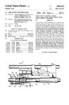
Fig. 1 is a top plan view of the improved feeding
mechanism, including a phantom outline of the
near cannon structure;
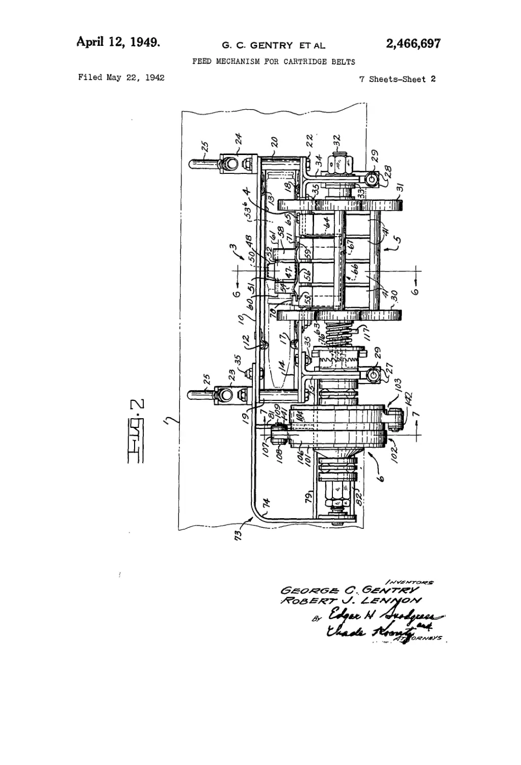
Fig. 2 is a side elevation of the feeding mecha-
nism, including a phantom outline of the near
cannon mount structure;
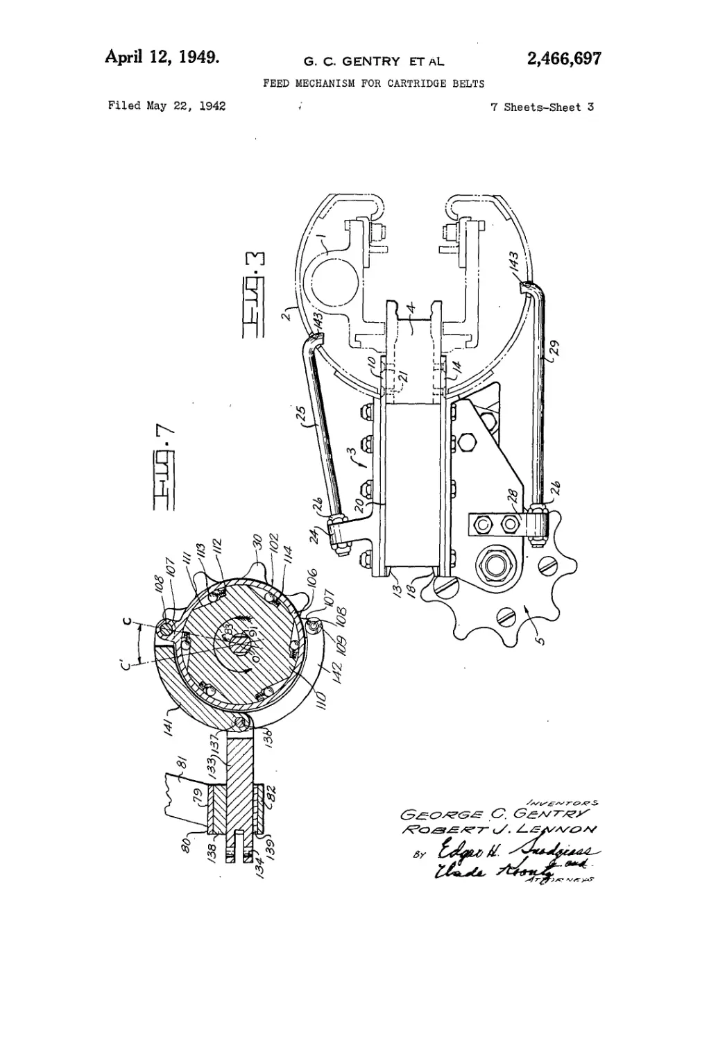
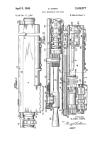
Fig. 3 shows a rear end view of the mechanism
secured to a phantom cross-section of both cannon
and mount;
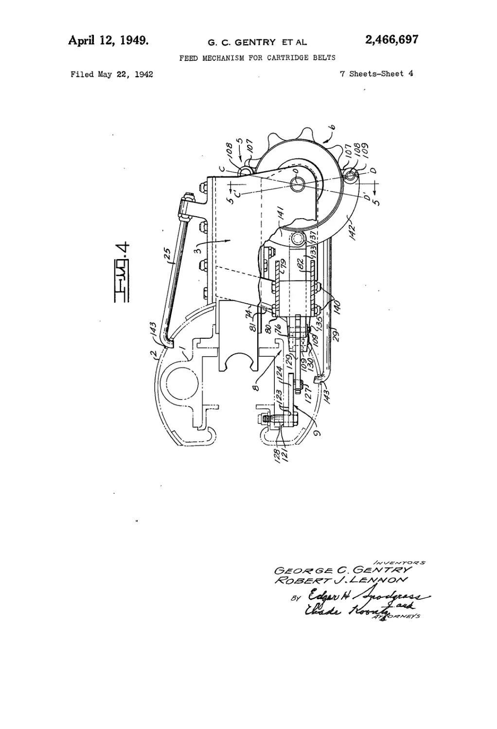
Fig. 4 shows a front view of the mechanism
secured to the phantom cross-section of Fig. 3,
the inner lower corner of the leading plate portion
being cut away to better show the feeding spool
drive;
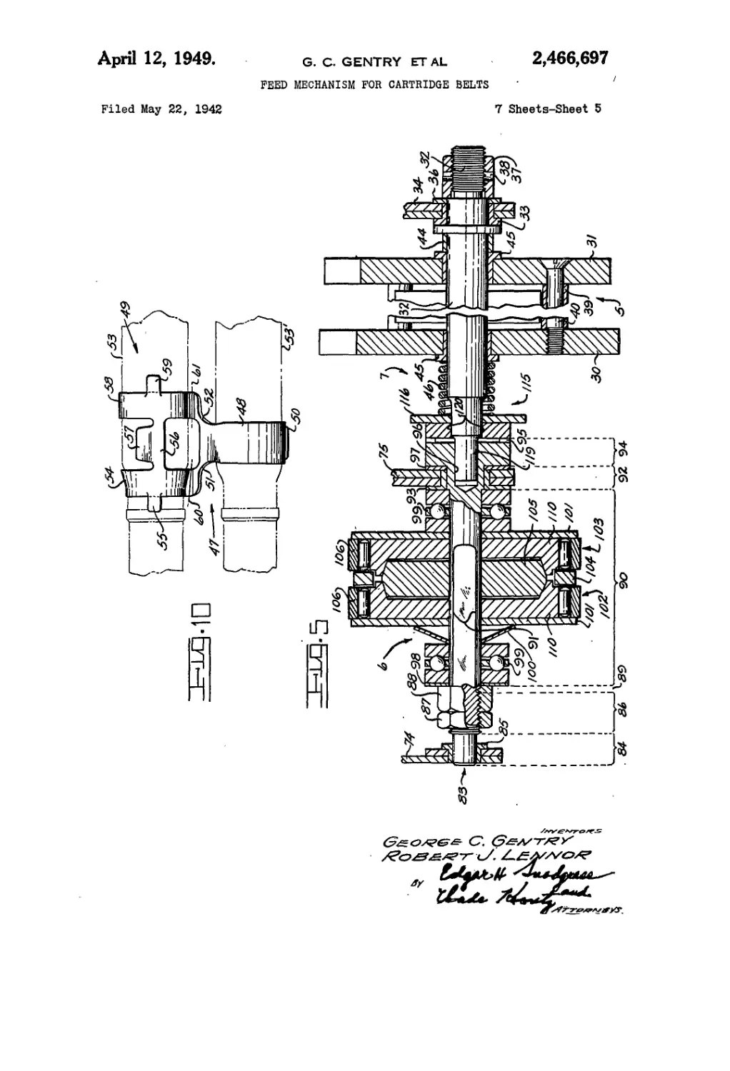
Fig. 5 is a sectional view taken on the line 5—5
of Fig. 4;
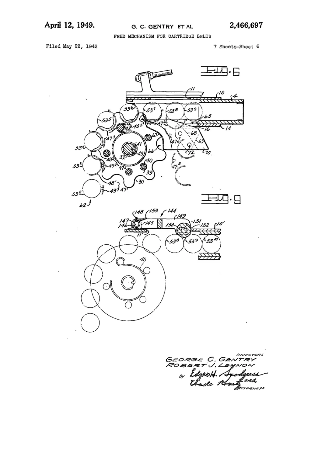
Fig. 6 is a sectional view taken on the line 6—8
of Fig. 2;
Fig. 7 is a sectional view taken on the line 7—7
of Fig. 2;
1928; 370 O. G. 757)
2
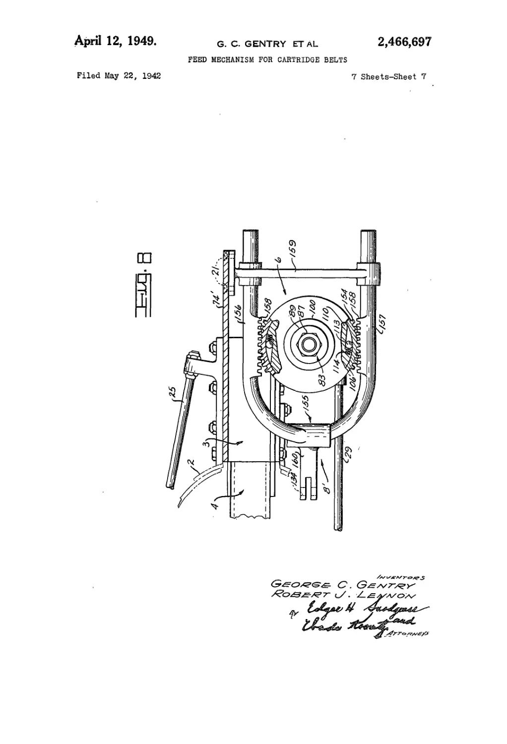
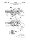
Fig. 8 shows a front view of a slightly modified
form of feeding spool drive;
Fig. 9' shows a transverse sectional view of a
stripped cartridge positioning means; and
5 Fig. 10 is a bottom plan view of the stripping
cartridge clip shown in side elevation in Fig, 2.
In the description which follows, we have elected
to illustrate our invention as presently utilized
by. the Army Air Forces in connection with non-
10 engine installations of the twenty millimeter
Hispano-Suiza (Birkigt) type 404 cannon in air-
craft. It therefore follows that ultimate distinc-
tion.must be clearly drawn between broad appli-
cation of our invention to automatic cannons and
15 machine guns, in general, and the special applica-
tion. thereof described below. In the latter, care
is taken to particularly point out’ parts arrange-
ments exclusively required in connection with .the
type 404 cannon.
20 Referring jointly to Figs. 1, 2 and 4 of the draw--
ings, the cannon structure adjacent to our feeding
mechanism is represented by a phantom outline I.
As viewed in transverse section^ the cannon out-
line I is completely surrounded as well as sup-
25 ported by a mount represented by a phantom out-
line. 2. The principal sub-assemblies of our inven-
tion consist of a feed box 3,. with outlet abutting
a,“through.feedway” в which previously formed
an essential part of a well known cylindrical type
30 magazine extensively used in connection with .the
type 404 cannon; a “spring loaded” feeding.spool
5. located immediately beneath the inlet of the
feed box 3; a driving mechanism .6 in front of and
coaxial with the feeding spool 5; a clutch 7 jointly
35 coaxial with and interconnecting the feeding spool
5 and its driving mechanism 6; and a linkage 8
interconnecting the driving mechanism 6 with a
bracket assembly 9 longitudinally adjustably se-
cured. to the under surface of the cannon outline I.
40 As- best illustrated in Figs. 1 through 3 of the
drawings, the feed box 3' consists of a top 10 hav-
ing an inspection opening 11 and to the bottom
surface of which are riveted two parallelly dis-
posed front and rear cartridge guides 12 and 13;
45 of a bottom 1в having feeding spool and cartridge
clip ejector cutouts 15 and 16’and to the top sur-
face of which are riveted two parallelly disposed
front and rear cartridge guides 17 and 18; of a
front end 19; and of a rear end 28. It will be
50 noted, in Figs. 1 and 3, that the inner overhanging
ends of the feed box top 10 and bottom 14 are
fixed-to-the; outer half of the through feedway 4
by means of screws 21 and that their outer ends
are fixed to the front and rear feed box ends 19
55 and 20 by means of bolts 22. As viewed-in Fig. 3,
2,466,697
3
4
the feed box 3 is readily detachably secured to
the cannon mount represented by the phantom
outline 2 by means of front and rear top brackets
23 and 24, including associated tie rods 25 and
lock nuts 26; and front and rear bottom brackets 5
27 and 28 secured to later referred to spool sup-
ports, including associated tie rods 29 and lock
nuts 26. If desired, four lock washers can be
readily added beneath the four outermost (i. e.,
left hand) lock nuts 26. Description of the car- 10
tridge clip removing means fixed to the lower mid-
portion of the feed box bottom 14 immediately
follows description of its cofunctioning feeding
spool 5.
As shown in Figs. 2, 3, 5 and 6 of the drawings, is
the “spring loaded” feeding spool 5 consists of a
supporting shaft portion, a spool assembly portion,
and a (spring) coupling portion therebetween.
The first mentioned portion consists of a star
wheel shaft 32, with rear end supported by a bush- 20
ing 33 pressed into the outer lower extremity of
a rear spool supporting bracket 34 fixed to the rear
undersurface of the feed box bottom 14 by means
of four previously mentioned bolts 22 and other
bolts 35. The shaft 32 is held against longitudinal 26
movement by means of a washer 36, a lock nut 37,
and a staked pin 38. The second mentioned spool
assembly portion consists of front and rear star
wheels 30 and 31 fixed in the assembled showing
of Figs. 5 and 6 by means of a plurality of spacer 30
tubes 39 and cooperating screws 40. The last
mentioned driving portion consists of a plurality
of coil springs 41 and a driven pin 42, the latter
being fixed to the aforesaid star wheels well out-
board of their supporting shaft. The outer ex- 35
tremities of the coil springs 41 are looped fast to
the driven pin 42, while their inner ends are
inwardly turned in such manner that they rota-
tionally fixedly engage a driving groove 43 pro-
vided in the star wheel shaft 32, Figure 6. While 40
rendered substantially fixed against longitudinal
movement through addition of a spacer collar 44,
two inwardly pressed bushings 45, and a compres-
sion spring 46 of the clutch 7, as viewed in Fig. 5,
the feeding spool 5 is free to lag behind clockwise 45
rotation of its supporting shaft 32 until the four
coil springs 41 have built up a “tight wound” total
torque of 400 inch pounds. The aforesaid springs
are further designed to deliver a total 145 degree
unwound torque of 280 inch pounds. 50
The following forms an essential prelude to de-
scription of the cartridge clip removing means.
Referring jointly to Figs. 2, 6 and 10 of the draw-
ings, as viewed from the rear or trailing side and
from the bottom plan, the stripping clip 47 con- 55
sists of a leading (non-cartridge gripping) por-
tion 48 and a trailing (cartridge gripping) por-
tion 49. The portion 48 is of simple half-ring
form with leading end terminating in an out-
wardly turned stop 59 and trailing end provided 60
with forwardly and rearwardly projecting arms
51 and 52, respectively. Its inside diameter is
slightly in excess of the outside case base diam-
eter of the (partial) cartridge phantom outline
53' shown in Fig. 10 such that the former readily 65
falls away from the latter under circumstances
fully discussed below. The trailing portion 49
consists of a front half-ring 54, from the front
midportion of which projects (and slightly de-
pends) a front stripper lug 55 and from the rear 70
midportion of which projects (and slightly de-
pends) a tie piece 56 with a trailing projection
57; and of a rear half-ring 58, with front mid-
portion joined to the tie piece 56 and from the
rear midportion of which projects (and slightly 75
depends) a rear stripper lug 59, the trailing por-
tion 57 supporting the cartridge between the
half-rings 54 and 58. As viewed in Fig. 10, the
downwardly extending leading ends of the front
and rear half-ring 54 and 58 are bent upwardly
about the longitudinal axes 68 and 61, slightly
less than 180 degrees, after which they project
upwardly and blend into the forwardly and rear-
wardly projecting arms 51 and 52 of the leading
portion 48. The inside diameters of the front
and rear half-rings 54 and 58 are less than the
outside diameters of the case bottleneck and case
base of the (partial) cartridge 53 such that the
former predeterminately grip the latter. The
phantom cartridge belt 62 shown in Fig. 6 is
formed by snapping the trailing edge portion 49'
(only the tie piece 56 and trailing projection 57
of which are cut by section 6—6) of a phantom
clip 47' over the case bottleneck and case base
of a phantom cartridge 532; by loosely cradling
the forward end of the case base of a second
phantom cartridge 533 within the leading edge
portion 48' (completely cut through by section
6—6) of the phantom clip 47' and thereafter
“securing” the latter to the former by snapping
the trailing edge portion 492 of a second phantom
clip 472 over the case bottleneck and case base
of the aforesaid second phantom cartridge 533
(such that the two half-rings of 492 straddle the
single half-ring of 48'); and by thereafter re-
peating the above enumerated process for the
remaining six phantom cartridges 534 through
539 and six phantom clips 473 through 47s. In
conclusion, it should be noted that although each
trailing cartridge 53 and its attached stripping
clip 47 can be freely rotated as a whole about
the longitudinal axis of its preceding cartridge
53 through an angle closely approximating 180
degrees; the presence of the outwardly turned
stop 59 upon the open ends of each clip leading
portion 48, in combination with the presence of
the leading edges of the tie pieces 56 of each clip
trailing portion 49, positively prevents premature
cartridge disengagement prior to contact with the
clip removing means.
The cartridge clip stripper and deflector means
can be best visualized by joint study of Figs. 1, 2,
6 and 10 of the drawings. As shown in the first
three figures noted above, the front and rear
edges of the cartridge clip cutout 16 provided in
the feed box bottom 14 are supplied with flush
front and rear angle brackets 63 and 64, fixed
in place by means of bolts 65. The gap between
the inturned surfaces of the angle brackets 63 and
64 is bridged by a cartridge clip deflector as-
sembly 66, consisting of a depending deflector
apron 67 supported by front and rear ends 68 and
69. The last named ends are clamped fast be-
tween the front and rear faces, respectively, of
a front stripper 79 and a rear stripper 71 and
the above mentioned inturned surfaces of the
angle brackets 63 and S4 by means of screws 72.
The outermost or leading edges of the front and
rear strippers 70 and 71 are sharply tapered or
wedge-shaped in form such that they are readily
adapted to enter the two vertical gaps best indi-
cated in Fig. 2 as existing between the top sur-
face of the partially depending front stripper lug
55 and adjacent case bottleneck surface of the
phantom cartridge 536 and the top surface of the
partially depending rear stripper lug 59 and adja-
cent case base surface of the phantom cartridge
536. Thereafter; with continuing Fig. 6 advance-
ment of the aforesaid phantom cartridge to the
positioning of the sixth phantom cartridge 537,
2,466,697
5
then to the positioning of the seventh phantom
cartridge 538, then to the positioning of the eighth
phantom cartridge 539; the phantom outline of
each succeeding clip 476, ST7 and 47s is indicated,
respectively; firstly, as only slightly withdrawn
such that its trailing two half-rings still partially
grip the cartridge casing; secondly, as fully with-
drawn such that its trailing two half-rings no
longer grip the cartridge casing; and thirdly, as
still more fully withdrawn such that the greater
portion of its trailing two half-rings have now
fallen clear of the cartridge clip deflector assem-
bly 6.6. With departure of the two trailing half-
rings from the casing of any advancing cartridge,
the leading half-ring of the next (i. e., imme-
diately following) cartridge is entirely free to fall
away from the undersurfaces of the aforesaid
advanced cartridge.
As. a prelude to detailed description of the
feeding spool driving mechanism 6, the clutch 7
and the linkage 8, it is felt desirable to deal
briefly with a bracket 73 specially designed to
simultaneously support the aforesaid three parts
groupings. Referring jointly to Figs. 1, 2 and 4
of, the drawings, the bracket 73 consists of an
L.-shaped cover and end plate 74 fixed to the front
end of the feed box top 10 by means of the
bolts 35; a front spool supporting bracket 75
fixed to the front end of the feed box bottom 14
by means of other bolts 35; two vertically sepa-
rated and laterally disposed brackets 75 welded
to the rear inner face of the front spool sup-
porting bracket 75 and having an outer (ratchet
release lever) clevis pin hole 77 and an inner
(feed drive bellcrank) clevis pin hole 78; an up-
per (push rod guide) supporting plate 7 g having
its front and rear ends welded to the inner mid-
portions of the plate 74 and the front spool sup-
porting bracket 75 and its inner edge provided
with- a shallow inwardly projecting portion or
boss- 89; a slightly sloping and narrow vertical
plate 81 with top and bottom ends welded, re-
spectively, to the inner midbottom surface of the
plate 74 and to the inner midtop surface of the
upper supporting plate 79; and a lower (push
rod'guide) supporting plate 82 shaped like, at-
tached like, and disposed parallel to the upper
supporting plate 79.
As best illustrated in Figs. 2, 5 and 7 of the
drawings, the feeding spool driving mechanism
6 is- supported by and operates through a shaft
83' consisting of a front bearing portion 84, en-
cased- in a bushing 85; a threaded portion 86,
carrying lock nuts 87 and 88; a narrow recess
89; a central portion 99 with oppositely disposed
driving surfaces 91 (best shown in Fig. 7); a
rear bearing portion 92 of slightly increased di-
ameter, encased in a bushing 93; and a shoul-
der portion 94, the rear or open end of which is
provided with twenty-four ratchet teeth 95 and
a coaxially disposed pilot hole 96: If desired, a
thrust washer 97 can be added between the front
face of the shoulder portion 94 and the rear face
of: the front spool supporting bracket 75. The
predetermined torque delivering portion of the
feeding spool driving mechanism 6 is entirely
confined to portions 86, 89 and 98 of the shaft
83. It consists of the previously referred to lock
nuts 87 and 88; a thrust washer 98; front and
rear thrust bearing 99; a conically formed spring
washer 108; front and rear thrust collars 10!;
a front female cone assembly 102, with rear-
wardly. facing cavity; a rear female cone assem-
bly- li03'„ with forwardly facing cavity; a ring
shaped spacer 104 interposed between the outer
5
10
15
20
25
30
35
40
45
50
55
60
65
70
75
6
(driving! portions of the female cone assemblies
(02 and (03; and a double male cone 105 en-
cased within the inner (driven) portions of the
female cone assemblies 102 and 103. While free
to slide longitudinally along the shaft 83, with-
in the limits of the oppositely disposed driving
faces 9!, the double male cone 105 is fully fixed
by the last mentioned faces against rotation
with respect to the aforesaid shaft 83. The re-
maining parts 98 through 104 of the feeding
spool driving mechanism 6 are merely journaled
upon the shaft 83. The amount or degree of
joint friction which the inwardly turned (right
circular conical) surfaces of the driven female
cones (192 and !B3) can in turn impart to the
outwardly turned surfaces of the double male
cone (105) is regulated by longitudinal adjust-
ment of the lock nuts 87 and 88.
Referring specifically to Figs. 2, 5, and 7 of the
drawings, the front female cone assembly 102
comprises one complete (counterclockwise act-
ing) silent ratchet mechanism consisting of. a
driving ring 108 provided with a clevis boss 107,
a clevis pin !G8 and a clevis cotter pin 109; a
driven cone I (9 (previously referred to as a “cone
element”) having its circumference provided
with six equispaced wedge-shaped recesses III,
the butt or radially disposed end of each of which
is provided with a spring recess 112; six rollers
113 (held against longitudinal escapement by
the thrust collar 101 and the ring-shaped spacer
154 of Fig. 5); and six compression springs 1(4
for constantly urging the rollers 113 towards-the
converging ends of the wedge-shaped re-
cesses ! I!.
While unessential to the obviously adequate
present drawing disclosure, a lateral sectional
view through the rear female cone assembly (03
would disclose an exact repetition of the parts
showing of Fig. 7, with the single exception that
the clevis boss 187 (and a later referred to link
element of the linkage 8) would appear at the
bottom of the assembly as shown in Fig. 4. It
therefore follows that the rear cone assembly
(83 constitutes a second (likewise counterclock-
wise acting) silent ratchet mechanism. The op-
eration of the aforesaid ratchet mechanisms will
be fully covered in connection with the descrip-
tion of the linkage 8.
As best illustrated in Figs. 1, 2 and 5 of the
drawings, the clutch 7 is shown to consist of the
previously described shoulder portion 94 of the
shaft 83; a wheel shaft ratchet (15 having its
front end provided with twenty-four ratchet
teeth 95 adapted to mate with similar teeth lo-
cated upon the rear end of the shaft 83 and its
rear end provided with a “pushout” disk 1(6; a
ratchet release lever 117 having its front inner
portion pivotally secured between the inturned
faces of the brackets 76 by means of a clevis pin
1(8 and the clevis cotter pin 199; and the previ-
ously mentioned clutch compression spring 46.
It will be noted that the front end of the wheel
shaft 32 is provided with a pilot 119, journaled
within the pilot hole 96' provided in the rear
end of the shaft 83, and with oppositely disposed
driving surfaces 120. While free to slide longi-
tudinally along the wheel shaft 32, within the
limits of the oppositely disposed driving faces
120, the wheel shaft ratchet 115 is fully fixed
by the last mentioned faces against rotation with
respect to the aforesaid shaft 32. Usage of the
clutch 7 is fully explained, below.
Construction and interaction of the bracket
assembly 9 and the linkage 8 can be best under-
2,4вв,в97
7
stood by joint reference to Figs. 1, 4 and 7 of
the drawings. The former consists of an elon-
gated plate 121 having- two reamed holes 122
therethrough and its undersurface provided with
very finely spaced and laterally disposed teeth
123 thereacross; a second substantially triangu-
lar shaped plate 124 having two elongated holes
125 so constructed and arranged (with respect
to the reamed holes 122) that it can be mate-
rially longitudinally adjusted with respect to the
immediately overlaying elongated plate 121, the
top surface of the aforesaid plate 124 being fur-
ther provided with mating laterally disposed
teeth 123 and the outer corner thereof being still
further provided with a threaded hole 126; a pin
127 adapted to be screwed into the aforesaid hole
126 such that its smooth end thereafter depends
therebeneath; and two bolts 128 whereby the
plates 121 and 124 can be fixedly secured to
the left-hand portion (as viewed in Fig. 4) of
the undersurface of the phantom cannon out-
line I. Once properly adjusted, the aforesaid
bracket assembly remains permanently secured
to that portion of the cannon under surface
which recoils in firing. As viewed in Fig. 1, each
cartridge explosion causes material right hand
(i. e., rearward) movement of the phantom can-
non outline 1 and its attached bracket assembly
9. The latter (linkage 8) consists of an L-shaped
bellcrank 129 with its heel portion pivotally se-
cured to the hole 78 provided in the inner end
of the horizontal brackets 76 (welded to the
rear inner face of the front spool supporting
bracket 75) by means of a clevis pin 130 and re-
taining cotter pin f09 and its end portions pro-
vided open pin slots 131 (for engaging the pin
127) and 132; a push rod 133 with its horizon-
tally slotted inner end provided with a hole f34
for receiving a clevis pin 135 (engaged by the
open pin slot 132) and retaining cotter pin 109
and its vertically disposed undercut outer end
provided with a hole 136 for receiving a clevis
pin 137 and retaining cotter pin 109; upper and
lower push rod guides 138 and 139 fixed to the
upper and lower supporting plates 79 and 82
by means of bolts 140; an upper arcuate link 141
having its lower extremity pivotally secured to
the outer forward face of the push rod 133 by
means of the clevis pin 137 and upper slotted ex-
tremity similarly secured to the driving ring
clevis boss 107 (of the front ring) by means of
the clevis pin 108; and a lower arcuate link 142
having its upper extremity pivotally secured to
the outer rear face of the push rod 133 by means
of the same clevis pin 137 and its lower slotted
extremity similarly secured to the driving ring
clevis boss 107 (of the rear ring) by means of
another clevis pin 108. If desired, washers can
be installed beneath the cotter pins 109 of the
aforesaid clevis pins 130, 135. 137 and 108.
As a prelude to operation of the subassemblies
6 through 9, it should be noted that the driving
mechanism 6, the clutch 7 and the linkage 8
form an integral part of and are attached di-
rectly to the feed box 3 and that the last named
are readily brought into or removed from op-
erable engagement with the bracket assembly 9
by attachment or removal of the hooked inner
ends of the (upper front and rear) tie rods 25
and the (lower front and rear) tie rods 29 from
four attaching holes 143 shown in Figs. 3 and 4
to be provided in the phantom outline 2 of the
cannon mount. With each reassembly of the
feed box 3, the open pin slot 131 (of the bellcrank
129) must be carefully aligned with the pin 127
10
15
20
25
30
35
40
45
50
55
60
65
70
70
8
(of the bracket assembly 9) prior to final attach-
ment. It should also be noted, in Figs. 1 and 2,
that the phantom outline I of the cannon is
in its most forwardly position with respect to
the phantom outline 2 of the cannon mount.
Under such conditions, as viewed in Fig. 1, the
dot-dash longitudinal axis OA of the inner arm
of the bellcrank 129 has a decided forward cant
or tilt with respect to “true lateral,” resulting in
corresponding outward cant or tilt of the dot-
dash longitudinal axis OB of the outer arm (of
the same bellcrank) from “true fore and aft.”
The aforesaid longitudinal axes positions result
in counterpositioning of the upper and lower
arcuate links 141 and 142 in the extreme right-
hand placement of Figs. 4 and 7. Under such
conditions, as viewed in Fig. 4, the dot-dash ref-
erence line ОС (drawn through the longitudinal
axes of the shaft 83 and the clevis pin 108) has
a decided outward or right-hand tilt with respect
to “true vertical.” The significance of the afore-
said “positionings” will soon be apparent.
The cannon and mount are retained in the
“normal” phantom I and 2 relationships of Figs.
1 and 2 by means of an adapter located a con-
siderable distance (i. e., several feet) in advance
of the cartridge feeding mechanism. As long as
the cannon remains “inert,” the aforesaid rela-
tionships continue. However, once “firing” com-
mences, the cannon adapter permits marked
right-hand or rearward movement of the cannon
with respect to the mount, resulting in clockwise
movements of the dot-dash longitudinal axes OA
and OB of Fig. 1 into the new dot-dot-dash lon-
gitudinal axes positionings OA' and OB'. The
aforesaid new axes positionings result in corre-
sponding repositioning of the upper and lower
arcuate links 141 and 142 approximately one
and one-half link widths to the left hand of the
present Fig. 4 and Fig. 7 placement. Under such
conditions, the dot-dash reference line ОС of
Fig. 4 moves in a counterclockwise direction to
the new dot-dash positioning ОС', at which posi-
tioning the cannon adapter has completely ab-
sorbed rearward shock incident to cartridge dis-
charge. Recoil energy stored within the adapter,
as a result of cartridge discharge, thereafter
automatically returns the cannon to the initial
positioning of Figs. 1 and 2. The effect of al-
ternate movement of the last mentioned ref-
erence line (from positioning ОС to ОС', then
from positioning ОС' to ОС) upon the driving
mechanism 6 is fully described below.
From the counterclockwise inclinations of the
wedge-shaped recesses 111 of Fig. 7, in combina-
tion with the further fact that the rollers 113
are constantly being urged in the same counter-
clockwise direction by the compression springs
114, it is at once apparent that an infinitely small
counterclockwise movement of the driving ring
166 is all that is required to cause counterclock-
wise rotation of the rollers 113 up the inclines
111 sufficiently to bring about complete fixation
between the driving ring 106 and the driven cone
110. Therefore, during substantially all of its
movement from position ОС to position ОС', the
driving ring 196 is effecting counterclockwise
movement of the driven cone HO. From the
above, it is also equally apparent that following
attainment of position ОС', a like infinitely small
clockwise movement of the driving ring 106 is
all that is required to cause clockwise rotation
of the rollers 113 down the incline 111 sufficiently
to bring about complete removal of prior fixa-
2,406,697
9
йоп existing between the driving ring 106 and
the driven cone 11.0.
During return of the front and rear driving
rings 106 to the initial position ОС and OD shown
in Fig. 4, two additionally important mechanical
operations occur. Firstly, the front driven cone
f.1:0 is held in rotation,’.! fixity with respect to
the double male cone 165 of Fig. 5 (during the
entire period of driving ring return) through
friction induced in their mating conical surfaces
by the longitudinally acting thrust washer 98.
Secondly, in returning from displaced position
OD' to the initial position OD shown in Fig. 4,
the rear driving ring I Й6 performs an exact dupli-
cation of the “work” performed by the front driv-
ing ring 106 in passing from the initial position
ОС of Fig. 7 to the displaced position ОС'. It is
thus readily apparent that applicants utilize
countercoil, as well as recoil, of the cannon for
the purpose of maintaining constant driving
torque in their cartridge feeding mechanism.
The function of the clutch 1 becomes readily
evident when “initial loading” of the cartridge
belt 62 shown in Fig. 6 is considered in conjunc-
tion with the further showings of Figs. 2 and 5
of the drawings. As long as the cannon remains
“inert,” the shaft 83 of the driving mechanism
6 must also remain stationary. Thus, were the
ratchet wheel shaft 32 of the feeding spool 5
fixedly coupled to the aforesaid shaft 83, the
coiled springs 41 of Fig. 6 would completely
counteract any attempt to accomplish initial in-
sertion of the cartridge belt 62. However,
through simple manipulation of the ratchet re-
lease level 117 of Figs. 1 and 2, the feeding spool
5 is rendered completely free to rotate in any de-
sired direction and an armorer can readily “load”
the shell belt 62 in the position indicated in Fig. 6.
In the previous description of Fig. 6 of the
drawings, it is noted that on and after assuming
tbe phantom position 538, the cartridges of the
belt 62 are completely freed from clip attach-
ment. In passing from phantom position 538 to
phantom position 53°, each inwardly traveling
cartridge 53 is still firmly grasped fore and aft
by the front shell guides 12 and 17 and the rear
shell guides IS and 18 of Fig. 2. While the above
arrangement should normally assure proper lon-
gitudinal alignment of the unclipped cartridges
advancing through the “through feedway” 4,
prior to bolt pickup, if desired a stripped cart-
ridge positioning means 144 can be installed. In
Fig. 9, a slightly modified feed box top ! S' is pro-
vided with front and rear lever bosses 145 having
their inwardly facing ends flush with the front
and rear edges of an inspection opening 11'
(identical in shape and placement to the inspec-
tion opening II of Fig. 1). Each of the afore-
said bosses is provided with a clevis pin hole 146,
clevis pin 147 and clevis cotter pin 148 for pivot-
ally securing the outer ends of an H-shaped
lever 149. The slightly depending inner ends of
the lever 149 are provided with laterally disposed
slots 150 adapted to slidably engage and support
two journals 151 provided in the front and rear
ends of a roller 152. The last named is retained
in pressure engagement with successively advanc-
ing pairs of cartridges 53 by means of two coil
springs 153. It thus becomes readily apparent
that two independent (though coacting) means
are provided for the purpose of assuring con-
tinuously correct positioning of all cartridges
which have progressed inwardly beyond the
phantom cartridge positioning S38 and are there
awaiting bolt pickup.
6
10
15
20
25
30
35
40
45
50
55
60
65
70
75
10
Fig. 8 of the drawings shows a modified form
of linkage 8' in which the front and rear driving
rings IB6, the upper and lower arcuate links 141
and 142, and the push rod 133 of Figs. 4 and 7
are replaced, respectively, by modified front and
rear driving rings 106' incorporating short gear
segments 154 in lieu of the previous clevis bosses
167 (best shown in Fig. 7); by upper and lower
prongs 156 and 157, of a forked link 155, incor-
porating short racks 158 and slidingly guided by
a depending support 159 fixed to the undersurface
of a slightly modified cover and end plate 74' by
means of screws 21; and by a base portion 160,
of the forked link 155, having its inner end
formed in a manner identical to formation of
the inner end of the push rod 133. It will be
noted that tire upper, the vertical and the lower
supporting plates 79, 81 and 82; the upper and
lower push rod guides I?" and 139; and the four
bolts 140 shown in Figs. 4 and 7 are not required
in connection with the modified form of linkage
8' illustrated in Fig. 8. The linkages 8 and 8'
both operate in identically the same manner.
At the commencement of the preceding de-
scription, it is stated that a clear distinction
will be drawn between broad application of-our
invention to automatic cannons and machine
guns installations and the special application
thereof described above. Many parts disclosed
above are exclusively related to type 404 cannon
operation and for that reason are not essential
to basic operation of our invention. Their
presence is due principally to the fact that the
aforesaid cannon has been heretofore serviced
solely by such “spring loaded” cartridge maga-
zines as the (French) Chatellerault cylindrical
magazine, which is designed in such a manner
that advancing cartridges are successively re-
moved from their retaining clips prior to weapon
entry, due to the fact that the bolt action of the
type 404 cannon is unsuited for accomplishing
normal cartridge clip release.
There are discussed below, in order of their
original presentation, certain sub-assemblies and
individual parts which can be either completely
eliminated from basic consideration of our inven-
tion or for which much simpler structures can
be substituted in connection therewith. Refer-
ring to Figs. 1 through 3 of the drawings, the
feed box 3 can be greatly simplified for the aver-
age machine gun installation by elimination of
the cartridge guides 12, 13, 17 and 18; and the
“through feedway” 4 (previously noted as taken
from the Chatellerault magazine). As best seen
in Figs. 5 and 6, the feeding spool 5 can be
materially simplified by complete elimination of
the four coil springs 41 (providing the “spring
loaded” feature referred to in the preceding para-
graph) and by substituting therefor rotational
fixity between the front and rear star wheels 30
and 31 and their supporting shaft 32. Referring
to Figs. 2 and 3, the feed box attaching parts 25
through 29 relate exclusively to a type 404 cannon
installation.
The cartridge clip 47 shown in Figs. 2 and 10
of the drawings; as well as the cartridge clip
“stripper” parts 70 through 73 of Figs. 1, 2 and 6;
pertain solely to the type 404 cannon. In the
average machine gun installation, our invention
can employ any one of several widely utilized
metal cartridge clips. While still retaining its
present L-shaped form, the “arm lengths” and
“pivot point” of the bellcrank 129 (of the linkage
8 shown in Figs. 1 and 4) must be obviously
varied to suit the recoil working limits of each
3,466,697
11
separate automatic cannon or machine gun in-
stallation to which applied. The structural form
of the bracket assembly 9 (associated with the
above referred to linkage S) will vary widely with
each new automatic cannon or machine gun in-
stallation. The cartridge positioning means
shown in Fig. 9 pertains exclusively to the type
404 cannon installation and can therefore be
eliminated from broad usage of our invention.
Although the descriptions of this specification
are mainly specific to the type 404 cannon instal-
lation illustrated in Figs. 1 through 10 of the
drawings, or readily understood modifications
thereof, it is to be understood that there can be
departures therefrom, both with respect to nar-
row type 404 cannon application and to general
automatic cannon and machine gun usage, which
will still clearly fall within the field and scope of
the subject invention, and we therefore do not
wish to be restricted thereto, but only in so far
as the appended claims are so limited.
Having thus described our invention, what we
claim as new and desire to secure by Letters
Patent of the United States is:
1. A cartridge belt feed mechanism for an au-
tomatic gun having parts subject to movement
during recoil and counterrecoil, comprising a
frame, a driving shaft and a driven shaft co-
axially mounted for rotation in said frame, a
cartridge feed spool rotatably and non-slidably
mounted on said driven shaft, a clutch connect-
ing the adjacent ends of said shafts, manually
operable means for disconnecting said clutch,
driving means for said driving shaft comprising
an inner friction member non-rotatably mounted
thereon, outer friction members rotatably mount-
ed on said driving shaft in frictional contact with
said inner member, oscillatable driving rings sur-
rounding said outer members, clutch means be-
tween said rings and said outer members con-
structed and arranged to drive said outer mem-
bers solely in one direction upon the oscillation
of said driving rings, a linkage interposed be-
tween the moving parts of the gun and said rings
for actuating the latter upon recoil and counter-
recoil of the gun, and a yielding torque transmit-
ting connection between said driven shaft and
said spool for rotating the latter in the direction
of rotation of said driving shaft.
2. A feed mechanism as set forth in claim 1,
including a plurality of plates rotatably mounted
on said driving shaft in engagement with the
outer faces of said outer friction members, and a
spring washer engaging at least one of said plates,
and having adjustable means operatively associ-
ated therewith for varying the tension of said
washer to vary the pressure between the surfaces
of said friction members.
3. In a cartridge belt feed mechanism for an
automatic gun having a part subject to move-
ment in recoil and counterrecoil, a frame, a driv-
ing shaft and a driven shaft coaxially mounted
for joint and independent movement in said
frame, a cartridge feed spool rotatably and non-
slidably mounted on said driven shaft, a clutch
adapted to connect the adjacent ends of said
shafts and including a clutch element carried by
each shaft, driving connections between said
driven shaft and its associated clutch element, a
spiral spring interposed between said driven shaft
element and said feed spool for transmitting
torque to said spool, a friction disc non-rotatably
mounted on said driving shaft, oppositely dis-
posed friction members rotatably mounted on
said driving shaft in frictional engagement with
5
10
15
20
25
30
35
40
45
50
55
60
65
70
75
12
said friction disc, one-way clutch devices carried
in the periphery of said friction members oscil-
latable driving rings, means operatively connect-
ing said rings to the aforesaid gun part, said
rings surrounding said members and coacting
with said clutch devices to rotate said members in
one direction, both upon recoil and counterrecoil
of the gun part, and a linkage interposed between
said rings and the gun part for actuating said
rings to drive said shafts through said friction
disc.
4. In a belt feed mechanism for an automatic
gun having a part subject to movement during
recoil and counterrecoil, a frame including a shaft
journaled therein, a feed spool rotatably and non-
slidably mounted on said shaft, torque-transmit-
ting means connecting said feed spool and shaft,
a friction disc non-rotatably mounted on said
shaft, driving members rotatably mounted on
said shaft in frictional engagement with said disc,
a plurality of clutch devices mounted in the pe-
ripheries of said members, oscillatable drive rings
coacting with said devices to drive said members,
a push rod slidably mounted in said frame, a plu-
rality of links pivotally connected with said rod
and with said driving rings whereby when the
push rod is reciprocated said driving rings will be
oscillated, said clutch devices cooperating with
said rings to drive said shaft through said fric-
tion disc, a bell crank pivoted to said frame and
having one arm pivoted to said push rod and the
other to the movable part of the gun whereby said
push rod is reciprocated upon recoil and counter-
recoil of the gun,
5. In a cartridge belt feed mechainsm for an
automatic gun adapted to reciprocate in recoil
and counterrecoil, a cartridge spool rotatable to
feed cartridges to said gun, a driving mechanism
for said cartridge feed spool including a frame,
a driving shaft mounted in said frame and hav-
ing members thereon through which said shaft
is driven, a plurality of oscillatable driving rings,
one surrounding each of said members and each
being provided with pinion segments, clutch de-
vices between said members and said rings and
cooperating therewith to drive said members in-
termittently in one direction upon the oscillation
of said rings, a yoke shaped member slidingly
supported in said frame and having a rack on
each of its arms in engagement respectively with
said pinion segments, a linkage operatively en-
gaging said yoke-shaped member and adapted to
engage the said gun and constructed and ar-
ranged to transmit reciprocating motion due to
said recoil and counterrecoil to said yoke-shaped
member to thereby oscillate said rings.
6. In a self-loading weapon having a support
fixed against recoil and counterrecoil and a barrel
movable with respect to the support in recoil
and counterrecoil, an ammunition feeding device
comprising a main carrying structure adapted to
be secured to the support, a first shaft journaled
in said structure, a second shaft journaled in said
structure coaxial with and adapted to be driven
by said first shaft, a clutch interposed between
said first and said second shafts, resilient yield-
ing means mounted on at least one of said shafts
and normally operative to urge said clutch into
positive driving engagement, manually operable
means for positively disengaging said clutch, am-
munition engaging means operatively connected
to said second shaft, a resilient lost motion con-
nection interposed between said last-named
means and said second shaft for transmitting
torque therebetween, and means responsive to
2,466,697
13
both recoil and counterrecoil of the barrel, and
having an element for imparting unidirectional
rotation to said first shaft during substantially
the entire recoil of the barrel, and having a second
element for imparting further rotation in the
same direction to said first shaft during substan-
tially the entire counterrecoil of the barrel.
7. In a self-loading weapon having a support
fixed against recoil and counterrecoil and a bar-
rel movable with respect to the support in recoil
and counterrecoil, an ammunition feeding device
comprising a main carrying structure adapted to
be secured to the support, a first shaft journaled
in said structure, a second shaft journaled in said
structure coaxial with and adapted to be driven
by said first shaft, a clutch interposed between
said first and said second shafts, ammunition en-
gaging means operatively connected to said sec-
ond shaft, and means responsive to both recoil
and counterrecoil of the barrel, and having an
element for imparting unidirectional rotation to
said first shaft during substantially the entire
recoil of the barrel, and having a second element
for imparting further rotation in the same direc-
tion to said first shaft during substantially the
entire counterrecoil of the barrel.
8. In a self-loading weapon having a support
fixed against recoil and counterrecoil and a bar-
rel movable with respect to the support in recoil
and counterrecoil, an ammunition feeding device
comprising a main carrying structure adapted to
be secured to the support, a first shaft journaled
in said structure, a second shaft journaled in said
structure coaxial with said first shaft, means con-
nectible between said shafts for the driving by
said first shaft of said second shaft, ammunition
engaging means operatively connected to said sec-
ond shaft, means responsive to both recoil and
counterrecoil of the barrel and constructed and
arranged whereby to impart unidirectional rota-
tional movement to said first shaft during sub-
stantially the entire movement of the barrel in
recoil and counterrecoil, said last-named means
comprising an inner member secured to said first
shaft and having a plurality of frictional driving
surfaces, a plurality of outer members rotatably
mounted on said first shaft, each of said outer
members having at least one surface adapted
to frictionally engage a driving surface of said
inner member and including a plurality of uni-
directional clutches in its periphery, a plurality of
driving rings operatively associated with said uni-
directional clutches for driving said inner and
outer members in one direction, and a linkage
interconnecting said driving rings and at least the
gun barrel, said linkage including a bracket
mounted on the barrel, and means for adjustably
5
10
15
20
25
30
35
40
45
50
55
14
positioning said bracket on the barrel for regu-
lating the feeding of ammunition to said weapon.
9. In a self-loading automatic weapon having
a fixed part and a relatively movable part there-
on, an ammunition feeding device comprising a
main supporting structure adapted to be secured
to said relatively fixed part, shaft means rotatably
mounted in said supporting structure, ammuni-
tion engaging and feeding means operatively con-
nected to said shaft means, means responsive to
relative motion in opposite directions between
said fixed and movable parts and constructed and
arranged whereby to impart unidirectional rota-
tional movement to said shaft means during sub-
stantially the entire movement of said relatively
movable parts in said opposite directions, and a
bracket adjustably mounted on said relatively
movable part, said relative motion responsive
means including a linkage operatively associated
with said bracket and with said shaft means for
transmitting motion therebetween and including
an element for imparting unidirectional rotation
to said shaft means during substantially the en-
tire recoil of the barrel and including a second
element for imparting further rotation in the
same direction to said shaft means during sub-
stantially the entire counterrecoil of the barrel.
GEORGE C. GENTRY.
ROBERT J. LENNON.
REFERENCES CITED
The following references are of record in the
file of this patent:
UNITED STATES PATENTS
Number Name Date
863,101 Schwarzlose____________Aug. 13, 1907
1,178,624 Candelon_______________Apr. 11, 1916
1,399,440 Payne__________________Dec. 6, 1921
1,692,328 Browning_______________Nov. 20, 1928
1,842,446 Dabrasky_______________Jan. 26, 1932
2,222,812 Faulkner et al_________Nov. 26, 1940
2,366,395 Hall___________________Jan. 2, 1945
2,375,219 Gentry et al.__________May 8, 1945
2,375,452 Webb-------------------May 8, 1945
2,377,828 Trotter et al__________June 5,1945
FOREIGN PATENTS
Number Country Date
2,332 Great Britain________________1914
19,641 Great Britain__________________1906
193,950 Switzerland_____________Feb. 1, 1938
310,179 Germany________________Dec. 13, 1919
323,401 Germany________________July 24, 1920
355,767 France_________________Feb. 21, 1930
492,774 France__________________Apr. 2, 1919
706,160 Germany____________May 19,1941