/


Текст
hsmag.cc
October 2022
Issue #59
VORON
Oct. 2022
Issue #59 £6
3D PRINTING
Plus
Why your next printer should be a Voron
Relays Vinyl cutting
Like transistors,
but steampunk
Etch designs into glass,
PCBs, and more
Aquaponics
Build an indoor salad farm
Carrie
Sundra
Alpenglow:
Pixels with
purpose
KEYBOARD LEGO SHADOWS BRICKS
WELCOME
EDITORIAL
Editor
Ben Everard
ben.everard@raspberrypi.com
Welcome to
HackSpace magazine
3D printing is different things to different people. For some
Sub-Editors
Nicola King, Phil King
DESIGN
Critical Media
giving form to their artistic ideas. This month, we’re looking
Designers
other printer can
spit out parts as fast,
and, for artists, the
quality of the prints
is unsurpassed.
Whether or not
you’re on the lookout for a new machine, the work Voron is
doing now is sure to shape the future of 3D printing, so let’s
see what tomorrow might hold.
BEN EVERARD
Editor
get in touch at
andrew.gregory@raspberrypi.com
Head of Design
Whether or not you’re on the lookout for a new
machine, the work Voron is doing now is sure
to shape the future of 3D printing, so let’s see
what tomorrow might hold
hsmag.cc/hello
Andrew Gregory
people it’s a hobby in and of itself, for some people it’s a tool
to create parts for their projects, and for others it’s a way of
at Voron printers, which should appeal to all three. For
tinkerers, there’s no other printer on the market that offers
the same amount of potential geekery. For people who use
them as tools, no
Got a comment,
question, or thought
about HackSpace
magazine?
Features Editor
criticalmedia.co.uk
Lee Allen
Sam Ribbits, Olivia Mitchell,
Ty Logan
Photography
Brian O’Halloran
CONTRIBUTORS
Jo Hinchliffe, Marc de Vinck,
Andrew Lewis, Mike Bedford, Phil
King, Rosie Hattersley, Brendan
Charles, PJ Evans
PUBLISHING
Publishing Director
Russell Barnes
russell@raspberrypi.com
Advertising
Charlie Milligan
charlotte.milligan@raspberrypi.com
DISTRIBUTION
Seymour Distribution Ltd
2 East Poultry Ave,
London EC1A 9PT
+44 (0)207 429 4000
ben.everard@raspberrypi.com
SUBSCRIPTIONS
Unit 6, The Enterprise Centre,
Kelvin Lane, Manor Royal,
Crawley, West Sussex, RH10 9PE
PAGE
50
FREE PICO W
WHEN YOU
SUBSCRIBE
To subscribe
01293 312189
hsmag.cc/subscribe
Subscription queries
hackspace@subscriptionhelpline.co.uk
GET IN TOUCH
hackspace@
raspberrypi.com
hackspacemag
hackspacemag
ONLINE
hsmag.cc
This magazine is printed on
paper sourced from sustainable
forests. The printer operates an
environmental management system
which has been assessed as
conforming to ISO 14001.
HackSpace magazine is published
by Raspberry Pi Ltd, Maurice Wilkes
Building, St. John’s Innovation
Park, Cowley Road, Cambridge,
CB4 0DS The publisher, editor, and
contributors accept no responsibility
in respect of any omissions or
errors relating to goods, products or
services referred to or advertised.
Except where otherwise noted,
content in this magazine is licensed
under a Creative Commons
Attribution-NonCommercialShareAlike 3.0 Unported (CC BY-NCSA 3.0). ISSN: 2515-5148.
3
Contents
SPARK
06
06
104
35
Top Projects
36
Creativity knows no bounds
18
LEGO pendulum
52
Objet 3d’art
58
Meet the Maker: Kathy Hinde
66
Improviser’s Toolbox Bricks
Bricks: like rocks, but rectangular
Letters
Promising signs regarding the chip shortage
32
Interview: Carrie Sundra
Unicorns, politics, and LEDs
Sound and vision creatively combined
30
How I Made: Ceres-1 Portable
A tiny Raspberry Pi laptop
Feel the precision in this camera build
24
The future of printing
We’ve seen the future, and it’s a Voron
A classic engineering project with a LEGO spin
22
LENS
Crowdfunding now
Tutorial
Laser cutting
MNT Pocket Reform
Cover Feature
VORON
VORON
NEXT GEN
3D PRINTING
Why your next 3D printer
should be a Voron
36
4
72
Cut out awesome designs
with a simple K40 laser cutter
06
CONTENTS
110
Tutorial
76
Aquaponics
24
Interview
22
Carrie Sundra
86
71
72
Grow food, provide housing
for fish-shaped friends
FORGE
SoM Laser cutting
How to cut round irregular shapes
76
Tutorial Build a robot
Back to basics with simple robotics
80
Tutorial Vinyl cutting
58
Anyone can learn electronics – you
just need a glorious golden unicorn
Build switches with copper tape
86
Tutorial Aquaponics
Create an ecosystem for fish and salad crops
92
Tutorial Relays
103
104
Meet the bigger, louder cousin of the transistor
98
Tutorial Soft start
Switch on power tools the gentle way
FIELD TEST
Best of Breed
52
Adaptation to get through the chip shortage
110
Review Mechanical keyboard
A tiny typing gadget from PocketType
Some of the tools and techniques shown in HackSpace Magazine are dangerous unless used with skill, experience and appropriate personal protection equipment. While we attempt to guide the reader, ultimately you
are responsible for your own safety and understanding the limits of yourself and your equipment. HackSpace Magazine is intended for an adult audience and some projects may be dangerous for children. Raspberry
Pi Ltd does not accept responsibility for any injuries, damage to equipment, or costs incurred from projects, tutorials or suggestions in HackSpace Magazine. Laws and regulations covering many of the topics in
HackSpace Magazine are different between countries, and are always subject to change. You are responsible for understanding the requirements in your jurisdiction and ensuring that you comply with them. Some
manufacturers place limits on the use of their hardware which some projects or suggestions in HackSpace Magazine may go beyond. It is your responsibility to understand the manufacturer’s limits. HackSpace magazine is published monthly by Raspberry Pi Ltd, Maurice Wilkes Building, St. John’s Innovation Park, Cowley Road, Cambridge, CB4 0DS, United Kingdom. Publishers Service Associates, 2406 Reach Road, Williamsport,
PA, 17701, is the mailing agent for copies distributed in the US. Application to mail at Periodicals prices is pending at Williamsport, PA. Postmaster please send address changes to HackSpace magazine c/o Publishers
Service Associates, 2406 Reach Road, Williamsport, PA, 17701.
5
Top Projects
REGULAR
James Webb mirror
By The Cellar Nerd
hsmag.cc/JamesWebbMirror
I
f you’re in any way interested in science, you’ll be
fascinated by the first images that are being beamed back
from the James Webb Space Telescope. Nebulae, planets,
stars, galaxies… it’s familiar, but the improvement in the level
of detail is utterly fantastic.
As a tribute to this latest of NASA’s huge accomplishments,
the Cellar Nerd has built a Raspberry Pi-powered image displayer.
Surrounded by 18 metallic-finish wall-tiles, he’s used an old laptop
screen, a Raspberry Pi 2 Model B, and a black plywood frame to
hang it all on. You might think it odd to use such an old, relatively
low-powered Raspberry Pi as the centrepiece of this build, but all it’s
doing is displaying images, so processing power isn’t crucial.
Right
The mirrors on the
real James Webb
Space Telescope
are made from goldplated beryllium
6
SPARK
7
Top Projects
REGULAR
Portable tube amp
By ThomasH358
hsmag.cc/MiniTubeAmp
T
his beautiful build is a portable push-pull tube
amp. In the tradition of audio equipment, this won’t
work on its own – you need a speaker cabinet to plug
it into, plus a guitar, and maybe even enough talent to
be able to play the thing.
What makes it stand out is the sheer amount of
electronics packed into such a small space. It’s built into a
Hammond 125B enclosure measuring around 120 × 65 × 40 mm;
that enclosure is also typically used in guitar effects pedals, so
packing a while amplifier in – and one that uses three full-sized
vacuum tubes – is seriously impressive.
Right
This is not a project
for a beginner – for
that, try building a
fuzz pedal instead
8
SPARK
9
Top Projects
REGULAR
10
SPARK
Concrete lava lamp
By MattGyver92
hsmag.cc/ConcreteLavaLamp
I
f you can use a 3D printer, you’re not limited to making
things out of hot plastic. If you have the imagination to
design the inverse of the shape you need (or if you can
locate the right setting in your design software), you can
use your printer to create moulds for papier mâché, food (as
long as you’re using food-safe materials)… anything really,
including concrete.
MattyGyver92 has used this fact to design and build this lava
lamp. It’s a blend of space-age Soviet visuals with brutalist raw
concrete, and we love it. There’s no microcontroller involved;
everything is old-fashioned analogue electronics but, despite that,
it’s still a complex build. Did you know, for example, that the wax
used in lava lamps is paraffin wax, which floats in water, and so, in
order to use it, the maker is obliged to add tetrachloroethylene in
order to make it more dense?
Left
Chemistry, brutalism,
and electronics: this
build has it all
11
Top Projects
REGULAR
Laser-cut
Bluetooth speaker
By SiddharthS141
hsmag.cc/LaserCutSpeaker
W
e tend to think of Fusion 360 as a design
tool primarily for 3D printing, but it’s useful
for all sorts of digital fabrication. This
laser-cut speaker cabinet, for example, was
designed in Fusion 360, enabling the maker
to tweak elements of the plans multiple times
without having to throw everything out of the window and start
again from scratch.
This build uses repurposed electronics – namely a Bluetooth
headphone set fed through an amplifier, and finally out through the
speakers – and an original enclosure built out of Ӊ-inch plywood.
Right
Laser-cut plywood
looks good,
sounds great, and
smells fantastic
12
SPARK
13
Top Projects
REGULAR
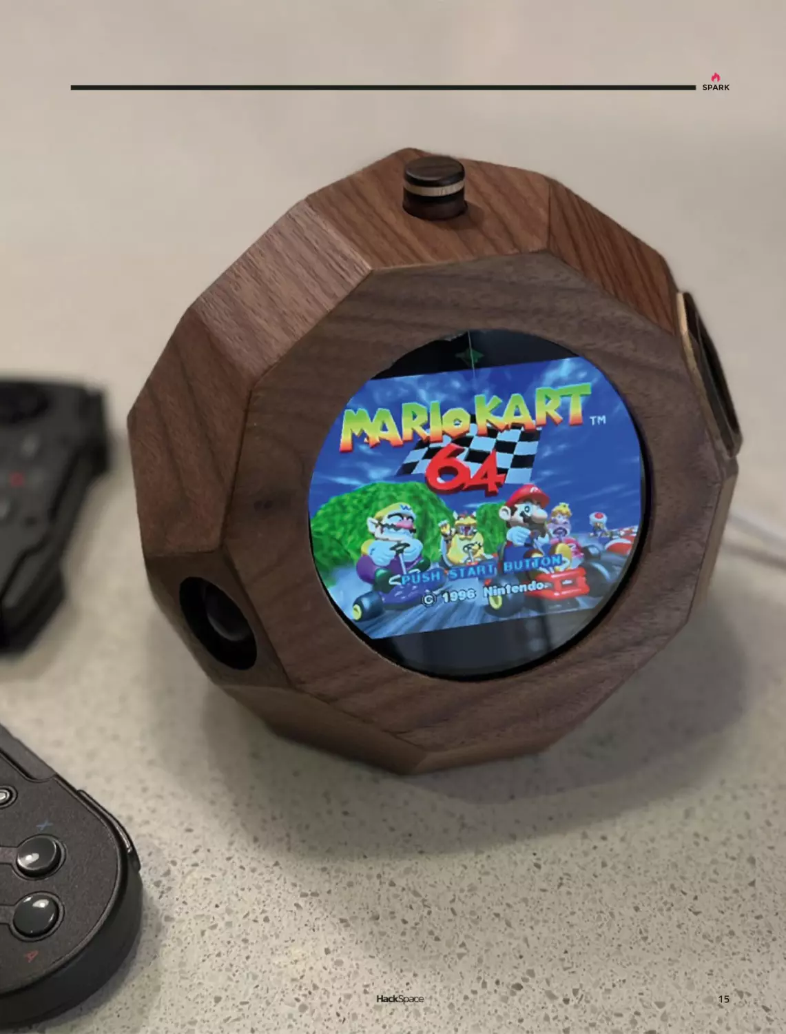
Dual-screen
games console
By mw33212
hsmag.cc/DualScreenConsole
A
ccording to the creator, Reddit user and
woodworker extraordinaire mw33212, this build
is “a small, largely impractical dual-screen
games console.” We don’t mind that; games are
by their nature impractical.
It’s built out of 10 mm walnut and houses a
Raspberry Pi 4, two fans, two screens, and assorted other
electronics; with the angles involved, we can imagine that the
glue-up was on the tricky side.
Right
Apparently, this shape
is a tridiminished
rhombicosidodecahedron
14
SPARK
15
Top Projects
REGULAR
Thérrarium
By Samuel Gidoin
O
hsmag.cc/Therrarium
ver-complicated Heath Robinson devices
are wonderful, doubly so when they involve
making cups of tea, and quadruply so when
they take design inspiration from The Lord
Of The Rings. This wonderful laser-cut machine
makes tea with aplomb, controlling water
temperature, the amount of tea added to the brew, the length of
time that the tea leaves are immersed in the water, and has room
for three varieties of tea, for when you get bored with Yorkshire
Tea and want to branch out into Earl Grey (hot).
This completely original build took four years in total – you can
see the intricacy that’s gone into the laser-cut elements.
16
SPARK
Left
A lovely cup of tea
is just the thing to
revive you when
you’ve just walked
all the way from The
Shire to Rivendell
17
Inverted pendulum
REGULAR
Inverted pendulum
Newton and his absurd, pathetic laws of gravity mocked
by LEGO and a Raspberry Pi Zero W
A
Rosie Hattersley
@RosieHattersley
Rosie Hattersley writes
tech, craft, and life
hacks and tweets
@RosieHattersley.
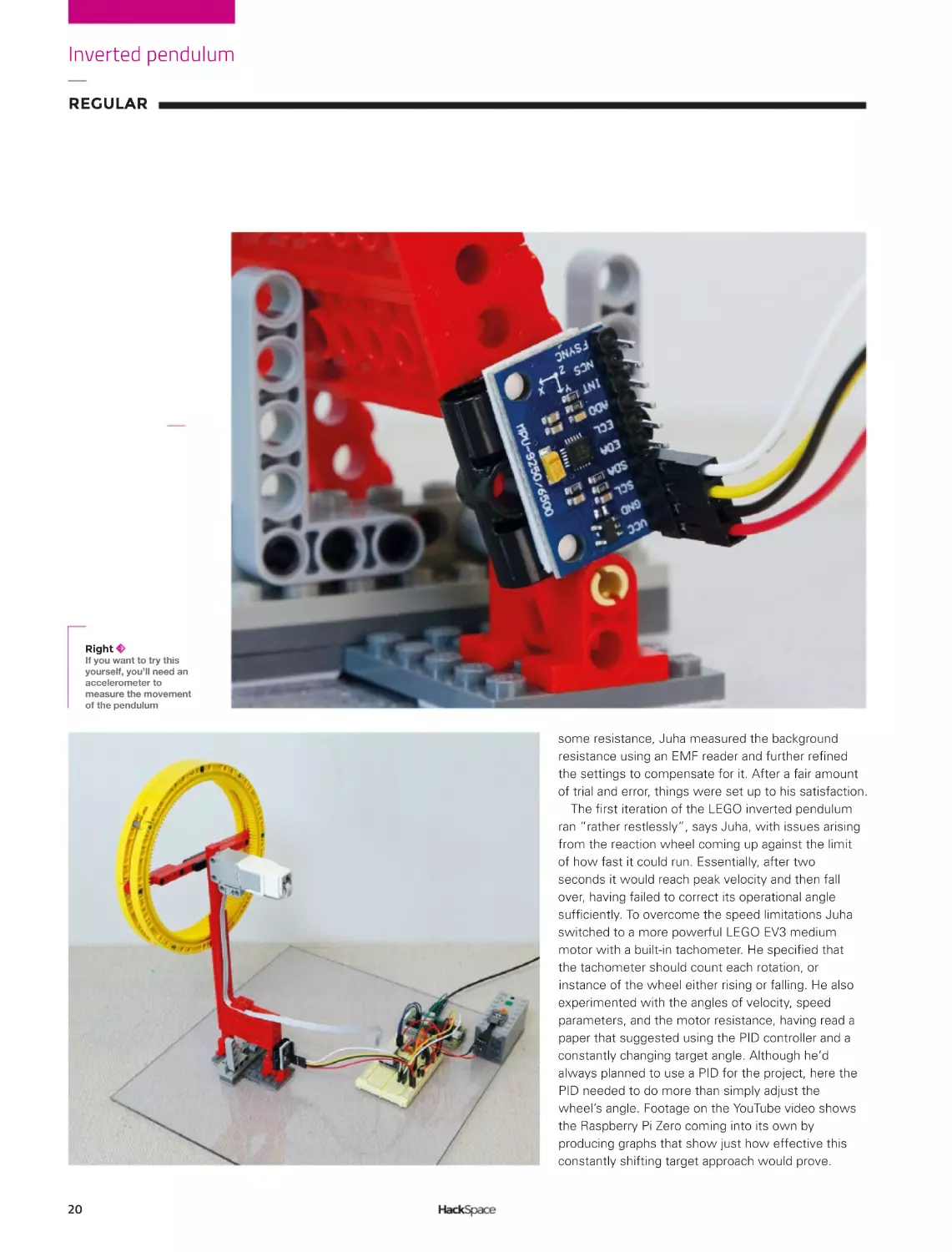
Right
Witchcraft, or
physics? We think
it’s a bit of both
18
rchitecture students are often
challenged to design a chair; for
aspiring physicists and engineers,
the classic test is the inverted
pendulum suspended on a robot
chassis. The self-balancing
motorised vehicle is expected to propel itself and
manage corners and other tricky manoeuvres, such
as changes of direction. Unless you get the balance,
angles, weight, and measurements exactly right, the
whole thing will just fall over, leaving the maker
looking less than clever too. If you get it right, the
reaction wheel will self-manage and ensure the whole
thing can propel itself and remain upright. In other
words, it’s classic control theory in action.
With a ‘medium-sized’ collection of plastic bricks
worth more than 8000 euros, software engineer
Juha spends his free time in Finland coming up
with ingenious builds using LEGO Technics and
posts YouTube videos of his inventions on his Brick
Experiments Channel (hsmag.cc/BrickExperiment),
as well as a blog where he discusses some of his
builds and their progress. Having first encountered
the pendulum challenge 20 years ago, he decided
SPARK
to revisit it in LEGO, with a Raspberry Pi spin. This
proved a smart move: the Raspberry Pi Zero 2
W handles the data and provides a control loop,
along with PID (proportional integral derivative)
controller output calculations. The PID’s autocorrection is used to adjust the motor speed and
direction, providing the active control needed to
keep everything upright. The pendulum is powered
by a 240 rpm LEGO EV3 medium motor, while
its angles are measured by an Elecrow three-axis
gyroscope and accelerometer. Torque is generated
by rotating the wheel, which in turn changes the
pendulum’s angle. This creates instability and keeps
the wheel moving.
CONSTANTLY MOVING PARTS
Aside from the electronics, LEGO parts were used
exclusively in this build. Juha began by assembling a
LEGO pendulum arm weighing exactly 29 g, and
inserted a frictionless pin (part ID 32556) to give a
very delicate rotational inertia of just 0.0012 kg/m2.
To create the reaction wheel, two sets of four curved
LEGO gear rack pieces each form a 16.8 cm circle to
which a cross brace is added and sandwiched
between them.
This reaction wheel was then connected to the
LEGO motor and Raspberry Pi Zero 2 W, which
processes the gyroscope and accelerometer readings
and provides the Python code needed to keep the
wheel spinning at the required
rate and angle. There was a
certain amount of educated
guesswork involved in
working out what angles of
rotation were needed and
changes to the parameters in
Python. An initial version of
the design, using a small
wheel, was only able to
correct angle errors of less
than four degrees, but a larger,
heavier wheel improved
things such that 28-degree
angle corrections were
possible. Realising that the
motor itself was causing
Above
Juha used an
OKYSTAR
TB6612FNG
motor driver
19
Inverted pendulum
REGULAR
Right
If you want to try this
yourself, you’ll need an
accelerometer to
measure the movement
of the pendulum
some resistance, Juha measured the background
resistance using an EMF reader and further refined
the settings to compensate for it. After a fair amount
of trial and error, things were set up to his satisfaction.
The first iteration of the LEGO inverted pendulum
ran “rather restlessly”, says Juha, with issues arising
from the reaction wheel coming up against the limit
of how fast it could run. Essentially, after two
seconds it would reach peak velocity and then fall
over, having failed to correct its operational angle
sufficiently. To overcome the speed limitations Juha
switched to a more powerful LEGO EV3 medium
motor with a built-in tachometer. He specified that
the tachometer should count each rotation, or
instance of the wheel either rising or falling. He also
experimented with the angles of velocity, speed
parameters, and the motor resistance, having read a
paper that suggested using the PID controller and a
constantly changing target angle. Although he’d
always planned to use a PID for the project, here the
PID needed to do more than simply adjust the
wheel’s angle. Footage on the YouTube video shows
the Raspberry Pi Zero coming into its own by
producing graphs that show just how effective this
constantly shifting target approach would prove.
20
SPARK
Although far from the only inverted pendulum
project to feature online, Juha’s brick experiment
project provides an instructive and minutely
documented masterclass in how to work through a
problem and come up with a working version that you
refine and iterate until it operates smoothly and to
your satisfaction. Of the many admiring (and
constructively instructive) comments on his YouTube
video, documenting the notion that Juha “could use
this as a balancing system to make a LEGO robot that
does tightrope walking” sounds like the advanced
challenge we’d be keen to see him tackle.
”
Juha experimented with the angles of
velocity, speed parameters, and the
”
motor resistance
Above
Early tests needed
a certain degree of
safety equipment
to protect the
precious LEGO
21
Objet 3d’art
REGULAR
Objet 3d’art
3D-printed artwork to bring more beauty into your life
S
ometimes when you’re
working on a custom bit of
electronics, only a custom case
will do. This 3D-printed remote
Raspberry Pi Desktop/Camera/
Server by Mukesh Sankhla marries a
Raspberry Pi 4, a Raspberry Pi High Quality
Camera with a 16 mm telephoto lens, plus a
5 V fan into a device that records and
streams stills, video, and time-lapse images.
Mukesh designed the 3D-printed parts in
Fusion 360, and has made the STL files
freely downloadable at the link below.
hsmag.cc/3DPrintedCamera
22
SPARK
23
Meet The Maker
REGULAR
Meet The Maker:
Kathy Hinde
Combining graphics and sound to make art
K
athy Hinde is an audio-visual artist
whose work often features a range
of technologies familiar to many
readers, including Raspberry Pis,
servos, and solenoids. She uses these
to create immersive experiences that
have been featured in galleries and festivals around
the world. We caught up with her to find out how she
creates these works.
HackSpace: Audio-visual artist isn’t the sort of job
that my career advisor at school told me about.
How did you end up doing this?
Below
Each bellow makes a
different note and
together they make
Morse-code-like words
24
Kathy Hinde: I actually sort of studied a joint degree
in visual art and music, and [have] just been always
really interested in combining those disciplines, which
led me down all kinds of routes. One of the routes
was getting really involved in making live video
projections for music, so I could play the visuals like in
an instrument. That was my first encounter with using
any sort of tech. Before that, I was kind of making
stuff, as in I was working with sculptural installations,
but using light and slide projection and things like that.
So, I’ve kind of always been a maker in terms of, like,
physicality of making, but I’ve always also had a kind
of a sound music strand to my work. And then this
was starting to work in video.
The piece that I made that shifted my practice into
the work I do now is called Piano Migrations. I had a
piano soundboard – I play piano and have a normal
piano, but was given a soundboard. I thought it was a
beautiful visual, as well as [an] interesting way of
playing the instrument. The piece that I ended up
making with it is: I made a film of birds taking off and
landing on telegraph lines, which look like a musical
score. I was really interested in automatic ways of
playing pianos, so I decided to combine this digital
score made by birds by projecting it directly onto the
piano, and then using a computer vision patch, made
by Matt [Olden], which looked for movement in parts
of the video, and converting this into solenoids tapping
directly on the piano strings. The impression is that
SPARK
wherever the birds are fluttering, they’re actually
touching the strings and making a sound. It combined
lots of the things that I’m interested in – playing
musical instruments in interesting ways and
combining visual art and music so one isn’t overriding
the other. The piano is like a sculpture with this visual
on it, but also, it’s a piano. There’s also this idea of
working with a behaviour. I worked with different
videos of birds, and the piano’s got different nuts and
bolts in it to change the sound. It’s this idea of having
something that has its own behaviour. It’s completely
controlled by the birds and how they were moving at
the time. I’ve just defined the framework for
something to play out in. I think that was a turning
point in my work, and those key elements come back
in other pieces.
It was also the first time I’ve worked with solenoids,
and a MIDI-to-voltage system. It was quite challenging
technically for me at the time, but the result is a very
direct relationship – you get it straight away. There’s
not too much unpicking of what’s going on.
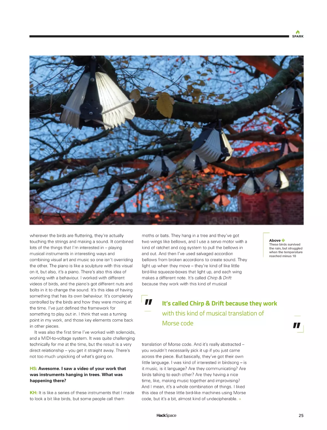
HS: Awesome. I saw a video of your work that
was instruments hanging in trees. What was
happening there?
KH: It is like a series of these instruments that I made
to look a bit like birds, but some people call them
moths or bats. They hang in a tree and they’ve got
two wings like bellows, and I use a servo motor with a
kind of ratchet and cog system to pull the bellows in
and out. And then I’ve used salvaged accordion
bellows from broken accordions to create sound. They
light up when they move – they’re kind of like little
bird-like squeeze-boxes that light up, and each wing
makes a different note. It’s called Chirp & Drift
because they work with this kind of musical
”
Above
These birds survived
the rain, but struggled
when the temperature
reached minus 18
It’s called Chirp & Drift because they work
with this kind of musical translation of
Morse code
translation of Morse code. And it’s really abstracted –
you wouldn’t necessarily pick it up if you just came
across the piece. But basically, they’ve got their own
little language. I was kind of interested in birdsong – is
it music, is it language? Are they communicating? Are
birds talking to each other? Are they having a nice
time, like, making music together and improvising?
And I mean, it’s a whole combination of things. I liked
this idea of these little bird-like machines using Morse
code, but it’s a bit, almost kind of undecipherable.
”
25
Meet The Maker
REGULAR
The words chirp and drift are both terms used to
names of those local birds into Morse code. And then
describe Morse code when it gets distorted
create a composition that has one note for a dot and
in transmission.
more than one note for a dash. It’s a really broad
I was interested in how I’d read an article about
spectrum and there’s a lot of creative licence there.
how birds might re-pitch their song to a different pitch
But you can work it out if you really try.
because of urban noise. Originally in the ecosystem,
They’re all playing this Morse code. And because
each species would have its kind of bandwidth to
it’s all sealed in a Peli case, it’s just got an outdoor G4
communicate on because they’ve evolved to kind of
plug on it. When it’s all set up and ready, you just have
have this balance. And there’s loads of really exciting
to plug it in, and it all just starts up and runs. On the
research on that. I’m also
bellows, I’m using this
interested in using
Tyvek paper which is like
Morse code to refer to
a waterproof paper – it’s
When
it’s
all
set
up
and
communication
used in roofing. I’ve
bandwidths and noise,
laser-cut all the parts and
ready, you just have to plug
and not being heard or
then painted them and
it in, and it all just starts up
misunderstood. That was
oiled them, so they’re
kind of the background
weatherproof enough. I
and runs
of the idea of the piece.
have to re-oil them, and
I set it up on night
things like that. I’ve used
trails, or it just needs to
Delrin cogs – I’ve tried to
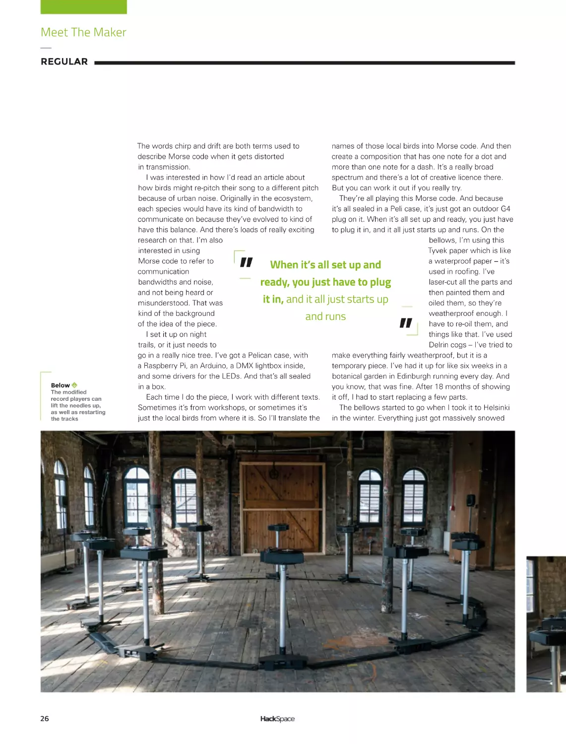
go in a really nice tree. I’ve got a Pelican case, with
make everything fairly weatherproof, but it is a
a Raspberry Pi, an Arduino, a DMX lightbox inside,
temporary piece. I’ve had it up for like six weeks in a
and some drivers for the LEDs. And that’s all sealed
botanical garden in Edinburgh running every day. And
in a box.
you know, that was fine. After 18 months of showing
Each time I do the piece, I work with different texts.
it off, I had to start replacing a few parts.
Sometimes it’s from workshops, or sometimes it’s
The bellows started to go when I took it to Helsinki
just the local birds from where it is. So I’ll translate the
in the winter. Everything just got massively snowed
”
”
Below
;OLTVKPÄLK
record players can
lift the needles up,
as well as restarting
the tracks
26
SPARK
on – and it did survive. We decided we had to leave it
on all the time, so it wouldn’t freeze, so it’s always
moving a little bit.
But when it came back from there, I realised that
a lot of the seals were broken on the bellows
because I’d laser-cut them to make them easier to
fold, and then lined them with sticky-back plastic
so that they were airtight. I was so worried about
the servos stopping working and all the reeds
getting frozen, but the actual thing that ended up
being a problem was the bellows actually
developed some little gaps because of them being
frozen and then moving the plastic. It started to
crack and so I had to replace that. There’s always
new challenges showing things outside. I’ve had to
deal with rain a lot – obviously showing stuff in the
UK, I’ve kind of got quite good at working out how
to make things that are fine in the rain. But I had
never had to do something that was going to be OK
in minus 18.
Above
The solenoids twang
the strings when
movement is
detected
HS: I think you’ve recently come back from Mexico.
What was the piece you were exhibiting there?
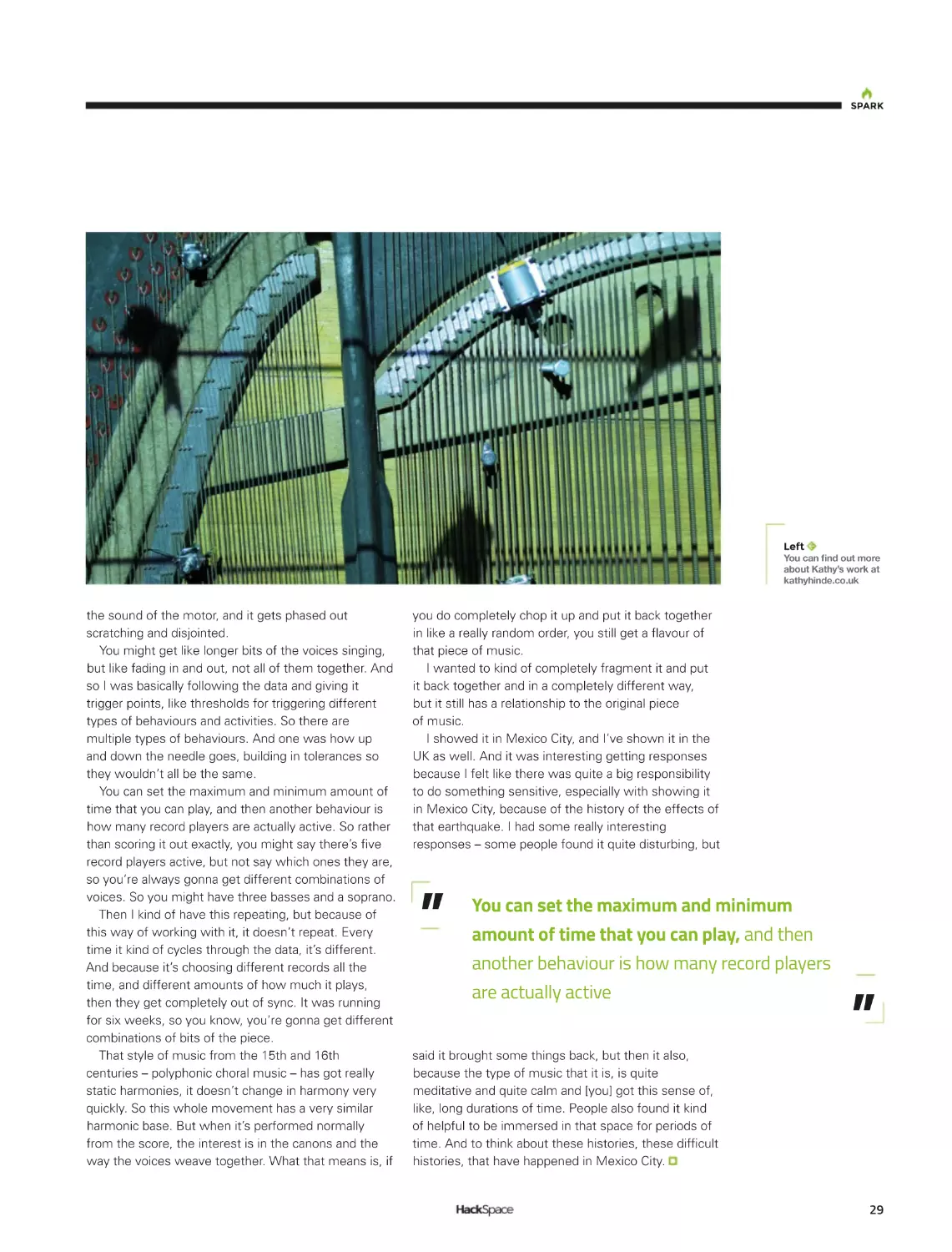
KH: It’s a series of twelve individual record players. I
was very interested to work with this 15th century
choral mass called the Earthquake Mass, because it
was composed around a piece of literature around the
Earth moving. And the last movement of that piece, it
was discovered incomplete, as if it was returning to
the Earth, it was kind of rotting away. I wanted to take
this incomplete movement and work in collaboration
with partners in Mexico, which is obviously a place
that’s got a lot of seismic activity. I worked with a
Mexican choir and, with this last movement, recorded
each singer individually singing each part, and then
pressed those to vinyl.
The idea was to then use seismic data to somehow
interfere with the playback of this piece. I wanted to
use vinyl because I liked the idea of physical
27
Meet The Maker
REGULAR
Above
A repurposed sound
board forms the basis
of Piano Migrations
28
sound-waves being engraved into a surface, a bit like
seismic waves engraving their way through the kind of
core of the Earth. And also, I’ve just also been
fascinated with the physicality of sound and how it
moves through materials.
Of course, this is exactly the same as seismic
waves, but it’s very, very low frequency waves
moving through the Earth. There are a lot of parallels
with how sound behaves – resonant frequencies
and reverberation; things like that also apply to
seismic activity.
I had all these things pressed to vinyl and I chose to
use the seismic data from the 2017 earthquake that
hit Mexico City. It was a really devastating earthquake,
and I wanted to use that data to sort of fragment this
choral piece. So, I worked with the shape of the
seismic data and adapted all the record players so that
there was a little motor that lifted the needle up and
down. But then also a sensor and a motor that would
then move the needle back to the beginning so each
vocal part could play forever. I wasn’t playing any of
them straight from beginning to end. When there’s
like, really, really high seismic activity, I was
fragmenting the piece really heavily – lifting the needle
up and down a lot, so it’s granulated but physically.
The nice thing about that is you can see the needles
going up and down and touching the record and
making a tiny sound, and going back up, and you get
SPARK
Left
@V\JHUÄUKV\[TVYL
about Kathy’s work at
kathyhinde.co.uk
the sound of the motor, and it gets phased out
scratching and disjointed.
You might get like longer bits of the voices singing,
but like fading in and out, not all of them together. And
so I was basically following the data and giving it
trigger points, like thresholds for triggering different
types of behaviours and activities. So there are
multiple types of behaviours. And one was how up
and down the needle goes, building in tolerances so
they wouldn’t all be the same.
You can set the maximum and minimum amount of
time that you can play, and then another behaviour is
how many record players are actually active. So rather
than scoring it out exactly, you might say there’s five
record players active, but not say which ones they are,
so you’re always gonna get different combinations of
voices. So you might have three basses and a soprano.
Then I kind of have this repeating, but because of
this way of working with it, it doesn’t repeat. Every
time it kind of cycles through the data, it’s different.
And because it’s choosing different records all the
time, and different amounts of how much it plays,
then they get completely out of sync. It was running
for six weeks, so you know, you’re gonna get different
combinations of bits of the piece.
That style of music from the 15th and 16th
centuries – polyphonic choral music – has got really
static harmonies, it doesn’t change in harmony very
quickly. So this whole movement has a very similar
harmonic base. But when it’s performed normally
from the score, the interest is in the canons and the
way the voices weave together. What that means is, if
you do completely chop it up and put it back together
in like a really random order, you still get a flavour of
that piece of music.
I wanted to kind of completely fragment it and put
it back together and in a completely different way,
but it still has a relationship to the original piece
of music.
I showed it in Mexico City, and I’ve shown it in the
UK as well. And it was interesting getting responses
because I felt like there was quite a big responsibility
to do something sensitive, especially with showing it
in Mexico City, because of the history of the effects of
that earthquake. I had some really interesting
responses – some people found it quite disturbing, but
”
You can set the maximum and minimum
amount of time that you can play, and then
another behaviour is how many record players
are actually active
said it brought some things back, but then it also,
because the type of music that it is, is quite
meditative and quite calm and [you] got this sense of,
like, long durations of time. People also found it kind
of helpful to be immersed in that space for periods of
time. And to think about these histories, these difficult
histories, that have happened in Mexico City.
”
29
Letters
REGULAR
Letters
ATTENTION
ALL MAKERS!
If you have something you’d
like to get off your chest (or
even throw a word of praise
in our direction) let us know at
hsmag.cc/hello
PKE METER
GhostbustersKUQPGQHVJGƓPGUVƓNOU
GXGTOCFG+VũUWRVJGTGYKVJCP[YQTM
QHCTVQHVJGVJEGPVWT[+VũURGTHGEV+
COUQUQINCFVJCVVJGRGQRNGYJQ
NQXGFVJGƓNOYJGPKVECOGQWVKP
QTOQTGNKMGN[YJQYCVEJGFKVQP
JQOG8*5KPVJGHQNNQYKPI[GCTU CTG
PQYUMKNNGFGPQWIJYKVJCUQNFGTKPI
KTQPVQOCMGVTKDWVGUVQVJGƓNO2GQRNG
NKMG-GXKP/E#NGGTYJQUG2-'OGVGT
9K(KUVTGPIVJKPFKECVQTDWKNFKUVQVCNN[
UKNN[CPFQPN[LWUVWUGHWNGPQWIJVQDG
YQTVJOCMKPI+VCMGO[JCVQHHVQJKOК
David
Hertfordshire
30
Ben says: It’s great, isn’t it? There’s
something magical about seeing your
QYPRCUUKQPUTGƔGEVGFKPVJGYQTMQH
QVJGTUYJGVJGTVJCVũUCHCXQWTKVGƓNOC
XKFGQICOGQTCP[QVJGTMKPFQHUJCTGF
experience. And the easier it gets to
OCMGVJKPIUVJGGCUKGTKVKUVQOCMG
VJKPIUVJCVTGCNN[TGƔGEVWUCURGQRNG
Which in our case is Egon, Ray, Peter,
and Winston.
SPARK
CHOCOLATE PRINTING
'NNKG9GKPUVGKPETGCVQTQHVJGEJQEQNCVG
&RTKPVGTKUCIGPKWU+FQPũVECTGKH+ũNN
PGXGTVT[KVO[UGNH+LWUVNQXGVJGKFGC
VJCVUQOGQPGũUQWVVJGTGFQKPIETC\[
UVWHHNKMG&RTKPVKPIUJCRGUQWVQH
GFKDNGǭEJQEQNCVG6JGHCEVVJCVFKHHGTGPV
KPƓNNUVCUVGFKHHGTGPVKUVJGKEKPIQPVJG
EJQEQNCVG ECMG
Robert
Hamburg
Ben says:9GũXGUGGPCHGYHQQFDCUGF
&RTKPVGTU
RCPECMGOKZCPFUSWGG\G
EJGGUGEQOGVQOKPF6JGFKHƓEWNV[
with chocolate is that when it leaves
VJGGZVTWFGTKVJCUVQDGNKSWKFVJGPKV
JCUVQEQQNSWKEMN[KPVQCUQNKFCNNYJKNG
staying within a temperature range
VJCVYQPũVOCMGVJGƓPCNRTQFWEVIQ
OWUJ[+VNQQMUNKMG'NNKGũUETCEMGFVJCV
EQPWPFTWOCPFYGNQQMHQTYCTFVQ
UGGKPIEJQEQNCVG$GPEJ[UYQQFYQTMKPI
LKIU&WPIGQPUCPF&TCIQPUƓIWTGU
CPFCNNVJGTGUVQHVJGENCUUKE&
printing repertoire.
CHIP (NUMBERS)
ARE DOWN
)GV[QWTET[UVCNDCNNUQWVEJCRU
YJGPKUVJKUEJKRUJQTVCIGIQKPI
VQGPF!+VũUDGGPCPCDUQNWVGRCKP
ƓPFKPIRTQLGEVUQPVJGKPVGTPGVƓPFKPI
VJGDKNNQHOCVGTKCNUCPFVJGPTGCNKUKPIVJCV
VJGRCTVUCTGGKVJGTPQPGZKUVGPVQTUVWEMQPC
UNQYDQCVHTQO5JGP\JGP1PVJGWRUKFG+FKFIGV
O[JCPFUQPC4CURDGTT[2KUQ+ũNNIGVVJCVYGCVJGT
UVCVKQPDWKNVKPVKOGHQTPGZV[GCTũURNCPGVUEQTEJKPI
UWOOGTVGORGTCVWTGU
Paul
Peterborough
Ben says: 6JKUUGGOUNKMGCVKOGN[OQOGPVVQTGOKPF
you that you can get a Raspberry Pi Pico W when you
VCMGQWVCUWDUETKRVKQPVQ*CEM5RCEGOCIC\KPGŦVWTPVQ
RCIGHQTVJGHWNNFGVCKNU1VJGTVJCPVJCVYGPQVKEGF
recently that used cars are getting cheaper, which
indicates that more new cars being made, so car
OCPWHCEVWTGTUOWUVDGUQWTEKPIEQORQPGPVUHTQO
UQOGYJGTG6JCVũUQWTDGNNYGVJGT
KH8QNMUYCIGPKU
IGVVKPIEJKRUPQYOGTGJWOCPUNKMGWUUJQWNFDG
CNNQYGFCHGYETWODUHTQOVJGHCEVQT[ƔQQTKPCHGY
months. That’s what we’re hoping anyway!
31
Crowdfunding now
REGULAR
CROWDFUNDING
NOW
MNT Pocket Reform
Open hardware for your (large) pockets
From TBD hsmag.cc/pocket Delivery: TBD
T
here was a time when a computer came
in a box that you could open. Inside
this box, there were parts that you
could actually buy upgrades for.
Desktop PCs still are like that,
but the vast majority of computers these
days are laptops, phones, and other
portable devices. These are usually not
designed with user servicing in mind.
You might be able to get some
replacement parts, but fitting them
is usually tricky and upgrades
are often just a dream.
The original MNT
Reform project aimed
to solve this problem
for laptops with an
open-source design
and replaceable parts,
and now the MNT Pocket
Reform is taking aim at smaller
devices. The MNT Pocket Reform
is a slightly unusual form factor, being
32
essentially a very small laptop running Linux on an
Arm processor. Similar devices have popped up in
the past and have found a cult following, but have
rarely found commercial success.
The MNT Pocket Reform is
powered by the same quad ARM
Cortex-A53 processor board
as the MNT Reform,
which makes it
an interesting
option for reusing
existing modules
if you upgrade an
MNT Reform (if,
and when, other
processor modules
become available).
We love the idea of an
open-hardware portable, and
anything that helps us, as a
society, move away from
touchscreen keyboards is – in our
opinion at least – a good thing.
BUYER
BEWARE
!
When backing a crowdfunding
campaign, you are not purchasing
a finished product, but supporting
a project working on something
new. There is a very real chance
that the product will never ship
and you’ll lose your money. It’s
a great way to support projects
you like and get some cheap
hardware in the process, but if
you use it purely as a chance to
snag cheap stuff, you may find
that you get burned.
Above
Is the world
ready for a tiny,
ortholinear
laptop?
33
Join us as we lift the lid
on video games
Visit wfmag.cc to learn more
LENS
HACK
MAKE
BUILD
CREATE
Uncover the technology that’s powering the future
PG
PG
52
HOW I MADE:
CERES-1
PORTABLE
58
INTERVIEW:
CARRIE
SUNDRA
The head honcho of
Alpenglow Industries on
politics, art, and mountains
VORON
VORON
NEXT GEN
3D PRINTING
Why your next 3D printer
should be a Voron
Take a Raspberry Pi, a mechanical
keyboard, and make some magic
PG
36
PG
66
IMPROVISER’S
TOOLBOX:
BRICKS
Who knew that baked mud
could be so useful as a
weekend play medium?
Next Gen 3D printing
FEATURE
VORON
VORON
Why your next printer
should be a Voron
36
LENS
I
t can feel like the world goes in cycles. The hobbyist 3D printer
community started off with homebrew designs built from
off-the-shelf components and 3D-printed parts. Then, for a few
years, it became standard to get printers almost fully assembled
(or at least as custom-made kits). Now the circle is starting to
complete itself as more and more makers are building their own
printers from off-the-shelf parts and 3D-printed parts, thanks to Voron
Design and its selection of high-quality, open-source designs.
Voron has built up a reputation for fast, good-looking printers that
follow the DIY, open-source ethos, similar to the RepRap project that first
spawned the world of hobbyist 3D printers. These new printers are a
step away from the classic i3 design that dominates the scene currently.
Utilising CoreXY kinematics and Klipper firmware, these machines are on
the very cutting edge of what’s possible with off-the-shelf technology.
Is there really still a need for homemade machines? Can community
designs compete with commercial machines? We decided to see what
all the fuss was about, so built ourselves a Voron printer, and had a chat
with the team behind the machines.
37
Next Gen 3D printing
FEATURE
MAKS ZOLIN
The man behind Voron
Above
Maks Zolin, aka
RCF, started the
Voron project
38
LENS
V
oron is an open-source project where printers are
designed, tested, and documented by volunteers, so how
does this project produce printers that are getting more
attention and acclaim than almost any 3D printer
company? We caught up with Maks Zolin (aka Russian
Cat Food / RCF) to find out more about how the project
started and how they design printers.
HACKSPACE How did the Voron project get started?
MAKS ZOLIN The Voron project began as part of MZ Bot, the 3D
printing company that I started 2015. The original goal was to make
extruders for 3D printers. I saw there was a market for lightweight
extruders, and I felt like I could fill a niche in this space. And then that
kind of grew into, ‘I would like a printer that I designed that is better than
things that I can buy right now off-the-shelf.’ And that’s how the first
Voron prototype began. I posted this prototype on, like, a RepRap forum
on Reddit, in 2015. People got excited. From there, I got inspired to
streamline it, and eventually it was released as a fully open-source thing
in 2016. Then the community started growing on Reddit. People showed
up and built printers, and there was a demand for kits. I still had the
company going so I said, ‘Oh, I’m gonna do kits, that’s gonna be great.’
So I did the initial run of 18 kits. I think most of them are still in operation,
which is kind of remarkable.
So we went through a couple of revisions of the original Voron printer.
And in 2017, I kind of decided I don’t want to really do consumer space
any more. I really want to focus on the commercial space. One client
came and approached me about scaling up a Voron to humongous
dimensions, 24 inches by 24 inches by like, 600 by 600 millimetres. I
said, ‘actually, I have a better idea’ because Voron 2 was already in
development, at least on pieces of cardboard in my shop – pen and paper
basically. So that’s how Voron 24 was born. It’s an old metal machine; I
built two of them. One was kind of like my prototype machine basically
to tinker with, and then one that’s like, super, super-clean, and all the
stuff got put on to that. And then it got shipped to Minnesota. And there
it lived for a long time.
Eventually I realised I couldn’t keep my full time job and do a side job,
and have any kind of meaningful family life. My daughter was born in
January of 2016. And Voron was released in March of 2016. Voron is
really kind of the closest thing I’m ever going to have to a second child.
In 2018, I made the decision to dissolve MZ Bot, but I loved what I did
as part of the Voron project. So the entire endeavour got redesignated as
Voron Design, which is not really a company, it’s just a project effectively.
Then 2020 happened. And everybody built Vorons. All of a sudden, we
started getting kits arriving out of nowhere. The popularity just basically
went like vertical, kind of took us by surprise.
Honestly, as far as the admin team, we were not really prepared for
that kind of inrush of people but, thankfully, for the most part, we
managed. I was imagining complete meltdown of our communities, but
we did OK.
So the stationary bed, the flying gantry stuff, all came out of the
Voron 24.
“
EVERYBODY
BUILT
VORONS.
ALL OF A
SUDDEN,
WE
STARTED
GETTING
KITS
ARRIVING
OUT OF
NOWHERE
”
39
Next Gen 3D printing
FEATURE
That was when we discovered Klipper, and Klipper really made Voron 2
possible because this machine needs a minimum of seven stepper
drivers to work, and getting an off-the-shelf board that runs Marlin well,
with seven steppers going all at the same time. It’s kind of horrible. And
expensive, cost-prohibitive – let’s go with cost-prohibitive. Klipper really
solved the problem for us because we could literally take off-the-shelf
RAMPS boards from the olden days and plug as many of them as we
wanted into a Raspberry Pi. Klipper ran on a Raspberry Pi and then you
can have, theoretically, unlimited drivers. And that’s when Raspberry Pi
became a core thing inside of Voron, because it basically powered the
entire printer. So, Klipper plus Raspberry Pi solved a huge development
issue for us, basically, and actually made it affordable. It was cheaper for
you to buy Raspberry Pi and a whole bunch of controller boards than find
a standalone like seven- or eight-driver board.
Above
HS So that takes us to the Voron 2. How did the project progress
after that?
;OLÄYZ[
Voron prototype
MZ So yeah, I mean 2020, we actually released three printers that year.
We were gonna go to Midwest RepRap festival and, like basically, unveil
a whole bunch of stuff. And none of that happened because of
unmentionable illnesses and pandemics. So we just did a whole live
stream where we’re like, ‘Oh, there’s this printer’ which was an update
to one which basically was one with V2 gantry on it. It was an update to
Voron 2 to 2.4, which is actually the current printer that we have right
now. And Voron 0 was released in 2020. That was a huge, huge hit for us
honestly. And then later that year, I did Switchwire as a Christmas
present, which was that CoreXZ.
Yeah. And then we did a partnership with E3D recently, where we
basically approached them to design a better heatsink for the V6 hot end.
And then Sanjay kind of dropped in and said, ‘Well, we got a new thing
going on here’ – we had no idea. Revo Voron was born out of that.
We started working with LDO, and a whole bunch of other companies
trying to vet what they do and make sure that our community gets the
best products, and really we became like champions for open-source
hardware. Because we are not financially involved in any of this, we are
really good at generating other people a whole bunch of money. But we
trade in fun. I love what I do, I love doing this. It’s truly my passion. And I
am truly lucky to be surrounded, in my community, by people that also
feel the same way. Especially the development team and stuff. And
yeah, it’s effectively my second home.
Above
The Voron
Stealthburner
print head
Right
Trying to connect
enough motors to
a RAMPS board
40
LENS
Left
Voron printers
are brought to
you by a team
including (from top
to bottom) Doc
(Adam), Eddie,
Nemgrea, Steve,
and Tim
“
IT’S RUN A
LOT LIKE
Above
The Voron 1.0
printer that
started it all
ANY OTHER
OPENSOURCE
HS How do you organise the work with a team of volunteers?
MZ We have a few people that kind of, like, take over a product line,
so to speak. Nemgrea is basically in charge of all the V0 stuff. Steve
recently took over the V1 line, and basically we transitioned it to Voron
Trident. Steve also did the recent R2 update to V2. And now we’re
working together on Switchwire a little bit. People kind of come and go,
people get burned out, they want to do something else, they kind of,
you know, go away and come back. And it’s not really like, ‘Oh, this is
the dev team’. It’s run a lot like any other open-source project. People
come in and do a bunch of pull requests, and I stay around and do this
for like six years.
HS How long does it take to design a new Voron printer?
MZ The longest it’s ever taken, I guess is V2, because it was a good
three years – I mean, for something that people actually want to build,
which is one of these things [gestures at printer]. The 2.0 was never
released at all, because it was horrible. V2.1 was the first V2 line. The
shortest – we actually have pipelined that quite a bit now -- Switchwire
as an example, took three months, from zero to: here is a list of parts,
here’s all the printed parts, here’s a full manual, and here’s the sourcing
guide for all the things. Then I think six months later, LDO turned around
and started releasing kits for it, which was fast.
We’ve cut it down quite a bit now, simply because we have a lot more
processes and tools in place. We try really hard not to make it feel like a
job. Because people get super-twitchy about, you know, getting tasks
assigned to them. Yeah. So we’re just pretty basic, like here’s all the
stuff, we throw it out on the table. Somebody walks by and picks it up.
‘Oh, I want to do this’ and then eventually it happens.
PROJECT.
PEOPLE
COME IN
AND DO
A BUNCH
OF PULL
REQUESTS
”
41
Next Gen 3D printing
FEATURE
CORE X-WHY
WHY
What’s the technology behind the project?
Left
It can be a bit
tricky to follow the
belt path, but the
key thing is that
both motors stay
still while the print
head moves
Left
Each belt loops
around both the
Y and X axes
42
LENS
C
Below
You can see four
belts attached to
the print head; on
each side, there’s
one connection
from each motor
ompared to the majority of consumer-grade 3D printers,
there are a couple of things that make Voron printers
stand out. Firstly, they use the CoreXY motor setup, and
secondly, they use Klipper firmware. Let’s take a look at
what this means.
All Voron printers use CoreXY motor configuration (except
the Switchwire which uses CoreXZ, but this is just CoreXY rotated 90
degrees). To understand what this means, first, let’s quickly look at the
alternative, which is usually Cartesian configuration. In Cartesian printers,
each motor controls the motion in one axis. So, to move the print head in
the X axis, you run the X axis motor. There may be two motors on a
single axis, but each motor is only ever attached to a single axis.
On a CoreXY machine, the Z axis operates just as it does on a
Cartesian machine (on the Voron machines, typically the bed moves
down rather than the print head moving up, but this doesn’t really change
the kinematics), but the X and Y motors work a bit differently. The X axis
is typically a gantry that’s free to slide around the Y axis, and then the
drive belt from one motor goes along the Y axis, loops around the end
and comes back down the Y axis before going along to the print head.
The other motor is a mirror image of this along the Y axis on the other
side of the machine. In this way, both motors are directly connected to
the print head. All movements (even straight-line movements along a
singe axis) require both motors to work together.
The key advantage of this setup is that neither of the X or Y axis
motors has to move anything heavy. On a Cartesian printer, one of the
motors has to move either the print bed (typically in the Y axis as in a
Creality Ender 3 or Prusa MK3S – aka bed slingers) or the entirety of one
of the other axes (such as how the Y axis moves the entire X axis
assembly on an Ultimaker).
The CoreXY, in contrast, can keep all its motors stationary, and moving
the print head doesn’t require moving any heavy things around. This
means that you can have much higher accelerations without either
skipping steps or ‘ringing’. One motor still has to move the heavy print
bed, but only in the Z axis where generally movements are less critical.
A second advantage, particularly over the ‘bed slinger’ type design, is
that they have a small footprint. Any printer that moves the print bed in
the Y axis needs to have a lot of desk space to allow for this movement.
This is a problem if you want a lot of them, and it’s also a concern if you
want an enclosed printer. The CoreXY machines allow much smaller
enclosures for a given print volume, which means it’s easier to enclose
them and easier to have hotter enclosure temperatures.
While none of the Voron machines have heated enclosures that you
need for some of the more really exotic engineering filaments (the
limiting factor being the plastic parts holding the printer together – if you
push the chamber temperature too high, then these are liable to melt),
they can hold a reasonably high temperature with the heat from the hot
end and print bed.
CoreXY isn’t unique to Voron machines – there are plenty of
commercial machines set up this way (and a few that claim to be but
aren’t). However, Voron machines are among those which embrace the
advantage of CoreXY designs as much as possible, allowing for really
fast printing.
“
THE KEY
ADVANTAGE
OF THIS
SETUP
IS THAT
NEITHER
OF THE X
OR Y AXIS
MOTORS
HAS TO
MOVE
ANYTHING
HEAVY
”
43
Next Gen 3D printing
FEATURE
THE PRINTERS
Which is the right Voron for you?
Voron 2.4
This is perhaps the flagship Voron printer. It’s
a big, solid, capable printer, but it’s also
expensive and time-consuming to build. You
can customise the build volume from
250×250×250 up to 350×350×350, so it’s
potentially a large printer. It prints quickly and
has some features you may not expect in a
consumer 3D printer (such as four-point
gantry trimming). This does make it the most
complex and expensive of the Voron printers.
Voron 0
This tiny little printer has a build volume of just
120×120×120, which makes it not just the smallest
Voron, but one of the smallest printers around. It’s
also one of the most popular Voron machines, and
the one we chose to build. We suspect we chose
it for the same reasons a lot of other people have
chosen it: most of the parts we want to print will fit
on this (but we do have a larger printer should we
need it). It’s small enough to fit on a shelf, meaning
it’s a great ‘home’ machine (for this author who
has separate workshop machines. If it was going
to be our only machine, I’m not sure I’d go with
this option).
Simple physics makes smaller printers more
forgiving as well. With everything closer together,
there can’t be any levering to apply large forces to
joints. If you don’t need a large printer, why
introduce these potential problems?
44
LENS
Voron Trident
This has almost the same build volume as
the 2.4 (while the X and Y axes both go
between 250 and 350, the Z height is
limited to 250).
It’s less complex and cheaper to build
than the Voron 2.4, but also a bit less
feature packed. This makes it a sort of
middle ground printer. It’s at least as big as
most hobbyist machines and is still a fast,
capable machine, but it’s not quite the
same level of investment of time and
money as the Voron 2.4.
“
IT PRINTS
QUICKLY
AND HAS
SOME
Switchwire
While not an easy or cheap printer to build by most standards,
the Switchwire is probably the easiest and cheapest of the
Voron machines.
This is the only Voron printer that’s not CoreXY – it’s CoreXZ
instead. This means that it looks a lot more like a Prusa MK3S or
Ender 3, with the bed sliding back and forwards under a frame. With
the heavy bed sliding back and forth, you don’t get the same speed
advantages as you do with CoreXY, but you do get solid Voron design.
While the Switchwire can be built from scratch (as most Vorons
are), the design does lend itself to conversions. You can take a Prusa
MK3 apart for parts and there are community mods to convert an
Ender 3 into a Switchwire-like machine.
FEATURES
YOU MAY
NOT EXPECT
IN A
CONSUMER
3D PRINTER
The future
We asked Maks about what
new models of Voron
machine we might see in the
future. While he didn’t give
anything away about new
printers, he did rule a couple
out. We won’t be seeing a
Voron Delta printer any time
soon, as the wasted Z height
means it’s not space-efficient
enough to make the Voron
grade. He also ruled out (for
the time being) a Voron resin
printer – the part availability
at the moment means it
doesn’t make sense.
”
45
Next Gen 3D printing
FEATURE
BUILDING A
VORON 0
Getting a tiny printer for our workshop
Left
You’ll start with a
big box of screws,
nuts, and other
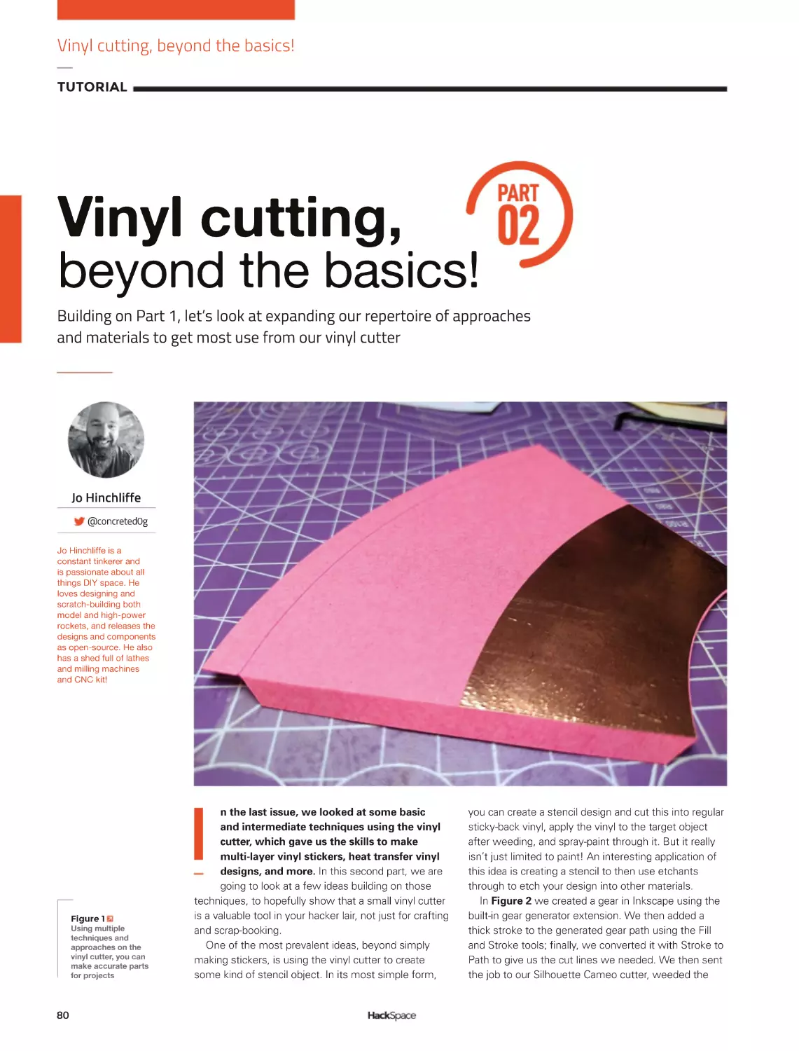
Ä_PUNZI\[P[»SSIL
empty by the time
`V\»]LÄUPZOLK
46
LENS
B
Left
This is most of the
printed parts for
a Voron 0.1 – yes,
they take a long
time to print
uilding a Voron is an involved process. To be perfectly
honest, it was a lot more involved than we expected it to be.
That’s not to say it’s difficult (there’s plenty of information and
advice about what to do), but that it not only takes a lot of
time, it also takes quite a bit of brain power.
This starts right at the beginning. What printer are you
going to make? What options are you going to select? How are you going
to source the manufactured parts, and how are you going to get the
3D-printed parts?
We’ll ignore the first two questions there for now because we’ve
looked at them a bit already, but there are quite a few ways of getting
hold of the bits for Voron machines, and they can have quite a big impact
on how the build goes.
By far the simplest way of getting the bits is just to buy them
pre-selected. You can get hardware kits with all the bits you need (usually
excluding the 3D-printed parts). If you’re starting from scratch, then this
is probably a good bet. If you’ve got some bits already lying around (such
as an old printer that can donate bits), you might be able to save money
by getting just the bits you need. If you don’t opt for this, you’ll need to
cut, drill, and tap quite a lot of extrusion yourself.
One of the fiddlier tasks of building a Voron printer is crimping the
wires. You can out-source this by buying a wiring harness. Like plenty of
things, it’ll save you some time but cost you some money. Whether or
not this is a good trade-off is up to you.
Note that most of the time, a kit will come with all of the electronics
other than a Raspberry Pi (though do check your exact kit to make sure it
has what you’re expecting). You can use any model of Raspberry Pi board
(other than Pico or Pico W), but Raspberry Pi 1 or Zero will have
performance issues. If possible, a Raspberry Pi 3 or better is preferred.
All Voron printers are built with parts printed in ABS. You might
wonder if you really need to do them, and if maybe you could use
another type of filament. There’s a detailed explanation on the website,
but the short version is yes, you really do need to print them in ABS.
ABS isn’t the easiest material to print – it’s particularly sensitive to
chamber temperature and drafts. It is technically printable on most
consumer printers, but you will need at least an enclosure. This can
be as simple as a cardboard box over your printer. If you’re not used
to printing ABS, it’s worth factoring in a bit of time to get to grips with
the filament, particularly for the parts with fine detail (such as screw
threads or overhangs).
If you don’t already have a printer, or not one capable of printing ABS,
then you can get hold of a printed set of parts. There are some people
selling them, and there’s also a Print It Forward scheme where Voron
owners print parts for people looking to get started. Take a look at their
website: pif.voron.dev.
As you can see, there’s quite a bit involved in just getting the bits for
your Voron, but don’t let it put you off. Remember that we said it was
involved but not excessively difficult? There’s plenty of guidance on the
Voron website (and people in the Discord channel willing to help). The
result of all this choice is a very flexible printer. There aren’t many models
of printer around that you can size to fit in the exact space you have, or
even that you can pick the exact colour you want them to come in.
“
THERE’S
QUITE A BIT
INVOLVED
IN JUST
GETTING
THE BITS
FOR YOUR
VORON,
BUT DON’T
LET IT PUT
YOU OFF
”
47
Next Gen 3D printing
FEATURE
Once you’ve sourced your parts, it’s time for the build. We’re not going
to go through how to build a Voron printer here, because the build guides
available on the website are excellent and would fill up the entire
magazine. However, here’s our experience of building a Voron 0.1.
FRAME
The first thing you’ll build is the mechanical assemble: the frame and
suchlike. Compared to most consumer printers, most Vorons have very
solid frames – a consequence of them being made of a lot of parts. This
means you can print fast, but it’s a slow build.
The Voron 0, like all the other Voron printers, is based around
aluminium extrusions with captive nuts. Building with these isn’t a
complex process, but can be fiddly. Expect to spend a lot of time
sliding nuts into slots and then attaching screws – or, if you’re not
careful, turning the extrusion over and sending a shower of nuts
across the workshop floor.
ELECTRONICS
Above
You can pick which
hot end you want
in your extruder
If you’ve opted to buy a wiring harness, then the electronics are pretty
straightforward. If you’re building it from scratch, it’s going to take some
time. You’ll need a crimping tool and some patience. Put on some music,
get a comfortable working environment, and it can be quite relaxing.
Once you have the correct wires, it’s just a case of plugging everything
in and keeping everything tidy and as tucked away as possible. There is
some mains wiring, but it’s fairly painless as it’s just getting power from
the socket to the power supply which will then output lower voltages to
the rest of the parts.
Above
As well as the
manual, there’s
guidance on
[OL°^LIZP[L
Left
There’s a huge
range of
compatible driver
boards, including
this RP2040powered board
from Big Tree Tech
48
LENS
Right
An online
JVUÄN\YH[VY^PSS
create a custom
bill of materials
for your printer
SOFTWARE
Below
The Voron 0.1
manual is 159
pages long, and
the most detailed
3D printer manual
we’ve seen
Voron printers use the Klipper software, which comes in two parts:
there’s the part that runs on the microcontroller board and the part
that runs on a Raspberry Pi. Voron printers support a wide range of
different microcontroller boards, but each one needs setting up a little
differently, so take a look at the manufacturer’s website for details of
the firmware for them. This may be a download or it may require you
to compile it for yourself.
On the Raspberry Pi side, Klipper will do the actual control of the
printer, but you probably want something running on top of that to give it
a nice user interface. The main options are Fluid and Mainsail. They both
work well, but have different user interfaces. OctoPrint is another option
and while this isn’t recommended by Voron, it does work and gives you
the benefit of the vast plug-in library. However, OctoPrint requires
significantly more CPU power and memory to keep up with a Voron
printer than the other options.
TUNING
Some of the tuning of a Voron is the same sort of tuning that every
printer requires – getting the belt tension right, etc. However, the Klipper
firmware also enables a lot of software tuning, including input shaping.
We found this took a little time to get right, but it increased the quality of
our parts once we did.
ENJOY YOUR PRINTERS
Yes, there’s quite a lot involved in building a Voron machine, but the end
result – if you follow the process carefully – will be a 3D printer that
operates better than any other hobbyist machine that we’re aware of.
They can print fast and produce high-quality parts. What’s more, As
you’ve lovingly sourced and assembled every part of it, you’re in a great
position to keep it running should any problems befall it.
“
THE END
RESULT
WILL BE A
3D PRINTER
THAT
OPERATES
BETTER
THAN ANY
OTHER
HOBBYIST
MACHINE
”
49
SUBSCRIBE
TODAY
FOR JUST £10
Get three issues plus a
FREE Raspberry Pi Pico W
delivered to your door
hsmag.cc/FreePico
UK offer only. Not in the UK?
Save money and get your
issue delivered straight to your
door at hsmag.cc/subscribe.
See page 62 for details.
Subscription will continue quarterly unless cancelled
SUBSCRIPTION
SUBSCRIBE
on app stores
From £2.29
Buy now: hsmag.cc/subscribe
Free Pico with print subscription only
How I Made: Ceres-1 Portable
FEATURE
HOW
I
MADE
By Brendan Charles
!0ª0²٬ל
PORTABLE
A retro-inspired laptop
52
C
omputers used to be enormous
machines the size of entire
rooms, made exclusively for
governments and industry.
Then they became small enough
to serve as fixtures inside the home.
Eventually, somewhere in the 1980s, they
were small enough to become portable
devices that you could take with you nearly
anywhere. At this point, the possibilities of
productivity and creativity were practically
limitless. It’s this feeling of limitless potential
and portability that inspired me to create my
portable PC project.
Taking some mid-1980s portables as a
point of inspiration, I looked at two specific
models: the Dynamac and the Grid
Compass. Both have a certain sense of rarity
and mystique to them (the Dynamac being a
limited release Macintosh conversion, and
the Compass being the computer of choice
for NASA engineers). The two models were
also aesthetically pleasing in both opened
and closed positions.
I originally wanted to use an old PC case
for the body of my computer, but quickly
realised that, with the price collectors pay for
LENS
these relics, it wasn’t going to fit my budget.
So, I started looking at retro toy computers
instead. Luckily, I discovered the Talking
Whiz Kid made by VTech in 1987. It looked
like an old computer, had plenty of room to
fit a small screen, a Raspberry Pi, and other
components and, even better, it was only
about 30 bucks. So I bought the one in the
best condition for the best price, and moved
on with my project.
While I waited for the body to ship, I
began making mock-ups in
SketchUp. I got
measurements of the body
online, and started to plan
where the components were
going to go. There was a lot of
guesswork at this stage, but I
was comfortable enough to
commit to a 7-inch screen
made by GeeekPi for the
display. I also bought a
compact keyboard (for an iPad case) that I
thought might fit into the body of the PC.
When I finally received the Talking Whiz
Kid, it felt like Christmas morning. The first
thing I did was open it up and (carefully) take
out all the original components. Then, I used
a Dremel to cut out any plastic pieces or
parts that weren’t needed any more. This
gave me a better idea of how much room I
had for all my parts, and the exact size I had
to work with. I had two big revelations at
this point: first, that I could use the original
VTech speaker if I got an amplifier board for
my Raspberry Pi, and second, the iPad
Above
The donor
machine: a 1980s
toy computer
ٲÀR0IXª²ÀÀRXyJX(X(à²
§0yXÀǧy(Àj0ÇÀmm
ÀR0ªXJXym!w§y0yÀ²ٳ
53
How I Made: Ceres-1 Portable
FEATURE
Right
Mocking up my
design in CAD
Below
Keyboards aren’t
complex, but do
involve a lot
of soldering
54
keyboard I bought was not going to work.
If I wanted to plug the keyboard in while
using it, the wire was going to stick out
awkwardly from the side and would be too
large for the case.
I now ran into my first major blocker of
the project: the keyboard. I spent months
looking for the perfect keyboard to fit inside
this small case, and finally came to one
daunting conclusion: I was going to have to
make a custom mechanical keyboard.
Having never soldered anything in my life,
this was an intimidating prospect, but was
looking like the best option. The smallest
keyboard I found was a PB Gherkin, a tiny
30-key kit that fit perfectly in my case. I also
had to buy an inexpensive soldering iron to
get the job done.
To construct the Gherkin, I had to solder
diodes, key switches, and a microcontroller
onto a PCB. I must have made every
mistake you could possibly make. I soldered
diodes in the wrong direction, installed the
microcontroller upside-down, and bridged a
couple of switch pins. Eventually, I was able
to troubleshoot all these issues away and,
along the way, learned even more soldering
skills, like applying flux and desoldering
using a sucker. I also came to the realisation
that, if the keyboard was going to fit, I was
going to need to add a layer of Plexiglas to
the bottom of the case and then drop the
keyboard into it. Otherwise, the keyboard
would be too high and the top of the case
wouldn’t close. After all this work, I had
made a fully functioning mechanical
keyboard, complete with custom keystrokes
and macros to account for the small size.
My second biggest obstacle for the
project was the battery and power system.
Not being an electrical engineer, some of the
inner workings of power draws, currents,
and amperage were lost on me, and
probably still are. However, using the many
resources online, I was able to learn that I
was going to need a few things to make this
setup work: a battery with a high enough
capacity to run the PC for a couple hours, a
power boost module to provide a stable
enough current at the right amperage, and
good wires to connect everything together.
Since my Raspberry Pi would be powering a
screen, keyboard, audio amplifier, and small
fan, it was really important to get the most
LENS
Left
The new keyboard
and screen in place
power from my battery as possible. I
learned most of this information from
Adafruit and their many guides, and ended
up buying the battery and wires directly
from them. I purchased the power boost
module from another manufacturer called
DFRobot, which was able to supply a little
more power to my build. After
a bunch of trial runs and
refunding wires for slightly
better ones, I finally got my
entire setup to work solely off
battery power.
As I progressed through the
build and started using the
keyboard more for trial runs,
I realised I could do a whole
lot better. Even though I
practically pulled my hair out
trying to figure out my Gherkin, the
experience I got from building it made
me realise there were other, better
options. So, I went back to the chalkboard
and found another keyboard that worked
even better.
The 5×5 keyboard was a modular project
that allows you to connect PCBs of five
keys by five keys together, to make a
configuration of 5×5, 5×10, or 5×15. So I
chose to make a 5×10, but had to leave the
top row of keys empty in order for
everything to fit in my case.
After already having one under my belt,
the second was much easier to assemble
than the first. Though I’ll admit it was not
without its own challenges. This keyboard,
ٲXwDzÀRß0
w(00ß0ªæ
wX²Àj0ٳ
Above
The internals
before gutting
for example, used a different microcontroller
(an Arduino Micro) which was slightly more
difficult to get working than the last one (a
Teensy). When the keyboard was finally
complete, it fitted into the case much better,
and I had an extra row of keys for the
numbers at the top.
As I was going down the checklist of
features I wanted in the build, only one thing
was missing: I wanted to add a built-in
55
How I Made: Ceres-1 Portable
FEATURE
Left
Paint hides a
multitude of sins
cursor to the case. After doing some more
research and ordering some more parts, I
found two modules that might work: a
ThinkPad-style trackpoint (red ball) and a
trackball made by Pimoroni. While both
made really good cursors when I tested
them on a normal PC, I ran into problems
using them with my Raspberry Pi. The
problem seemed to be in my power
distribution. Since my
Raspberry Pi was already
powering so many different
things, it had reached its limit
for what it could do with the
battery. I might have been
able to make it work if I
upgraded the battery or
power boost module but, if
I’m being honest, I didn’t
have the know-how to pull it
off, and I also really wanted
ٲXIÇy(Àà
w(Çm0²ÀRÀ
wXJRÀàªjٳ
Right
Old and new in one
hybrid build
56
to complete the project. So, unfortunately, I
had to settle on using a Bluetooth wireless
mouse when in the Raspberry Pi OS.
Now that I had solidified my complete
setup, I dry-fitted my components into the
case to confirm that everything worked
properly. With the help of my 3D printer,
I made some brackets to fit the display
into, a clip for the ribbon cable, and a front
panel for the top of the case to leave room
for the keyboard and hold down the screen.
It was pretty satisfying to see everything
working and enclosed in the body of the PC
that I’d spent many months cutting and
cramming parts into.
The last major step in the completion of
my portable PC was painting it. I uninstalled
all my components once again and did a few
coats of spray paint, sanding in between
each layer. I ended the process with a
couple of light coats of spray polyurethane
to seal everything up and protect from stains
and smudges.
Seeing my finished project boot up for the
first time was a magical moment. There
were some flaws in my execution of the
build that stuck out to me, but probably
weren’t so noticeable to everyone else. The
biggest issue was a small sealed-up hole on
one side from where I was going to place
the built-in trackball. On the whole though, I
LENS
which, with a little research, I discovered
was an existing line of computers made by
ETH Zurich in 1987. While I wasn’t aware of
the existing models, the fact that these
computers existed in the same era I drew
inspiration from was kind of validating.
As happy as I was with the final
product, I was even happier
with all the skills I learned
along the way. Prior to the
project, I had never
touched a soldering iron,
made a custom keyboard,
or dealt with many of the
components that I used in
this build. With the help of
YouTube tutorials, message
boards, and different Discord
servers, I was able to navigate my way
through these unknowns and build myself a
cool PC that not only worked, but brought
back the nostalgic feeling of retro PCs that
inspired me.
Below
(SSÄUPZOLKHUK
looking new, well,
old. You get the idea
Above
A layer of varnish
helps protect
[OLÄUPZO
was very happy with the way it turned out.
From this point on, I focused on the
software. I installed the system to boot
into RetroPie, where I also installed Kodi
for media, and a short cut to the PIXEL
desktop environment for coding and
word processing.
For a while, I didn’t know what to name
my portable computer, except I knew I
wanted it to have a space-related name. So,
I started looking at celestial bodies and
stopped on Ceres, a dwarf planet in our solar
system. It’s small, and so is my PC, and I
liked the wordplay of Ceres-1 (instead of
Series 1). So the Ceres-1 Portable was born,
and I’ve been having fun with it ever since.
A fun coincidence happened after I posted
my creation online – I received a comment
from someone asking if my project had
anything to do with the Ceres Workstation,
57
Carrie Sundra
INTERVIEW
HackSpace magazine meets…
Carrie Sundra
Art, LEDs, and a political message or two
C
ontrary to what the liars at
school told you all those
years ago, swearing is
big, clever, and funny. So,
when we saw the FUnicorn
display by Alpenglow
Industries, we just had to talk to its
creator. What does it mean? Why make
everything so pointlessly beautiful?
What’s all this about wanting people to
vote anyway, and why does it matter
if more people get into electronics?
These are the questions that we put to
Carrie Sundra.
58
Left
Carrie Sundra,
of Alpenglow
Industries
Carrie Sundra
INTERVIEW
HackSpace Morning Carrie! So who are
you, and what do you do with Alpenglow?
Carrie Sundra I’m Carrie Sundra, and I
have a very small company called
Alpenglow Industries. I am an engineer by
training. I went to Harvey Mudd College
and graduated with a degree in
engineering. At Harvey Mudd, they only
give out general engineering degrees, so I
have a pretty broad educational
background in, not only several different
types of engineering disciplines, but also
science in general, because we had to all
take classes in biology, chemistry, physics,
computer science, math, and engineering
as part of a core curriculum.
Mudd has a philosophy that engineers
and scientists should know a lot about a
wide variety of subjects, and specialise
later if they choose to, which has set me
up very well for the path that I took. I
ended up working pretty much as an
electrical engineer in the UAV [Unmanned
Aerial Vehicle] industry for a dozen years
back in its infancy in the late 1990s and
early 2000s. We were doing things with
electronics that would horrify people – we
were taking pressure sensors and milling
them down in order to shave grams off of
them, because electronics were still really
big. And weight is really important in tiny
aeroplanes, and we didn’t have the type of
lithium-ion batteries that are common
now. We were using nickel cadmium
batteries and lithiums were, like, just
coming out.
So anyway, it taught me a lot about
doing stuff with minimal resources. At
VJCVRQKPVKPVKOGCWVQPQOQWUƔ[KPI
aeroplanes were still just kind of a dream
instead of something that you can buy off
Amazon. After maybe a dozen years, I was
super-burned out. And so, I just decided to
dye yarn for a little while.
HS That’s an absolutely dreamy
career move.
CS I was really into knitting and
ETQEJGVKPICPF[CTPCPFƓDTGUQ+FGEKFGF
to do that. I went from being the only
woman in the room many times, and
60
being the only technical engineer in like
the room most of the time, to being in a
woman-dominated industry where
something like 95% of the other business
owners and customers were women.
There was a little bit of whiplash there
but, like, I remembered how to be human
again. I dyed yarn for a few years, but I
didn’t really love it enough to build that
up to what it needed to be. I kind of got
sucked into a crazy startup that a friend
of mine was doing and did that for a
little while.
But really, I did miss engineering. I
missed building things. I missed
electronics and that challenge. I really
liked laying out circuit boards – there’s a
fun puzzle aspect to it that my brain really
enjoys. And so, I started doing some
consulting, and I also started to make the
tools that I had always wanted to have as a
[CTPF[GT#PFUQ#NRGPINQYƓTUVUVCTVGF
out as Alpenglow Yarn… I was dyeing yarn
with natural dyes. Alpenglow Yarn turned
into making tools for other yarn dyers, and
now Alpenglow Yarn is a DPA under
Alpenglow Industries, which, you know,
has two pretty different product lines. One
is the yarn tools that are for other yarn
businesses; the other is maker electronics:
helpful little tools for engineers and
makers. What I’m really passionate about
is just getting more people into electronics
and playing with circuits, and hopefully
just helping to create a world where the
next woman electrical engineer won’t be
the only woman in the room.
HS Your website says that you support
other women and marginalised folks?
How do you do that?
CS In a variety of different ways. And
we’re always thinking about how we can
do better, because there’s no perfection,
there’s no magic recipe for this, right?
You just you do the best you can. The
ƓTUVVJKPIKUVJCVXKUKDKNKV[KUUWRGT
important. If women see other women in
the space, that is inspiring – I know that
I have personally been inspired by other
women in electronics like Limor Fried. It
makes it feel more possible when you see
people like you in the space and doing
cool things.
We’re also doing live streams. We’re a
little bit on a hiatus right now – we’re
going to start back up again in late
September, early October – but we had
almost a year of them. I’m not supercomfortable on camera, so I started it just
to kind of challenge myself. It’s like
anything else: to get more comfortable at
it, you just need to practise. So I started
LENS
live-streaming, putting together soldering
kits, because we had a bunch of kits
around the shop that were languishing,
and I was like, ‘Let’s just start soldering
them up live and see what happens.’ And
then we started reaching out to some
other makers who were making cool kits
and having them on. So we really try to
reach out and feature a lot of diverse
people in tech on the live streams, and
give other people that visibility too.
The two other things that are the
biggest points, in my mind at least, are to
just be welcoming, and not questioning
and not assuming of other people’s skill
sets, or lack thereof.
When people ask questions, just answer
them as best you can, from wherever they
seem to be coming from. I really do try to
share my experience and my knowledge
as much as I can, whether that’s online
QPǭ6YKVVGTJCXKPIEQPXGTUCVKQPUYKVJ
other people there, or on the live streams,
or on various Discord channels, just trying
to help other people out in the way that
I can.
And then the other thing is the whole
issue of gatekeeping and jargon. When
you’re new to anything, even if it’s
knitting, right… I could go off about
knitting. And I could use a whole bunch of
words, and you would be like, ‘I have no
idea what you just said.’ That’s not very
Carrie Sundra
INTERVIEW
helpful if I’m trying to get you excited
about knitting!
So, I really tried to simplify my
language and make it a little bit more
relatable. And when I do use jargon, I
try to explain what the heck it is I’m
talking about. I think a lot of the time
people tend to be kind of insecure and
use jargon to make themselves sound
accomplished. It’s a real gatekeeper kind
of thing, like, ‘Oh well, if you don’t know
what I’m talking about, then you don’t
deserve to be in this space.’ I really want
to do away with that whole attitude.
There are plenty of times that people
use jargon that I don’t know about. And
I used to freeze and pretend that I knew
what they were talking about. But now I
just come out with: ‘What do you mean
Below
Circuitboards
don’t have to be
boring green
by that? I’m not familiar with that term.’
Normalising that kind of attitude, and
having people actually converse with
you is key to being welcoming.
They do say that there is no such thing
as a silly question, but that is a two-way
process, and it requires the person who is
being asked to be on board with that.
HS You do a lovely line in cute circuit
boards. But why? Why make them pretty,
when most other makers just make
them functional?
CS It’s a good question. Why make art
of any type, right? Because you like it!
Because other people like it, because
it’s fun to look at that kind of thing.
Anything with LEDs and colours is fun
to play with and experiment with. There
are people doing some really awesome
things with just colourful LEDs. Like
Deborah [of Geek Mom Projects] – she
makes all sorts of super-cool wearables
that are all LED-based. Jason Coon is
doing these amazing Fibonacci displays
that you could just happily look at
for hours.
I think beauty is one more way that
electronics can speak to us, and get
others interested in them.
If you just look at a circuit board for a
computer, a motherboard or something,
yeah, it looks really cool to a superhardcore electronics nerd. And that is
beautiful in its own way.
But for somebody without a lot of
experience, who’s not already really into
it, you know, it’s kind of like, ‘Oh, that
looks like a lot of chips and stuff and it’s
kind of boring, right?’
If you can make something a little bit
more interesting, then I think there’s an
extra hook of making people want to
learn about it, and just getting a little bit
of that interest and just making it more
engaging to people who will want to
interact with your thing.
It opens a bigger door towards having
somebody maybe take another step and
learn a little bit more about it.
HS Have you had to teach yourself a lot
of industrial processes to step up from
hobbyist to manufacturer, or did you
already have a pretty solid grounding in
VJCVHTQOOCMKPIUVWHHVJCVƔKGU!
CS Yeah, I got a lot of experience in
jobs with doing that. And especially at
that time it was such low volumes of
anything; we were doing anything from
single wacky prototypes of these small
aeroplanes to making ten demos to get
KPVGTGUVKPVJGO'XGPVJGƓTUVRTQFWEVKQP
quantities that I worked on were just a
few hundred a month, so nothing in a
grand consumer electronics context. It
was all really low volume, small batch
stuff. That’s what really most of my
experience is in, and that’s what I’m
RTGVV[IQQFCV
ƓIWTKPIQWVJQYVQOCMG
hundreds or low thousands of something,
and still make the numbers work out.
+VũUFGƓPKVGN[PQVUQOGVJKPIVJCV+
learned in school, though I did do this one
great class called manufacturing and
metallurgy. The project at the end of the
class was that you had to make ten of
something. And I think that that class
taught me more about manufacturing
and what that is actually like than any
other class for sure.
HS What’s your favourite thing that
you’ve made?
CS I think it’s the FUnicorn. It’s a nice
little tidy package of my personality. I
initially made it for a white elephant gift
exchange at a place that I used to work at.
Everybody brings the present, you put
it in a big pile, you all take numbers, the
ƓTUVRGTUQPRKEMUCRTGUGPVDWVVJGPVJG
second person has the option to either
RKEMCPGYRTGUGPVQTVQUVGCNVJGƓTUV
Carrie Sundra
INTERVIEW
Above
The FUterus: circuit design as a form of protest
person’s present. By the time you get to
the last person, it’s just all sorts of
stealing, going back and forth. And
nobody knows who brought any of
VJGǭRTGUGPVU
So you have your typical bunch of
smart alecs who will bring maybe sex
toys, funny inappropriate things; then
other people would bring stuff like bottles
of booze. And toys – toys were also very
popular because this was like a bunch of
engineering nerds.
I wanted to actually make something
for it one year. And I don’t know if there
YCUCPCEVWCNURGEKƓEGXGPVVJCVVJKUYCU
a response to, but wanted to make a
funny way of saying F-you, and then it
just grew from there. I wanted to make
something that lights up and it says
F-you, and it’s kind of a surprise, right?
And I thought, well, it should be classy,
though. And so I decided that it would be
in cursive script – because who doesn’t
want to manually lay out 120 0603 LEDs
in cursive?
And then I decided to add the unicorn,
because unicorns are super-classy. And
what if it was solid gold? So yeah, it
started with that.
6JGƓTUVRTQVQV[RGUYGTGRTGVV[UKORNG
but I really liked it, so I set about making
it Arduino-compatible so that you could
64
add other sensors to it. I had
a graphic designer draw me
like a nice unicorn, because
I love making cool-looking
circuit boards, but I
personally don’t possess
artistic drawing skills.
So, I am always looking
to collaborate with others
that can help beautify
the boards.
Of course, when you
have this big giant copper
patch on the circuit board, the
obvious thing to do is make it a
capacitive touch button. So I added
that, made it Arduino-compatible, put a
shield footprint on the back… so you can
add stuff that’s I2C, and UART SPI is kind
of shared with programming and stuff.
But anyway, a lot of the digital I/O just
are not available because they are busy
blinking lights. But we did do things like
you know, when Covid started, we made
this social distancing version with an
ultrasonic sensor, so you walk in front of
KVCPFKVƔCUJGU
Doing stuff like that is really fun. So
many people I’ve talked to are like, ‘Well,
you know, I have an Arduino, but I just
don’t know what to do with it’ or, ‘Yeah,
I’ve heard about Arduino. I just don’t
really get them, like what is it useful
for?’ When you show somebody the
FUnicorn, it immediately gets a laugh;
it provides some context. We have
one that is hooked up to a Raspberry
Pi with the AIY Google kit. It’s a voiceactivated FUnicorn, which is probably my
favourite version.
HS Don’t you have another similar design
you’re working on?
CS Yes! Right now the FUterus is half-ish
designed in KiCad, so it’s not superfar yet. And we’re pretty busy getting
TGCF[HQTQWTƓTUVKPRGTUQPUJQYUCPF
conventions that are coming up in a few
weeks. So, I probably won’t have time to
bring it out for, like, about another month
or so. It’s probably going to be a relatively
simple, no-frills blinky thing. That was
one that started with the message: the
OGUUCIGYCUƓTUVCPFVJGPVJGDQCTF
design was second.
HS That that brings us on to your ‘I
voted’ badge. Is there a place for politics
in tech?
CS +FGƓPKVGN[VJKPMUQ+VũUTGCNN[JCTFHQT
me to think about politics as a separate
thing from life. Because at least right
now, in the US, you know, there are a lot
of things that are happening to take away
rights. When that starts happening, that
is my life, and my well-being and that of
my friends that you’re talking about, and
that’s no longer politics: that is a human
rights issue.
I feel pretty strongly in standing up
HQTǭDQFKN[CWVQPQO[CPFHTGGFQOQH
expression and equal treatment for
everyone, and providing equal
opportunities for everyone.
[With the ‘I voted’ badges] we encourage
absolutely everybody to get out and vote.
Even if you’re not voting the same way
we are, you still should get out and vote,
because that’s the way our country
decides things. But the second part of
that is that I also use it as an opportunity
to bring light to the fact that, even within
the United States, there are still some
very unequal voting rights. I grew up in
the Caribbean on the Island of St John in
a US territory called the US Virgin
Islands. And a lot of people who are
stateside don’t realise that people in
territories have practically no
Congressional representation. They do
have Congressional representatives, but
they can’t vote on legislation.
People who live in US territories also
cannot vote for president – you are not
allowed. People tend to kind of write this
off, as it’s only a small number of people
– the old ‘it doesn’t apply to me’ kind of
thing. Oh, well, maybe those people
CTGPũVǭEKVK\GPUQTJCXGCFKHHGTGPVENCUU
QHǭEKVK\GPUJKRTKIJV!#PFVJCVũUTGCNN[
PQVǭVJGECUG#P[75EKVK\GPPQOCVVGT
YJGTGǭ[QWYGTGDQTPPQOCVVGT[QW
where you live, if you move to a territory,
you would be stripped of your right to
LENS
vote for president – it doesn’t matter if
you were born there or not; if you live
there, you can’t vote for president. And
that’s pretty messed up. I would like to
UGGVJCVǭEJCPIG
So yeah, anytime that there is a
national election, I try to talk about that a
little bit. And then, of course, the other
thing about the territories is that it is
mostly people of colour there, and so
there are absolutely partisan efforts going
on to block people from having
representation in Congress, because if
you add a few more Senate seats, you will
probably get Democrats in there.
HS6JCVKUDCHƔKPI
CS I think one of my favourite ways that
I’ve heard it in a short little bite was that
we’re still on democracy 1.0 and the rest
of the world is at least on 2.0. Some are
on 4.0. We’re like the Windows NT, or
something, of democracy.
HS&Q[QWƓPFVJCV[QWTRTQFWEVU
reach people who don’t, maybe, have an
educational background with electronics?
CS+FQƓPFVJCVRGQRNGYJQFQPũVMPQY
anything about electronics or soldering, or
whatever, will see some of our boards and
see some of our kits and they’ll be like, ‘Oh,
that’s kind of cool.’ And that’s exactly what
we’re trying to do.
I think there’s also this image of who
you have to be in order to successfully
use electronics, or work with electronics,
or understand electronics. You have to
have gone to school for it; you have had
to have played with electronics kits since
you were a kid in order to really be into
it or understand it. And that’s really not
the case – you can get into electronics
CP[ǭVKOG[QWYCPV#P[QNFVKOGYKVJCP[
kind of background, and you don’t need
calculus in order to get started with it,
you know.
That’s what we’re trying to do. We’re
trying to approach electronics from this
perspective that it’s fun and cool and
interesting. And it’s just like any other
skill: if you wanted to start trying to build
your own workbench or something
NKMGǭVJCVCPF[QWFKFPũVJCXGCP[
woodworking skills, you would probably
look online for some videos, start
NGCTPKPIǭCDQWVKVCPFOC[DGVCNMVQ
UQOGǭHTKGPFUYJQJCXGFQPGUQOGVJKPI
similar. Electronics is exactly the same.
+VǭKUCUMKNNǭVJCVCP[DQF[ECPRKEMWRC
NKVVNGǭDKVQHCPFVJGPFKXGCUFGGRKPVQCU
VJG[ǭYCPV
Below
One of the other
strings to Carrie’s
bow: Alpenglow
Yarn’s Skein Twister
HS How did you come up with the
name Alpenglow?
CS I picked the name Alpenglow back
when I was dyeing yarn. Another thing
that I’m pretty into doing is climbing.
I really love being in the mountains,
and the Sierra Nevada in California are
probably my favourite mountains in
the world.
There’s this amazing light effect
that happens in the mountains called
alpenglow, and it happens at sunrise and
sunset, when you have like these really
long, reddish wavelengths of light. It just
lights up the entire landscape in a very
different way. And especially when it hits
the Yosemite granite, it lights up orange,
NKMGKVũUQPƓTG;QWJCXGVJKUITG[ITCPKVG
that suddenly just has all of this colour
and it’s literally glowing.
It’s just such a fantastic and beautiful
thing. One of the things that I was trying
to do with my business at the time was to
IGVCNKVVNGDKVOQTGƔGZKDKNKV[UQVJCV+
could actually take trips and go to the
mountains. And here I was, like, creating
these amazing colours on yarn.
65
Improviser’s Toolbox: Bricks
FEATURE
BRICKS
Favoured for its durability, the humble brick is an ideal creative material as
well as an obvious construction choice, finds Rosie Hattersley
T
Rosie Hattersley
@RosieHattersley
Rosie Hattersley writes
tech, craft, and life
hacks and tweets
@RosieHattersley.
he walls of Jericho were
made of brick, which gives
you some idea of just how
long we’ve been making use
of this invaluable building
material. While those city walls
famously came tumbling down 9000 years ago,
thanks to either an earthquake or the vibrations
of the displeased Israelites’ horns, brick-based
settlements from this period are still standing
in the Jericho region. The Egyptians were also
brickmakers and builders, depending on the sun
to dry and harden them, a technique echoed
contemporaneously in Mexico and central America
for building adobe homes. China began firing bricks
nearly 6500 years ago, while the Romans used
portable kilns for drying bricks, bringing the art
of brickmaking with them as their empire spread
across Europe. The introduction of brickmaking
“Reusing existing bricks is not only
ecologically sound, but is fairly
straightforward”
factories in the late 1880s helped cement (sorry!)
their place in our homebuilding dreams, while their
robustness also helped usher in the age of the
66
skyscraper: the Empire State Building is made from
10 million bricks.
That quite so many brick buildings, from so many
civilisations and climate types, are still standing
attests to their basic excellence for construction and
beyond. Although we think of bricks as being claybased, the basic building block variety, the common
brick, is often made from concrete; facing bricks, on
the other hand, earn plaudits for their attractiveness,
aesthetically evoking a particular architectural period
or style. Cost-wise, there’s a big difference, which
is why it pays to plan a project in advance and work
out which bricks will be on show and how many of
these you need. Bricks may have replaced stone
as the building material of choice because of their
relative affordability and ease of transportation, but
a healthy black market for stolen bricks, as well as
money to be made from selling popular brick types,
emphasises the relativity of this comparison.
Reusing existing bricks is not only ecologically
sound, but is fairly straightforward. You can use
wire-cutters to cut apart bricks that are currently
cemented together, and sand off any unwanted
mortar. Preparation advice for readying bricks
for new uses can be found online and in DIY
manuals:hsmag.cc/CleanBricks.
Finally, should you find yourself in possession of a
solitary spare brick and are at a loss as to how to use
it, there’s also plenty of inspiration to be had in this
amusing blog post: hsmag.cc/SingleBrick.
LENS
Left
This stylish coffee
table was made in
two distinct parts,
from bricks and
JLTLU[°ISVJRZ
BRICK
COFFEE TABLE
S
ome people pour their energies and
craftsmanship into woodworking or
painting; Stu Crompton’s passion is
bricks. Along with his detailed YouTube
videos showing how to create stunning
walls, walkways, and patios is this gem showing how
to use a combination of bricks, stones, and tiles to
construct a coffee table around an aluminium frame.
A wall of engineering bricks with holes in them are
used to form a solid table end; the other is made
from cement blocks clad with hexagonal cement tiles.
Next, a two-deck strip of bricks is created and added
either side of the metal bars that give the table rigidity
– a clever idea since the cement in the bricks’ holes
helps hold things tight. Having smoothed everything
down, Stu added a layer of bricks before cladding the
exterior in a combination of stone, tiles, and facing
bricks. The result shows off the textures of each
material, with no fancy glazes or finishes. A good
honest job.
Project Maker
Stu Crompton
Project Link
hsmag.cc/BrickTable
67
Improviser’s Toolbox: Bricks
FEATURE
HOUSE
BRICK FORGE
Project Maker
joleothetall
Project Link
hsmag.cc/BrickForge
Right
Forges have been
built for millennia, so
needn’t be complex
68
J
oleo makes handcrafted kitchen
utensils, tools, and knives at his forge,
and thoughtfully shared a detailed
Instructable on how to create your
own small forge using a handful of
spare bricks as the basis. While all sorts of alarm
bells might ring when considering just how wrong
things could go in tinder-dry conditions, his detailed
and well-illustrated instructions are reassuringly
thorough. Start with a small frame-like layout, leaving
room in the middle of one side for the fuel pipe. Build
an overlocking wall of bricks three or four bricks high.
Cut a length of pipe the same height as the wall,
attach to a right-angle curved piece of pipe, twisting
it into place and then tapping it to make it very snug.
Drill several holes in the elbow piece, then firmly
attach another length of pipe to act as the fuel feed.
Slide the pipe into position, with one end vertical in
the middle of the forge. Pack the structure with sand
and tamp it down. Add a grate with another brick
layer to keep it in place. Gaffer-tape the blower end
of a small bellows to the air input pipe. Stack twigs
and branches into a tepee shape and light it, using
the bellows to make everything hotter once the fire is
established. Ensure you keep a metal bucket of water
to hand in case anything burns that shouldn’t.
LENS
ROOT CELLAR
I
f you have a few dozen old bricks,
you’ll find plenty of uses for them
in the garden: walls for raised
beds, practical walkways, and
small structures, such as a cold
frame to help kick-start your growing season
(hsmag.cc/ColdFrame). Given concerns about
food security and gloomy prospects for next year’s
crops, though, it might be better to save what you
can from this year’s garden harvest and store it over
winter to tide you through. There’s a fine tradition of
this in the US, where root cellars keep vegetables
cool and dry for months. The Stone Structures
website (stonestructures.org) celebrates some of
these historic buildings, and also features ideas to
create your own by banking up earth either side of a
rounded tunnel, reminiscent of a WWII air raid shelter.
Homesteaders have recently embraced the concept,
with sites such as GroCycle offering useful guides
and advice on climate and what you might store. Such
stores need only be as large as a shed and can be
constructed from a combination of brick, timber, rocks,
and old tyres. Once half-covered with earth and grass,
they become a fairly subtle addition to the garden.
BUG HOTEL
A
s the long hot summer gives way to
autumn, it’s a great time to scoop up
assorted bits of garden debris that
could be corralled into something
definite. Twigs, tree stumps, leaves,
shards of terracotta flowerpot, pallets and planking
and, of course, a few bricks with holes in are ideal
materials from which to assemble a welcoming home
to everyday bugs and beetles. The RSPB’s useful
video guide advises that a bug hotel needs to be built
on level ground and should be no more than a metre
tall, with pallets and other stabilising materials used to
ensure it won’t collapse on an unsuspecting toad. If
you don’t have bricks with holes, place two half bricks
a small distance apart to form a well-fortified home
for your local wildlife. A golden rule is to site your bug
hotel well away from your vegetable patch (if you have
one). Wildflowers planted close to the structure will
help attract butterflies, bees, and other pollinators.
Project Maker
GroCycle
Project Link
hsmag.cc/RootCellar
Above
Like a wine cellar,
but for vegetables
Project Maker
RSPB
Project Link
hsmag.cc/BugHotel
Left
A quick and easy
project to bring life
to your garden
69
3 ISSUES FOR £10
+
FREE BOOK
hsmag.cc/hsbook
YFWGVMFIXS8LI2EK5M-EGOTEGIQEKE^MRISV(YWXSQ5(=SYVǰVWXXLVIIMWWYIWJSVfXLIRSYVKVIEXZEPYIVSPPMRKWYFWGVMTXMSR
EJXIV[EVHW.RGPYHIWEJVIIZSYGLIVJSVSRISJǰZIJERXEWXMGFSSOWEXWXSVIVTMTVIWWGGGSPPIGXMSRWPEXIWXFSSOE^MRIW
90SRP]+VIIHIPMZIV]SRIZIV]XLMRK
FORGE
HACK
MAKE
BUILD
CREATE
Improve your skills, learn something new, or just have fun
tinkering – we hope you enjoy these hand-picked projects
PG
76
RASPBERRY PI
ROBOTICS
Build your first bot
PG
80
PG
SCHOOL OF
MAKING
Start your journey to craftsmanship
with these essential skills
CNC
SCISSORS
Making the most of
your vinyl cutter
PG
86
AQUAPONICS
Grow salad in your fish tank
72
72 Laser cutting
PG
92
PG
RELAY
RACE
SOFT START
Steampunk lights with
clack-y logic
Ease into machining with
a gentler beginning
98
Cutting around with a K40 and Inkscape
SCHOOL OF MAKING
Cutting around with
a K40 and Inkscape
Find out how to cut an even border around irregular
shapes using Inkscape and a K40 laser
I
Dr Andrew Lewis
Dr Andrew Lewis is a
specialist fabricator
and maker, and is the
owner of the Andrew
3L^PZ°>VYRZOVW
Below
In this image, you can
see the Flood Fill icon is
selected, and the Flood
Fill menu is visible at
the top of the screen.
The green box drawn
around the robot can be
KLSL[LKUV^[OH[[OLÄSS
operation is complete,
and the outer red
border can be deleted
VUJL[OLÄSSWH[OOHZ
been broken apart. This
will leave just the robot
image with a contoured
border of 6 mm
72
nkscape and K40 Whisperer are a popular
choice for makers working with a K40 laser
cutter. It’s pretty easy to create designs that can
cut or engrave shapes on a K40 laser, but one
thing that isn’t obvious is how to create a closefitting border around an irregular shape. This
article shows you a quick way to generate a perfect
border with just a few mouse clicks.
Let’s assume that you want to cut out some wall
decorations for a playroom, or some shaped drinks
coasters. You’ve sketched the design on paper and
scanned it into your computer. You’ve figured out that
you can import the scanned image into Inkscape, trace
the bitmap to create a vector image, colour the path
black, and set it to raster engrave in K40 Whisperer.
You decide that you want to cut around the outlines
of the design leaving a generous border, so that your
image really stands out on the wall. What do you do
now? You could always try to manually draw a path
to create the border, but it can be very tricky to keep
an even distance from the edges if you’re trying to do
things freehand, and it takes quite a long time to go
around several different images.
Thankfully, there is a quick (if slightly obtuse) way to
create the border. Start by drawing a box around the
object you want to cut out.
The size of the box isn’t
critical, as long as it’s larger
than the object you want to
cut out, including the size of
the border that you want to
add. It’s best to set the box
to have no fill, so that it’s
easier to see what you’re
doing in the next steps.
Select the Flood Fill tool,
and then set the stroke
colour to red (#ff0000),
while leaving the fill unset.
At the top of the work area, you should see the fill
toolbar, giving you options for ‘fill by’, ‘threshold’,
‘grow/shrink by’, and ‘close gaps’. These options let
you control how the Flood Fill works. You can ignore
‘fill by’ and ‘threshold’ for now if you’re working with a
vector image on a plain document, as any value should
be fine. The most important options are ‘grow/shrink
by’ and ‘close gaps’. The ‘grow/shrink by’ setting
causes the Flood Fill to either overfill the area, or leave
a blank gap where it detects an edge. Set this to a
suitable size (roughly -6 mm is a good starting point).
Note that you’re going to be creating a filled area inside
the box you’ve drawn, with the image inside the box
acting like a resist. That means the ‘grow/shrink by’
value will be a negative number, because you want to
create a border outside the image and inside the box. If
your image has lots of spiky areas or small edge gaps,
you can make the Flood Fill skip over these by altering
the value of the ‘close gaps’ option from ‘none’ to
‘small’, ‘medium’, or ‘large’.
Click inside the box you drew to fill the area using
the Flood Fill Tool. You should see a red border appear
around the inside of the box and the outside of your
image. You can now delete the box.
You are going to remove the outside border that
followed the contours of the box, leaving just the
inside border that follows the edge of the image. You
do this by selecting the fill object you just created
and selecting ‘break apart’ from the path menu. You
should now be able to select the inner and outer
borders independently, so just select the outer border
and delete it.
If everything has gone well, you should now have
a neatly shaped red cutting path around your image.
Select the image and the path and group them
together for convenience. Go into your document
properties, resize the page to match the content, save
the document as an SVG file, and import it into K40
Whisperer as usual.
FORGE
Above
Cutting around the edge of an engraved image
looks a little bit strange if you don’t leave a
border. A few millimetres of blank space make
a laser-cut image look more professional
73
THE OFFICIAL
Raspberry Pi
Beginner’s Guide
The only guide you
need to get started
with Raspberry Pi
Now
includes
Scratch 3
projects!
Inside:
• Learn how to set up your Raspberry Pi,
install an operating system, and start using it
• Follow step-by-step guides to code your
own animations and games, using both the
Scratch 3 and Python languages
• Create amazing projects by connecting
electronic components to Raspberry Pi’s
GPIO pins
Plus much, much more!
£10 with FREE
worldwide delivery
Buy online: magpi.cc/BGbook
Build your own robot: CamJam EduKit #3
TUTORIAL
BUILD YOUR
OWN ROBOT:
CAMJAM
EDUKIT #3
Robots are a great way to learn physical computing and lots of
fun too. Don’t know where to start? This is the tutorial for you
R
MAKER
PJ Evans
PJ is a writer,
software engineer,
and general
tinkerer. He
believes no robot is
ǰRMWLIHYRXMPMXLEW
googly eyes.
twitter.com/
mrpjevans
aspberry Pi computers have often
been the controller of choice for robot
builders. Its small size, combined with
the power of Raspberry Pi OS, makes it an ideal
choice for simple ‘buggy’ projects and complex
machine-learning autonomous builds alike. By
combining Raspberry Pi with a battery, you can
make untethered robots that can be controlled
by Bluetooth, wireless LAN, or radio. There are
literally thousands of options out there, so getting
started can be intimidating. We’ve hand-picked
some great beginner kits, and will walk you
through them over the next few issues, starting
with the CamJam EduKit #3.
01
Get to know your kit
The CamJam EduKit #3 Robotics kit
frqwdlqv#hyhu|wklqj#|rx#qhhg#wr#exlog#|rxu#Ľuvw#
urerw1#Lqvlgh/#|rxġoo#Ľqg#doo#nlqgv#ri#elwv#dqg#erev1#
Grqġw#eh#sxw#rļ/#zhġoo#jr#wkurxjk#doo#ri#wkhvh#
in time. We’re going to start with some basic
components and then build on that. Of interest to
us are the two motors (which will drive the robot),
the big grippy wheels, and the castor ball, which
provides the rear ‘wheel’. You may be wondering
what we’re going to mount these on. Well, remove
all the components and safely store them, because
we’re going to use the box itself as the chassis!
02
Prepare the brains!
Our robot, unsurprisingly, is going to be
controlled by a Raspberry Pi 4. The kit works with
any Raspberry Pi model, so a Zero W would also
work well. We recommend using Raspberry Pi OS
Lite, but everything will work with the ‘regular’ OS
too. Using Raspberry Pi Imager (magpi.cc/imager),
pdnh#vxuh#|rx#frqĽjxuh#dq|wklqj#|rx#qhhg#wr#
access the OS, such as wireless LAN and SSH,
using the advanced menu. Now write the image to
the SD card and use it to boot your Raspberry Pi.
Log in and ensure everything is up-to-date with
the following command:
sudo apt -y update && sudo apt -y upgrade
You’ll Need
03
> CamJam EduKit #3
magpi.cc/edukit3
> 4 × AA batteries
> USB power bank
(optional)
76
=SYGERYWIXLIFEXXIV]TEGOERH7EWTFIVV]5MEWƯFEPPEWXư
EXXLIVIEV&HHETS[IVFEROJSVXVYIVIQSXIGSQTYXMRK
Motor mounting
We’re going to begin with the two yellow
motors that will drive the wheels. Take the nowempty box, then put aside the blue cover. Flip
the larger white portion over so you’re looking
at the base. At one of the shorter ends (doesn’t
matter which), attach the two motors on either
FORGE
THE MAGPI
The motors are
controlled by this
7EWTFIVV]5Mc
using a custom
controller HAT
side using the supplied sticky pads. A good tip
is to trim one down to just the size of the yellow
section, so we have a spare sticky for the next part.
Wkh#|hoorz#edvh#vkrxog#Ľw#lqwr#wkh#fruqhu#rq#hdfk#
side, running parallel with the longer box edge, so
the black part and the wires are pointing inward,
and one white shaft is hanging over the edge of
the box.
04
Add some steering
To help guide your little robot on its way, a
castor ball has been supplied. This makes handling
left and right movements much easier by being
able to turn in any direction. You’ll need another
sticky pad (hopefully you’ve got a spare from the
previous step). Place the sticky pad on the base of
the castor ball holder, and mount it on the box base
on the other side from the motors, in the middle,
a little way in from the edge. Place the ball in it, if
not already there. Now, carefully make a small hole
next to each motor and feed the wires through. You
fdq#qrz#ľls#wkh#er{#ryhu1
05
Wiring time
Motors require a lot more current than
computers are normally able to safely handle. To
solve this problem, CamJam has provided a special
HAT add-on for your Raspberry Pi that allows the
Two motors power the robot
forward, directly driving
these chunky wheels
motors to be controllable, while powered by a
separate power source. Looking at the underside of
the board, you’ll see three green connectors. You
need to connect one motor to the left connector,
and the other to the right. Finally, connect the
battery pack to the centre connector. Take your
The wrong wiring could
damage your Raspberry Pi
time with this, as the wrong wiring could damage
your Raspberry Pi. Check the diagram for the
correct wiring.
06
This tutorial
is from in The
MagPi, the official
Raspberry Pi
magazine. Each
issue includes a
huge variety of
projects, tutorials,
tips and tricks to
help you get the
most out of your
Raspberry Pi.
Find out more at
magpi.cc
Top Tip
Make a chassis
Why not try and
build your own
chassis? Maybe
you can upscale
some junk and
make it mobile?
Connect the controller
If you haven’t already, shut down your
Raspberry Pi 4 and disconnect it from any power.
Place your Raspberry Pi 4 in the box towards
the rear. Later on, you can secure it with sticky
pads, but it’s best to wait until you’re happy
with the placement and everything has been
tested. Connect the controller to the GPIO, being
very careful to place it on the correct pins. The
controller board should point inward to the
Raspberry Pi PCB and, viewing with the USB and
Ethernet ports on the right, be placed on the
leftmost pins (pin 1 onwards).
77
Build your own robot: CamJam EduKit #3
TUTORIAL
;
MVIYTXLIGSRXVSP
FSEVHEWWLS[R
LIVI8LMWMWXLIZMI[
looking down
Top Tip
Zero friendly
This kit works with
any Raspberry
Pi model, even
the original. Try
a Raspberry Pi
Zero W which has
much lower power
requirements.
2EOIWYVIXLEX
XLIQSXSVWEVI
TSWMXMSRIHEWWLS[R
ERHXLEXXLI[LIIPW
GEREXXEGL[MXLSYX
WGVETMRKXLIFS\
07
Empowering your robot
The supplied battery pack will only serve
the two motors, so you need to have a think about
how your Raspberry Pi 4 will be powered. If you
want to power it from the mains, then the range of
your new robotic pal will be limited by the length
of cable you can supply. For a true free-range
experience, a decent power bank, such as the type
that are used to charge phones, is what you need.
Make sure it’s capable of supplying enough current
– a capable output of 3 A will be plenty. If you’re
using a Raspberry Pi Zero W, 1 A is enough.
08
Power up
09
Test drive
If you haven’t already, insert four AA
batteries into the battery pack and double-check
all your wiring from the previous step. Toggle the
power switch to ‘on’. Absolutely nothing should
happen. If anything does, such as a moving motor,
vzlwfk#edfn#wr#Ġrļġ/#dqg#fkhfn#doo#wkh#zlulqj1#
Carefully place the battery box and Raspberry Pi 4
into the chassis box, placing them at the rear, to
provide some stability. Now, add your power source
for your Raspberry Pi 4 and power up. Don’t put the
zkhhov#rq#mxvw#|hw#Ğ#lwġv#d#orw#hdvlhu#wr#Ľ{#sureohpv#
if your robot cannot move!
Let’s make sure Raspberry Pi can control the
motors. Have a look at the test_motors.py listing.
These few lines will simply spin up the motors for
a second. It uses the GPIO Zero library, which has
dedicated commands for controlling this robot, and
comes pre-installed with Raspberry Pi OS.
Enter the code using Thonny (or your favourite
editor) and save it in your home directory as
test_motors.py. Now run it:
python3 ~/test_motors.py
78
FORGE
Did both motors spin? If so, you’re good to carry
on. Otherwise, go back through the steps and
check everything again.
test_motors.py
DOWNLOAD
THE FULL CODE:
magpi.cc/testmotorspy
> Language: Python 3
10
Back and forth
The next step is to check the motors
are correctly wired for backwards and forwards
pryhphqw1#Fuhdwh#d#qhz#Ľoh#lq#wkh#krph#gluhfwru|#
called test_direction.py, and enter the code from
the test_direction.py listing. This will move the
robot forwards, backwards, then left and right.
Once you’ve got the code ready, run it with:
python3 ~/test_direction.py
If you can’t quite see what’s going on, try
attaching the wheels and see your robot move for
wkh#Ľuvw#wlph$#Ihho#iuhh#wr#sod|#zlwk#wkh#frgh#dqg#
You can control the speed
001.
002.
003.
004.
005.
006.
007.
008.
009.
010.
011.
012.
013.
014.
015.
016.
# CamJam EduKit 3 - Robotics
# Motor Test Code
import time # Import the Time library
from gpiozero import CamJamKitRobot # Import the CamJam
GPIO Zero Library
robot = CamJamKitRobot()
# Turn the motors on
robot.forward()
# Wait for 1 seconds
time.sleep(1)
# Turn the motors off
robot.stop()
wu|#glļhuhqw#wlplqjv1#Mxvw#nhhs#dq#h|h#rq#dq|#zluhv#
powering Raspberry Pi 4.
11
Make a maze!
Try out your new robot, and give yourself a
coding challenge by drawing a maze for the robot
wr#qdyljdwh1#Fuhdwh#d#qhz#S|wkrq#Ľoh/#mxvw#olnh#
before, and use the forward, backward, left, and
right commands to create a series of instructions
that will drive the robot around the maze. You can
control the speed of the robot by adding a value
between 0 and 1 after each command. For example,
robot.forward(0.5) will start the robot moving
iruzdug#dw#kdoi0vshhg1#\rx#pd|#Ľqg#wklv#xvhixo#wr#
vwrs#vnlgglqj#rq#kdug#ľrruv1
12
Next month
Congratulations! You now have a small
urerw#sdo1#Li#|rxġg#olnh#wr#Ľqg#rxw#zkdw#hovh#zh#fdq#
do with the CamJam robotics kit, make sure you
get next month’s issue, where we will have a look
at those other components we put aside. Soon, our
robot will be able to detect obstacles and follow
lines all on its own. Plus, we’ll go beyond the kit
and look at how you can customise your robot to
do even more. Thanks to CamJam for providing
assistance with this tutorial!
test_direction.py
magpi.cc/testdirectionpy
> Language: Python 3
001.
002.
003.
004.
005.
006.
007.
008.
009.
010.
011.
012.
013.
014.
015.
016.
017.
018.
019.
020.
021.
DOWNLOAD
THE FULL CODE:
# CamJam EduKit 3 - Robotics
# Driving and Turning
import time # Import the Time library
from gpiozero import CamJamKitRobot # Import the CamJam
GPIO Zero Library
robot = CamJamKitRobot()
robot.forward()
time.sleep(1) # Pause for 1 second
robot.backward()
time.sleep(1)
robot.left()
time.sleep(0.5)
# Pause for half a second
robot.right()
time.sleep(0.5)
robot.stop()
79
Vinyl cutting, beyond the basics!
TUTORIAL
Vinyl cutting,
beyond the basics!
Building on Part 1, let’s look at expanding our repertoire of approaches
and materials to get most use from our vinyl cutter
Jo Hinchliffe
@concreted0g
Jo Hinchliffe is a
constant tinkerer and
is passionate about all
things DIY space. He
loves designing and
scratch-building both
model and high-power
rockets, and releases the
designs and components
as open-source. He also
has a shed full of lathes
and milling machines
and CNC kit!
I
Figure 1
Using multiple
techniques and
approaches on the
vinyl cutter, you can
make accurate parts
for projects
80
n the last issue, we looked at some basic
and intermediate techniques using the vinyl
cutter, which gave us the skills to make
multi-layer vinyl stickers, heat transfer vinyl
designs, and more. In this second part, we are
going to look at a few ideas building on those
techniques, to hopefully show that a small vinyl cutter
is a valuable tool in your hacker lair, not just for crafting
and scrap-booking.
One of the most prevalent ideas, beyond simply
making stickers, is using the vinyl cutter to create
some kind of stencil object. In its most simple form,
you can create a stencil design and cut this into regular
sticky-back vinyl, apply the vinyl to the target object
after weeding, and spray-paint through it. But it really
isn’t just limited to paint! An interesting application of
this idea is creating a stencil to then use etchants
through to etch your design into other materials.
In Figure 2 we created a gear in Inkscape using the
built-in gear generator extension. We then added a
thick stroke to the generated gear path using the Fill
and Stroke tools; finally, we converted it with Stroke to
Path to give us the cut lines we needed. We then sent
the job to our Silhouette Cameo cutter, weeded the
FORGE
resulting stencil, and then
applied the vinyl mask to a
Figure 2
Etching a gear design into
piece of copper-clad PCB
copper using a vinyl mask
and ferric chloride
board. We then used
some (quite old and
previously used) ferric chloride solution to etch away
the exposed part of the gear stencil. This worked
pretty well, and we can imagine this being a useful
approach for etching into copper or brass, or even
other metals with a correctly identified etchant.
Another great stencil approach is to create guides or
masks for etching glass. There are a couple of
techniques, both of which are capable of excellent
results. Both the approaches are a simple case of
creating a vinyl mask or stencil and applying it to your
glassware. This can be a great way of creating a nice
unique design on a specific bought piece of glassware,
or it can be a fun way to make a cool object from a
used glass food jar. If you have access to sand-blasting
equipment, the vinyl will resist the sand-blasting
medium really well. It actually bounces off the vinyl and
causes very little wear, but will quickly etch any
exposed area through the stencil. If, however, you
don’t have a sand-blasting cabinet, sand-blasting gun
and a compressor, there is a simpler way! You can
purchase small tubs of chemical etchant for glass
Figure 4
You can get excellent results using this method
to upcycle used glass jars
online, and this can be applied over a stencil to etch
away a layer of glass. There are numerous brands, but
the one we have used is Armour Etch.
ETCH A SKETCH
Having cut a vinyl stencil and transferred it to our
glassware, we need to apply a small amount of the
etchant evenly over the exposed glass sections
(Figure 3). It should be obvious, but the etchant is
extremely dangerous if it comes into contact with skin
or, of course, someone’s eyes. We, as a minimum,
wore a pair of rubber gloves and some PPE glasses as
protection, and we also worked inside a sink with the
idea that any wayward etchant could then be rinsed
away and diluted with copious amounts of water (as
the instructions on the etchant stated). We applied the
etchant with a brush, and took care not to allow the
brush to flick at the end of a stroke, again to minimise
risk. The etchant needs to be applied pretty evenly and
then left to stand for around three minutes. Again, as a
safety precaution, we didn't leave this to stand
unattended. Once the three minutes were up, we
rinsed the etchant away and then peeled our vinyl cut
off the glass to reveal our design. It’s really pleasing to
see the results and it’s easy to get a high-quality etch
(Figure 4). It’s a perfect way to upcycle old glassware.
Earlier, we discussed etching copper, but there are
ways to cut very thin copper directly on the vinyl cutter.
A popular choice for this is to find ‘slug deterrent’ tape,
which is an adhesive copper tape that you are
Figure 3
A glass jar is
masked with a vinyl
cut and the Armour
Etch is applied in an
even coat
YOU’LL NEED
Access to a vinyl
cutter
Sticky-back vinyl
Heat transfer vinyl
Transfer tape
Copper adhesive
tape
Aluminium
adhesive tape
Thin card stock
Felt Ripstop nylon
or other thin fabric
for experimenting
A squeegee or
a small piece of
ɰɽȈǹǹԝɥȢƃɰɽȈƺ
A weeding tool
Something like
a craft knife or
ˎȶljɽʥljlj˃ljɨɰɁɨƃ
dental pick
81
Vinyl cutting, beyond the basics!
TUTORIAL
”
You need to adjust your
settings and blade depth
for a thinner material than
regular vinyl
Figure 5
A tiny dipole antenna
cut into adhesive
copper tape is about
at the limit of tiny
accurate work for
the Silhouette
Cameo Mk1
Figure 6
Combining some
laser-cut components
and some vinyl-cut
conductive copper
tape to make an
interesting, small,
switchable light
82
”
supposed to wrap around a plant pot, as an area a slug
will not crawl over. Adhesive copper tape is sold in a
variety of widths, and we found 25 mm tape was
available very cheaply in a local garden centre –
alternatively, we bought some wider 50 mm copper
tape online. As this is a tape with a backing sheet, it
uses the same method of cutting as regular vinyl; with
the 25 mm-wide tape, you might have to be careful to
align the tape well on the carrier mat to make sure
your cut paths are on target. One difference is that
copper tape is very thin, so you need to adjust your
settings and blade depth for a thinner material than
regular vinyl. As discussed in the last issue, we
drive our Silhouette Cameo Mk1 cutter directly
from Inkscape using the open-source extension:
hsmag.cc/InkscapeSilhouette. If you are running this
system as well, we found that the preset for ‘Thin
Media’ was a good start point for thin metal tapes. Of
course, copper tape makes for a nice decorative effect,
so you can use it to create regular sticker-type designs.
But, as copper is a great conductor of electricity, you
can perhaps get a little more creative. We’ve seen
copper tape vinyl cut and added to
flexible plastic sheet to create
flexible circuits; another area in
which it excels is for cutting
custom antenna designs. As a
torture test in cutting small things,
we cut this tiny 5.8GHz dipole
design (Figure 5).
In Figure 6, you can see a
project we built using vinyl-cut
copper tape which was added to
some laser-cut plywood
components. This is a simple
design for a switchable magnetic
LED light. The base of the design
has two plywood sides and a
centrepiece into which are glued a
couple of magnets. These are just
installed so you can attach the little
light to a fridge, or perhaps a
whiteboard. Before the base
components are glued together,
vinyl-cut copper tape pieces are
stuck onto the inside surfaces. Eventually, when
assembled, a CP2032 battery will be inserted between
these legs and will make contact with these copper
tape sections. The arm of the light is a single piece of
3 mm plywood and it sits on a pivot (made from a nut
and bolt); this piece also has copper tape either side.
On the end of the arm, an LED is soldered onto the
ends of the copper tape. When we first tried doing
this, we wondered if the adhesive would melt or burn
when soldering but, if you are pretty quick at soldering,
the copper tape is completely unharmed. One side of
the copper tape system is designed so that it only
touches the lower sections of tape when the arm is
bent over and pointing downwards (Figure 7).
Adhesive copper tape isn’t the only metal tape in
town – aluminium tape is pretty common to find in a
FORGE
QUICK TIP
If you don’t have
access to a laser
cutter, the LED lamp
could easily be made
using a hand drill and
lollipop sticks.
range of sizes. Similar to the copper tape, it’s often
thinner than standard vinyls. An interesting application
for both copper and aluminium tapes is to create
tiny gasket components for small/model engines
(Figure 8). A friend was interested in this for a small
diesel engine for a vintage model aeroplane, and so
some experiments were undertaken. Cutting small
designs in the both the copper and aluminium tapes
was simple and straightforward, although it required
a steady hand to weed some of the tiny hole centres.
We then needed to remove the adhesive from the
back of the gasket. Trying a few different approaches,
we settled on using a small bath of isopropyl alcohol
and a cotton bud to gently rub away the adhesive.
Whilst this all takes a little time and patience, it’s a
brilliant use for a vinyl cutter, making parts that would
be very difficult to hand-cut.
PLOTTING ALTERNATIVES
It’s fair to say that a vinyl cutter shares a lot of
design ideas with a pen plotter, with the X and Y axis
movement and short raising Z axis. Indeed, Silhouette
and other companies often sell pen sets that are made
to fit in the blade holder to enable them to act as a pen
plotter. This is a great idea as, with some forethought,
you can create designs that you draw, and then you
can exchange the tool back to a cutting blade to cut
out the design. However, the pen attachments are
often quite expensive and single-use. Looking around
sites such as GrabCAD or Thingiverse, you can find
Figure 7
The complete
assembled magnet
base LED light
Figure 8
A tiny gasket created
from aluminium tape
Figure 9
Using a 3D-printed
pen-holding adapter
to turn the vinyl cutter
into a pen plotter
3D-printable adaptors for many different types of pen.
Or indeed, modelling a simple pen-holding adapter is
quite a nice small project to apply your CAD modelling
skills to. We have an adapter which accepts Finelinerstyle pens and has a simple bolt through the side
that clamps a pen in position. It’s fun to play with
decorative ideas when set up as a pen plotter, but it
can also be useful when making projects to be able to
draw/indicate fold lines, or other construction marks,
onto parts you are cutting (Figure 9).
Cutting fabric is another option for vinyl cutters.
There are heaps of examples online of people using
their cutters to cut all manner of fabrics. Our first
experiment in cutting fabric was cutting super-fine,
lightweight ripstop nylons. It’s exactly the same
technique as any other sheet material. We attached
the fabric to the carrier mat and loaded it into the
machine. It cuts incredibly well and accurately.
83
Vinyl cutting, beyond the basics!
TUTORIAL
Obviously, as this is a cut with a blade, the edge of
the ripstop is prone to fraying and, indeed, with very
small designs cut in very fine ripstop, you run the risk
of pulling and warping the design simply by removing
it from the carrier mat. With care, it's possible to
create excellent results, but we have to confess our
go-to tool for cutting ripstop nylon is our CNC diode
laser as this approach cuts and seals the edge in one
go. Beyond ripstop nylon, the other material we have
good success with on the vinyl cutter is sheet felt
material. This material isn’t woven, so is very tolerant
of cut edges and often doesn’t need hemming.
Figure 11
Medium cutting speed with a higher pressure setting
Cutting and scoring
card using different
works well and you can create perfectly clean cuts in
settings for different
paths in the design
felt sheets (Figure 10).
One idea we love, that
is made quite simple
MAT REFRESH
when driving a vinyl
cutter directly from
If you use your carrier mat regularly, as we have in
Inkscape, is that of
these articles, you’ll notice that the sticky section
allocating different
loses its adhesion over time, as it picks up lint and
dust. Sometimes we even have encouraged this by
cutting settings for
sticking the carrier mat repeatedly on and off a fleece
different parts of a
jumper to reduce the tack. This can be really useful
design. One area for
when you want to cut fine materials like tissue paper,
which this is really useful
where too high an adhesion on the carrier usually
is cutting and scoring
means you ruin the workpiece trying to remove it.
card (Figure 11). These
Often though, you’ll want to refresh the carrier mat
techniques open up a
adhesion. You can often do this by washing the mat
gently in some soapy water – this removes the dust
great amount of options
and lint but, after hanging out to dry, shouldn’t have
of things to make, whilst
affected the adhesive. Eventually, you will find that
giving an amazing level
you wear down the adhesive on your cutting mat.
of accuracy when
Some people consider them a disposable item, but
compared to printing and
it’s really easy to rejuvenate them. Give them a wash
hand-cutting. As an
and then mask-off the non sticky margins. A fine spray
example, we downloaded a template to create
platonic solid objects in card from a fabulous website,
templatemaker.nl/en. This is an excellent, free-touse website that has parametric generator tools for all
kinds of card boxes and enclosures. You can select
the box or shape you are interested in, add your own
dimensions and parameters, and then you can
download the flattened design image in a range of
formats. These formats include DXF and PDF but,
most importantly, also include SVG, the native file
type of Inkscape projects. For this example, we opted
to download the ‘Platonic solids‘ examples as an SVG.
Opening the download in Inkscape, there are plans for
lots of platonic solids, and we decided to cut and
assemble the dodecahedron. The downloaded SVG is
completely editable, so we can copy out the main
dodecahedron cut and fold lines, and put it in a fresh
document without any of the instructional text that is
included in the original file. Templatemaker puts cut
lines as a pink/red stroke line, and the fold lines as a
blue line. The different line types are separate
selectable objects in the design, so simply selecting
one to send to the Silhouette cutter and then the
other, each with different settings, is straightforward.
We mounted up an A4 sheet of thin cardstock to our
carrier mat, and sent the cut lines through using the
‘Cardstock 40-60 lb 90 g’ preset, and then we found
that a light scoreline could be made in the card if we
used the ‘Thin Media’ preset that uses a pressure of
2 and a speed of 10. The score lines mean that you
can create perfectly crisp angles when folding the
tabs and sections. The challenges of folding and
gluing this all together aside, it means you are set up
to assemble a really accurate model (Figure 12).
of spray-mount adhesive over the sheet will return
the sheet to its full tackiness. Definitely cheaper, and
better than replacing them.
Figure 10
Cutting fabrics on
a vinyl cutter can
work really well
84
FORGE
TAKE TO THE SKIES
We’ve outlined a lot of different ideas and approaches
for a range of materials over the two articles, and it can
get really interesting when you start to combine
techniques and materials. As a final example of the
versatility of the vinyl cutter, we used it to make a card
component for a lightweight model rocket build
(Figure 1). The design of the rocket called for a
transitional cone at the rear of the airframe, which gets
referred to as a ‘boat tail’. You can see an example of a
complete version of this part made from black card in
Figure 13. It needed to be reasonably precise in
dimensions, as it fits into and onto two other tubes, so
it’s a good project for the vinyl cutter. It has a tab along
one side to glue when the card is rolled into the cone,
so we wanted to score that tab to give us an accurate
tab line to aim for. When the rocket is complete and in
flight, at one point of the flight an ejection charge (a
small explosion) occurs inside this cone and, as it’s just
very thin card, it can be useful to add some flameresistant material to the inside surface. Therefore, we
can use part of the same Inkscape design to cut a
copper tape panel to fit inside the cone. Along the long
curved edge, we have a curved tab that we hand-cut
into tabbed sections, and these form the joint inside
the body of the rocket tube. We are still prototyping
the design and are experimenting with different
numbers of tabs. We don’t want to weaken the base
of these tabs with a score line, therefore we used our
pen holder to quickly add a marked line to the design.
The trick with all of this is to make sure you never
unload the carrier mat when swapping between jobs
on the main piece, as you will lose the accurate zero/
start point which allows all the jobs to be accurately
carried out on the part.
We hope, in this two-part miniseries, that we’ve
shown just how versatile a vinyl cutter can be and
that, perhaps, they have a broader range of uses than
previously considered. From crafting custom
celebration cards, to creating super-lightweight and
accurate engineering components, a small vinyl cutter
offers a lot of bang for the buck, and also doesn’t take
up masses of space in your hackspace area.
Figure 12
The complete
and assembled
dodecahedron model
Figure 13
Using multiple
techniques to create
a card and copper
component that
will be rolled into a
conical transition
part for a rocket
85
Portable aquaculture
TUTORIAL
Portable
aquaculture
Create a tiny fish-fuelled farm at home
Y
Dr Andrew Lewis
Dr Andrew Lewis is a
specialist fabricator
and maker, and is the
owner of the Andrew
3L^PZ°>VYRZOVW
86
ou’ve probably heard of
hydroponics, where plants are
grown without soil and are fed
with a nutrient-rich liquid.
Aquaponics uses a similar set of
technologies, but relies more on fish
and natural processes than chemicals to create the
nutrient-rich liquid in which your plants will grow. An
aquaponic setup takes months to establish properly,
and you’ll need to spend time looking after the fish
and plants while the system stabilises. In the end,
you’ll get a tank filled with healthy fish, and a regular
crop of edibles from your farm.
Hydroponic farming is amazing, and certain crops
lend themselves particularly well to the hydroponic
process. Plants like lettuce, for example, can be
ready to harvest in just a few weeks using a
hydroponic setup. Unfortunately, hydroponic growing
can feel very sterile.
Aquaponics takes the technology of hydroponic
growing, and puts animals and animal waste back
into the mix. You’re obviously
not going to find a wetsuit big
Left
enough for a cow, but fish
The cluttered look
make a good alternative
of this tropical tank
is intentional. The
livestock for the aquatic
ornaments provide
farmyard. In a commercial
surface area for
bacterial growth and
setting, the livestock can be
JV]LY[VZ[VWÄZO
getting stressed. Even
part of the harvest, either as a
the poster backdrop
foodstuff (like trout) or a
serves a purpose,
preventing the glass
commodity for sale (like koi
sides from appearing
carp). In the home setting, the
like a mirror. Without
backdrops like this,
fish are more likely to be for
ÄZOMLLSZ[YLZZLKHUK
aesthetic purposes. The fact
will become sick
WARNING
!
Water and electricity do not mix well. You need to site any
non-waterproof electrical equipment well away from your
tanks, where they cannot be affected by water. Sensors
and float switches should only ever need to run on very
low-voltage, low-current lines. Never bring high-voltage
cables or equipment near to water tanks unless they have
been specifically designed for that purpose.
Left
This diagram shows
^H[LYÅV^HYV\UK
a typical aquaponic
system. The large
tank houses plants
like lettuce and
tomato, potted
in growth media,
and supported in
ÅVH[PUN[YH`Z;OL
shallower tray is
ÄSSLK^P[OJSH`
pebbles and can be
used for bringing
on plant cuttings,
micro-greens, or
leaf salads
that fish are often kept as pets makes it very easy
to find the parts necessary to set up your own
aquaponic system.
Regardless of scale, all aquaponic systems are
made up of the same general parts. You will have an
enclosure for the fish, deep trays or propagators for
plants, filters, air pumps, and water pumps.
”
The fish tank should provide an environment
that fish will find comfortable, so start by adding a
base layer of gravel around 10 cm deep. This layer
of gravel will catch the waste from the fish, and
will harbour useful bacteria that help neutralise
harmful chemicals.
WATER FLOWS DOWN
Regardless of scale, all
aquaponic systems are
made up of the same
general parts
”
For a small-scale system, you can start with a
regular fish tank, and add extra tanks to
accommodate the plants. Planting tanks should be
black plastic if possible, as light can affect root
growth and the growth of algae in the water.
Next, you will add a heater (optional) and a pump
(necessary). The pump circulates water around the
tanks. You’ll need to think very carefully about how
water flows around the system, because a blocked
pipe or a leak shouldn’t be able to drain the system.
With a little bit of careful planning, it’s possible to set
up a system where the fish tanks and growing tanks
sit on completely different levels, yet fail gracefully
in the event of a problem. The water volume and
height to which the water is being pumped in an
aquaponic system are usually more than in a simple
aquarium. If your growing tanks are on a different
level to your fish tank, you will need to choose a
pump with a sufficient ‘head’ to pump the water
QUICK TIP
Aquaponics can be
tricky to get right,
and getting things
wrong can harm
the live fish, as
well as the plants.
On a large-scale
aquaponic setup, you
have some time to
correct any problems
with the system, but
a small-scale tank is
much less forgiving.
It’s important to stay
on top of things.
87
Portable aquaculture
TUTORIAL
Right
The equipment
for monitoring an
aquaponic setup
is very simple.
Most aquarium
components are
designed to function
autonomously, and
the only action that
a monitoring system
might need to take
is to cut power to a
faulty or misbehaving
Z`Z[LT(ÅVH[Z^P[JO
triggers when water
rises or falls to a
certain level, and a
simple relay board, or
solid-state relay, can
be used to cut power
[VWYL]LU[ÅVVKPUN
if an outlet becomes
blocked. Temperature
can be monitored
using a thermistor and
an Arduino, set to turn
off the heater relay in
the event of a
thermal runaway
Below
Monitoring things
like pH (potential of
hydrogen), TDS (total
dissolved solids), and
oxygen saturation
are all relatively
easy to do with the
correct sensor. This
pH sensor can be
connected to the
analogue input of an
Arduino or Raspberry
Pi Pico, and used to
report the acidity or
alkalinity of your water
samples. A TDS (total
KPZZVS]LKZVSPKZÄS[LY
can be connected
in the same way.
Unfortunately, a
constant need for
maintenance and
recalibration means
that leaving these
sensors in situ isn’t
possible. They need to
be removed, cleaned,
and stored correctly
between each use.
Some sensors (like
oxygen saturation
sensors) use a
solution that’s held in
place by an osmotic
barrier, and over time
those sensors will
become less effective.
This doesn’t mean
that you shouldn’t
bother probing your
system to make sure
everything is OK; it
just means that you
need to think about
exposing the sensors
HZIYPLÅ`HZWVZZPISL
88
FORGE
AIR SUPPLY
Choosing the right air pump for your tank can make
life much more pleasant. Most air pumps use a rubber
diaphragm that gets vibrated by an electromagnet to
generate airflow. These pumps are a proven technology
and work well, but they are noisy. More modern
alternatives with a piezoelectric diaphragm require less
power and are almost silent in operation. Piezoelectric
diaphragm pumps tend to be less powerful, but they
are very cheap to buy. It’s perfectly fine to use multiple
small pumps to increase O2 saturation, and it will
probably be much quieter than the alternatives. Larger
air pumps use rotary compression or cylinders to
generate air. Unfortunately, these pumps are usually
loud and, for a home aquaponic setup, the permanent
drone of a large pump is too much.
up into the tanks. A tank
heater is necessary if you
want to keep tropical fish,
but is also a great addition
from a hydroponics
perspective. Many plants grow better in warm water,
with a temperature of 25 °C being optimal for crops
like lettuce.
Adding an air pump is not strictly necessary, but it
serves two useful purposes that make it worth
including. Agitating the water in the tank and
increasing the levels of oxygen in the water benefits
fish and plants, and it isn’t uncommon to see
multiple pumps in a single system. Fish enjoy the
bubbles, and it’s nice to have an air-brick, even just
for aesthetic purposes.
In a hydroponics setup, you work with pure water
and add the nutrients you need to maintain the
plants that you’re growing. There are very few
considerations, other than making sure that the
water is free of pests and algae. In aquaponics, you
need to make sure that the system is growing the
right bacteria to break down harmful waste into safer
nutrients. This process is known as ‘cycling the
tank’, and involves seeding and growing the bacteria
slowly (typically without any fish), and introducing
waste that they can feed on. A popular method of
starting a tank cycle involves adding a starter
bacteria from a bottle with some fish food. A few
hardy fish can be added after several days. It takes
around six weeks to cycle a system properly, but
MEDIA MOGUL
Plants need support when they’re growing. In nature,
soil supports the roots of a plant and provides nutrients.
In aquaponics, nutrients are provided through liquid
alone, and support for the plant is provided by a
growth medium. Clay pellets are a popular choice for
a growth medium, as are rockwool and cocoa coir. It’s
even possible to use regular gravel or grit as a growth
medium, although its non-porous nature means that it
holds less nutrients than other media. It’s important to
note that many of these growth media are light enough
to float on the surface of water (at least initially). Floating
chunks of growth medium can play havoc with the
plumbing and mechanical parts of an aquaponic system.
Make sure that you use mesh filters and pots to contain
the growth medium as much as possible.
Above
After your tank has
cycled, you can add
PUTVYLÄZOHUK
plants. Fish like the
zebra danio, harlequin
rasbora, and the platy
(shown in the photo)
are great starter
ÄZOILJH\ZL[OL`»YL
relatively hardy,
friendly, and pretty.
(IYPZ[SLUVZLJH[ÄZO
or clown loach are
also a great choice,
because they’re algae
eaters and help keep
the tank clean
Left
Perlite and
vermiculite are often
touted as a suitable
growth medium, but
the lightweight, small
pieces of rock have a
tendency to escape
from their pots and
can cause blockages
in the pipework of
aquaponic systems
89
Portable aquaculture
TUTORIAL
FULLY FILTERED
Above
Not everything in your
aquarium has to be
HÄZO6UJL[OL[HUR
has settled for a few
months, you can also
add crustaceans like
bamboo fan shrimp to
scavenge waste from
the water. Snails and
crabs are less suitable
choices because they
tend to either escape
or eat their tank mates
90
Commercial aquaponic systems use biofilters and
mechanical filters to process water. Mechanical filters
use artificial meshes or layers of different-sized gravel
to filter out objects from the water. Pieces of plant root
or leaves, dead fish, bits of grit, and food don’t do your
pump or pipework any good, and a simple mesh or foam
filter will remove all of these to keep your water clear.
Some pumps even have a mechanical filter included
in their design. In commercial systems, a biofilter is an
essential component, but in a home system it’s possible
to integrate the functionality of the filter into the
aquarium and grow tanks.
A biofilter is just a container filled with a porous
growth medium that beneficial bacteria can use to
grow in. The more bacteria you have, the more quickly
they can process waste. Clay pebbles, gravel, and
plastic bio-balls in your tanks can all foster colonies of
good bacteria, making a dedicated filter unnecessary.
rushing through the process will just end with sick or
dead fish and plants. It takes time for bacteria to
grow inside gravel and filters, and it’s a process that
can’t be hurried.
You’re probably thinking by now that all of these
chemical levels, water flows, and temperatures
seem ripe for automated monitoring – and you’re
largely right. Mechanical aspects of the aquaponic
system can be monitored and controlled using a
microcontroller. Pump control, temperature
control, water level, and flow monitoring are all
ripe targets for the maker to work on, and systems
for this have been discussed in previous articles
(Desktop Hydroponics, HackSpace #20, July 2019,
hsmag.cc/issue20). However, there are some
caveats that need to be understood before you get
too invested in setting up an all singing and dancing
control system. Most importantly, fish are living
creatures and are very sensitive to certain metals
and oxides. Keep that in mind when you are
choosing components that will be in contact with
water. Plastic is the material of choice.
FORGE
Low potassium is easy to spot because your plants
will have brownish marks on the leaves, and the
leaves will be curling. You can fix this by dropping
some blackened banana peel into your biofilter. These
symptoms and their fixes are common to many plants
and growth systems, and a quick search of Google
will tell you everything you need to know about
identifying deficiencies in plant nutrition.
Aquaponics is a huge subject, and trying to fit
everything you need to know into a few pages is
almost impossible. Hopefully, this article has shown
how to set up a basic aquaponic system and populate
it with fish and plants. You’ve also seen how
technology can be used to monitor things like pH and
TDS, and how it’s possible to use the plants and fish
themselves to diagnose problems in the system.
Most importantly, you’ve seen that setting up and
maintaining an aquaponic tank setup is not something
you can do quickly, or without thought for the
livestock in the system.
TEST AND TRACE
Regular water testing is important, but your plants
are a great indicator if something goes wrong in the
aquaponic system. The nutrients your plant needs are
usually present in the food that you feed to your fish,
but sometimes those nutrients need to be processed
by bacteria before your plants can digest them. If
your plants are looking pale and aren’t growing well,
then you might not have enough nitrogen in your
tank. Assuming that you have a well-cycled system,
boosting nitrogen is as simple as adding more fish to
produce more waste.
Excess nitrogen is a more serious matter, and its
effects include rapid algae growth, stressed fish,
and low oxygen levels. If not treated quickly, excess
nitrogen can kill everything in your tank. The quickest
treatment for this is changing out a high percentage
of the water for fresh (dechlorinated) water, while
preventing the problem from recurring by adding
more plants.
QUICK TIP
Moss balls and
aquatic plants are
attractive tank
features that add
interest for fish and
help keep algae
down, and their
presence won’t
affect aquaponic
plant growth much.
Left
You don’t have to
grow from seed to
get a good harvest.
Multiple cuttings from
a single plant can be
rooted in a shallow
tray (or even a mug
of water) and then
transferred into your
aquaponic system
91
Getting hands-on with relays
TUTORIAL
Getting hands-on
with relays
Find out all about these electromagnetic
switching devices and use them in circuits
I
Mike Bedford
Despite loving all things
digital, Mike admits to
being a bit of a Luddite,
vinyl records and all.
f you’ve dabbled with electronics, you’ll
know that a transistor is an electronic
switch. What we mean by that is that it
can turn one electronic circuit on and off
by the presence or absence of a voltage in
another circuit. You might have done just
that, for example, to control a high-voltage or highcurrent device from a Raspberry Pi or Arduino. But
the transistor wasn’t the first electronic switch. That
honour belongs to the valve, aka a tube, as we saw
in HackSpace #48 (hsmag.cc/issue48) when we
delved into these curious glowing components of
old. Well, we now have to admit that even the valve
wasn’t the first device to act as a switch, and that
brings us to the relay, which is our subject here. To
get our terminology right, it’s not considered a fully
electronic component, as transistors and valves are.
Instead, it’s an electromagnetic device. So, although
it allows one electrical circuit to control another, just
like a transistor, it does involve mechanics as well as
electrics. Here, we’ll look at how relays work, we’ll
show you how to put them through their paces on
a breadboard, we’ll see how to make a steampunkesque relay-based contraption, and we’ll investigate
how they still have a place today – for example, for
interfacing to single-board computers.
INTRODUCING THE RELAY
Figure 1
Understanding
how a relay works
is a lot easier than
getting your head
around moving
holes and electrons
in transistors
92
So, how does a relay work? It’s not difficult to
understand, especially if we start with a diagram
(Figure 1), which is a lot easier to follow than the
ones that claim to explain how transistors work,
holes migrating across P-N junctions and all. In the
diagram, let’s start by thinking about the part labelled
‘electromagnet’, which is a coil of wire wound
around an iron core. When an electrical current is
applied to the coil, the electromagnet becomes
magnetic, and will attract iron objects towards
it. In fact, there’s an iron object just above the
electromagnet, the part that’s labelled ‘armature’,
so it will be attracted to the electromagnet.
Because the armature is angled and pivoted, this
movement causes it to move the metallic strip
shown as ‘movable common contact’, causing it to
disengage from the normally closed contact (‘NC’)
and engage with the normally open contact (‘NO’).
It will, therefore, have broken one electrical circuit,
the one between the common and normally closed
FORGE
Figure 2
We trust you’ll be
able to see that this
circuit will act as an
oscillator if the red
capacitor is missing.
And all you have to
RUV^[VÄN\YLV\[
how the capacitor
slows it down is that
the capacitor takes
a while to charge up,
so the relay will take a
while to switch once a
voltage is applied to it
contacts, and made another electrical circuit, the one you can buy these for about £5 each. The type we
between the common and normally open contacts.
used was part number G2R-1 5DC from Omron.
It is, therefore, an electromechanical switch. And
Unfortunately, the pins on relays aren’t usually
when the electrical current is removed from the coil,
spaced in multiples of 0.1”, so you won’t be able to
the spring connected to the armature will return the
plug them into a breadboard directly. Instead, you
relay to its initial position.
need to solder some lengths of solid conductor
We’ve looked at a
hook-up wires to each of
relay with one normally
the pins first.
open and one normally
If you’re using
When an electrical current
closed contact – these
batteries as your supply,
is
applied
to
the
coil,
the
are called SPDT (single
you’ll probably end up
pole, double throw)
with 6 V, so put a silicon
electromagnet
relays, but there are
diode in series with the
becomes
magnetic
others. An SPST (single
positive lead of the
pole, single throw) relay
batteries to drop it to
only has the normally
about 5 V. Pretty much
open contact, while a DPDT (double pole,
any diode will work. Our first circuit (Figure 2)
double throw) relay has two completely
couldn’t be simpler, so how about building it on a
independent sets of common, normally open, and
breadboard, omitting the capacitor shown in red?
normally closed contacts.
The box with a diagonal line is the relay coil,
Here, we’re going to be concentrating on SPDT
although sometimes you’ll see it depicted in a way
relays, which are the most common, and which, of
that looks more coil-like. The circuit to the coil
course, can also be used as SPST relays.
passes through the normally closed contact so,
when you first apply power, the coil will be
SIMPLE RELAY CIRCUITS
energised. This will cause the normally closed
Despite being basic electromagnetic devices, relays
contact to open, which will remove the supply from
can perform most switching tasks. In fact,
the coil, causing the normally closed circuit to close
computers have been made from relays. So, to
again. This will continue ad infinitum, so the circuit
become familiar with relay circuits, we’re going to
acts as an oscillator, with the normally open contact
suggest a couple of things you could try out on a
being available to drive other components, say an
breadboard. We’re using a relay with a 5 V coil, and
LED, as shown in the diagram. However, there’s
”
”
93
Getting hands-on with relays
TUTORIAL
Above
Because relays
don’t have contacts
^P[OãZWHJPUN
breadboard circuits
aren’t going to look
too smart, but at
least they work
94
nothing controlling the speed at which the relay
turns on and off, other than its mechanical
characteristics; the buzzing sound that you’ll hear as
the contacts open and close suggest a frequency of,
perhaps, 100Hz. You can’t increase the frequency,
although you can reduce it. To do that, wire in the
red capacitor, being careful to connect the negative
pin on the capacitor (assuming it’s an electrolytic
capacitor) to the side of the coil connected to
negative supply. A value of 1000 μF would be a good
place to start, but feel free to experiment – the larger
the value, the slower it’ll be. You should now hear
the relay clicking away rather than buzzing, and the
LED will turn on and off sufficiently slowly that it
won’t appear to be continuously lit.
We’re not going to describe the workings of our
second circuit (Figure 3) in detail, because you’ll
easily be able to figure out how it works. However,
it’s an AND gate, which means the LED will be lit
only if both push-buttons are pressed at the same
time. Since gates like these are some of the most
basic building blocks in even complicated digital
circuits, the fact that computers have been built
from relays might not seem so surprising after all.
A STEAMPUNK CONTRAPTION
As we’ll see later, relays are alive and well today and
you might well find them useful in your projects.
However, it has to be admitted that they do have a
somewhat retro look and feel to them. So, how
about making a curious contraption that relies on
their quirkiness and wouldn’t look amiss adorning
your coffee table (though other family members may
disagree)? The device and circuit diagram (Figure 4)
are shown overleaf. It takes our single relay oscillator
circuit a bit further, or four relays further to be more
FORGE
accurate. Because we’re aiming for a retro look,
we’re using tiny MES light bulbs instead of LEDs.
You might not be able to find 5 V bulbs, but 6 V bulbs
will be bright enough with a 5 V supply.
Understanding how it works is straightforward
once it’s running, although you might puzzle over
what happens when you first turn it on. The answer
is that, because of slight differences in the exact
values of the capacitors, one of the relays will turn
on slightly before any others, and from then on it’s
plain sailing.
Wiring up the circuit is fairly trivial; making it a
work of art, somewhat less so. We chose to give it a
steampunk look, so if you follow our lead, you’ll be
”
circuit. If that box is metal, as we recommend, make
sure the holes are a lot bigger in diameter than the
pins and, to provide further protection against shorts,
use heat-shrink tubing to insulate the pins. All you
have to do now is fix the relays to the box. You could
use epoxy resin, but not if you want to use the
relays for something else later, so we used a sticky
pad under each relay. Apart from that advice, and
recommending you use sockets for the light bulbs,
we suggest you peruse the photos and have fun
exercising your own creativity. Oh, and with all those
relays and old-fashioned light bulbs drawing a high
current, batteries might not last too long. So, D cells
would be better than AAs (but remember that
Figure 3
AND gates made
from relays work in
much the same way
as ones made from
transistors, but they’re
a lot slower
Below
This relay-based AND
gate lights the LED
only when both inputs
are present. Logic
gates are the building
blocks of all digital
circuitry, so you could
make a computer
using relays
Solder directly to the
pins, and pass the pins
through holes in the top
surface of the box
”
spending most of your time and effort in making it
look the part. We’ll mostly leave that to you, but
here are a few things you need to know. We used
the type of relay that’s mounted on a base with a
transparent cover. You can get relays that are totally
encased in an opaque box, but since a major part of
the appeal of this project is being able to see the
relays working, we suggest you do likewise. You can
buy sockets for relays, but they cost almost as much
as the relays and they don’t look at all good, so we
suggest you don’t use them. Instead, solder directly
to the pins, and pass the pins through holes in the
top surface of the box in which you’re building this
95
Getting hands-on with relays
TUTORIAL
Figure 4
How many lights do
you want? Expand
the circuit as far as
you like
Below, Right
Here’s our steampunk
contraption in all its
NSVY`JSPJRZÅHZOLZ
and all. In hindsight,
though, we have to
admit that we missed
a trick by not adding
gear wheels and the
VKK^H[JO°MHJL
diode we saw earlier to drop the 6 V to 5 V), although
a 5 V mains power supply would be better.
RELAYS TODAY
We haven’t taken advantage of this so far, but a
feature of relays is that they can switch much higher
voltages and currents than the ones used to
energise the coil. This is useful in a whole load of
applications, of which interfacing to single-board
computers (SBCs) is probably one that will be of
most interest to HackSpace readers.
If you’ve dabbled with connecting stuff to SBCs,
you’ll know that some components like LEDs can be
connected directly to GPIO pins, via only a currentlimiting resistor, while other components either draw
too much current or operate on too high a voltage to
96
FORGE
Figure 5
Interfacing using a
relay is barely more
complicated that
using a transistor, but
don’t forget that diode
to protect against
back EMF
be connected directly. Commonly, a transistor is
used in these cases. For these really high-powered
devices, perhaps a high-power motor, a relay
provides a viable solution. You can buy ready-built
relay modules, but here we’re going to look at the
principles so that you’re not always constrained to
having to find room in your project box to house
these modules.
The basic interfacing circuit is shown in Figure 5.
As you’ll notice, we haven’t replaced a transistor
with a relay, but added a relay to the transistor. The
reason for this is that even the relay coil draws too
much current to be powered directly from
a GPIO pin. However, we’re using
the transistor in exactly the same
way, as if we were using it to
drive a white LED or other
device that can’t be driven
directly. Knowing that, you
should be able to figure out
exactly how the circuit
works, except you might
be puzzling about
the
which diode is
connected across
the relay coil. That’s
there because of back
EMF. In plain English, if you
remove a voltage from a coil, it
generates a short pulse of current
flowing in the opposite direction to
the current that formerly flowed. That
pulse could be sufficient to burn out the
transistor, so the diode shorts out any such pulses
that might occur, but be sure to connect it the right
way round. Obviously, any circuit that involves mains
voltage is potentially very dangerous. While relays
can switch high voltages (check the voltage rating of
your relay, as not all can), using a relay doesn't
automatically make it safe. Make sure you're familiar
with the risks associated with mains voltages before
taking on any such circuit. The task is a bit easier if
you use a pre-made relay module that mounts a
relay (and often a transistor) on a PCB. This doesn't
remove all the potential problems, but does mean
it's easy to mount safely. If you're not
confident with high voltages, there’s
still plenty of fun to be had with
relays at lower voltages.
Who doesn't like
electromechanical
blinkies?
Left
You don’t have to build your
own relay circuits since HATS,
shields, and modules are
available, cheaply, like this
one from pololu.com
97
Start soft and stop tripping breakers
TUTORIAL
Start soft and stop
[YPWWPUNIYLHRLYZ
Use a soft-start module to protect
your workshop power supply
Y
Dr Andrew Lewis
Dr Andrew Lewis is a
specialist fabricator
and maker, and is the
owner of the Andrew
3L^PZ°>VYRZOVW
Right
Soft-start modules
come in all shapes
and sizes, and simple
models cost less than
£10. Unfortunately,
most manufacturers
don’t add soft-start
modules to their
products because
they assume that
the end user will
have access to a
WLYMLJ[S`JVUÄN\YLK
electrical installation,
HUKUV[PUJS\KPUN
one improves their
WYVÄ[°THYNPU
98
ou’ve just got a shiny new machine
for your workshop, and you’re
eager to try it out. You push the
power button and suddenly machines
stop printing, ventilation fans switch
off, your computer powers down,
and the lights go out. You’ve tripped the breaker,
even though the machine’s power rating says that
you shouldn’t. Or maybe you’ve got a portable table
saw, but you’re nervous about using it because it
almost does a back-flip when you turn it on. If either
of these scenarios seems familiar to you, then you’ll
benefit from fitting a soft-start unit to your machine.
ZERO TO SIXTY IN NO SECONDS
The problem with a lot of electrical equipment is
that power ratings are calculated using very specific
formulas which don’t always reflect the actual use
case in the real world. It’s a variation of the spherical
cow problem described in theoretical physics. In the
real world, the actual rating of a device is affected
by room temperature, orientation, the thickness of
any lubricants, and a thousand other things. Just
because the power rating on the machine says
2.2 kW, doesn’t mean you’re going to draw exactly
2.2 kW all the time. When a machine is at a dead
stop, it can take a lot of energy to get it moving.
FORGE
Left
Some users switch
out the oil in their
compressor for a
thinner alternative,
to reduce the load
on the motor when
P[Z[HY[Z(KKPUNH
soft-start module
is a better solution.
<ZPUN[OPZ+YHWLY
compressor as an
example, the softstart module should
be mounted between
the pressure control
switch and the motor,
ZV[OH[UV[OPUN
else sits between
the motor and the
soft-start module.
The effect of the
soft-start module is
[OH[[OLTV[VY[HRLZ
an extra couple of
seconds to reach full
speed, which has no
effect at all on the
overall function of the
compressor
Inertia, friction, and lubricant viscosity all want to
keep the parts of the machine exactly where they
are, and it will take extra energy to overcome the
resistance and get the machine moving. The initial
current drawn by the machine is known as the peak
inrush current, and while it typically only occurs for a
fraction of a second, it can be much higher than the
rated input of a machine. The fraction of a second
”
The initial current
drawn by the machine is
known as the peak
inrush current
”
that the peak happens might not be long enough to
blow a fuse, but some modern circuit breakers will
certainly trip.
Assuming that your machinery is working properly
and that the high inrush current isn’t being caused
by a maintenance issue like overly viscous lubricant,
how do you deal with a machine that keeps tripping
your breaker? The answer is to use a soft-start
circuit. Soft-start circuits limit the inrush current by
gently ramping up the input power over a period of
time. Some soft-start units are very advanced and
will let you specify the power input curve with a
BREAKER TYPES
Miniature circuit breakers (MCBs) have different
ratings, and the type of MCB you use will affect how
often it trips. Typically, a domestic setting will have
a B or C type MCB, which is designed to handle the
sort of small motors and lighting circuits you’ll find in
a domestic setting. D and K type MCBs are designed
to handle much larger inrush currents you might find
in a workshop, like welders and transformers. They
are the MCB equivalent of a slow-blow fuse. However,
fitting the right MCB isn’t as simple as swapping out
the unit, and other factors like wire thickness and the
length of a cable run will play a part in making sure
that the MCB is safe and operating correctly. This
is one of the reasons that all electrical installations
should always be carried out, or at least checked by, a
qualified engineer.
Left
0[»Z]LY`YHYL[VÄUKH
house with an actual
fusebox in the UK,
HS[OV\NOZVTLKVZ[PSS
exist. Most houses
will have a consumer
unit with miniature
JPYJ\P[IYLHRLYZ
instead. MCBs offer
more protection than
a conventional fuse,
but domestic units
can be over-sensitive
to some types of
electrical equipment
99
Start soft and stop tripping breakers
TUTORIAL
QUICK TIP
Soft-start circuits
ramp input power
over time, which
means motors will
take a few seconds
to reach full speed.
This can help stop
some tools, like
table saws, from
starting up with a
disconcerting jolt.
Right
;OPZWS\NHUKZVJRL[
are an example of what
can happen if your
device repeatedly
draws excess current.
(S[OV\NO[OLV]LYHSS
J\YYLU[KYH^[OYV\NO
[OPZZVJRL[^HZSLZZ
[OHU[OLYH[PUNVM[OL
M\ZLYHWPKZWPRLZVM
OPNOJ\YYLU[L]LU[\HSS`
caused the connections
PU[OLZVJRL[[V
overheat and melt the
WS\N(WYVWLY4*)PU
the consumer box and
soft-start on the
machines could have
helped to prevent this
MYVTOHWWLUPUN
QUICK TIP
One piece of
equipment that
frequently needs
a soft-start unit is
the compressor on
an air conditioning
unit. The motor of
a dust extraction
system is another
strong candidate.
100
FORGE
Left
;OLKPHNYHTMVY
this soft-start
module shows how
it connects to the
AC power and sits
between the power
input and the motor
VFD
Soft-start modules are often talked about in the same
breath as VFD (variable frequency drives), but what is
the real difference between the two devices? In short,
a VFD is a device that can gradually increase the
speed of a motor just like a soft-start, but the VFD also
allows you to control the overall running speed of the
motor. VFDs are useful on machines like older lathes
or drill-presses, where the VFD speed control can
be used to replace a gearbox or pulleys connected
to a fixed speed motor by altering the speed of the
motor itself. A VFD offers much more control over the
acceleration and speed of the motor than a simple
soft-start module, and is more useful on big machines
where a very slow start-up acceleration is needed.
Unlike a soft-start module, a VFD is a larger device,
often with a serial connection and an LCD display. A
VFD would typically be mounted in an accessible spot
on or near to a fixed machine, rather than inside the
machine itself. VFDs can work from a single-phase
source, but are designed to work with a three-phase
output. While it’s technically possible to use a VFD on
a single-phase AC motor, you would probably need to
get the motor rewound. It’s most likely cheaper and
easier to just replace the motor with a three-phase
version if you really want to use a VFD.
digital interface, almost like a VFD. They are more
expensive units, and for the vast majority of
workshop machinery, a simple analogue soft-start
module will be perfectly adequate.
Fitting a soft-start module isn’t difficult, but it
does involve working with mains electricity. If
you’re not comfortable or competent to do this, an
electrician should be able to do it for you. A soft-start
module fits directly onto a machine’s motor, with
the module’s inputs connected to the feed lines for
the motor. The outputs then connect to the motor.
Often, small modules will have only three wires, two
of which connect to the feed lines for the motor,
while the third replaces the connection to the motor,
as shown in the diagram found on the device itself.
POWERED BY SPICY ELECTRONS
Unfortunately, a soft-start module isn’t a magic
box, and it can’t help with every machine that
trips the breaker. If your machine’s power rating
is higher than the breaker, a soft-start unit won’t
help. Some machines (like ‘old school’ non-inverter
welding machines) can’t use a standard softstart because they rely on having power available
immediately. However, if you’ve got an old-style
transformer welder, it is possible to add soft-start
with the right type of circuit, as can be found at this
link: hsmag.cc/SoftStartWeld.
QUICK TIP
Soft-start units don’t
just help prevent
circuit breakers from
tripping, they also
offer some physical
protection by
reducing mechanical
and thermal stress
on parts.
101
DON’T MISS THE BRAND NEW ISSUE!
SUBSCRIBE
FOR JUST
£10!
>
FREE! Raspberry Pi
Pico W
>
FREE! delivery
to your door
NEW
MO
*
Three issues and free Pico W for £10 is a UK-only offer. Free Pico W is included with a
12-month subscription in USA, Europe and Rest of World. Not included with renewals.
Offer subject to change or withdrawal at any time.
magpi.cc/subscribe
DEL!
t
las
PICO W
THREE! issues
of The MagPi
ks
toc
es
hil
*W
+ FREE
RASPBERRY PI
>
FIELD TEST
HACK
MAKE
BUILD
CREATE
Hacker gear poked, prodded, taken apart, and investigated
PG
104
BEST OF
BREED
Microcontrollers you can
actually buy
PG
110
TINY KEYBOARD
The little keyboard with real switches
Microcontrollers – get ‘em while you can!
BEST OF BREED
ONLYTHE
BEST
Microcontrollers –
Get ’em while you can!
A collection of potentially available microcontrollers
By Marc de Vinck
R
@devinck
emember when you could go to your
local electronics shop – OK, online
shop – and pick up any type of
microcontroller or single-board
computer for your next project? Yeah,
neither do we. Supply chain issues and
delays in shipping and manufacturing have made
buying electronics, especially any type of
microcontroller, difficult, if not impossible.
All is not lost. Some microcontrollers, like the
RP2040 or ESP32, do seem to be in stock, and new
boards are being released on occasion. And that is
where this Best of Breed comes into play. We’ll be
looking at microcontrollers, specifically in-stock and
new microcontrollers. Some are completely new, and
others may just be a refresh but, in either case, they
are in stock. At least for now!
We’re really looking forward to returning to the
days when stock levels aren’t much of an issue, and
innovative new boards are being released regularly.
There are signs of things getting better, but for now,
look at what is available and start planning your
next project.
104
FIELD TEST
QT Py ESP32-S2 WiFi Dev Board
vs Teensy 4.1
ADAFRUIT
$12.50 adafruit.com
PIMORONI
T
he QT Py ESP32-S2 WiFi Dev Board
from Adafruit combines the ease of
use of the Adafruit STEMMA QT
connectors with the power and speed
of the ESP32-S2. Now you can quickly
prototype your design, and
you won’t even need to break out your
soldering iron. Just plug and play. There are
tons of compatible breakout boards in this
ecosystem, and if there isn’t the exact
sensor you need, you can just solder one to
the conveniently located castellated edges.
The board features an ESP32-S2 that is
low-power, runs at 2.4GHz, and has native
USB. Just note that this variant of the
ESP32 is a single core, which means it isn’t
as fast as a dual core, and it doesn’t have
native Bluetooth support. But there’s still
$31.90 pimoroni.com
lots to love, including 4MB of flash memory and
2MB PSRAM, a USB type C connector, and the
built-in RGB NeoPixel LED. Check out the product
page for more information, including links to tutorials
and downloadable code.
Left
So much power in
such a small space
A
nyone who’s used a Teensy
before knows they are fast,
versatile, and have loads of GPIO.
The new Teensy 4.1 runs at the
same speed as the 4.0 board with
its ARM Cortex-M7 processor at
600MHz, but it has a bunch of new features, more
memory, and expanded I/O to name a few.
The new 4.1 Teensy includes 10/100 Mbit
Ethernet support, a microSD socket, 35 PWM
pins, 18 analogue inputs, eight serial ports,
8MB of flash memory, and a total of 55
I/O pins. And all that packed into a
board that only measures 2.4
inches by 0.7 inches, (61 mm
× 18 mm). Head on over to the
product page to see all the upgrades
and additions that the new Teensy 4.1
has to offer.
VERDICT
QT Py ESP32-S2
WiFi Dev Board
Affordable
and small.
10/ 10
Teensy 4.1
When you
need power!
Left
Teensy size, large
processing power
9/ 10
105
Microcontrollers – get ‘em while you can!
BEST OF BREED
SparkFun Thing Plus
SPARKFUN
$22.50 sparkfun.com
T
he SparkFun Thing Plus – ESP32
WROOM is another board that has
been revised and improved since its
first introduction. The board still
features the same small form factor of
the original Thing Plus, but they have
managed to squeeze in a microSD card slot,
upgraded the connection to USB-C, and added an
RGB status light, two voltage regulators, and a
Qwiic connector for solderless prototyping.
This is a very capable development board
that includes built-in WiFi and Bluetooth,
and it’s Feather-compatible too, so the
ecosystem is very robust. And best of all,
it’s in stock! If you’re not 100% sure what
project you’ll be working on next, this
would be a good board to pick up since
it can do so much.
VERDICT
SparkFun
Thing Plus
Updating the
classic board.
9 / 10
106
Left
The classic
SparkFun red adds
a bit of colour to
your projects
FIELD TEST
Metro Mini 328 V2
ADAFRUIT
$14.95 adafruit.com
Left
Small, 5 V, and USB-C
A
lthough Arduino-compatible boards
are not as difficult to find in stock
as a Raspberry Pi, they can still be
challenging to source. The
revamped Adafruit Metro Mini 328 V2
is a 5 V, 16MHz, Arduino-compatible
board that fits right into the STEMMA QT and Qwiic
Connect ecosystem. The board still features the same
ATmega328 integrated circuit, same pinout, same size,
and same mounting hole locations. But, now you have
the STEMMA port for prototyping without the need to
solder. Just snap together and get programming. They
also got rid of the old micro-USB port and upgraded to
a reliable and more robust USB-C connection. It’s
teeny, it’s tiny, it’s mini, and it’s Arduino-compatible!
And it’s in stock! What’s not to love?
VERDICT
Metro Mini
328 V2
Updated and
better than ever.
9/ 10
GALACTIC UNICORN
PIMORONI
$72.50
pimoroni.com
OK, we had to make an exception to the rule of ‘in
stock’. The Galactic Unicorn from Pimoroni is “coming
soon”, but exactly when is a bit of a mystery. We had
to include it because we really like this product and
the creators. And, since it’s powered by a Raspberry
Pi Pico W, we assume it will be in stock soon! The
Galactic Unicorn features a 53×11 LED matrix that is
coupled with a Raspberry Pi Pico W, so technically
this is a microcontroller, just with a very specific use.
And we love it! We’re looking forward to picking one
up once they ship.
107
Microcontrollers – get ‘em while you can!
BEST OF BREED
Raspberry Pi Pico W
RASPBERRY PI
£6 pimoroni.com
A
lthough finding a Raspberry Pi
single-board computer has
become quite challenging, the
Raspberry Pi people have done a
great job keeping up with the
supply of Raspberry Pi RP2040
microcontrollers. The new Raspberry Pi Pico W
builds upon the success of the original Pico board,
and now includes wireless connectivity, thanks to the
integrated Infineon CYW43439 integrated circuit. And,
just like the original Pico, you can easily upload code
to this board using C/C++, SDK, or MicroPython.
And, just like all the other boards featured in this
Best of Breed, it’s in stock! (At least, at the time
of this article being written.) You can also buy the
Raspberry Pi Pico W with headers already soldered
on for easy prototyping, but that board is typically out
of stock. So, just break out your soldering iron and
add some header pins so you can get to building your
next project.
Right
Get yourself a
free Pico W by
subscribing to
HackSpace magazine
VERDICT
Raspberry Pi
Pico W
A great board
just got better!
10/ 10
108
200 PAGES OF RASPBERRY PI
QuickStart guide to setting up
your Raspberry Pi computer
The very best projects built by
your Raspberry Pi community
Updated with Raspberry Pi Pico
and all the latest kit
Discover incredible kit and
tutorials for your projects
Buy online: magpi.cc/store
PocketType mini mechanical keyboard
REVIEW
PocketType mini
mechanical keyboard
Testing a teeny typing tool
POCKETTYPE
$35 mechboards.co.uk
By Jo Hinchliffe
@concreted0g
T
Below
The complete
assembled
white version
of Mechboards’
PocketType
110
iny portable keyboards are available
in various forms, and our most
common use case for them is for a
quick additional keyboard on the
desk, often plugged into a half-built
Raspberry Pi project that needs some
attention and scripting. That said, we aren’t sure
that you need a defined use case for the PocketType,
as they are so cute and appealing, you might just
want to grab one anyway!
The PocketType from Mechboards is a kit that,
once assembled, is a 48-key ortholinear layout
mechanical keyboard. The PocketType is available
in two basic forms: a white kit with white PCB and
white keys, and a black PCB and key version. It’s
self-assembly, with all the components being throughhole mount, which makes it friendly to those who
are newer to soldering. There’s a lot of soldering to
do and we feel it could be a little overwhelming for a
first soldering project, but if you have built a couple of
smaller through-hole electronic kits before, with this
one you will be absolutely fine.
The kit consists of all the keyboard component
parts, but you need to add a microcontroller flashed
with the provided QMK firmware to
make it work. There are numerous
options for the microcontroller,
and an Arduino Pro Mini from our
collection was our choice. If you
don’t have a compatible controller
on hand, they sell a variety that will
work on the Mechboards website.
The parts are packaged well, and it’s
nice to see that there are a couple of
spare diodes, switches, and keycaps
included, should anything go wrong
or a small part gets dropped and
lost. We assembled ours following
the smallest components through
to largest components rule, so we
started with the 48 diodes. We then
did the two resistors and the LEDs
before populating the board with all its
switches. It’s a lot of soldering, but it
took us around an hour to complete
FIELD TEST
what the LED marked ‘act‘ is supposed to do and,
so far, we haven’t seen it light up, despite all being
mounted correctly, so we’ll explore that at some
point. It’s probably fair to say that this tiny keyboard is
not something we’d want to write a novel on, or even
a small magazine review; however, for poking around
and inputting a few lines of text with your fingertips,
it’s pretty good. You can also customise the QMK
firmware mapping keys or assign virtual layers for all
kinds of keystrokes suited for your needs. As such,
it’s actually an excellent introduction to homebrew
keyboards, and it might well be a gateway into
other keyboard builds. It’s certainly a fun little device
to experiment with as a sort of macro pad with a
this part of the build. It’s also fair to say that if you
lot of keys.
took two hours to solder it, you could make every
We found it a little hard to keep track of the blank
diode extremely neat and aligned, rather than our
keys, and we’d seen some people mark the keycaps
functional approach!
with a permanent marker. We were keen to be able
We decided to
to revert to the pristine
flash the firmware to
blank keycaps and we
our Arduino Pro Mini
found an nice alternative
We didn’t need to consult
before soldering it into
in that someone has
the build instructions whilst
the PocketType, as it’s
modelled a keycap for
nice to confirm a board
these switches and
soldering the pretty clearly
is functional before
uploaded the design:
marked
components
committing it to solder.
hsmag.cc/PocketType.
We hadn’t noticed, but
We printed these up
flashing the supplied
in PETG on the Prusa
firmware requires you to use the QMK toolkit which,
MINI+ using a textured build plate to give the keycap
when we went to investigate, is Windows 10 or
surfaces a nice finish. Having replaced these onto the
macOS only. As keen Linux users, this sent us on a
PocketType, we then went to town adding a legend
mission to find a Windows 10 laptop in the cupboards
with a fine marker.
to make use of. Once a laptop was found, the
installation of the QMK toolkit, and the subsequent
firmware flashing, was simple and straightforward.
We didn’t need to consult the build instructions
whilst soldering the pretty clearly marked
components into the PCB, but we did have a look
when it came to adding the case components. The
case consists of a laser-cut acrylic base and an upper
section that covers the diode area. We noticed that
the supplied bolts and standoffs we had in our kit
didn’t match the documentation but, after some
head-scratching and experiments, we realised we did
have a way to correctly assemble the case, albeit in
a slightly different arrangement than described. We
then clipped on the supplied white circular keycaps
and plugged it in for testing.
Everything worked as expected. The small 48-key
keyboard has some nifty tricks and buttons to get all
the functions and characters you need on a keyboard,
and it’s worth reading around the QMK website if
you are finding it tricky to navigate. We aren’t sure
”
”
Left
We found an
alternative 3D print
keycap online, and
printed a set
Below
Assembly of the
through-hole
components into
the board is pretty
straightforward
VERDICT
A lovely little
device that’s
fun to build,
and a great
introduction
to homebrew
keyboards.
8/ 10
111
PLAY
& CODE
GAMES!
RETRO GAMING
RASPBERRY PI
WITH
2 ND E D I T I O N
Retro Gaming with Raspberry Pi shows you how to set up a
Raspberry Pi to play classic games. Build your own games console or
full-size arcade cabinet, install emulation software and download classic
arcade games with our step-by-step guides. Want to make games? Learn
how to code your own with Python and Pygame Zero.
Set up Raspberry Pi for
retro gaming
Emulate classic
computers and consoles
Learn to code your
own retro-style games
Build a console,
handheld, and full-size
arcade machine
BUY ONLINE: magpi.cc/store
1J,7.
.BOBHFZPVSTFSWFSTPS
XPSLTUBUJPOTSFNPUFMZ
"DPTUFŗFDUJWFTPMVUJPOGPSEBUBDFOUFST
*5EFQBSUNFOUTPSSFNPUFNBDIJOFT
1J,7.)"5
GPS%*:BOEDVTUPNQSPKFDUT
1SF"TTFNCMFEWFSTJPO
3FBMUJNFDMPDLXJUISFDIBSHFBCMFTVQFSDBQBDJUPS0-&%%JTQMBZ#PPUBCMFWJSUVBM$%30.
ŚBTIESJWF4FSJBMDPOTPMF0QFOTPVSDF"1*JOUFHSBUJPO0QFOTPVSDFTPGUXBSF
$YDLODEOHDWWKHPDLQ5DVSEHUU\3LUHVHOOHUV
3FTFMMFSTVHHFTUJPOTBOEJORVJSJFT
XIPMFTBMF!IJQJJP