/


Текст
Electronics --- A First Course
AFCpreli2
page 1
02 February 2006 15:36
Black
This page intentionally left blank
Electronics --- A First Course
Second Edition
Owen Bishop
AMSTERDAM • BOSTON • HEIDELBERG • LONDON • NEW YORK • OXFORD
PARIS • SAN DIEGO • SAN FRANCISCO • SINGAPORE • SYDNEY • TOKYO
Newnes is an imprint of Elsevier
AFCpreli2
page 3
02 February 2006 15:36
Black
Newnes is an imprint of Elsevier
Linacre House, Jordan Hill, Oxford OX2 8DP
30 Corporate Drive, Burlington, MA 01801
First edition 2002
Second edition 2006
Copyright © 2002, 2006, Owen Bishop. Published by Elsevier Ltd. All rights reserved
The right of Owen Bishop to be identified as the author of this work has been
asserted in accordance with the Copyright, Designs and Patents Act 1988
No part of this publication may be reproduced, stored in a retrieval system
or transmitted in any form or by any means electronic, mechanical, photocopying,
recording or otherwise without the prior written permission of the publisher
Permissions may be sought directly from Elsevier's Science and Technology Rights
Department in Oxford, UK: phone (+44) (0) 1865 843830; fax: (+44) (0) 1865 853333;
email: permissions@elsevier.com. Alternatively you can submit your request online by
visiting the Elsevier web site at http://elsevier.com/locate/permissions, and selecting
Obtaining permission to use Elsevier material
Notice
No responsibility is assumed by the publisher for any injury and/or damage to persons
or property as a matter of products liability, negligence or otherwise, from any use
or operation of any methods, products, instructions or ideas contained in the material
herein. Because of rapid advances in the medical sciences, in particular, independent
verification of diagnoses and drug dosages should be made
British Library Cataloguing in Publication Data
A catalogue record for this book is available from the British Library
Library of Congress Cataloging-in-Publication Data
A catalog record of this book is available from the Library of Congress
ISBN-13: 978-0-7506-6960-3
ISBN-10: 0-7506-6960-8
For information on all Newnes publications
visit our web site at www.newnespress.com
Printed and bound in UK
060708091010987654321
AFCpreli2
page 4
02 February 2006 15:36
Black
xi
1
1
2
25
778899
10
11
14
16
18
20
22
24
26
28
30
30
31
31
32
32
Introduction
What is electronics?
How to use this book
1 Electrons
2 Static and current electricity
Extension Boxes 1 Ions in solutions
2 Ions in gases
3 Electric current
4 Conductors
5 Discharging static electricity
6 Conduction through solutions
7 Photocopying
3 Cells and batteries
4 Current, voltage and power
5 Alternating currents
6 Mains electricity
7 Plugs and fuses
8 Electricity in the home
9 Sources of energy
10 More sources of energy
Extension Boxes 8 Power supply unit
9 Root mean square
10 Joules and watts
11 Volts
12 Cells in series
Questions on electricity
Contents
Part 1: Electricity
AFCpreli2
page 5
02 February 2006 15:36
Black
Contents
11 Resistance
12 Resistors
13 More about resistors
14 Resistor networks
Extension Boxes 13 Resistances in parallel
14 Mixed networks
15 Resistor printed code
16 Multiturn trimmers
17 Energy transfer
18 More about voltage dividers
19 Measuring resistance
Questions on resistance
15 Capacitors
16 Charging capacitors
17 Inductors
Extension Boxes 20 Electric motors
21 Generators
22 Power and current
23 Power and voltage
24 Mains power distribution
25 High voltage transmission
Questions on capacitors and inductors
18 SI units
19 Switches
Extension Boxes 26 More switches
27 Rotary switches
28 Relays
20 Diodes
21 Rectifier diodes
22 Light-emitting diodes
Extension Boxes 29 Power diodes
30 Voltage-current graphs
31 Current through a diode
32 Zener diodes
Questions on diodes
34
36
38
40
42
42
43
43
43
44
45
45
48
50
53
56
57
57
58
58
59
59
61
64
66
67
67
68
70
72
74
74
75
75
75
vi
AFCpreli2
page 6
02 February 2006 15:36
Black
Contents
23 Light-dependent resistors
24 Thermistors
25 Transistors
26 Transistor action
27 Transistor switches
Extension Box 33 Surface mount devices
28 Thyristors
29 Field effect transistors
Extension Boxes 34 Switching a relay
35 Protective diode
36 Data sheets
37 Selecting transistors
38 Selecting a BJT (1)
39 Selecting a BJT (2)
40 Selecting an FET (1)
41 Selecting an FET (2)
Questions on sensors, transistors and thyristors
30 The structure of a system
31 Sensors
32 Interfacing sensors
33 Amplifying signals
76
77
78
79
80
82
84
86
91
92
95
97
97
98
99
100
101
102
103
103
106
106
108
114
118
120
123
124
Part 3: Electronic systems
vii
AFCpreli2
page 7
02 February 2006 15:36
Black
Contents
Extension Boxes 42 Non-inverting amplifier
43 Clipping
44 Op amp mixer
45 Transistor pre-amplifier
46 Building and testing the pre-amplifier
47 A stabilised pre-amplifier
48 Op amp inverting amplifier
Questions on systems, sensors and interfacing
Questions on amplifiers
34 Timing
Extension Boxes 49 Duty cycle
50 Variable frequency
51 Variable duty cycle (1)
52 Variable duty cycle (2)
Extension questions on amplifiers
Questions on timing
35 Logic
Questions on logic
36 Logical systems
Questions on logical systems
37 Logical sequences
Questions on logical sequences
38 Storing data
Questions on storing data
39 Microcontrollers
Questions on microcontrollers
40 Programs
128
128
129
129
130
130
131
131
131
132
137
137
137
138
138
139
141
142
148
150
154
155
156
165
167
168
171
172
175
176
viii
AFCpreli2
page 8
02 February 2006 15:36
Black
Contents
Questions on programs
41 Visual output
42 Audible output
43 Mechanical output
Questions on output devices
44 Audio systems
45 Radio transmission
Questions on audio systems and radio transmission
46 Radio reception
Questions on radio reception
47 Digital communications
Extension Boxes 53 Time division multiplexing
54 RS-232 ports
55 ASCII code
56 Cable transmission
57 Optical transmission
Questions on digital communications
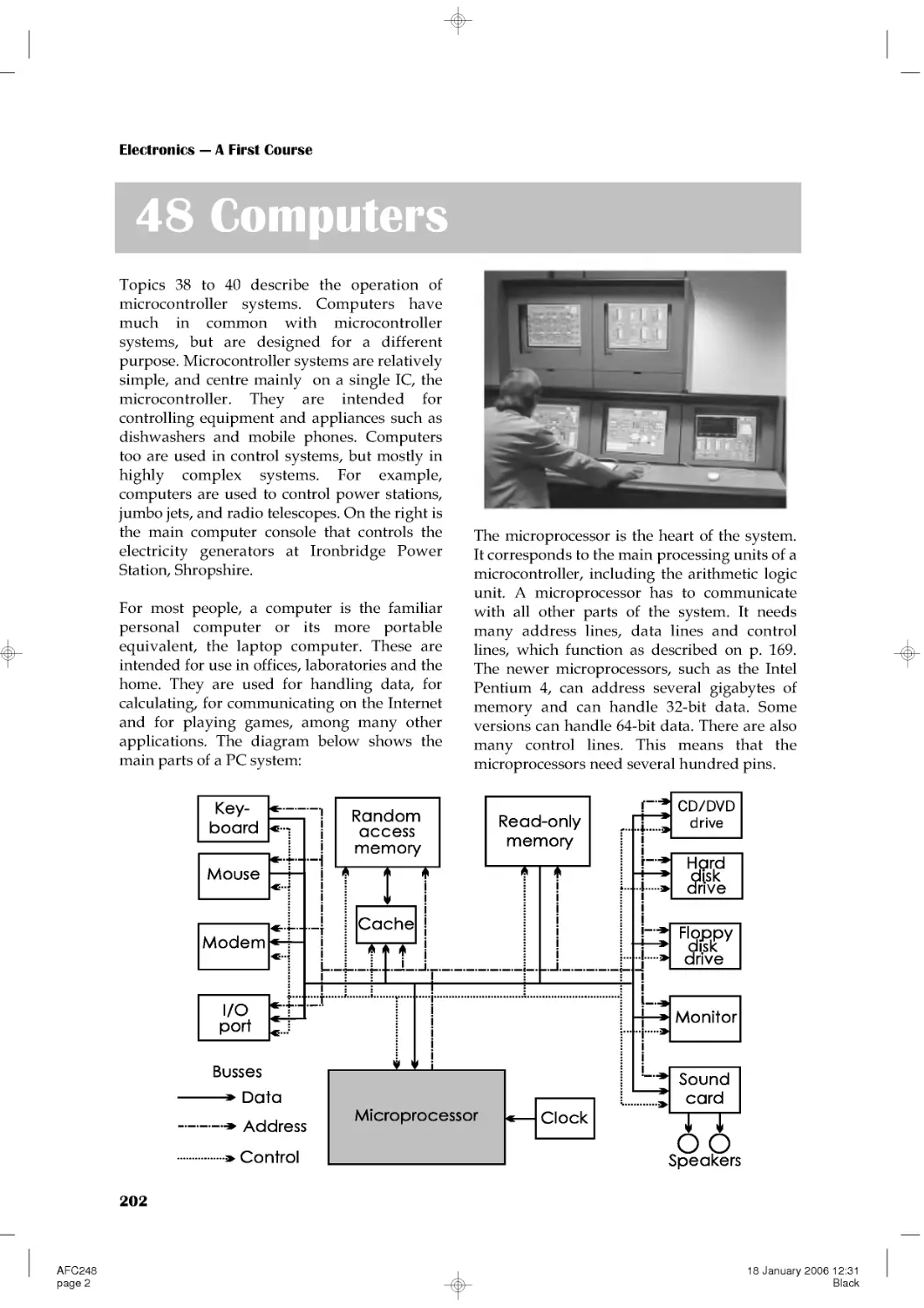
48 Computers
46 Control systems
Extension Box 58 Voltage regulators
Questions on computers and control systems
A Symbols used for circuits
B Symbols used in flowcharts
180
181
182
183
184
185
187
188
188
192
193
194
195
196
199
199
199
200
201
201
202
206
210
210
211
212
212
215
Part 4: Electronic systems in action
ix
Supplements
AFCpreli2
page 9
02 February 2006 15:36
Black
Contents
C Answers to questions
D Acknowledgements
Index
Index by type numbers
215
218
219
223
x
AFCpreli2
page 10
02 February 2006 15:36
Black
Introduction
This is a complete introductory textbook
intended for courses leading to GCSE
Electronics. It also caters for the Electronics
sections of GCSE Design and Technology
(Electronic Products), for the Electricity and
Magnetism sections of GCSE Physics, the
GNVQ unit on Electronics for Engineering,
and the Intermediate GNVQ unit on
Electronics Principles and Applications. It
assumes no previous knowledge of electronics
or of the electronic aspects of physics.
Most of the text is divided into numerous short
Topics, presented as double page spreads.
These cover the topics common to the majority
of the specifications at the level of the
Foundation Tier (FT). The topics are dealt with
thoroughly, with simple explanations and
plenty of examples and illustrations. This
double-page presentation has two advantages.
It allows students to confine their attention to
the particular topics found in a given
specification. It also presents the student with
self-contained, easily assimilable and readily
testable segments of knowledge.
At frequent intervals throughout the text there
are sets of Extension Boxes. These contain the
material that is found only in the Higher Tier,
and also deal with topics that appear in only
one or two of the specifications. Students may
read or omit these boxes according to the
specification and tier for which they are
working.
The book is student-centred and it features:
• Frequent 'Self Test ' questions to allow
students to assess their progress.
• Sets of questions at numerous key stages
in the book, linking together the material
of consecutive Topics. Answers to these
and the Self Test questions are given at the
end of the book, if they are numerical or of
few words.
• An abundance of practical examples, with
numerous circuit diagrams. Detailed
instructions for simple constructional
techniques, and for test procedures appear
xi
in the 'In the Lab' sections.
• An underlying emphasis on electronics
systems.
• 'Design time' pages provide a wealth of
practicable suggestions for circuits and
projects that students can design for
themselves. These are intended to help
students to prepare coursework projects
for the examination, as well as to promote
understanding of electronic theory.
• The book is copiously illustrated with half-
tone and line drawings, the circuit symbols
following the guide set out in the AQA
GCSE Electronics specification. There are
numerous photographs, including close-
ups of electronics components, and
illustrations of constructional techniques.
Introduction to Second Edition
In preparing this Second Edition we have
extended the First Edition to include the basic
requirements in Electronics of the Edexcel
Level 2 BTEC First Certificate and Edexcel
Level 2 BTEC First Diploma in Engineering.
As a result, there are six new chapters and
numerous additions to the text and
illustrations throughout the book. The
additions also cover the more recent
developments in electronics, with extended
material on MOSFETs, thyristors, digital
electronics, data storage and transmission, and
telecommunications.
All the special features of the First Edition are
retained. New to this edition are the 'On the
Web' boxes which invite students to search on
the World Wide Web to acquire up-to-date
information on a range of electronics-related
subjects. Also, in response to a number of
requests from instructors, we have for the first
time included batches of multiple-choice
questions as well as increasing the number of
exam-type questions.
Introduction
AFCpreli2
page 11
02 February 2006 15:36
Black
1
What is electronics?
Most of the book is set out as double-page
spreads. When you open the book at one of
these spreads, the two pages tell you all you
need to know about one electronic topic. As
well as the text and pictures, there may be:
• Things to do that help you to learn more.
• Design tips to help you design and build
your electronic project.
• Self tests to find out how you are getting
on. Answers are at the back of the book.
Most students will need to work on most of the
spreads. These cover all the essential topics for
Electronics exams at Level 2. Your teacher will
tell you which spreads, if any, you can leave
out.
In the Lab and Design Time pages provide
you with advice and ideas for your project.
After every few
spreads, there
is a batch of
questions. The
answers to
these are on our
web site (see
p. 215).
Also after each group of spreads are some
pages that give you more details or cover extra
topics. These are mostly for students taking the
Higher Tier papers in the exam. They also
cover topics that are required by only one or
two of the exam boards. Ask your teacher
which topics to study.
How to use this book
Electronics makes a big
difference to all our lives.
Without electronics, our lives would be less
comfortable, less safe, less interesting and
less fun. Or do you disagree? Talk about it
with other
students.
Electronics is about electrons.
It is about the ways we use electrons to do
useful and interesting things.
The photos on this page show some of the
things that we can do with electrons. Can
you work out what these things are?
AFC201
page 1
16 January 2006 15:56
Black
2
1 Electrons
Put some small pieces of kitchen foil on the
workbench. You can use small pieces of cork,
instead. Rub a plastic pen with a dry woollen
cloth. Rub hard for ten or twenty seconds.
Hold the pen a few millimetres above the
pieces of foil. They jump up and stick to the
pen. Some of them may jump up and down
again several times.
The reason that the pieces jump is that they are
attracted by electrons on the pen. Rubbing the
cloth on the pen has made electrons from the
cloth transfer to the pen. We say that the pen is
charged with electrons. It has an electric
charge.
Some other things can
be charged by rubbing.
Rub a balloon with a
cloth (or against your
clothes). Then place it in
contact with the wall of
the room. It does not fall
down to the floor but
stays where you put it,
on the wall. The electric
charge has produced an
electric force that holds
the balloon against the
wall.
Self test
What do you expect will happen if you try
to bring two charged acetate strips
together?
Things to do
You need two strips of polythene, about 30
cm by 2 cm, and a soft dry cloth. Put the
strips on the workbench and rub them
briskly with the cloth. Pick up the strips by
one end, one in each hand. Hold them
about 50 cm apart. Then slowly move them
together.
Repeat this, using one strip of polythene
and one strip of acetate sheet. What do the
strips do now?
Part 1 Electricity
AFC201
page 2
16 January 2006 15:56
Black
Electricity
3
Electrons
Electrons are too small to see, even with a
powerful microscope.
Electrons are too light to weigh. You need
1 000 000 000 000 000 000 000 000 000 000
electrons to weigh 1 kg (an amazing fact that
you do not need to remember).
Kinds of charge
You have found that:
• Two charged polythene strips repel each
other. They try to stay apart.
• A polythene strip and an acetate strip
attract each other. They try to come
together.
It seems that the charge on acetate is different
from that on polythene, so:
There are two kinds of charge
Two charged polythene strips repel each other,
so:
Like charges repel
Two differently charged strips attract each
other, so:
Unlike charges attract
Positive and negative charge
The two kinds of charge are called positive
charge and negative charge. These names do
not mean that positive charge has something
that negative charge does not have. They just
mean that the charges are of opposite kinds.
Rubbing a polythene strip with a cloth
transfers some of the electrons from the atoms
in the cloth on to the strip. Electrons have
negative charge, so the strip becomes
negatively charged. Also, the atoms of the cloth
have now lost some electrons. This makes the
cloth positively charged.
Rubbing an acetate strip with a cloth does the
opposite. It removes electrons from the strip,
leaving it positively charged. The cloth gains
electrons and becomes negatively charged.
Using energy
Positive and negative charges always attract
each other. They try to come together. When
you rub the cloth on the plastic, you separate
the negative charge from the positive. It takes
energy to pull them apart when they are trying
to come together. This energy comes from the
muscles of your arm.
Self test
Pieces of foil jump up to a charged plastic
pen. Then some of them jump down again.
Why does this happen?
The most important fact about electrons is that
they carry negative electric charge. The charge
on a single electron is extremely small. But, if
you have enough of them (as on the pen or the
charged polythene), you can show the force
that their charge causes. There are lots more
things that we can do with electrons, as you
will find out as you work through the book.
Self test
Why is it impossible to have a pile of
electrons, like that shown in the drawing?
AFC201
page 3
16 January 2006 15:56
Black
Electronics --- A First Course
4
Electrons and atoms
Matter is made up of molecules of many
different kinds. Molecules are made up of one
or more atoms. Atoms are made up of electrons
(negatively charged), protons (positively
charged) and neutrons (uncharged).
The simplest possible atom consists of one
electron and one proton. The proton is at the
centre of the atom and the electron is circling
around it, in orbit.
With one unit of negative charge on the
electron and one unit of opposite but equal
charge on the proton, the atom as a whole is
uncharged.
The electron is circling at high speed around
the proton, like a planet orbiting the Sun. There
must be a force to keep it in orbit. In the case of
a planet the force is gravity, the attraction
between the masses of the Sun and the planet.
In the case of the electron the force is the
electrical attraction between oppositely
charged bodies. The experiments on pages 2-3
demonstrated this.
Other kinds of atom
There are more than a hundred different
elements in nature, including hydrogen,
helium, copper, zinc, iron, mercury and
oxygen, to name only a few.
Each element has its own distinctive structure,
the atoms being made up of fixed numbers of
electrons and protons.
In spite of these differences, all elements have
the same basic plan. There is a central part,
called the nucleus, where most of the mass of
the atom is concentrated. The nucleus is
surrounded by a cloud of circling electrons.
Atoms other than hydrogen have more than
one proton and also some neutrons in the
nucleus.
The protons in the nucleus give the nucleus a
positive charge --- one unit of charge for each
proton. The number of electrons in the cloud
equals the number of protons, so the cloud as a
whole has an equal but negative charge which
balances the charge on the nucleus.
The electrons of an atom are on the outside.
They can be removed by friction, heating and
electric fields. This is how we obtain the supply
of electrons to use in the electronic circuits and
devices described in this book.
Other particles
Some readers may have heard of quarks and
other sub-atomic particles. Detailed studies by
atomic scientists have discovered that atoms
are actually made up of several more sorts of
particle. In electronics, however, the only
particle we need to know about is the electron.
AFC201
page 4
16 January 2006 15:56
Black
Electricity
5
2 Static and current electricity
When two different substances rub together,
electrons are transferred from one substance to
the other. One substance gains electrons and
becomes negatively charged. The other loses
electrons and becomes positively charged.
However, this happens only with certain
substances, such as polythene, acetate, wool,
and rubber. Other substances that can be
charged in this way include glass, ceramics,
nylon, paper, and air. These substances are
known as insulators. The electrons stay fixed
on the surface of the substance and can not
move away. Insulators do not let charge flow
through them. We say the charge is static, a
word meaning 'standing'.
Small particles in a cloud collide together. It
is thought that the larger particles gain
electrons and become negatively charged.
The smaller particles lose electrons and
become positively charged. Movements in the
cloud tend to sort out the particles by size.
The top of the cloud has a positive charge,
and the bottom a negative charge.
A person may become charged when walking
on a carpeted floor. The rubbing of their plastic
soles against the carpet (often nylon) generates
a charge on the person. In very dry climates the
charge on the person may become very large.
They feel a 'tingle', hear a tiny 'tick' or may
even see a spark, when they touch an earthed
metal object, such as a door handle.
Similarly, just sitting working at a desk may
generate charge because of the person's
woollen, nylon or polyester clothes rubbing
together. Electronics engineers have to be
particularly careful to avoid this, as the charge
they pick up on their bodies may destroy
delicate electronic components when they
touch them.
Most lightning flashes are within a cloud,
and some are between a cloud and one of its
neighbours. They do not do any damage,
except possibly to aeroplanes flying through
the cloud.
The most dangerous flashes are between a
cloud and charged areas on the ground.
Lightning
The charges build
u
ps
om
u
c
ht
h
a
t
there is a strong
attraction between
the electrons and the
nearest positive
charges. A lightning
flash occurs as
electrons rush across
the gap. The air
along the flash is
heated so much that
it causes a shock
wave, which we
hear as thunder.
AFC202
page 1
16 January 2006 16:21
Black
Electronics --- A First Course
6
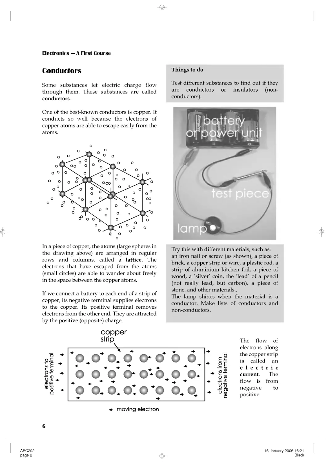
In a piece of copper, the atoms (large spheres in
the drawing above) are arranged in regular
rows and columns, called a lattice. The
electrons that have escaped from the atoms
(small circles) are able to wander about freely
in the space between the copper atoms.
If we connect a battery to each end of a strip of
copper, its negative terminal supplies electrons
to the copper. Its positive terminal removes
electrons from the other end. They are attracted
by the positive (opposite) charge.
The flow of
electrons along
the copper strip
is called an
electric
current. The
flow is from
negative to
positive.
Conductors
Some substances let electric charge flow
through them. These substances are called
conductors.
One of the best-known conductors is copper. It
conducts so well because the electrons of
copper atoms are able to escape easily from the
atoms.
Things to do
Test different substances to find out if they
are conductors or insulators (non-
conductors).
Try this with different materials, such as:
an iron nail or screw (as shown), a piece of
brick, a copper strip or wire, a plastic rod, a
strip of aluminium kitchen foil, a piece of
wood, a 'silver' coin, the 'lead' of a pencil
(not really lead, but carbon), a piece of
stone, and other materials..
The lamp shines when the material is a
conductor. Make lists of conductors and
non-conductors.
AFC202
page 2
16 January 2006 16:21
Black
Electricity
7
Memo
Symbols for elements:
Cl = chlorine
O = oxygen
Cu = copper
S = sulphur
Na = sodium
When a salt such as sodium chloride is
dissolved in water, some of its molecules
separate into two atoms, sodium and
chlorine:
NaCl→Na+Cl
An electron from the sodium becomes
attached to the chlorine. The chlorine
(gaining an electron) is negatively charged.
The sodium (losing an electron) is positively
charged:
NaCl→ Na++Cl---
The charged sodium and chlorine atoms are
called ions.
In the same way, when copper sulphate is
dissolved in water, some of it separates into
copper and sulphate ions:
CuSO4 → Cu++ + SO4------
Wih copper sulphate, the sulphate ion gains
two electrons and becomes negatively
charged. The copper ion loses two electrons
and becomes positively charged.
When the molecules split into two ions, we
say the substance is ionised.
Ions in solutions
Extension Box 1
Gases can be ionised too. A neon striplight
consists of a sealed glass tube containing
neon gas. The neon is under low pressure.
Some of the neon atoms lose an electron and
become positively charged ions:
Ne→Ne++e--
Self Test
Which of these represent ions?
Cl--, CuSO4, Na+, H2O, SO4----, H2, NaCl.
When a current is
passed through the
tube, the electrons
move rapidly along the
tube striking the neon
ions. The ions glow
with a bright red light.
Neon lamps are used for signs and also as
low-power indicator lamps. Other gases, such
as argon and krypton, also ionise and can be
used in lamps. These gases produce a range
of colours for use in illuminated signs.
Ions in gases
Extension Box 2
AFC202
page 3
16 January 2006 16:21
Black
Electronics --- A First Course
8
An electric current is a flow of negative
charge (electrons) from negative to positive.
In electronics, we usually think of the current
as flowing from positive to negative.
Although this is not what actually happens,
most people like to think of it in that way.
This idea of a current flowing from positive to
negative is known as conventional current.
In the rest of this book, when we say 'current'
we mean conventional current, flowing from
positive to negative.
Electric current
Extension Box 3
The best conductors are metals. Copper is the
most commonly used conductor because it
conducts electric charge better than any
metal, except silver. But silver is too
expensive to be used. Copper wires are used
in almost all electronic equipment. The tracks
on a circuit board are also made of copper.
Carbon is a non-metal but it has important
uses as a conductor. It does not conduct
charge as well as the metals do. Rods of
carbon are used for making certain kinds of
electric cell. Carbon is also used in making
resistors (p. 36).
Solutions of salts in water are reasonably
good conductors (see Ions in solutions, p. 7).
Much of the human body consists of such
solutions, so the body is a reasonable
conductor of electricity. This is why we must
be very careful when handling electrical
equipment and working with electricity in
the laboratory. Even quite a small current
through a part of the body can paralyse the
nerves and may kill you. Electricity can also
cause unpleasant burns.
The next best conductor is aluminium. This is
often used in power lines, because of its
lightness and cheapness. It is not as strong as
copper, so a few strands of steel wire are
included when making the cable.
Elecctrons are negative charge carriers.
When current flows through a gas (p. 7) or
through a solution (see opposite) there may
be positive charge carriers as well. These are
the positive ions such as neon (Ne+), sodium
(Na+) and copper (Cu++).
The electrons carry negative charge from
negative to positive. At the same time, the
positive ions carry positive charge from
positive to negative. There is a two-way
conduction of charge.
Self test
List these substances in order, from the
best conductor to the worst:
aluminium, rubber, copper, carbon, gold,
silver.
Conductors
Extension Box 4
AFC202
page 4
16 January 2006 16:21
Black
Electricity
9
Sometimes a charge builds up on an object
faster than it can leak away or can be
conducted away. The charge may eventually
become so great that it breaks through the air
as a spark. Lightning is the most powerful
example of this.
An aeroplane picks up static charge as it flies
through the air. On landing, the plane does
not remain charged, because its tyres are
made from special conductive rubber. If it
were not for these, there would be a danger
of fire or explosion resulting from
electrostatic sparks while refuelling.
A solution of substances that ionise is called
an electrolyte. If we place two conducting
rods (or electrodes) in an electrolyte and
connect a battery or power unit to them,
conventional current flows through the
solution from positive to negative.
Copper ions (positive) are attracted toward
the negative electrode (cathode). On arrival,
they gain two electrons each and are
discharged. The electrons have come from the
negative terminal of the battery. The
discharged ions are deposited on the cathode
as metallic copper. This process is called
electrolysis.
Sulphate ions (negative) are attracted toward
the positive electrode (anode). There they are
discharged, giving up two electrons, which
flow to the battery.
Conduction through solutions
Extension Box 6
Self test
In what three ways may a charged object
lose its charge?
It can be shown by weighing that the amount
of copper deposited on the cathode is
proportional to the size of the current and to
the length of time for which the current
passes. This shows that copper ions carry a
fixed amount of charge.
A charged plastic pen or balloon may hold its
charge for an hour or more. The charge is on
an insulating substance that stops it from
flowing away. But the charge can be removed
by contact with the air. The air often contains
charged ions. A positively charged ion in the
air is attracted toward an electron on a
charged object. When it contacts it, the
electron transfers to the ion and their charges
cancel out. Gradually, all the electrons on the
surface of the charged object are removed in
this way. The object becomes discharged.
Charged conductors lose their charge quickly
if they are connected to ground by a wire.
Electronics engineers often wear metallised
wrist bands, connected by wire to ground.
This allows any charge on the body of the
engineer to be conducted away to ground,
and so prevents static charges from
damaging the electronic components.
Discharging static electricity
Extension Box 5
AFC202
page 5
16 January 2006 16:21
Black
Electronics --- A First Course
10
To make a photocopy, place the
original document face-down on the
glass and close the cover. Press the
START button. The photocopy is
made in six stages:
1 A high voltage is applied to the
corona wire 1. Positive ions from the
corona wire are attracted toward the
drum. The drum is a cylinder of
aluminium, coated with a special
light-sensitive layer.
2 A bright light shines on the
original document and a system of
lenses focuses an image of the
document on to the drum.
3 The light in the brighter parts of
the image causes electrons to appear
on the light-sensitive layer. These
discharge the positive ions already
there. There is less effect in the
darker parts of the image. There is
now an image on the drum, in which
the darkest parts still have positive
ions. The lightest parts have none.
4 A black powder (toner) is scattered
o
ntothedr
u
m.Itisn
egatively
charged, so it is attracted toward the
positive ions. It forms an image on
the drum, black where the original
was black.
5 A sheet of paper is fed past the drum as it
turns. Before reaching the drum, the paper is
positively charged by another corona wire.
The charge on the passing paper strongly
attracts the powder, which is still negatively
charged.
`The attraction to the paper is
stronger than the attraction to the drum, so
the powder is transferred to the paper. Next
the paper passes between two hot pressure
rollers. These melt the powder which then
sticks firmly to the paper. This produces an
image on the paper which is an exact copy of
the original image.
Many copiers have a lens system that projects
an image larger or smaller than the original.
Then the photocopy is identical to the
original except for its size.
There is not enough room on the drum to
copy a whole sheet at once. The drum turns
several times to copy one sheet, a little at a
time. The drum is automatically cleaned and
discharged after the part-image has been
transferred to the paper. Then it is re-charged
(stage 1) ready to receive the next part of the
image.
Photocopying
Extension Box 7
AFC202
page 6
16 January 2006 16:21
Black
Electricity
11
3 Cells and batteries
Cells
Cells are the most compact sources of electric
power. They produce electricity as a result of
chemical actions inside the cell. When the cell
is made, it is packed with chemical compounds
that are ready to react together. As current is
drawn from the cell the chemical reaction
occurs. Current can be obtained from the cell
until the chemicals have completed their
reaction and no more of the original
compounds are left.
There are several different types, based on the
chemical reactions that drive them :
Type of cell
Features
Examples of uses
Zinc-carbon
Cheapest type. Produces 1.5 V. The
voltage falls slowly during the life
of the cell.
May leak when old and damage the
equipment by corroding its metal
parts.
Electric torches, handlamps,
doorbells, security alarms.
Alkaline
Holds 3 times more charge than a
zinc-carbon cell of the same size,
but is more expensive.
Produces 1.5 V.
Can supply a larger current than a
zinc-carbon cell.
Voltage steady during life of cell;
falls sharply at the end (keep a
spare handy).
Does not leak.
Electronic equipment such as clocks,
remote controllers, electronic toys.
Also used for the same purposes as
zinc-carbon cells and gives superior
performance.
Zinc-chloride
Heavy duty cell in standard sizes.
Produces 1.5 V. Holds more charge
than zinc-carbon cells and is
cheaper.
As for zinc-carbon cells.
Zinc-carbon, alkaline,
zinc-chloride
and
lithium cells are made in
a number of different
standard sizes.
The alkaline cell on the
right is the AAA size,
which is one of the
smallest.
The photograph shows
the AAA cell about 1.4
times its real size. It
produces an electrical
force of 1.5 volts (1.5 V,
see next topic).
Table continued overleaf.
AFC203
page 1
21 October 2005 09:43
Black
Electronics --- A First Course
12
Type of cell
Features
Examples of uses
Silver oxide
Made as disc-shaped 'button' cells.
Output = 1.4 V.
Delivers a small current for a long
time.
Digital watches, small pocket
calculators.
Lithium
Made in standard sizes and as
'button' cells. Output = 1.5 V.
Produces a small current for a long
time (several years) but can
produce a large current for a short
time.
Memory backup in computers. Pocket
calculators, digital cameras, mobile
phones. Also used for the same
purposes as zinc-carbon cells.
Rechargeable cells
For a continuous power supply, or occasional large bursts of current, we use rechargeable cells.
When the cell is exhausted, we connect it to a charger, powered from the mains supply. It restores
the chemicals in the cell to their original state.
Rechargeable cells include:
Type of cell
Features
Examples of uses
Nickel-cadmium (NiCad) Stores less charge than zinc-carbon
cells of the same size. Produces 1.2 V.
Voltage falls rapidly when nearly
discharged. Can deliver high current.
Shows the 'memory effect'; it
'remembers' the level to which it has
been discharged. After being
recharged, it ceases to deliver current
when is reaches the remembered
level. This reduces its current
capacity.
High-current portable
equipment such as video
cameras, digital cameras,
mobile phones.
Nickel metal hydride
(NiMH)
Stores about double the charge of a
NiCad cell of the same size, but is a
little more expensive. Delivers 1.2 V.
No memory effect.
As for NiCad cells. Also for
electrically powered vehicles.
Lead-acid (Accumulator) Produces 2 V. Can deliver very high
current. Not portable; lead electrodes
make the cell heavy. Danger of
spilling acid electrolyte.
Car starter motors.
Types of cell (continued):
AFC203
page 2
21 October 2005 09:43
Black
Electricity
13
Danger!
NiCad, NiMH, and lead-acid batteries can
produce very large currents. They can give
a dangerous electric shock. A 12 V lead-acid
car battery is capable of providing a bigger
current than a 12 V battery made up from
zinc-carbon cells. Take care when working
with NiCad, NiMH and lead-acid batteries.
Batteries
A battery is a number of cells connected
together. They are usually connected so that
the battery produces an increased output
voltage.
A battery can be built up from separate cells in
a battery box (right). The plastic boxes have
contacts and wires to join the cells together.
The box (a) in the photograph has four NiMH
size AA cells. Each produces 1.2 V, so the total
voltage of the battery is 4.8 V.
Boxes (b) and (c) also hold four AA cells, but
differently arranged.
Self Test
1 A lead-acid car battery produces 6 V. How
many cells does it contain?
2 A torch battery is made up of 3 alkaline
cells. What voltage does it produce?
3 What type of cell or battery would you
select for powering (a) a mini-computer
game, (b) a hearing aid (c) a flying model
aeroplane, and (d) a petrol lawn-mower
motor?
For example, the
popular
PP3
battery produces
9V. It is made up
from six cells, each
delivering 1.5 V. It
is used in clocks,
test meters, and in
other low-current
equipment.
This compact battery of 8
alkaline cells is only 28 mm
long. It produces a 12 V
supply. Small batteries such
as this are used where we
need a high voltage in a small
space.
Examples of this include
photographic equipment and
key-fob remote controllers.
Battery chargers
These are mains-powered and include a
transformer to produce low-voltage direct
current suitable for charging.
The inexpensive charger in the photo plugs
directly into a mains socket. It holds four size
AA rechargeable cells. More expensive
chargers are able to hold cells of several
different sizes.
AFC203
page 3
21 October 2005 09:43
Black
Electronics --- A First Course
14
4 Current, voltage and power
Current
The unit of electric current is the ampere. Its
symbol is A. Few people use the word
'ampere'. They use 'amp' instead. A typical
mains electric lamp needs about one-third of
an amp to make it glow brightly. A two-bar
room heater needs about 8 amps.
Smaller amounts of current are measured in
milliamps. A milliamp, symbol mA, is one
thousandth of an amp. A torch bulb uses
60 mA or less.
An even smaller unit of current is the
microamp, symbol μA. A microamp is one
thousandth of a milliamp, or one millionth of
an amp. Electronic clocks and watches take
only a few microamps. A single AAA cell
(p. 11) can power a digital clock for many
months.
Voltage
Voltage is the electric force that drives current
around an electric circuit. The unit of voltage is
the volt, symbol V. Most cells produce a
voltage of about 1.5 V. The voltage of the mains
supply is 230 V.
At a power station, the voltage is higher and is
measured in kilovolts, symbol kV. A kilovolt
is equal to one thousand volts. On high-power
transmission lines the voltage may be as high
as 400 kV.
Small voltages are measured in millivolts,
symbol mV. A millivolt is one-thousandth of a
volt. Voltages that are smaller still are
expressed in microvolts, symbol μV. A
microvolt is one-thousandth of a millivolt or
one-millionth of a volt. Electrical signals from a
microphone and other sensors are generally
measured in millivolts or microvolts.
Current flows round a circuit. It flows out of
the positive terminal of the battery, through the
lamp and back into the battery through the
negative terminal. The same amount of current
flows in all parts of the circuit.
Current is driven round the circuit by the
electric force (the voltage) between the positive
and negative terminals of the battery.
AFC204
page 2
21 October 2005 15:39
Black
Electricity
15
Summing up
Electrical
quantity
Units of
measurement Symbols
Current
amp (ampere)
milliamp
microamp
A
mA
μA
Voltage
kilovolt
volt
millivolt
microvolt
kV
V
mV
μV
Power
megawatt
kilowatt
watt
milliwatt
MW
kW
W
mW
The basic units are in heavy type. The multiple
and submultiple units that are listed are the
ones most often used in electronics.
Self test
1 A projection lamp runs on a 36 V supply
and takes 11 A. What is its power?
2 An electric hair-clipper runs on 230 V, and
is rated at 10 W. How much current does it
take?
3 A torch uses two alkaline cells and the
current through the lamp is 60 mA. What is
the power of the torch?
4 A 25 W soldering iron runs on 50 V. How
much current does it use?
5Express(a)34AinmA,(b)1.2mAinμA,
(c)1.2mAinA,(d)5505mAinA, and(e)
58μAinmA.
6Express(a)4.5VinmV,(b)11kVinV,(c)
675mVinV,(d)521μVinmV,(e)0.55Vin
mV,(f)440μVinV,(g)0.22mVinV,and
(h) 3300 V in kV.
7Express(a)675WinkW,(b)25MWin
kW,(c)650mWinW,(d)6MWinW,(e)
4450kWinMW,(f)2.55Win mW,(g)
79kWinW, and(h)33MWinkW.
Power
Electric power expresses the rate at which an
electrical device is converting energy from one
form into another. For example a room heater
converts electrical energy into heat energy. The
rate at which it does this is its power, expressed
in watts. The symbol for watt is W.
An average electric lamp runs at 75 W. A
typical two-bar heater is rated at 2000 W, or
2 kilowatts. The power of an electrical power
station (converting energy from coal into
electrical energy) is measured in megawatts.
It can be shown that the power of a device is
proportional to the amount of current flowing
through it. It is also proportional to the voltage
that is driving the current. The bigger the
current and the bigger the driving force, the
bigger the power. Writing this as an equation:
power = current × voltage
• power is expressed in watts
• current is in amps
• voltage is in volts
Example 1
An electric steam iron runs on the 230 V mains
and the current through it is 5.65 A. What is its
power?
power = 230 × 5.65 = 1299.5 W
This result is close to 1300 W, or 1.3 kW.
Example 2
A 100 W lamp is running on the mains at
230 V. What current is passing through it?
Rearranging the power equation above gives:
current = power/voltage
Using this version of the equation:
current = 100/230 = 0.435 A
Current is 0.435 A, or 435 mA.
AFC204
page 3
21 October 2005 15:39
Black
Electronics --- A First Course
16
Measuring current and voltage
A multimeter measures several different
electrical quantities, usually including voltage
and current. There are two kinds of
multimeter, analogue (left below) and digital
(right).
Both meters have sockets for probes:
• Positive, marked '+' and usually red.
• Common (negative), marked COM or '--'
and usually black.
Some meters have a second positive socket
which must be used for high voltages.
With an analogue meter, you must touch the
black (common) probe to the more negative
point and red to the more positive. If you touch
them the wrong way round, the needle swings
below zero. Remove the probes from the test
points immediately or you may damage the
meter. Digital meters often have autopolarity.
These work with the probes touching either
way and display a minus sign to the left of the
reading, if necessary.
With an analogue meter, there is the problem
that the reading is wrong if you do not look
straight down at the scale. This is called a
parallax error. To help you avoid this, the
meter has an arc of mirror on the scale. You can
see the needle reflected in this. When you take
a reading, move your head from side to side,
until you have lined up the reflection of the
needle exactly behind the needle. This makes
sure that you are looking straight down on the
scale and the reading will be correct.
Both kinds of meter have a knob for selecting
which quantity to measure. It often selects the
range too. On the right, the knob is selecting
the0Vto10Vrange.
Digital meters (such as that in the photo) may
be autoranging. They select the correct range
automatically when a measurement is made.
AFC204ITL
page 2
16 January 2006 16:27
Black
Electricity
17
Placing the probes
When you measure current, the meter is part
of the circuit. The current flows through the
meter. So, break the circuit at one point and
connect the meter across the break.
When you measure voltage, you are
measuring the difference of electrical force at
two points in the circuit. Do not break the
circuit. Touch the probes to the two points to
measure the difference.
Things to do
Set up circuits like those in the photos, but
using cells or batteries of different voltages.
You could also use some old batteries that
have lost most of their charge. Use various
lamps or, instead of the lamp, connect in a
small electric motor, an electric bell or a
buzzer.
For each circuit:
1 Make a simple drawing of the circuit.
2 Measure the current, and write the result
on your drawing.
3 Measure the voltage across the lamp or
other device, and write the result on your
drawing.
Use your readings of current and voltage to
calculate the power of the lamp or device.
Test routine
1 Before you connect the meter to the circuit,
set the selector knob to the range you want
to use. If the meter has autoranging, you
need only select the quantity (current or
voltage). If you are not certain which range
to choose, select the highest range (for
example, 0 V to 1000 V). Then, if the meter
shows only a very small reading, you can
work down through the ranges to one that
gives a readable result.
2 Connect the meter to the circuit, or just
touch the probes to two points (remember
about polarity -- black to negative, red to
positive).
3 Take the reading (remember to avoid
parallax), and write it down.
4 If you need to change the range, disconnect
the meter from the circuit first.
5 Disconnect the meter from the circuit when
you have taken the reading.
6 Turn the selection knob to the OFF position.
AFC204ITL
page 3
16 January 2006 16:27
Black
Electronics --- A First Course
18
5 Alternating currents
The voltage at the positive terminal of a battery
stays constant until the the cell is exhausted. If
we plot a graph of the voltage during a period
of time, the graph for a fresh battery is like this:
The graph is a horizontal straight line. It shows
that the voltage of the battery is constant at 6 V.
If we connect the battery to a lamp, we can use
a multimeter to measure the current flowing
through it. Because the voltage is constant, the
current that it drives is constant too. The graph
of current against time is a straight horizontal
line, like the graph above. Constant current like
this is called direct current. This name is often
shortened to DC.
DC always flows in the same direction, from
positive to negative.
Memo
As usual, we are thinking of current as
conventional current (p. 8).
The current that we get from some kinds of
generator (including mains generators) is
different from this. It repeatedly changes its
direction.
This kind of current is called alternating
current. This name is often shortened to AC.
Alternating voltage
The voltage at one terminal of a typical AC
generator is shown in this graph:
At one instant, the terminal is 1 V positive of
the other. Then the voltage decreases until it is
1 V negative of the other terminal. Then it
swings back again to become 1 V positive. This
cycle is repeated indefinitely. The effect of this
reversing voltage on the current in a circuit is
shown below:
As the voltages at the terminals swing from
positive to negative and back, the current
repeatedly changes its direction. It is
alternating current.
AFC205
page 2
16 January 2006 16:32
Black
Electricity
19
Self test
1 The frequency of the mains is 50 Hz. What
is its period?
2 A musical note has a period of 3.9 ms.
What is its frequency?
3 Describe this waveform:
4 The 'bleep' of a microwave oven has a
frequency of 1000 Hz. What is its period?
Describing an alternating
current
A direct current is simple to describe. We just
quote its size, in amps. To describe an
alternating current we need to state three
things:
• Amplitude: its maximum size, in amps.
• Period: the time for one complete cycle
from positive back to positive again.
• Waveform: the shape of its graph.
The AC plotted above has an amplitude A =
1V.IthasaperiodP=1s.
If we plot a graph of the sine of an angle from
0º to 360º, it has exactly the same shape as one
cycle of the AC graph. The AC has a sinewave
shape. Not all AC has this shape, but this is the
commonest. The mains AC and any AC from
mains transformers are sinewaves.
Frequency
The unit of frequency is the hertz. Its symbol is
Hz. The hertz is defined as a frequency of one
cycle per second. The AC waveform shown in
the graph has a frequency of 1 cycle per
second, or 1 Hz.
If the period of a waveform is P seconds, there
are 1/P cycles in one second. Its frequency is
1/P Hz: frequency = 1/period
Things to do
1 Look at a demonstration of the shape of
AC waveforms, using an oscilloscope. View
the mains AC or the AC from mains
transformers. Look at sinewaves of other
frequencies and amplitudes from a signal
generator.
2 Listen to a demonstration of the sound of
sinewaves of various frequencies. This is
best demonstrated by connecting an audio
amplifier to the output of a signal generator.
If possible, view and hear the signals at the
same time.
3 Using the same equipment as for item 2
above, try to find out which is the lowest
frequency that you can hear. Try to find out
which is the highest frequency you can
hear.
4 Using a microphone and audio amplifier
connected to an oscilloscope, look at the
shapes of sound waves produced by
various musical instruments. Try to
measure the frequency of notes on the
musical scale.
AFC205
page 3
16 January 2006 16:32
Black
Electronics --- A First Course
20
6 Mains electricity
Mains supply
The electricity supply to a building has three
wires:
Mains electricity is produced in power stations
like the one illustrated in the photo below.
This is one of the two generators at Ironbridge
Power Station in Shropshire. Here the
generators are driven by turbines. The turbines
are turned by steam under pressure. The steam
is produced in a coal-fired boiler. The rate of
production of electrical energy from the
chemical energy in coal is over 200 MW.
In other power stations, the steam may be
produced in an oil-fired boiler, or by using
heat from a nuclear reactor. In a hydro-electric
power station, the turbines are turned directly
by the flow of water. Wind is another source of
energy for electricity generation. In a few parts
of the World, such as the thermal areas of
New Zealand, steam for turbines is generated
using energy from the hot rocks just below the
Earth's surface.
There is more on sources of power in Topic 9.
In the United Kingdom and many other
countries, the mains supply to the consumer is
close to 230 V. The current is alternating.
• Live
• Neutral
• Earth
The earth wire is connected to the earth.
Normally, no current flows in this wire. It is
there to provide a path to earth when there is a
fault. We explain this later.
To help make sure that wiring is correctly
installed, the three wires are colour coded:
• Live is brown.
• Neutral is blue.
• Earth is striped green and yellow.
Cables
The conductors in mains cable (as in most
electrical cables) are made of copper. This is
because copper is one of the best conductors.
The copper is in the form of several copper
strands twisted together. This makes the cable
flexible. It can be bent into the right shapes for
running it around the building. Cable used for
connecting appliances needs to be even more
flexible.
The live wire supplies the current.
On this wire, the voltage alternates
positive and negative of the neutral
wire.
The neutral wire returns the current
to the power station after it has
passed through all the appliances in
the building. The voltage on this
wire is close to earth voltage, which
wetaketobe0V.
AFC206
page 2
16 January 2006 17:12
Black
Electricity
21
The photo shows how a 3-core mains cable is
made up. It has three cores of twisted copper
strands for live, neutral, and earth. Each core
is surrounded by a layer of plastic to insulate it
from the other cores.
The three insulated cores are surrounded by an
outer plastic layer to hold them together and to
give more insulation between the cores and
anything that the cable is in contact with.
Switches
Most appliances have a switch for turning
them on or off. The switch must always be
wired into the live wire of the supply to the
appliance. In the top diagram (right), the
switch is open. No current can flow through
the appliance, so it is off. It is still connected to
the neutral line of the mains, but this line is
close to earth voltage. If there is a fault in the
appliance, there is little danger.
In the middle drawing, the switch is closed
and the appliance is on. Current flows through
the appliance between the live and neutral
lines. There is little danger.
In the bottom drawing, the switch is open and
the appliance is off. But it is still connected to the
live wire. Should there be a fault, the appliance
is still live and this is dangerous.
Self test
1 Why is the core of a cable made from
copper?
2 What is the reason for making the core
from thin strands twisted together?
3 What are the names of the three wires in
an electrical supply? What does each do?
4 Why are the cores of a cable covered with
plastic?
5 Why is it important for the plastic to be
flexible?
The switching drawing shows the earth wire
not connected to anything. Connections for the
earth wire are described in the next topic.
AFC206
page 3
16 January 2006 17:12
Black
Electronics --- A First Course
22
7 Plugs and fuses
Plugs and sockets
Electrical appliances such as electric cookers
and immersion heaters need a heavy current.
They are usually connected through a switch
directly to the mains supply. The supply to
ceiling lamps and other fixed appliances is also
permanently wired to the mains. A qualified
electrician does this.
A moveable appliance is usually plugged in to
a socket on the wall. The plug has three pins,
live, neutral, and earth. The pins are made of
brass. This is a good conductor. It is not quite
such a good conductor as copper, but it is
stiffer and more hard-wearing. The earth pin is
longer than the other two so that it makes
contact first when the plug is pushed into the
socket. It breaks contact last when the plug is
pulled out. This makes sure that the appliance
is earthed all the time it is connected to the
mains.
The body of the plug is made of plastic or hard
rubber, which are good insulators.
Wiring a mains plug
The photograph shows a mains plug with the
top removed.
The steps for wiring the plug are:
1 Unscrew the fixing bolt and remove the
top from the plug.
2 Look at the instructions supplied with
the plug to find out how much of the
outer insulation to remove. Use a wire-
stripper to remove it.
3 Check whether any of the three wires
need to be shortened. If so, cut it shorter.
4 Look at the instructions to find out how
much insulation to remove from each
wire. Use a wire-stripper to remove it.
5 Twist the bare copper strands with your
fingers to make them stay together.
6 Usually it is best to thread the cable
through the cable grip at this stage.
AFC207
page 2
16 January 2006 17:15
Black
Electricity
23
Fuses
Fuses are used to protect equipment and
people against electrical faults. A fuse contains
a thin wire made of a special alloy that melts at
a fairly low temperature. If the current through
the fuse is too high, heat is produced faster
than it can be lost from the fuse. The fuse wire
gets so hot that it melts and breaks the circuit.
This disconnects the supply.
7 Loosen the terminal screws on each pin.
Wrap the bare cores around each screw
and tighten each screw.
8 Make sure that the wires run neatly
inside their channels.
9 Check that there are no loose strands of
copper.
10 Knowing the maximum current that the
appliance will require, select a fuse of
slightly greater rating. Press it into the
fuse clips.
11 Check again that the three wires are
connected to the correct pins.
12 Replace the top and tighten its retaining
screw. If the cord grip has screws,
tighten these too.
Danger from electricity
• Touching live metal parts may cause burns
or, in serious cases, loss of life. Often, the
breathing muscles are paralysed. First aid:
turn off the power; then apply artificial
respiration.
• A current too heavy for the cable will make
the cable hot. This may cause heat damage
to the cable and the appliance. It may also
lead to fire.
• Sparks, either from static charge (p. 5) or
from switches and other devices may ignite
inflammable vapours or dusts in the air.
This may result in fire or explosion.
Circuit breakers
Some kinds of circuit breaker are used instead
of fuses to protect a faulty appliance from
drawing too much current. A thermal circuit
breaker becomes overheated by excess current
passing through it. This triggers the breaker
switch to open.
A residual current circuit breaker (RCCB) has
a different action. It switches off the mains
supply to an appliance when it detects a
leakage of current to earth or to another circuit.
For example, an exposed metal part of an
appliance (such as its case, or a control knob)
may become 'live' because of faulty insulation.
A person touching that part conducts current
to earth and receives a shock. The RCCB
measures the current flowing along the live
wire and that flowing along the neutral wire.
Because some of the current is leaking away
(through the person) the live and neutral
currents are unequal. The RCCB detects this
state and switches off the supply. A typical
RCCB detects a current leak as small as 30 mA,
and switches off within 20 ms. This greatly
reduces the chances of serious electric shock.
RCCBs do not switch off if the leakage is direct
from live to neutral. This is because the
currents are equal. A person accidentally
touching both live and neutral wires or
terminals at the same time receives a shock.
Fuses are rated to blow if the current exceeds a
stated amount. Mains fuses such as the one in
the plug (opposite) are made in 3 A, 5 A and
13 A ratings. Always select the rating
according to the device being protected. Use
13 A fuses only with high-current appliances
such as room heaters and vacuum cleaners.
Self test
Fuses are always placed on the live side of
an appliance. Why?
(Hint: see drawing on p. 21)
AFC207
page 3
16 January 2006 17:15
Black
Electronics --- A First Course
24
8 Electricity in the home
In this Topic, the word 'home' includes the
house you live in, the garden, the garage and
(if you have one) the workshop and swimming
pool. In all of these you may have appliances
that run on electricity. Some use mains power,
others use batteries. These appliances convert
electrical energy into other forms of energy.
Example
An immersion heater converts electrical
energy into heat energy.
We use these other forms of energy for doing
useful work in the home.
Things to do
Make a list of the electrical appliances in
your home. For each one, state into what
form of energy it converts electrical energy.
Self test
1 Most appliances produce light, heat or
motion. What other form of energy do some
appliances produce?
2 Some appliances convert electrical energy
into two or more forms. Name three
appliances which do this. Which of the
forms are useful? Which are wasteful?
Power
The rate at which an appliance converts energy
is its power. Power is expressed in watts (W).
One thousand watts is 1 kilowatt (kW)
Example
A typical electric kettle runs at 2 kW.
Things to do
Go through your list of appliances and find
out how many watts each one takes. This
information is often marked on a small
panel on the back or underside of the
appliance. Or you may find it in the
manual. Do not forget to include some
battery-powered appliances in your list.
Examples are an electric torch and a digital
clock.
Amounts of energy
The amount of energy converted by an
appliance depends on:
• Its power rating.
• The length of time it runs.
The higher the power, the more energy it
converts in a given time. The longer the time,
the more energy it converts for a given
wattage. Putting this as a formula:
energy converted = power × time
For mains-powered electrical appliances, it is
more practical to rate the power in kilowatts
and the time in hours. The unit of electrical
energy is the kilowatt-hour, symbol kWh.
Example
An immersion heater, power 8 kW, takes 3
hours to heat the water in the tank. How much
energy does it convert while doing this?
Energy converted = power × time
=8×3
=24kWh
AFC208
page 2
21 October 2005 10:38
Black
Electricity
25
Things to do
Select three appliances from your list. You
already know their power.
Find out the average times they take to
perform a task.
Examples
How long does the kettle take to boil
enough water for a pot of tea? How long
does a vacuum-cleaner take to clean a
room? How long does the oven take to cook
a joint of meat?
Calculate how much energy they convert
while doing these tasks.
Paying for electric power
The amount of electricty used in a home is
measured with an electricity meter, connected
in to the mains supply line. This reads the
amount in kilowatt-hours. The electricity bill
charges for this amount of energy at a fixed
cost per kilowatt-hour. On the bill, the
kilowatt-hour is sometimes referred to as a
'Unit'.
The cost is worked out on the bill using the
formula:
cost = number of units × cost per unit
Example
A security floodlight runs at 500 W. It is
switched on every night for 10 hours. Electric
power is charged at 7.6 p per kWh. How much
does it cost to run the lamp each night?
In kilowatts, the rating of the 500 W lamp is 0.5
kW. Use this value in the formula.
Energy converted = 0.5 × 10 = 5 kWh
Cost=5×7.6=38p
Things to do
Find out the cost of a kilowatt-hour of
electricity from your local supplier.
You have calculated how much energy is
used by your three chosen appliances to
perform a typical task. Use this information
to calculate how much it costs to do this.
Have a discussion in class about ways of
saving electric power in the home.
Self test
1 A 1000 W microwave oven cooks a bowl
of porridge in 4 minutes. If electricity costs
8.31 p per kWh, what is the cost of cooking
the porridge?
2 The 2 kW heater of a fan-heater is found
to be switched on for 20% of the time. The
fan, runs all the time and takes 10 W. At
7.9 p per kWh, what is the daily cost of
running the fan-heater for an 8-hour day?
AFC208
page 3
21 October 2005 10:38
Black
Electronics --- A First Course
26
9 Sources of energy
In this Topic and the next we look at and
compare the many sources of energy that we
use to generate electrical energy.
Fossil fuels
These are the remains of plants and animals
that existed on Earth many millions of years
ago. When the plants were living, the energy of
sunlight was stored in their tissues. At the
same time, animals fed on some of the plants.
The energy from these plants became stored in
the tissues of the animals.
Since that time, the remains of some of the
plants and animals have been subject to
chemical changes and to various combinations
of temperature and pressure beneath the
Earth's surface. Given the right conditions,
they have gradually been turned into coal, oil
or gas. Because they originate from fossils and
release energy when burned, they are known
as fossil fuels.
The main problem with fossil fuels is that their
supply is limited and will eventually run out.
Coal: This is a soft rock consisting mainly of
fossilised plant matter. It is mined in many
parts of the World. A coal-fired power station
was described in Topic 6. The diagram above
shows its main features. The fuel is coal that
has been ground into a fine dust. To reduce
production costs, it may sometimes have a
small amount of other combustible material
added to it, such as waste sawdust.
Gas: Occurs naturally deep beneath the surface
rocks in several parts of the World. It is the
result of the breakdown of the plant and
animal tissues. An example is North Sea gas.
This is piped to the surface and distributed in
the gas mains. Gas can also be generated from
coal. Some of the gas is used directly for
heating and other purposes but it is also used
to generate electricity. Power stations using
gas are similar to those described in Topic 6. In
2003, gas was used for generating 38% of the
power supply in Britain.
Oil: This comes from the breakdown of fossil
plants and animals. It occurs deep beneath the
surface in several parts of the World. It is
sometimes used for heating and lighting and is
widely used for motor vehicles, ships and
aeroplanes. It is rarely used in Britain for
electric energy generation.
Energy can not be created.
It can only be converted
from one form into
another form. Therefore,
electrical energy must be
obtained from other forms
of energy.
In Topic 3, Cells and
Batteries, we learned that
chemical energy can be
converted into electrical
energy. In Topic 6, Mains
Electricity, we learned
how the energy stored in
coal is converted into
electrical energy.
Electricity
27
Nuclear energy
The main source of nulear energy is uranium.
This exists as a mixture of uranium atoms of a
few distinct kinds, one of which (U-235) is
radioactive. At any instant, some of the U-235
atoms break up. They change into plutonium
atoms, with the release of energy as heat.
The uranium is held in the central core of the
reactor and the heat is carried away by hot
water, either as steam or as very hot liquid
water under high pressure (see heat transfer
loop 1 in the diagram below). Some reactors
carry away the heat as hot carbon doxide gas
or molten sodium or potassium metal. From
then on, the heat is used to generate steam in a
boiler (heat transfer loop 2) and to drive a
turbine and generator, as in fossil fuel power
stations.
The control rods are lowered or raised to
control the rate of breakdown of uranium, and
so regulate the amount of heat.
The plutonium produced from the uranium
may itslf be used as a nuclear fuel.
In 2003, nuclear power stations were used for
generating 22% of the power supply in Britain.
Wind power
Wind power
generators are
sited in open,
windy areas.
The generators
are mounted on
pylons and each
has a large fan,
like an aeroplane
propellor. The
mounting of the
generator turns
to direct the fan
in the direction
of the prevailing
wind.
The areas where several generators are
clustered are known as a 'wind farms'. The
photo shows a wind farm at Albany in Western
Australia.
Wave power generators
Usually these are sited in wide estuaries or on
the coast. They use the energy in the waves or
in the action of rising and falling tides.
Things to do: See the 'On the Web' panel in Topic 10, p. 29.
Electronics --- A First Course
28
10 More sources of energy
Hydroelectricity
In hilly areas with high rainfall, the water of a
stream or small river runs through a water
turbine (or water wheel) to turn an electricity
generator.
Usually a dam is built across the stream to hold
back the water. It provides a reservoir of water
so that water stored there in the rainy season
can be used to generate power during the drier
times of the year.
Large hydroelectric schemes have been
constructed in USA and Canada. For example,
87% of the power used in the State of
Washington is generated by the dams on the
Columbia River.
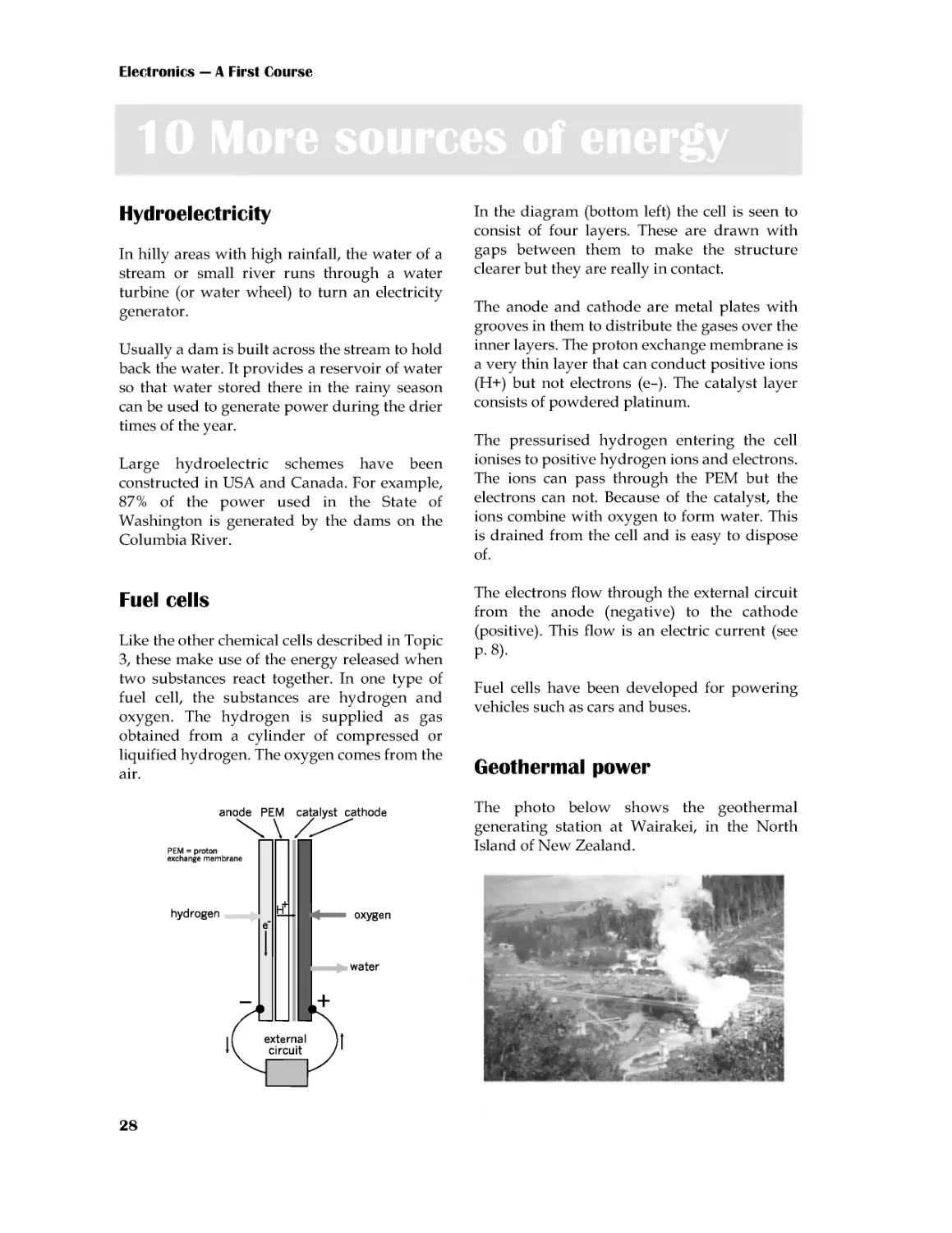
Fuel cells
Like the other chemical cells described in Topic
3, these make use of the energy released when
two substances react together. In one type of
fuel cell, the substances are hydrogen and
oxygen. The hydrogen is supplied as gas
obtained from a cylinder of compressed or
liquified hydrogen. The oxygen comes from the
air.
In the diagram (bottom left) the cell is seen to
consist of four layers. These are drawn with
gaps between them to make the structure
clearer but they are really in contact.
The anode and cathode are metal plates with
grooves in them to distribute the gases over the
inner layers. The proton exchange membrane is
a very thin layer that can conduct positive ions
(H+) but not electrons (e--). The catalyst layer
consists of powdered platinum.
The pressurised hydrogen entering the cell
ionises to positive hydrogen ions and electrons.
The ions can pass through the PEM but the
electrons can not. Because of the catalyst, the
ions combine with oxygen to form water. This
is drained from the cell and is easy to dispose
of.
The electrons flow through the external circuit
from the anode (negative) to the cathode
(positive). This flow is an electric current (see
p. 8).
Fuel cells have been developed for powering
vehicles such as cars and buses.
Geothermal power
The photo below shows the geothermal
generating station at Wairakei, in the North
Island of New Zealand.
Electricity
29
New Zealand is a land of geological activity.
The rocks below the surface are very hot.
Water is pumped through pipes laid beneath
the surface. The heat in the rocks turns the
water into steam. This is used to drive turbines
and so generate electricity
Solar cells
A solar cell is a slice of silicon coated on both
sides with metallic contacts. The silicon has
been processed to give it semiconducting
properties. .
As a result, a voltage is developed between the
front and back contacts when light shines on
the front surface of the cell.
A typical solar cell develops 0.45 V in full
sunlight, and a current of up to 200 mA. For
larger voltages and currents, several solar cells
are connected together into a battery, mounted
on a panel. A battery of over 60 cells can
supply 12 V at 500 mA. Latest developments
include very large arrays of cells that generate
enough power to supply a village.
Solar cells are a useful power source for
equipment that is remote from the mains.
Examples: Microwave transmitters on mountain
tops, spacecraft and satellites. In countries such
as Western Australia, which has plenty of
sunshine, there are solar-powered radio-
telephones beside out-of-town highways for
emergency calls.
The descriptions in Topic 9 and this Topic give
only the basic facts. Fill in the details by
browsing the World Wide Web. Use Google,
Yahoo!, or any other browsing software.
Keywords that you could search for include:
electricity, power generation, grid, fuel cell,
wind power, environment, pollution,
greenhouse effect. You will be able to think of
many more to try.
Web sites with handy information include:
www.dti.gov.uk
www.aepuk.com
www.natwindpower.co.uk
www.electricityforum.com
www.nucleartourist.com
www.howstuffworks.com
Prepare a project detailing two or three of the
energy sources. For each source, write about:
how it works, where stations are sited and
why, efficiency, dangers, safety precautions,
disposal of waste, pollution of the
environment, whether source is renewable or
not, costs of production, specially interesting
features.
Electronics --- A First Course
30
Cells and batteries are ideal for powering
hand-held portable equipment such as
torches and pocket calculators. Other devices
that work on low voltage are powered from
the mains, using a low-voltage power supply
unit (or PSU).
A PSU contains a transformer (p. 55) to
reduce the voltage from mains voltage to a
lower voltage, such as 6 V. It may have a
means of switching to a number of standard
voltages,suchas3V,6V,9Vand12V.It
usually has a rectifying circuit (p. 70) to
convert the AC output of the transformer into
DC. It may also have a regulator circuit
(p.210), so that it produces a steady voltage
even when the load on the PSU varies.
Most PSUs produce only small currents,
generally less than 1 A, but this is enough for
driving most low-current equipment.
PSUs are made in various forms:
• a plastic body that looks like a large
mains plug, with three pins for plugging
directly into a mains socket. It has a
flexible lead for connecting to the
equipment.
• a case with two leads, one to connect to a
mains plug and the other low-voltage
lead to connect to the equipment.
• a bench PSU is used in laboratories and
workshops. It connects to the mains and
has terminals that provide the low-
voltage DC output. It is usually possible
to switch to a range of different voltages
and also to vary the output voltage
smoothly over a wide range, typically
from 0Vto30V ormore. Alimitcan
be set on the current delivered, to protect
circuits powered by the PSU. Meters
display the voltage and current being
delivered.
Power supply unit
Extension Box 8
One way of stating the size of an alternating
current or voltage is to quote its amplitude
(p. 19). But amplitude tells us the peak current
or voltage. Sometimes, it is more useful to
know the average .
Simply
taking the
average of
all values
does not
work.
The voltage values of the positive half-cycle
are exactly cancelled out by the negative
values during the next half-cycle. The
average value is zero!
To avoid this difficulty, we use the fact that
the squares of all numbers are positive.
To find this new kind of average, we use
some special maths to square all the
thousands of voltage values during a cycle,
find the average (or mean) of the squares and
finally take its square root. The kind of
average we get is called the root mean square
or rms, for short. The maths is too
complicated to describe here, but we can
quote its result:
The rms value of a sinewave is 0.707 times
its amplitude
Putting it the other way round:
The amplitude of a sinewave is 1.4 times its
rms value.
Example
When we say that the mains voltage is 230 V,
we are quoting its rms voltage. Its amplitude
is 1.4 × 230 = 322 V. The voltage peaks to
±322 V and circuit designers must allow for
this when choosing components to use.
Root mean square
Extension Box 9
Electricity
31
In Physics, we learn about the joule, symbol
J. This is the unit of work. Work is done
when a force is applied to an object and the
object moves in the direction of the force.
Examples
Work is done when the wind blows against
a leaf and it moves in the direction of the
force.
Work is done when an electric force is
applied to an electron and it moves in the
direction of the force..
In both these examples we can see that,
when work is done, one form of energy is
converted into another form. Force is
converted into motion. The amount of work
done, or energy converted, is stated in
joules.
The rate of doing work (or converting
energy) can be stated in joules per second.
However, we have a special unit for this,
the watt.1 watt = 1 joule per second.
Example
Amandoes2800Jofworktoclimbupa
ladder. He takes 5 seconds to climb. What is
his rate of conversion of energy.
He applies 2800 J in 5 s.
His rate of working is 2800/5 = 560 J/s
In watts, this is 560 W.
Imagine a positively charged object in an
electric field. A force F is applied to the
object to move it from point A to point B,
against the force of the electric field.
Self test
1 An electric motor does 5 J of work while
movingatoycar1metrein2s.Whatisits
rate of conversion of energy?
2Howmuchworkisdonebya25Wlamp,
switched on for 1 minute?
The force does work in
moving the object from A
to B. Suppose that, if the
charge on the object is 1
coulomb, the work done
is 20 J. If the charge is
doubledto2C,40Jof
work are required. To
moveachargeof3C
needs 60 J.
When the charge is at B,
it has potential energy,
stored in it by moving it
fromAtoB.
If the force is removed, the object is repelled
by the field and moves back to A. As it does
so, it loses potential energy and gains
energy of motion. Its potential energy at
point B is equal to the work that must be
done to move it to B. This we have seen is 20
joules per coulomb. Whatever charge we
move from A to B takes 20 J/C. This is the
electrical potential at B relative to A.
We have a special name for the unit of
potential, instead of J/C. We call it a volt,
symbol V. So, in this example, the potential
atBrelativetoAis20V.
Note that potential (or 'voltage') is always
measured relative to some other point. For
convenience, we often take the Earth as zero
potential. In a circuit powered by a battery
we often take the negative terminal of the
battery as 0 V.
Self test
If it takes 56 J to move an object charged
with 4 C from A to B, what is the potential
of A relative to B? Of B relative to A?
Volts
Extension Box 11
Joules and watts
Box 10
Electronics --- A First Course
32
The drawing shows four 1.5 V cells in a
battery box. When cells are joined in series
like this, the total voltage of the battery is
the sum of the voltages:
1.5+1.5+1.5+1.5=6V
Cells in ready-made batteries (p.13) are also
joined in series.
When we connect two or more cells to make
a battery, we normally join the cells in
series. The cells are connected positive-to-
negative, as seen in the drawing below.
Extension Box 12
Questions on electricity
(Answers to questions with short answers are
given on the website.)
1 Describe how you would show that like
charges repel each other.
2 Name three substances that can be charged
by rubbing them with a woollen cloth.
3 What are the names of the two kinds of
electric charge. Which kind of charge is
carried on an electron?
4 Why can we not charge copper by rubbing it
with a cloth?
5 Why is copper such a good conductor of
electricity?
6 What causes lightning?
7 List four good conductors and four
insulators.
8 What is an electric current?
9 What is the difference between a cell and a
battery?
10 List two types of cell, describe their features
and give examples of their uses.
11 Name a type of rechargeable cell, describe
its features and give examples of its uses.
12 What types of battery could you use for
backing up the power supply to a security
system? If the system is to run on 24 V, how
many cells of each type would you require?
13 In what ways may a 12 V car battery be
dangerous?
14 Name the units of: (a) current, (b) voltage,
and (c) power. What are their symbols?
15 Write an equation that shows how the three
units of Question 14 are related to each other.
16 What are the units and symbols for (a) a
millionth of a volt, and (b) a million watts?
17 A halogen lamp runs on 12 V with a power
of 20 W. How much current does it take?
18 A small radio receiver uses two alkaline
cells and takes a current of 12 mA. What is its
power?
19 Draw a diagram to illustrate 4 cycles of AC.
Label the amplitude and the period. If the
period is 20 ms what is the frequency?
20 Name the three lines of the mains supply
and explain what they do.
21 Explain why a power switch must be placed
on the live side of an appliance.
22 Why should an RCCB be used with an
appliance such as an electric lawn-mower?
23 An electric kettle rated at 2.2 kW takes 5 min
to bring water to the boil. How much does
this cost if electricity is charged at 7.2 p per
unit?
24 Describe a solar cell and list some ways in
which solar cells are used.
Multiple choice questions
(Answers are on the web site)
1 In the list below, the best conductor of
electricity is:
A nylon.
B copper.
C aluminium.
D carbon.
Electricity
33
2 In the mains supply, the wire that supplies
the current is called the:
A neutral.
B earth.
C ground
D live.
3 The nucleus of an atom of carbon consists of:
A one proton.
B several protons.
C protons and neutrons.
D electrons and neutrons.
4 A nickel metal hydride cell:
A produces 1 V.
B shows the memory effect.
C stores less energy than a NiCad cell.
D is rechargeable.
5 Three lithium cells in series produce:
A4.5V.
B3.6V.
C6.0V.
D1.5V.
6 A typical residual current circuit breaker
limits the leakage to earth to:
A20mA.
B13A.
C30mA.
D1A.
7 A 12 V battery is used to light a small lamp.
The current flowing through the lamp is
500 mA. The power of the lamp is:
A6W.
B24A.
C 0.24 mW.
D 500 mA.
8 The switch for a mains-powered circuit
should be in the live lead because:
A this is a legal requirement.
B it isolates the circuit from the live
mains.
C putting it there is a convention.
D the switch controls mains voltages.
9Thelongestpinofa13Aplugisthe:
A earth.
B live.
C neutral.
D none; they are all the same length.
10 The body of a mains plug is made from
plastic or hard rubber because they are:
A flexible.
B insulators.
C cheap.
D light-weight.
Extension questions
1 Describe what happens when sodium
chloride ionises in solution.
2 What conductor is often used in power lines?
3 What is conventional current?
4 How does a neon lamp work?
5 Describe some of the dangers of static
electricity.
6 Explain the meanings of these terms:
electrolyte, cathode, anode.
7 In a photocopier, why does the black powder
form a positive image on the drum?
8 In a photocopier, what are the corona wires
and what do they do?
9 A sinewave produced by an audio generator
has an amplitude of 6 V. What is its rms
value?
10 Draw a diagram showing three 1.5 V cells
connected in series. What is the total voltage?
11 An electric torch has four 1.5 V cells in
series. It has a 0.96 W lamp. How much
charge passes through the lamp while it is
switched on for 10 min?
12 A krypton lamp takes 0.7 A when running
on a 2.4 V supply. How much work is done
while the lamp is switched on for 20 min?
13 How much work is done in moving a charge
of 25 C from one terminal of a 6 V battery to
the other?
14 Several NiCad cells are wired in series to
make a battery. This battery is connected to a
heating coil. If 48 J of electrical energy are
converted to heat energy while 10 C of charge
pass through the coil, how many cells make
up the battery?
11 To measure the voltage across lamp x, the
probes of the meter are placed as shown at:
34
11 Resistance
We begin by investigating what happens when
we use different voltages to make a current
flow through a conductor. We use a poor
conductor, such as carbon, so that the current
will not be too large to measure with an
ordinary multimeter.
Things to do
A suitable piece of carbon for this
investigation is a short length (about 3 cm)
of Artists' charcoal .
1 Connect a 6 V battery, a multimeter and
the piece of carbon in a circuit, as shown in
the photograph. Use short leads with
crocodile clips at each end.
2 Leave the positive (red) probe of the meter
free. By touching this against different
metal contacts in the battery box, you can
obtain voltages of 1.5 V, 3 V, 4.5 V and 6 V.
Alternatively, use a PSU with switchable
output instead of the battery.
3 Set the multimeter to its largest current
range (500 mA or 1 A). If the readings are
too small to read accurately, you can switch
to a lower current range.
4 Take the first reading with the red probe
at the 6 V point. Measure the current, using
the meter. Record these results in a table:
5 Repeat with the voltage set to 4.5 V, 3 V
and 1.5 V.
What do you notice about the current as we
reduce the voltage? To investigate this
further, divide each voltage by the
corresponding current and write the results
in the third column. What do you notice
about the values in the third column?
Voltage
(volts) Current
(amps) voltage/
current
6
4.5
3
1.5
Ohm's Law
The results of the investigation above show
that:
The current passing through the carbon is
proportional to the voltage difference
between its ends.
This was first discovered, using lengths of
wire, by Gregor Ohm, so it is called Ohm's
Law. It applies to all conductors. We can state
it as an equation:
You may have noticed in your class that
different people, working with different pieces
of carbon have found different constants. The
value of the constant is a property of a
particular piece of carbon. We call it the
resistance of the piece of carbon. Now we can
write the equation like this:
Part 2 Electronic components
Electronic components
35
Units of resistance
If the voltage is expressed in volts and the
current in amps, the unit of resistance is the
Ohm, symbol Ω. This symbol is the Greek
capital letter omega.
Self Test
1Whenavoltageof6V isappliedtoa
piece of carbon, the current is 120 mA. What
is the resistance of the carbon?
2 When a voltage of 230 V is applied to a
lamp, the current is 260 mA. What is the
resistance of the lamp?
To use the diagram, cover the quantity that you
want to calculate. The diagram shows the
remaining quantities as they appear in the
equation.
Example
To calculate current:
Current equals 'voltage over
resistance'.
Try it for the other two
quantities.
Self test
1 When 25 V is applied to a length of cable,
the current through it is 10 A. What is the
resistance of the cable?
2 A coil of wire has a resistance of 600 Ω and
the voltage across it is 4.5 V. How much
current flows through the cable?
3Ifawirehasaresistanceof2.4Ω,anda
current of 3.5 A is flowing through it, what is
the voltage difference between its two ends?
4 A 2.3 kW heater runs on the 230 V mains.
What is its resistance?
Symbols for quantities
You have already used symbols for units, such
as A, V, and W. It is useful to have symbols for
quantities, too. This makes it quicker to write
out equations. The symbols for quantities are:
I for numbers of amps
V for numbers of volts
R for numbers of ohms
Symbols for quantities are in slanting letters
(italics). Using these symbols instead of words,
the Ohm's Law equations become:
R=V/I
I=V/R
V=IR
Try not to confuse V, which means 'volts' with
V, which means 'numbers of volts'
Larger units of resistance are the kilohm (kΩ)
and megohm (MΩ).
1kΩ=1000Ω
1MΩ=1000kΩ
Ohm's Law equations
The equation given opposite can be written in
three forms:
If we are given any two of the quantities, we
can calculate the third. These three equations
are used more than any in electronics, so you
will need to remember them. An easy way of
remembering is to memorise this diagram:
AFC211
page 3
16 January 2006 17:49
Black
Electronics --- A First Course
36
12 Resistors
In most circuits, we join the components
together with copper wires. This is because
copper is a good conductor of electricity. It has
very low resistance.
Some connections may need greater resistance
than that of a copper wire. This is when we use
resistors.
The photo shows a typical fixed resistor.
Resistors of this kind are sold in a range of
different resistances, from less than 1 Ω and up
to 10 MΩ.
These are two different
symbols used for
resistors in circuit
diagrams. We use the
rectangle symbol in this
book. The zigzag
symbol is less often used
nowadays.
Preferred values
Resistors are made in a range of values (in
ohms):
1.0 1.1 1.2 1.3 1.5 1.6 1.8 2.0 2.2 2.4 2.7 3.0
3.3 3.6 3.9 4.3 4.7 5.1 5.6 6.2 6.8 7.5 8.2 9.1
After these 24 values, the sequence repeats in
multiples of ten:
10 11 12 13 ... upto...82 91,
then 100 110 120 ... up to 820 910,
then1k 1.1k 1.2k...upto8.2k 9.1k,
('k' means kilohms)
then10k 11k 12k...upto82k 91k,
then100k110k 120k...upto910k 1M.
This is the E24 series. The E12 series comprises
the alternate values of the E24 series: 1.0, 1.2,
... , 6.8, and 8.2, with multiples.
Resistor colour code
Three coloured bands are used to tell us the
resistance of a fixed resistor. The bands are
close together at one end of the resistor. The
colour of each band represents a number.
Colour Number
Black
0
Brown
1
Red
2
Orange
3
Yellow
4
Green
5
Blue
6
Violet
7
Grey
8
White
9
Example 1
The bands are
yellow, violet, red.
Yellow means '4'
Violet means '7'
Red means '2'
Write '4', then '7',
then follow with two
zeros. This gives:
4700 Ω
We normally write
this as:4.7 kΩ
Reading from the end, the meaning of the
bands are:
First band
First digit of resistance
Second band Second digit of resistance
Third band
Multiplier --- a power of
10, or the number of zeros
to follow the two digits.
The table shows the meanings of the colours.
AFC212
page 2
21 October 2005 10:53
Black
Electronic components
37
Example 2
The bands are white, brown, yellow.
White means '9'
Brown means '1'
Yellow means '4'
Write '9' then '1', then follow with four zeros.
This gives: 910 000 Ω or 910 kΩ
There is a similar system with four bands for
marking high-precision resistors.
Things to do
You need:
• 10 fixed resistors of different values.
• A multimeter.
• A breadboard.
1 Find out the value of one of the resistors
by reading its colour code.
2 Use the multimeter to check the resistance.
First select a suitable range on the meter.
3 Plug the wire leads of the resistor into
different rows on the breadboard. Touch one
probe to each of the resistor leads.
4 Read the resistance on the meter. Does it
agree with the colour code?
5 Repeat with the other resistors.
Resistance on an analogue meter
The resistance scale runs from right to left and
is not linear. This means that the markings are
more crowded toward the higher (left) end of
the scale.
When using an analogue meter, adjust the zero
setting occasionally. To do this, touch the two
probes together. Then set the 'Ohms adjust'
knob or wheel until the needle lines up with
zero (on the right of the scale).
If you plug two or more component wires
into the same row, current can flow from
one to the other.
The reading
in the photo
(on the top
scale) is 72 Ω.
Self test
1 State the resistances of resistors that have
bands of these colours:
(a) orange, white and brown.
(b) green, blue and yellow.
(c) brown, black and green.
(d) brown, black and black.
(e) red, red, and red.
2 What colours are the bands on resistors of
these values?
(a)33Ω,(b)200kΩ,(c)750Ω,(d)43kΩ,(e)
820 Ω.
Breadboards
A breadboard makes it easy and quick to build
circuits. It is a plastic block with rows of
sockets. The sockets in each row are connected
electrically, as indicated in the photo.
AFC212
page 3
21 October 2005 10:53
Black
Electronics --- A First Course
38
13 More about resistors
If we want to be able to vary the resistance of
part of a circuit, we use a variable resistor. One
type of variable resistor is called a
potentiometer. This type is a often used for
volume controls in audio equipment. It is more
often called a 'pot', for short.
Above is a slider pot, which has a track made
from a film of carbon. In the more expensive,
hard-wearing and accurate types, the track is a
layer of conductive ceramic. The ends of the
track are connected to two terminals.
The third terminal is connected to the wiper.
This is a springy metal strip that presses firmly
against the track and makes electrical contact
with it. It is attached to a sliding knob, used to
move the wiper along the track. As it moves,
the distance between one end of the track (say,
A) and the wiper is changed. This changes the
electrical resistance between A and the wiper.
The resistance can have any value between
zero and the resistance of the whole track.
Slider pots are often used on audio equipment
(p. 191) for setting the frequency response.
A common form
of variable pot is
the rotary pot.
This has a
curved track,
along which the
wiper moves as
the shaft is
turned.
Rotary pots are often used as volume controls
in audio equipment and also for controlling the
brightness of lamps, the speed of motors and
many other purposes. The shaft can be fitted
with a knob, if preferred.
Sometimes we want to adjust a resistance when
we are setting up a circuit. After 'pre-setting' or
'trimming' the circuit, we may not need to
change the resistance again.
We use a smaller
rotary pot,
known as a
preset pot, or as
a trimmer, or
trimpot, which is
adjusted with a
screwdriver.
Special symbols used for pots (left) and presets
(right). Zigzag versions are also used.
Design tip
Pots need careful use. If the wiper is near
one end of the track, the resistance between
the wiper and the near end is small. As a
result, the current through that part of the
track is too high and burns out the track. If
possible, wire a small fixed resistor in series
with the wiper or track to limit the current
to a safe amount.
Often the track covers an angle of about 270°.
AFC213
page 2
16 January 2006 18:04
Black
Electronic components
39
Power ratings
Many fixed resistors are intended to conduct
electricity at a maximum power of a quarter of
a watt (250 mW). This power must not be
exceeded.
Example 1
The current through a 250 mW resistor is
10 mA and the voltage across it is 5 V. The
poweris0.01×5=0.05W=50mW.Because
the resistor is rated at 250 mW, it can safely run
at 50 mW. It becomes only slightly warm as a
result of the current passing through it..
Example 2
If the current through a 250 mW resistor is 50
mA and voltage is 5 V, the power is 250 mW.
This is as much as the resistor can safely stand.
It will get hot but it is not damaged. If either
the current or voltage is increased above these
amounts, the resistor gets too hot. It may
scorch or burn and possibly crack into pieces.
Even if it is not totally destroyed, its resistance
changes permanently as a result of
overheating.
Resistors are made with higher power ratings,
suchas0.5A,1A,5A.Someareabletorunat
several hundred watts. These are larger than
the typical low-power resistors. Those of the
highest ratings usually consist of a coil of thin
wire wound on a ceramic core.
Typical pots are rated to run at a maximum of
0.2 W to 0.5 W. Pots of higher rating, up to 3 W,
usually consist of a coil of wire wrapped on a
ceramic core.
Tolerance
There is usually a fourth coloured band on a
resistor, at the end opposite to the three bands.
This band indicates the tolerance or precision
of the resistor. This tells us how far the actual
resistance may differ from the nominal
resistance, as shown by the colour code
Colour Tolerance
Red
±2%
Gold
±5%
Silver
±10%
No band ±20%
Example 1
A 470 Ω resistor has
a gold tolerance
band. This means a
tolerance of ±5%.
Calculate 5% of
470Ω, which is 470
× 5/100 = 23.5Ω.
The actual resistance of the resistor may be
somewhere between:
470--23.5=446.5Ω
and
470+23.5=493.5Ω
Example 2
A 220 kΩ resistor has no tolerance band. Its
tolerance is ±20%. Calculate 20% of 220 kΩ,
which is 220 × 20/100 = 44 kΩ.
The actual value of the resistor may be
somewhere between:
220--44=176kΩ
and
220+44=264kΩ
The reason for E24
It would be very expensive to make and stock
all possible values of resistor from 1 Ω up to
1MΩ. Also, because 5% tolerance is good
enough in most circuits, the limited number of
resistances of the E24 series (p. 36) covers the
whole range of values. Take these four nominal
values as examples:
The range of each value slightly overlaps each
of its neighbours. At 5% tolerance, there is no
point in making resistors with values in
between these E24 values.
Nominal Lowest (--5%) Highest (+5%)
390
370.5
409.5
430
408.5
451.5
470
446.5
493.5
510
484.5
535.5
AFC213
page 3
16 January 2006 18:04
Black
Electronics --- A First Course
40
14 Resistor networks
When two or more resistors are joined together
we create a resistor network. This Topic
describes several types of network and their
properties.
Resistors in series
If two or more resistors are joined end-to-end
so that current flows through each one in turn,
we say they are joined in series. Compare this
with cells joined in series (p. 32). We find the
effective resistance of the series by adding
together their resistances.
Example
In the series of three resistors above, the
effective resistance is 330 + 68 + 270 = 668 Ω.
As a check on the calculation, note that the
effective resistance is always bigger than the
biggest of the individual resistances.
Self test
1 What are the effective resistances of each
of the following groups of resistors when
wired in series?
(a) 220 Ω and 3.3 kΩ.
(b)5.6Ω,39Ω,and16Ω.
(c)13kΩ,1MΩand390kΩ.
2 A student needs a 470 Ω resistor, but the
lab is out of stock. How could this be made
up from resistors of other E24 values?
3 Make up a 130 kΩ resistor from other E24
values.
Current rules
1 Three or more wires in a network meet at one
point. It is not possible for charge to build up at
the junction. It is not possible for charge to
decrease at the junction. Therefore:
The total current arriving at a junction
equals the total current leaving it.
Example
The total current
arriving is 2.1 + 2.4
=4.5A
The total current
leaving is 1.5 + 3.0
=4.5A
Things to do
You need:
• 10 fixed resistors of different values
and various tolerances.
• A multimeter.
• A breadboard
1 Read the colour codes to find the
resistance of each resistor. Then check your
reading by measuring the resistances with a
multimeter (p. 37).
2 Take any two or three resistors and plug
them into the breadboard so they are in
series. Calculate the effective resistance of
the series. Then check your calculations by
using the multimeter to measure the
resistance of the series. Repeat for four more
groups of resistors.
3 From its colour bands, find the resistance
and tolerance of a resistor. Work out what
its lowest and highest resistances could be.
Check with a multimeter that the actual
resistance is within these limits.
AFC214
page 2
20 February 2006 13:02
Black
Electronic components
41
2 In a series circuit (one in which all the
components are in series), there is no point at
which charge can enter or leave the circuit.
Therefore:
The current is the same everywhere in a
series circuit.
Example
The cell and three
resistors are in
series. The same
current (= i amps)
flows in all parts of
the circuit.
Voltage rules
1 Going round a series circuit in the direction
of the current, there is a voltage drop across
each of the resistors. There is a voltage rise
across the cell. The size of each voltage drop
depends on Ohm's Law. The voltage rule is
that:
The sum of the voltage drops in a series
circuit equals the voltage across the circuit.
Example
The voltage drops
are v1, v2, and v3.
Their total is equal
to the voltage rise
vT across the cell.
One end of each resistor is
connected to the positive
terminal of the cell. The
other end of each resistor is
connected to the negative
terminal. This means that:
In a parallel circuit, there
is the same voltage across
each component.
2 The drawing shows a circuit in which the
resistors are joined in parallel.
Voltage divider
This kind of network is also called a potential
divider. The input to a voltage divider is a
voltage vIN. This drives a current i through the
two resistors. Because the two resistors are in
series, the same current flows through both
(Current Rule 2).
There are questions about the current rules,
the voltage rules and about voltage dividers
on pp 45-6.
The effective resistance of the two resistors in
series is R1 + R2. The voltage across them is vIN.
By Ohm's Law, the current is:
Using Ohm's Law again, the voltage across R2
is:
vOUT=i×R2
Substituting the value of i from the previous
equation:
2
1
2R
R
R
v
v
IN
OUT
+
×
=
2
1R
R
v
i
IN
+
=
This is the equation for calculating the output
voltage of a voltage divider. By choosing two
suitable resistors, we can obtain any output in
the range from 0 V to vIN.
Example
Inavoltagedivider,vIN=6V,R1=220Ωand
R2 = 390 Ω. Calculate vOUT.
V
84
.
3
220
390390
6
=
+
×
=
OUT
v
AFC214
page 3
20 February 2006 13:02
Black
Electronics --- A First Course
42
The effective resistance of two or more
resistances in parallel (p. 41) is calculated from:
...
1
1
1
1
3
2
1
+
+
+
=
R
R
R
R
Things to do
Repeat the tests you made on p. 40, but with
the resistors in parallel.
There are as many terms on the right as
there are resistances in parallel.
Example
The effective
resistance of
this network
is found by
calculating:
01774
.
0
01471
.
0
00303
.
0
68
1
330
1
1
=
+
=
+
=
R
Check: the effective resistance is always less
than the smallest of the resistances in
parallel.
Self test
Find the effective resistance of each of the
following sets of resistors, when wired in
parallel:
(a)22Ωand270Ω,(b)120 Ωand10kΩ,(c)
27Ω,47Ω,and15Ω,(d)390kΩ,18kΩ,and
91kΩ,(e)100Ω, and100Ω.
Resistances in parallel Box 13
A mixed network has some resistances in
series and others in parallel. Look for
groups of resistances in the network, which
are all in series or all in parallel. Re-draw
the network, replacing each group with its
equivalent resistance. Gradually simplify
the network to a single resistance.
Example 1
The56Ωand33Ω
resistances
in
parallel can be
replaced with
20.8 Ω. This gives
two resistances in
series. Replace
these with 67.8 Ω.
Example 2
There are two sets
of resistances in
series.Simplify
them to 550 Ω and
473 Ω. These are in
parallel, so may be
replaced with
254 Ω.
Self test
1 Find the effective resistances of these
networks:
(a)
(b)
2 What is the effective resistance if the
1200Ω of the network above is (a) removed,
and (b) replaced with a copper wire?
Mixed networks
Box 14
Ω
=
=
⇒
40
.
56
01774
.
01
R
AFC214
page 4
20 February 2006 13:02
Black
Electronic components
43
This is sometimes used instead of the
resistor colour code. It is also known as the
BS1852 code. The code uses one of three
letters to show the unit and the position of
the decimal point. The letters are:
R = ohms, K = kilohms, M = megohms.
Examples
Code Value Code Value
8R2
8.2 Ω 82K
82 kΩ
82R
82 Ω 820K 820kΩ
820R 820 Ω 8M2 8.2 MΩ
8K2
8.2 kΩ
--
A second letter at the end of the code
indicates tolerance:
G=±2%
K=±10%
J=±5%
L=±20%
Examples
9K1J means a 9.1 kΩ resistor with ±5%
tolerance.
12KK means a 12 kΩ resistor with ±10%
tolerance.
Self test
1 What are the values of resistors marked
(a) 33K, (b) 4M7, (c) 2R2, (d) 1R8J, and (e)
27KK?
2 Write the codes for resistors with the
following ratings: (a) 47 Ω, (b) 100 kΩ, (c)
9.1 kΩ, (d) 3.9 kΩ ±5%, and (e) 750 kΩ
±10%.
Resistor printed code Box 15
These are used when we need to be able to
adjust a variable resistor with high
precision. The wiper is moved by a screw
mechanism. It takes several turns of the
screwdriver to move the wiper the full
length of the track.
The screw head can be seen on the left. It
requires 10 turns of the screwdriver to move
the wiper from one end of the track to the
other. Even more precise trimmers need 18
or 25 turns.
Self test
Can you read the value and tolerance of the
trimmer illustrated above?
A charge carrier (such as an electron) loses
energy as it moves through a conductor.
The energy is transferred to the atoms of the
conductor. This makes them vibrate the
conductor becomes hot. Electrical energy is
converted to heat. We use this action to heat
electric kettles and room heaters. In
electronic circuits the resistors, and other
components become warm or hot. This is
usually a disadvantage because energy is
being wasted. In an electric lamp, the
conductor is a thin wire that becomes white
hot and emits visible light.
The rate of energy conversion is measured
in watts (p. 15).
Multiturn trimmers Box 16
Energy transfer
Box 17
AFC214
page 5
20 February 2006 13:02
Black
Electronics --- A First Course
44
Circuit diagrams
There are two points that you should notice:
• Cell or battery symbol: These are not
often used. Instead, the diagram shows a
pair of terminals. One, labelled 0V, is the
negative terminal of the power supply.
The other is labelled with the voltage of
the positive terminal of the supply. The
supply may be a cell or battery, but it is
more likely that you will obtain the supply
from a bench PSU.
• Ohms symbol: This is omitted. Instead we
use a shorter form, using the resistor
printed code (p. 43).
The values of R1 and R2 decide the upper
and lower limits of vOUT. Without R1 and R2,
the divider output ranges from 0 V to v IN.
Variable voltage divider
If a variable output voltage is needed, use a
divider based on a variable resistor.
Things to do
You need:
• A breadboard.
• A power supply (6 V battery or PSU).
• A 22 kΩ resistor, a 10 kΩ resistor, and
one other.
• A multimeter.
1 With the 22 kΩ resistor and one other,
build a voltage divider to give an output of
3.6 V, as shown in the drawing. You have to
work out what the value of the other
resistor (R2) should be. Do not put the
10 kΩ resistor in the circuit yet.
2 Use the multimeter to check that the
divider is working. Its input voltage should
be 6 V and its output should be 3.6 V.
3 Connect the load resistor (10 kΩ) to the
divider. Measure the output voltage again.
What has happened to it?
The results of the investigation above are
explained by thinking of the currents at point
A. According to current rule 1 (p. 40) the
currents leaving point A to flow through R2
and the load, must be equal to the current
arriving through R1. The current splits and
more goes through the load than through R2.
This is because the load has a lower resistance
than R2.
Because the current through R2 is reduced
when the load is connected, the voltage
across R2 is decreased (Ohm's Law). The
output of the divider is less than we first
calculated. Try working out the voltages and
current in the network to check your results.
Design point
We need to avoid a serious voltage drop
caused by the load taking too much current
from the divider. A simple rule is that the
current flowing through the divider from
positive supply to the 0 V line must be at
least 10 times the current being taken by
the load. There will still be a drop, but it will
not be unduly large.
More about voltage dividers
Extension Box 18
AFC214
page 6
20 February 2006 13:02
Black
Electronic components
45
This is another way of measuring resistance.
It uses two separate meters, an ammeter for
current (I) and a voltmeter for voltage (V).
R is the resistance being measured. The
ammeter measures the current through R.
The voltmeter measures the voltage across
R. The values beside each meter in the
diagram are their full scale deflection. This
is the largest current or voltage that the
meter can measure.
The supply V+ is variable up to 10 V. Use a
PSU or connect different numbers of cells.
Try 4 or 5 different voltages. Measure I and
V at each and calculate R = V/I at each.
There is an error in this technique. Some of
the current that goes through the ammeter
goes through the voltmeter, not through R. So
the ammeter reading is too big. But a
voltmeter takes very little current compared
with that through R, so the error is small.
Box 19
Questions on resistance
1 How much current
flows through R?
What is its direction?
2 If the 4.2 A current is
reduced to 0.7 A,
what is the current
through R? What is
its direction?
3 In the network on the
right, which resistor has
the biggest voltage
across it?
4 What is the current
through the network on
the right? What is the
voltage drop across
each resistor?
5 In the network on the
right, what supply
voltage produces a
current of 30 mA?
6 On the left, what
is the voltage
across and the
current through
each resistor?
Tolerance
In all questions, assume that the resistors
have the exact values stated. Tolerance
does not have to be allowed for.
9 What is the output
voltage of the
divider on the left?
10 What is its output
voltage if the input
voltage is raised to
15 V?
7 On the right,
what is the
current
through R?
8 What is the
voltage across
R?
AFC214
page 7
20 February 2006 13:02
Black
Electronics --- A First Course
46
11 What is the output in the diagram of
question 9 if R1 is increased to 680 Ω?
12 What input is required in the diagram of
question 9 to give an output of 5 V?
13 What is the output
of the divider on the
left?
14 What is the output if
the input is reduced to
3V?
15 What is the output if
the resistors are
exchanged?
16 Design a divider to produce an output of
4.5 V, given an input of 9 V.
17 Design a divider to produce an output of
4.8 V, given an input of 12 V.
18 State the equation that describes Ohm's
Law. If a voltage of 5 V is applied to a resistor
and the current through the resistor is 61 mA,
what is the resistance of the resistor?
19 If a 2.2 kW electric kettle runs on the 230 V
mains, what is the resistance of its heating
element?
20 A coil has a resistance of 200 Ω. What
voltage is required to produce a current of
400 mA through it?
21 What value of resistor is required so that a
current of 65 mA passes through it when 5 V
is applied across it? What is the nearest value
in the E24 series? What is the colour code for
the nearest resistor, assuming it has 5%
tolerance?
22 Describe three types of variable resistor and
give a practical use for each.
23 What is the maximum current that may be
passed by a 0.5 W resistor, when the voltage
across it is 12 V?
24 The tolerance band on a resistor is silver.
What does this mean? If the three colour code
bands on this resistor are all red, what are the
lowest and highest values that the resistor
can have?
Multiple choice questions
1 Which one of these values is NOT an E24
value?
A21Ω.
B910Ω.
C5.6Ω.
D62Ω.
2 Which of these values is an E12 value?
A110Ω.
B 7.5 kΩ.
C 4.7 MΩ.
D240Ω.
3 The multiplier band in the three-band colour
code is the:
A tolerance band.
B first band.
C black band.
D third band.
4 If the tolerance band is red, the resistor has a
tolerance of:
A ±2%.
B ±5%.
C ±10%.
D ±20%.
5 The effective resistance of two or more
resistors wired in series equals:
A the resistance of the largest resistor.
B the sum of the resistances.
C the average of the resistances.
D the resistance of the smallest resistor.
6 Three resistors, 10 Ω, 100 Ω and 220 Ω are
joined in parallel. A battery is connected
across the network. The resistor that is
passing the largest current is:
A10Ω.
B100Ω.
C220Ω.
D All pass the same current.
7 In the circuit of question 6, the resistor that
has the biggest voltage across it is:
A10Ω.
B100Ω.
C220Ω.
D All have the same voltage.
AFC214
page 8
20 February 2006 13:02
Black
Electronic components
47
Extension questions
1 Two resistors, 270 Ω and 1 kΩ, are connected
in parallel. What is their effective resistance?
2 Three resistors have values of 10 kΩ, 22 kΩ,
and 18 kΩ. What is their effective resistance
when wired in parallel? Which resistor
carries the largest current when a voltage is
applied across the network?
3 Three resistors, 470 Ω, 560 Ω and 220 Ω are
wired in parallel. What is the current through
the network when a 6 V battery is connected
across it? What is the voltage across the 560 Ω
resistor?
4 Find the effective resistance of each of the
networks shown below:
7 What are the resistor colour codes equivalent
to the following printed codes?
(a) 1M8L.
(b) 56RJ.
(c) 750KK.
(d) 2K4G.
8 (a) In the circuit below, what are the lowest
and highest obtainable values of VOUT? (b) If a
load of 50 Ω is connected between the output
terminal and the 0 V line, what is the highest
obtainable value of VOUT?
5 A circuit is set up for measuring resistance as
in Extension Box 19. With the test resistance R
connected, the milliammeter reads 176 mA
and the voltmeter reads 12 V. What is the
value of R?
6 What are the resistor printed codes
equivalent to the following colour codes?
(a) red, violet, brown; red tolerance.
(b) blue, red, yellow; gold tolerance.
(c) brown, blue, red; red tolerance.
(d) red, red, green; no tolerance band.
9 What is the maximum practicable current
that can be drawn from the voltage divider
above? To what values should the resistors be
changed, to allow up to 40 mA to be drawn
from the divider, keeping the same minimum
and maximum voltages?
10 A voltage divider is made from a single
variable resistor, value 1 kΩ, and connected
to a 15 V supply. The wiper is set so that the
output voltage is 9 V. Then a 470 Ω load is
connected to the output. What is the new
value of the output voltage and how much
current flows through the load?
11Des
cribe how to use an am
m
eter (or a
milliammeter) and a voltmeter to measure
resistance. State why there is an error in this
technique.
12 Explain why a conductor becomes warm or
hot when an electric current passes through
it. Name two useful applications of this effect.
AFC214
page 9
20 February 2006 13:02
Black
Electronics --- A First Course
48
15 Capacitors
A simple capacitor consists of two metal plates
with a layer of insulator between them.
The insulating layer may be a thin sheet of
plastic, but some types of capacitor have a
layer of air instead.
If a capacitor is
connected to a source
of DC electric power,
electrons accumulate
on the plate that is
connected to the
negative
supply
terminal. These repel
electrons from the
opposite plate. The
repelled electrons
flow toward the
positive terminal.
If the capacitor is
removed from the
supply, it remains
charged.
A capacitor connected like this to a power
supply instantly becomes charged. The voltage
between its plates equals that of the supply.
Because of the insulating layer, current can not
flow through the capacitor. The capacitor
remains charged indefinitely. For this reason,
capacitors are useful for storing charge.
Capacitance
The ability of a capacitor to store charge is
called its capacitance, symbol C.
The unit of capacitance is the farad, symbol F.
The farad is defined as the amount of charge
stored (in coulombs) per volt:
voltage
charge
e
capacitanc =
Example
The amount of charge stored on a capacitor is 6
coulombs. The voltage between its plates is 2 V.
What is its capacitance?
capacitance = 6/2 = 3 F
Self test
1 A capacitor receives a charge of 2.5 C and
the voltage across it is 10 V. What is its
capacitance?
2A2Fcapacitorhas5Vacrossit.How
much charge is it storing?
Capacitors rated in farads are used for backing
up the power supply to computer memory.
However, most electronic circuits need much
smaller capacitances. The units in which most
capacitors are rated are:
• microfarad, millionths of a farad, symbol
μF.
• nanofarad, thousandth of a microfarad,
symbol nF.
• picofarad, thousandth of a nanofarad,
symbol pF.
Self test
Express in nanofarads: (a) 1000 pF, (b)
2.2μF,(c) 1F,(d)47pF,(e)56μF.
AFC215
page 2
16 January 2006 18:12
Black
Electronic components
49
Types of capacitor
There are many types of capacitor, of which
only the most often used are described here:
Polyester: The insulating material is polyester
which gives a relatively high capacitance. The
plates are made of metal foil, or a metallised
film is deposited on the insulator. The
'sandwich' of plates and insulator is rolled to
make it more compact and the roll is coated
with insulating plastic. Polyester capacitors
(the three on the left below) are general-
purpose capacitors and widely used.
Polystyrene: (fourth from left above) These are
constructed in a way similar to polyester
capacitors. Using polystyrene as an insulator
results in lower capacitances than with
polyester. However, they can be made with
much closer tolerance, so are suitable for
tuning circuits and filters.
Variable: These have two sets of plates, the
alternate plates being electrically connected.
One set is fixed. The other set can be turned so
that we can vary the amount by which the sets
overlap (below). This varies the capacitance.
The larger capacitors used for tuning radio
receivers have air as the insulator. Plastic film
is used in small trimmer capacitors (right
above). Some trimmers work by having a
screw adjustment that compresses or loosens
the plates and film to vary the capacitance.
Tantalum bead capacitors are made with
smaller capacitances than aluminium
electrolytics. However, they are generally
smaller in size so are useful where space is
limited.
Electrolytic capacitors
These are used to store large amounts of
charge. Their capacity is usually 1μF or more
andmaybe as muchas10000μF.
Electrolytics can store large amounts of charge
for hours. When building or testing circuits,
there is danger from electric shock if you touch
the terminal wires without giving the capacitor
time to discharge. When storing large
electrolytics, twist their terminal wires together
(left above) so that they can not retain a charge.
Electrolytics are polarised, which means that
they have positive and negative terminals.
They must be connected the right way round.
In the photo, there are markings on the case to
indicate the negative terminal. If an aluminium
electrolytic capacitor is connected the wrong
way round, gas is formed inside and it will
explode. Tantalum bead capacitors, can be
destroyed in a few seconds by wrong
connection.
The insulation between the plates in
electrolytics (especially the aluminium type) is
not as high as that in other types of capacitor.,
A few microamps leaks across between the
plates.
Electrolytics have wide tolerance normally
±20% or wider. They can not be used in
precision filters or timing circuits.
The two commonest types of electrolytics are
aluminium electrolytics (left and centre
below) and tantalum bead capacitors (right).
AFC215
page 3
16 January 2006 18:12
Black
Electronics --- A First Course
50
16 Charging capacitors
Things to do
Set up the circuit shown in the diagram,
using a breadboard. The wire from the
positive terminal of the electrolytic
capacitor is a flying lead. It is a piece of
wire about 10 cm long. One end is plugged
into the same row of contacts as the positive
wire of the capacitor. The other can be
plugged into the board to connect either to
(A) the positive supply or (B) the lamp.
1Connect the flying lead C to the positive
power line (A) to charge the capacitor.
2 Quickly connect C to the lamp at B, to
discharge the capacitor. Did you see the
lamp flash? If not, try again.
3 Connect the lead to A again. Remove it
from the socket, but wait 10 seconds before
connecting it to the lamp. Does the lamp
flash?
4 Repeat 3, but wait for longer times before
connecting to the lamp. How long does the
capacitor hold enough charge to flash the
lamp?
This investigation demonstrates that
capacitors can hold charge for a long time.
Storing charge
The ability of a capacitor to store charge is one
of its most important properties.
Charging and discharging
The rate of flow of charge depends on the
voltage across the capacitor.
Things to do
This circuit has a switch for charging and
discharging. It has a resistor to make the
current smaller. Because of this, charging
and discharging take longer. It gives you
time to see what happens. The meters can
be a separate voltmeter and ammeter, or a
pair of multimeters.
1 Set the switch to A to discharge the
capacitor if it is already charged.
2 Set the switch to B and watch the meters
as the capacitor is charged. You and a
partner could watch one meter each.
3 Set the switch to A and watch the meters
as the capacitor is discharged.
4 Repeat 2 and 3 until you can answer these
questions:
• When does the biggest current flow into
the capacitor?
• When does the biggest current flow out of
the capacitor?
• When does no current flow into or out of
the capacitor?
• When does the voltage across the
capacitor change most quickly?
• When does the current into or out of the
capacitor change most rapidly?
AFC216
page 2
16 January 2006 18:17
Black
Electronic components
51
In the investigation, the flow is too fast to see
exactly what happens. The voltage change can
be more clearly seen by connecting an
oscilloscope in place of the voltmeter. The
display looks something like this:
When the switch is turned to A, the voltage on
the supply side of the resistor is 6 V and that on
the capacitor side is 0 V. By Ohm's Law, the
current through the resistor is 6/10 000 =
600 μA. Charging begins and the voltage across
the capacitor (see graph) rises steeply. The
voltage on the supply end of R1 stays at 6 V,
but the voltage at its other end is increasing.
The voltage difference across R1 is decreasing.
Ohm's Law still applies, so the current through
R1 is decreasing. This means that the rate of
charge of C1 is decreasing and the voltage
across it rises more slowly.
The voltage rises more and more slowly until
C1 is charged to 6 V. Then there is NO voltage
difference across R1 and therefore NO current
flows through it. The graph levels out. The
capacitor is fully charged.
A curve shaped like the graph above is called
an exponential curve.
The reverse happens when the capacitor is
discharged. At first, there is a voltage
difference of 6 V across R1, so 600 μA flows out
of the capacitor, through R1 to the 0 V line. The
voltage becomes less as the capacitor
discharges. The voltage drops more and more
slowly. When it reaches zero, the capacitor is
uncharged.
Capacitors in parallel
Wiring two or more capacitors in parallel is the
equivalent of adding together the areas of their
plates. For this reason, the effective capacitance
is the sum of the individual capacitances.
Example
In the diagram above, the effective capacitance
is:
C=47+10+2.2=59.2μF
The effective series capacitance is always
greater than the greatest of the individual
capacitances.
Self test
1 If the supply voltage in the circuit in
column 2 opposite, was increased to 10 V
and R1 was increased to 18 kΩ, what would
be the current into C1 when the switch was
first set to B? What would be the final
current into C1?
2 If C1 was decreased to 470 μF, would the
time to charge the capacitor be longer? or
the same? or shorter?
AFC216
page 3
16 January 2006 18:17
Black
Electronics --- A First Course
52
Design tip --- Capacitor values
Capacitors are made in a range of values
that is similar to the range of preferred
resistor values (p. 36). Capacitors have
wider tolerances than resistors so there is no
point in having 24 basic values in the range.
Instead, capacitors values are the E12 series:
1.0 1.2 1.5 1.8 2.2 2.7
3.3 3.9 4.7 5.6 6.8 8.2
The values are repeated in multiples of 10.
Design tip --- Marking capacitors
Values are often marked on the case (see
photo, p.49). There is no room for this on
small capacitors so the value is coded. The
code has two digits. The first two digits are
the first two digits of the capacitance, in
picofarads. The third digit is the number of
zeros following the two digits.
Example
The code '223' means '22' followed by three
zeros. This gives 22 000 pF, which is equal to
22 nF.
Tolerance is coded by an extra letter, as for
the resistor printed code (p. 43).
For medium capacitance (10 nF to 1μF)
normally use polyester or ceramic
capacitors (not suitable for audio circuits).
For better temperature stability, use
polycarbonate.
For low capacitance (under 10 nF) use
polystyrene or ceramic capacitors.
Capacitors have a working voltage, usually
marked on the case. The capacitor is
destroyed if this is exceeded. Polyester,
polystyrene, polycarbonate and ceramic
capacitors usually have working voltages of
100 V or more, so you will usually have no
problems. Electrolytics have lower working
voltages. If it is important to reduce
leakage, choose an electrolytic with higher
working voltage than you need (say, 63 V).
However, it will be more expensive and
larger than one with a lower working
voltage (10 V or 25 V).
Design tip --- Selecting capacitors
For high capacitance (1 μF or more), use
aluminium electrolytic capacitors. These
may have axial or radial lead wires. Axial
leads are one at each end of the capacitor.
This can be useful if you need to 'jump a
gap' on the circuit board. More often,
especially on PCBs, you will need radial
leads (both leads at the same end).
If space is short, use tantalum bead
capacitors, but these are more expensive.
Questions on capacitors
1 State the values and tolerances of capacitors
marked as follows: (a) 473J, (b) 394K, (c)
102J.
2 What is the effective capacitance of 470 nF,
150 nF and 1.2 μF connected in parallel?
3 What are the main features of an aluminium
electrolytic capacitor? When would you use
such a capacitor?
4 Draw a curve to represent the change in
voltage across a capacitor while it is being
charged from 0 V to the supply voltage?
What name is given to this curve. Explain
why it has this shape.
5 In question 4, how could you make the
charging time longer?
6 What is the insulating material in the most
widely used type of capacitor?
7 State two ways of varying the capacitance
of a variable capacitor.
Multiple choice questions on capacitors are
on p. 59.
AFC216
page 4
16 January 2006 18:17
Black
Electronic components
53
17 Inductors
It can be shown that, when a current flows in a
wire, a magnetic field is produced around the
wire. If the wire is formed into a coil, the
magnetic field resembles that of a bar magnet.
The magnetic field is represented by lines of
force that show the direction of the field in and
around the coil.
Note that the current is flowing in the same
direction in the two drawings. This means that
the induced current is producing a magnetic
field with its north pole at the end nearer the
magnet. This induced magnetic field is trying
to repel the magnet (like poles repel). It is trying
to stop it from moving toward the coil.
The induced magnetic field opposes the motion
of the magnet. When we move the magnet
away, the current reverses and the field
reverses too. Now there is a south pole near the
north pole of the magnet. Unlike poles attract.
There is a force trying to prevent us from
moving the magnet away.
Whichever way we move the magnet, there is a
force to oppose the motion. We have to do extra
muscular work to move the magnet. The extra
energy we use appears as the voltage
difference between the ends of the coiled wire.
Induction
A current through a coil produces a magnetic
field, as described above. The reverse action
also occurs. In the drawing below, a bar
magnet moving toward a coil induces a
current in the coil:
The current flows and the voltage difference is
produced only when the magnet is moving. If
we hold the magnet still, the current stops. If
we move the magnet away from the coil, the
current flows in the opposite direction.
Things to do
Connect a coil of wire to a multimeter
switched to a low voltage range. Take a bar
magnet and move it towards one end of the
coil. Try it with the north pole nearer the
coil, then with the south pole nearer the coil.
Hold the magnet still. Move the magnet
away from the coil. Move the magnet
slowly. Move the magnet quickly. What do
you notice about the voltage?
Self induction
When the current through a coil changes, the
magnetic field through the coil changes. This
changing field acts just like a magnet being
moved around near the coil --- it induces
another current in the coil. The direction of the
current opposes the change in current through
the coil. This effect, in which a coil induces
current in itself, is called self induction.
AFC217
page 1
20 February 2006 15:06
Black
Electronics --- A First Course
54
Self induction is important in the action of
chokes (see below). If there is a very rapid
change of current, such as when the current is
switched off, self induction produces a large
current that damages components (p. 97).
Types of inductor
An inductor is a component in which the main
cause of its action is its inductance. Usually an
inductor is a coil of wire. It often has a core,
consisting of a rod of magnetic material.There
are two main types of inductor:
Chokes: 'Things to do' on p. 53 demonstrated
that the faster you move the bar magnet, the
larger the induced voltage. In other words, the
voltage induced in a coil is proportional to the
rate of change of the magnetic field.
A high-frequency signal changes from positive
to negative and back again very quickly ---
much faster than a low-frequency signal. So,
when an alternating signal is passing through a
coil, the rate of change of the magnetic field is
greater for high-frequency signals than for low-
frequency signals.
This means that a high-frequency signal self-
induces a higher voltage to oppose the signal.
As a result of this effect, low-frequency signals
pass through the coil much more easily than
high-frequency signals.
A choke is a coil which makes use of this action
to block high-frequency signals from passing
through from one part of a circuit to another.
High-frequency signals are partly blocked
while low-frequency signals or DC voltage
levels are able to pass through.
Large chokes look like transformers (opposite),
but have only one coil. Small chokes consist of
beads or collars made of ferrite, threaded on to
the wire that is carrying the high-frequency
signals. Ferrite is an iron-containing material,
so it acts as a core to contain the lines of
magnetic force around the wire. Sometimes a
choke is made by winding the wire around a
ferrite ring.
The coil is wound on a
plastic former. It may
have a core of ferrite or
iron dust ceramic that
can be screwed in or out
of the coil to tune it.
Two or more coils can be
wound on one former to
make a transformer.
A large choke may be used to prevent mains-
frequency 'hum' from getting through from the
power supply to the amplifying circuits of an
amplifier. The photo below shows a small
ferrite ring choke on the lead connecting a
digital camera to a computer for downloading
the pictures.
Tuning coils: Used in radio transmittters and
receivers to tune a circuit to a particular radio
frequency.
Inductance
The unit of inductance and self-inductance is
the henry, symbol L. It is defined by this
equation:
voltage = -L × rate of change of current
Putting it into words, if the current through an
inductor is changing at the rate of 1 A per
second, the inductance of the coil is
numerically equal to the voltage induced in the
coil. The negative sign indicates that the
induced voltage opposes the change in current.
AFC217
page 2
20 February 2006 15:06
Black
Electronic components
55
Example:1:
The current through an inductor changes from
2Ato0.5Ain0.3s.Therateofchangeis(2-
0.5)/0.3 = 1.5/0.3 = -5 A/s. If the induced
voltage is +50 V (opposing the fall in current),
the inductance of the coil is:
L= -50/-5=10H
Example 2:
The current through an inductor changes by
2Ain aperiodof1ms.The rate ofchangeis
2/0.001 = 2000 A/s. If the inductance is 0.5 H,
the induced voltage is:
V= -0.5×2000= -1000V
Self test
1 A current increasing at the rate of 100 mA
per second is passing through an inductor
of 0.25 H. What is the voltage induced
across the coil?
2 A voltage of -200 V is induced in an
inductor of 400 mH (a millihenry is one
thousandth of a henry). What is the rate of
change of current through the coil?
Transformers
A transformer consists of two coils wound on a
core. The core is made of layers of iron.
The coils normally have many more turns than
are shown in the drawing.
When a current is passed through the primary
coil, it produces a magnetic field. The core is to
provide a path for the lines of magnetic force so
that they almost all pass through the secondary
coil. Induction occurs only when there is a
change of magnetic field. So a transformer does
not work with DC. When AC flows through the
primary coil there is an alternating magnetic
field. This induces an alternating current in
the secondary coil.
Frequency: The frequency of the induced AC
equals that of the inducing AC.
Amplitude: If VP is the amplitude of the
voltage in the primary coil, and VS is the
amplitude of the voltage in the secondary coil,
then:
Example
A transformer has 50 turns in the primary coil
and 200 turns in the secondary coil. The
amplitude of the primary AC is 9 V. What is
the amplitude of the secondary AC?
Rearranging the equation above gives:
The amplitude of the secondary current is 36 V.
These calculations assume that the transformer
is 100% efficient.
turns
primary turns
secondary
=
P
S
V
V
turns
primary turns
secondary
×
=P
SV
V
V
36
950
200 =
×
=
s
V
Self test
1 A transformer has 25 primary turns and
1200 secondary turns. The amplitude of the
primary AC is 5 V. What is the amplitude of
the secondary AC?
2 A transformer is used to transform 20 V
AC to 120 V AC. It has 50 primary turns.
How many secondary turns does it have?
AFC217
page 3
20 February 2006 15:06
Black
Electronics --- A First Course
56
When a wire is carrying a current, and that
wire is in a magnetic field, there is a force
that makes the wire move.
The direction of motion can be found by
holding your left hand so that your thumb,
your first finger and your second finger are
pointing at right-angles to each other. Then:
• Point your First finger in the direction of
the Field (which goes North to South).
• Point your seCond finger in the direction
of the Current.
• Your thuMb is now pointing in the
direction of the Motion.
Remember the three directions --- F, C, and
M! This is known as Fleming's Left-hand
Rule.
How a simple DC motor works
The drawing at top right represents a simple
DC motor. There is a permanent magnet to
provide the field. A coil mounted on an axle
spins between the poles. The coil is shown
with a single turn. In a real motor, it would
have several hundred turns.
The ends of the coil are connected to a
commutator, consisting of two metal half-
rings. There are two springy metal brushes in
contact with the half-rings.
When a DC voltage is applied to the
terminals, current flows along the upper
brush to the commutator, around the coil to
the other half-ring of the commutator and
back along the lower brush. The current is
flowing away from the commutator in the
upper section of the coil. The field and
current are as in the diagram on the left.
Applying Fleming's Left-hand Rule, the
upper section of the coil is forced to move to
the right. Applying the rule to the lower
section, where the current is flowing toward
the commutator, that section is forced to
move to the left. The two forces cause the coil
to rotate in an anti-clockwise direction.
The coil spins round until the gaps between
the half-circles come under the brushes. For
an instant, the current stops. Inertia makes
the coil continue to spin until the brushes
contact the half circles again. But the section
that is now the upper one still carries current
away from the commutator. The section that
is now the lower one still carries current
toward the commutator. So the coil continues
to turn in a clockwise direction.
In a real motor, the coil has a core of layers of
iron (an armature) to help guide the lines of
magnetic force through the centre of the coil.
Electric motors
Extension Box 20
AFC217
page 4
20 February 2006 15:06
Black
Electronic components
57
In the drawing, the part of the coil labelled
CD is moving past the north pole. Current
flows in through terminal A (negative) and
out through terminal B (positive). As the coil
is rotated, CD moves upward and then
moves past the south pole. The current in it
reverses. Now terminal A is positive and
terminal B is negative. The current is
alternating. It goes through one cycle for
each rotation of the coil.
A DC motor (opposite) can also be used as a
generator. If we turn the coil, by hand or
perhaps by using a petrol engine or a turbine
(see Topics 9-10), the motion of the coil
through the field generates a current.
The direction of the current is found by using
Fleming's Right-hand Rule. Hold your right
hand with the thumb and first two finger at
right-angles to each other. If the thuMb
points in the direction of Motion, and your
First Finger points in the direction of the field,
your seCond finger is pointing in the
direction of the Current. Applying this rule
we see that the current flows in the opposite
direction to that in the motor. This is because
the induced current is trying to prevent the
coil from rotating. To turn the coil we have to
supply extra energy, which appears as
generated electrical power.
An AC generator is similar to a motor, but
has two slip rings instead of a commutator.
These are connected to the ends of the coil. As
the coil is rotated, each brush remains in
contact wth the same ring.
Generators
Extension Box 21
Power is defined by the equation:
power = current × voltage
P=IV
From Ohm's Law we know that:
V=IR
Putting this expression for V into the power
equation, we get:
P=IV=I×IR=I2R
P= I2R
Example 1
A current of 5 A passes through a 16 Ω
resistance. The power is:
P=52×16=25×16=400W
Example 2
The current in the previous example is
doubled to 10 A. The power now is:
P=102×16=100 ×16=1600W=1.6kW
Self test
1 The resistance of the coil of a DC motor is 10
Ω. The motor is being driven by 600 mA.
What is the power?
2 A soldering iron heater coil has a resistance
of 3.7 kΩ, and runs at 15 W. What current
does it take?
Power and current
Extension Box 22
AFC217
page 5
20 February 2006 15:06
Black
Electronics --- A First Course
58
Another form of the Ohm's Law equation is:
Putting this expression for I into the power
equation, we get:
P=V2/R
Example 1
A 6 V battery is connected to a 100 Ω resistor.
The power is:
P=62/100=36/100=0.36W
R
V
I=
2
R
V
V
R
V
IV
P
=
×
=
=
Example 2
What is the maximum voltage that can be
applied across a 220 Ω, 0.25 W resistor
without damaging it? Given R and P, we
calculate:
V
4
.
7
55
220
25
.
0
=
=
×
=
=PR
V
Self test
1 A 2.2 Ω resistor has a 12 V battery
connected across it. What is the power?
2 A2kWroomheaterrunsonthe230V
mains. What is its resistance?
Power and voltage
Extension Box 23
Mains power is generated in power stations,
as outlined in Topics 6 and 9-10.
It is distributed to homes, offices, shops,
factories and other places in which it is used
by the National Grid. The National Grid is a
network of cables spreading to all parts of the
country. Power stations supply electricity to
the Grid, the amount they supply depending
on local demand at the time.
The cables of the Grid have thick copper or
aluminium conductors, so their resistance is
low. However the cables are many kilometres
long and their resistance can not be ignored.
As electricity passes along the cables there is
a loss of power. Electrical energy is converted
to heat energy, which escapes into the
surroundings.
The power loss is proportional to the square
of the current (see opposite). To keep the loss
as small as possible, the current must be as
small as possible. For a given power level, to
make current as small as possible, the voltage
must be as large as possible.
Power is distributed through high-voltage
power lines. These may run underground or
may be above ground and supported by
pylons (photo above). Underground power
lines are necessary in built-up areas, but are
more expensive to install. There are also
complications in routing the power lines
through areas where water mains, gas mains
and sewers are already in position. It is
relatively cheaper to string cables from
pylons, which is a very important factor for
lines many kilometres long in country areas.
Unfortunately, most people consider rows of
pylons to be unsightly.
Mains power distribution
Extension Box 24
Power lines cross the Western Australian bush
AFC217
page 6
20 February 2006 15:06
Black
Electronic components
59
The final stage of transforming to 230 V for
use in a group of premises may be done by a
transformer mounted on the power poles.
Transformers play an essential part in power
distribution. Transformers work only with
AC. This is one reason why mains power is
supplied as alternating current.
Power losses during transmission can be
estimated like this. Suppose that the
resistance of the power line between the
generating station and a house is 1 Ω.
Suppose that the various appliances in the
house are using power at the rate of 6 kW.
Assume that the current is being distributed
at 230 V.
First calculate the current:
I=P/V=6000/230=26A
Next calculate the power loss in the line:
P=I2R=262×1=676W
The loss is over 10% of the power being
consumed in the house.
Now see what happens if the transmission
voltage is raised to 132 kV. We can ignore the
loss in the relatively short distance after the
voltage has been transformed down to 230 V.
At the higher voltage, the current is:
I=V/R=6000/132000=0.045A
The power loss in the line is:
P=I2R=0.0452×1=0.002W
The loss is only 0.000 003%. This is why
electric power is distributed at high voltage.
Power is generated at about 10 kV, though
this depends on the way in which it is
generated. Before distributing it, a
transformer at the power station steps up the
voltage to 66 kV, 132 kV, or even to 400 kV. It
is distributed through the National Grid at
this voltage.
Before being supplied to the user, local
transformers step it down (in stages) to 230 V.
High voltage transmission
Extension Box 25
Multiple choice questions on
capacitors and inductors
1 Answer 'True' or 'False' :
a) Electrolytic capacitors store large
amounts of charge.
b) Polystyrene capacitors have high
tolerance.
c) Polystyrene capacitors have a high
leakage current.
d) A capacitor does not work properly if
the applied voltage is less than its
working voltage.
e) Electrolytic capacitors are polarised.
f) A charged capacitor loses its charge
as soon as it is disconnected from the
supply.
g) The unit of capacitance is the farad.
h) A capacitor must have a layer of
plastic between its plates.
i) A trimmer is a small variable
capacitor.
j) Electrons can flow from one plate of a
capacitor to the other plate.
k) All inductors have an iron or ferrite
core.
AFC217
page 7
20 February 2006 15:06
Black
Electronics --- A First Course
60
3 What is the name of the rule that relates the
directions of motion, current and field in a
generator?
4 Why does an AC generator produce an
alternating voltage. If the coil is turned at 120
revolutions a minute, what is the frequency of
the AC produced?
5Ifa43Ωresistorisratedat0.5W,whatisthe
maximum voltage that can be placed across
it?
6 A pocket calculator uses power at an average
rate of 8 mW. It is powered by two lithium
cells delivering a total of 3 V. What is its
effective resistance?
7 A current of 3 A flows through a low-voltage
projector lamp when it is running at 35 W.
What is the resistance of its filament when the
lamp is running at this rate?
8 Why is mains power distributed at high
voltage?
9 Why must mains power be distributed as an
alternating current?
4 A transformer has 24 V AC applied to its
primary coil. The primary coil has 500 turns
and the secondary coil has 40 turns. What is
the voltage across the secondary coil?
Extension questions
1 State Fleming's Left-hand Rule.
2 In the drawing of a DC motor below. State
which terminal, A or B, is made positive in
order to make the coil rotate in the direction
shown. Name the parts labelled C and D.
Questions on inductors
1 A bar magnet has its south pole nearer to one
end of a coil. The bar magnet is being moved
away from the coil. Draw a diagram to
illustrate this and show the direction of the
current induced in the coil.
2 Describe one type of choke and what it does.
3 A transformer has 6 V AC supplied to its
primary coil and is to deliver 24 V AC from
its secondary coil. The primary coil has 400
turns. How many turns has the secondary
coil? If the frequency of the 6 V supply is
100 Hz, what is the frequency of the 24 V
output from the transformer?
2 Two capacitors wired in parallel have values
15 μF and 2.2 μF. Their effective capacitance
is:
A15μF.
B 2.2 μF.
C 17.2 μF.
D 12.8 μF.
3 When a capacitor is discharged through a
resistor, the current through the resistor is:
A greatest at the beginning.
B constant.
C greatest when fully discharged.
D greatest when half discharged.
4 Answer 'True' or 'False':
a) A magnet induces a current in a coil
only when the magnet is moving.
b) A tranformer works on DC and AC.
c) A choke blocks low frequencies but
passes high frequencies.
d) The voltage induced in an inductor
acts to oppose any change in the
magnetic field in the inductor.
e) The size of the induced voltage
depends on the rate of change of
magnetic field.
f) If a transformer has twice as many
turns in its secondary coil as in its
primary coil the amplitude of the
secondary current is half that of the
primary current.
AFC217
page 8
20 February 2006 15:06
Black
Electronic components
61
18 SI units
The International System (SI) of units defines
seven base units. These include:
• the metre (symbol, m), the unit of
distance,
• the kilogram (symbol, kg), the unit of
mass,
• the second (symbol, s), the unit of time,
and
• the ampere (symbol A), the unit of
electric current.
Using the base units
On its own, each base unit describes a
particular quantity --- distance, mass, time and
current. We also combine these quantities to
describe other quantities. If a model plane flies
a distance of 1 metre in 1 second, we say its
velocity is 1 metre per second. Velocities are
measured in metre per second (in symbols,
m/s).
Its velocity has increased by 1 m/s in a period
of 1 s. Its acceleration is 1 metre per second per
second (in symbols m/s/s or m/s2).
Note the division symbol (/). To measure
velocity, we divide the distance by the time. For
example, if the plane flies 3 m in 2 s, its velocity
is 3/2 m/s. Completing the division gives:
velocity = 1.5 m/s
From velocity we obtain acceleration. This is
the amount by which the plane's velocity
increases per second. Suppose that it is flying
at a velocity of 1.5 m/s and then, 1 second
later, it is flying at a velocity of 2.5 m/s.
We have seen two examples of combining
units by dividing a measurement made in one
unit by a measurement made in the same or a
different unit. We can also multiply
measurements made in different units. An
example of this occurs when we define the unit
of force.
A force is applied to an object of mass 1
kilogram and the object accelerates at 1 m/s2 in
the direction of the force. In the figure, the
object is a model sailing-boat and the force is
that of the wind on its sails. We assume that
this drives the boat in the same direction as the
wind.
The force is calculated by multiplying the mass
of the boat by its acceleration. The figure gives
the unit of force as kg m/s2. But measuring the
force in 'kilogram metres per second per
second', although it demonstrates that force is
related to the SI base units, is rather too
lengthy. So we give the unit of force a special
name: the newton (symbol, N).
Electronics --- A First Course
62
SI includes many other units, but all of these,
like the newton, can be obtained from the base
units by multiplication and division, without
using any numerical factors. These are called
derived units.
Derived units
Some of the derived units are based on the
newton. An example is the unit of work or
energy, the joule (symbol, J). The joule is
defined as the work done (or energy used)
when a unit force of 1 N is applied to an object
and that object moves a unit distance of 1 metre
in the direction of the force.
In the case of the model sailing boat, if it moves
a distance 1 m, and the wind force is 1 N, the
work done is 1 J.
This is another instance of obtaining a unit by
multiplication. To calculate the work done we
multiply the force by the distance moved and
express the result in newton metres (N m)
usually referred to as joules.
The joule is described in more detail in
Extension Box 10, p. 31.
The unit of power is the watt (symbol, W). This
is the rate of doing work, in joules per second. If
apersondoes1Jofworkin1s,therateof
workingis1J/s,or1W.Inthecaseofthe
sailing boat, if it took 1 s for the wind to
accelerate the 1 kg boat at 1 m/s2 and during
that time it travelled 1 m, the power of the wind
would be 1 watt.
We have already met the watt as unit of
electrical power (p. 15). Now we are describing
it in terms of wind and sailing boats! The
explanation is that the watt is the unit for the
rate of doing any sort of work, whether it be an
electric heater warming a room, or a donkey
pulling a cart.
These examples illustrate how the system
consists of units that are related to each other
and can all be related back to the base units.
Electrical and electronic units
The base units of SI include one electrical and
electronic unit, the ampere. In practical
electricity and electronics, we hardly ever refer
to it by its full name. Usually we call it the
amp.
The ampere is defined by the force (measured
in newtons) between two wires carrying an
electric current. The force is caused by the
magnetic fields surrounding the wires (p. 53),
causing them to be repelled from each other.
Once again we are referred back to the SI base
units. Having defined the amp, referring to SI
base units, we are now able to define other
electrical and electronic units.
The first of these is the unit of electrical charge,
the coulomb (symbol, C). In the diagram, if the
switch is closed for exactly 1 second, and the
current is 1 A, the amount of electrical charge
flowing through the resistor is 1 coulomb.
Next, we define the unit of electrical potential,
the volt (symbol V). As explained in Extension
Box 11, p. 31, this is the more usual name for
the unit, joule per coulomb (J/C).
Now we come to the interesting unit, the unit
of electrical power, the watt. In the left-hand
column we stated that it is both mechanical
and electrical. How can this be?
On this page we define the watt in mechanical
units:
watt = joule/second
Electronic components
63
So the distance from Sun to Earth is 150 Gm.
Fractions of units
There are also many instances where the SI
unit is far too large. The wavelength of the light
from a blue light-emitting diode (p. 72) is:
0.00000047 m
As before, there are too many zeros. To express
such small quantities we can write them in
exponential form (with negative indices) or use
these SI prefixes:
On p.15, we defined the watt in electrical units:
watt = volt × amp
But now we have defined the volt as:
joule/coulomb
and the amp as:
coulomb × second
So we can write:
watt = volt × amp
= (joule/coulomb)× (coulomb × second)
= joule × second
The 'coulomb' terms have cancelled out,
bringing us back to the mechanical definition
of the watt. Mechanical power and electrical
power are just different forms of the same
thing --- power.
Three important electrical units remain to be
defined:
• Resistance: unit, the ohm (symbol, Ω),
definition: ohm = volts/amp (p. 34)
• Capacitance: unit, the farad (symbol, F),
definition: farad = volt/coulomb (p. 48)
• Inductance: unit, the henry (symbol, H),
definition: henry = (--1/volt) ×(amp/second)
(p. 54).
There is one other SI unit that is often used in
electronics. This is the hertz (symbol Hz), the
unit of frequency. Frequency is the number of
oscillations per second, so 1 Hz is 'one per
second'.
Multiples
Suppose that we want to write down a very
large quantity, such as the average distance
between the Earth and the Sun. Unfortunately
the SI base unit, the metre, is too small for
convenience. The distance is approximately:
150 000 000 000 m
There are too many zeroes and it is easy to
write too few or too many. One way of
overcoming this problem is to write the
number in exponential form.
This means expressing it as a number
multiplied by a power of 10:
1.5 × 10¹¹
SI provides another way. Multiples of units are
given prefixes:
Multiple Prefix Symbol Example
103
kilo k
kilovolt
106
mega M
megawatt
109 giga G
gigahertz
1012
tera T
teraohm
Fraction Prefix Symbol Example
10--3
milli m
mm
10--6
micro μ
μs
10--9
nano
n
nH
10--12 pico p
pF
10--15 femto f
fW
10--18
atto
a
aV
1 Search the Web for the biggest, smallest,
heaviest, longest, shortest, and fastest
things you can find. Express their sizes in SI
units.
2 Look for other SI units as keywords, such
as candela, mole, kelvin and pascal.
So the wavelength of the blue light is 470 nm.
Electronics --- A First Course
64
19 Switches
Switches are used to control the flow of current
in a circuit. Current flows when the switch
contacts come together. We say that the switch
is closed, or contact is made. Current can not
pass through the switch when the contacts are
apart. We say that the switch is open, or
contact is broken.
There are many different types of switch, used
for different purposes. Here we describe a few
of the most useful types.
Toggle switch
A toggle switch is a basic switch, operated by a
toggle lever that can be pushed up or down. By
convention, the down position is the 'on', or
'closed' , or 'made' position. The toggle switch
in the photo has its toggle lever up. Behind the
lever is a threaded dolly with a large nut. This
is for mounting the switch in a circular hole cut
in a panel.
At the rear
are
two
terminal tags
to which the
connecting
wires are
soldered.
This switch is a heavy-duty type, rated to
switch currents as large as 10 A and 250 V AC.
Heavy-duty toggle switches are often used for
switching the mains power supply to
appliances and equipment. However, they can
be used for switching smaller currents too.
This miniature
toggle switch is
suitable for
mounting on a
control panel.
Design tip
When selecting a switch for a project,
remember to check the contact rating. If you
use the switch for too high a current or
voltage, the contacts will become corroded
and pitted by sparking. They may fail to
make good contact, increasing the
resistance of the switch. With much
sparking, the contacts may melt and fuse
together. Then the switch becomes
permanently closed and is useless.
The larger toggle
switch has two solder
tags, showing that it
has single-pole, single
throw contacts (SPST).
Its symbol shows how
it works. It switches a
single circuit and it is
either open or closed.
The miniature toggle switch has single-pole,
double-throw contacts (SPDT). The centre tag
is common and can be switched into contact
with either of the other tags. Such contacts are
called changeover contacts.
Microswitch
The 'micro' part of its name does not mean that
the switch itself is necessarily small. It means
that the operating button moves only a small
distance.
Itisabletoswitch1.5Aat250VAC.
AFC219
page 2
16 January 2006 18:39
Black
Electronic components
65
The switch is very sensitive. A light pressure
on the lever causes the switch to click over
from one position to the other. Most
microswitches have SPDT contacts so that they
can either switch something on or switch
something off, perhaps both at the same time.
The contacts on a microswitch are sprung so
that normally the common contact connects to
what is called the normally closed (n.c.)
contact. The third contact is the normally open
(n.o.) contact.
Microswitches are used where a switch has to
be operated mechanically. For example, a
microswitch is mounted inside a cupboard, so
that the lever is held down when the door is
closed. Its common and normally closed
contacts are wired into a lamp circuit. When
the door is closed, the contacts are open and
the lamp is off. When the door is opened, the
contacts close and the lamp is switched on.
Reed switch
This consists of two springy metal contacts (the
reeds) sealed into a capsule with their ends
over-lapping. Normally the contacts are open.
In a magnetic field, the reeds become
magnetised. Their north and south poles attract
each other. The reeds come together and make
contact. When the field is removed, their
springiness moves the reeds apart.
Larger reeds switches can switch mains
currents of up to 2 A.
Self test
What type of switch would you use for:
(a) detecting if a protective grid on a lathe is
in position.
(b) a power switch on a PSU.
(c) detecting if a mobile robot has fallen
over.
Membrane switches are available as single
switches or as key-pads of the type used in
pocket calculators and security systems.
When the button is pressed, a flexible,
conductive plastic film below the button is
pressed down. It bridges the gap between two
metal contact pads, so that current can flow
from one to the other.
The magnetic field may be provided by a
permanent magnet or by a coil. For example, in
a security system, a reed switch is mounted on
a door-frame. A magnet is mounted on the
door. When the door is shut, the magnet is near
to the switch. Contact is made. If the door is
opened, the magnet is moved away from the
switch. The contacts open, breaking the circuit
and triggering an alarm. If the reed switch is
operated by a coil wound round its capsule, the
switch acts as a relay (see p. 67).
Tilt switch
The switch closes when it is placed in its
normal vertical position. The switch opens
when it is tilted. If a switch is attached to a
movable part of a machine, it can be used to
detect whether that part is in the correct
position or not.
Membrane switch
AFC219
page 3
16 January 2006 18:39
Black
Electronics --- A First Course
66
Push switches
A push switch is operated by pressing a
button. There are two types of action. Most
switches are push-to-make (or PTM)
switches. Pressing the button pushes the
contacts together and the switch closes. The
other type are push-to-break (or PTB)
switches. The contacts are normally closed
but are forced apart when the button is
pressed.
In a latching switch, the button stays down
when pressed. The contacts remain closed or
open, depending on the type of switch. You
need to press the button again to return the
button to its normal state.
Push buttons are used for a wide variety of
control purposes, and may be used for power
switching for lamps, radio sets and other
appliances.
Rocker switches
These are similar in action to toggle switches
and are used for the same purposes. The
difference is that they are operated by a
rocker.
Either type of switch
may be momentary or
latching. A switch that
is momentary acts only
for as long as the
button is pressed.
When the button is
released, the switch
springs back to its
normal state.
Slide switches
These have uses similar to toggle switches,
but they are operated by a sliding knob.
The slide switch in
the photo is a SPDT
switch. The common
connection is made to
the central terminal.
DPDT switches
Toggle, rocker and slide switches are also
made as double-pole double throw versions.
This gives two separate switches within the
same unit, but operated together.
DPDT switches can be
used to switch on two
circuits at the same
time. They may also
be wired into both the
live and the neutral
mains lines.
When the switch is off, the appliance is
completely isolated from the mains. DPDT
switches are often used with electric blankets
for safety.
Key switches
A key switch can be turned on and off only
by using a key. Only the pair of keys sold
with the lock will allow the switch to be
operated. Key switches are used when
security is important.
Keyboard switches
These are PTM, momentary switches with
large square tops, often marked with letters,
number or symbols. They are used for
building keyboards for computers. Cheaper
keyboards use membrane switches (see
p. 65).
More switches
Extension Boxes 26
AFC219
page 4
16 January 2006 18:39
Black
Electronic components
67
Rotary switches are used for switching one
line to any one of several other lines. Often
several such switches are combined in one
unit.
The switch has one or more rotating contacts
surrounded by a ring of usually 12 stationary
contacts. Switches are produced with several
different arrangements of contacts. These are
1-pole-12-way, 2-pole-6-way (see drawing),
3-pole-4-way and 4-pole-3-way.
They are used for
functions such as
selecting
wavebands on a
radio receiver, or
selecting the
measurement
ranges
ofa
multimeter.
Rotary switches
Extension Box 27
A relay is a current-controlled switch.
Compare with a reed switch, p. 65.
A relay has a low-voltage coil wound on a
core. There is an iron armature that is
attracted toward the core when current
passes through the coil. This is attached to a
sprung lever. The common contact moves
across from the normally closed contact to the
normally open contact.
Most modern relays are totally enclosed and
sealed in, like the one below. Most have SPDT
contacts, but there are also DPDT versions.
The larger ones will switch 10 A at 250 V AC.
The maximum voltage for switching DC is
always much less, often only a half of the
maximum AC voltage. There are also
miniature relays like the one below that are
suitable for mounting on circuit boards.
A typical relay of this type operates in about
10 ms.
These are the symbols
used in circuit
diagrams for the relay
coil (left) and the
changeover contacts
(right). The solid
arrow indicates the
normally closed
contact.
Build the latching
relay circuit, p. 79.
Relays
Extension Box 28
AFC219
page 5
16 January 2006 18:39
Black
Electronics --- A First Course
68
20 Diodes
A diode is made of silicon. Silicon is neither an
insulator nor a conductor. It is a
semiconductor. This means that its properties
are different from ordinary conductors such as
copper.
Small amounts of substances are added to the
silicon to give it the very special properties of a
diode. In this Topic we find out what these
properties are.
A diode is contained in a small capsule made
of glass or plastic. It has two terminal wires.
One of these is called the anode. The other is
called the cathode.
Usually there is a band marked on the diode to
show which wire is the cathode.
Things to do
You need:
• A6VbatteryoraPSU.
• A 6 V lamp in a socket, with connecting
wires.
• A diode. Type 1N4148 is suitable, but
any ordinary silicon diode will do.
• A breadboard.
1 Examine the diode. Look for the band and
identify the cathode wire.
2 Set up the circuit shown at top right on
this page, but not the battery or PSU.
3 Check that the diode is connected the
right way round. Its cathode wire goes to
one terminal of the lamp.
4 Connect the battery and see what happens
to the lamp. What can you say about the
diode?
5 Disconnect the battery. Remove the diode
and replace it the other way round. It now
has its anode wire connected to the lamp.
6 Connect the battery and see what happens
to the lamp. What can you say about the
diode now?
Conduction through a diode
The experiment above demonstrates that:
A diode conducts in only one direction
and
Conduction is from anode to cathode.
As we shall see, these properties are very
useful.
When a diode is connected as in the diagram
above, with its anode to positive, we say that it
is forward biased. A diode conducts only
when it is forward biased.
When a diode is connected in the reverse
direction, with its cathode to positive, we say
that it is reverse biased. A diode does not
conduct when it is reverse biased.
AFC220
page 2
16 January 2006 18:42
Black
Electronic components
69
Voltage drop
In a voltage divider circuit (p. 41), the output
voltage is a proportion of the input voltage.
The values of the two resistors decide what
the proportion is. We will see what happens if
we replace one of the resistors with a diode.
The diode is forward biased so that current
can flow through it.
Things to do
You need:
• 6 V battery or PSU.
• 220 Ω resistor.
• diode.
• multimeter or 2 V voltmeter.
• breadboard.
1 Set the input voltage to 6 V. Measure the
voltage across the diode. Record the result
in a table.
2 Repeat (1) with the voltage set to 4.5 V, 3
V, and 1.5 V.
3 What do you notice about the output
voltage as you change the input voltage?
4 Is output proportional to input?
5 Does this circuit work like a voltage
divider?
Input voltage Output voltage
6
4.5
3
1.5
The results of the investigation show that a
diode does not behave like a resistor. It does
not obey Ohm's Law. The output voltage (that
is, the voltage across the diode) varies only
slightly with input voltage. It stays very close
to 0.7 V.
We can sum up the results of the investigation
by saying that:
A forward biased diode has a voltage drop of
about 0.7 V.
This voltage drop is called the forward voltage
drop.
Testing diodes
Many multimeters have a diode test function.
It measures the forward voltage drop of the
diode.
Things to do
You need:
• several diodes of different types,
including some faulty ones.
• multimeter that has the diode test
function.
1 Turn the range selector knob to the diode
test function.
2 Connect the test probes of the meter to the
diode, with the negative (black) probe to the
cathode and the positive (red) probe to the
anode.
3 With a good diode the reading is about
0.7 V (700 mV). Diodes vary slightly, so it
may range between 400 mV and 900 mV.
Anything outside this range indicates a
faulty diode.
4 Reverse the connections to the diode.
There should be a 'zero' or equivalent
reading (depending on the meter) to
indicate that the diode is not conducting
when reverse biased.
AFC220
page 3
16 January 2006 18:42
Black
Electronics --- A First Course
70
21 Rectifier diodes
One of the most important uses of diodes
comes from their ability to conduct in only one
direction. See what happens in this circuit:
The diode does not conduct during the
negative half-cycles, as shown below:
The waveform of the current through the load
is plotted at top right. Although the voltage is
pulsing, it is always positive. It is the
equivalent of DC.
Comparing the graphs of the AC input and
pulsed DC output, we see that:
• There is no output during negative half-
cycles. Half the input power is wasted.
• The output amplitude is less than the input
amplitude. This is because of the forward
voltage drop across the diode.
A circuit that converts AC to DC is called a
rectifier. Because this rectifier produces
current only from the positive cycle, it is called
a half-wave rectifier.
Full-wave rectifier
The circuit below rectifies AC by using a
bridge of four diodes:
During the positive half-cycle, diodes D1 and
D2 are forward biased, so they conduct. Diodes
D3 and D4 are reverse biased and do not
conduct. Current flows through the load as
shown in the next diagram.
The supply is alternating current, from a
transformer.
In the diagram below, there is a load connected
to the circuit. The diagram shows the path of
the current during the positive half-cycles of
the AC. The diode is foward biased, so it
conducts. Current flows through the diode to
the load and returns along the 0 V line.
AFC221
page 2
21 October 2005 12:20
Black
Electronic components
71
During the negative half-cycle, diodes D1 and
D2 are reverse biased so they do not conduct.
Diodes D3 and D4 are forward biased and
conduct.
The result is that current continues to flow
through the load, in the same direction as before.
The graphs of input and output are:
The rectifier produces output during both half-
cycles, so it is 100% efficient. It is called a
full-wave rectifier. In each half-cycle, the
current flows through two diodes, so the output
amplitude is two voltage drops (about 1.4 V)
less than the input amplitude.
Rectifiers are used in PSUs and other power
units to produce DC from the low-voltage
output of a mains transformer.
Smoothing
The pulsed DC from a rectifier is unsuitable for
powering circuits until it has been smoothed.
This is done by connecting a large-value
capacitor across the DC output.
The capacitor is usually an aluminium
electrolytic one and has a capacity of 1000 μF or
more. Repeated pulses of DC soon charge the
capacitor up to the peak voltage. When current
is being drawn from the circuit the voltage
starts to fall after each peak, but it is returned
to peak level by the next pulse. The result is DC
with a slight ripple.
If the capacitor is large enough and the current
drawn by the load is not too large, the voltage
is almost as smooth as a pure DC.
Things to do
Use a low-voltage mains transformer and
an oscilloscope to view the output from
half-wave and full-wave rectifiers,
unsmoothed and smoothed
AFC221
page 3
21 October 2005 12:20
Black
Electronics --- A First Course
72
22 Light emitting diodes
Light emitting diodes, usually known as LEDs,
give off light when a current flows through
them. The original LEDs were red, but now
there are orange, yellow, green, blue and white
LEDs. There are also infrared LEDs, which
produce infrared instead of visible light.
A typical LED is in a domed plastic package,
with a rim. There are two terminal wires at the
bottom. Usually, though not always, the
cathode wire is shorter than the anode wire.
Another way to tell cathode from anode is to
look at the rim (if the LED has one). The rim is
flat on the side nearer the cathode wire.
An LED needs about 20 mA to light it to full
brightness, though as little as 5 mA still
produces a clearly seen glow. The forward
voltage drop (p. 69) of an LED averages about
1.5 V, so a 2 V supply will light most types to
their maximum brightness. When lit by a
higher voltage, the LED may be burnt out if the
forward voltage across it exceeeds 2 V. It is
essential to wire a current limiting resistor in
series with it.
The most recent LEDs are exceedingly bright.
They are used for torches, reading lights, car
indicator lamps, and street lights. The most
powerful take up to 5 A, yet need only 3.5 V to
operate them. They are very energy efficient.
Current limiting resistor
A suitable value for a current limiting resistor
is calculated as follows.
The supply voltage
is VS volts. The
current that we
want to flow
through the LED is
i amps. Assume
that the forward
voltage drop will be
2V.
The voltage drop
across the resistor
mustbeVS--2.
By Ohm's Law, this voltage drop equals iR.
Therefore:
VS--2=iR
Rearranging terms gives:
i
V
RS2
-
=
Example
AnLEDislitfroma9Vsupplyandtakesa
current of 15 mA. The value of the series
resistor is:
Use the next higher resistance in the E24 series,
which is 470 Ω.
Self test
Calculate the value of the series resistor
required for an LED that:
(a)runsat25mAona12Vsupply.
(b)runs at10mAona15Vsupply.
Ω
=
-
=
-
=
466
015
.
02
9
2
i
V
RS
AFC222
page 2
21 October 2005 12:22
Black
Electronic components
73
Reverse bias
An LED is not able to withstand a reverse bias
of more than a few volts. Most can survive a
reverse bias of 5 V, but no more. This is quite
different from most diodes, which can
withstand reverse bias of hundreds of volts.
Since the circuits in which LEDs are used often
have a supply voltage of 6V or more, it is
important to make sure that the diode is wired
into the circuit the right way round.
Bicolour LEDs
An LED that can change colour is useful in
some applications. For instance the LED could
indicate 'all systems GO' when it is green and
'fault condition' when it is red. On a digital
camera, there may be a 'record/play' indicator
that is red when the camera is in recording
mode and changes to green when it is in play
mode. LEDs that can display two colours are
called bicolour LEDs.
A bicolour LED has two LEDs of different
colours inside one package. There are two
ways in which the LEDs may be connected.
Shapes and sizes
Some LEDs are used as indicator lamps. For
example, to indicate that the power to an
appliance is switched on. They are also used
for informative or decorative displays. They
are made in a variety of shapes, including
circular, rectangular, and triangular LEDs
Arrays
of
shaped LEDs
are used for
displays. The
commonest of
these is the
seven-segment
display, used
for displaying
numerals and
letters.
One or more rows of these are used for
displaying messages.
LEDs are made in a range of sizes. The
smallest are about 1 mm in diameter, used as
indicators on panels where space is short. At
the other extreme the jumbo LEDs, 10 mm in
diameter, are useful where a readily noticeable
warning lamp is needed.
LEDs are ideal as indicators because they
require very small currents when compared
with filament lamps. This makes them very
suitable in battery-powered equipment, in
which a filament lamp would soon exhaust the
supply. There is also the factor that filament
lamps have a limited life. Sooner or later the
filament burns out. LEDs last almost for ever.
In the type with
three terminal wires,
the LEDs have a
common cathode. A
positive
voltage
applied to either of
the other two wires
is used to light the
corresponding LED.
In the two-terminal
type the LEDs are
connected anode to
cathode. Which LED
lights depends on
which terminal is
made positive.
By switching the supply, we can light red and
green alternately. If this is done at high speed,
the LED appears to be emitting yellow light.
AFC222
page 3
21 October 2005 12:22
Black
Electronics --- A First Course
74
The diode illustrated in the photo on p. 68 is
a signal diode. It is able to pass a maximum
current of 100 mA. A rectifying diode for a
power supply unit generally needs to pass
more current than that. Special power
rectifying diodes are made that can pass
much larger currents.
Below is a bridge rectifier. This consists of
four power diodes in one package. They are
already connected to make a full-wave
rectifying bridge. It has four terminal wires,
two for the AC input and two for the DC
output.
Power diodes
Extension Box 29
The relationship between the voltage across a
diode and the current through it is
investigated below. First we test the diode
when it is connected with forward bias.
Things to do
Set up this circuit on a breadboard:
Check that the diode is connected the right
way round, with its cathode wire to the
ammeter.
1 Draw a table of three columns for the
results. Head the columns 'Voltage, V',
'Current, I' and 'Ratio V/I'.
2 Connect the power supply and turn VR1 so
that the voltmeter reads zero. Record the
voltage and the current in the table.
3 Turn the knob of VR1 slowly until the
voltage across the diode is 0.1 V. Record this
value. Read and record the current.
4 Repeat step (3) for increasing voltages: 0.2,
0.3, 0.4, 0.5, 0.6, 0.7, 0.9, 1.0, 1.5 and 2 V. You
may need to change the ammeter or the range
of the multimeter to an fsd of 1 mA for later
readings. Note: 'fsd' means 'full scale
deflection', the maximum reading.
5 Calculate the ratio V/I for each pair of
readings. Does this remain constant for all
pairs? Compare this result with the result
from p. 34.
6 Plot a graph of your readings of voltage and
current. In your own words, describe how the
current changes as voltage is increased.
7 Repeat steps 1 to 6 with the diode
connected the other way round, so that it is
reverse biased. Range the voltage up from
0Vto10Vinstepsof1V.Recordyour
results.
8 How much current flows through a diode
when it is reverse biased?
Voltage/current graphs
Extension Box 30
AFC222
page 4
21 October 2005 12:22
Black
Electronic components
75
When reverse biased:
• No current flows.
No diode is perfect, so when we said (above)
that there is no current through the diode,
there is always a small leakage current. This
is only a few nanoamps, which is too small to
measure easily.
The investigation opposite tells us several
things about the current through a diode:
When forward biased:
• No current flows when the voltage is less
than about 0.6 V.
• When the voltage is a little over 0.6 V, a
small current flows. With higher voltage, a
large current flows.
Extension Box 31
If a Zener diode is reverse biased with a
small voltage, it behaves like an ordinary
diode. It does not conduct.
If a Zener diode is reverse biased with a
voltage greater than a certain amount,
called the Zener voltage, it conducts easily.
The Zener voltage of a Zener diode is fixed
when the diode is manufactured. It may
range from about 2.7 V to 20 V, with a
tolerance of ±5%.
Zener diodes are used to regulate the
output of power supply circuits. The circuit
on the right has a rectifier with smoothed
DC output (p. 70), followed by a Zener
diode voltage stabiliser. The Zener diode is
chosen with a Zener voltage equal to the
required output voltage.
The output from the rectifier is several volts
greater. Part of that voltage is dropped across
the resistor. Its resistance is such that, when
the load is drawing its maximum current,
about 5 mA flows through the Zener to the
0V line. The output voltage is equal to the
Zener voltage. If the load is taking less than
its maximum, or no current at all, the surplus
current flows away through the Zener diode
to ground. The Zener diode is still operating
and the output voltage is still equal to the
Zener voltage.
Extension Box 32
Questions on diodes
1 What are the properties of a diode?
2 The cathode of a diode is made 4 V positive
of its anode. What is the name for this type of
bias? Does current flow though the diodes?
3 Draw a circuit diagram of a half-wave
rectifier. Describe how it works. Draw a
sketch of 3 cycles of its output waveform.
4 Answer question 3 for a full-wave rectifier.
5 How do we smooth the output of a rectifier?
6 What are the properties of an LED? Describe
some of the ways in which LEDs are used.
7 With the help of a diagram, describe one type
of bicolour LED and how it works.
Extension questions
1 Describe how the current through a forward
biassed diode varies as the voltage is
increased from 0 V to 3 V.
2 State the properties of a Zener diode. How is
a Zener diode used as a voltage stabiliser?
AFC222
page 5
21 October 2005 12:22
Black
Electronics --- A First Course
76
23 Light dependent resistors
A light dependent resistor (or LDR) consists of
a disc of semiconductor material with two
electrodes on its surface.
In the dark or in dim
light, the material of
the disc has a
relatively small
number of free
electrons in it. There
are few electrons to
carry electric charge.
This means that it is a
poor conductor of
electric current. Its
resistance is high.
In the light, more electrons escape from the
atoms of the semiconductor. There are more
electrons to carry electric charge. It becomes a
good conductor. Its resistance is low. The more
light, the more electrons, the lower the
resistance.
Things to do
This investigation is to measure the changes
in the resistance of an LDR when we change
the amount of light falling on it.
It is better to use a battery for the power
supply, so that the circuit can be carried
about.
1 The circuit is on the workbench to begin
with. Connect the power supply and
measure the voltage. Record your result.
2 Cover the LDR with your hand. Repeat
the reading .
3 Move the circuit to other places and
measure the voltage when it is in each
place. Suitable places are: by a large
window, outdoors, under a bright bench-
light, under the workbench, in a cupboard.
4 In what kind of place is the voltage
reading greatest? In a bright place or in a
dark place?
5 What is the effect of light on the resistance
of the LDR?
6 What kind of network is made by R1 and
the LDR? (Hint: see p. 41)
7 What result would you get if you
exchanged R1 and the LDR? Try it.
8 How could you alter the circuit to make it
more sensitive to changes in light when it is
in shaded places?
Circuits and systems
Leaving out the precise details of how the
components are connected and how they work,
we can represent the circuit on the left by a
system diagram:
This shows that the system has two parts:
• The LDR, which receives input from the
surroundings: an amount of light.
• The meter, which provides output, in this
case, a measurement of voltage.
In this system, the two parts are directly linked.
As we shall see later, most systems have more
than two parts.
Drawing a system diagram makes it easier to
understand what a circuit does. A system
diagram is particularly useful when the circuit
is complicated, with many parts.
AFC223
page 2
21 October 2005 12:24
Black
Electronic components
77
Try exchanging R1 and
R2.
Add a switch to the circuit so that
you can switch it to operate in (1)
bright light, or (2) dim light.
Design time pages are scattered throughout the book. They provide
collections of simple circuits, tips, problems, data and other things of
interest to people designing circuits.
You are not expected to memorise these circuits. They are here to give
you something to think about. The thinking will help you
understand electronics better. You may find one or two of the circuits
help you with your exam project. Or you might just like trying them
out on a breadboard to see what happens.
The circuits are not described in detail. You are expected to work
from the circuit diagram and think things out for yourself.
An LDR controls an LED. What
happens? How does it work?
The LED in the circuit could
beattheendofalonglead.It
could be a remote indicator.
This circuit could be
improved (and will be later),
but --- for the moment ---
suggest some ways that this
circuit could be used.
Shade the circuit, if necessary, so
that the LED just goes out. Now
change R1 for another resistor so
that the LED
comes on
again. Try to
find
a
resistor so
that the LED
is off in
fairly dim
light and
comes on in
very dim
light.
What is the purpose of this
arrangement of switches?
When a DPDT switch is wired like
this, what does it do?
AFC223
page 3
21 October 2005 12:24
Black
Electronics --- A First Course
78
24 Thermistors
A thermistor is made from a semiconductor
material. It is shaped into a disc, a rod or a
bead. Bead thermistors may be only a few
millimetres in diameter. Some bead
thermistors have the bead enclosed in a glass
capsule.
Because of their small size, bead thermistors
respond very rapidly to changes of
temperature. Thermistors have two terminal
wires. The resistance of most thermistors
decreases as temperature increases. These are
negative temperature coefficient thermistors,
or ntc thermistors. Thermistors with a positive
temperature coefficient (ptc) are also made, but
are less often used.
Thermistors are used in circuits that measure
temperature or respond in other ways to
temperature. They may also be used in circuits
that could be put out of adjustment by changes
of temperature. The thermistors automatically
compensate for the temperature changes.
Things to do
This is a circuit for investigating the change
of resistance of a thermistor with
temperature. Preferably use a bead
thermistor.
The thermistor is soldered to a pair of leads
about 20 cm long, so that it can more easily
be placed in various situations.
1 Put the thermistor in different places, with
a thermometer beside it. Leave them there
for 2 minutes. Then measure the
temperature, current and voltage.
2 Record the results in a table that has a
fourth column for the calculated resistance
of the thermistor (V/I) .
3 Plot a graph of resistance against
temperature. Is the graph a straight line?
Circuits and systems
The system diagram for the circuit on the left
is:
This has the same shape as the system diagram
for the light meter (p. 76). Both diagrams can
be drawn like this:
A sensor senses what is happening. Examples
of sensors are switches, LDRs, and thermistors.
An actuator makes something happen.
Examples of actuators are motors, meters,
lamps and LEDs.
AFC224
page 2
21 October 2005 12:26
Black
Electronic components
79
Design and build a latching relay
circuit. The relay switches on a
small siren when a microswitch is
closed by an intruder. But the
siren continues to sound when the
switch is opened again. It sounds
until a 'cancel' button is pressed.
Hints: The relay holds itself on. You need
more
than
SPST
contacts.
Add an indicator LED to this circuit,
to show when the power is switched
on.
The range of the electronic
thermometer depends on the
value of R2. Design a circuit
that includes a switch, so that
there are two temperature
ranges. Calibrate each range
separately.
A voltage divider circuit is the basis of this simple
electronic thermometer. If you want to measure
temperatures around room temperature (25°C), R2
should have about the same resistance as the
thermistor R1 has at that temperature.
1 Stick an adhesive label on the outside of the meter
to cover its scale. Use a removable label that can be
peeled off later.
2 The fir
s
ts
t
epist
o calibrate the electronic
thermometer. Put the thermistor and an ordinary
room thermometer in various places that are at
different temperatures.
3 Leave them for a few minutes in each place. Then
draw a pencil line on the label, level with the needle
of the meter. Mark the line with the temperature
shown on the room thermometer.
4 Using the pencilled marks as a guide, draw a scale
in ink to show temperatures in steps of, say, 5
degrees. Rub out the pencilled marks and figures.
5 Put the thermistor in several other places and read
the temperature directly from your scale on the
meter.
Itisagoodideato
use a low supply
voltage for these
thermistor circuits.
Why?
EVEN IF you are not following a
Design and Technology course,
these Design Time projects and
problems will help you
understand electronic theory.
All the windows and doors of a house
have a magnetic reed switch mounted
on them. The switches are closed when
the windows and doors are closed.
Design a circuit that lights an LED only
when all of the windows and doors are
closed.
AFC224
page 3
21 October 2005 12:26
Black
Electronics --- A First Course
80
25 Transistors
There are several classes of transistor. The class
that is described in this Topic is known as a
silicon npn transistor. It is also known as a
bipolar junction transistor, or BJT.
The BJT class of transistor described in this
Topic was the first to be widely used. Another
important class is the MOSFET, described in
Topic 29.We shall not go into the reasons for
these names, and you need not remember
them, except for 'BJT' and 'MOSFET'.
All transistors have three terminal wires or
connections.
Low-power
transistors are
enclosed in a
plastic package or
a metal case. The
plastic case has a
flat surface and
the metal case has
a tag on its rim.
These are to help
you to identify the
terminal wires.
Seen from below, the wires are arranged like this
in most (but not all) low-power transistors:
The symbol on the right is used to represent
BJTs in circuit diagrams. The terminals are
labelled with letters c, b and e, to identify the
terminals as collector, base and emitter.
Transistor action
To use a BJT, we connect it so that:
• its emitter is its most negative terminal.
• its collector is several volts positive of its
emitter.
• its base is 0.7 V (or slightly more) positive of
its emitter.
Under these conditions, we find that:
• a small base current flows into the base.
• a much larger current flows into the
collector.
• the base and collector currents flow out of
the emitter.
This diagram illustrates the way the currents
flow:
The base current is drawn with a thinner arrow
because it is a much smaller current than the
collector or emitter currents.
Things to do:
This is a demonstration of the relative sizes
of the base and collector currents. We
demonstrate the sizes of the current by
passing them through filament lamps. The
bigger the current, the brighter the lamp.
AFC225
page 2
21 October 2005 12:28
Black
Electronic components
81
S1 is a push-to-make push-button. It has
two short wires soldered to its terminals.
Their other ends are stripped so that they
can be pushed into sockets in the
breadboard. LP1 and LP2 are two identical
lamps, in sockets with connecting wires
attached. Q1 is a transistor, type BC548;
most other types can be used. A BC548 has
the arrangement of terminal wires as in the
diagram opposite.
1 Check that the three terminal wires of Q1
are inserted into the correct sockets.
2 Connect the power supply. Does LP1
light?
3 Press S1. Does current flow through LP1?
Does current flow through LP2?
4 Keep S1 pressed down and unscrew LP2
from its socket. Watch what happens to
LP1. Was LP2 carrying a current at step (3)?
5 If so, what can you say about this current?
Transistor switch
The investigation above demonstrates one of
the two important uses of transistors. A very
small base current switches on a much larger
collector current. We call this a transistor
switch.
An an example, we can use the small current
through an LDR sensor to switch a relatively
large current through a filament lamp.
Here is the circuit:
The LDR sensor consists of a voltage divider
made up from VR1 and the LDR. A variable
resistor is used so that the switching level can
be set to different light levels. The transistor
switch consists of R1 and Q1. R1 limits the
amount of current being drawn from the
potential divider. The collector current of Q1
flows through lamp LP1, and is about 60 mA.
With the LDR in normal room lighting, we
adjust VR1 so that the light just goes out. When
the LDR is shaded, its resistance increases. This
increases the voltage across it.
An increase of voltage across the LDR raises
the voltage at the wiper of VR1. More current
flows to the base of Q1. More current flows
through LP1 and into the collector of Q1. The
lamp is switched on.
Things to do
Check that the switching circuit above
works as described.
Circuits and systems
The switching circuit is a three-stage system:
We will build several more systems that have
this pattern.
AFC225
page 3
21 October 2005 12:28
Black
Electronics --- A First Course
82
26 Transistor action
Things to do
This circuit has two meters, a
microammeter to measure the base current
and a milliammeter to measure the collector
current. You will also need a digital
voltmeter (fsd=10 V) , but this is not to be
connected into the circuit.
The diagram specifies a BC548 BJT, but you
can try it with other types, such as BC337,
2N2222A, or 2N3904.
1 Adjust VR1 so that there is zero base
current (ib). Read the collector current (ic).
Record your results in a table
2 Without altering the setting of VR1, use
the voltmeter to measure vbe, the voltage
difference between the base and emitter.
Also measure vce, the voltage difference
between collector and emitter.
3 Repeat steps (1) and (2) with ib equal to
5 μA to 50 μA (if possible) in steps of 5 μA.
4 Plot a graph of collector current against
base current. What does this tell you about
the relationship between the currents?
5 Plot a graph of base voltage against base
current. What does this show as base
current increases?
6 Plot a graph of collector voltage against
base current. What does this tell us about
the voltage across the load as collector
current increases?
Transistor action
The results you obtain from the investigation
may vary slightly depending on the type of
transistor tested. With a typical transistor, the
graph of collector current against base current
looks like this.
Passive and active devices
Electronic components are of two kinds ---
passive and active. Passive devices are not able
to generate an increase of power. Examples
include resistors, capacitors and inductors.
Resistors are able to convert electrical power to
heat. Inductors are able to convert electrical
energy into magnetic force. But neither of these
devices are able to increase the power in the
circuit. They are passive. In contrast, a
transistor has a low-power input (small
current) and converts this to a high-power
output (large current). It is an active
component. The energy for this activity comes
from the electrical supply to the circuit.
Current and voltage changes
The investigation below looks in more detail at
the changes of current and voltage in a
transistor switch circuit.
AFC226
page 2
21 October 2005 12:31
Black
Electronic components
83
Noting the scale on the left, we see that the
voltage between the base and emitter starts off
a little less than 0.7 V and finishes up at 0.7 V.
As an approximation we may say that:
The base-emitter voltage is close to 0.7 V.
In fact, it is equal to one diode drop, because
there is the equivalent of a forward-based
diode between the base and emitter terminals.
The collector-emitter voltage changes in this
way:
Self test
1 What is the normal value of the base-
emitter voltage?
2 What is the collector voltage of a saturated
BJT?
3InagivenBJT,achangeof20μAinthe
base current produces a change of 2.4 mA
in its collector current. What is its small
signal current gain?
There is a straight-line (linear) relationship
between the base and collector currents. In
other words:
Collector current is directly proportional to
base current.
We can find out something else of interest from
this curve. We mark off a section of the curve
and measure the change in base current. The
section marked starts at 20 μA and runs to
30 μA. This is a change of 10 μA. Over the same
section of the curve, the collector current
changes from 2.5 mA to about 3.5 mA, a
change of 1 mA (= 1000 μA).
Putting this all into microamps, we can say that
a change of 10 μA in base current results in a
change of collector current of 1000 μA. The
change of collector current is 100 times bigger
than the change of base current. Putting this in
other words we can say that:
The current gain of the transistor is 100.
This current gain is usually called the small
signal current gain, and it has the symbol hfe.
The graph of base-emitter voltage against base
current is like this:
As base current increases, so does collector
current. As the current through R3 increases,
the voltage across it increases too (Ohm's Law).
The voltage at one end of R3 is fixed at 10 V,
the supply. The voltage at its other end (the
collector end) must fall. The graph shows the
falling voltage at the collector. It falls steadily
until it is only slightly greater than zero. At this
point it can not fall any further because the
collector is only just positive of the emitter and
the transistor would not work if it went down
further. We say that the transistor is saturated.
Or we can say that it has bottomed out.
In this circuit, the transistor saturates when the
base current is about 37 μA. From the graph of
collector current against base current, we can
see that, when the base current reaches this
value, the collector current levels off. It no
longer increases in proportion to the base
current.
AFC226
page 3
21 October 2005 12:31
Black
Electronics --- A First Course
84
27 Transistor switches
There is a basic transistor switch on p. 81. Now
look more closely at these switching circuits
and how to design them.
A transistor switch makes use of the BJT's most
important property --- gain. There is more than
one way of defining gain, but here we mean the
small signal current gain, hfe, described on
p. 83. Gain has no units. It is just a number,
because it is a current divided by a current. The
gain of a typical BJT is 100.
This circuit is an interesting but simple way of
demonstrating transistor gain:
Things to do
The parallel lines A and B in the diagram
represent two metal contacts spaced with
about 1 mm between them. They could be
two drawing pins pushed into a small scrap
of wood, cork or plastic. Or they could be a
pair of stripped copper wires, about 3 cm
long, pushed into the sockets of a
breadboard, and lying flat on the board.
Select the sockets so that the wires have NO
contact with each other, either electrical or
physical.
Currents are small in this circuit, so there is
no need for a resistor in series with the LED,
or for one in the connection to the base of
Q1.
1 Check that there is no connection between
AandB.
2 Connect the power supply. The LED
should not light.
3 Press your finger on A and B to bridge the
gap between them (but NOT to force them
into contact with each other!)
4 The LED should light. You may not see it
easily if you are close to a window. Try
moistening your finger-tip before touching
the contacts.
5 Estimate how much current is passing
through the surface of your finger-tip.
Power transistors
Low power BJTs such as the BC548 are suitable
for switching on LEDs and small filament
lamps. They are rated to carry a collector
current of up to 100 mA. Many other devices
such as DC motors and bright lamps take more
current than this. To switch these, we need
medium-power or high-power transistors.
The high power BJT
on the right is capable
of passing up to 10 A.
Like any other
transistor, it has three
terminals.
One of the problems
with high power is
that part of the power
used appears as heat.
With a current of
several amps, the heat
may be so great that
the BJT is damaged.
To avoid this, we bolt a heat sink to the tag at
the top of the transistor. The heat sink carries
the heat away to the surroundings.
AFC227
page 2
21 October 2005 12:32
Black
Electronic components
85
A heat sink is made of metal (usually
aluminium) to conduct heat away. Most of
them have fins, to allow convection currents in
the air to carry the heat away. Also, they are
painted matt black so as to radiate heat
efficiently. A special heat-conducting paste is
applied to the surface in contact with the tag.
However, a transistor usually does not need a
heat sink if it is switched fully off (no current)
or fully on (saturated). When it is saturated, its
resistance to the collector current is very low. A
low resistance converts little power to heat.
Memo
P = I2R. Because R is small, then P is small.
Designing a switch
We need a circuit that switches on an LED
when the light level falls. It could be the first
stage in a security system for detecting
intruders. Its system diagram has the typical
three stages:
The light sensor can be a voltage divider, made
from an LDR and a resistor. The output current
from the sensor goes to a transistor switch,
consisting of a transistor with a base resistor.
This switches an LED with its series resistor.
The complete circuit is:
R1 and the LDR (R2) are arranged so that the
voltage at point A rises as the LDR receives less
light.
The power supply will be a 6V plug-in PSU
because the circuit will be run night and day.
The sensor will be the popular and easily
available ORP12.
A typical LED takes 20 mA when lit. A low-
power transistor such as a BC548 can switch up
to 100 mA, so we will settle on this type for Q1.
When Q1 is saturated, there will be almost 6 V
across D1 and R4. The forward voltage drop is
about2V, so we needtodrop4VacrossR4.
Ohm's Law tells us that R4 must be 4 V divided
by 20 mA, which gives 200 Ω
Ω
Ω
Ω.
Using a multimeter, we may find that the
resistance of R2 in low light (the LED-ON
level) is 1.3 kΩ. To switch on Q1, we need a
voltage at point A that is over 1 V. A few
calculations with some of the E24 values show
thatifR1is3.9 kΩ
Ω
Ω
Ω, then the voltage at A is
1.5 V. This gives us a margin to allow for
resistor tolerance.
When Q1 is on, the voltage at A is 1.5 V (as just
calculated) and that at the base is 0.7 V (p. 83).
The voltage drop across R3 is 0.8 V. If the gain
of Q1 is 100 (p. 83), the base current must be (20
mA)/100, or 200 μA. So the resistance of R3
must be 0.8 V divided by 200 μA, which gives
4kΩ. The nearest value is 3.9 kΩ
Ω
Ω
Ω.
Here is the final design, including the critical
voltages and currents:
Things to do
Check the calculations by building and
testing the circuit.
AFC227
page 3
21 October 2005 12:32
Black
Electronics --- A First Course
86
Stripboard is a handy way of assembling an
electronic circuit. It is particularly useful when
you intend to build the circuit only once.
The components are mounted on the plain side
of the board. The terminal wires and pins of the
components are passed through the holes in
the board
The wires and pins are soldered to the copper
strips on the rear side of the board.
In this way we build up a circuit with the
copper strips as the connecting conductors. We
may use wire links to connect one copper strip
to another.
Sometimes a copper strip is cut across to
separate it into two or more parts.
AFC227ITL
page 2
18 January 2006 09:48
Black
Electronic components
87
Stripboard has the important advantage that it
is easy to make alterations to the circuit after it
has been built. This makes stripboard very
useful for building prototype circuits. These
are the first versions of circuits that have been
designed, but not tested in action. After testing,
they may need modifying to improve their
performance. For example, we may decide to
change some of the component values, or to
correct the logic. This is almost impossible to
do when the circuit is built on a PCB (p. 108).
Tools
• Junior hacksaw: for cutting the stripboard
to size.
• Medium file: for smoothing the cut edges
of the board and (optionally) rounding the
corners.
• Magnifier: preferably 8X or 10X; essential
for examining soldering work at all stages.
Materials
• Stripboard: is sold in standard sizes. It is
often more convenient (and cheaper) to buy
a large board and cut it into pieces of
suitable shape and size.
• Solder: Use cored lead-free solder,
preferably 22 swg (0.7 mm diameter).
• Wire: For on-board connections: single-
stranded (1/0.6) with PVC insulation. It is
helpful to have several different colours,
such as red, blue, black and yellow. For
off-board connections to the control panel,
other boards, and power supply: multi-
stranded wire, with PVC insulation in
different colours. For normal use, 10-
stranded wire is best (10/0.12). For special
purposes you may need: heavy-duty wire,
sheathed wire, computer cable, telephone
cable, ribbon-cable or mains cable.
Laying out the board
The first stage is a schematic or circuit diagram
of the circuit you intend to build. You may
design this yourself or use a design from a
book or magazine. The example we are
following in this Topic is the 7555 monostable
circuit shown on p. 134. You may decide to
check it first by building it on a breadboard, as
in the photo on p. 135. This gives you a chance
to check component values before building a
permanent version of the circuit.
Plan the layout of the stripboard on squared
paper.
• Spot face cutter: for cutting the strips where
a break is needed.
• Soldering iron: Low-power (about 15 W),
with a fine bit (not more than 2 mm
diameter).
• Wire stripper: for removing insulation from
the ends of connecting wires.
• Wire cutter: for cutting connecting wires
and for trimming off the projecting ends
after component and connecting wires have
been soldered into the board.
• Heat shunt: to absorb heat and prevent it
reaching delicate components such as
transistors.
AFC227ITL
page 3
18 January 2006 09:48
Black
@Spy
Electronics --- A First Course
88
The layout shows:
• Copper strips: these are the horizontal lines
of the squared paper. The corners of the
squares are where the holes are located. To
make the layout clearer and to avoid
mistakes in the layout, we have inked over
the supply line, the input line from S1, and
the line from D1 to R3, a connection which
might not be clear otherwise.
• Components: Allow for the size of the
components that you will be using. If in
doubt, place the component on a spare
scrap of board and count the number of
holes required. Normally, a 0.25 W resistor
lying flat on the board needs a minimum of
four strips between the strips its wires are
soldered to. Resistors may also be stood on
end and can then be soldered to adjacent
strips.
• Terminal pins: labelled to indicate whether
they are power connections or connections
to off-board components. In some designs
you may use an edge-connector or some
other type of connection.
• Test points: It makes testing simpler if
certain points in the circuit have a terminal
pin to which test equipment can be
connected. An example is the output of the
timer IC at pin 3. The test point is marked
'TP' in the diagram.
• Wire links: As far as possible, run these at
right angles to the strips.
• Cut strips: These are each marked with a
bold 'X', preferably with a pen of different
colour. In this circuit, we have had to cut the
four strips that run beneath the IC. Apart
from these, we have been able to arrange
the layout so that no other strips need to be
cut.
When the diagram is complete, you will know
the minimum size of board required. You may
need to increase the size of the board slightly to
allow space for drilling holes for bolts or plastic
stand-offs. Alternatively, you may leave a
blank area along one edge of the board so that
it can be slotted into a support. This area is
labelled 'mounting' in the photo.
Assembling the circuit
Cut the board: If you do not have a ready-cut
standard board, use a junior hacksaw to cut a
board to the required size. Before you cut it,
check that it really will fit inside the box you
intend to use. After cutting the board, smooth
its edges with the file. Use the file to round the
corners slightly.
Cut the strips: Use a spot face cutter for this.
When you have finished, use a magnifier to
examine the cuts. Look for incomplete cuts,
where a 'wire' of copper still connects the strip
across the intended cut (A, below). Also look
for and remove any flakes of copper that might
bridge the gap between adjacent strips (B,
below).
Solder wire links: See p. 90 for soldering
procedures. It is usually best to start by
soldering one stripped end of the wire into its
hole (see below).
AFC227ITL
page 4
18 January 2006 09:48
Black
@Spy
Electronic components
89
Then cut the wire to length, strip its other end,
bend it, and insert it in the other hole, pulling it
tight. Solder the other end into its hole. Trim
both ends.
If there are IC sockets in the layout they can be
soldered in place now. They act as 'landmarks'
and help you to avoid soldering components in
the wrong places.
When soldering IC sockets, begin by soldering
two diagonally opposite pins. Then check that
the socket is lying flat on the board. If not,
remelt the solder on one or both pins and push
the socket flat. Solder the remaining pins.
Solder resistors: Check values carefully and
that their wires go to the correct holes.
Solder other small components: These include
terminal pins, small capacitors, preset pots,
diodes, transistors, and sockets (if you have
not assembled these earlier). Check that
polarised components such as diodes and
tantalum capacitors are inserted the right way
round.
Solder larger components: These include
electrolytic capacitors, which too must be the
right way round. Solder leads to off-board
components.
Last thing: Remove ICs from their packaging
and insert them in their correct sockets (right
way round).
Visual check
Using a magnifier, look again for badly cut
strips, badly made solder joints, and blobs or
fine threads of solder causing short-circuits
between adjacent strips. Check again that the
components and links are in the correct holes.
Check again that diodes, polarised capacitors,
transistors and ICs are the right way round.
Refer to page 118 for testing procedures.
Modular approach
The order of assembly outlined above is best
for most projects, especially small ones.
However, there are some projects where a
different order is preferable. If a circuit has
several stages it may be better to build it stage
by stage. When each stage is built, test it before
adding the next stage on to it.
Another way, that is a combination of both
techniques is to assemble the whole circuit as
described above but to leave out the connecting
links between each stage. Then test each stage
separately before adding the links to join it to
the other stages.
AFC227ITL
page 5
18 January 2006 09:48
Black
@Spy
Electronics --- A First Course
90
Soldering
Cleaning: Make sure that all surfaces are free from grease. Even handling the board with bare
fingers can make it too greasy. If the copper strips or the wires are at all tarnished, rub them
with fine emery paper until they gleam.
Heating: Let the soldering iron warm up before you start work. Touch the iron to the end of the
solder coil. A small amount of the lead-free solder melts and coats the tip thinly. For best
soldering, the combination is 'hot iron plus quick action'. Pass the wire link or component lead
through the hole in the copper strip. Touch the tip of the iron against both the wire and the strip
at the same time. After a few moments, feed a little solder into the angle between the strip and
the wire (Note: on to the wire and strip, NOT on to the iron). With practice, you will learn to
feed in enough but not too much. The solder must flow into the angle and wet all surfaces freely.
Finishing: Remove the iron. Do not move the board or wire until the solder has set (about 3
seconds, if you have not over-heated the joint). Use pliers or a wire cutter to cut off the excess wire
protruding from the joint.
WARNING! A hot soldering iron does not look hot, but is hot enough to burn your skin, or
your clothes, or the surface of the workbench. It is also hot enough to melt the plastic
insulation on wires. Handle the iron with great care!
Inspecting: Use a hand lens to examine the
joint. If there is not enough solder, or if the
joint is 'dry' (arrowed, right), repeat the
soldering. A 'dry' joint is often the result of
not having the iron hot enough, or trying to
solder on to a greasy surface.
Heat shunt: When soldering heat-sensitive
components such as diodes and transistors,
clip a heat shunt to the wire leads of the
device before soldering (left). The heat from
soldering is diverted into the heat shunt
instead of travelling up the wires to the
device itself. Even with a heat shunt, still try
to solder the joint as quickly as you can to
avoid over-heating.
AFC227ITL
page 6
18 January 2006 09:48
Black
@Spy
Electronic components
91
Advances in electronic technology and the
trend toward portability mean that designers
are cramming more and more components
into smaller and smaller space. A mobile
phone is a good example of this. But smaller
components have advantages in larger
equipment too, such as desk-top computers.
One way of miniaturising circuits is to use
integrated circuits (p. 122). Another way is to
build the circuit with surface mount devices.
The smallest SMDs are the resistors,
measuring only 1.6 mm long by 0.8 mm wide.
They have metal contacts at their ends for
soldering directly to the circuit board. Other
devices such as transistors are slightly larger.
On the left below are two SMT transistors.
The labelled one is upside down, to show the
'legs' by which it is soldered to the circuit
board.
Above are two 10 μF electrolytic capacitors.
Many integrated circuits are available as
SMDs (see photo of SMD microcontroller,
p. 172).
SMDs have several advantages:
• small, and there can be tracks and
components on both sides of the board (both
features save board space).
• easily assembled on the board, no holes to
be drilled for leads (both features reduce
assembly costs).
• shorter tracks reduce the inter-track
capacitance, and the lack of wire leads
reduces self-inductance (both features
improve performance in radio-frequency and
high-speed digital circuits).
• shorter tracks reduce propagation delays
(improves performance of digital circuits).
Desoldering
If a component or wire is soldered in the wrong
place, it is usually easy to remove it. Simply
re-heat the joint with the iron, then pull the
wire out. A pair of forceps (tweezers) helps to
avoid burnt fingers.
This operation may leave too much solder on
the strips. Use solder braid to remove excess
solder.. This consists of fine copper wire
braided into a ribbon. Touch the end of the
braid on to the soldered area. Melt a little
solder on the tip of a hot iron to give good
thermal contact.
Touch the iron against the braid. The solder
beneath the braid melts. The braid acts as a
wick and soaks up the molten solder. Remove
the braid and, when the solder in it has
solidified, clip off the used end of the braid.
Surface mount devices
Extension Box 33
AFC227ITL
page 7
18 January 2006 09:48
Black
@Spy
Electronics --- A First Course
92
28 Thyristors
Thyristors belong to the group of components
known as silicon controlled switches or
silicon controlled rectifiers (shortened to SCS
or SCR).
Their name suggests that their main use is for
turning a current on and off. The name
'rectifier' indicates that, as in a diode, the
current can flow only in one direction.
Thyristors are not included in some Electronics specifications
The symbol for a thyristor indicates its diode-
like property, current flowing from the anode
to the cathode. But a thyristor has a third
terminal, the gate. The gate controls the flow of
current through the thyristor.
Most often a thyristor is
used for switching a
large current. A typical
example is the C106D
thyristor (right), which
can switch currents of
upto4A.Thisiswhy
the thyristor has a tag
for bolting to a heat
sink.
Although the anode to
cathode current can be
high, only a small
c
u
r
r
e
n
tof15μAis
required to trigger the
thyristor
into
conduction.
Things to do
Build this circuit on a breadboard and use it to
discover how a thyristor operates. The switches
are not the same type (p. 66).
Note what happens to the LED (D1) at each
stage:
1 Switch on the power.
2 Press and hold S1.
3 Release S1.
4 Press and hold S2.
5 Release S2.
6 Press S1 for an instant.
7 Pull one wire of R2 from its socket.
8 Replace the wire of R2 in its socket.
9 Press R1 for an instant.
10 Switch off the power.
11 Switch on the power.
12 Press S1 and S2 alternately.
What do you need to do to turn D1 on? State
three ways of turning D1 off.
The circuit above demonstrates that the
thyristor does not conduct until it has been
triggered by a positive pulse applied to its gate.
From then on, it conducts indefinitely. It ceases
to conduct when the anode and cathode are
connected, when the flow of current through
the thyristor is interrupted, or when the power
supply is turned off. It can also be shown that
conduction ceases if the flow of current is
reduced below a value known as the holding
current.
@Spy
Electronic components
93
The relatively large current through the lamp
and the electric bell (or other audible warning
device) is switched on by the very small
current from the VR1/R1 voltage divider.
The LDR (R1) has a beam of light shining on it.
This means that the resistance of R1 is very low
and the voltage at point A is too low to trigger
the thyristor. When an intruder breaks the
beam, even for an instant, the resistance of R1
increases. The voltage at A rises sharply, and
the thyristor is triggered. Current flows
through the thyristor the lamp and the bell.
Once the beam has been broken, restoring the
beam has no effect. The alarm continues to
sound and the lamp remains on. The only way
to turn them off is to press the reset button (S1)
or disconnect the power supply.
Switching AC
Most thyristor applications are concerned with
AC circuits. The circuit below is a lamp-
dimming circuit which controls the power
supplied to the filament lamp LP1.
Bistable circuit
As well as demonstrating the facts about a
thyristor, the circuit opposite is an example of
a type of circuit known as a set-reset bistable
circuit. A S-R bistable is a circuit that can exist
indefinitely in one of two states, set and reset.
At any time it can be changed from one state to
the other by sending a short pulse to one of its
terminals. The pulses could come from a logic
circuit or computer but, in the demonstration
they are produced by pressing S1 (set, high
pulse to the gate) or S2 (reset, low pulse to the
anode).
There is more about bistables on p. 157.
Switching DC
The circuit opposite may be adapted to switch
on a siren and an alarm lamp.
R1 and VR1 make up a voltage divider. As the
input voltage alternates, the voltage at A rises a
few volts above zero and falls a few volts
below. It rises and falls by only a few volts,
because R1 is much bigger than VR1. We can
adjust VR1 to vary the size of the rise and fall.
Rises and falls are greatest if VR1 is set to its
maximum value. The values of R1 and VR1 are
such that, very early in the positive half-cycle
the voltage at A becomes large enough to
trigger the thyristor. The lamp is turned on
very early in the half-cycle. Because of the
thyristor action, the thyristor stays on for the
remainder of the half-cycle. So the lamp is on
for almost the whole of the half-cycle.
Maximum power is delivered to the lamp and
it glows brightly.
Remember that this is a half-wave rectifier so,
as explained on p. 70, half the available power
is wasted during the negative half cycle.
@Spy
Electronics --- A First Course
94
The graphs above show the changes of voltage
at the input (grey) and across the lamp (black).
The graphs are the same as those on p. 70,
except that they do not show the effect of
forward voltage drop across the diode. There is
still a 2 V drop across the thyristor but this does
not show in the graphs above because the input
voltage is several hundred volts.
If VR1 is set to a lower value, the rises and falls
of voltage at A are smaller. This means that it
takes longer for the voltage to rise to the level
that switches on the thyristor.
The effect of this is that there is a delay
between the beginning of the positive half-
cycle and the triggering of the thyristor. This is
seen in the graphs above.
Switching on the lamp is delayed by a fraction
of a second. Once the lamp is on, it stays on for
the remainder of the positive half cycle. Power
is delivered to the lamp for a shorter period in
each cycle and therefore the lamp is partly
dimmed.
Full-wave controlled rectifier
The half-wave rectifier wastes 50% of the
power. A full-wave rectifier can be made by
connecting two thyristors in parallel, so that
one conducts during the positive half-cycle and
the other conducts on the negative half cycle.
Each thyristor has a voltage divider to trigger
it.
Another full-wave rectifier is shown below.
The AC supply is rectified by a full-wave diode
rectifier, D1 -D4. This gives pulsed DC in
which all half-cycles are positive. The diode is
switched on during both half-cycles so the DC
load (represented by a resistor) can receive up
to full power.
Alternatively, the load can be placed on the
input side of the rectifier, where marked in the
diagram. Here the current is alternating. The
current still has to flow through the thyristor to
complete its path through the circuit. It is
turned on and off by the thyristor during both
positive and negative half-cycles.
This circuit is used in mains-powered circuits
for controlling brightness of lamps and the
speed of DC or AC motors.
Operating voltage
You could study these rectifier circuits by
connecting them on a breadboard. But, use
a low-voltage AC supply such as 12 V AC.
NEVER power your circuits from the
mains.
@Spy
Electronic components
95
29 Field effect transistors
These are known as FETs, for short. They are
active devices (p. 82) and there are several
kinds of them, including junction FETs (JFETs)
that were widely used in the past. Nowadays
an enormous range of n-channel metal oxide
silicon FETs (n-channel MOSFETs) is available
and, with BJTs, are now the most commonly
used types. We deal only with MOSFETs in this
book and will simply call them FETs.
There are low-power,
medium-power and
high-power FETs,
enclosed in the same
kinds of package as
BJTs. The photo shows
a typical high-power
FET. The case is the
same as that of the
high-power BJT seen
on p. 84, but this photo
shows the other side of
the transistor.
We can see that the metal tag extends down the
body of the transistor. This gives a large area
for contact with a heat sink. It also means that
the tag is in close contact with the actual
transistor in the body of the device.
The photo also shows that the FET has three
terminals. These are named source, drain and
gate. They roughly correspond with the
emitter, collector and base of a BJT, but there
are important differences. The most important
practical difference is that virtually no current
flows into the gate of an FET.
In normal use, an FET is connected in a similar
way to a BJT. The source is the most negative
terminal and the drain is the most positive.
When a positive voltage is applied to the gate,
a current, the drain current flows in at the
drain and out at the source. The next
discussion looks more closely at this.
Transistor action
An FET can be used as a transistor switch, as in
this circuit:
The transistor switches on the load when the
temperature falls below a given level. The
transistor is switched on by the voltage output
of the voltage divider. As temperature falls, the
resistance of R2 increases. When the voltage
across R2 exceeds the threshold voltage of the
FET, the transistor begins to turn on. The
threshold voltage varies with different types of
FET, but is often between 2 V and 4 V.
Once the threshold voltage is exceeded, further
increase of voltage may rapidly saturate the
transistor. Here is a graph of the drain current
(ID) through a 100 Ω load against the gate-
source voltage (VGS):
AsVCS increases above the threshold (2 V), the
current increases rapidly. The FET saturates at
about 2.3 V.
AFC229
page 1
20 February 2006 15:11
Black
@Spy
Electronics --- A First Course
96
The FET saturates because the voltage across
the load resistor brings the drain terminal
almost down to zero. With a smaller load, the
voltage drop is smaller and we can see the
shape of the voltage-current curve more easily:
Compare this graph with the graph for base
current and collector current of a BJT (p. 82).
The line is reasonably straight in the middle, so
that current is proportional to voltage.
However, it is not straight at the ends, which
means that current is only approximately
proportional to voltage if the signal voltage
varies over a wide range.
What might be called the 'gain' of the FET is
the change of drain current for a given change
in gate-source voltage. In the central region of
the graph above, the current increases by about
1.7 A when the voltage increases by 2 V. We
can say that the 'gain' is:
1.7/2 = 0.85 amps/volts
We have already said (p. 34) that volts/amps is
called resistance. The inverse, amps/volts, is
known as conductance. In the case of an FET,
where the voltage is the input and the current is
the output, we call this the transconductance,
gm, of the FET:
The unit of conductance and transconductance
is the siemens, symbol S. The FET illustrated
by the graph above has a transconductance of
0.85 S, or 850 millisiemens.
Self test
1 The collector current of a BJT increases by
35 mA when its base current is increased by
140 μA. What is its gain?
2 The drain current of an FET increases by 2
A when its gate-source voltage is increased
by 1.6 V. What is its transconductance?
BJTs and FETs
BJTs and FETs have similar actions, but
distinctive properties:
• Conversions: BJTs convert current to
current. FETs convert voltage to current.
• Input current: A BJT needs an input
current. An FET requires no input current.
• Input/output: The input/output
relationship of a BJT is linear (a straight-line
graph), but that of an FET is not linear for
large signals. This may lead to distortion of
large signals by an FET.
• Speed: FETs switch faster than BJTs, though
both types are fast enough for most
applications.
• Input voltage: An FET switches on when
the gate-source voltage exceeds the
threshold voltage. The gate voltage can be
any voltage between the threshold and the
supply voltage. when the FET is on. The
base-emitter voltage of a BJT remains close
to 0.7 V when it is on, whatever the size of
the input current.
• Input resistor: An FET does not require a
resistor in its gate circuit. This simplifies
circuit-building.
• Output resistance: Most FETs have very
low resistance when switched on, usually
less than 1 Ω. This makes them good
transistor switches.
Things to do
Design, build on a breadboard, and test a
circuit that uses an FET to switch an LED on
when light is high, and off when light is
low.
voltage
source
-
gate
of
change
current
drain
of
change
m=
g
AFC229
page 2
20 February 2006 15:11
Black
@Spy
Electronic components
97
Sometimes we want to use a transistor switch
to control a high-power device. It may
require larger current or higher voltage than
a power transistor can handle. Or we may
want to switch an alternating current, which
is something that transistor switches can not
do. This is when we use a relay (p. 67)
In this example, the system has four stages.
The sensor is a thermistor. This controls an
FET switch, which switches a relay coil. The
relay contacts control a mains-powered
heater.
As in many switching circuits, the first stage
is a voltage divider. There is a variable
resistor to set the switch-on temperature.
There is no resistor between the divider and
the gate of the FET.
When the temperature falls, the resistance of
R2 increases. The voltage at the wiper of VR1
increases. Q1 is switched on when this
voltage exceeds the threshold voltage.
Current flows through Q1 and the relay coil
(RL). D1 is a protective diode (see Box 35,
below).
The relay switches a separate mains circuit,
using its normally-open contacts. When
current flows through the relay coil, the
normally-open contacts close. The heater
circiit is completed and the heater comes on.
It stays on until the temperature reaches the
set level.
A protective diode is essential when
switching a load that has high inductance.
Inductive loads include relay coils, electric
bells and electromagnets. The diagram on the
right illustrates the effect of self-induction
(p. 53) in the coil.
(a) When the transistor (BJT or FET) is on,
current is passing through the coil. Possibly
the current varies slightly and, if so, the
magnetic field varies slightly. But there are no
dramatic changes.
(b) When the transistor switches off, the
current ceases instantly and the field collapses
rapidly. The effect of induction depends on
the rate of change of the field. The faster the
change, the greater the effect.
Total switch-off is a very
fast change. A very large
electric force is induced, to
try to keep the magnetic
field as it was. This force
may be equal to several
hundred volts, even
though the original voltage
across the load was only,
say, 10 V. A current of
several amps surges
through the transistor and
burns it out.
(c) The solution is to wire a
diode as shown, to conduct
the excess current safely
away.
Extension Box 35
Extension Box 34
AFC229
page 3
20 February 2006 15:11
Black
@Spy
Electronics --- A First Course
98
There are so many thousands of different
types of transistor and other components that
no electronic engineer is expected to
remember their characteristics. Yet such
information is essential when you are
planning a new project. Here are some of the
sources that you can use.
Manufacturers' data sheets
These are the most detailed source of
information. They describe what a device
does and list possible applications. There are
tables that tell you, for example, the absolute
maximum power supply voltage that you can
use, and the highest frequency at which it can
operate. Other tables specify how the device
operates: what size of voltages and currents it
responds to and what output voltages and
currents it delivers. The sheets often include
notes on how to use the device, and suggest
circuits that you might find useful when
designing a project.
But manufacturers' data sheets can be hard to
use. They contain so much information that it
may be difficult to pick out the item you
need. Also, they are written for the
electronics professional. The jargon may be
difficult to understand.
Finally, the data sheets describe only the
products of a particular manufacturer. You
are not able to compare products of different
manufacturers, except by building up a
collection of sheets from several
manufacturers.
Internet
Most component manufacturers have a web
site to promote their products. They publish
their data sheets there, often in downloadable
form. They may also produce CD-ROMs that
carry the same information as the web site.
This is an advantage if you prefer to browse
the data sheets off-line.
These CDs are often available free or at a very
low cost.
Continued opposite
Data sheets
Extension Box 36
AFC229
page 4
20 February 2006 15:11
Black
@Spy
Electronic components
99
Suppliers' catalogues
These are probably the most useful sources of
information for the student. The data tables in
the catalogues are usually limited to telling
you the things you are most likely to want to
know. They list the products of all the more
important manufacturers, which makes it
easier to pick out the type that best suits your
needs. The bigger suppliers have web sites
and may issue their catalogue as a low-cost
CD-ROM.
Books
Data books can be useful because they deal
mainly with the most popular devices. They
may include advice that helps you choose
which type to use. The main drawback with
such books is that they eventually become out
of date. The newest devices are not
mentioned and some of the devices listed in
the book may no longer be available.
Electronics magazines
These publish details of the newest
components, and articles which explain how
to use them. They are a valuable source of
ideas for projects. Occasionally, the
magazines publish free data sheets or CD-
ROMs, that provide much useful
information.
Data sheets (continued)
Extension Box 36
For most components, the data sheets and
catalogues are fairly easy to use. For example,
when choosing a resistor the resistance and
tolerance are usually the only things that
matter. In some applications we may also
need to consider power rating too. For
transistors, there are several features that
need to be thought about when selecting a
suitable type.
For your examination work, you are
concerned with only two classes of transistor.
One is the npn bipolar junction transistor (or
BJT). The other is the n-channel MOSFET (or
FET). The comparisons of the two classes on
p. 96 will help you decide which is better for
your circuit. If you decide on a BJT, study
Extension Box 38, overleaf. FETs are listed in
Extension Box 40, p. 102.
Selecting transistors
Extension Box 37
AFC229
page 5
20 February 2006 15:11
Black
@Spy
Electronics --- A First Course
100
This table is set out like a typical data sheet for BJT transistors:
Type Case Ic (max) Ptot hfe at Ic (mA) Ft at Ic
(MHz at
mA)
Applications
BC108 TO-18 100 mA 300 mW 110-800 2 300 10 GP small signal amplifier
BC109 TO-18 100 mA 300 mW 200-800 2 300 10 Low noise, small sig. amp.
BC109C TO-18 100 mA 300 mW 420-800 2 300 10 Low noise, high gain, amp
BC337 TO-92 500 mA 625 mW 100-600 2 100 10 Output stages
BC548 TO-92A 100 mA 500 mW 110-800 2 300 10 GP small signal amplifier
BC549 TO-92 100 mA 500 mW 520 2 100 10 Low noise small sig. amp.
BC639 TO-92 1 A
1W
40-250 150 200 10 Audio output
BD139 TO-126 1.5 A 8 W
40-250 150 250 50 Power GP
BD681 TO-126 4 A
40W
750 1.5A -
Med. power Darlington
MJE3055 TO-220 10 A 75 W
20-70 4 A 2 500 Power output
MPSA13 TO-92 500 mA 625 mW 5000 10 125 10 Low power Darlington
TIP35C T0-218 25 A 125 W 25 1.5 A 3 1 A Power amp, power switch
2N2222 TO-18 800 mA 500 mW 100-300 150 300 20 High speed switch
2N3641 TO-105 500 mA 350 mW 40-120
250 50 GP, amplifier, switch
2N3771 TO-3 30 A 150 W 15-60 1.5 A 0.2 1 A Power output
2N3904 TO-92 200 mA 310 mW 100-300 10 300 10 Low power GP
The transistors are listed by type number.
Many of the circuit diagrams in this book
specify type number BC548. This is an easily
available, cheap, general-purpose BJT, made
by several different manufacturers. As can be
seen from the table, there are several other
types of BJT that would work in these circuits
just as well as the BC548.
The type number is not particularly useful
when you are selecting a transistor. The
easiest way is to refer to the final column of
the table and select by application. The
majority of transistors are described as
'general-purpose' (GP) possibly with some
additional features mentioned. One of these
types will suit most projects.
If you have a special application in mind,
look for descriptions such as 'small signal',
'audio output' , 'power switch', 'high power',
and 'high gain'.
The table lists the case of the transistor. TO-
18, for example, is the small metal case seen
in the photo on p. 80.
The TO-92
plastic case is
in the same
photo. The
TO-3 is the
power
transistor case
(right).
Selecting a BJT (1)
Extension Box 38
AFC229
page 6
20 February 2006 15:11
Black
@Spy
Electronic components
101
Extension Box 39
This box explains how to use transistor data
tables when you are selecting a transistor to
suit a special application.
Probably the most important item is the
maximum collector current. The data sheet
lists this in a column headed IC (max). This is
the maximum collector current (almost equal
to the emitter current) that the BJT can pass
when it is saturated. It is equal to the current
passing through the load.
As an example, we will
select a transistor for a
transistor
switch
circuit. The supply
voltage is 15 V, and the
resistance of the load is
10 Ω. When the
transistor is saturated,
there is almost 15 V
across the load. The
current through the
load is 15/10 = 1.5 A.
The only single transistors (non-Darlington)
in the data table that are able to carry 1.5 A
are the BD139, MJE3055, TIP35C, and
2N3771. The BD139 can only just carry the
required current. Select one of the others, say
the MJE3055, which is the cheapest of the
three.
In a switch circuit, the transistor is sometimes
off, with no current flowing through it and no
power being converted to heat. At other times
it is fully on, with only a small voltage across
it. The power is low and little heat is
produced.
The situation is different in some kinds of
amplifier, because the transistors are never
saturated. On average, the transistor is half
on. With a 15 V supply, the voltage across it is
7.5 V. Given a 4 Ω speaker as the load, the
current is 7.5/4 = 1.875 A. Electric current is
being converted to heat in the transistor at the
rateof 7.5×1.875=14W.
In the table, the
maximum
power (Ptot)
rating of the
BD139is8W,so
it can not be used
here. Of the other
power BJTs,
those in TO-3
cases are usually
dearer.
Choose the MJE3055, which is in a cheaper
case.
The current gain specified in the table is the
small signal current gain, hfe, defined on
p. 83. It is measured with the collector current
at the stated value. Usually, a range is
specified because transistors of the same type
may vary widely in gain. The BC548, for
instance, has a gain of 110 to 800. Sometimes
transistors are graded by the manufacturer
and sold in gain groups. A transistor sold as a
BC548A, for instance, has a gain in the range
110 to 220. BC545B ranges fron 200 to 450,
and BC548C ranges from 420 to 800.
The fourth important feature of a transistor is
its maximum frequency, Ft. A transistor
being used as a switch responds quickly
enough for most applications. When working
at radio frequencies, it may not be able to
respond quickly enough to the alternating
currents. The gain falls off at high
frequencies. Ft is defined as the frequency for
which the gain is 1. For many transistors, Ft is
rated in hundreds of megahertz and, in the
table, is quoted in megahertz at a given
collector current.
Normally, we do not have to worry about Ft.
It is mainly in radio circuits and computer
circuits that such high frequencies are used.
But it can be seen from the table that high-
power transistors have much lower Ft than
other types.
AFC229
page 7
20 February 2006 15:11
Black
@Spy
Electronics --- A First Course
102
This table is set out like a typical data sheet for MOSFET transistors:
Type
Case ID (max)
(A) Ptot (W) gm(S) RDS
(max) (Ω)
Applications
BUZ71
TO-220 14
40
-
0.10
High power amplifier
BUZ73L TO-220 7
40
5.00
0.40
High power amplifier
IRF530 TO-220 33
75
3.00
-
High power amplifier
IRF630 TO-220 9
75
3.00
0.40
High power amplifier
MTP
3055E
TO-220 12
40
-
0.15
High power amplifier
VN10KM TO-92 0.5
1
0.20
5.00
Low power logic
VN66AF TO202 2
10
0.25
3.00
Medium power amplifier
ZVN
2106A
E-line 0.45 1.5
0.15
2.00
Low power, medium
resistance
ZVN
3306A
E-line 0.27 0.6
0.15
5.00
Low power, small signals
ZVN
4210
E-line 0.45 0.7
-
1.80
Low power, medium
resistance
2N7000 TO-92 0.2
0.4
0.10
5.00
GP, low cost
2SK1058 TO-3 7
100
-
1.00
Medium power amplifier
The table lists some of the commonly-used
FETs, omitting the more expensive types.
The transistors belong to two groups:
• High-power
and medium-power
transistors (such as the IRF630), suitable for
audio amplifier output stages and power
switching.
• Low-power devices (such as the VN10KM),
suitable for use in logic switching, amplifier
input stages, and radio-frequency circuits.
Within the high-power and medium-power
group, choose a type that is rated to pass the
required drain current (ID). In general, the
larger the current the higher the cost of the
transistor. Pick one that is rated high enough,
but not excessively high.
FETs generally have a very small 'ON'
resistance (RDS), which means that a
minimum of power is dissipated within the
transistor. For devices rated at 10 W or less a
small heat sink may be needed, and a large
sink is needed on 40 W transistors.
The low-power devices normally need no
heat sink. Usually their package is T0-92 or
E-line both of which are small (see opposite).
This gives them the advantage of taking up
less space on the circuit board. Also, they are
cheaper. They are most useful for interfacing
sensor circuits to logic inputs (for example, to
a microcontroller). They are also suitable for
the reverse operation --- interfacing low-
current logic outputs to relatively high-
current devices such as filament lamps,
motors and solenoids.
Selecting an FET (1)
Extension Box 40
AFC229
page 8
20 February 2006 15:11
Black
@Spy
Electronic components
103
The threshold (switch-on) voltage of a given
type may vary considerably between
different transistors of the same type. This is
why we have not quoted threshold voltages
in the table opposite. Usually it is between
2Vand4V.
Transconductance (gm) is of less importance
when selecting FETs. In general, the
transconductance of FETs intended for use as
high-power amplifer outputs is several
siemens. The transconductance of low-power
FETs is more often a few hundred
millisiemens.
For most of the FET circuits described in this
book and for those you may build as projects,
you will be using low-power devices.
Questions on sensors,
transistors and thyristors
1 What is a light dependent resistor? What is its
most important property?
2 Describe how to build a light meter, using a
light dependent resistor, a multimeter, and
any other components you need.
3 Draw a system diagram of the light meter
that you described in Q. 2.
4 Describe a thermistor that you have worked
with. What is its most important property?
5 What is meant by the term 'negative
temperature coefficient'?
6 Name the three terminals of a BJT. Out of
which of these does the current flow when
the BJT is connected into a circuit?
7 Describe how you would demonstrate
transistor action and what results you would
obtain.
8 Which is the biggest, collector current,
emitter current, or base current?
9 Draw the symbol for a push-to-make push-
button.
In the photo, the FET on the left is in the
TO-92 package; this is the same as the
ordinary TO-92 (p. 80) but has a small heat
sink built in to it. The FET on the right is in
the E-Line package. From left to right in both
transistors, the pins connect to the source, the
gate, and the drain.
10 A transistor switch circuit uses a BJT to
switch on an LED when the temperature is
greater than a set value. Draw a system
diagram of the circuit.
11 Draw a circuit diagram of the circuit of
Q.10 and explain how it works.
12 A BJT transistor switch is being used for
switching an LED. The supply voltage is
12 V. Calculate a suitable value for the
series resistor.
13 Design a transistor switch circuit similar to
that of Q. 12, but using an FET.What do we
mean by 'small signal current gain'?
14 Describe how you would measure the
small signal current gain of a BJT.
15 When the base current of a BJT is 40 μA, its
collector current is 35 mA. When the base
current is 65 μA, the collector current is
38 mA. Calculate its small signal current
gain.
16 What is the typical small signal current
gain of a BJT? What is its base-emitter
voltage when it is switched on?
17 What is meant when we say that a BJT is
saturated?
Selecting an FET (2)
Extension Box 41
AFC229
page 9
20 February 2006 15:11
Black
@Spy
Electronics --- A First Course
104
18 Design a transistor switch to be used with
anORP12assensor,toswitcha12V6W
lamp when the light level increases above a
set level.
19 What are advantages of FETs over BJTs
when used as switches?
20 What do we mean by the threshold voltage
of an FET?
21 What is the difference between gain and
transconductance?
22 An FET has a transconductance of 3 S. Its
gate voltage is above the threshold and
increases by 1.5 mV. What change occurs in
the drain current?
23 Draw the symbol for an FET and name the
terminals.
24 Design a touch-switch circuit (p. 72) to
activate a 12 V, 1.5 A door catch release in a
security system.
25 Name two passive and two active devices.
26 Design an FET switch circuit to turn on a
230 V, 100 W lamp in a porch at night.
27 Name the three terminals of a thyristor.
Through which terminal does current flow
out when the thyristor is triggered?
28 Once a thyristor is conducting, what can we
do to stop it?
29 Draw a circuit diagram of a thyristor half-
wave rectifier and explain how it works.
30 Draw a diagram of a frost alarm circuit in
which a thyristor switches on a siren when
the room temperature exceeds a set value.
Extension questions
1 Using the data table on p. 102, select a
transistor to use in the following circuits:
a) a switch circuit for an LED running at
20 mA when the base current can be no
more than 40 μA.
b) a switch circuit for a DC motor running
ona3Vsupplyatupto1A.
c) the output stage of an audio amplifier
running on an 18 V supply, with an 8 Ω
speaker.
d) a switching circuit in a computer running
at 150 MHz.
2 List five sources of transistor data to which
you have access. Which is the most useful
and why?
Multiple choice questions
1 In the dark, a light-dependent resistor:
A has low resistance.
B contains more electrons.
C has high resistance.
D is a good conductor.
2 In warm conditions, a thermistor:
A becomes overheated.
B has reduced resistance.
C has increased capacitance.
D has reduced capacitance.
3 Some types of thermistor respond quickly to
changes in temperature because they are:
A small.
B shaped into a disc.
C sensitive to heat.
D enclosed in a glass capsule.
4 The drawing is the symbol for:
A a potentiometer.
B a thermistor.
C an LDR.
D an LED.
5 Answer 'true' or 'false':
a) An LED conducts charge from anode to
cathode.
b) Thermistors can be used to automatically
compensate for changes in the
temperature of a circuit.
c) An FET amplifies current.
d) The resistance of an ntp thermistor
increases when temperature increases.
e) An electric motor is an example of an
actuator.
f) A transistor is an example of an active
device.
6 The symbol for small signal current gain is:
A hFE.B
gm.
C hfe.D
ID.
AFC229
page 10
20 February 2006 15:11
Black
@Spy
Electronic components
105
7 Over its operating range, the collector current
of a transistor is directly proportional to:
A the change in base current.
B the collector voltage.
C the base current.
D the emitter voltage.
8 The normal voltage difference between the
base and the emitter is:
A0V.
B about 0.7 V.
C equal to the collector voltage.
D variable.
9 This is an experimental circuit:
The graph shows that as base current
increases to 37 μA :
A the voltage across R3 decreases.
B vCE is constant.
C the transistor is saturated.
D the voltage across R3 increases.
10 The current through an FET is:
A constant.
B much greater than the base current.
C greater than that through a BJT.
D proportional to the gate voltage.
Plotting vCE (the voltage between collector
and emitter) against the base current gives:
11 A thyristor is triggered by a:
A negative pulse applied to the gate.
B negative pulse applied to the anode.
C positive pulse applied to the cathode.
D positive pulse applied to the gate.
12 A thyristor is NOT turned off by:
A short-circuiting anode to cathode.
B a negative pulse to the gate.
C turning off the power supply.
D interrupting the current through it.
13 The circuit below is in a dimly-lit room and
the lamp is not on. The lamp is turned on
when:
A push-button S1 is pressed.
B bright light is shone on R1.
C the resistance of VR1 is decreased.
D R1 is shaded.
14 In a thyristor half-wave rectifier the lamp
can be switched on at any time:
A in the first half of the positive half-
cycle.
B after the peak of the positive half-
cycle.
C in the cycle.
D in the second half of the positive half-
cycle.
15 An FET is used to convert:
A a small current to a larger current.
B a voltage to a current..
C a small current to a voltage.
D a small voltage to a larger voltage.
16 When an FET is conducting current the gate
voltage may be:
A0V.
B greater than the threshold voltage but
less than the supply.
C close to 0.7 V.
D between 0 V and the threshold.
AFC229
page 11
20 February 2006 15:11
Black
@Spy
106
30 The structure of a system
Part 3 Electronic systems
An electronic kitchen scale is a simple example
of a system.
It consists of:
• a force sensor,
• a microcontroller
for taking a signal
from the sensor
and producing
signals to send to
the display,
• a display.
Here is the system diagram:
The system has three parts, just like the
systems drawn on pages 81 and 85. In the
diagram above we have named the parts as
force sensor, microcontroller and display. We
can understand the system without knowing
anything about force sensors, microcontrollers
or displays. We know what each part does,
even though we do not know how it does it.
This is described later in the book.
The diagram above also names the parts of the
system in more general terms: input,
processing and output. We can apply these
names to many different systems. On p. 81, for
example, the LDR provides the input, the
transistor switch does the processing , and the
lamp indicates the output.
Remember that the arrows in the system
diagram do not represent wires carrying
currents. They represent a flow of information
through the system. At each stage this
information is represented by forces, voltages
or currents until, in the output stage, it is
represented by numerals on the display.
The sliding doors of a shopping centre are
opened and closed by a system that has a
similar structure.
The system diagram is:
As before, there is a flow of information
through the system. This time the information
is 'A person is approaching the door'. The
sensor detects the pattern of reflected
microwaves that represents this information.
The information is then converted into
electrical signals. Finally the information is
acted upon and the door motors are turned on.
A more complicated system is needed to run a
supermarket checkout.
AFC230
page 2
21 October 2005 15:58
Black
@Spy
Electronic systems
107
It has four inputs: the bar code scanner (1), a
keyboard for use by the checkout assistant (2),
an electronic scale for weighing vegetables (3).
and an input from the in-store computer which
holds the prices of the goods.
The checkout has four outputs: a display for
the checkout assistant (4), a display for the
customer, a printer to print the invoice, and an
output to the in-store computer to update the
stock list.
A small computer is at the centre of the system
to process the information from the inputs and
send information on to the outputs.
This is an Automatic Teller Machine (ATM). It
has two inputs: a card reader (1) and a small
keypad (2). It has three outputs: a screen (3), a
receipt printer (4), and a banknote counter (5).
It has a modem to connect it by telephone line
to the bank. Processing is done by its own
computer.
The ATM can give you cash drawn from a
bank account almost anywhere in the world.
Things to do
Draw system diagrams of (a) a supermarket
checkout, (b) an automatic teller machine,
and (c) any other electronic system that you
know about.
Designing and building systems
This part of the book describes components
and circuits that are useful in building systems.
The topics are listed below, under the headings
Input, Processing and Output.
Use this part as a source of ideas and practical
help for the systems and projects you build.
Learn about other systems that you do not
have time to build.
Input
31 Sensors for temperature,
light, force, sound, magnetic
field, position, vibration,
moisture. Switching sensors.
32 Interfacing sensors Ways of
connecting sensors to systems.
Processing
33 Amplifying signals
34 Timing
35 Logic The basic logic gates
36 Logical systems
37 Logical sequences
38 Storing data
39 Microcontrollers
40 Programs
Output
41 Visual output Lamps,
LEDs, displays. Data output.
Transducers.
42 Audible output Bells,
buzzers, sirens, loudspeakers,
sounders.
43 Mechanical output Motors,
solenoids.
AFC230
page 3
21 October 2005 15:58
Black
@Spy
Electronics --- A First Course
108
PCBs were invented for mass production of
electronic equipment. The idea is that a plain
circuit board is 'printed' with a copper film
that provides all the connections between
components. If the master layout is correct, all
PCBs made from this will be correct. All that is
necessary is to drill holes for the component
wires or pins, insert the components, and apply
a wash of molten solder. The whole process,
including most of the placing of components,
can be automated. Large numbers of circuit
boards can be produced at greater speed and
lower cost.
PCB designs are popular with many
constructors because they make circuit-
building easier and quicker. There is less
chance of making mistakes. Designing and
making your own PCBs helps you to
understand the techniques used in the
electronics industry. It gives you an idea of the
economics of industrial production techniques.
PCB techniques
A PCB begins as a board of insulating material
coated on one or both sides with a layer of
copper. We will not refer again to double-sided
boards, but the techniques for handling them
have much in common with those used for
single-sided boards.
The principle of making PCBs is to prepare a
mask that shows the copper pads to which the
component wires are soldered. The mask also
shows the tracks that join the pads together.
The tracks are the equivalent of the copper
strips and wire links that we use in the
stripboard technique.
In various ways, to be described later, the mask
is applied to the copper surface of the board.
Then the board is etched. This dissolves away
the copper, except where it is protected by the
mask.
This leaves the copper pads connected by
tracks. Before the components can be mounted
on the board, a hole is drilled in each pad to
accept the component leads. This stage is
omitted when assembling a board with
surface-mount components.
Surface-mount devices (p. 91) have the
advantage that no holes are required. In hand-
assembly with SMTs a small quantity of solder
paste is placed on each pad. The paste consists
of flux mixed with powdered solder. The paste
holds the SMT in place while a hot soldering
iron is appled to each contact to melt the
solder.
With wire leaded devices, the technique is very
much the same as with stripboard.
Components are soldered in place, beginning
with wire links and resistors and finishing with
the largest components. The board is visually
inspected and finally tested.
Tools
Most of the tools required for PCB production
are the same as those used for stripboard and
described on p. 87. The only one that is not
needed is the spot face cutter.
Additional tools and equipment required are:
• UV exposure box: for use in photo-resist
methods (see opposite)
• Shallow glass or plastic dish: for etching,
or an etching tank (preferably with an air
pump and heater).
• Plastic forceps: for handling PCBs during
etching.
• Goggles and gloves: for protection from
corrosive fluids used for etching.
• Abrasive block: or equivalent for cleaning
etched board.
Mini electric drill: with 0.8 mm and 1 mm bits,
and possibly a few of larger diameter.
AFC230ITL
page 2
18 January 2006 10:19
Black
Electronic systems
109
• Acetate sheet (thin): The thinner kind is
used with a laser printer. This has a paper
backing that is peeled off after printing on
to the acetate sheet.
• Etchant: This is usually a solution of ferric
chloride. It is highly corrosive and must be
handled with great care. Always wear
goggles and gloves when handling it. It can
be re-used several times.
Laying out the circuit and making the mask
The diagram shows two techniques. More details are given on the next two pages.
Develop photo-resist
board.
Computer aided design
(CAD)
Select images
of
components, position
them on the computer
screen, then link them by
connectors.
Precision mask-making.
Good for all kinds of
circuit.
Automatic
routing helps with large
circuits. One or many.
Use laser
printer to
print
layout on
to thin
acetate
sheet.
Use an
ink-jet
printer to
print
layout on
to paper.
Photocopy
printed
layout on
to acetate
sheet.
Place mask over photo-
resist board. Expose in light
box.
Make a sketch of the
layout.
Copy the sketch on to the
copper, using a resist
pen.
For very simple circuits.
Not for use with ICs. A
once-only technique.
Etch in ferric chloride
solution. See p. 112 for
later stages.
Hand-drawn
directly on to the copper
Materials
• Blank PCB board: with a layer of copper on
one side. If you are using a photo-resist
technique it is best to use board already
coated with the photosensitive resist layer.
It is also possible to obtain spray-on resist.
• Resist pen: for hand-drawn PCBs.
• Acetate sheet (thick): Required for the
photo-resist techniques.
AFC230ITL
page 3
18 January 2006 10:19
Black
Electronics --- A First Course
110
.Layout
We now look at the stages of PCB production
in more detail. As an example, we use the same
7555 monostable circuit that we used to
illustrate the stripboard technique on pp 85-91.
The first step is to plan the layout of the
components on squared paper. Components
should be aligned parallel with the edges of the
board. Arrange the components so that they
are not too widely spaced, but not so close
together that they are difficult to get at. You
need to know the distances between the wire
leads or pins. If in doubt, measure them and
keep a note of the distances.
With a well-planned PCB there should be
relatively few wire links. Instead, resistors and
some other components can be used to jump
across tracks where a crossing is needed. It is
also possible to run tracks beneath ICs and
(with care!) between the pins of ICs.
Hand drawn masks
Draw a sketch of the circuit on plain paper. It
need not be to scale. The sketch shows the
positions of the components as seen from the
component (top) side of the board. It may help
you later if it is similar to the circuit diagram.
Trace the sketch on to tracing paper. In the
tracing, draw circular spots to show the
terminals of the components. These will be the
pads o
n the finished PCB. Dr
a
w lin
e
sto
connect the pads. These will be the tracks.
Cut the board to size, using the junior hacksaw.
Smooth the edges with a file.
Clean the board by scrubbing it with a scouring
pad or use a domestic scouring fluid. Rinse the
board and dry it with a paper tissue. Try not to
touch the copper surface with your fingers
from now on, until it is etched.
Turn the tracing upside down. It now shows
the pattern of tracks as viewed from the track
(under) side of the board. Use this as a guide to
marking the pads and tracks with a resist pen.
While you are drawing, lay components on the
board to help you mark the pads the correct
distances apart.
When you have finished, check the layout very
carefully. Once the board has been etched, it is
very difficult to correct mistakes.
The board is now ready for etching (p. 111).
CAD
Using CAD software, build up the layout on
the computer screen.
Points to notice about this example (opposite)
include:
• A track runs under the IC to link pins 4 and
8 (compare with stripboard layout, p. 86).
• Polarities of the LED and capacitor are
indicated.
AFC230ITL
page 4
18 January 2006 10:19
Black
Electronic systems
111
• Only one wire link is used, from pin 1 to R3
and C1.
• There is a clear area of board on the right,
for mounting the board.
There are two techniques for printing it out,
depending on the type of printer:
• Laser printer: print on to thin acetate sheet,
specially made for laser printers. This has a
backing of thin white paper. Peel this off
after printing.
• Ink-jet printer: print on to ordinary white
paper. Then make a full-size copy of the
printed layout on to acetate sheet, using a
photocopier.
The printout shows only the pads and tracks:
Exposing and developing
This description applies only to masks made by
printing on to acetate sheet. You need copper-
clad board that is coated with a layer of photo-
resist. Before use, the photo-resist is protected
from light by a stick-on film of light-proof
plastic.
The following operations should be done well
away from sunlight or bright windows.
Without removing the light-proof film, use a
junior hacksaw to cut a piece of board to size.
Peel the light-proof film from the board. Place
the mask in contact with the photo-resist. Make
sure that it is the right way round. The printed
side must be in contact with the resist.
Place the mask and board in the exposure box.
Close the lid and switch on. The exposure time
is the standard one used in your lab.
As soon as the board is exposed, remove the
mask and develop the board. Use a shallow
plastic dish containing photo-resist developer.
The developer is a strong caustic solution, so
handle it with care. Wear gloves and goggles,
and use plastic forceps. Rock the dish gently to
keep the solution stirred. When the layout
shows clearly on the copper, rinse the board
with water.
Etching
The etchant is usually a solution of ferric
chloride. This is strongly corrosive, so handle
it with great care, using the same precautions
as for the developer. An alternative etchant is
ammonium persulphate solution.
Boards prepared by any of the processes
described on pages 110-1 may be etched in a
shallow plastic dish, as used for developing
photoresist. Alternatively etch the boards in a
special etch tank. A tall narrow tank allows a
large board to be etched in a relatively small
volume of solution.
AFC230ITL
page 5
18 January 2006 10:19
Black
Electronics --- A First Course
112
The board or boards to be etched are held in a
wire-mesh basket or suspended from clips. Lift
the board every few minutes to see how
etching is progressing.
Nothing may appear to be happening at first
while copper in the exposed areas of the board
is becoming thinner. Then the copper in these
areas clears away. The copper may take longer
to clear between tracks that are close together.
Continue the etching process until the tracks
and pads are clearly separated, with no
incompletely etched bridges between them.
Then remove the board from the etchant and
rinse it thoroughly with water.
Cleaning
Use an abrasive pad to remove the mask from
the board. Smooth the edges of the board with
a file, if you have not already done this.
Use a 1 mm bit for terminal pins, and for the
thicker component wires. For IC pins and
thinner component wires, use a bit of narrower
diameter, such as 0.8 mm.
Assembly
The final steps of placing the components,
soldering, inspection and testing are as
described on pp. 110-1 and 118-9.
Here is the completed circuit:
An air pump blows bubbles through the
solution to stir it and help the etchant to act
evenly.
There may be a heater to warm the solution
and reduce the etching time.
Drilling
A small low-voltage electric drill is used for
this. It can be hand-held.
AFC230ITL
page 6
18 January 2006 10:19
Black
Electronic systems
113
In the factory
It is interesting to compare the way a PCB is
made in the laboratory with the way it is done
in industry. On this page we look at various
aspects of the factory production of electronic
components and devices.
PCB production
If you look closely at a professionally made
PCB you will probably notice features not
found on home-made (or school-made) boards.
The professional boards are likely to be double-
sided or even multi-layered. The network of
pads and tracks may be covered with a
transparent solder mask. This prevents the
copper from becoming tarnished. It has holes
in it to allow the joints to be soldered. The
board usually has overlay on both sides,
printed with outlines of the components and
their reference numbers.
CAD/CAM
This is short for computer-assisted design and
computer-assisted manufacture. It covers most
of the ways that computers are used in design
and manufacture. Under the CAD heading
c
o
m
es
oftw
a
r
es
u
cha
sthatw
eu
s
ed fo
r
designing the PCB earlier in this topic. But
there is also CAD software for designing in
other fields, as browsing on the Web will show.
In the early days CAD/CAM software was run
on computers specially designed for that
purpose. Nowadays the software runs on any
PC or similar computer
The chief features of CAD software is that you
build up a scale drawing of a project on the
computer screen. You can zoom on to any part
of it to fill in the details, and you can zoom out
to view the whole. If the drawing is a 3D object
you can view it from any angle. If you alter any
of its dimensions the computer can
automatically alter other dimensions to keep
the proportions the same.
Other topics
Other aspects of the electronics manufacturing
industry include:
• Automated assembly, including techniques
for populating boards with components and
whole-board soldering.
• Computer-based testing of finished PCBs.
• Manufacture of semiconductors and
integrated circuits on wafers of silicon.
PCBs: Key 'PCB' into your browser and you
will find dozens of sites, some of them
offering free downloads of PCB software.
Interesting sites include:
www.everythingpcb.com , and
www.wikipedia.com (gives lots of links to
other sites).
When in Google, remember to search for
images too.
CAD: Keying in 'CAD' produces numerous
sites with downloads (often free) of CAD
software. Topics include engineering
applications, and one that has software for
clothes designers:
www.cadcam.solutionsaustralia.com.au
Sites such as www.cadprimer.com/library
and
www.caddigest.com are worth a visit.
Assembly and testing: keywords and
phrases such as 'electronic assembly',
'automated PCB assembly', and 'test
equipment', provide
interesting
information. Also try the web encyclopedias
such as wikipedia.com and webopedia.com.
These carry links to other relevant sites.
Manufacturing semiconductors: Try
keywords such as 'semiconductor',
'intergrated circuits', 'silicon', and 'CMOS'
as well as the encyclopedias.
AFC230ITL
page 7
18 January 2006 10:19
Black
Electronics --- A First Course
114
31 Sensors
Temperature
The sensor for temperature is the thermistor,
described on p. 78. Its resistance decreases with
increasing temperature. The best way to use a
thermistor is to connect it in a voltage divider.
Then the information about temperature
appears as a voltage at the junction of the
divider. Putting it another way, the
temperature is represented by a voltage signal
from the divider.
Light
The resistance of a light dependent resistor
(p. 76) decreases with increasing light. As with
the thermistor, it is best used as part of a
voltage divider, that produces a voltage signal.
A photodiode has the properties of an
ordinary diode and is sensitive to light.
In the photo on
the right, the
photodiode is
housed in a
metal can. The
diode is visible
through the
lens at the top
ofthecan,asa
square chip of
silicon.
The photodiode on the left
is housed in an opaque
plastic case. The case is
transparent to infrared
light. This diode is useful in
security systems to detect
the breaking of an infra-red
beam that is invisible to an
intruder.
A photodiode is connected
so that it is reverse biased.
Only a small leakage
current of a few
microamps passes through
it. The current is
proportional to the amount
of light falling on the
photodiode. The current
passes through a resistor
and a voltage develops
across it.
The voltage (VOUT) is proportional to the
amount of light.
Force
A strain gauge is sensitive to mechanical force.
It consists of thin metal foil etched to form a
number of very fine wires. This is embedded
in a plastic film.
The gauge is cemented to the object that is to be
stressed. When the object is stressed there is
tension on the foil which stretches the wires.
They become longer and thinner so their
resistance increases. The change in resistance
is very small, so a special circuit is used to
measure it.
AFC231
page 2
21 October 2005 16:16
Black
Electronic systems
115
The circuit is a Wheatstone Bridge. One arm of
the bridge is the gauge and another is an
identical gauge, the dummy. This is not put
under strain but is included in the bridge to
compensate for changes in resistance of the
gauge and its leads due to temperature. R2 is a
fixed resistor and variable resistor in series.
Think of the bridge as two voltage dividers
(ACB, ADB) side by side. The voltage at C is
proportional to R1/R2. The voltage at D is
proportional to the resistance of the gauge
divided by the resistance of the dummy.
One way to read out the result is to adjust the
variable resistor until the voltage at C equals
the voltage at D. When this is done, the bridge
is said to be balanced and VOUT is zero. Then
we calculate the resistance of the gauge using
this equation:
dummy
gauge
R
R
R
R=
2
1
R1 and R2 are known. The resistance of the
dummy at a standard temperature is taken
from a data sheet, so we can calculate the
unknown resistance of the gauge under strain.
The final step is to calculate the force from the
change in resistance of the gauge. Usually the
circuit is calibrated by applying known forces,
measuring the changes in resistance, and
plotting a graph to relate force to resistance.
A load cell consists of one or more strain
gauges cemented to a metal bar or ring. The
load cell is calibrated by the manufacturer.
They are designed to measure tension,
compression, or twisting forces. When the bar
or ring is strained, the voltage at the gauge
terminals is used to find the force. Special
electronic devices automatically calculate and
display the force on the load cell. Load cells
are often used for weighing. Heavy-duty types
can be used for weighing hundreds or
thousands of kilograms. In a weighbridge, they
are used to weigh heavily loaded vehicles.
Smaller versions are made which weigh masses
of a few kilograms.
For project work, it is
often cheaper to use a
'microphone insert', as
illustrated in the
photo. This is the basic
microphone without
case and stand. It has
two solder pads
behind.
The sound quality
from a capacitor
microphone is very
good, but the
voltages it produces
are small. Often
there is a small
amplifier built in.
The complete unit is connected as shown in the
diagram above. The resistor required depends
on the supply voltage. Check the values on the
data sheet for the microphone. Usually the
signal from the microphone is passed through
a capacitor to the next stage of amplification.
This is because a direct connection might draw
so much current that the amplitude of the
voltage signal would be reduced.
A crystal micro-
phone produces a
voltage
output
signal without the
need for a power
supply. The photo
shows a crystal
'microphone insert'.
Often the microphone has a metal case
intended to shield it from stray magnetic fields.
This case is connected to one of the two
terminals. To make use of the shielding effect,
always connect that terminal to the 0 V supply
line.
Sound
Sound is detected with a microphone such as a
capacitor microphone.
AFC231
page 3
21 October 2005 16:16
Black
Electronics --- A First Course
116
The
other
terminal
is
connected to the
amplifying stage
by a capacitor.
The reason for this
is the same as for
the
capacitor
microphone.
Crystal microphones are cheap but the quality
of their output is poor.
An ultrasonic sensor is a type of crystal
microphone. It is specially made to be sensitive
to sound of high frequency. Typically it
responds best to sounds at 40 kHz.
Ultrasonic sensors
are
used in
security systems
for detecting
moving persons.
They can also be
used to detect
when stationary
objects are near.
Another application is in equipment for
measuring distances, such as electronic tape
measures and range finders.
Magnetic field
A Hall effect sensor responds to the intensity
of the magnetic field around it. It has three
terminals. If there is no magnet close to it, its
output voltage is about half the supply voltage.
If the south pole of a
magnet is brought
close to it, the output
voltage rises. The
amount of rise is in
proportion to the
strength of the field. If
the north pole of a
magnet is brought
close to it, the output
falls.
The UGN3503 is typical of Hall effect sensors.
It requires a supply voltage between 4.5 V and
6V.
It can be used as a switch, simply by moving a
magnet towards it or away from it. It has the
advantage that it changes state more quickly
than a mechanical switch, and needs less force
to operate it. It can operate at high speed,
switching on and off thousands of times per
second.
The device can measure the speed of rotation
of an axle. There is a toothed iron wheel on the
axle. A permanent magnet produces a field
through the Hall effect device. This field
changes as each tooth passes by the device. The
output alternates at a frequency depending on
the rate of rotation and the number of teeth on
the wheel. A circuit measures the frequency
and from this we can calculate the rate of
rotation.
AFC231
page 4
21 October 2005 16:16
Black
Electronic systems
117
Moisture
Moisture sensors are generally home-made. A
water level sensor has two probes of thick
copper wire mounted close together.
Normally the resistance between the wires is so
high that it is like an open switch. When water
partly covers the probes, conduction occurs
and the resistance between the probes is low.
Current flows, as through a closed switch.
Another type of moisture sensor can be made
from a small rectangle of stripboard.
Connect alternate strips by soldered wires.
This type of sensor is useful for detecting rain
or water sprays.
Position sensors
Position sensors are available but are very
expensive. A microswitch (p. 64) can be used to
detect whether an object is in position or not.
For example, it can tell us whether a cupboard
door is open or closed. Better, use two
microswitches, one for 'door open', and
another for 'door closed '.
If you want to determine the exact position of
an object, it may be possible to connect it to the
wiper of a slider pot (p. 38). As the object
moves, the wiper moves. The resistance
changes between the wiper and one end of the
pot. In this way position is converted to
current. The information can then be processed
by a logic or amplifying circuit. A rotary pot
can be used in a similar way to sense rotary
position or angle.
Another way to sense position is to use a beam
of light. Preferably use infrared. Direct the
beam so that it is broken when the object
reaches a certain position. The voltage output
from an infrared photodiode sensor (p. 114)
falls when the object is in position. Below, a
beam is being used at a supermarket checkout.
It moves the belt until the first item reaches the
end near the operator.
Things to do
Try to think of an unusual sensing
application for a switch or a sensor. For
instance, how could we use a photodiode to
sense force? Or how could we use a
microswitch to sense water level?
Set up a temporary version of your sensor
design, and test it. What are its good points?
What are its bad points?
Switches as sensors
Microswitches, magnetic reed switches and tilt
switches are often used as sensors.
AFC231
page 5
21 October 2005 16:16
Black
Electronics --- A First Course
118
The hints in this section are to help you test a
project that you have built but does not work.
Very often the fault is either a:
• Short circuit: an electrical connection that
should not be there, or an
• Open circuit: a break in a connection.
Checklist
Run through the points in the list below:
• Is the power supply on?
• Is the voltage correct at the positive supply
terminal? If it is lower than expected, you
probably have a short-circuit somewhere.
Switch off immediately.
• Is there a component missing? This includes
a missing wire link. Check against the
circuit diagram.
• Are all components soldered in correct
holes? Applies particularly to projects on
stripboard.
• Are components the right way round?
Applies to diodes (including LEDs),
electrolytic and tantalum bead capacitors,
transistors, and ICs in sockets.
• Are all solder joints good? Check with a
magnifier.
• Have IC pins become bent when being
inserted in their sockets? Remove ICs and
check.
Continuity
Check that all points that should be directly
connected are in fact connected. Use a
multimeter set to its continuity range. A bleep
is heard when the two probes are touched to
points that are connected. Alternatively, use
the LED continuity checker, shown in the
drawing at the top of the next column.
Always disconnect the power supply when
making continuity checks.
A and B are probes or crocodile clips on the
ends of flexible leads about 25 cm long. The
LED lights when there is continuity between A
and B.
As an example, take the circuit above. The
probes should be placed where shown as one
of the tests for continuity in the positive supply
line. Touch them against the positive supply
input terminal and against the anode wire of
the LED. Then check between the positive
supply input terminal and the terminal wire of
R1. In another circuit there might be other
direct connections to the positive supply line.
These must all be checked for continuity.
In the circuit above, check the negative supply
line by placing one probe against the 0V
terminal and the other against the terminal
wire of R2, and against the emitter terminal
wire of Q1.
AFC231ITL
page 2
18 January 2006 10:25
Black
Electronic systems
119
Short circuits
Short circuts may often cause components to
over-heat. There may be a strong smell of
scorching, or there may be smoke. If so, turn off
the power supply immediately and investigate
the cause.
There is a short circuit if a continuity tester
indicates continuity where there should be
none. For example, in the circuit below there
should be no continuity across R3. If there is,
look for a short circuit. It might be caused by a
solder bridge between adjacent tracks.
Continuity across a semiconductor device may
indicate a faulty device.
Voltage checks
When you are building from a kit, the
instructions will often tell you what voltages to
expect at certain key points in the circuit. In
other cases, it is not difficult to work out what
some of the voltages should be.
The diagram on the
right shows a simple
audio signal tracer.
If the signal is 'lost'
between one stage
and the following
stage, this helps to
locate the fault.
For example, check that the base-emitter
voltages of all BJTs are about 0.7 V. If not, the
transistor may be faulty. The voltage across the
LDR should vary according to the amount of
light reaching it. If you place probes on either
side of the sensor and wave your hand in front
of it, the voltage should rise as the shadow falls
on the sensor.
In logic circuits, voltages should be close to 0 V
or close to the supply voltage. A voltage that is
about half way between usually indicates a
short circuit. However, it may also indicate a
voltage that is alternating between high and
low levels at a rate too fast for the multimeter
to register. If this is suspected, use an
oscilloscope to examine the signal.
Alternatively, use a logic probe with the
facility of responding to rapidly alternating
signals.
Signal tracing
Audio and radio-frequency circuits may be
tested by injecting a signal (such as a sine wave
of suitable frequency) into the circuit at one
point, and trying to recover it at another. If the
signal is injected at the input to the circuit, it
should be possible to trace it at various stages
in the circuit until it emerges at the output. It
can be traced by using an oscilloscope.
In the reverse procedure, the signal tracer is
connected to the output. A signal is injected at
the input to the final stage. Then, working
backward through the stages, the faulty stage
can be identified when the signal no longer
appears.
AFC231ITL
page 3
18 January 2006 10:25
Black
Electronics --- A First Course
120
32 Interfacing sensors
An interface is a connecting link. In this Topic
we look at the ways of linking a sensor to the
rest of the system. The interface may be just a
transistor. Or it may be more complicated.
Transistors
There are several instances of transistor
interfacing in earlier Topics. The transistor may
be a BJT or an FET. Usually, the transistor is
either off, or it is on and saturated.
Signals
Many sensors are resistive. Their resistance
changes with temperature, for example, or
with light level or position. We use a potential
divider to produce a voltage signal from this
change of resistance.
The output is at the collector terminal of the
BJT (or at the drain terminal if it is an FET). The
output is a varying current. Often we connect a
load such as a lamp or a relay coil between the
output and the positive supply line. There are
several examples of this, such as the transistor
switch circuits in Topic 27.
In some systems we need a varying voltage.
Maybe the signal has to be amplified, as in an
audio system. In this case we connect a resistor
between the collector and the positive supply
line. When current flows through the resistor a
voltage appears across the resistor. This
voltage signal appears at the output.
This is an example of:
Using a resistor to convert a current into a
voltage.
Example
A transistor (Note: not saturated) has a
collector current of 3.5 mA. The supply voltage
is 9 V and the collector resistor (R3) is 1 kΩ.
What is VOUT?
The voltage across the resistor is:
v=i×R3=0.0035×1000=3.5V
One end of the resistor is connected to the
positive supply line, so it is at 9 V. If there is a
voltage drop of 3.5 V, the other end is at 9 -- 3.5
=5.5V.
As the current increases, the voltage drop
increases and VOUT falls. As the current
decreases, the voltage drop decreases and VOUT
rises. Summing up:
The voltage signal is proportional to the
inverse of the current signal.
Self test
1 In the circuit above, hfe = 160, the base
current is 30 μA. What is VOUT?
2 If the base current falls to 20 μA, what
happens to VOUT?
AFC232
page 2
21 October 2005 16:23
Black
Electronic systems
121
Two basic variations on this interface circuit
are to:
• exchange the sensor and R1, to give the
opposite action.
• include a variable resistor in the potential
divider to vary the output for a given input.
Darlington pair
A Darlington pair consists of two BJTs joined
as in the diagram below.
You can wire two
single BJTs together
oryoucanbuya
ready-made
Darlington pair. The
ready-made type has
the two transistors in
a single package with
three terminal wires.
The advantage of a Darlington pair is its gain.
This is because the emitter current of one
transistor becomes the base current of the
other. Assuming that the gain of each transistor
is 100, the gain of the pair is 100 × 100, which
equals 10 000. Two examples of a Darlington
are listed in the data table on p. 100.
In operation, there are voltage drops of 0.7 V
between the base and emitter of both
transistors. This gives a base-emitter voltage of
1.4 V for the pair.
Using a Darlington pair instead of a single BJT
greatly increases the input sensitivity of a
system.
Schmitt trigger input
When experimenting with some of the
transistor switch circuits (examples, pp. 81 and
85), you may have thought that the switch-on
action is too gradual. As the LDR is shaded, for
example, the LED gradually brightens. It would
be better if it came on suddenly as the light
level falls just below the set level. A Schmitt
trigger input can produce this effect.
There is another advantage in using a Schmitt
trigger. Suppose a system is designed to switch
on a porch lamp at dusk. At this time of day,
the light level falls very slowly. It may not fall
steadily because of clouds occasionally moving
in front of the Sun and then clearing again. Or
there may be the shadows of leaves moving
across the LDR. The effect in a system with a
simple transistor switch is to make the porch
lamp continually flicker on and off at dusk.
This is annoying. Also, if the transistor is
switching a relay, the chattering of the contacts
will shorten its life.
The performance of the system can be
improved by using a Schmitt trigger, as shown
below.
Without going into the theory, the action of the
trigger is as shown in the graph below.
As the input rises from 0 V, the output is first of
all high (supply voltage). As the input exceeds
the upper threshold, the output very rapidly
decreases to 0 V.
AFC232
page 3
21 October 2005 16:23
Black
Electronics --- A First Course
122
As the input decreases, the output does not
become high again until the input has fallen
below the lower threshold. Once the input is
below the lower threshold, the output does not
change again until the input has exceeded the
upper threshold.
This graph shows a Schmitt trigger operating
on a very irregular input.
Small reversals of the direction of change of
input have no effect on the output. The effect of
the trigger is to remove irregularities and to
'square up' the waveform. Note that the trigger
inverts the waveform.
The output from the trigger may be taken from
the VOUT terminal, as seen in the graphs. It is
also possible to replace R6 with a load, such as
a lamp, LED or motor. R2 must have a higher
resistance than the load. If a large driving
current is needed, use a power BJT for Q2. If
the sensor can supply only a small current to
the trigger, Q1 can be an FET instead of a BJT.
The exact voltage levels of the thresholds and
the difference between them can be altered by
changing the values of R2, R5 and R6.
Things to do
Set up the Schmitt trigger circuit on a
breadboard. Use a PSU with variable
voltage to find out the upper and lower
threshold voltages.
Experiment with different resistor values to
alter the thresholds.
Comparators
A comparator is an amplifying circuit with two
inputs. Its output voltage is proportional to the
difference between the two input voltages. Its
gain is about 200 000, so an input difference as
small as 100 μV is enough to swing the output
well toward 0 V or the supply voltage.
These and all the connections between them
are built up on a tiny silicon chip. This is
housed in an 8-pin package. You do not have to
know how many components there are inside
the package, or how the comparator works. But
you need to know what it does and how to use
it.
Comparators are
manufactured as
integrated circuits.
In one type, there
are 23 transistors, 2
diodes, 19 resistors.
The drawing above shows the 8-pin package.
Pin 1 is identified by the circular 'dot' (see
photo also). The other pins are numbered as
shown.
The two inputs to the amplifier are the non-
inverting input (+) and the inverting input (--).
The output swings to the positive supply rail if
the (+) input is greater than the (--) input. The
output swings to 0 V if the (+) input is less than
the (--) input.
This device requires a dual power supply. Pin
1 is connected to 0 V. Pin 8 is connected to the
positive supply line. Pin 4 is connected to the
negative supply line. The positive and negative
supplies must be of equal but opposite
voltages.
AFC232
page 4
21 October 2005 16:23
Black
Electronic systems
123
Then try to drive a heavier load, such as a
torch lamp, a motor or a siren. You may
need to use a power transistor for the
second transistor.
A touch switch with a siren could make a
useful panic button in a security system.
The transistor at the output is like the one in
the first diagram on p. 120. It has no collector
resistor. At the output, we need to add a
resistor connected to a positive supply line.
An example of a complete comparator circuit
is:
When you read this diagram, note where wires
are connected ('dot', see p. 212) and where
wires are not connected (no 'dot').
The inverting input (--) is connected to the 0 V
supply line, so the inverting input is at 0 V. The
non-inverting input (+) is connected to a
thermistor voltage divider. If the input from
the divider is 0 V or less, the output is 0 V. If
the input is a fraction of a millivolt more than
0 V, the output swings very rapidly to + 6V.
The output changes from 0 V to +6 V when R2
precisely reaches the set temperature. In this
circuit the output changes at about 25°C.
Instead of connecting the (--) input to the 0 V
line we can connect it to a two-resistor voltage
divider that produces a different voltage. The
output then changes at a different set
temperature.
Build the touch switch circuit on p. 84, but
with a Darlington pair instead of a single
transistor. Does this have greater
sensitivity?
A moisture sensor and
Schmitt trigger could be the
basis of a rain detector. When
the washed clothes are out on
the line, this could warn
someone to bring them in.
Design and build a system.
Select a suitable warning
device.
Design and build a wind
detector. Use it as part of a
system that flashes an
LED when it is windy.
Design build and test a system
to sound a buzzer when a
model train passes a given point
on the track.
Describe how this circuit
works.
Draw its system diagram.
Suggest an application for
this circuit.
Adapt the moisture
sensor to sense
when a pot plant
needs watering.
AFC232
page 5
21 October 2005 16:23
Black
Electronics --- A First Course
124
33 Amplifying signals
In earlier Topics we have seen how to use a BJT
for switching. We can use a BJT on its own, or
use two BJTs as a Darlington pair or as a
Schmitt trigger. A comparator has a similar
switching action. In all these uses, the
transistor is used in an all-or-nothing way. It is
either off or saturated. All of these are
amplifiers because a small change in input
results in a large change in output.
Such amplifiers are no use when we need to
amplify an audio signal. The waveforms are
complicated. When we amplify them, we must
maintain their shape as exactly as possible.
The aim of the audio amplifier is to produce a
varying output voltage that is an exact copy of
the input varying voltage, except that the
voltages of the output signal are much larger.
We turn signal VIN into signal VOUT:
Voltage gain
The voltage gain of an amplifier is given by:
GV = vOUT/vIN
where vOUT and vIN are the output and input
voltages at any instant. An amplifier may also
have current gain, defined in a similar way.
Putting these two gains together, and
remembering that P = IV, we can see that an
amplifier increases the power of a signal.
Voltage gain is not fixed. It depends on the
frequency of the signal. This is mainly due to
the effects of capacitance in the circuits. Try
measuring this effect in a low-quality audio
amplifier, as below.
There are other signals that need similar
processing. When a doctor is recording an
electroencephalogram (EEC), the electrical
signals from the muscles of the patients's heart
are amplified before being fed to a chart
recorder. A seismologist needs accurately
amplified signals in order to analyse tremors
during an earthquake. At the other end of the
frequency scale, we need to be able to amplify
ultra-high-frequency signals in a microwave
receiver.
Things to do
Connect a signal generator to the input of
the amplifier. Connect an oscilloscope to the
output of the amplifier.
1 Select an input signal of medium
frequency, such as 1 kHz. Select the sine
waveform, and a suitable amplitude. Use
the oscilloscope to view the amplifier
output.
2 Set the amplitude of the input signal to
several different values. Measure frequency
and amplitude of the correpsonding output
signals. Calculate the gain of the amplifier.
Does the amplifier alter the frequency?
3 Repeat (1) and (2) at lower and higher
frequencies, such as 100 Hz, 10 kHz,
100 kHz, 1 MHz and the highest frequency
available from the signal generator.
Calculate the voltage gain at each frequency
.
4 Plot a graph to relate gain to frequency.
To plot all the frequencies on one graph, it is
best to use a logarithmic scale for frequency,
like the one in the next diagram.
AFC233
page 2
18 January 2006 10:33
Black
Electronic systems
125
A typical amplitude-frequency graph looks like
this one, taken on a single-transistor general
purpose amplifier:
Frequency is plotted on a logarithmic scale, so
that each step toward the right represents a
tenfold increase in frequency. Amplitude is
also plotted on a logarithmic scale. At the top
level (0) is the maximum amplitude. Negative
values show decreased amplitude. At the level
minus 3, the power of the amplitude is half the
maximum power.
The graph shows that the output signal is
below half power at frequencies less than about
800 Hz. It also falls below half power at
frequencies greater than about 5 MHz. There is
a range of frequencies, from 800 Hz to 5 MHz
in which the signal is above its half-power
level. This range is defined as the bandwidth
of the amplifier. In this case, the bandwidth is a
little under 5 MHz.
Audio amplifier ICs
Audio amplifiers are widely used in audio
equipment such as inexpensive radio receivers,
music systems, and intercoms. The amplifiers
are manufactured as integrated circuits. They
are packaged as 8-pin or 14-pin devices at an
average cost of £1. The amplifier is complete
except for the addition of a dozen or fewer
external components such as resistors and
capacitors. The most popular audio amplifiers
are the LM380, LM386 and TBA820. For data
and constructional details, refer to the data
sheets or the suppliers' catalogue.
Operational amplfiers
These integrated circuits, known as op amps
for short, are widely used for general purpose
amplification because of their special features:
• Very high input resistance. They take very
little current from the device that supplies
them with input.
• Very low output resistance. They are able to
supply a large output current without
serious drop in output voltage.
• Very high gain.
Like comparators (p. 122), they have two
inputs, an inverting and a non-inverting input.
Their pin arrangement is slightly different from
that of the comparators:
They operate on a dual power supply, +V and
--V. They do not need a connection to the 0 V
line. However, many op amps can operate on a
single supply, in which case, pin 4 goes to the
0 V line.
The output of an op amp swings towards the
+V line when the voltage at the (+) input is
greater than that at the (--) input. This is the
same as for comparators, but op amps do not
need a pull-up resistor at the output. The
output swings towards the --V line when the
voltage at the (+) input is less than the (--)
input. This is another difference from
comparators.
Op amp comparator
Because of their similarity, op amps can be
used as comparators. The circuit (overleaf) is
similar, except for the power connections and
the lack of pull-up resistor.
AFC233
page 3
18 January 2006 10:33
Black
Electronics --- A First Course
126
The output of this circuit swings toward the
positive supply as temperature falls:
It swings toward the negative supply as
temperature rises. The exact temperature at
which the output changes is set by adjusting
VR1.
The output of an op amp may not swing all the
way to the supply voltages. In the 741, for
example, on a ±15 V supply, the output can
swing only to ±13 V. In other types it may
swing closer.
Inverting amplifier
An inverting amplifier is intended to amplify
signals without the output swinging too far in
either direction. The connections are like this:
Boosting output current
The output of a typical op amp has a resistance
of 75 Ω. This means that there is the equivalent
of a 75 Ω resistance between the amplifier
circuit and the output terminal. If the load is
drawing a current of 1 mA, for example, the
voltage drop across this resistance of 0.001 × 75
=75mV.Theoutputoftheopampis75mV
less than it should be.
If the op amp is to provide more than about
10 mA, its output must be boosted by using a
tr
a
n
sisto
r(BJTo
r FET), a
sinthecir
c
uit
opposite.
Note that in this diagram (and in some others)
the amplifier is drawn with its (--) above the (+)
symbol. This is to simplify the layout of the
drawing. Always check which terminal is
which.
In the inverting amplifier, part of the output
signal is fed back to the inverting input. The
effect of this negative feedback is to reduce the
voltage gain to:
GV = --R2/R1
The negative sign indicates that the amplifier
inverts the input signal as well as amplifying it.
In the diagram, the gain is:
GV = --330 000/1000 = --330
If the input is +17 mV, for example, the output
is --0.017 × 330 = --5.61 V. This is assuming that
the voltage of the power supply would let the
output swing that far. A ±6 V supply is too
small to allow this. The amplifier needs at least
±8 V to amplify a voltage as big as 17 mV.
The resistor R3 is there to compensate for
voltage drops across R1 and R2. It has a value
equal to R1 and R2 in parallel. Here, R2 is so
much larger than R1 that the nearest E24
resistor is 1 kΩ, the same as R1. For lower
precision, R3 can be omitted and the (--) input
connected directly to the 0 V line.
Self Test
1 An op amp wired as an inverting
amplifier has R1 = 2.2 kΩ and R2 = 820 kΩ.
What is its voltage gain?
2 Select resistors to give voltage gains of (a)
--220, (b) --12, (c) --3, and (d) --1200.
AFC233
page 4
18 January 2006 10:33
Black
Electronic systems
127
The load is an 8 Ω loudspeaker. A BC639
transistor has been used, so as to be able to
carryupto1A.
If necessary, a BJT of higher power can be
used. For loads that require more than 1 A, the
output of the op amp is fed to a Darlington pair
(p.121) with a power transistor as the second
transistor, or to a power Darlington.
Single supply operation
An op amp is operated on a single supply by
using a potential divider to supply the
reference line. This is normally the 0 V line, but
herethelineisat3V.
The output of this circuit is normally at 3 V
and swings either side of this. It can not swing
fullyto0Vor6V.
The LM358 op amp is specially intended for
single supply operation, and will run on 3 V (or
±1.5 V). It accepts inputs that are close to the
0 V rails and its output will swing down to this
level too. It has BJT inputs like the 741, but the
input resistance is higher. The LM358 requires
less power to operate it than the 741. The
LM358 has two independent amplifiers in the
same package, which means that amplifying
circuits take up less board space. These
features make it ideal for battery-powered
portable equipment.
Noise
Noise is an unwanted signal that has become
added to the signal that is being processed.
Noise comes from various sources, either from
inside the circuit or from outside. Noise is
generated in several kinds of components,
including resistors and transistors. It is
generated in circuits such as amplifiers that
contain transistors. In general, the amount of
noise generated is related to the size of the
currents passing through these components.
One way to avoid noise is:
Keep currents as small as possible.
Transistors and op amps can be designed so as
to generate less noise. There are three examples
of low noise transistors in the data sheet on
p. 100. So another rule for noise reduction is:
Use low-noise versions of transistors and op
amps.
Noise that comes from outside the circuit
includes voltage spikes on the mains power
supply. A refrigerator that is constantly
switching its motor on and off produces spikes
on the mains supply that affect mains powered
circuits in the same house. The spikes may pass
through the transformer and into the low-
voltage supply. To avoid this:
Place chokes in the power supply circuit.
This kind of circuit is useful for battery-
powered devices. This one runs on 6 V.
However, not all op amps will run on such a
low voltage. We have used the TL071C, which
runsonadual±2Vsupply,oronasingle4V
supply. The TL071C has FET inputs, which
means that it requires much less input current
than the 741, which has BJT inputs.
Another point about the TL071C is that it is a
low-noise amplifier.
AFC233
page 5
18 January 2006 10:33
Black
Electronics --- A First Course
128
A similar thing can happen within a circuit
where, for example, a relay is continually being
switched on and off. Chokes can help. Another
technique is to:
Use capacitors for decoupling the supply
lines.
This 8-core computer cable is shielded by a
braided wire sheath, with an outer layer of
insulating plastic.
The output of a non-inverting amplifier
rises and falls as the input rises and falls.
The circuit for a non-inverting amplifier
based on an op amp is shown below.
R1 equals R2 and R3 in parallel. The voltage
gain of this amplifier is:
For example, with the values in the
diagram:
GV=110/10=11
In this amplifier, the input current flows
through R1 to the (+) input. There, in the
741, it meets an input resistance of 2 MΩ.
With such a high input resistance, the op
amp draws very little current from the
source circuit. The input resistance of op
amps with FET inputs is even higher, and
they draw almost no current.
Non-inverting amp Box 42
If the gain of an
amplifier is too high,
the output voltage
can not swing far
enough. Then the
waveform becomes
clipped. A clipped
audio signal has a
distorted sound.
Clipping Extension Box 43
Spikes and pulses from a noisy part of a circuit
pass along the supply lines but are absorbed
by the capacitors. This is very important in
large logic circuits.
Electromagnetic interference (EMI) is caused
by magnetic fields from electrical appliances
and equipment. Makers of equipment are
required by law to keep EMI down to strict
limits.
EMI is reduced by metal screening,
connected to ground or the 0 V line.
This is the reason for grounding the aluminium
case of a microphone (p. 115). It is important
for signal cable to be screened. Usually the
screening consists of a flexible woven sheath of
copper wires surrounding the conducting wire
or wires. One end of the screening is connected
to ground or 0 V line.
AFC233
page 6
18 January 2006 10:33
Black
Electronic systems
129
Anopampcanbeusedtomixtwoormore
signals. This is a variation on the inverting
amplifier. The gain of each signal is:
GV = --R/Rinput
Where Rinput is the input resistor for the
signal. The output is the sum of these
amplified signals.
If all resistors are equal, the gain for each is
--1. The signals are simply inverted and
mixed. If R1, R2 and R3 are unequal, the
signals are mixed in different proportions. An
audio mixer has variable resistors for R1, R2
and R3, so that the volumes of each channel
can be adjusted. A variable resistor for R
allows the amplitude of the mixed signal to
be increased or decreased.
Op amp mixer
Extension Box 44
Self test
An op amp mixer has R1=R2=R3=10 kΩ
andR=22kΩ.VIN1=10mV, VIN2=15
mV, and VIN3 = 5 mV. What is VOUT?
The BJT amplifier below is intended to
amplify the signals from a source such as a
microphone or photodiode sensor.
Its features are:
• Resistors R1 and R2 are a voltage
divider. They bias the base of Q1 to just
over 0.7 V, so the BJT is just switched on
but not saturated.
• It may be necessary to alter R1 or R2
slightly depending on the gain of Q1.
• With the biasing resistors as shown and a
gain of 400 for Q1, the current through R3
is about 1 mA. This is a small current to
minimise noise.
• A current of 1 mA through R3 causes a
voltage drop of 3 V. This puts the voltage
at the collector about half way between
0 V and the positive supply. This allows
the collector voltage to swing freely up or
down.
• C1 is a coupling capacitor that passes the
signal from the microphone to the base of
Q1. Its value is selected so that it will
pass all frequencies in the audio range
(30 Hz to 20 kHz).
• C2 is another coupling capacitor that
passes the amplified signal at the collector
to a further amplifying stage.
• The varying base current produces a
larger and varying collector current. This
produces a varying voltage across R3.
The collector voltage is an amplified and
inverted signal. The gain of this amplifier
is about --100.
More about this and other amplifiers overleaf.
Transistor pre-amplifier
Extension Box 45
AFC233
page 7
18 January 2006 10:33
Black
Electronics --- A First Course
130
Things to do
1 Build the pre-amplifier (p. 129) either on a
breadboard or on stripboard (see right and
p. 86).
2 Measure the voltages at the base and
collector of Q1 to check that they are
suitable. If not, replace R2 or possibly R1.
3 As input, use a signal generator, set to
give a sine wave at 1 kHz and with
amplitude 25 mV. Observe the output
signal with an oscilloscope. Measure its
amplitude. What is the voltage gain of this
amplifier?
4 Check that the gain of the amplifier is
constant over the whole audio range.
The diagram below shows how to lay out the
components on a piece of stripboard. This is a
top view. The black dots at A1, E1 and J1 are
1 mm terminal pins. The diagram shows the
copper strips, but these are under the board.
You can see where to cut one of the strips at E8.
A wire link runs from G13 to J13.
Building and testing the pre-amplifier
Extension Box 46
The addition of an emitter resistor (R4) with a
large-value capacitor (C3) reduces the gain of
the amplifier but improves its stability. It
makes the gain of the amplifier independent
of the gain of the transistor. Because the gain
of the transistor depends on temperature, the
modified circuit is less dependent on
temperature. It is stabilised.
When the 'no signal' collector current of
1 mA is flowing through R3, an
approximately equal current is flowing
through R4. This generates a voltage of 1 V
across R4. This puts the emitter of Q1 at 1 V.
The base-emitter voltage is 0.7 V, as usual.
The base must therefore be biased at 1.0 + 0.7
= 1.7 V. The values of R1 and R2 are selected
to do this.
Things to do
1 Build the preamplifier, either on a
breadboard or on stripboard (p. 86). For
the stripboard layout follow the diagram
in the box above. Add R4 and C3 in the
space left vacant to bottom right. Do not
include the wire link from G13 to J13.
2 Test the amplifier as described in the
previous box.
A stabilised pre-amplifier
Extension Box 47
AFC233
page 8
18 January 2006 10:33
Black
Electronic systems
131
This circuit uses almost any op amp, that has
a single amplifier in the package. Instead of a
double supply, with 0V line and positive and
negative supply lines, the op amp has a single
supply (0 V and +V), with R2 and R3 forming
a voltage divider. The divider provides a
+3 V reference line.
Things to do
Build the amplifier on a breadboard or on
stripboard (p. 86). Note that the copper
strips are cut beneath the op amp, at C10,
D10, E10 and F10.
1 Select a suitable op amp from data sheets.
2 Decide what gain you require and select
the appropriate resistors.
3 Test it as described opposite.
Op amp inverting amplifier
Extension Box 48
Questions on systems, sensors
and interfacing
1 Draw a system diagram of a electronic
system that you might find in an office.
Identify the three main stages of the system.
2 Describe a strain gauge, how it works, and
one application in which a strain gauge is
used.
3 Describe how you would obtain an amplified
signal from a named type of microphone.
4 What is a Hall effect device? Describe an
application in which a Hall effect device is
used. Draw a system diagram to explain how
it is used in this application.
5 Describe a simple moisture sensor and how
to use it to switch a relay.
6 Why are position sensors important in
industrial machinery?
7 Describe three position sensors used in
industrial applications.
8 What is a Darlington pair? How does it
work? If the voltage gains of the transistors
are 120 and 220, what is the gain of the pair?
9 Describe the action of a Schmitt trigger?
Draw a diagram to show how it is used.
Questions on amplifiers
1 What is meant by the bandwidth of an
amplifier?
2 List the main features of an op amp and
explain why they are important.
3 Draw the circuit of an op amp comparator
circuit. How would you use the op amp as a
comparator to process the signal from a
thermistor sensor?
4 Describe how the output of an op amp
comparator differs from that of a regular
comparator IC (such as a 311).
6 Show how to operate an op amp on a single
supply.
7 Draw a circuit diagram of an op amp
inverting amplifier. How do we calculate its
voltage gain? Give an example.
8 What is noise? What are its causes? How may
noise be avoided?
More questions at the end of Topic 34.
AFC233
page 9
18 January 2006 10:33
Black
Electronics --- A First Course
132
34 Timing
The circuits that we have looked at in previous
topics have all operated instantly. At least, this
is how it seems to us. They take a few
nanoseconds to respond but, in effect, a change
of input immediately produces a change of
output. In this Topic we introduce noticeable
periods of time into circuit operation.
Delay
Charging a capacitor takes time (p. 51). The
time taken to charge a capacitor introduces a
delay into the operation of a circuit. The
sequence is:
• Discharge the capacitor completely.
• Let current flow into the capacitor through
a resistor.
• Wait until the voltage across the capacitor
reaches a set level.
• The delay is the time taken to charge to the
set level.
The problem is to monitor the voltage across
the capacitor. We need to do this without
drawing currrent from the capacitor. The
solution is to use an op amp which has high-
resistance inputs.
In the circuit above, current flows through R1
and charges C1. We press SW1 to discharge C1
at the start of the delay.
R2 and R3 form a voltage divider. The voltage
at the (--) input of IC1 is 4.8 V.
When S1 is pressed briefly, the voltage across
C1 and at the (+) input becomes zero. IC1 is
acting as a comparator (p. 125). As C1 charges,
the voltage at (+) rises. At first, it is less than
the voltage at the (--) input, so the output of IC1
iscloseto0V.TheLEDisnotlit.
When the voltage at (+) reaches 4.8 V and
above, it is greater than the voltage at (--). The
output of IC1 swings up to nearly 6 V. The LED
is lit. The time taken for charging C1 from 0 V
to 4.8 V is approximately 75 s. When S1 is
pressed, the LED goes out and there is a delay
of 75 s before it comes on again.
This circuit works because IC1 has:
• High input resistance. It takes very little
current from C1.
• Low output resistance. It can provide
plenty of current to light the LED.
When a device is being used in this way, we
say that it is a buffer between the capacitor
part of the circuit and the LED part of the
circuit.
Things to do
Set up the delay circuit on a breadboard.
1 Measure the delay.
2 Use a digital multimeter to measure the
voltage across C1 as it charges. Why is an
analogue meter of no use for this
measurement?
3 How can you increase or decrease the
delay time?
4 Draw a system diagram of the delay
circuit.
5 Re-design the delay circuit to switch a
lamp on when the button is pressed. This
could be used to light a lamp in a dark
corridor for a period, then switch it off
automatically. Think of other applications.
AFC234
page 2
18 January 2006 10:47
Black
Electronic systems
133
Pulse generator
Instead of thinking of the previous circuit as a
delay, we can think of it as a pulse generator. It
produces a low pulse for 75 s, which turns off
the LED for that period of time.
Here is a circuit for a pulse generator (or delay)
that is based on two BJTs.
The diagram shows a possible output to an
LED that indicates the state of the circuit.
The circuit consists of two transistor switches.
The output from each switch is the input to the
other. A system diagram shows that the
connection from Q2 to Q1 is direct (through
R3), but the connection from Q1 to Q2 passes
through a delay stage. The delay stage is
provided by C1 and R2 --- another example of
charging a capacitor through a resistor.
The circuit is triggered by briefly connecting
the trigger input to 0 V. Triggering the circuit
turns Q2 off. This puts the LED on (remember,
transistor switches are inverting switches).
Without the delay, Q1 would turn Q2 on again
immediately. You would not see even a flash of
light from the LED. With the delay unit
present, there is a delay of a few seconds while
C1 charges through R2. Q2 is turned on when
C1 has charged to the right level.
This circuit is stable when Q1 is off and Q2 is
on. It remains indefinitely in that state.
It is unstable in the
reverse state, with Q1 on
and Q2 off. After the
delay, it goes back to the
other state. A circuit that
is stable in only one of two
states is called a
monostable. There are
several kinds
of
monostable. They are
used to generate a single
pulse when triggered.
Things to do
Build the monostable on a breadboard and
check voltage levels as it operates.
When you have finished, leave the
monostable on the breadboard ready for the
addition of a sensor trigger.
AFC234
page 3
18 January 2006 10:47
Black
Electronics --- A First Course
134
Triggering the monostable
The monostable is triggered by briefly bringing
thebaseofQ2to0Vtoturnitoff.Insteadof
doing this by hand we can use a sensor. Here is
one way of interfacing the monostable to an
LDR.
The interface is a transistor switch that takes its
input from a voltage divider R6/R7. The
switch turns on when a shadow falls across R7.
This causes a fall in voltage at the collector of
Q3. This is passed across the coupling capacitor
C2 to the base of Q2 in the monostable circuit.
We do not need the diode D1 when using this
interface.
This is a good example of using a capacitor to
couple two circuits together. Normally, the
collector of Q3 and one side of the capacitor are
at 6 V. Normally, the base of Q2 is at 0.7 V. The
capacitor has a voltage difference of 5.3 V
between its two plates. When a shadow falls on
R7 the voltage at the collector drops suddenly
to zero, a fall of 6 V. The voltage on the other
plate of C2 falls by an equal amount, from 0.7 V
to --5.3 V, maintaining for a while the 5.3 V
difference across C3. The fall of voltage at the
base of Q2 turns it off, triggering the
monostable action. The system diagram is:
Things to do
Build the LDR interface on a breadboard
and couple it to the monostable (remember
to remove D1).
Test the combined circuits. Try to increase
the length of the pulse that puts the LED
out.
The 555 timer IC
This IC c
a
nbeu
s
eda
stheba
sisofa
monostable circuit. The advantages of the 555
are:
• Greater precision in the length of the pulse.
• Pulse length is not affected by variations in
the supply voltage.
• A long pulse length (up to 1 hour) is
obtainable.
• Only a few additional components are
needed.
• Output current is up to 200 mA, which is
enough to light a lamp or power a relay.
A low-power version of the 555 is known as the
7555. This can generate even longer pulses,
with output current up to 100 mA.
Below is the standard monostable circuit for
the 7555.
AFC234
page 4
18 January 2006 10:47
Black
Electronic systems
135
The 555 operates on a supply of 4.5 V to 16 V. It
requires the capacitor C1 connected between
pin 5 and the 0 V line. This capacitor is not
needed with the 7555.
The length of the pulse depends on the timing
resistor R and the timing capacitor C. The
length, t, of the pulse is:
t = 1.1RC
t is in seconds, R is in ohms and C is in farads.
With the values in the diagram, the pulse lasts
for 10 s.
The trigger input at pin 2 is normally held at
the positive supply voltage. In the diagram we
show a pull-up resistor R1 that does this. The
timer is triggered by a brief low pulse. Here we
have a push-button that, when pressed briefly,
connects the trigger input to the 0 V line. The
input can be triggered in other ways by
interfacing various sensors to the timer.
The output (pin 3) is normally at 0 V. It rises
instantly to the supply voltage when the timer
in triggered. It falls instantly to 0 V at the end
of the pulse.
Things to do
Build and test the monostable circuit, using
a 555 or 7555 timer IC.
1 Try replacing R with resistors of other
values and see what effect this has on the
pulse length.
2 Try replacing C with capacitors of other
values and see what effect this has on the
pulse length.
3 Using the equation given above, try to
build timers with pulse lengths of 20 s, 60 s,
5 min, and 0.1 s. Use an oscilloscope to
check the 0.1 s pulse.
4 Interface the timer to an LDR sensor. Find
values for R and C so that the LED lights for
30 s when a shadow falls on the LDR.
Pin 4 is the reset pin. Often this is permanently
wired to the positive supply line, as in the
diagram opposite. If this pin is briefly
connected to 0 V while the timer is generating
a pulse, the output of the timer at once goes to
0V.
Things to do
Connect a resistor and push-button to reset
the timer.
Astable circuits
This kind of circuit is like a monostable that
triggers itself to start again at the end of pulse.
The result is a circuit that is not stable in any
state. It runs continuously, producing pulses
indefinitely. It is astable.
A clear example of this is the circuit below.
This is similar to the BJT monostable (p. 133)
but with a delay circuit for each transistor
switch.
AFC234
page 5
18 January 2006 10:47
Black
Electronics --- A First Course
136
Things to do
Build the astable on a breadboard.
1 How long are the pulses? How long are
the gaps (LED off) between the pulses?
2 Try the effect of replacing C1 and C2 with
capacitors of other values, such as 47μF. If
the LED flashes very quickly, use an
oscilloscope to measure the frequency.
3 Try the effect of replacing R2 and R3 with
resistors of other values, such as 680Ω.
4 Investigate what happens when C1 and
C2 are not equal in value, or when R2 and
R3 are not equal.
5 Try to get the astable running at several
hundred hertz. Replace the LED with some
other more suitable output stage.
The 555 astable
The 555 or 7555 timer IC can be used to build
an astable circuit:
The system diagram of the astable is:
44
.
1)
2
(
C
R
R
t
B
A×
+
=
The time, t1, for which the output is high is:
t1 = 0.69(RA + RB)C
The time, t2, for which the output is low is:
t2 = 0.69RBC
In the astable, the timing capacitor C is charged
by current flowing from the positive supply
through the timing resistors RA and RB. While
this is happening, the output at pin 3 is equal to
the supply voltage. The time taken for C to
charge depends on the values of RA, RB and C.
As soon as the capacitor is charged, it is
immediately discharged through RB and pin 7.
While this is happening, the output at pin 3 is
at 0 V. The time taken depends on the values of
RBandC,butnotonRA.
One end of C is connected to the trigger input
(pin 2, see p. 134). As C fully discharges, the
falling voltage at pin 2 triggers the IC to start
charging C again. With the values shown in the
diagram, the IC takes about 10 s to run through
a complete charge/discharge cycle.
The time, t, for one complete cycle is:
This is a system without a special input stage.
The astable runs for as long as the power is
switched on. However, the power switch (not
shown in the drawing) can be thought of as an
input. Another possible input is a switch that
closes to connect the base of Q2 to the 0 V line.
This holds Q2 off and prevents the astable from
running. It runs again as soon as the switch is
opened.
AFC234
page 6
18 January 2006 10:47
Black
Electronic systems
137
The duty cycle of an astable is:
A 555 astable circuit such as that opposite
always has a duty cycle greater than 50%.
With a circuit like the one below, the lengths
of t1 and t2 can be set independently.
The capacitor is charged through RA and
D1. It is discharged through D2 and RB.
t1 = 0.69RAC
t2 = 0.69RBC
%
100
cycle
Duty
2
1
1×
+
=t
t
t
It is clear from the equations that t1 is greater
than t2. We can make them almost equal by
making RA small compared with RB. If we must
have the periods exactly equal, or if t1 must be
smaller than t2, we use a circuit with diodes, as
in Extension Box 49.
For heavier loads, the output of a 555 or 7555,
either in monostable or astable mode, can be
used to drive a transistor switch. The circuit is
the same as is used for boosting the output of
an op amp (p. 126-7).
Duty cycle Extension Box 49
The duty cycle can be varied by replacing
resistors RA and RB by a variable resistor.
The wiper is connected to pin 7. In this
diagram, RA is replaced by R1 and the 'top'
part of VR1. RB is replaced by the 'bottom'
half of VR1 and R2.
To obtain variable frequency, make RA
small (say, 1 kΩ) so that the duty cycle is
always close to 50%. For RB, use a variable
resistor with a small fixed resistor in series
with it. The fixed resistor (say, 470 Ω) is
there to prevent a zero resistance between
pins 6 and 7 when the wiper of the variable
resistor is at one end of its track.
Variable frequency Box 50
The duty cycle can be adjusted from about
70% to almost 100%. The astable runs at
about 170 Hz. The lamp is turned on and off
at this rate. It flickers too rapidly for the eye
to see. It appears to be on continuously.
This is a lamp dimming circuit. The
brightness can be varied smoothly over the
range of 70% to 100%.
When the duty cycle is less than 100%, the
lamp is being supplied with power for only
part of the time. The shorter the 'on' period
and the longer the 'off' period, the dimmer
the lamp.
Variable duty cycle (1) Box 51
Things to do
Build and test a 555 or 7555 astable.
AFC234
page 7
18 January 2006 10:47
Black
Electronics --- A First Course
138
The disadvantage of the circuit in Extension
Box 51 is that the duty cycle must always be
50% or more. This means that it is not
possible to dim out the lamp completely. To
give full dimout, we need to be able to
reduce the duty cycle to almost zero. We
use diodes as in the circuit in Extension Box
49.
R1 and the 'top'
part of VR1
represent RA. The
'bottom' part of
VR1 and R2
represent RB.
Now the duty
cycle can range
from 3.7% to
96.3%.
The
brightness of the
lamp ranges from
off to (almost) full
brilliance.
This circuit is also useful for controlling the
speed of a motor. It is better than simply
putting a variable resistor in series with the
motor. This is because a typical DC motor
does not run well on a small voltage. It does
not start well and, when running has a
tendency to stall. This is particularly likely
to happen if the mechanical load on the
motor is suddenly increased.
Using the 7555 astable control, variation in
the duty cycle causes variation in the length
of the pulses, not variations in their voltage.
The turning action of the motor is always at
full strength. The result is that the motor
can be run slowly without stalling.
Provided that the astable runs fast enough
(a few hundred Hertz), there is no jerkiness
in the action of the motor.
Box 52 Extension questions on
amplifiers
1 Describe the circuit of an op amp non-
inverting amplifier. What value resistors of
the E12 series could be used to produce a gain
of 23? What is the nearest value for the input
resistor in the E12 series?
2 The amplifier of Q. 1 is running on a supply
of ±15 V. The input is a sine wave of
frequency 250 Hz, amplitude 600 mV.
Describe the waveform of the output voltage.
3 This is the circuit of an op amp mixer with
three inputs:
R=R1=20kΩ,R2=10kΩ,andR3=5kΩ.If
all three input voltages are 200 mV, what is
VOUT?
4 Given a single BJT pre-amplifier, what
additional components are used to stabilise
it? Where are they connected in the circuit.
What is their effect on the output of the
amplifier?
5 What is the purpose of the coupling
capacitors in a BJT amplifier?
6 Using data sheets from manufacturers or
other sources, make lists of three op amps
with BJT inputs and three op amps with FET
inputs. For each type, list its input resistance
and its output resistance. What is the
advantage of having (a) a high input
resistance, and (b) a low output resistance?
7 The collector resistor of BJT preamplifier is
chosen so as to make the output voltage
about about half the supply voltage. What is
the reason for doing this?
8 What is a suitable value for the collector
current of a BJT pre-amplifier, and why?
AFC234
page 8
18 January 2006 10:47
Black
Electronic systems
139
Questions on timing
1 Describe a delay circuit built from a resistor,
a capacitor and an op amp. Why is the op
amp needed?
2 Draw the circuit diagram of a monostable
based on two BJTs.
3 Draw the system diagram of a BJT
monostable.What are the advantages of a
monostable circuit based on a 555 or 7555
timer IC?
4 With the help of a circuit diagram, describe a
practical application for the 555 or 7555 IC
when used as a monostable.
5 Given the values of the timing resistor and
timing capacitor, calculate the pulse lengths
produced by a 555 monostable:
(a)R=47kΩandC =100nF.
(b)R=10kΩandC=2.2nF.
(c)R=2.2MΩandC=470μF.
6 Given that the timing capacitor of a 555
monostable is 39 nF, what is the nearest E24
value of resistor required to produce a pulse
of:
(a) 1.15 ms.
(b) 5 μs.
(c) 22 ms.
7 With the aid of a circuit diagram and system
diagram, describe the action of a BJT astable.
8A555astablehasRA=22kΩ,RB=47kΩand
C = 100 nF. What are the lengths of (a) its
cycle, (b) its high output pulses, and (c) its
low output between pulses?
Extension questions on timing
1 What is meant by duty cycle? If the output of
an astable is high for 45 ms and low for 5 ms,
what is its duty cycle?
2 Draw a diagram to show how to obtain duty
cycles of 50% or less from a 555 astable.
3 Describe a circuit that uses a 555 astable as a
motor speed control. What is its advantage
over a variable resistor in series with the
motor?
Multiple choice questions
on Topics 30 to 34
1 The processing stage of a typical electronic
system contains:
A a loudspeaker.
B an amplifier.
C a sensor.
D an interface.
2 The arrows in a diagram of an electronic
system represent:
A the flow of information.
B electric currents.
C interfaces.
D connecting wires.
3 A Hall effect device is sensitive to:
A magnetic field.
B moisture.
C infrared.
D ultrasound.
4 An example of a sensor that changes its
resistance is a:
A photodiode.
B capacitor microphone.
C Hall effect device.
D strain gauge.
5 The device shown in the photo below is:
A an infrared diode.
B a crystal microphone.
C a photodiode.
D an ultrasonic sensor.
AFC234
page 9
18 January 2006 10:47
Black
Electronics --- A First Course
140
6 The circuit below is a:
A voltage divider.
B Schmitt trigger.
C Wheatstone bridge.
D Load cell.
7 In the circuit below, the sensor is a
thermistor. When a current of hot air is blown
at the sensor, the voltage VOUT:
A rises.
B falls.
C does not change.
D becomes zero.
8 In an inverting op amp amplifier circuit, the
input resistor is 15 kΩ and the feedback resis-
tor is 180 kΩ. the power supply is ±9 V. If the
input voltage is 120 mV, the output voltage is:
A +1.44 V.
B+8V.
C --1.44 V.
D --7.2 V.
9 An appliance such as a large refrigerator can
put voltage spikes on the mains when it
switches on or off. To reduce the effects of
these spikes getting into an amplifier circuit
connected to the same mains supply, we:
A use a choke.
B use a shielded mains lead.
C keep currents in the amplifier below
1mA.
D use low-noise transistors.
10 In the circuit below, c is several volts posi-
tive of e. A current of 50 μA flows into b. The
gainofQ1is150andthegainofQ2is100.
The current flowing into c is:
A50μA.
B5mA.
C 750 mA.
D 7.5 mA.
11 The circuit shown above is called:
A a Darlington pair.
B a Schmitt trigger.
C an inverting amplifier.
D a non-inverting amplifier.
12 A circuit that produces one pulse when
triggered is called:
A a pulse generator.
B a monostable.
C an astable.
D a delay circuit.
13 One of the features of the 555 timer IC is
that:
A the pulse length is not affected by the
supply voltage.
Bitcansupplyupto1Afromits
output.
C it is triggered by a positive-going
input pulse.
D its output goes low when the IC is
triggered.
AFC234
page 10
18 January 2006 10:47
Black
Electronic systems
141
This page has some ideas for projects based on timing. Design and build!
A BJT monostable is used as a 'pulse stretcher'
in an electronic version of the twisty wire game.
When the loop touches the wire, the
monostable is triggered for about 5 seconds,
ringing a bell or flashing a lamp for that time.
A porch lamp or a lamp for
ada
rkc
o
r
rido
ristobe
switched on for 2 minutes
by pressing a button briefly.
Use a 555 timer in
monostable mode.
An egg timer is based on a 555
monostable that switches on an
LED. Press a button when you put
the egg in the boiling water. The
LED comes on until the egg is
ready, 5 minutes later.
Try to improve the design by
adding a switch to select cooking
periods of 4, 5 and 6 minutes.
A simple buzzer or single-note siren
(p. 183) is cheap. But the continuous
sound it gives out is easy to ignore.
Build an astable (either BJT or 555)
that makes the siren
'beep' about once a
second. This makes the
sound more attention-
catching.
A metronome circuit flashes an LED at a
rate that can be set to several different
musical tempi, from largo to presto.
Preferably make the duty cycle low, so that
the LED flashes crisply on the beat.
Finally, a rather tricky one. The panic
button, when pressed, makes this
project emit a note at about 1 kHz for
a period of 3 minutes.
To make it even trickier, let the note
sound for half-second 'bleeps' with a
half-second gap between them.
There are lots of other timing
projects that you could design.
Think up some for yourself!
A 555 astable can be the basis for an
audio signal generator. You can drive
the speaker with a transistor switch.
The frequency of the generator
should be adjustable over the range
50Hzto1kHz.
AFC234
page 11
18 January 2006 10:47
Black
Electronics --- A First Course
142
35 Logic
Logic circuits are used for processing binary
information. By 'binary', we mean that the
information has only two possible states. For
example, a switch is open or it is closed. It can
not be half-open or half-closed.
There are two switches in the circuit below.
There is one lamp. The circuit has two binary
inputs and one binary output.
There are four possible ways in which the two
switches can be set:
1 A open and B open: lamp off.
2 A closed but B open: lamp off.
3 A open but B closed: lamp off.
4 A closed AND B closed: lamp ON.
There is only one way to light the lamp --- close
AANDB.
The circuit performs a logical operation, the
AND operation. The circuit works only for
closing the switches. Leaving A and B open has
no distinctive result. Note the binary nature of
the inputs. The switches are open or closed.
Note the binary nature of the output. The lamp
is on or off.
This circuit can have practical applications. The
switches could be microswitches that detect the
positions of two safety grids on a power drill.
The switches close when the grids are locked in
position. The lamp comes on when both grids
(A AND B) are in position. This signals 'OK to
drill' to the operator.
The action of the circuit can be summarised if
we represent the binary states of inputs and
output by '0' and '1'. For the switches, 0 =
'switch open' and 1 = 'switch closed'. For the
lamp, 0 = 'lamp off' and 1 = 'lamp on'.
Now we can set out the four states of the
switches in a truth table:
Inputs
B
A Output
Z
000
010
100
111
The table shows the lamp on only when both A
AND B are closed.
Logic is not limited to two inputs. There may
be any number. For example, there could be
four switches in series. The lamp lights only if
AANDBANDCANDDareallclosed.
Another example of switched logic is
illustrated opposite. By connecting the
switches in parallel we obtain logical OR. The
lamp lights when any one or more of the
switches is closed.
A system such as this provides control over a
device from one of a number of stations. A
domestic example is the lamp on an upstairs
landing. This is controlled from switches at the
top and bottom of the stairs.
AFC235
page 2
18 January 2006 11:36
Black
Electronic systems
143
Another example is a fire alarm system in
which the alarm is switched on by closing any
one of a number of switches located in different
parts of a building.
There are many instances when a few switches
wired together can perform logic, as in the
examples given above. In some systems we use
relays instead of ordinary hand-operated
switches, but the principle is the same.
However, there is a limit to what can be done
with mechanical switches. The next example
shows how we use electronic logic circuits for
the same purpose.
Electronic logic is faster and cheaper than
mechanical switching, and we can build
complex logic functions in a very small space.
Electronic logic
Electronic logic circuits work with two levels of
voltage:
• Low: 0Vor closeto0V.
• High: The positive supply voltage, or
close to it. In some types of logic circuit,
'high' is always 5 V. In others, it may
have other values.
Usually the low voltage level corresponds to
logical '0' and the high level to logical '1'.
To see how logic circuits operate, we will
consider a practical example of a logical
system. This is part of a security system that
controls a floodlight in the garden of a house.
Intruders are detected when they break a beam
of infrared light that is directed at a
photodiode. The floodlight is to be switched on
when the beam is broken. However, there is no
point in turning on the floodlight during the
daytime, so there is an LDR set to tell whether
it is day or night.
The system diagram below shows the two
sensors and the processing of their outputs by
two interface circuits. These are a Schmitt
trigger and a transistor switch. The diagram
shows which logic levels correspond with
which conditions at the inputs.
AFC235
page 3
18 January 2006 11:36
Black
Electronics --- A First Course
144
The logic signals from the interfaces both go to
the same next stage. This is a logic circuit that
performs the AND operation. It works
according to the truth table on p. 142. It accepts
two inputs, A and B, and produces a single
output, Z. According to the table, the
floodlights are switched on only when it is
night AND an intruder is detected.
Logic gates
Building logic circuits is simple. All the logic
gates and other more complicated logic circuits
that you might need are available as integrated
circuits. There are two commonly used
'families' of logic ICs:
• TTL, which is short for transistor-transistor
logic. This runs on 5 V, so it needs a
regulated power supply. TTL type numbers
all begin with '74' so this is sometimes
known as the 74XX series. There are various
types of TTL, of which the Low Power
Schottky type has almost replaced the
original 74XX series. 74LSXX ICs need less
power than the 74XX type.
• CMOS, which is short for complementary
MOS. These have type numbers ranging
upward from 4000, so are sometimes
known as the '4000' series. There is also the
'4500' series. Members of both series run on
any voltage between 3 V and 15 V.
CMOS is slower than TTL but requires less
current. It has the additional advantage that it
does not require a regulated power supply.
Many of the 74XX series are also available as
CMOS ICs. Their type numbers begin 74HC.
They operate on 2 V to 6 V, require less current
than TTL and are faster than CMOS.
Logic ICs
Both TTL and CMOS are packaged as double-
in-line ICs (see top right). They usually have 14
or 16 pins, but sometimes more. There are four
AND gates to the 7408, 74LS08, and 4081 ICs.
The four gates share the power supply pins.
Note that the connections to the gates are
different in the two types of IC.
Design tip
The two types of logic IC differ in the way
they must be used.
1 TTL must have a 5 V regulated supply.
CMOS can run from batteries.
2 AllinputsofaCMOSICm
u
st be
connected to 0 V, the positive supply, a
CMOS output, or another point in the
circuit. If you leave any input unconnected
while testing a circuit, the IC will not work
properly. It may overheat and destroy itself.
3 TTL inputs may be left unconnected. An
unconnected input behaves as if it has a
high (=
'1') signal applied to it. For best
operation, the unused inputs should be
connected to the positive supply through a
1kΩ resistor. Several inputs can share the
resistor.
Boolean notation
On previous pages we have represented logical
operators by writing out the name in full. For
example, the action of a two-input AND gate
is written:
Z=AANDB
In this equation, A and B are the values of the
two inputs. They may be 'low ('0') or 'high'
('1'). Z is the value of the output, which may
also be 'low'or 'high', depending on the entries
in the truth table.
The equation can also be written using a 'dot'
(.) for 'AND'. The equation is written:
Z=A.B
AFC235
page 4
18 January 2006 11:36
Black
Electronic systems
145
The OR operation is represented by a 'plus'
symbol. Thus, the action of a three-input OR
gate is:
Z=A+B+C
The NOT or INVERT operation is indicated by
placing a bar or line over the variable. So the
action of a NOT gate is written:
Z=A
OR gate
This performs a common logical operation. In
words, the output of an OR gate is high (1) if
any one OR more of the inputs is high.
On the right is the
symbol for a 2-input
OR gate. Any larger
number of inputs is
possible.
The Boolean equation representing the action
of this gate is:
Z=A+B
Remember that this is a Boolean equation, so it
isreadas'ZequalsAORB',notas'ZequalsA
plus B'.
The truth table is:
Inputs
B
A Output
Z
000
011
101
111
OR gates are available in 14-pin ICs, with the
same pinouts as shown opposite for AND
gates.
NOT gate
This gate is unusual because it has only one
input. The output is always the inverse of the
inputs. This is why it is also called the INVERT
gate.
Here is its symbol.
The small circle
indicates that the
output is inverted.
The Boolean equation that represents the action
of this gate is:
Z=A
The truth table is:
Input
A
Output
Z
01
10
Systems of gates
The output of a gate can be fed to the input of
one or more other gates. In this way we can
create more complex logic functions. As an
example, take this system of two AND gates:
There are eight possible combinations of the
three inputs. Their truth table is shown
overleaf. The stages of working out the table
are:
1 Draw a blank table with the headings listing
system inputs (C, B, A), the intermediate
output (Z1) and the system output (Z2).
2 Fill in the eight combinations of inputs.
3 Work out the logic at gate 1. Looking only at
inputs A and B, work down the column Z1.
Enter the value of A AND B for each
combination of inputs. Use the truth table on
p. 142 to help with this.
AFC235
page 5
18 January 2006 11:36
Black
Electronics --- A First Course
146
As before, there are eight possible
combinations of inputs (see the table above
right). This time there are two intermediate
outputs (Z1, Z2).
The stages of working out the table are:
1 Draw a blank table with the headings given
above.
2 Fill in the eight combinations of inputs.
Inputs
C
BAZ1Z2O/P
Z3
000010
001100
010100
011100
100011
101100
110100
111100
3 Work out the logic at gate 1. Looking only at
inputs A and B, work down the column Z1.
Enter the value of A OR B for each combination
of inputs.
4 In Z2 enter the inverts of the values in Z1 (0
for1,and1for0).
5 Looking only at columns C and Z2, work
down column Z3. Enter the value of C AND Z2
or each combination of inputs to gate 3.
6 Z3 is the output of the system. This is '1' only
whenAandBare'0'andCis'1'.There isno
single gate equivalent to this system.
Inputs
C
B
A
Z1 Output
Z2
00000
00100
01000
01110
10000
10100
11000
11111
4Nowwecangoontoworkoutthelogicat
gate 2. Looking only at columns C and Z1,
work down column Z2. Enter the value of C
AND Z1 or each combination of inputs to gate
2.
5 Z2 is the output of the system. This is '1' only
when all three inputs are '1'. In other words,
these two gates are the equivalent of a 3-input
AND gate.
Here is another example:
Things to do
On a breadboard, set up systems of AND,
OR and NOT gates. To provide the inputs,
join the input pins to the 0 V line or the
positive supply line. To read the outputs,
use either a logic probe, or an LED driven
by a transistor switch (see the circuits on
p. 85, but without R1 and R2).
For each system of gates, run though all
possible combinations of inputs. Fill in a
truth table to show how the output varies
with combinations of inputs.
Verify your practical results by drawing a
diagram of each system and working out its
action on paper.
AFC235
page 6
18 January 2006 11:36
Black
Electronic systems
147
Self test
Write out the truth table of each of the
systems of gates shown below. Where
possible, draw the equivalent single gate
that could replace them.
NAND gate
The NAND gate or NOT-AND gate is one of
the most useful gates for logical processing
(see p. 153). The NAND gate is the equivalent
of an AND gate follo
wed by NOT, a
sin
diagram (b) above.
The symbol is an
AND gate with a
small circle at its
output to indicate
that the output is
inverted.
Inputs
B
A Output
Z
001
011
101
110
The output is '0' only when A AND B are '1',
as shown in the truth table:
Inputs
B
A Output
Z
001
010
100
110
The output is '0' when A OR B are '1'.
The symbol is an
O
Rg
a
t
ew
i
t
ha
small circle at its
output to indicate
that the output is
inverted.
NOR gate
This is the equivalent of an OR gate followed
by a NOT gate. Its truth table is:
Two-input NAND gates are available as ICs,
with four gates to the package.
As a Boolean equation, the action of the gate is:
Z=A.B
As a Boolean equation, the action of this gate is:
Z=A+B
Ex-OR gate
An Ex-OR, or exclusive-OR gate is a relative of
the OR gate. The output of an OR gate is '1'
when inputs A OR B OR BOTH are '1'. The
output of an Ex-OR gate is '1' when inputs A
OR B but NOT BOTH are high. The truth table
differs from that of OR in the last line:
Inputs
B
A Output
Z
000
011
101
110
The Boolean equation of the gate is:
Z=A⊕B
AFC235
page 7
18 January 2006 11:36
Black
Electronics --- A First Course
148
The Ex-OR gate is sometimes known as the
'same or different' gate. Output is '0' if the
inputs are the same and '1' if they are different.
They can be useful in circuits when we want to
compare two logical quantities to see if they are
alike or not.
The ex-OR gate has only 2 inputs.
An ex-NOR gate is an ex-OR followed by
NOT. Its output is the inverse of ex-OR.
Self test
Write the truth tables of these circuits:
8 A system is designed to switch on a room
heater if the temperature is below 15°C, but
not if the door has been left open. Draw the
system diagram, including the logic required.
9 A system is designed to flash a beacon lamp
and sound a siren when any one of three
windows or the door is opened. But the
beacon is not to be flashed at night. Draw the
system diagram, including the logic required.
10 Write the truth table for the logic circuit
below. To what gate is it equivalent?
Questions on logic
Use this combined truth table for reference
when answering these questions.
Inputs
BA
Outputs
A.B A.B A+B A+B A⊕
⊕
⊕
⊕B A⊕
⊕
⊕
⊕B
00010101
01011010
10011010
11101001
4 Use a system diagram to help you describe a
system with two named inputs and one
named output, that is based on AND logic.
5 Use a system diagram to help you describe a
system with three named inputs and one
named output, that is based on OR logic. The
system may also include NOT logic.
6 Use a system diagram to help you describe a
system with two named inputs and two
named outputs, that is based on both AND
and OR logic. The system may also include
NOT logic.
7 Compare the properties of TTL logic ICs and
CMOS logic ICs.
1 What is meant by 'binary'? Give some
examples to illustrate this idea.
2 Describe a switched logic circuit to control
the electric motor of a drilling machine and
make the machine safer to use.
3 Write the truth tables of these logic circuits:
AFC235
page 8
18 January 2006 11:36
Black
Electronic systems
149
Multiple choice questions
1 The logical operation performed by the
circuit below is:
A NOR.
B NAND.
C OR.
D INVERT.
2 Given the values for switch positions and the
state of the lamp that are listed on p. 142, the
output Z is '1' in the system below when:
AA=1,B=1,C=0.
BAORB=1,C=1.
CA=1, BORC=1.
DZ=AORBORC=1.
3 When using TTL, the supply voltage should
be:
A5V.
B6V.
C3V.
D15V.
4 The logical operation performed by this gate
is:
A AND.
B NOR.
C NAND.
D Ex-OR.
5 If a system has 3 input terminals the number
of possible combinations of inputs is:
A8.
B3.
C4.
D2.
6 The output of a two-input NOR gate is high
when:
AAishighandBislow.
BAislowandBishigh.
CBothAandBarelow.
DBothAandBarehigh.
7 The output from this logic system is low
when:
AAishighandBislow.
BAislowandBishigh.
CBothAandBarelow.
DBothAandBarehigh.
8 The output of an Ex-OR gate is '1' when:
AAis'1'.
BBis'0'.
CAandBarethesame.
D A and B are different.
9IfZ=A.B,thenZislowwhen:
AAandBarehigh.
B Never.
CAorBislow.
DAislowandBishigh.
10 The combination of inputs that produces a
low output from the system below is:
A All low.
BAhigh,BandClow.
C All high.
DAandBhigh,Clow.
AFC235
page 9
18 January 2006 11:36
Black
Electronics --- A First Course
150
36 Logical systems
The logic gates described in Topic 35 produce a
fixed output for every combination of inputs.
Each gate has a truth table that describes its
action. We can connect several gates together
in a logical circuit and write a truth table that
describes the outputs for every combination of
inputs. This is called combinational logic.
In this Topic we see how to design
combinational logic circuits and look at some
useful examples.
Designing circuits
Follow this plan:
• Set out a truth table with a row for each
combination of input states. With one input
there are two states (0 and 1). With two inputs
there are four combinations of states (00, 01, 10,
and 11). With three inputs there are eight
combinations (000 to 111).
• Fill in a column for each output. On each row
enter '0' or '1', according to what you want to
happen to that output for each combination of
inputs.
• Taking each output column in turn, scan
down it and look for one of these:
∗ An exact match with one of the input
columns.
∗ An exact inverse of one of the input
columns.
∗ A set of '0's and '1's that is identical
with the output of one of the two-input
gates: AND, OR, NAND, NOR ex-OR
or ex-NOR.
• If you find one of the above, write out the
logical equation. If the system has two
inputs and you do not find one of the
above, you will probably find that
inverting one of the inputs before sending
it to a gate will produce the result you
need.
• Use the logical equations to design the
system, keeping the number of gates used
to a minimum. Look for logical terms that
appear in several of the equations. For
example, you may find that A occurs in
two or more of the equations. If so, you
need to invert A only once and feed it to
the inputs that need it.
Design examples
Half adder
A half adder circuit takes two one-digit binary
numbers and adds them together. There are
only two different one-digit binary numbers ---
'0' and '1'. These are to be added in all four
possible combinations.
The first step in designing the logic is to set out
the truth table. This describes the inputs and
what output we expect them to produce. Here
is the table for a half adder:
Inputs
B
A
Outputs
Carry Sum
0000
0101
1001
1110
This is ordinary binary arithmetic, in which:
0+0=0
0+1=1
1+0=1
1+1=0,carry1
AFC236
page 2
22 October 2005 10:14
Black
Electronic systems
151
Looking down the Carry (C) column, we can
see that C is '1' only when both A and B are '1'.
This is an example of the AND operation. As a
logic equation, we write:
C=A.B
The column for the Sum (S) is recognisable as
the output of an exclusive-OR gate. The
Boolean equation is:
S=A⊕B
The symbol ⊕ means 'exclusive-OR'.
The logic circuit for these two equations is:
Sprinkler control
A system is designed to turn on a garden water
sprinkler when the soil is dry, but not when the
sun is shining. A light sensor A has outputs 0 =
dull, and 1 = sunny. A soil moisture sensor B
has outputs 0 = moist, and 1 = dry. For the
sprinkler S, 0 = off, and 1 = on. The truth table
for the system is:
Inputs
B
A Output
S
000
010
101
110
The sequence of '0's and '1's in the output
column does not fit any of the regular patterns
suggested opposite.
The third line down corresponds to 'dull day
and dry soil', the ideal conditions for watering.
ForS=1,weseethatA=0andB=1.Asa
logic equation, this is written:
S=A.B
The equation shows that we need an AND
gate, and that the A input must be inverted.
This is a case of inverting one of the inputs to a
standard 2-input gate.
Decoder
You have probably noticed that the inputs to a
2-input system in the truth table are the binary
numbers 00, 01, 10, and 11. These are
equivalent to decimal numbers 0, 1, 2, and 3.
This system decodes the
binary numbers to drive a
7-segment
display
(p. 182). Each of the
segments a to g has an
output to drive it.
The truth table is:
Inputs
BA
Outputs
abcdefg
001111110
010110000
101101101
111111001
Scanning the table one row at a time, we enter
output 'on' (1) or 'off' (0) for each segment.
AFC236
page 3
22 October 2005 10:14
Black
Electronics --- A First Course
152
Logic equations are:
a=d=A.B (NANDofAandB)
b = 1 (on for every numeral, connect to +V)
c=A.B (NANDofAandB)
e=A
f=A+B
g=B
The decoder circuit (the circuit that produces
the outputs corresponding to the given inputs)
is shown below.
Priority encoder
The system has three inputs, numbered 1, 2,
and 3, according to their priority. Input 3 has
the highest priority and input 1 the lowest.
The system has two outputs, Z0 and Z1, which
correspond to the four binary numbers 00, 01,
10and11(or0,1,2and3indecimal).
Output Z0 is the least significant digit, the
rightmost digit of the pair.
Normally all inputs are low and the output is
zero (00). When one or more of the inputs is
made high, the output indicates which of the
high inputs has the highest priority.
For example, if 1 and 2 are high, the output
shows '2' (10 binary). If 3 and 2 are high, the
output shows '3' (11 binary).
Data selector
The system has two data input terminals, A
and B. These could be receiving digital signals
from two sources (for example, two digital
radio receivers). The system has a third input
terminal named SELECT, which is labelled 'S'
in the diagram.
When S is low, data (a sequence of low and
high pulses) that arrives at A is sent through to
the output Z. Data arriving at B is ignored.
When S is high, data arriving at B goes through
to Z, but data arriving at A is ignored.
By making S low or high we can select which
set of data is sent on to the next stage.
A data selector system is often called a
multiplexer.
Things to do
Draw the truth tables of the priority
encoder and the data selector. Confirm that
they operate as described above. Build them
on a breadboard.
AFC236
page 4
22 October 2005 10:14
Black
Electronic systems
153
NAND logic
One or more NAND gates can be wired together so that they are equivalent to any other kind of
gate:
The diagrams above show how to connect
NAND gates to produce modules that have the
same action as the other kinds of gate.
When you are building up systems from these
modules, it is often possible to obtain two or
more functions from a single module. For
example, the module for NOR also produces
OR and the inverts of A and B. An example is
given overleaf.
Things to do
Work out the truth tables of the diagrams
and confirm that they perform as stated.
Alternatively, using ICs on a breadboard or
a ready-made logic board, connect up some
of these NAND gates circuits, and check
their truth tables.
AFC236
page 5
22 October 2005 10:14
Black
Electronics --- A First Course
154
Questions on logical systems
1 Write the truth table for this circuit. To what
gate is it equivalent?
2 For the circuit below, write the value of Z as
a Boolean expression, using A and B.
3DrawacircuitthathasoutputZ=A+B+C.
4 Convert the half-adder circuit into a NAND
gate version.
5 Convert circuit (b) in 'Self test' Topic 35,
p. 148 into a NAND gate version.
Replacing with NAND
Logic gates are manufactured as
ICs, each of which typically
contains four two-input gates (p.
124). NOT gates are six to a
package. To be most economical of
cost, as many as possible of the
gates in an IC should be used.
Look at the priority encoder circuit
on p. 152. This has a NOT gate, an
AND gate, and two OR gates. As
there are three different kinds of
gate we have to have three ICs. to
build the circuit. Using one NOT
gate leaves five gates unused (but
needing current). Using only one
AND gate leaves three unused.
Using two OR gates leaves two
unused. The total is 9 unused gates
out of 14, which is costly, and
wastes power and board space.
In the upper diagram on the right the four
gates of the decoder are each replaced with
their NAND equivalents. The circuit has the
same action as before but now needs eight
gates.
However, as it consists wholly of NAND gates,
this circuit can be simplified, as shown in the
lower diagram. Compare the upper and lower
diagrams and note the changes.
Gates b and d invert the signal twice, so replace
them with a plain wire. Next, there is no need
for two gates (e and h) to invert signal 3.
Replace them with one gate and split its output
to send to f and i. Finally, gate i needs the
invert of signal 2, provided by gate g. But this
signal is already available from c, so remove g
and take the signal from the output of c. The
encoder now needs only five gates, in two ICs.
There are only three unused gates, which
possibly might be used in other NAND logic.
AFC236
page 6
22 October 2005 10:14
Black
Electronic systems
155
Build a 2-line to 1-line
data selector. Give it two
outputs: Z and Z. Design
a display of 4 LEDs to
show the state of the two
inputs and two outputs.
Build the decoder system
(pp. 151-2). Use logic that
produces counts 0 to 3 (as on
pp. 158-9). Or you could try
out the logic for your
solution to Extension Q. 3
opposite.
Alternatively, redesign the
logictogive1,2,3,and4,orto
give capitals A, B, C and D.
A model railway is on display in a shop window. The train
runs continuously in the direction shown by the arrows.
There are two sensors (A and B) that detect when the train
is passing. For A and B, 0 = no train, 1 = train passing. The
train is to circulate the loops alternately.
The junction can
switch left or
right. Its motor
responds to two
control signals,
Z1 and Z2. For Z1,
0=motoroff,1=
motor on. For Z2,
0=goleft,1=go
right.
Draw a truth table of the operation of the junction. Note
that one combination of inputs A and B is not possible.
Design the logic circuit.
As extensions of the system, add logic and other circuits to
(a) make the train halt in the station for 1 minute every
time it goes through and (b) stop the train if it approaches
the crossing and the gates are closed across the track.
In an industrial process, two liquids are run into a tank through valves W and X and
stirred together by stirrer Y. Then the mixture is run out of the tank through valve Z.
There are two level sensors A and B which have output 0 when they are uncovered and
1 when they are covered. Starting with a full tank (A
covered) and the stirrer running, valves W and X are to be
closed and valve Z is to be opened. When the mixture has
drained so that both sensors are uncovered, valve Z is to
close and valves W and X are to open. The stirrer continues
running. The tank then fills until both sensors are covered.
The cycle repeats indefinitely.
Design a logic system to produce the action specified above.
Then add a manual over-ride switch that immediately closes
W and X, and opens Z. The stirrer stops when the lower sensor is uncovered and the
mixture is allowed to drain away completely.
Feed the output of a slow-running 555 astable to a
NOT gate. What do you notice about the duty
cycle of the output from the gate? A useful tip!
Build the sprinkler
control system (p. 151).
Design your own soil
moisture sensor. Use a
solenoid-operated valve
to turn on the water, or
a small fountain pump
driven by an electric
motor.
AFC236
page 7
22 October 2005 10:14
Black
Electronics --- A First Course
156
In Topics 35 and 36 we looked at combinational
logic. In this Topic we describe logic circuits
that go through a sequence of changes. Their
outputs depend not only on the present inputs
but also on what inputs there have been in the
past. This is called sequential logic.
The circuit below is a simple example of a
sequential logic circuit.
The output of each gate connects back to an
input of the other gate. This is a reminder of the
circuits on pp. 133 and 135. These circuits have
two possible states, but are stable in only one
state or neither state, respectively. This circuit
also has two possible states, but it is stable in
both of them. It is called a bistable circuit.
If you try working out the circuit using the
NAND truth table, or if you try some practical
runs on an actual IC, you find that the circuit is
stable only when both inputs are high (=1).
When it is stable, one of its outputs is low (=0)
and the other is high (=1).
In one of its stable states the logic levels are like
The inputs have been relabelled S (= set) and R
(= reset). In the drawing, the circuit is in the
reset state, with its Q output low (0). Its Q
output is the reverse of this. The bar over the Q
indicates this relationship.
In the drawing, the inputs appear not to be
connected to anything. In practice, they must
be connected to something that will hold them
at a high logic level. A pull-up resistor
connected to the positive supply line would do.
Watch what happens if we make the S input
low for an instant:
1 Start with circuit in
RESET state, Q low.
2 Make S input low. Q
goes high.
3 Gate 2 has two high
inputs. Q goes low.
Now Gate 1 has two
low inputs, Q goes
high.
4 Make S high again.
NochangeinQorQ.
The circuit is in the
SET state.
The circuit is stable in this state too. Making S
low again has no effect on the output.
The only way to make the circuit change back
to its reset state is to make the R input low for
an instant. The resulting action is the reverse of
that above.
AFC237
page 2
20 February 2006 15:18
Black
Electronic systems
157
S-R bistables
The circuit described opposite is a set-reset
bistable. It is also known as a set-reset flip-
flop. It has the same type of action as the
thyristor bistable (p. 93).
The result of a brief low pulse to one of its
inputs may be 'no change' or a change of state
from reset to set, or from set to reset. It all
depends on the state the circuit is already in. It
depends on what has happened to the circuit in
the past. In this way, the circuit has a memory.
Set-reset bistables are used as the units of
certain types of digital memory.
Self test
A S-R bistable can also be built from a pair
of NOR gates. Draw the diagram and work
out the logic levels as it is set and reset.
Design tip
S-R bistables are a useful circuit unit
because they can be set or reset by the
output from sensors or from other logic.
Also, they are easy to build using a pair of
gates from a NAND or NOR IC. The next
example shows you how to use a NAND
bistable to 'remember' that there is an
intruder around.
Using a S-R bistable.
On pages 81 and 85 are circuits that switch on a
lamp or LED whenever the light falling on an
LDR is reduced. These circuits could be used
with an electronic siren instead of LP1 or D1.
This could be the beginning of a security system.
A beam of light shines on an LDR. If an intruder
passes through the beam, the siren sounds. This
is not quite good enough, for the siren stops
sounding as soon as the intruder moves out of
the beam. The system needs to 'remember' that
the beam has been broken. This is where we use
a bistable.
The system diagram looks like this:
The circuit might be:
When the beam is broken the transistor switch
is turned on. It delivers a low pulse to the S-R
bistable.This makes the output (Q) go high.
This turns on the second transistor switch,
which switches on the siren.
Once the beam is broken, the siren sounds
continuously until someone (a) switches off the
power supply, or (b) presses the reset push-
button. Pressing the button produces a short
low pulse at the reset input. The bistable
changes state. Q goes low and the siren is
switched off.
Clocked logic
In a big logic system there may be dozens,
hundreds, or even thousands of gates. Any of
them may change state when they receive a
suitable input. Different gates take different
lengths of time to change. The situation is very
complicated. It is like an orchestra with all the
players following their scores at their own
speed. It needs a conductor. Watching the
conductor's baton, the players all keep in step
and the music sounds right.
The conductor of a logic system is the system
clock. This might be a 555 astable circuit.
AFC237
page 3
20 February 2006 15:18
Black
Electronics --- A First Course
158
The system clock (or simply 'clock', as we shall
call it) produces a series of pulses at a fixed
rate. In a computer, which must perform many
actions in a short time, the clock beats very fast.
It may run at several hundred megahertz.
In a clocked logic system, the logic circuits do
not act immediately there is a change in their
inputs. Instead, they all wait. They do nothing
until the clock tells them to act. Most act on the
'rising edge' of the clock. That is, the instant
when the signal from the clock changes from
low to high. However, some logic is clocked by
a falling edge, so you must always check the
data sheets for this point when designing a
clocked logic circuit.
D-type flip-flop
This is our first example of a clocked logic
device. The device actually consists of several
logic gates joined together, but we will just
look at the action of the circuit as a whole. The
circuit is available as a CMOS integrated circuit
(4013). Each IC contains two identical flip-
flops. The drawing shows the symbol for a
D-type flip-flop.
There are four input
terminals:
• D, the data
input.
• CLK, the clock
input.
• Set and reset.
There are two output terminals, Q and Q. Q is
the inverse of Q.
Data is fed to the D input. The data may be high
or low and may be changing, but nothing
happens to the outputs. Then, when the clock
input rises from low to high, the data that is
present at the D terminal at that instant appears
at the Q output. If the input changes again, there
is no change at Q. There are no further changes
at Q until the next rising edge of the clock signal.
At all times, Q is the inverse of Q.
The graph below plots typical changes in the
inputs and outputs of a D-type flip-flop.
Although D changes, there is no change in Q
until the next rising edge. Then Q changes to be
equal to D at that time. Note that in the
sequence above the second time D changes, it
changes back again before the next rising edge
of the clock. In this case, the change in D does
not register as a change in Q.
A D-type flip-flop acts as a latch. It samples the
data input at regular intervals. The value is
held until the next sampling. This is useful if
data is changing rapidly. It gives a logic circuit
time to process data without it changing while
it is being processed.
The Set and Reset inputs are used when we
need to change the output immediately,
without waiting for the clock. Normally these
two inputs are held low and have no effect. If
the Set input is made high, Q immediately goes
high and Q goes low. The reverse happens if
the Reset input is made high.
Counter/divider circuit
The D-type flip-flop can be built into several
useful circuits.
The Set and Reset
inputs are not used.
They are connected
tothe0Vline.
The Q output is
connected to the D
input.
AFC237
page 4
20 February 2006 15:18
Black
Electronic systems
159
The stages of its operation are as follows:
1 Suppose the Q output is 0. The Q output is 1,
and this is fed back to the D input.
2 At the next rising edge of the clock, Q takes
the value of D and becomes 1. Q changes to the
inverse, 0, and this is fed back to D.
3 At the next rising clock edge, Q becomes 0. Q
changes to 1, and this is fed back to D. The
circuit is now back to stage 1 and the cycle
repeats indefinitely.
Look at this as a graph:
Q changes every other time that the clock
changes. In other words, it changes at half the
rate of the clock. Or, we can say that the
frequency of Q is half the clock frequency. The
flip-flop is acting as a frequency divider.
Design tip
If the output of an astable is fed to the clock
input of this circuit, the output Q of the
circuit has half the frequency of the astable.
The more important fact is that Q has a duty
cycle of exactly 50%, no matter what the
duty cycle of the astable. This is a simple
way of obtaining a 50% duty cycle.
Two-stage divider
If the Q output from the 4013 is fed to the CLK
input of a second 4013 (perhaps the other flip-
flop in the IC), we divide the frequency again.
The output of the second flip-flop has a
frequency that is one quarter of the original
frequency. By setting up a chain of flip-flops,
we obtain half-frequency, quarter-frequency,
eighth-frequency, and so on.
An interesting action comes from feeding the
second flip-flop with the Q output.
The circuit is:
The graph of the outputs is:
The frequency is halved at each stage, as
before. However, the logic levels of Q1 and Q2
go through an interesting sequence. In the table
below, we set them out more clearly:
Q2 Q1 Binary Decimal
000
00
010
11
101
02
111
13
000
00
010
11
And so on ...
Beacuse the CLK input for Q2 comes from the
inverted output of Q1, Q2 changes on the
falling edge of Q1. Taking the Q1 and Q2 logic
levels as numbers written in binary, we see that
the output from the flip-flops repeatedly runs
through the decimal equivalents: 0, 1, 2, 3, 0, 1,
... and so on. The circuit is a counter.
AFC237
page 5
20 February 2006 15:18
Black
Electronics --- A First Course
160
We can add more stages to the counter
The output graphs are:
The falling edge of each stage triggers the next
stage to change state. This produces the binary
equivalents of 0 to 7, repeating. If we add a
fourth flip-flop to the chain, the counter runs
from 0000 to 1111, repeating. This is equivalent
to 0 to 15 in decimal.
The graphs show that the counter circuit also
acts as a frequency divider. It divides the
frequency by two at each stage.
Other binary counter/dividers
A four-stage binary counter/divider is
available as a single IC, the 74LS93. The
counting chain is in two parts, one containing a
single flip-flop and the other containing three
flip-flops already connected as in the drawing
on the left. This gives three dividing options:
divide by 2, divide by 8 and (by connecting the
two parts with an external link) divide by 16. In
terms of counting, the IC can count from 0 up
to1,7,or15.
CMOS binary counter/dividers usually have
more stages. The 4020, for example has 14
binary stages, so it divides by 214, which equals
16 384. As a counter, it counts from 0 up to
16 383. However, the outputs of stages 2 and 3
are not connected to terminals, so not all binary
numbers can be obtained.
The 4040 IC has 12 stages, dividing by 212, or
4096. It counts from 0 to 4095. Outputs are
available from all stages. The 4060 IC has 14
stages, like the 4020, though it does not have
outputs from stages 1 to 3 and 11. Its
advantage is that it has an astable circuit
included. It needs only a capacitor and a pair of
resistors to build the clock generator. For
further details of these ICs, refer to the data
sheets.
Things to do
Build a two-stage counter/divider, using the two flip-flops of a 4013
IC. The diagram below shows how to connect the power supply and
the Set and Reset terminals.
Take the input from a
slow 555 or 7555
astable or a signal
generator. Observe
the counting action as
indicated by the
LEDs.
Extend the counter
by adding two more
stages and two more
LEDs.
AFC237
page 6
20 February 2006 15:18
Black
Electronic systems
161
Decade counters
In Topic 37, several ICs are identified by type
number so that you know which ones to use
when experimenting, or for building a project.
The aim is to give you an idea of the range of
counters that is available. However, apart from
the 4013 and (later) the 4017, you are not
expected to memorise type numbers and their
distinctive features. All the details you may need
are provided in data sheets or in retailers'
catalogues.
Although digital circuits work most easily with
binary numbers, humans are more familiar
with decimal numbers. Several types of
counter IC produce decimal output. The
output runs through the sequence from 0000 to
1001 (0 to 9) and then returns to 0000 to repeat
the sequence. The 74LS90 is an example of a
decade counter IC.
Another decade counter is the 4518, which has
two decade counters in one IC (see 'Cascading
counters', below). The 4510 contains a counter
that has the useful feature of being able to
count up or down. If its up/down input is low,
itcounts upinthe normalway(0,1,2, ... ,9,0,
1, ...). If this input is high, it counts down (9, 8,
7, ..., 1, 0, 9, ...). Another feature of this counter
is that it has four inputs that are used to load
the counter with any starting value from 0 to 9.
Probably the most versatile of the decade
counters is the 4029, which has all the features
of the 4510, and may also be set to count either
in binary or in decimal.
Cascading counters
A single decade counter runs from 0 to 9. If we
want to count numbers larger than 9, we need
to join two or more counters in series. This is
called cascading them. The 4518 is cascaded as
shown in the diagram at top right.
Some counters have special outputs for use
when cascading. The 4518 does not have such
an output so we use an AND gate to detect
when the output of the counter is '9', by
ANDing the '1' and '8' outputs.
Note that the clock input drives both counters.
The logic levels are:
There are several points to note in this graph:
• Decade counting: The 4518 counts from 0
(0000) up to 9 (1001), then goes back to 0
and starts again. This gives a sequence of
outputs different from binary counting (see
opposite page).
• Carrying: A counter operates only while its
ENABLE input is high. Counter 1 has this
tied to the +V line. It counts all the time. The
EN input of Counter 2 is fed from the AND
gate. The output of this is normally low, so
Counter 2 ignores the clock pulses.
However, when Counter 1 gets to the count
of '9', the output of the AND gate goes high.
With a high EN input, Counter 2 advances
on the next clock pulse. Then the EN input
goes low and Counter 2 does not count
again until after the next '9' on Counter 1.
AFC237
page 7
20 February 2006 15:18
Black
Electronics --- A First Course
162
• Binary coded decimal: Numbers are
represented on this counter by using a four-
digit binary number for every digit of the
decimal number. In binary, decimal 10 is
1010. In a counter made from two decade
counters, the code for decimal 10 is '0001' and
'0000'. These binary codes represent the digits
'1' and '0' respectively. They thus represent a
decimal number.
As another example of binary coded decimal (or
BCD), take the decimal number 25. In binary,
this is '1 1001'. In BCD, it is '0010' and '0101',
representing '2' and '5' respectively. BCD is
important for driving numeric displays.
Self test
Write these
decimal
numbers
as
BCD:
(a) 84, (b) 33,
(c) 29, (d) 362.
BCD decoders
On p. 152 we described a circuit that decodes
the first four binary numbers to produce the
logic levels for driving a seven-segment
display. There are ICs that contain decoding
circuits for the whole range of binary numbers
from 0 to 9. The 4033 is a decade counter with a
built-in seven-segment decoder. Instead of the
usual '1', '2', '4', and '8' outputs, it has seven
outputs that will drive a display. The outputs
are not able to drive the LEDs directly, so you
need seven transistor switches for that
purpose. There are also decoders that can take
their input from sources other than counters.
One of the most popular of these is the 4511.
The 4511 has four inputs for the digits of the
binary values '1', '2', '4', and'8'. It has seven
outputs for the seven segments of a numeric
display. These outputs are different from the
usual CMOS outputs because they provide
enough current (up to 25 mA each) to drive the
LED segments directly without using transistor
switches.
The current from each output passes through a
resistor that limits it to a safe amount. Each
LED of the display has its own anode terminal
but the cathodes are connected within the
display to a common terminal. This type of
display is called a common cathode display.
Below is a typical circuit for using the 4511:
The 4511 has latches that store the input. When
the STORE input is low, the output follows the
input. If the STORE input is made high, the
input data is held latched. The output shows
the latched data, in decoded form. Any further
changes that occur in the data arriving at the IC
have no effect on the display. This is useful
because it makes it possible to hold a rapidly
changing input, to allow time to read the
display.
The BLANK input is normally held high. If it is
made low, the LEDs all go out. This happens
also if the IC receives an input corresponding
to numbers 10 to 15. The LAMP TEST input is
normally low. If it is made high, all segments
come on. This allows the display to be tested.
AFC237
page 8
20 February 2006 15:18
Black
Electronic systems
163
Resetting the counter
Sometimes we want a counter that counts up to
a number other than 10 or 16. For example, we
might want to count up to 6, then continue
from zero. This is easily arranged by external
gates. The technique is to generate a pulse that
resets the counter as soon as it reaches the
number after the required maximum count.
Here is a circuit for making a 4518 count up to
6:
The counter counts normally from 0 to 6.
During these stages there is no stage in which
all inputs to the AND gate are high. Its output
stays low. On the next clock pulse, the outputs
are the binary equivalent of '7'. Outputs '1', '2',
and '4' all go high. Immediately, the 3-input
AND gate detects there are three highs and its
output goes high. The high level at the RESET
input resets the counter to 0000. There is in fact
a brief count of 7, but resetting is too fast for
this to be noticed.
Design tip
Unless you are going to use several 3-input
AND gates for other purposes in your
circuit, you would probably not use a 3-
input AND gate for resetting. Instead, you
could use a 3-input NAND gate and follow
this with an inverter. The inverter too might
be another NAND gate with its inputs
joined together (p. 153).
Any surplus 3-input NAND gates can easily
be converted to 2-input NAND gates by
joining two of their inputs together.
The 4017 counter
The output stage of this counter is completely
different from that of other counters looked at
so far. It is a decade counter and its outputs are
described as 'one of 10' outputs. The IC
contains a special decoder to provide these
outputs.
It has 10 output terminals all of which, except
for the '0' output, go low when the counter is
reset. Then, on each rising edge of the clock
input, one of the outputs goes high, in order
from1to9.
This type of counter is useful for triggering a
series of actions. As each output goes high, it
triggers an action. An example is driving a
display of changing coloured lights. A complex
sequence of lighting effects can easily be
produced. If any stages are to go on for longer
than the others, they may be triggered
repeatedly by consecutive outputs fed to an OR
or NOR gate.
It is simple to arrange for this counter to
produce a lower count. If we want it to count to
7, for example, the output '8' is fed back to the
RESET input. The counter has an OUT output.
This goes high for counts 0 to 4 and low for
counts 5 to 9. Two 4017 counters may be
cascaded by feeding this output to the CLOCK
input of the second counter.
The 4017 is useful for dividing a frequency by
10 or, if cascaded, for dividing by 100 or higher
powers of 10. Note that cascading does not
extend the 'one of 10' action to '1 of 20' or
more.
AFC237
page 9
20 February 2006 15:18
Black
Electronics --- A First Course
164
Two-digit counter
The single-digit 0 to 9 counter may be extended
to make a two-digit 00 to 99 counter.
The first stage consists of two decade counters
with a gate to decode the output of Counter 1.
This enables Counter 2 on the count of '9'. The
circuit for this is on p. 161.
The second stage consists of two 7-segment
displays. These are each connected as in the
diagram on p. 162. A system diagram of the
complete circuit is:
Inputs
BA
Outputs
WXYZ
001100
010110
100011
111001
1 = 'lamp on' and this travels across the output
side of the table from left to right.
Scanning the columns:
• ZisthesameasB:Z=B
• XistheinverseofB:
X=B
• W has the same outputs as an ex-NOR gate:
W=A⊕B
• Y has the same outputs as an ex-OR gate:
Y=A⊕B
The logic circuit is opposite at top left.
This circuit produces the required result.
However, it might be possible to build it more
economically, using NAND gates, as explained
on p. 153.
All lamps labelled with the same letter are
switched on together. This means that we can
wire the lamps in four groups (W, X, Y, Z).
Because the system needs only four outputs,
W, X, Y, and Z, it needs only two inputs. A
2-bit counter circuit such as that described on
p. 159 produces the inputs 00, 01, 10 and 11 in
a repeating sequence. To activate the display
the counter is driven by a slow-running
astable. This could be based on a 555 timer IC
(p. 136). We switch on the groups two at a time
according to the four stages shown in this truth
table:
Counter-driven systems
We have shown how counter circuits can be
used for counting objects or events or for
dividing frequencies. Another use for counters
it to provide a sequence of inputs for multi-
stage combinational circuits. We will look at
two examples.
Chaser lights display
A fairground booth has a row of lamps that are
switched on in pairs, the pattern travelling
from left to right. At a given instant, the lamps
look like this, where black = 'off' and white =
'on'.
AFC237
page 10
20 February 2006 15:18
Black
Electronic systems
165
Traffic lights
The sequence of lighting the red, yellow and
green lamps goes through four stages, as
shown in the truth table:
Inputs
BA
Outputs
RYG
00100
01110
10001
11010
For four stages, we need two inputs A and B,
which is easily provided by a 2-bit counter
driven by a very slow astable. The output
columns conform to the standard cycle.
Scanning the columns, we note that:
• YisthesameasA,so:
Y=A
• RistheinverseofB,so:
R=B
• With three '0's and one '1', G looks like the
output of an AND gate, but the bottom
two lines are in the wrong order. Invert
the A input, and obtain:
G=A.B
The logic circuit is on the right above.
Questions on logical sequences
1 Describe the action of a set-reset bistable built
from two NAND gates. Suggest an
application for this circuit.
2 Describe the 4013 D-type flip-flop. Name its
input and output terminals and outline their
functions.
3 Draw a graph to show the changes in input
and output of a D-type flip-flop as the logic
levels of the data change. What is the
advantage of a system that is based on
clocked logic?
4 Describe how a D-type flip-flop is used as a
data latch.
5 Draw a circuit in which a D-type flip-flop is
used to divide the frequency of a signal by
two. Draw a graph of all input and output
signals.
6 Draw a circuit in which two D-type flip-flops
are used to build a two-stage counter. Draw a
graph of all input and output signals.
7 Describe the features of three different types
of counter IC and suggest a possible
application for each type. Type numbers are
not required.
8 Describe how two decade counter ICs are
cascaded to count from 00 to 99.
9 Explain what is meant by 'binary coded
decimal'.
10 Write the decimal number '69' (a) as a
binary number, and (b) in BCD.
AFC237
page 11
20 February 2006 15:18
Black
Electronics --- A First Course
166
21 Using a system diagram, illustrate how to
build a 2-digit display circuit that counts
from 00 to 99.
22 In what way could the circuit of Q. 21 be
modified to count from 00 to 45?
23 Draw a system diagram of a counter that
runs from 000 to 999 and drives a display.
24 Design a circuit using a 14-stage binary
counter/divider to produce two output
signals running at 1024 Hz and 64 Hz, driven
by an astable running at 8192 Hz.
11 What is meant when we say that an IC
decodes BCD into levels for a 7-segment
display?
12 Taking any digit between '0' and '9', write it
in BCD form and in the form in which it is
used to drive a 7-segment display.
13 Describe a circuit that can be used to make a
decade counter count up to 4 instead of to 9.
14 Describe a circuit that can be used to make a
4-stage binary counter count up to 12 instead
ofupto15.
15 Describe the 4017 decade counter IC. Draw
a graph of its inputs and outputs while it
counts from 0 to 4. Suggest an application for
this counter IC.
16 Design a system based on the 4017 decade
counter that counts cars driving into a car
park and turns on a 'Full' illuminated sign
when eight cars have entered.
17 A car park has separate entry and exit gates.
Design a system to count up when a car
enters and to count down when a car leaves.
18 Design a circuit to implement your design
forQ.16or17.
19 Design a logic circuit for the chaser lights
display (p. 164) using only NAND gates.
20 Design a 2-input decoder circuit (as on p.
151) to display letters a to d on a 7-segment
display, as below:
Multiple choice questions
1 Output Q of an S-R bistable made from two
NAND gates changes from high to low when:
A the Set (S) input is made high.
B the Reset (R) input is made high.
C the Set input is made low.
D the Reset input is made low.
2 The Q output of a 4013 D-type flip-flop is
high if:
A the Reset input is made high.
B the Data input is high and the Clock
input goes high.
C the Data input is low and the Clock
input goes low.
D The Data input is high and the Clock
input goes low.
3 A 4013 D-type flip-flop acts as a divide-by-
two frequency divider. The D input is
connected to the:
A clock input.
B Q output.
C Q output.
D positive supply line.
4 A binary counter with 14 stages counts from
zero to:
A214--1.
B214--1.
C 14².
D 214.
5 The number 1000 0011 in binary coded
decimal equals the binary number:
A 0011 0101.
B 38.
C 0101 0011.
D 53.
6 To make a four-bit binary counter count from
0 to 5, we feed back to the reset input the:
A outputs '4' and '1' ANDed together.
B outputs '4' and '2' ANDed together.
C output '4'.
D outputs '4' and '1' NANDed together.
AFC237
page 12
20 February 2006 15:18
Black
Electronic systems
167
A clock running
at50Hzormore
drives a D-type flip-flop.
The outputs of this
switch on two LEDs
alternately. One LED is
labelled 'Heads', the
other 'Tails'. There is a
button which, when
pressed, stops the
clock. This leaves
either 'Heads' or
'Tails' lit,
virtually at
random.
Next, try to
modify the
system so
that it rings a bell when
the 7th person passes
through the doorway.
The system sounds an
alarm, as on the left, but
the sound continues for 5
minutes after the person
has stepped off the mat,
then stops automatically.
More circuits for you to design and (possibly) build.
An alarm sounds briefly when someone stands on a
pressure mat. The alarm continues to sound after the
person has stepped off the mat. It stops only when a
reset button is pressed.
A metronome circuit with
variable speed flashes a red LED
on every beat. It also flashes a
green LED on every fourth beat.
Design and build a
system that counts people
passing through a
doorway and displays the
number.
A simple reaction tester has a
4017ICandarowof10LEDs
which light up one at a time,
in order. The counter is driven
by a 10 Hz astable. Design the
logic so that the counter starts
when the operator presses a
button. The subject watches
for the first LED to light and
presses a button as soon as
they see it. Pressing this
button stops the counter. The
subject's reaction time to the
nearest tenth of a second is
measured by noting which
LED is lit.
Increase the frequency of the
astable to obtain greater
precision.
An alarm sounder unit that emits
an intermittent (beep-beep-beep-...)
sound, instead of a continuous
sound.
Slightly more complicated is a unit
that emits a two-toned sound.
Build the chaser light
display circuit (p. 164) and
use it to drive 12 LEDs
arranged in a circle.
AFC237
page 13
20 February 2006 15:18
Black
Electronics --- A First Course
168
The processing stages of some systems may
need to store data. The data, or information, is
stored in the system to be used later.
The set-reset bistable (p. 156) is an example of a
circuit that stores data.
It 'remembers' if the Set input has been made
low since the bistable was last reset. Its output
is a low voltage or a high one. We may write its
output as '0' (usually for 'low') or '1'. These are
the two digits used for numbers in the binary
system. The output of the bistable is a single
BInary digiT, or BIT.
The D-type flip-flop (p. 158) is another memory
device with a one-bit output.
Bits and bytes
A bit can have one of two possible values, 0 or
1. The bit can represent facts, for example, 0 =
'It is not raining', and 1 = 'It is raining'. The
facts represented by '0' and '1' must always be
the exact opposites of each other. Alternatively
a bit can represent a quantity, 'zero' or 'one'.
If we have eight bistables, their eight outputs
are each represented by '0' or '1'. The collection
of eight bits is called a byte. One possible set of
outputs is shown in the drawing in the next
column. There, the byte is 10100110. This might
represent eight different facts, such as 'It is/is
not raining', 'It is/is not windy', It is/is not
Monday', 'It is/is not a public holiday' and so
on.
Alternatively, the byte
might represent a quantity.
'10100110' is the binary
equivalent of the decimal
number 166. This could be
the output of an 8-stage
counter and '10100110' (or
decimal 166) is the number
of cars in an automatic car
park.
It is important to read the
outputs in the right order.
In this example, we are reading from bottom to
top. The bottom bistable outputs the most
significant bit (MSB). The top bistable outputs
the least significant bit (LSB).
A byte, when representing number, can take
any value in the range 0000 0000 (all bistables
reset) to 1111 1111 (all bistables set). This is
equivalent to 0 to 255 in decimal, a total of 256
possible values altogether.
Multiples
The memories of most of today's systems need
to store more than a few bytes of data. Larger
amounts are rated in:
• Kilobyte (Kb): A kilobyte is 1024 bytes.
Note that it is not 1000 bytes, as one might
expect from the meaning of 'kilo' in the
metric system. A kilobyte of memory is
enough to store a short document, such as
half a page of text. It could also store the
instructions for operating a simple circuit
such as an automatic dishwasher.
• Megabyte (Mb): A megabyte is 1024
kilobytes. It is roughly equal to a million
bytes, or 8 million bits. A megabyte could
store a small colour photograph, or the
instructions for a simple computer game.
AFC238
page 2
18 January 2006 11:51
Black
Electronic systems
169
• Gigabyte (Gb): a gigabyte is 1024
megabytes, or approximately a thousand
million bytes. The total storage capacity of a
personal computer is usually a few
gigabytes.
Memory
Many automatic systems such as dishwashers,
microwave ovens, robots, and computers are
based on logic and need memory for data
storage. As suggested above, the data may be
in the form of instructions to the machine,
telling it how to perform its tasks, or how to
respond to given inputs. Data of this kind is
called a program. We shall say more about
programs later. Data may also be numeric, as
in an automatic weighing machine.
Both program data and numeric data are
stored in binary form. The memory chip carries
thousands or even millions of bistables, each
storing a single bit of data, '0' or '1'. The
bistables may each be similar to that shown
opposite but a different kind of bistable is
found in many types of memory chip.
A typical example of a memory chip is the
6116, which stores 2 kilobytes of data.
Data is loaded into the chip or recovered from
the chip a byte at a time. This means that the
chip must have eight output terminals, one for
each bit of the byte. When data is being loaded
(or, as we more often say, written) into
memory we have to be able to tell the chip
which set of eight bistables to store it in. This is
easily done because each byte has its own
address. This being a 2 Kb memory, the
addresses are numbered from 0, up to 1 less
than 2 Kb.
2 Kb is a little more than 2000 bytes. It is 2
times 1024 bytes, or 2048 bytes. So the
addresses run from 0 to 2047. These numbers
need to be in binary form for the logic circuit of
the chip to be able to decode them (see p. 151).
The binary equivalent of 2047 is 111 1111 1111.
This is an 11-bit number, so we need 11 input
lines to specify the address of the byte in which
the data is to be stored.
The IC is a large one, but not because the chip
inside is particularly big. The main reason for
its size is to provide space for the 24 pins that
are needed for the power supply and for input
and output signals.
Two of the remaining five pins are used for the
power supply to the chip. Finally there are
three control inputs:
• CHIP SELECT: A system may have more
than one memory chip. To make one
particular chip operate, its CS line is made
low.
• OUTPUT ENABLE: If this line is made low,
the chip outputs data from an address in its
memory.
• WRITE ENABLE: When this is low, data
that is placed on the 8 data lines is stored at
an address in the memory.
AFC238
page 3
18 January 2006 11:51
Black
Electronics --- A First Course
170
The bars over CS, OE and WE mean that the
lines are normally held at logic high, and have
to be made low to act. We call this active low.
There are two kinds of operation, writing and
reading. To write some data into memory, the
CHIP SELECT input is made low. Then the
byte to be written into memory is put on the
data lines, and the address where it is to be
written is put on the address lines. Finally,
when the WRITE ENABLE line is made low,
the data is stored in the eight bistables at the
given address.
The 6116 and similar memory ICs are used for
temporary storage of data. When the power
supply to the circuit is switched off, the data is
lost. This type is used as RAM in computers
(p. 203) and other equipment. Other types of
memory IC include ROM, used in computers
and other equipment, which retains the stored
data permanently. It remains there when the
power is switched off. Some types of ROM are
re-programmable, but retain the data when
power is switched off.
Flash memory
A flash memory chip consists of arrays of MOS
transistors each of which has two gates. One of
the gates is completely insulated so that any
charge of electrons placed on it remains there
indefinitely. Once the gate is charged or
discharged, the transistor remains on or off
indefinitely. Its state is read by a technique that
employs the other gate. The two possible states
of each transistor are equivalent to the binary
logic values '0' and '1', and in this way the chip
stores arrays of binary data.
The reader might wonder how it is possible to
alter the charge on a gate that is electrically
insulated. A conductor would seem to be
essential. However, there are ways of
tranferring electrons without conduction.
The advantages of flash memory are:
• It needs no power supply to keep the data
in memory. This makes it ideal for portable
equipment.
• It is removable. An owner of a digital
camera can have several flash cards in use.
Flash memory used in a computer can be
removed and locked away for security.
• Writing and reading is fast, so it is ideal for
memories holding large amounts of data.
Flash memories holding hundreds of
megabits are easily obtainable; one storing 8
gigabits has been developed.
• It is not damaged by mechanical shock,
unlike hard disks (p. 205).
To read data that is stored in memory, make
the CHIP SELECT input low. Then put on the
address lines the address to be read from. The
stored data appears on the data lines when the
OUTPUT ENABLE line is made low. Below,
we are reading from address 15.
The diagram
on the right
shows logic
levels at the
moment when
the byte
1001 1100 is
being written
into address
100 0110 0110.
In decimal,
the value 156
is
being
written into
address 1126.
AFC238
page 4
18 January 2006 11:51
Black
Electronic systems
171
The disadvantages are:
• Individual bytes can not be erased; flash
memory is erased in blocks.
• They eventually wear out; typically, a
memory can be erased 10 000 times.
• They are more expensive per stored bit than
a hard disk.
The advantages outweigh the disadvantages,
so flash memory has become very popular.
Flash memory is used for storing data in a
digital camera. A typical flash card stores 256
Mb, which is enough for hundreds of high-
resolution digital colour photos. Later, after the
data has been transferred to a computer, or has
been printed out on to paper as a photo, the
data can be erased and a new set of
photographs recorded.
The photo below is the flash memory card from
a Personal Digital Assistant. The PDA is a
hand-held computer, slightly larger than a
mobile phone, and with a large (for the PDA's
size) LCD screen and and a built-in phone. It
can exchange data with a remote computer
through the mobile phone network. The card
shown here stores 256 Mb. The text and
illustrations of Electronics --- a First Course need
about 95 Mb so this tiny card can store over
two books the size of this one.
A memory stick is a similar device which may
contain as much as 1 Gb of storage. It is a
convenient way of transporting data between
computers as well as filing away text and
images. It has a plug at one end to fit into a
USB socket on the computer.
Flash memory is also widely used in MP3
players and mobile phones.
Questions on storing data
1 What is a bit and what values can it have?
2 How many bits are there in 2 bytes?
3 How many bytes are there in 5 Kb?
4 Describe a 1-bit memory circuit.
5 When a given bit is '1', it means 'The
temperature is greater than 25°C'. What is
meant when the bit is '0'?
6 What is the value of the most significant bit in
the binary number 1 0011 0010?
7 Given the logic levels shown in the diagram,
what operation is being performed by this
memory IC?
8 What are the three main groups of inputs or
outputs of a typical memory IC?
9 What is the action of the CHIP SELECT input
on a memory IC, and when is it needed?
10 What is the meaning of the bar over the
names of input terminals such as WE and CS?
11 Give three examples of equipment or
appliances that have memory built in to
them. In each case, say what kind of data is
stored in the memory. If possible, state the
size of the memory.
12 Explain what is meant by the terms 'write'
and 'read' when applied to the action of a
memory IC.
13 What is 'flash memory'? List three types of
electronic equipment that have flash
memory. Explain why flash memory is so
suited to these applications.
AFC238
page 5
18 January 2006 11:51
Black
Electronics --- A First Course
172
39 Microcontrollers
All kinds of electronic equipment, from mobile
phones to microwave ovens and from
dishwashers to digital cameras, have a
microcontroller at the heart of their system.
The microcontroller performs all the
complicated processing needed to link the
inputs of the system to its outputs.
A microcontroller is sometimes referred to as a
'computer on a chip'. This is a good
description. A microcontroller is a single
integrated circuit on which are combined most
of the circuit blocks that we find as separate
units within a computer.
There are hundreds of different
microcontrollers available. It is difficult to say
that any one type is 'typical'. The 28-pin
integrated circuit in the photo is average in size
and contains the items that are needed by all
controllers:
• Arithmetic-logic unit (ALU): Logic circuits
that perform addition, subtraction, and
many logical operations.
• Memory: Logic circuits for storing data.
There are two kinds. RAM stores up to 72
bytes of data. This memory is used by the
ALU for a temporary store of data that it
needs while processing. ROM stores up to
3 kb of data. This is where the program is
stored that tells the controller what to do.
Microcontrollers are not included in some Electronics specifications
• Clock: The chip contains all the components
of the system clock (p. 157) except for the
crystal.
• Input and output: Of the 28 pins of this IC,
20 are used for the input or output of data.
They may be connected to sensors and other
input devices. They may be connected to
lamps, displays, motors, loudspeakers and
other output devices. There is more on
pp. 174-5 about interfacing these to the
microcontroller.
As well as these essential units, the controller
in the photo has special facilities that many, but
not all, microcontrollers possess. These include
a pair of digital timers and an 8-stage binary
counter.
Memory
There are many different types of memory, and
manufacturers are always inventing new types.
Essentially, the two main types are known as
RAM and ROM.
RAM (short for random access memory) is used
for temporary data storage, as already
mentioned. The data stored there is lost when
the power is switched off.
ROM (short for read-only memory) is more-or-
less permanent. It is intended to be read from
often but not often written to. It stores
instructions as binary code that the controller
can 'understand' and act on.
In some controllers, the data in the memory is
programmed into it when the chip is made. It
can not be altered. This type of ROM might be
found in a controller for a washing machine.
Thousands of ready-programmed ROMs are
mass-produced for a particular model of
machine.
AFC239
page 2
22 October 2005 10:28
Black
Electronic systems
173
Many controllers, such as the one opposite,
have ROM in which the program can be erased
and then re-written as many times as you want.
The photo below shows a device used for
programming the ROM of this kind of
controller.
The programmer has circuits concerned with
providing the voltages necessary for storing
data in the ROM of the controller.
Programming is controlled by a computer, on
which the user creates and tests the program.
The board has a special 20-pin socket into
which a controller is plugged for
programming.
Writing the binary code of the program into the
ROM of the controller is under the control of
software running on a computer. The person
creating the program types in instructions
telling the controller which of its inputs to
check on and what to do if the inputs are at
logic high or low (depending on the sensors
attached to the inputs). The program tells the
controller what to do (that is, what outputs to
activate) when it detects certain combinations
of inputs.
When programming software is run, the
computer screen looks something like that at
the bottom of the page.
The operator is typing the program into the
window at top left. The operator uses a special
'language' to tell the controller what to do
(more about that in Topic 40). The other
windows tell the operator about the state of
various parts of the controller. This includes a
list of all the input and output pins and the
present state of each of these. Using software
such as this, the operator creates a program
and tests it before actually writing it into the
controller. The program can be run at its usual
speed or just one step at a time. Stepping
through gives the operator time to check that
the program is working correctly at each step.
When the program is
complete and tested,
the controller is
removed from the
socket. It is then put in
a socket in the device
(such as a home
security system or an
electronic kitchen
scales) that it is
intended to control.
The 40-pin socket on
the right of the
controller is for
programming the
more
complicated
controllers that have
more input and output
pins.
AFC239
page 3
22 October 2005 10:28
Black
Electronics --- A First Course
174
Input interfacing
An input pin of a typical controller can accept
up to 25 mA. This does not mean that we can
feed 25 mA into all 20 pins at once. That would
be a total of 0.5 A, which would be too much
for the chip to handle. The data sheets state
maximum limits for input currents. Normally,
the input current from a sensor may be only a
few microamps, so the problem does not arise.
The other point about input to a
microcontroller is that the voltage of the signal
must be within a certain range. Normally the
minimum voltage is 0 V, or close to 0 V, and
this is accepted as a logic low. The highest
voltage is normally the supply voltage, or close
to it. This is accepted as a logic high.
Most microcontrollers run on a range of supply
voltages. The PIC microcontroller illustrated
on p. 172 runs on any voltage between 2 V and
6.25 V. The Atmel controller on p. 173 runs on
2.7 V to 6 V. These ranges allow the chip to be
conveniently powered from batteries in
portable equipment.
Circuit (a) normally gives a low input, but
gives a high input when the switch is closed.
Circuit (b) normally gives a high input, but
gives low when closed.
Voltage dividers: Sensors such as thermistors
and LDRs are usually a part of a voltage
divider network. We use a version of the circuit
on p. 95 to obtain a binary input .
The operator can also decide on key stages of
the program at which the run should stop.
When the program stops at the breakpoint, the
operator can study the contents of memory and
registers, and the state of the outputs at the end
of each stage.
Up to this stage, the controller itself has not
been programmed. Everything is being done in
the operator's computer. When the operator is
satisfied that the program works correctly, it is
downloaded into the ROM. The software in the
computer converts the instructions keyed in by
the operator into a binary code that the
processor can 'understand'.
If the program is still not quite right, it is
corrected on the computer and the new version
downloaded into ROM, to replace the original
version.
Inputs to the controller usually come from
switches or sensors. Here are some examples:
Switches: This category includes pressure
mats, microswitches, push-buttons and
keyboard switches. Typical circuits are shown
below.
When the temperature is above a certain level,
Q1 is off. There is no voltage drop across R3, so
the input to the pin of the microcontroller is
logic high.
When the temperature is below that level the
input is logic low. Switching occurs fairly
sharply as temperature crosses the set point. If
a more precise action is required, use a Schmitt
trigger, as on p. 121.
AFC239
page 4
22 October 2005 10:28
Black
Electronic systems
175
Questions on microcontrollers
1 Name three appliances or pieces of
equipment that contain a microcontroller.
2 What are the main units present in a
microcontroller, and what does each do?
3 What are RAM and ROM? Describe the main
uses of each of these.
4 Using a data sheet, list the amounts of RAM
and ROM present in a named
microcontroller.
5 In what type of applicance or equipment
would you expect to find permanently
programmed ROM.
6 Outline the process of programming a
controller from a computer.
7 Describe how you would interface (a) an LDR
and (b) a tilt switch to a controller.
8 Why is it essential to know the current
needed to drive an output device?
9 Describe how you would interface (a) a 6 V
360 mW filament lamp and (b) a mains-
voltage electric fan to a controller.
Another way of obtaining the same action is to
use a microcontroller that has a comparator on
the chip. The circuit is the same as that on
p. 126, except that the comparator is included
in the microcontroller. The output of the
comparator sets or resets a bit in the memory,
so the ALU can read '0' or '1' from this,
depending on the temperature, and act
accordingly.
Analogue input: For some projects we need to
input the actual voltage across the sensor,
instead of simply '0' or '1'. For example, we
might need to record air temperature once an
hour throughout the day, and also find
minimum, maximum and average values.
Although the input will actually be a voltage in
the range 0 V to the supply voltage, there is no
problem in converting this to a Celsius
temperature. For analogue quantities we need
an analogue-to-digital converter, or ADC. If
you need this feature, check through the data
sheets to find a controller that has one (or
more) ADCs on board. The data sheet will tell
you how to use it. Alternatively, use an
external ADC such as the ADC0804LCN. This
has an 8-bit output that can be fed directly to a
microcontroller.
Output interfacing
The output pins of a controller can supply only
a limited current. Typically, this can not be
more than 20 mA. Outputs can burn out in a
second or two if this limit is exceeded. As with
inputs, there is an overall limit to the total
output current that can be supplied at any one
time.
Light emitting diodes:
These can be driven
directly, provided that
there is a current-limiting
resistor in series with the
LED. To be on the safe
side, limit the current to
10 mA. Given the supply
voltageis6V,a390Ω
resistor is suitable.
LEDs are useful for displaying output logic
levels when testing a new project.
Transistor switches: Most output devices, such
as motors, solenoids and loudspeakers, take
such large currents that they are best driven by
a transistor switch. A MOSFET switch is ideal
(p. 92 and p. 97) as it takes virtually no current.
It can not overload the output circuit of the
controller.
The circuit on p. 97 shows how to interface a
relay using a MOSFET switch. This is useful for
controlling heavy-current devices. Smaller
loads can be switched by reed relays, directly
from the output pins.
Pulsed switching: On pp. 137-8, a method is
described of varying the duty cycle of a 555
astable. This is used for lamp dimming and for
controlling the speed of a motor. The same
effect can be produced by a controller that has
a built-in pulse generator. Pulse width is set by
programming the controller.
AFC239
page 5
22 October 2005 10:28
Black
Electronics --- A First Course
176
40 Programs
The program stored in the ROM of a
microcontroller tells it what to do. It consists of
a series of instructions. An instruction might
mean 'Find out the logic level at input pin 5'.
But, although this is what the controller will
do when it comes to that instruction in its
ROM, the instruction is not there as a sentence
made up of words. It is coded, often as a single
byte of a binary code.
To help you understand what a program really
is, we will look more closely at a very short
section of an actual program. It runs on the
controller pictured on p. 173. It is part of the
security program featured in the screen shot on
the same page. Follow the descriptions, noting
the main features that are printed in bold type.
If we were to check the contents of the ROM in
which the program is stored, we would find
this:
Address Byte
0 11101111
1 01001010
2
10111011
3 01000111
4
10111011
5 01001000
and so on ...
This is what the controller has to read, byte by
byte. The '0's and '1's represent bistables that
a
r
e eithe
rr
e
s
eto
rs
et. This is what the
programmer has to put into the ROM in order
to make the controller do anything useful. This
array of '0's and '1's is called machine code.
Few operators try to program directly in
machine code.
Summing up:
A program contains a series of instructions,
coded by the states of bistables in ROM.
Codes for programming
The screen shot on p. 173 shows the program
being written by using a special kind of
software, called an assembler. The program
begins with the line:
ldi r20, 250
This too is a code but a little easier to
understand than machine code. The first part
of the code 'ldi' means 'Take the value that
comes next and load immediately into a specified
register'. The byte stored at address 0 is the
machine code version of this instruction. This
means something to the controller but not to
us!
The second part of the code 'r20, 250' means
'The value is 250 and the place to load it is
register 20'. This data is coded in the byte at
address 1. Register 20 is one of 32 sets of 8
bistables that form part of the RAM. So the first
two bytes of the program tell the controller to
put the value 250 in register 20. Register 20 will
then look like this:
11111010
This binary number is the equivalent of
decimal 250. Note that byte 1 is not an
instruction. It is coded data: what to put and
where to put it.
As well as instructions, a program contains
coded data.
The next part of the program sets up the
controller to operate the security system. We
will not go into the details of how bytes 2 to 5
code this. After that, we have the instructions
for waiting for input and producing output.
Programming is not included in some Electronics specifications
AFC240
page 2
18 January 2006 11:58
Black
Electronic systems
177
Another language that is often used for
programming controllers is called Java. This
has many useful features though it takes longer
to learn. Summing up:
Programming is done in assembler or a high-
level language, such as BASIC or Java.
Inputs and outputs
The controller shown on p. 173 has a set of 8
pins for input or output. These can be
programmed singly or as a byte. A set of pins
such as this is often called a port.
In this very simple programming example, we
need only three bits. Two are programmed to
be inputs (from the sensor and from the reset
button). One is programmed as an output (to
switch on the siren).
A program written in assembler lists an
instruction, and often a byte of data, for every
operation that the controller does. There is no
way of combining the two into one statement.
The instructions all specify very simple, short
processes. For example, when two numbers are
to be be added together, there must be
instructions to place the numbers in different
registers, then add them, then transfer the
result to some other register.
Processing is broken down into very
elementary steps.
As a result of this, a program has many
instructions, and takes a long time to write.
Other codes, or languages, are often used for
programming, using different software. Some
use BASIC, which is easy to learn. The
instructions are written in statements that are
very like ordinary English sentences. For
example, the instruction on the opposite page
would be:
LET r20 = 250
This is equivalent to several lines of machine
code or assembler code. Also it is much easier
to understand.
The sensor circuit includes a NAND gate with
its inputs connected together. It acts as a NOT
gate. The output goes low when the beam is
broken by the intruder, making bit 0 low.
The output bit 1 is normally low. When it is
made high it switches on the MOSFET and the
siren sounds. Bit 2 is an input that reads the
state of the reset button. Pressing the button
makes bit 2 go low.
There are 5 unused bits on the port and the
controller also has another port with 7 bits. We
could use these to control a more complicated
security system. In fact, it is barely worthwhile
to use a controller on such a simple system as
our example. The same action can be obtained
with a few logic gates. However, the point of
this example is to show that a system built up
from hardware (logic gates, op amps and other
electronic components) can be mainly replaced
by software (programs run by a controller).
The advantage of software over hardware is
more easily seen when the system is a
complicated one. Designing, writing and
possibly amending software is much easier
than wiring hardware, especially if the
hardware needs to be re-wired to correct it or
improve it.
AFC240
page 3
18 January 2006 11:58
Black
Electronics --- A First Course
178
Program flowcharts
To program a controller, you will need to learn
more about the assembler or high-level
language of the programming software. The
manual or help screens of the software will
guide you in this. Usually, the first step in
writing the program is to prepare a flowchart.
This outlines the main sections of the program
without going into the step-by step details of
the instructions to the controller.
Flowcharts are drawn as a number of linked
boxes. There is a box for each major step of the
program. The shape of the box depends on
what kind of operation is involved:
To illustrate the way these are used, on the
right is the flowchart of the security system
referred to on p. 177.
The program begins by setting up the three
pins as two inputs and an output. This is a
process within the controller. Next, the
controller inputs the state of bit 1, the output
from the sensor. If it is not '0', the light beam is
unbroken. This is a decision box, and the
answer is NO. The program loops back to read
the input again. It does this repeatedly, looping
round and round, waiting for an intruder to
break the beam. This is a wait loop.
If the beam is broken, the answer to the
question in the decision box is YES. Then the
controller continues to the next step of the
program. Output at bit 1 is made high, turning
on the siren.
The siren continues to sound while the
controller waits in the next loop. This time it is
inputting data at bit 2, the state of the reset
button. It waits until the button is pressed and
bit 2 becomes '1'. Then the answer to the lower
decision box is YES. The controller loops back
almost to the beginning of the program. There
it turns off the siren and waits in the first wait
loop for the next intruder to break the beam .
Note that this program runs continuously in
loops and does not have an END box.
AFC240
page 4
18 January 2006 11:58
Black
Electronic systems
179
Automatic doors
The flowchart on the
right is the first step at
writing the program.
Note that the flowchart
shows the software.
The hardware is shown
in the system diagram
on p. 106.
The flowchart begins
with the usual setting-
up of input and output
pins. Then the doors
are closed, if they are
not already closed. It is
usually safer to begin a
program with an action
such as this, to ensure
that the system is in a
specified state to start
with.
Next, the input from the microwave sensor is
read. If a person is detected approaching the
doors, the program runs on to open the doors.
If not, the program loops around, reading the
sensor repeatedly until someone approaches.
After the doors are opened, there is a delay to
give the person a chance to pass through. After
that, the program jumps back to read the
sensor again. The person may have been
walking too slowly or a second person may be
approaching. In these cases the doors remain
open. However, if no one is approaching, the
doors are closed.
It is a good approach to a program to map out
the main stages first. Details follow later. In this
example, it is important to program the
opening and closing of the doors more
carefully. A practical point is that the doors do
not need opening if they are already open.
Another point is that just switching on a motor
for a given time does not guarantee that the
doors are fully open. We need positive input
about whether the doors are fully open or not.
This data about what has (or has not)
happened is known as feedback.
The system needs two more inputs, perhaps
from two microswitches. One closes when the
door is fully open and the other closes when
the door is fully shut. Using these sensors, we
expand the 'Open doors' stage of the previous
program.
The first step is to check
if the doors are already
open. If so, the program
skips to the end of the
open doors routine. The
motor is turned on to
open the doors. Then the
sensor is read to find out
if the doors have opened
as wide as possible. If
not, the routine loops
around, with the doors
motor still running, to
check again. When the
'doors-open'
sensor
confirms that the doors
are open, the motor is
switched off. This is an
example of feedback.
Things to do
Even this is not the end of the
programming. What happens if someone
leaves a supermarket trolley in the doorway
as the doors close? How can we provide a
manual over-ride button to open or close
the doors at the beginning and end of the
day, or when the window cleaner needs to
work on the doors? It would also be a useful
feature to have automatic locking, so that
the doors can be made secure when the
supermarket is closed. There are lots of
refinements possible. Can you think of
more? Write the programs.
A matching routine should be added to the
main program to supervise the closing of the
doors.
AFC240
page 5
18 January 2006 11:58
Black
Electronics --- A First Course
180
Twisty wire game
The microcontroller version of this game
(p. 141) has one input. This goes high (=1)
when the loop contacts the twisty wire. It has
one output, to a MOSFET switch that turns on
a buzzer.
The program
begins by setting
up the input and
output pins. Then
a register, called
count, has zero
loaded into it.
Count has 1 added
to it every time
contact is made
between the loop
and the wire.
The player is
allowed five
'contacts'. When
count reaches five,
the buzzer is
switched on for 5
seconds and the
game ends.
Note the 0.2 s
delay. This allows
for the contact
bounce. Multiple
makes and breaks
of contact are
registered as only
one contact on
each occasion. It
gives time for the
bounces to settle.
Contact debouncing can be done by using a
capacitor or a Schmitt trigger circuit (hardware
debouncing) but here we use software
debouncing. The routine used here also checks
the input until it has returned to '0' before
returning to wait for the next contact.
Questions on programs
1 Where and in what form is the program
stored in a microcontroller?
2 What are the two main kinds of information
in a program?
3 Name one of the programming languages
that are used by programming software. Give
an example of an instruction written in that
language.
4 Describe a circuit suitable for interfacing a
named sensor to an input pin of a
microcontroller.
5 Explain how you would instruct the
controller to read the input from the sensor
circuit of Q. 4.
6 Describe a circuit suitable for interfacing a
named output device to an output pin of a
microcontroller.
7 Explain how you would instruct the
controller to activate the output device.
8 When we use a microcontroller, much of the
hardware of a circuit is replaced by software.
What are the advantages of this?
9 Describe the meanings of the shapes of the
two flowchart boxes drawn below:
10 Why is a flowchart the best first step toward
writing a program?
11 What is the difference between a program
flowchart and a system diagram?
12 What are normally the first processes at the
start of a flowchart?
13 Draw a flowchart for a panic button
program, operating as described on p. 141.
14 Draw a flowchart for the operation of a
washing machine (with only one washing
program).
AFC240
page 6
18 January 2006 11:58
Black
Electronic systems
181
Build and
program
a working model lift or car-park
entrance gate.
Make the twisty wire
game more competitive.
Extend the program to
put a time limit on the player's
turn.
Design programs for the systems described on this page. Draw
the flowchart and, if your course includes this, write and debug
the program. If possible, program a microcontroller and attach
the hardware needed to complete a fully operational system.
Add
to the realism of the
model railway by
designing a circuit
sensitive to the
sound of a whistle.
Program
the
controller to start the
train when the
whistle is blown
once and to stop it
when
blown
twice.
The twin-loop model railway system
on p. 155 can be made more realistic
by putting it under the control of a
microcontroller. It could route the
train in several different ways and
perhaps use a more complicated
layout. You may want to add extra
sensors. If you have the model
equipment, you could add electrically
operated signals. This makes an
effective Open Day exhibit.
Make the twisty wire game
more rewarding. Add a special
contact sensor at the far end of
the wire. Then extend the
program to flash LEDs when
the player makes a clear run.
Microcontrollers are ideal for programming
lighting displays. Connect MOSFET switches
(or possibly relays) to half-a-dozen or more
output pins. Then wire up panels or strings of
lamps. Program the controller to produce a
scintillating display. Fun at Christmas time.
Devise a reaction tester program for a microcontroller
that has the same action as the 4017 logic system
described on p. 167. Then extend it to include other
features that you would like it to have.
The intruder system on p. 143
can be implemented and
extended by programming a
microcontroller to drive it. Most
controllers can perfom the AND
operation so the hardware AND
gate can be replaced by its
software equivalent.
Design a metronome system based on a
microcontroller. Devise a system of lamps
or sounds ('clicks') to emphasise the beat
at the beginning of each bar. Try
programming Latino rhythms.
Design and program a weather
station system. This could be
done by several students, each
working on a different section.
It could show present
temperature, and 24-hour
maximum and minimum. You
might design simple sensors for
wind direction, wind strength,
pressure and rainfall.
AFC240
page 7
18 January 2006 11:58
Black
Electronics --- A First Course
182
Apart from the video tubes used in
oscilloscopes, TV sets and radar displays, the
most important visual outputs are based on
lamps, LEDs, and liquid crystal displays.
Lamps and LEDs
LEDs are probably used more widely than any
other device for indicating the output of a
system. They are very efficient, use little
current, last much longer than filament lamps,
and are less easily broken. They are made in a
wide range of colours, shapes and sizes. They
are also available with a built-in flashing
circuit. Because they take little current, they
can be driven directly from the output of a 7555
timer IC, TTL, CMOS buffer gates (4049 and
4050), microcontrollers and many other
devices. This simplifies circuit design and
construction. Super bright LEDs, requiring
larger currents, are used in applications such as
car brake and indicator lamps and in torches.
Filament lamps are gradually being replaced
by LEDs, especially as ultra-bright LEDs are
becoming available.
7-segment displays
These are described on pp. 73 and 162. The
4511 CMOs decoder described there has
outputs capable of driving the segments of an
LED display. The outputs are active-high. This
means that when a segment is to be switched
on the corresponding output goes high. The
display used with this IC must be the common
cathode type (p. 162).
A decoder-driver from the TTL family is the
74LS47 IC.This has four BCD inputs and seven
outputs to the segments. The outputs are
active-low and need a common-anode display.
The anodes are connected inside the display
and to a terminal pin that is connected to the
positive supply line. The individual cathodes
are connected, through series resistors to the
outputs of the 74LS47.
Liquid crystal displays
An LCD consists of a special fluid sandwiched
between two sheets of glass. There is a
backplane, which is a transparent electrode
coating the inner surface of the rear glass.
Normally the liquid is clear. Regions of it
appear black when an alternating voltage is
applied between the backplane and the pattern
of transparent electrodes that is plated on to
the inner surfaces of the front glass. LCDs are
usually made with several digits and decimal
points. Often there are extra symbols and
words to suit the LCD for special applications.
The digital multimeter shown on p. 16 has an
LCD. There are hundreds of other applications
for LCDs, including pocket calculators, kitchen
scales, microwave ovens and CD players.
Colour LCDs are used in mobile phones,
digital cameras, and computer monitors.
LCDs can be driven by the BCD-to-7-segment
ICs already described. However, it is simpler
to use the 4543 LCD driver. Like the other ICs,
it includes a BCD decoder with 7 outputs.
There is an input for the display frequency.
This is a square wave at about 200 Hz,
generated by an astable. When a segment is to
appear black, the IC generates an alternating
field between the appropriate electrodes.
LCDs have the advantage that they are easy to
read in bright daylight. In dull light or
darkness, there must be a lamp mounted
behind the display. A big advantage of LCDs
for portable equipment is that the LCD takes
only microamps of current (compared with
about 20 mA per segment for an LED display).
Clocks, watches and thermometers with LCDs
run for months on a small button cell.
AFC241
page 2
22 October 2005 10:33
Black
Electronic systems
183
42 Audible output
The buzzer on the left
operates on 6 V and
requires 20 mA. Its power
leads are coloured red and
black. Connect red to
positive and black to
negative. There are two
fixing lugs. Bolt the
buzzer firmly to the case
or circuit board to obtain
maximum sound.
The note is continuous
but is made much
more noticeable by
sounding it in short
bursts. Drive the siren
from an astable
running at about 1 Hz.
A small piezo-electric siren produces a
penetrating high-pitched note. The one below
operates on 3-16 V and requires only about
5-7 mA.
The sirens can also be used as alerts or alarms.
Their sound level is between 100 dB and
110 dB. For maximum loudness, the siren must
be firmly attached to the enclosure or circuit
board.
A sounder is a brass disc coated with piezo-
electric material. It may be driven directly by a
3 V peak-to-peak square wave generated by
CMOS logic. It is useful for producing a variety
of 'alert' sounds. Sounders are made in
different diameters with different resonant
frequencies. For maximum effect, the sounder
should be mounted firmly on the enclosure or
circuit board and be driven by a signal close to
its resonant frequency.
Loudspeakers
These can be used as
alerts and alarms. An
example of such use
is a 'musical chimes'
door alert. The photo
shows a suitable
miniature speaker,
26 mm in diameter.
The mylar cone of this speaker makes it
weatherproof. The coil resistance of speakers is
typically 8 Ω, so a power transistor is needed in
the output circuit. For maximum sound, mount
the speaker on a baffle, that is, a panel with a
circular aperture cut in it to accept the speaker.
Alarms
These produce
much louder
sounds than
alerts. Also the
sound itself is
usually
an
intermittent
bleeping or
warble to catch
attention.
Alerts
A piezo-electric buzzer produces a low-
pitched sound suitable for a door alert.
A wide range of alarm sirens is available. The
multiple 'screecher' (above) produces a
warbling tone. It requires 50 mA at 6 V or (for
a louder sound) up to 200 mA at 15 V. This
siren is for indoor use but weatherproof sirens
are made for use outdoors. Alarm sirens
produce about 130 dB of sound. Very loud
sirens such as these can damage your hearing if
you are close to them. . Because of their
loudness, they are effective at forcing an
intruder to leave the premises as quickly as
possible.
AFC241
page 3
22 October 2005 10:33
Black
Electronics --- A First Course
184
43 Mechanical output
Motors
Small DC motors are used for driving many
mechanical projects. They normally run on
low voltages, such as 6 V or even as little as
1.5 V. They usually require a few hundred
milliamps to drive them. This means that they
must be switched with either a power
transistor switch or a relay.
Page 77 shows
a diagram of a
reversing
switch, based
on a DPDT
switch.
The DPDT switch can be replaced by a relay
that has two changeover contacts (p. 97). This
allows the flow of current through the motor to
be reversed. A second relay with single
normally-open contacts is used to switch the
motor on and off.
Small motors usually run at several thousands
of revolutions per minute. Gearing can be used
to reduce the rate of revolution and to increase
the turning force. As an example, the motor in
the photo has a worm gear on its shaft. This can
engage with a large cog-wheel to act as a
reduction gear.
Another way to obtain reduced speed and also
to control the speed is to drive the motor with
pulses of variable duty cycle. Extension box 52
on p. 138 shows the circuit.
Solenoids
A solenoid consists of a coil in which slides a
soft-iron plunger (photo, top right). The
plunger normally has just one end in the coil.
When a current is passed through the coil, the
plunger is pulled strongly into the coil.
The arrow shows
the direction of
forceful motion.
The outer end of
the plunger may
be coupled to
parts
ofa
mechanism.
Note that this solenoid can pull but it can not
push. Most mechanisms need to be able to
return to their initial position. This can be done
by using a spring or a rubber band. In some
cases we can rely on gravity to pull the plunger
back out of the coil. A third solution is to have
two solenoids, one to pull the mechanism one
way and the other to pull it back again.
In this photo, the
plunger is on the
left. There is a
spring to force the
plunger back out
of the coil when
the current is
turned off.
Like the previous solenoid, this solenoid can be
used to pull. However, there is a rod attached
to the plunger. This projects on the right. When
the current is switched on, the plunger is
drawn into the coil and the rod pushes forcibly
toward the right.
Solenoids require several hundred milliamps
to power them so are best controlled by power
transistor switches or by relays.
Other devices
These are often driven by solenoids. They
include valves, taps, and door latches. A
stepper motor is a useful way of obtaining
controlled rotary motion.
AFC243
page 2
20 February 2006 15:23
Black
Electronic systems
185
Questions on output devices
1 List three visual output devices and suggest
one use for each.
2 What is a seven-segment display? Mention
one type of IC that can be used to drive such
a display from a BCD input.
3 What are the advantages and disdvantages of
an LCD compared with an LED display.
4 What audible output device is most suitable
for use with:
(a) a cooking timer?
(b) a 'musical chimes' doorbell?
(c) a smoke alarm?
(d) a circuit that detects when a customer
has entered a shop?
5 Describe the action of a solenoid. What type
of circuit is needed to interface it to CMOS
logic?
6 Design a relay circuit to start and stop a small
DC motor and change its direction.
Multiple choice questions
on storing data, microcontrollers, programs,
and output devices.
1Abitis:
A a binary number.
B0.
C high logic level.
D a binary digit.
2 A megabyte is
A about 8 million bits.
B 1000 Kb.
C 1024 gigabytes.
D about 8 million bytes.
3 To read data stored in a memory chip we
make the:
A CS and WE inputs low.
B OE input high.
C OE and WE inputs low.
D CS and OE inputs low.
4 The number of address inputs for a 4 Kb
memory chip is:
A 1024.
B 4096.
C 2047.
D 8192.
5 The highest address in an 8 Kb memory is:
A 8192.
B 4096.
C 4095.
D 8191.
6 A data bit is stored in flash memory by:
A Setting a transistor flip-flop.
B Charging a gate negatively.
C Resetting a flip-flop.
D Turning on a MOS transistor.
7 A disadvantage of flash memory is that:
A it eventually wears out.
B it is removable.
C it is easily damaged by mechanical
shock.
D data can only be written and erased in
large blocks.
8 A microcontroller chip has:
A a memory.
B a unit for processing data.
C a clock.
D all of the above.
9 In a microcontroller, RAM is used for:
A permanent data storage.
B temporary data storage.
C data processing.
D storing the program of the operating
system.
10 The program is stored in a microcontroller's
memory as:
A binary code.
B assembler.
C BASIC code.
D a flowchart.
11 Most of the pins of a microcontroller IC are
used for:
A data input.
B data input or output.
C the power supply and the clock.
D data output.
AFC243
page 3
20 February 2006 15:23
Black
Electronics --- A First Course
186
12 When interfacing an output pin of a microcontroller to a motor, it is
best to use:
A an FET switch.
B a direct wired connection.
C a relay.
D a BJT switch.
13 In a flowchart, the type of box shown below is used for:
Questions 14 to 16 refer to the flowchart on the right.
14 A microcontroller has a one-bit input from a push-button. The
binary input levels are 0 = button not pressed and 1 = button
pressed. There is a one-bit output to drve an LED. 0 = LED off and 1
= LED on. One of the registers in the microcontroller is declared as
Count. To run through the program from Start to End, the button
must be pressed and released:
A once.
B sixteen times.
C twice.
D eight times.
15 If the button is pressed once and held, the LED:
A comes on.
B flashes on and off eight times.
C stays off.
Dmaygoonorstayoff.
16 When the program reaches the End, the state of the LED is:
A off.
B flashing.
C unpredictable.
D on.
17 For a door alert, the simpest and most suitable audible warning
device is a:
A solid-state buzzer.
B 130 dB siren.
C electric bell.
D loudspeaker driven by a 555 astable
A calling a subroutine.
B processing data.
C taking a decision.
D waiting for an event to
occur.
AFC243
page 4
20 February 2006 15:23
Black
Electronic systems
187
A garage lamp is to be
s
w
i
t
c
h
e
do
nw
h
e
na
sensor detects the
headlights
of an
approaching car at night.
T
h
e
r
ei
st
ob
en
o
response during the day.
The light is to be switched off 5 minutes later,
unless a push-button is pressed. A warning
bleep is to sound 20 seconds before the lamp
goes out. Another bleep is heard if the button is
pressed. This
circuit might
need
a
microcontroller.
Design and build a minute timer. Use a 7555 astable to
time the minutes and a CMOS counter to count the
minutes from 0 to 9. Add a decoder and single-digit
LED display to show the time elapsed.
An automatic plant-pot
watering circuit turns on a
water tap for 1 minute
twice in every 24 hours.
Design and build the
circuit, including the
watering mechanism. Use
a ready-
made
valve or
devise a
water tap
actuated
bya
solenoid.
Design and
build a one-way intercom
system, with an alert to call
someone to the receiving
station.
Search the data sheets to find out
about stepper motors and how to
control them
with a
microcontroller. Design a project
that is based on a stepper motor.
Devise a solenoid actuated
mechanism to open and close a
greenhouse window. Add a circuit
to open the window when the
temperature inside the greenhouse
exceeds, say, 25°C. The circuit is to
close the window when the
temperature falls below, say, 20°C.
Design and build a two-tone alert
circuit using a 7555 astable and a
frequency divider based on
CMOS ICs. The 7555 would run
at about 2 kHz. The divider
produces a range of lower
frequencies. Use two of these
frequencies and design CMOS
gating circuits to send these to a
suitable audible output device.
Test the properties of
Flexinol wire. This is
sometimes known as
'muscle
wire'. It
contracts forcibly when
it is heated by a current
passing through it.
About 180 mA is needed.
Measure
response and
recovery times. Build a simple mechanical model to
illustrate the use of Flexinol wire. Design
and build a circuit to switch the current
on and off. It could be a slow astable and might
include a sensor or two. It might even be part of
your robot.
Design a mobile robot,
but read Topic 49 first.
Decide what you want it
to be able to do before you
start on the design.
If you decide to build it,
you will need to learn
about programming
software.
AFC243
page 5
20 February 2006 15:23
Black
188
The term 'audio system'
could describe any system
operating at audio
frequencies, from a basic
intercom to the sound
reproduction system of a
super-cinema. In this book,
we look only at a typical
stereo system for use in the
home.
A system diagram (right)
shows the main features of
such a system. Typical
inputs to the system are on
the left.
Radio tuner: This receives
radio signals carrying audio
signals and converts them
into electrical signals. The
way it does this is described
in more detail in Topic 46.
CD player: Music and sound, recorded
digitally on a compact disc, are converted to
analogue electrical signals by this unit. The disc
consists of two plastic layers sandwiched
together with a silvered coating between them
(left).
The data is recorded as a series of dimples with
spaces between them. The dimples represent
logic '1' and the spaces between them
represent logic '0'. As the disc spins, a beam of
light from a low-power laser is focused on its
underside. If there is no dimple, the beam is
reflected back and detected by a photodiode.
Where there is a dimple, the beam is scattered
sideways and is not detected. This provides a
stream of bits, either '0' or '1'. This is processed
by complex logic circuits, eventually producing
two analogue signals for the left and right
stereo channels.
Tape deck: Many of the newer audio systems
do not have a tape deck, but there are still
plenty of older sytems in use. Also the
recording technique it still employed in
computer hard disc drives (see Topic 48).
AFC244
page 2
18 January 2006 12:07
Black
Electronic systems in action
189
The plastic tape is coated with a layer
containing a magnetic substance such as
chromium dioxide. This becomes organised
into microscopic regions known as domains.
Each domain is equivalent to a very small
magnet. In an unrecorded tape, the domains
are arranged irregularly, so there is no overall
magnetisation.
When sound is being recorded on a tape deck
the tape passes a gap in a magnet in the
recording head. A signal from an amplifier
causes an alternating magnetic field in the
gap, and this causes the domains to change
direction.
When the tape is played back, it passes under
the playback head. There the magnetic fields
produced by the domains on the tape induce
alternating currents in the coil. These currents
are a reproduction of the original signal
current.
In some regions they are mainly pointing one
way (→ below). In other regions they are
mainly pointing the other way (←). The
directions and the proportions of domains
affected correspond to the waveform that is
being recorded. The diagram below shows the
original analogue audio signal and the
corresponding arrangement of the domains.
Microphone: These are described on p. 115.
Two microphones are needed to produce the
left and right stereo signals.
Processing
There are two identical processing channels for
the left and right stereo signals. The
preamplifiers, accept the signals from the
input stage that is switched through to them.
These are voltage amplifiers, as described in
Topic 33. The amplitude of signals from the
input stages is usually no more than a few
milliamps. Typical supply voltages for
amplifier circuits are 15 to 30 V, and
amplification increases the signal amplitude in
this range. Currents in these amplifiers are
small, to avoid generating noise during the
amplification of the low-voltage input (p. 127).
It is essential to avoid introducing noise at the
early stage, when the signal is small, for the
later stages will amplify the noise along with
the signal. There may be several stages of
voltage amplification.
The final stage of amplification is performed by
current amplifiers. Current amplifiers often
have no voltage gain, but the current gain may
be100o
rm
o
r
e
. Thec
o
mbin
ed effe
ct of
amplifying voltage and then current is a high
amplification of power. (P = IV, p. 57). The
loudness of the sound produced is
proportional to the power.
AFC244
page 3
18 January 2006 12:07
Black
Electronics --- A First Course
190
Output
The output from the power amplifiers goes to
two sets of speakers. A single speaker for each
channel is all that is essential, but quality
systems have twin arrays of speakers.
Typically, an array consists of three speakers
mounted in one enclosure. Between them they
cover the range of frequencies perceptible to
the human ear. This is the range from 30 Hz to
20 kHz. Below 30 Hz the sensation is one of
vibration rather than sound. Above 20 kHz the
ear hears nothing.
The smallest speaker in a typical array is a
tweeter, for sounds in the highest frequency
range, 2 kHz to 20 kHz. The mid-range speaker
has a greater diameter and covers the range
50 Hz to 5 kHz. The bass speaker, or woofer,
deals with the low frequency range 30 Hz to
800 Hz. There may also be a fourth speaker, a
sub-woofer, that handles 20 Hz to 200 Hz.
The signal from the power output amplifier is
fed to these speakers through a cross-over
network. This feeds each speaker with signals
in its frequency range.
Other connections
A home audio system is most often used for
listening to sound from one of the four input
units shown in the diagram on p. 188.
However, other connections may sometimes be
used. For example, the signal from the radio
tuner may be sent direct to the tape deck. This
allows a radio programme to be recorded on
tape to be listened to later.
Other inputs devices may also be attached to
the system. For example, an MP3 player can be
used as a source of recorded music. The term
MP3 refers to a technique for compressing
digital music files so that they become small
enough to be stored in a reasonably small
memory chip. MP3 files may be downloaded
from sites on the World Wide Web.
The frequency when it is vibrating as in the top
drawing is f. It is also vibrating as in the middle
and lower drawings, but not as strongly. The
frequencies of these two vibrations are 2f and 3f
respectively. It may also be vibrating in four or
more sections, giving frequencies of 4f, 5f, and
so on.
Frequency f is called the fundamental
frequency. The higher frequencies are called
the overtones, or harmonics.
The development of cheap 'flash' memory
chips has made MP3 players affordable. This
has made MP3 and more recent systems very
popular .
Digital versatile disks (DVDs) are another
possible audio source. Although they are more
frequently used for recording films with
multiple sound tracks. They may include
special multimedia features, such as subtitles
in several languages. DVDs can be used for
audio recordings of high quality. They are very
similar to compact discs but have smaller
dimples, more densely packed, and so store a
much larger amount of data (up to 17 Gb
compared with 700 Mb on a compact disc).
Musical sounds
When a musical instrument emits a note, the
note is not just a pure sine wave. It is a mixture
of sine waves, all sounding at the same time,
but not all equally loud. Consider a violin or
guitar string fixed at both ends, then plucked.
The string vibrates as in the top drawing
below. The frequency of its vibration depends
on the tension in the string and on its mass per
metre.
AFC244
page 4
18 January 2006 12:07
Black
Electronic systems in action
191
If we use a microphone to pick up the sound
made by the vibrating string and display it on
an oscilloscope, we see the waveform labelled
'f+2f+3f'inthedrawingbelow.
This is the sum of the fundamental note of the
string plus the first two harmonics, drawn
separately. The fundamental and harmonics
are all sine waves of different amplitudes. But
the frequencies of the harmonics are multiples
of the fundamental.
If we alter the length of the string to get
another note, we get a different frequency and
a different but related set of harmonics. In all
cases, the combination of fundamental plus
harmonics has the characteristic sound of a
violin or guitar.
Similarly, the air in a flute vibrates in several
different ways, producing a fundamental and a
different set of harmonics. Their relative
amplitudes may differ and some may be
missing. They sound like a flute when added
together. Differences between the sets of
harmonics are not the only features that make
a flute sound different fron a guitar but they
are an important difference.
The bandwidth (p. 125) of an audio system has
a big influence on the quality of the sound it
produces. The amplifier that gave the graph on
p. 125 has a bandwidth from 800 Hz to 5 MHz.
This might be suitable as a radio-frequency
amplifier, but it is not suitable for audio
frequencies. It does not amplify the lower
frequencies. The graph shows that the signal is
much reduced in amplitude between 30 Hz
and 800 Hz. The bass response of the system
would be very faint indeed. Ideally, the
bandwidth of an audio system should extend
from 30 Hz (or a little lower) up to 20 kHz.
Within the bandwidth, the amplifier should
amplify all signals equally. In other words, the
top of the curve should be flat, as in the
diagram on p. 125. Then the system will
reproduce the original sound with the loudness
of all its harmonics in the correct proportions.
Even though a musical instrument does not
play fundamental notes as high as 10 kHz,
some of its harmonics may be over 10 kHz. If
these are not reproduced at their correct
relative volumes, the 'mix' of harmonics in the
sound is wrong, and the quality of
reproduction is poor.
Tone control
Ideally, the outputs from the speakers is an
exact replica of the original sound. The
amplifier and all other stages in the system
must have a bandwidth extending over the
complete audio range. Unfortunately, there
may be stages in the system in which the
bandwidth is too narrow, or the frequency
response is not flat-topped. For instance, the
recording microphone may emphasise some
frequencies and reduce others. The amplifier,
the speakers and their enclosures, and even the
furnishings of the room exert their effects on
the final sound as heard by the listener.
To compensate for these effects, most audio
systems have tone control circuits (above).
These consist of capacitors, resistors and op
amps. They allow bands of frequencies to be
boosted or cut. The frequency response can
thus be adjusted to give high-fidelity sound
reproduction.
AFC244
page 5
18 January 2006 12:07
Black
Electronics --- A First Course
192
The paragraph above describes a basic radio
transmitter. In the case of the transmitter we
have described, its antenna or aerial is the pair
of rods (or dipole), but it may be a piece of
wire several metres long, suspended from
masts or a similar structure. It may have a
reflector of metal rods or wire mesh to
concentrate the radio waves into a beam.
Radio waves travel from the transmitting
antenna. They may travel for millions of miles
through Space, as when we communicate with
a space probe approaching the planet Pluto.
However, not all transmissions travel so far.
Depending on their frequency, radio waves
may be reflected back toward the Earth's
surface from layers high in the atmosphere.
Others stay fairly close to the Earth's surface.
Focused beams of radio waves are usually
directed at a receiver that is a few tens of
kilometres away. The receiver is in line of sight
of the transmitter. Radio waves that are
reflected in the Earth's upper atmosphere may
be detected at distances of many hundreds of
kilometres from the transmitter.
If we apply the output from an oscillator to a
pair of metal rods, electrons rush to and fro
along the rods. Their rapid motion generates
an electromagnetic field. Electromagnetic
waves spread outward from the rods, like
ripples on a pond, only in three dimensions. If
the frequency of the oscillator is between 30 Hz
and 30 GHz, the waves are radio waves.
Information carrier
If we receive radio waves from a transmitter
that is steadily operating at, say, 10 MHz, this
tells us only that the transmitter is switched on.
To be useful, the radio waves must be made to
carry information. We use the basic radio-
frequency as a carrier wave.
One way to carry information is to switch the
output stage of the transmitter on and off. The
transmission is a series of short bursts or
pulses of the carrier.
We say that the carrier is modulated into
pulses. The pulses are all the same amplitude
but the pulses and the gaps between them may
vary in length. The pulses are a code, which
represents the information that is being carried.
This type of transmission is known as pulse
code modulation (PCM). It is the most widely
used technique for carrying digital
information, and there is more about this in
Topic 47.
When a PCM transmission is received, it is first
demodulated. The radio-frequency waves are
removed, leaving the pulses. These are sent to
a decoder, to convert them to understandable
data. As well as being widely used for data
transmission, PCM is used in remote control
systems, such as car immobilisers and domestic
security systems.
AFC245
page 2
18 January 2006 12:13
Black
Electronic systems in action
193
Questions on audio systems and
radio transmission.
1 Draw a system diagram of a domestic audio
stereo system. Explain the function of three
of its parts.
2 What is the principle of a CD player?
3 Outline the way in which a tape recorder and
player work.
4 Why does the pre-amplifier amplify voltage
and not current?
5 What are the lowest and highest audio
frequencies?
6 Explain the meanings of the terms
'fundamental' and 'harmonic'.
7 What is meant by the term 'bandwidth'?
With the help of a diagram describe the
frequency response of an ideal audio
amplifier.
8 Why is tone control needed in an audio
system?
9 Explain how an oscillator is made to produce
radio waves.
10 What is meant by the terms 'carrier wave'
and 'PCM'.
11 Describe one way of transmitting analogue
information by radio.
Amplitude modulation
AM is used for transmission of analogue
signals. Before transmission, the carrier wave is
passed through a modulator. This modulates
the amplitude of the analogue signal on to the
carrier wave.
The result is shown below:
The modulated carrier is transmitted. It is
demodulated at the receiver (p. 194).
Frequency modulation
FM is an alternative technique for placing an
analogue signal on a carrier wave. We
modulate the frequency of the carrier according
to the analogue signal. The amplitude of the
carrier is constant. The effect of FM on the
carrier is shown below:
The frequency increases as the signal voltage
goes more positive. It decreases as it goes more
negative. To make the effect clear, the diagram
shows a large increase and decrease in
frequency. In practice, the variation in
frequency is much less than this.
FM is not affected by changes in the amplitude
of the modulated signal. This means that if
reception is poor and the amplitude varies, the
strength of the demodulated signal remains
unaltered. Another related advantage is that
sudden spikes in the amplitude of the signal,
caused perhaps by lightning discharges or
local electrical disturbances, have no effect on
the frequency. There are no crackling sounds of
interference such as are common with AM
transmission.
AFC245
page 3
18 January 2006 12:13
Black
Electronics --- A First Course
194
Sensitivity and selectivity
These are two important features of a radio
receiver.
A sensitive radio receiver is able to pick up
signals from weak or distant transmitters.
A selective radio receiver is able to pick out the
signal of a particular transmitter from the
signals on close-by frequencies that are
arriving from other transmitters.
Radio receiver
The diagram shows the main stages in a tuned
radio frequency receiver.
A ferrite rod is a compact type of antenna,
which is often used in portable radio receivers.
Ferrite is a magnetic material. It makes the
lines of force of the received electromagnetic
field tend to bunch together through the rod.
This increases the apparent strength of the
signal and makes the receiver more sensitive.
One or more coils of fine wire are wound on
the rod and the magnetic fields induce currents
in these coils. The coils are connected to
variable capacitors that, together with the coils,
form tuned circuits. These tuned circuits make
the receiver more selective
The tuned circuit is selective and does not
amplify the signals from transmitters with
slightly lower or higher frequencies. Usually
there are two or three stages of tuned
amplification, so increasing selectivity and, at
the same time increasing sensitivity.
Demodulator: In an AM system, there are two
stages in demodulation. The first stage is to
rectify (p. 70) the output from the rf amplifier.
The way this is done is shown in the drawing
at the top of the opposite page. The effect of
demodulating an audio transmission is shown
in the drawing opposite.
RF amplifier: This includes a resonant circuit
(often a combination of a capacitor and an
inductor) that makes the receiver amplify one
particular frequency very strongly. In other
words, the tuned receiver has very narrow
bandwidth in the radio-frequency band.
Dipoles often have
extra elements to
make an array that is
more sensitive. They
also make it more
directional, which is
another way of
making it more
selective.
Antenna: This may be a dipole, similar to the
antenna of the transmitter. Other types of
antenna may be used, for example, a long wire
suspended well above the ground on two or
more masts. When radio waves strike the
antenna, their electromagnetic field makes the
electrons in the antenna oscillate.
The electrons in a dipole antenna oscillate most
strongly when receiving waves of a particular
frequency. This makes the antenna more
sensitive to transmissions of a given frequency.
It is more selective. It helps to tune the system to
receive a particular station.
AFC246
page 2
22 October 2005 10:44
Black
Electronic systems in action
195
Another way of thinking of this is to say that
the capacitor acts as a low-pass filter, passing
the low-frequency audio or data signal, but
conducting the high-frequency carrier signal to
the 0 V line.
Demodulation is different in an FM receiver.
The receiver includes an rf oscillator that is
tuned to the same frequency as the transmitter.
A comparator circuit compares the frequency
of the built-in oscillator with the frequency of
the received radio signal. It produces a voltage
that is proportional to the difference between
the frequencies. The voltage rises and falls as
the frequency of the received signal increases
or decreases relative to the constant frequency
of the oscillator. This voltage signal is a replica
of the original audio signal.
Audio amplifier: The output from the
demodulator may need amplification. A wide
band amplifier is needed for an audio signal.
Questions on radio reception
1Draw a system diagram of an FM radio
receiver and explain what each stage does.
2 Explain how an AM signal is demodulated.
3 At what stages in a radio receiver is there a
(a) wideband amplifier, and (b) a narrow-
band amplifier?
4 What features of a radio receiver make it
more selective? Why is selectivity important?
Radio astronomy
Events in distant galaxies generate
electromagnetic waves at radio frequencies.
By receiving and analysing these signals, we
can learn much about the Universe. Above is
one of the radio telescopes at Jodrell Bank,
Cheshire. The parabolic reflector concentrates
the received radiation on to an antenna, which
is mounted at its focal point. The rf amplifiers
are also at this point. Signals from these are
passed to computers for analysis.
Output: A speaker is required for speech and
music. A data transmission signal may first go
to a decoder. After that it may go to various
kinds of control circuit, to a computer screen,
or to a memory for storage.
The second stage is to 'average out' or smooth
the amplitude of the rectified signal. The
capacitor does this. The result is an audio
signal or data signal across the resistor. This is
then sent to an amplifier.
AFC246
page 3
22 October 2005 10:44
Black
Electronics --- A First Course
196
Serial transmission
In computers and other data processing
devices, data is usually handled in bytes. Eight
parallel lines carry one bit each. However,
setting up eight separate transmission channels
between a transmitter and a distant receiver is
not practicable.
Normally, data is transmitted one bit at a time,
or serially. The diagram shows exchange of
data between two computers. A special logic
interface IC receives bytes of data from the
computer.
Usually the IC adds additional bits to this to
prepare it for transmission. These include a
start bit, a parity bit (see 'Parity' opposite) and
a stop bit. The receiver is waiting (or 'marking')
while the received voltage is low. The arrival of
the start bit tells it that there are 9 more bits to
follow, equal in length to the start bit.
Reception begins when the start pulse arrives.
From then on, the system clock in the receiver
has to time only 9 bits.
Even if the receiver clock does not run at
precisely the same speed as the transmitter
clock, it is unlikely to get out of step during
such a short transmission. Because the clocks
do not need to be synchronised, this is known
as an asynchronous system.
Analogue data
Analogue data includes speech, music, and
video. It may also include data from sensors,
such as when a satellite sends temperature
readings back to Earth.
Analogue data can be transmitted as an AM or
FM signal (p. 193). However, because of the
advantages of digital communication (p. 198) it
is better to convert it to digital form before
transmission (using an ADC) and then convert
it back again (Using a DAC) after reception.
AFC247
page 2
18 January 2006 12:24
Black
Electronic systems in action
197
The drawing below shows the signal being
converted into 4-bit samples but this gives only
15 possible values. For greater precision, most
ADC converter ICs produce at least a 12-bit
sample, which gives 4096 possible values. If the
sampling is to keep track of the varying signal
voltage, it is essential to take samples at short
intervals. It can be shown that the sampling
frequency should be at least double the highest
frequency present in the signal. In the example
in the diagram, the signal is sampled at 44 kHz.
This just covers the top end of audio
frequencies, at 20 kHz.
The logic at the transmitter receives the output
from the ADC. It then transmits it serially. At
the other end of the channel, a similar IC in the
receiver is able to collect the bits as they arrive
and assemble them into bytes again.
It is important to check that there have been no
errors in transmission. The only error that can
occur is that a '0' may become a '1', or the other
way about. The simplest way to check that this
has not happened is to check the parity of the
bytes as they arrive at the receiver.
Parity
The data byte comprises seven data bits, plus
one bit that is known as the parity bit. The
parity bit is either '0' or '1', and is selected
automatically so as to give an even number of
'1's in the byte. For example, suppose the data
bits are:
1101001
This has an even number of '1's so the parity
bit is '0' and the complete byte is:
11010010
The byte is checked for parity by the logic
interface at the receiver. If the byte arrives with
an odd number of '1's, it shows that something
is wrong.
Self test
If parity is even, what parity bit is added to
these seven bits: 0101100
The first stage in analogue to digital conversion
(ADC) is sampling. The signal is sampled at
regular intervals and each sample is converted
into its digital equivalent.
As another example, take these
7 data bits:
0110010
They have an odd number of
'1's, so the parity bit must be '1'
to make the number even. The
completed byte is:
01100101
The parity described above is
called even parity. Some
systems use odd parity, in
which the number of '1's is
made odd. There are ICs that
automatically check parity and
indicate when there is an error.
Parity checking is a simple operation but is
itself subject to error. For example, if two bits
are wrong, the errors may cancel out. Other
similar but more complicated techniques are
used for error checking when accuracy is
essential.
AFC247
page 3
18 January 2006 12:24
Black
Electronics --- A First Course
198
Pulse code modulation
Pulses may be sent along a cable as a sequence
of high and low voltage levels but, for
transmission by radio, optical fibre and also by
cable, they are more often modulated on to a
carrier frequency. This is pulse code
modulation, as described on p. 192.
PCM is the most widely used technique for
transmitting digital and (after conversion)
analogue data. Bursts of the carrier frequency,
representing '0's and '1's, are transmitted and
then demodulated at the receiver.
The use of carriers means that many different
messages may be sent along the same channel
at the same time. This is a valuable feature.
Communications links such as satellites and
under-sea cables are expensive to build and
maintain. The more signals that can be carried
at any one time, the more economic the system.
The technique is to modulate the pulsed signal
on to one of a number of carrier frequencies.
The frequencies are spaced sufficiently widely
apart that they do not interfere with each other.
Yet they are close enough together to allow
many carrier frequencies to be fitted into the
bandwidth of the channel. This is known as
frequency division multiplexing.
With FDM, the modulated carriers all pass
through a single channel at the same time. The
signals keep separate from each other because
of their different carrier frequencies. Using
only a single channel means that only one
broadband amplifier is needed for transmitting
and for receiving the multiplexed signals.
On reception, the individual tranmissions are
separated out by using circuits tuned to each of
the carrier frequencies. The separated signals
are then routed to computers, and to the public
telephone network.
Digital signals that were originally audio or
analogue signals are restored to their original
form by analogue to digital converters.
• Distorted or noisy signals can easily be
'cleaned up'. Passing the signal through a
Schmitt trigger circuit (p. 121) restores it to
its original pulsed form. In this way, noise is
eliminated.
• Distortion of the shape of signals is
unavoidable, but the effect is much less
serious with digital signals than with
analogue signals. The original pulses are
easily restored.
• On a long transmission path (for example,
England to Australia) the signal can be
cleaned up, amplified and re-transmitted at
a series of regenerators along the route.
Digital signals are much easier to regenerate
accurately than analogue signals. Fewer
regenerators are required along the route.
• Digital signals are suited to processing by
computer or digital logic circuits. This
makes such procedures as automatic parity
checking and multiplexing much easier. The
channel can be completely under computer
control.
Advantages of PCM
Pulse code modulation is the basis of today's
'information explosion'. Ever-increasing
amounts of data are being transmitted across
the world at ever increasing speeds. Below are
some of the reasons for the success of PCM:
• Digital signals consist of '0's and '1's. There
are no intermediate levels that may become
difficult to recover after a signal has been
distorted during transmission.
• Digital signals are highly immune from
noise. The signal below, though noisy, is
still recognisable as a pulsed signal.
AFC247
page 4
18 January 2006 12:24
Black
Electronic systems in action
199
This is another technique for transmitting
several signals along the same channel. In
TDM, all transmissions are on the same
frequency. Each can use the full bandwidth of
the channel.
In TDM, signals from several sources are
allocated to short time slots. Usually a time
slot is about 3.9 μs long. A channel is
allocated a time slot every 125 μs. The
signals from different sources are
transmitted one after another in quick
succession. Each signal is automatically
placed in its allocated slot. At the receiving
end the signals are sorted out automatically
and routed to their correct receivers.
The RS-232 standard defines a serial port for
transmitting data over cables to a distance of
up to 15 m. The system is often used for
communications between computers. The
standard specifies the type of connector as
either a 9-pin or a 25-pin D-type connector.
The logic levels are --12 V for digital '1' and
+12 V for digital '0'. ICs are available for
converting between TTL logic levels and RS-
232 levels. The standard specifies that the
connecting cable has nine lines. Three of these
are concerned with sending the signal: SG,
the signal ground line; TD, transmitted data;
RD, received data. In this way, the system
allows for two-way transmission.
One of the complications of this system is that
it has to be synchronous. The transmitter and
receiver are synchronised so that time slots at
the transmitting and receiving ends occur at
exactly the right times. In contrast to this,
frequency division multiplexing is
asynchronous. The channels are independent
and transmitters can send messages at any
time.
TDM is used on the telephone network and in
radio satellite communications. The
equipment required for TDM is more
complicated but the system is able to carry
twice as much data as an equivalent FDM
system.
Extension Box 53
Many simpler (not true RS-232) systems use
just these three lines.
In RS-232, the other six lines carry
handshaking signals. These are high or low
logic levels by which the two stations
coordinate their actions. For example, a high
level on the RTS line is a 'request to send'
telling the receiver that the transmitter is
waiting to send data. If it is ready to receive
data, the receiver puts a signal on the CTS
line, indicating 'clear to send'. On receiving
this signal, the transmitter begins sending
data on the TD line.
Extension Box 54
This is a widely used code for transmitting
alphabetic and numeric characters and most
punctuation marks. The code consists of the
128 seven-bit binary numbers from 0000000
to 1111111. The seven bits are transmitted
serially as bits D0 to D6 (see the diagram on
p. 196). The eighth bit of the byte is D7, which
is a parity bit.
The code includes 'control characters', which
do not appear in the printed text but are used
to control the transfer of data between sender
and receiver. For example, 0000100 indicates
'end of transmission', 0001101 is 'carriage
return', and 0000111 is 'bell' which sounds a
'beep'. The names come from their use in
early teletype machines.
Extension Box 55
AFC247
page 5
18 January 2006 12:24
Black
Electronics --- A First Course
200
Telecommunications cables are of two main
kinds:
• Twisted pair Two insulated wires twisted
around each other.
• Coaxial cable This has a solid inner copper
conductor, which carries the signal, and a
braided copper wire screen or outer
conductor.
The two types of cable are illustrated below:
It is important that a cable should not be
affected by external magnetic fields. These
would induce currents in the wires and add
noise (p. 127) to the signal.
The inner conductor of a coaxial cable is
shielded by the outer conductor. Although
the wires of a twisted pair are not shielded
from external magnetic fields, the twisting of
the wires reduces their effects. In the diagram
below, the loops of the twisted pair are
threaded by a magnetic field coming upward
through the book. This induces a clockwise
current in each loop. Because of the twisting
these tend to cancel out between adjacent
loops of the wires. Alternate loops are equally
but oppositely affected and the magnetic field
has little overall effect.
The diagram below shows how a signal is
sent along a twisted pair, using a line driver.
A line driver is an IC similar to an op amp but
with two output terminals. When one output
goes high the other one goes low. The driver
has high bandwidth.
There is a load resistor at the far end of the
line and a voltage develops across this when
one line goes high and the other low. The
line receiver is also similar to an op amp. Its
output depends on the voltage across the
load resistor.
Logic gates such as NOT and NAND can be
used as drivers and receivers for digital
signals, but special ICs with higher
bandwidths are preferred.
When using logic line drivers and receivers
with coaxial cable, the outer conductor
(shield) is usually connected to the 0 V
supply terminals of the ICs, as shown in this
diagram.
The receiver has a Schmitt trigger input to
'square up' the distorted incoming signal and
to reduce the effects of noise on the line.
Cable transmission
Extension Box 56
AFC247
page 6
18 January 2006 12:24
Black
Electronic systems in action
201
Questions on digital
communications
1 What is PCM? What advantages does it have
over analogue transmission?
2 What is frequency division multiplexing?
What are its advantages?
3 Explain, giving an example of each, the
difference between asynchronous and
synchronous data transmission?
4 Outline the way in which an analogue signal,
such as a musical signal, is converted to a
stream of bits for transmitting by cable or
radio.
5 If seven data bits are 0100100, and the parity
is even, what will the eighth bit be?
6 Describe how a byte of data is transmitted
asynchonously. What bits are added to the 8
data bits and what is their function?
7 What is time division multiplexing?
As a channel of telecommunications, optical
fibre has several advantages. It relies on the
fact that a ray of light travelling in a glass
fibre is totally reflected when it strikes the
surface of the glass.
Even if the fibre is curved, the light travels
from one end to the other without emerging.
For best results, with cables many kilometres
long, the glass is of the highest purity to
minimise loss of light. Light is lost where the
surface is scratched. To prevent this the fibre
consists of a core of glass of standard
refractive index surrounded by a cladding
(surface layer) of glass of lower refractive
index. Reflection takes place at the boundary
between the core and the cladding.
In graded index fibre the refractive index
decreases gradually from the centre of the
core to its boundary with the cladding.
Instead of being sharply reflected the path of
the light is more smoothly curved. This
reduces the distortion of high-frequency
pulses.
At the transmitter, the source of light is an
LED or a solid-state infra-red laser. These are
mounted in a holder that clamps the source
against the highly polished end of the fibre.
The light from the LED or laser is amplitude
modulated with an effect similar to that of
modulated radio waves (p. 193).
At the receiver the light is detected by an
avalanche photodiode, a PIN photodiode or a
phototransistor. For the highest frequencies
we use the APD, which has an extremely
short response time of only 200 ps.
The advantages of optical fibre are:
• Bandwidth: because of the high
frequency of light, optical fibre has a
greater bandwidth than any other
system of telecommunication. This
allows many more channels to be
frequency multiplexed on a single
channel.
• Cable cost: dearer than cable, but the
cost is falling. However, repeater
stations can be further apart.
• Electromagnetic interference: optical
fibre is not subject to this.
• Safety: faults in copper cable may
generate heat and lead to fire. This is
unlikely to occur with optical fibre.
• Security: signals on copper cables and
radio can be read by surveillance
equipment. This can not be done with
optical fibre.
• Corrosion: unlike copper cable, optical
fibre does not corrode.
Optical transmission
Extension Box 57
AFC247
page 7
18 January 2006 12:24
Black
Electronics --- A First Course
202
48 Computers
Topics 38 to 40 describe the operation of
microcontroller systems. Computers have
much in common with microcontroller
systems, but are designed for a different
purpose. Microcontroller systems are relatively
simple, and centre mainly on a single IC, the
microcontroller. They are intended for
controlling equipment and appliances such as
dishwashers and mobile phones. Computers
too are used in control systems, but mostly in
highly complex systems. For example,
computers are used to control power stations,
jumbo jets, and radio telescopes. On the right is
the main computer console that controls the
electricity generators at Ironbridge Power
Station, Shropshire.
For most people, a computer is the familiar
personal computer or its more portable
equivalent, the laptop computer. These are
intended for use in offices, laboratories and the
home. They are used for handling data, for
calculating, for communicating on the Internet
and for playing games, among many other
applications. The diagram below shows the
main parts of a PC system:
The microprocessor is the heart of the system.
It corresponds to the main processing units of a
microcontroller, including the arithmetic logic
unit. A microprocessor has to communicate
with all other parts of the system. It needs
many address lines, data lines and control
lines, which function as described on p. 169.
The newer microprocessors, such as the Intel
Pentium 4, can address several gigabytes of
memory and can handle 32-bit data. Some
versions can handle 64-bit data. There are also
many control lines. This means that the
microprocessors need several hundred pins.
AFC248
page 2
18 January 2006 12:31
Black
Electronic systems in action
203
Memo
A file is a block of data or a program stored
or transmitted in binary code. Files vary in
length from one or two kilobytes to many
megabytes.
Cache memory: This is a special type of RAM,
which can be written to and read from very
quickly. It is used for temporarily storing
addresses and data that the processor might
need at short notice. This helps to make
processing faster. The cache memory may be
on a separate chip or on the microprocesssor
chip. Typically, there is 276 Kb of cache
memory, but some computers have more.
Input and output
The computer needs to communicate with the
outside world. It has many devices attached to
it for this purpose. Some are for input and
some are for output. Some are for both. Some
are built into the main case of the computer
while some are separate and connected to the
computer by cable.
The photo above shows a typical PC system in
the home. The main circuits and some of the
input and output devices are housed in the
tower at the rear. Other input and output
devices are seen in the photo as separate units.
The action of the microprocessor is timed by
the system clock. This is basically an astable,
but one that runs at high speed. To process
such large amounts of data at high speed, the
clock in a typical PC runs at several hundred
megahertz.
Memory
There are three types of memory:
RAM: Used for temporary storage of data and
programs. Typically, there is 128 Mb or 192
Mb. Memory is often expandable up to 2 Gb by
plugging in extra ICs. This might be necessary
if you are working with extra-large files, such
as animated 3D graphics.
ROM: For storing routines used at start-up.
AFC248
page 3
18 January 2006 12:31
Black
Electronics --- A First Course
204
Mouse: A mouse (above) is the most
convenient way of moving the image of a small
arrow (known as the mouse pointer) over the
screen. The mouse has one or more keys on it
and usually a wheel for scrolling the display.
The operator uses the mouse to position the
pointer over images of 'buttons' (below).
Clicking one of the keys on a 'button' results in
an appropriate response from the computer.
In the photo on p. 202, the operator is using a
mouse (not a keyboard) to click on 'buttons'
and 'sliders' to control the power station.
Input devices
A typical PC system has a number of more-or-
less standard input devices:
Keyboard: This is usually the main interface
between the computer operator and the
system. The microprocessor scans the
keyboard frequently to detect key-presses.
When a key is pressed, the microprocessor
responds accordingly.
Output devices
These are the means by which the computer
delivers the results of its activities. They
include:
Monitor: Also known as a visual display unit
(VDU). This is usually a colour LCD display
panel operating on digital signals from the
computer. Older computers have a monitor
based on a colour cathode ray tube.
Sound card: Most people use this only as an
output device. It can be used for listening to
CDs played on the CD-ROM drive, for playing
sound files downloaded from the Web or for
listening to sounds that are part of a
multimedia presentation. With suitable
software, the sound card can be used to
generate musical and other effects. The output
goes to a pair of speakers. It can also be used
for recording sound signals from a
microphone, a compact disc or an MP3 player.
Input/Output devices
The remaining devices allow two-way
communication.
Modem: The name is short for modulator/
demodulator. It is a two-way device that
connects the computer to the public telephone
system. It is used for accessing the Internet, to
view websites and to exchange e-mail. It is also
used to send or receive files from other
computers.
CD/DVD drive: This drive accepts compact
discs (p. 188) and DVDs. Provided that the
computer has the necessary software, the drive
can be used for a number of purposes,
including:
• Playing audio CDs.
• Showing movie DVDs on the monitor.
• Downloading and running commercial
software. Discs of this kind with ready-
stored programs and data are often
called CD-ROMs.
AFC248
page 4
18 January 2006 12:31
Black
Electronic systems in action
205
Many add-on devices make use of serial ports.
Examples include joysticks for playing games,
microcontroller programmers (p. 173), and
digital cameras.
Newer computers have sockets for the
Universal Serial Bus, or USB. This is a standard
bus with standard USB sockets used for
connecting add-on devices to the computer. As
well as the devices listed above, the USB is
used for connecting flashcards, flash memory
readers, printers, and modems.
Hard disk drive
This is used for fast storage of programs and
data. The capacity of the drive is high, rated in
gigabytes. It contains a stack of several disks
turning on the same spindle. The disks are
coated with a magnetic material. There is a pair
of magnetic heads to read or write on the
upper and lower sides of each disk. When the
disks are spinning, the heads 'float' with a thin
film of air between the disks and the heads.
Being so close to the disk, the head is able to
record a large amount of data in a small area.
The disk is not removable from the drive, and
is sealed in to exclude dust. This is essential, as
the heads are so close to the disk that even a
fine smoke particle between the head and the
disk would cause the disk to crash.
The hard drive is the main storage unit of the
computer. All programs currently in use are
stored there, together with the files that they
use or produce. When the computer is running,
programs and blocks of data are continually
being transferred between the hard disk and
RAM.
Internal busses
The parts of the computer are connected
together by sets of parallel lines (see p. 169)
known as busses. The data bus has at least 8
lines so that data can be transferred a byte at a
time. The address bus often has 24 or more
lines to address all the computer's RAM. The
control bus has at least 6 lines.
• Recordable CDs, or CD-Rs. These can be
written to only once but may be read as
often as you want. They are ideal for
storing up to 700 Mb of data very
quickly. They are so cheap that there is
no need to fill the disc.
• Re-writeable CDs, or CD-RWs. These
can be written to and read from as often
as you like. So they are handy for
backing up files at the end of every work
session. This book was written on a CD-
RW. Their capacity is 700 Mb.
Floppy disk drive: A floppy disk is a thin
circular sheet of magnetic material in a plastic
cover. Data is written or read using a magnetic
head and circuits similar to those used in a tape
recorder/player (p. 189). The floppy disk can
be removed from the drive, so it is useful for
backing up data, and for transferring data or
programs to other computers. However, the
rate of transfer of data is relatively slow. A
floppy disk holds up to 1.44 Mb. This is not
large enough for storing the larger computer
files of present-day computers, so floppy disks
are less useful than they once were. CDs have
mostly taken over from floppy disks, another
reason being that CDs are much less
destructible. In particular, they are unaffected
by magnetic fields that so easily corrupt the
data stored on a floppy disk.
Ports: These are ICs that provide a means of
connecting the computer to a range of external
devices. They may accept input or provide
output or perhaps both at the same time.
Usually, a computer has at least one parallel
port. The cable from a printer is often
connected here. Typically, this has a 36-pin
connector and carries 8 bits at a time along 8
data lines. Parallel data transfer is fast enough
to keep the printer fully occupied. Other lines
are used for handshaking (p. 199) between the
computer and printer.
There may also be one or two serial ports,
which are often RS232 ports (p. 199). Being
serial ports they transmit only 1 bit at a time
and are slower than the parallel ports.
AFC248
page 5
18 January 2006 12:31
Black
Electronics --- A First Course
206
49 Control systems
Electronic control systems are found almost
everywhere, from controlling the ignition
system of a car to the control of rush-hour
traffic on the motorways. Electronics controls
everything from the drilling machine on the
factory floor to the coffee-making machine in
the boardroom. Electronics controls everything
from the fan-heater in the living-room to the
power station that generates the electricity it
uses.
There are so many electronic control systems
that we can take only a few examples to
illustrate the main types of control system that
have been invented.
Microwave oven
This familiar domestic appliance has a fairly
complicated system that makes it much easier
to use than the ordinary gas or thermal electric
oven.
The centre of the system is a microcontroller or
possibly a microprocessor. This is responsible
for running the system. The program for this is
permanently stored in its ROM. In addition, it
needs a small amount of RAM and possibly
three clocks. One is the system clock, another is
an elapsed time clock, which provides the
cooking times, and the third gives the time of
day. These clocks may be on separate ICs,
though they might also be on the
microcontroller chip.
The system has two inputs. The keypad is for
entering cooking power and times and also has
keys for starting, resetting and other functions.
The door switch senses whether or not the door
is closed.
There are five outputs. The magnetron
generates the microwaves. This is switched
fully on when cooking at high power, but is
switched on for intermittent periods when
cooking at reduced power or when defrosting.
It can not be switched on when the door is
open. The turntable motor runs for the whole
cooking time. The display normally shows the
time of day, but displays time settings as they
are entered at the keypad, and the time
remaining during cooking. It may also display
power levels and messages. The lamp comes
on when the door is open or when cooking is in
progress. The bleeper sounds when keypad
entries are made and at the completion of
cooking.
The microcontroller unit accepts the inputs
from the keyboard and door switch. It then
goes through a logically controlled series of
steps to cook the food as instructed. Its clocks
help it to time the processing according to the
instructions that have been keyed in.
AFC249
page 2
18 January 2006 12:37
Black
Electronic systems in action
207
This is a flowchart of a
possible program for the
microwave oven. Most of
the steps are self-
explanatory. Some of the
steps omit details. For
example, the 'Keypad
entry routine' would be a
lo
ngo
n
e
,t
o allo
wfo
r
different types of entry
such as
cooking
instructions, setting the
clock, or using the clock as
a kitchen timer. In the
early stages
of
development it is best to
keep the flowchart
relatively simple so that its
overall action can be more
easily understood. Later,
the programmer can come
back and fill in the details.
A routine for keypad entry
could be used at several
places in the flowchart. We
call this a subroutine, a
program
within
a
program.
Note that this is a digital
program. The door is open
or closed, the lamp is on or
off, the magnetron is on or
off. Also there is plenty of
scope for logic in the
programming. A typical
logical statement might be:
'IF the start button is
pressed AND the door is
shut, THEN start cooking
now'. Microcontrollers are
ideal for logical programs
of this kind.
Things to do
The flowchart above goes only as far as the
beginning of cooking. Carry it on to when
the bleeper sounds at the end.
Fan heater
Although the hardware of the control system of
the fan heater in the photo is mainly digital, the
action involves an analogue quantity --- the
temperature of the room. A thermistor (p. 78)
or equivalent device senses the air temperature
and an analogue voltage is produced. This is
turned into a digital quantity by an analogue-
to-digital converter (ADC, p. 175). The ADC is
usually located on the chip of the
microcontroller that controls the system. The
digital temperature is stored in a register ready
for processing.
The system diagram (Note: not a flowchart)
and the following description show how the
system works.
There are two inputs. One is the input from the
thermistor that we have already mentioned.
The other is from the keypad that can be seen
on the top of the heater.
AFC249
page 3
18 January 2006 12:37
Black
Electronics --- A First Course
208
When someone is flying a radio-controlled
model plane, they watch it as they manipulate
the controls. In this case, feedback is visual
and no electronic sensors are involved.
Many examples of feedback are found in
robotic systems, as the next section illustrates.
Robotics
The hobby robot in the photo opposite is
controlled by a system based on a PIC
microcontroller. We will look at a few of the
things it can do.
This robot has three wheels. The two drive
wheels with springy plastic tyres are each
driven by an electric motor under the control of
the PIC. The rear wheel is a small free-running
castor, for balance.
There is no special steering mechanism. The
robot turns or spins left or right by running one
wheel forward and at the same time either
stopping or reversing the other wheel.
The robot has several sensors, including a pair
of bumpers (see system diagram below). They
are each suspended on a loose hinge. When the
robot runs into a solid object, such as a book or
a wall, one or both of the bumpers is pushed
backward. The bumper presses against a
microswitch, which closes. The bumpers are
interfaced to the PIC as in circuit (a) in the
diagram on p. 174. The PIC receives a logic
high input when the bumper comes into
contact with an object.
The keyboard is used by the operator to set the
air temperature required. This is called the set
point. The keys are frequently scanned by the
microcontroller. When a new temperature is
entered, the set point register in the
microcontroller is updated to the new value.
The value from the ADC is also updated
frequently.
The processing is mainly mathematical. First,
the temperature is subtracted from the set
point value. If the difference is less than a given
amount, no action is taken. If the difference is
more than that amount a signal is sent to the
semiconductor switch to increase or decrease
the average current flowing to the heater
element. The action is similar to that described
in Extension Box 52, p. 138.
The microcontroller is also programmed for
other more complex actions, including control
of the speed of the fan, that would not be
possible with an analogue circuit.
Feedback
Most of the heat is carried away to warm the
air in the room. A small amount of heat finds
its way to the thermistor. It is fed back to an
earlier stage in the system. We call this action
feedback.
In this system, the action of the feedback is
negative. If the air is too cool, it turns the heater
on. If the air is too warm, it turns the heater off.
This is called negative feedback.
Negative feedback is often used in control
systems. It acts to oppose change. It gives
stability. It is often used in regulator systems
like this fan heater.
Many, but not all, control systems have sensors
to provide them with feedback. On p. 179 we
showed how the automatic door system uses
sensors to confirm that the doors have actually
opened or closed. This is not a regulator
system. The sensors are simply feeding back
information about the state of the doors.
AFC249
page 4
18 January 2006 12:37
Black
Electronic systems in action
209
The flowchart on the right presents a simple, though not
perfect, solution. It starts by turning off both motors,
which is a sensible precaution to prevent the robot from
running off out of control when power is switched on.
Next, it reads the input from the light sensor. If it can 'see'
the lamp (light = 1), it moves forward 5 cm. If it can not
see the lamp, its spins 5° to the left and checks the sensor
again. It continues spinning until it does see the lamp and
then runs forward 5 cm in that direction.
If there are no objects in its path, it will run forward 5 cm
at a time, occasionally adjusting its direction slightly,
until it reaches the lamp. However, if its bumpers detect
an object, it adopts a different routine. It reverses a
distance of 5 cm, turns 10° left or right (depending on
which bumper made contact) and then runs forward
again. This does not necessarily take it toward the lamp,
particularly if it had to reverse and turn several times to
avoid a large object.
When it is clear of the object (neither bumper contacted
during the most recent forward run), it returns to the
start of the program to scan for the lamp and run toward
it. In this simple description, we have not said how it
knows when it has reached the lamp. Perhaps a heat
sensor could be used.
The third sensor is a photodiode
(p. 114) connected in a voltage divider
as shown there. The output of the
divider goes to an input pin of the
PIC.
The photodiode is mounted on the
front of the robot and shielded by a
forwardly directed open tube When
there is a bright light ahead, the
voltage is high enough to count as
logic high. Otherwise, the voltage
counts as logic low.
Now to tell the robot how to behave!
Its main task is to seek and approach a
bright lamp placed on the opposite
side of the room. To complicate
matters, the floor is littered with
books, food cans, and similar massive
objects. When the robot encounters
any of these, it is to forget the lamp for
the present and concentrate on finding
its way around the object.
AFC249
page 5
18 January 2006 12:37
Black
Electronics --- A First Course
210
A circuit on p. 75 illustrates how to use a
Zener diode as a voltage stabiliser. For more
precise control of the voltage from a PSU we
use a voltage regulator. This is an IC often
contained in a 3-terminal package and
looking like a power transistor.
The most popular 3-terminal regulators
belong to the 78XX series. The last two digits
of the number indicate the regulated voltage.
For example, a 7805 regulator produces +5 V,
and a 7812 regulator produces +12 V. The
type number may also include a letter to
indicate the maximum output current. For
example, a 78L09 regulator is a low-power
device producing 9 V at up to 100 mA. Other
types are available that produce larger
currents; up to 1 A is typical.
The connections for a 78XX regulator are:
• Input: This usually comes from a
transformer, followed by a rectifier and
smoothing capacitor, as on p. 71. The
voltage must be 2.5 V to 6 V higher than
the required regulated voltage. Special
low dropout regulators operate with a
supply voltage only 100 mV above the
regulated output.
• Common: The 0 V line for both input and
output.
• Output: Regulated output.
The standard circuit connections are shown
below.
78XX regulators have an output precision of
±4%, which is better than that provided by a
Zener regulator. The output voltage varies no
more than 1% when the input voltage varies,
provided it is 2.5 V or more higher. Similarly,
the output voltage varies no more than 2%
when variable amounts of current are drawn
from the regulator. The regulator almost
completely removes any ripple from the
supply.
The regulator has other important features,
such as current limiting, which drops the
output voltage if excessive current is drawn
from the regulator. There is also thermal
shutdown, which cuts off the current if the
regulator becomes overheated.
An equivalent series of regulators, the 79XX
series, is used to regulate the negative supply
to op amps and other devices.
Extension Box 58
Questions on computers and
control systems.
1 Describe three input devices that are part of a
typical computer system, and what they do.
2 In what ways does a microprocessor differ
from a microcontroller?
3 Describe three types of memory found in a
computer system, and explain the uses of
each type.
4 Name three different devices (other than
memory) used for storing data. What are
their features and for what are they used?
5 What is a bus in a computer system? What
are the functions of the different kinds of bus?
6 Draw a flowchart of a computer program for
controlling (a) a dishwasher, (b) a washing
machine (only one wash program), (c)
automatic sliding doors, (d) the entry barrier
of an automatic car park, (e) a supermarket
checkout, (f) disco lights or chaser lights, (g)
a fan heater (as in p. 207, including an action
like that of the Schmitt trigger).
7 Draw a flowchart program to replace the
logic-gate system used to control the mixing
tank on p. 153.
AFC249
page 6
18 January 2006 12:37
Black
Electronic systems in action
211
The keyword 'control systems' will lead
you to hundreds of examples of practical
control systems. Keywords 'robotics' or
'robots' will take you into the worlds of
professional and hobby robotics.
Web sites that are of interest include:
www.cdrfaq.org
www.mricher.com (info on CD-Rs)
www.roxio.com/en/support
www.wikipedia.org.wiki/CD-RW
www.intel.com (for the Pentium story)
www.usb.org
arstechnica.com (Note: no 'www')
Happy browsing!
Extend your knowledge of the topics in Part
4 by browsing the Web. Use Google, Yahoo! or
any other browsing software. Remember to
search for images too, when using Google.
Often the reference given with an image will
lead you to an interesting web site.
Keywords for electronic systems include:
CD-R, CD-RW, mouse, USB (for the
Universal Serial Bus), iPod, RFID (radio-
frequency identitity tags), Bluetooth,
Pentium, Intel, AMD (for AMD
microprocessors), pcb (some of the images
show factory production).
A model
railway controller that does what
is described on p. 155, and more.
There could be three or four
alternative routes,
selected by keypad
(pp. 155, 181).
A sprinkler
or pot-watering system based on a
moisture sensor and solenoid
operated valve. The system must not
overwater the soil (pp. 129, 133).
Design programs by drawing them out as flowcharts.
Here are some suggestions for topics taken from
previous 'Design time' pages.
Amplify your design by writing it as
a program for a microcontroller. Try
one of the simpler programs first. To
complete the control system, build
the input and output circuits it needs
and program a microcontroller to run
it.
A rain detector
that sounds an
alarm (p. 123).
A wind detector that
records the number of
gusts in 15 minutes (p. 123).
An egg timer (p.
141) that is based
on the internal
timer
ofa
microcontroller.
A microcontroller
version of the twisty
wire game, with a few
novel features (pp. 141,
181).
A metronome circuit
with LED and/or
audio-'click' outputs
(pp. 141, 167, 181).
A 'people-counter'
(p. 167).
A reaction tester
(p.181).
AFC249
page 7
18 January 2006 12:37
Black
Electronics --- A First Course
212
A. Symbols used for circuits
AFCsupp2
page 2
18 January 2006 12:42
Black
Supplements
213
AFCsupp2
page 3
18 January 2006 12:42
Black
Electronics --- A First Course
214
AFCsupp2
page 4
18 January 2006 12:42
Black
Supplements
215
B. Symbols used in flowcharts
When using decision boxes, it is better for the 'No' arrow to point sideways, as
shown above. The 'Yes' arrow continues the flow in the original direction.
C. Answers to questions
These are the answers to numerical Self Test
questions and to Self Test questions that are
only a few words long.
Answers to 'Questions on ...' and multiple
choice questions are available at our web site:
http://books.elsevier.com/companions/
0750669608
Page 2: They repel each other.
Page 3: They become charged like the plastic,
so are repelled.
Because they would repel each other.
Page 6: Cl--, Na+, SO4----
.
Page 7: Silver, copper, aluminium, gold,
carbon, rubber.
Page 8: By contact with air, by conduction to
ground, by sparking to another object.
Page 11:
13
2 4.5V
3(
a
)Alkaline
(b) Silver oxide
(c) NiCad
(d) Lead-acid
Page 13:
1 396W
2 43mA
3 180mW
4 500mA
5(
a
)34 000 mA
(b) 1200 μA
(c) 0.0012 A
(d) 5.505 A
(e) 0.058 mA
6(
a
)4500 mV
(b)11000V
(c) 0.675 V
(d) 0.521 mV
(e) 550 mV
(f) 0.000 440 V
(g) 0.022 mV
AFCsupp2
page 5
18 January 2006 12:42
Black
Electronics --- A First Course
216
Page 13:
6 (h) 3.300 kV
7(
a
)0.675 kW
(b) 33 000 kW
(c) 0.650 W
(d)6000000W
(e) 4.450 kW
(f) 2550 mW
(g)79000W
(h) 33 000 kW
Page 17:
120ms
2256Hz
3 sine wave, amplitude =
6 V, frequency = 20 Hz
41ms
Page 19:
1 Good conductor
2 Flexible
3 Live, neutral, earth
4 Insulation
5 Cable can be bent
Page 21: To disconnect from live mains when
fuse blows
Page 23:
1 0.544 p
2 25.912 p
Page 25:
36C
Page 26:
1 2.5W
2 1500J
--14V,+14V
Page 29:
150Ω
2885Ω
12.5Ω
27.5mA
323Ω
Page 31:
1(a)390Ω
(b) 560 kΩ
(c)1MΩ
(d)10Ω
(e) 2.2 kΩ
2 (a) orange, orange, black
(b) red, black, yellow
(c) violet, green, brown
(d) yellow, orange, orange
(e) grey, red, brown
Page 34: ST: 1 (a) 3520 Ω
(b) 60.6 Ω
(c) 1403 kΩ
Page 34:
2 110Ω+360Ω,or
270Ω+100Ω+100Ω
3 120kΩ+10kΩ,or
110kΩ+20kΩ,or
100kΩ+30kΩ
Page 36:
(a) 20.34 Ω
(b) 1186 Ω
(c) 8.00 Ω
(d) 14.47 kΩ
(e)50Ω
1 (a)39.3Ω
(b) 928.5 Ω
2 (a)1950Ω
(b) 220 Ω
Page 37:
1 (a)33kΩ
(b) 4.7 MΩ
(c) 2.2 Ω
(d)1.8Ω±5%
(e)27kΩ±10%
2 (a) 47R
(b) 100K
(c) 9K1
(d) 3K9J
(e) 750KK
The multiturn trimmer is 5 kΩ ±10%
Page 40:
1 0.25F
210C
(a)1nF
(b) 2200 nF
(c)1000000000nF
(d) 0.047 nF
(e) 56 000 nF
Page 43:
1 556 μA, no current
2 Shorter
Page 46:
1240V
2 300 turns
Page 48:
1 3.6W
2 63.7 mA
Page 49:
1 65.5W
2 26.45 Ω
Page 53:
(a) Microswitch
(b) Toggle switch
(c) Tilt switch
(d) Microswitch
Page 60:
(a) 400 Ω (or nearest, 390 Ω)
(b) 1.3 kΩ
AFCsupp2
page 6
18 January 2006 12:42
Black
Supplements
217
Page 71:
10.7V
2 Closeto0V
3 120
Page 81:
1 250
21.25S
Page 102:
14.2V
2 Risesto5.8V
Page 108:
1 373
2 (a) R1=10 kΩ, R2=2.2 MΩ
(b) R1=10 kΩ, R2=120 kΩ
(c) R1=100 kΩ, R2=300 kΩ
(d) R1=1 kΩ, R2=1.2 MΩ
Page 111:
66 mV
Page 126: left column
(a)
TRUE gate
(b)
NAND
gate
(c)
TRUE gate
Input
A
Outputs
Z1
Z2
010
101
Input
A
Output
Z
00
11
Inputs
B A Outputs
Z1 Z2
0001
0101
1001
1110
Page 126: right column
(a)
No
equivalent
(b)
TRUE
gate
Page 140:
(a) 1000 0100
(b) 0011 0011
(c) 0010 1001
(d) 0011 0110 0010
Page 171:
1
Inputs
C B A Outputs
Z1 Z2
00010
00101
01001
01101
10010
10100
11000
11100
Input
A
Outputs
Z1Z2Z3
0 110
1 001
AFCsupp2
page 7
18 January 2006 12:42
Black
Electronics --- A First Course
218
Acknowledgements
The author thanks these companies and
organisations for permission to take
photographs on their sites:
Bossong Engineering Pty. Ltd., Canning Vale,
Western Australia (p. 1).
Eastern Generation Ltd., Ironbridge,
Shropshire (p. 20, p. 202).
Nuffield Radio Astronomy Laboratories,
Jodrell Bank, Cheshire (p. 1, p. 195).
The author thanks Christine Bishop for
permission to use her photograph on p. 27, and
also thanks Emma and Laura Bishop for acting
as models for the photograph on p. 29. All
other photographs and all drawings (except
those on pp. 2, 48, 53, 55 and 189) are by the
author.
The photograph of the low-cost hobby robot on
p. 209 is from the author's book on practical
robot building and programming, The Robot
Builder's Cookbook (Newnes, 2006),
AFCsupp2
page 8
18 January 2006 12:42
Black
219
Index
Active device, 82
Active low, 170
Actuator, 78
Address, 169
Aerial, 194
Alarms, 183
Alerts, 183
Alkaline cell, 11
Alternating current (AC), 18
Ampere (amp), 14, 62
Amplifier, 124
audio, 125, 195
inverting, 126, 131
non-inverting, 128
operational, 125
preamplifier, 129-30
radio-frequency, 194
stabilised, 130
Amplitude, 19
Amplitude modulation (AM), 193
Analogue-to-digital converter (ADC), 196
AND logic, 142, 144
Antenna, 193, 194
Anode, 9, 68, 92
Arithmetic-logic unit, 172
ASCII code, 199
Assembler, 176
Astable, 135-7
Asynchronous data transmission,
Atoms, 4, 5
Audio amplifiers, 125, 188
Automatic doors, 179
Bandwidth, 125, 191, 201
Base, 80
Base-emitter voltage, 83
BASIC, 177
Batteries, 13
Battery charger, 13
Binary coded decimal (BCD), 162
Binary data, 142
Bipolar junction transistor, 80
Bistable, 93, 156-7
Bit, 168
BJT, 80selecting, 100
Boolean notation, 144
Breadboard, 37
Bridge, 70, 114-5
Buffer, 132
Bus, 205
Buzzer, 183
Byte, 168
Cable, mains, 20
Cable transmission, 200
Cache memory, 203
Capacitance, 48, 63
Capacitor, 48
Capacitor microphone, 115
Carrier wave, 192
Cascading counters, 161
Cathode, 9, 68, 92
CD player, 188
CD/DVD drive, 203-4
CD-R disc, 205
CD/RW disc, 205
Cells, 11-2, 28, 29
Charge carriers, 7
Charging capacitor, 50
Chaser lights, 164-5
Choke, 54, 127-8
Circuit breaker, 23
Clipping, 128
Clock, system, 172
Clocked logic, 157-8
CMOS logic, 144
Coaxial cable, 200
Colour code, resistor, 36-7
Collector, 80
Combinational logic, 150
Compact disc, 188
Comparator, 122-3, 126
Computer aided design (CAD), 110-1, 113
Conductance, 96
Conductors, 6, 8
Contact bounce, 180
Continuity check, 118
Cost of electric power, 25
Coulomb, 62
Counter, 158-62
Coupling capacitor, 129, 134
AFCindex2
page 1
22 October 2005 10:55
Black
Electronics --- A First Course
220
Crystal microphone, 115
Current, 14, 57
Current gain, 124, 189
Current electricity, 5
Current rules, 40
Danger from electricity, 23
Darlington pair, 121
Data selector, 152
Data sheets, 98-9
Decade counter, 161
Decoding, 151-2
Decoupling, 128
Delay, 132
Demodulator, 192, 194
Desoldering, 91
Digital-to-analogue converter (DAC), 196
Digital versatile disk (DVD), 204
Diode, 68, 74, 75
Dipole, 194
Direct current (DC), 18
Discharging, 9, 50
Divider, 158-60
DPDT switch, 66
Drain, 95
D-type flip-flop, 158
Duty cycle, 137-8
E12 series, 36
E24 series, 36, 39
Earth wire, 20, 22
Electric charge, 2
Electric current, 6, 8
Electrode, 9
Electrolyte, 9
Electromagnetic field, 192
Electromagnetic interference (EMI), 128, 201
Electromagnetism, 53
Electron, 1, 2 , 4
Emitter, 80
Energy, 24
Energy transfer, 43
Exclusive-NOR logic, 148
Exclusive-OR logic, 147-8
Exponential curve, 51
Farad, 48, 63
Feedback, 208
Ferrite, 54, 194
FET, 95
Field effect transistor, 95
Flash memory, 170-1
Flip-flop, 158
Floppy disk drive, 204-5
Flowcharts, 178
Forward bias, 69
Fossil fuels, 26
Frequency, 19, 63
Frequency division multiplexing, 198
Frequency modulation (FM), 193
Full scale deflection (fsd),
Fuel cell, 28
Fundamental frequency, 190
Fuses, 23
Gain, 83, 124
Gate, logic, 144
Gate, of FET, 95
Gate, of thyristor, 92
Generator, 20, 26-7, 57
Geothermal power 28-9
Gigabyte, 169
Half adder, 150-1
Hall effect sensor, 116
Handshaking, 199
Hard disk drive, 205
Hardware, 177
Harmonic frequency, 190
Heat sink, 84-5
Henry, 54, 63
Hertz, 19, 63
Hydroelectricity, 28
Inductance, 54, 63
Induction, 53
Inductor, 53
Infrared beam, 117
Input, 106, 174, 177
Insulation, 21
Insulators, 5
Integrated circuit (IC), 122
Interfacing, 174-5
International system (SI), 61
Internet, 29, 63, 98, 113, 211
Inverting amplifier, 126, 131
INVERT logic, 145
Ions, 7, 9
Java, 177
Joule, 31, 62
AFCindex2
page 2
22 October 2005 10:55
Black
221
Index
Keyboard, 203-4
Keyboard switch, 66
Key switch, 66
Kilobyte, 168
Kilowatt-hour, 24-5
Lamps, 182
Latch, 158
LDR, 76
Lead-acid cell, 12
Least significant bit (LSB), 168
LED, 72, 182
Left-hand rule (Fleming's), 56
Light dependent resistor, 76, 114
Light emitting diode, 72, 182
Lightning, 5
Line driver and receiver, 200
Liquid crystal display (LCD), 182, 203-4
Lithium cell, 12
Live wire, 20, 22
Load cell, 115
Logical switching, 142-3
Logic circuit design, 145-6, 150-4
Logic, electronic, 143
Loudspeaker, 183, 190
Machine code, 176
Magnetic sensor, 116
Magnetic tape, 189
Mains electricity, 20, 58-9
Mains plug, 22
Materials for printed circuit boards, 109
Materials for stripboard building, 87
Measuring resistance, 45
Megabyte, 168
Membrane switch, 65
Memory, 169, 172, 203
Microcontroller, 172
Microphone, 115-6
Microprocessor, 202
Microswitch, 64
Mixer, 129
Modem, 204
Modulation, 192-3
Molecules, 4
Moisture sensor, 117
Monitor, computer, 203-4
Monostable, 133-4
MOSFET, 95
Most significant bit (MSB), 168
Motor, 56, 184
Mouse, 203-4
MP3, 190
Multimeter, 16
Multiplexing, 152, 198, 199
Multiturn trimmer, 43
Musical sounds, 190
NAND logic, 147, 153-4
Negative charge, 3
Negative temperature coefficient, 78
Neon lamps, 7
Neutral wire, 20, 22
Nickel-cadmium (NiCad) cell, 12
Nickel metal hydride (NiMH) cell, 12
Noise, 127
Non-inverting amplifier, 128
NOR logic, 147
NOT logic, 145
npn transistor, 80
Nuclear energy, 27
Ohm, 34-5, 63
On the Web, 29, 63, 113, 211
Operational amplifier, 125, 132
comparator, 125-6
inverting, 126, 131
mixer, 129
non-inverting, 128
Optical transmission, 201
OR logic, 145
Output, 106, 175, 177
Overtone, 190
Parallax, 16
Parallel, capacitors in, 51
Parallel, resistors in, 42
Parity, 197
Passive device, 82
PCB, 108
PCM, 198
Period, 19
Photocopying, 10
Photodiode, 114, 201
Port, 205
Position sensor, 117
Positive charge, 3
Potential, 31
Potential divider, 41, 44
Potentiometer, 38
Power, 15, 24, 39, 57, 58
Power diode, 74
AFCindex2
page 3
22 October 2005 10:55
Black
Electronics --- A First Course
222
Power supply unit, 30
Power transistor, 84
Preferred values, 36
Preamplifier, 129-30
Preset potentiometer, 38
Printed circuit board, 108, 113
Priority encoder, 152
Processing, 106
Program, 173, 176
Programmer, 173
Protective diode, 97
Proton, 4
Pulse code modulation (PCM), 198
Pulsed switching, 175
Pulse generator, 133
Push switch, 66
Radio astronomy, 195
Radio tuner, 188
Radio waves, 192
Random access memory (RAM), 172, 203
Reading data, 170
Read-only memory (ROM), 172, 203
Rechargeable cells, 12
Rectifier, 70, 93-4
Reed switch, 65
Regulator, 210
Relay, 67, 97
Resetting counters, 163
Residual current circuit breaker (RCCB), 23
Resistance, 34, 63, 120
Resistor, 36, 38
colour code, 36-7
printed code, 43
Reverse bias, 73
Right-hand rule (Fleming's),
Ripple, 71
Robot, 208-9
Rocker switch, 66
Root mean square (rms), 30
Rotary switch, 67
RS-232, 199, 205
Sampling analogue data, 197
Saturation, 83
Schmitt trigger, 121-2
Screening, 128
Security system, 177-8
Selectivity of radio receiver, 194
Self induction, 53-4
Semiconductor, 68, 76
Sensitivity of radio receiver, 194
Sensors, 76, 78, 114
Sequential logic, 156
Serial data transmission, 196
Series, cells in, 32
Series, resistors in, 40
Set point, 208
Set-reset bistable, 157, 168
Seven-segment display, 73, 182
Short-circuit check, 118
Siemens, 96
Silver oxide cell, 12
Single supply operation, 127
Signal tracing, 119
Siren, 183
Slide switch, 66
Smoothing, 71
Software, 177
Solar cell, 29
Soldering, 90
Solenoid, 184
Sounder, 183
Source, 95
Sprinkler control, 151
Static electricity, 5, 9
Strain gauge, 114
Stripboard, 86
Surface mount devices, 91
Switches, 21
Synchronous data transmission, 199
System clock, 157, 172, 202
System diagram, 76, 78, 106
Tape deck, 188-9
Thermal circuit breaker, 23
Thermistor, 78, 114
Threshold voltage, 95
Thyristor, 92
Tilt switch, 65
Time division multiplexing, 199
Timer IC, 134-5
Toggle switch, 64
Tolerance, 39
Tone control, 191
Tools for building circuits, 87
Tools for printed circuit boards, 108
Traffic lights, 165
Transconductance, 96
Transformer, 55, 59
Transistor, 80
action, 80, 82, 95
AFCindex2
page 4
22 October 2005 10:55
Black
223
Index
4000 series, CMOS logic, 144
4013, D-type flip-flop, 158-60
4017, decade counter, 1-of-10 outputs, 163
4020, 14-stage binary counter/divider, 160
4033,decade counter with 7-segment
output, 162
4040, 12-stage binary counter/divider, 160
4081, quad 2-input AND gate, 144
4511, 7-segment latch and driver, 162
4518, dual decade counter/divider, 161
4543, 7-segment LCD driver, 182
6116 2 Kb RAM, 169-70
74XX and 74LSXX series, TTL logic, 144
7408, 74LS08, quad 2-input AND gate, 144
74LS47, BCD to 7-segment decoder-driver,
182
74LS93, 4-stage binary counter/divider, 160
7555, CMOS low-power timer, 134-8
78XX, voltage regulator, 210
Transistor, selecting, 99-103
switch, 81, 84, 97
Transistor-transistor logic (TTL), 144
Transmitter, radio, 192
Trimmer, 38, 43
Truth table, 142
Tuning coil, 54
Twisted pair cable, 200
Twisty wire game, 141, 180
Ultrasonic sensor, 116
Universal serial bus (USB) 205
Volt, 14, 31, 62
Voltage, 14, 58
Voltage check, 119
Voltage divider, 41, 44
Voltage drop, 69, 72
Voltage gain, 124
Voltage regulator, 210
Voltage rules, 41
Water level sensor, 117
Watt, 15, 31, 62-3
Waveform, 19
Wave power, 27
Wheatstone bridge, 114-5
Wind power, 27
Wiper, 38
Writing data, 170
Zener diode, 75
Zinc-carbon cell, 11
Zinc-chloride cell, 11
Index by type numbers
(See also the data for BJTs on p. 100, and for
FETs on p. 102).
ORP12, light-dependent resistor, 76
TL071C, low noise op amp, 132
LM311, comparator, 122
LM358, dual op amp, 125
LM380, audio amplifier IC, 125
LM386, audio amplifier IC, 125
555 timer, 134-8
741, op amp IC, 126
TBA820, audio amplifier IC, 125
UGN3503, Hall effect device, 116
AFCindex2
page 5
22 October 2005 10:55
Black