/
Теги: weapons military affairs patent
Год: 1990
Текст
Europaisches Patentamt
® European Patent Office ® Publication number: 0188179
Office еигорёеп des brevets ® 1
@ EUROPEAN PATENT SPECIFICATION
@ Date of publication of the patent specification: ® Int. Cl.5: F41A 19/02, F41A 11/00,
07-11-90 F41A19/00
@ Application number: 85830298.7
@ Date of filing: 02.12.85
® Tripping mechanism for the conversion of closed-bolt automatic rifles to open-bolt ones.
ЕР О 188 179 В1
® Priority: 10.12.84 IT 5243 ® Proprietor. FABBRICA D’ARMI P.BERETTA S.p.A., 10, Via P. Beretta, I-25063 Gardone V.T. (Brescia)(IT)
® Date of publication of application: 23.07.86 Bulletin 86/30 ® Inventor: Beretta, Pier Giuseppe, 18, Via P. Beretta, i-25063 Gardone V.T. (Brescia)(lT)
Publication of the grant of the patent: 07.11.90 Bulletin 90/45 ® Representative: Manzonl, Alessandro, MANZONI & MANZONI - UFFICIOINTERNAZIONALE BREVETTI P.le Arnaldo n. 2,1-25121 Brescia(IT)
Designated Contracting States: AT BE CH DE FR GB LI
® References cited: EP-A-0039 274 DE-A-1453 908 GB-A-1011964 US-A-1 911 859 US-A-2 325 646 US-A-2 376 057 US-A-3446114 US-A-4 023 465 US-A-4 448109
Note: Within nine months from the publication of the mention of the grant of the European patent, any person may give notice to
the European Patent Office of opposition to the European patent granted. Notice of opposition shall be filed in a written reasoned
statement. It shall not be deemed to have been filed until the opposition fee has been paid (Art. 99(1) European patent
convention).
ACTORUM AG
1
ЕР 0 188 179 В1
2
Description
The present invention is related to a tripping
mechanism for automatic weapons, in particular to a
tripping mechanism for the conversion of automatic
rifles of the so-called closed-bolt type to rifles of
the open-bolt type. More specifically, the invention
is directed to a tripping mechanism as specified in
the preamble of Claim 1 and of the type dealt with,
e.g., in the document US-A 3 446 114, which actual-
ly comprises a trip box and, in the latter, a bolt car-
riage displaceable from a rearward, armed position
to a forward, firing position, and provided with a
shoulder for the rearward arrest thereof through
block means, and a trigger device cooperating with
said bolt carriage and with a safety rod functioning
as a selector for the firing modes of the rifle, said
modes being the individual shot firing and the auto-
matic firing mode.
In the field of automatic weapons, the so-called
closed-bolt automatic rifles are provided with a fir-
ing mechanism which includes a hammer striking ro-
tationally, while the so-called open-bolt automatic ri-
fles have a bolt carriage which is movable and can
be engaged in the armed position by means of a trip-
ping mechanism and then disengaged to form a strik-
ing mass for the firing of the cartridge in the cham-
ber of the rifle.
Both systems and arrangements are generally
suited for firing single shots or automatically, re-
spectively, and their tripping mechanism also com-
prises a firing selector for the desired mode and
means, to block the trigger in safety position.
In said document US-A 3 446 114 a trigger mecha-
nism for automatic firearms is disclosed, as having
a changeover device to change both semi-automat-
ic to full-automatic firing and simultaneously, for fir-
ing from closed-bolt position to firing from open-bolt
position. The mechamism is disposed in a trigger box
and comprises a catch lever which in its normal posi-
tion, with the weapon set for automatic firing,
projects into the path of movement of the breech
block, catching and holding the latter in its rearmost
position, the trigger of said mechanism being provid-
ed with a driving member for displacing said catch
lever from its normal position.
At any rate, said US-patent achieves the con-
version from close-bolt rifle to open-bolt rifle by
means of the same mechanism, i.e. always using the
same components of the trigger mechanism without
dismounting or replacing them. As a matter of fact it
comprises a hammer for closed-bolt operation and
some means to prevent the hammer from operating
when the firearm is operated with open bolt.
In addition, said conversion takes place simulta-
neously with the conversion of the firing mode from
semi-automatic to full-automatic. In other words, the
same arm comprises and always maintains two oper-
ating modes for alternate use.
Another embodiment of automatic or semi-auto-
matic firearm is known from the document US-A 3
448 109 which discloses a firing mechanism in con-
junction with a system operable to fire from a
5
10
15
20
25
30
35
40
45
50
55
60
65
closed-bolt positon and an open-bolt position. It is
based on the use of a single spring which positively
positions the bolt and barrel for semi-automatic,
closed-bolt firing, while also providing the neces-
sary spring and positioning action for open-bolt, dif-
ferential recoil, blow-back operation. The firing
mechanism also provides for semi-automatic fire
from the closed-bolt position, and for full automatic
fire from the open-bolt position, with a selector to
permit selection by the gunner.
Therefore, also in this case the conversion from
closed-bolt to open-bolt position takes place simul-
taneously when the firing mode is transformed from
semi-automatic to full-automatic.
Also, an open-bolt type rifle is described by US-
A 2 376 057, this rifle having a housing provided
therein with a trip box that is open at the bottom
thereof and a firing mechanism assembly including a
casing having inwardly extending tracks at the top
and opposite sides thereof, a reciprocatory rifle
bolt supported by said casing and having longitudi-
nal grooves in opposite sides thereof to receive
said tracks, and means for detachably securing
said assembly as a unit to said housing in the open
end of said chamber. On the casing there are a seat
for holding said rifle bolt in cocked position, and
means for detachably securing said assembly as a
unit to said housing, the various operating parts of
the assembly remaining, respectively, in their nor-
mal operative positions and the rifle bolt remaining
in cocked position after detachment of said unit
from said housing.
In said embodiment the bolt is therefore directly
mounted in the removable box or casing and thus
dismounted by removing said box. In addition, the
quoted embodiment, even if it allows both individual
and automatic shots as well as the removal of the
firing assembly for maintenance etc., is neither de-
signed nor suitable for a transformation of a closed-
bolt rifle into an open-bolt one as disclosed by the
present invention.
DE-A 1 453 980 discloses a rifle to be used for
automatic and semi-automatic rifles fitted with a trig-
ger mechanism which can be separated from the bolt
mechanism and have a bolt mechanism to select the
firing mode.
Also in this case, however, the trigger mecha-
nism serves its particular function and is neither re-
movable nor designed to be applied to closed-bolt ri-
fles in order to transform and use them as open-bolt
rifles.
It is therefore the object of the present invention
to provide a tripping mechanism for the conversion
of automatic rifles of the so called closed-bolt type
into rifles of the open-bolt type without any modifi-
cation to the body or to the bolt carriage of the rifle.
In other words, the invention proposes a tripping
mechanism designed to be handled as a separate,
preassembled unit to be applied, whenever it is
wanted, to conventional closed-bolt rifles, after de-
tachment of some of their parts, like the hammer and
trigger, so as to "transform" said rifles into open-
bolt ones, apt not only for automatic but also for sin-
gle shot firing, with the advantage to have avail-
able, departing from closed-bolt rifles, open-bolt ri-
2
3
ЕР 0 188 179 В1
4
fles which are safer and reliable from the functional
point of view, specially, when employed in a sus-
tained volume of fire, because the bolt carriage re-
mains in the withdrawn position and the firing cham-
ber is empty, thus eliminating the danger of an acci-
dental firing.
To this purpose the component members of the
tripping mechanism are pre-mounted and enclosed
in a box-like support easily insertable within the trip
box of the weapon, instead of the traditional tripping
mechanism with a striking hammer, and have the ad-
vantage of being easily assembled, of permitting the
most rapid conversion of the close-bolt rifles into
open-bolt ones without removing the bolt carriage,
and of permitting ease of maintenance and inter-
changing of the various members of the tripping
mechanism.
Thus, the present invention relates to a tripping
mechanism for the conversion of close-bolt type au-
tomatic rifles into open-bolt type automatic rifles
having a trip box and, in the latter, a bolt carriage
displaceable from a rear, armed position to a for-
ward, firing position, and provided with a shoulder
for the forward arrest thereof through trip block
means, and a trigger device cooperating with said
bolt carriage and with a safety rod which functions
as a selector for the firing modes of the rifles, said
modes being the individual shot firing mode and the
automatic firing mode, characterized in that it com-
prises a box like support removably inserted as a
unit in said trip box and containing pre-mounted
thereon:
(a) a trigger rotating about a pin and having a
rear tail cooperating with said selector and further
having an upwardly facing arm ending with a thrust-
ing portion and a tooth;
(b) a trip block pivoting on a pin and having a first
spring-urged arm for engagement with said shoul-
der of said bolt carriage in a rearwards armed posi-
tion and a second downwardly facing arm;
(c) a safety block pivoting about a pin and having
a rear terminal for intercepting said shoulder of
said bolt carriage and a frontal, cam-like appendix
cooperating with said thrusting portion of said trig-
ger for the determination of the displacement of
said safety block in an idle position; said safety
block being actuated by a spring towards an opera-
tive position;
(d) a connecting rod pivoting about said upwardly
facing arm of said trigger, and having a rear arm
with a shoulder at the extremity thereof for engage-
ment with and disengagement from said second arm
of said trip block, a lower arm actuated by a spring
and cooperating with said selector, and a upper arm
having a top inclined surface cooperating with said
bolt carriage to disconnect the rear arm from the
second arm of the trip block, said selector extend-
ing transversely within said box like support to be
positioned between said tail of said trigger and said
lower arm of said connecting rod; and
(e) a spring actuated engaging lever, pivoting
about a pin and having a first arm with a peg facing
toward and cooperating with said tooth of said trig-
ger, and a second arm with an upper surface posi-
5
10
15
20
25
30
35
40
45
50
55
60
65
tioned in the trajectory of said bolt carriage to move
said peg away from said tooth.
The extremity of the downwardly facing arm of
said trip block is fork-like shaped, the two branches
of said fork-like extremity definiting a notch open
downwardly and closed upwardly by a full portion;
said two branches having two pegs facing inwardly
toward each other/and interacting with downwardly
facing arm of the trip block.
The rear arm of the connecting rod is inserted
within said notch, so that the rear shoulder of said
connecting rod cooperates selectively with said full
portion or with said pegs; the cooperation between
said rear shoulder and said full portion or said pegs
being determined by said shoulder of said connect-
ing rod; said selector having means for positioning
said connecting rod in a neutral position wherein
said shoulder of said connecting rod is intermediate
said full portion and said pegs.
Greater details of the invention will be set forth in
the following description thereof and will become ap-
pratent from the accompanying drawings, in which,
illustratively and not limitatively:
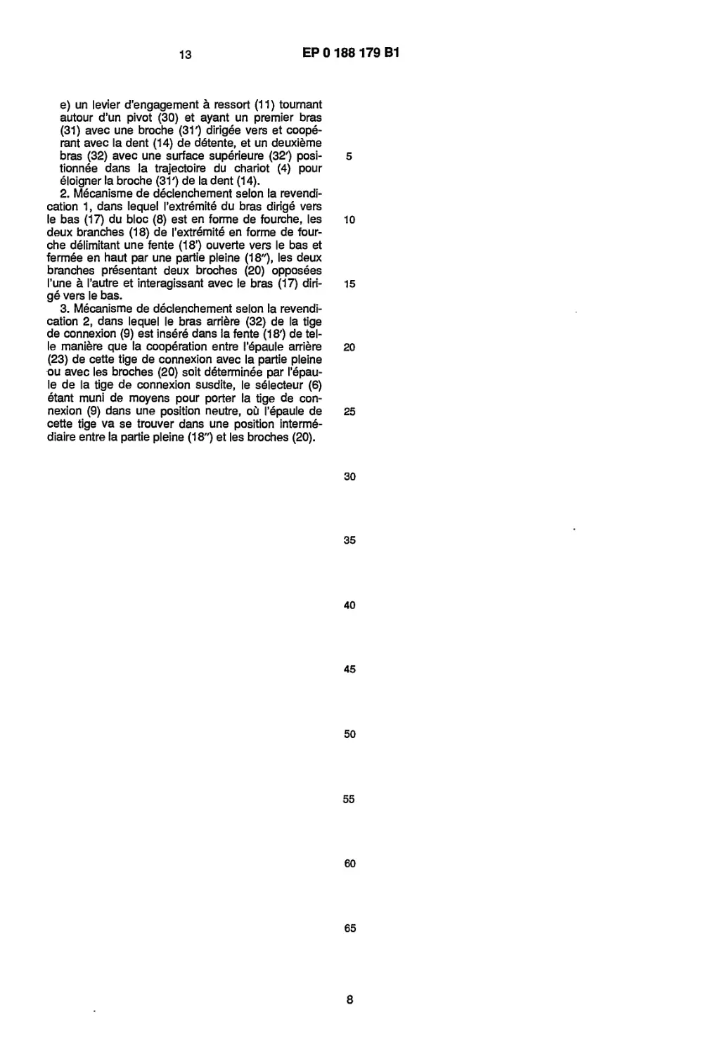
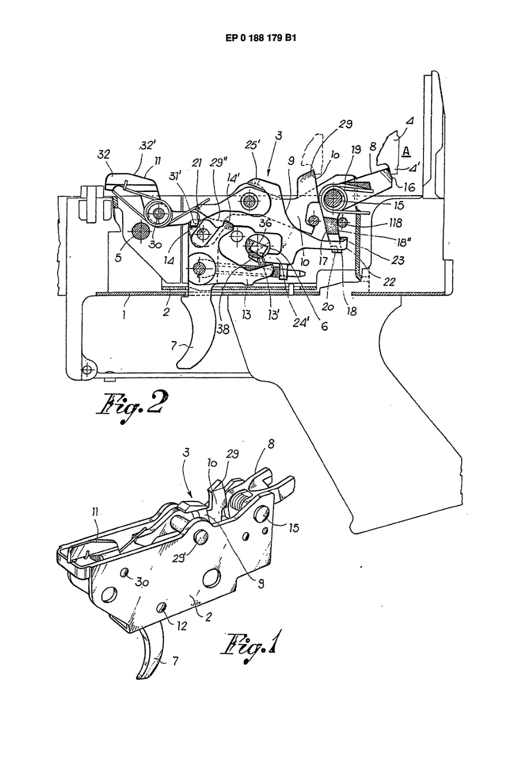
Figure 1 is a perspective view of the tripping
mechanism pre-mounted in a support box-like body
and insertable, as a unit, in the trip box of an auto-
matic rifle;
Figure 2 is a sectional view of a portion of an au-
tomatic rifle containing the tripping mechanism in po-
sition of safety and with bolt carriage blocked in
withdrawn position (armed);
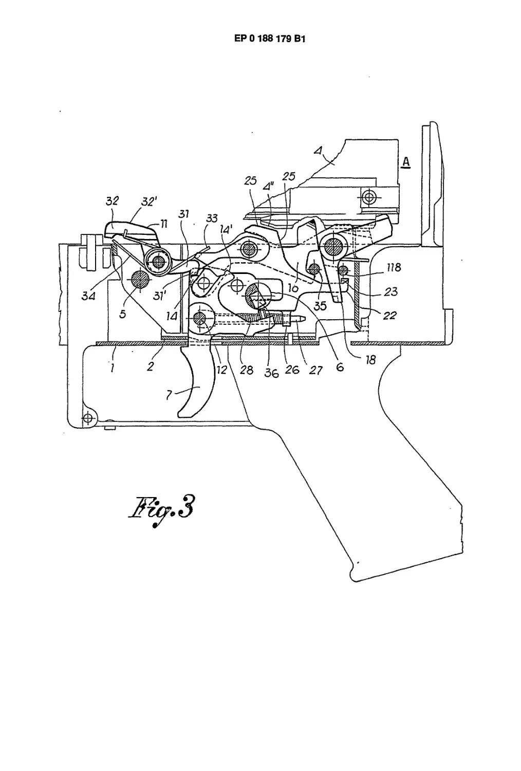
Figure 3 is a view analogous to Figure 2, but with
the firing mode selector rotated, so as to use the ri-
fle for single, individual firing of cartridges;
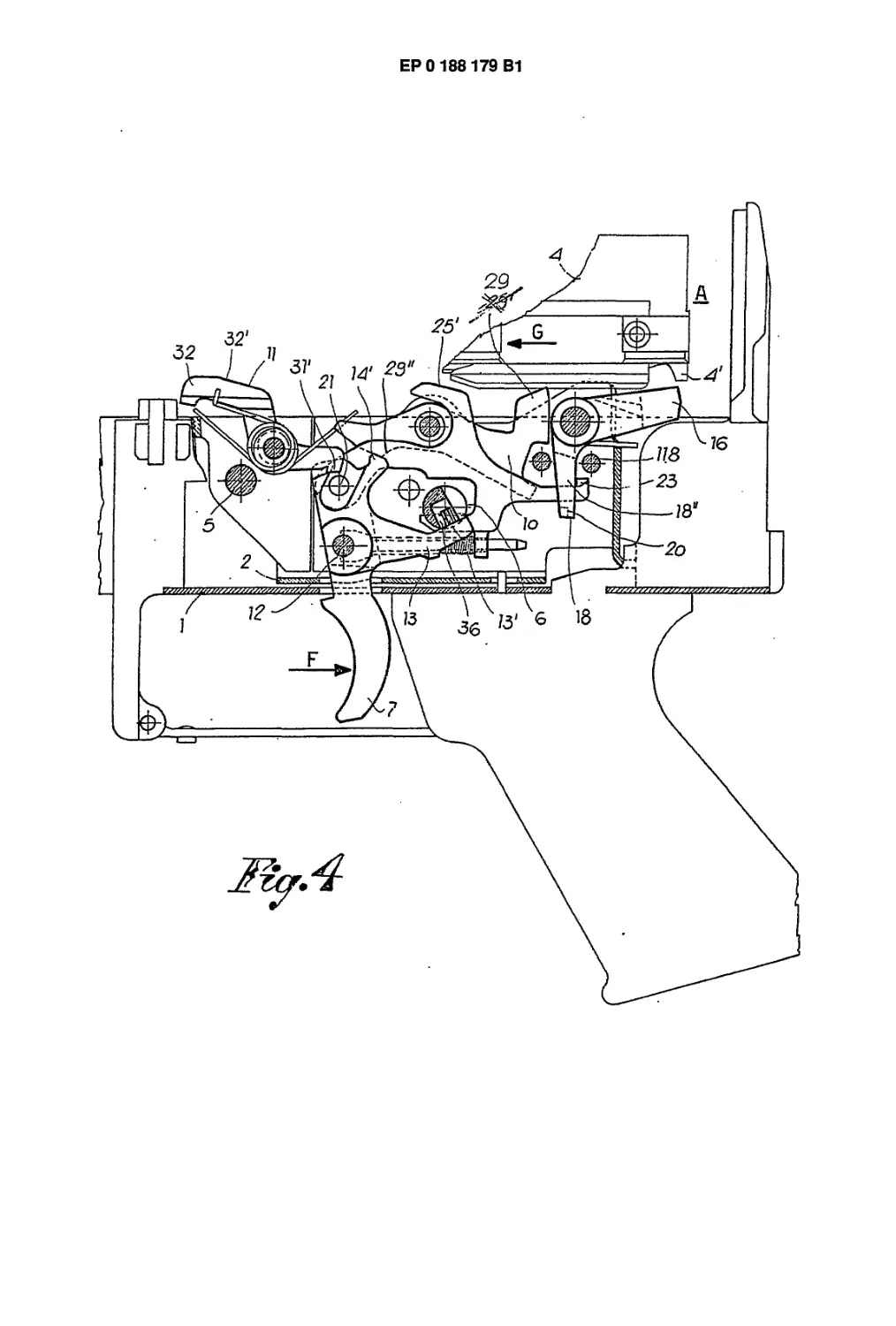
Figure 4 is a view analogous to Figure 3, but with
the trigger in pulled positon and the bolt carriage
disengaged to allow its forward displacement;
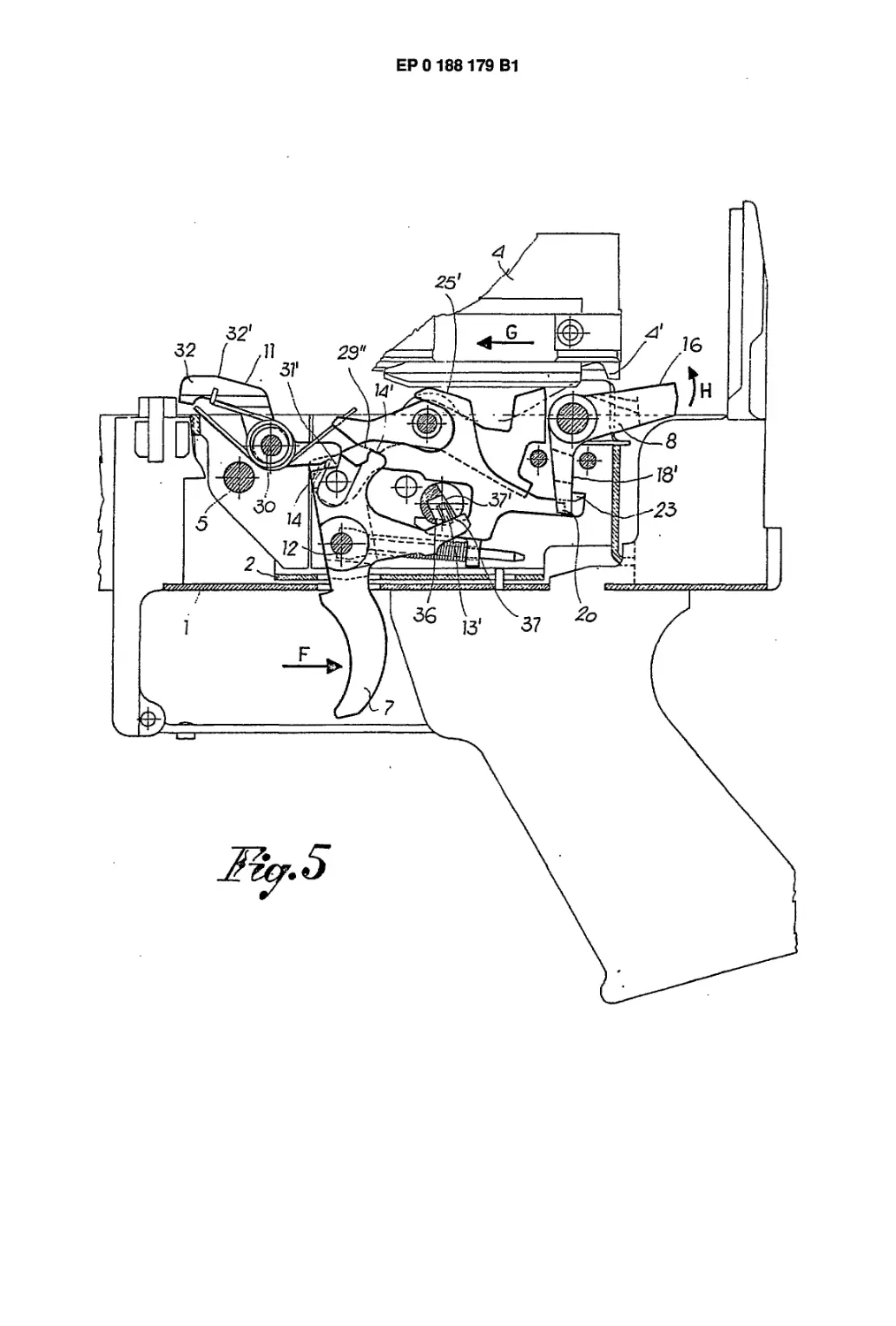
Figure 5 shows the tripping mechanism in a posi-
tion immediately following that illustrated in Figure 4
and corresponding to the disconnection of the con-
necting rod from the trip block;
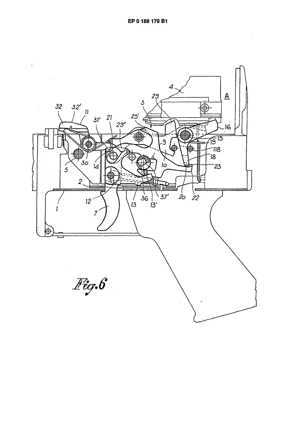
Figure 6 shows the tripping mechanism assembled
at the beginning of an automatic fire volley;
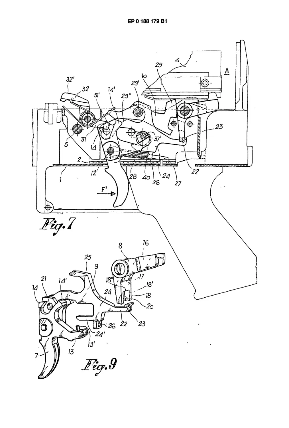
Figure 7 shows the position of the mechanism with
the trigger pulled during an automatic fire volley;
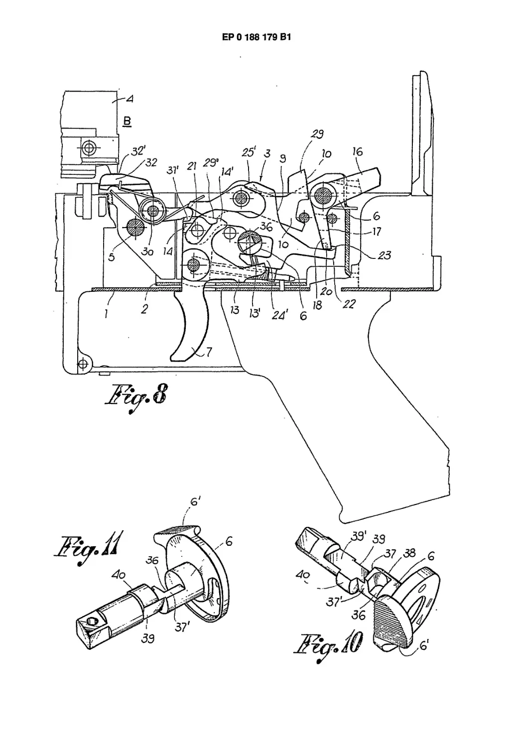
Figure 8 shows the mechanism when the rapid au-
tomatic fire is interrupted;
Figure 9 is a perspective view in exploded format
of the trigger, the connecting rod and the trip block
of the rifle;
Figures 10 and 11 shows two representations, per-
spectively, of the safety bolt, serving also as se-
lector for the firing mode.
Referring now to the accompanying drawings,
reference numeral 1 represents, generically, the
trip box of an automatic rifle, in which there is mount-
ed the tripping mechanism 3 by means of box-like
support. Tripping mechanism 3 serves to control the
bolt carriage 4 of the weapon, the carriage being
guided and displaced in known manner from a with-
drawn and back position A (armed) to an advanced
and forward position В (percussion or firing), and
3
5
ЕР 0 188 179 В1
6
back again. All the member components of the trip-
ping mechanism are pre-mounted in the box-like sup-
port 2 for the insertion, as a unit, within the trip box
1. The box-like support 2 is blocked in the trip box 1
by means of at least one pin 5 and by the safety rod
6 of the tripping mechanism.
The tripping mechanism 3, in greater detail, com-
prises a trigger 7, a trip box 8, a connecting rod 9,
the above mentioned safety rod 6 (which serves al-
so as firing mode selector and which is positioned
between the trigger 7 and the connecting rod 9), a
safety block 10 and an engaging lever 11. This lever
11 serves to couple itself to the trigger during the
automatic firing.
Trigger 7 is mounted on the box-like support 2 by
means of a pin 12 and is provided with a tail 13 which
faces backward and is provided with a pin 13'. Trig-
ger 7, furthermore, has an upwardly extending arm
which carries at least one tooth 14 and at least part
of a thrusting portion 14', the function of which will
become apparent hereinafter.
The trip block 8 is mounted, in pendular-like fash-
ion, in the box-like support 2 by means of a pin 15
and has a first arm 16 facing obliquely upwardly and
engaging head-on with an arresting shoulder 4'
which is provided on the bolt carriage 4, so that the
bolt carriage be stopped in the armed, withdrawn po-
sition A. Trip block 8 has a second arm 17 facing
downwardly and terminating in its lower portion with
a bifurcated extremity 18. Trip block 8 is urged by a
spring 19 which tends to rotate the block itself in
such a way that its first arm 16 be normally facing
upwardly in position of interception and engagement
with the arresting shoulder 4' of the bolt carriage 4.
Spring 9 is further limited by a pin 118. The fork-like
portion 18 of the second arm 17 of the trip block 8 de-
fines a cut or notch 18', open toward the underside
and close on the upperside by a full portion 18". On
the two branches of the fork-like extremity are pro-
vided two opposed pegs 20 facing toward the cent-
er of the opening 18' (see figure 9).
Th connecting rod 9 is mounted on the upper arm
of the trigger 7 by means of a pin 21, so as to move
concurrently with the trigger, but also independent-
ly thereof, on pin 21. The connecting rod 9 extends
rearwardly, where it ends with an arm 22 positioned
in correspondence with the cut or opening 18' of the
fork-like portion 18 of the trip block. The arm 22 is
shaped so as to penetrate from beneath and up-
wardly into the opening 18', passing between the two
opposed pegs 20. The arm 22 of the connecting rod
9 is furthermore provided with a stepwise shoulder
23 protruding from the sides of the arm and serving
to cooperate selectively with the full portion 18"
which superimposes on the fork-like member 18 of
the trip block 8, and to further cooperate also with
the pegs 20 of the fork-like member, so that the trip
block 8 be displaced in opposition to the action of
the spring 19, that is to say, away from the shoulder
4' of the bolt carriage 4.
On its intermediate portion, the connecting rod 9
has a C-shaped arm 24 facing downwardly and a
second C-shaped arm 25 facing upwardly. Arm 24
has an horizontal portion 24', or substantially hori-
zontal, which passes beneath the safety rod 6 and
5
10
15
20
25
30
35
40
45
50
55
60
65
cooperates therewith. Arm 24 is also provided with
a perforated support 26 through which is guided an
extremity of a spring-carrying rod 27, the opposite
extremity which rod being testing on pin 12 of the
trigger 7. On the rod 27 is mounted a pre-stressed
spring 28, which tends to displace normally the con-
necting rod upwardly to a position wherein the step-
wise shoulder 23 of the back arm 22 of the connect-
ing rod cooperates with the trip block 8, such a dis-
placement being in any event defined and limited by
the horizontal portion of the arm 24 cooperating
with the safety rod 6.
Arm 25 of the connecting rod, faced upwardly,
has on its top an inclined plane 25' which serves to
cooperate with a similar inclined plane 4" provided
on the bolt carriage 4, when this latter passes from
position A to position B, so as to determine the dis-
connection of the connecting rod 9 from the trip
block 8.
As to the safety block 10, this is mounted, in pen-
dular-like fashion, in the box-like support 2 by
means of a pin 29', and on its back it has a terminal
29 for intercepting the shoulder 4' of the bolt car-
riage 4, as shown in phantom lines in Figure 2, when-
ever the carriage is not properly engaged or es-
capes accidentally from the trip block 8.
In front, the safety block 10 is provided with a
cam-like appendix 29" for cooperation with the
thrusting portion 14' of the upper arm of the trigger
7. The engaging lever 11 is pivoting in the box-like
support 2 by means of a pin 30 and it displays a first
arm 31 faced toward the appendix 29" of the safety
block 10. This first arm has a peg 31' which cooper-
ates with the tooth 14 of the trigger 7. The engaging
lever 11 also displays a second arm 32 facing in the
opposite direction from the first arm and having an
upper surface 32' so positioned as to be engaged
by the bolt carriage when it is displaced forwardly in
the position B.
The safety block 10 and the engaging lever 11 are
actuated by springs 33 and 34, respectively, which
tend to keep the block and the lever normally in their
respective positions of interception and of engage-
ment by the bolt carriage 4. These positions are de-
fined by a pin 55 for the safety block 10 and by the
peg 31' of the engaging lever 11 on the tooth 14 of
the upper arm of the trigger. The safety block 10
and the engaging lever 11 are, nevertheless, dis-
placeable in opposition to the action of their respec-
tive springs by the bolt carriage 4.
The safety rod is transversely mounted on the
box-like support 2 and is provided, at one or both
extremities thereof, with a maneuver lever 6', for
its rotation and for its arrest in the positions of
safety or of individual firing or of automatic rapid
firing.
The safety rod 6 is provided on its intermediate
portion with the following members: a cavity 36 for
receiving the pin 13' on the tail 13 of the trigger 7; a
cam-shaped portion, formed by two flat surfaces of
diverse depth 37-37' and by a cylindrical surface
38, said cam-shaped portion cooperating with the
tail 13 of the trigger; a second, cam-shaped portion,
also having two flat surfaces of various depth 39-
39' and a cylindrical surface 40, said second cam-
4
7
ЕР 0 188 179 В1
8
shaped portion cooperating with the lower arm 24 of
the connecting rod 9 (see also figures 10 and 11), the
surface 40 of the safety rod which is not affected
by the cavity and by the flat surfaces mentioned
above being in this case cylindrical.
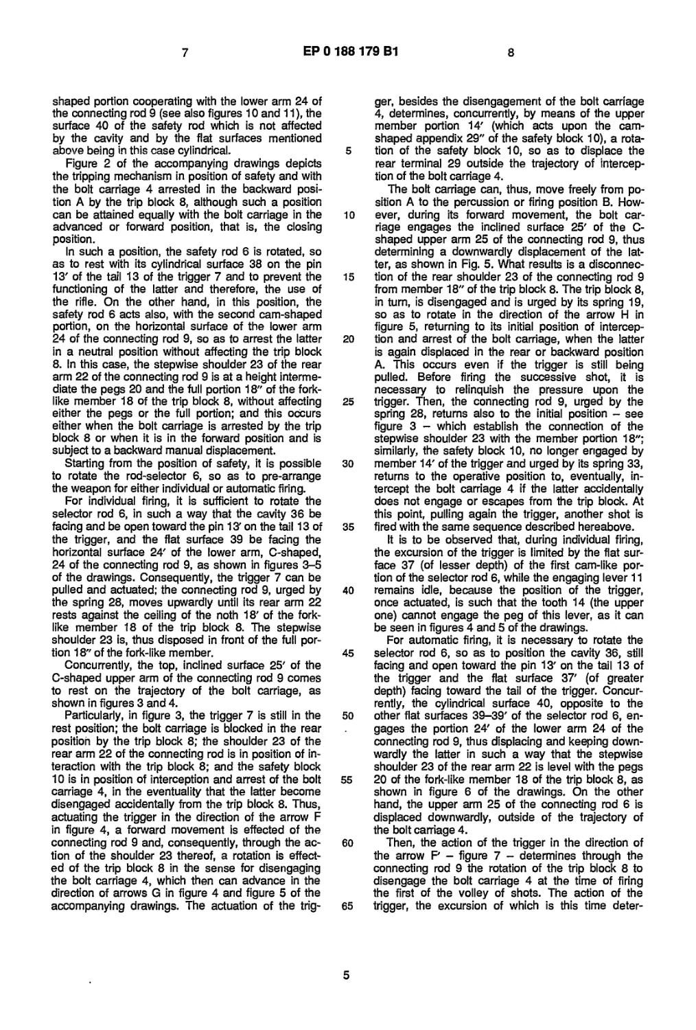
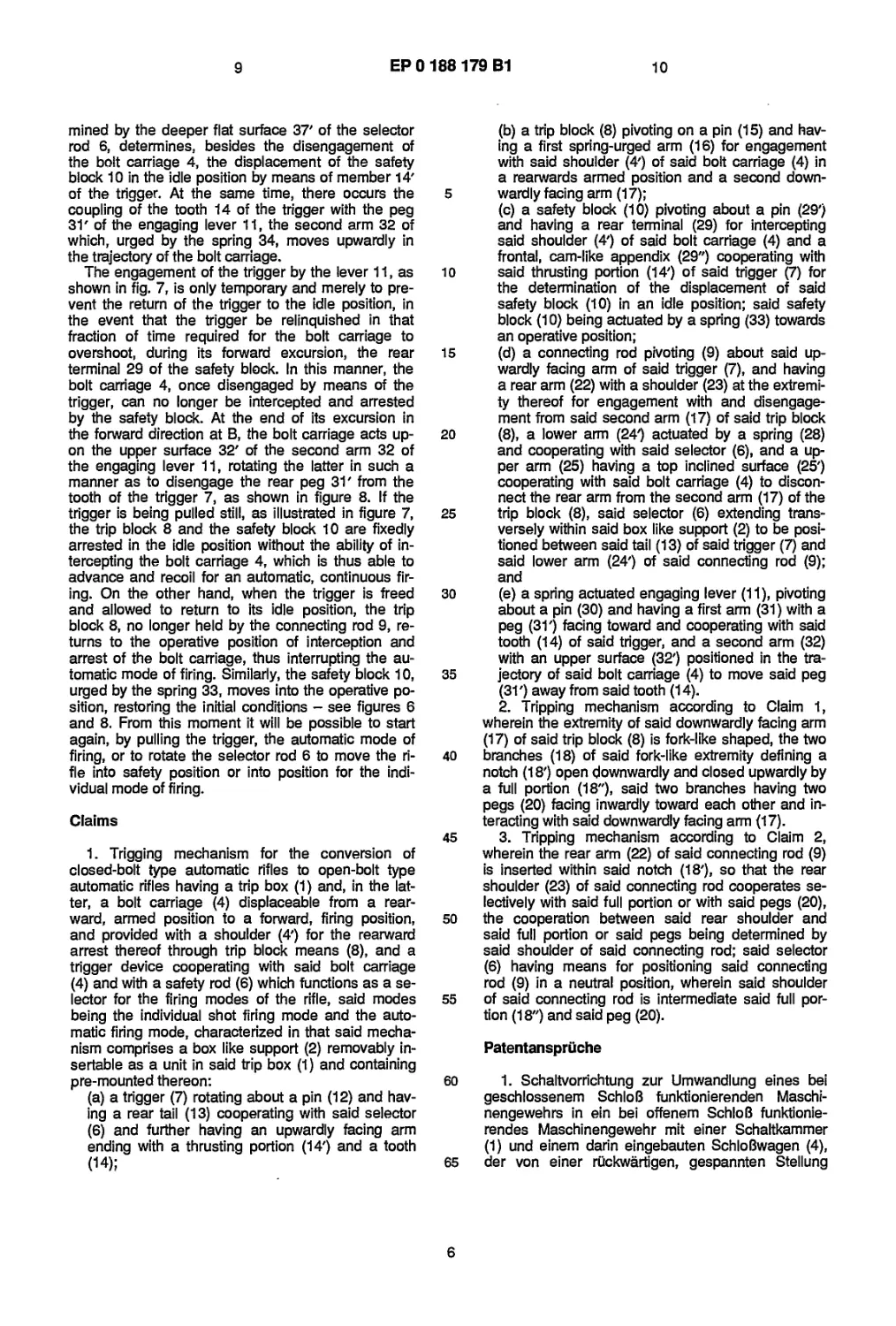
Figure 2 of the accompanying drawings depicts
the tripping mechanism in position of safety and with
the bolt carriage 4 arrested in the backward posi-
tion A by the trip block 8, although such a position
can be attained equally with the bolt carriage in the
advanced or forward position, that is, the closing
position.
In such a position, the safety rod 6 is rotated, so
as to rest with its cylindrical surface 38 on the pin
13' of the tail 13 of the trigger 7 and to prevent the
functioning of the latter and therefore, the use of
the rifle. On the other hand, in this position, the
safety rod 6 acts also, with the second cam-shaped
portion, on the horizontal surface of the lower arm
24 of the connecting rod 9, so as to arrest the latter
in a neutral position without affecting the trip block
8. In this case, the stepwise shoulder 23 of the rear
arm 22 of the connecting rod 9 is at a height interme-
diate the pegs 20 and the full portion 18" of the fork-
like member 18 of the trip block 8, without affecting
either the pegs or the full portion; and this occurs
either when the bolt carriage is arrested by the trip
block 8 or when it is in the forward position and is
subject to a backward manual displacement.
Starting from the position of safety, it is possible
to rotate the rod-selector 6, so as to pre-arrange
the weapon for either individual or automatic firing.
For individual firing, it is sufficient to rotate the
selector rod 6, in such a way that the cavity 36 be
facing and be open toward the pin IS' on the tail 13 of
the trigger, and the flat surface 39 be facing the
horizontal surface 24' of the lower arm, C-shaped,
24 of the connecting rod 9, as shown in figures 3-5
of the drawings. Consequently, the trigger 7 can be
pulled and actuated; the connecting rod 9, urged by
the spring 28, moves upwardly until its rear arm 22
rests against the ceiling of the noth 18' of the fork-
like member 18 of the trip block 8. The stepwise
shoulder 23 is, thus disposed in front of the full por-
tion 18" of the fork-like member.
Concurrently, the top, inclined surface 25' of the
C-shaped upper arm of the connecting rod 9 comes
to rest on the trajectory of the bolt carriage, as
shown in figures 3 and 4.
Particularly, in figure 3, the trigger 7 is still in the
rest position; the bolt carriage is blocked in the rear
position by the trip block 8; the shoulder 23 of the
rear arm 22 of the connecting rod is in position of in-
teraction with the trip block 8; and the safety block
10 is in position of interception and arrest of the bolt
carriage 4, in the eventuality that the latter become
disengaged accidentally from the trip block 8. Thus,
actuating the trigger in the direction of the arrow F
in figure 4, a forward movement is effected of the
connecting rod 9 and, consequently, through the ac-
tion of the shoulder 23 thereof, a rotation is effect-
ed of the trip block 8 in the sense for disengaging
the bolt carriage 4, which then can advance in the
direction of arrows G in figure 4 and figure 5 of the
accompanying drawings. The actuation of the trig-
5
10
15
20
25
30
35
40
45
50
55
60
65
ger, besides the disengagement of the bolt carriage
4, determines, concurrently, by means of the upper
member portion 14' (which acts upon the cam-
shaped appendix 29" of the safety block 10), a rota-
tion of the safety block 10, so as to displace the
rear terminal 29 outside the trajectory of intercep-
tion of the bolt carriage 4.
The bolt carriage can, thus, move freely from po-
sition A to the percussion or firing position B. How-
ever, during its forward movement, the bolt car-
riage engages the inclined surface 25' of the C-
shaped upper arm 25 of the connecting rod 9, thus
determining a downwardly displacement of the lat-
ter, as shown in Fig. 5. What results is a disconnec-
tion of the rear shoulder 23 of the connecting rod 9
from member 18" of the trip block 8. The trip block 8,
in turn, is disengaged and is urged by its spring 19,
so as to rotate in the direction of the arrow H in
figure 5, returning to its initial position of intercep-
tion and arrest of the bolt carriage, when the latter
is again displaced in the rear or backward position
A. This occurs even if the trigger is still being
pulled. Before firing the successive shot, it is
necessary to relinquish the pressure upon the
trigger. Then, the connecting rod 9, urged by the
spring 28, returns also to the initial position - see
figure 3 - which establish the connection of the
stepwise shoulder 23 with the member portion 18";
similarly, the safety block 10, no longer engaged by
member 14' of the trigger and urged by its spring 33,
returns to the operative position to, eventually, in-
tercept the bolt carriage 4 if the latter accidentally
does not engage or escapes from the trip block. At
this point, pulling again the trigger, another shot is
fired with the same sequence described hereabove.
It is to be observed that, during individual firing,
the excursion of the trigger is limited by the flat sur-
face 37 (of lesser depth) of the first cam-like por-
tion of the selector rod 6, while the engaging lever 11
remains idle, because the position of the trigger,
once actuated, is such that the tooth 14 (the upper
one) cannot engage the peg of this lever, as it can
be seen in figures 4 and 5 of the drawings.
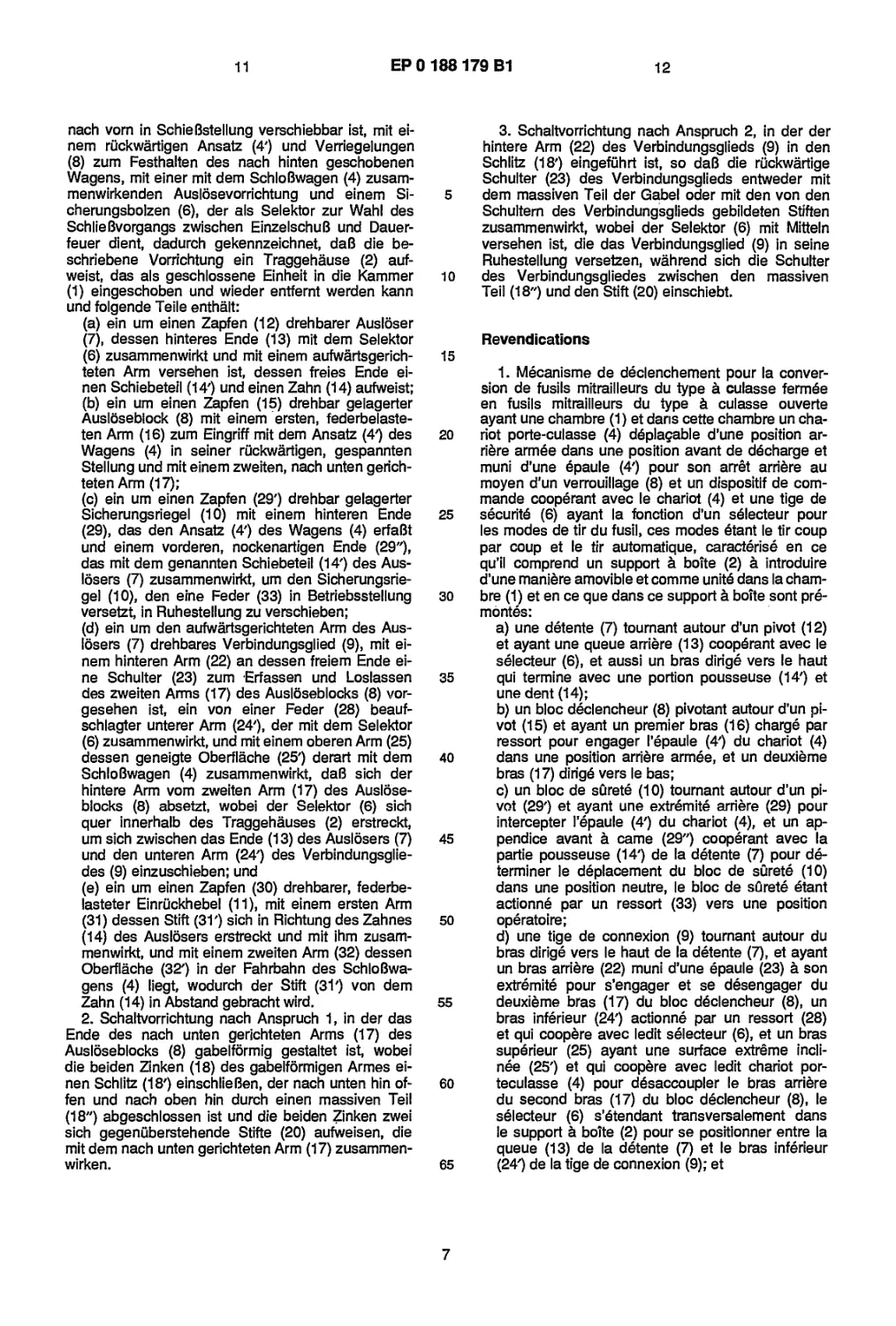
For automatic firing, it is necessary to rotate the
selector rod 6, so as to position the cavity 36, still
facing and open toward the pin 13' on the tail 13 of
the trigger and the flat surface 37' (of greater
depth) facing toward the tail of the trigger. Concur-
rently, the cylindrical surface 40, opposite to the
other flat surfaces 39-39' of the selector rod 6, en-
gages the portion 24' of the lower arm 24 of the
connecting rod 9, thus displacing and keeping down-
wardly the latter in such a way that the stepwise
shoulder 23 of the rear arm 22 is level with the pegs
20 of the fork-like member 18 of the trip block 8, as
shown in figure 6 of the drawings. On the other
hand, the upper arm 25 of the connecting rod 6 is
displaced downwardly, outside of the trajectory of
the bolt carriage 4.
Then, the action of the trigger in the direction of
the arrow P - figure 7 - determines through the
connecting rod 9 the rotation of the trip block 8 to
disengage the bolt carriage 4 at the time of firing
the first of the volley of shots. The action of the
trigger, the excursion of which is this time deter-
5
9
ЕР 0 188 179 В1
10
mined by the deeper flat surface 37' of the selector
rod 6, determines, besides the disengagement of
the bolt carriage 4, the displacement of the safety
block 10 in the idle position by means of member 14'
of the trigger. At the same time, there occurs the
coupling of the tooth 14 of the trigger with the peg
31' of the engaging lever 11, the second arm 32 of
which, urged by the spring 34, moves upwardly in
the trajectory of the bolt carriage.
The engagement of the trigger by the lever 11, as
shown in fig. 7, is only temporary and merely to pre-
vent the return of the trigger to the idle position, in
the event that the trigger be relinquished in that
fraction of time required for the bolt carriage to
overshoot, during its forward excursion, the rear
terminal 29 of the safety block. In this manner, the
bolt carriage 4, once disengaged by means of the
trigger, can no longer be intercepted and arrested
by the safety block. At the end of its excursion in
the forward direction at B, the bolt carriage acts up-
on the upper surface 32' of the second arm 32 of
the engaging lever 11, rotating the latter in such a
manner as to disengage the rear peg 31' from the
tooth of the trigger 7, as shown in figure 8. If the
trigger is being pulled still, as illustrated in figure 7,
the trip block 8 and the safety block 10 are fixedly
arrested in the idle position without the ability of in-
tercepting the bolt carriage 4, which is thus able to
advance and recoil for an automatic, continuous fir-
ing. On the other hand, when the trigger is freed
and allowed to return to its idle position, the trip
block 8, no longer held by the connecting rod 9, re-
turns to the operative position of interception and
arrest of the bolt carriage, thus interrupting the au-
tomatic mode of firing. Similarly, the safety block 10,
urged by the spring 33, moves into the operative po-
sition, restoring the initial conditions - see figures 6
and 8. From this moment it will be possible to start
again, by pulling the trigger, the automatic mode of
firing, or to rotate the selector rod 6 to move the ri-
fle into safety position or into position for the indi-
vidual mode of firing.
Claims
1. Trigging mechanism for the conversion of
closed-bolt type automatic rifles to open-bolt type
automatic rifles having a trip box (1) and, in the lat-
ter, a bolt carriage (4) displaceable from a rear-
ward, armed position to a forward, firing position,
and provided with a shoulder (4') for the rearward
arrest thereof through trip block means (8), and a
trigger device cooperating with said bolt carriage
(4) and with a safety rod (6) which functions as a se-
lector for the firing modes of the rifle, said modes
being the individual shot firing mode and the auto-
matic firing mode, characterized in that said mecha-
nism comprises a box like support (2) removably in-
sertable as a unit in said trip box (1) and containing
pre-mounted thereon:
(a) a trigger (7) rotating about a pin (12) and hav-
ing a rear tail (13) cooperating with said selector
(6) and further having an upwardly facing arm
ending with a thrusting portion (14') and a tooth
(14);
5
10
15
20
25
30
35
40
45
50
55
60
65
(b) a trip block (8) pivoting on a pin (15) and hav-
ing a first spring-urged arm (16) for engagement
with said shoulder (4') of said bolt carriage (4) in
a rearwards armed position and a second down-
wardly facing arm (17);
(c) a safety block (10) pivoting about a pin (29')
and having a rear terminal (29) for intercepting
said shoulder (4') of said bolt carriage (4) and a
frontal, cam-like appendix (29") cooperating with
said thrusting portion (14') of said trigger (7) for
the determination of the displacement of said
safety block (10) in an idle position; said safety
block (10) being actuated by a spring (33) towards
an operative position;
(d) a connecting rod pivoting (9) about said up-
wardly facing arm of said trigger (7), and having
a rear arm (22) with a shoulder (23) at the extremi-
ty thereof for engagement with and disengage-
ment from said second arm (17) of said trip block
(8), a lower arm (24') actuated by a spring (28)
and cooperating with said selector (6), and a up-
per arm (25) having a top inclined surface (25')
cooperating with said bolt carriage (4) to discon-
nect the rear arm from the second arm (17) of the
trip block (8), said selector (6) extending trans-
versely within said box like support (2) to be posi-
tioned between said tail (13) of said trigger (7) and
said lower arm (24') of said connecting rod (9);
and
(e) a spring actuated engaging lever (11), pivoting
about a pin (30) and having a first arm (31) with a
peg (31') facing toward and cooperating with said
tooth (14) of said trigger, and a second arm (32)
with an upper surface (32') positioned in the tra-
jectory of said bolt carriage (4) to move said peg
(31') away from said tooth (14).
2. Tripping mechanism according to Claim 1,
wherein the extremity of said downwardly facing arm
(17) of said trip block (8) is fork-like shaped, the two
branches (18) of said fork-like extremity defining a
notch (18') open downwardly and closed upwardly by
a full portion (18"), said two branches having two
pegs (20) facing inwardly toward each other and in-
teracting with said downwardly facing arm (17).
3. Tripping mechanism according to Claim 2,
wherein the rear arm (22) of said connecting rod (9)
is inserted within said notch (18'), so that the rear
shoulder (23) of said connecting rod cooperates se-
lectively with said full portion or with said pegs (20),
the cooperation between said rear shoulder and
said full portion or said pegs being determined by
said shoulder of said connecting rod; said selector
(6) having means for positioning said connecting
rod (9) in a neutral position, wherein said shoulder
of said connecting rod is intermediate said full por-
tion (18") and said peg (20).
Patentanspriiche
1. Schaltvorrichtung zur Umwandlung eines bei
geschlossenem SchloB funktionierenden Maschi-
nengewehrs in ein bei offenem SchloB funktionie-
rendes Maschinengewehr mit einer Schaltkammer
(1) und einem darin eingebauten SchloBwagen (4),
der von einer riickwartigen, gespannten Stellung
6
11
ЕР 0 188 179 В1
12
nach vorn in SchieBstellung verschiebbar ist, mit ei-
nem riickwartigen Ansatz (4') und Verriegelungen
(8) zum Festhalten des nach hinten geschobenen
Wagens, mit einer mit dem SchloBwagen (4) zusam-
menwirkenden Auslosevorrichtung und einem Si-
cherungsbolzen (6), der als Selektor zur Wahl des
SchlieBvorgangs zwischen EinzelschuB und Dauer-
feuer dient, dadurch gekennzeichnet, daB die be-
schriebene Vorrichtung ein Traggehause (2) auf-
weist, das als geschlossene Einheit in die Kammer
(1) eingeschoben und wieder entfernt werden kann
und folgende Teile enthalt:
(a) ein urn einen Zapfen (12) drehbarer Ausloser
(7), dessen hinteres Ende (13) mit dem Selektor
(6) zusammenwirkt und mit einem aufwartsgerich-
teten Arm versehen ist, dessen freies Ende ei-
nen Schiebeteil (14') und einen Zahn (14) aufweist;
(b) ein urn einen Zapfen (15) drehbar gelagerter
Ausloseblock (8) mit einem ersten, federbelaste-
ten Arm (16) zum Eingriff mit dem Ansatz (4') des
Wagens (4) in seiner riickwartigen, gespannten
Stellung und mit einem zweiten, nach unten gerich-
teten Arm (17);
(c) ein urn einen Zapfen (29') drehbar gelagerter
Sicherungsriegel (10) mit einem hinteren Ende
(29), das den Ansatz (4') des Wagens (4) erfaBt
und einem vorderen, nockenartigen Ende (29"),
das mit dem genannten Schiebeteil (14') des Aus-
losers (7) zusammenwirkt, urn den Sicherungsrie-
gel (10), den eine Feder (33) in Betriebsstellung
versetzt, in Ruhestellung zu verschieben;
(d) ein urn den aufwartsgerichteten Arm des Aus-
losers (7) drehbares Verbindungsglied (9), mit ei-
nem hinteren Arm (22) an dessen freiem Ende ei-
ne Schulter (23) zum Erfassen und Loslassen
des zweiten Arms (17) des Ausloseblocks (8) vor-
gesehen ist, ein von einer Feder (28) beauf-
schlagter unterer Arm (24'), der mit dem Selektor
(6) zusammenwirkt, und mit einem oberen Arm (25)
dessen geneigte Oberflache (25') derart mit dem
SchloBwagen (4) zusammenwirkt, daB sich der
hintere Arm vom zweiten Arm (17) des Auslose-
blocks (8) absetzt, wobei der Selektor (6) sich
quer innerhalb des Traggehauses (2) erstreckt,
urn sich zwischen das Ende (13) des Auslosers (7)
und den unteren Arm (24') des Verbindungsglie-
des (9) einzuschieben; und
(e) ein urn einen Zapfen (30) drehbarer, federbe-
lasteter Einriickhebel (11), mit einem ersten Arm
(31) dessen Stitt (31') sich in Richtung des Zahnes
(14) des Auslosers erstreckt und mit ihm zusam-
menwirkt, und mit einem zweiten Arm (32) dessen
Oberflache (32') in der Fahrbahn des SchloBwa-
gens (4) liegt, wodurch der Stift (31') von dem
Zahn (14) in Abstand gebracht wird.
2. Schaltvorrichtung nach Anspruch 1, in der das
Ende des nach unten gerichteten Arms (17) des
Ausloseblocks (8) gabelformig gestaltet ist, wobei
die beiden Zinken (18) des gabelformigen Armes ei-
nen Schlitz (18') einschlieBen, der nach unten hin of-
ten und nach oben hin durch einen massiven Tell
(18") abgeschlossen ist und die beiden Zinken zwei
sich gegeniiberstehende Stifte (20) aufweisen, die
mit dem nach unten gerichteten Arm (17) zusammen-
wirken.
5
10
15
20
25
30
35
40
45
50
55
60
65
3. Schaltvorrichtung nach Anspruch 2, in der der
hintere Arm (22) des Verbindungsglieds (9) in den
Schlitz (18') eingefiihrt ist, so daB die riickwartige
Schulter (23) des Verbindungsglieds entweder mit
dem massiven Teil der Gabel oder mit den von den
Schultem des Verbindungsglieds gebildeten Stiffen
zusammenwirkt, wobei der Selektor (6) mit Mitteln
versehen ist, die das Verbindungsglied (9) in seine
Ruhestellung versetzen, wahrend sich die Schulter
des Verbindungsgliedes zwischen den massiven
Teil (18") und den Stift (20) einschiebt.
Revendications
1. Mecanisme de declenchement pour la conver-
sion de fusils mitrailleurs du type & culasse fermSe
en fusils mitrailleurs du type 4 culasse ouverte
ayant une chambre (1) et dans cette chambre un cha-
riot porte-culasse (4) d6plagable d’une position ar-
rive агтёе dans une position avant de dScharge et
muni d’une ёраи!е (4') pour son arret arriere au
moyen d'un verrouillage (8) et un dispositif de com-
mande cooperant avec le chariot (4) et une tige de
зёсигйё (6) ayant la fonction d’un зё1ес1еиг pour
les modes de tir du fusil, ces modes ё1ап1 le tir coup
par coup et le tir automatique, caracterise en ce
qu’il comprend un support a boite (2) a introduire
d’une maniere amovible et comme ипкё dans la cham-
bre (1) et en ce que dans ce support a boite sont ргё-
топ1ёз:
a) une detente (7) tournant autour d’un pivot (12)
et ayant une queue arriere (13) соорёгат avec le
зё1ейеиг (6), et aussi un bras dirige vers le haut
qui termine avec une portion pousseuse (14') et
une dent (14);
b) un bloc declencheur (8) pivotant autour d’un pi-
vot (15) et ayant un premier bras (16) сЬагдё par
ressort pour engager 1’ёраи1е (4') du chariot (4)
dans une position arriere агтёе, et un deuxieme
bras (17) Ьтдё vers le bas;
c) un bloc de surete (10) tournant autour d’un pi-
vot (29') et ayant une extremite arriere (29) pour
intercepter Гёраи1е (4') du chariot (4), et un ap-
pendice avant a came (29") cooperant avec la
partie pousseuse (14') de la dёtente (7) pour dё-
terminer le dёplacement du bloc de sCirete (10)
dans une position neutre, le bloc de зйге1ё etant
actionne par un ressort (33) vers une position
operatoire;
d) une tige de connexion (9) tournant autour du
bras dirige vers le haut de la dёtente (7), et ayant
un bras arriere (22) muni d’une ёраи1е (23) a son
extreme pour s’engager et se dёsengager du
deuxieme bras (17) du bloc ЬёйепсЬеиг (8), un
bras 1п1ёпеиг (24') actionne par un ressort (28)
et qui coopere avec ledit selecteur (6), et un bras
зирёпеиг (25) ayant une surface extreme incli-
nes (25') et qui coopere avec ledit chariot por-
teculasse (4) pour dёsaccoupler le bras arriere
du second bras (17) du bloc declencheur (8), le
зё!ейеиг (6) s^tendant transversalement dans
le support a boite (2) pour se positionner entre la
queue (13) de la dёtente (7) et le bras 1п1ёг1еиг
(24') de la tige de connexion (9); et
7
13
ЕР 0 188 179 В1
е) un levier d’engagement a ressort (11) tournant
autour d’un pivot (30) et ayant un premier bras
(31) avec une broche (31') dirigee vers et coope-
rant avec la dent (14) de dStente, et un deuxieme
bras (32) avec une surface superieure (32') posi- 5
tionnee dans la trajectoire du chariot (4) pour
eloigner la broche (31') de la dent (14).
2. Mecanisme de declenchement selon la revendi-
cation 1, dans lequel I’extremite du bras dirige vers
le bas (17) du bloc (8) est en forme de fourche, les ю
deux branches (18) de I’extremite en forme de four-
che delimitant une fente (18’) ouverte vers le bas et
fermee en haut par une partie pleine (18"), les deux
branches presentant deux broches (20) opposees
I’une a I’autre et interagissant avec le bras (17) din- 15
ge vers le bas.
3. Mecanisme de declenchement selon la revendi-
cation 2, dans lequel le bras arriere (32) de la tige
de connexion (9) est insere dans la fente (18') de tel-
le maniere que la cooperation entre I’Spaule arriere 20
(23) de cette tige de connexion avec la partie pleine
ou avec les broches (20) soit determines par I’epau-
le de la tige de connexion susdite, le sSlecteur (6)
etant muni de moyens pour porter la tige de con-
nexion (9) dans une position neutre, ou I’epaule de 25
cette tige va se trouver dans une position interme-
diaire entre la partie pleine (18") et les broches (20).
35
40
45
50
55
60
65
8
ta 6Zl.88l.0d3
ЕР 0 188 179 В1
fficp.3
ЕР 0 188 179 В1
ЕР 0 188 179 В1
ЕР 0 188 179 В1
La 6ZL 881- 0 d3
ЕР 0 188 179 В1