/

Теги: weapons military affairs patent
Год: 1992

Текст
Europaisches Patentamt IIII II II II II11 11 11 II I I III II I II
(19) European Patent Office IIII II II II II11 11 11 II I I III II I II
Office europeen des brevets (11) EP 0 555 617 B1
(12) EUROPEAN PATENT SPECIFICATION
(45) Date of publication and mention (51) Int Cl.6: F41A 19/44
of the grant of the patent:
16.10.1996 Bulletin 1996/42
(21) Application number: 92830621.6
(22) Date of filing: 11.11.1992
(54) Tripping mechanism for semiautomatic and automatic firearms
Auslosemechanismus fur halb- und vollautomatische Feuerwaffen
Dispositif de declenchement pour armes a feu semi-automatiques et automatiques
(84) Designated Contracting States: (72) Inventor: Beretta, Pier Giuseppe
AT BE CH DE DK ES FR GB GR IT LI LU MC NL I-25063 Gardone V.T., (Brescia) (IT)
PT SE
(74) Representative: Manzoni, Alessandro et al
(30) Priority: 14.01.1992 IT BS920001 MANZONI & MANZONI,
UFFICIO INTERNAZIONALE BREVETTI,
(43) Date of publication of application: Pie Arnaldo 2
18.08.1993 Bulletin 1993/33 1-25121 Brescia (IT)
(73) Proprietor: FABBRICA D’ARMI RBERETTA S.p.A. (56) References cited:
25063 Gardone V.T. (Brescia) (IT) AT-B- 388 237 US-A- 4 028 835
ЕР 0 555 617В1
Note: Within nine months from the publication of the mention of the grant of the European patent, any person may give
notice to the European Patent Office of opposition to the European patent granted. Notice of opposition shall be filed in
a written reasoned statement. It shall not be deemed to have been filed until the opposition fee has been paid. (Art.
99(1) European Patent Convention).
Printed by Jouve, 75001 PARIS (FR)
1
ЕР 0 555 617В1
2
Description
The present invention relates to semiautomatic and
automatic firearms with a closed-type bolt carriage and
more particularly regards a tripping mechanism for
suche firearms especially for machine guns according
to the preamble of claim 1. Such a mechanism is well-
known in practice.
An object of the present invention is to supply a trip-
ping mechanism for firearms with a new conception and
execution and which permits the firearm to be used both
in single shot firing mode and in automatic, continuos
firing mode, by changing over the mechanism from one
condition to the other through a selector cam rod which
also acts as a safety rod and with the help of a lever
placed on the side of the hammer which is designed to
delay the percussion action of the hammer in order to
ensure the closure of the obturator beforehand. Another
object of the invention is to supply a tripping mechanism
of a simpler construction than the ones known so far,
formed from a limited number of components and which
is reliable due to this simplicity.
The here proposed tripping mechanism is fitted on-
to an underguard which is insertable in the trip box of a
semiautomatic or automatic firearm with an open bolt
and is characterized in what is claimed in at least claim
1.
Further details of the invention will appear clearer
following the description with references being made to
the attached drawings regarding an embodiment for the
release mechanism.
In said drawings:
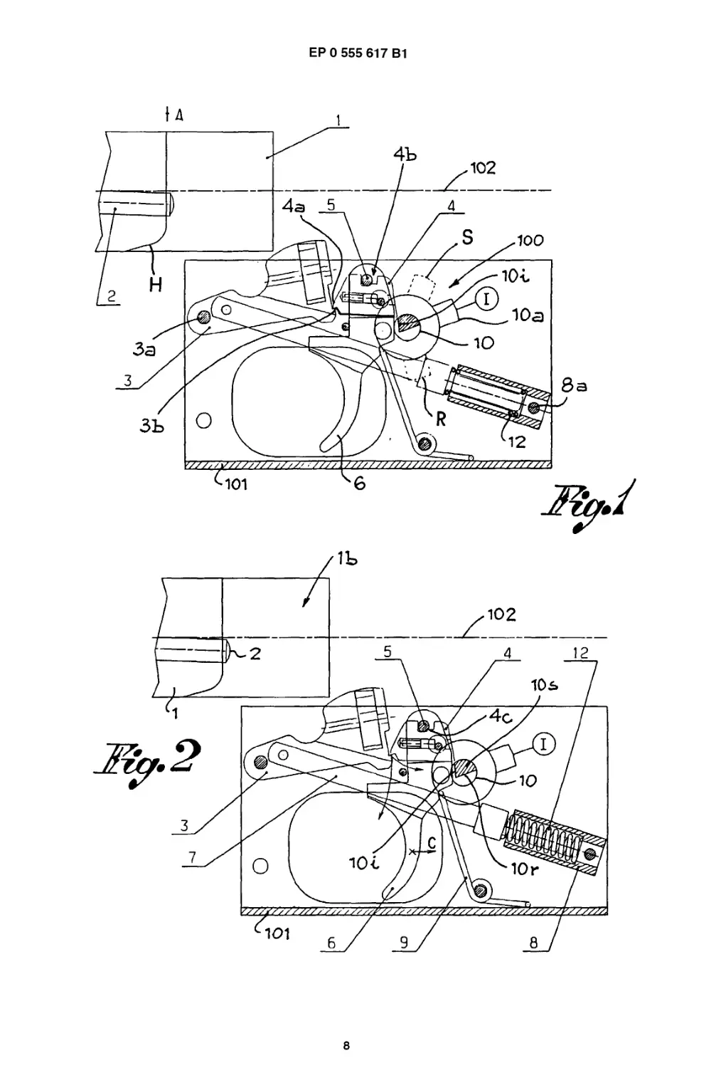
Fig. 1 shows the trippings mechanism in a "ready to
fire" static situation and in relation to the bolt
carriage of the firearm in a closed position;
Fig. 2 is a similar view to the one in Fig. 1, but with
the device in a position a moment before the
releasing of the hammer in the single shot fir-
ing mode;
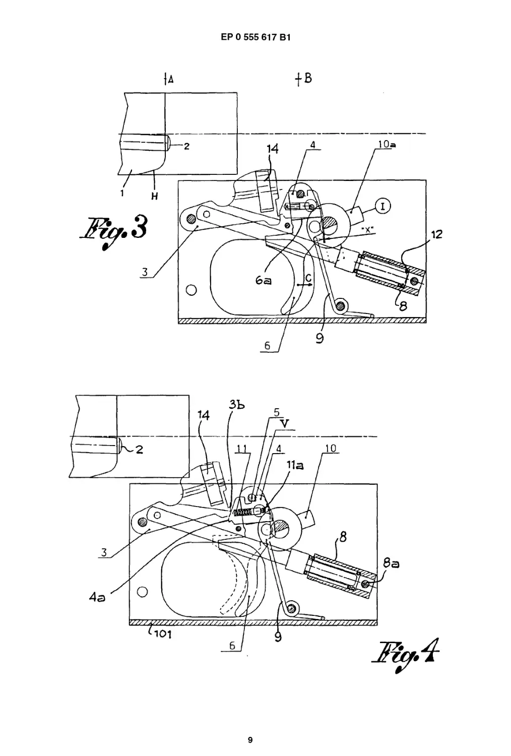
Fig. 3 is a view as in Fig.2, but at the moment when
the hammer is released;
Fig. 4 shows the mechanism with the hammer as re-
leased and in an intermediate position of its
movement towards the firing pin;
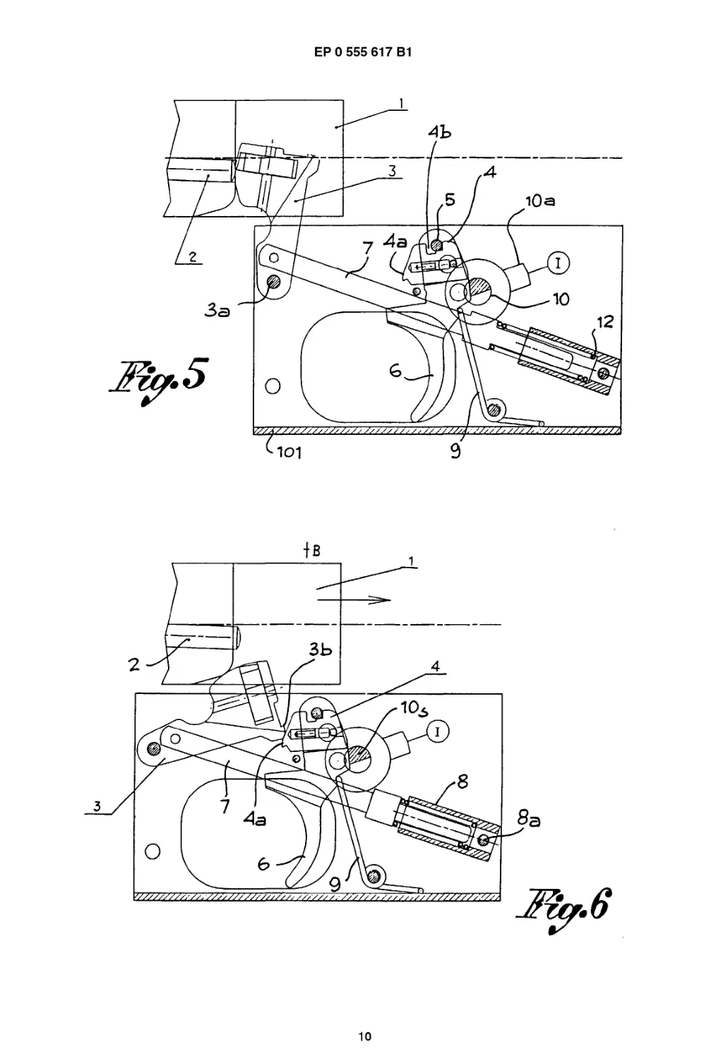
Fig. 5 shows the mechanism with the hammer in a
position of percussion on the firing pin for the
shooting of an ammunition;
Fig. 6 shows the mechanism in an intermediate re-
cocking phase of the bolt carriage which re-
turns to the opening position after the shoot-
ing of each ammunition;
Fig. 7 shows the mechanism the moment before the
engaging of the hammer by the sear;
Fig. 8 shows the mechanism at the moment when
the hammer engages to the sear and whilst
the trigger still pressed;
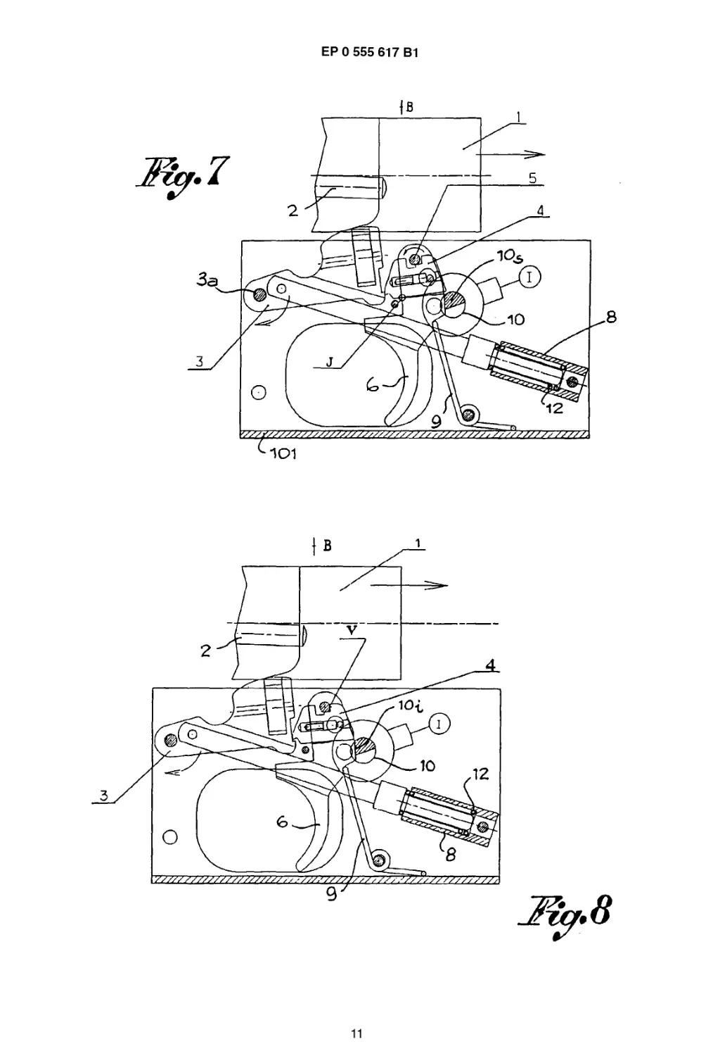
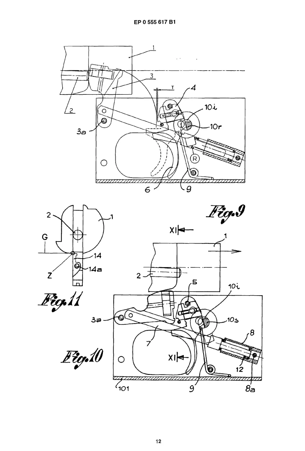
Fig. 9 shows the mechanism with the hammer in a
5
10
15
20
25
30
35
40
45
50
55
percussion position as in Fig.5, but in an au-
tomatic firing mode;
Fig. 10 shows the mechanism in the automatic firing
mode at the moment of the releasing of the
automatic firing lever with the bolt carriage in
a backing phase;
Fig. 11 is a view of the bolt carriage and of the ham-
mer ind direction of the arrows XI-XI in Fig.10;
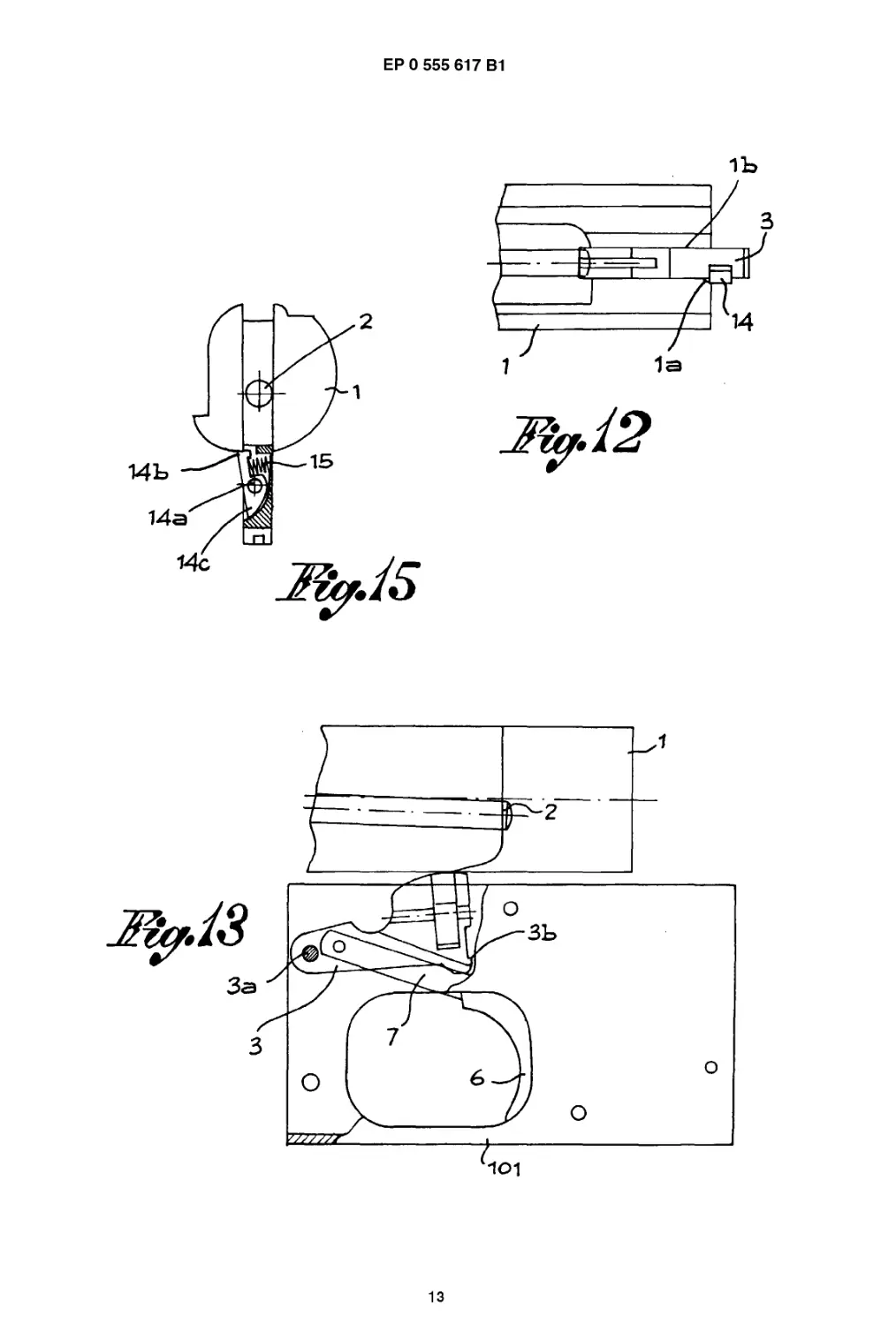
Fig. 12 is a view from above of the bolt carriage and
of the hammer;
Fig. 13 is a similar view to the one in Fig. 10, but with
the bolt carriage completely backwards;
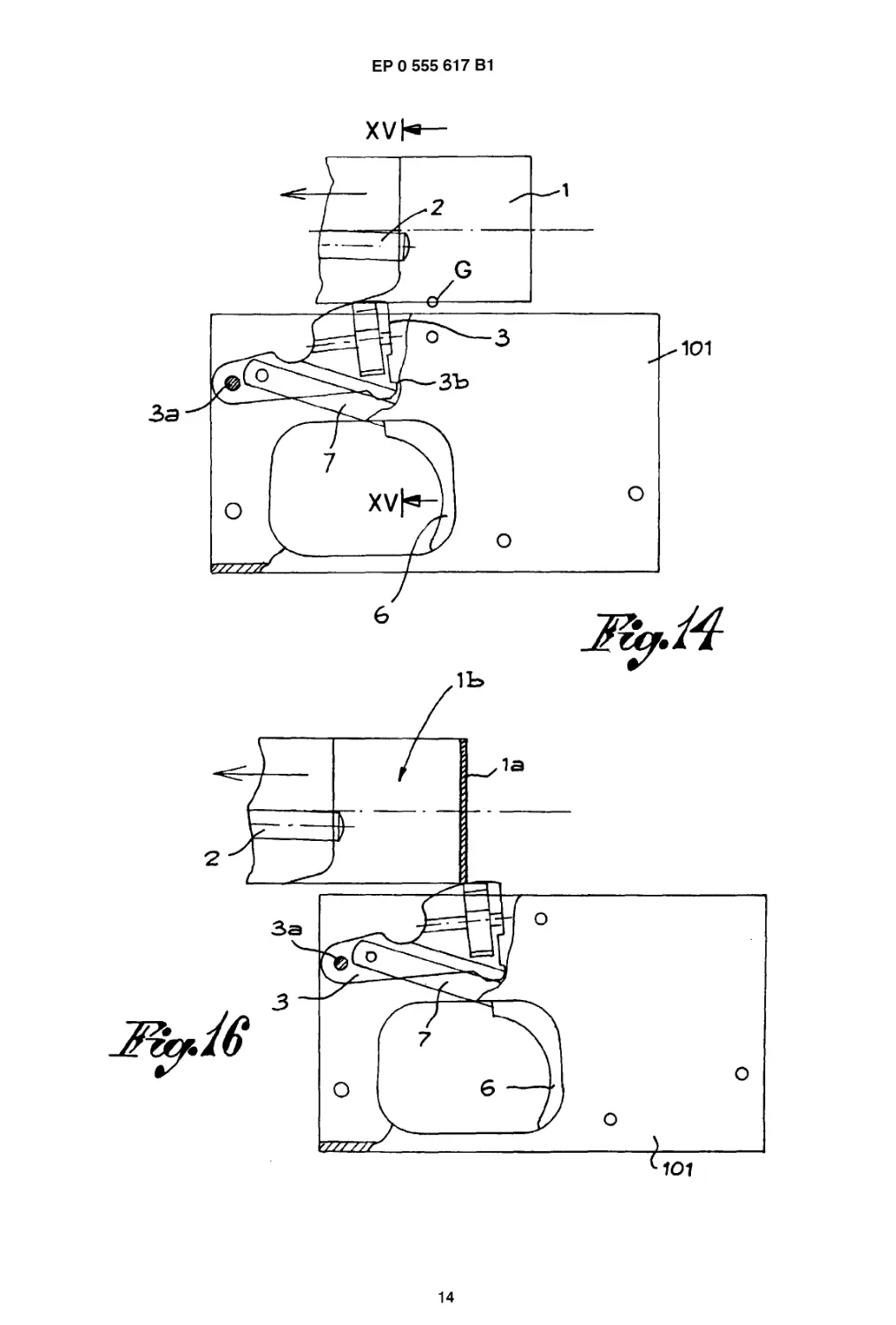
Fig. 14 shows the mechanism at the moment the au-
tomatic firing lever begins sliding on the bolt
carriage;
Fig. 15 is a view in the direction of the arrows XV-XV
in Fig. 14; and
Fig. 16 is a similar view to the one in Fig. 13, but with
a bolt carriage as closed.
The tripping mechanism (100) is fitted onto an un-
derguard (101) which in insertable in the trip box (not
shown) of a firearm such as a machine gun. The firearm
has a barrel, of which only the axis (102) is indicated,
and a bolt carriage (1) carrying a firing pin (2) only par-
tially shown and already known. The bolt carriage (1) is
movable in a known way from a forward position (A) of
closure/percussion of ammunition in the barrel to a
backward position (B) of aperture/armament and vice
versa. In particular, it should be noted that the bolt car-
riage (1) has a sloped plane (H) on its lower part, at the
lever of the back end of the firing pin (2). The sloped
plane (H) is angled from the top to the bottom, from the
back towards the front of the bolt carriage itself and has
a split (1b) aligned to the firing pin (2) in its back part.
The tripping mechanism (100) comprises a percus-
sion hammer (3), a sear (4), a trigger (6) and a safety
camshaft.
The hammer (3) is fitted onto the underguard (101)
through a rotating axle (3a) for its angular movements
towards and away from the firing pin (2) on the bolt car-
riage (1) respectively in the percussion and armament
positions. The hammer (3) has an arming tooth (3b) on
its top which is designed to interact with a release tooth
(4a) integral to the sear (4) for the stopping of the ham-
mer in its armed position. The hammer (3) is also
stressed by a spring (12) placed between a spring hold-
er rod (7) and a spring guide housing (8) and is designed
to move the hammer to its percussion position on the
firing pin (2) when it is released from the sear (4).
The spring holder rod (7) and the spring guide hous-
ing (8) are aligned and whilst the rod (7) is pivoted (7a)
to an intermediate part of the hammer (3), the spring
guide housing (8) is pivoted (8a) to the underguard (101)
so that the two elements (7,8) can vary their position
depending on the position and rotation of the hammer.
The sear (4) is fitted as a slide which is susceptable
to longitudinal movements on the trigger (6) and is nor-
2
3
ЕР 0 555 617В1
4
mally pushed forwards towards the hammer (3) through
a sear spring (11) placed between the sear itself and a
pin (11a) fixed to the underguard (101). The base of the
sear (4) rests on a plane (6a) which is formed on the
trigger.
The trigger (6) is pendulum fitted on the underguard
(101) through an oscillating pivot (5) and is stressed by
a spring (9). This spring normally tends to move and
keep the trigger (6) in a forward inactive position, that is
to say at rest, whilst it loads when the trigger is operated.
It should be noted that the oscillating pivot (5) of the
trigger (6) is found in a split (4b) formed on the top fo
the sear (4). This is so that the pivot can alternately in-
teract with the sides of said split (4b) in order to limit the
longitudinal sliding of the sear and also to engage with
a step (4c) on the bottom of said split so as to determine
a balancing of the sear following its longitudinal move-
ments and to fovour the engaging of the hammer in the
armed position by the sear.
The safety camshaft (10) is transversally fitted in the
underguard (101) behind the trigger (6). It can be rotated
through a safety lever (10a) and can bestopped in three
different positions (with reference to the lever):
a safety position "S";
a single shot firing position "I";
an automatic firing position "R".
In the intermediate part of such a safety camshaft
(Fig.2) there is a portion with a cylindrical surface (10s)
and two flattenings or depressions (1 Oi, 10r) of different
depths. By rotating the camshaft (10) in the above men-
tioned positions it is possible to turn the cylindrical sur-
face portion (10s) or one or the other of the two flat sur-
faces (1 Oi, 10r) towards the trigger in order to secure the
firearm or to respectively choose whether to use the fire-
arm for single shot firing mode or automatic firing mode,
the flat surfaces (1 Oi, 10r) allowing for a different back-
wards movement of the trigger when operated.
Finally an automatic firing lever (14) is fitted in a re-
cessed position on the side of the hammer (3).
Said lever (14) oscillateds on an intermediate pivot
(14a) and has a head (14b) designed to interact with the
lower plane (G) of the bolt carriage (1) and a tail (14c)
designed to rest against the hammer. A spring (15) nor-
mally tends to move the lever (14) by the head (14b)
outwards, outside the profile of the hammer. The move-
ment is delimited on the other side by the tail (14c) which
rests against the hammer.The lever is returned to the
position inside the hammer profile because of a bevel
(1a) formed at the tree end (back) of the bolt carriage,
on one side with respect to the trajectory of the hammer,
that is to say on one sine of the split (1b) of said bolt
carriage.
Fig. 1 of the drawings show the tripping mechanism
in a static "ready to fire" situation. Thus, the tooth (3b)
5
10
15
20
25
30
35
40
45
50
55
of the hammer (3), is engaged to the sear tooth (4a) of
the sear (4); the bolt carriage is moved forwards in the
closed position (A); the trigger (6) is at rest and the safe-
ty camshaft (10) is rotated in the single shot firing mode
"I". In such conditions, the sear (4) is kept in a balanced
position through its contact with the plane (6a) of the
trigger, by the resting of the front side and the bottom
(4c) of its split (4b) against the oscillating pivot (5) of the
trigger (6) and, obviously, by the force exerted on it by
the hammer through the coupled teeth (3b,4a). The
hammer (3) is thus ready to be released for the percus-
sion action on the firing pin (2) which is on the bolt car-
riage (1).
Such a release of the hammer occurs by voluntarily
operating the trigger (6) according to the arrow "C"
shown in Figs. 2 and 3. When the trigger (6) is operated,
it rotates on the pivot (5) and moves the sear (4); the
hammer (3), which is engaged with the sear tooth (4a),
slightly rotates downwards according to the arrows in
Fig. 2. This rotation of the hammer (3) causes a further
compression of the spring (12) whilst the rotation of the
trigger (6) causes a further loading of the spring (9).
When the trigger (6) is pressed (Fig. 3) but is not
yet engaged on the safety shaft, the sear (4) disengages
the hammer (3). The spring (12) pushes the hammer (3)
which rotates towards the obturator (1); but there still
remains a space "X" between the trigger (6) and the flat
surface (61), (single shot firing mode) of the safety cam-
shaft (10).
When the trigger is completely pressed it stops
against said flat surface (6i), (the least deep), whilst the
rotating hammer slides against the sear (4), (Fig.4), in
its first movement phase and then abandons the sear in
order to move towards the firing pin.
In this situation the sear is subject to:
a forward translation towards the hammer because
of the relative spring (11);
a forward balancing as the pivot (5) of the trigger
comes into contact whit the step (4c) on the bottom
of the split of the sear;
a stopping as the back side (V) of said split rests
against the pivot (5).
Fig.5 shows the mechanism with the hammer re-
leased in the percussion position on the firing pin (2) on
the bolt carriage (1) for the firing of ammunition in the
barrel; the trigger is always operated through voluntary
pressure. The automatic firing mode lever (14) on the
side of the hammer (3), in contact with the bevel (1a) on
the bolt (1) returns into the profile of the hammer.
Following the firing of ammunition, the bolt carriage
moves backwards towards the opening position (B)
causing the rotation of the hammer towards the sear (4)
through the sloped plane (H). Figs. 6, 7 and 8 show the
rearmament sequence of the hammer. In Fig. 6 the ham-
mer comes into contact with the sear pushing it back in
opposition to the action of the spring (11). When pushed
3
5
ЕР 0 555 617В1
6
by the hammer (Fig. 7), the sear (4) makes composite
movements, firstly rotating forwards (anti-clockwise in
Fig. 7) with respect to the pivot of the trigger and then
translating towards the back. These movements are
forced from the top by the pivot (5) resting on the step
(4c) and from the bottom by the sear resting (J) on the
plane (6a) of the trigger. The sear (4) is then in an un-
stable position which resets as soon as the tooth (3b) of
the hammer goes under the tooth (4a) of the sear (4),
Fig. (8). In this condition the sear (4) translates forwards
when pushed by the spring (11) until it rests (V) against
the pivot of the trigger and into the engaging position of
the hammer as soon as the bolt carriage, which has fin-
ished the contrary stroke, returns forwards in the closed
position (Fig. 1). The firing of another single shot will it
then only be possible by releasing the trigger and then
pressing it once more.
For the automatic firing mode, it is first of all neces-
sary to rotate the safety camshaft (10) in the "R" position
where its automatic firing flat surface (1 Or), which is the
deepest, is turned towards the trigger.
The firing of a first shot and the releasing sequence
of the hammer from the sear take place in a similar way
as described in relation to Figs. 1-4.
Fig. 9 shows the mechanism for an automatic firing
mode where the operated trigger (6) is moved against
the automatic firing flat surface (1 Or) of the safety cam-
shaft (10) and where the hammer (3) is in a percussion
position on the firing pin (2) of the bolt carriage (1), ob-
viously in the closed position (A). When the trigger (6)
rests against the said flat surface (1 Or) the sear (4) never
intercepts the hammer (3) because it is at a "T" distance
out of the trajectory of the hammer. The hammer thus
rotates backwards when pushed by the bolt carriage
which returns to the open position (B) and then forwards
towards the firing pin when the bolt carriage goes in the
closed position (A) for firing a second shot, a thrid shot,
etc. in sequence as long as the trigger is pressed.
Fig. 10 shows the mechanism once again in the au-
tomatic firing mode and during the phase in which the
bolt carriage (1) slides with the relative sloped plane (H)
on the hammer (3) rotating it backwards while returning
to the position (B), (Fig. 13), after the firing of ammuni-
tion. In the same Fig. 10 and more particularly in Fig. 11
the moment of the release of the automatic firing lever
(14) is also shown, that is to say the moment in which
such a lever disengages from the split (1b) of the bolt
carriage at "Z" when pushed by the relative spring (15).
Thus, the head (14b) of the automatic firing lever
(14) protrudes from one side of the hammer (3), (Fig.
15) in order to interact with the lower plane (G) of the
bolt carriage on one side of the split (1b). This phase is
also reproduced in Fig. 14 where the bolt carriage has
already inverted its direction of movement in order to
return towards the closed position. During its return to
closure, the lower plane (G) of the bolt carriage slides
on the automatic firing lever thus keeping the hammer
in an armed position until the bolt carriage is actually in
5
10
15
20
25
30
35
40
45
50
55
ten closed position (A). Only at this point (Figs. 16 and
17) does the automatic firing lever result as being dis-
engaged from said plane (G) so the hammer can rotate
towards the firing pin.
Following this rotation, the automatic firing lever
(14) returns inside the profile of the hammer after com-
ing into contact whith the bevel (1b), as also occurs in
single shot firing mode. This allows the hammer to go
into the split (1b) of the bolt carriage and to reach the
firing pin.
This is so as long as the trigger remains operated,
but as soon as the trigger is released, the sear returns
to the intercepting and stopping position of the hammer
thus interrupting the automatic firing mode.
Thus, the sear selects either single shot firing mode
and automatic firing mode by either going closer to or
moving further away from the hammer. The automatic
firing lever on the side of the hammer helps to delay the
percussion action of the hammer until the bolt carriage
is securely closed.
Claims
1. A tripping mechanism for semiautomatic and auto-
matic firearms with a closed-type bolt carriage for
either single shot firing mode and automatic, con-
tinues firing mode, comprising:a hammer (3) fitted
on a rotation axle and movable away from and to-
wards a firing pin on the bolt carriage, the hammer
being movable away from the firing pin in an armed
position by the bolt carriage and towards the firing
pin by a spring: a sear (4) designed to engage the
hammer in said armed position at least for the single
shot firing mode; a trigger (6) fitted on an oscillating
pivot, designed to control said sear (4) and stressed
by a spring in a normal rest position; a rotating cam-
shaft (10) which acts as a safety catch for the fire-
arm and for selecting single shot firing mode and
automatic firing mode, characaterized in that the
sear (4):
is slideably fitted on the trigger between the os-
cillating pivot (5) and a resting plane (6a)
formed on the trigger away from said pivot;
is stressed by a spring (11) to be normally
pushed towards the hammer in an intermediate
position with the latter;
is susceptible to translation with the trigger
when the trigger is operated;
is also susceptible to slide longitudinally on the
trigger in one direction through said spring (11)
and in the opposite direction through the ham-
mer at least during the engaging phase in the
armed position and to balance between said
oscillating pivot (5) and said resting plane (6a).
2. Tripping mechanism as claimed in claim 1 and
4
7
ЕР 0 555 617В1
8
wherein the bolt carriage has a split (1 b) in its back
part which is aligned to the firing pin, has a resting
plane (G) in its lower part at least on one side of
said split and has a sloped plane (H) descending
from the back towards the front at the same height
of the firing pin, whereby the hammer (3) is fitted
with and automatic firing lever (14) in a recessed
position of one side of the hammer, in that said au-
tomatic firing lever (14) oscillates on an intermedi-
ate pivot and has a head (14b) designed to protude
from the profile of the hammer and to interact with
said lower resting plane (G) of the bolt carriage and
has a tail designed to rest against the hammer in
order to limit the prolusion of the head of the auto-
matic firing lever from the hammer, in that said au-
tomatic firing lever (14) is stressed by a spring (15)
which tends to keep said head normally protruding
from the hammer, and in that the back end of the
bolt carriage has a bevel (1 a) on one side of the split
(1b) which interacts with said head of the automatic
firing lever to return it inside the profile of the ham-
mer when the hammer moves towards the firing pin
and the bolt carriage is closed.
3. Tripping mechanism as claimed in claim 1, charac-
terized in that the sear (4) has a sear tooth (4a)
turned towards and interagent with an arming tooth
(3b) which is integral with the hammer for engagin
the hammer in the armed position when the trigger
is in a resting position.
4. Tripping mechanism as claimed in claim 1, charac-
terized in that the oscillating pivot (5) of the trigger
extends in a split (4b) formed at the top of the sear
(4), in that said split has two sides which alternately
rest against said pivot to allow for the longitudinal
sliding of the sear on and relative to the trigger in
one direction and the other, and in that the bottom
of said split (4) has a step (4c) which is interagent
with said pivot in order to cause the balancing of the
sear during the longitudinal movement of the sear
itself and during the operating of the hammer in the
arming phase.
Patentanspriiche
1. Auslosemechanismus fur halbautomatische und
automatische Feuerwaffen mit einem Bolzenschlit-
ten des geschlossenen Typs fur EinzelschluB-Feu-
ermodus Oder automatischen, kontinuierlichen
Feuermodus, mit einem Hahn (3), der auf einer
Drehachse angeordnet und in Richtung weg von
und hin zu einem an dem Bolzenschlitten vorgese-
henen Schlagbolzen bewegbar ist, wobei der Hahn
vom Schlagbolzen weg in eine feuerbereite Stel-
lung durch den Bolzenschlitten und zum Schlagbol-
zen hin durch eine Feder bewegbar ist, mit einer
5
10
15
20
25
30
35
40
45
50
55
Ausloserklinke (4), die vorgesehen ist, urn mit dem
Hahn in der genannten feuerbereiten Stellung zu-
mindest fur den EinzelschuB-Feuermodus zusam-
menzuwirken, mit einem auf einer Schwenkachse
angeordneten Abzug (6), der vorgesehen ist, urn
die genannte Ausloserklinke (4) zu steuern und der
durch eine Feder normalerweise in eine Ruhestel-
lung beaufschlagt ist, mit einer drehbaren Nocken-
welle (10), die als Sicherungselement fur die Feu-
erwaffe und zur Auswahl des EinzelschuB-Feuer-
modus und des automatischen Feuermodus dient,
dadurch gekennzeichnet, daB die Ausloserklinke
(4)
verschiebbar an dem Abzug angeordnet ist,
zwischen der Schwenkachse (5) und einer mit
Abstand zu der Schwenkachse (5) an dem Ab-
zug ausgebildeten Abstutzebene (6a);
durch eine Feder (11) derart beaufschlagt ist,
daB sie normalerweise gegen den Hahn in eine
Position des Zusammenwirkens mit letzterem
gedruckt wird;
zu einer Verlagerung gemeinsam mit dem Ab-
zug in der Lage ist, wenn der Abzug betatigt
wird;
auBerdem in der Lage ist, in Langsrichtung an
dem Abzug zu gleiten, in einer Richtung verur-
sacht durch die genannte Feder (11) und in der
entgegengesetzten Richtung durch den Hahn
zumindest wahrend der Phase des Beaufschla-
gens in die feuerbereite Stellung, sowie zwi-
schen der genannten Schwenkachse (5) und
der genannten Abstutzebene (6a) zu balancie-
ren.
2. Auslosemechanismus gemaB Anspruch 1 und wo-
bei der Bolzenschlitten in seinem ruckwartigen Ab-
schnitt einen mit dem Schlagbolzen ausgerichteten
Schlitz (1b) aufweist, an seinem unteren Abschnitt
zumindest an einer Seite des Schlitzes eine Ab-
stutzebene (G) aufweist und eine geneigte Ebene
(H) aufweist, die von hinten nach vorne auf der glei-
chen Hohe des Schlagbolzens abfallt, wobei der
Hahn (3) mit einem Hebei (14) fur Automatikfeuer
versehen ist, der sich in einer eingelassenen Posi-
tion an einer Seite des Hahns befindet, wobei der
Automatikfeuer-Hebel (14) auf einer Zwischenach-
se schwenkbar ist und einen Kopf (14b) aufweist,
der vorgesehen ist, urn uber das Profil des Hahns
uberzustehen und mit der genannten unteren Ab-
stutzebene (G) des Bolzenschlittens zusammenzu-
wirken und ferner ein Endstuck aufweist, das vor-
gesehen ist, urn am Hahn anzuliegen, urn den Uber-
stand des Kopfes des Automatikfeuer-Hebels be-
zuglich des Hahns zu begrenzen, wobei auBerdem
5
9
ЕР 0 555 617В1
10
der Automatikfeuer-Hebel (14) durch eine Feder
(15) beaufschlagt ist, die versucht, den Kopf norma-
lerweise in einer uber den Hahn uberstehenden Po-
sition zu halten, und wobei das ruckwartige Ende
des Bolzenschlittens an einer Seite des Schlitzes
(1b) eine Abschragung (1a) aufweist, die mit dem
Kopf des Automatikfeuer-Hebels zusammenwirkt,
um ihn nach innerhalb des Profils des Hahns zu-
ruckzufuhren, wenn der Hahn sich in Richtung des
Schlagbolzens bewegt und der Bolzenschlitten ge-
schlossen ist.
3. Auslosemechanismus gemaB Anspruch 1, dadurch
gekennzeichnet, daB die Ausloserklinke (4) einen
zu einem integral mit dem Hahn ausgebildeten
Feuerungszahn weisenden und mit diesem zusam-
menarbeitenden Ausloserzahn (4a) aufweist, der
dazu dient, den Hahn in der feuerbereiten Stellung
zu beaufschlagen, wenn der Abzug eine Ruhestel-
lung einnimmt.
4. Auslosemechanismus gemaB Anspruch 1, dadurch
gekennzeichnet, daB sich die Schwenkachse (5)
des Abzuges in einen an der Oberseite der Auslo-
serklinke (4) eingebrachten Schlitz (4b) erstreckt,
daB der Schlitz zwei Seiten aufweist, die alternativ
an der Schwenkachse anliegen, um die langsge-
richtete Verschiebebewegung der Ausloserklinke
an und bezuglich dem Abzug in der einen und der
anderen Richtung zu ermoglichen, und daB der
Grund des Schlitzes (4) eine Stufe (4c) aufweist, die
mit der Schwenkachse zusammenwirkt, um das Ba-
lancieren der Ausloserklinke wahrend ihrer Longi-
tudinalbewegung und wahrend der Betatigung des
Hahns in der Feuerphase zu verursachen.
Revendications
1. Mecanisme de declenchement pour armes a feu
semi-automatiques et automatiques a culasse de
type ferme pour decharge a coup unique et pour tir
automatique en rafales, comprenant: un chien (3)
monte sur un axe de rotation et pouvant etre eloigne
et rapproche d'un percusseur situe sur la culasse,
ledit chien s'eloignant du percusseur dans la posi-
tion armee de la culasse, et s'en rapprochant au
moyen d'un ressort; un cliquet (4) destine a enclen-
cher le chien dans la position armee ci-dessus au
moins pour le tir a coup unique; une gachette (6)
montee sur un axe oscillant, destinee a actionner le
cliquet (4) et maintenue normalement en position
de repos sous la contrainte d'un ressort; un arbre a
cames pivotant (10) ayant le role d'un loquet de su-
rete de I'arme et servant a selectionner le mode de
tir a ooup unique ou en rafales; ledit mecanisme se
caracterise par le fait que le cliquet (4):
5
10
15
20
25
30
35
40
45
50
55
glisse sur la gachette entre I'axe oscillant (5) et
un plan d'appui (6a) obtenu sur la gachette elle-
meme dans une position eloignee dudit axe;
est sous la contrainte d'un ressort (11) qui le
pousse normalement vers le chien dans une
position d'interaction avec ce dernier;
est susceptible d'effectuer un mouvement de
translation avec la gachette lorsque cette der-
niere est actionnee;
est egalement susceptible de coulisser longitu-
dinalement sur la gachette dans un sens par
Taction du ressort (11), et dans le sens oppose
par Taction du chien, au moins dans la phase
d'enclenchement en position armee, et de bas-
culer entre I'axe oscillant (5) et le plan d'appui
(6a).
2. Mecanisme de declenchement conforme a la re-
vendication 1, et dans lequel la culasse presente
dans sa partie posterieure une fente (1b) alignee
avec le percusseur, dans sa partie inferieure un
plan d'appui (G) au moins d'un cote de ladite fente,
et un plan incline (H) descendant vers I'avant a la
hauteur du percusseur; le chien (3) est equipe d'un
levier de tir automatique (14) encastre sur un cote
du chien; ledit levier de tir automatique (14) oscille
sur un axe intermediate et possede une tete (14b)
ayant pour caracteristique de depasser du profil du
chien et pour fonction d'entrer en interaction avec
ledit plan d'appui interieur (G) de la culasse, et une
queue destinee a s'appuyer contre le chien de fagon
a limiter la saillie de la tete du levier de tir automa-
tique du chien; ledit levier de tir automatique (14)
est sous la contrainte d'un ressort (15) tendant a
maintenir normalement la tete en position de saillie,
et la culasse presente en son extremite posterieure,
sur un cote de la fente (1b), un biseau (1a) qui entre
en interaction avec la tete du levier de tir automati-
que de fagon a la faire rentrer dans I'alignement du
profil lorsque le chien se deplace vers le percusseur
et que la culasse se ferme.
3. Mecanisme de declenchement conforme a la re-
vendication 1, caracterise par le fait que le cliquet
(4) presente une dent (4a) tournee vers I'avant et
en interaction avec une dent d'enclenchement (3b)
solidaire avec le chien, qui engage ce dernier dans
la position armee lorsque la gachette est en position
de repos.
4. Mecanisme de declenchement conforme a la re-
vendication 1, caracterise par le fait que I'axe os-
cillant (5) de la gachette est situe dans une fente
(4b) pratiquee sur le sommet du cliquet (4); ladite
fente est definie par deux cotes qui s'appuient al-
ternativement sur I'axe de fagon a entrainer le glis-
sement longitudinal du cliquet dans un sens et dans
I'autre, sur et par rapport a la gachette; le bas de la
6
11
ЕР 0 555 617В1
12
fente (4) presente un gradin (4c) qui entre en inte-
raction avec I'axe de facon provoquer le balance-
ment du cliquet lorsque celui-ci se deplace longitu-
dinalement et sous I'action du chien au moins dans
la phase d'enclenchement. 5
10
15
20
25
30
35
40
45
50
55
1
8
L3ZL9 SSS0d3
ЕР 0 555 617В1
9
ЕР 0 555 617В1
10
ЕР 0 555 617В1
11
ЕР 0 555 617В1
12
ЕР 0 555 617В1
13
ЕР 0 555 617В1
14