/


Теги: military affairs engineering design handbook
Год: 1963
Похожие


Текст
CONFIDENTIAL
AMC PAMPHLET
АМОР 706-215
RESEARCH AND DEVELOPMENT
OF MATERIEL
ENGINEERING DESIGN HANDBOOK
AMMUNITION SERIES
FUZES, PROXIMITY, ELECTRICAL
PART FIVE (U)
See in«lde back cover for information on previous publication».
HEADQUARTERS U. S. ARMY MATERIEL COMMAND
AUGUST 1963
Tbit materiel containa information
affecting the national defense of the
United Statea within the meaning
of tho Eapionafe Law*» Title 18,
U.S.G, See 793 end 794, the trane*
mieaion or revelation of which in
any manner to an unauthorized per*
eon ie prohibited by lew.
- zv
j Jc- >'£'3/5'
NFIDENTIAL
GROUP 3
Downgraded at 12 year
intervals; not automat-
ically declassified.
CONFIDENTIAL
HEADQUARTERS
UNITED STATES ARM! MATERIEL COMMAND
WASHINGTON 25, D. C.
20 August 1963
AMCP 706-215(C), Fuaee, Proximity, Electrical, Part Five (U),
forming part of the Ammunition Series of the Army Materiel Coma nd
Engineering Design Handbook Series, is published for the information
and guidance of all concerned«
(AMCRD)
FOR THE COMMANDER:
SELWIN D. SMITH, JR.
Brigadier General, USA
Chief of Staff
OFFICIAL:
R.>&54)AVIDS0N
Colonel, GS
Chief, Administrative Office
CONFIDENTIAL
CONFIDENTIAL
ARMY MATERIEL COMMAMD PAMPHLET AMCP 706-21S
ENGINEERING DESIGN HANDBOOK
AMMUNITION SERIES
FUZES, PROXIMITY, ELECTRICAL
PART FIVE (U)
CONSISTING OF
CHAPTER 7-13
CONFIDENTIAL
CONFIDENTIAL
FOREWORD
The Ammunition Series is part of a group of
handbooks covering the engineering principles
and fundamental data needed in the develop-
ment of Army materiel, which (as a group)
constitutes the Engineering Design Handbook
Series.
Fuzes, Proximity, Electrical comprises five
numbered Parts, each of which is published as
a separate volume and assigned an Army Mate-
riel Command Pamphlet (AMCP) number. Ar-
rangement into Parts and Chapters, with
Chapter titles, is as follows:
AMCP 706-211(C), Fuzes, Proximity, Electri-
cal—Part One (U)
Chapter 1 —Introduction
Chapter 2 —Philosophy of Fuze Design
Glossary
Index
AMCP 706-212(S), Fuzes, Proximity, Electri-
cal—Part Two (U)
Chapter 3 —VHF and UHF Radio Systems
AMCP 706-213(S), Fuzes, Proximity, Electri-
cal- -Part Three (U)
Chapter 4 —Microwave Radio Systems
AMCP 706-214(S), Fuzes, Proximity, Electri-
cal—Part Four (U)
Chapter 5 —Nonradio Systems
Chapter 6 —Multiple Fuzing
AMCP 706-215(0, Fuzes, Proximity, Electri-
cal—Part Five (U)
Chapter 7 —Power Supplies
Chapter 8 —Safety and Arming Devices
Chapter 9 —Components
Chapter 10—Materials
Chapter 11—Construction Techniques
Chapter 12—Industrial Engineering
Chapter 13—Testing
The purpose of these handbooks is twofold:
(1) to provide basic design data for the expe-
rienced fuze designer, and (2) to acquaint new
engineers in the fuze field with the basic prin-
ciples and techniques of modern fuze design.
These handbooks present fundamental oper-
ating principles and design considerations for
electrical fuzes and their components, with par-
ticular emphasis on proximity fuzes. Informa-
tion on mechanical fuzes, and other general
information on fuzes, is contained in AMCP 706-
210, Fuzes, General and Mechanical.
As indicated by the Table of Contents, the ar-
rangement of material is primarily topical. This
permits ready reference to the area in which the
user desires information.
Some subjects are covered in considerable de-
tail, whereas others are covered only superfi-
cially. Generally, the amount of coverage is an
indication of the state of development of a sys-
tem. There are exceptions to this, however. For
example, although the section on optical fuzing
is comparatively extensive, this type of fuzing
is not as far advanced as other methods of fuz-
ing. Much of the information in this section,
however, is based on an unpublished report.
Rather than risk the loss of this information,
and to disseminate it more widely, the informa-
tion is included in these handbooks.
A Glossary is included in which terms that
are unique to the fuze field, or that have special
meaning in the fuze field, are defined.
References at the end of a chapter indicate
the documents on which the chapter is based.
They also furnish additional sources of infor-
mation.
Titles and identifying numbers of specifica-
tions, standards, regulations and other official
publications are given for the purpose of in-
forming the user of the existence of these docu-
ments, however, he should make certain that he
obtains editions that are current at the time of
use.
Defense classifications are indicated for chap-
ters, paragraphs, illustrations and tables. The
degree of classification of the contents of each
illustration or table is indicated by the appro-
priate initial symbol immediately preceding the
title. In the case of classified illustrations or ta-
bles the classification of the title itself is indi-
cated by appropriate initial symbol immediately
after such title.
и
CONFIDENTIAL
э"«-
These handbooks were prepared under the
joint direction of the Harry Diamond Labora-
tories (formerly Diamond Ordnance Fuze Labo-
ratories) and the Engineering Handbook Office,
Duke University. Text material was prepared
by Training Materials & Information Services,
McGraw-Hill Book Company, Inc., under con-
tracts with both of these organizations. Mate-
rial for text and illustrations was made avail-
able throgglMlle cooperation of personnel of the
Harry Diamond Laboratories. The operation of
the Engineering Handbook Office of Duke Uni-
versity is by prime contract with the U. S. Army
Research Office, Durham.
Comments on these handbooks should be ad-
dressed to Commanding Officer, Army Research
Office, Durham, Box CM, Duke Station, Dur-
ham,
CONFIDENTIAL
PREFACE
Part Five of this handbook contains Chapters 7 through 13. A Table of Contents for all Parts
is also included. The Index and a Glossary, defining terms that are unique to, or that have special
meaning in, the fuze field are included in Part One. Chapter 7 discusses the various types of power
sources used in fuze design. Chapter 8 presents fuze safety concepts and describes the design of
safety and arming devices. Chapter 9 gives a brief treatment and refers the reader to other litera-
ture concerning detonators and fuze components. Chapters 10, 11, 12, and 13 cover materials, con-
struction techniques, industrial engineering, and testing, respectively.
iv
CONFIDENTIAL
CONFIDENTIAL
TABLE OF CONTENTS
Paragraph Page
PART ONE
FOREWORD ................................. ii
PREFACE .................................. iv
LIST OF ILLUSTRATIONS .................... xviii
CHAPTER 1 (C) INTRODUCTION
1-1 (C) Types of Fuzes................................ 1-1
1-1.1 (U) Proximity Fuzes......................... 1-1
1-1.2(11) Contact Fuzes .......................... 1-1
1-1.3(C) Computer Fuzes ......................... 1-3
1-1.4(U) Guidance Fuzes.......................... 1-3
1-1.5(U) Command Fuzes .......................... 1-3
1-2 (U) Fuze Requirements ........................ 1-3
1-3 (C) History .................................. 1-4
1-3.1 (U) World War II....................... 1-4
1-3.2(C) World War II to Korean War ............. 1-7
1-3.3(C) Korean War to 1960 ..................... 1-9
(U) REFERENCES ............................ 1-10
CHAPTER 2 (C) PHILOSOPHY OF FUZE DESIGN
2-1Л.’) Introduction.............................. 2-1
2-2(G; Requirements for Any Fuze................. 2-1
2-2.1 (U) Safety...................................... 2-1
2-2.2(U) Detonation ................. 2-1
2-2.2.1(U) Terminal Considerations................. 2-2
2-2.2.2(U) Recognizing Proper Time for Detonation .... 2-3
2-2.3(U) Reliability ................................. 2-3
2-2.4(C) Other Fuze Requirements...................... 2-4
2-2.4.1(U) Environmental Requirements............. 2-4
2-2.4.2(C) Countermeasures ....................... 2-5
2-2.4.3(U) Compatibility With Weapon.............. 2-6
2-2.4.4(U) Human Engineering...................... 2-6
2-2.4.5(U) Production and Cost.................... 2-6
(C) GLOSSARY ............................ G-l
(U) INDEX ............................... 1-1
PART TWO
FOREWORD.................................. ii
PREFACE................................... iv
LIST OF ILLUSTRATIONS ................... xviii
LIST OF TABLES............................ xxii
CONFIDENTIAL
CONFIDENTIAL
TABLE OF CONTENTS (cont’d)
Paragraph Page
CHAPTER 3 (S) VHF AND UHF RADIO SYSTEMS
3-1 (S) CW Doppler Fuzing..................................... 3-1
3-1.1 (U) Basic Operation ............................. 3-1
3-1.2 (U) Basic Parameters............................. 3-1
3-1.2.1(U) Doppler Shift and Radiation Resistance....... 3-1
3-1.2.2(U) Sensitivity ................................. 3-3
3-1.2.3(U) Doppler Signal Amplitude..................... 3-3
3-1.2.4(U) M Wave ...................................... 3-3
3-1.3(S) Antenna Systems ............................. 3-4
3-1.3.1(U) Loop Antennas ..................................... 3-4
3-1.3.2(U) Characteristics of All Loop Antennas......... 3-4
3-1.3.3(U) Transverse Loop Antennas..................... 3-6
3-1.3.4(S) Slotted, Wide Cylinder Loop Oscillator....... 3-6
3-1.3.5(S) Push-Pull Loop Oscillator.................... 3-7
3-1.3.6(S) Slotted, Narrow Cylinder Loop Oscillator .... 3-7
3-1.3.7(S) Wire Loop Oscillator ........................ 3-8
3-1.2.8(S) Small-Diameter, Narrow Cylinder Loop
Oscillator .............................. 3-8
3-1.3.9(S) Longitudinal Loop Antennas .................. 3-8
3-1.3.10(U) Loop Antenna Design Considerations........... 3-12
3-1.4(U) Oscillator-Detector Systems ................. 3-12
3-1.4.1(U) Basic RF System ................................... 3-13
3-1.4.2(U) Oscillator-Diode ............................ 3-13
3-1.4.3(U) Reaction Grid Detector....................... 3-14
3-1.4.4(U) Plate Detection ................................... 3-20
3-1.5(S) Amplifier Systems............................ 3-20
3-1.5.1(U) Frequency Selection Circuits for Ground
Approach Applications ................... 3-23
3-1.5.2(U) Longitudinal Antenna......................... 3-23
3-1.5.3(U) Transverse Antenna........................... 3-23
3-1.5.4(U) Frequency Selection Circuits for Air Target
Applications ............................ 3-24
3-1.5.5(U) М-Wave Selection Circuits ................... 3-24
3-1.5.6(L) Integrating Amplifiers....................... 3-26
3-1.5.7(U) Principles of Integrating Amplifiers......... 3-26
3-1.5.8(S) Progressive-Time System ..................... 3-26
3-1.5.9(S) PTTB Amplifier (Progression Time,
Transverse Bomb) ........................ 3-29
3-1.5.10 (S) FL AH Amplifier.............................. 3-29
3-1.5.11 (S) FLAF Circuit . . ............................ 3-31
3-1.5.12 (S) FLA J Circuit ............................... 3-31
3-1.5.13(S) Summary of Integrating Amplifier
Characterirtics ......................... 3-32
3-1.6(U) Firing Circuits . . 3-33
3-1.6.1(U) Electrical Detonator......................... 3-33
3-1.6.2(U) Firing Capacitor............................. 3-34
CONFIDENTIAL
CONFIDENTIAL
TABLE OF CONTENTS (cont’d)
Paragraph Page
3-1.6.3(U) Thyratron .................................... 3-34
3-1.6.4(U) Firing Circuit Operation...................... 3-35
3-1.6.5(U) RC Arming .................................... 3-35
3-1.6.6(U) Time Delay ........................... 3-35
3-1.6.7(U) Component Selection for Firing Circuits..... 3-36
3-2(S) . Ised-Doppler Fuzing ........................... 3-36
3-2.1 (S) Basic Operation.................................. 3-37
3-2.2 (S) Design Considerations............................ 3-38
3-2.2.1(S) Pulse Width Limits............................ 3-38
3-2.2.2(S) Repetition Rate Limits........................ 3-39
3-2.2.3(S) Pulsed Doppler Detectors...................... 3-40
3-2.2.4(C) Pulsed Doppler Fuzes.......................... 3-40
3-2.2.5(C) SPD Fuze System............................... 3-40
3-2.2.6(C) MPD Fuze System............................... 3-41
3-3(S) Frequency Modulated Fuzing....................... 3-41
3-3.1 (S) Possible Methods of Obtaining Frequency
Deviation at VHF............................................... 3-42
3-3.1.1(C) Reactance Tube................................ 3-42
3-3.1.2(C) Mechanical Systems............................ 3-42
3-3.1.3(C) Voltage-sensitive Capacitors (Varactors) .... 3-42
3-3.1.4(S) Ferrite Modulating Element.................... 3-42
3-3.2(S) Reduction of Microphonic Effects................. 3-43
3-3.3(S) Signal Shaping Versus Range Characteristics 3-43
3-3.4 (S) Typical VHF/FM System ........................... 3-45
3-3.4.1(S) Modulating Oscillator......................... 3-45
3-3.4.2(S) RF Oscillator................................. 3-45
3-3.4.3(S) Detector ..................................... 3-46
3-4(S) Pulsed Frequency Modulated Fuzing........................ 3-46
3-4.1 (S) Operation of SPJ2 Fuze System......................... 3-48
3-4.2(S) Design Considerations ........................ 3-49
3-4.2.1(S) Pulse Width and Frequency Deviation . .. . 3-49
3-4.2.2(S) Calculation of Recovered Doppler Signal .. 3-50
3-5(S) Induction Field Fuzing........................... 3-51
3-5.1(S) Design Considerations......................... 3-51
3-5.1.1(S) Function Height .............................. 3-51
3-5.1.2(S) Range of Function Height................. 3-52
3-5.1.3(S) Variation of Height With Approach Angle 3-53
3-5.1.4(S) Variation of Height With Signal Amplitude . 3-53
3-5.1.5(S) Signal-to-Noise Considerations........... 3-53
3-5.1.6(S) Countermeasures Resistance............... 3-54
3-5.2(S) Typical Induction Field Fuze................... 3-54
3-6(S) Capacity Fuzing ................................ 3-54
3-6.1 (S) Principles of Operation.......................... 3-54
3-6.2(S) Circuit Design .................................. 3-57
3-6.2.1(S) Neutralization . ...................... 3-57
3-6.2.2(S) Velocity Discrimination....................... 3-58
CONFIDENTIAL vn
CONFIDENTIAL
TABLE OF CONTENTS (cont’d)
Paragraph Page
3-6.2.3(S) Bandwidth and Detection........................ 3-59
3-6.3(S) Sing-Around System ....................... 3-60
3-6.4 (S) D-C Capacity Fuze......................... 3-60
3-6.5(S) Specific Fuzing Applications.............. 3-61
3-6.5.1(S) Mortar Fuzing............................ 3-61
3-6.5.2(S) XM28 Near Surface Burst Fuze System . ... 3-61
3-7(S) Pulsed Radar....................................... 3-61
3-7.1 (C) Superheterodyne Type...................... 3-61
3-7.2(S) TRF Type ................................. 3-62
3-7.2.1(S) Basic Operation ............................... 3-63
3-7.2.2(U) Loop Sensitivity and Signal Return............. 3-63
(U) REFERENCES .............................. 3-64
PART THREE
FOREWORD..................................... ii
PREFACE ..................................... iv
LIST OF ILLUSTRATIONS........................ xviii
LIST OF TABLES............................... xxii
CHAPTER 4 (S) MICROWAVE RADIO SYSTEMS
4-1 (S) FM/CW Systems ................................ 4-1
4-1.1 (S) Alpha System.................................... 4-1
4-1.1.1 (S) Operation of the Alpha System ........... 4-1
4-1.1.2(S) Alpha System Components ................. 4-5
4-1.1.3(S) Design Considerations for Alpha Fuzing
System ................................................. 4-16
4-1.1.4(S) General Limits on Design Parameters............ 4-17
4-1.1.5(S) Limitation on Maximum Peak Deviation
(Less Than or Equal to 3 Megacycles) . 4-17
4-1.1.6(S) Limitations on Modulation Frequency .... 4-18
' 4-1.1.7(S) Limitations on Modulation Index.......... 4-19
4-1.1.8(C) Limitation on Arbitrary Fuze-Firing
Distance............................... 4-19
1-1.1.9(S) Maximum to Minimum Fuze-Firing Distance
(Ш) .................................................... 4-19
4-l.l.J0(S) Amplitude Ratio of Largest to Second-Largest
Response Peak.......................... 4-23
4-1.1.11 (S) Typical Calculations for a Specific System
Design .............................................. 4-26
4-1.2(S) Delta Fuzing System ............ 4-29
4-1.2.1(S) Operation of the Delta Fuzing System 4-29
4-1,2.2(S) System Components ... ... 4-31
4-1.2.3(S) Divided-Channel, Spectrum-Ratio Fuzing
System ................................ 4-45
viii CONFIDENTIAL
CONFIDENTIAL
TABLE OF CONTENTS (cont’d)
Paragraph Page
4-1.3(S) Cobra Fuzing System................................ 4-46
4-1.3.1(S) Operation of the Cobra Fuzing System . . . 4-47
4-1.3.2(S) System Components.......................... 4-50
4-1.3.3(C) System Design.............................. 4-64
4-1.3.4(S) Mixer Output Spectrum...................... 4-64
4-1.3.5(S) IF Amplifier .............................. 4-67
4-1.3.6(S) Discriminator ............................. 4-68
4-1.3.7(S) Integrator ................................ 4-73
4-1.3.8(S) Decision Circuit .......................... 4-77
4-1.3.9(S) Modulation................................. 4-77
4-1.3.10(S) Amplitude Modulation....................... 4-77
4-1.3.11 (S) Spurious Signals Caused by Leakage . 4-84
4-1.3.12(S) Resolution ................................ 4-86
4-1.4(S) Coral Fuzing System.......................... 4-87
4-2 (S) Pulsed Radar Fuzing Systems......................... 4-88
4-2.1 (U) Typical Pulsed Radar Fuze.................... 4-88
4-2.2(S) Pulsed Radar Fuze Design..................... 4-88
4-2.2.1(S) Antennas .................................. 4-88
4-2.2.2(C) Transmitter and Modulator.................. 4-91
4-2.2.3(C) AFC and Local Oscillator .................. 4-93
4-2.2.4(C) Mixer ..................................... 4-93
4-2.2.5CS) IF Amplifier and Detector.................. 4-94
4-2.2.6(C) Decision and Firing Circuits ... 4-95
4-2.3(C) Short Pulsed Radar Fuzes .................... 4-97
4-2.4(C) Pulse Radar Performance ..................... 4-97
4-3(S) rW Doppler Fuzing System ... 4-100
4-4(S) Pulsed Doppler Fuzing Systems ...................... 4-100
4-4.1(S) Basic Pulsed Doppler Operation 4-101
4-4.2(S) Pulsed Doppler With Delay Line . . . 4-101
4-4.3(S) Pulsed Doppler With Delay Line and Crystal
Switch . ...................................... ... . 4-103
4-4.4 (S) Pulsed Doppler Ferrite Alternate . 4-103
4-5(S) Sin x/x (Zero) Fuzing System .... 4-104
4-6(C) Computer Fuzing Systems 4-105
4-6.1 (C) Predictor-Type Computer Fuze 4-106
4-6.2(C) Computer Fuze Using Continuous Range Data . 4-107
4-7(C) Guidance-Fuze Systems ......................... 4-108
4-8(S) Command Fuzing Systems . . ... ... 4-109
(U) REFERENCES................................ 4-111
PART FOUR
FOREWORD..................................... ii
PREFACE ..................................... iv
LIST OF ILLUSTRATIONS..........................xviii
LIST OF TABLES .............................. xxii
CONFIDENTIAL
CONFIDENTIAL
TABLE OF CONTENTS (confd)
Paragraph Page
CHAPTER 5 (S) NONRADIO SYSTEMS
5-1 (S) Optical Fuzing Systems................................ 5-1
5-1.1 (C) Target Characteristics......................... 5-2
5-1.1.1 (U) Ground Targets............................... 5-2
5-1.1.2(C) Air Targets.................................. 5-2
5-1.2(C) Background Radiation .......................... 5-4
5-1.2.1(C) Sunlight and Skylight ....................... 5-4
5-1.2.2(C) Other Types of Background Radiation.......... 5-4
5-1.3(U) Properties of the Atmosphere................... 5-5
5-1.4 (U) Optical Fuze System Components................. 5-7
5-1.4.1 (U) Optical Detectors ........................... 5-7
5-1.4.2(U) Radiation Sources............................ 5-14
5-1.4.3(U) Filters ..................................... 5-15
5-1.4.4(U) Optical Windows, Lenses and Reflectors..... 5-15
5-1.5(C) Optical Ground Approach Fuzes.................. 5-17
5-1.5.1(C) Contrast Optical Fuze........................ 5-18
5-1.5.2(U) Modulated Optical Fuze....................... 5-18
5-1.5.3(U) Pulsed Optical Fuze.......................... 5-19
5-1.6(S) Optical Fuzing Systems for Use Against Air
Targets ................................. 5-19
5-1.6.1(C) Problems Associated With Optical Air Target
Fuzing Systems........................... 5-19
5-1.6.2(U) Passive Infrared Fuze System................. 5-19
5-1.6.3(S) Dual-Channel Passive Infrared Fuze........... 5-20
5-1.6.4(C) Active Optical Fuzes.............................. 5-21
5-2(S) Barometric Fuzing Systems...................... 5-23
5-2.1 (C) General Theory of Barometric Devices......... 5-24
5-2.2(C) Location and Description of Pressure Orifices. .. 5-25
5-2.3(C) Types of Probes.............................. 5-27
5-2.3.1(C) Fixed-Angle Nose Probe....................... 5-27
5-2.3.2(C) Free-Swiveling-Vane Nose Probe............... 5-30
5-2.3.3(C) Body-Trailing Probe.......................... 5-30
5-2.3.4(C) Use of Orifices Located on the Surface Contour
of a Vehicle.................................................. 5-30
5-2.4(C) Use of Barometric Devices at High Supersonic
and Hypei sonic Speeds........................................ 5-32
5-2.5 (S) Barometric Switch Element.......................... 5-33
5-2.6(C) Wind Tunnel and Laboratory Simulation of
Flight Conditions............................................. 5-34
5-2.7(C) Meteorologic Effects on Altitude Determination 5-36
5-3(0 Acoustic Fuzing Systems ............................... 5-39
5-3.1 (U) Electroacoustic Transducers for Fuzes........ 5-39
5-3.1.1(U) General Considerations With Respect to
Fuzing Moving Missiles........................................ 5-39
5-3.1.2(U) Classification of Possible Transducers ............ 5-39
CONFIDENTIAL
CONFIDENTIAL
TABLE OF CONTENTS (cont'd)
Paragraph Page
5-3.2(C) Considerations for an Active Acoustic Fuze .... 5-40
5-3.2.1(C) Nature of the Target........................... 5-41
5-3.2.2(C) Required Function Distance..................... 5-41
5-3.2.3(U) Flight Characteristics of the Missile......... 5-41
5-3.2.4(C) Required Physical Properties of the Trans-
ducer and Associated Waveguides........... 5-41
5-3.2.5(C) Self-noise at the-Transducer......................... 5-41
5-3.2.6(C) Required Properties of the Sound Source and
Its Location.................................................... 5-42
5-3.2.7(U) Environmental Effects..................... 5-42
5-3.3 (C) Considerations for a Passive Acoustic Fuze . .. 5-42
5-3.3.1(C) Characteristics of the Target................ 5-43
5-3.3.2(C) Propeller-Driven Aircraft as a Sound Source. . 5-43
5-3.3.3(C) Jet Aircraft as a Sound Source............... 5-43
5-4(S) Shock Wave Fuzing Systems......................... 5-43
5-5(C) Magnetic Fuzing Systems........................... 5-44
5-6 (S) Radioactive Fuzing Systems........................ 5-45
5-7(S) Inertial Fuzing Systems........................... 5-46
5-7.1 (S) Picatinny Arsenal Fuze................................ 5-46
5-7.2(S) Ratio Inertial Fuze........................... 5-47
5-7.3(S) Vertical Accelerometer Fuze............................ 5-47
5-8(0 Thermal Fuzing Systems........................... 5-47
5-8.1 (C)- Ratio Thermal Fuze ..: ...................... 5-48
5-8.2(C) Null Thermal Fuze........................... 5-48
5-9(S) ' Electrostatic Fuzing.............................. 5-49
5-9.1 (S) Basic Operation................................ 5-49
5-9.2(S) Element Configuration.......................... 5-51
5-9.3 (S) Passive Fuzing ................................ 5-52
5-9.3.1(S) Transverse-Cut PEF............................. 5-52
5-9.3.2(S) Longitudinal-Cut PEF........................... 5-53
5-9.4(S) Active Electrostatic Fuzing (AEF) 5-53
5-9.4.1(S) Transverse-Cut AEF............................. 5-53
5-9.4.2(S) Longitudinal-Cut AEF........................... 5-53
5-9.5(S) Charging Methods .............................. 5-57
5-9.6(S) Electrostatic Fuze Circuits.................... 5-57
5-9.6.1(S) One-tube, Cold-cathode Circuit.............. 5-58
5-9.6.2(S) Two-tube, Hot-cathode Circuit .............. 5-58
5-9.6.3(S) Comparisons of One- and Two-tube Circuits . 5-60
5-9.6.4(C) Power Supply .................................. 5-60
5-10(C) Contact Fuzing Systems.................................. 5-61
5-10.1(C) Piezoelectric (Lucky) Fuze .................... 5-61
5-10.2(C) Trembler Switches.............................. 5-63
5-10.3(C) Bridging Systems............................... 5-63
5-10.4(C) Inertial Generators............................ 5-64
5-11 (S) Antivehicular Land Mine Fuzes 5-65
5-11.1 (S) Influences for Mine Fuzes ..................... 5-65
CONFIDENTIAL
CONFIDENTIAL
TABLE OF CONTENTS (cont’d)
Paragraph Page
5-11.1.1 (S) Magnetic Field Activation................... 5-66
5-11.1.2(S) Vibration Field Activation.................. 5-66
5-11.1.3 (S) Pressure Activation ........................ 5-66
5-11.1.4 (S) Radiation Activation ....................... 5-66
5-11.1.5(S) Heat Activation............................. 5-67
5-11.1.6 (S) Eddy Current Activation..................... 5-67
5-11.2(S) Basic Operation of Mine Fuzes....................... 5-67
5-11.2.1 (S) Alert Circuit .............................. 5-67
5-11.2.2(S) Localizer Circuit .......................... 5-67
5-11.2.3 (S) Detector Circuit ........................... 5-67
5-11.2.4 (S) Safety and Arming Device.................... 5-67
5-11.2.5 (S) Power Supply Circuit ....................... 5-67
5-11.2.6(S) Sterilizer Circuit.......................... 5-67
5-11.2.7(C) Forget Circuit.............................. 5-68
5-11.2.8 (C) Failure Circuit............................. 5-68
5-11.2.2(S) Command Arming.............................. 5-68
5-11.3(S) Magnetic Influence Mine Fuzes.................. 5-68
5-11.3.1 (S) Interpretation of Contour Charts............ 5-70
5-11.3.2(S) Countermeasures Against Magnetic Land
Mines ........................................................ 5-75
5-11.3.3(S) Magnetic Sensing Elements................... 5-76
5-11.4 (S) Vibration Influence Mine Fuzes . . ........... 5-78
5-11.4.1 (S) Interpretation of Vibration Signatures . . 5-79
5-11.4.2(S) Vibration-Sensing Elements............ 5-82
5-11.5(S) Pressure Influence Mine Fuzes ... . 5-90
5-11.6 (S) Radioactive Influence Mine Fuze ................... 5-91
5-11.6.1 (S) Basic Operation.................................. 5-91
5-11.6.2(S) Radioactive Fuze Signature Data................... 5-92
(U) REFERENCES ................................ 5-96
CHAPTER 6 (C) MULTIPLE FUZING
6-1 (C) Introduction .................................. 6-1
6-2(C) Types of Multiple Fuzing Systems............... 6-2
6-3(C) Analysis of Simple Multiple Fuzing Systems..... 6-2
6-3.1(C) Parallel Fuzing Systems (Two Fuzes).......... 6-2
6-3.2(C) Series Fuzing System (Two Fuzes)............... 6-2
6-3.3 (C) Series-Parallel Arrangements . ....... 6-3
6-4(C) Reliabilities of Multiple Fuzing Systems....... 6-4
6-4.1 (C) Multiple Fuze Data.................................. 6-4
6-4.2(C) Choice of Fuze Arrangements . ... 6-4
6-5(C) Effects of Memory Spans on Multiple Fuzing . . 6-8
6-6(C) Other Factors Affecting Multiple Fuze Design ... 6-10
(U) REFERENCES................................. 6-13
xii
CONFIDENTIAL
CONFIDENTIAL
TABLE OF CONTENTS (cont’d)
Paragraph Page
PART FIVE
FOREWORD .................................... ii
PREFACE...................................... iv
LIST OF ILLUSTRATIONS........................ xviii
LIST OF TABLES............................... xx
CHAPTER 7 (C) POWER SUPPLIES
7-1 (U) Requirements for Fuze Power Supplies....... 7-1
7-2(U) Types of Power Supplies.................... 7-1
7-3 (U) Generators ................................ 7-2
7-3.1 (U) Wind-Driven Generators..................... 7-2
7-3.2(U) Gas-Driven Generators...................... 7-2
7-3.3 (U) Piezoelectric Generators .................. 7-3
7-3.4(U) Inertia Generators ............................. 7-3
7-3.5(U) Spring-Driven Generators................... 7-3
7-4 (C) Batteries.................................. 7-3
7-4.1 (C) Batteries for Guided Missile Applications.. 7-3
7-4.1.1(C) Thermal Batteries........................ 7-3
7-4.1.2(U) Silver-Oxide Zinc Batteries.............. 7-6
7-4.1.3(U) Liquid Ammonia Batteries................. 7-9
7-4.2(C) Batteries for Rotating Projectiles ........ 7-9
7-4.2.1(C) Operating Temperature.................... 7-10
7-4.2.2(C) Activation Time and Active Life ......... 7-10
7-4.2.3(C) Voltage and Current Capacity............. 7-10
7-4.2.4(C) Noise ................................... Ml
7-4.2.5(C) Minimum Spin and Setback Required for
Activation ........................... 7-11
7-4.3 (U) Batteries for Nonrotating Projectiles...... 7-11
7-4.4(C) Batteries for Land Mine Fuze Applications . . . 7-11
7-4.4.1(C) Radioactive Batteries.................... 7-12
7-4.4.2(C) Zamboni Pile............................. 7-12
7-4.4.3(C) Mercury Batteries........................ 7-13
(C) REFERENCES .............................. 7-14
CHAPTER 8 (C) SAFETY AND ARMING DEVICES
8-1 (U) Introduction .................................... 8-1
8-1.1 (U) Design Requirements for Safety and Arming
Devices .............................. 8-2
8-1.2(U) Safety and Arming Devices for Missile Fuzes ... 8-3
8-1.3(U) Design Factors for Guided Missiles S & A Devices 8-3
8-2(U) Mechanical Safety and Arming Devices ............. 8-4
8-2.1 (U) Devices Based on Deformation of Materials . . 8-4
8-2.2 (U) Detents.................................... 8-4
8-2.3 (U) Springs.................................... 8-4
8-2.4(U) Sliders ................................... 8-5
CONFIDENTIAL xin
CONFIDENTIAL
TABLE OF CONTENTS (cont’d)
Paragraph Page
8-2.5 (U) Rotary Devices ............................. 8-5
8-2.6 (U) Sequential Events Setback Mechanisms........ 8-5
8 2.6.1(U) Applications, Advantages, and Limitations ... 8-5
8-2.6.2(U) Equations of Motion....................... 8-6
8-2.6.3(U) Equations for Minimal Velocity Change for
Operation ................................................. 8-7
8-2.6.4(U) Relationship between Minimal Velocity and
Drop Safety............................ 8-8
8-2.6.5(U) Construction and Design Details........... 8-8
8-2.7(U) Clockwork .................................. 8-9
8-2.7.1(U) Tuned Watchspring Escapements............. 8-9
8-2.7.2(U) Untuned Escapements ...................... 8-11
8-2.8(U) Acceleration-Time Devices .................. 8-14
8-2.8.1(U) Single or Double Integration.............. 8-15
8-2.8.2(U) Single Integration........................ 8-15
8-2.8.3(U) Pseudo-Integrators ....................... 8-16
8-2.8.4(U) Pseudo-Integrators With Spring Bias....... 8-17
8-3 (U) Electrical Safety and Arming Devices............... 8-17
8-3.1 (U) Switches.................................... 8-17
8-3.1.1(U) Trembler Switches......................... 8-19
8-3.1.2(U) Mercury-Type Centrifugal Switch........... 8-19
8-3.1.3(U) Fusible-Link Thermal Switches............. 8-19
8-3.2 (U) Explosive Motors............................ 8-20
8-3.3 (U) Electron Tubes.............................. 8-20
8-3.4(U) Electrical Generators....................... 8-21
8-3.5 (U) КС Circuits................................. 8-21
8-3.5.1(U) Basic RC Delay Circuits......................... 8-21
8-3.5.2(U) Tank Capacitor RC Delay Circuit .......... 8-22
8-3.5.3(U) Triode RC Delay Circuit .................. 8-22
8-3.5.4(U) Three-Wire RC Delay Circuit .............. 8-23
8-3.5.5(U) Cascade RC Delay Circuit.................. 8-23
8-3.5.6(U) Ruehlmann RC Delay Circuit................ 8-24
8-3.5.7(U) Accuracy of RC Delays .................... 8-25
8-3.5.8(U) Application of Delay-Error Theory to Fuze
Design .................................................... 8-26
8-4 (U) Magnetic Safety and Arming Devices............ 8-26
8-5 (U) Fluid-Operated Safety and Arming Devices .. .. 8-27
8-6 (C) Arming Programmers............................ 8-27
8-6.1 (U) Types of Arming Programmers ..................... 8-27
8-6.2(C) Operation of Arming Programmer.............. 8-28
8-6.3(TJ) Design Considerations for Arming Programmers 8-29
(U) REFERENCES .............................. 8-30
xiv
CONFIDENTIAL
CONFIDENTIAL
TABLE OF CONTENTS (cont’d)
Paragraph Page
CHAPTER 9 (U) COMPONENTS
9-1 (U) Introduction .................................... 9-1
9-2(U) Selection of Components.......................... 9-1
9-3 (U) Environmental Problems........................... 9-1
9-4 (U) Application Data .. ............................. 9-2
9-5 (U) Detonators ...................................... 9-2
CHAPTER 10 (U) MATERIALS
10-1 (U) Introduction ................................... 10-1
10-2(U) Potting Compounds for Electronic Components ... 10-1
10-2.1 (U) Advantages of Potting Electronic Components. 10-1
10-2.2(U) Disadvantages of Potting Electronic Components 10-1
10-2.3 (U) Types of Potting Compounds.................... 10-2
10-2.4 (U) Effects of Temperature Changes on Potting
Compounds ............................... 10-3
10-2.5(U) Effects of Weather on Potting Compounds .. . . 10-3
10-2.6 (U) Corrosive Effects of Potting Resins on Bare
Copper Wire .......................... 10-5
10-2.7(U) Compatibility of Potting Compounds With
Explosives ........................... 10-5
10-2.8(U) Mechanical and Electrical Properties of Potting
Compounds ............................ 10-5
10-2.9 (U) Selecting Potting Compounds.................. 10-14
10-2.10(U) Fabricating the Circuit...................... 10-14
10-2.11 (U) Recovery of Potted Components................ 10-15
10-3 (U) Sealants and Sealing Materials . ............ 10-15
10-3.1 (U) Considerations in Selecting a Sealant or Sealing
Material ............................... 10-15
10-3.2(U) Sealants .................................... 10-15
10-3.3(U) Sealing Materials ........................... 10-16
10-3.4(U) Ceramic-to-Metal Seals ...................... 10-16
10-3.5(U) Polyethylene-to-Metal Seals.................. 10-16
10-4 (U) Solders and Fluxes........................... 10-17
10-4.1 (U) Solders ..................................... 10-17
10-4.2(U) Fluxes....................................... 10-20
10-4.3(U) Conductive Adhesives......................... 10-21
(U) REFERENCES ............................... 10-21
CHAPTER 11 (U) CONSTRUCTION TECHNIQUES
11-1 (U) Mechanical Considerations .................... 11-1
11-1.1 (U) Structural ................................... 11-1
11-1.2(U) Shock and Vibration Isolation..................... 11-2
11-1.2.1 (U) General Considerations ........................ 11-2
11-1.2.2(U) Considerations for Guided Missile Fuzes .... 11-3
11-2(U) Encapsulation ...................................... 11-6
CONFIDENTIAL
XV
CONFIDENTIAL
TABLE OF CONTENTS (cont’d)
Paragraph Page
11-2.1 (U) Encapsulating Methods..................... 11-6
11-2.2(U) Design Considerations..................... 11-7
11-3 (U) Sealing ...................................... 11-8
11-3.1 (U) Component Sealing Versus Unit Sealing..... 11-8
11-3.2(U) Fillers for Hermetically Sealed Units..... 11-9
11-3.3(U) Sealing and Maintenance................... 11-10
11-4(U) Heat Transfer................................. 11-10
11-4.1 (U) Methods of Heat Transfer.................. 11-10
11-4.1.1 (U) Conduction................................ 11-10
11-4.1.2(U) Convection................................ 11-10
11-4.1.3 (U) Radiation ................................ 11-11
11-4.2(U) Techniques for Heat Transfer.............. 11-11
11-4.2.1 (U) Cooling of Components..................... 11-11
11-4.2.2(U) Electron Tubes............................ 11-11
11-4.2.3(U) Iron-Core Inductors....................... 11-12
11-4.2.4(U) Resistors................................. 11-12
11-4.2.5(U) Cooling of Assemblies..................... 11-12
(U) REFERENCES............................... 11-13
CHAPTER 12 (U) INDUSTRIAL ENGINEERING
12-1 (U) Introduction ................................. 12-1
12-2(U) Functions of an Industrial Engineering Program.. 12-1
12-2.1 (U) Study and Familiarization Phase During R & D. 12-1
12-2.2 (U) Product and Process Engineering................ 12-1
12-2.3 (U) Modeling and Testing of Product-Engineered
Fuze .................................. 12-2
12-2.4(U) Technical Data Package.......................... 12-2
12-2.4.1 (U) Types of Technical Data Packages.......... 12-2
12-2.4.2(U) Development of a Technical Data Package ... 12-3
12-2.4.3 (U) Contents of a Technical Data Package...... 12-3
12-3 (U) Industrial Engineering Methods .................. 12-5
12-3.1 (U) Minimum Program (No Product or Process
Engineering) .......................... 12-5
12-3.2 (U) Engineering Evaluation.................... 12-6
12-3.3(U) Pilot Lot Manufacturing................... 12-6
12-3.4(U) Comprehensive Study After R & D Engineering
Tests.................................. 12-6
12-3.5 (U) Comprehensive Study Concurrent With R & D
Phase ................................. 12-C
12-3.6 (U) Comparison of Industrial Engineering Methods 12-j
12-4 (U) Phasing of R & D and Industrial Engineering . . . 12-6
(U) REFERENCES .............................. 12-9
xvi
CONFIDENTIAL
CONFIDENTIAL
TABLE OF CONTENTS (cont’d)
Paragraph Page
CHAPTER 13 (U) TESTING
13-1 (U) Introduction ................................. 13-1
13-1.1 (U) Test Program ................................. 13-1
13-1.2(U) Validity of Test Program...................... 13-1
13-2(U) Types of Tests................................ 13-1
13-2.1 (U) Developmental Tests .......................... 13-2
13-2.2(U) Tests Governed by Military Standards.......... 13-2
13-2.3 (U) Accelerated Storage Tests..................... 13-3
13-2.4 (U) S & A System Tests............................ 13-3
13-2.4.1 (U) Group I Tests............................... 13-5
13-2.4.2(U) Group II Tests.............................. 13-5
13-2.4.3 (U) Field Tests................................. 13-5
13-3(U) Test Programming for Economy.................. 13-5
13-3.1 (U) Reject Approach............................... 13-5
13-3.2(U) Cost-per-Test Approach........................ 13-5
13-3.3 (U) Least-Cost Sequence Method.................... 13-5
13-4(U) Test Facilities............................... 13-6
13-4.1(U) Air Gun Test Facilities....................... 13-7
13-4.2(U) Centrifuge Test Facilities.................... 13-7
13.4.3 (U) Rocket Sled Test Facilities................... 13-7
13-4.4 (U) Parachute Recovery Test Facilities............ 13-9
13-4.5 (U) Rain Test Facilities ......................... 13-9
13-4.6(U) Nuclear Environment Test Facilities........... 13-10
13-4.7(U) Explosive Atmosphere Test Facilities.......... 13-10
13-4.8(U) Flyover Test Facilities....................... 13-10
13-4.9(U) Rocket Target Range Facilities ............... 13-10
13-4.10(U) Gun Target Range Facilities................... 13-11
13-4.11 (U) Vertical-Firing Range Test Facilities......... 13-11
13-4.12(U) Drop Tower Test Facilities.................... 13-11
(U) REFERENCES ............................... 13-12
706*493 О -'3 -2
CONFIDENTIAL
xvii
CONFIDENTIAL
LIST OF ILLUSTRATIONS
Fig. No. Title Page
7-l(U). Typical Wind-driven Generator for Mortar Fuzes 7-2
7-2(U). Typical Wind-driven Generator for Bomb Fuzes. . 7-2
7-3(C). Thermal Battery Current Behavior Curve (U)... . 7-6
7-4 (U). Thermal Power Supplies with Pressure Sensitive
Seals............................................... 7-7
7-5 (U). PS-502A Silver-zinc Power Supply.................... 7-7
7-6(U). Performance of Silver-zinc Power Suppb Under
Heavy Current Drain (—65° and -j-20oF).............. 7-8
7-7(U). Performance of Silver-zinc Power Supply Under
i-eavy Current Drain (4-30° and 4-165°F) ........... 7-9
7-8 (U). Operation of Silver-zinc Battery ...................... 7-10
7-9(U). Typical Aqueous-type Battery for Rotating Projec-
tiles ............................................. 7-11
8-1 (U). Typical Setback-leaf System ............................ 8-6
8-2(U). Parameters of One Element in a Setback-leaf sys-
tem ........................................... 8-9
8-3(U). Operation of Tuned Escapement............... 8-10
8-4 (U). Effect of Rocket Motor Temperature on Accelera-
tion-time Relationship ............................ 8-11
8-5(U). Untuned Escapement.......................... 8-11
8-6(U). Typical Rocket Acceleration................. 8-15
8-7(U). Acceleration of a Mass in a Fluid-filled Body ... 8-16
8-8(U). Effect of Linearly Varying Acceleration on Arming
Distance .......................................... 8-18
8-9(U). Typical Trembler Switch ............. .... 8-18
8-10(U). Mercury-type Centrifugal Switch............ 8-19
8-ll(U). Thermal Delay Arming Switch................ 8-19
8-12 (U). Thermal Delay Self-destruction Switch . . 8-20
8-13(U). Explosive Motors .................................. 8-21
8-14(U). Basic RC Delay Circuit ............ ... 8-21
8-15(U). Tank Capacitor RC Delay Circuit............. 8-22
8-16(U). Triode RC Delay Circuit..................... 8-22
8-17(U). Three-wire RC Delay Circuit................. 8-23
8-18(U). Discharge Curve for Capacitor C2(E2 > Ei) . .. . 8-23
8-19(U). Discharge Curve for Capacitor C2(E2 < Ei) . . . 8-23
8-20(U). Cascade RC Delay Circuit................. ... 8-24
8-21 (U). Cascade RC Delay Circuit with Instantaneous
Charging .......................................... 8-24
8-22(U). Two-diode Ruehlmann Circuit . .. 8-24
8-23(U). Circuit After Closure of Switch S2................. 8-25
8-24 (U). Single-diode Ruehlmann Circuit .... 8-26
8-25(C). Circuit Diagram for an Arming Programmer (U). 8-28
8-26 (U). Arming Programmer.................................. 8-29
10-1 (U). Resistance Increase Vs Time for Copper Wire Dip-
coated in Embedding Compounds ... 10-4
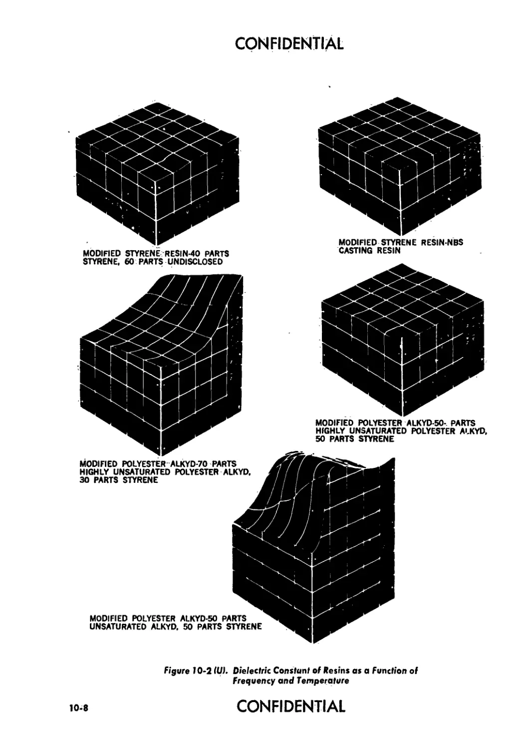
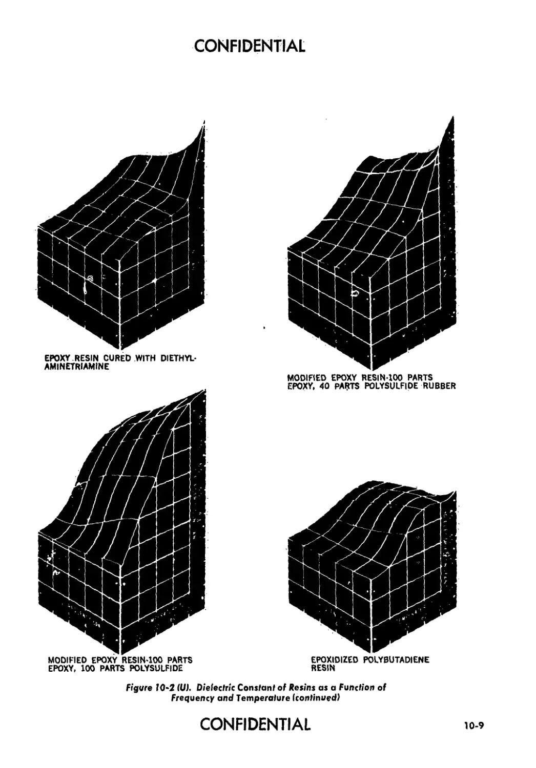
10-2(U). Dielectric Constant of Resins as a Function of Fre-
quency and Temperature....................................... 10-8
xviii
CONFIDENTIAL
CONFIDENTIAL
LIST OF ILLUSTRATIONS (confd)
Fig. No. Title Page
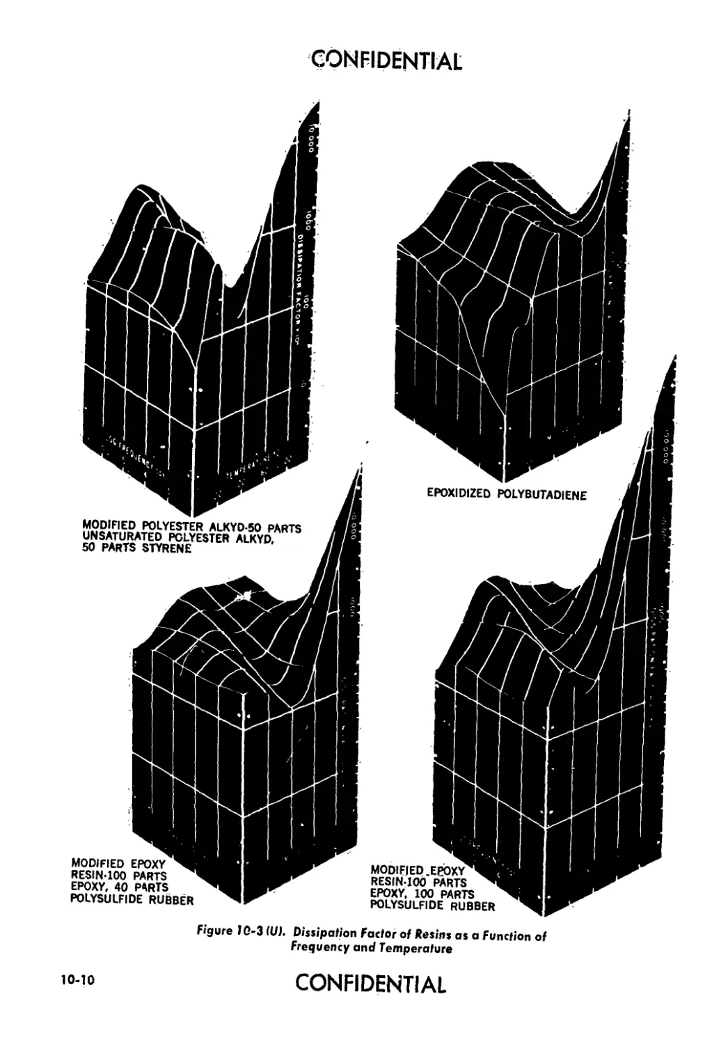
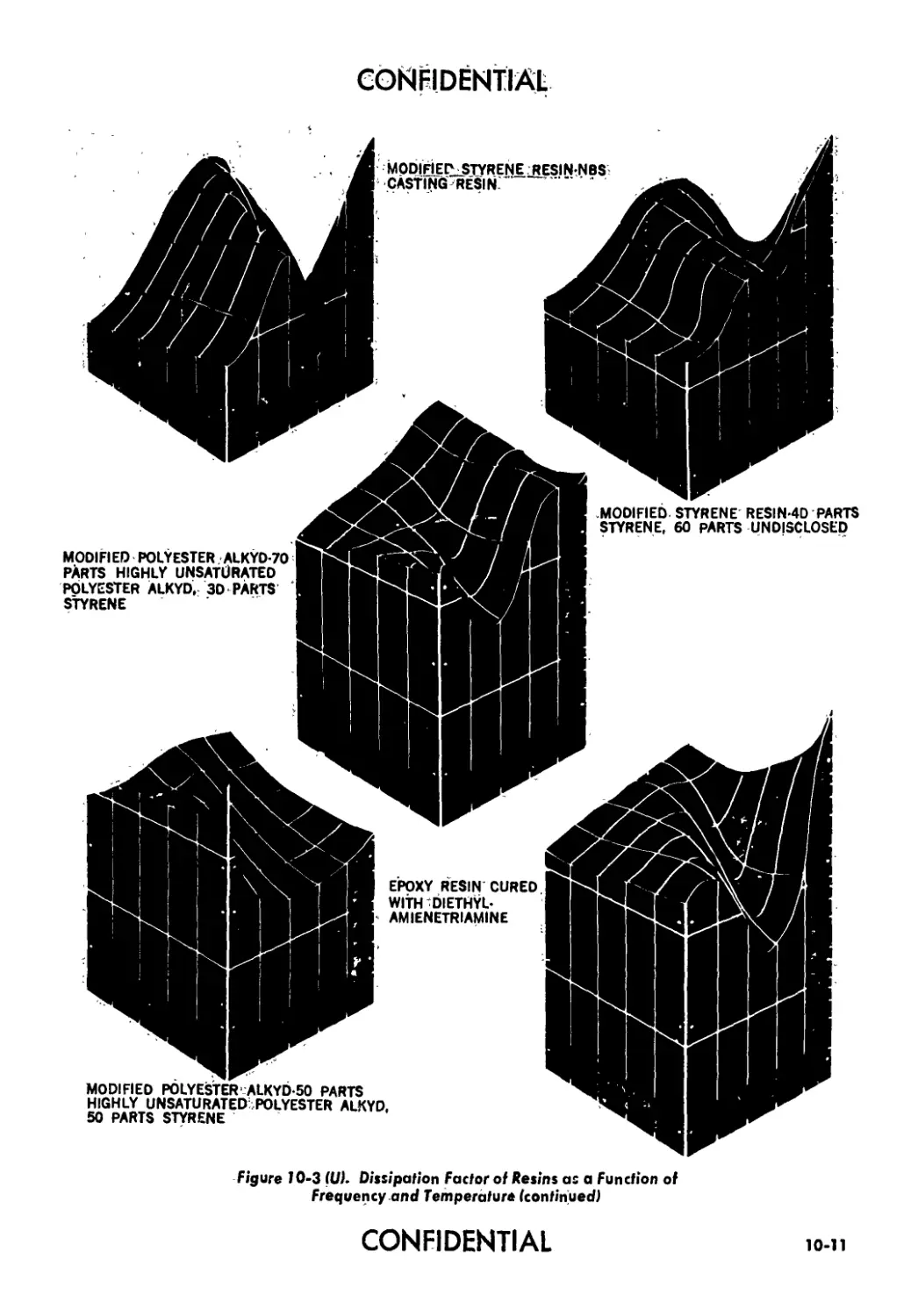
10-3 (U). Dissipation Factor of Resins as a Function of Fre-
quency and Temperature..................................... 10-10
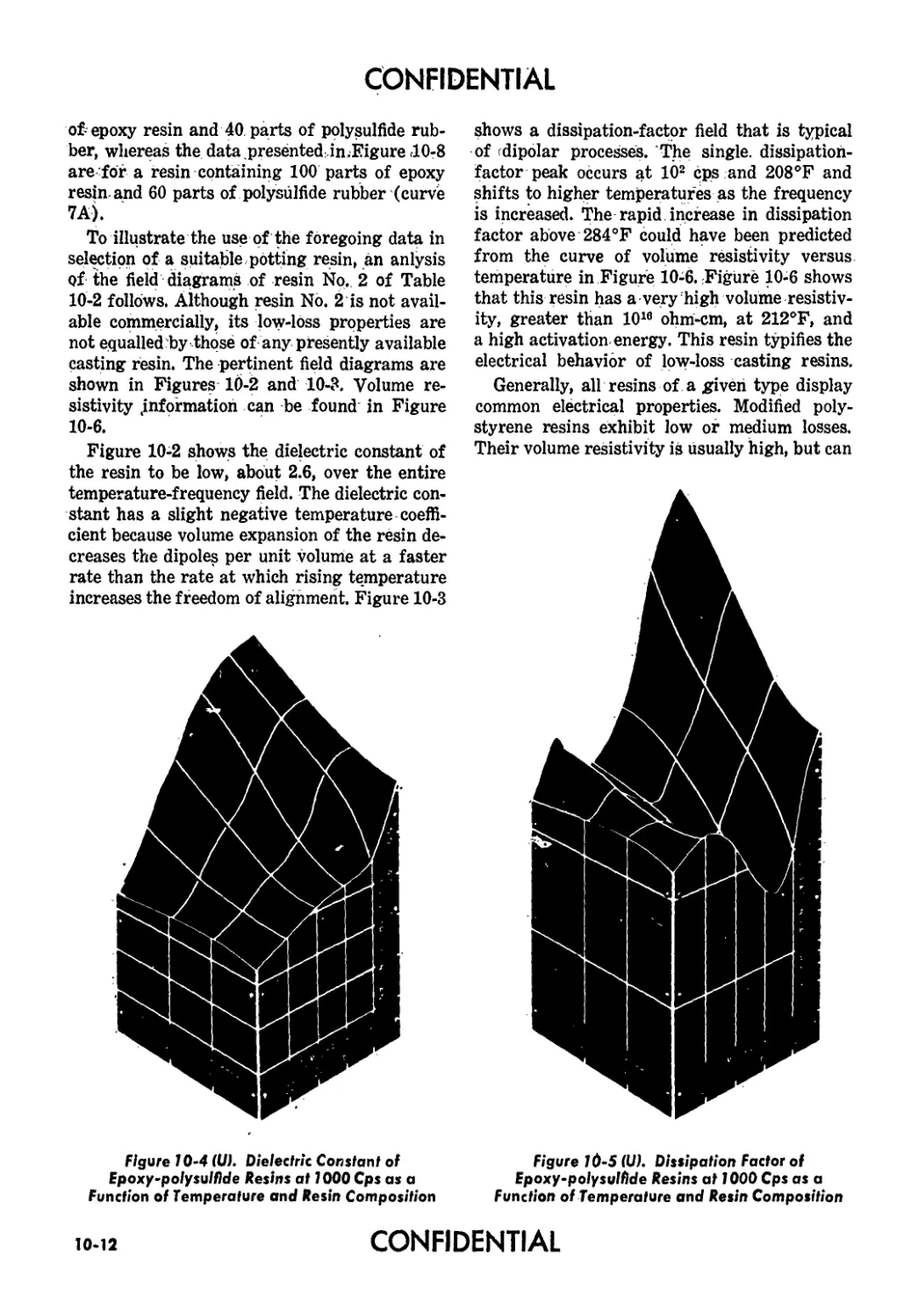
10-4 (U). Dielectric Constant of Epoxy-polysulfide Resins at
1000 cps as a Function of Temperature and Resin
Composition................................................ 10-12
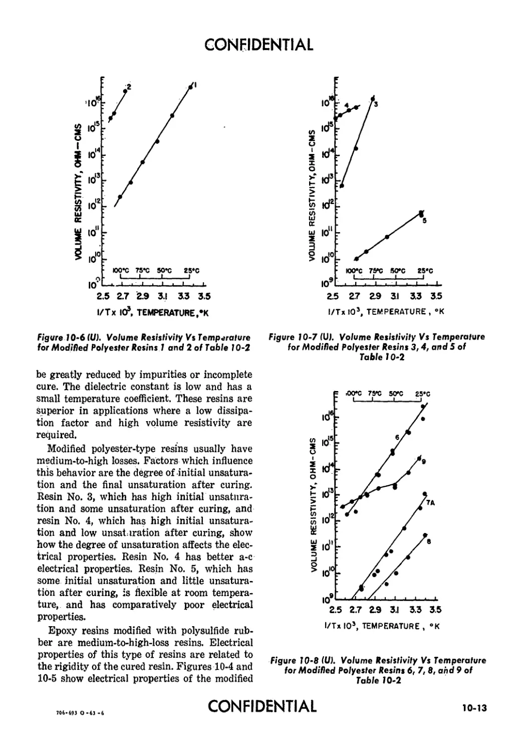
10-5(U). Dissipation Factor of Epoxy-polysulfide Resins at
1000 cps as a Function of Temperature and Resin
Composition................................... 10-12
10-6(U). Volume Resistivity Vs Temperature for Modified
Polyester Resins 1 and 2 of Table 10-2..................... 10-13
10-7(U). Volume Resistivity Vs Temperature for Modified
Polyester Resins 3, 4, and 5 of Table 10-2 10-13
10-8(U). Volume Resistivity Vs Temperature for Modified
Polyester Resins 6, 7, 8, and 9 of Table 10-2 . ... 10-13
10-9(U). Provision for Prevention of Entry of Moisture Into
Fuze .................................................... . 10-17
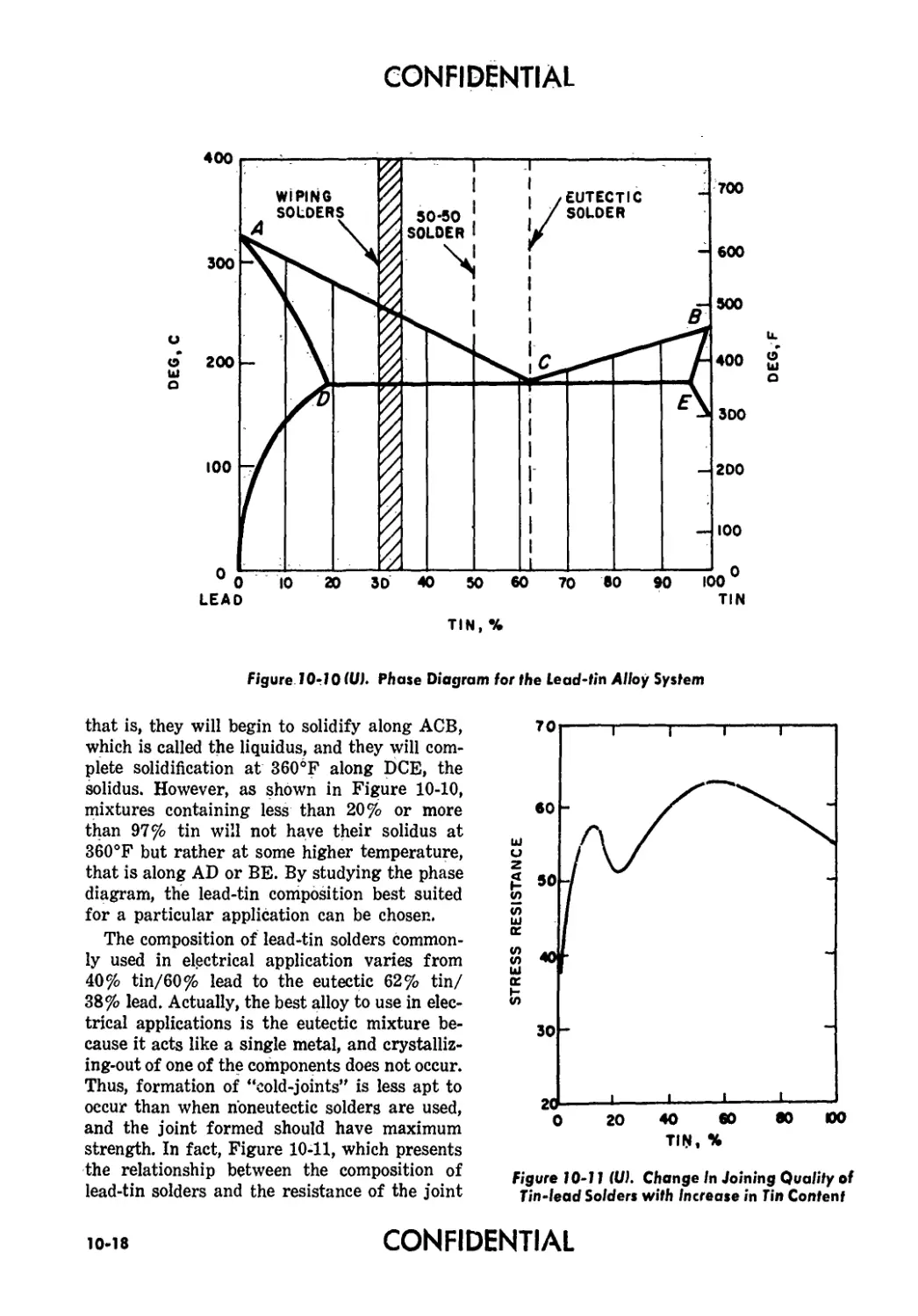
10-10(U). Phase Diagram for the Lead-tin Alloy System.... 10-18
10-ll(U). Change in Jojjynir Quality of Tin-lead Solders with
Increase in Tin Content ................................... 10-18
11-1 (U). Construction of Typical Mortar Fuze............. 11-3
11-2(U). Catacomb Amplifier.............................. 11-4
11-3 (U). Catacomb Amplifier with Printed End Plates 11-4
11-4(U). Amplifier with Printed End Plates Only......... 11-4
11-5 (U). Transmissibility of Undamped Single Degree of
Freedom System............................................ 11-5
11-6(U). Electronics Assembly for Typical Guided Missile
Fuze................................................ ... 11-5
11-7(U). Thermal Conduction of Aluminum-to-aluminum and
Steel-to-steel Joints as a Function of Contact Pres-
sure ...................................................... 11-11
12-1 (U). Product-engineered Mounting Plate Used in a Cer-
tain Missile................................................ 12-2
12-2(U). Phasing Diagram from Research and Development
to Mass Production ....................................... 12-8
13-1 (U). Average Heating and Cooling Characteristics of
Fuzes Subjected to the Temperature and Humidity
Test Cycle.................................................. 13-2
13-2(U). Typical Installation in a Vacuum-steam-pressure
Chamber .................................................... 13-3
13-3(U). Recovery of Projectile in Catcher’s Mitt Rocket
Sled........................................................ 13-8
13-4 (U) Paracovery Mortar Projectile........................ 13-9
13-5 (U). Flyover Test Principle............................ 13-10
CONFIDENTIAL
xix
CONFIDENTIAL
LIST OF TABLES
Table No. Title Page
7-l(C) Operating and Physical Characteristics of Typical Thermal Batteries (U) 7-5
8-l(U) Fractional Error Relations for the Ruehlmann Cir- cuit 8-26
10-1 (U) Comparison of Properties of Typical Potting Ma- terials 10-3
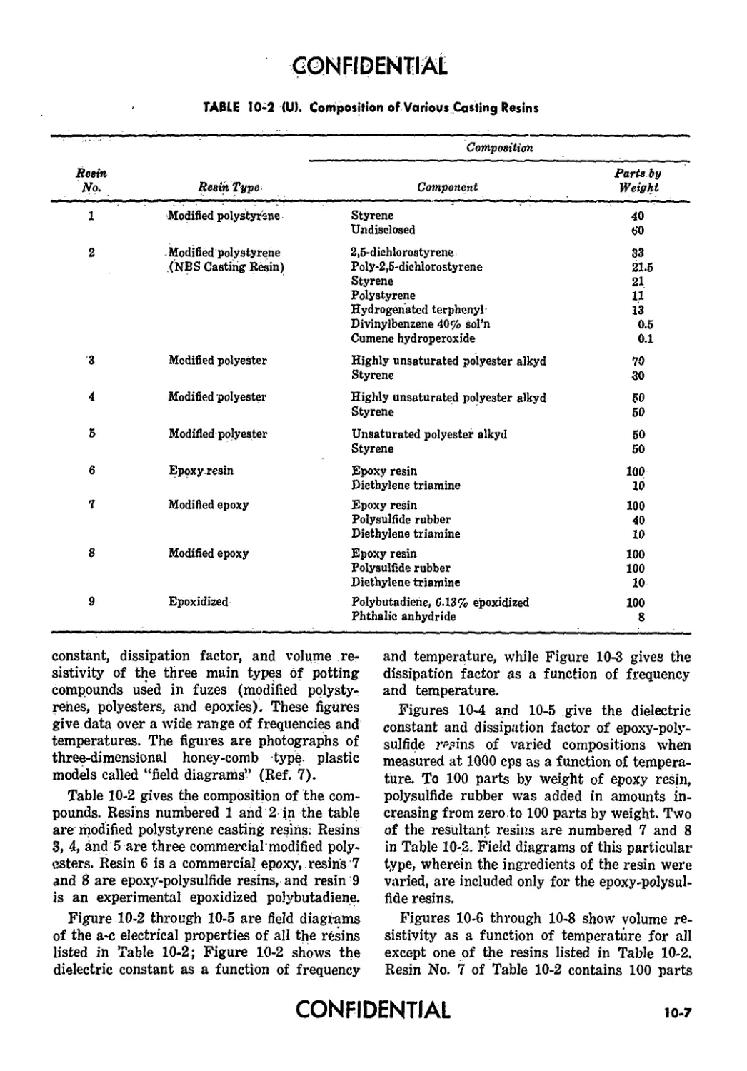
10-2(U) Composition of Various Casting Resins . 10-7
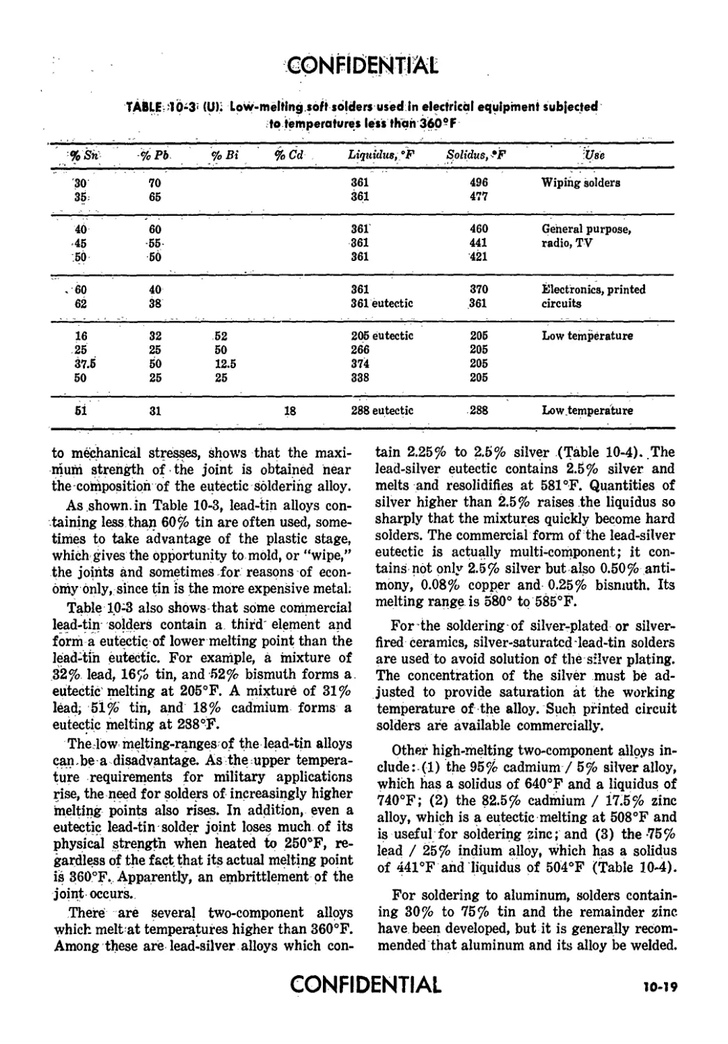
10-3 (U) Low-melting Soft Solders Used in Electrical Equip- ment Subjected to Temperatures Less than 360°F 10-19
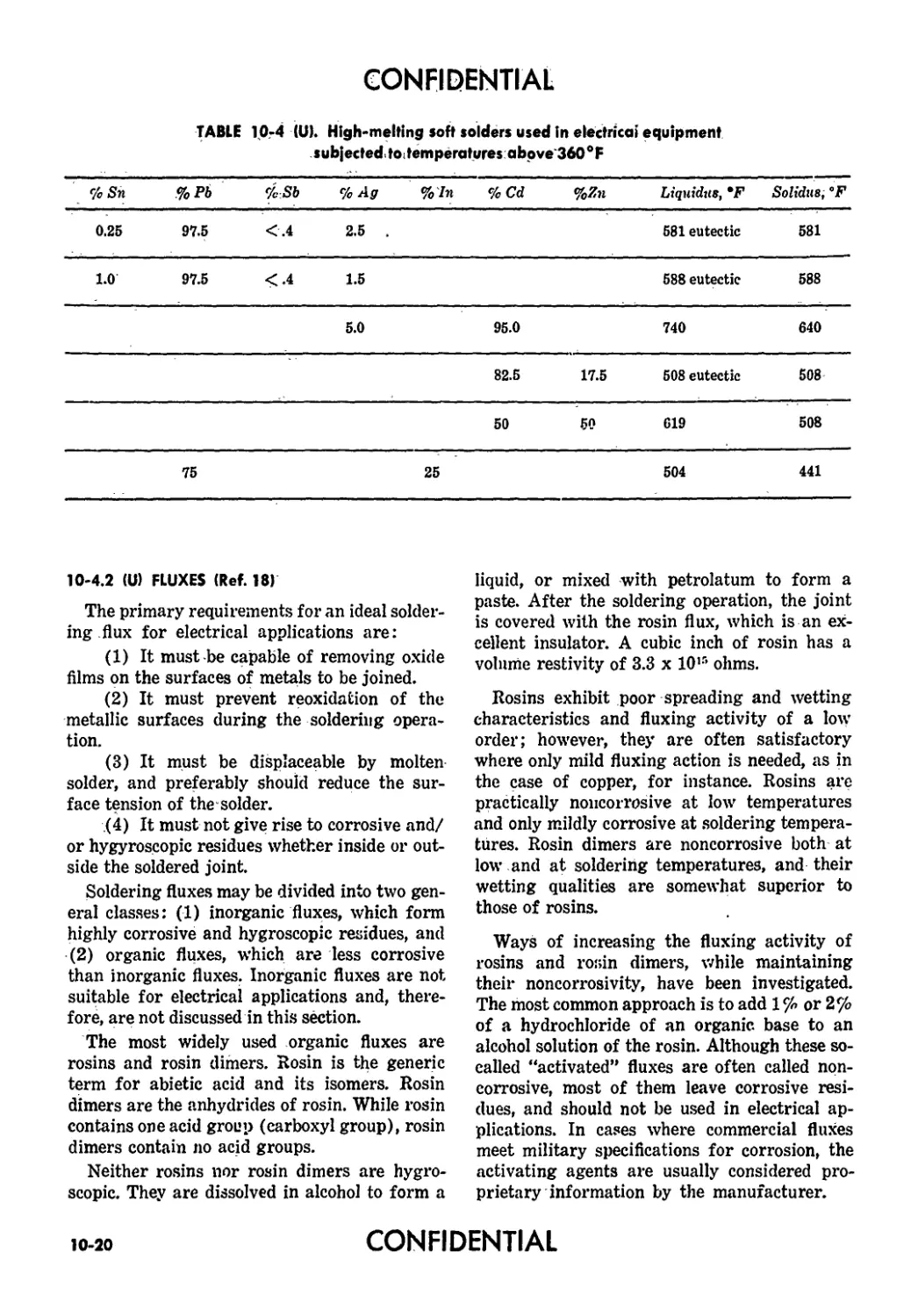
10-4(U) High-melting Soft Solders Used in Electrical Equip- ment Subjected to Temperatures Above 360°F 10-20
ll-l(U) Thermal Conductivity of Some Potting Compounds 11-8
11-2(U) Relative Merits of Hermetic Sealing Techniques 11-9
12-1 (U) Comparison of Industrial Engineering Methods 12-7
13-1 (U) MIL-STD Tests for Fuzes 13-4
XX
CONFIDENTIAL
CONFIDENTIAL
CHAPTER 7
(О POWER SUPPLIES
7-1 (U) REQUIREMENTS FOR FUZE
POWER SUPPLIES
An existing power supply seldom meets the
requirements of a new fuze. Power supplies
must usually be designed for specific fuze ap-
plications. Five basic requirements for all fuze
power supplies, however, are as follows:
(1) Electrical. The power supply must
provide electrical energy having certain cur-
rent and voltage characteristics for a given
period of time. Current and voltage require-
ments vary with the fuze design. Activation
time (the time interval required for the power
supply to reach its specified voltage and current
rating after initiation) and active life are im-
portant considerations. Both of these vary de-
pending upon the application. For example,
artillery projectiles require power supplies that
activate quickly, but their active life is meas-
ured in seconds. A short activation time is usu-
ally not required in long range guided missile
fuzes, but an active life measured in minutes
is generally needed. In some cases, activation
time can be taken advantage of and used as an
arming delay for safety.
(2) Size and Weight. Usually a power sup-
ply must fit into a very small space and its
weight must not exceed a prescribed limit.
Space and weight requirements are a function
of the weapon and vary widely. Severe restric-
tions are usually placed on the size and weight
of power supplies used in motar, artillery, and
similar type projectiles. The restrictions placed
on guided missile power supplies are usually
less stringent.
(3) Environmental. The power supply
must withstand the shock, vibration, ambient
pressures, and temperatures to which it will be
exposed in storage, transportation, and use.
Operation in the —65° to 160°F range is norm-
ally required. Shock and vibration requirements
are usually governed by the weapon’s flight
characteristics.
(4) Shelf life. The shelf life of a power
supply is of great importance. To be of any
value, a fuze power supply must furnish the
requirea electrical energy on demand after
many months or years of storage. Generators or
reserve-type batteries are essential to meet this
requirement. A reserve battery is inert during
storage and is not activated until functioning
of the weapon is desired. The shelf life of com-
mercial active or ready-type batteries is too
short for use in most fuze applications. Re-
serve-type batteries for fuze applications must
be stored with the electrolyte in place. The
electrolyte is generally in an inert state or is
kept separated from the battery cells until the
missile or projectile is launched. Reserve-type
batteries in which the electrolyte is added just
prior to launching a missile or projectile are
unsuitable for fuze applications.
(5) Reliability. This is a critical require-
ment. Because of the tactical importance of as-
suring proper functioning at the right time,
the power supply must approach 100% relia-
bility.
7-2 (U) TYPES OF POWER SUPPLIES
The two broad classes of power supplies used
in fuze applications are generators and batter-
ies. Generators are operated by mechanical
means. They may be wind-driven, gas-driven,
spring-driven, or may be operated by the in-
ertial forces of setback. Piezoelectric genera-
tors have also been used in fuze applications.
Batteries may be broken down into two broad
categories: active or ready batteries and re-
serve batteries. Active or ready batteries are
generally used for mine fuzes only. For other
fuzing applications reserve-type batteries are
preferred. For fuze applications, the entire bat-
tery must be in one container and must be cap-
able of remote activation.
All batteries, except radioactive, generate
power by electrochemical processes. The elec-
trolyte may be either a solid or a liquid. The
electrolyte in a thermal battery is a solid inert
material which contains no water. It becomes
active when heated to about 300 °C. Reserve-
type aqueous batteries have a solution of some
CONFIDENTIAL
7-1
CONFIDENTIAL
chemical in water with the liquid solution her-
metically sealed in a separate container until
operation of the battery is desired.
7-3 (U) GENERATORS
7-3.1 (U) WIND-DRIVEN GENERATORS (Ref. 1)
Wind-driven generators can be used to pro-
vide power for fin-stabilized bomb, rocket, and
mortar fuzes. Basically, the generators con-
vert part of the kinetic energy of a projectile
into electrical energy and thus eliminate the
requirement for stored energy. Other advan-
tages of a wind-driven generator are low cost,
safety, and the fact that it withstands repeated
testing. Its main weakness lies in the exposure
of its moving parts. A wind vane may become
fouled or damaged, or a shaft may be bent.
Direct-current type wind-driven generators
are not feasible. Slip rings and brushes develop
serious electrical noise problems, and, also,
speed-voltage relationships are hard to regu-
late.
The alternator-type wind-driven generators
overcome these defects. Electrical noise is re-
duced since the alternator does not require slip
rings or brushes. The alternator also provides
a reactance that can be used to obtain sufficient
voltage regulation.
Typical mortar fuze and bomb fuze genera-
tors are shown in Figures 7-1 and 7-2, respec-
tively. The mortar fuze generator delivers 2.75
watts and operates between 20,000 and 80,000
rpm. The bomb fuze generator delivers 40 watts
when operating at 40,000 rpm.
Wind-driven generators reached a satisfac-
tory stage of development and were produced
in large numbers up until about 1948. They
have now been superseded by reserve-type, elec-
trochemical power supplies. A detailed discus-
sion of this type of generator is given in Refer-
ence 2.
7-3.2 (U> GAS-DRIVEN GENERATORS (Ref. 3)
A typical gas-driven generator system con-
sists of a solid propellant charge, an ignitor, a
housing containing a nozzle, a turbine, an alter-
nator, and rectifier, filter, and regulating net-
works. Systems that run from 10 to 90 sec and
generate 50 to 100 watts of power have been
designed and operated successfully. Probably
the most successful gas-driven generator is
used in the Navy’s Sidewinder missile (Ref. 4).
The Sidewinder power supply generates pneu-
matic power to drive torque motors for guid-
ance in addition to providing electrical energy.
The Sidewinder alternator is 1.5 in. in diam-
eter and 1.5 in. long and has a useful output of
60 watts at 6,000 cps. The original Sidewinder
power supply was required to run 10 seconds.
This was later extended to 20 sec, and a system
that will operate 1 minute was under develop-
ment when this text was “frozen”; 1961.
Electrical components for gas-driven gen-
erating systems are easily designed. There are
Figure 7-1 (U). Typical Wind-driven Generator
for Mortar Fuzes
Figure 7-2 (Uk Typical-driven Generator
for Bomb Fuzes
7-2
CONFIDENTIAL
CONFIDENTIAL
difficulties, however, in obtaining propellants
that will burn evenly, provide constant pres-
sures, and burn at low rates over the tempera-
ture range of —65° to 160°F. Until considerable
improvement takes place in propellants, the
gas-driven power supply system has no par-
ticular advantage over other systems. For short
operational periods (less than 5 minutes) the
thermal battery is less complex and more re-
liable, although it cannot be tested nondestruc-
tively under load. For operating periods of 10
to 20 minutes, the reserve alkaline primary
battery appears a better choice. Although the
gas-driven alternator and its regulating cir-
cuits may be tested nondestructively, the pro-
pellant cannot. As far as weights and volumes
are concerned there is little difference between
thermal batteries, the reserve alkaline primary
battery, and the gas-driven generator.
7-3.3 (U) PIEZOELECTRIC GENERATORS
Some crystalline substances such as barium
titanate generate electrical energy when under
pressure or stress. In certain cases, it is desir-
able to take advantage of this fact for fuzing
projectiles. Piezoelectric power generation is
covered in more detail in Chapter 5.
7-3.4 (U) INERTIA GENERATORS
An inertia generator consists basically of an
Alnico magnet enclosed within a coil of many
turns of fine wire. At setback the magnet is
rapidly ejected from the coil and generates a
voltage across the terminals of the coil. The
voltage is applied across a capacitor to provide
power to operate a fuze. This type of device was
abandoned primarily because a suitable release
mechanism, which would prevent the fuze from
becoming accidentally armed if it was dropped,
became too complicated.
7-3.5 (U) SPRING-DRIVEN GENERATORS
Spring-driven generators were investigated
primarily for use with electrostatic fuzes. En-
ergy produced by releasing a cocked spring
drove a rotor for about 0.1 sec. Operation of
the rotor developed a voltage that was used to
charge a capacitor, which was then used to
provide power for fuze circuits. This type of
device was abandoned for the same reason as
the inertia generator (paragraph 7-3.4).
7-4 (C) BATTERIES
(U) There are two broad categories of bat-
teries : active (sometimes called ready) and re-
serve. In an active battery, electrochemical ac-
tion is always taking place, whether the bat-
tery is in storage or operational use. In a re-
serve-type battery, however, no electrochemical
action occurs until the time the battery is used.
The electrolyte is distributed to the cells then,
or is maintained in inactive form until activa-
tion is required.
Active batteries deteriorate rapidly at high
temperatures; operate poorly, if at all, at low
temperatures; and have a very limited shelf
life. In addition, switches are usually required
to provide safety when they are used. On the
other hand, reserve batteries operate over a
wide temperature range, have an excellent shelf
life, and provide a high degree of safety. For
this reason, they are used in almost all fuzing
applications. An exception to this is mine fuz-
ing. Reserve-type batteries are one-shot de-
vices ; that is, they cannot be activated, turned
off, and then reactivated at some later time,
which is required in most mine fuze applica-
tions. Also, mine fuze batteries usually require
a much longer active life than can be provided
by reserve type batteries.
7-4.1 (C) BATTERIES FOR GUIDED MISSILE
APPLICATIONS
(U) Batteries for guided missile applications
are generally required to deliver high power
and have a relatively long active life. An active
life of 1 to 3 minutes is typical, but in some ap-
plications an active life of 20 minutes or more
is required. The following paragraphs discuss
two types of batteries: the thermal battery and
the silver oxide-zinc battery. Both are used in
many present-day fuzing applications. Another
type, the liquid ammonia battery, which is rela-
tively new and appears to have direct applica-
tion to guided missiles, is also discussed.
7 4.1.1 (C) Thermal Batteries (Ref. 5)
Thermal batteries are a rugged, efficient, and
reliable reserve power source. They consist
basically of a combination of primary voltaic
cells with each cell having a negative electrode,
a positive electrode, and an electrolyte. Nega-
tive electrodes are usually made of magnesium
CONFIDENTIAL
7-3
CONFIDENTIAL
or calicum; positive electrodes of nickel and
silver. A thermal battery contains no water.
The electrolyte is a solid material such as
lithium chloride, potassium chloride eutectic,
or the equivalent bromide eutectic. The electro-
lyte is carried in Fiberglas or asbestos tape that
also separates the electrodes of the cell. During
storage the electrolyte is in an inactive solid
state. When heat is applied to the electrolyte,
and it reaches a temperature between about
275° and 375°C, it becomes a liquid ionic con-
ductor. A complete thermal power supply con-
tains an integral source of heat that is inert
until required for operation. One way of pro-
viding heat is to surround the individual cells
with a pyrotechnic material.
Several actions take place in a typical ther-
mal power supply to produce useful voltage and
current. An electric match initiates the power
system, and in a matter of milliseconds the
pyrotechnic paper is ignited. A few tenths of
a second later combustion is complete, and suf-
ficient heat is transferred to the voltaic cells
so that the electrolyte is fused. As internal re-
sistance is reduced, terminal voltage increases,
and useful current can then be drawn from the
supply. Since the action of the heat source is
irreversible, any pretesting for performance
of the completed unit is precluded. This is the
main disadvantage of thermal batteries.
No one thermal battery can satisfy all re-
quirements over the wide range of missile ap-
plications. Physical and operating character-
istics for several thermal batteries are given
in Table 7-1. Some of the batteries listed were
not designed specifically for guided missile ap-
plications : however, thej' indicate the variety of
thermal batteries available.
Important characteristics to be considered
when selecting thermal batteries for fuzes are
activation time, active life, temperature, rug-
gedness, voltage, current, and size and weight.
A brief discussion of each follows.
7-4.1.1.1 (U) Activation time
A thermal battery is normally inactive be-
cause of the inert containment of the electro-
lyte. To activate it, an initiating force is re-
quired. Primers, electric matches, or internal
starters are the usual activating agents.
7-4
The time required to activate a battery varies
from a few tenths of a second to several sec-
onds. In general, the greater the permissible
activation time, the longer the battery life.
Small batteries are activated in about 1 sec or
less, larger ones take from about 2 to 8 sec.
7-4.1.1.2 (U) Active life
The maximum life of present thermal bat-
teries is about 10 minutes, although a life of
about 15 minutes is considered feasible. The
active life of the average battery is largely con-
trolled by thermal rather than chemical con-
siderations. The space available for thermal in-
sulation is, therefore, important for a long-life
battery.
7-4.1.1.3 (U) Temperature
Thermal batteries perform satisfactorily in
the —65° to +160°F temperature range provid-
ing the battery activation temperature reaches
400°C (752°F) or higher. Over a given tem-
perature range, one particular operating tem-
perature generally gives the most efficient per-
formance. This operating temperature can be
obtained by varying the heat input of the bat-
tery, and in this manner optimum performance
can be attained for either very low or very
high environmental temperature ranges.
7-4.1.1.4 (U) Ruggedness
Thermal batteries are inherently rugged
since they have no moving parts and do not
rely on the displacement of materials. Some
thermal batteries withstand more than 10,000
g. With proper construction, all thermal bat-
teries can withstand normal vibration and
shock environments.
7-4.1.1.5 (C) Output voltage
An individual thermal cell produces an out-
put voltage of between 1 and 3 volts. The bat-
tery voltages available are multiples of the
single cell voltage. This in turn is not infinitely
variable. There are discrete levels, depending
upon the battery system i sed. Thermal batter-
ies with voltages up to 2,500 volts have been
produced. Overall weight and bulk considera-
tions make it impractical, however, to attempt
higher outputs.
CONFIDENTIAL
CONFIDENTIAL
TABLE 7-1 (C). Operating end Physical Characteristics of Typical
Thermal Batteries (U)
Voltage (volts) Current (amperes) Activation Time ( seconds) Active Life (seconds) Initiation Method Size (inches) Weight (pounds)
1.5 0.33 15 Primer 0.5 x 0.5**
1.5 150 0.450 0.012 2.0 5.0 45 Inertia Match 1.62 X 1.59** 0.28
1.5 0.450 Primer 1.35 0.25
145 1 * 0.012 0.5 20 X 1.62^
8.5 0.0001
6.0 5.0 1.5 30 Primer 1.62 X 1.31** 0.41
6 4.5 Electrical 5.69 10.0
28 ¥ 4.5 8.0 480 X 3.69
6 J 4.5 X 6.38
12 20.0 0.3 1 Primer 1.62 0.20
X 1.0**
28 4.5 0.8 60 Electrical 3 x 3** 1.34
350 0.090 1.0 60 Electrical 3.48 1.56
X 3.0**
600 0.001 1.0 180 Electrical 3.19 X 1.62** 0.57
* Single package
’* Diameter of cylindrical package
The noise produced by thermal batteries is
quite low compared to that produced by con-
ventional batteries. Thermal batteries with out-
puts of 600 volts produce a noise level of about
10 mv; conventional batteries produce this
noise level at outputs of about 150 volts.
Thermal batteries lasting about a minute
have a voltage regulation of i 5%, which is
satisfactory for fuzing applications. Similar
data for batteries with longer active life are
not currently available.
CONFIDENTIAL
7-5
CONFIDENTIAL
7-4.1.1.6 (C) Output current
Low voltage, short-life cells have been de-
signed chat are capable of supplying up to 100
amperes. The present В-type thermal batteries
can provide up to 100 milliamperes. Figure 7-3
shows the current behavior for a compact, light-
weight thermal battery that measures only
2-1/2 in. in diameter and 1 in. high and weighs
only 5 ounces. The battery produces a peak dis-
charge current of 10 amperes with a reason-
ably flat response (within 0.1 volt). Activation
times to reach the operating voltage of 1.8 volts
is about 5 sec; the battery life is about 1-1/2
minutes.
7-4.1.1.7 (C) Shelflife
The storage characteristics of thermal bat-
teries are better than those of any other type
battery for fuze applications. Tests indicate
that hermetically sealed thermal batteries
normally remain in good condition for at least
four years. Thermal batteries in storage de-
teriorate very little unless they are subject to
a temperature of 250°F or more. In actual stor-
age this temperature rarely occurs.
Two views of a hermetically sealed thermal
battery before and after use are shown in Fig-
ure 7-4. Pressure seals prevent chemical reac-
tions with atmospheric constituents during
storage.
7-4.1.2 (U) Silver-Oxide Zine Batteries (Refs. 6, 7)
Silver-oxide zinc reserve batteries provide a
primary power source for surface-target
guided missile fuzes. They are an alternate to
thermal batteries and should be considered for
low-voltage, high-power applications. Their
volume efficiencies are 5 to 10 times greater
than those of other batteries, but since their
capacity decreases rapidly below 30°F, they re-
quire integral heating units for operation at
low temperatures. Silver-zinc cells deliver
about 60 w-hr/lb and 3 w-hr/in.3. Cell voltage
under load is 1.5, whereas maximum current
density is about 2.5 а/in.2 of projected plate
area.
Silver-zinc batteries may be activated by an
electrical command signal and have an active
life of a few hours at normal temperatures.
The shelf life of reserve-type silver-zinc bat-
teries is believed- to be greater than five years.
Figure 7-3 (Ci. Thermal Battery Current Behavior Curve (U)
CONFIDENTIAL
7-6
CONFIDENTIAL
Figure 7-4 IU). Thermal Power Supplies with Pressure Sensitive Seals
Figure 7-5 (U). PS-502A Silver-zinc Power Supply
CONFIDENTIAL
CONFIDENTIAL
TIME, MINUTES
Figure 7-6 <U). Performance of Silver-zinc Power Supply Under Heavy Current
Drain (-65° and +20°F)
Figure 7-5 shows the PS-502A silver-zinc
power supply developed for guided missile ap-
plication. The supply is about the size of a 6-in.
cube, and weighs about 12.5 lb. It is a 28-volt
battery and delivers up to 60 amperes with
less than a 4-volt drop in output voltage
throughout its operating range of —65° to
165°F. The performance of the battery under
heavy current drain is shown in Figures 7-6
and 7-7.
The operation of the silver-zinc power sup-
ply is shown in Figure 7-8. An initiating com-
mand fires two squibs which release pressurized
nitrogen gas into the electrolyte reservoir,
forcing the 31% water solution of potassium
hydroxide electrolyte through the heat ex-
changer and into the cell pack. Twenty cells,
connected in series, are filled through a com-
mon manifold. Air within the cells is not bled
off but is compressed by the influx of potassium
hydroxide. The back pressure equalizes the vol-
ume entering each cell and makes resistance to
flow uniform.
The heat exchanger contains a heat powder
which releases about 40,000 calories in less
than 0.5 sec to warm the electrolyte when the
power supply is activated at low temperatures.
If ambient temperature at the time of initia-
tion is below 25°F, a thermostatic switch be-
tween the signal-input terminals and two elec-
tric matches is closed, allowing the command
signal to initiate the squibs and matches simul-
taneously. The matches, in turn, ignite the heat
powder, which warms the electrolyte passing
through a copper tube to the cell pack. The cells
can deliver full power in 1 to 10 sec.
Although relatively complex and expensive,
the power supply is made of roneritical materi-
als. Its reliability is high, and it can be acti-
vated by a low-energy command signal. Present
design efforts are directed at decreasing the
7-8
CONFIDENTIAL
CONFIDENTIAL
VOLTS
Figure 7-7 (U). Performance of Silver-zinc Power Supply Undei Heavy Current
Drain (+ 30е and — ' 65°F)
complexity, cost, and weight of the unit and
eliminating the need for heat for low-tempera-
ture operation.
7-4.1.3 (U) Liquid Ammonia Batteries
Liquid ammonia batteries are being investi-
gated as this is being written (1961). They ap-
pear to have excellent low-temperature opera-
tion characteristics, and may be suitable for
fuze application. No further information is
available at the time of this writing. Ammonia-
vapor batteries have been investigated (Ref.
8), but they do not appear suitable for fuze ap-
plications.
7-4.2 (C) BATTERIES FOR ROTATING PROJECTILES
(U) Rotating projectiles, such as antiair-
craft projectiles, field artillery projectiles, and
many rockets, use reserve-type aqueous batter-
ies almost exclusively. An aqueous battery is
one ir. which the electrolyte is in liquid form
during boti. storage and operational use. Car-
bon-zinc batteries and lead-lead dioxide bat-
teries are the two main types used in rotating
projectile applications.
A typical battery is shown in Figure 7-9. As
in all batteries of this type, the electrolyte is
contained in a glass or plastic ampule. When a
projectile is fired, the ampule is broken by a
setback-operated device, or in applications
where the projectile experiences low setback
force, by a mechanically-operated spin breaker.
As the projectile spins, centrifugal force dis-
tributes the electrolyte between the plates, thus
energizing the battery.
The battery shown in Figure 7-9 uses half
plates. Other types of batteries have been con-
structed, however, using radial plates, involute
plates, and annular plates.
Typical characteristics of aqueous batteries
CONFIDENTIAL
7-9
CONFIDENTIAL
used in rotating projectile applications are dis-
cussed in the following paragraphs.
7-4.2.1 (C) Operating Temperature
The operating range of carbon-zinc batter-
ies is from about 4-Ю0 to +120cF. The lead-
lead dioxide battery operates over a range of
about —40° to 4- 160°F. Both types will operate
at temperatures lower than the minimum tem-
perature specified, although degradation of per-
formance will result. Activation time will in-
crease greatly as the operating temperature de-
creases below the minimum operating tempera-
ture; output voltage, active life will decrease.
7-4.2.2 (C) Activation Time and Active Life
Activation time for both types of batteries
is a function of temperature. Within the tem-
perature limits of the batteries, however, ac-
tivation requires about 0.2 sec. Rotating pro-
jectiles normally do not require a long active
life. Both types of batteries can be made with
an active life of a few seconds up to about 120
sec.
7-Ч.2.3 (C) Voltage and Current Capacity
The A section of a typical aqueous battery
produces about 1.4 to 1.7 volts and can provide
a maximum current of about 1 ampere. The В
Figure 7-8 (U). Operation of Silver-zinc Battery
CONFIDENTIAL
7-10
CONFIDENTIAL
mum setback of approximately 1600 g is re-
quired to break the ampule containing the elec-
trolyte. For batteries equipped with spin break-
ers no setback force is required to break the
ampule.
Figure 7-9 (U). Typical Aqueous-type Battery
for Rotating Projectiles
section is usually required to produce about 90
volts for most applications at a maximum cur-
rent of about 20 milliamperes. For the C sec-
tion, a voltage of —6.5 volts is typical at a
maximum current of about 10 milliamperes.
Actually, voltages and currents considerably
higher than these can be obtained by connect-
ing more cells. The size of the battery, how-
ever, becomes an important factor as more and
more cells are connected.
7-Д.2.4 (C) Noise
Electrical noise generated within the bat-
tery ranges from about 1 to 25 millivolts. For
most batteries however, it is less than 5 milli-
volts.
7-4.2.5 (C) Minimum Spin and Setback Required
for Activation
The minimum spin required for proper dif-
fusion of the electrolyte is about 25 rps. For
batteries that are initiated bj’ setback, a mini-
7-4.3 (U) BATTERIES FOR NONROTATING
PROJECTILES
Nonrotating projectiles, such as mortar pro-
jectiles and bombs, generally use thermal bat-
teries to provide fuze power. Thermal batteries
used in nonrotating projectile applications are
characterized by small size, fast activation
time, and short active life. They are of rather
low power, when compared with thermal bat-
teries used in guided missile applications.
Thermal batteries are discussed in detail in
paragraph 7-4.1.1.
7-4.4 (C) BATTERIES FOR LAND MINE
FUZE APPLICATIONS (Ref. 9)
Batteries considered for fuzes of this type
must meet certain stringent conditions. They
must supply voltage over a wide range of tem-
perature, have a long shelf life, and be able to
supply ample energy for days, and sometimes
weeks or months, after the fuze has been armed.
Wherever possible, fuzes are designed to use a
passive detector, i.e., a continual power supply
is not required by the sensing and firing ele-
ments.
The energy required from the battery is ex-
tremely small. A hundred to a thousand ergs is
all that is necessarjr to initiate firing of the ex-
plosive charge. Circuits can be designed that
connect only the insulation of the fuze as a
load on the battery. Thus, the drain is only a
little greater than that normally flowing
through the insulation of the battery itself.
The effect of moisture on the insulating proper-
ties of the components does become a serious
problem. It can be solved by proper plotting,
seals, and metallic vapor barriers. Essentially
then, the life of a battery is the primary con-
sideration. In addition to supplying this min-
ute current, it needs only to maintain a charge
on a capacitor with a very high insulation re-
sistance. The following^- paragraphs discuss
some of the batteries considered for mine fuze
applications. All are of the active type since,
CONFIDENTIAL
7-11
CONFIDENTIAL
at this time (1931), reserve-type batteries do
not appear suitable for this fuze application.
7-4.4.1 (C) Radioactive Batteries (Ref. 10)
Radioactive batteries have direct applica-
tion to mine fuzing. They can be used to main-
tain the charge on a capacitor and, if sufficient
time is available, the battery can be used to
charge the capacitor directly. They can also be
used as long interval timers to provide sterili-
zation of mine fuzes. Interval timers have been
constructed to measure time intervals of a few
hours to many days.
There are other possible fuzing applications
of radioactive batteries: to provide power for
electrostatic Aizes; to provide self-destruction
in many types of fuzes; and to provide arming
delays.
Radioactive materials, decaying through an
alpha or beta emission process, eject particles
that carry an electrical charge. A radioactive
battery is essentially a de; ice that provides for
the collection of these charged particles and
permits utilization of the accumulated electrical
energy.
In its simplest form, a radioactive battery
consists of an electrode coated with active ma-
terial, separated by a dielectric from another
electrode which traps and accumulates the
charged particles. It can be considered as a
selfcharging capacitor, or as a voltage or cur-
rent source, with the maximum voltage and
total charge being determined by the amount
and type of radioactive material used, the size
of the electrodes, the dielectric material used,
and the electrical leakage of the battery and
its associated circuits.
For maximum efficiency, radioactive batter-
i' ? require an active material as a point source
of radiation, suspended by an insulated lead in
the center of an evacuated sphere. Under these
conditions, all emitted particles reach the col-
lector, and a potential difference between the
insulated lead and metal sphere would develop
at a rate dependent upon the rate of emission
of the charged particles. For ruggedness and
simplicity of construction, however, it is con-
sidered iripractical to use either a vacuum
dielectric or a spherical shape. Available bat-
teries are cylindrical with polystyrene as the
dielectric material. Strontium 90 (SR90), which
has a 25-year half-life, is used as the radio-
active material.
Radioactive batteries have many important
advantages. They are small in size, light in
weight, and 3R9" is plentiful since it is a by-
product of pile operation. Other components
of the battery are easily assembled and are
relatively cheap. Units can be mass produced
with few facilities and little cost for special
tooling. Radioactive batteries are rugged
enough to withstand 20,000-g acceleration.
They have no moving parts or voids, and the
only activation problem is one of switching.
Other advantages are that the rate of radiation
changes only with time, and the power supply
is independent of both pressure and tempera-
ture, except as the dielectric is affected.
Radioactive batteries also have a number of
disadvantages. The ability of dielectrics to
withstand radiation for long periods has not
been proven, and the deteriorating effect of
aging and temperature variations on dielectrics
is considerable. Since SR9" has a half-life of
25 years, there is a 50% reduction in current
at the end of 25 years when it may be needed
for use. Due to the low current drains per-
missible, all circuit elements must have high
leakage resistance (10й ohms or better). Since
the unit is normally used with a charged ca-
pacitor. the problem of premature functioning
requires safety devices. Another disadvantage
is the question of the tactical use of radioactive
material in any significant quantity, as well as
the use of the battery adjacent to other radio-
active materials.
7-4.4.2 (C) Zamboni Pile
A Zamboni pile battery consists of a a' ei of
paper on one side of which is a thin layer of
aluminum and on the other side a mix of man-
ganese dioxide, caibon, aluminum chloride, and
a very small quantity of water and ethylene
glycol. Discs are cut from a sheet of paper so
treated and stacked one upon the other. Approx-
imately 1.1 volts is obtained from each of these
discs. When stacked together to give a pile two
inches in height, a battery of over 200 volts is
obtained. The batteries promise to give very
long shelf life because they are exceedingly dry,
7-12
CONFIDENTIAL
CONFIDENTIAL
but they are incapable of supplying heavy cur-
rents. In mine fuze circuits, however, there is
no requirement for a heavy continuous current,
and thus it is permissible to use batteries of
the Zamboni type.
Zamboni piles have been tested under vari-
ous conditions and appear to maintain their
open circuit voltage down to temperatures that
will be encountered in operation. However,
there is some doubt because of the high internal
impedance of the Zamboni piles at low tem-
peratures that tbey can deliver even the small
current required for some mine fuze applica-
tions. Provisions would have to be made to
maintain the standby current drain from the
Zamboni pile to a negligible value to keep the
395A gas triode tubes, which are used exten-
sively in mine fuzes, in a sensitive state.
7-4.4.3 (C) Mercury Batteries (Ref. 9)
Commercially available mercury cells having
a shelf life from 5 to 10 years and capable of
supplying ample energy over the temperature
range likely to be encc untered could be used in
mine fuze applications. However, their cost ap-
pears to be excessive. A possible method of
overcoming this high cost is to employ an in-
ductive “kick-back” circuit to obtain high volt-
age from a single mercury cell.
Inductive kick-back is accomplished by con-
necting the cell in series with an inductance and
a vibration-operated switch, such as the reed
or seismometer systems described in paragraph
5-11. Under the influence of vehicle-produced
vibrations, the switch closes and opens estab-
lishing and then breaking a current in the in-
ductance. The current decay in the inductance
produces a high voltage, with a peak value ap-
proximately equal to the ratio of the resistance
across the inductance and the resistance in the
inductance proper. Therefore, the external re-
sistance must be large in comparison to that
of the inductor. Several hundred volts c: n be
produced across the inductance with a source
having an e.m.f. of only 1.3 volts.
If a capacitor and rectifier with a high back
resistance are connected across the coil, high
voltage energy can be stored in the capacitor.
This capacitor then functions in the same man-
ner in fuze operations as it would in conjunc-
tion with a Zamboni pile.
706-693 0-63-3
CONFIDENTIAL
7-13
CONFIDENTIAL
(U) REFERENCES
1. G. L. Scillian, Miniature Alternators for
Proximity Fuzes, Paper, Symposium on
Auxiliary Power for Guided Missiles, Re-
port CES 212/4, Volume II, OASD Re-
search and Development, 5-7 February
1957. (CONFIDENTIAL)
2. Radio Proximity Fuze for Fin-Stabilized
Projectiles, Report of NDRC Division 4,
Vol. I, Office of Scientific Research and
Development, 1946.
3. G. L. Scillian, Gas-Driven Alternators for
Fuze Power, Report TR-813, Diamond
Ordnance Fuze Laboratories, 9 March
1960. (CONFIDENTIAL)
4. L. Lorant and N. Johnson, Sidewinder
Turbine-Driven Generator. Paper, Sym-
posium on Auxiliary Power for Guided
Missiles, Report CES 212/4, Volume II,
OASD Research and Development, 5-7
February 1957. (CONFIDENTIAL)
5. This section based on:
Thermal Batteries, Technical Report-155,
Diamond Ordnance Fuze Laboratories,
Dept, of the Army, 14 March 1955.
Thermal Batteries, Report 13/7-93R, Na-
tional Bureau of Standards, Ordnance
Components Section, Ordnance Develop-
ment Division, 11 December 1950. (CON-
FIDENTIAL)
Reliability in Thermal Pozver Supplies for
Guided Missile Fuzes (C) DOFL Report
R22-57-7, Diamond Ordnance Fuze Labo-
ratories, Dept, of the Army, 14 August
1957. (CONFIDENTIAL)
Evaluation of a 850-Volt Thermal Battery
for Guided Missile Fuzing Applications
(C), Technical Report TR-401, Diamond
Ordnance Fuze Laboratories, 13 November
1956. (CONFIDENTIAL)
Development of Thermal Pozver Supplzj foz-
Szzrface-Target Fuzing Applications (C),
Technical Report TR-169, Diamond Ord-
nance Fuze Laboratories, 3 May 1955.
(CONFIDENTIAL)
6. Reserve Primary Pozver Supplzj Develop-
ment for Fuzizig and Warhead Applica-
tions ozi the Redstone Missile, Report TR-
523, Diamond Ordnance Fuze Laboratories.
7. Azi Automatically Activated Silver-Zinc
Pozvez- Supply for Radar Fuzes, Report
TR-665, Diamond Ordnance Fuze Labora-
tories, 6 February 1959.
8. Application of Ammonia Vapor Activated
(AVA) Battery Systems to Guided Mis-
siles Powez- Supplies, Eastman Kodak
Company, Apparatus and Optical Divi-
sion, Paper presented at Symposium on
Auxiliary Power for Guided Missiles, Re-
port CES 212/4, Office of Assistant Sec-
retary of Defense. (CONFIDENTIAL)
9. A. G. McNish, et al., Research azid Devel-
opment for Inflzzezice foz- Lazid Mines and
Accessories, Report 5A-161, Diamond Ord-
nance Fuze Laboratories, 30 September
1952. (SECRET)
10. N. Kaplan, The Radioactive Batterzj azid
!ts Possible Ordnance Applicatiozis, Re-
port 13-4-40R, Diamond Ordnance Fuze
Laboratories, 12 September 1953. (CON-
FIDENTIAL)
7-14
CONFIDENTIAL
CONFIDENTIAL
CHAPTER 8
(C) SAFETY AND ARMING DEVICES
8-1 (U) INTRODUCTION
A safety and arming (S & A) device is a
transfer device between the fuze and warhead.
It keeps the warhead safe until detonation of
the explosive charge is desired and then arms
the fuze by providing a reliable path for trans-
mitting the firing impulse. The safety and arm-
ing device is not the sole determinant of safety;
it is a component of an overall safety system,
which includes the explosive warhead. Gen-
erally, the warhead is made relatively insensi-
tive, thus the probability of spontaneous deto-
nation in an expected environment is very low
(Ref. 20).
An explosive charge is considered safe when
its fuze is safe. A fuze is safe (or unarmed)
when the S & A device places a physical barrier
in the fuze explosive train so that detonation of
the sensitive element (usually the primer) is
confined in such a way that the detonation will
not be transmitted to the explosive train. An
explosive charge is not safe when a fuze is
armed. A fuze is armed when the S & A device
has removed the physical barrier between the
sensitive element in the fuze and the explosive
train, and detonation of the sensitive element
can be transmitted through the explosive train
to detonate the main explosive charge. There
are a few instances in which space or other
exigencies have precluded the use of physical
barriers in the explosive train. In such cases
the electrical initiating circuit may be discon-
nected or the firing pin blocked to prevent ini-
tiation of the explosive train in the safe condi-
tion.
An S & A device may malfunction in one of
two ways. It may arm a fuze too soon, or it may
fail to arm a fuze in time for effective detona-
tion of the explosive charge and cause either
a hangfire or a dud.
To assure proper operation, it is desirable
that a fuze have at least two independent safety
and arming devices, a primary and a secondary
device. This is not always practicable, however.
A desirable feature in the design of S & A
devices is the “no-stored-energy” concept. This
concept states that no primary safety and arm-
ing device should depend for its operation on
cocked springs, explosive motors, or other kinds
of energy stored prior to projectile flight, al-
though such devices may be used to perform
auxiliary functions. To prevent arming before
launching, arming energy should come from
forces or conditions that occur during launch
or after the projectile is in flight. These forces
and conditions must be such that they are not
duplicated in transportation, handling, storage,
and pre-launching operations. Sometimes the
“no-stored-energy” concept must be ignored,
but then extreme care must be exercised in the
details of design, especially with regard to such
factors as stress, corrosion, and creep of
springs and stability of chemicals.
Although safety and arming devices vary
widely in appearance and in method of opera-
tion, most of them fall into two broad classes:
mechanical and electrical. Some that do not fall
clearly into these two classes are fluid operated
devices, barometric devices, thermal devices,
and chemical eroders.
This chapter discusses basic design require-
ments f. r S & A devices used in electronic fuzes.
It supplements the material contained in Ord-
nance Corps Pamphlet ORDP 20-210, Fuzes,
General and Mechanical (Reference 1), which
covers basic arming principles and various
types of arming devices generally suitable for
use in projectiles, bombs, and rockets. The
reader should be thoroughly familiar with the
information contained in Reference 1 before
using this chapter.
Besides the general safety and arming re-
quirements common to most fuzes, additional
requirements are sometimes specified for elec-
tronic fuzes. Spncial safety or arming require-
ments vary, depending upon the size and type
of warhead, function of the weapon system, and
the launch environment. Warheads with a large
lethal radius not only require a very large
separation distance before arming, but also
CONFIDENTIAL
8-1
CONFIDENTIAL
require that the probability of premature func-
tion be extremely small; usually less than 1 in
105 or 10(i. This may dictate the use of multiple
independent arming devices operated in series
to provide such safety reliability. Also, weapons
for defense of civilian centers often require an
“intent to launch” feature to insure non-arming
in the event of accidental launch.
As in the case of the mechanical fuzes dis-
cussed in Reference 1, there is not one best
criterion for making the arming decision for
all weapons. For example, elapsed time may
be the most convenient measure of separation
distance following bomb release; missile ve-
locity may be both a sufficient and a required
criterion for arming a low-acceleration rocket;
and minimum velocity plus elapsed time might
be required for a mortar fuze. For arming se-
quences similar to the last-mentioned, which is
performed in two stages the system may be
said to be committed to arm when the launch
conditions are satisfied.
Quite often, the arming system in an elec-
tronic fuze is required to delay arming beyond
the time required for safety. This may be to
minimize early functions, to decrease the effect
of enemy countermeasures, or to conserve the
life of a battery. For some special warheads, it
may be required that the arming functions,
which are usually the closure of switches, be
programmed in a given sequence rather than
occurring at once.
8-1.1 (U) DESIGN REQUIREMENTS FOR SAFETY
AND ARMING DEVICES
Basic design requirements for an S & A
device are as follows:
(1) The device must operate reliably. Re-
liability in S & A design (as in all ammunition
design) has a very special meaning. It means
thousands of devices working well for a few
seconds or minutes, rather than one device
working well for 10,000 hrs.
(2) The device must positively lock fuze
elements in the safe position and in the armed
position.
(3) The device should not remain in the
partially armed position. If any combination of
forces and conditions partially arms the de-
vice, the device should return to the safe posi-
tion when these forces and conditions are re-
moved.
(4) In the safe position, the device must
block the explosive train so that if the sen-
sitive explosive is detonated, other explosives
in the train will not be detonated.
(5) The device must withstand all forces
and conditions to which it may be subjected in
launching and in flight.
(6) The device must withstand the rigors
of transportation and handling as designated
in the following tests:
a. Jolt Test, MIL-STD-300.
b. Jumble Test, MIL-STD-301.
c. Forty-foot Drop Test, MIL-STD-302.
d. Transportation and Vibration Test,
MIL-STD-303.
e. Jettison Tests, MIL-STD-307 (8) (9)
(10).
f. Accidental Release Test, MIL-STD-311.
(7) The device must function throughout
a temperature range of —65° to +160°F. after
being subjected to the Temperature and Hu-
midity Test, MIL-STD-304.
(8) The device must pass the Salt Spray
Test, MIL-STD-306.
(9) The device must have a shelf life of
20 years. All materials in contact with each
other must be mutually compatible. Materials
used must be corrosion and fungus resistant.
Devices used with nuclear weapons must not
be adversely affected by radiation.
(10) The device must be as small and
light in weight as possible.
(11) The shape of the device must be such
that it will fit into the assigned space.
(12) The device must be as simple as pos-
sible in design. It should contain a minimum
number of parts, and it should not require parts
such as unlinked pins or balls that may be easily
omitted in assembly.
(13) The device must usually be adaptable
to mass production and be safe and economical
to manufacture.
(14) The device must be versatile. It must
be adaptable to changes in fuze and missile de-
sign.
8-2
CONFIDENTIAL
CONFIDENTIAL
(15) Indicators must be incorporated to
show handlers whether or not a fuze is armed.
(16) It must be impossible to assemble
an armed fuze to (or insert one into) an ex-
plosive charge.
Many of these requirements conflict with
one another. Certainty of action at the proper
time, safety, and compatibility of materials
complicate design and manufacture and add to
the cost of making the device. Size and shape
are determined by available space; weight is
governed by the weight allowance of the fuze.
When feasible, adoption of a standard shape,
size, and weight and use of the same device in
fuzes for all projectiles of a given class affords
economy of manufacture. Design compromises
implicit in “trade offs” that must be made to
satisfy overall system requirements should be
very carefully analyzed.
8-1.2 (U) SAFETY AND ARMING DEVICES FOR
MISSILE FUZES (Ref. 2)
Characteristics of S & A devices for guided
missile fuzes are based on the required char-
acteristics of the missile in which the fuze is
used. Most of the design requirements pre-
viously covered apply; however, their relative
importance changes. Because of the increased
cost of the weapon and its much greater dam-
age capability, safety and reliability must be
emphasized. Size, weight, shape, simplicity,
long shelf life, adaptability to mass production,
and economy of manufacture become relatively
less important.
Safety requires that the probability of pre-
mature arming of a guided missile must be
very much less than that of devices for less
powerful projectiles. The probability of prema-
ture arming must be extremely low (10—°,
IO-7), while a dud rate of IO-3 is tolerable. In
some missile designs, there must not be any
chance of premature arming, and only a neg-
ligible chance of a dud. To meet such require-
ments the designer must compromise between
the following two contradictory facts:
(1) The chance of premature arming de-
creases with the number of independent steps
(each having a given chance of failure) that
must be completed to arm the device.
(2) The chance of a dud increases as the
steps (each having a given chance of failure)
required for arming increase.
An S & A device will remain safe, or unarmed,
as long as any one step in the arming cycle is
not completed, and the device will be a dud if
any one of the steps is not completed as de-
signed.
A feel for the relations involved can be ob-
tained from the following oversimplified ex-
amples. When the probability of premature
arming must be less than 1 in 1,000,000 and
three independent steps are to be completed in
series for arming, then the probability that
each step will be completed prematurely must
be less than 1 in 100 (100 x 100 x 100 = 10°).
With only two steps in the arming cycle, the
probability that each step will be completed
prematurely must be less than 1 in 1,000
(10002 = 10е). When the chance of a dud must
be less than 1 in 100,000 each step for a 3-step
arming cycle will have to have a failure rate of
less than 1 in 50; and each step for a 2-step
arming cycle will have to have a failure rate
of less than 1 in 350. Performance reliabilities
of this order are hard to attain and even
harder to prove because of the large number of
controlled tests required. This subject is treated
more rigorously in Reference 21.
8-1.3 (U) DESIGN FACTORS FOR GUIDED
MISSILE S & A DEVICES
Before designing an S & A device for a missile,
a designer must have the following informa-
tion:
(1) Dynamic characteristics. Axial forces
caused by axial acceleration and deceleration
during missile launching and flight, as well as
side thrust forces resulting from lateral accel-
eration, must be known, as must the vibration
and shock forces caused by booster and sus-
tainer ignition and aerodynamic disturbances.
With knowledge of the size and duration of
axial acceleration forces, the designer can de-
rive acceleration-time relationships to estab-
lish an arming sequence over a given time and
distance. Inertial forces of axial acceleration
and deceleration can be used to trigger certain
actions in the device, and the device can be de-
signed strong enough to withstand the forces
CONFIDENTIAL
8-3
CONFIDENTIAL
of lateral acceleration, vibration, and shock.
For air-to-air or air-to-surface missiles used by
naval aircraft, the device must also withstand
the special shocks of catapulting and arresting
the aircraft.
(2) Missile environmental temperatures.
The temperatures resulting from all internal
and external conditions must be known. High
temperatures caused by skin friction, propel-
lant burning, and heat generated by internal
electronic devices may affect temperature-sen-
sitive circuits and materials with high tempera-
ture coefficients. Special temperature-resistant
materials, temperature-compensated circuits,
and special packaging may have to be used.
(3) Minimum and maximum arming times
and distances. These are specified in the mili-
tary characteristics of the missile.
(4) Size, shape, and weight. These are de-
termined by the available space and the weight
allowance for the S & A device, the location of
the device in the missile, and the type of war-
head used in the missile.
(5) Explosive components. Most S & A de-
vices contain explosives, which when properly
aligned, complete the fuze explosive train.
These essential parts of the device create a
very serious compatibility problem. Typical ex-
plosives are a detonator, tetryl lead, and a
booster. The explosive train is loaded in the
S & A device and laboratory tested before be-
ing tested in high explosive warheads.
(6) Handling and storage safety require-
ments. Completed S & A devices must pass the
300-series of Military Standards tests (para-
graph 8-1.1). These tests cover jolt, jumble,
drop, transportation vibration, extreme tem-
peratures, humidity cycling, and salt spray.
8-2 (U) MECHANICAL SAFETY AND
ARMING DEVICES
Pins, rods, bearings, wires, foil, detents,
springs, rotary devices and clockworks are
some of the many mechanical devices used to
arm a fuze, to permit a fuze to arm, or to trans-
mit an arming signal. The choice of a type for
a particular application is usually based on its
operating principle, although other factors such
as available space and economics, for instance,
play important roles in selection.
8-2.1 (U) DEVICES BASED ON DEFORMATION
OF MATERIALS (Ref. 3)
When the setback force during launching is
much higher than any forces encountered dur-
ing transportation and handling, it may be used
to deform material which, when deformed, per-
mit a fuze to arm, perform the actual arming,
or provide an arming signal. Cost, environment,
and space limitations govern whether the ma-
terial used is a plastic, a metal, or a ceramic.
Materials may be loaded in tension, compres-
sion, or shear. They may be ruptured, stressed
beyond the elastic limit, or stressed and allowed
to recover their original shape or position.
Some plastics have special recovery characteris-
tics after strain. For example, lucite when
stretched 3% returns to 2% deformation rapid-
ly, to 1% in about 2 msec, and to zero after an-
other 4 msec, nroviding a cheap but crude time
delay unit.
Wires, pins, and foil are the most common
elements that are ruptured to function. Punch-
ing through controlled thickness of these ele-
ments or shearing their specially designed cross
sections are some of the methods used to rup-
ture them.
8-2.2 (U) DETENTS
Detents are catches, pawls, dogs, or clicks
used to lock or unlock sliders or rotary devices.
They must be designed with great care to in-
sure proper operation, to prevent damage to
mating parts and to prevent accidental unlock-
ing due to shock.
8-2.3 (U) SPRINGS
Springs provide a convenient source of stored
energy that remains essentially constant over
the 20-year shelf life required for fuzes (see
“no-stored-energy concept discussed in para-
graph 8-1). They also act as restrainers for
various parts of a fuze, such as detents, pins,
balls, and rotors.
Flat leaf, flat spiral, and helical coils are
three common types of springs, and all are
used in fuze arming mechanisms. The flat leaf
spring is a thin beam that has tensile and com-
pression stresses when it bends. The flat spiral
8-4
CONFIDENTIAL
CONFIDENTIAL
spring is a leaf spring wound into a spiral. The
helical toil spring is a wire coil in which a
shear stress is induced when the coil is de-
flected.
Reference 1 discusses the motion of masses
of springs and gives elementary spring equa-
tions. It also describes fuzes that contain
spring-loaded components.
8-2.4 (U) SLIDERS
Fuze components, such as interrupters, lock
pins, detents, and similar devices, which move
without rotating or without the aid of roller
or ball bearings, are called sliders. Their use
reduces manufacturing costs because large
tolerances are permitted.
Because sliders have open bearing surfaces,
they are more vulnerable than rotating devices
to jamming caused by dirt and corrosion. In
rotating devices the bearing surfaces are cov-
ered and protected to some extent. Sliders are
also subject to cocking when clearances are
large, and to galling or gouging where corners
are sharp.
Sliders are moved by springs, inertial forces
such as setback and creep, or centrifugal forces.
They may travel along, normal to, or at an
angle with the missile axis. They are usually
held in their initial position by springs. Sliders
are discussed in detail in Reference 1.
8-2.5 (U) ROTARY DEVICES
Some arming devices are pivoted so that they
can rotate through a specified angle. Rotation
may be caused by setback, creep, or centrifugal
forces, by the air stream, or by unwinding
springs. The axes of the rotating members may
be parallel to, perpendicular to, or at an angle
with the missile axis.
The disk rotor, the centrifugal pendulum,
the simple plunger, the rotary shutter, the ball
rotor ana a ball cam rotor, sequential events set-
back devices (setback leaves), and clockwork
are common rotary devices. Design data for
these devices are given in Reference 1. Sup-
plementary data for sequential events setback
mechanisms and clockworks are given in the
following paragraphs.
8-2.6 (U) SEQUENTIAL EVENTS SETBACK
MECHANISMS (Ref. 4)
Sequential events setback mechanisms, com-
monly called setback leaves, provide safety by
discriminating between sustained firing set-
back and momentary setback caused by poor
handling. These mechanisms refer to any arm-
ing system employing interlocking elements
that must be moved in a particular sequence by
a firing acceleration to accomplish a particular
final motion. Thus, as shown in Figure 8-1, leaf
1 must rotate counterclockwise through an
angle eri to permit motion of leaf 2; leaf 2
must then rotate counterclockwise through an
angle 0r2 to release leaf 3; and leaf 3 must then
rotate counterclockwise through the angle вгя
to permit counterclockwise motion of the arm-
ing rotor. Motion of the arming rotor through
90 degrees is the particular final motion desired
in this case. Note that motion of the nth leaf
cannot occur unless all previous n—1 elements
have been rotated through their release angles.
Each element must have some restrain.ng
torque, usually a spring, so that motion can
occur only when some reasonable minimum ac-
celeration is applied.
Leaves are not limited to rotary motion but
can be elements moving linearly. Only rotary
leaves will be discussed here as thev are by
far the most prevalent. Final motions are not
limited to rotating arming rotors but can in-
clude starting clocks, clocking switches, start-
ing therma’ power supplies, etc.
8-2.6.1 (U) Applications, Advantages, and
Limitations
Setback leaves can be used as a primary
safety device in all high-velocity, nonrotating
projectiles that are launched with acceleration.
There are limitations depending on the degree
of safety required by the military characteris-
tics and the intrinsic nature of the round. For
example, a HVAR rocket is launched at accel-
erations as low as 20 g and as high as 80 g,
depending upon the launch temperature of the
propellant. If a fuze must have, for example,
300 ft safe arming distance, then setback
leaves are impractical because of the nature
of the requirements. To delay arming for 300
ft of acceleration would require either large,
CONFIDENTIAL
8-5
CONFIDENTIAL
massive leaves or an extraordinary number of
small leaves.
When leaves cannot be used as primary safe-
ty devices because accidental accelerations can
reproduce firing accelerations, they can be used
in conjunction with a pull-pin or some other
environmental force or forces peculiar to the
round. The greatest advantage of setback leaves
is that they use the one large force that is com-
mon to all projectiles—firing acceleration. In
some fuzes, it is the only practical force avail-
able.
For rounds that must be safe to dispose of
after delivery by a malfunctioning parachute,
when the impact velocity may be as great as
160 ft/sec and bouncing may occur, it is neces-
sary that the setback leaves shall prevent arm-
ing at firing velocities nearly twice the maxi-
mum impact velocity. This safety factor takes
into account the effect of bouncing and the
fact that no setback-leaf system integrates a
full firing acceleration.
8-2.6.2 (U) Equations of Motion
Figure 8-2 shows the major parameters of
one element in a setback-leaf system. Assum-
ing that 0 is positive when the center of gravity
is above the line drawn through the pivot and
perpendicular to the direction of acceleration,
the differential equation of motion is
10 = — maA(t) cos 0 + S(0) + F (8-1)
where
I — moment of inertia of the leaf about
the pivot
0 = angle (radians) that the pivot-cen-
ter of gravity line makes with the
line perpendicular to the direction
of acceleration
m = mass of leaf
a = distance of the pivot to the center of
gravity of the leaf
A(t) = applied acceleration as a function of
time t
Figure 8-1 (U), Typical Setback-leaf System
CONFIDENTIAL
8-6
CONFIDENTIAL
S(6) = spring torque as a function of angle
e
F = friction torque (coulomb — always
directed to oppose motion)
The initial conditions are at
t = 0
e = e0
в = 0
If T is the time for the leaf to move into posi-
tion to permit the next element to move, then
the final boundary condition for t equals T is
0 = 0„ - 0,-
where
0o = initial 0 (radians) at time t — 0
0,. = release angle (radians)
S(6) can usually be written in the form b — св,
where b and c are nonnegative constants. F is
usually taken to be a constant for simplicity.
It is usually best to solve Equation 8-1 nu-
merically because Aft) is usually a complicated
function of time. If Aft) is a constant, A, such
as would occur in centrifuge time-testing, then
a first integral is immediately obtained, sim-
plifying numerical solutions:
(1/2)Iff- — — waA(sin 0 — sin в0)
+ (0 + F)(0-0„)
The value of T can be obtained by solving this
equation. All of the constants must have a sub-
script, 7i. for the 7Lth leaf, and if there are L
leaves the total time for operation, r, is given
by
8-2.6.3 (U) Equations for Minimal Velocity
Change for Operation
The principle of operation of setback leaves
is that firing accelerations must be sufficiently
high and last for a sufficient length of time to
operate all the leaves. Accidental accelerations,
however, must be able to operate only some
(but not all) of the leaves, due either to a lack
of high acceleration, or to a lack of time. This
must be so for proper safety design. The prin-
ciple suggests that there must be a minimal
integral of acceleration over time that is man-
datory for proper operation. This minimal in-
tegral (or velocity change that the round un-
dergoes), which exists for every design, can
be helpful in determining the degree of drop
safety in the design, as well as determining a
design for the proper degree of drop safety
desired. The minimal velocity V,„n can be found
for the ?ith leaf (Reference 5) depending on
characteristics of the leaf as follows:
(1) If в„п > 0 and 0„n > 0,n, then
v
у m„
2InN„ tan 0„n - tan (0„n - 0,„)
(8-3)
(2) If 0„n > 0 and 0,n 0„n, then
2Z„xV,.
tan 0„„ + 0,„ - 0„„
(3) If 0„n 0, then
(8-2)
where
To determine whether ur not a particular ac-
celeration function, Aft), will operate the
mechanism, it is necessary to compute each Tn
by Equation 8-1 and sun: as indicated by Equa-
tion 8-2. The initial conditions for the «th leaf
are at
-----77— = acceleration required to start mov-
ing the 7(th leaf (obtained by
Equation 8-1 with 0=0)
w _ b„ — c„0„n + F„
m„a„
The minimum velocity, V„„ required for opera-
tion is, therefore
0 = 0O„
0 = 0
CONFIDENTIAL
8-7
CONFIDENTIAL
8-2.6.4 (U) Relationship between Minimal
Velocity and Drop Safety
A corollary to tk't existence of a minimal
velocity change for ax’ming is that there exists
a minimum height from which a unit can be
safely dropped. Below this height it is impos-
sible to produce arming, independent of the im-
pact material. This follows from the fact that
the impact velocity, V, of a unit dropped from
height, h, can be at most y/2gh; the bounce
height can be at most h, so that the maximum
velocity change the round can experience is
2 \:2gh.
Equations 8-3 through 8-5 are derived from
a special acceleration function which can never
be met in actual practice; that of instantaneous
velocity changes acting on each leaf (infinite
accelerations lasting for zero time). It a prac-
tical estimate of minimal velocity changes, VPn,
is desired, considerations (Reference 5) lead to
the expressions:
^„ = 2V,„n
and
Л-1
Vp = VmL + 2 У V„.n
>i=i
VmL = velocity of last leaf
These equations are results for approximately
2N
constant accelerations of value------%— applied
cos 0O„
to the nth leaf.
The following statements can now be made
concerning the possibility of accidental arming
from a drop impact of velocity, V
(1) If 2V < Vm, arming is impossible
(2) If V < V,„ < 2V, arming can only
occur if bouncing of the round occurs but is
у
very unlikely because then, V < (app.roxi-
Lt
mately, since Vp s? 2Vm), and 2V < Vp
(3) If V < arming is unlikely unless
bouncing occurs to make V + V (of bounce)
>VP
(4) If V > Vp, it is likely that arming
will occur when dropped onto some materials.
8-2.6.5 (U) Construction and Design Details
For optimum safety, the designer must pro-
vide the following features:
(1) The leaves must be self-resettable.
Otherwise, a series of accidental accelerations
might eventually trip all the leaves.
(2) The direction of acceleration that is
most likely to trip the leaves should be close to
the firing direction (axial). Otherwise, acci-
dental accelerations other than base down are
more critical.
(3) The acceleration that starts moving
each leaf should be about half of the accelera-
tion acting on each leaf. This utilizes a mini-
mum part of the acceleration-time curve and
can, therefore, provide maximum safety.
(4) The design should incorporate in-
trinsic features to prevent misassembly. This
is especially important when setback leaves are
to be used as a primary safety.
In determining the type of setback-leaf sys-
tem to use for a particular fuze, the most im-
portant consideration is the available space at
hand. The cheapest method of construction is
to stamp each piece, and if a flat vertical space
is available, a system similar to the one shown
in Figure 8-1 is preferable to any other. Sys-
tems have been proposed in a wide variety of
forms and designs, however, because of the
space problems encountered (Refs. 22, 23, 24).
In most cases, leaves are staked to shaft that
rotate in bearings. Restraining springs are
mounted on the shafts, one end attached to the
leaf and the other to a nonmoving member of
the mechanism.
Once the general shape and type of setback
leaf is established, theoretical computation and
experiments must be employed to establish the
proper parameters. An acceleration-time firing
curve is necessary to establish the range of Nn.
Centrifuge experiments can provide data on N„
(Nn = centrifuge value X cos 0On), while firing
tests will determine whether or not leaves op-
erate properly. Three methods for adjusting
parameters are as follows:
(1) Changing Nn by changing the preload
of the torque spring.
(2) Changing Zn/?^na„ by making small
changes in the design which do not affect other
parameters greatly.
8-8
CONFIDENTIAL
CONFIDENTIAL
(3) Changing вГп by making small changes
in design which do not affect other parameters
greatly.
It is usually necessary to use one of the above
three methods for adjusting parameters of a
proposed design. Experience has shown that
“first” designs are not perfect, and experimen-
tal triai-and-error methods in design are
required.
8-2.7 (U) CLOCKWORK
Clock escapements and gear trains are used
extensively as acceleration arming mechanisms.
Both the watchspring-type (tuned) escape-
ment and the runaway-type (untuned) escape-
ment can be used.
8-2.7.1 (U) Tuned Watchspring Escapements
A tuned escapement is essentially a mass on
a spring, and executes simple harmonic motion.
This type of device provides greater timing ac-
curacy than most other devices. This is not
necessarily an advantage, however, because
many fuzing applications do not require pre-
cise arming times. A tuned escapement usu-
ally includes a means for positive starting.
It must include a means to reset to full safe
position after any momentary arming force
without, in most cases, running the escapement
backwards.
Setback force may be used to alter the beat
frequency of the clock as well as to provide
driving power and, in this way, vary the arm-
ing tine If the frequency is made proportional
to acceleration, the system will integrate to a
constant missile velocity before arming. If the
frequency is made proportional to the square
root of acceleration, the system integrates to a
constant distance before arming, assuming that
the acceleration is essentially constant.
The operation of a tuned escapement is
shown in Figure 8-3. Figure 8-3(A) shows
tooth A falling on the locking face of pallet A'.
In Fig. 8-3(B), the pallet has reversed its mo-
tion and is passing through the equilibrium
point in its oscillation where pallet A’ is re-
ceiving an impulse from tooth A. In big. 8-3
(C), the escape wheel tooth C has fallen onto
the locking iace of pallet tooth B’ which is the
Figure 8-2 (U). Parameters of One Element in a Setback-leaf System
CONFIDENTIAL
8-9
CONFIDENTIAL
(A) PALLET TOOTH SLIDING ALONG
ESCAPE WHEEL TOOTH FACE
(C) ESCAPE WHEEL TOOTH FALLING
ON PALLET TOOTH
(D) PALLET AT EQUILIBRIUM
Figure 8-3 (U). Operation of Tuned Escapement
opposite part of the cycle from Fig. 8-3(A). If
the line of action of the fall impulse passes
through the pivot of the pallet, the simple har-
monic motion of the pallet will .not be altered
(neglecting friction). As pallet E' slides be-
neath tooth C, the escape wheel stops. In Fig.
8-3(D), the pallet has returned to its equi-
librium position and is being driven by the
escape wheel as in Fig. 8-3 (В). I/ the energy
is added as the pallet passes through its equi-
librium position, the frequency of the oscillat-
ing mass is least affected.
The tuned escapement is probably more com
plex than necessary for most arming applica-
tions. It can be made to meet unusual arming
requirements, however, if necessary. Design
data for tuned escapements are given in Refer-
ence 1.
8-10
CONFIDENTIAL
CONFIDENTIAL
8-2.7.2 (U) Untuned Escapements (Ref. 6)
The untuned escapement is simpler and in-
herently more rugged than the tuned escape-
ment (Ref. 7). It is not as accurate because the
beat frequency varies with driving force. This
variation can be used to advantage, however, to
provide either constant arming velocity or con-
stant arming distance, depending upon how the
acceleration force is coupled to the escapement.
The untuned escapement also has the advan-
tages of being seif starting and reversible.
Untuned escapements are used extensively in
rocket fuze arming applications. A timing de-
vice measuring a fixed time interval would suf-
fice if the speed of a rocket were constant.
Acceleration-time c:;; \ ,-s for rockets are not the
same, however, even for rockets of one type.
Figure 8-4 shows the effect of rocket motor
Figure 8-4 (U). Effect of Rocket Motor Temperature
on Acceleration-time Relationship
temperature at the time of firing upon the ac-
celeration-time curve. Other factors such as air
density, velocity of the launcher, and steering
activity can also affect the acceleration-time
curve significantly. By driving a runaway es-
capement with a device that derives its power
from the acceleration of the rocket, the escape-
ment can be designed to effect arming at a con-
stant distance regardless of acceleration level,
as long as acceleration is relatively constant.
8-2.7.2.1 (U) Operation ot Untuned Escapement
An untuned escapement consists essentially
of a starwheel and a verge (Figure 8-5).
Torque is supplied to the starwheel either
through a gear train by a force (spring, accel-
eration, etc.) as shown in Figure 8-5, or direct-
ly to the starwheel. The collision of the star-
wheel with the verge provides substantial delay
in the rotation of the starwheel and its geared
members.
The actual operation of the untuned escape-
ment is as follows (Figure 8-5):
(1) The torque drives the starwheel so
that tooth A strikes the leading face of the
verge, changing the velocities of starwheel and
verge.
(2) After collision, tooth A contacts the
leading face and slides along until it becomes
free of the leading face. This part of the mo-
tion is called “leading contact.”
(3) Free motion occurs where the verge
is not in contact with the starwheel.
(4) Tooth В collides with the trailing face
of the verge, changing the relative motions of
both verge and starwheel.
(5) Tooth В slides a1 ng the trailing face
in “trailing contact.”
CONFIDENTIAL
8-11
CONFIDENTIAL
(6) Free motion again occurs.
(7) Tooth C strikes the leading face of
the verge as the cycle repeats again.
Some general characteristics of the opera-
tion of untuned escapements are as follows
(Refs. 8-11):
(1) Bouncing of starwheel teeth against
the verge does not noticeably occur, suggest-
ing an inelastic collision.
(2) With a constant torque on the star-
whee1, a steady-state periodic motion occurs
after about 3 cycles of verge motion. It is then
possible to consider the average angular ve-
locity, в, of the starwheel, which is a factor
needed for calculating time delays.
(3) Experimental evidence (Ref. 11) indi-
cates that the material from which the star-
wheel and verge are made slightly affects the
running rate. Brass and aluminum behave
about the same, whereas an escapement made
of steel runs about 5% faster, and a clock made
from magnesium runs abo'it 5% slower. These
results were obtained with equivalent moments
of inertia and are different due to material
alone.
(4) From a study (Ref. 10) of nearly 300
samples of a particular clock mechanism em-
ploying an untuned escapement, it appears that
some aging effect occurs. After a mechanism
has been run-in several times to remove burrs,
a decrease in в of about 2c/o can be expected
when it is stored for a short period of time;
for example, a day or so._The study also indi-
cates that the spread in в varies about ± 8%
about the mean. The most important reasons
for this variation are as follows:
(a) Differences in geometrical dimensions
of the verge.
(b) Differences in the center-to-center
spacing of the verge ana starwheel shafts.
(c) Differences in the friction of the gear
train which transmits the torque from the
spring to the starwheel.
(5) If acceleration is applied to a rack to
produce torque to drive the starwheel, an un-
tuned escapement can be shown to be an ap-
proximate integrator to obtain a constant arm-
ing distance.
8-2.7.2.2 (U) Analysis of Motion
To determine the average angular velocity of
the starwheel, d, the following assumptions are
made:
(1) Collision is inelastic.
(2) Impact time for collision is zero.
(3) Sliding friction between verge and
starwheel is zero.
Let ip = Torque acting on starwheel
Iv = Moment of inertia of the verge
= Moment of inertia of the starwheel
(effects of other members of the gear
train included)
7i = Ratio of starwheel moment arm to
verge moment arm at leading face
collision' point
y2 = Ratio of starwheel moment arm to
verge moment arm at trailing face
collision point
N — Number of teeth in starwheel
With the three assumptions stated above,
any analysis is still necessarily complicated,.
The equilibrium velocity of the starwheel, 6,
depends upon how much free motion and slid-
ing motion exists. If the assumption that yi =
y2 = у is made, however, 0 lies between the
limits
/ ipTr(Iw + y-Iv 7^ I____________1ртт7,с
У/ 2NyVJ„ \ 2Ny'-/„(I,„ + y'-/„)
(8-6)
provided that =: y-Iv.
In applying Equation 8-6 an approximation of
y2 = yi y2 can be made.
If y‘-Iv > different formulas apply. The
time for sliding motion is radically changed
under these conditions because, after collision,
the starwheel reverses its direction of motion,
against the torque, before moving forward
again.
Since the left-hand and right-hand terms in
Equation 8-6 represent conditions where no
free motion exists and all free motion exists,
respectively, their ratio is an approximation
of the effects of center-to-center distance be-
tween verge and starwheel. The ratio, R, of
в when the center-to-center distance is just
8-12
CONFIDENTIAL
CONFIDENTIAL
small enough to jam the mechanism to в when
the center-to-center distance is just large
enough so that the starwheel does not contact
the verge, is given by
= (8.7)
* w
provided that у does not change radically as
the center-to-center distances are changed.
Equation 8-7 shows there is no appreciable
effect due to changes in center distances if
Iw» y24>.
Generally speaking, a numerical computa-
tion using the theory given in References 8 and
9 will yield correct running rates of untuned
mechanisms to within 15% to 20%, provided
the time for one cycle of the verge is much
greater than the impact time for the collision.
The latter was assumed zero in the above analy-
sis, an assumption which breaks down in this
case. The effects of dynamic friction also intro-
duce error and tend to make the theoretical (F
too great.
Most of the breakdowns of assumptions are
not important if Im >> y-Iv, since the impul-
sive torque offered by the verge does not ap-
preciably slow the starwheel down. This is
equivalent, therefore, to a large ф when Equa-
tion 8-6 is fairly good even when y-Iv > IK.
With a large ф, however, dynamic friction
greatly affects the error, and theoretical re-
sults may differ by as much as 50% from the
actual results.
8-2.7.2.3 (U) Design considerations
When designing for a particular application,
the limitations of an untuned mechanism must
be kept in mind. Generally, time delays up to
about 1 minute can be obtained within a rea-
sonably small fuze space. Most applications,
however, run 30 sec or less.
The amount of time delay required, rather
than the other parameters in Equation 8-6,
usually determine the size of the gear train.
For example, assume that a delay of 50 msec
is desired when bringing a detonator rotor in-
line from its out-of-line position 90 degrees
away. With the size of the parts generally en-
countered, the inertia of the rotor itself, driven
by a suitable spring, will inherently provide
about 10 msec. To change the delay by a factor
of 5 by just increasing the inertia of the rotor
or decreasing the torque of the spring may be
impracticable. A factor of 25 is involved for
these parameters, and space plus friction prob-
lems become magnified. A simple solution
would be an untuned escapement attached di-
rectly to the rotor without gearing. Experience
has shown that such an arrangement can in-
crease time delays by one order of magnitude.
If a delay of as much as one second is de-
sired, the designer may be tempted to increase
the inertia of the verge and reduce the torque
of the spring. Increasing the inertia of the
verge almost always means making it heavier
since space is not available to make it larger.
Hence the bearing friction of the verge in-
creases to make the action uncertain and
erratic, especially if the spring torque is re-
duced. A better design approach uses a gear
train between starwheel and rotor to increase
verge speed and, therefore, apparent verge in-
ertia at the rotor.
8-2.7.2.4 (U) Calculations with spring torque and
gear reduction
It is usually desirable to determine the speed
of the driving gear (the initial member of the
gear train) rather than the starwheel. It is the
driving gear that receives the delay. With a
spring torque, the time delay, T, given to the
driving gear is given by
2G:,/2 Г — —"1
r=T^L'/e--H <8-8>
where
к = constant for any design and is a func-
tion of 7,, Z„., N, and у
G = gear train reduction (ratio of speed of
starwheel to speed of driving gear)
s = spring constant
в0 = initial angular displacement of the
spring from the zero torque position
et- = final angular displacement (в„ > )
e = r..cio of G times the tor.^e delivered to
starwheel to the torque delivered by the
spring to the driving gear
Equation 8-8 shows the effect of gear ratio
G on the time delay. By varying G, delay time,
CONFIDENTIAL
8-13
CONFIDENTIAL
T, can be altered considerably. Small changes
in speed can be accomplished by changing k,
usually by varying I,.. Changing the thickness
of the verge and still using the same blanking
die is common practice. Altering spring con-
stant, s, is another method of producing small
changes in the speed. Ratio e is usually a fixed
characteristic of the gear train and friction and
is a measure of torque transfer efficiency.
If the time of operation between two 0’s is
obtained experimentally, the constant for the
gear train 2G:,/-/k \/se can be evaluated, and
the time for rotation through any angle deter-
mined.
Similar results can be obtained if the driving
gear is a linear rack. If x is the measurement
of the compression length of the drive spring,
then the time will be proportional to (V^i —
\/ж2).
8-2.7.2.5 (U) Calculations with acceleration torque
In some applications, firing acceleration is
used on either an eccentric initial gear or a rack
to produce the driving torque. In the case of an
eccentnc gear, the average speed of the driving
gear, can be obtained by replacing the
spring torque with the component of accel-
eration torque, which can be expressed as
Amr cos 0
where
r cos в = moment arm
m = mass
A =z acceleration
In this case, however, a friction term from the
acceleration is desirable in addition to the in-
trinsic frictional loss due to the rubbing of
gear teeth involved in parameter e.
As a first estimate, the average speed of the
driving gear, в, can be expressed as
г к у/A mr cos в e
The accuracy of this equation is not very great
because к changes when the verge and star-
wheel are operated under acceleration. In many
cases, в increases by as much as 20r/o with in-
creasing friction torques. The unpredictability
of this phenomenon necessitates experimental
design to obtain accuracy. It is con n there-
fore, for an untuned mechanism to . .med at
various accelerations in a centrifuge ii the driv-
ing torque for the mechanism is produced by
acceleration.
8-2.8 (U) ACCELERATION-TIME DEVICES (Ref. 12)
Acceleration-time devices are discussed in de-
tail in Reference 1. This section supplements
this reference, and is intended primarily to
show the application of arming devices as ac-
celeration integrators or pseudo-integrators.
The most convenient arming influence for
many weapons is the combinations of continu-
ous force, due either to spin or acceleration,
for a period of time. For example, the integra-
tion of acceleration to measure velocity is suf-
ficient to measure proper launch for many sys-
tems. It is applicable to those missiles and pro-
jectiles that acquire greater velocity at launch-
ing or firing than can be acquired accidentally.
The minimum accidental impact velocity is
probablj' that due to a faulty parachute de-
livery, and is about 1ГЭ ft/sec.
The second integral of acceleration, distance,
is often used for arming rockets and guided
missiles. This is particularly true in the case
of low-g rockets with long burning times; the
rocket reaches a safe separation distance be-
fore burnout.
Often, the arming tolerance, i.e., the per-
centage difference between minimum and
maximum arming distance, is relatively great.
Hence, there are several simple mechanisms
that can be used to recognize either a minimum
velocity or separation distance as a prerequi-
site to arming. Some of these mechanisms can
be classed as true acceleration integrators.
Other mechanisms, can provide a constant
arming distance regardless of acceleration
level, so long as the acceleration is relatively
constant. Mechanisms of this class are dis-
tinguished by rate-of-motion proportional to
the square root of acceleration, and are often
called distance integrators. They are not true
acceleration integrators, however, because they
integrate the square root of the acceleration.
As shown in Figure 8-6, most small rockets
have a relatively constant acceleration. Hence,
8-14
CONFIDENTIAL
CONFIDENTIAL
Figure 8-6 (U). Typical Rocket Acceleration
the distance integrators have been used exten-
sively in rocket arming applications.
Another class of mechanisms, typified by
sequential arming segments (paragraph 8-2.6),
has also been referred to as acceleration in-
tegrators. Mechanisms of this class, however,
actually provide only a means of insuring a
minimum velocity at arming.
Principles of acceleration-time devices are
discussed in the following paragraphs. For sim-
plicity, it is assumed that either acceleration is
great compared to gravity, or that the missile
is launched horizontally so that the effect of
gravity can be neglected. It should be remem-
bered that an accelerometer in a free missile
can only measure the acceleration that the mis-
sile would have obtained, or the distance it
would have traveled, in the absence of gravity.
8-2.8.1 (U) Single or Double Integration
If an inertial mass is coupled through a
frictionless gear to a flywheel, the torque de-
veloped on the flywheel is directly proportional
to acceleration. Thus, flywheel acceleration is
proportional to missile acceleration, flywheel
velocity to missile velocity, and flywheel revo-
lutions to the distance traveled by the missile.
The system can theoretically be used for either
single or double integration. For single integra-
tion, a centrifugal device must be used on the
flywheel to recognize a preset velocity. Gear-
train friction causes the system to give ap-
proximate, rather than exact, integration. Sev-
eral types of servosystems have been developed
that increase integration accuracy by minim-
izing the effects of friction.
In practice, the system includes other* ele-
ments to x re vent integration below a specified
level of acceleration and to restore the system
to its initial position in case it does not com-
plete the arming cycle. There are other types
of integrating systems, such as the integrating
motors and gyro precession systems used in
guidance systems. Generally, however, they are
not suitable for arming applications.
8-2.8.2 (U) Single Integration
Laminar fluid-flow devices and the eddy cur-
rent brake are typical systems employing sin-
gle integration. In single-integration systems,
the velocity of the inertial element is propor
tional to acceleration. The following discussion
is based on laminar fluid flow; however, it ap-
plies to all systems in which the velocity of the
inertial element is proportional to acceleration.
For laminar fluid flow, the resistance to flow
varies directly with rate of flow and fluid vis-
cosity. Figure 8-7 illustrates a spring and mass
in a fluid-filled body subjected to acceleration,
a. The equation of motion for mass tn, during
setback is then:
d2x , „ dx ,
ш-^г + Ст?-7г + Г = та
where
x — displacement of mass
t] = viscosity
C = proportionality constant
F = opposing force of spring and friction
When applied to systems with an acceleration
time of the order of 1 sec or longer, the mass
acceleration term, tn is very small corn-
pared to the fluid resistance term, and may be
neglected. If the spring restoring force and
friction, F, is small compared to ma, it may be
neglected and the approximate equation is
dx _ m _ m dV
~di~ ~ ~C^ * “ ~ ~C^ ~dT
where
V = missile velocity
CONFIDENTIAL
8-15
705-695 0-63-4
CONFIDENTIAL
Figure 8-7 (U). Acceleration of a Mass in a
Fluid-filled Body
It follows that the displacement of the mass is
proportional to the integral of acceleration, or
missile velocity. Thus,
Actually, the spring can be completely elim-
inated from the dynamic system by using a sep-
arate spring-mass bias that moves faster than
integrating mass, m. In rocket applications, the
neglected term is usually very small; and there-
fore the approximations made are valid, and
the system can be considered a true accelera-
tion integrator.
When considering laminar flow devices, the
designer must bear in mind that the integration
constant varies directly with viscosity, and
fluid viscosity varies with temperature. The
viscosity of the best silicone liquids varies by
a factor of about 8 to 1 over tl\> required op-
erating range usually specified by the military.
Therefore, the designer must incorporate tem-
perature control into the system, or must com-
pensate for the change in viscosity by choos-
ing materials of different expansion coefficients
for the piston and housing.
The use of a gas rather than a liquid reduces
the temperature problem. When a gas is used,
however, tolerances on piston clearance and
flow orifices become more critical.
8-2.8.3 (U) Pseudo-Integrators
Turbulent fluid-flow devices, glass-bead de-
vices and untuned escapements are typical
pseudo-integrators. In pseudo-integrating sys-
tems, the velocity of the inertial mass is pro-
portional to the square root of acceleration.
The following discussion is based on turbulent
fluid flow; however, it also applies to glass-
bead devices and untuned escapements.
Resistance to turbulent flow varies as the
square of the fluid velocity. Thus, for a spring-
mass system resisted by turbulent flow through
an orifice, the differential equation of motion
for mass, m, is
Cp (F = ma
dt“ \ wt j
p = fluid density
C = constant, which depends on geometry of
orifice and piston
x = displacement of mass
F = opposing force of spring and friction
If the mass acceleration term, m -jpr, and the
spring restoring force, F, can be neglected
(paragraph 8-2.8.2), the approximation equa-
tion is:
dx I m
~dF = Va
Since density p is relatively constant for liquids,
л. таУ be replaced by a single constant,
C thus:
-^- = C'Va (8-9)
Equation 8-9 shows the velocity of the mass
varies as the square root of acceleration. Mass
displacement, then, is:
x = C'$yfadt (8-10)
Equation 8-10 is not, in general, a measure of
either missile velocity or distance. If the accel-
eration is a constant (a = A), however, mass
displacement can be represented as
x = С' \/ A t
8-16
CONFIDENTIAL
CONFIDENTIAL
If arming is triggered by a mass displacement
of then arming time, ta, can be expressed as:
t — Xa_____— K—
a~ С' V A ~ у/A
where
К = which is a constant, dependii.- np-
on the design of the arming mechanism
Therefore, arming velocity, Va, and arming dis-
tance, Sa, can be expressed by Equations 8-11
and 8-12, respectively.
Va = Ata = Ky/A (8-11)
SA=X>Ata2 = i/2№ (8-12)
Equation 8-12 indicates that arming distance
is a constant independent of acceleration level,
provided that acceleration r constant. It is be-
cause of the fact that arming distance is inde-
pendent of acceleration level that this type is
sometimes called a distance integrator. If the
acceleration is not constant, the arming dis-
tance will vary, as indicated in Figure 8-8.
8-2.8.4 (U) Psuedo-lntegrators With Spring Bias
If the peusdo-integrating system described
in paragraph 8-2.8.3 has considerable friction,
or if a bias spring is used, the approximate
equation of motion for the system becomes •
Jg--C'y/a-b
dt v
(8-13)
where
Ь=Л
m
If part of the friction is proportional to accel-
eration, the effect is to change the proportion-
ality constant C.
If acceleration is constant (a = A), Equa-
tion 8-13 may be integrated, and arming time,
ta, arming velocity, Va, and arming distance,
Sa, can be expressed as
Xg________
a~ C'y/A-b \/A — b
V *A
* “ VA - b
„ K2 A
° “ 2 A - b
(8-14)
(8-15)
(8-16)
where
К = which is a constant, depending up-
О
on the design of the arming mechanism.
If A is large compared to b (Equation 8-16),
arming distance is relatively constant.
8-3 (U) ELECTRICAL SAFETY AND
ARMING DEVICES
To insure safety most fuzes require that the
detonator be physically moved into line for
arming. There are certain advantages to using
electrical systems rather than mechanical sys-
tems to accomplish this. For example:
(1) Electrical components are economical
and easily produced by mass production meth-
ods.
(2) Electrical systems can be hermetically
sealed and will withstand severe impacts.
(3) Extremely short or long delays can
be quickly set, and a round may be made inert
or destroyed after a specified period.
(4) Command arming of missiles in flight
is possible only by using electrical arming.
Electrical devices can be used to accomplish
many of the functions of safety and arming.
For instance, resistance-capacitance (RC) cir-
cuits, fusible-link switches, or the inherent de-
lays of electron tubes can be used to provide
delay. Other functions can be accomplished by
other types of switches, explosive motors, etc.
There are many electrical devices available.
Some of the more commonly used ones are
discussed in succeeding paragraphs. Power
sources to operate these devices are usually
internal capacitors, batteries, or generators but
may be external for stationary ammunition ap-
plications.
8-3.1 (U) SWITCHES
Switches used in safety and arming devices
must be small and rugged, must close (or open)
in a specified time, and must remain closed (or
open) long enough to do their job. Switches
may be operated by setback, centrifugal force,
impact, or other means.
CONFIDENTIAL
8-17
CONFIDENTIAL
ACCELERATION, FT/SEC2
Figure 8-8 (UL Effect of Linearly Varying Acceleration on Arming Distance
ARMING DISTANCE
Figure 8-9 (UL Typical Trembler Switch
8-18
CONFIDENTIAL
CONFIDENTIAL
8-3.1.1 (U) Trembler Switches (Ref. 1)
A typical trembler switch (Figure 8-94 is
essentially a weight on a spring. When a mis-
sile’s velocity changes, inertial forces cause the
weight to deflect the spring so that the weight
makes contact with the case. The switch shown
in Figure 8-9 has a current rating of 100 mil-
liamperes and operates at accelerations of 40
to 100 g.
8-3.1.2 (U) Mercury-Type Centrifugal Switch
(Ref. 1)
Figure 8-10 shows a mercury-type cen-
trifugal switch. As the missile spins about its
axis, mercury in the right compartment pene-
trates the porous barrier to open the circuit.
The switch has an inherent arming delay that
depends on the porosity of the barrier. Mer-
cury-type switches should not be used at tem-
peratures below —40°F.
8-3.1.3 (U) Fusible-Link Thermal Switches (Ref. 13)
Heat generated by thermal batteries may be
used to activate simple, reliable time delay
mechanisms that permanently close an electri-
cal circuit at some specified temperature. Per-
formance of these devices as delay elements de-
pends upon close control of the rate of heat
transfer from the battery to the thermal switch.
Their application is generally limited to rela-
tively short time delays (up to a few seconds)
in applications where high accuracy is not re-
quired. Two switches of this type are shown
in Figures 8-11 and 8-12. These switches are
used to provide the electrical arming delay and
the self-destruction delay in the T1012 hand
grenade fuze. Both switches operate over an
ambient temperature range of —40° to 125°F.
The arming delay switch, Figure 8-11, closes
within 1.0 to 2.4 sec after initiation of the
thermal battery. The switch contains a cad-
mium-lead-zinc alloy disc having a melting
point of about 280°F. This metal disc is ad-
jacent to a larger Fiberglas disc, which is
perforated with a number of small holes. When
the metallic disc melts, the molten metal flows
through the holes in the Fiberglas, bridging the
gap between the contacts, and closing the
switch. Coating the Fiberglas insulator with a
wetting agent to improve flow of the molten
metal gives more uniform switch closure.
The self-destruction switch shown in Figure
8-12 has an average function line of 4 to 6
sec. Closure times range from 3.5 sec at
—125°F to 7.0 sec at —40°F. Its thermally-ac-
tivated element is a pressed pellet of mercuric
iodide, which has insulating characteristics at
normal temperatures but becomes a good elec-
trical conductor at its melting point, 500°F.
More uniform switch closures are obtained by
spring loading one of the switch contacts. This
brings the contacting surfaces together sharply
when the iodide pellet melts and reduces con-
tact resistance in the closed switch to a few
hundredths of an ohm.
Although other thermal-sensitive devices,
such as bimetals, may be feasible for thermal
switch applications, the fusible link appears to
possess the advantages of simplicity, safety and
reliability. Its compactness and rugged design
make it resistant to damage or malfunction
caused by rough handling, shock or vibration.
There is also little variation in the temperature
at which the switch closes, since this is de-
termined by the melting point of the fusible
link. Bimetallic thermal switches must often
be individually calibrated and adjusted, and
Figure 8-10 (U). Mercury-type Centrifugal Switch
OPEN POSITION
INSULATOR
CLOSED POSITION
Figure 8-11 (U). Thermal Delay Arming Switch
CONFIDENTIAL
8-19
CONFIDENTIAL
thereafter may be subject to deformation or
premature closure. Cost and size also favor the
fusible-link design.
Ambient temperature variation can greatly
affect the function time of a thermal switch.
Care should be taken to install the switches so
that their ambient temperature is kept as near-
ly constant as possible. The following precau-
tions will aid in reducing the adverse effects of
variations in ambient temperature:
(1) Place the thermal switch as close to
the heat source as practicable.
(2) Minimize the mass of thermal switch
components and of any components interposed
between the heat source and the thermal switch.
(3) Use materials with low specific heat
wherever possible.
It is also important to closely control the
following other factors that influence per-
formance :
(1) The quantity and calorific value of the
heat producing material.
(2) Thermal insulation of the assembly.
(3) Manufacturing tolerance of compo-
nents.
(4) Uniformity of assembly, including as-
sembly pressure on components, intimacy of
contact between mating surfaces, etc.
8-3.2 (U) EXPLOSIVE MOTORS (Ref. 1)
An explosive motor is a small one-shot device
used to move, lock, or unlock an S & A mecha-
nism. It can also be used to open or close a
switch in an electrical circuit. An explosive
switch is a packaged unit containing an explo-
sive motor and the switch which it operates.
The explosive motor is initiated electrically.
The size of the explosive charge is such that
sufficient gases are created to expand a bel-
lows or deform a case, as desired.
Dimple and bellows-type explosive motors are
shown in Figure 8-13. Dimple motors have a
travel of about 0.1 in. and deform faster than
bellows motors. Bellows motors expand about
1 in. Both types are capable of producing forces
up to 10 lb.
8-3.3 (U) ELECTRON TUBES (Ref. 14)
The time lag from th time power is applied
to the heater of a diode until electrical conduc-
tion through the tube takes place has been
considered to delay arming. Delays of 4 to 60
OPEN POSITION
CONTACT
TEMPERATURE SENSITIVE
ELEMENT (Hgl2)
CONTACT
INSULATION
CONTACT SPRING
Figure 3-12 (U). Thermal Delay Self-destruction Switch
CONFIDENTIAL
CLOSED POSITION
8-20
CONFIDENTIAL
DIMPLE MOTOR M4
BELLOWS MOTOR M6
Figure 8-13 (U). Explosive Motors
sec are possible with commercial tubes of the
heater-cathode type. Delays of from 0.1 to 1
sec can be obtained with filament type tubes.
Delays of this type are affected by high ambient
temperatures, but circuits can be adjusted to
correct for these variations. Further informa-
tion on this subject is contained in Reference
14.
8-3.4 (U) ELECTRICAL GENERATORS
Small wind-vane-driven or air turbine-driven
generators have been used in some bomb,
rocket, and mortar fuzes to provide delay and
electrical power for arming. Generators elim-
inate the temperature and shelf life problems
associated with batteries. But because of prob-
lems such as damaged propellers or shafts, air-
intake clogging, providing adequate sealing,
etc., generators are not considered for use in
most present-day fuzing applications. Further
information on electrical generators is con-
tained in Chapter 7.
8-3.5 (U) RC CIRCUITS (Ref. 15)
RC Circuits provide arming delays in many
fuze applications (Refs. 2,16). The circuits are
simple, reasonably accurate, and economical.
The desired delay interval may be easily set by
varying the value of the resistor, capacitor, or
charging potential.
In simple delay systems, a battery is switched
on at the start of the delay period to charge a
capacitor through a resistor. In other systems,
such as the T905 bomb fuze system (Ref. 16), a
tank capacitor is charged from the aircraft
power supply. The tank capacitor then charges
a second capacitor through a resistor to obtain
the desired delay.
Six types of RC delay circuits are discussed
in this section: the basic RC delay circuit; the
tank capacitor RC delay circuit; the triode RC
delay circuit; the three-wire RC delay circuit;
the cascade RC delay circuit; and the Ruehl-
mann RC delay circuit. The equations for these
circuits are based on the assumption that the
capacitors have negligible internal leakage cur-
rents. For circuits used over wide temperature
ranges, temperature variations of the leakage
resistances, along with temperature variations
of other circuit elements, limit the lengths of
delays realizable in practice.
The simpler types of RC circuits have been
used successfully for delays up to a minute un-
der severe conditions. Cascade and three-wire
differential circuits extend the delay range sev-
eral fold. Under restricted conditions, RC de-
lays of a few hours can be obtained.
8-3.5.1 (U) Basic RC Delay Circuits
Figure 8-14 shows a simple RC delay circuit
with its power supply. At the beginning of the
operation, capacitor C is assumed uncharged.
Switch S is closed to initiate charging and is
kept closed during the timing operation. When
potential V of capacitor C is lower than strik-
ing potential V, of the diode, current through
the diode is about 10-13 ampere. This current
is too low to fire a detonator in load I. When V
equals striking potential V„ the diode fires and
permits current through the Lad.
Figure 8-14 (U). Basic RC Delay Circuit
CONFIDENTIAL
8-21
CONFIDENTIAL
In terms of time, t, measured from switch
closure, potential V of capacitor C is given by :
У=®’(1-е-'/Д0) (8;17)
and,
4 = ^171-^- (8-18)
Figure 8-15 (U). Tank Capacitor RC Delay Circuit
Equation 8-18 gives the time, t, required for
potential V to rise to diode striking potential,
Vt. Using Equations 8-17 and 8-18, any one of
the five parameters can be determined when
the others are known.
8-3.5.2 (U) Tank Capacitor RC Delay Circuit
In Figure 8-15, tank capacitor Ci is charged
to potential E during the brief interval that
switch Si is closed. In the T905 bomb fuze (Ref.
16) this interval is about 10 milliseconds. If
switch S2 is permanently closed, delay begins
when capacitor Ci is charged. If switch S2 is
open at charging, delay begins when it is closed.
Since charge flows from capacitor Ci through
resistor R to capacitor C2. potential Vi de-
creases while potential V» increases. The ratio
Ci/C2 must be considered in determining the
charging potential E because, at the end of the
desired delay, potential V2 must reach the value
V, at which diode D strikes to initiate opera-
tion of load I.
In terms of time, t, measured from the ini-
tiation of the delay, potential V2 is given by
V2.= E (1 - e~t/T) (8-19)
bi -J- V2
and
__ RCiC2
Ui + c2
T is the time constant of the circuit, in this
case the time at which V2 equals approximately
0.42 E. Equation 8-19 can be solved to give the
time, t, required for capacitor C2 to reach some
predetermined value V2 = V.:
RC1C2 \
. Ci C2 /
/___E__
Iм I p Ci + c2 v
\E—~v\
8-3.5.3 (U) Triode RC Delay Circuit
In Figure 8-16, . capacitor C is charged
through resistor R. Potential V of capacitor C
Figure 8-16 III). Triode RC Delay Circuit
at time t, measured from closure of switch Si,
is given by Equation 8-17, and the time required
for capacitor C to attain any potential V is
given by Equation 8-18.
When potential V reaches the required plate
potential of the triode and switch S2 is closed,
application of a suitable signal to the grid of
the triode causes it to conduct. Capacitor C
discharges through load I to initiate the de-
sired operation.
This circuit is used in the arming system of
some proximity fuzes. Switch Si may be omitted
if a reserve battery is activated at bomb re-
lease. Switch S2 may be omitted or it may be
closed by an auxiliary arming system at the
end of its delay. When delays of both arming
systems are completed, a signal to the triode
grid fires the triode.
This circuit may be used as a two-event arm-
ing system. The first event closes switch Si or
activates the battery source. When capacitor C
is charged to the required plate potential of the
triode, the second event triggers the triode.
Load I is an explosive switch or explosive motor
that aligns the explosive train, closes function-
ing circuits, or performs other operations to
complete the arming.
8-22
CONFIDENTIAL
CONFIDENTIAL
8-3,5.4 (U) Three-Wire RC Dele-/ Circuit
>In ’Figure '8-17, capacitors Ci and C2 are
charged to different potentials Ei and E2 by a
brief closure of switch Si. Potential E2 may be:
either higher or lower than potential Ei, but
the difference between Ei and E2 must be less
than striking potentials V, of diode D. Also, Ei
must.be higher than Vt.
Potential Vi ci capacitor Ci remains •! the
constant value Ei. When switch S2 closes, ca-
pacitor C2 discharges through resistor R. At
the end of a delay, t, potential V2 finally drops
to such a value that the potential (Vi — V2)
across diode D reaches its striking potential V,.
The diode then fires and initiates the desired op-
eration of the load.
Potential V2 of capacitor C2 is given by
V2 = E2e~,/RC2
Diode D striking potential V, at the end of
delay t is given by: •
V , = Pi - V2 = Ei - E2 ( )
When this equation is solved for delay t
t = RC2 In
Figures 5-18 and 5-19 show the discharge
behavior of this circuit. In Figure 5-18, E2 is
higher than Ei; in Figure 5-19, E2 is lower than
Ei. In either case, diode D strikes when poten-
tial V2 falls to the value of Ei — V,.
This circuit has less variation in delay with
variation in temperature than the circuits men-
tioned previously, particularly if E2 is higher
than Ei. Both capacitors leak more at higher
temperatures, but the potential drops of the
two capacitors caused by this leakage tend to
compensate each other. When the diode finally
fires, the difference in potential between the
two capacitors is caused mainly by the decrease
in potential V2 of capacitor C2 from discharge
through resistance R.
S2 is a safety switch which is open at the be-
ginning of arming to prevent prefiring in case
switch Si does not close both circuits at the
same instant or if there is a break in the cir-
cuit which would prevent one capacitor from
charging.
Figure 8-17 (U). Three-wire RC Delay Circuit
Figure 8-18 (U). Discharge Curve for Capacitor
C2(E3 > Ei)
Figure 8-19 (U). Discharge Curve for Capacitor
C2(k2 < EJ
8-3.5.5 (U) Cascade RC Delay Circuit
Figure 8-20 shows an extension of the basic
RC delay circuit (paragraph 8-3.5.1) to
lengthen delays several fold, while using com-
ponents of comparable values. Delay begins
when switch Si is closed. The switch is kept
closed throughout the operation of the system.
CONFIDENTIAL
8-23
CONFIDENTIAL
Figure 8-20 (Ul. Cascade RC Delay Circuit
The solution is simplified if
A = Ri = and С == C\ = C2
The value of potential V2 reached at time t after
switch closure is given by
V2 = -— —— [e-“ (e” _ e-M)]
pr ( 3C ЛУ2
RC ~ 1J
where
8-3.5.6 (U) Ruehlmann RC Delay Circuit
Three tank capacitors give the Ruehlmann
circuit advantages over simpler RC! circuits.
The diode striking potential, on which RC
delay accuracy depends, is stabilized immedi-
ately before delay begins. Therefore, wide
power supply variations can be tolerated.
8-3.5.6.1 (U) Two-Diode Ruehlmann Circuit
Figure 8-22 shows a circuit that gives accu-
rate delays from 10 to 20 sec. This wide range
is obtained by varying charging potential E4.
Variation of E4 in this circuit is permitted by
the charging diode T2.
_____3
a~ 2RC
Figure 8-22 (U). Two-diode Ruehlmann Circuit
h__ 1 Г3C
ЯС|_4Я
’/2
1
In Figure 8-21, tank capacitor Ст is added to
provide instantaneous charging. Switch Si is
closed for a period of less than 1 sec to charge
capacitor Ст to potential E. Delay starts when
switch S2 is closed. The switch remains closed
for the duration of the delay operation. Since
the potential of tank capacitor CT falls as
charge leaks to capacitors Ci and C2, the delays
are longer than those using the circuit of Fig-
ure 8-20.
Figure 8-21 (U). Cascade RC Delay Circuit with
Instant? .eous Charging
Resistances Rb and Ra are set for the desired
delay. The ratio of E4 to Ei, on which delay
depends, then remains constant even though
supply potential E, may vary.
Capacitors Ci, C2 and C4 are charged during
a brief closure of switch Si. Capacitor C2 is
charged through diode T2 to a potential
(Ei — V2E), where V2E is the extinction poten-
tial of diode T2. C:. *acitor C2 then discharges
through diode Ti, ч<stor R3t and capacitor C3
until potential 1 equals (Vi, — Д2?), where
Vi, is diode Ti strikin'» potential. If C3 << C2,
&E may be of the order of 10 millivolts; The
parameters of the diodes, and potentials Ei and
E4 must be chosen so that the potential across
diode T2 does not again reach the striking po-
tential. The resistance of diode T2 can be con-
sidered infinite after extinction. The relaxation
operation is completed in about 0.25 sec.
Delay begins when switch S2 closes the series
circuit shown in Figure 8-23. The initially
higher potential Vi = Ei opposes the sum of
potentials V2 and V4. Potential V4 = E4 = kE lt
where к is a function of resistances Ra and Rb.
8-24
CONFIDENTIAL
CONFIDENTIAL
Figure 8-23 (U). Circuit After Closure of Switch S2
Potential Vi at time t is V\ = As
stated previously, V2 = (71,— ДЕ). During the
period that potential 7r is high enough to dom-
inate the series circut but not high enough to
cause diode Tj to strike, terminal m of the diode
is at a higher potential than terminal n, and the
sum of potentials in the circuit is
Vi _ v„ _ y4 — о (current assumed
zero)
Finally, potential Vi drops to the point at which
7n equals zero, and with further decreases of
7i terminal m of diode Л becomes more and
more negative. At the potential Fn = 7U, the
tube fires, and
V1_y8_.y4+Vl, = 0
or, on substitution of values
- (7U - ДЯ) - kE. + = 0
(8-20)
Then
Я1е“'/Л1С1 =ад-ДЕ7
from which
= К _ ЬЕ\
к Ег J
and
t = - BjCj In f(8-21)
\ E. J
When ДЕ is negligible with respect to Et, Equa-
tion 8-21 very nearly equals
t = RiCi In (—
\k J
8-3.5.6.2 iU) Single-diode Ruehlmann circuit
The single-diode circuit shown in Figure 8-24
compares in performance to the two-diode cir-
cuit of Figure 8-22, except that a smaller varia-
tion range of charging potentials can be tol-
erated. This circuit is particularly suited to
applications in which the leakage resistance Rt
can be adjusted to vary the delay.
Capacitors Cu C2, and are charged during
closure of switch Si. After discharge of capaci-
tor C2 through Ti, R3, and C3, switch S2 is
thrown to initiate the delay by establishing a
series circuit similar to that shown in Figure
8-23. Equations developed for the two-diode
circuit apply to the single-diode circuit also.
When other parameters of the circuit are fixed,
Ri can be found from Equation 8-21 to give the
desired delay, t.
8-3.5.7 (U) Accuracy of RC Delays
Delay errors are due primarily to errors in
measured value of components and variation of
diode striking potential. The delay error is ex-
pressed as a fraction of the desired delay time,
To determine the probable fractional error
of a particular circuit, is determined for
each parameter separately, and then all are
added together. To illustrate the methods of cal-
culating errors, the Ruehlmann circuits are
considered in the following paragraphs.
8-3.5.7.1 (U) Calculating errors in component
values
The fractional error is computed for each
parameter in Equation 8-21. This equation is
then partially differentiated with respect to
each parameter and, in each case, an equation
is obtained of the form The
t F
term F represents any one of the parameters.
Table 8-1 contains formulas for determining
delay errors of Ruehlmann circuits due to er-
rors in component values.
8-3.5.7.2 (U) Calculating error in striking potential
Table 8-1 also contains the formula to deter-
mine the delay error due to variation in strik-
ing potential. The formula is derived from
CONFIDENTIAL
8-25
CONFIDENTIAL
Figure 8-24 (U). Single-diode Ruehlmann Circuit
TABLE 8-1 (U). Fractional Error Relations for the Ruehlmann Circuit
Tj/pe of Error Parameter, F Multiplying Factor, Mf Error Equation
Component Errors Ri 1 At ДЙ1 = 1 t Ri
Ci 1 At ACi = 1 t Ci
1 At -1 Afc
Ink t Ink к
Variation of Vi, -1 At -1 AV
Striking Potential kink t kink Ei
Equation 8-20 by substituting Vb + AV (the
actual potential at the time of firing) and
t -J- At (the actual time of firing) for Vi, and t,
respective, and solving for
tr
8-3.5.8 (U) Application of Delay-Error Theory to
Fuze Design
For a circuit using a diode of fixed striking
potential, the delay may be adjusted by varying
either charging potential E or one or more of
the capacitors or resistors. An analysis of the
equations governing delay-error theory points
out that a much greater delay range can be ob-
tained by varying resistance or capacitance
than by varying the charging potential.
The charging potential can be varied by suit-
able charging gear. Capacitance and resistance
values can be changed directly, or controlled
remotely by applying radio-frequency pulses
from control equipment to explosive transfer
switches in the fuze. Resistors required for
such a switching system are cheap and take lit-
tle space.
8-4 (U) MAGNETIC SAFETY AND ARMING
DEVICES (Ref. 17)
Although magnetic arming devices have been
investigated, none are in use at the time of this
writing. A magnetic arming device itself ap-
pears simple and inexpensive. However, mag-
netic and electromagnetic devices small enough
8-26
CONFIDENTIAL
CONFIDENTIAL
tofit in. conventional fuzes do not possess suffi-
cient strength to insure positive action under
service conditions. They usually require an ex-
plosive motor or squib to obtain positive action
which many times creates a need for additional
RF shielding. Also, schemes such as magnetiz-
ing part of a gun barrel or electrically energiz-
ing a coil on the barrel or launcher have always
been rejected because they involve modifying
existing weapons or make weapons more com-
plicated and more subject to failure.
One type of magnetic-delay device that has
occasionally been considered is the eddy current
brake (Ref. 7). This device is sensitive to accel-
eration and tends to integrate to a constant
velocity rather than distance. It has two ad-
vantages over the often used clock-delay mecha-
nisms (paragraph 8-2.7): (1) easier ahd more
positive starting and (2) it is more easily regu-
lated. With respect to clock mechanisms, how-
ever, it has the disadvantages of greater size,
requires more critical materials for permanent
magnets, and is more temperature sensitive.
Therefore, the eddy current brake is not gen-
erally used.
8-5 (U) FLUID-OPERATED SAFETY AND
ARMING DEVICES
Fluid-operated devices provide a simple
means of providing arming delays from a frac-
tion of a second to several seconds. They might
also be used to program events in complex de-
vices such as guided missiles.
Any mechanism operated by a liquid or a gas
is termed a fluid-operated device. These devices
are usually simple, easy to design, and inex-
pensive. Force is readily transmitted in all di-
rections through a fluid,' and either force or
displacement can be easily amplified.
Devices operating in both the laminar (vis-
cous) flow region and the turbulent (nonvis-
cous) flow region have been investigated for
fuze applications. The use of fluid-operated de-
vices has been very limited, however, because
their disadvantages quite often outweigh their
advantages. For example, they are not capable
of providing the required accuracy specified for
many applications; fluids leak, creating sealing
problems; and in devices where flow is in the
laminar region, variation of viscosity with tem-
perature often alters the operating* characteris-
tics of the device.
The mechanics of fluid flow are covered in
many standard texts. References 1 and 18 de-
scribe typical fluid-operated devices. Para-
graphs 8-2.8.2 and 8-2.8.3 of this handbook dis-
cuss the use of fluid-operated devices as accel-
eration-time mechanisms.
8-6 (C) ARMING PROGRAMMERS
(U) Although an arming programmer is not
considered a true S & A device, it performs
essentially the same function and, therefore,
is discussed in this chapter. Differences be-
tween the two types of devices should be borne
in mind, however. For example, an S & A de-
vice contains explosive elements, while an arm-
ing programmer delivers electrical signals to a
device containing the explosives (warhead).
Also, an out-of-line element physically inter-
rupts the explosive train in an S & A device;
in arming programmers, safety is provided by
switches, which must operate in a particular
sequence.
Arming programmers provide certain out-
puts in a desired sequence when they are sup-
plied with a given set of inputs. When program-
mers are used in missiles, inputs may be com-
mand signals from a remote location; signals
from built-in timing devices; and signals gen-
erated by launching, various degrees of accel-
eration in flight, changes in altitude, or other
environmental conditions. Normally, outputs
operate electrical switches in a certain sequence
and at specified times to supply power for war-
head boosting, primary fuze arming, command
dud operation, self destruction, and so on.
8-6.1 (U) TYPES OF ARMING PROGRAMMERS
Arming programmers are generally electro-
mechanical or electronic devices. They may be
classified as follows:
(1) Type 1. These have gross-motion elec-
tromechanical devices such as relays, solenoids,
motors, gear trains, and spring-weight com-
binations. Although they may be one-shot de-
vices, they generally are recycleable, and store
CONFIDENTIAL
8-27
CONFIDENTIAL
static logic data (logic, states) without consum-
ing;power inithe;process; Theyican?be designed
to meet the stringent reliability requirements
for programmers although, inherently,, such
mechanisms are vulnerable to vibration caused
by launching and flight and to failure caused
by foreign particles or corrosive gases that
enter during, storage, transportation, mainte-
nance, and flight.
(2) Type 2. These have magnetic storage
devices, a minimum of moving parts, many
small components of high inherent reliability,
and store logic states without consuming power.
They are compact, require small amounts of
signal energy, and have relatively simple cir-
cuits. Type 2 programmers will operate reliably
at temperatures as high as 176°F.
(3) Type 3. These are composed entirely
of small, space-saving, one-shot components,
such as explosive motors, time delay powder
trains, and thermal batteries. This type of pro-
grammer can also store logic states without
consuming energy,
(4) Type 4. These have a high number of
solid state- devices, such as transistors and
diodes, but cannot store logic states without
using power in the process.
When a missile, power supply is not continu-
ous, and when it must complete its mission or
destroy itself if power fails, the ability to store
logic states without using power in the process
is important, and Type 4 programmers cannot
be used in such cases.
8-6.2 (C) OPERATION OF ARMING
PROGRAMMER
The following steps detail the operation of a
typical arming programmer. The programmer,
which is of the electromechanical type (Figures
8-25 and 8-26), is for ground-to-air application.
MISSILE POWER
A/S ’SAFE"
Figure 8-25 (C). Circuit Diagram for an Arming Programmer (U)
•-28
CONFIDENTIAL
CONFIDENTIAL
Figure 8*26 (Uh Arming Programmer
The missile in which the programmer is used
climbs to a predetermined altitude and then
dives to intercept the target.
(1) The launch signal energizes the upper
solenoid, closing the attached switch contacts
to apply voltage to the common terminals of
the G switches.
(2) When the launch acceleration exceeds
1.8 g, the g switches close, energizing the timer
motors. These motors run only when the accel-
eration is above 1.8 g, and stop if acceleration
drops below this level.
(3) When acceleration has remained
above 1;8 g for a total of 30 sec, the T30 timer
actuates switches, which are connected in
parallel for reliability, to deenergize the timer
motors, and close the circuit from altitude “A”
to the next relay.
(4) The altitude “A” signal energizes the
second relay, which causes it to deenergize its
associated solenoid. This applies power to the
command dud and destruct relay, closes the
TRUD = 0 (time remaining until dive) and
altitude “C” circuits, and energizes the “arm”
line of the arm-safe switch in the warhead.
(5) When TRUD = 0, timers T3 and T5,
which are in parallel, are started. These timers
immediately actuate contacts to maintain power
to their associated motors and to supply power
for warhead boosting and primary fuze arming.
(6) After 3 sec, switches are closed to
energize the warhead batteries.
(7) After 5 sec, the circuits from the
primary and secondary fuze to the warhead fire
lines are closed, preparing the warhead for det-
onation.
(8) If the altitude “B” signal occurs after
the altitude “A” signal and before warhead det-
onation, the self-destruct power supply becomes
energized to arm the self-destruct system.
Then, if the altitude “C” on the baro-switch
signal occurs, the last relays become energized.
Switches on these relays disconnect the relay
solenoids, transmit a self-destruct firing signal,
and energize the “safe” line of the arm-safe
switch.
8-6.3 (U) DESIGN CONSIDERATIONS FOR
ARMING PROGRAMMERS
Premature functioning of an arming pro-
grammer can cause an extremely dangerous
condition. Therefore, reliability of an arming
programmer is its most important design re-
quirement. The reliability requirement for
some missile programmers is 25,000 to 1
against premature detonation, and the prob-
ability of proper performance, 100 to 1. Other
major design considerations are:
(1) Nature-of the inputs and outputs.
(2) Time relationships of inputs and out-
puts.
(3) The number of times it must function.
Although a programmer functions only once
in operation, it may have to endure as many
as 500 tests simulating various environmental
conditions.
(4) Size and weight limitations.
(5) Maintenance and service capabilities
of the various echelons.
(6) The number of programmers to be
made. Since only a few programmers will be
made, as compared to the large numbers of
S & A devices made for conventional weapons,
emphasis on design for mass production is not
usually required.
Reference 19 contains a discussion of the
various types of components used in the
T3019E3 Arming Programmer, which is an
electromechanical programmer. This reference
also describes proposed electronic program-
mers and discusses the types of components
that could be used.
CONFIDENTIAL
8-29
CONFIDENTIAL
01) REFERENCES
Г. Fuzes, General and Mechanical, Ordnance
Corps Pamphet ORDP 20-210, January
1960.
2. H. B. Smith, A Summary of Mechanical
and Electrical Safety and Arming Devices,
Report No. TR-311, Diamond Ordnance
Fuze Laboratories, 1 November 1956.
(CONFIDENTIAL)
3. R. Bowles, Deformation of Materials, man-
uscript, Diamond Ordnance Fuze Labora-
tories.
4. A. Hausner, Sequential Events Setback
Mechanisms, manuscript, Diamond Ord-
nance Fuze Laboratories.
5. A. Hausner, A Safety Analysis of Setback
Leaves, Report No. NBS 16.5-6R, Na-
tional Bureau of Standards, 24 April 1953.
6. Unless otherwise noted, this section is
based on A. Hausner, Untuned Escape-
ments, manuscript, Diamond Ordnance
Fuze Laboratories.
7. M. Apstein, et al., Arming Systems for
Nike 1, Nike B, and Hawk Missiles, Re-
port No. TR-214, Diamond Ordnance Fuze
Laboratories, 17 August 1955. (SECRET)
8. A Study of the Dynamics of an Untuned
Clock Mechanism, Department of Physics,
VMI, 1 September 1953.
9. A Study of the Effect of Geometrical Fac-
tors Upon the Behavior of an Untuned
Clock Mechanism, Department of Physics,
VMI, 30 June 1954.
10. A Study of N on-Uniformity in Running
Rates of a Certain Type of Time Delay
Mechanism, Department of Physics, VMI,
31 August 1954.
11. The Effect on Unbalanced Verge Torques,
Acceleration Friction Torques, and Verge
Starwheel Material Upon the Running
Rates of a Certain Type of Time Delay
Mechanism, Department of Physics, VMI,
January 1955.
12. L. Andrews, Mechanical Arming Devices,
manuscript, Diamond Ordnance Fuze Lab-
oratories.
13. L. Richmond Thermal Time Delays Asso-
ciated with Thermal Batteries, manu-
script, Diamond Ordnance Fuze Labora-
tories.
14. R. E. Rouse, Thermal Time Delay Report
No. NBS 17-189, National Bureau of
Standards, September 1953.
15. J. G. Moorhead, RC Circuits, manuscript,
Diamond Ordnance Fuze Laboratories.
16; J. W. Utecht, et al., Development of T905-
E1 and Т905ЕЬ Electric Bomb Fuzes, Re-
port No. TR-159, Diamond Ordnance Fuze
Laboratories, 15 April 1955 (CONFI-
DENTIAL)
17. Magnetic Arming Device Design Study,
Report No. R-152, Rheer.i Manufacturing
Company, 30 March 1954. (CONFIDEN-
TIAL)
18. A Study of Fluid Flow and Similar De-
vices for Use in Fuze Delays, Summary
Report No. R-212, Rheem Manufacturing
Company, 30 August 1955. (CONFIDEN-
TIAL)
19. This section based on:
Safety and Arming Device T-3019E3,
Engineering Redesign Evaluation, Ham-
ilton Watch Company, 12 June 1959.
(CONFIDENTIAL)
Design Methods for IM-99A Arming
Programmer, Kaman Aircraft Corpora-
tion, June 1959. (SECRET)
Engineering Study Report of the T-
3019-3 Arming Programmer, Zenith
Radio Corporation, September, 1959.
(CONFIDENTIAL)
20. G. Merrill, et al., Principles of Guided
Missile Design Series. Operations Re-
search, Armament, Launching, D. Van
Nostrand, Inc., 1956.
21. J. R. Rosenblatt, On Prediction of System
Performance from Information on Compo-
nent Performance, Proceedings of the
Western Joint Computer Conference, Los
Angeles, California, February 1957.
8-30
CONFIDENTIAL
CONFIDENTIAL
22. A. Hausner, A Procedure for Developmen-
tal Drop-Testing Safety and Arming
Mechanisms Containing Time-Integration
System, Report No. R-320-61-4, Diamond
Ordnance Fuze Laboratories, 15 February
1961.
23. A. Hausner, An Analysis of Friction in a
T29S Type Setback Heat System, Report
No. R-320-60-14, Diamond Ordnance .Fuze
Laboratories, 10 October 1960.
24. A. Hausner, Optimizing a Setback Leaf
System for Safety, Report No. R-320-60-
22, Diamond Ordnance Fuze Laboratories,
28 December 1960.
706-693 0-63 -5
CONFIDENTIAL
8-31
CONFIDENTIAL
CHAPTER 9
(U) COMPONENTS
9-1 (U) INTRODUCTION
Fuze components, like other critical compo-
nents of a weapons system, must have high re-
liability in storage and in short-time operation.
In many cases, failure of a fuze component is a
greater calamity than failure of a component
in another system. Early activation can cause
personnel hazard. Improper activation results
in failure of the weapon after others systems
have done their job.
When selecting fuze components, the fuze de-
signer must bear in mind that many compo-
nents of questionable reliability for long-time
applications may be entirely suitable for use in
fuzes. Components with a relatively short op-
erating life or with failure rates that rise
sharply with cycling might not be usable in
some conventional radars or computers. These
components, however, might be quite satisfac-
tory for fuzing applications. Even though some
fuzes undergo many tests prior to actual use,
their total operating life expectancy is norm-
ally much less than that of conventional radars
or computers, and they are subjected to far less
cycling. Similarly, tolerances of some compo-
nents may prohibit their use in certain types of
electronic equipment, but they might be used
very well in an on-off fuze application.
The factors working against fuze component
reliability vary with the type of fuze with
which the components are used. Generally in
fuze applications, component reliability in re-
lated to the requirements for long inactive shelf
life, extreme operational environmental condi-
tions, and the inability to field test certain fuzes
or at least parts of them.
9-2 (U) SELECTION OF COMPONENTS
The fuze designer is cautioned to take full
cognizance of the importance of u tilizing stand-
ard components, that is, components that meet
all the requirements of an applicable MIL or
Federal Specification. The underlying reasons
for this are as follows:
(1) Standard components are known to be
manufacturable to the specifications for that
component.
(2) The performance of most standard
components under specific conditions can be
predicted.
(3) Standard components are available,
and developmental and test times do not con-
stitute a problem.
(4) Standard components have been man-
ufactured in quantity and are probably cheaper
than special components.
(5) Standard components do not require
engineering development costs.
(6) The logistic problems involved in
utilizing special components are tremendous.
Stockpiling, cataloging, and distributing re-
quire considerable time, effort and cost.
WADC Technical Report 57-1 gives complete
information on the publications available for
determining suitable standard parts available
for various applications. Topics to be consulted
are “Military Specifications and Military
Standards for Components,” “Qualified Prod-
ucts List,” and for cases where special parts
are required, “Specification Writing.”
9-3 (U) ENVIRONMENTAL PROBLEMS
The fuze designer must be well acquainted
with the environmental conditions under which
the fuze must operate. Any component that is
chosen must perform satisfactorily in its ex-
pected operating environment; the environ-
ment before use is also of importance. Environ-
mental conditions that must be taken into consid-
eration during storage and handling are tem-
perature extremes, corrosive atmospheres;
abrasive conditions, barometric pressure, hu-
midity, radiation exposure, shock, vibration and
acceleration. Most of the conditions are of ob-
vious elementary consideration. Not so often
recognized, however, is the effect of the com-
bination of different conditions. Of particular
CONFIDENTIAL
9-1
CONFIDENTIAL
importance is the relationship between tem-
perature and>rate of*chemical-action. This rela-
tionship is an important factor affecting the
storage life of equipment.
Methods used to combat deleterious condi-
tions are covered in WADC Technical Report
57-1 under the heading of “Component Appli-
cation Factors.”
9-4 (U) APPLICATION DATA
Much background information and applica-
tion data for electronic components exist in
available literature, and consequently, are ex-
cluded from this chapter. Sources of such in-
formation are given below. The publications
listed give information on electronic compo-
nents that are widely used in military electronic
equipment. These publications are only a few
of the many available. However, all commonly
used electronic components are covered by at
least one of the sources mentioned.
Electronic Components Handbook, series of
three volumes, Keith Henney, Craig Walsh, and
Harry Mileaf, McGraw-Hill Book Company,
1957-1959.
Prepared for the Air Force, Volume One covers re-
sistors, relays, capacitors, and switches. Volume Two
covers power sources and converters, fuses and cir-
cuit breakers, electrical indicating instruments,
printed wiring boards, solder and fluxes, choppers,
blowers, RF transmission lines and wave guides. Vol-
ume Three contains information on transformers and
inductors, connectors, wire and cable, terminals, tube
shields, and hardware. The books present general
information and application data. Military specifica-
tions pertinent to the components discussed are sum-
marized, and design techniques are included.
RADC Reliability Notebook, RADC TR 58-111,
Rome Air Development Center, November 1959.
Prepared for the Air Force. Chapter 8 contains in-
formation on electron tubes, tube shields, microwave
-tools, transistors, semiconductor diodes, crystals, re-
sistors, capacitors, transformers and inductors, con-
nectors, relays and switches, wire,.and>motors.
’Included are failure data for the different components
under various conditions.
Transistor Application Manual, Arinc Research
Corporation, 29 May 1959.
Prepared under joint service contract. Contains in-
formation on application of transmitters to military
electronic equipment. Part I is concerned with infor-
mation provided by specifications. Part II presents a
summary of applications information including in-
formation on product variability.
Techniques for Application of Electron Tubes
in Military Equipment, WADC TR 55-1, Elec-
tronics Components Laboratory, WADC, 1957.
Part I discusses tube properties, ratings, character-
istics essential in circuit operation, and properties
detrimental to circuit operation. Part II covers tube
properties in relation to circuit design, and includes
a checklist for use by the circuit designer. Part III
contains numerical data and special design considera-
tions for specific tubes. Part IV presents product
distribution curves derived from life tests for certain
tube types.
Other information dealing with components
essentially unique to fuze design is included in
various chapters of this handbook. For ex-
ample, thermal batteries are covered in Chap-
ter 7, the R-1B klystron in Chapter 3, etc.
9-5 (U) DETONATORS
For published information pertaining to det-
onators, the reader is referred to the Engineer-
ing Design Handbook Fuzes, General and Me-
chanical, ORDP 20-210; and to Ordnance Ex-
plosive Train Designers Handbook, NOLR
1111.
Additional and more recent information on
detonators is included in a new volume of the
Engineering Design Handbook, now nearing
completion. Tentative title of the new hand-
book is Explosive Charge Design. Exact title
and numerical designation will appear on an
early list of handbooks published.
9-2
CONFIDENTIAL
CONFIDENTIAL
CHAPTER 10
(U) MATERIALS
10-1 (U) INTRODUCTION
General characteristics and properties of
most materials qsed in fuzes are covered in
standard texts and handbooks. This chapter
therefore, presents only information on a few
special materials of particular interest to the
fuze designer. Emphasis is on potting materials.
The main consideration in selecting a ma-
terial for a particular application is its in-
tended use. Other considerations are cost, avail-
ability, ease of fabrication, tolerances, com-
patibilty with adjacent materials, and deteri-
oration by the elements or the operational en-
vironment. Generally, many materials are
available, but none has all of the chemical,
physical, and other characteristics desired. The
problem is to choose a material with the best
combination of characteristics for a particular
application.
10-2 (U) POTTING COMPOUNDS FOR
ELECTRONIC COMPONENTS
This section presents basic data on the use
of various potting materials for electronic
components; A detailed evaluation of various
potting materials is contained in Reference 1.
Potting compounds are used to seal electronic
parts for protection against temperature, pres-
sure, moisture, dirt, corrosion, fungus, vibra-
tion shock and arcing between components.
Development of new electronic component
parts and circuits, for example miniaturized
parts and integrated circuits, results in a con-
tinuing demand for potting materials with spe-
cial properties. Present emphasis is still on
potting materials of increased resiliency and
flexibility, and decreased dielectric loss.
10-2.1 (U) ADVANTAGES OF POTTING
ELECTRONIC COMPONENTS
Low and medium powered electronic compo-
nents are more reliable and longer lived when
encapsulated in the proper compounds. The
compound protects the component from mois-
ture, fumes, dirt, external heat, and all adverse
environmental factors except internally gen-
erated heat. The potting compound gives me-
chanical support to components; hence, it acts
as a ruggedizer. It also prevents unauthorized
or unskilled tampering or adjustment of com-
ponents in the field and provides supnort for
sprayed or painted electrical shielding of the
embedded circuit. The potting process is rela-
tively fast and cheap. It can result in a saving
in space since components do not require cases,
and uncased components can be compacted to-
gether. The potting resin itself provides insula-
tion and holds components in fixed position. It
may result in a saving in weight over other
holding, sealing, and protective measures. Be-
cause the potting material give > structural sup-
port as well as protection, omponent cases,
chassis, brackets, terminal t rds, nuts, screws,
washers, and other hardware are usually not
required. These items occupy considerable
space and are 20% to 30% of the weight of
most electronic assemblies. Their elimination
generally compensates for the weight of the
resin. Resins occupy all free space in a casting,
but their specific gravity is low, generally half
that of aluminum.
Whether or not space and weight are saved
depends on layout. When the layout is good,
free space is limited to that required by
strength or heat considerations.
10-2.2 (U> DISADVANTAGES OF POTTING
ELECTRONIC COMPONENTS
Disadvantages of potting electronic compo-
nents are: (1) replacing wires and components
of a potted assembly is almost impossible, (2)
compounds generally do not withstand very
high or very low temperature, (3) since the
potting material occupies all free space in an
assembly, it sometimes adds weight to the as-
sembly, (4) the circuit must be specifically de-
signed for potting, (5) extra time and labor are
required to clean the circuit and to protect com-
ponents prior to embedment, (6) component
CONFIDENTIAL
10-1
CONFIDENTIAL
heat is trapped by the insulating character of
the resin, -.(,7,) lime and special -ovens-are «re-
quired to cure the resin after embedment.
Potting compounds also affect the electrical
characteristics of a circuit. Distributed ca-
pacity increases, circuit “Q” decreases (i.e.,
power losses increase), and insulation resist-
ance decreases. Initial changes in these factors
due to the presence of the compound can be
determined and partially compensated for by
the designer. Changes caused by aging of the
compound and adverse environment are an-
other matter. Stability of the compound during
and after exposure to heat, vibration, shock,
etc., is therefore important.
In most instances, no potting compound will
possess all of the characteristics that the fuze
designer desires. For example, one type of com-
pound may have a higher insulation resistance
than another in a given environment, but
might be inferior in another sense. The de-
signer must compromise, and search- for the
best, not the ideal, potting compound for the
particular application.
10-2.3 (U) TYPES OF POTTING COMPOUNDS
Potting compounds include a catalyst and a
resin mixed in correct proportions. They some-
times contain a reactive diluent to facilitate
pouring. The mixture is generally poured or
foamed in place and allowed to harden. Ex-
ternal heat may or may not be used. In the
past, natural waxes, tars, and pitch were used
to seal electrical compounds. With the discovery
of synthetic plastics, new compositions based
on polyesters and polystyrene were developed.
Now, however, epoxies, polyurethanes, and
silicones are available and permit wider use of
potted or encapsulated components.
A comparison of various potting compounds
is given in Table 10-1. This is a simplified com-
parison, since it presents properties in ranges
to cover.a vast number of commercial and lab-
oratory formulations. The table, however, pro-
vides a useful guide for preliminary selection.
Three basic resins that have generally proved
satisfactory in fuzes are polystyrenes, polyes-
ters and epoxies. Many modifications of these
three basic resins have been made, such as
the NBS casting resin, which is a modified poly-
styrene’type.
Foamed polyurethane and silicone resins can
also be used. Foamed polyethylene, polystyrene
and epoxy resins cannot be used, because they
can only be foamed in place at temperatures
so high as to damage electrical components.
Although vinyls, cellulosics, and phenolics
can be foamed in place, the electrical proper-
ties of these resins preclude their use as pot-
ting materials. Epoxy resins containing amine
curing agents should not be used as potting
materials in cases where they are in direct
contact with explosives; amines may react with
the nitro groups of an explosive to cause de-
terioration of the explosive, or the resin, or
both.
Although the silicones have very low water
absorption, they nevertheless are very perme-
able to water vapor. Silicone rubber is a fair
heat conductor, a reasonably good electrical in-
sulator and withstand both high and low
temperatures.
Silicone resins are sometimes foamed in
place. Heat is not required for foaming; a
“blowing agent” is used. One manufacturer,
when foaming silicone resins, uses a silicone
polymer which releases gaseous hydrogen when
mixed with an amine catalyst in the compound.
Specific amounts of ingredients are mixed to-
gether for a certain period of time, poured in
place, and allowed to foam. After expansion is
complete, samples are cured at given tempera-
tures for specified periods of time.
Catalysts that are added to many potting
compounds are selected so as to control the
curing process and to modify the properties of
the cured compound. The type and amount of
catalyst added depends on the compound and
its intended use. Peroxide catalysts are used
most often.
Commercial polyester resins are solutions of
unsaturated polyesters in an unsaturated mon-
omer, such as glycol maleate in styrene. It has
been suggested that gamma rays could cure
some resins quickly without using heat or
catalysts. This process is not considered prac-
tical, since the gamma dosage that would prob-
ably be required to cure the resin would also be
sufficient to damage the electronic components.
10-2
CONFIDENTIAL
CONFIDENTIAL
TABLE 10-1 (U). Comparison of Properties of Typical Potting Materials (Ref. 2)
Material Linear Shrinkage Thermal Expansion Thermal Conductivity Volume Resistivity. Dielectric Strength
Epoxy: Unfilled Filled (rigid) Filled (flexible) Syntatic very low-med. very low-low low-high very low-low low-high low low-high very low low-medium high medium very low-low good-excel. very good-excel. good-very good very good very good very good-excel. very good good
Polyurethane: Foam Cast very low very low-high low-high high very low very low very good good-very good (not avail.) good-very good
Polyester: Filled (rigid) Filled (flexible) med.-very high med.-very high low-high High medium medium g'odd-very good good very good good-very good
Silicone: Cast (filled) RTV rubber Gel low high very low high very high very high very high medium medium excellent very good excellent good very good excellent
Key to Ranges
LINEAR SHRINKAGE, (in/in): very low 0.002; low 0.0021-0.004; medium 0.0041-
0.010; high 0.0101-0.020; very high 0.0201.
THERMAL EXPANSION, (in/in °C) x 10-B: very low 2.0; low 2.1-5.0; high 5.1-10;
very high 10.1 (figures referenced against aluminum).
THERMAL CONDUCTIVITY, (cal/sec/sq cm/’C per cm) x 10-4: very low 1.5; low
1.6-4.0; medium 4.1-9.0; high 9.1-20; very high 20.1.
VOLUME RESISTIVITY, (ohm-cm): good l011-1012; very good 1013-10W; excellent
1015-1017.
DIELECTRIC STRENGTH, (volt/mil): good 225-399; very good 400-500; excellent
500.
Tests, particularly on transistors, have shown
this to be true in a number of instances.
Cure doses and cure times for Laminacs,
Paraplex, Plasticast, and Selectron potting
resins cured by radiation are given in Refer-
ence 3. These data are provided for information
only. The properties of resins cured by radia-
tion are also contrasted with conventionally
cured plastics.
10-2.4 (U) EFFECTS OF TEMPERATURE CHANGES
ON POTTING COMPOUNDS
Extreme temperature changes not only
physically degrade resinous materials, but
change their hardness and impact resistance
and their thermal and electrical conductivity.
Temperature extremes cause dimensional
changes, resulting in stress formations, distor-
tion, cracks, and compression of embedded com-
ponents. Generally, potting compounds must
perform satisfactorily over a temperature
range of about —65° to +165°F, which is the
operating range normally specified for fuzes.
10-2.5 (U> EFFECTS OF WEATHER ON
POTTING COMPOUNDS
Weathering damages resins. Some damage
is caused by temperature changes, some by
other causes. Sunlight acts as an initiator or
catalyst for many chemical reactions that
change the color or alter the properties of com-
pounds. For example, transparent compounds
may become dark or opaque. Although the
change of color is generally unimportant, con-
comitant physical damage may be harmful.
Chemical reactions between potting materials
CONFIDENTIAL
ЮтЗ
CONFIDENTIAL
AV.INCREASE IN RESISTANCE, %
STORAGE TIME AT 50‘C, 85% RH.DAYS
Figure 10-1 (U). Resistance Increate Vt Time for Copper Wire Dip-coated in
Embedding Compounds
10-4
CONFIDENTIAL
CONFIDENTIAL
and atmospheric oxygen, ozone, and other gases
cause disintegration. In externally plasticized
plastics, rain ‘may leach important modifying
agents, the loss of which causes deterioration.
For example, the material may become hard or
brittle. Of more importance, is the adverse
effect on the electrical properties of potting
compounds.
Second-order transitions occur in all poly-
mers. In this type of reaction, heat is not given
off, and no volume change occurs, but the
thermal expansion coefficient and the specific
heat of the compound are different above and
below the transition temperature. Below the
transition temperature, brittleness may occur;
therefore, a polymer should be selected that is
riot brittle under this condition. Most thermo-
setting resins satisfy this requirement.
Outdoor weather aging tests conducted at
Yuma, Arizona and Churchill, Canada indicate
that polyester and epoxy resins are satisfac-
tory after exposure in desert or sub-arctic en-
vironments. The electrical properties of epoxy
polyester resins were not seriously degraded
after exposure for one year in the desert near
Yuma. The tests also show that hot melt ma-
terials should not be used in the Arctic, since
they crack and fall away at low temperatures.
Reference 4 contains a detailed discussion and
some illustrations of the effects of exposure on
various materials.
10-2.6 (U) CORROSIVE EFFECTS OF POTTING
RESINS ON BARE COPPER WIRE
The corroding effects of a potting resin on
copper wire are particularly important because
electronic components are connected by copper
wires. Also, many potted components, such as
transformers arid coils, are composed of fine
copper wires.
Corrosion of a copper wire can be measured
in terms of the increased resistance of the wire.
The resistivity of corrosion products is high
compared with the resistivity of pure metals.
Figure 10-1 shows the percentage increase
in resistance of coils of bare copper wire (AWG
No. 40) when dip coated in various potting
compounds, then stored in an environment of
122°F and 85 percent relative humidity for
100 days. The slopes of the curves reflect the
corrosiveness of the resin; the steeper the slope,
the greater the corrosiveness. Polyester resin
cured with cumene hydroperoxide, polyester
resin curedwithbenzoyl peroxide, and’tung oil
cured with hardener containing ferric chloride
are highly corrosive systems. Other resins, for
example epoxy resin cured with diethylamino-
pylamine, actually decrease corrosion of copper
wire. Potting compounds producing resistance
change-vs-time curves with greater slopes than
for bare wires contain a corrosive agent and
should be avoided as potting materials.
10-2.7 (U) COMPATIBILITY OF POTTING
COMPOUNDS WITH EXPLOSIVES
Some potting formulations may be incom-
patible with explosives. If the potting resin and
explosive are not in close proximity, incompati-
bility is of little concern. Curing of some resins
directly in contact with explosives is the most
risky condition. Also, intimate mixtures of
precured resins with certain explosives may be
dangerous. As pointed out in paragraphs 10-2.3,
it is the amine curing agent and not the resin
itself that is incompatible with an explosive.
Frequently, acid anhydride curing agents can
be used near explosives if temperatures are not
too high. In any event, the fuze designer should
always specify that materials used near explo-
sives must be compatible with the explosives.
Picatinny Arsenal has collected quantitative
data on compatibility. Most of these data are
contained in References 5 and 6.
10-2.8 (U> MECHANICAL AND ELECTRICAL
PROPERTIES OF POTTING COMPOUNDS
A fuze designer generally sele'cts a potting
compound first on the basis of its electrical
properties arid second on the basis of its me-
chanical properties. The selected potting com-
pound must not only be strong enough to with-
stand any forces encountered in transportation
and handling, but it must also withstand set-
back, vibration, and other forces and conditions
that fuzes are subject to.
Shrinkage of potting compound during cure
is an important consideration. Curing time di-
rectly affects shrinkage. Compounds are cured
by heat or catalysts, or a combination of these.
All potting materials undergo a certain reduc-
tion in volume during the curing process. This
CONFIDENTIAL
10-5
CONFIDENTIAL
shrinkage is sometimes called the characteris-
tic; j.or' true;.< shrinkage .of the: material and ’ dif-
fers from; material,;to material; In addition, if
external heat is used in the curing process,
thermal shrinkage occurs. Shrinkage sets up
stress .that may cause the potting material to
crack during curing dr to crush the delicate
parts encapsulated within it. These tendencies
are increased when the potted; assembly is sub-
jected to extreme environments during storage
or operational use. Fillers can be added to a
potting compound- to reduce shrinkage or the
effects of shrinkage. This sometimes degrades
other properties of the compound, such as elec-
trical behavior, and a compromise must be
reached.
Important electrical properties of potting
compounds are dielectric constant, dissipation
factor, volume resistivity, and dielectric
strength (Ref. 8). The dielectric constant of
any substance is the ratio of the capacitance of
a. capacitor filled with the potting compound to
.the capacity of the same capacitor with the
compound replaced by a vacuum. The dissipa-
tion factor is the ratio of the energy lost to the
energy stored in the material per cycle. Vol-
ume resistivity is the direct current resistance
in ohms-centimeter. Dielectric strength is the
voltage gradient a compound can withstand
without rupture.
The dielectric constant and dissipation factor
of a given potting compound vary with tempera-
ture and frequency. Many compounds have a
peak dissipation factor occurring at a particu-
lar frequency. The formation of this peak is
accompanied by a rapid change in the dielec-
tric constant. These important effects are the
result of a relaxation phenomenon occurring
in polar materials. The position of the dissipa-
tion-factor peak is sensitive to temperature; an
increase in temperature raises the frequency
at which the peak occurs. Nonpolar potting ma-
terials have very low losses without a noticeable
peak; the dielectric constant remains essen-
tially unchanged over the frequency range.
Another effect that contributes to dielectric
losses- is that of ionic and electronic conduce
tior*. This effect, if present, is important usually
at the lower end of the frequency range, and is
distinguished by the fact that the dissipation
fac' varies inversely with frequency. An in-
crease in temperature of. the.material increases
the ? loss < due tto ionic - cond uction because of the
increased:mobility of the ions.
The direct-current volume resistivity of
many materials is influenced by changes in tem-
perature and humidity.
To select a resin with desirable electrical
characteristics, at least the following should be
determined:
(1) At what temperature does the part
of the dissipation factor that is due to conduc-
tion current become a significant part of the
whole, and what is the rate of increase of the
part due to conduction current? This increase
is exponential and depends on the activation
energy of the charge carriers. The activation
energy is proportional to the slope of the curve
of log volume resistivity versus absolute
temperature.
(2) Are there one or more dipolar losses
and, for a given frequency, at what tempera-
ture does the maximum loss occur? These losses
are characterized by bell-shaped dissipation
factors in the temperature-frequency field (dis-
persion region). It has been shown that the
frequency-temperature relationship is deter-
mined by the activation energy for the dipoles
in question, and that it is possible to extra-
polate the loss factor (delectric constant x dis-
sipation factor) to regions outside the field pre-
sented here. Values of dissipation factor below
10 x IO-4 are considered low loss, between
10 x 10—4 and 100 x IO-4 medium loss, and
above 100 x 10~4 high loss. The relative terms
low, medium, and high are actually delineated
by specific applications.
(3) Is the dielectric constant high, and
what type of temperature behavior does it ex-
hibit? Most polar resins have postive coeffi-
cients of dielectric constant up to some “criti-
cal” temperature at which the coefficient be-
comes negative. Critical temperature is also a
function of frequency. This behavior is pro-
nounced at low frequencies and can be offset
in low dielectric constant materials by volume
expansion.
The following discussion includes data that
are useful in making such determinations, and
an illustrative example;
Figures 10-2 through 10-5 give the dielectric
10-6
CONFIDENTIAL
CONFIDENTIAL
TABLE 10-2 (U). Composition of Various Casting Resins
Resin, No. Resin Type Composition
Component Parts by Weight
1 Modified polystyrene Styrene 40
Undisclosed 0'0
2 . Modified polystyrene 2,5-dichlorostyrene 33
(NBS Casting Resin) Poly-2,5-dichlorostyrehe 21.5
Styrene 21
Polystyrene 11
Hydrogenated terphenyl- 13
Divinylbenzene 40% sol’n 0.5
Cumene hydroperoxide 0.1
3 Modified polyester Highly unsaturated polyester alkyd 70
Styrene 30
4 Modified polyester Highly unsaturated polyester alkyd 50
Styrene 50
5 Modified polyester Unsaturated polyester alkyd 50
Styrene 50
6 Epoxyresin Epoxy resin 100
Diethylene triamine 16
7 Modified epoxy Epoxy resin 100
Polysulfide rubber 40
Diethylene triamine 10
8 Modified epoxy Epoxy resin 100
Polysulfide rubber 100
Diethylene triamine 10
9 Epoxidized Polybutadiene, 6.13% epoxidized 100
Phthalic anhydride 8
constant, dissipation factor, and volume re-
sistivity of the three main types of potting
compounds used in fuzes (modified polysty-
renes, polyesters, and epoxies). These figures
give data over a wide range of frequencies and
temperatures. The figures are photographs of
three-dimensional honey-comb type, plastic
models called “field diagrams” (Ref. 7).
Table 10-2 gives the composition of the com-
pounds. Resins numbered 1 and 2 in the table
are modified polystyrene casting resins. Resins
3, 4, and 5 are three commercial modified poly-
esters. Resin 6 is a commercial epoxy, resins 7
and 8 are epoxy-polysulfide resins, and resin 9
is an experimental epoxidized polybutadiene.
Figure 10-2 through 10-5 are field diagrams
of the a-c electrical properties of all the resins
listed in Table 10-2; Figure 10-2 shows the
dielectric constant as a function of frequency
and temperature, while Figure 10-3 gives the
dissipation factor as a function of frequency
and temperature.
Figures 10-4 and 10-5 give the dielectric
constant and dissipation factor of epoxy-poly-
sulfide r<"-pins of varied compositions when
measured at 1000 cps as a function of tempera-
ture. To 100 parts by weight of epoxy resin,
polysulfide rubber was added in amounts in-
creasing from zero to 100 parts by weight. Two
of the resultant resins are numbered 7 and 8
in Table 10-2. Field diagrams of this particular
type, wherein the ingredients of the resin were
varied, are included only for the epoxy-polysul-
fide resins.
Figures 10-6 through 10-8 show volume re-
sistivity as a function of temperature for all
except one of the resins listed in Table 10-2.
Resin No. 7 of Table 10-2 contains 100 parts
CONFIDENTIAL
10-7
CONFIDENTIAL
MODIFIED STYRENE RESIN-40 PARTS
STYRENE, 60 PARTS UNDISCLOSED
MODIFIED POLYESTER ALKYD-70 PARTS
HIGHLY UNSATURATED POLYESTER ALKYD.
30 PARTS STYRENE
CASTING RESIN
MODIFIED POLYESTER ALKYD-50-. PARTS
HIGHLY UNSATURATED POLYESTER ALKYD.
50 PARTS STYRENE
MODIFIED POLYESTER ALKYD-50 PARTS
UNSATURATED ALKYD. 50 PARTS STYRENE
Figure J0*2 IUL Dielectric Constant of Resins as a Function of
Frequency and Temperature
10*8
CONFIDENTIAL
CONFIDENTIAL
EPOXY.RESIN CURED WITH DIETHYL-
AMINETRIAMINE
MODIFIED EPOXY RESlN-100 PARTS
EPOXY, 40 PARTS POLYSULFIDE RUBBER
MODIFIED EPOXY RESIN-100 PARTS
EPOXY, 100 PARTS POLYSULFIDE
EPOXIDIZED POLYBUTADIENE
RESIN
Figure 10'2 (U). Dielectric Constant of Resins as a Function of
Frequency and Temperature (continued)
CONFIDENTIAL
10-9
CONFIDENTIAL
V
WHIMP * Л
/1 EPOXIDIZED POLYBUTADIENE JMH
MODIFIED POLYESTER ALKYD-50 PARTS gBk IKK
UNSATURATED POLYESTER ALKYD,
50 PARTS styrene
W 4
RESuTlon MODIFIED.ЕРОХ^вИИ
EPOYY1^ МРТЧ RESIN-100 PARTS
™&&₽'Е1?бВёь epoxy,100 parts
POLYSULFIDE RUBBER POLYSULFIDE RUBBER
Figure 10-3 (U). Dissipation Factor of Resins as a Function of
Frequency and Temperature
10-10
CONFIDENTIAL
CONFIDENTIAL
MODIFIED STYRENE RESIN-4D PARTS
STYRENE, 60 PARTS UNDISCLOSED
MODIFIED POLYESTER ALKYD-70
PARTS HIGHLY UNSATURATED
POLYESTER ALKYD, 3D PARTS
STYRENE
MODIFIED STYRENE RESIN-NBS-
CASTING RESIN
Я
MODIFIED POLYESTER ALKYD-50 PARTS
HIGHLY UNSATURATED POLYESTER ALKYD.
50 PARTS STYRENE
*4
Figure 10-3 (Ul. Dissipation Factor of Resins as a Function of
Frequency and Temperature (continued)
CONFIDENTIAL
10-11
CONFIDENTIAL
of-epoxy resin and 40 parts of polysulfide rub-
ber, whereas the data,presented.in.Eigure 10-8
are for a resin containing 100 parts of epoxy
resin-and 60 parts of polysulfide rubber (curve
7A).
To illustrate the use of the foregoing data in
selection of a suitable potting resin, an anlysis
of the field diagrams of resin No. 2 of Table
10-2 follows. Although resin Nd. 2 is not avail-
able commercially, its low-loss properties are
not equalled by those of any presently available
casting resin. The pertinent field diagrams are
shown in Figures 16-2 and 10-3. Volume re-
sistivity .information can be found in Figure
10-6.
Figure 10-2 shows the dielectric constant of
the resin to be low, about 2.6, over the entire
temperature-frequency field. The dielectric con-
stant has a slight negative temperature coeffi-
cient because volume expansion of the resin de-
creases the dipoles per unit volume at a faster
rate than the rate at which rising temperature
increases the freedom of alignment. Figure 10-3
shows a dissipation-factor field that is typical
of rdipolar processes. The single, dissipation-
factor peak occurs at 162 cps and 208°F and
shifts to higher temperatures as the frequency
is increased. The rapid increase in dissipation
factor above 284°F could have been predicted
from the curve of volume resistivity versus
temperature in Figure 10-6. Figure 10-6 shows
that this resin has a very high volume resistiv-
ity, greater than IO18 ohm-cm, at 212°F, and
a high activation energy. This resin typifies the
electrical behavior of low-loss casting resins.
Generally, all resins of a given type display
common etectrical properties. Modified poly-
styrene resins exhibit low or medium losses.
Their volume resistivity is usually high, but can
Figure JO-4 (U). Dielectric Constant of
Epoxy-poiysuiflde Resins at 1000 Cps as a
Function of Temperature and Resin Composition
Figure 10-5 (III. Dissipation Factor of
Epoxy-polysulfide Resins at 1000 Cps as a
Function of Temperature and Resin Composition
10-12
CONFIDENTIAL
CONFIDENTIAL
l/Tx 10s, TEMPERATURE,*K
l/Tx 103, TEMPERATURE , °K
Figure 10-7 (Ul. Volume Resistivity Vs Temperature
for Modified Polyester Resins 3,4, and 5 of
Table 10-2
Figure 10-6 (U). Volume Resistivity Vs Temperature
for Modified Polyester Resins 1 and 2 ot Table 10-2
be greatly reduced by impurities or incomplete
cure. The dielectric constant is low and has a
small temperature coefficient. These resins are
superior in applications where a low dissipa-
tion factor and high volume resistivity are
required.
Modified polyester-type resins usually have
medium-to-high losses. Factors which influence
this behavior are the degree of initial unsatura-
tion and the final unsaturation after curing.
Resin No. 3, which has high initial unsatura-
tion and some unsaturation after curing, and
resin No. 4, which has high initial unsatura-
tion and low unsatiration after curing, show
how the degree of unsaturation affects the elec-
trical properties. Resin No. 4 has better a-c
electrical properties. Resin No. 5, which has
some initial unsaturation and little unsatura-
tion after curing, is flexible at room tempera-
ture, and has comparatively poor electrical
properties.
Epoxy resins modified with polysulfide rub-
ber are medium-to-high-loss resins. Electrical
properties of this type of resins are related to
the rigidity of the cured resin. Figures 10-4 and
10-5 show electrical properties of the modified
l/Tx IO3, TEMPERATURE , °K
Figure 10-8 (U). Volume Resistivity Vs Temperature
for Modified Polyester Resins 6, 7, 8, and 9 of
Table 10-2
706*693 0-63 -6
CONFIDENTIAL
10-13
CONFIDENTIAL
epoxy resins at 1000 cps as a function of tem-
perature and parts of polysulfide rubber. The
dissipation-factor peak, the critical tempera-
ture, and the temperature at which the con-
duction current becomes a significant part of
the dissipation factor, all shift to lower tem-
peratures with increased parts of polysulfide
rubber and increased flexibility. Other meas-
urements indicate that the curing agent used
will have a similar effect on the electrical prop-
ties if the resulting resins have varying degrees
of rigidity.
The epoxidized polybutadiene (resin No. 9)
has good electrical properties when compared
to resins of similar flexibility. Resin No. 5 and
resin No. 8 both have about the same degree
of flexibility as the epoxidized polybutadiene
resin at room temperature but the dissipation
factor of the latter resin is lower over most of
the temperature-frequency field. This superi-
ority of the epoxidized polybutadiene resin is
due primarily to the low slope of its curve of
volume resistivity versus temperature shown in
Figure 10-8; that is, to its low activation
energy.
Factors other than electrical properties, such
as curing properties and mechanical properties
of the cured resin, are important in the final
selection of a resin for a particular application.
Also, for each application, the required elec-
trical and mechanical properties are different.
For this reason, the resin selected usually repre-
sents a compromise.
10-2.9 (U) SELECTING POTTING COMPOUNDS
Selecting a suitable potting compound is very
important, since an unsuitable one may defeat
the purpose of potting.
The ideal potting compound does not exist.
If it did it would
(1) Hermetically seal the unit from its en-
vironment with a minimum of stress at the
boundaries and a minimum of strain in the
resin itself.
(2) Support the unit and cushion it from
shock. This requires some resiliency at all op-
erating temperatures.
(3) Provide good .electrical insulation at
all frequencies, and low absorption especially
at high frequencies.
(4) Protect the unit from extreme tem-
perature changes,.yet dissipate-the.internal.heat
generated.
(5) Be transparent so that embedded com-
ponents can be seen.
(6) Have good adhesion to all potted sur-
faces including sides of the container.
(7) Have a curing or baking temperature
not higher than 150°F. Have low internal tem-
peratures due to controlled, slow exothermal
reaction.
(8) Not shrink during curing.
(9) Not become brittle at temperatures
as low as —65°F, melt at high temperatures,
or lose any of the above desirable qualities at
any operating temperature.
(10) Resist deterioration by the weather
and chemical agents.
(11) Be compatible with the embedded
comonents and adjacent materials.
Since no known material has all of these qual-
ities, some compromise must be made whenever
a material is chosen for use. Aside from elec-
trical characteristics, important parameters of
a potting compound are pour temperature, cure
temperature and shrinkage during curing, exo-
thermal heat, operating environment, resist-
ance to deterioration, thermal conductivity, and
heat resistance.
10-2.10 (U> FABRICATING THE CIRCUIT
Usually, circuit components that are com-
bined to perform a function, such as a sine
wave generator, a pulse generator, or an audio
amplifier, should be potted together. This sim-
plifies testing and replacement. Where inter-
connecting wiping is needed, solid bare or solid
enamel covered wire is preferable. If insulated
wire is used, the insulating materials must be
inert to the chemical and thermal reactions of
the potting compound. Vinyl insulation reacts
with some compounds, and prevents “through-
curing” of the resin. When electrical connec-
tions are made with conventional lead-tin
solder, assurance must be obtained that the
heat of casting and curing does not melt the
solder. Also, if a potted assembly is to be ex-
posed to temperatures above the melting point
of the solder used, external pins on the assem-
bly should be sealed with high temperature
10-14
CONFIDENTIAL
CONFIDENTIAL
solder to insure that the leads remain firmly
connected to the pins. If solid pins are used, and
connections to these. pins are made within the
potted area, conventional solder is suitable,
since the cured resin will restrict ^solder flow.
The shape of the mold for the functional unit
depends on space limitations, component ar-
rangement, and other factors. Preference in
component placement is given to vacciim tubes.
To hold tubes and to protect them from being
crushed when the potting compound contracts
as it cools, silicone rubber jackets and a “star-
shaped” mesh support are used. All components
should be kept as far from the surface as possi-
ble to retain the strength of the resin.
Additional information on constructing pot-
ted assemblies is contained in Chapter 11.
10-2.11 (U> RECOVERY OF POTTED
COMPONENTS
Potted assemblies are normally discarded
when any one component becomes defective. It
is generally uneconomical to attempt to repair
defective components or to salvage good com-
ponents. Occasionally, however, it might be de-
sirable to salvage an extremely valuable com
ponent or to recover a defective component to
determine the cause of failure.
Methods of depotting components are de-
described in References 9 and 16. Again it is
emphasized that the recovery of potted compo-
nents is not economically feasible, except under
very special circumstances.
10-3 (U) SEALANTS AND SEALING
MATERIALS
Fuzes are sealed to keep out moisture, fungus,
vapors, dust, and dirt. Keeping moisture out is
the most difficult problem. Moisture in a fuze
causes corrosion of metal parts, deteroration
of the explosive if exposed, and electrical mal-
function. Atmospheric corrosion is an oxida-
tion process that causes progressive deterora-
tion and weakening of all parts. Deterioration
of an explosive is caused by chemical or electro-
chemical changes in the explosive composition,
and may result in erratic sensitivity. In extreme
cases, deterioration may result in nonfunction-
ing or spontaneous functioning.
10-3.1 (U> CONSIDERATIONS IN SELECTING A
SEALANT OR SEALING MATERIAL
A sealant is a viscous liquid which can be
cured to a solid; a sealing material is a solid,
e.g., a gasket. Before selecting a' sealant or
sealing material, careful consideration must be
given to the design of the joint in order to
make it suitable for a specific sealant or sealing
material. The following factors must be care-
fully weighed when selecting a sealant or seal-
ing material.
(1) Physical properties of the sealant or
sealing material, such as tensile strength, com-
pression set, elongation, and hardness.
(2) Chemical compatibility. The seal must
be chemically compatible with the metals, fuels,
lubricants, explosives, acids, or nuclear materi-
als to which it may be exposed.
(3) Storage characteristics. The seal must
withstand exposure to a wide range of environ-
ments over a long period of time in storage.
No sealant or sealing material has all the
qualities required. The problem, then, is to
choose the best combination of characteristics.
Choice is usually based primarily on the over-
all physical and chemical properties of the
sealant or sealing materials and secondarily on
its aging properties. Other things to be con-
sidered before a final decision is made are avail-
ability of materials, cost, ease of application,
toxicity, useful bath life, and service life.
10-3.2 (U) SEALANTS
A sealant is a liquid or paste which is applied
to a joint to prevent or reduce the penetration
of gases, liquids, and/or dust. Two types of
joints on which sealants are often used in fuze
construction are the butt or crimped joint, and
the threaded joint A sealant used on threads
must not act as a cement for the threaded joint,-
but must be easily broken to permit inspection
or repair of enclosed components. A sealant
for a butt or crimped joint has greater latitude
because this type of joint is usualy a permanent
one and cementing is desired.
A polysulfide rubber and two forms of neo-
prene are suitable thread sealants. Polyesters,
styrenated alkyds, styrenated isobutylene,
phenolics, vinyls, and epoxy resins are possible
sealants for crimped or butt-type surfaces. No
CONFIDENTIAL
10-15
CONFIDENTIAL
sealant has yet been, found-that will produce a
sealastight as, that made by an unbroken.metal
surface or even a well-soldered joint.
10-3.3 (U) SEALING MATERIALS
Plastic, natural rubber, and synthetic rubber
gasket-seals are commonly used in fuzes. A par-
ticular зёа! is selected primarily on its ability
to seal a fuze, or a fuze assembly, against such
contaminants as moisture, dirt, gases. However,
other characteristics of the sealing material,
such as high and low temperature resist-
ance, aging characteristics, elongation, tensile
strength and compatibility with adjacent ma-
terials, must also be considered. Gharacteristics
of various sealing materials are discussed in
Reference 11. This reference also discusses con-
siderations involved in designing the joint that
is to be sealed.
10-3.4 (U) CERAMIC-TO-METAL SEALS
The use of ceramic covers, or windows, in
slotted-waveguide antennas is common prac-
tice in guided missile fuzing applications. Both
glass seals and metalized seals have been used
to bind the window to the waveguide.
Choosing a ceramic to use with a given metal,
and the type of seal needed to bond the two, are
major considerations. Primarily, the coefficient
of expansion of the ceramic and the metal
should be similar. Often, the ceramic-to-metal
bond should also:
(1) Withstand temperatures to about
1600°F.
(2) Withstand shock, vibration, and bend-
ing stresses.
(3) Be adaptable to production.
(4) Withstand erosion due to rain and
dust.
(5) Hermetically seal the component
against moisture and changes .in atmospheric
pressure.
Bonding considerations differ, depending up-
on the particular fuze application. Powdered
glass ceramic-to-metal seals are fairly easy to
apply, require no special equipment and with-
stand temperatures up to 1110°F. Various
metalized ceramic-to-metal bonds are described
in References 12 and 13. Some require special
equipment and involve as many as four firings.
Metalized seals are stronger than glass seals
and withstand temperatures up to 1380°F.
Several glasses have been developed which
closely match the coefficient of expansion of a
given ceramic or metal and will adhere to both
metals and ceramics to form a bond between the
two. The problem is that glasses used for seal-
ing are low-temperature glasses and soften
when subjected to high temperatures. Also, the
wide softening range of glasses requires that
they be fired into place at much higher tempera-
tures than they will withstand in operation.
The technique for using powdered glass in
ceramic-to-metal seals involves mixing a 200-
mesh powdered glass with water to form a thin
paste. The paste is brushed onto the parts to be
sealed, allowed to dry, and then fired in an
oxidizing atmosphere. Only one firing operation
is required. Firing temperature depends on the
glass used. A disadvantage of the method is
that the required oxidizing atmosphere tends
to oxidize metals used.
10-3.5 (U) POLYETHYLENE-TO-METAL SEALS
Many radio proximity fuzes must have an
electrically transparent enclosure to permit the
transmitting and receiving of signals. This en-
closure frequently consists of an injection-
molded polyethylene nose fastened to a metal
base. The fuze shown in Figure 10-9 is typical.
The area of contact between the polyethylene
and the metal base presents a greater sealing
problem than a metal-to-metal seal. Conven-
tional seals formed by О-rings and seals formed
of polyethylene injection-molded directly onto
the cold aluminum base leak when subjected to
relatively low air pressures, or more significant-
ly, to high humidity.
Leakage, in such cases, can be more than ten
times that of a well-designed metal-to-metal
О-ring seal. In addition, because polyethylene
cold-flows under pressure, these seals deterio-
rate with time.
Injection molding the nose to a fused-floc
coating on the metal base is one effective seal-
ing method used. Floc may be powdered poly-
ethylene in air suspension, deposited on a hot
metal surface to which it becomes fused. In ad-
dition to sealing out water vapor, it is believed
10-16
CONFIDENTIAL
CONFIDENTIAL
*
note: ’о".RINGS COATED WITH DOW-CORNING TYPE DC-33
SILICONE GREASE OR EQUAL
Figure 10-9 (U). Provision for Prevention of Entry of
Moisture Into Fuze .
that the bond between the polyethylene and
the metal eliminates cojd flow of the plastic.
Pretreatment of bases, floc-coating techniques,
and preheating temperatures for the best pos-
sible bond depend on the kind of polyethylene
used, the metal used as a base, and on the
mechanical designs of both the nose and base.
Reference 14 contains further information on
this subject. More recently, the contact surface
of the polyethylene has been oxidized in
chromic acid to render it bondable; the use of
a plastic or rubber sealant then establishes a
bond to both the polyethylene and the metal
surfaces.
10-4 (U) SOLDERS AND FLUXES
10-4.1 (U> SOLDERS (Refs. 15,16)
Solders are fusible metals or metal alloys
which, when melted, are used to join metallic
surfaces. The joining occurs through inter-
metallic solution. For example, the action of
molten solder on a metal such as copper in-
volves first the dissolution of a small amount
of the copper by the solder at a temperature be-
low the melting point of the copper, and then
the'formation of an alloy with’the copper. Thus,
a well-formed solder connection is a continuous
metal bond.
The two general classes of solder are soft
soldeu and hard solders. In assembling compo-
nents, soldering operations must be performed
at temperatures well below the melting point
of the metals to be joined. Therefore, soft
solders, which are low-melting solders (below
650°F), are used for this purpose. Only soft
solders are discussed in this section.
Soft solders possess a number of very desir-
able properties. Some of these are as follows:
(1) They can be used to join metals at
relatively low temperatures.
(2) They can withstand considerable bend-
ing without fracture.
(3) They can usually be applied by sim-
ple means and can be used with metals having
relatively low melting points.
Probably the primary disadvantage of soft
solders is their low strength as compared to the
strength of the metals usually joined.
The most commonly used soft solders are
lead-tin alloys. Lead and tin together form a
fusible alloy, and this alloy composition melts
at a lower temperature than does either .com-
ponent alone. However, there exists only one
composition of lead and tin that has a sharp
and identical melting and solidification point.
Such a composition is known as a eutectic mix-
ture. The phase diagram given in Figure 10-10
shows that the eutectic mixture of lead and tin
occurs at a composition of 61.9$? tin and 38.1%
lead, and melts at a temperature of 360°F
(Point C). A solder of these characteristics is
known as a eutectic solder.
Point A of Figure 8-10 is the melting point
of pure lead (620°F) and point В is the melting
point of pure tin (450°F). When increasing
amounts of pure lead are mixed with pure tin,
the temperature of complete melting will fol-
low the line BG. When these mixtures are then
cooled, and their solidification points measured,
only the eutectic mixture will solidify at a true
melting point (360°F). Most of the other mix-
tures will begin to solidify (become plastic) at
some definite temperature higher than 360°F;
CONFIDENTIAL
10-17
CONFIDENTIAL
Figure 10-10 (U). Phase Diagram for the Lead-tin Alloy System
that is, they will begin to solidify along ACB,
which is called the liquidus, and they will com-
plete solidification at 360°F along DCE, the
solidus. However, as shown in Figure 10-10,
mixtures containing less than 20% or more
than 97% tin will not have their solidus at
360°F but rather at some higher temperature,
that is along AD or BE. By studying the phase
diagram, the lead-tin composition best suited
for a particular application can be chosen.
The composition of lead-tin solders common-
ly used in electrical application varies from
40% tin/60% lead to the eutectic 62% tin/
38% lead. Actually, the best alloy to use in elec-
trical applications is the eutectic mixture be-
cause it acts like a single metal, and crystalliz-
ing-out of one of the components does not occur.
Thus, formation of “cold-joints” is less apt to
occur than when noneutectic solders are used,
and the joint formed should have maximum
strength. In fact, Figure 10-11, which presents
the relationship between the composition of
lead-tin solders and the resistance of the joint
Figure 10-11 (Ul. Change In Joining Quality of
Tin-lead Solders with Increase in Tin Content
10-18
CONFIDENTIAL
CONFIDENTIAL
TABLE lb-3' (UE Low-melting soft solders used in electrical equipment subjected
to temperatures less than 360° F
%Sn % Bi % Cd Liquidus, °F Solidus, ЛР 'Use
30 70 361 496 Wiping solders
35. 65 361 477
40 60 361 460 General purpose,
•45 55 361 441 radio, TV
50 50 361 421
.60 40 361 370 Electronics, printed
62 38 361 eutectic 361 circuits
16 32 52 205 eutectic 205 Low temperature
25 25 50 266 205
37.6 50 12.5 374 205
50 25 25 338 205
51 31 18 288 eutectic 288 Low temperature
to mechanical stresses, shows that the maxi-
mum strength of the joint is obtained near
the composition of the eutectic soldering alloy.
As shown, in Table 10-3, lead-tin alloys con-
taining less than 60% tin are often used, some-
times to take advantage of the plastic stage,
which gives the opportunity to mold, or “wipe,”
the joints and sometimes for reasons of econ-
omy only, since tin is the more expensive metal.
Table 10-3 also shows that some commercial
lead-tin solders contain a third' element and
form a eutectic of lower melting point than the
lead-tin eutectic. For example, a mixture of
32% lead, 16% tin, and 52% bismuth forms a.
eutectic melting at 205°F. A mixture of 31%
lead; 51% tin, and 18% cadmium forms a
eutectic melting at 288°F.
The low melting-ranges of the lead-tin alloys
can.be a disadvantage. As the upper tempera-
ture requirements for military applications
rise, the need for solders of increasingly higher
melting points also rises. In addition, even a
eutectic lead-tin solder joint loses much of its
physical strength when heated to 250°F, re-
gardless of the fact that its actual melting point
is 360°F. Apparently, an embrittlement of the
joint occurs.
There are several two-component alloys
which melt at temperatures higher than 360°F.
Among these are lead-silver alloys which con-
tain 2.25% to 2.5% silver (Table 10-4). .The
lead-silver eutectic contains 2.5% silver and
melts and resolidifies at 581 °F. Quantities of
silver higher than 2.5% raises the liquidus so
sharply that the mixtures quickly become hard
solders. The commercial form of the lead-silver
eutectic is actually multi-component; it con-
tains not only 2.5% silver but also 0.50% anti-
mony, 0.08% copper and 0.25% bismuth. Its
melting range is 580° to 585°F.
For the soldering of silver-plated or silver-
fired ceramics, silver-saturated lead-tin solders
are used to avoid solution of the silver plating.
The concentration of the silver must be ad-
justed to provide saturation at the working
temperature of the alloy. Such printed circuit
solders are available commercially.
Other high-melting two-component alloys in-
clude: (1) the 95% cadmium / 5% silver alloy,
which has a solidus of 640°F and a liquidus of
740°F; (2) the 82.5% cadmium / 17.5% zinc
alloy, which is a eutectic melting at 508°F and
is useful for soldering zinc; and (3) the-75%
lead /25% indium alloy, which has a solidus
of 441°F and liquidus of 504°F (Table 10-4).
For soldering to aluminum, solders contain-
ing 30% to 757» tin and the remainder zinc
have been developed, but it is generally recom-
mended that aluminum and its alloy be welded.
CONFIDENTIAL
10-19
CONFIDENTIAL
TABLE 1,0-4 (U). High-melting soft solders used in electrical equipment
subjected.tottemperatures above'360°F
% Sn %P6 %S6 % Aff % In % Cd %Zn Liquidus, *F Solidus, °F
0.25 97.5 <.4 2.5 . 581 eutectic 581
1.0 97.5 <.4 1.5 588 eutectic 588
5.0 95.0 740 640
82.5 17.5 508 eutectic 508
50 50 619 508
75 25 504 441
10-4.2 (U) FLUXES (Ref. 18)
The primary requirements for an ideal solder-
ing flux for electrical applications are:
(1) It must be capable of removing oxide
films on the surfaces of metals to be joined.
(2) It must prevent reoxidation of the
metallic surfaces during the soldering opera-
tion.
(3) It must be displaceable by molten
solder, and preferably should reduce the sur-
face tension of the solder.
(4) It must not give rise to corrosive and/
or hygyroscopic residues whether inside or out-
side the soldered joint.
Soldering fluxes may be divided into two gen-
eral classes: (1) inorganic fluxes, which form
highly corrosive and hygroscopic residues, and
(2) organic fluxes, which are less corrosive
than inorganic fluxes. Inorganic fluxes are not
suitable for electrical applications and, there-
fore, are not discussed in this section.
The most widely used organic fluxes are
rosins and rosin dimers. Rosin is the generic
term for abietic acid and its isomers. Rosin
dimers are the anhydrides of rosin. While rosin
contains one acid group (carboxyl group), rosin
dimers contain no acid groups.
Neither rosins nor rosin dimers are hygro-
scopic. They are dissolved in alcohol to form a
liquid, or mixed with petrolatum to form a
paste. After the soldering operation, the joint
is covered with the rosin flux, which is an ex-
cellent insulator. A cubic inch of rosin has a
volume restivity of 3.3 x IO15 ohms.
Rosins exhibit poor spreading and wetting
characteristics and fluxing activity of a low
order; however, they are often satisfactory
where only mild fluxing action is needed, as in
the case of copper, for instance. Rosins are
practically noncorrosive at low temperatures
and only mildly corrosive at soldering tempera-
tures. Rosin dimers are noncorrosive both at
low and at soldering temperatures, and their
wetting qualities are somewhat superior to
those of rosins.
Ways of increasing the fluxing activity of
rosins and rosin dimers, while maintaining
their noncorrosivity, have been investigated.
The most common approach is to add 1 c/n or 2c/o
of a hydrochloride of an organic base to an
alcohol solution of the rosin. Although these so-
called “activated” fluxes are often called non-
corrosive, most of them leave corrosive resi-
dues, and should not be used in electrical ap-
plications. In cases where commercial fluxes
meet military specifications for corrosion, the
activating agents are usually considered pro-
prietary information by the manufacturer.
10-20
CONFIDENTIAL
CONFIDENTIAL
10*4.3 (U) CONDUCTIVE ADHESIVES
Conductive adhesives can sometimes be used
in applications where heat generated during
the soldering process might damage tempera-
ture-sensitive components. Typical applica-
tions include bonding barium titanate elements
together or to ferrite rods, making electrical
connections to battery terminals, and repairing
printed circuits.
A low-viscosity conductive adhesive has been
developed having a volume resistivity of ap-
proximately 0.5 ohm-cm and bond strengths
greater than 4000 psi. Details of this adhesive,
and of similar adhesives, are contained in
Reference 19.
(U) REFERENCES
1. Evaluation of Plastic Encapsulating Ma-
terials, Report FRL-TR-4, Plastics and
Packaging Laboratory, Picatinny Arsenal,
August 1960.
2. E. A. Schatz “A Survey of Encapsulating
Systems,” Product Engineering, McGraw-
Hill Publishing Company, 19 September
1960.
3. T. D. Callinan, Curing Resins Suitable for
Embedding Electronic Components by
Irradiation, Army-Navy-Air Force spon-
sored Symposium on Casting Resins, Dia-
mond Ordnance Fuze Laboratories, 24-25
January 1956.
4. E. G. Linden, The Effects of Outdoor
Weather Aging on Encapsulating Materi-
als, Army -Navy-Air Force sponsored Sym-
posium on Casting Resins, Diamond Ord-
nance Fuze Laboratories, 24-25 January
1956.
5. M. St. Cyr, Compatibility of Explosives
with Polymers, Technical Report 2595,
Picatinny Arsenal, March 1959.
6. O. R. Abolafia, Technical Report 1838,
Picatinny Arsenal.
7. “Field Diagrams Ease Comparing Casting
Resins,” Chemical and Engineering News
32, 4942 (1954).
8. R. Tucker, et al., Dielectric Properties of
Several Casting Resins, DOFL Technical
Review, Vol. I, No. 1, 91-103, Diamond
Ordnance Fuze Laboratories, October.
1957.
9. L. Lane and R. Rudy, Depotting of Epoxy-
Resin-Encapsulated Components, Report
No. R53-57-33, Diamond Ordnance Fuze
Laboratories, 20 August 1957.
10. Report No. 58-M2-1, Picatinny Arsenal,
1 April 1958.
11. Gasket Materials, MIL-HDBK-212, De-
partment of Defense, 26 September 1958.
12. L. Shoot, Literature Survey of Ceramic-to-
Metal Seals, Report No. R53-56-18, Dia-
mond Ordnance Fuze Laboratories, 6
August 1956.
13. L. Shoot, Sealing Ceramic Windows to
Waveguide Antennas, Report No. R53-
57-2, Diamond Ordnance Fuze Labora-
tories, 15 January 1957.
14. Humidity Permeability of Fuze Seals, Re-
port No. R22-56-8, Diamond Ordnance
Fuze Laboratories, 21 November 1956.
15. M. Schwartz, Solders and Soldering Tech-
niques, Report No. R53-57-43, Diamond
Ordnance Fuze Laboratories, 18 November
1957.
16. R. Mels and W. Roeser, Solders and Solder-
ing, NBS Circular 492, National Bureau
of Standards, 28 April 1950.
17. Solder, Its Fundamentals and Usage, Kes-
ter Solder Company, 1954.
18. M. Schwartz, Soldering Fluxes, Report No.
R53-57-44, Diamond Ordnance Fuze Lab-
oratories, 20 November 1957.
•19. T. Kilduff and A. Benderly, Conductive
Adhesives for Electronic Applications, Re-
port No. TR-650, Diamond Ordnance Fuze
Laboratories, 31 October 1958.
CONFIDENTIAL
10-21
CONFIDENTIAL
CHAPTER 11
(U) CONSTRUCTION TECHNIQUES
Broadly speaking, there are two interdepen-
dent aspects that must be considered when de-
signing an electrical fuze. These are (Ref. 1):
(1) Electronic design, using proven cir-
cuits and properly chosen components so that
the fuze can perform its specified function.
(2) Mechanical design, which supports the
components in their proper relationship to each
other.
Both mechanical and electrical design must
take into account the environments to which
the fuze will be exposed. The planning neces-
sary for proper shock and vibration isolation,
heat transfer, packaging, etc., must be insti-
tuted during the early phases of a fuze devel-
opment program and must continue to grow,
and change if necessary, along with the elec-
tronic planning.
11-1 (U) MECHANICAL CONSIDERATIONS
11-1.1 (U> STRUCTURAL
The environments to which a fuze will be ex-
posed are generally more severe than those for
many other types of electronic equipment, both
military and commercial. Fuzes for artillery
and antiaircraft projectiles are exposed to ac-
celerations of the order of 10,000 to 50,000 g;
guided missile fuzes must withstand severe vi-
brations caused by the propulsion system.
The permissible volume and weight of the
fuze, and its location in the associated missile,
are generally specified at the start of a pro-
gram. However, since a fuze program is only
one part of an overall systems program, these
specifications may change as the program
progresses. Constant liaison between the fuze
designer and other members of the system team
is, therefore, imperative.
The anticipated fuze environments during
operational use and during storage, handling
and transportation are also specified. These en-
vironments, particularly any unusual ones,
must be kept in mind from the start of a fuze
program.
When designing housings, packages, and
other mechanical parts of a fuze, it is not suf-
ficient to consider only the mechanical require-
ments for strength, volume and weight. In
many instances, their effect on the electrical
performance of the fuze must be considered.
The dimensions of some parts, and the toler-
ances on the dimensions, may have a direct re-
lation to electrical performance. On other parts,
the degree of stiffness or positional variation
under conditions of shock or vibration may
affect the electrical performance of a fuze.
Although the mechanical designer has the
problem of designing a fuze of specified weight
and volume that will withstand the rigors of
shock, vibration, rough handling, etc., the elec-
tronics designer, by judicious circuit design,
can help to simplify this problem. For exam-
ple, using miniaturized circuits can greatly re-
duce a weight or volume problem. Or, when the
electronic designer uses circuits that are not
greatly affected by shock or vibration, the me-
chanical designer need only concern himself
with designing the circuit package to with-
stand these environments. Obviously, close co-
operation between the mechanical and elec-
tronic designers is imperative.
Many mechanical design problems can be
eliminated by following a logical design ap-
proach. A suggested approach is as follows
(Ref. 2):
(1) Determine the mechanical require-
ments in shape, dimension, rigidity, material,
and finish imposed by the electrical functions
of the fuze, and the tolerances within which
the requirements may vary.
(2) Determine the mechanical require-
ments in shape, dimension, strength, material,
and finish, etc., imposed by operational use,
transportation, handling and storage.
(3) Make a preliminary design and check
critical elements for stress, resonant frequency,
static and dynamic balance, etc. Refer the de-
sign to the electronic designer for a check on
its electrical functions.
CONFIDENTIAL
ii-i
CONFIDENTIAL
(4) Examine these designs with respect
to ability of the shop to manufacture and to ob-
tain the required tolerances.
(5) Check the preliminary designs by ob-
serving the performance of a preliminary fuze
model subjected to tests pertinent to the veri-
fication of the design.
(6) Revise the design as indicated by the
model tests and repeat the tests if necessary.
(7) Prepare the manufacturing informa-
tion, incorporating all of the information and
tolerances which must be observed in the manu-
facture and inspection of the fuze.
11-1.2 (U) SHOCK AND VIBRATION ISOLATION
11-1.2.1 (U) General Considerations
Because of the nature of employment of a
fuze, it is often subjected to severe shock and
vibration. These occur not only during opera-
tional use of a fuze, but also during rough hand-
ing and rugged transportation.
Shock occurs when a force is applied sudden-
ly. Its effect is a transient vibration of the
structure at its natural frequency. Brittle ma-
terial is fractured, ductile material flows. A
secondary shock effect is that large accelera-
tions are transmitted to all components and
equipment attached to the structure.
Vibration is a continuing, periodic motion in-
duced by an oscillating force. When the fre-
quency of a disturbing force is much less or
much more than the natural frequency of a
mass system, forces tend to oppose each other.
When the frequency of the disturbing force
approaches the natural frequency of the sys-
tem, and damping forces are small, very large
oscillations are built up. When the frequency
of the disturbing force and the natural fre-
quency of the system are the same, a condition
of resonance exists. This is the most dangerous
condition. In such cases, very small forces can
cause considerable damage.
Fuzes generally employ rigid mounting; i.e.,
parts and assemblies are mounted in such a
manner that relative motion of the parts and
assemblies is not possible. Shock mounts and
vibration isolators are not used in fuze con-
struction primarily because of their low natural
resonant frequency and because additional
space is required to allow for the excursion of
the part or assembly that they support.
Mechanical considerations alone do not dic-
tate the need for adequate shock and vibration
protection. Since proximity fuzes are, in gen-
eral, very sensitive devices, the problem of mi-
crophonics is very important. While special
ruggedized tubes have been developed for fuze
applications, care must be taken to insure that
spurious fuzing signals are not generated by
mechanical vibration.
Fuzes for conventional weapons, such as
rockets, mortar projectiles, etc., are generally
of catacomb construction. Ideally, all parts
should be made as a block so that the completed
fuze is literally “as solid as a rock.”
Figure 11-1 shows the basic construction of
a typical mortar fuze. The top part, which is
made of plastic, contains a four-tube electronic
system with the RF oscillator in the nose of the
fuze. The remaining electronic components,
consisting of a two-stage amplifier and a thyra-
tron firing circuit, are mounted immediately be-
low the oscillator tube. A plastic catacomb,
which houses many of the electronic compo-
nents, is shown in the lower right part of Fig-
ure 11-1. The catacomb also serves as a mount-
ing block around which the components are
wired (Figure 11-2). In other applications,
printed end plates have been used on one or
both sides of the catacomb (Figure 11-3) and
sometimes, only printed end plates, without a
catacomb (Figure 11-4).
The components of the fuze shown in Figure
11-1 are held rigidly in place by molding the en-
tire electronics assembly with injected poly-
ethylene. Fiber glass packing, however, is
placed completely around the oscillator tube,
which appears contradictory to the practice of
mounting all components as rigidly as possible.
This packing is often necessary for fuzes that
are required to operate during heavy rain.
Raindrops impact ti e nose of a high speed pro-
jectile much like buckshot. Fuzes fired for re-
covery in heavy rain have shown fairly deep
pockmarks over their external plastic portions.
These repeated impacts produce the same ef-
fect as serious vibra^'on, resulting in severe
microphonics. The Fiberglas packing provides
high-frequency damping and, thus reduces the
11-2
CONFIDENTIAL
CONFIDENTIAL
Figure 11-1 (U). Construction of Typical Mortar Fuze
microphonic noise output of the oscillator. In
applications of this type, it is necessary to com-
promise between the required rigidity to with-
stand the shock at firing and the desired cush-
ioning to eliminate raindrop impact effects.
The method of mounting a fuze to its asso-
ciated missile is very important. For a given
vibratory force, acceleration is inversely pro-
portional to mass. Thus, no matter how the
fuze is mounted, it must be made a rigid part
of the missile.
11-1.2.2 (U) Considerations for Guided Missile
Fuzes (Ref. 3)
Two approaches to the design of a guided
missile fuze to resist vibration are:
(1) Isolate the fuze from vibration.
(2) Stiffen the fuze so that it has a very
high natural frequency.
Isolation from all vibration is highly desirable
but, as in the case of fuzes for bombs, rockets,
and mortars, it is impractical because of space
limitations and because of the wide frequency
CONFIDENTIAL
11-3
CONFIDENTIAL
Figure 11-2 (UJ. Catacomb Amplifier
Figure 11 -3 (Uk Catacomb Amplifier with
Printed End Plates
range of the vibrations to which the fuze is sub-
jected. Major frequencies encountered are gen-
erally in the range of 10 to 2000 cps in flight.
Lower frequencies (down to 1.5 cps) are en-
countered in transportation and handling, and
frequencies in the range of 10,000 cps are pro-
duced by rocket engine noise.
A simple, practical approach is to design the
support structure with a natural frequency so
high that transmissibility does not exceed 1.5.
As most guided missiles seldom have vibration
forces over 10 g at the 'fuze mounting, this
transmits 15 g to the fuze components. Prop-
erly mounted fuze components are well able to
withstand this and operate satisfactorily.
The equation for transmissibility, T, is
where
F = disturbing frequency
fn — natural frequency of vibration
For the transmissibility to be less than 1.5,
the natural frequency must be nearly double the
disturbing frequency. For most fuze structures
the natural frequency should be greater than
2000 cps.
Damping may also be used to minimize ef-
fects of vibration. Silicone oils and hollow glass
beads have been investigated as damping ma-
terials for fuze packages (Ref. 4). The effect
of damping, however, is appreciable only with
excessive motion (Figure 11-5). Damping is
not needed in a system with a transmissibility
of less than 1.5 because the system has only a
negligible relative motion.
Lightweight castings of a material such as
aluminum or magnesium alloy are generally
Figure 11-4 (U). Amplifier with Printed End
Plates Only
11-4
CONFIDENTIAL
CONFIDENTIAL
TO NATURAL FREQUENCY (-Д)
* n
Figure 11-5(1/1. Transmissibility of Undamped
Single Degree of Freedom System
used to construct a fuze structure having a
high natural frequency. Castings are generally
preferred over sheet metal structures because
they provide a more rigid structure and are
usually more economical. Components are in-
serted into cavities (Figure 11-6) and are se-
cured in place with an adhesive or with screws.
Passive circuit components such as coils and
capacitors, which do not emit appreciable heat,
are grouped in modules and rigidly potted in
epoxy resin.
Transmission of vibration within the block is
limited to preclude undesirable excitation of
the enclosed components. The response vibra-
tion of all units within the block is very nearly
the same, and the response vibration of the
entire package is practically insensitive to
small changes of components inside the block.
This type of package may be treated as a sim-
ple structure having a definite mode of vibra-
tion, at least for low frequencies (Ref. 5).
Surprisingly, the weight and space required
for several block-type designs is sometime no
more than that required by conventional pack-
age designs. An additional advantage of the
block-type design is that the block can add
strength to the missile body. In fact, its ex-
terior wall can also serve as the missile body.
The strength and mass of the block can be
made greater; consequently its resonant fre-
quency is high, and the amplitude of vibration
low. Vibration energy is distributed through-
out the block and not concentrated in any one
place. The block might also be built in the form
of a ring, and located at a vibrational node of
Figure 11-6IU). Electronics Assembly for Typical
Guided Missile Fuze
CONFIDENTIAL
11-5
CONFIDENTIAL
the* missile shell. Of equal interest is the fact
that the blocks also enhance heat transfer from
the-components.
The main support structure must be designed
first. If it is inadequate with respect to shock
and vibration, the fuze system will probably be
inadequate. The support should be built and
vibration tested with solid masses simulating
the electronic components. This permits the
natural frequency of the structure to be found
without the obscuring effect of resonances in
components and terminal boards. If the natural
frequency is low, the structure should be cor-
rected before components are added.
As soon as possible after the design of the
fuze structure, mockups of the proposed termi-
nal boards and electronic components should be
made so that layouts and arrangements can be
studied with respect to shock and vibration. It
must be emphasized that when designing elec-
tronic assemblies to have high natural fre-
quencies, each component must have a corre-
spondingly high natural frequency. Individual
components are subject to resonance and pos-
sible damage at their own natural frequencies,
regardless of the remainder of the system.
When considering the shock and vibration de-
sign of a fuze, the following should be kept in
mind:
(1) Springs or other compliances and
large masses resiliently supported complicate
the vibrational response of the fuze. They
should be kept to a minimum, and avoided al-
together if possible. When resiliently-mounted
large masses cannot be avoided, stops must be
used to limit their motion. These stops require
very sophisticated nonlinear design to prevent
the generation of damaging shocks.
(2) Heavy items such as transformers and
chokes should be belted directly to the struc-
ture as close as possible to the points where
the fuze is attached to the missile. The lines of
force from the center of gravity of heavy items
should lie within the metal of the fuze struc-
ture. Use of cantilever beams and unsupported
spans should be avoided.
(3) Thin panels should not be used as it
is hard to avoid resonances in them. When thin
panels are unavoidable, their span should be as
short as possible. Generally, section modulus
and light weight are more important than high
tensile strength. Aluminum and magnesium are
preferable to steel unless high temperature is
a problem.
(4) Components should be arranged in a
nonlinear, unsymmetrical manner to break up
the formation of nodes.
(5) Fillet radii should be kept as large as
possible to avoid creating stress concentrations.
(6) If possible, block-type construction
should be used.
11 <2 (U) ENCAPSULATION
Embedding compounds for electronic com-
ponents, the advantages and disadvantages of
their use, criteria for selecting a suitable em-
bedding compound, and recovery of embedded
components are covered in Chapter 8. Encapsu-
lation as a construction technique, and meth-
ods of encapsulating, are covered below.
The trend toward standard circuits, minia-
turization, and modular construction has made
knowledge of encapsulation increasingly impor-
tant to the f:'ze designer. Encapsulation is per-
formed before final testing in constructing a
packaged electronic assembly. By encapsulat-
ing, components are surrounded by a solid
resinous material that holds them in fixed posi-
tions, and protects them from moisture, fungus,
shock, vibration, and external heat. The last
sometimes causes a heat dissipation problem.
11-2.1 (U) ENCAPSULATING METHODS
The basic encapsulating methods are jotting,
dipping, coating, and casting. Potting involves
melting the embedding compound and pouring
it into a pot or mold. The pot is normally left in
place and the resin used is comparatively soft.
Dipping and coating are generally confined to
single components such as coils, resistors, or
capacitors. Casting usually involves the use of
resins which require the chemical process of
polymerization to set. The resulting compound
is hard and the mold is stripped from it. Molds
may be made of metals or rigid plastics.
Of the four methods, casting is the most com-
plicated. Typical procedures in a casting op-
eration follow.
(1) The unit to be embedded is assembled,
tested, cleaned, and given special preparation
11-6
CONFIDENTIAL
CONFIDENTIAL
required to ensure protection from corrosion,
heat, contraction of the compound during cool-
ing, or other special conditions.
(2) A suitable mold is made. Here good
design is important. Proper dimensions, mini-
mum thickness, correct tapering, rounding of
sharp corners, and many other factors must be
considered- and the necessary compromises
made.
(3) The inside of the mold is coated with
a mold release preparation, the selection of
which depends on the type of resin used.
(4) The assembly is positioned in the mold
and the mold and contents are preheated in an
oven to drive off any absorbed moisture.
(5) Immediately after removal from the
oven, the prepared resin is poured into the
mold, either under atmospheric conditions or
under a vacuum, depending on the degree of
penetration desired. Coils, transformers, and
capacitors are usually embedded while in a
vacuum.
(6) The filled mold is then cured. In some
cases this process requires a heated oven, al-
though many embedments are cured at room
temperature.
(7) The mold is removed, the casting in-
spected, and the assembly retested.
Two different approaches are possible in the
embedment of electronic assemblies. One is to
embed the entire circuit in one large casting.
The disadvantage of this is if one component
fails, the entire circuit is useless and must be
discarded. The repair of embedded circuits is
difficult because dissolving the resin is time
consuming and may be injurious to elements of
the circuit. Drilling and other machining proc-
esses to gain access to defective components are
expensive, time consuming, and practical only
where clear resins have been used.
The second approach is to make several
smaller castings, embedding components such
as tubes having high failure rates separately.
This reduces the possibility of having to throw
away large castings containing many usable
components when one component fails.
11-2.2 (U) DESIGN CONSIDERATIONS
When designing an assembly for embedment,
tests must be made to determine the effects of
the resin on th<: electrical characteristics of the
circuit. Typical dielectric constants of resins
are from 2.5 to 4.0. Anticipated changes in the
circuit after embedment may be considered in
advance. In some castings a small hole is pro-
vided to allow for screwdriver adjustments.
The hole is then filled after final adjustments
have been made.
Compatibility of the resin with embedded
components is always a consideration. An im-
properly chosen resin may react with materi-
als of a fuze component thereby damaging it.
Contraction of the resin on cooling or dimen-
sional changes of components due to tempera-
ture changes may result in damaging pressures
or movement of components. These effects are
not always predictable.
Special precautions are required when small
electron tubes are embedded in polyesters.
These resins contract during polymerization
and may crush the envelopes. Possible solutions
are to place nylon or silicone-rubber jackets
around the tubes, or to apply a spongy tube-
coating compound to the tube surface before
embedment.
All plastics absorb and transmit moisture to
some degree. This changes their dielectric
properties and heat dissipation factors. Mois-
ture also has a deteriorating effect on many
circuit components. Varying the compound in-
gredients, increasing the embedding compound
thickness, and coating the completed castings
are several ways to minimize this problem.
A serious problem is moisture seepage into
the embedment around metal leads. If flexing
of wires at entrance points, due to vibration
or handling, is not severe, solid, bare, single-
conductor leads are best. Leads must be located
so that the plastic, on shrinking will make a
seal around them. When stranded wire is re-
quired, the separate strands should be spread
out within the embedment for a short distance.
Care must be taken to insure that the spread
strands do not extend beyond the embedment or
the lead will be weakened. Spreading permits
the plastic to shrink around each separate
strand, making a better seal. To offset the mois-
ture problem, casting resins with good adhe-
sion to metals are required. It is also essential
706 -693 0 -63 -7
CONFIDENTIAL
11-7
CONFIDENTIAL
TABLE 11-1 (U). Thermal Conductivity of Some
Potting Compounds
Type of Compound Kilowatt8/in‘/°C
100% bitumin 0.008
Bitumin, 45% silica 0.015
Bitumin, 55% silica 0.016
that coefficients of expansion of metal wires and
the plastic be close.
Another serious problem is heat dissipation.
Resins suitable for embedding electronic cir-
cuits must have low electrical conductivity. Un-
fortunately, materials with low electrical con-
ductivity have low heat conductivity as well.
Heat is transferred from embedded components
by conduction through both the plastic and the
metallic wiring. Since the plastic is a poor con-
ductor, failure of the electronic part, fracture
of the plastic, or melting of solder connections
is possible when heat concentration is 0.5 watt
or more per cubic inch. Table 11-1 gives ther-
mal conductivity of three potting compounds.
Thermal conductivities of polyester resins
are about ten times that of air, and only 0.001
times that of aluminum. However, heated
bodies exposed to air are cooled mainly by con-
vection and very little by conduction. Only com-
ponents with very low heat dissipation can be
used in many castings. Spot temperature caused
by power concentrations of 0.5 watt per cubic
inch, which can destroy the component, the
casting, and the solder joints, must be avoided.
In a few cases it is possible to run components
at higher temperatures in castings than in air.
The reason for this is that the casting excludes
the oxygen of the air and prevents oxidation.
The most effective way to remove heat from an
embedded component is to use a metal mass to
conduct it to a surface radiator or heat sink.
“Satisfactory performance” at —50°C is
claimed for many resins. Most manufacturers,
however, mean by this that a block of resin ex-
posed at —50°C will not crack. This does not
take into consideration the problems involved
when irregular shapes are embedded in the
plastic. Sharp corners of embedded components
will cause cracking in some plastics at tempera-
tures which these plastics in block form would
withstand. Similar problems are encountered
at high temperatures! because of different coeffi-
cients of expansion. Since resins soften and
flow at high temperatures, the problem is less
serious.
Many resins shrink appreciably during poly-
merization. By controlling the process, and by
using fillers, this can be reduced in most cases.
11-3 (U) SEALING
Sealants and sealing materials are covered in
Chapter 8. Some techniques developed to seal
fuzes are covered here. Fuzes are sealed main-
ly to keep out moisture, since this is the most
common deteriorating agent. However, sealing
also protects a sealed fuze from fungus, harm-
ful vapors, dust, and dirt. Since a fuze is used
only once or, at most, a few times if it is to be
tested, its operational life is measured in min-
utes. Thus, deterioration takes place almost en-
tirely in storage rather than in use. Long stor-
age periods and demands for higher reliability
make fuze sealing more important than ever.
Sealing can sometimes be a major problem and
should be considered in the early design stages
of a fuze or subassembly.
A waterproof seal protects against entry of
large amounts of water and is moderately mois-
ture resistant. It also seals out sand, dust,
fungus, water vapor, and salt spray. O-rings
and lapped disk seals are common waterproof
seals.
The ideal seal is the true hermetic seal which
protects against all infiltration. It does not
deteriorate in any environment (including a
nuclear one) and therefore gives permanent
protection. The nearest approach to this is a
glass, ceramic, or metal seal. Ceramics, soldered
glass bushings, and fused metal joints are usu-
ally moisture proof. Generally, true hermetic
seals cannot be made of organic materials, be-
cause such materials have low resistance to
deterioration.
11-3.1 (U) COMPONENT SEALING VERSUS
UNIT SEALING
Hermetic sealing can be accomplished by
sealing the overall package, or by sealing in-
dividual components. When individual compo-
nents only are sealed, care is required in the
11-8
CONFIDENTIAL
CONFIDENTIAL
TABLE 11-2 (Uh Relative Merits of Hermetic Sealing Techniques
Technique Mechanical Rigidity Temp Resist High Low Heat Transfer Effective Dielectric Constant* Losses at High Freq Humidity Protect Ease of Service
Sesin embedment E P PtoF P 2.5 to 4.0 PtoG E P
Foam embedment G P F P 1.03 to 1.2 G G P
Ceramic embedment E E E F 10 Fto G E F
Plastic coating PtoF P F PtoF 1.0 GtoE FtoG F to G
Silicone film PtoF G G Pto F 1.0 GtoE P G
Silicone fluid filling P G FtoG FtoG 2.5 to 3.5 GtoE E F
Gas filling P E E F 1.0 E GtoE F to G
E = Excellent
G = Good
F = Fair
P = Poor
* Circuit stray capacitances are increased by approximately this factor.
final assembly to protect plugs, sockets, and in-
terconnecting wiring from moisture and
fungus. Sealed components are generally heav-
ier and more expensive than those used in an
overall sealed package.
Overall sealing is simpler and cheaper be-
cause only one large seal is required. Its dis-
advantage is that any servicing requires break-
ing the seal and then resealing after servicing.
When the seal is broken, any gases or liquids
used in the assembly are lost and moisture en-
ters. The moisture must be removed and gases
or liquids replaced before resealing.
11-3.2 (U) FILLERS FOR HERMETICALLY
SEALED UNITS
A hermetic seal must, of course, be absolute
and permanent. Any break in the seal of a unit
containing free space allows breathing, which
may permit moisture vapor to condense in the
free space. If the free space is small, breathing
may be prevented by filling it with a casting
resin, if the unit is not thereby damaged or its
function impaired. Sometimes liquids are used,
instead of resins, to help transfer heat to the
outside in conventional electronic equipment.
In fuze design, however, liquids are generally
not used. In many fuze applications, the weight
of a liquid alone prohibits its use. When solids
or liquids cannot be used, an inert gas can be
used. Table 11-2 compares a number of her-
metic sealing techniques.
Factors to be considered when using casting
resins are covered in paragraph 11-2. Consid-
erations involved in the use of gases are dis-
cussed in the following paragraphs.
Filling spaces in hermetically sealed devices
with embedding compounds or fluids is often
impossible. However, such devices can usually
be filled with a dry, inert gass at atmospheric
pressure. Advantages of this are:
(1) No electrical losses are added to the
circuit.
(2) Gas filling does not increase circuit
capacitance.
(3) The gas does not affect operating tem-
peratures.
(4) Gas filling permits inclusion of moving
parts.
(5) Arcing of relays, switches, and other
current interrupting devices is reduced.
(6) The gas prevents oxidation of lubri-
cants in moving assemblies.
(7) The‘gas prevents oxidation of switch
contacts and similar devices.
(8) Gas convection cooling, which is better
than resin conduction, is provided.
Some of the disadvantages of filling electronic
packages with gas are:
CONFIDENTIAL
11-9
CONFIDENTIAL
(1) Gas filling doss not provide additional
mechanical support to contained elements
against vibration and shock that embedding
resins do.
(2) Gas filling necessitates using a con-
tainer strong enough to withstand the internal
pressure when in outer space or high-altitude
operation. The structural and form rigidity re-
quirements are usually more stringent. The con-
tainer must usually withstand 15 psi.
(3) Gas filling requires a controlled at-
mosphere or drying facility for both fuze and
gas when servicing. This makes field mainte-
nance of the equipment more difficult.
Typical gases used for filling are helium,
argon, and nitrogen. Hydrogen possesses many
desirable characteristics but is flammable. Dry
air instead of inert gas is sometimes used to
fill packages, but is less desirable. When dry
air is used, a chemical desiccant, packaged so
that it can be removed, must usually be included
in the space.
11-3.3 (U) SEALING AND MAINTENANCE
Hermetic sealing of equipment considerably
reduces the need for maintenance but does not
eliminate it. Discretion is required in deciding
whether or not to seal a unit. A hermetically
sealed unit cannot normally be repaired in the
field. It may have to be replaced, and the defec-
tive unit returned to a repair depot or to the
manufacturer’s plant. It is desirable to limit
sealing to components extremely sensitive to
moisture or to relatively small assemblies that
may easily be replaced and shipped. When little
or no maintenance is anticipated and high re-
liability is required, units should normally be
sealed.
11-4 (U) HEAT TRANSFER
The increased capacity and variety of elec-
tronic equipment, combined with the growing
trend to pack it in smaller and smaller space,
makes it necessary to transfer internally gen-
erated heat from the package. A missile fuze
designer may also find that he must locate elec-
tronic equipment near other sources of heat
such as the missile skin or rocket motors. This
adds to the problem.
The internal temperature of equipment .may
approach a value where low melting point ma-
terials become soft and flow. Embedding resins,
seals, protective finishes, solders, and explosives
are particularly sensitive to heat. Most thermo-
plastics have heat distortion temperatures be-
low 95°C.
Differential expansion of materials can dis-
tort structures, rupture seals, and bind moving
parts. “Aging” is also much faster at high
temperatures.
It is generally good practice to select com-
ponents so that they can operate in tempera-
tures as high as may be encountered. It is also
desirable to keep temperatures down.
11-4.1 (U> METHODS OF HEAT TRANSFER
Heat is transferred by conduction, convec-
tion, and radiation. Each method is discussed
briefly below.
11-4.1.1 (U) Conduction
Heat transferred by conduction goes from
one part of a body to another part of the same
body, or from one body to another one in physi-
cal contact with it, without displacement of the
particles in contact. To obtain maximum heat
transfer by conduction:
(1) Use the highest conductivity material
possible. Generally, the thermal conductivity
of a metal is proportional to its electrical con-
ductivity.
(2) Keep conducting paths short.
(3) Use tight bonds between materials
forming the conducting path. Soldering, weld-
ing and brazing are good metal-to-metal con-
tacts. If pressure joints are used, they must be
tight fits. Figure 11-7 shows how increasing
contact pressure increases heat conductivity.
11-4.1.2 (U) Convection
Convection is the transfer of heat from one
place to another within a fluid or gas by the
mixing of one portion of the fluid or gas with
another. This method of heat transfer is not
used in fuzes, primarily because of weight and
size restrictions on the faze.
11-10
CONFIDENTIAL
CONFIDENTIAL
Figure 11-7 (Ul. Thermal Conduction of Aluminum-
to-aluminum and Steel-to-steel Joints as a
Function of Contact Pressure
11-4.1.3 (U) Radiotion
All bodies give off heat in the form of radiant
energy. This energy is propagated in all direc-
tions as wave motion. Radiation falling on a
body is either absorbed or reflected by it. En-
ergy in the form of radiant heat is continually
being interchanged by all bodies. A hot body
radiates more energy than it absorbs, a cold
body absorbs more than it radiates. This goes
on all the time, eveh after equilibrium has been
established. The amount of heat radiated by a
body depends on its color, its temperature, and
the character and area of its radiating surface.
Generally, polished surfaces make poor radia-
tors, while rough surfaces make good one. The
color of the radiating surfaces is also impor-
tant. A “black-body” is a perfect radiator. In-
creasing the area of a radiating surface in-
creases the amount of heat radiated.
The rate that a body absorbs heat is in direct
relation to its radiating ability. Good absorbers
are good radiators. Rough, black surfaces are
the best absorbers and radiators.
The amount of radiant heat reflected from a
surface also depends on the character of the
surface and its color. Polished surfaces are good
reflectors. Rough black surfaces are poor re-
jectors. Surfaces that are .good radiators or
absorbers are poor reflectors.
To increase heat transfer by radiation the
following methods are recommended:
(1) Select materials that have high emis-
sivity and absorbency. Discretion must be used,
however, not all surfaces should be blackened.
For example, vacuum tubes should not be
painted black. In this case the surface that can
be painted is not the primary radiator. In gen-
eral, painting the glass hinders the escape of
radiation from the interior elements.
(2) Increase the temperature differential
between the radiating and absorbing bodies.
The greater the temperature difference, the
greater the radiant heat dissipation.
(3) Locate heat-sensitive parts so that
they cannot “see” the heat radiators. Place
parts that radiate large amounts of heat near
good absorbers.
11-4.2 (U) TECHNIQUES FOR HEAT TRANSFER
Heat dissipation from electronic equipment
is divided into two phases. The first phase, in-
ternal cooling, is the transfer of heat within
components or embedments to a local sink of
limited capacity. The second phase is the trans-
fer of heat from the local sink to a large one of
relatively unlimited capacity.
11-4.2.1 (U) Cooling of Components
Various ways have been devised to remove
heat from each of the primary heat producing
electronic components. These components are,
in order of importance, tubes, iron core induc-
tors. and resistors. Some techniques that are
illustrative of those that may be used follow.
11-4.2.2 (U) Electron Tubes
The electron tube is by far the greatest heat
producer in electronic equipment. Tube shields
are sometimes used to conduct heat from tubes.
However, the standard miniature tube shield
is not fully satisfactory from a heat transfer
standpoint. The shield is a heat barrier. The
blanket of air enclosed l?etween the shield and
the tube envelope is too thin for formation of
free convection currents, making heat transfer
CONFIDENTIAL
ii-u
CONFIDENTIAL
from the tube to the shield possible only by
gaseous^ conduction and «radiation. For this and
other reasons tube shields should either be in
accordance with MIL-S-9372, .which provides
good conduction by a special design, or be the
blackened standard shield, with a commercially
available insert to improve conduction.
Thicker shields produce relatively lower tem-
peratures because of the larger heat conducting
path. There is a point, however, where increas-
ing thickness results in diminishing. An in-
crease from 1/32 to 1/16 in. decreases the
tube-to-shield temperature difference by 10%,
whereas an increase from 1/32 to 3/16 in. de-
creases the difference by only 20%.
Tubes should always be mounted so that con-
duction flow is unimpeded, and provision for
cooling by convection and radiation should be
made. To insure cooling by radiation, tubes
should be located so that radiation to a cooler
surface is possible.
11 -4.2.3 (U) Iron-Core biductors
Cooling of iron-core transformers and chokes
can be improved by conduction from the core.
Thermal resistunci, of the core is usually low,
and hot spot can be reduced by cooling the ex-
ternal surface of the core. The core should be
thermally bonded over a wide area to a heat-
conducting support or chassis connected to a
sink. Eddy current losses from a lamination
short circuit at the thermal bond must be pre-
vented, however.
Increased cooling, together with size and
weight reduction, can be obtained by inserting
metal heat conductors into the laminations and
windings. In one case the temperature rise was
reduced by 20°C and weight reduced from 18
to 8 lb by this technique.
11-4.2.4 (U) Resistors
Most resistors are rated with natural cooling
in still air. Greater power can be dissipated
from a resistor when adequate cooling is pres-
ent. The dissipation rating of a given resistor,
therefore, depends on its environment.
11-4.2.5 (U) Cooling of Assemblies
Two concepts govern thermal design of as-
semblies. The first is that heat-emitting com-
ponents are located so that they transmit mini-
mum heat to their neighbors; the second, a
heat-removal path, thermally matched and con-
nected to a sink, must be provided. Metal-block
chassis are especially effective as heat-transfer
mediums.
Unless special heat-transfer paths are de-
signed into an embedded assembly and heat
sinks are provided, heat is transferred from
embedded components by conduction through
the metal wiring and conduction through the
plastic. Since plastics and embedding resins are
poor conductors, extreme care is required in
designing embedded assemblies. Embedding
materials must be selected which can stand the
required operating temperatures.
Heat-generating components must be located
as close as possible to the coolest surface avail-
able. This provides the shortest thermal path
from the source to the sink, together with the
minimum heat gradients. To obtain maximum
heat transfer, heat-producing parts cooled by
radiation and conduction must be mounted with
their major axes parallel to cooled surfaces.
When natural convection is used, heat-produc-
ing parts are mounted with their longer axes
vertical.
When heat-producing parts cooled only by
convection and radiation are mounted in closely
spaced groups, overheating is inevitable. Much
can be accomplished by judicious Prf.-.ngement
of components, and by conducting away
from hot spots to local sinks, and from them to
larger surfaces, where it can be transferred to
the air or some other cooling medium.
11-12
CONFIDENTIAL
CONFIDENTIAL
(U) REFERENCES
1. RADC Reliability Notebook, Report No.
RADC-TR-58-111 (Astia AD-148868),
Rome Air Development Center, Griffiss Air
Force Base, Rome, New York.
2. Design Factors for Aircraft Electronic
Equipment, WADC Technical Report No.
56-148, Wright Air Development Center,
Wright-Patterson Air Force Base, Decem-
ber 1956.
3. R. W. Warren, Design of Guided Missile
Fuze Structure for Vibration, Report No.
R40-56-1, Diamond Ordnance Fuze Labora-
tories, January 1956.
4. J. E. Vineski and R. W. Warren, The Effect
of Added Mechanical Damping on Fuze
Electronic Assemblies, Report No. R40-56-7,
Diamond Ordnance Fuze Laboratories,
April 1956.
5. I. Pollin, A Study of the Problem of the
Mechanical Design of Guided Missile Fuzes,
Report No. R40-55-32, Diamond Ordnance
Fuze Laboratories, November 1955.
CONFIDENTIAL
11-13
CONFIDENTIAL
CHAPTER 12
(U) INDUSTRIAL ENGINEERING
12-1 (U) INTRODUCTION
Industrial engineering is that activity of en-
gineering which translates the item developed
during R & D to an item which can be manu-
factured and procured in production quantities
economically and reliably. In research and de-
velopment (R & D) a basic functional fuze de-
sign evolves which meets operational require-
ments and which is capable of being fabricated.
The industrial engineering effort assures that
this basic design can be manufactured in the
needed quantities, at the required production
rates, and with the minimum expenditures of
manpower and natural resources, while still
maintaining the specified reliability.
12-2 (U) FUNCTIONS OF AN INDUSTRIAL
ENGINEERING PROGRAM
A modest industrial engineering program
may involve only the preparation of a technical
data package (paragraph 12-2.4). At the other
extreme, the most extensive type of program
involves: (1) a detailed study of the R & D
item during the R & D phase; (2) product and
process engineering to reduce costs, improve
manufacturing methods, etc.; (3) testing the
produet-engineered item; and (4) preparation
of a technical data package. Between these two
extremes are programs tailored to specific fuze
projects. Regardless of the extent of industrial
engineering, a technical data package must al-
ways be prepared.
12-2.1 (U) STUDY AND FAMILIARIZATION
PHASE DURING R & D
During the R & D phase, industrial engi-
neering makes recommendations on product en-
gineering to the R & D project group, collects
evincive data, and helps establish or firms up
applicable military characteristics. Evaluation
tests are made and the validity of test data es-
tablished to substantiate the fact that the item
meets the user's requirements. Also, R & D
documents such as specifications, drawings,
and notes on development type materials are re-
viewed for completeness, accuracy, conform-
ance with ordnance specifications, etc.
12-2.2 (U) PRODUCT AND PROCESS
ENGINEERING
Product engineering is the engineering effort
applied to the item itself to improve produci-
bility and to conserve critical material, man-
power, time, and money. Process engineering
has the same objectives, but involves improv-
ing the processes used to manufacture the item.
Among the things to be considered when an
R & D item is examined for product and process
engineering are:
(1) Alternate manufacturing processes.
(2) Substitution of less critical or less
costly materials.
(3) Relaxation of noncritical tolerances.
J^4) Redesign to permit more economical
uction techniques, including minimizing
the number of required parts or use of standard
parts.
(5) Consideration of human engineering
factors.
(6) Development of new or special proc-
esses, inspection and testing techniques, or
equipment.
(7) Automation of production operations
where appropriate.
The amount of product and/or process engi-
neering to be applied must be judged by com-
paring the gains with the cost of the work. The
gains are (1) reduction in cost of fuze, (2)
improvement in reliability, and (3) savings of
critical material.
Figure 12-1 shows an example of product im-
provement as a result of product engineering.
The mounting plate supports two safety and
arming mechanisms and contains a low-pass
filter network for each mechanism. The prod-
uct-engineering mounting plate is essentially a
repackage of the R & D design, with some com-
ponents changed to suit the new package. The
product-engineered design has less than half
CONFIDENTIAL
12-1
CONFIDENTIAL
Figure 12-1 IU). Product-engineered Mounting
Plate Used in a Certain Missile
the number of parts in the R & D design, and
even in small quantities can be produced at
25%> of the cost of the R & D design.
12-2.3 (U) MODELING AND TESTING OF
PRODUCT-ENGINEERED FUZE
Modeling and testing the product-engineeerd
items assures that the user’s requirements have
not been compromised. The degree of modeling
and testing depends on the extent of product
engineering. Extensive product-engineering
changes made to the R & D model might require
additional field testing, which is very undesir-
able, particularly in the case of guided missile
fuzes. Thus, one can see the importance of con-
sidering the producibility of a fuze from the
very beginning of a development program.
12-2.4 (U) TECHNICAL DATA PACKAGE
A technical data package is a compilation of
technical information required for procurement
or manufacturing of an item,, including the cri-
teria for acceptance by the Government. Any
industrial engineering program requires that
a technical data package be compiled for trans-
fer to the procuring agency. This package in-
sures that the item purchased is, in fact and
performance, the item that the user intended
to obtain. It must be self-contained and suffi-
ciently comprehensive so that the fuze can be
procured or manufactured with a minimum of
engineering support.
12-2.4.1 (U) Types of Technical Data Packages
(Ref. 1)
There are three types of technical data pack-
ages. Each type is briefly described in the fol-
lowing paragraphs.
12-2.4.1.1 (U) Final Technical Data Package
This is a technical data package that is com-
plete in all respects. Its contents conform to the
provisions of ORDM 4-4 (and applicable sup-
plements), and its adequacy has been proved
through its use in actual production. A final
techmeal data package is fully adequate for use
in competitive procurement. No technical data
package can be considered as final prior to
classification of the item as adopted type.
12-2.4.1.2 (Ul Interim Technical Data Package
The interim package, like the final package,
is complete in all respects and its contents con-
form to the provisions of ORDM 4-4 and ap-
plicable supplements. It differs from the final
package in that its adequacy has not been
proved in actual production. The interim pack-
age may be used for competitive procurement
when the gains of such use outweigh the risks
incurred. No technical data package can be
considered as interim unless the design is suit-
able for classification as limited production
type, and in no event prior to the successful
completion of engineering tests.
12-2
CONFIDENTIAL
CONFIDENTIAL
12-2.4.1.3 (Ul Preliminary Technical Data Package
The preliminary technical data package con-
sists of a preliminary purchase description,
item drawings, Security Item Check List (DD
Form 254), inspection equipment list, inspec-
tion equipment, diawings and specifications, en-
gineering parts list, and bill of materials. Al-
though it is desirable that the contents of the
package conform to the provisions of ORDM
4-4, for the sake of expediency they may not do
so. This package is used when it is necessary to
initiate procurement prior to completion of
engineering tests. Since design parameters are
not necessarily fixed at this time, the package
may have to be modified by engineering orders.
The prelimnary technical data package is gen-
erally considered inadequate for use in com-
petitive procurement, but may be used for con-
trolled procurement where the control is vested
in the responsible development mission activity.
12-2.4.2 (U) Development of a Technical Data
Package (Ref. 2)
To avoid the loss of valuable data, the de-
signer must always be aware that his design
must be definable through the technical data
package. Once he has solved a technical prob-
lem, even in the very early phases of develop-
ment, he must insure that all future manufac-
turers will be able to profit by his solution.
Whenever design factors are defined, some sort
of preliminary document should be prepared
that can ultimately be included in the technical
data package. This document should consist of
enough drawings, preliminary specifications,
descriptive notes, and tests to insure that what-
ever was tested and approved can be made
again. Sometimes the designer does this natu-
rally. He generally does it, however, to assure
himself of the soundness of the development,
and may overlook the need to guide others in
the necessary perpetuation of the final item in
production. Unless the designer considers both
of these points, much confusion and loss of de-
sign effort may occur during the production
phase of a program.
In addition to a qualitative study of user re-
quirements, the fuze designer must also make
a quantitative evaluation of the design. The
effect of variation of any of the specified param-
eters must be known. The designer readily
recognizes certain design problems. Unless ab-
solutely necessary, he should avoid methods
such as screening components, selective assem-
bly, setting very tight tolerances on parameters,
etc., to solve the problems. These methods are
usually very expensive, and frequently result in
production problems.
The above discussion illustrates not only the
need for recording important data from the
start of the development program for the item
but also the need for conducting the program
in a manner that will yield the required data.
Such data can sometimes be obtained later, but
always at a considerable cost and lack of flexi-
bility. Item development and technical data
package development are parallel rather than
series programs.
12-2.4.3 (U> Contents of a Technical Data Package
(Ref. 21
The following paragraphs discuss the vari-
ous types of information a technical data pack-
age must contain. The discussion is based on the
final technical data package, the most compre-
hensive of the three types of packages (para-
graph 12-2.4.1).
12-2.4.3.1 (U) Item Requirements
All requirements needed to insure that the
production item will meet the specified military
characteristics must be given. To be useful,
these requirements must possess the following
characteristics:
Definition—The requirement must be specific
and complete to insure only one interpretation
Measurability—The requirement must be
amenable to verification by inspection as a basis
for acceptance or rejection of the product. In-
spection uses three basic tools:
(1) Measurement of dimensional or physi-
cal properties.
(2) Functional testing.
(3) Visual inspection.
Practicability—The requirement must be
capable of being achieved. Such ability should
be clearly demonstrated by data obtained from
development and production engineered items.
Requirements that are only ultimate wishes will
result in high prices and may make it impossi-
ble to procure the item at the time it is needed.
CONFIDENTIAL
12-3
CONFIDENTIAL
Thus, they have no place in the technical data
'package.
Efficiency—First, of the vast number of
parameters that define an item, a relatively
small number of the parameters must be se-
lected to establish the acceptance criteria for
the item. It is practically impossible to inspect
everything and, therefore, it is necessary to
use the available effort in the most effective
manner. For example, incoming inspection tests
might require testing only a few resistors from
each lot to establish the quality of the lot. On
the other hand, it is generally advisable to test
all magnetrons and klystrons because of their
comparatively high cost and because of the lim-
ited number needed.
Second, nondestructive requirements are
preferable to destructive ones, and those re-
quiring simple tests are preferable to those
needing complex testing or test equipment.
Finally, the time for testing and evaluation
should be as short as feasible to enable prompt
corrective action and to avoid large, high-risk
inventories.
12-2.4.3.2 (U) Inspection Criteria
For each requirement, there must be a means
of establishing that the requirement has been
met. The inspection criteria must be specific
and, above all, repeatable. They must be amen-
able to determination by the inspection tools
listed in paragraph 12-2.4.3.3. In addition, the
frequency and extent of inspection must be de-
termined from the importance of the parameter
and the likelihood of variation in manufacture.
Inspection should be kept to the minimum re-
quired to obtain assurance that a suitable prod-
uct is obtained. The measurements, tests, and
other criteria used for this inspection, however,
must be specific enough to insure that any in-
spector or manufacturer applying them makes
the same fundamental measurements and ob-
tains the same results. The inspection informa-
tion should specify variables such as position,
measuring points, and environmental condi-
tions existing when the requirement was eval-
uated in design.
12-2.4.3.3 (U) Inspection Equipment
The basic design of inspection equipment and
gages must be documented for both procure-
ment and inspection methods.'In general, such
designs should be specifically documented only
to the extent that they fundamentally affect the
test. For example, the holding fixture, the basic
radius measurement point, and the rpm are
generally adequate for most centrifuge tests.
A voltmeter may be entirely defined by its
range, input impedance, sensitivity and scale
accuracy. The ultimate aim is to avoid the need
for highly specialized test equipment beyond
the absolute minimum required to properly per-
form the required tests.
Because these equipments and gages must be
established for each design, it is necessary to
be able to correlate and calibrate them against
each other and against standards. There must
be means of insuring that the test equipment is
functioning properly at the time of inspection.
The basic correlation standard must be identi-
fied and perpetuated, and must literally “stand
up in court.” Again, the primary requirement
for equipment is to insure that it will perform
the inspection function exactly as required
every time it is used.
When it is necessary to design special equip-
ment for certain tests, adequate drawings and
specifications must be prepared in order to es-
tablish the fundamental portions of the equip-
ment and necessary test standards. Beyond
these fundamentals, it is better to leave the re-
maining portions to each manufacturer in or-
der to best fit his facilities, although a complete
design may be shown for information.
12-2.4.3.4 (U) Instructions
All pertinent data for performing tests, op-
erating test equipment, calibrating and corre-
lating procedures, repairing equipment, han-
dling procedures, determining responsibilities,
etc., must be included. These instructions must
specifically cover such points as formation of
lots, selection of sampling plans, initial product
qualification procedures, engineering samples,
contractor records, and inspection responsibili-
ties. These areas are controlled to a large de-
gree by procurement policies of the Army.
Within the field of these policies, however, it is
necessary to define the particular applications
necessary for the particular ordnance item to
be procured.
12-4
CONFIDENTIAL
CONFIDENTIAL
12-2.4.3.5 (U) Acceptance Limits
It is of paramount importance that a specific
definition be established for acceptance of each
parameter inspected. The limits directly affect
the reliability, cost, and manufacturability of
the item. To keep costs down and to enhance
producibility, limits should be as broad as prac-
tical, consistent with satisfactory function of
the item. The following should be considered:
(1) Evaluation of limits in terms of im-
portance for determining acceptability of func-
tion.
(2) Evaluation of process variation by
actual measurements and tests.
(3) Actual test or engineering results
showing variation of performance with varia-
tion of the parameter.
(4) Evaluation of cost of maintaining
limits versus reliability increase obtained. To
establish a valid comparison, these costs
should reflect all costs of failure such as round
costs, logistics, and firing costs.
Limits should then be chosen that result in
the least cost per effective round delivered on
the target area. When only extremely tight
limits can be used to achieve effectiveness, the
item might border on nonprocurability, and ad-
ditional design and development may have to
be undertaken to enable normally achievable
limits to be used.
12-2.4.3.6 (U) Processing Procedures
A final manufacturing process report is nor-
mally prepared after substantial pilot line pro-
duction has been completed. Processing infor-
mation is required for two purposes:
(1) To define and describe any special or
critical processes required to produce satisfac-
tory items.
(2) To assure realistic bidding (when ap-
plicable) by furnishing enough information for
realistic evaluation of the extent of production
capacities.
The primary purpose of the manufacturing
process report is to provide the detailed descrip-
tion of specialized techniques. Shop records,
sketches, photographs, etc., are generally all
that are needed for this purpose.
12-2.4.3.7 (U) Security Requirements
The question of security must be evaluated
in great detail. Since some manufacturing
plants are not generally set up to handle classi-
fied information, special procedures must be
established to perform classified operations.
This is expensive and disruptive. Therefore, no
security requirements should be placed in the
package without a thorough study to determine
their necessity. Policies are available for the
various types of ordnance, and must be used
to insure that security is adequate but not ex-
cessive.
12-3 (U) INDUSTRIAL ENGINEERING
METHODS (Ref. 3)
There are numerous industrial engineering
methods that have been used or could be used
in fuze programs. Some of these methods, and
obvious advantages and disadvantages, are dis-
cussed in the following paragraphs.
12-3.1 (U) MINIMUM PROGRAM (NO PRODUCT
OR PROCESS ENGINEERING)
Only the preparation of a technical data pack-
age is required for this type of program. No
product or process engineering studies are per-
formed prior to production. Any such studies
would be performed after production begins.
Disadvantages of this method:
(1) Inability to establish or maintain pro-
duction control.
(2) Imbalance in the productive capacity
of the various segments of the production line
with attendant excessive capital investment.
(3) Overdesign of product and processes
leading again to excessive costs for capital in-
vestment as well as for manufacture.
(4) Excessive costs and delays in initiat-
ing production and in maintaining production
because of inadequacies of the production tool-
ing equipment and processes.
(5) Possible compromise on quality in or-
der to meet the schedules involved.
(6) Hesitancy to change the process or
product once production has been established,
to avoid interfering with production schedules.
CONFIDENTIAL
12-5
CONFIDENTIAL
The primary advantage of this method is that
it. allows .immediate production of an item in. at
least limited quantities. Such quantities could
be obtainable, for example, by screening out the
good from the bad. However, there is consid-
erable danger that long delays may be encoun-
tered in providing quality materiel in the quan-
ties needed.
12-3.2 (U) ENGINEERING EVALUATION
An engineering evaluation requires a so-
called desk or paper engineering study of the
research and development prototype fuze after
final research and development engineering
tests. Additional studies, if any, would be con-
ducted after initiation of production. Some ad-
vantage is gained over the first method with re-
spect to overdesign of product and process.
However, only limited and superficial changes
will be made in the design or processes to avoid
any engineering tests. Moreover, there is the
danger that some of these changes may yield an
unsatisfactory product.
12-3.3 (Ul PILOT LOT MANUFACTURING
Pilot lot manufacturing is carried out to
evaluate the technical data package, and to
prove the producibility of the design.
Advantages of this type of program are:
(1) Production procedures are developed
on pilot lines.
(2) Guides for costs and rates of produc-
tion are determined.
(3) Items are provided for field testing.
12-3.4 (Ul COMPREHENSIVE STUDY AFTER
R & D ENGINEERING TESTS
This method calls for a comprehensive study
to be initiated after successful preliminary re-
search and development engineering tests. The
study includes a desk or paper engineering
study plus the manufacture and test of sample
items and, finally, the production of limited
production quantities to proye out the proposed
product design and processes. This method may
require the longest time for accomplishment,
but it provides proved designs and product and
processes that are suitable for economical quan-
tity production. It is important to note that con-
siderable time can be saved for a complex sys-
tem containing many components if the indi-
vidual components are product-engineered one
at a time as they are developed, without wait-
ing for the entire system to be developed.
12-3.5 (U) COMPREHENSIVE STUDY
CONCURRENT WITH R & D PHASE
This method is similar to the one discussed
in paragraph 12-3.4 and is the most extensive.
It calls for a comprehensive industrial engi-
neering study to be conducted along with func-
tional design to cut lead time to production to
a minimum. Advantages of this method are
similar to those of the method discussed in
paragraph 12-3.4, with the added advantage of
minimum time to production. The major disad-
vantage is that preliminary designs, many of.
which might be discarded along the way, must
nevertheless be continuously evaluated. This re-
sults in a greater expenditure of money and
manpower for the production engineering.
12-3.6 (U) COMPARISON OF INDUSTRIAL
ENGINEERING METHODS
A comparison of the industrial engineering
methods discussed in this section is given in
Table 12-1. Each method is rated with respect
to all other methods, with the numeral 1 indi-
cating best choice and the numeral 5 indicating
worst chc ice. No one method appears applicable
to all programs. At present, a systematic or
scientific means does not exist for selecting the
most effective method for a particular program.
The selection must generally be based on engi-
neering and executive judgment.
12-4 (U) PHASING OF R & D AND
INDUSTRIAL ENGINEERING
Functional design and industrial engineering
may appear to be two separate functions. Actu-
ally, however, they are considered as two inter-
dependent functions that run parallel to one
another through at least a major part of the
program. At the beginning, emphasis must
necessarily be on designing a fuze that will meet
the specified military characteristics. As the
12-6
CONFIDENTIAL
CONFIDENTIAL
TABLE 12-1 (U). Comparison of Industrial Engineering Methods
Method Least Mfg. Cost Least Capital Investment Greatest Probability of Success- ful Prod. Least Time to Initiate Prod. Highest Quality or Efficiency Least Utilization of Critical Material Least Cost of Prod. Eng.
Minimum program (No product or process eng.) 5 5 5 lor 2* 5 5 1
Engineering paper study 4 4 4 3* 4 3 2
Pilot lot Mfr. 3 3 3 4 3 4 3
Comprehensive study after R & D eng. tests 1 or 2 lor 2 lor 2 5 lor 2 1 or 2 A
Comprehensive production study concurrent with R & D phase lor 2 lor 2 lor 2 lor 2 lor 2 lor 2 5
* Production rate wiii De limited
functional design features become more firm,
however, the procurement and producibility as-
pects must be given more and more considera-
tion, until the item is finally released for quan-
tity production. The degree of effort exerted on
functional design and on manufacturability at
various stages of development will, of course,
depend on the particular project. The industrial
engineer must be considered as a part of a team,
contributing in his specialty to the overall de-
velopment of the item. He can contribute on an
informal or consultant basis even in the very
early stages of development. Also, the produc-
tion engineer brings an entirely new perspec-
tive to the problem which can, in some cases,
lead to final successful acceptance of a new
item. He is there to assure that the item will be
acceptable from a procurement and production
standpoint only.
Figure 12-2 shows one way in which indus-
trial engineering is phased into an overall de-
velopment program. The phasing diagram is
based on the method described in paragraph
12-3.4, and shows the various stages established
between research and development and mass
production for a typical item. The mission re-
sponsibilities encompass both the National De-
velopment and National Industrial Engineering
Mission Agencies. The illustration indicates
guide lines to determine the category of an
item when control responsibility for the item
is transferred from the National Development
to the National Industrial Engineering Mission.
When a project has been established for the
development of an item, the responsibility is re-
tained by the National Development Mission
and is carried through a period known as status
E, which encompasses various phases: re-
search, feasibility study, engineering design,
component development, system demonstration,
and engineering tests.
When the development of an item has pro-
ceeded to such a point as to indicate with a
reasonable degree of certainty that the design,
as established, is basically sound and can be
developed into a satisfactory item by refine-
ments in design (normally upon success in pre-
liminary engineering tests), the status of the
item is considered such that a production-engi-
neering study can be initiated. This stage is
designated as D status, and at this time the
Industrial Engineering Agency technically and
formally evaluates design producibility.
Note that development continues concurrent-
ly with production engineering to a point where
the final engineering tests have proved to be
successful (C status). Any changes made by the
agencies between D and C periods are fully
coordinated to assure that the product-engi-
neered design includes the latest features of the
CONFIDENTIAL
12-7
CONFIDENTIAL
RESPONSIBLE
INO
INO
IND
INITIATE
DEVELOPMENT
RELEASED
FOR
PRODUCTION
Figure 12-2 (U). Phasing Diagram from Research and Development Io
Mass Production
research and development item. Any changes de-
veloped by the Industrial Engineering Agency
during this period are similarly coordinated
with the research and development agency.
Product engineering is continued after the
final engineering tests to a point where suffi-
cient hardware has been produced and engi-
neering tests conducted to prove out the an-
ticipated producibility of the product-engi-
neered version item. At the same time, this
assures that the quality of the research and
development design has not been compromised
in terms of the established military characteris-
tics, safety, etc.
Transfer of responsibility for the item from
research and development to industrial, includ-
ing the preparation of user test qualities, occurs
at the C status point. The Industrial Engineer-
ing Agency will, upon completion of product
engineering, furnish the using service v/ith the
quantities of items required for user testing.
User test items will be of the product-engi-
neered design. Furnishing a product-engi-
neered item allows the user to test an item
that is exactly the same as will be subsequently
furnished in production.
When product engineering is completed and
the user test quantities have been delivered, the
design may be released for production, depend-
ing upon the need to meet urgent deadlines. At
this point, known as status B, a complete tech-
nical data package is made available pending
acceptance of the item by user and type classi-
fication as a standard item. The technical data
package is then transferred to the National
Procurement Agency.
In situations where the need for a particular
item is critical and time schedules are very
tight, there is a modification of the above
scheme. This arises quite often with items for
special weapons. The modification is known as
interim procurement, and involves delivering
acceptable items to the user while the final tech-
nical data package is being prepared and while
product and process engineering is being con-
ducted. Actual production is initiated with an
accepted risk.
The unit item cost is found to be high when
procured on this basis. The high cost, however,
is outweighed by such factors as earlier avail-
ability of the item and earlier discontinuance
of other itertis that become obsolete because of
the new replacement item.
12-8
CONFIDENTIAL
CONFIDENTIAL
(U) REFERENCES
1. Ordnance Co-ps Engineering and Drafting
Manual, ORDM 4-4 (OSWAC), Ordnance
Corps, February 1960.
2. G. R. Keehn, Basic Requirements of a Pro-
curement Package, Report No. M63.0-58-2,
Diamond Ordnance Fuze Laboratories, Feb-
ruary 1958.
3. Engineering for Production, Picatinny
Arsenal.
706-69) О-63 -6
CONFIDENTIAL
12-9
CONFIDENTIAL
CHAPTER 13
(U) TESTING
13-1 (U) INTRODUCTION
This chapter discusses basic philosophy and
considerations involved in fuze testing. The
various types of tests that must be performed
and typical test facilities are also described. Ad-
ditional information on testing can be found in
Reference 1.
13-1.1 (U) TEST PROGRAM
The program to develop any fuze must in-
clude provisions for testing all along the line.
Careful analysis must be given to the following:
(1) The point in development at which a
test should be performed.
(2) The order in which the tests should be
performed.
(3) The procedure to be used to accom-
plish the required tests.
The analysis given to each of these points can
have a significant effect on the cost, reliability,
safety, and producibility of a fuze.
The designer must take cognizance of the test
problems involved during the development of
the design. He must provide access to mecha-
nisms, electrical test points, etc., to facilitate
testing.
The ultimate aim of any test program is to
determine whether a fuze satisfies its require-
ments. However, if a test indicates that the re-
quirements cannot be met but at the same time
isolates the problem, the test will still have
made a valuable contribution to the development
program.
Since fuze tests often destroy the fuze and
the available number of fuzes for test is lim-
ited, it is necessary to apply special methods
of analysis to the test data. There is a definite
trend toward standardization of fuze tests and
the designer should give attention to this area.
There are many established procedures that can
serve in the absence of a standard.
13-1.2 (U) VALIDITY OF TEST PROGRAM
The fuze designer must recognize that test-
ing fuze components, or the complete fuze, in
a simulated environment is only a step in the
right direction. The operational use of the fuze
will introduce factors which are difficult to fore-
see. In laboratory tests, the personnel involved
in the handling of the device are influenced in
their handling procedures by a more intimate
knowledge of the device than those who will
be handling it as part of the final weapon sys-
tem. The assembly techniques for those who
fabricate the test item are usually different
from those used in production models.
Fuzes must often be tested before associated
units of the weapon system have been produced.
This makes it impossible to test the fuze in ex-
actly the same surroundings as in the final sys-
tem. Added to this is the problem of fuze com-
patibility with parts of the system that are not
available at the time the fuze is tested.
Unfortunately, the fuze designer cannot wait
until the rest of the system is completed; he
must, therefore, exert every effort to use all the
information at his disposal to develop a testing
program that will, as realistically as possible,
provide conditions equivalent to those in which
the fuze must eventually operate.
13-2 (U) TYPES GF TESTS
Fuzes are given various types of tests to de-
termine whether they will operate as intended.
Tests are given to complete fuzes and to in-
dividual fuze components or combinations of
components. Where applicable, standardized
tests are suggested. Programming of develop-
ment-type performance tests should always be
included in the initial planning for a fuze de-
velopment project. Development tests are used
to evaluate the designer’s latest efforts. They
seek an answer to the behavior of a component,
a combination of components, or the complete
CONFIDENTIAL
13-1
CONFIDENTIAL
unit. Acceptance tests apply only to the final
design. They are often called ordnance approval
tests or ordnance evaluation tests. They are
used to confirm the acceptability of the design.
Acceptance tests are not within the scope of
this handbook.
13-2.1 (U) DEVELOPMENTAL TESTS
Developmental tests often begin before the
start of assembly. It may be necessary to test
a component for its performance in an area not
covered by specifications or the performance
data record.
Developmental tests will continue through
the completion of assemblies and the complete
unit. Each test should be aimed at proving the
ability of the item under test to perform. It
is desirable to test the item under the environ-
mental conditions to which it will be exposed.
This includes safety tests that duplicate co.
ditions to be encountered during storage, han-
dling, and proof testing.
13-2.2 {lb GOVERNED BY MILITARY
5i'№£»ARDS (Ref. 1)
Various Military Standards have been estab-
lished and approved by the Departments of the
Army, Navy, and Air Force for testing fuzes
and fuze components. These standards give
complete information on a type of test which
will meet some specific test requirement. The
specifications cover purpose and description of
the test, test equipment, procedures, and safety
precautions. Some MIL-STDS contain draw-
ings showing the construction of the test equip-
ment or list the source of such drawings.
Table 13-1 lists MIL-STDS applicable to fuze
tests. Each MIL-STD test serves a definite pur-
pose. The selection of tests for a specific appli-
cation requires engineering judgment. In no
case should tests be applied indiscriminately
without due consideration as to necessity and
costs involved. In Table 13-1, the tests are
grouped together for convenience, but not with
the intent that each test should apply to every
development and production program. On the
other hand, these t?sts are standards, and once
a particular test has been prescribed by the
procuring agency, it is mandatory that it be
performed precisely as specified without excep-
tion or deviation.
The standard temperature and humidity test
(MIL-STD-304, MIL-STD-354) involves expos-
ing bare fuzes to two complete 14-day cycles.
During these periods, fuzes are heated to 160°F
and then cooled to —65°F nine times. A relative
humidity of 95% at the high temperatures is
used to accelerate the damage. All fuze ele-
ments must be present during the test and all
must be safe and operative following the tests.
Static and operational tests under field condi-
tions are used to determine whether the fuze
withstood the test.
Figure 13-1 shows average heating and cool-
ing characteristics of fuzes subjected to the
temperature and humidity test cycle.
The vacuum-steam-pressure test (MIL-STD-
305, MIL-STD-355) simulates tropical climates.
It is especially important for fuzes that con-
tain electrical components. The test has been
found to be the equivalent of approximately
eight months storage in the Pacific. Each sam-
ple fuze is exposed to 1000 consecutive, 15-min-
ute cycles in a vacuum-steam-pressure cham-
ber. Figure 13-2 shows a typical installation.
Considerable equipment is required to control
the cycles automatically and to record results.
In the waterproofness test (MIL-STD-314),
fuzes are immersed in water to determine their
ability to withstand water penetration. After
soaking for one hour in water containing a
Figure 13-1 (U). Average Heating and Cooling
Characteristics of Fuzes Subjected to the
Temperature and Humidity Test Cycle
13-2
CONFIDENTIAL
CONFIDENTIAL
fluorescent dye, they are examined under ultra-
violet light for evidence of moisture.
In addition'to >these >more common tests, the
fuze may be subjected to other environmental
conditions that it may encounter. For example,
it may be exposed to the cold and low absolute
humidity of the polar regions, or to low pres-
sure, cold air streams at high altitude. Proce-
dures are available to test effects of sand and
dust, fungus, solar radiation, rain, and low
pressure. These may be found in “Environmen-
tal Testing, General Specification for, Specifi-
cation MIL-E-5272B, 5 June 1957, Custodian:
USAF.
13-2.3 (U) ACCELERATED STORAGE TESTS
One area of test consideration which is par-
ticularly applicable to fuze design is that of
storage. The design must provide for proper
operation after a storage period of up to 20
years. MIL-STDS provide for accelerated stor-
age tests. The designer, however, must recog-
nize that the MIL-STDS may not, as individual
tests, provide a cy<*K.ig of conditions that will
be revelant to the storage envisioned for the
fuze undergoing design. Beside the normal en-
vironmental problems of extremes of tempera-
ture, pressure, and humidity, the designer may
have to consider exposure to. magnetic fields,
inductive fields, etc.
In some instances the designer will plan on
overcoming storage problems by packaging.
But unless he has conclusive evidence that his
proposed packaging will oe fully effective, he
will have to arrange for testing of the pack-
aged unit.
13-2.4 (UIS& A SYSTEM TESTS (Ref. 2)
Development of safety and arming devices
requires an extensive series of tests in the lab-
oratory and field. There are two types of labora-
tests: (1) design tests that are performed on a
Figure J3-2 (Ui. Typical Installation in a Vacuum-steam-pressure Chamber
CONFIDENTIAL
13-3
CONFIDENTIAL
TABLE 13-1 (U). MIL-STD Tests for Fuzes
DEVELOPMENT SERIES
MIL-STD-300 Jolt Test for Use in Development of Fuzes
MIL-STD-301 Jumble Test for Use in Development of Fuzes
MIL-STD-302 Forty- (40) Foot Drop Test for Use in Development of Fuzes
MIL-STD-303 Transportation-Vibration Test for Use in Development of Fuzes
MIL-STD-304 Temperature and Humidity Test for Use in Development of Fuzes
MIL-STD-305 Vacuum-Steam-Pressure Test for Use in Development of Fuzes
MIL-STD-306 Salt Spray (Fog) Test for Use in Development of Fuzes
MIL-STD-307 Jettison (Aircraft Safe Drop) Test for Use in the Development of Fuzes
MIL-STD-308 Jettison (Simulated Aircraft Safe Firing from Ground Launcher) Test for Use in the Development of Rocket Type Fuzes
MIL-STD-309 Jettison (Simulated Aircraft Safe Drop from Ground Launcher) Test for Use in the Development of Fuzes
MIL-STD-310 Jettison Aircraft Safe Firing Test for Use in the Development of Rocket-Type Fuzes
MIL-STD-311 Accidental Release (Low Altitude Hard Surface) Safety Test for Use in the Devel- opment of Fuzes
MIL-STD-312 Muzzle Impact Safety Test for Use in Development of Projectile Fuzes
MIL-STD-313 Impact Safe Distance Test for Use in Development of Fuzes
MIL-STD-314 Waterproofness Test for Use in Development of Fuzes
MIL-STD-315 Static Detonator Safety Test for Use in Development of Fuzes PRODUCTION SERIES
MIL-STD-350 Jolt Test for Use in Production of Fuzes
MIL-STD-351 Jumble Test for Use in Production of Fuzes
MIL-STD-352 Forty- (40) Foot Drop Test for Use in Production of Fuzes
MIL-STD-353 Transportation-Vibration Test for Use in Production of Fuzes
MIL-STD-354 Temperature and Humidity Test for Use in Production of Fuzes
MIL-STD-355 Vacuum-Steam-Pressure Test for Use in Production of Fuzes
MIL-STD-356 Salt Spray (Fog) Test for Use in Production of Fuzes
MIL-STD-358 Five-Foot Drop Test for Use in Production Fuzes
13-4
CONFIDENTIAL
CONFIDENTIAL
limited number of units for preliminary engi-
neering evaluation; and (2) Group I and II
evaluation tests. The objective of the design
tests is that of the immediate requirement of
the designer. The Group I and Group II tests
have specific objectives.
13-2.4.1 (U) Group I Tests
Group I tests are performed to determine the
safety and reiiability of the design. Passing the
Group I tests permits the S & A unit to be used
in flight tests with high explosive warheads
under controlled conditions that will assure
safe operation.
13-2.4.2 (U) Group II Tests
Group II tests are more rigorous than Group
I tests. They yield results which permit an eval-
uation of the design for safety and operational
reliability under field service conditions.
13-2.4.3 (U) Field Tests
In the field, S & A units are tested in their
associated missile with, or without, the asso-
ciated fuze system. Performance is monitored
by telemetering and spot-change action. Safety
is usually measured in terms of arming time
and/or distance from the launcher.
Frequently it is desirable in the early stages
of development to incorporate a telemetering
system into the basic design of an S & A de-
vice. This avoids having to. improvise systems
when telemetry data is needed. Such a system
can be bypassed in the operational device.
13-3 (U) TEST PROGRAMMING FOR
ECONOMY (Ref. 3)
When a series of non-destructive tests is re-
quired, even though the order of performance
of the tests will have no technical significance
the order may be of real significance from an
economic standpoint. Often the difference in
cost warrants effort to select the least-cost se-
quence. This is particularly true when repeti-
tive testing is planned. It may be applicable to
testing a large number of components when
many items are to be tested during develop-
ment.
The method of selecting the manner in which
the least-cost sequence will be determined de-
pends on the testing program, the information
available to the designer on test costs and re-
ject rates, and the possibility of integrating the
testing program with another. For testing a
large number of components or fuzes, there are
at least three significant approaches that offer
considerable possibilities for cost saving.
13-3.1 (U) Reject Approach
The reject approach requires an analysis of
reject rates. The tests are then arranged in
such an order that those producing the greatest
number of rejects are performed first. This
has the advantage of removing the requirement
for test of a maximum number of items at the
earliest possible stage, thus reducing the overall
number of tests required.
13-3.2 (U) Cost-per-Test-Approach
The cost-per-test approach requires an analy-
sis of the cost required to make each test. The
tests are then arranged in an order of increas-
ing costs. This has an advantage of eliminating
the high-cost test on an item that will be re-
jected on the basis of a low-cost test performed
at a later stage of the testing program.
13-3.3 (U) Least-Cost Sequence Method
If the series of tests is such that the test hav-
ing the highest reject rate has the lowest cost-
per-test, and the other tests have a similar in-
verse relationship of reject rate and cost, both
the reject approach and cost-per-test approach
will result in the determination of the same
least-cost sequence. In actual situations, how-
ever, the relationship between cost and reject
rate will often produce contradictory sequences.
By consideration of both the reject rate and
the cost-per-test, it is possible to determine
mathematically the least-cost sequence.
The total cost Cr is the sum of the costs ac-
crued at each test position throughout the pro-
gram. The cost of operating each test position
is the per-item cost of test times the number of
iter.is tested. For the first lest position this is
Cost, = NCi
where
CONFIDENTIAL
13-5
CONFIDENTIAL
W = number of items entering test
Ci =.per-item cost of test number one
The cost of operating the second test position
is
Costz — Л7(1 — Ri)C2
where
Ri = reject rate of test position I
C2 = per-item cost of test number two
The factor (1 — Ri) is included in this equa-
tion since the number of items entering test
position 2 is the numbei, N, entering test posi-
tion 1 reduced by the amount of rejects from
test position 1. Thus, if 100 items enter test po-
sition 1, and Ri — 0.02, then 98 items will enter
test position 2, since two of the items were re-
jected in position 1. In general, then,
Cost„ = W(1 - Ri) (1 - R2) (1- R3)...
(l-Rn-OCn
is the cost of operating the nth test position.
If an accept rate is defined as
An —-1 Rn
then the expression can be written as
Costn = N(Ai * Az * As... An-i)Cn
The total cost of operating the whole test pro-
gram is-then
CostT = Costi -|- Costz 4- Cost?... Costn
= NCi 4- NAiCz И- NAiAzC3
4- NAiAzAqCi 4- • •. 4- Л7(А1А2Аз
...An-OCn
= N [Ci 4- AiCz И- AiAzCa 4~ A1A0A3C4
+... + (A1A2A3... An-i)Cn]
where
CostT = total cost of operating entire test
program
N = number of items entering test pro-
gram
Cn = per-item cost of the nth test
An = (1 -< Rn) = accept rate of the nth
tfftt
Rn = reject rate of the nth test
Define CT as the per-item coet of the whole
program.
Then
„ CostT
And
Ct — Ci 4“ AiCz 4* A1A2C3 4“ A1A2A3C4
4-... 4- (A1A2A3... An—i)Cn
Implicit in this treatment is the assumption
that the values of the individual A’s and C’s
for each test are independent of the position of
the test in the sequence.
The least-cost sequence, then, is that sequence
of tests a, b, c, d . . . which will minimize Cr.
Therefore, the procedure is to calculate CT
with test “a” in position number 1, test “b” in
position number 2, test, “c” in position number
3, etc. This process is to be continued with all
combinations of tests and positions. Finally, the
procedure is to select that combination yielding
the lowest value of Ст- This sequence, by defini-
tion, is the least-cost sequence.
For a small r umber of tests (n), 2 or 3 for
example, this procedure is feasible for manual
computation since only two or six calculations
are necessary. For larger values of n, a com-
puter is advisable, since the total number of
possible sequences is factorial n.
13-4 (U) TEST FACILITIES
A major consideration in any fuze testing
program is where, when, and how the tests will
be conducted. The fuze designer must determine
what he wants tested, how he wants it tested,
and what measurements or records he needs.
After he has determined this, he will have to
look into the availability of facilities capable
of carrying out his program. Generally, this
will require a direct contact with the personnel
who operate the facility. Pertinent matters to
be decided are: the availability of open time
for the tests to be conducted; the adequacy of
the measurement and recording system; the se-
curity requirements; set up time required; the
determination as to who will conduct the test
and the indoctrination requirement; and the
cost for the use of the facility or performance
13-6
CONFIDENTIAL
CONFIDENTIAL
of the test. Other pertinent matters are: means
of shipment and handling of the device to be
tested; storage arrangement; and any special
requirements for power, mounting, etc.
Special test facilities provide a means of ap-
plying simulated conditions or environments
in a determinable or measurable degree. Al-
though simulated tests give an indication of
field performance, they do not provide a guar-
antee of reliable operational use. Advantages
of simulated tests are: close control and meas-
urement of conditions or forces involved;
safety; confinement of test item for ease of in-
spection after test; and, in many cases, sav-
ing of the test item in a usable condition for
future use.
Various special test facilities suitable for
fuze testing have been developed. The follow-
ing paragraphs describe typical testing facili-
ties available to fuze designers.
13-4.1 (U) AIR GUN TEST FACILITIES (Ref. 41
Air guns provide a means of testing compo-
nents and assemblies at high acceleration
forces. Items of various size and weight can be
tested. An air gun at Sandia Corp, can test ob-
jects up to 24.5 in. in diameter, and is capable
of exerting an acceleration of 3000 g on a 50-
1b test item. One air gun at the DOFL test area
has a 32-ft barrel. Muzzle velocities up to 500
fps are obtained.
Another DOFL air gun was specifically de-
signed for testing fuzes and fuze components.
In this air gun, low-pressure air gradually
brings a projectile up to high speed along the
length of a 96-ft, 4-in. ID tube. The projectile
is then stopped suddenly in a catcher box to
produce high acceleration forces. A,125-psi,
70-cu ft tank supplies the air needed for pro-
jectile acceleration. The air gun catcher box
provides space for inserting various materials
to stop the projectile. The density and hardness
of the material will determine the deceleration
forces applied. Provision is also made at the
catcher box to measure impact velocity. Both
break wire and photoelectric means are used for
measurement.
Although this air gun is designed to use low
pressure air, the 1-in. wall thickness of the tube
provides sufficient strength for great latitude in
working pressures, and makes the use of ex-
plosive gases as a propelling medium a realistic
possibility.
A smaher air gun is also located at DOFL.
This air gun operates in much the same manner
as the larger one. It is capable of accelerating
a 1-1/8-lb steel projectile to a speed of 400 fps,
or a light plastic projectile to a speed of 750
fps. The tube of this gun is 22 ft in length and
is 1/2 in. in inside diameter.
13-4.2 (U) CENTRIFUGE TEST FACILITIES (Ref. 41
There are many centrifuge test facilities in
operation throughout the country. DOFL cen-
trifuges, designated Hl, H2, LI, and L2, pro-
vide a wide range of capability. The Hl pro-
vides the greatest acceleration force, while the
LI has the most weight-carrying capacity. The
H2 and L2 are of intermediate range.
The Hl was designed to produce ultra-high
acceleration forces. It is capable of producing
an accelerating force of 60,000 g on a specimen
weighing up to 1 lb. Full speed of 11,000 rpm
can be attained in 30 sec. The centrifuge arm
rotates in a chamber capable of helium filling
and evacuation.
The LI is capable of testing heavy compo-
nents under the influence of acceleration forces
of relatively low magnitudes. The centrifuge
can produce an acceleration of 100 g on com-
ponents weighing up to 100 lb.
The fuze or its parts can be mounted in vari-
ous positions on the arm of the centrifuges.
Many valuable devices have been used with
these centrifuges. Some of these devices are:
optical systems to observe the part during the
test; slip rings to take off signals for data re-
cording; data storage systems that can be car-
ried on the rotating arm; telemetering systems.
The acceleration pattern may be programmed
for the part. By proper fixture design, the ef-
fects of axial accelerations (propulsion), lateral
acceleration (steering), and rolling accelera-
tions can be simulated and measured.
13-4.3 (U) ROCKET SLED TEST FACILITIES (Ref. 51
Rocket sleds provide a means of testing fuze
function at very high target-to-fuze closing
speed. Hypersonic closure is possible. Monorail
sleds have achieved near hypersonic velocity and,
CONFIDENTIAL
13-7
CONFIDENTIAL
CONFIDENTIAL
CONFIDENTIAL
by the use of two such sleds fired on opposite
rails from opposite ends of a dual rail track,
closure speeds well above hypersonic can be
achieved.
Speed of rocket sleds can be so closely con-
trolled that live projectiles travelling at prac-
tically muzzle velocity can be softly caught in
flight without damage to the projectiles (Fig-
ure 13-3). This permits a complete examination
of a recovered projectile.
Rocket sleds can be used for package testing
when large quantities of small components are
to be tested for such characteristics as fuze-
arming time and operability of components un-
der high acceleration.
Fuze function can be tested and evaluated.
Recovery may be made of the test item, or im-
pact may be arranged under controlled condi-
tions, and the results assessed.
Effect of rain may be determined by use of
a simulated rainfall over a desired portion of
a run.
Items that can be tested by rocket sled vary
from minute size to full size airframes or mis-
siles weighing many thousands of pounds.
Track lengths run from a few hundred feet
to seven miles. The ballistic track at the Aber-
deen Proving Ground is of particular interest
to fuze designers. This 2448-fi track is pro-
tected by a canopy running the full length of
the track. Use of aircraft rockets in multiples
or in stages makes it possible to achieve high
supersonic speed. Telemetering and other types
of electronic instrumentation are available.
Photographic coverage includes Fartax and
other types of camera equipment.
13-4.4 (U) PARACHUTE RECOVERY TEST
FACILITIES (Ref. 6)
Particularly valuable for the determination
of the burst height of guided missile fuzes is
an aircraft “bomb type” test vehicle. This
vehicle, containing the item undergoing test,
may be dropped from an aircraft and recovered
without damage by means of a parachute de-
ployed subsequent to the functioning of the test
item.
Vehicles used for this purpose may be of the
modified bomb type or may be specially de-
signed vehicles of supersonic capability.
Burst height measurement may be obtained
by using burst charges and cine-theodolites, by
telemetering, and by vehicle-borne instrumen-
tation and recording equipment.
If the size of the test item permits, multiple
units may be tested on the same drop.
Parachute recovery test facilities are also
available for testing rockets, mortar projectiles,
and other projectiles. These tests permit study-
ing the performance of arming mechanisms and
the effects of firing forces on fuze components.
Figure 13-4 shows a mortar projectile equipped
for parachute recovery of the fuze. An explo-
sive delay train ejects the parachute and fuze
at the desired time. A rubber pad protects the
fuze from the ejection shock.
13-4.5 (U) RAIN TEST FACILITIES
Rain and clouds can cause premature fuze
function or the reduction of the sensitivity of
the fuze to its target signal. Rain test facilities
can aid investigations in this area.
Rain is generally simulated in test chambers
by water flowing through controllable spray
nozzles. A typical rain chamber is equipped
with water spray nozzles capable of simulating
rainfall at the rate of one to four inches per
hour. The rainfall is dispersed uniformly over
the test area and is in the form of droplets
having a minimum diameter of approximately
1.5 mm. Variable speed blowers and refrigera-
tion equipment drive the rain and cool the test
space, respectively. A well lighted interior and
large window equipped with a wiper permit
visual observation.
Figure 13-4 (U). Poracovery Mortar Projectile
CONFIDENTIAL
13-9
CONFIDENTIAL
13-4.6 (U) NUCLEAR ENVIRONMENT TEST
FACILITIES
Nuclear radiation environment is simulated
by a nuclear reactor and associated chambers
in which the fuze or component is irradiated.
Gamma facilities are also used to simulate
nuclear radiation environment. In these facili-
ties, the specimen under test is placed in a
chamber or cell with a radioactive source of
gamma radiation. The radioactive source can
be fission products, spent fuel elements from
nuclear reactors, or a radioactive element, usu-
ally cobalt-60.
13-4.7 (U) EXPLOSIVE ATMOSPHERE TEST
FACILITIES
Tests in explosive atmospheres are conducted
in explosion chambers by simulating the vari-
ous parameters involved in an explosive atmos-
phere. The most important of these parameters
are air/fuel ratio, temperature, altitude and
humidity.
Explosion chambers range in size from sev-
eral cubic feet to approximately 50 cu ft. Ex-
plosion chambers at Wright Air Development
Division can provide an altitude range of 0
to 60,000 ft and temperature control, by use of
a heater, to 200°F (93°C).
13-4.8 (U) FLYOVER TEST FACILITIES (Ref. 71
Flyover test facilities are used to obtain in-
formation on the dynamic operation of a guided
missile fuzing system. The setup for a flyover
test, such as has been conducted at the Aber-
deen Proving Ground, is shown in Figure 13-5.
The target aircraft is flown over a stationary
fuze. Suitable instrumentation provides data
in such a way that the intercept may be recon-
stituted at a later date.
The system used at the Aberdeen Proving
Ground provides for the same target-fuze rela-
tive trajectory as would be expected in an ac-
tual encounter. Target positions relative to the
fuze can be determined within ±1%. Each fuze
function is recorded so that the fuze time se-
quence is accurately determined. Both elec-
tronic and photographic records are made for
the complete and accurate time history.
13-4.9 (U) ROCKET TARGET RANGE FACILITIES
(Ref. 8)
Rocket target ranges are designed primarily
for tests of air-to-air rocket and guided-missile
SIMPLIFIED FLYOVER
BLOCK DIAGRAM
Figure 13-5 (Ul. Flyover Test Principle
13-10
CONFIDENTIAL
CONFIDENTIAL
fuze sensitivity and pattern, and for obtaining
accurate trajectory information. At the U. S.
Naval Ordnance Test Station, at China Lake,
California, and at DOFL facilities, it is possi-
ble to simulate rocket and missile launchings
from aircraft against aircraft targets.
Principal components of the facility at China
Lake are two 300-ft wooden towers standing
700 ft apart, and a 150-ft rocket launching
tower with a variable-angle track launcher.
The two wooden target towers are capable of
supporting a target of up to 20,000 lb 150 ft
above the ground. Hemp hawsers are used
rather than steel cables to ensure that there
are very few reflections unrelated to tactical
conditions. Targets available range from a 10-
ft diameter metal sphere, to various full size
aircraft and mockups of aircraft. Fuji elec-
tronic instrumentation including telemetering
is available, as is photographic coverage.
At the DOFL test area, captive rocket tests
are possible. In this test, the rocket is suspended
and restrained by ropes while it is fired, which
permits investigation of fuze noise generated
by flame ionization, afterburning, and rocket
vibration. The ropes are attached to steel loops,
welded to the rocket head, or welded to a ring
clamped to the rocket motor. They provide a
relatively resilient restraint and permit normal
rocket vibration to develop more freely than
would be the case if the rocket were held in a
rigid firing stand. Voltage fluctuations pro-
duced in the fuze circuits by rocket vibration,
and the response of accelerometers used to
measure the vibrations, are recorded by radio
or wire telemetry.
13.4.10 (U) GUN TARGET RANGE FACILITIES
Gun target range test facilities can be used for
accurate sensitivity and pattern measurements
of gun-fired projectiles equipped with fuzes.
They are also valuable in determining the effect
of a prematuring round in a salvo upon the
other fuzes in the salvo. The effect of various
environments, such as heavy smoke between
gun and target, can be also investigated. The
gun target range at U. S. NOTS, China Lake,
California, s particularly well suited for de-
termination > of the effect of varying target
aspects on fuze performance. On this range,
two wooden towers are used for suspending tar-
gets between them. They are 640 ft apart, and
can suspend a target as large as a 50,000 lb
B-29 bomber 250 ft above the ground. Al-
though the normal range is 3200 yd, a mobile
gun road extends the firing limits of the range
to 10,000 yd. Complete electronic instrumenta-
tion and photographic coverage are available.
13-4.11 (U) VERTICAL-FIRING RANGE TEST
FACILITIES (Ref. 9)
Vertical recovery firing tests are particularly
valuable because they provide a composite of
conditions unattainable by any other test pro-
cedure. The magnitude and duration of the set-
back acceleration and of the barrel vibration,
etc., are essentially the same as those which
proximity fuzes undergo in service use.
For this test the fuzes are mounted in inert-
loaded projectiles. The gun elevation is set at
nearly vertical so that the spinning projectile
will maintain its nose-up position throughout
the entire flight and will land base-down, thus
protecting the fuze from impact with the earth.
The impact force on hitting the earth may,
or may not, be as great or greater than the
force produced on firing. The impact force is a
function of ground hardness. The soft soils at
the test facilities at Stump Neck, Newton Neck,
and Edgewood Arsenal generally produce a
lower impact force than that produced at firing.
The dry sands at the Naval Ordnance Test Sta-
tion can produce impact forces appreciably
above those produced at firing.
Various systems have been devised for the
“soft” recovery of projectiles and/or fuzes.
Both parachutes and whirling-wire drag de-
vices have been used successfully.
Instrumentation recording provides: (1) the
time at which the fuze signal is first received,
when it becomes fully modulated, when it ul-
timately disappears, and any intermittence or
change in strength of the signal; (2) the fre-
quency of the fuze radiation and any drift in
this frequency; and (3) time of fuze function.
13-4.12 (U) DROP TOWER TEST FACILITIES
There are many drop tower test facilities
throughout the United States. Essentially they
are towers from which a test item is allowed to
free-drop to the ground to test for safety. Most
drop test facilities provide for extensive instru-
mentation and photographic coverage.
CONFIDENTIAL
13-11
CONFIDENTIAL
(U) REFERENCES
1. Fuzes, General and Mechanical, Ordnance
Engineering Design Handbook, Ammuni-
tion Series, ORDP 20-210, Ordnance Corps
Pamphlet, January 1960.
2. H. B. Smith, Jr., A Summary of Mechanical
and Electronic Safety and Arming Devices,
Report No. TR 311, Diamond Ordnance
Fuze Laboratories, 1 November 1956.
(CONFIDENTIAL)
3. H. Walter Price, Reliability Engineering
Notes, DOFL, Reliability Branch, “Least-
Cost Testing Sequence” as published in The
Journal of Industrial Engineering, July-
August 1959.
4. Air Gun Building, U. S. Department of
Commerce, National Bureau of Standards.
5. Rocket Sled Design Handbooks, ISTRACON
Report No. 60-1, ARDC, January 1960.
6. USAF Parachute Handbook, WADC Report
No. TR 55-265, Parachute Branch, Equip-
ment Laboratory, WADD, December 1956.
7. G. Cohen and A. Diem Flyover Instru-
mentation, Report No. TR-175, Diamond
Ordnance Fuze Laboratories, May 1955.
(SECRET)
8. Randsburg Wash Test Activities, Report
No. NOTS 1433, U. S. Naval Ordnance Test
station, China Lake, California, March 1956.
9. C. R. Larkin and V. A. Brown, A Survey of
VT Fuze Field Tests, NAVORD Report
No. 3715 U. S. Naval Ordnance Labora-
tory, White Oak, Maryland, May 1954.
(SECRET)
U. S. GOVERNMENT PRINTING OFFICE : 1963 C -’06 -6?3
13-12
CONFIDENTIAL
CONFIDENTIAL
ENGNEERING DESIGN HANDBOOK SERIES
The Engineering Design Handbook Series is Intended to provide a compilation of principles and fundamental data to
supplement experience in assisting engineers in the evolution of new designs which will meet tactical and technical
needs while also embodying satisfactory producibility and maintainability.
Listed below are the Handbookswhich have been published or submitted forpublication. Handbooks with publication
dates prior to 1 August 1962 were published as 20-aerioe Ordnance Corps pamphlets. AMC Circular 310-38. 19 July
1963. redesignated those publications ae 706-seriee AMC pamphlets (i.e.. ORDP 20-138 was redesignated AMCP 706-
138). All new, reprinted, or revised handbooks are being published as 706-serles AMC pamphlets.
General and Miscellaneous Subjects Ballistic Missile Series
Number Title Number Title
106 Elements of Armament Engineering. Part One. 281(S-RD) Weapon System Effectiveness (U)
Sources of Energy 282 Propulsion and Propellants
107 Elements of Armament Engineering, Part Two. 384(C) Trajectories (U)
Ballistics 286 Structures
108 Elements of Armament Engineering, Part Three,
Weapon Systems and Components Ballistics Series
110 Experimental Statistics, Section 1, Basic Con- 140 Trajectories, Differential Effects, and Data
cepts and Analysis of Measurement Data for Projectiles
111 Experimental Statistics, Section 2, Analysis of 160(S) Elements of Terminal Ballistics, Part One,
Enumerative and Classificatory Data Introduction, Kill Mechanisms, and
112 Experimental Statistics, Section 3, Planning and Vulnerability (U)
Analysis of Comparative Experiments 161(S) Elements of Terminal Ballistics, Part Two,
113 Experimental Statistics, Section 4, Special Collection and Analysis of Data Concern-
Topics ing Targets (U)
114 Experimental Statistics, Section 5, Tables 162(S-RD) Elements of Terminal Ballistics, Part Three,
134 Maintenance'Engineering Guide for Ordnance Application to Missile and Space Targete(U)
Design
135 Inventions, Patents, and Related Matters Carriages and Mounts Series
136 Servomechanisms, Section 1, Theory 341 Cradles
137 Servomechanisms, Section 2, Measurement 342 Recoil Systems
and Signal Converters 343 Top Carriages
138 Servomechanisms, Section 3, Amplification 344 Bottom Carriages
139 Servomechanisms, Section 4, Power Elements 345 Equilibrators
and System Design 346 Elevating Mechanisms
170(C) Armor and Its Application to Vehicles (U) 347 Traversing Mechanisms
270 Propellant Actuated Devices
290(C) Warheads--General (U) Materials Handbooks
331 Compensating Elements (Fire Control Series) 301 Aluminum and Aluminum Alloys
355 The Automotive Assembly (Automotive Series) 302 Copper and Copper Alloys
303 Magnesium and Magnesium Alloys
Ammunition and Explosives Series 305 Titanium and Titanium Alloys
175 Solid Propellants, Part One 306 Adhesives
176(C) Solid Propellants, Part Two (U) 307 Gasket Materials (Nonmetallic)
177 Properties of Explosives of Military Interest, 308 Glass
Section 1 309 Plastics
178(C) Properties of Explosives of Military Interest, 310 Rubber and Rubber-Like Materials
Section 2 (U) 311 Corrosion and Corrosion Protection of Metals
210 Fuses, General and Mechanical
211(C) Fuses, Prosdmity, Electrical, Part One (U) Surface -to-Air Missile Series
212(S) Fuses, Proximity, Electrical, Part Two (U) 291 Part One, System Integration
213(S) Fuses, Proximity, Electrical, Pert Three (U) 292 Part Two, Weapon Control
214 (S) Fuzes, Proximity, Electrical, Part Four (U) 293 Part Three, Computers
215(C) Fuses, .Proximity, Electrical, Part Five (U) 294(8) Part Four, Missile Armament (U)
244 Section'!, Artillery Ammunition--General, 295(S) Part Five, Countermeasures (U)
with Table of Content*', Glossary and 296 Part Six, Structures and Power Sources
Index for Series 297(S) Part Seven, Sample Problem (U)
245(C) Section 2, Design for Terminal Effects (U)
246 Section 3, Design for Control of Flight Char-
acteristics
247(C) Section 4, Design for Projection (II)
248 Section 5, Inspection Aspects of Artillery
Ammunition Design
24#(C) Section 6, Manufacture of Metallic Components
of Artillery Ammunition (U)
CONFIDENTIAL