/


Текст
MANUAL FOR DETAILING REINFORCED
CONCRETE STRUCTURES TO EC2
Jose Calavera
Spon Press
Manual for Detailing Reinforced
Concrete Structures to EC2
Detailing is an essential part of the design process. This thorough reference guide for the
design of reinforced concrete structures is largely based on Eurocode 2 (EC2), plus other
European design standards such as Eurocode 8 (EC8), where appropriate.
With its large format, double-page spread layout, this book systematically details 213 structural
elements. These have been carefully selected by Jose Calavera to cover relevant elements used
in practice. Each element is presented with a whole-page annotated model along with commen¬
tary and recommendations for the element concerned, as well as a summary of the appropriate
Eurocode legislation with reference to further standards and literature. The book also comes
with a CD-ROM containing AutoCAD files of all of the models, which can be directly developed
and adapted for specific designs.
Its accessible and practical format makes the book an ideal handbook for professional engi¬
neers working with reinforced concrete, as well as for students who are training to become
designers of concrete structures.
Jose Calavera is Honorary President of the Technical Institute of Materials and Construction
(INTEMAC - Instituto Tecnico de Materiales у Construcciones) and Emeritus Professor, School
of Civil Engineering, Polytechnic University of Madrid.
Manual for Detailing Reinforced
Concrete Structures to EC2
Jose Calavera
Spon Press
an imprint of Taylor & Francis
LONDON AND NEW YORK
First published 2012
by Spon Press
2 Park Square, Milton Park, Abingdon, Oxon 0X14 4RN
Simultaneously published in the USA and Canada
by Spon Press
711 Third Avenue, New York, NY 10017
Spon Press is an imprint of the Taylor & Francis Group, an informa business
Copyright © 2012 Jose Calavera
The right of Jose Calavera to be identified as author of this work has been asserted by him in
accordance with sections 77 and 78 of the Copyright, Designs and Patents Act 1988.
All rights reserved. No part of this book may be reprinted or reproduced or utilised in any form or by
any electronic, mechanical, or other means, now known or hereafter invented, including photocopying
and recording, or in any information storage or retrieval system, without permission in writing from the
publishers.
This publication presents material of a broad scope and applicability. Despite stringent efforts by all
concerned in the publishing process, some typographical or editorial errors may occur, and readers are
encouraged to bring these to our attention where they represent errors of substance. The publisher and
author disclaim any liability, in whole or in part, arising from information contained in this publication.
The reader is urged to consult with an appropriate licensed professional prior to taking any action or
making any interpretation that is within the realm of a licensed professional practice.
Trademark notice: Product or corporate names may be trademarks or registered trademarks, and are
used only for identification and explanation without intent to infringe.
British Library Cataloguing in Publication Data
A catalogue record for this book is available from the British Library
Library of Congress Cataloging-in-Publication Data
Calavera Ruiz, Jose.
Manual for detailing reinforced concrete structures to EC2 / Jose Calavera.
p. cm.
Includes bibliographical references and index.
1. Reinforced concrete construction—Details. 2. Reinforced concrete construction—
Standards—Europe. I. Title.
TA683.28.C35 2012
624.1 '8341 —dc22 2011009904
ISBN: 978-0-415-66348-9
Typeset in Helvetica by RefineCatch Ltd, Bungay, Suffolk
Contents
List of tables xiii
Foreword xv
The author xvii
Author’s curriculum vitae xix
Acknowledgements xxi
Citations xxiii
General notes xxv
The three golden rules for pouring concrete on site xxvii
1 General rules for bending, placing, anchoring and welding
reinforcing bars 1
1. Introduction 1
1.1 Summary of codes and standards on construction details 1
1.1.1 Permissible mandrel diameters for bent bars (See EC2, 8.3) 1
1.1.2 Standard bends, hooks and loops 3
1.1.3 Cover 4
1.1.4 Bar spacing 7
1.1.5 Bundled bars 8
1.1.6 Surface reinforcement 9
1.2 Tying bars 11
1.2.1 Tying method 12
1.2.2 Tie points 12
1.3 Spacers and chairs 14
1.3.1 Types of spacer and chair 14
1.3.2 Graphic representation 16
1.3.3 Placement rules 17
1.4 Welding reinforcing bars 22
1.4.1 Types of weld 22
1.4.2 Welded joint details 24
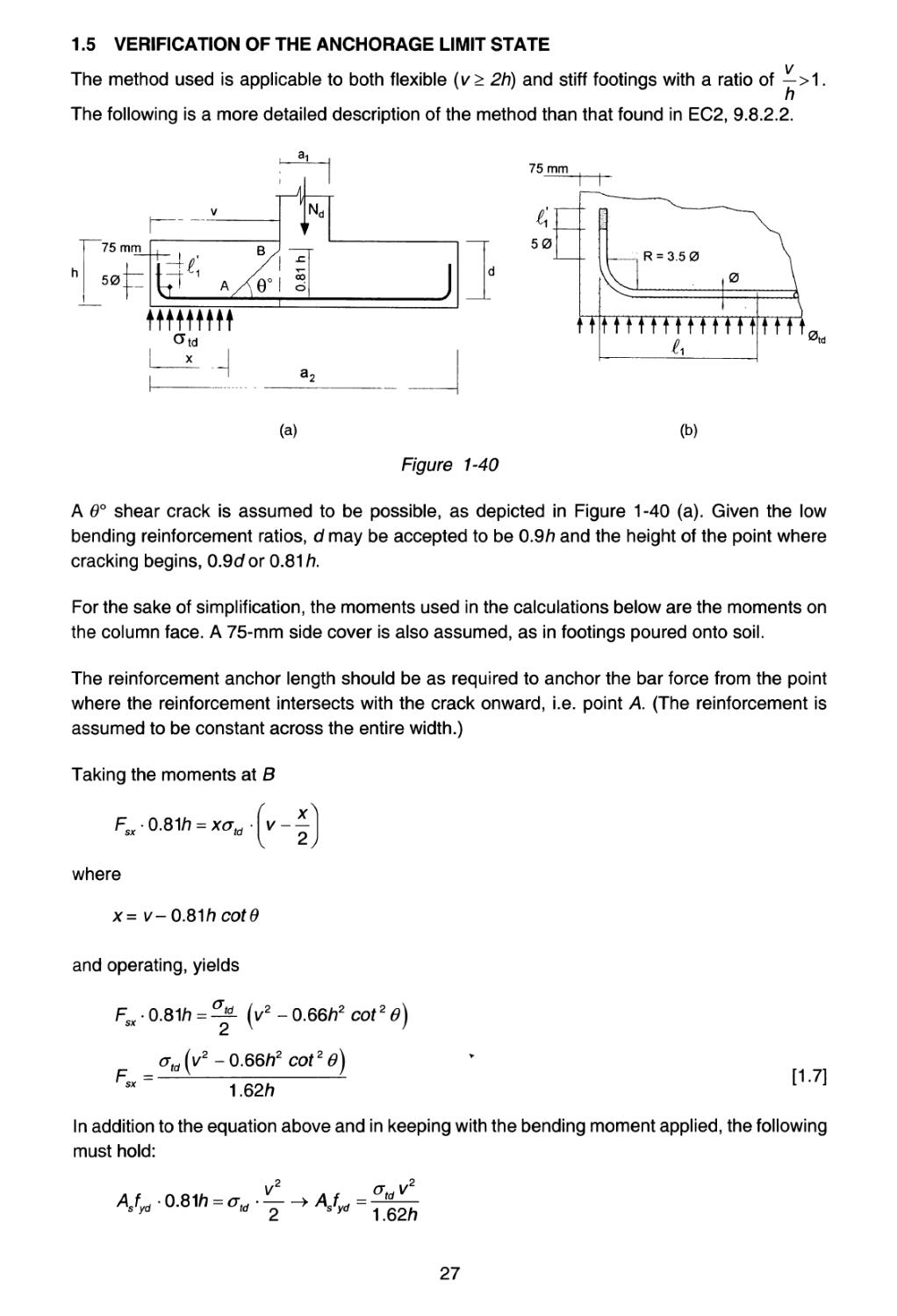
1.5 Verification of the anchorage limit state 27
1.5.1 Bond anchorage 28
1.5.2 Welded transverse bar anchorage 29
1.6 Anchorage rules for welded transverse bars 30
1.6.1 Bars where 14 <фт< 32 mm, 14 <0L < 32 mm 30
1.6.2 Bars where фт< 12 mm, ф1 < 12 mm 31
1.7 Relationship between construction details and durability 32
2 Constructive details 33
Group 01 Foundations 35
CD - 01.01 Wall footing supporting a reinforced concrete wall 36
CD - 01.02 Wall footing supporting a brick wall 38
CD - 01.03 Spread footing 40
V
42
44
46
48
50
52
54
56
58
60
62
64
66
68
70
72
74
76
78
80
82
84
86
88
90
92
94
96
98
100
102
105
106
108
110
112
114
116
118
120
122
124
126
128
130
132
Spread footing with variable depth
Circular footing (Circular reinforcement)
Circular footing (Reinforced with two welded panels)
Spread footing and expansion joint
Strap footing
Self-centred edge footing
Combined edge footing (Variation 1)
Combined edge footing (Variation 2)
Strap footing at comer (1 of 2)
Strap footing at corner (2 of 2)
Self-centred corner footing
Combined footing (Variation 1)
Combined footing (Variation 2)
Tie beam between footings
Foundation beam (Variation 1)
Foundation beam (Variation 2)
Grid foundation (Variation 1) (1 of 2)
Grid foundation (Variation 1) (2 of 2)
Grid foundation (Variation 2) (1 of 2)
Grid foundation (Variation 2) (2 of 2)
Foundation slab (1 of 2)
Foundation slab (2 of 2)
Caisson
Wall footing
Bored pile
Pile cap
Two-pile cap
Three-pile cap
Four-pile cap
Group pile cap (N > 4)
Centring beam for one- or two-pile caps
Retaining walls and basement walls
Cantilever retaining walls. Nomenclature
Cantilever retaining walls. Footing
Cantilever retaining walls. Stem
Cantilever retaining walls. Variations
Cantilever retaining walls. Key
Cantilever retaining walls. Construction joints in footings
Cantilever retaining walls. Vertical contraction joints in the stem
Cantilever retaining walls. Horizontal construction joints in
architectural concrete
Cantilever retaining walls. Vertical contraction joints
Cantilever retaining walls. Expansion joints
Cantilever retaining walls. Fill and drainage
Buttress walls. Buttress nomenclature and distribution
Buttress walls. Footing
Buttress walls. Stem
vi
134
136
138
140
142
144
146
148
150
152
154
156
158
160
162
164
166
169
170
172
174
176
178
180
182
184
186
188
190
192
194
196
198
200
202
204
206
209
210
212
214
216
218
220
Buttress walls. Inside buttress
Buttress walls. End buttress
Tray walls
Tray walls. Tray details
Basement walls. Facade footing
Basement wall. Centred footing
Basement wall. Vertical contraction joint
Basement walls. Special details (1 of 2)
Basement walls. Special details (2 of 2)
Diaphragm walls. General reinforcement
Diaphragm walls. Crown beam
Diaphragm wall-beam bond (Variation 1)
Diaphragm wall-beam bond (Variation 2)
Diaphragm wall-beam bond (Variation 3)
Diaphragm wall-slab bond (Variation 1)
Diaphragm wall-slab bond (Variation 2)
Walls. Drainage chamber and channel in diaphragm wall
Columns and joints
Columns springing from the footing. Tie bar arrangement
Columns in intermediate storeys. Tie bar arrangement
Columns in top storey. Tie bar arrangement
Intermediate joint in edge columns (Variation 1)
Intermediate joint in edge columns (Variation 2)
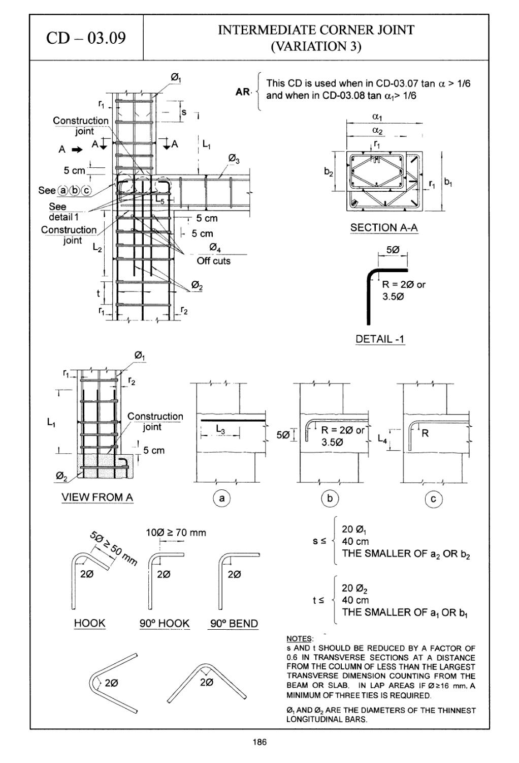
Intermediate joint in edge columns (Variation 3)
Intermediate corner joint (Variation 1)
Intermediate corner joint (Variation 2)
Intermediate corner joint (Variation 3)
Facade or corner joint on last storey
Inside joint in intermediate storeys (Variation 1)
Inside joint in intermediate storeys (Variation 2)
Intermediate joint in circular columns
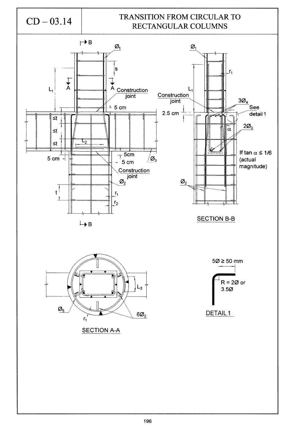
Transition from circular to rectangular columns
Corner joint in large span portal frames
Bar arrangement and shapes of ties in columns
Bundled bar arrangements
Arrangement of laps in columns with bundled bars
Edge schedule. Column schedule
Walls subjected to axial loads
Walls, shear walls and cores. General arrangements
Walls, shear walls and cores. Joint detail
Walls, shear walls and cores. Corners, joints and edges
Walls, shear walls and cores. Detail of openings
Walls, shear walls and cores. Special details for slip forms
(Variation 1)
Walls, shear walls and cores. Special details for slip forms
(Variation 2)
vii
223
224
226
228
230
232
234
236
238
240
242
244
246
248
250
252
254
256
258
261
262
264
266
268
270
272
274
276
278
280
282
284
286
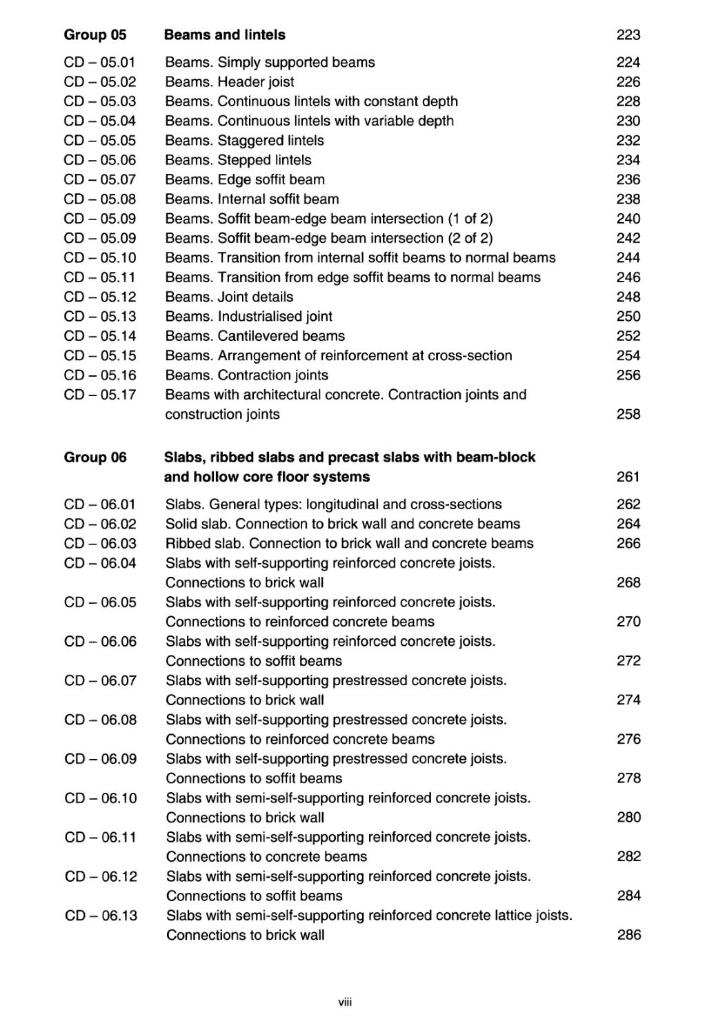
Beams and lintels
Beams. Simply supported beams
Beams. Header joist
Beams. Continuous lintels with constant depth
Beams. Continuous lintels with variable depth
Beams. Staggered lintels
Beams. Stepped lintels
Beams. Edge soffit beam
Beams. Internal soffit beam
Beams. Soffit beam-edge beam intersection (1 of 2)
Beams. Soffit beam-edge beam intersection (2 of 2)
Beams. Transition from internal soffit beams to normal beams
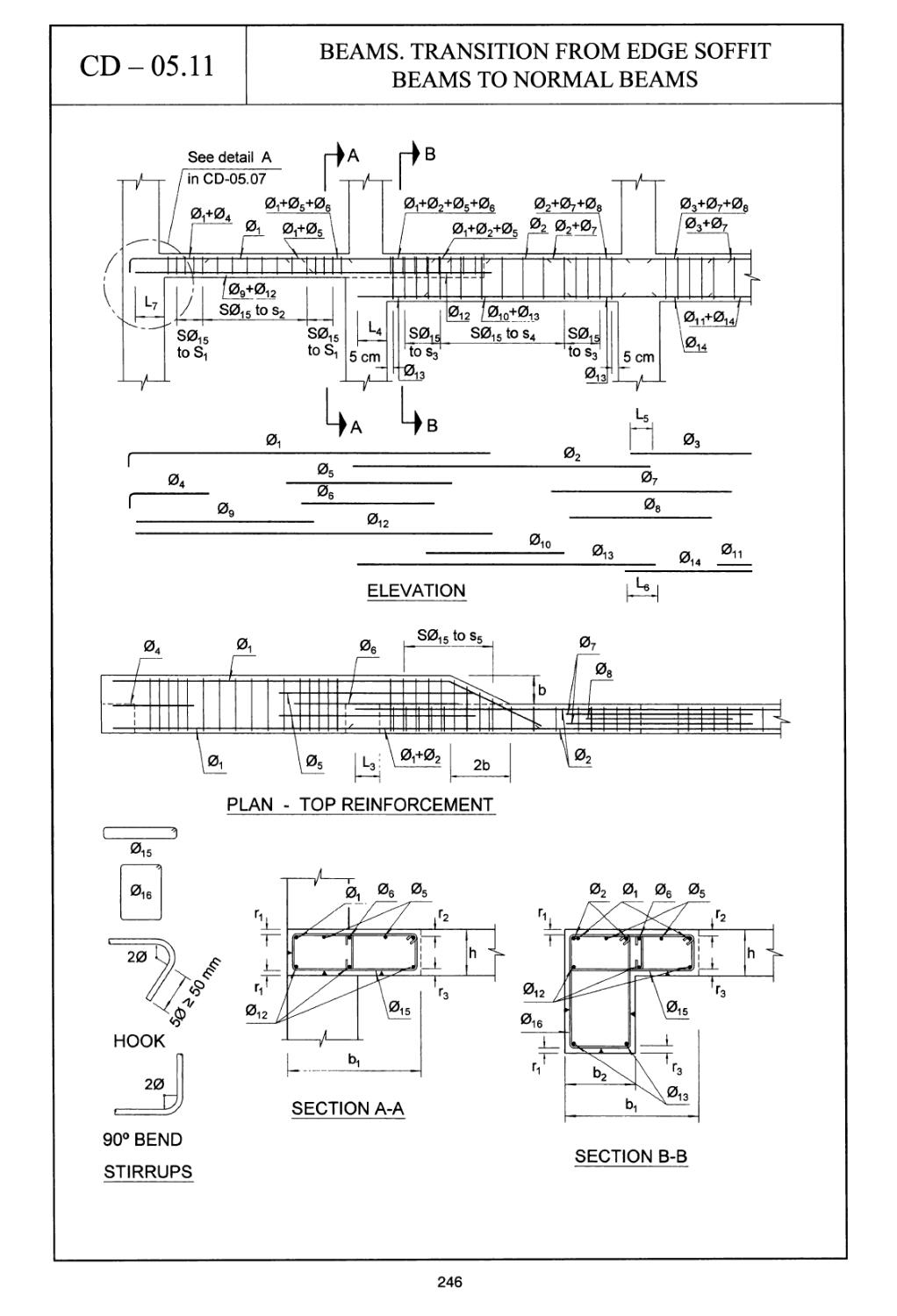
Beams. Transition from edge soffit beams to normal beams
Beams. Joint details
Beams. Industrialised joint
Beams. Cantilevered beams
Beams. Arrangement of reinforcement at cross-section
Beams. Contraction joints
Beams with architectural concrete. Contraction joints and
construction joints
Slabs, ribbed slabs and precast slabs with beam-block
and hollow core floor systems
Slabs. General types: longitudinal and cross-sections
Solid slab. Connection to brick wall and concrete beams
Ribbed slab. Connection to brick wall and concrete beams
Slabs with self-supporting reinforced concrete joists.
Connections to brick wall
Slabs with self-supporting reinforced concrete joists.
Connections to reinforced concrete beams
Slabs with self-supporting reinforced concrete joists.
Connections to soffit beams
Slabs with self-supporting prestressed concrete joists.
Connections to brick wall
Slabs with self-supporting prestressed concrete joists.
Connections to reinforced concrete beams
Slabs with self-supporting prestressed concrete joists.
Connections to soffit beams
Slabs with semi-self-supporting reinforced concrete joists.
Connections to brick wall
Slabs with semi-self-supporting reinforced concrete joists.
Connections to concrete beams
Slabs with semi-self-supporting reinforced concrete joists.
Connections to soffit beams
Slabs with semi-self-supporting reinforced concrete lattice joists.
Connections to brick wall
viii
CD - 06.14 Slabs with semi-self-supporting reinforced concrete lattice joists.
Connections to concrete beams 288
CD - 06.15 Slabs with semi-self-supporting reinforced concrete
lattice joists. Connections to soffit beams 290
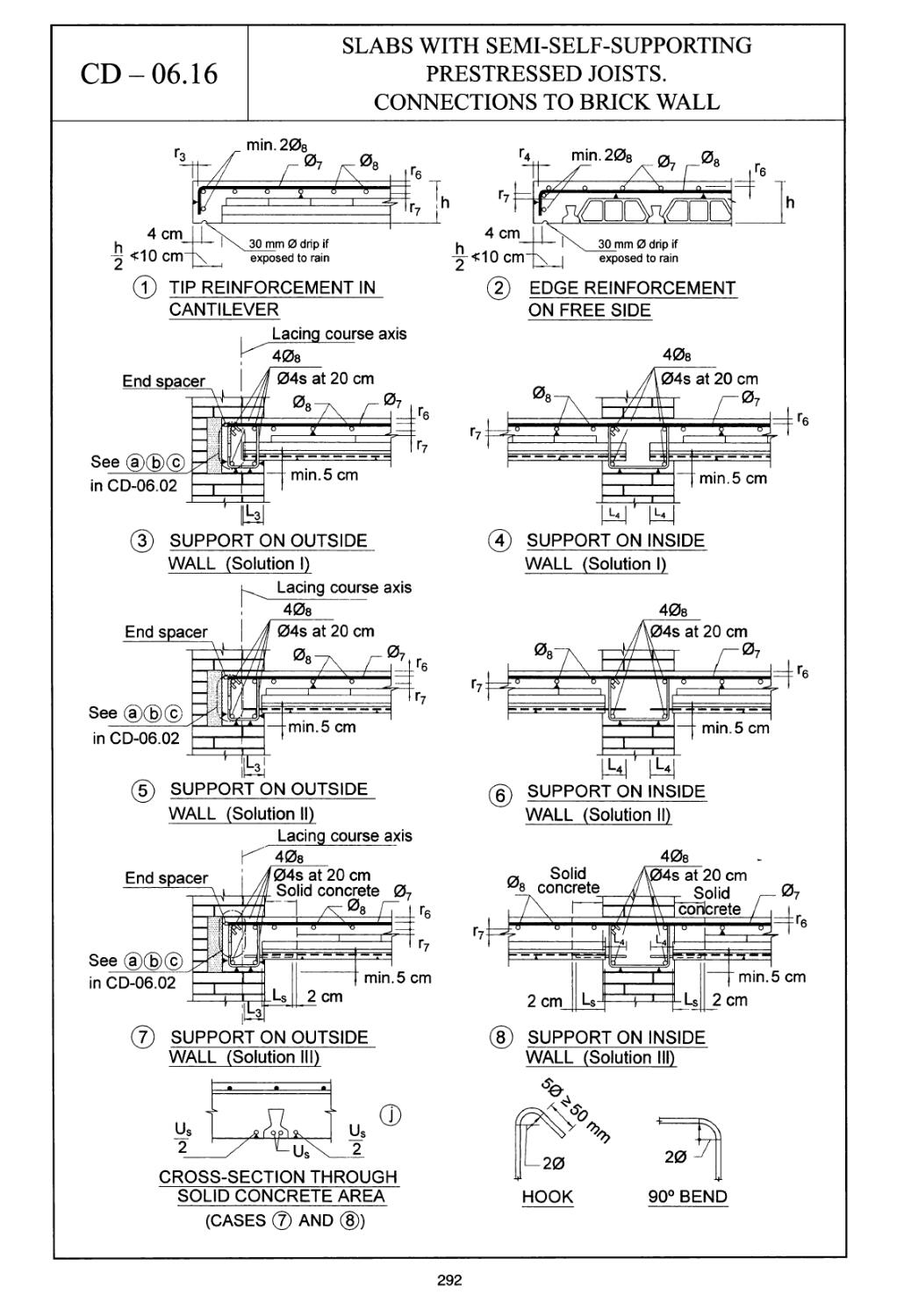
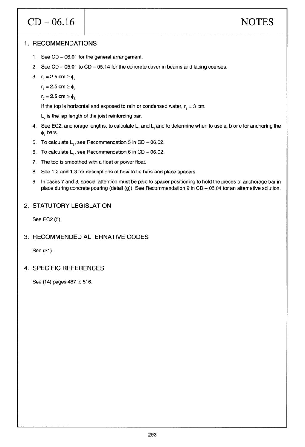
CD - 06.16 Slabs with semi-self-supporting prestressed joists.
Connections to brick wall 292
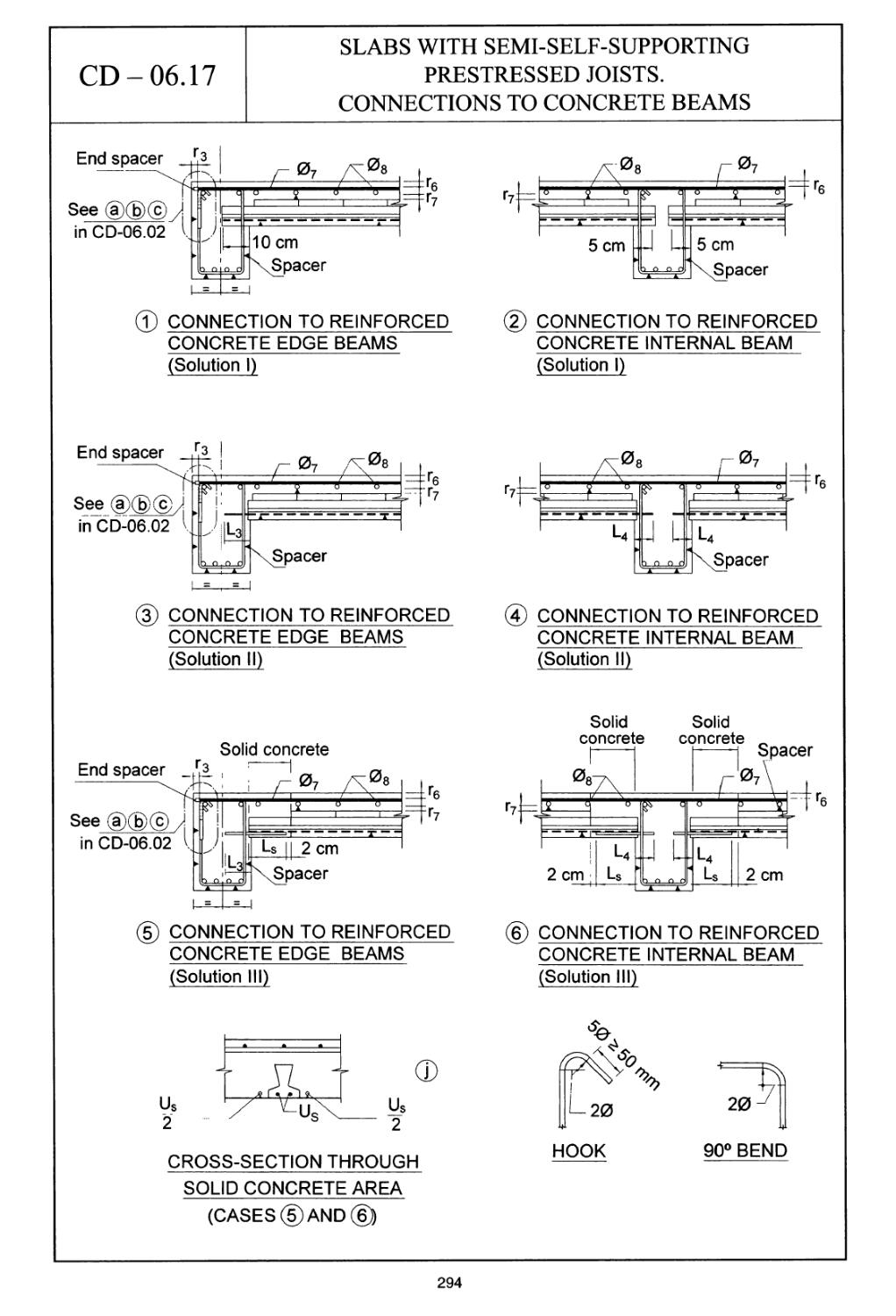
CD - 06.17 Slabs with semi-self-supporting prestressed joists.
Connections to concrete beams 294
CD - 06.18 Slabs with semi-self-supporting prestressed joists.
Connections to soffit beams 296
CD - 06.19 Precast beam and block floor systems. Change in
beam direction 298
CD - 06.20 Precast beam and block floor systems. Connection
to wall parallel to beams 300
CD - 06.21 Precast beam and block floor systems. Cantilever with
extended joists 302
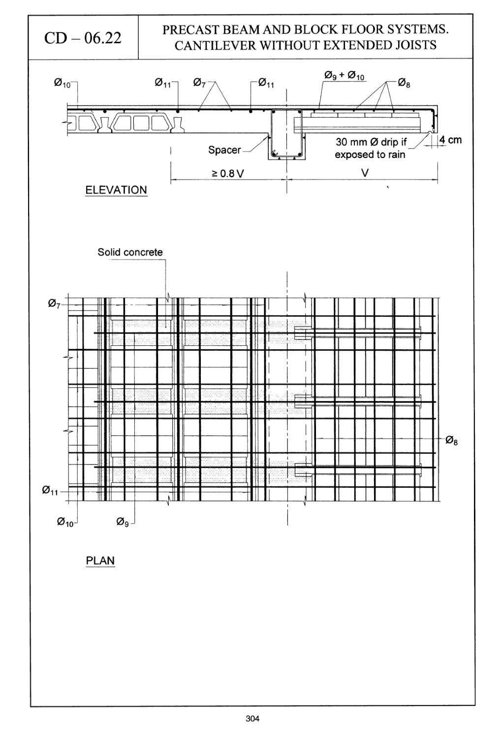
CD - 06.22 Precast beam and block floor systems. Cantilever without
extended joists 304
CD - 06.23 Beam and block floor systems. Openings 306
CD - 06.24 Slabs lightened with embedded tubing 308
CD-06.25 Hollow cores. General details 310
CD-06.26 Hollow cores. Connections 312
CD-06.27 Hollow cores. Tip and edge tie hoops in cantilevers 314
CD-06.28 Hollow cores. Vertical panel and beam supports 316
CD - 06.29 Hollow cores. Supports on vertical panels 318
CD - 06.30 Hollow cores. Supports on vertical panels and beams 320
CD - 06.31 Hollow cores. Openings in the slab 322
Group 07 Flat slabs 325
CD-07.01 Flat slabs. Top reinforcement 326
CD - 07.02 Flat slabs. Bottom reinforcement 328
CD - 07.03 Flat slabs. Arrangement of flexural reinforcement (1 of 2) 330
CD - 07.03 Flat slabs. Arrangement of flexural reinforcement (2 of 2) 332
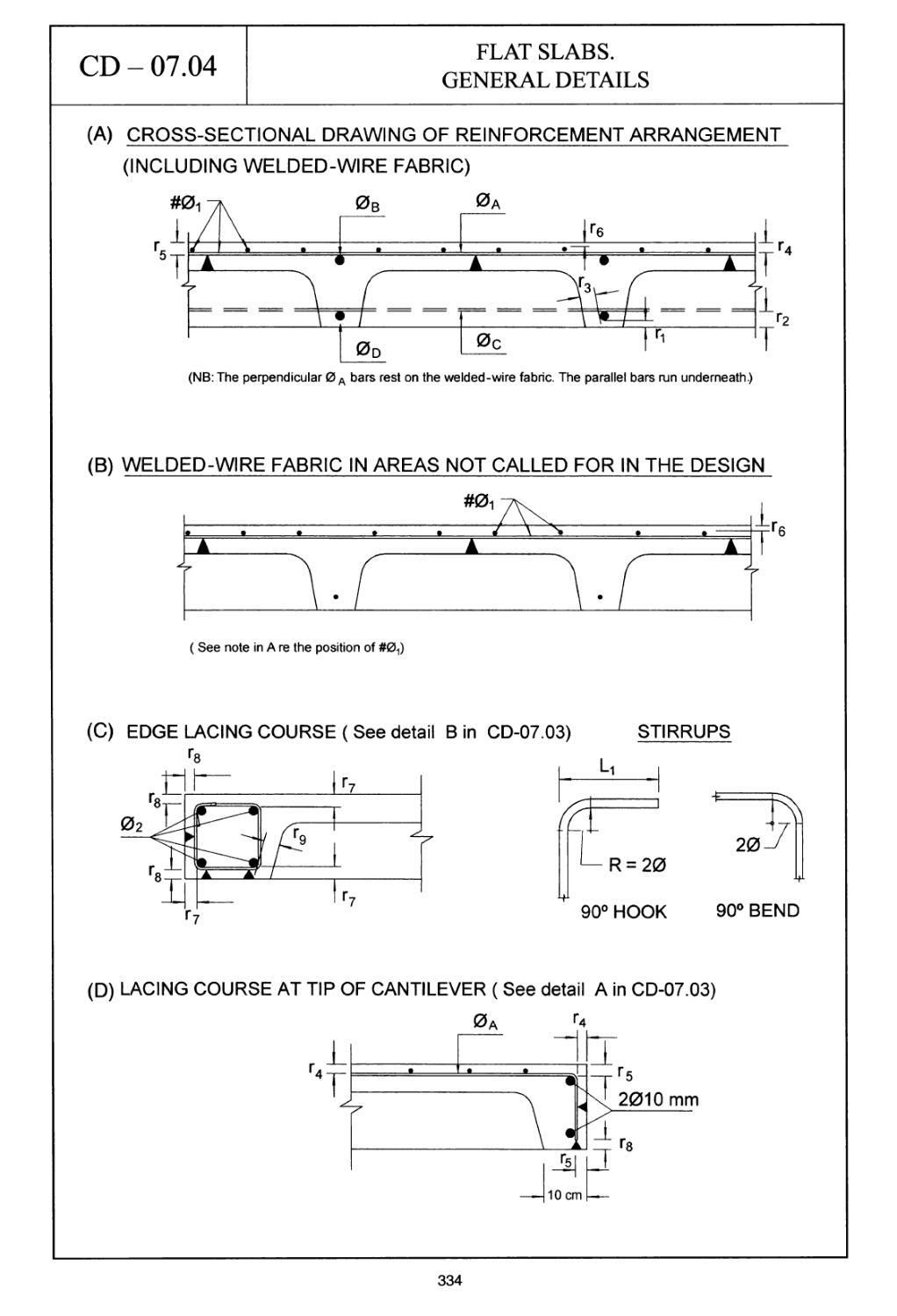
CD - 07.04 Flat slabs. General details 334
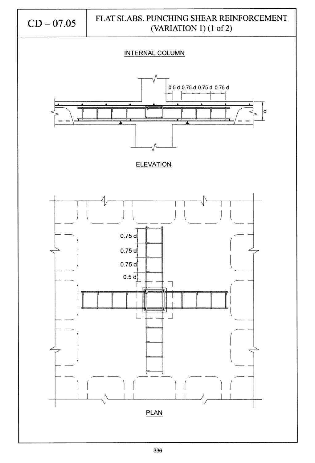
CD - 07.05 Flat slabs. Punching shear reinforcement (Variation 1) (1 of 2) 336
CD - 07.05 Flat slabs. Punching shear reinforcement (Variation 1) (2 of 2) 338
CD - 07.06 Flat slabs. Punching shear reinforcement (Variation 2) (1 of 2) 340
CD - 07.06 Flat slabs. Punching shear reinforcement (Variation 2) (2 of 2) 342
CD - 07.07 Flat slabs. Punching shear reinforcement (Variation 3) (1 of 2) 344
CD - 07.07 Flat slabs. Punching shear reinforcement (Variation 3) (2 of 2) 346
CD - 07.08 Flat slabs. Punching shear reinforcement (Variation 4) (1 of 2) 348
CD - 07.08 Flat slabs. Punching shear reinforcement (Variation 4) (2 of 2) 350
CD - 07.09 Flat slabs. Drop panels 352
CD - 07.10 Flat slabs. Column with drop and head 354
CD - 07.11 Flat slabs. Openings (Variation 1) 356
CD - 07.12 Flat slabs. Openings (Variation 2) (1 of 2) 358
CD-07.12 Flat slabs. Openings (Variation 2) (2 of 2) 360
ix
Group 08 Stairs 363
CD - 08.01 Stairs. General layout details 364
CD - 08.02 Stairs. Reinforcement scheme for double flight 366
CD - 08.03 Stairs. Reinforcement arrangement for stairs with three flights 368
CD - 08.04 Stairs. Foundation for starting flight 370
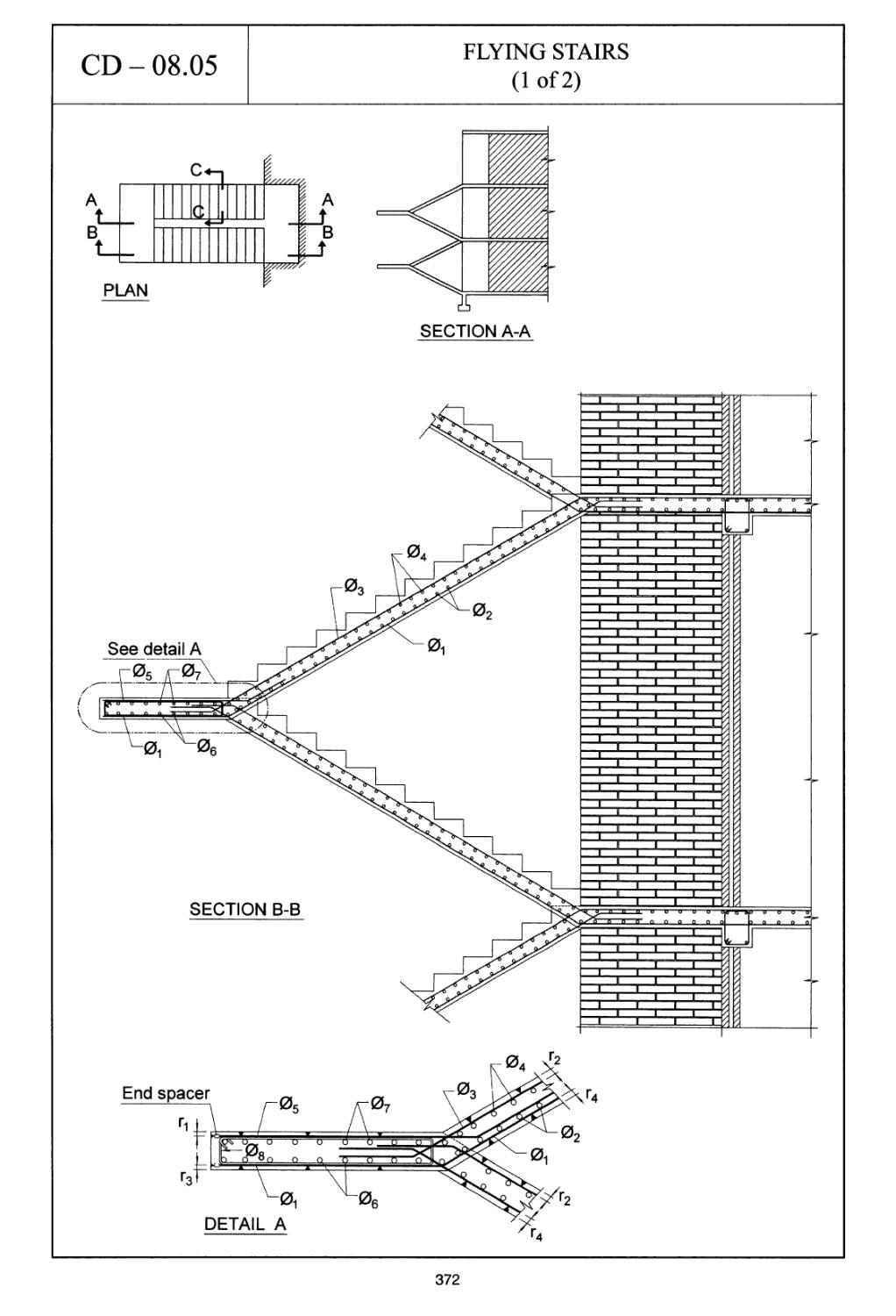
CD - 08.05 Flying stairs (1 of 2) 372
CD - 08.05 Flying stairs (2 of 2) 374
Group 09 Bearings 377
CD - 09.01 Bearings. Device for centring loads 378
CD - 09.02 Bearings. Confinement for linear loads 380
CD - 09.03 Bearings. Elastomer bearings 382
CD - 09.04 Flat jack housing to change bearings 384
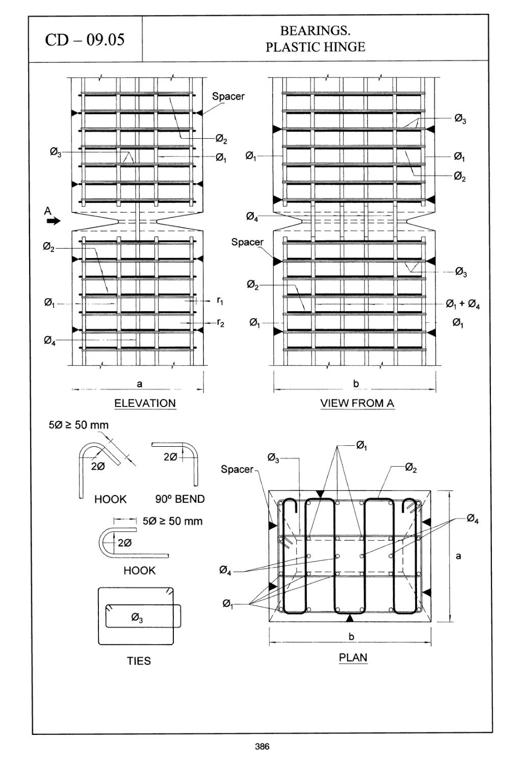
CD - 09.05 Bearings. Plastic hinge 386
Group 10 Brackets and dapped-end beams 389
CD -10.01 Brackets (Variation 1) 390
CD - 10.02 Brackets (Variation 2) (Suspended load) 392
CD - 10.03 Brackets. Double bracket 394
CD -10.04 Dapped-end beams 396
Group 11 Ground slabs and galleries 399
CD - 11.01 Ground slabs. Typical section 400
CD - 11.02 Ground slabs. Joints (1 of 2) 402
CD - 11.02 Ground slabs. Joints (2 of 2) 404
CD - 11.03 Ground slabs. Contraction joints 406
CD - 11-04 Ground slabs. Expansion joints 408
CD - 11.05 Ground slabs. Strengthening free edge of slab 410
CD - 11.06 Galleries. Ductways 412
Group 12 Chimneys, towers and cylindrical hollow columns 415
CD - 12.01 Chimneys, towers and cylindrical hollow columns.
General layout 416
CD - 12.02 Chimneys, towers and cylindrical hollow columns. General
arrangement of reinforcement 418
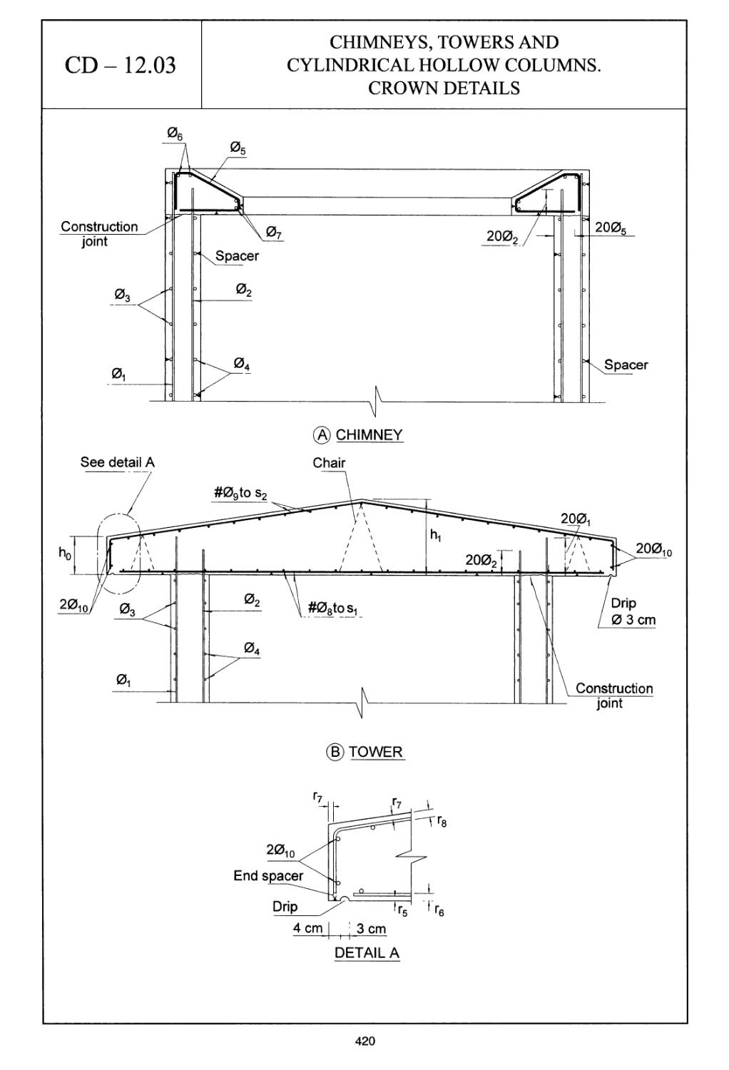
CD - 12.03 Chimneys, towers and cylindrical hollow columns. Crown details 420
CD - 12.04 Chimneys, towers and cylindrical hollow columns. Bracket to
support lining 422
CD - 12.05 Chimneys, towers and cylindrical hollow columns. Duct inlets 424
CD - 12.06 Chimneys, towers and cylindrical hollow columns. Circular slab
around the top 426
CD - 12.07 Chimneys, towers and cylindrical hollow columns. Circular slab
foundations 428
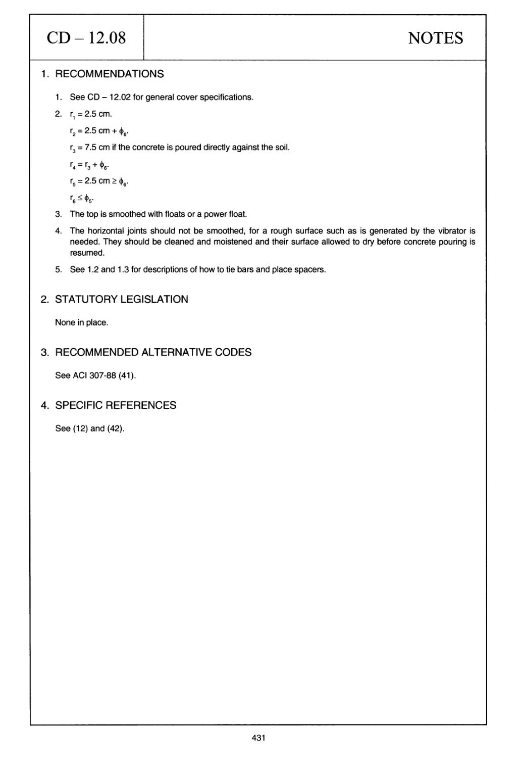
CD - 12.08 Chimneys, towers and cylindrical hollow columns. Annular footings 430
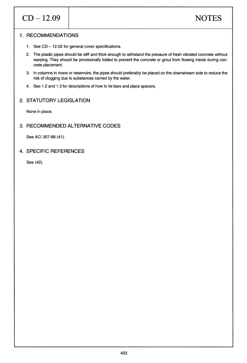
CD - 12.09 Chimneys, towers and cylindrical hollow columns. Plastic
water inflow pipes in submerged hollow columns 432
CD - 12.10 Chimneys, towers and cylindrical hollow columns. Reinforcement laps 434
437
438
440
442
444
446
448
450
453
454
456
458
460
462
464
466
468
470
473
474
476
478
480
482
484
486
488
491
493
Silos, caissons and rectangular hollow columns
Silos, caissons and rectangular hollow columns. Silo sections
Silos, caissons and rectangular hollow columns. Intersections
and connections (Horizontal sections) (1 of 2)
Silos, caissons and rectangular hollow columns. Intersections and
connections (Horizontal sections) (2 of 2)
Silos, caissons and rectangular hollow columns. Plastic water inflow
pipes in submerged columns
Silos, caissons and rectangular hollow columns. Hoppers
Silos, caissons and rectangular hollow columns. Foundations
Silos, caissons and rectangular hollow columns. Reinforcement laps
Reservoirs, tanks and swimming pools
Reservoirs, tanks and swimming pools. Rectangular open tanks.
General details
Reservoirs, tanks and swimming pools. Circular open tanks.
General details
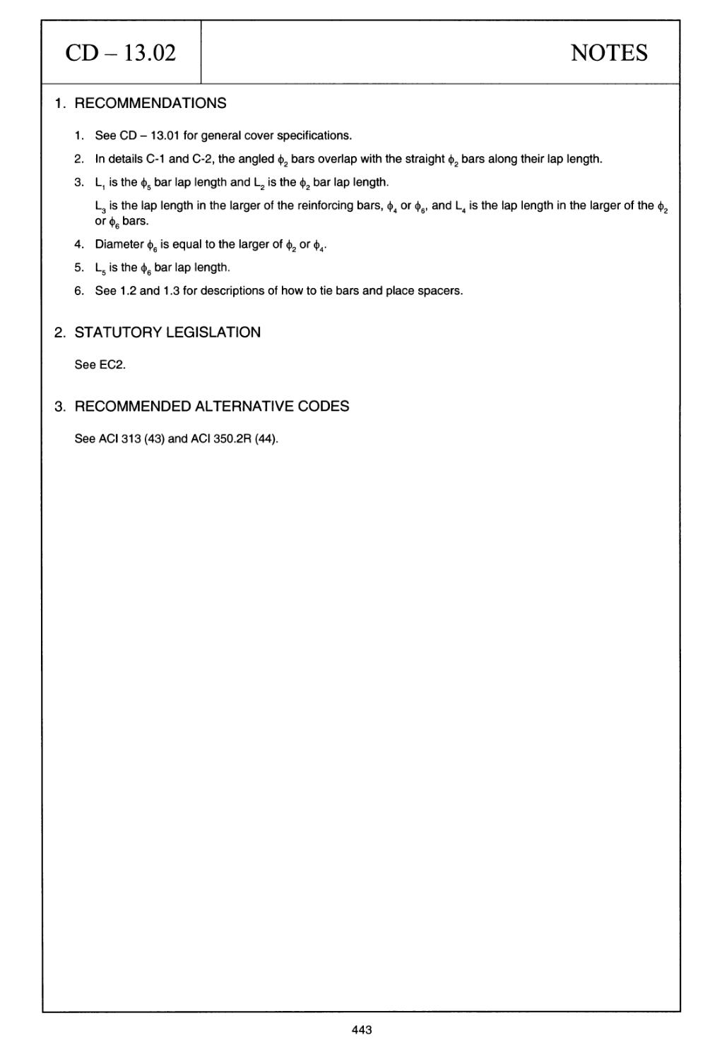
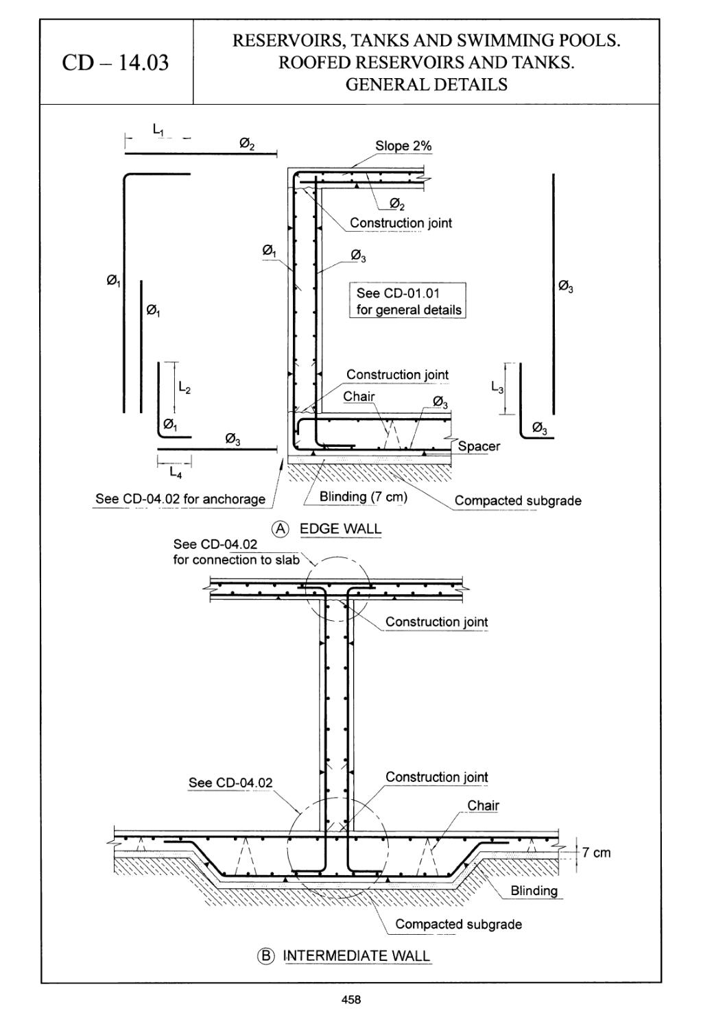
Reservoirs, tanks and swimming pools. Roofed reservoirs and tanks.
General details
Reservoirs, tanks and swimming pools. Corner details (1 of 2)
Reservoirs, tanks and swimming pools. Intersection details (2 of 2)
Reservoirs, tanks and swimming pools. Joints and bearings in walls
Reservoirs, tanks and swimming pools. Contraction and expansion
joints in slabs on grade
Reservoirs, tanks and swimming pools. Joints in walls
Reservoirs, tanks and swimming pools. Specific details for improving
construction joint watertightness
Special construction details for earthquake zones
Summary of basic aspects
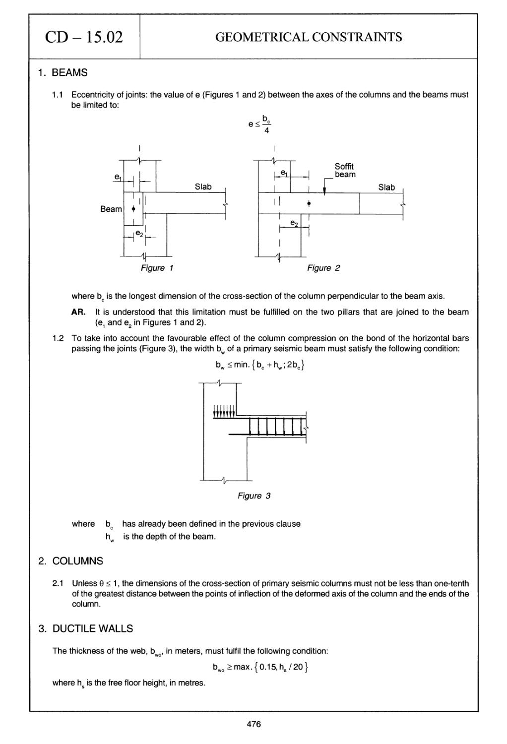
Geometrical constraints
Particular aspects of detailing (1 of 2)
Particular aspects of detailing (2 of 2)
Coupling elements in coupled walls
Reinforcement anchorage
Splicing of bars
Concrete foundations elements
xi
List of tables
T-1.1
Minimum mandrel diameter to prevent damage to reinforcement (EC2)
2
T-1.2
Mandrel diameters for reinforcing bars in accordance with Table T-1.1
(B 400 or В 500 steel) (in mm) (EC2)
3
T-1.3
Minimum cover, cminb, bond-related requirements (EC2)
5
T-1.4
Recommended structural classification (EC2)
6
T-1.5
Values of minimum cover, cmindur, requirements with regard to durability
for reinforcement steel in accordance with EN 10080 (1) (EC2)
6
T-1.6
Maximum bundles general specifications
8
T-1.7
Bundles compressed bars in vertically cast members and overlap areas
in general
9
T-1.8
Bundles equivalent diameters in mm
9
T-1.9
Welding processes permitted and examples of application
23
T-1.10
Concrete. Indicative strength classes
32
xiii
Foreword
The aim of this book is to present a fairly full and systematic description of the construction
details used in concrete structures.
While I paid particular attention to construction details in my previous books, all dealing primar¬
ily with structural design and engineering, I was naturally unable to address the issue in depth
in any of them.
I have decided to do so today, acknowledging the importance of detailing and convinced that
it is one of the areas of expertise that professionals must quickly learn to master. Construction
details have a substantial impact not only on the quality of both the design and the building
processes, but on concrete structure maintenance and durability as well.
Forty-five to fifty per cent of the problems arising around concrete structures are widely known
to be attributable to the design stage. That half of those problems are due to errors in, or the
lack of, construction details is a fact much less generally recognised.
Detailing is always the outcome of a synthesis of four areas of knowledge:
• a command of the theory underlying structural concrete engineering
• on-site professional practice
• experimental information obtained from laboratory trials
• the experience obtained in forensic engineering studies.
The extraordinary complexity resulting from such diversity is deftly reflected in the expression
‘the art of detailing’, which alludes to the mix of technical skill and creativity entailed in good
detailing.
Someone inevitably decides how details are to be built: otherwise construction could not
proceed. But the task is actually incumbent upon the designer. The further ‘downstream’ the
detailing is done, the greater is the risk of malfunction.
This book begins with an introductory chapter that summarises specifications on concrete cov¬
er, reinforcing bar placement and spacing, hook bending radii, anchorages and bar welding. It
also briefly discusses questions that have been scantily addressed in most countries’ codes,
such as how bars should be tied or spacers and chairs placed.
The second chapter is a description of the 213 construction details that comprise the book.
Divided into 15 groups, they embrace what I believe to be a sufficient range of issues arising in
reinforced concrete construction.
In this chapter each page on the left shows a drawing of a construction detail. The Notes set out
on the page opposite on the right contains further information, as specified below.
(a) A series of Recommendations that supplement and help to interpret the drawing, in
some cases with concise reference to specific engineering questions.
XV
(b) Reference to Statutory Legislation in the European Union.
(c) Reference to Recommended Alternative Codes to enable the reader to fill in the gaps
where no statutory legislation is in place in the European Union, or in a number of spe¬
cific cases, to resort to variations of interest.
(d) Finally, a list of Specific References that deal explicitly and directly with the detail in
question.
Version 2005 AutoCAD software is furnished with the book to enable designers to adapt each
detail to the reinforcing bars used in their designs and print the results on a printer or plotter.
In closing, I owe a word of thanks to the people who collaborated in the preparation of this book.
My gratitude goes to Antonio Machado for coordinating the draughting, Maribel Gonzalez and
Mercedes Julve for the typing; and Antonio Machado, Fernando Marcos and Julio Cesar Lopez
for draughting the details from my sketches, which were not always as carefully drawn as would
have been desired.
Many thanks as well to Margaret Clark and Me LEHM Language Services for the translation of
my original Spanish manuscript into English.
I am also indebted to Jorge Ley for his assistance in many respects.
Lastly, I wish to express my very special gratitude to Taylor & Francis for the support received
in connection with the publication of this book, and particularly to Tony Moore and Siobhan
Poole for their assistance.
Jose Calavera
Madrid, March 2011
xvi
The author
Jose Calavera graduated in civil engineering in 1960 and earned his doctorate in the field in
1967, both from the School of Civil Engineering, Polytechnic University of Madrid. From 1960 to
1967 he headed the Engineering Department at Tetracero, a Spanish producer of ribbed bars
for reinforced concrete.
In 1967 he founded the Technical Institute of Materials and Construction (INTEMAC - Instituto
Tecnico de Materiales у Construcciones), an independent quality control organisation that cov¬
ers design, materials and workmanship in both building and civil engineering. He is presently
the Institute’s Honorary President.
In 1982 he was appointed Professor of the Building and Precasting Department at the School
of Civil Engineering, Polytechnic University of Madrid, where he is now Emeritus Professor.
He is a Fellow of the American Concrete Institute (ACI), the American Society of Civil Engineers
(ASCE) and the International Association for Bridge and Structural Engineering (IABSE). He
holds the International Federation for Structural Concrete’s (FIB) Medal of Honour, and has
been awarded the Italian Association of the Prefabrication Prize for Outstanding Achievement
in Engineering and the Eduardo Torroja Medal.
He has written 15 books in Spanish, one in Italian and two in English on structural concrete-
related subjects. His most prominent designs include the Fuente De Aerial Cableway, the roof
over the Real Madrid Sports Centre and the space frame roofs over the National Livestock
Market at Torrelavega. He is also a renowned specialist in forensic engineering.
Author’s curriculum vitae
Jose Calavera
• PhD in Civil Engineering.
• BSc in Civil Engineering.
• Emeritus Professor of Building and Prefabrication at the School of Civil Engineering,
Polytechnic University of Madrid.
• Honorary President of the Technical Institute of Materials and Construction (INTEMAC -
Instituto Tecnico de Materiales у Construcciones).
• Member of the Commission on Prefabrication of the International Federation for
Structural Concrete (Federation Internationale du Beton - FIB).
• Member of the Working Group 2.2 on Design by Testing of the Commission 2 on Safety
and Performance Concepts of the International Federation for Structural Concrete (FIB).
• Editor for Europe of the international Council on Tall Buildings.
Previously, he was:
• Chairman of Commission VII on Reinforcement: Technology and Quality Control
of the Euro-International Concrete Committee (Comite Euro-International du Beton -
СЕВ).
• Chairman of the Joint Committee on Tolerances (СЕВ - FIB).
• Chairman of the Working Group on Precast Beam-Block Floor Systems of the
International Federation for Structural Concrete (FIB).
• Member of the Administrative Council of СЕВ.
• Member of the Model Code CEB-FIB 1990 Drafting Committee.
• Chairman of the Eurocode Drafting Committee for the Design of Concrete
Foundations.
• Chairman of the Working Group on Precast Prestressed Bridges of the International
Federation for Structural Concrete (FIB).
• Chairman of the Working Group on Treatment of Imperfections in Precast Concrete of
the International Federation for Structural Concrete (FIB).
• Chairman of Scientific-Technical Association of Structural Concrete (ACHE)
• Medal of the Spanish Technical Association for Prestressing (ATEP) (1978).
• Honorary Professor of the Civil Construction Faculty, Pontifical Catholic University of
Chile (1980).
• Member of Honour of the Engineering Faculty, Pontifical Catholic University of Chile
(1980).
• Elected Fellow of the American Concrete Institute (ACI) (1982).
• Medal of Honour of the Civil Engineering College (1987).
• Eduardo Torroja Medal (1990).
• Medal of the Spanish Road Association (1991).
• Honorary Doctorate of the Polytechnic University of Valencia (1992).
xix
• Institutional Medal of the Lisandro Alvarado’ Central Western University, Venezuela
(1993).
• Medal of the International Federation for Structural Concrete (FIB) (1999).
• Medal of Honour of the Fundacion Garcia-Cabrerizo (1999).
• Award of the Spanish Group of IABSE (2000).
• Great Figures of Engineering Award of the Italian Association of Prefabrication (CTE)
(2000).
• Award of the Spanish National Association of Reinforced Bars Manufacturers (ANIFER)
(2001).
• Member of Honour of the Spanish Association of Structural Consultants (ACE) (2001).
• Honorary Member of the Academy of Sciences and Engineering of Lanzarote (2003).
• Member of Honour of the Argentine Structural Engineering Association (2004).
• Camino de Santiago Award of Civil Engineering (2004).
• Elected Fellow of IABSE (International Association for Bridge and Structural Engineering)
(2006).
• Member of the Board of Trustees of the Fundacion Juanelo Turriano (2006).
• Member of Honour of the Association of BSc Civil Engineers (2008).
• Best Professional Profile in Forensic Construction Engineering Award of the Latino
American Association of Quality Control and Forensics Engineering (ALCONPAT) (2009).
• Elected Fellow of ASCE (American Society of Civil Engineers) (2009).
• Among his most important projects are the Fuente De Aerial Cableway (Cantabria), the
space frame roofs of the Real Madrid Sports Centre and the Mahou Beer Factory (Ma¬
drid), the space frame roofs of the National Livestock Market of Torrelavega (Santander)
and numerous industrial buildings, especially for paper manufacturers and the prefabrica¬
tion of concrete and steel industry.
• He is author of 15 books in Spanish, two in English and one in Italian, three monographs
and 176 publications on matters concerning structural design, reinforced and prestressed
concrete, structural safety, prefabrication, quality control and pathology of structures. He has
been thesis director for 27 doctoral theses.
XX
Acknowledgements
The publishers wish to thank the Instituto Tecnico de Materiales у Construcciones (INTEMAC)
for granting permission to reproduce parts of the following books authored by J. Calavera.
Manual de detalles constructivos en obras de hormigon armado, [Manual for detailing
reinforced concrete structures], Madrid, 1993.
Calculo de estructuras de cimentation [Foundation concrete design], 4th edn, Madrid,
2000.
Muros de contention у muros de sotano [Retaining walls and basement walls], 3rd edn,
Madrid, 2000.
Calculo, construction, patologfa у rehabilitation de forjados de edification [Design,
construction, pathology and strengthening of slabs in buildings], 5th edn, Madrid, 2002.
Proyecto у calculo de estructuras de hormigon [Structural concrete design], 2nd edn,
Madrid, 2008.
xxi
Citations
• Symbols and abbreviations. The conventions adopted in Eurocode 2 (EC2) have been
used as a rule, except in Group 15 (Special construction details for earthquake zones),
where the Eurocode 8 (EC8) conventions were followed.
• For greater clarity and brevity, references are shown as a number in brackets, which match¬
es the number under which the publication is listed in the References at the end of the book.
For instance: (3) refers to the third reference, namely EN ISO 3766:2003, Construction
Drawings. Simplified Representation of Concrete Reinforcement.
• References to sections of the book itself are cited directly.
For instance: 1.2 refers to section 1.2, Tying bars, in Chapter 1, General rules for bend¬
ing, placing, anchoring and welding reinforcing bars.
• References to other construction details cite the designation shown at the top of each page.
For instance: see CD - 01.02 refers to detail CD - 01.02, Wall footing supporting a brick
wall.
• References to recommendations sometimes specify another CD. For instance: R-3 in 01.03
refers to Recommendation 3 in CD - 01.03. On occasion, the word ‘recommendation’ is
written out in full, rather than as the abbreviation ‘R’.
• References to formulas are placed in square brackets.
For instance: [1.1] is the first formula in Chapter 1, item 1.1.1.
• The figures in Chapter 1 are designated as Figures 1-1 to 1-45.
• When figures are (very occasionally) shown in the Notes, they are designated by letters:
(a), (b) and so on.
• The book is logically subject to EC2 specifications in particular and European Committee
for Standardization (CEN) standards in general. When a given subject is not included in the
CEN system of standards, explicit mention is made of that fact and an alternative standard
is suggested.
• Inevitably, as in any code, the author’s opinion occasionally differs from the criteria set out
in CEN standards. Such recommendations are clearly labelled AR (author’s recommenda¬
tion). In these cases readers are invited to use their own judgement.
General notes
1. Chapter 1 summarises the specifications in Eurocode 2 on concrete cover, bar spacing,
bending radii, spacer placement and welding, or alternative codes when no CEN standard
is in place (for spacers and tying bars, for instance).
2. Many details assume a 2.5 cm or 1 ф cover (abbreviated throughout this book as a lower
case r), which is the value for the most usual case, i.e. exposure classes XC2/XC3 in struc¬
tural class S4. For other conditions, the cover can be changed as described in 1.1.3.
The cover values in the drawings are the Cmjn values. A further 10 mm must be added to
accommodate the spacers. (Members cast against the ground are an exception: in such
cases the 7.5 cm specified includes the 10-mm margin.) The minimum cover value was not
simply enlarged by 10 mm, because while this is the EC2 recommended value, countries
are free to set their own value in their National Annexes.
3. Details on spacers and tying are indicative only. Their number and specific position are
given in Chapter 1. The symbols for spacers and chairs are shown in Figure 1-21.
4. In some cases, more than one page was required to describe a detail. This is clearly speci¬
fied in the heading (‘1 of 2’, for instance). In all such cases, the same Notes apply to both
drawings and are repeated on the page opposite on the right for the reader’s convenience.
5. In keeping with standard terminology in many English-speaking countries, in this book the
word ‘stirrups’ has been used to designate transverse reinforcement in beams and ‘ties’ to
signify transverse reinforcement in columns. In Eurocode EC2, the word ‘links’ is applied
in both situations.
In most structures these two types of reinforcement serve very different purposes, and
perhaps for that reason, in (US) English, French and Spanish, different terms are used for
each.
XXV
The three golden rules for pouring concrete on site
Construction details have a heavy impact on the actual quality of the concrete in a structure.
RULE No. 1
CONCRETE MUST BE CAST INTO ITS FINAL POSITION ACROSS AN ESSENTIALLY
VERTICAL PATH
Horizontal paths must be avoided. This must be taken into consideration in the design drawings
for reinforcing bar arrangements.
75mm 75mm 25mm
ПП -tr
RIGHT WRONG
Figure (a) Figure (b)
Figure (a) depicts the right way to reinforce a beam to ensure that the forms are filled speedily
and satisfactorily. If the bars are arranged as depicted in Figure (b), the coarse aggregate will
not pass readily between them. As a result, the concrete will have to flow horizontally, inducing
segregation and lengthening the time needed to fill the formwork. Moreover, such arrange¬
ments leave insufficient space for the vibrator.
Concrete should not be dumped in a pile for subsequent spreading with vibrators. Rather, it
should be poured in each and every spot where it is needed.
xxvii
RULE No. 2
THE VIBRATOR MUST BE ABLE TO REACH THE BOTTOM REINFORCEMENT
Figure (c) shows the right way to reinforce a beam. With 65-mm spacing (somewhat smaller on
site due to the height of the ribs), a standard 50-mm vibrator will be able to reach the bottom
reinforcement. The solution depicted in Figure (d) is wrong, for it leaves insufficient room for
the vibrator.
65 mm 65 mm
41mm 41mm 41mm
RIGHT. The vibrator can be
readily introduced into the
beam and the joint.
WRONG. The vibrator cannot
be introduced into the beam or
the joint.
Figure (c)
Figures (e) and (f) show two further cases in
bottom reinforcement.
Figure (d)
which the vibrator is able, or unable, to reach the
RIGHT. The vibrator reaches the
bottom layer of reinforcement.
Figure (e)
WRONG. The vibrator cannot
reach the bottom layer of
of reinforcement.
Figure (f)
\
xxviii
RULE No. 3
CONCRETE CONSISTENCY MUST BE IN KEEPING WITH THE REINFORCEMENT
ARRANGEMENT. AS A GENERAL RULE THE CONCRETE SLUMP SHOULD BE NO
SMALLER THAN 60 mm
Unless the reinforcement is arranged very openly and spaciously or powerful vibration methods
are used, overly dry concrete is characterised by the following.
• The required strength can be reached in test specimens (but not on site) with a lower pro¬
portion of cement. The real strength of concrete can be lower.
• Since the control specimens can be compacted with no difficulty, the laboratory trials will
furnish good information.
• In situ placement and a good surrounding of the reinforcement will be difficult to achieve and
the loose consistency will lower actual on-site strength.
xxix
1 General rules for bending, placing,
anchoring and welding reinforcing bars
1 INTRODUCTION
The present summary, based largely on Eurocode 2 (EC2), covers details of a general nature
whose inclusion in all the relevant chapters of this book would be unnecessarily repetitious.
Nonetheless, certain characteristics specific to each type of structural member are addressed
in the respective chapters.
Eurocode 2 (EC2) is supplemented by a number of other standards, the following in particular:
EN 10080 Steel for the reinforcement of concrete (1)
EN ISO 17760 Permitted welding process for reinforcement (2)
EN ISO 3766:2003 Construction drawings. Simplified representation of concrete rein¬
forcement (3)
Eurocode 8 Design of structures for earthquake resistance (4).
Further to EC2 (5), for buildings located in seismic areas, the construction details in this and the
following chapter may be modified as described in Chapter 2, Group 15 below.
1.1 SUMMARY OF CODES AND STANDARDS ON CONSTRUCTION DETAILS
1.1.1 PERMISSIBLE MANDREL DIAMETERS FOR BENT BARS (see EC2, 8.3)
EC2 (5) stipulates that:
• the minimum diameter to which a bar may be bent shall be defined as the smallest diameter
at which no bending cracks appear in the bar and which ensures the integrity of the concrete
inside the bend of the bar;
• in order to avoid damage to the reinforcement, the diameter to which the bar is bent (man¬
drel diameter) should not be less than фттт-
1
TABLET-1.1
MINIMUM MANDREL DIAMETER TO PREVENT DAMAGE
TO REINFORCEMENT (EC2)
(a) for bars and wire
Bar diameter
Minimum mandrel diameter for bends, hooks and loops
ф < 16 mm
4 ф
ф > 16 mm
7 ф
(b) for bent welded reinforcement and wire mesh bent after welding
Minimum mandrel diameter
S » or S
^ or /
I d I
5 ф
d > 3 ф: 5 ф
d < 3 ф or welding within the curved zone: 20 ф
Note: The mandrel size for welding within the curved zone may be reduced to 5 ф where
welding is performed as specified in EN ISO 17660 Annex В (2).
The mandrel diameter need not be checked to avoid concrete failure if the following conditions
exist:
• the length of the bar anchorage beyond the end of the bend is not over 5 <f>-,
• the bar is not in an end position (plane of bend close to concrete face) and a cross bar with a
diameter > ф is duly anchored inside the bend;
• the mandrel diameter is at least equal to the recommended values given in Table T-1.1.
Otherwise, the mandrel diameter, Фтт1п, must be increased as per Expression [1.1]
+ m И-1]
where:
Fbt is the tensile force of the ultimate loads in a bar or bundle of bars at the start of
a bend
ab for a given bar (or group of bars in contact) is half of the centre-to-centre dis¬
tance between bars (or groups of bars) perpendicular to the plane of the bend.
For a bar or bundle of bars adjacent to the face of the member, ab should be
taken as the cover plus 0/2.
The value of fcd must not be taken to be greater than the value for class C55/67 concrete.
\
2
TABLET-1.2
MANDREL DIAMETERS FOR REINFORCING BARS
IN ACCORDANCE WITH TABLE T-1.1 (B 400 or В 500 steel) (in mm) (EC2)
case (a) case (b)
mm
6
8_
10_
12_
14_
16
20_
25^
2A_
32^
40^
50
MANDREL
(mm)
24
32
40
48
56
64
140
175
196
224
280
350
Ф
mm
^ » or /
MANDREL (mm)
L_d_|
6 I or
/
d< 3 0 or welding
within the curved
zone
MANDREL (mm)
6
30
30
120
8
40
40
160
10
50
50
200
12
60
60
240
14
70
70
280
16
80
80
320
20
100
100
400
25
125
125
500
28
140
140
560
32
160
160
640
40
200
200
800
50
250
250
1000
The same rules are applicable to ties and stirrups.
AR. In cases routinely found in practice, such as depicted in Figure 1 -1, the use of 12-mm ф or
larger stirrups leaves the corner unprotected. Consequently, joining two smaller diameter
stirrups is preferable to using 14-mm and especially 16-mm ф elements.
Figure 1-1
1.1.2 STANDARD BENDS, HOOKS AND LOOPS
EC2 specifies the bends, hooks and loops depicted in Figure 1-2 for rebar in general. Ties and
stirrups call for special shapes, as specified in EC2, 8.4 and 8.5, and shown in Figure 1 -3.
3
(a) Equivalent anchorage length for
standard bend
(b) Equivalent anchorage length for
standard hook
г
^b,eq:
(c) Equivalent anchorage length for
standard loop
0f> 0,6 0
\
0
I £ 50
lb,eg- 0-74
(d) Equivalent anchorage length for
welded transverse bar
Figure 1-2. Anchorage methods other than straight bars
(See EC2, Table 8.21 for side cover specifications)
10 0, but
> 70 mm
fr
-0
(b)
> 10 mm
>0.7 0;
>20
>20 mm
£ 50 mm
(C)
£ 10 mm
£ 1.4 0
-0
(d)
Notes:
AR. For (a) usually the hook is at 45°
For (c) and (d) the cover should not be less than either 3 0 or 50 mm. See 1.6 for more detail.
Figure 1-3. Link anchorage
Welding must be performed as specified in EN ISO 17660 (2) and the welding capacity must
be as stipulated in 1.6.
1.1.3 COVER
The EC2 specifications are summarised below.
(a) General
The concrete cover is the distance between the surface of the reinforcement closest to the
nearest concrete surface (including ties and stirrups and surface reinforcement where rele¬
vant) and the nearest concrete surface. For these intents and purposes, groups of reinforcing
bars cannot be replaced by the equivalent circle: rather, the cover refers to the actual bars in
the group.
The nominal cover shall be specified on the drawings <*>. Such cover is defined as the minimum
cover, cm/n, plus a design allowance for deviation, Ac
^ пот ~ С min dev -2]
(b) Minimum cover, с .
' 7 ’ min
Minimum concrete cover, cmjn, shall be provided in order to ensure:
• the safe transmission of bond forces
• the protection of the steel against corrosion
• adequate fire resistance.
The greatest value of cmin that meets the requirements for both bond and environmental condi¬
tions shall be used.
с . = max {c. ,; c. • 10 mm} ^ '3^
min 1 mm, d 1 min, dur J
where:
cm,nb = minimum cover stipulated to meet the bond requirement
Cmin dur = minimum cover stipulated for the environmental conditions.
(For the use of stainless steel or additional protection, see EC2 4.4.1.2)
The minimum cover, cmjnb, needed to transmit bond forces is given in Table T-1.3
TABLET-1.3
MINIMUM COVER, cminti, BOND-RELATED REQUIREMENTS (EC2)
Bond requirement
Arrangement of bars
Minimum cover с „ <**>
min,b
Discrete
Bar diameter
Bundled
Equivalent diameter (0n)
(**) If the nominal maximum aggregate size is greater than
32 mm, с h must be increased by 5 mm.
’ mm,b J
The minimum cover for reinforcement in normal weight concrete for each exposure and
structural class is given by cmjn dur.
Note: The recommended structural class (50-year design service life) is S4 for the indicative
concrete strengths given in EC2, Annex E, while the recommended modifications to the
structural class are given in Table T-1.4. The recommended minimum structural class
is S1.
(*) Given that the EC2 ‘recommends’ 4cdev = 10 mm, but allows the choice to each Member State of the
European Union to determine another value in its National Annex, in this manual are indicated the
values of с ..
5
The recommended values of cmjndur are given in Table T-1.5 (reinforcing steel).
TABLET-1.4
RECOMMENDED STRUCTURAL CLASSIFICATION (EC2)
Structural class
Criterion
Exposure class (see EC2,1
fable 4.1 and notes)
XO
XC1
XC2/XC3
XC4
XD1
XD2/XS1
XD3/XS2/XS3
Design working
life of 100 years
increase
class by 2
increase
class by 2
increase
class by 2
increase
class by 2
increase
class by 2
increase
class by 2
increase class
by 2
Strength class
> C30/37
reduce
class by 1
> C30/37
reduce
class by 1
> C35/45
reduce
class by 1
> C40/50
reduce
class by 1
> C40/50
reduce
class by 1
> C40/50
reduce
class by 1
> C45/55
reduce
class by 1
Member with
slab geometry
(position of
reinforcement
not affected by
construction
process)
reduce
class by 1
reduce
class by 1
reduce
class by 1
reduce
class by 1
reduce
class by 1
reduce
class by 1
reduce class
by 1
Special quality
control of
the concrete
production
ensured
reduce
class by 1
reduce
class by 1
reduce
class by 1
reduce
class by 1
reduce
class by 1
reduce
class by 1
reduce class
by 1
TABLET-1.5
VALUES OF MINIMUM COVER, cmnW . REQUIREMENTS WITH REGARD
7 mm,aur
TO DURABILITY FOR REINFORCEMENT STEEL IN ACCORDANCE
WITH EN 10080 (1) (EC2)*
Environmental requirement for cmjndur (mm)
Structural class
Exposure class (see EC2, Table 4.1)
XO
XC1
XC2/XC3
XC4
XD1/XS1
XD2/XS2
XD3/XS3
S1
10
10
10
15
20
25
30
S2
10
10
15
20
25
30
35
S3
10
10
20
25
30
35
40
S4
10
15
25
30
35
40
45
S5
15
20
30
35
40
45
50
S6
20
25
35
40
45
50
55
(*) Fire safety may call for higher values.
AR. Except in special cases, covers of under 15 mm should not be used.
Where in situ concrete is placed on other (precast or in situ) concrete elements, the minimum
concrete cover from the reinforcement to the interface may be reduced to a value meeting the
bond requirement only, providing that:
• the concrete strength class is at least C25/30;
• the concrete surface is exposed to an outdoor environment for only a short time (< 28 days);
• the interface is roughened.
6
For uneven surfaces (e.g. exposed aggregate) the minimum cover should be increased by at
least 5 mm.
AR. If the surface is roughened mechanically, this value should be 20 mm, for mechanical
treatment generates microcracks in the concrete surface.
(c) Allowance in design for deviation
When calculating the design cover, cnom, the minimum cover must be increased to allow for de¬
viations (Acdev) by the absolute value of the tolerance for negative deviation. The recommended
allowance is 10 mm.
For concrete poured onto uneven surfaces, the minimum cover should generally be increased
by allowing larger deviations in design. The increase should compensate for the difference de¬
riving from the unevenness, maintaining a minimum cover of 40 mm for concrete poured onto
prepared ground (including blinding) and 75 mm for concrete poured directly onto the soil.(*>
The value
reflects the spacer size.
AR. The 40-mm cover for blinding would appear to be excessive. Where the blinding is
reasonably flat, 25 mm or 1 ф would appear to suffice.
1.1.4 BAR SPACING
Bars must be spaced in such a way that the concrete can be poured and compacted for sat¬
isfactory bonding and strength development. See the ‘three golden rules of concrete pouring’
that precede Chapter 1.
The clear (horizontal and vertical) distance between individual parallel bars or horizontal
layers of parallel bars should not be less than the larger of (dg + 5 mm), where dg is the
maximum aggregate size, and 20 mm (Figure 1-4).
Where bars are positioned in separate horizontal layers, the bars in each successive layer
should be vertically aligned with the bars in the layer below. Sufficient space must be left
between the resulting columns of bars for vibrator access and good concrete compaction.
Lapped bars may be allowed to touch one another within the lap length.
(*) Under certain circumstances, European standard EN 1536 (24) allows smaller values for bored piles.
a
Figure 1-4
7
AR. The 20-mm limit for a and b is too narrow to ensure satisfactory concrete casting. For
single layers, a 25-mm space is suggested, and 35 mm for two or more: a should be
2.5 times the diameter of the vibrator needle for bars in any other than the bottom layer
in the beam. Note that the longitudinal ribs on bars usually constitute 0.07 to 0.10 of the
diameter and that bar placement inevitably entails deviations.
1.1.5 BUNDLED BARS
(a) Bundled bars versus large diameter bars
The standard series of large diameter (ф > 32 mm) reinforcing bars includes two diameters in
Europe, 40 mm and 50 mm, and three in the United States, 11 (0 35 mm), 14 (ф 44 mm) and
18 (0 57 mm).1*1 While using these diameters provides for more compact reinforcement, which
is a clear advantage, it also entails two drawbacks. On the one hand, the substantial load trans¬
fers generated call for carefully designed anchorage. On the other, since such large diameter
bars cannot be lap spliced, construction is more complex and costly. Indeed, even lap splicing,
if it were allowed, would be extremely expensive because of the extra steel needed for the long
overlap lengths that would be required.
The alternative solution is to use bundled bars, which afford the advantages of compact distri¬
bution without the aforementioned drawbacks.
(b) Possibly usable bundles
The EC2 specifications are summarised below.
• As a rule, no more than three bars can be bundled (and their axes must not be in the same plane).
• In overlap areas and when using compressed bars in vertically cast members in which no
splicing is needed, four bars are required.
• The equivalent diameter (for the ideal bar whose area is the same as the area of the bundle)
must not be over 55 mm.
(c) Equivalent diameters, areas and mechanical strength
The specifications laid down in Tables T-1.6 and T-1.7 are applicable to bars with an equivalent
diameter Фп = where nb is the number of bars and ф is the diameter of each individual
bar (Table T-1.8).
TABLET-1.6.
MAXIMUM BUNDLES GENERAL SPECIFICATIONS
ф in mm
n
25
28
32
40
2
YES
YES
YES
NO
3
YES
YES
YES
NO
4
Only in overlaps
NO
NO
NO
(*) In the United States and Canada, bars are designated by their diameter expressed in eighths of an inch.
8
TABLET-1.7
BUNDLES COMPRESSED BARS IN VERTICALLY CAST MEMBERS
AND OVERLAP AREAS IN GENERAL
ф in mm
n
25
28
32
40
2
YES
YES
YES
NO
3
YES
YES
YES
NO
4
YES
NO
NO
NO
TABLET-1.8
BUNDLES EQUIVALENT DIAMETERS in mm
ф in mm
n
25
28
32
40
2
35
40
45
57
3
43
48
55
69
4
50
56
64
80
(d) Cross-sectional arrangement of bundles
• Distances between bundles or bundles and bars. The provisions of 1.1.4 apply. The mini¬
mum distance must be equal to the equivalent diameter, <j>n, whose values are given in
Table T-1.8. Note that the minimum spacing between bundles is the physical space be¬
tween two points on the perimeter of the bar closest to the nearest bar in another bundle.
The space between two bundles should always be large enough to accommodate a vibrator
during concrete casting.
• Cover. The cover must be at least equal to the equivalent diameter, фп, measured as the
distance to the closest bar.
• For anchorage and overlaps in bundled bars, see item 8.9.3 of EC2.
1.1.6 SURFACE REINFORCEMENT
For bars with a diameter of over 32 mm, the following rules supplement the specifications in
EC2, 8.4 and 8.7.
When such large diameter bars are used, cracking may be controlled either with surface rein¬
forcement or by calculating crack widths.
As a general rule, large diameter bars should not be lapped. Exceptions include sections
whose smallest dimension is 1.0 m or where the stress is no greater than 80 per cent of
the design’s ultimate strength. In any event, such bars should be lapped with mechanical
devices.
In addition to shear reinforcement, transverse reinforcement should be placed in anchorage
zones with no transverse compression.
9
(a) Additional reinforcement
For straight anchorage lengths (see Figure 1-5), such additional reinforcement should be at
least as described below.
(i) In the direction parallel to the stressed surface:
Ash = 0-25 Asn, [1.5]
(ii) In the direction perpendicular to the stressed surface:
Asv= 0.25 Asn2, [1.6]
where:
A„ is the cross-sectional area of the anchored bar
n1 is the number of layers with bars anchored at the same point in the member
n2 is the number of bars anchored in each layer.
The additional transverse reinforcement should be uniformly distributed in the anchorage
area and bars should not be spaced at more than five times the diameter of the longitudinal
reinforcement.
о Anchored bar
• Continuing bar
Example: On the left, n, = 1, and n2= 2 and on the right,
n, = 2, n2 = 2
ADDITIONAL REINFORCEMENT IN AN ANCHORAGE FOR LARGE
DIAMETER BARS WHERE THERE IS NO TRANSVERSE COMPRESSION
Figure 1-5
For surface reinforcement, (i) and (ii) apply, but the area of the surface reinforcement should not
be less than 0.01 A in the direction perpendicular, and 0.02 Ааех( in the direction parallel, to
the large bars. A is the area of the tensile concrete external to the stirrups (see Figure 1-6).
(b) Additional surface reinforcement
Surface reinforcement may be needed either to control cracking or to ensure adequate
cover resistance to spalling. EC2 addresses this question in Informative Annex J, summarised
below.
\
10
Surface reinforcement to resist spalling should be used where the main reinforcement com¬
prises:
• bars with diameters of over 32 mm;
• bundled bars with an equivalent diameter of over 32 mm.
The surface reinforcement, which should consist of welded-wire mesh or narrow bars, should
be placed outside the stirrups, as shown in Figure 1-6.
^s,surf £ 0.01 Act,ext
x is the depth of the neutral axis at ULS
Figure 1-6. Example of surface reinforcement
The area of the surface reinforcement Assurf should not be less than 0.01 Аае)Л in the directions
parallel and perpendicular to the tension reinforcement in the beam.
Where the reinforcement cover is over 70 mm, similar surface reinforcement should be used,
with an area of 0.005 AaexX in each direction for enhanced durability.
The longitudinal bars in surface reinforcement may be regarded as constituting reinforcement
to resist any other action effects whatsoever.
AR. If such additional reinforcement is included, concrete with a suitable slump should be used
and poured and compacted with utmost care.
1.2 TYING BARS
This issue is not addressed in the EC2 or in any CEN standard. Three excellent References
((6), (7) and (8)) are available on the subject:
• The Concrete Society, Spacers for reinforced concrete Report CS 101, Concrete Society,
1989.
• Comite Euro-International du Beton (СЕВ), Spacers, chairs and tying of steel reinforcement,
Lausanne, 1990.
• BS 7973:2001, Spacers and chairs for steel reinforcement and their specifications.
11
1.2.1 TYING METHOD
Reinforcing bars are always tied with tempered steel wire, generally 1.6 mm in diameter.
Standard practice is to use wires fitted with hooks (Figure 1-7) that are marketed in three or
four lengths to adjust to the standard bar diameters. They are tied with the tool depicted in
Figure 1 -8, consisting of a worm spindle with which the steel fixer first hooks the two loops in
the wire together (Figure 1-7) and then pulls outward on the tool, joining the bars in just two
or three movements (Figure 1-9). The use of tongs leads to bonds such as that depicted in
Figure 1-10, which often work loose. A valid alternative is mechanical joiners that tie the bars
securely (Figure 1-11).
1.2.2 TIE POINTS
The following recommendations are made.
• Slabs and plates. All the intersections between bars around the perimeter of the reinforce¬
ment panel should be tied.
In the rest of the panel, where the bar diameter is 20 mm or less, every second intersection
should be tied. Where the bars are 25 mm or larger, the distance between tied intersections
should not exceed 50 diameters (Figure 1-12) of the thinnest tied bar.
b
1
Figure 1-12
12
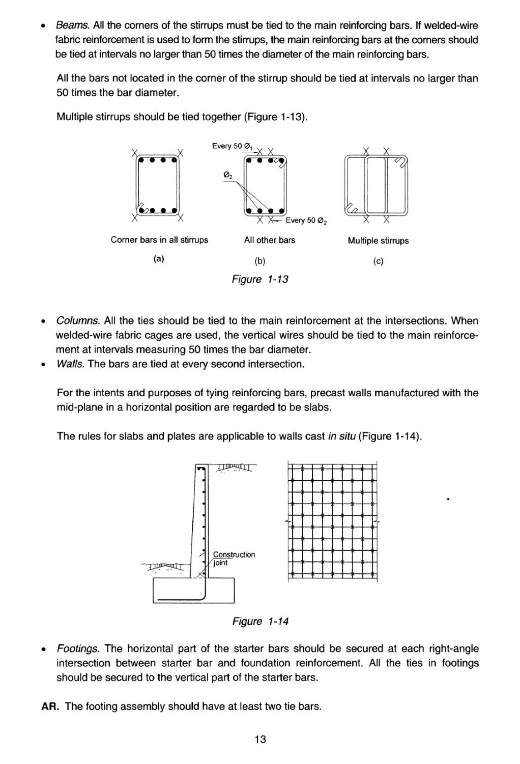
• Beams. All the corners of the stirrups must be tied to the main reinforcing bars. If welded-wire
fabric reinforcement is used to form the stirrups, the main reinforcing bars at the corners should
be tied at intervals no larger than 50 times the diameter of the main reinforcing bars.
All the bars not located in the corner of the stirrup should be tied at intervals no larger than
50 times the bar diameter.
Multiple stirrups should be tied together (Figure 1-13).
Every 50 0
^-x x
0,
Corner bars in all stirrups
(a)
X X— Every 50 02
All other bars
(b)
Figure 1-13
1
L
■ ■ j
Multiple stirrups
(c)
• Columns. All the ties should be tied to the main reinforcement at the intersections. When
welded-wire fabric cages are used, the vertical wires should be tied to the main reinforce¬
ment at intervals measuring 50 times the bar diameter.
• Walls. The bars are tied at every second intersection.
For the intents and purposes of tying reinforcing bars, precast walls manufactured with the
mid-plane in a horizontal position are regarded to be slabs.
The rules for slabs and plates are applicable to walls cast in situ (Figure 1-14).
Constnjction
/joint
Figure 1-14
• Footings. The horizontal part of the starter bars should be secured at each right-angle
intersection between starter bar and foundation reinforcement. All the ties in footings
should be secured to the vertical part of the starter bars.
AR. The footing assembly should have at least two tie bars.
13
1.3 SPACERS AND CHAIRS
This subject is not addressed in the EC2 or in any CEN standard. Here also, references (6), (7)
and (8) are excellent sources of information.
Spacers and chairs are elements made of sundry materials used to ensure a suitable concrete
cover or to hold bars in position. The specific definition for each is given below (see (1.3.1a)
and (1.3.1b)).
1.3.1 TYPES OF SPACER AND CHAIR
(a) Spacers
The are plastic or galvanised or stainless steel wire or steel plate or mortar elements designed
to ensure a satisfactory concrete cover for reinforcing bars. Three general types of spacer can
be distinguished.
• Wheel or clip spacers, which are tied with a wire or clipped to bars or act as unsecured sup¬
ports (Figure 1-15). Figure 1-16 shows a manual procedure for making this type of spacer
where necessary. <*>
Figure 1-15
(a) (b)
Figure 1-16
(*) ‘Home-made’ spacers are not usually permitted.
14
• Linear spacers designed to support the bottom beam and slab reinforcement where the
bars must be prevented from toppling (Figure 1-17).
Figure 1-17
End spacers (Figure 1-18), placed at the ends of bars to ensure they remain at a sufficient
distance from the formwork.
Figure 1-18
(b) Chairs
Chairs are usually made of galvanised or stainless steel wire. They may be discrete, to support
bars in a specific position, or continuous, for continuous support (Figure 1-19). Type (c), which,
may be made of welded-wire fabric, is especially suitable for slabs and flooring. Plastic tubes
are required where the slab soffit is tobe exposed.
Plastic
cap
(a)
(b)
r\
Plastic cap
(C)
Figure 1-19
15
In all cases their purpose is to separate the top reinforcement in slabs from the formwork or the
soil, or the various layers of reinforcement in walls or similar.
Linear chairs should in turn rest on suitable spacers to prevent corrosion.
(c) Special chairs
The standard sizes in which chairs are manufactured are limited for reasons of economy.
Nonetheless, similar elements are needed in very deep slabs or very wide walls to secure the
reinforcing bars.
These elements, known as ‘special chairs’, are normally made with the off cuts metal gener¬
ated when assembling concrete reinforcement (Figure 1-20 (a)). Their diameter and dimen¬
sions should be in keeping with the depth of the member and, in slabs, with the weight of the
top layer of reinforcement.
If they rest on the formwork, they should be supported by spacers (Figure 1-20 (b)). They are
tied to the bottom layer, when present (Figure 1-20 (c)).
(a)
(b) (c)
Figure 1-20
(d) Price
The price of spacers, chairs and special chairs is usually included in the kilo of reinforcing steel
assembled at the worksite. While the financial impact of these elements is small, their cost
should be estimated where large slabs and plates are involved.
Important note: Spacers, chairs and special chairs must be positioned in such a way that they
ensure that all cover distances are 10 mm greater than called for in the design. The reason is to
provide the necessary tolerance for bar deformation between spacers so that the actual cover
or distance is not less than the minimum values.
1.3.2 GRAPHIC REPRESENTATION
The conventional signs listed in the box below (Figure 1-21) are used in drawings to symbolise
spacers, chairs and special chairs.
16
^50 01 but not exceeding
(a) WHEEL OR CLIP SPACER
▲ LATERAL VIEW
■ SUPPORT SIDE VIEW
(b) LINEAR TYPE SPACER
LATERAL VIEW
■— PLAN VIEW
(c) END SPACER
□=>■ LATERAL VIEW
PLAN VIEW
(d) DISCRETE CHAIR
A LATERAL VIEW
И PLAN VIEW
(e) CONTINUOUS CHAIR
SIDE VIEW (PROFILE)
—□— PLAN VIEW
(f) SPECIAL CHAIR
~L SIDE VIEW (PROFILE)
\ PLAN VIEW
Figure 1-21
1.3.3 PLACEMENT RULES
(a) Slabs and footings
• Bottom reinforcement layers should rest on and be attached to spacers positioned at
intervals measuring no more than 50 times the bar diameter and never over 1000 mm
(Figure 1-22).
SECTION
SECTION
"D
<D
O)
O)
OJ
W
T>
С
со
E
•E
о
о
о
PLAN
Individual bars Welded fabric
(a) (b)
SPACERS FOR BOTTOM REINFORCEMENT IN SLABS AND FOOTING
Figure 1-22
17
• The top reinforcement should rest on:
- continuous chairs set at intervals measuring not over 50 times the bar diameter.
These continuous chairs rest, in turn, on the bottom reinforcement, if any (Figure
1-23 (a)) and where there is none, on linear chairs spaced at no more than 500 mm
(Figure 1-23 (b));
-01
-01
,_Q Q L .0. Q fi
’A Д1 - J
/ \ / \
r-L \ L—i_
у SJ SJ
Г01
c.
c
с
с
с
с
1
р
1
[
]
1—
j
i
j
\
j
-I
-\
D
A
[
]-
i »
SECTION
SECTION
PLAN
X
4TJ
E
E
E
о
о.
ю
<50 0V not exceeding
500 mm for welded fabric
(a)
4
c
с
a
с
с:
I
Г
1
j
-
t=“
1
m
-
1
■i
i—
tr
■i
T
т|
H
! к
к
й 50 0V for bars or
-01
1 PLAN
500mm for welded fabric
(b)
CONTINUOUS CHAIRS FOR TOP REINFORCEMENT IN SLABS AND FOOTINGS
WITH BOTTOM REINFORCEMENT
Figure 1-23
discrete chairs spaced in both directions at no more than 50 times the diameter of
the supported bar (Figure 1-24);
-01
_Q Q L Q 2 Q_
К
Л '‘p SECTION
О
sl
SS-
2 s
о |
ю E
VI о
о
ю
c:
i
c=
i
c
к—
Г71
d
Hzfzh
Щ
d
-И-
A
4=71-
d
. . A .
PLAN
<50 0V for bars or
500 mm for welded fabric
CHAIRS FOR TOP REINFORCEMENT IN SLABS AND
FOOTINGS WITHOUT BOTTOM REINFORCEMENT
Figure 1-24
18
special chairs spaced at the intervals shown in Figure 1 -25.
1200 mm
1 JL Г
, i
1 0 [
II
1 . D
1 fl
1 f
I 1
1 fl
1 П 0 [
i ii
i r
1 fl
r
II
1
1 ч
о II 1
i *
1
г
ii i
m
'"'ГТ/Г
U гч -X Li
1 II
■4-
i i^i
1
II II
i 1 \
■VI 1
11.
ii 1
\y
4 II 1
II II I
1
U D
ii
L II
i
II II
1 ■
, 1
L
= =y=
N
'1
1
N
44-
“Г4
PLAN
SPECIAL CHAIRS FOR TOP REINFORCEMENT IN SLABS
Figure 1-25
(b) Spacers on slab edges
• In the absence of horizontal reinforcement along the slab edges, spacers are placed
on alternate bars, as in Figure 1-26 (a).
►
|
1
V4wO О О
SECTION
• 1
i.. ...J
i i
i
i
Spacers on
ELEVATION
alternate bars
(a) Without horizontal reinforcement
. J
i
w^
VVO о о
SECTION
—■
i
: \
r
ELEVATION
A i
к ]
ii
Spacers at 500 and not
exceeding 1000 mm
(b) With horizontal reinforcement
SPACERS FOR SLAB EDGES
Figure 1-26
• When the slab has horizontal reinforcement on the edges, the spacers should be
placed as in Figure 1-26 (b).
19
(с) Spacers for ribbed slabs
Spacing is as shown in Figure 1-27.
(a) Without stirrups
Figure 1-27
(d) Beams
Spacers should be set in the stirrups at intervals of no more than 1000 mm longitudinally
(Figure 1-28), with a minimum of three planes of spacers per span.
Cross-wise placement must be as shown in Figure 1-28.
All spacers tied to stirrups at not
over 1000 mm
С
(a)
s
pq
< 250 mm
(b)
■kfl.
(d)
G
о
Ю
o>
250 mm - 500 mm
(c)
Spacers at intervals
not exceeding 50 01
(e)
Figure 1-28 Spacers in beams
Г
D
0
С
Э . ...
0
Q
... ^
> 500 mm
End or ordinary spacers are needed at the ends of beams in contact with the formwork,
depending on the case (Figure 1-29).
20
ii
Figure 1-29
(e) Columns
Lengthwise along the member, spacers should be placed in the stirrups at no more than 100
times the minimum diameter of the main reinforcement, with at least three planes of spacers
per member or section (Figure 1-30).
a £50 0
bS5O0.,
(a)
SPACER ARRANGEMENT IN COLUMNS
Figure 1-30
Spacers at intervals
not exceeding 50 0,
F
Face > 50 0
-0,
Spacers at intervals
not exceeding 50 0Л
i I
_Q_
(b)
Double links
(c)
Spacers at intervals
not exceeding 50 0V
At least 4 per group
Circular columns
(d)
(e)
MULTIFACETED COLUMNS
Figure 1-31
Crosswise placement should be as shown in Figure 1 -31.
21
(f) Walls
Spacers should be staggered in each layer of reinforcement at intervals measuring the
larger of 500 mm or 50 times the diameter of the reinforcing bars. Spacers for reinforcement
on opposite sides of the member must be placed at the same height. Spacing between the
reinforcement on the two sides must be ensured with continuous chairs set at intervals of
not over 1000 mm. In large retaining walls, special chairs must be used instead of chairs
(Figure 1-32).
In precast concrete walls whose mid plane is in a horizontal position, the spacers must be set
as described for slabs.
О
С
«£
ie
is
с о
TO О)
go
р
<0 <D
"О
С
ш
Continuous chairs at intervals not
exceeding 1000 mm
-I— kc
с
с
с
с
А
rJ
rJ
j
I
i
—
■ j
i
li
—
u
4-
b
h
ELEVATION
-0«
Spacers at intervals not exceeding the
greater of 50 <2Л or 500 mm
, in both directions ,
SECTION
ft
h
ft
8
4
£
“Д—
/ \
/ \
1 1 "Л ■
/ \
J L.
t
8
s
V
8
PLAN
<1000 mm
SPACERS AND CONTINUOUS CHAIRS FOR WALLS
Figure 1-32
1.4 WELDING REINFORCING BARS
Bars are commonly welded together, using any of a number of procedures. The following is a
summary of standard ENISO 17660-1, Welding of Reinforcing steel (11).
1.4.1. TYPES OF WELD
Two types of welded joints can be distinguished:
(a) load-bearing
(b) non-load-bearing.
22
In addition, such joints can be classified by their position or the welding procedure used.
The welding procedures allowed for reinforcing bars are set out in Table T-1.9 (EC2, Table 3.4)
and weldability requirements are established in EN 10080 (1).
TABLET-1.9
WELDING PROCESSES PERMITTED
AND EXAMPLES OF APPLICATION
Loading conditions
Welding method
Tension bars1
Compression bars1
Predominantly
static
flash welding
butt joints
manual metal arc
welding and metal
arc welding with
filling electrode
butt joints with ф > 20 mm, splice, lap and
cross joints3 and joints with other steel
members
metal arc active welding2
splice, lap and cross3 joints and joints with
other steel members
-
butt joints with ф> 20 mm
friction welding
butt joints, joints with other steel members
resistance spot welding
lap joints4
cross joints2'4
Not predominantly
static
flash welding
butt joints
manual metal arc welding
-
butt joints with ф > 14 mm
metal arc active welding2
-
butt joints with ф > 14 mm
resistance spot welding
lap joints4
cross joints2,4
Notes:
1. Only bars with approximately the same nominal diameter may be welded.
2. Allowable ratio for mixed diameter bars > 0.57
3. For load-bearing joints with 0 < 16 mm
4. For load-bearing joints with ф< 28 mm
All reinforcing bars shall be welded as specified in EN ISO 17760 (2).
The welds joining wires along the anchorage length of welded-wire fabric shall be strong
enough to resist the design loads.
The strength of the welds in welded-wire fabric may be assumed to be adequate if each welded
joint can withstand a shearing force equal to at least 25 per cent of the characteristic yield
stress times the nominal cross-sectional area of the thicker of the two wires, if they differ in
size.
AR. In cross joints with hardened concrete around the bars, the strength of the joint is
25 per cent higher than in exposed joints.
23
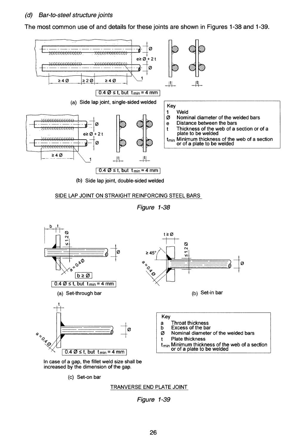
1.4.2. WELDED JOINT DETAILS
(a) Butt joints
In all such joints, the edges are prepared as shown in Figure 1-33.
= 60°
= 60°
(a) Double V butt weld
' £ 45°
(c) Double bevel butt weld (d) Single V butt weld with backing
Note: x and у depend on the welding process.
EXAMPLES OF BUTT JOINT PREPARATION
Figure 1-33
(b) Lap joints
These joints call for no preparation. The procedure is as shown in Figures 1-34 and 1-35.
МЭ
£ 4 0
£20
£40
44N4444NN4N4NNN4N4NNNN
■ i
Key
1 Weld
a Throat thickness
0 Nominal diameter of the thinner of the two welded bars
tQ Overall lap length
w Weld width
Note: Welding is also possible on both sides with minimum weld length of 2.5 0.
A conservative estimate of the effective throat thickness can be taken as
a = 0.5 w.
LAP JOINT
Figure 1-34
24
£40
£20
£40
а£0.3 0
Key
1 Weld
a Throat thickness
0 Nominal diameter of the thinner of the two welded bars
w Weld width
Note: Welding is also possible on both sides with minimum weld length of 2.5 0.
A conservative estimate of the effective throat thickness can be taken as
a » 0.4 w.
STRAP JOINT
Figure 1-35
(c) Cross joints
Cross joints can be resistance-welded (with machines with widely varying characteristics) or
metal-arc-welded (Figures 1-36 and 1-37).
-h
A
Key
1 Longitudinal bar
2 Transverse bar
F Force to be anchored by transverse bar
(b) Single-sided weld
CROSS JOINTS WELDED BY RESISTANCE MANUAL ARC WELDING
Figure 1-36
-Jb—
CROSS JOINTS WELDED BY RESISTANCE
SPOT WELDING
Figure 1-37
25
(d) Bar-to-steel structure joints
The most common use of and details for these joints are shown in Figures 1-38 and 1-39.
И)))))))))»)))))),
)))»)»»»))))))>
)»))).))»»)))))))
£ 4 0
>20
£ 4 0
'0
+ 2 t
0
ш й
_
-
-4U
| 0.4 0 £ t, but tmin = 4 mm~l
(a) Side lap joint, single-sided welded
)))))))))))))))»»
0
e£ 0 + 21
73-rl"0
Key
1 Weld
0 Nominal diameter of the welded bars
e Distance between the bars
t Thickness of the web of a section or of a
plate to be welded
tmin Minimum thickness of the web of a section
or of a plate to be welded
240 x_i JU -Д-
| 0.4 0 < t, but tmin = 4 mm |
(b) Side lap joint, double-sided welded
SIDE LAP JOINT ON STRAIGHT REINFORCING STEEL BARS
Figure 1-38
ь ,t,
J]
CN
VI
p 2
к
. У
г
t*0
0.4 0 < t, but t min = 4 mm
(a) Set-through bar
t
0
1
Г
0
| 0.4 0 < t, but tmin = 4 mm |
In case of a gap, the fillet weld size shall be
increased by the dimension of the gap.
Key
a Throat thickness
b Excess of the bar
0 Nominal diameter of the welded bars
t Plate thickness
tmin Minimum thickness of the web of a section
or of a plate to be welded
(c) Set-on bar
TRANVERSE END PLATE JOINT
Figure 1-39
26
1.5 VERIFICATION OF THE ANCHORAGE LIMIT STATE
The method used is applicable to both flexible (v> 2h) and stiff footings with a ratio of ^>1.
The following is a more detailed description of the method than that found in EC2, Э.8.2.2.
(a) (b)
Figure 1-40
A 6° shear crack is assumed to be possible, as depicted in Figure 1-40 (a). Given the low
bending reinforcement ratios, d may be accepted to be 0.9ft and the height of the point where
cracking begins, 0.9c/or 0.81/7.
For the sake of simplification, the moments used in the calculations below are the moments on
the column face. A 75-mm side cover is also assumed, as in footings poured onto soil.
The reinforcement anchor length should be as required to anchor the bar force from the point
where the reinforcement intersects with the crack onward, i.e. point A. (The reinforcement is
assumed to be constant across the entire width.)
Taking the moments at В
F„. 0.81/7 = X<7„ (v-£
where
x = v — 0.81/? cote
and operating, yields
Fsx • 0.81/7 = (v2 - 0.66/72 cot2 в)
CFtd (v2 - 0.66/72 cot2 в)
F [1.71
1.62/7
In addition to the equation above and in keeping with the bending moment applied, the following
must hold:
AJyd.0Mh = *td.^^Asfyd=f^
27
from which it follows that:
As,eq (у2 — 0.66/72 cot2 о) Д
о — ^~sx . e
,net Af A
syd s,prov
s,req
s,prov
[1.8]
reflects bonding position I, given the position of the bars.)
" b,net
1 - 0.66
2
cot2#
л
p . s're(* (*)
b A
s,prov
[1.9]
1.5.1 BOND ANCHORAGE
Given x = v- 0.81/7 cot6\
If lbm < x - 75 = v - 0.81/? cot в - 70
If 0.7 £bnet <x-75=v- 0.81/7 cot в- 70
If 0.7 ibnet > x-75 =v- 0.81/7 cote- 70
-> use straight anchorage [1.10]
->■ use hook anchorage [1.11]
-» lengthen l\ [1-12]
(See Figure 1 -40 (b))
(Dimensions in mm)
Since length l\ is in bonding position I:
. x-75 v-0.8Mi cote-75 ..
b npt = +Л = +Л
0.7 0.7
and consequently:
Л =*Ь,пе, ~ V-°-8^te~75 [1-13]
where £bnel is calculated as per [1.9].
Since:
x = y-0.81/7 cote.
The minimum value of x is found with the maximum value of cot в which, according to
EC2, is equal to cote = 2.5, yielding:
x = v - 2.03/7 = /7
f v ^
- - 2.03
\h у
or
(*) [1.9] is a more general expression than the formulas set out in EC2, in which critical value x is simpli¬
fied to be equal to 0.5/7. See the discussion below.
28
(I
V
h
Figure 1-41
The graph in Figure 1-41 shows the distance x in terms of h for different values of —.
v
If — < 2.5, a conservative value for x is 0.5/7, as adopted in Eurocode EC2. Direct calcula¬
tion is preferable.
1.5.2 WELDED TRANSVERSE BAR ANCHORAGE
In this case, the force to be anchored at the end of the bar, assuming a 75-mm cover, is defined
as shown in Figure 1-42.
F = F -x 75 F =F
О SX A sx sx
1-
x-70
where F was deduced from [1.7]
and substituting
c <Jtd (v2 - 0.66/72 cot2 в)
1.62/7
v-75 -0.81/7cot в
1.62/? А Г,
and given atd = r——
Fo=Asfyd
1-0.661-^1 cot* 6
1-
y-75 -0.81/7 cot в
[1.15]
hence, according to the discussion in section 1.6, with welding strength 0.5 Asfyd, the
number of welded transverse bars required, n, is calculated as:
29
Inasmuch as expression [1.16] is always less than one, anchorage is attained with a
welded transverse bar of the same diameter as the main bars.
1.6 ANCHORAGE RULES FOR WELDED TRANSVERSE BARS
This issue has been researched in a number of countries. The results are summarised below(*>
in somewhat greater detail than in ЕС2. In this method, the strength of the welded joint can be
found assuming that the cross-joined bars are surrounded by concrete.
1.6.1 BARS WHERE 14 < фт < 32 mm, 14 < ^ < 32 mm
The design value of the anchorage capacity of a welded transverse joint can be found from the
following formula:
Fbtd=^-^ald<Fwd [1.17]
where:
Fbld = design value of the anchorage capacity of the welded transverse joint
L» = 1-16*.,fe-SL, [1.18]
LT = in single transverse bars, bar length, or spacing between longitudinal bars, as appropriate
фт = transverse bar diameter.
(The assumption is that фт < 0L and that the welded joint is at least 50 per cent of the design
mechanical strength of the longitudinal bar).
atdJ^^±<3fcd [1.19]
4*0 05 = design characteristic tensile strength of the concrete surrounding the welded joint. Its
sign is positive
fcd = design compressive strength of the concrete
ocd = design compressive stress in the concrete in the direction normal to the axes of the
two bars (positive for compression)
у = 0.015 + 0.14 e(-°'18x)
x = 2 — + 1 [1.20]
Фт
c = cover in the direction perpendicular to the axes of the two bars
Fwd = guaranteed design strength for the welded joint (where ys = 1.15).
(*) The following formulas are based essentially on research conducted by Finnish construction and
reinforcing steel companies. Of particular note are the studies conducted by Statens Tekniska Forsk-
ingscentral and Pekka Nykyri (9), which were included in the Annex to the final version of Eurocode
2, Part 3 (Concrete foundations) (10). (It presently forms parts of Part of EC2 (5)).
The foregoing is illustrated graphically in Figure 1-43.
Anchored bar
0t
Transverse
bar
Cross weld to anchor bar
(a)
0t
-t-r—
/
=:C
ttttttttttttttttttttttft
(b)
Figure 1-43
If two transverse bars are welded to opposite longitudinal sides, the anchorage strength found
with the aforementioned formula is doubled (Figure 1-44 (a)). By contrast, if two transverse para¬
llel bars are welded at the minimum spacing of 3 <j>T, strength is multiplied by 1.4 (Figure 1 -44 (b)).
£3 0T
0T
0T
0T
01
0d
0r
(a)
(b)
Figure 1-44
1.6.2 BARS WHERE фт< 12 mm, 0L < 12 mm
The strength of a welded transverse joint in a concrete mass is at least 25 per cent greater than
the strength of the same welded joint found with the standard uncovered joint test.
The design value of the anchorage capacity of a welded transverse joint can be found from the
following formula:
F„a=1.25F„<16^-4,t [1-21]
tL
where the minimum bar length or spacing between parallel longitudinal bars, as appropriate,
must be > 7 :
Fwd = design guaranteed strength for welded joint
фт = transverse bar diameter, фт< 12 mm
ф1 = anchored bar diameter, ф1 < 12 mm
AsL = area of the transverse bar cross-section.
(The assumption is that фт < ф1 and that the strength of the welded joint is at least 50 per cent
of the design mechanical strength of the longitudinal bar.)
31
If two transverse bars (Figure 1-45) are welded at the minimum spacing of 4 фг strength is
multiplied by 1.4.
0T 01
Figure 1-45
1.7 RELATIONSHIP BETWEEN CONSTRUCTION DETAILS AND DURABILITY
The insufficient durability of many concrete structures is one of the most severe problems
encountered in this type of construction today.
Satisfactory construction detailing plays an essential role in concrete structure durability. Such
details affect performance in any number of ways, including the aspects listed below.
(a) They contribute to appropriate cover over reinforcement, preventing corrosion during the
expected design life.
(b) They control shrinkage and thermal contraction cracking.
(c) They control cracking due to reinforcement elongation.
(d) They prevent cracking in anchorage and curved areas.
(e) They prevent cracking due to excessive local compressive stress in the concrete.
Construction detailing in the design not only has an impact on the safety and cost of built struc¬
tures, but on their durability as well.
Table E.1 N in Annex E of EC2 (reproduced as Table T-1.10 below) recommends the minimum
concrete strength for each exposure class.
TABLET-1.10
INDICATIVE STRENGTH CLASSES
Exposure class according to Table 4.1
Corrosion
Carbonation-induced
corrosion
Chloride-induced
corrosion
Chloride-induced
corrosion
from sea water
XC1
XC2
ХСЗ XC4
XD1 XD2
XD3
XS1
XS2 XS3
Indicative
strength class
C20/25
C25/30
C30/37
C30/37
C35/45
C30/37
C35/45
Damage to concrete
No risk
Freeze/thaw attack
Chemical attack
XO
XF1
XF2
XF3
XA1 XA2
XA3
Indicative
strength class
C12/15
C30/37
C25/30
C30/37
C30/37
C35/45
32
2 Constructive details
Group 01
Foundations
Group 02
Retaining walls and basement walls
Group 03
Columns and joints
Group 04
Walls subjected to axial loads
Group 05
Beams and lintels
Group 06
Slabs, ribbed slabs and precast slabs with beam and block and hollow core floor
systems
Group 07
Flat slabs
Group 08
Stairs
Group 09
Bearings
Group 10
Brackets and dapped-end beams
Group 11
Ground slabs and galleries
Group 12
Chimneys, towers and cylindrical hollow columns
Group 13
Silos, caissons and rectangular hollow columns
Group 14
Reservoirs, tanks and swimming pools
Group 15
Special construction details for earthquake zones
33
Group 01
Foundations
CD-01.01
WALL FOOTING SUPPORTING
A REINFORCED CONCRETE WALL
v
v
Nominal reinforcement
01
\ /
01
Off cuts 02 = 0.,/2
(Every fifth pair of vertical
bars in the wall)
Construction joint See(a)(5)(c)
Spacers
(every fifth
bar)
Blinding
End spacer
Asphalt membrane (if any)
Compacted subgrade
CROSS-SECTION
—*3 «3 1—сT~t «3 «5 к «5 n «3 my—
0fi
See (ch
= 20 orl
ii
J
50
У'
I
@
ARRANGEMENT WHEN TWO
STARTER BARS ARE USED PER
MAIN BAR IN THE COLUMN
PLAN
36
CD-01.01 NOTES
1. RECOMMENDATIONS
1. The ф1 bars rest directly on the top of the footing, with no hooks needed.
2. L1 is the ф1 bar lap length.
3. AR. The starter bars are diameter ф1 bars. L4 should be > £ы, but length £bd is defined in EC2 for the least
favourable case. In this case the side covers for the ф bars are very large. See (12), p. 69. A safe value
2 2
would be tbd = — £bd • If L4 <— ^bd > °^en a more suitable solution than increasing the depth of the footing is
to use two starter bars for every ф1 bar in the wall. The sum of the cross-sections of these two bars should
2
not be less than the ф1 bar cross-section, but their diameter should be such that — £bd < L4, where ib6 is the
anchorage length. The arrangement detail is as in alternative (d). This rule can be applied wherever the bar
cover is > 10 ф but not under 10 cm.
4. r1 = 7.5 cm if the concrete for the footing is poured directly against the soil.
5. r2 = 2.5 cm but not less than ф4.
6. See 1.5 to determine when to use anchor type a, b or с at the end of the ф4 reinforcing bar.
7. Length L2 shall suffice to tie the ф1 starter bars securely to two ф5 transverse bars. (It may not be less than
2s, where s is the space between ф5 bars.)
8. The bars with diameters ф2 and ф3 are supports whose sole purpose is to keep the starter bar assembly
firmly in place while the concrete is cast in the foundations. The starter bar assembly is to be tied at all cross
points. Depending on the case, these ties may be supplemented or replaced by positioning reinforcement ф6
in lapping length L1 before pouring the concrete in the footing.
9. The top of the footing is smoothed with floats or a power float except in the contact area with the future wall,
where a rough surface such as is generated by the vibrator is needed.
10. In soft soils, the 25 cm over the level of the future blinding should not be excavated until shortly before pour¬
ing the concrete to ensure that the soil is not softened by rainfall immediately before placement.
11. The foundation subgrade must be compacted before the blinding is poured.
12. The blinding under the footing is floated or smoothed with a power float. Its standard 10-cm thickness may
be varied to absorb tolerances in foundation subgrade levelling.
13. Where the footing is to be poured on soils that constitute an aggressive medium, it should be protected by
an asphalt membrane as specified.
14. Before pouring the concrete to form the wall, the Joint surface should be cleaned and pressure hosed. The
concrete should not be cast until the surface dries.
15. See 1.2 and 1.3 for descriptions of how to tie bars and place spacers.
37
38
CD-01.02 NOTES
1. RECOMMENDATIONS
1. r1 = 7.5 cm if the concrete for the footing is poured directly against the soil.
2. r2 = 2.5 cm but not less than ф4.
3. See 1.5 to determine when to use anchor type a, b or с at the end of the ф4 reinforcing bar.
4. The top is smoothed with floats or a power float. The mortar bed under the wall that interfaces with the foot¬
ing shall be 10 mm thick.
5. In soft soils, the 25 cm over the level of the future blinding should not be excavated until shortly before pour¬
ing the concrete to ensure that the soil is not softened by rainfall immediately before placement.
6. The foundation subgrade should be compacted before the blinding is poured.
7. The blinding under the footing is floated or smoothed with a power float. Its standard 10-cm thickness may
be varied to absorb tolerances in foundation subgrade levelling.
8. Where the footing is to be poured on soils that constitute an aggressive medium, it should be protected by
an asphalt membrane as specified.
9. Before the first bed mortar is laid under the wall, the area of the joint that will interface with it should be
pressure hosed. The mortar should not be placed until the surface of the footing dries.
10. See 1.2 and 1.3 for descriptions of how to tie bars and place spacers.
2. STATUTORY LEGISLATION
This type of footing is not addressed in EC2 (5).
The articles in the Code on spread footings are partially applicable.
39
CD-01.03
SPREAD FOOTING
Blinding —A \_ Compacted subgrade
ELEVATION
ARRANGEMENT WHEN TWO STARTER
BARS ARE USED PER MAIN BAR IN THE
COLUMN. (SEE NOTE 3)
DETAIL OF STARTER BAR STIRRUPS
40
CD-01.03 NOTES
1. RECOMMENDATIONS
1. The ф1 bars rest directly on the top of the footing, with no hooks needed.
2. L1 is the ф1 bar lap length.
3. AR. The starter bars are diameter ф1 bars. L4 should be > £bd, but length lbd is defined in EC2 for the least
favourable case. In this case the side covers for the ф bars are very large. See (12), p. 69. A safe value
2 2
would be l'b(i =— £bd . If L4 <— £bd, often a more suitable solution than increasing the depth of the footing is
to use two starter bars for every ф1 bar in the wall. The sum of the cross-sections of these two bars should
2
not be less than the ф1 bar cross-section, but their diameter should be such that — ^bd < L4, where £bd is the
3
anchorage length. The arrangement detail is as in alternative (d). This rule can be applied wherever the bar
cover is > 10 ф but not under 10 cm.
4. r, = 7.5 cm if the concrete for the footing is poured directly against the soil.
5. r2 = 2.5 cm but not less than ф4.
6. See 1.5 to determine when to use anchor type a, b or с at the end of the ф4 reinforcing bar.
7. Length L2 shall suffice to tie the ф1 starter bars securely to two ф5 transverse bars. (It may not be less than
2s, where s is the space between the ф5 bars.)
8. The starter bar ties are supports whose sole purpose is to keep the starter bar assembly firmly in place while
the concrete is cast in the foundations. The starter bar assembly is to be tied at all cross points. These are
not the same ties as in the column.
9. The top of the footing is smoothed with a float or power float except in the contact area with the future col¬
umn, where a rough surface such as is generated by the vibrator is needed.
10. In soft soils, the 25 cm over the level of the future blinding should not be excavated until shortly before pour¬
ing the concrete to ensure that the soil is not softened by rainfall immediately before placement.
11. The foundation subgrade must be compacted before the blinding is poured.
12. The blinding under the footing is floated or smoothed with a power float. Its standard 10-cm thickness may
be varied to absorb tolerances in foundation subgrade levelling.
13. Where the footing is to be poured on soils that constitute an aggressive medium, it should be protected by
an asphalt membrane as specified.
14. Before pouring the column concrete, the joint surface should be cleaned and pressure hosed. The concrete
should not be cast until the surface dries.
15. See 1.2 and 1.3 for descriptions of how to tie bars and place spacers.
16. Where calculations are very tight, the mid plane in pairs of lapped bars should be perpendicular to the direc¬
tion of the greatest bending moment acting on the column springing.
17. Rectangular footings can be set out in exactly the same way, although the resulting grid is logically not
symmetrical.
41
42
CD-01.04 NOTES
1. RECOMMENDATIONS
1. The ф1 bars rest directly on the top of the footing, with no hooks needed.
2. L1 is the ф1 bar lap length.
3. AR. The starter bars are diameter ф1 bars. L4 should be > £bd, but length £bd is defined in EC2 for the least
favourable case. In this case the side covers for the ф1 bars are very large. See (12), p. 69. A safe value
2 2
would be £\d=—£bd .If L4 <— £bd, often a more suitable solution than increasing the depth of the footing is
3 3
to use two starter bars for every ф1 bar in the wall. The sum of the cross-sections of these two bars should
2
not be less than the ф1 bar cross-section, but their diameter should be such that — £bd < L4, where £bd is the
3
anchorage length. The arrangement detail is as in alternative (d).
Particular care should be taken with edge or corner columns, because there either L4 > Ц, or the two starter
bars per ф1 bar arrangement should be adopted (detail (d)).
4. r1 = 7.5 cm if the concrete for the footing is poured directly against the soil.
5. r2 = 2.5 cm but not less than ф4.
6. See 1.5 to determine when to use anchor type a, b or с at the end of the ф4 reinforcing bar.
7. The square base with side length L5 should be at least 15 cm2 to provide for assembly of the column
formwork.
8. Length L2 shall suffice to tie the ф1 starter bars securely to two ф5 transverse bars. (It may not be less than
2s, where s is the space between ф5 bars.) *
9. The sole purpose of the starter bar ties is to keep the starter bar assembly firmly in place while the concrete
is cast in the foundations. The starter bar assembly is to be tied at all cross points. These are not the same
ties as in the column.
10. The top of the footing is smoothed with a float or power float except in the contact area with the future col¬
umn, where a rough surface such as is generated by the vibrator is needed.
11. In soft soils, the 25 cm over the level of the future blinding should not be excavated until shortly before pour¬
ing the concrete to ensure that the soil is not softened by rainfall immediately before placement.
12. The foundation subgrade must be compacted before the blinding is poured.
13. The blinding under the footing is floated or smoothed with a power float. Its standard 10-cm thickness may
be varied to absorb tolerances in foundation subgrade levelling.
14. Where the footing is to be poured on soils that constitute an aggressive medium, it should be protected by
an asphalt membrane as specified.
15. Before pouring the column concrete, the joint surface should be cleaned and pressure hosed. The concrete
should not be cast until the surface dries.
16. See 1.2 and 1.3 for descriptions of how to tie bars and place spacers.
17. Where calculations are very tight, the mid plane in pairs of lapped bars should be perpendicular to the direc¬
tion of the greatest bending moment acting on the column springing.
18. Rectangular spread footings can be set out in exactly the same way, although the resulting grid is logically
not symmetrical.
19. This type of footing is usually cost-effective for large loads. Even in that case, a < 25° to ensure that the
concrete slope can be maintained during vibration.
20. In large footings, top surface reinforcement may be advisable to prevent drying shrinkage and thermal con¬
traction.
43
CD - 01.05 CIRCULAR FOOTING (CIRCULAR REINFORCEMENT)
NOTE: This footing, out of use for years, has recently made a comeback in windmill
foundations. See also CD-01.06 for a variation of considerable interest.
End spacers on one
per five radial bars
10 cm
Asphalt membrane (if any)
Blinding
Compacted subgrade
CROSS-SECTION
See
See@
ARRANGEMENT WHEN TWO
STARTER BARS ARE USED PER
MAIN BAR IN THE COLUMN.
(SEE NOTE 3)
fr
+
V
-20
44
CD-01.05 NOTES
1. RECOMMENDATIONS
1. The ф1 bars rest directly on the top of the footing, with no hooks needed.
2. L1 is the ф1 bar lap length.
3. AR. The starter bars are diameter ф1 bars. L4 should be > lb6, but length £bd is defined in EC2 for the least fa¬
vourable case. In this case the side covers for the ф1 bars are very large. See (12), p. 69. A safe value would
2 2
be £'b6 ——. If L4 <— £bd, often a more suitable solution than increasing the depth of the footing is to use
two starter bars for every ф1 bar in the wall. The sum of the cross-sections of these two bars should not be
2
less than the ф1 bar cross-section, but their diameter should be such that — £bd < L4, where £b6 is the anchor-
* 3
age length. The arrangement detail is as in alternative (d). This rule can be applied wherever the bar cover is
> 10 ф but not under 10 cm.
4. r1 = 7.5 cm if the concrete for the footing is poured directly against the soil.
5. r2 = 2.5 cm but not less than ф0.
6. The L5 wide circular base should measure at least 15 cm to provide a base for the column formwork.
7. Length L2 shall suffice to tie the starter bars securely to the reinforcing bars. (Normally L2 = 2s, where s is the
spacing for circular reinforcement.)
8. The sole purpose of the starter bar ties is to keep the starter bar assembly firmly in place while the concrete
is cast in the foundation. The starter bar assembly is to be tied at all cross points. These are not the same
ties as in the column.
9. The top of the footing is smoothed with a float or power float except in the contact area with the future col¬
umn, where a rough surface such as is generated by the vibrator is needed.
10. In soft soils, the 25 cm over the level of the future blinding should not be excavated until shortly before pour¬
ing the concrete to ensure that the soil is not softened by rainfall immediately before placement.
11. The foundation subgrade must be compacted before the blinding is poured.
12. The blinding under the footing is floated or smoothed with a power float. Its standard 10-cm thickness may
be varied to absorb tolerances in foundation subgrade levelling.
13. Where the footing is to be poured on soils that constitute an aggressive medium, it should be protected by
an asphalt membrane as specified.
14. Before pouring the column concrete, the joint surface should be cleaned and pressure hosed. The concrete
should not be cast until the surface dries.
15. See 1.2 and 1.3 for descriptions of how to tie bars and place spacers.
16. Where calculations are very tight, the mid plane in pairs of lapped bars should be perpendicular to the direc¬
tion of the greatest bending moment acting on the column springing.
17. This type of footing is usually cost-effective for large loads. Even in that case, a < 25° to ensure that the
concrete slope can be maintained during vibration.
18. In large footings, top surface reinforcement may be advisable to prevent drying shrinkage and thermal
contraction.
AR. According to EC2, lapping in circumferential reinforcement should be spaced at Ls. Any other length is
preferable. (See (13), (14)).
2. STATUTORY LEGISLATION
This type of footing is not addressed in EC2 (5).
45
46
CD-01.06 NOTES
1. RECOMMENDATIONS
1. The ф1 bars rest directly on the top of the footing, with no hooks needed.
2. L1 is the ф1 bar lap length.
3. AR. The starter bars are diameter ф1 bars. L4 should be >£bd, but length £M is defined in EC2 for the least
favourable case. In this case the side covers for the ф bars are very large. See (12), p. 69. A safe value
2 2
would be £'bd = — £M .If L4 <— £bd, often a more suitable solution than increasing the depth of the footing is
to use two starter bars for every ф1 bar in the wall. The sum of the cross-sections of these two bars should
p
not be less than the ф1 bar cross-section, but their diameter should be such that — £bd < L4, where £bd is the
3
anchorage length. The arrangement detail is as in alternative (d). This rule can be applied wherever the bar
cover is > 10 ф but not under 10 cm.
4. r, = 7.5 cm if the concrete for the footing is poured directly against the soil.
5. r2 = 2.5 cm but not less than ф2.
6. The L5-wide circular base should measure at least 15 cm to provide a base for the column formwork.
7. Length L2 shall suffice to tie the starter bars securely to the reinforcing bars. (It should not be less than 2s,
where s is the space between bars ф2).
8. The sole purpose of the starter bar ties is to keep the starter bar assembly firmly in place while the concrete
is cast in the foundations. The starter bar assembly is to be tied at all cross points. These are not the same
ties as in the column.
9. The top of the footing is smoothed with a float or power float except in the contact area with the future col¬
umn, where a rough surface such as is generated by the vibrator is needed.
10. In soft soils, the 25 cm over the level of the future blinding should not be excavated until shortly before pour¬
ing the concrete to ensure that the soil is not softened by rainfall immediately before placement.
11. The foundation subgrade must be compacted before the blinding is poured.
12. The blinding under the footing is floated or smoothed with a power float. Its standard 10-cm thickness may
be varied to absorb tolerances in foundation subgrade levelling.
13. Where the footing is to be poured on soils that constitute an aggressive medium, it should be protected by
an asphalt membrane as specified.
14. Before pouring the column concrete, the joint surface should be cleaned and pressure hosed. The concrete
should not be cast until the surface dries.
15. See 1.2 and 1.3 for descriptions of how to tie bars and place spacers.
16. See 1.6 for panel welding.
17. Where calculations are very tight, the mid plane in pairs of lapped bars should be perpendicular to the direc¬
tion of the greatest bending moment acting on the column springing.
18. In large footings, top surface reinforcement may be advisable to prevent drying shrinkage and thermal con¬
traction.
2. SPECIFIC REFERENCES
This solution was first used in northern Europe, together with welded panels (see 1.6). It was included in Part 3
of EC2 in 1998 (10). Part 3 presently forms part of EC2 (see 9.8.2.1). This solution is only cost-effective in small
footings where the circular trenches can be dug mechanically.
The design is given in (12). Further to those calculations, the total longitudinal reinforcement in each panel can
be found as:
A -A
^s.tot.x ^s.tot.y о .r
37idr
■yd
where F is the design load on the column.
47
Asphalt
membrane (if any)
Compacted
subgrade
ELEVATION
Spacer
Blinding
4 Asphalt
membrane (if any)
. L5 .
. L5 .
2b
0C
VIEW FROM A
(Reinforcement recommended when
pouring concrete in warm weather).
Establish an area equal to 1/8 of the
04 main bottom bar.
&
J*
&
PLAN - TOP REINFORCEMENT
,.L
T'1
See (§)
-20
*
20-
/
04 DETAIL OF STARTER
BAR STIRRUPS
04
NOTE: See details (a)(6)(c) and @in CD-01.03
PLAN - BOTTOM REINFORCEMENT
48
CD-01.07 NOTES
1. RECOMMENDATIONS
1. The ф1 bars rest directly on the top of the footing, with no hooks needed.
2. L1 is the ф1 bar lap length.
3. AR. The starter bars are diameter ф1 bars. L4 should be >£bd, but length £bd is defined in EC2 for the least
favourable case. In this case the side covers for the ф1 bars are very large. See (12), p. 69. A safe value would
2 2
be £'bd =—£bd . If L4 <— £bd, often a more suitable solution than increasing the depth of the footing is to use
3 3
two starter bars for every ф1 bar in the wall. The sum of the cross-sections of these two bars should not be
2
less than the ф1 bar cross-section, but their diameter should be such that — £bd < L4, where £bd is the anchor-
3
age length. The arrangement detail is as in alternative (d). This rule can be applied wherever the bar cover is
> 10 ф but not under 10 cm.
4. r1 = 7.5 cm if the concrete for the footing is poured directly against the soil.
5. r2 = 2.5 cm but not less than ф4.
6. See 1.5 to determine when to use anchor type a, b or с at the end of the ф4 reinforcing bar.
7. Length L2 shall suffice to tie the ф1 starter bars securely to two ф4 transverse bars. (It may not be less than
2s, where s is the space between ф4 bars.)
8. The sole purpose of the starter bar ties is to keep the starter bar assembly firmly in place while the concrete
is cast in the foundations. The starter bar assembly is to be tied at all cross points.
9. The top of the footing is smoothed with a float or power float except in the contact area with the future col¬
umn, where a rough surface such as is generated by the vibrator is needed.
10. In soft soils, the 25 cm over the level of the future blinding should not be excavated until shortly before pour¬
ing the concrete to ensure that the soil is not softened by rainfall immediately before placement.
11. The foundation subgrade must be compacted before the blinding is poured.
12. The blinding under the footing is floated or smoothed with a power float. Its standard 10-cm thickness may
be varied to absorb tolerances in foundation subgrade levelling.
13. Where the footing is to be poured on soils that constitute an aggressive medium, it should be protected by
an asphalt membrane as specified.
14. Before pouring the column concrete, the joint surface should be cleaned and pressure hosed. The concrete
should not be cast until the surface dries.
15. See 1.2 and 1.3 for descriptions of how to tie bars and place spacers.
16. Where calculations are very tight, the mid plane in pairs of lapped bars should be perpendicular to the direc¬
tion of the greatest bending moment acting on the column springing.
17. Rectangular footings can be set out in exactly the same way, although the resulting grid is logically not sym¬
metrical.
18. Unless calculated in the design, the width of the expansion joint should be 20-30 mm.
19. Reinforcement ф8 is placed to control possible cracking on the top surface between two columns as the tem¬
perature drops in the two frames, which pull in opposite directions.
49
CD-01.08
STRAP FOOTING
Construction (X)
joint ~\.
01
10 cm.
Piece of off cuts
tied to the 01
bar to secure the
03 bars
CROSS-SECTION A-A
03
5 cm
5 cm
J
01/05
07 Skin
reinfor
^fany)
A4j \ .reinforcement,
£
0,
^ J ■ '■ '. ■ — 1
| z02 Af Y0 Шшшшшшшш
0 / / Compacted \/. Asphalt 6 7
membrane (if any)
ELEVATION
Blinding
NOTES:
Reinforcement for column
(§) not specified. See
CD-01.03 for details.
See details (a)(b)(c)(3) and (e
in CD-01.03. h
See 0(b) (cj
Asphalt _J ^05
membrane (if any) CROSS-SECTION B-B ^
50
CD-01.08 NOTES
1. RECOMMENDATIONS
1. The ф1 bars rest directly on the top of the footing, with no hooks needed.
2. L1 is the ф1 lap bar length.
3. The starter bars are diameter ф1 bars, except where L4< £bd. If L4 < £bd, often a more suitable solution than
increasing the depth of the footing is to use two starter bars for every ф1 bar in the column. The sum of the
cross-sections of these two bars should not be less than the ф1 bar cross-section, but their diameter should
be such that £bd, their anchorage length, should be < L4.
4. r1 = 7.5 cm if the concrete for the footing is poured directly against the soil.
5. r2 = 2.5 cm but not less than ф4.
6. See 1.5 to determine when to use anchor type a, b or с at the end of the ф4 reinforcing bar.
7. Length L2 must suffice to tie the ф1 starter bars securely to two ф5 transverse bars. (It may not be less than
2s, where s is the space between ф5 bars.)
8. Length L5 is the ф2 bar anchorage length.
9. If the tops of the beam and footing are flush, the beam should be at least 5 cm less deep to ensure that its
reinforcement does not interfere with the reinforcing bars in the footing.
10. In this case the column starter bars need ties of the same diameter and maximum spacing as in the column.
They differ in size.
11. The top of the footing is smoothed with a float or power float except in the contact area with the future col¬
umn, where a rough surface such as is generated by the vibrator is needed.
12. In soft soils, the 25 cm over the level of the future blinding should not be excavated until shortly before pour¬
ing the concrete to ensure that the soil is not softened by rainfall immediately before placement.
13. The subgrade is compacted before pouring the blinding for the footing and beam.
14. The blinding is floated or smoothed with a power float. Its standard 10-cm thickness may be varied to absorb
tolerances in foundation subgrade levelling.
15. Where the footing is to be poured on soils that constitute an aggressive medium, it should be protected by
an asphalt membrane as specified.
16. Before pouring the column concrete, the joint surface should be cleaned and pressure hosed. The concrete
should not be cast until the surface dries.
17. See 1.2 and 1.3 for descriptions of how to tie bars and place spacers.
2. STATUTORY LEGISLATION
EC2 (5).
51
SELF-CENTRED EDGE FOOTING
v2
See (e)
10 cm
0,
m
Q
01
See (§) (Б) ©
02
04 I
i
I
Asphalt
membrane (if any)
Spacer
ELEVATION
See (g)
Compacted
' subgrade
Blinding
Spacer End sPacer
VIEW FROM A
0,
f
7
=aLl
IT
-0.
-02
PLAN
(Э
ARRANGEMENT WHEN TWO
STARTER BARS ARE USED PER
MAIN BAR IN THE COLUMN.
(SEE NOTE 3)
DETAIL OF STARTER
BAR STIRRUPS.
t
20
52
CD-01.09 NOTES
1. RECOMMENDATIONS
1. The ф1 bars rest directly on the top of the footing, with no hooks needed.
2. L1 is the lap length in the larger of the reinforcing bars, ф1 or ф2. L2 is the ф1 bar lap length.
3. The starter bars are diameter ф1 bars, except where L4 < Lr If L4 < Ц, often a more suitable solution than
increasing the depth of the footing is to use two starter bars for every ф2 bar in the column. The sum of the
cross-sections of these two bars should not be less than the ф2 bar cross-section, but their diameter should
be such that their anchorage length, should be < L4.
4. r1 = 7.5 cm if the concrete for the footing is poured directly against the soil.
5. r2 = 2.5 cm but not less than ф3.
6. See 1.5 to determine when to use anchor type a, b or с at the end of the ф2 and ф3 reinforcing bars.
7. The ф4 distribution steel has a straight extension at the end.
8. Length L5 should suffice to tie ф1 starter bars to ф2 bars; 20 cm is the suggested length.
9. In this case the column starter bars need ties of the same diameter and maximum spacing as in the column.
They differ in size.
10. The top of the footing is smoothed with a float or power float except in the contact area with the future col¬
umn, where a rough surface such as is generated by the vibrator is needed.
11. In soft soils, the 25 cm over the level of the future blinding should not be excavated until shortly before pour¬
ing the concrete to ensure that the soil is not softened by rainfall immediately before placement.
12. The subgrade is compacted before pouring the blinding for the footing and beam.
13. The blinding is floated or smoothed with a power float. Its standard 10-cm thickness may be varied to absorb
tolerances in foundation subgrade levelling.
14. Where the footing is to be poured on soils that constitute an aggressive medium, it should be protected by
an asphalt membrane as specified.
15. Before pouring the column concrete, the joint surface should be cleaned and pressure hosed. The concrete
should not be cast until the surface dries.
16. See 1.2 and 1.3 for descriptions of how to tie bars and place spacers.
2. STATUTORY LEGISLATION
EC2 (5).
53
CD - 01.10
COMBINED EDGE FOOTING (VARIATION 1)
Lb
5 cm
0i
I
-01
5 cm
r
03-
-05
03
5 cm
H
Li
Li
02
a
•s
П
02
5 cm
Гл5
J
J
cm
L5
uu
J
-Special chair
See (а) (Б) (c)
Asphalt
membrane (if any)
'10 cm
Blinding
s3j L Zj-ii.4 liii \ '
Special chair ^-Spacer \_ Compacted
subgrade
LONGITUDINAL SECTION
i—i
-л
■ Нв~~аР
Ы-
-
.О
-
-
-05
PLAN - TOP REINFORCEMENT
0.
1 1
—(
—(
1
П 1
-1
1
-1
i
-
v-L
□i
if
Ц
M
...
__ u
n
U
PLAN - BOTTOM REINFORCEMENT
пГг
STIRRUP ARRANGEMENTS
Special chair
V,
VARIATION 1
й 0.75d 5 60 cm
h H
Off cuts
See (e)
Skin reinforcement
2.5 cm
^0.75d й 60 cm
VARIATION 2
note:
^Lb
V2
Li0rL5
See details (а)(Б) ©(H) and (e) in CD-01.03
Blinding
CROSS-SECTION
54
CD-01.10 NOTES
1. RECOMMENDATIONS
1. The ф1 and ф2 bars rest directly on the top of the footing, with no hooks needed.
2. L1 is the lap length in the ф1 bar and L5 is the lap length in the ф2 bar.
3. AR. The starter bars in the inner column are diameter ф2 bars. L4 should be >^bd, but length is defined in
EC2 for the least favourable case. In this case the side covers for the ф bars are very large. See (12), p. 69.
2 2
A safe value would be £'bd =-£bd . If L4 <- ^bd, often a more suitable solution than increasing the depth of
3 3
the footing is to use two starter bars for every ф2 bar in the column. The sum of the cross-sections of these
2
two bars should not be less than the ф2 bar cross-section, but their diameter should be such that — ^bd < L4,
where £bd is the anchorage length. The arrangement detail is as in alternative (d). 3
Particular care should be taken with edge and corner columns, because there either L4 > L1, or the two starter
bars per ф2 bar arrangement should be adopted (detail (d)).
4. r1 and r3 are equal to 7.5 cm if the concrete for the footing is poured directly against the soil.
5. r2 = 2.5 cm but not less than ф5.
6. See 1.5 to determine when to use anchor type a, b or с at the end of the ф4 reinforcing bar.
7. Length L2 shall suffice to tie ф1 or ф2 starter bars to two ф4 transverse bars. (It may not be less than 2s, where
s is the space between the ф4 bars.)
8. In this case the edge ф1 column starter bars need ties of the same diameter and maximum spacing as in the
column. They differ in size. See CD - 01.03 for inner column ties.
9. Sole stirrups may only be used where a < 65 cm. If a > 65 cm, multiple stirrups are needed, except where
the concrete absorbs the shear stress entirely. The vertical legs must be spaced at no more than 0.75d <
60 cm.
10. If multiple stirrups are used, the horizontal legs must overlap along a distance of at least Lb, where Lb is the
ф5 bar lap length. (This is required for the horizontal leg of the stirrup to act as transverse bending reinforce¬
ment.)
11. The top of the footing is smoothed with a float or power float except in the contact area with the future col¬
umn, where a rough surface such as is generated by the vibrator is needed.
12. In soft soils, the 25 cm over the level of the future blinding should not be excavated until shortly before pour¬
ing the concrete to ensure that the soil is not softened by rainfall immediately before placement.
13. The subgrade is compacted before pouring the blinding for the footing and beam.
14. The blinding is floated or smoothed with a power float. Its standard 10-cm thickness may be varied to absorb
tolerances in foundation subgrade levelling.
15. Where the footing is to be poured on soils that constitute an aggressive medium, it should be protected by
an asphalt membrane as specified.
16. Before pouring the column concrete, the joint surface should be cleaned and pressure hosed. The concrete
should not be cast until the surface dries.
17. See 1.2 and 1.3 for descriptions of how to tie bars and place spacers.
2. STATUTORY LEGISLATION
This type of footing is not addressed in EC2.
55
CD-01.11
COMBINED EDGE FOOTING (VARIATION 2)
See (a) © ©
Asphalt j i_ Rijnriinn
membrane (if any) y LONGITUDINAL SECTION
—r
тппм Spacer 04 \_Compac
10 cm
Compacted
subgrade
5 cm
5 cm
5 cm
\}=Щ. |_4Jb VgL ,|S2|,
S4 . I S5 I .
PLAN - TOP REINFORCEMENT
See © 04
t
J
r-
7
’i
(}- с
I, ^
г
I
1
'
1
!
1 1
1
Ss
1
L
-
T+
PLAN - BOTTOM REINFORCEMENT
06
0*
к-Г1
Construction
joint
ii- b .
tfr
4
07
Construction
joint
03
0 See®®©
kr3 /
or
10 cm -
1V\ 04 05 See®®© /04 l_ Blindi
L10rL5
Asphalt
membrane (if any) w4 05
CROSS-SECTION
BETWEEN COLUMNS
10 cm:
See(p®(g)
04 05-1 1- L2>| '— Blinding
CROSS-SECTION
AT THE COLUMNS
NOTE: See details (a)(B) @@ and (e) in CD-01.03
56
CD-01.11 NOTES
1. RECOMMENDATIONS
1. The ф1 and ф2 bars rest directly on the top of the footing, with no hooks needed.
2. L1 is the lap length in the ф1 bar and L5 is the lap length in the ф2 bar.
3. AR. The starter bars in the inner column are diameter ф2 bars. L4 should be but length tbd is defined in
EC2 for the least favourable case. In this case the side cover on the ф bars is usually very large. See (12),
2 2
p. 69. A safe value would be £'bd=—£bd . If L4<— £b6, often a more suitable solution than increasing the
3 3
depth of the footing is to use two starter bars for every ф2 bar in the wall. The sum of the cross-sections of
2
these two bars should not be less than the ф2 bar cross-section, but their diameter should be such that — £bd
< L4, where £bd is the anchorage length. The arrangement detail is as in alternative (d). (If the side cover on
2
the web in the ф1 or ф2 bars is less than ten times their diameter, or less than 10 cm, substitute — £bd for £bd
3
in the above formulas.
Particular care should be taken with edge and corner columns, because there either L4 > Ц, or the two starter
bars per ф2 bar arrangement should be adopted (alternative (d)).
4. r1 = 7.5 cm if the concrete for the footing is poured directly against the soil.
5. r2 = 2.5 cm > ф5; r3 = 2.5 cm > ф6.
6. See 1.5 to determine when to use anchor type a, b or с at the end of the ф4 and ф5 reinforcing bars.
7. Length L2 shall suffice to tie ф1 or ф2 starter bars to two ф4 transverse bars. (It may not be less than 2s, where
s is the space between ф4 bars.)
8. In this case the edge column starter bars need ties of the same diameter and maximum spacing as in the
column. The starter bars on the inner columns need ties of the same diameter and maximum spacing as in
the column if the side cover over the T-section web is less than ten times their diameter, or less than 10 cm.
Otherwise two ties suffice (see CD - 01.03) across depth h1 and two along the height of the web.
9. The top of the footing is smoothed with a float or power float except in the contact area with the future
column, where a rough surface such as is generated by the vibrator is needed. The flange-to-web joint is
treated similarly.
10. In soft soils, the 25 cm over the level of the future blinding should not be excavated until shortly before pour¬
ing the concrete to ensure that the soil is not softened by rainfall immediately before placement.
11. The subgrade is compacted before pouring the blinding for the footing and beam.
12. The blinding is floated or smoothed with a power float. Its standard 10-cm thickness may be varied to absorb
tolerances in foundation subgrade levelling.
13. Where the footing is to be poured on soils that constitute an aggressive medium, it should be protected by
an asphalt membrane as specified.
14. Before pouring the column concrete, the joint surface should be cleaned and pressure hosed. The concrete
should not be cast until the surface dries. The flange-to-web joint should be treated similarly.
15. See 1.2 and 1.3 for descriptions of how to tie bars and place spacers.
2. STATUTORY LEGISLATION
This type of footing is not addressed in EC2 (5).
57
CD - 01.12
STRAP FOOTING AT CORNER (1 of 2)
r*A r>
в
©
с
D
ЕЭ
©
-0S
“I
I
“0 0 D 0 (Г
02
V
-0c
в
03+04
l"
H—I- I
07
-03 + 04
V
D
CROSS-SECTION E-E
CROSS-SECTION F-F
PLAN
tT-J
ARRANGEMENT WHEN TWO
STARTER BARS ARE USED PER
MAIN BAR IN THE COLUMN.
0,-
(See (§))
4
02J
DETAIL A
07
58
CD-01.12 NOTES
1. RECOMMENDATIONS
1. The ф1 bars rest directly on the top of the footing, with no hooks needed.
2. L1 is the ф1 bar lap length.
3. The starter bars are diameter ф1 bars, except where L4 < Lr If L4 < Lv often a more suitable solution than
increasing the depth of the footing is to use two starter bars for every ф1 bar in the column. The sum of the
cross-sections of these two bars should not be less than the ф1 bar cross-section, but their diameter should
be such that Lb< l_4, where Lb is the anchorage length. The arrangement detail is as in alternative (e).
4. ^ = 7.5 cm if the concrete for the footing is poured directly against the soil.
5. r2 = 2.5 cm > ф4.
6. See 1.5 to determine when to use anchor type a, b or с at the end of the ф2 reinforcing bars.
7. Length L2 must suffice to tie the ф1 starter bars securely to two ф2 transverse bars. (It may not be less than
2s, where s is the space between ф2 bars.)
8. L6 is the ф4 bar anchorage length.
9. In this case the column starter bars need ties of the same diameter and maximum spacing as in the column.
They differ in size.
10. The top of the footing is smoothed with a float or power float except in the contact area with the future col¬
umn, where a rough surface such as is generated by the vibrator is needed.
11. In soft soils, the 25 cm over the level of the future blinding should not be excavated until shortly before pour¬
ing the concrete to ensure that the soil is not softened by rainfall immediately before placement.
12. The subgrade is compacted before pouring the blinding for the footing and beam.
13. The blinding is floated or smoothed with a power float. Its standard 10-cm thickness may be varied to absorb
tolerances in foundation subgrade levelling.
14. Where the footing is to be poured on soils that constitute an aggressive medium, it should be protected by
an asphalt membrane as specified.
15. Before pouring the column concrete, the joint surface should be cleaned and pressure hosed. The concrete
should not be cast until the surface dries.
16. See 1.2 and 1.3 for descriptions of how to tie bars and place spacers.
2. STATUTORY LEGISLATION
This type of footing is not addressed in EC2.
59
CD - 01.12
STRAP FOOTING AT CORNER (2 of 2)
©
v-
01
Construction joint
5 cm
.0,
05 5 cm
h
"I
Asphalt \ I- *~2 _,| | .U
membrane (if any)
Г1 Г1
-03 r-02
шшшшт
Blinding
04
I— Spacer
h
10 cm
Ш
tit
SECTION A-A
j:2.5 cm
See (S)(E)(c)
Г^г2
9/.
-02 Blinding
CROSS-SECTION B-B
©
L5
0.
5 cm 05
г
0,
'1—
Construction joint
3,
Compacted
subgrade
*-6 | 04Blinding
CROSS-SECTION C-C
10 cm
See detail A
Asphalt
membrane (if any)
I ^
2.5 cm1—fry
See (a
02—к 0я
I
—Г
iiiSi
0o J
ШшШ
10 cm
Blinding
CROSS-SECTION D-D
60
CD-01.12 NOTES
1. RECOMMENDATIONS
1. The ф1 bars rest directly on the top of the footing, with no hooks needed.
2. L1 is the ф1 bar lap length.
3. The starter bars are diameter ф1 bars, except where L4 < Lr If L4 < Lv often a more suitable solution than
increasing the depth of the footing is to use two starter bars for every ф1 bar in the column. The sum of the
cross-sections of these two bars should not be less than the ф1 bar cross-section, but their diameter should
be such that Lb< L4, where Lb is the anchorage length. The arrangement detail is as in alternative (e).
4. r1 = 7.5 cm if the concrete for the footing is poured directly against the soil.
5. r2 = 2.5 cm > ф4.
6. See 1.5 to determine when to use anchor type a, b or с at the end of the ф2 reinforcing bars.
7. Length L2 must suffice to tie the ф1 starter bars securely to two ф2 transverse bars. (It may not be less than
2s, where s is the space between ф2 bars.)
8. L6 is the ф4 bar anchorage length.
9. In this case the column starter bars need ties of the same diameter and maximum spacing as in the column.
They differ in size.
10. The top of the footing is smoothed with a float or power float except in the contact area with the future col¬
umn, where a rough surface such as is generated by the vibrator is needed.
11. In soft soils, the 25 cm over the level of the future blinding should not be excavated until shortly before pour¬
ing the concrete to ensure that the soil is not softened by rainfall immediately before placement.
12. The subgrade is compacted before pouring the blinding for the footing and beam.
13. The blinding is floated or smoothed with a power float. Its standard 10-cm thickness may be varied to absorb
tolerances in foundation subgrade levelling.
14. Where the footing is to be poured on soils that constitute an aggressive medium, it should be protected by
an asphalt membrane as specified.
15. Before pouring the column concrete, the joint surface should be cleaned and pressure hosed. The concrete
should not be cast until the surface dries.
16. See 1.2 and 1.3 for descriptions of how to tie bars and place spacers.
2. STATUTORY LEGISLATION
This type of footing is not addressed in EC2 (5).
61
CD-01.13
SELF-CENTRED CORNER FOOTING
Г+А Г*
в
Г0*
02
n
—
rJ
\
\
4,
\
\
l>
в
PLAN
0*
.a.
0i
ARRANGEMENT WHEN TWO
STARTER BARS ARE USED PER
MAIN BAR IN THE COLUMN
CROSS-SECTION A-A
CROSS-SECTION C-C
NOTE: See detail (a)®© in CD-01.03
62
CD-01.13 NOTES
1. RECOMMENDATIONS
1. The ф1 bars rest directly on the top of the footing, with no hooks needed.
2. L1 is the ф1 bar lap length.
3. The starter bars are diameter ф1 bars, except where L4 < Ц. If L4 < Ц, often a more suitable solution than
increasing the depth of the footing is to use two starter bars for every ф1 bar in the column. The sum of the
cross-sections of these two bars should not be less than the ф1 (bar cross-section, but their diameter should
be such that Lb< L4, where Lb is the anchorage length. The arrangement detail is as in alternative (e).
4. r1 = 7.5 cm if the concrete for the footing is poured directly against the soil.
5. r2 = 2.5 cm but not less than ф2.
6. See 1.5 to determine when to use anchor type a, b or с at the end of the ф2 and ф3 reinforcing bars.
7. Length L2 shall suffice to tie the ф1 starter bars securely to two ф3 transverse bars. (It may not be less than
2s, where s is the space between ф3 bars.)
8. In this case the column starter bars need ties of the same diameter and maximum spacing as in the column.
They differ in size.
9. The top of the footing is smoothed with a float or power float except in the contact area with the future col¬
umn, where a rough surface such as is generated by the vibrator is needed.
10. In soft soils, the 25 cm over the level of the future blinding should not be excavated until shortly before pour¬
ing the concrete to ensure that the soil is not softened by rainfall immediately before placement.
11. The subgrade is compacted before pouring the blinding for the footing and beam.
12. The blinding is floated or smoothed with a float or power float. Its standard 10-cm thickness may be varied
to absorb tolerances in foundation subgrade levelling.
13. Where the footing is to be poured on soils that constitute an aggressive medium, it should be protected by
an asphalt membrane as specified.
14. Before pouring the column concrete, the joint surface should be cleaned and pressure hosed. The concrete
should not be cast until the surface dries.
15. See 1.2 and 1.3 for descriptions of how to tie bars and place spacers.
2. STATUTORY LEGISLATION
This type of footing is not addressed in EC2 (5).
63
CD-01.14
COMBINED FOOTING (VARIATION 1)
Special chair
See (f)®©
LAsphalt membrane (if any)
_ 0 subgrade
0
End spacer
04
LONGITUDINAL SECTION
L7
0.,
'
I4' '
1
\
T" У
1
If—it
1 a—81
О
■v-
\ ' "/
/ 4
4”' "7
/ \
I—П
0R
J-6
PLAN - TOP REINFORCEMENT
See©
07
0Я
[— Г|
PLAN - BOTTOM REINFORCEMENT
0я
-Г1
/
II
4
/
I
p
г
V-
~l
,
'I
11
V
/
II
1
u!
{\
VI t
1
1
г
[
—
4
/
\
/
/
\
STIRRUP ARRANGEMENTS
Special chair
Construction
joint
Skin reinforcement
(if any)
2.5 cm
< 0.75dl/ ^ ^—"Lb
< 60 cm VARIATION - 2
NOTE:
See details (§)(§)(c)(§)(e) in CD-01.03
Li or L5
; _ _10 cm
06 or 07 Blinding / |. 2 . | . 11 /3
CROSS-SECTION
64
CD-01.14 NOTES
1. RECOMMENDATIONS
1. The ф1 and ф2 bars rest directly on the top of the footing, with no hooks needed.
2. L1 is the lap length in the ф1 bar and L5 is the lap length in the ф2 bar.
3. AR. The starter bars are diameter ф1 bars. L4 should be >£bd, but length £bd is defined in EC2 for the least
favourable case. In this case the side covers for the ф bars are very large. See (12), p. 69. A safe value
2 2
would be £'bd =—£bd . If L4 <— £bd, often a more suitable solution than increasing the depth of the footing is
3 3
to use two starter bars for every ф1 bar in the column. The sum of the cross-sections of these two bars should
2
not be less than the ф1 bar cross-section, but their diameter should be such that — £bd < L4, where £bd is the
anchorage length. The arrangement detail is as in alternative (d). This rule can be applied wherever the bar
cover is > 10 ф but not under 10 cm.
4. r1 and r3 are equal to 7.5 cm if the concrete for the footing is poured directly against the soil.
5. r2 = 2.5 cm.
6. See 1.5 to determine when to use anchor type a, b or с at the end of the ф6 and ф7 reinforcing bars.
7. Length L2 shall suffice to tie ф1 or ф2 starter bars to two ф6 or ф7 transverse bars. (It may not be less than 2s,
where s is the space between ф6 or ф7 bars.)
8. L6 is the lap length in the larger of the ф3 or ф4 bars, L7 is the lap length in the larger of the ф4 or ф5 bars and
L8 is the lap length in the larger of the ф6 or ф7 bars.
9. Sole stirrups may only be used where a < 65 cm. If a > 65 cm, multiple stirrups are needed, except where
the concrete absorbs the shear stress entirely.
10. If multiple stirrups are used, the horizontal legs should overlap along a length of at least Lb, where Lb is the
anchorage length of the ф8 bars. (This is required for the horizontal leg of the stirrup to act as transverse
bending reinforcement.)
11. The sole purpose of the starter bar ties is to keep the starter bar assembly firmly in place while the concrete
is cast in the foundations. The starter bar assembly is to be tied at all cross points. These are not the same
ties as in the column.
12. The top of the footing is smoothed with a float or power float except in the contact area with the future col¬
umn, where a rough surface such as is generated by the vibrator is needed.
13. In soft soils, the 25 cm over the level of the future blinding should not be excavated until shortly before pour¬
ing the concrete to ensure that the soil is not softened by rainfall immediately before placement.
14. The subgrade is compacted before pouring the blinding.
15. The blinding is floated or smoothed with a float or power float. Its standard 10-cm thickness may be varied
to absorb tolerances in foundation subgrade levelling.
16. Where the footing is to be poured on soils that constitute an aggressive medium, it should be protected by
an asphalt membrane as specified.
17. Before pouring the column concrete, the joint surface should be cleaned and pressure hosed. The concrete
should not be cast until the surface dries.
18. See 1.2 and 1.3 for descriptions of how to tie bars and place spacers.
2. STATUTORY LEGISLATION
This type of footing is not addressed in EC2 (5).
65
CD - 01.15
COMBINED FOOTING (VARIATION 2)
(a)©©
-01^04
Утт
Vo
I „ See ©(§)©
U 0,1
10 cm
(if any)
LONGITUDINAL SECTION
0,
5 cm
5 cm
_04
5 cm
5 cm
0s
.|S1I-.|4i-b-i
0,
PLAN - TOP REINFORCEMENT
I ° I
4
/
\
/
“I -
_ Г-
"n
1 \
1
II
\
/
II
1
4
!
II
!
1
II
1
II
■ L
J ’ ’
4
У
L
\
/
/
\
0p
0«
PLAN - BOTTOM REINFORCEMENT
Construction
joint 4
2.5 cm
]_
Г
-чо
iL~
_09 See ©(g)©
03
04
05
V,
Construction
joint
— r.
U
1 сггсз
End spacer
TV ‘ \ : : : . \Al 1 1П
Asphalt тетЬгапе_^^т^\^К\чх^чЧ^'Ж
(if any) 06or07 08 See ©(g)© /0fi or 07 0r LJ^
09—-
■^Spacer
I1
Ш.
03
04
05
-See (e)
0.
’10
M
NOTE:
CROSS-SECTION
BETWEEN COLUMNS
Ц or L5
'в
CROSS-SECTION
AT THE COLUMNS
4 End spacer
Blinding
See details @®©(cJ)(e) in CD-01.03
66
CD-01.15 NOTES
1. RECOMMENDATIONS
1. The ф1 and ф2 bars rest directly on the top of the footing, with no hooks needed.
2. L1 is the lap length in the ф1 bar and L5 is the lap length in the ф2 bar.
2 2
3. The starter bars are diameter ф1 bars, except where L4< — If L4<- Ц, often a more suitable solution
о о
than increasing the depth of the footing is to use two starter bars for every ф1 bar in the column. The sum
of the cross-sections of these two bars should not be less than the ф1 bar cross-section, but their diameter
2
should be such that — Lb < L4, where Lb is the anchorage length. The arrangement detail is as in alternative
(d) The foregoing is equally applicable to ф2 bars. (If the side cover on the web in the ф1 or ф2 bars is less than
2
ten times their diameter, or less than 10 cm, substitute — L1 for L1 in the above formulas).
3
4. r1 = 7.5 cm if the concrete for the footing is poured directly against the soil.
5. r2 = 2.5 cm > ф8; r3 = 2.5 cm > ф9.
6. See 1.5 to determine when to use anchor type a, b or с at the end of the ф6, ф7 and ф8 reinforcing bars.
7. Length L2 shall suffice to tie ф1 or ф2 starter bars to two ф6 or ф7 transverse bars. (It may not be less than 2s,
where s is the space between ф6 or ф7Ьаге.)
8. L6 is the lap length in the larger of the ф3 or ф4 bars, L7 is the lap length in the larger of the ф4 or ф5 bars and
L8 is the lap length in the larger of the ф6 or ф7 bars. (Laps need not be used if the commercial length of the
bars suffices.)
9. The starter bars on the columns need ties of the same diameter and maximum spacing as in the column if
the side cover over the T-section web is less than ten times their diameter, or less than 10 cm. Otherwise
two ties suffice (see CD - 01.03) across depth h1 and two along the height of the web.
10. The top of the footing is smoothed with a float or power float except in the contact area with the future
column, where a rough surface such as is generated by the vibrator is needed. The flange-to-web joint is
treated similarly.
11. In soft soils, the 25 cm over the level of the future blinding should not be excavated until shortly before pour¬
ing the concrete to ensure that the soil is not softened by rainfall immediately before placement.
12. The subgrade is compacted before pouring the blinding for the footing and beam.
13. The blinding is floated or smoothed with a float or power float. Its standard 10-cm thickness may be varied
to absorb tolerances in foundation subgrade levelling.
14. Where the footing is to be poured on soils that constitute an aggressive medium, it should be protected by
an asphalt membrane as specified.
15. Before pouring the column concrete, the joint surface should be cleaned and pressure hosed. The concrete
should not be cast until the surface dries. The flange-to-web joint is treated similarly.
16. See 1.2 and 1.3 for descriptions of how to tie bars and place spacers.
2. STATUTORY LEGISLATION
This type of footing is not addressed in EC2 (5).
67
CD - 01.16
TIE BEAM BETWEEN FOOTINGS
'V,' .v.' Bljndjngy /spacer '
10 cm
ELEVATION Compacted subgrade
I
5 cm
s
5 cm
A+j ^20!
I
-Hf—
--
-МЧ44+--
I
20! /
A^l ^ 02
PLAN
yy/////y///y///^v//y/^ L Spacer “ 201
Blinding ELEVATION ^ Compacted subgrade
Ц
—I
! L
5 cm
s
5cm
A+] /-20,
Li
1 i
H-
---
-H-Lhit-
h—
T1
20^ ^-02
PLAN
4^
l Hi /f ^201 Afi x20i ^ ^
1 ~+:> /j1 1 и 1 I \ i i i Tf^=_ I
z20, a<J T0;
VARIATION FOR FOOTINGS CAST IN FORMS
(See note 11) Construction -
Off cuts 20 joint.
20! Af1 y20i 7
Blinding
CROSS-SECTION A-A
CD-01.16 NOTES
1. RECOMMENDATIONS
1. = 2.5 cm > Ф1 - ф2.
2. r2 = 7.5 cm if the concrete for the footing is poured directly against the soil.
3. In beams cast in an excavation width b should be at least 40 cm, for mechanised excavation.
4. L1 is the ф1 bar anchorage length.
5. The top of the beam is floated or smoothed with a power float.
6. The bottom of the excavation is compacted before pouring the blinding.
7. The blinding under the footing is floated or smoothed with a power float. Its standard 10-cm thickness may
be varied to absorb tolerances in foundation subgrade levelling.
8. Where the footing is to be poured on soils that constitute an aggressive medium, it should be protected by
an asphalt membrane as specified.
9. See 1.2 and 1.3 for descriptions of how to tie bars and place spacers.
10. Care should be taken to avoid beam breakage when compacting fill over tie beams.
11. If the footing is cast in forms, footing and tie beams may be cast separately as shown. L2 is the ф1 bar anchor¬
age length.
2. STATUTORY LEGISLATION
See EC2, 9.8.3 (5).
69
CD-01.17
FOUNDATION BEAM (VARIATION 1)
1Ы
/(Asphalt 07
membrane (if any)
|iLj\/ ТЫ-U§7 Й VOJ
Special 0„ L0ft | CompactedJ
cm
w chair _
LONGITUDINAL SECTION SpacerJ subgrade'
a
"T“
V
\
\
\
\
\ ✓
\
\
ml
V
О
(в , J
Т""Г
ч ?
У s.
!l'
_ PLAN - TOP REINFORCEMENT
0o
0?
-10
0Я
See (3)
-
n
T
T“"
/
jl
\
/
_ -
нЧ
L
'f
—
I
X
/
\
I1'
4
{a—i
Jl
(
I1'
•
\
/
- -
\
/
JL
,,
09
rJ-lP
PLAN - BOTTOM REINFORCEMENT
STIRRUP ARRANGEMENT
-j—t—j- ^Special chair
J:
Г
A ■ A
VARIATION - 1
ГТ
\_Skin reinforcement
/ (if any)
t> * ’ 4 ■ >3
FI-13
' О f n
Construction
joint
< 0.75d
\ <0.75d
< 60 cm
VARIATION - 2
L, or L5 or Ц
07 or 08
10 cm
NOTE:
See details (a)(6)(c)(9)(e) in CD-01.03
Blinding
w-ip*
CROSS-SECTION
70
CD-01.17 NOTES
1. RECOMMENDATIONS
1. The <j>1f <j>2 and ф3 bars rest directly on the top of the footing, with no hooks needed.
2. L1 is the lap length in the ф1 bar, L5 is the lap length in the ф2 bar and L6 is the lap length in the ф3 bar.
3. The starter bars are diameter ф1 bars, except where L4 < Lr If L4 < Ц, often a more suitable solution than
increasing the depth of the footing is to use two starter bars for every ф1 bar in the column. The sum of the
cross-sections of these two bars should not be less than the ф1 bar cross-section, but their diameter should
be such that Lb< L4, where Lb is the anchorage length. The arrangement detail is as in alternative (d). For the
inner columns, see CD - 01.03.
4. L8 is the lap length in the larger of the ф4 or ф5 bars, Lg in the larger of the ф5 or ф6 bars and L10 in the larger of
the ф7 or ф8 bars.
5. r1 and r3 are equal to 7.5 cm if the concrete for the footing is poured directly against the soil.
6. r2 = 2.5 cm > ф9.
7. See 1.5 to determine when to use anchor type a, b or с as end anchors.
8. Length L2 shall suffice to tie фг ф2 or ф3 starter bars to two ф7 or ф8 transverse bars. (It may not be less than
2s, where s is the space between ф7 or ф8Ьаге.)
9. The edge column starter bars need ties of the same diameter and maximum spacing as in the column. For
the inner column starter bars, see CD - 01.03.
10. The top of the footing is smoothed with a float or power float except in the contact area with the future col¬
umn, where a rough surface such as is generated by the vibrator is needed.
11. In soft soils, the 25 cm over the level of the future blinding should not be excavated until shortly before pour¬
ing the concrete to ensure that the soil is not softened by rainfall immediately before placement.
12. The subgrade is compacted before pouring the blinding for the footing and beam.
13. The blinding is floated or smoothed with a power float. Its standard 10-cm thickness may be varied to absorb
tolerances in foundation subgrade levelling.
14. Where the footing is to be poured on soils that constitute an aggressive medium, it should be protected by
an asphalt membrane as specified.
15. Before pouring the column concrete, the joint surface should be cleaned and pressure hosed. The concrete
should not be cast until the surface dries.
16. See 1.2 and 1.3 for descriptions of how to tie bars and place spacers.
2. STATUTORY LEGISLATION
This type of footing is not addressed in EC2 (5).
71
CD-01.18
FOUNDATION BEAM (VARIATION 2)
01
5 crr|i
i
f S:
I □ □ Г ГГ n 1|
J 1 ~ "l - rplr—° -*гЦ^-1 I lr " itU -Ub-jj—1^°.^
^Asphalt L07 Ч l07 07-l 0.J /Spacer40g 08J / [Con
membrane (if any) ^0a Riir,Hi««7 „..k.
ШШ
04
, 5 cm
V i
0
ITT
At
Lb
®2 Construction joint 03-
ИЙ
01
Ц 05 \ 05-
0o
05 5 cm
imrFr
0,
V,
See (a
'6 0r
E
HI
Г
1^10
I
I
hi
membrane (if any)
LONGITUDINAL SECTION
Blinding
^Compacted
subgrade
Construction
joint
>0,,ls
L *( or Lg orL6
Asphalt
membrane
(if any)
-08or07 09-
CROSS-SECTION
BETWEEN COLUMNS
NOTE: See details (a)(b) (c)(d) and (e) in CD-01.03
09 ^ t
08 or 07
CROSS-SECTION
AT COLUMN
Blinding
72
CD-01.18 NOTES
1. RECOMMENDATIONS
1. The фг ф2 and ф3 bars rest directly on the top of the footing, with no hooks needed.
2. L1 is the lap length in the ф1 bar, L5 is the lap length in the ф2 bar and L6 is the lap length in the ф3 bar.
3. The starter bars are diameter ф1 bars, except where L4 < L1. If L4 < Ц, often a more suitable solution than
increasing the depth of the footing is to use two starter bars for every ф1 bar in the column. The sum of the
cross-sections of these two bars should not be less than the ф1 bar cross-section, but their diameter should
be such that Lb< L4, where Lb is the anchorage length. The arrangement detail is as in alternative (d). For the
inner columns, see CD - 01.03. (If the side cover on the web in the ф2 bars is greater than or equal to ten
2
times their diameter, or more than 10 cm, the condition is L4 > — L5. If it is less, L4 > L5.) The same applies
to ф3.
4. L8 is the lap length in the larger of the ф4 or ф5 bars, Lg is the lap length in the larger of the ф5 or ф6 bars and
L10 is the lap length in the larger of the ф7 or ф8 bars. (Anchorages need not be used if the commercial length
of the bars suffices.)
5. r1 = 7.5 cm if the concrete for the footing is poured directly against the soil.
6. r2 = 2.5 cm but not less than ф9; r3 = 2.5 cm but not less than ф10.
7. See 1.5 to determine when to use anchor type a, b or с as end anchors.
8. Length L2 shall suffice to tie фг ф2 or ф3 starter bars to two ф7 or ф8 transverse bars. (It may not be less than
2s, where s is the space between ф7 or ф8 bars.)
9. The edge column starter bars need ties of the same diameter and maximum spacing as in the column. The
starter bars on the inner columns need ties of the same diameter and maximum spacing as in the column
if the side cover over the T-section web is less than ten times their diameter, or less than 10 cm. Otherwise
two ties suffice (see CD - 01.03) across depth h1 and two along the height of the web.
10. The top of the footing is smoothed with a float or power float except in the contact area with the future
column, where a rough surface such as is generated by the vibrator is needed. The flange-to-web joint is
treated similarly.
11. In soft soils, the 25 cm over the level of the future blinding should not be excavated until shortly before pour¬
ing the concrete to ensure that the soil is not softened by rainfall immediately before placement.
12. The subgrade is compacted before pouring the blinding.
13. The blinding is floated or smoothed with a power float. Its standard 10-cm thickness may be varied to absorb
tolerances in foundation subgrade levelling.
14. Where the footing is to be poured on soils that constitute an aggressive medium, it should be protected by
an asphalt membrane as specified.
15. Before pouring the column concrete, the joint surface should be cleaned and pressure hosed. The concrete
should not be cast until the surface dries. The flange-to-web joint should be treated similarly.
16. See 1.2 and 1.3 for descriptions of how to tie bars and place spacers.
2. STATUTORY LEGISLATION
This type of footing is not addressed in EC2 (5).
73
GRID FOUNDATION (VARIATION 1) (1 of 2)
See detai
ir
0.
’11
0
12.
0
11
03
0
5 cm
5 cm ®!4
EtL
5 cm
“ 05 /V 0i
5 cm
1 D
0.
0-
'14
See detail 3
T Ve¬
il 3
~
X
(“►A.
-0,
5cml
X_0.5 T
^\B 5 cm
(r 5 cm
L^B
06-
-05
5 cm
Г^с
09 8 08 L*C^ 09
PLAN - TOP REINFORCEMENT
L-c
03
TSee detail 2
0
5 cm
17
0.
’18
0R
5 cm
017
018
l5 cm
0c,
ri
2.5 cm, ^
h
10 cm
Г"
Construction
f~ joint
0.
2 <0.75d <60 cm r.
jf 2.5 cm 4= 1
. / 03 ^01 ^-SWri
Asphalt membrane^ ~3 ~, reinforcement,
(if any) (if any)
CROSS-SECTION A-A CROSS-SECTION B-B
Construction
Г joint
011^ r4
Asphalt membrane
(if any)
£0.75d £60 cm
2.5 cm
Skin
а ^ (л \ Asphalt membrane
12 reinforcement, \ и1з ,
(if any) SpaceA (lfany)
CROSS-SECTION D-D CROSS-SECTION E-E
74
CD-01.19 NOTES
1. RECOMMENDATIONS
1. r1 = 2.5 cm > ф1 - (
2. r2= 2.5 cm.
'3*
3. r4 and r5 are equal to 7.5 cm if the concrete for the footing is poured directly against the soil.
4. The ф10, ф13 and ф16 bars lie on the ф15 ф4 and ф7 bars, respectively.
5. The ф119 ф14 and ф17 bars lie on the ф2, ф5 and ф8 bars, respectively.
6. If the shear stress cannot be entirely absorbed by the concrete, the stirrups must be arranged in such a way
that their vertical legs are not separated by more than 60 cm or 0.75d. Cross-ties, as shown, or multiple stir¬
rups (see CD - 01.17) may be used.
7. If multiple stirrups are used, the horizontal legs must be lapped along a distance of at least Lb, where Lb is the
stirrup anchorage length. (This is required for the horizontal arm of the stirrup to act as transverse bending
reinforcement; see CD - 01.17.)
8. The corner column starter bars need ties of the same diameter and maximum spacing as in the column. Two
stirrups suffice for the inner column starter bars (see CD - 01.03).
9. The top of the footing is smoothed with a float or power float except in the contact area with the future col¬
umn, where a rough surface such as is generated by the vibrator is needed.
10. In soft soils, the 25 cm over the level of the future blinding should not be excavated until shortly before pour¬
ing the concrete to ensure that the soil is not softened by rainfall immediately before placement.
11. The subgrade is compacted before pouring the blinding.
12. The blinding is floated or smoothed with a power float. Its standard 10-cm thickness may be varied to absorb
tolerances in foundation subgrade levelling.
13. Where the footing is to be poured on soils that constitute an aggressive medium, it should be protected by
an asphalt membrane as specified.
14. Before pouring the column concrete, the joint surface should be cleaned and pressure hosed. The concrete
should not be cast until the surface dries.
15. See 1.2 and 1.3 for descriptions of how to tie bars and place spacers.
2. STATUTORY LEGISLATION
This type of footing is not addressed in EC2 (5).
75
GRID FOUNDATION (VARIATION 1) (2 of 2)
1
r0i /V03 2
See detai
1
Ц
0.
’10
0.
10
D
0
10
5 cm
5 cm f
0iV
5 cm
04 /Я 06~t
5 cm
D
04-
0-
’13
T 07
See detail 3 i
0«
0i
Г>А/г0з
j§-cmL*A
'^E ^
5 cm_
Г>5ст
013 «
L^B 06
5 cm
Г>С —1|
\
07^
9
3 01
0,
, 5 cm
0
\See
_ detail 2
016
'16
0R
04
5 cm
0
PLAN - BOTTOM REINFORCEMENT
Construction
<0.75d £60 cm rjoint
0.
2.5 cm. ^
Litl
*
% Skin | n ч
^^reinforcement, $ k: ■/ V
(if any)
'4~A rs 0
'11 nl 02
2 .5 cm
2.5 cm
r5-A'V-02
4'
07
0Я
16
5 cm
0Q
fj
10
0! 0!
r5
с
j) See (a)®©
||j in CD-01.03
0,
Asphalt _\ 09 ^ 07
membrane
(if any)
CROSS-SECTION C-C
DETAIL 1
£0.75d й 60cm
%v
20
HOOK
"b 20
90° BEND
DETAIL 2
0Я
07
и
■ 04
2.5 cm
0.
10
STIRRUP BEND RADIUS
NOTE:
DETAIL 3
Asphalt
membrane 0
(if any)
Spacer.
For similar starter bar layout and column anchorage
see CD-01.07 and the respective notes.
CROSS-SECTION F-F
76
CD-01.19 NOTES
1. RECOMMENDATIONS
1. ^ = 2.5 cm > ф1 - ф3.
2. r2=2.5cm.
3. r4 and r5 are equal to 7.5 cm if the concrete for the footing is poured directly against the soil.
4. The ф10, ф13 and ф16 bars lie on the ф1? ф4 and ф7 bars, respectively.
5. The ф115 ф14 and ф17 bars lie on the ф2, ф5 and ф8 bars, respectively.
6. If the shear stress cannot be entirely absorbed by the concrete, the stirrups must be arranged in such a way
that their vertical legs are not separated by more than 60 cm or 0.75d. Cross-ties, as shown, or multiple
stirrups (see CD - 01.17) may be used.
7. If multiple stirrups are used, the horizontal legs must be lapped along a distance of at least Lb, where Lb is the
stirrup anchorage length. (This is required for the horizontal arm of the stirrup to act as transverse bending
reinforcement; see CD - 01.17.)
8. The corner column starter bars need ties of the same diameter and maximum spacing as in the column. Two
stirrups suffice for the inner column starter bars (see CD - 01.03).
9. The top of the footing is smoothed with a float or power float except in the contact area with the future col¬
umn, where a rough surface such as is generated by the vibrator is needed.
10. In soft soils, the 25 cm over the level of the future blinding should not be excavated until shortly before pour¬
ing the concrete to ensure that the soil is not softened by rainfall immediately before placement.
11. The subgrade is compacted before pouring the blinding.
12. The blinding is floated or smoothed with a power float. Its standard 10-cm thickness may be varied to absorb
tolerances in foundation subgrade levelling.
13. Where the footing is to be poured on soils that constitute an aggressive medium, it should be protected by
an asphalt membrane as specified.
14. Before pouring the column concrete, the joint surface should be cleaned and pressure hosed. The concrete
should not be cast until the surface dries.
15. See 1.2 and 1.3 for descriptions of how to tie bars and place spacers.
2. STATUTORY LEGISLATION
This type of footing is not addressed in EC2 (5).
77
GRID FOUNDATION (VARIATION 2) (1 of 2)
PLAN - TOP REINFORCEMENT
2.5 cm
10cm
01^^ \ Blinding
CROSS-SECTION A-A
CROSS-SECTION B-B
Asphalt _
membrane
(if any) CROSS-SECTION C-C
0\^ '“орасег \ oj \j^ oc
17 membrane (if any) *^22 26
CROSS-SECTION D-D CROSS-SECTION E-E
subgrade
CROSS-SECTION F-F
78
CD-01.20 NOTES
1. RECOMMENDATIONS
1. r,=2.5cm.
2. r2= 2.5 cm.
3. r3=2.5cm.
4. r4 and r6 are equal to 7.5 cm if the concrete for the footing is poured directly against the soil.
5. r5 = 2.5 cm.
6. The ф17, ф22 and ф28 bars lie on the ф1? ф6 and ф12 bars, respectively.
7. The ф18, ф23 and ф29 bars lie on the ф2, ф7 and ф13 bars, respectively.
8. The ф20, ф25 and ф31 bars lie on the ф4, ф9 and ф15 bars, respectively.
9. L2 = 20 cm.
10. The corner and edge column starter bars need ties of the same diameter and maximum spacing as in the
column. The starter bars on the inner columns need ties of the same diameter and maximum spacing as in
the column if the side cover over the T-section web is less than ten times their diameter, or less than 10 cm.
Otherwise two ties suffice (see CD - 01.03) across depth h1 and two along the height of the web.
11. The top of the footing is smoothed with a float or power float except in the contact area with the future col¬
umn, where a rough surface such as is generated by the vibrator is needed.
12. In soft soils, the 25 cm over the level of the future blinding should not be excavated until shortly before pour¬
ing the concrete to ensure that the soil is not softened by rainfall immediately before placement.
13. The subgrade is compacted before pouring the blinding.
14. The blinding is floated or smoothed with a power float. Its standard 10-cm thickness may be varied to absorb
tolerances in foundation subgrade levelling.
15. Where the footing is to be poured on soils that constitute an aggressive medium, it should be protected by
an asphalt membrane as specified.
16. Before pouring the column concrete, the joint surface should be cleaned and pressure hosed. The concrete
should not be cast until the surface dries. The flange-to-web joint should be treated similarly
17. See 1.2 and 1.3 for descriptions of how to tie bars and place spacers.
2. STATUTORY LEGISLATION
This type of footing is not addressed in EC2 (5).
79
CD-01.20
GRID FOUNDATION (VARIATION 2) (2 of 2)
See
detail 2
PLAN - BOTTOM REINFORCEMENT
2.5 cm
Construction joint
018 /—02
DETAIL 1 017
-0
4^
^11 027 033
010 026 032
Ь05 016 021
034 035 036'
~0g
in CD-01.03
08“^
06
DETAIL 3
End
spacer
NOTES:
-fc-
20-
J
\Column
STIRRUP
ARRANGEMENT
90° BEND
-W-
DETAIL 4
FOR SIMILAR STARTER BAR LAYOUT AND
COLUMN ANCHORAGE SEE CD-01.08.
BARS WITH SUBSCRIPTS 2, 3, 7, 8, 13, 14, 18,
19,23,24,29 AND 30 CONSTITUTE SKIN
REINFORCEMENT AND ARE PLACED
CONTINUOUSLY ALONG THE ENTIRE SECTION.
80
CD-01.20 NOTES
1. RECOMMENDATIONS
1. 1^ = 2.5 071.
2. r2=2.5cm.
3. r3=2.5cm.
4. r4 and r6 are equal to 7.5 cm if the concrete for the footing is poured directly against the soil.
5. r5 = 2.5 cm.
6. The ф17, ф22 and ф28 bars lie on the фг ф6 and ф12 bars, respectively.
7. The ф18, ф23 and ф29 bars lie on the ф2, ф7 and ф13 bars, respectively.
8. The ф20, ф25and ф31 bars lie on the ф4, ф9 and ф15 bars, respectively.
9. L2 = 20 cm.
10. The corner and edge column starter bars need ties of the same diameter and maximum spacing as in the
column. The starter bars on the inner columns need ties of the same diameter and maximum spacing as in
the column if the side cover over the T-section web is less than ten times their diameter, or less than 10 cm.
Otherwise two ties suffice (see CD - 01.03) across depth h1 and two along the height of the web.
11. The top of the footing is smoothed with a float or power float except in the contact area with the future col¬
umn, where a rough surface such as is generated by the vibrator is needed.
12. In soft soils, the 25 cm over the level of the future blinding should not be excavated until shortly before pour¬
ing the concrete to ensure that the soil is not softened by rainfall immediately before placement.
13. The subgrade is compacted before pouring the blinding.
14. The blinding is floated or smoothed with a power float. Its standard 10-cm thickness may be varied to absorb
tolerances in foundation subgrade levelling.
15. Where the footing is to be poured on soils that constitute an aggressive medium, it should be protected by
an asphalt membrane as specified.
16. Before pouring the column concrete, the joint surface should be cleaned and pressure hosed. The concrete
should not be cast until the surface dries. The flange-to-web joint should be treated similarly.
17. See 1.2 and 1.3 for descriptions of how to tie bars and place spacers.
2. STATUTORY LEGISLATION
This type of footing is not addressed in EC2 (5).
81
CD-01.21
FOUNDATION SLAB (1 of 2)
82
CD-01.21 NOTES
1. RECOMMENDATIONS
1. r1 = 7.5 cm if the concrete for the footing is poured directly against the soil.
2. r2 = 2.5 cm. (The cover over the main reinforcement should not be smaller than its diameter.)
3. Ц is the lap length in the larger of the фьз or фЬ4 bars.
4. L2 is the lap length in the larger of the фЬ1 or фЬ2 bars.
5. The corner and edge column starter bars need ties of the same diameter and maximum spacing as in the
column. Two stirrups suffice for the inner column starter bars (see CD - 01.03).
6. The top of the footing is smoothed with a float or power float except in the contact area with the future col¬
umn, where a rough surface such as is generated by the vibrator is needed.
7. In soft soils, the 25 cm over the level of the future blinding should not be excavated until shortly before pour¬
ing the concrete to ensure that the soil is not softened by rainfall immediately before placement.
8. The subgrade is compacted before pouring the blinding.
9. The blinding is floated or smoothed with a power float. Its standard 10-cm thickness may be varied to absorb
tolerances in foundation subgrade levelling.
10. Where the footing is to be poured on soils that constitute an aggressive medium, it should be protected by
an asphalt membrane as specified.
11. Before pouring the column concrete, the joint surface should be cleaned and pressure hosed. The concrete
should not be cast until the surface dries.
12. See 1.2 and 1.3 for descriptions of how to tie bars and place spacers.
13. Placement of a polyethylene membrane over the blinding may be advisable to prevent thermal contraction
and shrinkage-induced tensile stress generated by the bond between the slab and the blinding concrete.
2. STATUTORY LEGISLATION
This type of footing is not addressed in EC2 (5).
3. SPECIFIC REFERENCES
See (18), (20) and (23).
83
Construction
Construction
10 cm;
subgrade
0b2
Spacer
CROSS-SECTION A-A
2.5 cm
f^See(a)(g)(c)
И in CD-01.03
’
Asphalt membrane
(if any)
0b,
10 cm
&
■'A
Construction
^i—r/loint
\L
0b.
El
0 \Compacted Y_0b*
End subgrade
spacer
0b4-
Spacer
CROSS-SECTION B-B
Construction
joint \ -p-/!-
L2IEl
0Ь2+01+02+0з ~ jj/ Blinding^ ri
NOTES:
2.5 cm
0b
_Asphalt membrane
(if any)
Anchorage in columns 7 and 8: for similar
details see CD-01.12.
Anchorage in columns 2, 3, 4, 8 and 9: for
similar details see CD-01.08.
Anchorage in columns 5 and 6: for similar
details see CD-01.03.
(See the respective recommendations).
CD-01.21 NOTES
1. RECOMMENDATIONS
1. = 7.5 cm if the concrete for the footing is poured directly against the soil.
2. r2 = 2.5 cm. (The cover over the main reinforcement should not be smaller than its diameter.)
3. L1 is the lap length in the larger of the фьз or фЬ4 bars.
4. L2 is the lap length in the larger of the фЬ1 or фЬ2 bars.
5. The corner and edge column starter bars need ties of the same diameter and maximum spacing as in the
column. Two stirrups suffice for the inner column starter bars (see CD - 01.03).
6. The top of the footing is smoothed with a float or power float except in the contact area with the future col¬
umn, where a rough surface such as is generated by the vibrator is needed.
7. In soft soils, the 25 cm over the level of the future blinding should not be excavated until shortly before pour¬
ing the concrete to ensure that the soil is not softened by rainfall immediately before placement.
8. The subgrade is compacted before pouring the blinding.
9. The blinding is floated or smoothed with a power float. Its standard 10-cm thickness may be varied to absorb
tolerances in foundation subgrade levelling.
10. Where the footing is to be poured on soils that constitute an aggressive medium, it should be protected by
an asphalt membrane as specified.
11. Before pouring the column concrete, the joint surface should be cleaned and pressure hosed. The concrete
should not be cast until the surface dries.
12. See 1.2 and 1.3 for descriptions of how to tie bars and place spacers.
13. Placement of a polyethylene membrane over the blinding may be advisable to prevent thermal contraction
and shrinkage-induced tensile stress generated by the bond between the slab and the blinding concrete.
2. STATUTORY LEGISLATION
This type of footing is not addressed in EC2 (5).
3. SPECIFIC REFERENCES
See (18), (20) and (23).
85
CD-01.22
CAISSON
Spacer
See detail A
Structural concrete
Construction joint
for placing the
starter bars
0,
Construction
С 5/6 concrete
ELEVATION
86
CD-01.22 NOTES
1. RECOMMENDATIONS
1. The ф1 bars in the column rest directly on the top of the foundation shaft.
2. L1 is the ф1 bar lap length.
3. L2 is the ф1 bar anchorage length.
4. The starter bar ties are supports whose sole purpose is to keep the starter bar assembly firmly in place while
the concrete is cast in the foundations. These are not the same ties as in the column.
5. The ф1 diameter starter bars should be positioned as shown in Detail A. Stability should be monitored during
concrete pouring.
6. In soft soils, the bottom 35 cm should not be excavated until shortly before placing the concrete to ensure
that the soil is not softened by rainfall immediately before pouring the blinding.
7. The foundation shaft subgrade must be compacted before the blinding is poured.
8. The top surface of the С 5/6 concrete should not be smoothed. (The last layer should be vibrated.)
9. The top surface of the foundation is smoothed with a float or power float except in the contact area with the
future column, where a rough surface such as is generated by the vibrator is needed.
10. Before pouring the column concrete, the joint surface should be cleaned and pressure hosed. The concrete
should not be cast until it dries.
11. See 1.2 and 1.3 for descriptions of how to tie bars and place spacers.
12. Where calculations are very tight, the mid plane in pairs of lapped bars should be perpendicular to the direc¬
tion of the greatest bending moment acting on the column springing.
2. STATUTORY LEGISLATION
None, to the author’s knowledge.
87
CD-01.23
WALL FOOTING
20-/
90° BEND
100 > 70 mm
— R= 20
DETAIL A
CORNER DETAIL - PLAN
88
CD-01.23
1. RECOMMENDATIONS
1. 1^=2.5 071.
2. r2= 7.5 cm if the concrete for the footing is poured directly against the soil.
3. r3= 2.5 cm.
4. r4 = 2.5cm.
5. The top of the stem and base are smoothed with a float or power float except at the joint, where a rough
surface such as is generated by the vibrator is needed.
6. In soft soils, the 25 cm over the level of the future blinding should not be excavated until shortly before pour¬
ing the concrete to ensure that the soil is not softened by rainfall immediately before placement.
7. The foundation subgrade must be compacted before the blinding is poured.
8. The blinding is floated or smoothed with a power float. Its standard 10-cm thickness may be varied to absorb
tolerances in foundation subgrade levelling.
9. Where the footing is to be poured on soils that constitute an aggressive medium, it should be protected by
an asphalt membrane as specified.
10. Before casting the concrete, the joint surface should be cleaned and pressure hosed. The concrete should
not be cast until the surface dries.
11. See 1.2 and 1.3 for descriptions of how to tie bars and place spacers.
2. STATUTORY LEGISLATION
None in place.
89
90
CD-01.24 NOTES
1. RECOMMENDATIONS
1. Cover r1 is taken to be 7.5 cm. Under certain circumstances, European standard EN 1536 (24) allows smaller
values for bored piles.
2. Transverse reinforcement shall be tied or welded at all intersections with the main reinforcing bars.
3. The reinforcement should protrude upward from the top of the pile after removal of the concrete above the
cutoff level.
4. At least six ф1 longitudinal bars should be used. (Five may exceptionally suffice in small diameter piles.)
5. ф2 > - ф< (ф; > 16 mm). (See EN 1536 ((24)), which allows smaller diameters.)
4
6. s < 20 фг
7. L1 is the ф2 bar lap length.
8. Lb is the ф1 bar anchorage length.
9. The standard 15-cm blinding depth may be changed to absorb levelling tolerances at the bottom of the cap.
10. Wheel spacers should be used and attached to the transverse reinforcement with sufficient clearance to
turn.
2. STATUTORY LEGISLATION
EC2 (5), EN 1536 (24).
91
CD-01.25
PILE CAP
1
10-15 cm
r
±3
01
01
l2U
Г*Г
£.
V-
iL02
11
w
mmk
I
I
Ш.
25 cm
c\D/2
ELEVATION
Li
Hi
>
1.5D |
10 cm
01
Blinding
i
±JL
-01
5 cnv*
X.
See (e)
& in CD-01.03
14' 44
^tih
P_02
SIDE VIEW
Panel welded as
per 1.6
s
7^
r
\
c_s
f
\
—V-
1
—>
r^=
— _i
__ x
/
a
02
See®
in CD-01.03
0,
AR. Maximum eccentricities
< 5 cm (Intense site supervision)
AR.em» < 10 cm (Standard site supervision)
t 15 cm (Limited site supervision)
(emaj,is the maximum eccentricity in any
direction)
PLAN
NOTE: See CD-01.30
92
CD-01.25 NOTES
1. RECOMMENDATIONS
1. In the following notes, caps are always assumed to be cast into forms.
2. The reinforcement panel rests on the pile surface at the cutoff level.
3. r, = 2.5 cm.
4. Length L2 shall suffice to tie the ф1 starter bars securely to two ф2 transverse bars. (It may not be less than
2s, where s is the space between ф2 bars.)
5. The starter bar ties are supports whose sole purpose is to keep the starter bar assembly firmly in place while
the concrete is cast in the cap. The starter bar assembly is to be tied at all cross points. These are not the
same ties as in the column.
6. The top of the cap is smoothed with a float or power float except in the contact area with the future column,
where a rough surface such as is generated by the vibrator is needed.
7. In soft soils, the 25 cm over the level of the future blinding should not be excavated until shortly before pour¬
ing the concrete to ensure that the soil is not softened by rainfall immediately before placement.
8. The cap subgrade must be compacted before the blinding is poured.
9. The blinding is floated or smoothed with a power float. Its standard 15-cm thickness may be varied to absorb
tolerances in foundation subgrade levelling.
10. Before casting the concrete, the joint surface should be cleaned and pressure hosed. The concrete should
not be cast until the surface dries.
11. See 1.2 and 1.3 for descriptions of how to tie bars and place spacers.
2. STATUTORY LEGISLATION
EC2 (5), EN 1536 (24).
93
CD-01.26
TWO-PILE CAP
01-
Construction
joint
End spacer g
cm
0Г
10-15 cm
|| Blinding—i 02 J ||
minimum 2D
-01
in CD-01.03
ELEVATION
SIDE VIEW
t
a
REINFORCEMENT PANEL
WELDED AS PER 1.6
0?
See (9)
=r
I
03
-1-
—
J.
/
— v
/
\
I.
\
1
\
4.
_
/
- -
__ ^
/
f 5 cm (Intense site supervision)
emax < 10 cm (Standard site supervision)
1^15 cm (Limited site supervision)
(emax is the maximum eccentricity
orthogonal to the plane containing
both axis of piles).
PANEL DETAIL
94
CD-01.26
1. RECOMMENDATIONS
1. In the following notes, caps are always assumed to be cast into forms.
2. The reinforcement lattice rests on the pile surface at the cutoff level.
3. AR. The starter bars are diameter ф1 bars. L4 should be >^bd, but length £bd is defined in EC2 for the least
favourable case. In this case the side covers for the ф1 bars are very large. See (12), p. 69. A safe value
2 2
would be ^'bd=—^bd. If *-4<— ^bd> °^en a more suitable solution than increasing the depth of the cap is to
use two starter bars for every ф1 bar in the wall. The sum of the cross-sections of these two bars should
2
not be less than the ф1 bar cross-section, but their diameter should be such that — £bd < L4, where £M is the
anchorage length. The arrangement detail is as in alternative (d). This rule can be applied wherever the bar
cover is > 10 ф but not under 10 cm.
4. Length L2 shall suffice to tie the ф1 starter bars securely to two ф3 transverse bars. (It may not be less than
2s, where s is the space between ф3 bars.)
5. The starter bar ties are supports whose sole purpose is to keep the starter bar assembly firmly in place while
the concrete is cast in the cap. The starter bar assembly is to be tied at all cross points. These are not the
same ties as in the column.
6. The top of the cap is smoothed with a float or power float except in the contact area with the future column,
where a rough surface such as is generated by the vibrator is needed.
7. In soft soils, the 25 cm over the level of the future blinding should not be excavated until shortly before pour¬
ing the concrete to ensure that the soil is not softened by rainfall immediately before placement.
8. The cap subgrade must be compacted before the blinding is poured.
9. The blinding is floated or smoothed with a power float. Its standard 15-cm thickness may be varied to absorb
tolerances in foundation subgrade levelling.
10. Before casting the concrete, the joint surface should be cleaned and pressure hosed. The concrete should
not be cast until the surface dries.
11. See 1.2 and 1.3 for descriptions of how to tie bars and place spacers.
12. AR. In large caps, top and side reinforcing grids may be advisable to prevent shrinkage and thermal contrac¬
tion cracking.
2. STATUTORY LEGISLATION
See EC2 (5), EN 1536 (24).
95
CD-01.27
THREE-PILE CAP
h>.
40 cm
1.5D
10 cm
01
Construction joint
See (e)
“CD-01.03
^ 10-15 cm
Blinding
D
minimum 2D
ELEVATION
D
Cover r, is regarded to be perpendicular to
the cap surface.
Y
/
/
\
96
CD-01.27 NOTES
1. RECOMMENDATIONS
1. In the following notes, caps are always assumed to be cast into forms.
2. The reinforcement panels rest on the pile surface at the cutoff level.
3. ^ = 2.5 cm.
4. AR. The starter bars are diameter ф1 bars. L4 should be >^bd, but length ^bd is defined in EC-2 for the least
favourable case. In this case the side covers for the ф bars are very large. See (12), p. 69. A safe value
2 2
would be Гм=—£bd. If L4<— £bd, often a more suitable solution than increasing the depth of the footing is
3 3
to use two starter bars for every ф1 bar in the wall. The sum of the cross-sections of these two bars should
2
not be less than the ф1 bar cross-section, but their diameter should be such that — eb6 < L4, where £bd is the
anchorage length. The arrangement detail is as in alternative (d). This rule can be applied wherever the bar
cover is > 10 ф but not under 10 cm.
5. The L2 length on the starter bars should suffice to tie them to two ф2 reinforcing bars. (It may not be less than
2s, where s is the space between ф2 bars.)
6. The starter bar ties are supports whose sole purpose is to keep the starter bar assembly firmly in place while
the concrete is cast in the cap. The starter bar assembly is to be tied at all cross points. These are not the
same ties as in the column.
7. The top of the cap is smoothed with a float or power float except in the contact area with the future column,
where a rough surface such as is generated by the vibrator is needed.
8. In soft soils, the 25 cm over the level of the future blinding should not be excavated until shortly before pour¬
ing the concrete to ensure that the soil is not softened by rainfall immediately before placement.
9. The cap subgrade must be compacted before the blinding is poured.
10. The blinding is floated or smoothed with a power float. Its standard 15-cm thickness may be varied to absorb
tolerances in foundation subgrade levelling.
11. Before casting the concrete, the joint surface should be cleaned and pressure hosed. The concrete should
not be cast until the surface dries.
12. See 1.2 and 1.3 for descriptions of how to tie bars and place spacers.
13. AR. In large caps, top and side reinforcing grids may be advisable to prevent shrinkage and thermal contrac¬
tion cracking.
2. STATUTORY LEGISLATION
See EC2 (5), EN 1536 (24).
97
CD-01.28
FOUR-PILE CAP
0,
PANEL DETAIL
98
CD-01.28 NOTES
1. RECOMMENDATIONS
1. In the following notes, caps are always assumed to be cast into forms.
2. The reinforcement grid rests on the pile surface at the cutoff level.
3. r, = 2.5 cm.
4. AR. The starter bars are diameter ф1 bars. L4 should be >£bd, but length £bd is defined in EC-2 for the least
favourable case. In this case the side covers for the ф bars are very large. See (12), p. 69. A safe value
2 2
would be If L4<^ often a more suitable solution than increasing the depth of the footing is
to use two starter bars for every ф1 bar in the wall. The sum of the cross-sections of these two bars should
2
not be less than the ф1 bar cross-section, but their diameter should be such that - £bd < L4, where £bd is the
3
anchorage length. The arrangement detail is as in alternative (d). This rule can be applied wherever the bar
cover is > 10 ф but not under 10 cm.
5. The l_2 length on the starter bars should suffice to tie them to two ф2 reinforcing bars. (It may not be less than
2s, where s is the space between ф2 bars.)
6. The starter bar ties are supports whose sole purpose is to keep the starter bar assembly firmly in place while
the concrete is cast in the cap. The starter bar assembly is to be tied at all cross points. These are not the
same ties as in the column.
7. The top of the cap is smoothed with a float or power float except in the contact area with the future column,
where a rough surface such as is generated by the vibrator is needed.
8. In soft soils, the 25 cm over the level of the future blinding should not be excavated until shortly before pour¬
ing the concrete to ensure that the soil is not softened by rainfall immediately before placement.
9. The cap subgrade must be compacted before the blinding is poured.
10. The blinding is floated or smoothed with a power float. Its standard 15-cm thickness may be varied to absorb
tolerances in foundation subgrade levelling.
11. Before casting the concrete, the joint surface should be cleaned and pressure hosed. The concrete should
not be cast until the surface dries.
12. See 1.2 and 1.3 for descriptions of how to tie bars and place spacers.
13. AR. In large caps, top and side reinforcing may be advisable to prevent shrinkage and thermal contraction
cracking.
2. STATUTORY LEGISLATION
See EC2 (5), EN 1536 (24).
99
100
CD-01.29 NOTES
1. RECOMMENDATIONS
1. In the following notes, caps are always assumed to be cast into forms.
2. The reinforcement grid rests on the pile surface at the cutoff level.
3. r1 = 2.5 cm.
4. AR. The starter bars are diameter ф1 bars. L4 should be > £M, but length £bd is defined in EC-2 for the least
favourable case. In this case the side covers for the ф bars are very large. See (12), p. 69. A safe value
2 2
would be £'M =—^bd■ If L4 <— ^bd, often a more suitable solution than increasing the depth of the footing is
to use two starter bars for every ф1 bar in the wall. The sum of the cross-sections of these two bars should
2
not be less than the ф1 bar cross-section, but their diameter should be such that — £bd < L4, where ^bd is the
anchorage length. The arrangement detail is as in alternative (d). This rule can be applied wherever the bar
cover is > 10 ф but not under 10 cm.
5. The L2 length on the starter bars should suffice to tie them to two ф3 reinforcing bars. (It may not be less than
2s, where s is the space between ф3 bars.)
6. The starter bar ties are supports whose sole purpose is to keep the starter bar assembly firmly in place while
the concrete is cast in the cap. The starter bar assembly is to be tied at all cross points. These are not the
same ties as in the column.
7. The top of the cap is smoothed with a float or power float except in the contact area with the future column,
where a rough surface such as is generated by the vibrator is needed.
8. In soft soils, the 25 cm over the level of the future blinding should not be excavated until shortly before pour¬
ing the concrete to ensure that the soil is not softened by rainfall immediately before placement.
9. The cap subgrade must be compacted before the blinding is poured.
10. The blinding is floated or smoothed with a power float. Its standard 15-cm thickness may be varied to absorb
tolerances in foundation subgrade levelling.
11. Before casting the concrete, the joint surface should be cleaned and pressure hosed. The concrete should
not be cast until the surface dries.
12. See 1.2 and 1.3 for descriptions of how to tie bars and place spacers.
13. In large caps, top and side reinforcing grids may be advisable to prevent shrinkage and thermal contraction
cracking.
2. STATUTORY LEGISLATION
This type of pile is not addressed in EC2 (5).
101
CD-01.30
CENTRING BEAM FOR ONE- OR TWO-PILE CAPS
Construction joint
10 cm
Asphalt
membrane
(if any) CROSS-SECTION A-A
Blinding
(a
20
90° BEND
102
CD-01.30 NOTES
1. RECOMMENDATIONS
1. The beam is assumed to be cast in formwork.
2. = 2.5 cm.
3. r2 = 2.5 cm.
4. r3 = 2.5 cm.
5. L1 is the ф1 bar anchorage length.
6. The bottom of the excavation is compacted before pouring the blinding.
7. The top of the beam is smoothed with a float or power float.
8. The blinding is floated or smoothed with a power float. Its standard 10-cm thickness may be varied to absorb
tolerances in foundation subgrade levelling.
9. Where the footing is to be poured on soils that constitute an aggressive medium, it should be protected by
an asphalt membrane as specified.
10. See 1.2 and 1.3 for descriptions of how to tie bars and place spacers.
11. Care should be taken to avoid beam breakage when compacting fill over centring beams.
12. This beam is built to resist the action effects induced by accidental eccentricity. See CD - 01.25.
2. STATUTORY LEGISLATION
None in place.
3. RECOMMENDED ALTERNATIVE CODES
See (7).
4. SPECIFIC REFERENCES
See Section 12 in EC2 (5).
103
Group 02
Retaining walls
and
basement walls
CD-02.01
CANTILEVER RETAINING WALLS.
NOMENCLATURE
Exposed face
■дрцищщЩ рР"ЩПЩ"
цррипщц рр-ппщр
Stem
Earth face
Heel
Toe
Key
106
CD-02.01 NOTES
1. RECOMMENDATIONS
None.
2. LEGISLATION
EC2 makes no reference to this member.
It is mentioned in EC7 (26), but essentially in connection with geotechnical aspects.
3. SPECIFIC REFERENCES
See (23) and (27).
107
CD - 02.02
CANTILEVER RETAINING WALLS.
FOOTING
Construction
See (a)
End spacer
10 cm
I Blinding
J13 \See (§)(e)0(§)
Asphalt membrane (if any)
©
1Г
1Г
-
• •
J
h ^
r R “
]50^
R
Ц
R
-J
ъ
\<
®
Ф
(D
End spacer
(Every fifth bar)
108
CD - 02.02
1. RECOMMENDATIONS
1. See 1.5 to determine when to use anchorage type a, b or с on the ф1 reinforcing bars.
2. The use of anchor type d, e, f or g in ф3 bars should be determined on the grounds of the anchorage calcula¬
tions. See 1.5.
3. Lower values can be obtained applying table 8.3 F EC-2. Length L1 is 2.0 times the ф1 bar lap length
(see EC2, 8.7.3).
4. L5 is the ф6 bar lap length.
5. r1 = 7.5 cm if the concrete is poured directly against the soil.
6. r2 = 2.5 cm but not smaller than фг
7. If the ф3 bar diameter is not large and cantilever V is not overly long, the bars may be tied to the ф1 and ф6 bars
to hold them in place, in which case the bar spacing must be coordinated accordingly. Otherwise, special
chairs must be used or solution (g) must be implemented.
8. To keep the ф1 starter bars in place during concrete pouring, they should be tied to the ф5 bars. Similarly, the
ф6 bars should be tied to the ф7 bars and, advisably, to the ф3 bars to ensure stiffness while the foundations
are poured.
9. The top of the foundations is smoothed with a float or power float except in the contact area with the future
vertical member (construction joint), where a rough surface such as is generated by the vibrator is needed.
Before casting the concrete to form the vertical member, the foundation surface should be cleaned and
moistened. The new concrete should not be cast until the surface of the existing concrete dries.
10. In soft soils, the top 25 cm underneath the blinding concrete should not be excavated until shortly before
pouring the concrete to ensure that the soil is not softened by rainfall immediately before casting.
11. The subgrade should be compacted before pouring the blinding.
12. This blinding is floated or smoothed with a power float. Its 10-cm depth can be varied to absorb the levelling
tolerances at the bottom of the foundations.
13. In humid soils that constitute an aggressive medium, an asphalt membrane should be used as specified to
protect the concrete.
14. See 1.2 and 1.3 for descriptions of how to tie bars and place spacers.
2. SPECIFIC REFERENCES
See Chapter 5 in (23) and (27).
109
CD - 02.03
CANTILEVER RETAINING WALLS.
STEM
2.5 cm 2.5 cm
H
See wall crown detail
m0.
/See details ® © ©
at CD-02.02
See details © Ф <3>
at CD-02.02
Asphalt membrane (if any)
0
H < 5 m
5 m & H £ 8 m
H > 8 m
0 12
016
0 20
m
01
§01
110
CD - 02.03 NOTES
1. RECOMMENDATIONS
1. Length L1 is 1.5 times the ф1 bar lap length (see EC2, 8.7.3).
2. L5 is the ф6 bar lap length.
3. r3 (cover of ф6) is 2.5 cm but not smaller than ф6.
4. r4 (cover of ф^ is 2.5 cm but may not smaller than ф1 if formwork is placed against the soil. r4 = 7.5 cm if the
concrete is poured directly against the soil.
5. In the upper part of the wall, the two grids can be separated with chairs. In high or very high walls, special
chairs must be used.
6. See 1.2 and 1.3 for descriptions of how to tie bars and place spacers.
7. The ф8 reinforcing bars are used to control drying shrinkage and thermal contraction at the top of the wall.
2. SPECIFIC REFERENCES
See Chapter 5, (23) and (27).
111
CD - 02.04
CANTILEVER RETAINING WALLS.
VARIATIONS
See wall crown
detail in CD-02.03
See wall crown
detail in CD-02.03
See wall crown detail
in CD-02.03
TOELESS WALL
112
CD - 02.04 NOTES
1. RECOMMENDATIONS
1. The Recommendations set out in CD - 02.02 and CD - 02.03 are applicable to these variations.
2. For toeless walls, the total length of the ф1 bar that is embedded in the foundations must be greater than or
equal to its anchorage length.
2. STATUTORY LEGISLATION
None in place. EC7 (26) is applicable for calculating thrust only.
3. SPECIFIC REFERENCES
See Chapter 5 in (23) and (27).
113
CD - 02.05
CANTILEVER RETAINING WALLS.
KEY
-ррящщц рР"Щ|Щ
1_J
See detail 1
DETAIL 1
114
CD - 02.05 NOTES
1. RECOMMENDATIONS
1. L1 is the ф9 bar lap length.
2. Cover r1 should be 2.5 cm but not smaller than ф9.
3. Cover r2 should be 7.5 cm.
4. In soft soils, the top 25 cm underneath the blinding concrete should not be excavated until shortly before
pouring the concrete to ensure that the soil is not softened by rainfall immediately before casting.
5. The subgrade should be compacted before pouring the blinding.
6. The blinding is floated or smoothed with a power float. Its 10 cm depth can be varied to absorb the levelling
tolerances at the bottom of the foundations.
7. A rough surface such as is generated by vibration is needed at construction joint AB, which should not
be smoothed. Before casting the concrete to form the vertical member, the foundation surface should be
carefully cleaned and moistened. The new concrete should not be cast until the surface of the existing con¬
crete dries.
8. See 1.2 and 1.3 for descriptions of how to tie bars and place spacers.
2. STATUTORY LEGISLATION
None in place. EC7 (26) is applicable for calculating thrust only.
3. SPECIFIC REFERENCES
See Chapter 5 in (23) and (27).
115
CD - 02.06
CANTILEVER RETAINING WALLS.
CONSTRUCTION JOINTS IN FOOTINGS
A-A
I
I
I
Lmax.
Lmax.
'-max.
aX
OK ......
MAXIMUM DISTANCE
CLIMATE
Uax. BY SEASON
WARM
COLD
DRY
12m
16 m
HUMID
16m
22 m
NOTE: The joint may adopt the natural slope of the vibrated concrete
(a = 25°) or be formed with welded-wire mesh.
116
CD - 02.06 NOTES
1. RECOMMENDATIONS
1. With the use of galvanised welded-wire mesh as ‘formwork’, the resulting joint can be positioned vertically.
2. In this case, the welded-wire mesh should be tied to the reinforcement perimeter and stiffened with pieces
of off cuts steel. (See CD - 02.10.)
2. STATUTORY LEGISLATION
None in place.
3. RECOMMENDED ALTERNATIVE CODES
None in place.
4. SPECIFIC REFERENCES
See Chapter 14 in (23) and (27).
117
CANTILEVER RETAINING WALLS.
VERTICAL CONTRACTION JOINTS IN THE STEM
WALL HEIGHT
RECOMMENDED DISTANCE BETWEEN
VERTICAL CONTRACTION JOINTS
H £ 2.4m
3H
2.40 < H < 3.6m
2 H
H > 3.6m
HO
(*) AR. The maximum distance should not exceed 7.5m
118
CD - 02.07 NOTES
1. RECOMMENDATIONS
1. See CD - 02.09 for details.
2. The distances specified entail observance of the minimum shrinkage reinforcement ratios and curing rules.
2. STATUTORY LEGISLATION
EC2 makes no reference to this subject.
3. RECOMMENDED ALTERNATIVE CODES
See ACI (29).
4. SPECIFIC REFERENCES
See (23) and Chapter 14 in (27).
119
CD - 02.08
CANTILEVER RETAINING WALLS.
HORIZONTAL CONSTRUCTION JOINTS IN
ARCHITECTURAL CONCRETE
Lath nailed to liner
3±1cm
overlap
Plastic tube
Board liner
Rib
10-15 cm
£10 cm
Tie-rod
120
CD - 02.08 NOTES
1. RECOMMENDATIONS
1. The holes in the plastic tube may be:
(a) plugged with plastic stoppers;
(b) filled with mortar, except the 3 or 4 cm closest to the exposed surfaces, to be able to identify the holes;
(c) filled flush with mortar.
2. If solution 1 (c) is adopted, a tentative mortar should be prepared by mixing around two parts of the cement
used in the works with about one part of white cement for a perfect long-term blend with the wall colour.
(The proportions should be adjusted as needed by trial and error.)
2. STATUTORY LEGISLATION
None in place.
3. RECOMMENDED ALTERNATIVE CODES
See ACI (29).
4. SPECIFIC REFERENCES
See Chapter 14 in (27).
121
CD - 02.09
CANTILEVER RETAINING WALLS.
VERTICAL CONTRACTION JOINTS
Induced
crack
\
•
/
о
о
Г о
о
•
/
\
(a)
Asphalt paint
(c)
Waterstop
Triangular lath
(d-1)
Wire (threaded through the
waterstop) for securing the
waterstop to the reinforcement
during concrete pouring
122
CD - 02.09 NOTES
1. RECOMMENDATIONS
1. Joints (a) and (b) can transmit stress. Joint (c) can only transmit horizontal bending stress. Joints (a) and (b)
may require corrosion protection in the area around the reinforcing bar that crosses the crack if significant
amounts of water seep in through the outer side of the member.
2. Joints (a), (b) and (c) are scantly waterproof.
3. Joints (d) and (e) are fully waterproof.
4. Vigorous vibration must be conducted with extreme care around waterstops.
5. The waterstop should penetrate at least 30 cm into the wall foundation. Welding must be performed very
meticulously in long splices.
6. The bevelled and sunken edges in joints (a), (b) and (e) must reduce the wall section by at least 25 per cent
to ensure that the crack will form.
2. STATUTORY LEGISLATION
See ACI (29).
3. SPECIFIC REFERENCES
See Chapter 14 in (27).
123
CD-02.10
CANTILEVER RETAINING WALLS.
EXPANSION JOINTS
1-
Fill
EXPANSION JOINTS ARE IMPERATIVE IN ALL SOIL TYPE OR
FOUNDATION SUPPORT LEVEL CHANGES.
MAXIMUM INTER-JOINT SPACING, £ 25 m.
THEY ARE ALSO NECESSARY IN CHANGES OF DIRECTION,
WHERE THE FILL IS IN THE CONCAVE AREA (CASES (a) AND
(b))®.
(D
(a)
Fill
(b)
Expanded
polystyrene
• * 1 c-
> , Ш ft .. _
- CD \
j (D
* • <
> 1 ■— •
120-30 mm
(c)
Seal
Expanded
polystyrene
Waterstop
Expanded
polystyrene
Waterstop
Seal
Wire (threaded through the
waterstop) for securing the
waterstop to the reinforcement
during concrete pouring
Wire (threaded through the
waterstop) for securing the
waterstop to the reinforcement
during concrete pouring
(e)
(f)
124
CD-02.10 NOTES
1. RECOMMENDATIONS
1. The failure to make J-J joints in (a) and (b) places horizontal tensile stress in the stems and may induce tor¬
sion in the footings. In this case, the members affected should be designed accordingly.
2. Expanded polystyrene may be replaced by any readily compressed material.
3. The seal for joint (d) should rest on the polystyrene.
4. Vigorous vibration must be conducted with extreme care around waterstops.
5. The waterstop should penetrate at least 30 cm into the wall foundation. Welding must be performed very
meticulously in long splices.
2. STATUTORY LEGISLATION
None in place.
3. RECOMMENDED ALTERNATIVE CODES
See ACI (29).
4. SPECIFIC REFERENCES
See Chapter 14 in (27).
125
CD-02.11
CANTILEVER RETAINING WALLS.
FILL AND DRAINAGE
126
CD-02.11 NOTES
1. RECOMMENDATIONS
1. Angle 0 must be calculated.
2. Granular fill should be used to ensure effective drainage. Otherwise, the thrust cannot be assessed using the
usual Rankine and Coulomb theories on earth pressure.
3. For water proofing the wall there are two systems, (b), (c). In solution (b), waterproofing consists of a mere
coat of asphalt paint. In (c), a waterproofing membrane is used.
4. Alternative (c) is the solution of choice when watertightness must be guaranteed.
2. STATUTORY LEGISLATION
None in place.
3. SPECIFIC REFERENCES
See (27).
127
CD-02.12
BUTTRESS WALLS.
BUTTRESS NOMENCLATURE AND DISTRIBUTION
Stem
L ,t„t, L ,t, L t. L l,t, L
(c)
L ,t, -0.82L ,t. L t. L t. L t. ~0.82L t, L
-0.41 L
-0.41 L
(d)
128
CD-02.12 NOTES
1. RECOMMENDATIONS
1. Solution (a) is the standard solution.
2. While distributing the buttress as in (c) means duplication along the expansion joint, the advantage to this
approach is that the formwork is the same for all the cells. Solution (d) calls for different formwork for the cells
alongside joints.
2. STATUTORY LEGISLATION
None in place.
3. RECOMMENDED ALTERNATIVE CODES
None in place.
4. SPECIFIC REFERENCES
See Chapter 8 in (27).
129
130
CD-02.13 NOTES
1. RECOMMENDATIONS
1. L1 is 1.5 times the ф5 bar lap length.
2. L2 is the ф8 bar lap length.
3. L3 is the ф7 bar lap length. The length that the ф7 bars are embedded in the foundations should not be smaller
than their anchorage length.
4. L4 is 1.5 times the ф8 bar lap length.
5. Lengths L5 and L6 should not be under 2 s, where s is the space between the ф2 bars, to ensure that the ф5
and ф6 starter bars are tied securely to the grid at the bottom of the foundations. Analogously, the preceding
arrangements are applicable to the ф7 starter bars and the minimum value of L6.
6. L7 is the ф3 bar lap length.
7. Cover rt should be 7.5 cm if the concrete is poured directly against the soil.
8. Cover r2 should be 2.5 cm but not smaller than фг
9. r4 = 2.5 cm > ф5.
10. r5 = 2.5 cm > ф6.
11. To keep the ф5, ф6 and ф7 starter bars in place during concreting, they should be tied to the ф3 or ф4 bars.
12. See 1.5 to determine when to use anchor type a, b or с on the ф1 reinforcing bars.
13. In soft soils, the top 25 cm underneath the blinding concrete should not be excavated until shortly before
pouring the concrete to ensure that the soil is not softened by rainfall immediately before casting.
14. The subgrade should be compacted before pouring the blinding.
15. The blinding is floated or smoothed with a power float. Its 10-cm depth can be varied to absorb the levelling
tolerances at the bottom of the foundations.
16. The top of the foundations is smoothed with a float or power float except in the contact area with the future
vertical member (construction joint), where a rough surface such as is generated by the vibrator is needed.
Before casting the concrete to form the vertical member, the foundation surface should be cleaned and
moistened. The new concrete should not be cast until the surface of the existing concrete dries.
17. Where the footing is to be poured against soils that constitute an aggressive medium, it should be protected
by an asphalt membrane as specified.
18. See 1.2 and 1.3 for descriptions of how to tie bars and place spacers.
2. STATUTORY LEGISLATION
None in place.
3. SPECIFIC REFERENCES
See Chapter 8 in (27).
131
CD-02.14
BUTTRESS WALLS.
STEM
0
'10
0
10
-10
L-io
0.
'10
0.
'10
0.
10
0.
'10
132
CD-02.14 NOTES
1. RECOMMENDATIONS
1. A.R. L1 is 2.0 times the ф5 bar lap length, Lb. Lower values can be obtained applying table 8.3 of EC2.
2. L2 is the ф6 bar lap length.
3. Lg is the ф9 bar lap length.
4. L10 is the ф10 bar lap length.
5. r4 = 2.5 cm > ф5.
6. r5 = 2.5 cm > ф6.
7. See 1.2 and 1.3 for descriptions of how to tie bars and place spacers.
8. In exposed concrete walls, the solution for horizontal construction joints is as specified in CD - 02.08.
9. Vertical contraction joints are to be made further to CD - 02.07, types (a) or (b) in CD - 02.09, or CD - 02.21.
They will, in any case, be positioned midway between buttresses.
2. STATUTORY LEGISLATION
None in place.
3. SPECIFIC REFERENCES
See Chapter 8 in (27).
133
BUTTRESS WALLS.
INSIDE BUTTRESS
See detail A
134
CD-02.15 NOTES
1. RECOMMENDATIONS
1. Lg is the ф9 bar lap length.
2. L10 is the ф10 bar lap length.
3. Lu is deduced from the ф12 stirrup anchorage. See variations in arrangement. The ф12 anchorage length is
counted from its point of entry in the wall.
4. L4 is 1.5 times the ф8 bar lap length. (Note that the lap length may be conditioned by the use of paired or
bundled bars.)
5. The ф8 bars rest directly on the top of the foundations.
6. In thick stirrups, the bend radius must not be overly sharp.
7. L12 is the ф7 bar lap length.
8. L13 is the ф8 bar lap length.
9. r4 = 2.5 cm > ф5.
10. r5 = 2.5 cm > ф6.
11. r6 = 2.5 cm > ф12.
12. r7 = 2.5 cm > фе - ф12, where фе is the equivalent diameter for bundled bars, if used. (фе = ф8 if no paired or
bundled bars are used.)
13. In exposed concrete walls, the solution for horizontal construction joints is as specified in CD - 02.08.
14. See 1.2 and 1.3 for descriptions of how to tie bars and place spacers.
2. STATUTORY LEGISLATION
None in place.
3. SPECIFIC REFERENCES
See Chapter 8 in (27).
135
CD-02.16
BUTTRESS WALLS.
END BUTTRESS
П
VARIATIONS IN 012 REINFORCING
BAR SHAPE
136
CD-02.16 NOTES
1. RECOMMENDATIONS
All the Recommendations in CD - 02.15 are applicable, in addition to the following.
1. L14 is deduced from the ф9 anchorage length.
2. L13 is deduced from the ф10 anchorage length.
3. In exposed concrete walls, the solution for horizontal construction joints is as specified in CD - 02.08.
2. STATUTORY LEGISLATION
None in place.
3. SPECIFIC REFERENCES
See Chapter 8 in (27).
137
CD-02.17
TRAY WALLS
CANTILEVER TRAY
TRAYS MAY BE PRECAST OR CAST
IN PLACE OVER CORBELS
(a)
(b)
138
CD-02.17 NOTES
1. RECOMMENDATIONS
None.
2. STATUTORY LEGISLATION
None in place.
3. SPECIFIC REFERENCES
See Chapter 9 in (27).
139
CD-02.18
TRAY WALLS.
TRAY DETAILS
(a)
0R
30 mm
140
CD-02.18 NOTES
1. RECOMMENDATIONS
1. хл = 2.5 cm > фг
2. r2 = 2,5 cm.
3. r3 = r4 = 2.5 cm.
4. L1 is deduced from the ф1 bar anchorage length.
5. L5 is deduced from the ф3 bar anchorage length.
6. L2 should be s, where s is the spacing between the outer side horizontal bars, to ensure its attachment to
these bars. This should also be the minimum value for L5.
7. L3 is deduced from the ф3 bar anchorage conditions. (See Recommendation 6 in CD - 01.10.)
8. L6 is the ф5 bar lap length.
9. At its narrowest, the corbel must be wide enough to support the trays and absorb any tolerances.
10. In solution (a), the trays may be cast in situ in formwork or over the corbels, in turn poured against the fill on
the outer side of the wall.
11. Solution (b) calls for cast-in-place corbels and precast trays.
2. STATUTORY LEGISLATION
None in place.
3. SPECIFIC REFERENCES
See Chapter 9 in (27).
141
CD-02.19
BASEMENT WALLS.
FACADE FOOTING
0,
'8-
0g—
Special
cnair —
Vi
(
У
See detail A
-02
- 01+02
-07
)
0=
0,
01
L
09 / L 0!+03 ОГ 0i+04
j *--01 or 04+03
‘—See detail С
See detail A
£
06
01-
Special chair
uF
See
И
detail В
-13
08
03
Spacer —
V2
-c
(
-1- N
-07
-02
3-
09
— 04
04 ОГ 04+05
1-6
0
0,
10
01
01
03
04
011
04 ОГ 04+05
0o
0Я
2012
09
5 cm
fT-r
h- •
■ \
1
О
ta „
.l8 /
j
r34
V
_ Jl
5 cm
L7
\ Construction joint
\ Spacer
U
DETAIL A
02
01
20 cm
011
1J4
Л-
1-1
~7
Г
Construction joint
41*
-Steel off cuts for
securing bars
\ Spacer
04
0,
r4- 4-r«
DETAIL В
See detail С
NOTE:
See CD-01.03 for column
reinforcement anchorage
Construction joint
r- t
L2 or L5
10 cm ±Z [
End spacer
t-
R.
ДА—
-А—Ш
Si I ft/
\
Spacer \ Asphalt membrane (if any)
/ / Blinding
See details ©(§)© in CD-02.02
DETAIL С
142
CD-02.19 NOTES
1. RECOMMENDATIONS
NOTE: In the remarks below, the same designations have sometimes been used for bars and covers whether
one or two basements are involved. In each case, they should be interpreted as required for the wall
to which they refer.
1. r1 = 7.5 cm if the concrete for the footing is poured directly against the soil.
r - 2 5 cm ; - and - Фз (one basement) r6 = 2.5 cm > ф4
2 ~~ > > ф4 and > ф5 (two basements)
r - 2 5 cm > J ^°ne basement) r _ I r3 (one basement)
3 ~~ - | ф1 (two basements) 7 ~~ j r5 (two basements)
r4 = 2.5 cm > ф2 (one and two basements) j r4 (one basement)
8 ~ | r6 (two basements)
r5 = 2.5 cm > ф3 (two basements)
2. The horizontal part of the starter bar anchorage area should be tied to hold these bars in place during con¬
crete pouring. A diagonal made of off cuts may be required in addition to the chairs to stiffen the assembly.
For L14, see CD - 01.03, recommendation 3.
3. See 1.5 to determine when to use anchor type a, b or с for bars фг ф3, ф4 and ф5.
4. L1 is the lap length of the thicker of the ф2 or ф3 bars, or of the thicker of the ф2 or ф4 bars.
5. L2 is the ф5 bar lap length.
6. L3 is the ф1 bar lap length.
7. L4 is the lap length of the thicker of the ф2 or ф4 bars.
8. L5 is the ф3 bar lap length.
9. L6 is the ф4 bar lap length.
10. Note that, according to the calculations for a wall in a single basement, the foundations may either be rein¬
forced only with ф1 bars or also require ф3 bars, in which case no ф4 starter bars are used.
11. Lu is the ф1 bar lap length (detail B).
12. L12 should be at least 2 s long, where s is the spacing between the transverse bars to which the respective
bar is tied.
13. In detail B, if the two walls in the two basements differ in thickness, they should be tied with bar cutting off cuts.
14. In soft soils, the top 25 cm underneath the blinding concrete should not be excavated until shortly before
pouring the concrete to ensure that the soil is not softened by rainfall immediately before casting.
15. The subgrade should be compacted before pouring the blinding.
16. The blinding is floated or smoothed with a power float. Its 10-cm depth can be varied to absorb the levelling
tolerances at the bottom of the foundations.
17. The top of the foundations is smoothed with a float or power float except in the contact area with the future
vertical member (construction joint), where a rough surface such as is generated by the vibrator is needed.
Before casting the concrete to form the vertical member, the foundation surface should be cleaned and
moistened. The new concrete should not be cast until the surface of the existing concrete dries.
18. Where the concrete is to be poured against soils that constitute an aggressive medium, it should be protected
by an asphalt membrane as specified.
19. In walls enclosing two basements, a rough surface such as is generated by vibration is needed for the horizontal
joints. Before pouring the new concrete, the joints should be cleaned and moistened and the surface allowed to
dry before proceeding.
20. See 1.2 and 1.3 for descriptions of how to tie bars and place spacers.
2. STATUTORY LEGISLATION
None in place.
3. SPECIFIC REFERENCES
See Chapter 10 in (27).
143
144
1. RECOMMENDATIONS
1. хл- 7.5 cm if the concrete for the footing is poured directly against the soil.
r2 = 2.5 cm
r3 = 2.5 cm >
> ф10 (one basement) r6 = 2.5 cm > ф4
> ф7 (two basements)
ф5 (one basement) f r3 (one basement)
ф1 (two basements) 7\ r5 (two basements)
r4 = 2.5 cm > ф2 (one and two basements) С r4 (one basement)
8 ~ < r6 (two basements)
r5 = 2.5 cm > ф3 (two basements) [
2. The horizontal part of the starter bar anchorage area should be tied to hold these bars in place during con¬
crete pouring. A diagonal made of off cuts may also be required to stiffen the assembly, in addition to chairs.
For L15, see CD - 01.03, recommendation 3.
3. See 1.5 to determine when to use anchor type a, b or с in ф1 or ф10 reinforcing bars.
4. L1 is the ф2 bar lap length.
5. L2 is the ф5 bar lap length.
6. L3 is the ф1 bar lap length.
7. L4 is the lap length of the thicker of the ф2 or ф4 bars.
8. L5 is the ф3 bar lap length.
9. L6 is the ф4 bar lap length.
10. Lu is the ф1 bar lap length (detail B).
11. L12 should be at least 2 s long, where s is the spacing between the transverse bars to which the respective
bar is tied.
12. In detail B, if the two walls in the two basements differ in thickness, they should be tied with bar cutting off
cuts.
13. L13 is the length of in the wall of two basements bars anchorage length.
14. In soft soils, the top 25 cm underneath the blinding concrete should not be excavated until shortly before
pouring the concrete to ensure that the soil is not softened by rainfall immediately before casting.
15. The subgrade should be compacted before pouring the blinding.
16. The blinding is floated or smoothed with a power float. Its 10-cm depth can be varied to absorb the levelling
tolerances at the bottom of the foundations.
17. The top of the foundations is smoothed with a float or power float except in the contact area with the future
vertical member (construction joint), where a rough surface such as is generated by the vibrator is needed.
Before pouring the concrete to form the vertical member, the foundation surface should be cleaned and
moistened. The new concrete should not be cast until the surface of the existing concrete dries.
18. Where the concrete is to be poured against soils that constitute an aggressive medium, it should be protected
by an asphalt membrane as specified.
19. In walls enclosing two basements, a rough surface such as is generated by vibration is needed at the horizontal
joints. Before pouring the new concrete, the joints should be cleaned and moistened and the surface allowed to
dry before proceeding.
20. See 1.2 and 1.3 for descriptions of how to tie bars and place spacers.
2. STATUTORY LEGISLATION
None in place.
3. SPECIFIC REFERENCES
See Chapter 10 in (27).
145
CD-02.21
BASEMENT WALL.
VERTICAL CONTRACTION JOINT
(a) VERTICAL CONTRACTION JOINT
Wire (threaded through the
waterstop)for securing the
Expanded metal
Waterstop
(b) EXPANSION JOINT (See CD-02.10). The specifications for
expansion joints in basement walls are the same as in retaining
walls
146
CD-02.21 NOTES
1. RECOMMENDATIONS
1. The solution depicted refers to basement walls that are also foundations, i.e. subjected to vertical bending
stress. In any other case, the solutions set out in CD - 02.09 are simpler and easier.
2. Lb is the ф1 bar lap length.
3. Galvanised expanded metal or small-mesh welded-wire ‘formwork’ must be tied to the grids and stiffened with
off cuts from ф3 bars, tied to the ф1 bars. Off cuts 12 mm in diameter and spaced at 50 cm suffice and may be
withdrawn before the concrete is poured.
4. Vigorous vibration around waterstops must be conducted with extreme care.
5. The joint must be left open for two days in winter and three in summer in cold, humid environments; and three
days in winter and five in summer in warm, dry climates.
2. STATUTORY LEGISLATION
None in place.
3. SPECIFIC REFERENCES
See Chapter 10 in (27).
147
CD - 02.22
BASEMENT WALLS.
SPECIAL DETAILS (1 of 2)
>i r.
■i n
VARIATION 1
0
VIEW FROM A
h ri
ri r.
Li
Li
05,04
VARIATION 2
VIEW FROM В
148
CD - 02.22 NOTES
1. RECOMMENDATIONS
1. If the column width is the same or narrower than the wall width, the bond is as shown in detail A. Variation 1
affords a straightforward solution. Variation 2 is an alternative, in which the column is set back by a certain
length from the outer side of the wall (3/4 cm generally suffices) to accommodate the starter bars. (Solutions
involving starter bar deviation may also be adopted. See CD - 03.04, for instance.) (The horizontal reinforce¬
ment may have to be strengthened due to the concentration of loads in the column.)
2. The ф1 starter bars are tied to two straight pieces of off cuts. Care must be taken to ensure that the tips are
covered.
3. The starter bars must have stirrups of the same diameter and spacing as in the column unless the side cover
of concrete over all the bars is ten times their diameter, in which case two assembly stirrups suffice.
4. L1 is the ф1 bar lap length.
5. If the column protrudes from the wall, its reinforcing bars and respective stirrups must reach into the founda¬
tions (see detail G). L2 must be at least 2 s, where s is the spacing between distribution bars in the founda¬
tions.
6. See 1.5 to determine when to use anchor type a, b or с in the ф1 reinforcing bars.
7. The reinforcement is arranged at wall corners as shown in details E and F. L5 is the ф8 bar lap length.
8. Further to calculations, L6, which is initially the ф6 bar lap length, may need to be lengthened to withstand
horizontal bending.
9. See CD - 02.11 for recommendations on fillers, waterproofing and drainage.
2. STATUTORY LEGISLATION
None in place.
3. SPECIFIC REFERENCES
See Chapter 10 in (27).
149
CD - 02.22
BASEMENT WALLS.
SPECIAL DETAILS (2 of 2)
See detail G
/
i
V
m
\
i
у
See detail H
/
i
V
m
\
t
)
Construction joint
See detail (j) © ©
in CD-02.02
L,
Spacer
■0i
End spacer
DETAIL H (Reinforcement in wall)
REINFORCEMENT IN CORNER
OF WALL
07
REINFORCEMENT IN FOOTING
150
CD - 02.22 NOTES
1. RECOMMENDATIONS
1. If the column width is the same or narrower than the wall width, the bond is as shown in detail A. Variation
1 affords a straightforward solution. Variation 2 is an alternative, in which the column is set back by a
certain length from the outer side of the wall (3/4 cm generally suffices) to accommodate the starter bars.
(Solutions involving starter bar deviation may also be adopted. See CD - 03.04, for instance.) (The horizontal
reinforcement may have to be strengthened due to the concentration of loads in the column.)
2. The ф1 starter bars are tied to two straight pieces of off cuts. Care must be taken to ensure that the tips are
covered.
3. The starter bars must have stirrups of the same diameter and spacing as in the column unless the side cover
of concrete over all the bars is ten times their diameter, in which case two assembly stirrups suffice.
4. L1 is the ф1 bar lap length.
5. If the column protrudes from the wall, its reinforcing bars and respective stirrups must reach into the founda¬
tions (see detail G). L2 must be at least 2 s, where s is the spacing between distribution bars in the founda¬
tions.
6. See 1.5 to determine when to use anchor type a, b or с in the ф1 reinforcing bars.
7. The reinforcement is arranged at wall corners as shown in details E and F. L5 is the ф8 bar lap length.
8. Further to calculations, L6, which is initially the ф6 bar lap length, may need to be lengthened to withstand
horizontal bending.
9. See CD - 02.11 for Recommendations on fillers, waterproofing and drainage.
2. STATUTORY LEGISLATION
None in place.
3. SPECIFIC REFERENCES
See Chapter 10 in (27).
151
CD - 02.23
DIAPHRAGM WALLS.
GENERAL REINFORCEMENT
0,
Spacer
0.
ELEVATION
Li
Special chair
01
0,
4
SECTION A-A
152
NOTES
1. RECOMMENDATIONS
1. ^ = 7.5 cm.
2. r2 = 7.5 cm.
3. Use revolving wheel spacers, positioned on the horizontal reinforcement.
4. L1 is the ф2 bar lap length.
5. The length of L2 can be greater for constructional reasons.
6. A rough surface such as is generated by vibration is needed at the top.
7. All reinforcement ties should be welded.
8. The special chairs should be welded to the ф2 bars.
9. See 1.4 for welding details.
2. STATUTORY LEGISLATION
None in place.
3. SPECIFIC REFERENCES
See Chapter 11 in (27).
CD - 02.23
153
CD - 02.24
DIAPHRAGM WALLS.
CROWN BEAM
154
CD - 02.24 NOTES
1. RECOMMENDATIONS
1. For the diaphragm wall, see CD - 02.23.
2. The construction joint surface is cleaned and moistened before pouring the concrete for the beam. The beam
is cast when the surface of the joint dries.
3. The top of the beam is smoothed with a float or power float.
4. If b > 65 cm, use multiple stirrups.
2. STATUTORY LEGISLATION
None in place.
3. SPECIFIC REFERENCES
See Chapter 11 in (27).
155
156
CD - 02.25 NOTES
1. RECOMMENDATIONS
1. See Recommendations in CD - 02.23.
2. ^ = 7.5 cm; r2 = 2.5 cm; r3 = 2.5 cm; r4 = 2.5 cm; r5 = 2.5 cm.
3. See 1.4 for welding details.
4. Particular care is needed when welding ф3 to ф2 and ф1 bars.
5. Ensure plate attachment stiffness. In any event, the design for the plate-beam bond must make allowance
for plate sliding and shifting when the diaphragm wall concrete is poured.
6. L1 is the ф3 bar lap length.
7. L2 is the ф4 lap length.
8. See 1.2 and 1.3 for descriptions of how to tie bars and place spacers.
2. STATUTORY LEGISLATION
None in place.
3. SPECIFIC REFERENCES
See Chapter 11 in (27).
157
CD - 02.26
DIAPHRAGM WALL-BEAM BOND
(VARIATION 2)
Bar straightened in this direction
PLAN
158
CD - 02.26 NOTES
1. RECOMMENDATIONS
1. See Recommendations in CD - 02.23.
2. ^ = 7.5 cm; r2 = 2.5 cm; r3 =
3. See 1.4 for welding details.
4. The ф3 bars designed to be straightened are to be welded to the ф1 and ф2 bars and must be left uncovered
at the inner side of the diaphragm wall.
5. Radius R should be the standard bend radius.
6. Ensure plate attachment stiffness. In any event, the design for the plate-beam bond must make allowance
for plate sliding and shifting when the diaphragm wall concrete is poured.
7. L1 is the ф3 bar lap length.
8. L2 is the ф4 lap length.
9. See 1.2 and 1.3 for descriptions of how to tie bars and place spacers.
2. STATUTORY LEGISLATION
None in place.
3. SPECIFIC REFERENCES
See Chapter 11 in (27).
159
CD - 02.27
DIAPHRAGM WALL-BEAM BOND
(VARIATION 3)
Void left by wood or expanded
polystyrene void former
160
CD - 02.27 NOTES
1. RECOMMENDATIONS
1. See Recommendations in CD - 02.23.
2. ^ = 7.5 cm ; r2 = 2.5 cm ; r3 > ф3; r4 > ф4; r5 > ф3; ф5 > ф4.
3. The void formers must be carefully tied to the diaphragm wall cage. In any event, the design for the plate-
beam bond must make allowance for void formers and shifting when the diaphragm wall concrete is poured.
4. Before casting the concrete to form the vertical member, the concrete around the void area should be
cleaned and moistened. The new concrete should not be cast until the surface of the existing concrete dries.
5. Special care must be taken during concrete pouring and compacting in the void area.
6. See 1.2 and 1.3 for descriptions of how to tie bars and place spacers.
2. STATUTORY LEGISLATION
None in place.
3. SPECIFIC REFERENCES
See Chapter 11 in (27).
161
162
NOTES
1. RECOMMENDATIONS
1. See the Recommendations in CD - 02.23 for the diaphragm wall.
2. r1 = 7.5 cm ; r2 = 2.5 cm > ф9.
3. r3 = 2.5 cm > ф4.
4. r. = 2.5 cm.
4
5. See 1.4 for welding details.
6. See 1.2 and 1.3 for descriptions of how to tie bars and place spacers.
2. STATUTORY LEGISLATION
None in place.
3. SPECIFIC REFERENCES
See Chapter 11 in (27).
CD - 02.28
163
CD - 02.29
DIAPHRAGM WALL-SLAB BOND
(VARIATION 2)
SECTION A-A
ELEVATION
PERSPECTIVE
164
CD - 02.29 NOTES
1. RECOMMENDATIONS
1. See the Recommendations in CD - 02.23 for the diaphragm wall.
2. For the bend radius R see Table T-1.1.
3. The ф3 bars are welded to the vertical diaphragm wall reinforcement. They must be uncovered on the inner
side, to be readily visible with superficial chipping.
4. See 1.4 for welding details.
5. r1 = 7.5 cm.
6. r2 = 2.5 cm.
7. L1 is the lap length of the thicker of the ф3 or ф5 bars.
8. L2 is the lap length of the thicker of the ф3 or ф6 bars.
9. See 1.2 and 1.3 for descriptions of how to tie bars and place spacers.
2. STATUTORY LEGISLATION
None in place.
3. SPECIFIC REFERENCES
See Chapter 11 in (27).
165
CD - 02.30
WALLS. DRAINAGE CHAMBER AND
CHANNEL IN DIAPHRAGM WALL
166
CD - 02.30 NOTES
1. RECOMMENDATIONS
1. This is the solution to be used to prevent water from seeping across the diaphragm wall.
2. The detail shows a diaphragm wall-slab bond analogous to the bond described in CD - 02.28. The system
can be adapted to any other circumstance.
3. The channel should slope toward the downpipes.
4. Openings must be left in the brick wall to allow water seeping across the diaphragm wall to evaporate.
2. STATUTORY LEGISLATION
None in place.
3. SPECIFIC REFERENCES
See Chapter 11 in (27).
167
Group 03
Columns and joints
CD-03.01
COLUMNS SPRINGING FROM THE FOOTING.
TIE BAR ARRANGEMENT
0?
5 cm
_L
01
1
1-2
Construction
joint
VIEW FROM A
JLlL
-0Я
f
..... ^
Ifr
m
lr1
T T
я
i
i
-Г1
SECTION A-A
SECTION B-B
100 2:70 mm
(5
20
(a
20
HOOK 90° HOOK 90° BEND
s <
20 0!
40 cm
THE SMALLER OF a OR b
NOTES:
s SHOULD BE REDUCED TO 0.6 s IN TRANSVERSE
SECTIONS AT A DISTANCE FROM THE COLUMN
OF LESS THAN THE LARGEST TRANSVERSE
DIMENSION COUNTING FROM THE BEAM OR
SLAB. IN LAP AREAS IF 0 >16mm,A MINIMUM OFTHREE
TIES IS REQUIRED.
0, IS THE DIAMETER OFTHE THINNEST
LONGITUDINAL BAR.
170
CD-03.01 NOTES
1. RECOMMENDATIONS
1. L1 is the ф1 bar lap length. L2 is the ф2 bar lap length.
2. See Tables T-1.1 and T-1.2 for bend radii.
3. Cover r1 = 2.5 cm.
4. Cover r2 may not be less than фг
5. The tie bars are bent in the starter bars and hooked in all others.
6. As a rule, the tie bars in the upper and lower lengths of the column can be used in the joints if appropriately
slanted (solid line). Otherwise, special tie bars are needed (dashed line).
7. See CD - 03.16 for tie bar shapes and bar layouts.
8. See 1.2 for bar tying procedures and 1.3 for spacer placement.
9. Before pouring the concrete for the column, the bottom joint should be cleaned and moistened, and the new
concrete should not be cast until the existing concrete surface dries.
2. STATUTORY LEGISLATION
See EC2 (5).
3. RECOMMENDED ALTERNATIVE CODES
See ACI 318-08 (22) and (15).
171
CD-03.02
COLUMNS IN INTERMEDIATE STOREYS.
TIE BAR ARRANGEMENT
VIEW FROM A
C-i
t " *
- -*!
-VJ
SECTION A-A
SECTION B-B
100 £ 70 mm
20
20
HOOK
90° HOOK 90° BEND
s <
20 0!
40 cm
THE SMALLER OF a OR b
NOTES:
s SHOULD BE REDUCED TO 0.6 S IN TRANSVERSE
SECTIONS AT A DISTANCE FROM THECOLUMN
OF LESS THAN THE LARGEST TRANSVERSE
DIMENSION COUNTING FROM THE BEAM OR
SLAB. IN LAP AREAS IF 0 >16mm, A MINIMUM OFTHREE
TIES IS REQUIRED.
0! IS THE DIAMETER OFTHE THINNEST
LONGITUDINAL BAR.
172
CD - 03.02 NOTES
1. RECOMMENDATIONS
1. L1 is the ф1 bar lap length. L2 is the ф2 bar lap length.
2. See Tables T-1.1 and T-1.2 for bend radii.
3. Cover r1 = 2.5 cm.
4. Cover r2 > ф2.
5. The tie bars are bent in the starter bars and hooked in all others.
6. As a rule, the tie bars in the upper and lower lengths of the column can be used in the joints if appropriately
slanted (solid line). Otherwise, special tie bars are needed (dashed line).
7. See CD - 03.16 for tie bar shapes and bar layouts.
8. See 1.2 for bar tying procedures and 1.3 for spacer placement.
9. Before pouring the concrete for the column, the bottom joint should be cleaned and moistened, and the new
concrete should not be cast until the existing concrete surface dries.
2. STATUTORY LEGISLATION
See EC2 (5).
3. RECOMMENDED ALTERNATIVE CODES
See ACI 318-08 (22) and (15).
173
CD-03.03
COLUMNS IN TOP STOREY.
TIE BAR ARRANGEMENT
VIEW FROM A
Ci
1Г1
"T V
f—r
*
1" A
Ь ►
——
f ' 4
►
t J
-Ii
t
SECTION A-A
SECTION B-B
100 > 70 mm
20
(a
20
HOOK 90° HOOK 90° BEND
20 0!
40 cm
THE SMALLER OF a OR b
NOTES:
s SHOULD BE REDUCED TO 0.6 s IN TRANSVERSE
SECTIONS AT A DISTANCE FROM THE COLUMN
OF LESS THAN THE LARGEST TRANSVERSE
DIMENSION COUNTING FROM THE BEAM OR
SLAB. IN LAP AREAS IF 0 >16mm,A MINIMUM OF THREE
TIES IS REQUIRED.
0, IS THE DIAMETER OFTHE THINNEST
LONGITUDINAL BAR.
174
CD-03.03
1. RECOMMENDATIONS
1. L1 is the ф1 bar lap length.
2. See Tables T-1.1 and T-1.2 for bend radii.
3. Cover ^ = 2.5 cm.
4. Cover г2>фг
5. The tie bars are bent in the starter bars and hooked in all others.
6. As a rule, the tie bars in the upper and lower lengths of the column can be used in the joints if appropriately
slanted (solid line). Otherwise, special tie bars are needed (dashed line).
7. See CD - 03.16 for tie bar shapes and bar layouts.
8. See 1.2 for bar tying procedures and 1.3 for spacer placement.
9. Before pouring the concrete for the column, the bottom joint should be cleaned and moistened, and the new
concrete should not be cast until the existing concrete surface dries. Analogously, the top joint should be
cleaned and moistened before pouring the concrete for the lintel.
2. STATUTORY LEGISLATION
See EC2 (5).
3. RECOMMENDED ALTERNATIVE CODES
See ACI 318-08 (22) and (15).
175
CD-03.04
INTERMEDIATE JOINT IN EDGE COLUMNS
(VARIATION 1)
01
VIEW FROM A
100 > 70 mm
(5
(a
HOOK
20
90° HOOK
AR.
tan a £ 1/6
If tan a > 1/6 use CD-03.05
a2
SECTION A-A
SECTION B-B
-4 V-
SECTION C-C
0
20
90° BEND
ts
20 04
40 cm
THE SMALLER OF a2 OR b2
2O02
40 cm
THE SMALLER OF a, OR b.
NOTES:
s AND t SHOULD BE REDUCED BY A FACTOR OF
0.6 IN TRANSVERSE SECTIONS AT A DISTANCE
FROM THE COLUMN OF LESS THAN THE LARGEST
TRANSVERSE DIMENSION COUNTING FROM THE
BEAM OR SLAB. IN LAP AREAS IF 0£16 mm, A
MINIMUM OF THREE TIES IS REQUIRED.
0, AND 02 ARE THE DIAMETERS OF THE THINNEST
LONGITUDINAL BARS.
176
CD - 03.04 NOTES
1. RECOMMENDATIONS
1. L1 is the ф1 bar lap length.
2. See Tables T-1.1 and T-1.2 for bend radii.
3. Cover r1 = 2.5 cm.
4. Cover r2 > ф2.
5. To calculate lengths L3 and L4, see EC2, anchorage lengths.
6. The tie bars are bent in the starter bars and hooked in all others.
7. As a rule, the tie bars in the upper and lower lengths of the column can be used in the joints if appropriately
slanted (solid line). Otherwise, special tie bars are needed (dashed line).
8. See CD - 03.16 for tie bar shapes and bar layouts.
9. See 1.2 for bar tying procedures and 1.3 for spacer placement.
10. Angle a is understood to be the actual measured magnitude. According to EC2, tie bars need not be calcu¬
lated if tan a < — . ACI 318-08 simply recommends tan a < — .
12 * 6
2. STATUTORY LEGISLATION
See EC2 (5).
3. RECOMMENDED ALTERNATIVE CODES
See ACI 318-08 (22) and (15).
177
CD-03.05
INTERMEDIATE JOINT IN EDGE COLUMNS
(VARIATION 2)
01
ri-l
Construction
joint в
cl
5 cm;
See t \r s?
t
Construction
joint
5 cm'
«1-
a<i
/f
В
50
This CD is used when in CD-03.04
tan a > 1/6
If tan a > 1/6 use CD-03.06
R = 20 or
3.50
02
— 5 cm
-.. ir1 .
I
1 г
1
'bi
i
О
SECTION A-A
0я
SECTION B-B
-A t-
Off cuts
02
-4 Y-
50 j_
%
VIEW FROM A
SECTION C-C
Q
| R = 20.
20 or
3.50
№.
-A V-
©
100 > 70 mm
%
(5
20
HOOK
(5
20
s <
90° HOOK
20
90° BEND
t<
20 01
40 cm
THE SMALLER OF a2 OR b2
2O02
40 cm
THE SMALLER OF a, OR b,
NOTES:
s AND t SHOULD BE REDUCED BY A FACTOR OF
0.6 IN TRANSVERSE SECTIONS AT A DISTANCE
FROM THE COLUMN OF LESS THAN THE LARGEST
TRANSVERSE DIMENSION COUNTING FROM THE
BEAM OR SLAB. IN LAP AREAS IF 0£16 mm, A
MINIMUM OF THREE TIES IS REQUIRED.
0, AND 02 ARE THE DIAMETERS OF THE THINNEST
LONGITUDINAL BARS.
178
NOTES
1. RECOMMENDATIONS
1. L1 is the ф1 bar lap length. L2 is the ф2 bar lap length.
2. See Tables T-1.1 and T-1.2 for bend radii.
3. Cover r1 = 2.5 cm.
4. Cover r2 > ф2.
5. To calculate lengths L3 and L4, see EC2, anchorage lengths.
6. The tie bars are bent in the starter bars and hooked in all others.
7. For tie bars in the joint, see the respective details.
8. See CD - 03.16 for tie bar shapes and bar layouts.
9. See 1.2 for bar tying procedures and 1.3 for spacer placement.
10. Angle a is understood to be the actual measured magnitude.
2. STATUTORY LEGISLATION
See EC2 (5).
3. RECOMMENDED ALTERNATIVE CODES
See ACI 318-08 (22) and (15).
CD-03.05
179
CD-03.06
INTERMEDIATE JOINT IN EDGE COLUMNS
(VARIATION 3)
01
и—
Construction
joint
5 cm
See
1J
.сГ
See
detain
Construction,
joint
ri-l
A-
AR.
В
Л
~lc
Ш
—p 5 cm
1-5 cm
04
Off cuts
J2
1
-A
01
Construction
/ joint
I
5 cm
50
VIEW FROM A
DETAIL 1
100 S 70 mm
(5
20
20
This CD is used when in CD-03.04 tan a > 1/6
and when in CD-03.05 tan ct, > 1/6
liO!-
i
SECTION A-A
SECTION B-B
IK—r^irv
.
>
r
L3 -
'A
Jl
1 1 1
W Nj
SECTION C-C
-4 V-
-4 f-
R = 20 50l
or 3.50
R = 20
or 3.50
-4
®
s <
©
t< <
HOOK
90° HOOK 90° BEND
20 0t
40 cm
THE SMALLER OF a2 OR b2
2O02
40 cm
THE SMALLER OF a1 OR b,
NOTES:
s AND t SHOULD BE REDUCED BY A FACTOR OF
0.6 IN TRANSVERSE SECTIONS AT A DISTANCE
FROM THE COLUMN OF LESS THAN THE LARGEST
TRANSVERSE DIMENSION COUNTING FROM THE
BEAM OR SLAB. IN LAP AREAS IF 0216 mm, A
MINIMUM OF THREE TIES IS REQUIRED.
0, AND 02 ARE THE DIAMETERS OF THE THINNEST
LONGITUDINAL BARS.
180
NOTES
1. RECOMMENDATIONS
1. L1 is the ф1 bar lap length. I_2 is the ф2 bar lap length.
2. See Tables T-1.1 and T-1.2 for bend radii.
3. Cover r1 = 2.5 cm.
4. The tie bars are bent in the starter bars and hooked in all others.
5. For tie bars in the joint, see the respective details.
6. Cover r2 > ф2.
7. To calculate lengths L3 and L4, see EC2, anchorage lengths.
8. See 1.2 for bar tying procedures and 1.3 for spacer placement.
2. STATUTORY LEGISLATION
See EC2 (5).
3. RECOMMENDED ALTERNATIVE CODES
See AC I 318-08 (22) and (15).
CD-03.06
181
CD-03.07
INTERMEDIATE CORNER JOINT
(VARIATION 1)
01
AR. {if tan a > 1/6 use CD-03.08
01
riU
02
Construction
/ joint
5 cm
T
VIEW FROM A
SECTION A-A
-4 V-
=3 |
-4 V-
®
©
100 £ 70 mm
HOOK
20
20
90° HOOK 90° BEND
ts
20 0!
40 cm
THE SMALLER OF a2 OR b2
2O02
40 cm
THE SMALLER OF a, OR b.
NOTES:
s AND t SHOULD BE REDUCED BY A FACTOR OF
0.6 IN TRANSVERSE SECTIONS AT A DISTANCE
FROM THE COLUMN OF LESS THAN THE LARGEST
TRANSVERSE DIMENSION COUNTING FROM THE
BEAM OR SLAB. IN LAP AREAS IF 02:16 mm, A
MINIMUM OFTHREETIES IS REQUIRED.
0, AND 02 ARE THE DIAMETERS OF THE THINNEST
LONGITUDINAL BARS.
182
CD-03.07 NOTES
1. RECOMMENDATIONS
1. L1 is the ф1 bar lap length.
2. See Tables T-1.1 and T-1.2 for bend radii.
3. Cover хл = 2.5 cm.
4. Cover r2 > ф2.
5. To calculate lengths L3 and l_4, see EC2, anchorage lengths.
6. The tie bars are bent in the starter bars and hooked in all others.
7. As a rule, the tie bars in the upper and lower lengths of the column can be used in the joints if appropriately
slanted (solid line). Otherwise, special tie bars are needed (dashed line).
8. See CD - 03.16 for tie bar shapes and bar layouts.
9. See 1.2 for bar tying procedures and 1.3 for spacer placement.
10. Angle a is understood to be the actual measured magnitude.
2. STATUTORY LEGISLATION
See EC2 (5).
3. RECOMMENDED ALTERNATIVE CODES
See ACI 318-08 (22) and (15).
183
CD-03.08
INTERMEDIATE CORNER JOINT
(VARIATION 2)
01
«I-
Construction
joint
A «►
5 cm:
Ф
See (a)(§)©^^1
t
Construction.
joint "■
5 cm-
i-
(Г
I— 1-5
^A
R = 20 or
50 3.50
/
0?
Li
0Я
Off cuts
09
AR.
This CD is used when in CD-03.07
tan a > 1/6
If tan^ > 1/6 use CD-03.09
01
4 —
0,
Construction
f joint
I
5 cm
VIEW FROM A
a2
,r1
I
I
к .
"7j
*21
|
jSw^-
%
Ji 1
I
SECTION A-A
! Lo
®
100 > 70 mm
(a
20
(Ц^
20
HOOK
90° HOOK 90° BEND
50j
J R = 20 or
3.50
S £
t£
20 0!
40 cm
THE SMALLER OF a2 OR b2
2O02
40 cm
THE SMALLER OF a, OR bi
NOTES:
s AND t SHOULD BE REDUCED BY A FACTOR OF
0.6 IN TRANSVERSE SECTIONS AT A DISTANCE
FROM THE COLUMN OF LESS THAN THE LARGEST
TRANSVERSE DIMENSION COUNTING FROM THE
BEAM OR SLAB. IN LAP AREAS IF0>16 mm, A
MINIMUM OF THREE TIES IS REQUIRED.
0, AND 02 ARE THE DIAMETERS OF THE THINNEST
LONGITUDINAL BARS.
184
CD - 03.08 NOTES
1. RECOMMENDATIONS
1. The limitation on angle a is understood to be the actual spatial magnitude. The main bars are on different
planes in this arrangement. Reinforcement schedules should be formulated with care. The arrangement
specified does not reduce bending strength in the lap area.
2. L1 is the ф1 bar lap length. L2 is the ф2 bar lap length.
3. See Tables T-1.1 and T-1.2 for bend radii.
4. Cover r1 = 2.5 cm.
5. Cover r2 > ф2.
6. To calculate lengths L3 and L4, see EC2, anchorage lengths.
7. The tie bars are bent in the starter bars and hooked in all others.
8. For tie bars in the joint, see the respective details.
9. See CD - 03.16 for tie bar shapes and bar layouts.
10. See 1.2 for bar tying procedures and 1.3 for spacer placement.
2. STATUTORY LEGISLATION
See EC2 (5).
3. RECOMMENDED ALTERNATIVE CODES
See ACI 318-08 (22) and (15).
185
CD-03.09
INTERMEDIATE CORNER JOINT
(VARIATION 3)
01
Construction
joint J
aJT
5 cm
SeeCaWcV^
See
detail 1
Construction/j
joint T
л
AR
This CD is used when in CD-03.07 tan a > 1/6
and when in CD-03.08 tan щ> 1/6
— 5cm
I- 5 cm
W 04
Off cuts
Jz
01
'1—
0,
Ж
Construction
/ joint
m
T
.5 cm
VIEW FROM A
100 > 70 mm
I
(P
ft
20
20
HOOK
90° HOOK 90° BEND
SECTION A-A
50
R = 20 or
3.50
DETAIL -1
-4 V-
fv.
-J, Jir-
s <
t<
©
20 0!
40 cm
THE SMALLER OF a2 OR b2
2O02
40 cm
THE SMALLER OF ai OR b,
NOTES:
S AND t SHOULD BE REDUCED BY A FACTOR OF
0.6 IN TRANSVERSE SECTIONS AT A DISTANCE
FROM THE COLUMN OF LESS THAN THE LARGEST
TRANSVERSE DIMENSION COUNTING FROM THE
BEAM OR SLAB. IN LAP AREAS IF 0>16 mm, A
MINIMUM OF THREE TIES IS REQUIRED.
0, AND 02 ARE THE DIAMETERS OF THE THINNEST
LONGITUDINAL BARS.
186
CD-03.09
NOTES
1. RECOMMENDATIONS
1. L1 is the ф1 bar lap length. L2 is the ф2 bar lap length.
2. See Tables T-1.1 and T-1.2 for bend radii.
3. Cover r1 = 2.5 cm.
4. Cover r2 > ф2.
5. To calculate lengths L4 and L5, see EC2, anchorage lengths.
6. The tie bars are bent in the starter bars and hooked in all others.
7. For tie bars in the joint, see the respective details.
8. See CD - 03.16 for tie bar shapes and bar layouts.
9. See 1.2 for bar tying procedures and 1.3 for spacer placement.
2. STATUTORY LEGISLATION
See EC2 (5).
3. RECOMMENDED ALTERNATIVE CODES
See ACI 318-08 (22) and (15).
187
CD-03.10
FACADE OR CORNER JOINT ON LAST STOREY
0,
Construction ^
joint
4 -
г
A
rz:
_ Г2
5 cm
- 5 cm
01
SECTION A-A
HOOK
100 > 70 mm
! I
20
90° HOOK
20
90° BEND
NOTES:
s SHOULD BE REDUCED BY A FACTOR OF 0.6 IN TRANSVERSE
SECTIONS AT A DISTANCE FROM THE COLUMN
OF LESS THAN THE LARGEST TRANSVERSE
DIMENSION COUNTING FROM THE BEAM OR
SLAB. IN LAP AREAS IF 0 £16 mm. A MINIMUM OF THREE
TIES IS REQUIRED.
0, IS THE DIAMETERS OF THE THINNEST
LONGITUDINAL BARS.
S<
20 0!
40 cm
THE SMALLER OF a OR b
188
CD-03.10 NOTES
1. RECOMMENDATIONS
1. L2 is the lap length of the thicker of the ф1 or ф2 bars.
2. See Tables T-1.1 and T-1.2 for bend radii.
3. Cover r1 = 2.5 cm.
4. Cover г2>фг
5. To calculate length Ц, see EC2, anchorage lengths.
6. L3 should not be shorter than the ф1 bar anchorage length.
7. See CD - 03.16 for tie bar shapes and bar layouts.
8. See 1.2 for bar tying procedures and 1.3 for spacer placement.
2. STATUTORY LEGISLATION
See EC2 (5).
3. RECOMMENDED ALTERNATIVE CODES
See ACI 318-08 (22) and (15).
189
CD-03.11
INSIDE JOINT IN INTERMEDIATE STOREYS
(VARIATION 1)
AR.
tan a < 1/6
If tan a > 1/6 use CD-03.12
60 > 70 mm
The position of
hook and bend
should alternate
up the column
У
о с
?__Li
Г1
< I
SECTION A-A
*
- . MW -
№
,8 №
i
Щ
— IVI
V
SECTION B-B
r a
■ -T—1
^ ll
•
_L
AR. VARIATION
SECTION C-C
HOOK
100 > 70 mm
l~i
^f=
20
20
90° HOOK 90° BEND
t<
20 0!
40 cm
THE SMALLER OF a2 OR b2
2O02
40 cm
THE SMALLER OF OR b.
NOTES:
s AND t SHOULD BE REDUCED BY A FACTOR OF
0.6 IN TRANSVERSE SECTIONS AT A DISTANCE
FROM THE COLUMN OF LESS THAN THE LARGEST
TRANSVERSE DIMENSION COUNTING FROM THE
BEAM OR SLAB. IN LAP AREAS IF 0S16 mm, A
MINIMUM OF THREE TIES IS REQUIRED.
0n AND 02 ARE THE DIAMETERS OF THE THINNEST'
LONGITUDINAL BARS.
190
CD-03.11 NOTES
1. RECOMMENDATIONS
1. L1 is the ф1 bar lap length.
2. See Tables T-1.1 and T-1.2 for bend radii.
3. Cover r1 = 2.5 cm.
4. Cover r2 > ф2.
5. L2 is the lap length.
6. The tie bars are bent in the starter bars and hooked in all others.
7. As a rule, the tie bars in the upper and lower lengths of the column can be used in the joints if appropriately
slanted (solid line). Otherwise, special tie bars are needed (dashed line).
8. See CD - 03.16 for tie bar shapes and bar layouts.
9. See 1.2 for bar tying procedures and 1.3 for spacer placement.
10. Angle a is understood to be the actual measured magnitude.
11. The variation shown in section C-C, taken from ACI 318-08 (22) greatly simplifies placing of the reinforce¬
ment. It may not be used in areas subject to seismic risk.
2. STATUTORY LEGISLATION
See EC2 (5).
3. RECOMMENDED ALTERNATIVE CODES
See ACI 318-08 (22) and (15).
191
CD-03.12
INSIDE JOINT IN INTERMEDIATE STOREYS
(VARIATION 2)
This CD is used when in CD-03.11 tan a > 1/6
This CD is applicable in soffit beams and flat
slabs. In flat slabs, no column ties are needed at
the joint. None are needed in soffit beams either if
the side cover on the vertical bars is at least 10
times their diameter and no less than 10 cm
5 cm
,r1
i
SECTION A-A
,ri
s
✓
4
У
7
\
bi
SECTION B-B
s £
20 0!
40 cm
THE SMALLER OF a2 OR b2
2O02
t s i 40 cm
THE SMALLER OF ^ OR b,
50
DETAIL 1
R = 20 or
^V
3.50
1“
fc Xjy
r J,
SECTION C-C
NOTES:
s AND t SHOULD BE REDUCED BY A FACTOR OF
0.6 IN TRANSVERSE SECTIONS AT A DISTANCE
FROM THE COLUMN OF LESS THAN THE LARGEST
TRANSVERSE DIMENSION COUNTING FROM THE
BEAM OR SLAB. IN LAP AREAS IF 0>16 mm, A
MINIMUM OF THREE TIES IS REQUIRED.
0, AND 02 ARE THE DIAMETERS OF THE THINNEST
LONGITUDINAL BARS.
192
NOTES
1. RECOMMENDATIONS
1. L1 is the ф1 bar lap length. L3 is the ф2 bar lap length.
2. See Tables T-1.1 and T-1.2 for bend radii.
3. Cover r1 = 2.5 cm.
4. Cover r2 > ф2.
5. L2 is the lap length.
6. The tie bars are bent in the starter bars and hooked in all others.
7. For tie bars in the joint, see the respective details.
8. See CD - 03.16 for tie bar shapes and bar layouts.
9. See 1.2 for bar tying procedures and 1.3 for spacer placement.
2. STATUTORY LEGISLATION
See EC2 (5).
3. RECOMMENDED ALTERNATIVE CODES
See ACI 318-08 (22) and (15).
CD-03.12
193
CD - 03.13 INTERMEDIATE JOINT IN CIRCULAR COLUMNS
Г+В
01
If tan a < 1/6 (actual magnitude)
SECTION A-A
194
NOTES
1. RECOMMENDATIONS
1. Ц is the ф1 bar lap length. L2 is the ф3 bar lap length.
2. See Tables T-1.1 and T-1.2 for bend radii.
3. Cover ^ = 2.5 cm.
4. The tie bars are bent in the starter bars and hooked in all others.
5. L_3 is the ф2 bar lap length.
6. The joint calls for special tie bars.
7. See 1.2 for bar tying procedures and 1.3 for spacer placement.
8. Angle a is understood to be the actual measured magnitude.
2. STATUTORY LEGISLATION
See EC2 (5).
3. RECOMMENDED ALTERNATIVE CODES
See ACI 318-08 (22) and (15).
CD-03.13
195
196
NOTES
1. RECOMMENDATIONS
1. L1 is the ф1 bar lap length. L2 is the ф3 bar lap length.
2. See Tables T-1.1 and T-1.2 for bend radii.
3. Cover xy = 2.5 cm.
4. The tie bars are bent in the starter bars and hooked in all others.
5. L3 is the ф5 bar lap length.
6. The joint calls for special tie bars.
7. See 1.2 for bar tying procedures and 1.3 for spacer placement.
8. Angle a is understood to be the actual measured magnitude.
2. STATUTORY LEGISLATION
See EC2 (5).
3. RECOMMENDED ALTERNATIVE CODES
See ACI 318-08 (22) and (15).
CD-03.14
197
198
CD-03.15 NOTES
1. RECOMMENDATIONS
1. To calculate length L2, see EC2, anchorage lengths.
2. L1 is the lap length of the thicker of the ф1 or ф2 bars.
3. Bar ф3 reinforces the web. It has a conventional anchorage (L3). An arrangement calling for 20 ф3 > 15 cm is
suggested.
2. STATUTORY LEGISLATION
None in place.
3. RECOMMENDED ALTERNATIVE CODES
None in place.
199
CD-03.16
BAR ARRANGEMENT AND SHAPES OF TIES
IN COLUMNS
60 > 70 mm
The position of
hook and bend
should alternate
up the column
AR. VARIATION
S15 cm
(a) n=4
>15 cm
(b) n=6
/'
A
*—
^15 cm
t
J
<15 cm
(c) n=6
(d) n=8
See variation
/
<135°
%
(g) n=10
1
35°
7<135°
(h) n=12
p' •
J* *—
. . .
• 4
| 1 <15 cm
(i) n=14
rm
» «
*
1 N
•j
J® '
. .
t _ «
A
A
>15 cm
▲
(j) n=12
200
CD-03.16 NOTES
1. RECOMMENDATIONS
1. See CD - 03.01, CD - 03.02 and CD - 03.03 for the distribution of tie bars along the column, cover and
spacers, respectively.
2. The maximum spacing between longitudinal reinforcing bars is 35 cm (not specified in EC2).
3. The tie bars should brace the longitudinal reinforcement at an angle of < 135Q (details (e), (f), (g) and (h))
(not specified in EC2).
4. AR. Only every other bar need be braced if they are spaced at more than 15 cm (details (c), (j)). This provi¬
sion is laid down in ACI-318-08 (22).
5. The general principle is that the smallest possible number of bars should be used (see CD - 03.17 on pos¬
sible bundling).
6. In long columns, the use of thick bars is advisable, with preference given to detail (i) over detail (j) arrange¬
ments.
7. Rather than very thick tie bars, the use of bundled ties is recommended.
8. When two or more ties are used, different shapes may be jointed or staggered at 10 ф, provided ties of the
same type are spaced within the maximum allowable distance. This second solution is preferable when,
following the preceding recommendation, double ties are used rather than four-ties.
9. Complex tie bar arrangements lead to segregation during concrete pouring and consequently to lower con¬
crete strength.
2. STATUTORY LEGISLATION
This subject is scantly dealt with in EC2 (5).
3. RECOMMENDED ALTERNATIVE CODES
See ACI 318-08 (22) and (15).
201
CD-03.17
BUNDLED BAR ARRANGEMENTS
£35 cm
'b
•
#• —- ~
•
•
i
8 BARS
>15 cm
in CD-03.16
20 BARS
See variation
in CD-03.16 \
£35 cm,
h 1
20 BARS
>15 cm
4
m
>15 cm
1Щ»
S* OsL
16 BARS
|gg~
4\
\
И sw
24 BARS
>15 cm
£35 cm
(P
►
»
*
A
J.
16 BARS
>15 cm
r 1
V //
V\ //
U 4ry/ J
*
4
la w"a
H \—
24 BARS
>15 cm
a fitsi в
i~i
к и
ff-i^'==a
II—|T“-
II II
В iHi я
28 BARS
32 BARS
36 BARS
0e = V 20
-^2 П S> V 20
(See note 5)
202
CD-03.17 NOTES
1. RECOMMENDATIONS
1. In 20-ф tie bar spacing, where ф is the diameter of the main reinforcement, ф is defined to be the diameter of
the individual bars comprising the bundle. Note that the maximum spacing between bundles is 35 cm.
2. For tie bar diameter, ф > -1 фе, where фе is the equivalent diameter of the thickest bundle (see Table T-1.8
for equivalent diameters for bundles).
3. Rather than very thick tie bars, the use of bundled pairs of tie bars is recommended.
4. When two or more tie bars are used, different combinations (such as the 24-bar solution shown opposite)
may be bundled or staggered at 24 ф, provided ties of the same type are spaced within the maximum allow¬
able distance. This second solution is preferable when, following the preceding recommendation, double tie
bars are used rather than four-tie bundles.
5. Note that the bundle cover may not be smaller than the equivalent diameter, but must be measured to the
actual physical position of the bars in the bundle.
6. See 1.2 for bar tying procedures and 1.3 for spacer placement.
2. STATUTORY LEGISLATION
See EC2 (5).
3. RECOMMENDED ALTERNATIVE CODES
See ACI 318-08 (22) and (15).
203
CD-03.18
ARRANGEMENT OF LAPS IN COLUMNS
WITH BUNDLED BARS
5 cm
Г-
5 cm
5 cm
5 cm
.
Г *s
4 : —I
-
-
i
к
L J
A
5 cm
L.La' - ж г
[- -I
5 cm
(a)
SECTION A-A
PLAN VIEW OF 90°
HOOK STARTERS
(b)
STARTER BAR
t
В
~z
в
—Q—Q Q Q Q Q Q Q Q Q_
1.3Lb
1.3Ц
13U
(c)
=®J
SECTION B-B
204
CD-03.18 NOTES
1. RECOMMENDATIONS
1. The column over-width with respect to the beam should be carefully studied to ensure that the reinforcing
bars do not interfere with one another at beam-column crossings (detail (a)).
2. In one-storey columns, the four bars in a bundle may all be active (detail (b)).
3. L1 should be greater than or equal to the group anchorage length (Ц = 1.3 Lb, where Lb is the anchorage
length of the individual bars).
4. L2 should be less than double the spacing between bars in the footing grid.
5. Since no more than four starter bars can be accommodated in several-storey columns, the most suitable
solution is to butt splice (but not weld) the bundles from the second storey up, which entails assuming only
three bars for strength calculations. While the fourth bar is merely a splice bar, it is more practical to place it
along the entire length of the bundle than in the splice area only.
2. STATUTORY LEGISLATION
See EC2.
3. RECOMMENDED ALTERNATIVE CODES
See ACI 318-08 (22) and (15).
205
CD-03.19
EDGE SCHEDULE.
COLUMN SCHEDULE
PLAN OF STRUCTURE
Vertical lines to
be maintained in
all the height of ^
the building
В
A1
В
\
E
Column with reference at vertex В
and sides AB and BC
Column with reference at side AB
and centreline
Column with reference at centreline
COLUMN
STOREY
Ground
1s*
3rd
4th
5th
6th
1-3-5-9
2-4
6-8-10-12
13-15-20
35x25
6020 - В
Ties 06mm
to 20 cm
14-16-17-18
-19
» *
• •
W Ш
25
i • «
35
35
6 BARS 6 BARS
A В
206
CD-03.19 NOTES
1. RECOMMENDATIONS
1. With the schedule shown, a clear indication can be given of the loads transmitted on each storey.
2. Note that cases ABC and AB appear not only in corner and edge columns, but in many other circumstances
(such as courtyards, stairwells or machinery shafts, to name but a few).
3. The position of the reinforcing bars in each column is specified by an ‘A’ or ‘B’ in the respective cell on the
column schedule.
A diagram to distinguish between A and В should be included in a note attached to the schedule.
2. STATUTORY LEGISLATION
None in place.
3. RECOMMENDED ALTERNATIVE CODES
None in place.
207
Group 04
Walls subjected to axial loads
CD-04.01
WALLS, SHEAR WALLS AND CORES.
GENERAL ARRANGEMENTS
Spacer
AR.f
e > 15 cm
i
r)
-0,
-01
HORIZONTAL SECTION
(a) MINIMUM THICKNESS
Spacer
External face
-01 l Spacer
HORIZONTAL SECTION
(Б) COVER
Spacer
AR.T
e < 25 cm
I
HORIZONTAL SECTION
(c) WALLS REINFORCED ON
ONE SIDE ONLY
HORIZONTAL SECTION
@ WALLS WITH e > 25 cm
(REINFORCEMENT MANDATORY
ON BOTH SIDES)
0,
-01
—ff-
■ ▼
.. . / ■"
▼
°
i
n
...... -y.
"TJ4
1
0 .1
qJ
Q
vJ
A
■ \ — ■
A
У1
—
< 50 cm
r,t
71
QJ
-02
IT
7
e,
_L
ь/
HORIZONTAL SECTION
HORIZONTAL SECTION
a) On the horizontal plane the cross-ties should be placed alternately on each side with the 90° hooks.
b) The 90° hooks should be placed alternately in the vertical direction.
L-— < 50 cm -
J .. . J
L
N
N
N
V
N
\
... r
\
4
j 02
/
4
<5
Ю cm
\
4
S
4
s
Г\
4
N
—01
N
s
S.
N
s.
-01
N
\
\
s
4
-v—
4
4
s
-V—
4
(e) ELEVATION
ф ELEVATION
f r = 20
50 > 50 mm
r = 20
50 > 50 mm
60 £ 70 mm
TIE DETAIL
210
CD-04.01 NOTES
1. RECOMMENDATIONS
1. For ease of pouring and to prevent segregation, the minimum recommended thickness is 15 cm. Nonethe¬
less, particular care is required when pouring walls with e < 25 cm.
2. ^ = 2.5 cm; r2 > ф2.
3. AR. Structural calculations permitting, where e < 25 cm the reinforcement may be placed on one side only
(the outer side if the wall is a facade). Where e > 25 cm, reinforcement is needed on both sides. The re¬
quired drying shrinkage and thermal contraction ratios must be observed. See details (c) and (d).
4. If the geometric ratio of the ф1 vertical reinforcement is < 2 per cent, ф < 16 mm, or if welded-wire mesh rein¬
forcement is used with a cover of 2 ф, no tie bars are required. Otherwise, four ties per m2 are required.
5. AR. If the conditions specified in recommendation 4 are not met, and:
(a) ф1 < 12 mm, tie bars must be spaced, horizontally and vertically, at no more than 50 cm; or
(b) ф > 12 mm, and in all cases where vertical compression reinforcement is needed, tie bars must be placed
at all intersections and spaced vertically at no more than 20 фг
6. See CD - 02.08 for horizontal construction joints in exposed concrete.
7. If vertical contraction joints are required, see CD - 02.09 and in particular, CD - 02.21.
8. See 1.2 and 1.3 for descriptions of how to tie bars and place spacers.
9. Recommendations 3 and 5 are taken from ACI 318-08 (22).
2. STATUTORY LEGISLATION
See EC2 (5).
3. RECOMMENDED ALTERNATIVE CODES
See ACI 318-08 (22), which deals with the subject more extensively than EC2 (5).
211
CD - 04.02
WALLS, SHEAR WALLS AND CORES.
JOINT DETAIL
Construction joint
(a) FOOTING SPRINGLINE
See detail 1
Construction joint
5 cm I
Г
02
01
© BOND TO ROOF SLAB
-П- O Q Q
V-
-01
DETAIL 1
0«
See detail 3 5 cm
Construction
joint
01-
Spacer.
0,
\
-v1-
04
\
■0«
09
-01
0) ROOF JOINT
V-
Construction joint
0.
~r
-0a
05 See detail 2
02
(Б) HORIZONTAL JOINT
ON STOREY
Г
05
Construction joint
"sp
acer
DETAIL 2
-0R
4^
DETAIL 3
212
CD - 04.02 NOTES
1. RECOMMENDATIONS
1. For cover, minimum thickness and the need for and placement of ties, see CD - 04.01.
2. Foundation springing a) is built exactly as described in CD - 01.01. See the recommendations included
therein as well.
3. L1 is the ф1 bar lap length.
4. L2 is the lap length in the thicker of the ф4 or ф5 reinforcing bars; is the lap length L3 in the thicker of ф3 or ф5
bars; ф5 is equal to the thicker of the ф3 or ф4 bars.
5. L4 is the lap length in the thicker of the ф4 or ф5 bars; L5 is the lap length L5 in the thicker of the ф5 or ф6 bars;
ф6 is equal to the thicker of the ф4 or ф5 bars.
6. See 1.2 and 1.3 for descriptions of how to tie bars and place spacers.
2. STATUTORY LEGISLATION
See EC2 (5).
3. RECOMMENDED ALTERNATIVE CODES
See ACI 318-08 (22), which deals with the subject more extensively than EC2 (5).
213
WALLS, SHEAR WALLS AND CORES.
CORNERS, JOINTS AND EDGES
See detail 1
0,
a
-*1
О
'i
° f
HORIZONTAL SECTION
DETAIL 1
(a) CORNER DETAIL
0fi
(b) JOINT DETAIL
DETAIL 2
Q -ft _
0?
ТГ
A //
01
See detail 3
07
HORIZONTAL SECTION
DETAIL 3
07
(c) EDGE DETAIL IN SHEAR WALLS
214
CD - 04.03 NOTES
1. RECOMMENDATIONS
1. For cover, minimum thickness and the need for and placement of tie bars, see CD - 04.01.
2. In detail (a), L1 is the lap length in the thicker of the ф4 or ф5 bars; and L2 is the lap length in the thicker of
the bars. ф3 or ф5. The cross-ties are tied to the horizontal reinforcing bars. ф5 is equal to the thicker of the
ф3 or ф4 bars.
3. In details (a), (b) and (c), L3 is the lap length in the horizontal reinforcement. The hairpins are tied to the
intersecting horizontal reinforcing bars.
4. See 1.2 and 1.3 for descriptions of how to tie bars and place spacers.
2. STATUTORY LEGISLATION
See EC2 (5).
3. RECOMMENDED ALTERNATIVE CODES
See ACI 318-08 (22), which deals with the subject more extensively than EC2 (5).
215
CD - 04.04
WALLS, SHEAR WALLS AND CORES.
DETAIL OF OPENINGS
-У-
-v-
See detail A
03>16 mm
\ ^
...
L о
CO
Al
9? -f
< Л1
cm ELEVATION
^203
—\
V
A
>1_ь > 60 cm
A
ОГ71
\
-203
DETAIL A
See detail В
ц- и
20o
See detail 1_j
% i и
0,
u
Y
01
SECTION A-A
Q Q Q ft
DETAIL 1
20
'3_X
e
J с
.3 . . ..
Э с
\_Spacer
"4
\
nn
50 s 50 mm
-20
SECTION B-B
TIES
HOOK
T^\
20
90° BEND
01
I/ N
»
i
l2
See detail 2
20,
SECTION C-C
DETAIL 2
216
CD - 04.04
1. RECOMMENDATIONS
1. For cover, minimum thickness and the need for and placement of tie bars, see CD - 04.01.
2. In details A and B, the anchorage length is diameter ф3.
3. L1 is the lap length in the ф2 horizontal reinforcement. The cross-ties are tied to the vertical reinforcing bars.
4. In detail B, L2 is the ф1 bar lap length. The cross-ties are tied to the vertical reinforcing bars.
5. Care must be taken in areas such as M in detail B. If b < 4e, for all intents and purposes, such areas must be
designed as if they were columns. See CD - 03.16.
6. See 1.2 and 1.3 for descriptions of how to tie bars and place spacers.
2. STATUTORY LEGISLATION
See EC2 (5).
3. RECOMMENDED ALTERNATIVE CODES
See ACI 318-08 (22), which deals with the subject more extensively than EC2 (5).
217
218
CD - 04.05 NOTES
1. RECOMMENDATIONS
1. L1 is the lap length in the thicker of the ф3 or ф4 bars.
2. L2 is the lap length in the thicker of the ф3 or ф5 bars.
3. ф3 is equal to the thicker of the ф4 or ф5 bars.
4. ф2 bars should be in the bent position, securely tied to the grids and in contact with the formwork.
5. After the forms are stripped, contact surface AB is superficially chipped and the hairpins are straightened.
6. The ф2 bars are tied to ф4 and ф5 bars, which must be designed to the same spacing.
7. See 1.2 and 1.3 for descriptions of how to tie bars and place spacers.
2. STATUTORY LEGISLATION
See EC2 (5).
3. RECOMMENDED ALTERNATIVE CODES
See ACI 318-08 (22), which deals with the subject more extensively than EC2 (5).
219
CD - 04.06
WALLS, SHEAR WALLS AND CORES.
SPECIAL DETAILS FOR SLIP FORMS (VARIATION 2)
TRANSVERSE CROSS-SECTION
DETAIL A
220
CD - 04.06 NOTES
1. RECOMMENDATIONS
1. Ц is the ф3 bar lap length.
2. L2 is the ф6 bar lap length.
3. Depending on the model of the coupler, its threading should be protected against contact with the concrete.
4. L3 is the anchorage length of the coupler anchorage bars.
5. After the forms are raised, the couplers are exposed and the ф4 and ф5 splice bars are positioned. (Where
necessary, the splice bars may have a larger diameter than the slab bars.)
6. The ф4 and ф5 splice bars are tied to the ф3 and ф5 general bars, which should be designed to the same
spacing.
7. Before casting the slab, the polystyrene should be removed from the void area. This area should be cleaned
and moistened and the concrete should not be poured until its surface dries.
8. See CD - 02.28 for an alternative procedure.
9 See 1.2 and 1.3 for descriptions of how to tie bars and place spacers.
2. STATUTORY LEGISLATION
None in place.
221
Group 05
Beams and lintels
CD-05.01
BEAMS.
SIMPLY SUPPORTED BEAMS
See ©(g)(h)
01
rnr
I m02 |_^д Spacer /*>2
n0,
S03 a Si
ЧРГ
П0о
I S03 a Si j I
01
0>
0,
Ц I 5 cm
P\\
L . ,5 cm
—к
г
j'4 j'5
т г r,_
H
j'4 |15
t t
Г Г 50Г
_Lr2 lr3 ^
♦ 1
Ц
|r2 ,r3
\ *
End spacer
©
R=20 or
3.50
Ц . 5 cm
, . | Г4 | r5
Г
T T
_[_r2 t r3
20
90° BEND
®
%
20
HOOK
01
r,-L"r
£ 1
1
l3 or 04 •
p*
§ • •
1 . 1
ьг9\
. I
1
Го^
1 .
,r3
-r-4 *
1- b3 4
1
SECTION A-A
©
224
CD-05.01 NOTES
1. RECOMMENDATIONS
1. See CD - 09 for information on support members.
2. r, = 2.5 cm > ф2.
r2 = 2.5 cm.
r3 * Ф2-
r4 = r2.
AR. If the top of the beam is horizontal and exposed to rain or condensed water, r4 = 3 cm.
Г5 ^ Фг
3. See EC2, anchorage lengths, to determine when to use anchor type f, g or h at the end of the ф2 reinforcing
bar. (The length is measured from the centreline of the support.)
4. The double tie solution (C) is only valid where b1 < 65 cm and < 0.75 d. Where 65 cm < b2 < 125 cm, use
solution (D). Where 125 cm < b3 < 185 cm, use solution (E).
5. Note that the web may need to be reinforced with skin reinforcement.
6. The top of the beam is smoothed with a float or power float.
7. See 1.2 and 1.3 for descriptions of how to tie bars and place spacers.
2. STATUTORY LEGISLATION
See EC2 (5).
225
226
CD-05.02 NOTES
1. RECOMMENDATIONS
1. хл = 2.5 cm > фг
r2 = 2.5 cm.
r3 * Фа-
AR. If the top of the beam is horizontal and exposed to rain or condensed water, r4 = 3 cm.
Г5 ~ Ф1
2. See EC2, anchorage lengths, to determine when to use anchor type a, b or с at the end of the ф1 reinforcing
bar.
3. See EC2 for information on calculating length L3.
4. Note that the web may need to be reinforced with skin reinforcement.
5. The top of the beam is smoothed with a float or power float.
6. See 1.2 and 1.3 for descriptions of how to tie bars and place spacers.
2. STATUTORY LEGISLATION
See EC2 (5).
227
CD - 05.03
BEAMS.
CONTINUOUS LINTELS WITH CONSTANT DEPTH
See (a)(b)(£)
/
^ д S015 to S-|
0!+02
02+05+06
S0«|g to S2
S015si
\ 1 2
5 cm
01
07+08
02+06
0Я
I*
02
07
0R
03+011+012
г+т
_ _ S015tos2 15
03+05+06 -———| to Si
- 5 6 03+06 Ц
S015 tO Si /^-5- 03+012 \
5 cm
H
t
ft
5 cm
r-
010
0,
09+0Ю
0S
0R
0
0,
09
0
'10
F10
04+011+012
S015
to Si
04+012
5 cm,
"Л
.5 cm
Г-
04
0.
S015
to s2
013+014
14
lie
04
0.
11
0.
'12
L7 013
014
Li
к
501
f R=20 or.
, 3.50
I—
©
02
20
90° BEND
HOOK
228
CD-05.03
NOTES
1. RECOMMENDATIONS
1. r = 2.5 cm.
r2 = 2.5 cm.
^Фу
r. = 2.5 cm.
4
If the top of the beam is horizontal and exposed to rain or condensed water, r4 = 3 cm.
r5 > ф2.
2. See EC2, anchorage lengths, to determine when to use anchor type a, b or с at the end of the ф1 and ф2
reinforcing bars.
3. See EC2 for information on calculating length L3.
4. L4 is the lap length in the thicker of the ф2 or ф3 bars, L5 is the lap length in the thicker of the ф8 or
is the lap length in the thicker of ф3 or ф4 bars and L7 is the lap length in the thicker of the ф10 or ф14 bars.
5. Note that the web may need to be reinforced with skin reinforcement.
6. The top of the beam is smoothed with a float or power float.
7. See 1.2 and 1.3 for descriptions of how to tie bars and place spacers.
■10 bars Le
2. STATUTORY LEGISLATION
See EC2 (5).
229
CD - 05.04
BEAMS.
CONTINUOUS LINTELS WITH VARIABLE DEPTH
See @@© 02+0S+06 03+05+06 03+0^ *1+042
0-|+02 02 02+06 03+06 03+012
HI — Чз I
^ I*
07+08
0,
S0.
15
S2
1 r
0.
'10
S0.
15
5 cm
Si
1 г
тТт
04+011+012
04+012
04
Si
1 It
H
010
5 cm
09+0Ю
bp
0
’14
5 cm
S0.
15
013+014
S0.
15
0,
07
0«
06
09
0.
10
I-6
....
»з Ц
01
01
1
011
0.
'12
0
’13
0
'14
Li
0,
50l
>i
к
R=20 or
3.50
20
90° BEND
(T
©
HOOK
230
CD-05.04
NOTES
1. RECOMMENDATIONS
1. r = 2.5 cm
r„ = 2.5 cm.
If the top of the beam is horizontal and exposed to rain or condensed water, r4 = 3 cm.
r5 > ф2.
2. See EC2, anchorage lengths, to determine when to use anchor type a, b or с at the end of the ф1 reinforcing
bar.
3. See EC2 for the procedure to calculate L3.
4. L4 is the lap length in the thicker of the ф2 or ф3 bars, L6 is the lap length in the thicker of the ф3 or ф4 bars and
L7 is the lap length in the thicker of ф10 or ф14 bars.
5. See EC2 for information on calculating anchorage lengths L5 and L8.
6. Note that the web may need to be reinforced.
7. The top of the beam is smoothed with a float or power float.
8. See 1.2 and 1.3 for descriptions of how to tie bars and place spacers.
2. STATUTORY LEGISLATION
See EC2 (5).
231
CD - 05.05
BEAMS.
STAGGERED LINTELS
See @(§)© ®ee ®(§)©
(!) M+02 02 02+03 (2
t|t //СТкАГ S015
02
Construction
joint
See (a)(§)(c)
j, 06+07 06 06+0j Q+011
// i S0
1 01
03 1
I j
04
j 1
I I
I 05 i
07
06+010
±15
U-
s2
08+09
0R
0я
0Q
02+0Ю+0'
'11
I
-k.
j
5 cm
S015
«1
1 Г
012+010
I
12
0
'14
5 cm
S015
0
r
S0.
’15
013+014
0
12
0
10
0.
11
16 hj^
0.
0.
’14
'13
50l
I-'
R=20 or
3.50
(T
©
02
20
90° BEND
HOOK
232
CD-05.05 NOTES
1. RECOMMENDATIONS
1. See the notes for CD - 05.04. The following refers to the present CD only.
2. See EC2, anchorage lengths, to determine when to use a, b or с at the end of the ф2, ф1? ф3, ф5 and ф7 reinforc¬
ing bars.
3. See EC2 for information on calculating L3 and L4.
4. Note the construction joints in column 2.
2. STATUTORY LEGISLATION
See EC2 (5).
233
CD - 05.06
BEAMS.
STEPPED LINTELS
See details (a)(b)(c)
in CD-05.02
See detail В
See details (а)(Б)(<Г)
in CD-05.02
02+03
ELEVATION
PLAN
PLAN
(TOP 0! AND 02 REINFORCING BARS SHOWN
ONLY)
(BOTTOM 04 AND 05 REINFORCING BARS
SHOWN ONLY)
DETAIL A
DETAIL В
234
CD-05.06 NOTES
1. RECOMMENDATIONS
1. See the notes for CD - 05.04. The following refers to the present CD only.
2. See EC2, anchorage lengths, to determine when to use a, b or с at the end of the ф, ф2 and ф3 reinforcing
bars.
3. See EC2 for information on calculating L3 and L4.
4. I_5, L6, L7 and L8 are the anchorage lengths for the ф2, фг ф5 and ф4, bars respectively.
5. Concrete is poured in the beam in the upward direction.
2. STATUTORY LEGISLATION
See EC2 (5).
235
CD - 05.07
BEAMS.
EDGE SOFFIT BEAM
See detail A
-ь
01+04
0,
01+05+06
01+05
I I I I l IN
/0 9+012
S0^ S015 to s2
a s.
04
01
0Q
0,
'12
S0.
Oii
'to s-
0
12
z=\ III VII 1
02
02+05+06/02+07+08
02+05 I 02+07
03+07+08
03+07
~L
/010+013
S0,.
S015 to s4
S0i«
0.
13
0fi
0R
ELEVATION
=>3
0131
ГПТГ1.{
S01t
to S51
014
0-H+0
11 *^14
0,
M 03
07
0Я
0
'10
0
'13
0
11
0.
'14
Construction
joint
See
5 cm
01+04 S015
L7
Si !S1
\0c+0
9 ^12
DETAIL A
Cross-tie
SECTION A-A
50
r
R=20 or
^50
©
r5_
1 1
Г
P
R
-
1 1-
©
20 4) £ 20
S'
J'
HOOK 90° BEND
STIRRUPS
236
CD - 05.07
NOTES
1. RECOMMENDATIONS
1. r = 2.5 cm.
i
i
Ф5
Г4 * фг
If the top is horizontal and exposed to rain or condensed water, r4 = 3 cm.
r5 = 2.5 cm
2. See EC2, anchorage lengths, to determine when to use anchor type a, b or с at the end of the ф1 and ф4
reinforcing bars.
3. See EC2 for information on calculating length L7.
4. L3 is the lap length in the thicker of the ф1 or ф2 bars, L4 is the lap length in the thicker of the ф12 or ф13 bars, L5
is the lap length in the thicker of the ф2 or ф3 bars and L6 is the lap length in the thicker of the ф13 or ф14 bars.
5. The top of the beam is smoothed with a float or power float.
6. See 1.2 and 1.3 for descriptions of how to tie bars and place spacers.
2. STATUTORY LEGISLATION
See EC2 (5).
237
238
CD - 05.08
NOTES
1. RECOMMENDATIONS
1. ^=2.5 cm.
If the top is horizontal and exposed to rain or condensed water, r, = 3 cm.
i
Ф1
Фэ
12
r, = 2.5 cm >
2. See EC2, anchorage lengths, to determine when to use anchor type a, b or с at the end of the ф1 and ф4
reinforcing bars.
3. See EC2 for information on calculating length L7.
4. L3 is the lap length in the thicker of the ф1 or ф2 bars, L4 is the lap length in the thicker of the ф12 or ф13 bars, L5
is the lap length in the thicker of the ф2 or ф3 bars and L6 is the lap length in the thicker of the ф13 or ф14 bars.
5. The top of the beam is smoothed with a float or power float.
6. See 1.2 and 1.3 for descriptions of how to tie bars and place spacers.
2. STATUTORY LEGISLATION
See EC2 (5).
239
CD-05.09
BEAMS.
SOFFIT BEAM-EDGE BEAM INTERSECTION (1 of 2)
F
Construction
/ joint
/See details (a)(6)(c)
/ in CD-05.07
i lJ cm
Construction
/ joint
ELEVATION
i 1
•-j
-
PLAN
PLAN
EDGE BEAM
INTERNAL SOFFIT BEAM
240
CD - 05.09
NOTES
1. RECOMMENDATIONS
1. See CD - 05.07 and CD - 05.08 for details in general and cover dimensions.
2. In special open stirrups, Lb is the lap length of the bar with the respective diameter.
3. The top of the beam is smoothed with a float or power float.
2. STATUTORY LEGISLATION
See EC2 (5).
241
CD-05.09
BEAMS.
SOFFIT BEAM-EDGE BEAM INTERSECTION (2 of 2)
Construction
joint
End spacer
~j/ in CD-05.07
// 5 cm
sZjCL .-...--1^. ■ ■ .
:n
>=t—^
1h
J
-J—1—
1, h
s
s
—1—L
ELEVATION
5 cm:
T-
5 cm
5 cm
5 cm
PLAN
5 cm
Special open stirrups
N
за
\
5 cm
Special open stirrups
PLAN
4>
INTERNAL SOFFIT BEAM
EDGE SOFFIT BEAM
242
CD-05.09
NOTES
1. RECOMMENDATIONS
1. See CD - 05.07 and CD - 05.08 for details in general and cover dimensions.
2. In special open stirrups, Lb is the lap length of the bar with the respective diameter.
3. The top of the beam is smoothed with a float or power float.
2. STATUTORY LEGISLATION
See EC2 (5).
243
244
NOTES
1. RECOMMENDATIONS
1. r1 = 2.5 cm
If the top of the beam is horizontal and exposed to rain or condensed water, r2 = 3 cm.
r3 ^ *12
2. See CD - 05.08 for anchorage and lap lengths.
3. Stirrups of varying dimensions are needed in the transition area.
4. The top of the beam is smoothed with a float or power float.
5. See 1.2 and 1.3 for descriptions of how to tie bars and place spacers.
2. STATUTORY LEGISLATION
See EC2 (5).
CD-05.10
245
BEAMS. TRANSITION FROM EDGE SOFFIT
BEAMS TO NORMAL BEAMS
See detail A
j in CD-05.07
/ 0.i+05+06
I 0!+04 — ®
' 01 01+0C
Г v~
в
0^02+05+06 02+07+08
0^02+05 ^2 02+07
>...,ст~ГХ
03+07+08
03+07 ^
I
J 09+012
J
S0-|5 to
S015
to S,
S01s
to S,
5 cm
®12 0jp+0i3
S015
S015 to S4
S015
iv.з
01
В
04
09
0S
0R
01
ELEVATION
01
'13
5 cm
\ 011+014/
\0.
\ 14
0,
ft *
07
08
0-
’10
0.
43
014
0-
15
STIRRUPS
246
CD -05.11
NOTES
1. RECOMMENDATIONS
1. r1 = 2.5 cm.
ф,
ф2
ф5
If the top of the beam is horizontal and exposed to rain or condensed water, r2 = 3 cm.
Г3 “ ^12’
2. See EC2 for anchorage and lap lengths.
3. Stirrups of varying dimensions are needed in the transition area.
4. The top of the beam is smoothed with a float or power float.
5. See 1.2 and 1.3 for descriptions of how to tie bars and place spacers.
2. STATUTORY LEGISLATION
See EC2 (5).
247
CD-05.12
BEAMS.
JOINT DETAILS
ELEVATION A
ELEVATION В
—^
■t 3
к
_1,
s i
1
I—1—11^
PLANA
PLAN В
r>:
в
JZptL
п
Г
JT^SL
г
□
Г
SECTION А-А SECTION В-В SECTION С-С
248
CD-05.12 NOTES
1. RECOMMENDATIONS
1. See CD - 05.01 to CD - 05.05 for general details.
2. In solution A, the beam reinforcement bars must be shaped.
3. The solutions of choice are В and C, the former in general and the latter for specific cases.
4. See CD - 03.01 to CD - 03.12 for details on reinforcing bar arrangement in nodes.
2. STATUTORY LEGISLATION
See EC2 (5).
3. RECOMMENDED ALTERNATIVE CODES
See ACI 318-08 (22) and ACI (15).
249
PERSPECTIVE
1
1
1
f- -b
К I
1
I
b I
Ч+- - ^
1
1
1
1
1
1
1
~h~
1
1
1
1
1
1
_l
1
1
1
a:
1
1
1
I--
1 «
1
1
_J
--I
p 1
1
1
i_
VIEW FROM A
250
CD-05.13
NOTES
1. RECOMMENDATIONS
1. This detail is applicable to highly industrialised systems, in which the ‘cages’ for each span are prepared in
the shop (usually by welding the stirrups to the bars). It is taken from the СЕВ manual (45).
2. Such systems provide for much speedier reinforcement assembly.
2. SPECIFIC REFERENCES
See СЕВ (45).
251
252
CD-05.14
NOTES
1. RECOMMENDATIONS
1. See CD - 05.01 and CD - 05.03 for general considerations.
2. Members exposed to the elements should be fitted with a dripstone.
3. r1 = 2.5 cm.
If the top is horizontal and exposed to rain or condensed water, хл = 3 cm.
r6 = 2.5 cm > фг
4. If thick bars are used in short cantilevers, length Ц must be verified.
5. L2 is the lap length of the thicker of the ф2 or ф3 bars.
6. The top of the beam is smoothed with a float or power float.
rQ = 2.5 cm.
2. STATUTORY LEGISLATION
See EC2 (5).
253
CD-05.15
BEAMS. ARRANGEMENT OF REINFORCEMENT AT
CROSS-SECTION
b . q d
®
(B) cc
CROSS-SECTIONAL VARIATIONS
p u
С
К*'"'
IS"
3
... . С
э
. .0
0
- г
S
)
г4
a. . . о с
,а_ _ о с
Off cuts
QC-L
2 QO _
n = 6
n = 9
n = 12
n = 18
USE OF BUNDLES
* n n n
(a)
Positive
moments
Off cuts
(b)
Negative
moments
о - Bars
. - Wires
^ЧтаЬ
□□
□□
□□
b n d
□ □
□ □
□ □
Spacer
USE OF WELDED-WIRE MESH
IN PLACE OF STIRRUPS
BEAM SUPPORTING THE OUTER
LAYER OF FACADE ENCLOSURES
TO REDUCE THERMAL BRIDGES
254
CD-05.15
NOTES
1. RECOMMENDATIONS
1. See CD - 05.01 to CD - 05.03 for cover dimensions and associated details.
2. Note that where bundles are used, while the cover dimension is determined in terms of the equivalent diam¬
eter, the cover must actually be measured from the outermost bar in the bundle.
2. STATUTORY LEGISLATION
See EC2 (5).
255
CD-05.16
BEAMS.
CONTRACTION JOINTS
Lma
type(T)
TYPE 2
POSITION:
SLANT:
EXECUTION:
FINISH:
POSITION:
SLANT:
EXECUTION:
Points with a nil (or very small) bending moment
*45°
For b ^ 30 cm, the natural slope is * 45°.
For b > 30 cm, form with galvanised welded
wire with mesh size under 20 mm or galvanised
metal lath, at a 45° angle
Natural roughness
Points with nil (or very small) shear
Vertical
Form with galvanised welded wire with mesh size
under 20 mm or galvanised metal lath
DISTANCE (Lmax) BETWEEN JOINTS
TYPE OF
CLIMATE
SEASON OF YEAR
WARM
COLD
DRY
16 m
20 m
HUMID
20 m
24 m
256
CD-05.16
1. RECOMMENDATIONS
1. AR. The suggested times for keeping contraction joints open are listed in the chart below.
Cement content, С
SUMMER
WINTER
С < 250 kg/m3
3 days
2 days
250 < С < 400 kg/m3
4 days
3 days
С > 400 kg/m3
MUST BE STUDIED
MUST BE STUDIED
Construction joints need not be left open for any specified time.
2. Two joints may be set close to one another (providing they are in positions 1 or 2) while concrete pour¬
ing continues. The area left open would subsequently be filled in as per the preceding recommendation.
A second option is simply to interrupt concrete pouring during the times specified. (This applies to contrac¬
tion joints.)
3. Note the specifications for architectural concrete to prevent rough edges from forming (see CD - 05.17).
2. SPECIFIC REFERENCES
See (14), Vol. I, pages 502 to 522.
257
CD-05.17
BEAMS WITH ARCHITECTURAL CONCRETE.
CONTRACTION JOINTS AND CONSTRUCTION JOINTS
ARCHITECTURAL CONCRETE VARIATIONS
'T
SECTION A-A
of form
SECTION B-B
TYPE 2 JOINT
Slats nailed to
Ж
4Г
с
1
с
STTnnw^nrr»
/
ELEVATION
SECTION C-C
258
CD-05.17
1. RECOMMENDATIONS
1. AR. The suggested times for keeping contraction joints open are listed in the chart below.
Cement content, С
SUMMER
WINTER
С < 250 kg/m3
3 days
2 days
250 < С < 400 kg/m3
4 days
3 days
С > 400 kg/m3
MUST BE STUDIED
MUST BE STUDIED
Construction joints need not be left open for any specified time.
2. Two joints may be set close to one another (providing they are in positions 1 or 2 (see CD - 05.16)) while
concrete pouring continues. The area left open would subsequently be filled in as per the preceding recom¬
mendation. A second option is simply to interrupt concrete pouring during the times specified. (This applies
to contraction joints.)
3. Note the specifications for architectural concrete to prevent rough edges from forming.
2. SPECIFIC REFERENCES
See (14), Vol. I, pages 502 to 522.
259
Group 06
Slabs, ribbed slabs and precast slabs with
beam-block and hollow core floor systems
CD-06.01
SLABS. GENERAL TYPES: LONGITUDINAL AND
CROSS-SECTIONS
SOLID SLAB
4-
RIBBED SLAB
01 y-03
Г /
JL'
02
LONGITUDINAL SECTION
BEAM-BLOCK FLOOR SYSTEM
(SELF-SUPPORTING JOIST)
CROSS-SECTION
BEAM-BLOCK FLOOR SYSTEM
(SEMI-SELF-SUPPORTING JOIST)
NOTE: See CD-05.16 for contraction joints
262
CD-06.01
NOTES
1. RECOMMENDATIONS
1. r, = 2.5 cm.
Г1^Фг
If the top is horizontal and exposed to rain or condensed water, r1 = 3 cm.
r2 = 2.5 cm.
r = 2.5 cm.
4
r = 2.5 cm.
О
r6 = 2.5 cm.
If the top is horizontal and exposed to rain or condensed water, r6 = 3 cm.
r7 = 2.5 cm.
2. The top is smoothed with a float or power float.
3. See 1.2 and 1.3 for descriptions of how to tie bars and place spacers.
4. The detail for contraction joints is CD - 05.16. In slabs, the joint is usually as specified in type 1.
2. STATUTORY LEGISLATION
See EC2 (5).
3. SPECIFIC REFERENCES
See (30) and (31).
263
CD - 06.02
SOLID SLAB. CONNECTION TO BRICK WALL AND
CONCRETE BEAMS
4 cm
f
min. 208
0
0я
г Г, Л7 i=h
/ \
g 0 I \ g.
30 mm 0 drip if
\exposed to rain
02
ф END REINFORCEMENT
IN CANTILEVER
See (§)(§)©
Lacing course axis
408
04s at 20 cm
03 /-01
в—г
/
L
min. 5 cm
0Л
SUPPORT ON OUTSIDE WALL
See (a
W
-E-
01
03
/ \
/■ inU
4'
"\Spacer
04 v02
SUPPORT ON EDGE
CONCRETE BEAM
/” '
I Column axis
JT . 0n A03
—Lr
1.
^9 \Q
l-П
Г t r
L3
^Чз4 0;
4f2
1
4 cm
V.
min. 208
X/ ^03
/ a/ i
01
/ \
Si
30 mm 0 drip if
exposed to rain
=b
-0
0.
EDGE REINFORCEMENT
ON FREE SIDE
408
Chair
?4 '—0->
min. 5 cm 5
(4) SUPPORT ON INSIDE WALL
Chair
SUPPORT ON INTERNAL
CONCRETE BEAM
© SUPPORT ON EDGE
SOFFIT BEAM
End Ц
spacer \ |—|
h
-03 /-01
Chair-
02-* 04^-U-4 ^иЦз4 02
(8) SUPPORT ON INTERNAL
SOFFIT BEAM
L+
50._
r3
R=3.50
*-2
Ж
End
Li I
©
20
HOOK
=H
50._
'CD
rR=20
■
20-
У
©
90° BEND
264
CD - 06.02
NOTES
1. RECOMMENDATIONS
1. See CD - 06.01 for the general arrangement.
2. See CD - 05.01 to CD - 05.14 for the concrete cover in beams and lacing courses.
3. r, = 2.5 cm.
If the top is horizontal and exposed to rain or condensed water, r, = 3 cm.
r2 = 2.5 cm > ф2.
r3 = 2.5 cm > фг
r4 = 2.5 cm > ф3.
4. See EC2, anchorage lengths, to calculate L1 and L2 and to determine when to use a, b, c, d, e or f for anchor¬
ing the ф1 bars, and to calculate L1 and L2.
5. L3 is calculated bearing in mind the following.
The force, T, at the beginning of the anchor (Figure (a)) is in equilibrium with Figure (b).
2. STATUTORY LEGISLATION
See EC2 (5).
3. RECOMMENDED ALTERNATIVE CODES
See (31).
4. SPECIFIC REFERENCES
See (14).
Figure (a)
Figure (b)
where £b is the anchorage length in the ф2 bar.
6. For negative moments (interior supports), L4 is calculated as follows.
(Shear friction with p = 1)
A f ^
yd 0.9d
Figure (c)
(Md is the design moment at the interior support.)
7. The top is smoothed with a float or power float.
8. See 1.2 and 1.3 for descriptions of how to tie bars and place spacers.
265
CD - 06.03
RIBBED SLAB. CONNECTION TO BRICK WALL
AND CONCRETE BEAMS
30 mm 0 drip if
exposed to rain
4 cm
min. 208
r01
i=t r.
<10 cm
09
r=b
(?) END REINFORCEMENT IN
CANTILEVER
See (a)(6)(c)
End spacer
T
Lacing course axis
408
04s at 20 cm
03 ^01
fL3
min. 5 cm
0,
SUPPORT ON OUTSIDE WALL
See (a)(g)(c)
X / -01
0a
J\Sp;
0,
acer
SUPPORT ON EDGE
CONCRETE BEAM
See @(e)(f)
|—Column's axis
0,
01-л a"3 ,
u 4| 1-1
„ „у-Иг- лг>т_|.г.
02
® SUPPORT ON EDGE
SOFFIT BEAM
End
spacer
r3
30 mm 0 drip if
exposed to rain
01 and 02 may not be smaller
than ordinary ribs
EDGE REINFORCEMENT
ON FREE SIDE
408
=h
r2
SUPPORT ON INTERNAL
CONCRETE BEAM
0,
01
U
Г2: =
a1 «
0.
SUPPORT ON INTERNAL
SOFFIT BEAM
0?
f R = 3.50
1-2
r3
R
V s0
End
spacer
©
20
HOOK
= :П
50
'©
f" R = 20
20-
У
©
90° BEND
266
CD - 06.03
1. RECOMMENDATIONS
1. See CD - 06.01 for the general arrangement.
2. See CD - 05.01 to CD - 05.14 for the concrete cover in beams and lacing courses.
3. г1=2.5ст>ф1.
If the top is horizontal and exposed to rain or condensed water, r1 = 3 cm.
r2 = 2.5 cm > ф2.
r3 = 2.5 cm > фг
r4 = 2.5 cm > ф3.
4. See EC2, anchorage lengths, to calculate L1 and L2and to determine when to use a, b, c, d, e or f for anchor¬
ing the ф1 bars.
5. To calculate L3, see Recommendation 5 in CD - 06.02.
6. To calculate L4, see Recommendation 6 in CD - 06.02.
7. The top is smoothed with a float or power float.
8. See 1.2 and 1.3 for descriptions of how to tie bars and place spacers.
2. STATUTORY LEGISLATION
See EC2 (5).
3. RECOMMENDED ALTERNATIVE CODES
See (31).
4. SPECIFIC REFERENCES
See (14) pages 487 to 516.
267
SLABS WITH SELF-SUPPORTING
REINFORCED CONCRETE JOISTS.
CONNECTIONS TO BRICK WALL
min. 208
r4 min. 208 m 0„
M=4r’
4 cm
у<10 cm
ф END REINFORCEMENT IN
CANTILEVER
Lacing course axis
Y' 408
End spacer j A 04s at 20 cm
±Ш 0Я^ .— 07
30 mm 0 drip if
exposed to rain
See (a)(g)(c)
in CD-06.02
(3) SUPPORT ON OUTSIDE
WALL (Solution I)
Lacing course axis
! ^ 408
End spacer
See (Dd)©
in CD-06.02
(5) SUPPORT ON OUTSIDE
WALL (Solution II)
Lacing course axis
К 408
End spacer | J 04s at 20 cm
Solid concrete
See (a)®©
in CD-06.02
min. 5cm
© SUPPORT ON OUTSIDE
WALL (Solution III)
Us
2
У?
2
CROSS-SECTION THROUGH
SOLID CONCRETE AREA
(CASES (7) AND (§))
(2) EDGE REINFORCEMENT ON
FREE SIDE
408
04s at 20 cm
■r6
~7\ 1
-Ш
J—W7
fl’p
1
min. 5cm
1 1
L„ , 1 ,U_
0 SUPPORT ON INSIDE
WALL (Solution I)
408
04s at 20 cm
07
L4 j j L4
(g) SUPPORT ON INSIDE
WALL (Solution II)
n Solid
08 concrete
1 Solid concrete
408
04s at 20 cm
dc
07
min. 5cm
(?) SUPPORT ON INSIDE
WALL (Solution III)
20
HOOK
-E~":
20 -
J
90° BEND
268
CD - 06.04
NOTES
1. RECOMMENDATIONS
1. See CD - 06.01 for the general arrangement.
2. See CD - 05.01 to CD - 05.14 for the concrete cover in beams and lacing courses.
3. r3 = 2.5 cm > ф7.
r4 = 2.5 cm > ф8.
r6 = 2.5 cm > ф7.
If the top is horizontal and exposed to rain or condensed water, r6 = 3 cm.
r7 = 2.5 cm > ф8.
Ls is the lap length of the joist reinforcing bar.
4. See Recommendation 4 in CD - 06.02 to calculate L1 and L2and to determine when to use a, b or с for an¬
choring the ф7 bars.
5. To calculate L3, see Recommendation 5 in CD - 06.02.
6. To calculate L,, see Recommendation 6 in CD - 06.02.
41
7. The top is smoothed with a float or power float.
8. See 1.2 and 1.3 for descriptions of how to tie bars and place spacers.
9. In cases 7 and 8, special attention must be paid to spacer positioning to hold the pieces of anchorage bar
in place during concrete pouring (detail (g)). A practical solution is shown in Figure (a) below.
2. STATUTORY LEGISLATION
See EC2 (5).
3. RECOMMENDED ALTERNATIVE CODES
See (31).
4. SPECIFIC REFERENCES
See (14) pages 487 to 516.
С
Figure (a)
269
CD - 06.05
SLABS WITH SELF-SUPPORTING
REINFORCED CONCRETE JOISTS.
CONNECTIONS TO REINFORCED CONCRETE BEAMS
End spacer ,г,з
See (a)©© J
in CD-06.02 I
i—=-
”\Spacer
0 EDGE CONNECTION WITH
REINFORCED CONCRETE BEAM
(Solution I)
REINFORCED CONCRETE BEAM
(Solution I)
End spacer
\
See (a)©© \
in CD-06.02
(D EDGE CONNECTION WITH
REINFORCED CONCRETE BEAM
(Solution II)
Solid concrete
End spacer
See (a)©©,
in CD-06.02
нЛ 1
^ 1
1 ~
f~ /\ 8 I
1
;J
} n
ll~3
'n с
Ls 11 2 cm '
\Spacer
1—
-s_|
EDGE CONNECTION WITH
REINFORCED CONCRETE BEAM
(Solution III)
H
-08
07
l4
^ J
l4 ^
\Spacer
4-
® INTERNAL CONNECTION WITH
REINFORCED CONCRETE BEAM
(Solution II)
Solid
Solid
INTERNAL CONNECTION WITH
REINFORCED CONCRETE BEAM
(Solution III)
Us
2
Us
2
CROSS-SECTION THROUGH
SOLID CONCRETE AREA
(CASES (5) AND (6)
%
%
20
HOOK
20-
90° BEAM
270
CD - 06.05
1. RECOMMENDATIONS
1. See CD - 06.01 for the general arrangement.
2. See CD - 05.01 to CD - 05.14 for the concrete cover in beams and tie beams.
3. r3 = 2.5 cm > ф7.
r6 = 2.5 cm > ф7.
If the top is horizontal and exposed to rain or condensed water, r6 = 3 cm.
r7 = 2.5 cm > ф8.
Ls is the lap length of the joist reinforcing bar.
4. See EC2, anchorage lengths, to calculate L1 and L2and to determine when to use a, b or с for anchoring the
ф7 bars.
5. To calculate L3, see Recommendation 5 in CD - 06.02.
6. To calculate L4, see Recommendation 6 in CD - 06.02.
7. The top is smoothed with a float or power float.
8. See 1.2 and 1.3 for descriptions of how to tie bars and place spacers.
9. In cases 5 and 6, special attention must be paid to spacer positioning to hold the pieces of anchorage bar in
place during concrete pouring (detail (g)). See Recommendation 9 in CD - 06.04 for an alternative solution.
2. STATUTORY LEGISLATION
See EC2 (5).
3. RECOMMENDED ALTERNATIVE CODES
See (31).
4. SPECIFIC REFERENCES
See (14) pages 487 to 516.
271
CD - 06.06
SLABS WITH SELF-SUPPORTING
REINFORCED CONCRETE JOISTS.
CONNECTIONS TO SOFFIT BEAMS
—Column axis
See (g)(e)®/
in CD-06.02
x^Spacer
See(R)
0 CONNECTION TO CONCRETE
EDGE SOFFIT BEAM
(Solution I)
CONNECTION TO CONCRETE
INTERNAL SOFFIT BEAM
(Solution I)
—Column axis
End spacer
See (§)(§)©/
in CD-06.02
Spacer
Spacer
CONNECTION TO CONCRETE
EDGE SOFFIT BEAM
(Solution II)
Column axis
’3
End spacer
£
h 07
~\
See (3)(e)©/" J
1-3
Ls
2 cm
in CD-06.02
0 CONNECTION TO CONCRETE
INTERNAL SOFFIT BEAM
(Solution II)
Solid
concrete
Solid
concrete
CONNECTION TO CONCRETE
EDGE SOFFIT BEAM
(Solution III)
Us
2
A rli 9ч
'LU.
s 2
CONNECTION TO CONCRETE
INTERNAL SOFFIT BEAM
(Solution III)
CROSS-SECTION THROUGH
SOLID CONCRETE AREA
(CASES (5) AND (6))
(CASES 0 AND (2))
272
CD - 06.06
1. RECOMMENDATIONS
1. See CD - 06.01 for the general arrangement.
2. See CD - 05.01 to CD - 05.14 for the concrete cover in beams and lacing courses.
3. r3 = 2.5 cm > ф7.
r6 = 2.5 cm > ф7.
If the top is horizontal and exposed to rain or condensed water, r6 = 3 cm.
r7 = 2.5 cm > ф8.
Ls is the lap length of the joist reinforcing bar.
4. See EC2, anchorage lengths, to calculate L1 and L2and to determine when to use d, e or f for anchoring the
ф7 bars.
5. To calculate L3, see Recommendation 5 in CD - 06.02.
6. To calculate L4, see Recommendation 6 in CD - 06.02.
7. The top is smoothed with a float or power float.
8. See 1.2 and 1.3 for descriptions of how to tie bars and place spacers.
9. In cases 5 and 6, special attention must be paid to spacer positioning to hold the pieces of anchorage bar in
place during concrete pouring (detail (g)). See Recommendation 9 in CD - 06.04 for an alternative solution.
10. Note that in cases 1 and 2, the stirrups in the soffit beam must be positioned so that each joist has one on
each side, as shown in detail (h).
2. STATUTORY LEGISLATION
See EC2 (5).
3. RECOMMENDED ALTERNATIVE CODES
See (31).
4. SPECIFIC REFERENCES
See (14) pages 487 to 516.
273
CD - 06.07
SLABS WITH SELF-SUPPORTING
PRESTRESSED CONCRETE JOISTS.
CONNECTIONS TO BRICK WALL
.min. 208
4 cm
у <10 cm
© TIP REINFORCEMENT IN
CANTILEVER
End spacer
Lacing course axis
408
04s at 20 cm
0R 7\ ^
See (a)®©
in CD-06.02
WALL (Solution I)
^ Lacing course axis
j 408
End spacer | Jj 04s at 20 cm
See (a)®©
(5) SUPPORT ON OUTSIDE
WALL (Solution II)
Lacing course axis
K" 408
End spacer I J 04s at 20 cm „
Solid concrete *"7
See (a)®©
in CD-06.02
min. 5 cm
“4S5
ф SUPPORT ON OUTSIDE
WALL (Solution III)
Us
2
Us
2
CROSS-SECTION THROUGH
SOLID CONCRETE AREA
(CASES Ф AND (8))
EDGE REINFORCEMENT
ON FREE SIDE
408
04s at 20 cm
V/ \ | / 07
© SUPPORT ON INSIDE
WALL (Solution I)
408
04s at 20 cm
Цс-т / 07
|k| Lkj
SUPPORT ON INSIDE
WALL (Solution II)
(91 ^0licl
8 concrete
408
04s at 20 cm
Solid 07
r6
min.5 cm
(8) SUPPORT ON INSIDE
WALL (Solution III)
20
HOOK
+ 1
20-
/
90° BEND
274
CD - 06.07
1. RECOMMENDATIONS
1. See CD - 06.01 for the general arrangement.
2. See CD - 05.01 to CD-05.14 for the concrete cover in beams and lacing courses.
3. r3 = 2.5 cm > ф7.
r4 = 2.5 cm > ф8.
r6 = 2.5 cm > ф7.
If the top is horizontal and exposed to rain or condensed water, r6 = 3 cm.
r7 = 2.5 cm > ф8.
Ls is the lap length of the joist reinforcing bar.
4. See EC2, anchorage lengths, to calculate L1 and L2and to determine when to use a, b or с for anchoring the
ф7 bars.
5. To calculate L3, see Recommendation 5 in CD - 06.02.
6. To calculate L, see Recommendation 6 in CD - 06.02.
4’
7. The top is smoothed with a float or power float.
8. See 1.2 and 1.3 for descriptions of how to tie bars and place spacers.
9. In cases 7 and 8, special attention must be paid to spacer positioning to hold the pieces of anchorage bar in
place during concrete pouring (detail (g)). See Recommendation 9 in CD - 06.04 for an alternative solution.
2. STATUTORY LEGISLATION
See EC2 (5).
3. RECOMMENDED ALTERNATIVE CODES
See (31).
4. SPECIFIC REFERENCES
See (14) pages 487 to 516.
275
CD - 06.08
SLABS WITH SELF-SUPPORTING
PRESTRESSED CONCRETE JOISTS.
CONNECTIONS TO REINFORCED CONCRETE BEAMS
End spacer
See (a)©© J
in CD-06.02 ^
" I
Г 07 /\08
с
►с
О
О
—
1 —
[J
“Г Г*
- 10 cm
1 n о с
"\Spacer
1—=
-j
r6
b
® CONNECTION TO REINFORCED
CONCRETE EDGE BEAM
(Solution I)
(2) CONNECTION TO REINFORCED
CONCRETE INTERNAL BEAM
(Solution I)
End spacer
in CD-06.02
*■ ^ !
—V—
/■ 07 /\08
''Ftp1
О
►С
О
О
• й
► г-
J'fL*
'-г- Г- -
^ О О £
"\Spacer
4
r6
b
CONNECTION TO REINFORCED
CONCRETE EDGE BEAM
(Solution II)
CONCRETE INTERNAL BEAM
(Solution II)
Solid concrete
End spacer
See (a)®©,
in CD-06.02
n n С
r6
r7
NSp
(5) CONNECTION TO REINFORCED
CONCRETE EDGE BEAM
(Solution III)
Solid Solid
concrete concrete
--1 Spacer
07
b- q si ri
CONNECTION TO REINFORCED
CONCRETE INTERNAL BEAM
(Solution III)
Us
2
Л ^ ^
Lus
Us
2
CROSS-SECTION THROUGH
SOLID CONCRETE AREA
(CASES (5) AND
%
20
HOOK
20-
J
90° BEND
276
CD - 06.08
1. RECOMMENDATIONS
1. See CD - 06.01 for the general arrangement.
2. See CD - 05.01 to CD - 05.14 for the concrete cover in beams and lacing courses.
3. r3 = 2.5 cm > ф7.
r6 = 2.5 cm > ф7.
If the top is horizontal and exposed to rain or condensed water, r6 = 3 cm.
r7 = 2.5 cm > ф8.
Ls is the lap length of the joist reinforcing bar.
4. See EC2, anchorage lengths, to calculate L1 and L2and to determine when to use a, b or с for anchoring the
ф7 bars.
5. To calculate L3, see Recommendation 5 in CD - 06.02.
6. To calculate L., see Recommendation 6 in CD - 06.02.
4’
7. The top is smoothed with a float or power float.
8. See 1.2 and 1.3 for descriptions of how to tie bars and place spacers.
9. In cases 5 and 6, special attention must be paid to spacer positioning to hold the pieces of anchorage bar in
place during concrete pouring (detail (g)). See Recommendation 9 in CD - 06.04 for an alternative solution.
2. STATUTORY LEGISLATION
See EC2 (5).
3. RECOMMENDED ALTERNATIVE CODES
See (31).
4. SPECIFIC REFERENCES
See (14) pages 487 to 516.
277
CD - 06.09
SLABS WITH SELF-SUPPORTING
PRESTRESSED CONCRETE JOISTS.
CONNECTIONS TO SOFFIT BEAMS
End spacer p
^Column axis
07 -v A-08, I
ЁЩ==Г7
in CD-06.02
.Spacer
Spacer
0 CONNECTION TO CONCRETE
EDGE SOFFIT BEAM
(Solution I)
CONNECTION TO CONCRETE
INTERNAL SOFFIT BEAM
(Solution I)
Li
— Column axis
07
End spacer y
See ©(e)®/
in CD-06.02
e q| a “ ' '5"
^30° <30°
i о n n /
jj Ls
Spacer
0 CONNECTION TO CONCRETE
EDGE SOFFIT BEAM
(Solution II)
0 CONNECTION TO CONCRETE
INTERNAL SOFFIT BEAM
(Solution II)
End spacer,
Column axis
Solid concrete
Ssls
See (jXg)®/"
in CD-06.02
Solid
concrete
07
Solid
concrete
,1 1
2 cm
^<30° <30°
in О -
ft 1 Ь
l4 l4
Ls
2 cm
CONNECTION TO CONCRETE
EDGE SOFFIT BEAM
(Solution III)
CONNECTION TO CONCRETE
INTERNAL SOFFIT BEAM
(Solution III)
Us
2
4*.
MJc
Us
2
0
20
HOOK
CROSS-SECTION THROUGH
SOLID CONCRETE AREA
(CASES 0 AND (6)
Stirrups
-f ■ 1 ■■
^4
20-
J
/ \
4V
90° BEND 3 ± 1 cm |_J ± 1 cm
®
(CASES 0 AND©)
278
CD - 06.09
1. RECOMMENDATIONS
1. See CD - 06.01 for the general arrangement.
2. See CD - 05.01 to CD - 05.14 for the concrete cover in beams and lacing courses.
3. r3 = 2.5 cm > ф7.
r6 = 2.5 cm > ф7.
If the top is horizontal and exposed to rain or condensed water, r6 = 3 cm.
Ls is the lap length of the joist reinforcing bar.
r7 = 2.5 cm > ф8.
4. See EC2, anchorage lengths, to calculate Ц and L2and to determine when to use d, e or f for anchoring the
ф7 bars.
5. To calculate L3, see Recommendation 5 in CD - 06.02.
6. To calculate L,, see Recommendation 6 in CD - 06.02.
4’
7. The top is smoothed with a float or power float.
8. See 1.2 and 1.3 for descriptions of how to tie bars and place spacers.
9. In cases 5 and 6, special attention must be paid to spacer positioning to hold the pieces of anchorage bar in
place during concrete pouring (detail (g)). See Recommendation 9 in CD - 06.04 for an alternative solution.
10. Note that in cases 1 and 2, the stirrups in the soffit beam must be positioned so that each joist has one on
each side, as shown in detail (h).
2. STATUTORY LEGISLATION
See EC2 (5).
3. RECOMMENDED ALTERNATIVE CODES
See (31).
4. SPECIFIC REFERENCES
See (14) pages 487 to 516.
279
CD-06.10
SLABS WITH SEMI-SELF-SUPPORTING
REINFORCED CONCRETE JOISTS.
CONNECTIONS TO BRICK WALL
4 cm
min. 20a
07 0fl
Г 1 f\ 8
' 1 fl g ^
30 mm 0 drip if
exposed to rain
® TIP REINFORCEMENT IN
CANTILEVER
End spacer
See (a)®©
in CD-06.02
T
. Lacing course axis
Г 40b
04s at 20 cm
087\ rt
г
m
N
Тб
г?
min. 5 cm
SUPPORT ON OUTSIDE
WALL (Solution I)
^ Lacing course axis
End spacer
See (a
in CD-06.02
33
3MJ
408
04s at 20 cm
0*^ -07
Ы
min. 5 cm
r
6
r7
SUPPORT ON OUTSIDE
WALL (Solution II)
Lacing course axis
K403
End spacer j i 04s at 20 cm
Solid concrete
See (a
in CD^06.02
min. 5 cm
(7) SUPPORT ON OUTSIDE
WALL (Solution III)
Us
2
Us
Us
2
CD
CROSS-SECTION THROUGH
SOLID CONCRETE AREA
(CASES (7) AND ®)
U
r7
4 cm
-^-<10 crrr
min. 208
30 mm 0 drip if
_| exposed to rain
(2) EDGE REINFORCEMENT ON
FREE SIDE
408
104s at 20 cm
±t±T Г-07
IkJ IkJ
@ SUPPORT ON INSIDE
WALL (Solution I)
408
04s at 20 cm
07
(6) SUPPORT ON INSIDE
WALL (Solution II)
408
n Solid /fi 04s at 20 cm
concrete
i // i Solid 0,
WT rnnrrptp /
min. 5 cm
(8) SUPPORT ON INSIDE
WALL (Solution III)
20
HOOK
20-
/
90° BEND
280
CD-06.10
1. RECOMMENDATIONS
1. See CD - 06.01 for the general arrangement.
2. See CD - 05.01 to CD - 05.14 for the concrete cover in beams and lacing courses.
3. r3 = 2.5 cm > ф7.
r4 = 2.5 cm > ф8.
r6 = 2.5 cm > ф7.
r7 = 2.5 cm > ф8.
If the top is horizontal and exposed to rain or condensed water, r6 = 3 cm.
Ls is the lap length of the joist reinforcing bar.
4. See EC2, anchorage lengths, to calculate L1 and L2and to determine when to use a, b or с for anchoring the
ф7 bars.
5. To calculate L3, see Recommendation 5 in CD - 06.02.
6. To calculate L4, see Recommendation 6 in CD - 06.02.
7. The top is smoothed with a float or power float.
8. See 1.2 and 1.3 for descriptions of how to tie bars and place spacers.
9. In cases 7 and 8, special attention must be paid to spacer positioning to hold the pieces of anchorage bar in
place during concrete pouring (detail (j)). See Recommendation 9 in CD - 06.04 for an alternative solution.
2. STATUTORY LEGISLATION
See EC2 (5).
3. RECOMMENDED ALTERNATIVE CODES
See (31).
4. SPECIFIC REFERENCES
See (14) pages 487 to 516.
281
CD-06.11
SLABS WITH SEMI-SELF-SUPPORTING
REINFORCED CONCRETE JOISTS.
CONNECTIONS TO CONCRETE BEAMS
0 CONNECTION TO REINFORCED
CONCRETE EDGE BEAM
(Solution I)
(2) CONNECTION TO REINFORCED
CONCRETE INTERNAL BEAM
(Solution I)
End spacer _
See (а)©© X
in CD-06.02 V
FTT
|N-
Us.
/-07 /\08
■B *1ЯЯ'$
£
r7
]\Sp
i acer
CONNECTION TO REINFORCED
CONCRETE EDGE BEAM
(Solution II)
So
End spacer
See (§)(§)©
in CD-06.02 V.
Spacer/
id concrete
07 /\08
fl' ' *5 1 4 \ ■
I I
2 cm
-s-j
(5) CONNECTION TO REINFORCED
CONCRETE EDGE BEAM
(Solution III)
0P
L4
£
07
T~~—' T s
J-4
\Spacer
0 CONNECTION TO REINFORCED
CONCRETE INTERNAL BEAM
(Solution II)
Solid Solid
CONNECTION TO REINFORCED
CONCRETE INTERNAL BEAM
(Solution III)
Us
2
ф
Us
2
CROSS-SECTION THROUGH
SOLID CONCRETE AREA
(CASES (5) AND (6>
20-
У
90° BEND
282
CD-06.11
1. RECOMMENDATIONS
1. See CD - 06.01 for the general arrangement.
2. See CD - 05.01 to CD - 05.14 for the concrete cover in beams and lacing courses.
3. r3 = 2.5 cm > ф7.
r6 = 2.5 cm > ф7.
If the top is horizontal and exposed to rain or condensed water, r6 = 3 cm.
r7 = 2.5 cm > ф8.
Ls is the lap length of the joist reinforcing bar.
4. See EC2, anchorage lengths, to calculate L1 and L2and to determine when to use a, b or с for anchoring the
ф7 bars.
5. To calculate L3, see Recommendation 5 in CD - 06.02.
6. To calculate L4, see Recommendation 6 in CD - 06.02.
7. The top is smoothed with a float or power float.
8. See 1.2 and 1.3 for descriptions of how to tie bars and place spacers.
9. In cases 5 and 6, special attention must be paid to spacer positioning to hold the pieces of anchorage bar in
place during concrete pouring (detail (j)). See Recommendation 9 in CD - 06.04 for an alternative solution.
2. STATUTORY LEGISLATION
See EC2.
3. RECOMMENDED ALTERNATIVE CODES
See (31).
4. SPECIFIC REFERENCES
See (14) pages 487 to 516.
283
CD-06.12
SLABS WITH SEMI-SELF-SUPPORTING
REINFORCED CONCRETE JOISTS.
CONNECTIONS TO SOFFIT BEAMS
t
—Column axis
07
End spacer
i u
ч \ Ж
See @)(p©/
in CD-06.02
.fl- . л ,n
08
^Spacer
4See (R)
See (k)
07
/Г0 8 / /-07
UiilV p ■ h
Щ
uT!
Spacer
0 CONNECTION TO CONCRETE
EDGE SOFFIT BEAM
(Solution I)
CONNECTION TO CONCRETE
INTERNAL SOFFIT BEAM
(Solution I)
r3 Li
— Column axis
<30‘
—о— ..о
Ш
See 0)(e)(f
08
Spacer
in CD-06.02
(3) CONNECTION TO CONCRETE
EDGE SOFFIT BEAM
(Solution II)
uU
О
Spacer
0 CONNECTION TO CONCRETE
INTERNAL SOFFIT BEAM
(Solution II)
End spacer
See ®©ф/~
in CD-06.02
Column axis
Solid concrete
07-
Solid
concrete
Solid
concrete
2 cm
Ls | I ^4 1-4 | | L;
2 cm
CONNECTION TO CONCRETE
EDGE SOFFIT BEAM
(Solution III)
CONNECTION TO CONCRETE
INTERNAL SOFFIT BEAM
(Solution III)
Us
2
Us
2
0
CROSS-SECTION THROUGH
SOLID CONCRETE AREA
(CASES 0 AND 0)
Stirrups
П
3 ± 1 cm | | | |3 ± 1 cm
0
(CASES 0 AND (2))
284
CD-06.12
1. RECOMMENDATIONS
1. See CD - 06.01 for the general arrangement.
2. See CD - 05.01 to CD - 05.14 for the concrete cover in beams and lacing courses.
3. r3 = 2.5 cm > ф7.
r6 = 2.5 cm > ф7.
If the top is horizontal and exposed to rain or condensed water, r6 = 3 cm.
r7 = 2.5 cm > ф8.
Ls is the lap length of the joist reinforcing bar.
4. See EC2, anchorage lengths, to calculate L1 and L2and to determine when to use d, e or f for anchoring the
ф7 bars.
5. To calculate L3, see Recommendation 5 in CD - 06.02.
6. To calculate L4, see Recommendation 6 in CD - 06.02.
7. The top is smoothed with a float or power float.
8. See 1.2 and 1.3 for descriptions of how to tie bars and place spacers.
9. In cases 5 and 6, special attention must be paid to spacer positioning to hold the pieces of anchorage bar in
place during concrete pouring (detail (j)). See Recommendation 9 in CD - 06.04 for an alternative solution.
10. Note that in cases 1 and 2, the stirrups in the soffit beam must be positioned so that each joist has one on
each side, as shown in detail (k).
2. STATUTORY LEGISLATION
See EC2 (5).
3. RECOMMENDED ALTERNATIVE CODES
See (31).
4. SPECIFIC REFERENCES
See (14) pages 487 to 516.
285
CD-06.13
SLABS WITH SEMI-SELF-SUPPORTING
REINFORCED CONCRETE LATTICE JOISTS.
CONNECTIONS TO BRICK WALL
4 cm
«10 crrr
min.208
07 0;
Tr
r4., min. 208 0 0g
~T S' ЛГ Г ire
30 mm 0 drip if
exposed to rain
0 TIP REINFORCEMENT IN
CANTILEVER
4 cm
у «10 cm-
4'
30 mm 0 drip if
j exposed to rain
EDGE REINFORCEMENT
ON FREE SIDE
End spacer
Lacing course axis
408
04s at 20 cm
See (a
in CD-06.02
= j КЛ/\Х\/Х/\\
— min.5 cm
408
04s at 20 cm
07
(3) SUPPORT ON OUTSIDE
WALL (Solution I)
^ Lacing course axis
! 408
End spacer J 04s at 20 cm
Ы N
@ SUPPORT ON INSIDE
WALL (Solution I)
,.U. 7\W¥. rr,f
счааУч^т трчАЛ 7 /рглу
— min.5cm / —min.5 cm
408
\04s at 20 cm
-07
See (a
in CD^06.02
r6
SUPPORT ON OUTSIDE
WALL (Solution II)
Lacing course axis
Г" 40a
End spacer I J 04s at 20 cm
See (a
in CD-06.02
J
IP
Ш
I
So
/■
■8“
zs
0,
Ы
id concrete
,/\-08
07
Щ
m
02 ^^-L; * > л 1
N \Ы
) SUPPORT ON INSIDE
WALL (Solution II)
408
0 Solid y/}0 4s at 20 cm
-^ concrete-, \ Solid _07
I ')// fj concrete
min. 5 cm
2 cm
2 cm
U-
£
zs
£+'
t'yiq'
0 SUPPORT ON OUTSIDE
WALL (Solution III)
02
® SUPPORT ON INSIDE
WALL (Solution III)
min. 5 cm
2 cm
CROSS-SECTION THROUGH
SOLID CONCRETE AREA
(CASES ф AND (§))
sO
20
HOOK
20 J
90° BEND
286
CD-06.13
1. RECOMMENDATIONS
1. See CD - 06.01 for the general arrangement.
2. See CD - 05.01 to CD - 05.14 for the concrete cover in beams and lacing courses.
3. r3 = 2.5 cm > ф7.
r4 = 2.5 cm > ф8.
r6 = 2.5 cm > ф7.
r7 = 2.5 cm > ф8.
If the top is horizontal and exposed to rain or condensed water, r6 = 3 cm.
Ls is the lap length of the joist reinforcing bar.
4. See EC2, anchorage lengths, to calculate L1 and L2and to determine when to use a, b, or с for anchoring the
ф7 bars.
5. To calculate L3, see Recommendation 5 in CD - 06.02.
6. To calculate L4, see Recommendation 6 in CD - 06.02.
7. The top is smoothed with a float or power float.
8. See 1.2 and 1.3 for descriptions of how to tie bars and place spacers.
9. In cases 7 and 8, special attention must be paid to spacer positioning to hold the pieces of anchorage bar in
place during concrete pouring (detail (m)). See Figure (a) below for an alternative solution.
Figure (a)
2. STATUTORY LEGISLATION
See EC2 (5).
3. RECOMMENDED ALTERNATIVE CODES
See (31).
4. SPECIFIC REFERENCES
See (14) pages 487 to 516.
287
CD-06.14
SLABS WITH SEMI-SELF-SUPPORTING
REINFORCED CONCRETE LATTICE JOISTS.
CONNECTIONS TO CONCRETE BEAMS
End spacer
See (a)®©
in CD-06.02
r3
07
z
08
АК7Ч7ЧУ
—-Г6
r7
”\Sp;
acer
ф CONNECTION TO REINFORCED
CONCRETE EDGE BEAM
(Solution I)
7H
CONNECTION TO REINFORCED
CONCRETE INTERNAL BEAM
(Solution I)
End spacer
See (a)®© /
in CD-06.02
r3
in;
Г 07
0Я
A A A A A
r6
r7
02
Xsp acer
CONNECTION TO REINFORCED
CONCRETE EDGE BEAM
(Solution II)
r>b
AAA
У\Л/\
u
'XSpacer
4'
® CONNECTION TO REINFORCED
CONCRETE INTERNAL BEAM
(Solution II)
End spacer
See (a)®© /
in CD-06.02
r3
Solid concrete
10,
h
07
zs:
08
VAAA
2 cm
r6
r7
• XSpacer
Spacer
Solid
concre
7Ь
0,
Г
Solid
e concrete
07
АЛЛ
2 cm
£
А /Г/4
3
l4
Ls
2 cm
CONNECTION TO REINFORCED
CONCRETE EDGE BEAM
(Solution III)
(6) CONNECTION TO REINFORCED
CONCRETE INTERNAL BEAM
(Solution III)
Us
2
m
Us
2
Us
CROSS-SECTION THROUGH
SOLID CONCRETE AREA
(CASES © AND (6))
&o
20
HOOK
*=—-
20-
J
90° BEND
288
CD-06.14
1. RECOMMENDATIONS
1. See CD - 06.01 for the general arrangement.
2. See CD - 05.01 to CD - 05.14 for the concrete cover in beams and lacing courses.
3. r3 = 2.5 cm > ф7.
r6 = 2.5 cm > ф7.
r7 = 2.5 cm > ф8.
If the top is horizontal and exposed to rain or condensed water, r6 = 3 cm.
Ls is the lap length of the joist reinforcing bar.
4. See EC2, anchorage lengths, to calculate L1 and L2and to determine when to use a, b or с for anchoring the
ф7 bars.
5. To calculate L3, see Recommendation 5 in CD - 06.02.
6. To calculate L4, see Recommendation 6 in CD - 06.02.
7. The top is smoothed with a float or power float.
8. See 1.2 and 1.3 for descriptions of how to tie bars and place spacers.
9. In cases 5 and 6, special attention must be paid to spacer positioning to hold the pieces of anchorage bar in
place during concrete pouring (detail (m)). See Recommendation 9 in CD - 06.13 for an alternative solution.
2. STATUTORY LEGISLATION
See EC2 (5).
3. RECOMMENDED ALTERNATIVE CODES
See (31).
4. SPECIFIC REFERENCES
See (14) pages 487 to 516.
289
CD-06.15
SLABS WITH SEMI-SELF-SUPPORTING
REINFORCED CONCRETE LATTICE JOISTS.
CONNECTIONS TO SOFFIT BEAMS
End spacer
Xi
—Column axis
07^ /v 08
ih J, о о
See @(e)(f
in CD-06.02
r
r6
r7
4See(n)
T
08
See (n)
ГТ-07
/V /4 \/K
L*U L*U
:Г6
:r7
0 CONNECTION TO CONCRETE
EDGE SOFFIT BEAM
(Solution I)
CONNECTION TO CONCRETE
INTERNAL SOFFIT BEAM
(Solution I)
End spacer
See (ch(e)Cf)
Li
-Column axis
0
_c
О
90",
с /
Л
4
ОС
CO
VI
с
с
VX 1\ /ч г
in CD-06.02
r6
r7
(3) CONNECTION TO CONCRETE
EDGE SOFFIT BEAM
(Solution II)
End spacer j-*
kl
I—Column axis
Solid concrete
О n -Q_
08
l/Ч Ai /V
See (9)(e)(T
r6
r7
2 cm
in CD-06.02
(5) CONNECTION TO CONCRETE
EDGE SOFFIT BEAM
(Solution III)
T
08
07
/V /\l
I*30: Aj
7\7\
L<U
4J
- Г6
:r7
0 CONNECTION TO CONCRETE
INTERNAL SOFFIT BEAM
(Solution II)
Solid concrete
Solid concrete
08 07-
2 cm
Q П —Q—
А A i
r6
>
2 cm
CONNECTION TO CONCRETE
INTERNAL SOFFIT BEAM
(Solution III)
NOTE:
a is the lap length, but it may be no
shorter than the distance between
two consecutive welds.
Stirrups
+
20-
/
Us
2
©
Us
2
7«Л
ш.
ж
90° BEND
3 ± 1 cm
3 ± 1 cm
CROSS-SECTION THROUGH
SOLID CONCRETE AREA
(CASES (D AND (D)
(CASES ф AND (2))
290
CD-06.15
1. RECOMMENDATIONS
1. See CD - 06.01 for the general arrangement.
2. See CD - 05.01 to CD - 05.14 for the concrete cover in beams and lacing courses.
3. r3 = 2.5 cm > ф7.
r6 = 2.5 cm > ф7.
r7 = 2.5 cm > ф8.
If the top is horizontal and exposed to rain or condensed water, r6 = 3 cm.
Ls is the lap length of the joist reinforcing bar.
4. See EC2, anchorage lengths, to calculate L1 and L2 and to determine when to use d, e or f for anchoring the
ф7 bars.
5. To calculate L3, see Recommendation 5 in CD - 06.02.
6. To calculate L4, see Recommendation 6 in CD - 06.02.
7. The top is smoothed with a float or power float.
8. See 1.2 and 1.3 for descriptions of how to tie bars and place spacers.
9. In cases 5 and 6, special attention must be paid to spacer positioning to hold the pieces of anchorage bar in
place during concrete pouring (detail (m)). See Recommendation 9 in CD - 06.13 for an alternative solution.
10. Note that in cases 1 and 2, the stirrups in the soffit beam must be positioned so that each joist has one on
each side, as shown in detail (n).
2. STATUTORY LEGISLATION
See EC2 (5).
3. RECOMMENDED ALTERNATIVE CODES
See (31).
4. SPECIFIC REFERENCES
See (14) pages 487 to 516.
291
CD-06.16
SLABS WITH SEMI-SELF-SUPPORTING
PRESTRESSED JOISTS.
CONNECTIONS TO BRICK WALL
4 cm_
jp- <10 crrr
min. 208
07 ^01
V
I
30 mm 0 drip if
exposed to rain
0 TIP REINFORCEMENT IN
CANTILEVER
End spacer
See (a
in CD-06.02
A
, Lacing course axis
Г 408
| i 04s at 20 cm
W 6 А Г%
min.5 cm
SUPPORT ON OUTSIDE
WALL (Solution I)
Lacing course axis
End spacer
408
04s at 20 cm
0a^v / 07
See (a)®©
in CD-06.02
WALL (Solution II)
Lacing course axis
К 408
End spacer j J 04s at 20 cm
[_^L_Solid concrete 07
~1 .a: 0e /~jl
See (a)®©
in CD-06.02 "
© SUPPORT ON OUTSIDE
WALL (Solution III)
Us
2
Us
2
Ф
CROSS-SECTION THROUGH
SOLID CONCRETE AREA
(CASES ® AND <D)
h
4 cm
It
min. 5 cm
min. 208
07
0Й
а -a- ■■
H
30 mm 0 drip if
~2 * 10 СГП “ X | exposed to rain
EDGE REINFORCEMENT
ON FREE SIDE
408
_Ц| [L±
SUPPORT ON INSIDE
WALL (Solution II)
408
04s at 20 cm
min.5 cm
8) SUPPORT ON INSIDE
WALL (Solution III)
sO
L20
HOOK
-F
20 -
V
90° BEND
292
CD-06.16
1. RECOMMENDATIONS
1. See CD - 06.01 for the general arrangement.
2. See CD - 05.01 to CD - 05.14 for the concrete cover in beams and lacing courses.
3. r3 = 2.5 cm > ф7.
r6 = 2.5 cm > ф7.
r7 = 2.5 cm > ф8.
If the top is horizontal and exposed to rain or condensed water, r6 = 3 cm.
Ls is the lap length of the joist reinforcing bar.
4. See EC2, anchorage lengths, to calculate L1 and L2and to determine when to use a, b or с for anchoring the
ф7 bars.
5. To calculate L3, see Recommendation 5 in CD - 06.02.
6. To calculate L., see Recommendation 6 in CD - 06.02.
4’
7. The top is smoothed with a float or power float.
8. See 1.2 and 1.3 for descriptions of how to tie bars and place spacers.
9. In cases 7 and 8, special attention must be paid to spacer positioning to hold the pieces of anchorage bar in
place during concrete pouring (detail (g)). See Recommendation 9 in CD - 06.04 for an alternative solution.
2. STATUTORY LEGISLATION
See EC2 (5).
3. RECOMMENDED ALTERNATIVE CODES
See (31).
4. SPECIFIC REFERENCES
See (14) pages 487 to 516.
293
CD-06.17
SLABS WITH SEMI-SELF-SUPPORTING
PRESTRESSED JOISTS.
CONNECTIONS TO CONCRETE BEAMS
End spacer
See (a)®© J
in CD-06.02 I
■ s 1
—V
Г 07 /\0в
1 i к '
—
■ 1
I 1 1
' j
“a a -
.10 cm
Э о
о r
\Spacer
1—
=
-i
ф CONNECTION TO REINFORCED
CONCRETE EDGE BEAMS
(Solution I)
(2) CONNECTION TO REINFORCED
CONCRETE INTERNAL BEAM
(Solution I)
End spacer
See (a)®© J
in CD-06.02 V
I.
\h-
07
08
I I ■
^r6
r7
J\Spacer
(3) CONNECTION TO REINFORCED
CONCRETE EDGE BEAMS
(Solution II)
0p
07
U
u
r\sP acer
(4) CONNECTION TO REINFORCED
CONCRETE INTERNAL BEAM
(Solution II)
Solid concrete
End spacer _
See (a)®© J
in CD-06.02 I
Г 07 /\0в
T У
Г"’
Ls II 2 cm
Те
Ь
Spacer
(5) CONNECTION ТО REINFORCED
CONCRETE EDGE BEAMS
(Solution III)
Solid
Solid
CONNECTION TO REINFORCED
CONCRETE INTERNAL BEAM
(Solution III)
Us
2
Uc
Ф
US
2
CROSS-SECTION THROUGH
SOLID CONCRETE AREA
(CASES (5) AND (6)
20-
90° BEND
294
CD-06.17
1. RECOMMENDATIONS
1. See CD - 06.01 for the general arrangement.
2. See CD - 05.01 to CD - 05.14 for the concrete cover in beams and lacing courses.
3. r3 = 2.5 cm > ф7.
r6 = 2.5 cm > ф7.
r7 = 2.5 cm > ф8.
If the top is horizontal and exposed to rain or condensed water, r6 = 3 cm.
Ls is the lap length of the joist reinforcing bar.
4. See EC2, anchorage lengths, to calculate L1 and L2 and to determine when to use a, b or с for anchoring the
ф7 bars.
5. To calculate L3, see Recommendation 5 in CD - 06.02.
6. To calculate L4, see Recommendation 6 in CD - 06.02.
7. The top is smoothed with a float or power float.
8. See 1.2 and 1.3 for descriptions of how to tie bars and place spacers.
9. In cases 5 and 6, special attention must be paid to spacer positioning to hold the pieces of anchorage bar in
place during concrete pouring (detail (j)). See Recommendation 9 in CD - 06.04 for an alternative solution.
2. STATUTORY LEGISLATION
See EC2 (5).
3. RECOMMENDED ALTERNATIVE CODES
See (31).
4. SPECIFIC REFERENCES
See (14) pages 487 to 516.
295
CD-06.18
SLABS WITH SEMI-SELF-SUPPORTING
PRESTRESSED JOISTS.
CONNECTIONS TO SOFFIT BEAMS
T*lt
—Column axis
End spacer
0
Г
a qi
..О Q
See (9)(е)ф/
in CD-06.02
iisH
r6
r7
See (k)
x^Spacer
® CONNECTION TO CONCRETE
EDGE SOFFIT BEAM
(Solution I)
08
See®
/— 07
I
'6
r7
Spacer
CONNECTION TO CONCRETE
INTERNAL SOFFIT BEAM
(Solution I)
r,
/ I
End spacer ,j>
-Column axis
0^
П i( О Q
a 1 ■ "g
See (g)©®/"
in CD-06.02
08
5=553
^=r'
—Г-
6
r7
Spacer
CONNECTION TO CONCRETE
EDGE SOFFIT BEAM
(Solution II)
Eg*
08
|S5i
07
„«УМр" I
L4 U* L4*U /Sf
Spacer
0 CONNECTION TO CONCRETE
INTERNAL SOFFIT BEAM
(Solution II)
I—Column axis
Solid concrete
End spacer
in CD-06.02
(D CONNECTION TO CONCRETE
EDGE SOFFIT BEAM
(Solution III)
Solid concrete Solid concrete
CONNECTION TO CONCRETE
INTERNAL SOFFIT BEAM
(Solution III)
Us
2
Ф
Us
2
CROSS-SECTION THROUGH
SOLID CONCRETE AREA
(CASES (5) AND
+
20-
/
Stirrups
17
90° BEND
3 ± 1 cm| | | | 3 ± 1 cm
®
(CASES 0 AND(2))
296
CD-06.18
1. RECOMMENDATIONS
1. See CD - 06.01 for the general arrangement.
2. See CD - 05.01 to CD - 05.14 for the concrete cover in beams and lacing courses.
3. r3 = 2.5 cm > ф7.
r6 = 2.5 cm > ф7.
r7 = 2.5 cm > ф8.
If the top is horizontal and exposed to rain or condensed water, r6 = 3 cm.
Ls is the lap length of the joist reinforcing bar.
4. See EC2, anchorage lengths, to calculate L1 and L2and to determine when to use d, e or f for anchoring the
ф7 bars.
5. To calculate L3, see Recommendation 5 in CD - 06.02.
6. To calculate L., see Recommendation 6 in CD - 06.02.
4’
7. The top is smoothed with a float or power float.
8. See 1.2 and 1.3 for descriptions of how to tie bars and place spacers.
9. In cases 5 and 6, special attention must be paid to spacer positioning to hold the pieces of anchorage bar in
place during concrete pouring (detail (j)). See Recommendation 9 in CD - 06.04 for an alternative solution.
10. Note that in cases 1 and 2, the stirrups in the soffit beam must be positioned so that each joist has one on
each side, as shown in detail (k).
2. STATUTORY LEGISLATION
See EC2 (5).
3. RECOMMENDED ALTERNATIVE CODES
See (31).
4. SPECIFIC REFERENCES
See (14) pages 487 to 516.
297
CD-06.19
PRECAST BEAM AND BLOCK FLOOR SYSTEMS.
CHANGE IN BEAM DIRECTION
0Я
08
10
2
08
07 09
T3
%Sp
A A
I acer
T
I I
07
0
10-
-=u
-08
298
CD-06.19 NOTES
1. RECOMMENDATIONS
1. The detail shows a floor slab with semi-self-supporting joists. The arrangement is analogous to other types
of joist.
2. See CD - 06.01 for the general arrangement.
3. See CD - 05.01 to CD - 05.14 for the concrete cover in beams and lacing courses.
4. See CD - 06.01 for the concrete cover.
5. Note the negative moment ф9 reinforcing bar on the right of the floor slab. It should be anchored in the top
slab on the left side of the floor slab for a length La equal to its anchorage length.
6. The top is smoothed with a float or power float.
2. STATUTORY LEGISLATION
See EC2 (5).
3. RECOMMENDED ALTERNATIVE CODES
See (31).
4. SPECIFIC REFERENCES
See (14) pages 487 to 516.
299
300
CD - 06.20 NOTES
1. RECOMMENDATIONS
1. The detail shows a floor slab with semi-self-supporting joists. The arrangement is analogous to other types
of joist.
2. See CD - 06.01 for the general arrangement.
3. See CD - 05.01 to CD - 05.14 for the concrete cover in beams and tie beams.
4. See CD - 06.01 for the concrete cover.
5. Particular care must be taken when placing the ф8 reinforcing bars and their anchorage in the beam or tie
beam. This is essential to prevent cracks from appearing parallel to the joists on the inner side of the floor
slab.
6. The top is smoothed with a float or power float.
2. STATUTORY LEGISLATION
See EC2 (5).
3. RECOMMENDED ALTERNATIVE CODES
See (31).
4. SPECIFIC REFERENCES
See (14) pages 487 to 516.
301
302
CD-06.21 NOTES
1. RECOMMENDATIONS
1. The detail shows a floor slab with semi-self-supporting joists. The arrangement is analogous to other types
of joist.
2. See CD - 06.01 for the general arrangement.
3. See CD - 05.01 to CD - 05.14 for the concrete cover in beams and lacing courses.
4. See CD - 06.01 for the concrete cover.
5. The top* is smoothed with a float or power float.
6. AR. The maximum value for deviation e is e < r.
2. STATUTORY LEGISLATION
See EC2 (5).
3. RECOMMENDED ALTERNATIVE CODES
See (31).
4. SPECIFIC REFERENCES
See (14) pages 487 to 516.
303
304
CD - 06.22 NOTES
1. RECOMMENDATIONS
1. The detail shows a floor slab with semi-self-supporting joists. The arrangement is analogous to other types
of joist.
2. See CD - 06.01 for the general arrangement.
3. See CD - 05.01 to CD - 05.14 for the concrete cover in beams and lacing courses.
4. See CD - 06.01 for the concrete cover.
5. In the solid concrete area on the left, the blocks should be sealed off to protect them from the flowing con¬
crete. Care should be taken to maintain the concrete within the specified width.
6. The top is smoothed with a float or power float.
2. STATUTORY LEGISLATION
See EC2 (5).
3. RECOMMENDED ALTERNATIVE CODES
See (31).
4. SPECIFIC REFERENCES
See (14) pages 487 to 516.
305
CD - 06.23
BEAM AND BLOCK FLOOR SYSTEMS.
OPENINGS
1—205
-20-1+ 202
-201
A4-j
nS0,
l202
ELEVATION
J_L
A4-J
-402 Spacer
PLAN
for design values of L3, L5)
306
CD - 06.23 NOTES
1. RECOMMENDATIONS
1. The detail shows a floor slab with semi-self-supporting joists. The arrangement is analogous to other types
of joist.
2. See CD - 06.01 for the general arrangement.
3. See CD - 05.01 to CD - 05.14 for the concrete cover in beams and lacing courses.
4. See CD - 06.01 for the concrete cover.
5. L1 is the anchorage length in the ф1 bar and L2 is the anchorage length in the ф2 bar.
6. The top is smoothed with a float or power float.
2. STATUTORY LEGISLATION
See EC2 (5).
3. RECOMMENDED ALTERNATIVE CODES
See (31).
4. SPECIFIC REFERENCES
See (14) pages 487 to 516.
307
308
CD - 06.24 NOTES
1. RECOMMENDATIONS
1. This solution is worthwhile only for bridge decks, floor slabs with very long spans and similar.
2. г1=2.5ст>ф1.
If the top is horizontal and exposed to rain or condensed water, r1 = 3 cm.
This is likewise applicable for bridge decks if the top is not waterproofed.
^Ф2-
r3 = 2.5 cm ><)>,.
r4^ Фз-
The ф6 and ф7 bars are tied at all bar-stirrup intersections.
3. If the ф2 and ф3 reinforcing bar spacing is coordinated, the stirrups may be tied to them with no need to wrap
around reinforcing bars.
4. If the deck is prestressed, the variation 2 stirrup should be used to allow space for positioning the ducts.
5. Particular attention should be paid to the possible flotation of the cardboard tubes used to lighten the struc¬
ture. One possible solution is to use а ф7 bar as in arrangement 1, winding wires around the tubes and tying
them to the bottom forms.
6. The tubes rest on spacers or continuous chairs set underneath them, depending on the case, and on the ф6
bar.
2. STATUTORY LEGISLATION
See EC2 (5).
309
CD - 06.25
HOLLOW CORES.
GENERAL DETAILS
£30 mm
Area to house
reinforcement
(a)
TYPE OF JOINTS
f
V*-1
®
* 30 mm
No bevel
(a)
(b)
BOTTOM BEVELLED EDGE
FOR HOLLOW CORES WITH
EXPOSED UNDERSIDE
(a)
JOINT VIBRATION
(Not necessary if self-compacting
mortar is used)
310
CD - 06.25 NOTES
1. RECOMMENDATIONS
1. The width of a standard hollow core panel is usually 1.20 m (4 ft in the US). Other widths can be made to
order, however.
2. The cores are normally circular. In large depths they may be oval, with the long axis in the vertical direction.
3. The joints are standardised in European Standard prEN 1168-1 (32).
4. Hollow cores can be used for normal spans and live loads with no concrete topping. For long spans or large
loads, concrete topping is needed.
5. Note detail 5. If the hollow core is exposed to view, the bevelled edge is always essential, but particularly if
the members are prestressed.
6. Today self-compacting mortar is recommended to fill in the joints. Otherwise, the concrete would have to be
vibrated and since normal vibrators cannot fit in the joint, a plate would have to be attached to the tip.
2. STATUTORY LEGISLATION
See EN 1168-1 (32).
3. SPECIFIC REFERENCES
See (33).
311
CD - 06.26
HOLLOW CORES.
CONNECTIONS
Reinforcement in core
Tie point or
assembly weld
(a)
- Slot in top
© SUPPORT ON BEAM OR WALL OVER RUBBER OR NEOPRENE STRIP
[— Joint reinforcement
Ш
7^7!
vj i -
| > 750
- ^crit
(a) (b)
CONTINUOUS SUPPORT ON RUBBER OR NEOPRENE STRIP
j • ■
j M r~~:
(b)
REINFORCEMENT HOUSED IN CONCRETE-FILLED CORES, BY CUTTING
THROUGH THE TOP SLAB
312
CD - 06.26 NOTES
1. RECOMMENDATIONS
1. If plastic stoppers are used to close off the cores, they are fitted to the end of the core, whereas if polystyrene
stoppers are used, they are inserted a certain distance into the core. The second solution yields better con¬
nections.
2. The slots in the top slab are made with special machinery.
2. STATUTORY LEGISLATION
See EN 1168-1 (32).
3. SPECIFIC REFERENCES
See (33).
313
314
CD - 06.27
NOTES
1. RECOMMENDATIONS
1. Tip and edge lacing courses are needed for many reasons, but especially to secure the railings.
2. The slot in solution 2 is cut with a circular saw.
2. STATUTORY LEGISLATION
See EN 1168-1 (32).
3. SPECIFIC REFERENCES
See (33).
315
CD - 06.28
HOLLOW CORES.
VERTICAL PANELAND BEAM SUPPORTS
P| Connection stirrup
^ Plastic or gummed paper strip to prevent
concrete from dripping into core
tr-t
(a) (b)
® SIMPLY SUPPORTED CONNECTION ON EDGE
N
(a) (b)
SIMPLY SUPPORTED CONNECTION ON EDGE
WITH SLOT IN TOP PLATE
Connection stirrup
и
о
б
о
Э<
О
о
п
)(
>
>
г
I
Connection stirrup
x Tie point or
assembly weld
VIEW
(a)
|~| Connection stirrup
(T-1
Plastic or gummed paper strip to prevent
concrete from dripping into core
(b)
SIMPLY SUPPORTED CONNECTION IN INTERMEDIATE
SUPPORTS
316
CD - 06.28
NOTES
1. RECOMMENDATIONS
1. Hollow cores should never rest directly on beams or vertical panels. A rubber strip or neoprene pad must
always be placed in between the two members. Otherwise, transverse bending stress will appear in the
hollow core that may cause longitudinal cracking.
2. STATUTORY LEGISLATION
See EN 1168-1 (32).
3. SPECIFIC REFERENCES
See (33).
317
CD - 06.29
HOLLOW CORES.
SUPPORTS ON VERTICAL PANELS
Stopper limiting fill width to panel
(b)
[INCORRECT SOLUTION]
When the fill is included in the
cores, cracks tend to form due to
the discontinuity generated
(c)
(d)
SIMPLY SUPPORTED INTERMEDIATE CONNECTIONS IN BUILDINGS
WITH PANELS
318
CD - 06.29
NOTES
1. RECOMMENDATIONS
1. Particular attention should be paid to solution b, which is complex.
2. STATUTORY LEGISLATION
See EN 1168-1 (32).
3. SPECIFIC REFERENCES
See (33).
319
HOLLOW CORES.
SUPPORTS ON VERTICAL PANELS AND BEAMS
Negative moment reinforcement
housed in the joint
u
и
Tie stirrup
X
Tie point or assembly
weld
® REINFORCEMENT HOUSED IN JOINTS
2) REINFORCEMENT HOUSED IN CONCRETE-FILLED CORES
J
0
s-
© REINFORCEMENT HOUSED IN TOP SLAB
© SUPPORT ON BEAM WITH REINFORCEMENT IN JOINTS
320
CD - 06.30
NOTES
1. RECOMMENDATIONS
1. Solution 2 calls for cutting through the top slab in the respective cores.
2. STATUTORY LEGISLATION
See EN 1168-1 (32).
3. SPECIFIC REFERENCES
See (33).
321
CD-06.31
HOLLOW CORES.
OPENINGS IN THE SLAB
SECTION A-A
(a)
0 DETAIL OF STEEL HEADER
322
CD-06.31
NOTES
1. RECOMMENDATIONS
1. A steel beam is the most practical solution. See (32) for the distribution of the point support reactions.
2. STATUTORY LEGISLATION
See EN 1168-1 (32).
3. SPECIFIC REFERENCES
See (33).
323
Group 07
Flat slabs
CD - 07.01
FLAT SLABS.
TOP REINFORCEMENT
Column
| strip |
Middle strip
Cstripn ^ Middle striP
LACING COURSE AT TIP OF CANTILEVER
С
E o-
о w
О
</)
0)
T3
“D
С
E.9-
,2b
о w
О
CO
<D
“D
“D
С
E.g.
is
о w
О
"H
s'
\
s'
У
V
~p—
/
f
/
/
/
/
r
\
\
\
\
\
\
\
s'
s'
:-h
s'
■
V
s'
X
"P—
/
/
/
/
/
/
T7—
/
\
\
\
\
\
\
\
/
4
s'
s'
“ 4
s'
У
4
s>~
/
f
/
/
/
/
s'
/
Л
/1
WELDED-WIRE FABRIC IS LAID ON TOP AS DISTRIBUTION
REINFORCEMENT * 01 0V-s1 - s1
120 cm
LAPPING IN WIRE FABRIC DISTRIBUTION REINFORCEMENT
326
CD-07.01 NOTES
1. RECOMMENDATIONS
1. See CD - 07.04 for concrete cover and other details.
2. The top reinforcement runs in the direction of the larger span, on top of and in contact with the perpendicular
reinforcement.
3. See CD - 07.05, CD - 07.06, CD - 07.07 and CD - 07.08 for possible punching shear reinforcement, which
is not shown in this solution.
4. The general arrangement is valid for slabs with pockets and solid slabs, although in that case the parallel
reinforcing bars should be spaced at no more than 25 cm.
5. The top is smoothed with floats or a power float.
6. See 1.2 and 1.3 for descriptions of how to tie bars and place spacers.
2. STATUTORY LEGISLATION
See EC2 (5) (although the code contains scant information on the subject).
3. RECOMMENDED ALTERNATIVE CODES
See ACI 318-08(22).
4. SPECIFIC REFERENCES
See (30).
327
328
CD - 07.02 NOTES
1. RECOMMENDATIONS
1. See CD - 07.04 for concrete cover and other details.
2. The top reinforcement runs in the direction of the larger span, on top of and in contact with the perpendicular
reinforcement.
3. See CD - 07.05, CD - 07.06, CD - 07.07 and CD - 07.08 for possible punching shear reinforcement, which
is not shown in this solution.
4. The general arrangement is valid for slabs with pockets and solid slabs, although in that case the parallel
reinforcing bars should be spaced at no more than 25 cm.
5. AR. The two ф1 reinforcing bars (integrity reinforcement) overlap by their lap length in the area over the col¬
umn (see (22)).
6. See 1.2 and 1.3 for descriptions of how to tie bars and place spacers.
2. STATUTORY LEGISLATION
See EC2 (5) (although the code contains scant information on the subject).
3. RECOMMENDED ALTERNATIVE CODES
See ACI 318-08 (22).
4. SPECIFIC REFERENCES
See (30).
329
CD - 07.03
FLAT SLABS. ARRANGEMENT OF FLEXURAL
REINFORCEMENT (1 of 2)
(A) COLUMN STRIP
01 + 02
See detail A
05+ 06
0g+ 0io
~ 7
4 /\ /\ X
04
01 + 02
04
08 07+ 08
01
“ТГ
011
05
0c
02
06
0
10
0a
07
8 cm max.
8 cm max.
4
8 cm max.
0 8 cm max.
f— 0
8 cm max. 20j
11
8 cm max.
20i
1-6
See detail
J
LONGITUDINAL SECTION
012+ 013
016+ 017
=*=
t
t;
014+ 015
\/\ /
0
15
0
19
012
016
013
017
014
015
8 cm max.
20i
018
019
0j is the integrity reinforcement
8 cm max.
20 i
CROSS-SECTION
'l7
See (a
A "V
5 cm - | |-
DETAIL A
See (a
DETAIL В
(THE DETAIL FOR THE EDGE LACING COURSE SHOWN IN CD-07.04 )
330
CD - 07.03 NOTES
1. RECOMMENDATIONS
1. See CD - 07.04 for concrete cover and other details.
2. The top reinforcement runs in the direction of the larger span, on top of and in contact with the perpendicular
reinforcement.
3. See CD - 07.05, CD - 07.06, CD - 07.07 and CD - 07.08 for possible punching shear reinforcement, which
is not shown in this detail.
4. The general arrangement is valid for slabs with pockets and solid slabs, although in that case the parallel
reinforcing bars should be spaced at no more than 25 cm.
5. See 1.6 to determine when to use anchor type a, b or с in details A and B.
6. See EC2 (5) for the procedure to calculate L1 (detail B).
7. The top is smoothed with floats or a power float.
8. See 1.2 and 1.3 for descriptions of how to tie bars and place spacers.
2. STATUTORY LEGISLATION
See EC2 (5) (although the code contains scant information on the subject).
3. RECOMMENDED ALTERNATIVE CODES
See ACI 318-08 (22).
4. SPECIFIC REFERENCES
See (30).
331
CD - 07.03
FLAT SLABS. ARRANGEMENT OF FLEXURAL
REINFORCEMENT (2 of 2)
(B) MIDDLE STRIP
020
See detail A
021
022
-t-
\ /
\ /
026
023*026
026
024+027
026
026
025*028
026
026
020
021
023
024
025
026
028
027
022
029
LONGITUDINAL SECTION
See detail В
■Vf
0
30
0
31
032*034
034
035
033*035
030
031
032
034
033
035
CROSS-SECTION
►c*
L
R = 20 or 3.50
50
/
(a) (b) ©
(THE DETAIL FOR THE EDGE LACING COURSE SHOWN IN CD-07.04 )
332
CD - 07.03
1. RECOMMENDATIONS
1. See CD - 07.04 for concrete cover and other details.
2. The top reinforcement runs in the direction of the larger span, on top of and in contact with the perpendicular
reinforcement.
3. See CD - 07.05, CD - 07.06, CD - 07.07 and CD - 07.08 for possible punching shear reinforcement, which
is not shown in this detail.
4. The general arrangement is valid for slabs with pockets and solid slabs, although in that case the parallel
reinforcing bars should be spaced at no more than 25 cm.
5. See 1.6 to determine when to use anchor type a, b or с in details A and B.
6. See EC2 for the procedure to calculate Ц (detail B).
7. The top is smoothed with floats or a power float.
8. See 1.2 and 1.3 for descriptions of how to tie bars and place spacers.
2. STATUTORY LEGISLATION
See EC2 (5) (although the code contains scant information on the subject).
3. RECOMMENDED ALTERNATIVE CODES
See ACI 318-08 (22).
4. SPECIFIC REFERENCES
See (30).
333
CD - 07.04
FLAT SLABS.
GENERAL DETAILS
(A) CROSS-SECTIONAL DRAWING OF REINFORCEMENT ARRANGEMENT
(INCLUDING WELDED-WIRE FABRIC)
#01
0b
0a
• * * A * *7
0D
4L
0C
(NB: The perpendicular 0 A bars rest on the welded-wire fabric. The parallel bars run underneath.)
( See note in A re the position of #0.,)
(C) EDGE LACING COURSE ( See detail Bin CD-07.03) STIRRUPS
r_
1-1 I
20
— R = 20
90° HOOK 90° BEND
(D) LACING COURSE AT TIP OF CANTILEVER (See detail A in CD-07.03)
0A Г4
i
T
-I
r5
2010 mm
-4
10 cm
_L
T
Г8
334
CD - 07.04 NOTES
1. RECOMMENDATIONS
1. r, = 2.5 cm > <j>D.
Г2 = ФС-
r3 must be large enough to accommodate the concrete; in any case > ф0 and never less than 2.5 cm.
r4 = 2.5 cm > фА.
r5 = 2.5 cm > фв.
r6 = 2.5 cm > фг
r8 = 2.5 cm > ф2.
г9>ф2.
The maximum aggregate size should be chosen carefully.
2. L1 should be sized so that the stirrup closure complies with the lap length.
3. If the top is horizontal and exposed to rain or condensed water, concrete covers r6 and r8 should be 3 cm.
4. See Recommendation 2 in CD - 07.01 and CD - 07.02.
2. STATUTORY LEGISLATION
See EC2 (5) (although the code contains scant information on the subject).
3. RECOMMENDED ALTERNATIVE CODES
See ACI 318-08 (22).
4. SPECIFIC REFERENCES
See (30).
335
CD - 07.05
FLAT SLABS. PUNCHING SHEAR REINFORCEMENT
(VARIATION 1) (1 of 2)
INTERNAL COLUMN
ELEVATION
336
CD - 07.05 NOTES
1. RECOMMENDATIONS
1. The symbol d is the effective depth in the respective direction.
2. See CD - 07.03 and CD - 07.04 for concrete cover and other details.
3. See 1.2 and 1.3 for descriptions of how to tie bars and place spacers.
2. STATUTORY LEGISLATION
See EC2 (5).
3. RECOMMENDED ALTERNATIVE CODES
See ACI 318-08 (22).
4. SPECIFIC REFERENCES
See (30).
337
338
CD - 07.05 NOTES
1. RECOMMENDATIONS
1. The symbol d is the effective depth in the respective direction.
2. See CD - 07.03 and CD - 07.04 for concrete cover and other details.
3. See 1.2 and 1.3 for descriptions of how to tie bars and place spacers.
2. STATUTORY LEGISLATION
See EC2 (5).
3. RECOMMENDED ALTERNATIVE CODES
See ACI 318-08 (22).
4. SPECIFIC REFERENCES
See (30).
339
CD - 07.06
FLAT SLABS. PUNCHING SHEAR REINFORCEMENT
(VARIATION 2) (1 of 2)
INTERNAL COLUMN
ELEVATION
340
CD - 07.06 NOTES
1. RECOMMENDATIONS
1. The symbol d is the effective depth in the respective direction.
2. See CD - 07.03 and CD - 07.04 for concrete cover and other details.
3. Ц is the ф, bar anchorage length.
4. See 1.2 and 1.3 for descriptions of how to tie bars and place spacers.
2. STATUTORY LEGISLATION
See EC2 (5).
3. RECOMMENDED ALTERNATIVE CODES
See ACI 318-08 (22).
4. SPECIFIC REFERENCES
See (30).
341
CD - 07.06
FLAT SLABS. PUNCHING SHEAR REINFORCEMENT
(VARIATION 2) (2 of 2)
EDGE COLUMN
CORNER COLUMN
a
1—и
I j L
г
<0.25 d
<0.25 d
-01
-01
L
Г
L
Г
I
I
L
PLAN
BE
Ш
SO.25 d
-01
-01
Г
''к
f I
lJ
г
PLAN
342
CD - 07.06 NOTES
1. RECOMMENDATIONS
1. The symbol d is the effective depth in the respective direction.
2. See CD - 07.03 and CD - 07.04 for concrete cover and other details.
3. L1 is the ф1 bar anchorage length.
4. See 1.2 and 1.3 for descriptions of how to tie bars and place spacers.
2. STATUTORY LEGISLATION
See EC2 (5).
3. RECOMMENDED ALTERNATIVE CODES
See AC I 318-08 (22).
4. SPECIFIC REFERENCES
See (30).
343
CD - 07.07
FLAT SLABS. PUNCHING SHEAR REINFORCEMENT
(VARIATION 3) (1 of 2)
A) INTERNAL COLUMN
©
SiE
ill
B) EDGE COLUMN
i m
I 1 EJ
©
344
CD - 07.07 NOTES
1. RECOMMENDATIONS
1. See CD - 07.03 and CD - 07.04 for concrete cover and other details.
2. r, = 2.5 cm > фв. r3 > фс.
r2 > фА. r4 = 2.5 cm > фс.
3. Particular attention should be paid to vibration near and underneath the profiles.
2. STATUTORY LEGISLATION
This type of solution is not envisaged in EC2 (5).
3. RECOMMENDED ALTERNATIVE CODES
See AC I 318-08 (22).
4. SPECIFIC REFERENCES
See (30).
345
CD - 07.07
FLAT SLABS. PUNCHING SHEAR REINFORCEMENT
(VARIATION 3) (2 of 2)
C) CORNER COLUMN
See
Г1
346
CD - 07.07 NOTES
1. RECOMMENDATIONS
1. See CD - 07.03 and CD - 07.04 for concrete cover and other details.
2. r, = 2.5 cm > фв. r3 > фс.
r2 > фА. r4 = 2.5 cm > фс.
3. Particular attention should be paid to vibration near and underneath the profiles.
2. STATUTORY LEGISLATION
This type of solution is not envisaged in EC2 (5).
3. RECOMMENDED ALTERNATIVE CODES
See ACI 318-08 (22).
4. SPECIFIC REFERENCES
See (30).
347
CD - 07.08
FLAT SLABS. PUNCHING SHEAR REINFORCEMENT
(VARIATION 4) (1 of 2)
d/2
L
/
/ /
/ /
/ x
/
o--
-Y-
o Q Q Q
-\jk
D"Q О iQ
\
Av = cross-sectional
area of studs on a
peripheral line
\
\ \
\ 4
\
<d/2
d/2
Outermost peripheral
line of studs
i
<kd (typ.)
! I 1 i
0-1» O^lj ..
Shear-critical
sections
INTERNAL COLUMN
Studs with
base rail
1
<0.75 d
£0.75 d
<d/2
Av = cross-sectional
area of studs on a
peripheral line
SECTION A-A
348
CD - 07.08
NOTES
1. RECOMMENDATIONS
None.
2. STATUTORY LEGISLATION
See EC2 (5).
3. RECOMMENDED ALTERNATIVE CODES
See ACI 318-08 (22).
4. SPECIFIC REFERENCES
See (30).
349
CD - 07.08
FLAT SLABS. PUNCHING SHEAR REINFORCEMENT
(VARIATION 4) (2 of 2)
350
CD - 07.08
NOTES
1. RECOMMENDATIONS
None.
2. STATUTORY LEGISLATION
See EC2 (5).
3. RECOMMENDED ALTERNATIVE CODES
See ACI 318-08 (22).
4. SPECIFIC REFERENCES
See (30).
351
CD - 07.09
FLAT SLABS.
DROP PANELS
EDGE OR CORNER COLUMN
352
CD - 07.09 NOTES
1. RECOMMENDATIONS
1. Ц = 10ф,.
2. г1=2.5ст>ф1.
r2 = 2.5 cm > фг
3. For column transition details, depending on whether tan a is smaller or greater than 1/6, see CD - 03.04 to
CD-03.14.
4. While column ties are not needed in the node or drop areas of inner columns, they are necessary in edge
and corner columns.
5. See EC2, anchorage lengths, to calculate lengths L1 and L2 in details a, b and c.
6. See Recommendation 5 in CD - 06.02 for the procedure to calculate L3.
7. See CD - 07.03 and CD - 07.04 for concrete cover and other details.
8. See 1.2 and 1.3 for descriptions of how to tie bars and place spacers.
2. STATUTORY LEGISLATION
See EC2 (5).
3. RECOMMENDED ALTERNATIVE CODES
See ACI 318-08 (22).
4. SPECIFIC REFERENCES
See (30).
353
354
CD-07.10 NOTES
1. RECOMMENDATIONS
1. See the Recommendations for CD - 07.09.
2. r3 = 2.5 cm.
3. г4>ф2.
4. Length L5 is the ф2 bar anchorage length.
5. Ties are not needed in the upper part of the head, the drop or the slab.
6. See CD - 07.03 and CD - 07.04 for concrete cover and other details.
7. See 1.2 and 1.3 for descriptions of how to tie bars and place spacers.
2. STATUTORY LEGISLATION
See EC2 (5).
3. RECOMMENDED ALTERNATIVE CODES
See ACI 318-08 (22).
4. SPECIFIC REFERENCES
See (30).
355
CD-07.11
FLAT SLABS. OPENINGS
(VARIATION 1)
©
,20^202
©
Strp 03
a s cm
/
At
Jvj
! ©
PLAN
SECTION A-A
&o
% *
a
20
-20
HOOK
90° BEND
STIRRUPS
356
CD-07.11 NOTES
1. RECOMMENDATIONS
1. See CD - 07.04 for concrete cover and general details.
2. Width b may be larger than the normal rib width in the edge area. If necessary around the supports, fill area
1 totally or partially with concrete.
3. Length L is the length of the ф1 (top) and ф2 (bottom) reinforcing bars.
2. STATUTORY LEGISLATION
See EC2 (5).
3. RECOMMENDED ALTERNATIVE CODES
See ACI 318-08 (22).
4. SPECIFIC REFERENCES
See (30).
357
CD-07.12
FLAT SLABS. OPENINGS
(VARIATION 2) (1 of 2)
E-
-И-
V
PLAN
358
CD-07.12 NOTES
1. RECOMMENDATIONS
1. See CD - 07.04 for concrete cover and general details.
2. The header width in the support areas may be greater than the rib width. In this case, areas 1 or 2 must be
totally or partially filled in with concrete.
3. Lengths Lv L3 and L5 are the anchorage lengths of the ф1? ф3 and ф5 bars, respectively.
4. To calculate lengths L3, L4 and L6, see Recommendations 5 and 6 in CD - 06.02.
2. STATUTORY LEGISLATION
See EC2 (5).
3. RECOMMENDED ALTERNATIVE CODES
See AC I 318-08 (22).
4. SPECIFIC REFERENCES
See (30).
359
CD-07.12
FLAT SLABS. OPENINGS
(VARIATION 2) (2 of 2)
/202 \ Strp 07
SECTION 1-1
U,
205 sa.09 M. Lacing course C-0
В
Lacing /
L6
5 cm
/206 c
5 cm
L6
206
course C-D
L+3
Strp 0c
LACING COURSE E-F
SECTION 3-3
360
CD-07.12 NOTES
1. RECOMMENDATIONS
1. See CD - 07.04 for concrete cover and general details.
2. The header width in the support areas may be greater than the rib width. In this case, areas 1 or 2 must be
totally or partially filled in with concrete.
3. Lengths Lv L3 and L5 are the anchorage lengths of the ф1? ф3 and ф5 bars, respectively.
4. To calculate lengths L3, L4 and L6, see Recommendations 5 and 6 in CD - 06.02.
2. STATUTORY LEGISLATION
See EC2 (5).
3. RECOMMENDED ALTERNATIVE CODES
See ACI 318-08 (22).
4. SPECIFIC REFERENCES
See (30).
361
Group 08
Stairs
CD-08.01
STAIRS.
GENERAL LAYOUT DETAILS
A) TREAD AND RISER DIMENSIONS
(a) (b)
h
(c)
*1
T
tan a = c/h
Most common expressions relating tread and riser с and h
© (Blondel) h + 2c = к / k = 59 cm (residential buildings)
к = 66 cm (public buildings)
(Neufert) 2c + h = 61 to 64 cm
or h - с = 12 cm
B) LANDINGS
(a)
A
£
PLAN
(b)
(a)
PLAN
(b)
©
A
PLAN
(a)
(b)
364
CD-08.01 NOTES
1. RECOMMENDATIONS
1. Construction details vary depending on the landing solution chosen, particularly in the landing itself.
2. STATUTORY LEGISLATION
Some countries have nationwide and others merely municipal codes.
3. SPECIFIC REFERENCES
See Chapter 62 in (30).
365
CD - 08.02
STAIRS.
REINFORCEMENT SCHEME FOR DOUBLE FLIGHT
See detail A
til
See (D (g) ©
V"N
0Г7 ^
p=f'": :( I
Ls I I
See detail A
Vk-J ,l-=2j
5 cm 1 |v—■^
01
0я
See (§)(§)©
v. ' у
End spacer
J. V0’
j 1
5 cm \
L L3
* \ л
"-03
)—|——Г4
-T '2
DETAIL A
0,
DETAIL OF CONCRETE STEPS
50
|R = 3.50'
i-
T
/ff
-h
©
366
CD - 08.02
NOTES
1. RECOMMENDATIONS
1. г1=2.5ст>ф1.
, = 2.5 cm > фг
= 2.5 cm > ф .
2. See EC2, anchorage lengths, to determine when to use anchor type a, b or с at the end of the ф1 reinforcing
bar.
3. See Recommendation 5 in CD - 06.02 for the procedure to calculate L3.
4. Where the steps are to be made of concrete, the ф6, ф2 and ф3 reinforcing bars should be spaced equally for
attachment of the ф6 and ф5 bars during concrete pouring.
5. Concrete is laid from the bottom up in stairs.
6. The top of the stairs is smoothed with a float or power float, unless the design calls for some special treat¬
ment.
7. See 1.2 and 1.3 for descriptions of how to tie bars and place spacers.
2. STATUTORY LEGISLATION
See EC2 (5).
3. SPECIFIC REFERENCES
See (30), Chapter 62.
367
See detaN A
/ ,\
See (a) ® ©
DETAIL A
DETAIL В
STEPS
©
368
CD - 08.03
1. RECOMMENDATIONS
1. See CD-08.02.
2. STATUTORY LEGISLATION
See CD - 08.01.
3. SPECIFIC REFERENCES
See Chapter 62 in (30).
NOTES
369
370
CD - 08.04
NOTES
1. RECOMMENDATIONS
1. See CD-08.02.
2. L1 is the lap length in the ф1 bar and L2 is the lap length in the ф2 bar.
3. Plane AB is a construction joint plane on which the rebar rests.
4. Dimension L3 varies depending on the forms used for the stairflight, but should not be less than 10 cm.
2. STATUTORY LEGISLATION
See CD-08.01.
3. SPECIFIC REFERENCES
See Chapter 62 in (30).
371
CD - 08.05
FLYING STAIRS
(1 of 2)
372
NOTES
1. RECOMMENDATIONS
1. г1=2.5ст>ф5.
r2 = 2.5 cm > ф3.
r3 = 2.5 cm > фг
r4 = 2.5 cm > фг
2. If the cantilevered landings are exposed, r1 = 3 cm.
3. Concrete is laid in the stairflight of stairs from the bottom up.
4. The top of the stairs is smoothed with a float or power float.
5. See 1.2 and 1.3 for descriptions of how to tie bars and place spacers.
2. STATUTORY LEGISLATION
See EC2 (5).
3. SPECIFIC REFERENCES
See Chapter 62 in (30).
CD - 08.05
373
CD - 08.05
FLYING STAIRS
(2 of 2)
SECTION C-C
DETAIL OF CONCRETE STEPS
374
NOTES
1. RECOMMENDATIONS
1. г1=2.5ст>ф5.
r2 = 2.5 cm > ф3.
r3 = 2.5 cm > фг
r4 = 2.5 cm > фг
2. If the cantilevered landings are exposed, ^ = 3 cm.
3. Concrete is laid in the stairflight from the bottom up.
4. The top of the stairs is smoothed with a float or power float.
5. See 1.2 and 1.3 for descriptions of how to tie bars and place spacers.
2. STATUTORY LEGISLATION
See EC2 (5).
3. SPECIFIC REFERENCES
See Chapter 62 in (30).
CD - 08.05
375
Group 09
Bearings
CD-09.01
BEARINGS.
DEVICE FOR CENTRING LOADS
See (a)(§)©
Spacer
Spacer
PLAN
©
378
CD-09.01
NOTES
1. RECOMMENDATIONS
1. See CD - 05.01 for concrete cover and general details.
2. See 1.5 to determine when to use a, b or с for anchorage of the bottom reinforcement.
3. The bearing strip can be held in position by setting it in a layer of plaster on the top of the column. The plas¬
ter, which serves as a bed for the formwork, is subsequently removed. Alternatively, an appropriate glue may
be used.
2. STATUTORY LEGISLATION
See EC2 (5).
3. SPECIFIC REFERENCES
See (30).
379
CD - 09.02
BEARINGS.
CONFINEMENT FOR LINEAR LOADS
bi
PLAN
Spacer/-
01
i5~
PLAN
(VARIATION 1)
01
-0,
^—
•
"•fl
►
\i
Tr
У
V
►
■A
r
. .
-02
- Spacer
0.
'3
01
0,
PLAN
(VARIATION 2)
380
CD - 09.02
NOTES
1. RECOMMENDATIONS
1. r, = 2.5 cm.
Г2^Фг
2. The bearing pad can be held in position by setting it in a bed of plaster on the top of the column. The plaster,
which serves as a bed for the formwork, is subsequently removed. Alternatively, an appropriate glue may be
used.
2. STATUTORY LEGISLATION
See EC2.
3. RECOMMENDED ALTERNATIVE CODES
See EN 1337-1 (34), EN 1337-3 (35).
4. SPECIFIC REFERENCES
See (30).
381
CD - 09.03
BEARINGS.
ELASTOMER BEARINGS
See(a)(b)(c
ELEVATION
VARIATION 1
See(a)(B)(c
VARIATION 2
382
CD - 09.03 NOTES
1. RECOMMENDATIONS
1. To hoop the bearing, the solution set out in CD - 09.01 may suffice, or the arrangement in CD - 09.02 may
be required.
2. The purpose of the second solution is to prevent the bearing from ‘creeping’ in the event of longitudinal varia¬
tions in the lintel due to thermal effects or creep.
2. STATUTORY LEGISLATION
See EN 1337-1 (34) and EN 1337-3 (35).
3. SPECIFIC REFERENCES
See (30).
383
CD - 09.04 FLAT JACK HOUSING TO CHANGE BEARINGS
Cast-in-place concrete slab
Precast girder
Л
Housing for flat jacks to
change bearings
05-
03-
01
1 1
era
1 Г
^-04
I J
^.04
\
03-
1 т/я'"'^
06—
06-
I - ■ T " -
/1
. л... л
-0S
SECTION
0,
384
CD - 09.04
NOTES
1. RECOMMENDATIONS
1. Provision for housing flat jacks may often be advisable to change bearings in precast girder bridges.
2. Dimension L should be established in accordance with the flat jacks to be used.
3. хл = 2.5 cm.
rA = 2.5 cm.
4
r2 = 2.5 cm > ф6.
r = 2.5 cm > ф4.
r3 = 2.5 cm > фг
r* = 2.5 cm > ф„.
2. STATUTORY LEGISLATION
See EN 1337-1 (34) and 1337-3 (35).
3. SPECIFIC REFERENCES
See (30).
385
386
CD - 09.05
NOTES
1. RECOMMENDATIONS
1. r = 2.5 cm.
2. r2 > ф,.
3. The ф4 bars may not be necessary, depending on the case.
2. STATUTORY LEGISLATION
See EC2 (5).
3. SPECIFIC REFERENCES
See (30), (39), (37).
387
Group 10
Brackets and dapped-end beams
CD-10.01
BRACKETS
(VARIATION 1)
01
I
03-
4Г
A
0,
rz.
Г
L
Construction
^ joint
-03
A
SIDE VIEW
0?
04
0,
SECTION A-A
ARRANGEMENT ALTERNATIVES FOR THE 03 REINFORCING BAR
390
CD-10.01 NOTES
1. RECOMMENDATIONS
1. 1^=2.5 071.
2. г2>фг
3. г3>ф2.
4- г4>ф3.
5. r5 > ф3. If the top of the bracket is exposed to rain or condensed water, r5 = 3 cm.
6. L1 is the ф1 bar lap length.
7. L2 can be calculated as per EC2, anchorage lengths.
8. The top of the bracket is smoothed with a float or power float.
9. See 1.4 for welding details.
10. See 1.2 and 1.3 for descriptions of how to tie bars and place spacers.
2. STATUTORY LEGISLATION
See EC2 (5).
3. RECOMMENDED ALTERNATIVE CODES
See ACI 318-08 (22).
4. SPECIFIC REFERENCES
See (38) and (39).
391
392
CD - 10.02 NOTES
1. RECOMMENDATIONS
1. For cover specifications, see CD - 10.01.
2. L1 is the ф1 bar lap length.
3. L2can be calculated as per EC2, anchorage lengths.
4. L3 is the lap length in the larger of the reinforcing bars, ф1 or ф4.
5. The top of the bracket is smoothed with a float or power float.
6. See 1.2 and 1.3 for descriptions of how to tie bars and place spacers.
2. STATUTORY LEGISLATION
See EC2 (5).
3. RECOMMENDED ALTERNATIVE CODES
See ACI 318-08 (22).
4. SPECIFIC REFERENCES
See (38) and (39).
393
CD-10.03
BRACKETS.
DOUBLE BRACKET
r2 r2
—— H-
50
1—I—
R = 20
or 3.50
02
DETAIL 1
0,
SIDE VIEW
394
CD-10.03 NOTES
1. RECOMMENDATIONS
1. ^>2.5 071.
2. г2>ф,.
3. r3 > ф2.
4- г4>ф3.
5. r5 > ф3. If the top of the bracket is exposed to rain or condensed water, r5 = 3 cm.
6. L, is the ф, bar lap length.
7. The top of the bracket is smoothed with a float or power float.
8. See 1.2 and 1.3 for descriptions of how to tie bars and place spacers.
2. STATUTORY LEGISLATION
See EC2 (5).
3. RECOMMENDED ALTERNATIVE CODES
See ACI 318-08(22).
4. SPECIFIC REFERENCES
See (38) and (39).
395
396
CD-10.04
NOTES
1. RECOMMENDATIONS
1. r =2.5 cm.
'2-
Ф:
Ф-
2. Care should be taken with regard to inward deviation in the vertical zones of the ф2 bar.
3. L1 is the ф3 bar lap length.
4. I_2 is the ф1 bar lap length.
5. L3 is the ф2 bar lap length.
6. For bearings, see CD - 09.01 to CD - 09-04.
7. See 1.2 and 1.3 for descriptions of how to tie bars and place spacers.
2. STATUTORY LEGISLATION
See EC2 (5).
3. SPECIFIC REFERENCES
See (39).
397
Group 11
Ground slabs and galleries
CD-11.01
GROUND SLABS.
TYPICAL SECTION
to S-j
Chair
400
CD-11.01 NOTES
1. RECOMMENDATIONS
1. Welded-wire mesh is normally used for ф1 to s1 grids (# ф1 to s,).
2. Inter-mesh lapping need be no greater than 20 cm in any direction.
3. r, = 5 cm. (This is to ensure that the gravel will not roll over the transverse wires as the slab is finished with
a vibrating screed.)
4. A water vapour barrier will be needed if moisture-sensitive materials are to be stored on the slab.
5. The percentage of silt in the subbase should ensure a smooth post-compaction surface.
6. The equipment needed for the surface finish must be specified.
7. See 1.2 and 1.3 for descriptions of how to tie bars and place spacers.
2. STATUTORY LEGISLATION
None in place.
3. RECOMMENDED ALTERNATIVE CODES
See ACI (40).
401
402
CD-11.02 NOTES
1. RECOMMENDATIONS
1. Welded-wire mesh is normally used for ф1 to s1 grids (# ф1 to s.,).
2. Inter-mesh lapping need be no greater than 20 cm in any direction.
3. A water vapour barrier will be needed if moisture-sensitive materials are to be stored on the slab.
4. The percentage of silt in the subbase should ensure a smooth post-compaction surface.
5. The equipment needed for the surface finish must be specified.
6. The maximum distance between contraction joints is 7 m.
7. The maximum distance between expansion joints ranges from 20 m to 40 m, depending on the climate.
8. A subbase should be laid between the slab and the top of the footing to avoid direct contact that would cause
the slab to crack.
9. See 1.2 and 1.3 for descriptions of how to tie bars and place spacers.
2. STATUTORY LEGISLATION
None in place.
3. RECOMMENDED ALTERNATIVE CODES
See ACI (40).
403
CD-11.02
GROUND SLABS.
JOINTS (2 of 2)
DETAIL В
COLUMN SEPARATION JOINT
Joint seal
Joint seal
Ground
Compressible
fill
Possible water
vapour barrier
i : Ai— [
Compressible
fill
Ground slab
Ш'у
See CD-01.03,
ELEVATION (VARIATION 1)
ELEVATION (VARIATION 2)
REINFORCEMENT 02
404
CD-11.02 NOTES
1. RECOMMENDATIONS
1. Welded-wire mesh is normally used for ф1 to s1 grids (# ф1 to sj.
2. Inter-mesh lapping need be no greater than 20 cm in any direction.
3. A water vapour barrier will be needed if moisture-sensitive materials are to be stored on the floor.
4. The percentage of silt in the subbase should ensure a smooth post-compaction surface.
5. The equipment needed for the surface finish must be specified.
6. The maximum distance between contraction joints is 7 m.
7. The maximum distance between expansion joints ranges from 20 m to 40 m, depending on the climate.
8. A subbase should be laid between the slab and the top of the footing to avoid direct contact that would cause
the slab to crack.
9. See 1.2 and 1.3 for descriptions of how to tie bars and place spacers.
2. STATUTORY LEGISLATION
None in place.
3. RECOMMENDED ALTERNATIVE CODES
See ACI (40).
405
CD-11.03
GROUND SLABS.
CONTRACTION JOINTS
©
Joint, cut and sealed
Induced crack
Min.0.2 h
1 »' »'"
i\
/ \
/ \
/ \
01
^4;
V
i\
/ \
/ \
/
Wood or plastic x 4 Min 0-2h
shape
TRANSVERSE CONTRACTION JOINT
TRANSVERSE CONTRACTION JOINT
Chair
Joint, cut and sealed
Induced crack
h/2
h/2
i\
" / \
/ \
/ \
'■ A’
/ \
I \
Л L_
/\
/ \ ^
/ \
/ \
L_
^ Min.0.2 h
Plan bar. The right half should
be greased or painted to / \ Wood or plastic
prevent bonding / \ shape
3020 per metre
TRANSVERSE CONTRACTION JOINT FOR
HEAVY LOADS
406
CD-11.03 NOTES
1. RECOMMENDATIONS
1. Welded-wire mesh is normally used for ф1 to s1 grids (# ф1 to s^.
2. Inter-mesh lapping need be no greater than 20 cm in any direction.
3. A water vapour barrier will be needed if moisture-sensitive materials are to be stored on the floor.
4. The percentage of silt in the subbase should ensure a smooth post-compaction surface.
5. The equipment needed for the surface finish must be specified.
6. The maximum distance between contraction joints is 7 m.
7. The maximum distance between expansion joints ranges from 20 m to 40 m, depending on the climate.
8. Variations A and В are not recommended where traffic is heavy.
9. See 1.2 and 1.3 for descriptions of how to tie bars and place spacers.
2. STATUTORY LEGISLATION
None in place.
3. RECOMMENDED ALTERNATIVE CODES
See ACI (40).
407
CD-11.04
GROUND SLABS.
EXPANSION JOINTS
Sealing joint
traffic is light or non-existent)
408
CD-11.04 NOTES
1. RECOMMENDATIONS
1. Welded wire mesh is normally used for ф1 to s1 grids (# ф, to s^.
2. Inter-mesh lapping need be no greater than 20 cm in any direction.
3. A water vapour barrier will be needed if moisture-sensitive materials are to be stored on the floor.
4. The percentage of silt in the subbase should ensure a smooth post-compaction surface.
5. The equipment needed for the surface finish must be specified.
6. The maximum distance between expansion joints ranges from 20 m to 40 m, depending on the climate.
7. See 1.2 and 1.3 for descriptions of how to tie bars and place spacers.
2. STATUTORY LEGISLATION
None in place.
3. RECOMMENDED ALTERNATIVE CODES
See ACI (40).
409
CD-11.05
GROUND SLABS.
STRENGTHENING FREE EDGE OF SLAB
2 h
410
CD-11.05
NOTES
1. RECOMMENDATIONS
1. The edge should be strengthened when it is exposed to rain-induced softening the subbase.
2. In addition, the surface of the ground around the area strengthened may also be sealed.
3. See 1.2 and 1.3 for descriptions of how to tie bars and place spacers.
2. STATUTORY LEGISLATION
None in place.
3. RECOMMENDED ALTERNATIVE CODES
See ACI (40).
411
CD-11.06
GALLERIES.
DUCTWAYS
#0! a s1
01
#01 a s1
REINFORCING BAR
412
NOTES
1. RECOMMENDATIONS
1. The details refer to galleries and ductways to house ducts or machinery.
2. r1 = 5 cm.
r2 = 5 cm. A thicker cover may be needed if required by the supports for the lids.
r3 = 7.5 cm.
r4 = 7.5 cm.
3. See CD - 11.01 for all other cover specifications.
4. See 1.2 and 1.3 for descriptions of how to tie bars and place spacers.
2. STATUTORY LEGISLATION
None in place.
3. RECOMMENDED ALTERNATIVE CODES
See ACI (40).
CD-11.06
413
Group 12
Chimneys, towers and cylindrical
hollow columns
CD-12.01
CHIMNEYS, TOWERS AND CYLINDRICAL HOLLOW
COLUMNS. GENERAL LAYOUT
See CD-12.03
See CD-12.03
V
See CD-12.04
See CD-12.05
See CD-12
See CD-12.06
(See CD-12.02)
(See CD-12.02)
See CD-12.08
416
CD-12.01 NOTES
1. RECOMMENDATIONS
1. This group addresses details specific to this type of structure only. See also Group 01, Group 04 and Group
10.
2. STATUTORY LEGISLATION
None in place.
3. RECOMMENDED ALTERNATIVE CODES
See ACI 307-88 (41).
4. SPECIFIC REFERENCES
See (42).
417
CD-12.02
CHIMNEYS, TOWERS AND
CYLINDRICAL HOLLOW COLUMNS.
GENERAL ARRANGEMENT OF REINFORCEMENT
'Ih Ti
0.
02
0Л
SECTION A-A
COVERS
Li
Construction
joint
7
‘v
VERTICAL SECTION
\ Construction
joint
See lap reinforcement detail in CD-12.10
418
CD - 12.02 NOTES
1. RECOMMENDATIONS
1. 1^=2.5 071.
_ f >2.5 cm (in submerged columns = 4 cm)
Го 1
2 ' * Y4
(Attention should be paid to operating temperature-related requirements.)
г3>фг
Г4^Ф2-
2. L1 is the ф1 bar lap length, L2 is the ф2 bar lap length, L3 is the ф3 bar lap length and L4 is the ф4 bar lap length.
See CD - 12.10 for lap distribution.
3. Where the ф1 and ф2Ьаге cantilever (see CD -12.10), the assembly should be duly stiffened during construc¬
tion to prevent oscillation under wind action, which would break the bond with the concrete.
4. The horizontal joints should not be smoothed, for a rough surface such as is generated by the vibrator is
needed. They should be cleaned and moistened and their surface allowed to dry before concrete pouring is
resumed.
5. See 1.2 and 1.3 for descriptions of how to tie bars and place spacers.
2. STATUTORY LEGISLATION
None in place.
3. RECOMMENDED ALTERNATIVE CODES
See ACI 307-88 (41).
4. SPECIFIC REFERENCES
See (42).
419
420
CD - 12.03 NOTES
1. RECOMMENDATIONS
1. See CD - 12.02 for cover specifications.
2. The ф5 bars should be covered with 3 cm of concrete.
3. r5 = 2.5 cm > ф8.
r6 > 2.5 cm + <t>8.
Гв=Г7 + Ф9-
4. The top in A is smoothed with a float or power float.
5. If the transverse slope on the slab in В is under 3 per cent, the cover over ф3 should be 3 cm.
6. The slab surface in В is smoothed with a float or power float.
7. The horizontal joints should not be smoothed, for a rough surface such as is generated by the vibrator is
needed. They should be cleaned and moistened and their surface allowed to dry before concrete pouring is
resumed.
8. See 1.2 and 1.3 for descriptions of how to tie bars and place spacers.
2. STATUTORY LEGISLATION
None in place.
3. RECOMMENDED ALTERNATIVE CODES
See ACI 307-88 (41).
4. SPECIFIC REFERENCES
See (42).
421
422
CD-12.04 NOTES
1. RECOMMENDATIONS
1. See CD - 12.02 for cover specifications.
2. The cover over the фп bar must be at least 3 cm, but may be conditioned by the chimney operating tempera¬
ture.
3. Since the ф„ bars are tied to the ф1 bars, their positions must be coordinated.
4. The top of the bracket is smoothed with a float or power float.
5. See 1.2 and 1.3 for descriptions of how to tie bars and place spacers.
2. STATUTORY LEGISLATION
None in place.
3. RECOMMENDED ALTERNATIVE CODES
See AC I 307-88 (41).
4. SPECIFIC REFERENCES
See (42).
423
CD-12.05
CHIMNEYS, TOWERS AND
CYLINDRICAL HOLLOW COLUMNS. DUCT INLETS
ELEVATION
DETAIL A
PLAN
424
CD-12.05 NOTES
1. RECOMMENDATIONS
1. See CD - 12.02 for cover specifications.
2. L1 is the lap length in the larger of reinforcing bars ф4 or ф13.
3. L2 is the lap length in the larger of reinforcing bars ф3 or ф13.
4. Diameter ф13 is equal to the larger of ф3 or ф4.
5. On the outer surface, L3 is the lap length of the ф1 bars, and on the inner surface, L3 is the lap length of
the ф2 bars.
6. See 1.2 and 1.3 for descriptions of how to tie bars and place spacers.
2. STATUTORY LEGISLATION
None in place.
3. RECOMMENDED ALTERNATIVE CODES
See ACI 307-88(41).
4. SPECIFIC REFERENCES
See (42).
425
426
CD - 12.06 NOTES
1. RECOMMENDATIONS
1. See CD - 12.02 for concrete cover specifications and general details.
2. г1=2.5ст>ф1.
If the top is horizontal and exposed to rain or condensed water, r1 = 3 cm.
Г2<ф2.
r3 = 2.5 cm > ф3.
Г4 * <t>4-
3. The Ф, reinforcing bars are tied to the outer horizontal bars.
4. See 1.2 and 1.3 for descriptions of how to tie bars and place spacers.
2. STATUTORY LEGISLATION
None in place.
3. RECOMMENDED ALTERNATIVE CODES
See ACI 307-88 (41).
4. SPECIFIC REFERENCES
See (42).
427
CD-12.07
CHIMNEYS, TOWERS AND
CYLINDRICAL HOLLOW COLUMNS.
CIRCULAR SLAB FOUNDATIONS
See detail A
ELEVATION
428
CD-12.07 NOTES
1. RECOMMENDATIONS
1. See CD - 12.02 for general cover specifications.
2. See CD - 01.06 for cover specifications for the foundation.
3. See CD - 01.01 for the wall springing at foundation level.
4. See CD - 01.05 and CD - 01.06 for the reinforcement in the circular foundation.
5. See 1.2 and 1.3 for descriptions of how to tie bars and place spacers.
2. STATUTORY LEGISLATION
None in place.
3. RECOMMENDED ALTERNATIVE CODES
See AC I 307-88 (41).
4. SPECIFIC REFERENCES
See (42).
429
CD-12.08
CHIMNEYS, TOWERS AND
CYLINDRICAL HOLLOW COLUMNS.
ANNULAR FOOTINGS
r2,ri,
307
0«
r6lr5
b
2Ra
2Rb
ELEVATION
06 to sn
r4
j (Measured on
/ outer edge)
^!h
T10
cm
0r 0r 0r
J6 ^6 *■'6
P 1 I 7,
0*
DETAIL В
DETAIL A
The 05 reinforcing bars are placed circumferentially
The 06 reinforcing bars are placed radially
Construction
joint
Blinding
20 cm
DETAIL С
(See CD-01.01)
T\\
90° BEND
STIRRUPS
430
CD-12.08 NOTES
1. RECOMMENDATIONS
1. See CD - 12.02 for general cover specifications.
2. r, = 2.5 cm.
r2 = 2.5 cm + ф6.
r3 = 7.5 cm if the concrete is poured directly against the soil.
r5 = 2.5 cm > ф6.
ге^Ф5-
3. The top is smoothed with floats or a power float.
4. The horizontal joints should not be smoothed, for a rough surface such as is generated by the vibrator is
needed. They should be cleaned and moistened and their surface allowed to dry before concrete pouring is
resumed.
5. See 1.2 and 1.3 for descriptions of how to tie bars and place spacers.
2. STATUTORY LEGISLATION
None in place.
3. RECOMMENDED ALTERNATIVE CODES
See ACI 307-88 (41).
4. SPECIFIC REFERENCES
See (12) and (42).
431
CD-12.09
CHIMNEYS, TOWERS AND CYLINDRICAL HOLLOW
COLUMNS. PLASTIC WATER INFLOW PIPES IN
SUBMERGED HOLLOW COLUMNS
100 mm 0 plastic
pipe
20.
12
20.
'12
0100 mm
Э С
Q С
Э С
О С
12 mm 0
^ off cuts
ELEVATION
SECTION A-A
432
CD -12.09 NOTES
1. RECOMMENDATIONS
1. See CD - 12.02 for general cover specifications.
2. The plastic pipes should be stiff and thick enough to withstand the pressure of fresh vibrated concrete without
warping. They should be provisionally lidded to prevent the concrete or grout from flowing inside during con¬
crete placement.
3. In columns in rivers or reservoirs, the pipes should preferably be placed on the downstream side to reduce the
risk of clogging due to substances carried by the water.
4. See 1.2 and 1.3 for descriptions of how to tie bars and place spacers.
2. STATUTORY LEGISLATION
None in place.
3. RECOMMENDED ALTERNATIVE CODES
See AC I 307-88 (41).
4. SPECIFIC REFERENCES
See (42).
433
CD-12.10
CHIMNEYS, TOWERS AND CYLINDRICAL HOLLOW
COLUMNS. REINFORCEMENT LAPS
Lbi"
Ц>1 :
Ui
*-m
l-M
f-
REINFORCEMENT LAP
® VERTICAL BARS
I I I I I I
Maximum percentage of
lapped bars in the same
horizontal section:
33%
AR. Vertical centre-to-centre
distance between lap
series:
2Lm
2Lm
2Lm
Construction
Joint
ELEVATION
B) HORIZONTAL BARS
k>2 lt>2 *-b2 , U)2 Ц>2
I I
2Lb2
2Lb2
*
Maximum percentage of
lapped bars in the same
vertical section:
33%
AR. Horizontal centre-to-centre
distance between lap
series:
21-ы
ELEVATION
434
CD-12.10 NOTES
1. RECOMMENDATIONS
1. Cantilevered bars should be duly stiffened during construction to prevent oscillation under wind action, which
would break the bond with the concrete.
2. The specified spacing refers to both the inner and outer sides.
3. Laps may concur on the two sides.
4. See Recommendation 4 in CD - 12.02 for construction joints.
5. See 1.2 and 1.3 for descriptions of how to tie bars and place spacers.
2. STATUTORY LEGISLATION
None in place.
3. RECOMMENDED ALTERNATIVE CODES
See AC I 307-88 (41).
4. SPECIFIC REFERENCES
See (42).
435
Group 13
Silos, caissons and rectangular
hollow columns
CD-13.01
SILOS, CAISSONS AND RECTANGULAR HOLLOW
COLUMNS. SILO SECTIONS
B) CIRCULAR SILO
Construction
joint
У /N
V - ::: :::: a I
\Spacer
(See CD-01.01)
RECTANGULAR SILO
D) FOOTING
438
CD - 13.01 NOTES
1. RECOMMENDATIONS
1. rA= 2.5 cm or 3 cm, depending on the case (see EC2, Table 4.1),
but always > ф2.
Г2**Г
r3 = 2.5 cm or 3 cm, depending on the case (see EC2, Table 4.1),
but always > ф4.
Г4^Ф3-
2. See the recommendations in CD - 12.03 for the roof slab.
3. See CD - 01.01 for the wall springing at foundation level.
4. See 1.2 and 1.3 for descriptions of how to tie bars and place spacers.
2. STATUTORY LEGISLATION
See EC2 (5).
3. RECOMMENDED ALTERNATIVE CODES
See ACI 313 (43) and ACI 350.2R (44).
439
CD-13.02
SILOS, CAISSONS AND RECTANGULAR HOLLOW
COLUMNS. INTERSECTIONS AND CONNECTIONS
(Horizontal Sections) (1 of 2)
INTERSECTION IN CIRCULAR SILOS
CORNERS OF RECTANGULAR SILOS
440
CD-13.02 NOTES
1. RECOMMENDATIONS
1. See CD - 13.01 for general cover specifications.
2. In details C-1 and C-2, the angled ф2 bars overlap with the straight ф2 bars along their lap length.
3. L1 is the ф5 bar lap length and L2 is the ф2 bar lap length.
L3 is the lap length in the larger of the reinforcing bars, ф4 or ф6, and l_4 is the lap length in the larger of the ф2
or ф6 bars.
4. Diameter ф6 is equal to the larger of ф2 or ф4.
5. L5 is the ф6 bar lap length.
6. See 1.2 and 1.3 for descriptions of how to tie bars and place spacers.
2. STATUTORY LEGISLATION
See EC2 (5).
3. RECOMMENDED ALTERNATIVE CODES
See ACI 313 (43) and ACI 350.2R (44).
441
CD-13.02
SILOS, CAISSONS AND RECTANGULAR HOLLOW
COLUMNS. INTERSECTIONS AND CONNECTIONS
(Horizontal Sections) (2 of 2)
CONNECTION IN RECTANGULAR SILOS (Horizontal Sections)
0,
0,
0A
0■
I
0,
л я
0R
0fi
0B
08 ^
У
0Я
0
it
0fi
0«
0B
0ft
€
£
0e \
*,, i
I-L,
01
0,
01 Г-02
T“
0
0i
07
06
Ч-
Spacer
0f
0f
Jr
0ft
442
CD-13.02 NOTES
1. RECOMMENDATIONS
1. See CD - 13.01 for general cover specifications.
2. In details C-1 and C-2, the angled ф2 bars overlap with the straight ф2 bars along their lap length.
3. L1 is the ф5 bar lap length and L2 is the ф2 bar lap length.
L3 is the lap length in the larger of the reinforcing bars, ф4 or фб, and L4 is the lap length in the larger of the <
or ф6 bars.
4. Diameter ф6 is equal to the larger of ф2 or ф4.
5. L5 is the ф6 bar lap length.
6. See 1.2 and 1.3 for descriptions of how to tie bars and place spacers.
2. STATUTORY LEGISLATION
See EC2.
3. RECOMMENDED ALTERNATIVE CODES
See ACI 313 (43) and ACI 350.2R (44).
443
444
CD-13.03 NOTES
1. RECOMMENDATIONS
1. See CD - 13.01 for general cover specifications.
2. The plastic pipes should be stiff and thick enough to withstand the pressure of fresh vibrated concrete without
warping. They should be provisionally lidded to prevent the concrete or grout from flowing inside during concrete
placement.
3. In columns in rivers or reservoirs, the pipes should preferably be placed on the downstream side to reduce
the risk of clogging due to substances carried by the water.
4. See 1.2 and 1.3 for descriptions of how to tie bars and place spacers.
2. STATUTORY LEGISLATION
See EC2 (5).
445
446
CD-13.04
1. RECOMMENDATIONS
1. See Group 05 for beam reinforcement cover specifications.
2. See Group 06 for slab reinforcement cover specifications.
3. See CD - 01 -21 for the column springing.
4. See 1.2 and 1.3 for descriptions of how to tie bars and place spacers.
2. STATUTORY LEGISLATION
See EC2 (5).
3. RECOMMENDED ALTERNATIVE CODES
See ACI 313 (43) and ACI 350.2R (44).
447
CD-13.05
SILOS, CAISSONS AND RECTANGULAR HOLLOW
COLUMNS. FOUNDATIONS
(See CD-12.08)
A) INDIVIDUAL FOOTING WITH
CIRCULAR SLAB
B) INDIVIDUAL FOOTING WITH
ANNULAR SLAB
(See CD-01.21)
C) GROUP OF SILOS WITH COMMON SLAB FOUNDATION
448
CD-13.05
NOTES
1. RECOMMENDATIONS
1. See CD - 01.05, CD - 01.06, CD - 12.07 and the respective recommendations for circular slab foundations.
2. See CD - 12.08 and the respective recommendations for annular foundations.
3. See CD - 01.21 and the respective recommendations for foundation slabs.
2. STATUTORY LEGISLATION
See EC2 (5).
3. RECOMMENDED ALTERNATIVE CODES
See ACI 313 (43) and ACI 350.2R (44).
449
CD-13.06
SILOS, CAISSONS AND RECTANGULAR HOLLOW
COLUMNS. REINFORCEMENT LAPS
Ul
ki
i-ы
Lbi
REINFORCEMENT LAP
® VERTICAL BARS
fl-Г I lb T i l l
2 Li
2 Li
Maximum percentage of
lapped bars in the same
horizontal section:
33%
AR. Vertical centre-to-centre
distance between lap
series:
2 Li
ы
ы
Ы
Construction
joint
ELEVATION
B) HORIZONTAL BARS
l-b2 b2 Ц>2 Ц)2 U>2
1 1 =]
rt f
1 ! 1
=L i.l
2L
b2
2Lb2
Maximum percentage of
lapped bars in the same
vertical section:
33%
AR. Horizontal centre-to-centre
distance between lap
series:
2 Li
m
ELEVATION
450
CD-13.06 NOTES
1. RECOMMENDATIONS
1. Cantilevered bars should be duly stiffened during construction to prevent oscillation under wind action, which
would break the bond with the concrete.
2. The spacing specified refers to both the inner and outer sides.
3. Laps may concur on the two sides.
4. See Recommendation 4 in CD - 12.02 for construction joints.
5. See 1.2 and 1.3 for descriptions of how to tie bars and place spacers.
2. STATUTORY LEGISLATION
See EC2 (5).
3. RECOMMENDED ALTERNATIVE CODES
See ACI 313 (43) and 350.2R (44).
451
Group 14
Reservoirs, tanks and swimming pools
CD-14.01
RESERVOIRS, TANKS AND SWIMMING POOLS.
RECTANGULAR OPEN TANKS. GENERAL DETAILS
See detail A
See detail В
See detail С
See detail D
0 0 End spacer-
i ~ J
\ End spacer
Construction joint
DETAIL В
DETAIL A
Blinding (7cm)
Compacted
subgrade
See(a)(g)(g) in CD-05.02
DETAIL С
к -«
Chair
See CD-01.01
Construction joint
DETAIL D
Blinding (7 cm)
Compacted subgrade
454
CD-14.01
NOTES
1. RECOMMENDATIONS
1. Covers:
r1 = 7.5 cm if the concrete is poured directly against the soil.
2 - Фг-
3 = 2.5 cm > <f>4.
4 ~ Ф3‘
. = 3 cm > ф5.
. = 3 cm.
, = 3 cm.
2. L1 is the lap length of the thicker of the ф1 or ф5 bars.
3. L2 is the lap length of the vertical bars.
4. r8 = 5 cm.
r9 = 3 cm > фг
5. The tops are smoothed with a float or power float. The bottom is smoothed with a vibrating screed. This is
why a 5 cm cover is needed. Otherwise, the vibrating screed would cause the coarse aggregate to rise up
over the transverse reinforcement, making it difficult to smooth the surface.
6. The blinding is floated or smoothed with a power float.
7. A rough surface such as is generated by vibration is needed in the construction joints. These joints should
be cleaned and moistened and their surface allowed to dry before concrete pouring is resumed.
8. See CD - 14.08 for the use of waterstops where watertightness is desired.
9. See 1.2 and 1.3 for descriptions of how to tie bars and place spacers.
2. STATUTORY LEGISLATION
See EC2 (5).
3. RECOMMENDED ALTERNATIVE CODES
See AC I 318-08 (22).
455
CD-14.02
RESERVOIRS, TANKS AND SWIMMING POOLS.
CIRCULAR OPEN TANKS. GENERAL DETAILS
204
э с
о с
DETAIL A
DETAIL В
456
CD-14.02 NOTES
1. RECOMMENDATIONS
1. See CD - 14.01 for cover specifications.
2. L3 is the ф1 bar lap length.
3. L4 is the ф4 bar lap length.
4. See wall crown detail in CD - 02.03. for the value of ф4 (detail A), which depends on the height of the tank.
5. The top is smoothed with a float or power float. The bottom is smoothed with a vibrating screed. This is why
a 5 cm cover is needed. Otherwise, the vibrating screed would cause the coarse aggregate to rise up over
the transverse reinforcement, making it difficult to smooth the surface.
6. A rough surface such as is generated by vibration is needed in the construction joints. These joints should
be cleaned and moistened and their surface allowed to dry before concrete pouring is resumed.
7. See CD - 14.08 for the use of waterstops where watertightness is desired.
8. See 1.2 and 1.3 for descriptions of how to tie bars and place spacers.
2. STATUTORY LEGISLATION
See EC2 (5).
3. RECOMMENDED ALTERNATIVE CODES
See ACI 318-08 (22).
457
CD - 14.03
RESERVOIRS, TANKS AND SWIMMING POOLS.
ROOFED RESERVOIRS AND TANKS.
GENERAL DETAILS
See CD-04.02
(§) EDGE WALL
7 cm
(B) INTERMEDIATE WALL
458
CD-14.03 NOTES
1. RECOMMENDATIONS
1. See CD - 14.01 for cover specifications.
2. L1 is the lap length of the thicker of the ф1 or ф2 bars.
3. L2 is the ф1 bar lap length.
4. L3 is the ф3 bar lap length.
5. L4 is the lap length of the thicker of the ф1 or ф3 bars.
6. The tops are smoothed with a float or power float. The bottom is smoothed with a vibrating screed. This is
why a 5 cm cover is needed. Otherwise, the vibrating screed would cause the coarse aggregate to rise up
over the transverse reinforcement, making it difficult to smooth the surface.
7. A rough surface such as is generated by vibration is needed in the construction joints. These joints should
be cleaned and moistened and their surface allowed to dry before concrete pouring is resumed.
8. See CD - 14.08 for the use of waterstops where watertightness is desired.
9. See 1.2 and 1.3 for descriptions of how to tie bars and place spacers.
2. STATUTORY LEGISLATION
See EC2 (5).
3. RECOMMENDED ALTERNATIVE CODES
See ACI 318-08 (22).
459
CD - 14.04
RESERVOIRS, TANKS AND SWIMMING POOLS.
CORNER DETAILS (1 of 2)
0i_
0,
0Л
0,
0,
01
07
» «
/ \
04
04 0d
0,
04 CJ==
/ 03 04
-7! /-^ /1 '2
I ' V» » ■/ i / . ' » '
« Iх)
U--
01
02 Г3
0,
0:
460
CD - 14.04 NOTES
1. RECOMMENDATIONS
1. See CD - 14.01 for cover specifications.
2. In details A and B, the ф2 angled bar overlaps with the ф2 straight bars along their lap length.
3. L1 is the ф8 bar lap length.
4. L2 is the ф6 bar lap length.
5. L3 is the lap length in the larger of the ф4 or ф6 reinforcing bars; L4 is the lap length in the larger of the ф2 or ф6
bars.
6. Diameter ф6 is equal to the larger of ф2 or ф4.
7. See 1.2 and 1.3 for descriptions of how to tie bars and place spacers.
2. STATUTORY LEGISLATION
See EC2 (5).
3. RECOMMENDED ALTERNATIVE CODES
See ACI 318-08 (22).
461
CD - 14.04
RESERVOIRS, TANKS AND SWIMMING
POOLS. INTERSECTION DETAILS (2 of 2)
01 0.
0R
07
0r tiHtt 0i
0?;
06,
06
0Я
0R
A
0Я
SI
Г
0R
0fi
0fi
0fi
^ 4:' '=>
I* Л ■ I I 1
\06_ I06
1з 0fi
01
02
0-
» 1
04 / L2
07,
0e
0fi
'6
/■ >
0f
0R
462
CD - 14.04 NOTES
1. RECOMMENDATIONS
1. See CD - 14.01 for cover specifications.
2. In details A and B, the ф2 angled bar overlaps with the ф2 straight bars along their lap length.
3. Ц is the ф8 bar lap length.
4. L2 is the ф6 bar lap length.
5. I_3 is the lap length in the larger of the ф4 or ф6 reinforcing bars; L4 is the lap length in the larger of the ф2 or ф6
bars.
6. Diameter ф6 is equal to the larger of ф2 or ф4.
7. See 1.2 and 1.3 for descriptions of how to tie bars and place spacers.
2. STATUTORY LEGISLATION
See EC2 (5).
3. RECOMMENDED ALTERNATIVE CODES
See ACI 318-08 (22)
463
CD-14.05
RESERVOIRS, TANKS AND SWIMMING POOLS.
JOINTS AND BEARINGS IN WALLS
See CD-02.09 for contraction joints in walls
See CD-02.10 for expansion joints in walls
Chair
Г
See (DQ)®
in CD-05.01
Waterstop
D A J СГ
/ V
/ \
о / \ о
D С
э с
Waterstop
Compressible fill
Elastomer bearing
-f
Elastomer bearing
DETAIL A
Nominal assembling
reinforcement
ROOF-WALL SLIDE BEARING
Off cuts
DETAIL В
WALL-FOUNDATION SLIDE BEARING
Elastomer bearing
/О
N
Э
с
►
<
\
■Is—,
.—^
/
DETAIL С
WALL - FOUNDATION SLIDE BEARING
464
CD - 14.05
NOTES
1. RECOMMENDATIONS
1. See CD - 09.02 and CD - 09.03 for elastomer bearing placement.
2. See CD - 02.09 and CD - 02.10 for waterstop placement.
3. Detail С may only be used when the weight of the wall can ensure the effectiveness of the seal.
2. STATUTORY LEGISLATION
See EC2 (5).
465
RESERVOIRS, TANKS AND SWIMMING POOLS.
CD - 14.06 CONTRACTION AND EXPANSION JOINTS
IN SLABS ON GRADE
Induced crack
(A) CONTRACTION JOINT
© EXPANSION JOINT (VARIATION 2)
466
CD - 14.06 NOTES
1. RECOMMENDATIONS
1. Covers:
r1 = 5 cm. (Since the slab is to be finished with a vibrating screed, if a thinner cover were used, the gravel
would rise up over the transverse wires to the detriment of the finish.)
r2 = 3 cm > ф (diameter of the bottom bar).
2. The blinding is floated or smoothed with a power float.
3. The area around the waterstops must be vigorously and meticulously vibrated.
4. The watertight band is difficult to position correctly with expansion joint type B.
2. STATUTORY LEGISLATION
See EC2 (5).
467
CD - 14.07
RESERVOIRS, TANKS AND SWIMMING POOLS.
JOINTS IN WALLS
> See CD-02.09 for contraction joints
> See CD-02.10 for expansion joints
DISTRIBUTION OF CONTRACTION JOINTS
See CD-02.10
(max. 7.5 m)
WALL 2
WALL 3
468
CD-14.07
1. RECOMMENDATIONS
1. See CD-14.06.
2. STATUTORY LEGISLATION
None in place.
NOTES
469
470
CD-14.08 NOTES
1. RECOMMENDATIONS
1. See CD - 14.01 for cover and lapping specifications.
2. The area around the waterstops must be vigorously and meticulously vibrated.
3. See CD - 02.09 and CD - 02.10 on securing the watertight band during concrete pouring.
4. The blinding is floated or smoothed with a power float.
5. A rough surface such as is generated by vibration is needed in the construction joints. These joints should
be cleaned and moistened and their surface allowed to dry before concrete pouring is resumed.
6. See 1.2 and 1.3 for descriptions of how to tie bars and place spacers.
2. STATUTORY LEGISLATION
See EC2 (5).
471
Group 15
Special construction details
for earthquake zones
CD - 15.01 SUMMARY OF BASIC ASPECTS
1. Eurocode 8 (EN 1998-1): Design of structures for earthquake resistance - Part 1: General rules, seismic
actions and rules for buildings (hereinafter EC8) (4) is the one that is relevant to Group 15.
EC8 (Part 1) is supplemented by the following Parts:
• EN 1998-2 contains specifications for bridges.
• EN 1998-3 contains specifications for seismic assessment and retrofitting of existing buildings.
• EN 1998-4 contains specifications relevant to silos, tanks and pipelines.
• EN 1998-5 contains specifications relevant to foundations, retaining structures and geotechnical aspects.
• EN 1998-6 contains specifications relevant to towers, masts and chimneys.
2. SEISMIC ZONES
For the purposes of EC8, the national authorities will have to subdivide their territory into seismic zones.
For most applications of EC8, the hazard is described in terms of a single parameter, which is the peak accelera¬
tion value Asr.
In cases of low seismicity, simplified calculation procedures may be used for certain structures. This information
is included in each country’s National Annex.
In cases of very low seismicity, application of the specifications in EC8 is not required. This information is also
included in each country’s National Annex.
3. SEISMIC MEMBERS
EC8 makes a distinction between:
• Primary seismic members. Members considered to form part of the structural system that withstands the seismic
action.
• Secondary seismic members. Members that are not considered to form part of the structural system that with¬
stands the seismic action and whose strength and rigidity is diminished by these effects.
4. CRITICAL REGIONS
This is the zone of a primary seismic member that is subject to the most adverse combination of action effects
possible and where plastic hinges could form.
5. MATERIALS
• Steel reinforcement. In primary seismic elements, the steel reinforcement must be class В or C, as specified in
EC2, Table C.1.
• With the exception of closes, stirrups and cross-ties, only corrugated bars should be used as reinforcing in critical
regions of primary seismic elements.
• Wire meshes may be used if they have ribbed wires and are class В or C.
• Concrete. Concrete lower than С 16/20 may not be used in primary seismic elements.
474
CD-15.01 NOTES
1. RECOMMENDATIONS
1. Some countries of the European Union have not published their National Annexes yet.
2. Some countries of the European Union have territorial zones located on other continents.
3. AR. The requirement of С 16/20 concrete appears to be very modest. A lower limit of С 20/25 would be
preferable.
2. STATUTORY LEGISLATION
See EC2 (5) and EC8 (4).
475
CD-15.02
GEOMETRICAL CONSTRAINTS
1. BEAMS
1.1 Eccentricity of joints: the value of e (Figures 1 and 2) between the axes of the columns and the beams must
be limited to:
e< —
4
where bc is the longest dimension of the cross-section of the column perpendicular to the beam axis.
AR. It is understood that this limitation must be fulfilled on the two pillars that are joined to the beam
(e1 and e2 in Figures 1 and 2).
1.2 To take into account the favourable effect of the column compression on the bond of the horizontal bars
passing the joints (Figure 3), the width bw of a primary seismic beam must satisfy the following condition:
bw <min. {bc + hw; 2bc}
-V
Figure 3
where bc has already been defined in the previous clause
hw is the depth of the beam.
2. COLUMNS
2.1 Unless 0 < 1, the dimensions of the cross-section of primary seismic columns must not be less than one-tenth
of the greatest distance between the points of inflection of the deformed axis of the column and the ends of the
column.
3. DUCTILE WALLS
The thickness of the web, bwo, in meters, must fulfil the following condition:
b„0> max. {0.15, hs/20}
where h is the free floor height, in metres.
476
CD-15.02
NOTES
1. RECOMMENDATIONS
1. The angle 0 is the inter-storey drift resistivity coefficient. See EC-8 (4).
2. STATUTORY LEGISLATION
See EC2 (5) and EC8 (4).
3. RECOMMENDED ALTERNATIVE CODES
See Chapter 21 in ACI 318-08 (22).
477
CD-15.03
1. BEAMS
PARTICULAR ASPECTS OF DETAILING
(1 of 2)
1.1 The regions of a primary seismic beam at a distance £cr = hw (where hw is the depth of the beam) from the
end section where the beam joins to a beam or column joint, as well as on both sides of any section that is
susceptible to yielding in the seismic design situation, must be considered to be critical regions.
1.2 Unless more detailed studies of the local ductility requirements are done, they could, in a simplified
manner, be considered to be fulfilled on both flanges of the beam, provided that the following requirements
are met.
• In the compressed reinforcing zone, there is at least half of the reinforcing installed in the tension zone.
(This is apart from the compression reinforcing needed to satisfy the U.L.S.).
• The reinforcement ratio of the tension zone, p, does not reach the value
" P
Н'ф ^sy,d ‘yd
where the reinforcement ratios of the tension zone and compression zone, p and p’ are both normalised
to bd, where:
sy.d
is the width of the compression flange of the beam,
is the design value of steel strain at yield
is the curvature ductility factor.
Along the entire length of the beam, the reinforcement ratio of the tension zone, p, must not be less than
the following value:
= 0.5
L
Within the critical regions of primary seismic beams, the stirrups must fulfil the following requirements:
(a) the diameter must not be less than 6 mm;
(b) the spacing s, of stirrups, in mm, must not exceed the following value:
s = min.{hw/4;24dbw;225;8dbL}
where
dbL
hw
cL
is the diameter of the narrowest longitudinal bar
is the beam depth in mm
is the stirrup diameter in mm;
(c) the first stirrup will not be more than 50 mm from the end surface on the beam (Figure 4).
t4-
< 50 mm
к
for
Figure 4
2. COLUMNS. DETAILING OF PRIMARY SEISMIC COLUMNS FOR LOCAL DUCTILITY
2.1 The total longitudinal reinforcement ratio, pv must be between 0.01 and 0.04. In members with symmetrical
cross-sections, the reinforcing must also be symmetrical (p = p’).
2.2 At least one intermediate bar must be installed on each side of the piece to ensure the integrity of the beam-
column joints.
2.3 The regions at a distance £cr from the ends of a primary seismic column must be considered to be critical regions.
2.4 In the absence of more precise calculations, the length of the critical region £cx (in metres) can be calculated
based on the following equation:
ia = max. { hc\ £J6; 0.45 }
478
CD-15.03
NOTES
1. RECOMMENDATIONS
1. In most cases, condition 1.2 prevents the use of soffit beams in seismic zones.
2. STATUTORY LEGISLATION
See EC2 (5) and EC8 (4).
3. RECOMMENDED ALTERNATIVE CODES
See Chapter 21 in ACI 318-08 (22).
479
CD-15.03
PARTICULAR ASPECTS OF DETAILING
(2 of 2)
where
h
is the longer dimension of the column’s cross-section (in metres)
is the clear length of the column (in metres).
2.5 If £Jhc < 3, the entire height of the column must be considered to be critical and reinforced accordingly.
2.6 In confinement of columns, a minimum value of cowd equal to 0.08 must be provided in the critical zone at the
base of the primary seismic columns. The value of cowd is given by the equation
_ volume of confining hoops
volume of concrete core L
i
V
A
bo
Figure 5
2.7 The spacing, s, of the hoops (in mm) must not exceed the value
s = min.{b0/2; 175; 8dbL}
where
bo (in mm) is the minimum dimension of the concrete core
dbL is the diameter of the narrowest longitudinal bar.
2.8 The distance between consecutive longitudinal bars engaged by hoops or cross-ties must not exceed
200 mm.
3. DUCTILE WALLS
3.1 The height of the critical region, above the base of the wall, can be estimated by applying the equation:
hcr = max.{^„,h„/6}
where
but
is the length of the wall cross-section
h is the height of the wall
Kr <
hs for n < 6 storeys
2hs for n > 7 storeys
where hs is the open height between floors.
3.2 Premature web shear cracking of walls shall be prevented by providing a minimum ratio of web reinforce¬
ment: p.. = p .n = 0.002.
* h.min r v.min
3.3 The web reinforcement should be provided in the two grids of bars, one at each face of the wall. The grids
should be connected by cross-ties spaced about 500 mm apart.
3.4 Web reinforcement must have a diameter of not less than 8 mm, but not greater than one-eighth of the width
of the wall. Spacing must not exceed 250 mm or 25 times the diameter of the bars, whichever is less.
480
CD-15.03
NOTES
1. RECOMMENDATIONS
1. In most cases, condition 1.2 prevents the use of soffit beams in seismic zones.
2. STATUTORY LEGISLATION
See EC2 (5) and EC8 (4).
3. RECOMMENDED ALTERNATIVE CODES
See Chapter 21 in ACI 318-08 (22).
481
CD-15.04
COUPLING ELEMENTS IN COUPLED WALLS
1. COUPLING ELEMENTS OF COUPLED WALLS
1.1 Wall coupling using just the floor slabs is not effective in the case of seismic zones (Figure 6).
1.2 To ensure against prevailing flexure mode of failure, it is necessary that
1*3
h
1.3 When diagonal reinforcing is used, it should be arranged in column-like elements with side lengths at
least equal to 0.5 bw; its anchorage length should be 50 per cent greater than the value required by EC2
(Figure 7).
Hoops should be provided around these column-like element to prevents buckling of the longitudinal bars.
482
CD-15.04
NOTES
1. RECOMMENDATIONS
None.
2. STATUTORY LEGISLATION
See EC2 (5) and EC8 (4).
3. RECOMMENDED ALTERNATIVE CODES
See Chapter 21 in ACI 318-08 (22).
483
CD-15.05
REINFORCEMENT ANCHORAGE
1. COLUMNS
1.1 When designing the length of the lap of the main reinforcing bars of a column, As req/As prov shall be assumed to
be 1.
1.2 If, in the seismic design situation, the axial force on a column is tensile, the anchorage lengths must be
increased by 50 per cent with respect to the values specified in EC2.
2. BEAMS
2.1 The part of the longitudinal reinforcing of the angle beam at the joints to anchor it must always be inside the
corresponding column hoops.
2.2 If it is not possible to fulfil the anchorage lengths specified in EC8, 5.6.2.2. P (4) on the outside of the beam-
column joint, one of the solutions shown in Figure 8 may be adopted.
1
Л-
Л-
^5dbt DCH
■C
flr-r
L
X
/
\
X
F
Л
>10d,
'bt
Л-
<Jbw>0.6dM
В
-dbt
'JZ
(a)
(b)
(c)
A Anchor plate
В Hoops around column bars
Figure 8
484
CD-15.05
NOTES
1. RECOMMENDATIONS
1. Specification 1.1 is included to guarantee that the bars reach their yield point in the failure of the structure.
2. STATUTORY LEGISLATION
See EC2 (5) and EC8 (4).
3. RECOMMENDED ALTERNATIVE CODES
See Chapter 21 in ACI 318-08 (22).
485
CD - 15.06 SPLICING OF BARS
1. Welded laps should not be located inside critical regions of elements.
2. Mechanical couplers can be used in columns and walls if they have been tested and shown to have the nec¬
essary ductility.
3. In addition to fulfilling the specifications in EC2, the transverse reinforcement provided within the lap length
must comply with the following additional requirements.
• If the anchored and the continuing bar are in a plane parallel to the transverse reinforcement, the sum of
the areas of all of the lapping bars must be used in the calculation of the transverse reinforcement.
• If both bars are within a normal plane to the transverse reinforcement, the transverse reinforcement will be
calculated based on the area of the thickest lapping bar.
• The spacing, s, of the transverse reinforcement in the lap zone (in mm) must not exceed the value
s = min.{h/4; 100}
where h is the smaller dimension of the cross-section in mm.
486
CD-15.06
NOTES
1. RECOMMENDATIONS
1. Note that the rules for transverse reinforcement in laps are more stringent.
2. STATUTORY LEGISLATION
See EC2 (5) and EC8 (4).
3. RECOMMENDED ALTERNATIVE CODES
See Chapter 21 in ACI 318-08 (22).
487
CD-15.07
CONCRETE FOUNDATIONS ELEMENTS
1. The short columns between the upper side of the foundation and the lower side of the tie-beams are not
allowed in seismic zones.
2. The tie-beams and foundation beams must have a minimum width of 0.25 m and a minimum depth of 0.4 m
for buildings of up to three storeys and 0.5 m for four or more storeys. (These values may be modified by the
National Annex.)
3. The tie-beams must have a steel ratio along their full length of 0.4 per cent. (This value may be modified by
the National Annex.)
488
CD-15.07 NOTES
1. RECOMMENDATIONS
1. Remember that the ground slabs (Group 11) do not serve as tie elements because they have separation
joints around the pillars (See CD - 11.02).
2. STATUTORY LEGISLATION
See EC2 (5) and EC8 (4).
3. RECOMMENDED ALTERNATIVE CODES
See Chapter 21 in ACI 318-08 (22).
4. SPECIFIC REFERENCES
See Chapter 3 in (12).
489
References
(1) EN 10080. Steel for the reinforcement of concrete.
(2) EN ISO 17760. Permitted welding process for reinforcement.
(3) EN ISO 3766:2003. Construction drawings. Simplified representation of concrete reinforce¬
ment.
(4) EUROCODE 8 (EN 1998.1). Design of structures for earthquake resistance - Part 1: General
rules, seismic actions and rules for buildings. December 2004.
(5) EUROCODE 2: Design of concrete structures - Part 1-1; General rules and rules for buildings.
December 2004.
(6) CONCRETE SOCIETY. Spacers for reinforced concrete. Concrete Society. 1989. Report CS
101. Camberley, Surrey.
(7) COMITE EURO INTERNATIONAL DU BETON. (СЕВ). Bulletin N 201. Spacers, chairs and
tying of steel reinforcement. Lausanne. 1990.
(8) BS 7973:2001. Spacers and chairs for steel reinforcement and their specifications. London. 2001.
(9) NIKYRY, P. Anchorage of reinforcement in concrete structures. Proceedings of International
Conference Bond in Concrete. Riga. 1992.
(10) EUROCODE 2: Design of Concrete Structures - Part 3: Concrete Foundations. 1998.
(11) EN ISO 17660-1. Welding of reinforcing steel.
(12) CALAVERA, J. Calculo de estructuras de cimentacion. (Foundation concrete design).
4 Edicion. 2000. INTEMAC. Madrid.
(13) PARK, R; PAULAY, T. Reinforced Concrete Structures. John Wiley & Son. New York. 1975.
(14) CALAVERA, J. Proyecto у Calculo de Estructuras de Hormigon. (Structural concrete design).
2 Edicion. INTEMAC. Madrid. 2008.
(15) AMERICAN CONCRETE INSTITUTE (ACI). ACI DETAILING MANUAL. Farmington Hills.
Michigan. 2004.
(16) CONCRETE REINFORCING STEEL INSTITUTE. Placing reinforcing bars. 8th Edition.
Schaumburg, Illinois. 2005.
(17) THE CONCRETE SOCIETY. Standard Method of Detailing Structural Concrete. 3rd Edition.
2006. Camberley, Surrey.
(18) CALAVERA, J. Manual de Detalies Constructivos en Obras de Hormigon Armado. (Manual for
Detailing Reinforced Concrete Structures). INTEMAC. Madrid. 1993.
(19) BANGASH, M.Y.H. Structural detailing in concrete. 2nd Edition. Thomas Telford. London.
2003.
(20) LEONHARDT, F. Vorlesungn uber massivbau. (Structural Concrete). Springer-Verlag. Berlin.
1979.
(21) SCHLAICH, J; WEISCHEDE, D. Ein praktisches verfahren zum methodischen bemessen und
konstruieren im stahlbetonbau. (A practical method for the design and detailing of structural
concrete). Bulletin d’lnformation N 150, Comite Euro-International du Beton. Paris. Mars, 1982.
(22) ACI 318-08. Buildings code requirements for structural concrete and commentary. American
Concrete Institute. Farmington Hills. Michigan. 2008.
491
(23) REYNOLDS, C.E.; STEEDMAN, J.C.; TARELFALL, A.J. Reinforced Concrete Designer’s
Handbook. 11th Edition. Taylor & Francis. London 2008.
(24) EN 1536. Execution of special geotechnical work. Bored piles.
(25) DUNHAM, C.W. Foundations of structures. McGraw-Hill. New York. 1962.
(26) EUROCODE 7. Geotechnical design-Part 1: General rules.
(27) CALAVERA, J. Muros de Contencion у Muros de Sotano. (Retaining walls and basement walls).
3 Edicion. INTEMAC. Madrid 2000.
(28) AC I 336-2R. Suggested Analysis and Design Procedures for Combined Footings and Mats.
American Concrete Institute. Farmington Hills. Michigan. 2002.
(29) ACI. Cast-in-Place Walls. 2nd edition. Farmington Hills. Michigan. 2000.
(30) Precast prestressed hollow core floors. FIP Recommendations. Thomas Telford. London. 1988.
(31) Draft pr EN 1168. Floor of precast prestressed hollow core elements. August 1993.
(32) pr EN 1168-1. Precast concrete products - Hollow core slabs for floors. August 2002.
(33) ASSAP. Association of Manufactures of Prestressed Hollow Core Floors. The Hollow Core
Floor. Design and Applications. Verona. 2002.
(34) EN 1337-1. Structural bearings. Part 1: General design rules. April 2001.
(35) Bearings EN 1337-3. Structural bearing. Part 3: Elastomeric bearings. November 2005.
(36) LEONHARDT, F. and MONNIG, E. Sonferfalle der Bemessung im Stahlbetonbau. (Custom¬
ised solutions in reinforced concrete structural engineering) Springer-Verlag. Berlin. 1974.
(37) LEONHARDT, F. and REYMANN, H. Betongelenke, Versuchsbericht und Vorschlage zur
Bemessung und konstruktiven Ausbildung. (Concrete joints, test report and structural
engineering and design proposals). DafStb. H 175. Berlin. Ernst v. Sohn. 1965.
(38) MATTOCK, A.H.; CHEN, K.C.; SOONGSWANG, K. The behaviour of reinforced concrete cor¬
bels. Journal of the Prestressed Concrete Institute. March-April. Chicago pp. 55-69.1976.
(39) NAGRODZKA-GODYCKA, K. Reinforced Concrete Corbels and Dapped - end Beams.
Cuaderno de INTEMAC N 69. Madrid. 1ertrimestre de 2008.
(40) ACI. SLABS ON GRADE. American Concrete Institute. Detroit. 1983.
(41) ACI 307-88. Standard Practice for the Design and Construction of Cast-in-Place Reinforced
Concrete Chimneys. American Concrete Institute. Detroit. 1988.
(42) PINFOLD, G.M.: Reinforced Concrete Chimneys and Towers. Viewpoint Publications.
London. 1975.
(43) ACI 313. Standard Practice for Design and Construction of Concrete Silos and Stacking Tubes
for Storing Granular Materials. Farmington Hills. Michigan. 1997
(44) ACI 350.2R. Concrete Structures for Containment of Hazardous Materials. Farmington Hills.
Michigan. 2004.
(45) СЕВ Application Manual on Concrete Reinforcement Technology. Georgi Publishing
Company. Saint-Saphorin (Switzerland). 1983.
(46) CALAVERA, J. Calculo, Construccion, Patologfa у Rehabilitacion de Forjados de Edificacion.
(Design, Construction, Pathology and Strengthening of Slabs in Buildings). 5 Edicion.
INTEMAC Madrid. 2002.
492
Index
Anchorage in footings
By bond 27, 28, 29
With welded transverse bars 29,
30, 31
Anchorage with welded transverse bars
30, 31,32
Anchorages 6
Seismic zones 474, 475
Asphalt membrane 36, 37
Bar spacing xv, xvi, 7
Basement walls 142,145
Beams (see Group 05 in Contents)
Header joist 226, 227
Soffit beams 237-247
Staggered lintels 232, 233
Stepped lintels 234, 235
Bearings (see Group 09 in Contents)
Device for centring loads 378, 379
Elastomer bearings 382, 383
Housing to change bearings 384, 385
Plastic hinge 386, 387
Blinding 90, 91
Bored pile 90, 91
Brackets (see Group 10 in Contents)
389-395
Bundled bars 8, 9, 204, 205
Buttress walls 128-137
Caisson 86, 87
Caissons (see Silos)
Cantilever retaining walls 106-127
Caps 92-103
Centring beams for piles 102, 103
Chairs (see Spacers)
Chimneys, towers and cylindrical hollow
columns (see Group 12 in Contents)
Annular footing 430, 431
Bracket for support lining in chimneys
422,433
Circular slab foundation 428, 429
General arrangement of reinforcement
418-419
General layout 416, 417
Reinforcement laps 434, 435
Circular footings 44, 45, 46, 47
Column schedule 206, 207
Columns (see Group 03 in Contents)
Combined edge footing 54, 55, 56, 57
Combined footing 64, 65, 66, 67
Compacted subgrade 36, 37
Construction joints
Basement walls 143
Beams and slabs 256, 257, 258, 259
Columns 171
Foundations 37
Retaining walls 116,117
Walls subjected loads 120, 121
Contraction joints
Beams and slabs 256, 257, 258, 259
Walls 118, 119, 122, 123
Cover
Minimum cover 4, 5, 6, 7
To meet the bond requirements 5
With regard to durability 5, 6
Allowance for deviation 7
Critical regions (Seismic zones) 474
Cylindrical hollow columns (see
Chimneys)
Dapped-end beams 396, 397
Diaphragm walls 152-167
Drip 264, 266, 268
Ductways xxviii, xxix, 412
Durability xxviii, xxiv, 5, 6, 7, 32
Edge reinforcement on free side in cantilever
of slabs 264, 266, 268
End reinforcement in cantilever of slabs 264,
266, 268
Expansion joints
Diapason spread footing 48, 49
Frames 48, 49
Ground slabs 408, 409
Walls 124, 125
493
Flat slabs (see Group 07 in Contents)
Arrangement of flexural
reinforcement 326-335
Openings 356-361
Punching shear 336-351
Float 37
Footings (see Foundations)
Foundation beam 70, 71, 72, 73
Foundation slab 82, 83, 84, 85
Foundations (see Group 01 in Contents)
Four-pile cap 98, 99
Galleries 412, 413
Geotextile 126,127
Grid foundation 74, 75
Ground slabs (see Group 11 in Contents)
Contraction joints 406, 407
Expansion joints 408, 409
Joints. General 402, 403, 404, 405
Typical section 400, 401
Group pile cap 100, 101
Header joist 226, 227
Hooks 3, 4
Joints in columns 176-199
Lacing course 264, 266, 268
Laps
Arrangement in columns with
bundled bars 204, 205
In columns 170,171
In the reinforcement of chimneys, towers and
cilindrical hollow columns 434, 435
In seismic zones 486, 487
Loops 3, 4
Mandrel diameters
For bent bars 1, 2, 3
For ties and stirrups 1, 2, 3
Nodular geotextile drainage shell 126,127
Off cut 37
Pile cap 92, 93
Plastic drainage pipe 126,127
Plastic pipe 432, 433, 444, 445
Power float 37
Rectangular hollow columns (see Silos)
Reservoirs, tanks and swimming pools
(see Group 14 in Contents)
Circular open tanks. General details 456, 457
Corner details 460, 461
General details 454, 455
Intersection details 462, 463
Joints and bearing in walls 464, 465
Joints in slabs on grade 466, 467
Joints in walls 468, 469
Special details for joint watertightness
470, 471
Seismic members 474, 477
Beams 476, 477, 478, 479
Columns 476-480
Coupling elements of coupled walls 482,
483
Ductile walls 476-477
Reinforcement anchorage 484, 485
Splicing bars 486, 487
Seismic zones 474
Self-centred corner footing 62, 63
Self-centred edge footing 52, 53
Silos, caissons and rectangular hollow columns
(see Group 13 in Contents)
Foundations 448, 449
Intersections and connections 440, 441,
442, 443
Reinforcement laps 450, 451
Silo hoppers 446, 447
Silo sections 438, 439
Slabs (see Group 06 in Contents)
Hollow cores 310-323
Ribbed 266, 267
With beam-block suptem 268-307
Solid 262, 263, 264, 265
Soffit beams 58, 59, 60, 61
Spacers 14-22
Special chairs (see Spacers)
Spread footing 40, 41, 42, 43
Staggered lintels 232
494
Stairs (see Group 08 in Contents)
Flying 372, 373, 374, 375
General layouts details 364, 365
With two or three flights 366-371
Standard bends, hooks and loops 3, 4
Starters bars 36, 37 (see especially R-3 of
CD-01.01) 170,171
Stepped lintels 234
Stirrups 224, 225, 254, 255
Strap footing 50, 51
At corner 58, 59, 60, 61
Surface reinforcement 9,10,11
Swimming pools (see Reservoirs)
Tanks (see Reservoirs)
Three-pile cap 96, 97
Tie beam between footings 68, 69
Ties 170, 171, 200-205
Arrangement in columns 170, 171
In walls subjected to axial loads 210,
211,216,217
Tip and edge in cantilever of hollow cores
314, 315
Towers (see Chimneys)
Two-pile cap 94, 95
Tying bars 11
Wall footing 36, 37, 38, 39, 88, 89
Walls (see Group 02 in Contents)
With slip form 218, 219, 220, 221
Welding reinforcing bars 22-26
495
Detailing is an essential part of the design process. This thorough reference
guide for the design of reinforced concrete structures is largely based on
Eurocode 2 (EC2), plus other European design standards such as Eurocode
8 (EC8), where appropriate.
With its large format, double-page spread layout, this book systematically
details 213 structural elements. These have been carefully selected by
Jose Calavera to cover relevant elements used in practice. Each element
is presented with a whole-page annotated model along with commentary
and recommendations for the element concerned, as well as a summary
of the appropriate Eurocode legislation with reference to further standards
and literature. The book also comes with a CD-ROM containing AutoCAD
files of all of the models, which can be directly developed and adapted for
specific designs.
Its accessible and practical format makes the book an ideal handbook for
professional engineers working with reinforced concrete, as well as for
students who are training to become designers of concrete structures.
Jose Calavera is Honorary President of the Technical Institute of
Materials and Construction (INTEMAC - Instituto Tecnico de Materiales
у Construcciones) and Emeritus Professor, School of Civil Engineering,
Polytechnic University of Madrid.