/


Теги: weapons military affairs patent
Год: 1903


Текст
No. 726,187. PATENTED APB. 21, 1903.
A. F. ODKOLEK VON AUGEZD.
LOCKING DEVICE FOR GUNS.
APPLICATION FILED JULY 23, 1902.
NO MODET. 2 SHEETS—SHEET 1
Inventor.
JljrOdkolek шкишЛ
ittttornxys.
В
No. 726,187.
PATENTED APR, 21, 1903.
A. F. ODKOLEK VON AUGEZD.
LOCKING DEVICE FOR GENS.
APPLICATION FILED JULY 23, 1902.
2 SHEETS-SHEET 2.
NO MODEL.
Inventor.
Jl.t.'Odkolelc vonffugexcl.
Attorneys.
United States Patent Office.
ADOLF FREIHERR ODKOLEK VON ATTGEZD. OF VIENNA, AUSTRIA-HUNGARY.
LOCKING DEVICE FOR GUNS.
SPECIFICATION forming part of ^Letters Patent No. 726,187, dated April 21,1903.-
Application filed July 23, 1902. Serial No. 116,708. (No model.)
Го all whom it may concern:
Be it known that I, Adolf Freiherr Od-
kolek von Augezd, gentleman, a subject of
the Emperor of Austria-Hungary, residing at
5 No. 8 Opernring, in the city of Vienna and
Empire of Austria-Hungary, have invented
certain new and useful Improvementsin Lock-
ing Devices for Guns; and I do hereby declare
the following to be a full, clear, and exact de-
io scription of the invention, such as will enable
others skilled in the art to which it appertains
to make and use the same.
My invention relates to a locking device
serving to couple and to lock in position parts
15 of machinery; and although this locking de-
vice may be used in connection with parts of
machinery in general it is particularly adapt-
ed for use in connection with firearms.
In the accompanying drawings I have shown
20 the locking device constructed in accordance
with my invention in connection with the
breech-bolt of a breech-loading gun.
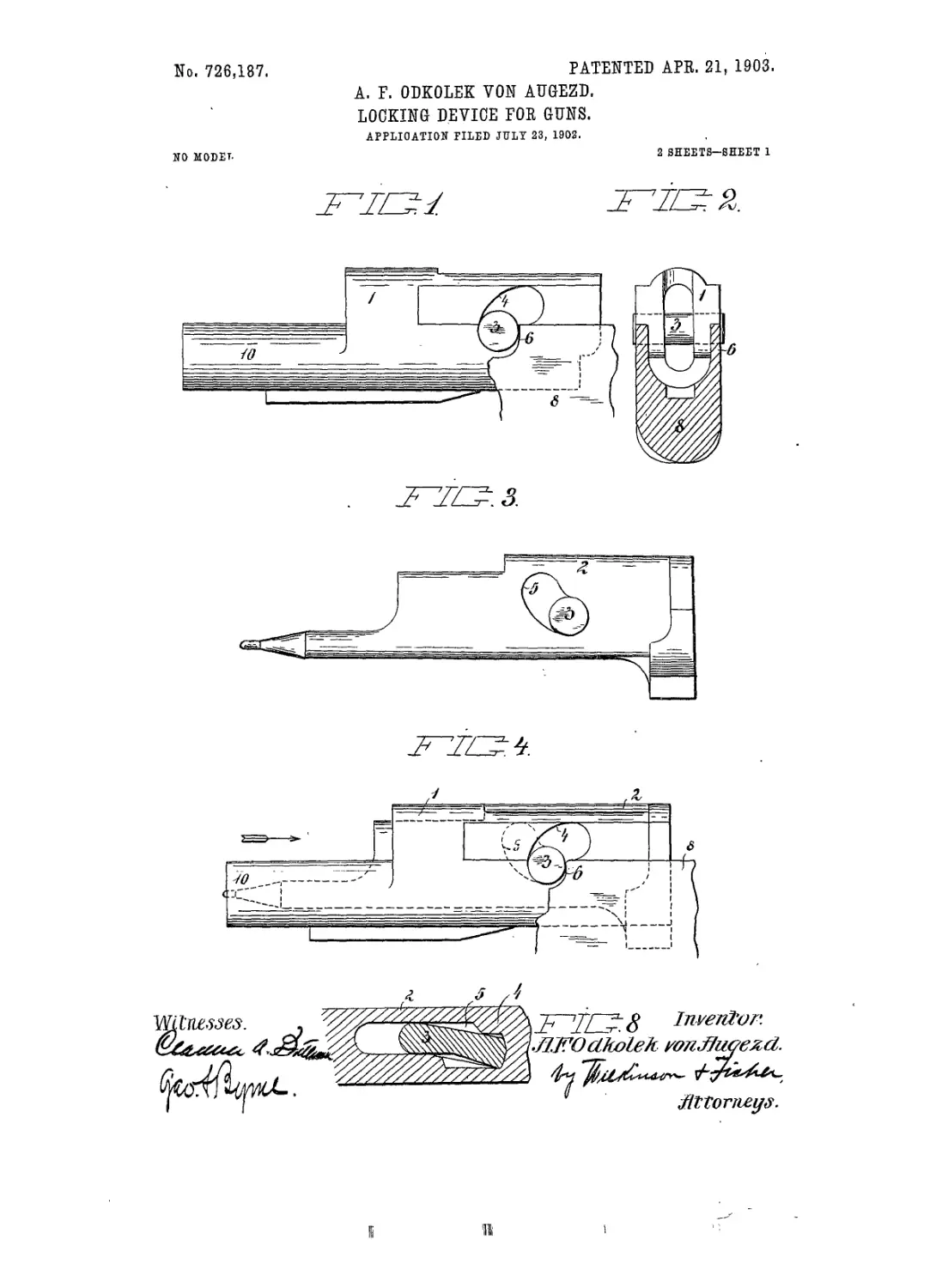
Figure 1 is a side elevation, Fig. 2 a rear
elevation of the breech-bolt. Fig. 3 is a side
25 elevation of the firing-pin. Fig. 4 shows the
breech-bolt and firing-pin in the coupled and
locked position. Fig. 5 is a similar view
showing the parts in the unlocked position.
Fig. 6 shows a modification of my locking de-
30 vice in longitudinal central section. Fig. 7
is a side elevation, and Fig. 8 a section, of
further modification of my locking device.
1 is one of the two parts to be coupled by
my improved locking device. As shown in
35 the drawings, it constitutes a breech-bolt for a
breech-loading firearm and is suitably shaped
' and guided in a suitably-constructed breech-
bolt casing.
2 is the second of the two parts to be cou-
40 pled by my improved locking device, and, as
shown in the drawings, it constitutes the fir-
ing-pin and is suitably inserted into and
guided in the breech-bolt l._
The breech-bolt 1 is provided on both sides
45 with curved slots 4, and the firing-pin 2 is
provided with a curved slot 5. Through the
slots 4-and 5 a transverse coupling and lock-
ing bolt 3 is passed, which projects laterally
from both sides of the breech-bolt 1. The
50 slots 4 and 5, in both of which the bolt 3 is
guided, are, as shown, so curved that by push-
ing the firing-pin 2 forward in the breech-
bolt 1 the bolt 3 is caused to descend, while
by pulling backward the firing-piu in the
breech-bolt the bolt 3 is caused to rise. In 55
other words, by moving the firing-pin to and
fro in the breech-bolt the bolt 3 is caused to
move to and fro positively in a direction at
right angles to the movement of the firing-
pin. 60
The coupling and locking bolt 3 on being
lowered by pushing forward the firing-pin
engages by its projecting ends with an abut-
ting surface 6 on the breech-bolt casing 8, as
shown in Fig. 4, whereas by pulling back the 65
firing-pin 2 in the breech-bolt 1 the bolt 3 is
raised, and thusdisengaged from theabntting
surface 6, as shown in Fig. 5. In the former
case any axial force'acting upon the front end
10 of the breech-bolt 1 and tending to move 70
the same in the direction of the arrow, Fig. 4,
will be resisted by the coupling and locking
bolt 3 then engaging with the lower end of
slots 4 and with the abutting surface 6. In
the latter case, however—that is to say, when 75
by pulling back the firing-pin 2 the coupling
and locking bolt 3 has been raised, so as to
be out of engagement, with the abutting sur-
faces 6—any pressure exerted upon the front
end 10 of the breech-bolt in the direction of 80
the arrow will drive back the breech-bolt, to-
gether with the firing-pin, as will be clearly
seen from Fig. 5.
The details of my improved locking device
may be varied without departing from the 85
essence of my inventiou.
Thus while in Figs. 1 to 5 the coupling and
locking bolt 3 is circular in cross-section it is-
substantially rectangularun cross-section in ,
Figs. 7 and 8; but it may ntroval or wedge- no
shapedin cross-section, provided that the slots
4 and 5 in the two parts 1 and 2 to be coupled
are suitably shaped.
In Fig. 6 the slot 5 is for a part of its length
straight and horizontal,the coupling and lock- 95
ing bolt 3 beingcircular in cross-section, while
in Figs. 7 and 8 the slots are oblong, t|,s adapt-
ed for the substantially rectangular cross-
section of the coupling and locking bolt.
The advantages obtained by my improved 100
locking device are that except the abutting
surfaces 6 on the casing 8 no other connect-
ing and engaging parts on such easing are
required for the operativencss of this device
fli
O'
£> 720,187
and that the coupling and locking bolt is
loosely held and safely and exactly guided in
the slots without requiring any fixing. The
construction of the locking devices is conse-
S quently much more simple and reliable than
th at of the locki ng devices heretofore proposed
and is particularly adapted for automatic fire-
arms.
I claim—
io In a locking device the combination of a
casing, a first part movable lengthwise therein
and a second partgnided and movable length-
wise in the first part with curved slots in both
of the said parts, a coupling and locking bolt
15 passed through and guided in such slots and
projecting beyond the said parts and adapted
to be displaced on shifting the second part
lengthwise relatively to the first part, along
the said curved slots in a direction at right
angles to the direction of the lengthwise rela- so
tive movement of the two parts, a fixed abut-
ting surface or surfaces on the casing adapted'
to be engaged by the coupling and locking
bolt in one of its extreme positions in the
slots and means for moving the second part 25
lengthwise relatively to the first part, sub-
stantially as and for the purpose hereinbefore
described.
In testimony whereof I affix my signature
in presence of two witnesses.
ADOLF FREIHERR ODKOLEK VON AUGEZD.
Witnesses:
T. Georges Moudy,
Alvesto S. Hogue.