/


Текст
BNCLASSfRED
WP C|R 373
ВТ
Мэ
MANIFOLD, PORTABLE
FLAME THROWER, E4
RESTRICTED: DISSEMINATION of restricted matter.
No person is entitled solely by virtue of his grade or position to
knowlege or possession of classified matter. Such matter is
entrusted only to those individuals whose official duties require
such knowledge or possession. (See also par. 23b, AR 380-5,
15 March 1944.)
department
3 march 1945
LIDK/AK 1
WEST TEXAS STATE Co
CANYON, TFXAS
WAR DEPARTMENT TECHNICAL MANUAL
TM 3-378
MANIFOLD, PORTABLE
FLAME THROWER, E4
WAR DEPARTMENT
3 MARCH 1945
RESTRICTED: DISSEMINATION OF RESTRICTED MATTER.
No person is entitled solely by virtue of his grade or position to know-
ledge or possession of classified matter. Such matter is entrusted only to
those individuals whose official duties require such knowledge or possession.
(See also par. 23b, AR 380-5, 15 March 1944.)
WAR DEPARTMENT,
Washington 25, D. C., 3 March 1945
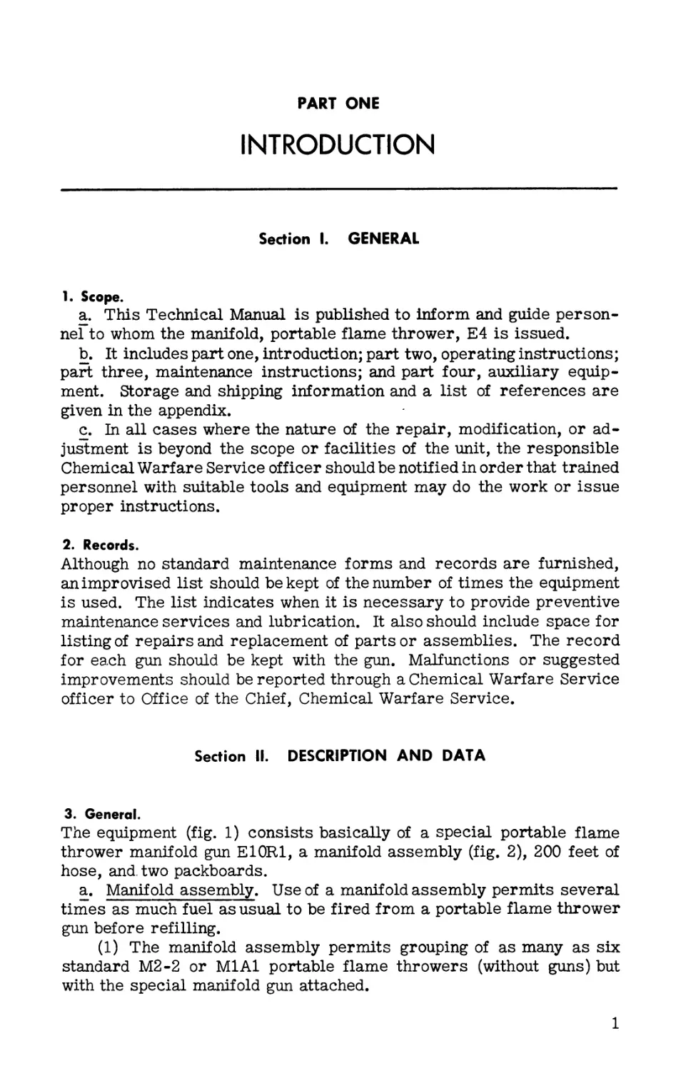
TM 3-378, Manifold, Portable Flame Thrower, E4, is published
for the information and guidance of all concerned.
[a.G. 300.7 (20 Feb 45)]
By order of the Secretary of War:
G. C. MARSHALL.
Chief of Staff.
OFFICIAL:
J. A. ULIO,
Major General,
The Adjutant General.
Distribution:
AAF (Cml O) (4); AGF (Cml O) (4); ASF (2); T of Opns (Cml O) (5);
Def Comd (Cml О) (1); Arm & Sv Bd (1); S Div ASF (1); Tech Sv (2);
SvC (Cml O) (1); PE (Cml О) (1); Sub PE (Cml О) (1); Ars 3 (1); ASF
Dep (CW Sec) (1); Dep 3 (1); Pro Dist 3 (1); Gen & Sp Sv Sch (CW Instr)
(2); USMA (1); A (Cml O) (2); CHQ (Cml O) (2); D (Cml О) (1).
Refer to FM 21-6 for explanation of distribution formula.
CONTENTS
Paragraphs Page
PART ONE . INTRODUCTION.
Section I. General.............................. 1-2 1
П. Description and data.................. 3-5 1
Ш. Tools, parts, and accessories....... 6 3
PART TWO . OPERATING INSTRUCTIONS.
Section IV. General................................ 7 6
V. Service upon receipt of equipment. . . 8-11 6
VI. Controls...............................12-15 10
VII. Operation under usual conditions . . . 16-27 14
VEH. Operation of auxiliary equipment ... 28 25
IX. Operation under unusual conditions . . 29-33 25
X. Demolition to prevent enemy use ... 34 26
PART THREE. MAINTENANCE INSTRUCTIONS.
Section XI. General.................................. 35
XU. Special organizational tools and
equipment............................... 36
ХШ. Lubrication.......................... 37
XIV. Preventive maintenance services . . . 38-41
XV. Trouble shooting...................42-48
XVI. Manifold assembly and hose.........49-51
XVII. Gun, manifold, portable flame
thrower, E10R1...........................52-54
PART FOUR. AUXILIARY EQUIPMENT.
Section XVHI. General............................. 55
XIX. Ammunition.....................56-59
XX. Portable flame throwers........... 60
28
28
28
29
31
34
39
49
49
51
APPENDIX
Section I. Shipment and storage....................... 52
П. References.................................. 52
SAFETY PRECAUTIONS
1. Handle flame thrower fuels as care*
fully as motor fuel to prevent pre-
mature ignition (AR 850-20).
2. Handle compressed air or nitrogen
in accordance with AR 850-60.
3. Handle and store ignition cylinders
as ammunition. They contain in-
cendiary material.
4. Do not fire ignition cylinders unless
weapon is being used to fire fuel.
5. Never send untrained firers or
assistants on a mission.
Fig. 1. Portable flame thrower manifold E4. The equip-
ment is connected to three tank groups of M2-2 portable
flame throwers (left) and three tank groups (fuel units)
of M1A1 portable flame throwers (right).
PART ONE
INTRODUCTION
Section I. GENERAL
1. Scope.
a. This Technical Manual is published to inform and guide person-
nel to whom the manifold, portable flame thrower, E4 is issued.
b. It includes part one, introduction; part two, operating instructions;
part three, maintenance instructions; and part four, auxiliary equip-
ment. Storage and shipping information and a list of references are
given in the appendix.
c. In all cases where the nature of the repair, modification, or ad-
justment is beyond the scope or facilities of the unit, the responsible
Chemical Warfare Service officer should be notified in order that trained
personnel with suitable tools and equipment may do the work or issue
proper instructions.
2. Records.
Although no standard maintenance forms and records are furnished,
an improvised list should be kept of the number of times the equipment
is used. The list indicates when it is necessary to provide preventive
maintenance services and lubrication. It also should include space for
listing of repairsand replacement of parts or assemblies. The record
for each gun should be kept with the gun. Malfunctions or suggested
improvements should be reported through a Chemical Warfare Service
officer to Office of the Chief, Chemical Warfare Service.
Section II. DESCRIPTION AND DATA
3. General.
The equipment (fig. 1) consists basically of a special portable flame
thrower manifold gun E10R1, a manifold assembly (fig. 2), 200 feet of
hose, and. two packboards.
a. Manifold assembly. Use of a manifold assembly permits several
times as much fuel as usual to be fired from a portable flame thrower
gun before refilling.
(1) The manifold assembly permits grouping of as many as six
standard М2-2 or Ml Al portable flame throwers (without guns) but
with the special manifold gun attached.
1
PARS. 3-5
INTRODUCTION
Fig. 2. Manifold assembly (with coupling plugs in inlets and outlet).
(2) The manifold gun and hose may be connected alternately to a
mechanized flame thrower fuel and pressure unit.
(3) If desired, the gun from an M2-2 portable flame thrower may
be used instead of the E10R1 manifold gun.
b. Hose and gun. The weapon is designed especially for use in jungle
or thick underbrush, through which the long hose may be drawn unde-
tected by the enemy. The 200-foot hose (or a shorter section of the
hose) is connected to the manifold assembly and the special gun; thus,
in some situations, the flame thrower firer can approach the target
with less danger of detection because of the lower silhouette, less in-
terference from underbrush, and less vulnerability than if he were
carrying the fuel and pressure tanks of a portable flame thrower.
c. Packboards. Two plywood packboards are provided for carrying
the hose.
d. Personnel. A squad of approximately four to six men is neces-
sary for emplacing and operating the weapon.
4. Identification information.
A brass name plate, riveted on each gun, bears the Chemical Warfare
Service nomenclature, lot number, serial number, and manufacturer’s
name. This information should be given when requisitioning spare parts
or when having equipment repaired.
5. Tabulated data.
All data are approximate.
a. Weights. Pounds
Gun, manifold, portable flame thrower, E10R1.................... 11
Gun nozzle-end................................................... 4
Gun control-end.................................................. 7
Hose, 200 feet (two 100-foot lengths — 45 pounds each)......... 90
2
DESCRIPTION AND DATA
PARS. 5-6
Pounds
Manifold assembly............................................. 21
Packboard (two — 4-1/2 pounds each)............................ 9
Complete equipment in the three boxes........................ 267
Box No. 1, with contents................................... 107
Box No. 2, with contents.................................... 80
Box No. 3, with contents................................... 80
Tool kit (in carton)........................................... 7
Accessories kit (in carton)................................... 12
Spare parts kit (in carton).................................... 2
b. Dimensions.
Box No. 1 (outside).... 22-1/2 inches x 59-1/2 inches x 10 inches
Box No. 2 (outside).... 27-3/4 inches x 27-3/4 inches x 13 inches
Box No. 3 (outside).... 27-3/4 inches x 27-3/4 inches x 13 inches
Gun (connected length).................................... 108 inches
Halves of gun (disconnected)............................... 56 inches
Hose (length over-aH)..................................... 200 feet
Hose (length of sections)................................. 100 feet
Manifold assembly . . . 16-1/4 inches x 12-3/4 inches x 3-1/4 inches
c. Capacity of weapon.
Maximum number of portable flame throwers which may be
connected to gun through manifold................................. 6
Fuel capacity, using six fined М2-2 or Ml Al portable flame
throwers................................................. 24 gallons
Ignition cylinders (each cylinder contains five incendiary
charges each burning 10 seconds).................. 1 cylinder per gun
Duration of fire (not including time between bursts) using
six portable flame throwers М2-2 or Ml Al at manifold
(depending on type of fuel)......................... 30 to 60 seconds
Range, liquid fuel......................................... 20 yards
Range, pourable thickened fuel............................. 30 yards
Section III. TOOLS, PARTS,
AND ACCESSORIES
6. Items with each portable flame thrower manifold.
The following tools (fig. 3), parts (fig. 4), and accessories (fig. 5) are
packed with each portable flame thrower manifold E4 (subject to minor
changes):
a. Tool kit.
Quantity Nomenclature 1 Screwdriver, common, normal duty, 4-inch blade 1 Pliers, combination, slip joint, wire cutting, 6-inch 1 File, American Standard, flat, bastard, 10-inch CWS Stock Number H22-50-22 H22-29-9 H22-108-10
3
PAR. 6
INTRODUCTION
Quantity 1 Nomenclature CWS Stock Number Wrench, adjustable, crescent type, single end, 12-inch H22-49-100
1 Wrench, screw, monkey, metal handle, 15-inch H22-49-123
2 Wrench, socket head screw, 1/16-inch hex. (for No. 6 set screw) H22-49-10
2 Wrench, socket head screw, 3/32-inch hex. (for No. 10 set screw) H22-49-11
b. Spare parts kit.
Quantity 1 Nomenclature CWS Stock Number Lubricant, aluminum thread (1/2- pound can) H99-4-17
6 Screw, set, socket head, cup point, S., No. 6, 32 NC x 3/16-inch H22-17-2
6 Screw, set, socket head, cup point, S., No. 10, 24 NC x 5/16-inch H22-17-111
24 1 Washer, coupling A81-1-513 Case, spring, assembly B81-1-444
c. Accessories kit.
Quantity 6 Nomenclature CWS Stock Number Coupling, pipe, reducing, galvanized, 3/4-inch x 1/2-inch. H98-5-215
6 12 Coupling, tank, assembly C81-1-509 Bushing, pipe, outside hd., galvanized, 3/4-inch x 1/2-inch , H98-5-93
6 Nipple, pipe, long, galvanized, 1/2-inch x 5-inch H98-5-156
6 Nipple, pipe, short, galvanized, 3/4-inch x 2-inch H98-5-318
6 Nipple, tank coupling E81-6-140
SOCKET HEAD
WRENCHES
ADJUSTABLE 12” WRENCH
SCREW DRIVER
15” MONKEY WRENCH
6” PLIERS 10” FILE
AND HANDLE
Fig. 3. Tool kit contents.
4
TOOLS, PARTS, ACCESSORIES
PAR. 6
SYNTHETIC RUBBER WASHERS
ALUMINUM THREAD
LUBRICANT
No. 6 SET SCREWS
No. 10 SET SCREWS
Fig. 4. Spare parts kit contents.
SPRING CASE
ASSEMBLY
Fig. 5. Accessories kit contents.
5
PARS. 7-10
OPERATING INSTRUCTIONS
PART TWO
OPERATING INSTRUCTIONS
Section IV. GENERAL
7. Scope.
Part two of this Technical Manual contains inf ormation for the guidance
of personnel responsible for operation of the equipment. It includes
information on controls and methods of operation.
Section V. SERVICE
UPON RECEIPT OF EQUIPMENT
8. General.
a. Upon receipt of new or used materiel, it is the responsibility of
the officer in charge to ascertain whether it is complete and in sound
operating condition. A record should be made of missing parts and
malfunctions, and such conditions should be corrected as quickly as
possible.
b. Attention should be given to small and minor parts which are likely
to become lost and loss of which may seriously affect the functioning
of the materiel.
c. Materiel should be cleaned and prepared for service in accordance
with instructions given in paragraph 39. The gun should be lubricated
in accordance with paragraph 37.
9. New equipment.
Open packing boxes (figs. 6 and 7). Check packing list to be sure all
equipment is present. Examine and test all parts and assemblies for
good condition. Remove rust preventive compound. Try all controls
(pars. 12-15) for easy operation Before use on a mission, test fire the
weapon. Save packing boxes for storage of the equipment when it is
not in use.
10. Used equipment.
When used equipment is received, it should be serviced in the same
manner as new equipment (par. 9); in addition, parts and assemblies
should be examined for signs of wear. Parts so worn that they will not
withstand continued use should be replaced. If the fuel hose is worn or
damaged in small areas only, it may be repaired or shortened (par. 51).
Detailed information on adjustments, maintenance, and repair of other
parts and assemblies is given in paragraphs 42 through 54.
6
SERVICE, RECEIPT OF EQUIPMENT
PAR. 10
Fig. 6. Contents of Box No. 1 laid out in front of box.
Fig. 7. Hose and packboard in opened Box No. 2 and Box No. 3.
7
PAR. 11
OPERATING INSTRUCTIONS
11. Adapting portable flame throwers for use with manifold.
a. General. Tank groups and fuel hose, of either M2-2 or M1A1
portable flame throwers, or of both (fig. 1), are used to furnish fuel
and pressure to the manifold, and thence, through the long manifold fuel
hose, to the special manifold gun. Parts (par. 6) for adapting portable
flame throwers so that they may be used either as originally intended
or with manifold are included with each manifold. Apply aluminum
thread lubricant, furnished with spare parts kit, on all threaded joints.
b. Adapting M2-2 portable flame throwers. To prepare an М2-2
portable flame thrower gun so that it may be used with the manifold
assembly as well as for usual use as a portable flame thrower gun,
proceed as follows (fig. 8):
(1) Unscrew flame thrower fuel hose from valve body.
(2) Screw a 3/4-inch by 2-inch galvanized short pipe nipple into
fuel valve body of gun.
(3) Screw a tank coupling on the short pipe nipple.
(4) Screw a tank coupling nipple on threaded end of fuel hose.
(5) Tighten all joints with appropriate wrenches.
Hose from M2-2 portable flame thrower tank group may now be readily
locked in coupling on either manifold assembly or on the modified М2-2
or M1A1 portable flame thrower gun, as the situation necessitates.
c. Adapting M1A1 portable flame throwers. To prepare an M1A1
portable flame thrower gun so it may be used with the manifold assem-
bly as well as for usual use as a portable flame thrower gun (fig. 9),
proceed as in subparagraph (1) or (2) below:
(1) Using fuel hose from M1A1 portable flame throwers.
Fig. 8. Gun of M2-2 portable flame thrower adapted for hose.
8
SERVICE, RECEIPT OF EQUIPMENT
PAR. 11
(a) Unscrew hose from gun, using wrench.
(b) Screw a 1/2-inch by 5-inch galvanized long pipe nipple into
fuel discharge valve opening.
(c) Screw a 3/4-inch by 1/2-inch galvanized pipe bushing on
1/2-inch by 5-inch nipple.
(d) Screw a tank coupling on 3/4-inch by 1/2-inch bushing.
(e) Screwinto M1A1 portable flame thrower fuel hosea3/4-inch
by 1/2-inch galvanized pipe bushing. This bushing is of the same type
as that used in subparagraphs (c) and (d) above.
M1A1 PORTABLE FLAME THROWER HOSE
Fig. 9. Gun of M1A1 portable flame thrower adapted for hose.
9
PARS. 11-12 OPERATING INSTRUCTIONS
(f) Screw a 3/4-inch by 1/2-inch galvanized pipe bushing (on end
of hose) into a tank coupling nipple. Tighten with wrenches.
(g) Tank coupling nipple may either be locked in manifold coup-
ling (when the equipment is to be used with the manifold assembly) or
may be locked in the coupling on modified Ml Al or М2-2 portable flame
thrower gun.
(2) Using fuel hose from М2-2 portable flame throwers.
(a) Follow procedure in subparagraph (l)(a) through (d) above
to modify end of M1A1 portable flame thrower gun.
(b) Unscrew female adapter union from end pf hose connector
of fuel unit (tank group). Screw 3/4-inch by 1/2-inch galvanized reduc-
ing pipe coupling on hose connector (fig. 10). Tighten with wrench.
(c) Screw threaded end of fuel hose from М2-2 portable flame
thrower into coupling described in subparagraph (b) above.
(d) Other end of hose maybe locked in coupling of either mani-
fold assembly or gun of modified M1A1 orM2-2 portable flame thrower.
d. Testing. If possible, test pressure regulators of all tank groups
or fuel units to be used by using pressure gage on low pressure side of
regulator. All fuel tanks should hold approximately the same number
of pounds per square inch when pressure is released into the filled fuel
tanks. Adjust regulators which do not provide the desired pressure as
described in TM 3-376A and TM 3-375.
Section VI. CONTROLS
12. Couplings.
a. General. Seven quick-connecting tank couplings are parts of
the manifold assembly and one quick-connecting coupling is mounted
on the end of the manifold fuel hose assembly. These couplings are
identical with the tank couplings on M2-2 portable flame throwers and
component parts are interchangeable.
Fig. 10. Hose from M2-2 portable flame thrower
connected to M1A1 fuel unit.
10
CONTROLS
PAR. 12
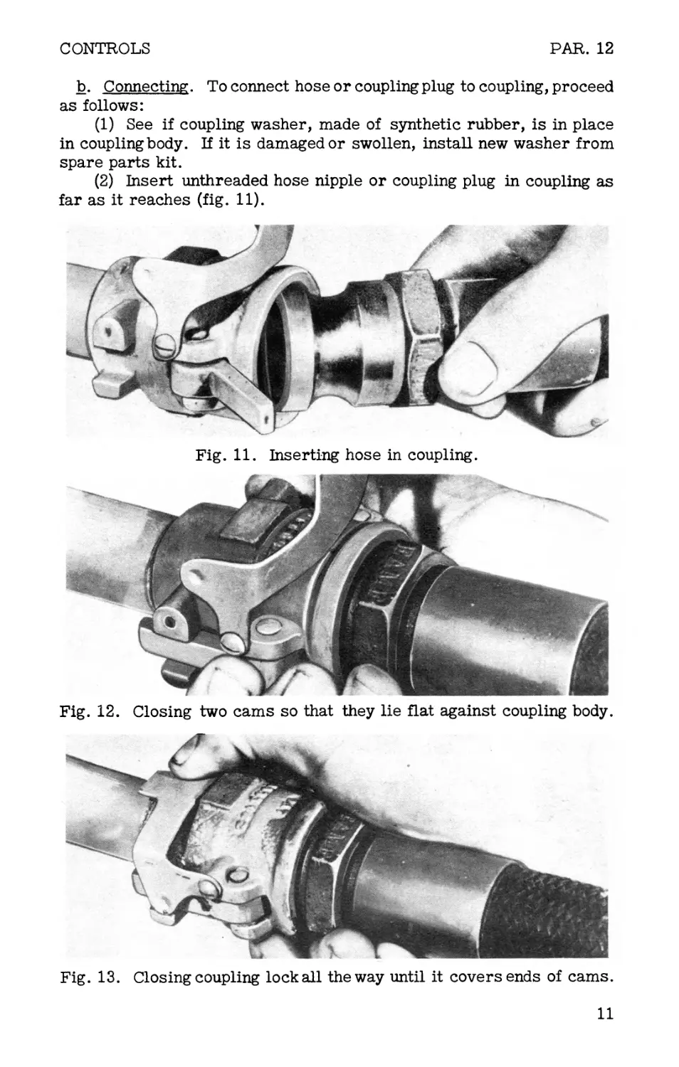
b. Connecting. To connect hose or coupling plug to coupling, proceed
as follows:
(1) See if coupling washer, made of synthetic rubber, is in place
in coupling body. If it is damaged or swollen, install new washer from
spare parts kit.
(2) Insert unthreaded hose nipple or coupling plug in coupling as
far as it reaches (fig. 11).
Fig. 11. Inserting hose in coupling.
Fig. 12. Closing two cams so that they lie flat against coupling body.
Fig. 13. Closing coupling lock all the way until it covers ends of cams.
11
PAR. 12
OPERATING INSTRUCTIONS
(3) Close two cams (fig. 12) so that they lie flat against coupling
body.
(4) Close coupling lock (fig. 13), being sure to push it all the way,
until it covers ends of both cams.
(5) Test by attempting to pull hose or plug from coupling.
c. Disconnecting.
(1) Release pressure from gun hose or manifold.
(2) Using hands, pivot coupling lock back on coupling body.
(3) Using hands, pivot two coupling cams back on coupling body.
(4) Slide out hose or plug.
Fig. 14. Connecting halves of gun; step 1.
Fig. 15. Connecting halves of gun; step 2. Pin is in notch.
PLUNGER
Fig. 16. Gun halves connected. Note plunger position.
12
CONTROLS
PARS. 13-15
13. Gun connector.
The gun connector consists of a female gun connector on the control-
end and a male gun connector on the nozzle-end. It makes possible
quick assembly of the two halves of the gun. The connector operates
like a tank coupling (par. 12), with the male portion inserted in the fe-
male and locked by closing two cams and a lock (figs. 14-16). When
connecting, be sure that the female connector plunger projects approxi-
mately 1/4 inch beyond the end of the connector body, so that contact
is firm, insuring movement of the ignition rod when the ignition lever
is compressed during operation. Be sure that the pin on the male gun
connector is engaged with the notch in the female gun connector before
attempting to close the cams and lock.
14. Ignition lever.
The ignition lever is mounted on the fuel pipe of the gun control-end.
To operate, press safety lock lever open with finger (fig. 17) and com-
press ignition lever with hand. This causes the ignition rod to be pushed
forward, resulting in ignition at the ignition head of the gun. If the
safety lock lever is in the safety position, the ignition lever cannot
move and push the ignition rod forward.
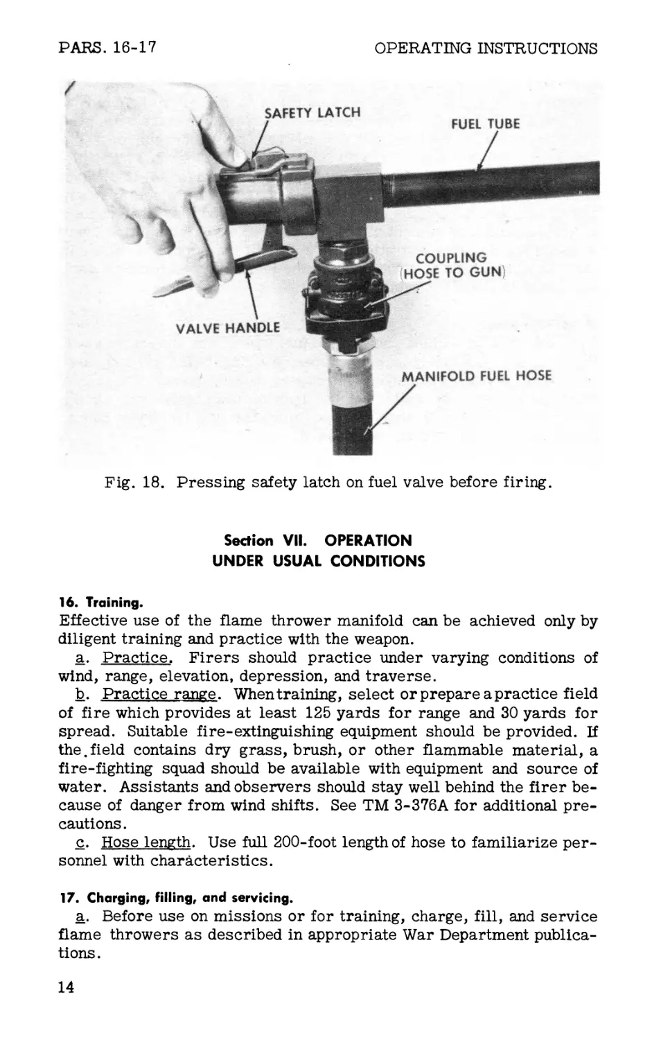
15. Gun valve.
The gun valve, located at the rear of the gun control-end, controls the
flow of fuel through the gun. When opened, it permits fuel to pass un-
der pressure from the hose to the nozzle; closed, it serves as a tight
seal, preventing leakage of fuel andpressure from the hose. To oper-
ate, press safety latch (fig. 18) and squeeze valve handle. This per-
mits passage of fuel from the hose through the gun and out toward the
target. To stop flow of fuel through gun, release gun valve. Safety
latch will lock the valve handle when valve handle is pushed away from
valve body to its full stroke.
IGNITION LEVER
Fig. 17. Pressing safety lock lever.
13
PARS. 16-17
OPERATING INSTRUCTIONS
Fig. 18. Pressing safety latch on fuel valve before firing.
Section VII. OPERATION
UNDER USUAL CONDITIONS
16. Training.
Effective use of the flame thrower manifold can be achieved only by
diligent training and practice with the weapon.
a. Practice. Firers should practice under varying conditions of
wind, range, elevation, depression, and traverse.
b. Practice range. When training, select or prepare a practice field
of fire which provides at least 125 yards for range and 30 yards for
spread. Suitable fire-extinguishing equipment should be provided. If
the.field contains dry grass, brush, or other flammable material, a
fire-fighting squad should be available with equipment and source of
water. Assistants and observers should stay well behind the firer be-
cause of danger from wind shifts. See TM 3-376A for additional pre-
cautions.
c. Hose length. Use full 200-foot length of hose to familiarize per-
sonnel with characteristics.
17. Charging, filling, and servicing.
a. Before use on missions or for training, charge, fill, and service
flame throwers as described in appropriate War Department publica-
tions.
14
OPERATION UNDER USUAL CONDITIONS
PARS. 17-19
b. Fuel tanks of all the flame throwers to be used simultaneously on
a manifold assembly should have the same pressure setting (between
350 and 390 pounds per square inch). Adjust pressure regulators as
necessary so pressures are as close to each other as can be readily
obtained. Use one gage to test all fuel tanks as gages may vary.
1 8. Carrying equipment to forward area.
If equipment is to be manhandled to area where the manifold is to be
set up, carry as follows:
a. Gun. One man may carry the split gun, the halves of which weigh
4 and 7 pounds.
b. Hose. One man can carry a 100-foot length of hose mounted on
packboard. If both 100-foot lengths of hose are to be used, two men
are required, one for each packboard.
c. Manifold assembly. One man can carry the manifold assembly
lashed to one of the hose packboards or by other means of man pack.
d. M2-2 or Ml Al portable flame throwers. One man is required to
carry each loaded and charged portable flame thrower. Do not release
pressure into fuel tanks during the approach march unless it is desired
to use the flame throwers as portable flame throwers instead of using
them with manifold.
e. Additional fuel and pressure. If it is desired to ’fire the weapon
at more targets than canbe attacked with six flamethrower tank groups,
extra fuel canbe brought up in 5-galloncans lashed to packboards to-
gether with replacement pressure tanks and ignition cylinders.
19. Setting up manifold assembly.
a. The weapon should be set up for operation at a well-concealed
area close enough to target so that the manifold fuel hose assemblies
reach the firing position without possibility of falling short. The mani-
fold assembly, if possible, should be on a level with or higher than the
gun firing position to keep pressure drop to a minimum. Consideration
should be given to possible curves of the hose required by terrain. The
weapon assembly area should be fairly level but should not be cleared
more than is necessary to permit handling of the equipment.
b. Have men remove flame throwers and packboards from their
backs, being careful to lower them to the ground without dropping.
c. Place manifold assembly on ground with manifold outlet facing
toward target.
d. Remove coupling plugs from the couplings on manifold assembly
(fig. 19). Hose from flame throwers may then be connected to manifold
as described in subparagraphs g and h below.
e. Stand flame thrower tank groups (fuel units) in two parallel rows
adjacent to manifold assembly. Hose of tank groups should lead toward
manifold assembly. If ground is uneven, use stones or sticks to prop
tank groups upright.
f_. Disconnect any guns which may be connected to tank groups (fuel
units) by disconnecting guns from hose. Do not remove hose from tank
groups (fuel units).
15
PAR. 19
OPERATING INSTRUCTIONS
Fig. 19. -Manifold assembly with coupling plugs removed.
(1) If M2-2 portable flame thrower fuel tanks have been pressured
by opening of pressure tank valves, release this pressure before re-
moving guns. To do so, close pressure tank valves. Then very slightly
loosen plugs on top of fuel tanks by turning plugs with wrench, allow-
ing the pressure to bleed from tanks. Do not completely unscrew the
plugs. After pressure is bled, tighten plugs with wrench.
(2) If any Ml Al portable flame thrower fuel tanks have been pres-
sured by opening of pressure cylinder valves, close fuel valves on tank
groups (fuel units) before removing guns. When removing guns, open
fuel discharge valve, allowing pressure to bleed from hose and hose
connector before disconnecting.
g. If filled M2-2 portable flame throwers are brought up without
guns and hose attached to tank groups, couplings on the tank groups
should be kept closed with coupling plugs until the tank groups are to
be connected to the manifold assembly. When ready to connect, place
tank groups on sides so tank couplings are uppermost. If fuel tanks
are not yet pressured, remove coupling plugs from tank couplings and
install flame thrower fuel hose in couplings. Tank groups may then be
stood on end as described in subparagraph e, above. If tank groups
have been pressured, it is necessary to bleed pressure from fuel tanks,
as in subparagraph f_ above, before removing coupling plug from tank
coupling.
h. Holding manifold assembly and ends of hose (from flame throwers)
above the top of fuel tanks, connect hose tom: hifoldassembly (fig. 20).
By holding them in air, escape of fuel is prevented. Place manifold
assembly and hose on ground in previous positions.
16
OPERATION UNDER USUAL CONDITIONS
PARS. 19-20
1. Uncoil manifold fuel hose from packboard or packboards, laying
hose on ground in front of manifold assembly as shown in figure 21. If
two 100-foot lengths of manifold fuel hose are to be used, couple them
before uncoiling front length.
j_. Couple forward end of manifold fuel hose assembly to the gun
(fig. 20).
k. Couple gun control-end and gun nozzle-end (par. 13).
1. Holding manifold assembly above the top of fuel tanks, remove
coupling plug from front (outlet) coupling of manifold assembly. Con-
nect rear end of manifold fuel hose assembly to this coupling. Place
manifold assembly on ground (fig. 20).
20. Loading with ignition cylinder.
a. Preliminary. Before loading ignition cylinder in gun, test ignition
system (par. 14) for operation.
b. General. Load an unused ignition cylinder (fig. 22) into the igni-
tion head. Cylinders are packed two to a can. Do not open cans until
ready to load for a mission.
TANK GROUPS FROM
M2-2 PORTABLE
FLAME THROWERS
TANK GROUPS FROM
M1A1 PORTABLE
FLAME THROWERS
Fig. 20. Equipment assembled for operation. Any combination of as
many as six M2-2 or Ml Al portable flame thrower tank groups may be
used.
17
PAR. 20
OPERATING INSTRUCTIONS
Fig, 21. Methods of uncoiling hose before carrying gun forward.
c. Precautions. Take care whenever handling cylinders to avoid
blows or pressure against the metal match ends. Never expose face,
hands, or other parts of the body to front of cylinder or front of gun.
d. Loading procedure. Loading procedure is as follows:
(1) Unscrew and remove ignition shield (fig. 23).
(2) Place ignition cylinder on end of gun (fig. 24), being careful
not to grasp cylinder by its ends.
(3) Raise nozzle end of gun so cylinder slides down against the
spring case of the ignitionhead (fig. 25). If necessary, rotate cylinder
so it slips down all the way. Do not force cylinder into place as forc-
ing may ignite it prematurely.
Fig. 22. Portable
flame thrower ig-
nition cylinder Ml
before use.
PLASTIC
BODY
18
OPERATION UNDER USUAL CONDITIONS
PAR. 20
Fig. 23. Unscrewing ignition shield.
19
PARS. 20-21
OPERATING INSTRUCTIONS
Fig. 26. Replacing shield. Slot must engage pin and latch.
(4) Rotate spring case and ignition cylinder clockwise as far as
they turn freely.
e. Replacing ignition shield.
(1) Place ignition shield over cylinder. Engage the slot in the
shield on the spring-case pin.
(2) Turn shield, screwing it onto ignition head body. Make sure
the threads engage during the first turn of the shield. When the slot on
the shield engages the latch on the ignition head (fig. 26), the gun is
loaded.
(3) If shield cannot be turned by hand tight enough to engage latch,
unscrew shield. Then turn shield backwardsuntilthreads engage,and
repeat step described in subparagraph (2) above.
21. Approach of firer to target.
When operations described in paragraphs 17 through 20 have been com-
pleted, the weapon is made ready. Procedure is as follows:
a. A man at the manifold assembly opens:
(1) The pressure tank valves on all M2-2 portable flame thrower
tank groups.
(2) The pressure cylinder valves and fuel valves on all Ml Al port-
able flame thrower fuel units.
b. The firer should operate the gun valve briefly so that fuel is
brought up through the hose to the gun. This avoids possibility of delay
at firing position.
£. Firer should reset the safety latch because of possibility of acci-
dental pressure on gun valve.
d. Firer and hosemen start together toward target. Firer carries
assembled gun with hose attached.
20
OPERATION UNDER USUAL CONDITIONS
PARS. 21-23
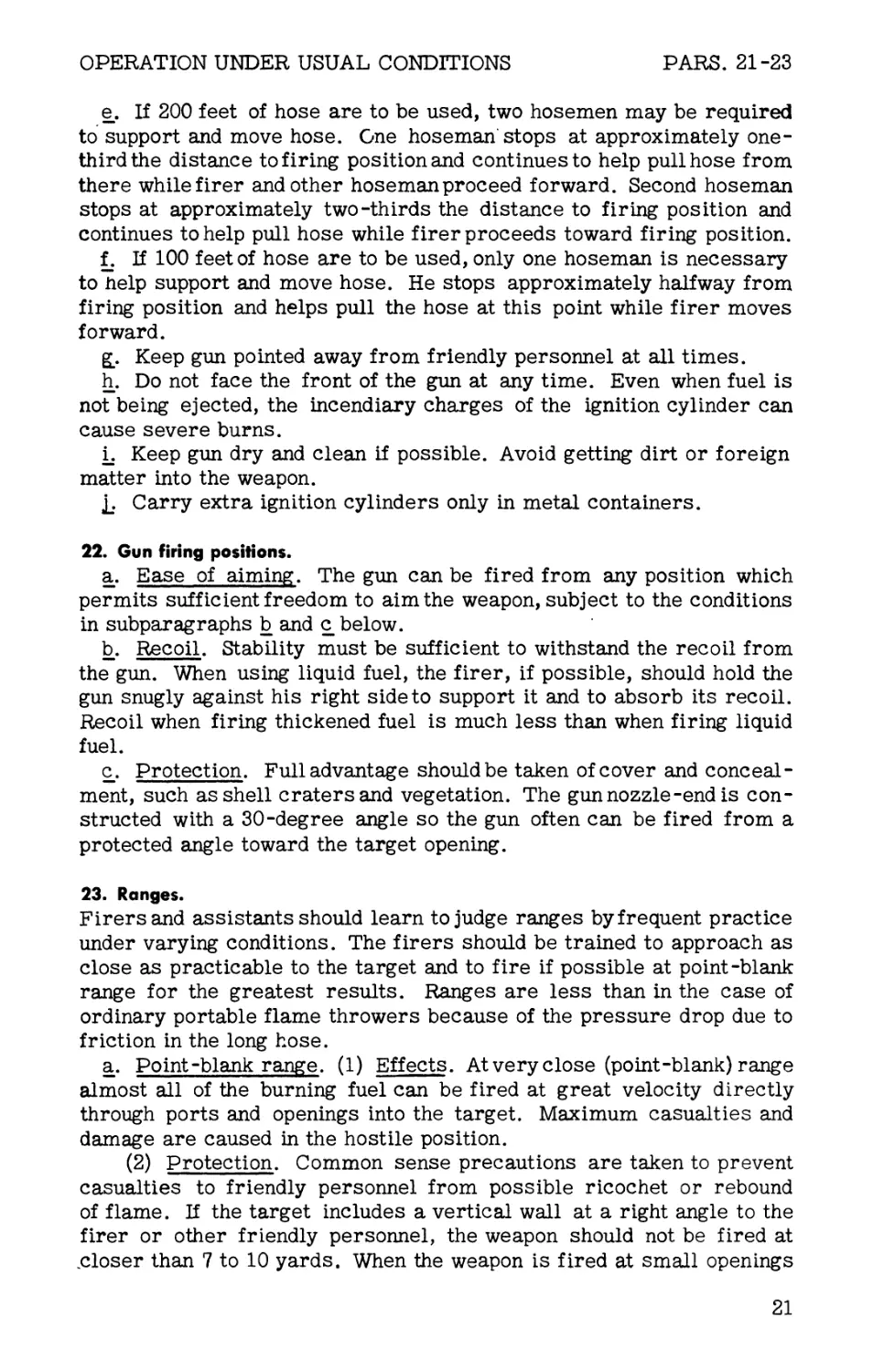
e. If 200 feet of hose are to be used, two hosemen may be required
to support and move hose. One hoseman stops at approximately one-
third the distance to firing position and continues to help pull hose from
there while firer and other hoseman proceed forward. Second hoseman
stops at approximately two-thirds the distance to firing position and
continues to help pull hose while firer proceeds toward firing position.
f. If 100 feet of hose are to be used, only one hoseman is necessary
to help support and move hose. He stops approximately halfway from
firing position and helps pull the hose at this point while firer moves
forward.
g. . Keep gun pointed away from friendly personnel at all times.
h. Do not face the front of the gun at any time. Even when fuel is
not being ejected, the incendiary charges of the ignition cylinder can
cause severe burns.
i. Keep gun dry and clean if possible. Avoid getting dirt or foreign
matter into the weapon.
£. Carry extra ignition cylinders only in metal containers.
22. Gun firing positions.
a. Ease of aiming. The gun can be fired from any position which
permits sufficient freedom to aim the weapon, subject to the conditions
in subparagraphs b and c below.
b. Recoil. Stability must be sufficient to withstand the recoil from
the gun. When using liquid fuel, the firer, if possible, should hold the
gun snugly against his right side to support it and to absorb its recoil.
Recoil when firing thickened fuel is much less than when firing liquid
fuel.
c. Protection. Full advantage should be taken of cover and conceal-
ment, such asshell cratersand vegetation. The gun nozzle-end is con-
structed with a 30-degree angle so the gun often can be fired from a
protected angle toward the target opening.
23. Ranges.
Firersand assistants should learn to judge ranges by frequent practice
under varying conditions. The firers should be trained to approach as
close as practicable to the target and to fire if possible at point-blank
range for the greatest results. Ranges are less than in the case of
ordinary portable flame throwers because of the pressure drop due to
friction in the long hose.
a. Point-blank range. (1) Effects. At very close (point-blank) range
almost all of the burning fuel can be fired at great velocity directly
through ports and openings into the target. Maximum casualties and
damage are caused in the hostile position.
(2) Protection. Common sense precautions are taken to prevent
casualties to friendly personnel from possible ricochet or rebound
of flame. If the target includes a vertical wall at a right angle to the
firer or other friendly personnel, the weapon should not be fired at
closer than 7 to 10 yards. When the weapon is fired at small openings
21
PARS. 23-26
OPERATING INSTRUCTIONS
in a bunker or pillbox, the firer and other members of the assault squad
should not approach closer than 7 to 10 yards from the target.
b. Other effective ranges. (1) Open fields of fire. When thickened
fuel is used, this weapon may fire with considerable effect as far as
30 yards under normal conditions, depending on wind direction and wind
speed. Under the same conditions, liquid fuel may be effective at 20
yards. Results and accuracy are not as great as at point-blank range.
(2) Jungle or thick underbrush. If the target is located in jungle
or thick underbrush without cleared fields of fire, the effective range
bf the flame thrower is reduced by as much as one-half, depending on
the nature and density of the vegetation.
c. Ineffective ranges. Although the flame may reach considerably
farther than the ranges stated in subparagraph b (1) above, it may be
useless because of the steep angle of descent and because much of the
fuel is burned before it reaches the target.
24. Wind deflection.
Wind is an important factor because of the low velocity of the flaming
fuel. Wind can lengthen, shorten, or deflect the flame.
a. Head winds. Head winds of more than 5 miles per hour tend to
carry heat or even flame back toward the firer. Liquid fuel should not
be fired into a headwind of more than 5 miles per hour. The range and
accuracy of thickened fuels are reduced by strong head Winds.
b. Following winds or very light winds. Best results are obtained
under these conditions.
c. Cross winds. Whenfiring at or near maximum range, cross winds
deflect, breakup, and disperse the flame. They also reduce the range.
25. Aiming.
a. Sighting. There are no sights on the gun because of the short
range from which it is fired, the variety of fuels used, and the marked
effects of wind.
b. Fortifications. When firing at a fortified position, flame should
be directed into openings (gun ports, firing slits, ventilation screens,
doorways). Flame inside gives the desired maximum effect.
c. Thickened fuel. Extensive training develops skiH in aiming and
is particularly important with thickened fuel.
26. Firing.
a. Soaking the target. It may be desirable to soak the target with
fuel first and to ignite it afterward. Todo this, fire the bur sts without op -
erating ignition lever. Then followwith an ignited burst, firer avoiding
blasts which may come from any target opening.
b. Ignited firing. (1) Ignition. Depress safety lock lever and squeeze
ignition lever (fig. 27) once vigorously. A flash should appear at the
front of the gun showing that an incendiary charge of the ignition cylin-
der has been ignited. If the flash does not appear, pull the ignition lever
again, or as often as necessary up to five times, until a flash appears.
22
OPERATION UNDER USUAL CONDITIONS
PARS. 26-27
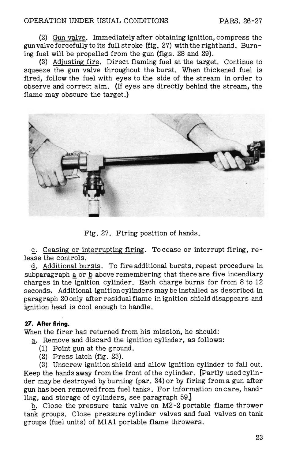
(2) Gun valve. Immediately after obtaining ignition, compress the
gun valve forcefully to its full stroke (fig. 27) with the righthand. Burn-
ing fuel will be propelled from the gun (figs. 28 and 29).
(3) Adjusting fire. Direct flaming fuel at the target. Continue to
squeeze the gun valve throughout the burst. When thickened fuel is
fired, follow the fuel with eyes to the side of the stream in order to
observe and correct aim. (If eyes are directly behind the stream, the
flame may obscure the target.)
Fig. 27. Firing position of hands.
c. Ceasing or interrupting firing. To cease or interrupt firing, re-
lease the controls.
d. Additional bursts. To fire additional bursts, repeat procedure in
subparagraph a or b above remembering that there are five incendiary
charges in tne ignition cylinder. Each charge burns for from 8 to 12
seconds-. Additional ignition cylinders maybe installed as described in
paragraph 20 only after residual flame in ignition shield disappears and
ignition head is cool enough to handle.
27. After firing.
When the firer has returned from his mission, he should:
a. Remove and discard the ignition cylinder, as follows:
(1) Point gun at the ground.
(2) Press latch (fig. 23).
(3) Unscrew ignition shield and allow ignition cylinder to fall out.
Keep the hands away from the front of the cylinder. [Partly used cylin-
der maybe destroyed by burning (par. 34) or by firing from a gun after
gun has been removed from fuel tanks. For information on care, hand-
ling, and storage of cylinders, see paragraph 59.]
b. Close the pressure tank valve on М2-2 portable flame thrower
tank groups. Close pressure cylinder valves and fuel valves on tank
groups (fuel units) of M1A1 portable flame throwers.
23
PAR. 27
OPERATING INSTRUCTIONS
Fig. 28. Firing liquid fuel.
Fig. 29. Firing thickened fuel.
24
OPERATION OF AUXILIARY EQUIPMENT PARS. 27-29
c. Point the gun away from personnel and blow out the remaining
fuel from the hose, manifold assembly, and fuel tanks by squeezing the
gun valve until there is no further discharge. The ignition lever should
not be used during this operation.
d. Inspect, clean, and maintain the equipment (par. 41), or turn the
weapon over to experienced maintenance personnel for servicing if they
are at hand.
e. After servicing, place the equipment in the packing boxes if avail-
able (sec. I, app.) for protected storage, or prepare it for the next mis-
sion (par. 39).
Section VIII. OPERATION
OF AUXILIARY EQUIPMENT
28. Packboards.
a. Uses. Two standard quartermaster plywood packboards are sup-
plied with the equipment for carrying the hose. Other packboards may
be used to carry the manifold assembly and often provide a simple
means of carrying cans of extra fuel and charged pressure tanks or
cylinders, along with accessories, tools, and spare parts. Packboards
aid in carrying awkward or heavy loads with relative ease, leave the
hands free, and hold the load away from the packer’s back, protecting
it from hard and irregular objects and helping to evaporate perspiration.
b. Loading and carrying. Loads should be well-secured with lashing
cord and the load should be carried high on the back.
(1) Lashing. As each article is laid separately on the packboard,
the cord should be run across and back, as well as up and down in the
hooks, and pulled up very tightly. When the whole load is on the board,
fasten the cord with a knot that is easily untied. Run the loose end
through the uppermost and lowest cross loops and drawthem close to-
gether to tighten the lashing.
(2) Quick-release straps. Straps with quick-release buckles may
be used instead of lashing cord. These straps, where adaptable to the
load, speed up loading and unloading.
Section IX. OPERATION
UNDER UNUSUAL CONDITIONS
29. Wet conditions.
The weapon may be carried and fired successfully in the rain or even
after short immersion in water. After use when wet, however, it should
be dried to prevent rusting, cleaned, and lubricated. Touch up with
fresh paint the areas where paint has worn off. Store the weapon in a dry
place. Moisture must not be allowed to enter fuel, ingredients of fuel,
or containers of ignition cylinders.
25
PARS. 30-34
OPERATING INSTRUCTIONS
30. Dust and mud.
Keep all possible dust, earth, and mud out of the equipment, as parti-
cles may interfere with the operation of spring case, valves, bearings,
and pressure regulators. If practicable, store weapons and auxiliary
equipment in closed chests and boxes when not in use. Clean before use.
31. Heat.
A hot climate or exposure to the sun makes the fuel thinner when in
containers. Thin fuel has shorter range; it is largely consumed in the
air before it reaches usual effective ranges. Where the climate is tor-
rid, less gasoline or other thinning agent should be used in a liquid fuel
blend.
32. Cold.
Cold weather reduces total heat produced at target but usually not enough
to lower seriously the value of a firing mission. Incendiary effects may
be decreased because materiel is less flammable when cold. The weap-
on may be used at temperatures as low as minus 20° F. To improve
ignition, use a larger proportion of gasoline in liquid fuel blends.
33. Wind.
Flame throwers should not be fired into strong head winds or across
strong side winds (par. 24).
Section X. DEMOLITION
TO PREVENT ENEMY USE
34. Destruction procedure.
a. When to destroy. If circumstances force abandonment oi chemi-
cal warfare materiel in the field, destroy materiel to prevent its use
or study by the enemy. Such destruction will be undertaken by the us-
ing arm only when in the judgment of the military commander con-
cerned such action is deemed necessary and as a final resort to keep
the materiel from reaching enemy hands.
b. Technique. Adequate destruction means damaging equipment so
that the enemy cannot restore it to usable condition in the combat zone
either by repair or by cannibalization.
(1) Guns. Bend or break over a rock, tree trunk, or other hard
object. Use ax, sledge, or other heavy instrument to crush or sever
parts of guns.
(2) Hose and packboards. Burn, or sever at a number of places
with ax, bayonet, or other sharp instrument.
(3) Tanks, cylinders, and manifold assembly. Fire small arms
bullets through each of these assemblies to prevent immediate use. If
pressure tanks or cylinders are charged and if rounds are to be fired
26
DEMOLITION
PAR. 34
point blank, open pressure valves permitting contents to dissipate. TNT
may be used to achieve total demolition of these assemblies.
(4) Fuel. Burn.
(5) Ignition cylinders. Burn. Personnel should stay several yards
from the fire because the cylinders ignite with a slight detonation.
(TEMPORARY)
WAR DEPARTMENT LUBRICATION ORDER
3 March 1945
References: TM 3-378
GUN, MANIFOLD, PORTABLE FLAME THROWER, EIORI
Lubricant • Interval
Interval • Lubricant
NOTES
Cleon ports with SOLVENT, dry cleaning; or OIL, fuel, Diesel. Dry before lubri-
cating. Reduce intervals under severe operating conditions.
SPRING CASE - Remove and wipe oil surfaces clean. Coution: Do not wosh.
Apply film of lubricant to all surfaces. Clean and apply film of lubricant to
contact surfaces of ignition heod body.
IGNITION WIRE - When disassembled for inspection or repair, cleon and coot
with CG No. 0.
KEY
LUBRICANTS (All Temperalure») INTERVALS
PS-OIL, lubricating, preservative, special. 1 • After eoch mission
CG-GREASE, general purpose. No. 0. 6-6 missions
R.quKih.n oddlli.nol lubrication Ord.n in conformant, with m.lructi.nc .nd lull in FM 21-6
Fig. 30. Tentative Lubrication Order.
27
PARS. 35-37
MAINTENANCE INSTRUCTIONS
PART THREE
MAINTENANCE INSTRUCTIONS
Section XI. GENERAL
35. Scope.
Part three contains information for guidance of using organization per-
sonnel responsible for first and second echelon maintenance of this
equipment. It includes instructions for performance of scheduled lubri-
cation and preventive maintenance services, and descriptions of the
major units.
Section XII. SPECIAL ORGANIZATIONAL
TOOLS AND EQUIPMENT
36. General.
No service kit is provided. Service kits for portable flame throwers
М2-2 and Ml Al include tools, parts, and accessories useful for main-
tenance of portable flame thrower manifold E4. A tool kit, an accessory
kit, and a spare parts kit (par. 6), however, are provided with each
portable flame thrower manifold E4.
Section XIII. LUBRICATION
37. Lubrication.
a. WDLO 3-378 (fig. 30, page 27) prescribes first and second echelon
lubrication maintenance.
b. Lubricants are prescribed in the KEY on the Lubrication Order
along with frequency of application. These intervals should be reduced
under severe operating conditions.
c. Use dry cleaning solvent or diesel fuel oil to clean or wash all
metal parts. (See note on Lubrication Order regarding spring case
assembly.) Dry all parts thoroughly before lubricating.
d. To lubricate ignition wire, fill the palm of the hand with lubricant
and rim ignition wire through the lubricant.
28
PREVENTIVE SERVICES
PARS. 38-39
Section XIV. PREVENTIVE
MAINTENANCE SERVICE
38. General.
Preventive maintenance services as prescribed by Army Regulations
are a function of using organization echelons of maintenance. These
services consist generally of: before operation, during operation, and
after operation services performed by the operator or crew; and the
scheduled services performed by organizational maintenance personnel.
39. Before operation service.
The following services are to be performed before connecting hose to
manifold assembly and before loading with ignition cylinder.
a. Portable flame throwers.
(1) Check fuel levels in fuel tanks.
(2) Be sure all tank groups are filled with the same type of fuel.
(3) Be sure all pressure tanks (cylinders) are properly charged.
(4) Check all fittings and couplings to be sure connections can be
made to manifold assembly.
(5) Check all connections for tightness and freedom from leaks.
(6) Visually check condition of all partsand assemblies for serv-
iceability.
b. Manifold fuel hose assembly and manifold assembly.
(1) Visually inspect all parts for serviceability.
(2) Check ail threaded connections for tightness and freedom from
leaks.
(3) Check all couplings for cleanliness as well as presence and
good condition of washers. Close camsand the lock on coupling nipples
as well as plugs to test for proper functioning.
(4) See that there is a coupling plug in each opening of the mani-
fold assembly.
(5) Be sure hose is coiled evenly and properly secured to pack-
boards for carrying comfort and ease of laying out.
c. Manifold gun.
(1) Visually inspect gun for completeness and good condition of
parts and assemblies.
(2) Check gun connector. Coupling washer must be present and in
good condition. Assemble gun and see that connector locks.securely.
(3) Test controls for operation.
(4) Unscrew ignition shield, and check spring case assembly for
ease of rotation on ignition head body. Operate ignition lever to see
whether ignition rod moves forward (par. 54) so that its end extends
approximately 1/16 inch beyond adjoining lug on ignition head body.
Release ignition lever and check whether ignition rod end is flush with
29
PARS. 39-41
MAINTENANCE INSTRUCTIONS
front surface of ignition head body. Adjust ignition system if necessary
(pars. 53 and 54).
(5) Check cleanliness of threads on ignition shield and on ignition
head body. If not clean, wipe off with cloth. When reassembling, shield
should turn freely until it locks in correct position.
(6) Use screw driver to check all screws for tightness. Be sure
lock washers are present.
(7) Check gun valve, using wrench, to see that it is screwed tightly
on gun. Check tightness of coupling nipple, using wrench, to be sure
it is tight on gun valve. Nipple should be clean and not badly burred.
40. Service when firing.
a. If ignition cylinder does not rotate after first ignited burst, as
shown by failure to obtain ignition when ignition lever is pulled, strike
ignition head lightly against some hard object, such as a tree, to jar
ignition cylinder loose.
b. If it is necessary to replace an ignition cylinder during operation,
any flame which persists within ignition shield must be extinguished
first. The ignition shield becomes very hot during firing and care should
be taken not to burn hands. Gloves may be used, or mud or leaves may
be applied to outside of shield to permit handling of shield when hot.
41. Service after firing.
a. Ignition cylinder. Remove ignition cylinder, and discard (par. 27).
b. Dismantling apparatus. After completion of firing, dismantle as
follows:
(1) If all fuel has been discharged, close valves of pressure tanks
or pressure cylinders. Open gun valve to relieve all pressure in gun,
hose, manifold, and fuel tanks. Uncouple equipment. Place hose se-
curely on packboards. Replace coupling plugs in couplings.
(2) If fuel has not been completely expended, procedure depends
upon whether tank groups are from Ml Al, mechanized flame throwers,
or М2-2.
(a) For Ml Al portable flame thrower tank groups or mechanized
flame thrower fuel groups, close fuel valves on fuel tanks and open man-
ifold gun valve to relieve pressure in the system. Proceed as in sub-
paragraph (1) above. w
(b) For M2-2 portable flame thrower tank groups, either open
the manifold gun valve to discharge all fuel and to relieve pressure or,
using wrench, slightly open filling plug on top of each tank group to re-
lieve pressure. Then disconnect equipment taking care to use coupling
plugs or portable flame thrower guns to close off openings and prevent
undue amount of fuel spillage. On return from mission, blow out re-
maining fuel from manifold fuel hose.
c. Cleaning and lubrication. After operation and return from mis-
sion, clean all equipment, lubricate (par. 37), and repeat before opera-
tion service (par. 39). Do not wash spring case assembly — clean it
by wiping.
30
TROUBLE SHOOTING
PARS. 42-44
Section XV. TROUBLE SHOOTING
42. Foaming of fuel stream.
Trouble
“Gassy” or frothy fuel when
firing due to unequal pressures
in fuel tanks.
43. Short range.
Trouble
a. Stream of burning fuel is-
sues at an angle or in a very broad
spray.
b. Rapid drop of range during
burst.
c. Shorter range in each suc-
cessive burst.
d. Short range with longer time
of discharge than usual.
44. Fuel leaks.
Trouble
a. Worn or damaged hose.
Remedy
Adjust pressure regulators of
flame throwers until the pres-
sure in fuel tanks of all the
flame throwers is approxi-
mately the same.
Remedy
Examine nozzle for clogging or
damage. Clean or replace
parts.
Pressure tank or pressure cyl-
inder valves are not fully open.
Open all the way. If this is not
effective, test pressure regula-
tors.
Pressure tanks or cylinders are
not fully charged.
(1) Before firing be sure pres-
sure tanks or cylinders are
charged to at least 1,800
pounds per square inch.
(2) Check for leaks to make
sure pressure has not de-
creased since charging.
Use pressure gage if avail-
able.
Dried fuel or other foreign mat-
ter is in fuel lines. Disassem-
ble and clean.
Remedy
Replace worn or damaged portion
of hose (par. 51).
31
PARS. 44-46
MAINTENANCE INSTRUCTIONS
Trouble
b. Leak at coupling or gun con-
nector.
c. Leaks at silver-brazed
joints of manifold assembly.
d. Leak at gun valve or nozzle.
45. Failure of fuel to ignite.
Trouble
a. Fuel troubles at low tem-
perature.
b. Failure of ignition cylinder.
46. Failure of ignition cylinder to ignite.
Trouble
a. Ignition lever does not op-
erate.
b. Match in ignition cylinder
moves but incendiary charge does
not ignite.
Remedy
Examine coupling washer. Re-
place if damaged or worn. If
coupling plug or nipple is dam-
aged or worn, repair or re-
place.
Return manifold assembly to
higher echelon for repair, and
install a replacement manifold
assembly.
Replace gun valve.
Remedy
At temperatures above minus 20°
F., no difficulty should be ex-
perienced with ignition of fuel.
When blended liquid fuels are
used, the ratio of gasoline con-
tent should be increased as
temperature decreases.
See paragraph 46.
Remedy
Move safety lock lever into safe
position with finger pressure.
If this does not correct condi-
tion, ignition wire probably
binds in its tube. This may be
caused by dirt, lack of lubri-
cant, or kinking of tube or wire.
Disassemble, clean, lubricate,
and repair or replace defective
parts.
Pull ignition lever repeatedly. If
an incendiary charge does not
ignite, remove cylinder and ex-
amine:
(1) If matches have been pushed
flush with inner surface of
cylinder body, the cylinder
is defective. Destroy (par.
34).
32
TROUBLE SHOOTING
PARS. 46-48
Trouble
c. Cylinder does not rotate to
bring new charge into position.
d. Ignition rod doesnot trans-
mit push to ignition cylinder.
47. Fuel tanks fail to empty.
Trouble
Insufficient pressure.
Remedy
(2) If matches project 1/16
inch or more from cylin-
der, ignition head is defec-
tive. Disassemble ignition
head (par. 54) and examine.
Replace parts as neces-
sary.
Failure to rotate may be caused
by:
(1) Spring case not free to ro-
tate because of dirt. Clean
and lubricate (par. 37).
(2) Improperly loaded cylin-
der. Reload (par. 20).
(3) Binding of ignition cylinder
on gun because of dirt or
excessive warping of igni-
tion cylinders from heat of
firing. Remove and destroy
ignition cylinder (par. 34).
(4) Defective spring case. Re-
place with new spring case.
Ignition wire is loose. Tighten
set screws (par. 53).
Remedy
Be sure pressure tanks or cyl-
inders are fully charged. Check
for possible leaks. If fully
charged and leaks are not pres-
ent, examine swing check valve
in manifold assembly adjacent
to fuel tanks for condition of
partsand possible need for re-
grinding (par. 50).
48. Fuel backs up into pressure system.
Trouble
a. Swing check valve failure.
b. Pressure regulator failure.
Remedy
Examine the swing check valve
adjacent to tank group involved.
Regrind if necessary (par. 50).
Service or replace regulator.
33
PARS. 49-50
MAINTENANCE INSTRUCTIONS
Section XVI. MANIFOLD
ASSEMBLY AND HOSE
49. General.
The manifold assembly and the manifold fuel hose assembly serve to
link manifold portable flame thrower gun E10R1 with the fuel hose and
tank groups (fuel units) of М2-2 or M1A1 portable flame throwers.
50. Manifold assembly.
a. General. The manifold assembly is a device for connecting the
fuel tanks and hose of as many as six portable flame throwers to a
single outlet (manifold fuel hose assembly). The manifold assembly
consists of the following:
(1) Manifold body. The body includes two bronze crosses and one
bronze tee which are silver brazed to short nipples and thence to six
bronze swing check valves (fig. 31). The central cross is connected to
the outer cross and the tee by two silver-brazed nipples. Nipples,
with 3/4-inch N.P.T. thread outlets, are silver brazed to each of the
six check valves and to the six outlets of the crosses and tee. An addi-
tional nipple, with 3/4-inch N.P.T. threaded outlet, is silver brazed to
the remaining outlet of one of the crosses. All nipples are made of
3/4-inch extra strong brass pipe.
(2) Couplings. Seven couplings are screwed on the outlets of the
manifold body (fig. 31). The couplings are interchangeable with the
coupling on the manifold fuel hose assembly and with those on tank
groups of M2-2 portable flame throwers. These couplings are quick-
connecting and provide a pressure tight and liquid tight seal if in proper
condition.
(3) Coupling plugs. Seven coupling plugs are provided. Each plug
closes off an outlet of the manifold assembly when it is not desired to
connect a hose to the outlet. The plugs are interchangeable with the
coupling plugs furnished with М2-2 portable flame throwers.
b. Removal. (1) Coupling plugs or hose assemblies may be removed
from couplings by opening couplings (par. 12).
(2) Couplings may be unscrewed from the manifold body by applying
a wrench to the coupling body.
(3) Coupling washers may be removed by prying from coupling
body with screw driver.
(4) In an emergency, cams and locks may be removed from coupling
body by driving out straight pin with hammer and drift, after filing
peened head from end of pin.
(5) The manifold body must not be disassembled at silver-brazed
connections except by third or higher echelon personnel skilled in the
technique of silver brazing.
c. Installation. (1) A coupling washer is installed by inserting it
into the undercut in the coupling body.
34
MANIFOLD ASSEMBLY AND HOSE
PAR. 50
Fig. 31. Manifold assembly.
(2) Coupling cams and locks may be installed by placing them in
position on coupling body and driving straight pin through the holes
with hammer. Use hammer to peen end of pin after pin has been as-
sembled into body.
(3) Before screwing couplings on the manifold body, apply a light
coating of aluminum thread lubricant, which is supplied in the spare
parts kit with the equipment, to the threads. Tighten couplings with
wrenches.
(4) Coupling plugs or hose assemblies are locked in coupling bodies
by closing the cams and locks (par. 12).
d. Maintenance. (1) Defective coupling washer. If synthetic rubber
coupling washer is swollen or damaged, causing possible leaks at the
joint, remove washer and install new one.
(2) Looseness in coupling. If a coupling does not lock tightly on
hose or on coupling plug, examine cams, lock, and body for damaged or
defective parts. Install new parts as needed.
(3) Leak between coupling and manifold body. If leak occurs be-
tween coupling and manifold body, remove coupling, apply fresh light
coat of aluminum thread lubricant (which comes in spare parts kit with
equipment), and reinstall. If leak persists, replace coupling body or
coupling.
(4) Silver-brazed joints. If leaks occur at silver-brazed joints in
manifold body, remove couplings from manifold body. Install couplings
35
PAR. 50
MAINTENANCE INSTRUCTIONS
SPRING
HINGE ASSEMBLY
SIDE PLUG
CAP
Fig. 32. Regrinding a swing check valve.
on new manifold body and return used manifold body to higher echelon
for repair.
(5) Swing check valve. Swing check valve may leak, causing fuel
to back up into the pressure system or preventing full discharge of the
fuel. If so, it may be reground without removal from the manifold
assembly and without need for special tools. Procedure is as follows:
(a) Using a wrench, unscrew and remove the large hexagonal
cap on top of valve (fig. 32), Do not remove until certain the manifold
assembly is not under pressure.
(b) Wipe interior of valve clean of any foreign matter, using
clean cloth and dry cleaning solvent if necessary.
(c) Using a wrench, unscrew square-headed regrinding plug
from top of downstream end of valve body.
(d) Using wrench, unscrew plug from side of valve body, and
withdraw hinge pin. Lift out disk, spring and hinge assembly.
(e) Apply valve grinding compound to disk. If both coarse and
fine grades of compound are available, apply coarse grade first.
(f) Place disk, hinge assembly, and hinge pin in their normal
positions in valve.
(g) Insert screw driver in slotted end of disk stud, and turn screw
driver to rotate disk approximately one-quarter turn. Rotate clockwise
and counterclockwise to grind disk in seat. Lift disk from seat and set
36
MANIFOLD ASSEMBLY AND HOSE PARS. 50-51
disk in a new position on seat. Add additional grinding compound if
necessary. Rotate disk clockwise and counterclockwise to grind new
area. Continue turning and grinding disk until entire surface of seat
and disk have been ground together.
(h) If coarse valve grinding compound has been used and fine
valve grinding compound is available, repeat procedures in subpara-
graphs (d) through (g) above, using fine valve grinding compound.
(i_) Using dry cleaning solvent and clean cloth, flush and remove
all traces of grinding compound from the valve and surrounding parts.
(j_) Place disk and hinge assembly, with spring and hinge pin in
their positions, in valve body.
(k) Using wrench to tighten, screw both plugs and hexagonal
cap in position in valve body.
(1) Connect manifold assembly to filled and charged tank group
(fuel unit) of portable flame thrower, and release fuel under pressure
through check valve to test for leaks. If leaks occur, more grinding
may be required. Retest, and if failure occurs again it may be neces-
sary to install new manifold assembly.
51. Manifold fuel hose assembly.
a. General. Manifold fuel hose assembly provides a flexible con-
nection between the manifold assembly and the manifold gun. Two hose
assemblies are provided with each gun and manifold. When connected,
they make possible the flow of fuel under pressure to the gun at dis-
tances of up to 200 feet from the manifold assembly. Each of the two
hose assemblies is 100 feet long and consists of:
(1) Hose. Made of synthetic rubber and reinforced with a cover
of metal wire and cotton braid, the hose resists the action of gasoline
and oil. It withstands abrasion and internal pressure of approximately
1,000 pounds per square inch. Inside diameter is 7/8 inch and outside
diameter is approximately 1-1/4 inches. The hose is provided in a
maximum of four lengths totalling 100 feet, with the lengths joined by
3/4-inch iron pipe couplings (fig. 33).
(2) Couplings. A coupling nipple screwed on one end of the 100-
foot hose fits into and may be locked in the end tank coupling of the
manifold assembly. A tank coupling screwed onto the other end of the
hose connects the 100-foot hose to a second 100-foot hose or to the
manifold gun.
b. Removal. (1) To remove hose assembly from the gun, the man-
ifold assembly, or a second hose assembly (par. 12), uncouple.
(2) To remove the coupling from the hose, unscrew, applying
wrenches to coupling body and hexagonal portion of hose nipple.
(3) To remove coupling nipple, apply wrenches to hexagonal por-
tion of nipple and hexagonal end of hose.
(4) To separate lengths of hose, apply wrenches to hexagonal ends
of hose adjacent to 3/4-inch iron pipe coupling.
(5) To disassemble quick-connecting tank coupling, follow proce-
dure in paragraph 50.
37
PAR. 51
MAINTENANCE INSTRUCTIONS
Fig. 33. Manifold fuel hose connections.
• c. Installation. (1) To couple hose assembly to gun, to manifold
assembly, or to a second hose assembly, close cams and lock the cou-
pling.
(2) To connect quick-connecting coupling to hose, lightly apply
aluminum thread lubricant (which comes in spare parts kit) to threads,
screw in position, and tighten with wrenches.
(3) To connect coupling nipple to end of hose, screw nipple into
hose, and tighten by applying wrenches to hexagonal portion of nipple
and hexagonal end of hose.
(4)- To connect separate lengths of hose, apply white lead, aluminum
thread lubricant, or equal, to threaded ends and screw into iron pipe
coupling. Tighten, applying wrenches to hexagonal ends of each hose.
(5) To assemble quick-connecting coupling, follow procedure in
paragraph 50.
d. Maintenance. (1) If leaks occur at threaded joints, disconnect
parts, clean threads, apply fresh luting compound, such as aluminum
thread lubricant from spare parts kit, and reconnect. If leaks persist,
install new parts.
(2) If a leak occurs between gun and coupling on hose assembly,
examine washer in coupling for swelling or damage. If washer is de-
fective, install new washer. If a cam, lock, or coupling body is damaged,
install new part by driving pin through cam, lock, and body. If the
coupling nipple which fits into the coupling is badly nicked and does
not provide a tight connection with a new coupling washer, file the end
surface of the nipple, being careful to keep the surface at right angles
to the sides of the nipple. Connect the nipple and coupling. If coupling
38
MANIFOLD ASSEMBLY AND HOSE
PARS. 51-53
closes too freely indicating washer is not being compressed, install
new washer. If coupling still closes too freely, the nipple has been filed
too short and the part must be replaced.
(3) If hose is punctured or badly worn in small areas, it should be
returned to higher echelon for repair. Disconnect length of hose in-
volved. In an emergency, hose may be repaired as follows:
(a) Place metal socket (on end of hose) in a vise, using shaped
wooden blocks if socket is cylindrical, or insert directly in vise if
socket is hexagonal.
(b) Using wrench on hexagonal portion of 3/4-inch threaded nip-
ple adjacent to socket, unscrew nipple from hose and socket.
n (c) Pull socket from hose, using twisting action.
(d) Cut off damaged portion of hose, being sure hose end is cut
clean and square.
(e) Replace socket over cut end of hose, pushing socket as far
as it will go.
(f) Wet the tapered end of 3/4-inch threaded nipple and interior
of hose with glycerine, hydraulic brake fluid, soap and water, or plain
water.
(g) Screw 3/4-inch threaded nipple into socket.
(h) Make connection tight with wrench.
Section XVII. GUN, MANIFOLD,
PORTABLE FLAME THOWER, E1OR1
52. General.
One portable flame thrower manifold gun E10R1 is included as part
of each portable flame thrower manifold E4.
53. Gun control-end.
a. General. The gun control-end is the rear half of the gun. It con-
nects the manifold fuel hose assembly with the gun nozzle-end, or for-
ward half of the gun. The control-end supports the controls of the gun
and also serves as a passage for fuel to the nozzle. The control-end
includes:
(1) Control-end fuel pipe. This pipe, through which fuel flows
when the weapon is operated, is made of 3/4-inch seamless aluminum
alloy tubing, threaded at both ends. A length of 3/16-inch outside diam-
eter aluminum alloy tubing is attached by clamp rings to the 3/4-inch
tubing and serves as a conduit for the ignition wire which is 0.056 inch
in diameter.
(2) Gun valve. This valve, which controls the flow of fuel, is
screwed on the rear end of the gun.
(3) Ignition lever assembly. This assembly is mounted on the
control-end fuel pipe between the gun valve and the gun connector.
39
PAR. 53
MAINTENANCE INSTRUCTIONS
Fig. 34. Butt of gun showing gun valve.
(4J Gun connector. The control-end gun connector fits over the
nozzle -end gun connector and serves to connect the two halves of the gun.
b. Disassembly of gun control-end. (1) Gun valve. Apply wrench to
square portion of valve (fig. 34) and unscrew from fuel pipe. Coupling
nipple may be unscrewed from valve body with a wrench.
(2) Ignition lever assembly, (a) Unscrew ignition lever pin. Re-
move pin and lever (figs. 35 and 36).
(b) Using hammer and drift or nail, drive lock pin from safety
lock lever. Remove lever from pin.
(c) Unscrew two screws from lever plunger guide. Remove
guide. Be careful not to lose lock washers.
(d) Loosen set screws in ignition lever plunger to free ignition
wire.
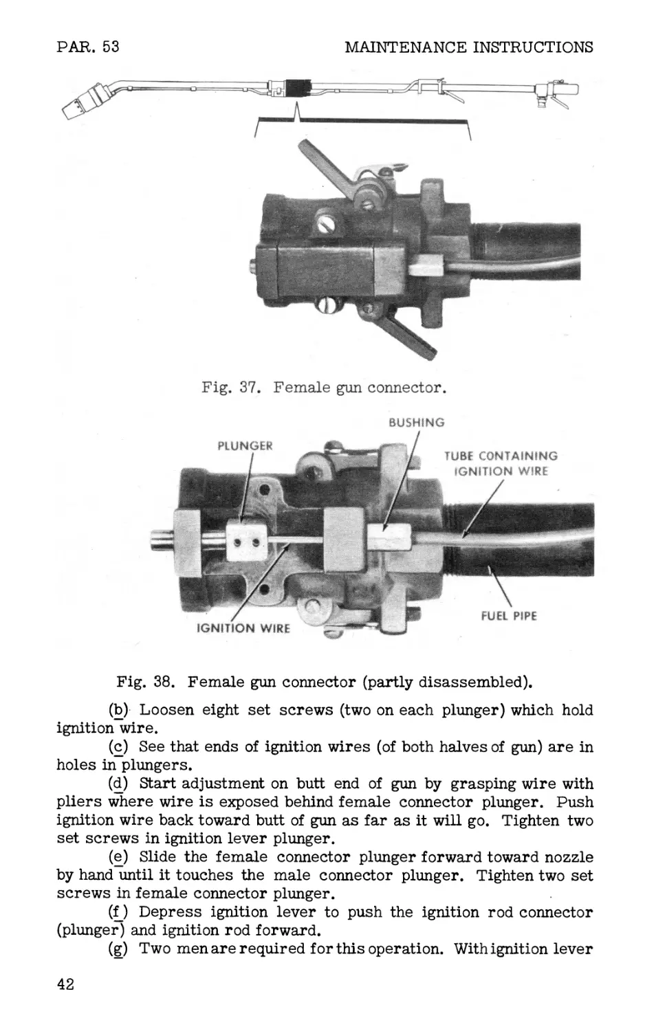
(3) Female gun connector, (a) Using wrench, unscrew bushing
from female gun connector (figs. 37 and 38).
(b) Using screw driver, remove screws and lock washers which
hold connector guide to body of connector. Lift out connector guide.
(c) Using socket head set screw wrench, loosen the two set
screws which hold connector plunger to ignition wire. Follow proce-
dure in subparagraph (2)(d) above to free back end of ignition wire.
(d) Slide connector plunger forward to clear end of ignition wire.
Push end of ignition wire clear of ignition plunger and female gun con-
nector. Pull ignition wire clear of gun connector.
(e) Apply large wrench to body of gun connector and unscrew
from fuel pipe.
(f) Washer, lock, and cams may be removed in manner similar
to those on couplings.
40
MANIFOLD GUN
PAR. 53
Fig. 35. Ignition controls.
Fig. 36. Ignition controls (partly disassembled).
(4) Tubing holding ignition wire. Loosen set screws in tube clamps
and slide tubing out from clamps.
c. Assembly of gun control-end. Reverse procedures in subpara-
graph b above, taking care not to kink ignition wire or tubing which
holds this wire. Be sure to lubricate before assembling (par. 37).
Place lock washers under screws before installing.
d. Adjustment of gun control-end. (1) Gun valve. This valve (fig.
34) rarely requires adjustment. If a leak develops, try to correct by
increasing tension of spring in valve by turning adjusting screw at butt
end of gun clockwise approximately one-eighth of a-turn, or more as
needed. If this does not stop leak or if increased tension makes valve
too difficult to operate, remove valve and install new valve. Old valve
may be reground in higher echelon.
(2) Ignition lever. The foot of the ignition lever should have not
more than approximately 3/16-inch play before it touchesignition lever
plunger. If play is greater, remove ignition lever and bend foot of the
lever slightly forward to reduce the gap. Reinstall ignition lever.
(3) Ignition wire, (a) Remove the four plunger covers from ig-
nition head, gun connectors, and ignition lever assembly of assembled
gun (both halves connected).
41
PAR. 53
MAINTENANCE INSTRUCTIONS
Fig, 38. Female gun connector (partly disassembled).
(b) Loosen eight set screws (two on each plunger) which hold
ignition wire.
(c) See that ends of ignition wires (of both halves of gun) are in
holes in plungers.
(d) Start adjustment on butt end of gun by grasping wire with
pliers where wire is exposed behind female connector plunger. Push
ignition wire back toward butt of gun as far as it will go. Tighten two
set screws in ignition lever plunger.
(e) Slide the female connector plunger forward toward nozzle
by hand until it touches the male connector plunger. Tighten two set
screws in female connector plunger.
(f_ ) Depress ignition lever to push the ignition rod connector
(plunger) and ignition rod forward.
(g) Two men are required for this operation. With ignition lever
42
MANIFOLD GUN
PARS. 53-54
Fig. 39. Male gun connector.
TUBE CONTAINING
IGNITION WIRE
Fig. 40. Male gun connector (partly disassembled).
depressed and using pliers, grasp ignition wire where it is exposed
behind connector in ignition head, and push wire back toward butt as far
as it will go. Tighten the two set screws in male connector plunger.
Release ignition lever.
(h) Push ignition rod and connector forward until the forward end
of rod is flush with end surface of ignition head body. Tighten two set
screws in connector.
(i) Lubricate parts (par. 37), and replace the four plunger covers.
54. Gun nozzle-end.
a. General. The gun nozzle-end is the front half of the gun. It serves
as a passage for fuel from the gun control-end and includes the nozzle
and ignition head of the gun. The nozzle-end includes:
(1) Gun connector. The male gun connector (figs. 39 and 40) fits
into the control-end gun connector and serves to connect the two halves
of the gun.
43
PAR. 54
MAINTENANCE INSTRUCTIONS
Fig. 42. Ignition head, partly disassembled
(ignition rod pushed fully forward).
(2) Nozzle-end fuel pipe. This pipe, through which fuel flows when
the weapon is operated, is made of 3/4-inch seamless aluminum alloy
tubing, threaded at both ends. A length of 3/16-inch outside diameter
aluminum alloy tubing is clamped to the 3/4-inch tubing and serves as
a conduit for the ignition wire. The nozzle-end fuel pipe is bent at a
30-degree angle at the front end to permit the firer to approach the
target and fire from a protected angle.
(3) Ignition wire. A 46-inch length of spring-tempered, corrosion
resisting steel wire, 0.056 inch in diameter, transmits forward pres-
sure from the control-end to the ignition head when the ignition lever
is operated. The ignition wire is housed in the 3/16-inch tubing of the
fuel pipe. The 3/16-inch tubing is connected to the ignition head body
and male connector by threaded bushings.
(4) Ignition head. The ignition head (figs. 41-43) is mounted on the
44
MANIFOLD GUN
PAR. 54
INNER-CASE PIN
Fig. 43. Parts of ignition head and ignition cylinder.
front end of the nozzle-end fuel pipe. It ignites the fuel when loaded
with igniter cylinder and when ignition lever is operated. The ignition
head includes:
(a) Ignition head body. This aluminum alloy part is screwed
onto the front end of the fuel pipe. It serves as a passageway for fuel
to the nozzle and supports other portions of the ignition head.
(b) Nozzle. The nozzle is press-fitted in the ignition head body.
It is an aluminum alloy part with an internal taper. Flamethrower fuel
is ejected from the nozzle through the ignition shield.
(c) Ignition shield. This metal tube, which is screwed on the
front end of the ignition head body, guides the flame and protects the
firer. Eight holes around the base of the shield provide an air intake
for ignition of the fuel. A slot in the base of the shield receives the
latch and the outer-case pin of the spring case.
(d) Latch. This metal part is held on the ignition head body by
a latch screw. The end of the latch fits in the ignition shield slot and
holds the shield on the ignition head body. Pressure on the knurled
end of the latch compresses the latch spring and permits unscrewing
of the shield from the body.
(e) Bushings. The bushings are metal tubes, hexagonal at one
end and threaded at the other. They support the ignition wire and tubing.
(f) Ignition rod connector. This steel block is the connecting
link between the ignition wire and the ignition rod. The ignition wire is
held in the rear of the connector by means of two socket head setscrews.
The ignition rod is held in the front of the connector by means of a
straight steel pin. The connector is held on the ignition head body by
the ignition rod connector guide.
(g) Ignition rod. When the ignition rod is pushed forward it
pushes one of the metal matches in the ignition cylinder which ignites
one of the incendiary charges in the ignition cylinder.
(h) Spring case assembly. When firing, the springcase assem-
bly automatically rotates the ignition cylinder one-fifth of a revolution
45
PAR. 54
MAINTENANCE INSTRUCTIONS
as soon as one of the five metal matches in the ignition cylinder is
pressed in by the ignition rod. This makes another incendiary charge
immediately available for use.
1. Four projections on the inner-case spring are bent over the
outer-case spring to hold the two parts together.
2. The inner-case pin engages a stop on the inside of the igni-
tion cylinder. The five projecting metal matches on the inside of the
ignition cylinder are each in turn stopped by the lug on the forward
surface of the ignition head body. The spring in the case rotates the
ignition cylinder until another match is stopped by the lug.
3. The outer-case pin (on the outside surface of the outer-
case spring) fits into the slot in the ignition shield and holds the spring
case as the shield is screwed into position. This action winds the
spring in the case.
(i) Snap ring. A split steel snap ring holds the spring case in
position on the ignition head body.
b. Disassembly of gun nozzle-end. (1) Uncouple the two halves of the
gun at the gun connector.
(2) Unscrew ignition shield by pressing latch and turning shield
counterclockwise. If an ignition cylinder is in ignition head, keep face
and hands away from front of shield.
(3) If ignition cylinder i£ in ignition head, remove it or allow it to
fall to ground. Keep hands from front of cylinder and do not force in
any of the metal matches in the ignition cylinder.
(4) Pry off snap ring which holds spring case assembly in position,
using screw driver. Be careful not to damage or break the ignition
head body by applying too much leverage. Slide spring case assembly
off gunfrom front of nozzle. Do not disassemble spring case assembly.
(5) Unscrew latch screw with screw driver. Lift out latch and
latch spring.
(6) Using screw driver, unscrew two screws and lock washer which
hold ignition rod connector guide on ignition head body. Lift out con-
nector guide.
(7) Using socket head wrench, loosen the two set screws which
hold ignition wire in ignition rod connector.
(8) With a nail or other small tool, push the pin out of the ignition
rod connector. Remove the ignition rod from the front of the ignition
head body.
(9) Remove ignition wire as described in paragraph 53b(14)-(16).
(10) Using adjustable wrench, unscrew and remove bushing from
ignition head body.
(11) Using large wrench, unscrew ignition head body from fuel pipe.
Subparagraphs (1) through (5) may be omitted if it is desirable to remove
entire ignition head as a unit. Do not attempt to remove nozzle from
ignition body as the two parts are held together by a press fit.
(12) Unscrew bushing from male gun connector, using adjustable
end wrench.
(13) Using screw driver, remove screws and lock washers from
46
MANIFOLD GUN
PAR. 54
connector guide and withdraw connector guide from gun connector.
(14) Using socket head wrench, unscrew the two set screws which
hold ignition wire in male connector plunger.
(15) Using screw driver, push male connector plunger toward
nozzle-end until end of plunger clears hole in male gun connector. Lift
plunger up and remove.
(16) Using pliers, pull ignition wire out through hole in end of male
gun connector.
(17) Remove ignition rod connector from ignition head body.
(18) Using large wrench, unscrew gun connector from fuel pipe.
c. Assembly of gun nozzle-end. (1) Screw male gun connector on
end of fuel pipe, using a small quantity of aluminum thread lubricant
(from spare parts kit) on pipe threads. Tighten with wrench so that
bottom of gun connector is alined with downward bend at front end of
fuel pipe.
(2) Place spring over end of male connector plunger. Insert 3/16-
inch tubing through bushing. Apply aluminum thread lubricant to
threads, and, using wrench, tighten bushing in gun connector.
(3) Lubricate and insert ignition wire in 3/16-inch tube. This is
most easily done by feeding the wire through the hole in the rear of the
male gun connector.
(4) Push forward end of wire into ignition rod hole in ignition head
body. Lift up rear end of wire from male gun connector. Put spring
over wire, insert end of wire into hole in male connector plunger, and
put male connector plunger in male gun connector.
(5) Put ignition rod connector over nozzle end of ignition wire, and
replace ignition rod connector in ignition head body.
(6) Insert ignition rod through ignition head body and into ignition
connector.
(7) Insert pin in ignition rod connector.
(8) Adjust ignition wire as described in paragraph 53.
(9) Replace connector guide and male connector plunger guide,
making sure a lock washer is underneath each screw.
(10) Place latch and latch spring on top of ignition head body. Spring
should fit over pin under the latch and should also fit into small recess
in ignition head body directly under the latch. Apply aluminum thread
lubricant to latch screw. Insert screw through holes in body and in
latch. Tighten with screw driver.
(11) Lubricate ignition head body (par. 37). Place spring case
assembly in position on body. Lock spring case assembly by pushing
snap ring into groove at front of ignition head body.
(12) Screw ignition shield in place (par. 20).
d. Adjustment of gun nozzle-end. Adjustment of ignition wire is de-
scribed in paragraph 53d.
e. Maintenance of gun nozzle-end. (1) Servicing. Clean and lubri-
cate ignition head (par. 37) each time it is disassembled.
(2) Spring case assembly. If outer case rotates and inner case
doesnot, and no spring action occurs, spring is broken and spring case
47
PAR. 54
MAINTENANCE INSTRUCTIONS
assembly should be replaced as a unit. Do not disassemble or repair
spring case assembly.
(3) Ignition rod. When ignition lever is fully depressed, end of
ignition rod should extend approximately 1/16 inch beyond lug on for-
ward surface of ignition head body. If ignition wire has been adjusted
(par. 53d) and proper motion of ignition rod is still not obtained, it may
be necessary to replace ignition rod. Lug on ignition head body should
be approximately 7/32 inch high. If lug is worn or broken, replace
ignition head body.
48
GENERAL
PARS. 55-57
PART FOUR
AUXILIARY EQUIPMENT
Section XVIII. GENERAL
55. Scope.
Part four contains information to guide personnel responsible for op-
eration of this equipment. It contains only the information necessary
for using personnel to identify, connect, and protect auxiliary equip-
ment while being used or transported with the main equipment. De-
tailed information on auxiliary equipment will be found in other publi-
cations. See appendix for list of references.
Section XIX. AMMUNITION
56. General.
Ammunition for the weapon may be said to consist of flame thrower
fuel, compressed air or compressed nitrogen, and ignition cylinders.
Fuel may be considered as the projectile,-compressed air or nitrogen
as the propelling charge, and the ignition cylinder as the igniter. Each
of these components is supplied separately. The portable flame thrower
fuel tanks are filled with fuel, and the pressure tanks (pressure cyl-
inders) are charged with air or nitrogen before the start of a mission.
Compressed air or nitrogen is released into the fuel tanks and an igni-
tion cylinder is loaded in the gun just prior to firing.
57. Flame thrower fuels.
Thickened fuels give greater range than liquid fuels. The stream of
thickened fuel is comparatively narrow. Most of the glue-like fuel clings
to and burns in or on the target for as long as 6 minutes. Liquid fuels,
on the other hand, are largely consumed in flight to the target. If the
location of small openings in the target is known, the stream of thickened
fuel can be spotted by accurate aiming so that most of the fuel enters di-
rectly into the openings. Although it does not billow around corners as
does liquid fuel, thickened fuel strikes the target with force enough to
ricochet inside. It clings to skin and clothing while burning. It also has
excellent incendiary effects. The initial flame and smoke are less from
thickened fuel than from liquid fuel, but the lower visibility, greater
range, and much longer burning period of thickened fuel compensate for
its smaller screening effect. Liquid fuels are easier to pour when filling
than are thickened fuels. Only pourable thickened fuels should be used.
49
PARS. 58-59
AUXILIARY EQUIPMENT
58. Compressed air or nitrogen.
All pressure tanks or pressure cylinders of the. portable flame thrower
tank groups (fuel units) must be fully charged before they are connected
to the manifold assembly.
a. Pressure required in pressure tanks of portable flame throwers
is approximately 1,800 to 2,000 pounds per square inch.
b. After filling fuel tanks with fuel, pressure regulators of all tank
groups (fuel units) to be used with a manifold should be tested with a
pressure gage for uniformity of outlet pressure (350 to 390 pounds per
square inch) in fuel tanks.
c. Pressure cylinders and pressure tanks are charged with air or
nitrogen by use of either an air compressor of suitable capacity (TM
3-377) or large cylinders containing compressed air or nitrogen (TM
3-376A and TM 3-375). Precautions described in Technical Manuals
accompanying equipment must be followed.
59. Ignition cylinders.
a. Description and functioning. The Ml ignition cylinder is used
(figs. 22 and 44). The cylinder fits over the forward part of the gun
and is revolved by the spring case. The five incendiary charges in
the cylinder are spaced sufficiently far apart in the plastic body to
prevent their igniting one another. Lead-foil seals, plastic closure
plates, and waterproof cement make the unit waterproof.
b. Action. When the ignition rod is pushed forward, one of five metal
matches tipped with red phosphorus scratches an igniting mixture. This
ignites a starter mix and a few grains of black powder or fulminate on
top of the incendiary charge. The black powder blows the foil seal and
closure plate clear of the gun; the incendiary charge ignites the fuel
as it is discharged from the nozzle. Each of the five incendiary charges
burns for from 8 to 12 seconds.
c. Packing. Ignition cylinders are packed two per waterproof can.
Three cans are furnished with each flame thrower. Fifty cans (100
ignition cylinders) are contained in each packing box of extra cylinders.
d. Care, handling, and storage. Ignition cylinders contain hazardous
incendiary material and must be handled with care. The following pre-
cautions should be observed.
(1) Opening cans. Do not open cans containing cylinders until
ready to load for a mission (par. 20). If an extra cylinder remains in
an opened can, use it as soon as possible. Any defective cylinders,
such as those with damaged closure plates, should be destroyed (par.
34). Moisture may affect the cylinders and all possible care should be
taken to avoid prolonged exposure to dampness.
(2) Handling cylinders. Pressure on any of the five metal matches
may ignite an incendiary charge in the cylinder. Care must be exercised
to avoid putting pressure on the projecting ends of the matches except
when firing the weapon. Ignition cylinders and cylinder containers
should be protected against shock. Boxes and cans containing cylinders
must not be thrown or dropped.
50
AMMUNITION
PARS. 59-60
(3) Storing containers. Containers of ignition cylinders are best
stored in a dry, well-ventHated place, out of the direct rays of the sun,
well protected against excessive temperatures. Smoking is not per-
mitted and matches are not used where ignition cylinders are stored.
Section XX. PORTABLE
FLAME THROWERS
60. Portable flame throwers M2-2 and Ml Al.
Tank groups (fuel units) and fuel hose of portable flamethrowers M2-2
or portable flame throwers M1A1 are required to operate the equip-
ment describedin this Technical Manual (unless fuel group of mechan-
ized flamethrower is used). It is not necessary that the guns of these
portable flame throwers be provided, but it may be found tactically
desirable to bring the flame throwers with guns attached into the area
of combat for possible use before the manifold is set up. Figure 1 shows
portable flame throwers with hose (but without guns) connected to the
manifold assembly for operation. Detailed instructions on portable
flame throwers, given in TM 3-375 and TM 3-376A, must be familiar
to all personnel concerned with operation of equipment described in this
Technical Manual.
CLOSURE
PLATE
MATCH
BLACK
POWDER
INCENDIARY
CHARGE
IGNITING
MIX \
STARTER
MIX
FOIL
SEAL
MATCH
TIP
PLASTIC
BODY
Fig. 44. Ignition cylinder (cutaway view).
51
APPENDIX
Section I. SHIPMENT AND STORAGE
The weapon is shipped, when new, in three packing boxes (fig. 45). If
it is desired to ship or store the equipment after use, it should be re-
turned to the packing boxes, if possible, or to improvised containers.
Before storing in the boxes or containers, be sure that all after opera-
tion service (par. 41) has been carried out and that all exposed metal
parts susceptible to rust are coated with rust preventive compound.
Waterproof wrapping paper and nonhygroscopic adhesive tape should
also be used, as required. Be sure hose exteriors and packboards are
dry before storing. The gun and manifold assembly come packed to-
gether in one box. The other two boxes each contain a 100-foot length
of hose and a quartermaster plywood packboard.
Section II. REFERENCES
Army Regulations:
AR 850-20 AR 850-60 Precautions in Handling Gasoline Compressed Gas Cylinders; Safe Handling, Storing, Shipping, Using
Technical Manuals:
TM 3-375 TM 3-376A TM 3-377 Portable Flame Throwers Ml and M1A1 Portable Flame Thrower М2-2 Compressor, Air, Gasoline Engine-Driven, 7CFM, Ml
Field Manuals:
FM 31-50 FM 100-5 Attack on a Fortified Position and Combat in Towns Operations
Technical Bulletins*:
ТВ CW 17 Flame Throwers, Mechanized E4R2-5R1 and E4R2- 4R3-5R1
ТВ CW 18 ТВ CW 20 Kit, Fuel Filling, Flame Thrower, E6 Cleaning Interiors of Compressed Gas Cylinders, Tanks and Accessories
ТВ ENG 39 ТВ QM 13 Safe Handling of Compressed Gases Clothing, Equipment, and Rations for Use in the Jungle (includes information on packboard)
ТВ 3-376A-1 Pressure Tanks for Flame Thrower, Portable, М2-2
52
Army Service Forces Catalogs (Chemical Warfare Supply Catalogs):
CW 7-440114 Flame Thrower, Portable, М2-2
CW 7-440106 Flame Thrower, Portable, M1A1
CW 6-445115 Kit, Service, for Portable Flame Thrower, M2-2
CW 6-445103 Kit, Service, for Portable Flame Thrower, M1A1
CW 6-445901 Kit, Fuel Filling, Flame Thrower, E6
CW 7-631110 Compressor, Air, Gasoline Engine Driven, 7CFM,
Ml
* Technical Bulletins are to be superseded by War Department Techni-
cal Manuals or changes to manuals.
Fig. 45. Open packing boxes.
53
INDEX
- A - Paragraph
Accessories kit................................................ 6c
Adapting portable flame throwers for use with manifold
Ml Al portable flame thrower.................................... 11, 60
M2-2 portable flame thrower.............................. 11, 60
Additional
bursts......................................................... 26d
fuel and pressure.......................................... 18e
Adjusting fire................................................ 26b
After firing................................................... 27
Aiming..................................................... 22a, 25
Aluminum thread lubricant......................... 6b, 50c, 51c, 51d
Ammunition...................................................56-59
Approach of firer to target.................................... 21
- В -
Body
ignition head........................................ 54a, 54b, 54c
manifold .................................................. 50a
Boxes, packing
dimensions...................................................... 5b
weights..................................................... 5a
Brake fluid, , hydraulic ..................................... 51d
Brazing, silver...................................... 50a, 50b, 50d
Bursts, additional............................................ 26d
Bushings
description.................................................... 54a
pipe..................................................... 6c, 11
- C -
Cams, coupling
installation................................................... 50c
operation................................................12b, 12c
removal..................................................... 50b
Cap, swing check valve........................................ 50d
Capacity of weapon. . ..........................................5c
Carrying equipment to forward area..............................18
Case, spring, assembly
during firing.................................................. 54a
in spare parts kit...........................................6b
installing.................................................. 54c
54
- C (Contd) -
Paragraph
Case, spring, assembly (contd)
removing from gun.................*........................ 54b
replacing................................................... 54e
Charging, filling, and servicing................................17
Cold............................................................32
Compound, valve grinding....................................... 50d
Compressed air.............................................. 56, 58
Connector
gun.......................................................53 a, 54 a
gun, female................................................ 53b
ignition, rod.................................... 54a, 54b, 54c
Control-end fuel pipe......................................... 53a
Control-end, gun (see gun control-end)
Controls..............................................12, 13, 14, 15
Coupling
cams
installation.................................................. 50c
operation.............................................12b, 12c
removal................................................. 50b
locks
installation........................................... 50c
operation.............................................12b, 12c
removal................................................. 50b
plugs
description............................................ 50a
removal................................................. 50b
washer
installation........................................... 50c
removal................................................ 50b
spare.....................................................6b
'Couplings
description..................................................12
hose........................................................ 51a
looseness................................................... 50d
pipe..................................................... 6c, 11
removal..................................................... 50b
with manifold body.......................................... 50a
Crosses, bronze................................................ 50a
Cylinder
ignition
failure to ignite.......................................4b
loading in gun...........................................20
removal................................................. 54b
pressure.................................................... 58
55
- D -
Paragraph
Data, tabulated...................................................5
Demolition to prevent enemy use..................................34
Destruction procedure............................................34
Dimensions ......................................................5b
Disk, swing check valve........................................ 50d
Disk spring, swing check valve................................. 50d
Dry cleaning solvent........................................... 37c
Dust and mud.....................................................30
- F -
Failure
of fuel tanks to empty........................................47
of fuel to ignite.............................................45
of ignition cylinder to ignite................................46
Female gun connector........................................... 53b
Files............................................................6a
Filing of nipple............................................... 51d
Firing
description...................................................26
positions.....................................................22
Flame thrower fuels............................................ 57
Foaming of fuel stream...........................................42
Fuel
backing up into pressure system...............................48
failure to ignite.............................................45
leaks.........................................................44
liquid........................................................57
thickened................................................... 57
use in training............................................. 16c
Fuel hose, manifold assembly
approach to target............................................21
carrying...................................................... 18b
description................................................. 51a
installation....................................... 19i_, 19^ 51c
removal..................................................... 51b
Fuel pipe
control-end................................................. 53a
nozzle-end.................................................. 54a
Fuel tanks
failure to empty ............................................ 47
use.......................................................... 11
- G -
Glycerine..................................................... 5 Id
56
- G (Contd) -
Paragraph
Gun
assembly of.................................................53c, 54c
carrying................................................< . 18a
connector..........................................53a, 54a, 54c
control-end
adjustment.............................................. 53d
assembly of............................................. 53c
description............................................. 53a
disassembly............................................. 53b
lubrication...............................................37
description........................................... 3b, 52-54
disassembly..............................................53b, 54b
firing positions.............................................22
installation............................................... 19i
loading with ignition cylinder................................20
lubrication...................................................37
nozzle-end
adjustment................................................ 53d
assembly of............................................... 54c
description............................................. 54a
disassembly............................................... 54b
lubrication...............................................37
maintenance............................................... 54e
valve
adjustment.............................................. 53d
description............................................15, 52a
operation..............................................15, 26b
- H -
Heat, effect of.................................................31
Hinge assembly, swing check valve............................... 50d
Hinge pin, swing check valve.................................... 50d
Hose coupling
description................................................ 51a
removal from hose..................................?....... 51b
Hose, manifold
carrying .................................................. 18b
description.............................................. 3b, 51
length.................................................. 16d, 51a
repair..................................................... 51d
Hydraulic brake fluid......................................... 51d
- I -
Identification information.......................................4
57
I (Contd) -
Paragraph
Ignition
cylinders
action.................................................. 59b
description............................................... 59a
failure to ignite...........................................46
handling.................................................. 59d
loading in gun..............................................20
opening cans.............................................. 59d
packing................................................... 59c
removal................................................... 54b
storage................................................... 59d
head................................................54a, 54b, 54c
head body...........................................54a, 54b, 54c
lever
adjustment................................................ 53d
description................................................14
operation..............................................14, 26b
lever assembly
adjustment............................................. 53d
description............................................14, 53a
installation.............................................. 53c
removal................................................... 53b
rod............................................54a, 54b, 54c, 54e
rod connector.......................................54a, 54b, 54c
shield
description............................................... 54a
removal...............................................20d, 54b
replacing................................................. 20e
wire
adjustment............................................53d, 54b
description...........................................53a, 54a
installation.............................................. 54c
lubrication............................................... 37d
removal................................................... 54b
wire tube................................................53b, 54c
Ineffective ranges.............................................. 23c
Items with each flame thrower..................................... 6
-J -
Jungle range.................................................... 23b
- К -
Kit
accessories..................................................6c
service........................................................36
58
- К (Contd) -
Paragraph
Kit (contd)
spare parts...................................................6b
tool..........................................................6a
- L -
Latch..................................................54a, 54b, 54c
Latch, safety....................................................15
Leaks
at silver-brazed joints..................................... 50d
at swing check valve........................................ 50d
between coupling and manifold body.......................... 50d
between coupling hose and gun............................... 51d
fuel..........................................................44
Lever
ignition
adjustment..................................................... 53d
description................................................14
operation...............................................14, 26b
ignition assembly
adjustment............................................... 53d
description . . ........................................14, 53a
installation............................................. 53c
removal.................................................. 53b
Liquid fuel......................................................57
Loading with ignition cylinder...................................20
Locks, coupling
installation................................................ 50c
operation.................................................12b, 12c
removal..................................................... 50b
Lubricant, aluminum thread ....................... 6b, 50c, 51c, 51d
Lubrication......................................................37
- M -
Male-connector plunger.......................................54b, 54c
Manifold
assembly
carrying....................................................... 18c
description.............................................3a, 50
setting up.................................................19
body......................................................... 50a
fuel hose assembly
approach to target.........................................21
carrying.................................................. 18b
description............................................... 51a
59
- M (Contd) -
Paragraph
Manifold (contd)
fuel hose assembly (contd)
installation......................................... 19i_, 19j, 51c
removal.................................................. 51b
hose
carrying................................................ 18b
description............................................3b, 51
length............................................... 16c, 51a
repair.................................................. 5 Id
Maximum range.................................................. 23b
Mud and dust....................................................30
- N -
Nipples, pipe............................................... 6c, 11
Nitrogen.................................................... 56, 58
Nozzle......................................................54a, 54c
Nozzle-end, fuel pipe.......................................... 54a
Nozzle-end, gun (see gun nozzle-end)
- О -
Open fields of fire............................................ 23b
Operation
auxiliary equipment..........................................28
unusual conditions.........................................29-33
usual conditions...........................................16-27
- P -
Packboards
description..................................................3c
loading and carrying........................................ 28b
uses........................................................ 28a
Packing boxes
dimensions...................................................5b
weights.......................................................5a
Personnel required...............................................3d
Pin, hinge swing check valve................................... 50d
Pipe
bushing......................................................6c, 11
coupling.................................................6 c, 11
fuel, control-end........................................... 53a
fuel, nozzle-end............................................ 54a
nipples..................................................6c, 11
Pliers...........................................................6a
60
- P (Contd) -
Paragraph
Plug, regrinding.............................................. 50d
Plunger, male-connector.....................................54b, 54c
Point-blank range............................................. 23a
Portable flame throwers
M1A1..................................................11, 18, 19, 60
М2-2...............................................11, 18, 19, 60
Pressure
cylinders................................................11, 56, 58
regulators................................................. lid
tank..................................................11, 56, 58
Preventive maintenance services
before operation.............................................39
definition...................................................38
service after firing.........................................41
service when firing .........................................40
Protection
for firer ................................................. 22c
for friendly troops.......................................... 23a
- R -
Range
judging......................................................23
short........................................................43
Recoil........................................................ 22b
Records..........................................................2
References............................................app. sec. П
Regrinding, swing check valve................................. 50d
Ring snap.............................................54a, 54b, 54c
Rod
ignition..........................................54a, 54b, 54c, 54e
ignition, connector................................54a, 54b, 54c
- S -
Safety latch................................................... 15
Screw drivers...................................................6a
Screws, set, spare..............................................6b
Service kit.....................................................36
Service upon receipt
new equipment..........................*......................9
used equipment...............................................10
Servicing
after firing.................................................27, 41
before operation.............................................39
when firing..................................................40
61
- S (Contd) -
Paragraph
Setting up manifold assembly......................................19
Shield, ignition (see ignition shield)
Shipment and storage.................................... app. sec. I
Shipping................................................ app. sec. I
Short range.......................................................43
Silver brazing........................................50a, 50b, 50d
Snap ring.............................................54a, 54b, 54c
Soaking the target..............................................26a
Soap............................................................5 Id
Solvent, dry cleaning............................................37c
Spare parts kit...................................................6b
Spring case assembly
during firing...............................................54a
in spare parts kit.............................................6b
installing....................................................54c
removing from gun.............................................54b
replacing.....................................................54e
spare..........................................................6b
Storage..................................................app. sec. I
Swing check valve
cap.........................................................50d
description...................................................50a
hinge pin.....................................................50d
leaks....................................................48a, 50d
regrinding....................................................50d
testing for leaks.............................................50d
- T -
Tabulated data .................................................5
Tanks
fuel.........................................................11, 19
failure to empty............................................47
pressure..................................................11, 58
Target, approach of firer.........................................21
Tee, bronze..................................................... 50a
Thickened fuel....................................................57
Thread lubricant, aluminum........................ 6b, 50c, 51c, 51d
Tool kit..........................................................6a
Training..........................................................16
Trouble shooting...............................................42-48
Tube, ignition wire.........................................53b, 54c
-U-
Unusual conditions, operation under............................29-33
Usual conditions, operation under..............................16-27
62
- V -
Paragraph
Valve
grinding compound........................................... 50d
gun (see gun valve)
swing check
description.................................................. 50a
leaks..................................................48a, 50d
regrinding.................;.............................. 50d
testing for leaks......................................... 50d
- W -
Washer, coupling
installation................................................ 50c
removal...................................................... 50b
spare..........................................................6b
Water, use of in training....................................... 16b
Weapon, capacity of...............................................5c
Weights...........................................................5a
Wet conditions....................................................29
Wind
cross....................................................... 24c
deflection.....................................................24
effect on firing...............................................33
following.................................................... 24b
head......................................................... 24a
Wire, ignition
adjustment...................................................53d, 54b
description...............................................53a, 54a
lubrication.................................................. 37d
Wrenche s.........................................................6a
63