/
Теги: radio
Год: 1944


Текст
The War Office,
London, S.W.l.
May 1944.
RESTRICTED
Th* information given in this document
ie not to be communicated, either directly
or indirectly, to the Press or to any person
not authorised to receive It.
TELEPHONE SETS E
HIGH POWER
No. 1, Mk. II
WORKINC INSTRUCTIONS
21053
CAT. No. YA7448
ii
CONTENTS
CHAPTER I. —GENERAL DESCRIPTION
SEC. PAGE
1. Purpose ... ... ... ... ... 1
2. Facilities ... 1
3. Range of Working ... ... ... 2
4. Power Supply ... ... ... ... ... 2
5. Weights and Dimensions TABLE I.—WEIGHTS AND DIMENSIONS ... 2
6. Mechanical Construction ... 2
CHAPTER II. —OPERATION
7. Preliminary ... ... ... ... ... ... ... 3
8. Operating the telephone ... ... ... ... ... ... 3
9. Adjustments ... ... ... ... ...... ... 4
CHAPTER III.—UNIT MAINTENANCE
10. General. ... ... ... ... ... ... ... ... 5
11. Internal ceils ... .... ... ... ......... ... 5
12. Buzzer and bqll ... ... ... ... ... ... ... 5
13. Handset ... ... ... ... ... ... ... ... 5
14. Amplifier unit ... ... ... ... ... ... ••• 6
15. Fault location ... ... ... ... ... ... ... 6
DIAGRAMS
FIG.
1. External view of Tele. F. High Power ... ... ... ... 8
2. Connections to the microphone ... ... ... ... 9
3. Circuit of amplifier unit ... ... ... ... ... 10
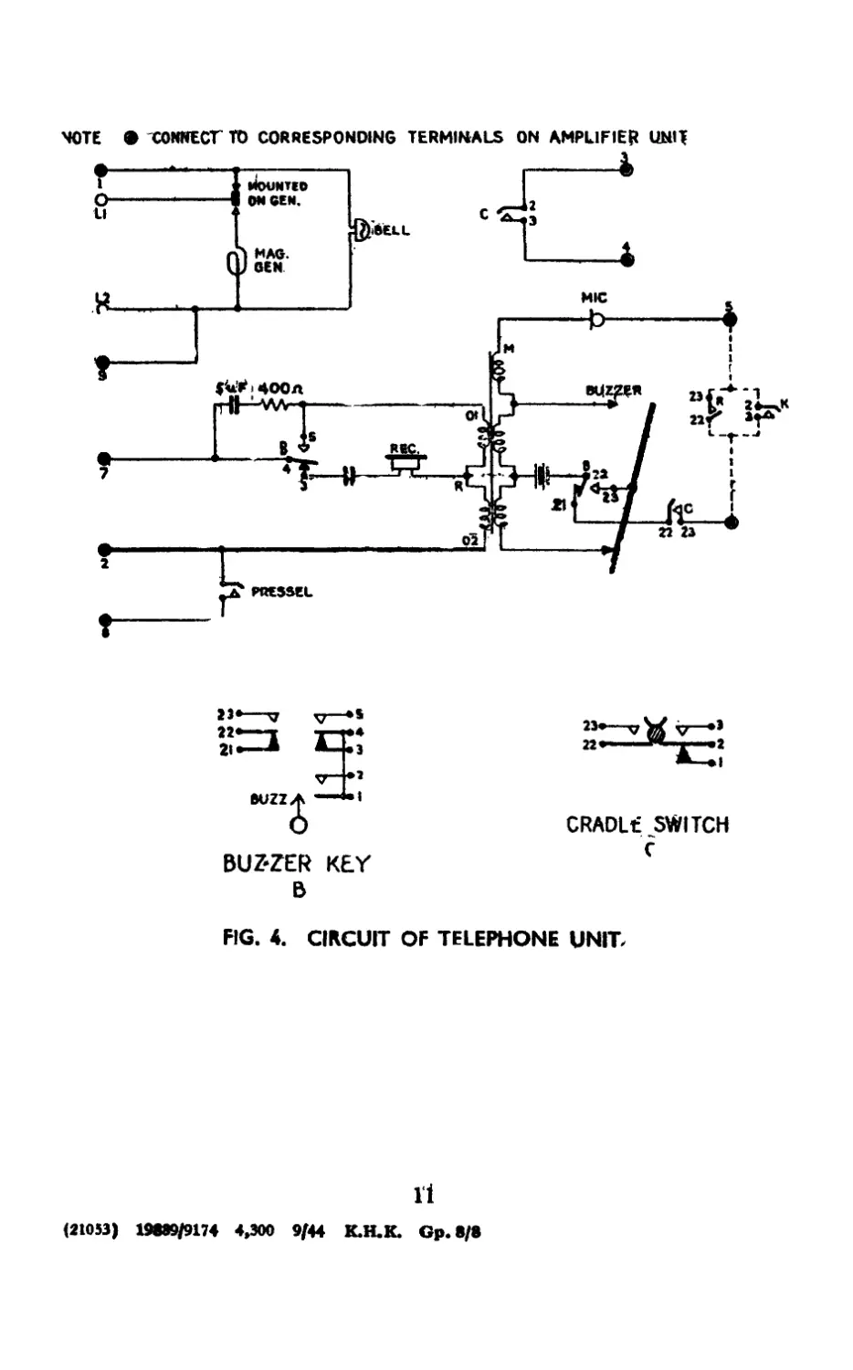
4. Circuit of telephone unit ... ... ... ... ... 11
TELEPHONE SETS F.
HIGH POWER No. 1, Mk. II
Working Instructions.
CHAPTER I.—GENERAL DESCRIPTION
1. Purpose
The Telephone Set F High Power is a portable instrument for army
communication on ranges greater than those obtainable with Telephone
Sets F. Its most common functions arc at the end of direct long range
extensions to a magneto switchboard, or a magneto calling equipment
on a C.B. switchboard, and on point to point circuits over which speech
is not possible with ordinary telephones.
The set comprises a modified Telephone Set F, and a valve amplifier?
A handset P.O. type 184C which incorporates a pressei switch replaces
the handset normally employed with the Telephone Set F.
2. Facilities
The set provides the following facilities :—
Calls by magneto generator.
Calls by buzzer.
Responds by bell to magneto generator calling.
Responds by aural indication to buzzer calling;
Sj^eech communication, using an over-over method (see below).
NOTE.—Buzzer facilities are not always provided.
The amplifier incorporated in the set is unidirectional, the direction
of amplification being controlled by the pressei switch on the handset
which must be depressed while sending speech or buzzer signal and
released while receiving, if the amplifier is switched on. Hence no
reception is possible while the telephone set is in a condition to send so
that an " over-over ” method of communication must be adopted.
With the amplifier switched off, the set may be operated as a normal
telephone F and the pressei switch need not be used.
Since replacement of the handset on the cradle disconnects the power
supply, the handset must be laid alongside the telephone with the
amplifier switched on if buzzer signals are to be received.
When the ringing handle is turned the telephone will give a visual
indication of a call to a magneto switchboard, or to a central battery
switchboard connected to a magneto calling relay set.
The telephone may be operated on any twin or single line with earth
return circuits. The precaution must be observed that if the line is
amplified or consists wholly or in part of a carrier channel, the circuit
between the amplifier or terminal equipment and the telephone F H.P.
must be of sufficient attenuation to ensure that the output of the
telephone does not overload the line equipment.
1
CHAPTER I—Sections 3-6
3. Range of working
The range of the Telephone Set F H.P. is approximately three times
that of a normal telephone, if liigli power telephones are provided at
both ends of the circuit, since the transmit and receive gains are 20 and
40 db respectively.
Depending pn local conditions a single line and earth circuit may give
longer or shorter ranges than a twin line. In general the earth circuit
tends to give better results relative to the twin line as the distance
increases. Bad earths, such as small earth pins in dry sandy soil
increase the noise in the circuit considerably, and the effect may be
of the same order as an increase in the length of the line of 10 to 15
miles.
On single line circuits it will invariably be found that the transmit
gain, which is fixed, is the chief factor in increasing the range. The
advantages of the receive gain will, in certain circumstances, be limited
by the noise on the line. In general on such circuits, the receive gain
control will probably be required in the minimum position. Under
such conditions, double the range of a normal telephone can be expected.
4. Power supply
An H.T. and an L.T. power supply are required for the operation of
the amplifier unit. The H.T. supply of 120 volts is derived from two
Batteries, Dry, H.T., 60-volt, No. 1, while the L.T. supply of 6 volts
is derived from three Cells, Secv., Port., 16 Ah., Mk. II. The H.T.
current consumption is approximately 6 mA, and the L.T, current
consumption is -21 amps on send and -15 amps on receive. In addition,
the operation of the telephone unit requires either two Cells. Dry,
X, Mk. II or two cells, inert, S Mk. I, which are housed in a compart-
ment inside the telephone unit in the normal manner.
5. Weights and dimensions
The approximate weights and overall dimensions are given in
Table I below.
TABLE I
Weights and Dimensions
Unit Length Width Depth Weight
Tel. Set F, H.P 12% ins. 11 ins. 6J ins. 2 5 lb
Batt. 60 V, No. 1 6 ins. 5 ins. 3 ins. 4 lb.
Cell Secy., Fort., 16 Ah. Mk. 11 4| ins. 2 ins. 7 J ins. 4^ lb.
6. Mechanical construction
The Telephone Set F High Power consists of a modified Telephone Set
F and an amplifier unit both housed in the same wooden carrying
case provided with a sling. The telephone unit slides into the front of
the case and is held inside the case by a spring catch which must be
2
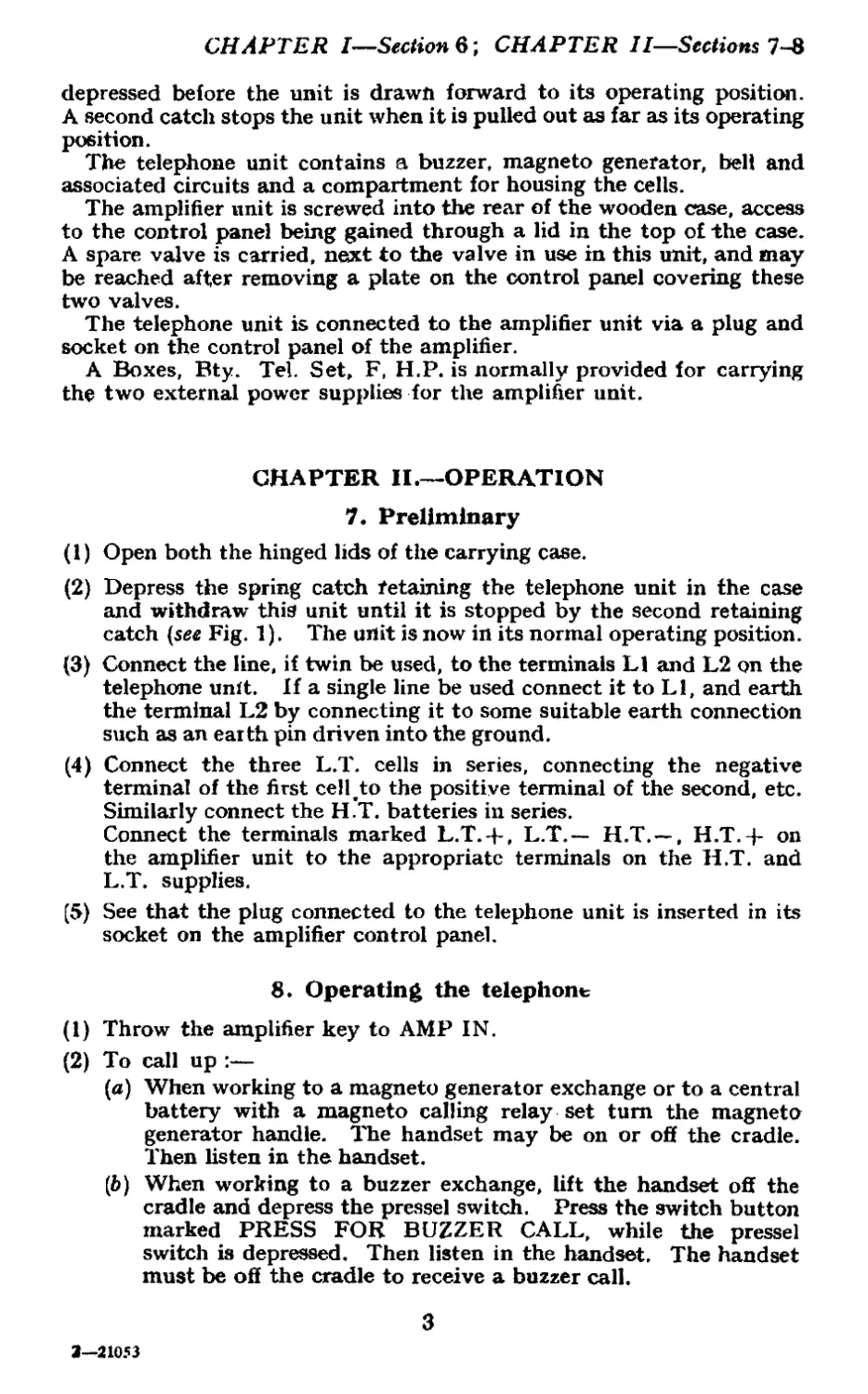
CHAPTER I—Section 6; CHAPTER II—Sections 7-8
depressed before the unit is drawn forward to its operating position.
A second catch stops the unit when it is pulled out as far as its operating
position.
The telephone unit contains a buzzer, magneto generator, bell and
associated circuits and a compartment for housing the cells.
The amplifier unit is screwed into the rear of the wooden case, access
to the control panel being gained through a lid in the top of the case.
A spare valve is carried, next to the valve in use in this unit, and may
be reached after removing a plate on the control panel covering these
two valves.
The telephone unit is connected to the amplifier unit via a plug and
socket on the control panel of the amplifier.
A Boxes, Bty. Tel. Set, F, H.P. is normally provided for carrying
the two external power supplies for the amplifier unit.
CHAPTER II.—OPERATION
7. Preliminary
(1) Open both the hinged lids of the carrying case.
(2) Depress the spring catch retaining the telephone unit in the case
and withdraw this unit until it is stopped by the second retaining
catch {see Fig. 1). The unit is now in its normal operating position.
(3) Connect the line, if twin be used, to the terminals LI and L2 on the
telephone unit. If a single line be used connect it to LI, and earth
the terminal L2 by connecting it to some suitable earth connection
such as an earth pin driven into the ground.
(4) Connect the three L.T. cells in series, connecting the negative
terminal of the first cell.to the positive terminal of the second, etc.
Similarly connect the H.T. batteries in series.
Connect the terminals marked L.T.-+-, L.T.— H.T. — , H.T. 4- on
the amplifier unit to the appropriate terminals on the H.T. and
L.T. supplies.
(5) See that the plug connected to the telephone unit is inserted in its
socket on the amplifier control panel.
8. Operating the telephone
(1) Throw the amplifier key to AMP IN.
(2) To call up :—
(a) When working to a magneto generator exchange or to a central
battery with a magneto calling relay set turn the magneto
generator handle. The handset may be on or off the cradle.
Then listen in the handset.
(b) When working to a buzzer exchange, lift the handset off the
cradle and depress the pressel switch. Press the switch button
marked PRESS FOR BUZZER CALL, while the pressel
switch is depressed. Then listen in the handset. The handset
must be off the cradle to receive a buzzer call.
3
3—21053
CHAPTER II—Sections
(3) Communication :—
(a) To speak, depress the pressei switch marked. PRESS WHILE
SPEAKING, and speak into the microphone. Before releasing
the pyessel switch, say " over.”
(b) To receive, listen in the earpiece with the pressei switch
released.
When the key is at AMP IN an interval of about 5 secs, should
elapse between lifting the handset off the cradle and
communicating
(4) To ring off :—
(a) If working to a magneto exchange, ring off at the end of a
conversation by turning the ringing handle.
9. Adjustments
(1) To adjust the receiver gain :
Adjust REC. GAIN control on the amplifier unit until suitable
reception is obtained. If reception is noisy, better results may be
obtained by turning down the REC. GAIN control.
(2) To adjust the buzzer :—
(a) Disconnect the line and withdraw the telephone unit com-
pletely from its carrying case. Remove the top of the unit
after removing the handset from the cradle and unscrewing the
three retaining screws. The buzzer is housed in a compartment
at the right-hand side of the unit.
(6) Loosen the two large locking collars on top of the buzzer.
(c) Screw out the adjusting screws a few turns.
(d) Depress the push button marked PRESS FOR BUZZER CALL.
(e) Keeping the push button switch depressed, screw in the rear
adjusting screw until a buzz is heard and adjust until the
loudest note is obtained irrespective of quality.
(/) Lock the collar.
(g) Adjust the front adjusting screw until a. clear and fairly high
note is obtained.
(Л) Check the adjustments by operating the push button switch
and rc-adjust if necessary.
NOTE.—Neither the maximum output nor the maximum
efficiency is obtained from the buzzer when adjusted for
the highest note. The best quality of the note and
permanence of adjustment are achieved when the pitch
is a little below the highest obtainable. When adjusting
the buzzer screws care must be exercised not to force
the screws hard on to the armature contacts or the
platinum contacts will be damaged and the buzzer pul
out of action.
4
CHAPTER II—Section 9; CHAPTER III—Sections 10—13
(3) To adjust the magneto bell:—
(a) With the telephone disconnected from the external line,
connect terminal LI of the telephone unit to the top right-hand
pin of the plug on the amplifier unit, holding the plug with the
pins towards you and the row of holes at the bottom.
(6) Turn the ringing handle. The bell should ring.
(c) If the ringing is weak, slacken the screws holding the gongs
in position and rotate the gongs, which are mounted eccen-
trically, until positions are found which give good ringing.
CHAPTER III______UNIT MAINTENANCE
10. General
The apparatus should be kept clean and dry. See that all electrical
connections are securely made.
11. Internal cells
(1) Remove the top of the telephone unit as described in Sec. 9 (2) (a)
and inspect (he cells which are housed in the left-hand side of the
unit.
(2) See that the cell compartment is thoroughly clean and remove any
corrosion from the cells. This is of importance, since, if corrosion
continues for any length of time, some difficulty may be experienced
in removing the old cells for replacement purposes.
(3) See that the cells are correctly connected, they should be connected
in series and the red and black out-going leads connected to the
positive and negative terminals respectively (see diagram on lid).
The buzzer will not function properly if the leads are reversed.
(4) See that the terminals of the cells are clean and the connections
are secure.
12. Buzzer and bell
Failure in the buzzer should be overcome by replacement by another
buzzer. For adjustments to the buzzer or bell, see Sec. 9 (2) or (3)
above.
13. Handset
(1) In order to remove the cover from the microphone press a blunt
instrument into the small hole in the top side of the cover, and
keeping it pressed down turn the cover in an anti-clockwise direc-
tion when it will come away readily.
(2) In order to replace the microphone cover, press on the cover so that
when turned through about 20 degrees it clicks into its correct
attitude with respect to the body of the instrument. When in
this position the small hole in the cover will point along the handle
towards the earpiece.
5
CHAPTER III—Sections 13-15
(3) The carpiece cover is removed by unscrewing.
(4) See that the contacts of the pressel switch, which consist of two
metal plates inside the microphone towards the handle of the
handset (see Fig. 2) are open when tire PRESS WHILE
SPEAKING switch is released, but closed when this switch is
depressed.
(5) See that the electrical connections inside the microphone are made
as shown in Fig. 2 and are secure. The connections to the telephone
are made on a terminal strip which is inserted in the telephone
unit as shown in Fig. 1.
14. Amplifier unit
(1) In order to reach the valves in the amplifier unit, slacken the two
screws which hold the valve cover plate to the control panel (Fig. 1)
and remove this cover plate. The valves are now easily reached.
A spare valve is mounted next to the valve in use.
(2) The relay contacts should never be touched. To inspect thb relay
remove the relay cover plate after slackening its securing screws.
The metal box over the relay may now be raised.
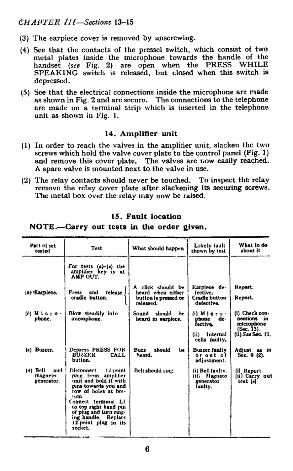
15. Fault location
NOTE.—Carry out tests in the order given.
Part of set tested Test What should happen Likely fault shown by test What to do about it
For tests («)-(«) the amplifier key is at AMP OUT.
(a)-Eatpiece. Press and release J cradle button. I A click should be heard when either button is pressed or released. Earpiece de- fective. Cradle button defective. Report. Report.
(fr) Micro- pbone. Blow steadily into microphone. Sound should be heard in earpiece. (i) Micro- phone de- fective, (ii) Internal cells faulty. (i) Check con- nections in microphone (Sec. 13). (ii)SMSec. II.
(c) Buzzer. Depress PRESS FOR BUZZER CALL button. Buzz should be heard. Buzzer faulty or out of adjustment. Adjust as in Sec. 9 (2).
(rf) Bell and magneto generator. Disconnect 12-point plug fmm amplifier unit and bold it with pins towards you and row of holes at bot- tom Connect terminal LJ to top right hand pin of plug and turn ring- ing handle. Replace 12-point plug in its socket. Bell should ring. (i) Bell faulty. (ii> Magneto generator faulty. (i) Report. (ii) Carry out test (e)
6
CHAPTER Section 15
Part of set tested Test What should happen Likely fault shown by test What to do about it
(c) Magneto generator. Turn ringing handle. Touch terminals Ll and L2 with moist ened fingers. Slight shock felt. Magneto generator faulty. Report.
If all the tests (f r(k) fail, the fault may b< in the amplifier unit. Report.
(f) Amplifier unit Connect to a good second' telephone. With key at AMP OUT and REC GAIN control at 2, speak and listen between phones. If received voice is too loud, speak into the re ceiver of the second telephone. Switch io AMP IN on first tele- phone and wait about 5* secs. Speak and listen using same loudness of voice as previously. When key is at AMP IN, increased volume should be received. (i) External batteries (ii) Amplifier valve. (iii) Internal fault in amp lifter unit. (i) Carry out test(g) (ii) Carry out test(A) (iii) Report,
(g) External batteries and ampli- fier unit. As in (/) above. Ro- tate REC. GAIN control. Increase m setting should increase volume received. <i) H.T. or L.T. battery run down. (ii) Internal fault. (i)i Replace by new batteries. (Ii) Report.
(Л) Amplifier valve. Switch key to AMP OUT or vibrate the amplifier unit mech anically. Noise should be heard in earpiece. Faulty ampli- fier valve. Replace by new valve see рог*. 14 (1).
(j) Connection! between telephones. Carty out tests </)—(*) И all tests show faults —faulty con- nections be- tween tele- phones. Inspect con- nections at terminals Li and L2, and test connect- ing line for continuity.
7
RELAY COVER PLATE.
BUZZER
SWITCH
BUTTON.
12 PT. PLUG.
TERMINAL STRIP.
FIG. 1. EXTERNAL VIEW OF TELE. F. HIGH POWER.
VALVE COVER PLATE.
CRADLE
switch.
MAGNETO
GENERATOR
HANDLE.
5ET RO. IG4C.
8
PRESSEL SWITCH.
FIG. 2. CONNECTIONS TO THE MICROPHONE.
MICROPHONE.
TERMINAL STRIP.
9
NOTE. • -CONNECT TO CORRESPONDING TERMINALS ON TELEPHONE UNIT.
AMPLIFIER KEY
К
FIG. 3. CIRCUIT OF AMPLIFIER UNIT.
19
6UZ2
BUZ’ZER KEY
В
CRADLf SWITCH
C
FIG. 4. CIRCUIT OF TELEPHONE UNIT,
11
(21053) 19889/9174 4,300 9/44 K.H.K. Gp.8/8