/


Теги: radio
Год: 1945


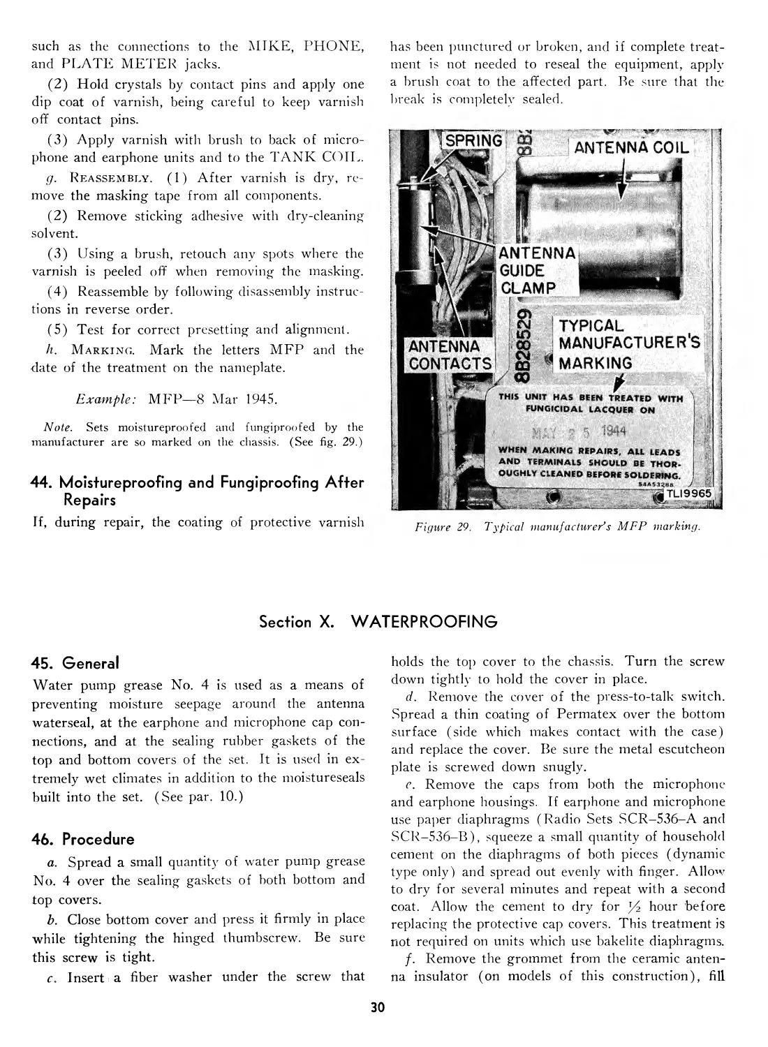
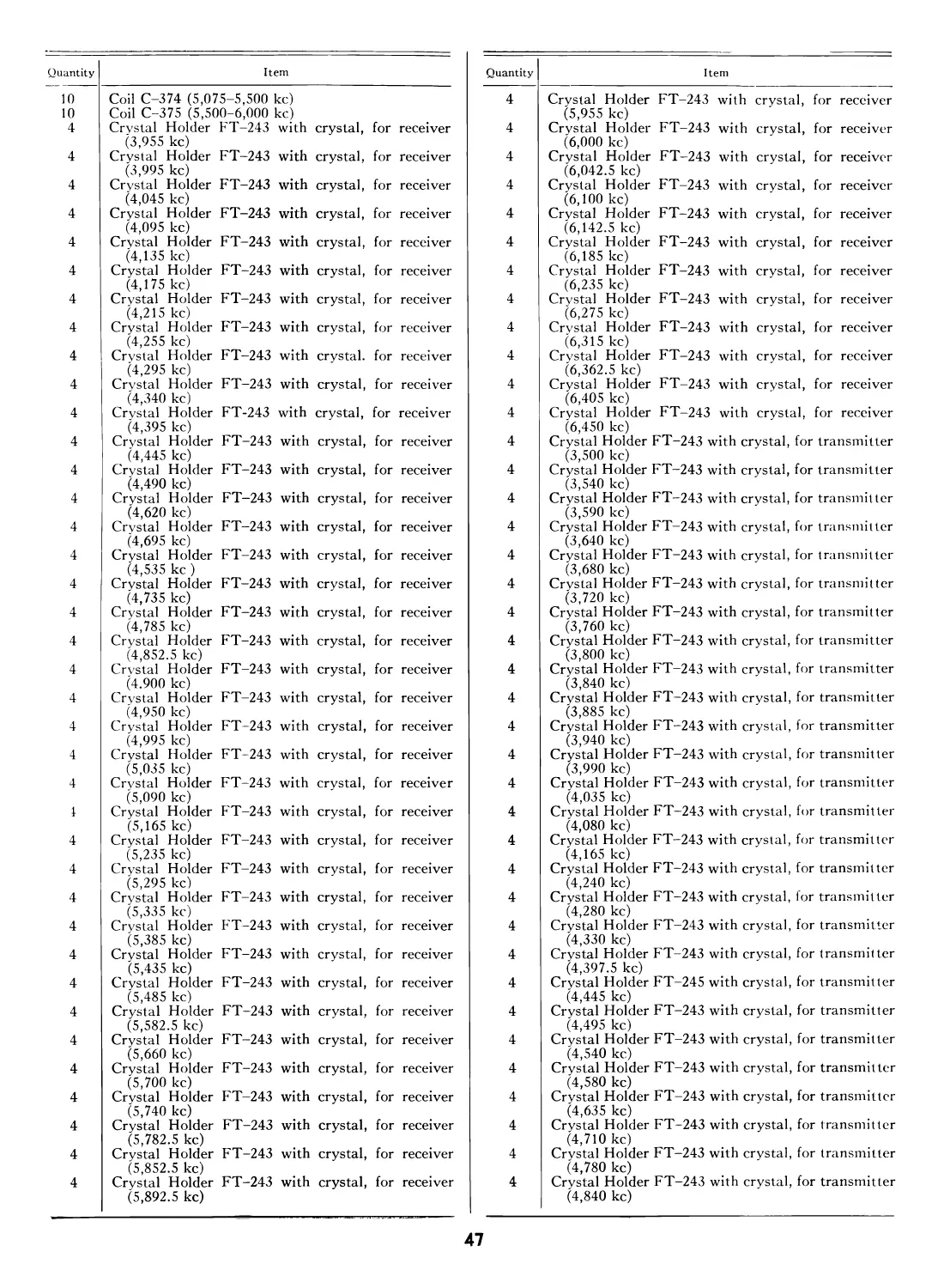
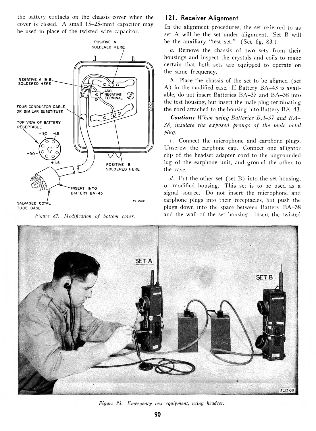
Текст
WAR DEPARTMENT TECHNICAL MANUAL
RADIO SETS
SCR-536-A, -В, -C,
-Г), -E, AND -F
WAR DEPARTMENT • MAY 1945
RESTRICTED
WARNING
Authority for release of this document to a foreign
government must be secured from the Assistant Chief
of Staff, G-2.
When this document is released to a foreign govern-
ment, it is released subject to the following conditions:
This information is furnished with the understanding
that it will not be released to another nation without
specific approval of the United States of America, De-
partment of the Army; that it will not be used for
other than military purposes; that individual or corpo-
ration rights originating in the information whether
patented or not will be respected; and that the infor-
mation will be afforded substantially the same degree
of security as afforded by the United States of America,
Department of the Army.
RESTRICTED
JU A R DEPARTMENT TECHNICAL MANUAL
T M 11-235
This manual sup rs^dcs TM 11-235, 14 May 1943, including C 1, 15 December 1943, C 2, 18 October 1944; ТВ 11-235-1, 31 May 1944; ТВ
11-235-2, 22 Jwy 1944; ТВ 11-235 -3, 8 August 1944; ТВ 11-235-4, 11 August 1944; ТВ 11-235-5, 16 September 1944; ТВ 11-235-6, 14
Noz ember 1944; ТВ 11-235-7, November 1944; and ТВ 11-235-8. 25 January 1945.
RADIO SETS SCR-536-A,
-В, -C, -D, -E, AND -F
IP A R DEPARTMENT
MAY 1945
United States Government Printing Office
W ashington: 1945
RESTRICTED
WAR DEPARTMENT
Washington 25. D. C., 31 May 1945
TM 11-235, Radio Sets SCR-536-A, -В, -C. -D, -E, and -F, is published for
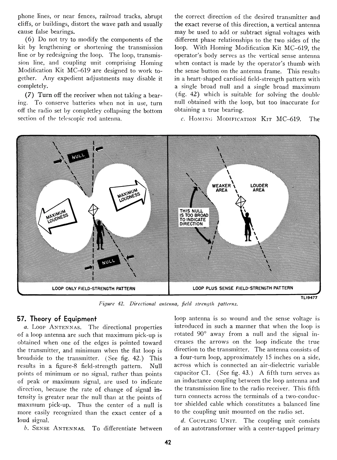
the information and guidance of all concerned.
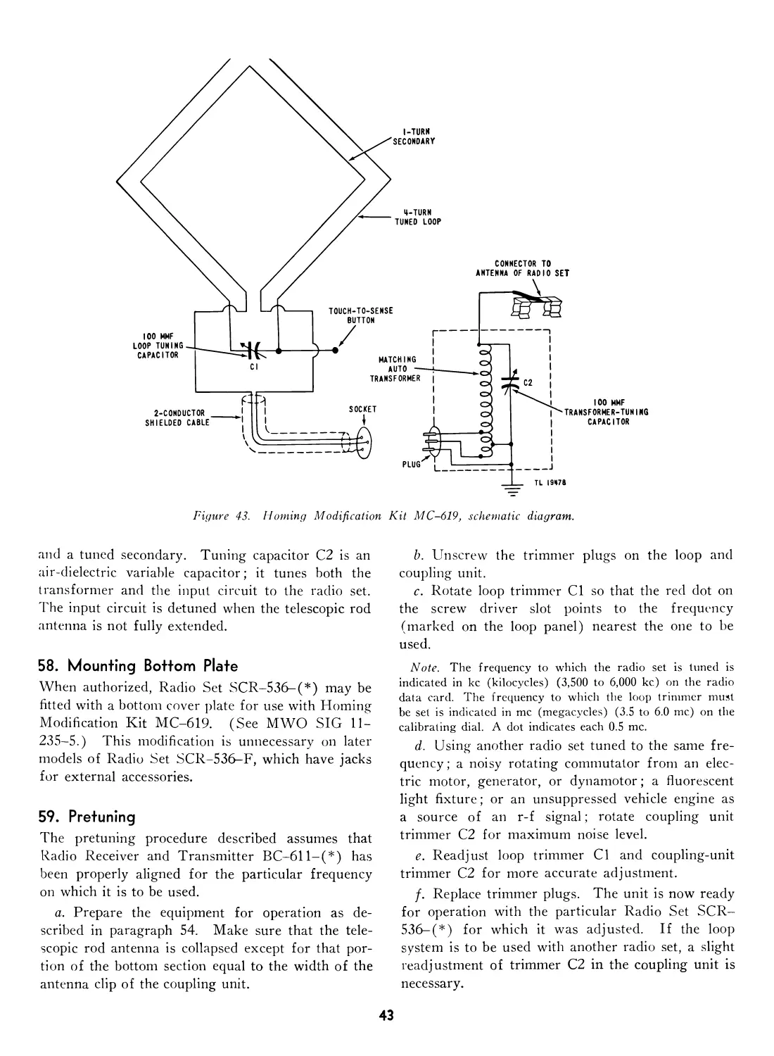
[AG 300.7 (28 Nov 44)]
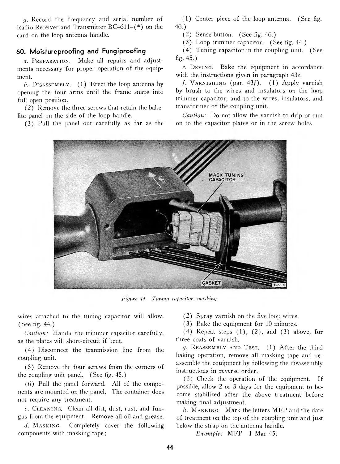
By order of the Secretary of War :
Official:
J. A. ULIO
Major General
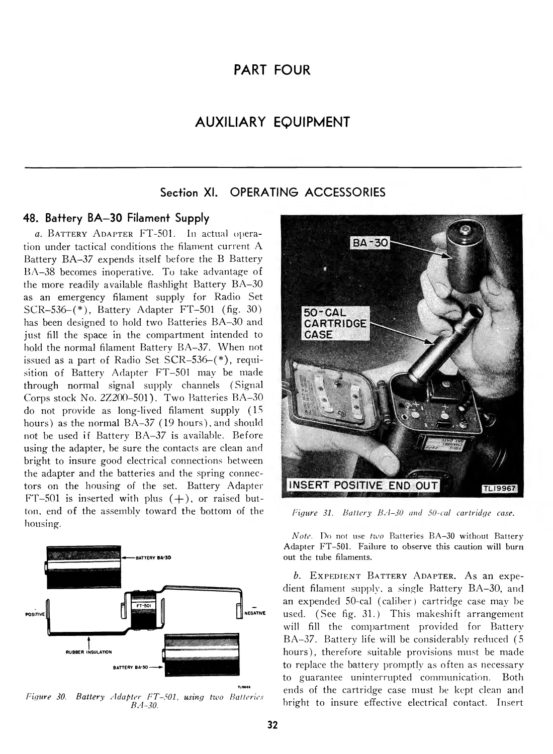
The Adjutant General
G. C. MARSHALL
Chief of Staff
Distribution :
AAF (5); AGF (5) ; ASF (2) ; T of Opn (5) ; Dept (5) ; Def Comd (2);
Base Comd (5); AAF Comd (2) ; Arm & Sv Bd (1) ; S Div ASF (1) ;
Tech Sv (2) ; SvC (5); Area ASVC (2) ; WDGS Lib (5) ; PC&S (2) ;
PE (2); Dep 11 (2) ; Gen Oversea SOS Dep (Sig Sec) (2); GH (2) ;
M Cone C (2); Air Base Hosp (2) ; Gen Sv Sch (5) ; Sp Sv Sch (10) ;
L'SMA (10); ROTC (5) ; Lab 11 (2) ; Sig AS (2) ; Rep Shop 11 (2) ;
A (5) ; D (2) ; AF (2) ; Three (3) copies to each of the following: T/O
& E 1-157; 1-617; 1-911; 1-987; 2-87T; 4-104; 4-227; 4-260-1; 6-156;
6-157; 6-186; 6-187; 7-16: 7-17; 7-18; 7-26: 7-27; 7-36; 7-37; 7-57;
7-58; 7—77; 7-86; 7-137; 7-138; 7-416; 7-417; 11-7; 11-7S: 11-15;
11-25: 11-95; 11-107; 11-127; 11-147S; 11-237; 11-287; 11-488S;
11-557; 11-557T; 44-327.
Refer to FM 21-6 for explanation of distribution formula.
CONTENTS
Para-
graph Page
PART ONE. INTRODUCTION.
Section I. Description of Radio Sets SCR-
536-A, —В, -C, -D, -E, and -F.
General ......................................... 1 1
Technical characteristics of Radio
Set SCR-536-(*)................... 2 2
Frequency Spectrum Chart.......... 3 3
Table of components................. 4 3
Shipping weights and dimensions of
packed sets.......................... 5 3
Housing ............................ 6 5
Power supply........................ 7 7
Chassis ............................ 8 7
Controls ........................... 9 10
Moistureseals ...................... 10 10
Differences in models............... 11 11
II. Installation of Radio Set SCR-
536-(*).
Unpacking and checking.......... 12 11
Installation ...................... 13 11
Repacking ......................... 14 14
PART TWO. OPERATING INSTRUCTIONS.
Section III. Controls and their use.
General ........................................ 15 15
Turning set on and off........... 16 15
Receiving and transmitting....... 17 15
Controlling volume................. 18 15
Tuning ............................ 19 15
IV. Operation.
Starting procedure...................... 20 15
Siting ........................... 21 15
Camouflaging ...................... 22 16
Receiving.......................... 23 16
Transmitting ..................... 24 18
Net operation..................... 25 18
Stopping procedure................ 26 19
V. Equipment performance check list.
Purpose and use of check list..... 27 19
Equipment performance check list. 28 20
PART THR EE. MAINTENANCE INSTRUCTIONS.
Section VI. Preventive maintenance techniques.
Meaning of preventive maintenance 29 21
Description of preventive mainte-
nance techniques................ 30 21
VII. Itemized preventive maintenance.
Introduction ........................... 31 22
Preventive maintenance tools and
materials ........................ 32 23
Item 1, exterior of Radio Set SCR-
536- (*) ......................... 33 23
Para-
graph Page
Item 2, antenna..................... 34 24
Item 3, inside bottom cover....... 35 24
Item 4, chassis and interior of Radio
Set SCR-536-(*)...................... 36 24
Preventive maintenance check list.. 37 25
Factors determining preventive
maintenance periods.................. 38 25
VIII. Lubrication.
Lubrication instructions............ 39 26
Recommended lubricants for camou-
flaging and waterproofing.......... 40 26
IX. Moistureproofing and fungiproofing.
Problems encountered................ 41 26
Treatment .......................... 42 26
Step-by-step instructions........... 43 27
Moistureproofing and fungiproofing
after repairs....................... 44 30
X. Waterproofing.
General ................................ 45 30
Procedure ......................... 46 30
Materials required................. 47 31
PART FOU R. AUXILIARY EQUIPMENT.
Section XI. Operating accessories.
Battery BA-30 filament supply.... 48 32
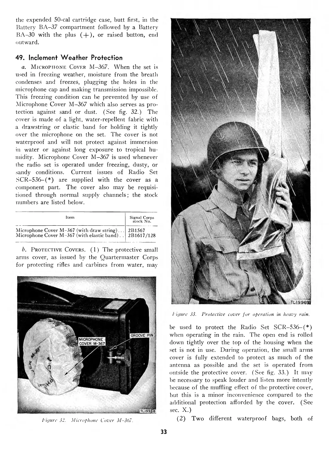
Inclement weather protection..... 49 33
Expedient antenna.................. 50 34
Equipment for use with external
jacks .............................. 51 34
Maintenance Equipment ME-36... 52 35
XII. Homing Modification Kit MC-619.
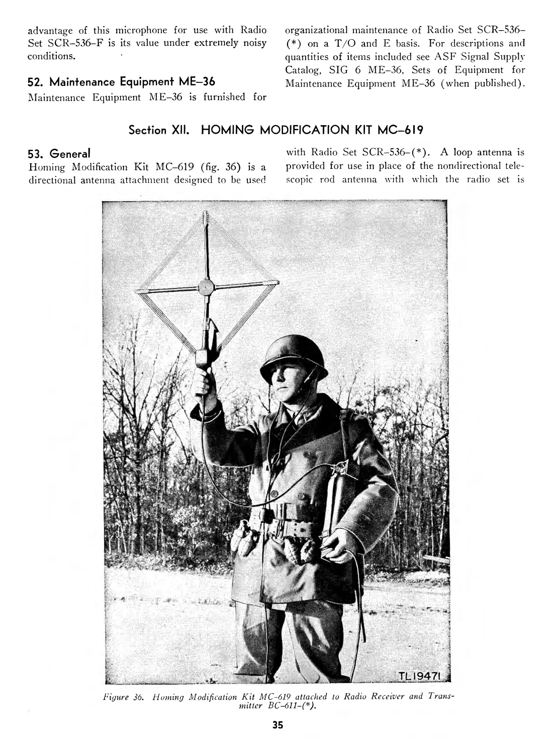
General .................................. 53 35
Components ........................ 54 36
Installation ...................... 55 36
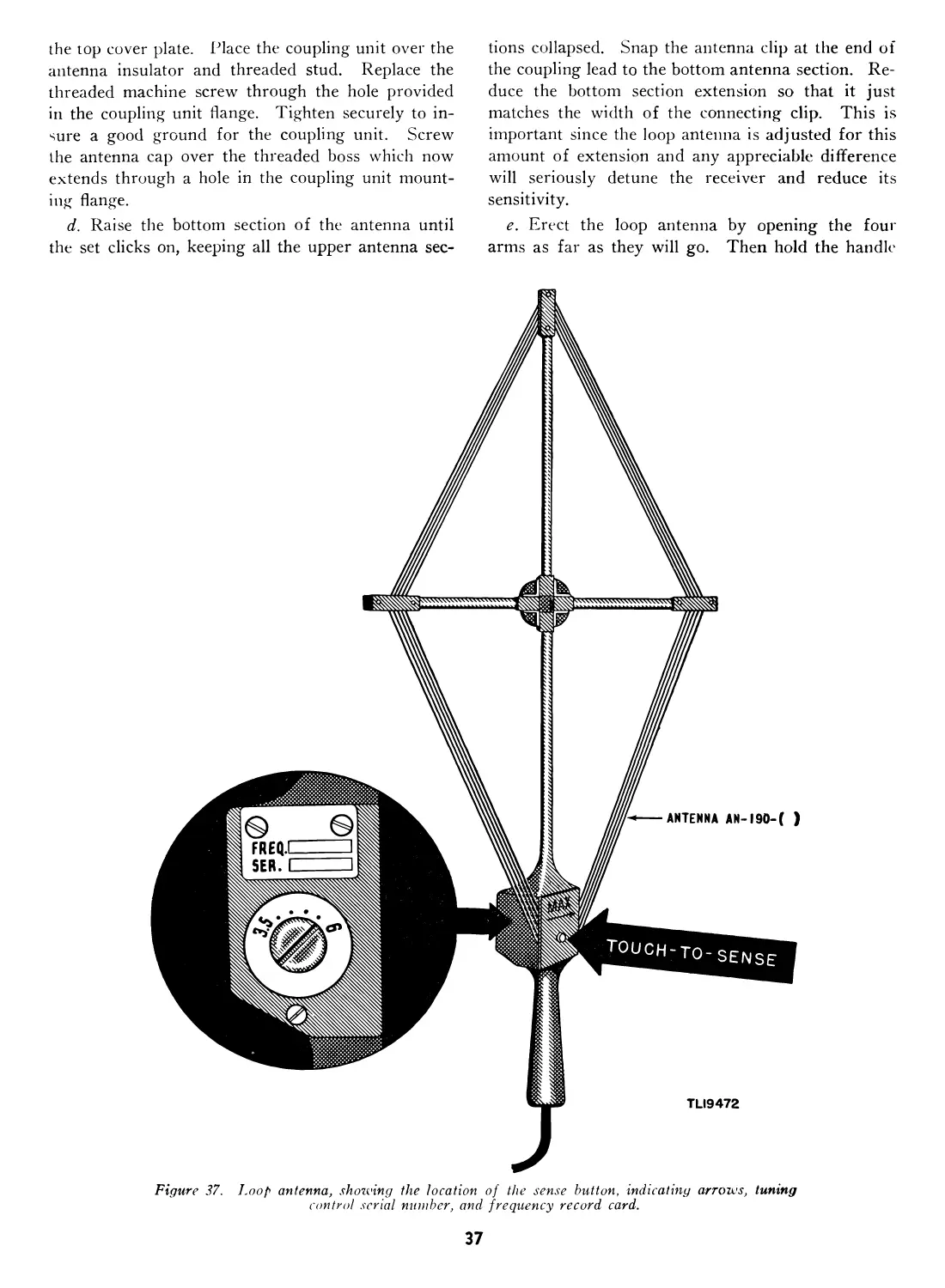
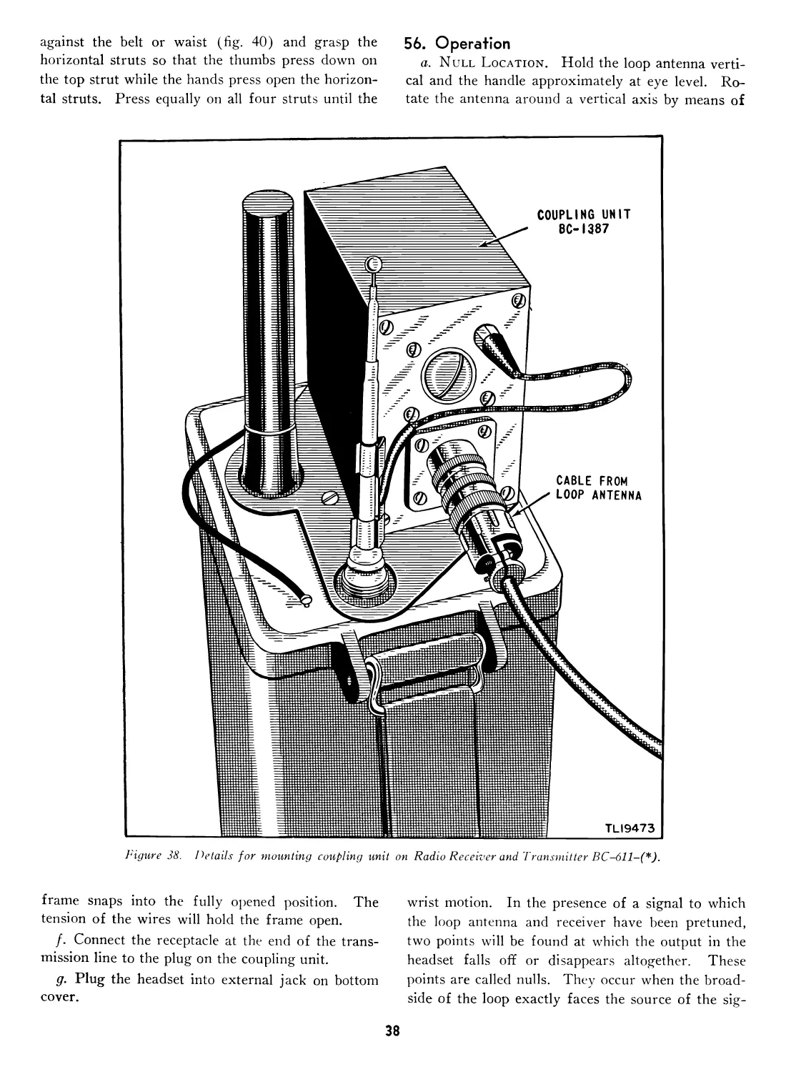
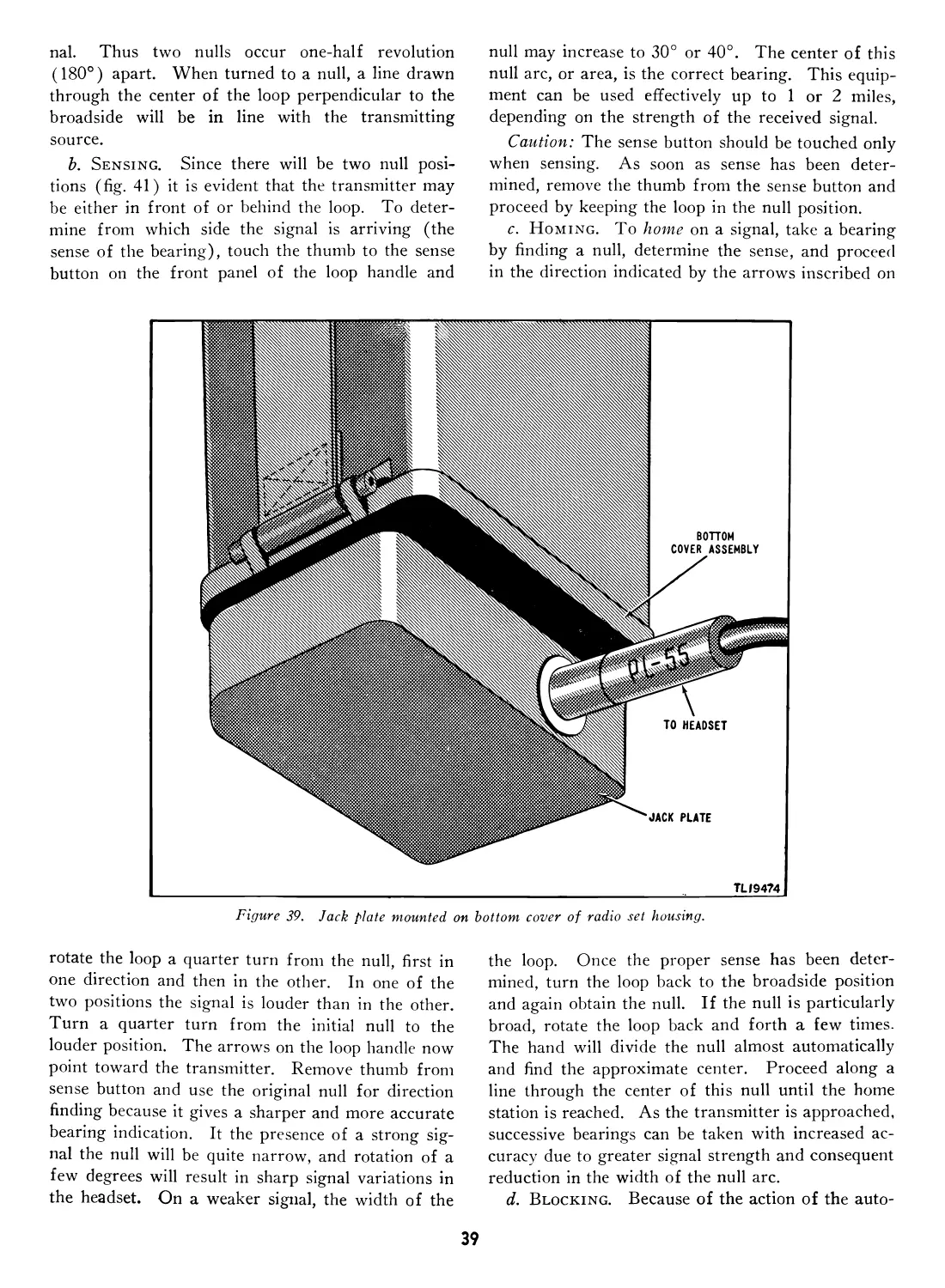
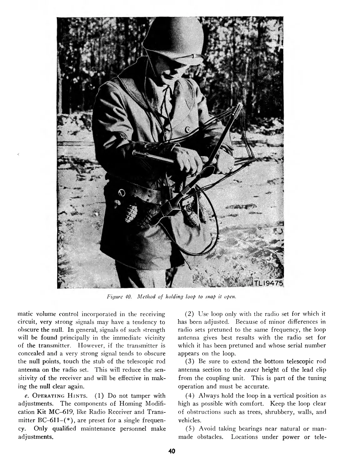
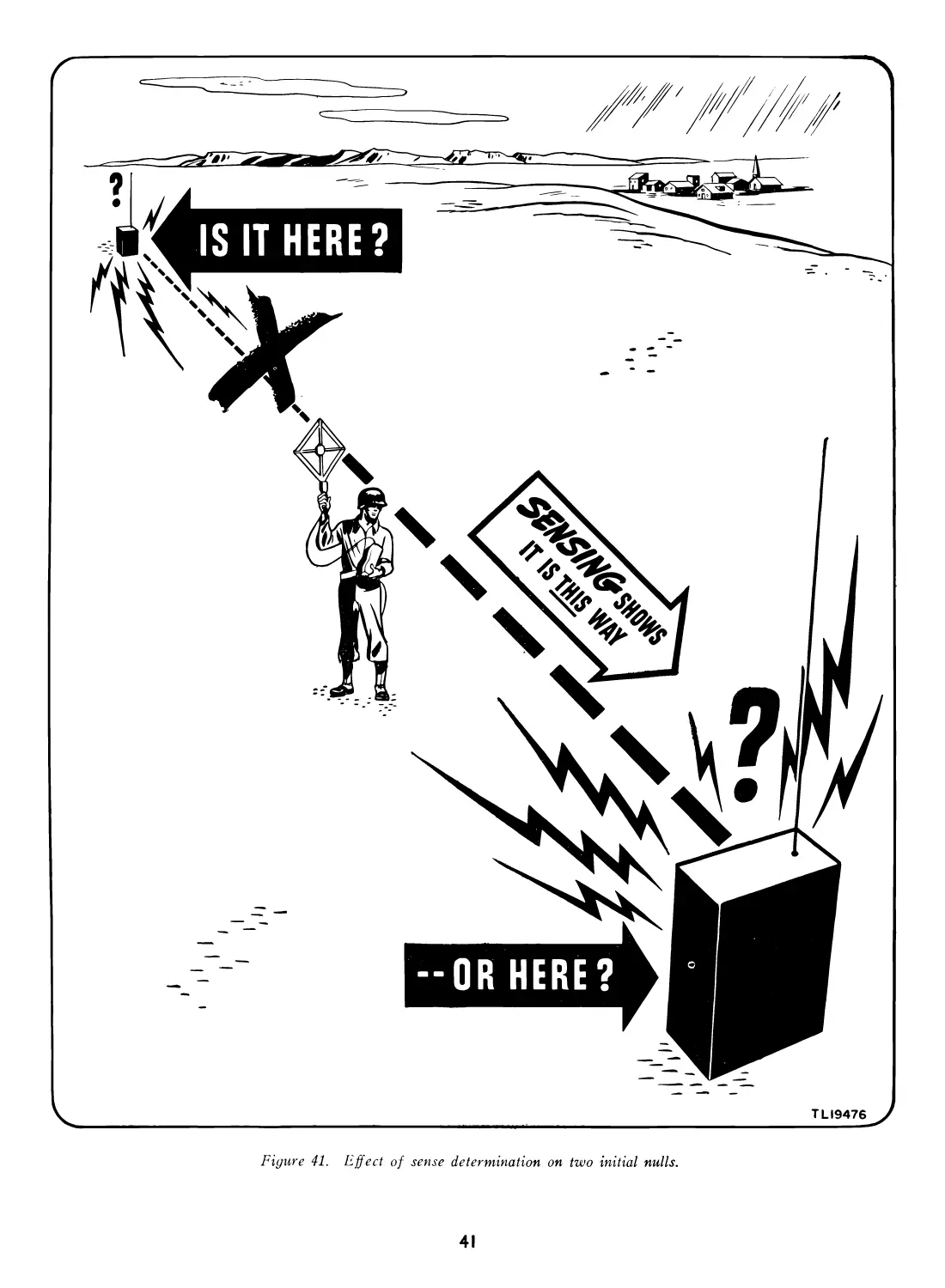
Operation ......................... 56 38
Theory of equipment................ 57 42
Mounting bottom plate.............. 58 43
Pretuning ......................... 59 43
Moistureproofing and fungiproofing 60 44
Moistureproofing and fungiproofing
after repairs....................... 61 46
XIII. Frequency conversion kits.
Frequency Conversion Kit MC-534 62 46
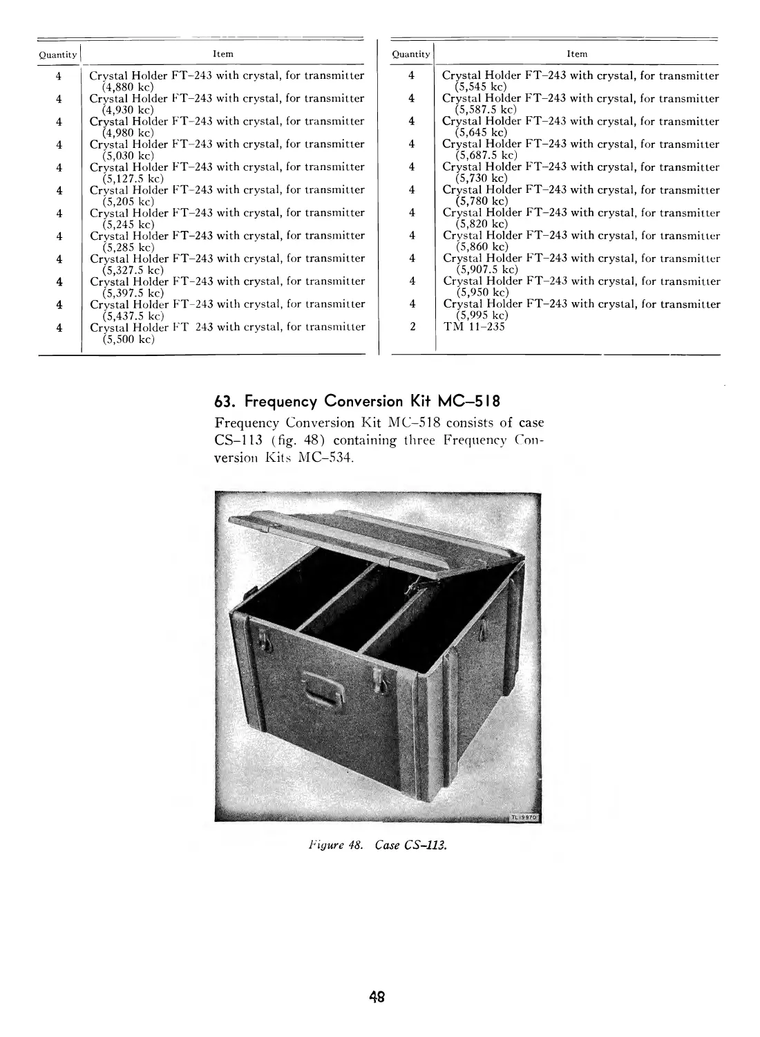
Frequency Conversion Kit MC-518 63 48
PART FIV E. REPAIR INSTRUCTIONS.
Section XIV. Theory of equipment.
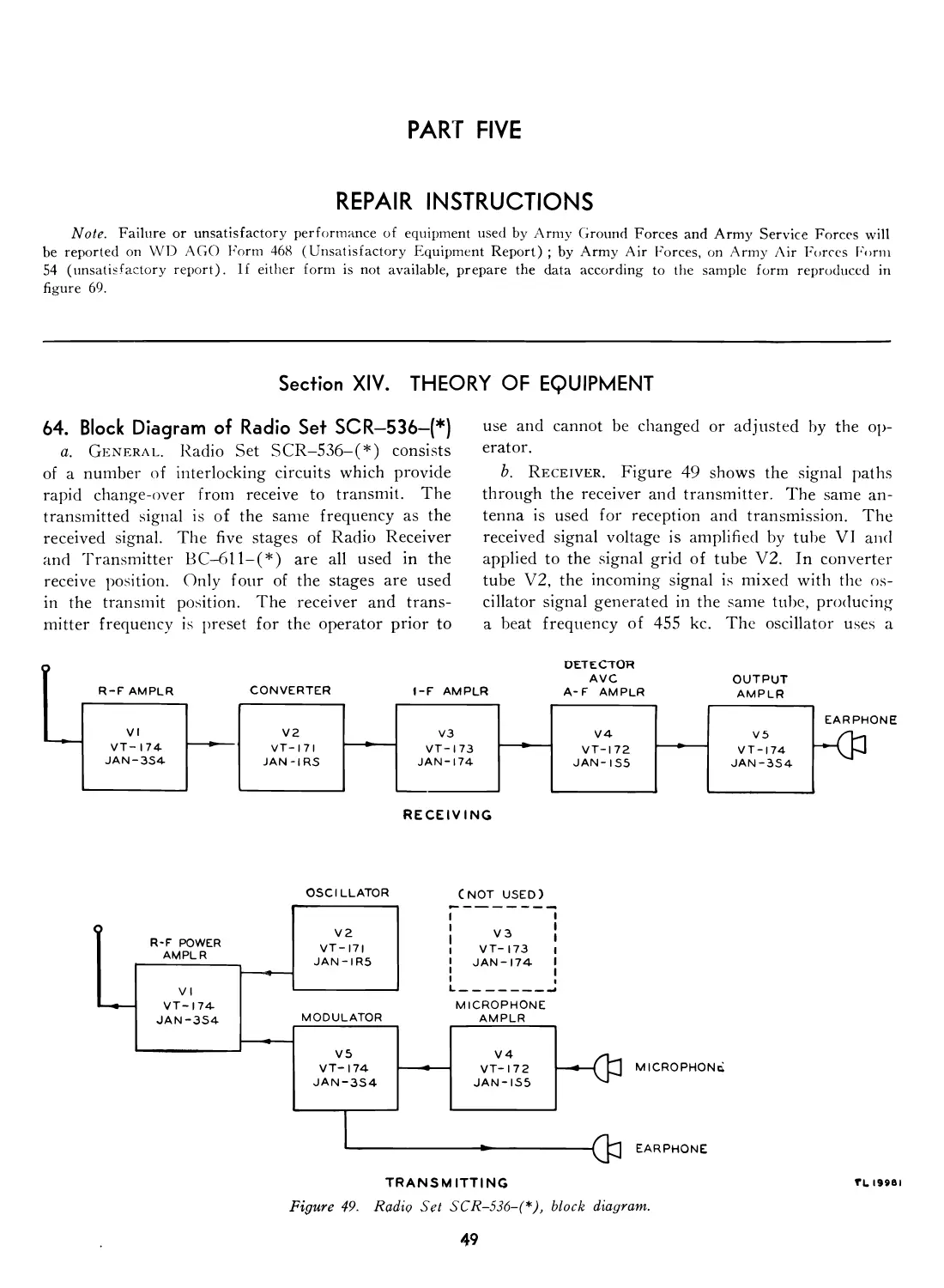
Block diagram of Radio Set SCR-
536-(*) ............................. 64 49
Circuit description................. 65 52
Para-
graph Page
Receiver r-f amplifier.............. 66 52
Converter .......................... 67 52
I-f amplifier....................... 68 53
Detector, automatic volume control,
and first audio amplifier......... 69 53
Receiver power output amplifier... 70 53
Transmitter oscillator.............. 71 56
Transmitter r-f amplifier........... 72 56
Microphone amplifier................ 73 56
Modulator .......................... 74 56
Press-to-talk switch................ 75 56
XV. Trouble shooting.
General trouble-shooting informa-
tion ............................... 76 57
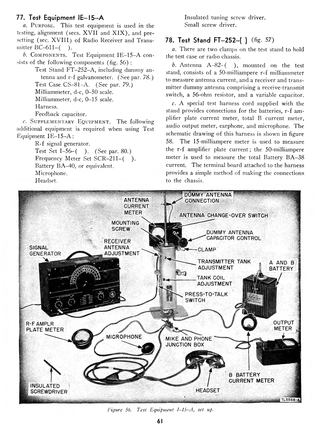
Test Equipment IE-15-A.............. 77 61
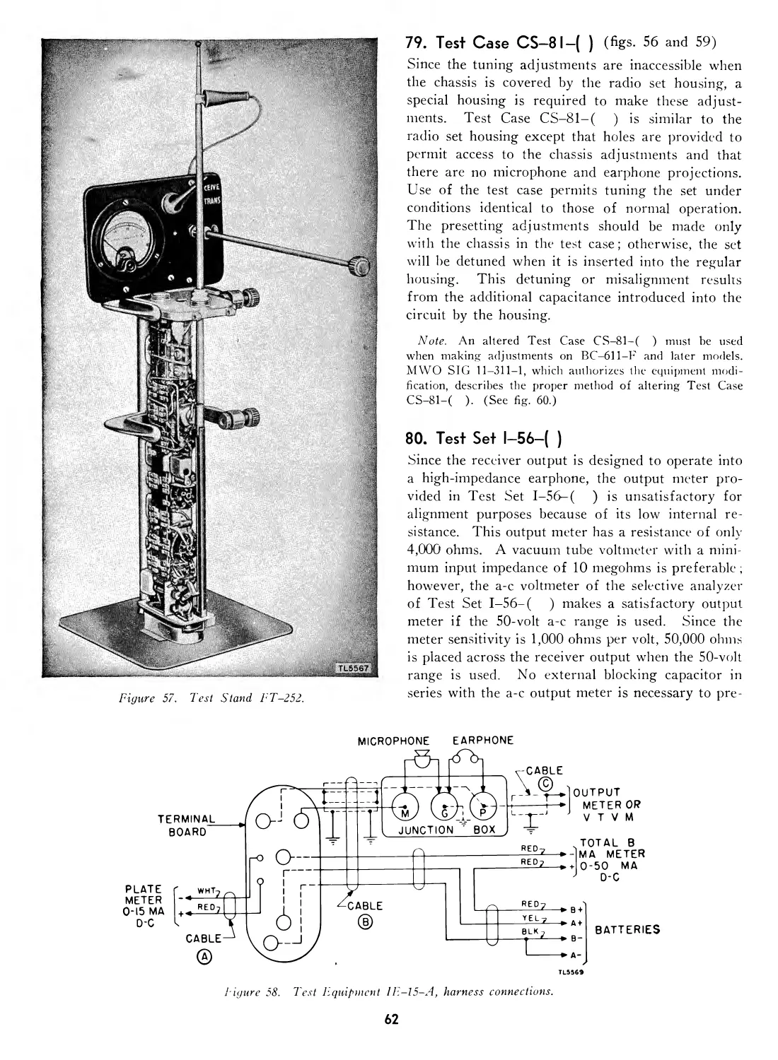
Test Stand FT-252-( )............... 78 61
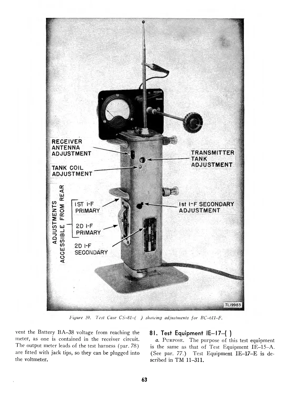
Test Case CS-81-( )................. 79 62
Test Set 1-56-( )................... 80 62
Test Equipment IE-17-( )............ 81 63
Test Unit I—135—( )................. 82 64
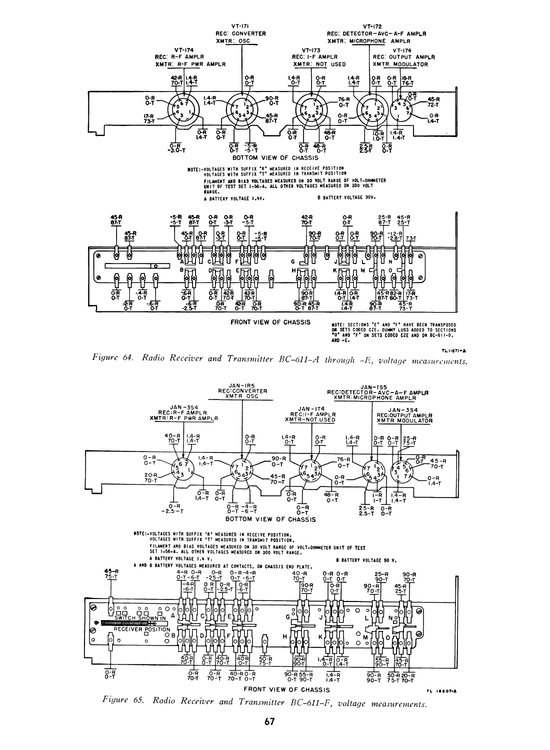
Trouble-shooting procedures........ 83 68
Sectionalizing trouble in Radio Set
SCR-536-(*) ...................... 84 68
Sectionalizing trouble in receiver
circuit ............................ 85 69
Sectionalizing trouble in transmitter
circuit ............................ 86 69
Localizing trouble in receiver and
transmitter circuits................ 87 69
XVI. Repairs.
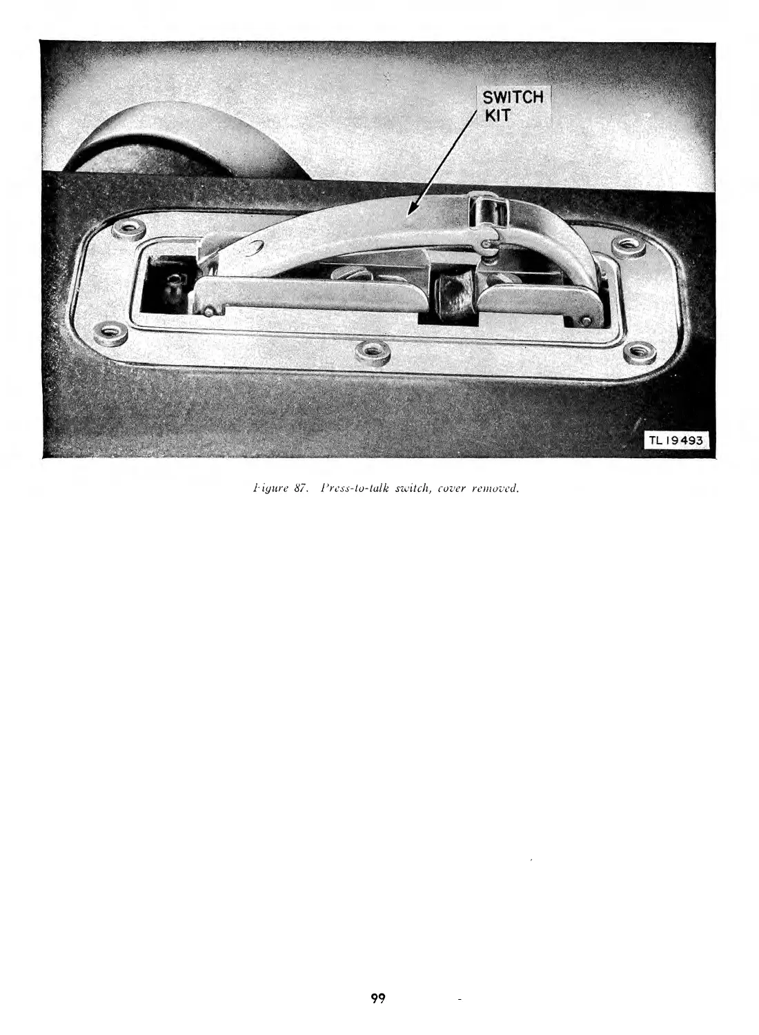
Replacement of press-to-talk switch 88 71
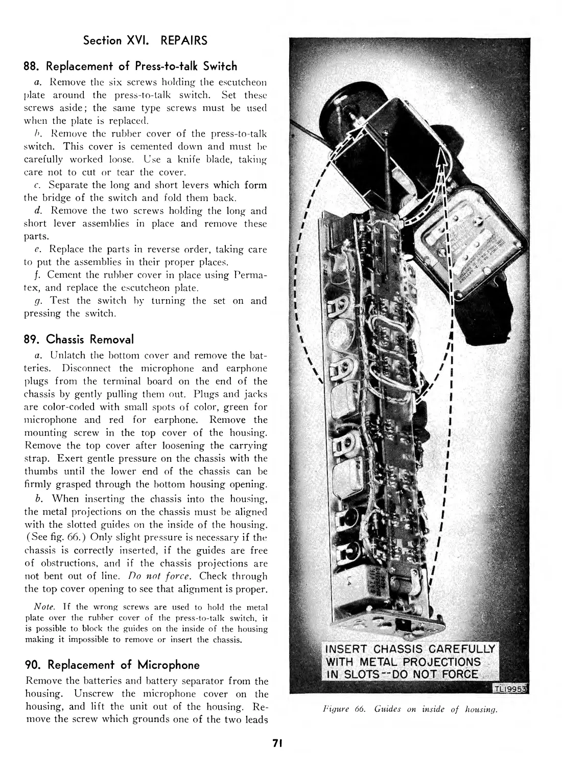
Chassis removal..................... 89 71
Replacement of microphone.......... 90 71
Replacement of earphone............. 91 72
Replacement of on-off switch....... 92 72
Replacement of antenna............. 93 72
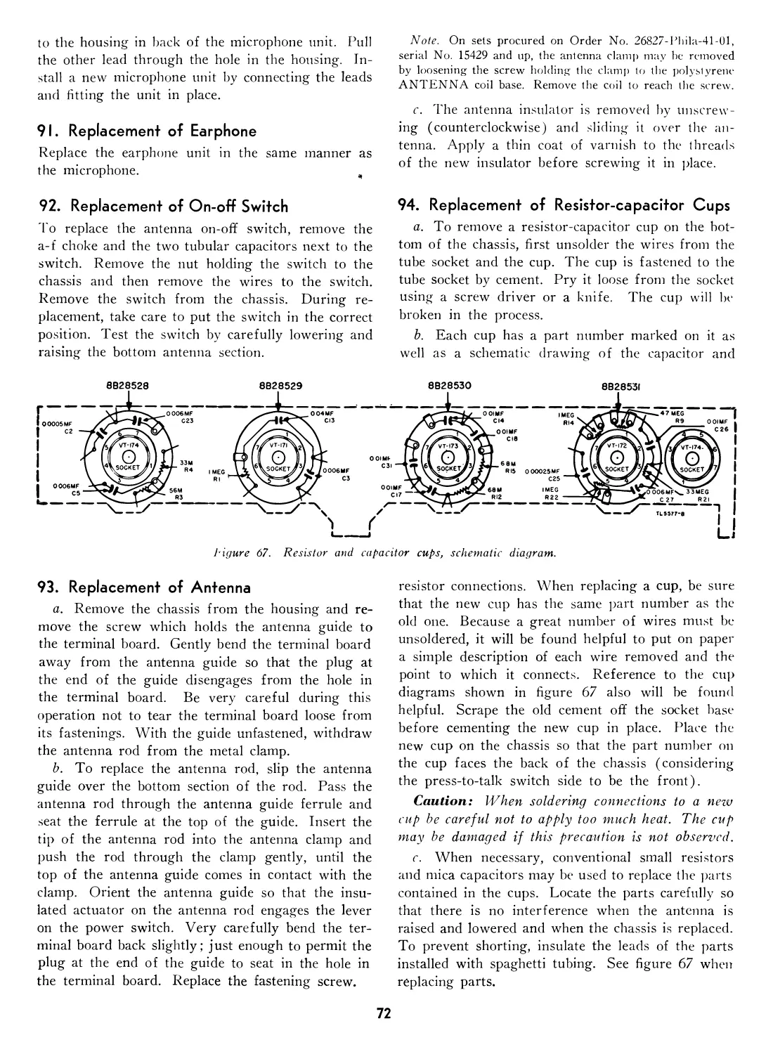
Replacement of resistor-capacitor
cups .............................. 94 72
Replacement of tubes............... 95 73
Changing coils and crystals....... 96 73
Removal of eyelets................. 97 73
Replacement of i-f transformer.... 98 73
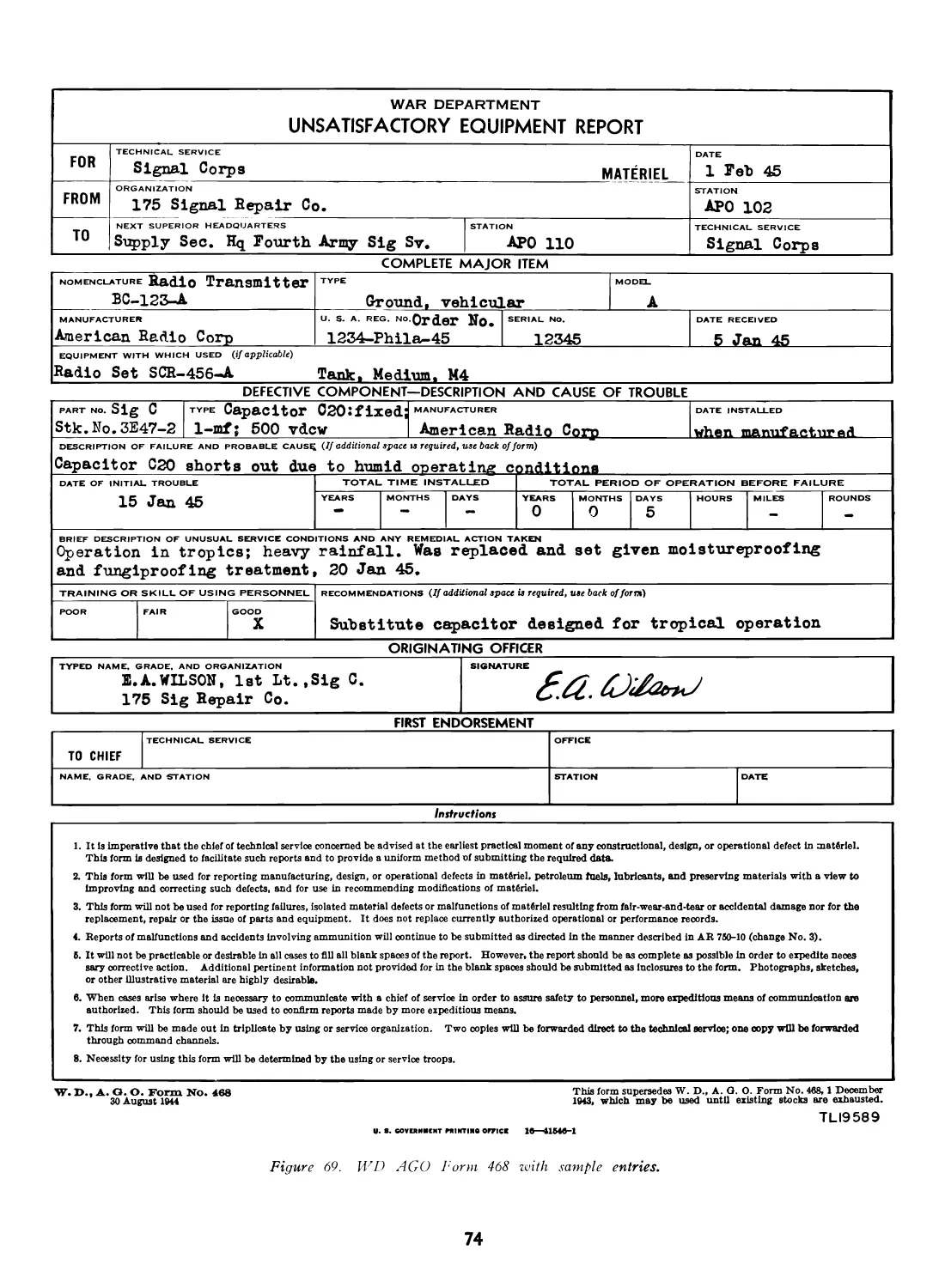
Unsatisfactory equipment report... 99 75
XVII. Alignment and adjustment.
General .................................... 100 75
I-f alignment using signal generator 101 75
I-f alignment using Test Unit I-
135-( ) ........................... 102 76
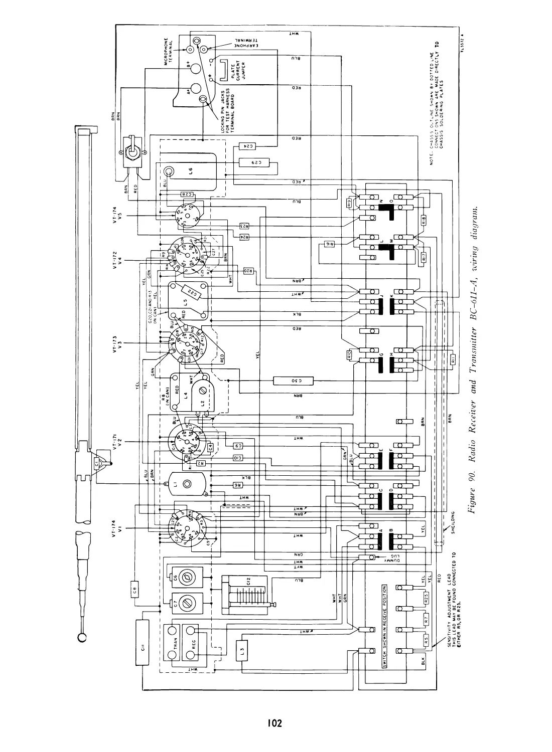
Minimum test requirements for
Radio Receiver and Transmitter
BC-611-(*) ..................... 103 76
Para-
graph Page
XVIII. Presetting.
General ..................................... 104 76
Setting up Test Equipment IE-15-A 105 77
Presetting receiver with Test Equip-
ment IE-15-A........................ 106 77
Presetting transmitter with Test
Equipment 1E-15-A................... 107 77
Checking for image frequency.... 108 80
Using Radio Set SCR-536-(*) as
signal generator................... 109 81
Crystal activity test............... 110 82
Presetting receiver with Test Equip-
ment IE—17—( )...................... Ill 83
Presetting transmitter with Test
Equipment lE-17-( )......... 112 85
Testing Batteries BA-37 and BA-
38 with Test Equipment IE—17—
( ).............................. 113 86
Receiver sensitivity................ 114 86
Receiver performance characteristics 115 86
Transmitter performance charac-
teristics .......................... 116 87
XIX. Emergency alignment and presetting
procedure.
General ..................................... 117 87
Major test equipment components.. 118 87
Housing modification................ 119 87
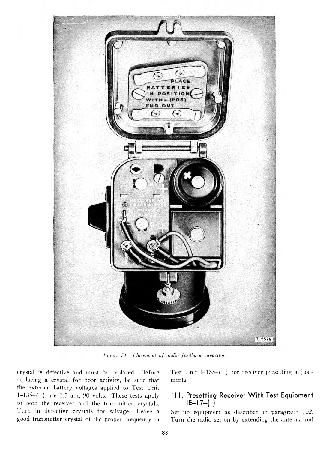
Foodback capacitor.................. 120 89
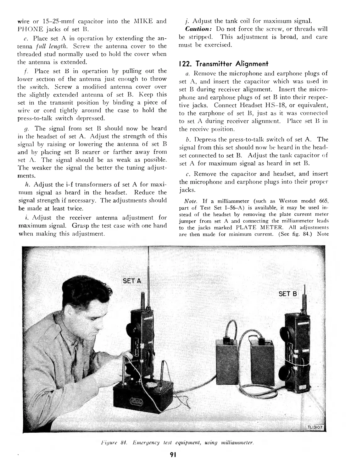
Receiver alignment.................. 121 90
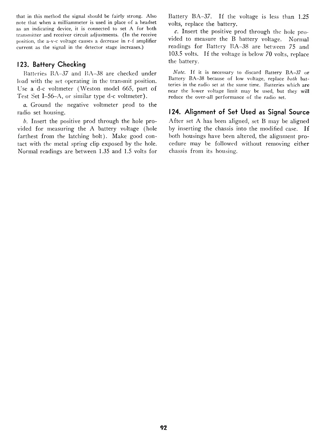
Transmitter alignment............... 122 91
Battery checking.................... 123 92
Alignment of set used as signal
source ............................. 124 92
APPENDIX I. REFERENCES.
Army Regulations.................... 1 93
Supply publications................. 2 93
Technical Manuals on auxiliary
equipment and test equipment... 3 93
Painting, preserving, and lubrication 4 93
Camouflage ......................... 5 93
Shipping instructions............... 6 93
Decontamination .................... 7 93
Demolition ......................... 8 93
Other publications.................. 9 93
Forms .............................. 10 94
Abbreviations ...................... 11 94
Glossary ........................... 12 94
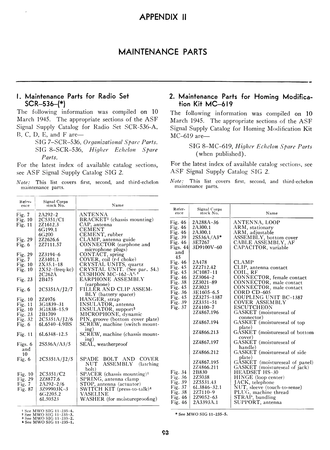
II. MAINTENANCE PARTS.
Maintenance parts for Radio Set
SCR-536-(*) ........................ 1 98
Maintenance parts for Homing
Modification Kit MC-619............. 2 98
IV
DESTRUCTION NOTICE
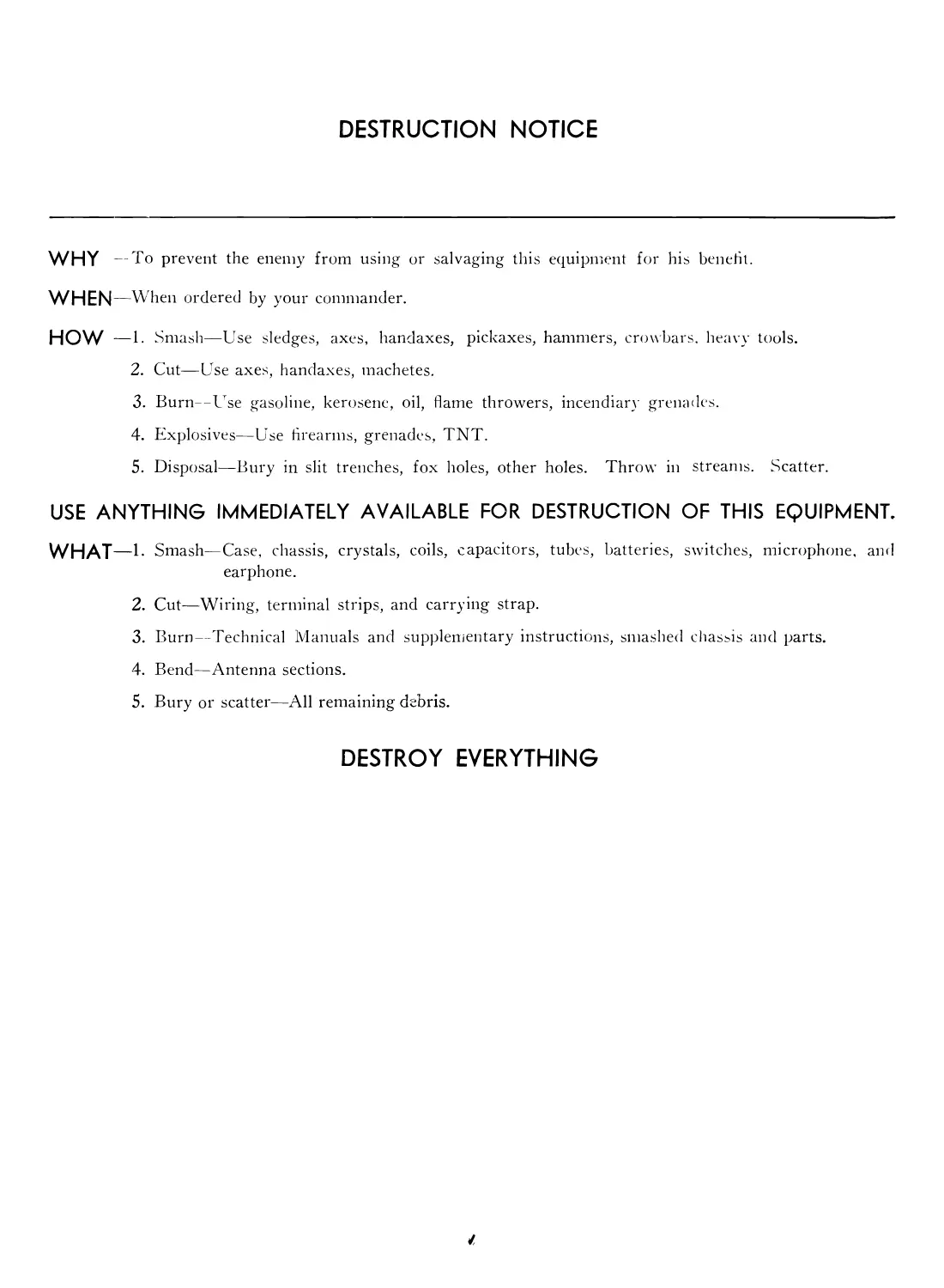
WHY — To prevent the enemy from using or salvaging this equipment for his benefit.
WHEN —When ordered by your commander.
HOW -1. Smash—Use sledges, axes, handaxes, pickaxes, hammers, crowbars, heavy tools.
2. Cut—Use axes, handaxes, machetes.
3. Burn—Use gasoline, kerosene, oil, flame throwers, incendiary grenades.
4. Explosives—Use tirearms, grenades, TNT.
5. Disposal—Bury in slit trenches, fox holes, other holes. Throw in streams. Scatter.
USE ANYTHING IMMEDIATELY AVAILABLE FOR DESTRUCTION OF THIS EQUIPMENT.
WHAT—1- Smash—Case, chassis, crystals, coils, capacitors, tubes, batteries, switches, microphone, and
earphone.
2. Cut—-Wiring, terminal strips, and carrying strap.
3. Burn—Technical Manuals and supplementary instructions, smashed chassis and parts.
4. Bend—Antenna sections.
5. Bury or scatter—All remaining debris.
DESTROY EVERYTHING
VI
This manual supersedes TM 11 -235, 14 May 1943, including Cl, 15 December 1943, C2, 18 October 1944, ТВ 11-235-1, 31 May 1944; IB
11-235-2, 22 July 1944; ТВ 11 235 3, 8 August 19 44, ТВ 11-235-4, 11 August 1944; ТВ 11-235-5, 16 September 1944; ТВ 11-235-6, 14
November 1944; ТВ 11-235—7, November 1944; and ТВ 11-235-8, 25 January 1945.
PART ONE
INTRODUCTION
Section I. DESCRIPTION OF RADIO SETS SCR-536-A, -В, -C, -D, -E, AND -F
I. General
a. Radio Set SCR-536-A, -В, -C, -D, -E, or -F
consists of a five-tube, low-power, dry-battery-oper-
ated radio receiver and transmitter, and certain ac-
cessories. It is designed for amplitude-modulated,
two-way communication over short distances. The
outstanding feature of its design and construction
is its extreme portability. It is intended primarily
as a handietalkie for foot combat troops.
b. Official nomenclature followed by (*) is used
to indicate all models of the equipment included in
this Technical Manual. Thus Radio Set SCR-536-
(*) refers to Radio Sets SCR-536-A, -В, -C, -D.
-E, and -F; and Radio Receiver and Transmitter
BC-611-(*) refers to Radio Receiver and Transmit-
ter BC-611-A, -В, -C, -D, -E, and -F. Official
nomenclature followed by empty parentheses is used
to indicate reference to all models of an item of
equipment.
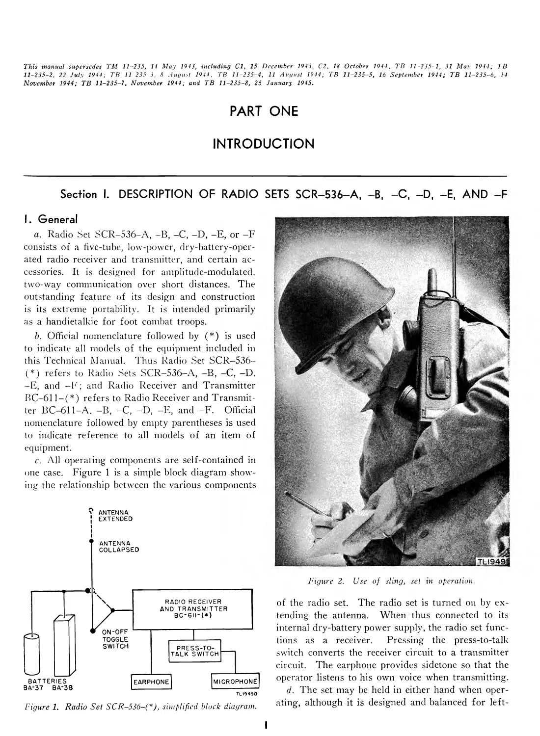
c. All operating components are self-contained in
one case. Figure 1 is a simple block diagram show-
ing the relationship between the various components
V ANTENNA
EXTENDED
TLI9490
Figure 1. Radio Set SCR-536-(*), simplified block diagram.
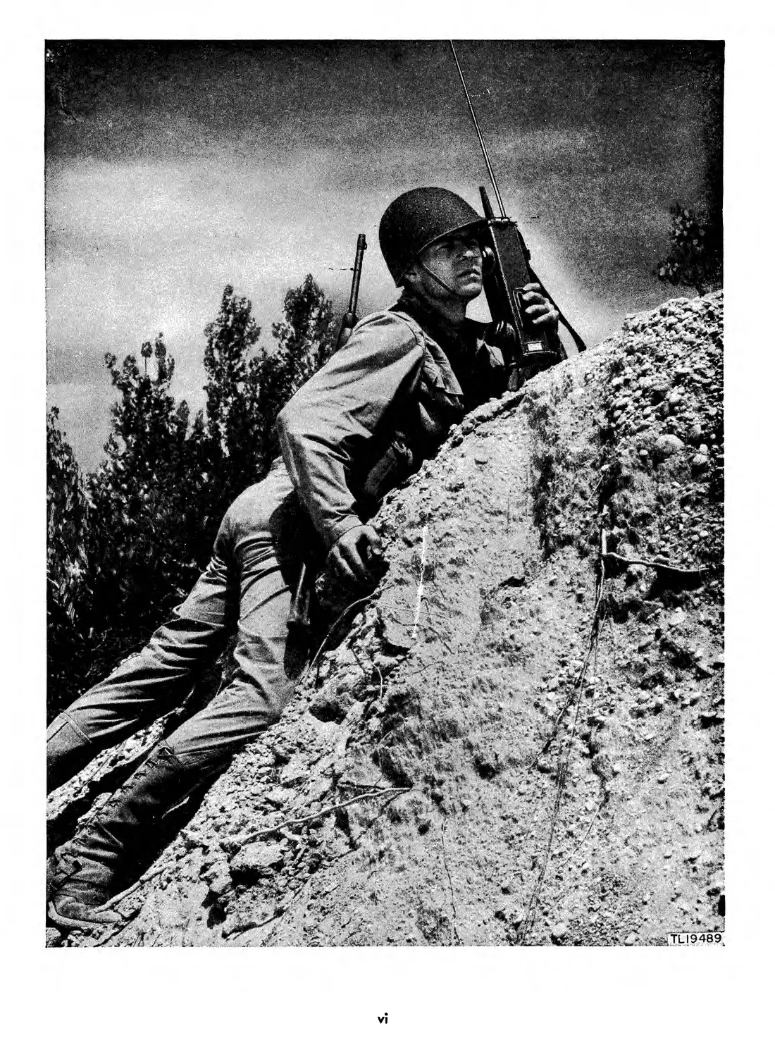
Figure 2. Use of sling, set in operation.
of the radio set. The radio set is turned on by ex-
tending the antenna. When thus connected to its
internal dry-battery power supply, the radio set func-
tions as a receiver. Pressing the press-to-talk
switch converts the receiver circuit to a transmitter
circuit. The earphone provides sidetone so that the
operator listens to his own voice when transmitting.
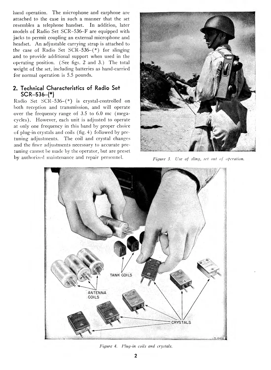
d. The set may be held in either hand when oper-
ating, although it is designed and balanced for left-
hand operation. The microphone and earphone are
attached to the case in such a manner that the set
resembles a telephone handset. In addition, later
models of Radio Set SCR-536-F are equipped with
jacks to permit coupling an external microphone and
headset. An adjustable carrying strap is attached to
the case of Radio Set SCR-536-(*) for slinging
and to provide additional support when used in the
operating position. (See figs. 2 and 3.) The total
weight of the set, including batteries as hand-carried
for normal operation is 5.5 pounds.
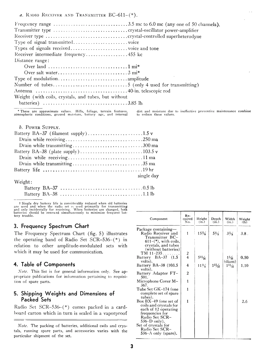
2. Technical Characteristics of Radio Set
SCR-536-(*)
Radio Set SCR-536-(*) is crystal-controlled on
both reception and transmission, and will operate
over the frequency range of 3.5 to 6.0 me (mega-
cycles). However, each unit is adjusted to operate
at only one frequency in this band by proper choice
of plug-in crystals and coils (fig. 4) followed by pre-
tuning adjustments. The coil and crystal changes
and the finer adjustments necessary to accurate pre-
tuning cannot be made by the operator, but are preset
by authorized maintenance and repair personnel.
Figure 3. Use of sling, set out of operation.
Figure 4. Plug-in coils and crystals.
2
a. Radio Receiver and Transmitter BC-611-(*).
Frequency range......................................3.5 me to 6.0 me (any one of 50 channels).
Transmitter type.....................................crystal-oscillator power-amplifier
Receiver type........................................crystal-controlled superheterodyne
Type of signal transmitted...........................voice
Types of signals received............................voice and tone
Receiver intermediate frequency......................455 kc
Distance range:
Over land.......................................1 mi*
Over salt water.................................3 mi*
Type of modulation...................................amplitude
Number of tubes......................................5 (only 4 used for transmitting)
Antenna .............................................40-in. telescopic rod
Weight (with coils, crystals, and tubes, but without
batteries) ..........................................3.85 lb.
* These are approximate values. Hills, foliage, terrain features, dirt and moisture due to ineffective preventive maintenance combine
atmospheric conditions, ground moisture, battery age, and internal to reduce these values.
b. Power Supply.
Battery BA-37 (filament supply)...........................1.5v
Drain while receiving...................................250 ma
Drain while transmitting................................300 ma
Battery BA-38 (plate supply)..............................103.5 v
Drain while receiving...................................lima
Drain while transmitting................................35 ma
Battery life .............................................19 hr
single day
Weight:
Battery BA-37 .......................................0.51b
Battery BA-38 .......................................1.11b
t Single dry battery life is considerably reduced when old batteries
are used and when the radio set is used primarily for transmitting
and only incidentally for receiving. When batteries are changed, both
batteries should be renewed simultaneously to minimize frequent bat-
tery trouble.
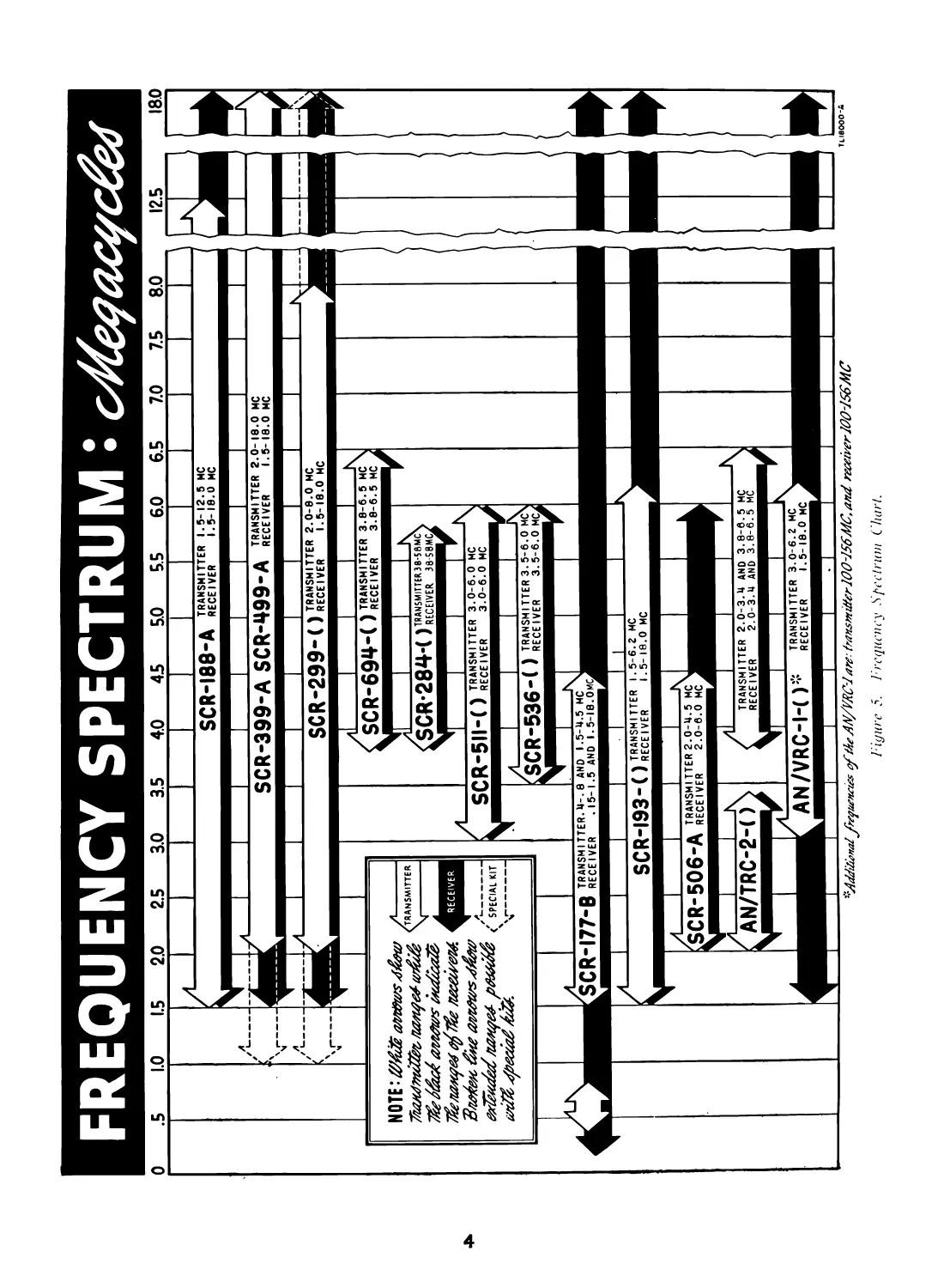
3. Frequency Spectrum Chart
The Frequency Spectrum Chart (fig. 5) illustrates
the operating band of Radio Set SCR-536-(*) in
relation to other amplitude-modulated sets with
which it may be used for communication.
4. Table of Components
Note. This list is for general information only. See ap-
propriate publications for information pertaining to requisi-
tion of spare parts.
5. Shipping Weights and Dimensions of
Packed Sets
Radio Set SCR-536-(*) comes packed in a card-
board carton which in turn is sealed in a vaporproof
Note. The packing of batteries, additional coils and crys-
tals, running spare parts, and accessories varies with the
particular shipment of the set.
Component Re- quired No. Height (in.) Depth (in.) Width (in.) Weight (lb)
Package containing—
Radio Receiver and 1 । 153% 534 3% 3.8 у
Transmitter BC- 611-(*), with coils, crystals, and tubes i
(without batteries) TM 11-235. ...... 2
Battery BA-37 (1.5 4 W6 i,54 0.50
volts). (diam)
Battery BA-38 (103.5 4 1134 1% 1% 1.10
volts). Battery Adapter FT- 2
501. Microphone Cover M- 1
367. Tube Set GK-174 (one 1
complete set of spare tubes).
Box BX-49 (one set of 1 2.6
coils and crystals for each of 12 operating frequencies for Radio Set SCR- 536-D only).
Set of crystals for
Radio Set SCR- 536-A only (spare).
3
FREQUENCY SPECTRUM:
1‘igurc 5. frequency Spectrum Chart.
bag and then packed in a waterproof carton. The
set, thus protected from moisture, is then packed in
a wooden case bound with two metal straps. The
over-all dimensions of the complete package are:
21% inches long, 10% inches deep, and 7% inches
high. The total weight of the set packed for export
is 17 pounds. See paragraph 12 and figure 14 for
unpacking information.
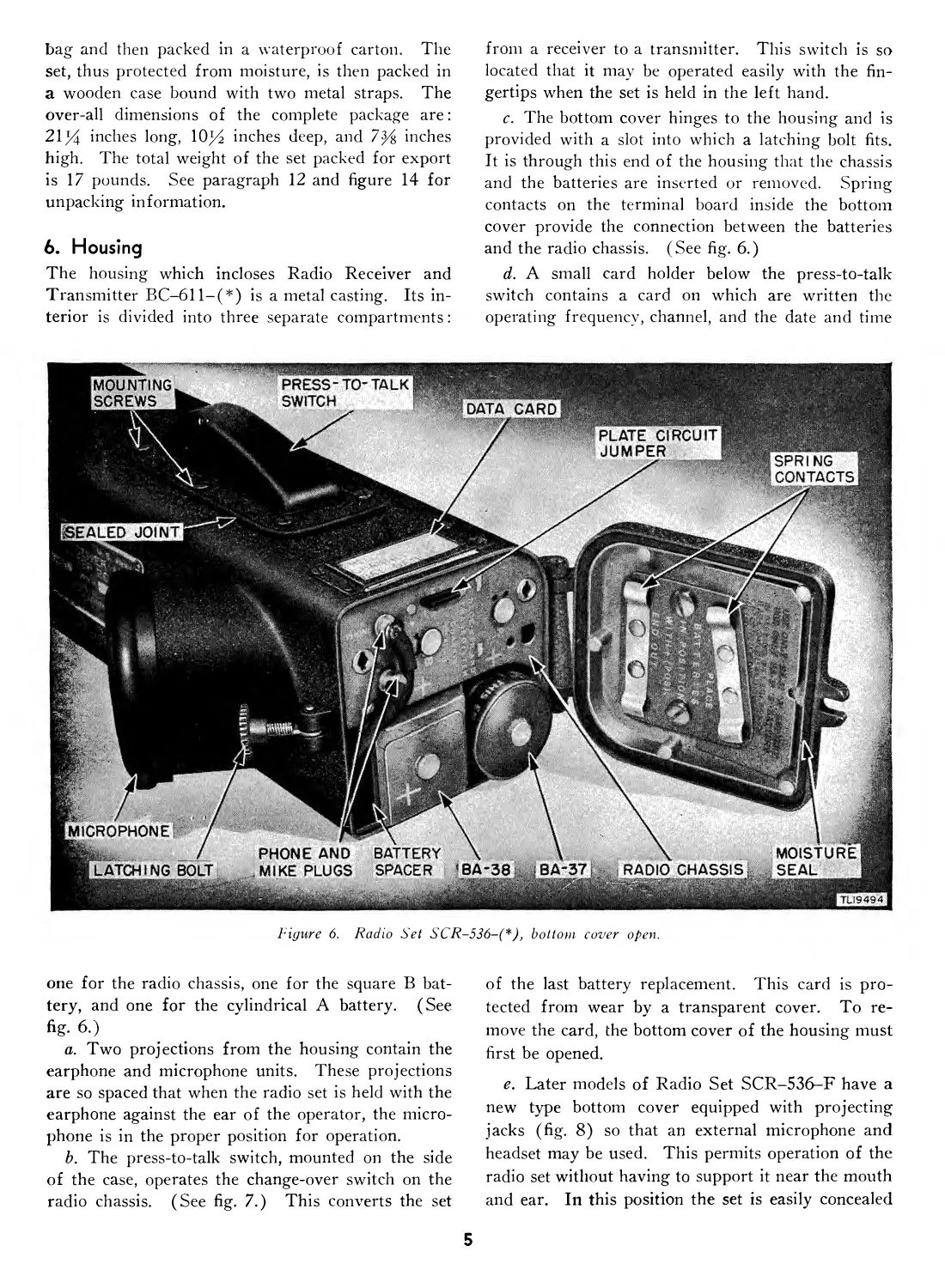
6. Housing
The housing which incloses Radio Receiver and
Transmitter BC-611-(*) is a metal casting. Its in-
terior is divided into three separate compartments:
from a receiver to a transmitter. This switch is so
located that it may be operated easily with the fin-
gertips when the set is held in the left hand.
c. The bottom cover hinges to the housing and is
provided with a slot into which a latching bolt fits.
It is through this end of the housing that the chassis
and the batteries are inserted or removed. Spring
contacts on the terminal board inside the bottom
cover provide the connection between the batteries
and the radio chassis. (See fig. 6.)
d. A small card holder below the press-to-talk
switch contains a card on which are written the
operating frequency, channel, and the date and time
Figure 6. Radio Set SCR-536-(*)> bottom cover open.
one for the radio chassis, one for the square В bat-
tery, and one for the cylindrical A battery. (See
fig. 6.)
a. Two projections from the housing contain the
earphone and microphone units. These projections
are so spaced that when the radio set is held with the
earphone against the ear of the operator, the micro-
phone is in the proper position for operation.
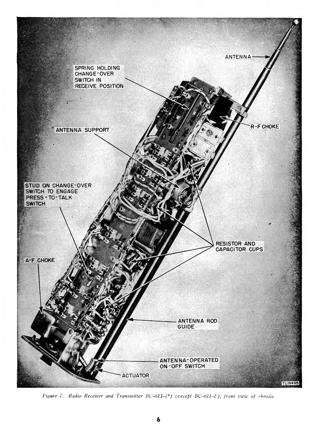
b. The press-to-talk switch, mounted on the side
of the case, operates the change-over switch on the
radio chassis. (See fig. 7.) This converts the set
of the last battery replacement. This card is pro-
tected from wear by a transparent cover. To re-
move the card, the bottom cover of the housing must
first be opened.
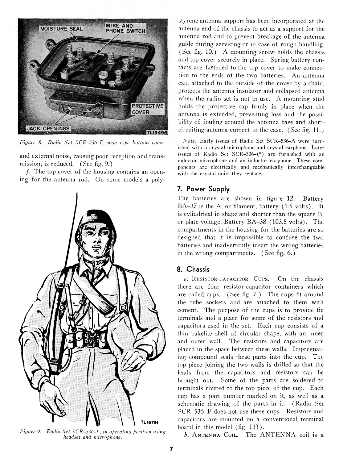
e. Later models of Radio Set SCR-536-F have a
new type bottom cover equipped with projecting
jacks (fig. 8) so that an external microphone and
headset may be used. This permits operation of the
radio set without having to support it near the mouth
and ear. In this position the set is easily concealed
5
R-FCHOKE
ACTUATOR
|TL19495|
RESISTOR AND
CAPACITOR CUPS
ANTENNA-OPERATED
ON-OFF SWITCH
ANTENNA ROD
GUIDE
ANTENNA
ANTENNA SUPPORT
STUD ON CHANGE-OVER
SWITCH TO ENGAGE
PRESS-TO-TALK
SWITCH
, SPRING HOLDING
CHANGE-OVER
SWITCH IN
RECEIVE POSITION
Д-F CHOKE
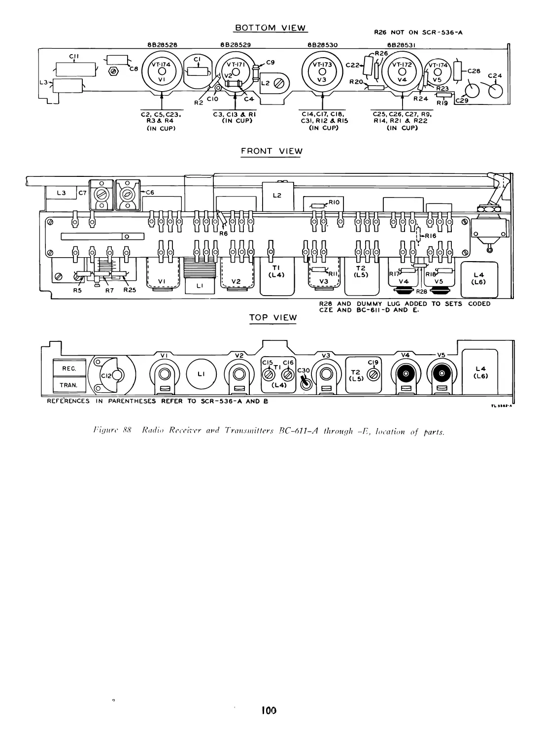
Figure 7. Radio Receiver and Transmitter BC-611-(*) (except BC-611-F), front view of rhassis.
6
Figure 8. Radio Set SCR-536-F, new type bottom cover.
and external noise, causing poor reception and trans-
mission, is reduced. (See fig. 9.)
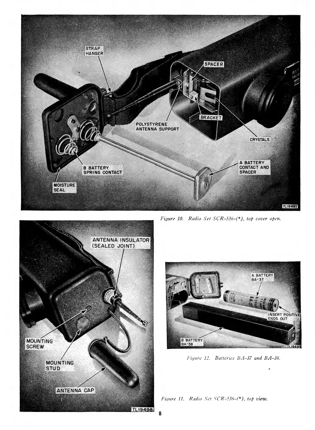
f. The top cover of the housing contains an open-
ing for the antenna rod. On some models a poly-
Figure 9. Radio Set SCR-536-P, in operating position using
headset and microphone.
styrene antenna support has been incorporated at the
antenna end of the chassis to act as a support for the
antenna rod and to prevent breakage of the antenna
guide during servicing or in case of rough handling.
(See fig. 10.) A mounting screw holds the chassis
and top cover securely in place. Spring battery con-
tacts are fastened to the top cover to make connec-
tion to the ends of the two batteries. An antenna
cap, attached to the outside of the cover by a chain,
protects the antenna insulator and collapsed antenna
when the radio set is not in use. A mounting stud
holds the protective cap firmly in place when the
antenna is extended, preventing loss and the possi-
bility of fouling around the antenna base and short-
circuiting antenna current to the case. (See fig. 11.)
Note. Early issues of Radio Set SCR-536-A were furn-
ished with a crystal microphone and crystal earphone. Later
issues of Radio Set SCR-536-(*) are furnished with an
inductor microphone and an inductor earphone. These com-
ponents are electrically and mechanically interchangeable
with the crystal units they replace.
7. Power Supply
The batteries are shown in figure 12. Battery
BA-37 is the A, or filament, battery (1.5 volts). It
is cylindrical in shape and shorter than the square B,
or plate voltage, Battery BA-38 (103.5 volts). The
compartments in the housing for the batteries are so
designed that it is impossible to confuse the two
batteries and inadvertently insert the wrong batteries
in the wrong compartments. (See fig. 6.)
8. Chassis
a. Resistor-capacitor Cups. On the chassis
there are four resistor-capacitor containers which
are called cups. (See fig. 7.) The cups fit around
the tube sockets and are attached to them with
cement. The purpose of the cups is to provide tie
terminals and a place for some of the resistors and
capacitors used in the set. Each cup consists of a
thin bakelite shell of circular shape, with an inner
and outer wall. The resistors and capacitors are
placed in the space between these walls. Impregnat-
ing compound seals these parts into the cup. The
top piece joining the two walls is drilled so that the
leads from the capacitors and resistors can be
brought out. Some of the parts are soldered to
terminals riveted to the top piece of the cup. Each
cup has a part number marked on it, as well as a
schematic drawing of the parts in it. (Radio Set
SCR-536-F does not use these cups. Resistors and
capacitors are mounted on a conventional terminal
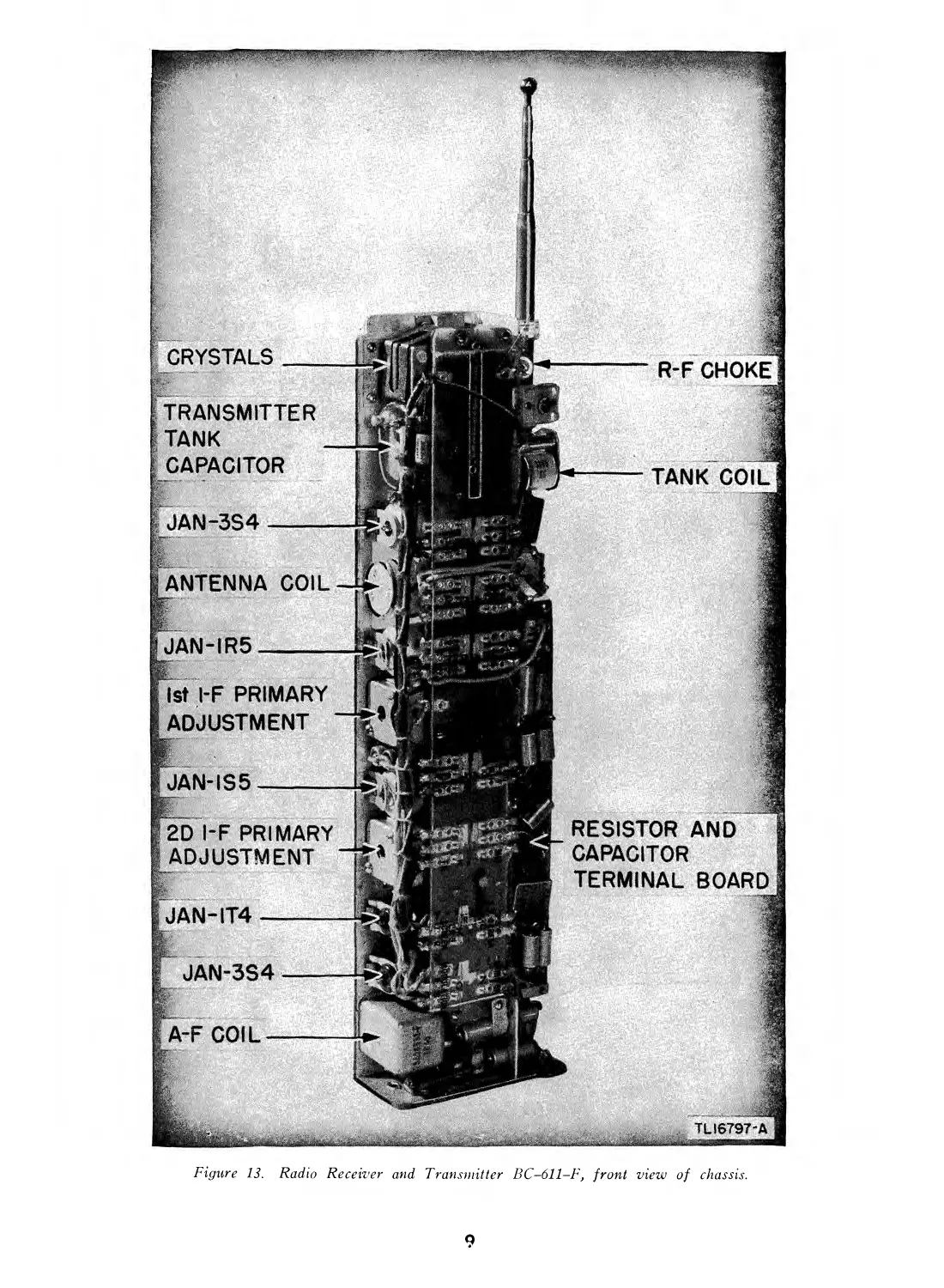
board in this model (fig. 13)).
b. Antenna Coil. The ANTENNA coil is a
7
Figure 10. Radio Set SCR-536-(*)} top cover open.
Figure 12. Batteries BA-37 and BA-38.
Figure 11. Radio Set SCR-536-(*), top view.
8
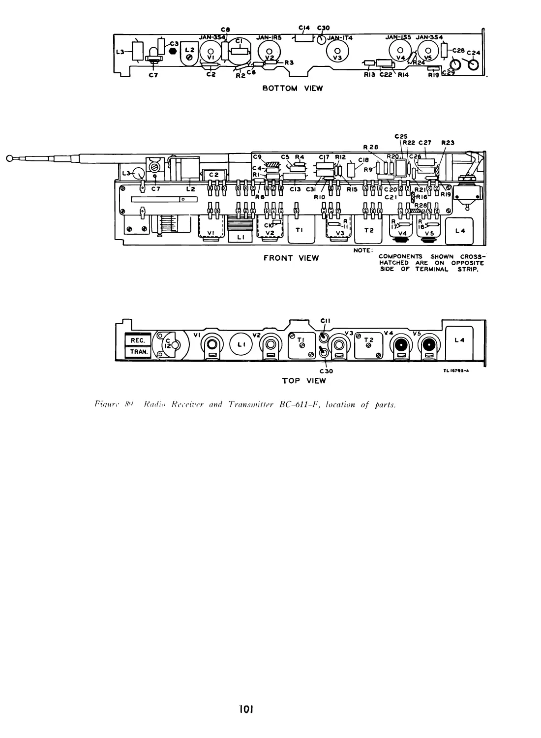
Figure 13. Radio Receiver and Transmitter BC-611-F, front view of chassis.
9
plug-in coil of the solenoid type and is wound on a
polystyrene form. The coil has three pins on its
base, two of which are electrically connected to the
coil. Each coil is marked with the name and fre-
quency of the coil. The antenna coil socket is also
of polystyrene, and is fastened to the chassis by a
long rivet through its center. This rivet also fastens
the antenna clamp and the antenna polystyrene sup-
port to the chassis. Electrical contact is made to the
antenna at this point by spring contacts.
c. Plate Circuit r-f Coil. The tuned r-f (radio-
frequency) amplifier plate coil (marked TANK
COIL) is wound on a small mica filled bakelite
form. The coil is permeability tuned and has a
powdered iron core in the form of a hexagon nut.
The winding and core are not visible, as they are
surrounded by a bakelite shell which completely in-
closes them. This shell is riveted to the coil form.
A threaded bakelite screw fits into the threaded iron
core, and the motion of the screw moves the core
relative to the winding, thereby determining the in-
ductance value. The name and frequency range is
marked on each coil. The coil form has a female
type base. The socket contains two pin connections
which fit into holes in the coil form and make elec-
trical contact to the coil. The pins are gripped by
spring clip connections in the base of the coil form.
A hole is provided in the socket for the inductance-
adjusting screw which extends through the form. A
spring clip in the socket grips the tuning screw and
provides a more rigid support for the coil. A spring
clip on top of the form prevents the coil from work-
ing loose from the socket.
d. First i-f Transformer. The i-f (intermedi-
ate-frequency) transformer windings are on a pow-
dered iron core and are surrounded by a powdered
iron sleeve to further increase their inductance. This
type of construction gives a high inductance with a
small winding which results in a small size trans-
former. The primary and secondary of the first i-f
transformer are tuned by small adjustable mica trim-
mers contained in the shield can. The adjustment of
the trimmers is reached through two holes in the top
of the can. A 1-megohm resistor is shunted across
the secondary winding and serves to broaden the
response of the transformer. This resistor is con-
tained in the shield can. The transformer is held
in the can by a metal bottom plate which is secured
by rolling the side walls of the shield over the edges
of the plate. Two U-shaped clamps riveted to the
back side of the chassis hold the transformer in
place.
e. Second i-f Transformer. The second i-f
transformer construction is similar to that of the
first i-f transformer. Only one trimmer is used,
however, and it is connected across the secondary
winding. This trimmer is accessible through a hole
in the top of the shield can. The transformer fastens
to the chassis in the same manner as the first i-f
transformer. A 220,000-ohm resistor and two 70-
microfarad mica capacitors are also mounted in the
shield can. They make up an i-f filter for the detec-
tor circuit.
Note. The i-f transformers in Radio Set SCR-536-F are
both double-tuned by adjustable powdered-iron slugs. These
slugs are easily accessible through holes in the top and
bottom of each can. Fixed mica capacitors, one for each
winding, are located at each end of the transformer com-
pleting the tuned circuit. No trimmers or shunt resistor^
are used.
f. Crystals. There are two crystals used in
Radio Receiver and Transmitter BC-611-(*). The
receiver crystal is 455 kc (kilocycles) higher in fre-
quency than the transmitter crystal. The crystals
are contained in plug-in type holders with two pin
connections. They are completely sealed against
moisture. The crystals are marked REC. and
TRAN, to indicate their use in the receiver and
transmitter circuits. Each crystal holder has an ar-
row indicating the direction in which it should be
placed in the socket. The sockets carry a similar
marking. The metal cover plate of the crystal hol-
der, marked with the frequency, does not make con-
tact with the crystal blank in the holder, but it does
have a capacitive effect on the crystal. If it comes
in contact with the chassis or metal clamp which
holds the crystal in the socket, the operation of the
crystal will be affected. A piece of insulating ma-
terial covers the chassis where the transmitter crystal
might touch when the set is jarred. When crystal
activity is low, it should be replaced with another.
Do not attempt to take the holder apart.
9. Controls
The only operating controls are the antenna on-off
swich and the press-to-talk switch. (See par. 15J
10. Moistureseals
a. Radio Set SCR-536-(*) is not waterproof.
The top and bottom covers are provided with heavy
moisture seal rings to provide effective moisture ex-
clusion. A ring gasket seals the machine screwhead
holding the chassis to the top cover. The joint be-
tween the antenna insulator and the case is sealed
to prevent entrance of moisture. The jacks for the
external microphone and headset for Radio Set
10
SCR-536-F are encased in a fungicide wax and
molded-bakelite housing which is moisturesealed by
a rubber gasket. The jack openings are covered by
a hinged cover that provides dust and mud protec-
tion. (See fig. 8.) The flexible covering of the
press-to-talk switch is cemented and held by a ribbed
steel escutcheon plate clamped in place by six ma-
chine screws.
b. Additional waterproofing may be necessary to
meet excessively wet operating conditions. Such
supplementary waterproofing procedures are treated
separately and in detail in section X.
I I. Differences in Models
a. The differences in models are described in this
manual whenever the components or circuits affected
are described. None of the differences in the vari-
ous models affect the basic operation of this equip-
ment.
b. Later models of Radio Set SCR-536-F are
equipped with a new type bottom cover which pro-
vides jacks for use of an external headset and mic-
rophone when desirable. The contact terminals on
the new type bottom cover are also of a different
design. (See fig. 8.) The MIKL and PHONE
CHANGE-OVER SWITCH located inside the bot-
tom cover and marked EXTERN AL-INTERNAL
cuts the jacks in or out of the circuit. When the
switch is in the EXTERNAL position, the micro-
phone and earphone units mounted on the side of
the set are cut out, permitting the use of the external
units. Early models of Radio Set SCR-536-F do
not have the new bottom cover, but are made so that
the new cover may be fitted when available.
c. The following Modification Work Orders have
been published pertaining to Radio Set SCR-536-
(*).
(1) MWO SIG 11-235-1, 8 August 1944, au-
thorizes the replacement of die-cast press-to-talk
switch parts with steel-stamped parts to minimize
breakage in service.
(2) MWO SIG 11-235-2, 25 August 1944, au-
thorizes the addition of a polystyrene antenna sup-
port insulator at the top of the chassis (fig. 10) to
provide firmer support for the telescopic rod antenna.
(3) MWO SIG 11-235-3, 18 October 1944,
authorizes the replacement of molded bakelite micro-
phone and earphone caps (not illustrated) by alumi-
num caps.
(4) MWO SIG 11-235-1, January 1945, author-
izes the replacement of the top chassis mounting
bracket (fig. 10) with a stronger bracket held in
place by two machine screws.
(5) MWO SIG 11-235-5, 25 January 1945, au-
thorizes the necessary drilling of the bottom cover
assembly to mount an external headset jack (fig. 39)
for use of Headset HS-30-( ) in connection with
Homing Modification Kit MC-619.
Section II. INSTALLATION
12. Unpacking and Checking
When unpacking Radio Set SCR-536-(*), follow
the instructions in figure 14. Take care to keep the
packing materials in good condition so that they may
be used to repack the set when necessary. Read the
repacking instructions (par. 14) before unpacking
the set to insure that nothing is done to prevent con-
venient repacking. Report any misisng or damaged
parts immediately.
Note. The silica-gel filled bags are included in the pack-
ing to absorb any moisture and prevent possible damage to
the set during storage. Discard them after repacking. Do
not use for repacking.
I 3. Installation
Since Radio Set SCR-536-(*) is designed for hand-
carrying, no particular difficulties are attached to its
installation.
a. General. Unlatch the bottom housing to per-
mit inspection of the terminal plate on the bottom
OF RADIO SET SCR-536-(*)
of Radio Receiver and Transmitter BC-61 !-(*).
(See fig. 6.) The lead from the microphone should
be plugged into the socket labeled MIKE, and the
lead from the earphone should be plugged into the
socket labeled PHONE. The black-handled jumper
plug must be inserted between the sockets labeled
PLATE METER. The contact studs should be
clean and bright. If not, clean them with a pocket
knife or other convenient scraper.
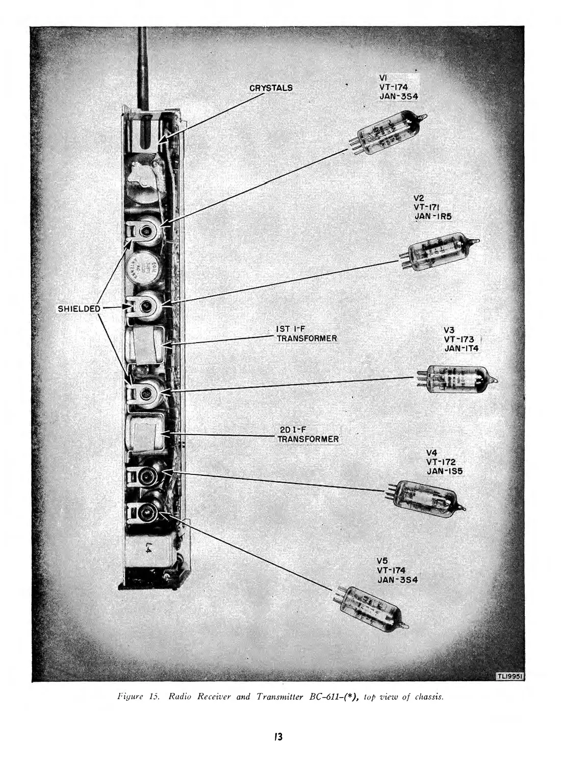
b. Tubes (fig. 15). Tubes are mounted in their
sockets before shipment. For information on re-
placement of tubes, see paragraph 93.
c. Batteries. (1) Radio Set SCR-536-(*) uses
one Battery BA-37 and one Battery BA-38. (See
fig. 12.) Instructions for insertion are included on
the inside of the bottom cover plate. Both positive
(-L) and negative (—) terminals on each end of
the batteries must be scraped clean and bright for
effective electrical contact with the spring connectors
on the end plates of the housing. Since batteries are
II
CLIP THE TWO METAL
BANDS BINDING THE
WOODEN PACKING CASE.
PULL OUT NAILS AND
REMOVE COVER.
LIFT OUT VICTORY
WATERPROOF CARTON
AND OPEN ITS FOUR FLAPS.
SLIT OPEN THE HERMETICALLY
SEALED VAPORPROOF BAG.
REMOVE TECHNICAL MANUALS,
BOX CONTAINING MICROPHONE
COVER, AND TWO SILICA-GEL BAGS.
REMOVE INNER
CARDBOARD CARTON.
REMOVE CARDBOARD FILLERS
REMOVE RADIO SET
TLI9500
Figure 14. Unpacking.
12
Fiyure 15. Radio Receiver and Transmitter BC-611-(*), top view of chassis.
13
heavily paraffined for protection from moisture, a
pocket knife or other suitable tool should be used to
completely-remove this insulating coating from the
battery terminals before installation. Insert batteries
flat end first, with the positive (raised center button)
end toward the bottom of the case. The positive
ends of both batteries are marked with a large plus
(-P) sign for daylight identification. The small
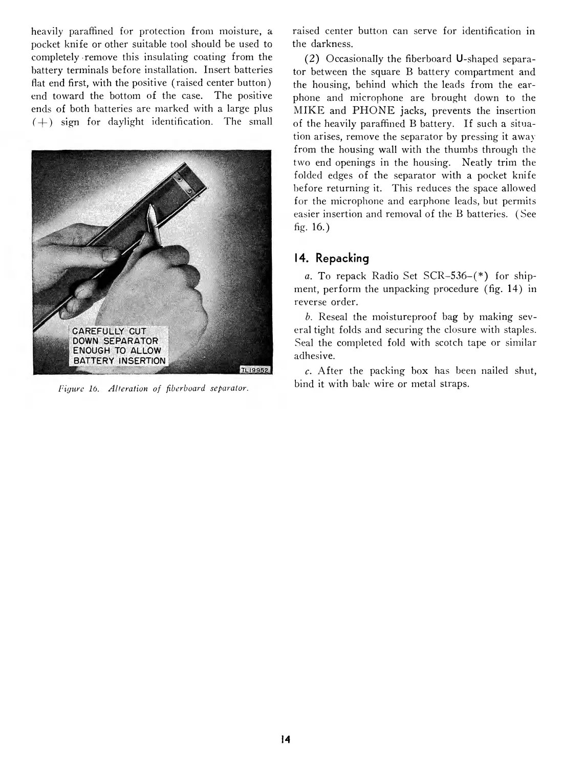
Figure 16. Alteration of fiberboard separator.
raised center button can serve for identification in
the darkness.
(2) Occasionally the fiberboard U-shaped separa-
tor between the square В battery compartment and
the housing, behind which the leads from the ear-
phone and microphone are brought down to the
MIKE and PHONE jacks, prevents the insertion
of the heavily paraffined В battery. If such a situa-
tion arises, remove the separator by pressing it away
from the housing wall with the thumbs through the
two end openings in the housing. Neatly trim the
folded edges of the separator with a pocket knife
before returning it. This reduces the space allowed
for the microphone and earphone leads, but permits
easier insertion and removal of the В batteries. (See
fig-16-)
14. Repacking
a. To repack Radio Set SCR-536-(*) for ship-
ment, perform the unpacking procedure (fig. 14) in
reverse order.
b. Reseal the moistureproof bag by making sev-
eral tight folds and securing the closure with staples.
Seal the completed fold with scotch tape or similar
adhesive.
c. After the packing box has been nailed shut,
bind it with bale wire or metal straps.
PART TWO
OPERATING INSTRUCTIONS
Note. For information on destroying the equipment to prevent enemy use, see the destruction notice at the front of
this manual.
Section III. CONTROLS AND THEIR USE
15. General
Radio Set SCR-536-(*) is designed for operation
under battle conditions. The number of controls,
therefore, has been kept at a minimum to free the
operator from time-consuming adjustments.
16. Turning Set On and Off
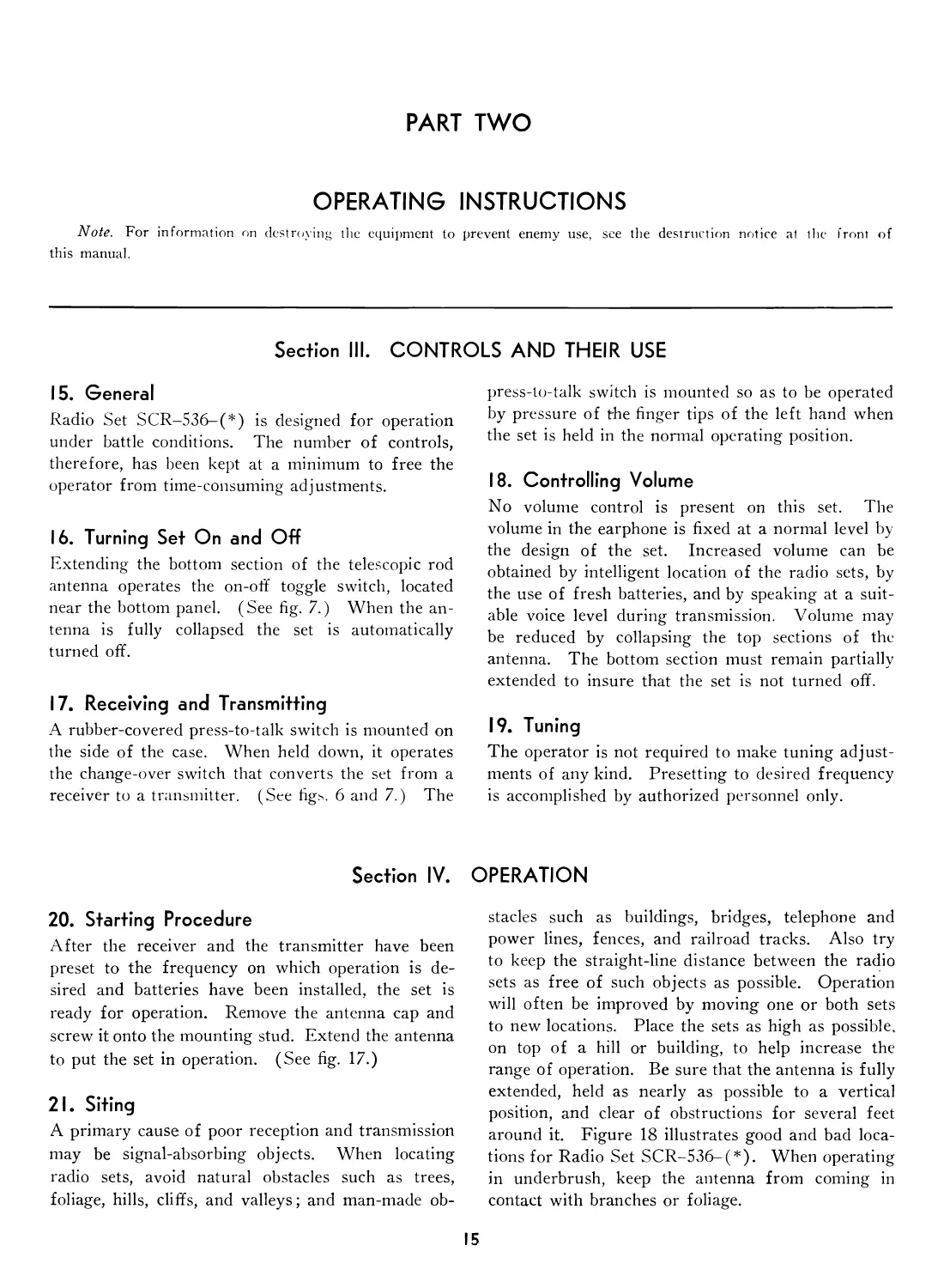
Extending the bottom section of the telescopic rod
antenna operates the on-off toggle switch, located
near the bottom panel. (See fig. 7.) When the an-
tenna is fully collapsed the set is automatically
turned off.
17. Receiving and Transmitting
A rubber-covered press-to-talk switch is mounted on
the side of the case. When held down, it operates
the change-over switch that converts the set from a
receiver to a transmitter. (See figs. 6 and 7.) The
press-to-talk switch is mounted so as to be operated
by pressure of the finger tips of the left hand when
the set is held in the normal operating position.
18. Controlling Volume
No volume control is present on this set. The
volume in the earphone is fixed at a normal level by
the design of the set. Increased volume can be
obtained by intelligent location of the radio sets, by
the use of fresh batteries, and by speaking at a suit-
able voice level during transmission. Volume may
be reduced by collapsing the top sections of the
antenna. The bottom section must remain partially
extended to insure that the set is not turned off.
19. Tuning
The operator is not required to make tuning adjust-
ments of any kind. Presetting to desired frequency
is accomplished by authorized personnel only.
Section IV.
20. Starting Procedure
After the receiver and the transmitter have been
preset to the frequency on which operation is de-
sired and batteries have been installed, the set is
ready for operation. Remove the antenna cap and
screw it onto the mounting stud. Extend the antenna
to put the set in operation. (See fig. 17.)
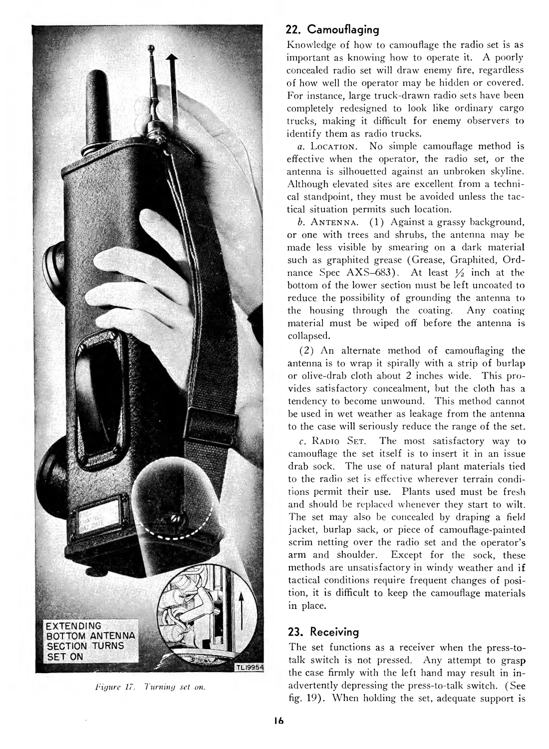
21. Siting
A primary cause of poor reception and transmission
may be signal-absorbing objects. When locating
radio sets, avoid natural obstacles such as trees,
foliage, hills, cliffs, and valleys; and man-made ob-
OPERATION
stacles such as buildings, bridges, telephone and
power lines, fences, and railroad tracks. Also try
to keep the straight-line distance between the radio
sets as free of such objects as possible. Operation
will often be improved by moving one or both sets
to new locations. Place the sets as high as possible,
on top of a hill or building, to help increase the
range of operation. Be sure that the antenna is fully
extended, held as nearly as possible to a vertical
position, and clear of obstructions for several feet
around it. Figure 18 illustrates good and bad loca-
tions for Radio Set SCR-536-(*). When operating
in underbrush, keep the antenna from coming in
contact with branches or foliage.
15
Figure 17. Turning set on.
22. Camouflaging
Knowledge of how to camouflage the radio set is as
important as knowing how to operate it. A poorly
concealed radio set will draw enemy fire, regardless
of how well the operator may be hidden or covered.
For instance, large truck-drawn radio sets have been
completely redesigned to look like ordinary cargo
trucks, making it difficult for enemy observers to
identify them as radio trucks.
a. Location. No simple camouflage method is
effective when the operator, the radio set, or the
antenna is silhouetted against an unbroken skyline.
Although elevated sites are excellent from a techni-
cal standpoint, they must be avoided unless the tac-
tical situation permits such location.
b. Antenna. (1) Against a grassy background,
or one with trees and shrubs, the antenna may be
made less visible by smearing on a dark material
such as graphited grease (Grease, Graphited, Ord-
nance Spec AXS-683). At least % inch at the
bottom of the lower section must be left uncoated to
reduce the possibility of grounding the antenna to
the housing through the coating. Any coating
material must be wiped off before the antenna is
collapsed.
(2) An alternate method of camouflaging the
antenna is to wrap it spirally with a strip of burlap
or olive-drab cloth about 2 inches wide. This pro-
vides satisfactory concealment, but the cloth has a
tendency to become unwound. This method cannot
be used in wet weather as leakage from the antenna
to the case will seriously reduce the range of the set.
c. Radio Set. The most satisfactory way to
camouflage the set itself is to insert it in an issue
drab sock. The use of natural plant materials tied
to the radio set is effective wherever terrain condi-
tions permit their use. Plants used must be fresh
and should be replaced whenever they start to wilt.
The set may also be concealed by draping a field
jacket, burlap sack, or piece of camouflage-painted
scrim netting over the radio set and the operator’s
arm and shoulder. Except for the sock, these
methods are unsatisfactory in windy weather and if
tactical conditions require frequent changes of posi-
tion, it is difficult to keep the camouflage materials
in place.
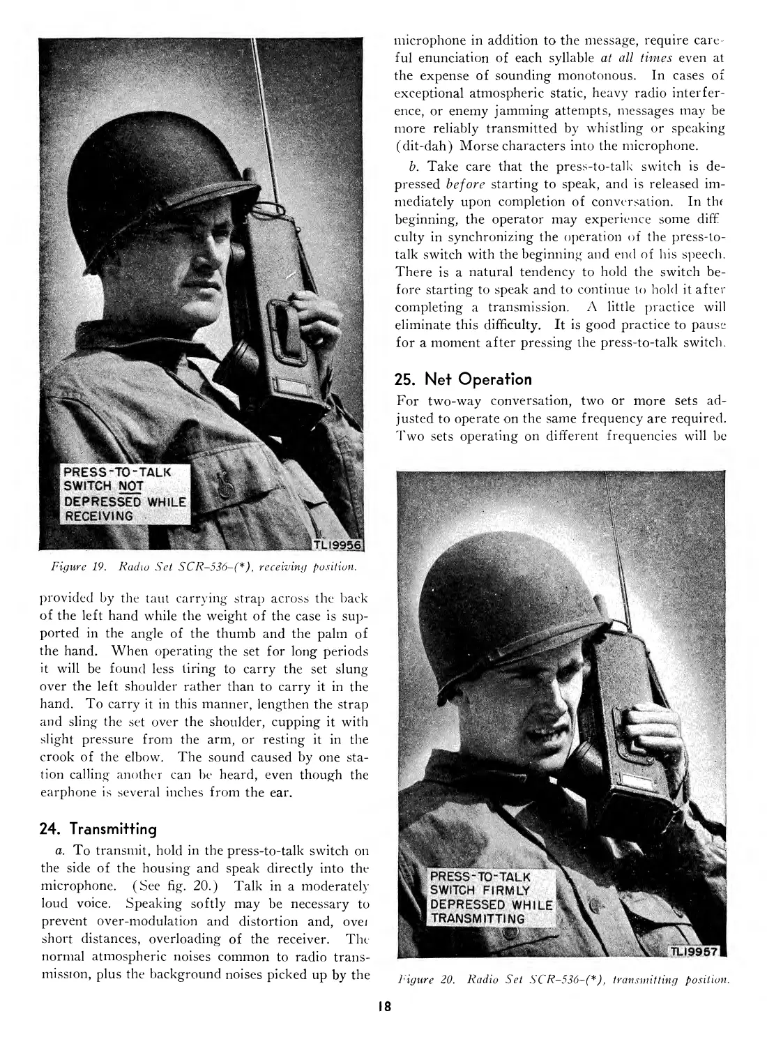
23. Receiving
The set functions as a receiver when the press-to-
talk switch is not pressed. Any attempt to grasp
the case firmly with the left hand may result in in-
advertently depressing the press-to-talk switch. (See
fig. 19). When holding the set, adequate support is
16
Figure 18. Siting.
17
Figure 19. Radio Set SCR-536-(*), receiving position.
provided by the taut carrying strap across the back
of the left hand while the weight of the case is sup-
ported in the angle of the thumb and the palm of
the hand. When operating the set for long periods
it will be found less tiring to carry the set slung
over the left shoulder rather than to carry it in the
hand. To carry it in this manner, lengthen the strap
and sling the set over the shoulder, cupping it with
slight pressure from the arm, or resting it in the
crook of the elbow. The sound caused by one sta-
tion calling another can be heard, even though the
earphone is several inches from the ear.
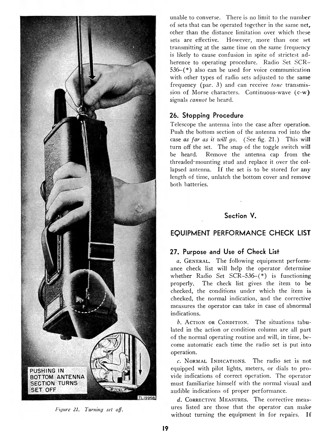
24. Transmitting
a. To transmit, hold in the press-to-talk switch on
the side of the housing and speak directly into the
microphone. (See fig. 20.) Talk in a moderately
loud voice. Speaking softly may be necessary to
prevent over-modulation and distortion and, ovei
short distances, overloading of the receiver. The
normal atmospheric noises common to radio trans-
mission, plus the background noises picked up by the
microphone in addition to the message, require care-
ful enunciation of each syllable at all times even at
the expense of sounding monotonous. In cases of
exceptional atmospheric static, heavy radio interfer-
ence, or enemy jamming attempts, messages may be
more reliably transmitted by whistling or speaking
(dit-dah) Morse characters into the microphone.
b. Take care that the press-to-talk switch is de-
pressed before starting to speak, and is released im-
mediately upon completion of conversation. In the
beginning, the operator may experience some diffi
culty in synchronizing the operation of the press-to-
talk switch with the beginning and end of his speech.
There is a natural tendency to hold the switch be-
fore starting to speak and to continue to hold it after
completing a transmission. A little practice will
eliminate this difficulty. It is good practice to pause
for a moment after pressing the press-to-talk switch.
25. Net Operation
For two-way conversation, two or more sets ad-
justed to operate on the same frequency are required.
Two sets operating on different frequencies will be
Figure 20. Radio Set SCR-536-(*), transmitting position.
18
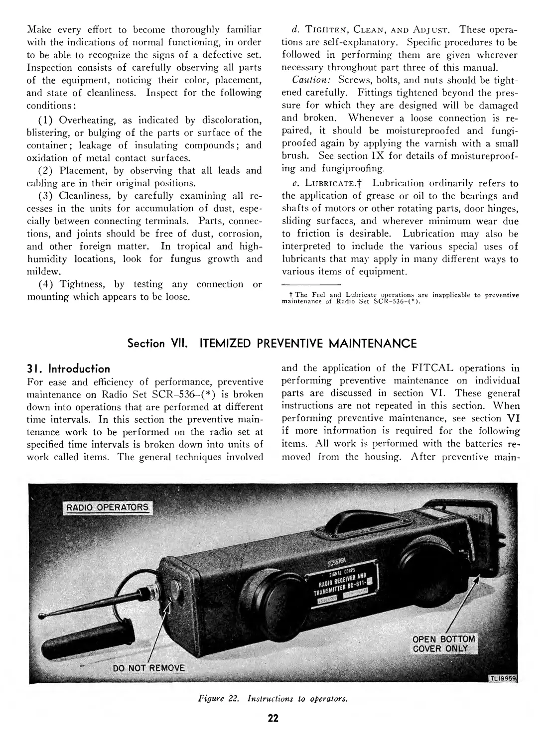
Figure 21, Turning set off.
unable to converse. There is no limit to the number
of sets that can be operated together in the same net,
other than the distance limitation over which these
sets are effective. However, more than one set
transmitting at the same time on the same frequency
is likely to cause confusion in spite of strictest ad-
herence to operating procedure. Radio Set SCR-
536-(*) also can be used for voice communication
with other types of radio sets adjusted to the same
frequency (par. 3) and can receive tone transmis-
sion of Morse characters. Continuous-wave (c-w)
signals cannot be heard.
26. Stopping Procedure
Telescope the antenna into the case after operation.
Push the bottom section of the antenna rod into the
case as far as it will go, (See fig. 21.) This will
turn off the set. The snap of the toggle switch will
be heard. Remove the antenna cap from the
threaded’mounting stud and replace it over the col-
lapsed antenna. If the set is to be stored for any
length of time, unlatch the bottom cover and remove
both batteries.
Section V.
EQUIPMENT PERFORMANCE CHECK LIST
27. Purpose and Use of Check List
a. General. The following equipment perform-
ance check list will help the operator determine
whether Radio Set SCR-536-(*) is functioning
properly. The check list gives the item to be
checked, the conditions under which the item is
checked, the normal indication, and the corrective
measures the operator can take in case of abnormal
indications.
b. Action or Condition. The situations tabu-
lated in the action or condition column are all part
of the normal operating routine and will, in time, be-
come automatic each time the radio set is put into
operation.
c. Normal Indications. The radio set is not
equipped with pilot lights, meters, or dials to pro-
vide indications of correct operation. The operator
must familiarize himself with the normal visual and
audible indications of proper performance.
d. Corrective Measures. The corrective meas-
ures listed are those that the operator can make
without turning the equipment in for repairs. If
19
the corrective measures listed do not rectify the
trouble, the set must be turned over to authorized
repair personnel.
e. Items 1 to 4. Items 1 to 4 should be checked
each time the equipment is put into operation.
f. Items 5 and 6. Items 5 and 6 are checked
when beginning operation.
g. Items 7 to 9. These items represent general
operating characteristics of the set. The operator
28. Equipment Performance Check List
must become familiar with the characteristics of the
set during normal operation; he must use that
knowledge as a basis for recognizing faults when the
set is not operating properly.
h. Items 10 and 11. Items 10 and 11 are checked
when the equipment is taken out of operation. Any
abnormal indications at this time are probably caused
by trouble in the set, and should be corrected before
the next expected period of operation.
Item No. Item Action or condition Normal indications Corrective measures
PREPARATORY 1 2 3 4 Carrying strap. Data card. Batteries. Antenna cap. Adjusted taut. Entries com- pleted. Inserted cor- rectly. Remove cap and attach to threaded stud. Chain not wrapped around antenna. No fouling.
START | 5 6 Antenna. Earphone. Extend antenna. Held near ear. Click of on-off switch. Back- ground noise from receiver. See para- graph 90. a. Scrape battery termin- als and housing contacts b. Replace both bat- teries. c. Check PHONE connec- tion under bottom cover.
7 Press-to- talk switch. Depressed. Normal friction of sliding contacts of change- See para- graph 88.
Item No. Item Action or condition Normal indications Corrective measures
EQUIPMENT PERFORMANCE 8 9 Micro- phone. Radio Receiver and Trans- mitter BC-611- (*) Talk, blow, or whistle. Call party and release press-to- talk switch over switch. Sidetone in ear- phone. Answering signal may be heard in ear- phone. Check MIKE and PHONE connec- tions under bottom cover. a. Check for same fre- quency on cards of both sets. b. Further check by moving to better location.
STOP 10 11 Antenna. Batteries. Collapse and replace cap. Remove and store separ- ately from set when not oper- ating. Click of on-off switch. Receiver back- ground noise ceases.
20
PART THREE
MAINTENANCE INSTRUCTIONS
Section VI. PREVENTIVE MAINTENANCE TECHNIQUES
29. Meaning of Preventive Maintenance
Preventive maintenance is a systematic series of
operations performed at regular intervals on equip-
ment, when turned off, to eliminate major break-
downs and unwanted interruptions in service, and
to keep the equipment operating at top efficiency.
To understand what is meant by preventive main-
tenance, it is necessary to distinguish between pre-
ventive maintenance, trouble shooting, and repair.
The prime function of preventive maintenance is to
prevent break-downs and, therefore, the need for re-
pair. On the other hand, the prime function of
trouble shooting and repair is to locate and correct
existing defects. The importance of preventive
maintenance cannot be overemphasized. The entire
system of radio communication depends upon each
set’s being on the air when it is needed and upon its
operating efficiency. It therefore is vitally important
that radio operators and repairmen maintain their
radio1 sets properly. (See ТВ SIG 123.)
Note. The operations in sections VI and VII are fir st-
and second-echelon (organization operators and repairman)
maintenance. Some operations in sections VIII, IX, and X
are higher echelon maintenance.
30. Description of Preventive Maintenance
Techniques
a. General. Many of the parts used in Radio
Set SCR-536-(*) require routine preventive main-
tenance in addition to the careful handling that is
normally accorded even the most rugged radio equip-
ment. Because hit-or-miss maintenance techniques
cannot be applied with any degree of effectiveness,
definite and specific instructions are needed. This
section of the manual contains these specific instruc-
tions and serves as a guide for personnel assigned to
perform the six basic maintenance operations, name-
ly: Feel, Inspect, Tighten, Clean, Adjust, and Rub-
ricate. Throughout this manual the lettering system
for the six operations will be as follows:
F—Feel*
I—Inspect
T—Tighten
C—Clean
A—Adjust
L—Lubricate*
The first two operations establish the need for the
other four. The selection of operations is based on
a general knowledge of the field needs. For example,
the dust encountered on dirt roads during cross-
country travel filters into equipment no matter how
much care is taken to prevent it. Rapid changes
in weather (such as heavy rain followed by blister-
ing heat), excessive dampness, snow, and ice tend
to cause corrosion of exposed surfaces and parts.
Without frequent insepctions and the necessary per-
formance of tightening, cleaning, and adjusting,
equipment becomes undependable and subject to
breakdown when it is most needed.
b. Feel.* The feel operation is used most often
to check rotating machinery, such as blower motors
and drive motors, bearings, and bushings, and to
determine whether electrical circuit components are
overheated. Feeling indicates the need for lubrica-
tion and the existence of circuit defects requiring
correction.
c. Inspect. Inspection is the most important
operation in the preventive maintenance program.
A careless observer will overlook the evidences of
minor trouble. Although these defects may not in-
terfere with the performance of the equipment, valu-
able time and effort can be saved if they are cor-
rected before they lead to major break-downs.
* The Feel and Lubricate operations are inapplicable to preventive
maintenance of Radio Set SCR 536- ( ).
21
Make every effort to become thoroughly familiar
with the indications of normal functioning, in order
to be able to recognize the signs of a defective set.
Inspection consists of carefully observing all parts
of the equipment, noticing their color, placement,
and state of cleanliness. Inspect for the following
conditions:
(1) Overheating, as indicated by discoloration,
blistering, or bulging of the parts or surface of the
container; leakage of insulating compounds; and
oxidation of metal contact surfaces.
(2) Placement, by observing that all leads and
cabling are in their original positions.
(3) Cleanliness, by carefully examining all re-
cesses in the units for accumulation of dust, espe-
cially between connecting terminals. Parts, connec-
tions, and joints should be free of dust, corrosion,
and other foreign matter. In tropical and high-
humidity locations, look for fungus growth and
mildew.
(4) Tightness, by testing any connection or
mounting which appears to be loose.
d. Tighten, Clean, and Adjust. These opera-
tions are self-explanatory. Specific procedures to be
followed in performing them are given wherever
necessary throughout part three of this manual.
Caution: Screws, bolts, and nuts should be tight-
ened carefully. Fittings tightened beyond the pres-
sure for which they are designed will be damaged
and broken. Whenever a loose connection is re-
paired, it should be moistureproofed and fungi-
proofed again by applying the varnish with a small
brush. See section IX for details of moistureproof-
ing and fungiproofing.
e. Lubricate.*)* Lubrication ordinarily refers to
the application of grease or oil to the bearings and
shafts of motors or other rotating parts, door hinges,
sliding surfaces, and wherever minimum wear due
to friction is desirable. Lubrication may also be
interpreted to include the various special uses of
lubricants that may apply in many different ways to
various items of equipment.
t The Feel and Lubricate operations are inapplicable to preventive
maintenance of Radio Set SCR-536-(*).
Section VII. ITEMIZED PREVENTIVE MAINTENANCE
31. Introduction
For ease and efficiency of performance, preventive
maintenance on Radio Set SCR-536-(*) is broken
down into operations that are performed at different
time intervals. In this section the preventive main-
tenance work to be performed on the radio set at
specified time intervals is broken down into units of
work called items. The general techniques involved
and the application of the FITCAL operations in
performing preventive maintenance on individual
parts are discussed in section VI. These general
instructions are not repeated in this section. When
performing preventive maintenance, see section VI
if more information is required for the following
items. All work is performed with the batteries re-
moved from the housing. After preventive main-
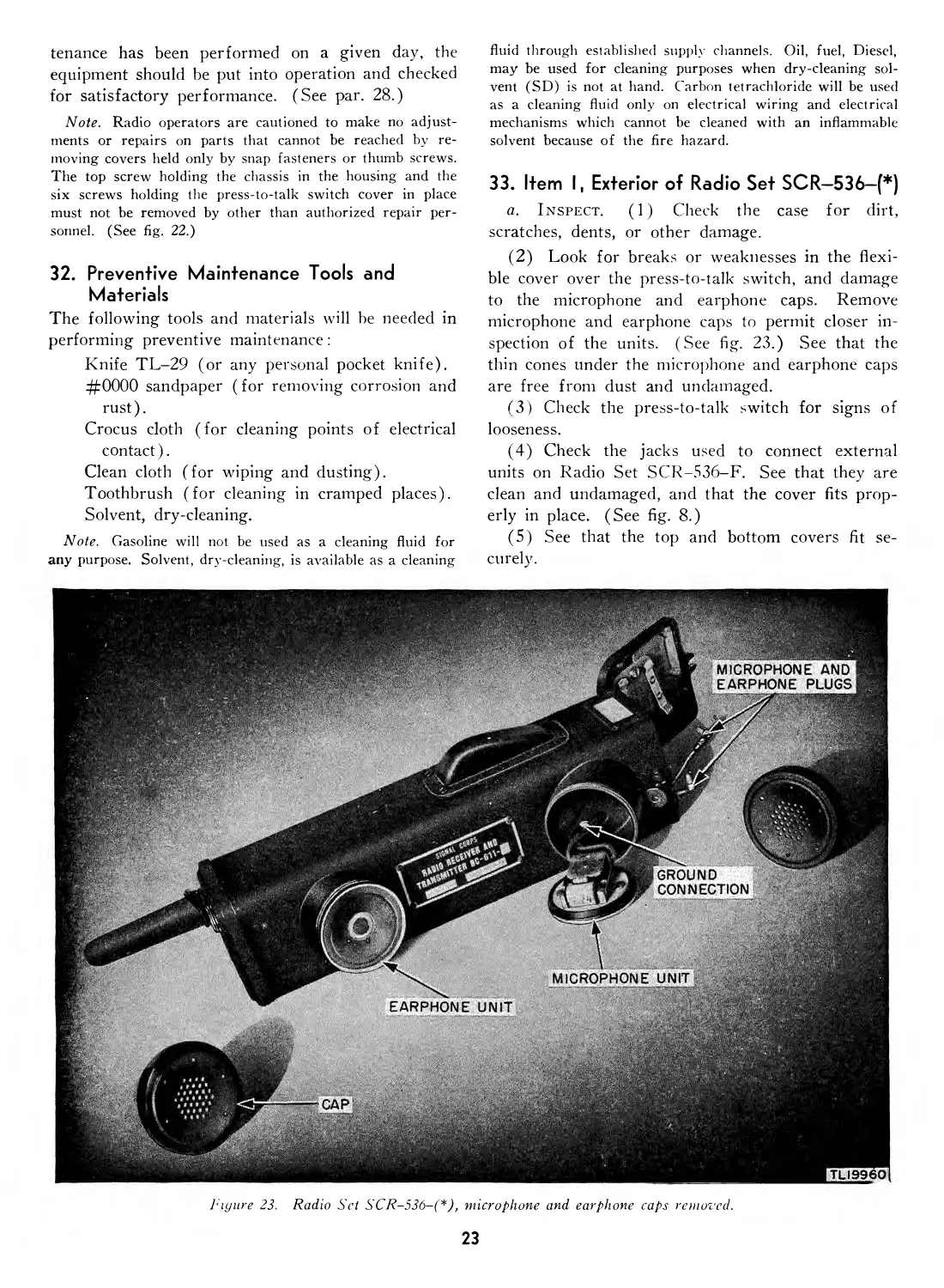
Figure 22. Instructions to operators.
22
tenance has been performed on a given day, the
equipment should be put into operation and checked
for satisfactory performance. (See par. 28.)
Note. Radio operators are cautioned to make no adjust-
ments or repairs on parts that cannot be reached by re-
moving covers held only by snap fasteners or thumb screws.
The top screw holding the chassis in the housing and the
six screws holding the press-to-talk switch cover in place
must not be removed by other than authorized repair per-
sonnel. (See fig. 22.)
32. Preventive Maintenance Tools and
Materials
The following tools and materials will be needed in
performing preventive maintenance:
Knife TL-29 (or any personal pocket knife).
#0000 sandpaper (for removing corrosion and
rust).
Crocus cloth (for cleaning points of electrical
contact).
Clean cloth (for wiping and dusting).
Toothbrush (for cleaning in cramped places).
Solvent, dry-cleaning.
Note. Gasoline will not be used as a cleaning fluid for
any purpose. Solvent, dry-cleaning, is available as a cleaning
fluid through established supply channels. Oil, fuel, Diesel,
may be used for cleaning purposes when dry-cleaning sol-
vent (SD) is not at hand. Carbon tetrachloride will be used
as a cleaning fluid only on electrical wiring and electrical
mechanisms which cannot be cleaned with an inflammable
solvent because of the fire hazard.
33. Item I, Exterior of Radio Set SCR—536—(*)
a. Inspect. (1) Check the case for dirt,
scratches, dents, or other damage.
(2) Look for breaks or weaknesses in the flexi-
ble cover over the press-to-talk switch, and damage
to the microphone and earphone caps. Remove
microphone and earphone caps to permit closer in-
spection of the units. (See fig. 23.) See that the
thin cones under the microphone and earphone caps
are free from dust and undamaged.
(3) Check the press-to-talk switch for signs of
looseness.
(4) Check the jacks used to connect external
units on Radio Set SCR-536-F. See that they are
clean and undamaged, and that the cover fits prop-
erly in place. (See fig. 8.)
(5) See that the top and bottom covers fit se-
curely.
Figure 23. Radio Set SCR-536-(*), microphone and earphone caps removed.
23
(6) See that the data card is properly in place
and covered. (See fig. 6.)
b. Tighten. (1) Carefully tighten any loose
screws.
(2) If the press-to-talk switch cover has worked
loose, reseal it with Permatex (Permatex, Aviation
Type, Signal Corps stock No. 6G1514). For sup-
plementary waterproofing information, see section
X.
(3) Replace the microphone and earphone caps
and see that they are screwed on snugly.
c. Clean. (1) Remove any caked mud with a
small brush. Remove any grease or oil with dry-
cleaning solvent.
(2) Carefully dust exposed surfaces of earphone
and microphone units and protective caps with a
clean dry cloth.
34. Item 2, Antenna
a. Inspect. (1) Inspect the antenna insulator
carefully, particularly in inclement weather. (See
fig. 11.) Water and foreign matter will provide a
leakage path, grounding the output signal to the
case.
(2) Inspect the individual antenna sections, espe-
cially around the three joints, to detect any signs of
damage due to rough handling. (See fig. 7.)
(3) Check the fitting of the antenna cover and
retaining chain.
b. Clean. Clean the antenna insulator and the
extended antenna sections with a dry cloth. Use
dry-cleaning solvent if necessary, especially after
having covered the antenna with foreign matter for
purposes of camouflage. (See par. 22.)
35. Item 3, Inside Bottom Cover
a. Inspect. (1) Check the spring contact con-
nections in the inside bottom cover and the battery
contact studs on the chassis to insure that they are
clean and bright and that there is sufficient spring
pressure. (See fig. 6.) Inspect the panel of the
chassis, which is exposed when the bottom cover of
the housing is unlatched, to see that it is clean and
free from dust.
(2) The plug from the internal microphone is
painted with a green spot to match the green spot
on the socket labeled MIKE, and the internal ear-
phone plug is painted with a red spot to match the
spot on the socket labeled PHONE. Check to make
sure that the plugs are inserted correctly and that
they fit snugly and can not become disengaged.
(See fig. 6.)
(3) Make sure that the black plate circuit jumper
plug inserted across the socket labeled PLATE
METER fits snugly. (See fig. 6.) To prevent loss
tie a thread or piece of serving twine around the
jumper plug and, after allowing a little slack, to
one of the mounting studs of the battery contact
plate in the bottom cover assembly.
(4) Check the jacks used for external micro-
phone and headset connections. See that the contact
points are clean and bright.
b. Tighten. Carefully tighten any loose screws
or connections.
c. Clean. (1) Remove any corrosion or dullness
from battery contact points (fig. 12) with a pocket
knife.
(2) Wipe the cover plate clean.
d. Adjust. If necessary, bend the spring contact
connectors outward slightly so as to press firmly
on the raised button of the batteries. (See fig. 6.)
Be very careful not to break the spring connectors
by bending them too much or too sharply. Do not
attempt to adjust the tension of the coil spring con-
tacts on sets using the bottom cover containing ex-
ternal microphone and headset jacks. (See fig. 8.)
36. Item 4, Chassis and Interior of Radio Set
SCR-536-(*)
a. Inspect. (1) After removal of the chassis,
check the tubes for proper seating. (See fig. 15.)
Make the inspection by pressing the tubes down in
their sockets and carefully testing them in that posi-
tion, not by partially withdrawing the tubes and
jiggling them from side to side. Inspect the tube
socket.
(2) Make certain that crystals and coils are
properly held in place. The self-supporting AN-
TENNA coil is light in weight and requires no
special holding bracket, but it should be inspected
for proper seating.
(3) Look for blistering, discoloration, or other
signs of overheating or abnormal operation; and
inspect for loose parts on the chassis.
(4) After removal of the chassis from the case,
extend the antenna to make sure that there is noth-
ing obstructing the free movement of the antenna
and that the antenna guide and supporting insulator
are in good condition. (See fig. 31.)
(5) When the top cover is removed to permit
removal of the chassis, also inspect the top battery
connectors and the A battery spacer. (See fig. 10.)
(6) Inspect the antenna contacts for loose elec-
trical connections. (See fig. 31.)
(7) Check the operation of the on-off switch at
the base of the antenna.
(8) Make sure moistureproofing and fungiprooL
24
mg treatment is still intact, and that moisture or
microscopic plant life is not present on the chassis.
(9) Check to see that the guides on the inside
of the case are unobstructed, and that the projec-
tions on the chassis are not bent. (See fig. 61.)
b. Tighten. (1) Any loose chassis connections
should be carefully soldered.
(2) The TANK COIL holding screw should be
firmly tightened to hold the coil in place.
(3) If the on-off switch is loosely mounted, care-
fully turn down the hexagonal mounting nut.
(4) When maintenance is completed and batteries
are replaced, press the bottom cover firmly against
some solid object, such as a tree stump, and tighten
the latching nut securely with the fingers.
c. Clean. (1) Wipe any dirt or grime from the
chassis and parts with a clean dry cloth or a small
brush. Tubes seldom require cleaning, but they
should be cleaned carefully whenever necessary.
(2) Carefully clean any dirty contact points with
crocus cloth and wipe clean. Take care not to dam-
age the operation of the change-over switch.
d. Adjust. (1) If necessary, make very careful
adjustments of the change-over switch contacts and
antenna contacts.
(2) Carefully bend the chassis projections slightly,
if necessary, to assure that the chassis slides in and
out of the case freely. (See fig. 66.)
(3) Change the position of any misplaced wiring
or parts that are being damaged by chassis removal.
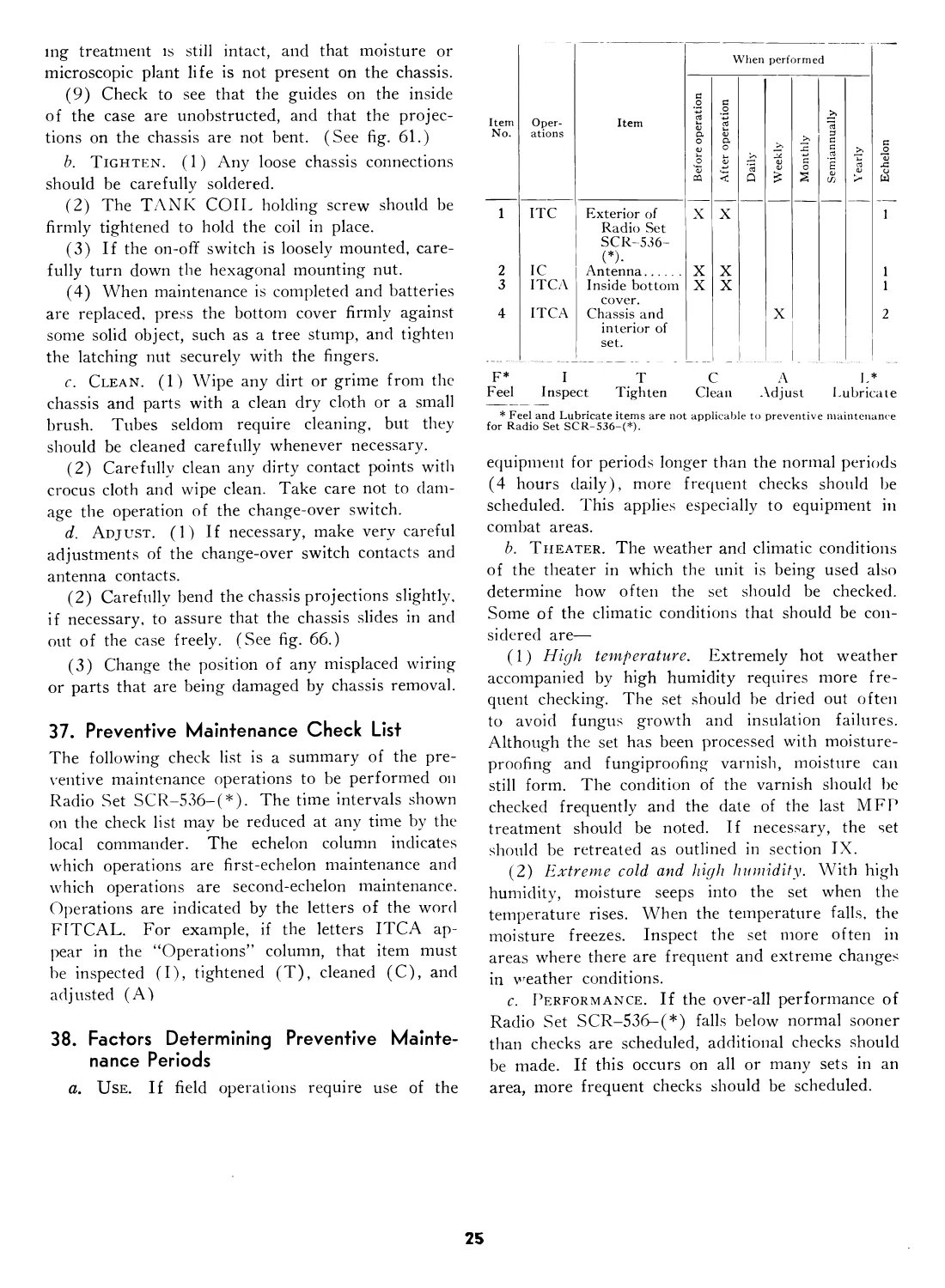
37. Preventive Maintenance Check List
The following check list is a summary of the pre-
ventive maintenance operations to be performed on
Radio Set SCR-536-(*). The time intervals shown
on the check list may be reduced at any time by the
local commander. The echelon column indicates
which operations are first-echelon maintenance and
which operations are second-echelon maintenance.
Operations are indicated by the letters of the word
F1TCAL. For example, if the letters ITCA ap-
pear in the “Operations” column, that item must
be inspected (I), tightened (T), cleaned (C), and
adjusted (A)
38. Factors Determining Preventive Mainte-
nance Periods
a. Use. If field operations require use of the
* Feel and Lubricate items are not applicable to preventive maintenance
for Radio Set SCR-536-(*).
equipment for periods longer than the normal periods
(4 hours daily), more frequent checks should be
scheduled. This applies especially to equipment in
combat areas.
b. Theater. The weather and climatic conditions
of the theater in which the unit is being used also
determine how often the set should be checked.
Some of the climatic conditions that should be con-
sidered are—
(1) High temperature. Extremely hot weather
accompanied by high humidity requires more fre-
quent checking. The set should be dried out often
to avoid fungus growth and insulation failures.
Although the set has been processed with moisture-
proofing and fungiproofing varnish, moisture can
still form. The condition of the varnish should be
checked frequently and the date of the last MFP
treatment should be noted. If necessary, the set
should be retreated as outlined in section IX.
(2) Extreme cold and high humidity. With high
humidity, moisture seeps into the set when the
temperature rises. When the temperature falls, the
moisture freezes. Inspect the set more often in
areas where there are frequent and extreme changes
in weather conditions.
c. Performance. If the over-all performance of
Radio Set SCR-536-(*) falls below normal sooner
than checks are scheduled, additional checks should
be made. If this occurs on all or many sets in an
area, more frequent checks should be scheduled.
25
Section VIII. LUBRICATION
39. Lubrication Instructions
a. General. No lubrication is authorized for
Radio Set SCR-536-(*) for either reduction of
friction between moving parts or for the prevention
of corrosion.
b. Camouflage. Use of a graphited grease to
reduce the reflected glare from the extended antenna
is described in paragraph 18.
c. Waterproofing. Use of waterpump grease
for waterproofing the case of the set in addition to
the moisture seals built into the set (par. 10) is
described in paragraph 46.
40. Recommended Lubricants for Camouflag-
ing and Waterproofing
The following table lists the lubricating material
recommended for use in camouflaging and water-
proofing Radio Set SCR-536-(*).
Approved symbol Standard nomenclature Specification No.
CG WP Grease, Graphited. Grease, Water Pump, No. 4. Ordnance AXS-683 U. S. Army 2-109
Section IX. MOISTUREPROOFING
AND FUNGIPROOFING
41. Problems Encountered
The operation of Signal Corps equipment in tropi-
cal areas where temperature and relative humidity
are extremely high requires special attention. The
following items represent problems which may be
encountered in operation:
a. Resistors, capacitors, coils, chokes, transformer
windings, and other components fail.
b. Electrolytic action takes place in resistors, coils,
chokes, and transformer windings causing eventual
break-down.
c. Hook up wire and cable insulation break down.
Fungus growth accelerates deterioration.
d. Moisture forms electrical leakage paths on ter-
minal boards and insulating strips.
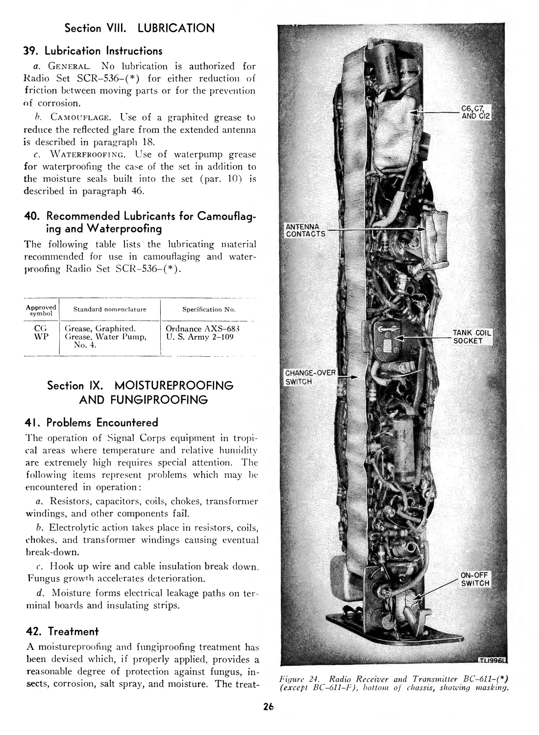
42. Treatment
A moistureproofing and fungiproofing treatment has
been devised which, if properly applied, provides a
reasonable degree of protection against fungus, in-
sects, corrosion, salt spray, and moisture. The treat-
Figure 24. Radio Receiver and Transmitter BC-611-(*)
(except BC-611-F ), bottom of chassis, showing masking.
26
ment involves the use of a moisture- and fungi-
resistant varnish applied with a spray gun or brush
See ТВ SIG 13 for a detailed description of the
varnish-spray method of moistureproofing and fungi-
proofing and the supplies and equipment required in
this treatment.
Caution: Varnish spray may have a toxic effect
if inhaled. To avoid inhaling spray, use respirator
if available; otherwise fasten handkerchief, cheese-
cloth, or other cloth material over nose and mouth.
43. Step-by-step Instructions
a. Preparation. Equipment must be in good re-
pair and all adjustments properly made before being
processed. Any defective parts should be replaced.
The set should be pretuned and aligned and oper-
ating satisfactorily so that a check can be made
after the treatment and any effect on alignment and
presetting more easily corrected.
b. Disassembly. The equipment is first disassem-
bled partially so that necessary masking and more
thorough drying of the equipment can be accom-
(8) Remove crystals from sockets, noting their
respective positions.
(9) Remove ANTENNA coil* from its socket.
(10) Loosen the holding clamp of TANK
COIL ;* remove coil.
(11) Remove the screws holding the celluloid
designation strip* over the change-over switch; re-
place screws in the original holes.
(12) Remove the screw holding the antenna guide
to the terminal board. Raise the antenna and care-
fully remove the guide.
(13) Extend the antenna and remove it by push-
ing through metal clamp riveted to chassis.
Note. On sets procured on Order No. 26827-Pbi1a-41-01,
Serial Nos. 15429 and up, the mounting of the antenna has
been changed. In these models, a screw fastened by a nut
replaces the rivet through the polystyrene base of the an-
tenna coil socket. This facilitates repairs by providing a
means of easily detaching the antenna guide.
(14) Remove microphone and receiver caps and
lift out units.
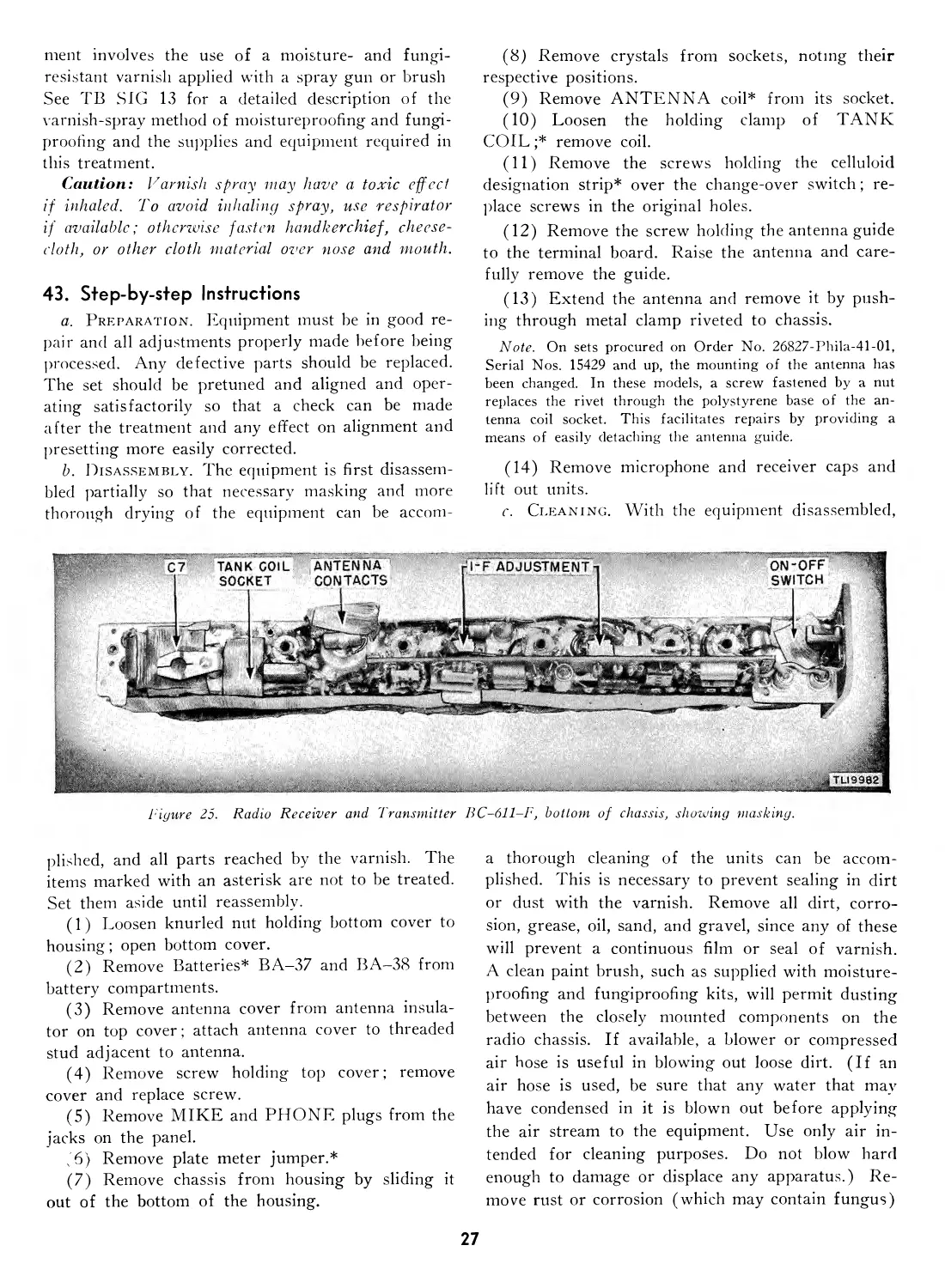
c. Cleaning. With the equipment disassembled,
Tigure 25.
Radio Receiver and Transmitter
ВС-611-Г, bottom of chassis, showing masking.
plished, and all parts reached by the varnish. The
items marked with an asterisk are not to be treated.
Set them aside until reassembly.
(1) Loosen knurled nut holding bottom cover to
housing; open bottom cover.
(2) Remove Batteries* BA-37 and BA-38 from
battery compartments.
(3) Remove antenna cover from antenna insula-
tor on top cover; attach antenna cover to threaded
stud adjacent to antenna.
(4) Remove screw holding top cover; remove
cover and replace screw.
(5) Remove MIKE and PHONE plugs from the
jacks on the panel.
(6) Remove plate meter jumper.*
(7) Remove chassis from housing by sliding it
out of the bottom of the housing.
a thorough cleaning of the units can be accom-
plished. This is necessary to prevent sealing in dirt
or dust with the varnish. Remove all dirt, corro-
sion, grease, oil, sand, and gravel, since any of these
will prevent a continuous film or seal of varnish.
A clean paint brush, such as supplied with moisture-
proofing and fungiproofing kits, will permit dusting
between the closely mounted components on the
radio chassis. If available, a blower or compressed
air hose is useful in blowing out loose dirt. (If an
air hose is used, be sure that any water that may
have condensed in it is blown out before applying
the air stream to the equipment. Use only air in-
tended for cleaning purposes. Do not blow hard
enough to damage or displace any apparatus.) Re-
move rust or corrosion (which may contain fungus)
27
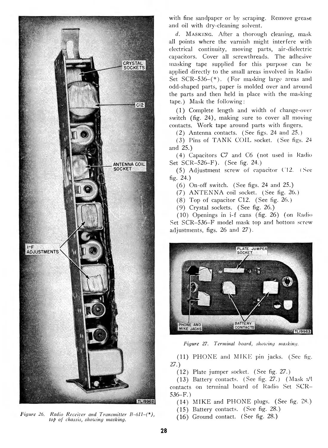
Figure 26. Radio Receiver and Transmitter ,
top of chassis, showing masking.
with fine sandpaper or by scraping. Remove grease
and oil with dry-cleaning solvent.
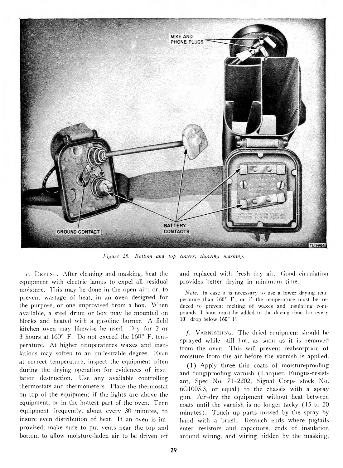
d. Masking. After a thorough cleaning, mask
all points where the varnish might interfere with
electrical continuity, moving parts, air-dielectric
capacitors. Cover all screwthreads. The adhesive
masking tape supplied for this purpose can be
applied directly to the small areas involved in Radio
Set SCR-536-(*). (For masking large areas and
odd-shaped parts, paper is molded over and around
the parts and then held in place with the masking
tape.) Mask the following:
(1) Complete length and width of change-over
switch (fig. 24), making sure to cover all moving
contacts. Work tape around parts with fingers.
(2) Antenna contacts. (See figs. 24 and 25.)
(3) Pins of TANK COIL socket. (See figs. 24
and 25.)
(4) Capacitors C7 and C6 (not used in Radio
Set SCR-526-F). (See fig. 24.)
(5) Adjustment screw of capacitor C12. (See
hg. 24.)
(6) On-off switch. (See figs. 24 and 25.)
(7) ANTENNA coil socket. (See fig. 26.)
(8) Top of capacitor C12. (See fig. 26.)
(9) Crystal sockets. (See fig. 26.)
(10) Openings in i-f cans (fig. 26) (on Radio
Set SCR-536-F model mask top and bottom screw
adjustments, figs. 26 and 27).
Figure 27. Terminal board, showing masking.
(11) PHONE and MIKE pin jacks. (See fig.
27.)
(12) Plate jumper socket. (See fig. 27.)
(13) Battery contacts. (See fig. 27.) (Mask aU
contacts on terminal board of Radio Set SCR-
536-F.)
(14) MIKE and PHONE plugs. (See fig. 28.)
(15) Battery contacts. (See fig. 28.)
(16) Ground contact. (See fig. 28.)
28
Piyiirc 28.
Bottom and top covers, showing masking.
c. Dryinc,. After cleaning and masking, heat the
equipment with electric lamps to expel all residual
moisture. This may be done in the open air; or, to
prevent wastage of heat, in an oven designed for
the purpose, or one improvised from a box. When
available, a steel drum or box may be mounted on
blocks and heated with a gasoline burner. A field
kitchen oven may likewise be used. Dry for 2 or
3 hours at 160° F. Do not exceed the 160° F. tem-
perature. At higher temperatures waxes and insu-
lations may soften to an undesirable degree. Even
at correct temperature, inspect the equipment often
during the drying operation for evidences of insu-
lation destruction. Use any available controlling
thermostats and thermometers. Place the thermostat
on top of the equipment if the lights are above the
equipment, or in the hottest part of the oven. Turn
equipment frequently, about every 30 minutes, to
insure even distribution of heat. If an oven is im-
provised, make sure to put vents near the top and
bottom to allow moisture-laden air to be driven off
and replaced with fresh dry air. Good circulation
provides better drying in minimum time.
Note. In case it is necessary to use a lower drying tem-
perature than 160° F., or if the temperature must be re-
duced to prevent melting of waxes and insulating com-
pounds, 1 hour must be added to the drying time for every
10° drop below 160° F.
f. Varnishing. The dried equipment should be
sprayed while still hot, as soon as it is removed
from the oven. This will prevent reabsorption of
moisture from the air before the varnish is applied.
(1) Apply three thin coats of moistureproofing
and fungiproofing varnish (Lacquer, Fungus-resist-
ant, Spec No. 71-2202, Signal Corps stock No.
6G1005.3, or equal) to the chassis with a spray
gun. Air-dry the equipment without heat between
coats until the varnish is no longer tacky (15 to 20
minutes). Touch up parts missed by the spray by
hand with a brush. Retouch ends where pigtails
enter resistors and capacitors, ends of insulation
around wiring, and wiring hidden by the masking,
29
such as the connections to the MIKE, PHONE,
and PLATE METER jacks.
(2) Hold crystals by contact pins and apply one
dip coat of varnish, being careful to keep varnish
off contact pins.
(3) Apply varnish with brush to back of micro-
phone and earphone units and to the TANK COIL.
g. Reassembly. (1) After varnish is dry, re-
move the masking tape from all components.
(2) Remove sticking adhesive with dry-cleaning
solvent.
(3) Using a brush, retouch any spots where the
varnish is peeled off when removing the masking.
(4) Reassemble by following disassembly instruc-
tions in reverse order.
(5) Test for correct presetting and alignment.
h. Marking. Mark the letters MFP and the
date of the treatment on the nameplate.
Example: MFP—8 Mar 1945.
Note. Sets moistureproofed and fungiproofed by the
manufacturer are so marked on the chassis. (See fig. 29.)
44. Moistureproofing and Fungiproofing After
Repairs
If, during repair, the coating of protective varnish
has been punctured or broken, and if complete treat-
ment is not needed to reseal the equipment, apply
a brush coat to the affected part. Re sure that the
break is completely sealed.
Figure 29. Typical manufacturer's MFP marking.
Section X. WATERPROOFING
45. General
Water pump grease No. 4 is used as a means of
preventing moisture seepage around the antenna
waterseal, at the earphone and microphone cap con-
nections, and at the sealing rubber gaskets of the
top and bottom covers of the set. It is used in ex-
tremely wet climates in addition to the moistureseals
built into the set. (See par. 10.)
46. Procedure
a. Spread a small quantity of water pump grease
No. 4 over the sealing gaskets of both bottom and
top covers.
b. Close bottom cover and press it firmly in place
while tightening the hinged thumbscrew. Be sure
this screw is tight.
c. Insert a fiber washer under the screw that
holds the top cover to the chassis. Turn the screw
down tightly to hold the cover in place.
d. Remove the cover of the press-to-talk switch.
Spread a thin coating of Permatex over the bottom
surface (side which makes contact with the case)
and replace the cover. Be sure the metal escutcheon
plate is screwed down snugly.
e. Remove the caps from both the microphone
and earphone housings. If earphone and microphone
use paper diaphragms (Radio Sets SCR-536-A and
SCR-536-B), squeeze a small quantity of household
cement on the diaphragms of both pieces (dynamic
type only) and spread out evenly with finger. Allow
to dry for several minutes and repeat with a second
coat. Allow the cement to dry for % hour before
replacing the protective cap covers. This treatment is
not required on units which use bakelite diaphragms.
/. Remove the grommet from the ceramic anten-
na insulator (on models of this construction), fill
30
the inside of the grommet with water pump grease
No. 4, and replace on the insulator.
47. Materials Required
The following materials, furnished with Mainte-
nance Equipment ME-36, are used to waterproof
50 Radio Sets SCR-536-(*) for 1 year:
Quantity Name and description Signal Corps stock No.
1 gross.... Washers, fiber, OD, %" ID, Иб" thick. 6L50523
8 ounces... Permatex, aviation type 6G1514
1 tube..... *Cement, household, 5|4 fluid oz (Duco). 6G199
2 pounds.. Grease, water pump, No. 4, U.S. Army Spec. 2-109. 6G617-1
*For Radio Sets SCR-536-A and -B only.
31
PART FOUR
AUXILIARY EQUIPMENT
Section XI. OPERATING ACCESSORIES
48. Battery BA—30 Filament Supply
a. Battery Adapter FT-501. In actual opera-
tion under tactical conditions the filament current A
Battery BA-37 expends itself before the В Battery
BA-38 becomes inoperative. To take advantage of
the more readily available flashlight Battery BA-30
as an emergency filament supply for Radio Set
SCR-536-(*), Battery Adapter FT-501 (fig. 30)
has been designed to hold two Batteries BA-30 and
just fill the space in the compartment intended to
hold the normal filament Battery BA-37. When not
issued as a part of Radio Set SCR-536-(*), requi-
sition of Battery Adapter FT-501 may be made
through normal signal supply channels (Signal
Corps stock No. 2Z200-501). Two Batteries BA-30
do not provide as long-lived filament supply (15
hours) as the normal BA-37 (19 hours), and should
not be used if Battery BA-37 is available. Before
using the adapter, be sure the contacts are clean and
bright to insure good electrical connections between
the adapter and the batteries and the spring connec-
tors on the housing of the set. Battery Adapter
FT-501 is inserted with plus (-(-), or raised but-
ton, end of the assembly toward the bottom of the
housing.
Figure 31. Battery BA-30 and 50-cal cartridge case.
Figure 30. Battery Adapter FT-501, using two Batteries
BA-30.
Note. Do not use two Batteries BA-30 without Battery
Adapter FT-501. Failure to observe this caution will burn
out the tube filaments.
b. Expedient Battery Adapter. As an expe-
dient filament supply, a single Battery BA-30, and
an expended 50-cal (caliber) cartridge case may be
used. (See fig. 31.) This makeshift arrangement
will fill the compartment provided for Battery
BA-37. Battery life will be considerably reduced (5
hours), therefore suitable provisions must be made
to replace the battery promptly as often as necessary
to guarantee uninterrupted communication. Both
ends of the cartridge case must be kept clean and
bright to insure effective electrical contact. Insert
32
the expended 50-cal cartridge case, butt first, in the
Battery BA-37 compartment followed by a Battery
BA-30 with the plus (-(-), or raised button, end
outward.
49. Inclement Weather Protection
a. Microphone Cover M-367. When the set is
used in freezing weather, moisture from the breath
condenses and freezes, plugging the holes in the
microphone cap and making transmission impossible.
This freezing condition can be prevented by use of
Microphone Cover M-367 which also serves as pro-
tection against sand or dust. (See fig. 32.) The
cover is made of a light, water-repellent fabric with
a drawstring or elastic band for holding it tightly
over the microphone on the set. The cover is not
waterproof and will not protect against immersion
in water or against long exposure to tropical hu-
midity. Microphone Cover M-367 is used whenever
the radio set is operated under freezing, dusty, or
sandy conditions. Current issues of Radio Set
SCR-536-(*) are supplied with the cover as a
component part. The cover also may be requisi-
tioned through normal supply channels; the stock
numbers are listed below.
Item
Signal Corps
stock No.
Microphone Cover M-367 (with draw string).. . 2В1567
Microphone Cover M-367 (with elastic band). . 2B1617/128
b. Protective Covers. (1) The protective small
arms cover, as issued by the Quartermaster Corps
for protecting rifles and carbines from water, may
Piyure 32. M icrophone Cover M-367.
ligure 33. Protective cover for operation in heavy rain.
be used to protect the Radio Set SCR-536-(*)
when operating in the rain. The open end is rolled
down tightly over the top of the housing when the
set is not in use. During operation, the small arms
cover is fully extended to protect as much of the
antenna as possible and the set is operated from
outside the protective cover. (See fig. 33.) It may
be necessary to speak louder and listen more intently
because of the muffling effect of the protective cover,
but this is a minor inconvenience compared to the
additional protection afforded by the cover. (See
sec. X.)
(2 ) Two different waterproof bags, both of
33
which will entirely cover the antenna when ex-
tended, are available through normal Quartermaster
Corps supply channels. The first special purpose
cover is a better fit for the radio set, since it is a
little smaller than the rifle or carbine cover, but both
types are satisfactory. They may be requisitioned
through normal supply channels; stock numbers are
listed below.
Name and description
Quartermaster
Corps stock
No.
Cover, waterproof, special purpose............
Cover, waterproof, rifle or carbine...........
24-C-7300
74-C310-41
50. Expedient Antenna
a. Construction. If the antenna rod is broken
or damaged or if inappropriate background renders
satisfactory concealment of the antenna impractical
(par.22), a wire antenna may be laid on the ground.
Use a length of insulated wire approximately 100
feet long and lay it on the ground pointing directly
at the station with which communication is required.
Bare several inches of the end of the wire near the
operator and wrap it tightly around the telescopic
rod antenna as near to the insulator as possible.
Apply rubber or friction tape, if available. Be sure
that the antenna, even if serviceable, remains com-
pletely telescoped for purposes of concealment, ex-
cept for about 1 inch of the bottom section required
to actuate the on-off switch.
b. Directional Pattern. This wire antenna has
a pronounced directional pattern and communication
will be unsatisfactory or impossible with stations
more than 30° on either side of the antenna. If
local conditions are such that it is impossible to lay
the wire to point directly at the other station, it may
be laid, with a slight reduction in signal strength,
pointing directly away from the second station. Any
reduction in the length of the antenna wire is not
recommended as the signal strength falls off rapidly
as the length is reduced. A longer length may be
used, but no substantial increase in signal strength
will be obtained.
51. Equipment for Use With External Jacks
When using the accessories in conjunction with the
jacks on Radio Set SCR-536-F, set the switch in-
side the baseplate at the EXTERNAL position.
a. Headset HS-30-( ). The headset may be
worn under a helmet. (See figs. 9 and 34.) The
earpieces fit into the ear cavities.
b. Microphone T-30. Microphone T-30 consists
of two carbon-button microphone elements housed in
plastic cases and held in a rubber neckpiece by snap
rings. The microphone is actuated by the mechani-
cal vibrations of speech as transmitted through the
throat of the operator. (See fig. 9.)
c. Microphone T-45. Microphone T-45 consists
of a small carbon-button microphone with antinoise
figure 34. Headset HS-30-( ).
characteristics. It is worn strapped to the head in
a position directly over the upper lip. (See fig. 35.)
It can be worn under the gas mask. The primary
Figure 35. Microphone T-45.
34
advantage of this microphone for use with Radio
Set SCR-536-F is its value under extremely noisy
conditions.
52. Maintenance Equipment ME—36
Maintenance Equipment ME-36 is furnished for
organizational maintenance of Radio Set SCR-536-
(*) on a T/O and E basis. For descriptions and
quantities of items included see ASF Signal Supply
Catalog, SIG 6 ME-36, Sets of Equipment for
Maintenance Equipment ME-36 (when published).
Section XII. HOMING MODIFICATION KIT MC-619
53. General
Homing Modification Kit MC-619 (fig. 36) is a
directional antenna attachment designed to be used
with Radio Set SCR-536-(*). A loop antenna is
provided for use in place of the nondirectional tele-
scopic rod antenna with which the radio set is
Figure 36. Homing Modification Kit MC-619 attached to Radio Receiver and Trans-
mitter BC-611-(*).
35
equipped. The loop, Antenna AN-190-( ), when
properly connected to the radio set, comprises an
effective homing device. Homing is the act of pro-
ceeding toward a fixed point, or station, which dis-
closes its identity by means of a radio signal. The
direction of this signal at some remote point can be
determined and followed to its source. The purpose
of this equipment is to make it possible for the radio
operator to find the approximate direction of a trans-
mitter tuned to his frequency and to proceed to-
ward it. Homing Modification Kit MC-619 may be
attached or removed from Radio Set SCR-536-(*),
as authorized.
54. Components
Homing Modification Kit MC-619 consists of a
multiturn loop permanently fastened to a collapsible
wooden frame, a transmission line permanently at-
tached to the loop at one end and fitted with a con-
nector at the other, Coupling Unit BC-1387 with
means for attaching to the top of Radio Receiver
and Transmitter BC-611-(*), and accessories. The
following table lists the components of Homing
Modification Kit MC-619:
Signal Corps
stock No.
2Z5725-619
Quantity Name and description
Homing Modification Kit MC-619: Kit
for use with Radio Set SCR-536-(*),
consisting of one each of the following
items:
Antenna AN-190-( ): folding loop,
(collapsible).
Coupling Unit BC-1387.
Case CS-156-( ): for carrying
Radio Set SCR-536-( ) and com-
ponent for Modification Kit MC-
619, less Antenna AN-190-( ).
Case CS-157-( ): for carrying
Antenna AN-190-( ).
Bottom cover plate (modified).
Headset HS-30-( ).
Cord CD-605.
a. Antenna AN-190-( ). The loop (fig. 37)
consists of five turns of insulated wire mounted on
four radial struts hinged at the center. The handle
of the loop is an extension of the bottom strut, and
contains a trimmer capacitor for tuning the loop and
a sense button mounted on the panel front directly
above the handle. A card, similar to that on the
radio set, carries the serial number of the radio set
and the frequency to which both are tuned.
b. Transmission Line. A 38-inch transmission
line extends through the bottom of the loop handle
and, at its end, has a three-conductor receptacle
which terminates the two leads from the loop an-
tenna plus an integral cable shield.
c. Coupling Unit BC-1387. The coupling unit
(fig. 38) is housed in a steel can. The container
has a mounting flange extending from its base plate
which permits installation over the threaded an-
tenna insulator base and the antenna cap mounting
stud. The coupling unit contains an r-f coupling
transformer and a variable capacitor for tuning the
transformer. A short lead, extending through the
front panel of the coupling unit and fitted with a
clip, connects to the bottom section of the telescopic
rod antenna of the radio set. A plug is mounted on
the front panel and engages the connector on the
transmission line.
d. Accessories. (1) Case CS-156-( ) pro-
vides carrying space for the radio set and Case CS-
157—( ) provides carrying space for the kit com-
ponents. The bags are fitted with suitable straps to
permit slinging over the shoulder or under the arm.
During homing operations the radio set may be car-
ried in this bag.
(2 ) A bottom plate for Radio Receiver and
Transmitter BC-611-(*) containing a jack for us-
ing an external headset is provided for installation
on the chassis housing.
(a) The jack plate (fig. 39) is shipped with
Homing Modification Kit MC-619; its installation
is described in MWO SIG 11-235-5.
(b) Late models of Radio Receiver and Trans-
mitter BC-611-F are equipped with provision for
connection of the external headset and microphone.
The plate need not be installed on these models.
(3 ) Headset HS-3(U( ) with Cord CD-605
(containing an 8,000-ohm coupling transformer) is
provided for use in conjunction with the external-
jack bottom plate to eliminate outside noise when
obtaining a bearing and to prevent the received sig-
nal from being heard by anyone other than the
operator.
55. Installation
The jack plate is mounted by authorized mainte-
nance personnel as described in MWO SIG 11—235—
5, and is not to be installed by the radio operator.
a. Remove the collapsible loop and coupling unit
from the carrying bag.
b. Check the card on loop handle with serial num-
ber and preset frequency on radio set.
c. Unscrew the antenna cap of the radio set and
remove the slotted machine screw in the center of
36
the top cover plate. Place the coupling unit over the
antenna insulator and threaded stud. Replace the
threaded machine screw through the hole provided
in the coupling unit flange. Tighten securely to in-
sure a good ground for the coupling unit. Screw
the antenna cap over the threaded boss which now
extends through a hole in the coupling unit mount-
ing flange.
d. Raise the bottom section of the antenna until
the set clicks on, keeping all the upper antenna sec-
tions collapsed. Snap the antenna clip at the end of
the coupling lead to the bottom antenna section. Re-
duce the bottom section extension so that it just
matches the width of the connecting clip. This is
important since the loop antenna is adjusted for this
amount of extension and any appreciable difference
will seriously detune the receiver and reduce its
sensitivity.
e. Erect the loop antenna by opening the four
arms as far as they will go. Then hold the handle
Figure 37. Loofr antenna, showing the location of the sense button, indicating arrows, tuning
control serial number, and frequency record card.
37
against the belt or waist (fig. 40) and grasp the
horizontal struts so that the thumbs press down on
the top strut while the hands press open the horizon-
tal struts. Press equally on all four struts until the
56. Operation
a. Null Location. Hold the loop antenna verti-
cal and the handle approximately at eye level. Ro-
tate the antenna around a vertical axis by means of
Figure 38. Details for mounting coupling unit on Radio Receiver and Transmitter BC-611-(*).
frame snaps into the fully opened position. The
tension of the wires will hold the frame open.
/. Connect the receptacle at the end of the trans-
mission line to the plug on the coupling unit.
g. Plug the headset into external jack on bottom
cover.
wrist motion. In the presence of a signal to which
the loop antenna and receiver have been pretuned,
two points will be found at which the output in the
headset falls off or disappears altogether. These
points are called nulls. They occur when the broad-
side of the loop exactly faces the source of the sig-
38
nal. Thus two nulls occur one-half revolution
(180°) apart. When turned to a null, a line drawn
through the center of the loop perpendicular to the
broadside will be in line with the transmitting
source.
b. Sensing. Since there will be two null posi-
tions (fig. 41) it is evident that the transmitter may
be either in front of or behind the loop. To deter-
mine from which side the signal is arriving (the
sense of the bearing), touch the thumb to the sense
button on the front panel of the loop handle and
null may increase to 30° or 40°. The center of this
null arc, or area, is the correct bearing. This equip-
ment can be used effectively up to 1 or 2 miles,
depending on the strength of the received signal.
Caution: The sense button should be touched only
when sensing. As soon as sense has been deter-
mined, remove the thumb from the sense button and
proceed by keeping the loop in the null position.
c. Homing. To home on a signal, take a bearing
by finding a null, determine the sense, and proceed
in the direction indicated by the arrows inscribed on
Figure 39. Jack plate mounted on bottom cover of radio set housing.
rotate the loop a quarter turn from the null, first in
one direction and then in the other. In one of the
two positions the signal is louder than in the other.
Turn a quarter turn from the initial null to the
louder position. The arrows on the loop handle now
point toward the transmitter. Remove thumb from
sense button and use the original null for direction
finding because it gives a sharper and more accurate
bearing indication. It the presence of a strong sig-
nal the null will be quite narrow, and rotation of a
few degrees will result in sharp signal variations in
the headset. On a weaker signal, the width of the
the loop. Once the proper sense has been deter-
mined, turn the loop back to the broadside position
and again obtain the null. If the null is particularly
broad, rotate the loop back and forth a few times.
The hand will divide the null almost automatically
and find the approximate center. Proceed along a
line through the center of this null until the home
station is reached. As the transmitter is approached,
successive bearings can be taken with increased ac-
curacy due to greater signal strength and consequent
reduction in the width of the null arc.
d. Blocking. Because of the action of the auto-
39
Figure 40. Method of holding loop to snap it open.
matic volume control incorporated in the receiving
circuit, very strong signals may have a tendency to
obscure the null. In general, signals of such strength
will be found principally in the immediate vicinity
of the transmitter. However, if the transmitter is
concealed and a very strong signal tends to obscure
the null points, touch the stub of the telescopic rod
antenna on the radio set. This will reduce the sen-
sitivity of the receiver and will be effective in mak-
ing the null clear again.
e. Operating Hints. (1) Do not tamper with
adjustments. The components of Homing Modifi-
cation Kit MC-619, like Radio Receiver and Trans-
mitter BC-611-(*), are preset for a single frequen-
cy. Only qualified maintenance personnel make
adjustments.
(2) Use loop only with the radio set for which it
has been adjusted. Because of minor differences in
radio sets pretuned to the same frequency, the loop
antenna gives best results with the radio set for
which it has been pretuned and whose serial number
appears on the loop.
(3) Be sure to extend the bottom telescopic rod
antenna section to the exact height of the lead clip
from the coupling unit. This is part of the tuning
operation and must be accurate.
(4) Always hold the loop in a vertical position as
high as possible with comfort. Keep the loop clear
of obstructions such as trees, shrubbery, walls, and
vehicles.
(5) Avoid taking bearings near natural or man-
made obstacles. Locations under power or tele-
40
TL19476
Figure 41. Effect of sense determination on two initial nulls.
--OR HERE?
IS IT HERE?
41
phone lines, or near fences, railroad tracks, abrupt
cliffs, or buildings, distort the wave path and usually
cause false bearings.
(6) Do not try to modify the components of the
kit by lengthening or shortening the transmission
line or by redesigning the loop. The loop, transmis-
sion line, and coupling unit comprising Homing
Modification Kit MC-619 are designed to work to-
gether. Any expedient adjustments may disable it
completely.
(7) Turn off the receiver when not taking a bear-
ing. To conserve batteries when not in use, turn
off the radio set by completley collapsing the bottom
section of the telescopic rod antenna.
the correct direction of the desired transmitter and
the exact reverse of this direction, a vertical antenna
may be used to add or subtract signal voltages with
different phase relationships to the two sides of the
loop. With Homing Modification Kit MC-619, the
operator’s body serves as the vertical sense antenna
when contact is made by the operator’s thumb with
the sense button on the antenna frame. This results
in a heart-shaped cardioid field-strength pattern with
a single broad null and a single broad maximum
(fig. 42) which is suitable for solving the double
null obtained with the loop, but too inaccurate for
obtaining a true bearing.
c. Homing Modification Kit MC-619. The
Figure 42. Directional antenna, field strength patterns.
57. Theory of Equipment
a. Loop Antennas. The directional properties
of a loop antenna are such that maximum pick-up is
obtained when one of the edges is pointed toward
the transmitter, and minimum when the flat loop is
broadside to the transmitter. (See fig. 42.) This
results in a figure-8 field-strength pattern. Null
points of minimum or no signal, rather than points
of peak or maximum signal, are used to indicate
direction, because the rate of change of signal in-
tensity is greater near the null than at the points of
maximum pick-up. Thus the center of a null is
more easily recognized than the exact center of a
loud signal.
b. Sense Antennas. To differentiate between
loop antenna is so wound and the sense voltage is
introduced in such a manner that when the loop is
rotated 90° away from a null and the signal in-
creases the arrows on the loop indicate the true
direction to the transmitter. The antenna consists of
a four-turn loop, approximately 15 inches on a side,
across which is connected an air-dielectric variable
capacitor Cl. (See fig. 43.) A fifth turn serves as
an inductance coupling between the loop antenna and
the transmission line to the radio receiver. This fifth
turn connects across the terminals of a two-conduc-
tor shielded cable which constitutes a balanced line
to the coupling unit mounted on the radio set.
d. Coupling Unit. The coupling unit consists
of an autotransformer with a center-tapped primary
42
Figure 43. Homing Modification Kit MC-619, schematic diagram.
and a tuned secondary. Tuning capacitor C2 is an
air-dielectric variable capacitor; it tunes both the
transformer and the input circuit to the radio set.
The input circuit is detuned when the telescopic rod
antenna is not fully extended.
58. Mounting Bottom Plate
When authorized, Radio Set SCR-536-(*) may be
fitted with a bottom cover plate for use with Homing
Modification Kit MC-619. (See MWO SIG 11-
235-5.) This modification is unnecessary on later
models of Radio Set SCR-536-F, which have jacks
for external accessories.
59. Pretuning
The pretuning procedure described assumes that
Radio Receiver and Transmitter BC-611-(*) has
been properly aligned for the particular frequency
on which it is to be used.
a. Prepare the equipment for operation as de-
scribed in paragraph 54. Make sure that the tele-
scopic rod antenna is collapsed except for that por-
tion of the bottom section equal to the width of the
antenna clip of the coupling unit.
b. Unscrew the trimmer plugs on the loop and
coupling unit.
c. Rotate loop trimmer Cl so that the red dot on
the screw driver slot points to the frequency
(marked on the loop panel) nearest the one to be
used.
Note. The frequency to which the radio set is tuned is
indicated in kc (kilocycles) (3,500 to 6,000 kc) on the radio
data card. The frequency to which the loop trimmer must
be set is indicated in me (megacycles) (3.5 to 6.0 me) on the
calibrating dial. A dot indicates each 0.5 me.
d. Using another radio set tuned to the same fre-
quency ; a noisy rotating commutator from an elec-
tric motor, generator, or dynamotor; a fluorescent
light fixture; or an unsuppressed vehicle engine as
a source of an r-f signal; rotate coupling unit
trimmer C2 for maximum noise level.
e. Readjust loop trimmer Cl and coupling-unit
trimmer C2 for more accurate adjustment.
f. Replace trimmer plugs. The unit is now ready
for operation with the particular Radio Set SCR-
536-(*) for which it was adjusted. If the loop
system is to be used with another radio set, a slight
readjustment of trimmer C2 in the coupling unit is
necessary.
43
g. Record the frequency and serial number of
Radio Receiver and Transmitter BC-611-(*) on the
card on the loop antenna handle.
60. Moistureproofing and Fungiproofing
a. Preparation. Make all repairs and adjust-
ments necessary for proper operation of the equip-
ment.
b. Disassembly. (1) Erect the loop antenna by
opening the four arms until the frame snaps into
full open position.
(2) Remove the three screws that retain the bake-
lite panel on the side of the loop handle.
(3) Pull the panel out carefully as far as the
(1) Center piece of the loop antenna. (See fig.
46.)
(2) Sense button. (See fig. 46.)
(3) Loop trimmer capacitor. (See fig. 44.)
(4) Tuning capacitor in the coupling unit. (See
fig. 45.)
e. Drying. Bake the equipment in accordance
with the instructions given in paragraph 43e.
f. Varnishing (par. 43f). (1) Apply varnish
by brush to the wires and insulators on the loop
trimmer capacitor, and to the wires, insulators, and
transformer of the coupling unit.
Caution: Do not allow the varnish to drip or run
on to the capacitor plates or in the screw holes.
Figure 44. Tuning capacitor, masking.
wires attached to the tuning capacitor will allow.
(See fig. 44.)
Caution: Handle the trimmer capacitor carefully,
as the plates will short-circuit if bent.
(4 ) Disconnect the tranmission line from the
coupling unit.
(5 ) Remove the four screws from the corners of
the coupling unit panel. (See fig. 45.)
(6 ) Pull the panel forward. All of the compo-
nents are mounted on the panel. The container does
not require any treatment.
c. Cleaning. Clean all dirt, dust, rust, and fun-
gus from the equipment. Remove all oil and grease.
d. Masking. Completely cover the following
components with masking tape:
(2) Spray varnish on the five loop wires.
(3) Bake the equipment for 10 minutes.
(4) Repeat steps (1), (2), and (3) above, for
three coats of varnish.
g. Reassembly and Test. (1) After the third
baking operation, remove all masking tape and re-
assemble the equipment by following the disassembly
instructions in reverse order.
(2) Check the operation of the equipment. If
possible, allow 2 or 3 days for the equipment to be-
come stabilized after the above treatment before
making final adjustment.
h. Marking. Mark the letters MFP and the date
of treatment on the top of the coupling unit and just
below the strap on the antenna handle.
Example: MFP—1 Mar 45.
44
Figure 45. Coupling unit, masking.
Figure 46. Loop antenna, masking.
45
61. Moistureproofing and Fungiproofing After
Repairs
If, during repair, the coating of protective varnish
has been punctured or broken, and if complete treat-
ment is not needed to reseal the equipment, apply a
brush coat to the affected part. Be sure the break is
completely sealed.
Section XIII. FREQUENCY CONVERSION KITS
62. Frequency Conversion Kit MC—534
a. General. Frequency Conversion Kit MC-534
consists of Chest CH-233 which contains 400 Crys-
tal Holders FT-243, 72 ANTENNA coils LI, and
60 TANK COILS, L2. (See fig. 47.) These com-
ponents provide the appropriate ANTENNA coil,
TANK COIL, receiver crystal, and transmitter
crystal for operation of Radio Set SCR-536-(*) on
any of 50 different frequencies.
b. Components.
Figure 47. Chest CH-233.
Quantity Item Quantity Item
1 Chest CH-233, for storing and transporting 400 crys- 6 Coil C-364 (4,625-4,825 kc)
tals in Crystal Holders FT-243, 72 ANTENNA 6 Coil C-365 (4,825-5,075 kc)
coils, and 60 TANK COILS for Radio Set 6 Coil C-366 (5,075-5,300 kc)
SCR-536-(*) 6 Coil C-367 (5,300-5,500 kc)
6 Coil C-358 (3,500-3,675 kc) 6 Coil C-368 (5,500-5,775 kc)
6 Coil C-359 (3,675-3,825 kc) 6 Coil C-369 (5,775-6,000 kc)
6 Coil C-360 (3,825-4,025 kc) 10 Coil C-370 (3,500-3,825 kc)
6 Coil C-361 (4,025-4,225 kc) 10 Coil C-371 (3,825-4,225 kc)
6 Coil C-362 (4,225-4,425 kc) 10 Coil C-372 (4,225-4,625 kc)
6 Coil C-363 (4,425-4,625 kc) 10 Coil C-375 (4,625-5,075 kc)
46
Quantity
Item
Quantity Item
10 10 Coil C-374 (5,075-5,500 kc) Coil C-375 (5,500-6,000 kc)
4 Crystal Holder FT-243 with crystal, for receiver (3,955 kc)
4 Crystal Holder FT—243 with crystal, for receiver (3,995 kc)
4 Crystal Holder FT-243 with crystal, for receiver (4,045 kc)
4 Crystal Holder FT-243 with crystal, for receiver (4,095 kc)
4 Crystal Holder FT-243 with crystal, for receiver (4,135 kc)
4 Crystal Holder FT—243 with crystal, for receiver (4,175 kc)
4 Crystal Holder FT—243 with crystal, for receiver (4,215 kc)
4 Crystal Holder FT-243 with crystal, for receiver (4,255 kc)
4 Crystal Holder FT-243 with crystal, for receiver (4,295 kc)
4 Crystal Holder FT-243 with crystal, for receiver (4,340 kc)
4 Crystal Holder FT-243 with crystal, for receiver (4,395 kc)
4 Crystal Holder FT-243 with crystal, for receiver (4,445 kc)
4 Crystal Holder FT-243 with crystal, for receiver (4,490 kc)
4 Crystal Holder FT-243 with crystal, for receiver (4,620 kc)
4 Crystal Holder FT-243 with crystal, for receiver (4,695 kc)
4 Crystal Holder FT-243 with crystal, for receiver (4,535 kc )
4 Crystal Holder FT-243 with crystal, for receiver (4,735 kc)
4 Crystal Holder FT-243 with crystal, for receiver (4,785 kc)
4 Crystal Holder FT-243 with crystal, for receiver (4,852.5 kc)
4 Crvstal Holder FT-243 with crystal, for receiver (4.900 kc)
4 Crvstal Holder FT-243 with crystal, for receiver (4,950 kc)
4 Crystal Holder FT-243 with crystal, for receiver (4,995 kc)
4 Crystal Holder FT-243 with crystal, for receiver (5,035 kc)
4 Crystal Holder FT-243 with crystal, for receiver (5,090 kc)
1 Crystal Holder FT-243 with crystal, for receiver (5,165 kc)
4 Crystal Holder FT-243 with crystal, for receiver (5,235 kc)
4 Crystal Holder FT-243 with crystal, for receiver (5,295 kc)
4 Crystal Holder FT-243 with crystal, for receiver (5,335 kc)
4 Crystal Holder FT-243 with crystal, for receiver (5,385 kc)
4 Crystal Holder FT-243 with crystal, for receiver (5,435 kc)
4 Crystal Holder FT-243 with crystal, for receiver (5,485 kc)
4 Crystal Holder FT-243 with crystal, for receiver (5,582.5 kc)
4 Crystal Holder FT-243 with crystal, for receiver (5,660 kc)
4 Crystal Holder FT-243 with crystal, for receiver (5,700 kc)
4 Crystal Holder FT-243 with crystal, for receiver (5,740 kc)
4 Crystal Holder FT-243 with crystal, for receiver (5,782.5 kc)
4 Crystal Holder FT-243 with crystal, for receiver (5,852.5 kc)
4 Crystal Holder FT-243 with crystal, for receiver (5,892.5 kc)
4
4
4
4
4
4
4
4
4
4
4
4
4
4
4
4
4
4
4
4
4
4
4
4
4
4
4
4
4
4
4
4
4
4
4
4
4
4
4
Crystal Holder FT-243 with crystal, for receiver
(5,955 kc)
Crystal Holder FT-243 with crystal, for receiver
(6,000 kc)
Crystal Holder FT-243 with crystal, for receiver
(6,042.5 kc)
Crystal Holder FT-243 with crystal, for receiver
(6,100 kc)
Crystal Holder FT-243 with crystal, for receiver
(6,142.5 kc)
Crystal Holder FT-243 with crystal, for receiver
(6,185 kc)
Crystal Holder FT-243 with crystal, for receiver
(6,235 kc)
Crystal Holder FT-243 with crystal, for receiver
(6,275 kc)
Crystal Holder FT-243 with crystal, for receiver
(6,315 kc)
Crystal Holder FT-243 with crystal, for receiver
(6,362.5 kc)
Crystal Holder FT-243 with crystal, for receiver
(6,405 kc)
Crystal Holder FT-243 with crystal, for receiver
(6,450 kc)
Crystal Holder FT-243 with crystal, for transmitter
(3,500 kc)
Crystal Holder FT-243 with crystal, for transmitter
(3,540 kc)
Crystal Holder FT-243 with crystal, for transmitter
(3,590 kc)
Crystal Holder FT-243 with crystal, for transmitter
(3,640 kc)
Crystal Holder FT-243 with crystal, for transmitter
(3,680 kc)
Crystal Holder FT-243 with crystal, for transmitter
(3,720 kc)
Crystal Holder FT-243 with crystal, for transmitter
(3,760 kc)
Crystal Holder FT-243 with crystal, for transmitter
(3,800 kc)
Crystal Holder FT-243 with crystal, for transmitter
(3,840 kc)
Crystal Holder FT-243 with crystal, for transmitter
(3,885 kc)
Crystal Holder FT-243 with crystal, for transmitter
(3,940 kc)
Crystal Holder FT-243 with crystal, for transmitter
(3,990 kc)
Crystal Holder FT-243 with crystal, for transmitter
(4,035 kc)
Crystal Holder FT-243 with crystal, for transmitter
(4,080 kc)
Crystal Holder FT-243 with crystal, for transmitter
(4,165 kc)
Crystal Holder FT-243 with crystal, for transmitter
(4,240 kc)
Crystal Holder FT-243 with crystal, for transmitter
(4,280 kc)
Crystal Holder FT-243 with crystal, for transmitter
(4,330 kc)
Crystal Holder FT-243 with crystal, for transmitter
(4,397.5 kc)
Crystal Holder FT-245 with crystal, for transmitter
(4,445 kc)
Crystal Holder FT-243 with crystal, for transmitter
(4,495 kc)
Crystal Holder FT-243 with crystal, for transmitter
(4,540 kc)
Crystal Holder FT-243 with crystal, for transmitter
(4,580 kc)
Crystal Holder FT-243 with crystal, for transmitter
(4,635 kc)
Crystal Holder FT-243 with crystal, for transmitter
(4,710 kc)
Crystal Holder FT-243 with crystal, for transmitter
(4,780 kc)
Crystal Holder FT-243 with crystal, for transmitter
(4,840 kc)
47
Quantity
Item
Quantity
Item
4
4
4
4
4
4
4
4
4
4
4
4
Crystal Holder FT-243 with crystal, for transmitter
(4,880 kc)
Crystal Holder FT-243 with crystal, for transmitter
(4,930 kc)
Crystal Holder FT-243 with crystal, for transmitter
(4,980 kc)
Crystal Holder FT-243 with crystal, for transmitter
(5,030 kc)
Crystal Holder FT-243 with crystal, for transmitter
(5,127.5 kc)
Crystal Holder FT-243 with crystal, for transmitter
(5,205 kc)
Crystal Holder FT-243 with crystal, for transmitter
(5,245 kc)
Crystal Holder FT-243 with crystal, for transmitter
(5,285 kc)
Crystal Holder FT-243 with crystal, for transmitter
(5,327.5 kc)
Crystal Holder FT-243 with crystal, for transmitter
(5,397.5 kc)
Crystal Holder FT-243 with crystal, for transmitter
(5,437.5 kc)
Crystal Holder FT 243 with crystal, for transmitter
(5,500 kc)
4
4
4
4
4
4
4
4
4
4
4
2
Crystal Holder FT-243 with crystal, for transmitter
(5,545 kc)
Crystal Holder FT-243 with crystal, for transmitter
(5,587.5 kc)
Crystal Holder FT-243 with crystal, for transmitter
(5,645 kc)
Crystal Holder FT-243 with crystal, for transmitter
(5,687.5 kc)
Crystal Holder FT-243 with crystal, for transmitter
(5,730 kc)
Crystal Holder FT-243 with crystal, for transmitter
(5,780 kc)
Crystal Holder FT-243 with crystal, for transmitter
(5,820 kc)
Crystal Holder FT-243 with crystal, for transmitter
(5,860 kc)
Crystal Holder FT-243 with crystal, for transmitter
(5,907.5 kc)
Crystal Holder FT-243 with crystal, for transmitter
(5,950 kc)
Crystal Holder FT-243 with crystal, for transmitter
(5,995 kc)
TM 11-235
63. Frequency Conversion Kit MC—518
Frequency Conversion Kit MC-518 consists of case
CS-113 (fig. 48) containing three Frequency Con-
version Kits MC-534.
Figure 48. Case CS-113.
49
PART FIVE
REPAIR INSTRUCTIONS
Note. Failure or unsatisfactory performance of equipment used by Army Ground Forces and Army Service Forces will
be reported on WD AGO Form 468 (Unsatisfactory Equipment Report) ; by Army Air Forces, on Army Air Forces Form
54 (unsatisfactory report). If either form is not available, prepare the data according to the sample form reproduced in
figure 69.
Section XIV. THEORY OF EQUIPMENT
64. Block Diagram of Radio Set SCR—536—(*)
a. General. Radio Set SCR-536-(*) consists
of a number of interlocking circuits which provide
rapid change-over from receive to transmit. The
transmitted signal is of the same frequency as the
received signal. The five stages of Radio Receiver
and Transmitter BC-611-(*) are all used in the
receive position. Only four of the stages are used
in the transmit position. The receiver and trans-
mitter frequency is preset for the operator prior to
use and cannot be changed or adjusted by the op-
erator.
b. Receiver. Figure 49 shows the signal paths
through the receiver and transmitter. The same an-
tenna is used for reception and transmission. The
received signal voltage is amplified by tube VI and
applied to the signal grid of tube V2. In converter
tube V2, the incoming signal is mixed with the os-
cillator signal generated in the same tube, producing
a beat frequency of 455 kc. The oscillator uses a
RECEIVING
OSCILLATOR
(NOT USED)
MICROPHONE
EARPHONE
TRANSMITTING
Figure 49. Radio Set SCR-536-(*), block diagram.
TL 19961
49
REFERENCES IN ( ) REFER TO BC-вИ-А AND -B
Figure 50. Radio Sets SCR-536-A through -E, functional diagram of receiver.
NOTE:
* THIS SWITCH IS ON THE DOUBLE - POLE, DOUBLE-THROW
SLIDE SWITCH IN THE BOTTOM COVER.
NUMBERS AROUND TUBE SYMBOLS ARE PIN NUMBERS.
M * 1,000 Л
MEG = MEGOHMS (1,000,000 П)
MF = MICROFARADS
MMF x MICROMICROFARADS
INDUCTOR
EARPHONE
IS SYMBOL FOR FIXED CAPACITOR
IS SYMBOL FOR VARIABLE CAPACITOR
TLI9975
Figure 51. Radio Set SCR-536-F, functional diagram of receiver.
crystal in a Pierce circuit, and functions at 455 kc
above the carrier (or incoming signal) frequency.
The receiver crystal, therefore, is 455 kc higher in
frequency than the transmitter crystal. The beat
frequency (or i-f signal) produced in the converter
tube is amplified by tube V3 and is applied to the
diode detector section of tube V4. Here the modu-
lated i-f signal is demodulated and an audio voltage
is impressed on the grid of the pentode amplifying
section of tube V4. The amplified a-f (audio-fre-
quency) signal is then applied to the grid of tube
V5, the power amplifier, where it is amplified, and
then applied to the earphone.
c. Transmitter. In the transmit position, only
four tubes are used. The r-f carrier wave is gener-
ated in the oscillator section of tube V2, again using
a Pierce crystal-controlled circuit with a crystal 455
kc lower in frequency than that used for the receiver.
The generated r-f voltage is applied to the grid of
tube VI where it is amplified and fed to the an-
tenna. The microphone output is amplified by the
pentode section of tube V4 and then applied to the
grid of tube V5 where it is further amplified. The
earphone is connected across the audio output of
modulator tube V5 to provide sidetone. The audio
output modulates the amplified carrier output of
tube VI.
65. Circuit Description
The following paragraphs describe the function of
each circuit element in the receiver and transmitter
circuits. See the functional and complete schematic
diagrams in figures 50 to 55.
66. Receiver R-F Amplifier
Capacitor Cl (in the antenna input circuit) is not
necessary in the receiver circuit, but serves to block
the d-c component of the plate voltage from the
antenna rod in the transmitter circuit. The plug-in
inductance LI (marked ANTENNA) is a loading
coil which aids in resonating the antenna to the pre-
set frequency. The antenna is series-tuned by mica
trimmer capacitor C7. The voltage developed across
this capacitor is impressed on the grid of r-f ampli-
fier tube VI through section C of the change-over
switch. Resistor R2, the grid resistor of tube VI,
provides a d-c path for the bias applied to the grid
of tube VI and a high-impedance path to the r-f
current, blocking it from the a-v-c (automatic-
volume-control) circuits. Capacitor C8 is an r-f by-
pass for the filament circuit to reduce regeneration.
Capacitor C2 bypasses the r-f current from the
screen. Resistor R18 is a screen-dropping and de-
coupling resistor. The permeability-tuned inductance
L2 (marked TANK COIL) provides the r-f plate
load for tube VI and is resonated by a capacitance
made up of the distributed capacitance of the coil,
the output capacitance of tube VI, the input capaci-
tance of tube V2, and the capacitance of the circuit
wiring. Coil L2 is adjusted to its operating fre-
quency by a movable powdered-iron slug. Capacitor
C3 and resistor RIO make up a decoupling filter for
the plate circuit of tube VI. Resistor RIO also
serves to lower the plate voltage of tube VI, re-
ducing its plate current and giving more economical
operation of the В battery. Only one filament sec-
tion (pins 1 and 5) of tube VI is used in the re-
ceiver circuit. This arrangement reduces the A bat-
tery drain.
Note. Capacitors C2, C5, and C23, and resistors R3 and
R4 in Radio Receiver and Transmitters BC-611-A through
-E are molded in a plastic ring surrounding the socket
connections of tube VI and cannot be replaced individually.
67. Converter
Converter tube V2 combines the functions of a
mixer and oscillator in a single tube. Capacitor CIO
is the coupling capacitor which provides passage for
the r-f signal current to the mixer grid of tube V2
through section E (section F On BC-611-F) of the
change-over switch, but blocks the direct current.
Resistor R1 is the grid resistor of tube V2. Re-
sistors R3 and R4 make up the grid leak which
provides the bias voltage for the oscillator grid.
Resistor R4 is also used to bias audio output tube
V5. A voltage suitable for biasing purposes is pro-
duced across these resistors because of the d-c com-
ponent of the grid current which exists as a result
of driving the oscillator grid positive. In Radio
Receiver and Transmitters ВС-611-A through -E,
resistors R25, R7, and R5 make up a voltage divider
to provide the proper bias for receiving. These re-
sistors are not present in BC-611-F which uses
fixed (nonadjustable) bias. Capacitors C13 and Cl4
and resistors R9 and R26 (R26 is not used in BC-
611-A) make up filters for the a-v-c voltage applied
to the grids of tubes VI, V2, and V3. This a-v-c
voltage is obtained from the detector load resistance
made up of resistors R13 and R14. The filters re-
move the audio component of the detector voltage
from the d-c component which is used for automatic
volume control. Capacitors C5 and C23 (C23 is not
used on BC-611-F) are r-f bypass capacitors to
prevent voltage of the oscillator frequency from get-
ting to the grids of the other tubes through the bias
system. Capacitor C4 is a neutralizing capacitor. It
reduces the voltage of the oscillator frequency on
52
the signal grid (which is due to coupling within the
tube) by feeding back a voltage of the oscillator
frequency out of phase with the internally coupled
voltage. R-f choke L3 is a shunt-feed arrangement
for the screen grid of tube V2. It provides a low-
resistance d-c path and a high-impedance r-f path to
the screen grid. The receiver crystal connected be-
tween the oscillator grid and the screen grid (plate
of oscillator section) provides the necessary coupling
for oscillation. This circuit is known as a Pierce
oscillator circuit. Capacitor Cll and resistors R17
and R28 make up a decoupling filter for the screen
circuit of tube V2. Resistor R28 is not used on
BC-611-A and -B, and early issues of BC-611-C.
It has been added to sets coded CZE (late issues of
BC-611-C), and BC-611-D, -E, and -F. It is
added for further decoupling and for dropping the
screen voltage sufficiently to stabilize bias voltage
when crystals of higher than normal activity are
used in the transmit position. Capacitor C31 is the
r-f bypass for the plate circuit of tube V2.
Note. Capacitors C3 and C13 and resistor R1 in BC-611-A
through -E are molded in a plastic ring surrounding the
socket connections of tube V2 and cannot be replaced
individually.
68. I-F Amplifier
The first i-f transformer T1 (L4 in BC-611-A and
-B models) is wound on iron cores. In BC-611-A
through -E, it is surrounded by an iron sleeve to
increase the inductance of the primary and secon-
dary coils and to reduce their size. The coils are
tuned by the trimmers Cl 5 and C16 and resistor R8
contained within the shield serves to broaden the
response of the transformer. In BC-611-F the iron
sleeve has been replaced by powdered-iron cups; the
coils are tuned by two tuning slugs, one at each end
of the transformer, and R8 is omitted. Capacitors
Cl 5 and C16 have been changed from adjustable
trimmers to fixed mica capacitors and are located at
the ends of the transformer. In BC-611-A through
-E only, Capacitor Cl7 and voltage-dropping resis-
tor R12 make up a decoupling filter for the screen
grid of tube V3. Capacitor C18 and resistor R15
comprise a decoupling filter for the plate circuit of
tube V3.
Note. Capacitors C14, C17, C18, and C31, and resistors
R12 and R15 in BC-611-A through -E are molded in a
plastic ring surrounding the socket connections of tube V3
and cannot be replaced individually.
69. Detector, Automatic Volume Control, and
First Audio Amplifier
Tube V4 consists of a diode detector and a pen-
tode amplifier combined in one tube. In BC-611-A
through -E, the second i-f transformer T2 (L5 in
BC-611-A and ~B models) consists of two wind-
ings, each wound on an iron core and surrounded
by an iron sleeve to increase the inductance of the
primary and secondary coils and to reduce their size.
Trimmer C19 tunes the secondary. In BC-611-F
the iron sleeve has been replaced by powdered-iron
cups. Both primary and secondary coils are tuned
by tuning slugs, one at each end of the transformer.
Capacitor C19 has been changed from an adjustable
trimmer to a fixed mica capacitor, and fixed mica
capacitor Cl9.1 has been added. These two capaci-
tors in BC-611-F are located at the ends of the
transformer to complete the tuned circuits. Resistor
R14 is the detector load across which the audio
voltage is obtained. Resistor R13 and capacitors
C20 and C21 make up a filter to remove the i-f
component from the audio component of the detec-
tor voltage. Capacitor C22 couples the detector to
the grid of the pentode audio-amplifier section of
tube V4. Resistor R20 is the grid resistor of the
amplifier section of tube V4. Grid current which
flows through the resistor on large signal inputs
provides additional bias for this tube. Resistor R22
is the plate load of tube V4. Capacitor C25 is an
i-f bypass to eliminate any i-f current which exists
in the plate circuit from getting into audio plate
load resistor R22. Capacitor C26 and dropping
resistor R21 make up a decoupling filter for the
screen. Capacitor C27 is the coupling capacitor
from the first audio amplifier to the power output
amplifier.
Note. Capacitors C25, C26, and C27 and resistors R9,
R14, R21, and R22 in BC-611-A through -E are molded
in plastic rings surrounding the socket connections of tube
V4 and cannot be replaced individually.
70. Receiver Power Output Amplifier
Capacitor C27 is the coupling capacitor from the
first audio amplifier to power output amplifier tube
V5. Resistor R23 is the grid resistor of tube V5.
Capacitor C29 and voltage-dropping resistors R24
and R16 make up a decoupling filter for the screen
grid of tube V5. Resistor R16 is used in the re-
ceiver circuit to reduce battery drain by lowering
the screen current. A-f choke L4 (L6 in BC-611-A
and —В) provides a low-resistance d-c path for the
plate current and offers a high-impedance path to
the a-f plate current. Capacitor C30 and resistor
Rll make up a plate decoupling filter. Resistor Rll
also serves as a dropping resistor to lower the plate
voltage. Capacitor C24 couples the audio output
from the plate to the output transformer for the
53
Figure 52. Radio Sets SCR-536-A through -E, functional diagram of transmitter.
CS
0006MF
VI V2 V3 V4 V5
JAN-3S4 JAN-IR5 JAN-IT4 JAN-IS5 JAN-3S4
FILAMENT HOOK-UP
NOTE:
* THESE TWO SWITCHES ARE THE DOUBLE-
POLE, DOUBLE-THROW SLIDE SWITCH
IN THE BOTTOM COVER. '
NUMBERS AROUND TUBE SYMBOLS ARE
PIN NUMBERS
M= 1,00011
MEG = MEGOHMS (1,000,000.0.)
MF =MICROFARADS
MMF= MICROMICROFARADS Г
IS SYMBOL FOR FIXED CAPACITOR
IS SYMBOL FOR VARIABLE CAPACITOR
103 5 VOLT
В BATT
IlJn.975
Figure 53. Radio Set SCR-536-F, functional diagram of transmitter.
earphone. Only one filament section (pins 1 and 5)
of tube V5 is used in the receive position. This
arrangement reduces the A battery drain.
71. Transmitter Oscillator
In the transmit position, only the oscillator section
of converter tube V2 is used. The filament (pins 5
and 7) as the cathode, the screen grid (pin 3) as
the plate, and the signal grid (pin 4) make up the
triode oscillator section. The mixer section, with its
associated circuits, is not used while transmitting.
The transmitter crystal serves as the tuned circuit
which determines the fixed frequency at which the
oscillator functions. Resistors R3 and R4 make up
the grid leak which provides the bias voltage for the
oscillator grid. The d-c component of the voltage
developed across resistor R4 is used also for the
grid bias to modulator tube V5. Capacitor C6 de-
termines the amount of feedback from the crystal
circuit to the grid. Resistor R28 reduces the screen
voltage, eliminating the possibility of oscillator fail-
ure when using an oscillator tube with low emission.
Resistor R28 has been added to BC-611-C models
coded CZE, and to BC-611-D, -E, and —F. R-f
choke L3 keeps the oscillator output from flowing
through the В battery to ground, forcing the gen-
erated r-f current to flow to the grid of the r-f
amplifier tube. Capacitor Cl 1 bypasses stray r-f
current to ground.
72. Transmitter R-F Amplifier
Blocking capacitor C9 couples the oscillator output
to r-f amplifier tube VI. Resistor R6 is the grid
leak and provides the bias voltage for the grid of
tube VI when transmitting. Capacitor C2 is the r-f
bypass for the screen grid. Coil L2 is the plug-in
r-f amplifier TANK COIL. Coil L2 is tuned by
capacitor Cl2. Capacitor Cl 2 also acts as the input
branch of the pi network to the antenna from the
amplifier tank. The capacitance between the antenna
rod and the case acts as the other branch of the pi
network. In the receiver circuit this antenna capaci-
tance becomes a part of the tuning capacitance of
the antenna. In BC-611-F models beginning with
serial No. 5635, capacitor C32 is added in parallel
across capacitor Cl2. The plug-in ANTENNA coil
LI is the series branch of the pi network, and also
acts as the antenna loading inductance. Capacitor Cl
blocks the d-c plate current from the antenna rod.
Capacitor C3 is the plate circuit r-f bypass.
73. Microphone Amplifier
Resistor R20 is the grid resistor of tube V4, as in
the receiving circuit. The diode detector section of
tube V4 is not used in the transmitter circuit. Re-
sistor R27 (not used in BC-611-A and -F) acts
as the load resistor for the inductor microphone.
Capacitor C26 and voltage-dropping resistor R21
make up a decoupling filter for the screen grid of
tube V4. Resistor R22 is the plate load.
74. Modulator
Capacitor C27 is the coupling capacitor from the
microphone amplifier to modulator tube V5. Re-
sistor R23 is the grid resistor. Capacitor C29 and
resistor R24 make up a decoupling filter for the
screen grid of tube V5. Choke L4 (L6 in BC-
611-A and ~B) provides a low-resistance d-c path
to the plate of the modulator and r-f amplifier tubes.
It also offers a high-impedance load to the a-f plate
current output of the modulator forcing it into the
r-f amplifier plate circuit. Capacitor C28 provides
a low-impedance path around modulation choke L4
for the stray r-f current. This is necessary since
the r-f amplifier plate is supplied through choke L4.
Resistor R19 prevents overloading of the earphone,
because the a-f output for modulating the r-f am-
plifier is high. Capacitor C24 couples the audio
output to the output transformer for the earphone.
Capacitor C30 bypasses stray alternating currents
to ground.
75. Press-to-talk Switch
The press-to-talk switch operates the change-over
mechanism which makes the necessary circuit
changes to convert the set from a receiver to a
transmitter. The change-over switch is made up of
14 sections. Each section has a name which is
marked on the transparent insulating strip covering
the change-over switch. For simplicity, however,
each section has been designated by a letter of the
alphabet on the schematic and functional drawings
and this letter also appears on the transparent in-
sulating strip.
a. Section A connects the proper crystal into the
circuit.
b. Section В connects the grid bias voltage divider
made up of resistors R25, R7, and R5 (R5 is not
used in BC-611-F) across resistor R4 in the re-
ceive position, and disconnects the voltage divider
in the transmit position. In BC-611-F, r-f amplifier
tuning capacitor C12 is connected to the plate of
tube VI in the transmit position.
c. Section C connects the control grid of tube VI
to the a-v-c voltage line in the receive position, and
connects the control grid to grid-leak resistor R6 in
the transmit position.
56
d. Section D connects the antenna to tuning ca-
pacitor C7 in the receive position, and to the plate
of the r-f amplifier tube VI in the transmit position.
e. Section E connects the plate of r-f amplifier
tube VI through the coupling capacitor CIO to the
signal grid of converter tube V2 in the receive posi-
tion, and to the r-f amplifier tank capacitor Cl2 in
the transmit position.
f. Section F connects the oscillator feedback con-
trol capacitor C6 to ground in the receive position
and connects capacitor C6 to the oscillator grid of
tube V2 in the transmit position. In BC-611-C
models coded CZE and in BC-611-F, sections E
and F have been transposed to shorten their respec-
tive leads and to prevent abrasion from the case
damaging the insulation. One dummy lug has been
added to section F in these later models to serve
as a soldering lug.
g. Section G puts voltage-dropping resistor RIO
in series with the plate of tube VI in the receive
position and shorts out the resistor in the transmit
position.
h. Section H connects the В battery to the plate
and screen of tube V3 in the receive position, and
disconnects the battery in the transmit position.
Section H also puts voltage-dropping resistor Rll
in series with the plate of tube V5 in the receive
position, and shorts out the resistor in the transmit
position.
i. No section I exists on the change-over switch.
/. In BC-611-A through -E section J grounds
the microphone in the receive position, thereby elim-
inating the possibility of pickup from the micro-
phone being introduced into the audio amplifier. In
the transmit position section I connects the micro-
phone to the grid of the audio-amplifier section о I
tube V4. In BC-611-F, section J connects coupling
capacitor C22 to the detector in the receive position,
and to the microphone in the transmit position.
k. Section К in the receive position connects the
filament of tube V3 to the A battery and discon-
nects one filament section of VI and V5 from the
A battery. Eliminating one of the parallel filaments
of tubes VI and VS reduces the total A battery
drain by 100 ma (milliamperes) in the receive posi-
tion. In transmit position the filament of tube V3
is eliminated.
I. Sections L and M are tied together electrically
through the moving arm of the switch. In the re-
ceive position, dropping resistor R16 is placed in
series with the screen grid of tube V5 by section L
and M. These switch sections also place dropping
resistor R17 in series with the screen circuits о
tubes VI and V2 and connect the В battery to the
plate of tube VI. In the transmit position, resistors
R17 and R16 are shorted out by switch sections L
and M.
ж. Section M ; see I above.
n. Sections N and О are tied together electrically
through the moving arm of the switch. In the re-
ceive position they place the earphone across audio
choke L4 (E6 in BC-611-A and -B in the plate
circuit of tube V5. In the transmitter circuit, they
connect the screen and plate circuits of r-f amplifier
tube VI to the plate of the modulator tube V5. This
switch section also places dropping resistor R19 in
series with the earphone to reduce the intensity of
the signal in the earphone in the transmit position.
o. See n above. In BC-611-C models coded
CZE, one dummy lug has been added to section О
for resistor R28 connection.
Section XV. TROUBLE SHOOTING
Note. Operators are to make no checks other than those which involve removing the bottom cover only. The top cover
and chassis are removed by organizational and higher echelon repairmen only.
76. General Trouble-shooting Information
No matter how well equipment is designed and
manufactured, faults occur in service. When such
faults occur, the equipment must be restored to nor-
mal operation in the shortest possible time. This
section contains general information to aid personnel
engaged in the important duty of trouble shooting.
It is essential to establish a logical, rapid, systematic
method of procedure for trouble shooting. Do not
use haphazard, hit-or-miss trouble shooting methods.
While such uncertain methods will sometimes locate
the trouble, inefficiency and damage to equipment are
almost sure to result.
a. Trouble-siioottng Data. Take advantage of
the material supplied in this manual to help in the
rapid location of faults. Consult the following
trouble shooting data when necessary:
(1) Theory of equipment. To perform efficient
repair on a set, a thorough knowledge1 of how and
why it works is essential. Study and learn the func-
tional theory of Radio Receiver and Transmitter
BC—611—( ) as explained in section XIV, which
57
сл
со
Figure 5-J Radio Sets SCR-536-A through -E, complete schematic diagram.
Figure 55. Radio Set SCR-536-F, complete schematic diagram.
analyzes the operation of the set in a logical step-by-
step sequence.
(2) Block diagram of Radio Set SCR-536— (*).
(See fig. 49.)
(3) Complete schematic diagrams. (See figs. 54
and 55.)
(4) Functional schematic diagrams. (See figs.
50 through 53.) These diagrams are particularly
useful in trouble shooting, because the repairman can
follow the electrical functioning of the circuits more
easily than on the regular schematics, thus speeding
trouble location.
(5) Voltage data for all tube socket connections
and change-over switch connections. (See figs. 64
and 65.)
(6) Illustrations of components and wiring dia-
grams. Figures 88 through 93 aid in locating and
identifying parts.
(7) Pin connections. Pin connections on sockets,
plugs, and receptacles are numbered on the various
diagrams.
b. Trouble-shooting Steps. The first step in
servicing a defective radio set is to sectionalize the
fault. Sectionalization means tracing the fault to
the circuit responsible for the abnormal operation of
the set. The second step is to localize the fault.
Localization means tracing the fault to the defective
part responsible for the abnormal condition. Some
faults such as burned-out resistors, shorted leads,
and broken connections may be located by sight and
smell. The majority of faults, however, must be
located by voltage and resistance checks and instru-
ment tests.
c. Sectionalization. Careful observation of
the performance of the radio set while operating the
equipment often sectionalizes the fault to the trans-
mitter circuit or the receiver circuit. Additional
sectionalizing of the fault is discussed in pargraphs
84, 85, and 86.
d. Localization. Paragraph 87 describes the
method of localizing faults within the receiver and
transmitter circuits. This paragraph is accompanied
by trouble-shooting charts which list abnormal
symptoms and their probable causes. The charts also
give the procedure for determining which of the
probable locations of the fault is the exact one. In
addition, there are drawings which show the voltage
at each tube socket connection and changeover
switch connection.
e. Nwymr Measurements. Voltage measure-
ments are an almost indispensable aid to the repair-
man, because most troubles either result from ab-
normal voltages or produce abnormal voltage. Volt-
age measurements are taken easily, because they are
always made between two points in a circuit and the
circuit need not be interrupted.
(1) The voltages listed on the voltage charts are
measured between the indicated points and ground.
(2) Always begin by setting the voltmeter on the
highest range so that the voltmeter will not be over-
loaded. Then, if it is necessary to obtain increased
accuracy, set the voltmeter to a lower scale.
(3) Do not take voltage readings across grid
coupling capacitors, because of possible damage to
the circuit.
f. Voltmeter Loading. It is essential that the
voltmeter resistance be at least 10 times as large as
the resistance of the circuit across which the voltage
is measured. If the voltmeter resistance is com-
parable to the circuit resistance, the voltmeter will
indicate a voltage lower than the actual voltage pres-
sent when the voltmeter is removed from the circuit.
(1) The resistance of the voltmeter on any range
can always be calculated by the following simple
rule: Resistance of the voltmeter equals the ohms
per volt multiplied by the full-scale range in volts.
For example: The resistance of a 1,000-ohm-per-
volt meter on the 300-volt range is 300,000 ohms
(R=1,000 ohms-per-volt times 300 volts=300,000
ohms).
(2) To minimize the voltmeter loading in high-
resistance circuits, use the highest voltmeter range.
Although only a small deflection will be obtained
(possibly only 5 divisions on a 100-division scale),
the accuracy of the voltage measurement will be in-
creased. The decreased loading of the voltmeter
will more than compensate for the inaccuracy which
results from reading only a small deflection on the
scale of the voltmeter.
(3) When a voltmeter is loading a circuit, the
effect can always be noted by comparing the voltage
reading on two successive ranges. If the voltage
readings on the two ranges do not agree, voltmeter
loading is excessive. The reading (not the deflec-
tion) on the highest range will be greater than that
on the lowest range. If the voltmeter is loading the
circuit heavily, the deflection of the pointer will re-
main nearly the same when the voltmeter is shifted
from one range to another.
(4) The ohm-per-volt sensitivity of the voltmeter
used to obtain the readings recorded on the voltage
and resistance charts in this manual is printed on
each chart. Use a meter having the same ohm-per-
volt sensitivity; otherwise it will be necessary to
consider the effect of loading.
60
77. Test Equipment IE—15-A
a. Purpose. This test equipment is used in the
testing, alignment (secs. XVII and XIX), and pre-
setting (sec. XVIII) of Radio Receiver and Trans-
mitter BC-611-( ).
b. Components. Test Equipment IE-15-A con-
sists of the following components (fig. 56) :
Test Stand FT-252-A, including dummy an-
tenna and r-f galvanometer. (See par. 78.)
Test Case CS-81-A. (See par. 79.)
Milliammeter, d-c, 0-50 scale.
Milliammeter, d-c, 0-15 scale.
Harness.
Feedback capacitor.
c. Supplementary Equipment. The following
additional equipment is required when using Test
Equipment IE-15-A:
R-f signal generator.
Test Set 1-56-( ). (See par. 80.)
Frequency Meter Set SCR-211-( ).
Battery BA-40, or equivalent.
Microphone.
Headset.
Insulated tuning screw driver.
Small screw driver.
78. Test Stand FT-252-( ) (fig. 57)
a. There are two clamps on the test stand to hold
the test case or radio chassis.
b. Antenna A-82-( ), mounted on the test
stand, consists of a 50-milliampere r-f milliammeter
to measure antenna current, and a receiver and trans-
mitter dummy antenna comprising a receive-transmit
switch, a 56-ohm resistor, and a variable capacitor.
c. A special test harness cord supplied with the
stand provides connections for the batteries, r-f am-
plifier plate current meter, total В current meter,
audio output meter, earphone, and microphone. The
schematic drawing of this harness is shown in figure
58. The 15-milliampere meter is used to measure
the r-f amplifier plate current; the 50-milliampere
meter is used to measure the total Battery BA-38
current. The terminal board attached to the harness
provides a simple method of making the connections
to the chassis.
ANTENNA CHANGE-OVER SWITCH
CONTROL
CLAMP
TANK
MICROPHONE
HEADSET
A AND В
BATTERY
OUTPUT
METER
INSULATED
SCREWDRIVER
MIKE AND PHONE
JUNCTION BOX
TRANSMITTER
ADJUSTMENT
TANK COIL
ADJUSTMENT
MOUNTING
SCREW
PRESS-TO-TALK
SWITCH
RECEIVER
ANTENNA
ADJUSTMENT
| R-FAMPLR
' PLATE METER
SIGNAL
GENERATOR
DUMMY ANTENNA
CONNECTION
DUMMY ANTENNA
CAPACITOR
0 BATTERY
CURRENT METER
ANTENNA
CURRENT
METER
Figure 56. Test Equipment I-15-A, set up.
61
Figure 57. Test Stand FT-252.
79. Test Case CS-81-( ) (figs. 56 and 59)
Since the tuning adjustments are inaccessible when
the chassis is covered by the radio set housing, a
special housing is required to make these adjust-
ments. Test Case CS-81-( ) is similar to the
radio set housing except that holes are provided to
permit access to the chassis adjustments and that
there are no microphone and earphone projections.
Use of the test case permits tuning the set under
conditions identical to those of normal operation.
The presetting adjustments should be made only
with the chassis in the test case; otherwise, the set
will be detuned when it is inserted into the regular
housing. This detuning or misalignment results
from the additional capacitance introduced into the
circuit by the housing.
Note. An altered Test Case CS-81-( ) must be used
when making adjustments on BC-611-F and later models.
MWO SIG 11-311-1, which authorizes the equipment modi-
fication, describes the proper method of altering Test Case
CS-81-( ). (See fig. 60.)
80. Test Set l-56-( )
Since the receiver output is designed to operate into
a high-impedance earphone, the output meter pro-
vided in Test Set I—56—( ) is unsatisfactory for
alignment purposes because of its low internal re-
sistance. This output meter has a resistance of only
4,000 ohms. A vacuum tube voltmeter with a mini-
mum input impedance of 10 megohms is preferable ;
however, the a-c voltmeter of the selective analyzer
of Test Set 1-56-( ) makes a satisfactory output
meter if the 50-volt a-c range is used. Since the
meter sensitivity is 1,000 ohms per volt, 50,000 ohms
is placed across the receiver output when the 50-volt
range is used. No external blocking capacitor in
series with the a-c output meter is necessary to pre -
l igure 58. Test Equipment IE-15-A, harness connections.
62
2D l-F
PRIMARY
1ST l-F
PRIMARY
2D l-F
SECONDARY
RECEIVER
: ANTENNA
ADJUSTMENT
. .. TLI9983
m
Ш
Ul
co
CD
CO
co
Ш
TANK COIL
ADJUSTMENT
TRANSMITTER
TANK
ADJUSTMENT
Figure 59. Test Case CS-81-( ) showing adjustments for BC-611-F.
1st l-F SECONDARY
vent the Battery BA-38 voltage from reaching the
meter, as one is contained in the receiver circuit.
The output meter leads of the test harness (par. 78)
are fitted with jack tips, so they can be plugged into
the voltmeter.
81. Test Equipment IE—17—( )
a. Purpose. The purpose of this test equipment
is the same as that of Test Equipment IE- 15-A.
(See par. 77.) Test Equipment IE-17-E is de-
scribed in TM 11-311.
63
Figure 60.
Test Case CS-81-( ) modification.
b. Components. Test Equipment IE-17-( )
consists of the following components (fig. 61) :
Test Stand FT-252-( )
Antenna A-82-( )
Test Case CS-81-( )
Test Unit I-135-( )
82. Test Unit |-| 35-( )
Test Unit I—135—( ) contains a multirange volt-
meter and milliammeter, a crystal tester, and an r-f
and a-f signal source. (See fig. 62.) The test unit
is used for measuring battery voltage and current,
r-f amplifier plate current audio output voltage, and
crystal activity. In addition, it supplies a modulated
r-f signal source for the test, alignment, and pre-
setting of the receiver and an a-f signal source for
determining the modulation capability of the trans-
mitter. It combines in one case all the meters and
additional apparatus required for use with Test
Equipment IE-15-A. (See par. 76.)
a. The r-f signal source is a Pierce crystal oscilla-
tor and makes use of a crystal such as the one con-
tained in the transmitter circuit of Radio Receiver
and Transmitter BC-611—( ). The oscillator cir-
cuit is used to generate a signal of the carrier fre-
quency, and also serves to check the activity of the
receiver crystal and the transmitter crystal.
b. The a-f signal source is a Colpitts oscillator
which generates a signal of 1,000 cycles per second.
This tone is used to modulate the r-f oscillator and
can be applied also to the microphone input ter-
minals of the transmitter to test for modulation
capability.
c. A test harness attached to the test unit pro-
vides the means for connecting the test unit to the
chassis. The insulated screw driver attached to the
cover of the test unit is used for making adjust-
ments.
d. Compartments are provided in the test unit for
Battery BA-37 and Battery BA-38 to permit these
batteries to be tested under load. (See fig. 63.)
Also, connections are provided for the use of ex-
64
ternal batteries. A heavyduty 1.5-volt battery (such
as Battery BA-23 or Battery BA-35) and a heavy-
duty 90-volt battery (such as two Batteries BA-26
or two Batteries BA-36) will be satisfactory for all
alignment and testing purposes. Battery BA-37 and
Battery BA-38 can be used for this purpose, but
(3) BA—37 0-600 MA. D. C., in which position
the meter indicates the current drain of the external
A battery or Battery BA-37.
(4) BA-38 0-150 V. D. C., in which position
the meter indicates the voltage of the external В
battery or Battery BA-38.
UJ
MOUNTING
SCREW
ANTENNA
CURRENT METER
TEST UNIT
l"l35-( )
DUMMY ANTENNA
CONNECTION
ANTENNA CHANGE-OVER
SWITCH
DUMMY ANTENNA
CAPACITOR CONTROL
ct
TL5559-I
2D l-F
SECONDARY
Figure 61. Test Equipment 1E-T7~( ), set up.
SECONDARY
HARNESS
TERMINAL
BOARD CS-8l-( )
are not recommended because of their short life
under these conditions.
e. The positions of the MASTER SWITCH of
the test unit (fig. 62) are as follows:
(1) OFF, in which position the external and in-
ternal batteries of Test Unit I-135-( ) are dis-
connected from the test unit and the radio set
chassis. The radio set and oscillator are in all other
positions of the MASTER SWITCH.
(2) BA-37 O-3V. D. C., in which position the
meter indicates the voltage of the external A battery
or Battery BA-37.
(5) BA-38 0-60 MA. D. C., in which position
the meter indicates the current drain of the external
В battery or Battery BA-38.
(6) PWR. AMP. 0-15 MA. D. C., in which
position the meter indicates the r-f power-amplifier
plate current when the radio set is in the transmit
position.
(7) OUTPUT 0-60 V. A. C., in which position
the meter indicates the audio output voltage of the
receiver circuit. (The meter is connected across the
test unit earphone.)
(8) CRYSTAL ACTIVITY 0-1.5 MA. D. C..
65
EXTERNAL
Figure 62. Test Unit 1-135-( ).
Figure 63. Test Unit I-135-( ). showing battery compartment.
bb
VT-I7I
VT-172
rec: converter rec: detector-avc-a-f amplr
xmtr: osc xmtr: microphone amplr
BOTTOM VIEW OF CHASSIS
ИОТЕ:-VOLTAGES WITH SUFFIX "R" MEASURED IN RECEIVE POSITION
VOLTAGES WITH SUFFIX T MEASURED IN TRANSMIT POSITION
FILAMENT ANO BIAS VOLTAGES MEASURED ON 30 VOLT RANGE OF YOLT-OH^ETER
UNIT OF TEST SET 1-56-A. ALL OTHER VOLTAGES MEASURED ON 300 VOLT
RANGE.
A BATTERY VOLTAGE 1.4V.
В BATTERY VOLTAGE 90V.
FRONT VIEW OF CHASSIS
NOTE: SECTIONS "E" AND "F" HAVE BEEN TRANSPOSED
ON SETS COOED CZE. DUMMY LUGS ADDED TO SECTIONS
•0" AND "F" ON SETS CODED CZE AND QN BC-611-D,
AND -E.
TL l Ю71-A
Figure 64. Radio Receiver and Transmitter BC-611-A through -E, voltage measurements
JAN-IR5
REC'CONVERTER
XMTR OSC
JAN-IS5
REC-DETECTOR-AVC-A—F AMPLR
XMTR: MICROPHONE AMPLR
JAN-3S4
REC:R-F AMPLR
XMTR:R-F PWR AMPLR
JAN-IT4
REC:I-F AMPLR
XMTR-NOT USED
JAN-3S4
REC-OUTPUT AMPLR
XMTR MODULATOR
NDTE:-VOLTAGES WITH SUFFIX 'R' MEASURED IN RECEIVE POSITION.
VOLTAGES WITH SUFFIX »T' MEASURED IN TRANSMIT POSITION.
FILAMENT ANO BIAS VOLTAGES MEASURED ON 30 VOLT RANGE OF VOLT-OHMMETER UNIT OF TEST
SET 1-56-A. ALL OTHER VOLTAGES MEASURED ON 300 VOLT RANGE.
FRONT VIEW OF CHASSIS
Figure 65. Radio Receiver and Transmitter BC—611—F, voltage measurements.
67
in which position the meter indicates the grid cur-
rent of the crystal oscillator to show the condition of
the crystal. The MODULATE TESTER switch
must be OFP' when crystal activity is being checked.
/. The switch marked MODULATE TESTER
is used to modulate the r-f oscillator with a 1,000-
cycle-per-second tone when the test unit is to be
used for receiver alignment purposes.
g. The switch marked MODULATE TRANS-
MITTER applies a 1,000-cycle-per-second audio
voltage across the microphone input circuit of the
transmitter as a test of the modulation capability of
the transmitter.
Note. The MODULATE TESTER switch must be ON
and a crystal must be in place in the compartment socket
when this test is made.
h. Test Unit I—135—( ) also contains an ear-
phone and a microphone which are mounted in the
front panel of the case. These are used to listen to
the audio output of the receiver or to modulate the
transmitter by speaking into the microphone.
83. Trouble-shooting Procedures
a. When trouble shooting take the following pre-
cautions :
(1) Do not check filament continuity with an
ohmmeter unless the highest scale is used. Failure
to observe this caution may result in burning out of
filaments.
(2) Although low voltages are used in Radio Set
SCR-536-(*), do not make careless voltage checks.
Shorting voltages to ground when taking measure-
ments causes damage to circuit elements and reduces
battery life.
(3) Exercise great caution when removing tubes,
as they break easily. Use a rod inserted through
the metal tube in the center of the tube socket on the
bottom of the chassis and gently force the tube out.
Be sure to first remove the locking clip on top of
the tube.
(4) Handle crystal holders carefully and do not
remove the crystals from the holders.
(5) Never replace any tube or circuit element
known to be faulty until the cause of failure of the
damaged element has been determined and corrected.
Instructions for replacing parts are given in para-
graphs 88 to 98.
(6) When making voltage and resistance meas-
urements on a set which has been moistureproofed
and fungiproofed, use a sharp probe to make good
contact, while causing as little damage to the pro-
tective coating as possible. Retouch any spots where
varnish is removed.
b. The trouble-shooting charts (pars. 84 through
87) and the voltage charts (figs. 64 and 65) will
assist in testing and trouble shooting. Signal trac-
ing and signal substitution may be used to localize
trouble that cannot be found by inspection and volt-
age and resistance checks.
c. The trouble-shooting chart in paragraph 84 is
used by the operator to aid in sectionalizing trouble
in Radio Set SCR-536-(*). The operator, if prop-
erly familiar with the normal operating indications,
may take corrective steps within his authority, and
report other faults to a qualified repairman. Most
of the trouble shooting in this chart may be accom-
plished by inspection and replacement of circuit
elements without making instrument checks.
d. The charts in paragraphs 85 and 86 are used
by the repairman to assist in sectionalizing trouble in
the receiver and transmitter circuits.
e. The chart in paragraph 87 will aid in localizing
trouble in the receiver and transmitter circuits. In
this chart, common troubles and their remedies are
listed for quick reference.
84. Sectionalizing Trouble in Radio Set SCR—536—(*)
Symptoms
1. Click of on-off switch not heard when
antenna is raised or lowered.
2. Set dead in both receive and transmit
positions (no background noise or
sidetone); usual click of switch heard
when antenna is raised.
Probable trouble
C orrections
1. Broken switch or actuating parts.
2. Weak batteries.
Dirty contact points.
Improper or damaged tubes.
Earphone jack.
Defective earphone.
Bad output amplifier-modulator tube
V4, or amplifier tube V5, or defect
in these circuits.
1. Replace broken parts.
2. Insert fresh batteries with positive
ends out.
Clean contact points on bottom cover,
spring contacts at top of housing,
and on the batteries.
Inspect to insure that the proper tubes
are correctly installed and that they
are undamaged.
Make certain that the PHONE jack is
properly inserted.
Check and replace earphone.
Check and replace tubes; check
circuits.
68
Symptoms Probable trouble Corrections
3. Background noise and sidetone heard, but no reception or transmission. 4. Background noise weak; excessive sidetone; no reception or transmis- sion. 5. Background noise weak; sidetone normal; no reception or transmission. Faulty change-over switch. 3. Antenna shorted. Defective or incorrect ANTENNA coil, TANK coil, on crystals. 4. Bad r-f amplifier tube VI, or open circuit in r-f amplifier in transmit position. 5. Bad converter tube V2, or open cir- cuit in converter stage. Correct any improper change-over switch operation. 3. Correct any shorted condition. Check and replace parts. 4. Check and replace tube; check circuit. 5. Check and replace tube; check circuit.
85. Sectionalizing Trouble in Receiver Circuit
Symptoms Probable trouble Corrections
1. No reception; transmitter circuit oper- ative; background noise heard; side- tone in transmit position. 1. Bad i-f amplifier tube V3 or circuit. Defective or incorrect receiver crystal. Improper alignment and presetting. Defective circuit element; short or open circuit. 1. Check and replace tube; check circuit. Inspect and replace crystal. Align and preset the receiver. Use signal tracing or signal substi- tution; make voltage and resistance checks.
2. Background noise level low. 2. Weak batteries. Weak tubes. Defective earphone (also indicated by loss in sidetone level). 2. Check and replace batteries. Check and replace tubes. Check and replace earphone. Be sure the PHONE jack is correctly in- serted.
86. Sectionalizing Trouble in Transmitter Circuit
Symptoms Probable trouble Corrections
1. No transmission; receiver circuit oper- ative; sidetone and receiver back- ground noise normal. 2. No sidetone, or sidetone level 1< w. 3. Circuit not converted when press-to- talk switch is depressed. 1. Incorrect or defective transmitter crystal. Improper presetting. Defective circuit element; short or open circuit. 2. Weak batteries. Defective earphone (also indicated by loss in receiver background noise). Defective microphone. Poor microphone amplifier lubes or modulator tubes. 3. Broken press-to-talk switch. 1. Check and replace crystal. Preset the transmitter. Make instrument checks. 2. Check and replace batteries. Check and replace earphone. Be sure the PHONE jack is correctly in- serted. Check and replace microphone. Be sure the MIKE jack is correctly in- serted. Check and replace tubes. 3. Replace switch.
87. Localizing Trouble in Receiver and Transmitter Circuit
Symptoms Probable trouble Corrections
1. Excessive r-f amplifier plate current in the transmit position. 1. Poor crystal. Burned out converter tube. Capacitor C9 open. Oscillator not functioning. (If the r-f amplifier grid excitation is low, in- sufficient bias voltage will be de- veloped across grid resistor of R6, and plate current will be excessive.) Improper r-f amplifier TANK COIL, or short-circuited turns in coil. 1. Replace crystal. Check and replace tube; check circuit. Shunt capacitor C9 with a good ca- pacitor and replace if necessary. Check circuit. See the transmitter char- acteristics, paragraph 71. Replace with good coil of correct frequency.
69
Symptoms
Probable trouble
Corrections
2. No reception and transmission; oscil-
lator does not function (improper
reading obtained when d-c voltmeter
is placed across R4). (See figs. 63
and 64.)
(Will show up in the inability to
get a dip in the plate current read-
ing of the r-f amplifier tube when
tuning this stage.)
Leaky or short-circuited coupling
capacitor C9.
2. Weak crystal.
Test and replace capacitor.
2. Check crystal as described in para-
graph 81e(8). Replace if necessary.
3. Audio oscillation in transmit position.
4. Oscillation or noise due to excessive re-
regeneration. (A small amount of
regeneration is permissible, as it
increases the selectivity and sensi-
tivity of the receiver.)
Low battery voltage.
Defective switching. (Moving blade
of section A of the changeover
switch must make contact with the
switch lug connected to the trans-
mitter crystal at the same time or
before the moving blade of switch
section M short circuits resistor
R17. Otherwise, the energy pulse
necessary to start crystal activity
will not reach the crystal and the
oscillator will not function. As a
result of the high screen voltage
and no bias, the oscillator tube will
become paralyzed.)
3. R-f amplifier tube inoperative. (Re-
moves load offered to modulator
tube. Plate load is then the high
impedance of the modulation choke.
Under this condition, sufficient
coupling exists between the input
of the audio amplifier and the out-
put of the modulator to cause os-
cillation.)
4. Coupling between circuit elements
due to close spacing of parts on the
chassis. (Trouble may become
evident when tubes are changed, as
tubes of the same type vary some-
what in gain characteristics.)
Check batteries under load. Replace
if low.
Check switching. If necessary, move
lug on switch section A connected to
the transmitter crystal so that it
does make contact at the same time
or before switch section M short
circuits resistor R17. Replace Lube
if necessary.
3. Check r-f amplifier tube VI for open
filament, gas, or loss of vacuum due
to a crack in the glass. A milky
color near the exhaust tip of the
tube indicates a cracked or gassy
tube. Replace if necessary.
5. Poor sensitivity.
6. Loose or tight adjustment of antenna
trimmer capacitor.
7. Set noisy when tapped gently.
5. Weak tubes or batteries.
Circuit failures.
Sensitivity adjustment incorrect.
6. Incorrect or defective coil.
7. Loose connection.
4. Change tubes. On BC-611-A through
-E, reduce receiver sensitivity to a
value which permits an allowable
noise level. Bias resistors R25, R7,
and R5, connected across oscillator
grid-leak resistor R4 provide an ad-
justable bias arrangement. Move
the lead connecting detector load
resistor R14 to the bias point to a
position one step up on the voltage
divider to decrease sensitivity. This
increases the bias on tubes VI, V2,
and V3. The lead is normally
grounded, but in sets of abnormal
sensitivity will be found connected
to one of the taps on the divider.
Make the connection to the lowest
point on this divider which provides
a satisfactory noise level. Radio
Set SCR-536-F has fixed bias.
5. Test tubes and batteries, making any
necessary replacements.
Check circuit for defective elements.
Make adjustment of sensitivity control
(see item 4 above). Reduce bias by
connecting the lead closer to the
ground end of the divider.
6. Check coil and replace if necessary.
7. Check sections of antenna rod, tension
between batteries and their con-
tacts. Inspect for poor connections.
Check for tube with loose internal
element. (Make checks by gently
tapping at various places wi‘h the
insulated handle of a small screw
driver.)
70
Section XVI. REPAIRS
88. Replacement of Press-to-talk Switch
a. Remove the six screws holding the escutcheon
plate around the press-to-talk switch. Set these
screws aside; the same type screws must be used
when the plate is replaced.
/>. Remove the rubber cover of the press-to-talk
switch. This cover is cemented down and must be
carefully worked loose. Use a knife blade, taking
care not to cut or tear the cover.
c. Separate the long and short levers which form
the bridge of the switch and fold them back.
d. Remove the two screws holding the long and
short lever assemblies in place and remove these
parts.
e. Replace the parts in reverse order, taking care
to put the assemblies in their proper places.
f. Cement the rubber cover in place using Perma-
tex, and replace the escutcheon plate.
g. Test the switch by turning the set on and
pressing the switch.
89. Chassis Removal
a. Unlatch the bottom cover and remove the bat-
teries. Disconnect the microphone and earphone
plugs from the terminal board on the end of the
chassis by gently pulling them out. Plugs and jacks
are color-coded with small spots of color, green for
microphone and red for earphone. Remove the
mounting screw in the top cover of the housing.
Remove the top cover after loosening the carrying
strap. Exert gentle pressure on the chassis with the
thumbs until the lower end of the chassis can be
firmly grasped through the bottom housing opening.
b. When inserting the chassis into the housing,
the metal projections on the chassis must be aligned
with the slotted guides on the inside of the housing.
(See fig. 66.) Only slight pressure is necessary if the
chassis is correctly inserted, if the guides are free
of obstructions, and if the chassis projections are
not bent out of line. Do not force. Check through
the top cover opening to see that alignment is proper.
Note. If the wrong screws are used to hold the metal
plate over the rubber cover of the press-to-talk switch, it
is possible to block the guides on the inside of the housing
making it impossible to remove or insert the chassis.
90. Replacement of Microphone
Remove the batteries and battery separator from the
housing. Unscrew the microphone cover on the
housing, and lift the unit out of the housing. Re-
move the screw which grounds one of the two leads
Figure 66. Guides on inside of housing.
71
to the housing in back of the microphone unit. Pull
the other lead through the hole in the housing. In-
stall a new microphone unit by connecting the leads
and fitting the unit in place.
91. Replacement of Earphone
Replace the earphone unit in the same manner as
the microphone.
92. Replacement of On-off Switch
To replace the antenna on-off switch, remove the
a-f choke and the two tubular capacitors next to the
switch. Remove the nut holding the switch to the
chassis and then remove the wires to the switch.
Remove the switch from the chassis. During re-
placement, take care to put the switch in the correct
position. Test the switch by carefully lowering and
raising the bottom antenna section.
Note. On sets procured on Order No. 26827-Ph iln-41-01,
serial No. 15429 and up, the antenna clamp may be removed
by loosening the screw holding the clamp to the polystyrene
ANTENNA coil base. Remove the coil to reach the screw.
c. The antenna insulator is removed by unscrew-
ing (counterclockwise) and sliding it over the an-
tenna. Apply a thin coat of varnish to the threads
of the new insulator before screwing it in place.
94. Replacement of Resistor-capacitor Cups
a. To remove a resistor-capacitor cup on the bot-
tom of the chassis, first unsolder the wires from the
tube socket and the cup. The cup is fastened to the
tube socket by cement. Pry it loose from the socket
using a screw driver or a knife. The cup will be
broken in the process.
b. Each cup has a part number marked on it as
well as a schematic drawing of the capacitor and
8028529
8B28530
8B2853I
higure 67. Resistor and capacitor cups, schematic diagram.
93. Replacement of Antenna
a. Remove the chassis from the housing and re-
move the screw which holds the antenna guide to
the terminal board. Gently bend the terminal board
away from the antenna guide so that the plug at
the end of the guide disengages from the hole in
the terminal board. Be very careful during this
operation not to tear the terminal board loose from
its fastenings. With the guide unfastened, withdraw
the antenna rod from the metal clamp.
b. To replace the antenna rod, slip the antenna
guide over the bottom section of the rod. Pass the
antenna rod through the antenna guide ferrule and
seat the ferrule at the top of the guide. Insert the
tip of the antenna rod into the antenna clamp and
push the rod through the clamp gently, until the
top of the antenna guide comes in contact with the
clamp. Orient the antenna guide so that the insu-
lated actuator on the antenna rod engages the lever
on the power switch. Very carefully bend the ter-
minal board back slightly; just enough to permit the
plug at the end of the guide to seat in the hole in
the terminal board. Replace the fastening screw.
resistor connections. When replacing a cup, be sure
that the new cup has the same part number as the
old one. Because a great number of wires must be
unsoldered, it will be found helpful to put on paper
a simple description of each wire removed and the
point to which it connects. Reference to the cup
diagrams shown in figure 67 also will be found
helpful. Scrape the old cement off the socket base
before cementing the new cup in place. Place the
new cup on the chassis so that the part number on
the cup faces the back of the chassis (considering
the press-to-talk switch side to be the front).
Caution: When soldering connections to a new
cup be careful not to apply too much heat. The cup
may be damaged if this precaution is not observed.
c. When necessary, conventional small resistors
and mica capacitors may be used to replace the parts
contained in the cups. Locate the parts carefully so
that there is no interference when the antenna is
raised and lowered and when the chassis is replaced.
To prevent shorting, insulate the leads of the parts
installed with spaghetti tubing. See figure 67 when
replacing parts.
72
95. Replacement of Tubes
Lift the tube retainer bracket at the top of the tube
and remove the shield, if there is one. Insert a
narrow rod through the bottom center of the tube
socket and gently force the tube out. A small,
narrow-bladed screw driver will be found useful
for this purpose. When replacing the tube, be sure
it is the right type and that the base of the tube is
so turned that the pins fit into the socket properly.
Use the wide space between pins 1 and 7 of the
tube as a guide to line the tube with the socket.
These tubes are small and fragile and must be
handled gently. It is impossible to insert the tubes
incorrectly in the socket, but make sure the pro-
truding wires and socket openings are properly lined
holder), lift the clamp located on top of the crystal
holder. This clamp pivots on a stud fastened to the
chassis. Place a small screw driver between the
crystal holder and the socket and gently pry the
crystal holder up. Remove the other crystal in the
same way. Select a transmitter and a receiver crys-
tal of the desired frequency. (The frequency of the
transmitter crystal will be the same as that of the
coils, while the receiver crystal will be 455 kc higher
in frequency.) Insert the receiver crystal holder in
the crystal socket marked REC. Insert it so that the
frequency printed on the metal side faces out and
the arrow on the holder points in the same direction
as the arrow on the socket. Place the transmitter
crystal in the socket marked TRAN in exactly the
VT-171
JAN-1R5
PIN ELEMENT
1 FILAMENT
2 PLATE
3 SCREEN GRID
4 OSC GRID
5 SUPPRESSOR
6 GRID
7 FILAMENT +
VT- 172
JAN-1S5
PIN ELEMENT
1 FILAMENT
2 NONE
3 DIODE PLATE
4 SCREEN GRID
5 PLATE
6 GRID
7 FILAMENT +
PIN ELEMENT
1 FILAMENT +
2 PLATE
3 GRID
4 SCREEN GRID
5 FILAMENT —
6 PLATE
7 FILAMENT +
TL
PIN ELEMENT
1 FILAMENT AND INT
SHIELD
2 PLATE
3 SCREEN GRID
4 NONE
5 SUPPRESSOR
6 GRID
7 FILAMENT +
Figure 68. Tube
base connections.
up before using any pressure. The correct tube
designations are marked on the chassis of the radio
set. Tube base connections are shown in figure 68.
96. Changing Coils and Crystals
a. Antenna Coil. Remove the plug-in AN-
TENNA coil by carefully lifting it out of its socket.
In its place insert another coil of the desired fre-
quency.
b. Tank Coil. To remove the TANK COIL,
loosen the screw holding down the coil-retainer
spring on top of the coil. Swing the spring free of
the coil. Lift the coil out of the socket. When re-
placing with another coil of the desired frequency,
carefully fit the coil over the two pins projecting up
from the socket, so that the pins fit into the holes
in the coil form and the coil adjustment shaft fits
into the hole in the socket. Gently press the coil
into the socket, replace the coil-retainer spring on
top of the coil, and tighten the screw holding the
spring.
c. Crystals. The crystals are mounted in plug-
in type holders. To remove a crystal (crystal and
same way. The printed metal side of the holder
should show through the opening in the chassis.
97. Removal of Eyelets
As most of the parts are fastened to the chassis
with eyelets, removal of the eyelets is necessary for
the replacement of these parts. A simple and effec-
tive way to remove an eyelet is to place a drill point
of a diameter larger than the eyelet in a vise with
the tip end up. Place another drill point of a similar
diameter in a brace. Put the eyelet to be removed
over the drill point in the vise, then apply the brace
to the other side of the rivet and drill it out. Drill
out only enough material to remove the rolled edge
of the eyelet. Take care not to drill through the
chassis.
98. Replacement of l-F Transformer
Disconnect the transformer wires, and remove the
clamps holding the transformer shield can to the
chassis. Make a note of the transformer position
so that the transformer wires can be put back in
73
WAR DEPARTMENT UNSATISFACTORY EQUIPMENT REPORT
FOR TECHNICAL SERVICE Signal Corps MATERIEL DATE 1 Feb 45
FROM ORGANIZATION 175 Signal Вepair Co. STATION APO 102
TO NEXT SUPERIOR HEADQUARTERS Supply Sec. Hq Fourth Army Sig Sv. STATION APO 110 TECHNICAL SERVICE Signal Corps
COMPLETE MAJOR ITEM
nomenclature Radio Transmitter BC-123-A TYPE Ground, vehicular MODEL. A
MANUFACTURER American Radio Corp U. s. A. REG. NO. Order JJq* 1234-Phila-45 SERIAL NO. 12345 DATE RECEIVED 5 Jan 45
EQUIPMENT WITH which used {if applicable) Radio Set SCB-456-A Tank. Medium, M4
DEFECTIVE COMPONENT—DESCRIPTION AND CAUSE OF TROUBLE
part no. Sig C type Capacitor 020• fixed; MANUFACTURER Stk. No. 3E47-2 1-mf; 500 vdcw American Radio Com DATE INSTALLED when manufactured
description of failure and probable caus^ {If additional space и required, use back of form) .x Л X - 1 л л хл _ ....
vgv auui vв quv auo vo uumia орегаъхпя c onaiTions
DATE OF INITIAL TROUBLE TOTAL. TIME INSTALLED TOTAL. PERIOD OF OPERATION BEFORE FAILURE
15 Jan 45 YEARS MONTHS DAYS YEARS MONTHS DAYS 0 0 5 HOURS MILES ROUNDS
BRIEF DESCRIPTION OF UNUSUAL SERVICE CONDITIONS AND ANY REMEDIAL ACTION TAKEN Operation in tropics; heavy rainfall. Was replaced and set given moistureproofing and fungiproof ing treatment, 20 Jan 45.
TRAINING OR SKILL OF USING PERSONNEL recommendations {If additional space is required, use back of form)
POOR FAIR GOOD X Substitute capacitor designed for tropical operation
ORIGINATING OFFICER
TYPED NAME, GRADE, AND ORGANIZATION E.A.WILSON, 1st Lt.,Sig 0. 175 Sig Repair Co. SIGNATURE
FIRST ENDORSEMENT
TO CHIEF TECHNICAL SERVICE OFFICE
NAME. GRADE, AND STATION STATION DATE
Instructions
1. It is imperative that the chief of technical service concerned be advised at the earliest practical moment of any constructional, design, or operational defect in materiel.
This form is designed to facilitate such reports and to provide a uniform method of submitting the required data.
2. This form will be used for reporting manufacturing, design, or operational defects in materiel, petroleum fuels, lubricants, and preserving materials with a view to
improving and correcting such defects, and for use in recommending modifications of materiel.
3. This form will not be used for reporting failures, isolated material defects or malfunctions of materiel resulting from fair-wear-and-tear or accidental damage nor for the
replacement, repair or the issue of parts and equipment. It does not replace currently authorized operational or performance records.
4. Reports of malfunctions and accidents Involving ammunition will continue to be submitted as directed in the manner described in AR 750-10 (change No. 3).
5. It will not be practicable or desirable in all cases to fill all blank spaces of the report. However, the report should be as complete as possible in order to expedite neoes
sary corrective action. Additional pertinent information not provided for in the blank spaces should be submitted as inclosures to the form. Photographs, sketches,
or other Illustrative material are highly desirable.
6. When cases arise where it is necessary to communicate with a chief of service in order to assure safety to personnel, more expeditious means of communication are
authorized. This form should be used to confirm reports made by more expeditious means.
7. This form will be made out in triplicate by using or service organization. Two copies will be forwarded direct to the technical service; one copy will be forwarded
through command channels.
8. Necessity for using this form will be determined by the using or service troops.
W. D.. А. О. O. Form No. 468 This form supersedes W. D., A. G. O. Form No. 468, 1 December
30 August 1944 1943, which may be used until existing stocks are exhausted.
TLI9589
U. 8. GOVERNMENT PRINTING 0F7ICE 16—41646-1
Figure 69. WD AGO Form 468 zvith sample entries.
74
their original position, otherwise, oscillation may re-
sult. Also be certain that the new transformer is
correctly installed, so that the tuning adjustments
can be reached through the openings in the test
housing when aligning the set. Make sure the i-f
unit clamps are not bent so that they come in contact
with the switch, causing a short circuit.
99. Unsatisfactory Equipment Report
a. When trouble in equipment used by Army
Ground Forces or Army Service Forces occurs more
often than repair personnel feel is normal, War De-
partment Unsatisfactory Equipment Report, WD
AGO Form 468 should be filled out and forwarded
through channels to the Office of the Chief Signal
Officer, Washington 25, D. C.
b. When trouble in equipment used by Army Ser-
vice Forces occurs more often than repair personnel
feel is normal, Army Air Forces Form 54 should be
filled out and forwarded through channels.
c. If either form is not available, prepare the data
according to the sample form reproduced in figure
69.
Section XVII. ALIGNMENT AND ADJUSTMENT
100. General
The i-f transformers must be properly aligned be-
fore Radio Set SCR-536-(*) can be preset. (See
sec. XVIII.) It is not necessary to realign the i-f
transformers when Radio Set SCR-536-(*) is pre-
set to a different frequency, unless the i-f trans-
formers have become misaligned. A signal genera-
tor connected to the signal grid of converter tube
V2 may be used with Test Equipment IE-15-A
(par. 77) for aligning the i-f transformers, or the
oscillator in Test Unit 1-135—( ) of Test Equip-
ment IE-17-( ) (par. 81) may be used.
101. I-F Alignment Using Signal Generator
a. Setting Up Equipment. (1) Remove the
chassis from the radio set housing. Remove the
plate circuit jumper from the terminal strip at the
end of the chassis. Do not misplace the jumper; it
must be replaced after alignment.
(2) Fasten the top cover of the housing to the
chassis with the mounting screw. Place the chassis
in Test Stand FT-252-( ) as shown in figure 57,
so that the upper clamp of the test stand grips the
top cover.
(3) Attach the harness terminal board of the test
set to the terminal board of the chassis, so that the
two small pins on the harness terminal board fit into
the plate current meter jacks, and so that the two
locking pins (one on each end of the terminal board)
fit into the holes provided for them. Lock the two
terminal boards together by a sideward movement
of the levers (locking ears) attached to the locking
pins.
(4) Connect the four leads of the harness
(marked A-f-, A—, ВЦ-, and В—) to the proper
terminals of the plate and filament supply (Battery
BA^-0, or equivalent).
(5) Connect the two leads marked VT-174
PLATE MA to the 15-milliampere meter, or short
them together and insulate them with a piece of tape.
Connect the two leads marked TOTAL В MA to a
50-milliampere meter, or short them together and
insulate them with tape.
(6) Connect the two unmarked leads to the 50-
volt a-c range of the selective analyzer unit of Test
Set 1-56-( ).
(7) Connect the ground lead of the signal genera-
tor to Test Stand FT-252-( ).
(8) Connect a 0.05-mf capacitor in series with
the output lead of the signal generator, and connect
the other end of the capacitor to pin No. 6 of tube
V2.
(9) Set the signal generator frequency accurately
to 455 kc, using Frequency Meter Set SCR-211-
( ). The signal generator should be modulated 30
percent by a 400- to 1,000-cycle-per-second tone.
(10) Adjust the signal generator output control
until a 10-volt reading is obtained on the output
meter connected to the receiver. Considerable gen-
erator output will be required when the set is badly
out of alignment.
b. Adjustments (figs. 7 and 13). (1) Adjust
the second i-f transformer secondary for maximum
audio output as indicated on the meter. Do not
grasp the test stand during i-f alignment. Reduce
the generator output as the audio output increases
above 10 volts to prevent overloading the receiver.
(2) On Radio Receiver and Transmitter BC-
611-F only, adjust the primary of the second i-f
transformer.
(3) Peak the secondary of the first i-f transfor-
mer.
(4) Peak the primary of the first i-f transformer.
75
(5) Repeat all adjustments carefully for maxi-
mum output.
102. l-F Alignment Using Test Unit I—135—( )
a. Setting Up Equipment. (1) Remove the
transmitter crystal. Check to see that the proper
receiver crystal and the proper coils are inserted.
Place the chassis in Test Case CS-81-( ). The
chassis must be inserted through the bottom of the
housing, as is done when inserting the chassis into
its own housing. It should not be necessary to force
the chassis. If it is, withdraw the chassis and check
to see that no parts are catching on the housing and
that the chassis has not jumped the guides. Slip the
top cover over the antenna rod and fasten the chassis
to it with the mounting screw. The chassis then
will be held securely in the housing. Remove the
plate current meter jumper from the terminal board
at the end of the chassis. Do not misplace the
jumper. It must be replaced after alignment.
(2) Attach the terminal board of test unit harness
to the terminal board of the chassis.
(3) Clamp Test Case CS-81-( ) in Test Stand
FT-252-( ) with the antenna end up and the hous-
ing in such position that the change-over switch is
opposite the left side of the operator, as he faces
the stand. (See fig. 61.) The upper clamp should
hold the housing at the edge of the top cover. The
clamps must not be tightened too much as the pres-
sure may crack the housing.
(4) Make certain that the MASTER SWITCH
of Test Unit I—135—( ) is in the OFF position.
Place the transmitter crystal in the crystal socket in
the front panel compartment of the test unit. (See
fig. 62.) Be sure the crystal is of the same frequency
as the coils and transmitter crystal in the radio set,
and that its frequency is 455 kc less than that of
the receiver crystal in the radio set. Connect external
1.5-volt and 90-volt heavy duty batteries to the bat-
tery terminals marked EXTERNAL 1.5 VOLTS
and EXTERNAL 105 VOLTS on the front of Test
Unit 1-135—( ).
b. Adjustments (figs. 7 and 13). (1) Place the
MASTER SWITCH of the test unit in the OUT-
PUT 60 V. A. C. position.
(2) Switch the MODULATE TESTER switch
to ON.
(3) The slide cover of the crystal compartment
of the test unit acts as a radiation control preventing
the signal from radiating when closed and allowing
maximum radiation when open. If no readable
audio voltage can be obtained on the meter of the
test unit, make sure that a maximum r-f signal is
being radiated. It may be necessary to connect a
short length of wire to the R.F. OUTPUT terminal
of the test unit and place the wire close to the
receiver antenna.
Note. Test Unit I-135-A does not have an R. F. OUT-
PUT terminal.
The instructions furnished with the unit explain how to
make this connection.
If it is impossible to obtain a readable output (since
the receiver circuit is not preset), the i-f transformer
adjustments may be accomplished using a signal
generator set for a 455-kc output frequency.
(4) Adjust the second i-f transformer secondary
for maximum output as indicated on the meter of
the test unit.
(5) On Radio Receiver and Transmitter BC--
61 l-F only, adjust the primary of the second i-f
transformer.
(6) Adjust the secondary of the first i-f trans-
former.
(7) Adjust the primary of the first i-f trans-
former. Make all adjustments for peak output
meter reading. When making adjustments, loosen
the signal coupling to the receiver antenna so that
the maximum audio output reading of the meter is
not over 10 volts. This is necessary to prevent over-
loading the receiver and consequent poor alignment.
The adjustments must be performed carefully for
good results.
(8) Repeat all adjustments. After alignment,
the receiver and transmitter circuits may be preset
as described in section XVIII.
103. Minimum Test Requirements for Radio
Receiver and Transmitter BC—611—(*)
Test data on sensitivity, selectivity, image rejection,
audio output, and various other performance char-
acteristics are contained in paragraphs 114, 115, and
116.
Section XVIII.
PRESETTING
104. General
To cover the authorized range in frequencies from
3.5 to 6.0 megacycles, matched sets of ANTENNA
coils, TANK COILS, and crystals are available.
Each coil is marked with its frequency and part
number so that errors of coil selection will be mini-
mized.
a. Obtain coil and crystal equipment of the de-
sired frequency.
b. Unlatch the bottom cover of the housing and
76
remove the batteries. Place them aside for test.
c. Disconnect the microphone and earphone plugs
from the terminal board on the end of the chassis.
d. Remove the screw in the top cover of the
housing and remove the chassis.
e. Remove the ANTENNA coil, TANK COIL,
and both crystals, and replace them with units of
the desired frequency.
105. Setting Up Test Equipment IE—15—A
(fig. 56)
a. Connect the four leads of the harness (marked
A-|-, A—, B—, and В—) to their proper terminals
on the plate and filament supply (Battery BA-40 or
equivalent). Connect the two leads marked VT-
174 PLATE MA to the 15-milliampere meter; con-
nect the two leads marked TOTAL В MA to the
50-milliampere meter; and connect the two un-
marked leads to the 50-volt a-c range of the selec-
tive analyzer unit of Test Set I-56-( ). Connect
the earphone to the terminals marked G and P on
the junction box attached to the harness. Connect
the earphone lead, which is attached to the braided
shield, to the G (ground) terminal.
b. Put the chassis in Test Case CS-81-( ).
c. Attach the terminal board of the harness to the
terminal board of the chassis.
d. Clamp Test Case CS-81-( ) in Test Stand
FT-252-( ).
e. The signal generator should be modulated 30
percent by a 400- to 1,000-cycle-per-second tone.
The signal generator frequency must be checked
with an accurate frequency meter, such as Frequen-
cy Meter Set SCR-211-( ).
106. Presetting Receiver With Test Equipment
IE-15-A
Set up the equipment as described in paragraph 105
and set the signal generator to the carrier frequency.
Turn on the radio set by extending the antenna rod
to its full length. Do not press the press-to-talk
switch on the test case during the receiver presetting
adjustments. Connect the ground lead of the r-f
signal generator to the test stand, but leave the out-
put lead of the signal generator unconnected. The
r-f input to the receiver will then be the pick-up
on the antenna. Adjust the generator output for a
reading of approximately 10 volts on the 50-volt a-c
range of the output meter. If the receiver is badly
out of alignment it may be impossible to get this
output reading or any at all; in such a case follow
the alignment procedure in section XVII. Grasp
the test case with one hand during the following
adjustments. (See figs. 70 and 71.)
a. With the insulated screw driver, turn the re-
ceiver antenna adjustment screw clockwise. Notice
the effect of this adjustment on the output meter
reading. If the meter reading increases, continue
to tighten the screw until a maximum reading is
obtained. If reading decreases, turn the screw coun-
terclockwise until a maximum reading is obtained.
Be careful not to force the screw, because the
threaded base will be stripped. If a maximum point
is not reached between the limits of the screw ad-
justment, replace the ANTENNA coil.
Note. Be sure that the r-f signal is not strong enough to
cause overloading of the receiver. If this condition exists,
adjustment of the receiver antenna adjustment screw will
have little or no effect on the output reading. Best results
will be obtained if the r-f output from the signal generator
is adjusted so that the output meter reading does not exceed
10 volts, although satisfactory results may be obtained with
the readings up to 20 volts.
b. Using the insulated screw driver, turn the
TANK COIL adjustment screw for maximum out-
put, using the same method as in subparagraph a
above.
Note. The TANK COIL adjustment screw is made of
bakelite and fits into a threaded powdered-iron core. Ad-
justing the screw changes the position of the core in the
coil. If the screw is turned too far clockwise, the threads
in the core will be stripped. If the maximum output is not
obtained within the limits, of adjustment, replace the TANK
COIL.
107. Presetting Transmitter With Test Equip-
ment IE-I5-A
Set up the equipment as described in paragraph 105.
The signal generator is not used. Grasp the test
case and operate the press-to-talk switch with one
hand during the following presetting operations.
(See fig. 72.)
a. Using the small screw driver, adjust the trans-
mitter tank adjustment screw for minimum current
reading on the 15-milliampere meter. The normal
reading is approximately 7 milliamperes. Release the
press-to-talk switch.
b. Telescope the upper three sections of the an-
tenna rod, leaving only the bottom section fully ex-
tended from the housing. Clip the dummy antenna
connection to the upper part of the antenna rod.
Set the antenna changeover switch on the panel of
Test Stand FT-252-( ) to the TRANS, position.
c. Connect the microphone provided with the test
set to the M and G terminals of the test harness.
Connect the braided lead to the G terminal.
d. Grasp the test case and depress the press-to-
talk switch. Using the insulated shaft extension,
adjust the dummy antenna capacitor control for
77
"-—’—
SWITCH IN
RECEIVE POSITION
ANTENNA
FULLY EXTENDED
DO NOT CONNECT
CLIP
DO NOT
TOUCH!
(м шчипан
2. ADJUST FOR
MAXIMUM READING
ON OUTPUT METER
(KEEP UNDER 2OV)
Figure 70. Radio Receiver and Transmitters BC-611-A through -E, receiver presetting
ad'justments.
’ I. GRASP HOUSING
DO NOT TOUCH
. PRESS-TO-TALK
'i switch
3. ADJUST FOR
minimum current reading on the 15-milliampere
meter. The reading should be approximately 7 mil-
liamperes. This adjustment of the dummy antenna
capacitor for minimum power-amplifier plate cur-
rent is necessary to compensate for the change in
antenna capacitance due to telescoping of the upper
three sections of the antenna rod. Observe the read-
ing on the antenna current meter on Test Stand FT—
252-( ). It should be from 15 to 24 milliamperes,
representing the unmodulated antenna current.
e. Modulate the transmitter by whistling a steady
note into the microphone. Watch the antenna cur-
rent meter on the stand. It will be found that the
meter reading increases. Keep whistling until the
78
ANTENNA
FULLY EXTENDED
DO NOT CONNECT
CLIP
— 2. ADJUST FOR
MAXIMUM READING
ON OUTPUT METER
(KEEP UNDER 2OV)
DO NOT TOUCH!
3. AD JUST FOR
MIXIMUM READING
ON OUTPUT METER
1. GRASP HOUSING
DO NOT TOUCH
PRESS-TO-TALK
SWITCH
DO NOT TOUCH!
TL16798 A
Figure 71. Radio Receiver and Transmitter BC-611-F, receiver presetting adjustments.
pointer on the meter reaches its highest position,
then note the reading. Be sure to whistle loudly
enough to cause the meter reading to rise. The
meter reading should increase 15 to 20 percent over
the reading obtained when not whistling into the
microphone. For example, assume that the current
when not whistling is 20 milliamperes and when
whistling is 24 milliamperes. The increase in cur-
rent is then 4 milliamperes. The percentage increase
will be: 4/20 X 100 = 20 percent.
If less than 15 percent increase is obtained, check
the crystal for activity; and also check the modula-
tor, r-f amplifier, and oscillator tubes. Be sure that
the battery voltage under operating conditions is at
least 75 volts.
79
3 . RELEASE PRESS-TO-TALK
SWITCH. TELESCOPE UPPER
SECTIONS. LEAVE BOTTOM
SECTION FULLY EXTENDED
4 .CLIP CONNECTION TO
TOP OF BOTTOM SECTION
5 .SET SWITCH IN
TRANS. POSITION
1.EXTEND
ANTENNA
FULLY; DO
NOT CONNECT
ANTENNA
CLIP. GRASP
HOUSING AND
OPERATE
PRESS-TO-TALK
SWITCH
6.0PERATE PRESS-TO-TALK
SWITCH AND ADJUST CAPACITOR,
CONTROL FOR MINIMUM R-F
AMPLR PLATE CURRENT(7MA) i
2. ADJUST /
TRANSMITTER
TANK ADJUST-
MENT FOR
MINIMUM R-F
AMPLR PLATE
CURRENT (7MA)
DO NOT TOUCH
OTHER ADJUSTMENTS
TL5566-B
Figure 72. Radio Receiver and Transmitter BC-611-A through -E, transmitter presetting
adjustments.
108. Checking for Image Frequency
When using the signal generator during presetting,
be sure that the generator frequency is the same as
the frequency to be received (carrier frequency) ;
and not the image frequency, which is 910 kc higher
than the carrier frequency. For example, a set tuned
for proper operation at 5,500 kc will have an image
response at 6,410 kc. In checking for proper re-
ceiver tuning, use a signal generator which has a
calibrated output, and proceed as follows:
a. Set the generator to the carrier frequency.
Note the signal generator output necessary for a
80
10-volt reading on the output meter connected to the
receiver.
b. Set the signal generator to a frequency 910 kc
above the carrier frequency.
c. Increase the signal generator output setting for
1,000 times the output used in a above. A signal
should now be heard. Rotate the frequency dial
slightly for a maximum signal indication on the out-
put meter.
d. Adjust the generator output setting so that the
output meter indicates exactly 10 volts. Note the
new generator output setting. The signal generator
output should now be at least 150' times the output
found in a above. If no signal is heard at the image
frequency, the receiver is not correctly aligned and
preset, and the set should be retuned.
109. Using Radio Set SCR—536—(*) as Signal
Generator
If no signal generator is available, one Radio Set
SCR-536-(*) may be tuned by using another Radio
Set SCR-536-(*) which operates at the same fre-
quency. If a radio set is available which is not of
the correct carrier frequency, it can be made to
operate at the correct frequency by inserting the cor-
rect transmitter crystal and the proper ANTENNA
coil and TANK COIL.
a. Converting Set to Signal Generator. To
convert the set to a signal generator, proceed as
follows:
(1) Remove the chassis from the housing of the
set.
(2) Place the set in the test housing and connect
the test harness as described in paragraph 102.
(3) With the antenna rod fully extended, grasp
the test case and put the set in the transmit posi-
tion. Using a small screw driver, adjust the trans-
mitter tank adjustment screw for minimum reading
on the plate current meter.
(4) Disconnect the harness from the chassis and
remove the chassis from the test housing. Replace
the plate current meter jumper.
(5) Put the set back into its own housing and
close the cover.
(6) Put the set in the transmit position and place
a buzzer near the microphone. The set is then
ready for use as a modulated signal generator.
(7) If a buzzer is not available, self-modulate the
carrier by converting the audio amplifier in the set
to an audio oscillator. Place a 100-mmf capacitor
between the microphone plug and the plate meter
jack on the terminal board of the chassis. This
capacitor will provide enough feedback to cause the
audio amplifier to oscillate. When the radio set is
put into the transmit position, an audio note will be
heard in the earphone of the unit. A signal is now
radiated, modulated by this audio tone.
(8) A special capacitor designed for self-modula-
tion ((7) above) is supplied with Test Equipment
IE-15-A. (See figs. 73, 74, and 75.) To simplify
connections, one lead of the capacitor is tipped with
a spade lug and the other lead is tipped with a plate
current meter jumper. The spade lug has a small
hole in it for the microphone plug. Place the spade
lug of the capacitor lead between the microphone
jack and the microphone plug. Remove the plate
current meter jumper and replace it with the jumper
attached to the other capacitor lead. Replace the
batteries and place the capacitor into the space be-
tween the housing wall and the В battery spacer and
then close the bottom cover. Check the set to see
that it is oscillating by operating the press-to-talk
switch and listening for an audio tone. The set is
then ready for use as a modulated signal generator.
b. Presetting Procedure. (1) Remove the
chassis from the housing of the set to be preset and
insert the correct crystals and coils.
(2) Put the chassis into the test housing (par.
102) and attach the test harness. Extend the an-
tenna to its full length. Do not connect the dummy
antenna.
(3) With a piece of twine or wire, tie down the
press-to-talk switch of the set being used as the
signal generator. Extend the antenna of the signal
generator set, and place the set about 20 feet away
from the radio set to be preset.
(4) With the set in the test case in the receive
position, adjust the antenna adjustment for maxi-
mum audio output. If the signal picked up is too
strong (which will show up in a noncritical adjust-
ment of the receiver antenna adjustment screw), the
signal radiated from the set used as the signal gen-
erator can be reduced by telescoping sections of the
antenna rod. (Be careful not to turn off the set.)
If this does not reduce the signal sufficiently, place
the set used as the signal generator on the ground
with its antenna in a horizontal position and pointing
way from the set being adjusted.
(5) Next adjust the TANK COIL screw for
maximum audio output. The receiver is now prop-
erly preset. Turn off the signal generator set.
(6) To preset the transmitter, place the set in the
transmit position and adjust the transmitter tank
adjustment screw for minimum plate current.
(7) Collapse the upper three sections of the an-
81
tenna rod and connect the dummy antenna to the
top of the rod. Connect the microphone to the M
and G terminals of the junction box. Then adjust
the dummy antenna capacitor control for minimum
plate current. Whistle into the microphone and
check the antenna current increase due to modula-
tion as described in paragraph 107.
I 10. Crystal Activity Test
Place the crystal in the crystal socket of Test Unit
I-135-( ). Place the MODULATE TESTER
switch in the OFF position, and turn the MASTER
SWITCH to the CRYSTAL ACTIVITY position.
The meter should read between 0.3 and 0.8 milli-
amperes. If it reads less than 0.3 milliamperes, the
Figure 73. Connections for self-modulation.
82
Figure 74. Placement of audio feedback capacitor.
crystal is defective and must be replaced. Before
replacing a crystal for poor activity, be sure that
the external battery voltages applied to Test Unit
I—135—( ) are 1.5 and 90 volts. These tests apply
to both the receiver and the transmitter crystals.
Turn in defective crystals for salvage. Leave a
good transmitter crystal of the proper frequency in
Test Unit I—135—( ) for receiver presetting adjust-
ments.
III. Presetting Receiver With Test Equipment
IE-l7-( )
Set up equipment as described in paragraph 102.
Turn the radio set on by extending the antenna rod
83
Figure 75. Connection of audio feedback capacitor in models with new bottom cover.
to its full length. Do not press the press-to-talk
switch of the test case during the receiver preset-
ting adjustments.
a. Before presetting the receiver, check the crys-
tals. (See par. 110.) Check operating voltages and
currents, using the miltirange meter of Test Unit
I—135—( ). The chart below lists normal voltage
and current readings.
b. Set the MODULATE TESTER switch at
ON. The 1,000-cycle-per-second tone will now
modulate the carrier signal.
Note. The r-f signal for tuning is fed into the receiver
by radiation from the compartment of the test unit in
Setting of MASTER SWITCH
BA-37 0-3 V. D. C......
BA-37 0-600 MA. D. C...
BA-38 0-150 V. D. C.. . . . . .
BA-38 0-60 MA. D. C....
Meter reading
1.35 v (min) to 1.5 v
250 ma
85 v (min)
5-11 ma
84
which the crystal is located. The slide cover of the crystal
compartment acts as a radiation control, preventing the
signal from radiating when closed and allowing maximum
radiation when open. If the set is badly out of adjustment,
the r-f signal picked up by the receiver may not be sufficient
to give a reliable audio voltage reading on the meter
(OUTPUT 0-6 V. A. C. position). For such a condition,
connect a short piece of wire to the Fahnestock clip marked
R-F OUTPUT. This clip is located in the crystal com-
partment of the test unit. The wire acts as an antenna and
increases the radiation of the r-f signal. Varying the posi-
tion of this wire with respect to the antenna of the radio
set or varying the length of the wire will control the
strength of the signal radiated. In extreme cases the wire
connected to the R-F OUPUT terminal may have to be
wrapped around the radio set antenna.
c. Turn the MASTER SWITCH to OUTPUT
60 V. A. C. A reading will be indicated on the
meter and a 1,000-cycle-per-second tone will be
heard in the earphone of the test unit.
d. Grasp the test case with one hand and per-
form the tuning procedures described in paragraph
106.
e. Turn the MASTER SWITCH to OFF.
Remove the transmitter crystal from Test Unit
I-135-( ). Telescope the rod antenna and remove
the test harness and the knurled fastening screw
from the chassis in the test case. Slide the chassis
out of the test case. Remove the receiver crystal
and install it in Test Unit I—135—( ). Insert the
transmitter crystal in its proper socket in the radio
set, making sure it is properly installed; put the
chassis back in the test case for transmitter pre-
setting. (See par. 112.) Tighten the mounting
screw and attach the harness terminal board. Put
the test case in place on the test stand.
1 12. Presetting Transmitter With Test Equip-
ment IE-l7-( )
Set up the equipment as described in paragraph 102.
Grasp the test case and depress the press-to-talk
switch with one hand during all following preset-
ting adjustments of the transmitter. The switch
may be held depressed by a clamp or a wire tight-
ened around the case. The MODULATE TESTER
switch should be OFF unless otherwise specified.
a. Extend the antenna of the radio set to its full
length. This will operate the power switch in the
radio set chassis.
b. Before presetting the transmitter, check oper-
ating voltages and currents using the multirange
meter of Test Unit I—135—( ). The following volt-
age and current readings should be obtained with
the press-to-talk switch on the radio set depressed.
c. The transmitter is now ready for presetting.
Setting of MASTER SWITCH
BA-37 0-3 V. D. C...
BA-37 0-600 MA. D. C..
BA-38 0-150 V. D. C.. ..
BA-38 0-60 MA. D. C.. .
Meter reading
1.35 v (min) to 1.5 v
275-300 ma
75 v (min)
26-30 ma
Turn the MASTER SWITCH on the test unit to
PWR. AMP. Adjust the transmitter tank adjust-
ment screw for 'minimum current reading on the
meter in the test unit. The normal reading in this
position is approximately 7 milliamperes. See figure
72 for location of transmitter tank adjustment. Be
sure to depress the press-to-talk switch during this
operation.
d. Telescope the upper three sections of the an-
tenna rod, leaving only the bottom or fourth section
fully extended from the housing. Clip the dummy
antenna connection to the upper part of the antenna
rod. Set the antenna change-over switch on the
panel of Test Stand FT-252-( ) to the TRANS,
position. Then, still grasping the test case and
press-to-talk switch, use the insulated shaft exten
sion to adjust the dummy antenna capacitor control
for minimum current reading on the meter in Test
Unit I—135—( ) (approximately 7 ma in PWR.
AMP. position). This adjustment of the dummy
antenna capacitance for minimum power-amplifier
plate current is necessary to compensate for the
change in antenna capacitance due to the telescop-
ing of the upper three sections of the antenna rod.
Observe the reading of the antenna current meter
on Test Stand FT-252-( ). This should be from
15 to 30 milliamperes, and represents the unmodu-
lated antenna current.
e. Switch the MODULATE TESTER switch to
ON, and press the MODULATE TRANSMIT-
TER button on the test unit. This modulates the
transmitter by applying a 0.2-volt, 1,000-cycle-per-
second audio signal across the microphone terminals
Note the rise in the antenna current meter reading
when the modulated signal is applied. This rise
should be at least 6 percent over the unmodulated
current reading. A 6-percent increase in antenna
current indicates 50-percent modulation. For exam-
ple, assume that the unmodulated antenna current
is 20 milliamperes and that the modulated current
is 22 milliamperes. The increase in current is then
2 milliamperes. The percentage increase will be:
2/20 X 100 = 10 percent.
Note. Further checks on modulation may be made by
whistling into the microphone or holding a sustained note.
There should be a substantial rise in current. The MODU-
LATE TRANSMITTER button must not be pressed
when using this method.
85
f. Remove the chassis from the test case, put it
into the radio set housing, and reconnect the micro-
phone and the earphone. Be sure to put back the
Plate current meter jumper. Reinstall the A and В
batteries, making certain that the positive ( + ) ^ids
face outward. Close the cover, move the latching
holt into place, and tighten the knurled nut. The
set is now ready for operation.
I 13. Testing Batteries BA-37 and BA—38
With Test Equipment IE-17-( )
Be sure that the external heavy-duty batteries are
disconnected.
a. Mount the radio set chassis in the test case
with both crystals in place.
b. Connect the test unit and clamp the case in
the test stand with the antenna rod extended.
c. Depress the press-to-talk switch, and turn the
MASTER SWITCH of the test unit and the
MODULATE TESTER switch to OFF.
d. Place Batteries BA-37 and BA-38 in the
compartment of the test unit. Close and secure the
compartment cover. (See fig. 63.)
e. Place the MASTER SWITCH on the test
unit to BA-37 0-3 V. 1). C. and observe the meter
reading. Normal readings will be between 1.35 and
1.5 volts. If the voltage is less than 1.25 volts, re-
place the battery.
f. Place the MASTER SWITCH on the test
unit to BA-38 0-150 V. D. C. and observe the meter
reading. Be sure that the set is in the transmit posi-
tion. The normal meter readings will be between
75 and 103.5 volts. If the voltage is below 70 volts,
replace the battery.
g. If it is necessary to discard Battery BA-37 or
Battery BA-38 because of low voltage, replace both
batteries at the same time. Batteries which are near
the lower voltage limit may be used, but they will
reduce the over-all performance of the radio set.
I 14. Receiver Sensitivity
The chart below gives the average signal input
voltages required for a fixed receiver output. These
values were obtained under the following conditions:
a. Chassis removed from Test Case CS-81-( ).
b. Battery BA-37 voltage: 1.45 volts.
c. Battery BA-38 voltage: 100 volts.
d. Receiver earphone, or equivalent, connected
across receiver output.
Signal generator connected to Signal generator frequency setting3 Dummy Signal input to produce 20-volt output on VTVMb Signal input to produce 15-volt output on metei r
Antenna. ... Receiver fre- quency Through ! Test Stand гт 252- ( к 3 mv (mi- cro- volts). 4 m\
Antenna. . . Receiver fre- । quenev 1 4-910 kc ; (image ! fre- quency). Through Test Stand I'T- 252- ( ). 1,850 mv 2,250 mv
Antenna .... 455 kc । 0.1 mf 24,000 mv 26,000 mv
R-f grid.... Receiver fre- quency. 0.1 mf 27 mv 28 mv
Converter grid. 455 kc 0.1 mf 190 mv 200 mv
I-f grid 455 kc 0.1 mf I 2,400 mv 2,400 mv
Microphone amplifier grid. 1,000 cps 0.1 mf 0.25 v 0.275 v
A-f output amplifier grid. 1,000 cps 0.1 mf il.lv 1.3 v
й Signal generator modulation: 4(10 cps, 30 percent.
b Values listed in this column are for 20 v output reading on a
vacuum tube voltmeter (General Radio type 726 -A).
* Values listed in this column art for 15-volt output reading on
50-volt a-c range of selective analyzer of Test Set 1-56 ( ).
I 15. Receiver Performance Characteristics
Note. All values taken with chassis in Test Case CS-
81-( )•
Test Average Minimum
Using VTVM I l \sing Test Set I 56- ( ) Using VTVM Using Test Set I-56-( )
Sensitivity* 3 mv ac 4 mvbd 6 mvac 7 mvbd
Image ratio । 800 800 150 150
Signal plus noise/ 2/1 2/1
noisef ratio.
Maximum audio 50 22 40 18
output. volts a volts b volts a volts1.
Battery BA-37:
Voltage 1.4 volts 1.4 volts
Current 235 ma 235 ma 275 ma 275 ma
(max) (max)
Battery BA-38:
Voltage 103 103
volts volts
Current 11 ma 11 ma 14 ma 14 ma
(max) (max)
3 Readings made on a vacuum tube voltmeter (General Radio tj p<*
726 A).
11 Readings made on selective analyzer of Test Set I—56—( ).
1 20-volt output meter reading. Signal generator modulation: 400
cps, 30 percent.
d 15-volt output meter reading. Signal generator modulation: 400
cps, 30 percent.
* With equipment set up in Test Stand FT-252-( ). Only bottom
section of antenna extended.
t Ratio of output with modulated signal input to output with un-
modulated signal input.
86
116. Transmitter Performance Characteristics
The chart below gives the average transmitter per-
formance characteristics.
Note. All values taken with chassis in Test Case CS-
81—( )•
Test Average Minimum
R-f current: Unmodulated.... 18 ma (r-f power: 15 ma (r-f power:
Modulated 181 mw) 20.5 ma (r-f power: 126 mw) 17.5 ma (r-f power:
Modulation 255.3 mw) Over 50 percent 170 mw) Over 50 percent
capability. Battery BA-37: Voltage Current 1.4 v 280 ma 330 (max)
Battery BA-38: Voltage Current 95 v 30 ma 37 (max)
Section XIX. EMERGENCY ALIGNMENT
AND PRESETTING PROCEDURES
I 17. General
When equipment is not available for the normal
alignment and presetting operations (secs. XVII
and XVIII), the procedures outlined in this section
may be used. The emergency alignment and pre-
setting procedures duplicate all functions of Test
Equipment IE-17-( ) with the exception of crys-
tal testing and measurement of r-f output. Two
Radio Sets SCR-536-(*) equipped with coils and
crystals for the same frequency are necessary.
a. The set on which adjustments are to be made
is inserted in a special test housing similar to Test
Case CS-81-( ), which is made by modification
of a Radio Receiver and Transmitter BC-611-(*)
housing. Another Radio Receiver and Transmitter
BC-611-(*) (not necessarily prealigned) is con-
verted into a modulated signal source by causing
the speech amplifier to oscillate. This is done by
inserting a capacitor across the MIKE and PHONE
jacks of the set used as a signal source and tying
down the press-to-talk switch. The modulated signal
from the set used as a signal source is received by
the set to be aligned and preset. The signal is indi-
cated by a headset or milliammeter, and is used for
peak receiver adjustments of the set under align-
ment. (See figs. 83 and 84.)
b. After the receiver has been aligned, the trans-
mitter is adjusted by restoring the set used as a
signal source to normal operating conditions, con-
verting the set under alignment into a signal source
by inserting the capacitor, and adjusting the trans-
mitter circuit of the set under alignment. Align-
ment is indicated by making peak transmitter ad-
justments and listening to the signal from the set
under alignment by use of a headset or meter at-
tached to the set previously used as a signal source.
I 18. Major Test Equipment Components
The components listed are fabricated from equip-
ment and parts available in the field. The compo-
nents of the test equipment used in emergency align-
ment and presetting are as follows:
2 Radio Set SCR-536-(*). One or both
housings modified and equipped with
battery cables and octal male plugs.
1 “Twisted wire” or 15-25-mmf capacitor.
1 Headset HS-30-( ) with Cord CD-874,
or Headset HS-18, or equivalent head-
set and cord combination.
1 Milliammeter (Weston model No. 665),
part of Test Set I-56-A or equal (op-
tional).
2 Batteries BA-43 (optional).
1 Adapter cord, fabricated to adapt the ter-
mination of the headset to two small
alligator clips for connection of the
headset to the earphone unit of the
test housing.
WITH THE NEGATIVE PROD OF THE
D-C VOLTMETER (PART OF TEST SET
1-56-0) GROUNDED TO THE TEST
HOUSING, CHECK BATTERY BA-37
THROUGH HOLE A AND BATTERY
BA-38 THROUGH HOLE В WHILE
UNDER LOAD CONDITIONS.
FOUR CONDUCTOR
CABLE OR SIMILAR
SUBSTITUTE
FILE OUT^ DIAM HOLE
(WHEN USING MILLIAMMETER
FEED LEADS THROUGH HERE)
TL13III
FILE OUT..HOLE APPROX-
IMATELY % DIAM (SUF-
FICIENTLY LARGE TO
PASS CABLE USED)
Figure 76. Location of holes in bottom cover.
jjDRILL-
2 HOLES
DRILL*
2 HOLES
INSERT INTO
BATTERY BA-43
SALVAGED OCTAL
TUBE BASE
INSULATE THESE PRONGS
WHEN INTERNAL BATTERIE
ARE USED
I 19. Housing Modification
To modify the housing, proceed as follows.
Warning: The modification of the set housings
is authorised only when the housings are in excess
of organisation requirements for Radio Set SCR-
536-(*). Under no circumstances will the housings
87
Figure 77. Battery check holes.
Figure 78.
Location of holes in housing.
of usable Radio Sets SCR-536-(*) be modified.
a. Remove the batteries from the housing and
pull out the microphone and earphone plugs from
the terminal board.
b. Unscrew the mounting screw and remove the
chassis from the housing.
c. Using a hacksaw or drill, cut or drill the top
inclosed portion of the antenna cover so that the
antenna may be extended with the cover encircling
it.
d. Locate and file a ^8-inch hole and a %-inch
hole in the bottom cover and bottom of case as
shown in figure 76.
Note. Be very careful when filing, center-punching, and
drilling, since the housing is a casting and will break if
unduly stressed. The drilling and filing described will
modify the housing to permit alignment of Radio Receiver
and Transmitter BC-611-A, -В, -C, -D, and -E. Addi-
tional drilling and filing must be performed to accommodate
Radio Receiver and Transmitter BC-611-F.
e. Close the bottom cover. Locate, center-punch,
and drill two 34e-inch holes through the cover and
battery contact board, exposing the contact clips at
Figure 79. Presetting adjustment holes.
points A and В as shown in figures 76 and 77. Care
should be taken not to drill through the battery con-
tact clips. Do not perform this operation on models
equipped with the bottom cover with jacks for ex-
88
ternal use. To check voltage under load on these
models, connect the meter test prods to the proper
contacts of the plug used to connect an external
battery. (See fig. 76.)
/. Remove the two screws holding the battery
contact board to the bottom cover, remove the bat-
tery contact board, and enlarge holes A and В in
the cover using a 1%2~inch drill. (See figs. 76 and
77.) For reference purposes, apply name tabs as
shown in figure 77.
g. Locate the three holes as shown in figures 78
and 79. Where measurements fall on the curved
portion of the housing, place a straight edge along
the side from which measurements are given and
Figure 80. Location of holes for i-f adjustments.
butt the rule against it. Center-punch and drill the
three holes, using a %e~inch drill. Enlarge the holes,
using a %-inch drill, and apply name tabs. (See
figs. 78 and 79.)
h. Remove the microphone cover. Locate, center-
punch, and drill a %-inch hole as shown in figures
80 and 81.
i. Replace the microphone cover and file the edge
of the cover slightly above the ^4-inch hole to per-
mit the use of a screw driver in a vertical position.
/. Remove the nameplate from the side of the
housing. Locate, center-punch, and drill two holes
as shown in figures 80 and 81, using a %6-inch drill.
Enlarge the two holes, using a ^4-inch drill.
k. Cut the nameplate to clear the two holes as
shown in figures 80 and 81.
I. Mount the nameplate in the original position
and apply name tabs near the adjustments shown
in figure 81.
m. Replace the battery contact board.
n. Fasten the battery cable to the bottom cover,
using a suitable clamp. Solder the cable to the
contact springs and clamp on the contact board as
shown in figure 82. (Make connections to the
proper contacts on the bottom cover equipped with
jacks for external units).
o. Clear the housing of all drill chips and filings;
slide the chassis back in place; replace the mounting
screw, batteries, and bottom cover; and check the
over-all performance of the unit.
Figure 81. 1-f adjustment holes.
120. Feedback Capacitor
Fabricate the capacitor from two lengths of insu-
lated wire about 5 inches in length. (The gauge of
these wires should be such that the microphone and
earphone jacks will not be damaged.) Strip one end
of each of the wires, and twist the two wires tightly
together to form a capacitor. Insulate the free ends
of the insulated wires so as not to interfere with
89
the battery contacts on the chassis cover when the
cover is closed. A small 15-25-mmf capacitor may
be used in place of the twisted wire capacitor.
positive a
TUBE BASE
Figure 82. Modification of bottom cover.
121. Receiver Alignment
In the alignment procedures, the set referred to as
set A will be the set under alignment. Set В will
be the auxiliary “test set.” (See fig. 83.)
a. Remove the chassis of two sets from their
housings and inspect the crystals and coils to make
certain that both sets are equipped to operate on
the same frequency.
b. Place the chassis of the set to be aligned (set
A) in the modified case. If Battery BA-43 is avail-
able, do not insert Batteries BA-37 and BA-38 into
the test housing, but insert the male plug terminating
the cord attached to the housing into Battery BA-43.
Caution: When using Batteries BA-37 and BA-
38, insulate the exposed prongs of the male octal
plug.
c. Connect the microphone and earphone plugs.
Unscrew the earphone cap. Connect one alligator
clip of the headset adapter cord to the ungrounded
lug of the earphone unit, and ground the other to
the case.
d. Put the other set (set B) into the set housing,
or modified housing. This set is to be used as a
signal source. Do not insert the microphone and
earphone plugs into their receptacles, but push the
plugs down into the space between Battery BA-38
and the wall of the set housing. Insert the twisted
Figure 83. Emergency test equipment, using headset.
90
wire or 15-25-mmf capacitor into the MIKE and
PHONE jacks of set B.
e. Place set A in operation by extending the an-
tenna full length. Screw the antenna cover to the
threaded stud normally used to hold the cover when
the antenna is extended.
f. Place set В in operation by pulling out the
lower section of the antenna just enough to throw
the switch. Screw a modified antenna cover over
the slightly extended antenna of set B. Keep this
set in the transmit position by binding a piece of
wire or cord tightly around the case to hold the
press-to-talk switch depressed.
g. The signal from set В should now be heard
in the headset of set A. Adjust the strength of this
signal by raising or lowering the antenna of set В
and by placing set В nearer or farther away from
set A. The signal should be as weak as possible.
The weaker the signal the better the tuning adjust-
ments.
h. Adjust the i-f transformers of set A for maxi-
mum signal as heard in the headset. Reduce the
signal strength if necessary. The adjustments should
be made at least twice.
i. Adjust the receiver antenna adjustment for
maximum signal. Grasp the test case with one hand
when making this adjustment.
/. Adjust the tank coil for maximum signal.
Caution: Do not force the screw, or threads will
be stripped. This adjustment is broad, and care
must be exercised.
122. Transmitter Alignment
a. Remove the microphone and earphone plugs of
set A, and insert the capacitor which was used in
set В during receiver alignment. Insert the micro-
phone and earphone plugs of set В into their respec-
tive jacks. Connect Headset HS-18, or equivalent,
to the earphone of set B, just as it was connected
to set A during receiver alignment. Place set В in
the receive position.
b. Depress the press-to-talk switch of set A. The
signal from this set should now be heard in the head-
set connected to set B. Adjust the tank capacitor of
set A for maximum signal as heard in set B.
c. Remove the capacitor and headset, and insert
the microphone and earphone plugs into their proper
jacks.
Note. If a milliammeter (such as Weston model 665,
part of Test Set I-56-A) is available, it may be used in-
stead of the headset by removing the plate current meter
jumper from set A and connecting the milliammeter leads
to the jacks marked PLATE METER. All adjustments
are then made for minimum current. (See fig. 84.) Note
Eigure 84. Emergency test equipment, using milliammeter.
91
that in this method the signal should be fairly strong. Also
note that when a milliammeter is used in place of a headset
as an indicating device, it is connected to set A for both
transmitter and receiver circuit adjustments. (In the receive
position, the a-v-c voltage causes a decrease in r-f amplifier
current as the signal in the detector stage increases.)
123. Battery Checking
Batteries BA-37 and BA-38 are checked under
load with the set operating in the transmit position.
Use a d-c voltmeter (Weston model 665, part of
Test Set 1-56-A, or similar type d-c voltmeter).
a. Ground the negative voltmeter prod to the
radio set housing.
b. Insert the positive prod through the hole pro-
vided for measuring the A battery voltage (hole
farthest from the latching bolt). Make good con-
tact with the metal spring clip exposed by the hole.
Normal readings are between 1.35 and 1.5 volts for
Battery BA-37. If the voltage is less than 1.25
volts, replace the battery.
c. Insert the positive prod through the hole pro-
vided to measure the В battery voltage. Normal
readings for Battery BA-38 are between 75 and
103.5 volts. If the voltage is below 70 volts, replace
the battery.
Note. If it is necessary to discard Battery BA-37 or
Battery BA-38 because of low voltage, replace both bat-
teries in the radio set at the same time. Batteries which are
near the lower voltage limit may be used, but they will
reduce the over-all performance of the radio set.
124. Alignment of Set Used as Signal Source
After set A has been aligned, set В may be aligned
by inserting the chassis into the modified case. If
both housings have been altered, the alignment pro-
cedure may be followed without removing either
chassis from its housing.
92
APPENDIX 1
REFERENCES
I. Army Regulations
AR 308-5, Safeguarding Military Information.
2. Supply Publications
SIG 1, Introduction to ASF Signal Supply Cata-
logue.
SIG 2, Complete Index to ASF Signal Supply
Catalogue.
SIG 3, List of Items for Troop Issue.
SIG 4—1, Allowances of Expendable Supplies.
SIG 4—2, Allowances of Expendable Supplies for
Schools, Training Centers, and Boards.
SIG 5, Stock List of All Items.
SIG 6, Sets (when published).
SB 11-6, Dry Battery Supply Data.
SB 11-8, Chests for Running Spares for Radio
Set SCR-506-( ), SCR-508-( ), SCR-528-
( ), and SCR-538-( ).
SB 11-10, Signal Corps Kit and Materials for
Moisture- and Fungi-resistant Treatment.
SB 11-17, Electron Tube Supply Data.
3. Technical Manuals on Auxiliary Equipment
and Test Equipment
TM 11-300, Frequency Meter Sets SCR-211-A,
В, C, D, E, F, J, K, L, M, N, О, P, Q, R, T, AA,
AC, AE, AF, AG, AH, AJ, AK, AL.
TM 11-303, Test Sets I-56^C, I-56-D, I-56-H,
and I-56-J.
TM 11-311, Test Equipment IE-17-E.
TM 11-321, Test Set I-56-E.
TM 11-472, Repair and Calibration of Electrical
Measuring Instruments.
4. Painting, Preserving, and Lubrication
ТВ SIG 13, Moistureproofing and Fungiproofing
Signal Corps Equipment.
ТВ SIG 69, Lubrication of Ground Signal Equip-
ment.
5. Camouflage
FM 5-20, Camouflage, Basic Principles.
6. Shipping Instructions
U.S. Army Spec. No. 100-14A, Army-Navy
General Specification for Packaging and Packing for
Oversea Shipment.
7. Decontamination
TM 3-220, Decontamination.
8. Demolition
FM 5-25, Explosives and Demolitions.
9. Other Publications
FM 21-6*, List of Publications for Training.
FM 24-18, Radio Communication.
MWO SIG 11-235-1, Replacement of Press-To-
Talk Switch in Radio Set SCR-536-A, B, and C.
MWO SIG 11-235-2, Modification of Radio Sets
SCR-536-A, B, and C to Prevent Breakage of An-
tenna Guide.
MWO SIG 11-235-3, Replacement of Micro-
phone and Earphone Caps on Radio Sets SCR-536-
A, B, and C.
MWO SIG 11-235-4, Replacement of Chassis
Mounting Bracket with Improved Bracket, Radio
Set SCR-536-A, В, C, D, and E.
MWO SIG 11-235-5, Modification of Radio Sets
SCR-536-A, В, C, D, E, and F to Permit Use of
Homing Modification Kit MC-619.
W.D. Pamphlet 12-6,f List and Index of Ad-
ministrative and Supply Publications.
ТВ SIG 5, Defense Against Radio Jamming.
ТВ SIG 66, Winter Maintenance of Signal
Equipment.
ТВ SIG 72, Tropical Maintenance of Ground Sig-
nal Equipment.
ТВ SIG 75, Desert Maintenance of Ground Sig-
nal Equipment.
ТВ SIG 123, Preventive Maintenance Practices
for Ground Signal Equipment.
TM 1-455, Electrical Fundamentals.
TM 11-227, Signal Communication Equipment
Directory, Radio Communication Equipment.
* See also for applicable Technical Bulletins.
t See also for applicable modification work orders.
93
ТМ 11-310, Schematic Diagrams for Maintenance
of Ground Radio Communication Sets.
TM 11-314, Antenna and Antenna Systems.
TM 11—453, Shop Work.
TM 11-455, Radio Fundamentals.
TM 11-462, Signal Corps Reference Data.
TM 11-483, Suppression of Radio Noises.
TM 11-496, Training Text and Applicatory Ex-
ercises for Amplitude-modulated Radio Sets.
TM 11-499, Radio Propagation Handbook.
TM 37-250, Basic Maintenance Manual.
10. Forms
WD AGO Form 468 (Unsatisfactory Equipment
Report).
Army Air Forces Form 54 (Unsatisfactory Report).
I I. Abbreviations
a-f ...........audio-frequency
a-v-c . .....automatic-volume-control
c-w..........continuous-wave
d-c..........direct-current
i-f .........intermediate-frequency
JAN .........prefix designation for radio electron
tubes procured under joint Army-
Navy specification JAN-1A
kc...........kilocycle
ma...........milliampere
me...........megacycle
r-f..........radio-frequency
v ...........volt
12. Glossary
See glossary in TM 11-455.
94
RMA 6-DOT COLOR CODE FOR
MICA-DIELECTRIC CAPACITORS
CftPftClIOR
COLOR COOtS
SIGNIFICANT FIGURES
FIRST SECOND THIRD
RMA 3-DOT COLOR CODE FOR
MICA-DIELECTRIC CAPACITORS
AWS 6-DOT COLOR CODE FOR
PAPER-DIELECTRIC CAPACITORS
SIGNIFICANT FIGURES
RANGE
Capacitors marked with this code have a voltage
rating of 500 volts.
The silver dots serve to identify this marking. The
sixth dot shows whether the capacitor has a maxi-
mum operating temperature of 167°F (black) or
185°F (brown).
COLOR SIGNIFICANT FIGURE MULTIPLIER VOLTAGE RATING (VOLTS) CHARACTERISTIC (AWS MICA- DIELECTRIC)
RMA MICA-AND CERAMIC-DIELECTRIC AWS MICA-AND PAPER-DIELECTRIC AWS CERAMIC- DIELECTRIC
BLACK 0 1 1 A
BROWN 1 10 10 100 В
RED 2 100 100 200 C
ORANGE 3 1000 1000 300 D
YELLOW 4 10,000 400 E
GREEN 5 100,000 500 F
BLUE 6 1,000,000 600 G
VIOLET 7 10,000,000 700
GRAY 8 100,000,000 0.01 800
WHITE 9 1,000,000,000 0.1 900
GOLD 0.1 1000
SILVER 0.01 2000
NO COLOR 500 TLI34I7
Figure 85. Capacitor color codes.
95
AWS 6-DOT COLOR CODE FOR
MICA-DIELECTRIC CAPACITORS
The black dot serves to identify the AWS marking.
Capacitors marked with this code are rated at 500
volts, except the following. AWS type CM35 capaci-
tors with capacitances of 6,800, 7,500, and 8.200
micromicrofarads, and AWS type CM40 capacitors
with capacitances of 9,100 and 10,000 micromicro-
farads are rated at 300 volts.
AWS COLOR CODE FOR TUBULAR
CERAMIC-DIELECTRIC CAPACITORS
SIGNIFICANT FIGURES
SIGNIFICANT FIGURES
Capacitors marked with this code have a voltage
rating of 500 volts.
RMA COLOR CODE FOR TUBULAR
CERAMIC-DIELECTRIC CAPACITORS
( RMA: Radio Manufacturers Association <
£ AWS: American War Standard J
t (American Standards Association) <
! ----------------------------------------- 1
l NOTE: These color codes give all capacit- <
t ances in micromicrofarads. <
L_____________________________________________ 1
Capacitors marked with this code have a voltage
rating of 500 volts.
CAPACITANCE TOLERANCE TEMPERATURE COEFFICIENT OF CAPACITANCE xlO'6 MMF/MMF/°C
RMA & AWS MICA- AND PAPER- DIELECTRIC (PERCENT) RMA CERAMIC- DIELECTRIC (PERCENT) AWS CERAMIC- DIELECTRIC GREATER THAN 10 MMF (PERCENT) AWS CERAMIC- DIELECTRIC LESS THAN 10 MMF (MMF)
20 20 20 2.0 0
1 1 1 - 30
2 2 2 - 80
3 3 2.5 0.25 -150
4 4 -220
5 5 5 0.5 -330
6 6 -470
7 7 -750
8 2.5 4- 30
9 10 10 1.0 Not specified
5
10
20 TLI34I7-I
Figure 85. Capacitor color codes—Continued.
96
RESISTOR
COLOR COOES
AWS COLOR CODE FOR
FIXED COMPOSITION RESISTORS
RMA COLOR CODE FOR
FIXED COMPOSITION RESISTORS
SIGNIFICANT FIGURES
Insulated fixed composition resistors with axial
leads are designated by a natural tan background
color. Non-insulated fixed composition resistors with
axial leads are designated by a black background
color.
MULTIPLIER TOLERANCE
The exterior body color of insulated resistors may
be any color except black. The usual color is natural
tan. The exterior body color of uninsulated resistors
with axial leads may be either black or white. The
exterior body color of uninsulated resistors with
radial leads may be black or it may be the color of
the first significant figure of the resistance value.
COLOR SIGNIFICANT FIGURE MULTIPLIER TOLERANCE (PERCENT) Г " 1 ► RMA: Radio Manufacturers Association j ► AWS: American War Standard J L
BLACK 0 1
BROWN 1 10
RED 2 100
ORANGE 3 1000
YELLOW 4 10,000
GREEN 5 100,000
BLUE 6 1,000,000
VIOLET 7 10,000,000
GRAY 8 100,000,000
WHITE 9 1,000,000,000
GOLD 0.1 5 TLI34IS.
SILVER 0.01 10
NO COLOR 20
Figure 86. Resistor color codes.
97
APPENDIX II
MAINTENANCE PARTS
I. Maintenance Parts for Radio Set
SCR-536-(*)
The following information was compiled on 10
March 1945. The appropriate sections of the ASF
Signal Supply Catalog for Radio Set SCR-536-A,
В, C, D, E, and F are—
SIG 7-SCR-536, Organizational Sparc Parts.
SIG 8-SCR-536, Higher Echelon Spare
Parts.
For the latest index of available catalog sections,
see ASF Signal Supply Catalog SIG 2.
Note: This list covers first, second, and third-echelon
maintenance parts.
2. Maintenance Parts for Homing Modifica-
tion Kit MC—619
The following information was compiled on 10
March 1945. The appropriate sections of the ASF
Signal Supply Catalog for Homing Modification Kit
MC-619 are—
SIG 8-MC-619, Higher Echelon Spare Parts
(when published).
For the latest index of available catalog sections, see
ASF Signal Supply Catalog SIG 2.
Note: This list covers first, second, and third-echelon
maintenance parts.
Refer- Signal Corps Name
ence stock No.
Fig. 7 2A292-2 ANTENNA
Fig. 10 2C5351/C1 BRACKET1 (chassis mounting)
Fig. 11 2Z1612.3 CAP, antenna
6G199.1 CEMENT
6G200 CEMENT, rubber
Fig. 29 Fig. 6 2Z2626.6 CLAMP, antenna guide
2Z7111.57 CONNECTOR (earphone and
microphone plugs)
Fig. 29 2Z3194-6 CONTACT, spring
Fig. 7 2Z3401.1 COVER, coil (r-f choke)
Fig. 10 2X35.1-18 CRYSTAL UNITS, quartz
Fig. 10 2X52-(freq-kc) 2C262A CRYSTAL UNIT. (See par. 54.) CUSHION MC-162-A1»2
Fig. 23 2B475 EARPHONE ASSEMBLY
2C5351A/J2/7 (earphone) FILLER AND CLIP ASSEM-
Fig. 6
BLY (battery spacer)
Fig. 10 2Z4976 HANGER, strap
Fig. И 3G1839-31 INSULATOR, antenna
Fig. 10 3G1838-15.9 INSULATOR, support3
Fig. 23 2B1709 MICROPHONE, dynamic
Fig. 32 2C5351A/J2/6 PIN, groove (bottom cover plate)
Fig. 6 6L6540-4.9BS SCREW, machine (switch mount-
ing)
Fig. 11 6L6348-12.5 SCREW, machine (chassis mount-
ing)
Figs. 6 2S536A/A3/5 SEAL, weatherproof
and 10
Fig. 6 2C5351A/J2/5 SPADE BOLT AND COVER
NUT ASSEMBLY (latching bolt)
Fig. 10 2C5351/C2 SPACER (chassis mounting)1
Fig. 29 2Z8877.6 SPRING, antenna clamp
Fig. 7 2A292-2/6 STOP, antenna (actuator)
Fig. 87 3Z99903K-3 SWITCH KIT (press-to-talk)4
6G2205.2 VASELINE
6L50523 WASHER (for moistureproofing)
I See MWO SIG 11-235-4.
2 See MWO SIG 11-235-3.
з See MWO SIG 11-235-2.
< See MWO SIG 11-235-1.
Refer- ence Signal Corps stock No. Name
Fig. 46 2A288A-36 ANTENNA, LOOP
Fig. 46 2A300.1 ARM, stationary
Fig. 46 2A300.1 ARM, adjustable
Fig. 39 2S536A/A3* ASSEMBLY, bottom cover
Fig. 46 3E7267 CABLE ASSEMBLY, AF
Figs. 44 and 45 3D9100V-60 CAPACITOR, variable
Fig. 46 2A478 CLAMP
Fig. 45 2Z2712.42 CLIP, antenna contact
Fig. 45 3C1087-11 COIL, RF
Fig. 46 2Z3064-2 CONNECTOR, female contact
Fig. 38 2Z3021-89 CONNECTOR, male contact
Fig. 45 2Z3023 CONNECTOR, male contact
Fig. 36 3E1605-6.5 CORD CD-605
Fig. 45 2Z3275-1387 COUPLING UNIT BC-1387
Fig. 39 2Z3351-51 COVER ASSEMBLY
Fig. 37 2Z4100-7 ESCUTCHEON
2Z4867.196 GASKET (moistureseal of connector)
2Z4867.194 GASKET (moistureseal of top plate)
2Z4866.213 GASKET (moistureseal of bottom cover)
2Z4867.197 GASKET (moistureseal of handle)
2Z4866.212 GASKET (moistureseal of side plate)
2Z4867.195 GASKET (moistureseal of panel)
2Z4866.211 GASKET (moistureseal of jack)
Fig. 34 2B830 HEADSET HS-30
Fig. 36 2Z5038 HINGE (loop center)
Fig. 39 2Z5531.43 JACK, telephone
Fig. 37 6L3846-32.1 NUT, sleeve (touch-to-sense)
Fig. 38 2Z7110-9 PLUG, machine thread
Fig. 46 2Z9052-63 STRAP, bundling
Fig. 46 2A3393A.1 SUPPORT, antenna
* See MWO SIG 11-235-5.
93
i-iyure 87. i'ress-to-lalk switch, cover removed.
99
BOTTOM VIEW
R26 NOT ON SCR-536-A
8B2853O____________8B2853I
04,07, CI8, C25, C26, C27, R9.
C3I.RI2ARI5 RI4, R2IAR22
(IN CUP) (IN CUP)
FRONT VIEW
R28 AND DUMMY LUG ADDED TO SETS CODED
CZE AND BC-6II-D AND E.
TOP VIEW
Figure 88 Radio Receiver and Transmitters BC-611-A through -E, location of parts.
100
BOTTOM VIEW
TOP VIEW
Fiqurc 8^ Radio Receiver and Transmitter BC-611-F, location of parts.
101
CITHER R5, OR R25.
Figure 90. Radio Receiver and Transmitter BC-611-A, wiring diagram.
о
<А>
Figure 91. Sets coded CZE, wiring diagram.
YEL (TUBINCI
figure 92. Radio Receiver and Transmitters BC-611-B through -IL, wiring diagram.
о
<л
Figure 93. Radio Receiver and Transmitter BC-611-F, wiring diagram.