/
Теги: weapons military affairs firearms submachine gun
Год: 1929


Текст
TRACK MARK
axsZUC/дг о»
HANDBOOK
of the
THOMPSON
SUBMACHINE
GUN
MODEL OF 1928
MODEL OF 1921
Thompson
Semi-Automatic Carbine
MODEL OF 1927
AUTO-ORDNaNCE
CORPORATION
302 BROADWAY
NEW YORK, N. Y., U. S. A.
Cable Амиго: “Avtorrco—-New York*’
Printed In U. S. A.
TRADB MARK
HANDBOOK
of the
THOMPSON
SUBMACHINE
GUN
MODEL OF 1928
MODEL OF 1921
Thompson
Semi-Automatic Carbine
MODEL OF 1927
AUTO-ORDNANCE
CORPORATION
302 BROADWAY
NEW YORK, N. Y., U. S. A.
Cable Address : “Autoroco-New York”
Printed In U. S. A.
4th Edition—January, 1929
TABLE OF CONTENTS
Part Page
I. Nomenclature of Parts.................... 7
II. Directions for Operating Gun............ 11
III. Ammunition and Ballistics............... 21
IV. General Description of Gun and Operating
Principle ................................... 26
V. Directions for Dismounting and Assembling 39
VI. Directions for Care and Preservation.... 46
VII. Data .................................... 49
VIII. Model 1928 and Cutts Compensator....... 51
IX. Model 1927 Carbine...................... 55
X. Carrying Equipment and Accessories.... 58
NOTE
The directions and pre-
cautions contained herein
should be carefully noted
before operating the gun.
Page two
THOMPSON SUBMACHINE GUN
Thompson Submachine Guns are made in
Model 1921 and Model 1928. (For convenience,
these are sometimes designated Model No. 21A
and Model No. 28A.) Models 21AC and 28AC
are equipped with Cutts Compensators.
The Model 1921, when fired full-automatic,
fires at the cyclic rate of about 800 shots per
minute.
The Model 1928 fires at a cyclic rate of about
600 shots per minute.
The general instructions contained herein are
the same for Model 1928 as for Model 1921.
While the principles of design are identical in
both models, the following parts of Model 1928
are different in construction from the correspond-
ing parts of the 1921 Model, viz.: Actuator, Re-
coil Spring, Buffer, Firing Pin Spring.
On some 1928 models, the foregrip.is horizon-
tal instead of vertical. See page 51.
Type XX (20-cartridge) box magazines are
not identical for Model 1921 and Model 1928.
When ordering, be sure and specify for which
model wanted.
All type L (50-cartridge) drum magazines can
be used with Model 1921 guns, but only those
type L magazines which are marked “Wind to 9
Clicks” should be used with the Model 1928 guns.
Type “C” (100-cartridge) drum magazines are
for Model 1921 Submachine guns only, and can-
not be used with Model 1928 guns.
Page three
Page four
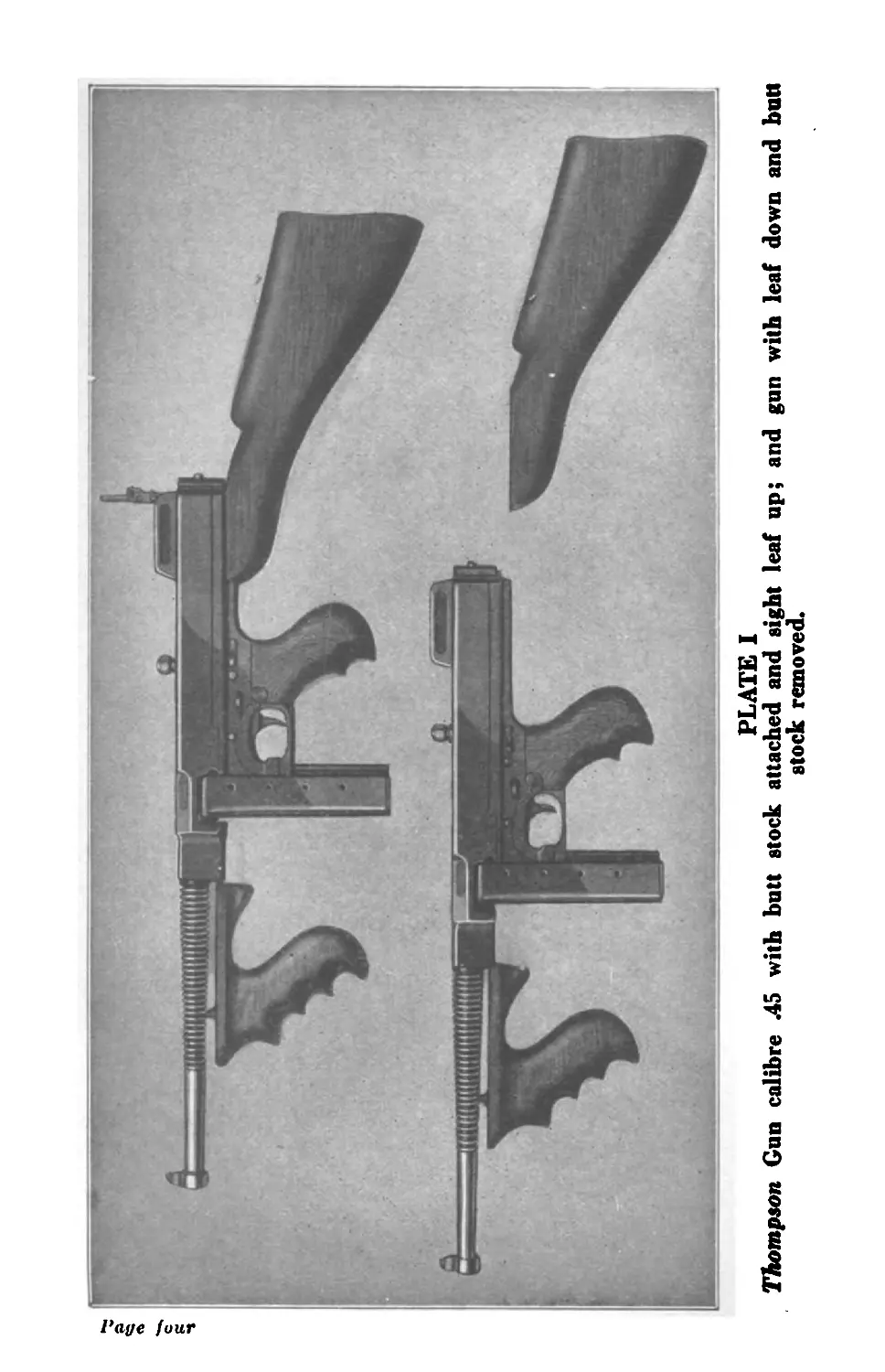
PLATE I
Thompson Gun calibre 45 with butt stock attached and sight leaf up; and gun with leaf down and butt
stock removed.
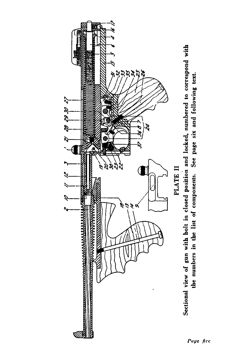
PLATE II
Риус
Sectional view of gun with bolt in closed position and locked, numbered to correspond with
the numbers in the list of components. See page six and following text.
Page six
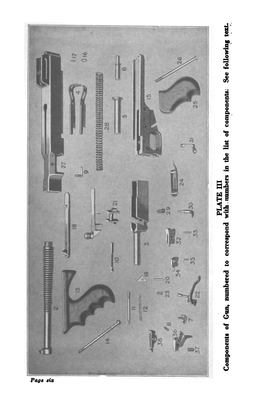
PLATE HI
Components of Gun, numbered to correspond with.numbers in the list of components; See following text.
THOMPSON SUBMACHINE GUN
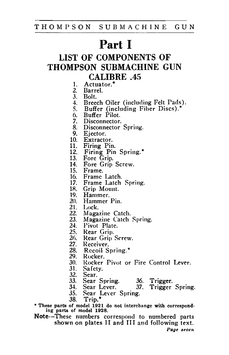
Part I
LIST OF COMPONENTS OF
THOMPSON SUBMACHINE GUN
CALIBRE .45
1. Actuator.*
2. Barrel.
3. Bolt.
4. Breech Oiler (including Felt Pads).
5. Buffer (including Fiber Discs).*
6. Buffer Pilot.
7. Disconnector.
8. Disconnector Spring.
9. Ejector.
10. Extractor.
11. Firing Pin.
12. Firing Pin Spring.*
13. Fore Grip.
14. Fore Grip Screw.
15. Frame.
16. Frame Uatch.
17. Frame Latch Spring.
18. Grip Mount.
19. Hammer.
20. Hammer Pin.
21. Lock.
22. Magazine Catch.
23. Magazine Catch Spring.
24. Pivot Plate.
25. Rear Grip.
26. Rear Grip Screw.
27. Receiver.
28. Recoil Spring.*
29. Rocker.
30. Rocker Pivot or Fire Control Lever.
31. Safety.
32. Sear.
33. Sear Spring. 36. Trigger.
34. Sear Lever. 37. Trigger Spring.
35. Sear Lever Spring.
38. Trip.*
* These parts of model 1921 do not interchange with correspond-
ing parts of model 1928.
Note—These numbers correspond to numbered parts
shown on plates II and III and following text.
Page eetie.n
THOMPSON SUBMACHINE GUN
MAGAZINES
Type XX Box Magazine (20-cartridgc).
Body.
Follower.
Spring.
Floor Plate.
Type L Magazine (50-cartridge drum).
Body, assembled.
Cover, assembled.
Rotor, assembled.
Winding Key, assembled.*
Body Clip*
Type C Magazine (100-cartridge drum).
Body, assembled.
Cover, assembled.
Rotor, assembled.
Winding Key, assembled.*
Body ('lip.*
SIGHTS
Front Sight (assembled to barrel).
Rear Sight.
Eye Piece.
Rear Sight Base (assembled to receiver).
Sight Base Pin.
Sight Plunger.
Sight Plunger Spring.
Sight Leaf (with slide retaining pin).
Sight Slide.
Sight Slide Catch.
Sight Slide Catch Screw.
Windage Screw, assembled.
Consisting of: Windage Screw.
Windage Screw Collar.
Windage Screw Collar Pin.
♦These parts are identical for both Type L and
Type C Magazines.
Paye eiyht
Paffe nine
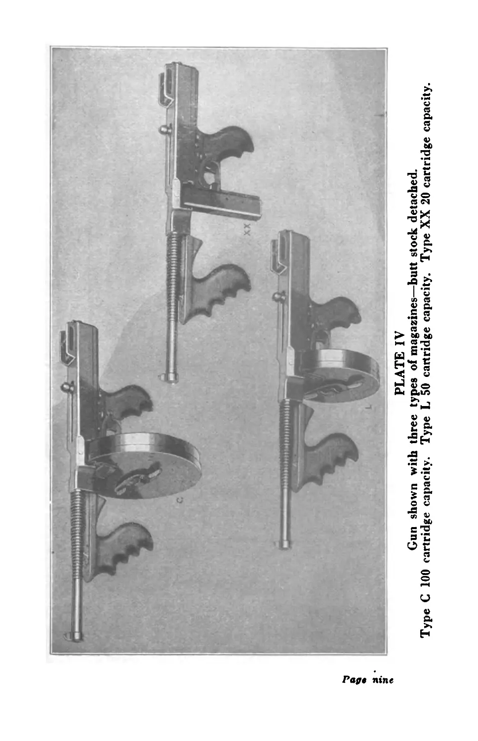
PLATE IV
Gun shown with three types of magazines—butt stock detached.
Type C 100 cartridge capacity. Type L 50 cartridge capacity. Type XX 20 cartridge capacity.
THOMPSON SUBMACHINE GUN
APPENDAGES AND ACCESSORIES
Butt Stock complete, consisting of:
Butt Stock (stripped).
Butt Stock Slide Group.
Butt Stock Slide.
Butt Stock Catch.
Butt Stock Catch Pin.
Butt Stock Catch Spring.
Butt Stock Screw, large.
Butt Stock Screw, small.
Butt Plate Group:
Butt Plate (stripped). Butt Plate Cap.
Butt Plate Pin.
Butt Plate Spring.
Butt Plate Spring Screw.
Butt Plate Screw, large.
Butt Plate Screw, small.
Cleaning Rod.
Brass Wire Brush.
Oil Can.
Petre ten
THOMPSON SUBMACHINE GUN
Part II
DIRECTIONS FOR OPERATING
GUN
The gun may be set for either full-automatic
or single shot fire. It is provided with sights
and a detachable butt stock. Three types of
magazines having capacities of 20, 50 and
100 cartridges, respectively, may be used.
It is possible to fire the Submachine Gun
from the hip either full-automatic or single
shot, with any of the magazines, with or with-
out the butt stock attached. Even though the
rocker pivot is set for full-automatic fire,
single shots may be obtained by a quick re-
lease of the trigger for each shot.
It is also possible to use the gun for aimed
fire from the shoulder, either full-automatic or
single shots, with any of the magazines.
Sight
The sight is graduated up to 600 yards for
the 230-grain bullet cartridge. The effective
range of the weapon with this standard am-
munition is about 350 yards. With tracer ammu-
nition very good results can be secured up to the
600 yards range. The eyepiece is laterally ad-
justable to correct for windage and drift. For
rapid firing with the sight leaf down a 50-yard
open sight is provided (Point Blank).
The index line on the eyepiece to “zero”
for lateral adjustment is omitted in manu-
facture to allow for individual determination
of this point. After this point has been satis-
factorily determined it is suggested that a line
Page eleven
THOMPSON SUBMACHINE GUN
be placed on the eye-piece index finger with a
sharp knife or other sharp instrument.
The personal element of holding the gun
greatly affects the accuracy of fire, and con-
sequently there may be a considerable varia-
tion in hits when the same sight setting is used
by different persons. Holding the gun loosely
tends toward shooting high. On page 50 the
sight correction for one foot at the various
ranges is tabulated. It will aid in judging
these small measurements to bear in mind that
the thickness of the projection on the sight
slide containing the battle sight notch is .05-
inch, and that the thickness of the eye piece is
also .05-inch.
The natural tendency of all automatic rifles,
especially in bursts of fire, is to raise the muz-
zle ; that of the average marksman is to shoot
high ; consequently the submachine gun should
be sighted slightly low, with a fine sight (the
top of the front sight just appearing in the bot-
tom of the peep or open sight), in order to ob-
tain maximum accurate results. The slightly
upward and to the right tendency of this gun,
especially in bursts of fire, can be corrected
by a small amount of practice on the part of
the gunner, in holding steady.
The Thompson Gun should be used prin-
cipally semi-automatic, i. e., a single shot for
each pull of the trigger. A rate of fire of 100
aimed shots can be easily obtained in one
minute in this manner. For full-automatic
purposes, or like a machine gun, the gun
should be fired in succession of bursts of three
to six shots at a time for most accurate results.
Page twelve
THOMPSON SUBMACHINE GUN
TO FIRE
First be sure gun is well cleaned and oiled
with sufficient oil on the oil pads of the breech
oiler (4).
Then SET SIGHT. The sight is set by
raising the leaf and sliding the slide to the
range desired. Lateral correction (right or
left) is obtained by turning the small thumb
screw.
To Fire — Semi-Automatically (A Single
Shot for Each Pull of the Trigger).
The normal method of firing the Thompson
Submachine Gun is semi-automatically, i. e.,
a single shot for each separate pull of the
trigger. To accomplish this first cock the bolt
(3) by grasping the actuator (1) with the left
hand and pull it rearward as far as possible,
i. e., until it clicks twice. Note: IT IS NECES-
SARY TO HAVE THE BOLT COCKED
BEFORE EITHER THE SAFETY LEVER
(31) OR THE FIRE CONTROL LEVER
(30) CAN BE TURNED TO THE POSI-
TION DESIRED. It is advisable to turn
the safety lever (31) to the safe position, that
is, so that it points rearward. Then turn the
fire control lever (30) so that it also points
rearward. The rear end of the gun is towards
the butt. The piece is now in its cocked
position for semi-automatic fire but locked
with the safety lever (31) on.
Face the target pointing the barrel in general
direction of range and insert loaded magazine
of the type desired. When in the proper
position the magazine will click in place. In
the case of the box type magazine (see Plate
Page thirteen
THOMPSON SUBMACHINE GUN
IV—Page 9) it is pushed upward into the
groove at the end of the trigger guard until
it clicks into place. The 50-capacity, Type L,
and the 100-capacity, Type C Drum Magazines
(see Plate IV—Page 9) are inserted from
left to right into the horizontal grooves of the
piece as shown on Plate IV, Page 9, the dis-
tinction being that the 20-capacity magazine
is inserted upward or vertically whilst the
drum magazines are inserted sidewise or hor-
izontally. In all cases be sure and push mag-
azines well up or in so that the magazine
catch can snap into position and hold the mag-
azine securely. Then set the safety (31) to
“Fire” by turning the safety lever (31) so that
it points forward towards the muzzle at the
position marked “Fire.” Pull the trigger and
release it quickly for each shot desired.
To Fire—Full-Automatically.
At the shorter ranges the Thompson Gun
can be fired very effectively full-automatically,
i. e., (like a machine gun) by following the
above directions for semi-automatic fire, with
the exception that the fire control lever (30)
is set for full-automatic fire, i. e., with the fire
control lever (30) pointing forward or towards
the muzzle. In firing full-automatically it is
well to remember that the prescribed method
is by bursts of a few shots at a time, that is,
by pulling the trigger until you have fired three
to ten shots and then releasing the trigger.
This method is called full-automatic fire by
bursts. After each burst of fire rearrange aim
and continue in this manner as may be desired.
In order to insert magazines, to set the
Page fourteen
THOMPSON SUBMACHINE GUN
safety lever (31) or to set the fire control lever
(30) the bolt must be in its rearward or re-
tracted position in all cases.
POSITION. The standing position when
firing full-automatically is very important.
The left foot is well advanced. The left knee
is bent with the weight of the body leaning
forward, resting on the left foot. The trunk
of the body is twisted or turned, thus push-
ing the right shoulder into the direction of the
fire, and the right shoulder is humped and
tense. It is as if a man was trying to push an
automobile, that had been stalled along the
road, with his right shoulder. The resistance
when fired full-automatically is not great and
surprisingly small with the *Cutts Com-
pensator, but the right shoulder must be
pushed into the gun by turning the trunk at
the hips and humping the shoulder. A few
trials will give remarkable results to anyone
who is at all acquainted with shooting. The
recoil is very slight but the rapid accumulation
of these slight recoils in full-automatic fire
will tend to push the operator backward, if he
is not well braced for the thrust and will con-
sequently affect the accuracy of fire. The
prone position (lying down) is better for ac-
curacy of fire.
In firing from the box magazine the bolt will
automatically be held in the open position
when the last shot has been fired therefrom.
In both drufrt magazines the bolt closes on the
empty chamber after the last shot has been
* Cutts compensator is a special device fitted on end
of guns to decrease the tendency of muzzle rising. It
is furnished on guns specially fitted for same on order.
Page fifteen
Page sixteen
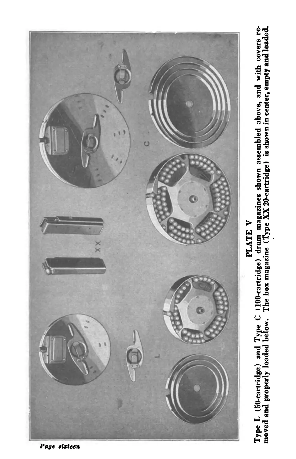
PLATE V
Type L (50-cartridge) and Type C (100-cartridge) drum magazines shown assembled above, and with covers re-
moved and properly loaded below. The box magazine (Type XX 20-cartridge) is shown in center, empty and loaded.
THOMPSON SUBMACHINE GUN
fired and a rattling noise can be heard in these
magazines which indicates they are empty.
Loading of Magazines (See Plate V)
Box Magazines
The normal capacity of a box magazine is
20 cartridges. It may be possible to force an
extra cartridge into the magazine, but this
should be avoided.
The cartridges feed into the magazine with
ease and without binding. If for any reason
excessive force is required to feed the car-
tridges out of the magazine, the energy of
the bolt is taxed to such an extent that a
misfire may result. The forward edge of the
magazine is rounded to prevent loading car-
tridges backward.
The lips of the mouth of the box magazine
should be a distance of .55-inch apart. If by
accident the magazine mouth should become
deformed, the lips should be carefully bent
back to this dimension.
Drum Magazines (See Plate V)
To load a drum magazine, remove the
winding key by lifting the flat spring thereon
and sliding the key off. The cover can then
be removed. Place the cartridges, bullet up,
into the spiral track of the body, beginning
with a full section at the mouth. The sim-
plest method to begin loading is to fill one
outer section and then rotate the rotor until
this section reaches the mouth. Thereafter,
continue to fill successive setons until the
end of the spiral track has been reached. Fill
each section complete; do not skip any section
Page seventeen
THOMPSON SUBMACHINE GUN
and do not fill beyond the end of the spiral track.
In order to obtain a capacity of 100 car-
tridges in the Type C magazine, a cartridge
should be placed in each of the four fingers
preceding the mouth.
Plate IV shows the magazines properly fill-
ed. Follow closely the arrangement of car-
tridges shown.
After the magazine is properly filled replace
the cover and key and wind to the number
of clicks indicated on the magazine nameplate.
Caution: Drum magazines when wound to
the number of clicks indicated on their cases,
namely, nine clicks for 1928 U. S. Navy Model
Guns and eleven clicks for Model 1927 Car-
bines and Model 1921 Submachine Guns,
should not be re-wound after many shots have
been fired. That is to say, a loaded magazine
which has been wound up should not be fired
a few shots and then rewound, as the resultant
strong spring tension will both interfere with
surety of action of the gun, as well as incurring
the possibility of breaking of the main spring
of magazine.
PRECAUTIONS
1. It is deemed advisable to habitually set
the gun at the “Safe” position while changing
the magazines and during lulls in firing.
2. Do not attach loaded magazine until you
are ready to fire. See that the magazine is
loaded and attached properly.
3. When getting ready to fire semi-auto-
matically make certain your fire control lever
(30) is set to “single” and your safety (31) to
“safe” before attaching magazine. Just before
Page eighteen
THOMPSON SUBMACHINE GUN
you are ready to fire raise gun to shoulder
and set safety (31) to “fire" position; in other
words, when the lever is pointing forward.
Apply the same precautions for full-automatic
fire making sure of the desired position of the
fire control lever (30).
4. Do not place the trigger finger within
the trigger guard until you are ready to fire
and have the gun pointed toward the target.
5. When you stop firing set the safety (31)
to “safe”; remove the magazine by pressing
up with your right thumb on the magazine
catch handle. Grasp the magazine in the left
hand when it is released by raising the mag-
azine catch (22). In an emergency where great
speed of fire is desired and it is necessary to
quickly replace the magazine with another the
box magazine will fall to the ground of itself
upon the release of the magazine catch (22).
See that there are no cartridges in the cham -
ber before you turn from your firing position.
6. When not in operation the bolt should
be closed, i. e., in its forward or uncocked
position, but closed on an empty chamber.
7. Each time before firing, reassure your-
self as to the type of fire that is desired,
whether full-automatic or single shot and make
certain that the fire control lever (30) is set
accordingly.
8. Make it a practice to see that chamber
is clear by looking through ejection opening.
9. For anticipated action carry the gun
with bolt cocked (retracted) and safety on.
Otherwise bolt should be left in closed position
on empty chamber, to relieve strain on recoil
spring. To close bolt on empty chamber, re-
Page nineteen
THOMPSON SUBMACHINE GUN
move magazine and let bolt go forward slow-
ly by retarding actuator knob with left hand.
Unless magazine is removed, the bolt if released
will fire cartridge from loaded magazine AS
THIS GUN FIRES ON THE FORWARD
STROKE OF THE BOLT.
10. For night operation, remember that
with both the safety (31) and fire control lever
(30) in forward direction the gun is ready for
full-automatic fire.
11. Do not snap bolt on empty chamber
unnecessarily.
12. In single shot fire release the trigger
quickly after each shot to reengage the sear,
as each pull of the trigger delivers but a single
shot.
13. When firing full-automatically fire in
bursts of three to ten shots.
MALFUNCTIONS
In case of a misfire, due to faulty ammuni-
tion or otherwise, retract or cock the bolt with
a sharp quick pull on the actuator knob. This
should insure ejection of the misfired cartridge.
In case of any other malfunction, retract
the bolt as above and clear the throat and
chamber of the gun by turning the gun over
on its side and letting the case or cartridge roll
out. If necessary remove the magazine quickly
and the cartridge or case will fall out from the
bottom. While manipulating the gun under
these circumstances it is deemed highly ad-
visable to always set the gun at “Safe.”
Remember you must first cock the piece
by pulling the actuator handle all the way back
before inserting magazines or setting the fire
control and safety levers.
Paffe twenty
THOMPSON SUBMACHINE GUN
Part III
AMMUNITION AND BALLISTICS
FOR CALIBRE .45 THOMPSON
SUBMACHINE GUN MODELS
1921 and 1928
The United States Army automatic service
pistol model of 1911 fires calibre .45 pistol
ball cartridges with a bullet weighing 230-
grains. This is also standard ammunition for
the Thompson Submachine Gun, calibre .45,
models of 1921 and 1928. The Thompson Sub-
machine Gun, Model 1921 only, also functions
equally well wtih commercial calibre .45 Colt
automatic pistol cartridge, the bullet of which
weighs 200-grains. The 200-grain bullet gives
a slightly increased velocity but is not as ac-
curate at the longer ranges in this gun.
There is also provided for use in the calibre
.45 Thompson Submachine Gun models of 1921
and 1928 Peters-Thompson birdshot cartridges
calibre .45. Each cartridge contains 120 number 8
birdshot. These cartridges are slightly longer
than the regular pistol ball cartridges and re-
quire a special box magazine similar to the
type XX 20-capacity cartridge magazine pro-
vided for the pistol ball ammunition, except
they are a little longer to accommodate the
slightly increased length of the Peters-Thomp-
son cartridge. The Peters-Thompson shot car-
tridges and magazines are used in the Thomp-
son Submachine Guns without any changes or
alterations being necessary except to use special
magazine. The extreme range of the Peters-
Paoe twenty-one
Т Н О М РS О N SUBMACHINE GUN
Thompson shot cartridge is about 150 feet. They
give a spread of a circle about six feet in diameter
at a range of 50 feet. In loading the Peters-
Thompson cartridge into special box magazine
care must be taken to exert no pressure on
paper carton bullet portion of cartridge. The
pressure to load cartridges into magazine must
be placed on the metal case.
The regular Colt calibre .45 pistol ball car-
tridges of either the military or commercial
design can be readily purchased from repre-
sentatives of the leading cartridge manufac-
turers of the United States such as the Rem-
ington Arms Company, 25 Broadway, New
York City; The Peters Cartridge Company.
Cincinnati, Ohio; Winchester Repeating Arms
Company, New Haven, Conn.; U. S. Cartridge
Company, 111 Broadway, New York City and
Western Cartridge Company, East Alton, Ill.
The Peters-Thompson shot cartridge is made
by The Peters Cartridge Company. In case
ammunition cannot be secured with facility
the Auto-Ordnance Corporation, 302 Broad-
way, New York City, will gladly furnish same
or give information enabling the purchaser to
secure his ammunition for Thompson Sub-
machine Gun with the least possible delay.
It is also to be noted that the Thompson
Submachine Gun mechanism can be made up
in quantities on special order for higher power-
ed and pressured ammunition than indicated
here, when desired. The Thompson Subma-
chine Gun mechanism can also be furnished
to fire high powered military service ammuni
Page twenty-two
THOMPSON SUBMACHINE GUN
tion, the guns of this type usually being pro-
vided with bipods and being of heavier weight.
Sight Setting
The sight on the Thompson Submachine
Gun, Models 1921 and 1928, is graduated for the
230 grain bullet ammunition.
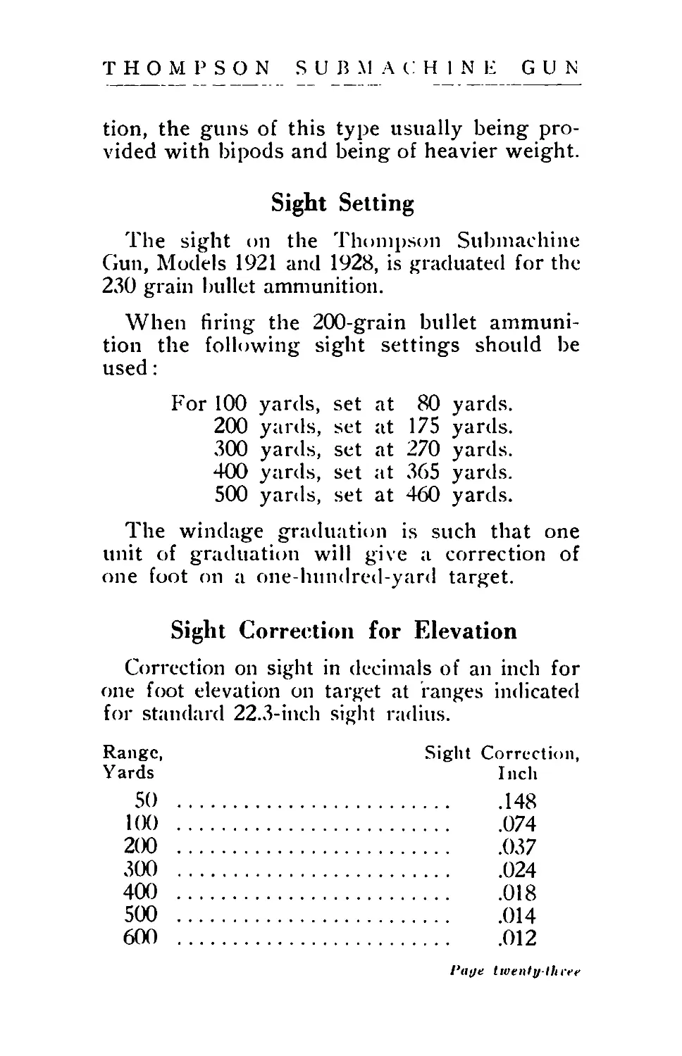
When firing the 200-grain bullet ammuni-
tion the following sight settings should be
used:
For 100 yards, set at 80 yards.
200 yards, set at 175 yards.
300 yards, set at 270 yards.
400 yards, set at 365 yards.
500 yards, set at 460 yards.
The windage graduation is such that one
unit of graduation will give a correction of
one foot on a one-hundred-yard target.
Sight Correction for Elevation
Correction on sight in decimals of an inch for
one foot elevation on target at ranges indicated
for standard 22.3-inch sight radius.
Range, Sight Correction,
Yards Inch
50 ..................................148
1(X) .................................074
200 ..................................037
300 ..................................024
400 ..................................018
500 ..................................014
600 ..................................012
/'«</« twenty-three
THOMPSON SUBMACHINE GUN
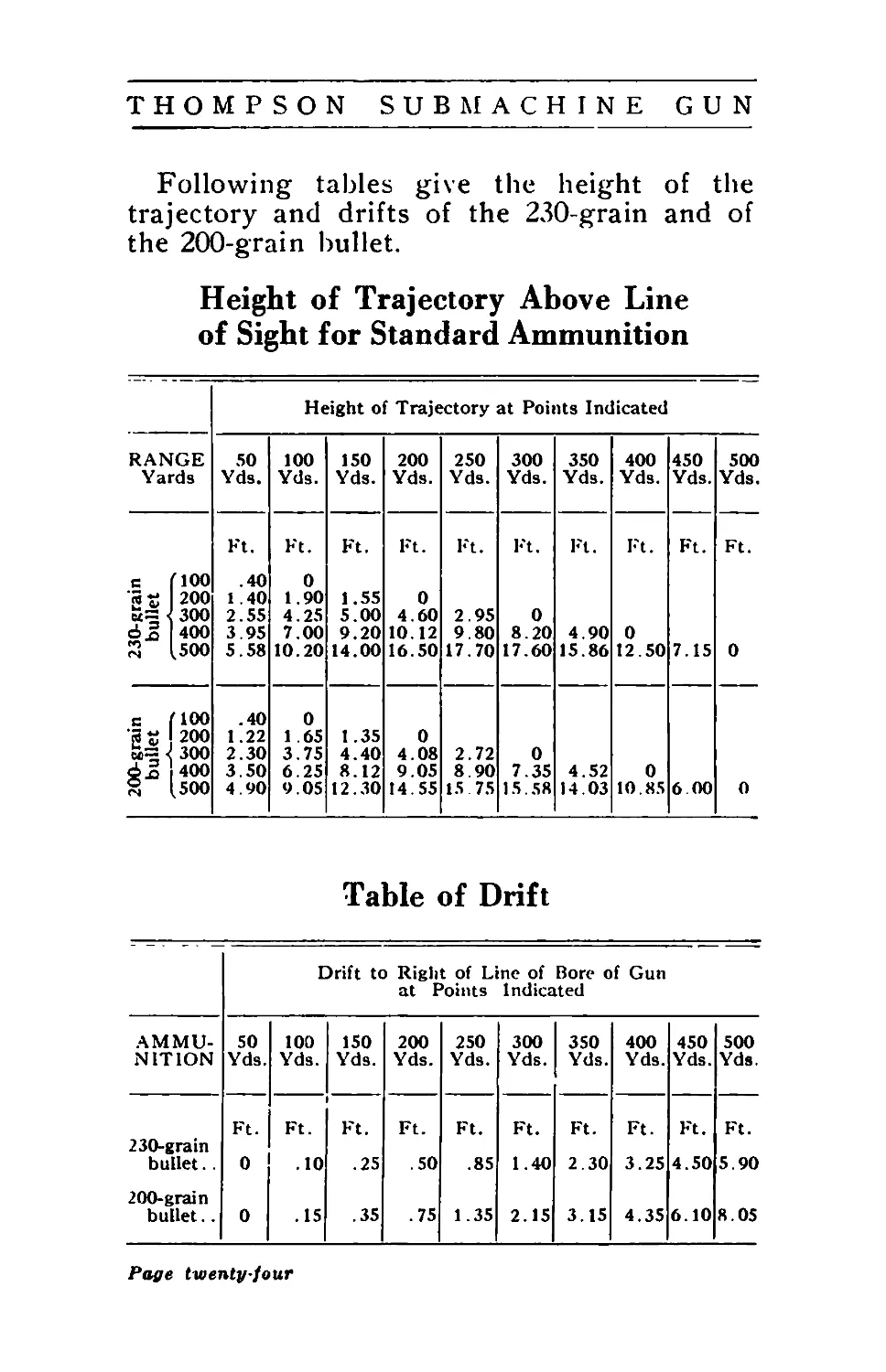
Following tables give the height of the
trajectory and drifts of the 230-grain and of
the 200-grain bullet.
Height of Trajectory Above Line
of Sight for Standard Ammunition
Height of Trajectory at Points Indicated
RANGE 50 100 150 200 250 300 350 400 450 500
Yards Yds. Yds. Yds. Yds. Yds. Yds. Yds. Yds. Yds. Yds.
Ft. Ft. Ft. Ft. Ft. Ft. Ft. Ft. Ft. Ft.
c (100 . 40 0
200 1.40 1.90 1.55 0
< 300 2.55 4.25 5.00 4.60 2.95 0
dj 400 3.95 7.00 9.20 10.12 9.80 8.20 4.90 О
й [500 5.58 10.20 14.00 16.50 17.70 17.60 15.86 12.50 7.15 О
с (100 .40 О
200 1.22 1.65 1.35 О
«=РОО 2.30 3.75 4.40 4.08 2.72 О
вл 400 3.50 6.25 8.12 9.05 8.90 7.35 4.52 О
8 (500 4.90 9.05 12.30 14.55 15 75 15.58 14.03 10.85 6 00 О
Table of Drift
Drift to Right of Line of Bore of Gun
at Points Indicated
AMMU-
NITION
50
Yds.
100
Yds.
150
Yds.
200 250 300 350
Yds. Yds. Yds. Yds.
400 450 500
Yds. Yds. Yds.
230-grain
bullet. .
200-grain
bullet..
Ft.
0
Ft.
.10
0 .15
Ft.
.50
.85
.35 .75 1.35
Ft. Ft.
1.40 2.30
2.15 3.15
Ft.
3.25
Ft. Ft.
4.50 5.90
4.35 6.10 8.05
Page twenty-four
THOMPSON SUBMACHINE GUN
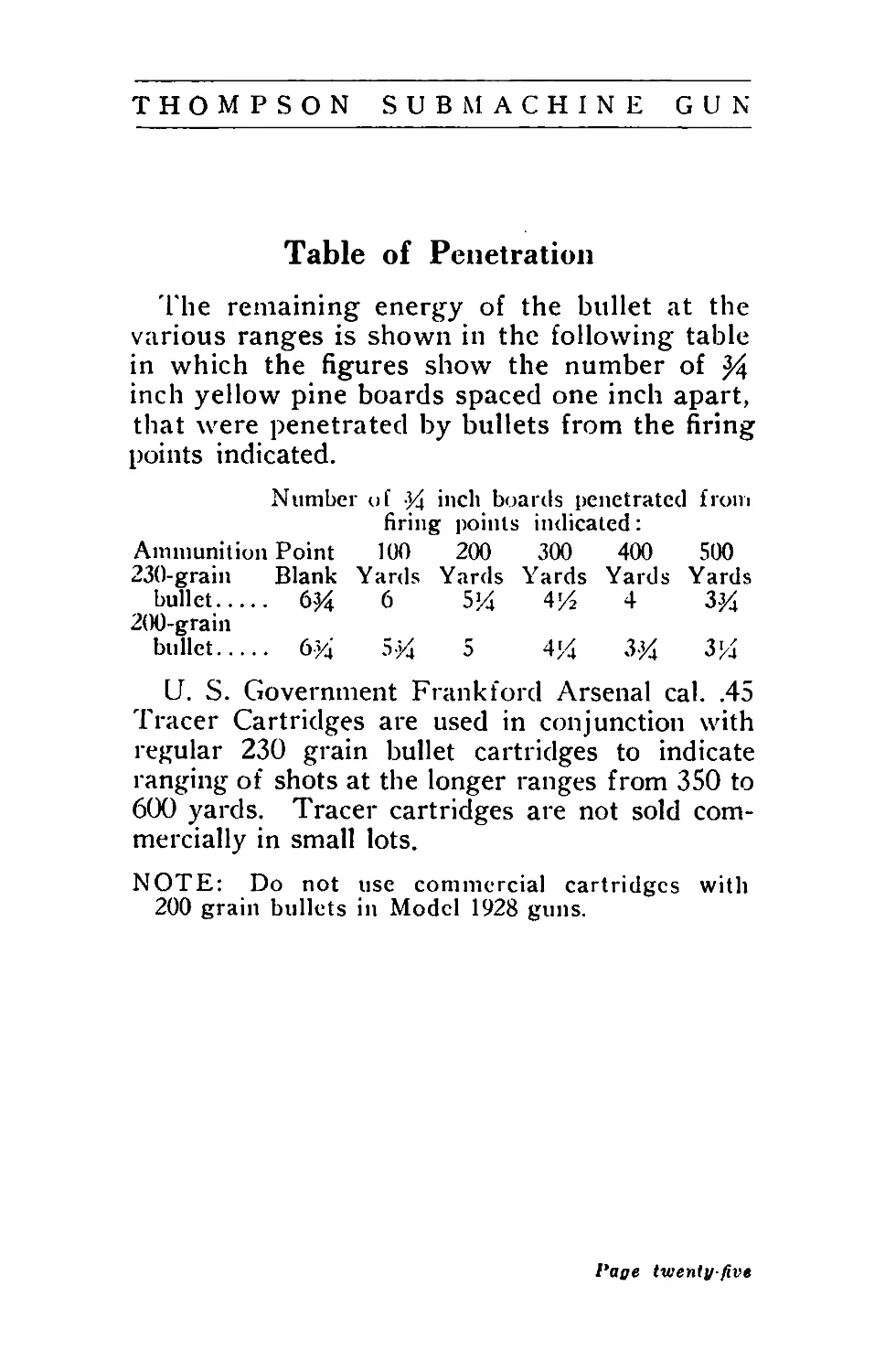
Table of Penetration
The remaining energy of the bullet at the
various ranges is shown in the following table
in which the figures show the number of 24
inch yellow pine boards spaced one inch apart,
that were penetrated by bullets from the firing
points indicated.
Number of Уд inch boards penetrated from
firing points indicated:
Ammunition Point 100 200 300 400 500
230-grain Blank Yards Yards Yards Yards Yards
bullet.... 6^4 6 5% 4J4 4 ЗУ
200-grain
bullet.... бУд 5-У 5 41У ЗУ ЗУ
U. S. Government Frankford Arsenal cal. .45
Tracer Cartridges are used in conjunction with
regular 230 grain bullet cartridges to indicate
ranging of shots at the longer ranges from 350 to
600 yards. Tracer cartridges are not sold com-
mercially in small lots.
NOTE: Do not use commercial cartridges with
200 grain bullets in Model 1928 guns.
Page twenty-five
THOMPSON SUBMACHINE GUN
Part IV
GENERAL DESCRIPTION OF GUN
AND OPERATING PRINCIPLE
(Note numbers correspond to parts shown
on Plates II and III, pages 5 and 6.)
The gun is composed of two distinct groups:
the Receiver (27) with the parts attached there-
to and contained therein, and the Frame (15)
with its attached and contained parts.
The Receiver Group
The receiver (27) forms the skeleton of the
gun and has the barrel (2) screwed thereon.
Immediately beneath the barrel (2), at the
front end of the receiver (27), is anchored the
fore grip mount, to which is secured the fore
grip (13). The fore grip mount (18) is held
in place by the barrel (2).
The receiver (27) immediately to the rear
of the barrel (2) is provided with an opening
for magazines and with a bolt well. Beyond
the magazine opening is a uniform enlarged
cavity which contains the body of the bolt (3),
with recoiling space for the same, also the re-
coil spring (28) and buffer (5).
The bolt (3) consists of a rectangular body
portion which fits into the cavity in the re-
ceiver (27), and a round forwardly projecting
portion which fits into the forward bolt well
of the receiver (27). The forward end of the
bolt (3) being of a reduced size permits the
magazine to be brought up in close proximity
Page twenty-six
THOMPSON SUBMACHINE GUN
to the chamber and as near as possible to the
axis of the bore.
The lock (21) consists of an “H” member
with lugs extending on each side thereof. The
sides of the lock (21) engage with the bolt,
(3), and the lugs thereon engage with grooves
in the receiver (29). The central bar is en-
gaged by the actuator (1) for control by the
recoil spring (28) and for manual operation.
The surfaces between the bolt (3) and lock
(21) are at an angle of 70 degrees to the axis
of the gun, and the surfaces between the lock
(21) and receiver (27) at an angle of 45 de-
grees to the axis, so that there is formed on
the lock (21) an intercepted angle of 25 de-
grees between the bolt (3) bearing and re-
ceiver (27) bearing surfaces of the lock (21).
The explosive pressure of the cartridge is
transmitted through the forward end of the
bolt (3) to the lock (21), and through the lock
(21) to the locking surfaces of the receiver
(27). The bolt (3) is limited in its forward
travel by the abutment on the forward end of
the rectangular section of the bolt (3) abutting
against the corresponding abutment in the re-
ceiver (27). In the portion of the bolt (3)
between this abutment and the lock (21) is
pivoted a hammer (19) in the form of a re-
versed lever. The lower end of this hammer
(19) strikes the abutment in the receiver (27)
slightly in advance of the bolt (3). The upper
end of the lever contacts with the firing pin
(11) which extends through the round forward
portion of the bolt (3) to the cartridge seat
and is held in rearmost position by the firing
pin spring (12). The hammer (19) is so con-
1‘aye twenty-seven
THOMPSON SUBMACHINE GUN
structed that it will strike the abutment of the
receiver (27) and cause the discharge oi the
cartridge only when the bolt (3) is completely
locked.
The actuator (1) rests slidably on top of the
bolt (3) and engages the cross-bar of the lock
(21) with two fingers; the rear finger also en-
gages the forward end of the recoil spring
(28). The cavity in the rectangular portion of
the bolt (3) forms a housing for the recoil
spring (28), and the buffer (5) serves as an
arbor therefor. The buffer (5) consists of a
cylindrical tube closed at the forward end and
having a flange at its rear end. This flange
furnishes a seat for the rear end of the recoil
spring (28) and a buffing abutment for the
rear end of the bolt (3). The buffer (5) is
mounted on the buffer pilot (6) ; a column of
fiber discs is interposed between the forward
end of the buffer (5) and the buffer pilot (6),
so that all pressure or shock on the buffer (5)
is transmitted to the- buffer pilot (6) through
these buffing discs. The buffer pilot (6) has a
flange which seats against the rear end of the
receiver (27) and is held in place by its pro-
longed end of reduced diameter fitting into a
hole in the receiver therefor.
Held in place by the buffer pilot (6) and ex-
tending forwardly in undercuts in the re-
ceiver is a breech oiler (4) formed of spring
steel which holds oil saturated felt pads to re-
lubricate the locking lugs on the lock (21) at
each recoil of the bolt (3). These pads also
tend to keep the sides of the bolt (3) lubri-
cated.
The principle of bolt action is this, that
Page twenty-eight
THOMPSON S U В MACHINE GUN
during the period of high chamber pressure
the lock (21) is fixed in position by adhesion
of its surfaces and moves to clear the locking
surfaces in the receiver (27) only after the high
pressure in the chamber lias subsided. The
angle of the lock (21) is so chosen that at the
moment the lock (21) is moved clear of the
receiver locking surfaces, there is only suffi-
cient residual powder pressure in the chamber
to blow the cartridge case and the bolt (3)
rearwardly, eject the empty case and impart
sufficient inertia to the bolt (3) to completely
compress the recoil spring (28) and prepare
the bolt (3) for a new cycle of operation. On
its forward movement, under impluse of the
recoil spring (28), the bolt (3) feeds a car-
tridge from the magazine into the chamber
and as the bolt (3) approaches its foremost
position, the lugs on the lock (21) engage the
forward surfaces of the receiver (27) locking
grooves, which in conjunction with the recoil
spring (28) pressure on the lock (21) through
the actuator (1), drives the lock (21) down-
wardly into locked position.
The receiver (27) is provided on the right
side with an ejection opening in a plane 30
degrees above the horizontal. In this same
plane the forward end of the bolt (3) is pro-
vided with an extractor (10) secured by an un-
dercut and limited in horizontal movement by
a stud. The extractor (10) is retained in its
assembled position under its own spring ten-
sion.
The opposite side of the receiver (27) is pro-
vided with an ejector (9) which is screwed in-
to place and secured in position by a projec-
Pagetwentynint
THOMPSON SUBMACHINE GUN
tion on the end of a spring leaf engaging with
a detent on the receiver (27). The ejector (9)
extends into the path of the bolt (3), a clear-
ance cut on the bolt (3) being provided there-
for.
At the rear end the receiver (27) is provided
with a projection which contains the frame
latch (16) and frame latch spring (17). This
member locks the frame (15) to the receiver
(27) when the former is assembled thereto.
The parts thus far mentioned comprise the
receiver group, which with the exception of
the fore grip mount (18), the fore grip (13)
and screw (14), and frame latch (16) with
its spring, composes the working parts of the
gun.
The Frame Group
The frame (15) houses the entire trigger
mechanism, furnishes a seat for the rear grip
(25), an attachment for the box magazine, and
contains a catch to hold the latter in place.
The rear projection of the frame (15) is also
provided with a guideway, to which the butt
stock can be attached.
Of greatest importance in the trigger mech-
anism group is the sear (32) which under
impulse of the sear spring (33) engages one of
the sear notches in the bolt (3) when the latter
is in retracted position. The trigger (36) is
mounted in the frame (15) forwardly of the
sear (32), and carries pivotally mounted on a
rearward projection thereon the disconnector
(7), which under impulse of the disconnector
spring (8) is continually urged toward the
sear.(32). The forward portion of the trigger
Page thirty
THOMPSON SUBMACHINE GUN
(36) houses trigger spring (37), which urges
trigger (36) to its normal released position.
Surrounding the upper portion of the trig-
ger (36) and mounted on the same pivot, the
trip (38) extends forwardly into the path of
the box magazine follower, and rearwardly
over a forwardly projecting member of the dis-
connector (7). The relation of trip (38) to dis-
connector (7) is such that when trigger (36) is
pulled, the trip (38) (when the last shot has been
fired from the box magazine) will be lifted by the
follower of magazine and will move disconnector
(7) away from sear lever (34), thus allowing
sear (32) to engage bolt (3) to hold it “open.”
Between the sear (32) and the disconnector
(7) is interposed the sear lever (34) mounted
on the same pivot with the sear (32). The sear
lever (34) is urged downwardly by the sear
lever spring (35). The disconnector (7)
when moving upwardly, by a pull on the trig-
ger (36) lifts the sear lever (34), and the sear
lever in turn lifts the forward projection of the
sear (32), causing the rear projection to be-
come depressed and disengaged from the bolt
(3). The bolt (3) is then free to move for-
ward under impulse of the recoil spring (28)
and will reciprocate in automatic action until
the cartridges are exhausted, or the trigger
(36) is released, or the bolt (3) is arrested in
its retracted position by the action of the fol-
lower of the box magazine on the trip (38)
when the last cartridge has been fed from the
box magazine. In this last-mentioned instance
the disconnector (7) will be disconnected from
the sear lever (34), which will be free to re-
Page thirty-one
THOMPSON SUBMACHINE GUN
sume its normal position and will in turn al-
low the sear (32) to re-engage the bolt (3).
Between the trigger (36) and sear (32) there
is provided a rocker pivot (30) which carries
a rocker (29) mounted on an eccentric portion
thereof. This rocker (29) extends upwardly
when the rocker pivot (30) is set for “auto-
matic” or “Full-Auto” position to within a very
short distance of the bolt (3). The forward
edge of the rocker (29) rests against the dis-
connector (7). When the rocker pivot (30)
is rotated through an arc of 180-degrees to the
“semi-automatic” or “single” position, the ec-
centric axis of the rocker pivot (30) causes the
rocker (29) to project upwardly into the path
of the bolt (3). There is provided on the bot-
tom of the bolt (3) a groove to clear the
rocker (29), of such length that the rear wall
of this groove will strike the rocker (29) at the
final stage of the forward movement of the
bolt (3), imparting to the rocker (29) sufficient
movement to cause it to throw the disconnector
(7) forwardly and disengage same from the
sear lever (34). The sear lever (34) immediate-
ly under impulse of the sear lever spring (35)
assumes its normal position, leaving the sear
(32) free to engage the bolt (3) in retracted
position.
The function of the sear lever is this:
That as the bolt (3) has reached its forward
position and has caused the rocker (29) to
disengage the disconnector (7) from the sear
lever (34,) if the sear lever (34) were not free
to move downward, the disconnector (7) might
re-engage the sear (32) when the bolt (3)
starts rearwardly on its recoil, and the sear
Page thirty-two
THOMPSON SUBMACHINE GUN
(32) would then not be free to re-engage the
bolt (3).
The position of the rocker (29) controls the
nature of fire of the gun, whether full-automatic
or single shot. The rocker pivot (30) can be
turned from “automatic” or “full-auto” to “semi-
automatic” or “single” position, only when bolt
(3) is retracted.
It can be turned in the reverse direction
with the bolt (3) closed, but to avoid con-
fusion the bolt (3) should always be retracted
when setting the rocker pivot (30) in either
direction.
The safety (31) is mounted at the rear end
of the sear (32). It consists of a cylindrical
body with its central portion halved to clear
the sear (32). The sear (32) is provided at the
rear end with a half hole to engage the safety
(31). When the safety (31) is turned to “safe"
position it engages the sear (32) so that the
latter is positively blocked against movement.
When the safety (31) is turned to “fire”
position, the half section of its body is rotated
out of engagement with the sear (32) and the
sear (32) is free to move.
The safety (31) can be turned to “safe”
position only when the sear (32) is in engage-
ment with the bolt (3) in its retracted position.
Obviously since this is an open chamber gun.
that is. the bolt (3) when released by the trig-
ger pull loads and immediately fires the car-
tridge, the gun with the bolt (3) resting in
forward position is completely inactive.
The pivot pin (24) for the trigger (36) and
trip (38), and the pivot pin (24) for the sear
(32) and sear lever (34) are both secured to a
Page thirty-three
THOM P SON SUBMACHINE G U N
spring plate, which is provided with projecting
spring fingers engaging grooves on the safety
(31) and the rocker pivot (30), retaining these
parts in assembled position.
The forward end of the frame (15) is pro-
vided with a dovetail cut, which engages a cor-
responding dovetail member of the box maga-
zine. On the side of the frame (15) is pivoted
the magazine catch (22) urged into engage-
ment with the magazine by a torsion spring.
This magazine catch (22) engages the box
magazine by a stud extending forwardly
through the center of the trigger guard; and
also holds the drum magazines in position by
the engagement of its forward edge with a
notch on these magazines.
The rear grip (25) is secured to the frame
(15) by means of the rear grip screw (26).
The frame (15) is assembled to the receiver
(27) by undercut ways engaging correspond-
ing ways on the receiver (27). When the
frame (15) is in foremost position on the re-
ceiver (27) the frame latch (16) pocketed at
the rear end of the receiver (27) is free under
impulse of the frame latch spring to project
downwardly into engagement with the frame
(15), locking same to receiver (27).
Magazines (See Plates IV and V)
The Box Magazine has a capacity for twenty
cartridges in double column. It consists of a
formed sheet metal body with a dovetail pro-
jection on its rear edge for engagement with
the frame and a hole therein for engagement
with the magazine catch. This rearwardly ex-
Page thirty-four
THOMPSON SUBMACHINE G UN
tending dovetail also furnishes a path for a
rear projection on the follower for contacting
with the trip to cause the bolt to be held open
when the last shot is fired from the magazine.
The follower serves as a table for the car-
tridges in the magazine and is urged upward
by the magazine spring, which is supported at
the bottom of the magazine by the floor plate.
This magazine consists of the four parts men-
tioned: the body, follower, magazine spring
and floor plate.
The Drum Magazines, Type L and Type C,
consist of circular pan-like bodies provided
with covers. Rotatably mounted on a hub
within the magazine is a rotor to which is
attached a spring case housing a motor spring.
To a flange on the hub is attached a ratchet
consisting of a circular disc, so cut that four
fingers are formed thereon and given a curva-
ture to project beyond the plane of the ratchet.
These fingers of the ratchet engage with in-
wardly protruding edges formed in the body
of the magazine in such a manner that the
fingers of the ratchet will pass over the pro-
jections when the hub is rotated in winding
direction, and will abut on these projections
when the hub is turned in opposite direction.
The motor spring is fastened on its inner end
to the hub, and on its outer end to the spring
case.
The relation of these parts is such that
when there are cartridges in the magazine,
so that the rotor is not free to rotate, and the
hub is turned in a feeding direction, the motor
spring will become wound up and the fingers
on the ratchet engaging.the projections on
Раце thirty five
THOMPSON SUBMACHINE GUN
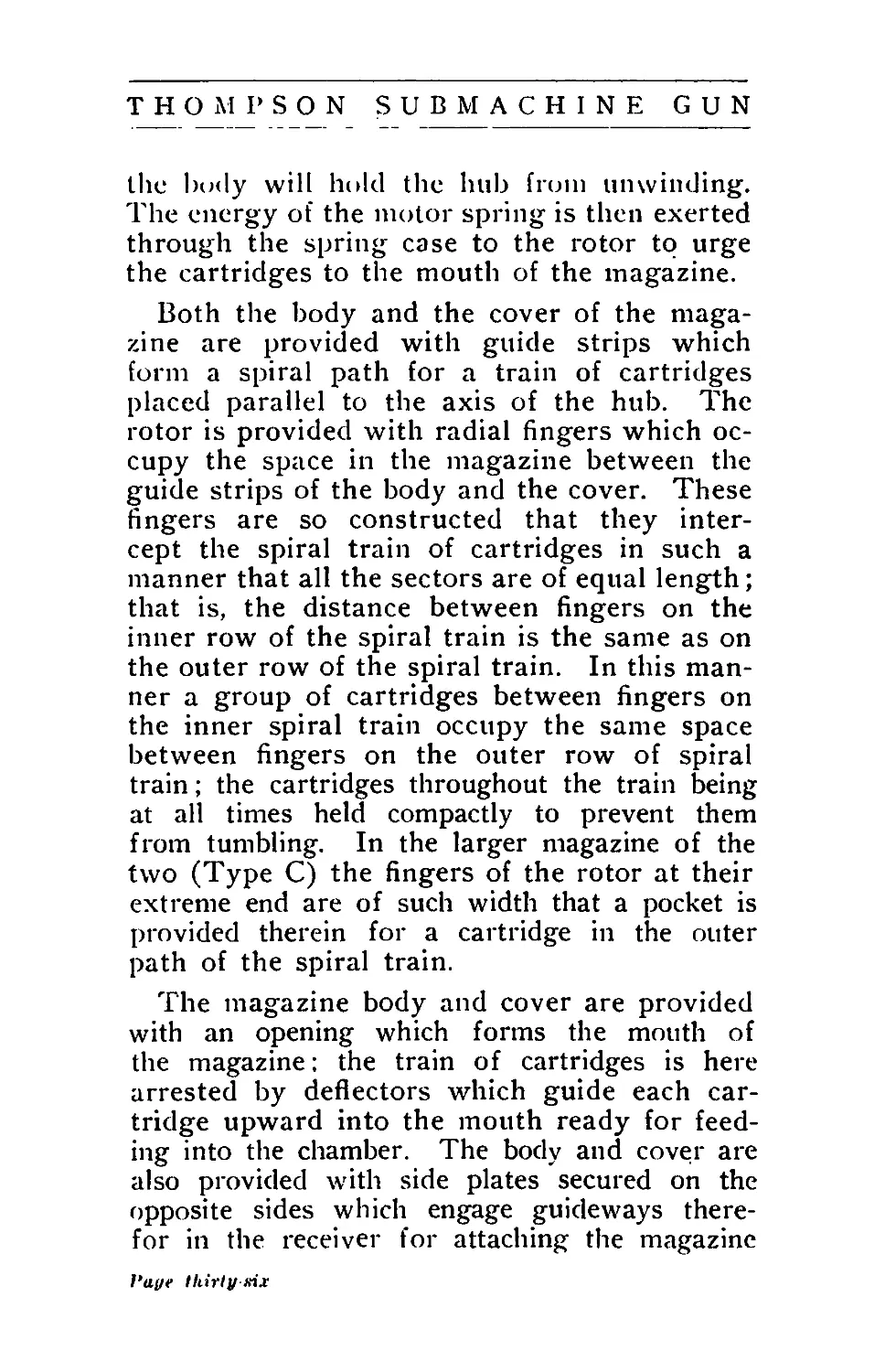
the body will hold the hub from unwinding.
The energy of the motor spring is then exerted
through the spring case to the rotor to urge
the cartridges to the mouth of the magazine.
Both the body and the cover of the maga-
zine are provided with guide strips which
form a spiral path for a train of cartridges
placed parallel to the axis of the hub. The
rotor is provided with radial fingers which oc-
cupy the space in the magazine between the
guide strips of the body and the cover. These
fingers are so constructed that they inter-
cept the spiral train of cartridges in such a
manner that all the sectors are of equal length;
that is, the distance between fingers on the
inner row of the spiral train is the same as on
the outer row of the spiral train. In this man-
ner a group of cartridges between fingers on
the inner spiral train occupy the same space
between fingers on the outer row of spiral
train; the cartridges throughout the train being
at all times held compactly to prevent them
from tumbling. In the larger magazine of the
two (Type C) the fingers of the rotor at their
extreme end are of such width that a pocket is
provided therein for a cartridge in the outer
path of the spiral train.
The magazine body and cover are provided
with an opening which forms the mouth of
the magazine: the train of cartridges is here
arrested by deflectors which guide each car-
tridge upward into the mouth ready for feed-
ing into the chamber. The body and cover are
also provided with side plates secured on the
opposite sides which engage guideways there-
for in the receiver for attaching the magazine
Paye thirty irix
Т Н О NJ Р S О N SUBMACHINE GUN
thereto. The side plate on the magazine body
is provided at the bottom with a notch for en-
gagement with the magazine catch to hold
the magazine in position on the gun. The hub
is secured to the magazine body with a spring
clip. The cover is secured by a winding key
which fastens to the end of the hub and by
means of which the motor spring is wound.
The drum magazines are of two sizes:
Magazine, Type L, of a 50-cartridge capacity,
and Magazine, Type C, of a 100-cartridge
capacity. (Type C is not made for Model 1928.)
Sights
Sights are provided for use in connection
with the butt stock to fire the gun from the
shoulder.
The front sight consists of a one-piece mem-
ber secured to the front end of the barrel with
a pin.
The rear sight consists of a base which is
riveted to the top of the receiver. The base
is provided with side walls to protect the sight.
It has a central housing for the plunger and
plunger spring, and at its rear end it carries
the sight leaf pivotally mounted thereon. The
pivot end of the leaf is cylindrical and is pro-
vided with “V” slots for engagement with the
plunger under pressure of the plunger spring.
These “V” slots are so located that the plunger
engages therewith when the leaf is in the “up”
or in the “down” position and serves as a de-
tent to hold the leaf in these two positions.
On the leaf is mounted a slide which is held
in position by a small studded leaf spring
secured on the edge thereof, the stud engag-
Page thirty-seven
Т Н О М Р SON SUBMACHINE G U N
ing with serrations on the edge of the leaf.
Projecting from the slide is a forward wall
notched for a battle sight and two lateral
lugs which support a windage screw. This
windage screw carries the eyepiece which ex-
tends below the slide. The eyepiece has an
opening for a field view and an aperture for
sighting. The upper end of the eyepiece is
provided with a suitable edge for carrying an
index mark for windage adjustment. Im-
mediately above this edge on the battle sight
wall is the windage graduation.
Butt Stock
To fire the gun from the shoulder there is
provided a butt stock which can be readily
attached to the frame, a catch locking the
same in place.
The butt stock consists of a black walnut
body. A slide which fits the frame of the
gun is secured to the front end of the body
by means of two screws. On this slide is
mounted the catch to lock the butt stock to
the frame.
At the butt end the stock is provided with
a pocket for an oil can, and a butt plate is
secured thereon with two wood screws. The
butt plate is provided with a small circular
hinged cap which serves as a door to the oil
can pocket.
l‘age thirty eight
THOMPSON SUBMACHINE GUN
Part V
DIRECTIONS FOR DISMOUNTING
AND ASSEMBLING
TO DISMOUNT
Read Precautions (a) and (b), page 45.
1. Remove Magazine
Remove magazine by pressing upward with
right thumb on magazine catch.
2. Remove Frame from Receiver
Turn safety to “fire" position and rocker
pivot to “automatic” or “full-auto” position.
Pull the trigger and allow bolt to go forward
gradually by retarding actuator with left hand.
Place gun upside down on knee or on a
table, the barrel extending rearward, and
steady against movement with the actuator
knob. With thumb of left hand depress frame
latch at rear end of the frame and with right
hand tap frame sliding same rearward a short
distance. Take the gun from table or knee,
grasping rear grip in right hand, and grasping
receiver with left hand pull trigger and slide
frame off to the rear.
3. Remove Recoil Spring
Support muzzle of barrel on table or knee,
with open side of receiver facing operator.
Grasp receiver with left hand, with thumb in
position to engage the buffer. With thumb of
right hand press down on buffer pilot which
projects beyond end of the receiver, and with
thumb of left hand engage the flange of buffer.
If the breech oiler follows, push same back
Page thirty-nine
THOMPSON SUBMACHINE GUN
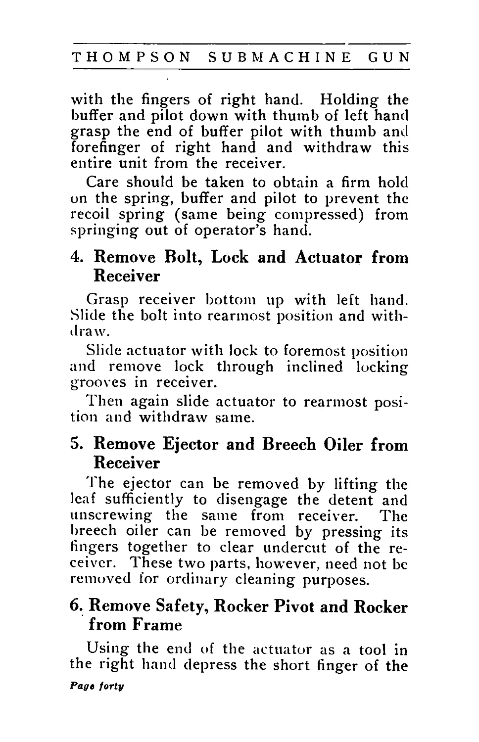
with the fingers of right hand. Holding the
buffer and pilot down with thumb of left hand
grasp the end of buffer pilot with thumb and
forefinger of right hand and withdraw this
entire unit from the receiver.
Care should be taken to obtain a firm hold
on the spring, buffer and pilot to prevent the
recoil spring (same being compressed) from
springing out of operator’s hand.
4. Remove Bolt, Lock and Actuator from
Receiver
Grasp receiver bottom up with left hand.
Slide the bolt into rearmost position and with-
draw.
Slide actuator with lock to foremost position
and remove lock through inclined locking
grooves in receiver.
Then again slide actuator to rearmost posi-
tion and withdraw same.
5. Remove Ejector and Breech Oiler from
Receiver
The ejector can be removed by lifting the
leaf sufficiently to disengage the detent and
unscrewing the same from receiver. The
breech oiler can be removed by pressing its
fingers together to clear undercut of the re-
ceiver. These two parts, however, need not be
removed for ordinary cleaning purposes.
6. Remove Safety, Rocker Pivot and Rocker
from Frame
Using the end of the actuator as a tool in
the right hand depress the short finger of the
Page forty
THOMPSON SUBMACHINE GUN
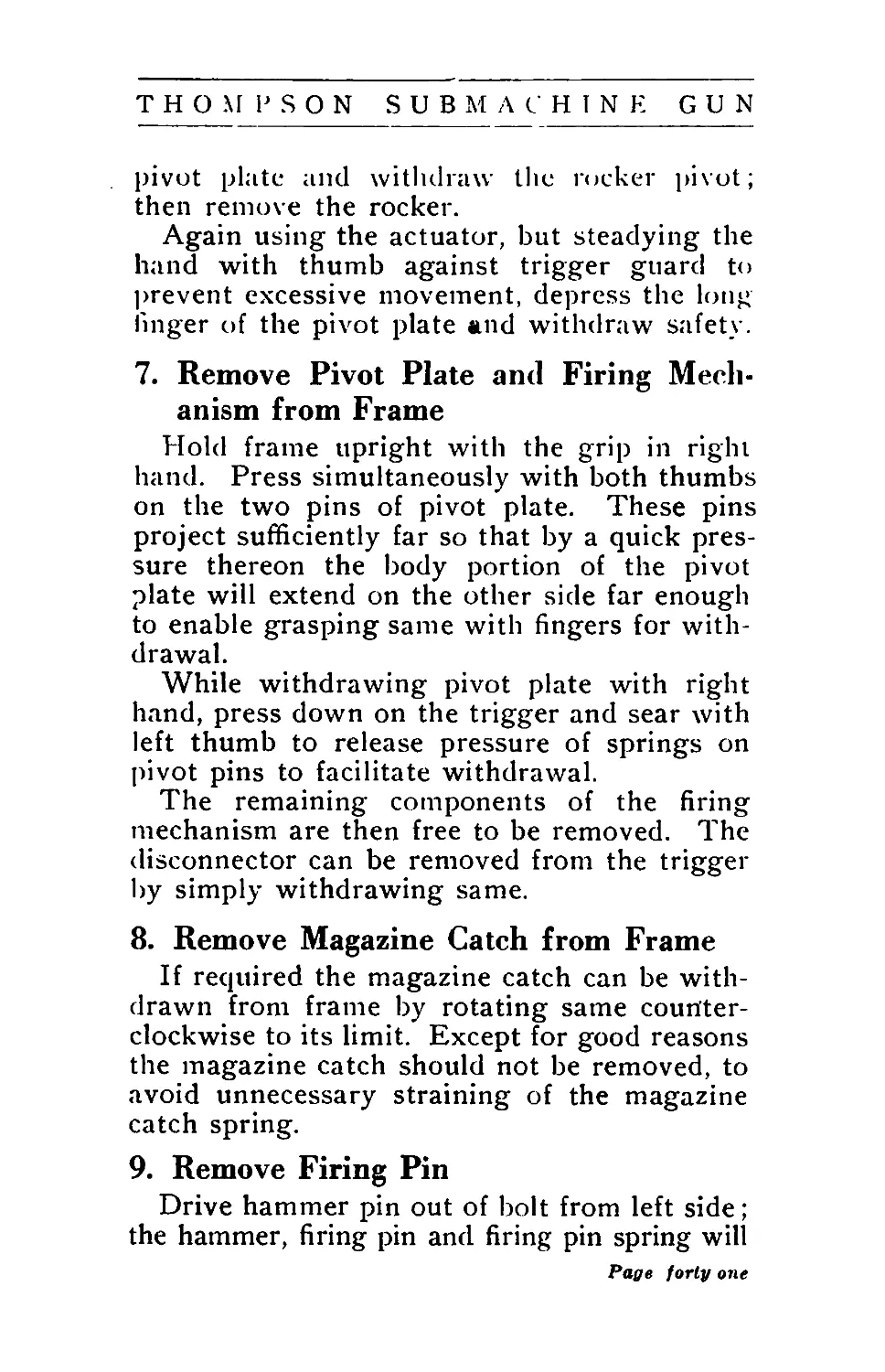
pivot plate and withdraw the rocker pivot;
then remove the rocker.
Again using the actuator, but steadying the
hand with thumb against trigger guard to
prevent excessive movement, depress the long
linger of the pivot plate and withdraw safety.
7. Remove Pivot Plate and Firing Mech-
anism from Frame
Hold frame upright with the grip in right
hand. Press simultaneously with both thumbs
on the two pins of pivot plate. These pins
project sufficiently far so that by a quick pres-
sure thereon the body portion of the pivot
plate will extend on the other side far enough
to enable grasping same with fingers for with-
drawal.
While withdrawing pivot plate with right
hand, press down on the trigger and sear with
left thumb to release pressure of springs on
pivot pins to facilitate withdrawal.
The remaining components of the firing
mechanism are then free to be removed. The
disconnector can be removed from the trigger
by simply withdrawing same.
8. Remove Magazine Catch from Frame
If required the magazine catch can be with-
drawn from frame by rotating same counter-
clockwise to its limit. Except for good reasons
the magazine catch should not be removed, to
avoid unnecessary straining of the magazine
catch spring.
9. Remove Firing Pin
Drive hammer pin out of bolt from left side;
the hammer, firing pin and firing pin spring will
Page forty one
THOMPSON SUBMACHINE GUN
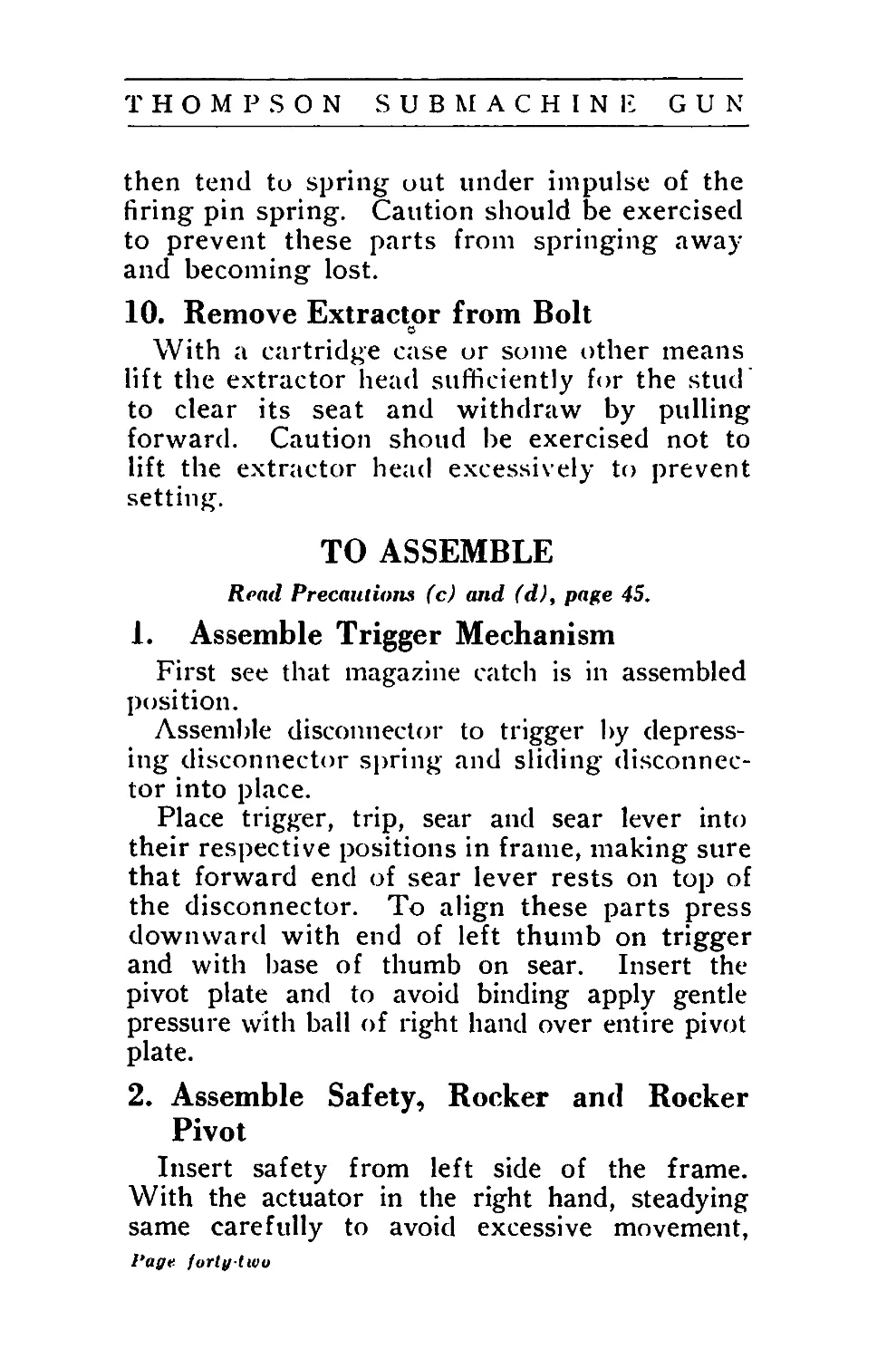
then tend to spring out under impulse of the
firing pin spring. Caution should be exercised
to prevent these parts from springing away
and becoming lost.
10. Remove Extractor from Bolt
О
With a cartridge case or some other means
lift the extractor head sufficiently for the stud’
to clear its seat and withdraw by pulling
forward. Caution shoud be exercised not to
lift the extractor head excessively to prevent
setting.
TO ASSEMBLE
Read Precautions (c) and (d), page 45.
1. Assemble Trigger Mechanism
First see that magazine catch is in assembled
position.
Assemble disconnector to trigger by depress-
ing disconnector spring and sliding disconnec-
tor into place.
Place trigger, trip, sear and sear lever into
their respective positions in frame, making sure
that forward end of sear lever rests on top of
the disconnector. To align these parts press
downward with end of left thumb on trigger
and with base of thumb on sear. Insert the
pivot plate and to avoid binding apply gentle
pressure with ball of right hand over entire pivot
plate.
2. Assemble Safety, Rocker and Rocker
Pivot
Insert safety from left side of the frame.
With the actuator in the right hand, steadying
same carefully to avoid excessive movement,
Page, forty-two
THOMPSON S и В M А С 11 1 N В G U N
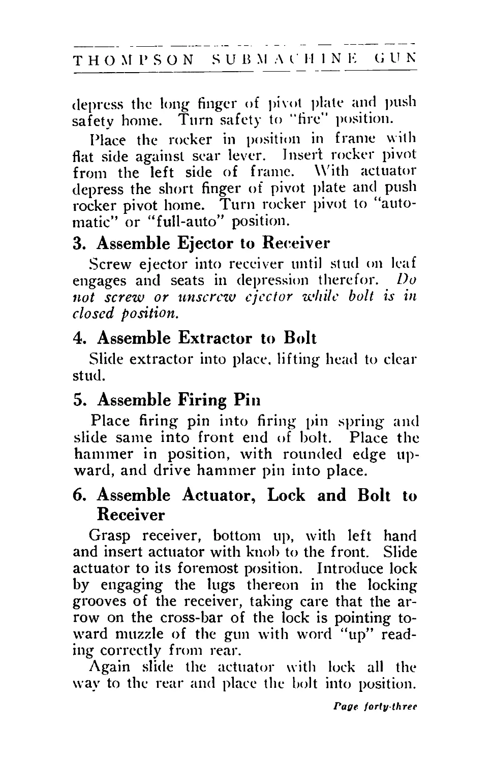
depress the long finger of pivot plate and push
safety home. Turn safety to "fire” position.
Place the rocker in position in frame with
flat side against scar lever. Insert rocker pivot
from the left side of frame. With actuator
depress the short finger of pivot plate and push
rocker pivot home. Turn rocker pivot to “auto-
matic” or “full-auto” position.
3. Assemble Ejector to Receiver
Screw ejector into receiver until stud on leaf
engages and seats in depression therefor. Do
not screw or unscrew ejector while bolt is in
closed position.
4. Assemble Extractor to Bolt
Slide extractor into place, lifting head to clear
stud.
5. Assemble Firing Pin
Place firing pin into firing pin spring and
slide same into front end of bolt. Place the
hammer in position, with rounded edge up-
ward, and drive hammer pin into place.
6. Assemble Actuator, Lock and Bolt to
Receiver
Grasp receiver, bottom up, with left hand
and insert actuator with knob to the front. Slide
actuator to its foremost position. Introduce lock
by engaging the lugs thereon in the locking
grooves of the receiver, taking care that the ar-
row on the cross-bar of the lock is pointing to-
ward muzzle of the gun with word “up” read-
ing correctly from rear.
Again slide the actuatin' with lock all the
way to the rear and place the bolt into position.
Page forty-three
THOMPSON SUBMACHINE GUN
7. Assemble Recoil Spring, Buffer and
Pilot
Slide bolt forward and rest muzzle of barrel
on table or knee, grasp receiver with left hand
and with right hand introduce recoil spring
with buffer and buffer pilot. Push recoil spring
down into bolt and let buffer pilot find its seat
in receiver and snap into place.
8. Mount Receiver on Frame
Grasp the frame with right hand in normal
position, making sure that the safety is set at
“fire” and the rocker pivot at “automatic” or
“full-auto.” Slide frame on to receiver and at.
same time pull the trigger. The frame latch will
lock the frame in position and the gun is now
ready for action.
9. Attaching Magazine
See Precaution (g), page 45.
The box magazine is attached by engaging
the dovetail thereon with the dovetail groove in
the forward end of the frame and moving maga-
zine upward until caught by the magazine
catch.
Drum magazines are introduced and removed
from left side of the gun. They are held in place
by the magazine catch. IVhen removing or at-
taching a drum magazine be sure that the bolt is
retracted.
Page forty-four
THOMPSON SUBMACHINE GUN
Precautions on Dismounting and
Assembling
(a) See that bolt is forward and rocker
pivot set at “automatic” or “fun-auto’’ before
attempting to dismount frame from receiver.
Rocker pivot must also be set at “automatic”
or “full-auto” and safety at “tire” when assem-
bling frame to receiver.
(b) Do not remove pivot plate until frame
has first been removed from receiver. If this
precaution is disregarded serious difficulties
may be entailed.
(c) When assembling or removing ex-
tractor to or from bolt, do not lift extractor
higher than necessary for lug to clear anchor-
age hole, to prevent setting or breaking of
extractor.
(d) When assembling or removing ejector
from receiver, make sure that bolt is not in
closed position, as the ejector head engages
with the ejector slot in front end of bolt.
Do not lift ejector leaf higher than neces-
sary for disengaging stud with depression in
receiver, to avoid setting or breaking of leaf.
(e) When assembling or removing safety
and rocker pivot, do not depress fingers on
pivot plate more than necessary, to prevent
setting or breaking.
(f) Do not remove breech oiler unless
necessary.
(g) Do not remove magazine catch unless
necessary. (The magazine catch can be
assembled or removed only with the pivot
plate partially withdrawn.)
Payc forty-five
THOMPSON SUBMACHINE GUN
Part VI
DIRECTIONS FOR CARE AND
PRESERVATION
Keep the gun well cleaned and oiled.
It is important that the gun be thoroughly
cleaned after each day’s firing regardless of
the number of shots fired. Not only should
the bore and chamber of the barrel be cleaned,
but also all parts and all surfaces of the re-
ceiver, bolt, ejector and extractor that are con-
tacted with the powder gases.
For this purpose the frame should be re-
moved from the receiver and the bolt should
be taken out to thoroughly clean the front
end thereof and the extractor. It may also
be desirable to remove the extractor. The
bolt-well and the throat of the receiver, as well
as the ejector head, are readily accessible.
To prevent rusting as a result of the im-
pregnation of powder gases a saturated solu-
tion of sal soda water, consisting of one-
quarter pound of sal soda per pint of water,
can be used. Cloth patches soaked in the
sal soda solution should be thrust through the
bore with the cleaning rod, and the receiver
and bolt surfaces affected should be wiped
with a cloth saturated in the soda solution.
Thereafter, all parts should be thoroughly
dried and well oiled.
Instead of the soda solution for cleaning
purposes, (jasolinc has been found to give good
results.
I’aye forty-six
THOMPSON S и В M Л С H I N Е G U N
In both cases, however, whether soda or
gasoline is used, it is important that the parts
be wiped dry after the wash and thoroughly
oiled.
With the exception of the magazines, it is
not necessary to give the remaining parts of
the gun a thorough cleaning after each firing,
unless many hundred shots have been fired and
it is desired to remove all powder residue or
other accumulated dirt. The magazines should
be treated and kept clean similar to the gun
parts affected by powder gases, and kept well
oiled inside.
The cleaning rod accompanying the gun should
be used in cleaning the barrel. The tip of this
cleaning rod is of such diameter that it will ac-
commodate one or two patches of flannel two
inches square. Brass wire brushes, which screw
directly on to the cleaning rod, arc also furnished
for cleaning.
Lubrication of Gun
Any good grade of light oil may be used for
lubricating the gun.
To lubricate, the frame should be removed
from the receiver. Oil should be dropped over
the pivot points of the trigger and trip, and the
sear and sear lever; also over the disconnector
and rocker.
Holding the receiver in the left hand, open
side up, the bolt should be slightly retracted and
oil should be dropped on the locking lugs of the
lock, on the sides of the lock and on all sliding
surfaces of the bolt and receiver.
Раце jarlii-sereu
THOMPSON SUBMACHINE GUN
The felt pads in the breech oiler should be
kept well saturated with oil.
After reassembling the frame to the re-
ceiver the bolt should be retracted and a little
oil should be dropped on the rounded front end
of the bolt. The actuator knob should be worked
back and forth several times to insure penetra-
tion of the oil to all parts of the mechanism.
All sliding surfaces should be oiled frequently
and freely to insure perfect functioning of the
gun.
Keep the chamber cleaned and oiled. Al-
though the Thompson gun is less affected in its
operation by powder residue than any other
known automatic arm, the careful machine gun-
ner will use the breech-cleaning bristle brush to
clean' and oil the chamber at reasonable intervals
in extended firing, to facilitate the extraction of
fired shells and to prevent pitting and rusting. It
is not necessary to dismantle the gun for this
purpose.
Lubrication of Magazines
The box magazine should have its inner slid-
ing surface well oiled to avoid friction and to
prevent rusting.
The drum magazines are assembled with an
abundant supply of vaseline in the spring case
but the hub bearings and the surfaces forming
the spiral track in both body and cover should
be kept well oiled to avoid friction and to pre-
vent rusting.
Page forty-eight
THOMPSON SUBMACHINE GUN
Part VII
DATA
1.—Table of Weights
Pounds
Gun complete with sights (without mag-
azine or butt stock)...................... 8.5
Five box magazines (empty).................. 2.0
One Type L drum magazine (50-cartridge),
empty ...................................... 2.5
One Type C drum magazine (100-cartridge),
empty ...................................... 3.9
One butt stock ............................. 1.5
One web gun case............................ 1.9
100 Cartridges (230-grain bullet)......... 4.6
2000 Cartridges (230-grain bullet), packed.. 110.0
Trigger pull...............................8 to 10
2 .—Table of Dimensions
Inches
Overall length of gun without stock......... 23.2
Overall length of gun with stock........... 31.8
Overall length of barrel................... 10.5
Length of bore............................. 9.76
Rifling, right hand one turn in 16 inches.
Heel of butt stock below top of receiver... 3.3
Heel of butt stock beyond rear of receiver.. 8.6
3 .—Magazines
Type XX box Magazine (,20-cartridge)
1.0 by 1.7 by 6.2 inch.
Type L Drum Magazine (50-cartridge)
Outside diameter .......................6.65 inch
Thickness of body ..................1.40 inch
Overall thickness ..................2.17 inch
Type C Drum Magazine (100-Cartridge)
Outside diameter .......................8.63 inch
Thickness of body ..................1.40 inch
Overall thickness ..................2.17 inch
Page forty-nine
THOMPSON SUBMACHINE GUN
4 .—Sight
Height of front sight above axis of bore..1.04 inch
Sight radius ..........................22.30 inches
Battle sight range .......................50 yards
5 .—Cartridges
Length of bullet:
230-Grain bullet .................662 inch
200-Grain bullet .................582 inch
Length of case .......................895 inch
Overall length of cartridge:
230-Grain bullet .............. 1.265 inch
200-Grain bullet .............. 1.258 inch
Diameter of bullet (cylindrical por-
tion) ................................450 inch
Diameter of cartridge................472 inch
Weight of bullet ..............200 and 230 grains
Weight of powder charge ............... 5 grains
Weight of cartridge case and primer 89 grains
Weight of cartridge:
230-Grain bullet ................ 324 grains
200-Grain bullet................. 294 grains
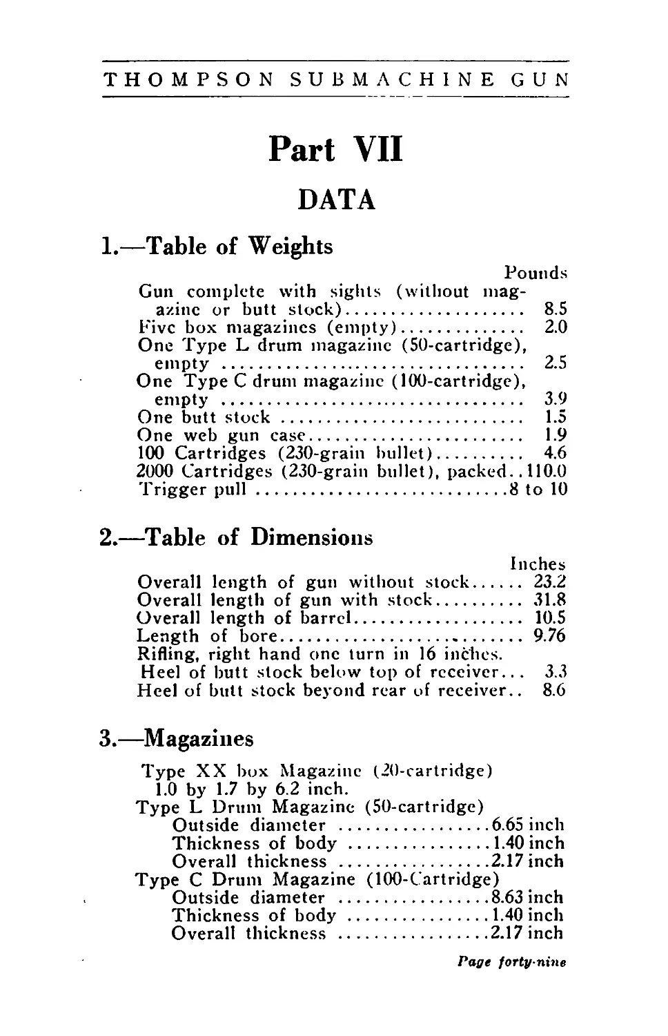
SPARE PARTS FOR U. S. NAVY MODEL 1928
3. Top—Recoil Spring.
2. Center—Buffer Disc and Buffer.
1. Bottom—Actuator (weighted).
Page fifty
THOMPSON SUBMACHINE GUN
Part VIII
THOMPSON SUBMACHINE GUN
MODEL OF 1928
The outstanding characteristic of Model 1928
Submachine Gun, our U. S. Navy Model, is its
slowed-down action. When used full auto-
matic, Model 1928 fires at the rate of about 600
shots per minute, while the cyclic rate for
Model 1921 is about 800 shots per minute.
Model 1928 Submachine Gun can be fired full
automatic or semi-automatic. The principles
of design are identical and the general instruc-
tions for Model 1921 apply equally to the
Model 1928, except as noted. The slower ac-
tion is accomplished by using a weighted ac-
tuator (1) ; the recoil spring (28) is of smaller
diameter and inserted into a hole in actuator;
the one-piece buffer (5) is complete with pilot
and of smaller diameter and uses a fibre wash-
er; the firing pin spring (12) is slightly shorter.
Ammunition and Ballistics: Model 1928 Sub-
machine Gun is made for the .45 Colt Auto-
matic Ammunition, and uses the regular ball
cartridges (230 grain bullet cartridges only)
also the shot cartridges and blank cartridges,
as used in Model 1921. The instructions for
sighting and the ballistic figures given for
Model 1921 apply equally to the Model 1928.
Magazines: Model 1928 uses both 20-shot
box magazines and 50-shot drum magazines.
However, the Type XX (20 cartridge) box
magazines are not identical for Model 1921 and
Page fifty-one
Page fifty-two
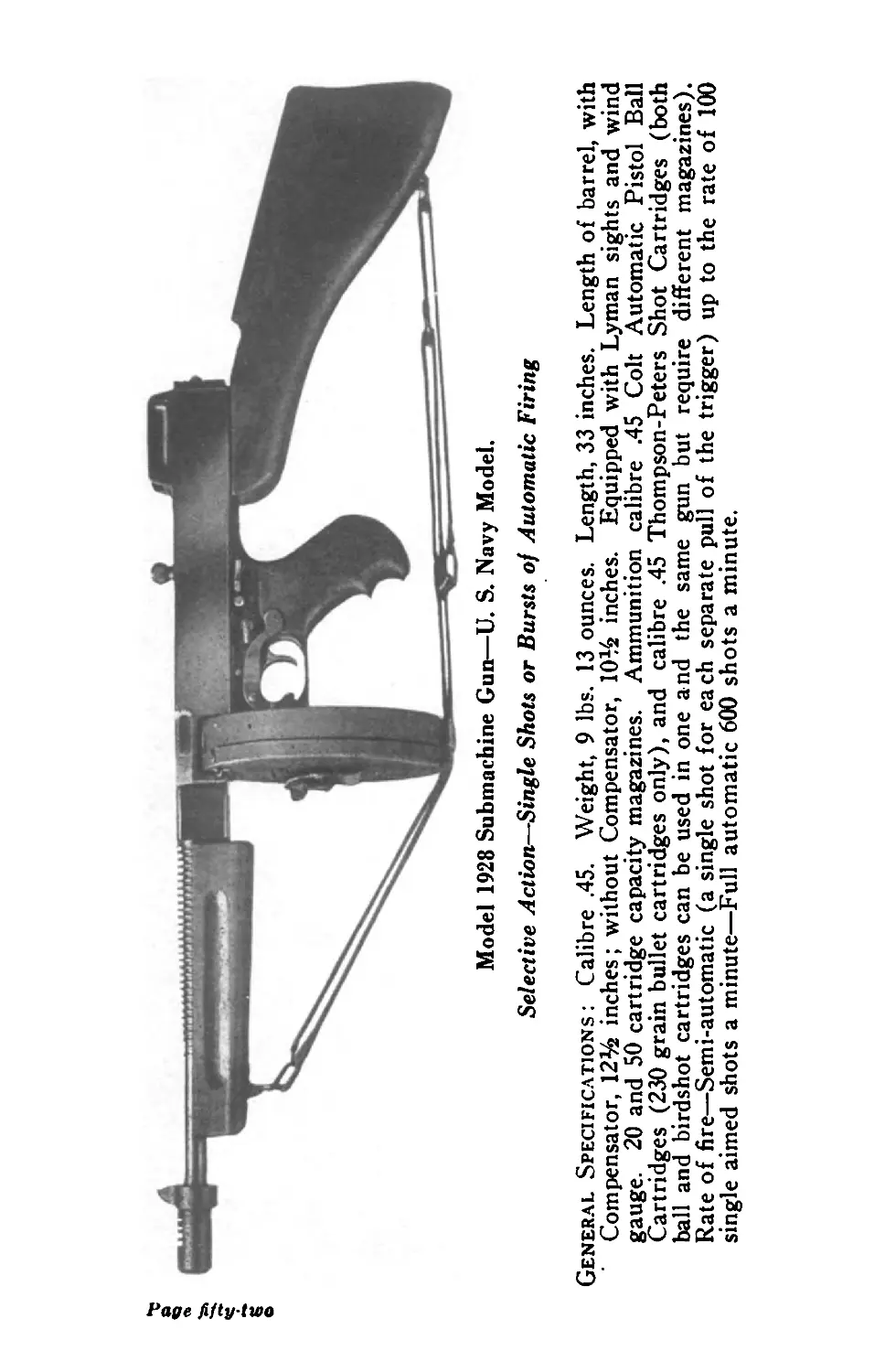
Model 1928 Submachine Gun—U. S. Navy Model.
Selective Action—Single Shots or Bursts of Automatic Firing
General Specifications : Calibre .45. Weight, 9 lbs. 13 ounces. Length, 33 inches. Length of barrel, with
Compensator, 12% inches; without Compensator, 10% inches. Equipped with Lyman sights and wind
gauge. 20 and 50 cartridge capacity magazines. Ammunition calibre .45 Colt Automatic Pistol Ball
Cartridges (230 grain bullet cartridges only), and calibre .45 Thompson-Peters Shot Cartridges (both
ball and birdshot cartridges can be used in one and the same gun but require different magazines).
Rate of fire—Semi-automatic (a single shot for each separate pull of the trigger) up to the rate of 100
single aimed shots a minute—Full automatic 600 shots a minute.
THOMPSON SUBMACHINE GUN
Model 1928, and only those Type L (50 cart-
ridge) drum magazines which are marked
“Wind to 9 clicks” should be used with Model
1928 guns. When ordering magazines, be sure
to specify model for which wanted.
Parts: When ordering parts, use the same
names of parts as in Model 1921 as the parts
are similar wth the following exceptions: Ac-
tuator (1) ; Buffer complete (5) with pilot and
fibre disc; Recoil Spring (28) and Firing Pin
Spring (12). State model number and type of
foregrip and give gun serial number when or-
dering.
Illustration on page 52 shows Model 1928
Thompson Submachine Gun with horizontal
foregrip, when equipped with a Cults Compensa-
tor, and 50-shot drum magazine.
This shows how conveniently swivels and
sling strap can be fitted to a gun with horizon-
tal foregrip.
Page fifty-thru
THOMPSON SUBMACHINE GUN
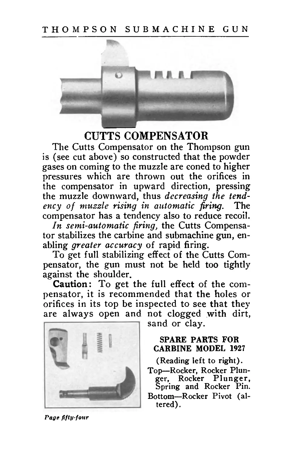
CUTTS COMPENSATOR
The Cutts Compensator on the Thompson gun
is (see cut above) so constructed that the powder
gases on coming to the muzzle are coned to higher
pressures which are thrown out the orifices in
the compensator in upward direction, pressing
the muzzle downward, thus decreasing the tend-
ency of muzzle rising in automatic firing. The
compensator has a tendency also to reduce recoil.
In semi-automatic firing, the Cutts Compensa-
tor stabilizes the carbine and submachine gun, en-
abling greater accuracy of rapid firing.
To get full stabilizing effect of the Cutts Com-
pensator, the gun must not be held too tightly
against the shoulder.
Caution: To get the full effect of the com-
pensator, it is recommended that the holes or
orifices in its top be inspected to see that they
are always open and not clogged with dirt,
sand or clay.
SPARE PARTS FOR
CARBINE MODEL 1927
(Reading left to right).
Top—Rocker, Rocker Plun-
ger, Rocker Plunger,
Spring and Rocker Pin.
Bottom—Rocker Pivot (al-
tered).
Page fifty-four
THOMPSON SUBMACHINE GUN
Part IX
THOMPSON
SEMI-AUTOMATIC CARBINE
MODEL OF 1927
(also called Model No. 27AC when equipped with
Cutts Compensator)
The Thompson Semi-Automatic Carbine, Model
of 1927, has the same automatic reloading prin-
ciple as the Thompson Submachine Gun, but fires
only one shot for each separate pull of the trigger.
Each shot is under full control by the operator,
yet the fast reloading action permits firing up to
100 single aimed shots in one minute, when re-
quired.
Construction: The Model 1927 Carbine is in
appearance similar to the submachine gun.
While the weight of the submachine gun and
carbine are about the same, and they have the
same barrel and same over-all length and the
same set of sights, there are differences in con-
struction and adjustment so that it is not prac-
ticable to convert the carbine into a submachine
gun. The parts which are different in construc-
tion are the frame, sear, sear lever, rocker,
rocker plunger, rocker plunger spring, rocker
plunger pin and rocker pivot.
Ammunition and Ballistics: Model 1927 Car-
bine .45 caliber is made for the .45 Colt Auto-
matic Ammunition, and» uses the regular ball
cartridges (230 grain bullet cartridges only),
also using the shot cartridges and blank cart-
ridges, as used in Model 1921. The instruc-
Page fifty-five
Page fi.ftg-nx
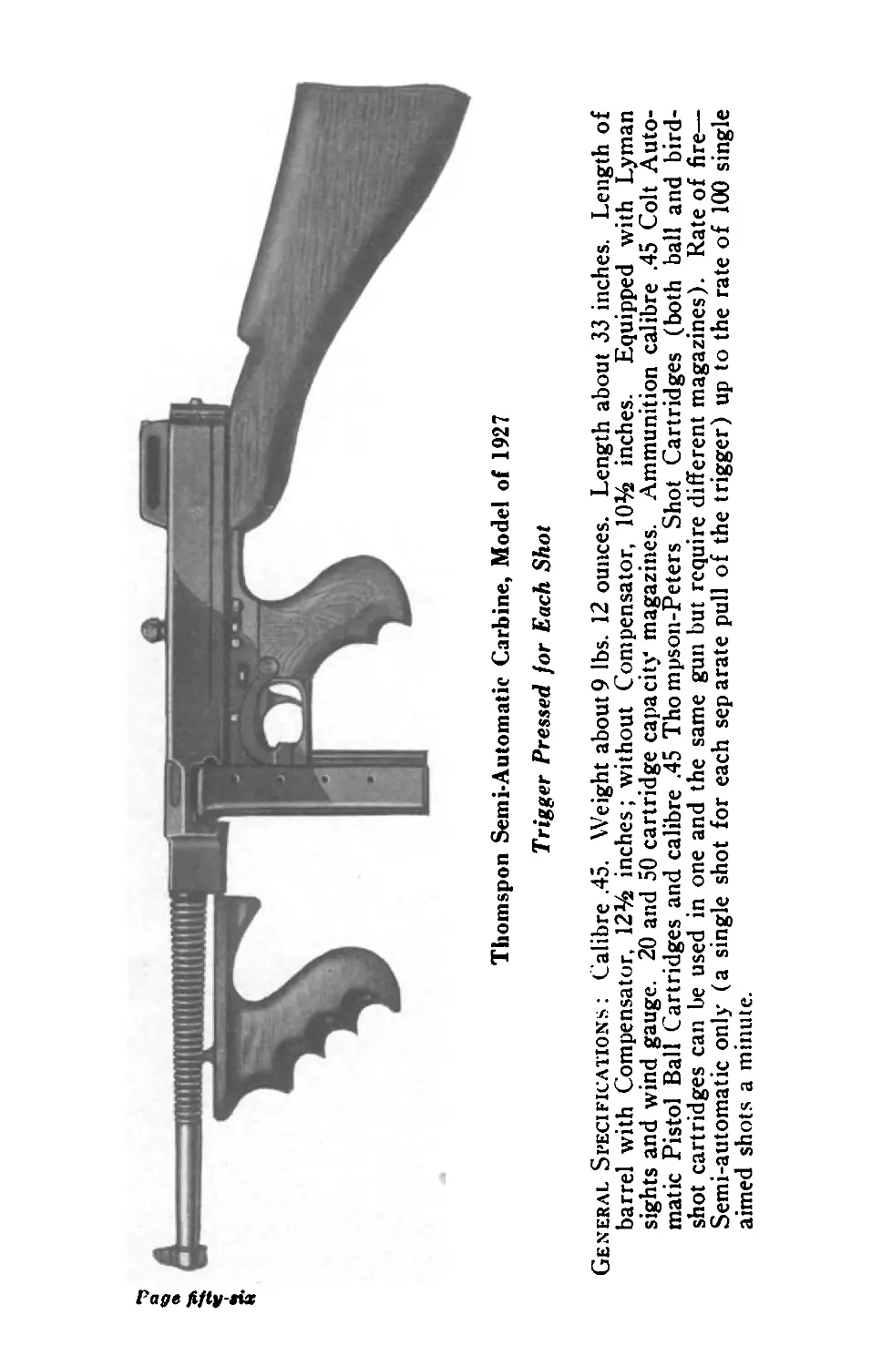
Thomspon Semi-Automatic Carbine, Mode! of 1927
Trigger Pressed for Each Shot
General Specifications : Calibre .45. Weight about9 lbs. 12 ounces. Length about 33 inches. Length of
barrel with Compensator, 12% inches; without Compensator, 10% inches. Equipped with Lyman
sights and wind gauge. 20 and 50 cartridge capacity magazines. Ammunition calibre .45 Colt Auto-
matic Pistol Ball Cartridges and calibre .45 Thompson-Peters Shot Cartridges (both ball and bird-
shot cartridges can be used in one and the same gun but require different magazines). Rate of fire—
Semi-automatic only (a single shot for each separate pull of the trigger) up to the rate of 100 single
aimed shots a minute.
THOMPSON SUBMACHINE GUN
tions for sighting and the ballistic figures given
for Model 1921 Submachine Gun apply equally
to the Model 1927 Semi-Automatic Carbine.
Magazines: The Model 1927 Carbine uses
the same box magazines and drum magazines
as the Model 1921 Submachine Gun.
Parts: When ordering parts, use the same
names of parts as in Model 1921 but be sure to
specify that parts are wanted for the 1927 Car-
bine. The rocker plunger, the rocker plunger
spring and the rocker plunger pin are found in
Model 1927 Carbine only. Some Model 1927 Car-
bines have vertical foregrip, others have horizon-
tal foregrip. State the Model number and type
of foregrip, and always give the carbine serial
number.
To take apart or re-assemble, and for clean
ing and oiling, follow the same instructions as
for Model 1921.
Cutts Compensator is usually ordered on
Model 1927 Carbine as well as on the Subma-
chine Guns, as it stabilizes the gun when fired
rapidly, and reduces the recoil to practically
nothing. Cutts Compensators can only be
fitted to Thompson Carbines and Submachine
Guns at the factory.
Page fifty-seven
THOMPSON SUBMACHINE GUN
Part X
CARRYING EQUIPMENT AND
ACCESSORIES
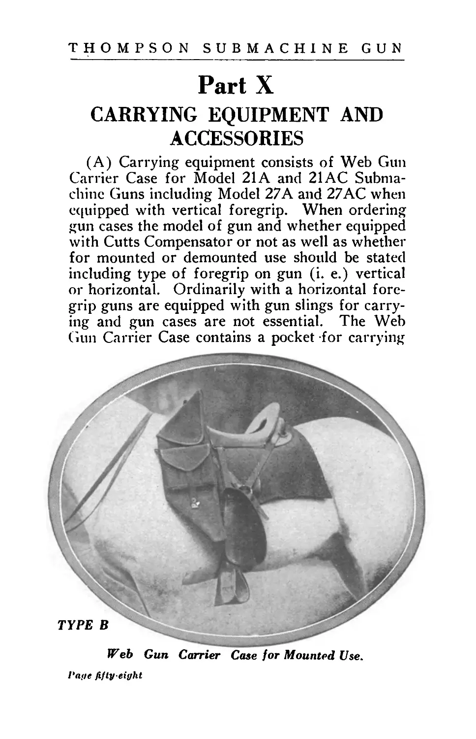
(A) Carrying equipment consists of Web Gun
Carrier Case for Model 21A and 21 AC Subma-
chine Guns including Model 27 A and 27AC when
equipped with vertical foregrip. When ordering
gun cases the model of gun and whether equipped
with Cutts Compensator or not as well as whether
for mounted or demounted use should be stated
including type of foregrip on gun (i. e.) vertical
or horizontal. Ordinarily with a horizontal fore-
grip guns are equipped with gun slings for carry-
ing and gun cases are not essential. The Web
Gun Carrier Case contains a pocket for carrying
TP e b Gun Carrier Case for Mounted Use.
Page fifty-eight
THOMPSON SUBMACHINE GUN
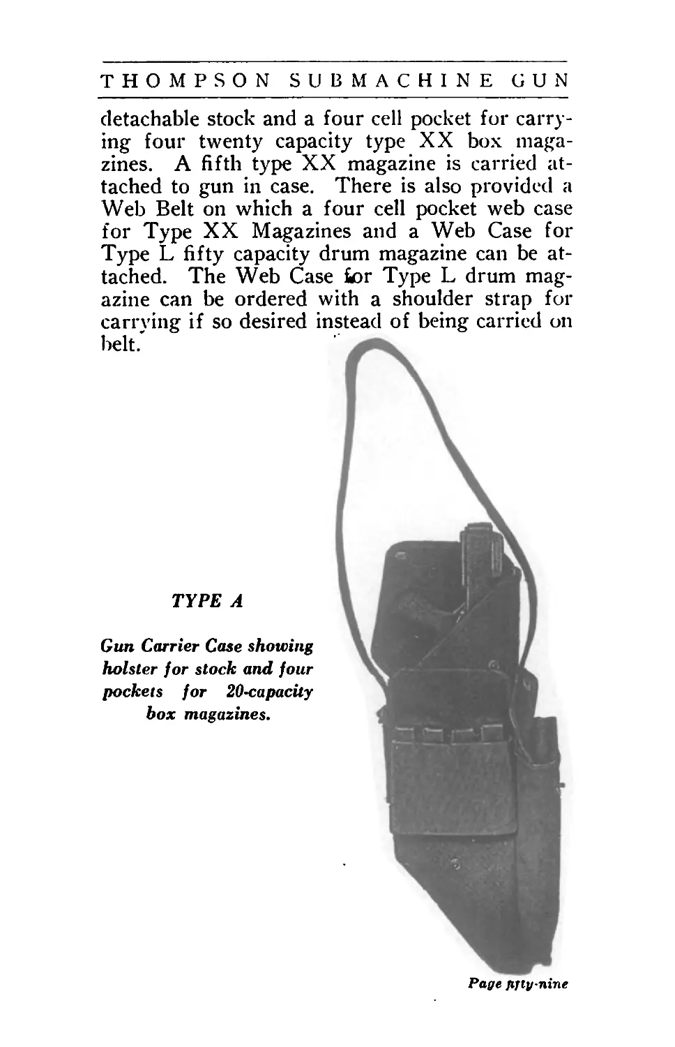
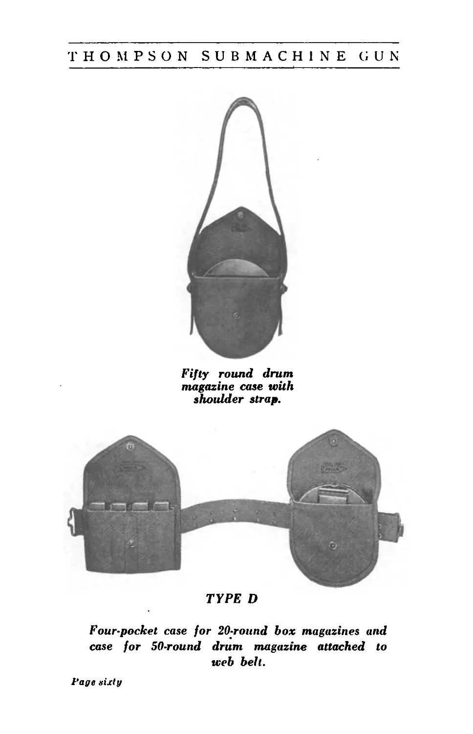
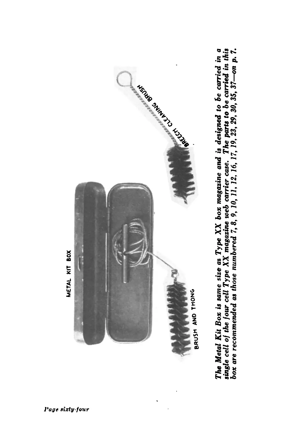
detachable stock and a four cell pocket for carry-
ing four twenty capacity type XX box maga-
zines. A fifth type XX magazine is carried at-
tached to gun in case. There is also provided a
Web Belt on which a four cell pocket web case
for Type XX Magazines and a Web Case for
Type L fifty capacity drum magazine can be at-
tached. The Web Case for Type L drum mag-
azine can be ordered with a shoulder strap for
carrying if so desired instead of being carried on
belt.
TYPE A
Gun Carrier Сазе showing
holster for stock and four
pockets for 20-capacity
box magazines.
Page fifty nine
THOMPSON SUBMACHINE GUN
Fifty round drum
magazine case with
shoulder strap.
TYPE D
Four-pocket case for 20-round box magazines and
case for 50-round drum magazine attached to
web belt.
Page sixty
Page sixty our
Method of carrying Models No. 21A
and 21AC
1'uye sixty-two
Method of carrying Model No. 27A, Model No.
27AC (when equipped with horizontal foregrip)
and Models No. 28A and 28AC.
Page Sixty-three
METAL KIT BOX
The Metal Kit Box is same size as Type XX box magazine and is designed to be carried in a
single cell of the four cell Type XX magazine web carrier case. The parts to be carried in this
box are recommended as those numbered 7,8, 9, 10, 11, 12, 16, 17, 19, 23, 29, 30, 35, 37—on p. 7.