/


Текст
P5SF
-Single-Fhe-
BRIEF DESCRIPTION
OF THE
MP 5 SF
SUBMACHINE GUN
-Single-Are-
2
GENERAL
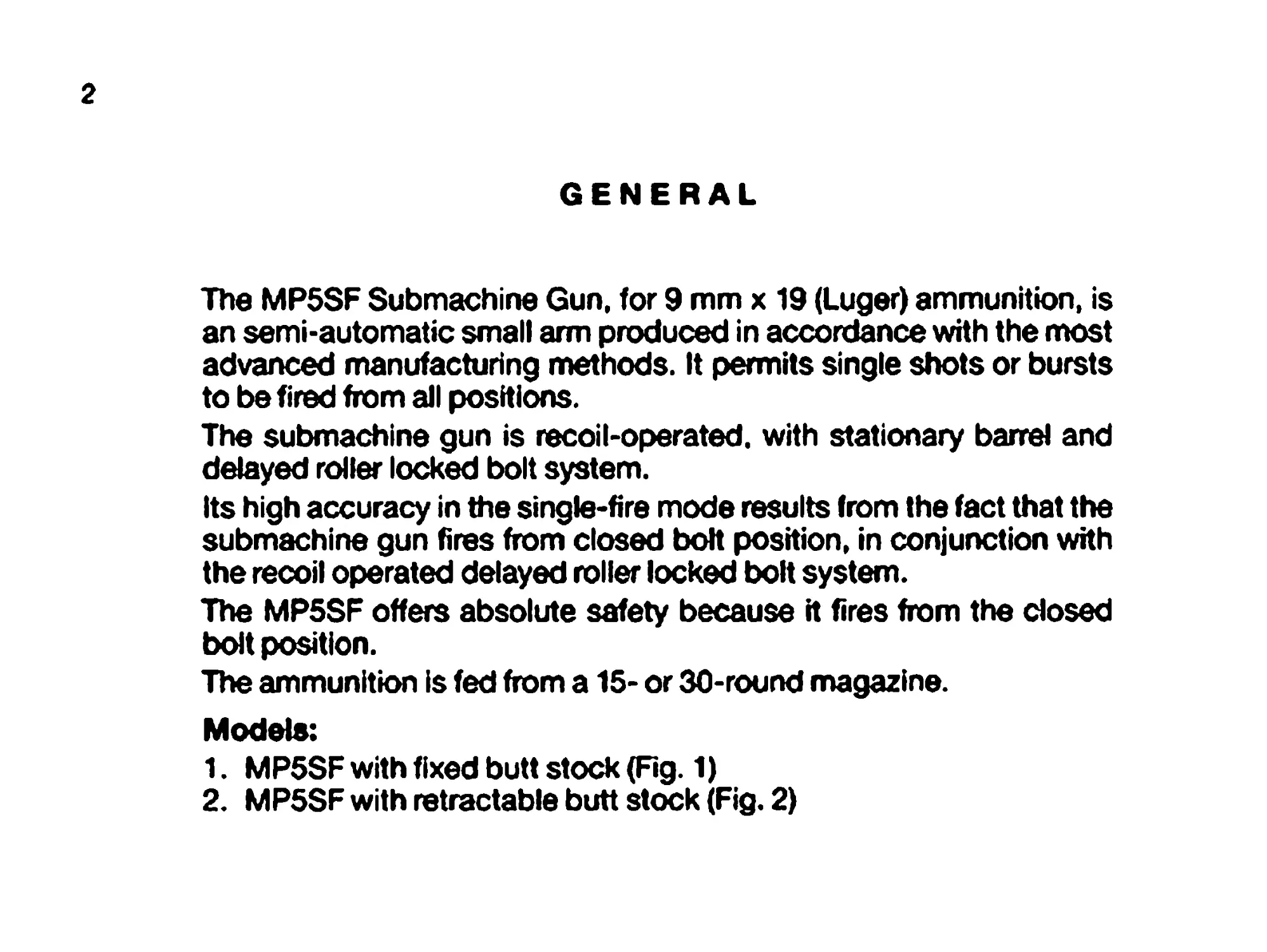
The MP5SF Submachine Gun, for 9 mm x 19 (Luger) ammunition, is
an semi-automatic small arm produced in accordance with the most
advanced manufacturing methods. It permits single shots or bursts
to be fired from all positions.
The submachine gun is recoil-operated, with stationary barrel and
delayed roller locked bolt system.
Its high accuracy in the single-fire mode results from the fact that the
submachine gun fires from closed bolt position, in conjunction with
the recoil operated delayed roller locked bolt system.
The MP5SF offers absolute safety because it fires from the closed
bolt position.
The ammunition is fed from a 15- or 30-round magazine.
Models:
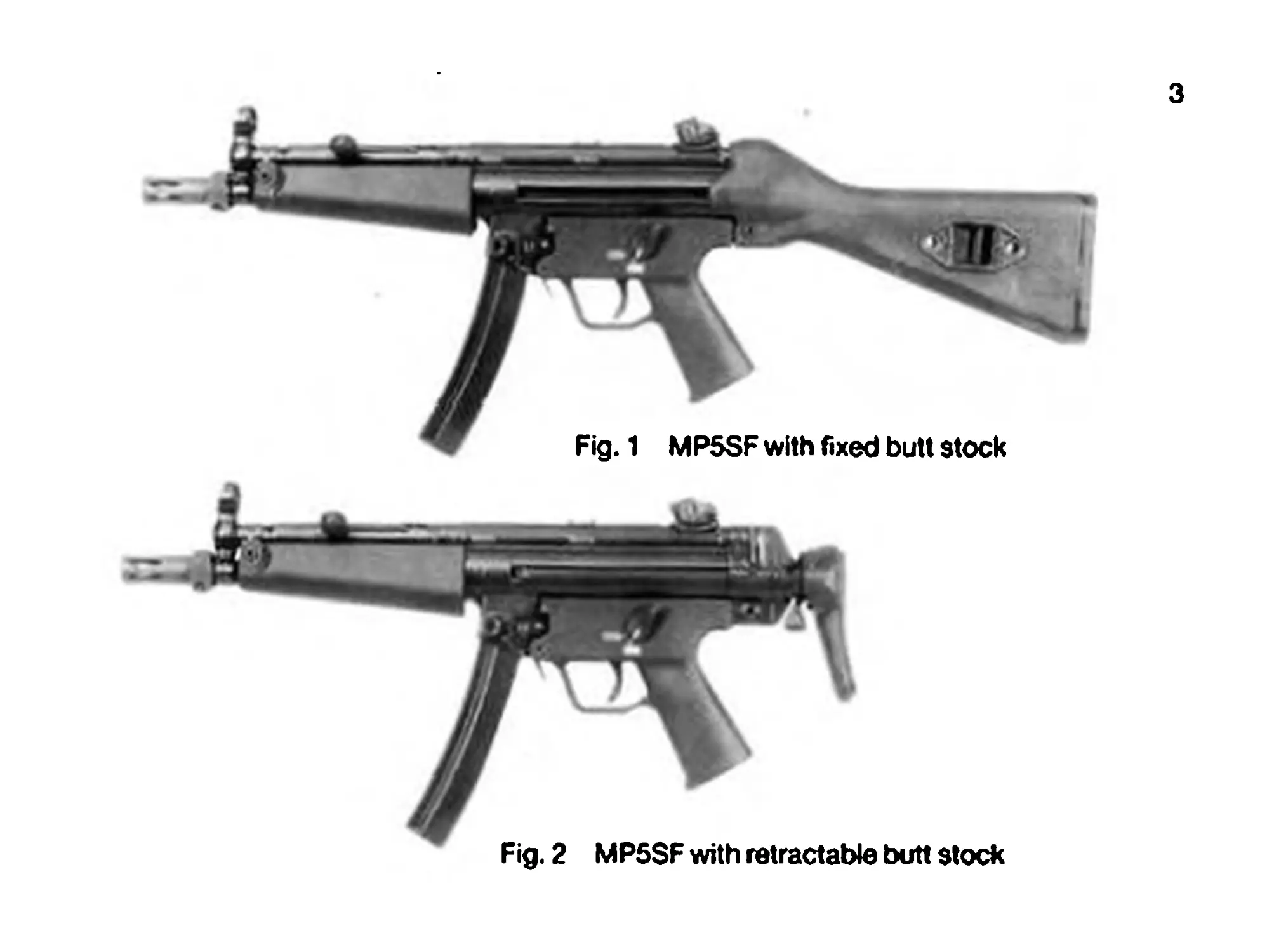
1. MP5SF with fixed butt stock (Fig. 1)
2. MP5SF with retractable butt stock (Fig. 2)
3
Fig. 2 MP5SF with retractable butt stock
4
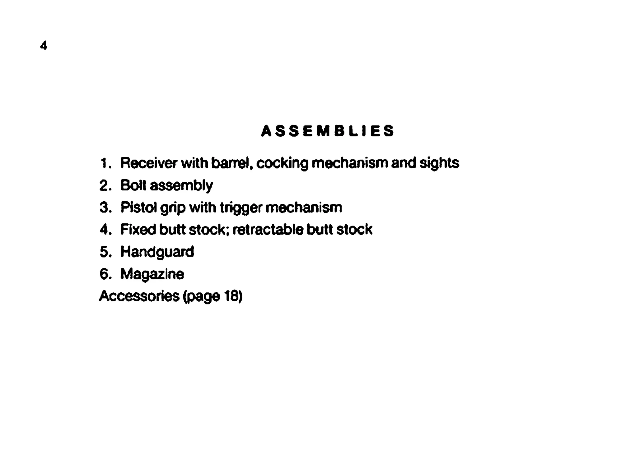
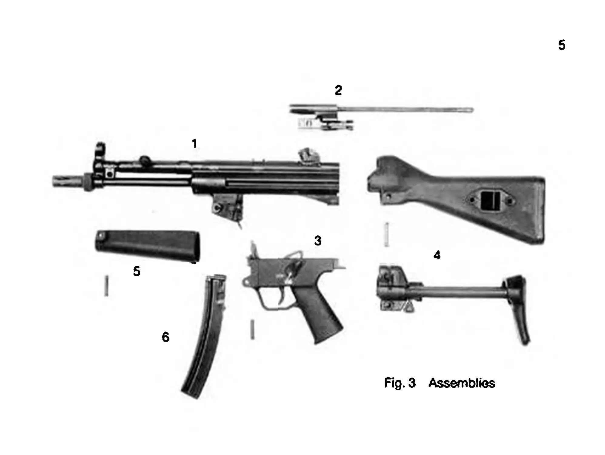
ASSEMBLIES
1. Receiver with barrel, cocking mechanism and sights
2. Bolt assembly
3. Pistol grip with trigger mechanism
4. Fixed butt stock; retractable butt stock
5. Handguard
6. Magazine
Accessories (page 18)
d
6
5
2
Fig, 3 Assemblies
6
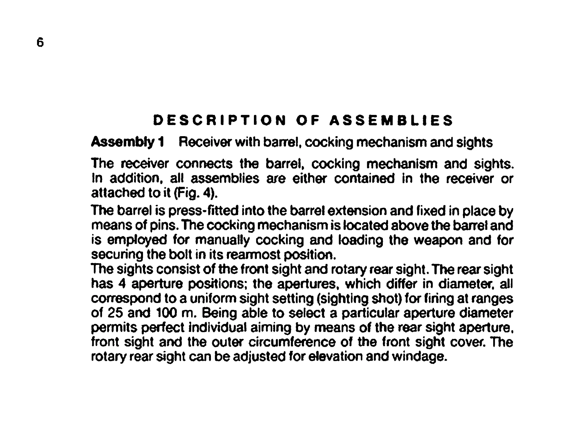
DESCRIPTION OF ASSEMBLIES
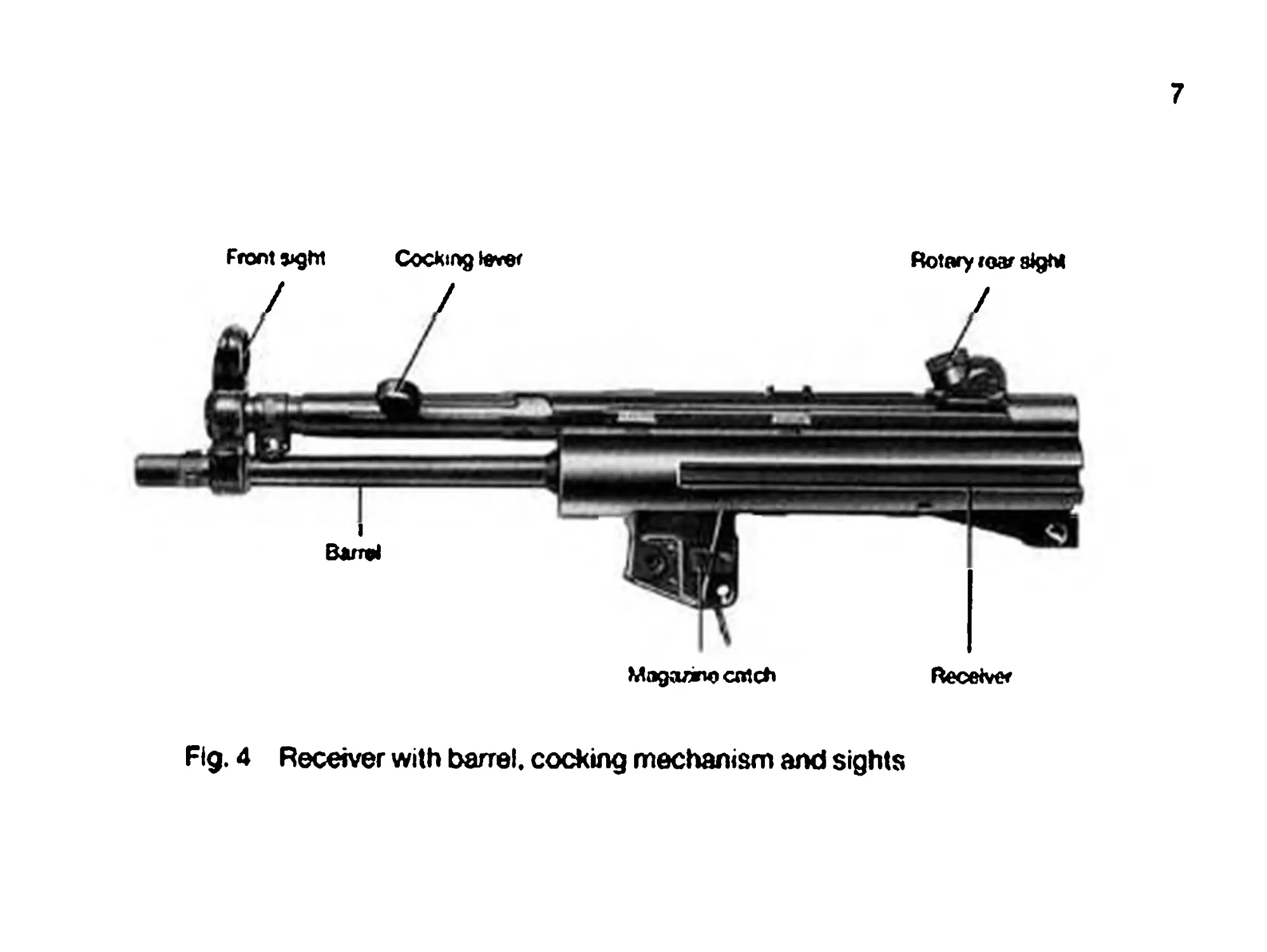
Assembly 1 Receiver with barrel, cocking mechanism and sights
The receiver connects the barrel, cocking mechanism and sights.
In addition, all assemblies are either contained in the receiver or
attached to it (Fig. 4).
The barrel is press-fitted into the barrel extension and fixed in place by
means of pins. The cocking mechanism is located above the barrel and
is employed for manually cocking and loading the weapon and for
securing the bolt in its rearmost position.
The sights consist of the front sight and rotary rear sight. The rear sight
has 4 aperture positions; the apertures, which differ in diameter, all
correspond to a uniform sight setting (sighting shot) for firing at ranges
of 25 and 100 m. Being able to select a particular aperture diameter
permits perfect individual aiming by means of the rear sight aperture,
front sight and the outer circumference of the front sight cover. The
rotary rear sight can be adjusted for elevation and windage.
7
Fig. 4 Receiver with barrel, cocking mechanism and sights
8
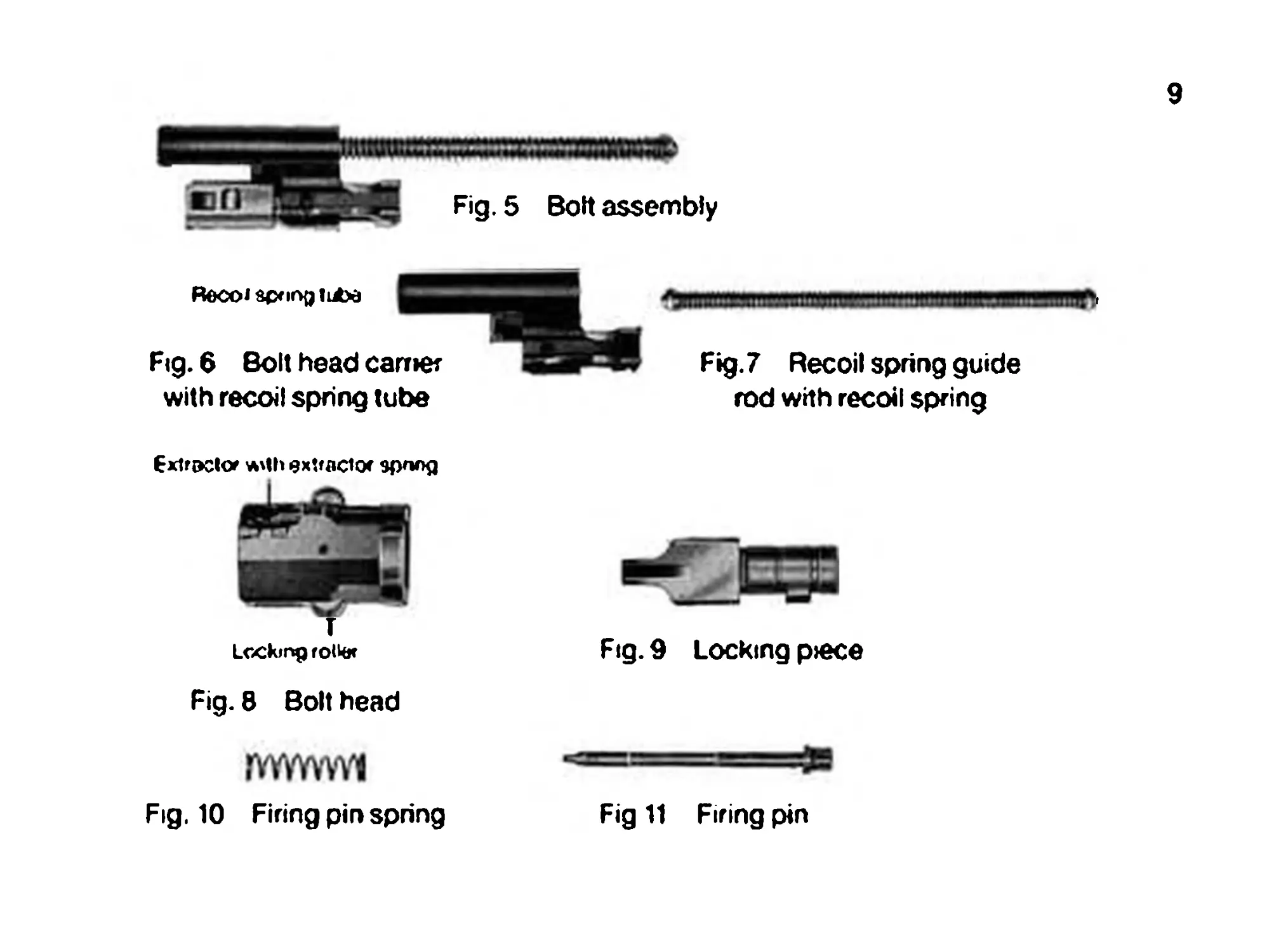
Assembly 2 Bolt assembly
The bolt assembly (Fig. 5) consists of the following elements:
Bolt head carrier with recoil spring tube Recoil spring guide rod and recoil spring Bolt head with locking rollers, extractor and extractor spring Locking piece Firing pin spring Firing pin (Fig- 6) (Fig- 7) (Fig. 8) (Fig. 9) (Fig. 10) (Fig. 11)
The bolt assembly is housed and guided in the receiver; in conjunction
with the recoil spring, it feeds and fires the cartridge, extracts and
ejects the empty cartridge case after firing, and cocks the hammer.
9
Recoi sfxirx, lube
Fig. 6 Bott head carrier
with recoil spring tube
Fig. 5 Bott assembly
Extractor *'lh extractor epnog
T
Locking rolkx
^MWIW!|WIHUIIIIW|IH!1 II»!! IIHWMHWMUWIf»,
Fig. 7 Recoil spring guide
rod with recoil spring
Fig. 8 Bolt head
rvvwvvvi
Fig. 10 Firing pin spring
Fig. 9 Locking p>ece
Fig 11 Fifing pin
10
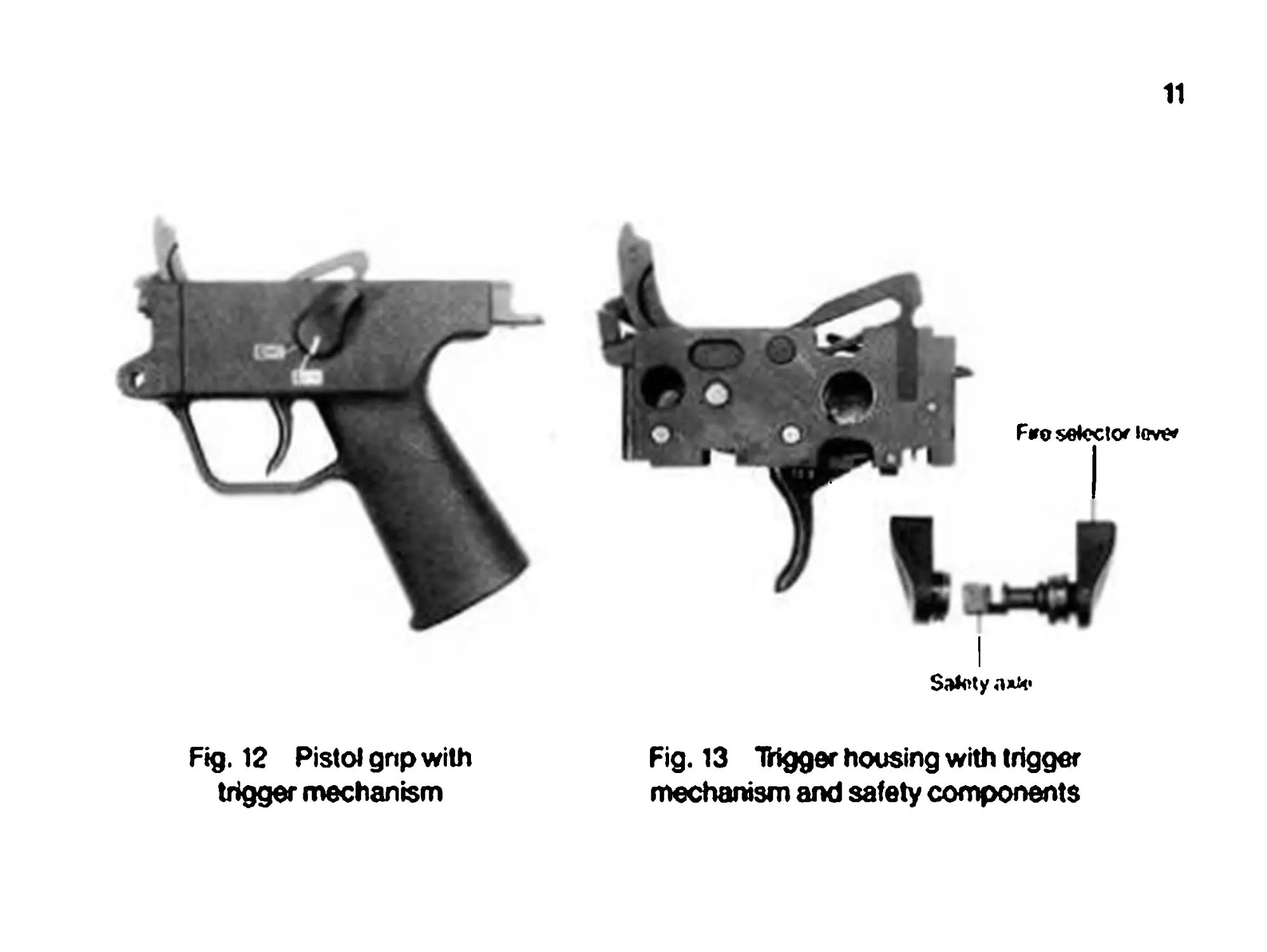
Assembly 3 Pistol grip with trigger mechanism
The pistol grip (Fig. 12) is hinged to the receiver and can be swung down
and removed from it: it contains the trigger housing (Rg. 13), with com-
ponents of the trigger and safety mechanism. The safety axle connects
the trigger housing to the pistol grip.
Fig. 12 Pistol grip with
trigger mechanism
11
Salety
Fig. 13 IHgger housing with trigger
mechanism and safety components
12
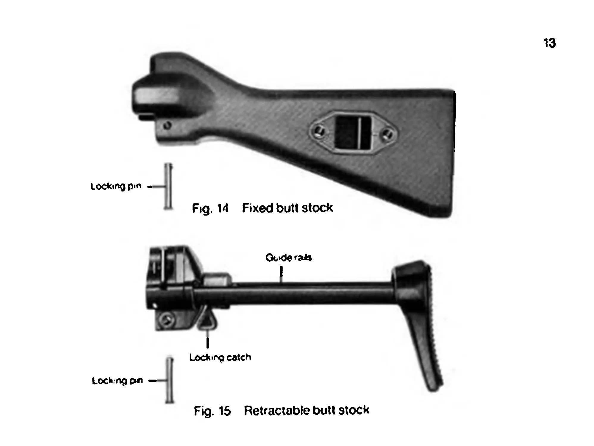
Assembly 4 Butt stock
Fixed butt stock
The fixed butt stock (Fig. 14) closes the rear of the receiver. It is con-
nected to the receiver by a locking pin.
The sling holder is attached to the butt stock by means of tubular rivets,
which are also employed for safekeeping of the locking pins when the
weapon is field stripped.
Retractable butt stock
The fixed butt stock can be replaced by a retractable butt stock (Fig. 15)
when required.
The two guide rails on either side of the butt stock are guided in grooves
on the receiver. They are secured by a locking catch in both the re-
tracted and extended positions.
A sling holder is attached to the back plate.
13
Fig. 15 Retractable bull stock
14
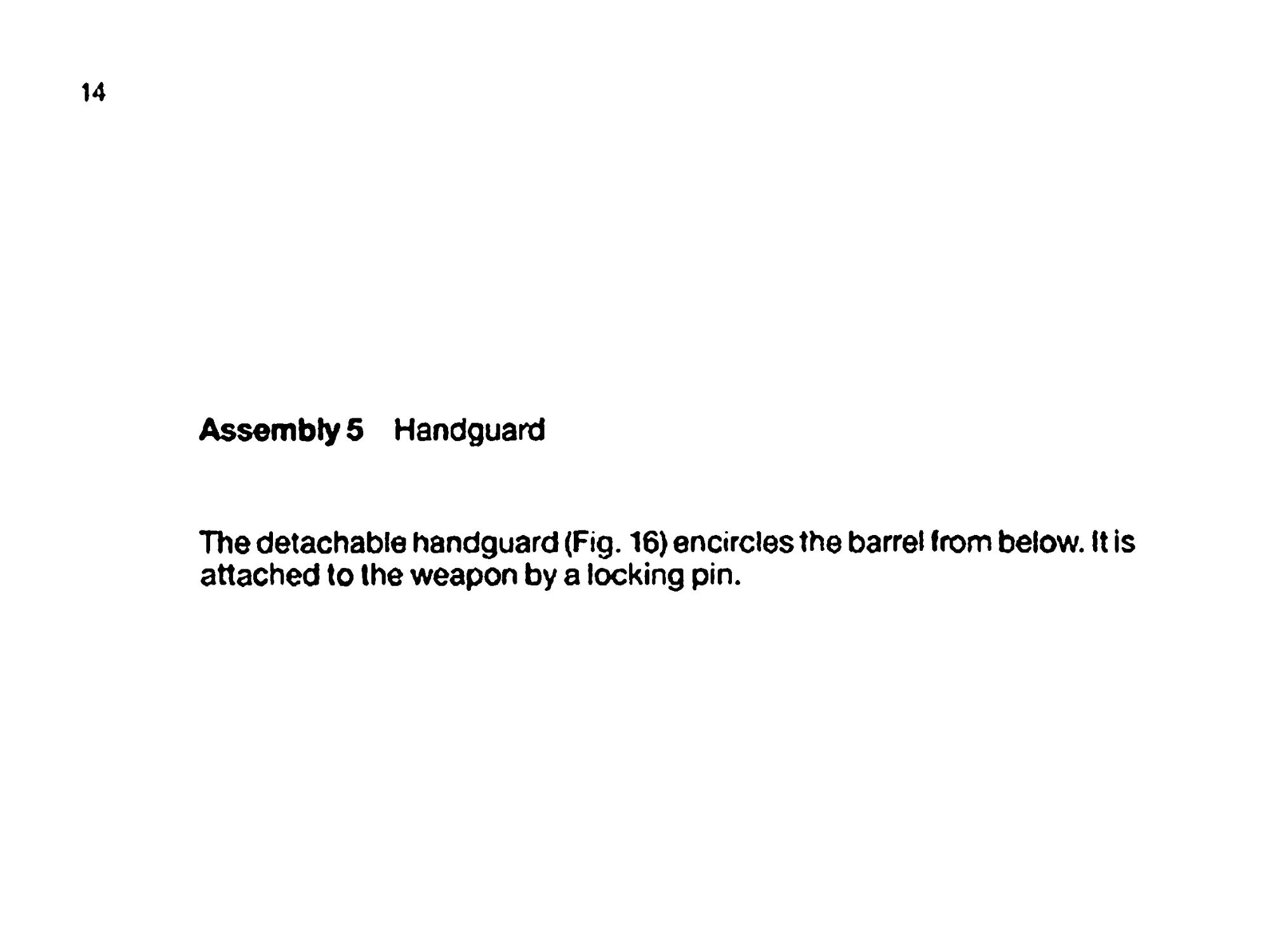
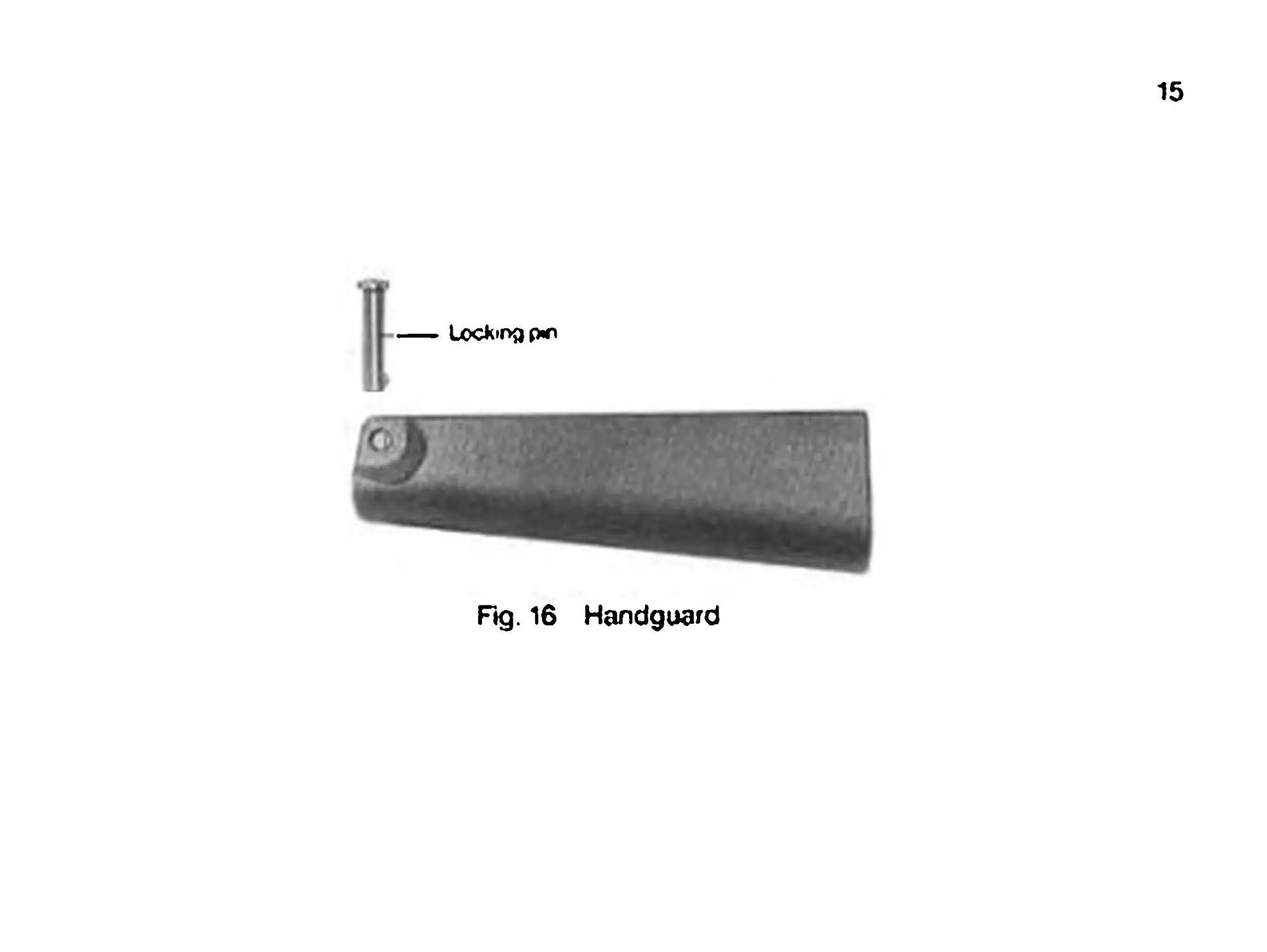
Assembly 5 Handguard
The detachable handguard (Fig. 16) encircles the barrel from below. It is
attached to the weapon by a locking pin.
15
Rg. 16 Handguard
16
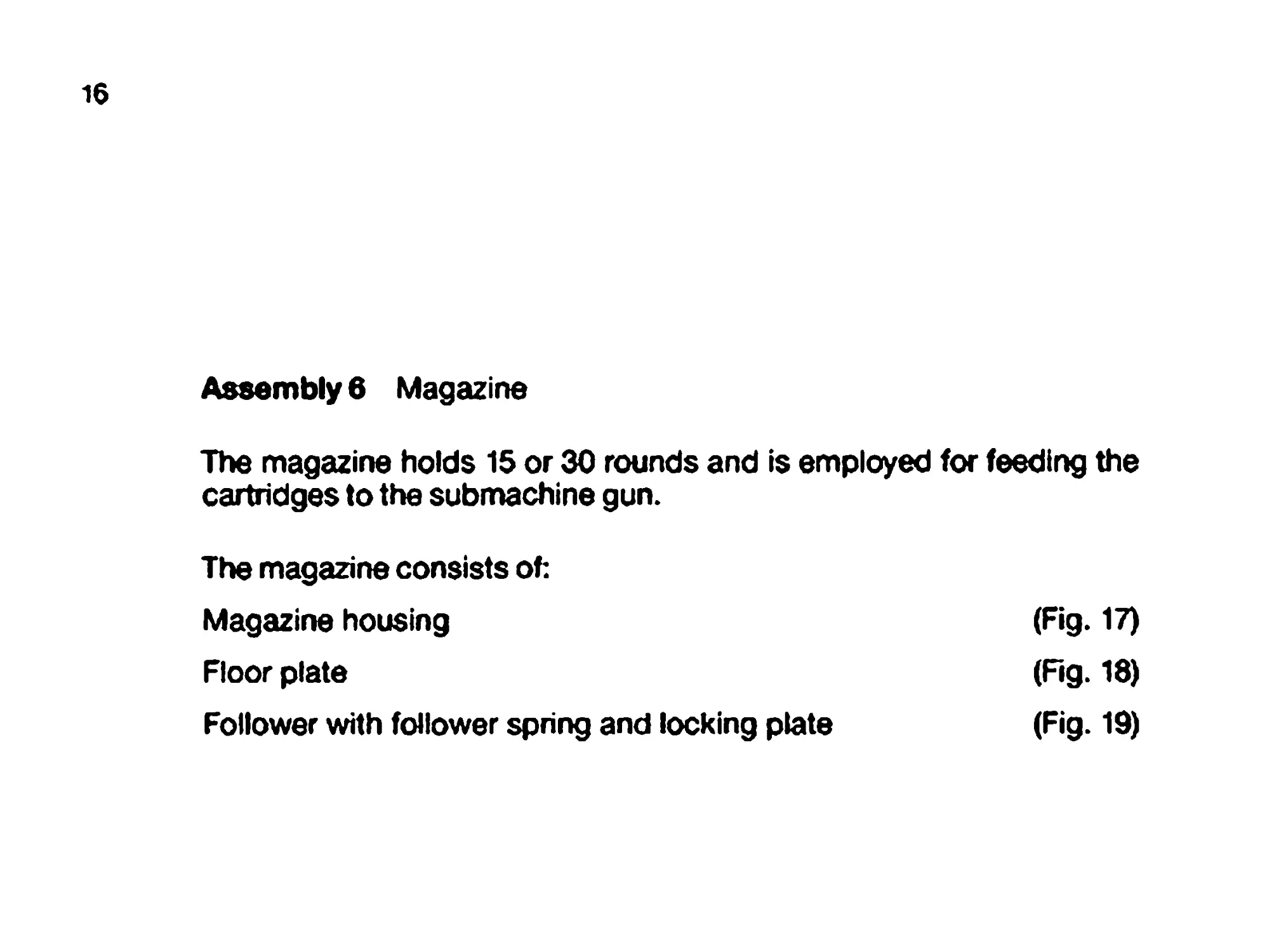
Assembly 6 Magazine
The magazine holds 15 or 30 rounds and is employed for feeding the
cartridges to the submachine gun.
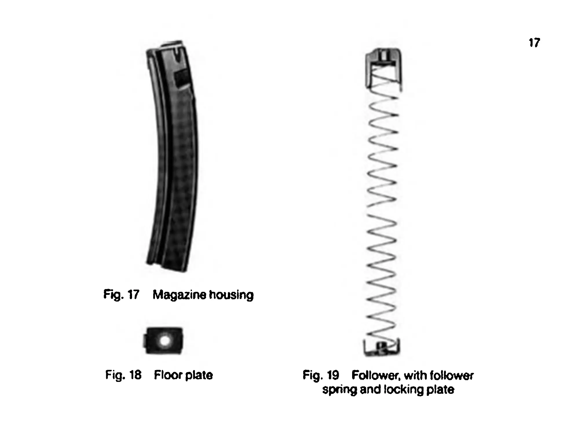
The magazine consists of:
Magazine housing
Floor plate
Follower with follower spring and locking plate
(Fig. 17)
(Fig. 18)
(Fig. 19)
Ag. 17
Magazine housing
Fig. 18 Floor plate
17
Fig. 19 Follower, with follower
spring and locking plate
18
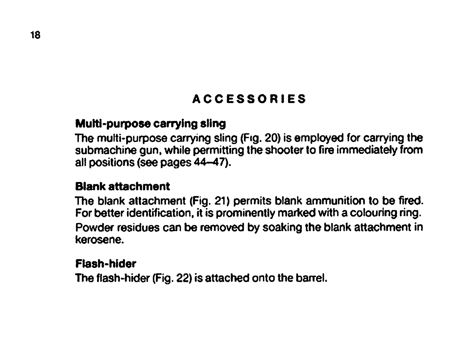
ACCESSORIES
Multi-purpose carrying sling
The multi-purpose carrying sling (Fig. 20) is employed for carrying the
submachine gun, while permitting the shooter to fire immediately from
all positions (see pages 44-47).
Blank attachment
The blank attachment (Fig. 21) permits blank ammunition to be fired.
For better identification, it is prominently marked with a colouring ring.
Powder residues can be removed by soaking the blank attachment in
kerosene.
Flash-hider
The flash-hider (Fig. 22) is attached onto the barrel.
19
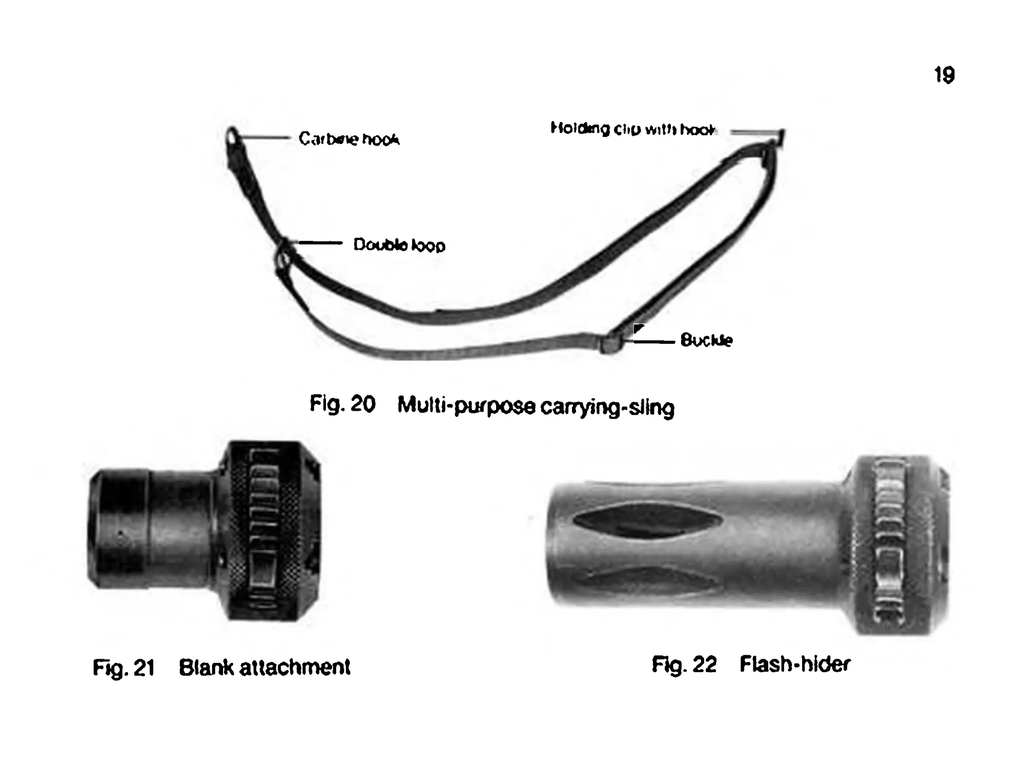
Fig. 20 Multi-purpose carrying-sling
Fig. 21 Blank attachment
Rg. 22 Flash-hlder
20
HANDLING AND OPERATION
Alling the magazine
Hold the magazine in one hand (Fig. 23); with your other hand, place the
cartridge in the magazine opening, pressing the uppermost cartridge
under the lip with your thumb.
Emptying the magazine
Hold the magazine in one hand, with the bullet end of the cartridges
pointing toward your other hand (Fig. 24). Using your thumb, push the
cartridges to the right, into your open hand.
Not*: A magazine niter and emptier is avatebte for both operations.
21
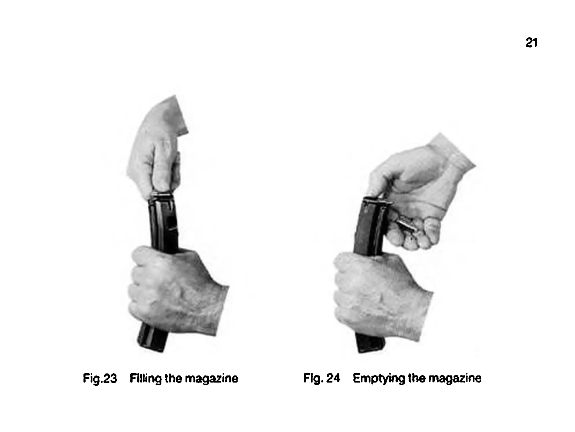
Fig.23 Alling the magazine
Fig. 24 Emptying the magazine
22
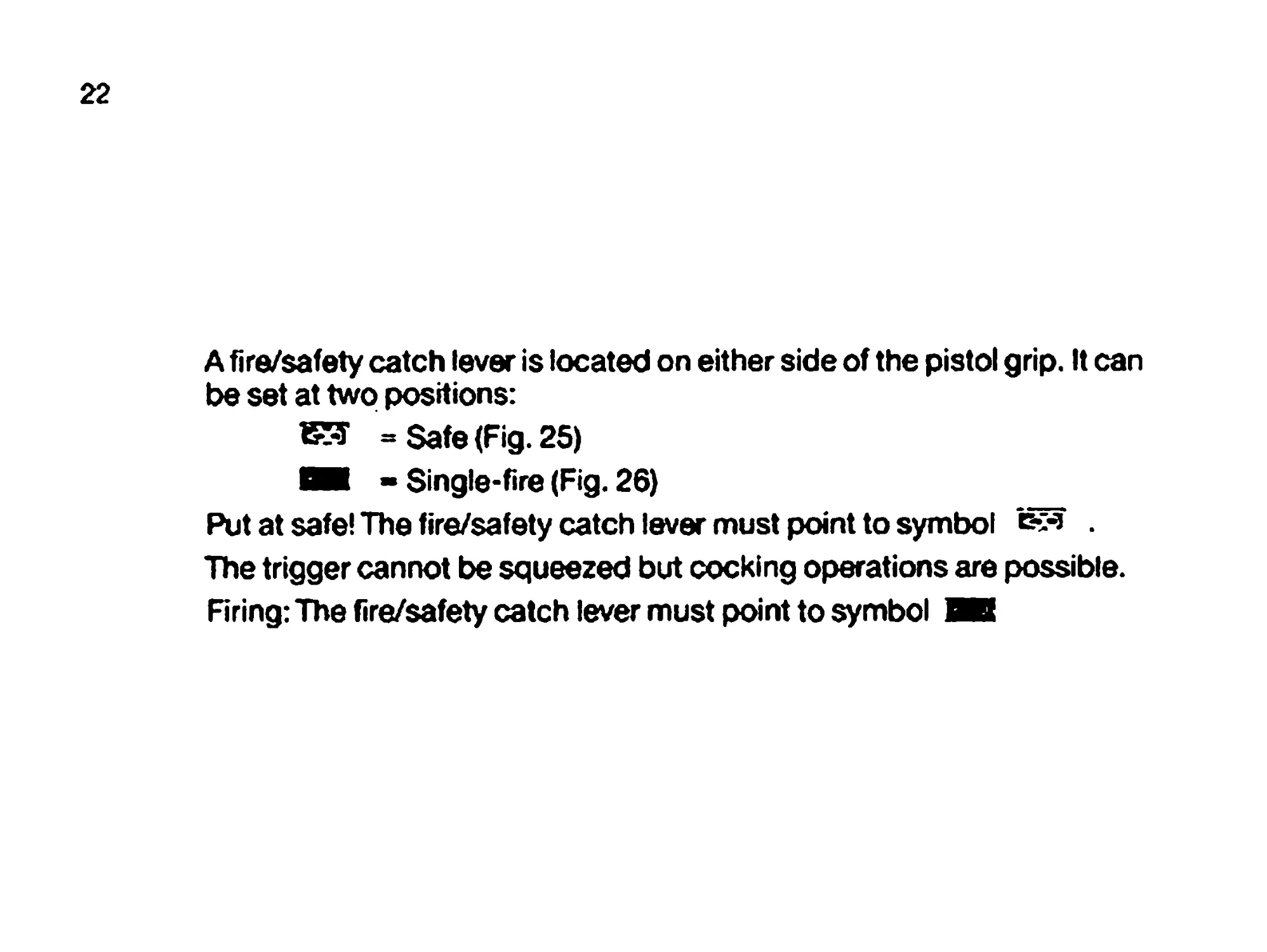
A fire/safety catch lever is located on either side of the pistol grip. It can
be set at two positions:
= Safe (Fig. 25)
i - Single-fire (Fig. 26)
Put at safe! The fire/safety catch lever must point to symbol Ev* .
The trigger cannot be squeezed but cocking operations are possible.
Firing: The fire/safety catch lever must point to symbol ЛВ
23
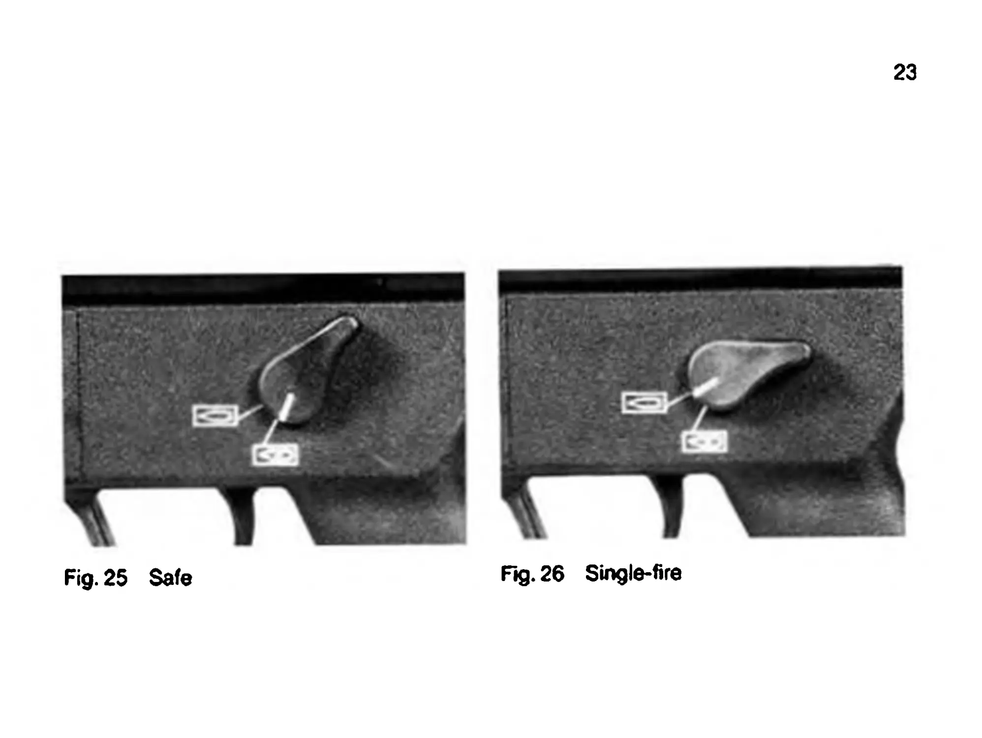
Fig. 26 Single-fire
Fig. 25 Safe
24
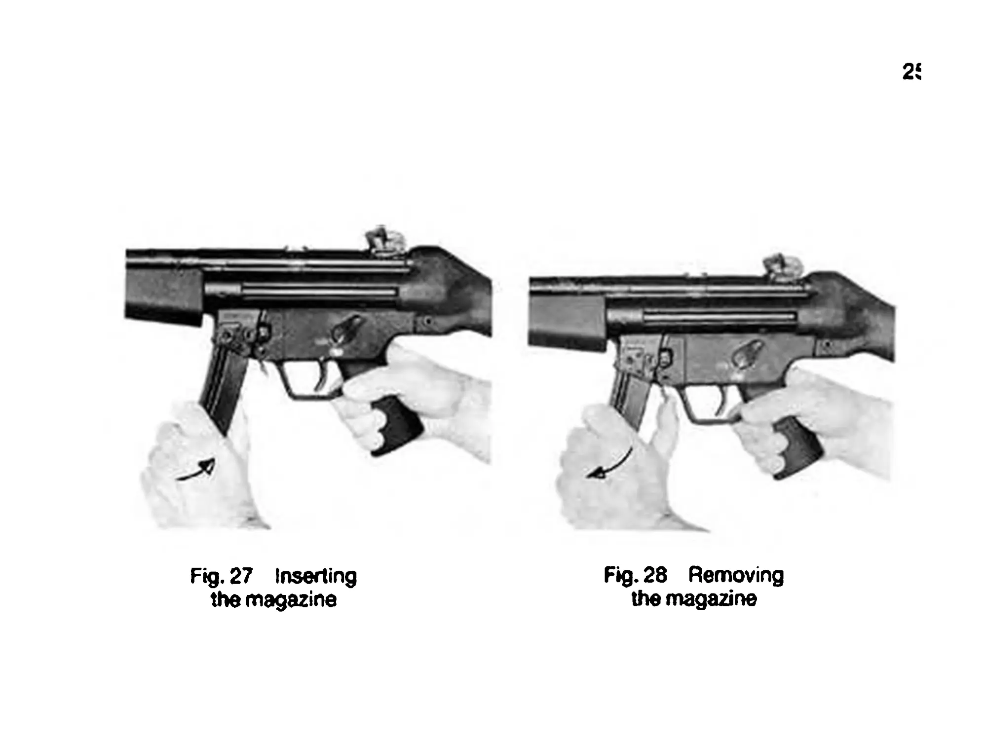
Inserting and removing the magazine
Engage the safety!
Insert magazine into the magazine well (Fig. 27) until you hear the
magazine catch engage.
To remove the magazine, push the magazine release lever (Fig. 28).
Fig. 27 Inserting
the magazine
2
Fig. 28 Removing
the magazine
26
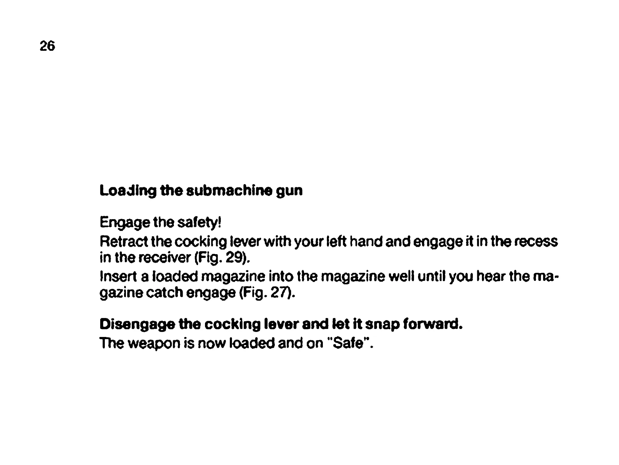
Loading the submachine gun
Engage the safety!
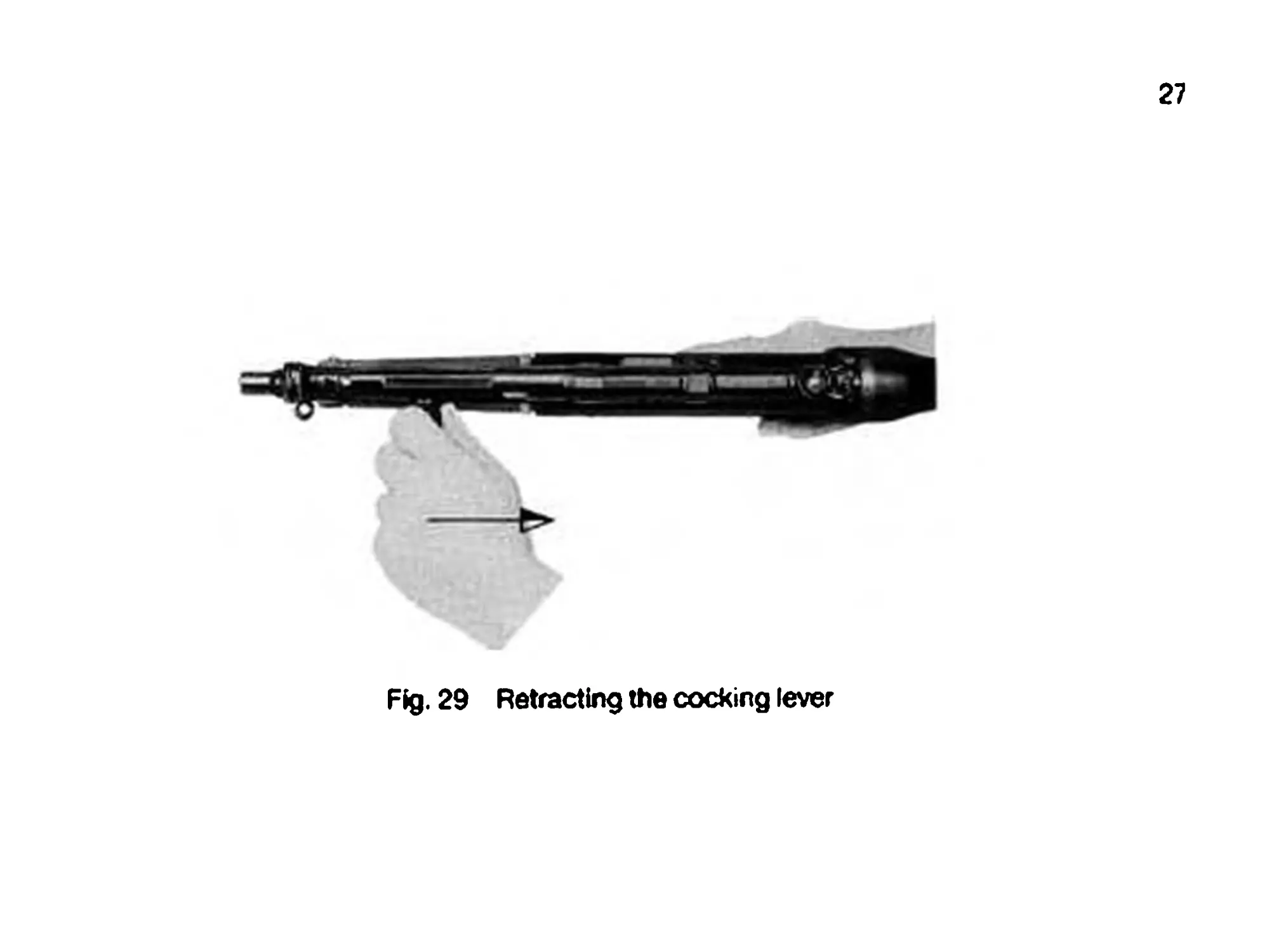
Retract the cocking lever with your left hand and engage it in the recess
in the receiver (Fig. 29).
Insert a loaded magazine into the magazine welt until you hear the ma-
gazine catch engage (Fig. 27).
Disengage the cocking lever and let it snap forward.
The weapon is now loaded and on "Safe".
27
Fig. 29 Retracting the cocking lever
28
OPERATING PRINCIPLE
The weapon is loaded and cocked, with the safety off.
Pulling the trigger releases the hammer, which strikes the firing pin. The
cartridge is ignited. The powder gases thus generated drive the bullet
out of the barrel. At the same time, these gases also exert pressure on
the cartridge case.
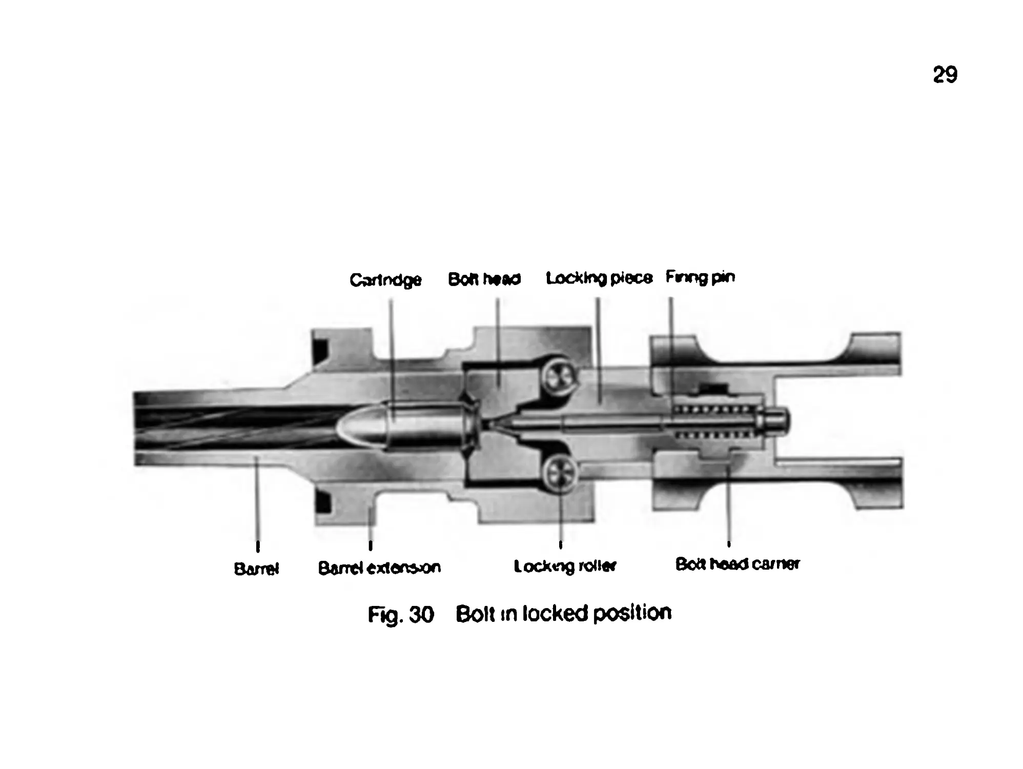
This causes forces to act on the bolt head face; a portion of these
forces is transmitted to the receiver and a portion to the bolt head car-
rier, via the locking piece; the balanced angular ratio of the locking
piece and barrel extension results in a delayed recoil movement of the
bolt head.
This guarantees that the bolt keeps the barrel locked until the bullet has
left the muzzle.
29
Cortndge ВоЛМйО Locking piece Fnogpm
li I I
Barrel Barrel extension Locking row Bott bead earner
Fig. 30 Bolt in locked position
30
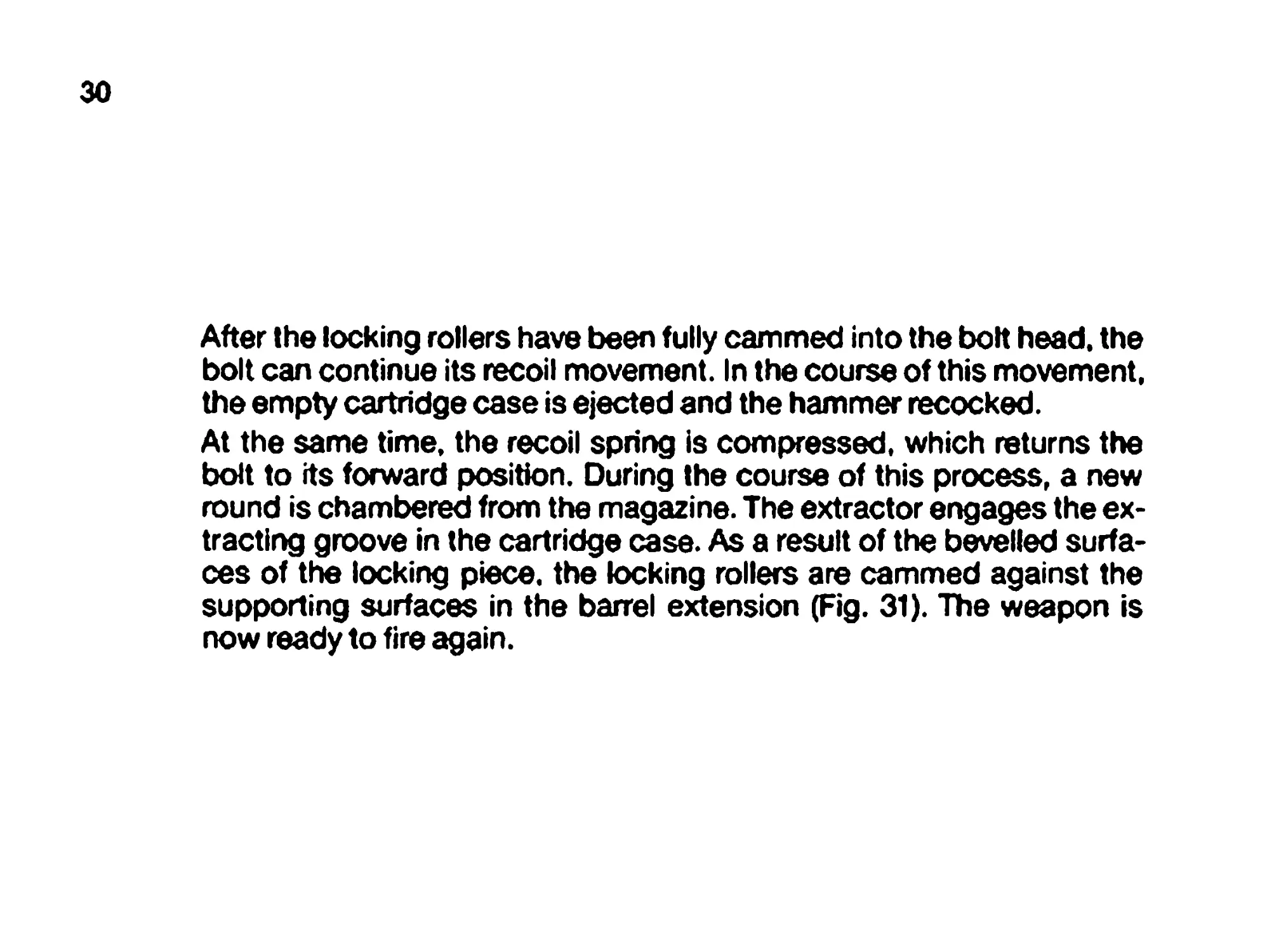
After the locking rollers have been fully cammed into the bolt head, the
bolt can continue its recoil movement. In the course of this movement,
the empty cartridge case is ejected and the hammer recocked.
At the same time, the recoil spring is compressed, which returns the
bolt to its forward position. During the course of this process, a new
round is chambered from the magazine. The extractor engages the ex-
tracting groove in the cartridge case. As a result of the bevelled surfa-
ces of the locking piece, the locking rollers are cammed against the
supporting surfaces in the barrel extension (Fig. 31). The weapon is
now ready to fire again.
31
Fkrtea
I
Supporting *urf*co
Fig. 31 Bolt in unlocked position
32
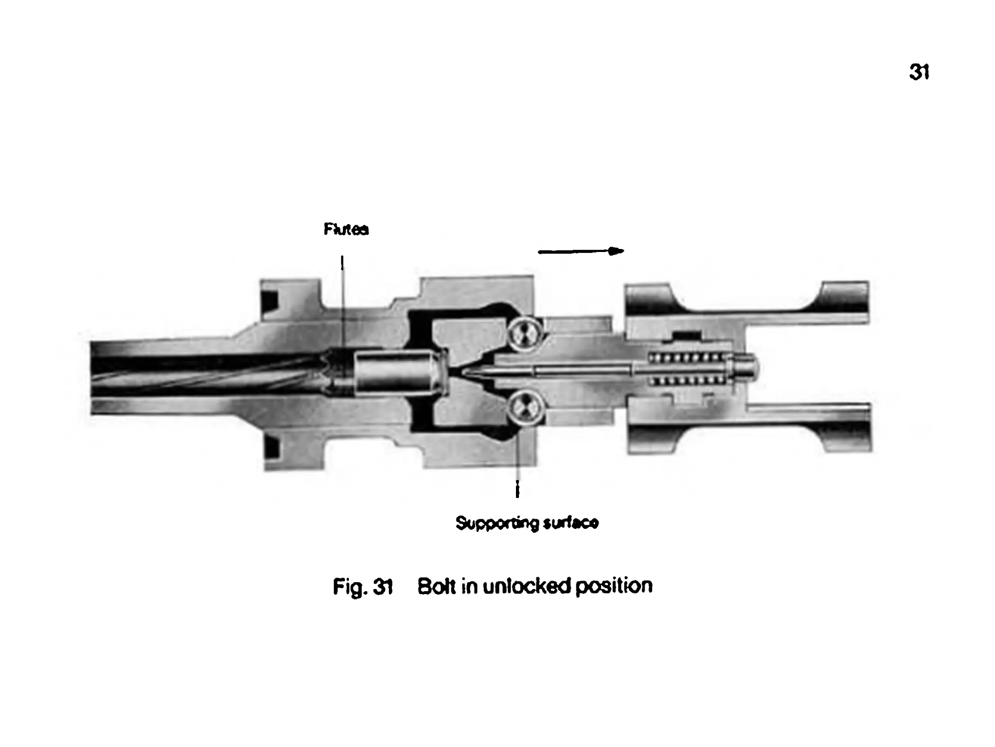
STRIPPING THE SUBMACHINE GUN
Engage the safety!
Remove magazine.
Unload chamber; retract cocking lever and make sure that the chamber
is clear. Then let cocking lever snap forward.
Unhook multi-purpose sling from front sight holder.
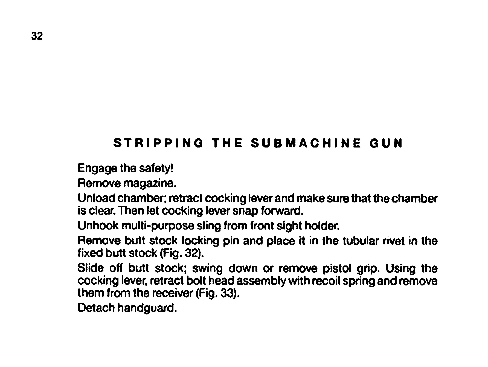
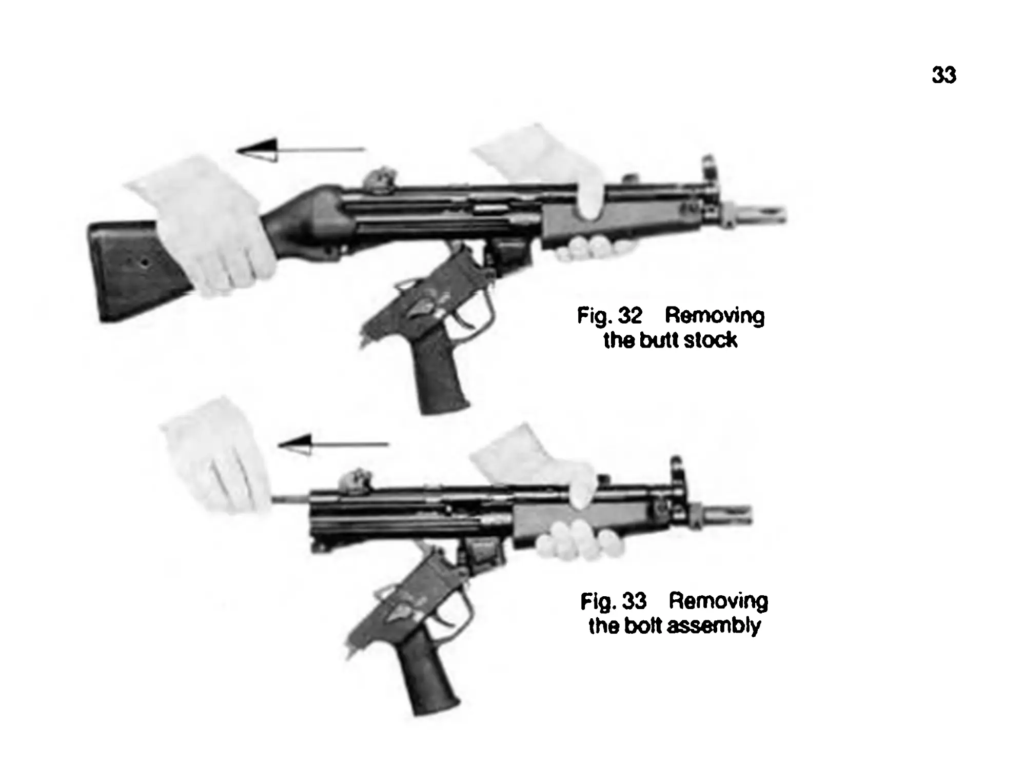
Remove butt stock locking pin and place it in the tubular rivet in the
fixed butt stock (Fig. 32).
Slide off butt stock; swing down or remove pistol grip. Using the
cocking lever, retract bolt head assembly with recoil spring and remove
them from the receiver (Fig. 33).
Detach handguard.
33
Fig. 33 Removing
the bolt assembly
34
Stripping the bolt assembly
Remove recoil spring from recoil spring tube by edging it off in the rear-
most position.
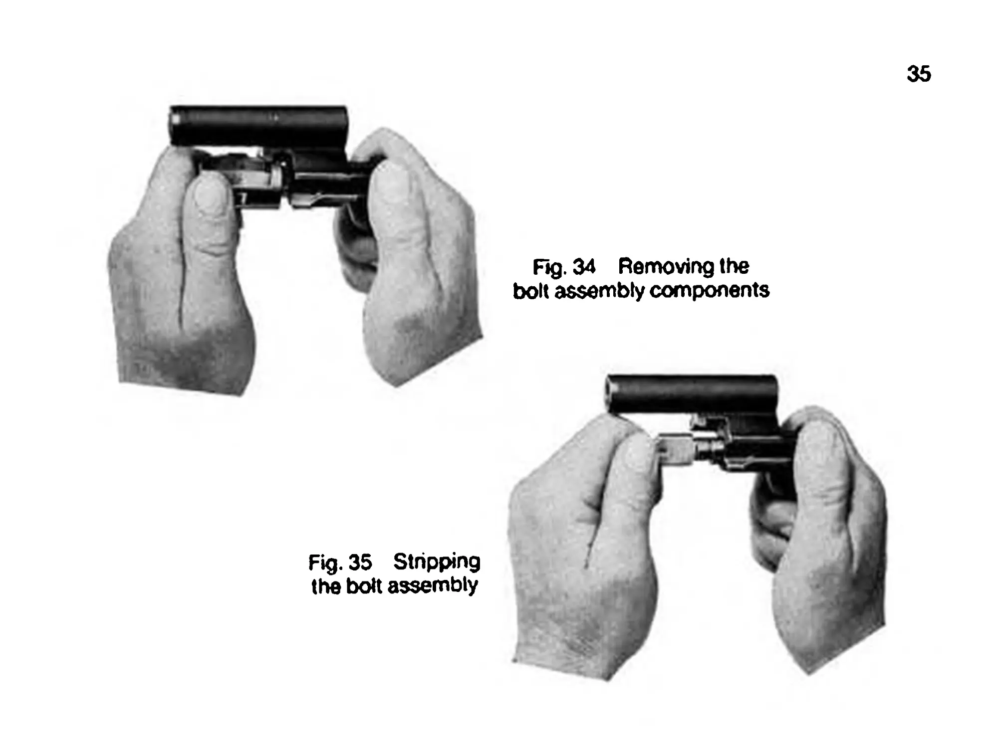
Rotate bolt heat 90° toward your body and detach it from the locking
piece. Remove locking piece, firing pin and firing pin spring from the
bolt head carrier (Figs. 34 and 35).
To reassemble the bolt assembly insert firing pin. firing pin spring
and locking piece into the bolt head. Insert all parts in the bolt head
carrier in such a manner that the lug on the locking piece is guided
through the recess in the bore of the bolt head carrier.
Rotate bolt head until you hear it engage.
Press recoil spring into the recoil spring tube.
Slipping the pistol grip with trigger mechanism.
Uncock hammer (spring).
Rotate selective fire lever until it is in a vertical position, then pull out.
Remove trigger assembly housing.
Note: Further stripping of the trigger assembly housing may only be
performed by ordnance personnel. If the trigger assembly housing is
severely fouled, it can be washed out in a cleaning solvent.
35
Fig. 34 Removing the
bolt assembly components
Fig. 35 Stripping
the bolt assembly
36
ASSEMBLING THE SUBMACHINE GUN
Attach handguard.
Insert the assembled bolt assembly, including recoil spring, into the
receiver.
Attach pistol grip and swing it into position.
(Set fire selector lever on pistol grip to ~SM.)
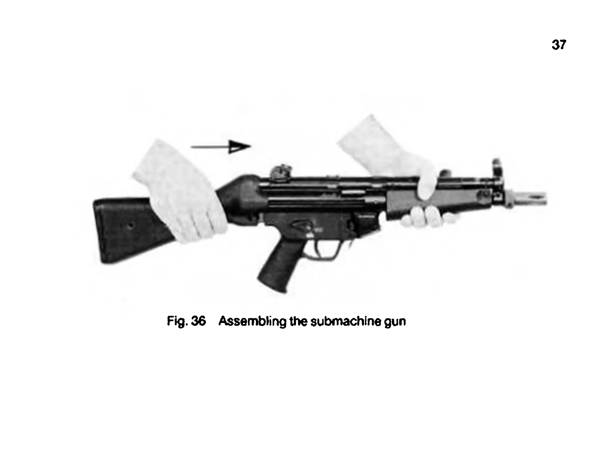
Push the fixed or retractable butt stock onto the receiver and press
locking pin into place (Fig. 36).
Attach the multi-purpose carrying sling.
Check the weapon for proper assembly by performing several cocking
motions.
JAMMING AND MALFUNCTIONS
Always! Cock and continue firing.
Should the weapon fail to fire, engage the safety, remove the magazine,
unload the weapon and determine the source of trouble.
37
Fig. 36 Assembling the submachine gun
38
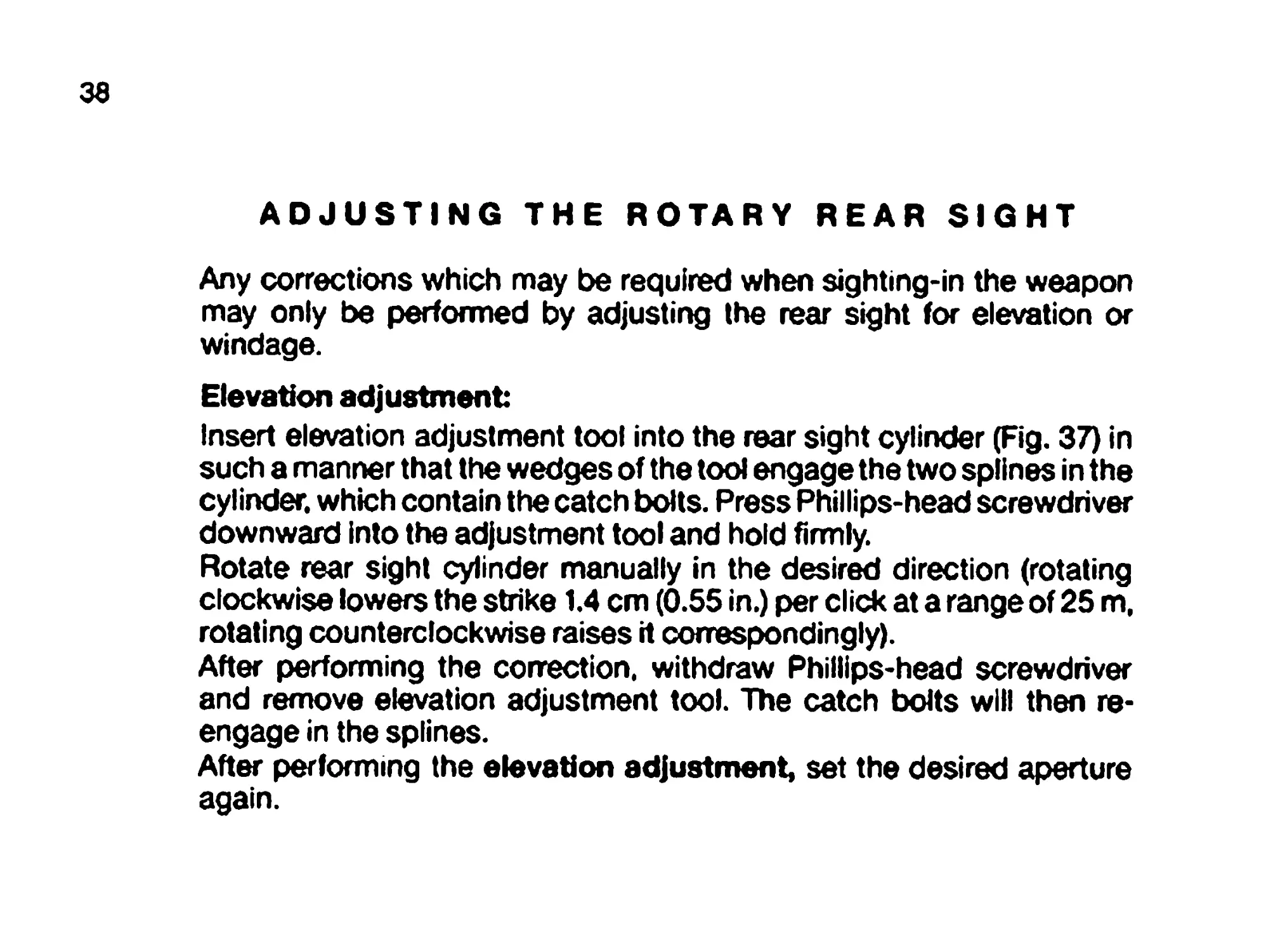
ADJUSTING THE ROTARY REAR SIGHT
Any corrections which may be required when sighting-in the weapon
may only be performed by adjusting the rear sight for elevation or
windage.
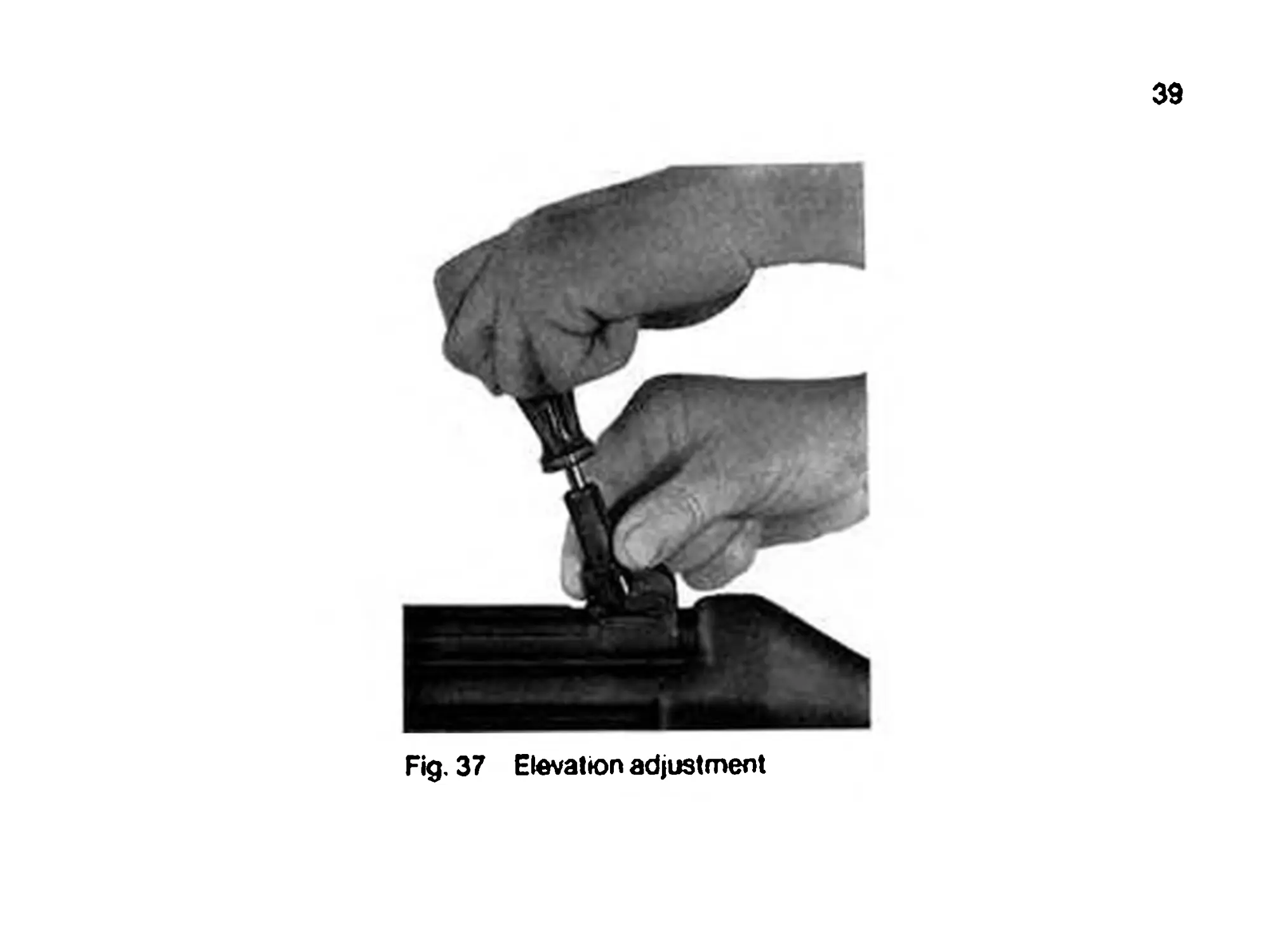
Elevation adjustment
Insert elevation adjustment tool into the rear sight cylinder (Fig. 37) in
such a manner that the wedges of the tool engage the two splines in the
cylinder, which contain the catch bolts. Press Phillips-head screwdriver
downward into the adjustment tool and hold firmly.
Rotate rear sight cylinder manually in the desired direction (rotating
clockwise lowers the strike 1.4 cm (0.55 in.) per click at a range of 25 m,
rotating counterclockwise raises it correspondingly).
After performing the correction, withdraw Phillips-head screwdriver
and remove elevation adjustment tool. The catch bolts will then re-
engage in the splines.
After performing the elevation adjustment, set the desired aperture
again.
39
Fig. 37 Elevation adjustment
40
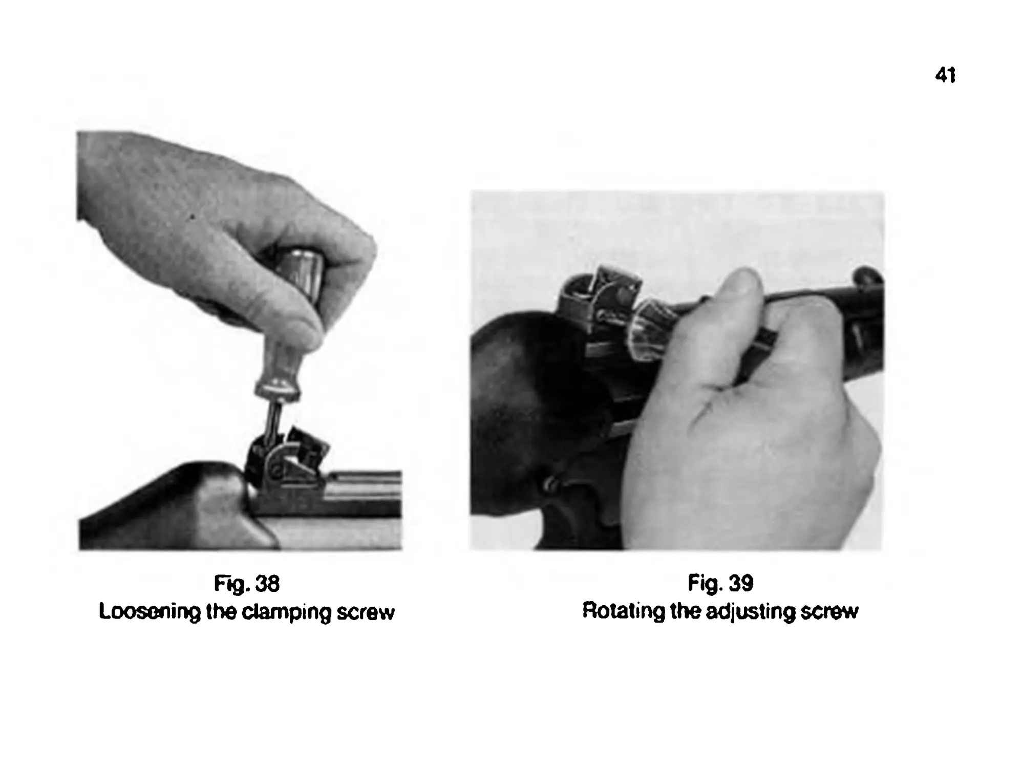
Windage adjustment
Correction of left-hand deviation: Loosen clamping screw (Яд. 38).
Turn adjusting screw (Fig. 39) counterclockwise, in accordance with the
required correction. Then retighten clamping screw.
Correction of right-hand deviation: Loosen clamping screw (Яд. 38).
Turn adjusting screw (Fig. 39) clockwise until the required correction is
obtained. Then retighten clamping screw.
Note: Each revolution of the adjusting screw moves the mean strike
5.5 cm (2.16 in.) to the left or right at a range of 25 m.
41
Fig. 39
Rotating the adjusting screw
F»g.38
Loosening the clamping screw
42
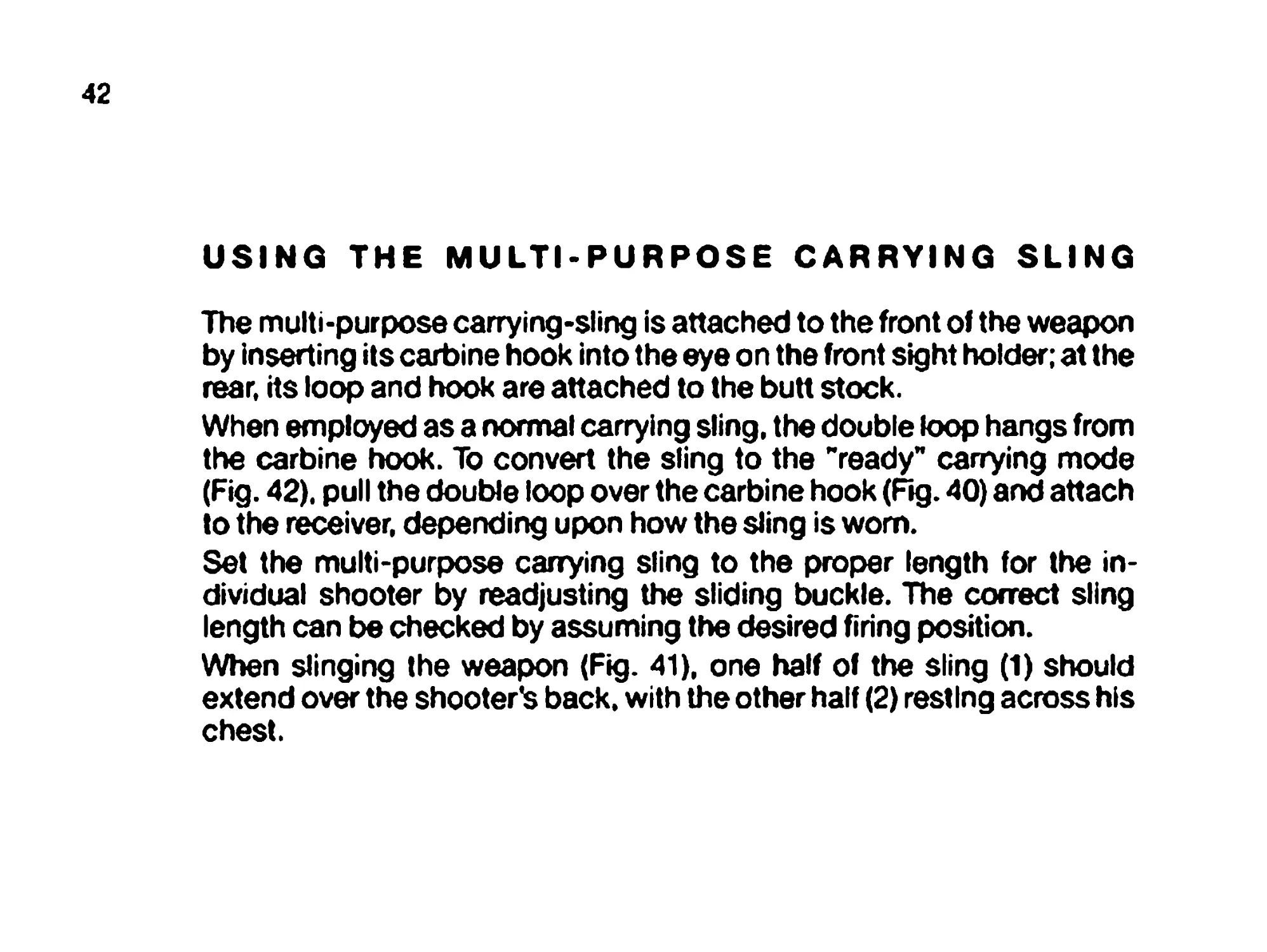
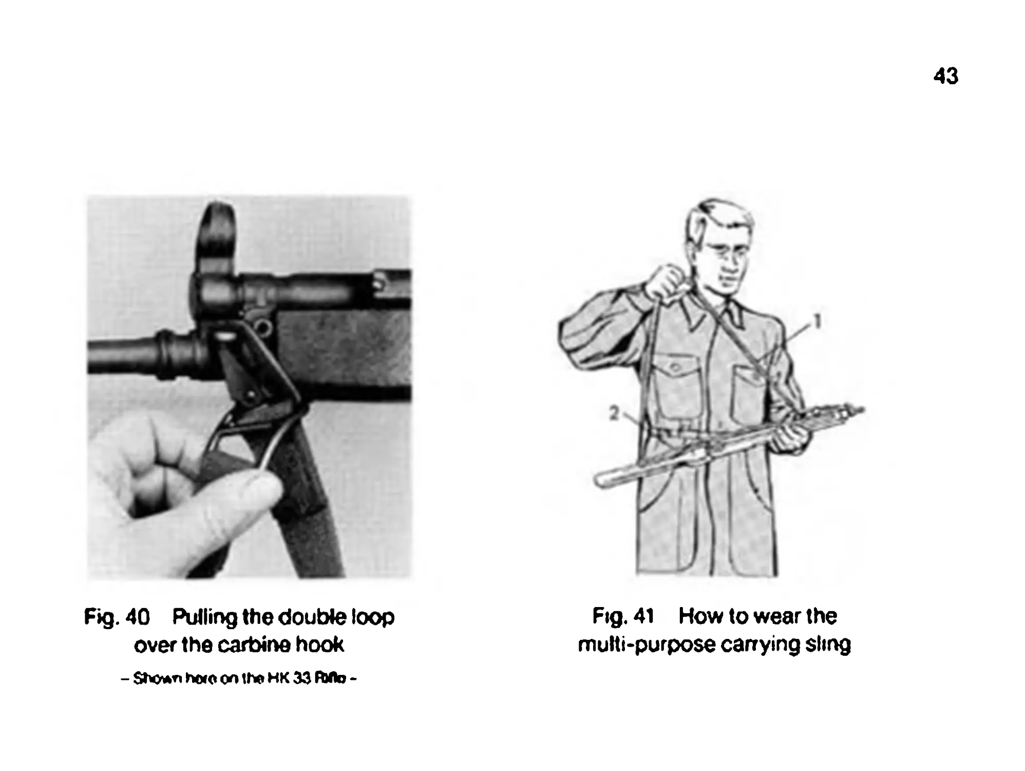
USING THE MULTI-PURPOSE CARRYING SLING
The multi-purpose carrying-sling is attached to the front of the weapon
by inserting its carbine hook into the eye on the front sight holder; at the
rear, its loop and hook are attached to the butt stock.
When employed as a normal carrying sling, the double loop hangs from
the carbine hook. To convert the sling to the "ready" carrying mode
(Fig. 42). pull the double loop over the carbine hook (Fig. 40) and attach
to the receiver, depending upon how the sling is worn.
Set the multi-purpose carrying sling to the proper length for the in-
dividual shooter by readjusting the sliding buckle. The correct sling
length can be checked by assuming the desired firing position.
When slinging the weapon (Fig. 41), one half of the sling (1) should
extend over the shooter's back, with the other half (2) resting across his
chest.
Fig. 40 Pulling the double loop
over the carbine hook
- Sbo*n ho<o on tfa HK 33 АЛ> -
43
Fig. 41 How to wear the
multi-purpose carrying sling
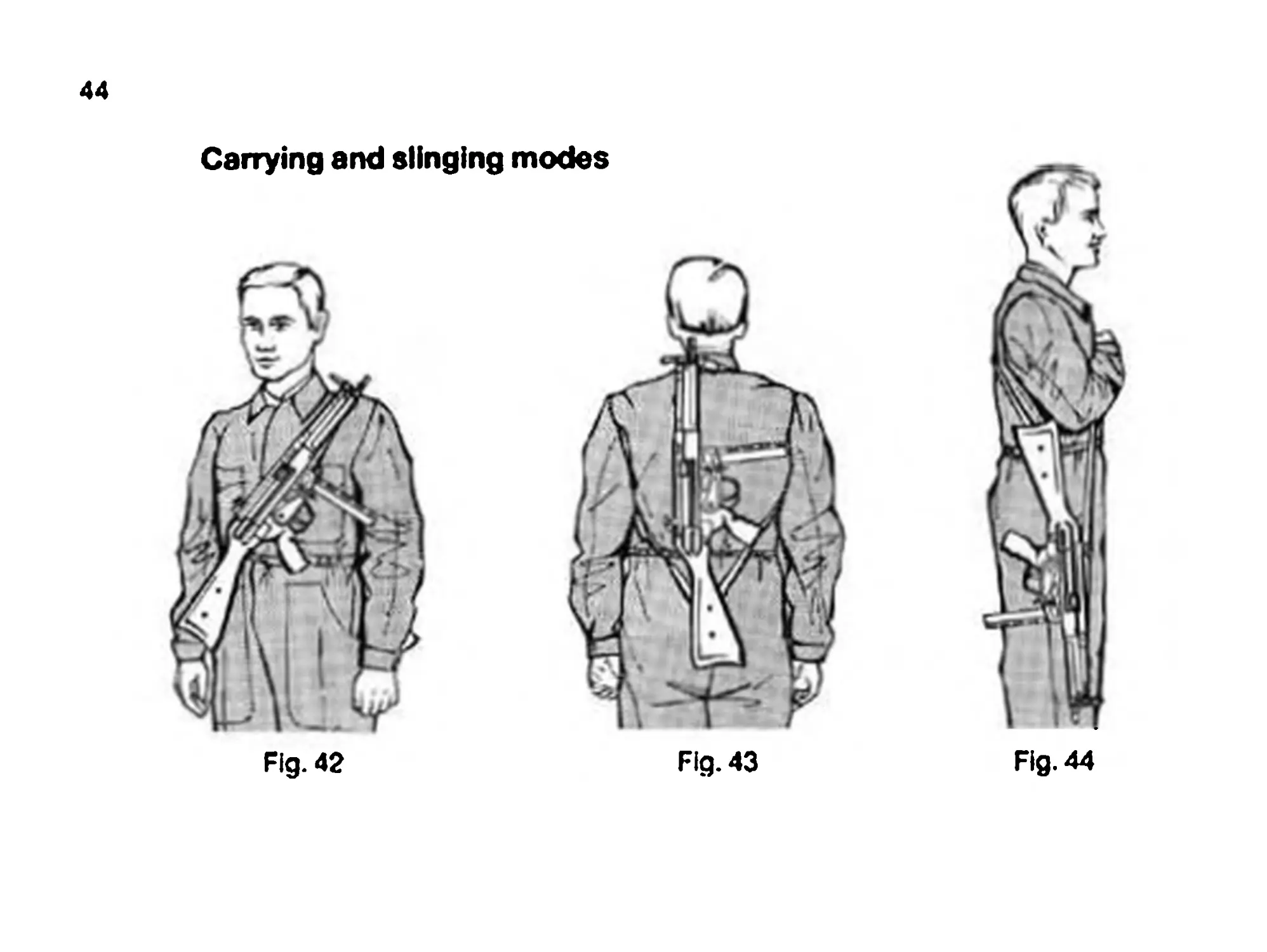
44
Fig. 42 Fig. 43 Fig. 44
Fig. 45
Fig. 46
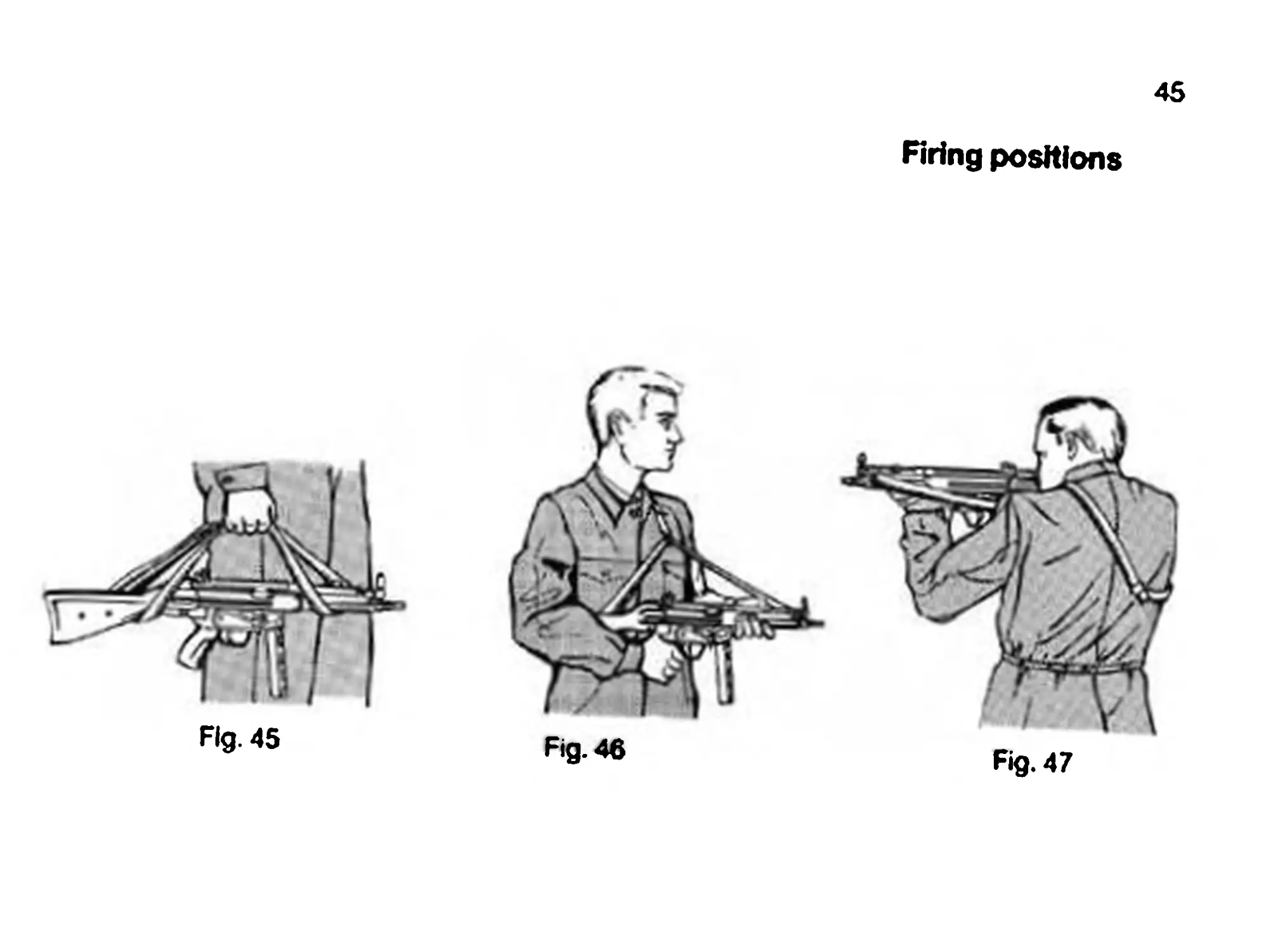
45
Firing positions
Fig. 47
46
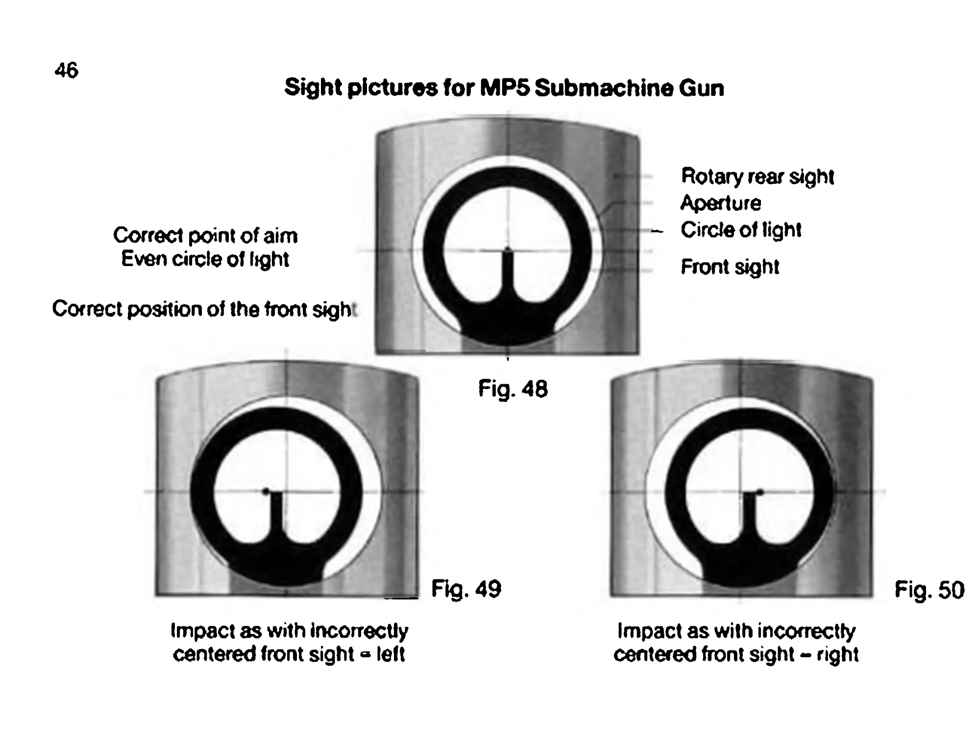
Sight pictures for MPS Submachine Gun
Correct position of the front sight
Correct point of aim
Even circle of light
Fig. 48
Fig. 49
Impact as with incorrectly
centered front sight»left
Rotary rear sight
Aperture
- Circle of light
Front sight
Fig. 50
Impact as with incorrectly
centered front sight - right
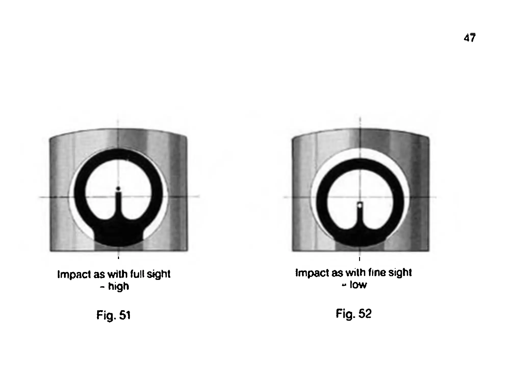
47
Impact as with full sight
- high
impact as with fine sight
- low
Fig. 51
Ag-52
48
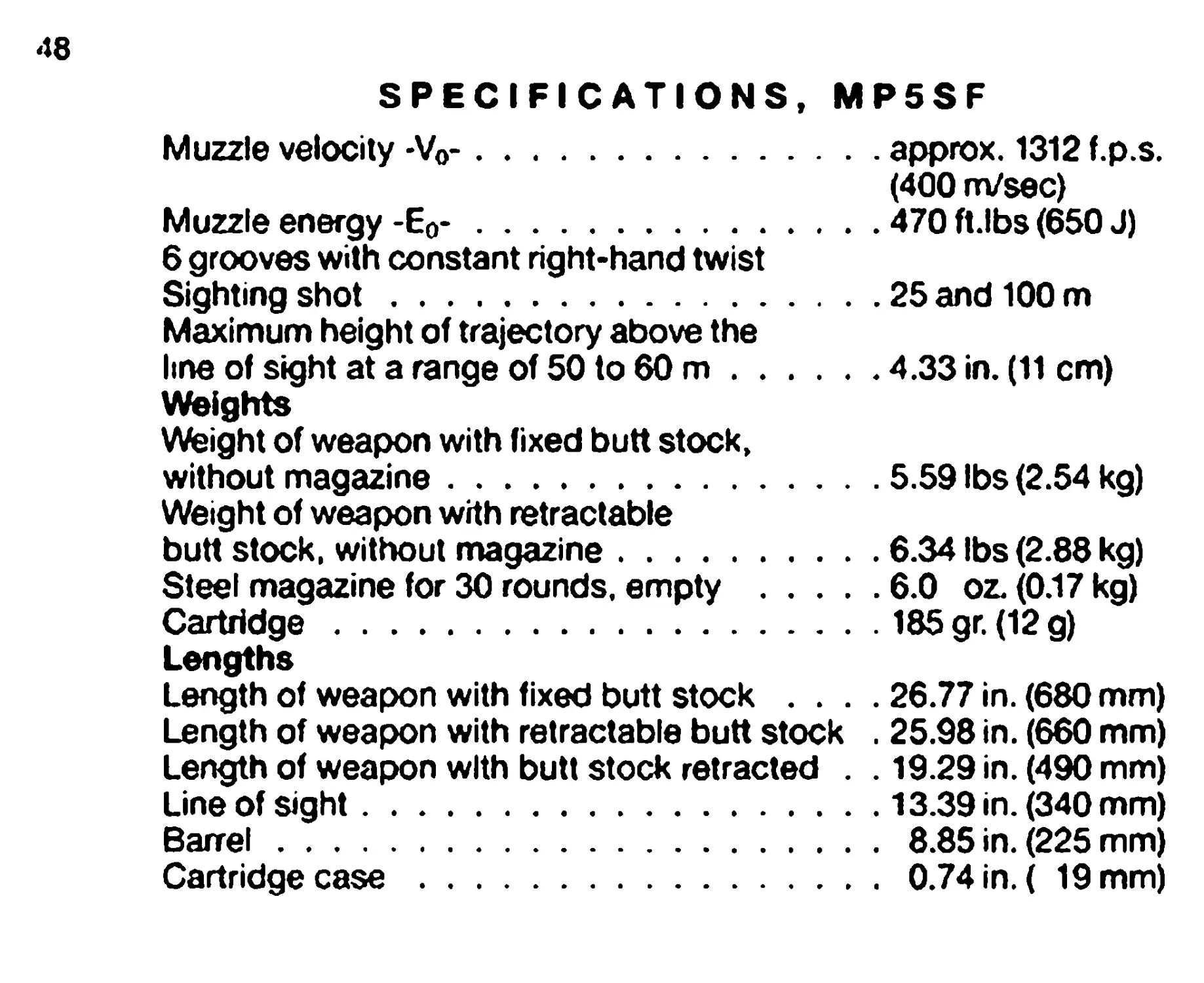
SPECIFICATIONS, MP5SF
Muzzle velocity -Vo-.....................approx. 1312 f.p.s.
(400 m/sec)
Muzzle energy -Eo-.......................470 ft.lbs (650 J)
6 grooves with constant right-hand twist
Sighting shot............................25 and 100 m
Maximum height of trajectory above the
line of sight at a range of 50 to 60 m...4.33 in. (11 cm)
Weights
Weight of weapon with fixed butt stock,
without magazine.........................5.59 lbs (2.54 kg)
Weight of weapon with retractable
butt stock, without magazine.............6.34 lbs (2.88 kg)
Steel magazine for 30 rounds, empty .....6.0 oz. (0.17 kg)
Cartridge................................185 gr. (12 g)
Lengths
Length of weapon with fixed butt stock .... 26.77 in. (680 mm)
Length of weapon with retractable butt stock . 25.98 in. (660 mm)
Length of weapon with butt stock retracted . . 19.29 in. (490 mm)
Line of sight............................13.39 in. (340 mm)
Barrel...................................8.85 in. (225 mm)
Cartridge case...........................0.74 in. ( 19 mm)
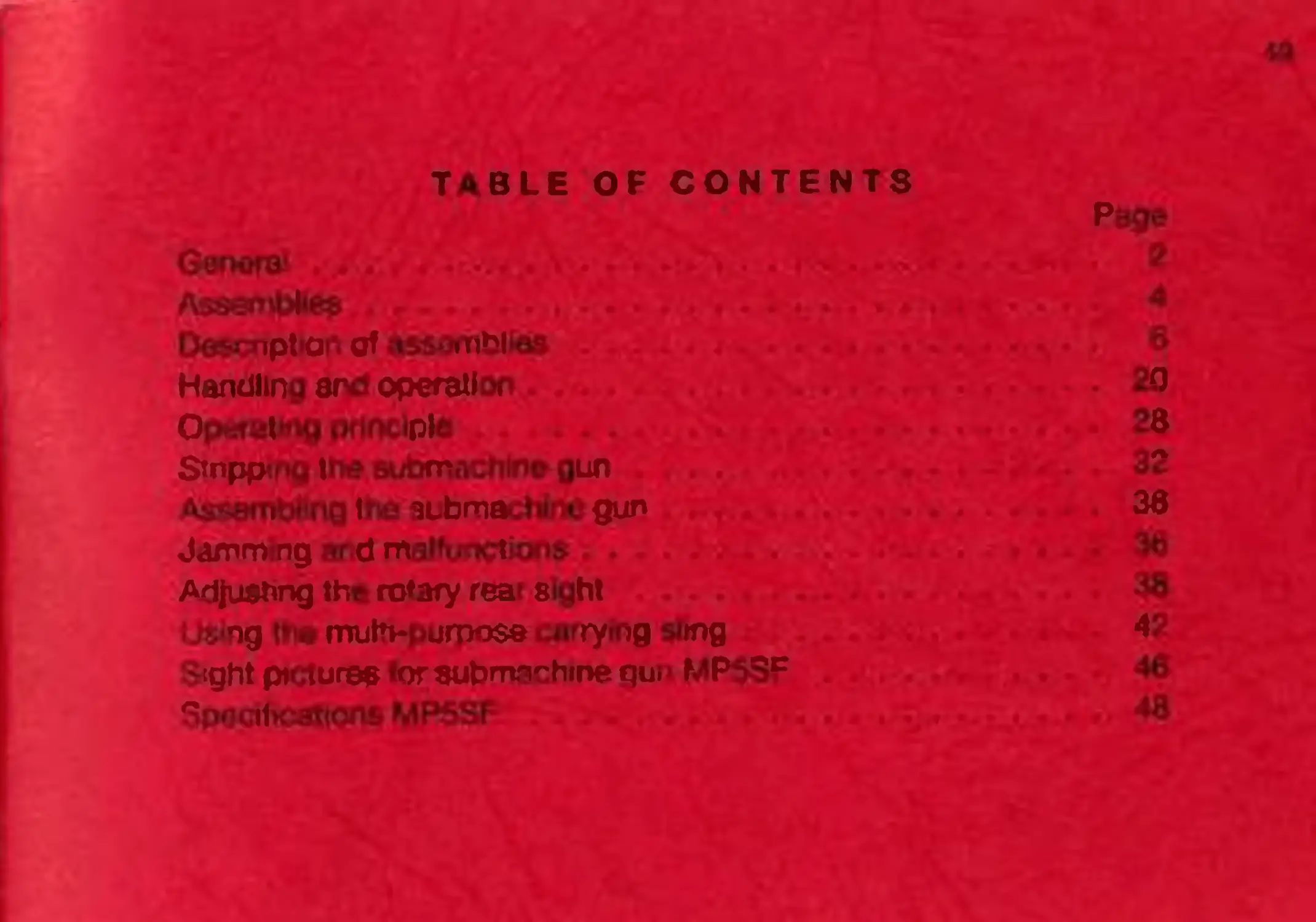
TABLE OF CONTENTS
Page
Genera1 . • • N ....* * 4
Assemble* - . - ...... • -
Description of assemblies *
Handling and operation •
Operating principle
Stripping the submachine gun
S 3 S $ 3 3
1 ne aubmactiinv gun
Jamming and malfunctions ...
Adjusting the rotary rea sight
>. ng t»'w mutvpumose carrying sling
S<ght picture® «or submnnhine gw MP5SF
SpQcifKiahons MP5SF