/

Похожие

Текст
MH I
Copy 3
FM 4-112
WAR DEPARTMENT
COAST ARTILLERY
FIELD MANUAL
&
ANTIAIRCRAFT ARTILLERY
GUNNERY, FIRE CONTROL,
POSITION FINDING,
AND HORIZONTAL FIRE,
ANTIAIRCRAFT AUTOMATIC
WEAPONS
(CASE I FIRING)
August 22, 1942
FM 4-112
COAST ARTILLERY
FIELD MANUAL
&
ANTIAIRCRAFT ARTILLERY
GUNNERY, FIRE CONTROL, POSITION
FINDING, AND HORIZONTAL FIRE,
ANTIAIRCRAFT AUTOMATIC WEAPONS
(CASE I FIRING)
UNITED STATES
GOVERNMENT PRINTING OFFICE
WASHINGTON : 1942
WAR DEPARTMENT,
Washington, August 22, 1942.
FM4-112, Coast Artillery Field Manual, Antiaircraft Artil-
lery—Gunnery, Fire Control, Position Finding, and Horizontal
Fire, Antiaircraft Automatic Weapons (Case I Firing), is
published for the information and guidance of all concerned.
[A. G. 062.11 (6-5-42).]
By order of the Secretary of War:
G. C. MARSHALL,
Chief of Staff.
Official :
J. A. ULIO,
Major General,
The Adjutant General.
Distribution:
R and Hl (2); Bn and H 4 (3); IBn and H 4 (10);
IC 4 (25).
(For explanation of symbols see FM 21-6.)
и
TABLE OF CONTENTS
Chapter 1. General. Paragraphs Page
Section I. General_______________________________ 1-5 1
II. Antiaircraft automatic weapons
problem___________________________________ 6-11 3
III. Gun pointer control__________________ 12-17 6
IV. On carriage sight control____________ 18-24 9
V. Off carriage sight control______ 25-32 11
VI. Director control_____________________ 33-38 13
Chapter 2. Dispersion and hit expectancy.
Section I. Dispersion_________________________________ 39-44 16
II. Hit expectancy_______________________ 45-47 25
Chapter 3. Calculation of leads.
Section I. Elements of data___________________________ 48-53 28
II. Firing tables________________________ 54-57 35
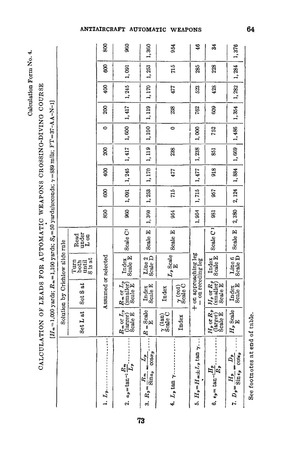
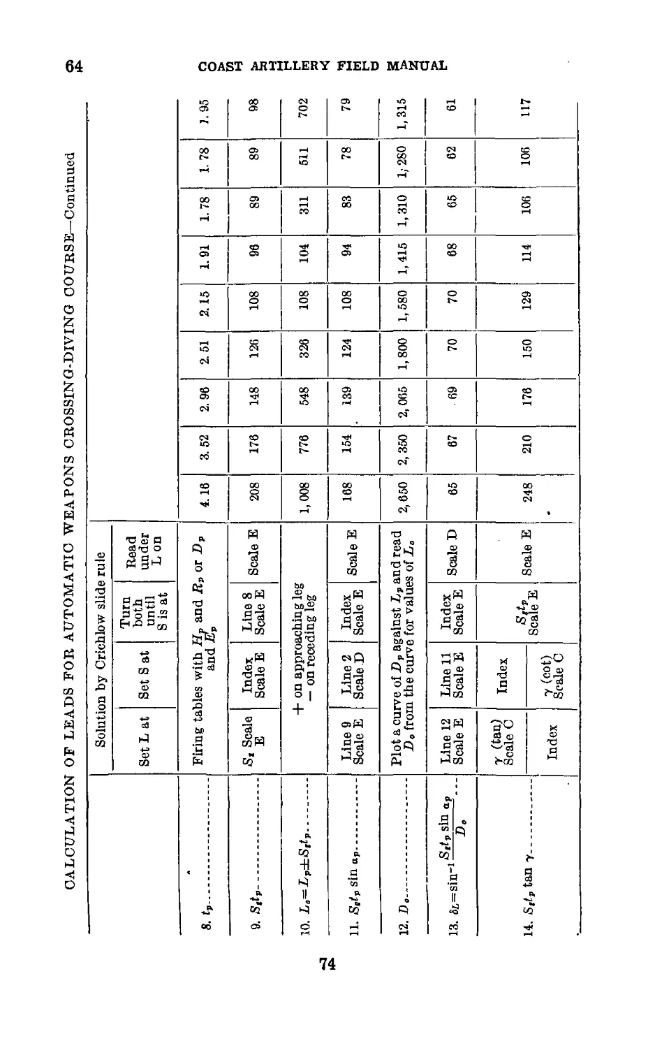
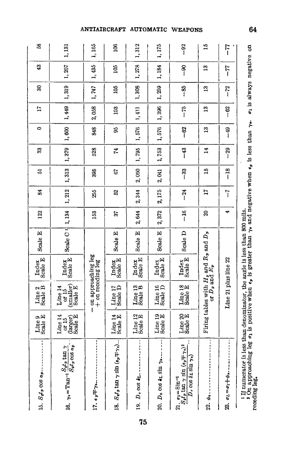
HI. Methods of lead calculation_______ 58-64 41
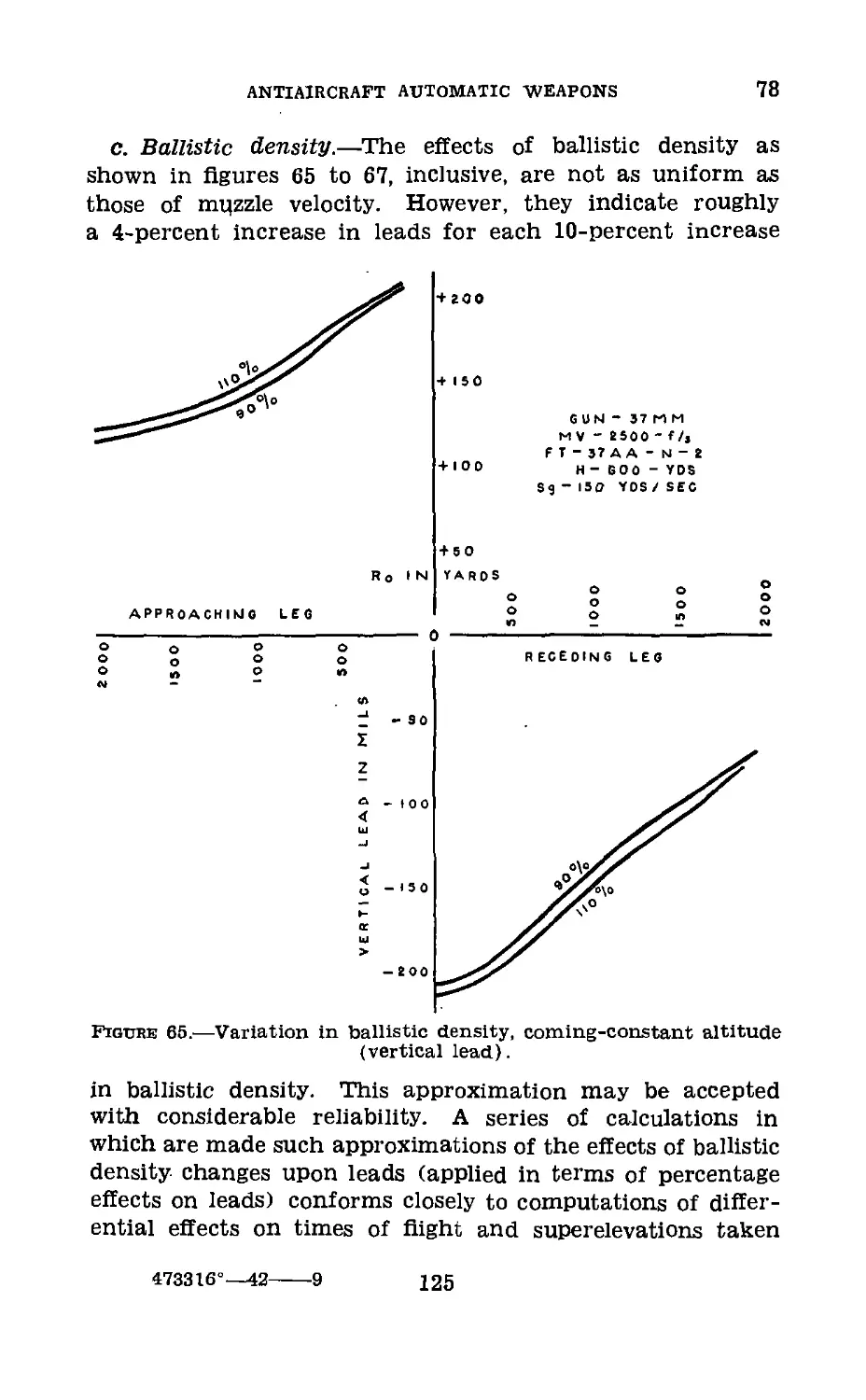
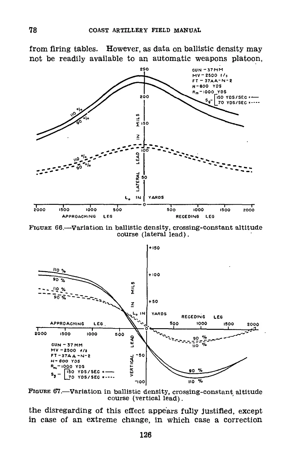
Chapter 4. Lead curves and charts.
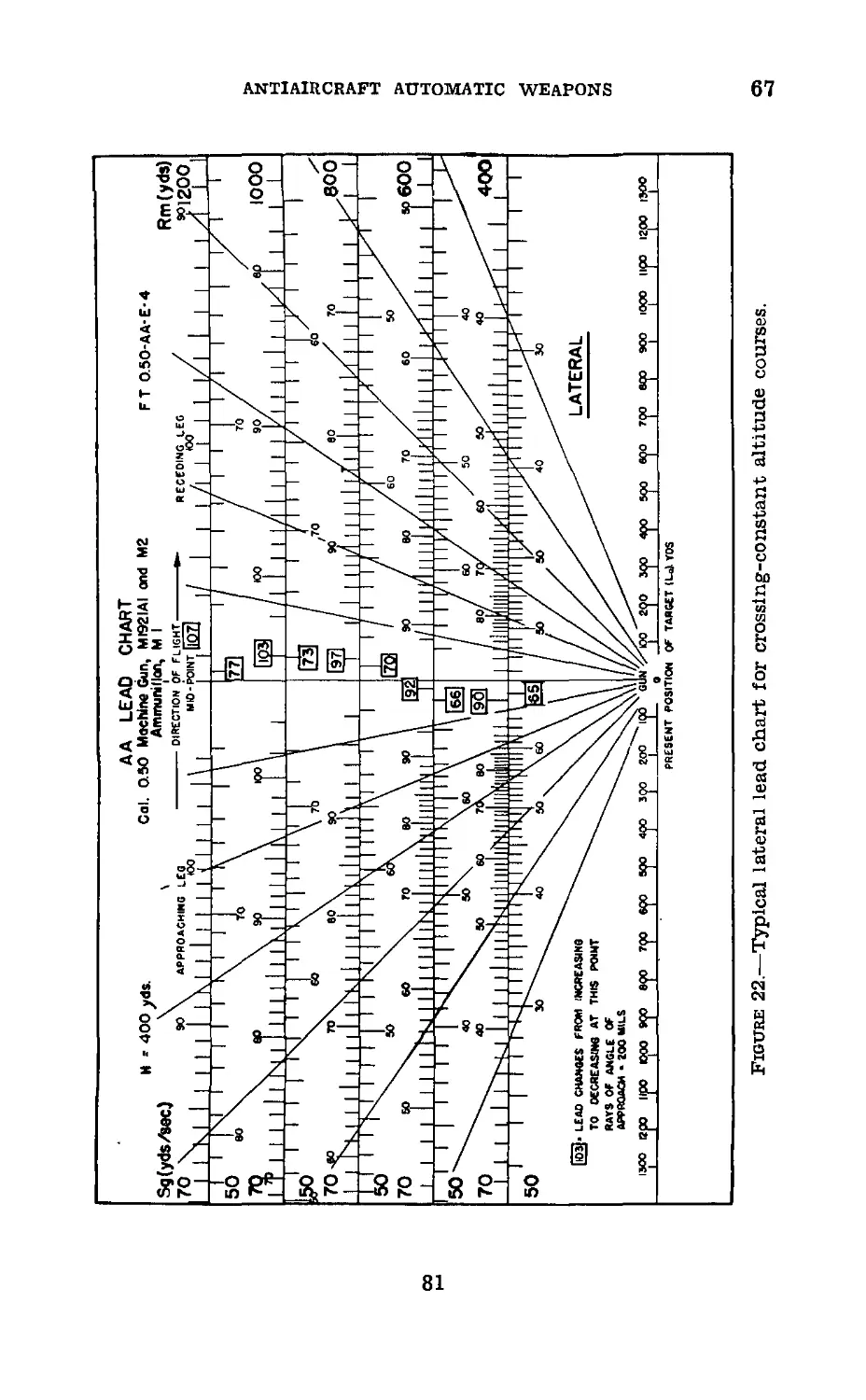
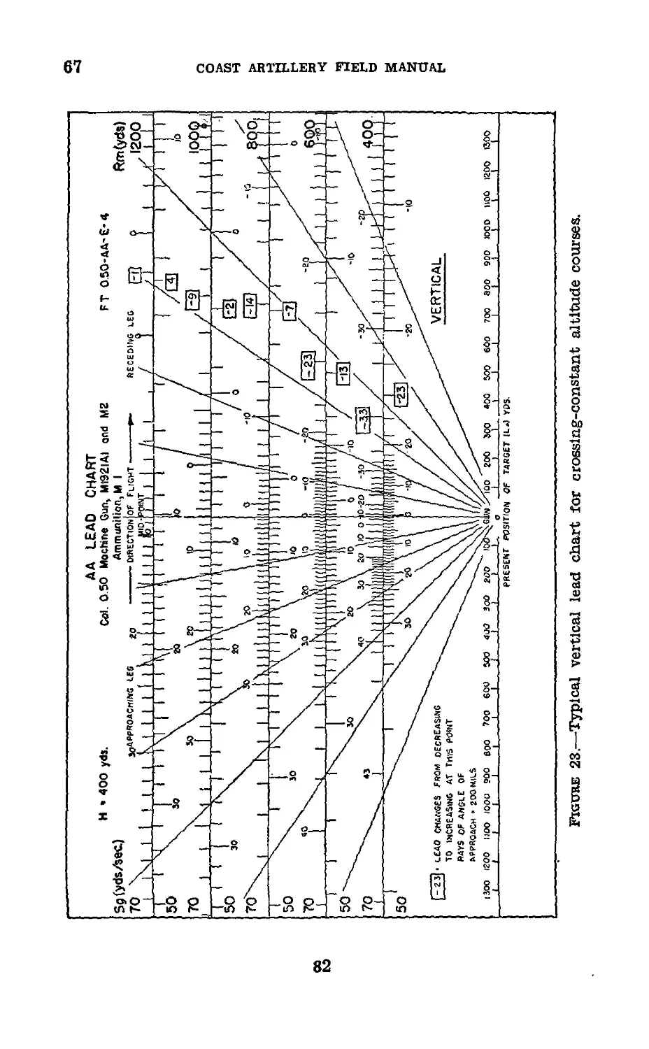
Section I. Lead curves and lead charts for
constant altitude courses________________________ 65-67 76
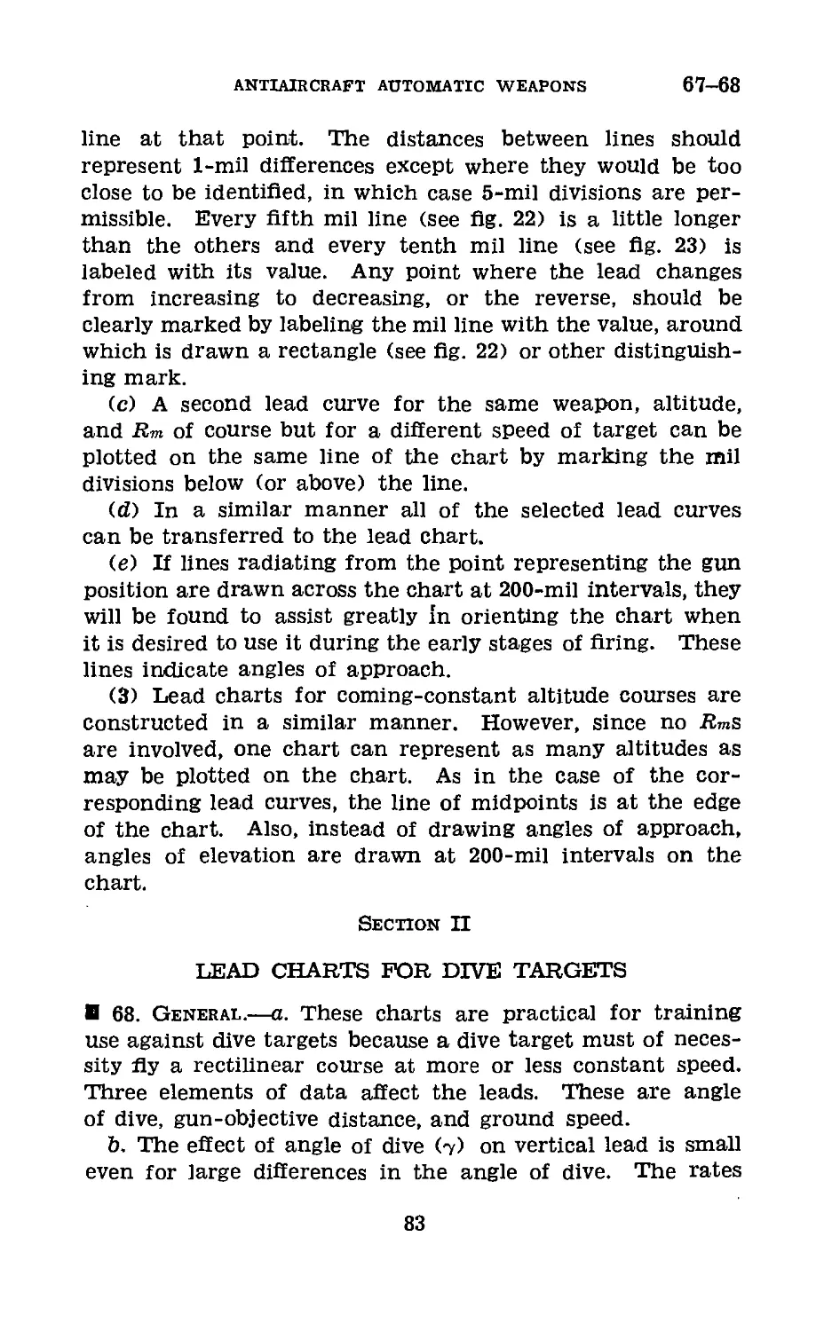
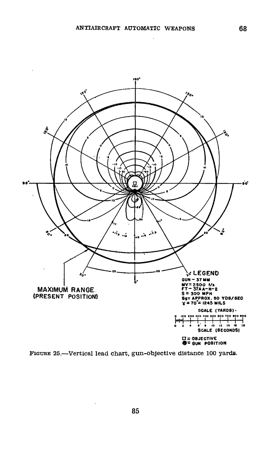
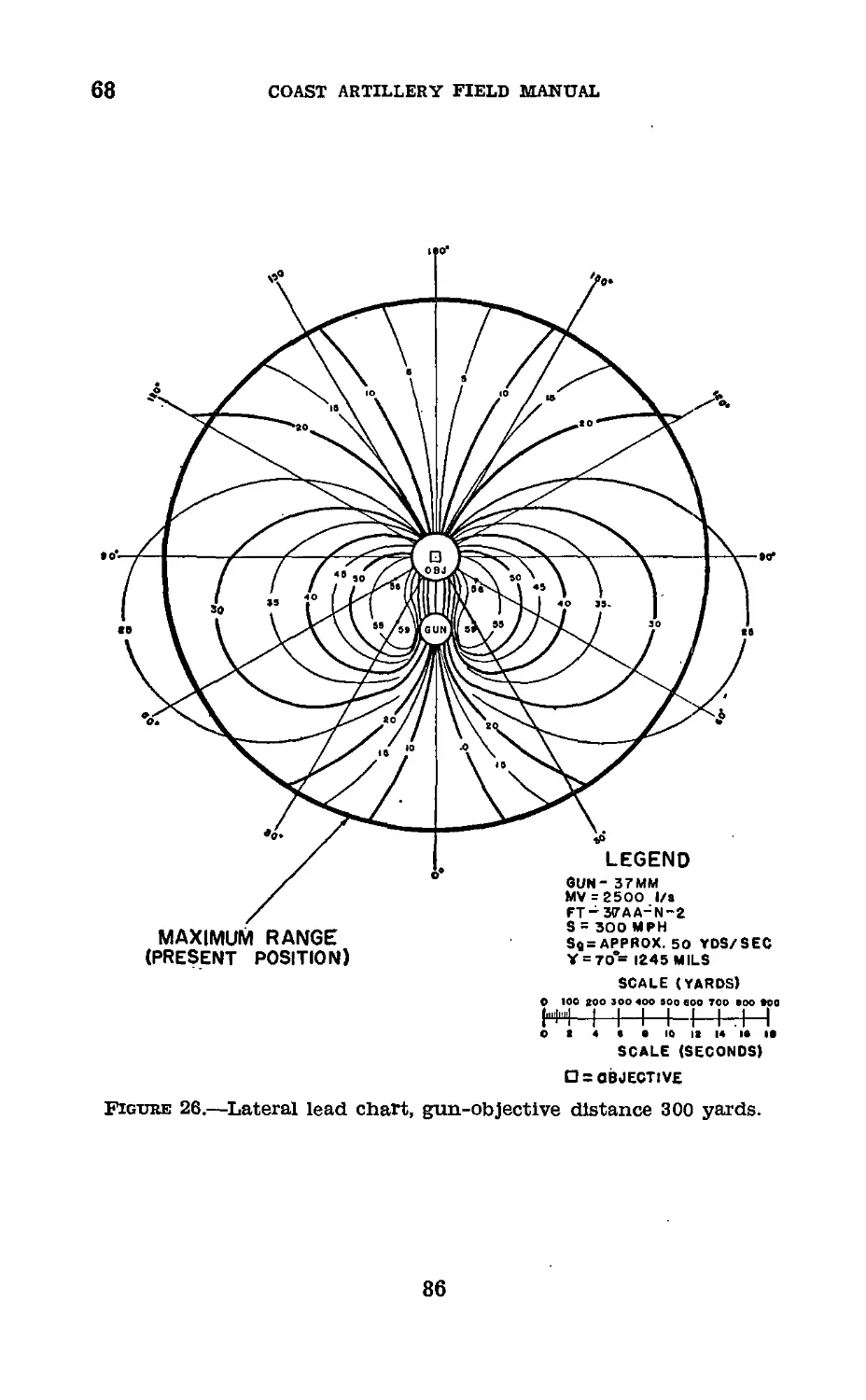
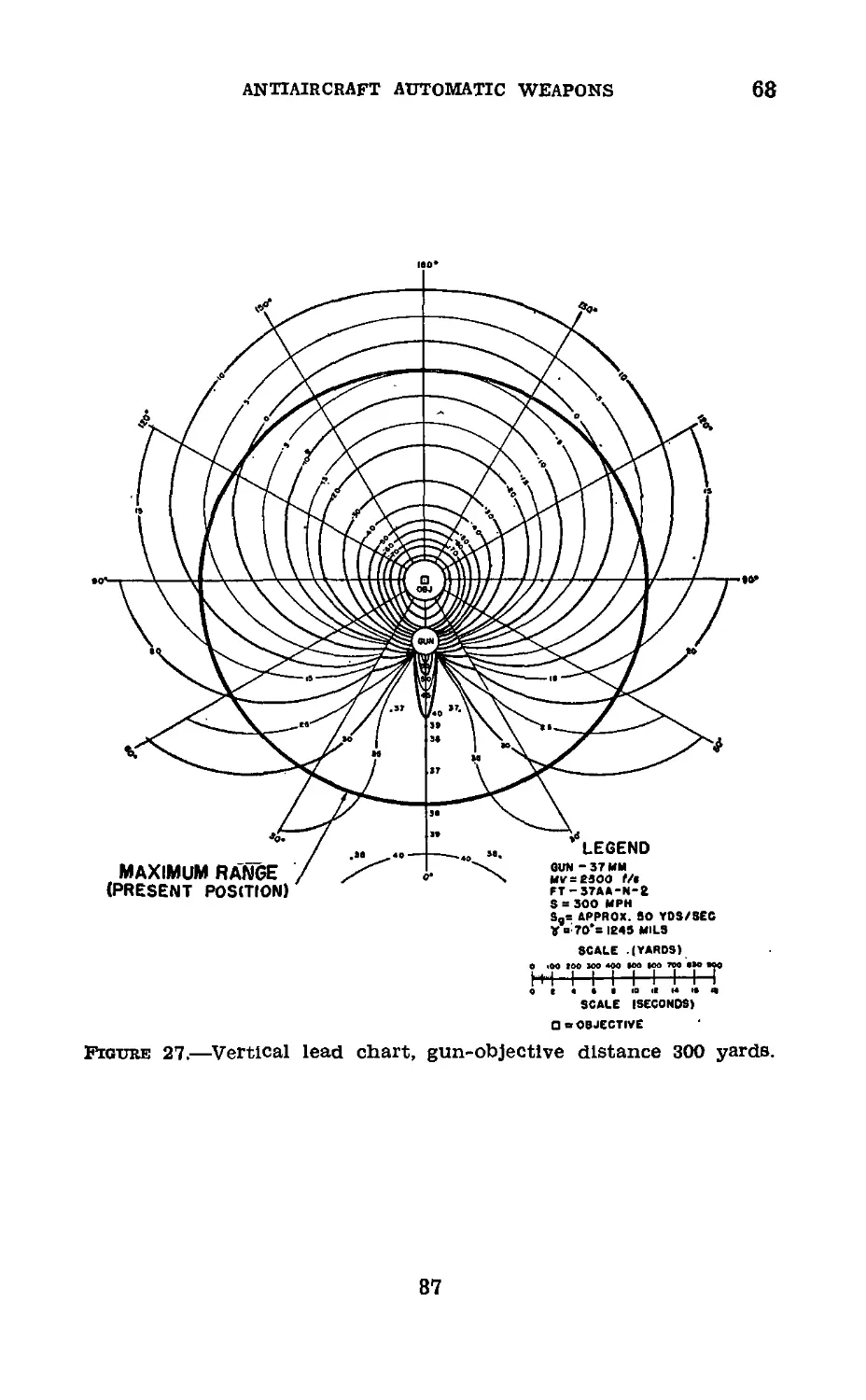
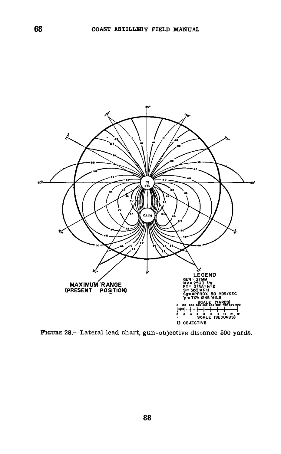
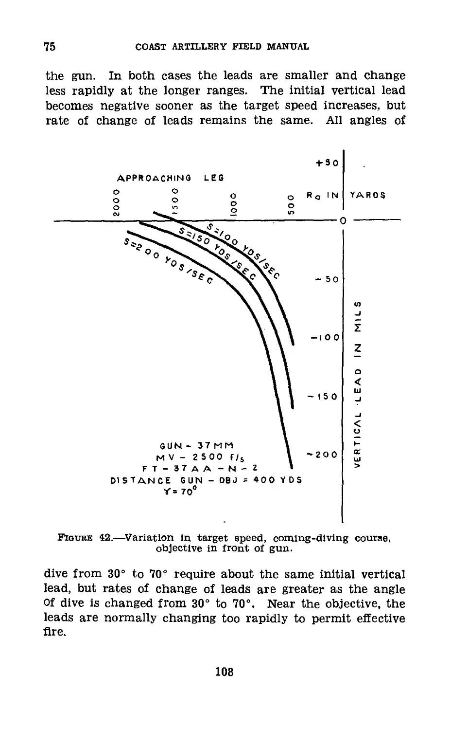
II. Lead charts for dive targets_____ 68-72 83
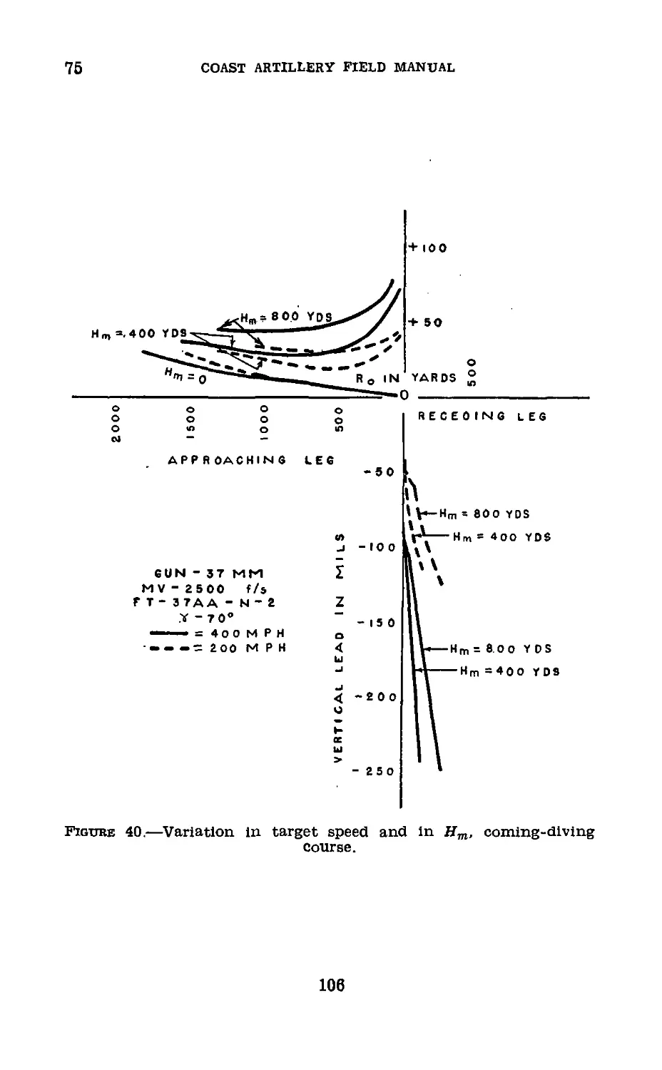
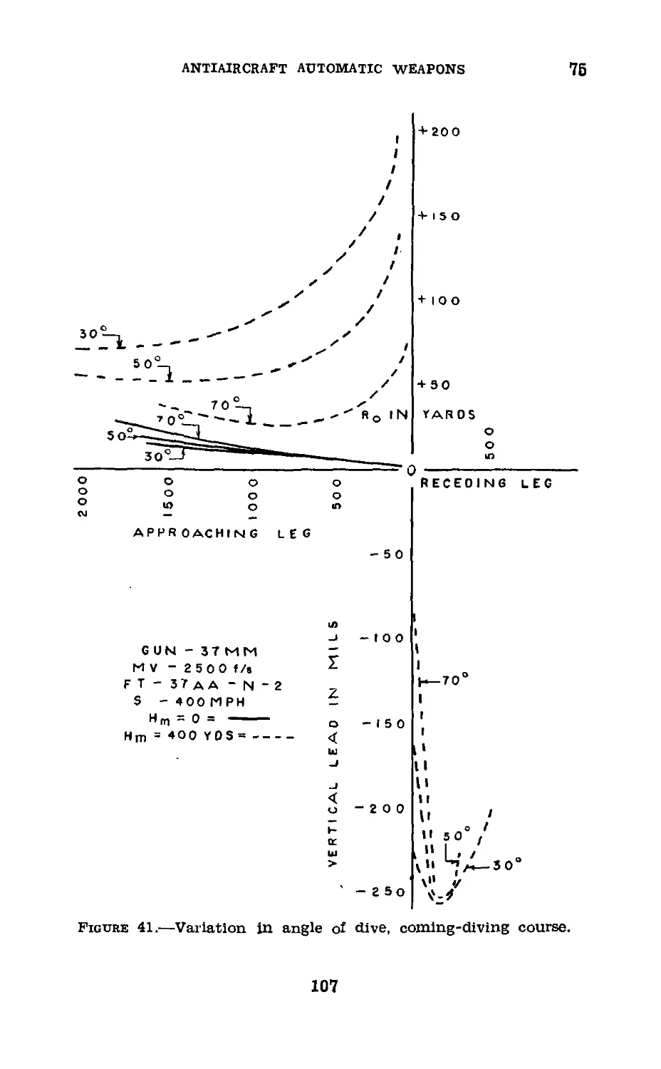
Chapter 5. Lead characteristics--------------------- 73-80 102
Chapter 6. Horizontal fire.
Section I. General_______________________________ 81-82 130
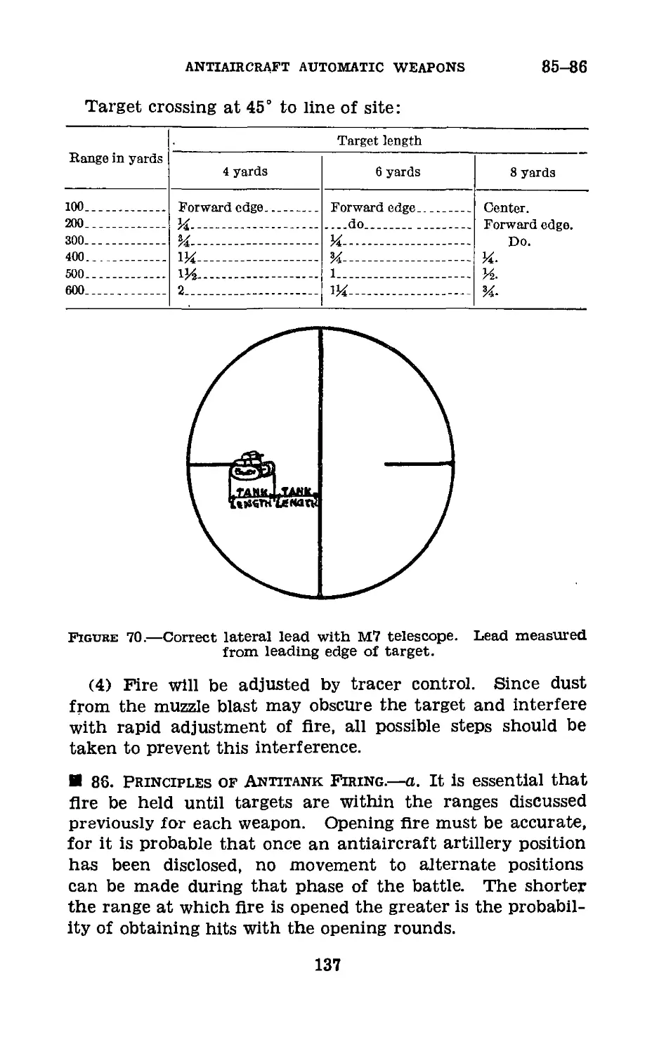
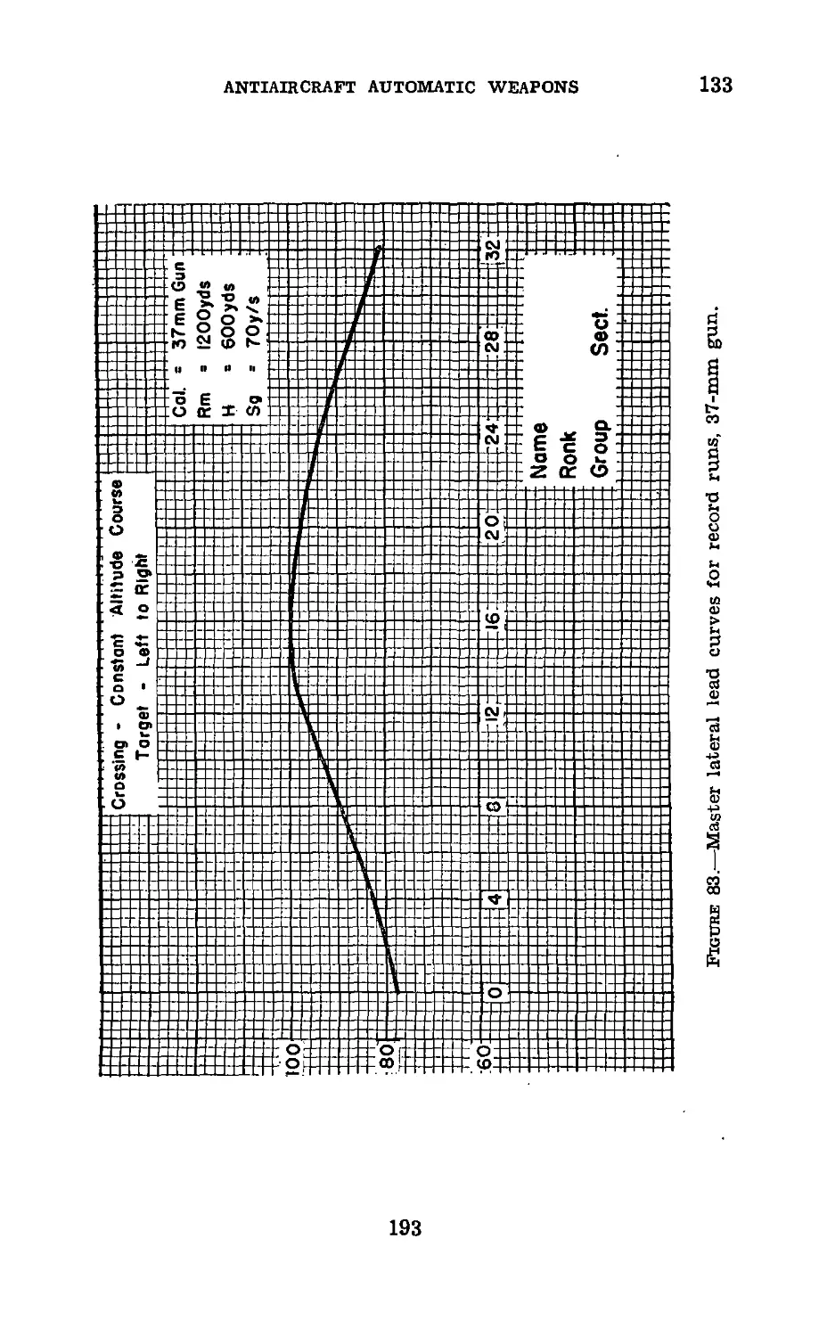
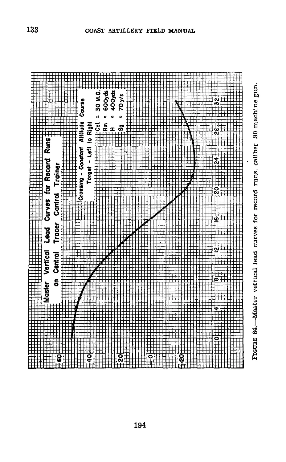
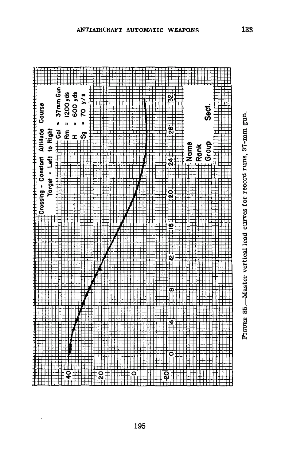
II. Antimechanized defense_______________ 83-86 130
Ш. Assault of fortifications______________ 87-88 138
IV. Engagement of water-borne tar-
gets _______________________________ 89-91 139
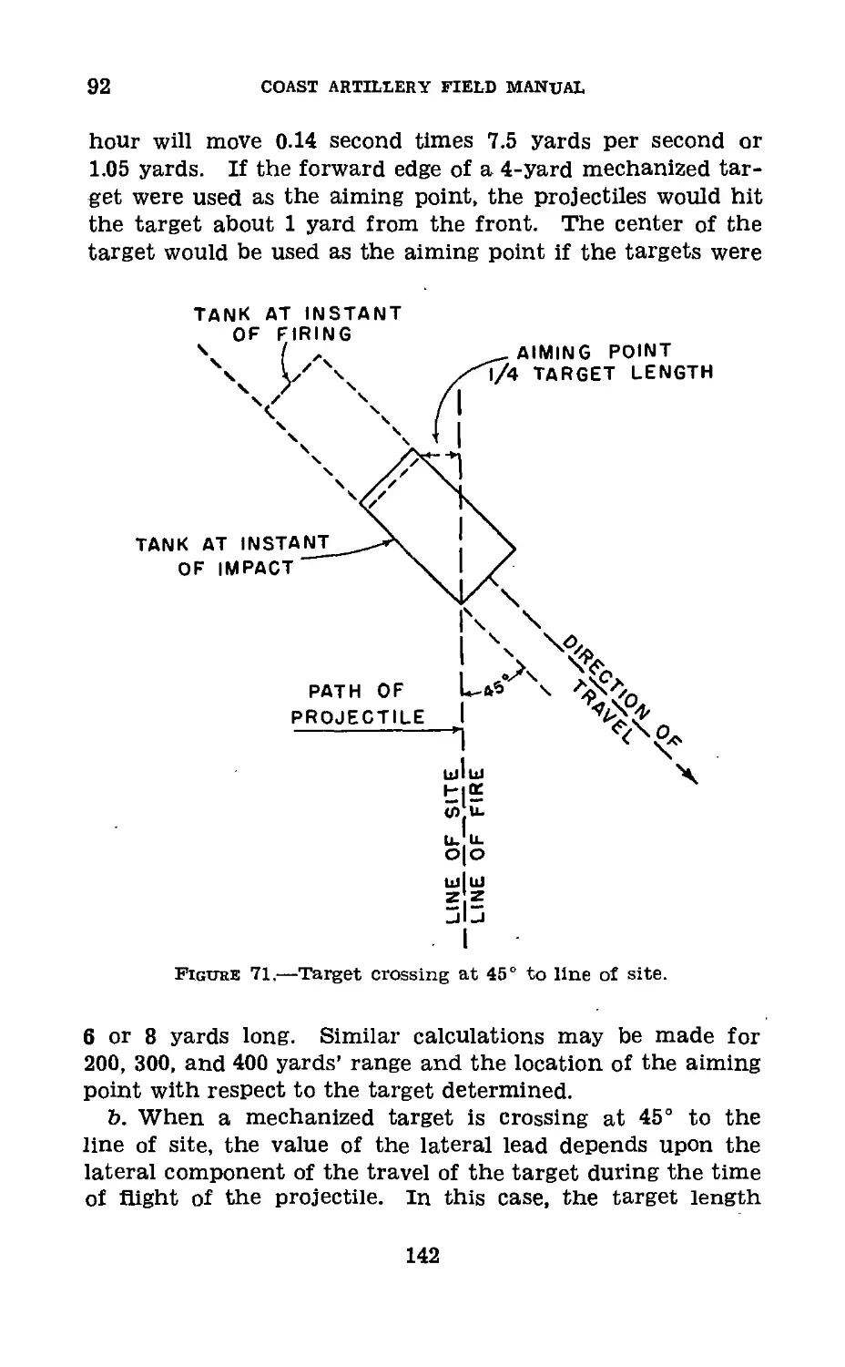
V. Lateral leads and lead charts___ 92-95 141
Chapter 7. Observation and adjustment of fire.
Section I. Methods of observation________________ 96-99 151
II. Individual tracer control__________ 100-101 157
1П. Central tracer control______________ 102-106 159
IV. Fire adjustment____________________ 107-109 161
V. Data transmission_________________ 110-113 165
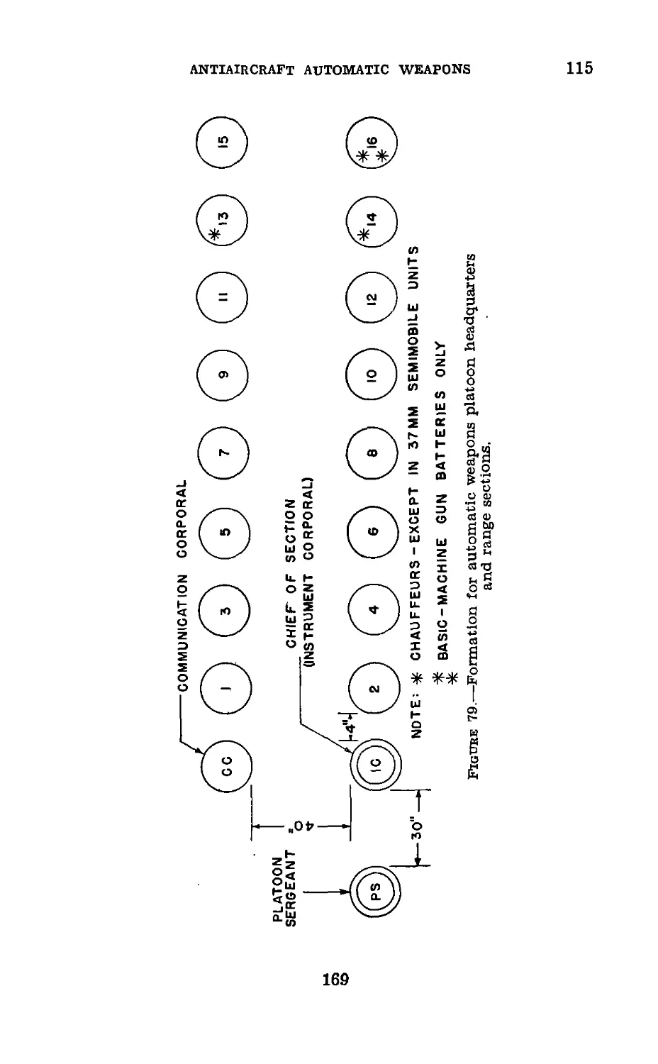
Chapter 8. Range section----------------------- 114-116 168
Chapter 9. Training.
Section I. General_______________________________ 117-120 173
II. Training of gunners and gun
pointers_______________________________ 121—123 174
IH. Training of adjusters and spotters 124-127 176
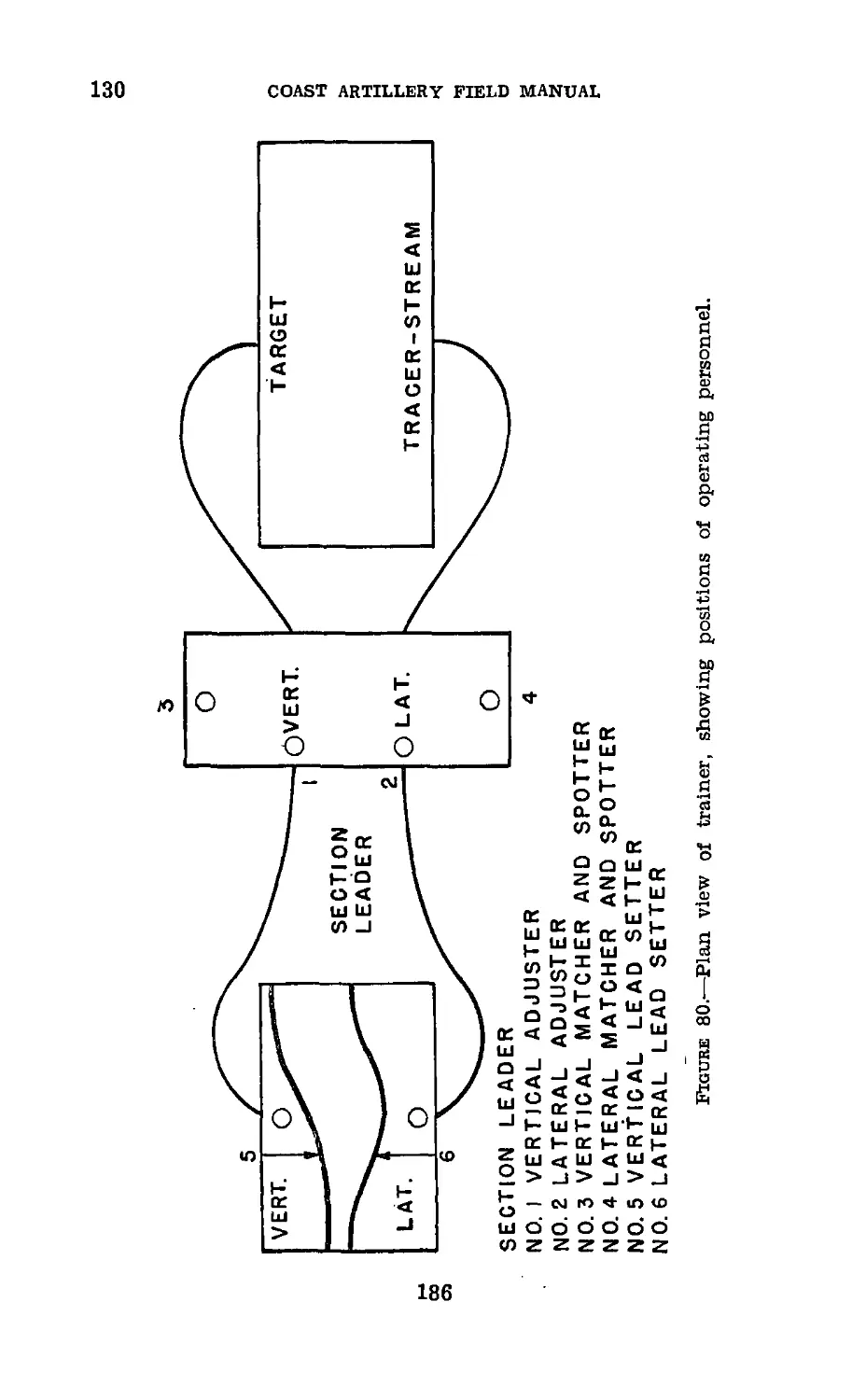
IV. Tracer control trainer______________ 128-133 180
V. Subcaliber firing______________________ 134 196
Appendix I. Glossary of symbols, automatic weapons__________ 197
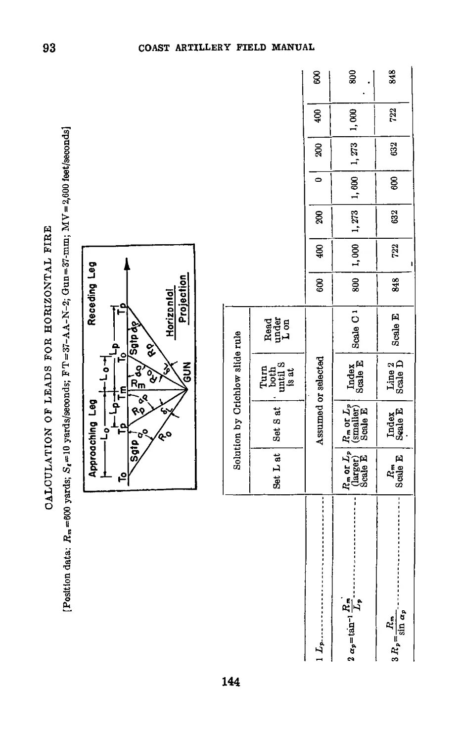
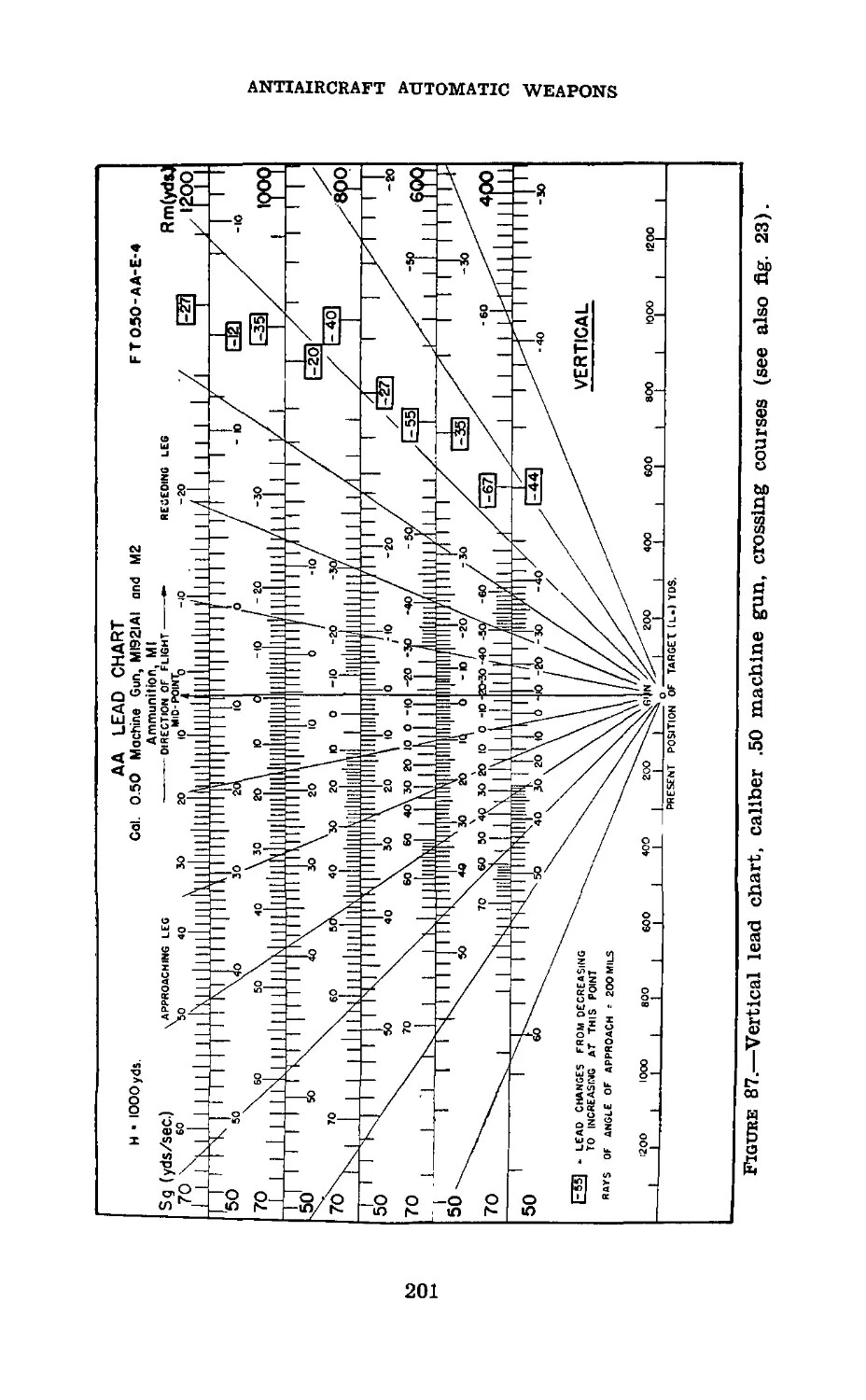
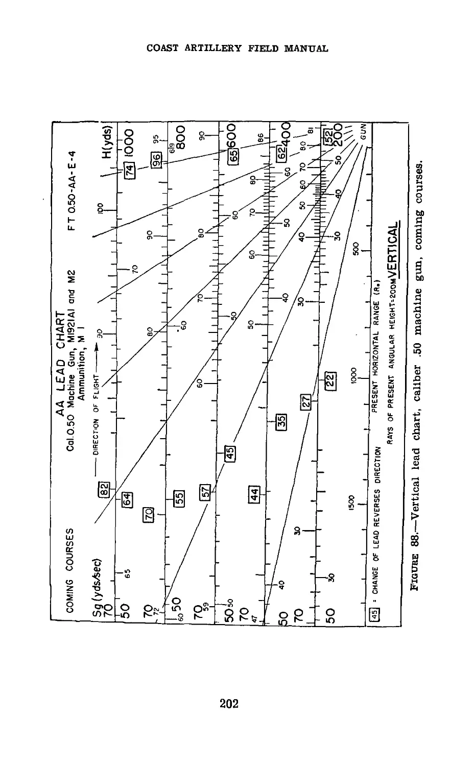
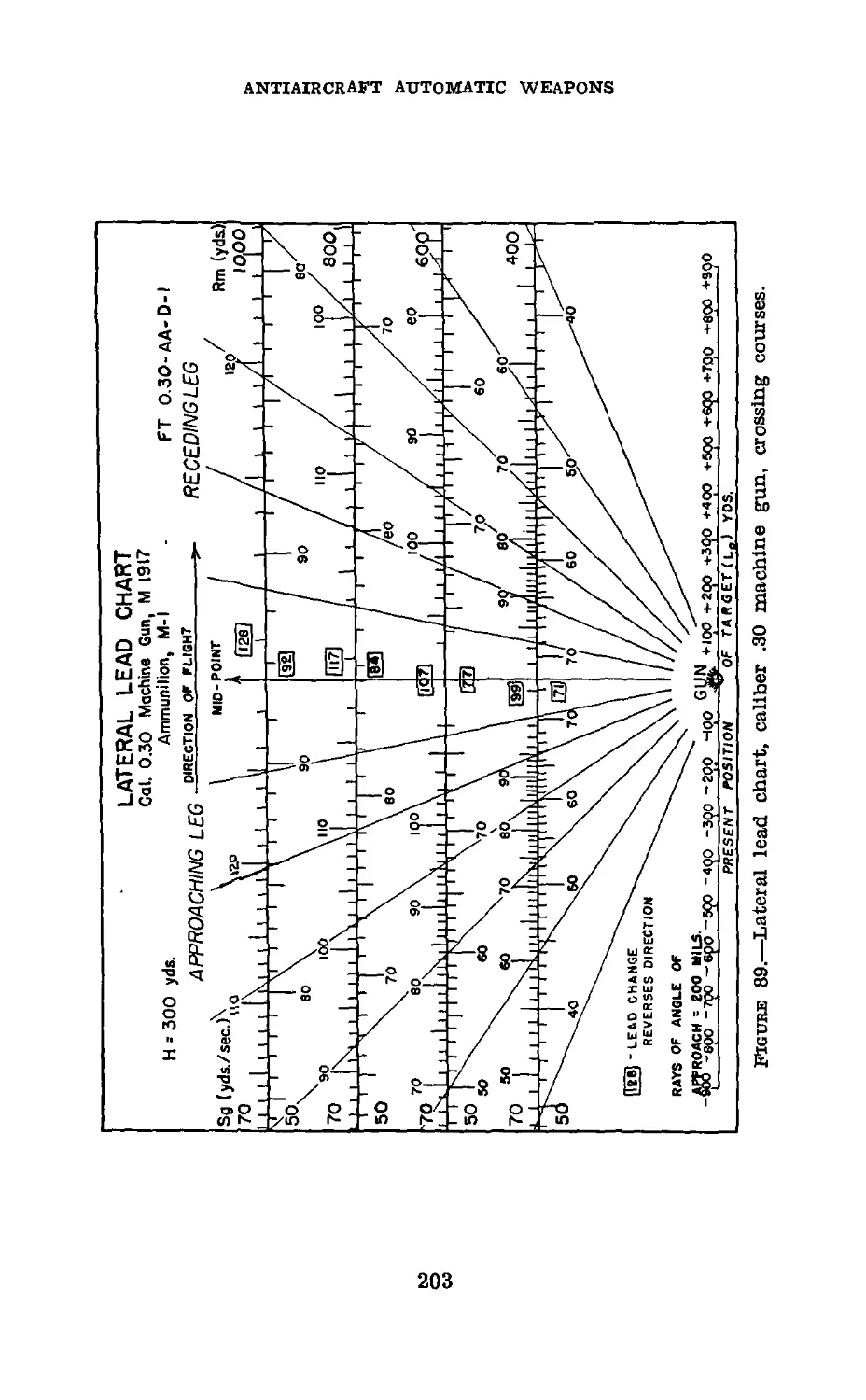
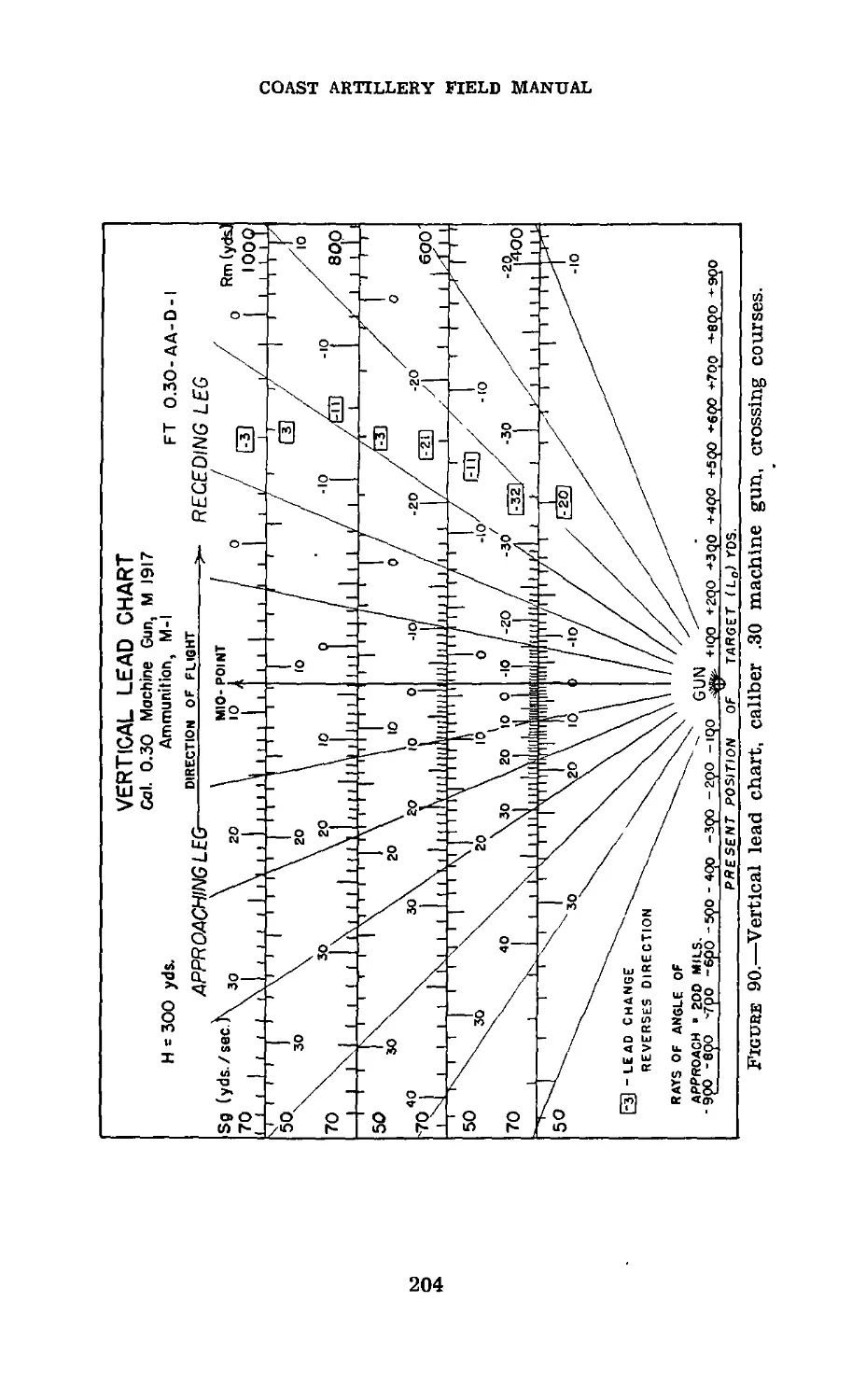
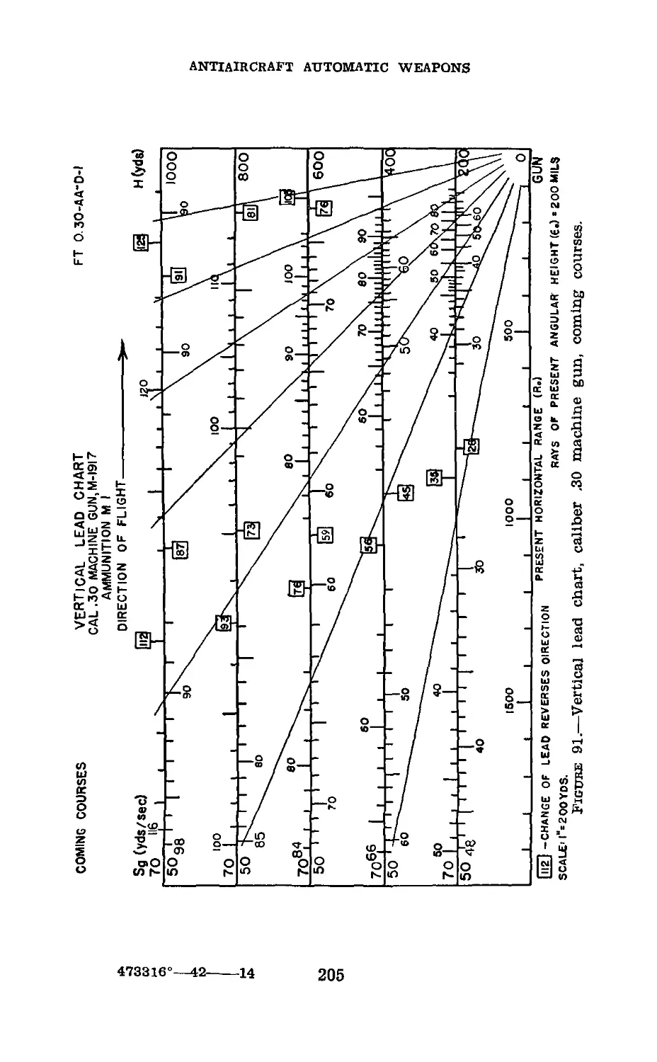
П. Lead charts__________________________________ 199
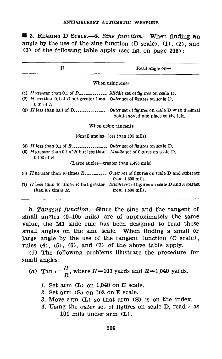
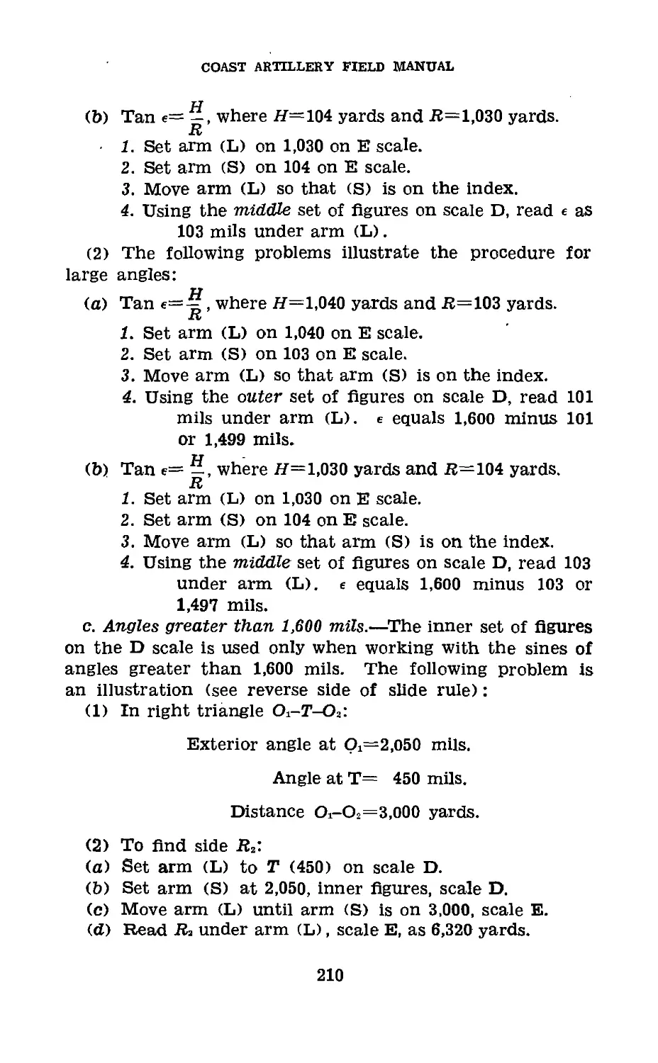
III. Use of Ml (Crlchlow) slide rule_____________ 206
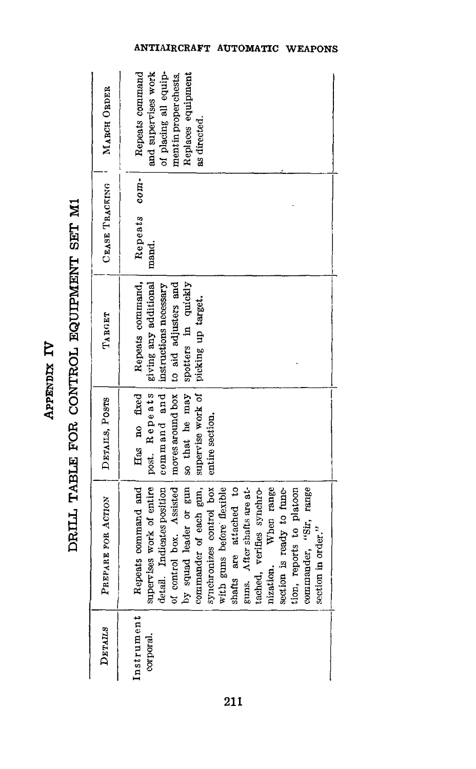
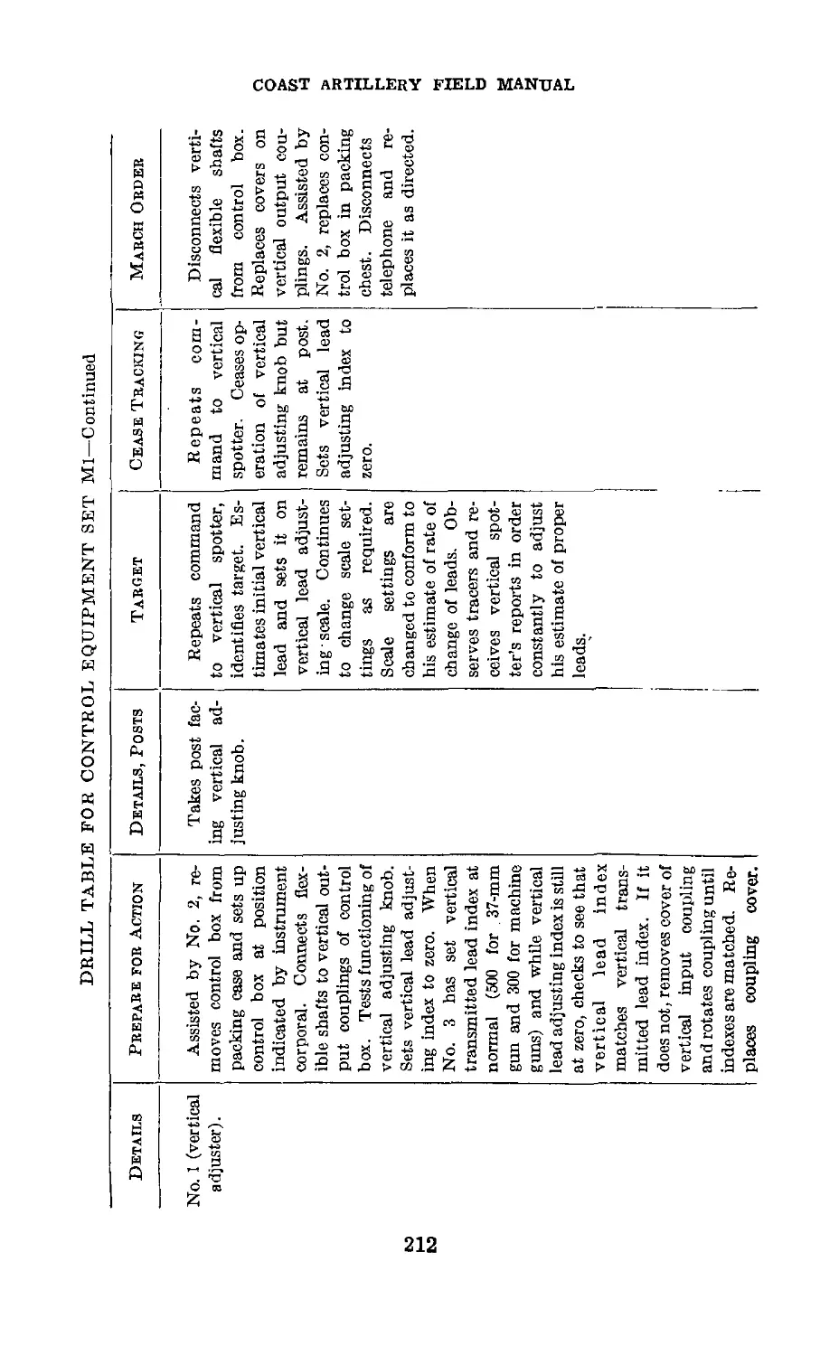
IV. Drill table for control equipment set Ml____ 211
Index________________________________________________________ 217
III
FM 4-112
1-2
COAST ARTILLERY FIELD MANUAL
ANTIAIRCRAFT ARTILLERY
GUNNERY, FIRE CONTROL, POSITION FINDING, AND
HORIZONTAL FIRE ANTIAIRCRAFT AUTOMATIC
WEAPONS (CASE I FIRING)
(This manual supersedes FM 4-112, July 12, 1940.)
CHAPTER 1
GENERAL
Paragraphs
Section I. General_____________________________________________ 1-5
II. Antiaircraft automatic weapons problem____________ 6-11
Ш. Gun pointer control_______________________________ 12-17
IV. On carriage sight control________________________ 18-24
V. Off carriage sight control_______________________25-32
VI. Director control__________________________________33-38
Section I
GENERAL
1. Scope.—This manual treats of the theory and practice of
gunnery and fire control for antiaircraft artillery automatic
weapons when firing by gun pointer and central control
methods. The fundamentals of exterior ballistics and gun-
nery as covered in chapters 1 and 2, FM 4-110, should be
carefully studied to acquire a thorough understanding of the
general antiaircraft problem. Pertinent definitions and sym-
bols which appear in FM 4-155 and appendix I of this manual
should also be studied. A clear understanding should be had
of the picture in space of the various elements of data. Case
HI firing (firing by director control) is completely covered
in FM 4-113.
2. General Missions.—a. The primary mission of antiair-
craft artillery automatic weapons is to attack all enemy air-
craft within range, particularly low-flying airplanes, to destroy
them, to cause them to abandon their missions, or to decrease
the efficiency of their operations. These aerial targets, either
low-level or diving, are the most dangerous of all aircraft to our
1
2-4
COAST ARTILLERY FIELD MANUAL
personnel and materiel. They strike suddenly, swiftly, and
with deadly effect if unopposed. It is difficult to obtain warn-
ing of their approach as they invariably use some form of
cover such as the sun, clouds, trees, or hills in order to get
near their objective unseen and unidentified. The only effec-
tive defense against such aircraft is to destroy them in such
numbers that the objective to be gained by their attack is
not worth the cost.
b. The contingent mission of antiaircraft artillery auto-
matic weapons is defense against mechanized vehicles, and
other ground, water, or air-borne targets, for fire against
which the characteristics and fire control methods of anti-
aircraft artillery automatic weapons are particularly suitable.
3. Types of Weapons.—The weapons designed or adopted
for this general mission are—
a. Small arms.—These include rifles and automatic rifles
which fire solid ball ammunition. Such weapons by them-
selves cannot be considered adequate for local defense, but
should always be used to supplement machine-gun fire.
b. Machine guns.—These include caliber .30 and caliber .50
machine guns which fire solid ball and tracer ammunition.
Such weapons are suitable for local defense or as training
weapons. They may also be used for the defense of very small
objectives, but consideration must be given to their limited
range and effectiveness.
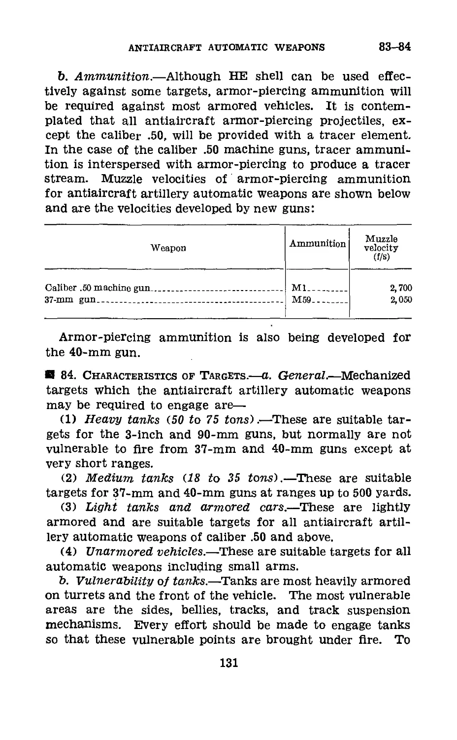
c. Automatic cannon.—These include guns of the 20-mm,
37-mm, and 40-mm type that fire high-explosive projectiles
with a tracer element and point-detonating fuze, and armor-
piercing shot for use against armored vehicles. Such pro-
jectiles are highly destructive to airplanes, but hits must be
obtained to accomplish the mission as detonation is by contact
with the target. To be effective, this type of antiaircraft
weapon depends on its ability to open fire quickly, its high rate
of fire, and rapid adjustment of fire by observation of tracers.
4. Basic Assumptions.—Effective fire with present antiair-
craft automatic weapons equipment is limited by ballistic and
gunnery factors to targets within approximately 3 seconds’
time of flight of the projectile. The only basic assumption
necessary is that the target will fly in a straight line at a
2
antiaircraft AUTOMATIC WEAPONS
4-6
constant speed during this time of flight. The flight of even
the latest high-speed aircraft will usually conform to this
assumption.
5. Importance.—The study of gunnery and fire control for
antiaircraft automatic weapons is of special importance for
the following reasons:
a. All military units armed with suitable weapons are
responsible for their own local antiaircraft defense. They
will use all their small arms for this purpose, but machine
guns fired by individual tracer control will be their primary
defense.
b. The short time available for opening and adjusting fire
with these local defense machine guns requires the individual
gunners to be expert in target identification, estimation of
certain elements of data, and adjustment of fire by obser-
vation of the tracer stream.
c. In antiaircraft automatic Weapons units, the individual
gun is usually the fire unit. This places the responsibility
for fire control upon the enlisted men of the section. The
training of these enlisted men will be the greatest problem
of the antiaircraft automatic weapons commander.
d. Some, if not all, data for the fire control of antiaircraft
automatic weapons must be estimated. Rapidity of opening
fire and adjustment require that these estimates be almost
instinctive. This can be accomplished only by careful study,
understanding of the problem, and training.
Section II
ANTIAIRCRAFT AUTOMATIC WEAPONS PROBLEM
6. Targets.—The primary target for antiaircraft automatic
weapons—the low-flying airplane—is the most versatile of all
targets. It not only can move in three dimensions at the will
of its pilot, but it also can accomplish its mission in a number
of ways and in a very brief period of time. If unopposed, the
low-flying airplane can accomplish almost any military mis-
sion except that of actually occupying territory. Even this
can be accomplished by landing of parachute or air-borne
troops. The inability of pursuit aviation and antiaircraft
3
6-8
COAST ARTILLERY FIELD MANUAL
guns of larger caliber to combat successfully the low-flying
airplane has been demonstrated many times. The barrage
balloon is an excellent defense in special situations, but the
antiaircraft automatic weapon still remains the best all-
around defense against such targets.
7. Element of Time.—The most important factor in the
antiaircraft automatic weapons problem is time. The high
speed of the target and its ability to use cover for its approach
require that it be quickly taken under fire as soon as observed
and identified. This is necessary in order to give sufficient
firing time to insure hits before the aircraft can complete
its mission or get out of range. Also, continuous and rapid
changes in time of flight and angular travel cause rapid
changes in the basic firing data. If a low-level (crossing-
constant altitude) target traveling 300 miles per hour passes
400 yards from a gun at the midpoint of its course, its angular
velocity in azimuth 10 seconds before it reaches the midpoint
will be 23 mils per second; at the midpoint, this angular
velocity will be 365 mils per second. On such a course the
leads will change as much as 40 mils per second. The target
should be kept under fire at least 10 seconds, and it will nor-
mally take an additional 10 seconds to identify the target,
obtain firing data, and open fire. In this total time of 20
seconds, assuming a reasonable target speed of 300 miles per
hour, the target will have traveled 3,000 yards or nearly 2
miles. If the target is coming directly at the gun, the range
will change from 2,000 yards to 500 yards in 10 seconds. In a
70° dive this target will change altitude from 5,000 feet to 900
feet in 10 seconds. All of these rapid changes in basic ele-
ments must be considered in selecting any method of fire
control. As these rapid changes practically preclude the ac-
curate measurement of all data, at least some of the data
must be estimated.
8. Ballistic Factors.—a. Any gun that will meet the re-
quired conditions of flexibility and high rate of Are will either
be of small caliber or decidedly heavy and complicated. Up
to the present time only small caliber guns have met these
conditions satisfactorily.
b. Two of the principal ballistic factors acting upon auto-
4
ANTIAIRCRAFT AUTOMATIC WEAPONS
8-10
matic weapons projectiles are the propelling charge and the
ballistic coefficient. The area weight relationship is included
in the ballistic coefficient.
(1) The procedure of manufacture is not sufficiently precise
to load’each projectile case with exactly the same amount
of propelling charge. Thus, the initial velocities caused by a
difference in loading may vary as much as 150 foot-seconds.
(2) The present type of small caliber projectiles has very
poor ballistic qualities as compared with larger caliber projec-
tiles. Practical limitations on the accuracy of manufacture
cause individual projectiles to have different ballistic coeffi-
cients. The rapidity with which a projectile loses initial
velocity is partially a function of the relationship between
the weight of the shot and its air resistance. An examination
of the firing tables will show that small caliber projectiles
lose their velocities faster than large caliber projectiles (see
fig. 2).
c. The difference in time of flight from round to round at a
given range directly affects the accuracy of fire at that range
when firing at a high speed target. Therefore, the accuracy
required to get a satisfactory percentage of hits cannot be
expected except for a small proportion of the ground impact
range of an antiaircraft automatic weapon.
И 9. Gunnery Factors.—The necessity for flexibility and
speed requires that observation and adjustment be practi-
cally instantaneous. Adjustment of fire, based on observa-
tion of tracer ammunition, is the best way to accomplish
this. It is a known fact that as the range increases, the diffi-
culty of tracer observation increases. The longer the time of
flight, the greater will be the probability of the target chang-
ing its course and speed such as to render fire adjustment
ineffective. Moreover, the longer the range, the smaller the
angular errors that can be absorbed by the size of the target.
The objective of gunnery for automatic weapons is to obtain
at least one hit on each target in the shortest time possible.
10. Summary of Problem.—The antiaircraft automatic
weapons problem may be summarized as follows:
a. The versatility of the target requires an accurate, flex-
ible, and high velocity gun with a high rate of fire.
5
10-13
COAST ARTILLERY FIELD MANUAL
b. Fire control must be simple, rapid, and accurate.
c. As fire must be destructive, high-explosive projectiles
should be used.
d. Effective fire is limited to short ranges by the ballistic
limitations of small projectiles and gunnery factors of the
problem.
e. Observation and adjustment, to be effective, must be
limited to short times of flight.
11. Possible Solutions of Problem.—a. Gun pointer con-
trol, in which the gun pointer or pointers have entire charge
of fire control.
b. On carriage sight control, where the sight or sights
on the gun are controlled from a position on the gun car-
riage.
c. Off carriage sight control, where the sight or sights on
the gun are controlled from a position some distance from
the gun.
d. Director control, where there are no sights on the gun
and the pointing of the gun is controlled remotely from a
director.
Section HI
GUN POINTER CONTROL
12. General.—The gun pointer or pointers open fire with
an estimated lead and control the fire. They can do this
by using either forward area sights or individual tracer con-
trol. This form of control, especially with machine guns,
gives extreme flexibility, as the gun is normally free mounted,
and allows each gun to be its own fire unit.
13. Forward Area Sights.—Such a sight usually has the
forward element so designed that leads can be obtained by
tracking the target off center on this element. Initial leads
are obtained by estimation of course and speed of target.
Such a sight is essential if tracers are not available and can
well be used at all times to obtain initial leads. Adjustment
can be carried on by continuous estimations or by tracer con-
trol. A gunner who thoroughly understands the leads and
6
ANTIAIRCRAFT AUTOMATIC WEAPONS
13-15
the possibility of such a sight can get good results at the
shorter ranges.
14. Individual Tracer Control.—Without the use of sights,
the gun pointer opens Are by leading the target the esti-
mated correct number of target lengths, and swinging with
it as in wing shooting. He then adjusts his fire by observa-
tion of the tracer stream as one would direct a stream of water
from a hose. Such a method of fire control is the simplest
as well as the quickest to use. All antiaircraft automatic
weapons troops should have some training in the use of
individual tracer control regardless of their type of weapon,
for often this simple method will be the only one available.
With the proper training and high morale of these gun
crews, this method will prove effective against airplanes com-
ing directly at them, and on crossing targets at short ranges.
15. Advantages.—a. Gun pointer control is the simplest
and most rapid method of fire control. For that reason it
must always be considered as an available emergency
method. When not on the alert and when the guns must
be manned with the fewest possible number of gunners, this
method can be exercised quickly and with the fewest men.
b. Forward area sights are essential when tracer ammuni-
tion is not available. A gunner who thoroughly understands
the leads and the possibility of such a sight can get results.
c. Forward area sights where two gun pointers are required
have proved more successful than individual tracer control.
With two gun pointers the problem of selecting a point of
aim on the forward element of the sight is simplified. The
lateral pointer has only to judge the speed and the angle
of approach to estimate fairly accurately the lateral lead
required. The vertical pointer can with fair accuracy esti-
mate the vertical lead by the range and the clock hour of
approach. With a clock face forward element on the sight,
this latter estimation is fairly simple.
d. Forward area sights are the most simple forms for anti-
mechanized firing. The target is picked up easily and quickly
and rarely lost due to the sight. For speed of getting on
target the forward area sight is the best type delevoped to
date.
7
15-16
COAST ARTILLERY FIELD MANUAL
e. Individual tracer control can be very effective at short
ranges and for coining targets. It is probably the best type
of control for close-in fighting with antiaircraft machine
guns. Given ball, armor-piercing, and tracer ammunition
that have very nearly the same ballistic qualities, machine
gun fire can be very effective against airplanes within 500
yards of the gun (slant range).
f. Individual tracer control is the only method of fire
control that can be used at night, unless targets are suf-
ficiently illuminated to use sights. It frequently happens
that airplanes can be seen close in at night by their exhaust
or due to moonlight, but not sufficiently to use sights. Trac-
ers from other guns passing near the airplane or the air-
plane’s own guns firing will often give sufficient indication
of its position to allow effective firing with individual tracer
control.
g. The advantage of full automatic fire can be obtained
with individual tracer control. The volume of fire thus
obtained in some measure makes up for its lack of accuracy.
Where firing time is extremely short, such as where a fast
airplane sneaks in close before being identified, this quick
volume of fire offers the best hope of success.
16. Disadvantage.—a. Gun pointer control is the least
accurate method of firing. For that reason its use should
be considered only as an emergency method for antiaircraft
automatic weapons units. For all troops it can be considered
the primary method of fire control for purely local defense,
that is, for firing on aerial or. ground targets coming directly
at the unit itself with obvious intent to strafe or bomb the
unit.
b. The use of gun pointer control places the whole burden
of fire control on the gunner. It must be realized that, in
fact, he acts in the capacity of range section and gun sec-
tion combined. His responsibility includes estimating leads,
operating the gun, and controlling the fire. His knowledge
must include leads, materiel, ammunition, and observation
and adjustment of fire. The selection of soldiers for this
position must be made with the greatest care and consider-
ation for their natural ability.
8
ANTIAIRCRAFT AUTOMATIC WEAPONS
16-19
c. When using forward area sights, both leads can seldom
be correct at the same instant.
d. When gun pointers also control the fire, it is very difficult
for them to track a fast target smoothly. Therefore, the
tracer stream is not steady, and observation is very uncertain
and difficult.
e. Gun pointers are invariably bothered, both in pointing
and in observation, by vibration, smoke, and flash of the firing
gun. Frequently they will lose the target and are forced to
cease firing to pick it up again. This decreases both the accu-
racy and the volume of fire.
/. Effective fire cannot be expected beyond 500 yards using
gun pointer control. This is mainly due to poor observation,
and the size of the target at longer ranges cannot absorb
even a small proportion of the errors in pointing.
17. Summary.—Gun pointer control can be considered—
a. The principal method for local defense machine guns.
b. An emergency method of fire control for all antiaircraft
automatic weapons.
c. Effective only within 500 yards.
d. The most flexible and rapid method of control and there-
fore desirable in close-in defense.
e. Sufficiently effective for antimechanized defense.
Section IV
ON CARRIAGE SIGHT CONTROL
18. General.—This method uses sights on the guns which
can be set to the required lateral and vertical leads. The
leads are set from a position on the carriage, either by estima-
tion of leads or by means of a simple computer using esti-
mates of various elements of the course and speed of the
target. By the latter method either a simple linear speed or
angular travel director mounted on the gun carriage can be
used for the computation.
19. Lead Control.—The gun pointers have only to track
the target with their sights, and the sights are controlled
from a position on the carriage by another man who esti-
9
19-23
COAST ARTILLERY FIELD MANUAL
mates and sets the leads. Adjustment of fire is continuous
by observation of the tracer stream.
20. Course and Speed Lead Computer.—A small, simple
linear speed lead computer is mounted directly on the car-
riage. It automatically sets the sights at the proper leads
when certain elements of data are set into the computer.
These elements include speed of target, range, angle of dive,
and direction of flight. This method has been used fre-
quently by European armies. Tests by our service have not
been satisfactory, and present policy is to discontinue further
experiments.
21. Angular Travel Lead Computer.—This method em-
ploys the angular travel principle of lead computing. Con-
tinuous tracking of the target by the gun pointers set hori-
zontal and vertical rates into a simple computer mounted
in the gun carriage. The only remaining element needed
is time of flight to the future position. This must be esti-
mated and set in the computer by the adjuster, who then
adjusts fire by observation of the tracer stream.
22. Advantages.—a. All such methods of fire control are
utilized to get on a target and open fire quickly. The guns
can go into action quickly from the traveling position, as
they should require no bore sighting or orientation.
b. Accuracy is much greater than for gun pointer control.
Specialized personnel do the estimating, observation, and
adjustment. The improved accuracy tends to make this
method effective at longer ranges than is possible with gun
pointer control.
c. Each gun can be used as a separate fire unit without
increasing the personnel required. More vital points and
a larger area can be covered with at least some fire.
d. The method should be satisfactory for antimechanized
firing.
23. Disadvantages.—a. Such methods of fire control are not
practical except for cannon type automatic weapons or
multiple mounts. Normally, it requires two gun pointers.
b. Too many estimations are required for lead control, and
10
ANTIAIRCRAFT AUTOMATIC WEAPONS
23-26
the course and speed lead computers; and adjustments must
be made in terms of two or more elements of data.
c. Accurate and steady gun pointing is difficult due to vibra-
tion of the mount, smoke, and flash of firing.
d. Observation of the tracer stream is difficult from a
position on the gun carriage. The adjuster is also bothered
by vibration, smoke, and flash of firing.
e. The use of sights limits such a method of fire control
to daylight or where targets are illuminated at night.
24. Summary.—a. On carriage sight control does not offer
the flexibility of gun pointer control but is more accurate.
b. Gun pointers and adjusters on the gun carriage are
badly handicapped by vibration, flash, and smoke of a con-
tinuously fired automatic gun.
c. The method depends to a great extent on estimations
which can seldom be accurate.
d. Reports from the present war indicate that it is not
entirely satisfactory.
Section V
OFF CARRIAGE SIGHT CONTROL
25. General.—This method of fire control is similar to on
carriage sight control except that the control, either by lead
estimations or by lead computer, is located at some distance
from the gun. This requires a data transmission system to
transmit leads to the sights on the gun.
26. Central Tracer Control.—The fire control system for
a platoon of Browning machine guns, caliber .50, М2, water-
cooled, mounted on antiaircraft machine-gun mounts, caliber
.50, М2, or a platoon of two 37-mm antiaircraft guns M1A2
on carriages М3 is called the automatic gun, antiaircraft,
control equipment set Ml, or the central tracer control. It
consists of movable sights on the guns that can be set to
desired leads. These leads are set on a centrally located
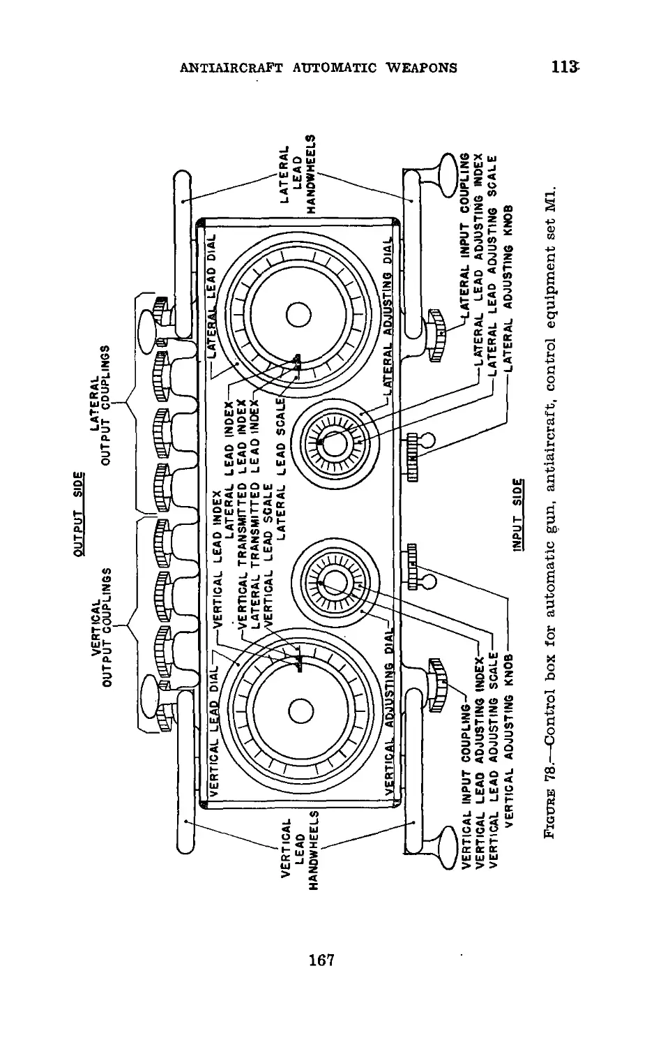
control box and are transmitted to the sights mechanically by
a system of flexible cables. This cable is a simple and trouble-
free method of transmission for distances up to 100 feet. In-
itial leads are estimated by the adjusters located at the con-
11
26-30
COAST ARTILLERY FIELD MANUAL
trol box, and adjustment is continuous, based on observation
of the tracer stream. Lateral and vertical leads are set
independently.
27. Remote Control.—Observation of the tracer stream is
greatly facilitated, especially at the longer ranges, if the
lateral and vertical adjusters are considerably separated and
placed in a more suitable position to observe lateral or ver-
tical deviations. To use such a system would require a more
flexible transmission system than the present mechanical
system. Electrical transmission has been tried with excel-
lent results, but the ballistic and gunnery limitations of anti-
aircraft automatic weapons now make it appear that such a
method of fire control would not be entirely justified.
И 28. Oriented Charts.—A form of lead computer which con-
sists of curves of computed leads has been experimented with
in connection with the central tracer control equipment.
This is similar to the course and speed lead computer in that
all elements of the target’s course and speed must be esti-
mated in order to select the proper lead curve to follow. Ad-
justment must be made by jumping from one curve to an-
other, as deviations of the tracer stream are observed.
29. Lead Computer.—Lead computers similar to those de-
signed for use on the gun carriage will give more accurate
results when taken off the gun and placed nearby. These
compute the required leads and transmit them to the gun
sights through the control box. The control box of the cen-
tral tracer control equipment is made to receive such data,
combine it with adjustments, and transmit the corrected lead
to the gun sights. Such computers have been tried but so far
have never given consistent results. Here, as in so many other
methods of fire control, there are too many estimations to be
made and too many possibilities of errors in transmission
and gun pointing to take full advantage of the accuracy of
a lead computer.
30. Advantages.—a. The off carriage method of fire control
allows the firing of two or more guns together as a fire unit,
thereby increasing the volume of fire and Improving observa-
tion of fire.
12
antiaircraft automatic weapons
30-33
b. Such a method gives the best observation of the tracer
stream, therefore the best opportunity to adjust fire con-
tinuously.
c. Except in distant remote control, the transmission sys-
tem is simple, trouble-free, and requires no electricity for
operation.
d. Accuracy of the fire unit is greatly increased.
31. Disadvantages.—a. Such a method of fire control re-
quires additional equipment and personnel.
b. It requires bore sighting and synchronizing to bring all
guns of the fire unit to fire together.
c. It does not eliminate the errors of gun pointing.
d. Flexibility of the fire unit is greatly decreased.
e. Consistent hitting on each target has not been obtained,
while a high percentage of hits has been obtained on a series
of targets.
32. Summary.—a. Central tracer control has proved much
more effective than either gun pointer control or on carriage
sight control.
b. The inherent errors of gun pointing will not allow full
advantage to be taken of lead computers or of continuous
observation and adjustment.
c. Such a system, while gaining somewhat In accuracy, loses
considerable in flexibility. It requires more materiel and per-
sonnel as well as more time to set up and go into action.
Section VI
DIRECTOR CONTROL
33. General.—It Is an acknowledged fact that a director
can track the present position of a target much more accu-
rately than can be done with sights on the gun. To take
advantage of this accuracy, the gun must be remotely con-
trolled from the director. The final degree of accuracy of this
method of fire control can therefore be separated into the
accuracy of the gun and ammunition and the accuracy of the
computed leads. The ballistic and gunnery factors of anti-
aircraft automatic weapons limit the accuracy of the gun to
short ranges. Thus the director, in addition to being rugged,
473316°—42---2
13
33-36
COAST ARTILLERY FIELD MANUAL
simple, and rapid of operation, should compute leads to an
accuracy within the limitations of accuracy of fire. Within
these limitations the director can be of the approximate angu-
lar travel type or of an exact angular travel or linear speed
type.
34. Approximate Director.—a. An approximate director
based on the angular travel principle is more feasible than
any other type. It requires only the measurement of both
horizontal and vertical angular travel and their multiplica-
tion by a time of flight to give approximate leads. For short
times of flight these leads would be sufficiently accurate. The
errors would be absorbed by the size of the target. The prin-
cipal requirements are smooth rates and accurate tracking.
b. The present standard director is the director M5, which
is based on the angular travel principle. This director is
used with the 40-mm antiaircraft gun on the carriage М2
and the 37-mm antiaircraft gun on the carriage M3A1. The
director tracks the target in present position, computes the
leads and superelevation, and transmits future azimuth and
future quadrant elevation to the gun. The director M6 is
identical with the director M5 except that it is designed to
be employed with British equipment. (See FM 4-113.)
35. Exact Director.—The British Vickers and the M4 are
such directors. It is possible that this type could be built
to compute leads with sufficient rapidity for use with anti-
aircraft automatic weapons. However, such a director would
not be simple or rugged. It is also doubtful if such a degree
of accuracy is required by small caliber guns, due to their
inherent ballistic limitations.
36. Advantages.—a. More accurate tracking can be accom-
plished with a director.
b. More accurate leads can be computed.
c. Control and adjustment of fire can be in terms of one
element, either range or time of flight.
d. Such a system will give a better chance of obtaining
a hit on each target.
e. Such a system should give better results at longer
ranges than any other system.
14
ANTIAIRCRAFT AUTOMATIC WEAPONS
37-38
37. Disadvantages.—a. The disadvantages of director con-
trol are the loss of time in getting on the target and obtaining
smooth rates.
b. Additional equipment and personnel are required, espe-
cially electrical equipment with its possible failure under
field conditions.
c. Accurate orientation and trial shots are required.
d. Such a method usually cannot make use of the full rate
of fire of automatic weapons.
38. Summary.—The many variations in the antiaircraft
automatic weapons problem practically prevent the use of
one method of fire control that will give the best results under
all conditions. Some form of tracer observation is the only
method that will give sufficient speed and continuous adjust-
ment. Individual tracer control must always be considered
an available emergency method of fire control, and all fire
units must be trained to use it. Regardless of the equipment
in use and the method of fire control, a complete knowledge
of the fire control problem, leads, their characteristics for
type courses, and the variation of the several elements of
these courses should be acquired by all antiaircraft automatic
weapons personnel.
15
39-40
COAST ARTILLERY FIELD MANUAL
CHAPTER 2
DISPERSION AND HIT EXPECTANCY
Paragraphs
Section I. Dispersion______________________________________39-44
П. Hit expectancy___________________________________45-47
Section I
DISPERSION
39. General.—a. Standard methods of fire control for
antiaircraft automatic weapons depend upon the observation
of tracer bullets for the adjustment of fire. To assist in ob-
serving these tracers, and to insure a reasonable percentage
of hits when fire is adjusted, the cone of fire which they
form must be as small as possible. This requirement is par-
ticularly important at the longer ranges.
b. Spreading of the cone of fire is caused by dispersion.
Many factors enter into dispersion. These factors are erratic
gun pointing, vibration of the gun and mount, variations in
muzzle velocity between shots from the same gun and be-
tween guns, and poor bore sighting and synchronization of
the fire-control system. Most of these factors can be elim-
inated or their effect greatly reduced by careful training and
proper care and use of equipment.
40. Gun Pointing.—a. Gun pointing is the basic factor in
the reduction of dispersion when firing using forward area
sights or individual tracer control. If the gun pointing is
erratic, all other efforts to reduce dispersion will be of little
or no value.
b. Gun pointing is particularly important in the case of
machine guns since one gunner points both laterally and ver-
tically with a free, mounted gun. The following steps must
be taken to insure smooth tracking by machine gunners:
(1) Machine gunners are selected whose eyes are not sensi-
tive to smoke, atmospheric conditions, flash, and glare. They
must have the strength to manipulate readily the gun and
16
ANTIAIRCRAFT AUTOMATIC WEAPONS
40-41
mount and should be mentally and physically well coor-
dinated.
(2) The back rests and the distance of the gun trun-
nions above the ground should conform to the stature of the
gunners. The gunners should also be provided with a firm
and level footing.
(3) The gunners should receive training in the tracking
of high speed aerial targets to accustom their muscles to
function smoothly and instinctively during rapid movements
in direction and elevation.
(4) The gunners should receive training in firing on high
speed aerial targets to accustom them to the shock, smoke,
and flash of firing and to the vibration of the mounts.
c. Gun pointing for the 37-mm gun, while not quite as im-
portant as in the case of machine guns, is still vital to the
problem of dispersion. Gun pointers move the gun in azi-
muth and elevation by means of handwheels. The following
steps must be taken to insure smooth tracking by the gun
pointers:
(1) Gun pointers are selected whose eyes are not sensi-
tive to smoke, atmospheric conditions, flash, and glare. They
should be mentally and physically well coordinated.
(2) They should receive training in the tracking of high
speed aerial targets to accustom them to the operation of
the handwheels to accomplish rapid movements in direction
and elevation.
(3) They should receive training in firing on high speed
aerial targets to accustom them to the shock, smoke, and flash
of firing and to the vibration of the carriages.
(4) The above remarks will also apply to the 40-mm gun
when using forward area sights.
41. Vibration of Mount or Carriage.—a. The high rates
of fire of caliber .50 machine guns and 37-mm and 40-mm
guns causes the mount or carriage to vibrate continually
while the gun is being fired. This vibration makes accu-
rate gun pointing difficult.
Ъ. (1) The vibration of the antiaircraft machine gun mount
can be reduced appreciably by adjusting the rate of fire of
the gun by means of the oil buffer as described in FM 4-135.
17
41-42
COAST ARTILLERY FIELD MANUAL
Each individual gun will be found to have its own cyclic
rate at which vibration is least. This rate should be deter-
mined and then maintained.
(2) On the М2 mount a recoil mechanism is provided
to reduce the vibration of the mount. Required adjustments
to this mechanism are made as prescribed in FM 4-135.
c. The carriages for the 37-mm and 40-mm gun are much
steadier than the machine gun mount. The only method
of reducing vibration is to keep all moving parts in good
operating condition and the length of recoil properly adjusted.
42. Variation in Time of Flight.—a. General.—When fir-
ing at fixed or slowly moving targets, moderate variations in
time of flight normally have only a minor effect on the fall
of the shots. However, as the target speed is increased, the
resulting dispersion becomes more serious and causes the
cross-section of the cone of fire to change from a circle to
an ellipse with the longer axis in the direction of flight of
the target. This can best be illustrated by a problem. Con-
sider a target moving at right angles to the line of fire at
150 yards per second. Assume that two bullets were fired
at this target at the same instant and that one of them
took 0.10 second longer to reach the target than the other.
(Such an assumption is reasonable. A difference in time of
flight of 0.10 second is caused at midrange (1,000 yards) by
a variation in muzzle velocity of 170 feet per second.) During
this 0.10 second the target will have moved 15 yards. Assum-
ing that these two bullets would have struck the same vertical
line in a stationary target, they will make holes 15 yards
apart in the target traveling at 150 yards per second. On
most automatic weapon targets, both shots could not have
been hits. When a series of shots is fired at normal rates,
this dispersion is apparent to the adjusters and spotters,
causing a widening of the cone of fire and resulting in poor
observation and adjustment of fire.
b. Variations from round to round.—(1) Variations in time
of flight from round to round of a particular type and lot of
ammunition are caused principally by slight differences in the
rounds, which cause variations in the developed muzzle veloc-
ity. These differences may be of considerable magnitude.
18
ANTIAIRCRAFT AUTOMATIC WEAPONS
42
Tests of the velocities of 10 shots fired consecutively from a
single caliber .50 machine gun barrel have shown variations
of more than 100 feet per second.
(2) Small differences in the time of flight of ball and tracer
ammunition also exist at most ranges. Complete data on
these differences are not available at this time. Present prac-
tice is to disregard the differences in these two types of ammu-
nition. This problem applies only to machine guns, since all
37-mm or 40-mm antiaircraft ammunition is tracer ammuni-
tion.
(3) Round to round variations in muzzle velocity, both
within types and between ball and tracer, are a characteristic
of the ammunition and cannot be corrected for by the using
personnel.
c. Variations among guns.—(1) Differences in time of flight
among guns are caused chiefly by differences in the muzzle
velocities developed by the individual barrels of those guns.
For a particular barrel and ammunition the muzzle velocity
depends mainly upon the amount that the bore has been
eroded, particularly that portion at the breech end of the
barrel. Due to the high rate of fire of antiaircraft automatic
weapons, the barrels erode rapidly. For example, available
data indicate that, under average conditions of firing, the
barrel of a caliber .50 М2 machine gun will be eroded suffi-
ciently to cause a loss of approximately 200 feet per second
in muzzle velocity by the time that 3,000 to 3,500 rounds have
been fired. At the maximum rate of fire (600 rounds per
minute) this represents only 5 to 6 minutes of continuous fire.
Similarly, erosion in the barrel of a caliber .30 machine gun
causes a loss of about 160 feet per second in muzzle velocity by
the time 5,000 rounds have been fired. This represents 9 to 11
minutes of continuous fire. Data on erosion of the 37-mm
guns are limited, but loss in muzzle velocity appears to be
negligible during the first 1,000 rounds, although after about
1,200 rounds have been fired loss in muzzle velocity increases
rapidly.
(2) (a) The best method for determining the loss of
muzzle velocity of machine-gun barrels is to gage the advance
of the forcing cone and the wear of lands at the breech.
Breech bore gages have been developed for both caliber .30
19
42
COAST ARTILLERY FIELD MANUAL
and caliber .50 machine guns but normally are not issued to
antiaircraft artillery units. However, bullet seating gives
a fair approximation of this gaging and therefore of the
muzzle velocity to be expected.
(&) A simple gage for determining bullet seating may be
made by fastening a stiff wire or rod to the base of a bullet
of the proper caliber. Insert the bullet in the breech of a
new barrel and scribe a mark on the rod or wire flush with
the face of the breech. Mark this point 1.9 inches for the
caliber .30 gage and 3.0 inches for the caliber .50 gage. With
this mark as a starting point, lay off on the rod or wire a
scale graduated in tenths of an inch, continuing the scale
outward 1.5 inches (caliber .30) or 4.0 inches (caliber .50)
from the mark. Each inch line should be marked to show
the number of inches from the rear face of the bullet to that
line. The wear of a barrel is then determined by dropping
the gage into the breech end of the bore and reading the
value on the scale at the point flush with the rear end of the
barrel.
(c) Where no gage (manufactured or improvised) is avail-
able, a loose bullet may be carefully dropped, point first, into
the breech end of the barrel and the distance from the rear
face of the bullet to the rear face of the barrel then measured
while the barrel is held vertically with the breech up. The
bullet should always be dropped the minimum distance pos-
sible, and care should be taken to avoid pressing on the bullet
when measuring the bullet seating.
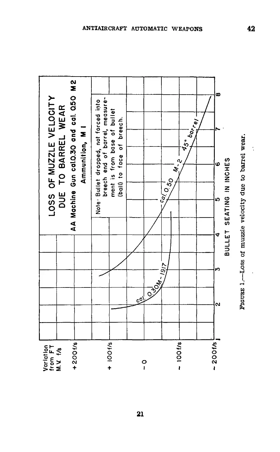
(d) Having determined the bullet seating of a barrel, the
chart in figure 1 is entered to obtain the variation in muzzle
velocity which may be expected. For example, a reading
of 5.5 inches’ bullet seating for a 45-inch caliber .50 barrel
indicates a muzzle velocity of about 90 foot/seconds below
firing table MV and of about 190 foot/seconds below that of
a new barrel.' Similarly a reading of 2.5 inches’ bullet seating
for a caliber .30 barrel indicates a muzzle velocity of about
50 foot/seconds below firing table MV and of about 150 foot/
seconds below that of a new barrel.
(e) So far as the question of dispersion is concerned, as
long as all barrels of a fire unit show approximately the
same amount of wear, variation in muzzle velocity from stand-
20
Figure 1.—Loss of muzzle velocity due to barrel wear.
ANTIAIRCRAFT AUTOMATIC WEAPONS
£
42-43
COAST ARTILLERY FIELD MANUAL
ard will have little effect as the guns will still shoot together.
(See ch. 5 for the effect on computed leads.) This desirable
condition can be maintained by frequently checking bullet
seating and matching the barrels in sets having approxi-
mately the same bullet seating. An examination of the
curves in figure 1 shows that to keep the muzzle velocities of
the different barrels within about 50 feet per second of each
other, the values of bullet seating should be within 1 inch
of each other for caliber .50 machine guns and 0.5 inch of
each other for caliber .30 machine guns.
(3) In the case of the 37-mm antiaircraft gun, no tested
method of determining tube (barrel) erosion employable by
using personnel has been developed. Therefore an attempt
should be made, when practicable, to fire the guns so that
the total number of rounds fired will be approximately the
same for both guns of the fire unit. This should give ap-
proximately uniform wear for both guns since the rate of fire
is not as variable as, and is much lower than, that of machine
guns.
Я 43. Spreading the Guns.—a. When used in connection with
antiaircraft automatic weapons, the term “spreading the
;guns” means the adjusting of the sighting systems of fire
unit so that when certain leads are set on the control box lead
dials, the corresponding leads set on the gun sights will vary
.slightly from gun to gun. For example, in a machine gun
platoon with the lateral lead dial of the control box set at
normal (see par. 26), the lateral leads for guns Nos. 2 and 3
might be 0; that for gun No. 1, plus 2; and that for gun No. 4,
minus 2. Similar spreading vertically can be accomplished.
b. The purpose of spreading the guns is to enlarge the cone
of fire so as to increase the volume of the space in which hits
can be expected.
c. There are three important reasons why spreading the
guns is unsound.
(1) Effective fire from automatic weapons can be ob-
tained consistently only when the maximum possible volume
of fire is placed on the target. Even under ideal conditions,
the dispersion of automatic weapons fire at moving targets
is such as to permit only a small percentage of hits on the
22
ANTIAIRCRAFT AUTOMATIC WEAPONS
43-44
target. Spreading the guns will increase this dispersion still
further, resulting in even fewer hits.
(2) The enlargement of the cone of fire will increase the
difficulty of observing and adjusting fire. This will normally
result in an additional reduction in the percentage of hits
obtained.
(3) Although spreading of the guns can usually be accom-
plished during target practice, it cannot be successfully ac-
complished, so far as lateral leads are concerned, under
service conditions. The guns are intended for use in all-
around fire. Guns spread laterally at one point are corre-
spondingly converged if they are traversed 3,200 mils. There-
fore, the spreading of the guns is accomplished for only a
part of the field of fire.
И 44. Synchronization of Fire-Control System.—a. The
synchronization of the fire-control system (central control
only) is the adjustment necessary to insure that the desired
lateral and vertical leads, when set on the control box, will
be set on each gun. This synchronization must be performed
each time the materiel is set up in firing position. When the
materiel is in position for some time, the synchronization is
performed daily, or more often if necessary.
b. The first step in synchronization of the system is the
adjustment of the control box. To accomplish this, the
control box having been set up, turn the adjusting knobs
until the lead adjusting indexes read zero. When this has
been done, see that the lead indexes are at normal (300
for machine gun units, 500 for 37-mm gun units). If they
are not, remove the covers from the input couplings and
rotate the couplings until the lead indexes are properly set.
Then replace the coupling covers, checking to see that the
lead adjusting indexes and lead indexes have not been moved.
After the adjustment is completed, the coupling covers must
not be removed unless specifically authorized. Set the trans-
mitted lead indexes at normal by turning the lead hand-
wheels.
c. The second step in the synchronization is the hooking
up of the flexible shafts. The control box having been ad-
justed as described in b above and the guns bore sighted as
23
44
COAST ARTILLERY FIELD MANUAL
described in FM 4-135 (machine guns) or FM 4-140 (37-mm
guns), hook up the required number of flexible shafts from
the output couplings of the control box to the correspond-
ing couplings (lateral or vertical) of the sighting systems
(see b above).
d. When the system has been connected, set various leads
on the lead dials of the control box and check them against
the readings of the counters on the sighting system of the
guns. At least one reading on each side of normal should be
checked for both the lateral and vertical sight mechanisms.
e. (1) If the readings checked as described in d above
agree in each case, the synchronization of the system is com-
pleted.
(2) If the readings of one of the counters are con-
sistently in error by a few mils plus or minus, the system
must be resynchronized. To do this, return the correspond-
ing lead index (lateral or vertical) of the control box to its
normal reading and remove the flexible shaft from the cou-
pling of the part of the sight mechanism to which the counter
is attached. Recheck the bore sighting, making the necessary
adjustments as described in FM 4-135 or FM 4-140. When
the system is again connected recheck the synchronization
as described in d above.
(3) If, after the system is connected, one of the counters
fails to turn when the corresponding lead handwheel is op-
erated, some part to the sight mechanism is probably broken
or damaged. In this case it will usually be found that the
flexible shaft is broken. Return all parts of the system to
normal, replace the flexible shaft with a new shaft, and
recheck the synchronization as described in d above.
/. (1) The vertical lead flexible shafts may be broken if
an attempt is made to turn the vertical lead handwheel on
the control box so as to set a positive vertical lead on the
gun sights when the 37-mm gun is depressed below about 15°.
Therefore, before the cables are connected to a gun sighting
system, be sure that the gun is elevated above 15°. There-
after, keep the guns elevated above 15° whenever the system
is connected except when they are depressed, for a specific
purpose, in which case care must be taken to insure that the
24
ANTIAIRCRAFT AUTOMATIC WEAPONS
44-45
control box is not operated. This precaution is necessary
because when the gun is depressed to zero, the sights can be
depressed only about 50 additional mils before they hit the
sight brackets. This precaution does not apply to the М2
machine-gun mount.
(2) (a) Even though the 37-mm guns are partly elevated, if
the gun sighting systenfs were to be connected to the- control
box when the vertical counter on a sighting system has a
reading which differs considerably from that of the vertical
lead index of the control box, an extreme vertical lead may
later be set on the sighting system resulting in the same diffi-
culty as described in (1) above.
(&) Under similar conditions, the front sight of the М2
machine-gun mount may be damaged at any angle of ele-
vation.
(c) Therefore, always insure that the lead counters or
indexes on the sighting systems and the indexes on the con-
trol box are at the same readings before hooking up the
flexible shafts.
(3) Forcing of lead handwheels may cause damage to the
control set or to the sight mechanism. Pointer matchers
must be cautioned never to put excessive pressure on the
lead handwheels. If a handwheel is hard to turn, they must
stop and determine the cause. Possible causes are sights
or the transmitted lead indexes coming up against a stop,
accumulation of dirt blocking the movement of the sight,
kinked flexible shaft, or burs on gears of the control box.
Section П
HIT EXPECTANCY
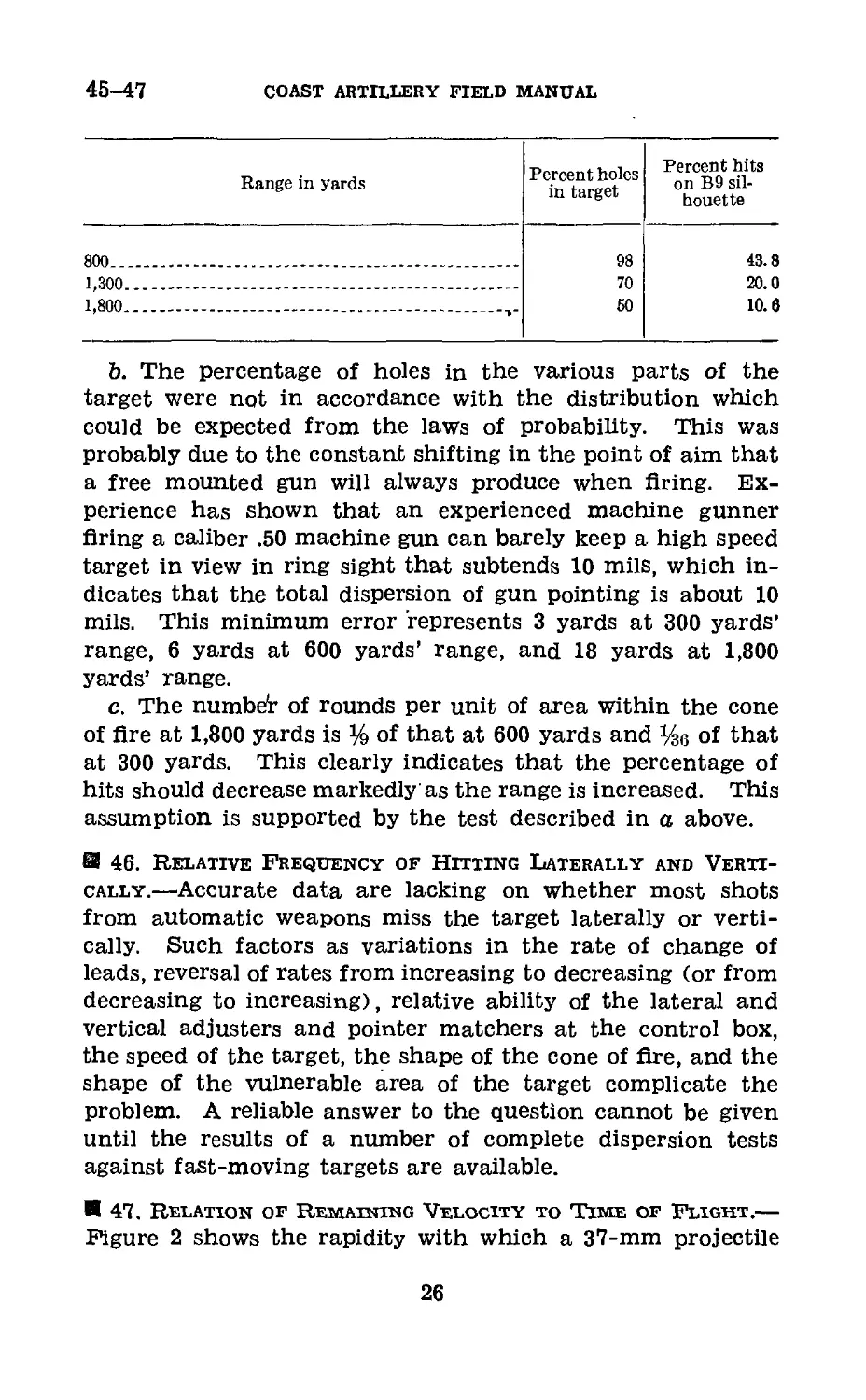
45. Test of Dispersion of Free Mounted Gun.—a. To
determine the minimum dispersion (maximum percentage
of hits) to be expected with a free mounted automatic
weapon, tests have been conducted with a caliber .50 machine
gun, mounted on an М2 mount, firing on a stationary target.
The hits obtained on the target and on the B9 silhouette may
be summarized as follows:
25
45-47
COAST ARTILLERY FIELD MANUAL
Range in yards
Percent holes
in target
Percent hits
on B9 sil-
houette
800...__________________________________________________
1,300___________________________________________________
1,800___________________________________________________
43.8
20.0
10.6
b. The percentage of holes in the various parts of the
target were not in accordance with the distribution which
could be expected from the laws of probability. This was
probably due to the constant shifting in the point of aim that
a free mounted gun will always produce when firing. Ex-
perience has shown that an experienced machine gunner
firing a caliber .50 machine gun can barely keep a high speed
target in view in ring sight that subtends 10 mils, which in-
dicates that the total dispersion of gun pointing is about 10
mils. This minimum error represents 3 yards at 300 yards’
range, 6 yards at 600 yards’ range, and 18 yards at 1,800
yards’ range.
c. The numbe'r of rounds per unit of area within the cone
of fire at 1,800 yards is % of that at 600 yards and of that
at 300 yards. This clearly indicates that the percentage of
hits should decrease markedly as the range is increased. This
assumption is supported by the test described in a above.
И 46. Relative Frequency of Hitting Laterally and Verti-
cally.—Accurate data are lacking on whether most shots
from automatic weapons miss the target laterally or verti-
cally. Such factors as variations in the rate of change of
leads, reversal of rates from increasing to decreasing (or from
decreasing to increasing), relative ability of the lateral and
vertical adjusters and pointer matchers at the control box,
the speed of the target, the shape of the cone of fire, and the
shape of the vulnerable area of the target complicate the
problem. A reliable answer to the question cannot be given
until the results of a number of complete dispersion tests
against fast-moving targets are available.
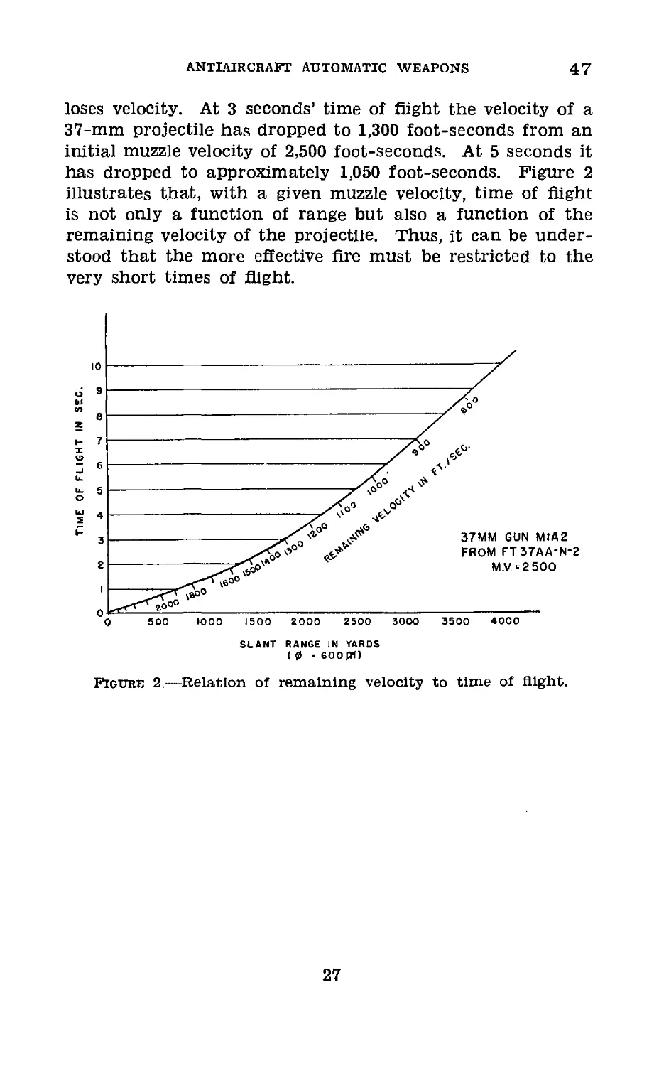
И 47. Relation of Remaining Velocity to Time of Flight.—
Figure 2 shows the rapidity with which a 37-mm projectile
26
ANTIAIRCRAFT AUTOMATIC WEAPONS
47
loses velocity. At 3 seconds’ time of flight the velocity of a
37-mm projectile has dropped to 1,300 foot-seconds from an
initial muzzle velocity of 2,500 foot-seconds. At 5 seconds it
has dropped to approximately 1,050 foot-seconds. Figure 2
illustrates that, with a given muzzle velocity, time of flight
is not only a function of range but also a function of the
remaining velocity of the projectile. Thus, it can be under-
stood that the more effective Are must be restricted to the
very short times of flight.
SLANT RANGE IN YARDS
( 0 • 600 00
Figure 2.—Relation of remaining velocity to time of flight.
27
48
COAST ARTILLERY FIELD MANUAL
CHAPTER 3
CALCULATION OF LEADS
Paragraphs
Section I. Elements of data________________________________48—53
II. Firing tables___________________________________54-57
Ш. Methods of lead calculation______________________58-64
Section I
ELEMENTS OF DATA
48. General.—a. An analysis of gunnery for antiaircraft
automatic weapons includes careful study of leads and their
characteristics for representative type target courses and
speeds. This is true whether forward area sights, computing
sights, tracer control, oriented charts for dive targets, or di-
rector control is the means of fire control.
b. If the fire of antiaircraft automatic weapons is to be
successfully adjusted by observation of tracers, the tracer
stream must be kept at least in the immediate vicinity of the
target. To accomplish this, approximately correct leads must
be continuously applied to the guns. Since no satisfactory
lead computer is at present available (except in the case of
director-controlled automatic weapons) for determining the
leads which should be applied to the guns, dependence must
be placed on the estimation of leads both for determining
initial leads and for anticipating the rates of change in the
required leads throughout the course of the target. These
changes in the leads are at rates which vary constantly dur-
ing the course. Leads must be calculated for use in con-
structing lead charts in order to enable personnel responsible
for the application of these leads to become familiar with the
approximate leads required for various types of target
courses..
c. Only target courses which are rectilinear and are flown
at constant speeds can be calculated readily. These courses
are divided, with respect to the target’s course and the gun
position, into two general types, coming courses and crossing
courses. Each of these types of courses Is further subdivided
into constant altitude courses and diving courses. The
28
ANTIAIRCRAFT AUTOMATIC WEAPONS
48-49
method of calculating leads for courses in each of these
classifications is discussed separately in section III.
d. In this text all calculations of leads for crossing courses
are based on left to right courses, and all lateral leads are
right leads. The data for right to left courses are calculated
and plotted in the same manner, in which case all lateral
leads would be left leads.
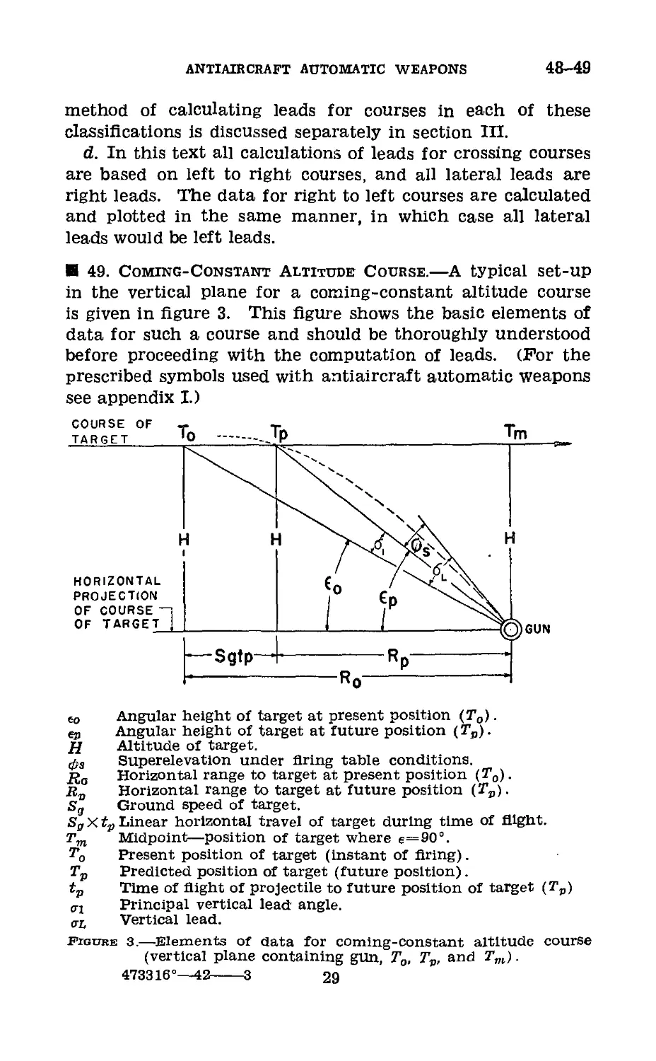
49. Coming-Constant Altitude Course.—A typical set-up
in the vertical plane for a coming-constant altitude course
is given in figure 3. This figure shows the basic elements of
data for such a course and should be thoroughly understood
before proceeding with the computation of leads. (For the
prescribed symbols used with antiaircraft automatic weapons
see appendix I.)
co Angular height of target at present position (To).
СЯ Angular height of target at future position (Tp).
Д Altitude of target.
ф3 Superelevation under firing table conditions.
/Jo Horizontal range to target at present position (To).
Horizontal range to target at future position (Гр).
Sg Ground speed of target.
Sg X tv Linear horizontal travel of target during time of flight.
Tm Midpoint—position of target where e=90°.
To Present position of target (instant of firing).
Tp Predicted position of target (future position).
ip Time of flight of projectile to future position of target (Tp)
oj Principal vertical lead angle.
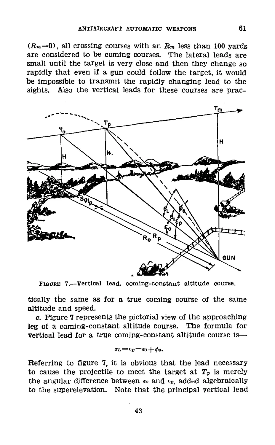
aL Vertical lead.
Figure 3.—Elements of data for coming-constant altitude course
(vertical plane containing gun, To, Tv, and Tm).
473316°—42-----3 29
49-51
COAST ARTILLERY FIELD MANUAL
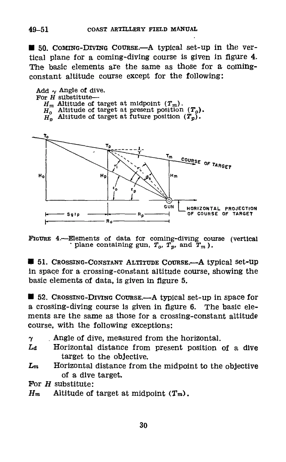
50. Coming-Diving Course.—A typical set-up in the ver-
tical plane for a coming-diving course is given in figure 4.
The basic elements are the same as those for a coming-
constant altitude course except for the following:
Add у Angle of dive.
For H substitute—
Hm Altitude of target at midpoint (Tm).
Ho Altitude of target at present position (To).
Altitude of target at future position (Ts).
Figure 4.—Elements of data for coming-diving course (vertical
• plane containing gun, To, Tp, and Tm).
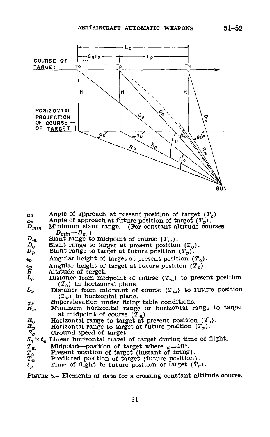
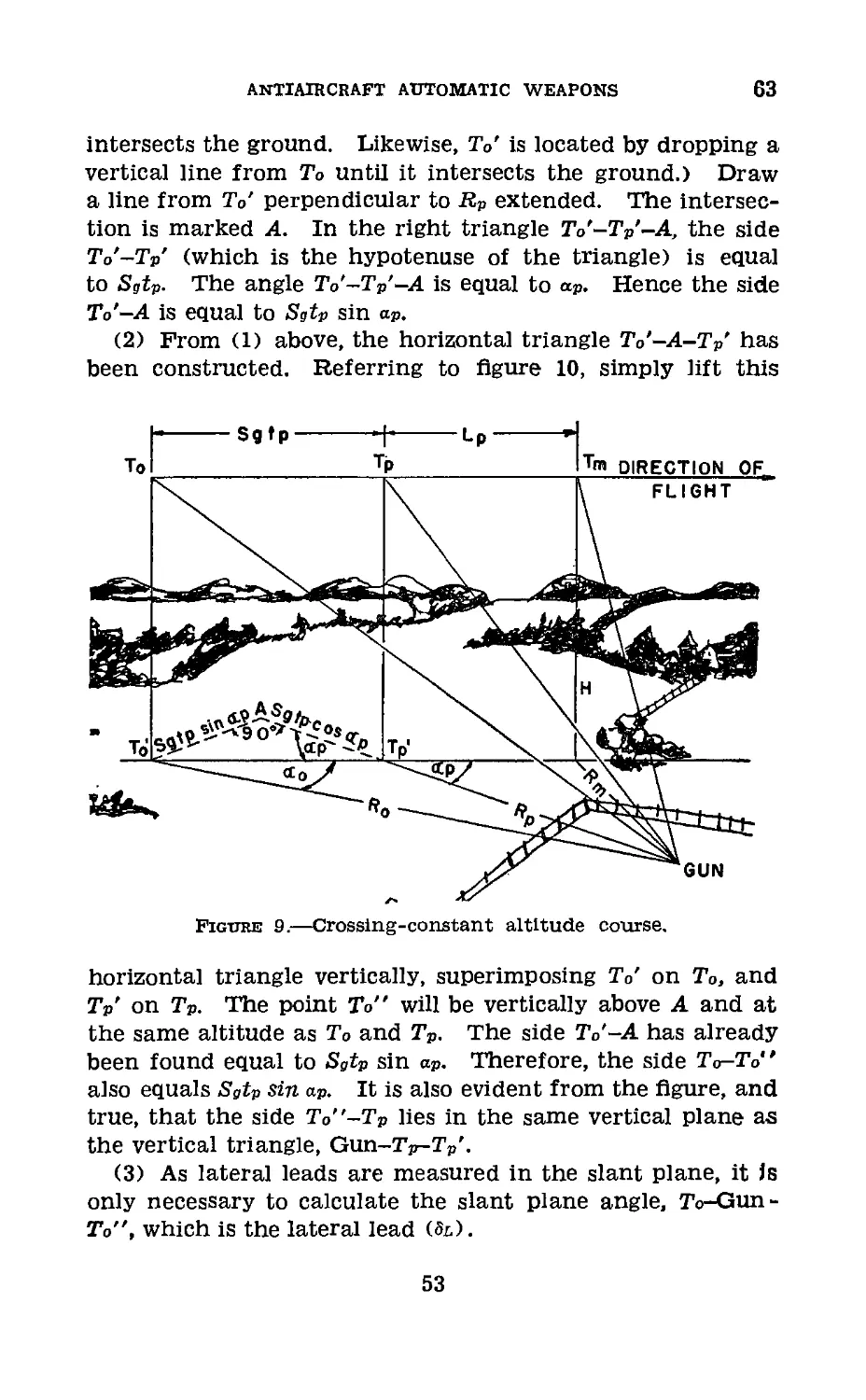
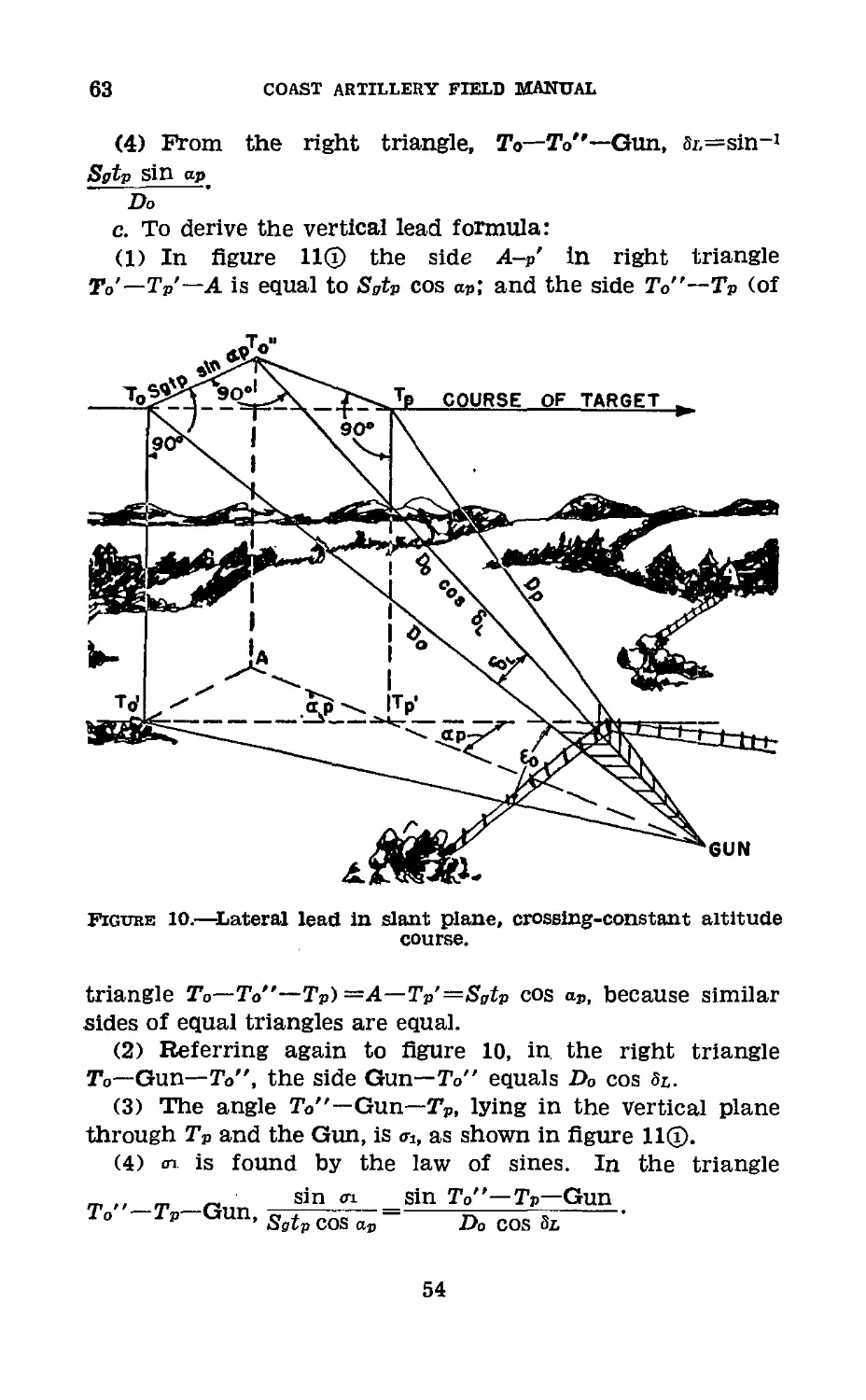
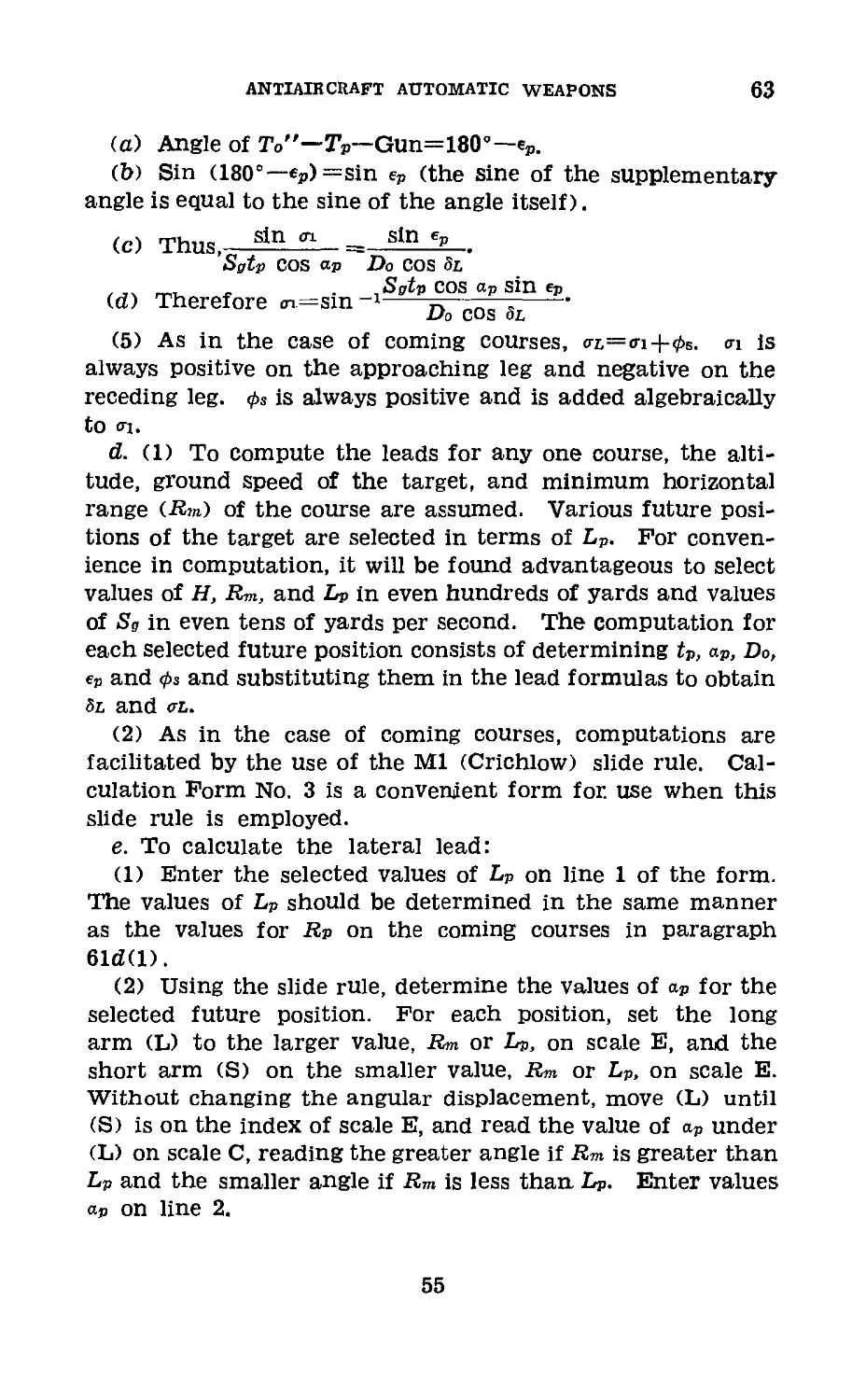
51. Crossing-Constant Altitude Course.—A typical set-up
in space for a crossing-constant altitude course, showing the
basic elements of data, is given in figure 5.
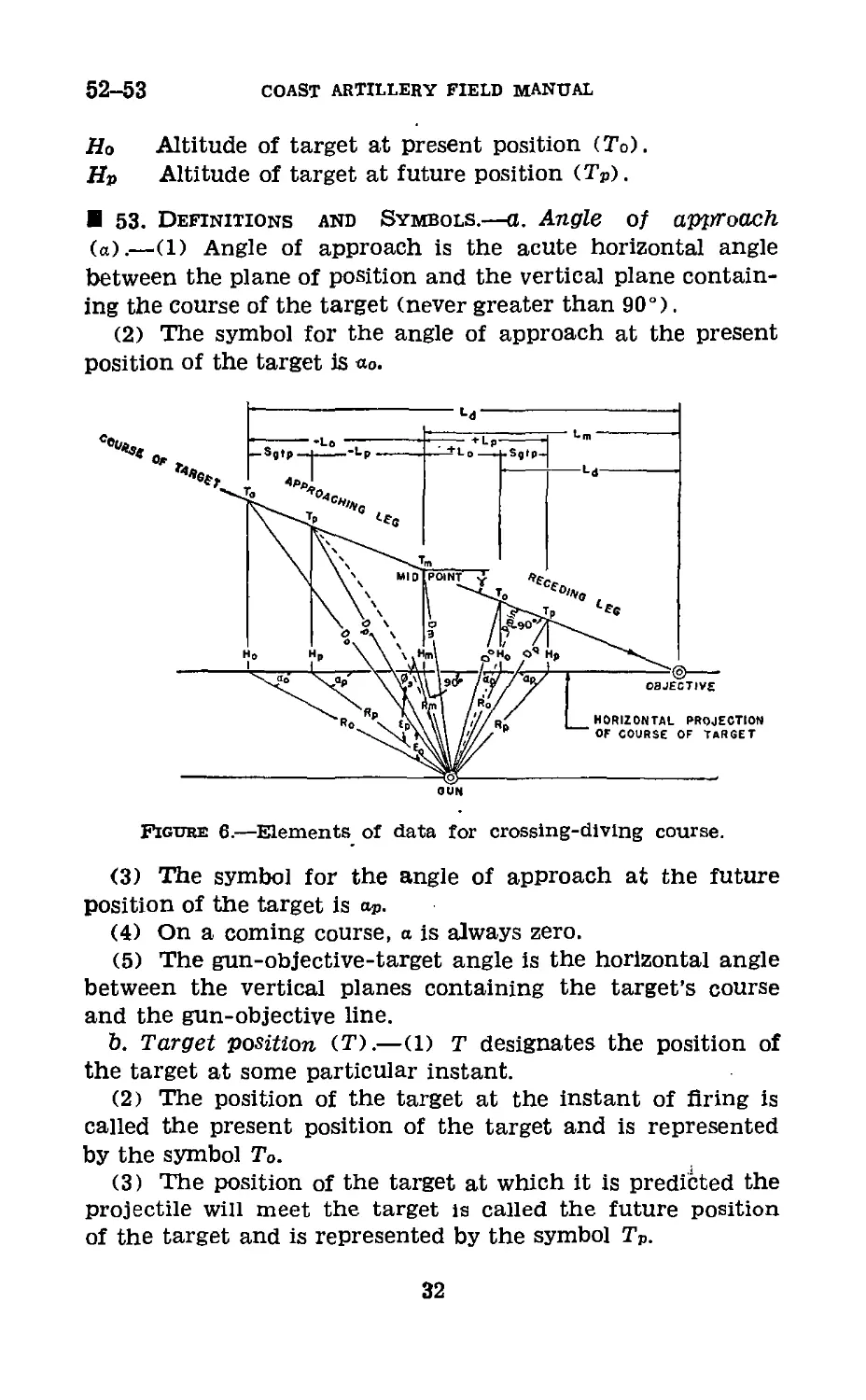
52. Crossing-Diving Course.—A typical set-up in space for
a crossing-diving course is given in figure 6. The basic ele-
ments are the same as those for a crossing-constant altitude
course, with the following exceptions:
7 . Angle of dive, measured from the horizontal.
Ld Horizontal distance from present position of a dive
target to the objective.
Lm Horizontal distance from the midpoint to the objective
of a dive target.
For H substitute:
Hm Altitude of target at midpoint (Tm).
30
ANTIAIRCRAFT AUTOMATIC WEAPONS
51-52
ao Angle of approach at present position of target (To).
a, Angle of approach at future position of target (Tp).
Dmin Minimum slant range. (For constant altitude courses
Dmln— Ar)
Dm Slant range to midpoint of course (Tm).
Do Slant range to target at present position (To).
Dp Slant range to target at future position (Tp).
e0 Angular height of target at present position (To).
ep Angular height of target at future position (Tp).
H Altitude of target.
Lo Distance from midpoint of course (Tm) to present position
(To) In horizontal plane.
LP Distance from midpoint of course (Tm) to future position
(TP) In horizontal plane.
<t>s Superelevation under firing table conditions.
Rm Minimum horizontal range or horizontal range to target
at midpoint of course (Tm).
Ro Horizontal range to target at present position (To).
Rn Horizontal range to target at future position (TP).
Sg Ground speed of target.
SgXtp Linear horizontal travel of target during time of flight.
Tm Midpoint—position of target where o=90°.
To Present position of target (Instant of firing).
To Predicted position of target (future position).
tp Time of flight to future position of target (Tp).
Figure 5.—Elements of data for a crossing-constant altitude course.
31
52-53
COAST ARTILLERY FIELD MANUAL
Ho Altitude of target at present position (To).
Hp Altitude of target at future position (Tp).
53. Definitions and Symbols.—a. Angle of approach
(a).—(1) Angle of approach is the acute horizontal angle
between the plane of position and the vertical plane contain-
ing the course of the target (never greater than 90°).
(2) The symbol for the angle of approach at the present
position of the target is «о.
Figure 6.—Elements of data for crossing-diving course.
(3) The symbol for the angle of approach at the future
position of the target is aP.
(4) On a coming course, a is always zero.
(5) The gun-objective-target angle is the horizontal angle
between the vertical planes containing the target’s course
and the gun-objective line.
b. Target position (T).—(1) т designates the position of
the target at some particular instant.
(2) The position of the target at the instant of firing is
called the present position of the target and is represented
by the symbol To.
(3) The position of the target at which it is predicted the
projectile will meet the target is called the future position
of the target and is represented by the symbol Tp.
32
ANTIAIRCRAFT AUTOMATIC WEAPONS
53
(4) The position of the target when the angle of ap-
proach equals 90° is called the midpoint of the course and
is represented by the symbol Tm. On coming courses, Tm
is directly over the gun, that is, e equals 90°.
c. Slant range.—(1) Slant range is the distance from the
gun to the target measured along the line of position.
(2) The slant ranges to each of the positions of the target,
To, Tp and Tm, are represented by the symbols Do, Dp, and Dm,
respectively.
(3) Dmin is the symbol for the minimum slant range to
the target. In constant altitude courses the minimum slant
range is at the midpoint of the course, and Dmin=Dm.
d. Horizontal range (Ю.—(1) Horizontal range is the dis-
tance from the gun to the projection of the target position
in the horizontal plane.
(2) The horizontal ranges to each of the positions of the
target, To, Tp, and Tm, are represented by the symbols Ro, Rp,
and Rm, respectively.
(3) On coming courses Rm is equal to zero.
e. Angular height (e).—(1) Angular height is the vertical
angle measured from the horizontal to the line of position.
(2) The angular heights to To and Tp are represented by
the symbols e0 and ep, respectively.
f. Altitude (H).—(1) Altitude is the vertical distance to
the target from the horizontal plane through the gun.
(2) The altitudes to each of the positions of the target,
To, Tp, and Tm are represented by the symbols Ho, Hp, and
Hm, respectively.
(3) For constant altitude courses Hm—Ho—Hp, and the
altitude is represented by the symbol H.
(4) For diving courses—
Ho—Hm—(Lo tan,y)
or Ho=Hm±(Ro tan7>
Hp=Hm± (Lp tan7>
or Hp=Hm±(Rp tan7>
(crossing)
(coming),
(crossing)
(coming).
g. Horizontal distance along course (D.—(1) The hori-
zontal distance from the midpoint (Tm) to the present posi-
tion of the target (To) is represented by the symbol Lo.
33
53
COAST ARTILLERY FIELD MANUAL
(2) The horizontal distance from the midpoint (Tm) to
the future position of the target (Tp) is represented by the
symbol Lp.
(3) The horizontal distance from the midpoint (Tm) to
the objective of a dive target is represented by the symbol Lm.
(4) The horizontal distance from the present position of
a dive target (To) to the objective is represented by the
symbol La.
Note.—Values of L„ and are considered plus when measured
In the direction of flight and minus when measured In the oppo-
site direction.
h. Superelevation (</>s).—(1) Superelevation is that part
of the quadrant elevation which compensates for the curva-
ture of the trajectory. It is the amount that the axis of the
bore must be pointed above the line of position to the future
position of the target (Tp) in order that the trajectory will
pass through the target at that point. Values of supereleva-
tion are obtained from firing tables.
(2) Superelevation is always a plus value and is added
algebraically to the principal vertical lead angle to obtain
the vertical lead.
i. Time of flight (tp).—Time of flight is the elapsed time
in seconds for the projectile to travel , from the gun to the
future position of the target (Tp). It is represented by the
symbol tp.
j. Ground speed (Sg).—(1) The ground speed of the target
is the velocity of the target with respect to the ground. It
is measured by determining the rate of travel in the hori-
zontal plane of the projection of the target in that plane.
In calculation it is always expressed in yards per second.
Miles per hour divided by two represents yards per second
with sufficient accuracy for calculation. Ground speed Is
represented by the symbol Sg.
(2) The symbol for speed of the target along its path
is S. It may be expressed in miles per hour or in yards per
second.
(3) For diving courses, Sg—S cos y.
k. Lateral lead (Sl).—Lateral lead is the angle in the
slant plane of the lateral sight by which the gun must lead
the target to cause the projectile and target to meet. It is
34
ANTIAIRCRAFT AUTOMATIC WEAPONS
53-54
the algebraic sum of the principal lateral lead angle № and
any necessary pointing correction (З2). The pointing correc-
tion (З2) is not considered in the calculation of leads. How-
ever, this correction does exist but it is included and applied
by the adjuster. (This element of data is not shown in figs. 7
and 8.)
I. Vertical lead (at.).—Vertical lead is the angle by which
the gun must lead the target vertically in order that the
projectile will meet the target at the future position. It is
measured in the vertical plane containing the axis of the
bore of the gun and is the algebraic sum of the principal
vertical lead angle (<n), the superelevation (</>s), and any nec-
essary pointing correction (m). The pointing correction
(аг) is not considered in the calculation of leads. However,
this correction does exist but it is included and applied by
the adjuster.
m. Principal lateral or vertical lead angle (Si or at).—(1)
The principal lateral (or vertical) lead angle is the lead
angle necessary to compensate for the travel of the target
during the time of flight of the projectile.
(2) The principal lateral lead angle is represented by the
symbol 3i.
(3) The principal vertical lead angle is represented by the
symbol or.
n. Angle of dive (7).—(1) Angle of dive is the vertical
angle between the course of the target and the horizontal.
(2) The projection of the angle of dive on the vertical
plane containing the gun and the future position of the
target (TP) is represented by the symbol 7».
Section П
FIRING TABLES
54. General.—a. Firing tables are used to determine time
of flight (tP) and superelevation ($s) for the future position
of the target in computing leads. A discussion of these tables
therefore properly belongs in a study of lead calculation.
b. In addition to their use in determining tp and фз, firing
tables are employed to determine differential effects of varia-
35
54-55
COAST ARTILLERY FIELD MANUAL
tions from the standard conditions on which the firing tables
are based and other trajectory data.
c. (1) The standard conditions on which firing tables are
based are—
(a) Muzzle Velocity (MV)—as listed in the table.
(&) Wind—none.
(c) Air density at the battery—that for a temperature of
59° F., a barometric reading of 29.53 inches of mercury, and
air saturation of 78 percent (525.9 grains per cubic foot).
(d) Air temperature at the battery—59° F.
(e) Powder temperature—70° F.
(f) A standard atmospheric structure aloft is assumed;
that is, atmospheric temperature and density vary with alti-
tude in a particular manner.
(2) Variations from these assumed conditions will affect
the behavior of the projectile. In firing tables for anti-
aircraft automatic weapons, these variations from standard
conditions are listed in terms of their effects on supereleva-
tion and time of flight, except in the caliber .30 tables, where
the effects are given in terms of range, altitude, and angular
height.
d. A list of the standard firing tables pertaining to a partic-
ular weapon will be found in the Standard Nomenclature
List published by the Ordnance Department.
55. Contents of Firing Tables.—The present standard
firing tables are published in book form. The first section
(introduction) contains general information pertaining to
the gun and projectile, and a detailed explanation of the
tables and of the meteorological message. Subsequent parts
of the tables give the following data:
a. Trajectory data (horizontal range, altitude, angular
height, and superelevation), using quadrant elevation and
time of flight as arguments.
b. Time of flight and superelevation, using horizontal range
and altitude (and, in addition, in firing tables for the 37-mm
or 40-mm guns, slant range and angular height) as argu-
ments.
c. (1) Differential effects on superelevation and time of
flight due to 100 f/s decrease in muzzle velocity, 10 percent
36
antiaircraft automatic weapons
55-56
decrease in density, and 10 mph rear wind, using horizontal
range and altitude as arguments.
(2) Differential effects on lateral lead due to 10 mph cross
wind, using horizontal range and altitude as arguments.
d. In each firing table, a trajectory chart is included. This
chart shows in- graphical form the relationship of altitude
and horizontal range, quadrant elevation, time of flight, and
angular height.
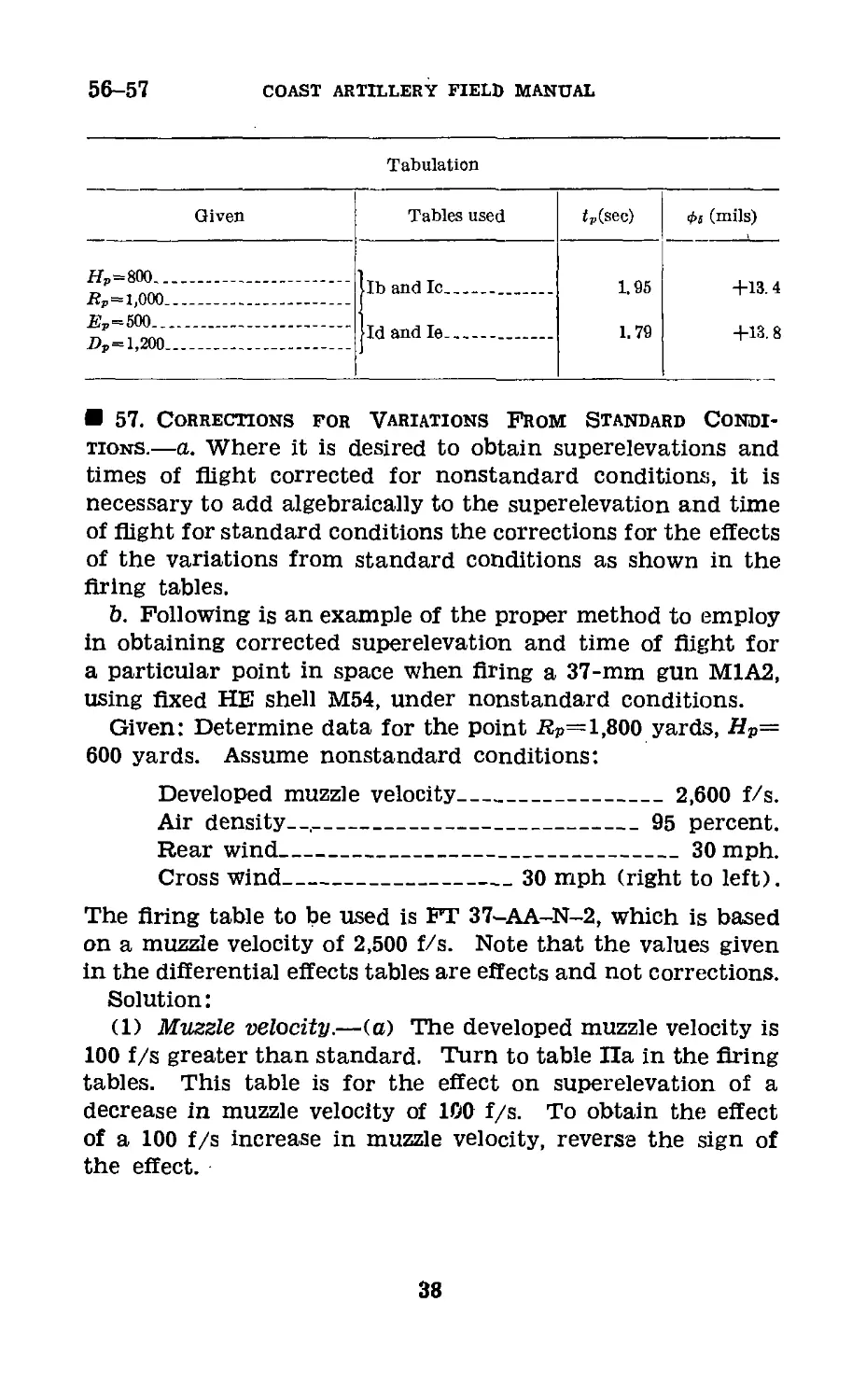
56. Determination of TIme of Flight and Supereleva-
tion.—a. Time of flight and superelevation under standard
firing table conditions are normally extracted from the firing
tables, using Rp and Hp (or H) as arguments. In the case of
tables for the 37-mm or 40-mm guns, Dp and may also be
used as arguments, the choice of arguments to be used being
dictated by convenience. For example, since time of flight
is virtually constant for a certain slant range, regardless of
angular height, tedious interpolation may often be eliminated
by using Dp and ep as arguments to extract tp. In either
case, however, values obtained should be the same.
b. (1) Having selected the proper table, the procedure is
to read under the correct value of altitude (or angular height)
and opposite the correct value of horizontal (or slant) range
the time of flight in seconds (or superelevation in mils).
(2) Example: What are the superelevation and time of
flight under standard conditions for the points (HP=800,
Kp=1,000) and (eP=500, DP=l,200), when firing a 37-mm gun
M1A2, using fixed HE shell M54? (Use FT 37-AA-N-2.)
(a) Entering table lb, opposite 1,000 yards horizontal range
and under 800 yards altitude is found the time of flight, 1.95
seconds.
(b) Entering table Ic, opposite 1,000 yards horizontal
range and under 800 yards altitude is found the supereleva-
tion, 4-13.4 mils.
(c) Entering table Id, opposite 1,200 yards slant range
and under 500 mils angular height is found the time of flight,
1.79 seconds.
(d) Entering table le, opposite 1,200 yards slant range
and under 500 mils angular height is found the superelevation,
4-13.8 mils.
37
56-57
COAST ARTILLERY FIELD MANUAL
Tabulation
Given Tables used ip(sec) 0s (mils)
Hp=800 Bp = l,000 .. .. |lb and Ic 1.05 +13.4
_EP=500 Dp= 1,200 jld and le 1.70 +13.8
57. Corrections for Variations From Standard Condi-
tions.—a. Where it is desired to obtain superelevations and
times of flight corrected for nonstandard conditions, it is
necessary to add algebraically to the superelevation and time
of flight for standard conditions the corrections for the effects
of the variations from standard conditions as shown in the
firing tables.
b. Following is an example of the proper method to employ
in obtaining corrected superelevation and time of flight for
a particular point in space when firing a 37-mm gun M1A2,
using fixed HE shell M54, under nonstandard conditions.
Given: Determine data for the point RP= 1,800 yards, Hp—
600 yards. Assume nonstandard conditions:
Developed muzzle velocity___________________ 2,600 f/s.
Air density--.---------------------------95 percent.
Rear wind___________________________________30 mph.
Cross wind____________________30 mph (right to left).
The firing table to be used is FT 37-AA-N-2, which is based
on a muzzle velocity of 2,500 f/s. Note that the values given
in the differential effects tables are effects and not corrections.
Solution:
(1) Muzzle velocity.—(a) The developed muzzle velocity is
100 f/s greater than standard. Turn to table Па in the firing
tables. This table is for the effect on superelevation of a
decrease in muzzle velocity of 100 f/s. To obtain the effect
of a 100 f/s increase in muzzle velocity, reverse the sign of
the effect.
38
ANTIAIRCRAFT AUTOMATIC WEAPONS
57
(&) Entering the table, opposite 1,800 yards horizontal
range and under 600 yards altitude, the value —2.5 mils is
obtained. Changing the sign as mentioned above, the effect
on superelevation of an increase of 100 f/s in muzzle velocity
at the point selected becomes 4-2.5 mils. Ehter this value
in the tabulation below.
(c) In a similar manner enter table lib to obtain the effect
of the assumed muzzle velocity on time of flight. The value
(with sign changed as above) is 4-0.15 second. Enter this
value in the tabulation.
(2) Air density.—(a) Turning to tables He and Hd, they
are found to show the effects for a decrease in air density
of 10 percent. The assumed air density is 95 percent or a
decrease from normal of 5 percent. Therefore, the effects
taken from tables He and lid will be correct in sign but must
be divided by two to obtain the required value.
(&) Enter table lie. Opposite 1,800 yards horizontal range
and under 600 yards altitude is the value 4-1.5 mils. Divid-
ing this by two, the effect on superelevation of the assumed
air density is found to be 4-0.8 mil. Enter this value in the
tabulation.
(c) In a similar manner the value 4-0.07 second is ob-
tained from table lid as the effect on time of flight of the
variation in air density. Enter this value in the tabulation.
(3) Rear wind.—(a) Turning to tables lie and Hf, they
are found to show the effects for a rear wind of 10 mph. Since
the assumed rear wind is 30 mph the values found in the
tables must be multiplied by three to determine effects of a
rear wind of this velocity.
(Ю Enter table He. Opposite 1,800 yards horizontal range
and under 600 yards altitude is found the value —0.7 mil,
which is the effect on superelevation of a rear wind of 10
mph. This value is multiplied by three and the product,
—2.1 mils, entered in the tabulation.
(c) In a similar manner the value 4-0.03 second is obtained
from table Ilf as the effect on time of flight of the variation
in rear wind. Enter this value in the tabulation.
39
57
COAST ARTILLERY FIELD MANUAL
Assumed condition
+100 f/s, MV______________________
—5 percent density----------------
30 mph rear wind__________________
Total effects,--------------
Tabulation
Tables used
Ila, lib______________
He, lid_______________
He, Ilf_______________
Effects on
Ф, (mils) tP (seconds)
+2.5
+0.8
-2.1
+1.2
+0.15
+0.07
+0.03
+0. 25
Ф, (mils)
tP (seconds)
Data-under standard conditions__________________________
Total corrections for nonstandard conditions____________
Corrected data____________________________________
+26.1
-1.2
+24.9
or +25
+3.28
-0. 25
+3. 03
(4) Correction for cross wind.—(a) In table Ilg the effect
of cross wind on the lateral lead is given directly in mils.
The table is made up for a cross wind of 10 mph. For a
cross wind of 30 mph the value taken from the table must be
multiplied by three to determine the effect of a cross wind
of this velocity.
(b) Entering the table opposite 1,800 yards horizontal
range and under 600 yards altitude, the effect on lateral
lead is found to be 7.8 mils (without sign). Since the wind
is from right to left, the trajectory is moved to the left, the
effect is L 7.8 mils, and the correction is R 7.8 mils. If the
computed lead is in reference numbers such as appear on the
lead dials of the control box, the correction is added alge-
braically to it. In cases where leads are given as left or
right by the actual number of mils, the correction would be
subtracted from a left lead and added to a right lead.
c. (1) Under service conditions it will be impracticable to
determine corrections for nonstandard conditions for the
specific course to be fired on. However, if the lead values for
points on type courses have been computed previously, both
for standard conditions and selected nonstandard condi-
tions, and lead curves plotted to show the relationships of
40
ANTIAIRCRAFT AUTOMATIC WEAPONS
57-59
these leads, an estimate of the approximate average change
in leads required as the result of a specific nonstandard con-
dition can be made.
(2) Wind corrections normally are not practicable for a
crossing course as the wind components vary continuously
throughout the course at a rapid rate. Possible exceptions
are courses at the longer ranges, particularly those which
approximate coming courses.
Section III
METHODS OF LEAD CALCULATION
58. General.—a. Antiaircraft automatic weapons pointed
by central control use sights to point the gun in elevation
and direction. The sight is mounted directly on the gun or
carriage and traverses and elevates with the gun. Appli-
cation of the required leads is accomplished by shifting the
line of sight (of the sight) from a line parallel to the axis
of the bore by an angular amount equal to the required leads.
The shifting of the line of sight is done by means of tangent
screws or by rotating the sighting elements.
b. Leads must be calculated for the future position of the
target (TP) where tp and Фз are applicable. Future posi-
tions are selected at convenient distances along the course
of the target (usually in even hundreds of yards to facilitate
use of the firing tables), and from them the corresponding
present positions as well as the leads are calculated.
59. Definitions of Leads.—a. Positive lateral leads.—(1)
A positive (+) lateral lead is one where the gun points
ahead of the target.
(2) An increasing positive (+) lateral lead is one where
the gun continues to point farther ahead of the target with
each succeeding increment of time.
(3) A decreasing positive (+) lateral lead is one where
the gun (pointing ahead of the target) continues to point
closer to the target with each succeeding increment of time.
b. Negative lateral leads.—These are leads in which the
gun points behind the target. Naturally, they are never used
in the automatic weapons gunnery problem whether increas-
ing, decreasing, or static.
41
59-61
COAST ARTILLERY FIELD MANUAL
c. Positive vertical leads.—(1) A positive (4-) vertical lead
is one where the gun points above the target.
(2) An increasing positive (4-) vertical lead is one where
the gun continues to point farther above the target with
each succeeding increment of time. (It is rarely obtained
in automatic weapons fire.)
(3) A decreasing positive (4-) vertical lead is one where
the gun (pointing above the target) continues to point closer
to the target with each succeeding increment of time.
d. Negative vertical leads.—(1) A negative (—) vertical
lead is one where the gun points below the target.
(2) An increasing negative ( —) vertical lead is one where
the gun continues to point farther below the target with each
succeeding increment of time.
(3) A decreasing negative (—) vertical lead is one where
the gun (pointing below the target) continues to point closer
to the target with each succeeding increment of time.
e. Zero vertical leads.—A zero vertical lead occurs when a
decreasing positive lead changes to an increasing negative
lead.
60. Data Required for Calculation of Leads.—a. To cal-
culate leads for a course, the following basic data are
assumed:
(1) Minimum horizontal range or range to midpoint (Rm) .
(2) Altitude at midpoint (Hn).
(3) Ground speed of target (Sg).
(4) Various future positions of the target (TP) along the
course are selected by assuming values of Lp or RP.
(5) Angle of dive (?).
b. In addition, certain data are extracted from firing
tables:
(1) Time of flight to future position (tP).
(2) Superelevation to future position (</>s).
61. Coming-Constant Altitude Courses.—a. In the com-
putation for coming courses, there are no lateral leads, since
the angle of approach of the target is 0. Only the vertical
leads are computed.
b. Although the only true coming courses are those
where the target comes directly toward the gun position
42
ANTIAIRCRAFT AUTOMATIC WEAPONS
61
(Km=0), all crossing courses with an Rm less than 100 yards
are considered to be coming courses. The lateral leads are
small until the target is very close and then they change so
rapidly that even if a gun could follow the target, it would
be impossible to transmit the rapidly changing lead to the
sights. Also the vertical leads for these courses are prac-
Figure 7.—Vertical lead, coming-constant altitude course.
tically the same as for a true coming course of the same
altitude and speed.
c. Figure 7 represents the pictorial view of the approaching
leg of a coming-constant altitude course. The formula for
Vertical lead for a true coming-constant altitude course is—
crL — ep— eo -)
Referring to figure 7, it is obvious that the lead necessary
to cause the projectile to meet the target at TP is merely
the angular difference between eo and eP) added algebraically
to the superelevation. Note that the principal vertical lead
43
61
COAST ARTILLERY FIELD MANUAL
angle (ep—e0, or <n) is always positive on the approaching
leg of a coming-constant altitude course, and is always
negative on the receding leg of such a course. Supereleva-
tion is always positive.
d. (1) To compute the leads for a type course, the altitude
and ground speed of the target are assumed, and various
future positions of the target are selected in terms of Rp.
The maximum value of Rp on either the approaching or
receding leg will depend on the maximum range of the
armament. Leads may be calculated at 100- to 400-yard
increments, depending upon the maximum range and desired
accuracy for plotting the lead curve. The approaching leg
and receding leg may be calculated on one form, using a large
increment for Rp, or a small increment may be used to com-
pute only the approaching or receding leg. The computation
for each selected future position then consists of determining
the following:
tp from Rp and H.
Ro from Rp and Sgtp.
«о from Ro and H.
aL from fP, eo, and 0s.
Note.—If corresponding values of R„ on the approaching leg and
on the receding leg are selected, the work required to determine
op, tp, and 0S will be reduced.
(2) The above computations can be rapidly performed by
using the Ml (Crichlow) slide rule. Calculation Form No.
1 (/ below) is a convenient form for use when this slide
rule is employed.
e. To calculate the vertical lead:
(1) Enter the selected values of Rp on line 1 of the form.
(2) Extract from the proper firing tables the times of
flight and the superelevations for each selected future posi-
tion, using H and Rp as arguments. Ehter the times of flight
(nearest hundredth of a second) and the superelevations
(nearest mil) on lines 3 and 8, respectively, of the form.
(3) Multiply each time of flight by the assumed ground
speed in yards per second and enter the results (to the nearest
yard) on line 4. It may be desired to perform the multipli-
44
ANTIAIRCRAFT AUTOMATIC WEAPONS
61
cation of Sg and tp on the Ml (Crichlow) slide rule. Set the
long arm (L) to the assumed Sg in yards per second on scale
E, and move the short arm (S) to the index of scale E.
Without changing the angle between the arms, shift (L) until
(S) is set to the first time of flight on scale E and read under
(L) the value of Sptp on scale E. Still without changing the
angle between the arms, continue to set (S) to times of flight
and read values of SgtP under (L) for each Up.
(4) Add to (approaching leg) or subtract from (receding
leg) line 1 the values in line 4 to obtain values of Ro. Enter
these values on line 5.
(5) Compute the values of eP for each selected future posi-
tion, using the slide rule. Set long arm (L) on the larger
value, RP or H, on scale E, and set the short arm (S) on the
smaller of the two' values, RP or H, on scale E. Without
changing the angle between the two arms, move (L) until
(S) is on the index of scale E, and read the value of <ч> under
(L) on scale C. Note that scale C has two sets of readings.
If H is less than RP, read the smaller angle. If H is greater
than read the larger angle. Enter the values of ep on
line 2 of the form.
(6) Compute the value of «о for each present position
corresponding to a selected future position, using the slide
rule. This is done as described in (5) above, except that
Ro is substituted for Rp. Enter the values of e0 on line 6.
(7) Subtract each value of ?0 from the corresponding value
of eP to obtain values of <n. Enter these values on line 7.
(8) Add lines 7 and 8 algebraically to obtain values of
n. Enter these values on line 9.
f. If it is desired to calculate the leads with an ordinary
slide rule or calculating machine, the form shown below
must be changed to show the functions of the angles. By
using the Crichlow slide rule the angle is found directly,
whereas on an ordinary slide rule or calculating machine the
trigonometric function of the angle is found. The angle
then will be found by referring to tables of natural trigono-
metric functions. Leads for coming courses can also be
measured graphically.
478316°—42---4
45
CD
CALCULATION OF LEADS FOR ANTIAIRCRAFT AUTOMATIC WEAPONS
COMING-CONSTANT ALTITUDE COURSE
[Gun—37-mm; M1A2. H=500 yards; S?=70 yards/seconds FT=37-AA-N-1; MV= 2,700feet/seconds] Calculation Form No. 1
Coming-Constant Altitude Solution by Orichlow slide rule
Set L at Set S at Turn both until S is at Read under L on
1. Rp - Assumed or selected 1,600 1,200 800 400 0 400 800 1.200 1,600
2. ep=tan-i Hor Rp (larger) Scale E H or Rp (smaller) Scale E Index Scale E Scale O1 309 402 569 913 1,600 913 569 402 309
3 From firing tables using H and Rp 2. 52 1.82 1.23 0. 80 0.61 0. 80 1.23 1. 82 2. 52
4. Sgtp.~. St Scale E Index Scale E Scafe E Scale E 176 127 86 56 43 56 86 127 176
5. R0=Rp±SetP +on approaching leg —on receding leg 1, 776 1,327 886 456 43 344 714 1,073 1,424
й . H 6. e0= tan-1 ilo H or Ro (larger) Scale E H or Ro (smaller) Scale E Index Scale E Scale 0 1 280 368 523 847 1,513 986 622 444 344
7. cri=«p—e0 Line 2 minus line 6 29 34 46 66 87 -73 -53 -42 -35
8. From firing tables using H and Rp 19 13 9 6 2 6 9 13 19
9. = Line 7 plus line 8 48 47 | 55 72 89 -67 -44 —29 -16
1 If numerator is less than denominator, the angle is less than 800 mils.
COAST ARTILLERY FIELD MANUAL
ANTIAIRCRAFT AUTOMATIC WEAPONS
62
62. Coming-Diving Courses.—a. Figure 8 represents a pic-
torial view of the approaching leg for a coming-diving course.
As in the coming-constant altitude course, the formula for
vertical lead for a coming-diving course is—
al, — ер—во
b. For courses where the target is diving at a point in rear
of the gun position, the value ep—eo will be positive on the
47
62
COAST ARTILLERY FIELD MANUAL
approaching leg and negative on the receding leg. For courses
where the target is diving at a point in front of the gun posi-
tion, the value eP—eo will always be negative. For courses
where the target is diving directly at the gun position,
ep—eo=0, and о-ь=фз. As in the case of the coming-con-
stant-altitude courses, the superelevation is always positive
and is added algebraically to ep—e0.
c. (1) The leads for coming-diving courses can be com-
puted in a manner similar to that for coming-constant alti-
tude courses, but with the addition of one other factor, the
angle of dive (7). Hm and Sg are assumed, as well as 7, and
as before, various future positions of the target are selected
in terms of RP. If actual speed of the target (S) is given,
ground speed (Sff) may be determined by the formula Sg=S
cos 7. ' The computation for each selected future position
then consists of determining the following:
Hp from Hm, Rp, and 7.
ep from Rp and Hp.
Ro from Rp and Sgtp.
Ho from Hm, Ro, and 7.
eo from Ko and Ho.
o-z, from eP, eo, and фз.
(2) The computations can be rapidly performed by using
the Ml (Crichlow) slide rule. Calculation Form No. 2 is a
convenient form for use when this slide rule is employed.
d. To calculate the vertical lead:
(1) Enter the selected values of Rp on line 1 of the form.
(2) Determine the values of Rp tan 7 for each future
position, using the slide rule.
(a) If 7 is greater than (>) 800 mils, set the long arm (L)
to the value of 7 on the outer set of figures (tangents) of
scale G, and the short arm (S) on the index. Without chang-
ing the angle of displacement between the two arms, move
(L) until (S) is set to the value of Rp on scale E, and under
(L) read the value of Rp tan 7 on scale E.
48
ANTIAIRCRAFT AUTOMATIC WEAPONS
62
(&) If 7 is less than (<) 800 mils, set (L) on the index,
and (S) to the value of 7 on the inner set of figures (co-
tangents) of scale C. Without changing the angle of displace-
ment between the two arms, set (S) to the value of Rp on scale
E, and under (L) read the value of Rp tan 7 on scale E. En-
ter these values on line 2.
(3) Determine the values of Hp for the selected future
positions, by adding to (approaching leg) or subtracting from
(receding leg) Hm the values of Rp tan 7 on line 2. Enter
these values on line 3.
(4) Extract from the proper firing tables the times of flight
and the superelevations for each selected future position,
using Hp and Rp as arguments. Enter the times of flight
(nearest hundredth of a second) and the superelevations
(nearest mil) on lines 5 and 12, respectively, of the form.
(5) Multiply each time of flight by the assumed ground
speed in yards per second, and enter the results (to the near-
est yard) on line 6. It may be desired to perform the multi-
plication of Ss and tp on the Ml (Crichlow) slide rule. In
this case all settings are made and read on scale E. Set the
long arm (L) to the assumed Sa in yards per second, and the
short arm (S) to the index. Without changing the angle
between the arms, shift (L) until (S) is set to the first time
of flight, and read under (L) the value of Sat?. Still without
changing the angle between the arms, continue to set (S) to
times of flight, and read values of Satp under (L).
(6) Add to (approaching leg) or subtract from (reced-
ing leg) the values of Rp (line 1) the values of SgtP (line 6)
to obtain values of Ro. Enter these values on line 7.
(7) Determine the values of Ro tan 7 for each required
present position in the same manner that values of Rp tan 7
were determined in (2) above, except that Ro is substituted for
Rp. Enter the values obtained on line 8.
(8) Determine values of Ho for each required present posi-
tion by adding to (approaching leg) or subtracting from
(receding leg) Hm the values of Ro tan 7 on line 8. Enter
these values on line 9.
49
CALCULATION OF LEADS FOR ANTIAIRCRAFT AUTOMATIC WEAPONS COMING-DIVING COURSE Ci
to
Calculation Form No. 2.
[Gun—37-mm M1A2. Hm = 1,100 yards; S<=70 yards/seconds; у=889 mils (50°); FT=37-AA-N-l]
Coming-diving course Solution by Crichlow slide rule
Set L at Set S at Turn both until S is at Read under L on
1. Rp Assumed or selected 800 600 400 200 0 200 400 600 800
CT ° 2. Rp tan у у (tan) Scale C or Index Index у (cot) Scale C Rp Scale E Scale E 954 715 477 238 0 238 477 715 954
3. Hp=Hjn^zRp tan y_. _ 4-on approaching leg —on receding leg 2, 054 1, 815 1,577 1,338 1,100 862 623 385 146
Л . 'Hp Hp or Rp (larger) Scale E Hp or Rp (smaller) Scale E Index Scale E Scale C 1 1,222 1,275 1,347 1, 449 1,600 1,368 1. 019 581 184
4. «у—tan-* -&
5. tp .... .. From firing tables using HP and Rp 3.71 3.02 2.43 1. 91 1.48 1.14 0. 94 66 0. 90 63 1. 04 73
6. Sgtp Scale E Index Scale E tp Scale E Scale E 260 211 170 134 104 80
COAST ARTILLERY FIELD MANUAL
7. Ro—Rp^cSgtp _ .... +on approaching leg —on receding leg 1,060 811 570 334 104 120 334 537 727
8. 7?„tan 7. у (tan) Scale C or Index Index Ro Scale E Scale E 1,264 967 679 398 124 143 398 640 867
T (cot) Scale 0
9. H«= Hm±Ro tan y._ +on approaching leg —on receding leg 2,364 2,067 1,779 1,498 1,224 957 702 460 233
,n . 1 10. e0=tan~i Ho or Ro (larger) Scale E Ho or Ro (smaller) Scale E Index Scale E Scale C 1 1,171 1,219 1,284 1,377 1,514 1,473 1,148 722 316
11. cri=ep— Line 4 minus line 10 51 56 63 72 86 -105 -129 -141 -132
12. ф, From firing tables using Hp and Rp 12 9 7 4 2 4 6 7 9
13. <7£, = ep—«о+ф». Line 11 plus line 12 63 65 70 76 88 -101 -123 -134 -122
1 If numerator is less than denominator, the angle is less than 800 mils.
ANTIAIRCRAFT AUTOMATIC WEAPONS
to
05
62-63
COAST ARTILLERY FIELD MANUAL
(9) Compute the values of ep for each selected future
position, using the slide rule. To do this, set the long
arm (L) on the larger value, Rp or Hp, on scale E, and the
short arm (S) on the smaller value, Rp or Hp, on scale E.
Without changing the angle between the two arms, move (L)
and (S) until (S) is on the index of scale E, and read the
value of ep under (L) on scale C. Note that scale C lias two
sets of readings. If Hp is less than Rp, read the smaller
angle. If Hp is greater than Rp, read the larger angle. En-
ter the values of ep on line 4.
(10) Compute the values of e0 for each present position
corresponding to a selected future position, using the slide
rule. This is done as described in (9) above, except that
Ro and Ho are substituted for Rp and Hp, respectively. Enter
the values of e0 on line 10.
(11) Subtract each value of e0 from the corresponding
value of to obtain values of <n (or eP—e0). Enter these
values on line 11.
(12) Add lines 11 and 12 algebraically to obtain values of
or.. Enter these values on line 13.
63. Crossing-Constant Altitude Courses.—a. When com-
puting leads for a crossing-constant altitude course, both
vertical leads and lateral leads must be determined. Figure
9 represents the approaching leg of a crossing-constant alti-
tude course. The formulas for computing the leads for such
a course are—
8l (lateral lead=sin -1 ^р5{пцр .
Do
n (vertical lead)=f sin ~1--gZp
\ Do cos 8l /
The various steps required to develop these formulas for a
point on the approaching leg of the course are shown in
figures 9, 10, and 11®- These formulas are also correct for
the receding leg of the course.
b. To derive the lateral lead formula:
(1) Referring to figure 9, the right triangle, To'-Gun-A, is
constructed by extending Rp beyond Tp. (The location of
Tp’ is determined by dropping a vertical line from Tp until it
52
ANTIAIRCRAFT AUTOMATIC WEAPONS
63
intersects the ground. Likewise, To' is located by dropping a
vertical line from To until it intersects the ground.) Draw
a line from To' perpendicular to RP extended. The intersec-
tion is marked A. In the right triangle T0'-Tp'-A, the side
То-Т? (which is the hypotenuse of the triangle) is equal
to S9tp. The angle To'-Tp'-A is equal to ap. Hence the side
To'-A is equal to SgtP sin ap.
(2) From (1) above, the horizontal triangle T0'—A-TP has
been constructed. Referring to figure 10, simply lift this
Figure 9.—Crossing-constant altitude course.
horizontal triangle vertically, superimposing To' on To, and
Tp' on Tp. The point To” will be vertically above A and at
the same altitude as To and Tp. The side To'-A has already
been found equal to Sstp sin ap. Therefore, the side То-То''
also equals SgtP sin aP. It is also evident from the figure, and
true, that the side T0"-TP lies in the same vertical plane as
the vertical triangle, Gun-Tp-Tp'.
(3) As lateral leads are measured in the slant plane, it is
only necessary to calculate the slant plane angle, To-Gun-
To”, which is the lateral lead (<«.).
53
63
COAST ARTILLERY FIELD MANUAL
(4) From the right triangle, To—To"—Gun, 8i,=sln_I
Sgtp Sin qp
Do
c. To derive the vertical lead formula:
(1) In figure 11® the side А-p' in right triangle
To’—Tp’—A is equal to Sgtp cos qP; and the side To”—Tp (of
Figure 10.—Lateral lead in slant plane, crossing-constant altitude
course.
triangle To—To”—Tp) =A—Tp’=Sgtp cos qp, because similar
sides of equal triangles are equal.
(2) Referring again to figure 10, in the right triangle
To—Gun—To", the side Gun—To" equals Do cos 3z,.
(3) The angle To”—Gun—Tp, lying in the vertical plane
through Tp and the Gun, is ai, as shown in figure 11®.
(4) oi is found by the law of sines. In the triangle
sin <n sin To"—Tp—Gun
To Tp Oun, CQS CQS
54
antiaircraft automatic weapons
63
(a) Angle of To"—Tp—Gun=180°—ep.
(b) Sin (180°—«p)=sin eP (the sine of the supplementary-
angle is equal to the sine of the angle itself).
(c)
(d)
Thus, - 5111 m ... sln .
Sgtp COS ap Z>0 COS OL
. Sgtp cos ap sin
Therefore <n=sin -1-----„ „„„ ,—
Do COS OL
(5) As in the case of coming courses, o-z,=ot-|-0s. <n is
always positive on the approaching leg and negative on the
receding leg. </>s is always positive and is added algebraically
to <n.
d. (1) To compute the leads for any one course, the alti-
tude, ground speed of the target, and minimum horizontal
range (Rm) of the course are assumed. Various future posi-
tions of the target are selected in terms of LP. For conven-
ience in computation, it will be found advantageous to select
values of H, Rm, and Lp in even hundreds of yards and values
of Sg in even tens of yards per second. The computation for
each selected future position consists of determining tP, ap, Do,
eP and фз and substituting them in the lead formulas to obtain
Sl and at.
(2) As in the case of coming courses, computations are
facilitated by the use of the Ml (Crichlow) slide rule. Cal-
culation Form No. 3 is a convenient form for. use when this
slide rule is employed.
e. To calculate the lateral lead:
(1) Enter the selected values of Lp on line 1 of the form.
The values of Lp should be determined in the same manner
as the values for Rp on the coming courses in paragraph
61d(l).
(2) Using the slide rule, determine the values of aP for the
selected future position. For each position, set the long
arm (L) to the larger value, Rm or Lp, on scale E, and the
short arm (S) on the smaller value, Rm or Lp, on scale E.
Without changing the angular displacement, move (L) until
(S) is on the index of scale E, and read the value of aP under
(L) on scale C, reading the greater angle if Rm is greater than
Lp and the smaller angle if Rm is less than Lp. Enter values
aP on line 2.
55
63
COAST ARTILLERY FIELD MANUAL
<J) Principal vertical lead angle and superelevation under firing
table conditions, crossing-constant altitude course.
® Relationship of L to D.
Figure 11.
56
ANTIAIRCRAFT AUTOMATIC WEAPONS
63
(3) Using the slide rule, determine the values of Rp for the
selected future positions. For each position, set the long arm
(L) to Rm on scale E, and the short arm (S) on the index
of scale E. Without changing the angular displacement of
the arms, move (L) until (S) is on the value of aP (line 2) on
scale D and read the value of Rp under (L) on scale E. Enter
values of Rp on line 3.
(4) Using the slide rule, determine the values of ep for the
selected future positions. Proceed as in (2) above, substitut-
ing H for Rm and Rp for Lp. Enter values of ep on line 4.
(5) Using the slide rule, determine the values of Dp for
the selected future positions. Proceed as in (3) above, sub-
stituting H for Rm and ep for aP. Enter values of Dp on line 5.
(6) Enter the firing tables with Dp and ep (or H and Rp) as
arguments, and extract values of tp and Фз for each selected
future position. Enter the values of tP (nearest hundredth
second) and фз (nearest mil) on lines 6 and 16, respectively.
(7) Multiply each time of flight by the assumed ground
speed of the target in yards per second, and enter the results,
to the nearest yard, on line 7. It may be desired to perform
the multiplication of Sg and tp on the slide rule. Set the
long arm (L) to the assumed Sg in yards per second on scale
E, and the short arm (S) on the index. Without changing
the angle between the arms, shift (L) until (S) is set to
the first time of flight and read under (L) the value of Sgtp.
Still without changing the angle between the arms, continue
to set (S) to times of flight, and read values of Sgtp under (L).
(8) Add to (approaching leg) or subtract from (receding
leg) the values of Lp (line 1) the value of SgtP (line 7) to
obtain values of Lo corresponding to each value of Lp. Enter
these values on line 8.
(9) Using the slide rule, determine the values of SgtP
sin ap for the selected future positions. For each position,
set the long arm (L) to SgtP on scale E, and the short arm
(S) to the value of ap (line 2) on scale D. Without changing
the angular displacement of the arms, move (L) until (S)
is on index of scale E, and read the value of SgtP sin aP under
(L) on scale E. Enter these values on line 9.
57
CALCULATION OF LEADS FOR ANTIAIRCRAFT AUTOMATIC WEAPONS
CROSSING CONSTANT ALTITUDE COURSE
[11=299 yards; R™=485 yards, S«=51.3 yards/sooonds; FT=0.50-AA-E-l] Calculation Form No. 3.
О1
со
Crossing-constant altitude course Solution by Crichlow slide rule
Set L at Set S at Turn both until S is at Read under L on
1 Lp Assumed or selected 800 600 400 200 0 200 400 600 800
2. exp—*tan ' 'y . _ bp m Rm or Lp (larger) Scale E Rm or Lp (smaller) Scale E Index Scale E Scale C1 555 692 897 1,202 1,600 1,202 897 692 555
00 3 Д -a Rm - =a ^p P sin aP COS€p ftm Scale E Index Scale E Line 2 Scale D Scale E 936 772 629 525 485 525 629 772 936
4. ,p=tan-<^ ip H or Rr (larger) Scale E Нот П, (smaller) Scale E Index Scale E Scale O1 315 377 452 527 563 527 452 377 315
5. 0„=-Д- sin ep cos H Scale E Index Scale E Line 4 Scale D Scale E 982 825 696 605 570 605 696 825 982
6. tp From firing tables using H and Rp 1,37 1.11 0. 90 0, 76 0. 71 0, 76 0.90 1.11 1. 37 70
7. iSefp s. Scale E Index Scale E Line 6 Scale E Scale E 70 57 46 39 36 39 46
COAST ARTILLERY FIELD MANUAL
8. Lo— DpdcSgtp 4- on approaching leg — on receding leg 870 657 446 239 36 161 354 543 730
9. Sgtp sin вр. Line 7 Scale E Line 2 Scale D Index Scale E Scale E 36 36 35 36 36 36 .. 36 36
10. Do.... Plot a curve of Dp against Lp and read Dp from the curve for values of Lo 1,045 865 725 615 572 595 670 785 925
11. Sl = sin-iS|,'i'J1 ° °’’.. Line 10 Scale E Line 9 Scale E Index Scale E Scale D 35 42 49 60 64 62 53 47 40
12. Sgfp COS ap Line 7 Scale E Line 2 Scale В Index Scale E Scale E CO 44 29 15 0 15 29 44 CO
13. Sgtp cos ap sintp_____ co lane 12 Scale E Line 4 Scale D Index Scale E Scale E 18 16 12 7 0 12 16 18
14. Do cos 5l-- ... Line 10 Scale E Line 11 Scale В Index Scale E Scale E 1,044 864 724 614 572 594 669 784 924
15. <ti=sin-1 xSg/p cos gP sin еае+г Do cos Sl, Line 14 Scale E Line 13 Scale E Index Scale E Scale D 18 19 17 12 0 -J2 -18 —21 -20
16. <f>t From firing tables using H and Rp 9 7 6 5 5 5 6 7 9
17. сг2,=31-|-фл — _ Line 15 plus line 16 27 2G 23 17 5 -7 -12 -14 -11
ANTIAIRCRAFT AUTOMATIC WEAPONS
1 If numerator is less than denominator, the angle Is less than 800 mils.
8 is + on approaching leg and — on receding leg.
63
COAST ARTILLERY FIELD MANUAL
(10) Determine graphically the value of Do for each value
of DP in the following manner. Plot on cross-section paper,
as shown in figure 11®, to any convenient scale, values of Dp
(line 5) as ordinates against the corresponding values of Lp
(line 1) as abscissas. With a French curve, draw a smooth
curve through the plotted points. Then from this curve, sub-
stituting Do for Dp and Lo for Lp, read the values of Do cor-
responding to values of Lo shown on line 8. Enter these
values on line 10.
Note.—The relationship of L to D Is the same for a given point on
the course regardless of whether the point represents To or Tp.
(11) Using the slide rule, determine Sl for each future
position. For each position, set the long arm (L) on the
value of Do on scale E, and the short arm (S) on the value
of Sgtp sin ap on scale E (line 9). Without changing the
angular displacement of the arms, move (L) until (S) is
on the index of scale E, and read under (L) the value of
Sl on scale D. (See appendix III for procedure on reading
mil angle values on the D scale of the Crichlow slide rule.)
Enter these values on line 11. They are the required lateral
leads.
/. To calculate the vertical lead:
(1) Using the slide rule, determine the value of Sgtp cos ap
for each future position. For each position, set the long
arm (L) to the value of Sgtp on scale E and the short arm
(S) on the value of ap (line 2) on scale B. Without changing
the angular displacement between the arms, move (L) until
(S) is on the index of scale E, and read Sgtp, cos ap under (L)
on scale E. Enter values of Sgtp cos ap on line 12.
(2) Using the slide rule, determine values of Sgtp cos ap
sin ep for the required future positions. Proceed as in e(9)
above, substituting Sgtp cos ap for Sgtp, and eP for aP. Enter
values of Sgtp cos aP sin eP on line 13.
(3) Using the slide rule, determine values of Do cos Sl for
the required future positions. Proceed as in (1) above, sub-
stituting Do for Sgtp, and Sl for ap. Enter values of Do cos
Sl on line 14.
(4) Using the slide rule, determine values of <n for the
required future positions. Proceed as in e(ll) above, sub-
60
ANTIAIRCRAFT AUTOMATIC WEAPONS
63-64
stituting Do cos Sl for Do, and Sgtp cos ap sin ep for Sgtp sin ap.
Enter values of <n on line 15. is plus on the approaching
leg and minus on the receding leg.
(5) Add values of <n (line 15) and Фз (line 16) algebraically
to obtain values of оъ. Enter these values on line 17. They
are the required vertical leads.
64. Crossing-Diving Courses.—a. As in the case of crossing-
constant altitude courses, both lateral and vertical leads
must be computed for crossing-diving courses. The compu-
tation is similar to that for crossing-constant altitude courses.
One additional factor, angle of dive, must be considered and
Hm assumed instead of H.
473316°—42---5
61
64
COAST ARTILLERY FIELD MANUAL
b. Figure 13 represents the approaching leg of a crossing-
diving course. The formulas for computing the leads for
such a course are—
Sl (lateral lead) =sin ^p ap.
Z?o
z „ i i / .Sgtp tan 7 sin (epTvaX , ,
o-l (vertical lead) = ( 4in ------I——Lt:—— ) +^s.
\ Sin 7i>Oo cos cl J
c. To determine the lateral lead:
(1) The formula for lateral lead for a crossing-diving
course is identical with, and developed in the same manner as,
the formula for lateral lead for a crossing-constant altitude
course.
(2) The various steps required to develop the vertical lead
formula for a point on the approaching leg of the course are
shown in figures 13 to 17, inclusive. These formulas are also
correct for the receding leg of the course.
d. To derive the vertical lead formula:
(1) Referring to figures 13, 14, and 15, the difference in
altitude between To and Tp is Sgtp tan 7, which is equal to the
line To—C.
(2) By actual construction the side To"—В is made equal
to the side To—C.
(3) Therefore, the side To"—B=Sgtp tan 7.
(4) By construction the side B— TP=the side A—Tp’.
(5) The side A—Tp' is equal to Sgtp cos ap.
(6) Therefore the side B—TP=SgtP cos ap.
(7) Referring to figure 13, simply connect the two points
To” and Tp with a line. This line then becomes the projec-
tion of the target’s course on to the vertical plane through
the gun and Tp. The angle formed, To"—Tp—B, is the pro-
jection of the angle of dive (7) on to this vertical plane. This
new angle, To”—Tp—B, is called 7u, and is always greater
than 7 because, as both of these latter angles subtend the
same vertical distance, the side To"—Tp is shorter than the
side To—Tp.
62
ANTIAIRCRAFT AUTOMATIC WEAPONS
64
(8) In the right triangle To"—Tp—JB,
7®=tan
Tp-—В
(9) Substituting, T»=tan-1^lt?
Sgtp COS Op
(10) In the same triangle, the sin 7u==—
side Tp—To
Sgtp tan 7
side Tp— To"
(11) The side Tp—
sin 7»
63
64
COAST ARTILLERY FIELD MANUAL
Figure 14.—Determination of yv, crossing-diving course.
(12) Then in the vertical triangle Gun—Tp— To”, ai may
be found by the law of sines.
(13) Thus sin of ап%1е Tp—Gun—To" _
side To”—Tp ~
sin of angle To”—Tp—Gun
side Do cos 8l
(14) The angle Tp—Gun—To” is <n, since it is the vertical
angle between To" (the projection of To on the vertical
plane through the Gun—Tp line) and Tp.
(15) Angle To"—Tp—Gun is equal to 180° —(angle
N— Tp—To").
(16) Angle N—Tp—To"=(angle N—TP—B)—(angle
To"—Tp—B).
64
ANTIAIRCRAFT AUTOMATIC WEAPONS
64
Figure 15.—Determination of cross-diving course.
(17) The angle N—Tp—B=«p.
(18)
(19)
(20)
(21)
(22)
The angle To"—Tp—B=yv.
Thus, angle N—Tp—T0”—^p—yv.
Therefore, angle To"—Tp—Gun=180° — (es—yv).
Sin 180°—(eo—yv)=sin (ep—7»).
Therefore,
sin <ri sin (gp—7v)
Sgtp tan 7~~ Do CDS 5b
sin yv
(23) a1=sin~1 —Izl.
sin yv Do cos.oz,
65
64
COAST ARTILLERY FIELD MANUAL
N
Figure 16.—Determination of Tp obtuse angle for crossing-diving
courses, approaching leg.
(24) oz, == o-i+0s, as can be seen from figure 17. <n is posi-
tive (-I-) when ep is greater than yv. Somewhere on the ap-
proaching leg, eP equals yv. At this point <n=0 (zero). As
the target' continues on its course, yv becomes greater than
eP, and is then negative (—).
(25) To summarize:
(a) <ri is + when ep>-y0 1 , .
is - when eP<7»f on the approachinS le*‘
(b) <n is always minus (—) on the receding leg.
(26) Superelevation (</>s) is always positive <+>, and is
added algebraically to oi.
66
, antiaircraft automatic weapons
64
Figure 17.—Determination of err, approaching leg.
e. (1) To compute the leads for any one course, the alti-
tude to the midpoint of the course, the ground speed of the
target, the minimum horizontal range, and the angle of dive
are assumed. If actual speed of the target is assumed, Sg is
obtained by the formula Sg=S cos y. Various future positions
of the target are selected in terms of Lp. For convenience in
computation, it will be found advantageous to select values
of Hm, Rm, and Lp in even hundreds of yards and values of Sg
(or S) in even tens of yards per second. The computation for
each selected future position consists of determining tp, «P,
Do, ep, yv, and 0s and substituting them in the lead formulas
to obtain Sr, and <?l.
(2) As in the case of other types of courses, computations
are facilitated by the use of the Ml (Crichlow) slide rule.
Calculation Form No. 4 is a convenient form for use when
this slide rule is employed.
67
64
COAST ARTILLERY FIELD MANUAL
/. To calculate the lateral lead:
(1) Enter the selected values of LP on line 1 of the form.
(2) Using the slide rule, determine the values of aP for the
selected future positions. For each position, set the long arm
(L) to the larger value, Rm or Lp, on scale E, and the short
arm (S) on the smaller value, Rm or Lp, on scale E. Without
Figure 18.—Crossing-diving course, receding leg.
changing the angular displacement, move (L) until (S) is on
the index of scale E, and read the value of aP under (L) on
scale C. Read the greater angle if Rm is greater than Lp, and
the smaller angle if Rm is less than Lp. Enter values of aP
on line 2.
(3) Using the slide rule, determine the values of RP for
the selected future positions. For each position, set the
long arm (L) to the value of Rm on scale E, and the short
arm (S) to the index of scale E. Without changing the an-
68
ANTIAIRCRAFT AUTOMATIC WEAPONS
64
gular displacement of the arms, move (L) until (S) is on the
value of aP on scale D, and read the value of Rp under (L) on
scale E. Enter values of Rp on line 3,
(4) Using the slide rule, determine the value of Lp tan у
for the selected future positions. Enter these values of Lp
tan у on line 4.
(a) If у is greater than 800 mils, set the long arm (L) to
the value of у on the outer set of figures (tangent) of scale C,
and the short arm (S) on the index. Without changing the
angular displacement between the arms, move (L) until (S)
is set to the value of Lp on scale E, and under (L) read the
value of Lp tan у on scale E.
(&) If у is less than 800 mils, set (L) to the index, and (S)
to the value of у on the inner set of figures (cotangent),
scale C. Without changing the angular displacement between
the arms, move (L) until (S) is set to the value of Lp on
scale E, and under (L) read the value of Lp tan у on scale E.
(5) Add to (approaching leg) or subtract from (receding
leg) Hm the values of Lp tan у to obtain values of Hp for each
69
64
COAST ARTILLERY FIELD MANUAL
selected future position. Enter these values of Hp on line 5.
(6) Using the slide rule, determine the values of ep for the
selected future positions. Proceed as in (2) above, substitut-
ing for Rm, and Rp for Lp. Enter values of on line 6.
(7) Using the slide rule, determine the values of DP for the
selected future positions. Proceed as in (3) above, sub-
stituting Hp for Rm, and ep for ap. Enter values of Dp on
line 7.
(8) Enter the firing tables with Dp and ep (or Hp and Rp)
as arguments, and extract values of tp and Фз for each se-
lected future position. Enter the values of tp (nearest
hundredth second) and Фз (nearest mil) on lines 8 and 22,
respectively.
(9) Multiply each time of flight by the assumed ground
speed in yards per second, and enter the results, to the
nearest yard, on line 9. It may be desired to perform the
multiplication of Sg and tp on the slide rule. In this case
all settings are made and read on scale E. Set the long
arm (L) to the assumed Sg in yards per second on scale E,
and the short arm (S) on the index of scale E. Without
changing the angle between the arms, shift (L) until (S)
is set to the first time of flight and read under (L) the
value of Sgtp. Still without changing the angle between the
arms, continue to set (S) to times of flight, and read values
of Sgtp under (L) on scale E.
(10) Add to (approaching leg) or subtract from (receding
leg) the values of Lp (line 1) the values of Sgtp (line 9) to
obtain values of Lo corresponding to each value of Lp. Enter
these values on line 10.
(11) Using the slide rule, determine values of Sgtp sin aP
for the selected future positions. For each position, set the
long arm (L) to Sgtp on scale E, and the short arm (S) to the
value of ap on scale D. Without changing the angular dis-
placement of the arms, move (L) until (S) is set to the
index, scale E, and under (L) read the value of Sgtp sin ap
on scale E. Enter these values on line 11.
(12) Determine graphically the value of Do for each value
of Dp in the following manner. Plot on cross-section paper,
to any convenient scale, values of Dp (line 7) as ordinates
against the corresponding values of Lp (line 1) as abscissas.
70
antiaircraft automatic weapons
64
With a French curve, draw a smooth curve through the
plotted points. Then from this curve, substituting Do for Dp,
and Lo for Lp, read for values of Lo (line 10) the corresponding
values of Do. Enter these values on line 12.
(13) Using the slide rule, determine Sl for each future
position. For each position, set the long arm (L) on the
value of Do on scale E, and the short arm (S) on the value
of Sgtp sin ap on scale E. Without changing the angular
displacement of the arms, move (L) until (S) is on the index
of scale E, and read under (L) the value of Зь on scale D.
Enter these values on line 13. They are the required lateral
leads. (See appendix П1 for notes on use of the Crichlow
slide rule.)
g. To calculate the vertical lead:
(1) Using the slide rule, determine the values of Sgtp tan 7
for the selected future positions. Proceed as in b(4) above,
substituting Sgtp for Lp. Enter values of Sgtp tan 7 on
line 14.
(2) Using the slide rule, determine the value of Sgtp cos aP
for each future position. For each position, set the long
arm (L) to the value of Sgtp on scale E, and the short arm
(S) to the value of aP on scale B. Without changing
the angular displacement between the arms, move (L) until
(S) is set on the index of scale E, and read Sgtp cos ap
under (L) on scale E. Enter values of Sgtp cos ap on line 15.
(3) Using the slide rule, determine the values of yv for
the selected future positions. Proceed as in b(2) above,
substituting Sgtp tan 7 for Rm, and Sgtp cos ap for Lp. Enter
values of 7» on line 16.
(4) Add to (receding leg) or subtract from (approaching
leg) the values of ep the corresponding values of yv to obtain
values of (ep=F7»). Enter these values on line 17 without
sign.
(5) Using the slide rule, determine the values of Sgtp
tan 7 sin (ep=F7t>) for the selected future positions. Proceed
as in b(ll) above, substituting Sgtp tan 7 for Sgtp, and
(ep±7«) for ap. Enter the values of Sgtp tan 7 sin (ep±7»)
on line 18. (See appendix Ш.)
(6) Using the slide rule, determine the values of Do cos Зь
for the selected future positions. Proceed as in (2) above,
71
64
COAST artillery field manual
substituting Do for Sgtp, and Sl for ap. Enter the values of
Do cos Sl on line 19.
(7) Using the slide rule, determine the values of Do cos Sl
sin 7i> for the selected future positions. Proceed as in b(ll)
above, substituting Do cos Sl for Sgtp, and yv for ap. Enter
the values of Do cos Sl sin yv on line 20.
(8) Using the slide rule, determine the values of <n for
the required future positions. Proceed as in b(13) above,
substituting Do cos Sl sin 7u for Do, and Sgtp tan у sin
(ep ± yv) for Sgtp sin ap. Enter values of <n on line 21. Note
that the value of is positive if is greater than yv, and
negative if ep is less than yv on approaching leg, and is also
negative on the receding leg. (See appendix Ш.)
(9) Determine values of и, for each future position by
adding <n and algebraically. Enter values of az, on line 23.
h. If it is desired to calculate the leads with an ordinary
slide rule or calculating machine, the calculation form must
be changed to show the functions of the various angles com-
puted. The angle then can be found by referring to tables
of natural trigonometric functions.
72
Calculation Form No. 4.
CALCULATION OF LEADS FOR AUTOMATIC WEAPONS CROSSING-DIVING COURSE
[Hm = l,000 yards; Rm = 1,100 yards; S« = 50 yards/seconds; y=889mils; FT=37-AA-N-1]
Solution by Crichlow slide rule
Set L at Set S at Turn both until S is at Read under L on
1. Lp Assumed or selected 800 600 400 200 0 200 400 600 800
2. ap = tan”1^— Lp Rm or Lp (larger) Scale E Rm or Lp (smaller) Scale E Index Scale E Scale C1 960 1, 091 . 1, 245 1,417 1,600 1,417 1, 245 1,091 960
4 7? — -Z-'P o. XLp— _ _ -.. DlHap COSffp R m Scale E Index Scale E Line 2 Scale D Scale E 1, 360 1,253 1,170 1,119 1,100 1,119 1,170 1, 253 1,360
4. Zptan у у (tan) Scale C Index Lp Scale E Scale E 954 715 477 238 0 238 477 715 954
Index у (cot) Scale C
5. Hp—Hm±Lp tan y._ _ + on approaching leg — on receding leg 1,954 1, 715 1, 477 1,238 1, 000 762 523 285 46
6. eP= tan**1^ a p Hp GiRp (larger) Scale E Hp or Rp (smaller) Scale E Index Scale E Scale C 1 981 957 918 851 752 609 428 228 34
7. SineP C0Sep Hp Scale E Index Scale E Line 6 Scale D Scale E 2,380 2,124 1,884 1,669 1,486 1,354 1,282 1,284 1,376
See footnotes at end of table.
ANTIAIRCRAFT AUTOMATIC WEAPONS
CALCULATION OF LEADS FOR AUTOMATIC WEAPONS CROSSING-DIVING COURSE—Continued
Solution by Crichlow slide rule
Set L at Set S at Turn both until S is at Read under L on
8. tp - Firing tables with H? and Rp or Dp and 4.16 3. 52 2. 96 2. 51 2.15 1. 91 1. 78 1. 78 3.95
9. Sttp St Scale E Index Scale E Line 8 Scale E Scale E 208 176 148 126 108 96 89 89 98
+ on approaching leg — on receding leg 1,008 776 548 326 108 104 311 511 702
11. Sgtp sin ap Line 9 Scale E Line 2 Scale D Index Scale E Scale E 168 154 139 124 108 94 83 78 79
12. Do — Plot a curve of Dp against Lp and read De from the curve for values of Le 2,650 2, 350 2, 065 1,800 1,580 1,415 1,310 1; 280 1,315
, Sgtp sin ap 13. 6b = Sin-l-£-L7r J-'O Line 12 Scale E Line 11 Scale E Index Scale E Scale D 65 67 69 70 70 68 65 62 61
у (tan) Scale C Index Sgtp Scale E Scale E 248 210 176 150 129 114 106 106 117
Index 7 (cot) Scale C
COAST ARTILLERY FIELD MANUAL
15. Sgip cos dp Line 9 Scale E Line 2 Scale В Index Scale E Scale E 122 84 51 33 0 17 30 43 58
16. 7,=Тап-ф*” tan<. Ogtp COS dp Line 14 or 15 (larger) Scale E Line 14 or 15 (smaller) Scale E Index Scale E Scale C 1 1,134 1, 212 1,313 1,379 1,600 1, 449 1,319 1,207 1,131
17. ep^7e — on approaching leg 4- on receding leg 153 255 395 528 848 2,058 1,747 1, 435 i, 165
18. Sgt, tan 7 sin (ерТ7в)- Line 14 Scale E 4 Line 17 Scale D Index Scale E Seale E 37 52 67 74 95 103 105 105 106
19. Do cos in. m Line 12 Scale E Line 13 Scale В Index Scale E Scale E 2, 644 2, 344 2, 060 1,795 1,576 1,411 1,308 1, 278 1,312
20. Do cos in sin 7» Line 19 Scale E Line 16 Scale D Index Scale E Scale E 2, 372 2,175 2, 041 1, 753 1, 576 1, 396 1,259 1,184 i, 175
21. (ri=Sin-1 Sgtp tan 7 sin (ePT7o)2 Do cos Sl sin 7„) Line 20 Scale E Line 18 Scale E Index Scale E Scale D -16 -24 -33 -43 -62 -75 -85 -90 -92
22. ф, Firing tables with Hp and Rp and Dp or Dp and Ep 20 17 15 14 13 13 13 13 15
23. о,£=о-1+Ф» Line 21 plus line 22 4 —7 -18 -29 -49 -62 -72 -77 -77
i If numerator is less than denominator, the angle is less than 800 mils.
3 On approaching leg <ri is positive when Is greater than 7, and negative when is less than 7,. <ri is always negative on дч
receding leg. >fx
ANTIAIRCRAFT AUTOMATIC WEAPONS
65
COAST artillery field manual
CHAPTER 4
LEAD CURVES AND CHARTS
Paragraphs
Section I. Lead curves and lead charts for constant altitude
courses__________________________________________ 65-67
П. Lead charts for dive targets________________________ 68-72
Section I
LEAD CURVES AND LEAD CHARTS FOR CONSTANT
ALTITUDE COURSES
65. General.—a. Chapter 3 described the methods of cal-
culating the leads for future positions of the target on various
types of courses. To put the leads in a satisfactory form for
practical use, they must first be referred to the corresponding
present positions by constructing lead curves, and then the
data from a number of curves transferred to suitable charts.
These curves and charts can be used to familiarize personnel
with the initial leads and the rates of change of leads re-
quired for particular courses and can also be employed to
study the effect of variations in altitude, speed of the target,
and other basic elements of data on those same leads and
rates of change of leads.
b. The greatest value of lead curves and charts is for use
in the training of personnel of those antiaircraft automatic
weapons units which control fire with central control equip-
ment. However, they also are valuable when used in train-
ing personnel who normally fire with director control in the
use of emergency fire control methods, or for training per-
sonnel who fire by individual tracer control.
c. Neither lead curves nor lead charts are suitable for use
during service firing to obtain the required leads, although
they may be used to a limited extent during the early stages
of individual firing and preliminary platoon firing if desired.
Their main purpose is to familiarize the adjusters, prior to
actual firing, with the initial leads and the rates of change
of leads which will be required at various points along repre-
76
ANTIAIRCRAFT AUTOMATIC WEAPONS
65-66
sentative courses. However, adjusters should not be per-
mitted to continue to refer to these charts in determining
required leads.
66. Lead Curves.—a. (1) In the computations of leads, the
present position corresponding to each selected future posi-
tion is determined in terms of either Lo (for crossing courses)
or Ro (for coming courses). When constructing lead curves,
points are plotted in terms of these present position values,
Lo or Ro as abscissas and the corresponding lateral or vertical
leads as ordinates.
(2) The values of Lo and Ro are computed from the mid-
point of the course. Therefore, the midpoint of the course
is represented by the у-axis. For crossing courses this y-axis
is placed at the center of the plot, and values of Lo are meas-
ured left or right from this line. Negative values are meas-
ured to the left if the approaching leg of the course is to the
left of the midpoint and to the right if the approaching leg
is to the right of the midpoint. Positive values are laid off in
the opposite direction from negative values. As only the
approaching leg of a coming course is usually plotted, the
у-axis of the lead curve for this type of course is usually
placed at the edge of the plot. Values of Ro are measured
from this line.
(3) When all the points for a particular curve have been
plotted, the plotted points are connected by a curved line.
This curved line is the lead curve (lateral or vertical) for the
particular weapon, ammunition, and target course under
consideration.
b. If desired, two or more lead curves may be placed on the
same plot. These curves may be the lateral and the vertical
lead curves for a particular course. Figure 20 is an example
of such a plot for a type crossing-constant altitude course
when firing a caliber .50 machine gun. Similarly, a series of
curves may be plotted for various target courses and speeds,
or for the various antiaircraft automatic weapons (see fig. 21).
Such grouping of curves facilitates study of the manner in
which the leads vary when the basic elements of data or the
weapons or ammunition are changed.
c. For a discussion of lead curves see chapter 5.
473316°—42-
6
77
Figure 20.—Lateral and vertical lead curves for typical crossing-constant altitude course.
COAST ARTILLERY FIELD
A LEADS FOR AUTOMATIC WEA
:1::+:::::::::::VERTICAL A PONS
— 1 — IM P fl M 1 Mfi PflllQQFZ- - - - - - “ -
UNI U1VI1 INu kJ JL
—
—
п - зии yes UQI. U. JUIVI.U.
| [ 11 11 ] 111 c.nl 0MMG 1-1 Ц-1
[ПН Sg s GOyds/sec. 1
' . 1ТШ: “ ’:: -:':. ~ • Q fiTlIII KJUH .r ~~~
» •r
C>L (mils) -1 -1
s:z:
701: J;::::::::::: 5:::
60 rpr . . :h — —
___J_ - —
?,Oi~~~lTT~T -j-— । t~i ::::::::::
:::::: 1800 -1600 -|400 -1200 -1000 -800 -600 -400 -SOO--:::
ill । । ii t । । । । । i ii i i i i < । । । । । । i i i i ii Present position Hn 11 i i i i i i i i i i i i i i i i i i i i i i
II 1 t 1 । 1 t 1 1 1 1 1 1 1 1 1 11 II 1 1 1 II < i i 1 1 i i r un’ "u" 1 ° °' I 1 1 I 1 I 1 I I 1 1 1 I I 1 1 1 1 1 1 1 I 1 I 1 1 1 1 1 1 T TT1TT
ANTIAIRCRAFT AUTOMATIC WEAPONS
Figure 21.—Vertical lead curves for typical coming-constant altitude course (caliber
JO and caliber .50- machine guns and 37-mm gun).
Oi
о
67
COAST ARTILLERY FIELD MANUAL
67. Lead Charts.—a. Lead charts are constructed from a
series of related lead curves. Two types of lead charts have
proved particularly satisfactory, one for constant altitude
courses and the other for diving courses.
b. (1) The simplest and most practical form of lead chart
yet devised is that for crossing-constant altitude courses,
examples of which are illustrated in figures 22 and 23. One
chart is required for lateral leads and another for vertical
leads. Similar charts can be made for constant-altitude
coming courses.
(2) A chart for crossing-constant altitude courses is usually
prepared from a number of lateral (or vertical) lead curves
for the same weapon and the same altitude of course. If
desired, two target speeds can be represented. Several
courses can be shown, each having a different Rm. The en-
tire chart is constructed to scale to assist personnel in visual-
izing the courses represented. The method of construction is
as follows:
(a) Draw a vertical line through the center of the chart
to represent the line of midpoints of all courses. On this line
and near the bottom of the chart mark a point representing
the gun position. Through this point draw a horizontal line
across the chart. Mark off this line to the same scale as the
Lo scale of the lead curves, using 100-yard divisions. Mark
off to scale, from the gun position, along the line of mid-
points, distances equal to the Rms of the courses to be repre-
sented. Through each of these points draw a horizontal line
across the chart.
' (b) Select a lead curve for the proper weapon, altitude,
and speed of target, and place it with the x-axis along the
line on the chart representing a course of that Rm and with
its; у-axis at the line of midpoints. Project the lead values
in mils from the lead curve to the line on the lead chart.
This is done by marking on the lead curve the points of
intersection of the curve with horizontal lines from the scale
of ordinates and then dropping a vertical line to the line on
the chart from each of these points, and marking the point
where these vertical lines strike the horizontal line of the
lead chart. Each of these points must be clearly marked by
drawing a short vertical line above (or below) the horizontal
80
00
AA LEAD CHART
И я 400 vds. Cal. 050 Machine Gun, MI92IAI and М2 FT 0.50-AA-E-4
PRESENT POSITION OF TARGET (LaK VOS
ANTIAIRCRAFT AUTOMATIC WEAPONS
Figure 22.—Typical lateral lead chart for crossing-constant altitude courses. 2
co
to
Figure 23.—Typical vertical lead chart for crossing-constant altitude courses.
COAST ARTILLERY FIELD MANUAL
ANTIAIRCRAFT AUTOMATIC WEAPONS
67-68
line at that point. The distances between lines should
represent 1-mil differences except where they would be too
close to be identified, in which case 5-mil divisions are per-
missible. Every fifth mil line (see fig. 22) is a little longer
than the others and every tenth mil line (see fig. 23) is
labeled with its value. Any point where the lead changes
from increasing to decreasing, or the reverse, should be
clearly marked by labeling the mil line with the value, around
which is drawn a rectangle (see fig. 22) or other distinguish-
ing mark.
(c) A second lead curve for the same weapon, altitude,
and Rm of course but for a different speed of target can be
plotted on the same line of the chart by marking the mil
divisions below (or above) the line.
(d) In a similar manner all of the selected lead curves
can be transferred to the lead chart.
(e) If lines radiating from the point representing the gun
position are drawn across the chart at 200-mil intervals, they
will be found to assist greatly In orienting the chart when
it is desired to use it during the early stages of firing. These
lines indicate angles of approach.
(3) Lead charts for coming-constant altitude courses are
constructed in a similar manner. However, since no RmS
are involved, one chart can represent as many altitudes as
may be plotted on the chart. As in the case of the cor-
responding lead curves, the line of midpoints is at the edge
of the chart. Also, instead of drawing angles of approach,
angles of elevation are drawn at 200-mil intervals on the
chart.
Section П
LEAD CHARTS FOR DIVE TARGETS
В 68. General.—a. These charts are practical for training
use against dive targets because a dive target must of neces-
sity fly a rectilinear course at more or less constant speed.
Three elements of data affect the leads. These are angle
of dive, gun-objective distance, and ground speed.
b. The effect of angle of dive (-y) on vertical lead is small
even for large differences in the angle of dive. The rates
83
68
COAST ARTILLERY FIELD MANUAL
of change for lateral leads are not excessive and can be
estimated.
c. The variable gun-objective distance can be readily elim-
inated by selection of a suitable chart as soon as the gun-
objective distance is known.
d. Ground speed has little effect on rate of change of leads.
It has an effect on initial leads which is uniform, and which
can be readily estimated. (For lead charts see figs. 24
through 31.)
160®
GUN - 37 MM
0* MV = 2500 fA
F7- 37AA-N-2
MAXIMUM RANGE s<j= iIpprox? 50 yds/sec
(PRESENT POSITION) r = 70 = 1245 mils
SCALE (YARDS I
о ioo 400 soo 400 500 600 too 600 too
H'l ' I I I 1 I I I—I
о 4 • 6 e <0 It 14 16 16
SCALE (SECONDS)
Оз OBJECTIVE
• « GUN POSITION
Figure 24.—Lateral lead chart, gun-objective distance 100 yards.
84
antiaircraft automatic weapons
68
I o'
MAXIMUM RANGE
(PRESENT POSITION)
<J LEGEND
CUN -37 MM
MV=2500 f/»
FT-37AA-N-E
S = 300 MPH
8g= APPROX.SO YDS/SEC
ye 70*= 1245 MILS
SCALE (YARDS)*
100 too SOO 400 SOO SOO TOO SOO ООО
•* e io it 14 ie
SCALE (SECONDS!
□ = OBJECTIVE
•-вин POSITION
Figure 25.—Vertical lead chart, gun-objective distance 100 yards.
85
68
COAST ARTILLERY FIELD MANUAL
SCALE (YARDS)
О 100 200 >00 400 900 600 ?00 000 000
SCALE (SECONDS)
□ = OBJECTIVE
Figure 26.—Lateral lead chart, gun-objective distance 300 yards.
86
ANTIAIRCRAFT AUTOMATIC WEAPONS
68
Sg= APPROX. SO YDS/SEC
a>0’= 1245 MILS
SCALE .(YARDS)
SCALE (SECONDS)
□ ^OBJECTIVE
Figure 27.—Vertical
lead chart, gun-objective distance 300 yards.
87
68
COAST ARTILLERY FIELD MANUAL
О OBJECTIVE
Figure 28.—Lateral lead chart, gun-objective distance 500 yards.
88
ANTIAIRCRAFT AUTOMATIC WEAPONS
68
□ ' OBJECTIVE
Figure 29.—Vertical lead chart,
gun-objective distance 500 yards
89
68
COAST ARTILLERY FIELD MANUAL
Sg= APPROX. SO YOS/SEC
У= 7O*= 1245 MILS
SCALE (YARDS)
0 100 200 300 *00 500 000 700 900 900
I..""I I I I I I 1-h-l
0 2 4 6 2 10 12 14 14 16
SCALE (SECONDS)
О • OBJECTIVE
• GUN POSITION
Figure 30.—Lateral lead chart,
gun-objective distance 1,000 yards.
90
ANTIAIRCRAFT AUTOMATIC WEAPONS
68
SCALE IYARDSI
O 100 800 300 400 900 600 TOO 800 000
SCALE (SECONDS)
□ a OBJECTIVE
Figube 31.—Vertical lead chart.
gun-objective distance 1,000 yards.
91
69-70
COAST artillery field manual
69. Use of Lead Charts.—A set of lead charts (vertical and
lateral) for dive targets should be available to every Are unit.
The gun-objective distance is the principal controlling fac-
tor. The technique of dive targets indicates that approxi-
mately a 70° dive is the most practical angle of dive. Their
most practical speed has proved to be from 250 to 300 miles
per hour, or 125 to 150 yards per second of travel. Four
charts should be available for gun-objective distances of 100,
300, 500, and 1,000 yards. If additional time is available two
additional charts may be calculated and plotted for gun-
objective distances of 200 and 750 yards. For discussion of
maximum range, see paragraph 70i.
70. Calculation of Lead Charts.—a. Decide on the angle
of dive (?) and the most probable speed of the target.
b. Locate the gun with respect to the objective, such as
100 yards away, as shown in figure 32.
c. Using a sheet of paper, locate the objective in the center.
Draw a vertical line through the objective to both the top
and bottom margins of the sheet. On the lower side of the
objective, on the vertical line, locate (to the scale of the
drawing) the position of the gun. Call that portion of the
line, objective to gun, the zero orienting line. This line will
be seen as zero degrees (0°) in figure 32.
d. With the objective as a center construct radiating lines
every 30° from the orienting (zero degree) line. Label these
lines 30°, 60°, 90°, 120°, and so forth in a clockwise and coun-
terclockwise direction from the zero line. These lines repre-
sent typical courses that may be flown by dive bombers at-
tacking the objective.
e. (1) Calculate the Rm for all courses from 30° to 150°.
Figure 32 shows this calculation for 30°, 60°, 120°, and 150°.
The Rm of a 90° course is the distance, gun-objective, while
on a 0° or 180° course, it is zero. It should be noted that the
Rm on the 120° and 150° course is laid out to a point on the
course extended through and beyond the objective.
(2) Rm is determined as follows: In the horizontal right
triangle O-G-MP, the side a is known (gun-objective dis-
tance) , and the angles О and G are known. Thus, the side
jRm can be calculated as follows: Rm=a sin 30°. The side g
92
ANTIAIRCRAFT AUTOMATIC WEAPONS
70
(objective-midpoint) may be calculated as: g=a cos 30°.
The same calculation is used to determine the 60°, 120°, and
150° radii.
f. (1) Calculate Hm of the same -courses for which Rm
was determined. Figure 33 shows Rm and Hm. Hm is found
as follows:
(2) In the vertical triangle T-O-MP, angle О is equal to
70° (angle of dive), and angle T is thus equal to 20°. With
Figure 32.—Lead chart showing construction of Rm.
the side g determined as above, Hm=g tan 70°. This same
calculation is used to determine Hm for 60°, 120°, and 150°
courses. It should be noted that Hm on the 120° and 150°
courses is also laid out to a point on the course extended
through and beyond the objective. This position corresponds
473316
93
70
COAST ARTILLERY FIELD MANUAL
to a minus (—) Hm as shown in figure 33. (Minus Hm is
shown by construction and by arrow pointed downward on
the 120° and 150° courses.)
g. Calculate all leads using Calculation Form No. 2 for
coming-diving courses and Calculation Form No. 4 for cross-
Figubb 33,—Lead chart showing construction of Bm and Hm.
ing-diving courses, chapter 3. Two courses will be calcu-
lated as coming-diving courses (0° and 180°). Five courses
will be calculated as crossing-diving courses (30°, 60°, 90°,
120°, 150°).
Note.—In addition to these courses it will be necessary to cal-
culate the vertical and lateral leads for the 15° course because the
leads are changing very rapidly on this course. For the same rea-
son, the lateral but not the vertical lead must be calculated for the
165° course. However, these radii (15° and 165°) are used only as
construction lines and are not drawn in on the completed chart.
94
antiaircraft automatic weapons
70
h. (1) Continue the computation of leads according to the
form. For determination of value of line 12, Calculation
Form No. 4, first plot the Dp and Lp curves on a large sheet
of cross-section paper. A sheet 18 inches by 24 inches is con-
venient. Plot Dp as the ordinate to a scale of 1 lnch=400
yards. Plot Lp as the. abscissa to the scale of 1 inch=200
yards. Connect all plotted points to construct Dp-Lp curve.
Figure 34 illustrates the method of this plotting. On the
Dp-Lp plot above, consider Lo as abscissa and Do as ordinate.
With the values of plotted Dp and Lp, read values of Do from
the curves for the value of Lo. From Lo as abscissa, read ver-
tically to a point on the curve, then read Do horizontally from
the ordinate scale.
I. In order to calculate the limit of maximum range, meas-
ured from the midpoint, Lp must be obtained. To secure
Lp read horizontally from the point on the ordinate scale
where Z>P=2,500 yards (a value which represents the approxi-
mate maximum slant range). When the 2,500-yard Dp hori-
zontal line meets the curve, follow a vertical line to the
bottom of the chart and read Lp on the abscissa. Then cal-
culate Lo from the formula L0=Lp+Sptp. To compute tp
enter firing tables with Z>P=2,500 yards as one argument and
the approximate value of eP at this point as the other
argument.
Note.—Greater and lesser values than 2,500 have been calculated
for on Form No. 4 with the corresponding angular height for
each. Thus, by interpolation, an approximate value of £p when
Dp—2,500 may be determined.
j. As the objective of the diving target is known, it is
easier to estimate the course and future position of the
target along its line of dive by reference to this objective,
rather than to have the adjuster make an estimate of the
midpoint. Thus, leads are calculated as for an ordinary
diving course, using the distance Lo from the midpoint to
the present position of target, but leads are referred to the
objective by addinff or subtractinff the distance, midpoint-
objective, to the distance Lo. This gives the horizontal dis-
tance from the objective to the present position of the
95
70
COAST ARTILLERY FIELD MANUAL
target (To). This distance, objective to present position of
target, is called La and is obtained from the formula—
L<1=Lo~Lm
in which
L<j=horlzontal distance To-objectlve
Lm=horizontal distance MP-objective
It must be noted that—
Ld=Lo+Lm when |_TOG<90°
Ld=Lo when L_TOG—90a
La=Lo—Lm when [_TOG>90°
SO»5I.3 YDS/.SEC
X • 70*
Figure 34.—Plot of DP and Lp curves, gun-objective distance
500 yards.
96
ANTIAIRCRAFT AUTOMATIC WEAPONS
70
Calculation Form No. 4 is completed to determine the lat-
eral and vertical leads. It is recommended that all calcula-
tions and plotting for a course be completed before entering
on computation for the next course, provided that calcula-
tions and plotting are consistent.
к. (1) Lateral and vertical curves are then plotted against
Ld, with the lead curves as the vertical scale and Ld as hori-
se = 51.3 ZOSZSEC
¥= ZO“
Figure 35.—Plot of lateral lead curves against Ld in yards,
gun-objective distance 500 yards.
zontal scale. A suitable scale for use in plotting Ld is 1
inch=200 yards; and for leads, 1 inch=10 or 20 mils, depend-
ing on the range of variation of leads. Figures 35 and 36
illustrate the plotting of the leads against Ld.
(2) From these curves, values of Ld in yards for eVen 5-mil
and 10-mil increments of lead may be read.
(3) It should be noted that a projection of the target’s
course in the vertical plane shows Rd (horizontal distance
97
70
COAST ARTILLERY FIELD MANUAL
from To to objective) for 0° course to be greater than Rd
for 180° course. Figure 37 indicates this difference. The
Figure 36.—Plot of vertical lead curves against In yards, gun-
objective distance 500 yards.
formula for Rd is K<j=Ko±distance gun-objective, in which
Ro^Rv+Sgtv. As will be seen from figure 37, the distance
gun-objective is added to Ro for 0° course. However, for a
98
ANTIAIRCRAFT AUTOMATIC WEAPONS
70
180° course, the distance gun-objective is subtracted, reducing
the value of Rd.
I. Plot on the chart the vertical and lateral leads in terms
of Ld in yards for each 5-mil increment. (It is more satis-
fy -1278+246-500=1024 YDS.
SCALE IN YARDS
O 200 400 600 800 1000
I I I III I I •*—Г
Figure 37.—Coming-diving target, vertical plane, gun-objective
distance, 500 yards.
99
70-71
COAST artillery field manual
factory to construct separate charts for vertical and lateral
leads.) La is measured along each ray to the scale of 1 inch=
200 yards. The initial lead (read as ordinate on lead-Ls
plot) is plotted on the proper ray at distance from objective
equal to value of La in yards (read as abscissa on lead-Ld
plot). Similarly, enter lateral or vertical lead for each 5-mil
increment in terms of Ld. Complete the plotting of lateral
and vertical leads for all rays.
m. All points of equal lead on chart are connected to con-
struct isolead curves.
n. Lay off on each ray the limit of maximum range, ob-
tained as in i above. Connect with a smooth curve all of these
points.
o. Draw a circle around objective 100 yards in radius. Leads
have been computed for this area but are not plotted, for it
is assumed, in this study, that the dive target will level off
and pull out of dive when Яр is 1,000 feet. (See figs. 24,
through 31.)
p. As the 37-mm has a maximum elevation of only 85°, a
dead space exists over each weapon. The area of the dead
space depends on the value of Hm on the 0° ray. The 5°
angle (90°-85°) at the gun describes a circle of dead space in
the air. The radius of the circle equals the product of tangent
5° and Hm. This dead space circle above the gun is drawn in
on the chart. For gun-objective distance of 100 yards, the
area of dead space is relatively small, but for greater gun-
objective distances, this dead space area becomes Increasingly
larger.
71. Comparison of Charts, Varying Gun-Objective Dis-
tance.—Upon completion of all charts for gun-objective dis-
tance of 100 to 1,000 yards, it will be observed that an increase
In gun-objective distance has the immediate effect of making
the pattern of similar leads more intricate and complicated,
indicating a rapidly changing rate and consequently a more
difficult problem for the adjusters in making estimates of
leads. Consequently, It may be stated that if the tactical
situation permits, and if target is primarily the dive bomber,
a gun should be placed as near as possible to area being de-
fended (not closer than 100 yards).
100
ANTIAIRCRAFT AUTOMATIC WEAPONS
72
72. Application to Training of Personnel.—a. A careful
inspection of the lead chart for dive targets reveals a num-
ber of definite advantages and characteristics for getting a
stream of fire upon the target more speedily and in holding
it there during the course of the target. These charts are
to be used in training to familiarize the adjusters and gunners
with the leads at various angles of approach, angle of dive,
and speed. The chart offers a practical and useful means of
estimating an initial lead, rates of change of leads, and the
time in which the plane will be under fire. These advantages
may be realized for any possible line of approach of the dive
target.
b. Furthermore, such a chart becomes most profitable when
it is oriented for certain prominent features of the terrain
about the gun installation. It is suggested that these promi-
nent landmarks be indicated on the oriented lead chart.
Thus, the chart is oriented for a line of approach of the
plane over a schoolhouse, a hill, a church steeple, a high
tree, and so forth. The adjusters can readily apply accurate
initial and “following” leads just as soon as the target appears
over or near one of these terrain features. Personnel may
become familiar with rates of change of leads over oriented
course, the sign (+ or —) of the leads, and the limit of time
in which the target will be subject to fire. Inasmuch as no
satisfactory diving target has as yet been developed for
actual firing practice, training of adjusters by using oriented
charts becomes especially advantageous.
101
73
COAST ARTILLERY FIELD MANUAL
CHAPTER 5
LEAD CHARACTERISTICS
73. General.—From a study cf lead curves and charts for
various target courses and speeds, conclusions can be drawn
as to the general characteristics of leads required for
automatic weapons (see par. 59 for definitions).
a. Coming courses.—(1) On a true coming course, the
lateral lead is zero. Any place where Rm Is equal to or less
than 100 yards, lateral lead is negligible and may be dis-
regarded so far as computed leads are concerned.
Note.—In actual firing a small lateral pointing correction may
be required for targets which do not pass directly over the gun
position.
(2) When the target is flying at a constant altitude, the
vertical lead curve is positive throughout the approaching
leg of the course. On the receding leg the lead curve ap-
proaches a straight line starting near the midpoint with a
large Initial negative value. It remains negative throughout
the receding course except for a slight positive value far
out on the course beyond the range of fire.
b. Crossing courses.—(1) Lateral leads for right-to-left
courses are always to the left of the target, and for left-to-
right courses are always to the right of the target.
(2) On crossing courses the lateral lead starts with the
least positive lead on the approaching leg, reaches a maxi-
mum at approximately the midpoint, and then decreases on
the receding leg.
(3) Vertical leads are at their maximum positive value
at the start of the approaching leg and decrease positively,
pass through zero, and then Increase negatively until the
target Is well past the midpoint of the course, the rate of
change being very great. After reaching their maximum
negative value they decrease negatively, sometimes passing
through zero again and increasing positively before the target
passes beyond range.
102
ANTIAIRCRAFT AUTOMATIC WEAPONS
73-74
c. Lead characteristics.—The remainder of this chapter Is
a discussion of lead characteristics for the 37-mm gun. The
characteristics for other automatic weapons are similar.
74. Coming-Constant Altitude Courses.—a. The vertical
lead for coming-constant altitude courses is affected by two
Figure 38.—Variation in target speed, coming-constant altitude
course.
variable elements of data, target speed and altitude of the
target.
b. From figure 38 it can be seen that an increase in target
speed on a coming-constant altitude course causes a large
103
74
COAST ARTILLERY FIELD MANUAL
increase in the required initial vertical lead and an increase
in the rate of change of leads. The rate of change of leads
is increased as the slope of the lead curve becomes steeper.
c. Figure 39 shows that, as the altitude is increased, the
initial vertical lead must be Increased. At the shorter ranges
the rate of change of leads is decreased as the altitude is
increased, but at the longer ranges the rates are nearly the
same. The rates are the same where the lead curves are
parallel to each other.
d. Note from both figures 38 and 39 that the extreme change
in leads from a large positive to a large negative value occurs
as the target passes overhead and thus makes any attempt
104
ANTIAIRCRAFT AUTOMATIC WEAPONS
74-75
to fire at that point of the course impracticable for several
seconds. Limitations of the gun mounts (maximum eleva-
tion of the 37-mm gun is 85°; maximum elevation of machine
guns is 70° to 80°) also prevent fire on this part of course.
75. Coming-Diving Courses.—a. (1) The vertical lead for
coming-diving courses is affected by three elements of data:
target speed, angle of dive, and the distance Hm.
(2) Three general situations must be considered: first,
where the target dives at the gun position; second, where the
target passes over the gun position while diving at a point
in rear of the gun; and third, where the target dives at a point
in front of the gun so that the gun must be fired across the
objective at the approaching target.
b. Figures 40 and 41 show that when the target dives di-
rectly at the gun position (Hm=0), the initial vertical lead
is small and decreases to zero at the theoretical conclusion
of the dive. In these courses, ep is always equal to eo, there-
fore the vertical lead is equal only to. superelevation.
These figures also show that there is very little change in the
lead for either a change in target speed or a change in angle of
dive when Hm is zero. With no lateral lead, and with ver-
tical leads small and changing slowly, this target is an ideal
automatic weapons target, providing the tactical situation
permits emplacement of the gun near the objective.
c. Figures 40 and 41 also show the effect of target speed
and angle of dive on vertical leads for courses having Hm=400
yards and Hm=800 yards (objective in rear of gun). As in
the case of coming-constant altitude courses, an increase of
target speed increases the initial vertical lead and slightly
increases the rate of change of leads. As angle of dive is de-
creased, the initial vertical lead and rate of change of lead
increase somewhat. The sharp angle at which the leads
increase on the receding leg of the course shows conclusively
that any attempt to track on the target on this type of course
after it passes overhead is practically useless. Therefore a
decision may be made to put up a fixed or semifixed barrage
on the receding leg.
d. Figures 42 and 43 show the effect of changes in target
speed and angle of dive when the objective is in front of
105
75
COAST ARTILLERY FIELD MANUAL
0003
Figube 40.—Variation In target speed and in Hm, coming-diving
Course.
106
ANTIAIRCRAFT AUTOMATIC WEAPONS
76
2 000
C UN - 37 MM
MV - 2 500 f/t
FT - 37 A A " N * 2
S - 400 MPH
Hm = ° = ------
Hm = 400 vos =-
Figure 41.—Variation in angle of dive, coming-diving course.
107
75
COAST ARTILLERY FIELD MANUAL
the gun. In both cases the leads are smaller and change
less rapidly at the longer ranges. The initial vertical lead
becomes negative sooner as the target speed increases, but
rate of change of leads remains the same. All angles of
Figure 42.—Variation In target speed, coming-diving course,
objective in front of gun.
dive from 30° to 70° require about the same initial vertical
lead, but rates of change of leads are greater as the angle
Of dive is changed from 30° to 70°. Near the objective, the
leads are normally changing too rapidly to permit effective
fire.
108
ANTIAIRCRAFT AUTOMATIC WEAPONS
75-76
Figure 43.—Variation in angle of dive, coming-diving course,
objective 400 yards in front of gun.
® 76. Crossing-Constant Altitude Courses.—The values of
three elements of data determine the lateral and vertical
leads for crossing-constant altitude courses. These are tar-
get speed, altitude, and horizontal range to the midpoint of
the course. Their effects on the lateral lead are shown in
figures 44, 45, and'46. Their effects on the vertical lead are
shown in figures 48 to 52, inclusive.
a. Lateral lead.—(1) Figure 44 shows that an increase of
80 yards per second in target speed calls for a large increase
in the initial lateral lead and a small increase in the rate
of change of leads. The point of maximum lead with relation
to the midpoint of the course is not materially changed.
(2) Figure 45 shows that for both service and target prac-
tice speeds a change of 400 yards in altitude causes only a
small change in the initial lateral lead and almost no change
473316'
109
76
COAST ARTILLERY FIELD MANUAL
Figubb 44.—Variation in target speed, crossing-constant altitude
course (lateral lead).
Figure 45,—Variation in altitude, crossing-constant altitude
course (lateral lead).
110
ANTIAIRCRAFT AUTOMATIC WEAPONS
76
in. the rate of change of leads. Particularly at service speeds,
the point of maximum lead occurs earlier on the course as the
altitude is increased.
(3) Figure 46 shows that for both service and target prac-
tice speeds, an increase (decrease) of 400 yards in horizontal
range to the midpoint causes a large increase (decrease) in
the initial lateral lead and a considerable decrease (increase)
Figure 46.—Variation in horizontal range to midpoint, crossing-con-
stant altitude course (lateral lead).
in the rate of change of the lead. The point of maximum lead
remains near the midpoint.
(4) Figure 47 shows how an incorrect estimation of angle
of approach (incorrect location of midpoint) causes gun to
shoot either ahead of or behind the target. If this error is
made, the only point at which the adjuster will be on the tar-
get will be at the midpoint. If the midpoint has been esti-
mated to the right, the gun will fire behind the target on
the approaching leg and ahead on the receding leg. The error
will be reversed if the midpoint is estimated to the left.
Ill
76
COAST ARTILLERY FIELD MANUAL
b. Vertical lead.—(1) Figure 48 shows that the vertical lead
becomes more positive on the approaching leg and more nega-
Figuhe 47.—Effect on lateral lead of incorrect estimation of angle
of approach, crossing-constant altitude course.
Figure 48.—Variation in target speed, crossing-constant altitude
course (vertical lead).
tlve on the receding leg as the speed increases, thus making
the curve for the higher speed steeper.
(.2) Figure 49 indicates that an increase in altitude causes
a large increase in vertical lead (both positive and negative),
112
antiaircraft automatic weapons
76
and makes the curve steeper. The effect is the same as for
an increase in speed.
Figure 49.—Variation in altitude, crossing-constant altitude course
at service speed (vertical lead).
Figure 50.—Variation in altitude, crossing-constant altitude course
at towed target speed (vertical lead).
(3) Figure 50 shows the same effects as in figure 49. It
is to be noted, however, that with a slower speed, the vertical
113
76
COAST ARTILLERY FIELD MANUAL
leads are smaller (both positive and negative) and the curves
are flatter.
(4) Figure 51 shows that as range to the midpoint (Rm)
is decreased, the vertical lead is more positive on the ap-
proaching leg and more negative on the receding leg. Thus,
the greatest rate of change of leads will occur on targets
Figure 51.—Variation in Rm, crossing-constant altitude course
at service speed (vertical lead). '
closest to the gun position, since the curve becomes steeper
as Rm is decreased.
(5) Figure 52 shows that the initial vertical leads are
nearly the same for all targets whose range to the midpoint
is between 600 and 1,400 yards. As the target approaches
the midpoint, the rate of change of the vertical lead is
greatest on the closer target; that is, the change in the
vertical lead is in inverse proportion to the change in Rm.
An increase in Rm decreases the lead, makes it less positive
on the approaching leg and less negative on the receding
leg, thus making the curve for the greater Rm flatter. Close
114
ANTIAIRCRAFT AUTOMATIC WEAPONS
76
to midpoint (approaching), curves pass through an identical
point.
(6) Figure 52 is similar to figure 51, except it is calculated
for approximately one-half the speed. The decrease in speed
<00
Figuhb 52.—Variation In Rm, crossing-constant altitude course
at towed target speed (vertical lead).
Figure 53.—Effect on vertical lead of incorrect estimation of angle
of approach, crossing-constant altitude course.
115
76-77
COAST ARTILLERY FIELD MANUAL
indicates a smaller initial vertical lead. However, the charac-
teristics of the curves are similar to those in figure 51. Gen-
erally, the rate of change of the vertical lead is also less at
the slower speed.
(7) Figure 53 shows how the incorrect estimation of the
angle of approach (incorrect choice of midpoint) causes the
trajectory to be below or above the target. If the midpoint
is incorrectly estimated to the left, the vertical lead will cause
the trajectory to be below the target during the approaching
leg and a considerable distance out on the receding leg. If
the midpoint were incorrectly estimated to the right, the
errors would be reversed.
77. Crossing-Diving Courses.—The leads for crossing-
diving courses are affected by four elements of data. These
GUN-37MM
MV -2500 f/s
FT - 37AA -N-2
Rm - 1000 YOS
APPROACHING LEG
Figure 54.—Variation in target speed, crossing-diving course
(lateral lead).
are speed of the target, altitude at the midpoint, range at the
midpoint, and the angle of dive. The effect of lateral lead
is shown in figures 54 to 57, inclusive. The effect on vertical
lead of changing elements of data is shown in figures 58 to
61, inclusive.
a. Lateral lead.—(1) Figure 54 shows how an increased
target speed increases the initial lateral lead. However, the
rate of change of the leads for these different speeds is fairly
uniform.
116
ANTIAIRCRAFT AUTOMATIC WEAPONS
77
(2) Figure 55 indicates that a difference in altitude at the
midpoint has little effect on either initial lateral lead or rate
of change. As the target reaches the midpoint, the leads
become erratic.
GUN - 37MM
MV - 2BOO f/8
FT-37AA -N-2
Rb “ ЮОО YDS
S- 400 MPH
*-70*
2000 1500 Ю00 500 500
Le IN YARDS
LEG
Figure 55.—Variation in Hm, crossing-diving course (lateral lead).
(3) Figure 56 indicates that as the range to the midpoint
increases, the initial lateral lead increases while the rate of
change is not seriously affected.
</> 150
f
GUN - 37MM
MV-2500 f/s
FT-37AA-N-2
S-4OOMPH
1500 1000 500
Lo IN YARDS
Figure 56.—Variation in Rm, crossing-diving course (lateral lead).
117
77
COAST ARTILLERY FIELD MANUAL
(4) Figure 57 shows how a variation in angle of dive has an
extreme effect on both initial lateral lead and the rate of
—I---------1---------1--------1--------1--------0
2500 2000 1500 1000 500
approaching leg
Figure 57.—Variation in angle of dive, crossing-diving course
(lateral lead).
change of lateral lead. This extreme effect is that as angle
of dive increases, the lead decreases and the curve becomes
flatter.
118
ANTIAIRCRAFT AUTOMATIC WEAPONS
77
b. Vertical lead.—(1) Figure 58 shows how an increase
in target speed increases the negative initial vertical lead
but the rate of change remains fairly constant.
APPROACHING LES
2000 1500 1000 500
J_________I_________I________L_
VERTICAL LEAD IN MILS
Figuhe 58.—Variation in target speed, crossing-diving course
(vertical lead).
119
77
COAST ARTILLERY FIELD MANUAL
(2) Figure 59 shows how an increase in altitude of the
midpoint on a crossing-diving course causes the initial lead
to become less negative but the rate of change of leads is
not materially affected.
(3) Figure 60 shows how an increase in horizontal range
to the midpoint causes vertical lead to become more nega-
tive. It also shows how a variation in horizontal range to
the midpoint causes a large difference in initial leads, while
the rate of change of lead is fairly uniform.
120
antiaircraft automatic weapons
77
APPROACHING LEG
Figure 60.—Variation in Rm, crossing-diving course (vertical lead).
121
77-78
COAST ARTILLERY FIELD MANUAL
(4) Figure 61 indicates that a variation in angle of dive has
a small effect on initial vertical lead. The rate of change
of these leads is fairly uniform except at the closer ranges.
+ 50
Figure 61.—Variation in angle of dive, crossing-diving course
(vertical lead).
78. Differential Effects.—a. General.—The differential
effects from standard conditions (muzzle velocity, ballistic
density, and wind) are shown in the differential effects
tables of FT 37-AA-N-2.
b. Muzzle velocity.—Of the three conditions for which
differential effects are provided, muzzle velocity varies most
uniformly. It can be predicted fairly accurately before firing
122
ANTIAIRCRAFT AUTOMATIC WEAPONS
78
is to take place. Figures 62, 63, and 64 show that on both
coming and crossing courses, the effects of variations in
muzzle velocity are quite uniform throughout the course.
Figure 62.—Variation in muzzle velocity, coming-constant altitude
course (vertical lead).
They indicate that for a 37-mm gun the lateral and vertical
leads, whether negative or positive, should be increased about
5 percent for each 100 foot-seconds decrease in muzzle
velocity.
123
78
COAST ARTILLERY FIELD MANUAL
Figure 63.—Variation in muzzle velocity, crossing-constant altitude
course (lateral lead). ,
+ ISO
Figure 64.—Variation in muzzle velocity, crossing-constant altitude
course (vertical lead).
124
ANTIAIRCRAFT AUTOMATIC WEAPONS
78
c. Ballistic density.—The effects of ballistic density as
shown in figures 65 to 67, inclusive, are not as uniform as
those of muzzle velocity. However, they indicate roughly
a 4-percent increase in leads for each 10-percent increase
Figure 65.—Variation in ballistic density, coming-constant altitude
(vertical lead).
in ballistic density. This approximation may be accepted
with considerable reliability. A series of calculations in
which are made such approximations of the effects of ballistic
density changes upon leads (applied in terms of percentage
effects on leads) conforms closely to computations of differ-
ential effects on times of flight and superelevations taken
473316°—42---9
125
78
COAST ARTILLERY FIELD MANUAL
from firing tables. However, as data on ballistic density may
not be readily available to an automatic weapons platoon,
Figuhe 66.—Variation in ballistic density, crossing-constant altitude
course (lateral lead).
Figure 67.—Variation in ballistic density, crossing-constant altitude
course (vertical lead).
the disregarding of this effect appears fully justified, except
in case of an extreme change, in which case a correction
126
ANTIAIRCRAFT AUTOMATIC WEAPONS
78-79
such as that above should be made. Such wide variations
will hardly be encountered in the continental United States.
If, in other latitudes, a variation of ±10 percent in ballistic
density occurs, a fiat correction to leads, as above, should
be applied.
d. Wind.—Wind effects as indicated by figure 68, where
usable, are so small as to make consideration of this condi-
tion a useless refinement of approximate data. As stated
in chapter 3, they cannot be used at all on crossing courses
except in a few special cases.
79. Lead Corrections for Differential Effects.—a. Gen-
eral.—The following calculations indicate that corrections
for ballistic density, muzzle velocity, and powder tempera-
ture may be made after leads for standard conditions have
been calculated:
(1) Ballistic density.
10 percent increase=4 percent increase in leads.
10 percent decrease=4 percent decrease in leads.
(2) Muzzle velocity.
100 f/s decrease=5 percent increase in leads.
100 f/s increase=5 percent decrease in leads.
(3) Powder temperature.—The formula is: (temperature
of powder —70°) X proper MV factor for the gun being used.
A-]-l° F. change in powder temperature from the normal
70° F. gives a-j-MV in accordance with the table below.
A—1° F. change reverses the sign of MV.
MV factor
Caliber .30 tracer, solid and AP shot=1.69 f/s
Caliber .50 tracer, solid and AP shot=1.80 f/s
37-mm shell and AP shot =1.62 f/s
40-mm shell and AP shot =1.77 f/s
b. Muzzle velocity correction.—Developed muzzle velocity
should be determined according to the following formula:
(1) Caliber .30 machine gun.—A. new gun barrel measures
1.9 inches from the face of the breech to the back of the
projectile. A barrel measures 3.0 inches from the face of
the breech to the back of the projectile when 175 f/s muzzle
velocity has been lost, or when approximately 6,000 rounds
127
79
COAST ARTILLERY FIELD MANUAL
have been fired. Therefore, there is a loss of approximately
3 f/s muzzle velocity per 100 rounds fired.
(2) Caliber .50 machine gun.—A new gun barrel measures
3.0 inches from the face of the breech back to the pro-
Figure 68.—Variation in wind velocity parallel to the trajectory,
coming-constant altitude course (vertical lead).
jectile. Guns which have lost approximately 200 f/s muzzle
velocity measure 6.0 inches from the face of breech to the
back of the projectile. Therefore, there is an increase of
approximately 1.5 inches in breech gaging for each lOOf/s
loss of muzzle velocity.
(3) 37-mm gun.—According to available information, this
gun loses 200 f/s muzzle velocity after approximately 3,000
128
ANTIAIRCRAFT AUTOMATIC WEAPONS
79-80
rounds have been fired. Thus, there is approximately a
6 f/s loss in muzzle velocity per 100 rounds fired.
c. Method of correcting leads.—(1) Determine the muzzle
velocity correction for powder temperature.
(2) Determine the muzzle velocity correction for barrel
wear.
(3) Add these two muzzle velocity corrections.
(4) Determine the lead correction percentage factor due
to change in muzzle velocity.
(5) Determine the lead correction percentage factor due
to change in ballistic density.
(6) Add these two factors algebraically.
(7) Correct the standard leads by applying this percentage
correction factor.
d. Methods.—In chapter 2 ballistic corrections were deter-
mined as a function of tp and Фз. However, it is easier to
calculate leads for standard conditions and then make fiat
percentage corrections for ballistic changes as shown above.
The latter method checks with sufficient accuracy against
the former method to be advantageously used, and It Is thus
recommended.
80. Summary.—The character of the automatic weapons
problem is such that a mastery of the fundamental charac-
teristics of lead curves and of the differential effects for
various types of courses is essential for the' delivery of effec-
tive fire. It is also of the highest practical importance for
officers and adjusters to realize that certain variables are
not as important as others. Ability to estimate quickly and
accurately the leads for a particular course should be instinc-
tive. Such ability can be developed only by the analysis of
lead curves and by experience. The expert “skeet” shooter
has learned from long experience at the sport the proper
lead to allow in order to hit the 25 “birds” from the various
shooting positions. The automatic weapons adjuster has a
more difficult problem in that he must not only learn the
value of the proper lead, but also must learn to take into
account the many conditions under which targets may ap-
pear, such as variations in altitude, speed, range, and angle
of dive.
129
81-83
COAST ARTILLERY FIELD MANUAL
CHAPTER 6
HORIZONTAL FIRE
Paragraphs
Section I. General_________________________________________81-82
П. Antimechanized defense__________________________83-86
HI. Assault of fortifications-----------------------87-88
IV. Engagement of water-borne targets_______________89-91
V. Lateral leads and lead charts-------------------92-95
Section I
GENERAL
81. General.—FM 100-5 states that the antiaircraft artil-
lery is so equipped that it can execute antitank and other
ground missions when necessary. Experience in the present
war indicates that these weapons are effective against mech-
anized targets and field fortifications. In addition, the
need for weapons with a relatively high muzzle velocity and
rate of’ fire may require the assignment of antiaircraft artil-
lery to missions of defense against small, high speed, water-
borne targets.
82. Tactics.—The details of the tactical employment of
antiaircraft automatic weapons against land and water-
borne targets are contained in FM 4-105.
Section II
ANTIMECHANIZED DEFENSE
Я 83. General.—a. Accuracy of fire.—Although the mecha-
nized target has less speed and maneuverability than the air-
plane, when a mechanized attack does occur, the action is
fast, furious, and of short duration. All personnel must
realize that tanks will appear with little or no warning, and
must be engaged speedily. It is essential that initial fire be
accurate. If opening fire is inaccurate, the tank can easily
seek another avenue of approach or may retire to a defiladed
spot and neutralize the disclosed position. Also when anti-
tank positions are disclosed, they may be attacked by dis-
mounted parties.
130
ANTIAIRCRAFT AUTOMATIC WEAPONS
83-84
b. Ammunition.—Although HE shell can be used effec-
tively against some targets, armor-piercing ammunition will
be required against most armored vehicles. It Is contem-
plated that all antiaircraft armor-piercing projectiles, ex-
cept the caliber .50, will be provided with a tracer element.
In the case of the caliber .50 machine guns, tracer ammuni-
tion is Interspersed with armor-piercing to produce a tracer
stream. Muzzle velocities of armor-piercing ammunition
for antiaircraft artillery automatic weapons are shown below
and are the velocities developed by new guns:
Weapon Ammunition Muzzle velocity (f/s)
Caliber .50 machine gun Ml 2,700
37-mm gun M59 2,050
Armor-piercing ammunition Is also being developed for
the 40-mm gun.
Я 84. Characteristics of Targets.—a. General.—Mechanized
targets which the antiaircraft artillery automatic weapons
may be required to engage are—
(1) Heavy tanks (50 to 75 tons').—These are suitable tar-
gets for the 3-lnch and 90-mm guns, but normally are not
vulnerable to fire from 37-mm and 40-mm guns except at
very short ranges.
(2) Medium tanks (18 to 35 tons).—These are suitable
targets for 37-mm and 40-mm guns at ranges up to 500 yards.
(3) Light tanks and armored cars.—These are lightly
armored and are suitable targets for all antiaircraft artil-
lery automatic weapons of caliber .50 and above.
(4) Unarmored vehicles.—These are suitable targets for all
automatic weapons including small arms.
b. Vulnerability of tanks.—Tanks are most heavily armored
on turrets and the front of the vehicle. The most vulnerable
areas are the sides, bellies, tracks, and track suspension
mechanisms. Every effort should be made to engage tanks
so that these vulnerable points are brought under fire. To
131
84-85
COAST ARTILLERY FIELD MANUAL
accomplish this, flanking Are is preferable to frontal, and
plunging fire is least effective. It is not necessary to de-
molish a tank to put it out of action. Shell fragments and
small caliber bullets may penetrate vision slits or ports
and destroy the crew or essential tank mechanism. Even
a caliber .30 bullet fired into a turret juncture may jam
the turret and prevent accurate sighting of the tank guns.
At close range, small arms fire should be brought to bear
on the vulnerable points mentioned above.
85. Technique.—a. General.—(1) In order to stop a tank
it must be hit with a force sufficient to penetrate the armor,
to demolish a vital part of the mechanism, or to kill the
crew. In order to obtain the first effective blow, accuracy
of initial fire is desired above all else.
(2) From a gunnery standpoint the accuracy of fire on a
moving tank is in part a function of the muzzle velocity and
the range at which the target is engaged. At short ranges
the maximum ordinates of trajectories of antiaircraft auto-
matic weapons is only a few feet. The target is usually high
enough to receive hits even though small errors are made
in range pointing, because of the flatness of the trajectory.
Moreover, the shorter time of flight results in a smaller lat-
eral lead. At longer ranges, not only are lateral leads greater,
but smaller errors in range pointing may result in complete
misses because of curvature of the trajectory.
b. Fire control.—(1) Power-trained 37-mm and 40-mm
guns can be fired at ground targets with the same director
control used against airplanes. By changing the position of
the mechanical stops on the guns slightly, these guns can
be used effectively with director control. These stops must
be adjusted so the gun will cut out slightly below zero quad-
rant elevation; otherwise the gun is apt to cut out from
power control while firing at or near zero degrees. When a
power-controlled unit must suddenly engage a ground target,
director control will be used.
(2) When units are controlled with central tracer equip-
ment for antiaircraft fire, this same method may be used for
antimechanized fire if only a single target must be engaged.
Where more than one target must be engaged by the unit,
132
ANTIAIRCRAFT AUTOMATIC WEAPONS
85
direct pointing by the individual gunners will be resorted to.
This will be accomplished if the control box is set to normal
and each gun pointer leads his target the necessary amount.
(3) Compared to airplanes, the speed of mechanized tar-
gets is low and the ranges at which these targets are engaged
are short. Consequently, the leads required for fire against
mechanized targets are small enough to be estimated and
applied by the gun pointers.
(4) A discussion of the latter method, as it applies to the
different types of automatic weapons, is contained in c and
d below. All members of antiaircraft gun crews, including
ammunition details, should be so thoroughly trained in the
estimation of speeds and ranges, and the application of leads
for fire against mechanized targets, that they can perform the
duties of gun pointers under the stress of antimechanized
action.
c. Caliber .50 AA machine guns.—(1) Fire should not be
opened at ranges greater than 400 yards.
(2) At such ranges, the maximum ordinate of the trajec-
tory is less than 3 feet. As a result a fiat correction for
superelevation (ф5) may be applied and the sights themselves
will supply the correct angle of site. Before opening fire, a
vertical deflection of plus 3 mils should be set on the sights.
The target should be tracked for elevations on the line of the
top track housing.
(3) Lateral leads are best estimated in terms of target
lengths that is, the over-all length of the silhouette as seen
by the gunner, and are measured from the leading edge of the
target. The gun should be swung across the target and the
swing continued until the proper number of target lengths
lead has been taken. Fire is then opened and adjustment
made by individual tracer control.
(4) The following tables showing the proper aiming point
on the target or the correct lateral lead in target lengths
to hit the center of the target are presented as an aid for
training. It is not expected that these tables will be used
during actual fire because gun pointers should be so thor-
oughly drilled in their use that the application of correct leads
becomes a matter of second nature. Leads are always meas-
133
85
COAST ARTILLERY FIELD MANUAL
ured from the leading edge of Шё target. See paragraph 92
for a method of calculating the lateral leads.
LATERAL LEADS IN TARGET LENGTHS
Caliber .50 Ml ammunition (MV 2,700 f/s)
Target speed, 15 miles per hour
Target crossing perpendicular to line of site:
Range in yards Target length
4 yards 6 yards 8 yards
100 Forward edge Center Center.
200 do Forward edge Forward edge.
300 и do Do.
400 И И Do.
Target crossing at 45° to line of site:
Range in yards Target length
4 yards 6 yards 8 yards
100 Center Center Center.
200 Forward edge do Do.
300 do Forward edge Forward edge.
400 И do Do.
Target speed, 30 miles per hour
Target crossing perpendicular to line of site:
Range in yards Target length
4 yards 6 yards 8 yards
100 Forward edge Forward edge Forward edge.
200 И И Do.
300 1 И----
400 1И X
134
ANTIAIRCRAFT AUTOMATIC WEAPONS
85
Target crossing at 45° to line of site:
Range in yards
Target length
4 yards
6 yards
8 yards
100______________
20U. ____________
300______________
400...........
Forward edge____
И_______________
И_______________
К_______________
Center_____________
Forward edge_______
Я------------------
-----------------
Center.
Forward edge.
Do.
d. 37-mm and 40-mm guns.—(1) Fire should not be opened
at ranges greater than 600 yards.
(2) At these ranges, as in the case of the machine guns,
the trajectory of even the M59 projectile (MV 2,050 f/s) is
Figure 69.—Correct pointing for range with M7 telescope. Hori-
zontal cross-hair on top track housing.
sufficiently fiat to permit the use of a single correction for
superelevation for all ranges. Superelevation of +6 mils
should be applied and the horizontal cross-hair of the vertical
sight carried on the top track housing of the tank as shown in
figure 69.
(3) Lateral leads are estimated and applied by the gun
pointer as shown in figure 70. The following tables, similar
135
85
COAST ARTILLERY FIELD MANUAL
to those described in paragraph c(4) above for the caliber .50
machine guns, are presented as an aid for training:
LATERAL LEADS IN TARGET LENGTHS
37-mm M59 ammunition (MV 2,050 f/s)
Target speed, 15 miles per hour
Target crossing perpendicular to line of site:
Range in yards Target length
4 yards 6 yards 8 yards
100 Center.. ....... .
200 Forward edge.. . ....
300 и Do.
400 % и
500 l.._. и и.
600 1И к И.
Target crossing at 45° to line of site:
Range in yards Target length
4 yards 6 yards 8 yards
100 Center. ... Center Center.
200 Forward edge.. Do.
300 _ do. _ . ..do Forward edge.
400 и do. Do.
500 Й Do.
600 'A и 4.
Target speed, 30 miles per hour
Target crossing perpendicular to line of site:
Range in yards Target length
4 yards 6 yards 8 yards
100 Forward edge.. . ....
200 % Do.
300 1И %
400 2 ._ 1Й
500 2^ 1^ 1.
600 з'й 2 1И.
136
ANTIAIRCRAFT AUTOMATIC WEAPONS
85-86
Target crossing at 45° to line of site:
Figure 70.—Correct lateral lead with M7 telescope. Lead measured
from leading edge of target.
(4) Fire will be adjusted by tracer control. Since dust
from the muzzle blast may obscure the target and interfere
with rapid adjustment of fire, all possible steps should be
taken to prevent this interference.
86. Principles of Antitank Firing.—a. It is essential that
fire be held until targets are within the ranges discussed
previously for each weapon. Opening fire must be accurate,
for it is probable that once an antiaircraft artillery position
has been disclosed, no movement to alternate positions
can be made during that phase of the battle. The shorter
the range at which fire is opened the greater is the probabil-
ity of obtaining hits with the opening rounds.
137
86-88 COAST ARTILLERY FIELD MANUAL
b. Fire will be opened as prescribed by the platoon or fire-
unit commander for 37-mm and 40-mm guns. In general,
as many targets as possible within range will be engaged by
the guns of a fire unit. The fire of more than one gun on one
target will be ordered only when no other suitable target
presents itself for the second gun.
c. The crews of moving tanks are relatively deaf, and blind
except in a narrow sector to their front. These handicaps
should be exploited by the use of ambush wherever possible.
For example, three tanks which appear to be traveling a
course that will take them to the flank of a gun position
should be permitted to come almost abreast of the position
and the last tank in the column engaged first, then the
second in column; and, last, the first in column,
d. On the other hand, when tanks approach and threaten
a gun position, the tank which is most menacing (usually the
closest to the gun) should be fired upon until hit; then the
next nearest (or most menacing) should be fired upon.
It must be noted, however, that the most effective fire from
tank guns is obtained when firing from a halted tank. Con-
sequently, a halted tank that is firing upon the gun position
may be more menacing than a closer, moving tank.
e. When a tank has been stopped, one more round should
be fired into it before another target is engaged. However,
no effort should be made completely to destroy disabled tanks
as long as a mobile tank is within range or view, unless the
disabled tank is firing upon friendly troops.
Section П1
ASSAULT OF FORTIFICATIONS
87. General.—The targets which the antiaircraft artillery
automatic weapons may be required to engage are the ports
and embrasures of fortifications.
88. Technique.—a. In the assault of a permanent fortifi-
cation, the mission of the antiaircraft artillery is to require
the defenders to keep ports closed and deny their use for
returning fire. This mission canbe effectively accomplished
by 37-mm and 40-mm guns firing HE shell with supersensi-
138
ANTIAIRCRAFT AUTOMATIC WEAPONS
88-89
tlve fuze. Where the actual destruction of smaller works
is required, direct fire by 3-inch and 90-mm guns firing
armor-piercing shot will probably be required. In either case
the problem involves direct laying on a stationary target,
and the comments made in paragraph 85 are appropriate for
this mission.
b. In order that opening rounds will fall near the target,
ranges should be determined as accurately as possible and
translated into vertical deflections and applied to the M7
sights of the automatic weapons. Since the effects of wind
and drift are usually negligible at short ranges, no lateral
corrections are indicated for opening fire. Adjustment of fire
will be as described in paragraph 85.
Section IV
ENGAGEMENT OF WATER-BORNE TARGETS
89. General.—a. The employment of antiaircraft artillery
automatic weapons against water-borne targets may be nec-
essary due to the need for weapons with relatively high
muzzle velocity and high rate of fire which can be used against
high speed maneuvering, small water-borne targets. The
fact that our present antiaircraft materiel was not designed
for and is not basically suited for use against water-borne
targets must be borne in mind before a decision is reached
to employ these weapons on such missions.
b. (1) In approaching the problem of employment of anti-
aircraft artillery automatic weapons against water-borne
targets, it is necessary to consider the probable enemy target
and tactics. Due to the comparative newness of the motor
torpedo boat and the lack of information as to its employ-
ment, many assumptions will have to be made.
(2) It is visualized that motor torpedo boats will operate
in groups of about five. They will depend on their speed
-and maneuverability for protection against fire from shore
batteries. They will attempt an attack at high speed in or-
der to take advantage of the element of surprise.
(3) Motor torpedo boats have the following character-
istics:
(a) Length, from 55 to 100 feet.
(b) Width, from 13 to 20 feet.
139
89-91
COAST ARTILLERY FIELD MANUAL
(c) Speed, from 30 to 60 miles per hour.
(d) Radius of action, up to 1,000 miles at reduced speed.
(e) Hull construction, almost entirely of wood.
(/) Low silhouette, about 10 feet above water line.
90. Available Antiaircraft Artillery Weapons.—a. The
weapons to be considered for use against water-borne targets
are the 37-mm and 40-mm automatic weapons, with their
standard and emergency fire-control systems.
b. In general, the 3-inch or 90-mm antiaircraft guns should
be used for defense against motor torpedo boats. Although,
in some cases, the 37-mm and 40-mm guns may have sufficient
range capabilities for the purpose, their caliber is too small to
insure sufficient damage from one hit. The larger caliber
guns will permit firing at greater ranges, thus increasing the
time that the targets can be taken under fire, and will also
insure destructive effect from one hit. In addition, ricochet
bursts from the larger caliber guns may cause considerable
damage.
c. In general, two-gun fire units should be used. This is the
standard unit for the 37-mm gun with central tracer con-
trol. The 37-mm and 40-mm guns with director control
will have to fire as individual guns. Thus, they may engage
either one or two targets simultaneously.
Я 91. 37-mm and 40-mm Materiel.—a. General.—In general,
effective fire from the 37-mm and 40-mm automatic cannon
against motor torpedo boats can be obtained only by accu-
rate adjustment of fire. This adjustment is facilitated if
the rate of fire is held to about 60 shots per gun per minute,
using single shot operation instead of automatic fire. This
condition is believed to be true of each of the methods of
fire control discussed below.
b. 37-mm gun with control equipment set Ml.—In this
case a two-gun fire unit sited as low as feasible is used. It
will be found advantageous to site the control station above
and in rear of the guns in order to make the determination
of overs and shorts easier. Initial lateral and vertical leads
must be estimated. These leads are altered by the control
station operators, based on their observation of the lateral
and vertical deviations of the splashes from the target. Fire
140
ANTIAIRCRAFT AUTOMATIC WEAPONS
91-92
will be relatively ineffective beyond a range of 2,500 yards
because of the difficulty of sensing splashes correctly.
c. 37-mm and 40-mm guns with directors of Kerrison type
(ЛГ5 or M6~).—The effective use of these directors requires
that the gun and director be sited as low as feasible. Иге
should not be opened beyond 2,000 yards’ range because of
mechanical limitations of these directors. The range setter
should estimate and set into the director a slant range to-
ward which the target’s course is tending and hold this value
until it is evident that either a hit is obtained or the slant
range set is obviously too long or too short.- The slant range
should be corrected then in bold steps of about 500 yards in
the indicated direction. It will be found that, because of the
height of the director, the range setter will rarely have an
unobstructed view of the target and must depend, in order
to adjust slant range, on the sensings of the overs and shorts
repeated to him by the trackers. Sensings of overs and
shorts are comparatively easy for the trackers since, in
general, the splash of a short will eclipse the target and the
splash of an over will silhouette it.
d. 37-mm and 40-mm guns using gun sights.—The same
method is employed using gun sights as is used with the
control equipment set Ml. However, both vertical and lat-
eral initial leads will be estimated and applied by the gun
pointers and adjusted in accordance with their observation
of the fall of shots. Generally, this method will be less
effective than either director or central tracer control and
should be resorted to only in the event that director control
cannot be used.
Section V
LATERAL LEADS AND LEAD CHARTS
92. Lateral Leads.—a. When a mechanized target is mov-
ing perpendicular to the line of site, the value of the lateral
lead depends upon the travel of the target during the time
of flight of the projectile. The time of flight of a caliber .50
Ml projectile for a range of 100 yards is given on page 8 of
FT 0.50-AA-E-4 as 0.14 second. During this 0.14 second,
a mechanized target traveling at a speed of 15 miles per
473316°—42-
-10
141
92
COAST ARTILLERY FIELD MANUAL
hour will move 0.14 second times 7.5 yards per second or
1.05 yards. If the forward edge of a 4-yard mechanized tar-
get were used as the aiming point, the projectiles would hit
the target about 1 yard from the front. The center of the
target would be used as the aiming point if the targets were
TANK AT INSTANT
Figure 71.—Target crossing at 45° to line of site.
6 or 8 yards long. Similar calculations may be made for
200, 300, and 400 yards’ range and the location of the aiming
point with respect to the target determined.
b. When a mechanized target is crossing at 45° to the
line of site, the value of the lateral lead depends upon the
lateral component of the travel of the target during the time
of flight of the projectile. In this case, the target length
142
ANTIAIRCRAFT AUTOMATIC WEAPONS
92-93
is the over-all length of the silhouette as seen by the gunner.
The time of flight of a caliber .50 Ml projectile for a range
of 400 yards is 0.51 second. During this 0.51 second, a mech-
anized target traveling at a speed of 15 miles per hour will
move 0.51 seconds times 7.5 yards per second or 3.82 yards.
If a lateral lead of ’4 target length were taken on the leading
edge of the silhouette of tank as shown in figure 71, the path
of the projectile would be approximately through the center
of the target.
93. Lead Charts.—a. Use.—A knowledge of the construe-?
tion of lead charts, length and height of targets in terms of
mils, and the conversion of lead chart leads into leads in
terms of target lengths for horizontal fire will be of value
for the determination of the correct lateral and vertical leads
in terms of target lengths for any course and speed of the
target.
b. Basic assumptions.—The computation of lateral and ver-
tical leads for horizontal fire is a simple process of solving
right triangles and taking certain data out of firing tables.
Certain assumptions are made that are not exactly correct,
but which are so nearly correct that no error of any magni-
tude is introduced into the results by their acceptance. Such
errors are within the probable error of the guns.
(1) It is assumed that initial lateral lead will increase in
direct proportion to the Increase in target speed up to 50
miles per hour.
(2) It is assumed that vertical lead is exactly equal td
superelevation for the horizontal range to the target, and
that It is not affected by speed.
(3) It Is assumed that leads will be the same on both the
approaching and the receding leg of a crossing target.
c. Computation form.—The following form has been de-
vised for use in computing leads for horizontal fire. One
such form will be required to figure the lateral and vertical
leads for one target, for one speed, and for one range to mid-
point (Rm). The form itself is self-explanatory, as is the
method of making the computations with the Crichlow slide
rule.
143
CALCULATION OF LEADS FOR HORIZONTAL FIRE
[Position data: Rm «600 yards; S,«10 yards/seconds; FT=37-AA-N-2; Gun=37-mm; MV=2,600 feet/seconds]
<0
00
Approaching Leg H L°. L Receding Leg —Lo—| 4> К n Toy Tj> r
To Tp r Tn
XSgtpJ \ \ yQ $ ) \7Л »ko/s9*₽^/
Horizontal Projection
144 Solution by Crichlow slide rule
Set L at Set S at Turn . both until S is at Read under L on
1 ip Assumed or selected 600 400 200 0 200 400 600
2 ap-tan-i^ ip Rm 0Г ip (larger) Scale E Rm ОГ ip (smaller) Scale E Index Scale E Scale G 1 800 1,000 1,273 1,600 1,273 1,000 800
злр=^11_... ... sin ap Rm Scale E Index Seale E Line 2 Scale D Scale E 848 722 632 600 632 722 848
COAST ARTILLERY FIELD MANUAL
4 tp From firing tables using Rp 1.18 0.98 0. 85 0. 80 0.85 0.98 1.18
5 Stlp st Scale E Index Scale E Line 4 Scale E Scale E 12 10 9 8 9 10 12
Q Lo“LP^Sgtj»~ ____________ 4- on approaching leg — on receding leg 612 410 209 8 191 390 588
7a0=tan-i^?.. Rm or Lo (larger) Scale E Rm ОГ Lo (smaller) Scale E Index Scale E Scale G i 790 989 1,260 1,586 1,286 1,012 810
8 $£.== H* ap—ao on approaching leg a0—ap on recedingleg 10 11 13 14 13 12 10
СЛ 9 -- ф,—From firing tables using Rp 11 9 8 8 8 9 11
i If numerator is less than denominator, the angle is less than 800 mils.
ANTIAIRCRAFT AUTOMATIC WEAPONS
<0
co
94
COAST ARTILLERY FIELD MANUAL
94. Construction of Lead Charts.—One very useful way to
construct lead charts is to plot and draw isolead curves of
the computed lead values. One chart will be constructed for
lateral and another for vertical leads. Vertical and lateral
leads are computed for one speed of target. Figures 72 and
73 illustrate lateral and vertical leads for a 20 mph target.
These leads are computed for all values of Rm from 0 to 600
yards in 100-yard increments. A convenient scale is selected
for Lo and Rm, and the lines of Rm (representing the courses
of the target) are drawn.
a. Lateral lead chart (fig. 72).—(1) Plot the even mil values
of lateral lead against Lo values along each Rm line on both
sides of the midpoint.
(2) Connect all points of the same lead value by a continu-
ous line, smoothing out the curves.
146
ANTIAIRCRAFT AUTOMATIC WEAPONS
94-95
b. Vertical lead chart (fig. 73).—(1) On the Rm=0 line,
the even mil values of superelevation are plotted against then-
proper firing table range away from the position gun.
(2) Using the point gun as center, draw concentric semi-
circles from these even mil superelevation points. (These
Figure 73.—Vertical lead chart, horizontal fire.
superelevation isolead curves are now known as vertical
lead curves.)
c. With the point gun as the center, draw mil ray lines on
each chart for each 200 mils.
d. Construct a scale of the chart along the bottom.
e. Label each chart with all data pertinent to that chart.
95. Leads in Target Lengths.—a. General.—Tables can now
be made up to show the mil values of the length and height
of various targets at various ranges and at various angles to
the observer. Figure 74® and ® shows such a form.
147
95
COAST ARTILLERY FIELD MANUAL
HEAVY TANK Approximate Dimension*: 9 Yds. long, 3 Y d s. wide44Yds. high.
Dimensions (mils) ol 1000 Yds. Range.
Crossing at Right Angles Crossing at 45* Coming
9 mils wide 4 mils high 9milswlde 4mil* high 4mils high
Dimensions (mils) at SOO Yds. Range.
Crossing alRIght Angles Crossing at 45* Coming
ISmilswIde emlls high IT mils wide Bmils high Q mils high
MEDIUM TANK Approximate Dimensions: 5 "6 Yds. long, 2.S Yds. wide, 2..5 Yd*, high.
Dimension* (mils) at IOOD Yds. Rgnge.
Crossing atrlght angles Crossing at 4 5 • Coming
6 mils wide .3 mil* high *6 mil* wide 3 mils high 3 mils high
Dimensions (mil) at 6O0 Yds. Range.
Crossing at right angles Crossing at 4 5* Coming
lOmllswide 4mils high 10 mils wide 4mlls high 4 mils high
Dimensions (mils) at $D0 Yds. Range.
Crossing at right angles Crossing at 45* Coming
BOmilswIde emits high 20mllewide в mils high В mils hi gh
® Lengths and heights of heavy and medium tanks in terms of mils.
Figure 74.
148
ANTIAIRCRAFT AUTOMATIC WEAPONS
95
LIGHT TANK Approximate Dimensions 3 - 5 Yds. long, 2 Yds. wide, 2 Yds, high.
Dimensions (mils) at 600 Yds. Range.
Crossing al right angles Crossing al 4 5 • Coming
5~8mils wide 3mils high 6-Bmils wide Smilshigh 3 mils high
Dimensions (mils) al 300 Yds. Range.
Crossing at right angles Crossing al 4 5 * Coming
ID-16 mils wide 6 mils high I2-I6mlls wide 6mlls high 6 mils high
ARMORED CAR Approslmate Dimensions 3-6 Yds. long, 2-3 Yds.wide, 2“3 Yds. high
Dimensions (mils) oi 6 00 Yds. Range.
Crossing at right angles Crossing al 45* Coming
5-l0mils wide 3-5mllehlgh 6-llmils wide 3-5mils high 3-5 mils high
Dimensions (mils) at 3 00 Yds. Range.
Grossing at right angles Crossing at 45* Coming
O"20mlls wide 6-l0mils high 12-22mils wide 6-IOmi.ls high 6“l0 mils high
LANDING BOAT
Dimensions (mils) at 600 Yds. Range.
Crossing at right angles Crossing at 45* Coming
22 mils wide 3 mils high 20 mils wide 3 mils high 3 mill high
® Lengths and heights of light tanks, armored cars, and landing
boats in terms of mils.
Figure 74.—Continued.
149
95
COAST ARTILLERY FIELD MANUAL
37-mm Gun
MEDIUM TANK Ronge 6 00 Yds. Speed 20m.p.h.
Crossing at right angles Crossing at 4 5’ C oming
6L 1 |4 mils = 1 1/2 target lengths. 6L = Ю mils « 1 target length. 2x2
aL s В mils s 2 target heights.
MEDIUM TANK Range 300 Yds. Speed 2 0 m.p.h.
Crossing ot right angles Crossing ot 4 5 ° Coming
6L » 1 3 mils « 2/3 target lengths. 6L 8 1 0 mils 8 1/2 target lengths.
в 5mils» 1/2 target height.
(5) Conversion of leads into terms of target length.
Figure 74.—Continued.
b. Conversion of lead chart leads into leads in terms of
target lengths.—When the trackers on the gun track and set
off leads for a particular target through their sights, and
there is no method of setting off mil lead values, it is desirable
to lead the target in terms of target lengths and heights. To
determine the target length and height on which to open
fire the following method is used:
(1) With the Rm, the speed of the target, and the angle
(mil ray line) it makes with the gun and midpoint known,
read the lateral and vertical leads from the lead charts.
(2) Knowing the length and height of the target, deter-
mine the mil value of the target’s length and height.
(3) Divide the lateral and vertical leads by the length
and height (in mils) of target, and this will give the lateral
and vertical leads of the target in terms of target lengths
and heights.
(4) Figure 74@ is an example of how such leads can be
tabulated into forms which show the length and height leads
for various targets at various ranges, speeds, and angles of
approach. The lateral and vertical trackers can either use
these tabulated forms to determine the leads with which to
open Are, or they can memorize enough of the values to know
the leads with which to open fire.
150
ANTIAIRCRAFT AUTOMATIC WEAPONS
96
CHAPTER 7
OBSERVATION AND ADJUSTMENT OF FIRE
Paragraphs
Section I. Methods of observation________________________ 96-99
П. Individual tracer control____________________ 100-101
П1. Central tracer control______________________ 102-106
IV. Fire adjustment_____________________________ 107-109
V. Data transmission____________________________110-113
Section I
METHODS OF OBSERVATION
И 96. General.—When automatic weapons are fired at
ground or water-borne targets during daylight, the fall of
shots usually can be readily observed and a correction applied
to place the cone of fire on the target. However, when firing
at aerial targets, using ball ammunition alone, the position
of the cone of fire with respect to the target cannot be
determined. Similarly, if firing tracerless, high-explosive
projectiles, the position of the cone of fire with respect to
the target would only be disclosed when a jiirect hit caused
a projectile to burst. The difficulty has been partially solved
by using tracer ammunition to disclose the cone of fire to
the observer. All 20-mm, 37-mm, and 40-mm antiaircraft
gun ammunition contains a tracer element, and machine
gun ammunition is loaded in belts with every fifth round
a tracer. Although this use of tracer ammunition permits
the observer to see the trace of the fired rounds, the position
of the cone of fire with respect to the target is still difficult
to determine. Two general methods of observing tracers
have been developed, single-station observation and bilateral
observation. Each of these methods recognizes two basic
facts: first, that when shots actually are passing through
the target, an observer, regardless of his position, will always
see the trajectory as passing through the target; and, second,
that from a particular position the trajectory may appear
to pass through the target when actually it is some distance
from the target.
151
97
COAST ARTILLERY FIELD MANUAL
97. Single-Station Observation.—a. The first method of
tracer observation attempted was single-station observation,
the simplest form of which is observation of tracers by the
gunner himself.
b. In this method of observation, the observer must first
select the point on the trajectory which is at or near the
same slant range as that to the target, and then note how
far the instantaneous cone of fire at this point must be shifted
to aline it with the target. The first operation is by far
the more difficult of the two. Referring to figure 75, if he
selects a point at a shorter range than that to the target,
such as point b, and alines this point with the target (line
gun-B), his tracer stream will actually be behind the target.
Similarly, if he selects a point at a greater range than that
to the target, such as point c, and alines this point with the
target (line gun-C), the tracer stream will be in front of the
target. It is only when the point on the trajectory which he
selects is at the same or very near the same range as the
target (as point a) that the tracers will pass through the
target.
c. In determining the proper point on the trajectory to
aline with the target, the observer is dependent on depth
perception. In exercising this ability, he is taking advantage
of several phenomena of sight which have become known to
him largely through experience. Three factors are: the ap-
parent size of the target, the amount of detail of the target
which can be seen, and the relative apparent size and bril-
liance of the tracers at various ranges. At slant ranges
beyond 600 yards, depth perception as a means of selecting
the proper point on the trajectory becomes relatively
ineffective.
d. Because of the limitations of depth perception as a
means of selecting the point on the trajectory which is to be
alined with the target, the following practical rules may be
applied with good results: When firing at an actual plane,
part of the tracer stream may be observed silhouetted against
the plane. In this case the tracers are actually behind the
target. If, on the other hand, a portion of the tracer stream
appears to be eclipsed by the plane, the tracers are really
passing in front of the target.
152
ANTIAIRCRAFT AUTOMATIC WEAPONS
97
Figure 75.—Single-station observation.
153
98
COAST ARTILLERY FIELD MANUAL
98. Bilateral Observation.—a. The short, effective range
and unreliable results of single-station observation necessi-
tated a further study of possible methods of tracer observa-
tion. This investigation showed that for best results two
spotters were required, each in a fairly definite position with
relation to the gun-target line, one to observe lateral devia-
A SPOTTER
100 YD&
--------—100 YDS.
^SPOTTER
100 YDS.---------*-i
SPOTTER
too YDS.
V SPOTTER
Figure 76.—Location of spotters for caliber .30 machine gun firing,
tions of the tracer stream from the target and the other to
observe vertical deviations. This method is now the standard
method of spotting for central tracer control.
b. In bilateral observation, depth perception is not em-
ployed by the spotters. The method of observation is some-
what like bilateral spotting as used in the adjustment of fire
for antiaircraft guns. Each of the two observers notes the
position of the tracer stream with relation to his observer-
154
ANTIAIRCRAFT AUTOMATIC WEAPONS
98-99
target line. If both observers see the tracer stream alined
with the target at the same instant, the tracer stream is
passing through the target. Best observation is obtained
when the lateral observer is in front of the gun (between the
gun and the horizontal projection of the target’s course) and
the vertical observer is on the flank from which the target is
coming (see fig. 76). Distances from the guns are the same
for both lateral and vertical observers, about 100 yards and
150 yards for caliber .30 and caliber .50 machine guns, respec-
tively, and about 200 yards for 37-mm and 40-mm guns when
using sight control. These distances are only approximate.
Experience has shown that observers at greater distances
cannot see tracers readily at all points in the field of fire,
and that observers at shorter distances are handicapped in
their observation by a small observing angle.
c. For a normal target practice set-up, one observer is
sufficient to observe lateral deviations, but two observers
are necessary to observe vertical deviations if courses are
flown in both directions. For coming courses, the lateral
observer should be directly under the course of the target,
while either of the flank observers observes vertical devia-
tions. For service conditions, four observers (spotters) are
placed around the fire unit 90° apart and at distances from
the gun position depending on the type of gun (see flg. 76).
As soon as the approximate target course is known, the ap-
propriate spotters are selected and proper telephone con-
nections made to the adjusters.
99. Difficulties in Observation of Fire.—a. In both
single-station observation and bilateral observation, the dif-
ficulty of observation is increased by the optical illusion
of a pronounced curve in the trajectory (see fig. 77) caused
by observing, simultaneously, tracers fired at successive azi-
muths, and by the movement of the airplane with respect
to each tracer as it travels along the trajectory. This illu-
sion can be partially eliminated if the observer centers his
attention on the part of the trajectory in the vicinity of the
target.
b. When single-station observation is by a gunner or gun
pointer, the difficulty of observation is increased, except at
155
99
COAST ARTILLERY FIELD MANUAL
short ranges, by the relative brightness of tracers near the
gun, and by some smoke and flash from the muzzle.
c. During daylight the use of red glasses or filters cuts
out some of the excess light and yet allows the observer to
see the red tracer distinctly. Glasses with red lenses are
issued for use in the observation of tracers.
d. In bilateral observation, both observers must see the tra-
jectory as passing through the target for fire to be adjusted
onto the target. To keep the trajectory passing through the
target, the observers constantly report its position so that
Are can be adjusted. If either observer allows the trajectory
to shift from the target, the other observer’s observations will
be in error. This error will be kept to a minimum if ad-
justments of fire are made smoothly, thus preventing the
shifting of fire back and forth across the target.
156
ANTIAIRCRAFT AUTOMATIC WEAPONS
100-101
Section П
INDIVIDUAL TRACER CONTROL
100. General.—a. Individual tracer control is a method of
fire control in which each gunner or gun pointer observes the
tracer trajectory of his own gun and makes the necessary
corrections in pointing to place the fire of his gun on the
target and keep it there. The method of observation is
single-station observation. The application of individual
tracer control to the 37-mm or 40-mm gun has not proved
satisfactory except as an emergency method of fire control.
b. In individual tracer control each gun functions as a sep-
arate firing element. The gunner (or gun pointers) must
estimate the required initial leads, fire the gun, observe
tracers, and adjust fire. All of these operations must be per-
formed within the space of a few seconds. It is obvious that
only by the most careful selection of personnel and extensive
training can satisfactory results be attained. Gunners must
be thoroughly familiar with lead characteristics as well as
with the proper handling of the gun and mount. They must
be able to estimate within fairly close limits the speed of
targets, slant ranges, and the probable direction of course of
the targets, and they must also be able to convert these esti-
mates into required leads and rates of change of leads.
c. The principal advantage of individual tracer control is
that it requires no data transmission and can therefore be
placed in operation against surprise targets with almost no
loss of time. This method of fire control may be employed
where no director or central control equipment is provided,
or in mobile situations when time does not permit the use
of the director.
101. Selection of Gunners.—a. The many duties which the
gunners are required to perform simultaneously make it
necessary to select personnel who are exceptionally quick-
thinking and well-coordinated. They must also have suffi-
cient physical agility to manipulate capably the gun and
mount. They must be steady under gunfire and their eyes
must be only moderately affected by the smoke and flash of
firing.
473316°—42---11
157
101
COAST ARTILLERY FIELD MANUAL
b. In order that individual tracer control may be an effec-
tive method of fire control, the gunner must thoroughly un-
derstand these important facts of correct tracer observation:
(1) He must develop an ability to determine whether the
tracers are passing high or low or right or left of the target.
He must not permit his eyes to follow the path of the tracers
from the gun, but should focus his eyes on the target and
should learn to bring the stream of tracers to it.
(2) If the gunner concentrates his attention on the target,
he will see only that part of the tracer trajectory which is
near the target, and can estimate his error in pointing accord-
ing to these rules:
(a) If no part of tracer stream is up to the target laterally,
the gun is firing behind the target.
(b) If no part of tracer stream rises as high as target ver-
tically, on a constant altitude course, the gun is firing low.
(c) If the tracer stream appears to be silhouetted against
the target, the gunner is firing behind the target.
(d) If the tracer stream appears to be eclipsed by the
target, the trajectory is actually in front of target.
(3) The gunner must always keep in mind the time lag in
adjusting fire by tracer observation. The time of flight of
the projectile, and hence the time required for an adjustment
of fire to take effect, may seem to be long. Nevertheless, the
gunner must keep his eyes on the part of the tracer stream
near the target, and wait for fire adjustment to take effect.
(4) Correct tracer observation is an ability developed only
by constant practice on moving targets. Gunners and gun
pointers should seize every opportunity to fire, and should
make it a habit to observe the firing of others, noting carefully
the direction in which shots are missing.
c. The following hints for use in firing with individual
tracer control will be found profitable:
(1) Use a sight for the initial lead. A well-trained gunner
usually opens fire with a fairly accurate lateral lead, but is
apt to find his opening burst off badly on vertical lead.
(2) Make the initial lead exactly correct, if you can, or too
much. It is much easier to allow the tracer stream to drop
back on target than to attempt to catch up on target after
the opening of fire.
158
ANTIAIRCRAFT AUTOMATIC WEAPONS
101-103
(3) The gunner must realize the vital importance of an
accurate initial lead. The target will be in the effective range
of the weapon for only 5 or 6 seconds. It is very probable
that not more than one adjustment of fire from tracer observ-
ation may be made; therefore, the opening burst should be
close to the target.
(4) After fire is opened, no attempt should be made to use
the sight; both eyes should be concentrated on the target
and on that part of tracer stream near it. In this way,
rapid adjustment may be made as indicated above.
(5) The gunner should keep the gun moving in the di-
rection of the required lead in much the same manner as
that of a good wing shot, when shooting at a moving bird.
If the tracers appear ahead of the target, decrease rate of
swing momentarily, then increase to normal. If tracers are
behind target, make a bold increase in lead, then take up
the normal rate.
(6) Individual tracer control can be effective only when—
(a) The tracers are plainly visible. Use red spotting
glasses.
(b) Target is within effective range. Hold your fire.
(c) Your gun is firing smoothly and continuously. Pre-
vent stoppages.
(d) The tracer stream is continuous. Use high rate of
fire and plenty of tracers.
(e) Your pointing is steady and accurate.
Section III
CENTRAL TRACER' CONTROL
102. General.—Central tracer control is a method of fire
control in which the sights of all guns of the fire unit are
controlled from a central point, adjustment of fire being
accomplished by the application of corrections at this central
point based on tracer observation. The gunners’ only duty
in connection with pointing is to keep their gun sights alined
with the target.
И 103. Equipment.—a. The present standard equipment for
central tracer control Is the automatic gun, antiaircraft,
159
103-104
COAST ARTILLERY FIELD MANUAL
control equipment set Ml. This set can be used either with
the М2 antiaircraft machine-gun mount or with the 37-mm
antiaircraft gun carriage М3. It consists of a control box
for setting leads, and several flexible shafts for transmission
of these leads to the gun sights.
b. The control box consists of two separate mechanisms,
one for lateral and the other for vertical sight control.
Each mechanism consists of one input flexible shaft cou-
pling, four output flexible shaft couplings (four used for
machine guns, two used for 37-mm guns), an adjusting
dial with knob, and a lead dial (having a scale, a lead index,
and a transmitted lead index) with dual handwheel drive.
Provisions have been made in the design of the control box
for utilizing a computer which would be connected to the
input couplings but such computers have not been authorized
or constructed. The operator of the lead handwheel matches
the transmitted lead index with the lead index, thereby ro-
tating the flexible shafts, positioning the gun sights.
104. Standard System.—a. In the standard system of . cen-
tral tracer control, bilateral observation of tracers is em-
ployed. Spotters, located as described in paragraph 98c,
and adjusters, at the control box, all observe the tracer
trajectories of all guns simultaneously. Each adjuster, aided
by reports by telephone from the corresponding spotter,
continuously applies the necessary leads to keep the cone of
Are on the target. One adjuster-spotter team makes the
necessary lateral adjustment and another adjuster-spotter
team makes the necessary vertical adjustment.
b. Past experience and records are the only means of
evaluating the effectiveness of this method. These show that
a satisfactory percentage of hits can be obtained with the
caliber .50 antiaircraft machine gun at ranges not exceeding
1,200 yards.
c. The selection of adjusters for this method of firing
must be done in about the same manner as in the selection
of individual tracer control gunners. However, the adjusters
must have a more thorough knowledge of lead characteristics,
and less consideration need be given to their physical agility.
160
ANTIAIRCRAFT AUTOMATIC WEAPONS
105-107
105. Other Systems.—a. Firings have been conducted us-
ing single-station observation with central tracer control.
In this system, the adjusters both observe and adjust fire
from their positions at the control box. Although this system
eliminates the use of a telephone system for communication
with spotters, it is not considered satisfactory as it makes
observation dependent on depth perception and therefore
limits the effectiveness of the central tracer control unit to
ranges far within its potential effective range.
b. Attempts have been made to eliminate the control box,
and to have spotters adjust fire of all guns simultaneously
from the spotting positions. Such a system, sometimes re-
ferred to as “remote tracer control,” would be advantageous.
However, a satisfactory data transmission system for service
conditions must be designed before this method of fire adjust-
ment can be used. (See sec. V.)
106. Advantages and Disadvantages of Central Tracer Con-
trol.—a. The principal advantages of central tracer control
over individual tracer control are as follows:
(1) The effective range is much greater.
(2) The guns shoot together, resulting in a smaller cone
of fire, which is easier to observe and to adjust.
(3) The lateral and vertical leads are handled separately,
permitting each adjuster to concentrate on one lead.
(4) Personnel adjusting fires are placed away from the
guns, thereby avoiding interference from the smoke, flash,
and vibration of the gun and the handicap of handling the
gun.
(5) Fewer personnel thoroughly trained in estimation of
leads and fire adjustment are required.
b. The principal disadvantages of central tracer control
when compared with individual tracer control are as follows:
(1) A data transmission system is required.
(2) The system is not satisfactory for use against surprise
targets.
Section IV
FIRE ADJUSTMENT
107. General.—a. Fire adjustment for automatic weapons
is an operation which is continuous from the instant the first
161
107
COAST ARTILLERY FIELD MANUAL
rounds reach the vicinity of the target until cease firing
is given. Each individual adjustment of fire is an adjust-
ment of the rate of change of leads rather than a change in
the lead itself. In the case of a coming-diving course where
the target dives directly at the gun position, this adjustment
is fairly simple because the rates of change of leads remain
fairly constant. However, for most target courses the rates
of change of leads are changing constantly. In such cases
the adjusters must anticipate these changes and modify their
adjustments accordingly.
b. (1) The problem of adjusting fire is further complicated
by the delay between the observing of a deviation from the
target and the arrival of the adjusted rounds at or near the
target. The major part of this delay is time of flight except
at very short ranges. It also includes time lag in observing
deviations and in applying corrections. A disregard of this
delay in adjusting fire will result in constant over-correction.
(2) The magnitude of this delay is shown by considering
a caliber .50 machine gun firing at a 300 mph target on
a crossing-constant altitude course with Rm equal to 600
yards and H equal to 500 yards. Fire is opened when the
target is 1,000 yards from the midpoint on the approaching
leg and continues until the target is 1,000 yards from the
midpoint on the receding leg. The total time of firing is
2'00° or 13.3 seconds. The time of flight of the initial
150
rounds will be approximately l’/г seconds. These shots must
be observed, and adjustment made, and the adjusted rounds
travel from the guns to the target before the effect of the
initial adjustment can be observed. In this particular case
the total time from commence firing to observation of the
effect of the first adjustment will be about 3 seconds, or
nearly one-fourth of the firing time. The time from the
instant of observation to the instant when the adjustment
takes effect at the target is about 1У2 seconds.
(3) It is apparent that once an adjustment of fire is
obtained, the adjuster must constantly anticipate variations
in the rate of change of leads by the time of delay in ad-
justment if the cone of fire is to continue to pass through
the target.
162
ANTIAIRCRAFT AUTOMATIC WEAPONS
108-109
108. Individual Tracer Control.—a. In Individual tracer
control, adjustment of the rate of change of leads is accom-
plished by the gunner by varying the rate at which he swings
his gun laterally and vertically.
b. The best initial training in this fire adjustment is firing
at free balloons drifting with the wind. These targets have
the following three important advantages:
(1) Rates of change of leads are practically constant, per-
mitting the effect of any change in the rate of change of
leads to be readily noted.
(2) Ranges are very short, making time of flight very
short, and causing adjustments to take effect at the target
almost immediately.
(3) Hits are signaled by the immediate bursting of the
balloon.
c. When the gunner has gained confidence in his ability
to adjust fire, he is allowed to fire on towed targets to speed
up the action and to Introduce the problem of constantly
varying rates of change of leads. This firing should, If prac-
ticable, be supplemented by use of the tracer control trainer,
described in chapter 9, particularly using service speeds.
109. Central Tracer Control.—a. In central tracer con-
trol, leads and adjustments of leads are applied by the
adjusters at the control box by turning the adjusting knobs.
Adjusters not only must have a knowledge of how to estimate
leads, but also must know how these leads change through-
out the course in terms of “rate of turning” of the hand-
wheels. They must know not only how fast to turn the
handwheel but also in which direction to turn it. Starting
to turn in the wrong direction when adjusting fire will often
eliminate any chance of placing fire on the target during the
course. As in the case of individual tracer control, firing
at balloons drifting with the wind is good Initial training
as It gives the adjusters confidence In their ability and
teaches them how to handle the adjusting knobs. It does
not, however, teach the required rate of turning for a fast-
moving target. For this training, firing on towed targets
must be employed. Even this firing will not be against
targets traveling at service speeds. For training against
163
109
COAST ARTILLERY FIELD MANUAL
targets traveling at service speeds, reliance must be placed
on the tracer control trainer described in chapter 9.
Ъ. (1) Following is a table showing the large variations in
rate of change of leads (lateral and vertical) for a caliber
.50 machine gun firing at a 300 mph target on a right to
left crossing-constant altitude course having Rm=600 yards
and H=500 yards. Fire is opened when the target is 1,000
yards from the midpoint on the approaching leg, and con-
tinues until the target is 1,000 yards past the midpoint. The
initial leads are: la,teral=left 118 mils; vertical=+80 mils.
The leads and rate of change of leads per second at the end
of each second of travel are as follows:
At the end of second (mils) Rate of change in (mils/sec) ctl (mils) Rate of change in <tl (mils/sec)
1st Left 129 Left 11 +78 Down 2.
2d Left 142 Left 13 +73 Down 5.
3d Left 160 Left 18 +66 Down 7.
4th Left 185 Left 25 +55 Down 11.
5th Left 196 Left 12 +35 Down 20.
6th Left 199 Left 3 -12 Down 47.
7th Left 196 Right 3 -46 Down 34.
8th Left 190 Right 5 -63 Down 17.
9th Left 179 Right 11 -75 Down 12.
10th Lett 163 Right 15 -81 Down 6.
11th Left 148 Right 15 -83 Down 2.
12th Left 137 Right 11 -80 Up 3.
13th Left 128 Right 9 -76 Up 4.
(2) From the foregoing tabulation, it is evident that the
rate of change of leads for this particular course and speed
of target varies from a “Left 25’’ to a “Right 15” mils per
second rate of change in lateral lead and from a “Down 47”
to an “Up 4” mils per second rate of change in vertical
lead. The lateral rate of change of leads increases and then
decreases on the approaching leg, reaching zero at about the
midpoint, then increasing in the opposite direction until the
11th second, when it starts decreasing again. The vertical
rate of change of leads increases negatively at a rapid rate
until the 6th second, then decreases again until it reaches 0
rate some distance past the midpoint, then gradually increases
in a positive direction.
164
ANTIAIRCRAFT AUTOMATIC WEAPONS
109-111
c. If the adjuster, upon noting that the cone of fire is ahead
of the target, stops his turning of the adjusting knob until
the cone of fire passes through the target, the cone of fire will
fall behind the target at a time interval (the time of flight)
after correct adjustment was observed. Further, the adjuster
will have difficulty in resuming the correct rate of turning
of the adjusting knob. Adjustments of fire must be made by
smooth variations in the rate of turning of the adjusting
knobs, and not by intermittent stopping and turning of these
knobs.
Section V
DATA TRANSMISSION
110. General.—a. No data transmission system is required
when using individual tracer control.
b. When using central control, some form of data transmis-
sion system is required. The data transmission system must
permit application of leads to the gun sights continuously
and practically instantaneously, as any delay in changing
leads makes fire adjustment useless since dead time (the
interval from observation to firing of the adjusted rounds)
will become excessive. The system must function efficiently
during the shock and noise of firing, must permit free move-
ment of the gun, and must not interfere with the action of the
gunner.
c. There are three general methods of data transmission:
telephonic, mechanical, and electrical. They may be used
separately or in any combination, depending on the system
desired and the equipment available.
,111. Telephonic Data Transmission.—When this type of
transmission is employed, spotters are directly connected by
telephone with the assistant gunners. Spotters continuously
indicate the lateral and vertical leads. Initial leads and
changes in leads, as received from the spotters, are set on the
sights by the assistant gunners. This operation is difficult
to perform smoothly, particularly when the mount is vibrat-
ing from gunfire, and may interfere seriously with the gun-
ner. This system is not very rapid. In addition, the assist-
ant gunner frequently has difficulty in understanding the
165
111-113
COAST ARTILLERY FIELD MANUAL
spotter while the gun. is firing. Because of the above defi-
ciencies, a telephonic data transmission system is not con-
sidered satisfactory except as an emergency method.
112. Mechanical Data Transmission.—a. Mechanical data
transmission has been tried at different times with various
types of shafting. The best mechanism employs flexible
shafts, which are used in the standard central control system.
In this system lateral and vertical leads are set on scales in
the control box (see fig. 78). In matching indexes, two op-
erators turn handwheels controlling the rotation of flexible
shafts which, through gearing, cause the sights on each gun
to. be moved the proper amount laterally and vertically.
b. In the standard system, telephonic data transmission is
combined with the mechanical data transmission system. In
this standard system, lateral and vertical leads are set into
the control box in the following manner. Telephone lines
are arranged so that each spotter can be connected by tele-
phone with either of the adjusters at the control box to per-
mit his use either as a lateral spotter or as a vertical spotter.
Since adjusters are provided with helmets, the telephone
communication will not be appreciably affected by the noise
of firing.
113. Electrical Data Transmission.—An electrical data
transmission system which would permit the spotters to con-
trol directly the movement of the gun sights would be the
best possible transmission system. At the present time, no
such system is available. However, a similar system has
been used wherein self-synchronous transmitters and receiv-
ers were employed for lateral and vertical lead transmission.
Each receiver had an electrical index controlled by the trans-
mitter and. a mechanical index which controlled the move-
ment of the sight laterally or vertically by means of a short
flexible shaft. When the indexes were matched, the trans-
mitted leads were set on the sights. This system provides
transmitters for only one lateral and one vertical observer
and does not permit direct control of the gun sights by the
spotter. Until these problems are solved, the telephonic-
mechanical system is the best available.
166
167
OUTPUT SIDE
Figure 78.—Control box for automatic gun, antiaircraft, control equipment set Ml.
ANTIAIRCRAFT AUTOMATIC WEAPONS 113
114-115
COAST ARTILLERY FIELD MANUAL
CHAPTER 8
RANGE SECTION
114. General.—a. A range section is required whenever
antiaircraft automatic weapons units fire with central con-
trol or director control.
b. For units which are equipped with the control equip-
ment sets Ml, the same central control equipment is pro-
vided for both antiaircraft machine-gun platoons and 37-mm
antiaircraft gun platoons. Therefore, except for the allot-
ment of basics, the assignment of personnel for the range
section of each of these types of platoons is identical. These
personnel are assigned to the platoon headquarters and range
section.
c. The details of the organization of the range section for
director control (M5 or M6) are covered in FM 4-113.
115. Organization.—a. The following table shows the per-
sonnel assigned to the platoon headquarters and range sec-
tions of mobile machine gun units, and mobile and semi-
mobile 37-mm gun units when equipped with control equip-
ment set Ml.
Organization, platoon headquarters and range section
Unit Machine gun unit 37-mm gun unit
Mobile Mobile Semimobile
First lieutenant___________________________
Sergeant, including________________________
Platoon--------------------------------
Corporal, including________________________
Communication__________________________
Instrument..___________________________
(in charge of central control equipment)
Private, first class] . ,
_ . x including_______________
Private_____•-—J
Chauffeur______________________________
Observer and spotter___________________
Operator, central control equipment____
Operator, telephone____________________ .
Basic__________________________________
Total enlisted
1 1 1
1 1 1
(1) (1) (1)
2 2 2
(1) (1) (1)
(1) (1) (1)
16 15 13
(2) (2) . (0)
(8) (8) (8)
(2) (2) (2)
(2) (2) (2)
(2) (1) (1)
19 18 16
168
169
PLATOON
*— 30"—► NOTE: * CHAUFFEURS-EXCEPT IN 37MM SEMIMOBILE UNITS
* BASIC-MACHINE GUN BATTERIES ONLY
Figure 79.—Formation for automatic weapons platoon headquarters
and range sections.
ANTIAIRCRAFT AUTOMATIC WEAPONS 115
115-116
COAST ARTILLERY FIELD MANUAL
b. Members of the platoon headquarters and range sec-
tions of antiaircraft automatic weapons batteries are desig-
nated as follows:
PS____________Platoon sergeant.
IC____________ Instrument corporal (chief of section).
CC____________ Communication corporal.
No. 1_________Vertical adjuster.
No. 2_________Lateral adjuster.
No. 3_________Vertical matcher.
No. 4_________Lateral matcher.
Nos. 5-10, incL Observers and spotters.
Nos. 11 and 12_ Telephone operators.
Nos. 13 and 14. Chauffeurs (except in 37-mm semimo-
bile units).
No. 15________Basic.
No. 16________Basic (machine-gun batteries only).
Duties of members of the range section are found in the
drill table, appendix IV.
c. The formation for automatic weapons platoon head-
quarters and range sections is shown in figure 79.
116. Equipment.—a. General.—(1) The central control
equipment used by the range section for central tracer con-
trol is the automatic gun, antiaircraft, control equipment
set Ml. This set consists of a control box for setting and
adjusting the leads, a number of flexible mechanical shafts
for transmitting the leads set on the control box to the
sights of the guns, and the necessary packing chests.
(2) In addition to the control set, selective telephone com-
munication is provided between the spotters and the ad-
justers. This equipment includes the necessary telephones
and headsets, the necessary field wire, and a special switch-
ing arrangement which permits direct communication to be
quickly established between a particular adjuster and any one
of the spotters.
(3) Glasses with red filters are provided for use by the
adjusters and spotters in observing the tracers.
b. Care and preservation.—(1) Control box.—(a) All mov-
ing parts of the control box are mounted on ball bearings
170
antiaircraft automatic weapons
116
which are lubricated at the time of assembly by the manu-
facturer. These bearings, as well as all gears and worms,
are lubricated only at long intervals by ordnance mainte-
nance personnel.
(b) The protective covers should be kept screwed on each
coupling except when a flexible shaft is connected to the
coupling.
(c) Keep the control box stowed in the steel packing chest
when not in use.
(d) Due to cold weather, malfunctioning of materiel, the
use of shafts coupled together, or a combination, of these,
the mechanism may work stiffly. If this occurs, do not
force the handwheels. Determine and correct the difficulty
before resuming operation of the control box.
(e) Keep the control box clean by wiping all water and
dirt from the outside before stowing it. Keep the dial
windows clean to insure visibility of the scales and indexes.
Keep the ends of the couplings clean and lightly coated
with oil.
(2) Flexible shafts.—(.a) Protective covers are provided
for all couplings and should be screwed in place when the
flexible shafts are disconnected. When two flexible shafts
are screwed together, the protective covers at the union
should be screwed together also, to prevent entry of foreign
matter into the threads.
(b) Do riot kink flexible shafts or bend them on too short
a radius when laying them between the control box and
other related equipment.
(c) Never subject the flexible shafts to crushing or to
chafing by rubbing against a moving object. Stepping on
or running a vehicle over a shaft may injure it. Do not lay
the shafts over a hard surface if it can be avoided. In semi-
permanent positions it may be possible to bury the shafts
a few inches under the ground surface.
(d) Do not drag flexible shafts over the ground. Lay
them in place.
(e) The ball bearings in the ends of the shafts are packed
with lubricant when assembled. They need lubrication only
at long intervals. Keep the ends of the couplings clean
and lightly coated with oil. Do not apply oil to the rubber
171
116
COAST ARTILLERY FIELD MANUAL
casing as this will materially reduce the life and wearing
qualities of the rubber.
(/) Keep the flexible shafts in the wooden packing chests
provided when not in use. Wipe all water and dirt from the
shafts before they are stowed.
c. Equipment for case Ш firing is not included herein
as this manual covers only case I firing. Case III firing
(director control) is covered in FM 4-113, and the technical
details of the 40-mm antiaircraft gun Ml are contained in
TM 9-252.
172
ANTIAIRCRAFT AUTOMATIC WEAPONS
117-119
CHAPTER 9
TRAINING
Paragraphs
Section I. General_______________________________________ 117-120
П. Training of gunners and gun pointers__________121-123
1П. Training of adjusters and spotters____________124^-127
IV. Tracer control trainer________________________128-133
V. Subcaliber firing_____________________________ 134
Section I
GENERAL
117. Phases of Training.—Training in antiaircraft auto-
matic weapons firing is divided into three distinct phases:
preliminary training, individual firing, and platoon firing.
118. Preliminary Training.—All personnel are given train-
ing during the preliminary training phase. The part of this
training pertaining to gunnery includes gun pointing, the esti-
mation of leads, and proper methods of observation and ad-
justment of fire. Personnel showing particular aptitude
during this training should be selected tentatively for the
key positions of gunners, adjusters, and spotters.
119. Individual Firing.—When preliminary training has
been completed, individual firing at moving targets Is begun.
This Includes firing at free balloons (released In a wind) and
towed sleeve targets. Balloon firing will be only for training
in individual tracer control and central tracer control on
machine guns, and subcallber firing on the 37-mm. The
purpose of balloon firing Is to familiarize personnel with the
operation and “feel” of the gun, to test their reaction when
firing the gun, and to test ability to adjust fire. This bal-
loon instruction is followed by Individual firing at towed
sleeve targets. Normally only those men who have shown
some ability as gunners, either In previous training periods
or during the balloon firing just completed, are allowed to fire
at towed sleeve targets. As a result of this towed target
firing, the key personnel for preliminary platoon firing are
selected.
473316°—42-
12
173
120-121 COAST ARTILLERY FIELD MANUAL
120. Platoon Firing.—Platoon firing, by such units as are
equipped with control equipment set Ml, includes preliminary
and record service practice. The purpose of preliminary
firing is to give gunners, adjusters, and spotters intensive
training as a team, and to permit final selection of key per-
sonnel. The purpose of record service practice is to give
additional training to the selected personnel and to record
the state of training attained by the unit.
Section П
TRAINING OF GUNNERS AND GUN POINTERS
Я 121. Gun Pointing.—a. As stated in paragraph 40a, accu-
rate gun pointing is essential if the cone of fire is to be kept
relatively small when firing by case I. Such gun pointing
can be attained only by thoroughly familiarizing the gunners
(or gun pointers) with the characteristics and “feel” of the
gun and mount; by training the gunners (or gun pointers)
in the operation of tracking high speed aerial targets; and
by conducting fire to permit the gunners (or gun pointers)
to become accustomed to the shock, smoke, and flash of firing
and to the vibration of the mount or carriage.
b. In pointing machine guns, gunners should be given
practice in assuming a proper position, so as to be able to
pick up quickly, and follow smoothly and accurately, targets
in any part of the field of fire. Play in the mount should
be carefully eliminated, and the mount should be kept well
lubricated and adjusted so that it traverses and elevates
easily.
c. In pointing the 37-mm gun, the gun pointers must learn
to operate the handwheels smoothly at the two speeds pro-
vided. Each must learn how to change from one speed to
the other without seriously interfering with the tracking by
the other gun pointer. Where possible, the same tracking
speed is used throughout the course.
d. The requirements of safety normally prevent antiair-
craft automatic weapons units from firing at targets towed
at very low altitudes and at extremely short ranges. Since
surprise attacks of this type can be expected during combat,
opportunity for fire may best be secured by the use of rockets
174
ANTIAIRCRAFT AUTOMATIC WEAPONS
121-122
and radio-controlled planes. The rocket target has been
developed in order to introduce into automatic weapons train-
ing the degree of alertness and speed required under combat
conditions. For instructions for the use of rocket targets by
antiaircraft units, see TM 4-236.
122. Estimation of Leads.—a. To provide training for oc-
casions when central tracer or director control cannot be used,
the gunners (or gun pointers) must be trained in the estima-
tion of required leads, observation of tracers, and rates of
change of leads for individual tracer control.
b. Every sportsman knows how difficult it is to train himself
to shoot ahead of a flying bird. Similarly, the beginner in
automatic weapons firing tends to aim directly at the target
and must be trained to Ignore this instinctive desire. The
necessity for taking adequate lateral leads should be empha-
sized from the beginning. It should be stressed that it is
easier to adjust fire smoothly when the initial lateral lead Is
too great than when it Is too small, and that hits on the
forward part of an airplane are more destructive than those
on the tall of the airplane, due to the location of the pilot,
controls, engines, and gasoline tanks.
c. Training should begin with classroom work in the funda-
mental principles. The gunners (or gun pointers) are shown
typical lead curves and charts, and their use is explained.
Then as much time as possible should be provided in lead
training. (See secs. 1П and IV.)
d. Where the time for training in the estimation of leads
is brief, one method sometimes employed is to have the gun-
ners (gun pointers) learn to estimate initial leads in target
lengths measured along the course of the target. A practical
rule for estimating quickly the required lead is to take a lead
of one target length for each 100 yards of slant range for each
100 miles per hour of target speed. Thus, for a 100-mile-
per-hour airplane at 500 yards’ slant range the estimated
lead would be 5 target lengths, and for a 200-mile-per-hour
airplane at the same slant range the estimated lead would be
10 target lengths. Although the estimate is only approximate
and tracking an exact number of target lengths ahead of the
airplane until fire is opened is difficult, the method is suffi-
175
122-125
COAST ARTILLERY FIELD MANUAL
clently accurate to give the gunner some idea of the proper
initial leads and some chance of adjusting his fire. Ulis
method is applicable only to individual tracer control.
Note.—By target length is meant the apparent length of the
target as seen from the observer’s position at the instant the initial
lead is estimated.
123. Immediate Action.—Immediate action is the procedure
used for the prompt reduction of usual stoppages, particularly
for machine guns. Although immediate action is connected
strictly with the service of the piece rather than with gunnery,
It definitely affects the latter. Unless a continuous stream
of tracers is kept flowing from the gun to the vicinity of the
target, the adjustment of fire cannot be successfully accom-
plished. Furthermore, unless the gun is cleared of stoppages
quickly and smoothly, no further firing on a target course
will be possible once a stoppage occurs. It is essential that
gunners (or gun pointers) be proficient in the duties of im-
mediate action as described in FM 4-135.
Section III
TRAINING OF ADJUSTERS AND SPOTTERS
124. General.—Much of the training of adjusters and
spotters (for units employing central tracer control) can be
conducted during the preliminary phase of training. This
preliminary work includes a detailed study of lead curves
and charts and the proper operation of the control box.
If a tracer control trainer is available, it will assist in teach-
ing both adjusters and spotters, as well as provide the initial
training in the adjustment of fire.
125. Study of Lead Curves and Charts.—Adjusters and
spotters should be selected who are able to grasp readily
the meaning and purpose of lead curves and charts. They
should be carefully trained in the several uses of curves and
charts. They should be required to study these curves and
charts frequently until they have become familiar with the
correct initial leads and rates of change of leads at various
points along a number of type courses for targets traveling
at different speeds. (For a discussion of lead characteristics,
see ch. 5.)
176
ANTIAIRCRAFT AUTOMATIC WEAPONS
126
126. Operation of Control Box.—a. The best preliminary
method of teaching the adjusters to operate the control box
is to train them on the tracer control trainer discussed in
section IV. The best training for operation of the control
box is, of course, actually operating the box during a target’s
course.
b. (1) Where no tracer control trainer is available, lead
charts may be used to familiarize adjusters with the setting
of leads and the rates at which the adjusting knobs must
be turned at various points of typical courses.
(2) One procedure in teaching the operation of the control
box by the use of lead charts is as follows:
(a) Using the same scale as that of the lead chart to be
employed, make up several scales each of which is marked
with lead values at intervals of 2 seconds of linear travel for
a particular target ground speed. For example, a scale for
200 miles per hour would be divided into 200-yard intervals.
The marks need not be labeled in terms of seconds unless
desired, but the scale of yards to the inch and the target
ground speed represented should be shown as well as the
lead values.
(b) The control box having been set up, the adjusters take
position opposite their respective adjusting knobs. Beside
each adjuster is a coach with the proper lead charts and a
set of the speed scales described in (a) above.
(c) When the instructor designates a course and target
ground speed, each coach places the proper speed scale along
the proper course line with the first mark of the scale oppo-
site the left (constant altitude charts) or outer (dive charts)
end of the course with scale extending in the direction of
flight as shown on the chart.
(d) Each coach calls off the lead value (initial lead)
opposite the first mark of the scale, and the values are set
on the proper adjusting dials by the adjusters. The instruc-
tor checks to see that the leads are set on in the proper
direction.
(e) At the command track given by the instructor, the
coaches call off values of mils opposite the marks of the
scale successively at 2-second intervals. (These intervals may
be determined by stop watch if desired.) The adjusters turn
177
126
COAST ARTILLERY FIELD MANUAL
the adjusting knobs at the proper rates to cause the proper
readings of the adjusting dials to pass their respective indexes
as they are called off by the coaches. Coaches continue to
call off lead values until the end of the course is reached
or the command cease tracking is given.
(3) As the training progresses, refinements can be added
to the above procedure. Some of these are—
(a) Adjusters may be required to call off the required
initial leads for the course and speed indicated without ref-
erence to charts. The instructor checks for errors the values
given.
(b) After track is given, adjusters may be required to turn
the adjusting knobs at estimated rates of lead changes
without assistance from the coaches. This may be varied
by having the coaches assist the adjusters by reporting high,
good, or low, or right, good, or left throughout the course
to simulate reports from the spotters. Records of the leads
set by adjusters during these courses can be taken and plotted
against the correct leads for those courses to demonstrate
the progress of adjusters in familiarizing themselves with
required leads.
(c) To check familiarity with the operation of the control
box, adjusters can be blindfolded and then required to set
initial leads and maintain correct rates for a prescribed
course.
(4) Another method of providing training in the opera-
tion of the control box with the use of lead charts is as
follows:
(a) Provide a “running rabbit” type of miniature target
in a room or at the gun position. Prepare a set of lead
charts for all types of target courses constructed.
(b) Standard lead charts show mil-ray lines radiating
from the gun position of the chart. These lines are drawn
at 200-mil increments. On a crossing course chart these
lines can be used to locate the position of the target along
the Rm line, and on a coming course chart these lines can
be used to locate the position of the target along the Hm
line.
(c) The values of the leads are written on the lead charts
where the mil-ray lines cross the Rm (Hm on incoming course)
178
ANTIAIRCRAFT AUTOMATIC WEAPONS
126-127
lines. (Enough charts should be provided to include all
probable service targets of various ranges, altitudes, speeds,
and angles of dive.)
(d) A coach, with the proper chart, is stationed beside
each adjuster.
(e) The target takes course. The instructor calls out the
data that must be estimated for any automatic weapon tar-
get; that is Rm, Hm, Sg, and angle of dive. These data de-
termine for the coach the proper lead scale to be used on that
course.
(/) The command track is given by the instructor. He
then estimates and calls out the position of the target along
its course in terms of the value of the angle target-gun-
midpoint.
(60 As the instructor calls out this angle, the coach calls
out to his adjuster the proper lead value for the target’s
position at this point.
(7i) The adjuster sets the initial lead at the command
track and starts to turn his adjusting knob in the proper
direction. At the same time, he attempts to turn his ad-
justing knob at the proper rate so that he will have the
correct lead set on his dial every time the coach calls out a
new value. If he has not turned at the proper rate and does
not have the proper lead set when the coach calls the next
lead, he will immediately readjust this dial and attempt to
be at the right value the next time a value is called.
(i) This process continues until the command cease
tracking is given by the instructor.
(5) This method is of especial value in preliminary firing.
It teaches the adjusters to set the correct lead for particular
targets and to turn the adjusters’ knobs at the proper rates.
Further, it insures opening fire comparatively close to the
target, and this means that fire adjustment will be easier
and faster.
127. Training in Adjustment of Fire.—A thorough
knowledge of lead characteristics is a prerequisite to the
inauguration of training in fire adjustment for automatic
weapons. In the initial step of this training, adjusters and
spotters must be taught the basic principles of observation
179
127-128
COAST ARTILLERY FIELD MANUAL
and adjustment of Are as outlined in chapter 7. The next
step is practical adjustment of Are using the tracer control
trainer as described in section IV, if such a trainer is available.
Training in the adjustment of actual bring is then begun,
starting with balloon targets and progressing to towed targets.
This adjustment of Are is performed as described in chapter
7, instructors noting errors in performance and correcting
them after each course. Usually the amount of ammunition
available will be limited, and the use of subcaliber guns must
be resorted to in order to obtain the maximum possible train-
ing in Are adjustment (see sec. V).
Section IV
TRACER CONTROL TRAINER
128. General.—a. The tracer control trainer has been de-
veloped to provide training for men of antiaircraft automatic
weapons batteries in estimating and applying leads through
central control equipment. It has been found that by means
of the trainer, observers and operators of the control equip-
ment set Ml can become quite expert in their duties. After
such preliminary training, they are able to put effective auto-
matic weapons Are on the target with a minimum expenditure
of ammunition.
b. The general purposes of this trainer are to—
(1) Provide personnel with a visible example of a tracer
stream and to demonstrate the effect on such a stream of the
movement of the adjusters’ knobs.
(2) Familiarize adjusters with the magnitude of leads and
rates of lead changes for type courses and afford practice
in the operation of the adjusting knobs in applying these
leads.
(3) Familiarize the adjusters with the appearance of the
tracer stream in space, and its proper relation with respect
to the target.
(4) Train the adjusters in adjusting Are with the aid of
spotting.
(5) Train the spotters in calling the sense of the tracer
stream deviation.
180
ANTIAIRCRAFT AUTOMATIC WEAPONS
128-129
(6) Train pointer matchers in matching the indexes of
the lead dials of the control box and anticipating the direc-
tion and rates of lead changes.
(7) Familiarize personnel operating the lead control unit
with the leads and rates of change of leads for different
courses and target speeds.
129. Description and Use of Trainer.—a. General.—The
trainer consists of three principal parts: the trajectory tun-
nel, the lead control unit, and the standard control box.
These parts are connected by means of flexible shafting.
(See fig. 80.)
b. Trajectory tunnel.—(1) The trajectory tunnel is that
part of the trainer which contains the apparent tracer stream
and the target. The tracer stream consists of a series of
small electric lights mounted on a curved rod and built to
scale so that it will give the appearance of a stream of tracers
directed against a moving target. The target consists of an
illuminated miniature airplane or sleeve target.
(2) The tracer stream and target are built so that they
can be mechanically displaced from each other in both a
lateral and a vertical direction. Displacement of the tra-
jectory laterally is controlled by the lateral handwheel of
the control equipment set Ml, while displacement of the
target vertically is controlled by the veritical handwheel of
that set.
(3) The small lights representing the tracers are connected
in four circuits of an equal number of lights per circuit. By
use of a rotary switch operated by a constant speed motor,
the lights of each circuit are turned on and off in sequence,
giving the appearance of tracers moving out from the point
of observation (gun position) toward and beyond the tar-
get. A switch is included in the circuit so that the tracer
stream can be turned on and off to represent commence fir-
ing and cease firing. Another control provides for simula-
tion of machine-gun fire, “fast,” or 37-mm gun fire, “slow.”
A rheostat controls the brilliance of the lights in the tracer
stream. These lights should just glow.
(4) To eliminate depth perception, except by one object
concealing another, the tracer stream and target are inclosed
181
129
COAST ARTILLERY FIELD MANUAL
in a lightproof box so that only the illuminated target and
the small flashing lights of the tracer stream can be seen.
A system of mirrors is arranged at the front end of the box
to bring the'lines of vision of the two observers together so
that both lateral and vertical adjusters see the relation be-
tween the tracer stream and target from approximately the
same point.
c. Lead control unit.—(1) The lead control unit is mounted
on the left side (looking from the gun or control end) of the
trajectory tunnel. Correct leads, laterally and vertically,
are shown as plotted curves. When following these curves,
the unit mechanically transmits, by means of the flexible
cables, correct lateral and vertical leads into the control
equipment set Ml. These leads are introduced into the con-
trol box through the input side and are in the opposite sense
to the true leads. The lead control unit consists of a set of
lead curves for various courses, two transmitters with point-
ers for following the curves (lateral and vertical), and a driv-
ing mechanism to move the curves past the pointers at a uni-
form rate. Twelve sets of lead curves are provided, each
mounted on a section of fiber board.
(2) The transmitters consist of handwheels connected
through gearing both to flexible shafts, which in turn are
connected to the input couplings of the control box, and to
racks acting as pointers for following the curves. The gear
ratios are such as to turn the shafts one turn for each 8
mils’ movement of the pointer up or down the ordinate
scale. (The input connections of the control box operate at
8 mils per turn.)
(3) Two rubber rollers mounted on a shaft, and driven by a
constant speed motor, are used to move the lead control
curves past the pointers at a uniform rate. The set of curves
is started and stopped by means of a clutch. By following
the designated lead curves with the pointers as the chart
moves past them, the leads are transmitted to the input
side of the control box.
Й. Control equipment set Ml.—(1) The control equipment
set Ml is used to control the relative movement of the target
and tracer stream and to receive the transmitted data from
the lead control unit. The control box is mounted under the
182
ANTIAIRCRAFT AUTOMATIC WEAPONS
129
observing end of the trajectory tunnel and receives the leads
transmitted from the lead control unit through the input
couplings. These leads are combined by the control box
differentials with the input of leads from the adjusting knobs
to offset the lead indexes (inner pointer). The differences
between the control unit leads (opposite in sign from true
leads) and the adjusters’ estimates are transmitted, by
matching indexes of the lead dials, to the trajectory tunnel,
where they offset the target and tracer stream from each
other by the same number of mils.
(2) Flexible shafts of the control equipment set Ml are
used to connect the main parts of the trainer as follows:
Two shafts connect the vertical transmitter and lateral trans-
mitter of the lead control unit to the vertical input coupling
and lateral input coupling, respectively, of the control box.
Two other shafts connect a vertical output coupling and a
lateral output coupling of the control box to the vertical con-
nection and lateral connection, respectively, of the trajectory
tunnel.
(3) When the adjusters are setting in the correct leads,
the lead indexes will be at the normals of the lead scales. At
other times the reading on the lead scales gives the amount
of error in the leads being set by the adjuster.
(4) The lead transmitted indexes (that is the outer point-
ers) indicate the position of the target and tracer stream
with respect to each other. As the indexes of the lead dials
read normal when the target is in the tracer stream, these
indexes can be used for checking the accuracy of the ad-
juster. By glancing at the lead dials, the instructor can tell
the sense and amount of the deviations of the tracer stream
from the target. If the error remains constant the initial
lead was wrong but the rate of change of lead is correct. If
the index starts at normal and then gradually swings away
from it, the rate is too great or too small. If the index con-
stantly moves toward and away from normal in an erratic
manner, the adjusters’ estimate of rates is erratic.
(5) The lead indexes can also be used to simulate spotting.
To do this, place a curved strip of paper or tape just outside
the scale of each lead dial at the normal with a colored sec-
tion, marked “good,” extending 5 or 10 mils on each side of
183
129-130
COAST ARTILLERY FIELD MANUAL
normal. The tape on the proper sides of this “good” sector
is marked “right” or “left” on the lateral dial, and “high”
or “low” on the vertical dial. The pointer matchers (simu-
lating spotters) note the position of the indexes on their lead
dials and throughout the course continuously call off the posi-
tion of the tracer stream with respect to the target as indi-
cated by the labeled sections of the tape.
130. Drill With Trainer.—a. General.—The drill with the
trainer is logically divided into the following phases:
(1) Practice runs where the adjusters learn only the proper
rate and the correct direction of turning the adjusters’ knobs.
(2) Target runs where the adjusters open with the proper
amount of initial leads and attempt to keep the target in the
tracer stream by watching the effect of their adjustments in
the trajectory tunnel.
(3) Target runs where the adjusters estimate the initial
leads with the help of lead charts, and during the course at-
tempt to keep the target in the tracer stream by watching
the effect of their adjustments in the trajectory tunnel.
(4) Target funs where the leads set by the adjusters are
recorded and later analyzed by the adjusters with the use
of lead charts or master curves. The preliminary selection
of potential adjusters is made by a short course of instruc-
tion using the first two phases listed above. These men pre-
viously selected can then be given more Intensive training
using all four of these phases.
b. Preliminary instruction.—(1) Prior to actual drill on the
trainer, it has been found extremely helpful to explain to
the entire training group the purpose of the trainer and
the method of its operation. First, have each man look
into the tunnel, the side door being opened. Then have each
man observe the tracer stream and lighted target from the
observing periscope. Explain and demonstrate that opera-
tion of the pointers on the chart displaces the lead (inner)
Indexes of the lead dials; that if the same lead set at the
lead control unit is set on the corresponding adjusting dial,
the lead Index will return to normal; and that matching
indexes (outer pointers matched with inner pointers) on a
lead dial by turning the handwheel causes the tracer stream
184
ANTIAIRCRAFT AUTOMATIC WEAPONS
130
to be offset from the target by the amount shown on the
lead dial.
(2) All men should be cautioned not to step on the flexible
shafts. They should also be cautioned against promiscuous
turning of handwheels. Warn that under no circumstances
should handwheels be forced. Handwheels need not be turned
very rapidly, and carelessness may result in broken flexible
shafts or stripped gears. If it appears that the indexes are
too far apart for easy matching, the drill should be stopped
until the instructor can rectify the situation'.
c. Composition of training groups.—(1) The training group
should not be too large, as in such groups individual instruc-
tion and proper observation are impossible. A group of 14
men is preferable. This group is divided into two sections,
a training section and an observing section. After everyone
in the training section has operated each part of the equip-
ment, the sections are reversed and the instruction repeated.
(2) The training section consists of the section leader; a
vertical adjuster, No. 1; a lateral adjuster, No. 2; a vertical
matcher and spotter, No. 3.; a lateral matcher and spotter,
No. 4; a vertical lead setter, No. 5; and a lateral lead setter,
No. 6 (see fig. 80).
d. Rotation of training section.—Positions of personnel at
the trainer equipment are changed at the command change
details, given by the instructor at frequent intervals. The
frequency with which positions are changed is dependent on
the time factor, but normally changes will be made after two
courses are run, one a practice run and the other a target
run. Odd-numbered men change to the next lower odd num-
ber, except No. 1, who changes to No. 5. Even-numbered
men change to the next lower even number, except No. 2,
who changes to No. 6. After each odd-numbered man has
filled each odd-numbered position and each even-numbered
man has filled each even-numbered position, odd-numbered
and even-numbered personnel change positions, and the op-
eration is repeated until each man has received instruction
in every position.
e. Target.—The section leader commands: TARGET, and
then reads from the chart to be used the caliber of weapon,
Rm, H, and Sg, and the To desired as the point to commence
185
ы
о
NO. 2 LATERAL ADJUSTER
N0.3 VERTICAL MATCHER AND SPOTTER
N0.4 LATERAL MATCHER AND SPOTTER
N0.5 VERTICAL LEAD SETTER
N0.6 LATERAL LEAD SETTER
COAST ARTILLERY FIELD MANUAL
Figure 80.-—Plan view of trainer, showing positions of operating personnel.
ANTIAIRCRAFT AUTOMATIC WEAPONS
130
firing. He then asks the adjusters for their estimated initial
leads. If these agree with the correct leads as indicated on
the lead curve, he indicates that fact; otherwise he corrects
the adjusters. The set of lead curves is then inserted in the
bottom of the lead control unit through the slot provided for
that purpose (lateral curves to the left) and is pushed upward
until the pointers are opposite the point indicated by time
“zero.” CAUTION: Be sure that the clutch is disengaged
before inserting the curves. The section leader then asks
“Ready?” When the adjusters have the leads set in, they
reply “Set.”
/. Commence firing.—(1) The section leader commands:
1. practice run (or target run) , 2. COMMENCE FIRING.
(2) If a practice run has been ordered, Nos. 3 and 4 place
their pointers on normal and remain inactive. Nos. 5 and 6
place their pointers on the proper charted curve, and No. 5
throws the clutch controlling the movement of the chart.
Nos. 1 and 2 watch their respective lead dials, turning their
adjusting knobs at the proper rate to keep the lead indexes
of their respective lead dials at normal. Throughout the
course they note how fast and in which direction they must
turn. At the midpoint of the course, No. 5 calls “Midpoint.”
(3) If a target run has been ordered, the section leader
throws the switch illuminating the tracer stream. Nos. 5
and 6 proceed as for a practice run. Nos. 1 and 2, by turning
the adjusting knobs, continuously set in leads, watching the
target in the trajectory tunnel to see that the tracer stream
continuously appears to pass through the nose of the target.
Nos. 3 and 4 continuously match indexes on their lead dials
and continuously sound off their spot observations, according
to the position of the indexes, as High-High-High, Good-
Good-Good, or Low-Low-Low (vertical matcher), of Left-
Left-Left, Good-Good-Good, or Right-Right-Right (lateral
matcher). No. 5 calls “Midpoint” at the midpoint of the
course.
g. Cease firing.—When the chart has been rim entirely
through its course, No. 5 commands: CEASE FIRING, and
immediately disengages the clutch. Nos. 1, 2, 3, and 4 imme-
diately release their knobs or handwheels and await com-
ments or instructions from the instructor. Nos. 5 and 6
187
130-131
COAST ARTILLERY FIELD MANUAL
both leave their pointers on the end of the charted curve.
All details remain at their posts until the command change
details is given.
131. Synchronization of Equipment.—a. Synchronization
of the equipment must be accomplished at the start of each
training period. This is necessary so that when the lead
control unit transmitter pointers and the adjusting dials
are at zero lead, the lead indexes will be at normal, and
the target will be in the tracer stream. It is always per-
formed by the first training section to man the equipment.
The synchronization consists of two operations: synchroni-
zation of the lead control unit with the control box and
synchronization of the control box with the trajectory tunnel.
b. Synchronization of the lead control unit and control box
is performed at the start of drill and when a change is made
from a high speed target to a low speed target or the reverse.
The latter synchronization is required because the zeros of
the ordinate mil scales of these two types of targets are
in different positions. The procedure is as follows: Nos.
5 and 6 set their pointers to zero for the type of course (service
or target practice) that is to be used. Nos. 3 and 4 set their
transmitted lead indexes to normal. (Normal is 500 on 37-mm
dials and 300 on machine-gun dials.) Then Nos. 1 and 2
zero the adjusting dials. If the lead (inner) indexes of
the lead dials are not then at normal, they disconnect the
input flexible shafts at the input couplings of the control
box and turn the couplings until the lead index of each
lead dial is at normal. They then reconnect the flexible
shafts. To check the synchronization, Nos. 5 and 6 set
various lead values with their pointers. Nos. 1 and 2 set
the adjusting dials to the same readings. The lead indexes
should then be at normal in each case.
c. Synchronization of the control box and the trajectory
tunnel is accomplished at the start of each training period
and also whenever a check of the target and trajectory shows
them to be out of synchronism with the control box. The
procedure is as follows: Nos. 1 and 2 open the side panel
and direct Nos. 3 and 4 in adjusting the lead handwheels
until the target is in the tracer stream. When the adjust-
188
ANTIAIRCRAFT AUTOMATIC WEAPONS
131-132
ments are completed, Nos. 3 and 4 note the position of
the transmitted lead indexes and, if they are not at normal,
disconnect the output flexible shafts, set the transmitted lead
indexes at normal by turning their handwheels, and then
reconnect the flexible shafts.
132. Method of Adjusting Leads.—a. Vertical adjuster.—
(1) In general, vertical leads start at the maximum for the
course and constantly decrease until near the end of the
course, when they begin to increase again.
(2) The lead being decreased, if his spotter reports “Low-
Low-Low,” the adjuster gradually reduces his rate of turning
of the adjusting knob until the spotter reports “Good.” If
the spotter reports “High-High-High,” the adjuster rapidly
increases the rate of turning of his adjusting knob until the
spotter reports .“Good.”
(3) When the vertical lead is increasing, the operations
described in (2) above are reversed, the rate of turning of
the adjusting knob being rapidly increased when the trajec-
tory is reported to be “Low” and gradually decreased when it
is “High.”
b. Lateral adjuster.—(1) in general, lateral leads are mod-
erate at the start of the course, increase until near the
midpoint, remain fairly constant for a second or two at ap-
proximately the midpoint, and then decrease on the receding
leg to about the same lead as that at the start of the course.
(2) The lead being increasing, if the spotter reports “Right-
Right-Right,” the adjuster gradually decreases the rate of
turning of the adjusting knob until the spotter reports
“Good.” If the spotter reports “Left-Left-Left,” the adjuster
rapidly increases the rate of turning of the adjusting knob
until the spotter reports “Good.”
(3) The lead being decreased, if the spotter reports “Right-
Right-Right,” the adjuster rapidly increases the rate of turn-
ing of the adjusting knob until the spotter reports “Good.”
If the spotter reports “Left-Left-Left,” the adjuster gradually
decreases the rate of turning of the adjusting knob until the
spotter reports “Good.”
c. Continuation of adjustment.—After the adjustment (lat-
eral or vertical) is completed, the adjuster continues to
473316°—42----13
189
132-133
COAST ARTILLERY FIELD MANUAL
change the rate of turning of the adjusting knob as re-
quired for a course such as that being flown by the target.
Я 133. Analysis of Training.—To obtain the maximum ad-
vantage from the instruction on the tracer control trainer,
a record should be kept of the progress of each individual
adjuster throughout his training. The following system of
obtaining and recording data from the trainer has been found
satisfactory and is recommended for use:
a. After the training section has become familiar with the
operation of the trainer, and every man has had at least
three courses (one practice run and two target runs) as ad-
juster, issue one Form for Analysis of Training (fig. 81) to
each man.’ A recorder is assigned to each adjuster for each
course. At the beginning of each target run, the section
leader announces the course data: type of gun, Rm, H, and Sg.
These data are recorded in the spaces provided at the top of
the form.
The adjuster estimates the initial lead from the proper
chart and the recorder enters it opposite time 0 on the
form. The instructor should not correct this initial lead
even though it has been estimated incorrectly. During the
course, the section leader announces each 4-second interval
by calling “Time -------,” “Ready,” “Take,” “Take” being
given as the proper time line passes the pointers of the
lead control unit. At “Take,” the recorder reads the correct
adjusting dial and records this reading on the form.
b. Each adjuster should have at least two preliminary
runs, each run being composed of two courses. The data
recorded are analyzed by the adjuster during the period
when he is not assigned a particular station on the trainer.
After these two preliminary runs, the adjuster is given two
record courses. These are recorded by the recorder as was
done for the preliminary courses. After being relieved from
the adjuster’s position, each man plots his two record courses
against the corresponding master (computed data) curves.
If time permits, each man should be given the opportunity
to set in both lateral and vertical leads and be given record
runs on both.
190
ANTIAIRCRAFT AUTOMATIC WEAPONS
133
Name______________
ANALYSIS OF TRAINING
Grade........................................
CENTRAL TRACER CONTROL TRAINER
Group.. .... Section
Battery.. . Place. Date... — - _ Time.-
Vertical Lateral
Preliminary Runs Recond Runs
Course 1 2 3 4 5 6
Caliber
Hm
H
8,
TIME
0
4
8
12
16
20
24
28
32
Adjuster
Recorder
Plot record runs against master curves.
Note.—Circle appropriate words for heading.
Figure 81.—Analysis form for tracer control trainer.
191
133
COAST ARTILLERY FIELD MANUAL
c. By comparing the plotted curves of courses run by the
various adjusters with the master curves, and noting an in-
Figure 82.—Master lateral lead curves for record runs, caliber .30 machine gun.
crease or decrease in accuracy from training period to train-
ing period, the progress of each adjuster can be observed and
the best adjusters selected. (See figs. 82 to 85, inclusive.)
192
CD
CO
Figure 83.—Master lateral lead curves for record runs, 37-mm gun.
ANTIAIRCRAFT AUTOMATIC WEAPONS
- — 44+ — - — ZZ2-222_~22 :2222222222222222222 2222222222222222222:
± .. .. —-Ill-Master Vertical Lead Curves for Record Runs;-------—-----
. .eo - ±-- .2 — an Central Tracer Control Trainer I:::::::::::::::::::
•:: .11 L: 2:8!; i: 2:: 2:2:: 2:::::: 2:::: 2:: 2 2:2: Grossing - Constant Altitude Course
::4л:i:: j I 1 I hFLi Torget - 1 efl In Right
::: ::::::::: ::::::::::::::: :::::Cal. = 30 M.G.
. 2 2 2 1 1 1 ---2 : 2--S:22_.2 + ..2:2::.__222222:22:2:2222:--:_2H 8 400yds
. .ОЛ _ ± _ .
2 ±22 . : 11 :2::22::::2222:::2222-E”2222:2:::::222222"'2'""i'''"'' • rvy/s
:::0 2^222: ill S"
: 40 pp
::::: :ф: 0 ::::zffl4::::::::8 ::::::±i2::::::::I6l:::::::2O:::::::;24::::::::20±:::22:32<:::::::
+t+ II 2 2 2 "± 2 2 2 2 2 ±2 22222"l"±2 2:222:222:
222 22Ш2 2 2±2 22222 2122 22222 :±2:2:2::222:1 22222 22222 22::: 22212 22222 22:122:::: 22222 2:2::
COAST ARTILLERY FIELD MANUAL
Figure 84.—Master vertical lead curves for record runs, caliber .30 machine gun.
Figuhe 85.—Master vertical lead curves for record runs, 37-mm gun.
antiaircraft AUTOMATIC WEAPONS
co
134
COAST ARTILLERY FIELD MANUAL
Section V
SUBCALIBER FIRING
H 134. General.—a. Due to the large amount of firing neces-
sary to train an antiaircraft automatic weapons fire unit to
fire with both central tracer control and individual tracer
control, it is contemplated that much of the individual
firing and preliminary platoon firing of such units will be
done with the caliber .30 machine gun M1917. Special
adapters are being provided to mount the caliber .30 machine
gun on the М2 antiaircraft machine-gun mounts and on
some of the 37-mm gun carriages.
• b. During the subcaliber firing, the range section functions
as usual, adjusting fire by tracer stream. Lead charts for
the caliber .30 machine gun should be studied by the adjusters
prior to and during the firing.
c. The ranges for these subcaliber firings are relatively
short, being limited by the tracer range of caliber .30 ammu-
nition. Horizontal ranges at the midpoint should be kept to
less than 600 yards on crossing courses and altitudes to less
than 600 yards on coming courses.
196
ANTIAIRCRAFT AUTOMATIC WEAPONS
Appendix I
GLOSSARY OF SYMBOLS, AUTOMATIC WEAPONS
The prescribed symbols used with antiaircraft automatic
weapons are given in the list below, arranged in alphabetical
order. Both English and Greek letters are used as symbols
and as prefixes to symbols. The former are also used as
subscripts to symbols. Numbers are used as subscripts only.
The subscripts о and P are used with T to indicate respectively
the position at the instant of firing (present position) and
the predicted (future) position. These subscripts are used
similarly with a, D, e, H, R, and t to indicate the particular
element corresponding to these two positions of the target.
The other subscripts used have, in general, a special meaning,
depending upon the symbol with which they are used.
Symbol Pronounced Definition
a Alpha Angle of approach.
a d Alpha sub о Angle of approach of target at instant of firing (pres- ent position). Never greater than 90°.
a j> Alpha sub p Angle of approach of target at its predicted (future) position. Never greater than 90°.
7 Gamma Angle of dive, that is, angle between course of target and the horizontal.
7» Gamma sub v Projection of angle of dive on the vertical plane con- taining the gun and the target at its predicted (future) position.
D D Slant range.
Dm D sub m Slant range to target at midpoint of course.
Dmin D sub min Minimum slant range. (For constant altitude courses, Dm<n equals Dm.)
D, D sub о Slant range of target at instant of firing (present posi- tion) .
Dp D sub p. Slant range of target at its predicted (future) position.
8 Delta. Lateral deflection angle.
<$L Delta sub L Lateral lead. (This includes lead necessary for travel of target during time of flight.)
£ Epsilon Angular height.
*0 Epsilon sub о Angular height of target at instant of firing (present position).
Epsilon sub p Angular height of target at its predicted (future) position.
H H Altitude of target.
Hm H sub m Altitude of target at midpoint of course.
197
COAST ARTILLERY FIELD MANUAL
Symbol Pronounced Definition
H. H sub о Altitude of target at instant of firing (present posi- tion) .
Hp H sub p Altitude of target at its predicted (future) position.
z L Distance in horizontal plane measured from midpoint of a crossing course to a point on the course. Posi- tive if measured in direction of flight.
Li L sub d Horizontal distance from the present position of a dive target to the objective.
Lm L sub m Horizontal distance from the midpoint to the objective of a dive target.
L. L sub о Distance in horizontal plane from midpoint of course to present position of target (at instant of firing).
LP L sub p Distance in horizontal plane from midpoint of course to predicted (future) position of target.
MV MV Muzzle velocity.
Ф Phi Quadrant elevation.
Ф» Phi sub 8 Superelevation under firing table conditions.
R R Horizontal range.
Rd R sub d (On coming diving courses.) Horizontal distance from the present position of a dive target to the objective. On these courses, Rd equals
Rm R sub m Minimum horizontal range or range to. target at midpoint of course (where a equals 90°).
Ro R sub o. Horizontal range to target at instant of firing (present position).
Rp R sub p___ Horizontal range to target at its predicted (future) position.
s 8 Speed of target along its path.
s. S sub g Ground speed of target. (For a diving course, So equals S cos 7.)
Sgtp S sub g t sub p Linear horizontal travel of target during time of flight.
a Sigma Vertical deflection angle.
vi Sigma sub one Principal vertical lead angle.
tfL Sigma sub L Vertical lead. (This includes lead necessary for travel of target during time of flight plus superele- vation.)
T T Position of target.
Tm T sub m Position of target at midpoint of course (a equals 90°). On incoming courses, Tm is directly over the gun; that is, e equals 90°.
Tp T sub о Position of target at instant of firing (present posi- tion).
Tp T sub p Predicted (future) position of target.
t t Time of flight.
to t sub о Time of flight to present position of target.
tp t sub p Time of flight to future position of target.
198
ANTIAIRCRAFT AUTOMATIC WEAPONS
Appendix П
LEAD CHARTS
Lead charts for certain courses and automatic weapons are
included in this section. Any additional lead charts re-
quired will have to be constructed locally. (See chapter 4
for method of computation and construction.)
199
200
AA LEAC H a 1000 yds Col. 0.50 Mochine Ammuni Sq (yds/sec.) v .apowckiw LK ч о«ест«. 1 1^1 1 1 1 1 1 1 I 1 T\ ! 1 II 1 1 1 \l° 1 1 1 A 1 CHART un, М1Э21А1 and М2 FT050-AA-E-4 ion, Ml д,т1Ж
1Ч 411 ’11 u 1 T°l 1 1 1 1 1 ШЧ1 1 1 1 11 1 1 1 l\l 1 II 1 1 1 l\l 1 1 1 \ 1 i i | i \ i i | ilr M ] i i i/i | i / “ / / 70 / 1000 HO / / Ю0 /90 / 80 i 1 1/1 i 111 И 1111 i i/i I i i I i i 1/ i i i i 1
IV i i i I m i | H i\| i iTi'Ki i ill 50 во \ to \ \ fscl 111111 i|i|i|lNiiii||l|ii'Miii| 1 i\ i I i\i 1 / 1 1 |1 1 1 I | yf\ 1 | 1 1 M | 1 1 1 1 | / / 70/ / 50 / / Ю0 / 90 / 80 / 70 800 11 I/iiiIi i hi i,i| 1 l/i i ii 1111 l/i 1 il 11111, ij/'i t
i l4.| f i 1111 hl] 11fl । IWi| I h\i । 1 Тин liiiih>NJiiiihiii4iiiliiii[ihjliiiiT\i i i I |/l 1 I 1 fl 1 1 ф 1 1 1 111/1 1 | 1 I 1 1 yv 1 1 1 1 |Пр|||/|||1||/||||1|1|4| II 1 1 II 1 1 tKl 1 1 1 1 1 I60!0
5(ГП l I ji 1 11 I |1г||Гцр1П[|{И| i i\r i 70 50 T°\e° 90 № П5з1 i lii 11 hwliiiiliiiiliiiihpliiiiliiiilmiii# 1 г 'n1 (упТ|,|'Гт''|ЧтГфгГ1 fг V i f I f i i> / 70/ /. 60 / 50y^ 40 ° / 90 / 80 / 70 /60 50^ 40 400 Hll/llllle 1 I 1 1 1 1 1 ,w4l II|T
5^i i i r 11wXljhfjillTfHUjjlTr|lTffmlii!K.|iN[A] s ГПа] r LEAD CHANGES FROM INCREASING \ \ \ \ TO DECREASING AT THIS POINT. \ \\\ \ RAYS OF ANGLE OF APPROACH » 200 MILS ^\ \\\\\ «zoo юоо boo 600 400 гоо^^Ху g 1 1 1 1 1 1 1 1 1 1 1 1 1^ П{П1й1п1|к1ф/]111|ИиГ|11 ll|lHjVp II 1 70 / 60 / 50 о \У'^ 30 LATERAL N 'уу^гоо 400 600 600 1000 1200 .<111111111111
PRESENT POSITION OF TARGET (L.) YOS.
COAST ARTILLERY FIELD MANUAL
Figure 86.—Lateral lead chart, caliber .50' machine gun, crossing courses (see also fig. 22).
201
Figube 87.—Vertical lead chart, caliber .50 machine gun, crossing courses (see also fig. 23).
ANTIAIRCRAFT AUTOMATIC WEAPONS
to
о
to
AA LEAD CHART
COMING COURSES Col.0.50 Machine Gun, MI92IAI and М2 FT 0.50-AA-E-4
Ammunition, M I
1451 = CHANGE OF LEAD REVERSES DIRECTION PRESENT HORIZONTAL RANGE (Ro)
rays of present angular height-zoomVERTICAL
Figure 88.—Vertical lead chart, caliber .50 machine gun, coming courses.
COAST ARTILLERY FIELD MANUAL
203
LATERAL L Cal. 0.30 Mad H = 300 yds. Ammuni APPROACHING LEG °!*EC™N_or_ Sg(yds./sec.)\0 \ I EAD CHART ine Gun, M 1917 ion, M-l FT 0.30-AA-D-l s- RECEDING LEG ro,NT 1 / ,«/ Rm (*da) 1 (Тае] / / 7 10.00 1 / 1 1 /1 । i 1 । /1 j । 1 । । i
'',чк' - \ 80 \ \ 90 Tq 90 iOO \ 110 \ @h ' \ 1 ' / ' ' ' 1/ ШЭ / . / "f / 1 X/ 800l 1 /1 1 ,1 f ) 1 1 i »/] 1.1 1 1 1 1 1/1 1 1 1 1
\ 70 \ \60 \ to 70 80 T \ '?° \ \ S 1' I /Ilf 1 1 1 ‘j 1 1' ) ^T-r,bi г Й5 / / / 1 A / /e0 / / 70 _ / 100 / 90 / eo 3 , /1 i. .Л 11 < ,/,,,1, ./1,.,. I., Л°Р
1 1 KJ Г I П Г l'| 1 iT rrrl If ГТ r-1 “\l so 1 \ \l \ 1 \ a SO 80 \ '70 \ \ П 11 l 1 f i l 1 1 i i'i'tIiii 111 И i ii li м\||1!|11|У| 1 f A ® / / 7 / 60 / / 9QZ 80 70 80х 4Q0 l i/l II IiZiihIiiZI il II ll/t 1 II 1 1 1 1 1Л<1 1 1 1 1 1 1 1 1^
Heel - LEAD CHANGE \\ \ \ \ \ REVERSES DIRECTION \\\\\ RAYS OF ANGLE OF -7pO°-6pO-590 -Apo -З90 -200 400 Gi 14 1 nqn^m'irp’fri । i i i 1 £ +100 -+2qo +390 +400 +590 -+6Q0 +7Q0 +800 +99O
PRESENT POSITION ^OF TARGET(Le) YDS.
Figure 89.—Lateral lead chart, caliber .30 machine gun, crossing courses.
antiaircraft automatic weapons
204
VERTICAL LEAD CHART
Col. 0.30 Machine Gun, M 1917
H = 3OO yds. Ammunition, M-l FT 0.30-AA-D-l
APPROACHING LEG-----°'RE1:T'°W °£ FUGHT--->- RECEDING LEG
Figure 90.—Vertical lead chart, caliber .30 machine gun, crossing courses.
COAST ARTILLERY FIELD MANUAL
COMING COURSES
473316'
VERTICAL LEAD CHART
CAL .30 MACHINE GUN.M-I9I7
AMMUNITION M I
FT 0.30-AA-D-l
со
о
СЛ
DIRECTION OF FLIGHT.
Figure 91.—Vertical lead chart, caliber .30 machine gun, coming courses.
antiaircraft automatic weapons
COAST ARTILLERY FIELD MANUAL
Appendix HI
USE OF Ml (CRICHLOW) SLIDE BULE
H 1. Description.—a. The Ml (Crichlow) slide rule is a
device used primarily in the solution of triangles. It con-
sists of four concentric logarithmic scales and two movable
transparent arms (one long arm (L) and one short arm (S))
pivoted at the center of the scales. Three of the scales are
graduated proportional to various logarithmic functions of
angles and the fourth proportional to the logarithms of num-
bers from 1 to 10. All of the scales have a common index
line; therefore, all functions and numbers having common
logarithms lie on the same radial line. In operation, the arms
are moved through angles proportional to the functions or
numbers being used.
b. The scales of the Ml slide rule are lettered successively
inward as follows:
Scale D: 1/sin.
Scale E: Logarithmic scale of numbers.
Scale B: 1/cos.
Scale C: Tan or cot.
c. From the instructions on the face and back of the slide
rule, it will be noted that the rule may be used to solve
both right triangles and oblique triangles. These operations
are not complicated. The following trigonometric formulas
apply to
rule:
the right
triangle
shown
on
the front of the slide
sin
cos
tan
cot
_ H
— D’
R
~ o’
~r’
R
sin
cos
tan
e.
cot
H
D ~sln e
R
D ~COS e
R____IL—
K ~tan e
H COt e
H =
R =
D
D
H = R
R = H
206
ANTIAIRCRAFT AUTOMATIC WEAPONS
2. Theory and Operation.—a. The operation of any slide
rule employs the basic principle of logarithms. This prin-
ciple is: The sum of the logarithms of two numbers is equal
to the logarithm of the product of the same two members.
Applying this principle, it is evident that the logarithm of
3 plus the logarithm of 2 equals the logarithm of 6. If
now a linear distance which represents the logarithm of 3
to a given scale is added to another linear distance which
represents the logarithm of 2 to the same scale, the sum of
these linear distances represents the logarithm of 6. The
slide rule is a mechanical method of adding and subtracting
linear distances. In the Ml slide rule the linear distances
have been laid off around the circumference of four con-
centric scales. Since the relative positions of the scales are
fixed, two arms are provided for making the additions and
subtractions. By positioning these arms, the linear distance
along the scale, which represents the desired logarithm, is
thus transformed to the angle between the arms. To multi-
ply two numbers, for example 2 and 3, proceed as follows:
(1) Set arm (S) on the index and arm (L) on the gradua-
tion on scale E marked “2.” The angle then formed by the
arms is proportional to the logarithm of 2.
(2) Without changing the angle between the arms, move
arm (L) until arm (S) is on the graduation marked “3.”
The logarithm of 2 has been added to the logarithm of 3.
(3) Read the product under arm (L) as 6. Had we decided
to divide 6 by 2, the angle corresponding to 2 would have
been laid off in a counterclockwise direction from 6. In other
words, the logarithm of 2 would have been subtracted from
the logarithm of 6, and the arm (S) would have indicated
the quotient as 3.
b. In like manner we may multiply the values of trigo-
nometric functions represented on scales В, C, and D by each
other or .by any value on scale E. The following example
207
COAST ARTILLERY FIELD MANUAL
illustrates the multiplication of a function by a number on
scale E:
Given: R=6,500 yards; e=750 mils.
To find: D.
Solution: * -XR-
(1) Place arm (S) on index, and set arm (L) on 750, scale B.
The angle between the arms is then proportional to the
logarithm of——
(2) Without changing the angle between the arms, move
arm (L) until arm (S) is over the 6,500 graduation on scale E.
The logaritm of-------— has been added to the logarithm of
cos 750
6,500.
(3) Read the value of D under arm (L) on scale E as 8,780
yards. Scales C and D are used in a similar manner with
other elements of right triangles. It is to be noted that scales
D and В give the values for — and respectively, whereas
sin cos
on scale C the values of the tangent or cotangent are given
direct.
c. To use the Ml slide rule in calculating the leads for anti-
aircraft automatic weapons, adaptations of the problems ex-
plained above are used. On the forms used for calculating
leads; will be found instructions for using the Ml slide rule
to solve that particular equation.
208
ANTIAIRCRAFT AUTOMATIC WEAPONS
3. Reading D Scale.—a. Sine function.—When finding an
angle by the use of the sine function (D scale), (1), (2), and
(3) of the following table apply (see fig. on page 208):
If— Read angle on—
When nsing sines
(1) H greater than 0.1 of D___________Middle set of figures on scale D.
(2) Wless than 0.1 of D but greater than Outer set of figures on scale D.
0.01 of D,
(3) I/less than 0.01 of D............. Outer set of figures on scale D with decimal
point moved one place to the left.
When using tangents
(Small angles—less than 105 mils)
(4) .Hless than 0.1 of R.............. Outer set of figures on scale D.
(5) Hgreater than 0.1 of R but less than Middle set of figures on scale D.
0.103 of R.
(Large angles—greater than 1,495 mils)
(6) H greater than 10 times R_________Outer set of figures on scale D and subtract
from 1,600 mils.
(7) H less than 10 times R but greater Middle set of figures on scale D and subtract
than 9.7 times R. from 1,600 mils.
b. Tangent function.—Since the sine and the tangent of
small angles (0-105 mils) are of approximately the same
value, the Ml slide rule has been designed to read these
small angles on the sine scale. When finding a small or
large angle by the use of the tangent function (C scale),
rules (4), (5), (6), and (7) of the above table apply.
(1) The following problems illustrate the procedure for
small angles:
(a) Tan e=-—, where 77=103 yards and R=l,040 yards.
R
1. Set arm (L) on 1,040 on E scale.
2. Set arm (S) on 103 on E scale.
3. Move arm (L) so that arm (S) is on the index.
4. Using the outer set of figures on scale D, read e as
101 mils under arm (L).
209
COAST ARTILLERY FIELD MANUAL
(b) Tan e= —, where №104 yards and R=l,030 yards.
R
1. Set arm (L) on 1,030 on E scale.
2. Set arm (S) on 104 on E scale.
3. Move arm (L) so that (S) is on the Index.
4. Using the middle set of figures on scale D, read e as
103 mils under arm (L).
(2) The following problems illustrate the procedure for
large angles:
(a) Tan , where 77=1,040 yards and R=103 yards.
R
1. Set arm (L) on 1,040 on E scale.
2. Set arm (S) on 103 on E scale.
3. Move arm (L) so that arm (S) is on the index.
4. Using the outer set of figures on scale D, read 101
mils under arm (L). e equals 1,600 minus 101
or 1,499 mils.
(b) Tan e= —, where 77=1,030 yards and R=104 yards.
R
1. Set arm (L) on 1,030 on E scale.
2. Set arm (S) on 104 on E scale.
3. Move arm (L) so that arm (S) is on the index.
4. Using the middle set of figures on scale D, read 103
under arm (L). e equals 1,600 minus 103 or
1,497 mils.
c. Angles greater than 1,600 mils.—The inner set of figures
on the D scale is used only when working with the sines of
angles greater than 1,600 mils. The following problem is
an illustration (see reverse side of slide rule):
(1) In right triangle Oi-T-O3:
Exterior angle at 01=2,050 mils.
Tingle at T= 450 mils.
Distance 0i-02=3,000 yards.
(2) To find side Д3:
(a) Set arm (L) to T (450) on scale D.
(b) Set arm (S) at 2,050, inner figures, scale D.
(c) Move arm (L) until arm (S) is on 3,000, scale E.
(d) Read Ra under arm (L), scale E, as 6,320 yards.
210
Appendix TV
DRILL TABLE FOR CONTROL EQUIPMENT SET Ml
to I—* t—• Details Prepare for Action Details, Posts Target Cease Tracking March Order
Instrument corporal. Repeats command and supervises work of entire detafl. Indicates position of control box. Assisted by squad leader or gun commander of each gun, synchronizes control box with guns before' flexible shafts are attached to guns. After shafts are at- tached, verifies synchro- nization. When range section is ready to func- tion, reports to platoon commander, “Sir, range section in order.” Has no fixed post. Repeats command and moves around box so that he may supervise work of entire section. Repeats command, giving any additional instructions necessary to aid adjusters and spotters in quickly picking up target. Repeats com- mand. Repeats command and supervises work of placing all equip- ment in proper chests. Replaces equipment as directed.
ANTIAIRCRAFT AUTOMATIC WEAPONS
DRILL TABLE FOR CONTROL EQUIPMENT SET Ml—Continued
Details Prepare for Action Details, Posts Target Cease Tracking March Order
No. 1 (vertical Assisted by No. 2, re- Takes post fac- Repeats command Repeats com- Disconnects verti-
co I—* L5 adjuster). moves control box from packing case and sets up control box at position indicated by instrument corporal. Connects flex- ible shafts to vertical out- put couplings of control box. Tests functioning of vertical adjusting knob. Sets vertical lead adjust- ing index to zero. When No. 3 has set vertical transmitted lead index at normal (500 for . 37-mm gun and 300 for machine guns) and while vertical lead adjusting index is still at zero, checks to see that vertical lead index matches vertical trans- mitted lead index. If it does not, removes cover of vertical input coupling and rotates coupling until indexes are matched. Re- places coupling cover. ing vertical justing knob. ad- to vertical spotter, identifies target. Es- timates initial vertical lead and sets it on vertical lead adjust- ing • scale. Continues to change scale set- tings as required. Scale settings are changed to conform to his estimate of rate of change of leads. Ob- serves tracers and re- ceives vertical spot- ter’s reports in order constantly to adjust his estimate of proper leads. mand to vertical spotter. Ceases op- eration of vertical adjusting knob but remains at post. Sets vertical lead adjusting index to zero. cal flexible shafts from control box. Replaces covers on vertical output cou- plings. Assisted by No. 2, replaces con- trol box in packing chest. Disconnects telephone and re- places it as directed.
COAST ARTILLERY FIELD MANUAL
де
w
w
Connects telephone to field wire to spotters.
No. 2 (lateral adjuster}. Assists No 1 in remov- ing control box from pack- ing case and setting up control box at position in- dicated by instrument corporal. Connects flex- ible shafts to lateral out- put couplings of control box. Tests functioning of lateral adjusting knob. Sets lateral lead adjusting index to zero. When No. 4 has set lateral trans- mitted lead index at nor- mal (500 for 37-mm gun and 300 for machine guns) and while the lateral lead adjusting index is still at zero, checks to see that lateral lead index matches lateral transmitted lead index. If it does not, re- moves cover of lateral in- put coupling and rotates coupling until indexes are matched. Replaces coup- ling cover. Connects tele- phone to field wire to spotters. Takes post fac- ing lateral adjust- ing knob.
Repeats command to lateral spotter. Identifies target. Es- timates initial lateral lead and sets it on lateral lead adjusting scale. Continues to change scale settings as required. Scale settings are changed to conform to his esti- mate of rate of change of leads. Observes tracers and receives lateral spotter's re- ports in order con- stantly to adjust his estimate of proper leads. Repeats com- mand to lateral spot- ter. Ceases opera- tion of lateral ad- justing knob but remains at post. Sets lateral lead ad- justing index to zero. Disconnects lateral flexible shafts from control box. Re- places covers on lat- eral output coup- lings. Assists No. 1 in replacing control box in packing chest. Disconnects tele- phone and replaces it as directed.
ANTIAIRCRAFT AUTOMATIC WEAPONS
214
DRILL TABLE FOR CONTROL EQUIPMENT SET Ml—Continued
Details Prepare for Action Details, Posts Tabcet Cease tracking Mabch Obdeb
No. 3 (vertical matcher). Removes flexible shafts from packing cases and . stretches shafts for vertical leads from control box to individual guns. Con- nects two lengths of shaft- ing together where neces- sary. Tests functioning of vertical lead handwheel. Sets vertical transmitted lead index at normal (500 for 37-mm and 300 for ma- chine guns). Takes post on seat facing verti- cal lead dial. Matches indexes of vertical lead dial and carefully keeps them matched thereafter. Ceases matching indexes of vertical lead dial, but re- mains at post. Sets vertical transmitted lead index at nor- mal. After vertical flex- ible shafts are discon- nected from control box, replaces covers on shaft ends and then replaces shafts in packing chests.
No. 4 (lateral matcher). Removes flexible shafts from packing cases and stretches for lateral leads from control box to indi- vidual guns. Connects two lengths of shafting to- gether where necessary. Tests functioning of later- al lead handwheel. Sets lateral transmitted lead index at normal (500 for 37-mm and 300 for ma- chine guns). Takes post on seat facing lateral lead dial. Matches indexes of lateral lead dial and carefully keeps them matched thereafter. Ceases matching indexes of lateral lead dial, but re- mains at post. Sets lateral transmitted lead index at nor- mal. After lateral flex- ible shafts are discon- nected from control box, replaces covers on shaft ends and then replaces shafts in packing chests.
COAST ARTILLERY FIELD MANUAL
Nos. 5 to 10 in- clusive (ob- servers and spotters).* Receive instructions as to where their stations will be located. Secure tele- phones and test them. Proceed to stations, laying field wire. Upon arrival at stations, each spotter connects his telephone to field wire and tests com- munication with adjust- ers. Remain at their telephones in des- ignated positions.
Nos. 11 and 12 ьз (telephone w operators). Connect telephone to line laid to spotters (pla- toon commander’s tele- phone) and connect tele- phone to line laid to pla- toon headquarters from battery headquarters. Test communication. Take post at telephones.
•Numbers 9 and 10 are extras.
When fire is com- menced, designated lateral and vertical spotters observe fire and telephone their observations (R ight, Good, Left, or High, Good, Low, respec- tively), to the corre- sponding adjuster. Other spotters prepare to observe if called upon. Cease telephoning observations if not already discon- tinued. Remain at posts. Disconnect tele- phones. Return to control station, wind- ing up field wire. Replace telephones as directed.
Remain at post. Relay any messages given to them by pla- toon commander. Remain at post. Relay any messages given to them by platoon comnjander. Disconnect tele- phones and replace them as directed. Assist in taking up field wire at platoon position, as directed.
ANTIAIRCRAFT AUTOMATIC WEAPONS
INDEX
Adjusters: Paragraph
Fire__________________________________________ 100
Location______________________________________ 104
Physical requirements_________________________ 101
Selection_____________________________________ 104
Training___________________________ 65, 109, 124-127
Adjustment fire----------------------- 85,91,107-109, 127
Aerial targets__________________________________2, 6, 7
Aircraft, capabilities__________________________ 2, 7
Altitude of target______________________________ 53
Analysis of training (trainer)__________________ 133
Angle of approach:
Definition_____________________________________ 53
Incorrect estimate, effects on lateral and ver-
tical leads___________________________________ 76
Angle of dive, definition__________________________ 53
Angular height of target, definition_______________ 53
Angular travel, lead computer______________________ 21
Antiaircraft automatic weapons problem, (See
Automatic weapons problem.)
Antimechanized defense:
Adjustment of fire_____________________________ 85
Ammunition------------------------------------- 83
Engagement ranges___________________________84, 85
Targets_____________________________________84, 86
Apparent tracer trajectory_________________________ 99
Approximate director_______________________________ 34
Armored cars, characteristics______________________ 84
Automatic weapons:
Aids in observing tracers___________________99, 116
Basic assumptions___________________________ 4
Capabilities________________________________2, 3, 5
Problems:
Ballistic factors--------------------------- 8
Elements of time---------------------------- 7
Gunnery factors_____________________________ 9
Possible solutions_________________________ 11
Summary____________________________________ 10
Targets_____________________________________ 6
Types___________________________________________ 3
Ballistic effects on leads______________________78, 79
Breech bore gaging__________________________42, 79
Ballistic factors, automatic weapons problem____ 8
Balloon firing____________________________ 108,109,119
Barrel wear, effect on muzzle velocity_____________ 42
Bilateral spotting______________________________98, 104
Breech bore gaging______________________________42, 79
Page
157
160
157
160
76, 163,
176
132, 140,
161,179
1,3,4
1,4
32
190
32
109
32
32
10
132
130
131, 132
131, 137
155
14
131
155, 170
2
1,2,3
4
4
5
6
5
3
2
122, 127
18, 127
4
163, 173
18
154, 160
18, 127
217
INDEX
Calculation of leads:
Computation forms--------------
Paragraph
61, 62, 63, 64, 93
Constant altitude, coming courses_________________ 61
Constant altitude, crossing courses_______________ 63
Data__________________________________________ 48-53, 60
Diving, coming courses---------------------------- 62
Diving, crossing courses-------------------------- 64
General_______________________________________48, 58
Horizontal fire_________________________________92,93
Care and maintenance, data transmission system— 116
Care and operation of control equipment set Ml__ 44, 116
Case III firing______________________________________ 116
Central tracer control____________ 85,90,91,102—106,109
Equipment____________________ 103, 109,116, 126
Characteristics of leads------------------------- 73-80
Cold weather precautions--------------------------- 116
Coming-constant altitude course:
Calculation of lead----------------------------- 61
Curves and charts_____________________________65-67
Differential effects________________________ 74, 78, 79
Elements of data----------------------------- 49
Lead characteristics-------------------------74, 80
Coming-diving course:
Calculation of lead______________________________ 62
Curves and charts____________________________ 68-72
Differential effects_________________________ 75, 78, 79
Elements of data__________________________ 50
Lead characteristics----------------------75, 80
Commands:
Cease firing______________________________ 107, 129
Cease tracking_____________________________ 126
Change details______________________________ 130
Commence firing___________________________107,129
Practice run________________________________ 130
Target______________________________________ 130
Target run__________________________________ 130
Track_______________________________________ 126
Computed leads________________________________ 29, 58-64
Computers_____________________________________ 20, 21, 29
Conduct of fire_______________________________96-113
Cone of fire____________________________ 39, 43, 96, 106
Construction of lead chart----------------------- 67
Dive targets_________________________________ 70
Horizontal ________________________________92-94
Control:
Central tracer____________________________ 102-106
Control equipment set Ml__________________ 103, 129
Director____________________________ 33-38, 85, 91
Gun pointer__________________________________ 12-17
Off carriage sight_____________•---------------25-32
On carriage sight____________________________ 18-24
Remote__________________________________________ 27
Control box, central tracer---------------------- 103,126
Conversion, lead chart leads into target lengths- 95
Corrections for variations from standard con-
ditions_____________________________________________ 57
Page
42, 47,
52, 61,143
42
52
28, 42
47
61
28, 41
141,143
170
23, 170
170
132, 140,
159,163
159, 163,
170, 177
102
170
42
76
103,122,
127
29
103, 129
47
83
105, 122,
127
30
105, 129
161, 181
177
184
161, 181
184
184
184
177
12, 41
10, 12
151
16, 22,
151, 161
80
92
141
159
159, 181
13,132,
140
6
11
9
12
159, 177
147
38
218
INDEX
Paragraph
Corrective action, operating troubles, data trans-
mission system_________________________________44,131
Crichlow slide rule______________________ 61-64, App. Ill
Crossing-constant altitude course:
Calculation of lead__________________________ 63
Curves and charts____________________________65-67
Differential effects_____________________ 76, 78, 79
Elements of data_______________________________ 51
Lead characteristics___________________________76, 80
Crossing-diving course:
Calculation of lead______________________________ 64
Curves and charts_____________________________ 66-72
Differential effects___________________________77—79
Elements of data_________________________________ 52
Lead characteristics---------------------------77, 80
Cross wind, effect on lateral lead___________________ 57
Curves, lead______________________________________ 65-67
Page
23, 188
42, 206
52
76
109, 122,
127
30
109, 129
61
83*
116
30
116, 129
38
76
Data required for calculation of leads_______ 48—53, 60 28, 42
Data transmission system:
Electrical_________________________________________ 113 166
General________________________________________ 110 165
Mechanical_____________________________________ 112 166
Operating troubles_____________________________ 116 170
Telephonic_____________________________________ 111 165
Definition of leads_________________________________ 59 41
Definitions of symbols_______________________53, Арр. I 32,197
Density, ballistic, differential effect__________ 55, 57 36, 38
Depth perception_________________________________ 97 152
Derivation of formulas:
Lateral lead_________________________________ 63, 64 52, 61
Vertical lead________________________________ 61, 64 42, 61
Development of fire control:
Central tracer control_______________________ 26 11
Comparison of charts, varying gun objective
distance____________________________________ 71 100
Computers________________________________ 20, 21, 29 10,12
Individual tracer control____________________ 14, 15 7
Oriented chart____________________________ 28,68-72 12,83
Trajectory tunnel studies---------------------- 129 181
Differential effects upon leads__________________ 74—78 103
Difficulties in observation of fire_________________ 99 155
Director:
Approximate______________________________— 34 14
Exact___________________________________________ 35 14
M5 or M6______________________________________34,91 14,140
Director control_________________________________ 33-38 13
Dispersion:
Due to gun pointing----------------------------- 40 16
Due to variation in time of flight______________ 42 18
Free-mounted gun________________________________ 45 25
Limiting_____________________________________ 39,40 16
Dive targets, lead charts for_______________________ 68 83
Drill table for control equipment set Ml_________Арр. IV 211
Duties, platoon headquarters and range sec-
tion ______________________________________ 115, App. TV 168,211
219
INDEX
Paragraph Page
Electrical data transmission____________________ 113
Element of time, automatic weapons problem_____ 7
Elements of data______________________________ 46-53, 60
Engagement ranges, horizontal fire_______________84, 85
Erosion of barrels_______________________________ 42
Errors in pointing________________________________40, 99
Estimation of leads______________________ 7, 48, 100, 122
Exact director_________________________________ 35
Expectancy, hit________________________________ 45
166
4
28, 42
131, 132
18
16, 155
4, 28,
157; 175
14
25
Filters, use____________________________________ 99, 116 155, 170
Fire:
Adjustment___________________________ 48, 85, 91, 107-109 28, 132,
140, 161
Conduct_____________________________________ 96—113 151
Control methods____________ 85, 88, 90, 91, 100, 102 132,138,
140, 157,
159
Individual_____________________________________ 119 173
Night___________________________________________ 15 7
Observation__________________________________ 96-99 151
Platoon________________________________________ 120 174
Firing tables___________________________________ 54, 55 35, 36
Flexible shafts, control equipment set Ml_ 103, 112, 116 159,166,
170
Formation, platoon headquarters and range
section____________________________________________ 115 168
Forms, calculation of leads______________________ 61-64, 90 42,140
Fortifications, assault on_______________________ 87, 88 138
Forward area sights_________________________________ 13 6
Free-mounted gun, test dispersion__________________ 45 25
Gaging machine-gun barrels_____________________ 42 18
Glossary of symbols____________________________Арр. I 197
Ground speed of targets:
Definition__________________________'__________ 53 32
Effect on leads______________________ 74,75,76,77 103,105,'
109,116
Gun-objective distance, effect on leads___________ 71 100
Gun pointer control-,__________________________ 12-17 6
Gun pointing___________________________________40, 121 16, 174
Gun, 37-mm, matching barrels______________________ 42 18
Gunner:
Observation of fire_______________________ 97,100 152, 157
Selection__________________________________40, 101 16, 157
Training----------------------------------- 40,108 16, 163
Gunnery, automatic weapons_____________________ 1 1
Gunnery factors, automatic weapons problem_____ 9 5
Hitting, probability________________________________ 45
Horizontal distance along course, definition___ 53
Horizontal fire___________________________________81-95
Antimechanized defense_______________________ 83—86
Assault of fortifications____________________ 87, 88
Control________________________________ 85, 88, 90, 91
25
32
130
130
138
132, 138,
140
Leads__________________________________ 85,91,92-94 132,140,
141
Water-borne targets________________________89—91 139
Horizontal range, definition_____________.____ 53 32
INDEX
Paragraph
Immediate action_________________________________ 123
Individual firing____________________________ 97,100,119
Individual tracer control____________________ 97,100, 101
Initial leads_____________________________________ 101
Isolead curves______________________________________ 94
Page
176
152,157,
173
152, 157
157
146
Landing boats, characteristics_____________________89-91 139
Lateral lead charts:
Caliber .50 machine gun, crossing_________67, Арр. II 80, 199
Caliber .30 machine gun, crossing_____________Арр. II 199
Horizontal fire________________________________ 93-95 143
Lateral leads, horizontal fire_______________________ 92 141
Lead charts:
Dive targets_______________________________________ 66-72 83
General_______________________________ 65, 67, Арр. П 76, 80,
199
Horizontal fire________________________________ 92—94 141
Lead computer____________________________________ 20,21,29 10,12
Lead control, on carriage sight______________________ 19 9
Lead corrections for differential effects______________ 79 127
Lead curves_________________________________________ 65-67 76
Lead tables, horizontal fire_______________________ 85, 95 132, 147
Leads:
Ballistic effects_________________________________ 78 122
Calculation:
Constant altitude, coming courses_____________ 61 42
Constant altitude, crossing courses_______ 63 52
Dive targets, oriented lead charts_________ 68-72 83
Diving, coming courses________________________ 62 47
Diving, crossing courses______________________ 64 61
Horizontal fire___________________________ 92—94 141
Characteristics_______________________________ 73-80 102
Effect of ground speed:
Elements of data________________________74^77 103
Estimation________________________________ 7, 109 4, 163
General_______________________________________ 58,65 41,76
xuiuiai_________________________________ do, 01, loo, iui <0, ±10,
157
Lateral__________________________________________ 53 32
Effect of cross wind on_____________________ 57 38
161
Training in determining_________________ 65—72, 122 76,175
Vertical, definition___________________________ 53 32
Lengths and heights of targets in terms of mils- 95 147
Linear speed lead computer_________________________ 20 10
Location of spotters_______________________________ 98 154
Lubrication_________________________________ 116, 121 170,174
Machine guns:
Matching of barrels____________________________ 42 18
Use of subcaliber_____________________________ 134 196
Maintenance_______________________________________ 116 170
Maneuvering targets, adjustment of fire_________ 7, 38 4,15
Master lateral and vertical lead curves for record
runs (trainer)________________________________ 133 190
Mechanical data transmission____________________ 112 166
Mechanical flexible shafts______________________ 103, 112 159,166
473316’—42---15 221
INDEX
Mechanisms: Paragraph
Director M5 and 40-mm gun__________________ 34
Director M5 and 37-mm gun____________ 34,85,91
Mechanized targets. (See Horizontal lire.)
Methods:
Lead calculation_____________________________58-64
Observation and adjustment of lire___________96-99
Mils, conversion of target lengths to_______________ 95
Miniature training device__________________________ 126
Minimum horizontal range____________________________ 53
Mission, automatic weapons___________________________ 2
Muzzle velocity:
Armor-piercing ammunition___________________________ 83
Differential effect, barrel wear_______________ 79
Differential effect, time of flight____________ 42
Effect, variation in propelling charge__________ 8
Night firing________________________________________ 15
Nonstandard conditions, corrections_________________ 57
•Observation and adjustment of fire:
Central tracer control______________________________ 102-106
Fire adjustment___________________________ 107—109
Individual tracer control_____________________ 100
Methods of observation_______________________96-99
Single station spotting____-____________ 97, 100, 101
Two station spotting (bilateral)____________98, 104
Off carriage sight control_______________________25-32
On carriage sight control________________________ 16-24
Operating troubles, data transmission systems____ 44,
116, 131
Organization, platoon headquarters and range sec-
tion ____________________________________________ 115
Oriented charts, dive targets________________ 28, 66-72
Personnel, selection_____________________________40, 101
Phases of training_______________________________ 117
Platoon fire_____________________________________ 120
Platoon headquarters and range section, auto-
matic weapons____________________________________ 114-115
Pointing errors__________________________________40, 99
Powder temperature, lead corrections for_________ 79
Preparation, lead charts, dive targets___________ 70
Principal lateral or vertical lead angle_________ 53
Probability of hitting___________________________46,47
Problem:
Automatic weapons____________________________ 6-11
Horizontal fire_____________________________ 81-83
Problems, illustrative__________________ 56, 109, App. Ill
Purpose of training______________________________ 118, 128
Range section____________________________________ 115, 116
Rate of change of leads________________________ 107-109
Rear wind, effect on leads__________________________ 57
Red glasses, use_________________________________99, 116
Relation of remaining velocity to time of flight_ 47
Remote control___________________________________ 27
Page
14
14,132,
140
41
151
147
177
32
1
130
127
18
4
7
38
159
161
157
151
152, 157
154, 160
11
9
23
170, 188
168
12,83
16, 157
173
174
168
16,155
127
92
32
26
3
130
37, 163,
206
173, 180
168, 170
161
38
155, 170
26
12
222
INDEX
Paragraph Page
Safety precautions________________________________ 121
Service conditions, lead characteristics_____ 76, 78, 121
Shafts, flexible_________________________________44, 112
Sighting system, 37-mm gun:
Application of leads_________________________ 85, 91
Synchronizing________________________________ 44
Sights:
Forward area_________________________________ 13
Horizontal fire______________________________ 85, 91
Slant range_________________________________________ 53
Spotters:
Location_______________________________________ 98
Number_________________________________________ 98
Training____________________________ 96-98, 124-127
Use of filters or red glasses_______________99, 116
Spotting:
Bilateral________________________________ 98, 104, 129
Unilateral___________________________________ 97, 100
Spreading guns________________________________ 43
Stoppages _________________________________________ 123
Subcaliber firing_____________________________ 134
Superelevation:
Definition________________________________ 53
Effect of rear wind______________________________ 57
Effect of variation in muzzle velocity_______________ 57
Firing tables_____________________________ 56
Horizontal fire__________________________ 85, 93, 94
Symbols and definitions________________________ 53,App.I
Synchronization---------------------------------- 44, 131
174
109,122,
174
23, 166
132, 140
23
6
132, 140
32
154
154
151, 176
155, 170
154, 160,
181
152,157
22
176
196
32
38
38
37
132, 143,
146
32, 197
23,188
Tables, firing____________________________________ 54-57 35
If я *
Characteristics_______________________________ 83, 84 130,131
Engagement ranges_____________________________ 84, 85 131,132
Principles of antitank fire___________________ 86 137
Target:
Aerial, general characteristics_______________2, 6, 7 1, 3, 4
General___________________________________________ 6 3
Position_________________________________________ 53 32
Speed_____________________________________________ 7 4
Visibility at night_______________________________ 15 7
Target lengths_____________________________________ 85,95 132,147
Telephonic data transmission_________________________ 111 165
Time of flight:
As function of hit expectancy______________________ 9 5
Definition________________________________________ 53 32
Effect of variation in density____________________ 57 38
Effect of variation upon dispersion_______________ 42 18
Firing tables_____________________________________ 56 37
Variations____________________________________ 8, 42 4,18
Tracer ammunition_____________________________________ 96 151
Tracer control:
Central_________________________________ 26, 102-106 11, 159
Difficulties in the observation of fire________ 99 155
Individual____________________________________ 14, 100 7,157
Limitations____________________________________ 106 161
223
INDEX
Tracer control trainer: Paragraph
Analysis of training__________________________ 133
Composition of training groups________________ 130
Control equipment set Ml______________________ 129
Description and use___________________________ 129
Drill_________________________________________ 130
General_______________________________________ 128
Lead control unit_____________________________ 129
Master lateral and vertical lead curves____________ 133
Preliminary instruction_______________________ 130
Synchronization of equipment__________________ 131
Trajectory tunnel_____________________________ 129
Training device, miniature________________________ 126
Training of personnel:
Fire adjustment___________________________ 108-109
General___________________________________ 117—120
Individual fire_______________________________ 108
Leads_____________________________ 109, 122, 124-127
Page
190
184
181
181
184
180
181
190
184
188
181
177
163
173
163
163, 175,
176
Phases_________________________________________ 117 173
Preliminary____________________________________ 118 173
Training section, tracer control trainer___________ 130 184
Trajectory, tracer__________________________ 97-99, 100 152, 157
Trajectory tunnel__________________________________ 129 181
Transmission of data:
Electrical_____________________________________ 113 166
Mechanical shafts______________________________ 112 166
Telephonic_____________________________________ 111 165
Two-station spotting____________________________ 98,104 154, 160
Unarmored vehicles_____________________________ 84 131
Unilateral spotting____________________________ 97, 100 152, 157
Vertical lead charts:
Caliber .50 machine gun:
Coming---------------------------------Арр. П 199
Crossing----------------------------67, Арр. П 80, 199
Caliber .30 machine gun:
Coming--------------------------------- Арр. II 199
Crossing_______________________________ Арр. II 199
Construction_______________________________ 94 146
Vibration of mount or carriage______________39, 41, 111 16,17,
165
Water-borne targets:
Adjustment of fire__________________________________ 91 140
Characteristics of targets______________________ 89 139
Fire control_______________________________90, 91 140
Selection of site_______________________________ 91 140
Wind, corrections for cross and rear________________ 57 38
224