/


Теги: weapons military affairs
Год: 1957
Похожие

Текст
DEPARTMENT OF THE ARMY
TECHNICAL MANUAL
(FORMERLY TM 9-1211)
Til
DEPARTMENT OF THE AIR
FORCE TECHNICAL ORDER
'field maintenance
CAL. .30 BROWNING
AUTOMATIC RIFLE
M1918A2
DEPARTMENTS OF THE ARMY AND THE AIR FORCE
FEBRUARY 1957
This manual is correct to 22 January 1957
*TM 9-2111-1 TO 11W3-5-3-122
Technical Manual
No. 9-2111-1
Technical Order
No. 11W3-5-3-122
DEPARTMENTS OF THE ARMY AND
THE AIR FORCE
Washington 25, D. C., 28 February 1957
CAL. .30 BROWNING AUTOMATIC RIFLE M1918A2
Paragraphs Paco
Chapter 1. INTRODUCTION_________________________________________ _ 2
Section I. General______________________________________________ 1-3 2
II. Description and data______________________________ 4,5 3
Chapter 2. PARTS, SPECIAL TOOLS. AND EQUIPMENT
FOR FIELD MAINTENANCE______________________________________ 6-9 7
3. INSPECTIONS_______________________________________ 11
Section I. General______________________________________________ 10-12 11
II. Inspection of materiel in hands of troops_____ 13-27 12
III. Preembarkation inspection_____________________ 28,29 18
IV. Inspection of materiel received in ordnance shops_ 30,31 19
Chapter 4. REPAIR_______________________________________________ 21
Section I. General______________________________________________ 32-43 21
II. Trigger guard assembly________________________ 44-49 25
III. Barrel and receiver group_____________________ 50-53 32
IV. Bolt group____________________________________ 54-58 44
V. Butt stock, buffer, and actuator group________ 59-62 46
VI. Slide and piston group________________________ 63-66 52
VII. Gas cylinder and forearm group________________ 67-70 56
VIII. Rear sight assembly___________________________ 71-75 63
IX. Magazine assembly_____________________________ 76-79 66
X. Bipod assembly________________________________ 80-84 68
XI. Cal. .30 jointed cleaning rod Ml______________ 85,86 68
Chapter 5. FINAL INSPECTION______________________________ 87,88 71
Appendix. REFERENCES____________________________________________ _ 72
Index___________________________________________________________ _ 75
*This manual supersedes TM 9-1211, 15 September 1947, and those portions of
ТВ ORD 507, 1 April 1953, and ТВ ORD 587, 20 December 1954, pertaining to the
equipment described in this manual.
AGO 4471B—Mar.
1
CHAPTER 1
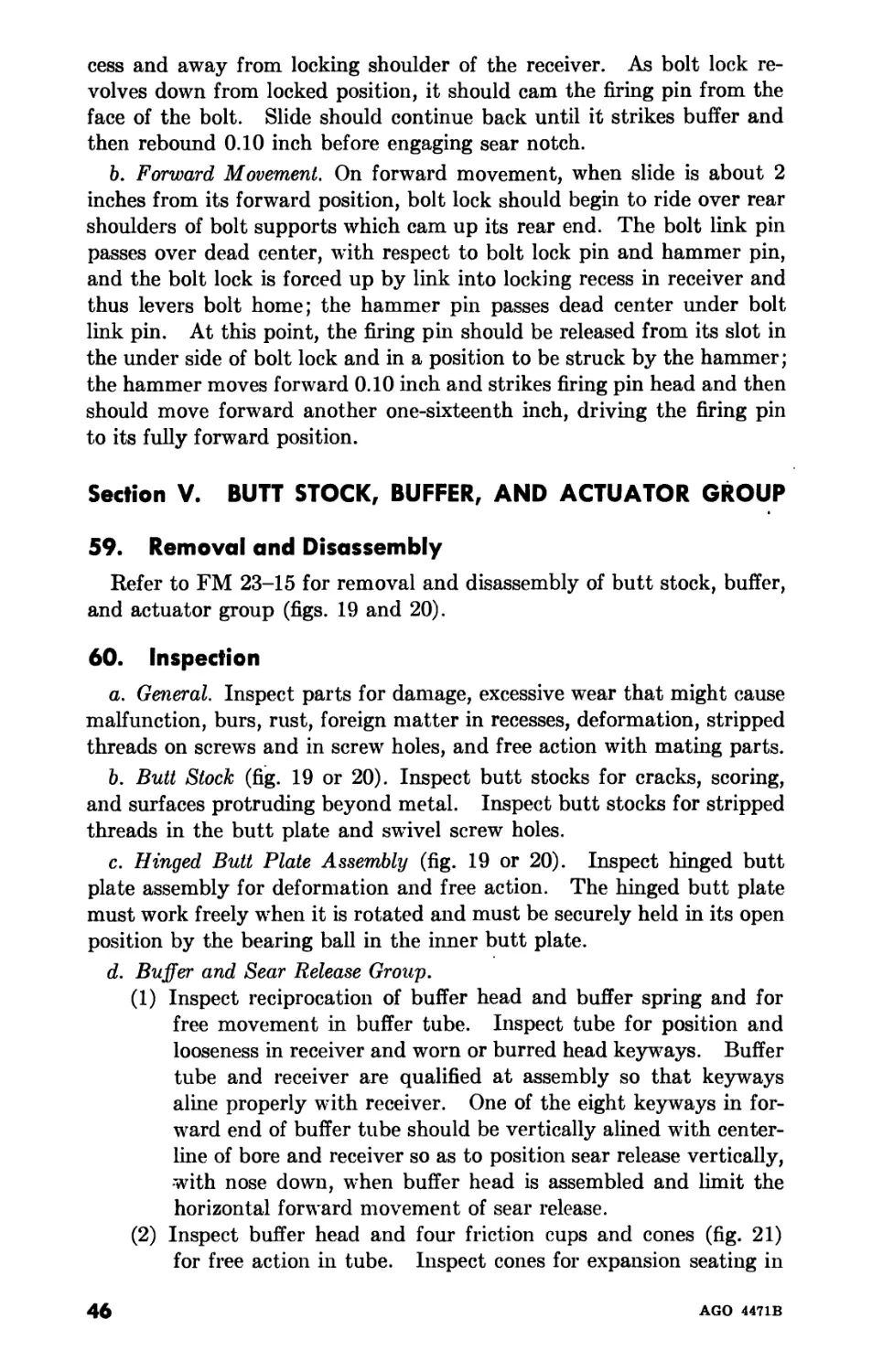
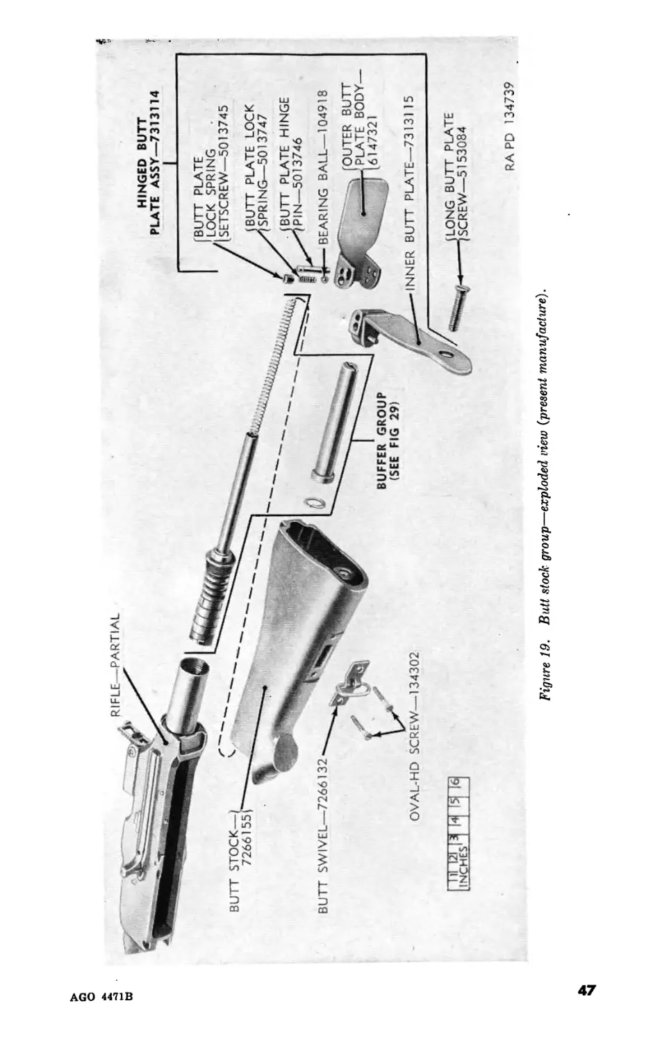
INTRODUCTION
Section I. GENERAL
1. Scope
a. These instructions are published for the use of personnel responsible
for field maintenance of this materiel. They contain information on
maintenance which is beyond the scope of the tools, equipment, or
supplies normally available to using organizations. This publication
does not contain information which is intended primarily for the using
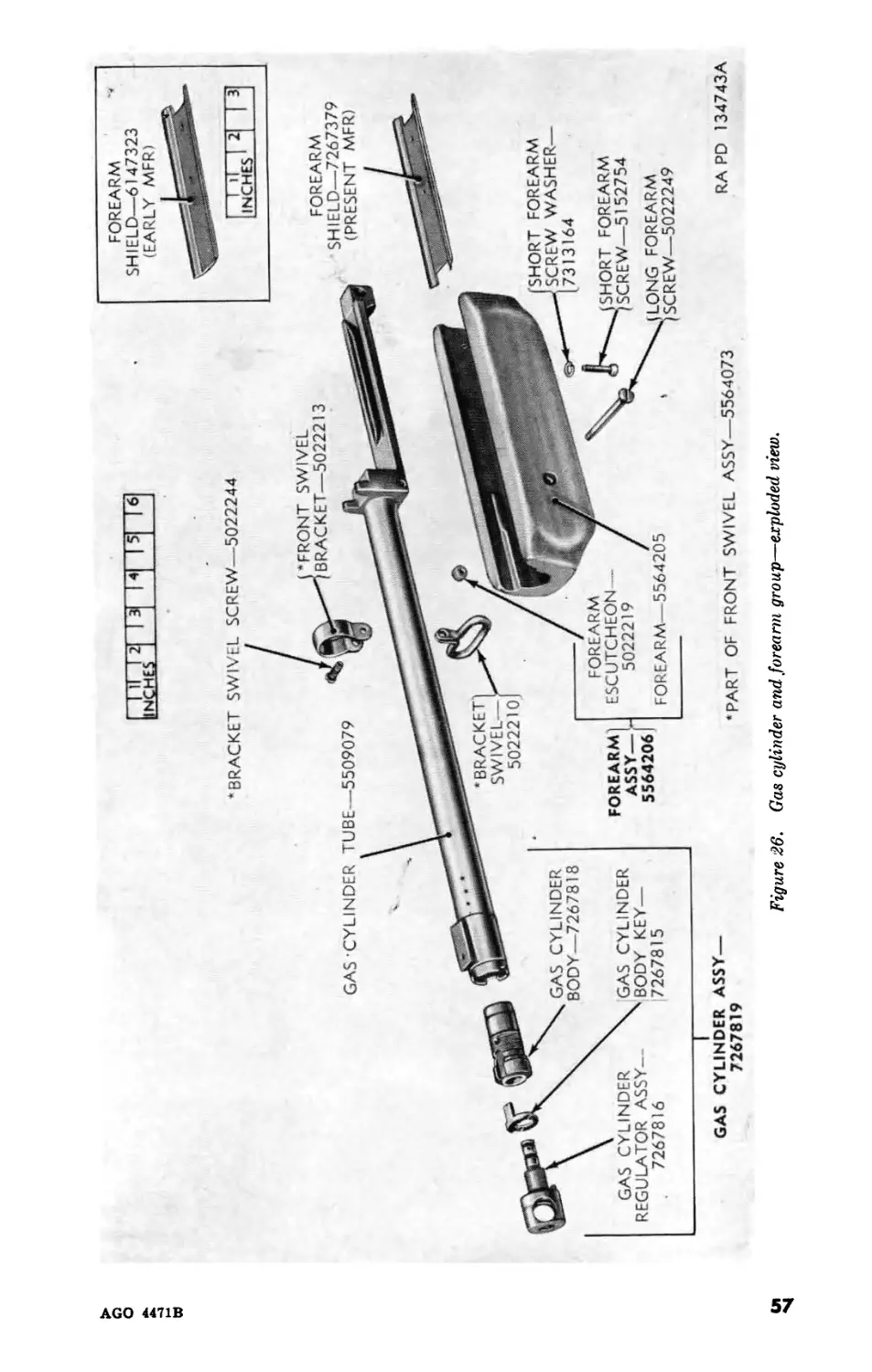
organization since such information is available to ordnance maintenance
personnel in FM 23-15.
b. This publication contains a description of and procedures for re-
moval, disassembly, inspection, repair, and assembly of the cal. .30
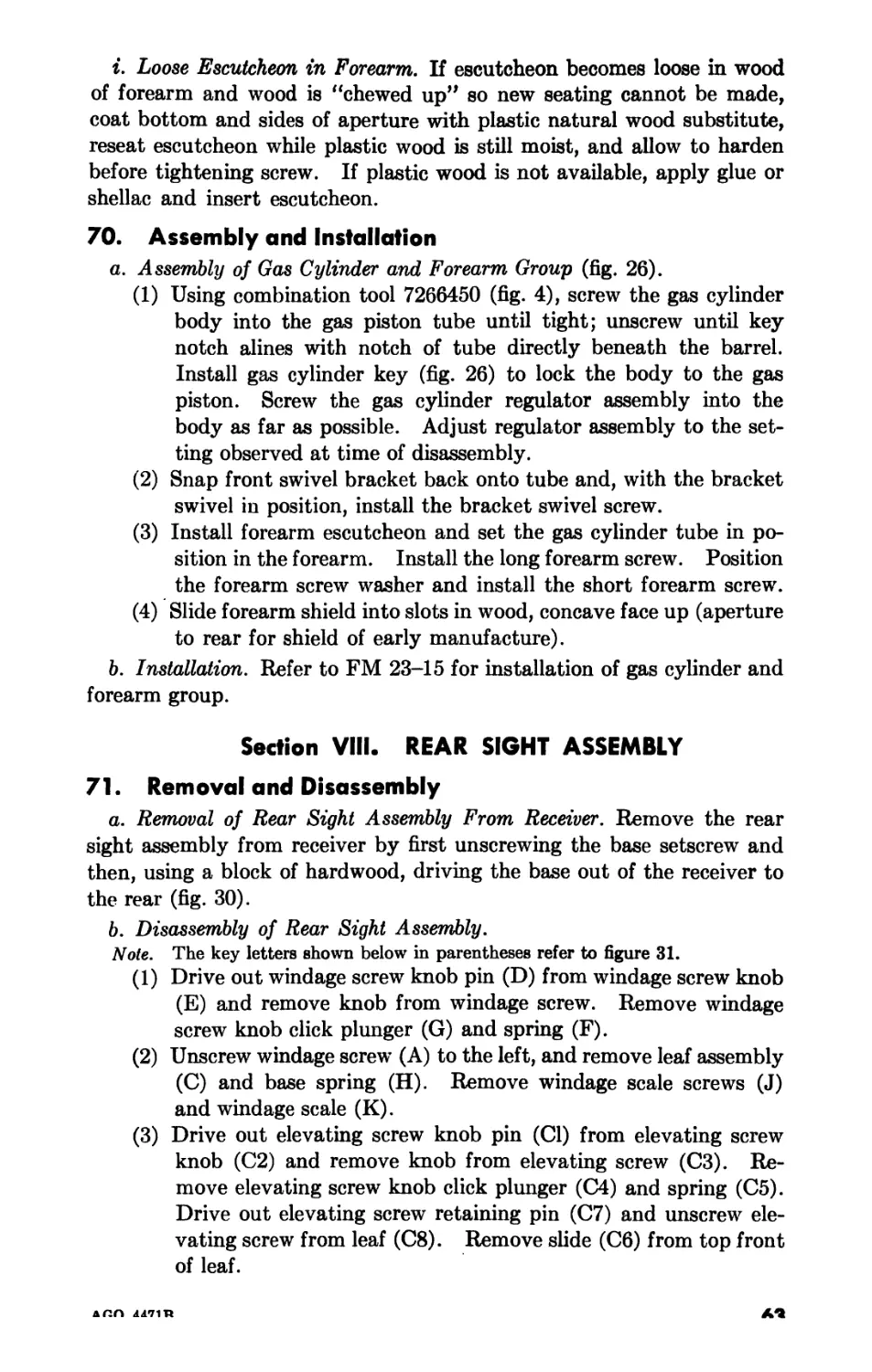
Browning automatic rifle M1918A2. The appendix contains a list of
current references, including supply and technical manuals, forms, and
other available publications applicable to the cal. .30 Browning auto-
matic rifle M1918A2.
c. FM 23-15 contains operating and lubricating instructions for the
materiel and all maintenance operations allocated to using organizations
in performing maintenance work within their scope.
d. This publication differs from TM 9-1211, as follows:
(1) Adds information on—
(a) Inspections.
(b) Cal. .30 jointed cleaning rod Ml.
(2) Revises information on—
(a) Field maintenance allocation.
(b) Forms, records, and reports.
(c) Parts, special tools, and equipment for field maintenance.
(d) Repair of the weapon.
2. Field Maintenance Allocation
The publication of instructions for complete disassembly is not to be
construed as authority for the performance by field maintenance units
of those functions which have been restricted to depot shops and arsenals.
In general, the prescribed maintenance responsibilities will apply as re-
flected in the allocation of maintenance parts listed in the appropriate
columns of ORD 8 SNL A-4. Instructions for depot maintenance are
to be used by maintenance companies in the field only when the tactical
situation makes the repair functions imperative. Provisions of parts
listed in the depot guide column of ORD 8 supply manual will be made
to field maintenance only when the maintenance to be performed has
been certified by a responsible officer of the requisitioning organization.
2
AGO 4471B
3. Forms, Records, and Reports
a. General. Responsibility for the proper execution of forms, records,
and reports rests upon the officers of all units maintaining this equip-
ment. However, the value of accurate records must be fully appreciated
by all persons responsible for compilation, maintenance, and use. Rec-
ords, reports, and authorized forms are normally utilized to indicate the
type, quantity, and condition of materiel to be inspected, repaired, or
used in repair. Properly executed forms convey authorization and serve
as records for repair or replacement of materiel in the hands of troops and
for delivery of materiel requiring further repair to ordnance shops. The
forms, records, and reports establish the work required, the progress of
the work within the shops, and the status of the materiel upon completion
of its repair.
b. Authorized Forms. The forms generally applicable to units main-
taining these weapons are listed in the appendix. For a complete listing
of all forms, see DA Pam 310-2. For instructions on use of these forms,
refer to FM 9-10.
c. Field Report of Accidents.
(1) Injury to personnel or damage to materiel. The reports necessary
to comply with the requirements of the Army safety program
are prescribed in detail in SR 385-10-40. These reports are
required whenever accidents involving injury to personnel or
damage to materiel occur.
(2) Ammunition. Whenever an accident or malfunction involving
the use of ammunition occurs, firing of the lot which malfunc-
tions will be immediately discontinued. In addition to any
applicable reports required in (1) above, details of the accident
or malfunction will be reported as prescribed in SR 700-45-6.
d. Report of Unsatisfactory Equipment or Materials. Any deficiencies
detected in the equipment covered herein, which occur under the cir-
cumstances indicated in AR 700-38 should be immediately reported in
accordance with the applicable instructions in cited regulation.
Section II. DESCRIPTION AND DATA
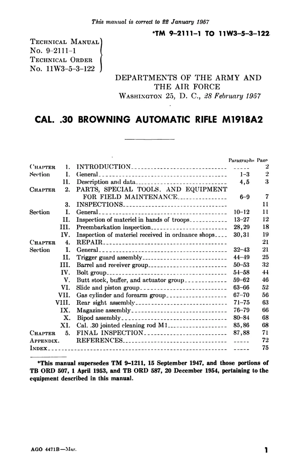
4. Description
(figs. 1 and 2)
a. The cal. .30 Browning automatic rifle M1918A2 is an air-cooled,
gas-operated, magazine-fed, shoulder-type weapon. It is primarily com-
posed of a barrel and receiver group, trigger guard assembly, gas cylinder
and forearm group, slide and piston group, rear sight assembly, buffer
group, hinged butt plate assembly, magazine assembly, bipod assembly,
and bolt group.
b. The trigger guard assembly, located on the bottom of the receiver,
acts as a housing for the trigger mechanism, ejector, magazine catch,
and cyclic change lever.
AGO 4471B
3
AGO 4471В
Figure 1. Cal. .30 Browning automatic rifle M1918A2—three-quarter left rear view.
AGO 4471В
RAPD 134695
Figure 2. Cal. .30 Browning automatic rifle M1918 A2—three-quarter right front view.
c. On the front of the receiver, just below the barrel, is the gas cylinder
and forearm group, within which the slide and piston group reciprocates,
actuated by gas pressure and the recoil spring.
d. The rear sight assembly is located on the top of the receiver just
forward of the butt stock.
e. Inside the butt stock is the buffer tube, which houses the buffer
group, composed of alternate cones and cups, and the actuator which,
combined with the actuator spring, operates in the passage formed by
the actuator tube.
/. The rear end of the stock is closed by the hinged butt plate assembly.
g. The magazine assembly, located on the bottom of the receiver to-
wards the front, holds 20 rounds.
h. The bipod assembly is mounted with the flash hider and bipod
bearing on the front of the barrel.
i. The bolt group, housing the firing pin and extractor, operates inside
the receiver.
j. The rifle is furnished with a cyclic rate mechanism housed in the butt
stock with a trigger guard mechanism. The cyclic rate mechanism al-
lows two rates of automatic fire, 550 rounds per minute (normal cyclic
rate) and 350 rounds per minute (slow cyclic rate).
5. Tabulated Data
Weight (complete with bipod and magazine
assemblies)____________________________
Weight (less bipod)___________________
Weight of bipod assembly______________
Weight of magazine assembly___________
Weight of moving parts________________
Weight of barrel______________________
Length of rifle_______________________
Length of barrel______________________
Length of rifling_____________________
Rifling:
Number of grooves_________________
Right-handed twist (one turn in)__
Depth of grooves__________________
Cross-sectional area of bore__________
Type of mechanism_____________________
Feeding device________________________
Capacity of feeding device____________
Rate of fire__________________________
Cooling system________________________
Sight radius__________________________
Trigger pull__________________________
Ammunition types______________________
19.4 lb
17 lb
-2.38 lb
0.44 lb
2.25 lb
3.65 lb
47.8 in.
24.07 in.
71.1 cal. (21.41 in.)
4
33.3 cal. (10 in.)
0.0040 in.
0.0740 sq in.
gas-operated
magazine
20 rds
(500 to 650 rds per min (fast automatic)
(300 to 450 rds per min (slow automatic)
air
31.125 in.
10 lb max; 6 lb min
ball; AP; tracer
6
AGO 4471B
CHAPTER 2
PARTS, SPECIAL TOOLS, AND EQUIPMENT FOR
FIELD MAINTENANCE
6. General
Tools and equipment and maintenance parts over and above those
available to the using organization are supplied to ordnance field main-
tenance units for maintaining and repairing the materiel.
7. Parts
Maintenance parts are listed in ORD 8 SNL A-4, which is the authority
for requisitioning replacements.
8. Common Tools and Equipment
Standard and commonly used tools and equipment having general ap-
plication to this materiel are listed in ORD 6 SNL’s J-8, Section 6 and
J-10, Section 2, and are authorized by TA and TOE.
9. Special Tools and Equipment
The special tools and equipment tabulated in table I are listed in ORD
6 SNL J-12. This tabulation contains only those special tools and
equipment necessary to perform the operations described in this publica-
tion, is included for information only, and is not to be used as a basis for
requisitions.
Note. Special tool sets in ORD 6 SNL J-12, in addition to special tools, also
contain standard and commonly used tools and equipment specifically applicable to
this materiel.
Table I. Special Tools and Equipment for Field Maintenance
Item Identifying No. References Use
Fig. Par.
BLOCK, vise, bbl holding, S. 6316006 4, 10 50a(2) To provide positive re- tention and prevent distortion of barrel when clamped in vise.
BRUSH, cleaning, chamber, cal. .30, Ml. 6528362 4 — To clean the chamber.
EXTRACTOR, rup- tured cartridge case, cal. .30, Mk II. 5507912 4 — For extracting ruptured cartridges.
FILLER, magazine, cal. .30. 5507913 4 — To aid in loading maga- zine rapidly.
AGO 4471B
7
Table I. Special Tools and Equipment for Field Maintenance—continued
Item Identifying No. References 1 Use
Fig. 1 Par.
GAGE, breech bore, cal. .30. 5564343 3 186, 51ti(2)(c), 88 To gage the lands at the breech end of the bar- rel to determine its serviceability.
GAGE, headspace, cal. .30, 1.940 in. 7319944 3, 5 276(1), 88 To gage the distance be- tween the shoulder of the chamber and the face of the bolt.
GAGE, headspace, cal. .30, 1.950 in. 7319954 3, 5 276(2), 88 To gage the distance be- tween the shoulder of the chamber and the face of the bolt.
GAGE, plug, NO GO, gas cyl, cal. .30, dia 0.053. 5077204 3, 28 23/, 686(3), 88 To gage the inside diam- eter of the gas cyl- inder.
GAGE, ring, NO GO, piston dia, cal. .30, 5077201 3, 25 206, 64c(2), 88 To gage the diameter of the piston.
dia 0.494.
REFLECTOR, bbl, cal. .30. 7265788 4 51a(2)(6) To provide a light re- flecting surface for vis- ual inspection of rifle bore without removing the barrel from re- ceiver.
ROLL, tool, canvas 6507389 4
empty, Ml 2.
TOOL, alinement, buffer tube, cal. .30. Composed of: 6316001 4, 16 53a(2) To position the buffer tube in receiver so that one of eight grooves in
PARALLEL 7113327 4, 16 53a(2) head of buffer tube lies
PLUG 7113326 4, 16 53a(2) centrally horizontal
SPACER 7113328 4, 13, 20 50c(5), 53a(2) with top of receiver.
TOOL, cleaning, gas cylinder. 7268211 3, 27 23/, 65a, 685(2) To remove carbon from gas cylinder and face of piston.
TOOL, comb 7266450 4 67b(4), 69c, 70a To assemble and disas- semble weapon (FM 23-15).
WRENCH single, open end, receiver 6316005 4, 10 50a(2) To remove receiver from barrel.
and bbl.
8
AGO 4471B
CAL .30 PISTON
DIA NO GO RING
7268211
GAGE—5077201
CAL .30 BREECH BORE
GAGE—5564343
1.940-IN. CAL .30
HEADSPACE GAGE-
7319944
CAL .30 GAS CYLINDER NO GO
PLUG GAGE—5077204
1.950-IN. CAL .30
HEADSPACE GAGE-
7319954
RA PD 91752D
Figure 3. Special tools for field maintenance.
AGO 4471B
9
О
AGO 4471В
..1.тг
INCHES
EMPTY CANVAS TOOL
ROLL Ml2—6507389
SPACER-
7113328
RECEIVER AND BARREL
OPEN-END WRENCH—6316005
CAL .30 CHAMBER
CLEANING BRUSH
Ml—6528362
COMBINATION
TOOL—7266450
PARALLEL—7113327
CAL. .30 BBL
REFLECTOR-
7265788
BARREL HOLDING VISE
BLOCK—6316006
CAL .30 MAGAZINE
FILLER—5507913
CAL. .30 RUPTURED
CARTRIDGE CASE
EXTRACTOR MK IL-
5507912
CAL. .30 BUFFER TUBE
ALINEMENT TOOL—6316001
RAPD 134733A
Figure 4- Special tools and equipment for field maintenance.
CHAPTER 3
INSPECTIONS
Section I. GENERAL
10. Scope
Paragraphs 10 through 31 provide specific instructions for the techni-
cal inspection by ordnance maintenance personnel of materiel either in
the hands of troops or when received for repair in ordnance shops. It
also briefly describes the in-process inspection of materiel during repair
and the final inspection after repair has been completed. Troubleshoot-
ing information is incorporated wherever applicable as a normal phase
of inspection.
11. Purpose of Inspections
Inspections are made for the purposes of (1) determining the condition
of an item as to serviceability, (2) recognizing conditions that would
cause failure, (3) assuring proper application of maintenance policies at
prescribed levels, and (4) determining the ability of a unit to accomplish
its maintenance and supply missions.
12. Categories of Inspection
In general, five categories of inspection are performed by ordnance
maintenance personnel.
a. Overall Inspection. This is a periodic overall inspection performed
by a contact party on materiel in the hands of troops and an inspection
performed by maintenance company personnel when materiel is evacu-
ated to the ordnance company. The inspection of evacuated materiel
is more thorough and includes check and repair of minor points that
should not be required in the inspection performed by a contact party.
b. Preembarkation Inspection. This inspection is conducted on materiel
in alerted units scheduled for oversea duty, to insure that such materiel
will not become unserviceable or worn out in a relatively short time. It
prescribes a higher percentage of remaining usable life in serviceable
materiel to meet a specific need beyond minimum serviceability.
c. In-Process Inspections. These are inspections performed in the
process of repairing the materiel. This is to insure that all parts con-
form to the prescribed standards, that the workmanship is in accordance
with approved methods and procedures, and that deficiencies not dis-
closed Iw the preliminary inspection are found and corrected. Detailed
instructions are contained in chapter 4.
d. Final Inspection. This is an acceptance inspection performed by a
final inspector after repair has been completed, to insure that the materiel
is acceptable for return to user according to the standards established.
Detailed instructions are contained in chapter 5.
AGO 4471B
11
e. Spot-Check Inspection. This is a periodic overall inspection per-
formed on only a percentage of the materiel in each unit, to determine
the adequacy and effectiveness of organizational and field maintenance.
Section II. INSPECTION OF MATERIEL IN HANDS OF TROOPS
13. Precautions
Before starting a technical inspection, be sure to clear the weapon. Do
not touch the trigger until the weapon has been cleared. Inspect the
bore and chamber to insure that they are empty and check to see that
no ammunition is in position to be introduced. Avoid having live am-
munition in the vicinity of the work.
14. General
a. Refer to TM 9-1100 for responsibilities and fundamental duties of
inspecting personnel, the necessary notice and preparations to be made,
forms to be used, and general procedures and methods to be followed by
inspectors. Materiel to be inspected includes organizational spare parts
and equipment and the stocks of cleaning and preserving materials.
b. Check to see that the weapon has been cleaned of all corrosion-
preventive compound, grease, excessive oil, dirt, or foreign matter which
might interfere with proper functioning or obscure the true condition of
the parts.
c. Make an overall inspection of the weapon for general appearance,
condition, operation, and manual functioning. Use dummy or drill
cartridges.
d. Determine serviceability, i. e., the degree of serviceability, com-
pleteness, and readiness for immediate use, with special reference to safe
and proper functioning of the materiel. If the materiel is found service-
able, it wdll be continued in service. In the event it is found unservice-
able or incipient failures are disclosed, the deficiencies wdll be corrected
on the spot or advice given as to corrective measures when applicable,
or, if necessary, the materiel wdll be tagged for delivery to, and repair by,
ordnance maintenance personnel.
e. Determine causes of mechanical and functional difficulties that
troops may be experiencing and check for apparent results of lack of
knowledge, misinformation, neglect, improper handling and storage, se-
curity, and preservation.
f. Check on application of all urgent modifications, and if any un-
authorized alterations have been made, or if work beyond the authorized
scope of the unit is being attempted, MWO ORD A4-W6 which provides
the rifle with the latest gas cylinder assembly is considered mandatory;
however, also check DA Pam 310-4 and the current modification work
order files for any additional work orders promulgated subsequent to
this printing.
12
AGO 4471B
g. Instruct the using personnel in proper preventive-maintenance
procedures where found inadequate.
A. Check on completeness of the organizational maintenance allow-
ances and procedures for obtaining replenishments.
i. Satisfactory metal finishes for weapons range from dense black to
medium light gray. Certain small arms weapons are manufactured with
an unusual shade of neutral gray finish. Since this finish (gray zinc
phosphate) is an accepted Department of the Army standard, these
weapons will not be rejected by inspectors or troops for this condition.
Rigid restrictions on shiny metal surfaces will not be carried to an ex-
treme. A worn surface is objectionable from the standpoint of visibility
when it is capable of reflecting light, somewhat as a mirror does. Check
to see that all rear sights have a dull black or gray finish on all surfaces.
j. Wooden components must not be cracked in such a way as to inter-
fere with the structural strength. Surface cracks, bruises, or dents that
do not affect their strength should not cause rejection.
k. Light pitting of the barrel, even though plainly visible, is not cause
for rejecting a weapon. It does not affect the accuracy materially, but
is a disadvantage because it interferes with subsequent cleanings. A
barrel that is uniformly pitted out with the edges of the lands sharp is
acceptable, provided the breech bore reading of the barrel is satisfactory.
Only those barrels showing developed pits or pits cutting into the lands
are unsatisfactory. Pits in the chamber large enough to cause extraction
difficulties wall be cause for rejection. Ringed bores or bores ringed suf-
ficiently to bulge the outside surface are cause for rejection.
Z. Looseness and play in such components as sights, gas cylinders, etc.,
may be cause for rejection. In many cases, however, the importance of
such defects is exaggerated. Looseness and play must be considerable
to affect the accuracy of a weapon beyond its natural dispersion. All
weapons, especially automatic guns, must have play between working
components to permit them to operate in localities where sand and d\ist
are prevalent. A weapon may be completely useless if its working parts
are fitted with insufficient clearance.
m. Minor defects in metal components do not normally affect their
being acceptable. Scratches and tool marks on barrels are ordinarily of
no importance.
15. Rifle
a. Hand-operate and check assemblies and parts for functioning and
smoothness of operation.
b. Inspect fit of magazine in receiver and functioning of magazine
catch and catch release with magazine.
c. Using magazine and dummy cartridges, test the loading function of
bolt and functioning of the extractor and the ejector. When inspecting,
use a serviceable magazine, as a worn retaining lug on the magazine may
allow maglzine to drop, thus affecting the feed function of the bolt.
AGO 4471B
13
d. Inspect locking action of bolt lock and bolt.
e. Fire several rounds of service ammunition, and examine primers of
fired casings. If primer shows indications of being set back in firing pin
hole of bolt, due to an enlarged firing pin hole or recessive wear of bolt
face, replace the bolt.
Warning: Test-fire when and where conditions permit, considering
safety and expediency.
16. SIGHTS
a. Check front sight base for looseness on the barrel, and check blade
for looseness in the base.
b. Blade must be straight and top of the blade square and properly
darkened.
c. Inspect rear sight base for looseness on receiver.
d. Inspect windage scale for looseness on base.
e. Check spring for functioning.
f. Inspect functioning of elevating screw and leaf with slide. Both
must operate freely and retain setting.
g. Windage knob will turn freely by hand and retain set. An accept-
able dull finish is required on all parts.
17. Bipod Group
a. Inspect bipod assembly for proper fit on flash hider bearing.
b. Inspect bipod assembly for looseness on barrel.
c. Inspect for missing or broken friction washer and sight cover.
d. Sliding legs will move readily to any position and will be locked and
held by the bipod leg thumbscrews.
18. Barrel and Receiver Group
Note. Weapon must be field-stripped (FM 23-15) to perform pertinent gage
checks.
a. Inspect headspace as described in paragraph 27.
b. Check breech bore dimension, using breech bore gage 5564343
(fig. 3). Insert the gage into the chamber. Looking through the ejec-
tion port and using the calibrated scale of the gage, read indication that
appears just flush with the rear face of the barrel. It should be 0.310
inch or less.
c. Inspect receiver for wear, burs, rust, and foreign matter.
d. Inspect for loose bolt supports.
e. Inspect bolt lock recess in top of receiver. Check especially where
lock seats when bolt is locked. Burs here will affect headspace.
f. Inspect operating handle for functioning and free movement in
slideways. Inspect plunger for free movement and spring tension.
g. Top plate should not be loose and a drive fit is required.
14
AGO 4471B
19. Bolt Group
a. Inspect firing pin hole for out-of-round.
b. Check firing pin protrusion. It should be approximately three
thirty-seconds inch.
c. Check firing pin for broken point, wear, burs, and fracture.
d. Remove extractor. Check spring for set or fracture, and check lips
of extractor for wear.
e. Check bolt link and lock for excessive wear, burs, and galling.
Check holes for out-of-round.
20. Slide and Piston Group
a. Check fit between piston and slide.
b. Total endplay of piston should approximate one-eighth inch in any
direction and face of piston must not strike gas cylinder body when slide
is in fully forward position. Gage piston, using NO GO gage 5077201
(fig. 3). Piston head should not enter gage. To gage, first clean piston
thoroughly of &11 carbon and fouling, and determine that surfaces of head
ring are smooth and polished. Wipe piston head and gage with a slightly
oiled cloth and try to pass gage over piston head. (Only light pressure
should be exerted on gage.)
c. Inspect slide for burs, deformation, galling, or battered rear end.
d. Check hammer pin hole for out-of-round.
21. Trigger Guard Assembly
a. Check functioning by hand operation.
b. Check change lever for movement in all positions and ability to re-
tain setting.
c. Check ejector for burs, fracture, or deformation.
d. Check all springs for tension and set.
e. Check magazine release and catch for proper functioning.
22. Buffer and Actuator Group
a. Check actuator for free movement in actuator tube.
b. Check actuator spring for kinks, rust, and free length.
c. Check buffer head assembly for burs, missing key, and sear release
for free movement and correct assembly. Check cones and cups for set
and proper assembly.
23. Gas Cylinder Group
a. Inspect gas cylinder for dents, cracks, deformation, and distortion.
b. Check gas port in the gas cylinder body to be sure it is free of car-
bon or other foreign matter.
c. Check gas cylinder body for burred or stripped threads.
AGO 4471B
15
d. Check the three gas ports in the gas regulator for carbon or other
foreign matter.
e. Be sure that dust shield is present.
f. Inspect gas cylinder body for wear, using gas cylinder gage 5077204
(fig. 3). This is a NO GO gage and should not enter the gas cylinder
body. Before gaging the cylinder, clean thoroughly to remove all car-
bon deposits and foreign matter, using gas cylinder cleaning tool 7268211
(fig. 4). Use crocus cloth to polish, and if necessary, wipe cylinder and
gage with a slightly oiled cloth and try to insert gage into cylinder. If
the gage enters, it is unserviceable. (Only light pressure should be ex-
erted on gage.)
24. Stock and Forearm Group
a. Butt plate will fit properly and screws will not be stripped or have
mutilated heads.
b. Butt swivel will be secure, screws will not be mutilated, and swivel
screw will be tight and staked.
c. Butt stocks will be checked for warping, loose fit, and cracks.
d. Forearm will be inspected in accordance with instructions in para-
graph 14J.
25. Trigger Pull
a. Test trigger pull for smoothness and pressure exerted. Trigger pull
should be clean, without creep, and smooth in action. The force exerted
to release slide is not less than 6 pounds, nor more than 10 pounds. If the
pull is rough, not within specified limits, or excessive creep is present,
check for wear or burs on sear and slide notch or for interference between
trigger and housing.
Note. The word “creep” is interpreted to mean any perceptible movement in the
trigger pull between the time the slack is taken up and the slide is released, with
pressure applied at a uniform rate of increase over a period of not less than 10 seconds.
b. In testing trigger pull of rifles, the inspector will use two weights,
one of 6 pounds and one of 10 pounds.
c. Check to insure that the change lever is set at the A or F position
and that the rifle is cocked. Rest the trigger weight on the floor or
ground, and insert the hook of trigger weight wire through the trigger
guard body bow to bear on the trigger, so that pressure is applied one-
quarter inch from the lower end or tip of trigger. With the barrel of the
rifle held at a 30° angle to the vertical, carefully raise the weight from the
floor. If the 6-pound weight pulls or the 10-pound weight fails to pull
the trigger to release the slide, correct (par. 46e). Exercise care during
the test to determine that the wire contacts the trigger only, that it
does not rub against the trigger guard body or stock, and that wire and
axis of bore are parallel and perpendicular.
16
AGO 4471B
26. Equipment
a. Make sure all spare parts and equipment are on hand and in good
condition.
b. Slings will be complete assemblies with keepers, frogs, and hooks
attached. Leather slings will be soft and pliable. When the sling is
bent double over a 1-inch round bar, there should be no cracking of the
leather. Leather slings will not be issued when the present supply is
depleted. Web slings will not be rotted or badly stained. Special
attention should be given to the points at which metal is attached, to
see that rust has not weakened the sling. Slightly soiled web slings may
be scrubbed with a mild s "o. However, care should be taken to pre-
serve the olive-drab color
27. Headspace
a. General.
(1) Definition. Headspace oi ? cal. .30 Browning automatic rifle
M1918A2 is the distance between the shoulder of the chamber
and the face of the bolt when the bolt is in “locked position.”
(2) Effect of headspace on operation. If headspace is insufficient, the
bolt does not fully lock behind the cartridge without being
forced. If headspace is excessive, the cartridge has too much
play in the chamber when the bolt is locked behind it. Either
condition is unsafe.
(3) Causes of variation in headspace. As component parts of the rifle
are manufactured to close tolerances and headspace is carefully
checked at manufacture, a variation usually is due to wear,
causing excessive headspace to develop. However, assembly
of parts with maximum tolerances results in either excessive or
insufficient headspace. Excessive headspace due to wear is
caused by advanced chamber shoulder in the barrel, worn face
of bolt, worn locking shoulder of bolt lock, or worn locking
recess in receiver.
b. Gaging Headspace (fig. 5). Headspace is gaged with the firing pin
and extractor removed from the bolt, recoil spring and guide removed
from the slide and piston group, operating handle removed from the re-
ceiver, and the trigger guard assembly removed from the rifle. With the
inspector’s bore reflector, examine the chamber to make certain that it is
clean. Place the bolt assembly (minus firing pin and extractor), with
bolt link assembled, in the receiver. Then install the slide and piston
group (minus spring and guide), and fit the hammer into its seat in slide
and insert hammer pin. Work the slide back and forth several times by
hand to insure that the parts are correctly assembled. Install the gas
cylinder and forearm group, and lock it in position with gas cylinder re-
taining pin. With slide pushed fully forward, note the relative position
of the hammer pin with reference to the forward part of its slot inside ot
AGO 4471B
17
receiver. It will be found that there is a clearance of from one thirty-
second to three sixty-fourths inch between the hammer pin and the for-
ward part of the slot. This position of the hammer pin is referred to as
the “locked position.”
POSITION OF HAMMER PIN WITH HEAD
SPACE GAGE-7319954 IN CHAMBER
SHOULD NOT BE LESS THAN
3/8 INCH FROM "LOCKED POSITION"
POSITION OF HAMMER PIN WHEN IN
"LOCKED POSITION" WITH HEADSPACE
GAGE-7319944 IN CHAMBER SHOULD
BE FROM 1/32 TO 3/64 INCH
Figure 5. Gaging headspace.
(1) Minimum headspace. To test for minimum headspace, place the
1.940-inch headspace gage 7319944 (fig. 3) in the chamber and
move the slide forward. Note the position of the hammer pin.
It should be in the locked position (fig. 5). If the hammer pin
is in the locked position, the minimum headspace is correct.
If the hammer pin is stopped before reaching the locked posi-
tion, the headspace is insufficient and should be corrected
by depot maintenance.
Note. Never use force against the gage to obtain locked position.
(2) Maximum headspace. To test for maximum headspace, place
the 1.950-inch headspace gage 7319954 (fig. 3) in the chamber
and move the slide forward until stopped by the gage. Note
position of hammer pin. It should be not less than three-eighths
inch from the locked position (fig. 5). If the hammer pin is not
stopped on or before it is in this, position, the headspace is ex-
cessive and should be corrected by depot maintenance.
Section III. PREEMBARKATION INSPECTION
28. Rifle
a. Proceed as in paragraphs 13 through 27 and in b and c below.
b. Do not reject the rifle for oversea use unless exterior parts have a
distinct shine; also, bright rear sights will not be permitted on weapons
for oversea use.
c. The breech bore dimension (par. 186) should be 0.306 inch or less.
18
AGO 4471B
29. Organizational Spare Parts, Tools, and Equipment
Examine all spare parts, tools, and equipment for completeness and
serviceability. Replace any defective items. It is not normally neces-
sary to inspect items in sealed packages, since they have been inspected
for serviceability prior to packaging and during storage.
Section IV. INSPECTION OF MATERIEL RECEIVED IN
ORDNANCE SHOPS
30. General
A technical inspection similar to that in paragraphs 14 through 27 is
performed. In addition, the extent of repairs necessary is determined
and an estimate is made of the parts required. A troubleshooting inspec-
tion is performed, as necessary, to localize malfunctions and apply cor-
rective measures.
31. Troubleshooting
Table II lists malfunctions, their probable causes, and proposed cor-
rective actions. For troubleshooting information within the scope of
organizational maintenance, see FM 23-15.
Table II. Troubleshooting
Malfunction Probable causes Corrective action
Failure to feed Dirty or dented magazine body. Weak or broken maga- | zine spring. Worn or broken magazine catch. Replace magazine (pars. 76 and 79). Replace magazine (pars. 76 and 79). Replace magazine catch (pars. 44 and 47).
Failure of slide to cock -. _ 1 Damaged sear or sear notch in slide. । Broken sear spring Burs or foreign matter in sear notch. Failure of bolt to retract । ; sufficiently. Replace slide or sear (pars. 44 and 47). Replace sear spring (pars. 44 and 47). Clean and remove burs (pars. 44 and 47). Correct (pars. 44 and 47). i
Failure to fire Weak recoil spring Worn or broken firing pin. Worn or broken sear spring. Defective sear or hammer.! i Replace recoil spring (pars. 63 and 66). Replace firing pin (pars. 54 and 57). Replace sear spring (pars. 44 and 47). Replace sear (pars. 44 and 47) or hammer (pars. 54 and 57).
Weak ejection Worn ejector ' Repair ejector (pars. 44 and
AGO 4471B
19
Table II. Troubleshooting—continued
Malfunction Probable causes Corrective action
Failure to eject Dirty or clogged gas ports. Broken ejector Weak or broken ejector lock and/or ejector lock spring. Clean and properly adjust gas cylinder assembly (pars. 67 and 70). Replace ejector (pars. 44 and 47). Replace ejector lock and/or spring (pars. 44 and 47).
Failure to extract Damaged or broken ex- tractor claw. Broken or missing ex- tractor spring. Replace extractor (pars. 54 and 57). Replace extractor spring (pars. 54 and 57).
Failure to pull off with Sear spring not correctly Reposition sear spring (pars.
change lever set at F or A. Muzzle depressed. | positioned. i 44 and 47).
20
AGO 4471B
CHAPTER 4
REPAIR
Section I. General
32. General
a. Information and instructions contained herein are supplementary
to instructions for the using organization contained in FM 23-15.
b. In this publication, the main groups of the weapon are disassembled,
inspected, replaced or repaired, and assembled. For information on dis-
assembly of the weapon permitted by organizational maintenance per-
sonnel, refer to FM 23-15.
33. Cleaning and Lubrication
a. General. Refer to FM 23-15 for using arms information on cleaning,
cleaning agents, and precautions to be observed in cleaning. Informa-
tion for ordnance personnel is given in b through e below.
b. Cleaning Materiel Received From Storage.
(1) Materiel received in ordnance shops from storage will be cleaned
by any available applicable cleaning process (TM 9-1005).
(2) If some time is to elapse before the start of repair or rebuild
operations, apply a light grade of preservative oil to all polished
metal surfaces to prevent rusting.
c. Cleaning After Repair. After repair operations and prior to as-
sembly, remove shop dirt and other foreign matter from all metal sur-
faces by any available applicable cleaning process (TM 9-1005).
d. Cleaning After Shop Inspection. After in-process shop inspections,
dip parts in a tank containing fingerprint remover oil (type A), remove
(use rubber gloves), and dry thoroughly with dry, compressed air (pro-
vided with moisture filter traps) or by wiping with clean, lint-free, dry
cloths. Apply preservatives as soon as possible after cleaning.
e. Lubrication. Oil and lubricate the rifle in accordance with instruc-
tions in FM 23-15. General instructions on lubrication are covered in
TM 9-2835. Lubricating materials are listed in ORD 3 SNL K-l and
their uses are explained in TM 9-850.
34. General Repair Methods
a. Disassembly and Assembly Procedures.
(1) In disassembling a unit, remove the major subassemblies and
assemblies whenever possible. Subassemblies may then be dis-
assembled, as necessary, into individual parts.
(2) During assembly, subassemblies should be assembled first and
then installed to form a complete unit.
AGO
4471B
21
(3) Complete disassembly of a unit is not always necessary in order
to make a required repair or replacement. Good judgment
should be exercised to keep disassembly operations to a mini-
mum.
b. Replacement of Parts.
(1) Unserviceable and unrepairable assemblies will be broken down
into items of issue and serviceable parts will be returned to
stock. Parts or assemblies that cannot be repaired or re-
claimed to the standards set forth in this publication will be re-
placed as indicated.
(2) When assembling a unit, replace taper pins and cotter pins with
new ones, if possible. If screws or nuts are damaged, they
should be replaced.
(3) All springs should be replaced if they are broken, kinked, cracked,
or fail to function properly.
(4) If a required new part is not available, reconditioning of the
old part is required. Such parts should be examined carefully
after reconditioning to determine their serviceability.
c. Use of Tools.
(1) Care must be exercised to use tools that are suitable for the task
to be performed, in order to avoid mutilation of parts and/or
damage to tools.
(2) Special tools (ch. 2) are provided for maintenance of the rifle.
These tools should be used only for the purpose for which they
are intended.
d. Welding and Riveting. For welding instructions and welding ma-
terials, refer to TM 9-2852 and ORD 3 SNL K-2.
e. Repairing Damaged Threads. Damaged threads should be repaired
by use of a thread restorer or by chasing on a lathe.
f. Finished Surfaces. Repaint all surfaces on which paint has deteri-
orated or become damaged (TM 9-2851).
35. Removal of Excessive Carbon and Rust
Light rust and carbon may generally be removed with a cloth moistened
with light oil or rifle-bore cleaner solvent cleaning compound. If this
does not suffice, crocus cloth or fine abrasive cloth may be used. Care
should be observed not to scratch or alter surfaces cleaned and to thor-
oughly remove all dirt and abrasive before assembling the parts. Avoid
the use of any abrasive that- may remove phosphate coating, zinc plating,
or cadmium plating.
36. Removal of Burs From Threads, Screwheads, and Working
Surfaces
During the entire life of the weapon, polishing and stoning are neces-
sary to relieve friction and to remove burs set up by firing. Burs on
22
AGO 4471B
screwheads, threads, and like surfaces should be removed with a fine file.
Burs or roughness on working surfaces should be removed with a fine
sharpening stone.
Caution: Care should be observed to stone and file evenly and lightly
and not to remove more metal than is absolutely necessary and to main-
tain correct contour of surfaces worked on. Parts or assemblies should
never be altered in any way that would affect interchangeability of parts.
37. Wooden Components
Dents or mutilations that do not affect strength or general appearance
may be sanded out. Wood dough (plastic wood substitute) may be
used, if practicable. Unvarnished wooden components, such as hand
guards, will be sanded all over. Patching is pemitted where strength
is not affected. Components cracked in such a manner that strength is
affected will be replaced. Unvarnished wooden components should be
treated with fungicide solution G-4 (powdered form) mixed in linseed oil
mixture.
38. Repair of Damaged Machined and Polished Surfaces
Rough spots, scores, burs, galling, and gouges will be smoothed so that
the part will efficiently perform its normal function. The finish of the
repaired part will approximate that of the original finish. In performing
any of these operations, critical dimensions will not be altered.
39. Barrels
a. Barrels will be free of corrosion, powder fouling, bulges, and rings.
Muzzles will be free of burs. Fine pits are allowed if they do not affect
the sharpness of lands materially. Pits are allowed in the chamber if
they are not large enough to cause extraction difficulties. Barrels will
be replaced if lands are worn to the extent that accuracy is affected or if
pits are as wide as the lands, grooves, or are more than three-eighths
inch long.
b. Powder burns, exterior irregularities, and deformations not affecting
the functioning or appearance are acceptable.
40. Springs
Replace all springs that are corroded, weak, or distorted.
41. Functioning of Safeties
Test all manually operated safety features for satisfactory operation.
42. Function-Firing
a. Following repair, fire each rifle as follows, if facilities are available
in third or fourth echelon:
Rounds Gas port Change lever position
20 Medium Full Automatic
20 AGO 4471B Medium Reduced automatic 23
If weapons do not function satisfactorily, additional rounds are author-
ized. Weapons that fail to meet the test are to be corrected by replace-
ment of defective component or by performing such repair as required.
b. All weapons will be cleaned as soon as possible after all firing tests
have been completed and each day thereafter for 3 days, making a total
of 4 consecutive days. An alternate method of scheduling cleaning op-
erations is to clean all weapons immediately after function-firing and two
successive times following the first cleaning; cleaning intervals should
be at least 16 hours with not more than 72 hours between any two suc-
cessive cleanings.
c. Special care should be taken to insure that bolt faces, pistons,
breech end of receiver, and other parts subjected to burned powder resi-
dues are thoroughly cleaned. These parts should be scrubbed with a
bristle brush moistened with rifle-bore cleaner solvent cleaning com-
pound.
d. A single cleaning of the bore and chamber of function-fired weapons
with steam or hot water (not less than 200° F.) is acceptable in lieu of the
cleaning in b above. The steam or hot water may be applied by hand
or machine and the bore and chamber air-dried. The bore and chamber
will then be scrubbed with a snug-fitting wire brush dipped in rifle-bore
cleaner solvent cleaning compound. Three dry patches will then be
passed through the bore and chamber, followed by one patch saturated
with prescribed oil.
43. Operations Route Sheet
The information in table III illustrates the sequence of operations neces-
sary during repair of the weapon. Special machines, tools, and gages
required for an operation are indicated opposite the operation.
Table III. Operations Route Sheet for Cal. .30 Browning Automatic Rifle M1918A2
Operation No. Operation | Machine 1 Tools j Gages
1 Unpack.
2 Degrease See TM
9-1005.
3 Record serial numbers.
4 Disassemble into subassemblies 7266450
5 Disassemble subassemblies 7266450
6 Clean all parts.
7 Inspect wooden components. 1
8 Inspect metal components:
Inspect for excessive wear in 1
bolt lock shoulder in receiver. i
Inspect bolt assembly. Inspect gas cylinder 1 , 5564144 5077204
Inspect gas piston | 5077201
24
AGO 4471B
Table III, Operations Route Sheet for Cal. .30 Browning Automatic Rifle
M1918A2—continued
Operation No. Operation Machine Tools Gages
9 10 Inspect all other parts for ser- viceability. Remove barrel from receiver if necessary. Inspect barrel and receiver: Inspect barrel visually for pits and dents. Inspect bore Vise 6316006, 6316005 7265788 5564343
11 12 13 14 15 16 17 18 19 20 21 22 23 24 25 26 27 28 29 Assemble barrel to receiver or re- barrel if necessary. Do necessary repairing of parts as required. Inspect. Do necessary polishing of parts as required. Inspect. Repair and sand stocks and fore- arms. Inspect. Sandblast parts requiring refinishing. Refinish. Inspect. Assemble subassemblies Assemble subassemblies to rifle Inspect. Function-fire. Do necessary repairing. Note. Do operations 23 and 24 again if repair is performed. Clean rifle. Final inspection. Record serial number. Preserve and pack. Vise 6316006, 6316005 7266450 7266450
Section II. TRIGGER GUARD ASSEMBLY
44. Removal and disassembly
Refer to FM 23-15 for removal and disassembly of the trigger guard
assembly (fig. 6).
45. Inspection
a. General. Inspect all parts for damage and excessive wear that
might cause malfunction, burs, rust, foreign matter in recesses, deforma-
tion, and free action with mating parts.
b. Trigger {Riveted) (figs. 6 and 7). Inspect trigger for full action on
pin with respect to guard. Inspect connector pin to see if it is riveted
securely in place. Rear projections at the heel of trigger must be free
AGO 4471B
25
SEAR SPRING—6019662-
SEAR—5564299
COUNTERRECOILj
SPRING—5153133,
SEAR RELEASE STOP
LEVER—6147487
EJECTOR—6019639
SEAR CARRIER—6147499
EJECTOR LOCK—/
5022225f
MAGAZINE CATCH SPRING—5153130
TRIGGER—6019684,
TRIGGER CONNECTOR—6019636
MAGAZINE
CATCH-
SEAR PIN—5022237
,TRIGGER GUARD
' BODY—6535470
EJECTOR LOCK/
SPRING—5153132J
CHANGE AND
STOP LEVER
SPRING—6147490
STGHT
PIN—5022238
AGO 4471В
INCHES
MAGAZINE RELEASE—5022242
CHANGE
LEVER-
5509071
RAPD 134734
Figure 6. Trigger guard assembly—exploded view.
AGO 4471В
82 DEG 30 MIN
MAGAZINE CATCH-
5022216
TRIGGER
CONNECTOR-
6019636
TRIGGER ASSY-
6019684
Ю
Figure 7. Important points to be inspected on trigger guard assembly parts.
CHANGE LEVER—
5509Q71
SEAR CARRIER
—6147499
RA PD 91755D.’
of wear that would affect operation of safety. Top rear comer should
be sharp, not beveled, at point where it enters the notch in change lever.
Inspect heel and tip for sufficient clearance with bore of guard for full
retraction.
c. Trigger Connector (figs. 6 and 7). Inspect top bearing surface of
trigger connector where it contacts sear and sear release stop lever. This
is a critical surface, as excessive wear or burs may affect function of sear
and stop lever. Inspect rear toe of connector where it contacts tongue
in change lever aperture and front sloping surface (sear carrier ramp) for
wear and burs. Profile must be clearly defined and all operating and
camming surfaces free of excessive wear that may affect functioning.
d. Sear (figs. 6 and 7). Inspect sear for looseness on pin. Inspect sear
pin for undue wear at ends and for burs. (Wear of pin at end is in-
creased due to movement in elongated hole in trigger guard.) Inspect
sear for deformation, wear, and burs on forward lower camming surface
contacting connector and on rear upper camming surface contacting sear
release. Rear beveled camming surface must be perfectly smooth.
Inspect sear notch faces (rear and top) for wear and burs. Sear notch
should be smooth and free from knife or wire edge.
Note. Sear pin holes in trigger guard and trigger pin holes in sear carrier are
elongated to allow play of mechanism, relative to counterrecoil spring, to absorb jar
of counterrecoil on the mechanism.
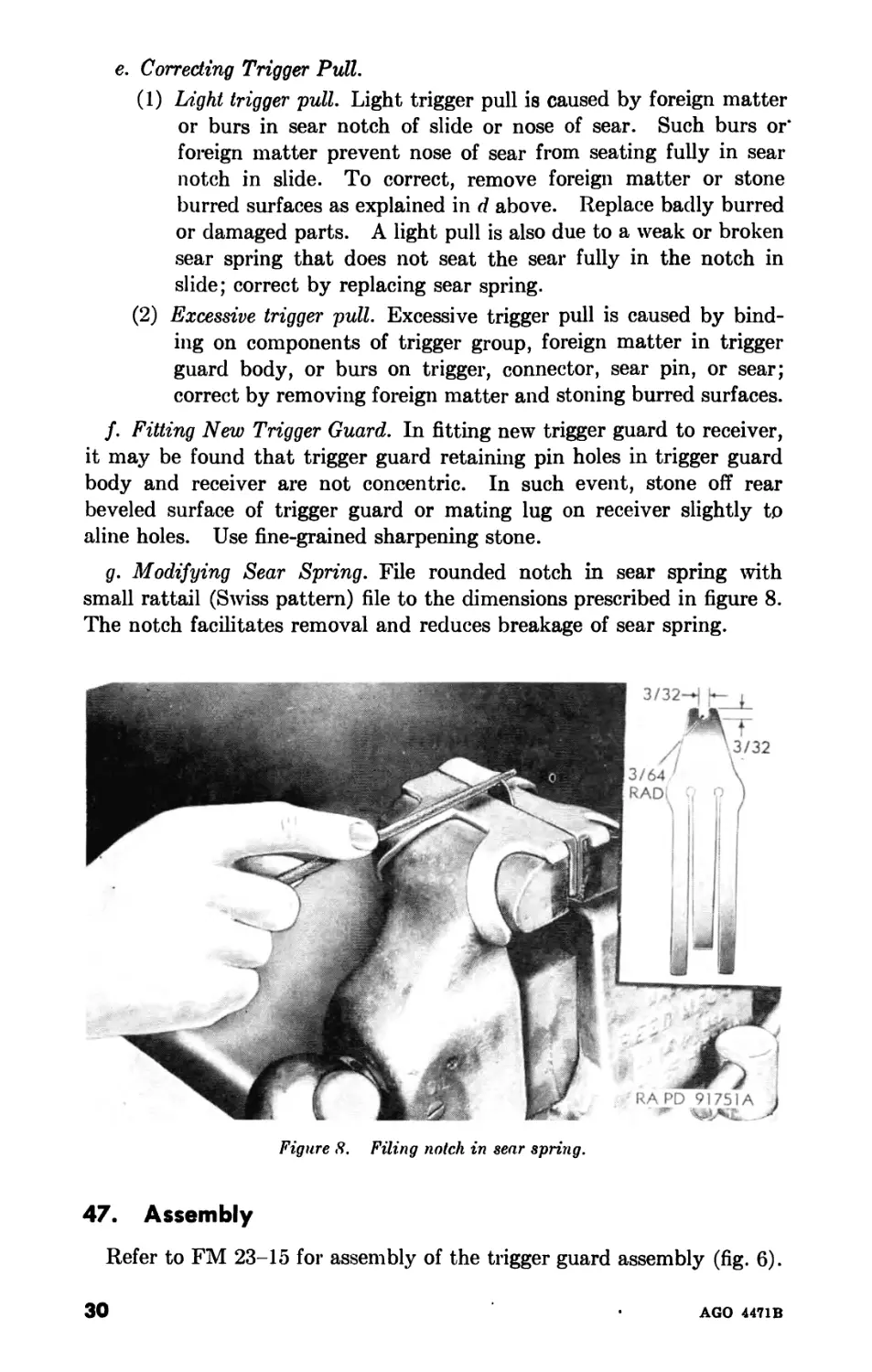
e. Sear Spring (fig. 8).
(1) Determine if sear spring is of latest design. Modify sear springs
of early manufacture, which do not have the %-inch notch
at the rear end, to conform to the latest design (par. 46g).
(2) Inspect sear spring for functioning with sear and connector,
looseness in retaining slots in trigger guard body, deformation,
fracture, and wear. The two side prongs of spring should bear
evenly on shoulders on forward end of sear. Center prong lies
below forward end of stop lever and bears on forward ramp of
connector. Prongs are even when at rest and curved down-
ward. Forward end of spring should be well seated in its lateral
notch in trigger guard body.
f. Sear Release Stop Lever (figs. 6 and 7). Inspect sear release stop
lever for wear and burs on forward lower surface where it contacts con-
nector and on rear surface where sear release strikes. Rear nose may
become expanded due to action of sear release and thus bind in sear.
g. Sear Carrier {Riveted) (figs. 6 and 7). Inspect sear carrier for loose,
fractured, worn, or burred connector stop (riveted on right end). Inspect
connector camming surface for wear and burs.
h. Change Lever (figs. 6 and 7). Inspect change lever for functioning
with connector and trigger, deformation, and free movement in trigger
guard body (should be close fit). The change lever moves freely in its
various positions, operates as intended, and remains in the selected
position.
r
AGO 4471B
28
i. Change and Stop Lever Spring (Riveted) (fig. 6). Inspect change and
stop lever spring for functioning with change lever (should bear firmly in
notches) and sear release stop lever, deformation, and cracks. Inspect
stop lever prong for fracture, looseness on rivet, and excessive deforma-
tion, causing weak action on stop lever.
j. Magazine Catch (figs. 6 and 7). Inspect nose of catch for wear and
burs (edge should be sharp). Catch must securely hold a loaded mag-
azine.
k. Magazine Catch Release (fig. 6). Inspect magazine catch release for
free movement in trigger guard body and catch, deformation, and frac-
tured nose.
Z. Ejector (figs. 6 and 7). Inspect nose of ejector for deformation, wear,
and burs. Upper forward corner of nose should be well defined. If
nose is bent or worn, it fails to eject properly; if too long, it binds on
bolt and causes weak ejection. It must fit the trigger guard body. It
must fit the trigger guard with sufficient freedom to permit normal re-
moval without perceptible looseness.
m. Ejector Lock (fig. 6). Inspect ejector lock for free movement in
well in trigger guard housing.
n. Trigger Guard Body (fig. 6). Inspect trigger guard body for deform-
ation, for worn and burred spring retaining grooves, and receiver reten-
tion groove (rear end). Trigger guard body assembles freely to the re-
ceiver without apparent looseness or sideplay.
o. Counterrecoil, Ejector Lock, and Magazine Catch Springs (fig. 6).
Inspect springs for function and fracture.
46. Repair
a. General. Replace all broken, worn, or otherwise unserviceable
parts. Remove burs and rust as explained in paragraphs 35 and 36.
b. Weak Ejection. Weak ejection of cartridge case is caused by the
neck of ejector scraping on bolt, the neck being bent or too short, or the
nose being worn. To correct, grind off nose, being careful to maintain
angle; straighten or replace ejector. Space between ejector and bolt is
not more than one thirty-second inch.
c. Slide Fails to Cock. This condition is due to damaged sear, broken
sear spring, burs, foreign matter in sear notch in slide, or failure of bolt
to move far enough to the rear on recoil movement to cock the slide.
Examine parts; clean and replace if necessary.
d. Stoning Nose of Sear. If nose of sear or sear notch in slide becomes
worn or burred, stone lightly with a fine-grained sharpening stone. Ex-
ercise care to maintain retentive angle and stone to polish only. If too
much metal is removed from top face of sear, the face becomes too shal-
low to retain slide, due to interference of rear end of sear (release cam
extension) with the slide, thus holding sear notch out of engagement.
Test sear retentive action after stoning, and if found questionable, re-
place sear. Dress in slide in like manner.
AGO 4471B
29
e. Correcting Trigger Pull.
(1) Light trigger pull. Light trigger pull is caused by foreign matter
or burs in sear notch of slide or nose of sear. Such burs or*
foreign matter prevent nose of sear from seating fully in sear
notch in slide. To correct, remove foreign matter or stone
burred surfaces as explained in d above. Replace badly burred
or damaged parts. A light pull is also due to a weak or broken
sear spring that does not seat the sear fully in the notch in
slide; correct by replacing sear spring.
(2) Excessive trigger pull. Excessive trigger pull is caused by bind-
ing on components of trigger group, foreign matter in trigger
guard body, or burs on trigger, connector, sear pin, or sear;
correct by removing foreign matter and stoning burred surfaces.
f. Fitting New Trigger Guard. In fitting new trigger guard to receiver,
it may be found that trigger guard retaining pin holes in trigger guard
body and receiver are not concentric. In such event, stone off rear
beveled surface of trigger guard or mating lug on receiver slightly to
aline holes. Use fine-grained sharpening stone.
g. Modifying Sear Spring. File rounded notch in sear spring with
small rattail (Swiss pattern) file to the dimensions prescribed in figure 8.
The notch facilitates removal and reduces breakage of sear spring.
Figure 8. Filing notch in sear spring.
47. Assembly
Refer to FM 23-15 for assembly of the trigger guard assembly (fig. 6).
30
AGO 4471B
48. Functional Check
a. Inspect trigger guard assembly for looseness, functioning, and co-
functioning of its assemblies and parts. Trigger guard assembly as-
sembles freely to receiver without apparent looseness or sideplay.
b. Check function of trigger, connector, and sear spring with trigger
guard assembly held horizontal, tipped forward, and tipped back. If
sear spring is not bearing properly on forward shoulders of sear and
center prong on connector, the connector will not function properly
when trigger guard assembly is tipped. Check functioning of trigger,
sear, and stop lever, when change lever is set at A position (normal cyclic
rate), F position (slow cyclic rate), and S position (safe) (fig. 9).
Figure 9. Various positions of change lever on assembled trigger guard assembly.
(1) Change lever set at A (vertical position) (fig. 9). When change
lever is set at A position and trigger is retracted, the connector
raises the forward end of sear and sear release stop lever to-
gether and holds them up as long as trigger is held fully re-
tracted. Thus the rear end of the sear is depressed and held
from engagement with sear notch in slide, while the rear end of
sear release stop lever is also depressed, preventing sear release
from striking camming surface on rear end of sear. When
trigger is released, sear and sear release stop lever both return
to their normal positions.
(2) Change lever set at F (forward position) (fig. 9). When change
lever is set at F position and trigger partially retracted, the
connector raises the forward end of sear and sear release stop
lever together. As trigger is further retracted, the connector,
still rising, is cammed from under front of sear by camming
surface on sear carrier, and continues to raise forward end of
sear release stop lever, and holds it in raised position as long as
AGO 4471B
31
trigger is held fully retracted. Therefore, the sear is free to
function when acted upon by the sear release, while the rear
end of the sear release stop lever is depressed to a point where
it will not block the action of the sear release upon the cam-
ming surface of rear end of sear. This action produces the slow
cyclic rate of fire.
(3) Change lever set at S (rear position) (fig. 9). When change lever
is set at S position, the trigger is blocked by the change lever
and prevented from rising, lifting the connector, and disen-
gaging the sear.
49. Installation
Refer to FM 23-15 for installation of the trigger guard assembly.
Section III. BARREL AND RECEIVER GROUP
50. Removal and Disassembly
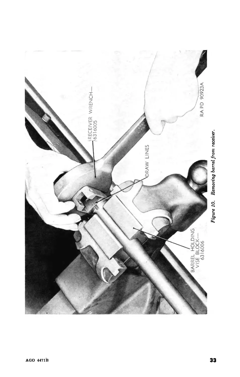
a. Removal of Barrel From Receiver (fig. 10).
(J) Only remove the barrel from the receiver when replacement is
necessary or for gaging depth of chamber.
(2) Place barrel in barrel holding vise block 6316006 (fig. 4) and
clamp in vise. Fit receiver and barrel open end wrench 6316005
(fig. 4) on receiver, and unscrew (right hand thread) receiver
from barrel.
b. Disassembly of Barrel Assembly (fig. 11).
(1) Never remove components attached to barrel except when re-
placements are necessary or for the purposes of salvaging.
(2) Drive off front sight blade, if necessary to replace.
(3) Drive out the front sight key pin, drive the front sight base off
to the front, and remove the front sight key.
(4) Drive out gas cylinder tube bracket pin and drive gas cylinder
tube bracket off to the front.
c. Disassembly of Receiver Group (fig. 12).
(1) Slide the operating handle out of its guides on the receiver.
(2) Press in on the operating handle plunger and push out the op-
erating handle plunger pin toward the countersunk side of the
plunger. Then remove the plunger and spring.
(3) Lift the bolt guide spring out of its seat in the bolt guide with
the rim of a cartridge. Remove the guide and spring from the
receiver.
(4) Depress change lever stop spring assembly until clear of groove
in change lever stop spring retaining pin, shake pin from re-
ceiver, rotate spring down, and push stop from aperture in
receiver.
32
AGO 4471B
AGO 4471В
Figure 10. Removing barrel from receiver.
RECEIVER WRENCH-
16005
AGO 4471В
Figure 11. Barrel assembly—exploded view.
AGO 4471В
♦LEFT BOLT
SUPPORT-
6019663
♦BOLT SUPPORT
RIVET—5022243
BOLT GUIDE—6147130
TOP PLATE—6019653
GJ
Ul
♦RIGHT
BOLT
SUPPORT-
6019664
*BOLT SUPPORT/
RIVET—5022243 f
CHANGE LEVER
RETAINING
STOP SPRING,
PIN—5022228'
BOLT GUIDE
CHANGE LEVER
STOP SPRING
ASSY—6019697
SPRING—5022251
CHANGE LEVER STOP//
SPRING—5022200 f
CHANGE LEVER STOP—5022207
OPERATING HANDLE
PLUNGER PIN—5022236
OPERATING
HANDLE—5509070
OPERATING'
HANDLE
PLUNGER
SPRING-
5153129
‘BUFFER
TUBE—6147493
OPERATING HANDLE PLUNGER—5022241
♦PART OF RECEIVER ASSY—6535472
Figure 12. Receiver group—exploded view.
RAPD 134736
(5) Buffer tube is threaded into receiver and is never removed ex-
cept for replacement or repair. To remove, clamp receiver in
vise with leather jaws, first inserting buffer tube alinement tool-
spacer 7113328 (fig. 4) inside faces of receiver walls to prevent
springing of the receiver, and then unscrew buffer tube with
strap wrench (fig. 13).
(6) If necessary, remove top plate of receiver by driving out of
grooves to front of receiver, using a block of hardwood as shown
in figure 14.
51. Inspection
a. Barrel,
(1) General inspection. Inspect barrel for deformation, alinement in
receiver, crossed threads, rust, corrosion, wear, burs, and for-
eign matter in gas port and extractor aperture. Barrel must
aline exactly with receiver when assembled, in order that rear
end of gas cylinder tube will fit mating slot in receiver; front
sight will aline properly; and extractor aperture will be correctly
positioned, drilled, and pinned during manufacture of the rifle
after barrel is assembled to receiver. A draw mark is then
placed in barrel and receiver for proper alinement upon as-
sembly. If draw marks do not qualify, fashion a shim from
shim metal.
36
AGO 4471B
AGO 4471В
Figure 14- Driving top plate from receiver.
(2) Inspection for serviceability.
(a) General. Inspect the barrel (fig. 11) as a whole from the
standpoint of serviceability. Before inspecting the barrel, all
metal and other fouling must be removed and the barrel
wiped dry. Accuracy of fire is the main point to consider
when inspecting a barrel. Accuracy is reduced in varying
degrees by bulges, erosion, and pits in the bore. The extent
to which these defects will reduce accuracy is determined by
two methods; namely, visual inspection and bore gaging.
(5) Visual inspection. For visual inspection, using barrel reflector
7265788 (fig. 4), hold the barrel so that its interior is illumi-
nated and examine the bore. If the barrel is not bent or
otherwise deformed, if the bore appears free from bulges and
large pits, and if the lands are sharp and uniformly distinct,
it is serviceable, providing it is in good condition otherwise.
A bulge is indicated by a shadowy depression or a ring in the
bore. It may often be detected also by a bulge or raised
ring on the exterior surface. If the barrel is pitted to the ex-
tent that the sharpness of the lands is affected or if it has a
pit or pits in the lands or grooves large enough to permit
passage of gas around the bullet (that is, a pit the width of a
land or groove and three-eighths inch long or longer), the
barrel will be scrapped.
(c) Bore gaging. Barrels inspected and found serviceable by visual
test will be bore-gaged, using breech bore gage 5564343 (fig.
3). Barrel will be replaced if gage reading exceeds 0.310
inch in hands of troops in field or 0.306 Inch at preembarka-
tion inspection.
b. Gas Cylinder Tube Bracket (fig. 11). Inspect gas cylinder tube
bracket for looseness on barrel, missing or loose pin, alinement of gas
port with barrel port, and for worn or burred dovetailed mating grooves.
(Bracket is a drive-fit on barrel and gas port is drilled through bracket
and barrel after assembly at manufacture.)
c. Front Sight Group (fig. 11). Inspect front sight base for looseness on
barrel; missing, loose, or burred key; and worn keyway (on barrel).
Inspect for missing front sight key pin, looseness of pin in base, and for
looseness with key. Inspect front sight blade for position (stakes),
looseness in base mating dovetail, worn or burred dovetail (male and
female), deformation, and shine.
d. Receiver (fig. 12).
(1) Inspect receiver for excessive wear, deformation (pinched sides
due to squeezing in vise), burs, rust, and foreign matter in re-
cesses.
(2) Inspect for loose rivets in bolt supports and for cracks in barrel
end and bridge.
м
Ann AA7TR
(3) If barrel and buffer tube are removed, inspect for crossed threads.
(4) Inspect bolt lock recess in top of receiver for wavy surface,
wear, and burs, especially where lock seats when bolt is locked.
Inspect surface by reflecting light on it from a small mirror or a
bright tool. This surface is critical and affects headspace.
(5) Inspect top plate for looseness (should be drive-fit).
(6) Inspect buffer tube for tightness on receiver. It should be free
of dents that would cause buffer cones and cups to freeze and
must contain eight splines.
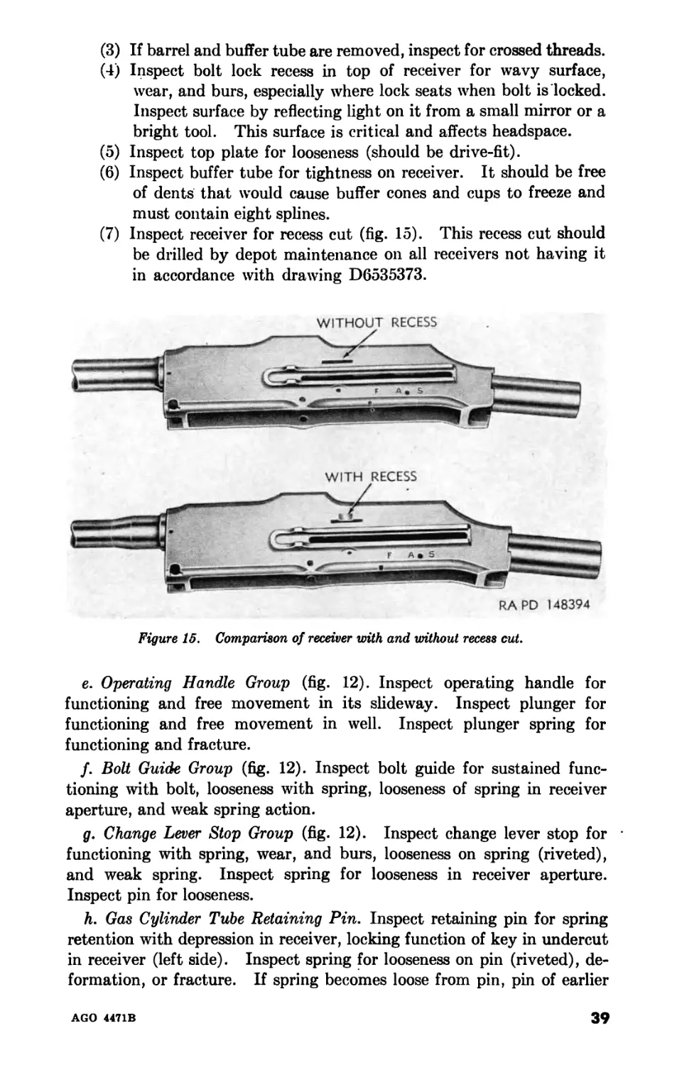
(7) Inspect receiver for recess cut (fig. 15). This recess cut should
be drilled by depot maintenance on all receivers not having it
in accordance with drawing D6535373.
e. Operating Handle Group (fig. 12). Inspect operating handle for
functioning and free movement in its slideway. Inspect plunger for
functioning and free movement in well. Inspect plunger spring for
functioning and fracture.
f. Bolt Guide Group (fig. 12). Inspect bolt guide for sustained func-
tioning with bolt, looseness with spring, looseness of spring in receiver
aperture, and weak spring action.
g. Change Lever Stop Group (fig. 12). Inspect change lever stop for •
functioning with spring, wear, and burs, looseness on spring (riveted),
and weak spring. Inspect spring for looseness in receiver aperture.
Inspect pin for looseness.
h. Gas Cylinder Tube Retaining Pin. Inspect retaining pin for spring
retention with depression in receiver, locking function of key in undercut
in receiver (left side). Inspect spring for looseness on pin (riveted), de-
formation, or fracture. If spring becomes loose from pin, pin of earlier
AGO 4471B
39
manufacture cannot be rotated to be withdrawn from receiver; however,
pin 5022232 of latest manufacture has a screwdriver slot on end for re-
moval of pin when spring breaks.
52. Repair
a. General. Replace all broken, worn, or otherwise unserviceable parts.
Remove burs and rust as explained in paragraphs 35 and 36.
b. Replacing Unserviceable Barrel.
(1) Disassemble barrel from receiver (par. 50).
(2) Assemble new barrel assembly, which includes front sight base
and gas cylinder tube bracket. Screw up barrel until draw
marks on barrel and receiver register. Assemble gas cylinder
tube to bracket; then check fit and alinement of rear tang and
retaining pin holes in tang and receiver. If tang of tube does
not mate without binding, turn barrel until this is accomplished.
Barrel should draw up tightly to receiver so there is no possi-
bility of vibrating loose. If there is no draw mark on barrel,
draw up until tube alines as above and check position of ex-
tractor cut by assembling bolt with extractor assembled.
(3) If barrel does not draw up to proper position, dress rear face of
shoulder in a lathe.
(4) Never alter the receiver to obtain draw-fit. When barrel is
alined, check alinement of gas cylinder tube, front sight, and
extractor cut. If barrel requires much shimming or dressing
to aline, headspace may be affected.
c. Front Sight Blade Out of Alinement. This is usually due to enlarged
dovetailed aperture in base. Peen lightly along upper edges, aline sight
blade (by eye), and stake, using old stake mark. Base pin may be miss-
ing; if so, replace and aline blade.
d. Rough or Wavy Surface of Bolt Locking Recess in Receiver. If surface
of bolt locking recess in receiver is burred or wavy, correct by removing
top plate (par. 50c(6)) and stoning rough or wavy surface smooth with a
fine-grained sharpening stone Exercise care to stone evenly and remove
as little metal as possible, as this surface affects headspace. Check
headspace (par. 27) after stoning.
e. Loose Spring on Gas Cylinder Tube Retaining Pin. If spring becomes
loose from body of pin, it may be impossible to withdraw pin by ordinary
methods for replacement. In such event, attempt to revolve and shake
pin out of aperture or pull out with needle-nosed pliers.
f. Dents in Buffer Tube. Shallow dents in buffer tube are often re-
moved by reaming with an expansion reamer set to the original inside
diameter of tube. Larger dents may be swaged out, first by using rod
the size of inside diameter of tube and then reaming. If dents are deep
enough to cause possible weakening of wall of tube due to this procedure,
replace the tube. Test components in tube after repair for free movement.
40
AGO 4471B
53. Assembly and Installation
a. Assembly of Receiver Group (fig. 12).
(1) Install top plate, being careful not to deform the dovetail.
(2) Install buffer tube on receiver as shown in figure 20, being sure
that one of the eight grooves in the head of the tube lies cen-
trally horizontal with the top of the receiver with nose down.
Clamp receiver in vise, first inserting the spacer 7113328 (fig. 4)
of the buffer tube alinement tool 6316001 between inside faces
or receiver walls to prevent squeezing of receiver, and insert
parallel 7113327 (fig. 4) of buffer tube alinement tool into re-
ceiver, with keyed end toward buffer tube end of receiver as
shown in figure 16. Start the buffer tube into the ends of the
receiver and insert plug 7113326 (fig. 4) of buffer tube aline-
ment tool as shown in figure 16. Tighten buffer tube with
strap wrench until plug engages keyed end of parallel.
Note. Buffer tube must be at tightest possible position at which the
plug and parallel will engage, using shim or shims, if necessary.
(3) Install change lever stop spring assembly in receiver and secure
with change lever stop spring retaining pin.
(4) Insert the longer turned-over end of bolt guide spring in its hole
inside the receiver. Then install the bolt guide and hold it
while the spring is pushed over until the shorter turned-over
end engages the groove in bolt guide.
(5) Install operating handle plunger spring (0.263-in. О D, 5 coils)
in the operating handle. Insert operating handle plunger and
secure with operating handle plunger pin. Be sure pin is in-
stalled with ridge in countersunk side of plunger.
(6) Insert operating handle group in slideway on receiver.
b. Assembly of Barrel Assembly (fig. 11).
(1) Install gas cylinder tube bracket, being sure to aline gas port
holes. Secure bracket in place with gas cylinder tube bracket
pin (0.1257x0.855).
(2) Position front sight key in groove on barrel and install front
sight base. Secure them in place with the front sight key pin
(0.0907 x 0.505).
(3) Install front sight blade and realine sights.
c. Installing Barrel Into Receiver (fig. 10). When installing the barrel,
always be certain that it is tight enough in the receiver never to work
loose. Screw the barrel into the receiver until the draw line matches
that of the receiver. Then assemble the gas cylinder tube to determine
whether the gas cylinder tube bracket on the barrel alines properly with
the receiver, so gas cylinder tube rear tang slides easily into its aperture
in receiver. If it does not, turn the barrel slightly until the alinement is
correct. When assembled, check extractor cut in rear face of barrel for
position. For assembling new barrel, refer to paragraph 52.
AGO 4471B
41
AGO 4471В
Figure 16. Assembling buffer lube to receiver.
AGO 4471В
Figure 17. Bolt group—exploded view.
Section IV. BOLT GROUP
54. Removal and Disassembly
Refer to FM 23-15 for removal and disassembly of the bolt group
(fig. 17).
55. Inspection
a. General. Inspect parts for damage, excessive wear which might
cause malfunction, burs, rust, foreign matter in recesses, deformation,
and free action with mating parts. Figure 18 shows important points
to be inspected.
Figure IS. Inspection points on bolt group parts.
b. Bolt (fig. 17). Inspect bolt for excessive sideplay and looseness with
bolt lock and bolt lock pin (riveted). Inspect firing pin hole for enlarge-
ment, and inspect face for corrosion and recessive wear. Firing pin holes
are gaged by fifth echelon organizations. Inspect lower surfaces con-
tacting bolt supports and center feed rib for wear and burs.
ЛА
AGO 4471B
c. Bolt Lock (fig. 18). Inspect rear top shoulder where lock contacts
receiver locking aperture for wear and burs. This is an important sur-
face, as it affects headspace (par. 27). Inspect lower rear cam surface
where lock rides up on bolt supports and firing pin camming surface for
wear and burs.
d. Extractor (fig. 18). Inspect extractor spring for fracture, weak
action, and looseness in extractor body. Claw nose and retaining
shoulder are square, not beveled.
e. Firing Pin (fig. 18). Firing pin should slide freely in well and pro-
trusion of nose from forward face of bolt should be approximately three
thirty-seconds inch. If firing pin protrudes too far, it will result in
punctured primers. Inspect firing pin nose for pits. Nose must be
smooth and round. The camming surface contacted by the bolt lock
and rear surface contacted by the hammer must be free of wear that
would affect action of firing pin.
J. Bolt Link and Bolt Link Pin (fig. 18). Inspect link for excessive
looseness with bolt lock and hammer. When assembled, the link bears
on rear camming face of bolt lock.
g. Hammer and Hammer Pin (fig. 18). Inspect hammer for excessive
looseness with link and slide. Inspect center rib of hammer which strikes
head of firing pin for wear and burs. Hammer pin must fit snugly in the
hammer and bolt link.
56. Repair
a. General. Replace all broken, worn, or otherwise unserviceable parts.
Remove burs and rust as explained in paragraphs 35 and 36.
b. Bolt Assembly. If it is necessary to replace one of the parts of the
bolt assembly, drive out the bolt lock pin, using a suitable drift. This is
a headed pin riveted on one side when assembled. After replacing the
unserviceable part, install a new pin and rivet in plaoe.
57. Assembly and Installation
Refer to FM 23-15 for assembly and installation of bolt group (fig. 17).
58. Functional Check
Check free movement of bolt, bolt lock, link, and hammer attached to
slide and piston, but with recoil spring disassembled.
a. Rearward Movement. When bolt is locked, the hammer pin should
be approximately 0.19 inch in advance of the link pin and the center rib
of hammer slightly in the rear of head of firing pin. When slide is re-
tracted, it imparts no motion to the bolt until it has traveled back 0.19
inch from extreme forward position. At this point, the hammer pin
should be directly under the bolt link pin. From this point, the bolt
and bolt lock start to move, and by the time the slide has traveled 1.20
inches, the bolt should be drawn completely down out of the locking re-
cess and away from locking shoulder of the receiver. As bolt lock re-
volves down from locked position, it should cam the firing pin from the
face of the bolt. Slide should continue back until it strikes buffer and
then rebound 0.10 inch before engaging sear notch.
b. Forward Movement. On forward movement, when slide is about 2
inches from its forward position, bolt lock should begin to ride over rear
shoulders of bolt supports which cam up its rear end. The bolt link pin
passes over dead center, with respect to bolt lock pin and hammer pin,
and the bolt lock is forced up by link into locking recess in receiver and
thus levers bolt home; the hammer pin passes dead center under bolt
link pin. At this point, the firing pin should be released from its slot in
the under side of bolt lock and in a position to be struck by the hammer;
the hammer moves forward 0.10 inch and strikes firing pin head and then
should move forward another one-sixteenth inch, driving the firing pin
to its fully forward position.
Section V. BUTT STOCK, BUFFER, AND ACTUATOR GROUP
59. Removal and Disassembly
Refer to FM 23-15 for removal and disassembly of butt stock, buffer,
and actuator group (figs. 19 and 20).
60. Inspection
a. General. Inspect parts for damage, excessive wear that might cause
malfunction, burs, rust, foreign matter in recesses, deformation, stripped
threads on screws and in screw holes, and free action with mating parts.
b. Butt Stock (fig. 19 or 20). Inspect butt stocks for cracks, scoring,
and surfaces protruding beyond metal. Inspect butt stocks for stripped
threads in the butt plate and swivel screw holes.
c. Hinged Butt Plate Assembly (fig. 19 or 20). Inspect hinged butt
plate assembly for deformation and free action. The hinged butt plate
must work freely when it is rotated and must be securely held in its open
position by the bearing ball in the inner butt plate.
d. Buffer and Sear Release Group.
(1) Inspect reciprocation of buffer head and buffer spring and for
free movement in buffer tube. Inspect tube for position and
looseness in receiver and worn or burred head keyways. Buffer
tube and receiver are qualified at assembly so that keyways
aline properly with receiver. One of the eight keyways in for-
ward end of buffer tube should be vertically alined with center-
line of bore and receiver so as to position sear release vertically,
with nose down, when buffer head is assembled and limit the
horizontal forward movement of sear release.
(2) Inspect buffer head and four friction cups and cones (fig. 21)
for free action in tube. Inspect cones for expansion seating in
46
AGO 4471B
Q
О
4471В
BUFFER GROUP
(SEE FIG 29)
BUTT PLATE LOCK
SPRING—5013747
'ТЛЯ 1
INCHES
'OUTER BUTT
PLATE BODY-
[6147321
BUTT SWIVEL—7266132
INNER BUTT PLATE—73131 15
RIFLE—PARTIAL
OVAL-HD SCREW—134302
LONG BUTT PLATE
SCREW—5153084
BUTT STOCK—(
7266155
BUTT PLATE HINGE
PIN—5013746
HINGED BUTT
PLATE ASSY—7313114
[BUTT PLATE
J LOCK SPRING
(SETSCREW—5013745
RAPD 134739
Figure 19. Butt stock group—exploded view (present manufacture).
RIFLE—PARTIAL
BUTT SWIVEL ASSY—7310001 (SHOWN)
or BUTT SWIVEL—7312240 r
HINGED BUTT PLATE/
ASSY—61477871
BRACKET SWIVEL/
SCREW—50222441
FLAT-HEAD
SCREW—133578
BUTT
BRACKET—731
BRACKET]
SWIVEL-
50222 lOj
LONG BUTT PLATE SCREW—51 53084
OUTER BUTT PLATE
BODY—6147321
STOCK-
6535519
BUTT PLATE
LOCK SPRING
SETSCREW—5013475
(BUTT PLATE LOCK
9 SPRING—5013747
JTT PLATE HINGE
N—5013746
BEARING
BALL—104918
INNER BUTT PLATE—5613688
AGO 4471В
' 1 11 121 |3l
INCHES1 I
Figure 20. Butt stock group—exploded view (early manufacture).
RAPD 134761
AGO 4471В
Figure 21. Buffer and actuator group—exploded view.
mating cups (cones should not seat fully in cups when at rest)
and for cracks. Cups and cones must be free of any burs or
wear that would cause them to freeze together.
(3) Inspect protrusion of buffer head from face of tube. This
dimension should be approximately one-eighth inch. Inspect
buffer spring for functioning, fracture, and set.
(4) Inspect sear release (fig. 21) for free movement in buffer head
(should be flush with forward face of buffer head when re-
tracted) and for binding in notch. Inspect camming face of
nose for wear and burs. Lower forward edge of nose should be
slightly beveled and perfectly smooth.
e. Actuator Group (fig. 21). Inspect actuator and sear release for co-
function under spring action. Inspect actuator tube for looseness in
buffer cap (cap brazed to tube). Tube should be smooth and polished
inside. Inspect free movement of actuator in actuator tube (should
slide freely). Assemble actuator with blunt end forward. Inspect
actuator spring for functioning, fracture, and set.
/. Stock Retaining Sleeve Group (fig. 21). Inspect stock retaining sleeve
for clearance with actuator tube and looseness of stop in sleeve and collar
on sleeve. Stop and collar are both brazed on sleeve. Stock retaining
sleeve screws on actuator tube by means of mating threads on stop and
in tube. Hole in stop is air compression relief vent. Inspect stock
retaining sleeve lock washer for locking function and cracks.
61. Repair
a. General. Replace all broken, worn, or otherwise unserviceable
parts. Remove burs and rust as explained in paragraphs 35 and 36.
b. Butt Stock.
(1) Stripped threads are often encountered in the screw hole located
in the heel of the butt stock using inner butt plate of early
manufacture (fig. 20), due to frequent removal of the butt plate
assembly. If the butt stock is found unserviceable, due to the
above mentioned threads being stripped, the stock may be
utilized by eliminating the requirement of a screw. This is
accomplished in the manner described in (a) through (c) below:
(a) Machine a steel pin to the dimensions shown in figure 22.
(b) Tack-weld pin to lug in butt plate as shown in figure 22.
(c) Finish off, if necessary, with a fine file.
(2) To reduce stripping of threads, remove the large screw from the
inner butt plate assembly before removing small screw in heel
of the butt stock. Install the small screw first when assem-
bling.
(3) Use helicoil screw thread inserts to repair stripped threads in
the butt plate screw holes and/or the swivel screw holes on butt
stocks.
50
AGO 4471B
WELD HERE
Iff 0.100 + 0.005
<—0.200 - 0.005
1 -I- 0.010
15 DEG
NOTE: ALL DIMENSIONS SHOWN ARE IN INCHES
RAPD 91750
Figure 22. Modification of inner butt plate of early manufacture.
AGO 4471B
51
c. Actuator Tube.
(1) Shallow dents in actuator tube are often removed by reaming
with an expansion reamer set to original inside diameter of tube.
If dents cannot be removed with an expansion reamer, tube will
be rejected. Test components in tube for free movement after
repairing.
(2) Remove rust and clean foreign matter from inside of actuator
tube in accordance with instructions in paragraph 35.
d. Frozen Buffer. If buffer head becomes frozen in buffer tube due to
broken cups, remove operating group, trigger mechanism, butt stock,
actuator tube with cap, and buffer spring. Soak jammed parts with dry-
cleaning solvent, mineral-spirits paint thinner, or special preservative
lubricating oil and drive out from front of buffer, using a hardwood plug.
If parts do not dislodge easily, remove buffer tube from receiver (par.
50c(5)), place on hardwood block, and drive out parts as above. If cups
and cones are frozen together, soak in dry-cleaning solvent or mineral-
spirits paint thinner and tap edge of cup until loose. Clean parts thor-
oughly, test, oil, and install.
62. Assembly and Installation
Refer to FM 23-15 for assembly and installation of butt stock, buffer,
and actuator group (figs. 19 and 20).
Section VI. SLIDE AND PISTON GROUP
63. Removal and Disassembly
a. Removal From Rifle. Refer to FM 23-15 for removal of slide and
piston group (fig. 23 or 24).
b. Disassembly of Slide Assembly.
(1) Remove pin securing piston to slide (fig. 23 or 24) and unscrew
piston.
(2) On rifles of early manufacture where a plug is screwed into the
head of the piston, remove the plug.
64. Inspection
a. General. Inspect free action of piston and slide with respect to gas
cylinder tube and receiver. Piston and slide should slide freely in gas
cylinder tube and receiver when rifle is tilted with recoil spring dis-
assembled. Inspect piston retaining pin for looseness in slide and wear
in piston and slide. A loose fit is provided between piston and slide,
when assembled, to insure proper alinement and free movement of slide
in receiver. Total end-play of piston in any direction should be approxi-
mately one-eighth inch.
b. Slide (fig. 23 or 24). Inspect slide for deformation of sides by pinch-
ing or springing, which may cause binding with operating mechanism or
receiver, badly dented rear end (indicating frozen buffer), and worn
hammer pin hole.
52
AGO 4471B
AGO 4471В
Figure 23, Slide and piston group—exploded view (present manufacture).
AGO 4471В
Figure 24. Slide and piston group—exploded view (early manufacture).
c. Piston
(1) General.' Inspect piston (fig. 23 or 24) for deformation, wear, and
burs on head of piston and on gas check bearing rings. Inspect
body for missing or fractured bushing. Bushing is held by light
drive-fit against forward shoulder of counterbore in piston body
and is not to be removed. If damaged, replace piston. Inspect
piston for carbon or rust.
Note. On rifles of early manufacture where a plug is screwed into the
piston (fig. 24), inspect plug for looseness in head and for rust; where plug
lies below face of piston, inspect for carbon in recess.
(2) Gaging. Gage piston head with 0.494-inch piston diameter NO
GO ring gage 5077201 (fig. 25). Piston head should not enter
gage. To gage, first clean piston thoroughly of all carbon and
fouling and determine that surfaces of head ring are smooth and
polished. Wipe piston head and gage with a slightly oiled cloth
and try to pass gage over piston head. If piston enters gage,
it is unserviceable. Piston must not be oval in shape, and
there must be no signs of light between gage and piston head
when held to the light. (Only light pressure should be exerted
on gage.)
Figure .>5. Gaging piston head.
d. Recoil Spring and Guide. Inspect recoil spring for functioning, frac-
ture, kinks, and set. Inspect spring guide for deformation, loose head
(riveted), fit, and retention in retaining shoulders in receiver.
AGO 4471B
55
65 • Repair
a. General. Replace all broken, badly worn, or otherwise unserviceable
parts. Remove rust, carbon, and burs as explained in paragraphs 35
and 36. Remove carbon from piston rings with drift of gas cylinder
cleaning tool 7268211 (fig. 3).
b. Alinement of Piston and Slide. The piston and slide are assembled
to a loose fit at manufacture. The piston is screwed into slide and
backed off sufficiently to allow some play in union; slide and piston are
then tested for free sliding fit in receiver and gas cylinder tube. If satis-
factory, pinhole is drilled and pin inserted. Pinhole is enlarged to give
the J^-inch play described (par. 64a).
Note. The slide is not furnished as a spare part; therefore, if the slide is found to
be unserviceable, replace the entire assembly consisting of the slide and piston. If
the piston is still serviceable, remove and salvage for further use.
c. Frozen Piston. When piston becomes locked or “frozen” in gas cyl-
inder, submerge barrel in dry-cleaning solvent or mineral-spirits paint
thinner until gas cylinder is covered and soak for 1 hour. If this does
not loosen piston, place butt stock on solid surface and, with wooden
block, tap lightly on operating handle. Often, considerable force is re-
quired to loosen piston. Clean rust and corrosion from piston, gas cyl-
inder, and tube; polish and oil. Remove all dry-cleaning solvent or
mineral-spirits paint thinner with a clean cloth.
d. Deformed Side Rails of Slide. Side rails of slide may become bent in
or out, causing binding with operating mechanism or receiver. Rails
can be spread or sprung in by using wooden wedges, clamping in vise
with copper jaws, or with the hands. Test slide after repair for free
sliding movement by tilting rifle.
e. Undersized Piston. Undersized pistons are salvaged by fifth echelon
organizations by chrome plating.
66. Assembly and Installation
a. Assembly of Slide Assembly.
(1) Insert gas piston plug (fig. 24) in piston on rifles of early manu-
facture.
(2) Insert gas piston retaining pin (0.1257 x 0.74 straight pin) (fig.
24) for early manufacture or spring pin (И x 1/й) (fig- 33)
for present manufacture.
b. Installation on Rifle. Refer to FM 23-15 for installation of slide and
piston group (fig. 23 or 24).
Section VII. GAS CYLINDER AND FOREARM GROUP
67. Removal and Disassembly
a. Removal of Gas Cylinder Group. Refer to FM 23-15 for removal of
gas cylinder group.
b. Disassembly of Gas Cylinder Group (fig. 26).
(1) Slide forearm shield to rear and remove.
56
AGO 4471B
AGO 4471В
FOREARM
SHIELD—6147323
(EARLY MFR)
GAS CYLINDER
REGULATOR ASSY-
7267816
I Т"Г2
INCHES 1
* BRACKET SWIVEL SCREW—5022244
FOREARM
SHIELD—7267379
(PRESENT MFR)
GAS CYLINDER TUBE—5509079
‘FRONT SWIVEL
BRACKET—5022213
GAS CYLINDER
‘BODY KEY-
7267815
GAS CYLINDER
BODY—7267818
{SHORT FOREARM
) SCREW—5152754
SHORT FOREARM
SCREW WASHER-
7313164
{LONG FOREARM
) SCREW—5022249
FOREARM
ASSY-
5564206
FOREARM
ESCUTCHEON..-
5022219
GAS CYLINDER ASSY-
7267819
‘PART OF FRONT SWIVEL ASSY—5564073
RAPD 134743A
Figure 26. Gas cylinder and forearm group—exploded view.
(2) Unscrew the short and long forearm screws, and remove the
screws, the forearm screw washer, and the forearm from the gas
cylinder tube. The long forearm screw is staked to the es-
cutcheon. Never remove the forearm escutcheon except for
repair; to remove, insert the screw and pull out.
(3) If replacement is necessary, remove the bracket swivel screw
and bracket swivel. Spring the front swivel bracket off over
the gas cylinder tube.
(4) Observe regulator setting to determine position of gas cylinder
regulator. Unscrew gas cylinder assembly, remove gas cyl-
inder key and, with combination tool 7266450 (fig. 4), remove
gas cylinder body.
68. Inspection
a. Gas Cylinder Tube (fig. 26). Inspect gas pad for alinement with port
in rifle barrel bracket and for carbon. If barrel is not alined properly
with receiver or if tube is deformed, the tang will not slide into aperture
freely. Inspect interior and exterior of tube for dents and rust. Tube
should be smooth and polished on inside. Inspect the six gas escape ports
for foreign matter.
b. Gas Cylinder Assemblies.
(1) Inspect gas ports for carbon and foreign matter and cylinder for
crossed threads, wear, and burs. Inspect gas pressure relief
vent in gas cylinder regulator (fig. 26) for carbon and foreign
matter.
(2) Clean the gas cylinder assembly as prescribed in (a) through
(e) below.
(a) Insert the large recess cutter of the gas cylinder cleaning tool
7268211 (fig. 3) into the large recess of the gas cylinder body
(A, fig. 27) and rotate the tool.
(b) Insert the long recess cutter of the tool 7268211 into the regu-
lator recess of the gas cylinder body (B, fig. 27) and rotate
the tool.
Caution: Always insert the tool through the large un-
threaded opening to avoid damage to the threads in the body.
(c) Insert the short recess cutter of the tool 7268211 into the recess
of the gas cylinder regulator assembly (C, fig. 27) and rotate
the tool.
(d) Insert the drift of the tool 7268211 into the gas ports of the
gas cylinder regulator assembly (D, fig. 27) and rotate the
tool.
(e) Clean all parts with a cloth saturated with rifle-bore cleaner
solvent cleaning compound. Inspect ports for cleanliness.
Dry parts but do not oil the inside of the body or the outside
of the regulator assembly.
58
AGO 4471B
Figure 27. Cleaning the gas cylinder assembly.
AGO 447IB
59
(3) Inspect gas cylinder body for wear, using 0.503-inch gas cylinder
plug gage 5077204 (fig. 28). This is a NO GO gage and should
not enter the gas cylinder body. Wipe cylinder body and gage
with a slightly oiled cloth and try to insert the gage into the
cylinder body (fig. 28). If the gage enters cylinder body, it is
unserviceable and is to be replaced. (Only light pressure should
be exerted on gage.)
Figure 28. Gaging gas cylinder body.
(4) Inspect the gas cylinder regulator (fig. 26) for ease in installing
in body, clogged port holes, carbon deposit, burs or wear; in-
spect the body key for distortions that would affect functioning
and for burs or wear; inspect body pin for serviceability.
c. Forearm Group (fig. 26). Inspect wooden forearm for loose escutch-
eon, scoring, and cracks. Inspect shield grooves for cracks and inspect
shield for deformation. Inspect escutcheon for worn threads.
d. Front Swivel Bracket (fig. 26). Inspect front swivel bracket for
looseness on gas cylinder tube. It should be positioned firmly just ahead
of forearm.
69. Repair
a. General. Replace all broken, worn, or otherwise unserviceable parts.
Remove burs and rust as explained in paragraphs 35 and 36.
b. Gas Cylinder Tube Out-of-Line With Receiver. If gas cylinder tube
is out-of-line with receiver, it may be caused by one of several factors: a
deformed tube, a missing gas cylinder tube bracket retaining pin, or the
barrel being improperly assembled to receiver. To correct, straighten
the tube, replace pin, and/or reposition barrel with receiver (par. 52b).
Test functioning of slide and piston with tube after repairs.
60
AGO 4471B
Note. The gas cylinder tube bracket pin hole is drilled at manufacture after the
barrel is alined to receiver, with respect to extractor cut, to insure alinement of gas
cylinder tube bracket and tube with receiver, together with extractor cut and front
sight base. This fact should be taken into consideration when assembling new parts.
c. Frozen Gas Cylinder Body. If gas cylinder body is frozen in gas cyl-
inder tube, remove tube from rifle, clamp in vise with copper jaw, and
unscrew gas cylinder body with combination tool 7266450 (fig. 4).
d. Removing Rust From Gas Cylinder Tube. Remove rust, if light, with
rifle-bore cleaner solvent cleaning compound and a clean cloth or with a
fine abrasive or crocus cloth. Wipe surface with a slightly oiled cloth
after rust is removed. To clean gas cylinder tube, use rifle cleaning rod
and patches. Clean same as rifle bore. If necessary, use crocus cloth.
e. Dents in Gas Cylinder Tube. Dents may be removed from gas cyl-
inder tube in the same manner as described in paragraph 61c for removing
dents from actuator tube. Correct edges of retaining slots in receiver
for tang of gas cylinder tube, if damaged, and replace damaged retaining
pin assembly.
/. Fitting New Gas Cylinder Tube to Receiver. In fitting new gas cyl-
inder tube to receiver, it may be found that pinholes in tang of tube and
receiver are not concentric. In such event, stone rear tang on gas cyl-
inder tube to fit, using fine-grained sharpening stone. Make certain
tube is properly alined before attempting to fit (6 above).
g. Cracked Forearm. Replace the forearm if cracked sufficiently to
weaken or if it indicates that the crack may spread. Oftentimes, a
starting crack is checked by drilling a small hole just ahead of it. If slide
grooves in forearm show superficial cracks, the section may, if not too
great, be dressed out and smoothed with a sharp blade. If cracks are
in areas where strength of forearm will not be affected, repair as prescribed
in (1) through (5) below.
(1) Place forearm in a vise or under pressure so that the cracks are
drawn together.
(2) Drill holes, using a No. 55 drill (0.052 in.) for the reinforcing
screws (BO21-7190954).
(3) Install reinforcing screws by gripping in the chuck of a hand
drill.
(4) Cut off screw and file flush so that no rough edges protrude.
(5) Inspect for general appearance. Determine that strength of
forearm has not been affected.
Note. If reinforcing screws are not available through normal supply
channels, they can be fabricated as shown in figure 29.
h. Dried-Out Wood of Forearm. In dry climate, the wood of the fore-
arm is apt to dry out and shrink. Occasional applications of raw linseed
oil help keep wood in condition. Apply oil to wood only, allow’ to remain
a few hours to be absorbed, then wipe off and polish with a clean, dry
cloth. Exercise care not to allow’ linseed oil to get into crevices or
mechanisms, as it will “gum up” wffien dry.
AGO 4471B
61
*—0.0555—Н
Figure 29. Fabrication of reinforcing screws.
i. Loose Escutcheon in Forearm. If escutcheon becomes loose in wood
of forearm and wood is “chewed up” so new seating cannot be made,
coat bottom and sides of aperture with plastic natural wood substitute,
reseat escutcheon while plastic wood is still moist, and allow to harden
before tightening screw. If plastic wood is not available, apply glue or
shellac and insert escutcheon.
70. Assembly and Installation
a. Assembly of Gas Cylinder and Forearm Group (fig. 26).
(1) Using combination tool 7266450 (fig. 4), screw the gas cylinder
body into the gas piston tube until tight; unscrew until key
notch alines with notch of tube directly beneath the barrel.
Install gas cylinder key (fig. 26) to lock the body to the gas
piston. Screw the gas cylinder regulator assembly into the
body as far as possible. Adjust regulator assembly to the set-
ting observed at time of disassembly.
(2) Snap front swivel bracket back onto tube and, with the bracket
swivel in position, install the bracket swivel screw.
(3) Install forearm escutcheon and set the gas cylinder tube in po-
sition in the forearm. Install the long forearm screw. Position
the forearm screw washer and install the short forearm screw.
(4) Slide forearm shield into slots in wood, concave face up (aperture
to rear for shield of early manufacture).
b. Installation. Refer to FM 23-15 for installation of gas cylinder and
forearm group.
Section VIII. REAR SIGHT ASSEMBLY
71. Removal and Disassembly
a. Removal of Rear Sight Assembly From Receiver. Remove the rear
sight assembly from receiver by first unscrewing the base setscrew and
then, using a block of hardwood, driving the base out of the receiver to
the rear (fig. 30).
b. Disassembly of Rear Sight Assembly.
Note. The key letters shown below in parentheses refer to figure 31.
(1) Drive out windage screw knob pin (D) from windage screw knob
(E) and remove knob from windage screw. Remove windage
screw knob click plunger (G) and spring (F).
(2) Unscrew windage screw (A) to the left, and remove leaf assembly
(C) and base spring (H). Remove windage scale screws (J)
and windage scale (K).
(3) Drive out elevating screw knob pin (Cl) from elevating screw
knob (C2) and remove knob from elevating screw (C3). Re-
move elevating screw knob click plunger (C4) and spring (C5).
Drive out elevating screw retaining pin (C7) and unscrew ele-
vating screw from leaf (C8). Remove slide (C6) from top front
of leaf.
Figure 30. Driving rear sight base off receiver.
72. Inspection
a. General. Inspect parts for damage, excessive wear, burs, rust, for-
eign matter in recesses, deformation, and for free action with mating
parts. Inspect screws and screw holes for stripped threads.
b. Base Group. Inspect rear sight base for looseness on receiver. In-
spect windage scale for looseness on base. Inspect spring for weak func-
tion and fracture.
c. Windage Screw Group. Inspect click plunger for functioning with
knob. Inspect click plunger spring for functioning and fracture.
d. Leaf Group. Inspect functioning of elevating screw in leaf and with
slide. Inspect click plunger for functioning. Inspect screw for missing
or loose retainer pin. Inspect plunger spring for functioning and fracture.
73. Repair
Replace all broken, worn, or otherwise unserviceable parts. Remove
burs and rust as explained in paragraphs 35 and 36.
74. Assembly and Installation
Note. The key letters shown below in parentheses refer to figure 31.
a. Assembly of Rear Sight Assembly.
(1) Install slide (C6) in leaf (C8) and insert elevating screw (C3);
then secure in place with the elevating screw retaining pin
(0.512 x 0.200) (C7). Insert elevating screw knob click plunger
(C4) and spring (0.071-in. О D, 5 coils) (C5) in hole on top of
leaf. Place elevating screw knob (C2) on elevating screw and
secure with elevating screw knob pin (0.512 x 0.37) (Cl).
64
AGO 4471B
A—WINDAGE SCREW—5013160
B—BASE SETSCREW—5013158
C—LEAF ASSY—5564208
nIELEV SCREW KNOB
}PIN—5013166
,_|ELEV SCREW KNOB-
15 152778
3—ELEV SCREW—6147327
д J ELEV SCREW KNOB CLICK
/PLUNGER—5163398
(ELEV SCREW KNOB CLICK
5— PLUNGER SPRING-
15163397
6—SLIDE—5564209
7-JELEV SCREW RETAINING
{PIN—5013162
8—LEAF—6535422
—C
(inches
D—WINDAGE SCREW KNOB PIN—5013700
E—WINDAGE SCREW KNOB—6008809
F—WINDAGE SCREW KNOB CLICK PLUNGER SPRING—5013154
G—WINDAGE SCREW KNOB CLICK PLUNGER—5013155
H-BASE SPRING-17266108 (SHOWN)
(DUI J ID/
^^-WINDAGE SCALE SCREW—5153167
K—WINDAGE SCALE—5013159
(7265564 (SHOWN)
L— BASE— 5564231
(5613656
RAPD 134744
Figure 31. Rear sight assembly—exploded view.
AGO 4471B
65
(2) Install base spring (H) and windage scale (K) on sight base
(L); then secure windage scale with two windage scale screws
(J). Position leaf assembly (C) and screw windage screw (A)
in place.
(3) Insert windage screw knob click plunger (G) and spring (0.118-
in. О D, 10^ coils) (F) in hole in windage knob screw (E) and
place knob on end of windage screw. Secure knob with a wind-
age screw knob pin (0.0635 x %, stght) (D).
b. Installation of Rear Sight Assembly on Receiver. Drive sight base
onto receiver and then secure with the base setscrew (B).
75. Functional Check
a. Check hinge and locking function of leaf assembly with windage
screw and base spring.
b. Check functioning of elevating and windage screws and click
mechanism.
c. Check О setting of windage scale for front sight alinement (aline by
eye).
Section IX. MAGAZINE ASSEMBLY
76. Removal and Disassembly
Refer to FM 23-15 for removal and disassembly of magazine assembly
(fig. 32).
77. Inspection
(fig. 32.)
a. Tube. Inspect magazine tube for dents, deformed or burred lips,
and worn or burred catch lug. If lug or catch is worn sufficiently to
allow magazine to drop slightly after insertion, feeding of cartridges may
be affected.
b. Base. Inspect base for looseness in tube.
c. Follower. Inspect follower for binding in tube under spring tension.
Follower with spring assembled slides smoothly up and down tube when
depressed and released by a blunt instrument or cartridges. When in-
specting, bear on entire top surface of follower, not at one point only.
d. Spring. Inspect spring for deformation, fracture, and set.
e. Magazine and Parts. Inspect magazine and parts for rust and cor-
rosion and interior of tube for foreign matter.
78. Repair
a. The magazine is expendable and is replaced as an assembly. No re-
placement spare parts are furnished for repair.
b. If catch lug on magazine is worn to the extent where proper reten-
tion is doubtful, scrap the magazine.
66
AGO 4471B
FOLLOWER—6019641
Figure 32. Magazine assembly—exploded view.
AGO 4471B
67
79. Assembly and Installation
Refer to FM 23-15 for assembly and installation of magazine assembly
(fig. 32).
Section X. BIPOD ASSEMBLY
80. Removal and Disassembly
Refer to FM 23-15 for removal and disassembly of the bipod assembly
(fig. 33).
81. Inspection
(fig. 33)
a. Washer, Thumbscrews, and Keys. Inspect for loose or broken washer
spring on washer body (tack-welded). Inspect clamping thumbscrews
for stripped threads. Inspect keys for fracture and deformation.
b. Body. Inspect bipod body for deformation of cylinder and leg-
locking slots for wear, cracks, and burs.
c. Bipod Legs. Inspect leg joints for looseness on tubes (brazed), loose
fit in body mating apertures, locking action, wear, and burs. Inspect
tubes for deformation and for burs and foreign matter in keyways.
d. Sliding Legs (LH and RH). Inspect clamps for looseness on tube
(brazed), spring action, and stripped or burred threads. Inspect for
loose and deformed feet (welded). Inspect sliding legs for binding or
excessive looseness on leg tubes; they should slide freely without binding
or shake.
82. Repair
a. When rebuilding rifles, replace bipod assemblies of early manufacture
(fig. 45) with bipod assemblies conforming to latest design (fig. 33);
b. Replace all broken, worn, or otherwise unserviceable parts. Re-
move burs and rust as explained in paragraphs 35 and 30.
83. Assembly and Installation
Refer to FM 23-15 for assembly and installation of the bipod assembly
(fig. 33).
84. Functional Check
Check bipod assembly for looseness on flash hider (bearing); should be
“slip on” fit. Check spring washer for functioning with bipod assembly.
Washer is assembled to barrel with spring forward. Check locking
function of thumbscrews, folding and locking action of legs, and locking
of sliding legs.
Section XI. CAL. .30 JOINTED CLEANING ROD Ml
85. Inspection
Inspect the cleaning patch section (fig. 34) of the cal. .30 jointed
cleaning rod Ml for deformation or other signs of unserviceability.
68
AGO 4471B
AGO 4471В
Figure 33. Bipod assembly—exploded riew.
JT p.M—505247
P c ,AU7612
r ROD HANDLE-'
CLEANING - sECT1ON-60W664
FIRST 5t I
SECOND^
I ГТ! Г2] ПП / ^^5a8aaaaas5<7~-.
[INCHES1 j » I I
CLEANING PATCH SECTION—6017660
RAPD 134745
Figure 3^, Cal. .30 jointed cleaning rod Ml—exploded view.
86. Replacement
If the cleaning patch section is imserviceable, replace.
ago 44llB
70
CHAPTER 5
FINAL INSPECTION
87. General
Materiel to be returned to user must meet the standards and toler-
ances prescribed in chapter 4.
88. Inspection Guide
Table IV is provided as a guide for the final inspection of weapons
after repair and before return to the user.
Table IV. Final Inspection
Point to be inspected Final inspection
FINISH FOREARM Dull enough to prevent glare. Seasoned cracks, small dents, and insignificant cracks are acceptable.
BUTT STOCK (PLASTIC) Cracks that are not at critical points are ac- ceptable.
BORE Fine uniform pitting but with sharp lands is acceptable.
BREECH BORE FRONT SIGHT Maximum 0.306 inch. Use gage 5564343. Securely assembled with no burs or malforma- tions.
REAR SIGHT Must be secure on receiver. Elevation and windage scales to function smoothly through- out range. Graduations to be legible.
HAMMER PIN BOLT LOCK BOLT LINK PIN BIPOD ASSY No check. No check. No check. Refer to figs. 44 and 45 to see if bipod assembly is of latest design.
HEADSPACE (Minimum 1.940 inch. Use gage 7319944. 1 Maximum 1.950 inch. Use gage 7319954.
PISTON DIA SLIDE ASSY Minimum 0.494 inch. Use gage 5077201. Check for out-of-round of hammer pin hole. Check sear notch for wear.
GAS CYLINDER DIA TRIGGER PULL FIRING PIN HOLE FIRING PIN PROTRUSION-. Maximum 0.503 inch. Use gage 5077204. Minimum 6 pounds. Maximum 10 pounds. No check. Approximately % inch.
AGO 4471B
71
APPENDIX
REFERENCES
1. Publication Indexes
Department of the Army pamphlets of the 310-series and DA Pam
108-1 should be consulted frequently for latest changes or revisions of
references given in this appendix and for new publications relating to
materiel covered in this publication.
2. Supply Manuals
The following manuals of the Department of the Army supply manual
pertain to this materiel:
a. Destruction to Prevent Enemy Use.
Ammunition Explosives, Bulk Propellants, and
Explosive Devices__________________________SM 9-5-1375
Pyrotechnics, Military, All Types____________SM 9-5-1370
Land Mines and Components____________________SM 9-5-1345
b. General.
Index of Supply Manuals; Ordnance Corps._ DA Pam 310-29
Introduction and Index_____________________ORD 1
c. Repair and Rebuild.
Abrasives, Adhesives, Cleaners, Preservatives,
Recoil Fluids, SpecialOils, and Related Items. ORD 3 SNL K-l
Soldering, Metallizing, Brazing, and Welding
Materials; Gases and Related Items______ORD 3 SNL K-2
Lubricating Equipment, Accessories, and Re-
lated Dispensers__________________________ORD (*) SNL K-3
Miscellaneous Hardware____________________ORD 5 SNL H-2
Shop Set, Small Arms, Field Maintenance___ORD 6 SNL J-8, Sec. 6
Special Tool Sets for Small Arms and Auto-
matic Weapons (SNL Groups A and B)______ORD 6 SNL J-12
Standard Hardware_________________________ORD 5 SNL H-l
Tool Set, Armorers’ (MOS 0511)____________ORD 6 SNL J-10, Sec. 1
Tool Set, Small Arms Repairman (Ordnance)
(MOS 0903)________________________________ ORD 6 SNL J-10, Sec. 2
d. Weapon.
Rifle, Automatic, Cal. .30, Browning,
M1918A2___________________________________ORD (*) SNL A-4
3. Forms
The following forms pertain to this materiel:
♦ See DA Pam 310-29, Index of Supply Manuals; Ordnance Corps, for published types of manuals of
the Ordnance section of the Department of the Army supply manual.
72
AGO 4471B
DA Form 9-71, Locator and Inventory Control Card
DA Form 9-77, Job Order Register
DA Form 9-78, Job Order
DA Form 9-79, Parts Requisition
DA Form 9-80, Job Order File
DA Form 9-81, Exchange Part of Unit Identification Tag
DA Form 421, Stock Record Card
DA Form 468, Unsatisfactory Equipment Report
DA Form 811, Work Request and Job Order
DA Form 828, Job Time Ticket—Individual
DA Form 829, Rejection Memorandum
DA Form 865, Work Order
DA Form 866, Consolidation of Parts
DA Form 867, Status of Modification Work Order
DD Form 6, Report of Damaged or Improper Shipment
4. Other Publications
The following publications contain information pertinent to this ma-
teriel and associated equipment:
a. Camouflage,
Camouflage, Basic Principles__________________________FM 5-20
Camouflage of Individuals and Infantry Weapons________FM 5-20A
b. Decontamination.
Decontamination__________________________________________TM 3-220
Defense Against CBR Attack_______________________________FM 21-40
c. Destruction to Prevent Enemy Use.
Explosives and Demolitions_______________________________FM 5-25
Ordnance Service in the Field____________________________FM 9-5
d. General.
Common Classification Code____________________________AR 711-50
Inspection of Ordnance Materiel in the Hands of
Troops_________________________________________________TM 9-1100
Accident Reporting____________________________________SR 385-10-40
Unsatisfactory Equipment Report__________________________AR 700-38
e. Operation.
Fundamentals of Small Arms_______________________________TM 9-2205
Small Arms Materiel and Associated Equipment__________TM 9-2200
/. Repair and Rebuild.
Abrasive, Cleaning, Preserving, Sealing, Adhesive, and
Related Materials Issued for Ordnance Materiel______TM 9-850
Welding Theory and Application________________________TM 9-2852
Lubrication___________________________________________TM 9-2835
Research and Development, Type Classification, Mod-
ernization Coding, and Modification of Materiel_____AR 705-5
Ordnance Maintenance and General Supply in the Field. FM 9-10
AGO 4471B
73
Painting Instructions for Field Use_________________TM 9-2851
Rebuild Standards for Small Arms Materiel___________ТВ ORD 366
g. Shipment and Limited Storage.
Army Shipping Document______________________________TM 38-705
Field Inspection and Serviceability Standards for Small
Arms Materiel_____________________________________ ТВ ORD 587
Ordnance Preservation, Packaging, Packing, Storage,
and Shipping________________________________________TM 9-1005
Marking of Oversea Supply___________________________SR 746-30-5
Ordnance Storage and Shipment Chart Group A Major
Items and Major Combinations of Group A___________ТВ 9-CSSC-A
Twin Cal. .50 Machine Gun Pedestal Mounts M46 and
M65_______________________________________________TM 9-230
Report of Damaged or Improper Shipment______________AR 700-58
h. Weapon.
Browning Automatic Rifle, Caliber .30, M1918A2______FM 23-15
Packaging of Small Arms Materiel With Volatile Cor-
rosion Inhibitor (VCI)______________________________ТВ ORD 623
74
AGO 4471B
INDEX
Paragraphs Pages
Accidents, field report____________________________________ 3c 3
Actuator. (See Butt stock, buffer, and actuator group.)
Barrel and receiver group:
Assembly and installation_____________________________________ 53 41
Inspection____________________________________________ 18, 51 14, 36
Removal and disassembly_____________________________________ 50 32
Repair_________________________________________________________ 52 40
Barrels, repair_____________________________________________________ 39 23
Bipod assembly:
Assembly and installation______________________________________ 83 68
Functional check_______________________________________________ 84 68
Inspection_____________________________________________________ 81 68
Removal and disassembly________________________________________ 80 68
Repair_________________________________________________________ 82 68
Bipod group, inspection in hands of troops__________________________ 17 14
Bolt group:
Assembly and installation______________________________________ 57 45
Functional check_______________________________________________ 58 45
Inspection____________________________________________ 19, 55 15, 44
Removal and disassembly________________________________________ 54 44
Repair_________________________________________________________ 56 45
Buffer. (See Butt stock, buffer, and actuator group.)
Burs, removal_______________________________________________________ 36 22
Butt stock, buffer, and actuator group:
Assembly and installation______________________________________ 62 52
Inspection____________________________________________ 22, 60 15, 46
Removal and disassembly________________________________________ 59 46
Repair_________________________________________________________ 61 50
Carbon and rust removal_____________________________________________ 35 22
Cleaning____________________________________________________________ 33 21
Cleaning rod Ml____________________________________________ 85, 86 68, 70
Cyclic rate mechanism_______________________________________________ 4j 6
Cylinder. (See Gas cylinder group.)
Data, tabulated_______________________________________________________ 5 6
Description of rifle M1918A2__________________________________________ 4 3
Equipment. (See Tools and equipment.)
Final inspection:
Description___________________________________________ 12d 11
Instructions (table IV)_______________________________ 87, 88 71
Forearm. (See Gas cylinder and forearm group and Stock
and forearm group.)
Forms, records, and reports__________________________________________ 3 3
Function-firing_____________________________________________________ 42 23
Gas cylinder and forearm group:
Assembly and installation---------------------------------------- 76 66
Inspection____________________________________________ 23, 68 15, 58
AGO 4471B
75
Removal and disassembly_______________________________________ 67 56
Repair________________________________________________________ 69 60
Headspace, inspection in hands of troops_________________________ 27 17
Inspections:
Categories____________________________________________________ 12 11
Final___________________________________________________ 12,87,88 11,71
Materiel:
In hands of troops____________________________________ 13-27 12
Received by ordnance shop_______________________ 30, 31 19
Preembarkation_______________________________________ 28, 29 18, 19
Purpose_______________________________________________________ 11 11
Scope_________________________________________________________ 10 11
Jointed cleaning rod Ml________________________________________ 85,86 68,70
Lubrication_______________________________________________________ 33 21
Magazine assembly:
Assembly and installation_____________________________________ 79 68
Inspection____________________________________________________ 77 66
Removal and disassembly_______________________________________ 76 66
Repair________________________________________________________ 78 66
Maintenance allocation_____________________________________________ 2 2
Operations route sheet (table III)________________________________ 43 24
Parts:
Inspection____________________________________________________ 29 19
Replacement__________________________________________________ 345 22
Requisitioning_________________________________________________ 7 7
Piston. (See Slide and piston group.)
Preembarkation inspection________________________________ 126, 28, 29 11, 18, 19
Rear sight assembly:
Assembly and installation______________________________________ 74 64
Functional check_____________________________________________ 75 66
Inspection_____________________________________________________ 72 64
Removal and disassembly________________________________________ 71 63
Repair_________________________________________________________ 73 64
Receiver. (See Barrel and receiver group.)
Records and reports_________________________________________________ 3 3
Repair__________________________________________________________ 32-86 21
Repair methods_____________________________________________________ 34 21
Rifle inspection in hands of troops________________________________ 15 13
Riveting__________________________________________________________ 34d 22
Rust removal_______________________________________________________ 35 22
Safeties___________________________________________________________ 41 23
Scope_______________________________________________________________ 1 2
Sights, inspection in hands of troops______________________________ 16 14
Slide and piston group:
Assembly and installation______________________________________ 66 56
Inspection____________________________________________ 20, 64 15, 52
Removal and disassembly________________________________________ 63 52
Repair_________________________________________________________ 65 56
Springs, repair____________________________________________________ 40 23
Stock and forearm group, inspection in hands of troops____ 24 16
76
AGO 4471B
Surfaces, repair:
Finished________________________________________________________ 34/ 22
Machined and polished_________________________________________ 38 23
Tables:
Final inspection (table IV)___________________________________ 88 71
Operations route sheet for cal. .30 Browning automatic
rifle M1918A2 (table III)__________________________________ 43 24
Special tools and equipment for field maintenance
(table I)____________________________________________________ 9 7
Troubleshooting (table II)__________________________________ 31 19
Tabulated data____________________________________________________ 5 6
Threads, repair_________________________________________________ 34e 22
Tools and equipment:
Common________________________________________________________ 8 7
Inspection__________________________________________ 26, 29 17, 19
Special (table I)_____________________________________________ 9 7
Unsatisfactory equipment report------------------------------ 3d 3
Use of tools________________________________________________ 34c 22
Trigger guard assembly:
Assembly_____________________________________________________ 47 30
Disassembly__________________________________________________ 44 25
Functional check_____________________________________________ 48 31
Inspection__________________________________________ 21, 45 15, 25
Installation_________________________________________________ 49 32
Removal______________________________________________________ 44 25
Repair------------------------------------------------------- 46 29
Trigger pull, inspection in hands of troops---------------------- 25 16
Troubleshooting (table II)_______________________________________ 31 19
Unsatisfactory equipment report---------------------------------- 3d 3
Welding_________________________________________________________ 34d 22
Wooden components, repair________________________________________ 37 23
AGO 4471B
77
[AG 474.2 (28 Jan. 57)]
By order of the Secretaries of the Army and the Air Force:
MAXWELL D. TAYLOR,
General, United States Army,
Official: Chief of Staff.
HERBERT M. JONES,
Major General, United States Army,
The Adjutant General.
N. F. TWINING,
Official: Chief of Staff, United States Air Force.
Charles m. McDermott
Colonel, United States Air Force,
Acting Air Adjutant General.
Distribution:
Active Army:
CNGB
ASA
Tec Svc, DA
Ord Bd
Hq CONARC
CONARC Bd
Army AA Comd
OS Maj Comd
OS Base Comd
Log Comd
MDW
Armies
Corps
Div
Ord Gp
Ord Bn
Ord Co
Ft & Cp
Gen & Br Svc Sch
PMST Sr Div Ord Units
Ord Ammo Comd
Gen Depots
Ord Sec, Gen Depots
Ord Depots
POE (OS)
Trans Terminal Comd
Army Terminals
OS Sup Agencies
Ord PG
Ord Arsenals
Mil Diet
Ord Proc Diet
MAAG
Mil Msn
JBUSMC
JUSMAG (Greece)
Fid Comd, AFSWP
NG: State AG; units—same as Active Army.
USAR: None.
For explanation of abbreviations used, see SR 320-50-1.
U. S. GOVERNMENT PRINTING OFFICE* 1957—400520
78
AGO 4471B