/


Теги: locomotive


Текст
3XEOLVKHGDVD&21752//(''2&80(17WKURXJK3$'6RQEHKDOIRI
+6%&5DLO
8.
/WG
6XEMHFWWRORFDOFRQWUROSURFHGXUHVRQFHFRSLHGSULQWHGRXWVLGHRIV\VWHP
$OZD\VFKHFN\RXUFRQWUDFWIRUDSSOLFDEOHGRFXPHQWYHUVLRQ
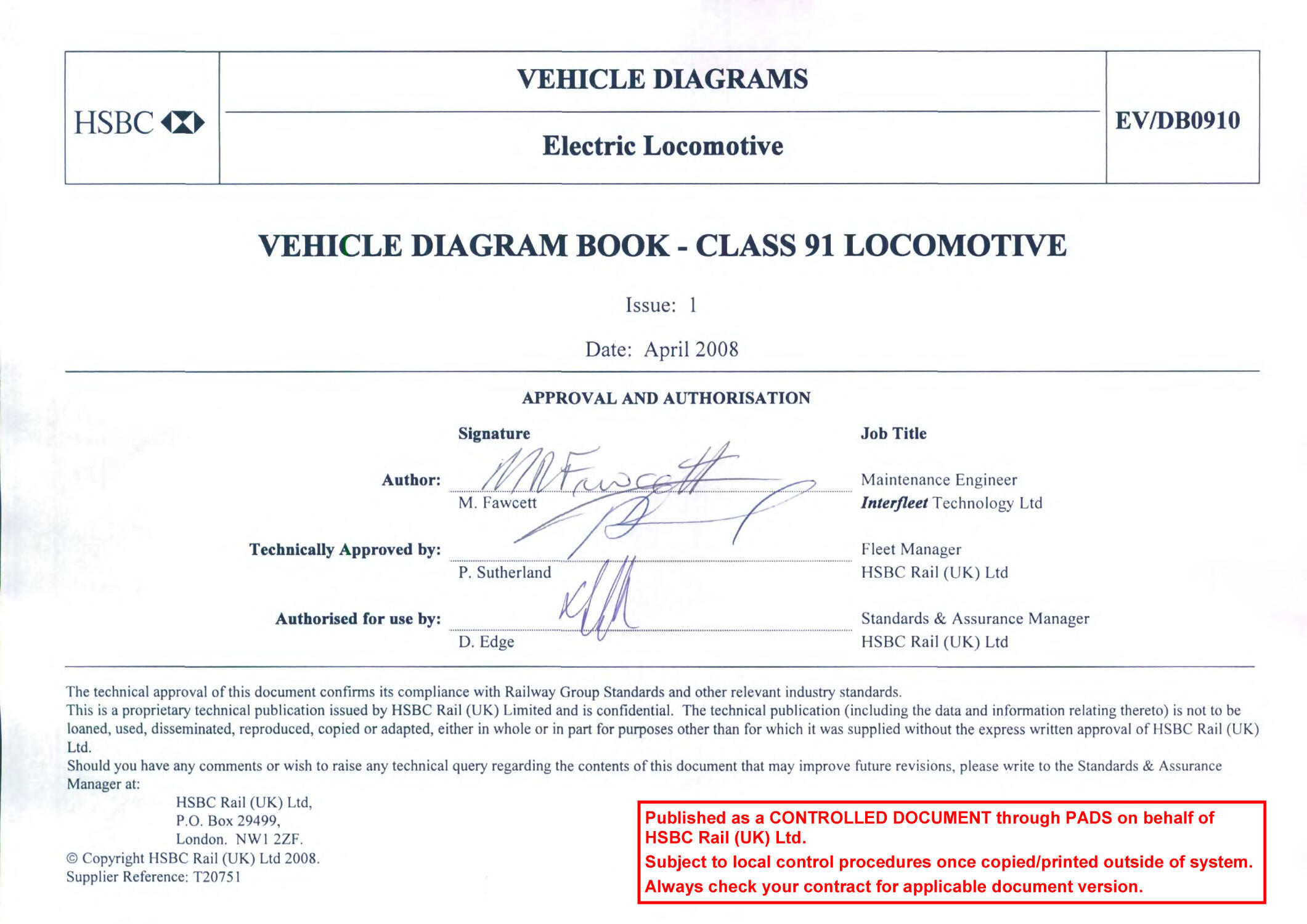
VEHICLE DIAGRAMS
Electric Locomotives
EV/
DB0910
Issue:
1
Date:
Apr
2008
Page:
2
of
11
DOCUMENT INDEX
CONTENTS
PAGE
Index
2
Issue/Revision
3
Vehicle Information:
Photograph
4
Data
5
Major Components
6
EMC Status
7
Component Identification Diagram
8
Veh
icle Diagram
9
Revision Letter:
Issue 1 (New Document).
10
VEHICLE DIAGRAMS
Electric Locomotives
EV/
DB0910
Issue:
1
Date:
Apr
2008
Page:
3
of
11
DOCUMENT ISSUE RECORD
This is a new document, which will be updated when necessary by issue of the complet
e document.
When changes occur, the amended or additional parts will be marked by a vertical black line in both the left and right margins.
Issue
Date
Pages Affected & Comments
1
April 2008
All pages affected
–
this is the creation of this document as I
ssue 1, based on
the relevant extract from the previous document, (EV/GD0003). See Revision
Letter for all change details.
VEHICLE DIAGRAMS
Electric Locomotives
EV/
DB0910
Issue:
1
Date:
Apr
2008
Page:
4
of
11
Class 91
-
Photograph
NXEC Trains Ltd
VEHICLE DIAGRAMS
Electric Locomotives
EV/
DB0910
Issue:
1
Date:
Apr
2008
Page:
5
of
11
Clas
s 91
-
Data
NOTE 1:
All vehicle and component weights shown are approximate weights.
NOTE 2:
The light locomotive maximum speed is limited to 75
mph and shall not be exceeded.
This is limited in the event that if all 4 safeset devices are lost (which
results in no
rheostatic brake) the locomotive still has adequate braking via the treadbrake.
Loco. No. Range:
91
1
01
-
91122 & 91124
-
91132
Interface
Equipment:
Thyristor,
Microprocessor
Control
, TDM,
Locomotives in Fleet:
31 (91023 now 91132)
FDM
,
TFDS
Supply:
25 kV, 50 Hz overhead line
Brakes:
Air, Electric Rheostatic
Maximum Speed
(
A
s part of
set):
125 mph
(Design Speed 140 mph)
Brake Pad:
Becorit
925/32 (Disc)
Maximum Speed (Light Loco):
75 mph (see Note 2)
Brake Block:
TBL
T804 (Tr
ead)
Length :
19.4 m
Auxiliaries:
Tertiary Winding
Weight :
85.25 tonnes
ETS Index:
95
Weight (less Bogies) :
62.25 tonnes
Lighting:
Incandescent
Built by:
BREL Crewe under contract from GEC
-
TPL
Train Communication
:
Cab / Shore Radio, Driv
er / Guard, NRN
Year Built:
1988
-
1991
AWS/TPWS:
Combined AWS/TPWS Solid State Receivers
Body Construction:
Steel
W.S.P. Equipment:
Alstom Traction Control MPU
Loading Gauge :
L
Wheelslip/Slide Protection
Minimum Radius Curve:
80 m
Coupl
er:
Drophead Buckeye
Route Availability:
7
Buffers:
Retractable
Number of Cabs:
2
Jumpers:
ETS, UIC (
RCH
-
No longer used)
OTMR:
Arrowvale 60 Channel which has user
Fire System:
Argonite Sealed System
defined digital & analogue channels
San
ding:
Auto Sanding in Traction & Braking
Power Rating:
Continuous rating 4.54 MW
Max Drawbar Force:
160kN
Maximum rating 4.70 MW
Performance:
Avg acceleration to 125mph 0.208 m/s
2
Deceleration Rate:
9% in Rheostatic & Friction
7%
in Friction only
VEHICLE DIAGRAMS
Electric Locomotives
EV/
DB0910
Issue:
1
Date:
Apr
2008
Page:
6
of
11
Class 91
-
Major Components
Bogies
(Bo Bo
BP52
11.5 tonnes
Wheelsets :
LSU02
1.7 tonnes
configuration):
Axle Construction:
Hollow
Main Transformer:
PT91
8.0
tonnes
Brake disc type:
Faiveley (D&M)
(wit
h Radiators &
oil)
Bearing Type:
Timken SP150 Cartridge Bearing
Pantograph:
Brecknell Willis
High Speed
(Special for Class 91)
Circuit Breaker:
20CB004B2
Air Conditioning (2):
EBAC
Power Choke (4):
G180CW
435kg
D.C. Power Supply Unit :
GEC
Traction Motor (4):
GEC G426AZ (Fitted with Safeset
Auxiliary Voltage :
110 V d.c.
Couplings & TFDS Sensors)
Battery (Control) :
VN71 (SAFT)
Traction Motor Power:
1.135Kw continuous
1.175Kw peak
Battery (Field) :
SRX45P (SAFT)
Traction Motor We
ight:
3.6 tonnes
Main Compressor (2) :
Faiveley (D&M) 2A115D
Transmission:
Main Compressor Motor:
Mawdsley, Lawrence Scott
Auxiliary Compressor :
Britol Type BPO/2
Auxiliary Compressor Motor:
Tuscan Type K8 BP/D
The power is transmitted from a body mounted
DC traction motor and Safeset coupling, via a
low friction cardan shaft and bogie mounted
90
° level drive gearbox, which is mount
ed
around the axle, via a quill onto the driven
wheel
Suspension Type:
Primary
–
Flexicoil Springs, Roll
ing
Rubber Ring Unit
Gear Ratio:
1.741:1
Secondary
–
Flexicoil Springs
Gearbox (4):
Voith HE22
1.1 tonnes
(inc drivehead)
Cardan Shaft:
Voith
GWB
288kg
259kg
Koni Dampers, Yaw, secondary
vertical, secondary lateral & primary
vertical.
VEHICLE DIAGRAMS
Electric Locomotives
EV/
DB0910
Issue:
1
Date:
Apr
2008
Page:
7
of
11
Class 91
-
EMC Status
All IC 225 Vehicles predate regulations.
Any ongoing changes to any vehicle are managed by the owner and operator in accordance with the relevant Engineering Change
process.
VEHICLE DIAGRAMS
Electric Locomotives
EV/
DB0910
Issue:
1
Date:
Apr
2008
Page:
8
of
11
Class 91
-
Component Identification
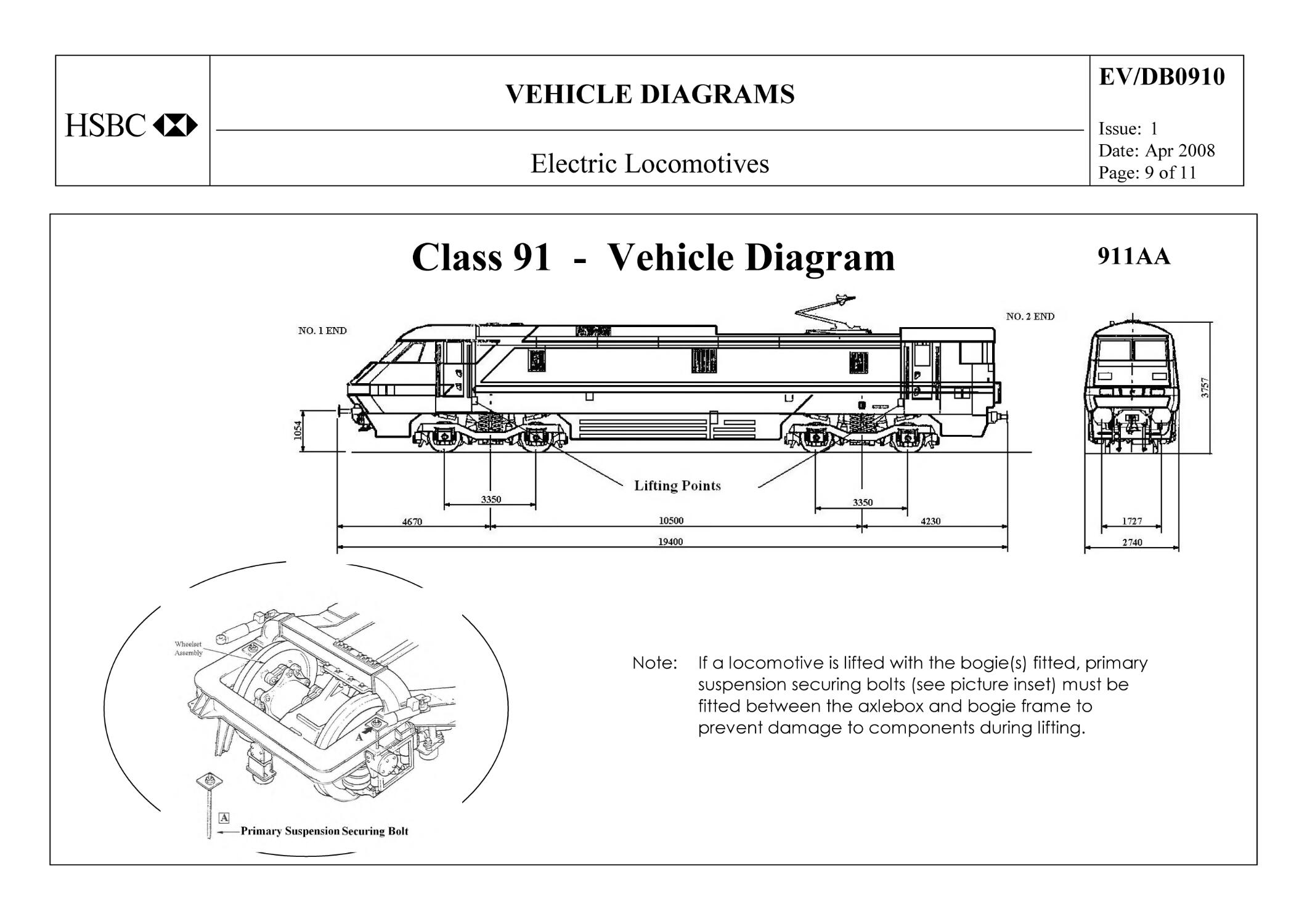
VEHICLE DIAGRAMS
Electric Locomotives
EV/
DB0910
Issue:
1
Date:
Apr
2008
Page:
9
of
11
Class 91
-
Vehicle Diagram
911AA
Note:
If a locomotive is lifted with the bogie(s) fitted, primary
suspension securing bolts
(see picture inset) must be
fitted between the axlebox and bogie frame to
prevent damage
to components
during lifting.
VEHICLE DIAGRAMS
Electric Locomotives
EV/
DB0910
Issue:
1
Date:
Apr
2008
Page:
10
of
11
REVISION LETTER
This is a new document, but is based on the pertinent extract from the previous document (EV/GD0003). For clarity, any future changes will have ‘bla
ck
lining’ added to indicate changes from the previous issue of the document. Additionally, to readily identify the specific changes to the document made
through deletions, additions, moved or modified data, etc., these changes are noted in the table belo
w:
Section
Change
Change
Category
Reason for Change
Authorisation
Front Sheet.
Page 1.
Authorisation Front Sheet now added.
M
To meet latest standards format
requirements.
Index.
Page 2.
Index now better defined and page
numbering now added:
F
Clearer d
rafting.
Issue / Record
Sheet.
Page 3.
Issue / Record Sheet now added.
M
To meet latest standards format
requirements.
Photograph
New photograph to show latest
TOC livery added.
C
To reflect new operators livery.
All other
sections
Latest known data c
aptured in relevant
sections.
C
To reflect changes that took place at
HGR
and post HGR.
VEHICLE DIAGRAMS
Electric Locomotives
EV/
DB0910
Issue:
1
Date:
Apr
2008
Page:
11
of
11
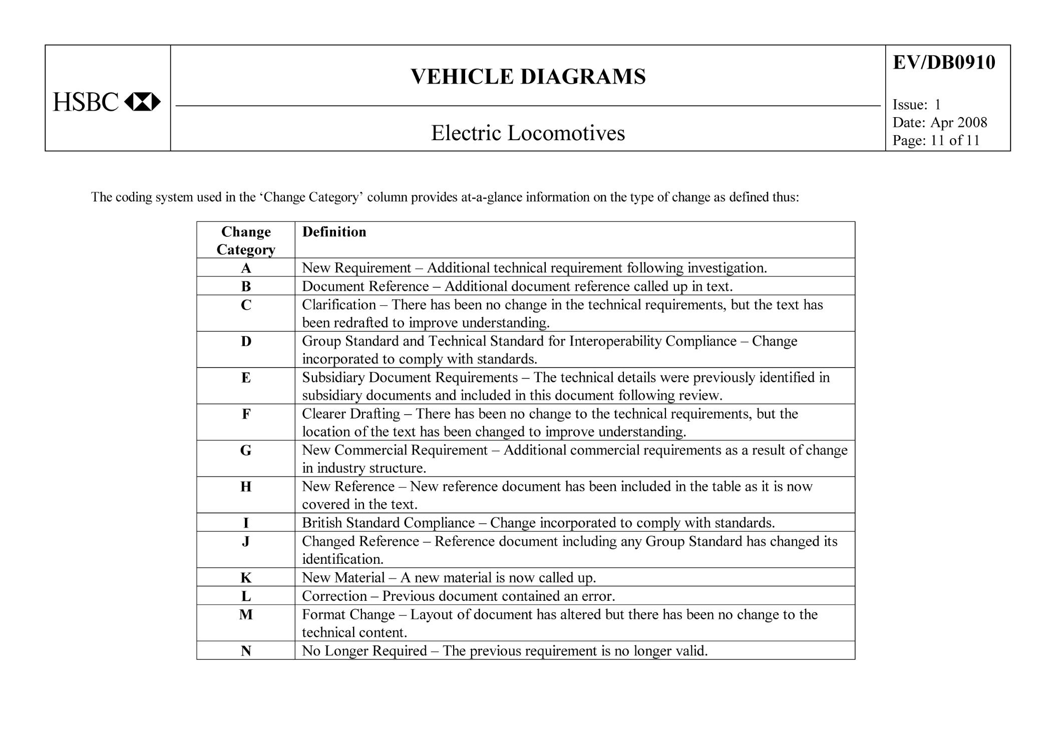
The coding system used in the ‘Change Category’ column provides at
-
a
-
glance information on the type of change as defined thus:
Change
Category
Definition
A
New Req
uirement
–
Additional technical requirement following investigation.
B
Document Reference
–
Additional document reference called up in text.
C
Clarification
–
There has been no change in the technical requirements, but the text has
been redrafted to impr
ove understanding.
D
Group Standard and Technical Standard for Interoperability Compliance
–
Change
incorporated to comply with standards.
E
Subsidiary Document Requirements
–
The technical details were previously identified in
subsidiary documents and i
ncluded in this document following review.
F
Clearer Drafting
–
There has been no change to the technical requirements, but the
location of the text has been changed to improve understanding.
G
New Commercial Requirement
–
Additional commercial requireme
nts as a result of change
in industry structure.
H
New Reference
–
New reference document has been included in the table as it is now
covered in the text.
I
British Standard Compliance
–
Change incorporated to comply with standards.
J
Changed Reference
–
Reference document including any Group Standard has changed its
identification.
K
New Material
–
A new material is now called up.
L
Correction
–
Previous document contained an error.
M
Format Change
–
Layout of document has altered but there has been
no change to the
technical content.
N
No Longer Required
–
The previous requirement is no longer valid.