/


Теги: military affairs engineering design handbook
Год: 1964
Похожие


Текст
AMC PAMPHLET
АМСР 706-175
ENGINEERING DESIGN HANDBOOK-
EXPLOSIVES SERIES
SOLID PROPELLANTS PART ONE
STATEMENT #2 UNCLASSIFIED
This document is subject to special export
controls and each transmittal to foreign
governments or foreign nationals may be made
only with prior approval of: Army Materiel
Command, Attn: AMCRD-TV, Washington, D.C.
20315
HEADQUARTERS, U. S, ARMY MATERIEL COMMAND
SIPTIMBIR 1964
/ЗС
f ENGINEERING DESIGN HANDBOOK SERIES
Listed below are the Handbooks which have been published or submitted for publication. Handbooks with publics-
tion dates prior to I August 1962 were published as 20-series Ordnance Corps pamphlets, AMC Circular 310-36, 19
July 1963, redesignated those publications as 7 06-series AMC pamphlets (i. e ., OR DP 20-138 was redesignated AMCP
706-138), All new, reprinted, or revised Handbooks are being published as 706-series AMC pamphlets.
General and Miscellaneous Subjects
Number Title
106 Elements of Armament Engineering, Part One,
Sources of Energy
107 Elements of Armament Engineering, Part Two,
Ballistics
108 Elements of Armament Engineering, Part Three,
Weapon Systems and Components
110 Experimental Statistics, Section 1, Basic Con-
cepts and Analysis of Measurement Data
111 Experimental Statistics Section 2, Analysis of
Enumerativs and CLassificatory Data
112 Experimental Statistics, Section 3,Planning
and Analysis of Comparative Experiments
113 Experimental Statistics. Section 4, Special
Topics
114 Experimental Statistics, Section 5, Tables
121 Packaging and Pack Engineering
134 Maintenance Engineering Guide for Ordnance
Design
138 Inventions, Patents, and Related Matte rs
(Revised)
136 Servomechanisms, Section 1, Theory
137 Servomechanisms, Section 2, Measurement
and Signa) Converters
138 Servomechanisms, Section 3, Amplification
4139 Servomechanisms, Section 4, Power Elements
I and System Design
170(C) Armor and Its Application to Vehicles (J)
250 Guns--Genera) (Guns Series)
252 Gun Tubes (Guns Series)
270 Propellant Actuated Devices
290(C) Warheads--Genera) (U)
331 Compensating Elements (Fire Control Series)
355 The Automotive Assembly (Automotive Series)
Ballistic Miseile Series
Number
281(S-RD)
282
284(C)
286
Title
Weapon System Effectiveness (U)
Propulsion and Propellants
Trajectories (U)
Structures
Ballistics Series
140
150
160(S)
161(S)
162(5-RD)
Trajectories, Differential Effects, and
Data for Projectiles
Interior Ballistics of Guns
Elements of Terminal Ballistics, Part
One, Introduction, Kill Mechanisms,
and Vulnerability (U)
Elements of Terminal Ballistics, Part
Two, Collection and Analysis of Data
Concerning Targets (U)
Elements of Terminal Ballistics, Part
Three, Application to Missile and
Space Targets (U)
Carriages and Mounts Senes
340 Carriages and Mounts--Qeneral
341 Cradles
342 Recoil Systems
343 Top Carriages
344 Bottom Carriages
345 Equilibrators
346 Elevating Mechanisms
347 . Traversing Mechanisms
Materials Handbooks
Ammunition and Explosive* Scries
175 Solid Propellants, Part One
176(C) Solid Propellants, Part Two (U)
17? Properties of Explosives of Military Interest,
Section I
301 Aluminum and Aluminum Alloys
302 Copper and Copper Alloys
303 Magnesium and Magnesium Alloys
Titanium and Titanium Alloys
308 Glass
309 Plastics
310
Rubber and Rubber-Like Materials
178(C)
210
211(C)
212(S)
2B(S)
214(S)
215(C)
244
Properties of Explosives of Military Interest,
Section 2 (U)
Fuses, General and Mechanical
Military Pyrotechnics Senes
186 Part Two, Safety, Procedures and
Glossary
187 Part Three, Properties oi Materials
Used in Pyrotechnic Compositions
Section 1, Artillery Ainmunition--Goneral,
245(C)
246
247
242
249
with Table of Contente. Glossary and
Index for Series
Section 2, Design for Terminal Effects (U)
Section 3, Design for Control of Flight
Characteristics
Surface-to-Air Missile Series
291 Part One, System integration
292 Part Two, Weapon Control
293 Part Three, Computers
294(S) Part Four, Missile Armament (U)
295(S) Part Five, Countermeasures (U)
296 Part Six, Structures and Power Sources
297(S) Part Seven, Sample Problem (U)
Section 4, Design for Projection
Section 5, Inspection Aspects of Artillery
Ammunition Design
Section 6, Manufacture of Metallic Components
of Artillery Ammunition
HEADQUARTERS
UNITED STATES ARMY MATERIEL COMMAND
WASHINGTON, D. C. 20315
30 September 1964
AMCP 706-175, Solid Propellants, Part One, forming part of
the Explosives Series of the Army Materiel Command Engineering
Design Handbook Series, is published for the information and guid'
ance of all concerned.
(AMCRD)
FOR THE COMMANDER:
Chief, Administrative Office
SELWYN D. SMITH, JR.
Major General, USA
Chief of Staff
DISTRIBUTION: Special
EXPLOSIVES SERIES
SOLID PROPELLANTS
PART ONE
By A. M. Ball
CONSISTING OF
CHAPTERS 1-10
PREFACE
This handbook has been prepared as one of a series on Explosives.
It is part of a group of handbooks covering the engineering principles
and fundamental data needed in the development of Army materiel,
which (as a group) constitutes the Engineering Design Handbook Series
of the Army Materiel Command.
\ “ГЦ '
-This handbook presents information on the design, functioning and
manufacture of solid propellants for use in propelling charges for guns
and rockets.
The text and illustrations for this handbook were prepared by
Hercules Powder Company under subcontract to the Engineering Hand-
book Office of Duke University, prime contractor to the Army Research
Office-Durham for the Engineering Design Handbook Series.
Agencies of the Department of Defense, having need for Handbooks,
may submit requisitions or official requests directly to Publications
and Reproduction Agency, Letterkenny Army Depot, Chambe'rsburg,
Pennsylvania 17201. Contractors should submit such requisitions or
requests to their contracting officers.
Comments and suggestions on this handbook are welcome and
should be addressed to Army Research Office-Durham, Box CM, Duke
Station, Durham, North Carolina 27706.
TABLE OF CONTENTS
Paragraph Page
PREFACE............................................. ii
LIST OF ILLUSTRATIONS............................. viii
LIST OF TABLES...................................... x
LIST OF SYMBOLS..................................... xi
СНАРП» 1
INTRODUCTION
1 PURPOSE............................................. 1
2 DEFINITIONS........................................... I
3 PLAN.................................................. 1
REFERENCES......................................... 2
CHAPTBt 2
EVOLUTION OF OASES BY PROFBIANTS
4 GENERAL............................................... 3
5 EQUATION OF STATE..................................... 3
6 BALLISTIC PARAMETERS................................. 3
6-1 Specific Force..................................... 4
6-2 Characteristic Velocity............................ 4
6-3 Reduced Characteristic Velocity...................... 4
6-4 Specific Impulse..................................... 4
6-5 Reduced Specific Impulse........................... 4
6-6 Volume Specific Impulse.............................. 5
6-7 Gas Horsepower....................................... 5
7 THERMOCHEMISTRY. .................................... 5
7-1 Specific Gas Volume.................................. 5
7-2 Flame Temperature at Constant Volume................. 6
7-3 Flame Temperature at Constant Pressure............... 6
7-4 Ratio of Specific Heats............................ 6
7-5 Exact Calculation of Flame Temperature and Product
Composition............................................... 7
7-6 Hinchfelder-Sherman Calculation.......................... 7
7-7 Example Calculation ofF, cf, by the Hirschfelder-Sherman
Method....................................................... 9
7-8 ABL Short Calculation for Specific Impulse.............. 10
8 MEASUREMENT OF BALLISTIC PARAMETERS....................... 10
8 -1 Measurement of Heat of Explosion.................... 10
8-2 Measurement of Specific Force...................... 10
8-3 Measurement of Characteristic Velocity............ 11
8-4 Measurement of Specific Impulse..................... 11
fi-5 Example Calculation of I* from Measured (del) at Non*
standard Conditions......................................... 11
9 BURNING OF PROPELLANTS.................................... 12
9-1 Effect of Pressure................................ 13
9-2 Effect of Temperature............................... 14
9-3 Effect of Ou Velocity. Erosive Burning.............. 15
9-4 Effect of Composition............................... 15
Ш
TABLE OF CONTENTS (Continued)
Paragraph Page
9-5 Burning Rate of Composite Propellant*............ 16
9-6 Problem of Unstable Burning...................... 17
9-7 Transition from Deflagration to Detonation....... 17
10 PROPELLANT GkAlN............................... 17
11 SCHEDULING OF MASS RATE.......................... 19
11-1 Gun.............................................. 19
11-2 Catapult......................................... 20
11-3 Rocket Motor....................................... 22
11-4 Calculation of a Rocket Propellant Charge...... 22
11-5 Gas Generator.................................... 24
11-6 Calculation of a Gas Generator Propellant Charge. 24
REFERENCES..................................... 24
CHAPTSt 3
PHYSICAL PftOPStTIES UQUIUMENTS
12 GENERAL........................................ 27
13 DENSITY.......................................... 27
14 GRAVIMETRIC DENSITY.............................. 27
15 HYGROSCOPICITY................................... 27
16 COEFFICIENT OF THERMAL EXPANSION................. 28
17 THERMAL CONDUCTIVITY............................. 28
18 MECHANICAL PROPERTIES............................ 28
18-1 Ultimate Tensile Strength........................ 28
18-2 Elongation in Tension............................ 28
18-3 Modulus in Tension............................... 28
18-4 Stress Relaxation................................ 28
18-5 Creep.............................................. 31
18-6 Compressive Strength............................. 31
18-7 Deformation at Rupture in Compression.......... 31
18-8 Modulus in Compression......................... 31
18-9 Shear Properties................................. 31
18-10 Brittle Temperature............................ 31
REFERENCES....................................... 31
CHAPTBt 4
MACK POWDBt
19 GENERAL.......................................... 33
20 APPEARANCE....................................... 33
21 COMPOSITION...................................... 33
22 GRANULATION...................................... 33
23 THERMOCHEMISTRY.................................. 33
24 HYGROSCOPICITY................................... 36
25 SHELF LIFE....................................... 36
26 MANUFACTURING PROCESS............................ 36
27 USES............................................ 37
REFERENCES....................................... 41
iv
TABLE OF CONTENTS (Continued)
Paragraph Page
CHAPTER 5
CRYSTALLINE MONOPROPWANTS
28 GENERAL............................................. 42
29 NITROGUANIDINE........................................ 42
30 RDX................................................. 43
31 HMX................................................... 43
32 PETN.................................................. 43
33 AMMONIUM NITRATE..................................... 44
34 AMMONIUM PERCHLORATE.................................. 44
REFERENCES........................................... 44
CHAPTBt «
PLASTIC MONOPROPWANTS
35 GENERAL.............................................. 45
36 FORMULATION.......................................... 45
36-1 Polymer.................................................. 45
36-1.1 Nitrocellulose....................................... 46
36-1.1.1 Nitrogen Content..................................... 46
36-1.1.2 Solubility....................................... 46
36-1.1.3 Hygroscopicity................................ 46
36-1.1.4 Viscosity....................................... 48
36-1.2 Other Polymers..................................... 48
36-2 Stabilizer............................................... 48
36.2.1 Diphenylamine.................................... 49
36-2.2 2-Nitrodiphenylamine............................... 49
36-2.3 Ethyl Centralite................................... 49
36-3 Oxidant-Type Plasticizers.......................... 49
36-4 Fuel-Type Plasticizers............................ 49
36-5 Additives........................................... 50
37 BALLISTIC CHARACTERISTICS............................ 50
38 PHYSICAL PROPERTIES.................................. 51
38-1 Ultimate Strength.................................. 51
38-2 Deformation at Rupture.............................. 52
38-3 Cold Flow........................................... 52
38-4 Hygroscopicity.................................... 52
38-5 Density............................................. 52
38-6 Vapor Pressure......................................... ,., 52
38-7 Coefficient of Thermal Expansion.................... 52
38-8 Plasticity.......................................... 52
39 THERMAL PROPERTIES................................... 52
40 USES................................................. 53
40-1 Gun Propellants.................................... 53
40-1.1 Propellants for Cannon............................. 54
40-1.2 Propellants for Small Arms..................... 54
40-1.3 Propellants for Mortars........................ 54
v
TABLE OF CONTENTS (Continued)
Paragraph Page
40-2 Rocket ant*. Gas Generator Propellants.................. 54
40-2.1 Propellants for Rockets........................ 56
40-2.2 Propellants for Gas Generators................. 56
REFERENCES.......................................... 56
CHAPTHt 7
COMPOSITES COMPRISING CRYSTALLINE MONOPROPEUANTS
IN PLASTIC MONOPROPEUAKT BINDERS
41 GENERAL............................................. 58
42 FORMULATIONS........................................ 58
43 BALLISTIC CHARACTERISTICS........................... 58
43-1 Nonflashing Nitroguanidine Propellants.............. 58
43-2 High Force Nitroguanidine Propellants............... 59
44 PHYSICAL PROPERTIES................................. 59
45 THERMAL PROPERTIES.................................. 61
46 MANUFACTURING PROCESS............................... 61
REFERENCES......................................... 61
CH APTER 8
MANUFACTURING PROCESSES FOR SMOKMESS POWDBt
47 GENERAL........................................... 62
48 NITROCELLULOSE...................................... 62
48-1 Nitrogen Content.................................... 65
48-2 Solubility.......................................... 66
48-3 Viscosity......................................... 66
48-4 Significance of Nitrocellulose Properties........... 66
49 SOLVENT EXTRUSION................................... 66
49-1 Mixing.................................................. 67
49-1.1 Premixing Operations............................. 67
49-1.2 Post-Sigma Blade Mixing Operations............. 68
49-2 Forming............................................ 72
49-3 Removal of Solvent.................................. 72
49-4 Finishing......................................... 72
49-5 Blending.......................................... 72
49-6 Propellants Made by Solvent Extrusion............... 72
50 SOLVENT EMULSION (BALL POWDER) PROCESS.............. 74
50-1 Forming Operations.................................. 74
50-2 Incorporation of Plasticizers....................... 75
50-3 Finishing Operations................................ 75
51 ROLLED SHEET PROCESS................................ 77
5I-I Mixing.................................................. 77
51-2 Rolling.......................................... 77
51-3 Finishing........................................... SO
vi
TABLE OF CONTENTS (Continue?}
Paragraph Page
52 SOLVENTLFSS EXTRUSION PROCESS........................ 80
52-1 Extrusion........................................ 80
52-2 Finishing.......................................... 80
52-3 Flaws.............................................. 84
53 CAST DOUBLE-BASE PROCESS............................. 84
53-1 Casting........................................... 85
53-2 Curing........................................... 88
53-3 Physical Strength....................................... 88
53-4 Uses of Propellants Made by Cast Double-Base Process. 88
54 SLURRY CASTING PROCESS............................... 88
REFERENCES.......................................... 88
CHAFT3». 9
FUEL BINDER COMPOSITES
55 GENERAL.............................................. 89
56 CHOICE OF OXIDIZER................................... 89
56-1 Potassium Perchlorate.............................. 90
56-2 Ammonium Perchlorate............................... 90
56-3 Lithium Ptrchlcrate........... ........................ .. 93
56-4 Ammonium Nitrate................................... 93
56-5 Mixed Oxidizers.................................... 94
57 VOLUMETRIC RELATION OF OXIDIZER TO BINDER.............. 94
58 CHOICE OF BINDER..................................... 94
58-1 Asphalt............................................ 95
58-2 Polyisobutene...................................... 95
58-3 Elastomeric Binders................................ 95
58-3.1 Polysulfide Rubber................................. 95
58-3.2 Polyurethane Rubber................................ 98
58-3.3 Butadiene-Acryiic Acid Copolymer Rubber, PBAA..... 99
58-3.4 Poly(vinyl Chloride)............................. 99
58-3.5 Elastomeric Binders for Cartridge-Loaded Grains... 101
58-4 Thermoplastic Synthetic Polymer Binders for Cartridge-Loaded
Grains........................................ 102
58-5 Cellulose Acetate................................. 102
58-6 Other R-ider Systems............................ 102
REFERENCES......................................... Ill
CHAPTH 10
INERT SIMULANTS FOR PROPELLANTS
59 GENERAL.................................... 112
60 MOCK-UPS............................. 112
61 SIMULANTS TO REPRODUCE PHYSICAL PROPERTIES. ..112
62 SIMULANTS TO REPRODUCE MANUFACTURING PROP-
ERTIES 112
63 SEMILIVE............................. 113
REFERENCES............................ 113
GLOSSARY......................................... 114
INDEX................................. 117
vii
LIST OF ILLUSTRATIONS
Figure Title Page
1 Reduced specific impulse versus area ratio and gamma.......... 5
2 Burning of solid monopropellant................................... 12
3 Rate-pressure relationship of propellants for which r = bP*.... 13
4 Rate-pressure relationship of plateau propellants............ 13
5 Rate-pressure relationship of mesa propellants............... 14
6 Burning of composite propellants—filler rate faster than binder... 16
7 Burning of composite propellant—filler rate slower than binder... 16
8 Neutral geometry............................................. 18
9 Rod and shell grain......................,........................ 18
10 Star-perforated grain............................................ 18
11 Slotted-tube grain................................................ 18
12 Progressive geometry.............................................. 18
13 Multiple-perforated cylinder...................................... 19
14 Degressive geometry............................................... 19
15 Gun cycle....................................................... 20
16 Closed bomb assembly.............................................. 21
17 Closed bomb record................................................ 21
18 Catapult cycle.................................................. 22
19 Rocket motor cycle................................................ 22
20 Tensile test setup................................................ 29
21 Tensile test record showing derivation of ultimate strength, elonga-
tion, and modulus..................................................... 30
22 Black powder, grade FFFFG, 8X magnify-uvii........................ 34
23 Black powder manufacturing process................................ 37
24 Black powder wheel mill........................................... 38
25 Black powder press.............................................. 39
26 Nitrocellulose monopropellant system.............................. 45
27 Cross section of grain of IMR smokeless powder for small arms,
photographed in ultraviolet light, 112X magnification........ 47
28 Physical properties versus polyi er concentration................. 51
29 Relationships among T„ F, ana Q for gun propellants........... 53
30 Specific impulse of double-base rocket propellants as a function
ofT,.................................................... 54
31 Burning rates of double-base rocket and gas generator propellants 55
32 Cross section of triple-base gun propellant grain, crossed nicols,
32X magnification..................................................... 60
33 Nitrocellulose manufacture........................................ 62
34 Cellulose nitrator................................................ 63
35 Nitrocellulose wringers........................................... 64
36 Nitrocellulose boiling tub*..................................... 65
37 Solvent extrusion process......................................... 67
38 Sigma blade mixer................................................. 68
39 Schraeder mixer................................................... 69
40 Macerator..................................................... 70
41 Macaroni and blocking presses..................................... 71
42 Cutting machine................................................... 73
43 Sweetie barrel.................................................. 74
viii
LIST OF ILLUSTRATIONS (Continued)
Figure Title Page
44 Solvent emulsion process.......................................... 75
45 Bail powder........................................,............. 76
46 Still.......................................................... 77
47 Rolled sheet process........ .................................... 78
48 Roll mill........................................................ 78
49 Slitter.......................................................... 79
50 Trench mortar increments......................................... 81
51 Solventless extrusion process.................................... 81
52 Solventless extruded shapes..............,....................... 82
53 Carpet rolling................................................. 83
54 Solventless extrusion press..................................... 84
55 Cast double-base process......................................... 85
56 Mold parts....................................................... 85
57 Casting setup............................... 86
58 Cast grain..................................................... 87
59 Specific impulse, /„, and flame temperature, of NH^CiO^-fuel
binder composites................................................... 91
60 Burning rate, r, at 1000 psi, ambient temperature of NH^lO^-fuel
binder composites..................................................... 92
61 Specific impulses, I„, and flame temperatures, of NH^NOj-fuel
binder composites..................................................... 93
62 Slurry casting process.......................................... 95
63 Sigma blade mixer (200 gallon).................................. 96
64 Vertical mixer (300 gallon)...................................... 97
65 Mandrel for medium size rocket motor............................. 98
66 Medium size case-bonded grain with a 5-point star configuration.. 99
67 1-inch extruder for poly (vinyl chloride) propellant............ 100
68 Extrusion of wired grain........................................ 101
69 Extrusion process for fuel binder composites.................... 102
70 Blocking press.................................................. 103
71 Extrusion press................................................ 104
72 Compression molding process for fuel binder composites.. 104
73 Compressing stacked disks....................................... 105
74 Machining outside diameter of grain............................. 106
75 Jato grains................................................... 107
76 Finished jatos.................................................. 108
77 Individual segment (50 pounds) of 1000-pound segmented grain.. 109
78 Segmented grain (1000 pounds)................................,,,,110
ix
UST OF TABUS
Table
1
2
3
4
5
б
7
8
9
10
11
12
13
14
Title Page
Reduced characteristic velocity.............................. 4
Thermochemical constants for Hirschfelder-Sherman calculation.. 8
Nominal compositions of biack powder available in the United
States....................................................... 33
Granulations of potassium nitrate black powders................ 33
Granulations of sodium nitrate black powders................... 36
Consumption of black blasting powder (all types) in the United
States....................................................... 40
Physical and ballistic parameters of crystalline monopropellants.. 42
Hygroscopicity of nitrocellulose............................... 48
Nonflashing propellants........................................ 39
High force propellants......................................... 59
Oxidizers for fuel binder composites......................... 89
Hypothetical fuel binder СН|Л.................................. 90
Hypothetical propellants..................................... 90
Oxidizer loading versus binder density per unit volume........ 94
x
UST OF SYMBOLS
a = a constant
a = acceleration
i — time rate of acceleration
a (subscript) = atmospheric
m (subscript) = average
Л» = area of burning surface = S
A, = area of nozzle exit
A, = port area
At = nozzle throat ares
b = a constant
b' = a constant
h" = a constant
c (subscript) = chamber
c* = characteristic velocity
c* —. calculated thermodynamic characteristic
velocity
С ® concentration of polymer in solution
Cd — mass flow factor = -r
c*
Cr = thrust coefficient
C< = number at weight atoms of carbon m
unit weight of ingredient I in propellant
composition
Ct = molar heat capacity at constant 1'ressure
C, = molar heat capacity at constant volume
d = grain diameter
Dt = diameter of nozzle exit
Dt = diameter of nozzle throat
e — base of natural logarithms
e (subscript) — exit
E — internal energy
aE = heat of formation = Ht
/ (subscript) = partial value contributed by fuel
F = specific force or impetus
F — thrust
g = acceleration of gravity
g (subscript) = gaseous state
G = mass velocity of the gases in the port
Ghp = gas horsepower
H = moisture content
Hf = heat of formation = A£
= heat of explosion = Q
AH = enthalpy change
i (subscript) = partial value contributed tr ingre-
dient/
I = ingredient in propellant composition
I = total impulse
= specific impulse
/Д = calculated thermodynamic specific im-
pulse
Z„ (del) = measured specific impulse at nonstand-
ard conditions
/ (subscript) = partial value contributed by product
J = product gas constituent
к = erosion constant
К = a constant
К = Kelvin (temperature)
К = ratio of initial propellant burning surface
to nozzle throat area =
= erosivity constant
/ (subscript) = liquid state
L = distance downstream from the stagna-
tion point
L = grain length
M — molecular weight of combustion gases
= specific gas volume
= average molecular weight of combustion
gases at isobaric adiabatic flame tem-
perature
= average molecular weight of combustion
gases at isochoric adiabatic flame tem-
perature
n = exponent in de Saint Robert burning rate
equation, r = bP*
n = gas volume in moles produced from unit
weight of propellant = ±
nt
n> — moles per unit weight of gas at isobaric
adiabatic flame temperature
n, = moles per unit weight of gas at isochoric
adiabatic flame temperature
a (subscript or superscript) = calculated thermo-
dynamic value
a (subscript) = initial condition
ox (subscript) = partial value contributed by oxi-
dizer
p (subscript) — constant pressure conditions
P = pressure
P, — chamber pressure
xi
LIST OF SYMBOLS (Continued)
— heat of explosion = H„
= linear burning rate
= Rankine (temperature)
R
= specific gas constant = -rj
R, = universal gas constant
RF = relative force
RH = relative humidity
RQ = relative quickness
j (subscript) = solid state
S — area of burning surface
S = tensile stress
5, = tensile stress at break
Sf = final area of surface after burning
St — initial area of surface
S» = maximum stress
t = time
X» = burning time
t (subscript) = throat condition
T = absolute temperature
Tt = initial temperature
T< = pyrolysis temperature
T« = reference temperature
7, = isobaric adiabatic flame temperature
Tt = temperature at throat
T, = isochoric adiabatic flame temperature
к = a constant
v (subscript) = constant volume conditions
V = velocity
V = volume
Vt = volume of propellant
W = weight
dW
W = weight burning rate =
x s weight fraction
у = volume fraction
------(overline) — average
a = a constant
a = covolume
a = nozzle divergence half-angle
fl = a constant
fl = volumetric coefficient of thermal expan-
sion
C.
у — ratio of specific heats = -£
c = nozzle-expansion area ratio ~
y = viscosity of solution
= viscosity of solvent
= relative viscosity
= nozzle divergence loss factor
= propellant mass ratio, ratio of propellant
mass of any stage to gross mass of that
stage
= temperature coefficient of pressure at
constant pressure-rate ratio =
temperature coefficient at pressure at
constant К value
= density
1
P
= specific volume
= temperature coefficient of burning rate at
. . /Э1пг\
constant pressure = ("gy)
— temperature coefficient of burning rate at
constant К value = ()
* (superscript dot) = time derivative
SOLID PROPELLANTS
FAM ONI
CHAPYM 1
INTRODUCTION
1. Purpose. Thb Handbook b intended to pro-
vide a general description of solid propellant*
wed in «mall arnu, artillery, rocket*, and кипе
other devices. It is assumed that the reader has as
background the equivalent of an undergraduate
degree in engineering or physical science, but no
previous experience in propellants or ballistics.
X Dadnitions. A solid propellant is a chemical
or a mixture of chemical* which when ignited
burns in the substantial absence of atmospheric
oxygen at a controlled rate and evolves gas capable
of performing work. In order to discuss certain
phenomena, notably burning and detonation proc-
esses, it b necessary to define certain term* that
are used with meanings differing significantly from
those given in MIL-STD-444.1* The more im-
portant of these are:
A (solid) monopropellant b a single physical
phaae comprising both oxidizing and fuel ele-
ment*. This is analogous to common usage in
the liquid propellant field describing a single-
phase liquid propellant.
A filler b a discrete material dispersed in
substantial quantity in the continuous or binder
phaae <Л a composite propellant
Deflagration b a bunting process in a solid
system, comprising both oxidant and fuel, in
which the reaction front advances at les* than
sonic velocity and gaseous products if produced
move away from unreacted material. Whether
or not explosion occurs as a result of deflagra-
tion depends on confinement.
None of these definitions b used for the first
time in thb Handbook. Other definition* are intro-
duced in the text at appropriate places. Unless
otherwise noted, definitions are in accord with
* Number* refer to items lined a* Betances at the end
0^ MCb сйяриг*
MIL-STD-444, Merriam-Webster's unabridged
dictionary, or common usage.
3. Plan. In Chapter 2 b described how the
figures of merit—specific force for gun propel-
lants and specific impulse or characteristic velocity
for rocket propellants—are derived from therm»,
chemical data and empirically verified. Abo in
Chapter 2 b discussed the mechanism of burning
of propellant* and the scheduling of gas evolution
to meet the requirements of various engine* in
which propellants are used, such a* guns, cata-
pults, rockets, and gas generator*. A few simple
numerical example* are given by way of illustra-
tion, but detailed discussion of the ballistics of
such engines b omitted as being beyond the scope
of thb work and available elsewhere. In Chapter 3
appear* a discussion of certain physical properties
of propellants as related to system requirement*.
In Chapters 4-9 conventional propellant* are dis-
cussed, arranged according to their physical struc-
ture. Black powder b presented in Chapter 4.
Crystalline monopropellants appear in Chapter
5. Plastic monopropellant*, commonly known as
single-base and double-base propellants, appear in
Chapter 6. These common terms can be somewhat
confusing, since the class contains propellant*
comprising, for example, cellulose acetate and
nitroglycerin winch are difficult to assign to either
single- or double-base. Composites comprising
mcnopropellaiit binder and monopropellant filler,
commonly known as triple-base, appear in Chap-
ter 7. Apia the common term can be confusing,
as when a nitroguanidlne propellant with a single-
base (nitrocellulose) binder is to be described.
Manufacturing processes for the propellants of
Chapters 6 and 7 are given in Chapter 8. Fuel
binder composites are discussed in Chapter 9. A
discussion of inert simulants, or dummies, for pro-
pellants b given in Chapter 10. Higher energy
1
systems are discussed in ORDP 20-176, Solid Pro-
plants. Part Two (C).
literature consulted in the preparation this
Handbook includes publications early in 1960.
The reader is referred to SPIA/M2,’ in which will
be found data sheets for all of the propellants
developed and used within the Department of De-
fense including those that win appear subsequent
to the publication of this Handbook.
ummui
1. MIL-STD-444, Military Standard. Nomenclature and
Definitions in the Ammunition Area, Department of
Defense, 6 February 1954.
2. SPIA/M2, Propellant Manual, Solid Propellant In-
formation Agency, Johns Hopkins University, CON-
FIDENTIAL.
2
СМАРТ* 2
EVOLUTION OF GASES BY PROPELLANTS
4. GcmmL The devices in which propellants
are commonly used, be they devices, such as guns
that comprise moving pistons, or vented vessels
acquiring momentum by discharge of gas, .are de-
vices that convert heat energy into mechanical
energy. They thus fall into the general classifica-
tion of beat engines. The propellant gas is then
the working fluid that actuates heat engines. In
solid propellant heat engines the working fluid is
generated in situ by burning the propellant within
the engine. The general problem in fitting a solid
propellant to a heat engine is the generation of gas
of specified properties at a specified rate which is
a function of time. The specifications of gas prop-
erties and rate of generation are not usually inde-
pendent of each other. Thus a given problem may
be solved by using gas with one set of properties
at one rate schedule or, alternately, by using a dif-
ferent set Gt gas properties on a correspondingly
different rate schedule. The properties of the gas
are determined by the composition of the propel-
lant The derivation of the gas properties from the
composition is known as thermochemistry of pro-
pellants. The rate of gas generation is determined
by the linear rate of burning and charge geom-
etry. Of these, the linear burning rate as a func-
tion of pressure is a propellant property. System
pressure and charge geometry are controlled at
least in part by the end-item specification. The
overall problem of selecting a propellant formula-
tion and geometry to meet a given end-item per-
formance specification is an exercise in interior
ballistics. Because the propellant developer owes
tire ballistidan both thermochemical data and rate
versus pressure data, he should have a qualitative
knowledge of interior ballistics in order to perform
his function intelligently.
5. Equation of state. The classical equation of
state used by ballisticians is known as the Noble-
Abel equation. For unit mass of propellant it is
usually written
P(V- a) = RT
where К is the gas constant per unit mass of pro-
pellant, or more generally
(1)
tn
where Я. is the universal gas constant The term
a is known as the covolume and may be thought
of as the space occupied by the gas when com-
pressed to the limit. It has the empirical value of
about 1 cc per gram for most propellants.1 The
significance Gt the covolume correction may be
shown by some simple numerical examples. Under
standard conditions of temperature and pressure
(273°K, 1 atm), 1 gram of gas of molecular weight
22.4 occupies 1000 cc. A temperature of 2730‘K
and a pressure of 68 atm (1000 psi) are conditions
typical of rocket ballistics. Under these circum-
stances
TIKI 1
V - a = 1000 X x ~ = 147 cc
273 Oft
For 1 percent accuracy, V — a does not differ
significantly from V. It is customary, 'berefore, in
rocket ballistics to ignore the covolume correction
and use the perfect gas equation
(la)
as the equation of state. On the other hand,
whereas we encounter similar temperatures in gun
ballistics, the pressures are higher. Taking 3000
atm (44000 psi) as typical, for 1 gram of gas
2730 1
V - « = 1000 x X = 3.3 cc
273 3UUU
Under these conditions, V — a differs significantly
from V, and the covolume correction must be
made. For precise calculations, other equations of
state of greater precision than Equation 1 are used.
These equations are more complex and contain
constants the physical significance of which is more
difficult to understand. In such calculations the
departure from the perfect gas law is still called
the covolume correction. The covolume if evalu-
ated is no longer a constant but is a variable with
a value stin in the neighborhood of Noble-Abel's a.
6. Ballistic parameters. Different systems’ * of
interior ballistics have been developed by gun bal-
listicians on the one hand and by rocket ballis-
ticians on the other. Both typer of system depend
on the same primary thermochemical properties
of propellant gases, but use different parameters as
3
working tools. Thus, as a measure of the ability
cf the combustion products of propellants to per-
form in their respective heat engines, gun ballis-
tioans use the parameter specific force (often
abbreviated to force), or impetus, F. Rocket bal-
Mstirians use for the same purpose characteristic
velocity, c*, or specific impulse, l„. Auxiliary
power unit engineers sometimes use gas horse-
power, Ghp.
Ы. fiperific tare. Specific force, F, is a meas-
ure of the ability of the propellant gas to perform
work. It is defined by the equation
F = ^ (2)
sad is expressed in terms of foot-pounds per
pound*
iW* ОмнгмОокЪЙс TaKeeSt^» Characteristic ve-
locity, c*, is not a significant physical quantity.
It is defined as where Pt is chamber pres-
sure, /It is nozzle throat area, and W is burning
rate in pounds per second. Mathematical analysis*
shows that it can be computed* from the thermo-
dynamic properties of the gas as
TABLE 1. REDUCED CHARACTERISTIC
VELOCITY
1.15 1.566
1J0 1342
1.25 1320
1.30 1.499
1.35 1.479
1.40 1.461
characteristic velocity with changing у points out
that the characteristic velocity to a stronger func-
tion of than of y.
4-4. Specific impulse. Specific impulse, to
defined as the impulse (force x time) delivered
by burning a unit weight of propellant in a rocket
chamber. From rocket ballistic theory1* can be
derived the equation
VgM(y- 1)
(4)
Note that this parameter becomes a thermo-
dynamic fonction of the propellant only when the
M, Redteed tbaratterisllt viintMy, Equation
3 may be rewritten
(3a)
The quantity
dnced characteristic velocity; it to dimensionless
sad to a function only of the specific beat ratio, y.
In Table 1 are shown the values of the reduced
characteristic velocity for different values <Л у.
The characteristic velocity is obtained by multiply-
ing the reduced characteristic velocity by
The comparatively small change of the reduced
•Computed thermodynamic vahtee an denoted by sub-
script or aupencript o, to diServatiate from values de-
yiwlina oa direct measurements. See stoo Paragraph S-3.
p
ratio p is specified. The current United States
convention to to consider P, as one atmosphere
(14.7 psi) and P, as 1000 psi unless otherwise
specified. Implied in this formula to the assump-
tion of zero half-angle of nozzle expansion. See
also Paragraph 8-4.
43. Reduced specific «aputa. Equation 4 may
be rewritten
(4a)
The quantity «/—V/ is known as the reduced
specific impulse; it is dimensionieu. and depends
/>
only on the pressure ratio, -jp, i 4 the specific
heat ratio, y. A plot of the reduced cific im-
4
mstric units<
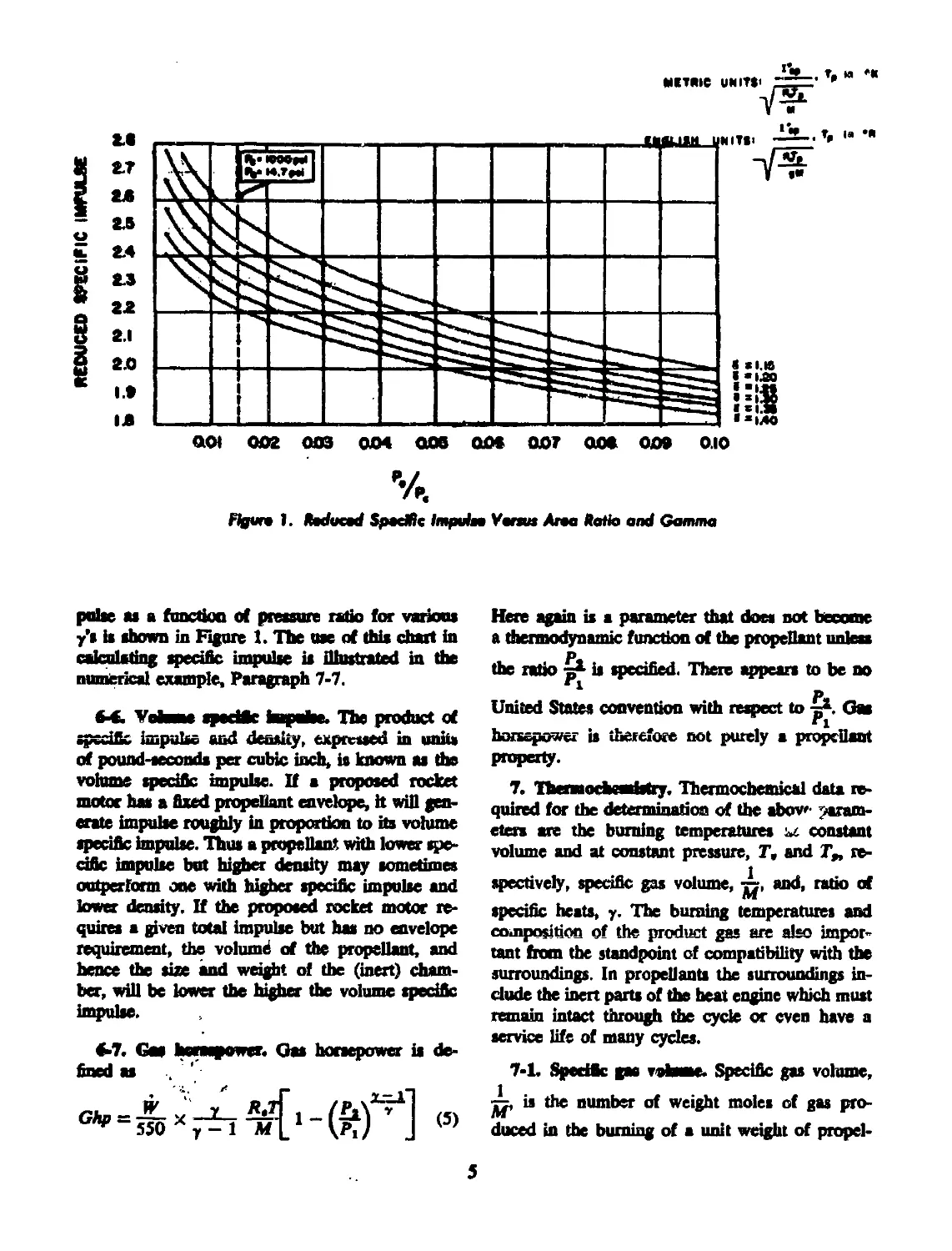
Figun 1. fiadueed Spedtic Impuin Yunus Ana Katie and Gamma
pulse as a function of pressure ratio for various
y's is shown in Figure 1. The use of this chart in
calculating specific impulse is illustrated in the
numerical example, Paragraph 7-7.
6-t Vohme specific impulse. The product of
specific impulse and density, expressed in unit*
of pound-seconds per cubic inch, is known as the
volume specific impulse. If a proposed rocket
motor has a fixed propellant envelope, it will gen-
erate impulse roughly in proportion to its volume
specific Impulse. Thus a propellant. with lower spe-
cific impulse but higher density may sometimes
outperform one with higher specific impulse and
lower density. If the proposed rocket motor re-
quires a given total impulse but has no envelope
requirement, the volume of the propellant, and
hence the size and weight of the (inert) cham-
ber, will be lower the higher the volume specific
impulse.
Here again is a parameter that does not become
a thermodynamic function of the propellant unless
the ratio is specified. There appears to be no
1 P-
United States convention with respect to -=*. Gas
“i
horsepower is therefore not purely a propellant
property.
7. Thcsmochcarisfry. Thermochemical data re-
quired for the determination of the abov»- param-
eters are the burning temperatures ы. constant
volume and at constant pressure, Г, and T„ re-
spectively, specific gas volume, and, ratio of
specific heats, y. The burning temperatures and
composition of the product gas are also impor-
tant from the standpoint of compatibility with the
surroundings. In propellants the surroundings in-
clude the inert parts of die heat engine which must
remain intact through the cycle or even have a
service life of many cycles.
7-1. Specific gas volume. Specific gas volume,
is the number of weight moles of gas pro-
duced in the burning of a unit weight of propel-
5
lent. In ыП cases where only gaseous products
result, M is the avenge molecular weight of the
product gas. The gas volume is determined from
the conservation equations for the elements
SC = [CO,] + [CO] (6a)
SH = 2[H,] 4 2[H,O] + [HC1] (6b)
XN = 2[N,] (6c)
SQ = [HC1] (6d)
SO = [CO] + 2[CO,] + SH,O (6e)
(CO,] + [CO] + [H,] + ГЯ,О] +
(N,] + [Ha]=^ (7)
n = SC + HSN + V4SH + WSCI (8)
Лж
In these equations, sC, e.g., is the total number
of weight atoms of carbon in a unit weight of pro-
pellant and [CO,] is the number of weight moles
of CO, in the gas from the unit weight of pro-
pellant. If is the weight fraction of ingredient I
in the propellant composition and C, the number
of weight atoms of carbon in unit weight of I, then
SC = S(a«C<) (9)
SH, sN, and SCI are derived in the same way.
7-2. Flame tanperatare at constant volume.
The flame temperature at constant volume is de-
termined by solving the equation
1 Г
* T c;
L J 1 о
dT
(10)
where is the mole (volume) fraction of a prod-
uct gas constituent J, e.g., CO,, in the gases
formed from the propellant and C(/ is the molar
heat capacity of the same gas constituent The
heat of explosion or calorific value of the propel-
lant, Q, usually expressed in calories per gram, is
the difference at reference temperature, be-
tween the heat of formation of the products and
the heat of formation of the propellant.
~Q ~ AEfntoeb — (11)
Assuming no heat effect of mixing
nniuit = SfxiAfr) (12a)
where &Et is the heat of formation of ingredient J
per gram.
&Ernt^t, = ^2(УуД£,) (12b)
where ДЕ/ is the heat of formation of product J
per mole.
The quantities yj are derived from Equations
6>-6c and various gas equilibrium equations, of
which the most important is the water gas equi-
librium
[CO][H,O]
ICO,][H9] “
(13)
In actual systems there may be found small
quantities of constituents other than those dis-
cussed above, such as CH4, NHa, NO, OH, H,
O, and N, as well as products of other atomic
species if present in the propellant For each such
constituent there is available an equilibrium con-
stant ЩТ) similar to K.(T) (Equation 13) and
an estimate of its molar heat capacity.
’ The constants Kt(T) and the various C/s and
AE*s have been quite precisely evaluated as func-
tions of temperature, T.“
7-3. Flame temperature at constant pressure.
The calculation of T, is similar to that of Tv,
except that instead of Equation 10 we must use
the following
С = ]^ь У/
fT,
' Ctj dT
T. .
(14)
where Cfj is the heat capacity at constant pres-
sure of gas constituent J,
Since burning is now at constant pressure, en-
thalpy instead of heat of formation must be used.
Q — AZ/p^uct, — AHpH^ibata (15)
= S(X(AH4) (16a)
~ (16b)
7-4. Ratio of specific heats. “The value of у for
a propellant is the weighted average of the y's of
tlx дм constituents
7 XxA
(17)
The values of у used are not the ratios of heat
capacities at room temperature, but the ratios at
operating temperatures of the heat engines con-
cerned.
6
7-5. Exact calculation of flame temperatare and
product composition. The calculation of the flame
temperature and product gas composition is done
by trial, starting usually with an assumed tempera-
ture. This is an iterative process and is profitably
done with a machine calculator, particularly when
gas equilibria other than the water gas equilibrium
must be considered. Programs11*14 have been
worked out for such calculations, assuming essen-
tially only adiabatic conditions and chemical and
thermodynamic equilibria, to give results of accu-
racy limited only by the thermodynamic data of
the individual species considered. These programs
also are used for calculated specific impulse on the
basis of either frozen composition flow or equilib-
rium flow through the nozzle. A JANAF Thermo-
chemical Panel exists for the coordination of
thermochemical data and calculating procedures.
The exact calculation, even with a sophisticated
machine calculator, is time consuming. Conse-
quently nearly every propellant development facil-
ity has for internal use a short-cut calculation
yielding approximate results useful for screening
and program guidance. Many of the data reported
in the literature, including some SPIA/M2 data
sheets, are the results of such approximate calcu-
lations and should be confirmed by exact calcula-
tions before important decisions are based on them.
Two approximate calculations that have been
used by more than one facility are described in
Paragraphs 7-6 ana 7-8.
7-6. Hirschfelder-Shennan calculation.11 It L
possible1* to calculate Q from additive constant;
Qi which are defined as the contributions of ingre-
dients I to the heats of explosion of propellants
containing them. The Hirschfelder-Shennan calcu-
lation takes as the reference temperature 2500°K,
The heat of explosion, Q, at the propellant differs
from the heat required to bring the combustion
products to 2500° К by an amount E, which can
also be calculated from additive constants E,
which are properties of the ingredients I. Finally,
the heat capacity of the product gas at 2500°K is
estimated from additive constants C„t which are
properties of the ingredients I. These heat capaci-
ties are assumed constant for the interval from
200C°K to 3000°K. The burning temperature at
constant volume, Tv, is the*1 given by the equation
T, = 2500 + (18)
The gas volume, is calculated by Equation 8,
M
and the force, F, by Equation 2.
If T, is above 3000°K, a better approximation
of T,. is given by the relationship
Tr = 3000 + 6046/ - (C, + 0.01185) +
[(C„ + 0.01185)2 4-
3.308(10" 4)(E - 5OOC,.)]2
In order to calculate characteristic velocity
from Equation 3 or specific impulse f om Equa-
tion 4 (see also Reference 17) we need the flame
temperature at constant pressure, Tp. and the ratio
of specific heats, y, at the working temperature.
The value of у is given by the relationship1 *
- t i 1987
y ~ 1 + CrM
(20)
from wl ich T, is calculated by the equation
T, = — (21)
У
Additive constants for a number of prooellant
ingredients are given in Table 2. Constants for
other organic ingredients can be estimated from
the relationships1'
M) , = Ct 4- HNt + ^Hi
(8)
CVf = 1.620C, 4- 3.265H, + 5.1930, 4- 3.38417,
(22)
Qi = (-nF), - 6742Ц2С, + йЛ', - О,] (23)
Е( = (-ДЕ), - 132771С,—
40026H, + 518190, — 67241V,
where (—AE), is the heat of combustion of ingre-
dient I.
Within the range 2000° to 4000“K for Tv this
method gives results within a few percent of the
exact method. The method should not be used
for propellants with 7\. over 4000°K as it does
not allow for dissociation to free radicals, such as
H, OH, and Cl. It should also not be used for
propellants yielding a substantial amount o;' con-
densed exhaust.
7
TABLE 2. THERMOCHEMICAL CONSTANTS FOR
HIRSCHFELDER-SHERMAN CALCULATION**
e< __E1_ 4 /1\
Acetone -1938 0.5104 —284X5 0.10331
Ammonium dichromate 1290 0.2700 610 0.0200
Ammonium nitrate 1450 0.4424 405.1 ООЭ748
Ammonium perchlorate 1603 0.3167 80022 0X128
Ammonium picrate 539 0.3213 -117 0.04470
Aephalt -2302 0.2179 -2305 0.09450
ЯЛ-МУР cefofyiatt (90% butadiene, ’0% 2-nrjthyl-5-tinylpyridine -2711 04132 -3183 011344
Butyl carbitol adipate -1836 0.4923 -2629 009099
Butyl cartdtol formal —1802 0.5229 -2652 0.10403
VMIXU ВИИ —3330 0.1349 -31874 008326
ChfinlOBt -1243 0.3953 -1971 006929
iubUyl maleate —1338 0.3872 -195? 008155
Di-a-butyl phthalate -2071 0.4258 -2656 009701
Dibutyi eebacate -2395 0.5108 -3139 01113
DH2-ethy&M>yl) aadate —2612 0.5272 -2272 011876
Diethyl phthalate -1760 0.3166 -2348.7 0.08550
Diglycol dinitraie 1073 0.3837 23X4 0.04389
Dinirropheamyethanol -15 0.3369 -633.4 005693
DJoctyl phthalate -2372 0.4650 - 3020 0.11086
Diphenytamine -26M 0.3471 -3010 0.10637
Diphecylguanidine -2270 0.3476 -2626 0.09941
Ether -2007 0.5970 -2958 0.12143
Ethyl alcohol — 1716 0.6083 -2785 010334
Ethyl ceutralltc -2412 0.3905 -2766 0.10434
Graphite -3370 0.1349 -3234 0.08326
GR-I rubber -3257 0.5779 -4006 0.14235
HMX, CydotctramethylcnetetranitramiDe 1321 0.3414 575 0.0405
Load «tearate -2000 0.3976 -2440 0.09180
M4V -1827 0.3976 —24ОД 0,09180
N-MethyJ-p-nitroamline -1095 0.35308 -1625 0.07887
Metriol trinitrate 1139 0.3052 377 004313
Mineral jelly -3302 0.5811 -475 0.1426
Nitrooelluloee, 1X2% N 900 0.3478 137.7 004127
NitroesHuloee, 12.6% N 956 0.3454 198.9 004040
Nitocafluloee, 13.15% N 1033 0.3421 283.1 003930
8
TABLE 2. THERMOCHFALCAL CONSTANTS FOR
HIRSCHFELDER-SHERMAN CALCULATION” (Cnuttmaed)
A <4
2-NitrodiptMnyUmine -1813 0.3226 -2201 0.08411
NStfOgiyccriii 1785 0.3438 951.9 0.03082
Nitrojuanidine 713 0.3710 —68.6 0.04806
гк1Л» лигамусплии wnmitrnw 1531 0.3424 727 0.0348
nm 1202 0.3703 374 0.04109
PoiywtK* -2184 0.3552 -2620 039123
MyiaotateM -3228 05798 -3981 0.14259
My (methyl acrylate) -1404 0.4231 —2111 008140
Myrtjmne -2983 03739 -3309 0.11523
Myurcthaae -3296 0.4073 -3773 0.10796
My(vinyl chloride) -1614 03080 -1851 OjOMOO
FotaeiiBn nitnte 1434 03138 243 0ЛО9О9
Masefam perchlorate 1667 03000 800 0.00722
Pot**hnn tutthte 300 0.1250 -800 0.00574
RDX, CydotrimethyienetrinitnuaiM 1360 0.3416 615 0.0405
Sucrose octucctkte -1121 0.3941 -1825 0.06922
Triacetin -1284 0.4191 -1973 0.07333
Triethylene glycol dinitrate 750 0.40430 -8934 04)5412
Trinitrotoluene 491 03037 -110 0.04843
7-7. Example caknlatton of F, cf, Z£ by Ae
Hbrschfelder-SberauB method. Consider a propel-
lant of composition:
Nitrocellulose, 12.6% N 0.50
Nitroglycerin 0.49
Ethyl centrallte 0.01
From the composition and Table 2, we have
Wettbt
Inredtait tractkn a«<2> *,c. 1 хД xi/M,
NkrooeUnlcrc 030 471 0.1727 993 0.020И
ГШгСффСвПЕ! 049 875 0.1685 4664 0.01510
Bthyt centralite 0.01 -24 0.0039 -274 0.00104
8шммй1иш 1Л0 1329 03431 5383 0.036*4
Isochoric flame temperature:
T9 by Equation 18: 2500 + = 4060°K
Since this is higher than 30C0°K, we must calcu-
late by Equation 19
T, = 3000 + 6О4б|- (0.3451 + 0.01185) +
[(0.3451 + 0.01185)» + 3.308 X 10~* X
1)
(538.3 - 500 X 0,3451)]® |
= 3855’K or 6940dR
Force:
F 1543 X 694 X 0.03634
= 389,000 ft-Ib/lb
9
Specific heat ratio:
_ , , 1.987 X 0.03634 _ -
y = 1+—o3Si--------------= 12092
isobaric flame temperature:
T, = = 3188°K or 5738eR
Characteristic vetocity, cf: From Table 1, the
reduced characteristic velocity corresponding to
у = 1.209 is 1.540. The characteristic velocity,
c{, h then
cf = 1.540 V 32.2 x 1543 x 5738 x 0.03634
= 4950 ft/eec
Specific impulse, l^. From Figure 1, the reduced
specific impulse corresponding to у = 1.209 and
& = 0.015 is 2.445. The specfflc impulse, is
then
= 245 Ib-sec/Ib
74. ABL start cMatfan for spedfle km*
puke.91 In order to shorten the time and coni'
piexity of the exact calculation for specific impulse
of propellants with condensible exhaust, the ABL
method makes a number of simplifying assump-
tions. Chief among them are:
(a) No product dissociation is considered.
(b) A priority system applies to the forma-
tion of the products. Thus, oxygen first oxidizes
all light metal, then converts C to CO, then
Hi to HiO, and any oxygen still not used up
converts CO to CO,.
(c) Certain latent heats are completely re-
covered during nozzle expansion.
The calculation can be performed with a desk
calculator, but is usually done with a larger calcu-
lator if available.
Results of this calculation пиу differ from exact
calculation results by as much as 3 percent
The results do not represent either frozen flow
or equilibrium flow, but agree fairly well with
exact equilibrium flow calculations.
The asaumption of no dissociation leads to arti-
ficial. values for Tf.
empirical detrnninarion of the ballistic parameters
is discussed in the next fere paragraphs.
fl-L MeaamoMat at beat at expiaatas. The
brat of explosion of a propellant, Q, also known
as the calorific value, is measured by burning in
a bomb calorimeter under an inert atmosphere.
Two types of calorimeters have been in common
use. In the Boas calorimeter the loading density,
or weight of propellant per unit volume, is Mriy
high, leading to pressures of some thousands of
pounds. This calorimeter need not be preprossur-
ized. In a coal calorimeter, the loading density is
low and an initial inert gas pressure of some 200
to 300 psi is required. Both types cf calorimeter
give essentially the same values of Q.
For thermochemical purposes, the observed heat
must be corrected for the heat of condensation of
water and for shifting gas equilibrium during the
cooling of the calorimeter and its contents. This
correction amounts to about 10 percent and may
be so approximated." Uncorrected calorimetric
values, denoted "water liquid,” are cf considerable
utility as a quality assurance measure in volume
production of propellants to verify that successive
lots of propellant manufactured to the same for-
mula actually duplicate each other within specified
limits. The calorimeter test can be run with much
less effort and more precision than a complete
chemical analysis. The procedure for the calorim-
eter test is given in a Navy Department Bureau
of Ordnance report" Calorific values encountered
in propellants seldom exceed 1500 cal/g and are
accordingly much less than for ordinary fuels. The
obvious reason for this is that ordinary fuels draw
on atmospheric oxygen for their combustion re-
actions, whereas propellants must carry their oxi-
dants within themselves in order to function in
the absence of air.
1-2. Measaronent of specific farce. Combining
Equations 1 and 2 we get
(25)
A direct experimental measure of F should then
be obtained from the pressure developed under
adiabatic conditions by burning a weight, W, at
propellant in a closed chamber of volume, V. Be-
cause truly adiabatic conditions can only be ap-
proached, a related concept, that of relative force,
is used. If equal weights cf two propellants with
the same burning time are fired consecutively in
10
the same doted vend at the same initial tempera-
ture, W and (P — »W) m constant Then
Fi, the force of the standard propellant, is arbi-
trarily assigned the vdue 100 percent, and die
relative force, RF, of the propellant under exami-
nation becomes
KF = &xl00% (26)
Relative force is used in quality control of gun
propellants to assure that successive kits of the
same formulation duplicate each other. In develop-
ing a new propellant to replace an existing one,
a measurement of relative force is useful as an
indication that the relationship between calculated
and delivered force is or is not similar to the rela-
tionship for the known standard propellant The
procedure and description of apparatus for the de-
termination of relative force may be found in an
Army Service Forces Directive.’4
8-3. Mt assay at at of characteristic velocity.
Delivered or actual characteristic velocity, c*, is
defined as
e*=^£/'p.dt (27)
Ft J
It is determined experimentally by static firing of a
weight, W, of propellant in a vented vessel of
known throat area, At, measuring the chamber
pressure as a function of time, and integrating.
The JANAF Solid Propellant Rocket Static Test
Panel has published” a survey of existing static
test facilities and is continuing to coordinate test
procedures. Comparison of c* with cf gives a
measure of the operating efficiency of the vented
vessel. In similar heat engines with similar pro-
pellants, should remain nearly constant. The
difference between cf and c* is due largely to
heat leases to the motor walls. -
8-4. MeMuranent of specific hnpcbe. Deliv-
ered or actual specific impulse, is defined as
This parameter is determined also by static firing
a vented vessel,, but measuring thrust"
Unless the operating and discharge presems
are 1000 psi and 14.7 pel, respectively, the meas-
ured I* must be corrected to these values. Cor-
rections must be applied also for the divergence
half-angle of the nozzle, since the amount of
impulse delivered decreases as nozzle angle in-
creases." The usual convention for half-angle is
15°. Part of the difference between IS, and
is therefore due to the divergence toss. The IS*
convention is unfortunately net always observed.
Some measured data reported in the literature
have been corrected to zero half-angle. In taring
1„ data, one must identify which half-angle cor-
rection has been used.
»-S. Example rairuintfan af fw fosm aremaredl
l„ at nonetanJarii coadMiaaa. The following
data were taken from an actual rocket firiqg:
Expansion ratio, i, = = 2.779
Mean chamber pressure, Pe = 218 pda
Nozzle divergence half-angle, a = 20°
Specific heat ratio, у = 1.17
/„ (del) = 201.3 Ib-sec/lb
The correction of I„ (del) to standard condi-
tions involves the parameter thrust coefficient, C,t
from interior ballistics. The thrust coefficient, de-
fined as
с'=га=^ m
measures the contribution of the nozzle to the
rocket thrust. Since c* is independent of discharge
conditions, for any given rocket firing 4?- is a
constant independent of nozzle and external con-
ditions.
The thrust coefficient has its maximum value
when expansion in the nozzle is to zero pressure
(vacuum) and discharge is also to zero pressure.
For any other exit pressure the vacuum thrust
coefficient must be corrected by a term И
the ambient pressure differs from the exit pres-
sure another correction involving »
applied.
^tjmust be
Values of Cr and «(y^are obtained from
Thrust Coefficient and Expansion Ratio Tables"
at which die tabulated CF is for vacuum discharge
11
and zero divergence angle. The divergence angle
correction” b made by the equation
A — 0.5 + 03 cos «
to that the overall correction becomes
actual Cr =
а[с,<-ы.>-.(£)] + .(£)-.(Й)
For the example at hand, using the table values:
Firing ccndttions Standard conditions
primary pyrolytic products are given off already
premixed and in proportions such that the final re-
action of die products among themselves wffl bring
the gas to flame temperature and thus duplicate the
hot atmosphere in temperature and composition.
Although the temperature rise and ccmpotiton
changes are continuous from the pro-
pellant to the products at flame temperature, it is
convenient for analysis to break the process down
into several phases as represented by Figure 2-
Region A represents the unheated interior portion
134358
021405
02699
1.75284
0.13856
0283
Inserting numrrical values, and **"**78 for
standard condkioM F< s Fs
C, (Brfa«)* = 02699(134358 - 021405) +
021405 - 2.779 X
= 1316
Cr ДО = 0283(1.75824 - 0.13856)
« 1387
Aowro 2> BwaIm cf ScU
The corrected value of /„ at standard condition
Пь UKfCuKCp
201.3 X = 242.8 Пмес/lb
9. Bunfag of prepelants. Heat will be trans-
ferred by ratfiaticn, conduction, and/or convec-
tion to the surface of a odd solid propellant
impended in a tot atmosphere. If the solid is
men ti ally a nonconductor-of heat, the heated sur-
face wfll pyrolize, giving rise to gaseous products
and exposing new surface to the hot atmosphere.
The gas in immediate contact with the burning sur-
face” wffl be the uncootantinated pyrolytic prod-
ucts of the surface, at the temperature of pyrolysis.
Moving out from the surface the gases are raised
to the temperature of the hot atmosphere and
undergo reactions among themselves and with the
atmosphere so that the hot atmosphere continues
to exist in a state of equilibrium among the sev-
eral chemical species present. If the solid is a
monopropdlant and the hot atmosphere comprises
its combustion products at flame temperature, die
•Shoe thb value b a theoretical value derived from
ntW*d рШОМЙП) Й dOtf DOt MCtflNtfily
aareo with a vahw of С» cakubMd by Equation 2* from
m seen red /» and c*.
of the solid. In region В a thin layer of the solid
is bring heated to pyrolysis temperature, T«. In
region C pyrolyns is taking place and gaseous
products are being formed. The pyrolytic reactions
may or may not involve the formation of liquid
intermediates (foam zone). A layer of primary
gaseous pyrolytic products at temperature Tt is
regfon D. In region E (fizz zone) these gases are
heated to ignition temperature. In titi' process
they may undergo low temperature reactions of
an exothermic character and produce some heat.
The bulk of the heat is generated in the flame zone,
region F, to yield finally burned gas at tempera-
ture T in region G.
At operating pressures in the neighborhood of
several hundred pounds per square inch and
higher, die thickness of the герои В through F
b small, perhaps of the order of 10~* inches in
total. By operating at greatly reduced pressures
one can broaden these regkms. The foam rone,
firn zone, and flame zone have been observed far
experiments of thb type.**
The linear rate of banting of the monopropel-
lant depends on the rate at which the surface
receives beat from the surrounding combustion
products. All caponed surfaces that can “see” the
12
hot combustion products should receive heat at
the seme rate and therefore bum at the same rate.
The bunting surface should recede by parallel
layers This coodusfoo, known as Ptobtrfr LmP1
and first announced for black powder, has been
verified for monopropellants under both racket
and gun conditions by examination and measure-
ment of partially burned grains. It appears also to
hold for composite propellants, although the ex-
The rate of regression of a burning propettant
surface, measured nosmal to die surface, is known
aa the Harar fotrnfog rate, r. It is usually expressed
in tunu of inches per second. When r is muMpiied
by the area of the 1яияйщ MrfflOC, S, and by the
densify we have, finally, the иеДО—or яма»—
htnflio reft, expressed as pounds per second
Ж = rSf (30)
Several factors are reco^iiaed as affecting the
burning rate. Among these are pressure at which
burning is taking place, initial temperature of the
ptopelam, gas velocity over the burning surface,
aad composition of die propellant.
•-L. Effect of prusuru Increasing the pressure
at which burning takes place should increase the
rale of heat transfer from the flame to the pro-
pellant by increasing the density of the gas phase
and thereby decreasing die thickness of regions
D and E through which the heat must be trans-
ferred. The influence of pressure has been stmfled
in both dosed bombs and vented vessels over
a period of years, and empirical equations in
various form* developed by different schools of
bBlKe6ciens«
de Saint Robert equation” r = bP* (31a)
Muraour equation** r = a + bP (31b)
Summerfield equation** £=^+b^^H(31c)
If the fogP —fogr relation for a propellant
is plotted we get a family of curves ressmbfiag
Figure 3 from propellants behaving according to
Equation 31a, from which the values of b and n
can be evaluated. The constant n is the dope of
lhe fog rate versus log pressure line. At gun pres-
sures, 10,000 to 50,000 pd, nearly all propellants
follow Equation 31a, with n = approximately
0.9.“ At rocket pressures, bdod 2000 psi, n for
the same propellant is generally lower than at gun
ferWMchr = bT
pressures. In thb region will be found propellants
giving the normal straight line log rate versus fog
pressure relationslap, but also many propellants
deviating widely from it Two types of curves are
worthy of special mention.
Propellants showing a region of markedly re-
duced n, as shown in Figure 4, are known as
Figure 4. flute Aeriure fleletiomfop of Plateau
Aepelfonti
13
“phtean** propellants.** Thb behavior is shown by
certain nitrocellulose system propellants contain*
tag small amounts of lead compounds and by
some fuel binder ammonium perchlorate compos-
ites. The effect of the lead compounds is to in-
crease the burning rate in the plateau region and
at lower pressures, aa shown by the fept dnx with-
out die lead the propellant would shw a nonaal
cur< coinckfing with the high psr-jaue trench of
the plateau propellant’s carve and continuing ыж-
malty huo the lower pressure region hne,
Figure 4). The mechanism of pialauj 1’Lnnation
has not been fully eh tidated. From Equation 31a
the pressure in a vented vessel is of the form**
P = co«t.x(^y_’ До)
from which it is apparent that a low value cf n
is desirable in rocket propellants to decrease the
sensitivity of die operating pressure to small
changes in b (a function of propellant ambient
temperature); 5, the burning area; and At, the
throat area. In practical terms, a low value of я
permits design of tighter weight rocket motor
chambers by decreasing die requirement for high
safety factors to take care of deviations o' b, S,
or A, from design values.
As a low value of л is desirable, a negative value
is even more desirable. Propellants are known
which show negative values of n wet short pres-
sure ranges, as shown in Figure 5.” They are
known, from the shape of the curves, as “mesa”
propellants. In the region of negative slope, should
the pressure increase as a result of sudden expo-
sure of additional burning surface or by partial
constriction of the throat the rate would drop
immediately to restore the balance. The close ap-
proach of the isotherms also contributes to a low
temperature coefficient of performance for vented
vessels designed to operate in this region. Cross-
ing of isotherms indicates a region of negative
temperature coefficient.
9-2, Effect of temperate*. As can be seen from
the isotherms cf Figures 3, 4, and 5, the initial
temperature of the propellant has a significant
effect on the linear bunting rate. If all of the heat
transferred to the propellant surface from the com-
bustion products were used to raise that surface
to a tefl^perature Г, at which vaporization or
Figure 5. Me-Fnmure Itekrtioruhip cf Mete
Aropelfants
reaction becomes appreciable, one would expect
die temperature-rate relationship to assume the
form
r'~ (.Г-Тд
(33)
where V is a constan t and T< is any initial tem-
perature. By measuring the linear burning rates
at the same pressure for the same propellant at
two initial temperatures one could calculate T.
Another frequently used relationship is
r = b"P4\T, - Tu) (34)
where b" and и are constants and T, is a refer-
ence initial temperature. A linear relationship has
also been noted.** The existence of regions of nega-
tive temperature coefficient described above is not
consistent with either of these relationships, so
the effect of propellant temperature on linear burn-
ing rate remains largely an empirical relationship.
In the SPIA/M2 data sheets four temperature
coefficients may be found. Of these ths tempera-
ture coefficient of burning rate at constant pressure,
v, = 0^^» 1» estimated from the rate-pressure
curves (Figures 3, 4 or 3) using the inters ?tions
of the curves for the different temperatures with
a vertical line at the constant pressure of interest.
14
Япсе for a real rocket motor the working ргаяпе
b not the same at different grain temperatures,
thb parameter does not haw real ognificance.
The tcoq*eramre coefficient of burning rate at coa-
rtant К value, b determined em-
pirically by static-firing rocket motors at dhferent
grain, temperatures and dividing the known web
dbnensions by the burning timer to get the rates
Since neither the boning turface nor the nozzle
throat area rhsngri appreciably with ambient
temperature^ the assumption of constant К wine
between rocket motors of the same design at «ef-
ferent temperatures b good. The temperature co-
eiBcbnt « premnre at coratant * wine. <2 =
b determined from the rate-pressure
curves, using the intersections of the carves for
«по шпеган шфсвпшпо wim о шкв wncn
J>
are Horn of constant In real rocket motors the
p
assumption of constant ~ with changing tempera-
tare b better than the assumption of constant pres-
sure, but thb parameter still has only qualitative
wine. The more significant temperature coefficient
of pressure at constant К value, »< s0£f)x’
again determined empirically by static firing at dif-
ferent ten^eratures. AH Tbur of there parameters
are expressed in units of percent per degree, usually
Fahrenheit. Low values of there coefficients are
desirable.
M. Cffisct st рв vsfiadty. Krnrive hurah*
When burning occurs inside tubes of propellant
such m the perforations of gun propellant and the
interior suttees of rocket propellant, it b found
that the Haear burning rate at and near the exit
of the tube exceeds the normal rate. The shape of
the “eroded” region suggests a velocity effect, and
indeed the erosion law may be written
г = ЫЧ1 +«x£) (35)
whore V is the local gas velocity in the tube and
C b the velocity of sound fas the combustion prod-
ucts. In the care of a stagje mternal-buniing rocket
grata ta a rocket*' motor, VA, = CA> where A,
b the “port area” or the exit area of the tube
and At b the nozzle throat area, so Equation 35
ticcoows
r=W41 + Xi;£) (35a)
which b in a more convenient form foe use by
rocket designers. The constant Kj b called the
“erosivtty constant and b a measure of the sus-
ceptibility of a propellant to erosion. Itr value b
of the order of 0.5 to 1.0. Equation 35 wfl! be
recognized ss a linear TT""1*"”**"". applicable
over the range of gas velocities for which the con-
stant St has been developed. A theoretical treat-
ment of erosion** has been breed cat the transition
front laminar flow to turbulent flow of the com-
bustion products within the perforation.
An erosive bunting law
^ = *'* + ^£в (ЭД
has been developed*1 from ecnsideratioc of heat
transfer to the propellant walls from rite hot gas
passing down the perforation. In thb equation, a
and 3 are constants characteristic to the propd-
tante binned, G is the mass velocity of the gases
in the port, and L b the distance downstream from
the stagnation point
9-4. Effect of cocsposiflaa. As the driving force
for the burning of propellant is the temperature of
the combustion products, all theories agree that
hot propellants should have a higher linear burn-
ing rate than cool ones. This b found quite gen-
erally true at gun pressures and also at rocket
pressures where the rate-pressure relationship b
“normal.” Thb b a matter of no more than aca-
demic interest to the users of gun propellants who
do not have the problem of reconciling grain
geometry to charge envelope requirements. In
rocket design on the other hand, where, in gen-
eral, single grains are used, it b necessary to be
able to control burning tenqteratnres and rates
independently in order to meet simultaneously per-
formance and envelope requirements. To thb and
rocket compositions quite commonly contain addi-
tives known as burntag rate catalysts which gen-
erally increase or decrease the normal burning
rate of the propellant. The choice of catalysts and
their proportions in the composition are deter-
15
mined by experiment. Temperature coefficients
and erodvity constants are also properties of the
compositions.
M. Bendtsg rate of composite prupeBsate. A
composite propellant has been defined as a solid
propellant system comprising two or more solid
phases intimately mixed. In all important cases,
with the possible exception cf black powder, one
of these phases is continuous and foams the matrix
or binder in which the other phase or phases is
dispersed. When a composite propellant burns, the
burning surface comprises a web of binder filled
with exposed surfaces of filler material Each ex*
posed material burns at its own linear rate at any
given pressure and starting temperature and has
its own pressure index and temperature coefficient.
A perfect match between die burning rates of
binder and filler would be a coincidence, and easily
disturbed by a c’tange in burning pressure. In gen-
eral die filler surface wffl recede faster or slower
than the binder, giving rise to an irregular and
time-dependent boundary between regions C and
D. Figure 6 shows die case of filler burning more
rapidly than binder. Area I shows a filler particle
not yet exposed. Area П shows a filler particle par-
tially burned, while at Area HI is a pocket left
by a filler partide completely consumed. The net
effect cf the foster-burning filler is to increase die
instantaneous burning surface of the binder. We
can no longer measure the burning area, only its
projection on a plane parallel to die original burn-
ing surface. By increasing the actual burning area,
we attain a greater apparent linear rate, referred
to the projected area. In spite of the lower apparent
burning rate of the binder, the burning rate of the
composite propellant approaches the linear rate of
the fest-burning filler.
The case of filler burning more slowly than
binder is shown in Figure 7. In Area I we have
again a filler psrtkle not yet uncovered, in Area U
a filler particle bunting at a slower rate than the
surrounding binder, and in Area III an incom-
pletely burned filler particle completing its com-
bustion in the gas phase outside the piece of
propellant. In thia instance the linear bunting rate
of the composite should approximate that of pure
binder.
As the linear bunting rate of the composite tends
to follow the burning rate of the faster-bunting
phase, it is to be expected that the temperature
eiMoea Qgg eiixea EWSI
Figure 6. Burning of CoapatHt Propellant—
Filer FalrFmtrt Thon Binder
Figure 7. Burning of Composite Propellant-
Filler Rote Slower Than Binder
coefficient and pressure index should also tend to
follow the corresponding figures for the faster-
burning phase.
L. a two-phase filler-binder composite various
combinations of monopropellants, fuels, and oxi-
dizers are possible. If both binder and filler are
monopropellants, region D is all combustible mix-
ture, although of a mixture of compositions. If the
binder is a monopropellant and the filler is either
oxidant or fuel, region D is a continuum of com-
bustible mixture containing pockets of fuel gas or
oxidizer gas, and a diffusion, process as well as
heating must occur in region E before the com-
bustion reactions can be completed. If the binder
is fuel or oxidant and the filler is monopropellant,
region D becomes a continuum of fuel gas or oxi-
dizer gas containing pockets of combustible mix-
ture. If the binder is fuel and the filler oxidant
or vice versa, region D contains no combustible
mixture.
A diffusion step is required to mix the fuel-rich
16
gat with oxidizer-rich gat before the reactions to
produce the flame temperature can be completed.
With larger filler particle size the distance either
gas must move to accomplish diffusion is longer
and, therefore, the distance between region D and
region F should be greater than with smaller filler
particle size. This may explain qualitatively the
observed slower burning rates of fuel binder com-
posites with large filler particle size.
The requirement at a diffusion step before a
combustible continuum is achieved is no essential
handicap in a burning regime. It is interesting to
note, however, that propellants with this require-
ment propagate detonation in the solid less readily
than do monoprcpellants.
The preceding discussion of the burning rela-
tionships applies to steady state burning and
assumes no pores, cracks, or fissures with com-
ponents perpendicular to die burning surface. Two
important problems are recognized in connection
with burning.
94. Problem of Mutable bontng. For as long
as modem rockets have been under investigation
in the United States and undoubtedly earlier else-
where, some rockets have exhibited a tendency to
develop irregular pressure peaks at some time
during their burning cycles. In severe cases this
has led to rupture of the motor chamber. With
pressure-time instrumentation of suffidently low
time constants these pressure irregularities have
been shown to exhibit frequencies identified with
axial, radial, and/or tangential vibration modes
of the burning cavity. In separate instances the
phenomenon has been overcome by “resonance
rods”4* placed inride the grain perforation, radial
holes4' through the web, slots4' or baffles4’-44
within the grain, and most recently by adding
small quantities of finely-divided aluminum41 to
the composition. In each case a “quick-fix” has
been accomplished but no real explanation has been
given for the phenomenon. Considerable light has
been shed very recently on this question by the
appreciation that the propellant grain does not
behave as a rigid body but has acoustic properties
similar to those of the gas in the burning cavity.”
9-7. ТишаШоп from deflagration to detonation.
With the advent of very large, high performance
rocket engines the question has been raised whether
and under what circumstances a rocket motor can
proceed spontaneously from a burning regime to
detonation. This question has been and is being
investigated intensively.
It is presumed that burning can give rise to
shock and that the shock thus produced can occa-
sion detonation in the propellant. That continuous
monopropellants can be detonated by shock has
been well documented.4'-4T The necessary condi-
tions are that the shock intensity be sufficiently
great and that the propellant be present in cross
section greater than its critical diameter. That
burning of a properly consolidated rocket grain
can give rise to shock has not been demonstrated.
A theoretical study4' indicates that only when die
pressure rises exponentially in a few microseconds
to several thousand atmospheres can coalescence
of pressure waves give rise to shock as a result of
burning. In an improperly consolidated propel-
lant, on the other hand, with regions of inter-
connected porosity it is comparatively easy to
attain a condition of shock which win result in
detonation. Unfortunately much of the literature
which purports to study die transition from def-
lagration to detonation actually reports studies of
the transition from shock to detonation.41
19. Prop i flant grain- A single piece of propel-
lant is known as a grain. The exposed portion of
the grain surface at any time during burning is the
burning surface, floaty portion of the surface which
is covered by adhered nonbuming material is in-
hibited. The shortest distance, normal to a burn-
ing surface, that the grain bums until it loses its
structural integrity is the burning distance. The
thickness of the propellant wall so consumed is
the web. If a grain burns on only one side, as
is the case with case-bonded or otherwise inhibited
grains, the web is equal to the burning distance.
If two parallel surfaces burn toward each other,
as in uninhibited single- at multiple-perforated
grains, the web is twice the burning distance. The
relationship between web and burning distance is
thus not single valued. The dimensions of the grain
taken collectively are known as the granulation
when referred to multiple-grain or bulk charges, or
as configuration when referred to a single grain.
A grain that maintains its burning surface con-
stant, or approximately constant, during burning
has neutral geometry. Simple neutral geometries
include sheets, squares, or disks with webs small
compared with surface dimensions or with edges
inhibited, long tubes, or tubes with ends inhibited.
17
A grain whose burning surface increases during
the burning has progressive geometry. Examples
of progressive geometry are tubes with outer sur-
face inhibited and burning only on the perforation
surface, also grains with multiple perforations. A
grain whose burning surface decreases as burning
progresses has degressive geometry. Such geom-
etries include spheres, cubes, also cylinders and
cords of any cross section. The burning surface is
{dotted against fraction of web burned for several
geometries in Figures 8-14. The portions of the
grain remaining at burn-through, shown shaded in
§
e
8
8
S
8
2
FRACTION OF WEO BURNED
A, LORO TORE, ENO-INNIOITEO TORE, RMEET.
CNO-OURNCR
A. IMORT TUOC. WEO 0.1 LENRTN. ITR1F
VII • 0.1 WIDTH
C. 01 OR, WEO* 0.00 DIAMETER
lUCIRVNRNMR IRNIt
Figaro 11. Slotted-Tube Grain
FRACTION OF DISTANCE OURNCD
A. INTERNAL OURNlNO TUBE, PERFORATION o>AM
Figure 12. Progrnuhf* Gaomatry
Figure 9. Natural Geometry
Figure 9. Pad and SMI Grain
18
• 1.1
НКПМ «MttMt Ht*i
Figun 13. Muliipli/trftrattd Cylinder
Figures 10 and 13 are known as slivers.
The terms neutrality, progressivity, and degres-
sivity are also applied to the weight burning rate,
W. Since W is proportional to both linear rate
and burning surface, factors affecting the rate can
affect the progressivity just as well as can geo-
metric factors. In this sense a dual-composition
grain in which the first composition exposed bums
more slowly than the second can be progressive in
spite of a degressive, geometry. Such grains are
used for small arms charges. The slow-burning
outer composition is created by coating or apply-
ing a plasticizer to the outside of the grain and
causing it to penetrate only part way through the
web, leaving the interior of the web unchanged.
Dual-composition grains may also be used in
rockets to create a boost-sustain situation. In this
case the fast-burning composition is first exposed
and the slow-burning one later. Erosive burning is
sometimes used to speed up the early burning of a
normally progressive geometry and attain essen-
tially neutral burning. Finally, pressure changes
that affect the rate contribute to progressivity. In
this sense all closed bomb burning is at least
initially progressive, regardless erf geometry, and
burning of a progressive or degressive geometry in
a vented vessel is more progressive or degressive
than is indicated by the geometry.
IL SchedaBug of mans sate. Let us now con-
sider some of the operating cycles for engines in
which propellants are used.
11-1. Gu. The pressure-time relationship in a
gun it shown in Figure 15. The propellant on
ignition starts to burn essentially in a closed cham-
ber. When the pressure has built up to a sufficient
level, known as shot-start pressure, the frictional
and other forces tending to hold the projectile in
place are overcome and the projectile starts to
move. As the projectile moves the volume of the
burning chamber increases, requiring generation of
more gas to maintain the pressure level. During
the early portion erf the projectile travel the quasi-
constant volume of the burning chamber permits
continued pressure build-up. By the time the pro-
jectile has traveled only a few calibers (distance
equal to the diameter of the gun tube), the rate of
addition of volume has caught up with the rate
of generation of gas, and the pressure has attained
its maximum value. The remaining portion of the
propellant is consumed at decreasing pressure,
after which the gases expand adiabatically until the
projectile leaves the muzzle. The entire cycle is
accomplished in a matter of milliseconds.
The gun cycle can be fairly precisely analyzed,
but the analysis is complicated and requires ma-
chine calculation. It is obvious that the mass rate
of burning is very high and that the propellant
must have either a very high linear burning rate or
a very large burning surface (Equation 30). Be-
* ceso
В STHSM, CUM
Flgvru 1-4. Deprauhra Geometry
19
MCMVM
FISSURE -TMVKL RSLATIOHSHIP HI
• UN
MtCSaUM- TIME Ktl*riMSHI> •
•UH
Ндип 15. Gun Cycfo
burning rates, even at gun pressures, we are left
with the requirement of a very large surface. The
geometric problem of accommodating a charge of
very lar je surface in the gun chamber or cartridge
case is very much easier t^ solve by breaking up
the charge into a number ot grains than by beep-
ing it in one piece, and we find gun propellant
charges are indeed multipte-trrain charges. In
Europe where charges are hau> loaded, gun pro-
pellant charges are often made up of long strips
or cords approaching the full length of the car-
tridge case. In the United Stater where charges are
machine-loaded, the shorter single- and multiple-
perforated cylinder form is preferred. Geometric
progressivity is not vital; guns have been quite
successfully fired using degressive cord charges.
There are, however, marginal advantages to pro-
gressive or neutral burning geometries which tend
to shift the position of the peak pressure to a later
time and, therefore, to a larger burning volume
than when a cord-form charge i used..
The practice in the United States in designing
a propellant charge for a new gun or in designing a
new propellant charge tor an existing gun is to
select a propellant composition on the basis of its
force, F, and flame temperature, T„ and estab-
lish the optimum granulation empirically. Having
established a given lot of profellant as the stand-
ard, additional lots that are manufactured must
match the standard by actual comparison firing in
the gun. For quality control purposes, firing in the
closed bomb (Figures 16 and 17) can yield a rela-
tive quickness, RQ, along with the relative force
RF (see Paragraph Я-2). In this determination
jp
the bomb is instrumented to record directly
versus pressure. The test propellant is fired in
comparison with the standard propellant, and RQ
is determined" as the ratio of for the test
4м
propellant to for the standard at one or more
pressure levels.
11-2. Catapult, The function of the catapult is
to accelerate a load attached to a piston to a final
velocity without exceeding a maximum accelera-
tion. The ideal catapult should operate at constant
pressure to afford constant acceleration. 1Ъе ideal
travel-time curve for the catapult is shown in
Figure 18. The same curve may be.used to show
the volume of the burning cavity and the required
progressivity of the charge. It may be observed
not only that an extremely high progressivity is
required, but that die required progressivity is not
linear. For personnel catapults there is an added
requirement that the rate of acceleration, d, (jerk)
not exceed a specified value. This sets an upper
limit on the slope of die rising portion of the
pressure-time curve, Figure 18. Catapult grains
may be designed in the form of multiple-perforated
20
Figurt 1& Closed loflb Assembly
|M«M И|ЖМН«1
ДТ FM« MClMtKt MB
yolii *bc«iu*c
FlgvM 17. CImm/ tomb Record
21
cylinder! inhibited externally, or rhomboid prism
burning from the corner edges, A fuller treatment
of the baDiirtics of the catapult is given in reports
by the Atlantic Research Corporation.’1
11-3. Rocket motor. The design requirements
for a rocket motor propellant charge usually
call for burning at a constant mass rate equal to
ibe mass rate of discharge required to impart the
design thrust, and for the design duration which
may be from tens of milliseconds to tens of sec-
onds. The burning pressure should at least approxi-
mate a constant level. The pressure versus time
record of the burning of a rocket grain usually
resembles Figure 19.
11-4. Cakuiattoa of a socket peepsBant charge-
A rocket motor is required to maintain an average
sea level thrust of 2C00 lb for 20 sec at a design
operating temperature of 70°F. The total impulse,
I, required is 20 x 2000 or 40000 Ib-sec.
At thia point in the design a propellant must
be selected. For this etrngk, OIO propellant (see
SPIA/M2) which has the following characteristics
is chotcn*
— 212 ib-sec/Ib at 1000 peia and optimum
otpanaiM
CD = 0.00741
у = 1.25
r = 0.27 at 1000 peia and 70®F
, = 0.0557 Ш/in»
A chamber pressure is now chosen in the re-
gion of plateau burning of the propellant, ao that
changes in the burning surface of the propellant
win саше only minimum variations in pressure
and thrust The pressure selected is 1000 pshu
Because of best loss to the rocket urntor and
other inefficiencies, a delivered specific fanpulse
with optimum expansion of 95 percent of the
theoretical specific impulse is assumed. The weight
of propellant required is
W ~ = 212(095) = 198,5 ,b
The weight flow rate is
= ~ = =9.93 Ib/sec
At a chamber pressure of 1000 peia
Al Ct?' ” (0,00741X1000) ~ 1,40 in
or D, — 1.34 in
Ting
Figun 19. flecket Meter Cycle
22
The optimum eiptmnwi ratio of obtained
own the Thrust Coeffidont and Expansion Ratio
Tobits" is found to be 8.4:1.
Therefore
Л. = 8.4(1.40) = 11.75 in1
, D, - 3.87 in
The average propellant surface during burning is
^ = ^’^fe?)=659inl
If a nearly neutral thrust is desired, then the sur-
face during burning should be as constant as pos-
sible, Lt., S< = Sf = The propellant burning
distance is equal to
rt, = (017X20) = 5.4 in
At this point some type of grata design, such
as a star-type, slotted cylinder, cruciform, rod and
tube, etc., should be initially chosen. The design
requirements can be met with a slotted cylinder.
An important parameter in grata design is the
ratio of the port area in an internal burning grain
to the nozzle throat area. For this illustration the
port-to-throat ratio is set at the minimum of 1.5:1
to prevent erosive burning of the grata.*
Therefore the port area
Л,^ = 1.5Л, = 15(1.40) = 2.10 in»
The use of a minimum port area will result in the
smallest possible space envelope for the rocket
motor. With a port diameter of 1.64 in and a
burning distance of 5.40 in, the outer diameter of
the propellant is 12.44 in. The volume of propel-
lant required is
.. IT 198.5 ,<xn. .
V* = f “ 0.0557 ~ 3560 Ш
The required grata length is approximately
r 3560____________«o . .
(0,7ЙХТ144* - 1.64») ~ “
•la mors KpbhticaMI d«si|a work tbs potHMhroat
ratio fraqtwally is cbossa м low м 1:1, accepting srosivs
bwatas. la the early WagM of burning (until the port-to-
throat ratio squab 1.9), a portion of the propaUaat will
buns at a bipksr rata than normal for the «tasting pres-
euro, and the grata geometry must compensate for this.
The dsdgn grobteaa beseem thus more dffleult, but by
п» пивав iingoMlbto.
Continuing with this design, the surface area with-
out slots and with the ends of the grain uninhibited,
is
S = 2 (~ )(OD» - ID*) + «(WML)
= 2(0.785X12.44» - 1.64») + 3.14(1.64X29.8)
= 393 in»
The surface of die slots is therefore
S^. = 659 - 393 = 266 in»
Using four slots at 90°, 5.40 in high, and 0.10 in
wide, the slot length becomes
“ 8(5.40) ~ 615 m
Disregarding the void volume of the dots for the
moment
S, = 3.14(12.44X29.8 - 6.15 - 5.4)
= 714 in»
Within die accuracy of the calculations this design
appears slightly progressive. The volume of the
skits is
Kw, = 6.15(5.40X0.1X4) - 13.3 in»
and the actual propellant length is
13 3
L = 29 8 * (0.785X1^-154») = 29 9 "
In an actual problem the design should be
cheeked for undesirable variations of burning sur-
face by plotting the calculated burning surface as
a function of burning time. Final verification ct
die design would be accomplished by fabrication
and static test of the grain.
While it is comparatively easy to design a rocket
grain to fit the performance requirements of a
design problem, it is often quite another thing to
fit the grain into the required envelope. Where
a gun charge designer can select a propellant com-
position and determine the proper granulation, a
rocket charge designer is often forced by envelope
requirements to start with a grain geometry and
develop a propellant composition to give the re-
quired burning rate. For this reason there are
nearly as many active rocket propellant composi-
tions as there are rockets. The propellant geom-
etries and significant performance parameters of
23
most solid propellant rocket mcton used by the
United State» military services are summarized in
the SPIA Jato Manual."
11-5. Gm isMatar. Gas generators arc re-
quired to provide for a certain duration (a) a spe-
cific volumetric flow rate, or (b) a specific mass
flow rate, or (c) a specific gas horsepower. In addi-
tion, a maximum gas temperature is usually speci-
fied, and the exhaust gases from the propellant
must be dean ।
11-4. CaicnWMGtagMgsneratar propafimtt
charge. Assume a gas generator must be designed
to provide 20 gas horsepower for 30 seconds.
The maximum allowable flame temperature, T„ is
1900°K. OGK propellant (see SPIA/M2), which
meets the temperature requirement, has the fol-
lowing characteristics:
у = 1.25
T,= 1888’K = 3398°R
= 0.04576 moles
r = 0.28 in/sec at 1000 pda
p = 0.055 Ib/in*
If the nozzle exit pressure is 50 pels, substituting
in Equation 5
20 =~ x X 1543 X 3388 x
[JLU*]
/ 50 \i a» I
!-(w J
W = 0.0254 Ib/scc
Using a singie-cnd burning grain design
s = ~ = /n&Vnnw = 1,63
гр (и.2вди.0ээ)
The propellant diameter is 1.45 in. The propellant
length is
L = rh = (0.28 x 30) = 8.4 in
If a certain mass rate at flow is required, the
design proceeds as above. If a volumetric flow
rate is defined, this can be converted to a mass
flow rate by using a variation of the perfect gas law
H = 07)
MHRBKK
1. J. Comer, Theory of the Interior Ballittiei of Guru,
p. 101, John WBey t Soa, Inc., New Yet*. New
York, 1954
2. Allegany Ballistics Laboratory, George Washington
University, Jtodter ГмАммамЬ; ABL-SB4, OSBD
3992, 1944 (SPIA Abstract No. 0574B).
3. M. Barrens, A. Laumotte, B. F. DeVeubeke and J.
Vandeakerckbove, Hocket РгораЫоп, Elsevier Pub-
lishing Company, In&, New Yost, New York. i960.
4. J. Cotner, toe. eb.
5. C. Cram, Innere Mfadi (JLehrbuch der BaHUtik,
Bd. 2), Jahns Springer. Berlin. Germany, 1924.
6. F. B. W. Hunt, Editor, Internal BalUtfice. Phfloeophi-
c»J Library, Inc„ New York, New York, 1931.
7. G. P. Sutton, Docket Propuldon Clemente. An Intro-
duction io ike Entineerinp of Hockett, 2nd edition,
John WBey A Sons, Inc., New York. New York, 1956.
a. R. N. Wimprees, internal Balliatia of Solid-Fuel
Hockett,. ЛИШагу Hockett Udng Drf-hxuml
ОшМе-Ввев Propellant at FmL McGraw-Hill Book
Company, InCn New York, New York, 1950.
9. M.Bamre,eroL,foc.cir.,p.9S.
10. Allegany Ballistics Laboratory, Georgs Washington
Univcrmy, loc. cit., p. 24.
11. F. D. Bosdni, D. D. Wagman, W. К Evans, S. Levine
and L Jaffa, Selected Faber of Chemical Thermo-
dynamic Propertiee, Circular of the National Bureau
of Standards 500, U. S. Government Printing Овсе,
Washington, D. С, 195X
IT S. L. Levy and O. A Reynolds, Hocket Propellent
Performance Computations Program for the IBM
620 Computer, Allied OSvnical Corporation, Gen-
eral Chemical Division, 16 May I960, Contract
DA-300690ED-263S.
13. T. O. Dobbins, Thermodynamic! of Hocket Proptd-
rion and Theoretical Evaluation of Some Prototype
Propellant CompotUone, WADC ТЖ-59-757 (Proj-
ect 314SX Wright Air Development Comer, Dayton,
Ohio, December 1959.
14. Joint Army-Navy-Air Force Л4 Hoc Panel on Per-
formance Cakufartioa Мейк.ч* > and Thermodynamic
Data, Bulletin of the Second Meeting, 27-19 April
19S9, PCMTD2, Solid Propefiaat ^formation
Agency, Applied Physics Laboratory, The Johns
Mcpkins University, Silver Spring, Maryland, CON-
FIDENTIAL.
15. 7. O. Hirschfclder and J. Sherman, Simple Calcula-
tion of Thermochemical Properttee for Ute in Bal-
Uuict, NDBC A-101, OSBD 935, October 1942,
CONFIDENTIAL (SPIA Abstract No. O3O3A); Ibid.,
NDBC A-101 (addenda), OSBD 935 (addenda)
(OSRD-1300, A-67M-A-70M), Match 1943, CON-
FIDENTIAL (SPIA Abstract No. O3O3B).
16. p. de Pauw, ‘Die Verbraanungswinne des rauchlosen
Pulvers," 2. gee, Schlett- a, Spratpemgu., 32,10,36,
60(1937).
17. A. O. Dekker, "Bapid Estimation of SpocMc Imputes
of Solid Propellants," Jet Propuldaa, M, 572 (1954).
IS. Allegany BaBistics Laboratory, George Waabingtaa
University, loc. cit„ p. 274.
19. Allegany Ballistics Laboratory, Georgs WashtaWoa
Uoivenity, foe. efr^ p. 275.
24
20. Allegany Ballistic* Laboratory, Hercules Powder
Смвриу» uepubUAcd d*tia
21. C A. Oriick and A. M. Jacobs, The ABL Procedure
jet Calculation of the /.» of Propelianti Which Yield
о CondeiuMe Exhatut Product, Allegany Ballistics
Laboratory, Hercules Powder Сопфапу, ABL/X-34,
March 1959, Contract NOrd 16640, CONFIDEN-
TIAL (SPIA Abstract No. 19064).
22 J. Сопит, toe. ch., p. 12».
23. Vtmtotorf UuMi and Procedure» for the Determi-
nation of Real of Expiation of Rocket Propellant
Powder», Navy Department, Bureau of Ordnance,
NAVORD OD 9375, 8 June 1953 (SPIA Abstract
No. 13,318).
24. Amy Service Forces, Proof Directive 12, 3rd revl-
atoii, 12 February 1946.
23. Joint Anny-Navy-AIr Force Solid PropeDant Rocket
Static Tact Panel, Description of Static Тем Facilitiet
at РоМреЛч OrganitatioM, CONFIDENTIAL,
Solid Propellant Information Agency, Applied Physic»
Laboratory, The Johns Hofkim University, Silver
Spring, Maryland.
26. F. A. Warren, E. L, Anderson and F. M. Ku, Evnte-
atton of Solid Propellant Propertie». Part I—4 Survey
of Current Method», Southwest Research Institute,
Report RS 217, 31 January 1959, CONFIDENTIAL
(SPIA Abatract No. 19191k
27. F. J. Malina, "Characteristics of the Rocket Motor
Unit Baaed on the Theory of Perfect Gases," J. Frank-
lin In*.. 23B, 433 (1940).
2». H. S. Seifert and J. Crum, Thnut Coefficient and Ex-
pansion Ratio Tablet, Remo Wooldridge Corpora-
tion, Guided Missile Research Division, 29 February
1936 (SPIA Abatract No. 17368).
29. H. Muraour, "Sur lea Iota de combustion des poudrea
colloldaiea. 3* note," Bull. toe. chim. France, 41,
1431 (1927); ibid., "Sur les toh de combustion det
poudrea coUoIdaies. 4* note,” Butt. toe. chim, France,
47, 261 (1930); ibid., "Sur une thforie de la com-
btttttos, ea vase ctoa, des poudrea coUddaW,” Compt,
rend., 192, 227 (1931); H. Muraour and W. Schu-
macher, "La vitesse de combustion des poudrea col-
toldales sous la pressioo atraospMrique,” Шт.
poudret, 21, 87 (1937). (Summarized in J. Corner,
toe. elt., pp. 43-3.)
30. B. L Crawford, Jr., C. Huggett and J. J. McBrady,
"The Mechanism of the Burning of Double-Base Pro-
pellants," J. Phyt. Chem., M, 134 (1930).
31. Piobert, ТгаЫ JAriUlerie. 1839 as cited in J. Taylor,
Solid Propellant and Exothermic CompoMoru, p. 56,
latersdence РиЫШт, Inc., New York, New York,
1939. Г
32. I. Taylor, Solid Propellent and Exoihcrmlc Compotl-
tiotu, p. 36, Intersctonce Publisher», Inc, New York,
New York, 1939. T
33. M. Summerfield, Burning Maehanltm of Ammonium
Perchlorate Propellant». Part ll. Theory of Burning
of a Composite Solid Propellant, paper presented at
American Rocket Society 13th Annual Moating,
17-21 November 1^5», New York, New York.
34. J. Corner, toe. elt., 9.71.
1
I
/ 25
35. W. H. Avery, R. E. Hunt and M. N. Donis, Burning-
Rate Studiet of Double-Bate Powder, АПецшу Bal-
lisucs Laboratory, George Washington University,
ABL/P-1, OSRD 3827, January 1946. CONFIDEN-
TIAL (SPIA Abstract Na 0314); S. Zmachhuki and
IL F. Preckel, Strand-Rale Ballistic Studiee of Pla-
teau-Type Propellant!, Hercules Powder Company.,
ABL/P-13, December 1948, Contract NOrd 9709,
CONFIDENTIAL.
36. Allegany Ballistics Laboratory, George Washington
University, toe. elt., p. 43.
37. J. H. Godsey and R. F. Preckel, Strand Rate Ballistic
Studiet of Plateau-Type Propellant*. Part IV. Char-
actertttiet of Vartout Battiitie Modifier», Allegany
Ballistics Laboratory, Hercules Powder Company,
ABL/P-25, April 1933, Contract NOrd 10431, CON-
FIDENTIAL (SPIA Abstract No. 15409).
38. J. Canter, toe. elt., p. 73.
39. F. T. McClure, R. W. Hart and J. F. Bird, Solid
Propellant Rocket Moton at Acouttk Otciilctori,
Applied Physics Laboratory, The Johns Hopkins Uni-
versity, Report TG 335-3, 5 October 1959, Contract
NOrd 7386.
40. J. Corner, “The Effect of Turbulence on Heterogene-
ous Reaction Rates," Trant. Faraday Soc., 43, 635
(1947). (Summarized in J. Comer, Theory of the In-
terior Ballittict of Gum, p. 74, John Wiley A Sons,
Inc., New York, New York, 1950.)
41. Rohm A Haas Company, Redstone Arsenal Research
Division, Quarterly Progrett Report on Interior Bal-
ilttict, Report No. P-54-9, 15 April-15 July, 1954,
Contract W-01-021-ORD-334, CONFIDENTIAL
(SPIA Abstract No. 14391); G. Robillard and J. M.
Lenoir, The Development of a New EroAve Bunting
Law, Jet Propulsion Laboratory, California Institute
of Technology, Bulletin of the Thirteenth Meeting of
the Joint Army-Navy-Air Force Solid Propellant
Group, Vol IL p. 441. CONFIDENTIAL, Solid Pro-
pellant Information Agency, Apr ’led Physics Labora-
tory, The Johns Hopkin» Univ, rity Silver Sprfag.
Maryland.
42. A. L Antonia Development of Intermd-Bumlng Solid
Propellant Rockett, Aerojet-General Corporation,
Aerojet Report L3O32/35-2, 16 November 1930.
CONFIDENTIAL (SPIA Abatract No. 10731).
43. Я. P. Smith and D. F, Spreagsr, Development of
tniemal-Buming Solid-Propellant Racket», Funda-
mental Studiet of Umaable Burning of Aeroplox Pro-
pellanit, Aerojet-General Corporation, Aerojet Report
606 (Final). 4 Jnne 1952, CONFIDENTIAL (SPIA
Abstract No. 12189).
44. и. E. Mitas, Jnvesrfparton of Vtutable Вахонине»
Burning, Allegany Ballistics Laboratory, Htrcutos
Powder Company, ABL/MPR 46 (p. 7 of Monthly
Progress Report 46), I August 1953, Contract NOrd
10431, CONFIDENTIAL (SPIA Abstract No. 13532).
45. R. L. Lou end R. C. Kriger, Effect of Chemical Addi-
tive» on Uнмable Burning, Aerajst-General Corpora-
tion, Aerojet Report L27M-18, -19 (16 October-15
December 1937), 10 January 1937, Contract NOrd
16979, CONFIDENTIAL (SPIA Abstract No.
18.003).
44. V. РкШрскак, DwMoRnar Cwt Ptopdtaat, Аяте»
meat of Fire «nd КярЫоо КвяягА йяНЧ Шяя/чс-
Un, Naval Previa* Gnoond, Report IM, 11 Ancuat
1951, CONFIDENTIAL (SPIA Abetmet No. 11162X
47. Rohm A Hau Company, RodNoae Araenal Reaoarch
Diviaion, Qearterip Ргв/чн Report oo hutrior ЛА-
Hrike (April IS, 19S6 to HAp IS, I9S9-, Report No.
P-56-14, io Aucuat 1154, Contract W41-42I-ORD
314, CONFIDENTIAL (SPIA Abairact No. №32);
Ibid., J. R. Hyndman, W. W. Brandon, H. M, Shuey,
IMfafraflon-DraoMNiM ЗиЛяя of Solid РгореЛмАя,
Bulletin of the Т»еЖк Moatia* of the Joint Army-
Navy-Air Force Solid Propellant Group, VoL Ц. p. *9,
CONFIDENTIAL, Solid PrapoihM Infocmatioo
Apency, Applied Phyaica Laboratory, The Jobae Hop-
kiw Unhweity, Saver Spriae. MaryiaanL
43. л. Масок, "ТгаоаШоа from DoSamattoa to Detona-
Пов in Chat ЕцрШма,” J. Chtm. Ркря^ 31, i<2
(1959).
49. S. J. Jacobo, "Reccat Advaacm in Ooodeawd Medfa
Dotomttoaa,” XJU ЗоалмГ, 3% 131 (1Мф.
SR L. E. Smith. Ju C, S. hemm and T. WMah, Rd-
Kt*> Teri МяИ»Ля-С1ояяЛ ЯвяЛ Teri VeriMee. A
Iririe» of Proof Directive 13, Srri lUririoo, Petr»
orp 13, №ff, SmaSownr Ordnance Worka, Horadoe
Powder Company, • July 1939.
31. M. L. Rioe, I. HnB, B. Watea and A. C. Scarlock.
A Stirip of РгореВвм Chorpe Raialwmtnw foe the
С-10 СвяяреЛ, Atlantic Raoearch Corporation, No-
wtobor 1932, Contract NOrd 10721, CONFIDEN-
TIAL (SPIA Abatract No 13Д37); M. L. Rica, T.
Dnvie aad A. C Scutfock, A Cotoporieoo of Rtaam
unit PooAer СеяеоиЬя. Inly 1934, Contract NOrd
10721, CON 1*'»N 1AL CSPU Abetract No.
IA4Q3).
32. hrio Maud Vohutte 1. Berfy Eeperiottofol leto
Volte, Solid Propellant Information Apeacy,
SPU/M1. CONFIDENTIAL; Roefat Motor MmmwL
Fofaaie 11 (of Joto МапмО. Vrite of Correiri liter-
ett, SPIA/M1, CONFIDENTIAL, SaUd PrapdBant
Inform otinu Араму, Applied Phyaka Laboratory, The
Мив ЯорЫм UMwn^SRavr Sprinp, Merytaad.
26
СНАРПЯ 3
PHYSICAL PROKitTIRS HQUIRUMMTS
12. Gtuml. Jut as propellants have different
ballistic requirements depending on the uses to
which they are put, the physical properties re-
quirements of propellants will be different depend-
ing on use.
13. Density. Since in a solid propellant heat
engine the propellant is always contained within
the engine, the propellant must have a density high
enough that the charge can be so contained. Two
factors enter into the determination that the charge
will fit into the chamber: the density of the pro-
pellant itself, and the volumetric efficiency of the
charge geometry or the fraction of the propellant
envelope occupied by propellant.
The density of a propellant is calculated .from
the densities of its ingredients, assuming.no volume
change 11 a result of mixing.
<’«>
In the case of я propellant undergoing chemical
reaction during the mixing operation, as is the case
of many fuel Under composites, the ingredients
indude the reaction products (e.g., polymen) and
not the reagents actually charged (monomer). In
the case of a propellant manufactured with in-
clusion of a volatile solvent later substantially
removed, that portion (residual solvent) of the
advent remaining in the finished propellant must
be considered an ingredient.
Density can be measured with a mercury dis-
placement volumeter* or with a pycnometer* or,
more roughly, from the weight and dimensions
of the grain. Comparison of the measured density
with the calculated value gives a measure of poros-
ity, cracks, and fissures in the propellant Micro-
scopic individual pores, as around crystals in
composite structures, have no apparent effect on
the burning of the propellant, but cracks and fis-
sures constitute undesirable burning surface that
cause excess pressure and interfere with the sur-
uled maxi burning rate, and interconnected gentry
porosity can lead to detonation. In monopropei-
laats measured density is usually very dose to
calculated density. In composites a difference of
more than 2 percent indicates trouble.
14. Cravlmefrit dsarity. Gravimetric density ф
measured on bulk gun propellants as the weight
of propellant required to fill a specified con-
tainer when charged at a specific rate from a
hopper at a specified height.* (The density of pro-
pellant as loaded into cartridge cases can also be
determined.*)
This datum is influenced not only by density
and dimensions but by the smoothness of tire sur-
face and the presence сиг absence of tailings from
die cutting operation. It is used as an indication
'that the required charge weight can be contained
in die cartridge case.
Iff. Hygroscopicity. Most propellants contain
constituents that are hygroscopic and this property
is passed along in some degree to the propellants.
The mechanism of sorption and desorption of
hygroscopic moisture probably involves a rapid
attainment of the equilibrium, dependent on rela-
tive humidity, at the surface of the grain, followed
by slow diffusion within the grain. The effect of
hygroscopic moisture is the same as if die formula
contained the same fraction cl water.
Hygroscopicity of propellants for cannon is de-
fined as the equilibrium moistuu content at 90
percent relative humidity and 30°C temperature.
For small arms propellants hygroscopicity is de-
fined as the difference between the equilibrium
moisture contents at 90 percent relative humidity,
30 °C temperature and at 20 percent relative hu-
midity, 3O°C temperature. The procedure for small
arms propellants* involves successive exposure of
the same sample to controlled humidity atmos-
pheres, whereas for cannon propellants* a single
exposure and a chemical analysis for moisture are
required.
Hygroscopicity of propellant charges loaded in
engines has been controlled by hermetic sealing
of the engine or its shipping and storage container,
or by loading a desiccant either into die engine or
the shipping container. Hygroscopicity of indi-
vidual grains has been minimized by formulating
to a minimum content of hygroscopic material and
in the case of coated grains by building a layer of
material of low permeability into the surface of the
grain.
27
xti. Ceefoefauf ef thuaai еарммйп. At the
level of about 10~4 per degree C, the thermal ex-
pansteu coeflldcot is of Httie moment to multiple-
grain charge*. Fur single-grain charge* loaded into
chamber* at small clearance*, care Bnul be taken
to verify that the clearance* between grain and
waQ do not disappear in th* upper range of stor-
age or firing temperature* became of die different
expansion coefficient! of propellant and chamber
material. In tiris event the chamber wall would
exert stress on the grain earning it to deform or
even fracture. If the grain is enclosed in a rigid
inhibitor, the coefficients of the-grain and inhibitor
should match as closely as possible for the same
reason. If the grata is to be case-bonded to the
chamber, it is not ordinarily feasible to match
the expansion coefficients and the grata must be
formulated to accept the stresses due to differen-
tial expansion.
17. Thermal eearitactivity. Propellant* are in
general very poor conductor* of heat This prop-
erty is a useful ccr for ballistic design, as it can
be safely assumed that the unburned portion of a
grata will remain at it* initial temperature through-
out the combustion process. On the other hand,
in a large grata the time required to bring dm
propellant to a uniform temperature following a
change of environment may be several hours or
«ven day* depending on temperature differential,
air circulation, and grata she. If the grata is fired
while it contains a temperature gradient, the rate
of gas production will reflect the temperature gm-
dient Thermal stack from too rapid change from
very cold to very warm or vice versa may lead to
cracking of the grain. The interior of grain* stored
in munitions in hot climates foils by a wide margin
to attain the maximum diurnal temperature».’
1*. Mechanical prepertiv. Ths mechanical
properties of propellants must be such as to enable
them to withstand the mechanical loads imposed
during shipping, ieandHng, and firing. These re-
quirements differ widely from one engine to an-
other. Method* for measuiug physical strength
and deformation ate reviewed by the JANAF
Pond on Physical Properties of Sofid Propellant*
and reported in the pubHcations of that pend.
Numerical values below are as measured by stand-
ard JANAF taste.' Results in such tests are strong
fractions of the rates of tending, propellants gen-
erally appearing stronger with higher rates of teed*
ing. The rate* of loading in actual rocket motors
vary from low rates during storage due to tem-
perature changes to very high rates during firing.
JANAF mechanical properties test data are sig-
nificant to the extent that they compere proptiiants
under test cooditioeut and imply that the tame com-
parison will be valid under operating conditions.
18-1. Ultimate tensile straegA. Tensile strength
is important for rocket grata* supported at the
head end during acceleration. For other applica-
tions it is of academic interest, or perhaps useful
as a quality control measure to assure that succes-
sive lots of a given propellant resemble eroh other.
Tensile strength ranges from about 10,000 pounds
per square inch for straight polymer mooopropel-
lants to below 50 pound* per square inch for some
case-bonded propellants.
IM. Eloagatien in tendon. Caso-bonded
grains must deform to accommodate changes in
dimensions of their containing cases with change*
in temperature. Although requirements very from
rocket motor to rocket motor, a minimum of 15
percent elongation at rupture at the lowest storage
or operating temperature is a typical requirement
for a case-bonded propellant in a large rocket
Many such propellant* have reported values of
50 to 100 percent elongation at normal ambient
temperature.
IM. Modules in tension. Alow vahie of modu-
lus is required of case-bonded grata* <n order to
avoid dittortion of the case or rupture of the
adhesive bond when the motor is tooted. A typical
value for modulus of a case-bonded propellant is
300 to 600 pounds per square tach per inch per
inch, cr dtatenstonally pound* per rquare inch.
Ultimate tensile strength, elongation, and modu-
lus are all determined ta the same test* A test
tootalladoo is shown in Figure 20 and a test record
indicating the derivation of data in Figure 21.
18-4. Stress retantian. It is advantageous ta a
case-bonded propellant for the stresses produced
by distortion to be relaxed as the grata become*
accommodated to its new environment so that
residual stresses will not lead to cracking ta areas
of stress concentration. The property of relaxation
under tension may be measured by measuring the
tensile stress at fixed etengatten as a function of
time.1
28
Q PROPELLANT SAMPLE
© SAMPLE GRIPS
©MOVABLE CROSSHEAD
©FIXED CROSSHEAD
© LOAD CELL
© STRESS-STRAIN RECORDER
©RECORDER CONTROLS
©CROSSHEAD CONTROLS
Flgun 20. Tuntilt Tert Setup
29
Figure 21. lentil» Tul Record Showing Derivation of Ultimate Strength, Elongation, anti Mulut
(Road curve from right to left)
30
18-3. Creep. A lower limit on tensile modulus
of case-bonded propellants is set by the require-
ment that under its own weight the propellant not
deform so as to decrease port areas or substan-
tially change shape and dimensions. Whether such
deformation is elastic due to too low modulus or
inelastic due to cold riow it is known as creep.
Creep has been responsible also for departures
from design ballistics of cartridge-loaded rocket
grains. The best criterion for assessing the tend-
ency to creep still appears to be experience.
18-6. Compressive strength. Cartridge-type
rocket grains supported on traps or otherwise at
the nozzle end are subjected to compressive stresses
during firing. The magnitude of such stresses and,
therefore, the compressive strength to withstand
them can be computed for any instance from the
designed acceleration of the rocket. Compressive
strengths of propellants are usually of the same
order of magnitude as ultimate tensile strength,
and for design purposes the tensile strength of the
propellant is frequently used with suitable safety
factors. Compressive strength can be readily meas-
ured on equipment shown in Figure 20.
18-7. Deformation at rapture in compression.
The most severe stresses on a gun propellant occur
during ignition when the grains impact on the
cartridge case or chamber wall and on the base
of die projectile as a result of having been accel-
erated by the igniter gases. If the grains shatter in
such impact, the added burning surface leads to
excess pressures in the gun. Redesign of the igniter
is the usual remedy, but the propellant is required
not to be brittle. The test specified for brittleness
is deformation in compression at rupture. Unless
otherwise specified the required minimum value is
30 percent. *•
18-8. Modulus in compression. For cartridge-
loaded rocket grains the deformation due to com-
pression during acceleration must not be great
enough to cause significant departures from design
geometry. This fixes a lower limit on the permis-
sible value of compressive modulus. The value of
this limit has not been precisely evaluated as high
values of compressive modulus usually accompany
the required compressive strength.
18-9. Shear properties. Case-bonded grains are
stressed in shear during acceleration. The weight
of the propellant must be supported by the shear
strength at the bond between the propellant and
the case. Per unit of propellant lengt', neglect-
ing the perforation, the weight cl the propellant
under acceleration and therefore the total shear
force is ^d2pa where d is the grain diameter in
inches, p the propellant density in pounds per
cubic inch, and a is the acceleration in g’s. The
total shear force is applied over an area of ird.
The required minimum shear strength, in pounds
per square inch, is
itd^pa _ dpa
4*d ~ 4
Procedures for measuring shear have been re-
ported.11
18-10. Brittle temperature. For many plastics
the second-order transition temperature1* sig-
nals the onset of brittleness. This appears to be
the case with casc bonded propellants. It hes not
been established that the same significance of the
second-order transition temperature holds for car-
tridge-loaded propellants which perform well at
temperatures considerably below that of a second-
order transition.
The second-order transition temperature may
be measured" by noting a break in the curve of
specific volume versus temperature or an abrupt
decrease in mechanical properties such as impact
strength at that temperature.
REFERENCES
1. C. G. Jackson, “A Mercury Displacement Volumeter,"
J. Sci. Instr., 6,261 (1929).
2. MIL-STD-286, Propellants: Sampling, Inspection and
Testing, Method 310.1.1—Specific Gravity (Pycncm-
eter Method), 28 June 1936.
3, MIL-STD-286, Propellants; Sampling, Inspection and
Testing, Method 502.1—Bulk Density, 28 June 1956.
4. MIL-STD-286, Propellants: Sampling, Inspection and
Testing, Method 507.1—Density of Loading, 28 June
1956.
5. MIL-STD-286, Propellants: Sampling, Inspection and
Testing, Method 503.1.2—Hygroscopicity, Small Arms
Propellants (Equilibrium Method), 28 June 1956.
6. MIL-STD-216, Propellants: Sampling, Inspection and
Testing, Method 503.2.1—Hygroscopicity, Cannon
Propellants (Equilibrium Method), 28 June 1956.
7. J. N. Sherman and H. M. Burns, Temperatures Pro-
duced in Solid Propellant Rockets by Exposure to
Climatic Extremes, Allegany Ballistics Laboratory,
Hercules Powder Company, ABL/X-37, June 1959,
Contract NOrd 16640, CONFIDENTIAL (SPIA Ab-
stract No. 19341).
31
S. Joint Artny-Navy-air Force Panel on Physical Prop-
erties of Solid Propellant», Methode for Determining
the Tensile Propertier of Solid Rocket PropelianK.
Part 1. Nitrocellulose Bate Propeliantr, SPIA/PP8,
March 1956; Port II. Composite, SPIA/PPS, Feb-
ruary 1957, Solid Propellant Information Agency,
Applied Phyaica Laboratory, The John, Hopkina Uni-
versity, Silver Spring, Maryland.
9. К, H, Sweeny and K. W. Bill*, Jr., Appanttiu for the
Measurement of Street Relaxation Behc lor, Aerojet-
General Corporation, Bulletin of the Seventeenth
Meeting of the John Army-Navy-Air Force Panel oa
Phyaica) Properties of Propellants, SPIA/PP11, p. 91,
May 195», CONFIDENTIAL, Solid Propellant In-
formation Agency, Applied Phyaica Laboratory, The
Johns Hopkina University, Silver Spring, Maryland.
10. MIL-P-270,4, Propellant, Artillery, 5 March 1959.
11, F. A. Warren, E. L. Anderson and P. M. Xu, Evalua-
tion of Solid Propellant Propertlee. Part I—A Survey
of Current Methods, Southwest Research Institute,
Report RS2S7, 31 January 1959, CONFIDENTIAL
(SPIA Abatract No. 19191).
12. F, W. Billmsyer, Jr., Textbook of Polymer Civmitiry,
p. 40, Intendence Publiaben, Inc., New York, Naw
York, 1957.
32
СНАРТМ 4
BLACK POWDIR
19. CumiL Black powder is our oldest pro*
pritasL It is older than any at the heat engines
(guns, rockets) in which propellants are used, and
has been used as a pyrotechnic and as a bunting
charge for centuries. It is an intimate mixture of
saltpeter, charcoal, and sulfur. There are two types
of black powder, one made with potassium nitrate
and the other with sodium nitrate.
The potassium nitrate type is the older, and for
ordnance uses is still the more commonly used.
In ordnance circles black powder it the potas-
sium nitrate type unless otherwise designated. The
name black powder is a translation of the German
“Schwarzpulver," named after Berthold, Schwarz
who experimented with it in the fourteenth cen-
tury.1 In the English language the material was
known as “gunpowder” until the use of smokeless
powder in guns made it necessary to differentiate
between the black and th smokeless varieties of
gun propellant. GunporAk. ..xluded Musket Pow-
der and Cannon Powder, later Rifle Powder and
Sexting Gunpowder. When used for blasting, gun-
powder was called Blasting Powder. The present
United States terminology is “A" Blasting Powder.'
The sodium nitrate type of black powder was
developed in the United States in the middle of the
nineteenth century9 an^. is known commercially as
“B” Blasting Powder. When used for ordnance it
is called sodium nitrate black powder.
20. Appearance. The appearance of black pow-
der is shown in Figure 22. The grains are irregu-
larly shaped solids, resulting from the fracture
of larger pieces on the rolls of the corning mill, of
roughly uniform size as a result of screening. Black
powder may alternatively be pelleted into grains
of uniform tiize and shape.
21. СсшрваШоо. The nominal composition of
black powder as available in the United States is
shown in Table 3. The same compositions are
used for both military and commercial grades.
Selection of the charcoal has an important bearing
on the quality and performance of black powder.
The charcoal is not pure carbon, but contains 13
to 20 percent volatile matter and 2 to 5 percent
moisture.
22. Ciwslaiion. The standard granulations of
potassium nitrate and sodium nitrate powders are
shown in Tables 4 and 3, respectively...
23. Thrrntochtibtry. Lacking knowledge of
the nature of die volatile matter in the charcoal,
and considering that manufacturing tolerances per-
mit 1 percent variation in the fraction cf each
TABLE 3. NOMINAL COMPOSITIONS OF
BLACK POWDER AVAILABLE IN
THE UNITED STATES
UNO,type 4 NaNOitype*
KNO>, % 74.0 —
NaNO„% — 710 ~ 2
Sulfur, % 10.4 12.0 * 2
Charcoal, % 13.6 16.0 «2
Ash, muimiMi, % 0.80 1.3
Moisture, maximum, % 0.30 0.70
Specific gravity 1,72-1.77 1.74-1.S2
ingredient, it is practically impossible to calculate
the gas composition or volume of black powder,
A rough approximation may be got by assum-
ing that the volatile matter is largely carbon, that
the potaasium appears in the product as K2CO8, the
nitrogen as the carbon as CO + COa, and
that the sulfur and such hydrogen as is in the vola-
tile matter do not make an important contribution
to the gas volume. Under these assumptions the gas
volume would be given by [C] + W[N] - M[KJ.
Since the IN} and IK] are present in equal num-
bers, the gas volume of black powder is deter-
mined roughly by the fr.Mion of charcoal in the
formula, In the United States grade of potassium
nitrate type of black powder, one gram contains
0.0130 gram atoms of carbon which when burned
should give 0.0130 moles or 290 cc (STP) cd gas.
An experimental value of the gas volume from
three samples of British black powder recently
examined in the Imperial Chemical Industries
laboratories has been reported at 280 cc (STP).*
The same author reports a beat of explosion, Q,
of 720 cal/g and a kulated flame temperature,
33
figwt 22. Block Powder, Grade ffffG, BX Magnification
34
TASLE 4. GRANULATIONS OF POTASSIUM NITRATE «LACK POWDKBS
Sieve ita Retained (maximum percent) Sieve ate
Military grade ‘ A-l • 4 3.0 s 3.0
A-2 4 3.0 12 ЗЛ
Cannon 6 3.0 12 5.0
A-3 12 3.0 16 3.0
A-3a 12 3.0 20 ЗЛ
Muaket 14 3.0 23 3.0
FFG 16 3.0 30 5.0
A-4 16 3.0 40 5.0
Shell 16 3.0 30 3.0
FFFG 20 3.0 30 ЗА
A-5, Fuse 40 3.0 100 5Л
FFFFO 43 3.0 140 SA
A-6 100 5Л 140 13.0
A-7 100 3.0 140 ЗОЛ»
Mad 100 3.0 200 50.0
Sphero-texagonal: 123 «> 2 grain* per pound, 0.6-jneb grain diameter
Commercial grade Sporting
Whaling 32/64* 3 4 12
Life Saving Service 6 3 12 12
Cannon c> 3 / 12
Saluting 10 3 4o 12
Fg 12 3 16 12
FFg 16 3 30 12
FFFg 20 3 30 12
FFFFg 40 3 100 12
"A** Stating
FA 20/64» 3 3 12
2FA 4 3 12 12
3FA 10 3 16 12
4FA 12 3 20 12
3FA 20 3 30 12
6FA 30 3 30 12
7FA 40 3 100 12
MmID 40 3 — —
Meal F 100 3 —
MetlXF 140 3 — —
* Diaawtar of circular pwfenitjonr in pitta.
35
TABLE 5. GKANULAHONS » SODIUM NTISATB BLACK POW9BBS
Store lias
ММагуОемй •
JANC 9/14 iacb
JAMB 4
JANA 12
СвммШ Gtada >
ТИмйч
ccc
cc
c
F
FF
FFF
FFFF
MrelBB
40/44*
34/44
27/64
20/44
4
6
12
14
MM1BD
Busis sit (axtonm psmat)
0 iii Sato 0
3 16 s
3 40 3
75 32/44* 75
75 24/64 75
75 11/64 75
75 5 75
75 a 75
75 14 75
75 40 75
75 — —
75
'DiMMtar ft circular parforMk*» ta pteta.
Г„ of 280C°C. Products identified in the ca<n-
bustioc products include mainly K3CO«. Kj3O«t
KfSg, CO3, N1( some H3, H3S, CH«, NH-, H,O,
XCNS, and some unreacted KNO3, C, and S.’
As the fraction of charcoal increases and the frac-
tion of saltpeter decreases, the gas volume should
increase and T, should decrease. The force, F,
calculated from the Imperial Chemical Industries
data, is 110,000 ft-Ib/lb.
The initial condensed phase reaction in the
burning of black powder has been identified as
the reaction of molten sulfur with occluded hydro-
gen* or oxy hydrocarbons in the charcoal,' or with
the potassium nitrate.1 A sutturiess grade of black
powder is manufactured in Great Britain. Uris has
a considerably higher ignition temperature than
normal black powder because molten saltpeter is
required to initiate its combustion.1*
The concept of linear burning rate as presented
in Paragraph 9 has little significance when applied
to the irregular shapes of black powder. The term
linear burning rate, when speaking of black pow-
der, is applied to the rate of propagation along a
column of the granular material, /л., a fuse.
24. 3ypwcopictfy. The hygroscopic nature of
black powder has long been known and is recog-
nized in the familiar slogan “Keep your powder
dry.” Uris hygroscopicity is primarily due to the
saltpeter. It may be explained on the basis of
moisture pickup at any time that die atmospheric
humidity exceeds the partial pressure of water
over a saturated solution of die saltpeter.
Humidity cycling results in a clow deterioration
due to crystal growth of У*е nitrates. Submergence
of black powder under water causes the saltpeter
to leach out
25. Shelf fife. At elevated temperatures, physi-
cal chauges in the sulfur can occur. The hygro-
scopic effects are also deleterious to shelf life.
Apart from these influences, black powder is very
stable thermally uui under optimum conditions
black powder can be stored for many yean with-
out serious deterioration.
26. Manufacturing precam. Both types of black
powder are manufactured by the process shown
schematically in the flowsheet, Figure 23. The
charcoal and sulfur are ground together in the pul-
verizer, which is essentially a ball mill using short
steel cylinders for balls. The “composition dust”
is discharged from the pulverizer through a “reel”
or screen which rejects the coarse material. The
saltpeter is added to the composition dust and
36
rework in the whed mill, shown in Figure 24,
along with a small quantity of water. The indi-
vidual wheels of the wheel mil' may weigh 10 tons
and stand 7 feet high. The functions of the wheel
mill indude in addition to grinding and mixing
the achievement of a state of “incorporation.”
Although incorporation is little understood, it is
believed to be a state of very dose contact among
ingredients, perhaps without intervening films of
air on partides, and accomplished by very con-
siderable mechanical effort in the form of shearing
pressure.1 When the wheel mill cycle is complete,
the whed cake is shoveled out and transported
to the press house where it is first broken down
by passing through rolls, then pressed into cakes
using a horizontal press shown in Figure 25.
The press cakes are broken into pieces of about
M -inch size on the cutting rolls shown in the back-
ground of Figure 25. The sire is reduced further
on the corning rolls. The product from the coming
mill is screened on a reel, the dust being sent back
to the press. The product size and shape do not
change essentially after the corning operation. The
remaining operations are glazing and screening to
separate the various grades produced. The glazing
operation is carried out at elevated temperature
in order, simultaneously, to evaporate water down
to the specified level. If fuse powder is being made,
two or more grades of different burning rate are
produced by varying the ratio of sulfur to char-
coal in the formula and these are blended to meet
burning rate specifications.
27. Uses. With a force, F, at 110,000 ft-lb/lb,
black powder was an effective gun propellant. The
presence of solid reaction products led to large
volumes of smoke and to a corrosive barrel trffce
requiring thorough cleaning of Ле gun dt^gw
after each use. When propellants known as sdttjie-
less powders with higher force and аиЬМаашйу
without solid products became available, qfock
powder became obsolete for gun use. The chjjpige
was not made overnight because a gun designed
for blade powder was not ideal for use with srdcke-
less powder and vice versa. There are still a few
antique sporting pieces in the hands of hobbyists
who fire them, but the use of black powder as the
propelling charge for guns no longer is significant.
During World War II a need arose for a flash
suppressant for use with certain guns, particularly
the 155-mm gun. It was known that potassium
salts are effective in suppression of flash. As black
powder is roughly three-quarters potassium nitrate
and a propellant in its own right, the use at night
of an auxiliary charge of black powder was under-
taken with considerable success. This use of black
powder is not expected to outlive the present in-
ventories of smokeless powder, however, since new
propellants containing largely nitroguanidine have
been developed which have at the same level of
force lower burning temperature than those of the
World War II smokeless powders. These nitro-
guanidine propellants exhibit much less tendency
to flash, and the incorporation of small fractions
of potassium salts in them generally inhibits flash
completely.
Black powder was also the original rocket pro-
pellant. In the decades before World War II, ex-
cept for Goddard’s experiments, rocketry in the
United States was confined to fireworks and 'mall
signal rockets of modest range and velocity h<id
small payloads. For such rockets, black powder
37
Cewtt»)/ с/ Ж. t. 4мЛм1 <й AFemow* Л Co., /яс.
figure 24. Week fowdar Wheel MH
38
Courtly ct 8.1. duFort tic Ntmoun • Со.» Зле»
Figure 25. Ы<кк Powder Prow
39
has been quite satisfactory. The smoke and sparks
of die exhaust were desirable and there was no
disadvantage connected with residue in the spent
motor chamber. When military rockets were de-
veloped during World War II, first abroad and
later in the United States, it was recognized that
the low calorific value of black powder took it out
of competition with the more energetic propel-
lants that were available. Manufacturing processes
moreover were not available to form black powder
into the grain geometries required for these higher
performance rockets., and it is doubtful that the
physical properties of black powder would be com-
patible with the thermal and acceleration forces of
such rockets.
As a bursting charge, black powder has been
supplanted largely by more potent high explosives
except for some practice bombs and projectiles
where the smoke puff helps locate the impact
point
In primers for gun charges and igniters for
rocket charges the easy ignitibility of black pow-
der has made it a preferred ingredient The high
content of potassium nitrate has abo been recog-
nized as favorable for such use, because potassium
salts are good emitters of radiation and radiation
may be an important means of transfer of heat
from the primer or the igniter to the surface of the
main propellant charge.
As the first civil as well as military explosive,
and for a long time the only available explo-
sive, Hack powder has been extensively used for
Wasting. For this use the sodium nitrate Wack
powder has been preferred ever since its introduc-
tion, in spite of somewhat greater hygroscopicity
and slower burning rate, because of its lower price.
Black powder does not detonate, even when ini-
tiated with a Wasting cap. The observed propaga-
tion rates of 100 to 600 m/sec’-11 when confined
in steel pipes and initiated with a detonator are
accounted for by shattering of the black powder
by the initiator and burning at the attained pres-
sure. Black Wasting powder was first supplanted
by commercial high explosives for blasting in rock
because the detonation cf the high explosives was
very much more effective than the burning of black
powder. For Wasting in earth, Wack powder with-
stood the competition of high explosives tor a
longer time because the shock of detonation of
high explosives wu rapidly dissipated in earth
TABLE 6. CONSUMPTION OF BLACK
BLASTING POWDER (ALL TYPES)
IN THE UNITED STATES1*
Year Founds (thousands)
1915 197,722
19» 254,140
1925 156,964
19» 99,473
1935 64,441
1940 59,754
1945 36344
19» 20,653
1955 6,624
1954 5,594
1957 3,644
1934 2,492
whereas the slower burning black powder main-
tained pressure longer and gave more “heaving” of
the burden. Coal miners like black powder be-
cause it breaks the coal into higher priced lump
coal and produces less fines than even the low
rate permissible high explosives. Unfortunately the
reaction time of Wack powder lasts longer than
the initial fracture of the coal, resulting in occa-
sional ignition of methane (fire damp) and dust in
the atmosphere of gassy mines and even of the
coal itself. Use of black powder tor blasting in coal
mines engaged in interstate commerce is now for-
bidden by federal law.
The largest current use of Wack powder is for
safety fuse. This b a column of Wack powder en-
closed in a fabric tube. The rate cf burning is
carefully standardized so that the shooter can pre-
dict the length of time between lighting hb fuse
and the shot. Black powder has also been used
as the timing element in some military fuzes. It
has the disadvantage of producing a considerable
volume of gas which either must be vented or it
increases the pressure on the powder train and
hence its bunting rate. It has the further disadvan-
tage that it b difficult to ignite at reduced pres-
sures and impossible to ignite ей pressures below
100 mm. For use at high altitudes it b necessary
to assure that any device relying on the burning of
black powder be pressurized.
The decline of the Wack powder industry in the
United States i’ shown in Table 6.
Recognizing the obsolescence of Wack powder,
the military forces have sponsored research on
substitutes tor Wack powder in all applications.
40
KfUAiMU
RCnKBPIvv*
I. A. P. VanGeider and H. Schlatter, History of the Ex-
plosives industry bi America, p. 10, Columbia Uni-
versity Pima, New York, New York, 1927.
2. C. W. Brooks (E. L duPont de Nemours A Co., Inc.),
private communication.
3. L. duPont (to E. I. duPont de Nemours A Co., Inc.),
U. S. Patent 17,321 (1837).
4. JAN-P-223A, National Military Eaabllthment Speci-
fication Powder, Slack (12 January 1949) with SCN
No. / (23 March 1939).
5. JAN-P-362, Joint Army-Navy Specification. Powder,
Black, Sodlam-Nitrate (28 June 1946) with Amend-
ment-1 (23 December 1946).
6. J. Taylor, Solid Propellent and Exothermic Compo-
sitions, p. 19, Intendcncc Publishers, Inc., New York.
New York, 1959.
7. H. Debus, “Chemische Theorie dee Schiesspulver*,"
Ann., Hi, 257 (1882); 213, IS (1882). (Smnmsrtied
in J. Taylor, loc. clt., p. 20).
8. J. D. Blackwood and F. P. Bowden, "The Initiation.
Burning and Thermal Decomposition of Gunpowder,"
Pmc. Bay. Soc. (London), A213, 285 (1952).
9. C. Campbell and G. Weingarten, "A Tbenaoanalyti-
cal Study of the Ignition and Combustion Reactions
of Black Powder," Tran*. Paraday Soc.. 99, 2221
(1939).
10. J. Taylor, loc. tit., p. 21.
11. Hercules Powder Company, unpublished data.
12. U. S. Bureau of the Census, Statlttical Abstract of
the United State*: 1940, 62nd edition, p. 860, Wash-
ington, D. C., 1940; ibid., Statistical Abstract of the
United State*: 1939, 80tb edition, p. 813, Washing-
ton, D. C., 1939; U. Я Bureau of Mines, Mineral
Market Export No. MMS 3973, Washington, D. C.,
1959.
41
СНАРГМ f
CRYSTAI'.iNE MONOPROPELLANTS
28. General. The shape of black powder grains
suggests crystalline material. A crystalline chemi-
cal with better thermodynamic properties than
black powder should have advantages over black
powder not only in ballistics but also in uniformity
of composition and ease of manufacture. Such
chemicals exist. They have not been exploited as
propellants because they became available at a
later date than nitrocellulose and smokeless pow-
der, and the background knowledge that would
have led them to be appreciated is of still more
recent origin.
The list of possible monopropeUants includes
many chemicals used as miKtaiy high explosives,
as the thennochemistiy of propellants is essentially
the same as that for high explosives. The difference
between combustion and detonation of a crystal-
line monopropellant is merely a difference in re-
action rate.' Except for primary explosives, which
can detonate from burning and are therefore ex-
cluded by definition from possible monopropel-
lants, these chemicals will burn quietly when
ignited. They will detonate only under the influ-
ence of a mechanical shock of severity far greater
than can be found in a gun or rocket chamber.
The thermal stability as well as the sensitivity of
these materials have been extensively investigated
in connection with their use as high explosives. In
general, they exhibit long shelf life and are very
stable at temperatures up to nearly their melting
points.
In common with black powder grains, single
crystals of monopropellants are not' subject to
being shaped to accurately controlled dimensions
and large sizes. Again like black powder, however,
they can sometimes be pelleted under sufficiently
high pressure to moderately well consolidated
large grains of controlled dimensions.
The densities, melting points, and ballistic pa-
rameters of several possible crystalline monopro-
pellants are tabulated in Table 7.
29. Nitrogaaaldine. Nitroguanidine may, as an
approximation, be considered 'to react according
to the equation
CH4O,N4 = CO + H, + H2O + 2N, (39)
The gas -volume, of nitroguanidine it quite
hi^h, and the fraction ot nitrogen in the gas is un-
usually high for propellant gas. The burning tem-
perature of nitroguanidine is some 150°K lower
than that of a smokeless powder of the same force
level (see Ml in SPIA/M2), indicating that nitro-
TABLE 7. PHYSICAL AND BALLISTIC PARAMETERS
OF CRYSTALLINE MONOPROPELLANTS
Density (g/ec) Mdtinr point Ct) 1/M (moiea/lb) T. СЮ cfo Fcrct (ft-Ib/W) (ibeec/ib)
Nitroguaaidine* 721 0.0481 226> 303,000
Nitroguaaidmcf 4.715 246 2405 1819 321,000 199
RDX, eycJotrimethylene- triaitretninc* 1.(2 202 1360 0.0405 4020 3250 452,000 255
HMX, cydotctramethylene- tetranitnunine* 1.92 276 1321 0.0403 3940 31(0 430,000 253
PETN, pentaaythritol Mranlnatt* 1.77 140 1531 0.034S 4220 3510 40,900 250
АлшюЫшп nitntef 1.72 170 334 0.0437 1622 1245 197,000 159
Ammonium perchloratef 1.9: Decomposes 335 0.0362 184» 1408 1(6,000 153
*Н1гмЬШ4аг-&мпаш cslcuistioo (see Pananwb 74).
t Exact cskulstion (ме Fuajtepb 7-5)
42
guanidine should cause less gun barrel erosion
than a comparable service gun propellant The
higher content of nitrogen in the gas should result
in less tendency to flash than a service gun propel-
lant at the same flame temperature and an even
more pronounced advantage at the same level of
force.
The usual crystal form of nitroguanidine is
needles, resulting in quite low gravimetric density
and small web. No successful work has been re-
ported on growing crystals of size and shape that
would permit using nitroguanidine as a gun pro-
pellant. The linear burning rate has apparently
not been measured.
Although uitroguanidine has not found use as
a monopropellant, the disadvantages of its crystal
form have been overcome at the cost of some
compromise of ballistic parameters by formulating
nitroguanidine as filler with plastic monopropeliant
binders into composite propellants. Development
of such composites has also permitted a continu-
ous spectrum of force and flame temperatures in
the triple-base system described in Chapter 7.
Nitroguanidine is synthesized by the fusion of
calcium cyanamide or dicyandiamide with ammo-
nium nitrate under high pressure and temperature
to yield guanidine nitrate, followed by dehydration
with mixed sulfuric and nitric acids*
CaNCN + NH4NO8 + 2H2O
- Ca(OH)2 + NH: C(NH2)NH2 • HNO8 (40a)
NH: C(NH2)NHCN + 2NH4NO,
= 2NH: C(NH2)NH2 • HNO, (40b)
NH: C(NH2)NH2- HNO, - H2O
~ NH: C(NHj)NHNOa (40c)
Other syntheses are known. The thiocyanate
process* depends on the series of reactions
2NH4CNS
= NH: C(NH,)NH,CNS +,H2S (41a)
NH: C(NHi)NHaCNS + NH4NO,
= NH: C(NH2)NH, • HNO, + NH4CNS (41b)
The Roberts process* proceeds through ethyl
pseudourea and guanidine sulfate
CCXNH,), + (C,He)2SO4
= NH: C(NH,)OCaHg + C,HBHSOg (42a)
H2SO4 + NH: C(NH2)OC2Hj + NH,
= NH: C(NH,)a • H2SO< + C2HBOH (42b)
NH: C(NH,)a • H,SO4 + HNO, - H2O
= NHC(NH,)NHNOa + H,SO4 (42c)
30. RDX. RDX (cyctotrimethylenetrinitramtae,
cyclonite, hexogen) may be considered to tract
according to Equation 43
(CH,N,OX)S = 3CO + 3HaO + 3N, (43)
The force and specific impulse, from Table 7, are
quite attractive, although the flame temperature*
are higher than desirable for gun applications.
RDX has been fired in sporting and small arms
successfully* with ballistics comparing favorably
with those of smokeless powder. As expected, the
quickness was found to depend on the crystal size,
finer crystals being quicker than coarser. The high
burning temperatures may be tempered by formu-
lating to a composite with a binder of lower burn-
ing temperature.
RDX is manufactured by the Woolwich proc-
ess' by the nitration of hexamethylenetetramine
(CH2)eN4 + HNO,
= (CH2N2O2), + gaseous products (44)
or by the Bachmann process' by reacting ammo-
nium nitrate and nitric add with hexamethylene-
tetramine under dehydrating conditions
(CH2),N4 + 4HNOa + 2NH4NO, -6H2O
= 2(CH2N2O2), (45)
31. HMX. HMX (cyclotetramethylenetetrani-
tramine) is homologous with RDX and may be
assumed to react
(CH2N2O2)4 = 4CO + 4H2O + 4N2 (46)
The ballistic parameters are similar to those of
RDX. It is somewhat more dense than RDX and
has a somewhat higher melting point (Table 7).
Like RDX, HMX can be compounded into
composites such as PPL 949 (see SPIA/M2).
HMX* appears as a by-product to the extent
of about 10% in Bachmann-process RDX. No
attempt is ordinarily made to separate it from the
RDX, because for most uses it is the full equiva-
lent of RDX. By changing the conditions of opera-
tion of the Bachmann process, the fraction of
HMX can be increased substantially to where iso-
lation of the HMX is practical.
32, PETN. PETN (pentaerythritol tetranitrate,
penthrite) may be assumed to react
C(CH,NO,)4
= 2CO + 3CO, + 2N, + 4H,O (47)
43
With buming fcinpfretuit, aftij lower gas
vtMj-'к, thf force and specific tmpulxe <X PLTN
ass compa-able w th-ж of RDX and HM.X
(Table 7), S:*л r’ETN has lower density and
к>*:т melting no>j3i than R.DX »л1 НИХ, these
kier material; ilrc-uld be. preiened to PETN
either as monopf ope Hants or as filler for composite
propellants
PFTN is manufactured' by the nitration of
penuerythritol
стенной), * 4Hno,
= CfCHjNOP, + 4H3O (48)
33. А «ни мйми вйп^е. Ammonium nitrate
may be auumed to react
NH.NO. - N, 4 SrijO 4 ИО, (49)
As ». tnonopropellant, ammonium nitrate produces
a working g« contaiainr free oxygen For this
reason, although rtt foe atsd apecific impulse art
•omewbat modest, when cotapectnded into com
pochn with my incompletely oxidized binder»
аишюсгсш, nitrate befrsves in par, as an oxi
dam Such composites tire diacuwed further in
Chapter 9
Anunonlum nitrate is hygroscopic a. relative
mmudities above 40 percent Any propellant
charges comprising ammonium nitrate murt be
protected from hunridity Ammonium nitrate also
undergoes a series of phase changes a: different
temperature’, including one at 32.2‘C,' all of
which are accompanied by changes iu de Bitty.
This и destructive to the integrity of single crys-
tai* Whrs’ into * ccs2pO2ti «^.th
hydrophobic or oonhygroscopic binder, ȣ of tfr
ammonium nitrate crystals within the binder rt
protected from moisture pickup The ph ase changes
can also be contained, as the crystal sue of the
«nmoniun nitrate is preferably very «nail and
the stresses produced by the volume change of the
individual partides can be absorbed by the binder.
When forated into large grains by romp-ession
molding, hygroscopic effects are likewise confined
io ibr material near toe surface Phase changes in
such propellants cause them to swell somewhat
on aging, bi t do not appear to interfere with then
normal burning processes. Such grain' have been
studied * but 1 ave not fe-itd service use
Ammonium nitia'; ci an article of -ommerce,
being widely used as t> fertiluri ingredient and as
i constituenl of cocamercial high explosive*.
34. АпыьоаМк^ регсКотме Ammonium per-
chlnratc may be asspnwd tc react
NH,ao4
= kN, -s- ИСТ -r- %H,O < »«O, (50)
As t mocipropieUani, animon.um perchlorate is
even more oxidmng than ammoniurr nitrate Like
ammonium nitrate, ammonium perchlorate is hy-
jroscopk The presence of hydrogen chloride in
the products of «за. nation тьке« asworiuin per-
chlorate unaXiracUvt !c use in engines used repeti
tiv.ly, such as guns For these reason з imnwit m
perchlorate has not tieen used *s a mocopropell mt
charge It is wkiely used as an oxidizing fukt
in composite proptliana for rockets, at discussed
further in Chapter 9, and in ORDP 20 176.
Ammon: um peirhlcrate is prepared by electro-
lytic oxidation of sodium chloride,
NaCI + 4H-O = NaCO* + 4H, (5'a)
followed by metaihess with an ammonium salt
NeOO, + NHr = КН4СЮЛ t Na' (51b)
I L Wohler wrd F. J. RrXh. “Ucbrr die Brisaaz <w
Елркоаумйгг,- Z. get Schutt- к Spreng coffn., 29,
9(1934).
2 G Б. L Sajlh, V J Sabriu sad O. F Suir.bach, Jr,
“Qutaiioiivr Stud, at the Prcperaticai ol Guar.wtiw
b’iljtl» s_aJ Nitroguiuudioc," iai. Eng. Client., 23,
1124(1931)
3 . The Synrlieiii алД Eioeruts e>j Sirrc^uanldine. Na'al
ГCCU,',, f.Tau Afvre.is V* ». <u
15 Juw 1950, CCNI'lDtNTIAL (SPIA Abstract
Ho 106401, Sfiuiufj or A'lirojf L-rudi**, ibu!. Re
pert QR 12, 15 Jub 195!. CONFIDENTIAL (SPL',
Abarwci No llAAi)
4 . Hcrculei Powder Ccraiwr.y unpubUsbed dsu
5 W. M Rinleebach, Extlosiies <Kifhi. in Enrfclo-
feiu of Chtnitai Teth-xolory, Vol 6, p 4C. Inter
science Publishers, lee. Ne* York. Ne* York, 195’..
4- W. F Bachmann, U S Pstetii 2?9S,«10 11957j.
7. E Berio», R H Barth tod J E Seo», Tne rente
enivib-Oi p 34. ».et=bcH Pubis vms Corpcrstiss.
Nr* Yorl, New York, 1954
t inle,-national Critical Tablet cf H'ameiical Date
Phjrict, Chemittrf and Technolorj. Vol 4, p 7,
McGrtw Hiff Book Сотри:», Inc, Nr» York, New
York. 1926
9 F R Groves. Jr sad L Greraer. A»"wew,«"i biiirat'
SoIid-Frope'Jci; Inictiifotion Fcpenrr»e-.i Isarp
rated. Technical Publktucm 144. I April i957, Cesv
usev NGrd 16490, CONFIDENTIAL
44
CKAFTW *
•LASHC
Л5. Pias/к mono} repellents, rom-
tnooly known as sraokr-less powdas,* have ч-г,
iis uy for abot'l '75 yean. The firs: such propedaii’
> » made by Vieilk in France in 1884.1 Vreilk's
pioduct was etsentiaily nitrrxcllulote, changed
from it* originally fibrous form to a dense ptatic
by coUmding with ether and alcohol, forming into
g ain.,, and subsequently removing most of the
solvent A few ye?,-, later Alfred Not*’ introduced
a different variety of smokeless powder in which
nitrogiycenn is used as a collriding plasticizer for
the nitrocellulose ’ Propellants containing nitro-
glycerin are клети as douNe-base because they
contain two explosive ingredients it- contrast to
engic-base propellants whsch coo taiu nluvcetiu-
k»e as the only explosive ingredient. Addittou of
fnel-type or “deterren'” plasticizers to the forma-
taxon gives the necessary flexibility for calorific
value and nitrocellulose content to be variec inde-
pendently, an important consideration alien both
ballistic qualities and physical properties may be
specified. Ballistic qualities are largely determined
by the calorific salue, and phyvkal properties by
the polymer content A smokeless powder, looked
at in this light, is a singk-phate or mooc-propellant
comprising three ingredien' . a polymer, to Xly
DjlroccUukxe, an oxidant ptastitizer, usually nitro-
glycerin, and a fuel plasticizer, fot example,
di-n-butyl phthalate. Toe terms ungte-Ьазс and
double bxsc fisvc thru Mguificauce, *iiut*e-
baae being just a special case in ’»hkh the oxidant
plasticizer content happens to be zero
34. Forastaos. The relationship* within the
family of nitrocellulose mrwopropeliants are shown
qualitatively tn the triangular diagram of Figure
26. For ballistic purposes the как of Figure 26
should be considered about hneai in wei^h' frac-
tions ^'or physical properties i’ is about linear <n
volume fractions. Ln tbit figure the Use PH rep-
resents all possible composraons with the same
calorific value as pure polymer, P. Lines parallel
to PH are lines of contUnt calorific vrlue. Com-
positions to the lefi of PH are ‘'cooker,” пл-t lower
ca.'srific value (lower dame temperature/ than that
•Although the term "«токек** powdc" ч «ей! cwrwr.
ataxd sad in Lniicd Suie* commerctaJ circle», th* De-
pantnesi of De Itrue h»> йиняЮаик! the ussjp: '
of pure poJywxr Io the right of PH, they art
“hotter.'' have higher calorific vahte (higher force
or specific impute) The line BC represents com
position» cf the minimum practical Yeung's tsuxfas-
lus for propellant use. Below BC the politest
cannot be relied on tc maintain itn geoosetry, e»ea
when supported by being bonded tv the chamber
wall The line А В define* thr lowest adori&c vahx
thzi ait end-item designer can profitably use AU
useful ruttoceUulosc одлххтгореПагШ are, there
fore formulated within the polygon PABC.
Since gun erosion limits ’he allowable flame
temperature of a propeliaat, gun propellant for-
mute* tend to fall to the left of the hr*. PH,
although fot some appheafiotu they иду be well
to the right High perform «лее racket propellants
art fooou tc the right of the tine PH. Case-bond-
able propellants fall in the neighborhood of the
tine BC. Propellants to generate gas at moderate
temperatures for aircraft riarier engines aad влй-
Ur appiscatiocs arc fowsd tn the neighborhood of
the hne AB. There exists considerable overlap
between the formulaltoc areas fo< different types
of end use in adiittoc to ак uirt- baste: ingre-
<fi»nts a stabilizer is universally used tc mmase
the storage life of the propellant, and additives
may be incorporated to reduce flash, to improve
ignitability, to reduce metal fouima in gun barred,
to reduce the pressure etpooeat, n, to provide
upiuiy. шк! tor various other reasons.
M-l Fcdywer. Nitroceliukwe is the usual poly-
mer in plastic morK j-TOpellanU, but other polyjten
can be, and have been, used
Ftgvrt 26. Nkrocahulae* M^nuprofl^ikinr SytHtn
45
34-1.1. Nltrs»ecfla»r»w. Nttf-tceihilose » the
product of partial tutratwn of cellulose. which » »
natursl polymer of empirical fonaula (C„HlftOs j,
*nd «trur<ursi fr rymtU
Of the three -OH grwpt. those at me. 2 and 3
po..tjocn are secondary, while that in the 6 posi-
tion is p imary. All of the -OH groups can be
nitrated, and when celb’Jose it. completely nitrated
the resulting nitrocellulose has a nitrogen content
of 14 15 percent. SltroceUulou as ujsd ir com
roerce, and as used in propellants is lesr than
eompfcteiy nitrated NttroceLukses are character-
uxd by nitrogen content and viscosity as inde-
pendent variable. Hygroscopicity and solubility in
various solvents depend primarily on the nitrogen
content. Significant commercial grades cf nitro-
cellulose are those used for lacquers at 12 pt rcent
nitrogen, for dynamite at 12 percent nitrogen, and
for plastics at 11 percent nitrogen The grades of
significance to propellants tn the United States art
guncotton or high grade at 13.4 percent nitrogen,
pyrocellulose at 12 6 percent nitrogen, and one as
yet not officially named at 12.2 percent nitrogen ‘
Foreign propellants frequently contain uitrocellu-
loae of krwer substitution than 12 percent nitrogen
Ouncottr..; i. not used as iix от.1у nitrocellulose in
Americas propellants, but is commonly blended
with pyrocellulose to yield a "military blend" at
about 13 15 percent nitrogen x a blend at 13.25
percent nitrogen. All fibrous nitrocelluloses look
alike, and indeed look much tike the original oellu
кие White there could be merit in aeparately for-
mulating two nitrocelluloses into a propellant, the
еЬтопаЬос of possible coofusjoci between ditfer-
eat grades of nitroceUakwe and the oppvwrotrity
of adjusting the ratio at the nitroceliuloeet whale
in the fibroui state to an exact blended nitrogen
coatent argue strongly for blending
M-l.1.1. NNregM ceatutt- As indicated in
Table 2, the contributke o' the тшхеПикие to
the calorific value, flame temperature, and there-
fore force, ’prcific impulse, or characteristic
vt locir of the j.TCpeIIs.n! i« higher the higher the
nitrogen coate*4.
34-1.1.2.. SuUMMj. Nitrocclluloae al 12 2 pc -
cent от 12.6 percent nitrogen is completely edub’c
i.e., miscible in all proportions, in a mixture at 2
parts by volume ether and 1 nvt alcohol, used in
the required solubility determination * At 13.4 per-
cent nitrogen only a small ft action of the nitro-
cellulose enters the solvent phase. No attempt is
made to пинигге the solvent content erf the nitro-
cellulose phase Neitner the high solvent fraction
nor the proportion of ether and alcohol used in
this determination is representative of the system
involved in the manufacture cf propellants, where
the nitrocellulose imbibes all of the solvent and tw
separate solvent phase is present Nevertheless, es
shown in Figure 27, under the microscope mdi
vjduai fibers can be seer, to have maintained their
identity in uaptasticized propellant made from
military blend with ethtr-tkohol solvent. Intro-
duction of plasticizer into the formula usually
obliterates this pi < nomenon completely. The rea-
son for this is that nbibttion of solvent pi us plasti-
cizer so softens the nitrocrUukae fibers that the
fibrous structure is destroyed by 'he mechanical
forces acting 'luring mixing and subsequent opera
* 'v taHTCZv-tSHaSwSsw «й ШwA^d^CtTiD
folk'»; ft ixrally the solubility in ether-alcoho’
Solvents risen used to fabricate double-base pro-
pellanu usually contain acetooe, in which all of
the military grades of nitrocellulose are soluble.
Detenmoatioe of etixr-akohol solubility has little
rea! Hgntficance c.ttier to the manufacuue от per-
formance of a propellant It does sene to indicate
that a given lot of nitrocellulose resembles the
particular n •roceDukne used when the propellant
was originally standardized
Л4-1.13. tlypMcaptrify. The ию»*'ч.|'г content
of nitrocellulose m equilibrium with a sars'Med
atmosphere at 25 rC has been expressed1 by the
eoualkm
H - 405 8 ~ 28 7* i52y
H ” 31.11-5 132)
where h is the percent nitrogen in the nitrocel'u-
кие. From tixLe equation have bee» calculated ’he
values shown io Table 8 for the niirocdiua'sea
used in propellants.
PjQ'jff1 27. Ccgjs SeHton or G'C*n о/ /MJ? SmoltJen PcwJe< to' Arms,
Phc»fO0fCipb*d in Uh'OviQltt Uj-И. H?> Mog^jficc*K>n
4?
ORDP 20-1 25
ТАМ.* 8 HYGROSCOPICITY OF
MTNOt ELL I LOSE
№клфса in
NwrxfUuioK Wall'
ijtffrcrat) (percent)
1Э 40 I H
IJ.iS i J*
li.M 2 И
И.20 2*1
The naruie of this relationship may be explained
on the beat that it и the unni(rated —OH groups
of the nitrocellulose that sorb ruou'wc
М-1 1.4. Vlwroakty. Viscoairy in very dilute *o-
iutKMi it a quantitative measure at tbe avetagr
molecular weight of x polymer, ш *hwn by tbe
equation'
“"C —» 0 — 1 .-= D— (33)
Gt. / 200 -
where , is the measured viscoeriy of the solution,
4, й the viscosity of the solvent, C i-> the concen-
tration of the тС-ч-Л^оас in the sdulM®, aad
DP is the degree of polymerization The value 200
is empirical aad varie slightly with the degree of
aubstitution and with me solvent used. Tue nguie
shown here is used for acetone solution. The left
member of Equation 53 is known ar the intrin-
sic "iwoeiry The ratio - is called the relative
1*
viscvsity
At higher «wKwraticn secondary effects, no»
completely identified, influence tbe viscosity For
example, two mtrocellukжа of different origin,
•bowing the same intrinsic viscosity, may have
widely differing measured viscosities in more con-
centrated solution. Fot propellant use viacoary is
measured' by timing the fall of a %e-inch steel
I all through a 10 percent solution of nitroceliujose
in ккиое. Турка! values of nitrocellulose vis-
cosity for propellant* are £ to 25 secor-is, but
niti oceiluktses of higher and lower viscosities are
sometimes used Th- conditions of the viscosity
determination art not representative of ary con-
ditions present during propellant manufacture
The deurmination has as its principal significance
the assurance that the nitrocellulose examined re
aembtea that used in the standardized propellant
M-1*4, Other pofyeen. Tbe polymer in the
propellant deed oct be nitrocellulose Other ener-
getic polymers may be used such as poly (vinyl
nitrate), polyfpetrin acrylate), polyftrinitroethyl
acry’atr). and even fuel-type polymers such at
cellulose acetate or poly (methyl methacrylate). I*
lh-.»a. cases tbe negative or deficient contribution
on the part of tbe polymet tc the force of tbe
prof client is oveicome by the i se of oxidant plasu-
cIzcts strh as nitroglycerin and other nitrate esters.
C x>l polymers if useo must be physically com-
patible with the hot pla^ficixCo, This accounts fci
the fact that die cool polymers cited above are JI
esters
Cellulose acetates, like nitrocellulose, are de-
rived from cellulose, are not completely esterified,
and are chai к'.trued by degree of esterification
(e.-.prtssed as pet cent combined acetic acid) and
by viscosity. Also like nitrocellulose, a cellulose
acetet’ tn a propr’lant has its higliest degree of
polymerization at the time of intr. duction into the
mixer
Synthetic polymers may be polymerized in ad-
vance of introduction, in which case charac-
ter. ration is possible. Alternatively, they can be
polymerized in situ after mixing
M-2 SttMKw. In couimoi) with other organic
chemical*, nitrocellulose tends io deteriorate with
»$e by a proceu known as thermal decomposition
In the ca.sc c* nitrocellulose, thermal decomposi-
tion suns with the splitting off of NO, from the
nitrate groups’ This NO, reacts immediately with
•сМ^ЙлТе^ ЙмшГш] Hj LlJfc prCipitliTiS \LkTVIkisliij!& "‘iuu-
celiukne) and is evolved as NO. The secondary
reaction of the NO, with the nitrocellulose accel-
erates tbe thermal decomposition Hence thermal
decomposition should be minimized by adding to
the formula a chemical that will react ith the
NO, to give a stable product and thus prevent
secondary reaction of NO, with nitrocellulose.
The other product resulting from the loss of the
NO, is a bound free radical which also tends to
react further to more stable product) An additive
to letnove the free radical character of toe residue
should also result in stabilizing the propellant
Nitroglycerin behaves in a manner similar to that
of nitrocellulose and can *x stabilized in the same
way The stabilizers in c irrerr use in tbe United
States are dipl enylamine, 2-nitrodiphenylamiLe,
and ethyl centralite These are all weak bates,
but they function by being nitrated lather that
by fora ation of tali' Other siabiliztis that have
been proposed include N-cthy'amhne, carbazoi",
48
/?-пс’оЬп, and К me thy! p r.itroar.ilinc Mineral
jell». an unsaturated aliphatic, function:. as th
stabd-zei in some Htitish piotellant*
3*-2.1, Diphenytawiuc, Diphenylamine.,
(C»Hj!sNH. is prepared by subjecting aniline V
high temperature tn an autoclave
2C4H5NH, = (C4H4)aNH + NHj (54)
Ju history in the aging of propellants has fven
traced 1 The first reaction product is diphenyl
nitrosoaminc, (CeHs)aNNO, followed by ring
rutraili-c Diphenyl amine is sufficiently bask to
attach nitroglycerin, so that its main use is in
si gic-Ьаж propeDanu
X -2 2, 2-NifiniWyhrayhihi. 2-Nitrodipben у I -
amine is less basic than drpheayhanine and is inert
toward nitrogiycei.n while still being a good sta-
bilizer I* is preferred to dipbeoylamine as a stabi-
brer frjr double-base propellants It is made by
reacting l-chloro-2-citrobenzeof with aniline.
(55)
34-2J. Efliyi cewtnribe. Ethyl centealite, oen
tralite-1, or centralite for short, is zym-dkthykb-
pbenylures, COfNCC^H*XCtH4))a It is made by
reacting phosgene with N-ethyl- or N,N-diethyi-
artiline Its reaction history is considerably more
fC-T’plvili-'' tht'*"--' -tip"—
up with nitrated anilines * The methyl analog.
centrahte-2 or «.vm-dnnethy'diphenylurea, it also
known and is used somewhat abroad The cen-
tral? ч it considered to be asmewhat less elec-
tive as stabilizers than 2-nitn<fiphenylarnjne, but
they »re also quite good plasticizers. When found
in propellants they are frequently used at higher
fractions than the diphenylsminet to take advan-
tage of their pfaslkuzing properties
34"5, OxkAaat-type pfawfirhan. The required
properties of an oxidant-type plasticizer are that
it contribute oxidizing as well ~s fuel elements to
the competition, that it be physically compatible
wit,' the polymer, and that its vapor pressure ovei
the composition be low enough that the composi-
tion will not change substantially over the rife of
the propellant
Nitroglvcerin was the original oxidant tyj-e ptas
ticizer and n is still the roost used of thi,- type
plasucizei in ihr Uni'td States It is usually pre-
pared on the propellant plant site, by the nitration
of glycerin w,J> mixtur ot nitric and sullunc
acids
Nitrate esters other th?_n nitroglycerin have ». so
been used In many cases these plasticizers ax
wokr than the ruiroceliulose, •wverthclcss, pi ope -
lants in which they are contained are stil! knowr
as double -base. Diethylene glycol dinitrate, DON,
NOjtOCjH^jONOj, and trie thy lent glycol di-
nitrate. TGN, NO;(OC'jH, jONOj, art the moat
important of these nitrates The ether bonds in
these esters axe considered advantageous in im-
proving low temperature physical properties of
the propellant. DGN his been used more abroad
than in the United States Other nitrates for which
feasibility is established art
metric! trinitrate
CHtC(CHaONOa),
1,2,3-butajwtriol trinitrate
CHjONOjCHONOjCHONOaCHj
l,2,4-butAnetnol trinitrate
CHaONO1CHONO1CHaCHjONOa
pctr,-
CHsOHC(CH;ONOj)»
dsethanohti'j amine duritrate (DINA)
NOjNfCaH.ONOak
34*4. FaeMype pfcartirhwn. As u the case with
the cxidaattype p!eit,’"izm, fuel type pUsuCuers
must be physically compatible with the nitrocellu
lose and should have sufficiently tow vapor pres
sure to remain in the propellant during its life
In contiast to the oxidant-type plasticizers, fuel-
type plasticizers contribute no oxidant or only a
little oxidant to the composition and thus tend to
reduct th. force and flame temperature of the
propellant It is difficult to draw a sharp line be-
tween chemicals which are oxidant type plasu
cizcrs and those which art fuel-typt plasticizers,
this distinction is not reaD) very important and
one is perhaps better ofl to consider both as Nas-
tKizers Fuel-type plasticizers are frequently the
same pl sharers that are found in commercial
plastics and protective coating They are used
because they are available in quantity at reason-
able prie s They may be esters such as diethyl, di-
methyl, di-n-butyl, or di-(2-ethylhexyl/phthalate,
49
ir.a,?! . the a,fi pates and sebavatei ntUo <•'”>
“• ;«' I- зг- 'Л:. subK.tUte'j tifcA»
such &s Ufa ir«(ailK4 «W CSC" miners’ leliv ».«
used in ин- British curd its. I' the propcuant is
made bv a p-,». ?ss involving a volatile solvent, the
residusi kiieat brh*ve« v- a tuei type rlastici/e'
an,. differs from the n ,t of the fuel-r-pc plash
ciier.. only in that is has a hjgbwr: vap г pressure
than is desirable G?a luai loss of resic iai yjheni
on aging of ptopellar’-. -nil change ue ballistic
characktistics. Choic- among the fuel-ivpe plasti-
ciren is usually made on the basis of г variability
and coat phis the contnbunon ic ’h* physical
properties of the propellant.
36-5. Additives. In-- combustion proc sets of
plastic monripropcUar.ts contain gases such as CO
and H8 which ate combustibk in all If the tem-
perature at time of discharge to the atmosphere is
high enough, ignition of these exhaust products
in air may take place. This phenomenon is known
as flash, or more 'pec’ftcaliy secondary flash Flash
is wv icurible in gunnery because it discloses the
position of the piece ano tend; to interfere with
the vision of the gunners, particularly during night
firing In rockets flam can likewise afford data on
the position of the launcher. Flash is also re span
»;bk, a least in pan, for the attenuate® of radar
signals to and from rocket rnissiks. interfering
with guidance ano tekmetrv. Io avom or diminish
flash, adds :« are frequently included in propel-
lant comp ;-tiw.s to supprej this ignition These
additives , v take the fnnri of poussirm salts
which funcn -n аз negative catalysts for the re
artions of CO and hydrogen with atmoenherw
oxygen. Of the potassium salts available in ths
United State;, potas, лп sulfate is the most fre-
quently used, though potassium nitrate has been
used in some prup*Uants Potusiurr cryolite has
been used abroad in propellants mixed tr water
slurry since it is insoluble in water.
Potassium nitrate and barium mtra’e have been
used in some prcpc 'ants to make the propellant
more readily ignitible. Mete'lic tin and metallic
bad “re examples o! add;t;‘-ca ;r, gun propeilartb
tv reduce meta! foul'ig They function by lower-
ing the melurg point ot copper which is deposited
in the barrel by Urc projectile during travel through
the bore
Cencir lead and coppet salts have been found
effective in lowering the pressure coefficient of
hcimng rate in double haw tnckrt propellants
Caibot biack and «thcr pvgnienis Су-г been need
in son e propella-tts to provide opacity and thus
Krtctt malfu'Kmm diie to !П“1йЧ! below tn? su:
face at the site of mmvt imperfection:, b.trtnl wire
either in chopped (опт- or strung continuously
parallel i<? the vns of end-burning grains increases
the -flcctiv; burning rate of grains in which they
w incorporated by increasing ’he burning surface
Other additives of claimed v.rtvr are found in
some r>rops)la/ u.
Solid products in the propellant eas resulting
from th- incorporatou of additives contribute to
smoke, which is objectionable fo. reasons similar
to those for flash The amount of additive used
for a given purpose, eg , flash suppression, must
te conddered in the light of the contribution to
«moke As discussed in the next section, carbon
may also appear in smoke
57, BsdUrtk characteristics. Th: calorific v allies,
flame temperatures, and gas volumes of plastic
mcnopropeHants may be estimat’d from the dau
of Table 2 fpag. 7). from which can be derived
the force, characteristic velocity, and specific im-
pulse as outlined in Paragraph 8 Calorific values
range downward from a maxim 'tin of about 1 T
calories per gram to quite ’-w or even negato*
values It i. surprising perhap. that a propellam
with a negative calorific value will bum to pro-
duce a useful working fluid That it doe; so is due
to the fact that thermodynamic equilibrium it not
attained at low flame temperature and endothermic
species appear in the gaseous products
Fl "me tomperatures, T., constant volume
may be somewhat over 700dcR for sporting or
pistol propellants and may be below 20G0°R tor
gat generator propellants
The composition of the gaseous products may
he determined as outiined in Paragraph 7. In gen-
eral, only minor quantities of solid products will
be found from the combustion of plastic mooo-
propellano The solid product» are derived from
the additives except that some cool-burning gas
generator propellants tend to be smoky. The ttmoke
is ca'bon derived from the propellant compos;
tior; Choice of fuel-type plasticizers has a coe-
siderahk effect on smok'.. It is claimed that long
carbon chains and particularly benzene rings in
the fuel-type plasticizers art more prone to smoke
than ut sliort aliphatic chains 11
50
POLYMER CONCENTRATION. «Асе
figvr* 28
ft./vent VeriLt folyrmti Cor^inirattor
ЗА. Fhyssca) aroaertita. Plastic monopropellants
«re thermoplastic, tTanslucent unless pigmented,
and resemble generally the inert thermoplastics of
cotmnenx. Many of tbe physical properties are
ikttrmijed by the polymer cootenL probably best
expressed in terms at ooooentratioo (weigh’ frac-
tion multiplied by specific gravity) of polymer in
the propellant Fipvrt 28 presents uata on the
ultimate «treneth. deformation at rupture, crxi
hygroscopic» ry typical of these propellants
ЗА-l. lAbMie ab'uagttu Unplasticized niuo-
cellulose hrs au ultimate uensile or compressive
strength near 10,000 pit As plasticizers of any de
senption are add d the strength decrease!, rapidly
to values in th*, order У 2000 psi at a nitrocellu
to*e сспсегьи'.ог' of ° 9 g/cc and continues to
decrease to SOO pai al 0.7 g/cc.
38- * MwBiiiod at naptm. L'npUstKiXffd
»tmcdlulov£ 'l hww №M btltlk, Гм; —
Hiring in either tension o- oarupressiou •' itu шал
10 percent deKtrnatJon. Fltsticucr» in. prove ihw
provert?, to about 50 percent at a concert it *tio<i
of 0.9 g cc and to 100 percent al 0.7 g cc.
34UJ. UAifcw. Ir ownnwci with c-thei thermo
piu'H'e. plaitk Bjonopropellants have a tendency
toward cold ftow that become* more pronounced
ai the polymer concert t-atior, Is decreased. This
tendency can be counteracted by сто»*-linking the
polymer Bifunctional OH-reactsve chemicals such
u diisocyanate* and anhydrides have been used
(uccMfuOy."
33-4. Hyiywrupteifr, The bygro»cop*crty of
anpititazed nitrocellulose propeBant is roughly
the tame as that of the tjtrocetiukMe from which
h u made Upon zddttioc d plasticizers the hygro
acopidty of ргореЛапм drop* oA a little mote
rapidly than can be accounted for V* simple dilu-
tion of the mus-ccliukae, indicating that ы a rule
piasbcioen tend to interfere somewhat with the
accptioo of water by the unnjtraced OH groups of
the ttitroceBuluae.
M>3. Daoeky. The aasumption seems to bv gen-
erally food that no volume changes occir during
the mu tug of nitic-;iUulu*c propellants. Tbec-
rental densities are computed according to the
formula
— = * — (*•;
where a u the weight fraction s nd & the density
of ingredient / Measured deusiro* of propellants
an juit». dose to tbe values.
38-4. vapor раките. Nitrocellukxe itself u
nonvolatile pituticuers in general do have twv
urabl but tow vapo; prewurr*. Propellants in
which tbeae plasticizer* ar» used should and
acnuuiy do have vapor pressure* which arc the
turn of toe partiaJ vapor prewires of tie plasti-
cizes* and volatile*, including hygroscopic mots-
tare and residua! advent* The vapor pressure
of nitroglycerin over propellants ha* been exten
arvely in vestige ted,'*11 without, however, subitan
rial agreement as to its value.
38-7. f oeftrkit d tteswai сяцийьйои, Aval;
frble data irxi'cstt a tbetmal ixpansitm cceflk eut
for propedantj compris-r^ laigrh- nitrocellulose
of about 10“’ in.-"in.'4C. This is coasi&rably
prater than the expansicc cotSdai of chamber
materials usually used Ccliutore acetate plastic
hat about the инк exg «jecoc coefficient as nitro-
cellulose propellant, sod this explains th; use of
rellutote acetate ar peripheral inhibtUx for mar?
large grains If the propellent is to be 'rase-bonded
the exm.cnrr of a considerable dift’r-ental in rht
expansion codfideuts requires that the propeuan.
tx deformable, hair tow modulus and large defor-
mation (e g . BUU, SP1A/M2).
34-8. Pfawteiry. Below a nitrocellutose concert-
Vatiori 0* about 0.9 g '<x, propeUant* can be
fanned under pressure a: temperatures considered
safe for ma.nuhtotujiag operation: If the polymer
woceatiatioc is much higner than this ir.Tit, vola
tile aoivtnt trust be used in the maculae Luing
process. When volatik aolvenls are au used, they
are c. stomarily added in sufficient amount tr per-
mit mixing and granulating at ambient temp<- ,a
tore Thii requires adding enough solvent to tower
the rvJymer coocehteatioo to about 0.6 j/tx
39. Tlwnui yrn|iMftai The thermal decora-
pjwttou of mtroctUutoae propellants has been
introduced in Paragraph 36-2 under the subject of
atabdiner Thermal stability of plutic пккюргоре!-
lanu is measured by the 134.5°C neat test” for
aingie-baie propellants, by the 1204’ beat test”
fos double-base propellents, and by the Tahani
teat" for the larger grains used in rockets and
gas generator* In addition a surveiHance trit” at
iWF t65.5'C) is used to indscatc the useful life
of propellants There tests are all ruu «I elevated
temperature* in oroe to get an eod point, and are
subject to the obyctiin th.it the icrupvi»ture co
efficients of the decortijostltor. resetto?» are rot
precisely known. In the 134.5 4 heat tert a life of
45 minutes is requned The 65.5eC surveillance
lite ranges from about 1 year for a propellant con-
taining 40 percent nitiog’yo’rin to about 3 year*
f™ a plMticired «л»’t-bxse p.opeilint A sscapk
of 40 percent nitroglycerin sporting propellant
stored under water since 1899 i* still stable and
reproduce* its original ballistics.”
The devetoptnent of iuperremic aircraft carry
lag munitions and propellant actuated derices has
focused attention on it.* life of plastic шоаорго
52
ftfjrtr 2r Ke’et.-omn-ps .more F,
F, and Q For Gun Frop^.'.Grrts
pcl/anb a! elevated temper;.lure; 1 ix test io: tins,
known as ilu. autoignition les'.11 is contpaiat vcl)
new. arid no? many data are available Values of
2ftC‘ F for 1 hour and 25'J’F for Б hous arc
typical of propellants cotiUnung 40 percent rulio-
40. Lses. Plastic nionopioptlian:= have been
used in all types or eng.net, inc’uding gvn>, rovcet
motors, and gas genetators
40-1, Gub prcipclUnb. V. ilh the exception of
antiques, and sonic signalling ^uns as well as mo1,
tog picture and television weapons where the
puff is at leas’, ar imi'O-tant as any other
rfi-л all guns use prop- liaots btaed or. nitroczllc-
|<-s Figure 29 shows the relationships among
fii'iie temperature. force. . , ana heat of ex
plo-ton, (?. of selected gi r [ roptllar.ls from
SI IA М2 du.ta sheets From these da’a it is ap-
ftb’eni th»7 th.re i, rvr- systematic hainstn. c Fcr
er-се between ’ing'c- an-. double ba;e p-opeliar,:s
a' the same force level and indeed the force and
flame temperature .л: be predicted reasonably
from th? calon'K value ’be accuracy of such
prediction approaches that of the Hirschfstder-
Sherman calculation (Paragraph ?ч-;. If mor. pre-
cision is needed, the exaci calcu’-adofi (Paragraph
"7• J i Sin.uiu */€ рч-ifvv r»’ni-w tL • j.4.Hii’itt»ioj «доний*
etrv become» unreliable ut values of (J somewhat
below SO.- Cai ц. due to fa.lure to attain chemical
equilibrium at the k-w resulting ‘.enqxrature in
the calorirr-etric tomb
Ther is a difference m physical properties h.
twee., si’glt- ;md dcuh'e base propidanu at the
same force level, ctoubk-base being softei because
of lower polymer content in thr I nited States
nilrotellulos ? concent!i-’lCHi. of uun ргч;ie ll.»l-o,
have been held to a mrr.imun. of atxn.il 1 У g oc
except fs. thin-webbed ignitron or trench mortar
propellants This nas necessanh led to res dim1
vc’vcnt, particularly in prerellan-.v о large web
That th-- high polymer content is not reai’y rf
q-uirtd ‘ >r futtc'ioning Itt gons 5 Wit- :sxil by Or
(act that gun propellants v- th polymer conc.ntf*
S3
Fid' '* ЭС SpeclFc impuls* of DovUo-3om Fc-cl»1 Fropeftonft ai a Fiocbon о/ T,
lion below 0.8 g cc have loog been used in guru
abroad British Cordite S.U. and SC, и mi u
ample of nuih a propellant Residual solvent can
bv dutvd Cut Cn чьЬ ргОрсИлйкз with p-jj¥uiC4
conaentratioD u high ac 1.1 g/cc," and propel
tanu with poSynier concentration below 0.9 g'cc
car be manufactured without volatile solvent.
4b’1.1 frgf iB—ti for самим Barrel life and
secondary flash are fee ton in the detection of
propellant* for cannon. Probably the ьхм< widely
used cannon propeUant in tbe United State* mill
Ury sendee* u M6 Hotter propellant* art uaeu
higher mnrHr ynprtrw к rwitritwi tK*n i*
c«ebvered by Mb Cooter propellant* are used for
guru in which Mb exhibit* muccte flash ur un-
acceptable barrel erosioe.
44-1Л FrepeRaafe for «май araaa. For many
yean 1MR prope'ar.i was tlw eandard propel-
l«u for small nrro* Limited barrel life in high
firing rate machine guns has now shown that tbe
flame temperature, 2835‘K, of IMR is too high
Cooter propeUant* such as M18, Г, = 2577’K,
are do*» preferred A reefni *rvdy*' La! «hr»» о
that other propellant* of tbe same T, as M18 will
yield comparable barrel life
4Ф-1Л. FrapalMts tor asartars. High force has
been the design goal of mortar propellant* Barrel
erosion appears to be unimportant *od flash can
be tolerated Flash can be eUaumued by mdng
cooter propellant, but at the oost of increased
charge weight *'
♦Л-Z. Rotfas aad pas gMarfoer yap Дм»,
FropeUanl» for rocket* and gas generator* have
usually coostetereNy greater web than gun propel
hum have For lfc*i reason tbe polymer oottoeob*-
tx>n moat be kepr low m order to permit removsJ
of voiadk soiveot or manufacture without volatile
solvent. Ld Figure 50 are shown the meaMiHd ape-
54
08
BURNING RATE, r, AT lOOOpil, TO* F (in/мс)
X >
X 1
r ж X
A : x
I! — U ИИ s = 2 X-IS »; Tie T3? M ОЭК & о “ Й ©is x-e ] J₽N MT
ISO 200 220 240
CALCULATED SPECIFIC IMPULSE , 1*^
fl*** fl. кпшч Mw W ftwMi law *ocfcw «mW Gm Ge«>ar«tar
35
сйк impulses of e number of double-base rocket
ДофеUanti as a function of flame temperatv
T,_ taken from selected SPIA/M2 data sheets.
The significance of the line shown is merely that
the points above the line are aU high because they
were either measured at higher than standard pres-
sure <x calculated, white those below the line were
measured at lower than standard pressure or with
inefficient expansion and should be corrected
upward These data, representing for the most pari
propellants in service use, were reported before
the adoption of the standard practice of correcting
measured specific tmpuhes to the standard condi-
tions described in Paragraph 8-4.
Bunting rates of douWc-bate rocket and gas
generator propellants at 1000 psi, 70rF a* a func-
tton of calculated specific impulse arc shown in
Figure 31.
4B-2.L Prep M—li far rerkite, Design spectfi-
catfons for rockets have usually required propel-
lant burning rates between 0.25 and 0,5 incites per
reomd is suitable geometries. For short range
applications, short burning times and high accd-
eratxxu may be more important than high burn-
out velocity, and propettaats with higher burning
rate than < .5 are used. With heavy patytoadh,
specific impulse is frequently sacrificed to take ad-
vantage of lower flame temperature and the aaso-
cuted ability io use cheaper materials in the inert
parts. PlMtic monopropeSaste in service use in-
dude:
M7 is need in the shoulder-fired rockets coe>-
monfy knnwn м Ьвпоокш. High rate is
attained by using potasetan perchlorate as a coe-
stitneat in order to satisfy the requirement that
bunang be complete before the rocket leaves the
launching tube
JPN was widely used during World War II,
notably in the S.O-iacb HVAR.
X~8 к a more recent high-rate реореймг fees
мшМге than JPN io baUhtics chtetge* with chsug
Mg temperature and pi sue tai
flf/fi is used te a booster for ienacMag миМ
target drone airrraft.
N-3 is used to ths 2,73-foc* FFAA MMghqr
Mow****
O1O is used ip the Hor-ай John rocket and in
the booster (fit и stage) motor* for the Nike Ajax
and Hercules, Terrier, sod Ts'os mum1'*
OGK is used in the Terrier гоммпег motor.
T16 is used in * tone charge projector.
4*-XX Prig rfla all far gas gmcnOan. A* con-
trasted with rocket motors, gas generator* usually
require «natter mass flow of propellant gu for
long r timet, therefore tower bwtdag rates. The
difference is qualitative, md for q>eci*lwed appli-
cations * rocket motor may be best fitted with a
gas geaersor-type propeflant and vice versa. Other
requirement* for gas generator use an y be cool
flame temperature or high performance, depend-
ing on the application. Typical of docMe-bate gat
generator propcDaat cumpositkms и X-13, used
in the Side-winder gai generator
i МП.-тМ44, Mfliwr; Standard, NorrMoclontre taA
£>гЦяМсч io rtr ^HMuoution 4rm (4 febtoary
2. T L. Db«w. fte CkeMterrv of Pavdtr tad Exfto-
otrti. Vol 11, p 392, Jofa WUry * Soot, lac.. New
York, I М3
3 A Nobel, Bnlfeb PstaUi 1471/1Ш. 4341/IMS.
(See alm T L. Dive, loc. cii, pp. 243 4)
4. JAN-N-244 NUivetttalaM (For Um io Etpiotirri!
(31 Jah IM5) ahh XmrWflwM-J (21 December
iMJy
5. E. C. Worden, rerfawfao of CtAJott EMtn. Vol I.
Fan }, NltmetHuioie—Гйеогу and Proctict, p. 1750,
D Via Nastnad Cow*«*y, Nee York, New York,
1P2I
S H Mfcwdtagw, Л4» kaekmotefadam му*ч<«гкее
Krritedangea. p. M, JsiaM faiagir, Bertie. Ger-
unro, 1*12. damwiriiBt ta M L tofani, njrinl
frt^trtlu of CtBuloM вя4 tu Dtrivottrot bt tohf
rieo. itcMta E. TEoory of At VittoAty of DUmh
fofatee of Loo^CEoh Cempeeetab, te R. On. tt of,
(adttersl, CrWatew and Cofatiw DorfyoAnt. 2nd
edteaa. Part Ш, p. IIX, latmnthari Pvt Vetter i, bic,
Now York. New York, l»JJ.)
7. J. Bertha, Oorfooitroi of Cifalew. SetHoo t. He-
•гемк fltern, la E, CM, el of. titeunk CrdMaoi
•ad Ccfafar OarirePvM. ЗяЛ idtli Pert |L 741
Wunciteiri РаЫкйвга, tee., Hsw York, faw York.
1И4
BtoHMd Г
9. Califomjui InnjCBM of Tecbnoloty. Stabtluanc-n oj
Srnolelru Fe*drr by Ethyl Centralite 1 Trcntfor-
motion Product! o- Ethyl Ceruraitte tn Double Bate
Parade,. OSRD 596’. October 1945 (SFlA Abaract
No e)M.wl!sNos !!M J4I2)
>0 F. WhltWiHth and С H Rygbv (to Imperial Chetnkal
IflJuMne* Lonued). Canadian Paten i Ml,559 11937).
li J H Oo&e). Сая Propellantt »i:h Croti tinned
Nitrocrihiloce, Allegany BtlltHu Laboratory. Her
culm Powder Company. ABL/MPR 4h ip 6 of
Moethty Proaraw Report 44), I June 19’5 Coturact
NOrd 1(M1). CONFIDENTIAL, Properties of Cross
Linked Propellant,. ABF 'MPR 44 (p. 6 cf Monthly
Profreaa Report 41), I October 195’ Connect NOrd
KM J ’.CONFIDENT) Al. (WiA Abatract No 15565)
12 W deC Crater, Die Vtpor Preaaura of Glycerol
Trautratt tad Czruie Giyro! Dini: rate», Ind Eng
Cheat.. 11, 474 OW»>
11. F. M Eraaberper. I. C. Wyihe and L CMuo, Physt
mi liuteMliry of DcoMe-ioae Propellanii Pan f.
Vapor Preuure of Bafiutiie. Navi! Ordnaace Test
Station. NOTj z«c, NAVORD I IM. 29 September
1949 (SPIA Abstract No 10544)
14 . MIL'STD-246, Propelitmta Sampbng. Tntpecwoti
toad Testing Method 464.1.1—Heat Ted, llld' and
2J4J'C/(2f Juae t»5«l
15 . MU^STD-244, Pmpeilaau. Sampling. Impeerion end
Tearing Method 406 I (T) Taiianl Гея <24 lune
1954).
16 F A ZiNrsws. el al. t < nnrel btelnarton of Knon-n
Method! of Steb'lir? retting Nira! Pouder Flcter ,
Indian Head, Techbia! Report 25, 5 March 1950.
CONFIDENTIAL tSPiA АЬцгай 102H) F A War.
ma. it. L Atadenwn end P. M Ku. Evetearion of
Solid PtOttellont Properiiet Part f —А Тьпгу о/ Cnr-
rent Methods, SouIhwelt Pmrirch Imtiluu. Report
R5 2Г. 5. lapuerj i»’9, CONFIDENTIAL (SPIA
Abt’-tect No 19)911
17 . Kcrvufei Powder Ccwpiny. иирпЫнкм! da,»
14 MH-.D-26J49 (USAF). IMta Preeentenon Reqtrire-
•neati tor tretr^~mrning Sift Handlott- otoeage .end
Shipping Procedn-et Aeonaniical Poe bet M-cnori
ernd Coenf-cwui (14 November |95S), MIL-C-25441
tUSAF), Cartridge, Gas Geneemng Solid PropeUant,
Airrrafi and Motile, Secondary Poner Зуяеяи, Gen-
end Specification For (21 January 1954)
19 A W B*Um. f-ffeel of lariat io v on Toto! ledoftle
Content of 7~t Inch Stick Powder. Radford Ordaancc
Workt Hercule* Powder Coer,potty, RD 1. 19 lune
1944 (SPIA Abstract No 07’6). The Modified M-2
Forrnnlcr.ori RD 12, 12 February 1945 (SPIA Ab
stracJ No 1149).
20 Peteanh and Deeeloftment of an fmprosed Small
Amu FropeUanu. Non-ErrOre EjtfmdeJ Double Bate
PrcpeUoeu for Cobber .50. Hercaie Powder Com-
pany. Kenvil, New Jency. Fisa! Report c< J! De
oemh.'r 1956, Contract DA JtM)54ORD-l19JRD
(SPIA AbatractNo 17.002)
21 A M Ball (to Herevia Powder Compaayi, U. S
P»WM 2377^94(1941
uiariik 7
«OMPOSntS СОММШНО CtYSTALUNI MONOPROPHIANTS
IN PLASTIC MONOPftOPKUANT BINDSKS
41. GvwtraL А» was shown in Chapter 5, cryt-
tcftine monopropellants have limited feasibility м
propelUnu, the itotitations being due to the di®
adty to getting crystals of the аи and shape re-
qufrvd for many app&abom, and to the fact that
pure cbcmicah do not yield a coc&tuom spectrum
of thennocbeoucal properties. The force or char-
anerotic velocity of a given crystalline meuopro-
peCant, while within the range cf desirable values
for propellants, is addon opttoonm for a specific
uac. These deficiencies are ятгеоае by accepting
an available particle azr dtitribution or grist of
the crystalline mooopropeOaM, and dispersing it to
a plastic mooopropcOanL Such composites partake
largely of the properties of the crystafiiae coen-
poaent The function of the plank is to act as
а мет at ary dthieat to permit enatniag the de-
sand yeosBetry with acceptable physical proper-
ties. and as a modifier to vary the thermochemical
properties.
The fidd of gun propellants ri the otdy field in
which two-mcsiopropeflanr-ptiase composites have
been widely adopted. Only those composites using
nstruguatudine have been standardized by the
United States military forces, although RDX com-
pottles ’ have been demonstrated feaebie few gnu
and rocket propellants aod ашоопгат nitrate
ccurpcettes* have been studied at rocket or gm
generator pr opr Hants.
CoateM* three exptoeve taerafienta: fj
whrocetaicae, nttrogtycena and nirrogwaradint,
these propeBzwts are commonly known as "triple-
bnee."
41. FanaainfioM. As with any c ran push t, each
phnae asmt be separately fomiiiiirtnrt, aa wd aa
(ha total амароаШпа. The (aapertamt cunaidtratioti
cf the rrystafifre phase to grist, or putfeclt ЙЖ
Md 4» dtotttastaB. la geaml (te Ibmi poo*
db* it BMitrnd In Hhm мм лЛ Ы1ПМПМ&-
dhw propcBeati foraatatod with dbyi семгаИк,
*e aaatraMa tans » ауаМКпе compound with ths
аКнраааЫкаа,* which кв&саам that As esntnBto
w0 not be fat the Hadar ptrnas. ТШ might ba lam
абааащеоза than to have tiu taaMtom to (ha
binder phase, although such propeltaats have ям
proven unstable
The binder will have tn withstand a different
set of mechanical forces during drying and tem-
perature cycling from those oacouatered to a ptae-
tic mooopropeQast, due to the presence of the
сгупаШае material The bmden are usually well
plasticized, cootainmg roughly equal weights of
ortroceHtdoae and oxidant plasticaer. If stabihxen
other than ethyl centrshte are used they will be
found io the binder phase. Potassium salts, such as
the mdtatt or ctyohte, stay be added to inhibit
flash.
43. BsMc сЬапкММк». Doe to the low
тоВм^йи- weight of the mrobtnrtno products of
sitFG^pMofcniiov ргорсОяясв ot due
same level cf force wiB have lower flame tempera-
ture* T, than singk-pha« propellants. At the sasne
level of flame temperature, nilroguanidtoe system
prapelltats wifl have greater force than tiagte-
phasr propeUanta. Advantage has been taire» «И
this situation in the development of two separate
series of propellants, for reduction of
muzzle flmh and for increase of terr*
В।
Secondary muzzle flash is due to the rrtnbnstinH
to air of the gases issuing from the stunk of the
gun after projector exit These gases ab»*yt row-
tain combustible i such as H* and CO. Among the
factors controflmg their ignition are temperature
and composition at the muede, tower tempera-
tures and towm contents of combmtibtet decreet
leg the tendency to produce astnafe flash. The
pieaemH. of amafl twin anti of poiiam'mn salts also
tonda to dbnfctiih flank by a ugntive catalytic
eCecr on the reactions cf H> and 00 with aanos-
pberk ozygia.
bfonfiaahtag ataraguanidtoe prcpaitame wests as-
pesimantod wM to tide country to (ha IWt, but
present etondsrd cumpoeitiom cm bnmd on tin
British Cordtis N, ffaetomd to m during WotM
War II Tbs AaatteM M1SA1 am about (ba
цмвв 44мнЬвм1м 1мвртмм sb Ав мвяврмрй^
TABLE 9. NOSrtASRING PROEELLAKTS
M15AI 7)4 Oethte N
Deewty. ? • tt !5! IM
Fore*, F, fi-lb'lb ?J2.«№ 1J?,OCX? 319.000 3! 7.000
FImk temperature, T,. *K 2 5 Mr IKS 2*4! 2J70
Oat ngfocalar »ri*hi. M 21 1 21 7 21.2 22 €
tent M6 and correspondingly greater force The
reduction in flash compared with M6 u therefore
due largely to the reduction of the rotnbwbbie
fraction of the product gas The corresponding
German mlroguanidine propellant' H considerabty
cooler, employing dtethykne giycoi diwitrate m
stead of nitroglycerin as the piasticszer Since
M15A1 has greater force than M6, a some» ba!
cooler propellant could still be used eflectiveb fen
guns chambered for M6 pcopeDant Three non-
flashing nitroguaiskJine propellants art shows fen
coanparuce with Mt in TaMe 9.
Two avenue* arc open for fonmdatiog cooler
nitrogwuDdine propetiaat*. O&c is tc increase the
fractioo of nitroguamdioe m the propellant «
tbe cost of a decreased binder fraction. This may
be limited by a coerespoetfeg edrerse effect on
physical properties. The other course h to de-
crease the calorific value of the binder phase by
rcbstitutifig a cooler piasocizer for that presently
used. Such a cooler plasticizer may be dsethyletx
glycol dinitrate as m the German formulation or
a cooler mixture of nitroglycerin and fuel-type
piasficiaer.
02. H^fi force -**—-y-- Jwe prapeflaste.
For certain field uses it is desired to give a pro-
jectile the highest possible muzzle velocity. To a
first approximation the muzzle velocity should be
proportional to the force of the propellant. The
hatitation co attairment of muzzle velocity by
increasing propellant force it that gun erosion is a
function of combustion terrc-rrature and increases
rapidly above some temperature level An eco-
nomic balance between muzzle velocity and gun
west for weapons of 3 -inch or larger bort indi-
cate* that the cost in barrel hfe is too high to pay
for added muzzle velocity i! the gun chamber gas
temperature it higher than about 3000’ К For
rapid-fire »t4xni the economic chamber gas tem-
penr»t ts comsderabiy lower than 3000* К
Aj shown in Table 10, propellants containing
mtroguamdine are cosuidetnbiy better than pro-
peSawtt without vitroguanidim in the iWmtoan
cd tcace within a permitted maximum gas tempera-
ture The ргореИавц Ml? and T36 contain nitro-
gusredtne. MIO and М2 do not contain it.
High force mtroguamdme propellants were ap-
parently originally developed in the United State* ’
Further development of tbs type propellant de-
pends or the abilrty to increase the friction of
mtroguanidine in the prepeflam, presently limited
by physical properties
44. Physical prsomltea. The physical proper-
ties of these composite* differ consderaMy front
those of the plastic mersoprope Hants They »rr
opaque, chalky white in color unless glazed, and
exhibit generally lover physical strength. As may-
be seen by comparison with the fuel binder com
powtes, Chapter 9, the decrease in physical prop-
erties is not necessarily due to the volume percent
of isDer It is more probably due to the shape of
the nitroguastidiDe crystals, which are needle*
TABU IB UGH FOfltCB PBOPBLLAfm
Ml? TH MIO М2
nsasky,» 147 IM 14? 1 *5
Parse, F, М4ЛМ» jmjoo mow мимо
РЫм umparaturs, 'k M17 №40 MW ЭН»
Oas awiataiar wsfifSt. M 23 1 212 24* 21»
99
О. Ом» SmHm ef 1м» Ом 6<м. G»<iW №й, Пх MfuJRrKu
«О
With an optimum oysl*! shape, a volume frac
txx, of Ю percent or a weight fraction of a httie
mou than 70 percent should be feasible without
иъ.'-us degradation of physical properties er manu
f.icturahiilty As the rntroguanidirx-filkd propel
‘writs are customarily гanufactured by solvent
extrusion. iKHiparalkl orientation of needles may
be expected to cause bridging and interfere with
norm shrinkage during drying The resulting
residual stresses in the binder phase may exp’ai.n
the physical property deficiencies of these propel
Janis Nitroguanidine, has bein prepared’ with a
tncr. favorable crysiil habit which itnp'oved the
mar.-tfacturabibn of existing formulations. It :s
interesting to note that in the early American
studies, experimental propellants containing up to
RO percent nitroguanidine were fired in a Tillery
-beces at Aberdeen Proving Ground '
43. Theraul propertie*. The аума!!|ги mono-
propeliarr . «’» generally more stable than plastK
riKHWpropdlarits, becsrsing ca-ubli. only near
their melting points The aging of cotnpetAes con-
fining them is therefore due mainly to the binder,
which is a plastic monopropellant Stability Jests
dependent on measuring the evolution of oxides
»rf nitrogen from a fixed weight of propellant in
dKW‘< better siabth’.y for these composite? than
for oedinaij nhcocelluhw mooupjopeiUn:^ this
indicated increased s'aouii) o>*,r not r* real Auto-
ignition temperatures for various lengths of capo-
sure may be expected to be higher than for the
binder акте, due to this *мпе binder dilution,
provided that the melting posnfs of the cry talline
moncprupellants ut not too closely approached
in the teat.
46> MaaufaKtarHg ргосм». The manufacturing
process used for the nitroguarddine propellants in
the United States has been uniformly solvent ea-
тмкг. The nitrorellulote concentration in the
binder рЬвк is low mougn to suggest that a sob
rentiew procedure rouid be used The amount of
sofveot used is quite low and the propellant dunng
«teuriw» is very soft to that ii is tometimes neces-
wiay «5 wy twe aSHlwicd toranu ралмяу before
cutting, n order not Io deforr.i the cross section at
tin cut Removal of solvent from the composites
is much more rapid, due possibly to diffusion of
solvent within the grain along the crystal-plastic
interfaces This does not mean that drying times
should be reduced In order to make a good
quality grain it is necessary to use lower drying
temperatures and times comparable m ihos« fo?
conventional smokeless powders in order to avoid
steep solvent grad'ents and resulting distortion and
cr acting
A photomicrograph of a cross section of a intro
guanidine propellant grain' is shown in Figure 32.
КЕгежЮТгЖЗ
I £ J Zander, Developmt di ot Imprond Propeflanli.
Ptatinn, Arwtud Technics' Report No 1921. 5 June
19 ’3, Ord Pro; TAI-3601, CONFIDENTIAL (S?IA
Ab»tr»ci No 13,23*1.
2 Redslonr Anenst {^uurterfy Report [Solid Propefhnj
and Ipmier D:relopmem\ Rep-: No 3M?N24 (Oct.-
Dec 1957J. ! Juuity 1956. CONFIDENTIAL (SPIA
Abslract No ifc.M'i
3 J N Print tbs mesne мщлтеви ю Imperial Chem
icai Industraes, Ltd j, L S Peteru 1.557.463 (1951).
4 R A Cooley. J Waset and К Mulo». Gerr-ая
Ptrn,1e~ [><. e lopmr ru Between 19 ft anti 1942 (A
Translation of <b* Omas Book Du Getohrttiodeint
by L‘ Gall»Ui). Cshfonua I'niiun of Tecbndojy.
IS September 1945, NAVORD 43-45 (SPIA Abstract
Pio ?5»7|.
5 A W Baum, ) G Ft’ickj and R Winer, PeoJiteoon
of h'iirofujnidine Propellent in Seterof Cennon
Pondn Grcnnlaitonj Radford Ordaanct Worki
Hercules Powder Cornpar,,. Radford RD 3, 11 Jut4
1945 (SPI A Abstract No l«J)
6 V Milsnc R E»n»». S Skohuk and F C Thames
Prapurarion о/ H<f6*Ba/3-Denary \iuogw^it/ine.
Nasal Powder Fan- rs liwhap Heed. Tech-P.r
port ’no 66, hdukb *0ii, 14 December 1953.
CONFIDENTIAL (SPIA Abstiacr No 1*0»), J
Cobec and R A Henry. А Лгн Ме1>ю4 for ike
Preoarshon of Kirrtrfuanidine niih Hifh Bnll Den
ary No*! Ordnance Te*i Station NOTS 112
NAVORD 1062 31 December 194«, CONFIDEN
TIAL (SPIA Aburacs No 3640,
7 W F Jackaot, (E 1 du Peer de Nemouti a Com-
Ray. toe 1 pnvaUe coenmunkation.
F C W. Hock HerroKopicei CitmiMlion of Propel
mall Coatainiaj NitrofmsnUine HercuHs Powder
С-лпраау, Rl 31 12 25 Auguu (954. CONFIDEN
TUL tar l А А вала» No IJAHi)
CHAPTV 8
MANUFACTURING FROCfSSFS FOR SMOKfLISS POWtHR
47, GevraL No one manufacturing process
*iii produce (.be *!кне spccwum of pi as tic mono-
propellap’s As is ihe case v Ji commercial inert
thermoplastics, a wide *arnty of manufacturing
processes his beer developed io make different
propellant gr*i.is Near)) ciery fabrication proc
ем used by the commercial plastics industry has
been used for propellants >n fact some precesses
used for propellants base not yet been used by the
plastics industry lor any given process the dif-
ference between use for propelianis and use for
inert plastics is that the consequences of a fire
during processing propellants are sesere and ex-
traordinary piecautions mus' be taken to prevent
fires and to control them if they do occur Aside
from details in the design of equipment, the most
striking feature of propellant manufacturing proc-
esses has been die requirement to handle the ma
Serial in process in batches of &iite size, operated
from other operations by dotance- such that the
loss of a charge and its containing equipnient will
not entail propagation to neighboring operations
This requirement has, until recently, discouraged
th development of continuous processes, and is
«till a problem to people currently working on
continuous processes
Important processes used lor nitrocellulose sys-
tem propellants are solvent extrusion, solvent
emulsion, rolling of sheets, sdveiitiess extrusion,
the cast double-base process, and slurry casting
Since nitrocellulose is commonly manufactured
alac at the propellant ladlity, its manufacture too
is described here.
4*. biMfuraHstfoee. The process installed in the
ordnance works, and also widely used comaier-
cially, is the Du Font mechanical dipping process '
Continuous processes have been installed by one
or more commercial producers bu’ the details have
not been published It is believed that these proc
esses are engineering adaptations of the mechani-
al dipping process The flowsheet of the Du Pont
process is shown in Figure 33
Cellulose in the form of cotton linters is dried on
a nt ing belt in a tunnel drier to a moisture con-
tent well below 1 percent. Alternatively, sheeted
wood cdbtlose’ may be dried in the drier and then
shredded. The dried cellulose and mixed nitrating
acid are introduced concurrently into the nitrator
(Figure 34; where the cellulose <s converted to
nitrocellulose At the end of the nitration cycle,
about 25 to 30 minutes, the nitrator is discharged
Try gravity to tbe centrifugal wringer (Figure 35j
where the spent acid is removed Part cf the spent
arid is sent back to the process for reuse after
butting sp with fresh acid The remainder is re
worked to remove from the system the water
picked up from the nitration The wrung nitro-
cellulose, wet with spent acid, is quickly drowned
and transferred to the boiling tubs (Figure 36)
There, fur a period of several hours’ depending
on the degree of nitration of the nitrocclluloie, it is
boiled in the weak aetd resulting from the dilution
of the spent arid nc< removed in the wringing
operation This boiling treatment serves to hydro
lyze am sulfate ester formed during the miration
The niuoceuiuose i> next pulped, ir. one or
«црмте И NkrwcWhdaM Atemfaefvr*
62
V t Алнл I
>4 ^aJL*^** М^^Ьм;
w^> ^Iw^wjw
*>
г a лжи*.'
fif/w* 35. NUrocoKvfaie W/ingeri
64
iiivil niiuin eng r ' F Simitar Ю tK,”SC Us^-d ;” the
papermaking tiKiusti). and final!) “peached’ 01
boiled in a slight!) alkaline solution to ncutialize
and remove any residual acid. Thorough washing
completes the purification cycle In ordei to accu
mulate lots of sufficient size, or to produce a mixed
nitration grade such- as military blind, poacher
batches are blended in blending tub=. 1 tie (inishcd
nitrocellulose is centrifugal!; wiuiig io a water
content of abeu! 25 to 30 percent for tr<m*fe: '_>
propellant operations
4»L Sttrotr» corkiest. The degree of nitration
is controlled by tbe equilibrium between the nitro-
cellulose and the spent acid 1 As :hc acid pene-
trates the cellulose panicle the surface is first
nitrated to equilibrium with the f.esh acid The
toid, bcvurrnrig utiuteo 0) the residual moisture in
tbe cellulose and afxr by the by product wa'er
of the nitration reaction perseuates on trirough the
particle, leaving behind rutrocellu.osc of slighGy
decreasinj. dcjie* of substitution 1 ne first rntra
tiori rcacuon л qui” r^piC. but subscqutni equi-
libration in acid of dJlerent composition is much
slower and is not ccnip'e'j by the end of the
nitration of-.ration For this reason, csiefui frac
Uizaation of mtrocd'ukzK- reveals a spectrum of
nitrogen contents in tire niriex cliuios*.
Cotton hnurs. finer» -4uch have thin cell walls
arid enough twist to keep them essentia’!) apart in
the nitistot produce a r>iUtXtllulo>i. of a narrower
substitution sp>eclruin tian wood cellulose shreds
where regions of compaction are found The cclin-
losc-acid <atio for wood cellulose is high.i th*n
65
that for cotton, resulting in a greater change of
acid strength during <hc nitration operation This
adds tc :hv ‘.s'dth of the nitration spectrum for the
v.ckxj nitrocellulose- I inaih . * hde cotton cellulose
ts almost pure polymerized dextran. wcaxJ cellu
tose usually contains an admixture of other sugars
such as xylan and mannan These become nitrated
and their nitrates burn like nitrated dextran, but
they have secondary effects or, the physical
strength of the polymer and its solution properties.
For most purposes wood nitrocellulose is a com-
plete substitute for cottar, nitrocellulose
Transpiration of moist air in the wrutgn can
cause a lowering of the nitrogen level by denitra-
tion. A Jight hydrolysis Occurs also in the boiling
operation Poth of these effects ar miner in a
well-conducted operation
44-J. SohtbiMty. At 12 6 percent nitrogen or
12 2 percent nitrogen niiro~?i>uk4c is miscible rn
all proportions with ether-alcohol Since the nitro-
gen content measured is tne average across a spec
truin, a poorly nitrated cellules: with average
nitrogen content in the. soit'bk range may contain
fractions either more or less highly substituted
than art completely miscible. In such cases this
weald be detected by a residue in the solubility
determination 1 Guncotton contains a small frac
Iron that is soluble, either by re&son of low sub-
stitution or low degree of polymerization.
4S-3, Viscosity The viscosity of nitrocellulose
is determined by the viscosity (degree of polymeri-
zation) of the original cellulose and by the nduc-
lion of the degree of polymerization incident to
the nitrocellulose manufacturing operations Most
«.h il.is itU'.^hun (xvuiy duitiig inc niiraikm мер
«here n is. ik-pcndcnt on the niimion tempera-
rure Higher nitrating temperatures result in Jowei
viscosity nitrocelluloses.
4S-4. Sigwifteaece of aitroceMote properties.
Of the three properties discussed above only the
degree of nihation has ballistic significance, affect-
ing the molecular weight and temperature of the
combustion products In order to manufacture a
propeiiani of a specified force, r, (nr specific in,
pulse) one must either have the proper nitration
of the nitrocellulose от compensate for the differ-
ence between the prescribed nitrocellulose and th?
nitrucelluJote ri band by adjusting the proportion
of oxidant plasticizer and fuel plasticizer. In a
volume production operation it is preferable io
maintain ihe nitration degree of the nitrocellulose
constant, by- control of the nitration operation and
by blending, rather than to adjust the foimula
The viscosity and solubility have secondary efftcc-
in the rr inufaclunng operations in th?t they effect
the amount of solvent (and plasticizer) required
to work the propellant This is particular’' 'rue
during the solvent extrusion operation wi be
applied pressure is constant and requires approxi
mattly constant plasticity of the green (solvent-
>ve: I propellant The finished di-nenvons of the
propellant are determined by the solvent content
and the die dimensions, so that if the plasticity ii
controlled by varying solvent content the dimen-
sional control is forfeited. Similarly for solventleu
extrusions the finished dimensions arc controUed
by extrusion temperature and die size, md if tem-
perature i are changed to control plasticity during
extrusion, control of dimensions is less good For
these reasons nitrocellulose specifications cd) for
control of solubility and viscosity aa well as con-
trol of degree of ratratiun
49. Solvent i sfradin In Figure 26 (page 45),
the line S3 divides the polygon PABC into two
regions. Below 55 the physical properties of the
system are such that the composition can be
worked and formed at tenable temperatures
Above the line 55 they cannot be so worked. A
composition X in the upper region can be made
only by a process using a volatile solvent which
is subsequently removed. A prop:I)ant made by
a volatile solvent process always contains some
residua' solvent, and residual solvent is one form
of fuel l?*.!r!zcr Op? first cstsWish в
cumposiuon X' such tha: thv addition of the re-
sidual solvent to A" will produce X. To the com-
position A" is added enough volatile solvent to
enable the propellant to be processed. This results
in the composition X" in the mixer which is well
below the line 55 Composition X" is frequently
so far to the left of line PH that the mix will not
bum without air, and the hazard situation is
thereby somewhat diminished. Solvent evaporates
during procevsing and the composition ot the ma-
terial in process creeps back toward X it must
not cross the line 55 until after the last forming
operation has been completed Final drying leas es
ihe material a' composition X. Note that X', X.
X", and P art collinear
66
Hfwr >*r. Лч'лннж гюпятоп rrwwi
For nitrocrlhdoses used for propeliwiu m the
United Stales the position of the hoc S3 corre-
sponds roughly to а mtrocstOulftr coocen (ration
(weight fraction multiplied by propeibult density)
tn the finished propellant of about 1.0 g/cc. A
volatile solvent process must be used for aJI pro-
pellants with a greatc nitrocellulose concentration
than this. Tbe solvent extrusion process is some-
times used for propellants with lower nitrocellu-
lose concentration in order to reduce the calorific
value of the mix Because the residual solvent con-
tent increases with polymer content and with the
web, the «olvcni extrusion process can be used
only on grains with fairly thin webs. It is widely
ur-ed for propellants for guns, including small arms
; nd sporting pieces
The flov sheet of the solvent extrusion process
:s r>hown in Figure 37.
The essential operations of the solvent extru-
ion ргссем are mixing, forming, removal of sol-
vent, and finishing. To these operations have been
added a number of auxiliary rjr»-r»tjr«s ****-*£" d
to save operation time and improve the quality of
the product As indicated by tlsc dotted lines, these
auxiliary operations arc not invariably used.
49-1. Mfartag. Tbe heart of tbe mixing opera-
tion is the sigma blade mixer, shown in discharge
position in Figure 38 To this mixer are added all
of the ingredients and vetvents used in the par-
ticular propellant, and it is the function of the
mixer to mix them thoroughly into a tingle homo-
geneous plastic phase. The sigma blade mixer ir.
capable of a good mixing job but it has certain
disadvantages. The shafts of the sigma blades pat*
through the end walls of the mixer below the upper
surface of the materia! being mixed The treat-
ment of the glands through which the shafts pass
is different for different types ot propellant being
processed For double-base propellant it is cus-
tomary to remove the packing, leaving a cle*renc*
between ’he shaft and tbe wall aperture. A small
amount d the mix leaks out through this clear-
ance and must be collected and destroyed, ft is
recognized that a mixer «• ithout submerged glands
would be preferable.
49-1.1. Pr wiling upuatiuw- Tbe ingredients
may be added singly or in combinations, if a
combined add is made, a premixing operation is
required. Thus nitrocellulose is premixed with
alcohol by displacing tbe water, present in tbe
nitrocellulose as received, in a hydraulic press
equipped to pass alcohol through the block under
pressure. The dehy press has two rams The basket
is first filled with loose, waler-wet nitrocellulose
Tbe press is then closed and the nitroceUuioae
compressed to a "block" tv express a portion of
67
V В Алку Агмямр
Fvur* 3g. Ярм 6bMk MiMt
the waler. Alcohol и then pumped through the
Mock, disputing the remainder of the water. The
drarydnttrd block is broken, sometimes in a "block
breaker” or picking roU, wmetuncs by hand dur-
ing the charging of the sigma blade mixer, some'
tares by the sigma blade iteett during the mixing
operation.
Addition of rtf’ ’ogiycertn or ether oxidant plac-
bciirr to the dehydrated rutroceL’ukne it usually,
tat Got always, accomplished in the Schroeder
bowl »bo.t> in Figure 39. The purpose of this is
to avoid the presence of a free ratroslycerin phase
in the sigma blade mixer at any time. NitoceUu
lose and nitroglycerin an sometime* mixed in
water starry, followed by drying and re-wetting
with solvent before mixing tn the sigma Made
taxer.
Fuel-type plasticizer' and solvent-soluble addi-
tive* may be dissolved in the solvent before adding
to the sigma Made mixer
The sotvents used tn the united States tor
solvent-extrusion process propellants are usually
3 ether: 1 alcohol by weight for single-base pro-
pellants and about I acctooe; 1 alcohol tor double-
base. Other solvent system», including esters, are
feasible
49-1X Fist sepsis Mads miltag egwrataua.
Fost-sigma Made, mixing epervtion? are also scene-
time' employed to shorten the sigma Made mixer
cycle rad tc '«tqxvve the quahty of the mix. The
maceratar, ».«o*n in Figure 40, works the mix on
toothed roils, subjects it to a vigorous tearing
actao, and reduces the talk density of the finished
sigma blade charge, particularly if the fiber struc-
ture has not been completely destroyed at that
69
и а. г*> Htinri
40, Ммагвавг
»•- — 11 и------------*
71
potot The macaroni or screemng press wort» the
ргореСам by Ito* through screen» aod die», wb-
jed>4 it to shear force* It tcrves also to filler oat
iammptetcly ctetaided partirlr; of tKtroceSsfcsc
remaining after miring at weD a* foreigB bodies.
49 2. FsraBfog. The cytindr al surfaces of the
•nan are fanned by ettrarioa thrnpgh a die, ming
either hortocutte or vertical fcydrufir presses. The
the dhtemscm mmt be tech ta to yidd a green
(toiveut-wet) strand of sncb cross section thee on
«obsequent drying the final dsmemiom wifi be m
designed The shrinkage of propeflant it atm rar
entinfr n the став aecrion and the volumes of
prnpiflnil bj wiwet are approsimaiety аЛЛ-
ttvc, ao the desired preen dfoseuteoao are rendfly
The charge far the fcfabmg press a prepared by
corseting в a btockiag press wfoeb s a hydraulic
pres working «gainst a dosed cad. A «waiter
blockfag operation known as prbbio^fag precedes
fas macaroni openaion if med. fa Rgjara 41 an
shmm steanfa санц^ар from the UMcartwi press
and entering the blocking press.
Banded strnedb accent to length, nocafly «fide
stft ccetataang sniviwt The equipment far thia
vurie» *M the grata kregrt A orttiag я schist-
med far gon propellant is down in Figure 42.
The caning knives an monneed on a rotating Mk,
and the strand is fad into the ararhinr by feed
rofls synttaoniaed with the mrnng head.
4M, ftsmeval ta sefranL Ute mirheteun of
rttivsni removal invoives ddfasson of the solvent
<a ifte ratface of the pans and evaporstioo from
me green 1Be rate ta Мшив controls the drying
rase, the amCaee of the grain being aonmfly dry.
Ftastictasd compctetiom dry more rapidly dhan
unpfasticiasd, ааЛ thte webs dry to lower residnai
nfac* ccflBMt Айв Afak wvbv wtAin tAnMt
fa the amsadsetmt of triads hmr propeflants
She «atoms» are recovered far ream. Ufa is not
oedtem* done with h nksdr ban propeflauta be-
come the recovered solvent» would be contann-
ntata with atauglyceto. Capital and operating
nosh nr rectaua item steely far reme outvvigh the
vtitas of fce recovered soiveam. The smonm tf
aahnm need with these arose highly ptastictoed
it coesiArtbty 1см Abb Abk tied fat
After omet of the advent hm been removed
from stngie-baoe pevders. the final stapes of sol-
vent reaeoval may be accomplished undsr water
in order to shore» the total elapsed thne. The
water aasiste sotwHit dtfesioa by preventing pre-
mature formation of an napcrvfaws fata an the
propefited surface. A final air dry re mum the,
water.
4M, Ptefahtete. Frcpetiaats tor meal! areas аму
tn coated wbh e dsteneat pfastictaei to resard
Bn evutatim dretag early tnreri of the psinjistih.
This operation is performed in a rotating "sweetie**
barrel, sfasdar to equipment med far mgar-oosting
flflfa. wiBBce Ab hik bombmI it Adwb
in Hgure 45. The barrel is equipped with a ware-
water jacket to heat the cLn-ge to a tomperatare
where the coating agent wiB flow evenly onto the
grams and be driven into the outer Iryro The
фш shown in Figarc 27 (page 47) has been sc
n Uli.
Some prooetimte are “gfamd” or coated
with graphite to decreme the accaaaafattoa of
static etectnrity during handflag and to tacnaoe
the baft density through better parting Thto apur-
atioc is also psrforeed in a rutteing barrel, wbfah
may be m aUjackoted sweetie barrel or a targre
barrel on ahoriaantal asfa.
fiupoflatti a* this stage ему contain taflaigs
from the cutting operation, cheaters cf gnim from
the drying opt r shorn, and duals of vartom do-
are removed by ocreealnp. Beremuog is wmn^y
arrnrapWirii dry just before Mradhg As res alter-
aate procedure aermmpg taagt be done wet with
water tioftowing the coating oparatton.
Al MtWBr<HHra0M propn-
foots art afosost fovarioMy mad to maltipfa-grato
charges, they are blended toto toteepmatafag up to
500,000 pounds. Thss btatefing asap he done л a
tower, to which case the entire lot fa Uton to the
top of the sower and aftosmd to caacado oner hori-
somai balflri. Aternotively bitndfag aaaf be done
in a barrel, in which cane a widiir of prwbfands
art mode, о barrel dsarge at a dace, and the flute
oiead is accosspnaaed by Maadfag to toe bonti of
айфкт from each prebtemt For barrel МиПц,
Ав jfaflMA сфсоАсв bmqt соввйМА
dfad. Vtopsfanfo rente by iterate reteaafau.
Praducte cd the mired estemfan procure toafade
sporting powder ta fore of dbfts anti chest
tubes; stagfe-bere prapeflaato far imtel sems amb
72
и в rtaMTW* Ял#*'* Алтм»
Figpr* 43 CtHUng МкМа»
73
ап ПЛ; for rananai, to i tiling Ml, MIO, M12,
М», Mt4, iX-ei; dowwr hnw gea пгт^кп йь
ctadkw М2, MS. M9, tbe British Cordate» CD
*d WM; douMe-bsne rocket propelbot M7. Data
sheets far ев al these propeOants nay be found
in the РюреЛвм Манна/ SMA/M2. Casting pew
den weed as interim Даю in the cast double-base
process may be made by solvent extrusion, as are
atao the tripie-beae gun propeUaot» riiemrrrl in
Chapter 7.
96. SOhaM лттТгТтг r»r.dg) A
second aad ladktoBy dtflerect process* ’ ше* a
**?***a» eoirenf to tons propellant as spheres and
tested shaoet acid as Bah Powder * The Bow-
sheet at this process is shown to Figure 44, and
the product ш Figure 45.
°TV*dww*£ Ы Ota Ммкамм Ctatacal CwjvratiM
•B-L Faenhqi apanemna. The process staets
wiw me forwwnon o# spheriroi purtiem of ичго-
ceSufoee. The equipment for this operatiuu com
priaes a dosed, steam-jacketed vessel or “still,"
shown in Figure 4b, equipped with pnddie-befle
or double turbine pgHatioa and an auxiliary ad-
vent recovery system Nrtrocelluioer. is dispersed
in a nomoivetit (water) and a sotvenl (ethyl ace-
Uta), a ttsbiliscT (4фЬшу1в8ШМ) sod pcrittpt
other additives are added. Additives introduced at
this point mist be insotable in water and if oystal-
hnc they must have a particle size that is maO com-
pered to the size of the finisbed propefiant spheres
When mixed and heated the ingiedieut« fora sepa-
rate water and Iscquer pbaaes. St^abzation of
redasaKd nitroceOutase' or even at inctanpietefy
atabttaed new nteoceDuioae stifi contafadng asaB
nnstofs of iningtoBc acid can be ncconsphsbed in
74
Figvra 44. Sotvvnf Frocau
this low viscosity lacquer phase, «-ring chalk as an
additive to neutralize the acid When a smooth
lacquer has formed, a protective colloid is added
to form aa eaiulsioo The size aod tax distribution
of the lacquer particles in this emufoce are con
trolled by the kind and degree of agitation. A salt
is then added to draw dissolved and emulsifies
water by osmosis from the lacquer droplets Omis-
sion at the salt wilts ir a lower density product.
The solvent is distilled off by raising the tempera-
tore ard is recovered for reuse. When solvent re-
moval is complete, the slurry is cooled, dew Hired,
and washed to remove the salt and protective col-
loid. The washed product is reslurried and pumped
to the screening operation.
Screening is done wet on a series of vibrating
or rotary screens, yielding one or more sizes for
further processing to diflereot end products The
grain size range of any cut is within about 10 to
15 percen, of the average of the cut.
Larger spheres and more uniform sizes may be
produced by a modification' * of the above proc-
ess ut winch the lacquer is made up in the absence
of nonsoivent, extruded via a metering pomp and
orifice plate as strands into л proportionate stream
£% nc&sdvmt Cvtitatuaisg the p-'Dicctivc cvutnu,
aod nit io square cylinders. The cylinden assume
а spherical shape during transfer to the still where
denaty adjustment (salt) and solvent removal an
aowwrpiishrd as described above.
Sphere* 50 to 75 micros» in character suitable
for slurry casting, described bekrw, are made" "
by emulsifying st high shear, heating the emulsion
to a temperature well above the atmospheric boil-
ing point, and flash evaporating the solvent. These
spheres may then be plasticized as described
below They are usually coaled with a smah
amount of casting plasticizer prior to drying to
minimize accwnulaticn of a static charge when
dry
M-2. tecorpanMan of pteatteiaen. Screened
cuts, still in water slurry , arc weighed pycoometn-
caiiy and pumped into a second stili The slurry is
again -teated and plasticizers (fuel and'or oxidant)
are added." " If nitroglycerin is used it is added
in the form of solvent sc'ution The plasticizer, or
plasticizer solution, is emulsified before addition
tc the slurry Penetration of the solvent into the
nitrocellulose spheres is я time-temperature func-
tion and may be controlled to leave a plasticizer
gradient within ihe granule. When the impregna-
tion has been completed the solvent is removed,
having a controlled amount of solvent in the
granules tc facilitate the coating oprratinn
Ftadshiag aperatfows. Coating agents are
again added as emulsions and the operation of
coating is performed at controlled time and tem-
perature.
In order to get more closely controlled web, the
coated propellant may next be passed through
sizing rolls which flatten the larger bails The prod-
uct is then dried and finished in the same way
as the corresponding solve nt -exruded propellants
75
76
figura 4f. Still
XVgrM»yi£j4iti^’C2 to w*^«i d'Jr'."r
the slurry operations, may be applie. to the sur-
ioce of the grains ri'inng the glazing operation
SI. ReAed «beet preen». If the propellant is to
be used in the form of she.tx, strip, cubes, or
sense other font, of rectangular geometry, it may
be suitably made by a rolled sheet process. This is
basically the process originally used by Nobel, and
is oore extensiseiy used abroad <har. in the United
cnatl) tin, tr-.’WjlriA I IVJ LU29 ^ZIVW33 r3 SUU«lt III
Figure 47.
Sl-1 Mixfag. A great deai of Pexibility is pos-
wbie within this process Mixing may be accom-
plished either with or without the use of volatile
solvent in a Sc’ racder mixer or in a sigma blade-
mixer, or it may take place in wa’er slurry If
slurry mixing is used, the still fibrous mix, ш paste,
m<>V Vw' rli- ”i'«*е»Л Vwt -i оеп‘«Д|'«о -”S' jifsinr. • /-«T
лл j *a V к> К - -» Оа • - - V- W 1 * К S-* 1* ** t *-* * Mb kJ , |Ъ M к I
through a fiber 01 a nutsch Further eUrainaUor,
of wa’er may be accomplished by air-dry ing Final
ebniinatior' of water or volatile solvent is usually
accomplished durinт the tolling operation at the
time that the oropellam is conso’idated to a sheet,
although dry и s operations may be used between
passes over the rol's or after the conclusion of the
rolbng operation
51-2. RoUiag. Ъе loll milk may be eten-rneed
(both rolls rotating at the s?me peripheral speed)
or diftercnnal (o.-.c roll faster than the other), or
a combination of differential and even speed mills
may be used Outside the United States most
tolling operations are conducted on even speed
rolls Iо this operation ths first pass forms a sheet,
which it folded and or rotated for each succeed
ing pass In the United S'ates differential rolling is
TRENCH MORTAR
tHCREMENT
WATER SLUftRV even-sheer kw
SCHRAEOER DIFFERENTIAL SLIT
•КМй RLAOE CHOP
HUNCH
Яуц> О. Rdbrf SkMt й*вам
ETR1R
CURE
V. A.
МчАих» O'A i i W«Mv
MMK
7«
V 9 Va, МгФ» ММ
79
«MuMtwfr read. Tbe charge Wtem to the cooler
rail and ранга nepeniedfr throngb the bite мйН
it n (tripped off. Л daflenotial roO cycle b that
property idcntM^ by tine sad rod Ггшрггатше
mite ad of by natabar of perms. A typical ratt odD
is shown to Fjgore 4g.
Я-1 П*М* Strip powder b nude by to-
ting the sheet *4 epnipmto rirattar to that
shown is Figure 49 in which rotating knives bear
«a the sheet ra it patera over a feed rader. Cobra
BBB7 вв В9ПЯ00 vf CwMg рвекфм <ж опрв wrd
a gfattotiac. or by feeding sheet slock through a
direr in which dtafag and chopping an done in
CBO epCVWMML nmVBVNN ИИ^ВВ WEB BB «MBS
may be poached from the sheet» with a rale dfe.
Daring World War 11 trench mortar facranram as
dhsatratad m Hgsre 30 were trade bora toet
powder by the segoeace of operetta!»; tewing
• рвсЙ^в <rf ilMtt togBChtf 1ов|й1вЛмЦр BBtay a
яНм xbiL вмаВа! k> fte ямам. юВ>
dng астата the aeant, and riaratanooedy pouch
Wg hotel with a poach pram.
49» SotasMtere ^^taarion ^naeanu Propettants
with a ohrnorlteiow coaocatrattai bataw 1 g/cc,
pantadarty at webs over 0.4-tach, aad in crore
wethras op to abean 7 jacket dunrattr mrqr be
ode by the eotvoadcre ettrarioa promm, shown
in Прага SI. The csbtenre of fastatted capacity
aad wo abb of eaperirare on the aohwat catro-
mob jvocttB Imb Люоогв^вй Ufliftcd SMbi boc
of the etrivetatera eatrarion proems tor wto tern
than 0.1 inch, ahhoogh abroad webs conriderabiy
saa&r ha*c been e&iradtd withewt aofrw. The
upper to Barit has been set by the abtoy of a dfe
in a 15-iach pros to fam a pesfacdy coaoottdMed
Wssl tore Worid Warn work both fa to Utoed
States and abroad hat indfcotad to pnstotoy of
omradfag oonridewbiy hngnr gratae, even eroeed-
fag to cron tecton of to powder banket of the
peats, by incorporating an aepanetan choate be-
twean to basket and the dfe. As with most sx-
trasion processes tbe prodaett here tylindrirai
geometry. tn to cate of aofrwndaa» nliraliw to
word cyBndrictd amy be very brandy orantroed
<Hpne 52). fltare an votafllM are ремам daring
to ailiiMliai to dfe has atnriy to rente tope
and dtontom at to strand, and cross toctiaaei
4вввйв todedfay якмр в^йвв cmi be twprodBQBd
wtlbhtoiy.
*4-L Stonriara The process starts with udted
sheet, which is fanned into preot cfanpes by carps*
rotting (Hpree S3) or by slacking dtafcs cat front
to sheet. United totes pracsta w ю are carpet
rods The charge is brongbt to mtaorion took
perreore befara porting into to pmt (Нраве 54)
«Meh b egpfpped with mmpentwe connote on
both to prats baaknt and to dfe. The pram baahrt
b evaonared befare entrntfen starts The ascended
attend may be can daring to i rtnato by a flyfag
enter which travels with to abend daring to
cat, ar the whole strand may be «xtradad tart cot
to grata blanks between pressing eyefes. The per-
ooa of to taraad ranaiafag in to to between
cxtnnion eyefee a known as to neck and b aaaen-
МЦг СавЦВСМКЖ'ЯКВ0М» П ВМ <ИВИВВВ (ВВг*
ВКЯМ ШИВ ШВ ВППММ BQEBM ВВВ м> BBBBHMg
in to to btewaan ratnaaora, and iirftaarifr b
iwaortad. In going to feryar craw seettan, one
may ranch the petal where an mtoe ctarnaian
weald be contained widto to dfe. Ftato toe ptot
on, the whole cKireafon woota be neck. Thb shooid
rondl fa even hr its r dhncnriowoi fldahty than fa
attained in riwwnrinaai niiorioa.
ПЛ. PMshfag. As to caae wkb to rotted
sheet process, floiahtag optratfone are developed
to meet to iwqtanwnts of the proctact. For a
gon prapettam no dabbing operations (horrid be
rajtarod other then ooottag and aqeSbratiog with
an ataoMphare of the standaod raitaive borahttty.
For a rocket or gae gnaentcr gram with tight
dbnesnioaci toteranom the flnt floithiqg operation
b anaealfag to stove raaidto atremm is order to
stahite dtaenstans. This is done by heating to
grain blanks to perhaps 120*F far several hoars.
In ite ttorarinn to grata binoani a Bate sharer
ano а пак toner, vntrarat me anneamtg opera-
tor to same changes moahl take piece riorafy,
canstag the finished grata to gt> cd tomnsfans.
Alter aonealfag to ₽tea can be raachtaed to
length by sowing, and to dfeoaeter by rniag ateto
or dowsl rod machine. Batol hates aay be driQed
toongh to web or slot» aatod m rayritvd
lahfabor pntehra so raatrict to burning may be
comenaed to to grata at to ends or along to
taaerai rarface. hMfan that cow to entire dr-
caandsresnfei carfare ate oraatty wrapped. Cettn-
kne «etale ptato to with acetone and ethyl
rrifajrer ptoeife to with a aeixfare of ethyl fec-
«re and tarty! testate an to ooasaecn taMbteora
и а. линт»* ымнйяяяч
Явшга Л Тгамк ММ» Ьигаамй
П^вП 99, М0ГМПСМ CSRVWtM HPQCMi
81
«2
V. в. Лп* ’ а * I
ЯрмЯ. CaqNf «•чв
«3
aed with аЫтаМкм extruded grams. The aoi-
VMtt are subsrajuentty removed by difiusion ami
auaporation.
С2-Л Itaw. Any tn^eriection* и the propel-
lant tend to be elongated in the axial direction as
a result of the exlrtmw cwersfcr.. Thb n ;•««£,
ot Mriott* when bummf of ibc grain < >n the
radial direction becaus-.- no f it amount of us-
ptaoaed additional surface n exposed when the
burning surface meets the fiau inspection on a ata-
tistical basis coupJ-i' with quality control tfaraugh-
out the operation is ariwpiatr to maintain such
Oawi at an acceptable mimmuat. When the grain
produced is an end-burner, however, no axial
teas may be permitted Great care must be taken
to reject any grains containing anch flaw». Flan
detection вау be done with X-rays or ropersoaaca
*3. Cast dahhke-Ьпж preeem. The cast ddobfe-
bese praneas is used to form propeBaots in ac?'
grfcrmrtry aod in soes trout about 1 inch № diam-
eter up to untimited stie. It me» as tnternscdMrte»
casting powder, which may be made either by
sotirent extntnon (short cylinders about 0 Q3-inch
in oriwncwr by 0.03-inch iongj w by the Ball
Powder process I spheres of tiunbu dnnemaonj.
and casting solvent, which is a mixture of pfaksti-
daera. The bufc density of die casting powders is
bmn ? Vrad die finished fkupcisaSri <a< ibises
the same volume as its casting powde; This re-
suiu in a Baxsamm aitroodhriose concentration
in the cast propeQant of about I g/cc Cast doubie-
base propeUsatts ere therefore possible in the same
range of compositions as sobentless е<£лшеб
propctati.
M
The fiowsheet o( the proem it shown tn Ftg-
«are S3.
U-l. Cafaf. The ctuting ponder » first
loaded «to the mold and evacuated overnight.
The casting «font, ito previously evacuated, is
then also introduced into the mold, ususlly by
air pressure, where it fiBs ihe interstices between
the individual casting powder grain». The casting
powder imbibes the solvent and swell*, causing
the individual grains to coalesce to form a smgte
grain within the mold Due to the tact that the
casting powder is glazed to dissipate static elec-
tricity and to facthtate charging, grain boundaries
are visible in the finished casting, but fractures
produced in lenuie strength testing do not follow
the grain boundaries. This indicate» that the cast
propellant has become really homogeneous.
The dreumferenud inhibitor required of car-
tridge-type internal burning grams is usually
83
и
v. a.
Я. CM Ой
»7
praabricsdcu йпи кйимй ш use ucakvi. It is tincu
а* реп of the пюИ If a cawe-bondcd gnuo ц called
foi, the сек n first lined with any required nmda-
tion and with a surface to which the propellant
wffl bead The сак then becXHB t part of the mold
Typical mold parts are shown in .'igure 56.
The assembled mold and a&xtwxiet are shown
i i Figure 57. The flow of casting solvent may be
iq ward, downward, or radial through the mnM.
Ai r result of Mending giant tu of carting pow-
der and carefully coctrcffing the compoaitioc of
cutting solvent, large lots of cast grains can be pre-
pared with an excellent wilhin-kx rrpnxLiribQity.
fifi-2. Curing. The curing operation, durisg
which coalescence is comptemd, u done at de-
voted temperatures (about 140°F) and require*
bt<m 3 days after the grain baa come to curing
temperature After the comptetioo of the cure the
акИ is dKawrmhtrd and cleaned for reuse The
grain is fimshed by sawing to length and machining
any designed surface* not produced by the mold.
4JJ. Floated stoangfo. Physical atmgfo of
cart double-base prop. Bant n comparable to that
of propellant of the same composition produced
by soiventless extruston. Flaws if present are ran-
domly distributed and not dengaeed, so that the
Kaleraaoe of Saws for end-burning castings is con
aidecabiy greater than for end-bunmy extruders*.
A finished grain is shewn in Figure 58.
fiX Uses al prepsftsnb made by cart dunMn-
base precsen Examples of propellants produced
by casting are OOK, OiO, and BPY foe cartridge
applications and BUU, a case-bonded propellant
Note that three сопфсшйош must be broken down
to a carting powder comporilion aod a carting
solvent in order to manufacture them.
fid. Stany caafoag pmrem. When the total vol-
ume at the liquid ingredients exceeds about 30
percent of the volume of the competition it be-
comes possible to suspend the solids, including the
polymer, in the mixed liquids and pour the result-
tag liurry directly into th. mJd. In this instance
the sofids must be supplied in a shape that has
good packing density, such as sphere* As tbe
packing density of foe solid* decreases, foe re-
paired volume fraction of foe liquid ingredients
iaerrasr*. It is further nc ее магу, for foe sake cf
pot life, that foe polymer particles posses* a sur-
face font relatively ,mprrvsaus tc foe Uqusd
components ar tie temperatures of muting and
casting and yet readily soluble ar curing tem-
perature. At least three such processes have been
described?'"
IWICU
I J. R. Do Post. “Manufacture of CaUatote №t,alc far
Pyroxylin Plames? Ckrm. Mtt. £<u.. M, 11 (1922)
ILL 3шт (to Herarit* Powder Coeptny). U. S.
Patent 2,02*.Oto (19361
3. JAN-N-244, Nbrocrtlniorr (For In m kiptoairtf
(31 July IMS) with Aewadmrxr-,1 (27 ITecerabe-
IMS)
4. E Red, K. R. Амсем and E Eacaka, Srdrdfr rar
Xeaaarab drr AfitcAjdfere, P 32. J. F. Lchaaan,
Muaah, Gtiman), 1937. (5«MMB*riwri in J. Bartha,
Dcrfrarlvti of Cranio*. Strtioa В /«wvjptow- Earn.
in E Ou, et al. (edito**L CeSnicw «Ы Crtlniosr De-
rivnrhvr, 2nd editto*, Pan 4, p 720, laknciiwre
PuHnhm, Ък., New Yort, New York, 1354 )
5. F. Otero. С. С. TibbrtU and L В W. Kero* (to
Western Csriridt* Cocnpsn)), U. S. Parent 2/127,114
(19M).
6 H F. Scfcncfcr (to Western Cartridge Coamaay), U. S.
Раки 2 16OA24(1939)
7. MIL-P-3M4, ProMtamr, for Small Ami Amrutii
Лт, CaUbm JO to 30UH Imhulv*. Eistft BlsiU
MfCchher <5 (W November 1954)
С. I 1 O’Meja, Jr and G R. Cox (to Otia Mattoe
aja Cbwnscal Corporal»*), I'. 5. PrlriC 2,740,705
(I9W)
3 J J. ОКеШ. Jr. and G R Cox (to Otto Mathie-
aon Cbertucai Corporetiua), U. S Patonl 2X3QAS4
(19ЯХ
10. It L. Cook a*d E. A. Andrew (to Otia Майоелм
CWrrucal Corporation), U. 5 Patent 2XM,713 0 9591
II. E. A. Andrew (to (Min Mathieses Chemical Corpor*-
tioaX U. S. PalcM 2323,107 (I960)
12. G. A McBride (to Western Cartritfne Cornpea)),
U. S. Paleal 1355Д27 (1334).
13. W. E. Wasser (to Western Canridpe Qaapany), U. S
Patent 2,00sXX? (1335).
14. С. E. Selk (to Western Cartridpr Company), U. S.
Paleal 2.735,ST4 (1343)
l’ i J. O’Neill. Jr. ‘to Oto: Mail)маги СЬезка! Сое
poraixwo. U.S Paleal 2.314.775 (1933), E A Andrew
(to CH» Ma&ivsoa CliemscaJ Ccrpcrattoa\ t). 5
Pateat 2,929,И-7 (I960).
It. A. W. Stoaa and D. J Maas (to Atlantic Research
Cortaratioa). U. S Paieats 2.931X00 anJ 2.93IXOI
(1W)
17 J. Rcsahart, W. E. Sttunp, M. L. Bcvee, F. O. SutC
and A. T. Салр, Nitratol Prvprllaui—Compoiitr
ProfrUaat Formalatiotu 9a»tU on a Piartirol Nitro-
te&aiore-Prntacrjrtknlol Trinilnur Bindr r. Naval
Ordaaoce Teat Staritwi, Bulletin cf Tbe Fowuealh
Meetssg of Tbe Joist Алпу-Navy-Air Force Sofa1
Propellant Oroop. Vo’ IV, p 3. CONFIDENTIAL.
Sohd PropeBaat laformalsoa A*eacy, Applied Fhyna
Laboratory, The Iotas Hopkins Uarrerwty. Silver
hpna*. Maryfand.
CMAPfM 9
нт nndmi coMFQsms
S5. Gmtni. The fuel binder cornpoaite*
?n the United State; were developed dun ay Warid
V u П in response to a need f« grcns for use m
aircraft jato* Smokeless prrwden frad been widely
used for gun propellants and had (wen made
abroad by sdventiess cxtruscm into grain: for
artillery rockets, and aohtnUea* extntaioQ was
being de veloped in ti.it country It was, not типе*
diately apparent that smokeless powder could be
fabricated into grain стон sccboas of the die
required for such jato иге, such стой jeetkaw
being beyord the capacity of existing or cootctn
plated presses The black powder art had demon-
strated that a solid propellant mxi not be a
monopropeJlant
Existing black powder manwlactunng tcch-
niquit would do. produce large grant The exist-
ing black powder formrla was less energetic than
deairtd Substitution at a hydrocarbon tor the
sulfur and charcoal of black powder put aQ of
the fud into the binder p^u. increasing the vol-
ume fraction of binder to a point where a casting
operation became feasible. At the same time oxi-
dation of the hydrocarbon led to products (includ-
ing H2 *.kJ HZO) of lower average molecular
weight than those derived from black powder. Sub-
stitution of potassium perchlorate for potassium
nitrate increased oxygen content per unit volume
of filler and decreased the weight of solid residue
per unit weight of propel'ant. The arphalt-potes-
aium ретсЫопие interim propellant successfully
eatablisbed the position of fuel binder composites
*» the propeucnf beK and encouraged further
development
The first таЙ* improvement was the substitu-
tion of a polymer system for the asphalt The filler
wm aahud with binder in monomeric or partially
pofytr.staed form and cast in that condition Poly
men. 1km was completed in the curing operation
in the BKtid, resulting in a grain that would not
cold Bow under moderately warm ambient condi-
tion* as • "Ouid the aspbah
The second nayor improvement was the sub-
stitution of ammonium perchlorate for the potas-
aram salt, rimrinatifig inorganic residues and dense
smoke. The gaseous combustion products, huw-
em, now contamod HCl winch is somewhat cor-
rostvt under renditions of high humidity This
condition has proven entirely acceptable for condi-
tions in rocketry where the engines arc expended
in a single firing. It is leu acceptable for some gas
generator uses where the combustion gases remain
in contact with metal parts that will be reused.
When considerations other 'han maximum per-
formance, suc<; as freedom from corrosive exhaust
or cheapness and availability of raw materials, take
precedence a nmonium nitrate may be used in
place of the ammonium perchlorate
The third major development was the substitu-
tion of an elastomeric binder for the hard polymer
binder This permitted case bonding of the pro-
pdlant and elimination of the inhibitor from in-
ternal burning grains Replacement of the inhibitor
by additional propellant increases the mass frac-
tion, or ratio of propellant weight to ’oad"d motor
weight, and thereby the performance of a rocket
Continuing need for thermal insulation negates
this advantage of ease bonding for end-burning
grains.
Si. Choice of vxiduer. The differences among
the three oxidizers that have been widely uied
in fue* binder composites, potassium perchlorate,
ammonium perchlorate, and ammonium .iitrate
are shown in Table 11 As a matter of interest,
TABLE 11. OXIDIZERS FOR FUEL
BINDER COMPOSITES
xc»o< NHiMig F.NO*
Molecular 138.55 117.50 so os 101 10
Specific fr»vit>. t 2 52 1.93 1 725 2 11
MCI., 0.0034 0.0043 —.
S4H„ — 0.0170 0.02 SO —
MN.. — С(ХЮ 0 0125 00049
O., o.o’M 0.03*0 0 057? 0 024-
_ .. i Specific vqImbs, “ 0 397 0 513 0.580 0 474
figures arc included for KNO3 Following the
somettdature of Chapter 2, the items Ci*, is
the number of gram atoms of Cl in one gram cl
oxidizer, H*, the number of gram atoms of hydro-
gen, ex In the case of potassium perchlorate part
of the KC1 refilling from pyrolysis of the oxidizer
is found to be vaporized, and part remains in the
99
condensed phase. For it ршрок < tbe present
argumtiii it u assumed that half of u is in the gas
yvif . In the C£S£ Cf gmmranturn pgrrIM eM
at tbe chlorine it in th git phase, and its con tri
butwri to the (to volume is ViO^, Any hydrogen
will be in the form of either Ha or HaO, s? the
contribution of the hydrogen of the oxiduet to
tbe combustion product volume is V&H». The
exyger of the oxidizer will appear as CO, COa,
ot H;O and makes no separate coatribuboo to
the gss. vofunx. In the саде of potassium nitrate
it is assumed that a solid retuduc of KaO wU
exist «мкг operating conditions This removes
one-half stout of oxygen from the quantity avail-
able for oxidizing fuel, and tbe value at G„ under
KNOa is corrected for this.
A more significant exapwrion « tbe oxidizer*
appears when they are formulated with a fuel As
Mi example, consider s series of prcpzllanU formu-
lated at 75 weight percent oxidizers with a hypo-
thetical fuel of composition CH, 6 and specific
gravity 1.2 Data concei ting such й fuel are shown
in Table 12 and for the propeQa&u in Table 13.
TASLt IX HYPOTHETICAL F”^L
BINDEk CHi 4
Molecular weight 13.5
ИН, 0.03%
Cf 0-0740
Specific «faa<, 0.833
TABLE 13. HYPOTHETICAL
PftOPELLANTS
К ЧО, Ъ'ЩСЮ, KN0»
Oxidizer *eigtu 0.75 0 75 0 75 0.73
Binder wtitfu 0.25 015 0.25 015
xc 0.0185 0.0185 0.0185 0.0185
HN » « 0.0032 0.009* 0-0037
— 0.0128 0.01U
VIH, 0.0139 0.01» 0.0139 0.0139
vjZG CuG27 M-wGj2 ,w— —
1 0jM51 0.0516 0.0606 0.0341
to 0.02 If 0.0255 0.0282 0.011'
SO-XG 00031 0.0070 0.0097 n
Oalduzr volume 0.298 0-M5 0.435 0.35 3
Better vclurar 0.209 0206 0.208 0.2«
T&cal tolaev 0506 0.595 0.M3 0543
Spscifc gn 1Л и» 1 54 l.?l
Butdj voteow. * 41 35 32 37
The polar*ium tuti.ue member of this series of
propellant* is cap/uk of product^ as much gas
ax thr potassium perchlorate member but
tbe total available oxygen is only enough to oxi-
dize the carbon to CO This propellant is badly
undcroxidized, a.,d potassium nitrate hai properly
been ignored in the development of fuel binder
composites.
Sd-i. PMaastaas porHrnste Potassium per-
cnkxiic has the considerable disadvantage that
s mayor part ol tbe KCl formed in its pyroiyus
remains condensed under opcsairog conditions, re-
sulting in a low gas volume ( У rcKl
KCl condense» ui the exhaust, and any propellant
formulated with potassium perchlorate burns with
a dense white smoks Linear burning rates of
potassium perchlorate propellants tend to be high,
0 8 to 0 9 in/sec az 1000 psi Propellant densities
also are high, ’ .8 to 2.0 g/ec, reflecting the high
specific gravity of potassium perchlorate. Specific
impulses are generally below 200 Ib-sec/lb, re-
flecting the to» gas volume, pt«*sure
exponent, n (Equation 31 a), tends also to be high
Due to the low specific impulse and smoky ex-
haust, potassium perchlorate ptopellanis are no
longer in general use.
56-2. Aaawitus perchlorate. Ammooiuin
perchlorate avoids most of the disadvantages c!
jMMK .siuui pcrvlik/» iiic riuyctiwis cvuiiuUiug «iu-
tnoruum perchlorate burn substantially witnoui
residue or tn tote, and the oxidizer makes a sub-
stantial contribution to the gas volume. As a rew.it
of this, specific impulses have been calculated to
about 250 and measured to about 240 Ib-sec/sec.
Tbe (measuredJ specific impulses and the flame
temperatures of selected ammonium perchlorate
propellants taken from SP1A/M2 date sheets are
shown in Figure 59.
As theue propellant* were made up with a vari-
ety of binders, it is apparent that specific impulse
and tame temperature are largely determined by
the weight towdmg of the oxidizer. Orer the range
55 to S! weight percent oxidiser, the flame tem-
peratures seem to be linear and nearly propor-
tional to the weight fraction of oxidizer. Tbe
specific iapube also rises with вдынвл weight
90
NH4C!04 OXIDIZER, WEIGHT PERCENT
figure 59, Specific taptdaa, and fiame Temperature, Tf, ct NHtCIQlJnl tinder ComparHer
fraction tit oxidizer but apptari to approach a
maximum of about 240 Ib-sec/lb.
Comparing the two examples of potassium per-
chlorate propellants (ALT-161 and AK-14) with
Fgure 59, it appear» that the potassium perchlo-
rate propeflants at about 75 percent oiaiianr arc
equivalent it. specif*. impulse and flame tempera-
ture to ammonium perchlorate propellants at
about 60 percent oxidi «у
Burning rates of ammonium perchlorate pro-
pellants at 1000 psi and room temperature are
plotted tn Figure 60. They also seem to trend
upward with increasing weight percent of oxidizer
but are subject to other influences. It is. recognized
that oxidizer grist has an effect on the burning
rate, tiatnt oxidizer leading to low burning rams
in a given compositkxi. Burning rates of ammo-
nium perchlorate propellants have also been in-
creased by substitution of potassium perchlorate
for pan of the ammonium perchlorate, but at the
cost of a smoky exhaust. Burning rf . may also
be influenced by catalysts
Ammonium perchlorate it a tnoaopropellant.
Iu pyrolysis starts with dissociation according to
the rescues’
NHjOOr -> NH, + HC1O4 (57)
leading to a combustible mixture of NHt and
НСЮ, in the gas phase adjacent to a NH.CJO,
crystal.’ Subsequent features of the combustion re-
actions are a matter of scam dispute. Accordmg
to the two-temperature theory’ the burning sur-
91
NH4CIO4, weight percent
figure 60 Оде-пиф Kofe, t. cl Itw fni, Ambient Teo^wcUixe of femfear Corapci* n
fax retreats in * plane, the linear burning rates
of the binder and oxidizer are the tame. This
requires that the turface temperatures of bv-ning
oxidrzr and binder be difierent. The thermal Layer
theory,* on the other hand, states that the rate*
coetrollmg step is the redox reaction of the tnooo-
propeUani, in this case between the NH- and
HOC,, that burning surface is not plane, and that
rfiffoHon of binder pyrolytic products into the
thermal Layer where the redox reaction is goiiig on
may Lead to perturbation depending on the rela-
tive rate* of reaction between the oxidizer-binder
pyroiyus products and the cxiduer pyrolysis prod-
ucts atone.
The reaction products of ammonium perchlo-
rate fuel binder composites arc Ns, CO, COS, H2,
H2O, and HC1 Of these products only HC1 de-
serves special mention, the others being common
to smokelex, powders which have кч^ be .n used
in vatious heat engines. At relative humidities
above about 85 prawnr ИС1 tends to condense
to droplets of aqueous HC1, giving rise to smoke
and to corrosion of metal surfaces. The wide use
of ammonium perchlorate fuel birder composite
propellants in rockets й an indication that for
rocketry HCi tn the exhaust is not a aeriouvprob-
lem. If other atomic species are present in the
binder, their compounds will, of course, appear
92
fq/vr* 41. Spacer йфмЬм, eW Лин Гаифагайга*, oi HH4t4Ot-A>el Bmdw Сояфовйн
in the exhaust and may be addtorcxiai tosnr ч
corroeioo.
M-X LMMmb parcMarata. Labia® perchlorate
ha» received кжк atteettosr as as, гиы&вй to these
composite propefianrs (e<-, GCR-300 m SPIA/
М2). Thi* oxidiser should be superior to potas-
кш perchlorate tn that thr LiC! should aS be
vaponsed and fores part of the woriuag field, with
the amount of available oxygen per met weight of
oxkLrer higher due to towrr molecular weight
CondematioG of LiC in the exhaust should lead
to dense smohe ns in the ewe of the potassium
salt- PropeUatns ccoUumng lithium perchlorate
have higher density but arc sort hygroscopic than
одтпропащ» itwmctHoa perctJcrste propcSsab.
num nitrate as oxidiger in hid binder composites
avoids the probtem d coiNtm exhaust due to
HO, at the coat of towered specific impulse As
indicated tn ТаЫе 13, the votwne prod-
act gu is higher than for a oonespoedtog аимгю-
шт percblxite propdlani, so that the lower
specific nacube must result H*» fee** £±se
lemperarure, Tf This » infeed the case, as may
be веса in Figure 61 The maximum specific itn-
puirc appears to be to the neifhborbood of 200
fis-sec/Ь, and this n attained at a Same leapt. >»-
bare seme hmdrub of degrees lower than for
cfiknle system. If maximum performewe is no
required, quite low ftaose temperatures can be
attained by decreasing the ammonium nitrate load-
ing or by incorporating thrncaliy decomposed
diluents such as Qanoguanidinc.
Buntusg rates appear tc raege from 0.05 to
0.27. The cosnbinatM» of few temperature and
low burning rate is attractive far gas generator
uses. The higher rales are available through the
ok ot catalysts such fa Prussian blue (ferric ferro-
cyanide), ' Mikxi blue,' chromium compounds
such as ammociiun dtchromate,* cobalt com-
pounds,1 or sodium barbiturate." The higher
burning rates so produced are useful tn sustaaer
nwjmi and even booster rodeeu.“
The bumtog mechanism of ammonium nitrate
propellants has been extensively inrcsttgated. Am-
mocMum nitrate is also a monopropellant, and its
first pyrolytic product is a gaseous mixture of NH,
and HNO, The rate-contrdhng readies is pre-
sumed’ to be the redox reaetton
NHj + NO, -o NH, + HNOj (58)
a»d m the uefnai layer theory the rca.doos ot
btDder pyrolytic products with the аллгкиилп
totrate pyroiyuc products occur so Utt (so
from the burning surface) that they do not com-
mutCcate heal to the burning surface This would
expfefe quahtativeJ) the slou buntoqg rates. The
агсЬашяв of catalysis has not been explaioed.
•3
The combustion product» of юшюоЛмп nitrate
cornpobhci аге r>';. CO, СО,, Hj, and HjO, the
umt as from smoke к si powders, and present no
new problems They are generally ir a compara-
tive!) high Mate of oxidation, so that even the
cw formulations burn without producing much
free carbon
Ararrrsu^r, nitrate a hygroscopic агД m a&k-
tion.exhjbiu phase changes at several temperatures.
Precautions must be taken to keep ammnmus ni-
trate propellants beta* 40 percent relative hratid-
ity during manufacture and subsequent handtag
Processing is preferably drew at tempesatures
above 9GrF to avoid cycling through the phase
change a; that temperature. The higher pefcnt-
агм aamoatua nitrate propellants are so foerai-
tateu that their volume fraction of trader is too
tow to permit casting Exmanon sr compreaticn
molduig processes are coamoal) mod as fabricate
such propellants.
SO-S. Mtetd «Мм. Totirtradtians ef ote-
dirers are sometimes used to get huamaag nan
outside the nonMr range* for *4^e naudaasn
The cxribination of poomnra peackforate11 with
enure nium perchlorate leads to higher tnuxsog
rates than the arithmetic moan of tbe noraud rates
«tic two oaidirers measured separately. This
oosnbiaauoe preserves the high pressure exponent
(e^. T10-E3 in SP1A/M2J of the potassium per-
chlorate prapeUanu, indeed w some proportions
of these two oxidusen value* of я approaching or
evert eaoeeday 1 hare been observed, Аливсевшп
nitrate, wtroguaaidute, ot cyctoteaamcihyieae-
aetnsitnuame (HMX) may be used as pan of tbe
oxidan’* to lower the bsnnig rate of aa mraao-
ИМИМ pC*VMoO«№V pB*Vp^*aS£*w AteateWMMMM pVteaFfoW
comprises part of tbe oxadsacr to the British plastic
ргореОми.
S7. Vatamafcfc пЫн «f wsWtar Sa btefor.
As shown itbove, the ballistic properties of a fuel-
bander composite propellent are determined by the
weight fraction of oxidizer. The physical proper-
ties including fluidity during mawdactore are de-
texfflined by the volume fraction of binder and on
rite/> f ff kte*vjU*r! **.»* lly сНтач* Jbf tlfon ArjAsar
particles aad their gm: playing a uippoetiag role
Roughly spherical solids caa be dispersed in liquids
ep io about SO volume percent without having
much <®k1 oo tbe fhddtty of tbe system, aad
with favorable grist and sohd particle shape the
volume fraction of the continuum may be Oe
creasro to 40 or crea 35 volume percent before
the presence of the solids is strongly fell in the
fluidity of the system. Beyond that point the vis-
craity of the system increases rapidly, and a rex?
ccotraram is soon reached where the system will
not flow. 1л the fuel binder composite system,
casting tote* Ft* feasibility when the volume frac-
tion of the binder goes much below 30 percent
CwKurreudy tree with е1амоякгк binders the
distortion M rapture approaches a low value when
the voIwk fraction of the binder decreases beta*
this regioc For case-boudcd systems, therefore,
the fraction of binder must be mmntamcd above
this a&risNMS in order that tbe grain makrain its
integrity over a temperature range Tbs means
thst when one is formulating a high performance
grain, winch witi therefore require a tar weight
fractioo of binder, the preferred binder will be a
tow density material in order that the volume frac-
in at the tender tee simsftaaeocety kept high.
On the «ten hand, at to* etodurr ioadfog such
aa gnAened for low flarae-tempentnre gm gm-
crakx penfir 11 anta, the binder wright fraction will
be natwratty higher and one iwgtu well choose a
dense binder to minimite the envetope. Table 14
tabu ja сгивета loading vrasus
BINDER DENSITY PER UNIT VCC’ ^ffi
Wader drawt) 1.0 12 t.4
Voteeae OK 0Ю 030
Wetfu «Л0 034 0.42
NHjOO, voteae 0.70 0.70 0.70
Wexalu IJ? 137 137
Рпфе0ав1 draaxy, * I.S7 1.73 ITS
NrieCIO*. wefote percent К 79 74
Bueder, wsi^t pcevna 18 21 24
№ЦМО| volume 0.70 0.70 0.70
Weiab: UK 1.21 121
PropdteM daaaty. p IJI 137 1A3
MHtNO*. veste perceat 80 77 74
fonder, wtifhi pteraes 29 23 24
illustrates the effect of binder density on the
weight perceut oxidiacr loading at a ccmstam M1
votuase percent binder basis.
S*. Ctetot *4 Made- fcnd4ie<n use may re-
quire either a cartridge-type grain, for ease of ia-
spcctoD or for repetitive use of the chamber, or
a case-bonded grai n fos high performaoct If *
cartridge-type grain is celled for, the propehani
«4
f дыгв 62 Slurry СмГйв Ftocmi
muH have high modulus and scene comprcsuve
strength If the grain is to be case-txwted tbe
sb act to which dte grain will be subjected cah
for kx modulus aod high rloogition
£*>1. АфЬек. Asphali, tbe first bmder used tn
• faei-bindtr composite, profaned a case-bondable
prcpeHant. As ir*ay be wren from tbe data sheet
cc ALT-161 (sec bFiA,M21. the sspl att was
srx'tetsed with 3 piastxr'.ui to decrease the modulus
so that the propellant could be used over a suit-
able but restricted temperature range A*, tempera
«res below about — 20cF the pr-yihwn became
very brittle, leading to fracture and explosion on
фхгОос At temperatures above about 120sF tbe
propeOant became quite soft and Sewed s»ay frpm
its design gecaartty Asphalt had the advantage of
being cheap and avadaUe The propeliar, manu-
facture was simple, the oxidizer was incorporated
into the binder at elevated temperature using a
sigma Made mixer and the mixture was pouted
into the mold or case and allowed to cool.
S$-L feiyiiwbim x«. Fol\isobutene, med m tbe
British “plastic propellant/ ddleis free» aspbai:
chiefly tn having a truer lemperature codficratt
of pby*rCai properties Au с паттерн: o< Mach pro-
pel tnt is RD. 2312 (see SPiAW; The cut-
dizer ammonium picrate h readily ddcnnable and
hen л permits a fowe.' than normal binder votiMK
fraction It also affords a lower burning rate thaa
ammonium perchlorate would gi>t as tbe «ax
oxidirer.
Mtiti. ЕкМоиНс Mbdm. Tousle stwagnh
enough to eroble the ргорсЛпы to withstand
handling and firing accelerabcsa h. added to tbe
binder properties by incorporated of a polymer,
often cross-imbed, inw tbe binder. Th' polytec:
may be one of the rubbers, used with or with-
out a piasbarxi. or it may be one of the non-
rvbiscry themopiiwocs such as сеНикже acetate or
polyivinyl chtondc), used with enough plastscizcr
to bring ‘hr modulus of the propellant into the
proper range
Sfi-31. Pnlyndfcfc iwMih The fust xuch bi.rter
was formulated with polysulfide rubber.” and
pcriysulbde rubbers have remained important con-
abluents cf case-bonded composite propellants “
The polymer is introduced as a partially polymer-
ized prepolymer (liquid polymer) and Ktiymcnz»-
tion is completed during the curing ope «non in
the case or mold at elevated temperature and in the
presence of a pcfymenzatioo catalyst such as
p-quinonedioxitn.-. In order to accelerate the cure
or to accomplish it at a lower temperature, a pro-
moter such as diphenyiguanidinc is sometimes tJso
used Magnesium oxide and ferric oxide ищу be
rased io modify the bunting rate, and other addi-
tives are occassonaiiy used for various reasons
Poiysu&de propellants ar. fairly dense, reftecl
ing it» density of the polysulfide polymer. This
feature restricts the allowable oxidizer loading. In
the moderate performance range, on the cthe.
bead, a grvee total impulse can be contained within
a smaller envelope than with a less dense p spcl-
(UH As ir Minera-urcs above iwtn iff the l.nsiic
(trass a! rapture is typically 50 to 100 percent,
beu^ to*u with the higher loading density. This
’’wtl is genera^y adequate for case-bonded appti
cations
Id more than 10 years of existence, pMysulfide
propellfcau have not shown senousiy deleterious
ag-ng effects except for a change oc the exposed
surface cf the grains that interferes with Ignition
Г. i> believed that this property has been over-
come tii User fo mulatiuns. but this can be demon
strated oah when the newer propellants have bet.,
agev'
The m«oufaciuriqg process used for pdysuifide
propellarth is the slurry casting p ocess,” for
which tin. fiowsbeet is shown ir. Figure 62.
tf ПшШ Cl—mW g—г Paw*
5<s-ur* <53 Segjeo Uada M>*ar (300 GoiicmJ
Reproducibility of the охкЬхег grist is one of
the most important qualrty control measures tn the
ел afacture The nuxer mas be a sigma blade
•Ma. equipped with Ivutocn nutlet, «hew»! ir
Figure 03, or, alternatively, a vertical miser shown
in Figure 64. The io^rcdaesU are added сошесс
tively to the mixer, darting with the prepoiyc л.
A: the coocluoo.j of the mixing dr charge is de-
aerated by evacuation or other meant and cast
into the motor сак. Curing is acoompbthed by
•ubjechng the leaded сак to elevated temperature
in a heated space (a pit is used foe huge charges)
The mandrels гт removed after the cured charge
d мм3—1, айи шё Coargr is usisned by rnaciwimg
assy des^jSod «ufwv-» not produced by the mold,
in general, such surfaces are chic Sy the aft end of
the graia. A typical maedrei is shown in Figure 65,
and a motor with case-bonded grain in Figure 6f
Foiysutede-aaaEKtoum peichkxate grains from
1J indtm to 40 mebes m diMMer, and in sights
from 0.5 pound to 8700 pounds have been manu-
factured and flown in rocket melon. Examples of
polysulfidt-amiboniuin perchlorate composites in
T14 used in early experimental work a h
Urge engines,
T17 used in RVAI0, Sergeant (XM-12),
Xi7, reentry vehicle (XM20), and various test
vehicles m the Polaris and NASA high altitude
programs,
T24 used in the Honest John spinner rocket
(M-7);
11 ’El 1жи iii Vivrvui aerodynamic rest
vch^ici CI 42;,
T-22 used ir Loki;
GCR-201C need in Vaqgrard third stage
rocket, and
T27 used in Falcon P'/4-46) two-level thrust
tnctot
O»’Mv 4 ГМй Сконто Сафплм. ttrn, town
figvn 64. Varfecoi Mtaar f300 (Мтл)
97
Ы ТЪвЬЫ Сличит!
F«jp.« 6$, Mandrel for Madwm Site fodtM Motor
$*3.2. FuijimrtuM пЫйг. Apart from the
poiyjulfufcs, roost synthetic rubber's ti' formed
by vinyl-type polymerizabon, or addition at doubie
beads. Other polymerization reactions not involv-
ing p-. sduction <jf volatile by-products are known
and n ftbe useful in preparation ot propellant
budu Fo. rump»’, it an isocyanate is added
to a compound containing an —OH group, a
uretkme u formed according tc the reaction
RTsvO + HOR = RTSHCOOR' (59)
Rea. dot i of a dr isocyanate and a diet thus fives
а tong chain linear polyurethane, and the presence
of sortM polyol cm polyisocyana% should cause
the polymer to cross-link, in order to mtnirnizc the
he t of polymerization during the core it is cus-
UNoary to use a tong chain did such as pdy
propylene glycol, HKXHa-CH].-OH, with a
CH4
simple diiiucyanate such a* toluene ditsocyanatc
There ate many toti£ chain <hd> available but
only relatively few diuocyanates are on the market
The polymerization reaction must be catalyzed, as
by ferric acetyl acrlonale. and accelerators of the
polymerization are known. The polymer may be
used with or without a plasticizer.
The physical properties are similar to those of
polysullide propellants at the same binder volume
fraction. The density of the polyurethane propel
lain is naturally tower than that of a polysulhdc
propellant at the same oxidizer weight fraction.
The menufactunng process is the same mj that
for pdysulfide propellant, with c.se important pre-
CeuuOu. Stfiuc inc гмКуаот«1о rv«Ci with -Cm
groups, it is particularly important that all ingre-
dients be quite dry. Addition of waler to iso-
cyanates results in -NHCOOH groups which tend
to decompose Polyurethane binders have been
more extensively used in the aluminum-ammo-
98
Сеопагл о/ TbmWi £«й*мм ХИпмя
ftgvn 66 ЛДОаив Size CoM-gomhd Grein Wih о Ь-feint Star Config-zron&n
nium psrctdoraic-bindcr propellants described in
ORDF 20-176.
51-3.3. IBHuJmiii atfjlir add йугг mis-
ter, РВАЛ. When butadiene is copolymeri’ffd
with acrylic *ctd and cured with ac epoxide, ar.
e'astomeric binder results with properties fairly
similar to those described lor the polyurethanes
Tin's binder system has а сошрёгаЫе density to
that of the polyurethane binder, toJeraxes about
tbe same weight percent of ox&zct in a case-
bcnd&bic propellant, and gives perfonn?occ in tbe
same raryje. Tbe manufacturing process is essen-
tially that shown in Figure 62 РВАЛ binders
are receiving eonsidcrsblc sucnuOti in inc newer
aluBiinum-amnsoruum perchlorate propellants, dis-
cussed in OR DP 20-176
5В-ЗЛ. Polylsiajl cfcterife). A nonrubbery
polymer, if, sufikkntiy pusueixed, may develop in
a heavily loaded plastK about tire same ultimate
tensile su.ngth, elongation, and modulus as a
ruixbery polymer with little or no plasticizer This
situation is taken advantage of in the polyfvinyi
chkMide) propellants such as Arctic Зов used in
dk Aicoo sounding rocket motor At a compara-
ble density to that of the polyurethane propellants,
a pdy(rinyl chief ide) propellant permits about the
same weight fraction of oxidizer and develops
about the same specific impulse At a k* ‘t: piasti-
cizer level a siiftet binder and therefore a more
rigid propellant results, with properties of com-
pressive strength and high modulus required for
a cartridge-loaded grain. Cross-linking may be ac-
comp>ish*d by formu’giior. -xith agents that react
during the cure.
A nove' feature of d e poly (vinyl chloride) pro-
pellants is ,hetr method of manufacture. Tbe poly-
mer, already complete!) polymeiized, is suspended
in the plasticizer together with the oxidant and
additives during 0>e nwung operalioo. At ambtent
99
л? > f «-J-fv--J Ctsi-rids) ftsssltsri
и * 4^ • • /* V V W V 1 • *r» * jf T * ntrri • <x< ^*4F/ • rvw^’rwrw
Centf ft M^ar >i«»wr» C^F»^nm
1. Hopper for inert prttpeBani ftid
2. PreMurin^ KUing pot fot Arufo propettom
3. 'HcT propnUoni food
4. Hartei at exkvrS-M
i Die
6. Wsrter trough
7. To«»-ofl roHott
В. Л-!*егкс$ге Jens'
P. fx^'uefod propeUant
100
Ajiaarir C&rpaf&vn
6(L E^rvuM t>f Wr*c Grain
temperature. or perhaps аг ь chilled mir.’^p tin',
pemurt, the ро1ут-ч;г does tot imbibe tbe plasti-
dzer, sc that good pot lif' is attainable Tbe sub
fcuid mix, called plasuiol, is transferred tbe case
<x mold and tbe grain is cured and fuusbed The
curing operation is mechanically tbe same as for
the synthetic rubbers, shown in Figure 62, but it is
chemically quite different. These propellants may
also be extruded A snail extruder is shown in
Figure 67, illustrating the essenuals of this piocess
The extruder is operated »i a temperature above
35O’"F, and curug takes place during toe extru-
sion. Grains corytming vires strung parallel to
tbe axis may also be extruded, as shown in Fig-
ure 6Ь. Since no polymerization lakes place during
the cwt, there is no exodirrm and Utile, if any,
volume usange auc to curing On tbe other haad,
the high temperature of Use curing opcr&uor en-
tails appreciable thermal shrinkage when the cured
grain is brought to ambient temperature
55-3.5. хдемиаветн. еиип for ortvegt-iaaded
grata». Although the case-bondable binders do not
in general contain so much plastic her that they
can be stiffened by eliminating plasticizer, there
are at kasi three ways that elastomers car. be
adapted to such use One such way is to bond
the grain to a relatively rigid mechanical member
separable from tbe case, which may also serve as
an inhibitor. Another is to cross-link tbe polymer
to a greater extent than is required foi the readily
deformable case bonds Tbe third method is to
decrease tbe volume fraction of tbe binder to below
30 percent so that interaction of tbe crystalhoe
particles carries part of the imposed load and
helps resist deformation. Tbe first two alternates
~voudd stili permit fabrication of t'x grain by cast-
ing The third would require other fabrication
techniques. In tbe case of propellant CPN-127A
(see SP1A/M2) used in aircraft jatos, the binder
employed is a butadicrK-Z-nuTi/l-S-vinyi-pyiidirH.-
IO I
copolymer plasticized with the formal of dKthyicae
giyco) monobutyl ether (Butyl Cartxtol fennel).
The volume frarton of the Ькмкг, calculated from
the composition and 4“ja*ztk> of the crystalline
ingredients, is about 7.6 percent. "Пи tnamdnc-
rwing ргосс'ч lot tl>u propellant и outlined in
Figure 69 Mixing >c done tn a sigma blade mixer.
The completed mi?; i« blocked in a hydraulic pres»,
shown in Fig^.. 70, to form a press charge for
extrusion. The extrus.au press is shown tn Fig-
ure 71. The extruded strand is <»t to grain blanks
which are then cured at elr.vtmd temperature to
complete the potymtnratioa. The cured grain
blank, are Crushed by machining to Caal dnccu-
rioos.*' I£
Still another fabncatkic process .. used for pi o-
peliant CBS-128 К (set SPlA/M-J, ^t-^ург-а for
the Dart and Sky Dart miariks. This ptopeliant
uses CR-I rubber plasticized with di-(2-ethylhexyi)
wylate, and bat t binder volume fraction even
lower than CFN-127A The flowsheet ter this
process is shown in Figure 72. Co'pounding and
simultaneously curing is done uu a oil null. Dirks
«re cut Iron, the rolled sheet, stacked, and v
W»< • Л.Л- »• л.» - Ж»-- t « T T fan. 44 • 4
iu^-пм >* fr*-"—»*
blanks. The grain blanks arc machined, as shown
in Figure 74, and then inhibited
S&-4. Ул», (imipteitir «yrrthnrir роЗуамг btefan
far cmtrldgk Ins Jiii grates. Tie use of thenno-
pUstk pt4yroejs polymerized in situ predates the
we of tic elastoaxrk. polymcra The binder ryi-
tet'ts are selected to give corny retsrie strength and
high modulus, thereby permirtidg а.гакшича of fbe
r quired physical properties in a grain prods vied
by the slurry casting process of Figure 62. ТЪе
prepo'ymcn or rncnranc» are mixed with the oxi-
dxrera and other additive* in a sigiua blade or
equivalent miler and cast into moku. Pc^ymrriza-
boo •* compsvted st elevaied temperatures in we
«sriJig operation in thr molds. The molds arc thr t
dtsattembted and die grams brushed by macte.-
ing and/or inhibitor Figures 75 and 76 show
cocuptetod grains and fcsM'rv" Jrttti.
5*4. СеОДем «ОШ- Cellulose acetate is
xrxde from a uatural polymer and is MX available
in a monomeric or prepolymer state. It has a fairly
h^h softening temperature which can be towered
by compounding with a plxsuclzer, allowing the
priptilaai to be arid (or med at a moderately
elevuted tauperaUixc. In propellant LFT-3 (see
SPIA/M2), used in the GAR 3 Falcon AFU,
like ccllukae acetarc it plasticized with acetyl tri-
ethyl citrate and dirutiophtnoxyethanol, and sta-
bilized wi h to'uencdiami&c. T he oxidizer loading
is fairly lew in order to maintain a desired tow
flame temperature. Mixing is done in a sigma
blade mixer, and the grain r. formed by comprei-
tton molding Larger grains may be made by bond-
ing segments together using a polyurethane layer
between the segments as well u for the periph-
eral ir.hibitO'. A 50-pourtd individual segment as
rt ov'Jed is shown in Figure 77 and a 100G-pound
segmented grain in Figure 78.
5*4. Otter btetor ауинмч The above toting
is by no means a complete roeter d bunder sys-
tems that can be used or even cf systems that have
been expetiinnited w?±. А сойяЛепЫе tSan
has been expended on binders containing acetylenic
and other endothermic gro<sps winch might add to
th. beat ci exptosK/n, Q, ot the propeliast at *
gives oxidizer folding. Tbeze is *ti2 room ta
binders with anproved physical properties such as
coeffictenu cc expansion doser to the expaauor
cnefikkau of the materipts rued for rocket moto
caw marifrftfture, tower brittle temperatures, aitd
It»» temperature dcpcodcact of irooduisu, oom-
preMrte and tensile strength, and eksigubo »r
rupture. It n expects that new Ъим&ь ;уг«аг
will continue u> appear.
J 02
103
Сввгаадг W i><i ' я>ми» г/ Них* Антии» Линия It*.
Ндип 71. Еиймдол
PREPOLYMER
PLASTICIZER
ALd/HIVES
72. Союргешсл Maiding Ргссны for Fool *4м^«г CoM^ocitHi
104
Cwtm W M CmmI Cw>*o«j
F®4#* Vi. C^nprtaatig Slatiti Dub
>05
901
«ewj ft м'ймед «доо
LMtrtsj af 4a**/*t Gtartl
figvn 7S. Jefo Grow
107
1(№
<МЛШ} ai Лт»ч СйммаЬ СауШм
figure 77. UuiiriAMl itgunnl 150 Peun&t) ai 1000-PountS Seguwttd Groin
109
Савву «Г *»•« CU—l4l Омрачай*
Плит ?&. Sqy—HiW Grain (I 000 PovndtJ
И0
штмкж
I t D Sctoda aad А, О. Огккж, Тлинама-Шые
Theory erf th* liner’ Rat« et Decompoairioa of
АпмпййЛ1йг rvrdniwate, ~ SLur Sympceiam (inter-
ngdonol) on Comteaicn, p. 6 It, Reinhold PubbtoiMC
Corporattoa, New York, New York. 1,57.
2. M. SumsaerheU, E. S SutbnAod, M. J Wabh, К >
Tabock «ad K. F. Hall, Bsmhy Mechotfam of Am-
тоМшл PerrHoeae PnopeBenit, paper pnawlad al
Ancricaa Каска Society llct Aaoual Harttog, 17-21
November 19 St, New York New York
Э. Л F. Caaiira aad W H Aaderaoa. The Hott of
Binder /л Composite Propetlens Comknueioit, Лао-
jet-Gami Oxportatioa, Report TN-30, AFO6R
TN 59-540, Jbly 195»,. CoaUwa AF49(6M>566
(SPIA Abatract No. 19.Я 0
4. N. A. Labrt, Hjutrochlcric Acid enA Sodom Seilftite,
p. it, ChrgriraJ Catalog Company. lnr~, New Ycat.
New Yak 1927.
5. W. A. Frnii, Devetopmenr of Anunanitm Hitrat
Лем Solid PropeHeni. Standard Oii Coaptsy (Iad>-
•aU Bmioachiy Report No. 3. November 1951, Coe
tract USAF ЗХ0МИ7М1, CONFIDENTIAL CSPIA
Abstract No 12,4(3)
4 J. LumX aad R. W. Todd (to Standard Oil Company
IladbaaJ), U. S. Fates! 2334225 (19ОД
7. РЫКфе FetrpiraB Смари>, ПееНорепем of Com-
pads» РгореИагв !ao Units. Final Report се Supyit
wtal Адгошх-и No I {Report 722-F54RF). I July
1954. ChMract AF ЭМ«Ю>710 (SPIA Attract No.
14,254).
t Ficatxnay Anenal teaic ЛсматА on Наше Rocket
fropiUenti. MB Jew-Dec., 1946. Jml-Dec, 1947,
Jm>Doc_ 1941. Jan-Miy, 1949. CONFIDENTIAL
(ЗУ1А Abacruot No. 10,073).
9 J. L, Jooee, Рпцтелг bt ike Otnlopt.itr- of An
Awnmium Hinas Smokeless Solid Propeliasu, let
Fropolaion Laboratory, Ci Йогам hutkutr o4 Tecb-
aotogy, Bulktio erf the Fourth Меешд of the
Алву.Navy SoUd Fropefiaat Group, p. 207, CON
FI^CNTIAL, Solid FippeBaitt inlormax^ta Agency,
Awbed Fhjwca Laboratory, The lobar Noptoaa Uat-
varwt), *Mr Spruce Mary'iMd CSPLA Ahatract No.
37ID.
10. N. 3. Bowman. Developnusu of an AawnoaiMM Hi-
not Ben Soiso PropeUems, Suadard Oil Coag*s>
(larkanaj. Qawneriy Brpon No. 29 (Attf -Or. 19M).
15 laaaary 1957, Ccecrac; 33(031127541, OONF1
DENTIAL TSPIA Abatru* No. 17.1521
II. Standard Oil Совп алj (ladtatMl, private ссвамаи-
еамж.
12 H. V Кгюйгу (iktMiM Criirai-ni Согропдшал pr>-
vaU «OBtawacalMK.
13. A. M Jacoba aad !. H. Godtr*, Burning Bae Modi
JSearioa of DoebieSea fropelionu, Alkgas) Ballis-
tic» Laboratory, Herutlra Powder Сощраа/, Bulkiia
Ы tbe nfieeatb Mattias orf tbe Joint Amy-Navy-Air
Force Solid FropeUiei Group. Vol IV, p 41, CON-
FIDENTIAL, Solid Prope&aBt lutorBatioc Agency,
Applied Fbyrica Laboratory. The Johat Hqpkiaa Uei-
wraiiy. Silver Spriag, Maryland.
14 С. E. Bartley, A Preliminay Investtgaion of Ле Лек-
BerdloM SoM РтореОям OBDCfT 2i. Jet Fropui-
atw Laboraioty, СаИсаш lorutuu al Tech*oto*y.
CTT/Jn. FB 4-it. 26 Auguat 1945, CONFIDEN-
TIAL (SPIA Abstract No. 2990).
15. W. C. Ayaxck, Deeifn end Internal Bafiuric Data tor
PoIrtullUe-Perchlowe FropeBanu, Tkiokol Ocsm-
cai Corporation. Report No. 24-51, October 1951,
CONFIDENTIAL (SPIA Abend No. 11,247/.
16. A- T. Gnxzo, Drvetopmnu of Standard Operating
Procedtm for Msuutfactitre of Fotpnrlisde Perchlo-
rate PropeUonu, Tbiokol CtexoicaJ Corporation. Re
рол No. 2^-51, November 1951. CONFIDENTIAL
CSPLA Abetnd No 11,361).
17. C F. Dougherty, *YrocesBg Hebber-Baae Onrapoa-
hc Rocket Рторейын,* Скат. Eng. Progr. S3, 439
(1957).
14 R S Dobynr aad J A. McBride, РюАпакт Prob-
lems on Solid PnrpeHsuu Rocket Motors papa
prseeotod a: American Rocket Socieiy Sminuraunl
Наград- 10-13 >UM 1937, 3aa Fraachco, Califcraia
Ill
CKAPW. W
fNBtl SIMULANTS FCK HtOPBLANTS
39. Gmeral. Propellants arc fouardous mate-
rials, necessary for functionii>g In their engmes but
undesirable for many uses such as display and
break-in of manufacturing equipment when ftmc-
tiocinf is not contemplated Tc meet the requirt-
ment for materials for such nonfuncnouing uses,
inert tiintslauis or dummy formuladoDs have been
developed to represent propellants The ideal inert
simulant for any propeBaat should duplicate tbe
propellant in all physical properti»—appearance,
density, trxtuit, hard&e&i, physical strength, and
ptasskity over a temperature гаедг—without being
a propellant. Сой»«ктаЬк «йргскж with tbe
ideal is permissibk and usual to save time and
devetopajctit expense, depending on the use to
which tbe dummy is to be put.
M, Mack-wye.. Where jpoeeetry is the only con-
sideration, as far iliasanttioii of the spatial rela
tiooshtp of the prapeUaBt to other puts of the
eagtn* or for assurance that tbe engine compete
with propellant can be aMembied, the dummy may
be built of wood and painted the proper color.
Coal is as admirable mock-up lor black powder.
<1. Maleate to repratac# physical properties.
In order to demonstrate the phytical properties of
a propellant by tbe use of an inert simulant, one
needs unucihlng mors cloudy akin to the propel-
lant than a wood mock-up. Mos', modern pre-
рс0м1& жгг pAttbok, eid л pi**Tv^ dummy will
icok, icd, sad haueie move fake ru live courier
part. Must of the physical properties of propellants
are traceable to the polymer content. In the case
of fuel binder campoete propellants the same
volume percent at ttie шве binder together with
a suitable KJUr should result in a reasonable dupb-
cation of tbe physical properties. The filler should,
if possible, have the same specific gravity ana
crystal structure aa the OJudaui used iu the iriv
peepeJlant. For example, potassium chloride is г
•ood replacement for ammoBium perchlorate 11
the specific gravity of the filler сашмх be precisely
matched and demdy of tbe dummy u important,
as in locating the center of gravity nf tbe e gjae,
the volume percent cf tender can u-uaUy be com-
prembed safely. Alternatively, two inert simu-
lants for a propellant may be dtvtkpod, car, to
dupbcsic density and another to diqd irate other
phytical properties required.
The problem it considerably more difficult when
the polymer is itself a propedant as is nitroceilu-
tore In this case an inert polymer should be found,
with density and other phytic*! properties dupb-
catiug the propellant polymer This has, in gcoeral.
Dot been done. Cellulose acetate is a popular simu-
lant for tutroceHufoK, but it is not very good Tbe
dtflerence is appreciable m density, appearance,
and feel, even with the best available plastscuen.
In order to reproduce density it appears necessary
to use crystalline tillers which worsen the match
between duinaay and live propellant in other
properties.
An inert ausuhtnt for OlO cast doubte-base
propellant {see SFLVM2) was formulated as
follows.
Outsat Cd "tins
Powder Soireei
CclhtioM M AMc 05?
TriaceCa 0.10 0M2
Graphite 0.05 —
RedteMl Э.УС —
2-№traiipbesylaatiae 0.034
100 LOO
Соддагёюа ot the iaert with live 0)0:
Inert Live
Cniiu Poutier
Detu-cy. f, (/cc l.t 5 13
Pwckiav dwity. » 'er »ro l Ol
Casr Powder
Dcatiry. p, 1.63 1.53
earik ш eseth, pei 465 WO
EioafetiosL, peroral s 49
Volume со.&эеш ol
expaasioe, per degree F ca x io-t Krw
dX Simulants to reproduce maastactiartag
pre^-ries. In the development of new manufac-
turing equipment, for checking out esti-uders aod
vtlsCr OfCi of piuCCSSiBg чаййГйтисгу aster main-
tenance or prolonged inactivity, and to duplace
Live propellant preparatory to shsamembiy cf proc-
esaibg equipment, it й necessary to have • dumc?y
formulation that behaves hix live propellant in
process In general this requires matching mcchan-
ica! properties not only dry and at ambient tem-
perature but also over a temperature raryjr and
112
pcrhapr wtafaed with vofatife solvents Smce ii и
the polymer whxh largely de'ennioes manufac-
turing propertie* u well au product physical prop-
C-iiXi, мёмёисмиий Ci fiiK f ii gvucPally adequate
in fuel binder coopowtct It must be verified Ош
the replacement filler will not aflect the reaction
rate o< any chemical changes involved in the
manufacture.
There are do good maaufaccurng dmar.fes fix
nitrocellulose-base propellants. Wax,' with or
without sawdust, or similar carbonaceous material
and ceiiukwc acetate compos;docs, respectively,
have been used successfully for clear out and to
put toads ж snachiuery, but they do sot duplicate
the operating mechanical loads, nor do tw, dic-
tate the dHDeosional changes .n the product during
manufacture.
<J. SoMBha. In order to overcome the dis-
advantages of a completely men dummy ш
studying manufacturing problems cf nitrocellulose
system propellants, semilive simulants have bees
developed, in which the nitrcctlititow: it retained
as the polymer but all plasticizers used art fuel
piasticuett 1 his results in compositions of few or
negative calorific value. If igniwd these simulants
will burn slowly and incompletely, allowing opct-
aurtg personnel to escape safely but emphatically
demonstrating any mechanical situations that
could cause destructive damage With 11 vt propel-
lant. In formulating a semilive propellant, the con-
centration of nitrocellulose should be about tne
saxtK as in the live counterpart ano the viscosity
cf the fuel plasticizer rbould be as clo*e as pos-
sible io the vivcosiry а йк combined plastioueii
in the five propellant With these i-itaJ criteria
the composition of the serai live propellant can be
readib developed empirically.
Tbs vomposiuon and physical ptvpe-rties of N-5
and its semilive analog are shown below.
N 5 S<auijv,
NarucelluJa»*, 11.4% N 50.К. 54.1»
harog!j»c«na 34 .SK
L>s-n txitj. phthalate — 3C.S7
Di (2-ethyt besyi ? f hiuAlue *£? 10ЭО
Dtechyl phuuiue 10.50
2-burodtpbeajiair oe 2.0C 2 tl
Lead m1U 2.40 2.10
CusdehUa OJO 021
Specific 1.56 1.31
Niirocclivic* cozaccatratioa, t 'cc 0.7» 0.71
Теш tie Kieafth. cronnfc, pa. 320 210
Tcoaih >иеед'.К length*at, pi. 4K 3JC t
Всадоюе, pcrcuri 4? 73
The lower tensile strength and greater elongs-
tioti ot the sc anil ve propellant are seen to follow
the lower nitrocellulose cono.ntiauon as predicted.
Extrusion pressure with the semilive was also con-
sidcrabty fewer than will 'ive N-5. In spite ot the
fact that the semilbe appears to be somewhat
deficient in nitroccUuiose it has bce.i used success-
fully to break in extrusion equipment of experi-
mental des^n
The measured calorific va’ue, 435 cal/g, is well
аЬсле toe calculated value, demunstrari^ agari
tt< lack of equilibrium in calorimetry ot cool
propellants discussed in Chants 2. Tbe burning
rare, about 0.01 in./see at 70'F, lOtiO psi, is low
enough to prevent destruction of extrusion equip-
ment in case ot fire
113
OLOisSAIiY
The terae eelоь. as usacs in thu hoxieooK,
ere Ordnance tante or are uaerf in a »₽» laliiw
ыгй, Other V *s are as defined i'. AA 32b-6,
feictioM.-j of ijniteu SUtee Ara> Тепн, *•* «II
STO-444, Иаеаг.сlatere «ос definition» in the
teoHr-.itior; ira« Herr -fee* ter» unabridged
rftClioeary, or COMBO"
ABC. tabbr;. Allegany Ba’itstics Laboratory-
АША. fabbn Adtiuced Research Projects
Agency
bau-jokr rocket.. Shoulder fired rocket, specifi-
cally tbe 2.36-incft.
Waits. Continuous phase in which some ocher
material is embedded.
Sensing r*te, hosau. Tbe rate of burning erf a
propellant measured normal to tbe burning
wrfjux.
caliber. The diameter of a projectile or the diam-
eter of tbe bote of a gun or launching tube.
Axia; distance equal to tbe caliber.
сшюмг A complete ’’ssemhly, conjisting erf 2
tube and a breech mechanism, firing mech-
anism or base cap, whKb is в component erf a
gun, how-itKt, or mortar May include tnuzek
appendages The term u generally limited io
rahbers greater than 1 inch
catapatL An engine which accelerates a load by
nirans erf a piston driven by high pressure gas
such as may be genet ated by tbe turning of a
p< upe Han l.
eitftnscteriflk relocily. A figure of merit of a
rocket propellant, de lined as ^4^-
К
esmprjatte ргарейав». A propellant system com-
ptmug a discrete wW phase dtspeisect in a
continuous solid phase
Ctrl orfaase. Volume occupied by a gas wbea coin
preuod to its limit of cocoprcarioc
critical thamtCrr. Diameter trf an explosive col-
umn below which detonation will not propagate.
de?sigiatKtt.” Buinig process in a soirfi system
ccmsrisinp both oxidant and fuei tn which
the reaction front ad-ances al less than sonic
velocity and gase>?us products if produced move
away from unrec.ted material. A defiagration
may. but need not, be an explosion.
«kgi-sai'lSy. Decrease of weight rale of burning
as web is consumed.
&ия*га«ь A material added to a propeluu; cotn-
pouuuo w applied to the surfsue of a grain to
decrease tbe dame temperature or rate
idrfoaetioa.. An expiosiou chwactesized by props -
gatioo of the reacuon front within tbe reacting
medium at supersonic velocity and inotirn of
the reaction products in the same direction
as tbe reaction front
diMtbk-basc prupdlsat. A propellant with two
explosave ingr-dient», such as tutroueUuirae and
cKroglycerin
eroehe burning Burning at a rate higher thar
normally associated with eximng pressure, due
to velocit» erf coniburtinn rmyt -u-o rww ti»e
burning surface
expa&siou ratio- Tbe ratio of the кшк exit sec-
tion area to the nuzzle Qu oat arra
ехркмЬж. A very rapid chemical reaction or
change <M state involving generally production
of a large volume of gas and resulting in rup-
ture of the coouiner if present and geuet alios
of a shock wave in the surrounding medium.
filit/.* Discrete material dispersed n substantial
quantity in the continuous ot binda phaie of a
composite propellant.
tow, equihbriwu. Condition crl continuous chem-
ical equilibrium during expansion ui the nozzle
flow, taee-i;. Condition of no chemical reaction
during expansion in the nozzle
’ Drffeis ugnifacaatl) from dahniuon C'ln ia MIL-
УПк*44.
114
CHOPART । Cent in usd;
for*.*. A figure of merit з gun orepeitx..:.
tfcfined as -^~
t»M. An igniting or ехркмпе device in the form
of * cord, consisting of a flexible fabfk tube
and a core erf Io» or high explosive Used in
bUning and tfemoiikon work, and in certain
ammunition
fates, A device with explosive components de-
signed to initiate a train erf ere or detonation
in an I’em of ammumucri by ?r, засол such at.
hydrostatic pressure, eteetrkai energy, cheat
tea) action, impact, mechanical lime. <x a
cotnbina'KMi o< these Types .of fuzes are dis-
oaguisbe-c by modify mg terms fonning pat t of
toe item name. (In some cases the explosive
components may be simulated or omitted.)
fits generator. А аехке for producing gas. by
burning of solid propellant to pressurize a tank.
dr‘t an engine, or actuate a mechanism.
£.ain. A s.ingie piece of solid ptopeiianl. regard-
less of size or shape. used tr. a gun or rcxAei
“green." Viet with solvent during the manufac-
turing p'txess.
giasl. Particle size distribution, especially that
produced by gi’ndtng
gen A piece of ordnance consisting essentially
erf a tube or banes’ foi throw ing projectiles t •
force, usua’iy the force of an cxploane but
sometimes mat of ccwptessed r»> »n»inc et<-
hea ci expiosioB. Heat evoked in burning (ex-
ploding' a sample in a com' usuon bomb tn an
inert atmosphere under standardized conditions
of piesiure and temperature
igtdier. A specially arranged charge of a ready
burning composition, usually black powder,
used to assist in the initiation of a propelling
charge.
hapulse. Product of thrust x time
г., v ; ь, ta _ л „ _>__> - .1 <• - _—e. . . j . - r
F; MiaZr».» srw . ri Mt-aMHiai армией tv >ujukv\sj LU pru>-
pedant grains to pres ent burning co the coated
surfaced).
JANAF. labbr). Joint Army-Navy-Au Fortt
Jafo. Jet-msist take off, a rocket motor cvl to
supplement the eng.net of an aircraft or missile
at takeoff
M A ' • (abbri Moisture and volatile*
кам. ratio. Ratio of the weight of the pi cpvUant
to the weight erf tire loaded rocket
km prop* Banta. Pr-wHin's which show neg-,
five values rrf ч over short pressure ranges on
a pkrf of log > verse- log P for r - bP*
баоворгоревади.' A single physical phase com-
prising both vudizing я. о Fuel elements
mortal. A compiew projectile-ruing weapon,
rifted or smoih tore, characterized by shorter
barrel, lower velocity, shutter range, and higher
angle erf hre than a howil&ts ora gun
plastisol. A flowable suspension of a polymer tn
aplasiKizet which die p-iytnci may later imbibe
to produce gelation.
phrUau propeUan;. Propellant showing a region
' markedly reduced slope on a plot of tog r
v -. ^us tog P tor r ~ bi'
port art a. The area of any opening through, winch
gas moves SpecdKc 'y the area of a discharge
end of a giain perforation
pot life. Length ot time a temporarily fluid sys-
tem can cc held or worked пепле setting up to
a SO.rt;
primer An. assembly v-hrth tg-iies a propelling
charge, especially tn guo амтыиюп
progressivity. Increase of weight rate of burning
as web is consumed
resorumce rod. A tod inserted into the pcrfoi a-
lion erf a rocke: gram to depress the (endetRj
toward unstable bunting
Ewwtvi'i A arwiiaii bfretinutk. pfk>
pulsion des ке that consists essentially of a
thrust chamber end exhaust nozzle, and that
carries it: own solid oxidizci-fuci cotnbination
fiom which hot gases are generated by com-
bustion and expanded through a nozzle
shelf the. Tt« storage time during which an trim
remains serviceable.
smgie-b&se propellam. Propellant сотри- ,.ig only
one explosive ingredieni. e.g., muoceli ilose
ali»*n, Portions zf the gram remaining at bum-
through
email u-J. A gun of snsall caliber Wnhm the
Ordnance Corps the term и presently applied to
guns of caliber up to and including 1 tuch Such
hand and shoulder xcapons as prsUiU, carbines,
rifles, and siiotgjnj
• Differs 1ц— die anil) from dcfuiHioc re» и МП-
STD-444
11?
Glossary (Contimsd)
«BiAtiess powder' Sob.d monoprr»peijant ссчп-
pming ritroceiiulosc. with or without orMizirg
and or fut; plasticizers
SFlA. (abbri Solid Propellant lnf>rmatton
Agency
SflA, М2. propellant Mitniuzl St i.A.’Mi. issired
by Scad Propellant Information Agency
rpc-cihv Bnpu-U*. A figure of ment of a rocket
propellant, defined as -
Й
•СНГ *n эдг.&здкГ) from de&uiaon f>ra ic M 1L
STD-444.
therunA*eajistn. The denvatxxt ai the ©ompo-
sturet, temperature, and denied parameter? of
the com bust i or, products froth lire сотпроыиоо
of the propellant, the heats of formation of the
in£7"d?ents and the tbennody naauc prupc.T-cs
of the products
trsplt-bsw pro, Ilaat. Propellant with three ел-
plosive ingredients. икЬ *s rulrocelluioat, tutro-
giycenr. and mtr©guanidine
weti. ТЪкклем of propellant *a" consumed by
burning
116
INDEX
A
Abe: Set Xobie-Abci e^tiat'Mi
ABL •bort cakuiauo® lot specific impulse. 10
Accelerant», 20, 5b
Acetone. 46
Aiiuraft iCAT’ci. 45
Alununv". 17
Aruncmu® nitrate. 44. 58, 69. 93
Aaimomwm pt r chlor ate. 14, 44. 89. 90
Агг-гкхиищ pscrJte, 94, 95
Aauiecling 80
Aspaaiu 89, 95
Auioigniuon lest. 53
a
Baclunanr.-procws (RDXi, 43
Bail Pou At 74
Barium mtrate, 50
Barrci life St Erouua
Bazooka, 56
Beaker, 88
binder, 16, 58, 89
fuel, 89-111
пюпо tof<ha?.t, 58
volume fractwo. 59, 8S. 94, 98. 101, 102. 112
Pitch, powder. 33-41, 89
Blasting powder, A. 33
Biasting powder, B, 33
Blending. 46. 65, 72, 88
Block breaku, 68
'tuuuvcijukMe,1, 62
Buttle temperaiure, 31
Burning
area., or iurf»ce, 5, 13, 16, 17
fhiiaitcc, 17
of propellants, 12-17
rare, iuKsau, r, 3, J2, i j, 15, 36, 56, 90, 94, 95
rate, weight or ouu, F . 13, 19, 20
unstable, 17
Burrtitu charge, 40
€
СаклШ value, Q, 6. 10, 45, 50, 53, 67
Culorimetet, Boat, 10
coal, 10
Calorimetry. 5 3
Салэсо propellant, 27 54, 74
Caicx»n black, 50
Carpel roUing, 80
Case bunding. 28, 45. 52, 88, 89. 94. 95. 99
Casting. 88, 89
C*« double-base ргомм, 74, 84
Casting powder, 74. 8.i
Casting solvent. 85
Catalyst polym.nie'-KW, 95. 98
Catalyst. brirning rate. 15, 95
Catapult propellant. 20
Cellukue ax Ute, 46. 52. 95, 102. 112
СеЙРкн; nitrate. See Nitrocellulose
Centralise
ethyl. 48. 4S, 58
m-Hhvi. 49
Centrifugal wruige-. 62. 65
CNuacienstic текхлиу
calculated. 4. 7, 50
measured, r*, 11
Cbmcoai. 33
Chromium, 93
Coating 19. 72. 75
CobalL 93
Cokl fltY*. 52, 89
Ccitoid. prot etive. 75
Composite
fuel bender, 27, 59, 89-111
ttranop.-vpil'oui binder. 58-61
propel/ini, I j, 16 17, 27
CosnfxriiUon dust, 36
Сопфгтлт nrukhng 44, 94, 102
Cotupresaivi Hrength, 31,94-95, 102
Configuration, 17
Cco&fcrv atxxi espauun.’,, 6
Corni?2 ttvM, 33
Conodoo, 37, 93
Cvvuiumc, л, 3
Creep, 31
Cnixai duj&etei, 17
Cross-finking, 52, 95, 99, 101
Curing. 88, 89. 96, 99, 101
Cutting machine, 73
INDfcX (Continued)
D
Deflagration. 17
Deform* uoa, 31, 52
Degressivity, 18, 19
IXnit iUOfi, t>6
Detuiiy, f. 13, 27, 52. 90, 93, 99
bulk, 72
gravimetric, 2?
de Saint Robert equa’uoo (burning rate). 13
Dtsaxant, 21
DewM-juo, 17, 27, 40
DeMrw, 66
Die, 66, "2. 80
Dtethylene giy.xd dmitrau, 49, 59
Dtftueija. 14, 27, 61, 92
Ditetxyaaate. 98
DtruUocoiueiic, 30
DtpbeoylanuDe, 48, 49, 74
Dcubte-bai* propellant, 45, 4b, 53, 6 \ 68
Du»ei red machine, 80
Dummy. Set Idui aimuiazu
Du Poa: tEechamcal dipping prixeti. 62
L'u", 72
8
Etocgauoo (uuaikj, 28, 95, 99
fcmelijotL 7j
Егккмйегшк group*, 102
Enthalpy, 6
jyi > /. w, У5
Equaaoc of itate, 3
Eroeoc, 45
Exoeive burning. 15, 23
Erotinty remnant. 15
Ether-alcobcl (mlventj, 46, 66
Ethyl кили, 74
Ethyl txatraliie See Ccnu alite, ethyl
Ехрагшои ruUo, 11,23
Explosive, high, 40
Eapk*u*c, primary, 42
Extruder, 101
Extruuon, aoJveat, 61, 66
aolventkn, 66, 80, 94
f
Filler, 16, U2
Firedamp. 40
Fuz гиие, 12
Flame tetDperitwe a? cotutit-t presrme, Tt, 5. 6.
7. 10, 93
temperature a; oorutant volume, 7,, 5. 6. 7, 9.
20, 45, 50, 53, 58
ZDlte, 12
Flwb, 37, 50, 54, 58
Raw >. 84, 88
How
equilibrium, 7
truer и ccmpoaitMXi, 7
lamina., 15
tuxbukut, 15
Flying cutter, 80
Foam tone, 12
Faue
Srr SpeczSc force
relative, Rf, 10, 11
Free racbcal, 4.
Fuel, 16
Fuse, Шегу, 40
Fuze. 40
•
Gar
generator propellant, 2ч, 50, 54, 56, 58, 80,
89.93
SxMiepjwer, Ghp, 4, 5
1 , _ „„
*М*Ы£ЛЖ,
Glazing. 7 2
Grain, 17
cord, 20
cruuforni, 23
dual composiuoc, 19
mulupk-peifocateJ, 19
rod and aoeli, 16, 23
segmented, 102
iloaed-rube, 18, 23
alar-perforated, 18, 23
strip, 20, 80
GranuLauoo, 17
C-rn., 58. 91, 94. 96
Gun, 19
Guocotwo, 46, 6L-
Gunpuwdei, 33
Gun рторе'йаш, 37, 53, 58, 67, 80
118
H
Heat
capacity C,. 6
Sois. 22
of explosion.. £>, 6, IQ
of fcrtnahoo, i£. 6
ten, 52
H inc Me kier -Sher m ar.
сышил, 7, 9, 10. 5?
constants,
HMX, 43, 94
Humidity «tlauiie, 2" 92
Hydrogen cbkwide. 89. 92
H)groscc₽<ity 27, 56, 44. 46, 48, 52, 93
!
Igmie*, 40
Igiz-tWity 45
Ig-Uon, 95
Impact uienfc .r 31
Impetus. Sei Specific ioetx
Impulse, total, 22, $5
Ibcc’poratKM?.. 37
loert simulant, 112-113
Inhibitor, 17, 26, 52, 80, 85, 101
IntcrkM balhi’oct, 3
J
JANAJ
Fhyucai Properuei Fcnel, 28
Suuk Test Panel, 11
TbernwchemWal Panel, 7
Jerk, 20
Jordan engoe. 65
I
Lacquer, 75
Lead. 14, 50
Lithium perohkniii, 93
M
M асе г aих, 68
Mandrel, 96
Mannaa, 66
Mui
frutbon. Set M.u> ratio
mt cf discharge, 22
ratio, 89
Melting pc*nt, *2. 61
Me t propellant*. 14
Metal fouling. -5
Millian Wend (nitrocellulose’, 45
Mifon Nue, 93
Mineral jelly- 49
Miter
Schraedei. 68. 77
««ma blade. 67, 77, 95. <4>. ’02
vet пса), 96
Mriing. 67
Mock-up, 112
Modulus (\ uung sj, 28. 31. 45, 52, 95. 99
Moid, 88, 96
MWeculbi weight, 6, 48
MoOopropcUant. 1, 12. 16, 17. 42, 44, 58, 93
Mixur propellant, 54
M1 itrpe-grun charge. 29
Muraour equation (bunung raiej. 13
Muzak
eoctg- 54
velocity 59
N
Neck, 80
Neutrabty, 17, 19
Futruoc (nitrocellulose.), 62
NiL-oceliukae, 45, 58, 62, 112
basing 62
inihur) bead, 46
oitrator, 62
nitrogen content, 46, 65
poaching, 65
reclaimed, 74
aduiality, 46, 66
vi*coaity, 46, 48, 66
wood, 66
x-Nitrocupbetij ssinine, 48
Nitrogen content (nitroccUukw), 46, 65
Nitrogivcenn, 45, 46, 48, 49, 52, 68, 75
Nitrogitanidine, 37, 42, 58, 94
Noble- Abel equxuoc, 3
Nozzle half-an^k, 11
Opacity 50
Oxidizer, 16, 89, 102
р
Perfect gas equation. 3
PETN, 44
Phau cbangcs. 44
Phthaiatei. 49
Piobett a Law, i 3
Ptsto! propel!-nt, 50
Plasitcity, 57, 66
PlMUCOer. 4b. 52. 75, 95, 96, 9у, 1C2, 113
fuel, 4э, 50, 68
oiudtni, 45, 4s. 49, 58. 68
Piaausol. Iff
Plateau propellants, 54
Poaching, nitrocellulose, 65
Poiytsobuumc, 95
Polymer. 45, 69, 95. 112
cotK-xnwatioi,. 51. 52. 54, 67, 84, 113
Pubimcihyi ШС1СЖ.1 yiatei. 48
Pofyipcsm actyiatc.1. 48
Polyp;opjкЛс glycol, 98
Pol ^irir-itroeihyl ccry—tc;, 48
Fol> vinyl chloride}. *'5. 99
Polyvinyl ustrate). 48
Porosity, I ?
Port to throat ratio, 23
Pot life, 8s, 101
Potassium
threw, 3'
r»,. SO on
salts, 50, 58
Premixmg, 67
Prepolymer, 95
Frew
blocking, 72, 102
dehy, 67
eiLitwoa, 80, 102
finishing. 72
macaroni. 72
screening See t tets, macaroni
Ptcwure
chamber, P, 11, 13
maximum, 19
index, n, 13, 45, 94
.Primer, 40
Progressivity, 18, 19, 20
Prussian blue, 93
Puhervxr, 36
Pycsxnueier, 2?
Py.v.ellulose (nitroceiluk; c), 46
Pyrolysis, 12
a
Quality assurance or ctsntro’, 11. 20, 28. 84
Quickness, relauve. KQ. 2'0, 43
R
RDX. 43. 58
Reduced
characteristic velocity, 4
specific impulse, 4
Reel. 36
Resonance reds. I7
Foberts process (mtroguanid;ne\ 43
Rocket propellant, 22, 37, 40. 54, 56, 58. 74, 8u,
89. 93
Roll mills, 77
Rolled sheet process, 77
Relit
cutting, 37
sizing. 75
Rubber, 95
butadiene —acrylic acid copolymer (PUAA}, 99
butadiene—2-tnethyi-5-vtny ipyndme
copolynnu, 101
GR-I, 102
.,,,14;^. nt
t гмггг ( v<
polyurethane. 91
Rule die. 80
S
Saltpeter, 33
Screening. 72, 75
Second order transition temperature, 31
Semilive, 11 3
Shear. 31
Shelf life See Stability
Shock. 17
Single-base propellar.L, 45, 53, 68, 72
Slivers, 19
Slurry
casting. 75, 88. 95, 102
m’sing. 68, 77
Small arms propellant, 27, 54, 67, 72
Smoke, 40, 50, 29. 90. 92, 93
Smokeless pc* Jer, 45
INutK (Concluded)
Soffium mtrau’. 3?
Solubility I r;ilr scehulowi. 46. fr&
Solvent
removal. 72
residual. 27. 50, 5 3. 6b
volatile, 2?, 52, 54
Spect.'K
force. Г. 4. Г ,0 20. P. 46, 50. 53, 58
heat ratio, y. 6, 7, ! (
impulse, 4, 1 ’, 22. 4$. 56. 90. 93, 99
calculated, /£. 4 5. 7, 5v
measared. 11
volume. 5
soJume, 3'
SPIA lato Manual. 2"'
Spotting propellant, 5*i, 67, 72
Stability. 36, 42, 52. 61
Stabilizer, 45, 48
Stalk. eicctr^nty. 72
Static test, 23
Suh. 7a
Stress telajcairon, 28
Sulfur, 33
Summerfield equation (burning ratej, 13
Supersonics, 84
Suneillarsce teA, 52
Sweetie barrel, 72
1
Tailings, 27, 72
Tapani test. 52
Temperature соейскпь of burning. 14, 15
Temperature, initial, 14
Tensile strength, 28, 51, 99
Thermal
conductivity. 2£
decwr.psmkon. 4b. 52
expansion ojefficient, 28. 52
msinanoa, gu
User theory, 92
TbernuKisemistry of prspellanu. 3, 5, 33. 42
Thermoplastic. 95, 10?
Thiocyanate process (nitroguanidme), 42
Thrust. ) I
coefikieni. 11, 23
coefficient arid expansion tauo tables, 11
Tnaccun. 50
Triethyiene g._.col dim irate, <9
Trip’e-basc propellant, 58, 74
Two-tempctatuie theory, 91
V
V apor pressure. 49. 50, 52
Velocity, burned, 56
Vibration modes, 17
Viscosity. 94. 113
of nitrocellulose, 46, 48, 66
Volumeter, 2/
Volumetric efficiency, 27
W
Water gas eqiilibnum, 6
Web. 18 54. 67, 72
Kneel null, 3 7
Kite, 50, 101
Woolwich process (RDXj, 43
X
X-rays, 84
Xylan, 66
«: * oc'f илbx>: раднтж. o*r,.e
121