/
Теги: weapons military affairs patent
Год: 1948

Текст
Nov. 16, 1948. н. e. eklund 2,453,897
SAFETY FOR SELF-LOADING FIREARMS
Filed July 28, 1942
Patented Nov. 16, 1948
2,453,897
UNITED STATES PATENT OFFICE
2,453,897
SAFETY FOR SELF-LOADING FIREARMS
Hans Erik Eklund, Malmo, Sweden, assignor to
Aktiebolaget Ljungman Verkstader, Malmo,
Sweden, a corporation of Sweden
Application July 28, 1942, Serial No. 452,642
In Sweden June 27, 1941
Section 1, Public Law 690, August 8,1946
Patent expires June 27, 1961
3 Claims.
1
My present invention relates to self-loading
fire arms having a receiver and a rear member
forming a rear wall on said receiver. The main
object of the invention is to provide for a suitable
disposition of the rear member and the safety
mechanism of the fire arm.
According to the invention the safety member
is connected with the rear member and is remov-
able therewith as a unit from the receiver, means
being provided to lock said unit to the receiver
in its mounted position. By combining the rear
member and the safety mechanism it is possible
to utilize the safety mechanism to removably lock
the rear member in its mounted position. Fur-
ther it is possible due to this combination to con-
struct the safety member in a simple maimer to
control the loading or bolt mechanism of the
fire arm. Because the safety member can be set
to maintain the rear member in its mounted posi-
tion or to release said member, the bolt mecha-
nism will be easily available for dismounting, i. e.
by removing the rear member.
The invention further consists in the novel de-
tails and combination of parts, more fully here-
inafter disclosed and particularly pointed out in
the claims.
Referring to the accompanying drawings form-
ing part of this specification and illustrating the
application of the invention to a self-loading
rifle,
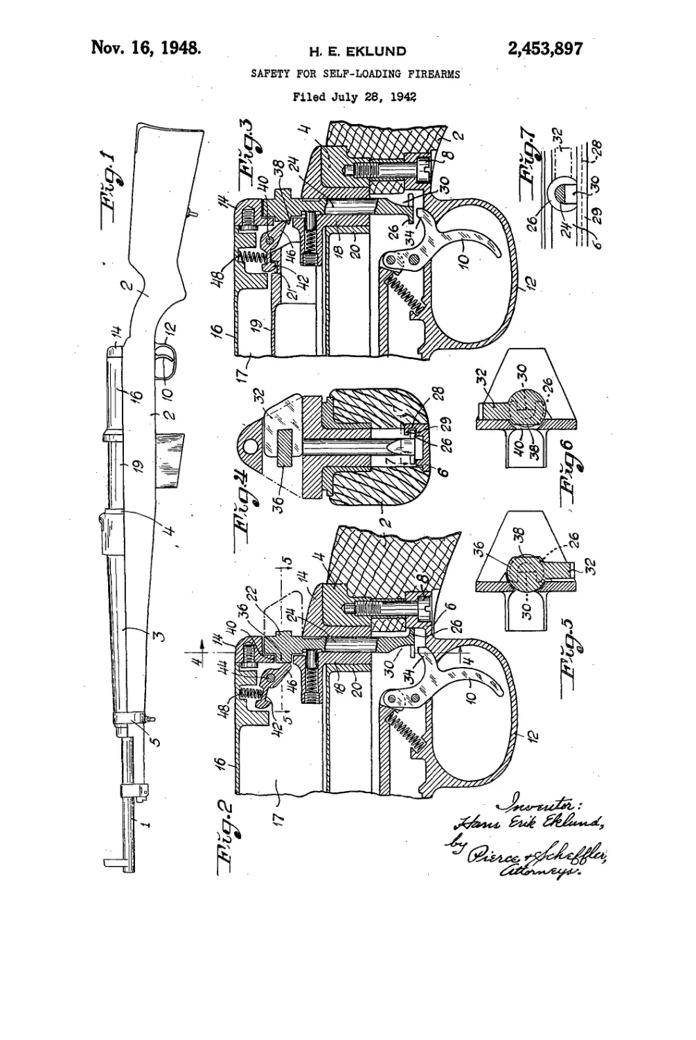
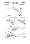
Fig. 1 is a left side elevation of the completely
assembled rifle with the bolt mechanism in the
closed position;
Fig. 2 is a longitudinal sectional view of a frag-
ment of the rifle at the rear portion of the re-
ceiver;
Fig. 3 is a similar view to Fig. 2 but showing
the safety member in a different position;
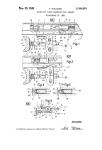
Fig. 4 is a transverse sectional view on the line
4—4 of Fig. 2;
. Figs. 5 and 6 are similar sectional views on the
line 5—5 in Fig. 2 and illustrate two different
positions of the safety; and
Fig. 7 is a , sectional view on the plane of line
7—I in Fig 4 but showing the locking flange in
the position in which, the rear member can be
removed.
In the illustrative construction of the draw-
ing, referring first to Fig 1, the barrel is indicated
at i, the stock at 2, the fore stock at 3, the re-
ceiver or frame at 4 and a strap, holding the fore
stock at 5. With reference also to Fig. 2 the
trigger guard plate is designated by 6, a rear
clamp screw for such plate by 8, the trigger by
10 and the trigger guard proper with 12.
(Cl. 42—70)
2
The rear member referred to above forms a
rear wall for the receiver cavity IT, which con-
tains the bolt mechanism. The detailed con-
struction of said mechanism forms no part of the
5 present invention but an element thereof is
shown at 19 in Figs. 1 and 3. The top of the
receiver cavity is confined by a protecting cover
or slide 16 which is slidably mounted upon the
receiver. The rear member 14 is mounted re-
10 movably on the receier and to this end it is pro-
vided with a cylindrical boss 18 which is fitted re-
movably in a corresponding transversely ar-
ranged cylindrical socket 20 of the receiver, the
axis of the socket being vertical when the rifle is
15 in normal firing position. The safety member
22 of the fire arm is carried by the rear member
which to this end has a bore extending axially
through the cylindrical boss 18 and through
which the safety pin 24 is carried. The safety
20 member is formed as a lock to maintain the rear
member in the receiver. At its lower end the
safety pin 24 has a locking flange 26 which in
a certain position engages a groove 28 formed in a
lateral marginal flange 29 on the guard plate 6
25 but in another position is moved out of this groove
to permit elevation of the rear member as will
be more particularly described hereinbelow.
At the lower end the safety pin 24 has a notch
3.0 beginning at the end surface thereof and
30 which when the safety lever or handle 32 secured
to the safety pin takes the position illustrated
in Figs. 2, 4 and 5 is located opposite to a projec-
tion 34 which extends rearward from the trigger
10 and in such position permits the trigger to be
35 actuated for firing the arm; in other words the
safety member then is in its unlocking position,
as illustrated in Fig. 2. In this position the safety
lever 32 is turned over to the right in Fig. 4. If
it is turned over half of a revolution from the
40 latter position, as illustrated in Figs. 3, 4 and 6
the rifle is locked because the lower end surface
of the safety pin then stands opposite to the pro-
jection 34 and thereby blocks the trigger as illus-
trated in Fig. 3. In consequence, the safety mem-
45 ber here has also the usual function of securing
the fire arm to prevent accidental firing.
However, the safety member has also the ob-
ject to control the loading of the fire arm to a
certain extent. To this end it has a rounded
50 flange 36, situated on a level with the safety lever
32 and having a flattened surface 38 at one side
thereof. This flange is extended laterally
through an aperture 40 in the rear member so
that its peripheral edge lies substantially flush
55 with the front of the rear member. Opposite
2,453,897
3
to the aperture 40 there is a pawl 42 which is
pivoted on a horizontal pin 40 in the protecting
cover 16 and has a rear projection 46 which is
pressed against the flange 36 by the spring 48.
In the position shown in Figs. 2 and 5 of the
safety member, the projection 46 engages the arc
shaped periphery of the flange 36, and the pawl
is held in its elevated position. This corresponds
to unlocked rifle (Figs. 2 and 5). The pawl 42
is intended to cooperate in a certain manner with
the bolt mechanism of the rifle, but is now main-
tained in its elevated position out of any actua-
tion thereof. On the other hand, if the safety
lever 32 is turned about half of a revolution to
the position illustrated in Figs. 3 and 6 the flat-
tened surface 38 of the flange 36 comes opposite
to the aperture 40 and the projection 46 so that
this projection permits the pawl to move down
to a certain extent. The pawl then takes a lock-
ing position in which it may have influence on
the bolt mechanism. In this position the pawl
can in fact catch hold of the element 19 of the
bolt mechanism to keep said mechanism in its
open position. In Fig. 3 the pawl 42 engages a
notch 21 in the element 19. In any automatic
or semi-automatic fire arms of similar type hav-
ing a locking member or action slide which is
actuated by a powder gas actuated member oper-
ating the loading mechanism, and in turn actu-
ates the bolt of the fire arm, the pawl can be con-
structed to maintain this locking member or ac-
tion slide and thereby keep the mechanism in its
open position.
Because the pawl 42 is journalled in the pro-
tecting cover or slide 16, it is carried forwardly
with the cover 16 when the latter is moved for-
wardly. The rear member 14 may be lifted from
the receiver when the cover or slide 16 is man-
ually moved forwardly; and the cover 16 and
bolt mechanism i 9 may then be removed as a unit
from the receiver. Since the rear member may
be removed only when the safety member takes
a certain position the safety mechanism is thus
also a key, which enables or prevents the mecha-
nism from being dismounted.
In the unlocked as well as the locked position
of the safety mechanism the locking flange 26
engages the notch 28 in the guard plate and
blocks the rear member to the receiver. The
notch 30 situated in the safety pin 24 and also
extending out through the flange 26 and form-
ing an opening therein is directed forward and
rearward respectively as illustrated at the bot-
tom of Figs. 5 and 6 respectively (dotted lines).
However, if the safety pin 24 is turned so that
the notch 30 will face to the groove 28, the lock-
ing flange does not prevent elevation of the rear
member and the safety member because the lock-
ing flange 26 is free beyond the marginal flange
29 containing the groove 28 on the guard plate.
The safety lever 32, the locking flange 26 and the
notch 30 then take the position relatively to the
marginal flange 29 as illustrated in Fig. 7.
What I claim is:
1. In a self-loading fire arm, a receiver, a bolt
mechanism in said receiver, a spring pressed latch
for retaining the bolt mechanism in retracted
position, firing mechanism for said bolt mecha-
nism, a rear member removably mounted in said
receiver to form a wall for the receiver back of
said bolt mechanism, and a safety member rotat-
5
io
15
20
25
30
35
40
45
50
55
60
65
70
4
ably mounted in the rear member; said safety
member including safety means operable to block
actuation of said firing mechanism upon adjust-
ment of said safety member to one position,
means operable upon adjustment of said safety
member to render said safety means inactive and
to actuate said spring pressed latch to inopera-
tive position, and means carried by said safety
member and operative in both of said adjust-
ments of the safety member to lock said rear
member against removal from said receiver.
2. In a self-loading fire arm, a receiver, a fir-
ing mechanism within said receiver, a rear mem-
ber removably mounted on said receiver to form
a rear wall thereof, a safety member adjustably
carried by said rear member and formed with
a circumferentially incomplete locking flange,
said safety member including means co-operating
with said firing mechanism to lock or alterna-
tively to unlock the same upon adjustment of said
safety member into one or the other of two sig-
nificant positions, a guard plate at the bottom
of the receiver having a groove to be engaged
by said locking flange in the locking and unlock-
ing adjustments of said safety member, said
safety member being movable into a third posi-
tion in which the circumferentially incomplete
flange is clear of said groove, thereby to permit
removal of the rear member and safety member
as a unit from the receiver.
3. In a self-loading fire arm, a receiver, a bolt
mechanism in said receiver, a spring pressed
latch for retaining the bolt mechanism in re-
tracted position, a rear member removably
mounted in said receiver to form a wall for the
receiver back of said bolt mechanism, and a safety
member rotatably mounted in the rear member;
said safety member including means operable
upon adjustment of said safety member into one
or the other of two significant positions to actu-
ate said spring pressed lateh to operative and
inoperative position respectively, and means car-
ried by said safety member and operative in both
of said adjustments of the safety member to lock
said rear member against removal from said re-
ceiver.
HANS ERIK EKLUND.
REFERENCES CITED
The following references are of record in the
file of this patent:
UNITED STATES PATENTS
Number Name Date
639,421 Mauser______________Dec. 19, 1899
861,939 Benet et al_________July 30, 1907
1,082,961 Lang _________________Dec. 30,1013
1,293,021 Browning_____________Feb. 4, 1919
1,317,633 Squire et al.______Sept. 30, 1919
1,433,945 Eickhoff__________ Oct. 31, 1922
1,523,831 Karpinski___,_______Jan. 20, 1925
1,586,048 Schmeisser___________May 25, 1926
1,637,235 Norman______________ July 26, 1927
1,843,916 Cole_________________Feb. 9, 1932
2,242,389 Burton__________________May 20, 1941
FOREIGN PATENTS
Number Country Date
78,449 Germany______________ Dec. 7, 1894
794,043 France_________________Dec. 2, 1935
653,566 Germany________________Nov. 26, 1037