/


Текст
L. SOHMEISSER.
BBEEOH MECHANISM FOB SELF LOADING FIBEABMS.
APPLICATION PILED FEB. 12, 1907.
909,233. Patented Jan. 12,1909.
UNITED STATES PATENT OFFICE.
LOUIS SCHMEISSER, OF ERFURT, GERMANY, ASSIGNOR TO RHEINISCHE METALLWAREN-UND
MASCHINENFABRIK, OF DUSSELDORF-DERENDORF, GERMANY.
BBEECH MECHANISM FOB SELF-LOADING FIRE ARMS.
No. 808,233. Specification of Lettexs Patent. Patented Jan. 12, 1808.
Application filed. February 12, 1807. Serial No. 360,987.
To all whom it may concern:
Be it known that I, Louis Schmeisseb,
engineer, a subject of the German Emperor,
residing at Erfurt, Loberstrasse 25-2711,
5 Germany, have invented certain new and
useful Improvements in Breech Mechanism
for Self-Loading Firearms; and I do hereby
declare the following to be a full, clear, and
exact description of the invention, such as
10 will enable others skilled in the art to which
it appertains to make and use the same.
My invention relates to novel breech
mechanism particularly designed for self-
loading fire-arms for which a stronger
15 charge of powder is used, for example, for
automatic rifles and guns, as also for quick
firing guns provided with recoil barrels, in
which the lock is opened by the impact or
backward force of the explosion.
20 This new breech mechanism, in addition
to its increased strength, has the advantage
of simple construction, and can be quickly
and conveniently taken apart and put to-
gether again.
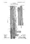
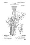
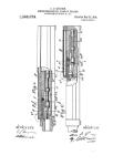
25 In the accompanying drawing illustrating
my invention Figure 1 is a vertical section Ot
the breech in. the locked position, as seen
from the left, without the top plate and
trigger mechanism. Fig. 2 is a similar sec-
30 tion of the same part showing the breech
sleeve moved back at the moment in which
the lock is opened, the breech piston not
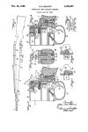
having recoiled further. Fig. 3 shows a sec-
tion on the line A—В of Fig. 1 as seen from
35 behind.
In the casing A slides the breech sleeve B,
at the front of which the barrel is fitted.
The Sleeve В is thickened at the back and
adapted to carry the locking lever C which
40 turns about c. In the sleeve В slides the
breech bolt D which carries the extractor
and the firing-pin E.
The casing A is closed at the back and
the recoil of the breech sleeve В and bolt D
45 is limited by the buffer F carried by the
closure plate Fl, which latter is connected
with the casing A by a hinge and can be so
turned about the pin f that the parts В and
D can be inserted in the casing A and taken
50 out again. In the closed position the plate
F1 is held by a bolt or screw /x which passes
transversely through the plate Fl aha also
through the side walls of the casing A, be-
tween which the back part of the plate F1
55 fits.
At the top of the casing A there is a
cover G, which is coimected to the casing at
the front by a hinge G1 and can be turned
up. On this cover G is provided the spring
casing H, which, however, can also be made 60
in one piece with said cover G. In the
spring casing H is provided the sleeve J
whose foot i engages in the' part d of the
breech bolt in such a manner that these-
parts describe their backward and forward 65
motion together. The part d of the breech
bolt D, as shown in Fig. 3, is extended on
one side and serves as a handle in order to
enable the loading movements to be carried
out or the breech to be opened for some 70
other purpose.for example to unload or in
taking the fire arm to pieces.
At the back of the spring casing H the'
spring bolt К is provided which is connected ,
by a bayonet joint at к to the cover G of the .75
spring casing H, being thus held. Further,
the return spring L is provided in said cas-
ing H which spring presses at the front
against the bottom of the sleeve J and at the
back against the spring bolt K. The part к 80
of thfe spring bolt К has the form of a tooth
and engages in a corresponding groove of
the plate F (Figs. 1 and 2). As the spring.
L presses against the bolt K, the tooth к
forms a spring fastening for the back part 85
of the cover G which fastening can be re-
leased by pressing against the head of the.
bolt К projecting at the back of the
casing H.
The casing A as well as the sleeve В and 90
the cover G including the spring casing BE
are slotted longitudinally in order to enable
the parts d of the breech bolt D and the part
i of the spring sleeve J to slide back.
The forward motion of the breech sleeve 95
В is limited by its back end striking against
a stop of the casing A, while the forward
movement of the breech bolt D is limited by
its part d striking a corresponding surface
of the breech sleeve B, as also by its breech loo
head striking against the back end of the
barrel.
As evident from Figs. 1 and 2 the locking.
lever C, by its beveled rear end c1 striking
against the inclined surface /2 of the buffer 105
F, is sb-tilted that its front end is moved out
of the locking position, as soon as the breech
sleeve В ana barrel, as well as the breech ।
bolt D connected to said sleeve by the lock-
ing lever C, are moved out of the position 110
809,233
&
shown in Fig. 1 into that shown in Fig. 2,
either by the recoil or by pulling the handle
of the breech bolt D.
The distance between the inclined surface
6 c1 of the locking lever C and the correspond-
ing surface /2 of the plate F is so calculated
that the parts B, D and C locked together
must first move back through the same dis-
tance that the horizontal surface c3 at the
10 front end of the locking lever C remains in
contact with the corresponding surface a
of the casing A, before said parts are un-
locked. If the handle of the breech bolt
D is pulled further it will recede to such an
15 extent that its back end will strike against
the buffer F, while the breech sleeve В is
retained by the plate F. The sleeve J con-
nected with the breech bolt D is also moved
backwards and the return spring L accord-
20 ingly compressed. As soon as the breech
bolt D is released, the return spring L drives
it forward through the agency of the sleeve
J, said breech bolt first arriving in the po-
sition shown in Fig. 2. The front end of
25 the locking lever C is then forced into the
locking position (Fig. 1), because the ad-
vancing power of the return spring L so
influences the locking lever C through the
sleeve В that its front inclined surfice c2,
30 rides up the inclined surface a2 of the casing
A, and brings the front end of the locking
lever C into the locking position when the
breech bolt D is advanced to such an extent
that the front end of the locking lever C can
35 move behind the same. At the moment in
which the locking lever C arrives in this po-
sition the locked parts B, D and C are moved
together a short distance until they arrive
at the final position shown in Fig. 1 and the
40 surface c3 of the locking lever C so bears
against the surface a of the casing A that
it can only be released when the locked parts
В, C and D have moved back a certain
distance.
45 If, now, in firing? the barrel and breech
sleeve В together with the locked parts re-
coil, the release takes place in the manner
above described. The great force with
which said parts are thrown back in firing
50 causes the unlocked breech bolt D to be
thrown back against the tension of the
spring L bv kinetic force until it is stopped
by the buffer F, the gas pressure in the in-
terior of the barrel assisting this operation,
55 which pressure, after the release has been
effected, drives the empty cartridge shell
backwards, together with the breech bolt D.
The return spring L then drives, by means
of the sleeve J, the breech bolt D forward
' 60 and all parts are locked in the manner above
described. During this backward and for-
ward motion of the breech bolt D all other
functions necessary in self-loading fire arms
are carried out in known manner; for ex-
ample, the empty cartridge shell is thrown 65
out, the trigger is raised, and a new car-
tridge is introduced into the barrel. In one
construction of the described breech mech-
anism for quick firing guns the casing A
is disposed to slide backwards in the same 70
manner as the barrel in guns with recoil
movement. Further the necessary retarding
devices and springs are provided by which
the gun is kept rigidly in its firing position.
It should be mentioned that the locking 75
lever (J can also be disposed at the top or
side instead of at the bottom as shown in
the drawing. Further two such locking
levers can also be provided.
What I claim and desire to secure by Let- 80
tors Patent of the United States is:—
1. In breech mechanism for automatic fire
arms, the combination, with the breech cas-
ing, the breech bolt therein and a locking
lever arranged to be tilted into and out of 85
the path of the recoiling breech bolt, of a
buffer having an inclined face opposed to
the rear end of the locking lever to tilt the
same, and a removable closure to the breech
casing, said closure carrying the buffer. 90
2. In breech mechanism for automatic fire
arms, the combination, with the breech cas-
ing, the breech bolt therein and a locking
lever arranged to be tilted into and out of
the path of. the recoiling breech bolt, of a 95
buffer having an inclined face opposed to
the rear end of the locking lever to tilt the
same, a closure hinged to the breech casing
and carrying the buffer, and a pin passing
laterally into the breech casing to secure 10<
the buffer and closure in operative closed
position.
3. In breech mechanism for automatic fire
arms, the combination, with the breech cas-
ing open to the lower side, the breech bolt 10.
therein, and a lacking lever arranged to be
tilted into and out of the path of the recoil-
ing breech bolt, of a buffer having an in-
clined face opposed to the rear end of the
locking lever to tilt the same, a closure 11<
hinged to the lower side of the breech casing
and carrying the buffer, and a pin passing
laterally into the buffer and the breech cas-
ing to secure the buffer and closure in opera-
tive closed position. 11
4. In breech mechanism for automatic fire
arms? a breech casing provided with an
opening, a breech bolt slidable therein, a
return spring connected to the breech bolt,
and a casing for said spring, the return 12'
spring casing arranged as a removable cover
to the breech casing.
5.. In breech mechanism for automatic fire
arms, a breech casing open above, a breech
bolt slidable therein, a return spring con- 12
nected to the breech bolt, a casing for said
spring, a hinge connection between the re-
turn spring casing and the breech casing,
809,888
8
and a spring clip to secure the return spring
casing in position with the opening closed.
6. In breech mechanism for automatic fire
arms, a breech casing open to the upper and
5 lower sides, a breech bolt therein, a locking
lever arranged to be tilted with one end into
and out of the path of the recoiling breech
bolt, a buffer having an inclined face op-
posed to the rear end of the locking- lever
10 to tilt the same, a closure hinged to the lower
side of the breech casing and carrying the
buffer, a pin passing laterally into the buffer
and tnei casing to secure the buffer in operas
tive relation to the lever with the lower
15. closure in place, a return spring connected
to the breech bolt, a casing for said spring,
a hinge connected between the return spring
casing and the breech casing, a bolt serving
as an abutment for the return spring and
20 provided with a tooth engaging a recess in
the breech casifig to secure the return spring
casing in position with the upper cover
closed. r
7. In breech mechanism for automatic fire
25 arms, the combination, with the breech cas-
ing, the breech sleeve and the breech bolt
therein, and a locking lever pivoted to the
breech sleeve and arranged to be tilted with
its forward end into and out of the path
30 of the breech bolt, the front and rear end of
the lever beveled, and the front and rear
walls of the breech chamber inclined parallel
to the respective beveled ends of the lever,
"whereby the limited longitudinal movement
35 of the lever with the breech sleeve causes
the tilting of the lever to lock and unlock
the breech bolt.
8. In breech mechanism for automatic fire
arms, the combination, with the breech cas-
40 ing, the breech sleeve and the breech bolt
therein, and a locking lever pivoted to the
. breech sleeve and arranged to be tilted with
its forward end into and out of the path of
the breech bolt, the front and rear end of
45 the lever beveled, and the front and rear
walls of the breech chamber inclined parallel
to the respective beveled ends of the lever,
whereby the limited longitudinal movement
of the lever with the breech sleeve causes the
tilting of the lever to lock and unlock the 50
breech bolt, in combination with a return
spring connected with the breech bolt, a
casing for said spring carried by the upper
wall of the breech chamber, said upper wall
hinged to permit its opening, a clip to hold 55
the said upper wall closed, the lower and
rear walls or the breech chamber hinged to
permit their swinging downward to give
'access to the mechanism within the chamber,
and means to secure them in a closed posi- 60
tion with the inclined rear wall in operative
relation to the locking lever.
9. In breech mechanism for automatic fire
arms, the combination, with the breech cas-
ing, the breech bolt tnerein2 and a locking 65'
lever arranged to be tilted into and out of
the path of the recoiling breech bolt, of a
buffer removably mounted in the casing
with its face opposed -at an inclination to
the rear end of the lever to tilt the same. 70
10. In breech mechanism for automatic
fire arms, the combination, with the breech
casing, the breech sleeve and the breech bolt
therein, and a locking lever moving with the
breech sleeve and arranged to be tilted with 75
its forward end into and but of the path of
the breech bolt, and the .front and rear walls
of the breech chamber inclined relative to
the respective ends of the lever, whereby
the limited longitudinal movement of the 80
lever with the breech sleeve causes the tilt-
ing of the lever , to lock and unlock the
breech bolt.
In testimony whereof I have hereunto
affixed my signature in the presence of two 85
witnesses.
LOUIS SCHMEISSER.
Witnesses:
Woldemab Haupt,
Henby Haspeb.