/


Теги: weapons military affairs patent
Год: 2008


Текст
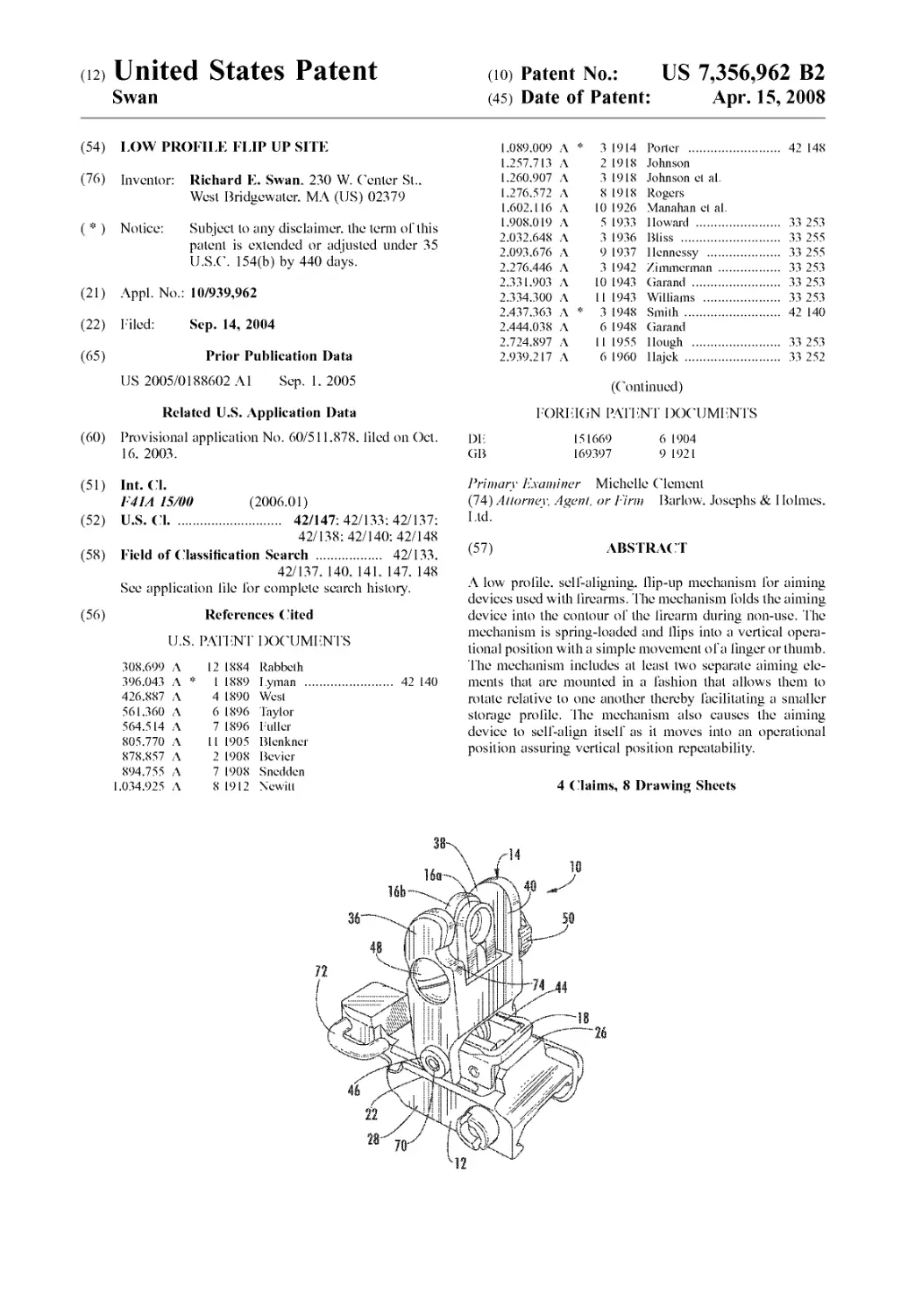
(12) United States Patent
Swan
(io) Patent No.: US 7,356,962 B2
(45) Date of Patent: Apr. 15, 2008
(54) LOW PROFILE FLIP UP SITE
(76) Inventor: Richard E. Swan. 230 W. ('enter St-
West Bridgewater. MA (US) 02379
( * ) Notice: Subject to any disclaimer, the term of this
patent is extended or adjusted under 35
U.S.C. 154(b) by 440 days.
(21) Appl. No.: 10/939,962
(22) Filed: Sep. 14, 2004
(65) Prior Publication Data
US 2005/0188602 Al Sep. 1. 2005
Related U.S. Application Data
(60) Provisional application No. 60/511.878. filed on Oct.
16. 2003.
(51) Int. (1.
1’41 A 15/00 (2006.01)
(52) U.S. (1................. 42/147:42/133:42/137:
42/138: 42/140: 42/148
(58) Field of Classification Search ....... 42/133.
42/137. 140. 141. 147. 148
See application file for complete search history.
(56) References Cited
U.S. PATENT DOCUMENTS
308.699 A 12 1884 Rabbelh
396.043 A * 1 1889 Lyman 42 140
426.887 A 4 1890 Wesl
561.360 A 6 1896 Taylor
564.514 A 7 1896 Fuller
805.770 A 11 1905 Blenkner
878.857 A 2 1908 Bevier
894.755 A 7 1908 Snedden
1.034.925 A 8 1912 Xewitt
1.089.009 A * 3 1914 Porter ................ 42 148
1.257.713 A 2 1918 Johnson
1.260.907 A 3 1918 Johnson el al.
1.276.572 A 8 1918 Rogers
1.602.116 A 10 1926 Manahan el al.
1.908.019 A 5 1933 Howard ................ 33 253
2.032.648 A 3 1936 Bliss ................. 33 255
2.093.676 A 9 1937 Hennessy ............. 33 255
2.276.446 A 3 1942 Zimmerman ............. 33 253
2.331.903 A 10 1943 Garand ................ 33 253
2.334.300 A 11 1943 Williams .............. 33 253
2.437.363 A * 3 1948 Smith ................. 42 140
2.444.038 A 6 1948 Garand
2.724.897 A 1 1 1955 Hough ....................... 33 253
2.939.217 A 6 1960 Ilajek ................ 33 252
(Continued)
FOREIGN PATENT DOCUMENTS
DE 151669 6 1904
GB 169397 9 1921
Primary Examiner Michelle ('lenient
(74) Attorney. Agent, or Firm Barlow. Josephs & I lolmes.
Eld.
(57)
ABSTRACT
A low profile, self-aligning, llip-ир mechanism for aiming
devices used with firearms. The mechanism folds the aiming
device into the contour of the firearm during non-use. The
mechanism is spring-loaded and Hips into a vertical opera-
tional position with a simple movement of a linger or thumb.
The mechanism includes at least two separate aiming ele-
ments that are mounted in a fashion that allows them to
rotate relative to one another thereby facilitating a smaller
storage profile, lite mechanism also causes the aiming
device to self-align itself as it moves into an operational
position assuring vertical position repeatability.
4 Claims, 8 Drawing Sheets
US 7,356,962 B2
Page 2
U.S. PATENT DOCUMENTS
3.930.316 Л * 1 1976 T'ellie ............ 42 140
4.597.211 Л 7 1986 Miles .............. 42 1 S
4.665.622 Л 5 1987 Idan ............... 33 241
4.691.442 Л * 9 1987 Center ............. 42 140
5.533.292 Л 7 1996 Swan ............... 42 100
6.490.822 Bl* 12 2002 Swan ................. 42 71.01
6.568.118 Bl* 5 2003 Teelzel ................. 42 105
6.606.813 Bl* 8 2003 Squire el al............. 42 90
6.615.530 B2* 9 2003 Johansson ............... 42 133
6.622.415 Bl* 9 2003 Canaday el al......... 42 140
6.722.075 Bl* 4 2004 Gabaldon ............. 42 141
6.732.467 Bl* 5 2004 I.ulh ................ 42 138
6.779.290 Bl* 8 2004 Iloulsma ............. 42 148
6.968.643 B2* 11 2005 Woodbury ............. 42 137
7.076.907 B2 * 7 2006 Nesselh el al......... 42 140
1)526.380 S * 8 2006 Swan ............... 1)22 109
7.181.882 B2* 2 2007 Woodbury ............. 42 137
2003 0140546 Л1 * 7 2003 Kay .................. 42 133
* cited by examiner
U.S. Patent
Apr. 15, 2008
Sheet 1 of 8
US 7,356,962 B2
U.S. Patent
Apr. 15, 2008
Sheet 2 of 8
US 7,356,962 B2
tf.S. Patent
APr-15, 2008
Sheet 3 of 8
US 7,356,962 B2
U.S. Patent
Apr. 15, 2008
Sheet 4 of 8
US 7,356,962 B2
U.S. Patent
Apr. 15, 2008
Sheet 5 of 8
US 7,356,962 B2
не. 4
U.S. Patent
Apr. 15, 2008
Sheet 6 of 8
US 7,356,962 B2
U.S. Patent
Apr. 15, 2008
Sheet 7 of 8
US 7,356,962 B2
FIG. 6
U.S. Patent
Apr. 15, 2008
Sheet 8 of 8
US 7,356,962 B2
18
US 7,356,962 B2
1
LOW PROFILE FLIP UP SITE
CROSS-REFERENCE TO RELATED
APPLICATIONS
Illis application is related to and claims priority from
earlier filed U.S. Provisional Patent Application No. 60/511.
878. filed Oct. 16. 2003. the contents of which are fully
incorporated herein by reference.
BACKGROUND OF fl IE INVENTION
Hie present invention relates generally to modular sight-
ing devices for weapons. More specifically, the present
invention relates to a low profile configuration for a for
providing a flip-up type sighting mechanism that folds down
onto the firearm in a compact manner to prevent damage or
snagging when not in use.
Generally, sighting mechanisms for firearms are bulky
and protrude outside the firearm’s general contour, This
construction creates a greater opportunity for the sighting
mechanism to be caught on clothing or brush while the lire
arm is being carried thereby knocking the sighting mecha-
nism out of alignment. Prior art devices that have attempted
to address this problem by allowing removal of the sighting
mechanism or providing a hinged attachment of the sighting
mechanism. Generally, however, the prior art devices
require that each time the sighting mechanism is moved into
the active position, the sighting mechanism must be re-
aligned before it is ready for use. Although this re-alignment
step may be acceptable when the firearm is used in a
controlled environment such as a firing range, it is not
acceptable for a firearm employed for field use. such as
hunting or combat environments where immediate, fully
aligned use of the sight is required.
litis is of particular concern in the field of combat
firearms. A firearm that is used in the field requires a sighting
mechanism that is located out of the way during times of
non-use. thereby providing a streamlined profile that is not
likely to be bumped or jarred out of alignment. Further, the
sight must be quickly engageable when the firearm is
urgently needed. The readiness time for the sighting mecha-
nism to move from the non-use or down position to the use
or up position must be minimized. Additionally, when
moved from the down position to the up position, the sight
must be fully and accurately aligned. It is critical that the
sighting mechanism have the ability to be consistently and
quickly engaged, and provide accurate aiming. Further, the
sight must maintain as small profile as possible when in the
retracted storage position to prevent bumping or jarring of
the sight.
In prior art devices such as disclosed in U.S. Pat. No.
5.533.292. issued to Swan, a self-aligning llip-ир sight is
provided that provides a sighting mechanism that can be
easily moved from a storage position to an active position
without requiring re-alignment of the sights. However, this
device has a relatively large vertical profile, even when it is
in the retracted position. The large profile results from the
use of two iron peep sights mounted fixedly at a 90° angle
relative to one another. In order for the sighting mechanism
to be moved into the storage position, the iron sight must be
placed into a position that allows one of the legs of the iron
sight assembly to lie parallel to the firearm with the other leg
pointing upwardly. If the iron sight assembly is not in this
position, the mechanism cannot be moved into the storage
position. Further, when the iron sight assembly is in the
proper storage position, one of the legs extends upwardly
in
15
211
311
35
411
45
511
55
60
65
2
from the upper surface of the firearm thereby requiring that
the protective shoulders of the sighting mechanism extend a
sufficient distance to protect this protruding leg of the iron
sight. In this manner, the sighting mechanism has a profile
that is larger than desired to allow the mounting of additional
accessories if desired. Specifically, if a user wished to mount
an optical telescopic sight in addition to the retractable sight,
an additional spacer would be necessary to allow the
required clearance.
In view of the foregoing disadvantages inherent in the
prior art devices, there is a need for a device that provides
an improved method of compacting and activating optical
and iron sight sighting device. There is a further need for a
sighting mechanism that provides improved engagement
method for firearms sighting devices which has the ability to
consistently and quickly engage, and provide accurate aim-
ing. while providing a reduced profile in the storage position
thereby reducing potential interference with other ancillary
aiming devices and attachments.
BRIEF SUMMARY OF fl IE INVENTION
In this regard, the present invention provides for a low-
prolile self-aligning llip-ир sight. The present invention
sighting device folds downwardly against a mounting rail
either directly on the lire arm. onto a receiver sleeve
mounting area or other desirable location, thereby keeping
the sighting device within the firearm’s contour during
non-use and streamlining the profile of a weapon. The
sighting device is spring-loaded and Hips into an operational
position with a simple movement of a linger or thumb. The
device includes a pair of iron sights that are also pivotally
mounted relative to one another allowing them to fold
against one another in the retracted position while moving
into a position wherein the two sighting elements are ori-
ented at a substantially 90° angle in the deployed position.
Further, the present invention sighting device self-aligns
itself as it moves into an operational position, thereby
providing accurate and consistent aiming while eliminating
the need for re-alignment each time the sight is deployed.
The present invention is particularly suited for iron sight
type sighting devices. The sighting device includes two iron
sight elements, one having a large aperture and one having
a small aperture. In the prior art. when two iron sights were
provided they were rigidly mounted perpendicular to one
another, 'lite sight was then selectibly positionable so that
one or the other of the two iron sights was in the operative
position while the other sight was positioned out of the way
in a position that was substantially parallel to the barrel of
the firearm. However as noted above, when utilized in a
llip-ир type sighting mechanism, if the sight was positioned
in the wrong manner, one of the iron sight elements would
prevent the sighting mechanism from closing. Even when
positioned in the proper alignment, extended shoulders were
required to protect the protruding top arm of the sight from
impact. To resolve this issue the present invention provides
that the two iron sights are mounted so as to be pivotably
movable relative to one another.
The present invention is a llip-ир sight and is comprised
of three major components namely, a base, an alignment
member and a sight housing. The sight housing contains the
actual aiming system in the form of collapsible iron sights.
The aiming system is comprised of two independent legs
pivotally mounted on a central sight adjustment screw-
positioned within the sight housing. The two legs cooperate
to form a collapsible aiming system. Each leg includes a
circular aiming peep sight, one sight being larger than the
US 7,356,962 B2
3
other. In the deployed position, the leg with the larger
aperture is always in the upright position, the leg with the
smaller aperture can be rotated approximately 90° around
the sight adjustment screw and is configured to be retained
in one of two selected positions. Accordingly, when the large
aperture sight is desired the small aperture sight can be
folded down out of the way of the large aperture. Further,
when the sight housing is placed into the stored position,
folded down against the base, the two legs of the aiming
system can fold against one another allowing the sight
housing to store tightly against the base while preventing
one of the sighting elements from protruding outwardly
from the firearm.
Accordingly, it is an object of the present invention to
provide a sighting mechanism for a firearm that includes at
least two aiming elements and has a compact profile when
placed into a storage position. It is a further object of the
present invention to provide a sighting mechanism for a
firearm that can be retracted to a low profile storage position
against the contour of the firearm while being quickly and
easily deployable to a fully aligned active position. It is yet
a further object of the present invention to provide a retract-
able sighting assembly for a firearm that includes at least two
user selectable aiming elements that can be fully retracted
into a low profile storage position against the contour of the
firearm.
lltese together with other objects of the invention, along
with various features of novelty which characterize the
invention, are pointed out with particularity in the claims
annexed hereto and forming a part of this disclosure. For a
better understanding of the invention, its operating advan-
tages and the specific objects attained by its uses, reference
should be had to the accompanying drawings and descriptive
matter in which there is illustrated a preferred embodiment
of the invention.
BRIEF DESCRIPTION OF THE DRAWINGS
In the drawings which illustrate the best mode presently
contemplated for carrying out the present invention:
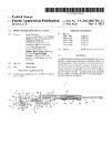
FIG. 1 is a front perspective view of the Hip up sight of
the present invention in the deployed position with the large
aperture aiming element in the active position:
FIG. 1Л is a top view thereof:
FIG. 2 is a front perspective view of the Hip up sight of
the present invention in the deployed position with the small
aperture aiming element in the active position:
FIG. 3 is a cross-sectional view taken along the line 3-3
of FIG. 1:
FIG. ЗА is an enlarged cross-sectional view of the aiming
elements with the second aiming element in the up (active)
position:
FIG. 3B is an enlarged cross-sectional view of the aiming
elements with the second aiming element in the down
(inactive) position:
FIG. 4 is a perspective view of the Hip up sight in the
retracted position:
FIG. 5 is a firearm with the Hip up sight assembly in the
retracted position mounted on the receiver thereof:
FIG. 6 is a perspective view of the Hip up sight in the
deployed position with the sighting elements reversed and
the large aperture aiming element in the active position: and
FIG. 7 is a perspective view of the alignment member.
DETAILED DESCRIPTION OF THE
INVENTION
Now referring to the drawings, the retractable flip-up
sighting device of the present invention is shown and
in
15
211
311
35
411
45
511
55
60
65
4
generally illustrated in the figures as 10. In particular, the
present invention is a retractable llip-ир sight 10 for a lire
arm wherein the llip-ир sight 10 has a reduced profile when
in the retracted position, litis feature allows improved
shielding and protection of the aiming elements within the
sighting device 10 when in the retracted storage position.
Further, the sighting device 10 includes a self-aligning
feature that ensures that the sighting elements remain in
proper alignment with the firearm each time the sighting
elements are deployed into the active position from the
storage position. The llip-ир sight assembly includes three
major components: a base 12. a sight housing 14. and an
aiming device 16. Further, to facilitate the self-aligning
feature, the sighting device 10 includes an alignment mem-
ber 18. The sight housing 14 serves to contain and support
the actual aiming device 16 while also including features to
protect the aiming device 16. The sighting device 10 is
designed to be mounted preferably on a Swan universal
receiver sleeve, extended rigid frame receiver sleeve, or any
other attachment device such as the receiver rail that is
attached on the top of a firearm upper receiver. Additionally,
the sighting device 10 may be used in place of or in
conjunction with most conventional firearm sighting mecha-
nisms.
fuming now to FIG. 1. the base 12 is formed to include
an interface means 20 to allow the sighting mechanism 10 to
be mounted onto a variety of firearms. The base has 12 an
upper surface 22 and a lower surface 24. wherein the lower
surface 24 has a cross-sectional profile that is configured to
interface with the dovetailed shape of a typical receiver
sleeve. The base 12 also includes a right side 26. a left side
28. a front 30 and rear 32 wherein the right side 26 and left
side 28 include lower interface members 20 for retaining the
sighting mechanism 10 on a receiver sleeve. Two identical,
vertical and parallel mounting tabs 34 extend perpendicu-
larly upward from the base 12 upper surface 22. The tabs 34
are thin, have a rectangular shape and lie in vertical parallel
planes a predetermined distance apart. The tab 34 planes are
parallel to the base 12 sides 26. 28. A spring trough resides
between the tabs 34. The width of the trough is defined by
the separation between the tabs 34. Each of the mounting
tabs 34 includes a mounting pin hole with a common center
on an aligned axis perpendicular to the axis of the base 12.
The sight housing 14 has two parallel side plates, a catch
plate 36 and an adjustment plate 38. positioned in vertical
planes. The sight housing 14 is further defined by an upper
support region 40 between the catch plate 36 and the
adjustment plate 38. The upper support region 40 is config-
ured to retain and protect the aiming elements 16u. 16Z>. The
sight housing 14 also includes a lower interface region 42
which includes an inside surface bounded by the catch plate
36. the adjustment plate 38 and further may include align-
ment surfaces 44 to enable the self alignment feature of the
present invention as will be described in detail below. The
catch plate 36 and the adjustment plate 38 have holes 46 in
the lower interface region 42 thereof, the holes 46 corre-
sponding to the mounting pin holes in the tabs 32 on the base
12.
The aiming elements 16u. 16Z> include at least one sight-
ing device such as for example an open iron type peep sight
having an aperture therein. Similarly, the aiming elements
16u. 16Z> could include any conceivable aiming device such
as a magnifying sight or an open sight. As shown in the
FIGS., the aiming elements include preferably two different
aiming elements such as a large aperture iron sight 16u and
a small aperture iron sight 16Z>. Similarly, the present inven-
tion may include 3 or more aiming elements 16 and fall
within the scope of the present invention. The aiming
US 7,356,962 B2
5
elements 16 each include a top aiming end and a bottom
mounting end. whereby the aiming elements 16 are mounted
into the upper support region 40 of the sight housing 14. The
aiming elements 16 are mounted on and retained in the upper
support region 40 of the sight housing 14 by the sight
adjustment screw 48 that is positioned and attached between
the catch plate 36 and the adjustment plate 38. Referring to
FIG. 1. the bottom mounting end of aiming element 16u
includes spaced mounting legs, while the bottom mounting
end of aiming element 16Z> has a single leg that is positioned
between the spaced mounting legs of element 16u. An arced
spring 41 is attached along the bottom of the upper support
region 40 and applies pressure against the bottom edge of the
aiming elements 16 thereby allowing element 16Z> to rotate
independently of element 16u approximately 90 degrees
around the sight adjustment screw 48 and hold in the desired
position by engaging one of two detents 43 (see FIGS. ЗЛ
and ЗВ). A sight adjustment knob 50 is attached to one end
of the sight adjustment screw 48 wherein the aiming ele-
ments 16 are adapted to be moved laterally across the shaft
49 of the sight adjustment screw 48 as the sight adjustment
knob 50 is turned, allowing line tune adjustment of the
aiming elements 16 for compensation in alignment with the
firearm as well as windage adjustment.
As can be seen by viewing FIG. 1 in conjunction with
FIG. 2. multiple aiming elements 16 can be used in the sight
housing 14 in conjunction with one another. In FIG. 1. the
active aiming element 16u is a huge aperture iron sight and
is in the up or active position, lite inactive element is a small
aperture iron sight 16Z> and is shown folded downwardly in
the inactive position. In FIG. 2. the small aperture iron sight
16Z> is shown in the up position against the large aperture
iron sight 16u. In this position the small aperture iron sight
16u is the active sight because when looking through the
aiming elements 16 the only aperture through which the user
can aim the firearm is the small aperture because the rest of
the small aperture aiming element partially blocks the large
aperture. Further, as will be more fully discussed later, both
aiming elements 16 would be positioned in this manner
when the sight housing 14 is placed into the retraced storage
position. It should be also appreciated, as can be seen in FIG.
5. that the relative positioning of the aiming elements 16
may be reversed placing the small aperture aiming element
16Z> in the rear position closest to the user and the large
aperture aiming element 16u in the front position without
departing from the disclosure of the present invention.
Further, a third or more aiming elements 16 could be added
as well and still reside within the present disclosure.
Referring now to FIG. 6. the U-shaped alignment member
18 has two vertical sides 52. 54 and a front face 56. The
vertical sides 52. 54 have inner surfaces that are parallel to
one another and an outwardly chamfered top edge. The
vertical sides 52. 54 each have a mounting pin hole 58
located in their rearward upper quadrants perpendicular to
the inner faces wherein when the alignment member 18 is
installed onto the base member 12. the mounting pin hole 58
in the vertical sides corresponds to the mounting pin holes
in the tabs 34 on the base 12. In this manner when the
alignment member 18 is installed onto the base 12 the inner
faces of the vertical sides 52. 54 rest against the tabs 34 with
the mounting pin holes in the tabs 34 being in alignment
with the mounting pin holes 58 in the vertical sides 52. 54
of the alignment member 18. To further assist in retaining
the alignment member 18 on the base 12. additional holes 60
are provided in both the alignment member 18 and the tabs
34 on the base 12 where by a spring pin is installed through
the common spring pin holes 60 to retain the alignment
member 18 and the base 12 in assembled relation. Alterna-
in
15
211
311
35
411
45
511
55
60
65
6
lively, other fasteners such as bolts or rivets could be used
and still fall within the scope of the present invention.
fuming back now to FIG. 1. the sighting device 10 of the
present invention is shown in the deployed or “open”
position, the sight housing 14 lower interface region 42 is
positioned over the outer faces of the vertical sides 52. 54 of
the U-shaped alignment member 18 such that the mounting
pin holes in the in the side walls of the sight housing 14 share
a common center with the mounting pin hole in the align-
ment member 18 and the mounting pin hole in the mounting
tabs 34. A mounting spring pin 70 is then inserted into the
mounting pin hole thereby attaching the sight housing 14.
U-shaped alignment member 18 and the mounting tabs 34
together. Accordingly, the sight housing 14 is pivotally
attached by the mounting spring pin 70 to the alignment
member 18 and the mounting tabs 34 such that the sight
housing 14 can rotate about the mounting spring pin 70 a
predetermined amount. Alternatively, other fasteners such as
bolts or rivets could be used in place of the mounting spring
pin.
As can best be seen in FIG. 3. a linger release clamp 72
is provided to hold the sight housing 14 in a retracted or
down position against the base 12. lite linger release clamp
14 engages a pin catch slot 74 formed in the catch plate 36
thereby holding the sight housing 14 in a normally closed
first position, lite linger release clamp 72 is mounted in a pin
bore which is drilled into the base 12. A tension spring is also
mounted in the pin bore thereby providing resistive force
against rotation of the linger release clamp 72. A half-
cylindrical notch is formed in the upper surface of the base
12. lite purpose of the notch is to provide a place in the base
for the clamp 72 to fold into, out of the way. when it is not
holding the sight housing 14 in a down position. Another
notch is formed in the rear of the catch plate 36. The purpose
of this catch plate notch is to avoid damage to the sight
housing 14 if it gets knocked down with great force into the
clamp 72 which is partially protruding from the base notch.
Rotating the linger release clamp 72 away from the sight
housing 14 disengages the linger release clamp 72 from the
pin catch slot 74 and allows rotation of the sight housing 14
from the normally closed first position to the open second
position. A torsional spring 76 urges the sight housing 14
from the closed first position to a vertical open second
position. The torsional spring 76 surrounds the mounting
spring pin 70 in the lower aperture 42 between the mounting
tabs 34.
In this embodiment as can best be seen in referring to
FIGS. 5 and 6. a self aligning feature is also provided within
the aiming device 10 of the present invention. While the
inclusion of this feature is not a critical component of the
overall device of the present invention, its inclusion further
enhances the overall performance of such a device. Accord-
ingly. consistent vertical positioning of the sight housing 14
is accomplished with the aid of alignment chamfers 78.
formed on the top edges of the vertical sides 52. 54 of the
U-shaped alignment member 18. In this embodiment of the
invention, the chamfer 78 slopes are at a forty-live degree
angle and the longitudinal axes of the alignment chamfers 78
are substantially parallel to the longitudinal axis of the base
12. The sight housing 14 has corresponding alignment
surfaces 44. When the sight housing 14 is released to the
open second position, the alignment surfaces 44 are wedged
against the alignment chamfers 78. respectively, bringing the
sight housing 14 to rest in the same vertical position every
time it is released. The slopes of the alignment surfaces 44
correspond to the slopes of the alignment chamfers 78.
Repeatability is further ensured by the “squeezing” action of
the alignment surface 44 and catch plate 36 against the
U-shaped alignment member 18 vertical side toward the
base mounting tab 34. and the corresponding “squeezing”
US 7,356,962 B2
7
action of the alignment surface 44 and adjustment plate 38
against the U-shaped alignment member 18 vertical side
toward the base mounting tab 34. This ensures repeated and
accurate alignment of the U-shaped alignment member
vertical sides during each movement of the sight housing 14
to the open, second position. It should also be appreciated
that the alignment member 18 may be eliminated in favor of
chamfering the tops of the tabs 34 thereby providing the
same type of alignment action each time the sight housing 14
is deployed.
It should also be noted that when the sight housing 14 is
in the retracted position, both of the aiming elements 16u
and 16Z> are folded Hat against one another and rest Hat
against the profile of the firearm 84. Further, the aiming
elements 16u and 16Z> in this position are shielded by the
catch plate 36 and the adjustment plate 38. As can be seen
in FIG. 4. the sighting device 10 is shown as being integrated
into a receiver rail 80 that is attached to the upper receiver
82 of a firearm 84. It can be seen that the sighting device 10
has a small and compact profile when placed in the retracted
position, fhis can be contrasted with the prior art devices
that utilized an I.-shapes aiming element. In the prior art
when the sight housing was in the retracted position, one of
the legs of the aiming element projected outwardly from the
firearm, litis projection necessitated that the side walls of
the sight housing be wider to provide protection for the
projecting leg of the aiming element. In the present inven-
tion. with both aiming elements 16u and 16Z> folded Hat
against the contour of the firearm 84. the walls of the sight
housing 14 can be narrower, providing a smaller overall
profile depth allowing the sighting device 10 to reside in a
more compact position against the firearm 84.
While the above-described embodiment uses a conven-
tional firearm “iron” peep sight as the aiming elements 16.
the principles of the present invention are also applicable to
the newer optics sights currently becoming available, i.e..
compact single optic frames with lens projected beam
optics. The newer optics sights have a radial axis parallel to
the transverse plane of the weapon and a central axis parallel
to the longitudinal axis of the weapon. The newer optics
sights have aiming optics which are quite Hat along their
central axis. The sights focus energy from illumination
means on the Hat aiming optics. The illumination means may
be a laser, or other directed energy illuminator which directs
energy onto the aiming lens. The present invention permits,
for the first time, an ability to fold down aiming optics when
not in use. and provides an ability to Hip up the aiming optics
to a preset configuration for actual use. Problems with the
aiming optics being caught on clothing or brush when
carried and knocked out of alignment from this contact or
contact with other solid objects, are thereby eliminated.
Accordingly, the basic sight apparatus is the same whether
or not an “iron” aiming element is used or an optics sight is
used.
It can therefore be seen that the present invention provides
an improved sighting device 10 that has a smaller and more
compact profile when placed into a storage position as
compared to the sighting devices in the prior art. Further, the
present invention can be modified to accommodate a number
of different aiming elements 16 and can be integrated onto
a variety of different firearms to provide a highly accurate
low profile Hip up sight for use in actual held conditions
typically associated with combat weaponry. For these rea-
sons. the instant invention is believed to represent a signifi-
cant advancement in the art. which has substantial commer-
cial merit.
While there is shown and described herein certain specific
structure embodying the invention, it will be manifest to
those skilled in the art that various modifications and rear-
rangements of the parts may be made without departing
in
15
211
311
35
411
45
511
55
60
65
8
from the spirit and scope of the underlying inventive concept
and that the same is not limited to the particular forms herein
shown and described except insofar as indicated by the
scope of the appended claims.
What is claimed:
1. A llip-ир aiming sight for use with a firearm compris-
ing:
a base member having a top surface and a bottom surface
configured and arranged to be mounted on an upper
receiver of a firearm:
a sight housing having an upper section and a lower
section configured and arranged to be rotationally mov-
able relative to said top surface of said base.
said sight housing being rotationally movable relative
to said base member between a first inactive position
adjacent said base member and a second active
position generally perpendicular to said base mem-
ber.
said upper section including upwardly extending,
opposing sidewalls that cooperate to define a central
support region.
a spring received and retained between said base member
and said sight housing for normally biasing said sight
housing to said active position:
a retainer configured and arranged to selectively engage
said sight housing and selectively retain said sight
housing in said inactive position: and
an aiming assembly mounted within said central support
region of said upper section of said sight housing, said
aiming assembly including a windage adjustment
screw rotatably mounted between said upwardly
extending opposing sidewalls, a first aiming element
having a top aiming end and a bottom mounting end
mounted on said windage adjustment screw, and a
second aiming element having a top aiming end and a
bottom mounting end mounted on said windage adjust-
ment screw, said first aiming element being configured
and arranged in a fixed upright position generally
perpendicular to said central support region, said sec-
ond aiming element being rotatably movable relative to
said first aiming element between a first active position
generally perpendicular to said central support region
and parallel to said first aiming element and a second
inactive position generally parallel to said central sup-
port region and perpendicular to said first aiming
element.
said first and second aiming elements being movable
laterally along a shaft portion of said windage adjust-
ment screw responsive to rotation of said windage
adjustment screw.
2. lite Hip up aiming sight of claim 1 further comprising
a spring seated beneath said first and second aiming ele-
ments. said spring engaging with spaced detents in said
bottom mounting end of said second aiming element to
selectively retain said second aiming element in said active
and inactive positions.
3. The Hip up aiming sight of claim 1 wherein said top
aiming end of said first aiming element includes a first
sighting aperture, and further wherein said top aiming end of
said second aiming element includes a second sighting
aperture having a smaller diameter than said first sighting
aperture.
4. The Hip up aiming sight of claim 2 wherein said top
aiming end of said first aiming element includes a first
sighting aperture, and further wherein said top aiming end of
said second aiming element includes a second sighting
aperture having a smaller diameter than said first sighting
aperture.