/


Теги: chancery
Год: 1917


Текст
CONFIDENTIAL!
FOR OFFICIAL USE ONLY
DEEP GALLERY SHELTERS
Translated at the Army War College
FROM A FRENCH STUDY
JULY, 1917
WASHINGTON
GOVERNMENT PRINTING OFFICE
1917
AVar Department,
Document No. 632.
Office of The Adjutant General.
WAR DEPARTMENT,
Washington, July 18, 1917.
The following notes on Deep Gallery Shelters are published
for the information of all concerned.
[661.1, A. G. 0.1
By order of the Secretary of War:
TASKER H. BLISS,
Major General, Acting Chief of Staff.
Official :
H. P. McCAIN,
The Adjutant General.
WAR DEPARTMENT,
Adjutant General’s Office,
Washington, June 19, 1917.
To all officers of the Army:
You are advised that this and all subsequent documents of a
similar character, which may be furnished to you from this
office, are to be regarded as strictly confidential. They are to
be kept at all times in your personal possession, and are not
to be copied, nor are any parts of their contefitfc; to be/ com-,’
municated either directly or indirectly to the press,’Wor to’any’
persons not in the military or naval service, >o£ tpe’, ’tyiit&^
States. In Europe these documents are nob to’be^ carried 3fntdJ
the front line trenches, nor farther to the front than the usual
post of the officers to whom issued.
Strict compliance with this injunction is enjoined upon every
officer into whose hands any of these confidential documents
may come.
By order of the Secretary of War:
H. Г. McCAIN,
The Adjutant General.
3536°—17
3
CONTENTS.
Page.
Object.......................................................... 5
Description and characteristics............................... 5-6
General description........................................... 6-7
Interior arrangement and details.............................. 7-8
Principles to observe........................................... 8
Depth...................................................... 8
Longitudinal strength of galleries......................... 8
Precautions concerning entrances and descents............ 8-9
Ground sanitary measures................................ 9-10
Defense of entrance.......................................... 10
Exterior defense...................................... 10
Blockhouse traverses.............................. 10
Prepared traverses................................... 11
Interior defense.......................................... 12
Protection against grenades.......................... 12
Protection against gas.............................. 12
t Detai Is. 0! fche уетук...................-............ 12-14-15
__ - < C t € г __
Diagrams J?A............................. 6-7-9-10-11-13-14-15
DEEP GALLERY SHELTERS
CONFIDENTIAL—FOR OFFICIAL USE ONLY.
OBJECT.
The question of shelters has become a capital one in preparing
sectors, because of the increasing intensity of bombardments.
•As this bombardment is usually effected by medium and large
caliber guns, it is absolutely necessary that shelters destined to
protect troops be impervious to systematic and regulated fire
of 150 c. m. and to individual rounds of a 210 mortar. Experi-
ence has proved that shelters covered with logs and earth were
unable to resist heavy shells with time fuses. Only shelters
in mine galleries, called underground shelters, or deep dugouts,
can provide sufficient protection. Therefore they alone should
be used.
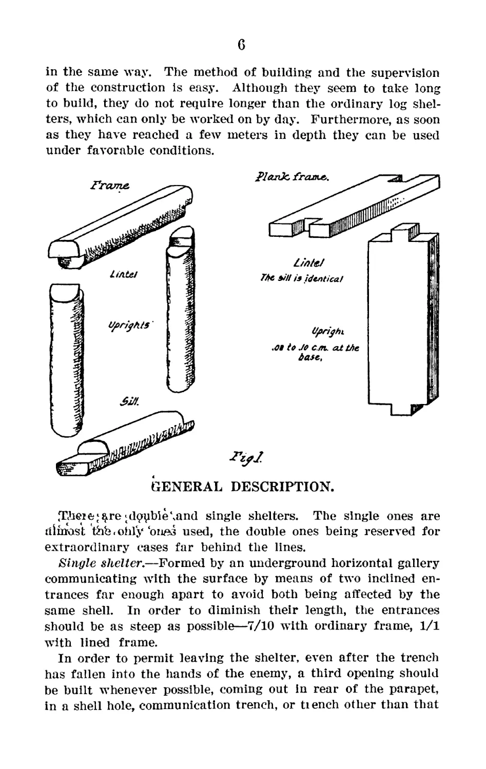
DESCRIPTION AND CHARACTERISTICS.
Shelters in mine galleries mean shelters dug in virgin* soil,
with roof and walls forming a solid inclosure, firmlyJ ^ved^e^
against the earth by a strong frame. These fram£s ’are usually'
made of thick logs, squared (0-20 c. m. at least). The entrances
are also solidly framed by thick planks.
CHARACTERISTICS.
The means at hand in the field are sufficient to provide shelter
rapidly against projectiles of large caliber. They can be easily
constructed without arousing the enemy’s suspicions, if pains are
taken to unload the earth sufficiently far away. They can be
constructed all alike, practically, the frames being of the same
workmanship, no matter how varying in size, and put together
5
6
in the same way. The method of building and the supervision
of the construction is easy. Although they seem to take long
to build, they do not require longer than the ordinary log shel-
ters, which can only be worked on by day. Furthermore, as soon
as they have reached a few meters in depth they can be used
under favorable conditions.
DESCRIPTION.
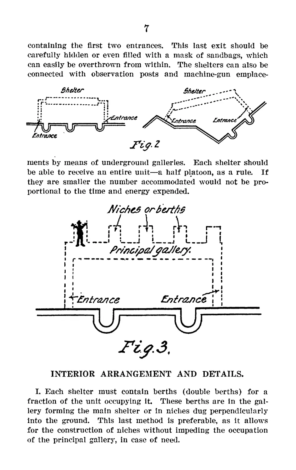
<Theieti^re‘dqpbie\and single shelters. The single ones are
almost thb. ohly ‘ones used, the double ones being reserved for
extraordinary cases far behind the lines.
Single shelter,—Formed by an underground horizontal gallery
communicating with the surface by means of two inclined en-
trances far enough apart to avoid both being affected by the
same shell. In order to diminish their length, the entrances
should be as steep as possible—7/10 with ordinary frame, 1/1
with lined frame.
In order to permit leaving the shelter, even after the trench
has fallen into the hands of the enemy, a third opening should
be built whenever possible, coming out In rear of the parapet,
in a shell hole, communication trench, or tiench other than that
7
containing the first two entrances. This last exit should be
carefully hidden or even filled with a mask of sandbags, which
can easily be overthrown from within. The shelters can also be
connected with observation posts and machine-gun emplace-
ments by means of underground galleries. Each shelter should
be able to receive an entire unit—a half platoon, as a rule. If
they are smaller the number accommodated would not be pro-
portional to the time and energy expended.
Niche# or b est
। ’__________________J ________________________________________j L
&)tnznce i
INTERIOR ARRANGEMENT AND DETAILS.
I. Each shelter must contain berths (double berths) for a
fraction of the unit occupying it. These berths are in the gal-
lery forming the main shelter or in niches dug perpendicularly
into the ground. This last method is preferable, as it allows
for the construction of niches without impeding the occupation
of the principal gallery, in case of need.
8
II. Supply the shelters of the niche with hand grenades (the
single ones should each have the supply for one man), infantry
munitions, gas protections, food, and signal rockets.
III. Reserve a special corner for the platoon or half-platoon
leader.
IV. Construct chimneys for ventilation or to clear away the
smoke, with a draft to be shut at the bottom.
V. Watch the approaches to the shelter by a well-placed look-
out post and a periscope position.
VI. Prepare the defense of the entrances.
VII. Protect the interior of the shelter against grenades.
VIII. Protect the interior of the shelter from action of
asphyxiating gas.
PRINCIPLES TO OBSERVE.
DEPTH.
Above the dugout roof there must be a minimum of 6 meters of
virgin soil. If there are shell holes on the surface, go down to
8 meters. If water level prevents reaching 8 meters, reinforce-
ments are placed on the ground above the shelter made bj
(1) bed of logs, .20 meter in diameter, side by side, separated
by earth. (2) Cement blocks. (3) Bags of cement placed in
water for 10 minutes then placed side by side. (4) Bags of
cement mixed with pebbles and treated as above. The best
reenforcing is not as good as virgin soil.
LONGITUDINAL STRENGTH OF GALLERIES.
The length of the gallery should be carefully looked after.
(1) Nail the battens that join the uprights.
(2) Place four horizontal props at the joints of the frames in
each interval. The props must be strongly wedged and must
prevent any play.
(3) Make the length of the intervals .6 meter from axis to
axis of the frame.
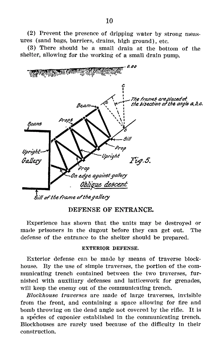
PRECAUTIONS CONCERNING ENTRANCES AND DESCENTS.
(1) The last frame in the descent must be strongly supported
against the woodwork of the shelter.
(2) Place a number of tools and sandbags in each shelter, so
that an entrance can be quickly cleared in case of need.
9
(3) Place a cord or rope the length of the descent to facilitate
the exit in case of obstruction.
(4) Nail a shaft to one of the supports or fix a tube so that
food and air may be obtained in case the entrance is destroyed.
There are certain precautions to be taken when ordinary frames
are used in descents to prevent the logs from rolling and the
frame from overturning. These precautions are as follows:
(1) Join the beams to the uprights by two oblique battens in
each corner.
(2) Connect adjoining beams by two battens.
(3) Place diagonal braces in each interval of props to form
an irregular system of triangles.
The figure shows the plan of the arrangement of the logs in an
oblique descent and the junction with the gallery. There can
be no sliding or overturning of the frames with triangular prop-
ping. There is no harm in adding to the dimensions of the
wood and strength of the shelter.
GROUND SANITARY MEASURES.
(1) Whenever possible, drain off the surface water by ditches
and well-studied drainage.
10
(2) Prevent the presence of dripping water by strong meas-
ures (sand bags, barriers, drains, high ground), etc.
(3) There should be a small drain at the bottom of the
shelter, allowing for the working of a small drain pump.
DEFENSE OF ENTRANCE.
Experience has shown that the units may be destroyed or
made prisoners in the dugout before they can get out. The
defense of the entrance to the shelter should be prepared.
EXTERIOR DEFENSE.
Exterior defense can be made by means of traverse block-
house. By the use of simple traverses, the portion of the com-
municating trench contained between the two traverses, fur-
nished with auxiliary defenses and latticework for grenades,
will keep the enemy out of the communicating trench.
Blockhouse traverses are made of large traverses, invisible
from the front, and containing a space allowing for fire and
bomb throwing on the dead angle not covered by the rifle. It is
a species of caponier established in the communicating trench.
Blockhouses are rarely used because of the difficulty in their
construction.
11
Prepared traverses.—These are the simple traverses in which
a niche Is dug out for a rifleman (seated or standing). A plat-
form for the grenadiers is constructed behind the traverse. Two
prepared traverses barricade or terminate the two exits of the
shelter. A wire entanglement, covered by several loopholes or
by the grenadier platform in the traverse, is placed along the
outside of the communication trench. A lattice against gre-
nades is placed above the communication trench.
6AieM. Supportedfy Sandbars.
fdiom of communication
Wooden Topho/e,
Traverse
. Section of a, Prepared Traverse
ri^.7.
^P/atform Tor Grenadier
step for rifleman behind the Shield
1. Niche in traverse for a rifle sweeping the bottom of the boyau and
a rifle firing 1.4 meters above the ground. 2. Platform for grenadiers.
3. Niche with loopholes enfilading the auxiliary defenses. 4-5. De-
scents to shelter. 6. Traverse between two descents to avoid the same
projectile striking both at the same time. 7. Wire entanglements.
8. Lattice against grenades.
The traverse blockhouses, with their covering of rails or
cement, have the same degree of solidity as the dugout. The
second arrangement, formed as a redoubt around the dugout
entrance, makes it easy for the occupants to get out.
12
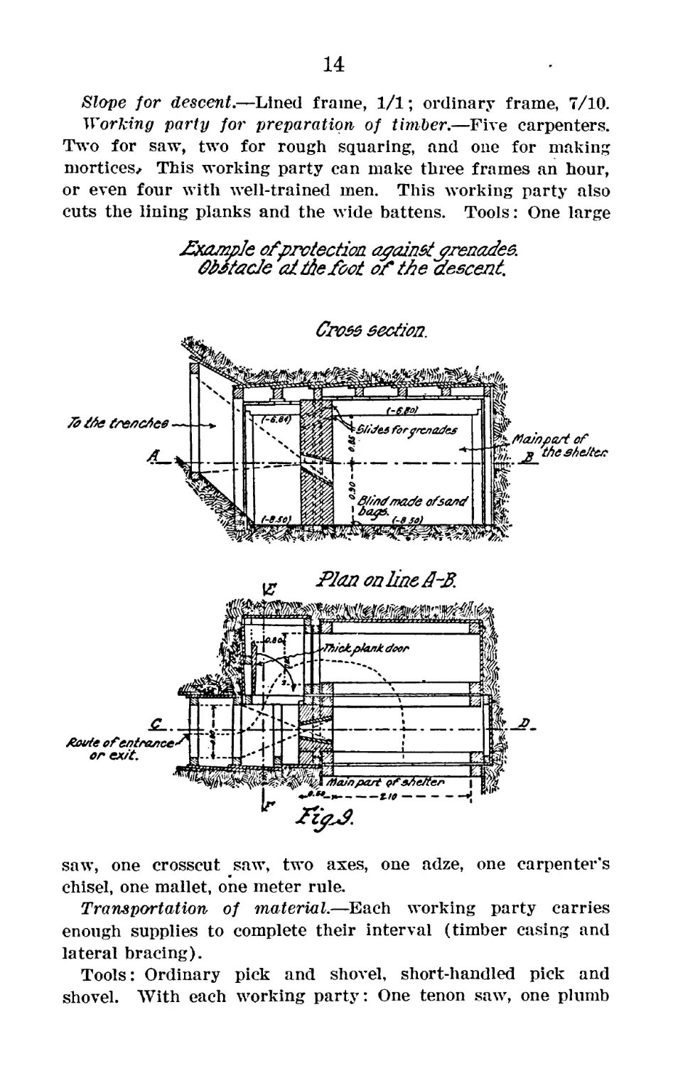
INTERIOR DEFENSE.
This defense can be assured by arrangement of obstacles,
one behind the other, placed in the descents—themselves either
at an intermediate or at the lowest point. The obstacle is made
by enlarging the descent and constructing a sandbag barrier at
the desired position. As the obstacles interfere with the light,
care must be taken in lighting the descent.
Protection against grenades.—Protection against grenades
must be added. The barrier of obstacles, one behind the other,
are not always able to keep the grenades from rolling into the
main part of the dugout. One of the following expedients may
be employed:
(1) A stationary panel with strong metal latticework is
placed In front of the barrier in the descent. The panel is pulled
up to the roof of the descent by means of a cord or wire when-
ever desired, or lowered so as to completely obstruct the
descent.
(2) Furnish the entrance of the obstacle with a heavy plank
door. A landing place can also be built at the bottom of the
descent, from which a short ramp leads up to the shelter. The
grenade will then roll down to the landing place, but can not
get up into the shelter. This arrangement is inconvenient, as
the time and difficulty in constructing the dugout is considerably
increased.
Protection against gas.—Place cloths, impregnated with lin-
seed oil or parafin, or simply soaked in neutralizing solution
in the descent. The men’s blankets are used if cloths are lack-
ing. Each descent should be furnished with two distinct
cloths placed at intervals of 1 meter. This permits the descent
to be hermetically closed to a sufficient degree and at the same
time allows passage. This arrangement is placed near the outlet
to prevent the accumulation of gas in the descent.
DETAILS OF THE WORK.
Frames.—For the descent—lining, lj by Л meters; ordinary,
by lA meters or тс by & meter; inside dimensions. For
the body of the shelter, by meters; diameter, Л meter.
Roofing and lining planks.—One-twenty-fifth by eight-tenths
by a variable width. The thickest are for the roof. Larger
frames are used for the commanders’ accommodation, with an
intermediate prop between the two uprights.
13
flan.
*1
14
Slope for descent.—Lined frame, 1/1; ordinary frame, 7/10.
Working party for preparation of timber.—Five carpenters.
Two for saw, two for rough squaring, and one for making
mortices^ This working party can make three frames an hour,
or even four with well-trained men. This working party also
cuts the lining planks and the wide battens. Tools: One large
£халр1е ofprotection. againstgrenades.
facie al the foot of the (descent.
saw, one crosscut saw, two axes, one adze, one carpenter's
chisel, one mallet, one meter rule.
Transportation of material.—Each working party carries
enough supplies to complete their interval (timber casing and
lateral bracing).
Tools: Ordinary pick and shovel, short-handled pick and
shovel. With each working party: One tenon saw, one plumb
15
line, one measuring tape, one hammer, one augur, one mason’s
level.
Removing earth: By means of sand bags or with small trucks
on wooden rails, or with cases sliding on the floor of the descent.
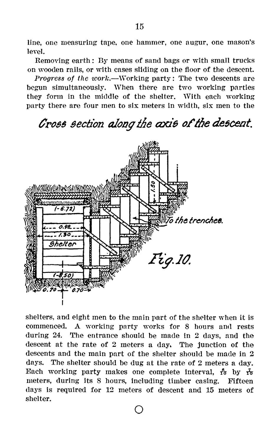
Progress of the work.—Working party: The two descents are
begun simultaneously. When there are two working parties
they form in the middle of the shelter. With each working
party there are four men to six meters in width, six men to the
fross section along the axis of the descent.
shelters, and eight men to the main part of the shelter when it is
commenced. A working party works for 8 hours and rests
during 24. The entrance should be made in 2 days, and the
descent at the rate of 2 meters a day* The junction of the
descents and the main part of the shelter should be made in 2
days. The shelter should be dug at the rate of 2 meters a day.
Each working party makes one complete interval, & by A
meters, during its 8 hours, including timber casing. Fifteen
days is required for 12 meters of descent and 15 meters of
shelter.