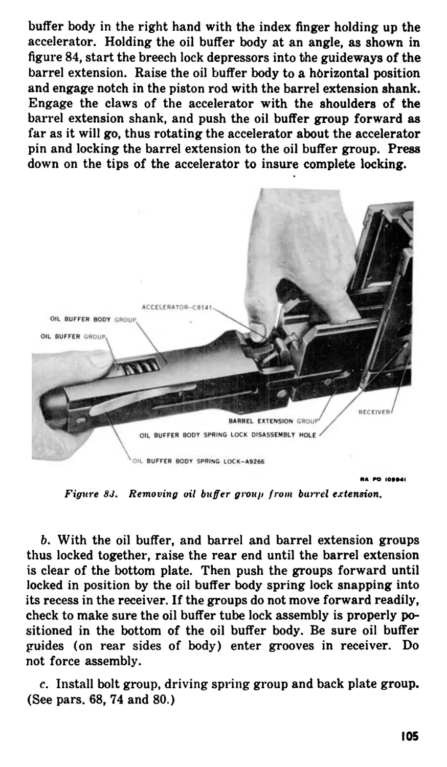
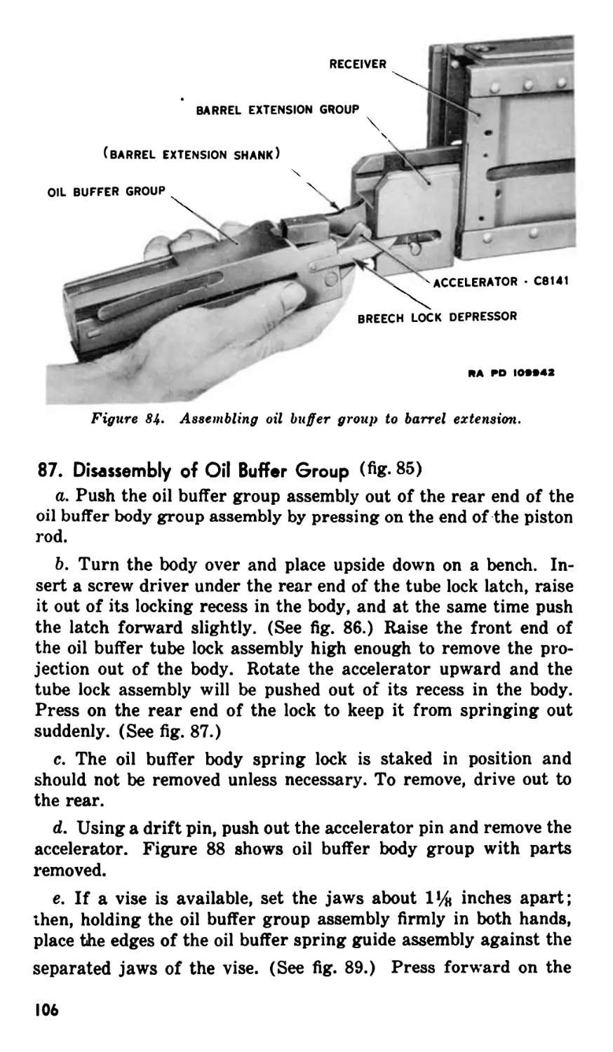
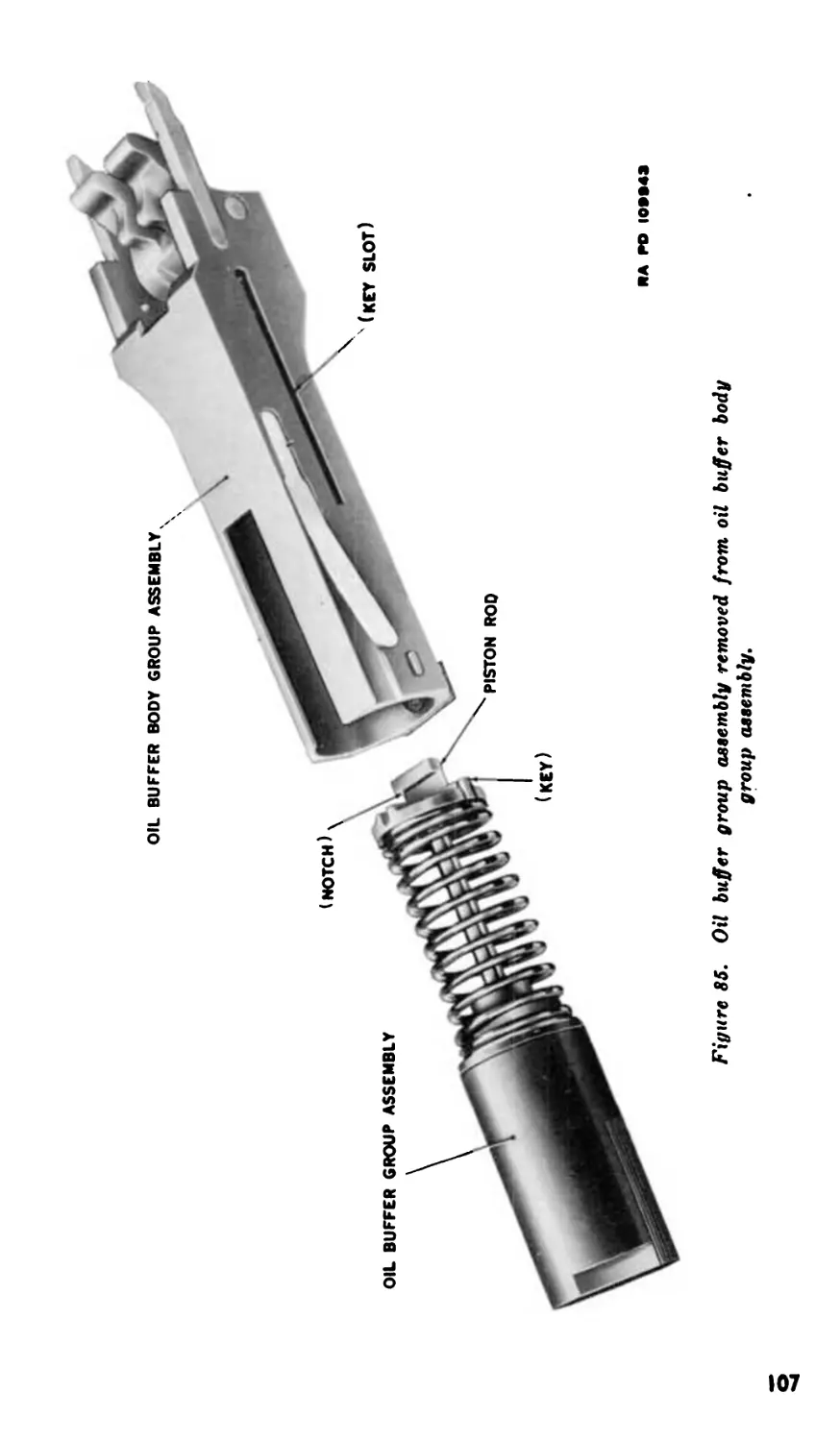
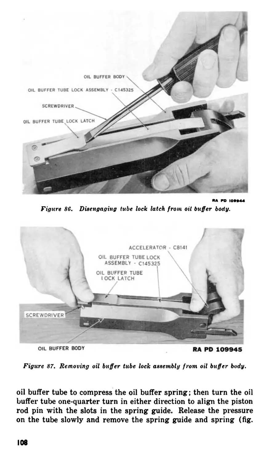
/

Теги: weapons military affairs machine gun
Год: 1947
Похожие

Текст
WAR DEPARTMENT TECHNICAL MANUAL
BROWNING
MACHINE GUN
CALIBER .50, A1N-M2
AIRCRAFT. BASIC
WAR DEPARTMENT . JANUARY. 1047
WAR DEPARTMENT
Washington 25, D. C., 28 January 1947
TM 9-225, Browning Machine Gun, Caliber .50, AN-M2, Air-
craft, Basic, is published for the information and guidance of
all concerned.
The material in this manual is correct as of 1 September 1946.
[AG 300.7 (1 Mar 46)]
By order of the Secretary of War :
DWIGHT D. EISENHOWER
Chief of Staff
Official :
EDWARD F. WITSELL
Major General
The Adjutant General
Distribution :
AAF (5) ; AGF (2); T (10) ; Dept (5); AAF Maj Comd (2);
Arm & Sv Bd (1); Tech Sv (2) ; FC (1) ; BU (1); PE,
ORD 0 (5); Dist 9 (3); Establishments 9 (3); Gen & Sp
Sv Sch (5); A (ZI) (10), (Overseas) (3); CHQ (2) ; D
(2); AF (3); G (1); S (1); LS (1); T/O & E 1-727 (1);
5-517S (1) ; 9-57 (1).
For explanation of distribution formula, see FM 21-6.
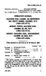
WAR DEPARTMENT TECHNICAL MANUAL
TM 9-225
This manual supersedes TM 9-225, 15 December 1913, including
Cl, 21 May 1915
BROWNING
MACHINE GUN
CALIBER .50, AN-Ma
AIRCRAFT, BASIC
WAR DEPARTMENT • JANUARY 191,7
RESTRICTED, dissemination of restricted matter.—no
person is entitled solely by virtue of his grade or position to
knowledge or possession of classified matter. Such matter
is entrusted only to those individuals whoso official duties
require such knowledge or possession. (See also AR 380-5.)
0F1 urbana-CHAMI
Washington: /947
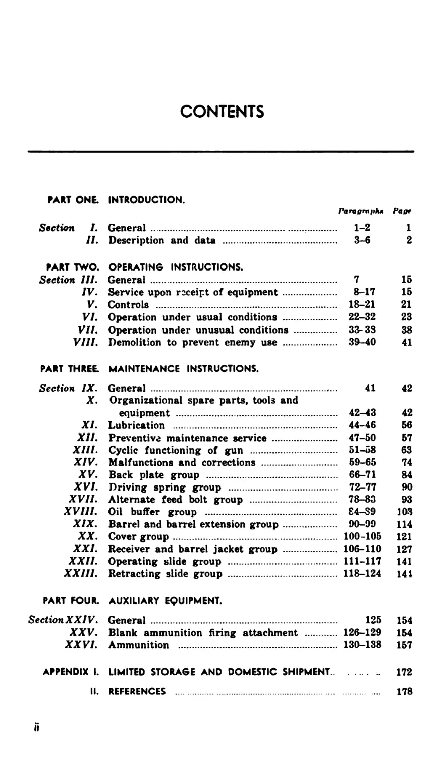
CONTENTS
PART ONE. INTRODUCTION.
Paragraph* Pagr
Section I. General................................... 1-2 1
IL Description and data ..................... 3-6 2
FART TWO. OPERATING INSTRUCTIONS.
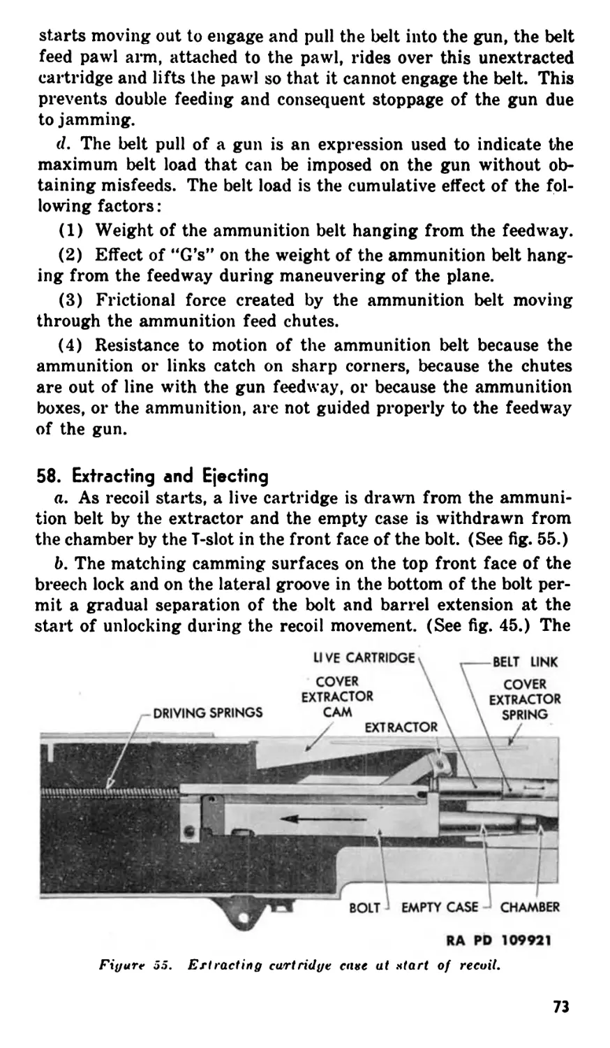
Section III. General .................................. 7 15
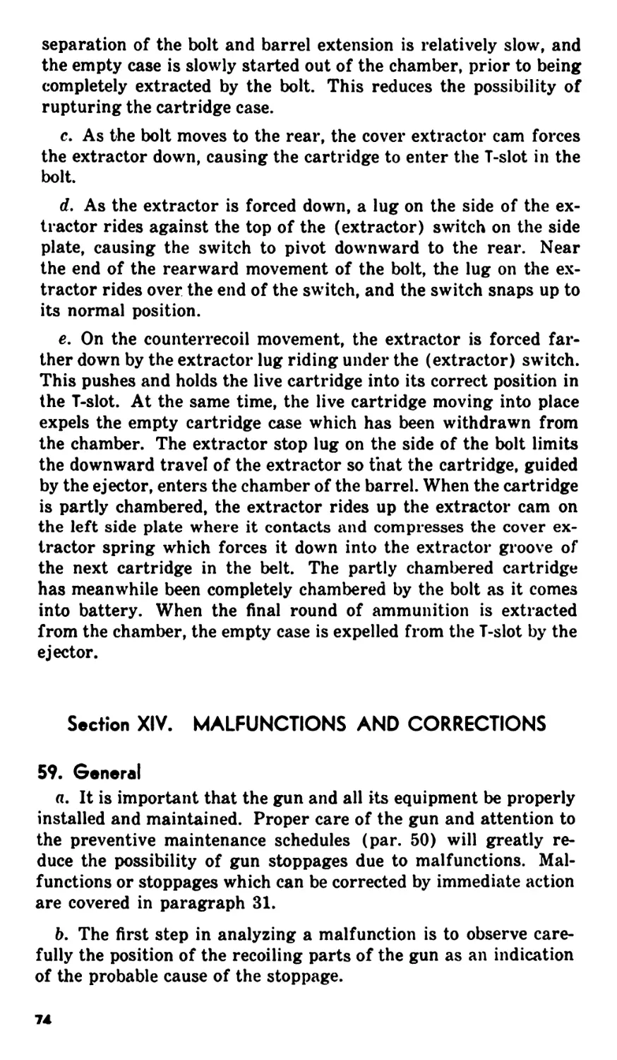
IV. Service upon receipt of equipment............ 8-17 15
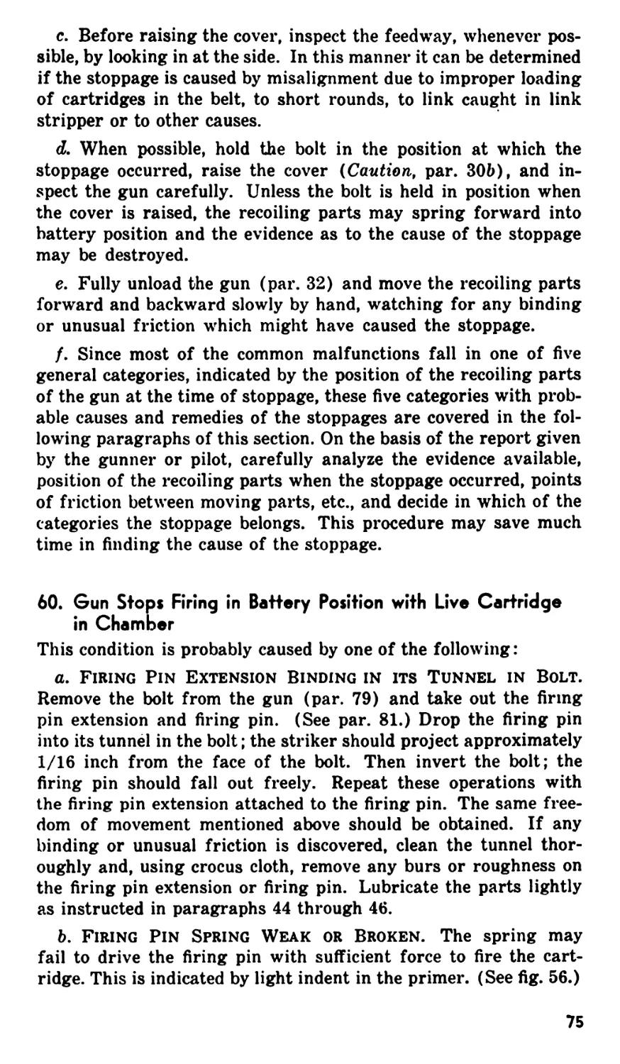
V. Controls ................................... 18-21 21
VI. Operation under usual conditions ........... 22-32 23
VII. Operation under unusual conditions ....... 33-3S 38
VIII. Demolition to prevent enemy use ............ 39-40 41
PART THREE MAINTENANCE INSTRUCTIONS.
Section IX. General ................................«... 41 42
X. Organizational spare parts, tools and
equipment ...................................... 42-43 42
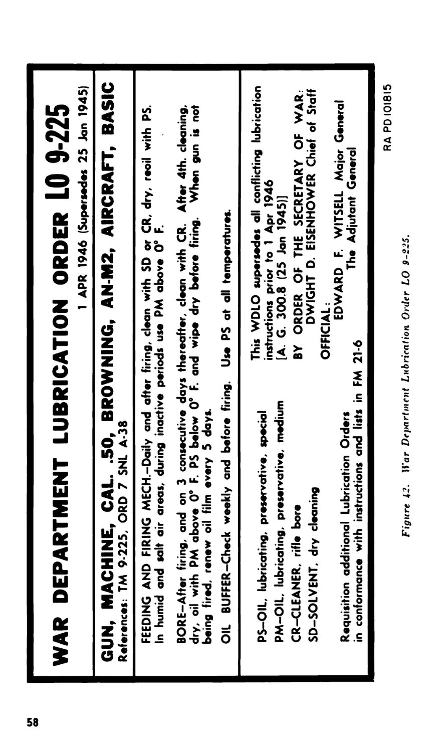
XI. Lubrication ................................ 44-46 66
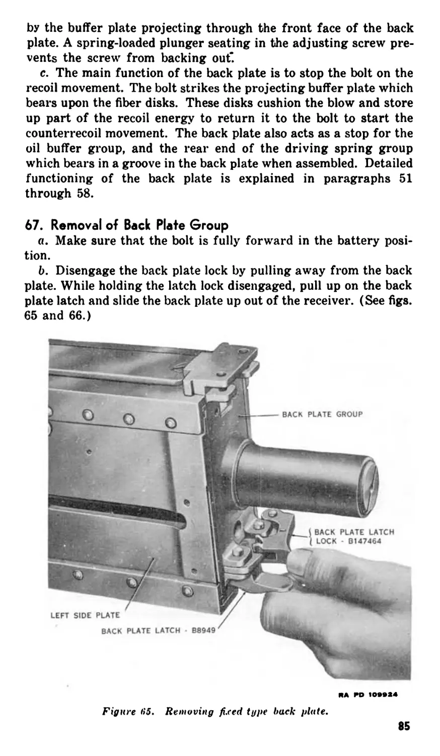
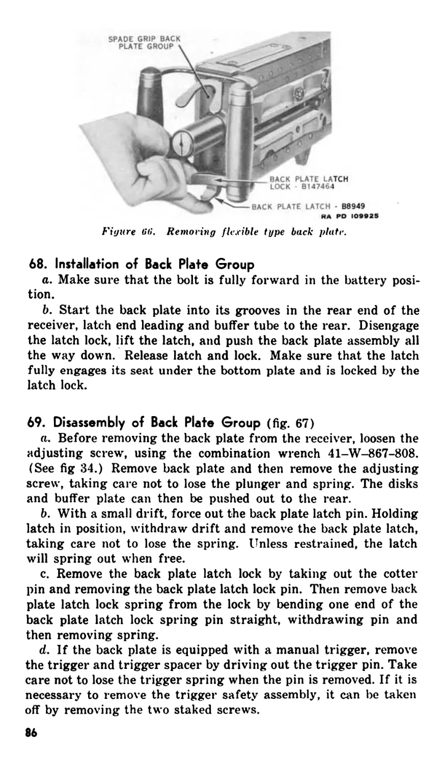
XII. Preventive maintenance service ............. 47-50 57
XIII. Cyclic functioning of gun .............. 51-58 63
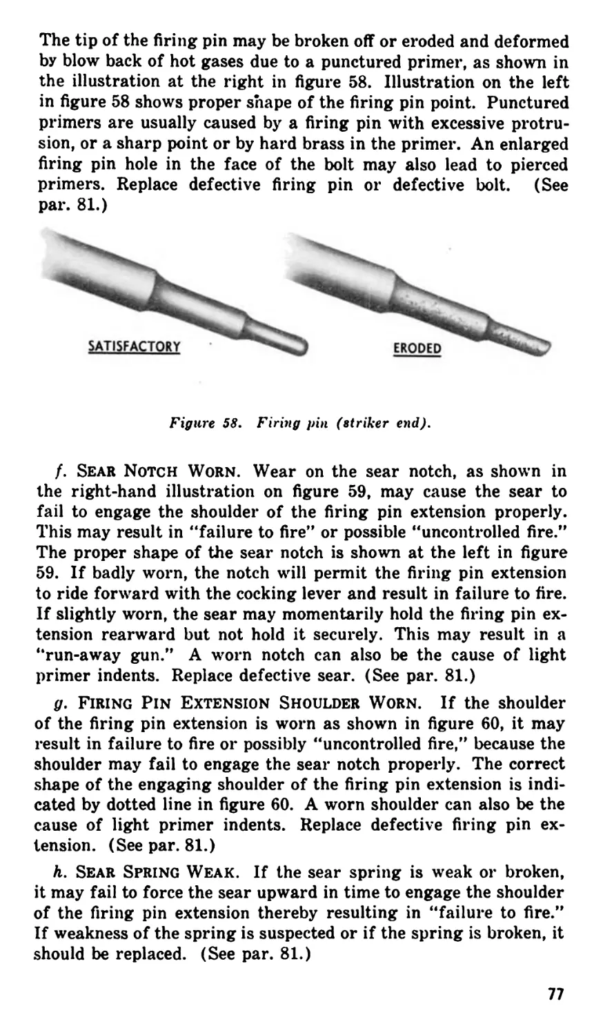
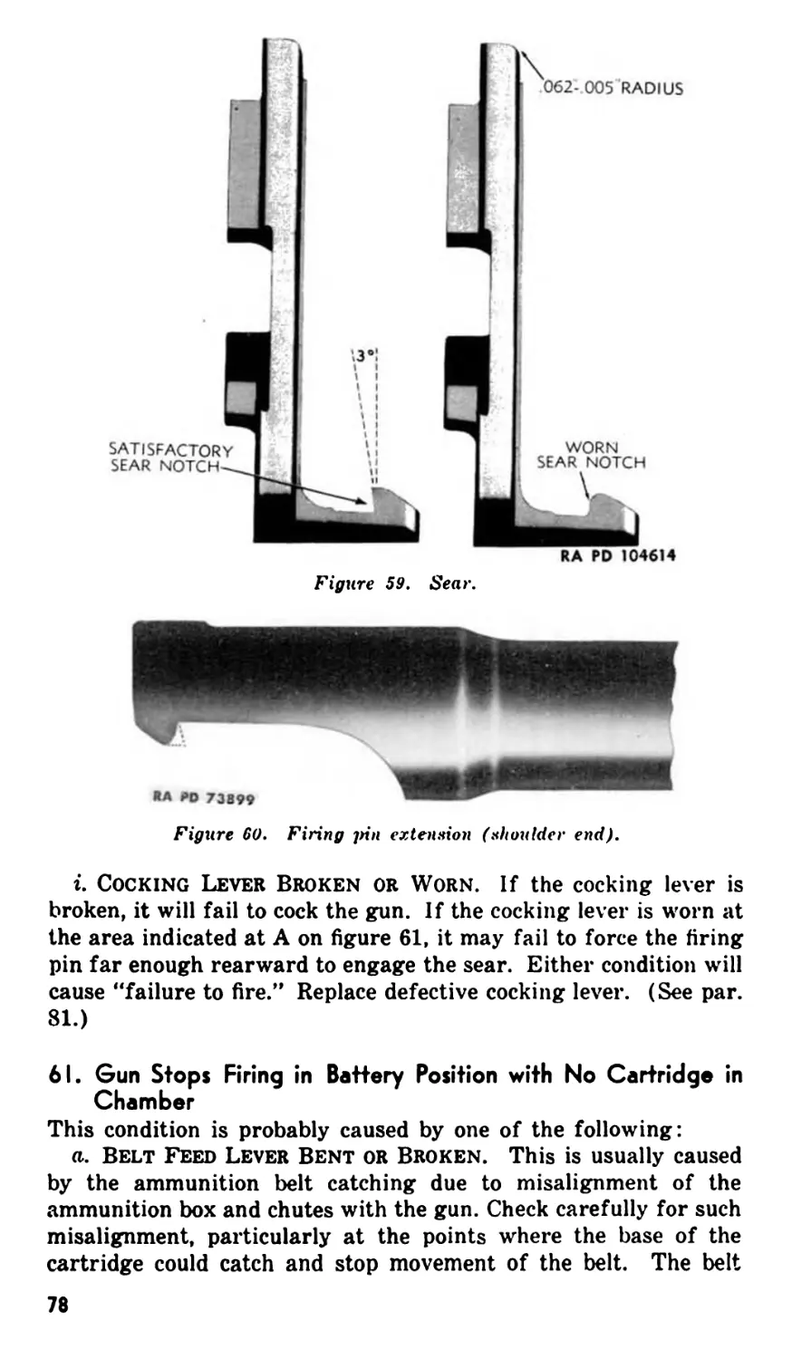
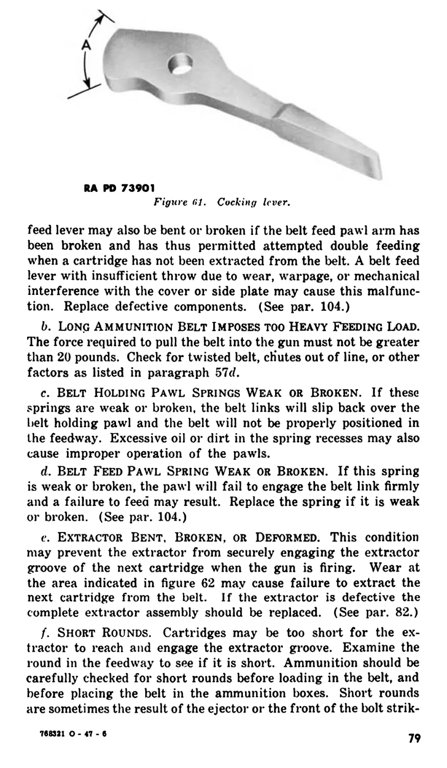
XIV. Malfunctions and corrections ............... 59-65 74
XV. Back plate group ........................... 66-71 84
XVI. Driving spring group ....................... 72-77 90
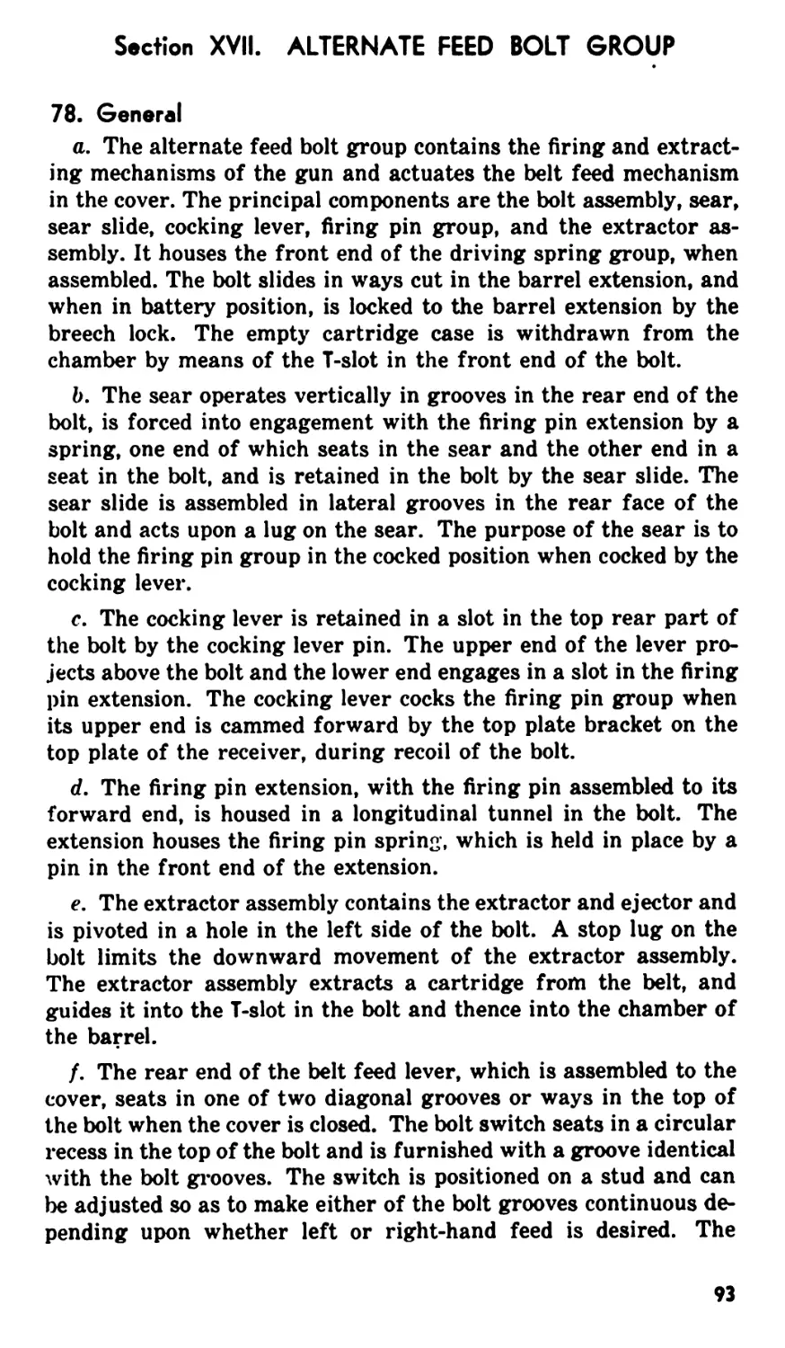
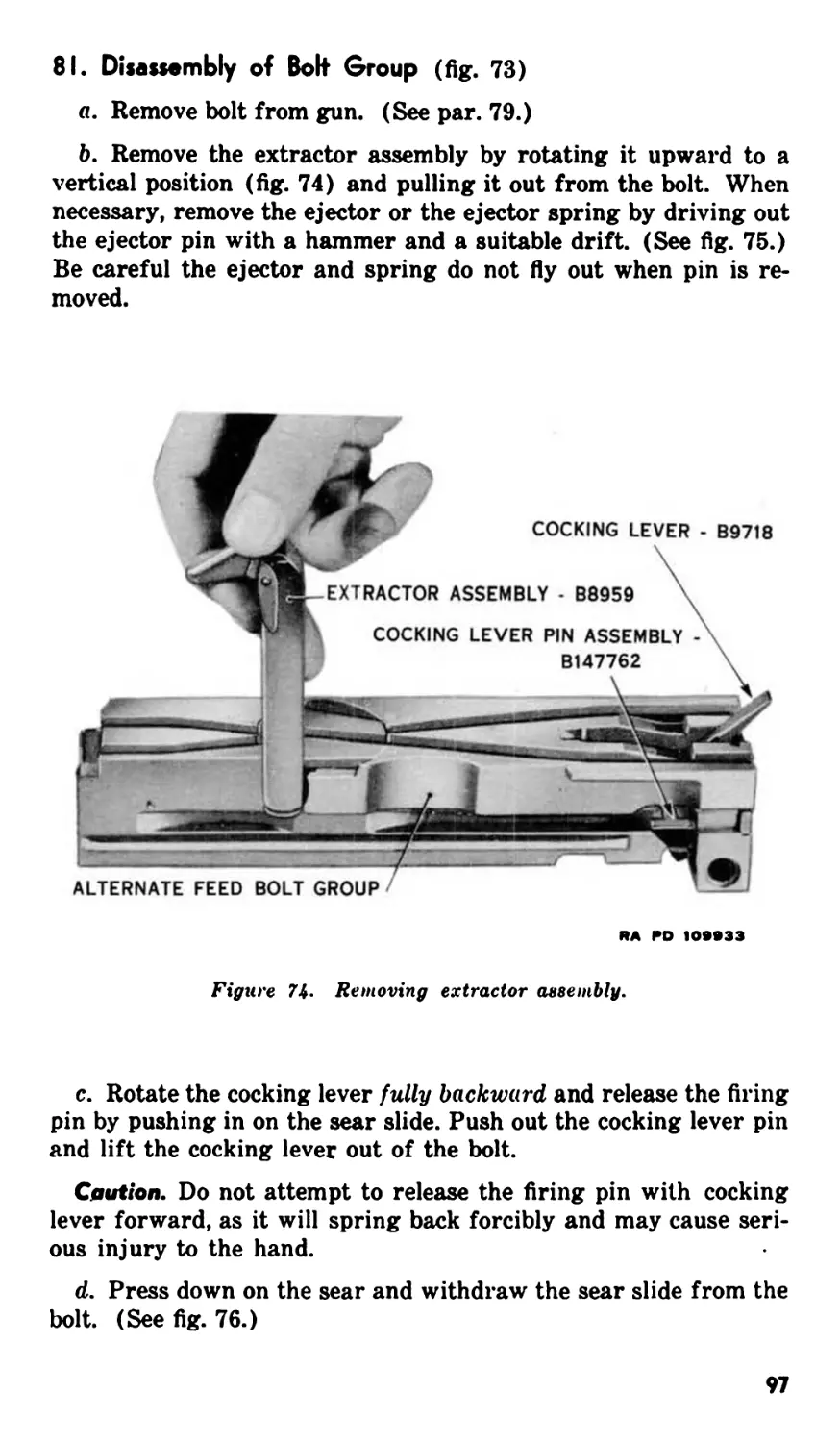
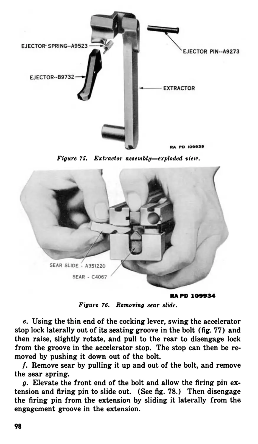
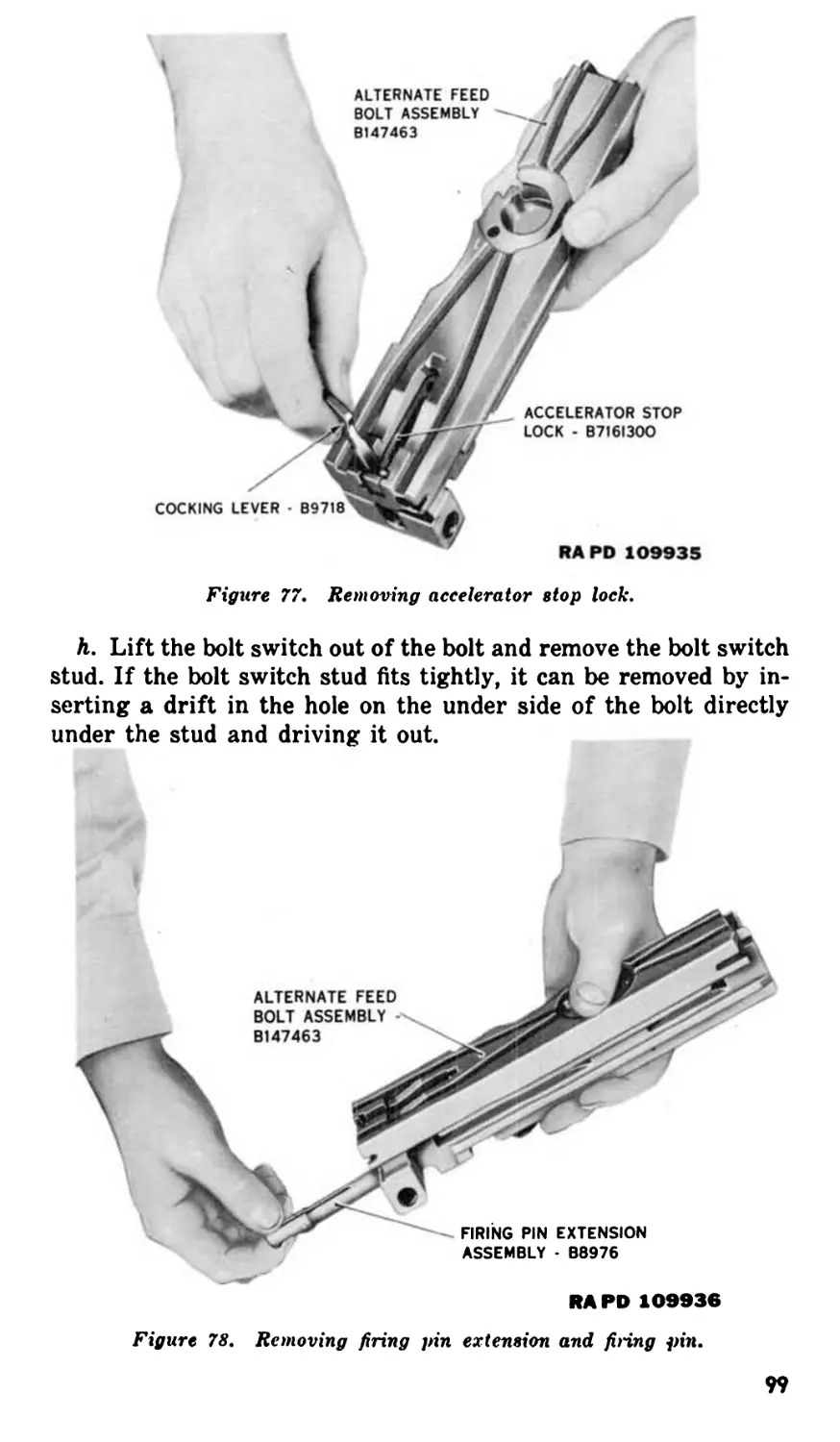
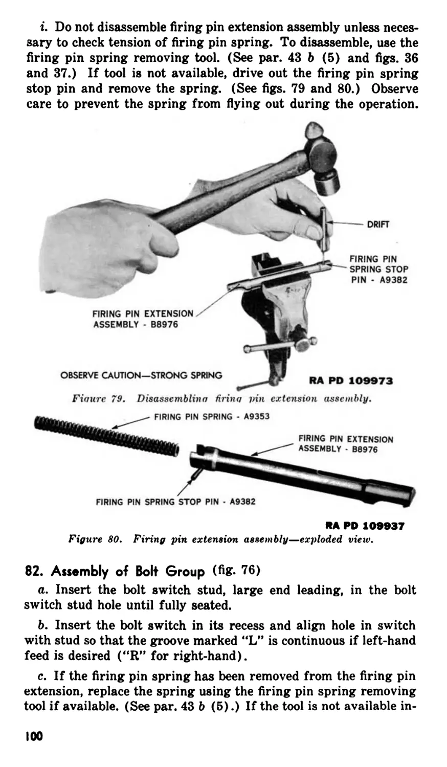
XVII. Alternate feed bolt group .............. 78-83 93
XVIII. Oil buffer group ........................... 84-S9 103
XIX. Barrel and barrel extension group........... 90-99 114
XX. Cover group................................ 100-105 121
XXI. Receiver and barrel jacket group .......... 106-110 127
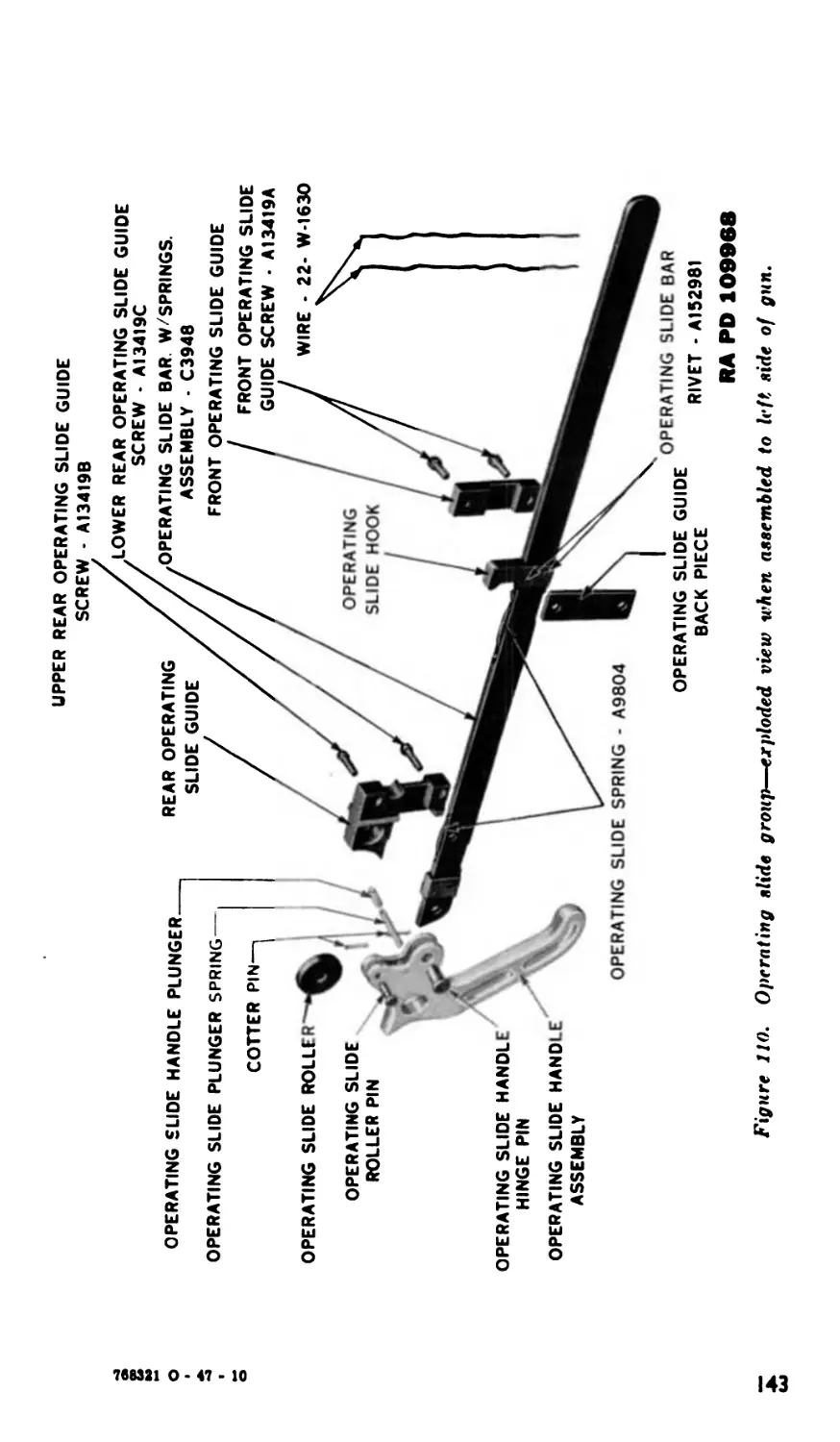
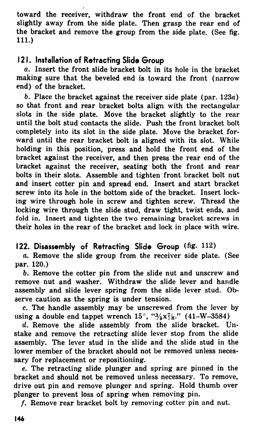
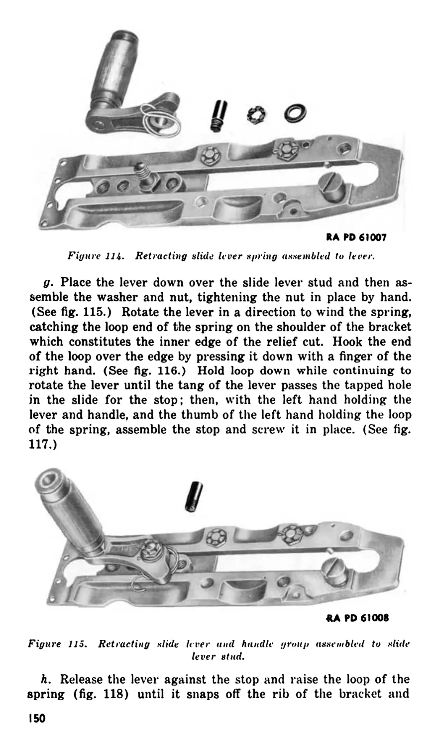
XXII. Operating slide group ..................... 111-117 141
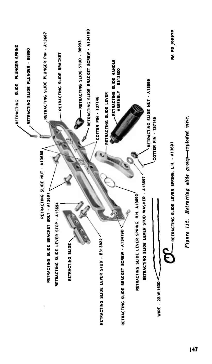
XXIII. Retracting slide group .................... 118-124 141
PART FOUR. AUXILIARY EQUIPMENT.
Section XXIV. General ....................................... 125 154
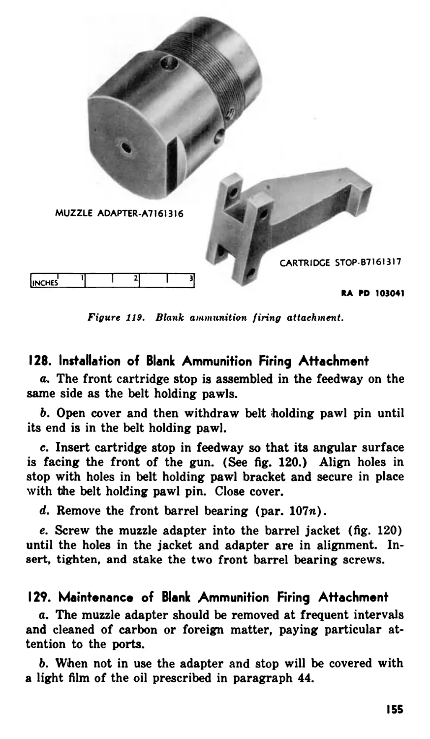
XXV. Blank ammunition firing attachment ...... 126-129 154
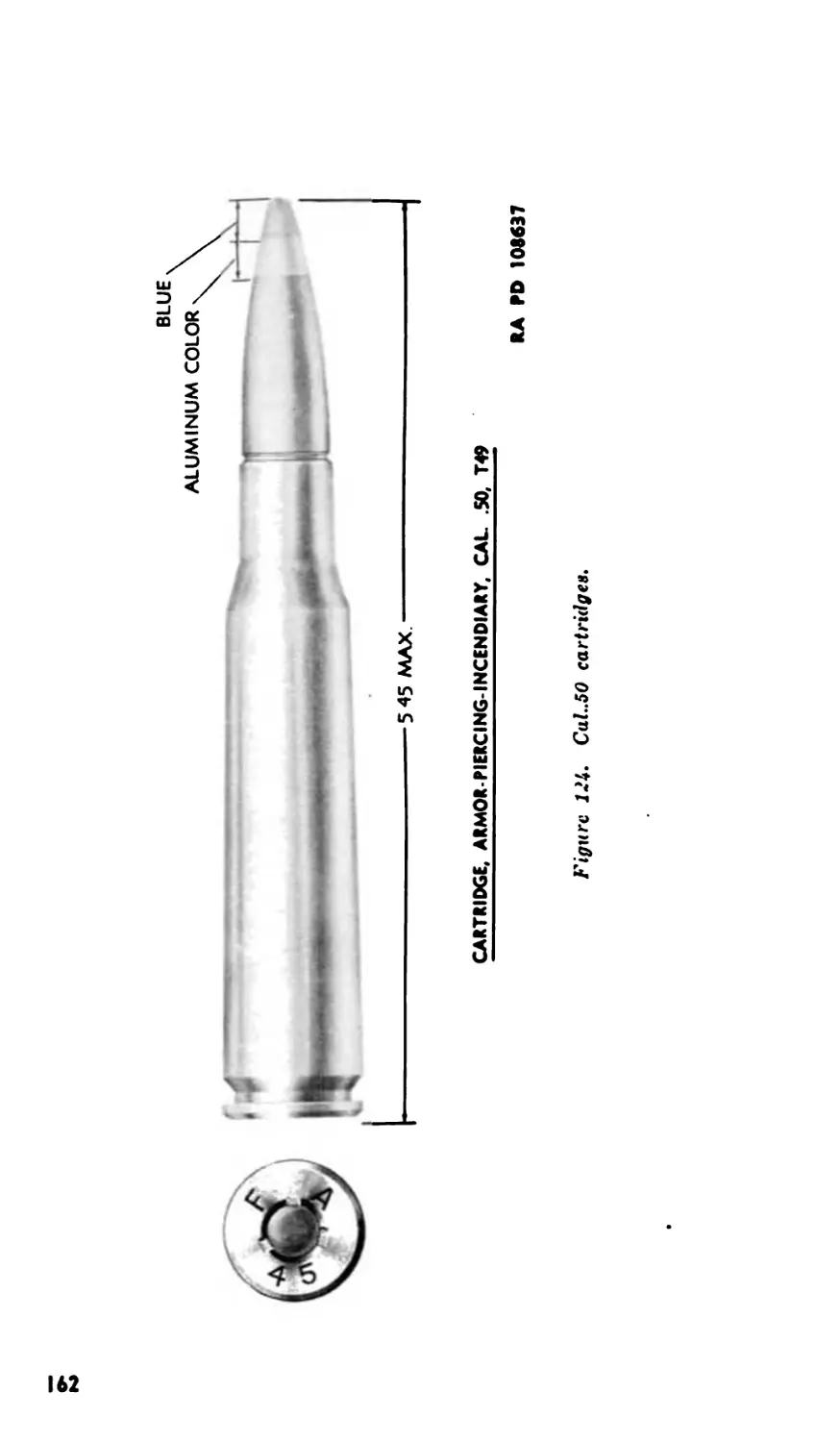
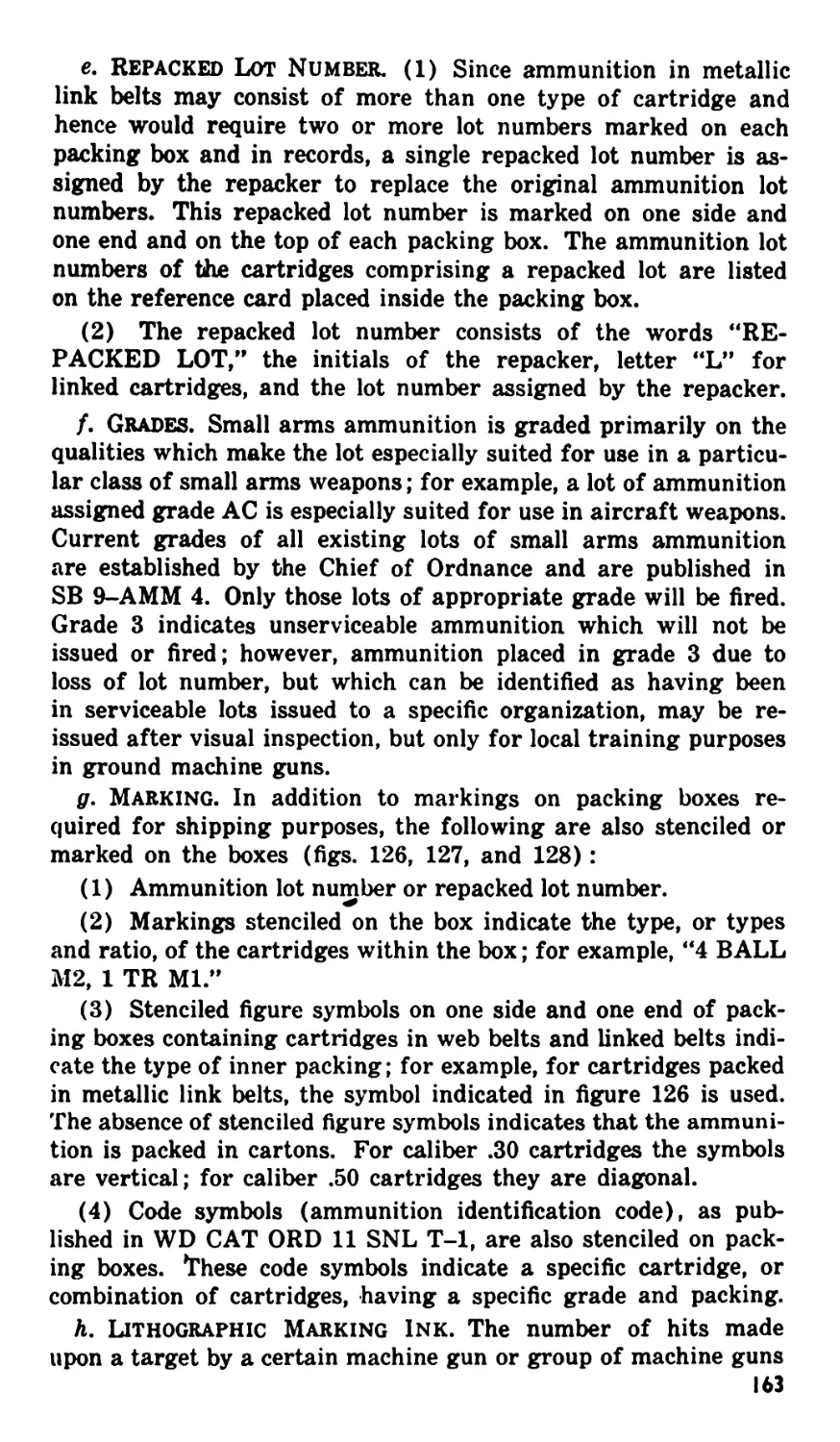
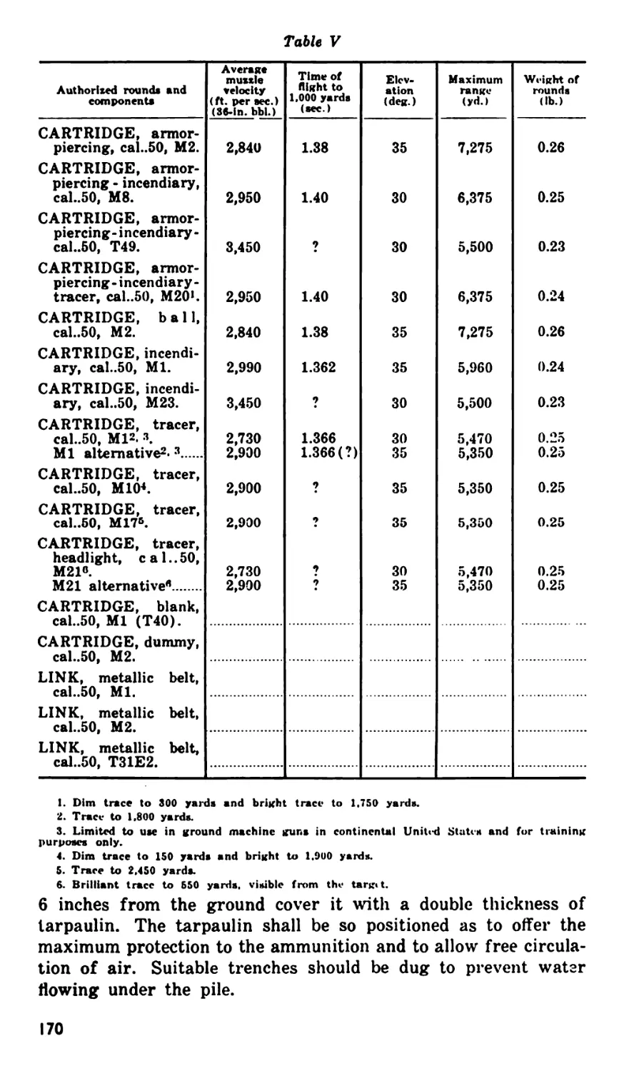
XXVI. Ammunition ................................ 130-138 157
APPENDIX I. LIMITED STORAGE AND DOMESTIC SHIPMENT.............. 172
II. REFERENCES ........................................ 178
ii
RESTRICTED
This manual supersedes TM 9-225, 15 December 1943, including
Cl, 24 May 1945
PART ONE
INTRODUCTION
Section I. GENERAL
I. Scope
a. This Technical Manual is published for the information of
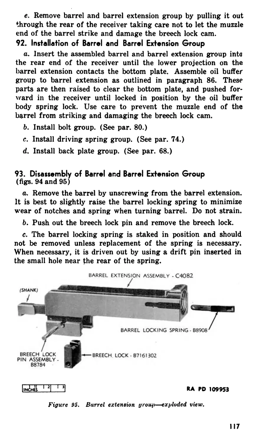
the using arms and services. It contains information required for
the identification, use, and operation of the basic aircraft Browning
machine gun, cal..5O, AN-M2 and the equipment and ammunition
used therewith.
b. In all cases where the nature of the repair, modification, or
adjustment is beyond the scope or facilities of the unit, the re-
sponsible ordnance service should be informed, so that trained
personnel with suitable tools and equipment may be provided, or
proper instructions issued.
2. Records
a. Field Report cf Accidents. When an accident involving
ammunition occurs during practice, the incident will be reported
as prescribed in AR 750-10 by the ordnance officer under whose
supervision the ammunition is maintained or issued. Where prac-
ticable, reports covering malfunctions of ammunition in combat
will be made to the Chief of Ordnance, giving the type of mal-
function, the type of ammunition, the lot number of the complete
rounds, and the condition under which fired.
b. Unsatisfactory Report. Suggestions for improvement in
manufacture, design, maintenance, safety, and efficiency of opera-
tion prompted by chronic failure or malfunction of the weapon,
spare parts, or equipment should be reported on WD AAF Form
54 (Unsatisfactory Report) with all pertinent information neces-
sary to initiate corrective action. This form will also be used for
reporting complaints on the application or effect of prescribed lu-
bricants, and preserving materials and, when so used, will contain
identifying details on both the products and the associated equip-
ment. The report should be forwarded to: Commanding General,
Headquarters Air Materiel Service Command, Wright Field, Day-
ton, Ohio, with carbon copy direct to the Office, Chief of Ordnance,
Field Service, Maintenance Division. If WD AAF Form 54 is not
available, one may be improvised by referring to sample in TM
37-250.
Section II. DESCRIPTION AND DATA
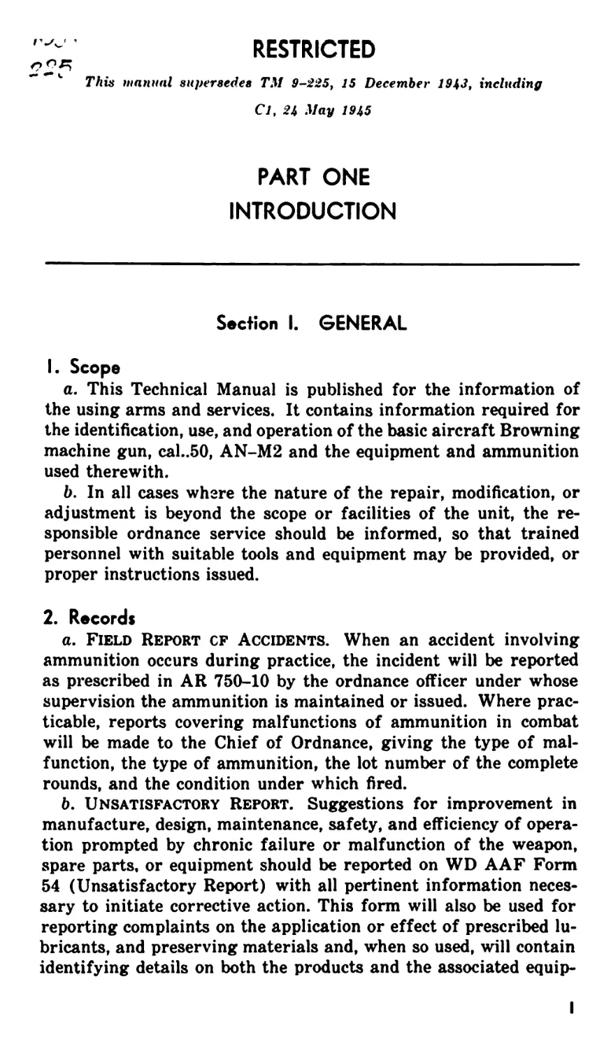
3. General
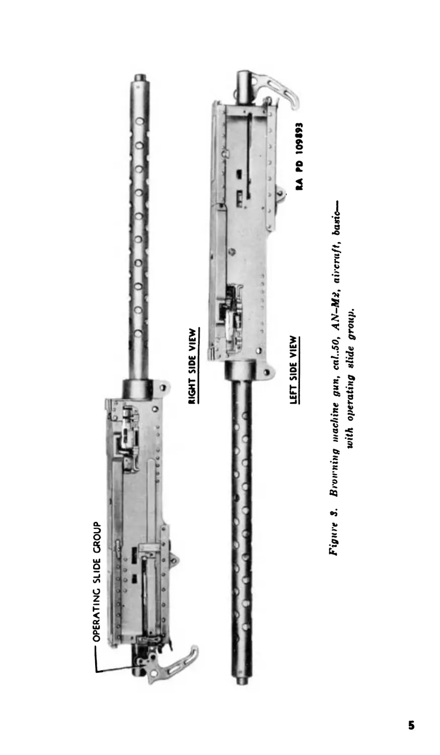
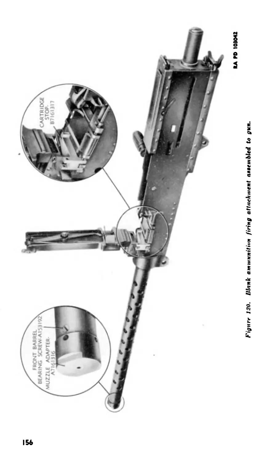
The basic aircraft Browning machine gun, cal..5O, AN-M2 (figs.
1, 2, 3, and 4) is an automatic, recoil-operated, belt-fed, air-cooled
machine gun. The metallic link disintegrating belt is used in all
firing of the gun. This gun is designed for all cal..5O aircraft
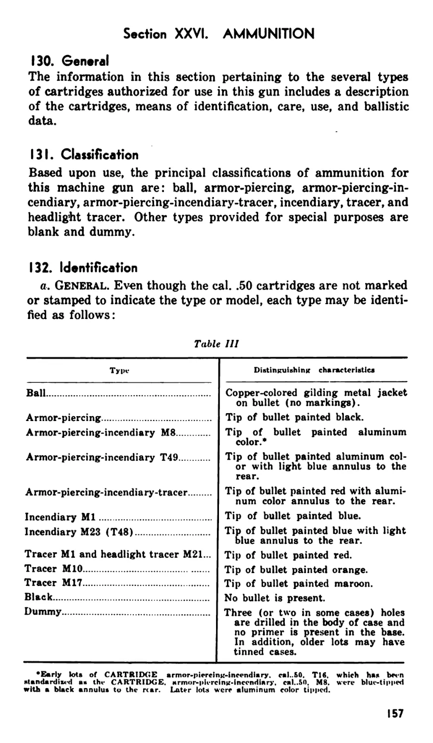
machine gun installations. By properly repositioning some of the
component parts, ammunition may be fed into the gun from either
the right or the left side.
4. Currant Modifications
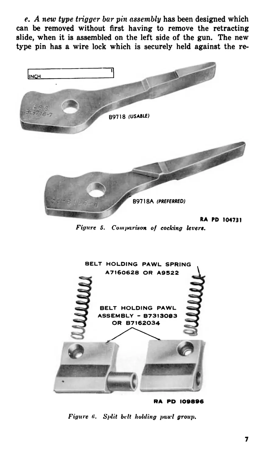
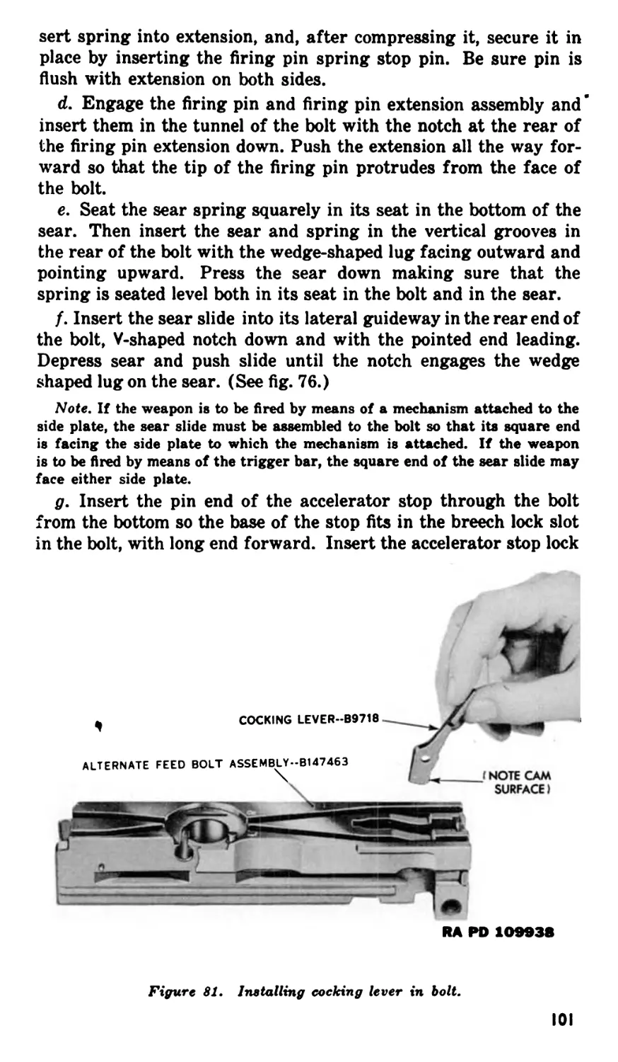
a. Cocking lever B9718A has been installed in many guns for
some time. This lever is similar to the old design lever B9718 but
has a shoulder on the right side which prevents assembling the
lever into the bolt backwards. A comparison of the two levers is
shown in figure 5.
b. A new type belt feed slide assembly to assist in increasing
the belt pull has been installed on a large number of these guns.
This slide can be distinguished from the old slide by a Ц-inch hole
drilled through its face. When there is difficulty in feeding or
when the gun will not lift the required ammunition load with the
old type slide, the new slide B261110 should be used.
c. A split belt holding patvl (fig. 6) is now being installed which
assists in increasing the belt pull. This pawl group consists of a
right-hand belt holding pawl, left-hand belt holding pawl, belt
holding pawl sleeve, and twin springs.
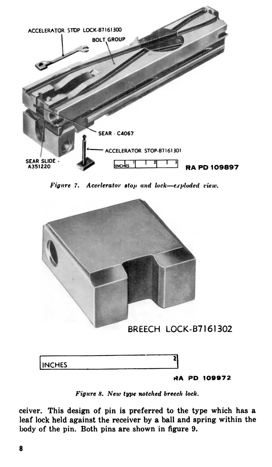
d. A positive accelerator stop group (fig. 7) is now being used
to prevent the possibility of the tips of the accelerator jamming
in the breech lock slot in the bolt during firing. The group is com-
posed of an accelerator stop and an accelerator stop lock and is
used in place of the sear stop assembly. A new type notched breech
lock (fig. 8) must be used when the accelerator stop group is as-
sembled.
2
Figure 1. Browning machine gun, cal„50, AN-M2, aircraft, basic.
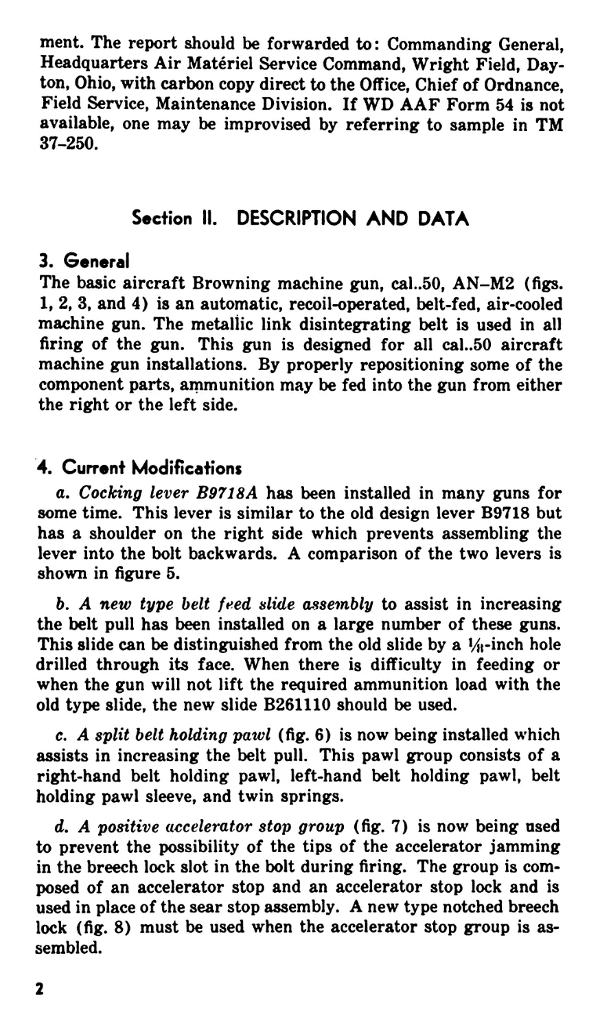
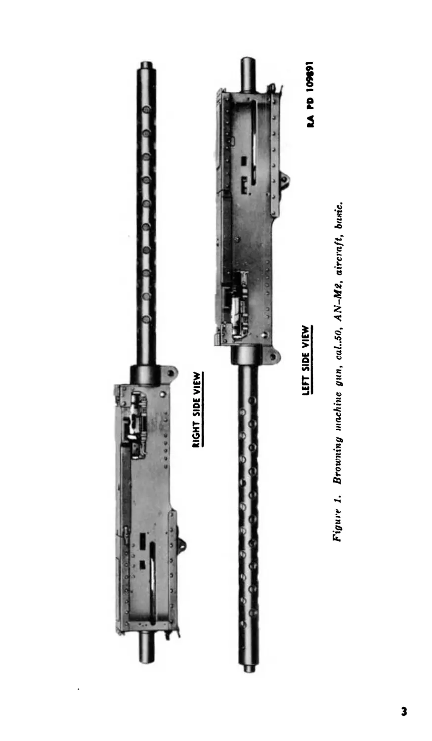
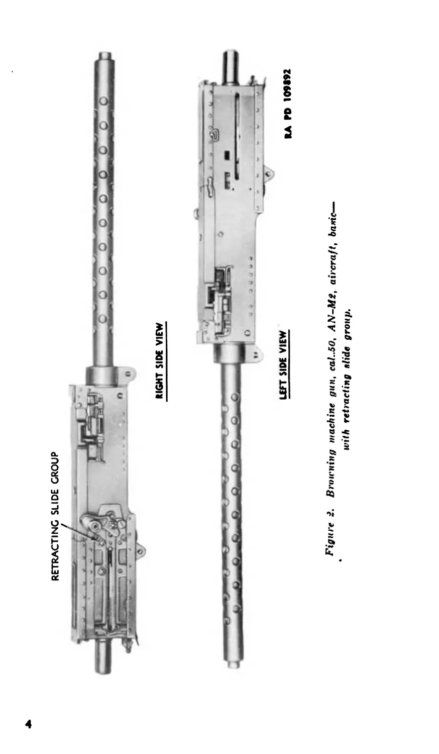
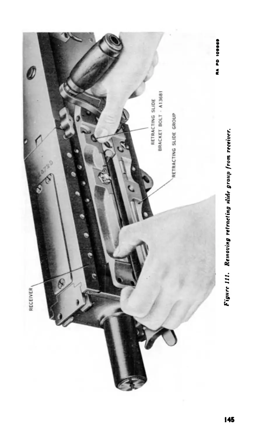
RETRACTING SLIDE GROUP
RIGHT SIDE VIEW
Figure 2. Browning machine gun, cal..50, AN-M2, aircraft, baric—
with retracting elide group.
RA ГО 109m
СЛ
operating slide croup
Figure 3. Broirning machine gun, cal..50, AN-M2, aircraft, basic—
with operating slide group.
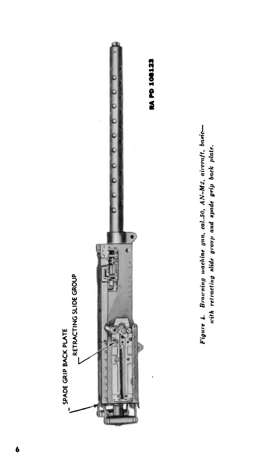
SPADE GRIP BACK PLATE
RA ГО 1OS123
Figure 4. Broirning machine gun, cal„50, AN-M2, aircraft, baric—
with retracting slide group and spade grip back plate.
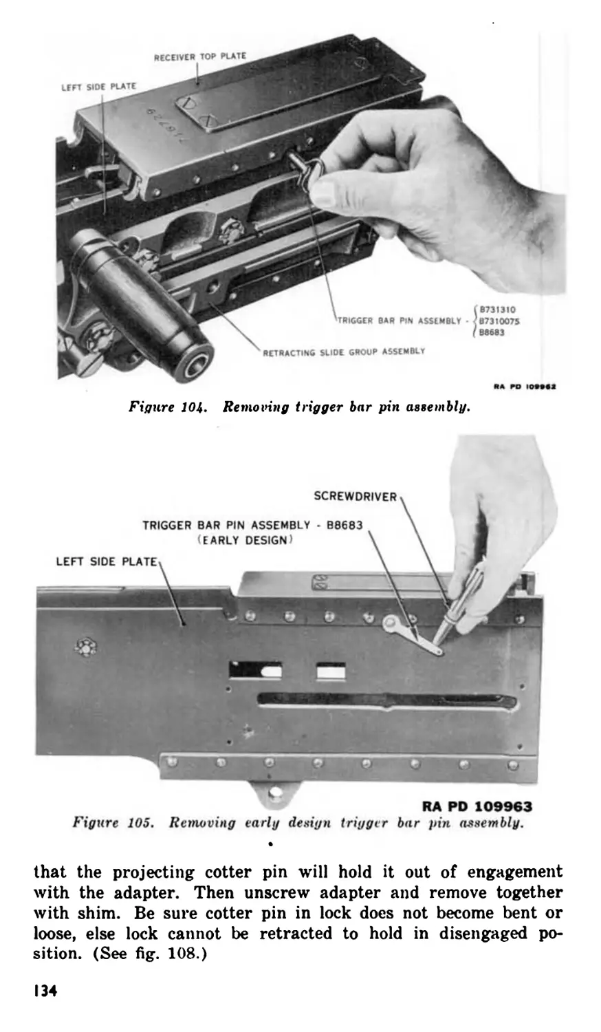
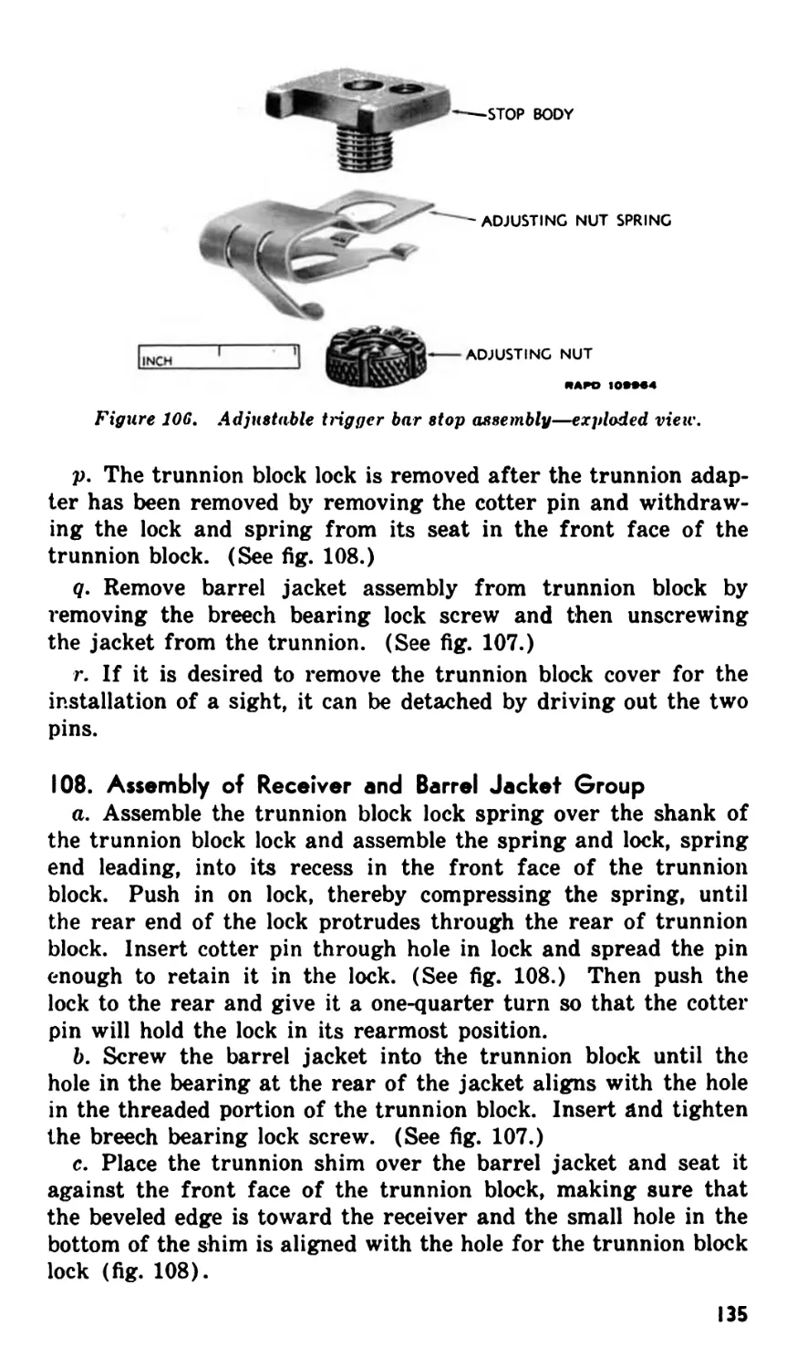
e. A new type trigger bar pin assembly has been designed which
can be removed without first having to remove the retracting
slide, when it is assembled on the left side of the gun. The new
type pin has a wire lock which is securely held against the re-
Figure 5. Comparison of cocking levers.
RA PD 109896
Figure <>. Split belt holding pawl group.
7
Figure 7. Accelerator stop and lock—exploded view.
INCHES
г
rtA PD 109972
Figure 8. New type notched breech lock.
ceiver. This design of pin is preferred to the type which has a
leaf lock held against the receiver by a ball and spring within the
body of the pin. Both pins are shown in figure 9.
8
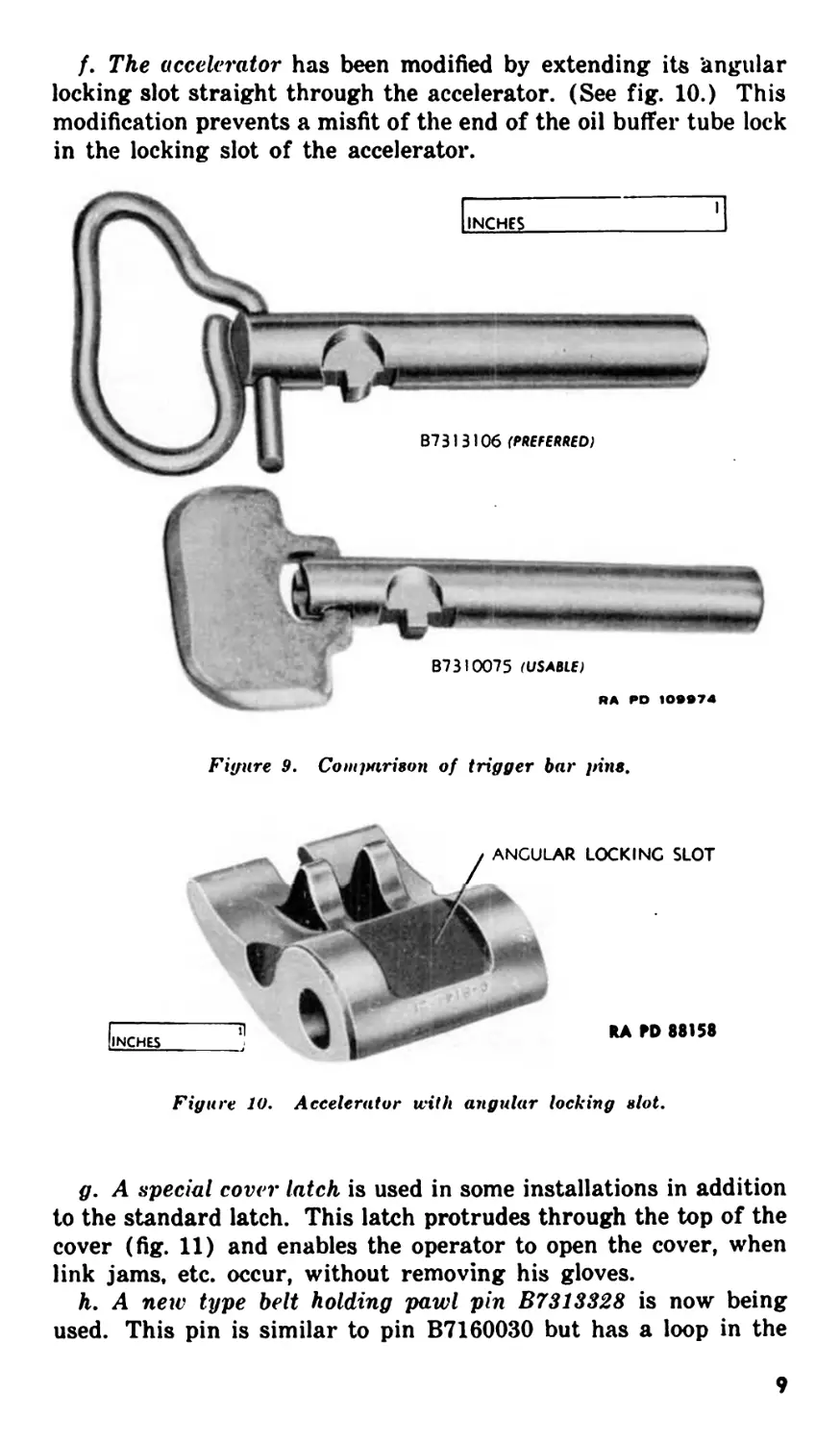
f. The accelerator has been modified by extending its ’angular
locking slot straight through the accelerator. (See fig. 10.) This
modification prevents a misfit of the end of the oil buffer tube lock
in the locking slot of the accelerator.
Figure 9. Comparison of trigger bar pins.
Figure 10. Accelerator with angular locking slot.
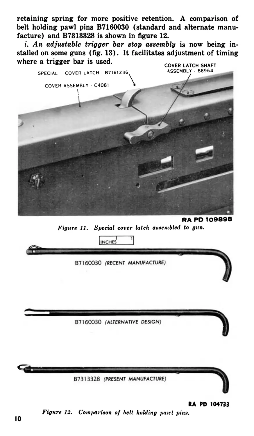
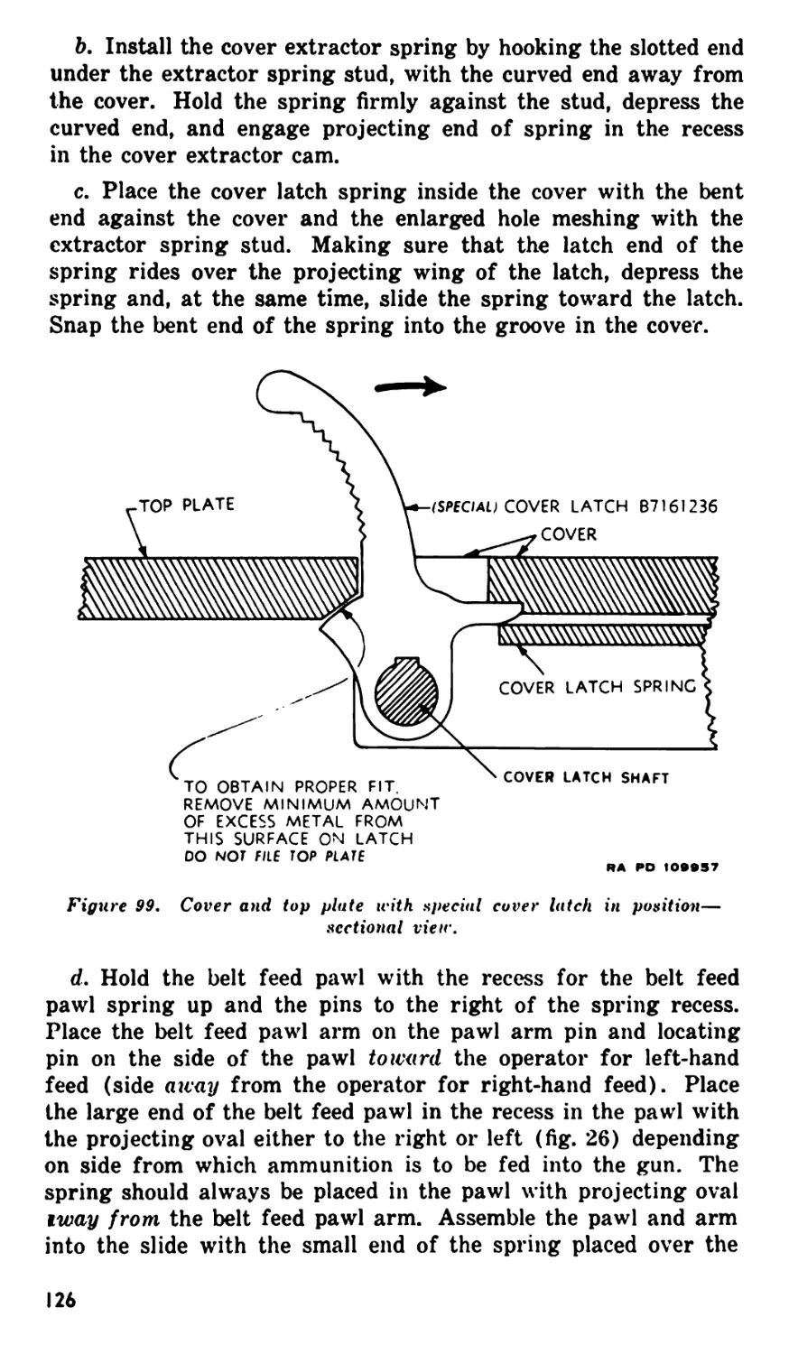
g. A special cover latch is used in some installations in addition
to the standard latch. This latch protrudes through the top of the
cover (fig. 11) and enables the operator to open the cover, when
link jams, etc. occur, without removing his gloves.
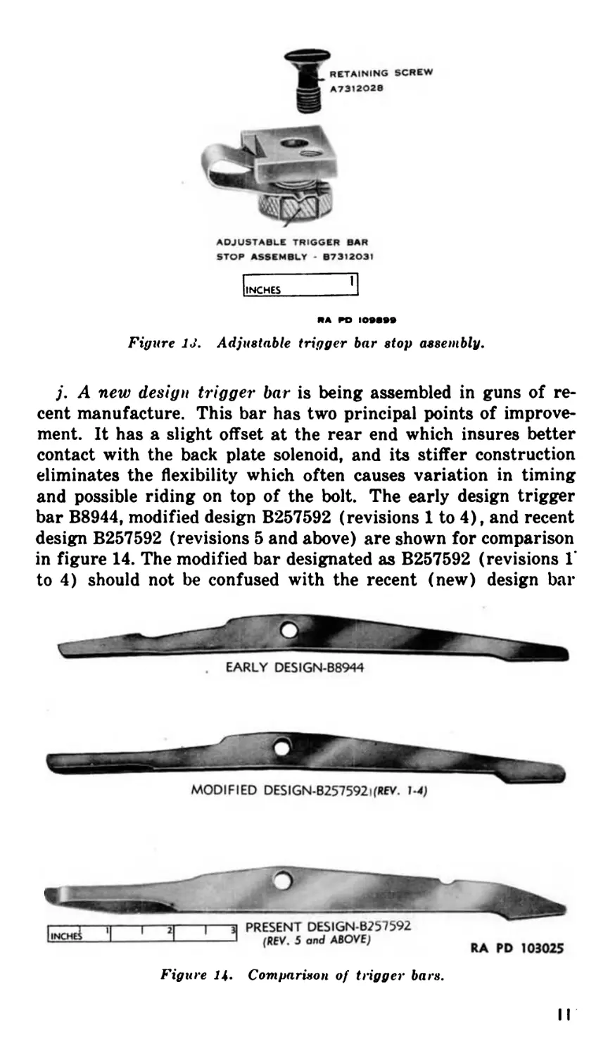
h. A new type belt holding pawl pin B7313328 is now being
used. This pin is similar to pin B7160030 but has a loop in the
9
retaining spring for more positive retention. A comparison of
belt holding pawl pins B7160030 (standard and alternate manu-
facture) and B7313328 is shown in figure 12.
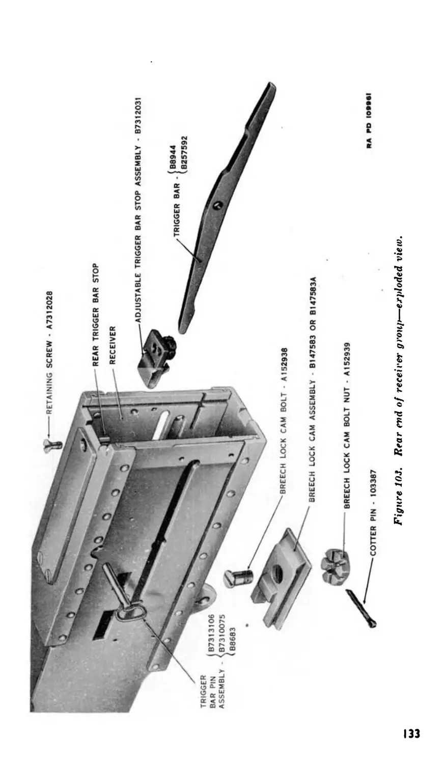
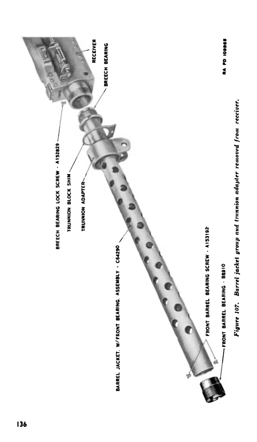
i. An adjustable trigger bar stop assembly is now being in-
stalled on some guns (fig. 13). It facilitates adjustment of timing
where a trigger bar is used.
SPECIAL COVER LATCH B716I236
COVER ASSEMBLY • C4O81
COVER LATCH SHAFT
ASSEMBLY B8964
RA RO 109898
Figure 11. Special cover latch assembled to gun.
[inches 'I
B7160030 (RECENT MANUFACTURE)
B7160030 (ALTERNATIVE DESIGN)
B7313328 (PRESENT MANUFACTURE)
RA PD 104733
Figure 12. Comparison of belt holding pawl pin».
10
ADJUSTABLE TRIGGER BAR
STOP ASSEMBLY - B73I2O3I
INCHES
RA PO IOSBSS
Figure 13. Adjustable trigger bar stop assembly.
j. A new design trigger bar is being assembled in guns of re-
cent manufacture. This bar has two principal points of improve-
ment. It has a slight offset at the rear end which insures better
contact with the back plate solenoid, and its stiffer construction
eliminates the flexibility which often causes variation in timing
and possible riding on top of the bolt. The early design trigger
bar B8944, modified design B257592 (revisions 1 to 4), and recent
design B257592 (revisions 5 and above) are shown for comparison
in figure 14. The modified bar designated as B257592 (revisions 1*
to 4) should not be confused with the recent (new) design bar
MODIFIED DESIGN-B257592i(REV. 1-4)
Figure Ц. Comparison of trigger bars.
II
В257592 (revisions о and above) which is easily identified by
greater depth, the notch in the top forward edge, and the offset
rear end.
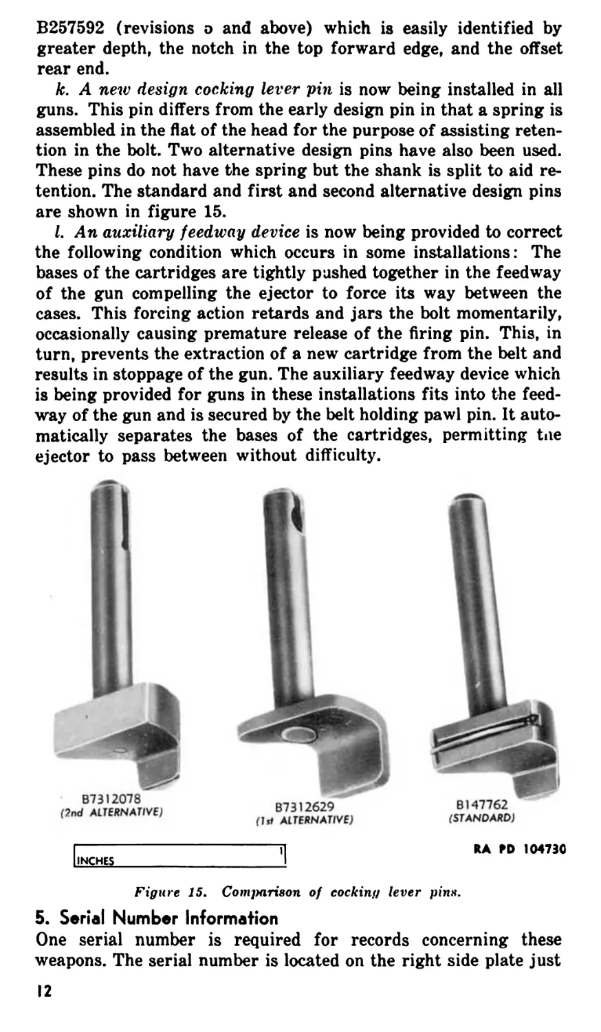
k. A new design cocking lever pin is now being installed in all
guns. This pin differs from the early design pin in that a spring is
assembled in the flat of the head for the purpose of assisting reten-
tion in the bolt. Two alternative design pins have also been used.
These pins do not have the spring but the shank is split to aid re-
tention. The standard and first and second alternative design pins
are shown in figure 15.
I. An auxiliary feedway device is now being provided to correct
the following condition which occurs in some installations: The
bases of the cartridges are tightly pushed together in the feedway
of the gun compelling the ejector to force its way between the
cases. This forcing action retards and jars the bolt momentarily,
occasionally causing premature release of the firing pin. This, in
turn, prevents the extraction of a new cartridge from the belt and
results in stoppage of the gun. The auxiliary feedway device which
is being provided for guns in these installations fits into the feed-
way of the gun and is secured by the belt holding pawl pin. It auto-
matically separates the bases of the cartridges, permitting toe
ejector to pass between without difficulty.
87312078
(2nd ALTEKNATIVE)
RA RD 104730
INCHES
Figure 15. Comparison of cocking lever pins.
5. Serial Number Information
One serial number is required for records concerning these
weapons. The serial number is located on the right side plate just
12
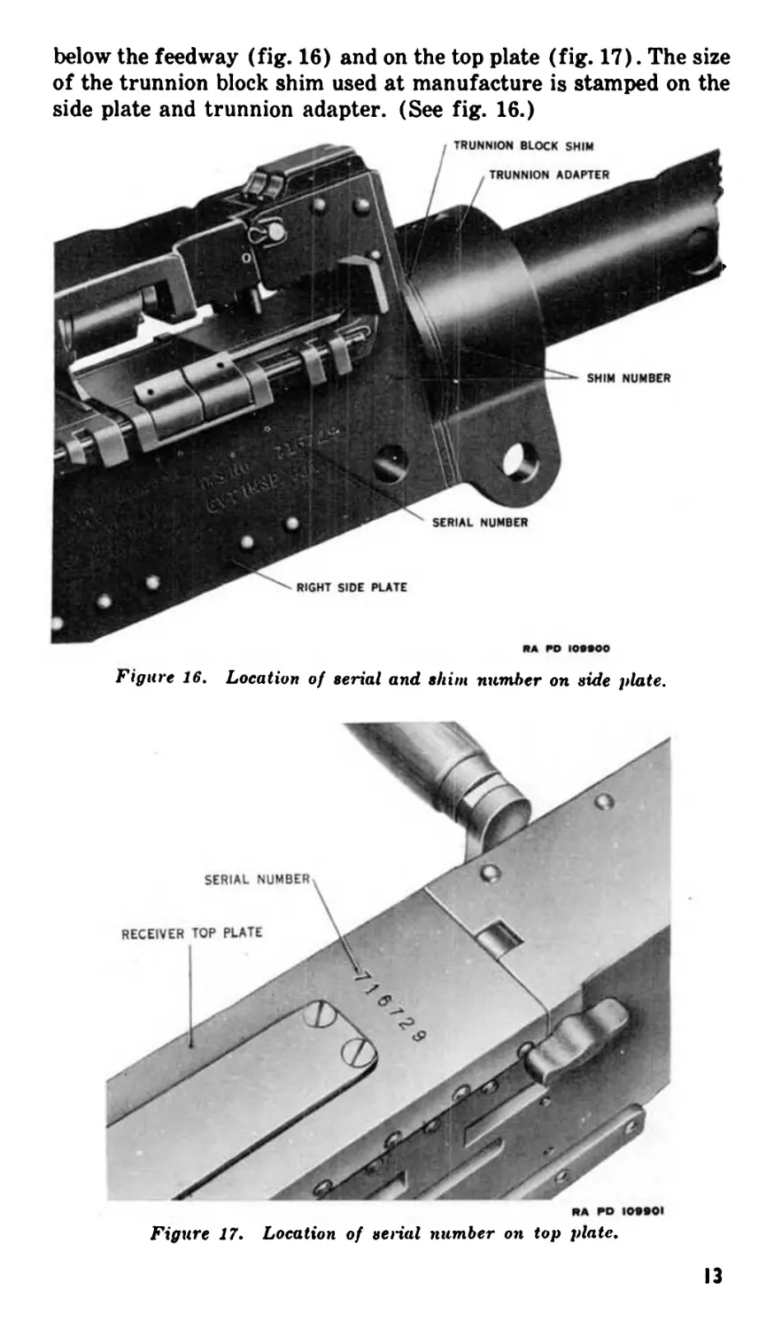
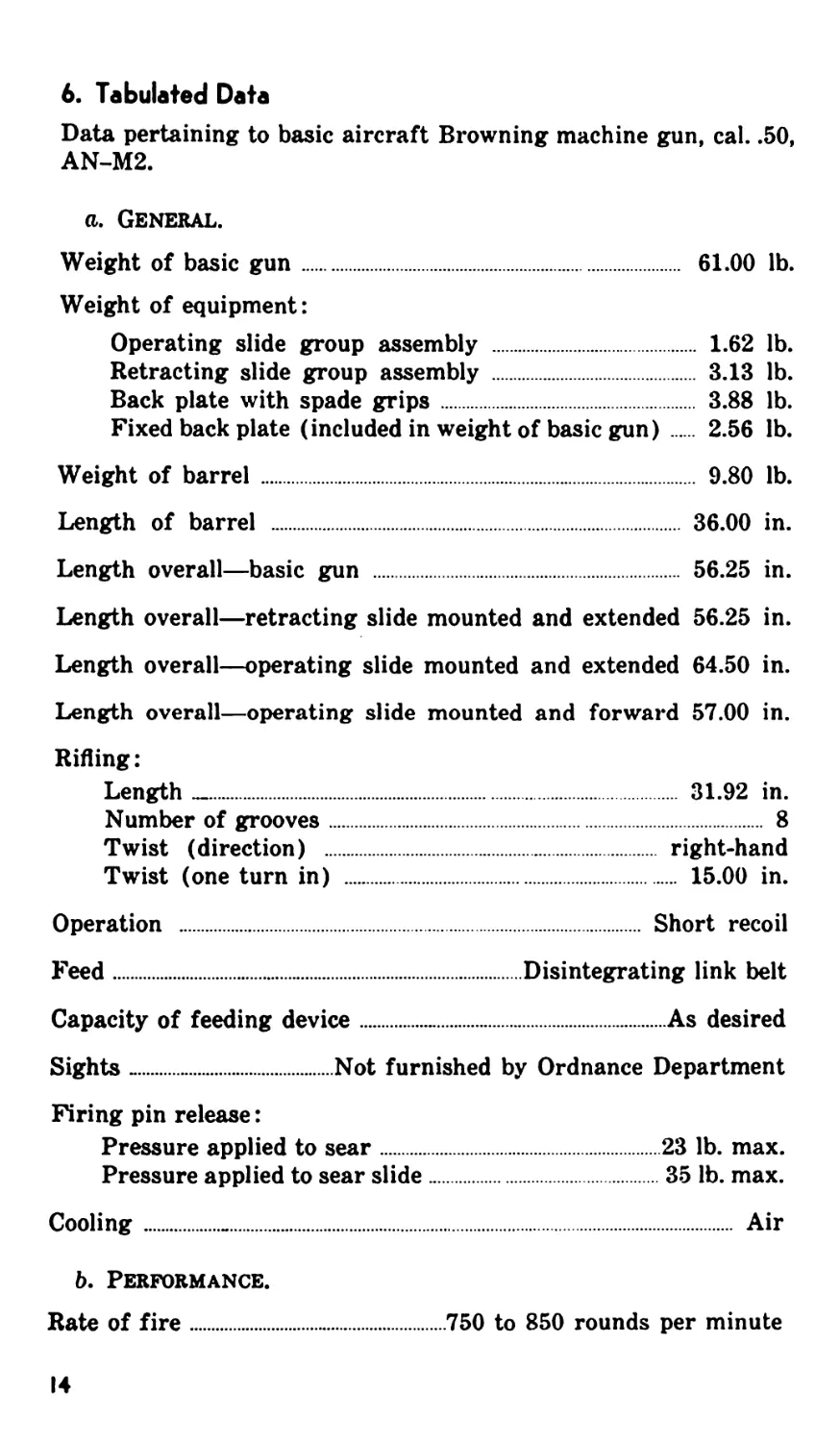
below the feedway (fig. 16) and on the top plate (fig. 17). The size
of the trunnion block shim used at manufacture is stamped on the
side plate and trunnion adapter. (See fig. 16.)
RA RO ЮМОО
Figure 16. Location of serial and shim number on side plate.
RA RO 109*01
Figure 17. Location of serial number on top plate.
13
6. Tabulated Data
Data pertaining to basic aircraft Browning machine gun, cal. .50,
AN-M2.
a. General.
Weight of basic gun................................ 61.00 lb.
Weight of equipment:
Operating slide group assembly ................. 1.62 lb.
Retracting slide group assembly ................ 3.13 lb.
Back plate with spade grips..................... 3.88 lb.
Fixed back plate (included in weight of basic gun). 2.56 lb.
Weight of barrel ...................................... 9.80 lb.
Length of barrel .................................. 36.00 in.
Length overall—basic gun .......................... 56.25 in.
Length overall—retracting slide mounted and extended 56.25 in.
Length overall—operating slide mounted and extended 64.50 in.
Length overall—operating slide mounted and forward 57.00 in.
Rifling:
Length —......................................... 31.92 in.
Number of grooves....................................... 8
Twist (direction) ............................. right-hand
Twist (one turn in) ............................. 15.00 in.
Operation ........................................ Short recoil
Feed..................................Disintegrating link belt
Capacity of feeding device..........................As desired
Sights .................Not furnished by Ordnance Department
Firing pin release:
Pressure applied to sear........................23 lb. max.
Pressure applied to sear slide..................35 lb. max.
Cooling................................................... Air
b. Performance.
Rate of fire
.....................750 to 850 rounds per minute
14
PART TWO
OPERATING INSTRUCTIONS
Section III. GENERAL
7. Scope
Part Two contains information for the guidance of the personnel
responsible for the operation of this equipment. It contains in-
formation on the preliminary servicing of the gun, description and
location of the controls, operation under usual (moderate) and
under unusual atmospheric conditions, and demolition to prevent
enemy use.
Section IV. SERVICE UPON RECEIPT OF EQUIPMENT
8. General
a. Upon receipt of new or used materiel, it is the responsibility
of the officer in charge to ascertain whether it is complete and
in sound operating condition. A record should be made of any
missing parts and of any malfunctions, and any such conditions
should be corrected as quickly as possible. Equipment should not
be disassembled except under the supervision of trained personnel.
b. Attention should be given to small and minor parts, as these
are the more likely to become lost and may seriously affect the
proper functioning of the materiel.
c. The materiel should be cleaned and prepared for service in
accordance with instructions given in paragraphs 9 or 10.
9. New Equipment '
a. Guns received from storage are coated completely with a cor-
rosion preventive and will be serviced as follows:
(1) Disassemble to the extent prescribed in paragraph 11.
(2) Clean by removing corrosion preventive or foreign matter
as outlined in paragraphs 14 or 16.
768321 0-47-2
IS
(3) Apply a light film of oil to all parts and assemble. (See
pars. 44 through 46 for lubrication instructions.)
(4) Check and adjust the head space as described in paragraph
24.
(5) Check and adjust timing as described in paragraph 25.
b. Check materiel with modification record and storage cards to
make sure all modifications and repairs have been made. A list of
current Modification Work Orders is published quarterly in FM
21-6.
»
c. Check general condition and appearance of materiel.
d. Make operational check of gun as described in paragraph 48/.
10. Used Equipment
Service used equipment in the same manner as new equipment as
described in paragraph 9. In addition, check the following points:
a. Check materiel for worn, cracked, rusted, loose, and missing
parts and correct any deficiencies.
b. Examine the oil buffer and fill if necessary. (See paragraph
88d for procedure.)
11. Disassembly of Gun Prior to Cleaning
a. Disassemble components. (See cover group, pars. 100 through
105.)
b. Remove the driving spring group. (See pars. 72 through 77.)
c. Remove the back plate group. (See par. 67.) (It is not neces-
sary to disassemble.)
d. Remove and disassemble the bolt group. (See pars. 78 through
83.) It is not recommended that the ejector be removed from the
extractor assembly.
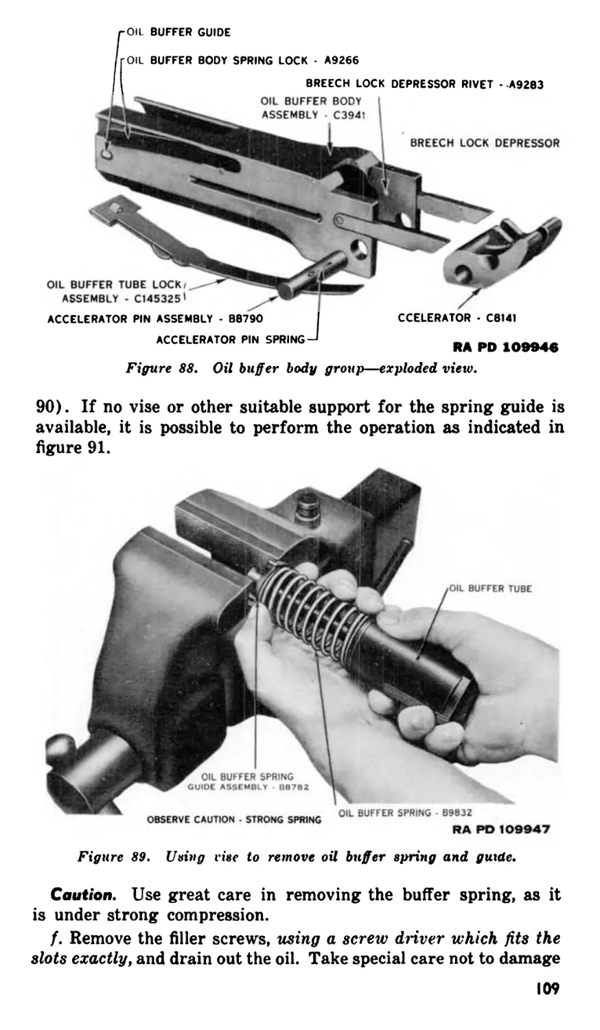
e. Detach the oil buffer body from the barrel extension. (See
par. 85.) Remove the oil buffer assembly from the body and re-
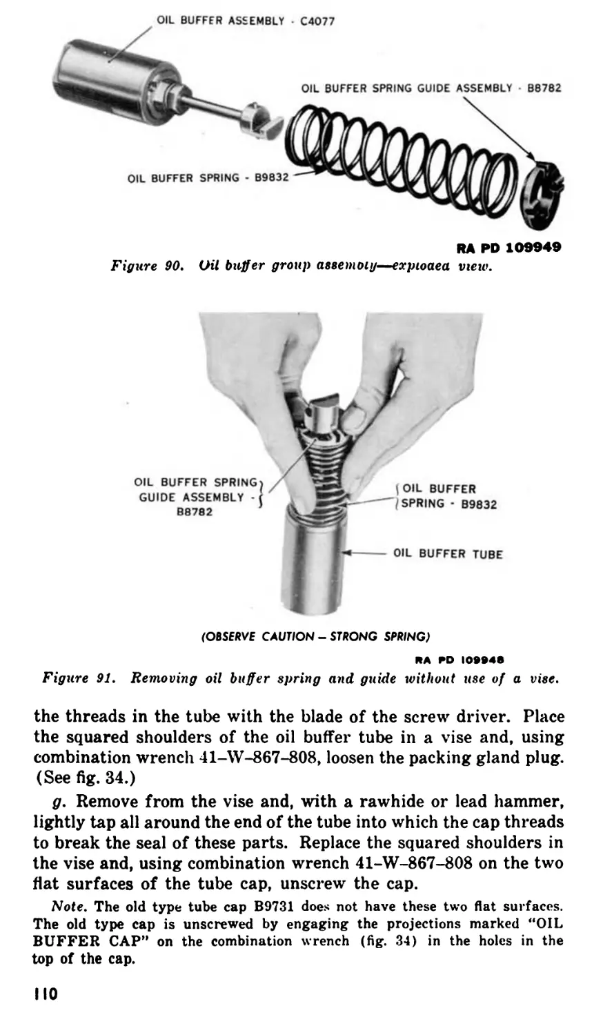
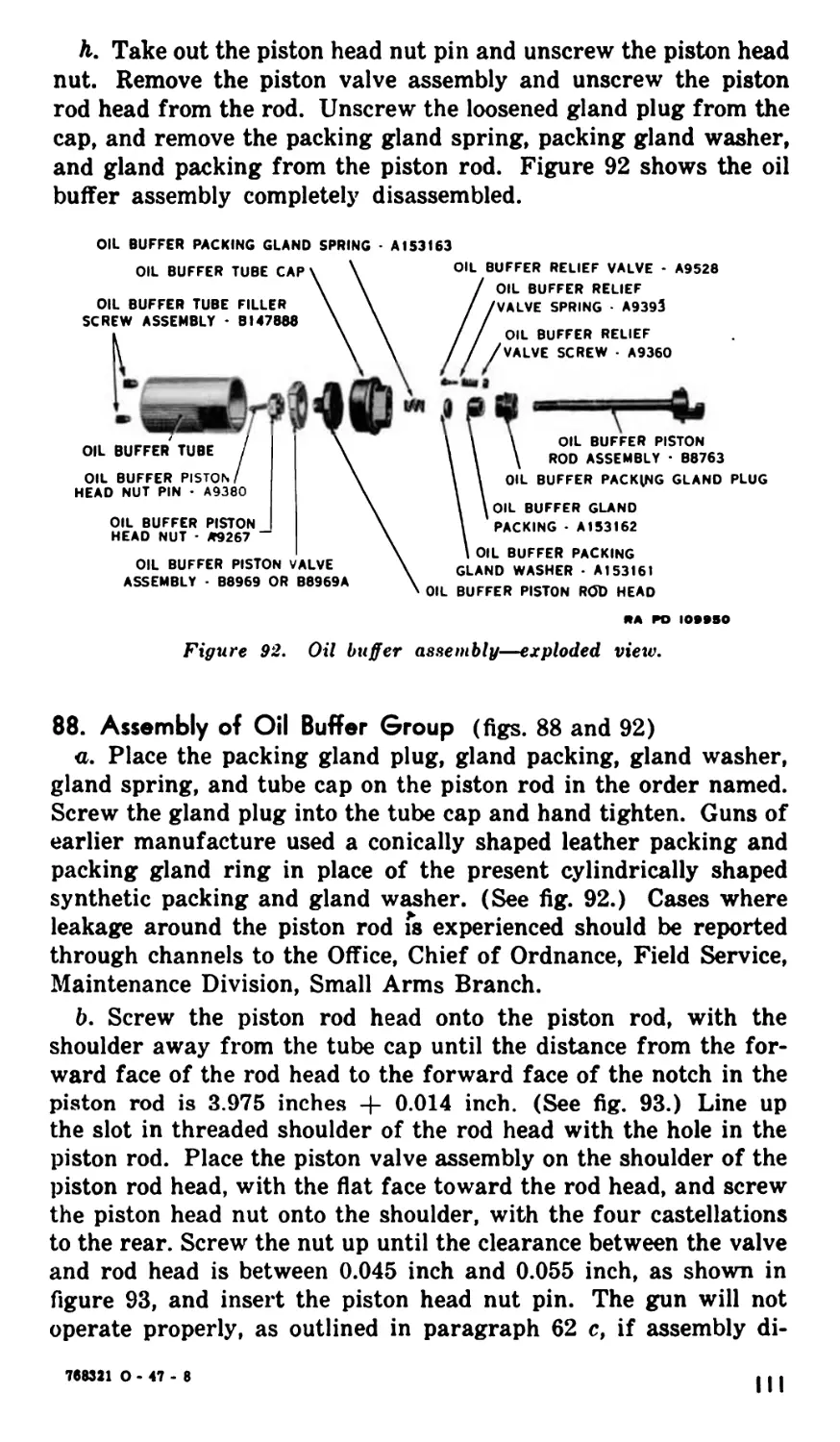
move the oil buffer spring and guide. (See par. 87.) Remove the
accelerator from the oil buffer body. (See par. 87.)
/. Remove the barrel and barrel extension group (par. 91),
unscrew the barrel extension from the barrel, and take out the
breech lock (par. 93).
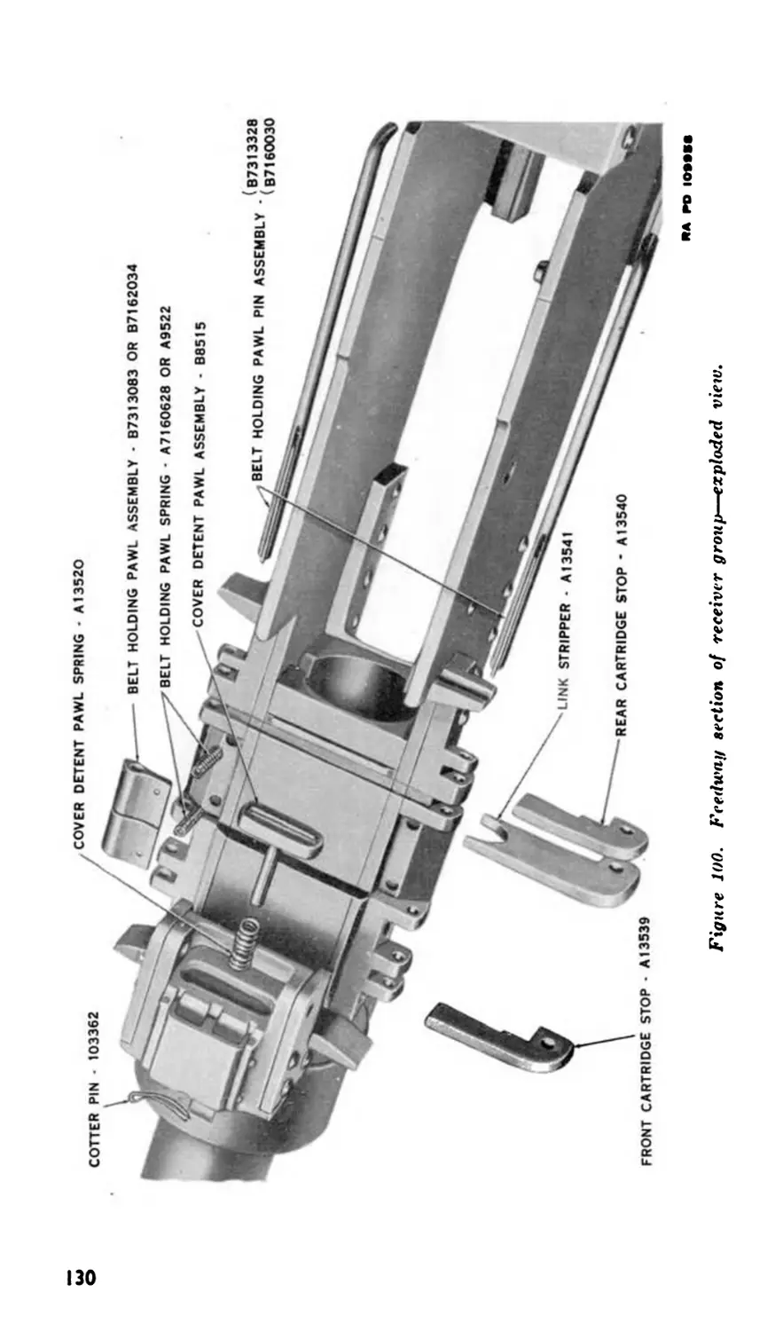
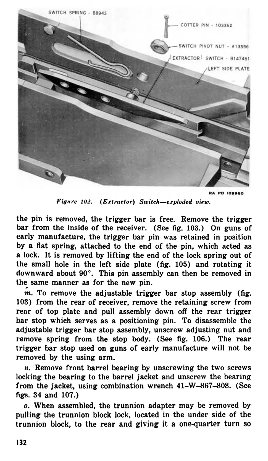
g. Remove the (extractor) switch and switch spring, the belt
holding pawl, cartridge stops, and link stripper. (See par. 107.)
16
12. Cleaning and Preserving Materials
The following cleaners and preservatives are required for use with
this materiel. See TM 9-850 for information additional to that
contained in this manual on the use of these materials. See WD
CAT ORD 3. SNL K-l. and WD CAT ORD 3. SNL K-2. for latest
specifications.
BORAX, powdered.
CLEANER, rifle bore.
CLOTH, bore cleaning.
CLOTH, crocus.
CLOTH, wiping, cotton.
COMPOUND, cleaning, alkaline.
PATCHES, cut, cotton flannel.
SOAP, or issue.
SODA-ASH.
SOLVENT, dry cleaning.
13. Cleaning—General Instructions
«. Guns received from storage should be cleaned with dry clean-
ing solvent (par. 14), or, if solvent is not available, with hot water
solution (par. 16).
b. Guns in use should be cleaned with rifle bore cleaner (par.
15), or, if bore cleaner is not available, with a hot water solution
(par. 16). Dry cleaning solvent may be used to clean parts other
than the bore and chamber if rifle bore cleaner or hot water solu-
tions are not available.
c. Components of each gun should be cleaned separately, for
while like parts are interchangeable, the parts originally assembled
to the gun work best together.
d. Hot water solutions have certain limitations when used to
clean component parts which have a phosphate finish such as
“Parco-lubrite” or “Parkerized.” A phosphote finish may be dis-
tinguished by its dull-gray or dull-black color. Strong alkaline
solutions will deteriorate phosphate finishes to the extent that the
corrosion-preventive quality will be reduced or removed. Mild soap
solutions or weak alkaline solutions may be used without harm-
ful results provided they are followed with a very thorough rinsing
in clean, hot water to completely remove all traces of the alkaline
materials.
e. Never use a solution of water and lye or any other caustic
to clean gun parts.
/. Never use carbon tetrachloride or trichlorethylene, except in
commercial degreasers as these solvents may cause rust. Gasoline
and benzine are prohibited as they present a fire hazard.
g. Cleaned parts must be lubricated (pars. 44 through 46) im-
mediately to prevent corrosion. Gloves should be worn when hand-
ling cleaned parts before lubrication as acid from the hands pro-
motes quick rusting. This is particularly true when dry cleaning
solvent is used. If rubber gloves are used they will be deterior-
ated by dry cleaning solvent.
17
14. Cleaning with Dry Cleaning Solvent
a. Refer to general instruction for cleaning covered in para-
graph 13.
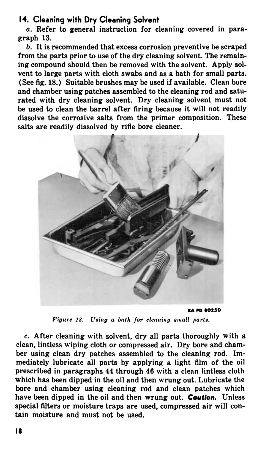
b. It is recommended that excess corrosion preventive be scraped
from the parts prior to use of the dry cleaning solvent. The remain-
ing compound should then be removed with the solvent. Apply sol-
vent to large parts with cloth swabs and as a bath for small parts.
(See fig. 18.) Suitable brushes may be used if available. Clean bore
and chamber using patches assembled to the cleaning rod and satu-
rated with dry cleaning solvent. Dry cleaning solvent must not
be used to clean the barrel after firing because it will not readily
dissolve the corrosive salts from the primer composition. These
salts are readily dissolved by rifle bore cleaner.
*A ro «O3SO
Figure 18. Using a bath for cleaning small parts.
c. After cleaning with solvent, dry all parts thoroughly with a
clean, lintless wiping cloth or compressed air. Dry bore and cham-
ber using clean dry patches assembled to the cleaning rod. Im-
mediately lubricate all parts by applying a light film of the oil
prescribed in paragraphs 44 through 46 with a clean lintless cloth
which has been dipped in the oil and then wrung out. Lubricate the
bore and chamber using cleaning rod and clean patches which
have been dipped in the oil and then wrung out. Caution. Unless
special filters or moisture traps are used, compressed air will con-
tain moisture and must not be used.
18
15. Cleaning with Rifle Bore Cleaner
a. Refer to general instructions for cleaning covered in para-
graph 13.
b. Rifle bore cleaner is a water-in-oil emulsion which is used
primarily for cleaning the bore and chamber. It contains volatile
solvents which evaporate above +150° F., thus reducing the clean-
ing action. Therefore, after firing, the bore should not be cleaned
until the barrel has cooled to the point where it can be touched with
the bare hand. Maximum cleaning efficiency and protection
against rusting will be obtained when rifle bore cleaner is used
undiluted. When necessary to conserve the supply it may be di-
luted up to 50 percent with water without materially reducing the
cleaning action, provided prevailing temperatures are above
+32° F. The rust-preventive qualities will be reduced, however,
and surfaces so cleaned must be immediately dried and coated with
oil. Rifle bore cleaner will also be used in lieu of hot water solutions
or dry cleaning solvent to clean other parts of the gun. The cleaner
is not a lubricant. Parts requiring lubrication must be dried after
cleaning, and the prescribed lubricant (pars. 44 through 46) ap-
plied.
c. To clean bore and chamber place two clean patches in the slot
of the cleaning rod; saturate the patches with the cleaner, and
move the rod back and forth through the barrel several times. If
rust spots or foreign matter are not removed by the cleaner attach
the cleaning brush M4 to the cleaning rod and scrub the lands and
grooves. The chamber cleaning brush M6 is used to clean the
chamber. Apply rifle bore cleaner to large parts with cloth swabs
and as a bath for small parts. Suitable brushes may be used if
available.
d. If it is anticipated that the weapon will be used or recleaned
within approximately 24 to 48 hours, lubrication for rust preven-
tion will not be necessary. If the weapon is not to be used or re-
cleaned within 24 to 48 hours dry and lubricate as outlined in
paragraphs 44 through 46.
16. Cleaning with Hot Water Solutions
a. General Instructions. See paragraph 13.
b. Preparation of Hot Water Solutions. (1) When it is de-
sired to use hot water cleaning methods to clean phosphate fin-
ished guns or parts, any one of the materials in proportions indi-
cated below can be used safely. No other materials will be used
without approval of competent authority.
Borax—6 to 10 ounces to each gallon of water.
Issue soap—not more than 2 ounces to each gallon of water.
19
(2) For cleaning guns and parts not phosphate finished, any one
of the following materials in proportions indicated below may be
used.
Borax—to 1 pound to each gallon of water.
Soda-ash—Vi to 1 pound to each gallon of water.
Issue Soap—pound to each gallon of water.
Alkaline cleaning compound—1/3 pound to each gallon of
water.
Note: Alkaline cleaning compound, or soda ash, will not be used in
any proportion to clean guns with a phosphate finish.
(3) Practical experience indicates that increasing the tem-
perature of a hot water solution provides greater cleaning effi-
ciency than increasing the amount of materials used therein. Best
results are obtained with a temperature of 180е to 200° F.
c. Cleaning Guns Received From Storage. (1) Disassemble
the gun as described in paragraph 11 and place all the small parts
within a fine mesh wire basket. Lower the basket, as well as th'*
barrel and receiver and barrel jacket, into the hot water solution
until completely submerged. Skim the compound off the top of the
water at frequent intervals to insure that particles of the com-
pound will not adhere to the clean gun parts when they are re-
moved from the bath. Remove the parts from the bath after ap-
proximately one-half hour and immediately rinse in clear warm
water. Dry and lubricate for rust prevention as explained in para-
graphs 44 through 46.
(2) Special care must be observed when cleaning the firing
spring extension assembly, tunnel in the bolt, recesses around the
ejector, coils of all springs, and recesses in which springs or plung-
ers operate, to completely remove all traces of corrosion preven-
tive or foreign matter.
d. Cleaning Guns After Firing. (1) Remove barrel and
barrel extension from the gun (par. 91) and unscrew barrel from
extension (par 93).
(2) Place the barrel, muzzle down, in a vessel containing the
hot water solution. Attach two patches to the cleaning rod, insert
rod in the breech end of the barrel, and move it backward and
forward for about one minute, pumping the solution in and out
of the bore through its entire length. If this does not remove for-
eign matter, while bore is still wet, scrub the lands and grooves
of the bore, as well as the chamber, with the cleaning brush M4
attached to the cleaning rod. The chamber cleaning brush M6
should be used to clean the chamber. Using clean patches, rinse
by pumping clean warm water through the bore and chamber.
Dry and lubricate bore and chamber as described in paragraphs
44 through 46.
20
(3) Rags, swabs, or suitable brushes saturated with the solu-
tion may be used to clean large parts, and a bath of the solution
for small parts. Do not immerse the back plate or the oil buffer
assembly in the solution. Immediately dry and lubricate as de-
scribed in paragraphs 44 through 46.
17. Assembly of Gun After Cleaning
a. Assemble the (extractor) switch and switch spring, the belt
holding pawl, cartridge stops, and link stripper to the receiver.
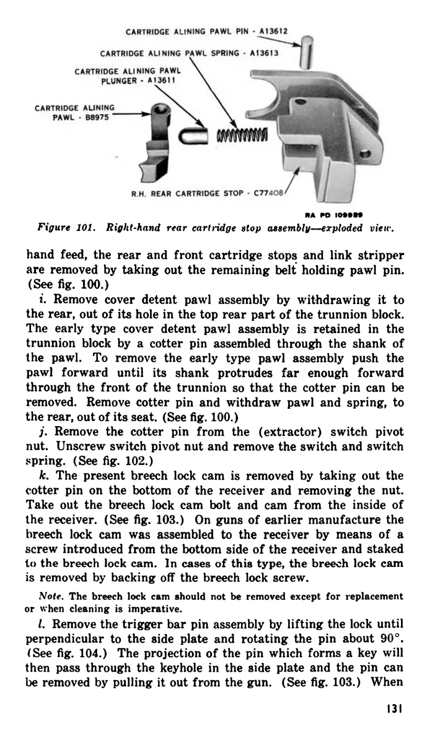
(See par. 108.) Assemble the right-hand rear cartridge stop as-
sembly. (See par. 108/.)
b. Assemble the breech lock to the barrel extension. (See par.
94b.) Assemble barrel extension to barrel. (See par. 94c.) Install
barrel and barrel extension group into receiver. (See par. 92.)
c. Assemble the accelerator and tube lock assembly to the oil
buffer body. (See par. 88b and g.) Assemble the oil buffer spring
and guide to the oil buffer assembly (par 88e). Assemble the oil
buffer assembly to the oil buffer body. (See par. 88 t.) Assemble
the oil buffer group to the barrel extension group (par. 86a) and
push the groups into the receiver (par. 86b).
d. Assemble bolt group. (See par. 82.) Install bolt group in
receiver. (See par. 80.)
e. Assemble driving spring group. (See par. 76.) Install group
into receiver. (See par. 74.)
f. Assemble cover group components. (See par. 104.)
g. Install back plate group in receiver. (See par. 68.)
Section V. CONTROLS
18. General
Controls for aircraft machine guns furnished by the Ordnance De-
partment and covered in this section consists of the operating
slide group, the retracting slide group, and the back plate assembly
with spade grips and trigger. All other controls are furnished by
the Air Forces and are covered by Air Force manuals.
19. Operating Slide Group (fig. 3)
a. The operating slide group is located on either the right or left
side plate and is used to retract the bolt manually for loading, un-
loading, and clearing of stoppages, and to hold the bolt in the re-
tracted position to facilitate cooling of the barrel. It consists of a
rectangular steel bar having a hook fastened to its center for en-
gaging the bolt stud, and an aluminum handle at the rear end for
actuating the group.
21
b. To retract the bolt, pull the handle to the rear. To release the
bolt, raise the handle and allow the bolt and operating slide group
to go forward.
20. Retracting Slide Group (fig. 2)
a. The retracting slide group is located on either the right or
left side plate and is used to retract the bolt manually for loading,
unloading, or clearing of stoppages. It consists of a rectangular
steel bracket having guideways for a slide which actuates the bolt
through the medium of the bolt stud when the slide is pulled to the
rear by means of the handle.
b. To retract the bolt, pull the handle to the rear. To allow the
bolt to go forward, release the handle.
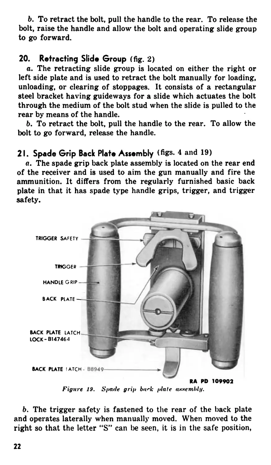
21. Spade Grip Back Plate Assembly (figs. 4 and 19)
a. The spade grip back plate assembly is located on the rear end
of the receiver and is used to aim the gun manually and fire the
ammunition. It differs from the regularly furnished basic back
plate in that it has spade type handle grips, trigger, and trigger
safety.
RA RD 109902
Figure 19, Spade grip badc plate assembly.
b. The trigger safety is fastened to the rear of the back plate
and operates laterally when manually moved. When moved to the
right so that the letter “S” can be seen, it is in the safe position,
22
and when moved to the left so that the letter “F” can be seen, it is
in the fire position.
c. The trigger is a butterfly shaped lever located in the back
plate just above the safety. When depressed, if the safety is in the
fire position, it actuates the trigger bar to release the firing mechan-
ism and fire a round of ammunition. When released, it is auto-
matically returned to the inoperative position by means of a spring.
Section VI. OPERATION UNDER USUAL CONDITIONS
22. General
Information in this section is concerned with the steps necessary
to operate the gun under the atmospheric conditions ordinarily
encountered while flying at moderate altitudes over a temperate
zone. When high altitude flying over a temperate zone is antici-
pated, see paragraph 35.
23. Mounting
Aircraft machine gun mounts are furnished by the Air Forces
and are covered in Air Force manuals.
24. Adjustment of Headspace
a. General. The headspace as measured on machine guns is
the distance between the front face of the bolt and the rear end of
the barrel. Headspace is correct when this distance is between
0.202 and 0.206 inches. Unless this distance is properly adjusted,
the cartridge, when chambered, will not be properly seated against
its sloping shoulder in the chamber. Headspace must be checked
and adjusted (c and d below) each time the gun is assembled and
at any other time when correctness is doubted due to the conditions
outlined in b below.
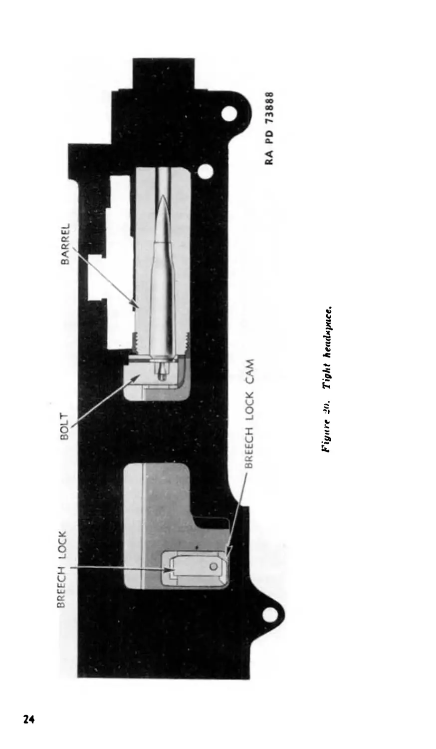
b. Improper Headspace Adjustment. (1) With too little
(tight) headspace, the chamber cartridge will prevent the bolt
from going completely forward. This may cause the following:
(a) The breech lock will not fully enter the locking recess of the
bolt (fig. 20) thereby preventing the recoiling parts from going
completely into the battery position during counterrecoil.
(b) The bolt may not go forward far enough for the sear to be
released, thereby causing failure to fire.
(c) Binding and excessive friction between the moving parts
will cause sluggish fire (particularly noticeable when pulling a
long ammunition belt).
23
Figure 2<>, Tight headx^ice,
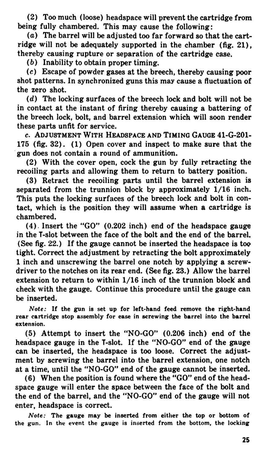
(2) Too much (loose) headspace will prevent the cartridge from
being fully chambered. This may cause the following:
(a) The barrel will be adjusted too far forward so that the cart-
ridge will not be adequately supported in the chamber (fig. 21),
thereby causing rupture or separation of the cartridge case.
(b) Inability to obtain proper timing.
(c) Escape of powder gases at the breech, thereby causing poor
shot patterns. In synchronized guns this may cause a fluctuation of
the zero shot.
(d) The locking surfaces of the breech lock and bolt will not be
in contact at the instant of firing thereby causing a battering of
the breech lock, bolt, and barrel extension which will soon render
these parts unfit for service.
c. Adjustment With Headspace and Timing Gauge 41-G-201-
175 (fig. 32). (1) Open cover and inspect to make sure that the
gun does not contain a round of ammunition.
(2) With the cover open, cock the gun by fully retracting the
recoiling parts and allowing them to return to battery position.
(3) Retract the recoiling parts until the barrel extension is
separated from the trunnion block by approximately 1/16 inch.
This puts the locking surfaces of the breech lock and bolt in con-
tact, which is the position they will assume when a cartridge is
chambered.
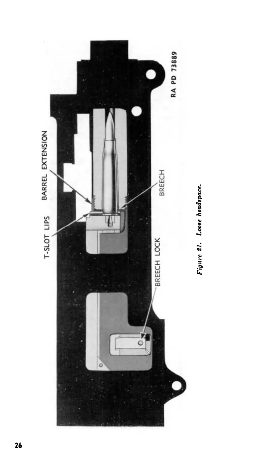
(4) . Insert the “GO” (0.202 inch) end of the headspace gauge
in the T-slot between the face of the bolt and the end of the barrel.
(See fig. 22.) If the gauge cannot be inserted the headspace is too
tight. Correct the adjustment by retracting the bolt approximately
1 inch and unscrewing the barrel one notch by applying a screw-
driver to the notches on its rear end. (See fig. 23.) Allow the barrel
extension to return to within 1/16 inch of the trunnion block and
check with the gauge. Continue this procedure until the gauge can
be inserted.
Note: If the gun is set up for left-hand feed remove the right-hand
rear cartridge stop assembly for ease in screwing the barrel into the barrel
extension.
(5) Attempt to insert the “NO-GO” (0.206 inch) end of the
headspace gauge in the T-slot. If the “NO-GO” end of the gauge
can be inserted, the headspace is too loose. Correct the adjust-
ment by screwing the barrel into the barrel extension, one notch
at a time, until the “NO-GO” end of the gauge cannot be inserted.
(6) When the position is found where the “GO” end of the head-
space gauge will enter the space between the face of the bolt and
the end of the barrel, and the “NO-GO” end of the gauge will not
enter, headspace is correct.
Note: The gauge may be inserted from either the top or bottom of
the gun. In the event the gauge is inserted from the bottom, the locking
25
BARREL EXTENSION
Figure SI. Loose headspace.
Figure 22. Checking headspace.
surfaces of the bolt and breech lock may be brought into contact by inserting a
screwdriver in the T-slot between the face of the bolt and the end of the
barrel.
(7) Remove the gauge and release the firing pin. Caution.
Never release the firing pin with the gauge in place, as to do so
will damage the pin.
d. Adjustment Without Headspace and Timing Gauge. (1)
Open the cover and inspect to make sure that the gun does not
contain a round of ammunition.
(2) Retract the bolt about 1 inch by means of the bolt handle
or other retracting device.
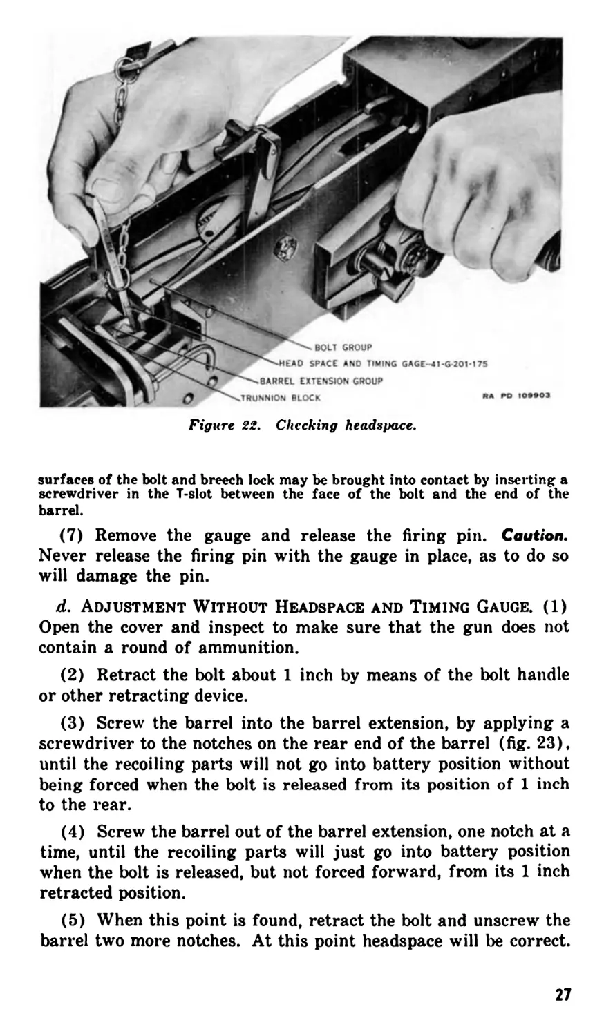
(3) Screw the barrel into the barrel extension, by applying a
screwdriver to the notches on the rear end of the barrel (fig. 23),
until the recoiling parts will not go into battery position without
being forced when the bolt is released from its position of 1 inch
to the rear.
(4) Screw the barrel out of the barrel extension, one notch at a
time, until the recoiling parts will just go into battery position
when the bolt is released, but not forced forward, from its 1 inch
retracted position.
(5) When this point is found, retract the bolt and unscrew the
barrel two more notches. At this point headspace will be correct.
27
RA PO 1ORRO4
TRUNNION BLOCK
Figure id. Turning barrel to adj и it headepace.
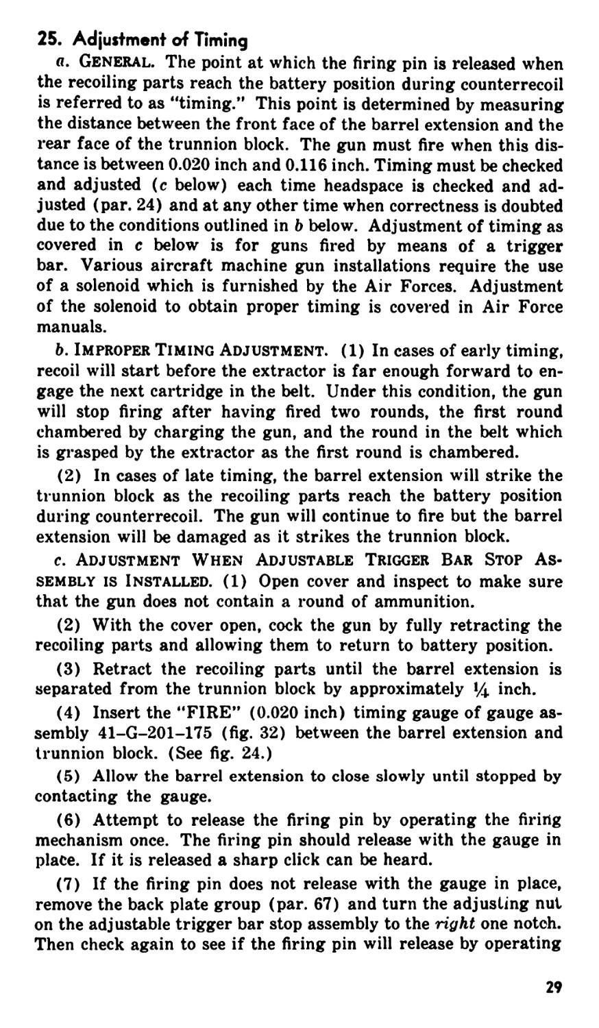
25. Adjustment of Timing
a. General. The point at which the firing pin is released when
the recoiling parts reach the battery position during counterrecoil
is referred to as “timing.” This point is determined by measuring
the distance between the front face of the barrel extension and the
rear face of the trunnion block. The gun must fire when this dis-
tance is between 0.020 inch and 0.116 inch. Timing must be checked
and adjusted (c below) each time headspace is checked and ad-
justed (par. 24) and at any other time when correctness is doubted
due to the conditions outlined in b below. Adjustment of timing as
covered in c below is for guns fired by means of a trigger
bar. Various aircraft machine gun installations require the use
of a solenoid which is furnished by the Air Forces. Adjustment
of the solenoid to obtain proper timing is covered in Air Force
manuals.
b. Improper Timing Adjustment. (1) In cases of early timing,
recoil will start before the extractor is far enough forward to en-
gage the next cartridge in the belt. Under this condition, the gun
will stop firing after having fired two rounds, the first round
chambered by charging the gun, and the round in the belt which
is grasped by the extractor as the first round is chambered.
(2) In cases of late timing, the barrel extension will strike the
trunnion block as the recoiling parts reach the battery position
during counter recoil. The gun will continue to fire but the barrel
extension will be damaged as it strikes the trunnion block.
c. Adjustment When Adjustable Trigger Bar Stop As-
sembly is Installed. (1) Open cover and inspect to make sure
that the gun does not contain a round of ammunition.
(2) With the cover open, cock the gun by fully retracting the
recoiling parts and allowing them to return to battery position.
(3) Retract the recoiling parts until the barrel extension is
separated from the trunnion block by approximately 1Д inch.
(4) Insert the “FIRE” (0.020 inch) timing gauge of gauge as-
sembly 41-G-201-175 (fig. 32) between the barrel extension and
trunnion block. (See fig. 24.)
(5) Allow the barrel extension to close slowly until stopped by
contacting the gauge.
(6) Attempt to release the firing pin by operating the firing
mechanism once. The firing pin should release with the gauge in
place. If it is released a sharp click can be heard.
(7) If the firing pin does not release with the gauge in place,
remove the back plate group (par. 67) and turn the adjusting nut
on the adjustable trigger bar stop assembly to the right one notch.
Then check again to see if the firing pin will release by operating
29
ЯА ГО 1М»О1
Figure 24. Checking timing.
the firing mechanism. If it does not release continue turning the
adjusting nut to the right, one notch at a time, checking after each
turn until the firing pin does release.
(8) After adjusting so that the firing pin does release with the
"FIRE” gauge in place retract the recoiling parts, remove the
gauge, and cock the gun.
(9) Retract the recoiling parts approximately 1Д inch and insert
the "NO-FIRE” (0.116 inch) gauge between the barrel extension
and trunnion block. (See fig. 24.)
(10) Allow the barrel extension to close slowly until stopped by
contacting the gauge.
(11) Attempt to release the firing pin by operating the firing
mechanism once. The firing pin should not release with the gauge
in place.
(12) If the firing pin does release with the gauge in place, re-
move the back plate group (if not already removed) (par. 67) and
turn the adjusting nut on the adjustable trigger bar stop assembly
to the left one notch. Then check again to see if the firing pin will
release by operating the firing mechanism. If it does release con-
tinue turning the adjusting nut to the left, one notch at a time,
checking after each turn, until the firing pin does not release.
(13) Retract the recoiling parts, remove the gauge, and allow
the recoiling parts to go forward to battery position.
30
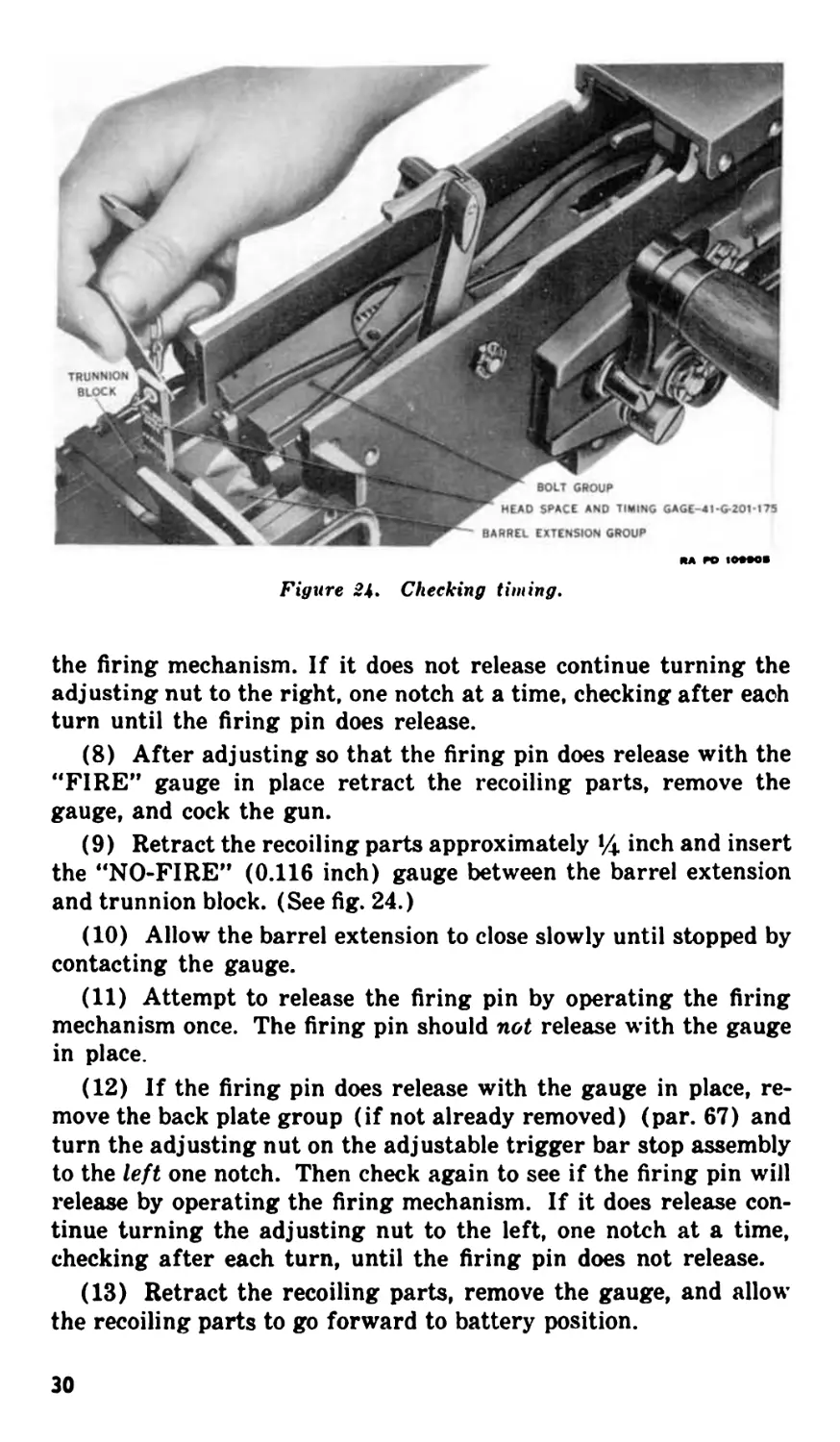
LEFT HAND FEED
RIGHT HAND FEED
RAPD 109906
Figure 25. Position of components for feeding ammunition from either
left-hand or right-hand.
768321 0-47-3
31
26. Repositioning Components to Feed Ammunition from
Opposite Side of Gun
a. General. In order to change the gun from left-hand feed to
right-hand feed, or vice versa, repositioning of parts must be car-
ried out in the bolt group, and cover group, and in certain parts in
the receiver. The correct position of the various parts for both left-
hand and right-hand feed is shown in figure 25. The change from
left-hand feed to right-hand feed is described in general terms be-
low. By reversing the process, the gun may be changed from right-
hand feed to left-hand feed. After changing the gun from left-
hand feed to right-hand feed, or vice versa, the gun should be in-
spected to determine that all parts have been properly assembled.
b. Bolt Group. (1) Remove the bolt group from the gun. (See
par. 79.)
(2) Remove the extractor assembly from the bolt. (See par.
81b.)
(3) Lift up bolt switch high enough to clear bolt switch stud;
rotate one-half turn so that bolt switch stud enters the opposite
hole in bolt switch. The cam groove in the bolt switch will then
line up to make the groove in the bolt marked “R” (right) con-
tinuous. In this position the wide part of the switch will be toward
the rear of the bolt.
(4) Assemble the extractor assembly to the bolt (par. 82 j),
and replace the bolt group in the receiver (par. 80).
Note. If the weapon is to be fired by a mechanism attached to the side plate
the square end of the sear slide must face the side plate to which the mechan-
ism is attachd. If necessary, reposition the sear slide. (See pars. 81 and 82.)
c. Cover Group. (1) Open the cover and remove the belt feed
lever. (See par. 103b.) Transfer the belt feed lever plunger and
spring from the upper hole (cover open) in the belt feed lever to
the lower hole.
(2) Remove the assembled belt feed slide from the cover, re-
verse it, and replace it in the cover with the pawl end of the slide
toward the right.
(3) Replace the belt feed lever and insert the cotter pin.
(4) Push the slide to the right, hold it so that the belt feed
pawl pin can be pushed out of place, and remove the belt feed pawl
pin, belt feed pawl, belt feed pawl arm, and spring from the belt
feed slide. (See par. 103e.) Take care not to lose the spring.
. <5) Move the belt feed pawl arm from its position at the bottom
of the pawl (cover in raised position) and place it in position on the
top of the pawl. The locating pins will locate the arm in the proper
position.
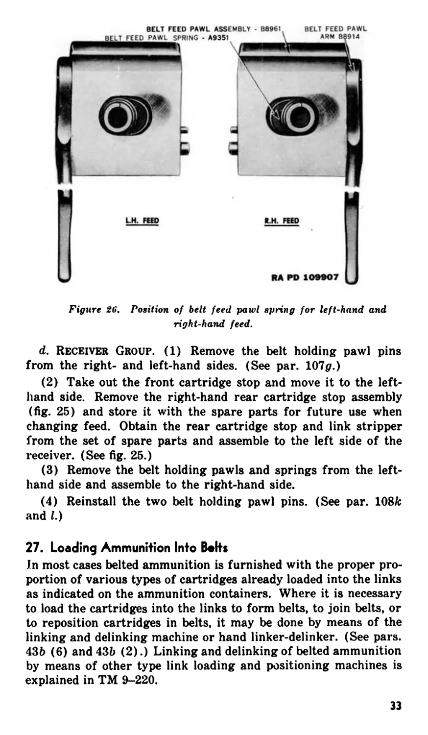
(6) Reassemble the belt feed pawl, spring, and arm to the belt
feed pawl by inserting the belt feed pawl pin. (See par. 104.) See
figure 26 for correct positioning of belt feed pawl spring.
32
RA PD 109907
Figure 26. Position of belt feed pawl spring for left-hand and
right-hand feed.
d. Receiver Group. (1) Remove the belt holding pawl pins
from the right- and left-hand sides. (See par. 107p.)
(2) Take out the front cartridge stop and move it to the left-
hand side. Remove the right-hand rear cartridge stop assembly
(fig. 25) and store it with the spare parts for future use when
changing feed. Obtain the rear cartridge stop and link stripper
from the set of spare parts and assemble to the left side of the
receiver. (See fig. 25.)
(3) Remove the belt holding pawls and springs from the left-
hand side and assemble to the right-hand side.
(4) Reinstall the two belt holding pawl pins. (See par. 108/c
and I.)
27. Loading Ammunition Into Bolts
In most cases belted ammunition is furnished with the proper pro-
portion of various types of cartridges already loaded into the links
as indicated on the ammunition containers. Where it is necessary
to load the cartridges into the links to form belts, to join belts, or
to reposition cartridges in belts, it may be done by means of the
linking and delinking machine or hand linker-delinker. (See pars.
43b (6) and 43b (2).) Linking and delinking of belted ammunition
by means of other type link loading and positioning machines is
explained in TM 9-220.
33
28. Loading Ammunition Bolts Into Gun
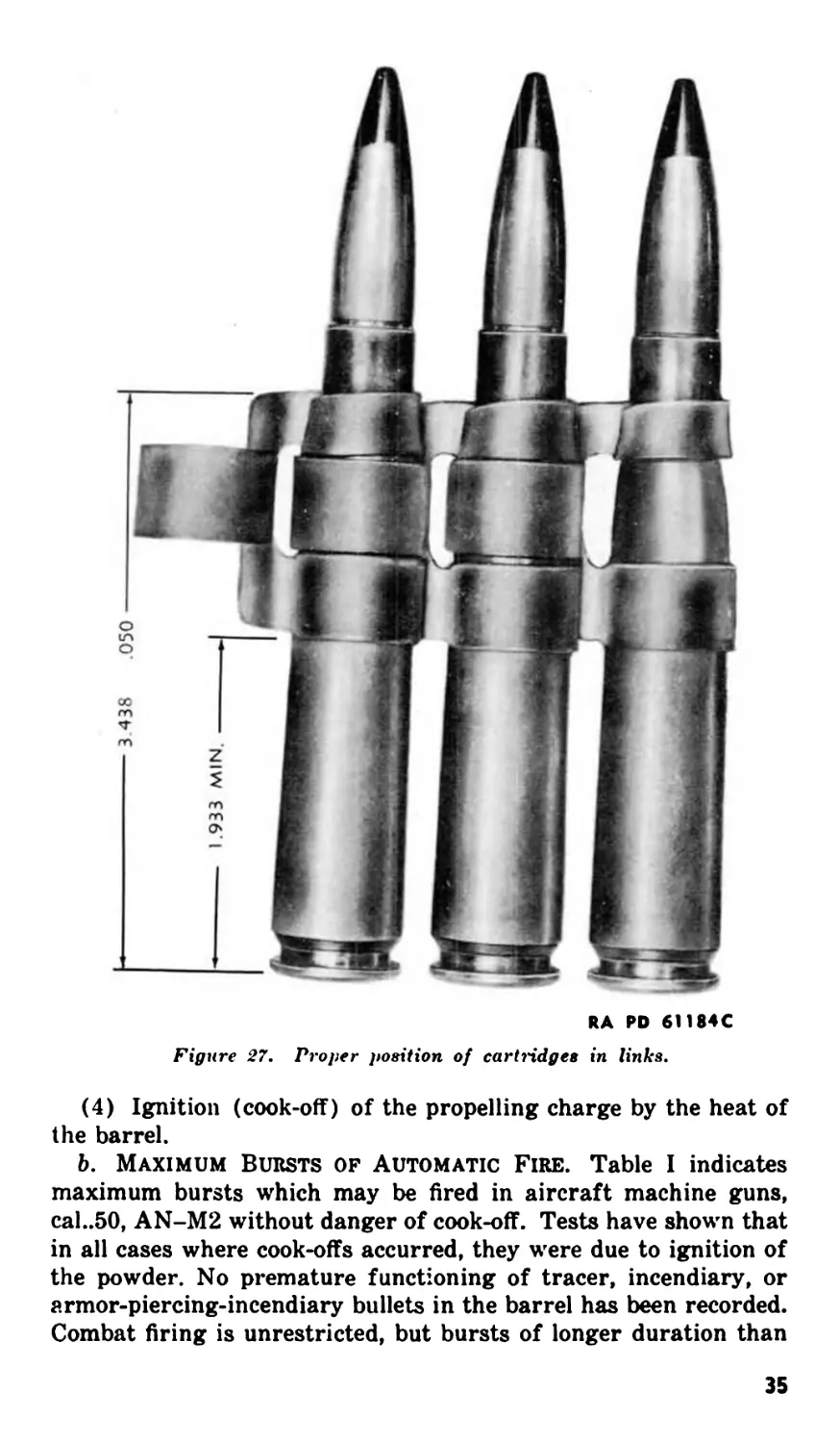
a. Check to see that ammunition is properly loaded in the belt,
and that the belt and ammunition box are in proper alignment and
secure. Figure 27 shows proper position of cartridges in the links
of the belt.
b. Close the cover before the first round is loaded into the feed-
way. The cover should remain closed as long as ammunition is
being fed. If the first round is fed with the cover open, the belt
feed lever may be bent as the cover is closed, due to the fact that
slight shifting of the belt in the feedway may cause misalignment
of the lug on the end of the belt feed lever and its cam groove in
the bolt.
c. Enter the double-loop end of the belt through the feed open-
ing until the first cartridge is beyond the belt holding pawl.
d. Fully retract the bolt and allow it to go forward freely. This
places the first cartridge in the belt in position in the feedway
where it is gripped by the extractor.
e. Pull the bolt once again completely to the rear and release it.
This action places a cartridge in the chamber, and the extractor
grips the next cartridge in the belt.
/. The gun is now fully loaded, cocked, and ready to fire when
the sear is depressed.
29. Firing
a. Guns Equipped With Back Plate Having a Manual
Trigger (fig. 4), and Guns Equipped With Adapters Having
Trigger Supplied as Part of Adapter. Guns of this type are
fired after moving the safety to the "fire” position by pressing the
trigger forward.
b. Guns Equipped With Firing Devices Having No Manual
Trigger (figs. 1, 2, and 3). Such guns are fired by means of firing
devices furnished by the Air Forces and covered by Air Force
manuals.
30. Permissible Bursts of Automatic Fire
a. General. Aircraft machine guns are air-cooled. Because of
the absence of a mechanical cooling medium, the temperature of
the barrel rises rapidly during firing. The longer the burst, the
higher the temperature attained. The progressive heating of the
barrel gives rise to several effects some of which are as follows:
(1) Accelerated wear of the bore.
(2) Expansion of the barrel leading to loss in bullet velocity
and finally to tumbling of the projectile.
(3) Stoppage of gun caused by the expanded barrel seizing in
the trunnion block or front barrel bearing.
34
RA RD 61184C
Figure 27. Proper position of cartridges in links.
(4) Ignition (cook-off) of the propelling charge by the heat of
the barrel.
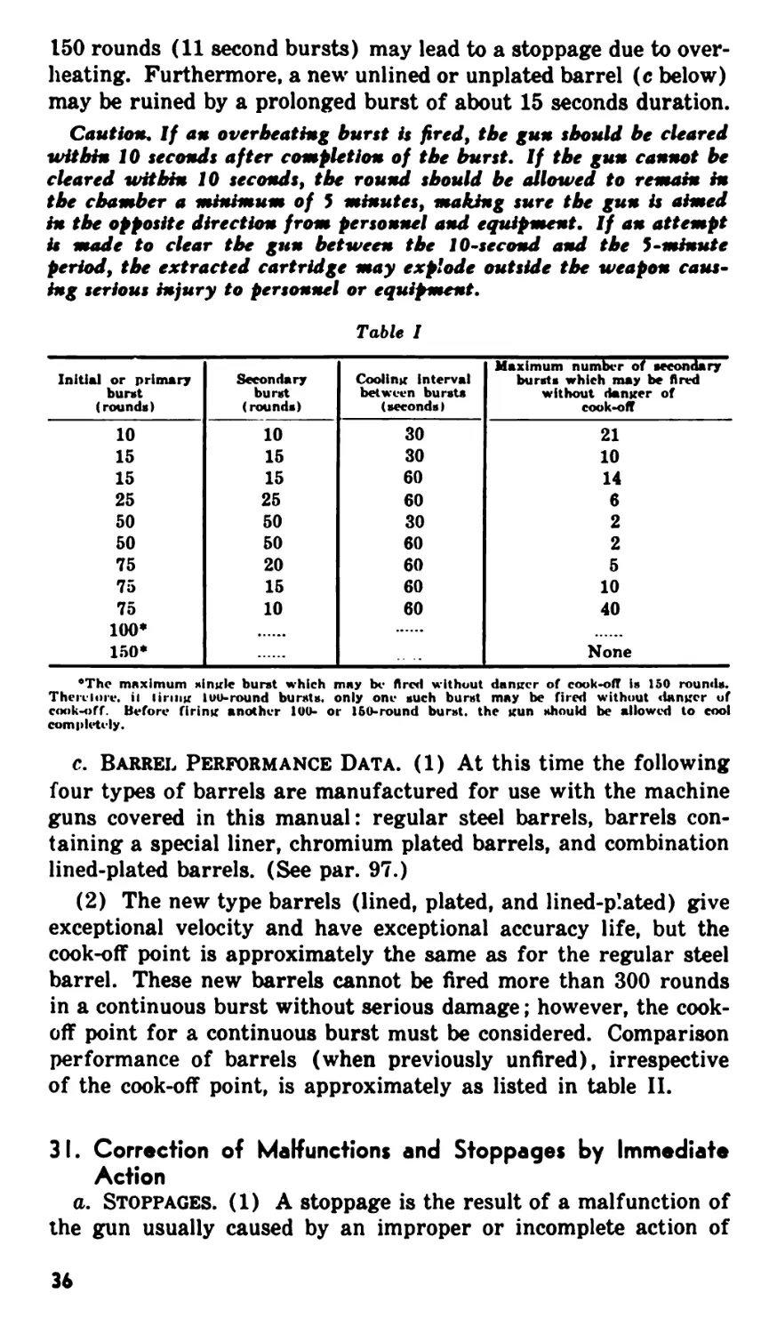
b. Maximum Bursts of Automatic Fire. Table I indicates
maximum bursts which may be tired in aircraft machine guns,
cal..50, AN-M2 without danger of cook-off. Tests have shown that
in all cases where cook-offs accurred, they were due to ignition of
the powder. No premature functioning of tracer, incendiary, or
armor-piercing-incendiary bullets in the barrel has been recorded.
Combat firing is unrestricted, but bursts of longer duration than
35
150 rounds (11 second bursts) may lead to a stoppage due to over-
heating. Furthermore, a new unlined or unplated barrel (c below)
may be ruined by a prolonged burst of about 15 seconds duration.
Caution. If an overheating bunt is fired, the gun should be cleared
within 10 seconds after completion of the burst. If the gun cannot be
cleared witbin 10 seconds, the round should be allowed to remain in
the chamber a minimum of 5 minutes, making sure the gun is aimed
in the opposite direction from personnel and equipment. If an attempt
is made to clear the gun between the 10-second and the 5 •minute
period, the extracted cartridge may explode outside the weapon caus-
ing serious injury to personnel or equipment.
Table I
Initial or primary burst (rounds) Secondary burst (rounds) Cooling interval between bursts (seconds) Maximum number of secondary bursts which may be fired without danger of cook-off
10 10 30 21
15 15 30 10
15 15 60 14
25 25 60 6
50 50 30 2
50 50 60 2
75 20 60 5
75 15 60 10
75 10 60 40
100*
150* None
•The maximum Mingle burst which may be fired without danger of cookoff is 150 rounds.
Then-lore. il linng luu-round bursts, only one such burst may be fired without <iangcr of
cook-off. Before firing another 100- or 150-round burst, the gun should be allowed to cool
completely.
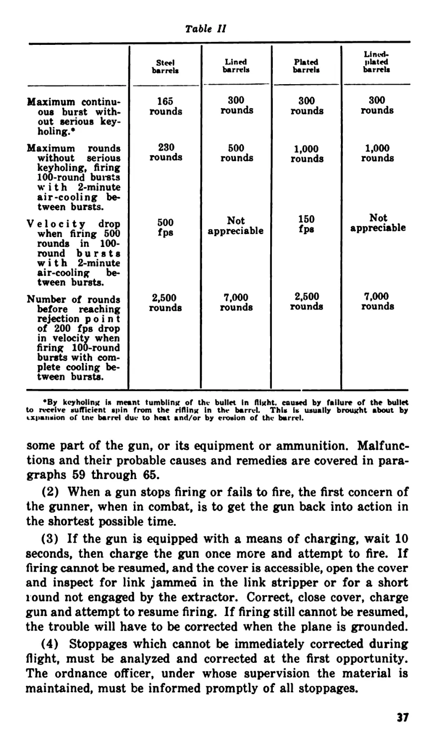
c. Barrel Performance Data. (1) At this time the following
four types of barrels are manufactured for use with the machine
guns covered in this manual: regular steel barrels, barrels con-
taining a special liner, chromium plated barrels, and combination
lined-plated barrels. (See par. 97.)
(2) The new type barrels (lined, plated, and lined-plated) give
exceptional velocity and have exceptional accuracy life, but the
cook-off point is approximately the same as for the regular steel
barrel. These new barrels cannot be fired more than 300 rounds
in a continuous burst without serious damage; however, the cook-
off point for a continuous burst must be considered. Comparison
performance of barrels (when previously unfired), irrespective
of the cook-off point, is approximately as listed in table II.
31. Correction of Malfunctions and Stoppages by Immediate
Action
a. Stoppages. (1) A stoppage is the result of a malfunction of
the gun usually caused by an improper or incomplete action of
36
Table II
Steel barrels Lined barrels Plated barrels Lined- plated barrels
Maximum continu- 165 300 300 300
oue burst with- out serious key- holing.* rounds rounds rounds rounds
Maximum rounds 230 500 1,000 1,000
without serious keyholing, firing 100-round bursts with 2-minute air-cooling be- tween bursts. rounds rounds rounds rounds
Velocity drop when firing 500 500 fps Not appreciable 150 fps Not appreciable
rounds in 100- round bursts with 2-minute air-cooling be- tween bursts.
Number of rounds 2,500 7,000 2,500 7,000
before reaching rejection point of 200 fps drop in velocity when firing 100-round rounds rounds rounds rounds
bursts with com- plete cooling be- tween bursts.
•By keyholing is meant tumbling of the bullet in flight, caused by failure of the bullet
to receive sufficient spin from the rifling in the barrel. This is usually brought about by
expansion of tne barrel due to heat and/or by erosion of the barrel.
some part of the gun, or its equipment or ammunition. Malfunc-
tions and their probable causes and remedies are covered in para-
graphs 59 through 65.
(2) When a gun stops firing or fails to fire, the first concern of
the gunner, when in combat, is to get the gun back into action in
the shortest possible time.
(3) If the gun is equipped with a means of charging, wait 10
seconds, then charge the gun once more and attempt to fire. If
firing cannot be resumed, and the cover is accessible, open the cover
and inspect for link jammed in the link stripper or for a short
round not engaged by the extractor. Correct, close cover, charge
gun and attempt to resume firing. If firing still cannot be resumed,
the trouble will have to be corrected when the plane is grounded.
(4) Stoppages which cannot be immediately corrected during
flight, must be analyzed and corrected at the first opportunity.
The ordnance officer, under whose supervision the material is
maintained, must be informed promptly of all stoppages.
37
b. Uncontrolled Firing. Uncontrolled firing of the gun, com-
monly known as a “runaway gun,” may be caused by malfunction
of worn or broken parts (pars. 60 f and g). If the cover is acces-
sible, and it is known that firing is not caused by cook-offs, the best
way to stop the gun from firing is to raise the cover and thus pre-
vent further feeding of ammunition. If the cover is not accessible
or if it is known that firing is caused by cook-offs, grasp and hold
the ammunition belt to prevent further feeding. When it is neces-
sary to use this method to stop firing, fully unload the gun after a
5-minute interval {Caution, par. 30b), carefully inspect the feed
lever, feed and holding pawls, and other parts of feed mechanism
for possible damage, and hand operate the gun as a check before
resuming firing. Keep a “runaway gun” pointed away from per-
sonnel and mat£riel.
32. Unloading Ammunition from Gun
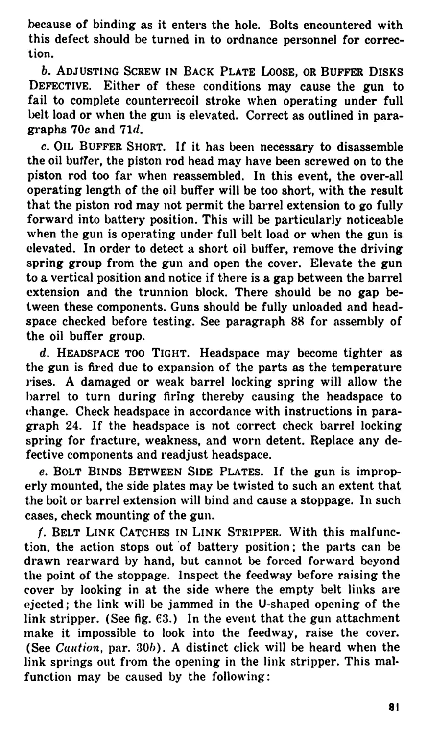
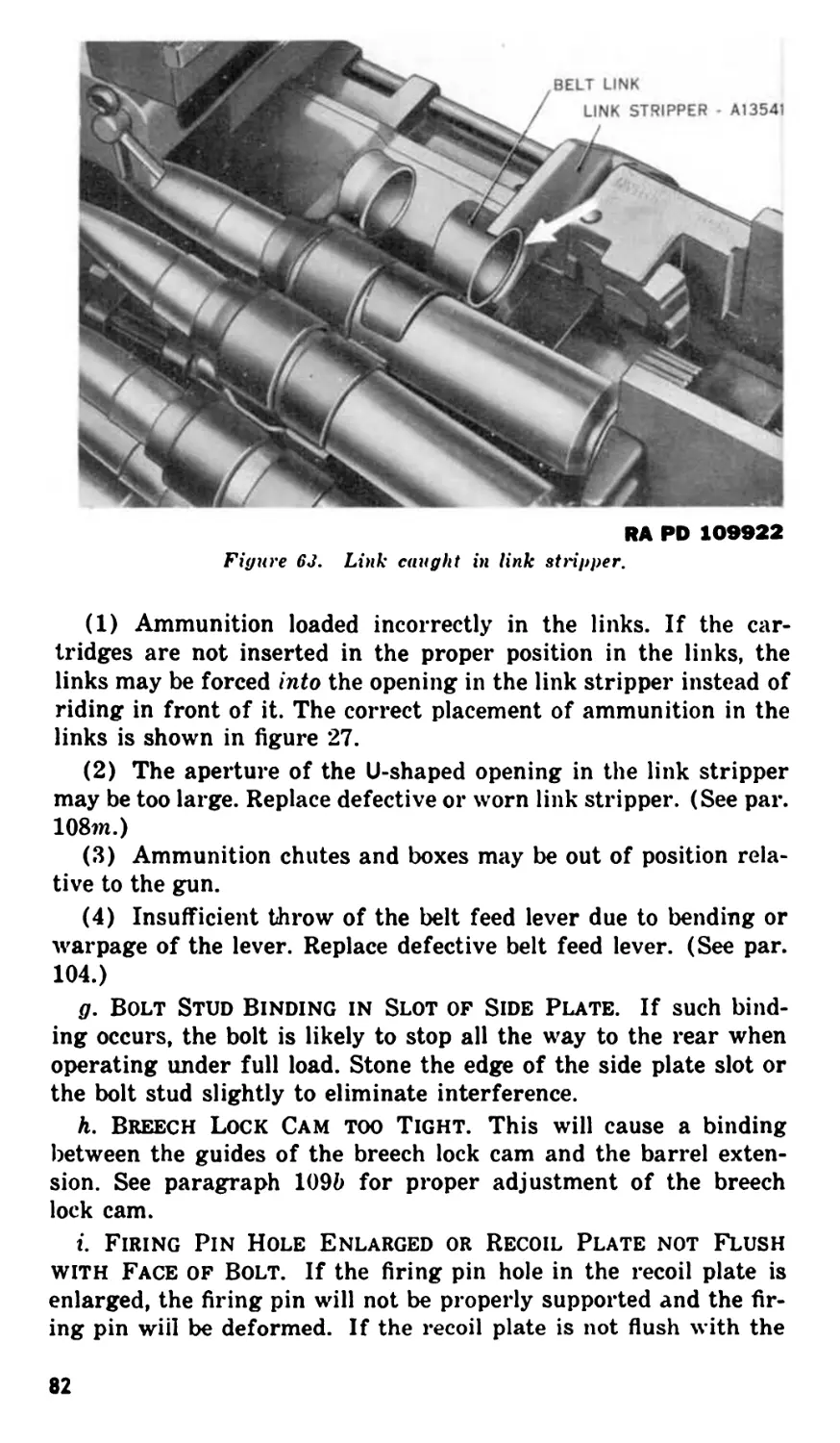
a. Lift the cover, raise extractor, and remove ammunition belt.
Caution. Before raising the cover, be sure the solenoid circuit or
other flying devices are placed in the safe position so that the gun
cannot be fired accidentally.
b. Lower extractor, retract the bolt sufficiently to remove the
round in the chamber, and make visual inspection of the feedway,
T-slot, and chamber to make sure that the gun is unloaded. Release
the bolt and lower the cover.
c. If certain that the gun is completely unloaded, release the
firing mechanism to allow the firing pin spring to drive the firing
pin forward and relieve compression of the firing pin spring.
Section VII. OPERATION UNDER UNUSUAL
CONDITIONS
33. General
Although the procedures for the mechanical operation of the gun
are the same for operation under either usual or unusual climatic
conditions, special care in cleaning and lubrication should be ob-
served where extremes of temperature, humidity, and atmospheric
conditions are present. Proper cleaning and lubrication not only
insure proper operation and functioning but also guard against ex-
cessive wear of the moving parts and deterioration of the materiel.
34. Operation in Cold Climates
a. In temperatures below freezing, it is necessary that the mov-
ing parts of the machine gun be kept absolutely free from moisture.
Excessive oil on the working parts will congeal to such an extent
38
as to cause sluggish operation and functioning, or complete failure.
This applies, in particular, to the firing mechanism and small
spring-operated parts. Special care should be taken to eliminate
all excess oil and powder fouling from the following parts and
assemblies:
Belt feed pawl and belt holding pawl springs and seats.
Bore and chamber of the barrel.
Driving spring group and its tunnel in the bolt.
Belt feed lever plunger, spring, and seat.
Firing pin group and its tunnel in the bolt.
(Extractor) switch, including pivot.
b. If guns are left mounted in the airplane, the exposed parts
should be carefully covered for protection and to prevent frosting.
c. When guns are removed from the airplane and taken into
heated buildings they should be allowed to come to the temperature
of the building before cleaning. Immediately after they reach room
temperature, they should be disassembled, and all moisture should
be thoroughly wiped from the parts and bore with a dry cloth to
prevent rusting. The guns should then be thoroughly cleaned by
one of the methods outlined in paragraphs 15 and 16 and then lub-
ricated as outlined in paragraphs 44 through 46.
35. Operation Under Conditions of High Altitude
When airplanes are operated in moderate climate at high altitudes
where extremely low temperatures are encountered, condensation
of moisture may occur on the guns when returned to ground tem-
perature. In such cases guns should be inspected, disassembled,
cleaned, and dried (pars. 15 and 16) and lubricated as prescribed
in paragraphs 44 through 46. When high-altitude flights are an-
ticipated, guns should be lubricated sparingly, irrespective of
ground temperatures.
36. Operation in Hot Climates
a. In hot climates, the thin film of oil necessary for aircraft
guns under combat conditions will be quickly dissipated. Guns
should be inspected frequently and a film of the oil prescribed in
paragraph 44 must be renewed as frequently as necessary to pre-
vent rusting. Guns should be cleaned frequently to remove dust
which will stick to oiled surfaces.
b. Guns should be kept covered as much as possible.
c. Perspiration from the hands is a contributing factor to rust-
ing because it contains acid. After handling, guns should be wiped
dry and oil film restored.
39
d. Where humidity is high, frequently inspect the gun paying
particular attention to unexposed surfaces such as the bore and
chamber, inside of barrel jacket, receiver, springs and spring
seats, firing pin, and driving springs tunnel in bolt, and like places
where rusting might occur and not be quickly noticed. Screws and
pins should be kept lightly oiled to prevent rust attacking them and
“freezing” them in place.
37. Operation Under Excessively Sandy or Dusty Conditions
a. In localities where dust and sand storms are prevalent, guns
should be kept carefully covered at all times, whether mounted in
the airplanes or not. Dust and sand will enter the mechanism and
bore and stick on lubricated surfaces, forming a gummy paste
which may clog the gun and cause malfunction. This paste will
also act as an abrasive and will cause undue wear of the mov-
ing parts of the gun.
b. Under such conditions, guns should be removed from the air-
plane as often as practical, and thoroughly cleaned by one of the
methods outlined in paragraphs 15 and 16. The lubricating oil
specified in paragraph 44 should be confined to moving parts and
contacting surfaces and should be as light as possible for proper
functioning of the gun.
c. After a dust or sand storm, guns should be disassembled,
thoroughly cleaned, inspected and lubricated as directed in b
above.
38. Operation in Excessively Moist or Salty Atmosphere
a. Salt air is conducive to quick rusting as the salt has a ten-
dency to destroy the rust-preventive qualities of the oil. When
mounted in the airplane, guns should be kept lightly lubricated
with the oil prescribed in paragraph 44 and inspected frequently
and treated in a manner similar to that prescribed for operation in
hot climates in paragraph 36.
b. If guns are dismounted, they should be thoroughly cleaned
and lubricated with the oil prescribed in paragraph 44 followed by
inspection intervals prescribed in paragraph 49 c, d and e. In-
spection should be thorough, with particular attention to unex-
posed parts as prescribed in paragraph 45.
c. Before mounting guns in the airplane, they should be
thoroughly cleaned by one of the methods outlined in paragraphs
15 and 16 and then lubricated as outlined in paragraphs 44
through 46.
40
Section VIII. DEMOLITION TO PREVENT ENEMY USE
39. General
a. The destruction of the materiel, when subject to capture or
abandonment in the combat zone, will be undertaken by the using
arm only on authority delegated by the division or higher com-
mander as a command function, when such action is deemed neces-
sary as a final resort to keep the materiel from reaching enemy
hands.
b. Adequate destruction of materiel means damaging it in such
a way that the enemy cannot restore it to usable condition in the
combat zone, either by repair or cannibalization. Adequate de-
struction requires that—
(1) Enough parts essential to the operation of the materiel must
be damaged.
(2) Parts must be damaged beyond repair in the combat zone.
(3) The same parts must be destroyed on all materiel, so that
the enemy cannot make up one operating unit by assembling parts
from several partly destroyed units.
40. Procedures for Demolition
a. Demolition of the plane normally will destroy any guns left
in the plane.
b. Any guns removed from the plane will be destroyed as fol-
lows : Remove groups as outlined in Part Three. Use Barrel as a
sledge. Raise cover; lay bolt in feedway; lower cover on bolt and
smash cover down over bolt. Deform back plate. Lay barrel ex-
tension on its side, hold down with one foot, and break off the
shank. Deform casing by striking side plates just back of feedway.
41
PART THREE
MAINTENANCE INSTRUCTIONS
Section IX. GENERAL
41. Scope
Part Three contains information for the guidance of the personnel
of the using organizations responsible for the maintenance (first
and second echelon) of this equipment. It contains information
needed for the performance of the scheduled lubrication and pre-
ventive maintenance services, as well as description of the major
groups and assemblies and their function.
Section X. ORGANIZATIONAL SPARE PARTS. TOOLS.
AND EQUIPMENT
42. Spart Parts, Tools, and Equipment
a. Spare Parts. A set of organizational spare parts is supplied
to the using arm for field replacement of those parts most likely to
become worn, broken or otherwise unserviceable.
b. Tools and Equipment. Tools and equipment include items
of issue required by personnel for the disassembly, assembly and
cleaning and preserving of the gun. Equipment should not be used
for purposes other than prescribed and, when not in use, should
be properly stored in the chest and/or roll provided for them.
c. List of Spare Parts, Tools and Equipment. Spare parts,
tools and equipment mentioned above, supplied for caliber .50
machine gun М2, are listed in WD CAT ORD 7 SNL A-38, which
is the authority for requisitioning replacements.
43. Specially Designed Tools and Equipment
a. List of Tools. Certain tools and equipment listed in WD
CAT ORD 7 SNL A-38 are specially designed for maintenance and
repair operations on caliber .50 machine guns. These tools and
equipment are listed below for information only. This list is not to
be used for requisitioning replacements.
42
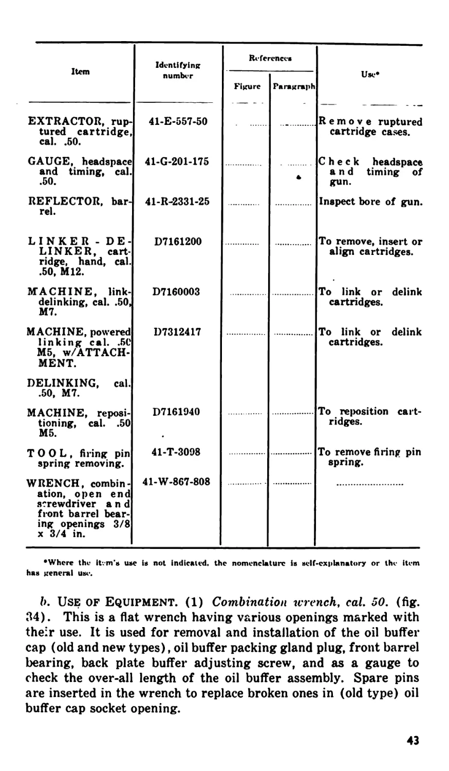
Item Identifying number References Use*
Figure Paragraph
EXTRACTOR, rup- 41-E-557-50 Remove ruptured
tured cartridge, cal. .50. cartridge cases.
GAUGE, headspace and timing, cal. .50. 41-G-201-175 a Check headspace and timing of gun.
REFLECTOR, bar- rel. 41-R-2331-25 Inspect bore of gun.
LINKER - DE- LINKER, cart- ridge, hand, cal. .50, M12. D7161200 To remove, insert or align cartridges.
MACHINE, link- delinking, cal. .50, M7. D7160003 To link or delink cartridges.
MACHINE, powered linking cal. .50 M5, w/ATTACH- MENT. D7312417 To link or delink cartridges.
DELINKING, cal. .50, M7.
MACHINE, reposi- tioning, cal. .50 M5. D7161940 To reposition cart- ridges.
TOOL, firing pin spring removing. 41-T-3098 To remove firing pin spring.
WRENCH, combin- ation, open end screwdriver and front barrel bear- ing openings 3/8 x 3/4 in. 41-W-867-808
•Where the itvm’a иле is not indicated, the nomenclature is self-explanatory or the item
has general use.
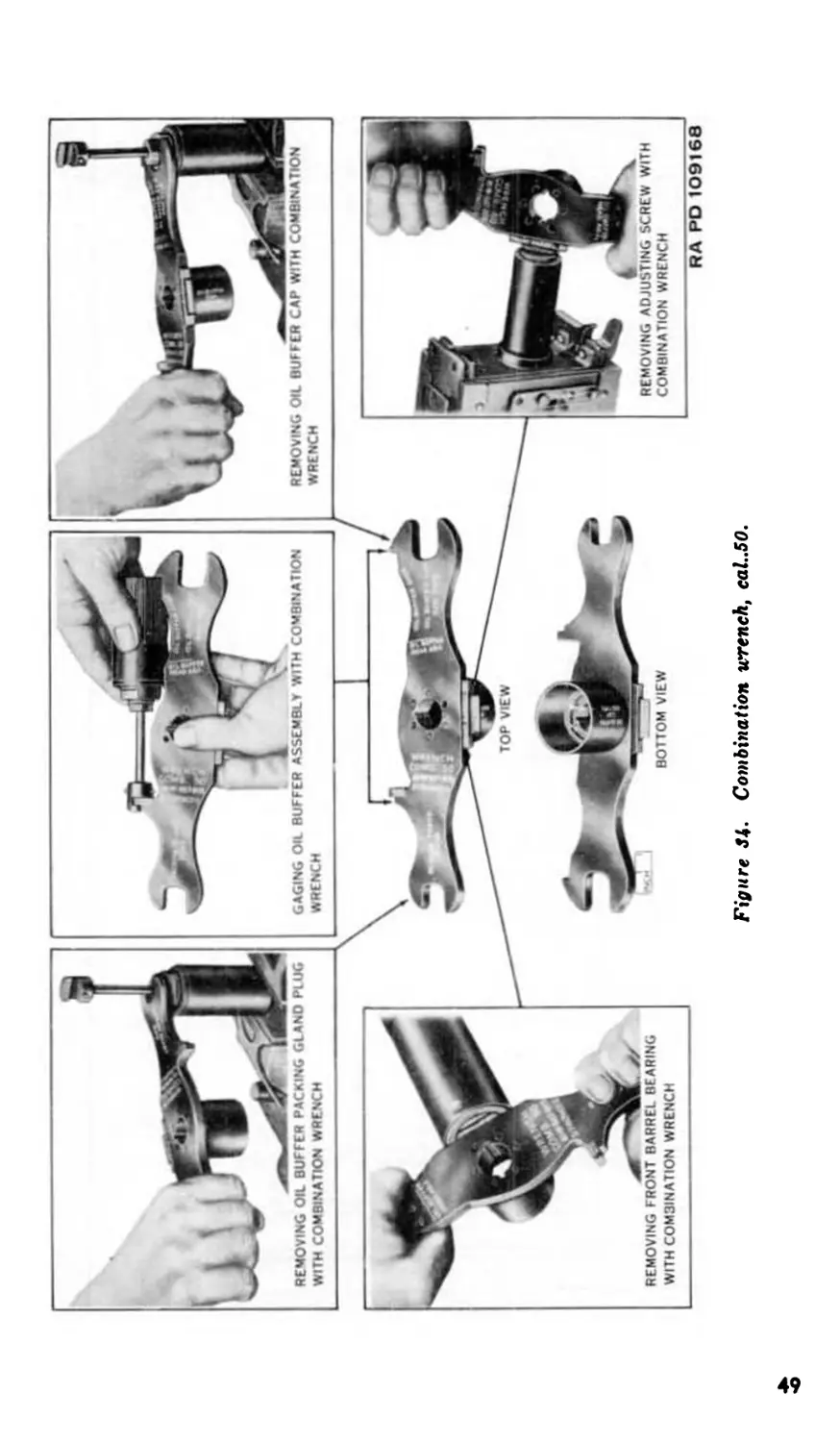
b. Use of Equipment. (1) Combination wrench, cal. 50. (fig.
34). This is a fiat wrench having various openings marked with
their use. It is used for removal and installation of the oil buffer
cap (old and new types), oil buffer packing gland plug, front barrel
bearing, back plate buffer adjusting screw, and as a gauge to
check the over-all length of the oil buffer assembly. Spare pins
are inserted in the wrench to replace broken ones in (old type) oil
buffer cap socket opening.
43
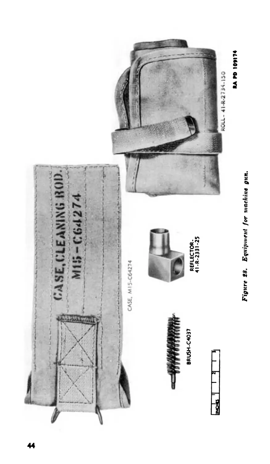
r=‘ <;ASE,(.LEANIN« HOI)
I ; X L ><' | MIS-C64274
Figure tS. Equipment for machine gun.
RA FO 109174
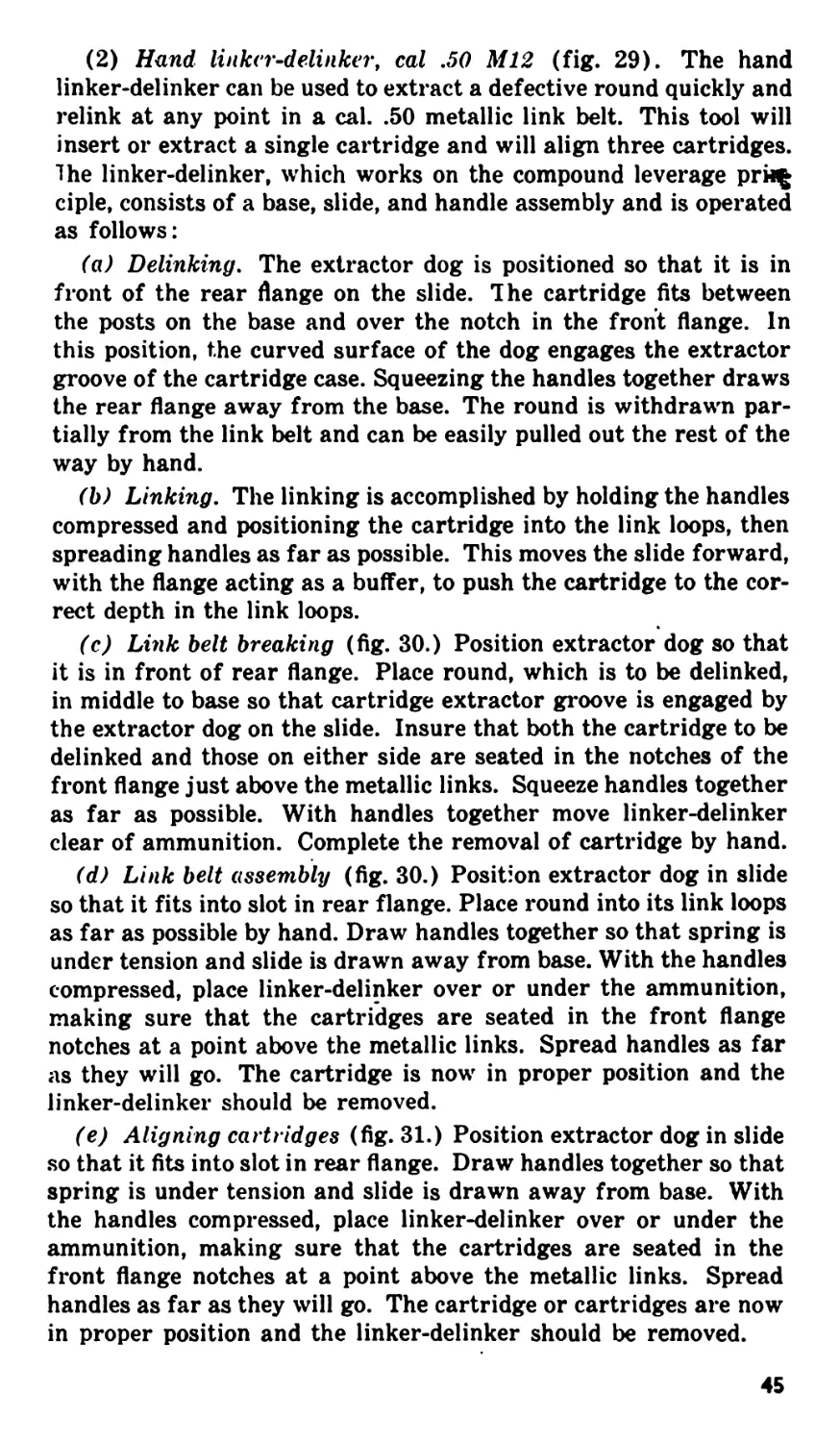
(2) Hund linker-delinker, cal .50 M12 (fig. 29). The hand
linker-delinker can be used to extract a defective round quickly and
relink at any point in a cal. .50 metallic link belt. This tool will
insert or extract a single cartridge and will align three cartridges,
lhe linker-delinker, which works on the compound leverage prh£
ciple, consists of a base, slide, and handle assembly and is operated
as follows:
(a) Delinking. The extractor dog is positioned so that it is in
front of the rear flange on the slide. Ihe cartridge fits between
the posts on the base and over the notch in the front flange. In
this position, the curved surface of the dog engages the extractor
groove of the cartridge case. Squeezing the handles together draws
the rear flange away from the base. The round is withdrawn par-
tially from the link belt and can be easily pulled out the rest of the
way by hand.
(b) Linking. The linking is accomplished by holding the handles
compressed and positioning the cartridge into the link loops, then
spreading handles as far as possible. This moves the slide forward,
with the flange acting as a buffer, to push the cartridge to the cor-
rect depth in the link loops.
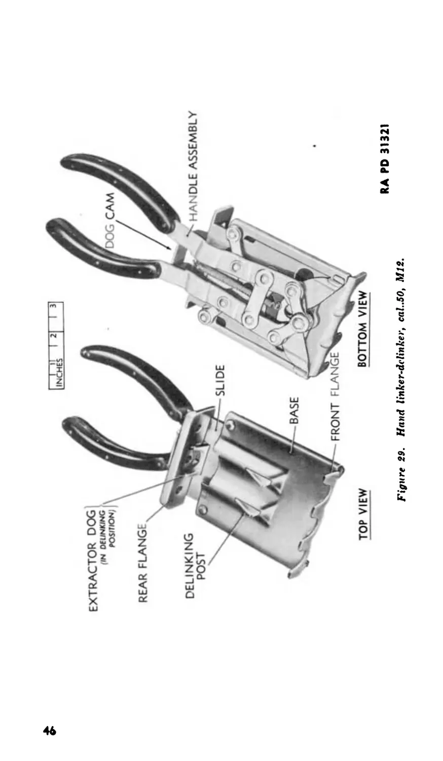
(c) Link belt breaking (fig. 30.) Position extractor dog so that
it is in front of rear flange. Place round, which is to be delinked,
in middle to base so that cartridge extractor groove is engaged by
the extractor dog on the slide. Insure that both the cartridge to be
delinked and those on either side are seated in the notches of the
front flange just above the metallic links. Squeeze handles together
as far as possible. With handles together move linker-delinker
clear of ammunition. Complete the removal of cartridge by hand.
(d) Link belt assembly (fig. 30.) Position extractor dog in slide
so that it fits into slot in rear flange. Place round into its link loops
as far as possible by hand. Draw handles together so that spring is
under tension and slide is drawn away from base. With the handles
compressed, place linker-delinker over or under the ammunition,
making sure that the cartridges are seated in the front flange
notches at a point above the metallic links. Spread handles as far
as they will go. The cartridge is now in proper position and the
linker-delinker should be removed.
(e) Aligning cartridges (fig. 31.) Position extractor dog in slide
so that it fits into slot in rear flange. Draw handles together so that
spring is under tension and slide is drawn away from base. With
the handles compressed, place linker-delinker over or under the
ammunition, making sure that the cartridges are seated in the
front flange notches at a point above the metallic links. Spread
handles as far as they will go. The cartridge or cartridges are now
in proper position and the linker-delinker should be removed.
45
£
-ГТ—Г21—гт
INCHES | |
Figure 29. Hand linker-delinker, cal..50, M12.
RA PD 31321
(f) Lubrication. Weekly, work a few drops of special preserva-
tive lubricating oil into the linkage.
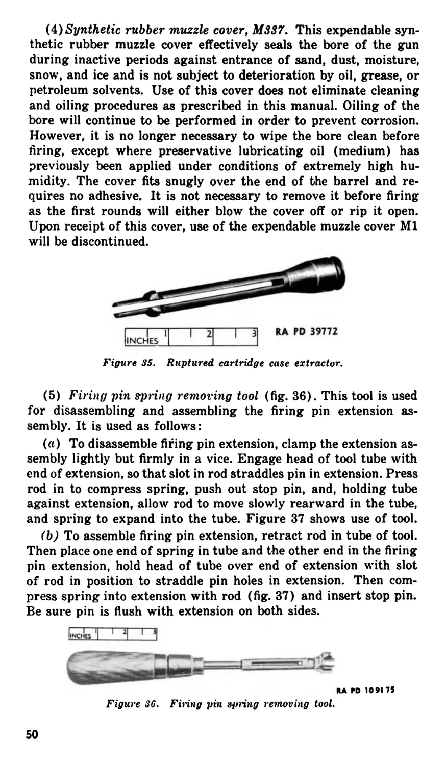
(3) Ruptured cartridge case extractor, cal. .50 (fig. 35). This
ruptured cartridge case extractor is for the purpose of extracting
a ruptured cartridge case from the chamber of the barrel by utiliz-
ing the leverage of the charging device. The extractor consists of
Figure 30. Linking and delinking cartridges.
RA PD 31320
768321 0 - 47 -4
Figure 31. Aligning cartridges.
47
a single piece of steel, the rear end turned to fit the T-slot of the
bolt, the front end machined and split to provide spring-type ex-
tracting shoulders. It is used by inserting in the T-slot of the bolt
in the same manner as a cartridge. When the bolt is driven for-
ward by the driving springs, the extracting shoulders of the ex-
tractor are forced through the ruptured case so that they engage
and withdraw the ruptured case when the bolt is withdrawn to
the rear. The lever action of the charging device provides the
necessary force for initial extraction.
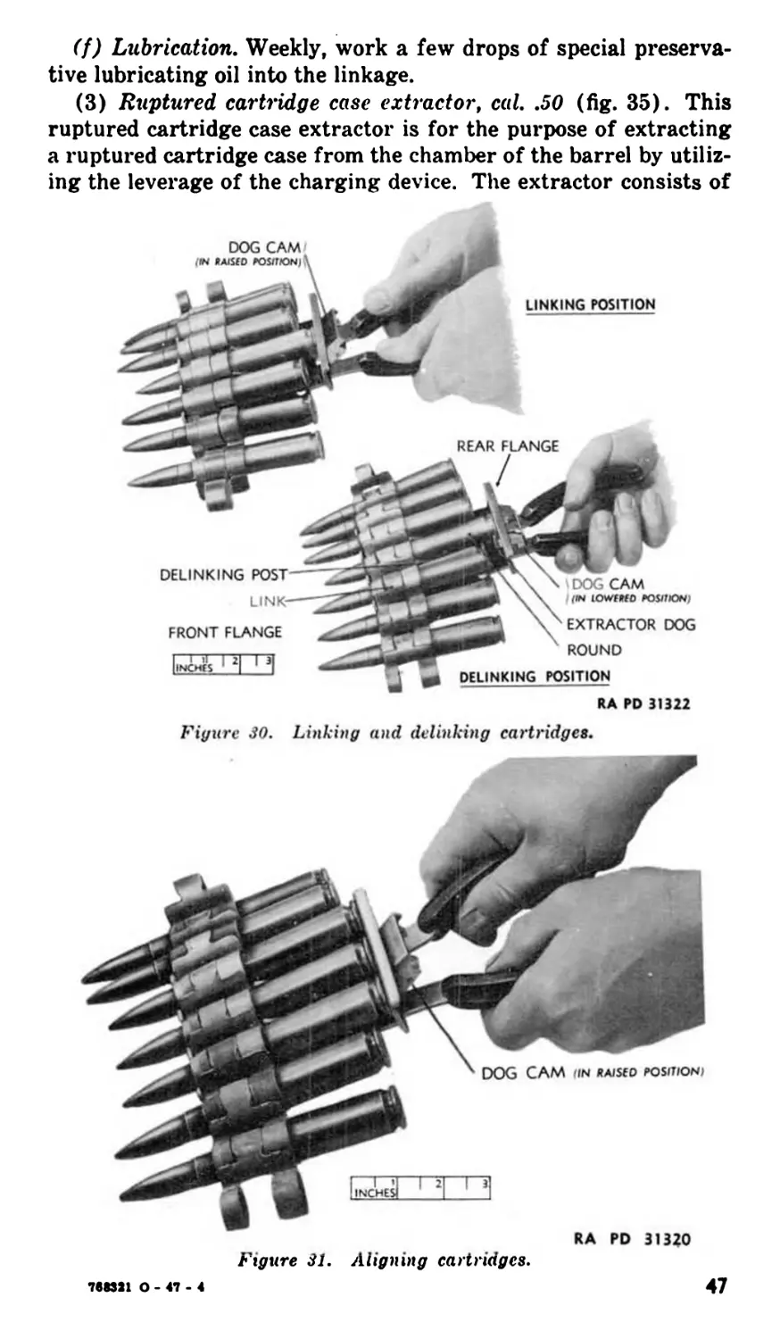
Figure 32. Headspace and timing gauge assembly.
BRUSH. M6-BI08828
ROD. M7-D35441
RA RD 92473
Figure 33. Chamber cleaning brush, M6 and jointed cleaning rod,
cal..5O, M7.
4ft
REMOVING FRONT BARREL BEARING
WITH COMBINATION WRENCH
BOTTOM VIEW
Figure 3 b. Combination wrench, cal..5O.
REMOVING OIL BUFFER PACKING GLAND PLUG
WITH COMBINATION WRENCH
GAGING OIL BUFFER ASSEMBLY WITH COMBINATION
WRENCH
REMOVING OIL BUFFER CAP WITH COMBINATION
WRENCH
RA PD 109168
(4) Synthetic rubber muzzle cover, M3S7. This expendable syn-
thetic rubber muzzle cover effectively seals the bore of the gun
during inactive periods against entrance of sand, dust, moisture,
snow, and ice and is not subject to deterioration by oil, grease, or
petroleum solvents. Use of this cover does not eliminate cleaning
and oiling procedures as prescribed in this manual. Oiling of the
bore will continue to be performed in order to prevent corrosion.
However, it is no longer necessary to wipe the bore clean before
tiring, except where preservative lubricating oil (medium) has
previously been applied under conditions of extremely high hu-
midity. The cover fits snugly over the end of the barrel and re-
quires no adhesive. It is not necessary to remove it before firing
as the first rounds will either blow the cover off or rip it open.
Upon receipt of this cover, use of the expendable muzzle cover Ml
will be discontinued.
Figure 35. Ruptured cartridge case extractor.
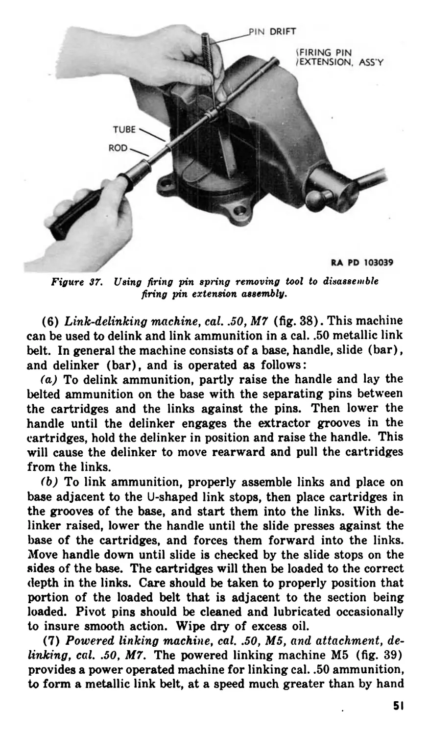
(5) Firing pin spring removing tool (fig. 36). This tool is used
for disassembling and assembling the firing pin extension as-
sembly. It is used as follows:
(a) To disassemble fifing pin extension, clamp the extension as-
sembly lightly but firmly in a vice. Engage head of tool tube with
end of extension, so that slot in rod straddles pin in extension. Press
rod in to compress spring, push out stop pin, and, holding tube
against extension, allow rod to move slowly rearward in the tube,
and spring to expand into the tube. Figure 37 shows use of tool.
(b) To assemble firing pin extension, retract rod in tube of tool.
Then place one end of spring in tube and the other end in the firing
pin extension, hold head of tube over end of extension with slot
of rod in position to straddle pin holes in extension. Then com-
press spring into extension with rod (fig. 37) and insert stop pin.
Be sure pin is flush with extension on both sides.
liNCHti ‘I ' 1 1
НА ГО 109175
Figure 36. Firing pin spring removing tool.
50
Figure 37. Using firing pin spring removing tool to disassemble
firing pin extension assembly.
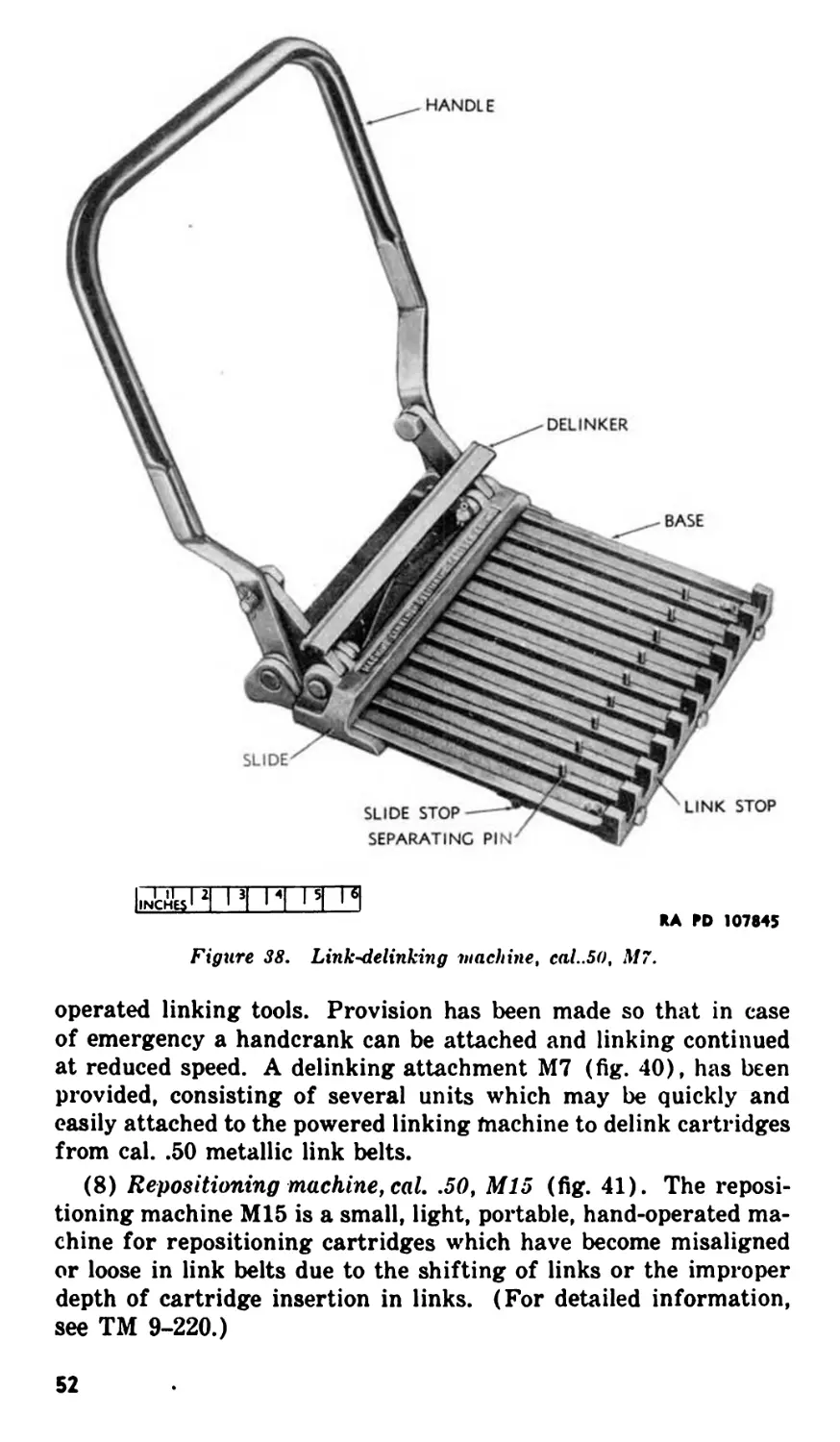
(6) Link-delinking machine, cal. .50, M7 (fig. 38). This machine
can be used to delink and link ammunition in a cal. .50 metallic link
belt. In general the machine consists of a base, handle, slide (bar),
and delinker (bar), and is operated as follows:
(a) To delink ammunition, partly raise the handle and lay the
belted ammunition on the base with the separating pins between
the cartridges and the links against the pins. Then lower the
handle until the delinker engages the extractor grooves in the
cartridges, hold the delinker in position and raise the handle. This
will cause the delinker to move rearward and pull the cartridges
from the links.
(b) To link ammunition, properly assemble links and place on
base adjacent to the U-shaped link stops, then place cartridges in
the grooves of the base, and start them into the links. With de-
linker raised, lower the handle until the slide presses against the
base of the cartridges, and forces them forward into the links.
Move handle down until slide is checked by the slide stops on the
sides of the base. The cartridges will then be loaded to the correct
depth in the links. Care should be taken to properly position that
portion of the loaded belt that is adjacent to the section being
loaded. Pivot pins should be cleaned and lubricated occasionally
to insure smooth action. Wipe dry of excess oil.
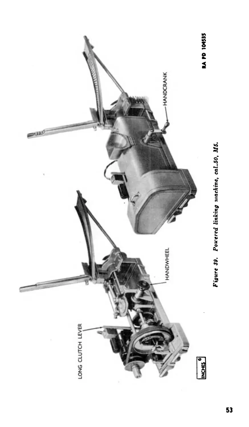
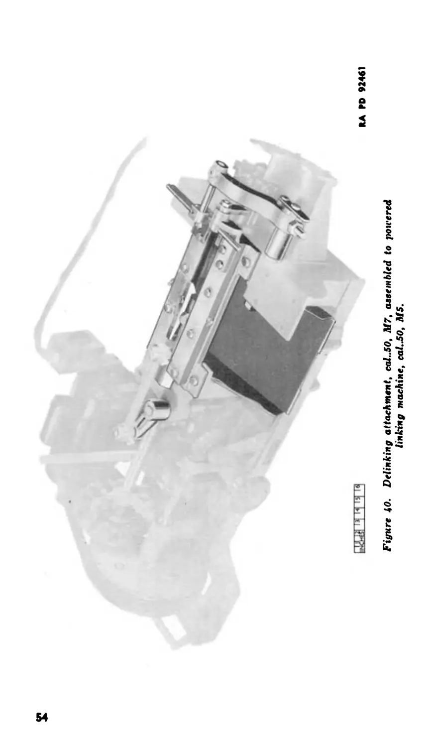
(7) Powered linking machine, cal. .50, M5, and attachment, de-
linking, cal. .50, M7. The powered linking machine M5 (fig. 39)
provides a power operated machine for linking cal. .50 ammunition,
to form a metallic link belt, at a speed much greater than by hand
51
HANDLE
n'c^H и p| ITT
RA M> 107845
Figure 38. Link ^delinking 'Machine, cal..50, M7.
operated linking tools. Provision has been made so that in case
of emergency a handcrank can be attached and linking continued
at reduced speed. A delinking attachment M7 (fig. 40), has been
provided, consisting of several units which may be quickly and
easily attached to the powered linking tnachine to delink cartridges
from cal. .50 metallic link belts.
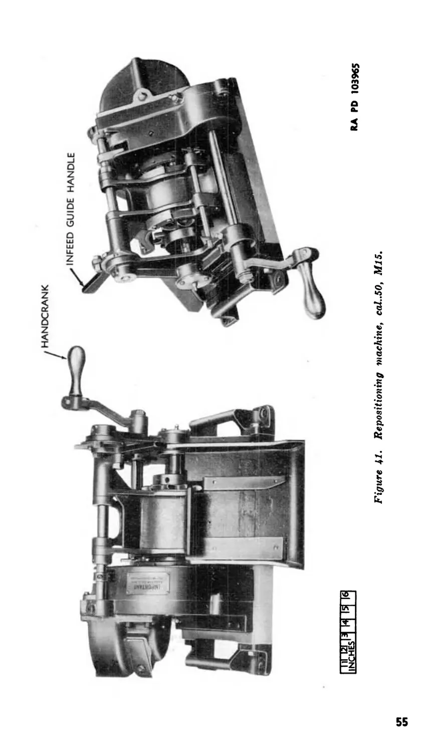
(8) Repositioning machine, cal. .50, M15 (fig. 41). The reposi-
tioning machine M15 is a small, light, portable, hand-operated ma-
chine for repositioning cartridges which have become misaligned
or loose in link belts due to the shifting of links or the improper
depth of cartridge insertion in links. (For detailed information,
see TM 9-220.)
52
у
I
Figure 39. Powered linking machine, cal..5O, MS.
£
Figure 40. Delinking attachment, cal..5O, M7, assembled to powered
linking machine, cal. .50, M5.
ШИШ
RA PD 924<1
RA RD 103965
Figure 41. Repositioning -machine, cal..5O, Ml5.
Section XI. LUBRICATION
44. Lubrication Order
a. Reproduction of LO 9-225 (fig. 42) prescribes first and
second echelon lubrication maintenance. In addition it prescribes
the lubricating oil to be used under various conditions of tempera-
ture, humidity, and atmosphere.
b. In the event that the lubricants prescribed in LO 9-225 are not
available lubricating oil (light) may be used as emergency substi-
tute.
45. Points to bo Lubricated
All bearing surfaces of moving parts should be lightly lubricated.
In addition to the general lubrication of the gun as explained in
paragraph 46 special attention should be given to the following
points:
Belt feed lever grooves in the bolt. Breech lock cam guides and top.
Belt feed lever pivot stud. Bore and chamber. Cocking lever. Cover extractor cam.
Breech lock. Cover extractor spring.
Extractor pivot. Sear, sear slide, and the grooves in which they operate.
Guideways in the barrel extension for the bolt guides. Oil buffer. Slideway in cover for the belt feed slide. Switch pivot.
46. General Lubrication Instructions
Note. In this manual the term “lubrication” is used to cover two func-
tions. It applies equally to the lubricating of moving, contacting surfaces
to minimize friction and to the covering of stationary parts with an oil
film to prevent rusting.
a. Service Intervals. Lubricants reduce friction between slid-
ing or rolling surfaces and protect metal parts against corrosion
and rust. Intervals specified on LO 9-225 (fig. 42) are based on
the preservative qualities of the lubricant under normal operating
conditions and continuous use of the materiel. Reduce these inter-
vals under extreme ground conditions such as excessively high air
temperatures, sandy or dusty areas, or exposure to moisture. The
protective qualities of the lubricant will be lost more quickly under
56
these conditions, and more frequent servicing will be required
in order to prevent malfunctioning or damage to the materiel.
b. Cleaning Before Lubrication. Prior to lubrication, all guns
should be cleaned by one of the methods outlined in paragraphs
8 through 17.
c. Lubrication. Lubrication should be careful and sparing and
is best accomplished by the use of a clean, lintless cloth saturated
in the proper lubricant and then wrung out. Excessive lubrication
may often be noticed by the smoke caused by the burning oil when
firing the gun. Excess oil should be wiped oft for the following im-
portant reasons:
(1) Excess oil in the chamber of the barrel will raise the breech
pressure to a hazardous point when the gun is fired and may result
in a blown bolt, a ruined gun, and serious injury to the personnel.
Removal of excess oil, therefore, is particularly important in re-
spect to the bolt and rear end of the barrel of the gun.
(2) Excess oil attracts grit and foreign matter which may clog
the mechanism and cause a malfunction or stoppage. In any case,
it will be conducive to excessive wear of the moving parts.
d. Dry Bore and Chamber Before Firing or Mounting Guns.
Wipe the bore and chamber of the barrel completely dry of oil be-
fore firing or mounting guns for combat unless muzzle cover M337
(33-C—801) is used.
Section XII. PREVENTIVE MAINTENANCE SERVICE
47. Scope
Preventive maintenance service prescribed by Army Regulations
is a function of using organization echelons of maintenance. This
section contains important general preventive maintenance pro-
cedure, and specific maintenance procedure applying to the gun
as a whole. In addition it contains schedules of preventive main-
tenance service allocated to crew (first echelon) and to organiza-
tional (second echelon) maintenance. Special maintenance of
specific groups of the gun components is covered, when necessary,
in sections pertaining to the groups.
48. Common Procedures
The following common general preventive maintenance will be
observed in addition to that referred to in the maintenance
schedules in paragraph 50.
a. The importance of a thorough knowledge of how to lubricate
and clean the machine gun cannot be over emphasized. The kind
57
сл
со
WAR DEPARTMENT LUBRICATION ORDER LO 9-225
_________________________________________________1 APR 1946 (Supersedes 25 Jon 1945)
GUN, MACHINE, CAL. .50, BROWNING, AN M2, AIRCRAFT, BASIC
References: TM 9-225, ORD 7 SNL A-38
FEEDING AND FIRING MECH.-Daily and after firing, clean with SD or CR, dry, rooil with PS.
In humid and salt air areas, during inactive periods use PM above 0° F.
BORE-After firing, and on 3 consecutive days thereafter, clean with CR. After 4th. cleaning,
dry, oil with PM above 0° F. PS below 0е F. and wipe dry before firing. When gun is not
being fired, renew oil film every 5 days.
OIL BUFFER-Check weekly and before firing. Use PS at all temperatures.
PS—OIL, lubricating, preservative, special
PM—OIL, lubricating, preservative, medium
CR-CLEANER, rifle bore
SD-SOLVENT, dry cleaning
Requisition additional Lubrication Orders
in conformance with instructions and lists in FM
This WDLO supersedes all conflicting lubrication
instructions prior to 1 Apr 1946
[A. G. 300.8 (25 Jan 1945)]
BY ORDER OF THE SECRETARY OF WAR:
DWIGHT D. EISENHOWER Chief of Staff
OFFICIAL:
EDWARD F. WITSELL Major General
A The Adjutant General
RA PD 101615
Figure 42. B’cir Department Lubrication Order L0 9-225.
of attention given to this weapon largely determines whether the
gun will shoot accurately and function properly when needed.
b. Rust, dirt, grit, gummed oil, and water cause rapid deteriora-
tion of internal mechanisms and outer surfaces. Particular care
should be taken to keep all bearing snrfaces and exposed parts clean
and properly lubricated. Wiping cloths, rifle bore cleaner, dry
cleaning solvents, and lubricants are furnished for this purpose.
Rust is an enemy of iron and steel. All traces of rust should be re-
moved with crocus cloth, which is the coarsest abrasive to be used
by the using arm for this purpose. Care should be used not to
change the shape or dimension of the part.
c. Loose parts will be kept tightened and unserviceable parts
replaced.
d. Serious damage to weapons, in many cases requiring repair
and replacement of component parts, has resulted from the use
of water, steam, or air from a high-pressure hose for cleaning pur-
poses. For this reason, all personnel are cautioned to prevent
water, dirt, or grit from entering functioning parts and bearing
surfaces. The prescribed methods of cleaning are outlined in para-
graphs 8 through 17.
e. Each time the gun is disassembled for cleaning or repair all
parts should be carefully inspected for cracks, excessive wear, rust
and like defects which might cause or lead to malfunction of the
gun. Worn, damaged or improperly adjusted parts which cause
definite malfunctions are covered in paragraphs 59 through 65.
These paragraphs should be used as a guide during inspection. All
parts should be thoroughly cleaned and properly lubricated before
assembly.
f. Each time a gun is assembled, after headspace and timing has
been checked and adjusted, the gun should be given an operational
check. This check consists of operating the gun by hand to see
that it functions properly. When possible a belt of dummy car-
tridges should be fed through the gun to be sure feeding, extrac-
tion, chambering, and ejection are properly executed by the me-
chanism.
g. When materiel is not in use, the proper covers should be
secured in place.
h. Spare parts, tools, and equipment will be inspected for com-
pleteness, serviceability, and interchangeability. Missing items
will be replaced and damaged items will be turned in for repair.
Use only tools that are provided and see that they fit properly.
Tools that do not fit will cause damage to parts.
i. At least every 6 months a check-up will be made to see that all
modifications have been applied. A list of current Modification
Work Orders is published quarterly in FM 21-6. If a modification
59
has not been applied, the local ordnance officer will be promptly
notified. No alteration or modification which will affect the moving
parts will be made by the using personnel, except as authorized by
the Ordnance Department.
49. Specific Procedures
a. Before Firing. (1) Thoroughly clean and dry the bore
and chamber of all dirt or oil. (See par. 15.) The bolt should be
removed from the gun when cleaning the barrel in order to prevent
damage to the T-slot.
Note, If the bore and chamber are protected with a light film of pre-
servative lubricating oil (special) and rubber muzzle cover M337 is used, it
is not necessary to clean and dry the bore and chamber or to remove the
muzzle cover before firing.
(2) Using clean, dry wiping cloth, wipe any surplus oil from
the bolt, feedway, and cover assembly. Reassemble parts.
(3) Wipe outer surfaces of gun with clean, dry, wiping cloth.
(4) Examine oil buffer and refill if necessary as outlined in
paragraph 88d.
b. After Firing. (1) Clean the barrel as outlined in para-
graphs 15 or 16 immediately upon return from flight. Repeat this
cleaning for 3 consecutive days thereafter or until there is no
longer any evidence of sweating. The purpose of the repeated
cleaning operations is to remove the effects of “sweating,” a chemi-
cal reaction of the burned powder which cannot be removed by one
cleaning.
(2) After the fourth cleaning following firing, and if no firing
is anticipated within the next 24 hours, place clean dry patches in
the slot of the cleaning rod and thoroughly dry bore and chamber.
Using clean dry patches which have been dipped in the oil pre-
scribed in paragraph 44 and then wrung out, apply a light film of
oil to the bore and chamber by working the patches through the
bore.
(3) Using one of the cleaning methods outlined in paragraphs 8
through 17 thoroughly clean the front face of the bolt and the
front of the barrel extension as well as all the cover group com-
ponents which have been exposed to powder gases. Dirt and for-
eign matter must be removed from all other parts.
Caution. Use special care to remove all fouling from the firing
pin hole in the face of the bolt.
(4) During firing, hard carbon gradually accumulates in the
T-s!ot of the bolt. This carbon deposit must be carefully removed,
using a scraper or crocus cloth.
60
(5) Thoroughly dry all components and immediately apply a
light coating of the oil prescribed in paragraph 44.
c. Daily Service. Inspect the bore and chamber, clean com-
ponent parts of feeding and firing mechanism, wipe thoroughly
dry, and relubricate as prescribed in paragraphs 44 through 46.
d. Service for Periods up to 1 Week. (1) If the gun has not
been fired, renew oil film in the bore and chamber every 5 days as
prescribed in paragraphs 44 through 46.
(2) Examine oil buffer and refill if necessary as outlmed in
paragraph 88d.
e. Service for Periods up to 90 days. If it is anticipated
that guns will not be used for a period up to 90 days, and neither
lubrication every 5 days nor placing the materiel in limited storage
(par. 140) are desirable, the guns may be coated with preservative
lubricating oil (medium). This is applied by dipping the gun com-
ponents into a bath of the oil. Before returning guns to service,
remove preservative by following one of the cleaning procedures
outlined in paragraphs 8 through 17.
Note. When preservative lubricating oil (medium) is used for tem-
porary storage, frequent inspections will be made to determine that the oil
film is adequate to prevent rusting.
f. Care cf Spare Parts and Equipment. Complete sets of
spare parts, tools, and equipment should be maintained at all times.
They should be inspected frequently and a light film of the lubri-
cation oil prescribed for feeding and firing mechanism in para-
graph 44 should be maintained.
61
50. Maintenance Schedules
FIRST ECHELON
Point Preventive maintenance Detailed instructions
PREFLIGHT OR BEFORE FIRING
Adjusting screw (back plate buffer) 2heck for adjustment Paragraph 70c.
Gun as unit Check for proper lubrication and cleanliness Paragraphs 44 through 46.
Accessory equipment.... Connect properly, adjust, and tighten Paragraph 28.
Ammunition belt See that belt is loaded prop* erly and properly inserted in the feedway Paragraphs 27 and 28.
Ammunition belt and ammunition boxes Check for proper alignment .. Paragraph 28.
Feedway See that gun is partially or completely loaded as in* structed Paragraph 28.
DURING FIRING
Bursts of fire Check for controlled bursts
Paragraph 30.
POSTFLIGHT OR AFTER FIRING
All malfunctions and stoppages Report to armorer for cor- rection Paragraph 59/.
SECOND ECHELON
Point Preventive maintenance Detailed instructions
PREFLIGHT OR BEFORE FIRING
Adjusting screw (back plate buffer) Check for adjustment Paragraph 70c.
Chamber and bore Clean and dry Paragraph 15. Paragraph 134.
Ammunition Check for dryness, cleanli- ness, short rounds, cor* rosion of ammunition or links, and defective rounds
Gun as unit Clean and properly lubri- cate Paragraphs 8 through 17 and 44 through 46.
Accessory equipment .. Connect properly, adjust and tighten Paragraph 28.
Ammunition belt Check for condition and see that it is properly loaded and properly inserted in feedway Paragraphs 27 and 28.
Ammunition belt and ammunition boxes. Check for proper alignment Paragraph 28.
62
SECOND ECHELON (Continued)
Point Preventive maintenance Detailed inntructiona
Oil buffer Check for leakage. Adjust- ment for rate of fire Paragraph 88 a and i.
Breech lock cam Check for adjustment and cleanliness Paragraphs 1096 and 1106.
Headspace Check Paragraph 24.
Timing Check Paragraph 25.
Trigger bar Check clearance, if required..
Assembled gun Check by hand functioning .. Paragraph 48/.
Barrel jacket Check front barrel bearing Paragraph 108e.
screws
Switch spring Check tension Should not bind.
Ejector spring Check tension Should snap back to normal position.
POSTFLIGHT OR AFTER FIRING •
Gun as unit Unload completely Paragraph 32.
Stoppages or malfunc- tions Correct Paragraphs 59 through 65.
Bore, chamber and all working parts Inspect, clean, and oil. If gun is temporarily out of use, the bore and chamber must also be cleaned on each of the following 3 days Paragraph 496.
Front barrel bearing .. Check for carbon Paragraph 110a.
Headspace Adjust Paragraph 24.
Timing Adjust Paragraph 25.
Assembled gun Check operation and adjust- ment Paragraph 48/.
Section XIII. CYCLIC FUNCTIONING OF GUN
51. General
«. The basic aircraft Browning machine gun, cal. .50 AN-M2
may be fired by means of a manual trigger, or by a back plate
solenoid acting upon the sear through the medium of a trigger bar,
or by a side plate solenoid, trigger motor or other device acting
upon the sear through the medium of the sear slide. In any case,
the functional operation of the gun is the same. For clarity, the
illustrations in this section show the sear operated by a manual
trigger and a trigger bar.
b. Each time a cartridge is fired, the mechanical action within
the gun involves many parts moving simultaneously or in their
proper order. The action of these parts, and their relationship one
to the other can be explained more clearly if each cycle of operation
is divided into various phases. Familiarity with the construction
of the gun and the function of its component parts and groups, as
explained in sections pertaining to the groups, is necessary to a
758321 0-47-5 63
DRIVING SPRING GROUP
CHAMBER
RA PD 109909
Figure 43. Receiver section of gun—cutaway view.
thorough understanding of the cyclic functioning of the gun as a
whole. A clear understanding of the explanations may be gained,
by hand operation of a gun, using dummy ammunition. Figure 43
below shows a cutaway view of the unloaded gun with the recoiling
parts in the forward or “battery” position.
c. For convenience and clarity cycles of operation are divided
into the following phases and explained in the order indicated.
(1) Firing the first round. (See par. 52.)
(2) Recoiling. (See par. 53.)
(3) Counterrecoiling. (See par. 54.)
(4) Cocking. (See par. 55.)
(5) Automatic firing of subsequent rounds. (See par. 56.)
(6) Feeding. (See par. 57.)
(7) Extracting and ejecting. (See par. 58.)
52. Firing First Round
a. In order to fire the first round the gun must be loaded and the
firing mechanism manually cocked. Figure 44 shows the firing
mechanism cocked and ready to fire. When the firing mechanism is
cocked, the firing pin spring is compressed and the firing pin ex-
tension engages with the sear. When the trigger is operated, it
contacts the rear end of the trigger bar and forces it upward. As
the trigger bar is actuated, it rotates about its pin and forces the
front end down to depress the sear, thereby disengaging the sear
from the firing pin extension. This allows the compressed firing
spring to force the firing pin and firing pin extension forward to
fire the round of ammunition in the chamber.
b. If the gun is fired by means of a back plate solenoid and
trigger bar, the firing pin extension and firing pin is released by
actuating the solenoid. When the plunger of the solenoid moves
forward it cams up the rear end of the trigger bar. The action of
the trigger bar in releasing the sear and firing pin extension is
then the same as in a above.
64
c. If the gun is fired by means of a side plate solenoid, trigger
motor, or other device, the plunger of the solenoid, trigger motor
or other device, when actuated, is forced against the sear slide.
The sear slide, moving laterally, cams down the sear, and the firing
pin is released to fire the cartridge as explained above.
d. For firing of subsequent rounds, see paragraph 56.
53. Recoiling
a. The complete cycle of the recoiling parts of the gun, which
takes place as each cartridge is fired, consists of the recoil move-
ment when certain parts move rearward, and the counterrecoil
movement when the same parts move forward. At the instant of
firing of the first shot, the barrel, barrel extension, and the bolt,
known as the recoiling parts, are in the fully forward or "bat-
tery” position in the gun.
b. When the cartridge is fired, the burning powder immediately
generates a chamber pressure of approximately 60,000 pounds per
square inch. This pressure acts upon the base of the bullet, forcing
the bullet out of the cartridge case and out of the barrel. At the
same time this pressure acts upon the head of the cartridge case
which is seated against the front face of the bolt, forcing the bolt to
the rear. Since the bolt is locked to the barrel extension and barrel
by the breech lock (A, fig. 45), these parts move to the rear as
one unit for about % inch, at which time the breech lock depressors
disengage the breech lock from the bolt (B, fig. 45). By this time,
the bullet is out of the barrel and the chamber pressure is relieved.
c. As the recoiling parts move toward the rear, the barrel ex-
tension bears against the accelerator, rotating it rearward about
the accelerator pin, until the rearward movement of the barrel
extension is stopped by the oil buffer. The tips of the accelerator
strike the lower projection pn the bolt, transferring kinetic energy
from the barrel extension to the bolt, and thus accelerating the bolt
to the rear.
65
BOLT -] r BREECH LOCK
BARREL EXTENSION
RA PD 109911
Figure 45. Bolt locked to barrel extension in A and unlocking in B.
d. The barrel and barrel extension have a total rearward travel
of V/ц inches at which point they are completely stopped by the
oil buffer.
e. During this recoil of 1 Vk inches, the oil buffer spring is com-
pressed by the rearward momentum of the barrel extension, which
is transmitted through the barrel extension shank to the oil buffer
piston rod, with which it is engaged. The spring is held in the
compressed position by the barrel extension shank which has been
locked by the claws of the accelerator which were rotated rearward
by the recoiling barrel extension (fig. 46). The oil buffer spring
assists the oil buffer piston in bringing the barrel and barrel ex-
tension to rest during the recoil movement.
RA PO 109912
Figure 46. Oil buffer spring locked in compressed position by barrel
extension shank and accelerator claw.
66
f. During recoil, the oil buffer piston rod head is forced from the
forward end of oil buffer tube to the rear. (See fig. 47.) The oil at
the rear of the tube, under pressure of the piston, escapes to the
front side of the piston through the oil buffer piston valve. This
valve regulates the flow of oil so that the barrel and barrel exten-
sion are decelerated gradually. This cushions the shock of the
barrel and barrel extension as they are stonoed
OIL BUFFER TUBE - OIL
OIL BUFFER SPRING
OIL BUFFER PISTON
ROD ASSEMBLY
OIL BUFFER PISTON VALVE ASSEMBLY '
BARREL EXTENSION SHANK
RA PD 109913
Figure 47. Action of oil buffer assembly during recoil.
g. The bolt travels rearward a total distance of 7Ц inches.
During this travel, the driving strings are compressed. The rear-
ward movement of the bolt is finally stopped as the bolt strikes
the buffer plate in the back plate. Thus, part of the recoil energy
of the bolt is stored in the driving springs, and part is absorbed
and stored by the buffer disks upon which the buffer plate bears,
in the back plate tube. Any remaining recoil energy is transmitted
to the gun mountings and their recoil mechanisms. At the end
of the recoil movement, the parts are in the position shown in
figure 48.
RA PD 109914
Figure 48. Recoil completed.
67
54. Counterrecoiling
a. After completion of the recoil movement, the bolt is forced
forward by the energy stored in the compressed driving springs
and the compressed back plate buffer disks. When the bolt has
moved forward about 5 inches, the projection on the bottom of
the bolt strikes the tips of the accelerator and rotates it for-
ward. (See fig. 49.) This rotation moves the claws of the ac-
celerator away from the shoulders of the barrel extension shank,
thereby releasing the compressed oil buffer spring. The energy
stored in the compressed oil buffer spring, supplemented by
the counterrecoil energy of the driving springs, forces the bolt
and the barrel and barrel extension forward into battery.
Figure 49. Bolt unlocking accelerator to release com pressed oil buffer spring.
b. No restriction to the forward motion of the barrel and barrel
extension is desired; therefore on the forward movement, addi-
tional openings for oil flow are provided in the piston rod head of
the oil buffer assembly. The piston valve is forced away from the
piston rod head as the parts move forward (fig. 50) uncovering
six ports which provide an additional path for flow of the oil to
the rear of the tube. The oil escapes freely at the opening in the
center of the piston valve as well as at the edge of the piston valve
next to the tube wall.
c. As the barrel extension moves forward, the breech lock en-
gages the sloping ramp of the breech lock cam and is forced up-
ward. The bolt, which has been continuing its forward motion
since striking the accelerator, has at this instant reached a position
where the notch in the under side of the bolt is directly above
the breech lock, permitting the breech lock to enter the notch
68
Figure 50. Action of oil buffer assembly during counterrecoiL
and engage the bolt. (See fig. 51.) Thus, the bolt is locked to the
barrel extension before the recoiling parts reach the firing posi-
tion.
55. Cocking
a. The act of cocking the gun begins as the bolt starts to recoil
immediately after firing. As the bolt moves rearward, the tip of
the cocking lever, which is in the V-slot in the top plate bracket.
DRIVING SPRINGS BOLT .BREECH LOCK
/ ACCELERATOR J BARREL 'BREECH
UTTER BODY EXTENSION LOCK CAM
RA PD 1099X7
Figure 51. Breech lock engaged with bolt.
is forced forward. Since the cocking lever pivots on the cocking
lever pin, the lower end, which engages in a slot in the firing pin
extension, is forced rearward, thereby pulling the firing pin exten-
69
sion and firing pin rearward and compressing the firing pin spring
against the accelerator stop. The shoulder on the rear end of
the firing pin extension forces the sear downward, compressing the
sear spring, and continues to travel rearward until immediately
beyond the front face of the notch in the sear. The sear is then
forced upward by the compressed sear spring to be in position to
engage the shoulder on the firing pin extension when it starts
moving forward again. Figure 52 shows cocking action of the
bolt and its components during recoil.
Figure 52. Cocking action during recoil.
SPRING SPRING EXTENSION
COMPRESSED) RA fo IOHIB
b. During the forward movement of the bolt, in counterrecoil,
the tip of the cocking lever again enters the V-slot in the top
plate bracket and is forced rearward. This action swings the
lower end of the cocking lever forward out of engagement with
the firing pin extension which moves forward so that its shoulder
is engaged and held by the sear. The cocking lever acts as a
safety device to prevent the firing pin extension and firing pin,
if released prematurely, from moving fully forward to fire
the cartridge before the bolt has gone forward sufficiently for
the breech lock to be engaged, and thus lock the bolt to the
barrel extension. When the recoiling parts are approximately
RA RO !<>••••
Figure 53. Action of the cocking lever during counterrecoil.
70
1/16 inch from the fully forward “battery” position, the gun
is ready to fire. If, at this instant, the sear is not depressed, the
recoiling parts will assume their fully forward “battery” posi-
tion and the gun ceases to fire. Figure 53 shows the action of
the cocking lever during counterrecoil.
56. Automatic Firing of Subsequent Rounds
a. The gun fires automatically, as long as the trigger action
is maintained, until the ammunition supply is exhausted. The
trigger cams up the rear end of the trigger bar and holds it in
that position which holds the front end of the trigger bar de-
pressed. The sear is depressed as its tip is carried against the
cammed surface of the depressed trigger bar by the forward
movement of the bolt near the end of the couterrecoil stroke. (See
fig. 54.) The sear releases the firing pin extension and the fir-
ing pin, thus automatically firing the next cartridge. This action
is timed so that the recoil starts just before the recoiling parts
reach the fully forward "battery” position. The barrel exten-
sion is thus prevented from striking the trunnion block.
b. When firing by means of a back plate solenoid, the gun fires
automatically as long, as the solenoid plunger remains in con-
tact with and cams up the rear end of the trigger bar and holds
it in that position. The action in maintaining automatic firing
from this point is the same as in a, above.
c. Firing by means of a side plate solenoid is accomplished in a
similar manner. As the bolt nears the. end of its counterrecoil
movement, the end of the sear slide is engaged by the cam surface
of the projecting solenoid plunger and is forced laterally. This lat-
SEAR ' FIRING PIN EXTENSION
(depressed) (after firing)
ra po io»»ao
Figure 54- Hear depressed by trigger bar during automatic firing.
71
era! movement of the sear slide cams the sear downward, thus re-
leasing the firing pin extension and firing pin to fire the gun as
outlined above.
57. Feeding
a. The belt feed mechanisnvfs actuated by the bolt. When the
bolt is in the forward position, the belt feed slide is entirely within
the gun. A lug on the rear end of the belt feed lever rides in one
of the two diagonal cam grooves in the top of the bolt. The for-
ward end of the belt feed lever engages in a slot in the belt feed
slide to which the belt feed pawl and belt feed pawl arm are at-
tached.
b. When the bolt is moved rearward, the belt feed lever is
pivoted about the belt feed lever pivot stud and the forward end of
the lever moves the slide out of the side of the gun over the am-
munition belt which is held in the gun by the belt holding pawl.
c. When the bolt moves forward, the belt feed lever is again
pivoted and moves the belt feed slide into the gun. The belt feed
pawl attached to the slide engages a link of the ammunition belt
and pulls the belt into the gun. By the time the bolt has reached
its forward position, the belt feed pawl has pulled a cartridge into
the feedway to a central point directly above the chamber. This
cartridge is then positioned against the cartridge stops and is
gripped by the extractor. The belt holding pawl has assumed a
raised position behind a link of the ammunition belt to prevent the
belt from falling out of the gun. Feeding during recoil and counter-
recoil is as follows:
(1) As the bolt recoils, the extractor withdraws the centered
cartridge from the belt, the belt feed slide is moved out over the
belt, and the belt feed pawl pivots so as to ride over the link holding
the next cartridge in the belt.
(2) At the end of the recoil movement, the travel of the belt
feed slide is sufficient to permit the belt feed pawl to snap down
behind the link holding the next cartridge in order to pull the belt
into the gun.
(3) As the bolt moves forward in counterrecoil, the belt is
pulled into the gun by the belt feed pawl. The belt holding pawl is
forced downward as the belt is pulled over it. As the cartridge is
positioned in the feedway, the belt holding pawl snaps up behind
the link holding the next cartridge, to keep the belt from falling
out of the gun.
(4) In the event that the cartridge in the feedway awaiting ex-
traction from the belt fails to be extracted as the belt feed slide
72
starts moving out to engage and pull the belt into the gun, the belt
feed pawl arm, attached to the pawl, rides over this unextracted
cartridge and lifts the pawl so that it cannot engage the belt. This
prevents double feeding and consequent stoppage of the gun due
to jamming.
d. The belt pull of a gun is an expression used to indicate the
maximum belt load that can be imposed on the gun without ob-
taining misfeeds. The belt load is the cumulative effect of the fol-
lowing factors:
(1) Weight of the ammunition belt hanging from the feedway.
(2) Effect of “G’s” on the weight of the ammunition belt hang-
ing from the feedway during maneuvering of the plane.
(3) Frictional force created by the ammunition belt moving
through the ammunition feed chutes.
(4) Resistance to motion of the ammunition belt because the
ammunition or links catch on sharp corners, because the chutes
are out of line with the gun feedway, or because the ammunition
boxes, or the ammunition, are not guided properly to the feedway
of the gun.
58. Extracting and Ejecting
a. As recoil starts, a live cartridge is drawn from the ammuni-
tion belt by the extractor and the empty case is withdrawn from
the chamber by the T-slot in the front face of the bolt. (See fig. 55.)
b. The matching camming surfaces on the top front face of the
breech lock and on the lateral groove in the bottom of the bolt per-
mit a gradual separation of the bolt and barrel extension at the
start of unlocking during the recoil movement. (See fig. 45.) The
RA PD 109921
Figure 55. Extracting cartridge cave at start of recoil.
73
separation of the bolt and barrel extension is relatively slow, and
the empty case is slowly started out of the chamber, prior to being
completely extracted by the bolt. This reduces the possibility of
rupturing the cartridge case.
c. As the bolt moves to the rear, the cover extractor cam forces
the extractor down, causing the cartridge to enter the T-slot in the
bolt.
d. As the extractor is forced down, a lug on the side of the ex-
tractor rides against the top of the (extractor) switch on the side
plate, causing the switch to pivot downward to the rear. Near
the end of the rearward movement of the bolt, the lug on the ex-
tractor rides over the end of the switch, and the switch snaps up to
its normal position.
e. On the counterrecoil movement, the extractor is forced far-
ther down by the extractor lug riding under the (extractor) switch.
This pushes and holds the live cartridge into its correct position in
the T-slot. At the same time, the live cartridge moving into place
expels the empty cartridge case which has been withdrawn from
the chamber. The extractor stop lug on the side of the bolt limits
the downward travel of the extractor so that the cartridge, guided
by the ejector, enters the chamber of the barrel. When the cartridge
is partly chambered, the extractor rides up the extractor cam on
the left side plate where it contacts and compresses the cover ex-
tractor spring which forces it down into the extractor groove of
the next cartridge in the belt. The partly chambered cartridge
has meanwhile been completely chambered by the bolt as it comes
into battery. When the final round of ammunition is extracted
from the chamber, the empty case is expelled from the T-slot by the
ejector.
Section XIV. MALFUNCTIONS AND CORRECTIONS
59. General
a. It is important that the gun and all its equipment be properly
installed and maintained. Proper care of the gun and attention to
the preventive maintenance schedules (par. 50) will greatly re-
duce the possibility of gun stoppages due to malfunctions. Mal-
functions or stoppages which can be corrected by immediate action
are covered in paragraph 31.
b. The first step in analyzing a malfunction is to observe care-
fully the position of the recoiling parts of the gun as an indication
of the probable cause of the stoppage.
74
c. Before raising the cover, inspect the feedway, whenever pos-
sible, by looking in at the side. In this manner it can be determined
if the stoppage is caused by misalignment due to improper loading
of cartridges in the belt, to short rounds, to link caught in link
stripper or to other causes.
d. When possible, hold the bolt in the position at which the
stoppage occurred, raise the cover (Caution, par. 306), and in-
spect the gun carefully. Unless the bolt is held in position when
the cover is raised, the recoiling parts may spring forward into
battery position and the evidence as to the cause of the stoppage
may be destroyed.
e. Fully unload the gun (par. 32) and move the recoiling parts
forward and backward slowly by hand, watching for any binding
or unusual friction which might have caused the stoppage.
f. Since most of the common malfunctions fall in one of five
general categories, indicated by the position of the recoiling parts
of the gun at the time of stoppage, these five categories with prob-
able causes and remedies of the stoppages are covered in the fol-
lowing paragraphs of this section. On the basis of the report given
by the gunner or pilot, carefully analyze the evidence available,
position of the recoiling parts when the stoppage occurred, points
of friction between moving parts, etc., and decide in which of the
categories the stoppage belongs. This procedure may save much
time in finding the cause of the stoppage.
60. Gun Stops Firing in Battery Position with Live Cartridge
in Chamber
This condition is probably caused by one of the following:
a. Firing Pin Extension Binding in its Tunnel in Bolt.
Remove the bolt from the gun (par. 79) and take out the firing
pin extension and firing pin. (See par. 81.) Drop the firing pin
into its tunnel in the bolt; the striker should project approximately
1/16 inch from the face of the bolt. Then invert the bolt; the
firing pin should fall out freely. Repeat these operations with
the firing pin extension attached to the firing pin. The same free-
dom of movement mentioned above should be obtained. If any
binding or unusual friction is discovered, clean the tunnel thor-
oughly and, using crocus cloth, remove any burs or roughness on
the firing pin extension or firing pin. Lubricate the parts lightly
as instructed in paragraphs 44 through 46.
b. Firing Pin Spring Weak or Broken. The spring may
fail to drive the firing pin with sufficient force to fire the cart-
ridge. This is indicated by light indent in the primer. (See fig. 56.)
75
NORMAL INDENT
LIGHT INDENT
Figure 56. Normal and light indent in primer.
----------------------------3-5/32"------------------------------»|
RA PD 39478
Figure 57. Firing pin spring.
Remove spring as outlined in paragraph 81, and check the free
length of the spring against that shown in figure 57. Replace a
spring that is short, broken or damaged.
c. Excess Oil or Foreign Matter in Firing Pin Spring.
This condition is indicated by a light indent in the primer. (See fig.
56.) Excess oil in the firing pin spring may congeal at low tempera-
tures and cause failure to fire. Foreign matter must be thoroughly
removed from the firing pin spring, firing pin, firing pin extension,
and firing pin tunnel in the bolt. Remove spring as outlined in
paragraph 81, clean, and then lightly lubricate as described in
paragraphs 44 through 46.
d. Defective Ammunition. Defective ammunition will cause
a misfire. If a normal firing pin indent appears in the primer
(fig. 56) and the cartridge is still unfired, it is an indication of a
defective cartridge.
e. Firing Pin Point Eroded or Broken. This condition is
usually indicated by no indent or a very light indent in the primer.
76
The tip of the firing pin may be broken off or eroded and deformed
by blow back of hot gases due to a punctured primer, as shown in
the illustration at the right in figure 58. Illustration on the left
in figure 58 shows proper shape of the firing pin point. Punctured
primers are usually caused by a firing pin with excessive protru-
sion, or a sharp point or by hard brass in the primer. An enlarged
firing pin hole in the face of the bolt may also lead to pierced
primers. Replace defective firing pin or defective bolt. (See
par. 81.)
Figure 58. Firing pin (striker end).
f. Sear Notch Worn. Wear on the sear notch, as shown in
the right-hand illustration on figure 59, may cause the sear to
fail to engage the shoulder of the firing pin extension properly.
This may result in "failure to fire” or possible “uncontrolled fire.”
The proper shape of the sear notch is shown at the left in figure
59. If badly worn, the notch will permit the firing pin extension
to ride forward with the cocking lever and result in failure to fire.
If slightly worn, the sear may momentarily hold the firing pin ex-
tension rearward but not hold it securely. This may result in a
"run-away gun.” A worn notch can also be the cause of light
primer indents. Replace defective sear. (See par. 81.)
g. Firing Pin Extension Shoulder Worn. If the shoulder
of the firing pin extension is worn as shown in figure 60, it may
result in failure to fire or possibly “uncontrolled fire,” because the
shoulder may fail to engage the sear notch properly. The correct
shape of the engaging shoulder of the firing pin extension is indi-
cated by dotted line in figure 60. A worn shoulder can also be the
cause of light primer indents. Replace defective firing pin ex-
tension. (See par. 81.)
h. Sear Spring Weak. If the sear spring is weak or broken,
it may fail to force the sear upward in time to engage the shoulder
of the firing pin extension thereby resulting in "failure to fire.”
If weakness of the spring is suspected or if the spring is broken, it
should be replaced. (See par. 81.)
77
Figure 60. Firing jnn extension (shoulder end).
i. Cocking Lever Broken or Worn. If the cocking lever is
broken, it will fail to cock the gun. If the cocking lever is worn at
the area indicated at A on figure 61, it may fail to force the firing
pin far enough rearward to engage the sear. Either condition will
cause "failure to fire." Replace defective cocking lever. (See par.
81.)
61. Gun Stops Firing in Battery Position with No Cartridge in
Chamber
This condition is probably caused by one of the following:
a. Belt Feed Lever Bent or Broken. This is usually caused
by the ammunition belt catching due to misalignment of the
ammunition box and chutes with the gun. Check carefully for such
misalignment, particularly at the points where the base of the
cartridge could catch and stop movement of the belt. The belt
78
RA ГО 73901
Figure (U. Cocking lever.
feed lever may also be bent or broken if the belt feed pawl arm has
been broken and has thus permitted attempted double feeding
when a cartridge has not been extracted from the belt. A belt feed
lever with insufficient throw due to wear, warpage, or mechanical
interference with the cover or side plate may cause this malfunc-
tion. Replace defective components. (See par. 104.)
b. Long Ammunition Belt Imposes too Heavy Feeding Load.
The force required to pull the belt into the gun must not be greater
than 20 pounds. Check for twisted belt, ch‘utes out of line, or other
factors as listed in paragraph 57<7.
c. Belt Holding Pawl Springs Weak or Broken. If these
springs are weak or broken, the belt links will slip back over the
belt holding pawl and the belt will not be properly positioned in
the feedway. Excessive oil or dirt in the spring recesses may also
cause improper operation of the pawls.
d. Belt Feed Pawl Spring Weak or Broken. If this spring
is weak or broken, the pawl will fail to engage the belt link firmly
and a failure to feed may result. Replace the spring if it is weak
or broken. (See par. 104.)
Extractor Bent, Broken, or Deformed. This condition
may prevent the extractor from securely engaging the extractor
groove of the next cartridge when the gun is firing. Wear at
the area indicated in figure 62 may cause failure to extract the
next cartridge from the belt. If the extractor is defective the
complete extractor assembly should be replaced. (See par. 82.)
f. Short Rounds. Cartridges may be too short for the ex-
tractor to reach and engage the extractor groove. Examine the
round in the feedway to see if it is short. Ammunition should be
carefully checked for short rounds before loading in the belt, and
before placing the belt in the ammunition boxes. Short rounds
are sometimes the result of the ejector or the front of the bolt strik-
768321 O - 47 -1
79
RA И) 73905
Figure 62. Extractor.
ing the end of the cartridge not properly centered in the feedway
and driving the case forward over the bullet. Remove defective
round.
g. Defective Belt Feed Slide Assembly. A new type belt
feed slide assembly, (installed on a large number of the guns)
identified by a i/ft-inch hole in the face of the slide, improves feed-
ing operations. The outward throw of the new slide in feeding
is less than the old slide but, on the inward movement, the belt feed
pawl is pulled farther into the center of the feedway, thereby
centering the cartridge more firmly against the cartridge stops.
If unsatisfactory feeding is encountered and an old type slide
is being used, replace the slide with one of the new type. (See
Note, par. 104d.)
Л. Defective Belt Links. Stretched or deformed belt links
may also cause this condition. Replace defective links. (See par.
43 b (2).)
62. Gun Stops Firing with Recoiling Parts Out of Battery Position
This condition may be caused by any of the following:
a. Driving Springs Weak or Broken. Springs in such condi-
dition provide insufficient force during counterrecoil to return
the recoiling parts to battery position. This is especially noticeable
when the gun is elevated and when it is pulling a long ammunition
belt. The minimum free length of both the inner and outer springs
is 21 inches. Springs shorter than this will be replaced. (See par.
76.) There should be a 60° countersink at the opening of the driv-
ing spring rod hole on the rear of the bolt. The omission of this
countersink will not prevent the gun from firing but will affect
the rate of fire and also cause the outer driving spring to wear
80
because of binding as it enters the hole. Bolts encountered with
this defect should be turned in to ordnance personnel for correc-
tion.
b. Adjusting Screw in Back Plate Loose, or Buffer Disks
Defective. Either of these conditions may cause the gun to
fail to complete counterrecoil stroke when operating under full
belt load or when the gun is elevated. Correct as outlined in para-
graphs 70c and 71г/.
c. Oil Buffer Short. If it has been necessary to disassemble
the oil buffer, the piston rod head may have been screwed on to the
piston rod too far when reassembled. In this event, the over-all
operating length of the oil buffer will be too short, with the result
that the piston rod may not permit the barrel extension to go fully
forward into battery position. This will be particularly noticeable
when the gun is operating under full belt load or when the gun is
elevated. In order to detect a short oil buffer, remove the driving
spring group from the gun and open the cover. Elevate the gun
to a vertical position and notice if there is a gap between the barrel
extension and the trunnion block. There should be no gap be-
tween these components. Guns should be fully unloaded and head-
space checked before testing. See paragraph 88 for assembly of
the oil buffer group.
d. Headspace too Tight. Headspace may become tighter as
the gun is fired due to expansion of the parts as the temperature
rises. A damaged or weak barrel locking spring will allow the
barrel to turn during firing thereby causing the headspace to
change. Check headspace in accordance with instructions in para-
graph 24. If the headspace is not correct check barrel locking
spring for fracture, weakness, and worn detent. Replace any de-
fective components and readjust headspace.
e. Bolt Binds Between Side Plates. If the gun is improp-
erly mounted, the side plates may be twisted to such an extent that
the bolt or barrel extension will bind and cause a stoppage. In such
cases, check mounting of the gun.
f. Belt Link Catches in Link Stripper. With this malfunc-
tion, the action stops out of battery position; the parts can be
drawn rearward by hand, but cannot be forced forward beyond
the point of the stoppage. Inspect the feedway before raising the
cover by looking in at the side where the empty belt links are
ejected; the link will be jammed in the U-shaped opening of the
link stripper. (See fig. €3.) In the event that the gun attachment
make it impossible to look into the feedway, raise the cover.
(See Caution, par. 30ft). A distinct click will be heard when the
link springs out from the opening in the link stripper. This mal-
function may be caused by the following:
81
RA PD 109922
Figure 63. Link caught in link stripper.
(1) Ammunition loaded incorrectly in the links. If the car-
tridges are not inserted in the proper position in the links, the
links may be forced into the opening in the link stripper instead of
riding in front of it. The correct placement of ammunition in the
links is shown in figure 27.
(2) The aperture of the U-shaped opening in the link stripper
may be too large. Replace defective or worn link stripper. (See par.
108m.)
(3) Ammunition chutes and boxes may be out of position rela-
tive to the gun.
(4) Insufficient throw of the belt feed lever due to bending or
warpage of the lever. Replace defective belt feed lever. (See par.
104.)
g. Bolt Stud Binding in Slot of Side Plate. If such bind-
ing occurs, the bolt is likely to stop all the way to the rear when
operating under full load. Stone the edge of the side plate slot or
the bolt stud slightly to eliminate interference.
h. Breech Lock Cam too Tight. This will cause a binding
between the guides of the breech lock cam and the barrel exten-
sion. See paragraph 109b for proper adjustment of the breech
lock cam.
i. Firing Pin Hole Enlarged or Recoil Plate not Flush
with Face of Bolt. If the firing pin hole in the recoil plate is
enlarged, the firing pin will not be properly supported and the fir-
ing pin wiil be deformed. If the recoil plate is not flush with the
82
face of the bolt, the primer will not be properly supported at the
time of the explosion and the metal of the primer may be forced
backward beyond the base of the cartridge forming what is known
as an “extruded primer.” The projecting surface of the primer
will cause the empty case to bind in the T-slot so that ejection can-
not take place. On counterrecoil, the front end of the case will
strike the barrel or barrel extension and cause the recoiling parts
to stop out of battery position. Replacement of the bolt assembly
will correct this condition.
j. Ruptured Cartridge Case in Chamber. A ruptured cart-
ridge case which has not been extracted will stick in the chamber
and prevent chambering of the following live cartridge. Remove
ruptured cartridge case, using the ruptured cartridge extractor.
(See par. 43b (3), and fig. 35.) Chamber and bore should then be
thoroughly cleaned, and headspace and timing of the gun checked.
63. Gun Fires One Shot and Stops
If this continues after repeated chargings, it is probably because
the oil buffer is set in the closed position. When the oil buffer is set
in the position shown in figure 64, there is insufficient recoil to
complete the feeding, extracting, and ejecting operations; there-
fore, the gun stops with the parts out of battery position after the
cartridge which was charged into the chamber is fired. Be sure the
oil buffer is completely filled (par. 88d) and that it is properly
adjusted for maximum rate of fire (par. 88t). For leaking oil
buffers and new type packing, see paragraph 88a.
64. Gun Fires Two Shots and Stops in Battery Position with No
Cartridge in Chamber
If this condition continues after repeated chargings, it is probably
due to early timing. With early timing, the gun is fired and recoil
starts before the extractor has gone forward far enough to en-
gage the cartridge in the feedway; therefore, the gun fires only
the cartridge which was charged into the chamber and that cart-
ridge engaged by the extractor before firing started. Check the
timing in accordance with instructions in paragraph 25.
65. Decrease in Rate of Fire
A decrease in rate of fire of the gun may be due to several causes,
such as type of mounting, improper adjustment of oil buffer, im-
proper recoil oil, or a dirty front barrel bearing. Correct as out-
lined below:
a. Adjust oil buffer as outlined in paragraph 88г.
83
OIL BUFFER TUBE
OIL BUFFER BODY
RECEIVER
OIL BUFFER TUBE LOCK
’ASSEMBLY-C145325
RA PD 109923
Figure OU buffer in closed position.
b. Drain and refill the oil buffer with preservative lubricating
oil (special) as outlined in paragraph 88cZ.
c. Remove dirt or foreign matter from front barrel bearing,
using crocus cloth. (See par. 110a.)
Section XV. BACK PLATE GROUP
66. General
a. The back plate group is attached to the rear end of the re-
ceiver assembly. For fixed installations, the group is primarily
composed of the back plate, latch, latch lock, and buffer compo-
nents. For flexible installations, spade grips, trigger and trigger
safety are added. The back plate is installed downward into
grooves inside the receiver side plates. It is held in position, when
assembled, by the latch engaging the bottom plate of the receiver.
The latch is prevented from disengaging by the latch lock. Both
latch and lock are spring operated.
b. An integral tube projecting rearward from the back plate
houses a buffer plate and 22 fiber disks. The disks are held in place
by an adjusting screw threaded into the rear end of the tube and
Я4
by the buffer plate projecting through the front face of the back
plate. A spring-loaded plunger seating in the adjusting screw pre-
vents the screw from backing out*.
c. The main function of the back plate is to stop the bolt on the
recoil movement. The bolt strikes the projecting buffer plate which
bears upon the fiber disks. These disks cushion the blow and store
up part of the recoil energy to return it to the bolt to start the
counterrecoil movement. The back plate also acts as a stop for the
oil buffer group, and the rear end of the driving spring group
which bears in a groove in the back plate when assembled. Detailed
functioning of the back plate is explained in paragraphs 51
through 58.
67. Removal of Back Plate Group
я. Make sure that the bolt is fully forward in the battery posi-
tion.
b. Disengage the back plate lock by pulling away from the back
plate. While holding the latch lock disengaged, pull up on the back
plate latch and slide the back plate up out of the receiver. (See figs.
65 and 66.)
RA ГО
Figure t>5. Removing fixed type back plate.
85
SPADE GRIP BACK
PLATE GROUP \
BACK PLATE LATCH
LOCK B147464
BACK PLATE LATCH • B8949
RA PD 109925
Figure 66. Removing flexible type back plate.
68. Installation of Back Plate Group
a. Make sure that the bolt is fully forward in the battery posi-
tion.
b. Start the back plate into its grooves in the rear end of the
receiver, latch end leading and buffer tube to the rear. Disengage
the latch lock, lift the latch, and push the back plate assembly all
the way down. Release latch and lock. Make sure that the latch
fully engages its seat under the bottom plate and is locked by the
latch lock.
69. Disassembly of Back Plate Group (fig. 67)
a. Before removing the back plate from the receiver, loosen the
adjusting screw, using the combination wrench 41-W-867-808.
(See fig 34.) Remove back plate and then remove the adjusting
screw, taking care not to lose the plunger and spring. The disks
and buffer plate can then be pushed out to the rear.
b. With a small drift, force out the back plate latch pin. Holding
latch in position, withdraw drift and remove the back plate latch,
taking care not to lose the spring. Unless restrained, the latch
will spring out when free.
c. Remove the back plate latch lock by taking out the cotter
pin and removing the back plate latch lock pin. Then remove back
plate latch lock spring from the lock by bending one end of the
back plate latch lock spring pin straight, withdrawing pin and
then removing spring.
d. If the back plate is equipped with a manual trigger, remove
the trigger and trigger spacer by driving out the trigger pin. Take
care not to lose the trigger spring when the pin is removed. If it is
necessary to remove the trigger safety assembly, it can be taken
off by removing the two staked screws.
86
£ UPPER FILLER PIECE ~ BACK PLATE ASSEMBLY - C64311 BACK PLATE LATCH LOCK PIN • A13581 BUFFER PLATE • A152869-^^ BUFFER DISK A152835 ' 'S | -ADJUSTING SCREW • Al 52834 ADJUSTING SCREW PLUNGER SPRING • A9300 ADJUSTING SCREW PLUNGER - A152839 у BACK PLATE LATCH PIN - A9275 J LOWER FILLER PIECE PIN - Al 52854 f^zC0TTER P,N , V у .BACK PLATE LATCH SPRING - A9356 ^BACK PLATE LATCH B8949 COTTER PIN 4 'LOWER FILLER PIECE - A152750 \'ВАСК PLATE LATCH LOCK SPRING B243607 'BACK PLATE LATCH LOCK SPRING PIN - A262799 ^BACK PLATE LATCH LOCK В147464 RA RD IO»»2«
Figure 67. Back plate group—exploded rieiv,
70. Assembly of the Back Plate Group (fig. 67)
a. Place latch spring in its seat in the latch. Insert latch into
back plate so that the free end of spring seats level in the recess
in lower filler piece. Then move latch so as to compress the spring
until the hole for the latch pin in the latch and the back plate are
aligned. Insert latch pin through back plate and latch until flush
with sides of back plate.
b. Insert latch lock spring in its recess in latch lock so that the
eye on the end of the spring is aligned with the hole for the latch
lock spring pin. The bowed side of the spring must be facing the
lock and the end opposite the eye must be facing toward the hole
for the latch lock pin. Insert the latch lock spring pin through the
holes in the side of the latch and the eye of the spring. Carefully
bend the ends of the spring against the lock making sure that each
end is equally long. Attach the latch lock to the filler piece by in-
serting the pin from the top and securing in place with the cotter
pin. When assembled, operate latch and latch lock to make sure
they function properly.
Note. The latch is normally attached to the back plate with the pin on the
right side; however, if an operating slide is. to be attached to the right side
of the receiver, the latch lock should be assembled with the pin on the left by
reversing the lower filler piece.
c. Insert the buffer plate in the tube of the back plate, putting
it in from the back with the small diameter forward and projecting
through the front of the back plate. Insert the 22 buffer disks into
the tube making sure they are seated properly. Start the adjusting
screw into the tube and insert the spring and plunger into their re-
cess in the screw. Depress plunger and spring while turning screw
to allow plunger to enter tube. Tighten adjusting screw, using the
combination wrench 41-W-867-808 (fig. 34), until the end of the
screw projects approximately 1/16 inch beyond the end of the
tube. Not more than one full thread of the adjusting §crew should
be exposed. (See fig. 68.) It may be necessary to remove or add a
buffer disk to secure tight adjustment and at the-same time meet
these requirements.
d. If the back plate is equipped with a manual trigger, insert the
trigger and trigger spacer into their recess with the trigger spacer
to the left. Seat the trigger spring in its recess in the back plate
and trigger, align the hole in the trigger with the hole in the back
plate, and insert the pin. Replace the trigger safety assembly by
inserting the two screws, drawing them tight, and then staking
the screw.
88
MAXIMUM (1 THREAD SHOWING)
RA ro 109*27
Figure Proper adjustment of adjusting screu*.
71. Maintenance of Back Plate Group
a. Replace the latch spring, latch lock spring, or latch lock spring
pin if weak, broken, or deformed.
I). Replace latch, latch lock, or latch pin if worn or damaged.
c. The back plate must slide freely into the receiver, guides must
89
not be burred or broken, and latch and latch lock must function
properly. Burs or rough surfaces should be removed with crocus
cloth.
d. Normally 22 disks are assembled in the buffer tube. If adjust-
ment outlined in paragraph 70c can be made with 21 disks, ex-
amine disks to see if they are swollen or improperly seated. Swollen
disks should be replaced with new ones. A light film of the oil pre-
scribed in paragraph 44 will be applied to each disk when assem-
bling. Under no circumstances should adjusting screw lie below
flush with respect to tube. In such a case, add one disk.
e. Replace broken or deformed adjusting screw plunger or ad-
justing screw plunger spring if weak, broken, or deformed.
f. Replace the adjusting screw if deformed or damaged.
g. The buffer plate should seat freely in back plate and project
through plate approximately 3/16 inch. Remove any burs or rough-
ness. Keep front face of buffer plate smooth and level to prevent
damage to the bolt in recoil.
h. Keep all components covered with a light film of the oil de-
scribed in paragraph 44.
Section XVI. DRIVING SPRING GROUP
72. General
a. The driving spring group is attached to the inner side of the
right side plate and extends forward into the longitudinal hole in
the bolt. The group is primarily composed of the outer driving
spring, inner driving spring, and driving spring rod assembly.
b. The group is held in position, before the back plate is installed,
by a pin on the driving spring rod head which is engaged in an
elongated hole at the rear end of the right side plate. The front
end rests in the bolt. When the back plate is installed, the group is
supported at the rear end by the head on the driving spring rod
which rests in a slot in the front face of the back plate.
c. The driving springs are compressed as the bolt moves to the
rear in recoil, thereby absorbing part of the bolt energy before it
strikes the buffer plate. After the rearward movement of the bolt
has been stopped, the driving springs drive it forward in counter-
recoil assisted by the buffer disks.
73. Removal of Driving Spring Group
a. Remove back plate group. (See par. 67.)
b. Push forward on the end of the driving spring rod and at
the same time push it away from the right side plate to disengage
90
the retaining pin from its hole. When the pin is disengaged trom
the side plate withdraw group from the bolt and out of the receiver.
(See fig. 69.)
RA PD 109928
Figure 69. Removing driving spring group.
74. Installation of Driving Spring Group
a. Insert the driving spring group into its hole in the bolt. Push
the rod forward, slightly compressing the spring, until the pin on
the driving spring rod head is aligned with the elongated hole in
the side plate. When aligned, push the rod to the right, seating the
pin in the hole and making sure that the head is against the side
plate.
b. Install back plate group (par. 68), making sure that the head
of the driving spring rod seats in the groove in the back plate.
75. Disassembly of Driving Spring Group (fig. 70)
The driving spring group should not be disassembled except to
check for spring tension. To disassemble, drive out the stop pin
from the collar on the front end of the rod with a punch, allowing
the punch to hold the collar in position. Then, holding collar
against the pressure of the expanding driving springs, withdraw
91
punch and ease collar and springs from the rod. Observe care that
collar does not spring off rod when punch is removed as it may
cause injury to personnel.
DRIVING SPRING ROD COLLAR - Al52900
OUTER DRIVING SPRING - B1475O9
DRIVING SPRING ROD HEAD DRIVING SPRING - B147510
—Z^==^========^^=^===^=:LJ
DRIVING SPRING ROD ASSEMBLY - C64304 44 DRIVING SPRING ROD RETAINING PIN DRIVING SPRING ROD COLLAR STOP PIN • A152898
RA PD 109929
Figure 70. Driving spring group—exploded view.
76. Assembly of Driving Spring Group (fig 70)
a. Slide the inner and outer springs onto the rod, compress on
rod, and hold in position with small punch or nail inserted through
hole in rod. The rod must be straight and there must be no binding
between inner and outer spring, or between inner spring and rod.
b. Slide collar on rod and, holding firmly, withdraw punch, align
holes in collar and rod, and replace punch temporarily.
c. Insert stop pin so that head will be on the same side of rod as
the retaining pin in the rod head, and drive through until flush,
pushing punch out in process. Upset end of pin to hold in place. Ob-
serve care that collar does not slip and fly off during process, as in-
jury to personnel may result. (If old pin is damaged by removal,
replace with new one.)
77. Maintenance of Driving Spring Group
a. Make sure that the driving spring rod is not bent. Examine
the rod, head, and pin for burs, removing any present with crocus
cloth.
b. Check to make sure that the outer and inner driving springs
are not fractured and that they operate freely when assembled
over the rod.
c. Examine the driving spring rod retaining pin to make sure
that it is tight in the head. If it is not tight, peen headed end
slightly.
d. Apply a light film of the oil prescribed in paragraph 44 to the
springs and rod.
92
Section XVII. ALTERNATE FEED BOLT GROUP
78. General
a. The alternate feed bolt group contains the firing and extract-
ing mechanisms of the gun and actuates the belt feed mechanism
in the cover. The principal components are the bolt assembly, sear,
sear slide, cocking lever, firing pin group, and the extractor as-
sembly. It houses the front end of the driving spring group, when
assembled. The bolt slides in ways cut in the barrel extension, and
when in battery position, is locked to the barrel extension by the
breech lock. The empty cartridge case is withdrawn from the
chamber by means of the T-slot in the front end of the bolt.
b. The sear operates vertically in grooves in the rear end of the
bolt, is forced into engagement with the firing pin extension by a
spring, one end of which seats in the sear and the other end in a
seat in the bolt, and is retained in the bolt by the sear slide. The
sear slide is assembled in lateral grooves in the rear face of the
bolt and acts upon a lug on the sear. The purpose of the sear is to
hold the firing pin group in the cocked position when cocked by the
cocking lever.
c. The cocking lever is retained in a slot in the top rear part of
the bolt by the cocking lever pin. The upper end of the lever pro-
jects above the bolt and the lower end engages in a slot in the firing
pin extension. The cocking lever cocks the firing pin group when
its upper end is cammed forward by the top plate bracket on the
top plate of the receiver, during recoil of the bolt.
d. The firing pin extension, with the firing pin assembled to its
forward end, is housed in a longitudinal tunnel in the bolt. The
extension houses the firing pin spring, which is held in place by a
pin in the front end of the extension.
e. The extractor assembly contains the extractor and ejector and
is pivoted in a hole in the left side of the bolt. A stop lug on the
bolt limits the downward movement of the extractor assembly.
The extractor assembly extracts a cartridge from the belt, and
guides it into the T-slot in the bolt and thence into the chamber of
the barrel.
f. The rear end of the belt feed lever, which is assembled to the
cover, seats in one of two diagonal grooves or ways in the top of
the bolt when the cover is closed. The bolt switch seats in a circular
recess in the top of the bolt and is furnished with a groove identical
with the bolt grooves. The switch is positioned on a stud and can
be adjusted so as to make either of the bolt grooves continuous de-
pending upon whether left or right-hand feed is desired. The
93
switch is retained in the bolt by an undercut in its seating recess
being engaged by the shank of the extractor.
g. A longitudinal tunnel in the bolt houses the forward end of
the driving spring group. The driving spring rod collar seats
against a shoulder at the forward end of the tunnel. As the bolt
moves in recoil the springs are compressed. When the recoil move-
ment of the bolt is stopped the springs expand and force the bolt
forward in counterrecoil.
A. The accelerator stop eliminates the possibility of the accelera-
tor claws entering the transverse breech lock notch in the bolt, thus
preventing jamming of the bolt.
i. A bolt stud is assembled in a hole in the side of the bolt, when
the bolt is assembled to the gun. This stud is used for retracting
the bolt. One end of the stud projects through a slot in the side
plate and is retained by its collar which bears upon the inside of
the side plate.
j. The general function of the bolt group is to withdraw am-
munition from the belt, to chamber and fire the ammunition, to
extract and eject the empty cartridge cases, and to actuate the belt
feed mechanism of the gun through the medium of the belt feed
lever in the cover group. The driving springs act to return the
bolt to the forward position at the end of the recoil movement.
Detailed functioning of the components of the bolt group is ex-
plained in paragraphs 51 through 58.
79. Removal of Bolt Group
a. Remove the back plate group. (See par. 67.)
b. Remove the driving spring group. (See par. 73.)
c. Raise the extractor assembly, and using it as a handle pull the
lx>lt to the rear until the bolt stud is in line with enlarged assembly
hole in the center of the slot in the side plate. Remove the bolt
stud by pulling it out to the side. (See fig. 71.) The bolt may then
be removed by sliding it to the rear. (See fig. 72.)
80. Installation of Bolt Group
a. With the cocking lever rotated fully forward insert the bolt
group into the receiver and engage it with its ways in the barrel
extension. Push forward until the hole for the bolt stud is in line
with the enlarged opening in the center of the slot in the side plate,
and insert the bolt stud. Take care when inserting the bolt not to
trip the accelerator forward, and be sure the tip of the cocking
lever is under the top plate bracket. The front end of the bolt
should be lifted over the tips of the accelerator for easy assembly.
After the bolt stud is inserted push the bolt completely forward.
94
BOLT STUD ASSEMBLY HOLE
BOLT STUD - А1Э424
Figure 71. Removing bolt stud.
Figure 72. Removing alternate feed bolt group from receiver.
b. Install driving spring group. (See par. 74.)
Caution. Do not use the driving spring group as a lever or
guide for the bolt when inserting the bolt in the receiver as this
may bend the rod. Be sure that the rod is straight and the
outer driving spring does not rub excessively or bind in the
bolt hole.
c. Install back plate group. (See par. 68.)
788321 0 - 47 -7
95
EXTRACTOR ASSEMBLY -
B8959
Figure 73. Alternate feed bolt group—exploded view,
81. Disassembly of Bolt Group (fig. 73)
a. Remove bolt from gun. (See par. 79.)
b. Remove the extractor assembly by rotating it upward to a
vertical position (fig. 74) and pulling it out from the bolt. When
necessary, remove the ejector or the ejector spring by driving out
the ejector pin with a hammer and a suitable drift. (See fig. 75.)
Be careful the ejector and spring do not fly out when pin is re-
moved.
RA RD 103333
Figure 74. Removing extractor assembly.
c. Rotate the cocking lever fully backward and release the firing
pin by pushing in on the sear slide. Push out the cocking lever pin
and lift the cocking lever out of the bolt.
Caution. Do not attempt to release the firing pin with cocking
lever forward, as it will spring back forcibly and may cause seri-
ous injury to the hand.
d. Press down on the sear and withdraw the sear slide from the
bolt. (See fig. 76.)
97
EJECTOR" SPRING-A9523
EJECTOR-89732
EXTRACTOR
RA PD 109939
Figure 75. Extractor assembly—exploded view.
RAPD 109934
Figure 76. Removing sear slide.
e. Using the thin end of the cocking lever, swing the accelerator
stop lock laterally out of its seating groove in the bolt (fig. 77) and
then raise, slightly rotate, and pull to the rear to disengage lock
from the groove in the accelerator stop. The stop can then be re-
moved by pushing it down out of the bolt.
f. Remove sear by pulling it up and out of the bolt, and remove
the sear spring.
g. Elevate the front end of the bolt and allow the firing pin ex-
tension and firing pin to slide out. (See fig. 78.) Then disengage
the firing pin from the extension by sliding it laterally from the
engagement groove in the extension.
98
Figure 77. Removing accelerator stop lock.
h. Lift the bolt switch out of the bolt and remove the bolt switch
stud. If the bolt switch stud fits tightly, it can be removed by in-
serting a drift in the hole on the under side of the bolt directly
under the stud and driving it out.
RAPD 109936
Figure 78. Removing firing pin extension and firing pin.
99
i. Do not disassemble firing pin extension assembly unless neces-
sary to check tension of firing pin spring. To disassemble, use the
firing pin spring removing tool. (See par. 43 b (5) and figs. 36
and 37.) If tool is not available, drive out the firing pin spring
stop pin and remove the spring. (See figs. 79 and 80.) Observe
care to prevent the spring from flying out during the operation.
Future 79. Disassemblina firin a yin extension assembly.
Figure 80. Firing pin extension assembly—exploded view.
82. Assembly of Bolt Group (fig- 76)
a. Insert the bolt switch stud, large end leading, in the bolt
switch stud hole until fully seated.
b. Insert the bolt switch in its recess and align hole in switch
with stud so that the groove marked “L” is continuous if left-hand
feed is desired (“R” for right-hand).
c. If the firing pin spring has been removed from the firing pin
extension, replace the spring using the firing pin spring removing
tool if available. (See par. 43 b (5).) If the tool is not available in-
100
sert spring into extension, and, after compressing it, secure it in
place by inserting the firing pin spring stop pin. Be sure pin is
flush with extension on both sides.
d. Engage the firing pin and firing pin extension assembly and *
insert them in the tunnel of the bolt with the notch at the rear of
the firing pin extension down. Push the extension all the way for-
ward so that the tip of the firing pin protrudes from the face of
the bolt.
e. Seat the sear spring squarely in its seat in the bottom of the
sear. Then insert the sear and spring in the vertical grooves in
the rear of the bolt with the wedge-shaped lug facing outward and
pointing upward. Press the sear down making sure that the
spring is seated level both in its seat in the bolt and in the sear.
f. Insert the sear slide into its lateral guideway in the rear end of
the bolt, V-shaped notch down and with the pointed end leading.
Depress sear and push slide until the notch engages the wedge
shaped lug on the sear. (See fig. 76.)
Note. If the weapon is to be fired by means of a mechanism attached to the
side plate, the sear slide must be assembled to the bolt so that its square end
is facing the side plate to which the mechanism is attached. If the weapon
is to be fired by means of the trigger bar, the square end of the sear slide may
face either side plate.
g. Insert the pin end of the accelerator stop through the bolt
from the bottom so the base of the stop fits in the breech lock slot
in the bolt, with long end forward. Insert the accelerator stop lock
Figure 81. Installing cocking lever in bolt.
101
in its recess in the top of the bolt and engage the forked end in the
groove in the pin end of the accelerator stop. Using wedge shaped
end of the cocking lever as a tool, swing the lock into its groove in
the left side of the bolt. Be sure the pin end of the accelerator stop
lies behind the firing pin spring and not through a coil.
h. Insert the cocking lever (fig. 81) into the slot in the top of the
bolt with the rounded nose on the lower end of the lever to the rear
and the shoulder on the side of the lever to the right. Align the
hole in the lever with the holes in the sides of the bolt and insert
the cocking lever pin from the left side.
i. Push the cocking lever all the way forward, return it fully to
its rear position, and press in on the sear slide. A sharp metallic
sound heard when the firing pin is released will indicate that the
firing pin spring and other components are in good working order.
Again push the cocking lever all the way forward for proper prep-
aration of the bolt before assembly in the gun. (See Caution in
par. 81c.)
j. Assemble the ejector to the extractor by inserting the ejector
spring in its recess and then positioning the ejector in its working
slot with the straight extension of the ejector spring bearing
against the straight side of the ejector. The ejector pin is then in-
serted from the right-hand side of the extractor, the side toward
the center of the gun, and secured by carefully expanding the drilled
end of the pin on the left side with a center punch. Hold the ex-
tractor assembly in a vertical position and insert the shank in the
bolt as shown in figure 74. Rotate the extractor assembly forward
making sure the flange on the bottom engages behind the shoulder
on the bolt, thus locking it in position.
83. Maintenance of Bolt Group
a. Remove any rust or burs from the bolt, using crocus cloth.
Clean all recesses of foreign matter or excess oil, paying particular
attention to the tunnels for the firing pin and driving spring
groups. Scrape any accumulated carbon from the T-slot.
b. Check frequently the sear spring, ejector spring, and the fir-
ing pin spring for weakness, rust, or fracture. The free length
of the firing pin spring must be not less than 3%2 inches. Re-
place if defective.
c. See that the bolt stud does not bind in slot in side plate when
assembled (par. 62 p).
d. Check to see that extractor stop lug on left side of bolt is not
worn sufficiently to throw cartridge out of line with chamber when
being chambered.
e. Keep all parts covered with a light film of the oil prescribed
in paragraph 46.
102
Section XVIII. OIL BUFFER GROUP
84. General
a. The oil buffer group is composed of two main group assem-
blies: the oil buffer body group assembly, which includes the ac-
celerator; and the oil buffer group assembly which includes the
spring and guide. When assembled, the oil buffer group assembly
is housed in the oil buffer body group assembly which is locked in
the rear lower end of the receiver by a leaf spring lock staked in
the body and bearing in a recess in the side plate. Guides fastened
to the sides of the body at the rear end seat in grooves in the side
plates of the receiver hold it in position. Longitudinal grooves
in the sides of the body, at the front end, seat the rear ends of the
breech lock depressors. The depressors act as anchors for the front
end of the body in addition to their function of unlocking the bolt.
A longitudinal slot in the right side of the buffer body acts as a
guideway for a key on the spring guide of the oil buffer assembly,
when assembled, to prevent the piston rod from turning.
6. The accelerator is pivoted in the front end of the body on a
transverse pin. The accelerator is acted upon by the barrel exten-
sion and the bolt during recoil, and locks the barrel extension shank
to the buffer body thereby holding the oil buffer spring in com-
pression until released by the bolt on the counterrecoil movement.
A tube lock assembled in the body bears against the bottom of the
accelerator to hold it in the locked position until released by the
bolt.
c. The oil buffer assembly is in general composed of a buffer
tube, buffer tube cap, piston rod, piston rod head, piston head nut,
and piston valve. The piston rod is assembled through a hole in
the cap. Fastened at the rear end of the rod is the piston rod head
and piston valve which are retained in place by the piston head nut.
The front end of the rod engages with the barrel extension shank
when assembled. A relief valve and spring are assembled to the
cap and retained in place by a screw. The piston rod group is as-
sembled into the buffer tube and retained in place by the threaded
buffer tube cap.
d. A large coil spring is assembled over the piston rod and is
held under compression by the tube cap and the buffer spring
guide. This guide is in the form of a washer and has two notches
which are engaged by a cross pin through the forward end of the
piston rod. A key in the side of the guide engages in a slot in the
buffer body and prevents the piston from turning during operation.
e. The oil buffer group has four main functions. It cushions the
shock of the barrel and barrel extension as they come to rest on
103
the recoil movement. It locks the barrel and barrel extension in
its rearward position until counterrecoil begins. It returns the
barrel and barrel extension to the forward “battery” position by
means of the expanding oil buffer spring which is unlocked by the
accelerator when acted upon by the bolt. And through the medium
of the accelerator, it times the forward movement of the barrel
and barrel extension thereby allowing the locking of the bolt to the
barrel extension just before the recoiling parts go into battery and
the cartridge is fired. Detailed functioning of the components of
the oil buffer group is explained in paragraphs 51 through 58.
85. Removal of Oil Buffer Group
a. Remove back plate group, driving spring group, and the bolt
group. (See pars. 67, 73 and 79.)
b. Insert a drift pin in the hole near the rear of the right side
plate (figs. 82 and 83) and depress the oil buffer body spring lock.
At the same time, push the barrel, barrel extension, and oil buffer
group to the rear. As the oil buffer group emerges from the rear
of the receiver disconnect it from the barrel extension by pushing
forward on the tips of the accelerator. (See fig. 83.)
RA PD 109940
Figure 82. Depressing oil buffer body spring lock.
86. Installation of Oil Buffer Group
a. If removed, insert the barrel and barrel extension into the
receiver until the lower projection on the barrel extension con-
tacts the bottom plate. Make sure that the oil buffer assembly is
.pushed all the way forward in the oil buffer body. Hold the oil
104
buffer body in the right hand with the index finger holding up the
accelerator. Holding the oil buffer body at an angle, as shown in
figure 84, start the breech lock depressors into the guideways of the
barrel extension. Raise the oil buffer body to a horizontal position
and engage notch in the piston rod with the barrel extension shank.
Engage the claws of the accelerator with the shoulders of the
barrel extension shank, and push the oil buffer group forward as
far as it will go, thus rotating the accelerator about the accelerator
pin and locking the barrel extension to the oil buffer group. Press
down on the tips of the accelerator to insure complete locking.
RA ГО 10**41
Figure 83. Removing oil buffer group from barrel extension.
b. With the oil buffer, and barrel and barrel extension groups
thus locked together, raise the rear end until the barrel extension
is clear of the bottom plate. Then push the groups forward until
locked in position by the oil buffer body spring lock snapping into
its recess in the receiver. If the groups do not move forward readily,
check to make sure the oil buffer tube lock assembly is properly po-
sitioned in the bottom of the oil buffer body. Be sure oil buffer
guides (on rear sides of body) enter grooves in receiver. Do
not force assembly.
c. Install bolt group, driving spring group and back plate group.
(See pars. 68, 74 and 80.)
105
RECEIVER
Figure 84» Assembling oil buffer group to barrel extension.
87. Disassembly of Oil Buffer Group (fi£- 85)
a. Push the oil buffer group assembly out of the rear end of the
oil buffer body group assembly by pressing on the end of the piston
rod.
b. Turn the body over and place upside down on a bench. In-
sert a screw driver under the rear end of the tube lock latch, raise
it out of its locking recess in the body, and at the same time push
the latch forward slightly. (See fig. 86.) Raise the front end of
the oil buffer tube lock assembly high enough to remove the pro-
jection out of the body. Rotate the accelerator upward and the
tube lock assembly will be pushed out of its recess in the body.
Press on the rear end of the lock to keep it from springing out
suddenly. (See fig. 87.)
c. The oil buffer body spring lock is staked in position and
should not be removed unless necessary. To remove, drive out to
the rear.
d. Using a drift pin, push out the accelerator pin and remove the
accelerator. Figure 88 shows oil buffer body group with parts
removed.
e. If a vise is available, set the jaws about V/ц inches apart;
then, holding the oil buffer group assembly firmly in both hands,
place the edges of the oil buffer spring guide assembly against the
separated jaws of the vise. (See fig. 89.) Press forward on the
106
OIL BUFFER BODY GROUP ASSEMBLY4
(notch)
OIL BUFFER GROUP ASSEMBLY
(key slot)
PISTON ROD
(key)
RA PO I0BB43
Figure 85. Oil buffer group caeembly removed from oil buffer body
group aseembly.
*А ГО 10»»44
Figure 86. Disengaging tube lock latch from oil buffer body.
Figure 87. Removing oil buffer tube lock assembly from oil buffer body.
oil buffer tube to compress the oil buffer spring; then turn the oil
buffer tube one-quarter turn in either direction to align the piston
rod pin with the slots in the spring guide. Release the pressure
on the tube slowly and remove the spring guide and spring (fig.
108
OIL BUFFER GUIDE
OIL BUFFER BODY SPRING LOCK - A9266
BREECH LOCK DEPRESSOR
BREECH LOCK DEPRESSOR RIVET - A9283
OIL BUFFER BODY |
CCELERATOR - C8141
ACCELERATOR PIN ASSEMBLY - B879O
ACCELERATOR PIN SPRING
RA PD 109946
OIL BUFFER TUBE LOCK/ ^-
ASSEMBLY - C145325'
Figure 88. Oil buffer body group—exploded view.
90). If no vise or other suitable support for the spring guide is
available, it is possible to perform the operation as indicated in
figure 91.
RA PD 109947
Figure 89. Utting vise to remove oil buffer spring and guide.
Caution. Use great care in removing the buffer spring, as it
is under strong compression.
f. Remove the filler screws, using a screw driver which fits the
slots exactly, and drain out the oil. Take special care not to damage
109
OIL BUFFER ASSEMBLY C4O77
OIL BUFFER SPRING GUIDE ASSEMBLY B8782
OIL BUFFER SPRING • B9832
RA PD 109949
Figure 90. OU buffer group assenioiy—expioaea view.
(OBSERVE CAUTION - STRONG SPRING)
RA PD 109940
Figure 91. Removing oil buffer spring and guide without use of a vise.
the threads in the tube with the blade of the screw driver. Place
the squared shoulders of the oil buffer tube in a vise and, using
combination wrench 41-W-867-808, loosen the packing gland plug.
(See fig. 34.)
g. Remove from the vise and, with a rawhide or lead hammer,
lightly tap all around the end of the tube into which the cap threads
to break the seal of these parts. Replace the squared shoulders in
the vise and, using combination wrench 41-W-867-808 on the two
fiat surfaces of the tube cap, unscrew the cap.
Note. The old type tube cap B9731 does not have these two flat surfaces.
The old type cap is unscrewed by engaging the projections marked “OIL
BUFFER CAP” on the combination wrench (fig. 34) in the holes in the
top of the cap.
110
h. Take out the piston head nut pin and unscrew the piston head
nut. Remove the piston valve assembly and unscrew the piston
rod head from the rod. Unscrew the loosened gland plug from the
cap, and remove the packing gland spring, packing gland washer,
and gland packing from the piston rod. Figure 92 shows the oil
buffer assembly completely disassembled.
OIL BUFFER TUBE CAP
OIL BUFFER TUBE FILLER
SCREW ASSEMBLY - В147888
OIL BUFFER RELIEF
VALVE SCREW - A936O
OIL BUFFER TUBE
OIL BUFFER PISTON
HEAD NUT PIN • A9380
OIL BUFFER PISTON
HEAD NUT • A9267 ““
OIL BUFFER PISTON VALVE
ASSEMBLY - B8969 OR B8969A
OIL BUFFER PACKING
GLAND WASHER • A153161
OIL BUFFER PISTON ROD HEAD
BUFFER GLAND
PACKING - A153162
ЯА PD IOBBBO
Figure 92. Oil buffer assembly—exploded view.
OIL BUFFER PACKING GLAND SPRING * A153163
OIL BUFFER RELIEF VALVE - A9528
OIL BUFFER RELIEF
VALVE SPRING * A9395
OIL BUFFER PISTON
ROD ASSEMBLY * B8763
OIL BUFFER PACKING GLAND PLUG
88. Assembly of Oil Buffer Group (figs. 88 and 92)
a. Place the packing gland plug, gland packing, gland washer,
gland spring, and tube cap on the piston rod in the order named.
Screw the gland plug into the tube cap and hand tighten. Guns of
earlier manufacture used a conically shaped leather packing and
packing gland ring in place of the present cylindrically shaped
synthetic packing and gland washer. (See fig. 92.) Cases where
leakage around the piston rod is experienced should be reported
through channels to the Office, Chief of Ordnance, Field Service,
Maintenance Division, Small Arms Branch.
b. Screw the piston rod head onto the piston rod, with the
shoulder away from the tube cap until the distance from the for-
ward face of the rod head to the forward face of the notch in the
piston rod is 3.975 inches -|- 0.014 inch. (See fig. 93.) Line up
the slot in threaded shoulder of the rod head with the hole in the
piston rod. Place the piston valve assembly on the shoulder of the
piston rod head, with the flat face toward the rod head, and screw
the piston head nut onto the shoulder, with the four castellations
to the rear. Screw the nut up until the clearance between the valve
and rod head is between 0.045 inch and 0.055 inch, as shown in
figure 93, and insert the piston head nut pin. The gun will not
operate properly, as outlined in paragraph 62 c, if assembly di-
788821 0-47-8
III
rections are not accurately followed. If no means of measuring
assembly dimensions is available, the assembly will be approxi-
mately correct if the shoulder of the piston rod head and the piston
head nut are adjusted to be approximately flush with the end of
the piston rod. In an emergency, a new dime or the thin end of an
oil buffer tube lock assembly may be used to check the clearance
between the piston rod head and valve.
RA PD 109951
Figure 93. Aeaembly dimensions of oil buffer.
c. Insert the assembled internal parts of the oil buffer into the
oil buffer tube, making sure the guides on the piston valve engage
in the grooves on the inside of the tube. Place the square shoulder
at the rear end of the tube in a vise and screw the tube cap down
firmly and then tighten the packing gland plug.
d. Pull the piston rod fully forward and fill the oil buffer com-
pletely full of preservative lubricating oil (special). Press the
bottom of the oil can, and when the oil is flowing in a steady
stream, insert the spout in one of the filler holes. Maintain pres-
sure on the oiler, and remove the spout from the hole while the
oil is still flowing. Repeat this operation, as necessary, until the
oil flows from the other filler hole. This procedure must be followed
to avoid getting air bubbles in the tube. Install both filler s' rews
If the slots or seats of the filler screws appear damaged, use new
screws. If filler screws A9361 are being used, tighten securely
with a screw driver which fits the slot exactly. If oil buffer tube
filler screw assembly B147888 with assembled washer is being
used, tighten only sufficiently to seat firmly. The washer is as-
sembled to the screw for the purpose of preventing oil leakage.
The washer is seated in a groove in the screw and should be free
to rotate.
112
e. Place the oil buffer spring over the piston rod, seat it on the
tube cap, and place the flat surface of the spring guide on top of
the spring with the guide key in line with the pin on the notched
side of the piston rod. (See fig. 90.) Following the procedure
outlined in paragraph 87 e, compress the oil buffer spring until the
ends of the pin in the piston rod pass through the slots in the
guide. Then give the piston rod one-quarter turn and allow the pin
to seat in its recesses in the guide. Make sure that the spring guide
key is in line with, and to the right of, the notch in the piston rod
when viewed from the rear with the notch up.
f. If the oil buffer body spring lock has been removed, replace it
in its seat, push it forward, and stake in position.
g. Position the tube lock assembly over the slot in the bottom
of the oil buffer body with the bowed side away from the buffer
body. With the flanges of the spring over the enlarged cut in the
slot, depress the spring into the cut and slide into position, raising
the projecting end of the lock slightly so that the lug on the tube
lock clears the oil buffer body. The lug should engage in the hole in
the bottom of the oil buffer body and the tube lock latch should be
depressed into the circular opening in the tube lock slot.
Note. If the tube lock assembly is to be replaced, some fitting by ordnance
personnel with respect to the slot in the oil buffer body and accelerator may
be necessary.
h. Place the accelerator, with the tips up and rounded surfaces
to the front, between the depressors on the oil buffer body and in-
sert the accelerator pin, taking care that both ends of the pin are
flush with the sides of the oil buffer body.
i. Insert the oil buffer group assembly in the oil buffer body
group assembly making sure that the key on the guide enters the
key slot in the side of the body. (See fig. 85.) Before pushing it all
the way forward, adjust the oil buffer for maximum rate of fire.
To do this, grasp the oil buffer body in the left hand and the pro-
jecting end of the oil buffer tube in the right. Turn the tube in
either direction until the projecting lug on the tube lock engages
in the serrations on the tube (indicated by a clicking sound as the
tube is turned). Then turn the tube counterclockwise until the
clicking just stops; the lug will now be just out of engagement with
the serrations. Now turn the tube clockwise three clicks, and the
oil buffer will be adjusted for maximum rate of fire. This pro-
cedure must be followed when the new type tube lock assembly is
used, since the adjustment cannot be changed when the parts are
assembled in the receiver. Furthermore, the oil buffer group can-
not be pushed forward in the receiver unless the projection on the
tube lock is engaged in the serration on the tube.
113
89. Maintenance of Oil Buffer Group
a. Make sure that the spring lock is staked securely in the body
and has sufficient spring to properly seat in side plate locking
recess.
b. Remove any burs on guide lugs on sides of body and key
slot in body. The oil buffer spring guide key should move freely
in slot when assembled. If slot or key appear battered or worn
it indicates the slot is too short, and group should be turned over
to ordnance personnel for check and repair.
c. Remove any burs on the accelerator or accelerator pin. Check
the accelerator for shipping or wear. Replace if necessary. (See
par. 88.)
d. Check the oil buffer tube for rust or burs. If present, re-
move using crocus cloth.
e. Check the piston valve assembly for deformation, wear, rust,
and burs. Check buffer spring for cracks or rust, and key on
spring guide for looseness, wear, or burs. Replace any defective
parts.
f. Inspect to make sure that the oil buffer is completely full of
oil. If it is not known what type of oil is in the buffer, drain and
refill with preservative lubricating oil (special).
g. Check the slots and seats of filler screws. If damaged, re-
place with new screws.
h. Check the breech lock depressors for loose rivets, deforma-
tion, or burs. Remove burs, using crocus cloth, and replace any
damaged rivets.
i. Check piston rod for wear or burs. Remove burs with crocus
cloth or replace a worn or defective rod.
j. Apply a light film of the oil prescribed in paragraph 44 to
all parts.
Section XIX. BARREL AND BARREL EXTENSION GROUP
90. General
a. The barrel is cylindrical, and threaded at the rear end to
screw into the barrel extension loosely enough for easy adjust-
ment. Just forward of this thread, serrations are cut around
the periphery for engagement of the barrel locking spring which
holds the barrel in adjustment, with regard to headspace, when
assembled to the barrel extension. A cylindrical sleeve is fastened
to the muzzle end of the barrel for engagement in the front barrel
bearing in the barrel jacket of the receiver group when assembled.
Various types of barrels are used with this machine gun and are
completely covered in paragraph 97.
114
b. The barrel extension extends to the rear of the barrel, when
assembled to it. Its forward end is a formed lug, drilled and
threaded, into which the barrel is screwed. Integral side mem-
bers extend rearward, terminating in lugs pointing downward
and carrying the breech lock. At the rear end is the barrel ex-
tension shank, pinned in position between the side members. The
shank terminates in a hook and extends rearward to engage a
similar hook on the piston rod of the oil buffer, when assembled.
Grooves cut in the side members of the barrel extension support
and form a slideway for the bolt, when assembled. A cut in the
upper inside edge of the left side member and the top of the for-
ward portion into which the barrel is screwed, provides clearance
for the extractor assembly of the bolt.
c. The breech lock slides vertically in grooves in the rear part
of the barrel extension and is retained by a pin passing laterally
through the breech lock and elongated holes in the side members
of the extension. The barrel locking spring is staked in an under-
cut groove in the right side of the extension, at the forward end.
d. The function of the barrel is to house the cartridge and di-
rect the bullet when fired. The barrel is rifled to rotate the bullet,
which helps to maintain direction and prevent tumbling.
e. The function of the barrel extension group is to support the
rear end of the barrel and maintain its adjustment, with regard
to headspace, by means of the barrel locking spring. The exten-
sion is, in turn, supported by the breech lock cam in the receiver.
The extension also supports the bolt, forms a slideway for it
during operation, and provides a means for locking the bolt to
the barrel during firing of the cartridge. The extension shank
engaging with the piston rod of the oil buffer, operates the piston
and compresses the oil buffer spring on the recoil movement, and
is, in turn, forced forward by the expanding spring on the counter-
recoil movement. The breech lock, acted upon by the breech lock
cam on the forward movement of the extension and by the breech
lock depressors on the rearward movement, locks and unlocks the
bolt with respect to the barrel extension. The extension also acts
upon the accelerator in the oil buffer body to lock the oil buffer
spring in compression until counterrecoil occurs. Detailed func-
tioning of the components of the barrel and barrel extension
group is explained in paragraphs 51 through 58.
91. Removal of Barrel and Barrel Extension Group
a. Remove back plate group. (See par. 67.)
b. Remove the driving spring group. (See par. 73.)
c. Remove bolt group. (See par. 79.)
d. Remove oil buffer group. (See par. 85.)
115
BARREL EXTENSION GROUP
RA PD IO»»52
Figure 94. Barrel and barrel extension group—exploded view.
(D28272
(D35346A
(D7161580
<07162011
BARREL ASSEMBLY - <07162012
(D7162079
<D7162095
<07162179
<07162259
e. Remove barrel and barrel extension group by pulling it out
through the rear of the receiver taking care not to let the muzzle
end of the barrel strike and damage the breech lock cam.
92. Installation of Barrel and Barrel Extension Group
a. Insert the assembled barrel and barrel extension group into
the rear end of the receiver until the lower projection on the
barrel extension contacts the bottom plate. Assemble oil buffer
group to barrel extension as outlined in paragraph 86. These
parts are then raised to clear the bottom plate, and pushed for-
ward in the receiver until locked in position by the oil buffer
body spring lock. Use care to prevent the muzzle end of the
barrel from striking and damaging the breech lock cam.
b. Install bolt group. (See par. 80.)
c. Install driving spring group. (See par. 74.)
d. Install back plate group. (See par. 68.)
93. Disassembly of Barrel and Barrel Extension Group
(figs. 94 and 95)
a. Remove the barrel by unscrewing from the barrel extension.
It is best to slightly raise the barrel locking spring to minimize
wear of notches and spring when turning barrel. Do not strain.
b. Push out the breech lock pin and remove the breech lock.
c. The barrel locking spring is staked in position and should
not be removed unless replacement of the spring is necessary.
When necessary, it is driven out by using a drift pin inserted in
the small hole near the rear of the spring.
RA PD 109953
|.'nU 1 *1 П
Figure 95. Barrel extension group—exploded view.
117
94. Assembly of Barrel and Barrel Extension Group
(figs. 94 ana 95)
a. If the barrel locking spring has been removed, insert it in
its recess with small end leading and the protrusion on the oppo-
site end facing the inside. Push back as far as it will go, and
stake in position.
b. Slide the breech lock into its slot in the barrel extension
with the beveled faces to the front and the notch on top. Insert
the pin, making sure that both ends are flush with the sides of
the barrel extension. Be sure the spring is firmly seated in the
pin, and retains the pin, when assembled.
c. Screw the barrel into the barrel extension (par. 93 a) and
then back out 8 or 10 notches to facilitate assembly of the group
into the gun. With the barrel screwed all the way into the ex-
tension, the recoiling parts will not go fully into battery, and
difficulty may be encountered when installing the barrel, barrel
extension, and oil buffer group. No attempt should be made to
operate the gun until headspace has been adjusted and checked.
(See pars. 24 and 25.)
95. Adjustment of Barrel and Barrel Extension Group
Adjustment of the barrel and barrel extension group is made
when the weapon is fully assembled and is referred to as ad-
justment of headspace and timing. This adjustment is covered
in paragraphs 24 and 25.
96. Maintenance of Barrel and Barrel Extension Group
a. Worn or damaged locking notches on a barrel may permit
the barrel to turn during firing, thus allowing headspace to
change; therefore, if this condition exists the barrel should be
replaced.
b. The bore and chamber of the barrel must be kept clean of
all metal and other fouling.
c. If the barrel extension shank is crooked, loose, or broken,
the barrel extension assembly should be replaced.
d. If the barrel locking spring is worn or broken, it should
be replaced. The locking projection should be sharp enough and
spring action strong enough to positively hold the barrel in po-
sition, and the spring should be tightly staked in the extension.
e. Any burs in the bolt guides or the breech lock slot in the bar-
rel extension should be removed, using crocus cloth.
f. Remove all burs from the breech lock and pin, using crocus
cloth. The breech lock should slide smoothly in its ways.
118
g. If the breech lock pin assembly is badly worn by action of
the depressors, or the spring is missing or damaged, the pin as-
sembly should be replaced.
97. Comparison of Various Types of Barrels
a. The various types of barrels are listed below. Each barrel
has a piece mark stamped approximately *5 inches from the
breech end. This piece mark affords positive identification.
(1) Barrel D28272. This is the standard two-piece steel barrel
assembly which has a removable sleeve for a bearing at the
muzzle end.
(2) Barrel D35S48A. This is a one-piece steel barrel with the
bearing at the muzzle end machined on the barrel itself, elimin-
ating the sleeve.
(3) Barrel D7161580. This barrel assembly has a rifled liner,
made of special steel, inserted in the breech end. It extends for-
ward approximately 12 inches at which point it abuts and joins
the rifling of the barrel. In other respects this barrel assembly is
similar to barrel assembly D28272 as described in (1) above.
(4) Barrel D7162079. This barrel assembly has the special steel
liner described in (3) above. In other respects it is similar to
barrel D35348A described in (2) above.
(5) Barrel D7162011. This barrel assembly is the same as
barrel assembly D28272 described in (1) above, except that
the barrel is nitrided and the bore is chromium plated. The
chamber is not plated. The bore can be recognized by a character-
istic frosty appearance.
Note. A mottled appearance on the sleeve or bearing surface at the muzzle
end of the barrel, caused by plating and finishing, does not affect gun func-
tioning.
(6) Barrel D7162012. This barrel assembly is nitrided and
plated the same as barrel D7162011 in (5) above. In other re-
spects it is similar to barrel D35348A described in (2) above.
(7) Barrel D7162095. This barrel assembly is lined the same as
barrel assembly D7161580 in (3) above, plated the same as
barrel D7162011 in (5) above, and in other respects is the same
as barrel assembly D28272 in (1) above.
(8) Barrel D7162179. This barrel assembly is lined and plated
the same as barrel assembly D7162095 'in (7) above, and in
other respects is the same as barrel D35348A in (2) above.
(9) Barrel D7162259. This barrel assembly is lined and plated
the same as barrel assembly D7162095 in (7) above. In addition,
119
it has a reenforcing sleeve around the outside. This sleeve is
6 inches long and its rear end is located 8 inches from the breech.
b. In addition to the above identification, the top and end of
each barrel box is marked as follows:
(1) Lined barrels have piece mark and words “Special Lined.”
(2) Plated barrels have piece mark and words “Chromium
Plated.”
(3) Combination lined-plated barrels have piece mark and
words “Lined and Plated.”
98. Barrel Inspection
a. Due to the various field conditions under which guns are
fired, suitable gauges which will determine serviceability of barrels
are not yet available. Tests are being conducted to correlate all
firing data in an attempt to design and furnish field gauges for
determining the rejection point of each of these barrels. Fur-
ther information on these gauges will be furnished when avail-
able.
b. Until gauges are available, barrels will be visually inspected
to determine their serviceability as.follows:
(1) Hold the barrel so that its interior is illuminated, and
examine the bore from both the muzzle and breech ends. If the
barrel is not bent or otherwise deformed, if the bore appears free
from bulges, constrictions, and large pits, and if the lands are
sharp and uniformly distinct, it is serviceable. Small pits will
not render the barrel unserviceable, provided it is in good con-
dition otherwise.
(2) Examine the breech end of the bore. If the lands are worn
away so that the first 6 or 8 inches of the bore are smooth, the
barrel is unserviceable and should be scrapped.
(3) If the barrel contains a bulge or constriction it should
be scrapped. A bulge is indicated by a shadowy depression or
ring in the bore. It may also be detected by a bulge or raised
ring on the exterior surface. A constriction is indicated by a
decreased diameter at a point in the bore or by a depression on
the exterior surface.
(4) If the barrel is pitted to the extent that the sharpness
of the lands is affected, or if it has a pit or pits in the lands or
grooves large enough to permit passage of gas around the bullet
(pits approximately 1/2 to % inch long and the width of one land),
the barrel is, or soon will be, too inaccurate for serviceability and
should be scrapped.
120
(5) Proper care and cleaning of the barrel usually will pre-
vent pitting of the lands and grooves.
(6) If an inspector’s barrel reflector is used (fig. 28), insert
the short tube of the reflector into the chamber of the gun barrel.
The reflector has a mirror and an opening through which the
reflection of the bore is obtained.
99. Special Disposition of Unserviceable Lined Barrels
Barrels containing liners (par. 97) have substantial quantities
of valuable material which can be reused by the manufacturing
arsenal in the manufacture of new liners. Special disposition of
unserviceable lined barrels is therefore desirable in order that
these liners may be salvaged. For convenience, barrels may be
cut in two just ahead of the liner, and only that section containing
the liner returned through supply channels to Rock Island Ord-
nance Depot, Rock Island, Ill. Barrels which are not lined will
be salvaged in accordance with existing regulations.
Section XX. COVER GROUP
100. General
a. The cover group carries the feeding mechanism of the gun,
which is operated by the bolt through the medium of the belt
feed lever. The principal components of the cover group are
the cover, belt feed slide group, cover extractor cam, cover ex-
tractor spring, belt feed lever, and cover latch.
b. The cover hinges in the trunnion block, pivoting on the
cover pin. It is held open by a spring loaded cover detent seated
in the trunnion block, and latched by the cover latch engaging
under the top plate when the cover is closed. The cover extractor
cam is fastened to the left inner side of the cover. The cover
extractor spring is secured beside the cam by means of a headed
stud engaging in a slot in the spring, and by an undercut in the
cam. The cover latch spring, assembled to the right of the cover
extractor spring by means of a headed stud and slot, holds the
cover extractor spring in position, and places spring pressure
on the latch.
c. The belt feed lever is pivoted at the middle on a stud in the
cover. The forward end engages in a slot in the belt feed slide,'
and a lug on the rear end engages in one of the two camming
grooves in the top of the bolt when the cover is closed. A spring
loaded plunger is housed in one of two wells in the side of the
lever and bears on the right-hand side of the cover. This plunger
121
positions the lever so that the lug on the rear end will properly
engage one of the two camming grooves in the bolt, for right- or
left-hand feed, when the cover is closed.
d. The belt feed slide group contains the feed pawl and pawl
arm pivoted in the slide, which moves laterally in guideways in the
forward section of the cover and is held in place by the forward
end of the belt feed lever. The pawl is operated by a spring
seating between the slide and pawl. The pawl arm is pivoted on
the pawl by a spring loaded pawl pin and positioned on the pawl
by the belt feed pawl arm pin and the arm locating pin, when
assembled. The slide group and lever may be assembled for either
right- or left-hand feed by positioning of parts as explained in
paragraph 26.
e. The function of the cover group is to pull the ammunition
belt into the gun, position a cartridge in the feedway and assist
the extractor of the bolt group to withdraw a cartridge from the
belt, position it in the T-slot of the bolt, and guide it into the
chamber of the barrel. The belt feed slide is operated laterally by
the belt feed lever which is in turn operated by the bolt during re-
coil and counterrecoil. The rear end of the lever engaging in
one of the two diagonal camming grooves in the bolt is moved
from side to side as the bolt moves backward and forward. This
causes the slide, which is engaged with the front end of the lever,
to move laterally. The cover extractor spring bears upon the ex-
tractor to force it into the extractor groove of the cartridge
awaiting extraction in the feedway. The cover extractor cam
forces the extractor downward against the (extractor) switch
in the receiver, to guide the cartridge into the T-slot in the bolt
when extracted from the belt, during the recoil movement of the
bolt. The belt feed pawl arm prevents the feed pawl from engag-
ing the ammunition belt to pull it into the feedway should the
cartridge awaiting extraction fail to be extracted, thus prevent-
ing jamming. Detailed functioning of the components of the
cover group is explained in paragraphs 51 through 58.
101. Removal of Cover Group
a. Withdraw the cotter pin from the hole in the end of the
cover pin and remove the cover pin.
b. Open cover by turning cover latch shaft lever and lifting
cover.
Note. On some installations a special cover latch (par. 4p) is used. To
open the cover when this latch is used, push forward on the latch and lift
cover.
c. Rotate the cover forward against the trunnion block to re-
move it from its seat between the side plates.
122
IELT FEED LEVER • C64278
BELT FEED LEVER PLUNGER SPRING • Al3516
BELT FEED LEVER PLUNGER • A13515*
COTTER
107763
COVER EXTRACTOR SPRING 89741
COTTER PIN
BFLT FEED PAWL SPRING A9351
BELT FEED PAWL
ASSEMBLY , 08961
BELT FEED PAWL
ARM • B8914
COVER LATCH SHAFT
ASSEMBLY • B8964
COVER. ASSEMBLY - C4081
COVER LATCH SPRING * В8931
COVER PIN A9271
COVER LATCH
B8928
BELT FEED PAWL PIN ASSEMBLY • B8962
COVER LATCH SHAFT WASHER • A13545-
BELT FEED SLIDE ASSEMBLY • B26111O _____ /L
COTTER PIN - 103373
Figure 96, Cover group—exploded view.
102. Installation of Cover Group
a. Place the latch end of the cover in position so that the latch
engages the top plate. Then force the hinge end downward into
position over the detent pawl, in the trunnion block, to compress
the pawl spring. Align hole in cover with holes in side plates,
using a drift to secure alignment if necessary.
b. Insert cover pin and secure it in place with the cotter pin.
Bend prongs of cotter pin snugly around cover pin to prevent
interference.
103. Disassembly of Cover Group (fig. 96)
Or Remove cover group. (See par. 101.)
b. Remove the belt feed lever cotter pin and belt feed lever,
taking care that the plunger and spring do not fly out. The front
end of the lever must be in line with the slot in the cover; other-
wise it cannot be removed.
c. Remove the belt feed lever plunger and spring from the
hole in the side of the lever.
d. Withdraw the belt feed slide, complete, from its guides in
the cover.
e. Push out the belt feed pawl pin and remove the belt feed
pawl, pawl spring, and belt feed pawl arm.
f. Lift end of cover latch spring out of the groove in the cover
as shown in figure 97 and turn this lifted end slightly so that
it rests on the cover extractor spring. The cover latch spring is
then compressed by firm pressure of the thumb, and the spring
is slid away from the latch and removed.
COVER LATCH SPRING • B893I
COVER ASSEMBLY • C4O81
RA PD 1099SS
Figure 97. Removing cover latch spring.
124
g. The latch is taken out by removing the shaft cotter pin and
washer, turning the latch shaft to the latch position, and with-
drawing the shaft from the cover.
Note. If the special cover latch is used it is removed in the same manner.
h. Hold the cover extractor spring with the thumb to keep it
from flying out, and pry the rear end of the spring out of its
recess in the cover extractor cam. Remove the spring by dis-
engaging it from the holding stud at the opposite end. (See fig. 98.)
OBSERVE CAUTION-STRONG SPRING
nA PD 108858
Figure 98. Removing cover extractor spring.
104. Assembly of Cover Group (fig« 96)
a. The latch is assembled to the cover by placing the latch be-
tween the pin bosses on the under side of the cover with the key-
way toward the top of the cover and with the projecting wing
of the latch against the under side of the cover. The shaft can
be installed from either side, but if a retracting slide is used,
the shaft lever must be on the opposite side from the slide to pro-
vide hand clearance. Insert the latch shaft assembly through
the cover, align key on shaft with keyway in latch and push shaft
through latch. Place the washer on the shaft and secure by in-
serting the cotter pin with the head toward the hinged end of
the cover. Bend the ends of the pin closely against shaft to avoid
interference when latching the cover.
Note. If the special cover latch B7161236 (Note, par. 101 a) is to be in-
stalled, a slight amount of fitting may be required. When necessary, stone
excess metal from latch, as shown in figure 99. No metal should be removed
from the top plate. A minimum amount of metal should be removed so that
looseness does not exceed approximately 1/64 inch. The same fitting should
be done to a new, standard latch, when assembled.
125
b. Install the cover extractor spring by hooking the slotted end
under the extractor spring stud, with the curved end away from
the cover. Hold the spring firmly against the stud, depress the
curved end, and engage projecting end of spring in the recess
in the cover extractor cam.
c. Place the cover latch spring inside the cover with the bent
end against the cover and the enlarged hole meshing with the
extractor spring stud. Making sure that the latch end of the
spring rides over the projecting wing of the latch, depress the
spring and, at the same time, slide the spring toward the latch.
Snap the bent end of the spring into the groove in the cover.
REMOVE MINIMUM AMOUNT
OF EXCESS METAL FROM
THIS SURFACE ON LATCH
DO NOT HIE TOP PIATE
RA RO IO«aS7
Figure 99. Cover and top plate with special cover latch in position—
sectional view.
d. Hold the belt feed pawl with the recess for the belt feed
pawl spring up and the pins to the right of the spring recess.
Place the belt feed pawl arm on the pawl arm pin and locating
pin on the side of the pawl toward the operator for left-hand
feed (side away from the operator for right-hand feed). Place
the large end of the belt feed pawl in the recess in the pawl with
the projecting oval either to the right or left (fig. 26) depending
on side from which ammunition is to be fed into the gun. The
spring should always be placed in the pawl with projecting oval
iway from the belt feed pawl arm. Assemble the pawl and arm
into the slide with the small end of the spring placed over the
126
spring stud in the slide. Insert the belt feed pawl pin, making
sure that both ends of the pin are flush with the sides of the slide.
Note. Belt feed slide B261110 has a %-inch hole drilled through its face
for identification. (See par. 61 g.)
e. Place the assembled belt feed slide in its groove in the
cover, with the pawl end of the slide toward the side from which
the gun is to be fed. Correct assembly of cover group parts for
both left- and right-hand feed is shown in figure 25.
/. Place the belt feed lever spring and plunger in the rear hole
of the belt feed lever for left-hand feed (forward hole for right-
hand feed), as shown in figure 25. Insert the toe of the belt feed
lever through the slot in the front of the cover and engage the
belt feed slide. At the same time, position the belt feed lever
plunger and spring to clear the side of the cover and seat the
lever on the stud. Insert the cotter pin in the stud.
g. Install cover group. (See par. 102.)
105. Maintenance of Cover Group
a. Any burs on the cover latch, cover extractor cam, belt feed
lever, pivot stud, belt feed slide, or belt feed pawl should be re-
moved, using crocus cloth.
b. If the cover extractor spring or coyer latch spring is weak
or broken, it should be replaced.
c. The belt feed lever must have free movement. Any binding
due to burs, rust, or broken parts should be corrected. If lever
is bent or the diamond-shaped cam which engages in the grooves
in the top of the bolt is badly worn the lever should be replaced.
d. Be sure cover latches positively.
e. A light film of the oil prescribed in paragraph 44 should be
applied to all parts.
Section XXI. RECEIVER AND BARREL JACKET GROUP
106. General
a. The receiver and barrel jacket group consists of the re-
ceiver assembly, barrel jacket assembly, and other parts as-
sembled to them. The receiver assembly consists of the trunnion
block, two side plates, a bottom plate, top plate, and other parts
assembled permanently to them. The trunnion block forms the
basic part of the receiver assembly. The side plates are attached
to the trunnion block and extend rearward. The top and bottom
plates are attached to the side plates.
7(8321 0-47-8
127
b. The barrel jacket assembly contains the breech bearing
permanently fastened to the rear end. The breech bearing
threads into the trunnion block to support the jacket when as-
sembled. A front barrel bearing is threaded into the front end
of the jacket. The breech bearing acts only as a guide for the
barrel which is supported at the rear by the barrel extension
into which it threads. The barrel extension is in turn supported
by the breech lock cam in the receiver. Holes in the barrel jack-
et provide ventilation to dissipate heat from the barrel caused
by firing.
c. A lateral feedway for the ammunition belt is cut into the
top of the trunnion block and the front top of the side plates. At
the lower edge of the feedway, right- and left-hand belt holding
pawl brackets are riveted to the side plates to support the belt
holding pawls, which are secured in the brackets by belt holding
pawl pins. A hole bored through the side plates and trunnion
block acts as a bearing for the front gun trunnion pin when
mounting the gun in some installations. Two drilled lugs on the
bottom plate act as bearings for the rear gun trunnion pin. A
lateral hole bored through the trunnion block at the top forward
end acts as a bearing for the cover pin.
d. A trunnion adapter, with a lug drilled to form a bearing
for the front gun trunnion pin in some installations, is threaded
onto the front end of the trunnion block, and is held in place by
a spring loaded trunnion block lock housed in the trunnion block.
A recoil adapter, which may be used in place of the trunnion
adapter in some installations, is assembled to the trunnion block
in a similar manner.
e. The breech lock cam is fastened to the inner face of the
bottom plate by means of a lug on the cam passing through a hole
in the plate and secured by a bolt and nut. The cam is grooved
at the sides to form a slideway for the barrel extension which it
supports. A ramp on the rear end of the cam forces the breech
lock upward to lock the bolt to the barrel extension just before
the recoiling parts go into “battery” position on the counterre-
coil stroke.
f. The top plate bracket is fastened to the under side of the
top plate and forms a bearing surface which engages the upper
end of the cocking lever to operate it during recoil and counter-
recoil movements of the bolt. A lateral hole through the bracket
and left-hand side plate forms a bearing for the trigger bar pin
which acts as a pivot for the trigger bar. A bolt latch bracket,
fastened to the top plate, is located to the right of the top plate
bracket. In this gun it serves only to position the trigger bar.
On some guns of later manufacture, an adjustable trigger bar
128
stop assembly is fastened to the under side of the top plate to the
rear of the bracket, for the purpose of adjusting the upward move-
ment of the trigger bar when acted upon by a back plate solenoid
or trigger. The adjustable stop is positioned on the rear trigger
bar stop riveted into the top plate, and is retained by a screw
extending through the top plate cover and top plate, and threaded
into the body of the adjustable stop. On guns of earlier manu-
facture only the rear trigger bar stop, which is not adjustable,
is used.
g. The (extractor) switch is pivoted to the inside of the left-
hand side plate and positioned by a threaded stud, nut, and spring.
The switch, in conjunction with the cover extractor cam in the
cover group, assists the extractor to position the cartridge in
the T-slot of the bolt. The extractor cam riveted to the side plate,
just ahead of the switch, raises the extractor near the end of
the counterrecoil movement of the bolt, after the cartridge has
been started into the chamber.
h. The purpose of the receiver group is to house the working
mechanism of the gun, as well as to act as a support for the
fixed parts which contribute to operation. It also acts, through
the barrel jacket, to support and protect the barrel. Detailed
functioning of the components of the receiver group is explained
in paragraphs 51 through 58.
107. Disassembly of Receiver and Barrel Jacket Group
a. Remove back plate group. (See par. 67.)
b. Remove driving spring group. (See par. 73.)
c. Remove bolt group. (See par. 79.)
d. Remove oil buffer group. (See par. 85.)
e. Remove barrel and barrel extension group. (See par. 91.)
f. Remove cover group. (See par. 101.)
g. Remove the two belt holding pawls, sleeve, and springs from
the feedway by withdrawing the belt holding pawl pin, being
careful not to lose the springs. (See fig. 100.) If the spring in
end of pin does not cam down freely, depress before withdrawing
pin. Do not force.
h. If the gun has been set up for left-hand feed, the right-hand
rear cartridge stop assembly is detached by removing the re-
maining belt holding pawl pin. This also frees the front cart-
ridge stop. The right-hand rear cartridge stop assembly is dis-
assembled by driving out the cartridge aligning pawl pin, and
removing the cartridge aligning pawl, the aligning pawl plunger,
and spring. (See fig. 101.) If the gun has been set up for right-
129
IM
О
COTTER PIN • 103362
COVER DETENT PAWL SPRING - A13520
BELT HOLDING PAWL ASSEMBLY • B7313083 OR B7162034
BELT HOLDING PAWL SPRING A7160628 OR A9522
COVER DETENT PAWL ASSEMBLY • B8515
BELT HOLDING PAWL PIN ASSEMBLY J®731?320
\B7160030
LINK STRIPPER . А13541
REAR CARTRIDGE STOP - A13540
FRONT CARTRIDGE STOP • A13539
RA PD
Figure Ю0. Feedway section of receiver group—exploded view.
CARTRIDGE ALINING PAWL PIN AI3612
RA RO 1М1И
Figure 101. Right-hand rear cartridge stop assembly—exploded view.
hand feed, the rear and front cartridge stops and link stripper
are removed by taking out the remaining belt holding pawl pin.
(See fig. 100.)
i. Remove cover detent pawl assembly by withdrawing it to
the rear, out of its hole in the top rear part of the trunnion block.
The early type cover detent pawl assembly is retained in the
trunnion block by a cotter pin assembled through the shank of
the pawl. To remove the early type pawl assembly push the
pawl forward until its shank protrudes far enough forward
through the front of the trunnion so that the cotter pin can be
removed. Remove cotter pin and withdraw pawl and spring, to
the rear, out of its seat. (See fig. 100.)
j. Remove the cotter pin from the (extractor) switch pivot
nut. Unscrew switch pivot nut and remove the switch and switch
spring. (See fig. 102.)
k. The present breech lock cam is removed by taking out the
cotter pin on the bottom of the receiver and removing the nut.
Take out the breech lock cam bolt and cam from the inside of
the receiver. (See fig. 103.) On guns of earlier manufacture the
breech lock cam was assembled to the receiver by means of a
screw introduced from the bottom side of the receiver and staked
to the breech lock cam. In cases of this type, the breech lock cam
is removed by backing off the breech lock screw.
Note. The breech lock cam should not be removed except for replacement
or when cleaning is imperative.
I. Remove the trigger bar pin assembly by lifting the lock until
perpendicular to the side plate and rotating the pin about 90°.
(See fig. 104.) The projection of the pin which forms a key will
then pass through the keyhole in the side plate and the pin can
be removed by pulling it out from the gun. (See fig. 103.) When
131
RA RD 109960
Figure 102. (Extractor) Switch—exploded view.
the pin is removed, the trigger bar is free. Remove the trigger
bar from the inside of the receiver. (See fig. 103.) On guns of
early manufacture, the trigger bar pin was retained in position
by a fiat spring, attached to the end of the pin, which acted as
a lock. It is removed by lifting the end of the lock spring out of
the small hole in the left side plate (fig. 105) and rotating it
downward about 90°. This pin assembly can then be removed in
the same manner as for the new pin.
m. To remove the adjustable trigger bar stop assembly (fig.
103) from the rear of receiver, remove the retaining screw from
rear of top plate and pull assembly down off the rear trigger
bar stop which serves as a positioning pin. To disassemble the
adjustable trigger bar stop assembly, unscrew adjusting nut and
remove spring from the stop body. (See fig. 106.) The rear
trigger bar stop used on guns of early manufacture will not be
removed by the using arm.
n. Remove front barrel bearing by unscrewing the two screws
locking the bearing to the barrel jacket and unscrew the bearing
from the jacket, using combination wrench 41-W-867-808. (See
figs. 34 and 107.)
o. When assembled, the trunnion adapter may be removed by
pulling the trunnion block lock, located in the under side of the
trunnion block, to the rear and giving it a one-quarter turn so
132
BREECH LOCK CAM ASSEMBLY Bl47583 OR B147583A
Figure 103. Rear evd of receiver group—exploded view.
receiver top plate
Figure 104. Removing trigger bar pin assembly.
that the projecting cotter pin will hold it out of engagement
with the adapter. Then unscrew adapter and remove together
with shim. Be sure cotter pin in lock does not become bent or
loose, else lock cannot be retracted to hold in disengaged po-
sition. (See fig. 108.)
134
STOP BODY
Figure 106. Adjustable trigger bar stop assembly—exploded view.
p. The trunnion block lock is removed after the trunnion adap-
ter has been removed by removing the cotter pin and withdraw-
ing the lock and spring from its seat in the front face of the
trunnion block. (See fig. 108.)
q. Remove barrel jacket assembly from trunnion block by
removing the breech bearing lock screw and then unscrewing
the jacket from the trunnion. (See fig. 107.)
r. If it is desired to remove the trunnion block cover for the
installation of a sight, it can be detached by driving out the two
pins.
108. Assembly of Receiver and Barrel Jacket Group
a. Assemble the trunnion block lock spring over the shank of
the trunnion block lock and assemble the spring and lock, spring
end leading, into its recess in the front face of the trunnion
block. Push in on lock, thereby compressing the spring, until
the rear end of the lock protrudes through the rear of trunnion
block. Insert cotter pin through hole in lock and spread the pin
enough to retain it in the lock. (See fig. 108.) Then push the
lock to the rear and give it a one-quarter turn so that the cotter
pin will hold the lock in its rearmost position.
b. Screw the barrel jacket into the trunnion block until the
hole in the bearing at the rear of the jacket aligns with the hole
in the threaded portion of the trunnion block. Insert and tighten
the breech bearing lock screw. (See fig. 107.)
c. Place the trunnion shim over the barrel jacket and seat it
against the front face of the trunnion block, making sure that
the beveled edge is toward the receiver and the small hole in the
bottom of the shim is aligned with the hole for the trunnion block
lock (fig. 108).
135
BREECH BEARING
LOCK SCREW - A152829
BLOCK SHIM
TRUNNION
TRUNNION
ADAPTER^
BARREL JACKET. W/FRONT BEARING ASSEMBLY • C6429O
RECEIVER
BREECH BEARING
FRONT BARREL BEARING SCREW * A153192
FRONT BARREL BEARING • В89Ю
RA RD 10888V
Figure 107. Barrel jacket group and trunnion adapter removed from receiver.
яд RO Ю»М«
Figure 108. Trunnion adapter and trunnion block lock removed from
receiver.
d. Place the trunnion adapter over the barrel jacket and screw
it onto the trunnion block. (See fig. 108.) Make sure that shim
maintains its alignment with lock hole. Tighten adapter until
the small hole in the bottom is aligned with the hole for the lock.
When aligned, turn trunnion block lock one-quarter turn allow-
ing it to seat in hole in adapter. Make sure lock passes through
shim and fully seats in adapter.
e. Screw the front barrel bearing into the barrel jacket until
the holes in the jacket and bearing are in alignment. Insert,
tighten, and stake the two screws.
/. If the adjustable trigger bar stop assembly is used, it is
installed by positioning the stop body on the rear trigger bar
stop, and fastened by inserting the retaining screw through the
top plate cover and threading it into the top plate and stop body.
(See fig. 103.) Stake the screw. Seat adjusting nut spring in
body with prongs forward and down, and screw nut onto body
with notches up. (See fig. 106.) For adjustment of nut, see para-
graph 25c. When assembled, be sure end of screw does not inter-
fere with level seating of the spring in the body, and that prong
of spring, which cushions the trigger bar, is not distorted.
g. Place the trigger bar with the long end forward and the
bowed surface upward, between the top plate bracket and the
bolt latch bracket (fig. 103), and hold up firmly. When posi-
tioned, the trigger bar should project approximately -yIti inch fo
the rear beyond the trigger bar stop. With the trigger bar held
in that position, insert trigger bar pin through the left side plate,
137
taking care to match the key on the pin with the keyhole in the
side plate. (See figs. 103 and 104.) After insertion, rotate the
lock 90° until stopped by the flange of the top plate, and push
the lock down flat against the side plate. If the early type trig-
ger bar pin is used, it is inserted in same manner. After insertion,
rotate the lock 90° until the projection on the lock spring seats
in the small hole in the side plate. (See fig. 105.)
Л. If the breech lock cam has been removed or has to be re-
placed, it should be placed in the receiver with the cam surface
up and sloping to the rear. (See fig. 103.) Place the lower pro-
jection of the cam through the hole in the bottom plate and in-
sert the breech lock cam bolt from the top. Screw the castellated
nut on the bolt with the notches (castellations) toward the bot-
tom surface of the bottom plate (fig. 103), and draw it tight (par.
1096). Line up the nearest castellation in the nut with the cotter
pin hole in the bolt and insert the cotter pin. Spread prongs of
pin and bend snugly around nut. Be sure head of cam bolt does
not project above cam. If the early type breech lock cam is
used, it is replaced in the same manner and is secured to the re-
ceiver with the screw assembled from the bottom side of the re-
ceiver and staked to the breech lock cam.
i. To install the (extractor) switch, first insert the bent end
of the switch spring into the small hole in the switch recess in
the inner face of the left side plate, with long end of spring out-
side and above recess. Then start the switch pivot into its hole in
the side plate, so that the lug on the switch is above the spring.
Then, making sure the lug on the switch rides on top of the
spring, rotate the switch downward and press against side plate
until spring and switch snap into the recess. Thread the nut
onto the projecting pivot and draw up snugly, but do not force.
Loosen nut slightly if necessary to line up the notches (castella-
tions) in the nut with the hole, in the pivot. Insert the cotter
pin and bend prongs snugly around nut to prevent interference.
Try the switch to see that it pivots freely, snaps back into posi-
tion, and there is no unecessary side play. Figure 102 shows
switch and spring in assembling position in receiver.
j. Insert the cover detent pawl spring into its recess in the
pawl and insert the assembly, spring first, into its hole in the
top rear part of the trunnion block. If the early type cover de-
tent pawl assembly is used place the spring over the shank on
the pawl and insert the assembly, spring first, into its hole in the
top rear part of the trunnion block. Press in on pawl, compress-
ing spring until the shank on the pawl protrudes through the
front of the trunnion block far enough so that the cotter pin can
138
be inserted through the hole in the shank of tne pawl. Insert
and spread cotter pin. (See fig. 100.)
k. For left-hand feed, the belt holding pawl assembly is placed
in position on the left side of the receiver and for right-hand feed
on the right side. Place the right-hand and left-hand pawls on
the belt holding pawl sleeve. Seat the springs in their seats in
the holding pawl bracket and place the assembled pawls and
sleeve in position over the springs so that springs seat in their
recesses in the pawls. Secure with a belt holding pawl pin (fig.
100) and turn handle down.
I. If the gun is to be equipped for left-hand feed, install the
right-hand rear cartridge stop assembly and front cartridge stop
on the right side of the receiver. These are secured by inserting
the belt holding pawl pin assembly. If the right-hand rear car-
tridge stop assembly has been disassembled, it is reassembled by
inserting the spring and plunger in their recess, placing the car-
tridge aligning pawl in position, and then inserting the cartridge
aligning pawl pin. (See fig. 101.) After testing to insure that
the pawl moves freely, the pin should be staked. To equip the
gun for right-hand feed, the front cartridge stop, link stripper,
and rear cartridge stop are installed on the left side of the re-
ceiver, and the belt holding pawl is installed on the right side.
(See fig. 25.)
m. If the trunnion block lock cover has been removed, place
it in position on top of the trunnion block and secure in place
by inserting the two pins.
n. Figure 25 shows the proper position of parts for both left-
hand and right-hand feed.
o. Install cover group. (See par. 102.)
p. Install barrel and barrel extension group. (See par. 92.)
q. Install oil buffer group. (See par. 86.)
r. Install bolt group. (See par. 80.)
я. Install driving spring group. (See par. 74.)
t. Install back plate group. (See par. 68.)
109. Adjustments of Receiver and Barrel Jacket Group
«. With the gun fully assembled and when the trigger bar is
depressed, there should be a clearance of from 0.005 inch to
0.008 inch between the forward end of the trigger bar and the
top of the bolt. The bar should not drag on the top of the bolt.
If the bar does drag on the top of the bolt and the adjustable
trigger bar stop is used, adjust as outlined in paragraph 25c.
139
b. When the breech lock cam is properly assembled, it should
float slightly to avoid any binding of the barrel extension in its
guides in the cam. The clearance between the cam and the bottom
plate should be between 0.001 inch and 0.012 inch, and should be
measured with a feeler gauge at the point indicated by the arrow
in figure 109. If proper clearance cannot be provided with the
nut drawn tight and the cotter pin inserted, try other nuts, bolts,
or cams until such are found to give this clearance.
MOUNTING LUG
COTTER PIN
103387
RECEIVER BOTTOM PLATE
RA PD 109967
BREECH LOCK CAM ASSEMBLY
BI47583 OR B147583A
BREECH LOCK CAM BOLT NUT
AI52939
BREECH LOCK CAM BOLT .
A152938
Figure 109. Measuring point for clearance of breech lock cam.
110. Maintenance of Receiver and Barrel Jacket Group
a. Any carbon deposit on the bearing surface of the front
barrel bearing should be removed by using crocus cloth or care-
fully scraping. Check front barrel bearing screws for tightness
and staking. Check for carbon deposits after each flight in which
the gun has been fired.
b. All dirt, burs, or foreign matter should be removed from
under the breech lock cam.
c. The belt holding pawl springs must be replaced if weak or
broken.
d. The barrel jacket assembly should be replaced if bent so
that it binds against the barrel.
e. The (extractor) switch spring must be replaced if broken
or weak.
140
f. If the belt holding pawl pins do not fit snugly or are broken
or if positive retention is doubtful, they will be replaced.
q. Be sure extractor cam is tightly riveted to the left side
plate and is not burred or unduly worn.
h. The trunnion block lock spring will be replaced if weak or
broken.
i. The cover detent pawl spring will be replaced if weak or broken.
j. Keep a light film of the oil prescribed in paragraph 44 ap-
plied to all parts.
Section XXII. OPERATING SLIDE GROUP
III. General
The operating slide group assembly is used when the gun is
mounted in a rigid installation. It is composed, in general, of
a handle, bar, and front and rear guides. The operating slide
bar operates horizontally in the front and rear slide guides which
are attached to either the right or left side plate by screws. The
bar is operated by the handle and engages the bolt stud which
is inserted in the bolt and projects through a slot in the side
plate. The bottom of the operating slide bar has two notches
which may be engaged against the rear guide to hold the bolt in
one of two positions—either entirely to the rear, or slightly out
of the battery position.
112. Functioning
The function of the operating slide is to retract the recoiling
parts of the gun for the purpose of loading, unloading, clearing
of stoppages in firing, and to hold the bolt in its rearward posi-
tion to facilitate cooling the barrel. The operating slide handle
and roller furnishes additional power for the initial movement
in retraction through the leverage obtained as the roller bears
upon the rear operating slide guide. When the gun is firing, the
bolt stud moves with the bolt; however, the operating slide re-
mains stationary and forward, so there are no hazardous moving
parts outside of the receiver.
113. Removal of Operating Slide Group
Remove the locking wires from the operating slide guide screws.
Remove the two front operating slide guide screws and the two
rear operating slide guide screws and withdraw front and rear
guides from the side plate. Remove the operating slide group
from the side plate, taking care not to lose the operating slide
guide back piece.
141
114. Installation of Operating Slide Group
Align the operating slide guide back piece with the front guide
screw holes. Place the operating slide bar in position on the
receiver side plate and assemble the front guide over the slide
bar making sure that the holes align with the holes in the back
piece. Insert the two front guide screws and partially tighten.
Both of these screws are the same length and both are shorter
than either rear screw. Assemble the rear guide over the slide
bar and align holes in guide with holes in receiver. Insert and
tighten the two rear guide screws. The longer screw must be in-
serted in the top hole and the other screw in the bottom hole.
Tighten the two front guide screws. Insert wire through the holes
drilled in the heads of the two front guide screws and twist ends
of wire together to lock the screws in place. Similarly lock the two
rear guide screws.
115. Disassembly of Operating Slide Group (fig. 1И))
a. Remove slide from the gun (par. 113).
b. Withdraw cotter pin from the operating slide roller pin,
push out the pin, and remove the roller.
c. Withdraw cotter pin from the operating slide handle hinge
pin, push out the hinge pin, and remove the handle from the bar.
d. Remove the handle plunger and plunger spring from its
recess in the front face of the handle.
e. The operating slide springs are staked in place and are not
removed except when necessary to replace them. To remove, in-
sert a suitable drift through the small drilled hole in the under
side of the bar and drive the end of the spring out of the hole.
Then slide the spring from under the staking.
116. Assembly of Operating Slide Group (fig- HO)
a. If the operating slide springs have been removed, insert
them in their recesses in the top of the bar so that the straight
ends slide under the staking and the bent ends enter the vertical
holes in the bar. Seat fully and stake if necessary.
b. Replace the operating slide handle plunger spring and
plunger in their recess in the front face of the handle.
c. Assemble the handle to the slide bar, with hook on bar up,
and insert the handle hinge pin in the lower hole in the handle.
Insert the cotter pin and spread. Be careful to see that plunger
is seated.
d. Place the operating slide roller in position and insert the
roller pin in the upper -hole in the handle. Insert the cotter pin
and spread.
e. Assemble the slide group to the gun. (See par. 114.)
142
768321 0- 47 - 10
OPERATING SLIDE HANDLE PLUNGER___
OPERATING SLIDE
OPERATING SLIDE
OPERATING
ROLLER PIN
OPERATING SLIDE HANDLE
HINGE PIN
OPERATING SLIDE HANDLE
ASSEMBLY
UPPER
PLUNGER SPRING —
COTTER PIN
WIRE - 22- W-1630
ROLLER
SLIDE
REAR OPERATING
SLIDE GUIDE
REAR OPERATING SLIDE GUIDE
SCREW - A13419B
OPERATING SLIDE SPRING - A9804
OPERATING SLIDE BAR
RIVET - A152981
OPERATING SLIDE GUIDE
BACK PIECE
LOWER REAR OPERATING SLIDE GUIDE
SCREW - A13419C
OPERATING SLIDE BAR W/SPRINGS.
ASSEMBLY • C3948
FRONT OPERATING SLIDE GUIDE
FRONT OPERATING SLIDE
GUIDE SCREW • A13419A
RA PD 109968
Figure 110. Operating elide group—exploded view when assembled to left side of gun.
117. Maintenance of Operating Slide Group
a. If the operating slide bar is bent, it should be straightened
or replaced.
b. If operating slide bar hook is loose, it should be tightened by
replacing the rivets or by replacing the bar assembly.
c. Replace slide springs if weak or broken.
d. Replace plunger spring if weak or broken.
e. Remove all burs, rough spots, or rust, using crocus cloth.
f. When slide is assembled to gun, make certain that the oper-
ating slide guide screws are kept tightened.
g. Keep a light film of the oil prescribed in paragraph 44 ap-
plied to all parts.
Section XXIII. RETRACTING SLIDE GROUP
118. General
The retracting slide group assembly is used in many types of
installations. It is composed, in general, of a slide, slide bracket,
slide lever, and slide handle. The retracting slide operates hori-
zontally in guides of the slide bracket which is attached to the
side plate (right or left) of the receiver. The slide is operated
by the slide handle attached to the slide lever, and engages the
bolt stud which is inserted in the bolt and projects through a
slot in the side plate and engages with the slide bracket.
119. Functioning
The function of the retracting slide is to retract the recoiling
parts of the gun for the purpose of loading, unloading, and
clearing of stoppages in firing. The slide lever furnishes addi-
tional power for the initial unlocking movement in retraction
through the leverage obtained by the cam action as the lower
end bears upon a stud in the bracket. When the gun is firing, the
bolt stud moves with the bolt; however, the retracting slide re-
mains stationary and forward, so there are no hazardous moving
parts outside of the receiver.
120. Removal of Retracting Slide Group
a. Remove the locking wire from the front bracket screw and
slide stud and remove screw from the bracket.
b. Remove the locking wire from the rear bracket screws and
remove screws from the bracket.
c. Remove cotter pin from the front retracting slide bracket
bolt and remove nut. While pushing the front slide bracket bolt
144
—w. А1
RtTR*CT'NG StIOt G„oup
Figure
nlnKlinll
toward the receiver, withdraw the front end of the bracket
slightly away from the side plate. Then grasp the rear end of
the bracket and remove the group from the side plate. (See fig.
111.)
121. Installation of Retracting Slide Group
a. Insert the front slide bracket bolt in its hole in the bracket
making sure that the beveled end is toward the front (narrow
end) of the bracket.
b. Place the bracket against the receiver side plate (par. 123a)
so that front and rear bracket bolts align with the rectangular
slots in the side plate. Move the bracket slightly to the rear
until the bolt stud contacts the slide. Push the front bracket bolt
completely into its slot in the side plate. Move the bracket for-
ward until the rear bracket bolt is aligned with its slot. While
holding in this position, press and hold the front end of the
bracket against the receiver, and then press the rear end of the
bracket against the receiver, seating both the front and rear
bolts in their slots. Assemble and tighten front bracket bolt nut
and insert cotter pin and spread end. Insert and start bracket
screw into its hole in the bottom side of the bracket. Insert lock-
ing wire through hole in screw and tighten screw. Thread the
locking wire through the slide stud, draw tight, twist ends, and
fold in. Insert and tighten the two remaining bracket screws in
their holes in the rear of the bracket and lock in place with wire.
122. Disassembly of Refracting Slide Group (fig* П2)
a. Remove the slide group from the receiver side plate. (See
par. 120.)
b. Remove the cotter pin from the slide nut and unscrew and
remove nut and washer. Withdraw the slide lever and handle
assembly and slide lever spring from the slide lever stud. Ob-
serve caution as the spring is under tension.
c. The handle assembly may be unscrewed from the lever by
using a double end tappet wrench 15°, "•%xj/8*” (41-W-3584)
d. Remove the slide assembly from the slide bracket. Un-
stake and remove the retracting slide lever stop from the slide
assembly. The lever stud in the slide and the slide stud in the
lower member of the bracket should not be removed unless neces-
sary for replacement or repositioning.
e. The retracting slide plunger and spring are pinned in the
bracket and should not be removed unless necessary. To remove,
drive out pin and remove plunger and spring. Hold thumb over
plunger to prevent loss of spring when removing pin.
/. Remove rear bracket bolt by removing cotter pin and nut.
146
RETRACTING SLIDE PLUNGER SPRING
RETRACTING SLIDE
COTTER PIN • 137146
RETRACTING SLIDE LEVER STUD WASHER • A13697
RETRACTING SLIDE HANDLE
ASSEMBLY • ВЭ13800
RETRACTING SLIDE PLUNGER - 88990
RETRACTING SLIDE NUT • A13686
RETRACTING SLIDE BRACKET BOLT • A13681
RETRACTING SLIDE PLUNGER PIN * A13687
RETRACTING SLIDE LEVER STOP • A13694
RETRACTING SLIDE BRACKET
RETRACTING SLIDE STUD - 88993
RETRACTING SLIDE BRACKET SCREW - A13419D
RETRACTING SLIDE LEVER STUD • 8313822
RETRACTING SLIDE BRACKET SCREW - A13419D<
RETRACTING SLIDE LEVER SPRING. R.H. A13692
RETRACTING SLIDE LEVER
WIRE • 22-W-1630
RETRACTING SLIDE NUT * A13686
COTTER PIN * 137146
RETRACTING SLIDE LEVER SPRING. L.H. • A13691
RA PD 109970
Figure 112. Retracting elide group—exploded vieiv.
123. Assembly of Retracting Slide Group (fig- П2)
a. The retracting slide group is generally assembled to the right
side of the receiver but may be assembled to the left side. If the
weapon is to be fired by a mechanism attached to the side plate,
the retracting slide group must be assembled to the side plate
opposite the mechanism. The following assembly is explained for
the retracting slide group when assembled to the right side of the
receiver. Variations in assembly when assembled to the left side
are explained in к below.
Note, A right- and left-hand retracting slide lever spring is furnished
with each group assembly. When assembling to the right side of the re-
ceiver, the right hand spring must be used, and when assembling to the left
side, the left hand spring must be used. The right hand spring is distin-
guished from the left hand spring by laying both springs on a bench with
the projection which fits into the lever pointing up and the small loop toward
the operator. The right hand spring has the opening in the small loop
facing right, whereas the opening in the small loop on the left hand spring
will be facing left.
b. If the retracting slide plunger has been removed from the
bracket, insert plunger, point leading, in hole in front top of
bracket. Insert spring in plunger, align pin slots in plunger
with pinholes in bracket, and insert pin so that it bears on top
of the spring. Depress spring with drift while inserting pin.
c. Place the slide assembly in the forward portion of the slide-
way in the inner side of the bracket so that the plunger in the
bracket is on the same side as the V-notch in the slide and the
lever stud is toward the front (narrow end) of the bracket. Push
the slide forward until it contacts the plunger.
d. Place the lever on the lever stud so that the camming lug
on the lever points toward the slide stud. In this position the
threaded hole for the handle will point toward the rear of the
bracket. (See fig. 113.) Screw the handle assembly into the
lever and tighten with wrench 41-W-3584. Remove handle and
lever from lever stud and stake handle to the lever.
e. With the slide in place in the bracket, place the bracket on
a flat bench or table with the front (narrow) end toward the
right of the assembler. The stop should not be assembled, but
the lever stud should be in place. A cleat should be nailed to the
bench on each side of the bracket to prevent its rotating while
in the process of assembly.
f. Grasp the lever and handle group in the left hand, handle
pointing up, and insert the bent right-angle end of the retracting
slide lever spring into the hole in the lever from the under side.
(See fig. 114.)
148
Figure lid. Lever in position on lever stud prior to assembling handle.
RA PD 61007
Figure 114- Retracting slide lever spring assembled to lever.
ff. Place the lever down over the slide lever stud and then as-
semble the washer and nut, tightening the nut in place by hand.
(See fig. 115.) Rotate the lever in a direction to wind the spring,
catching the loop end of the spring on the shoulder of the bracket
which constitutes the inner edge of the relief cut. Hook the end
of the loop over the edge by pressing it down with a finger of the
right hand. (See fig. 116.) Hold loop down while continuing to
rotate the lever until the tang of the lever passes the tapped hole
in the slide for the stop; then, with the left hand holding the
lever and handle, and the thumb of the left hand holding the loop
of the spring, assemble the stop and screw it in place. (See fig.
117.)
Figure 115. Retracting slide lever and handle group assent bled to slide
lever stud.
h. Release the lever against the stop and raise the loop of the
spring (fig. 118) until it snaps off the rib of the bracket and
150
snaps around the stop. The loop may become slightly enlarged
by this method of assembly, but this will not affect the function-
ing of the spring. Tighten the stop and stake in place. Tighten
the retracting slide nut and insert cotter pin.
RA PO 61009
Figure lid. Rotating lever with loop end of spring caught and held over
shoulder on bracket.
Figure 117. Lever rotated to clear stop hole in slide, and lever and spring
held preparatory to screwing stop into slide.
i. Assemble the rear bracket bolt to the bracket so that the
beveled end is pointing toward the rear, and secure in place with
nut and cotter pin.
j. Assemble retracting slide group to receiver side plate. (See
par. 121.)
151
RA PD 61011
Figure 118. Releasing loop of sirring from shoulder of bracket.
k. The retracting slide group is generally mounted on the
right side of the gun. However, when mounted on the left side
of the gun, the handle assembly is assembled to the opposite side
of the lever. The retracting slide bracket is vertically reversed
so that the plunger is on the bottom instead of on the top, and the
retracting slide stud is assembled to the lower member of the slide
bracket. A left-hand retracting slide lever spring (Note, a above)
is used in place of a right-hand spring. Otherwise, the assembly
is the same as when mounted on the right side. However, when
mounted to the left side, the cover latch shaft assembly is best
assembled to the right side to avoid interference. The retracting
slide stud should be staked in place when assembled.
I. In flexible installations where a spade-grip-type back plate
is used, the slide stud, the slide lever stud, and the lever stop
must be assembled in the forward holes in the bracket and slide
to prevent interference with the spade grips. When using a fixed
back plate, the two studs and stop can be assembled in either
the front or in the rear hole. However, their location is deter-
mined by the installation. To move the studs and stop to the
other location, unstake and remove. When moved to the new lo-
cation, they must be securely restaked.
124. Maintenance of Retracting Slide Group
a. Make sure that the retracting slide lever stop, retracting
slide lever stud, retracting slide stud, and the lever handle bolt
are firmly staked in place.
152
b. Be sure that the handle bolt is tight and firmly staked to
the lever and that the handle grip is free from cracks which
may cause injury to the hand.
c. Be sure that locking wires and cotter pins are not broken,
and that the ends are folded in to prevent any interference. If
damaged, replace.
d. Be sure that the bracket is tight on the receiver, and that
bracket bolts and screws are tight.
e. Make sure that the group is free from burs paying particu-
lar attention to the guideways for the slide in the bracket.
f. Make sure that the threads of the studs, stop, and handle
bolt are not damaged by removing the staking.
g. Keep a light film of the oil prescribed in paragraph 44 ap-
plied to all parts.
153
PART FOUR
AUXILIARY EQUIPMENT
Section XXIV. GENERAL
125. Scope
Part four contains information pertaining to the installation,
functioning, and preventive maintenance of the blank ammuni-
tion firing attachment. In addition this part contains informa-
tion on ammunition for the guidance of the personnel responsible
for the operation of this equipment. It contains only such infor-
mation as is necessary to using personnel. Detailed information
pertaining to ammunition is contained in TM’s of the 9-1900
series.
Section XXV. BLANK AMMUNITION FIRING
ATTACHMENT
126. General
The blank ammunition firing attachment permits automatic fir-
ing of belted blank cal. .50 cartridges in the basic aircraft Brown-
ing machine gun, cal. .50, AN-M2. The attachment consists of
a muzzle adapter and a cartridge stop. (See fig. 119.) Belts of
regular cal. .50 cartridges cannot be fired with the attachment
in place because the cartridge stop prevents them from being
drawn into the feedway.
127. Functioning of Blank Ammunition Firing Attachment
a. The cartridge stop is assembled into the feedway and ob-
structs the portion of the feedway that accommodates the bullet
part of the cartridge.
b. The muzzle adapter replaces the front barrel bearing in
the barrel jacket. After the blank cartridge is fired the powder
gases are trapped by the adapter and act upon the front face of
the barrel to assist the recoil action of the gun.
154
RA PD 103041
Figure 119. Blank ammunition firing attachment.
128. Installation of Blank Ammunition Bring Attachment
a. The front cartridge stop is assembled in the feedway on the
same side as the belt holding pawls.
b. Open cover and then withdraw belt holding pawl pin until
its end is in the belt holding pawl.
c. Insert cartridge stop in feedway so that its angular surface
is facing the front of the gun. (See fig. 120.) Align holes in
stop with holes in belt holding pawl bracket and secure in place
with the belt holding pawl pin. Close cover.
d. Remove the front barrel bearing (par. 107л).
e. Screw the muzzle adapter into the barrel jacket (fig. 120)
until the holes in the jacket and adapter are in alignment. In-
sert, tighten, and stake the two front barrel bearing screws.
129. Maintenance of Blank Ammunition Firing Attachment
a. The muzzle adapter should be removed at frequent intervals
and cleaned of carbon or foreign matter, paying particular at-
tention to the ports.
b. When not in use the adapter and stop will be covered with
a light film of the oil prescribed in paragraph 44.
155
RA RD 103042
Figure 120, Шапк ammunitiun firing attachment алеет bled to gun.
Section XXVI. AMMUNITION
130. General
The information in this section pertaining to the several types
of cartridges authorized for use in this gun includes a description
of the cartridges, means of identification, care, use, and ballistic
data.
131. Classification
Based upon use, the principal classifications of ammunition for
this machine gun are: ball, armor-piercing, armor-piercing-in-
cendiary, armor-piercing-incendiary-tracer, incendiary, tracer, and
headlight tracer. Other types provided for special purposes are
blank and dummy.
132. Identification
a. General. Even though the cal. .50 cartridges are not marked
or stamped to indicate the type or model, each type may be identi-
fied as follows:
Table 111
Type Distinguishing characteristics
Ball Copper-colored gilding metal jacket on bullet (no markings).
Armor-piercing Tip of bullet painted black.
Armor-piercing-incendiary M8 Tip of bullet painted aluminum color.*
Armor-piercing-incendiary T49 Tip of bullet painted aluminum col- or with light blue annulus to the rear.
Armor-piercing-incendiary-tracer Tip of bullet painted red with alumi- num color annulus to the rear.
Incendiary Ml Tip of bullet painted blue.
Incendiary M23 (T48) Tip of bullet painted blue with light blue annulus to the rear.
Tracer Ml and headlight tracer M21... Tip of bullet painted red.
Tracer MIO Tip of bullet painted orange.
Tracer M17 Tip of bullet painted maroon.
Black No bullet is present.
Dummy Three (or two in some cases) holes are drilled in the body of case and no primer is present in the base. In addition, older lots may have tinned cases.
•Early lots of CARTRIDGE armor-piercing-incendiary. cal..50. T16. which has been
standardized ан the CARTRIDGE, armor-pivrcinu-inccndiary. cal..50. M8. were blue-tipped
with a black annulus to the rear. Later lots were aluminum color tipped.
157
(1) The only stamping on the cartridge is that of the manu-
facturer’s initials and the year of loading which appear on the
base of the cartridge case.
(2) The marking on all original packing containers, both boxes
and cartons, clearly and fully identifies the ammunition except
as to grade. (See f below.)
(3) The code symbol stenciled on boxes indicates the grade.
(4) In addition to the marking, stenciled figure symbols on
the ammunition boxes indicate the type of packing.
(5) Color bands were formerly painted on boxes and printed
on carton labels to provide a ready means of identification as to
type; their use ihas been discontinued.
b. Types. When removed from their original packing con-
tainers, the cartridges may be identified, except as to ammunition
lot number and grade, by physical characteristics described in
table III and illustrated in figures, 27, 121, 122, 123, 124, and 125.
Care should be taken not to confuse these original markings with
any subsequent markings made with lithographic marking ink,
which is used to identify lots during target practice. (See h below.)
c. MODEL. To identify a particular design, a model designation
is assigned at the time it is classified as an adopted type. The
model designation becomes an essential part of the standard no-
menclature of the item and one of the means of identification.
The present system of model designation is the use of letter “M”
followed by an arabic number; for example, CARTRIDGE, ball,
cal. .50, М2.
d. Ammunition Lot Number. When ammunition is manu-
factured, an ammunition lot number, which becomes an essential
part of the marking, is assigned in accordance with pertinent
specifications. This lot number, or the repacked lot number (c*
below), is marked on all packing containers. It is required for
all purposes of record, including grading and use, reports on
condition, functioning, and accidents in which the ammunition
might be involved. No lot other than that of current grade ap-
propriate for the weapon will be fired (/ below). Since it is
impractical to mark the ammunition lot number on each individual
cartridge, every effort should be made to maintain the ammunition
lot number of cartridges that are removed from their original
packings. Cartridges for which the ammunition lot number has
been lost are placed in grade 3 (unserviceable ammunition which
will not be issued or fired); therefore when cartridges are re-
moved from the original packings they should be marked or tagged
so that the ammunition lot number may be preserved. The letter
“S” preceding the serial number of an ammunition lot indicates
that the cartridge case is made of steel.
158
A—CARTRIDGE, ARMOR-PIERCING, CAL .50, М2
B —CARTRIDGE, ARMOR-PIERCING-INCENDIARY. CAL JO. Ml
C-CARTRIDGE, ARMOR-PIERCING-INCENDIARY-TRACER, CAL 50, M20
RA PD 10M34
Figure 111. Cal..S0 cartridge».
7WM1 о - «7 - n
151
A —CARTRIDGE, BALL, CAL .50, М2
B — CARTRIDGE, INCENDIARY, CAL .50, Ml
C —CARTRIDGE, INCENDIARY, CAL .50, M23 цд FD ЮВ635
Figure 122. Cal.. 50 cartridges
IM
A —CARTRIDGE, TRACER, CAL .50, M17
B — CARTRIDGE, TRACER, CAL .50, Ml, AND CARTRIDGE,
TRACER, HEADLIGHT, CAL .50, M2I
C — CARTRIDGE, TRACER, CAL .50. MIO
RA RD 108636
Figure 12 J. CaL.SO cartridges.
161
CARTRIDGE, ARMOR-PIERCING-INCENDIARY, CAL .50, T49
RA PD 1OR637
Figure 124. Cal..50 cartridges.
e. Repacked Lot Number. (1) Since ammunition in metallic
link belts may consist of more than one type of cartridge and
hence would require two or more lot numbers marked on each
packing box and in records, a single repacked lot number is as-
signed by the repacker to replace the original ammunition lot
numbers. This repacked lot number is marked on one side and
one end and on the top of each packing box. The ammunition lot
numbers of the cartridges comprising a repacked lot are listed
on the reference card placed inside the packing box.
(2) The repacked lot number consists of the words "RE-
PACKED LOT,” the initials of the repacker, letter "L” for
linked cartridges, and the lot number assigned by the repacker.
f. GRADES. Small arms ammunition is graded primarily on the
qualities which make the lot especially suited for use in a particu-
lar class of small arms weapons; for example, a lot of ammunition
assigned grade AC is especially suited for use in aircraft weapons.
Current grades of all existing lots of small arms ammunition
are established by the Chief of Ordnance and are published in
SB 9-AMM 4. Only those lots of appropriate grade will be fired.
Grade 3 indicates unserviceable ammunition which will not be
issued or fired; however, ammunition placed in grade 3 due to
loss of lot number, but which can be identified as having been
in serviceable lots issued to a specific organization, may be re-
issued after visual inspection, but only for local training purposes
in ground machine guns.
g. Marking. In addition to markings on packing boxes re-
quired for shipping purposes, the following are also stenciled or
marked on the boxes (figs. 126, 127, and 128):
(1) Ammunition lot number or repacked lot number.
(2) Markings stenciled on the box indicate the type, or types
and ratio, of the cartridges within the box; for example, "4 BALL
М2, 1 TR Ml.”
(3) Stenciled figure symbols on one side and one end of pack-
ing boxes containing cartridges in web belts and linked belts indi-
cate the type of inner packing; for example, for cartridges packed
in metallic link belts, the symbol indicated in figure 126 is used.
The absence of stenciled figure symbols indicates that the ammuni-
tion is packed in cartons. For caliber .30 cartridges the symbols
are vertical; for caliber .50 cartridges they are diagonal.
(4) Code symbols (ammunition identification code), as pub-
lished in WD CAT ORD 11 SNL T-l, are also stenciled on pack-
ing boxes. These code symbols indicate a specific cartridge, or
combination of cartridges, having a specific grade and packing.
h. Lithographic Marking Ink. The number of hits made
upon a target by a certain machine gun or group of machine guns
163
a— CARTRIDGE. BLANK. CAL. .50. Ml (T40)
в _ CARTRIDGE. DUMMY, CAL .50. М2
RA PD 97676
Figure 125. Cal..50 cartridges.
164
when others are firing upon the same target is sometimes deter-
mined by coating the tips of the bullets with lithographic ink.
The bullets from each weapon or group of weapons are coated
with a distinctive color of ink, which upon striking the target
leaves a smear indicating the source of fire. (For method of
application, see TM 9-855.) Cartridges which have been so coated
must have the ink removed before return to storage.
133. Packing
a. Recent lots of caliber .50 service cartridges are packed as
indicated in table IV. The data indicated may vary, dependent
upon the particular lot. For additional packing data, see WD
Catalogs ORD 11 SNL T-l and ORD 11 SNL T-5. (See figs. 126,
127, and 128.)
RA PD 61215A
Figure 126. Packing box M1917 containing 265 cal..50 linked cartridges.
b. A wire carrying handle with metal hand ferrule is provided
to facilitate handling and transporting certain ammunition pack-
ing boxes. The handle is positioned below the end cross cleat and
between the vertical cleats on each end of the box.
134. Care, Handling, and Preservation
a. Small-arms ammunition, as compared with other types of
ammunition, is not dangerous to handle. Care, however, must
be observed to keep packing cases from becoming broken or
damaged. All broken cases must be immediately repaired and
165
Table IV
Packing Volume (cu. ft.) Weight (lb.)
10 cartridges per carton, 6 cartons per metal can, MIO, 2 cans (120 cartridges) per wooden box, M12. Dimensions of box: 14% by 10% by 7 %-inches. 0.7 44
10 cartridges per carton, 12 cartons per waxed con- tainer, 2 containers (240 cartridges) per box, T2*. Dimensions of box: 15% by 14 by 9%-inches. 1.1 79
10 cartridges per carton, 35 cartons (350 cart- ridges) per metal-lined box, M1917. Dimensions of box: 18% by 9% by 14%-inches 1.5 112
60 cartridges in metallic link belt, 1 belt per waxed container, 4 containers (240 cartridges) per metal-lined box, M1917*. Dimensions of box: 18% by 9% by 14%-inches 1.5 96
265 cartridges in metallic link belt, 1 belt per metal-lined box, M1917. Dimensions of box: 18% by 9% by 14%-inches 1.5 99
55 cartridges in metallic link belt, 1 belt per metal can, M10, 2 cans (110 cartridges) per wooden box, M12. Dimensions of box: 14% by 10% by 7 %-inches 0.7 43
•Some packings exist which have unwaxed containers, boxes without mrtal liners, or both.
careful attention given to the transfer of all markings to the new
parts of the box. If the box contains a metal liner, it should be
air-tested and sealed provided that equipment for this work is
available.
b. Ammunition boxes should not be opened until the ammuni-
tion is required for use. Ammunition removed from its con-
tainer, particularly in damp climates, may become corroded, there-
by causing the ammunition to become unserviceable.
c. The ammunition should be protected from mud, sand, dirt,
and water. If it gets wet or dirty, it should be wiped off at once.
If verdigris or light corrosion forms on cartridges, they should
be wiped off with a clean, dry wiping cloth; however, cartridges
should not be polished to make them look better or brighter.
d. The use of oil or grease on cal. .50 cartridges is prohibited.
e. Ammunition should not be exposed to the direct rays of the
sun for any length of time. Such exposure may seriously affect
its firing qualities.
166
Figure 127. M12 box containing cal..50 cartridges in cartons in M10
metal cans.
167
Л»
Figure 128. M12 box containing linked cal..50 cartridges in M10 metal cans.
168
f. Whenever cartridges are taken from original packing con-
tainers, they will be tagged or otherwise marked so that the
ammunition may be identified as to lot number. Such indenti-
fication is necessary to prevent otherwise serviceable ammunition
from being placed in grade 3, through loss of lot number.
135. Precautions in Firing
a. Ammunition which is seriously corroded should not be fired.
b. Do not fire cartridges having nonpermissable dents or
scratches, cartridges with loose bullets, or otherwise defective
rounds.
c. No cal. .50 ammunition will be fired until it has been posi-
tively identified by ammunition lot number and grade as published
in the latest revision or change to SB 9-AMM 4.
d. Do not fire cartridges with oil or grease on them without
first removing the oil or grease with a clean, dry wiping cloth,
nor those which have become overheated due to exposure to the
direct rays of the sun or other sources of high temperature. Such
cartridges, if fired, may develop hazardous chamber pressures.
136. Precautions in Firing Blank Ammunition
a. It is dangerous to fire machine guns loaded with bland car-
tridges at personnel representing an enemy at distances of less
than 20 yards, as the wad or paper cup may fail to break up.
b. Only blank ammunition closed with a thin paper cup or wad
will be used in the machine gun.
c. Misfires in which the primer explodes but fails to ignite the
powder charge may prove dangerous when blank ammunition
is being fired. In misfires of this kind some of the powder may
be blown into the bore of the weapon. A series of such rounds
in which the powder fails to ignite due to moisture or other
causes will result in an accumulation of powder sufficient to
cause serious damage when ignited by a normal cartridge. When
misfires are encountered in blank ammunition in excess of 5
percent, the firing of the lot will be suspended and the matter
reported to the Office, Chief of Ordnance, through channels in
accordance with existing regulations.
137. Storage
a. Whenever practicable, small arms ammunition should be
stored under cover. This applies particularly to tracer ammuni-
tion which is subject to rapid deterioration if it becomes damp,
and may even ignite spontaneously. When necessary to leave
small arms ammunition in the open, raise it on dunnage at least
169
Table V
Authorised rounds and components Average muzzle velocity (ft. per sec.) (33-in. bbl.) Time of flight to 1.000 yards (sec.) Elev- ation (deg.) Maximum range (yd.) Wright of rounds (lb.)
CARTRIDGE, armor- piercing, cal..50, М2. 2,84U 1.38 35 7,275 0.26
CARTRIDGE, armor- piercing - incendiary, cal..5O, M8. 2,950 1.40 30 6,375 0.25
CARTRIDGE, armor- piercing-incendiary- cal..5O, T49. 3,450 9 30 5,500 0.23
CARTRIDGE, armor- piercing-incendiary- tracer, cal..50, M201. 2,950 1.40 30 6,375 0.24
CARTRIDGE, ball, cal..50, М2. 2,840 1.38 35 7,275 0.26
CARTRIDGE, incendi- ary, cal..50, Ml. 2,990 1.362 35 5,960 0.24
CARTRIDGE, incendi- ary, cal..5O, M23. 3,450 9 30 5,500 0.23
CARTRIDGE, tracer, cal..5O, Ml2* з. Ml alternative2* 3 2,730 2,900 1.366 1.366 (?) 30 35 5,470 5,350 0.25 0.25
CARTRIDGE, tracer, cal..5O, MIO4. 2,900 9 35 5,350 0.25
CARTRIDGE, tracer, cal..50, M176. 2,900 2 35 5,350 0.25
CARTRIDGE, tracer, headlight, cal.. 50, M21°. M21 alternative* CARTRIDGE, blank, cal..5O, Ml (T40). CARTRIDGE, dummy, cal..50, М2. 2,730 2,900 9 9 30 35 5,470 5,350 0.25 0.25
LINK, metallic belt, cal..50, Ml.
LINK, metallic belt, cal..50, М2.
LINK, metallic belt, cal..5O, T31E2.
1. Dim trace to 300 yards and bright trace to 1.750 yards.
2. Trace to 1,800 yards.
3. Limited to use in ground machine guns in continental United States and for training
purposes only.
4. Dim trace to 150 yards and bright to 1.900 yards.
5. Trace to 2,450 yards.
6. Brilliant trace to 550 yards, visible from the target.
6 inches from the ground cover it with a double thickness of
tarpaulin. The tarpaulin shall be so positioned as to offer the
maximum protection to the ammunition and to allow free circula-
tion of air. Suitable trenches should be dug to prevent water
flowing under the pile.
170
b. If practicable, ammunition should be stored separately by
type and caliber from other ammunition.
c. In a fire, small arms ammunition does not explode violently.
There are small individual explosions of each cartridge, the case
flying in one direction aiyl the bullet in another. It is unlikely
that the bullets and cases will fly over 200 yards.
d. Small-arms ammunition in storage should be protected from
extreme heat in order to avoid decomposition of the propellant
powder and tracer mixture, if such is present. The combination
of high temperatures and a damp atmosphere is particularly detri-
mental to the stability of the powder and the tracer mixture.
e. When only a part of a box is used, the remaining ammuni-
tion in the box should be protected against unauthorized handling
and use by firmly fastening the cover in place.
138. Authorized Rounds and Ballistic Data
«. ROUNDS. The ammunition listed in table V, of appropriate
grade (par. 132/), is authorized for use in this gun (figs. 27, 121,
122, 123, 124, and 125). It will be noted that the nomenclature
(standard nomenclature) completely identifies the cartridge and
link as to type, caliber, and model. Links which may be issued
as separate components are also listed in table V.
b. Ballistic Data. The maximum ranges, muzzle velocities,
weights of rounds, and times of flight to 1,000 yards of the service
types of cal. .50 ammunition authorized for use in this machine
gun are given in table V. The trajectories of these cartridges
cross at 1,000 yards. Terminal ballistic data appears in TM
9-1907.
c. Penetration. Armor-piercing and armor-piercing-incendiary
bullets will perforate %-inch homogenous armor plate at 100
yards at normal impact and %-inch face hardened armor plate
at 100 yards at 30° impact.
788321 О - 47 - 12
171
APPENDIX I
LIMITED STORAGE AND DOMESTIC SHIPMENT
I. General
a. Preparation of the materiel for shipment will be the same
as that prescribed for limited storage. (See par. 140.)
b. Instructions for limited storage include receiving inspection,
preferred storage, preparation of materiel for storage, necessary
inspections, servicing to insure safe storage, and methods of re-
moval from limited storage.
c. Instructions for shipment include preparation of materiel
for shipment, construction of shipping container, packing pro-
cedure, and loading materiel in railroad cars or trucks.
d. In addition to those cleaning materials listed in paragraph
15, the following are required for preparation of materiel for
storage and shipment as specified throughout this section. (See
WD CAT ORD 3, SNL K-l, and SB 10-8 for latest specifications.)
COMPOUND, rust-preventive, light.
WRAPPING, greaseproof (type II, grade A or C).
2. Instructions for Limited Storage
a. General. When materiel is out of use, it must be turned over
to ordnance personnel, or placed in a limited storage status for
periods not to exceed 90 days.
Note. Storage of material for periods in excess of 90 days will normally
be handled by ordnance personnel only in accordance with instructions in
SB 9-OSSC-A.
b. Receiving Inspection. Immediately upon receipt of ma-
teriel for storage, it must be inspected for missing or broken parts.
If missing or broken parts cannot be replaced or repaired prior
to placing the materiel in storage, a tag must be attached specify-
ing the repairs needed and a written report of these items must
be made to the officer-in-charge of the materiel.
172
c. Preferred Storage. The preferred type of storage is in
closed dry warehouses or sheds. When outdoor storage is neces-
sary, materiel will be boxed and the storage site selected and ar-
ranged as described in SB 9-47.
d. Preparation of Materiel for Limited Storage. (1) Ma-
teriel which has already been processed for domestic or oversea
shipment will not be processed for limited storage unless the in-
spections preparatory to or during storage reveal it to be neces-
sary.
(2) Materiel to be processed will be cleaned and dried, but not
oiled, by one of the methods outlined in paragraphs 8 through 17,
observing all the cautions as directed.
(3) All outside metal surfaces that have become pitted or
rusted should be refinished.
e. Application of Preservative. (1) Immediately after
cleaning and drying, dip the gun in a hot bath of rust-preventive
compound (light). Immerse gun at a 45° angle to prevent air
bubbles from forming in the barrel and receiver. Allow gun to
remain in the bath until it reaches the same temperature as the
bath. Remove the gun, drain off surplus compound, and allow
the compound to set.
(2) Wrap the gun with type II, grade A or C, greaseproof,
wrapping at all places where it contacts the shipping box, bracing,
or cushioning.
(3) The prepared gun will then be placed into the shipping
box as described in paragraph 14d.
f. Inspections. A visual inspection must be made periodically
to determine general condition. If corrosion is found on any
part, remove the corrosion with crocus cloth, refinish if neces-
sary (d (3) above), and apply the prescribed preservative (e (1)
above).
g. Removal from Limited Storage. (1) If the materiel is
is not shipped or issued upon expiration of the limited storage
period, the materiel must be further treated for stand-by storage
(materiel out of use for periods in excess of 90 days up to 3
years. (See Note, a above.)
(2 ) Materiel to be shipped will not be reprocessed unless in-
spection reveals it necessary to reprocess the materiel for ship-
ment. (See par. 2, app. I.)
(3 ) When it has been ascertained that materiel is to be placed
into immediate service, any item noted by a tag attached to ma-
173
teriel as still needing repairs must be repaired and materiel will
be given complete inspection, plus any repairs which are indicated
by this inspection. Materiel will be reprocessed as prescribed in
paragraphs 14 or 16 and lubricated as prescribed in paragraphs
44 through 46.
3. Instructions for Domestic Shipment
a. General. If materiel to be shipped will reach its destina-
tion within the scope of the limited storage period, it need not
be reprocessed upon removal from storage, unless inspection re-
veals it necessary.
b. Preparation. For the preparation of materiel for domestic
shipment, see d and e below.
c. Shipping Container. The shipping container will be double-
end, nailed, wooden box, constructed and marked in accordance
with TM 9-2854.
(1) Data. See table VI.
Table VI
Dimensions (in.) Volume or weight
In aide Outaidc
Length 574 604
Width 4 A 5Л
Height 81«<
Cubic displacement 1.9 cu. ft.
Ship tons (40 cu. ft.) 0.047 ton.
Item weight 62 lb.
Tare weight 16 lb.
Gross weight 78 lb.
(2) Bill of material. The bill of material listed in table VII is
required to construct one complete double-end, nailed, wooden box
(fig. 129) for one basic aircraft Browning machine gun, cal. .50,
AN-M2.
(3) Nailing schedule. The nailing schedule (table VIII) applies
to group I woods only. (See TM 9-2854.) If woods of other
groups are used, the nailing must be adjusted accordingly as
described in TM 9-2854.
174
Table VII. Bill of Material*
Indi- cating number Quan- tity required Part name Actual size—inches
Length Width Thickness
1 2 End panels 4ft 7ft %
2 2 End panels 7ft 4% %
3 2 Side panels 60% 7ft %
4 6 Cleats 7% 1ft 1ft
6 2 Top and bottom panels 60% 5H %
6 1 Top cleat 4% 1ft 1%
7 1 Top cleat 4% 1ft 1%
8 1 Top cleat 4% 1ft %
9 1 Bottom block 4% 3 1ft
10 2 Bottom blocks 4% 1ft 1Л
1 pc. Felt cushioning 60 1% %
3 Steel straps with seals (or equiv- 33 % 0.020
alent steel wire).
0.01 lb. Threepenny cement-coated nails.
0.05 lb. Fivpenny box nails
0.10 lb. Sixpenny box nails
0.10 lb. Sevenpenny cement-coated nails.
•All lumber specified heivin is from groups I or П. as given in TM 9-2854. If wood of
other groups Is used, the thickness of lumber must be adjusted accordingly.
Table VIII
Fasten Nail (size and type) Notes
Part To part
Ends (1) Ends (2) Fivepenny box.... Around edges, stagger and clinch 1% inches apart.
Sides (3) Cleats (4) Sixpenny box Stagger and clinch 2 inches apart.
Top (5) Cleat (6) Sevenpenny cement-coated. Three nails, stagger.
Top (5) Cleat (7) Sevenpenny cement-coated. Three nails, stagger and clinch.
Top (5) Cleat (8) Threepenny Three nails, stagger and
cement-coated. clinch.
Bottom (5) Bottom block (9). Sevenpenny cement-coated. Three nails, stagger.
Bottom (5) Bottom blocks (10). Sixpenny box Three nails each, stagger and clinch.
Sides (3) Ends (1) and (2). Sevenpenny cement-coated. Seven nails per joint, stag- ger.
Top and bottom (5)- Ends (1) and (2). Sevenpenny cement-coated. Five nails per joint, stagger.
175
NOTES I - NUMBERS IN CIRCLES CORRESPOND TO THE INDICATING NUMBERS AS LISTED IN THE
BILL OF MATERIAL
2 - FELT CUSHIONING 'NOT SHOWN ON ILLUSTRATION» TO BE APPLIED TO ALL BLOCKING
WHICH COMES IN CONTACT WITH GUN
3 - ALL BLOCKING WILL HAVE THE 1-9/16 INCH FACE NAILED TO THE RESPECTIVE PD 104980
SIDE, TOP OR BOTTOM
Figure 129. Packing Ьол for the Browning machine gunt cal..50, AN—MJ, aircraft, basic.
d. Packing Procedure.
Note. The indicating numbers are those listed in table VII and shown
in figure 129.
(1) Prior to placing gun in the shipping container, cover all
parts of the blocking which will contact the gun, with felt
cushioning.
(2) Place the gun in the box in an inverted position so that
the top of the receiver rests on the bottom blocks (10) and the
barrel jacket on the bottom block (9).
(3) Place the top on the box so that cleats (7) and (8)
bear upon the receiver and cleat (6) bears upon the barrel
jacket.
(4) Reinforce the box with three tensional steel straps or
wires. Two of the straps will be spaced 10 inches from each
end of the box and one strap will be placed around the center
of the box.
e. Marking. For marking of exterior of shipping container,
see TM 9-2854.
f. Loading Material in Box Cars or Trucks. For the
methods used in loading and bracing boxed items for rail ship-
ment, see TM 9-2854.
177
APPENDIX II
REFERENCES
I. Publications Indexes
The following publications indexes should be consulted frequently
for latest changes or revisions of references given in this section
and for new publications relating to materiel covered in this
manual:
a. Current Ordnance OFSB’s and FSMWO’s...............SB 9-9
b. List and index of administrative and supply FM 21-6
publications.
c. List of War Department Aims, film strips, and FM 21-7
recognition film slides.
d. List and index of War Department publications .......FM 21-6
c. Military training aids............................FM 21-8
f. Ordnance major items and combinations, and SB 9-1
pertinent publications.
g. Ordnance supply catalog index.......WD CAT ORD 2
2. Standard Nomenclature Lists
a. Ammunition.
Ammunition, rifle, carbine, and WD CAT ORD 11 SNL T-l
automatic gun.
Packing materials used by field WD CAT ORD 11 SNL T-5
service for small-arms
service ammunition.
b. Cleaning, Preserving, and Repair.
Cleaning, preserving and lubri- WD CAT ORD 3 SNL K-l
eating materials; recoil
fluids, special oils, and mis-
cellaneous related items.
178
Lubricating equipment, acces- WD CAT ORD 5 SNL K-3
sories, and related dispen-
sers.
Soldering, brazing, and welding WD CAT ORD 3 SNL K-2
materials, gases and related
items.
c. Gun Material.
Gun, machine, cal. .50, WD CAT ORD 7, 8, and 9 SNL A-38
Browning, AN-M2,
and M2A1, aircraft,
basic.
d. Miscellaneous Standard Nomenclature Lists.
Tool-sets for maintenance of WD CAT ORD 6 SNL A-35
small and intermediate
caliber ground, aircraft,
and antiaircraft materiel,
cannon and mortars, and
of the 37-mm and 40-mm
antiaircraft materiel.
Truck, 21/2-ton, 6x6, small-arms WD CAT ORD SNL G-138
repair, M7, M7A1, and M7A2.
3. Explanatory Publications
a. Ammunition.
Ammunition, general .........................TM 9-1900
Ammunition, identification code (A.I.C.).„...SB 9-AMM 5
Ammunition inspection guide..................TM 9-1904
Ballistic data, performance of ammunition....TM 9-1907
Qualifications in arms and ammunition train- AR 775-10
ing allowances.
Range regulations for firing ammunition for AR 750-10
training and target practice.
Small-arms ammunition..........................TM 9-1990
Small-arms ammunition ................... SB 9-AMM 4
179
Ъ. Cleaning Lubrication, Preservation, and repair.
Basic maintenance manual ......................TM 37-250
Cleaning, preserving, sealing, lubricating TM 9-850
and related materials issued for ordnance
materiel.
Inspection of ordnance materiel................TM 9-1100
Ordnance maintenance—Browning machine TM 9-1225
gun, cal. .50, М2 all types, and ground
mounts.
c. Gas Attack.
Decontamination..................................TM 3-220
Defense against chemical attack ...............FM 21-40
Military chemistry and chemical agents..........TM 3-215
d. Miscellaneous.
— Basic aircraft machine gun, cal..5O, М3........TM 9-219
Dictionary of United States Army terms.........TM 20-205
Distribution and issue of ordnance general supplies.SB 9-3
Instruction guides: small-arms accidents, mal- TM 9-2210
functions, and their causes.
Powered linking machine M5 and delinking at- TM 9-218
tachment M7 (for cal. .50 cartridges).
Small-arms, light field mortars and 20-mm air- TM 9-2200
craft guns.
Synchronizing..................-...............TM 1-510
Targets, target material, and training course TM 9-855
lay-outs.
e. Shipment and Storage.
Army-Navy general specifications for U.S.A. No. 100-14A
packaging and packing for oversea
shipment (latest revision).
Catalog of approved packaging instructions PS No. 1000
for major items and spare parts for ord-
nance general supplies.
Instruction guide: ordnance packaging and TM 9-2854
shipping (posts, camps, and stations).
180
Ordnance packaging instructions for cleaning, P.S. 502
preserving, wrapping, and packaging of tools
and equipment.
Procurement of paper and paper products .........SB 10-8
Protection of ordnance materiel in open storage..SB 9-47
4. Training Films
a. Aircraft machine guns and cannon—.50 cal- TF 1-260
iber machine gun—stripping and assembly.
b. Aircraft machine guns and cannon—.50 cal- TF 1-261
iber machine gun—operation.
5. Film Strips
a. The Browning machine gun, cal. .50, М2. Part FS 9-24
I—disassembly and assembly (third and
fourth echelon).
b. Browning machine gun, cal. .50, М2 inspection FS 9-152
and gauging. Part I.
c. Browning machine gun, cal. .50, М2 inspection FS 9-153
and gauging. Part II—barrel extension
group.
d. Browning machine gun, cal. .50, М2, inspection FS 9-154
and gauging. Part III.
.OtffRNMINt РЯ1ЧПНС. OFFICE (> ’M’
181