/


Теги: military affairs military equipment
Год: 1969


Текст
FM 23-30
DEPARTMENT OF THE ARMY FIELD MANUAL
GRENADES AND
• PYROTECHNIC
SIGNALS
HEADQUARTERS, DEPARTMENT OF THE ARMY
DECEMBER 1969
FM 23-30
Field Manual'
No. 23-30 1
HEADQUARTERS
DEPARTMENT OF THE ARMY
Washington, D.C., 16 December 1969
GRENADES AND PYROTECHNIC SIGNALS
Chapter 1. INTRODUCTION Paragraphs 1,2 Page 3
Chapter 2. HAND GRENADES
Section I. Characteristics and main parts 8-6 6
II. Fuzes and hand grenade safety clip 6-8 6
III. Fragmentation hand grenades 9-15 8
IV. Chemical smoke hand grenades 16-19 11
V. Riot control hand grenades 20-26 12
VI. Special purpose hand grenades 26-80 16
Chapter 3. HAND GRENADE TRAINING
Section I. General 81-88 21
II. Fundamentals of hand grenade training 34-88 21
III. Hand grenade training courses — 89-48 27
IV. Hand grenade training safety 44,46 32
Chapter 4. RIFLE GRENADES AND ACCESSORIES
Section I. General 46-48 35
II. Accessories 49-54 35
III. Types of rifle grenades 66-59 40
Chapter 6. RIFLE GRENADE TRAINING
Section I. Direct-fire marksmanship training 60-66 46
II. High-angle direct-fire marksmanship training 67-72 60
III. Rifle grenade safety training 78,74 53
IV. Rifle grenade instruction course 76,76 54
Chapter 6. GROUND PYROTECHNIC SIGNALS
Section I. General 77-79 55
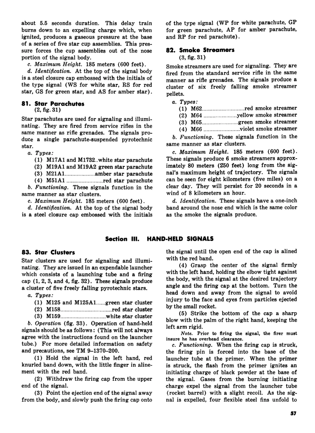
II. Rifle projected signals 80-82 55
III. Hand-held signals 88-85 57
Appendix A. REFERENCES 60
B. GUIDANCE FOR INSTRUCTORS 61
c. HAND AND RIFLE GRENADE RANGE
FACILITIES 62
D. SUMMARY OF GRENADES AND GROUND
PYROTECHNIC SIGNALS........................ 71
E. COLOR CODING OF GRENADES.................... 76
F. GRENADE QUALIFICATION COURSES............... 78
G. HISTORICAL RESUME OF GRENADES AND
PYROTECHNICS............................... 80
Index .................................................................. 83
* This manual supersedes FM 23-30, 23 October 1959, Including all changes»
1
CHAPTER 1
INTRODUCTION
1. Purpose and Scope
a. This manual provides guidance for the con-
duct of training with hand grenades, rifle gre-
nades, and ground pyrotechnic signals.
b. This manual contains descriptions, general
characteristics, capabilities and uses, functioning
data, training guidance, and safety procedures
for handling grenades and ground pyrotechnic
signals. It also includes information on the con-
struction and operation of facilities for grenade
training.
c. The material contained herein is applicable
without modification to both nuclear and non-
nuclear warfare.
d. Users of this publication are encouraged to
recommend changes or provide comments for im-
provement. Comments should be keyed to the
specific page, paragraph, and line of the text in
which the change is recommended. Reasons will
be provided for each comment to insure under-
standing and complete evaluation. Comments
should be prepared using DA Form 2028 (Recom-
mended Changes to Publications) and forwarded
direct to the Commandant, United States Army
Infantry School, Fort Benning, Georgia 31905.
2. General
a. Grenades are classified by method of projec-
tion as hand grenades or rifle grenades and by
origin as ordnance or chemical items. Ordnance
grenades contain high explosive fillers which
enable them to perform antitank or casualty-pro-
ducing missions. Chemical grenades contain fillers
which enable them to perform casualty-producing,
incendiary, illuminating, signaling, screening, or
riot control missions. Most hand grenades, al-
though designed to be thrown, may also be pro-
jected from the service rifle using a grenade
projection adapter.
b. Ground pyrotechnic signals are also catego-
rized as hand-held or rifle projected. They are
designed for use only as signaling and illuminat-
ing devices.
3
CHAPTER 2
HAND GRENADES
Section I. CHARACTERISTICS AND MAIN PARTS
3. General
Hand grenades are designed for projection to
a target by means of throwing. They assist the
individual soldier in the accomplishment of six
missions:
a. Producing casualties.
b. Signaling.
c. Screening.
d. Illuminating.
e. Producing incendiary effects.
/. Riot control.
4. Characteristics
All hand grenades share three characteristics:
a. Relatively short range in comparison to
other infantry weapons.
b. Small effective casualty radius (distance
from the grenade’s detonation point in which a
minimum of 50 percent of exposed personnel will
become casualties).
c. Incorporate a delay element to permit safe
throwing.
5. Main Parts
Hand grenades are composed of three main parts:
a. Body. This contains the filler and, in some
grenades, provides fragmentation.
b. Filler. The filler is the chemical or explosive
substance in the grenade body which gives the
grenade its characteristics and determines its use.
c. Fuze Assembly. This is the heart of the
hand grenade and causes the grenade to function
by means of a chain reaction of pyrotechnic,
mechanical, or electrical actions.
Section II. FUZES AND HAND GRENADE SAFETY CLIP
6. Functioning
(fig. 1)
All fuzes in U.S. hand grenades may be catego-
rized as either detonating or igniting. With few
exceptions, fuzes function in the following
manner:
a. When the safety pin is withdrawn from the
fuze, the safety lever is released from the gre-
nade body, but is held in place by the individual
throwing the grenade or, if the grenade is rifle
projected, by a grenade projection adapter. A
hand grenade safety clip, adaptable for the M26-
series, the МЗЗ-series, the M56, M57, and MK2
fragmentation grenades, and the M30 practice
grenade has been designed to prevent the gre-
nade safety lever from springing loose should
the safety pin be unknowingly or accidentally re-
moved from the grenade. Pressure exerted by the
safety clip prevents the release of the grenade
safety lever, regardless of whether the safety
pin is in place.
(1) The safety clip (fig. 2) is a single piece
of spring-steel wire bent to form—
(a) A metal loop which fits around the
grenade fuze at the grenade neck.
(b) A metal clamp which fits around and
presses against the grenade safety lever.
(2) To attach the safety clip to the grenade
(fig. 3)—
(a) Slide the clip onto the handle.
(b) Attach the loop portion of the safety
clip around the grenade fuze.
(c) Snap the clip end around the grenade
safety lever.
Note. The hand grenade safety clip may be
issued attached to the above grenades, or it may be issued
as a separate item.
b. When the safety lever (fig. 1) is released, it
is forced away from the grenade body by a striker
acting under the force of a striker spring.
c. As the safety lever is forced away from the
grenade body, the striker rotates on its axis and
strikes the primer.
d. When struck, the primer emits an intense
flash of heat which ignites the deb у element.
5
DELAY ELEMENT BURNS
DOWN TO THE DETONATOR
OR IGNITER.
DETONATOR OR IGNITER
SETS OFF BURSTER OR MAIN
CHARGE (FILLER)
Illllllllllllllllllllllllllllllll
grenade’s component parts, see 1, figure 4.)
WHEN SAFETY PIN IS WITHDRAWN, THE SAFETY LEVER
IS FREE TO RELEASE FROM THE GRENADE BODY
WHEN SAFETY LEVER IS RELEASED, **------
STRIKER ROTATES ON AXIS TO STRIKE PRIMER.
WHEN PRIMER IS STRUCK, FLASH OF
HEAT IGNITES DELAY ELEMENT
Figure 1.
Fuze functioning. (For details of the
e. The delay element burns for the prescribed
delay time and thereupon initiates the detonator
or igniter.
f. The detonator or igniter sets off the gre-
nade’s filler. Detonators are used in fragmenta-
tion, white phosphorous smoke, and bursting
chemical hand grenades. Igniters are used with
practice and burning chemical hand grenades.
7. Detonating Fuzes
a. M204A1 and M204A2 Fuzes (1, fig. 4).
These fuzes are used with the MK2, the M26, and
the M26A1 fragmentation hand grenades. The
fuze well accepting these fuzes will also accept
any standard firing device or the shipping plug
priming-adapter of the M18A1 antipersonnel
mine (CLAYMORE). Each fuze functions as
described in paragraph 6. The delay element is
a powder train requiring 4 to 5 seconds to burn
down to the detonator. The detonator sets off the
filler.
b. M206A2 Fuze (2, fig. 4). This fuze is used
with the MK3A2 offensive hand grenade and the
M34 white phosphorous smoke hand grenade. The
M206-series of fuzes are similar to the M204-
series of fuzes with the exception of the safety
lever. The fuze functions as described in para-
graph 6. The delay element is a powder train
requiring 4 to 5 seconds to burn down to the
detonator. The detonator sets off a tetryl burster,
which in turn ruptures the grenade body and
disperses the white phosphorous filler. (In the
MK3A2 offensive grenade, no burster is required.)
с. C12 Integral Fuze (3, fig. 4.) This fuze is
an integral part of the M25-series of riot control
hand grenades. The fuze consists of a firing pin
which is screwed into the base of the grenade
body, an arming sleeve, and a slider assembly.
The slider assembly contains a delay element of
1.4 to 3 seconds and a small detonator. When the
safety pin is removed, the arming sleeve is held
in place with the thumb. When the arming sleeve
6
Figure 2. Hand grenade safety clip fitted to the M3<>
practice grenade.
is released, the slider assembly is forced down-
ward toward the firing pin under pressure of the
firing spring. At the bottom of the fuze well, the
slider strikes the firing pin and ignites the delay
element which, in turn, sets off the detonator. The
detonator bursts the grenade body and disperses
the riot control agent over an area 5 meters in
diameter.
d. M213 and M215 Fuzes. The M213 and M215
fuzes are similar in their functioning to the M204-
series of fuzes. The M213 and M215 fuzes differ
from each other only slightly and differ from the
M204-series of fuzes in such physical details as
shape of body and safety lever. The M213 and
M215 fuze threads are larger than the M204-series
fuze threads. Therefore, the fuzes cannot be used
interchangeably. The М213 fuze is used with the
M33 fragmentation grenade and the M215 fuze is
used with the M56 fragmentation grenade. These
fuzes may be used interchangeably, but inter-
changing is not recommended.
e. М217 Fuze (4, fig. 4). This fuze is used with
the M59 and the M57 fragmentation hand gre-
nades. The M217 is an impact detonating fuze
which functions by electrical means. The purpose
of the fuze is to provide immediate detonation on
impact, to prevent the grenade from being thrown
back by the enemy, and to prevent the grenade
from rolling away from targets located on sloping
terrain. The M217 fuze can be distinguished from
other types of fuzes by the word IMPACT em-
bossed in raised letters on the red safety lever.
The M217 fuze thread diameter is larger than
that of other fuzes (except the M213 and M215
fuzes) and therefore the M217 fuze is not inter-
changeable with other types of fuzes (except the
M213 or M215 fuzes) or firing devices.
(1) The M217 is an electrical fuze which
functions either on impact or after a lapse of 4
seconds after the striker ignites the primer. The
fuze has an arming delay of 1 second which gives
the soldier a margin of safety when he throws the
grenade. This delay means that when the striker
hits the primer, the grenade is still not armed
until the 1-second arming delay is expended;
therefore, if a grenade is accidentally dropped
after the safety pin has been removed, a soldier
still has adequate time to pick the grenade up and
throw it to a safe area.
(2) Grenades armed with the M217 impact
detonating fuze must be thrown to a minimum
height of 4.5 meters (16 feet) (fig. 5). This
height gives the grenade enough flight time to
expend the 1-second arming delay and allows the
grenade to detonate on impact. The grenade will
detonate on impact when the arming delay is ex-
pended, regardless of the angle at which it strikes
a target. If the grenade impacts before the arm-
ing delay has elapsed, or if no impact occurs after
release of the safety lever, the grenade will det-
onate after a delay of 4 seconds. If the grenade
does not detonate, the fuze will become inert
within 30 seconds from the time the safety lever
is released.
Warning: Grenades armed with the im-
pact detonating fuze will NOT he projected from
the service rifle. In training, personnel will not
release the safety lever prior to throwing nor will
they observe the grenade's impact. A 5-minute
waiting period must be observed prior to ap-
proaching a dud. If a grenade armed with the
impact detonating fuze is dropped accidentally
after the safety pin has l>een removed, the grenade
MUST be picked up and thrown to a safe area.
Under no circumstances should the grenade be
kicked or tossed into a sump or ditch, since any
sudden jarring of the grenade after the arming
delay is expended, will cause detonation.
8. Igniting Fuzes
a. M201A1 Fuze (1, fig. 6). This fuze is de-
signed for use with chemical hand grenades whose
7
TO APPLY SAFETY CLIP;
IN PLACE
Figure 3, Attaching the hand grenade safety clip.
CLIP END
AROUND
GRENADE
HANDLE
© SLIDE CLIP
ON HANDLE
®ATTACH
LOOP PORTION
OF SAFETY CLIP
AROUND THE
GRENADE FUZE
fillers are initiated by burning (the M6- and the
M7-series of riot control grenades, the AN-M8 HC
white smoke grenade, the AN-M14 TH3 incen-
diary grenade, and the M18 colored smoke gre-
nade) . The M201A1 fuze is interchangeable with
any standard firing device. The fuze functions as
described in paragraph 6. The time delay element
is a powder train requiring 1.2 to 2 seconds to
burn to the igniter. The igniter ignites the filler
or a pyrotechnic starter with a violent burning
action and causes the filler to be expelled from
the grenade body.
b. M205A1 and M205A2 Fuzes (2, fig. 6).
These fuzes are used with the M30 practice hand
grenade. The fuze functions as described in para-
graph 6. The time delay element is a powder train
with a 4- to 5-second burning time.
c. Special Igniter (3, fig. 6). This fuze is used
with the MKI illuminating hand grenade. The
fuze functions as described in paragraph 6. The
special igniter differs from other igniting-type
fuzes in that it contains a quick match, rather
than a powder delay train. The quick match has
a burning time of 7 seconds, after which it sets
off an igniter charge. The igniter charge initiates
the burning process of the grenade’s filler.
Section III. FRAGMENTATION HAND GRENADES
9. General
Fragmentation hand grenades (fig. 7) are useful
weapons in both the offensive and defensive com-
bat roles. They are particularly effective for close
combat and are capable of inflicting multiple
casualties without requiring perfect aiming or
disclosing the soldier’s position.
10. MK2 Fragmentation Hand Grenade
(Lfig.7)
The MK2 fragmentation hand grenade is being
phased out as existing quantities are expended.
The grenade is presently being used by the armies
of our allies in many parts of the world.
a. Body. Cast iron (serrated to facilitate frag-
mentation).
b. Filler. 2 ounces of flaked TNT.
c. Fuze. M204A1, or M204A2 (para 7a).
d. Weight. 21 ounces.
e. Safety Clip. For the proper method of in-
stalling the hand grenade safety clip, see para-
graph 6a(2).
f. Capabilities. The average soldier can throw
the grenade 30 meters, or it can be projected 140
8
М204А2 DETONATING FUZE
(4-5 SECOND DELAY)
M206A2 DETONATING FUZE
(4-5 SECOND DELAY)
C-12 INTEGRAL FUZE FOR M25-SERIES
OF RIOT CONTROL GRENADES (1.4-3 SECOND
DELAY).
M217 IMPACT DETONATING FUZE
(4-SECOND DELAY; 1-SECOND
ARMING DELAY)
Figure 4- Detonating fuze*.
9
meters from the service rifle. The grenade has an
effective casualty radius of 10 meters.
g. Color. Olive drab body with a single yellow
band at the top. The yellow band indicates a high
explosive filler.
11. M26 and M26A1 Fragmentation
Hand Grenades
(2, fig. 7)
The M26 fragmentation hand grenade was de-
signed to replace the MK2 grenade and has been
in the hands of troops since the Korean Conflict.
The original design of the M26 grenade was later
modified to improve its fragmentation character-
istics and was designated the M26A1. Both the
M26 and the M26A1 grenades are presently in use.
a. Body. Thin sheet metal. (Fragments are
produced from a serrated wire coil fitted to the
inside of the sheet metal grenade body.)
b. Filler. 5.5 ounces of composition B.
c. Fuze. M204A1 or M204A2 with the M26;
M204A2 with the M26A1.
d. Weight. 16 ounces.
e. Safety Clip. For the proper method of in-
stalling the hand grenade safety clip, see para-
graph 6a(2).
f. Capabilities. The average soldier can throw
the grenade 40 meters, or it can be projected 160
meters from the service rifle. The grenade has
an effective casualty radius of 15 meters.
g. Color and Markings. Olive drab body with
a single yellow band at the top and yellow mark-
ings. The yellow band and markings indicate a
high explosive filler.
12. M56 Fragmentation Hand Grenade
The M56 grenade differs from the M26A1 gre-
nade (2, fig. 7) in that the M56 grenade contains
a larger amount of filler and its fuze well is larger
in diameter to accommodate the larger M215
time delay fuze.
a. Body. Same as the M26A1 grenade.
b. Filler. 6.3 ounces of composition B.
c. Fuze. M215 time delay fuze (para Id).
d. Weight. 15.2 ounces.
e. Capabilities. Same as the M26A1 grenade.
f. Color and Markings. Same as the M26A1
grenade.
13. M57 Fragmentation Hand Grenade
(3, fig. 7)
The M57 grenade differs from the M56 grenade
in that it has an impact detonating fuze.
a. Body. Same as the M26A1 grenade.
b. Filler. 6.3 ounces of composition B.
c. Fuze. M217 impact detonating fuze (para
7e).
d. Weight. 15.2 ounces.
e. Capabilities. Same as the M26A1 grenade,
except that the M57 grenade will detonate on
impact 1 second after the safety lever has been
released or automatically within 4 seconds after
the safety lever has been released if no impact
occurs. The M57 cannot be rifle projected. The
“cookoff” technique (para 37) will not be at-
tempted with the M57 grenade.
f. Color and Markings. Same as the M26A1
grenade, except that the safety lever is painted
red and has the word IMPACT embossed in
raised letters on its surface.
14. M33 Fragmentation Hand Grenade
(4, fig. 7)
The M33 grenade differs from the M26, M26A1,
M56, and M57 grenades in that the M33 has an
oblate spheriod body and contains a larger
amount of filler. The diameter of the M33 fuze
well is the same as that of the M56 and M57
fuzes.
a. Body. Steel with an oblate spheriod shape.
b. Filler. 6.5 ounces of composition B.
c. Fuze. M213 time delay fuze (para Id).
d. Weight. 13.9 ounces.
e. Capabilities. Same as the M26A1 grenade,
except that the M33 grenade cannot be rifle
projected.
f. Color and Markings. Same as the M26A1
grenade.
15. M59 Fragmentation Hand Grenade
(5, fig. 7)
The M59 grenade differs from the M33 in that
it is armed with an impact detonating fuze.
a. Body. Same as the M33 grenade.
b. Filler. 6.5 ounces of composition B.
c. Fuze. M217 impact detonating fuze (para
7e).
d. Weight. 13.9 ounces.
e. Capabilities. Same as the M26A1 grenade,
except that the M59 grenade will detonate on
impact 1 second after the safety lever has been
released or automatically within 4 seconds after
the safety lever has been released if no impact
occurs. The M59 grenade cannot be rifle pro-
jected. The “cookoff” technique (para 37) will
not be attempted with the M59 grenade.
f. Color and Markings. Same as the M26A1
grenade, except that the safety lever is painted
red and has the word IMPACT embossed in
raised letters on its surface.
10
Figure 5. Impact characteristics of the M217 impact detonating fuze.
Section IV. CHEMICAL SMOKE HAND GRENADES
16. General
Chemical smoke hand grenades are designed pri-
marily for signaling and screening. This group-
ing, however, includes the white phosphorous
smoke grenades which, in addition to their signal-
ing and screening capabilities, have casualty-
producing and incendiary capabilities. The white
phosphorous grenade is similar to other chemical
smoke hand grenades in color. For this reason,
caution must be exercised to insure that the gre-
nade is not used near friendly personnel for
signaling or for laying down a smoke screen
which friendly personnel will have to move
through.
17. M34 White Phosphorous Smoke
Hand Grenade
(1 and 2, fig. 8)
The M34 white phosphorous smoke hand gre-
nade is the most versatile of all hand grenades.
The grenade can be used for signaling, screening,
incendiary missions, or for producing casualties.
a. Body. Rolled steel (serrated to facilitate
fragmentation).
b. Filler. 15 ounces of white phosphorous.
c. Fuze. M206A2 (para lb).
d. Weight. 27 ounces.
e. Capabilities. The average soldier can throw
the grenade 30 meters, or it can be projected 120
meters from the service rifle. The grenade has a
bursting radius of 35 meters. All friendly per-
sonnel within this 35-meter area should be in a
covered position to avoid being struck by burning
particles. The WP filler burns for approximately
60 seconds at a temperature of 5,000°F. This
intense heat causes the smoke produced by the
grenade to rise quite rapidly, especially in cool
climates, making the M34 grenade less desirable
for use as a screening agent. (The M15 WP
smoke hand grenade is similar to the M34. For
detailed information, see TM 9-1330-200.)
f. Color and Markings.
(1) Under the old ammunition color-coding
system, the white phosphorous grenade is light
gray with a single yellow band and yellow
markings.
(2) Under the newer standard color-coding
system, the M34 grenade is light green with a
single yellow band and light red markings.
Note. Most M34 WP smoke hand grenades presently
in use were manufactured prior to the standard color-
coding system agreement and are painted according to
the old color code.
18. AN-M8 HC White Smoke Hand
Grenade
(3, fig. 8)
The AN-M8 white smoke hand grenade is used
to produce dense clouds of white smoke for signal-
ing and screening. The smoke produced by this
grenade clings to the ground more readily than
the smoke of the M34 grenade. The AN-M8 gre-
nade is used for ground-to-ground and ground-
to-air signaling, for marking targets or landing
11
zones, and for screening the movements of small
units for short periods of time.
a. Body. Sheet steel.
b. Filler. 19 ounces of type С, HC smoke
mixture.
c. Fuze. M201A1 (para 8a).
d. Weight. 24 ounces.
e. Capabilities. The average soldier can throw
the grenade 30 meters, or it can be projected 120
meters from the service rifle. The grenade emits
a dense cloud of white smoke for 105 to 150
seconds.
f. Color and Markings. The grenade is light
green with black markings and has a white top
to indicate the color of smoke it produces.
19. Ml 8 Colored Smoke Hand Grenade
(4, fig. 8)
The M18 colored smoke hand grenade is used as
a ground-to-ground or ground-to-air signaling
device, a target or landing zone marking device,
or to screen the movements of small units for
short periods of time. The grenade is available
in four colors: red. green, yellow, and violet.
a. Body. Sheet steel. (Four emission holes at
the top and one at the bottom of the grenade
release the filler when the grenade is ignited.)
b. Filler. 11.5 ounces of colored smoke mixture.
c. Fuze. M201A1 (para 8a).
d. Weight. 19 ounces.
e. Capabilities. The average soldier can throw
Section V. RIOT CO
20. General
Riot control hand grenades are designed chiefly
to aid in quelling civil disturbances, prisoner of
war riots, or similar disorders which require the
use of nonlethal agents to restore order. These
grenades are also effective in clearing buildings
or tunnel systems in which noncombatants may
be mixed with enemy personnel or on operations
where the taking of prisoners is the primary
mission. The M7A2 grenade and all other types
of burning grenades should not be used inside
buildings. The M25 CS grenade, the baseball
type, can be employed inside buildings since it
does not constitute a fire hazard. The grenade
should be used inside buildings to force personnel
outside or to prevent their entry. Most riot con-
trol hand grenades may also be used in training
to simulate chemical attacks.
21. Riot Control Agents
To facilitate the accomplishment of the above
missions, three types of riot control agents are
the grenade a distance of 35 meters, or it can be
projected 120 meters from the service rifle. The
grenade produces a cloud of colored smoke for
50 to 90 seconds.
f. Color and Markings.
(1) Most grenades of the M18-series pres-
ently in use are not marked according to the
old or the standard color-coding system. Instead,
they are olive drab with gray or yellow markings
and a top the same color as the smoke produced
by the grenade.
(2) Under the standard color-coding system,
the M18 grenade is the same color as the AN-M8,
except that the top of the grenade is either red,
green, yellow or violet indicating the color of
smoke it produces.
Note. When using the AN-M8 or the M18 grenades
to mark landing or drop zones, care must be taken to
insure the grenade is thrown into an area where the
smoke will not obscure the landing area. If the AN-M8
or the M18 grenades fail to function, they may be ignited
by punching a hole in the bottom of the grenades to
expose the filler. The filler may then be ignited with a
match or other open flame. When using this expedient
method, the grenades must immediately be thrown after
ignition, since they burn at a fairly high temperature
and produce very dense smoke. This smoke is harmful
if inhaled in large quantities. When using the AN-M8
HC white smoke grenade or the M34 WP smoke grenade
for signaling or screening, care must be taken to insure
the grenades are not thrown into areas where they may
start fires detrimental to tactical operations.
IOL HAND GRENADES
available in hand grenade form.
a. CN, commonly known as "tear gas.” The
effects of CN are a stinging sensation of the eyes
and a continuous flow of tears.
b. DM, a vomiting agent, often called “Adam-
site,” produces nausea and vomiting and normally
is used in hand grenades in combination with
other agents.
c. CS, the most powerful of the riot control
agents. It produces the same effects as CN and
adds involuntary closing of the eyes, nasal drip,
severe coughing, tightness of the chest, extreme
difficulty in breathing, and a stinging sensation
on moist areas of the skin.
22. M6 and M6A1 CN-DM Riot Control
Hand Grenades
(land 2, fig. 9)
The M6 and M6A1 riot control hand grenades
contain a combination mixture of CN and DM.
They differ chiefly in external appearance and the
manner in which the filler is combined.
a. Body. Sheet steel. (The M6 has six emis-
12
М201А1 IGNITING FUZE (1.2-2 SECOND UELAY)
M205A1 IGNITING FUZE (4-5 SECOND DELAY )
SPECIAL IGNITER (7 SECOND DELAY1
Figure 6. Igniting fuzes.
sion holes at the top and two rows of nine emis-
sion holes each along the sides. The M6A1 gre-
nade has four emission holes at the top and one
at the bottom.)
b. Filler. M6 grenade, 10.5 ounces of CN-DM
mixture; M6A1 grenade, 9.5 ounces of CN-DM
mixture.
c. Fuze. M201A1 (para 8a).
d. Weight. M6 grenade, 17 ounces; M6A1 gre-
nade, 20 ounces.
e. Capabilities. The average soldier can throw
the grenades 35 meters. The M6 and the M6A1
grenades can be projected 120 meters from the
service rifle. Both grenades emit a dense cloud
of irritant agent for 20 to 60 seconds.
/. Color and Markings. The M6 and the M6A1
grenades have a gray body with a single red band
and red markings. (Under the standard color-
coding system, the single red band and red mark-
ings indicate a nonpersistent, riot control filler.
A double red band with red markings indicates
a persistent riot control filler, and any combina-
tion of green bands and green markings indicates
a casualty-producing filler. Presently, there are
no casualty agents in grenade form.)
23. M7 and M7A1 CN Riot Control
Hand Grenades
(3, fig. 9)
The M7 and the M7A1 riot control hand grenades
contain only CN for a filler. They differ chiefly
in body construction and the amount of filler they
contain.
a. Body. M7 grenade, same as the Мб; M7A1
grenade, same as the M6A1 grenade.
b. Filler. M7 grenade, 10.25 ounces of CN;
M7A1 grenade, 12.5 ounces of CN.
c. Fuze. M201A1 (para 8a).
d. Weight. M7 grenade, 17 ounces; M7A1 gre-
nade, 18.5 ounces.
e. Capabilities. The average soldier can throw
the grenades 35 meters, or they can be projected
120 meters from the service rifle. Both grenades
produce a dense cloud of irritant agent for 20 to
60 seconds.
f. Color and Markings. Same as the M6 and
M6A1 grenades.
24. ABC-M7A2 and ABC-M7A3 CS Riot
Control Hand Grenades
(3, fig. 9)
The ABC-M7A2 and the ABC-M7A3 riot control
hand grenades contain only CS for a filler. They
differ only in the amount of filler and the form
of CS they contain.
a. Body. The bodies of both grenades are the
13
МК2 FRAGMENTATION HAND GRENADE
SREN HAND
FRAG M57
COMP В
PK З-ЗБб
GREN HAND
FRAB M26AI
COMP В
» 1-366
M2SA1 FRAGMENTATION HAND GRENADE
MSI FRAGMENTATION HAND GRENADE WITH M217 IMPACT DETONATING FUSE
Figure 7. Fragmentation hand grenades.
14
МИ FRAGMENTATION NANO GRENADE
WITH M217 IMPACT DETONATING FUSE
Figure 7—Continued.
15
same as the M6A1 and the M7A1 grenades with
four emission holes at the top and one at the
bottom.
b. Filler. ABC-M7A2 grenade, 5.5 ounces of
burning mixture and 3.5 ounces of CS in gelatin
capsules; ABC-M7A3 grenade, 7.5 ounces of burn-
ing mixture and 4.5 ounces of pelletized CS agent.
c. Fuze. M201A1 (para 8a).
d. Weight. Approximately 15.5 ounces.
e. Capabilities. The average soldier can throw
the grenades 40 meters, or they can be projected
120 meters from the service rifle. Both grenades
produce a cloud of irritant agent for 20 to 60
seconds.
f. Color and Markings. Same as the M6 and
the M6A1 grenades.
25. ABC-M25A1 and ABC-M25A2, CN1,
DM1, CS1 Riot Control Hand
Grenades
(4, fig. 9)
The ABC-M25A1 and the ABC-M25A2 riot con-
trol hand grenades are bursting munitions with
integral fuzes. The M25A2 grenade is an im-
proved version of the M25A1 grenade. The two
types of grenades differ primarily in body con-
struction. They are used to deliver all three
types of riot control agents presently used in
hand grenades.
a. Body. Compressed fiber or plastic hemi-
spheres.
b. Filler. The fillers of the M25-series of riot
control hand grenades vary in weight and com-
position according to the type of agent contained
in the grenade. All fillers are mixed with silica
aerogel for increased dissemination efficiency.
c. Fuze. Integral (para 7c).
d. Weight. 7.5 to 8 ounces, depending on the
type of filler.
e. Capabilities. The average soldier can throw
the grenade 50 meters. The M25-series of riot
control hand grenades cannot be rifle projected.
The radius of burst (visible cloud agent) is ap-
proximately 5 meters, but fragments of the gre-
nade occasionally are projected 25 meters.
f. Color and Markings. Same as the M6 and
the M6A1 grenades. (Most grenades of the M25-
series presently in use are not painted according
to any color-coding system. They are either to-
tally unpainted or have only a red band and red
markings.)
Warning: When the ABC-M25A1 grenade is
employed, do not drop as immediate functioning
may result; do not attempt to replace a pulled
safety pin; and DO NOT RELAX THUMB PRES-
SURE ON ARMING SLEEVE AFTER THE
SAFETY PIN IS PULLED.
Section VI. SPECIAL PURPOSE HAND GRENADES
26. General
This section covers special purpose hand grenades.
Included in this category are incendiary, illumi-
nating, practice, and offensive hand grenades.
27. AN-M14 TH3 Incendiary Hand
Grenade
(1, fig. 10)
The AN-M14 TH3 incendiary hand grenade is
used to destroy equipment. It can be used to
destroy or damage equipment, such as mortar
tubes, artillery and recoilless rifle breech blocks,
and vehicle engine blocks. The grenade may also
be used to start fires in areas containing flam-
mable materials.
a. Body. Sheet steel.
b. Filler. 26.5 ounces of thermate (TH3)
mixture.
c. Fuze. M201A1 (para 8a).
d. Weight. 32 ounces.
e. Capabilities. The average soldier can throw
the grenade 25 meters, or it can be projected 120
meters from the service rifle. A portion of the
thermate mixture is converted to molten iron,
which burns at 4000°F. and will fuse together
the metallic parts of any object with which it
comes in contact. Thermate is an improved ver-
sion of thermite, the incendiary agent used in
hand grenades during World War II. The ther-
mate filler of the AN-M14 grenade burns for 40
seconds and can burn through a 1/2-inch homog-
eneous steel plate. It produces its own oxygen
and will burn under water.
f. Color and Markings. Incendiary grenades
presently in use are gray with purple markings
and a single purple band. Under the standard
color-coding system, incendiary grenades are light
red with black markings.
28. M30 Practice Hand Grenade
(2, fig. 10)
The M30 practice hand grenade simulates the
M26-series of fragmentation hand grenades for
training purposes. The grenade adds realism to
16
training and familiarizes the soldier with the
functioning and characteristics of the fragmenta-
tion hand grenade. (The M21 and MK1A1 prac-
tice grenades are similar in operation but are
standard “C” items. For detailed information, see
TM 9-1300-200.)
a. Body. Cast iron. (The grenade body is
reusable.)
b. Fuze. M205A1 or M205A2.
c. Weight. 16 ounces.
d. Safety Clip. For the proper method of in-
stalling the hand grenade safety clip, see para-
graph 6a (2).
e. Capabilities. The average soldier can throw
the grenade 40 meters, or it can be projected 160
meters from the service rifle. The M30 grenade
emits a small puff of white smoke after a delay
of 4 to 5 seconds and makes a loud “popping”
noise. The grenade body can be used repeatedly
by replacing the fuze assembly.
Caution: Caution must be exercised to insure
that no detonating fuzes are used with the gre-
nade. The M205A1 and M205A2 practice fuzes
are the only ones authorized for use with the
M30 grenade. A detonating fuze may cause the
grenade body to shatter on detonation, scattering
dangerous fragments about the detonation point.
f. Color and Markings. Light blue with white
markings. (The safety lever of the fuze is light
blue with black markings and a red tip.)
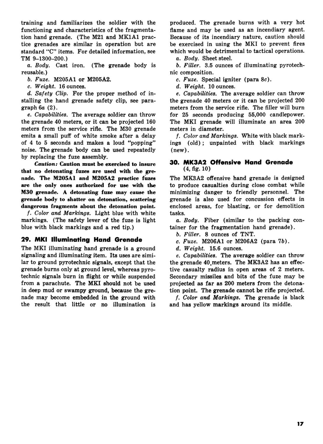
29. MKI Illuminating Hand Grenade
The MKI illuminating hand grenade is a ground
signaling and illuminating item. Its uses are simi-
lar to ground pyrotechnic signals, except that the
grenade burns only at ground level, whereas pyro-
technic signals burn in flight or while suspended
from a parachute. The MKI should not be used
in deep mud or swampy ground, because the gre-
nade may become embedded in the ground with
the result that little or no illumination is
produced. The grenade burns with a very hot
flame and may be used as an incendiary agent.
Because of its incendiary nature, caution should
be exercised in using the MKI to prevent fires
which would be detrimental to tactical operations.
a. Body. Sheet steel.
b. Filler. 3.5 ounces of illuminating pyrotech-
nic composition.
c. Fuze. Special igniter (para 8c).
d. Weight. 10 ounces.
e. Capabilities. The average soldier can throw
the grenade 40 meters or it can be projected 200
meters from the service rifle. The filler will burn
for 25 seconds producing 55,000 candlepower.
The MKI grenade will illuminate an area 200
meters in diameter.
f. Color and Markings. White with black mark-
ings (old); unpainted with black markings
(new).
30. MK3A2 Offensive Hand Grenade
(4, fig. 10)
The MK3A2 offensive hand grenade is designed
to produce casualties during close combat while
minimizing danger to friendly personnel. The
grenade is also used for concussion effects in
enclosed areas, for blasting, or for demolition
tasks.
a. Body. Fiber (similar to the packing con-
tainer for the fragmentation hand grenade).
b. Filler. 8 ounces of TNT.
c. Fuze. M206A1 or M206A2 (para 7b).
d. Weight. 15.6 ounces.
e. Capabilities. The average soldier can throw
the grenade 40,meters. The MK3A2 has an effec-
tive casualty radius in open areas of 2 meters.
Secondary missiles and bits of the fuze may be
projected as far as 200 meters from the detona-
tion point. The grenade cannot be rifle projected.
f. Color and Markings. The grenade is black
and has yellow markings around its middle.
17
MM, WP SMOKE HAND
GRENADE (OLD COLOR AND
MARKINGS).
M34, WP SMOKE HAND
GRENADE (STANDARD COLOR
AND MARKINGS).
AN-M8, HC SMOKE HAND
GRENADE.
M18 COLORED SMOKE HAND
GRENADE.
Figure 8. Chemical smoke hand grenades.
18
Me, CN-DM RIOT CONTROL
HAND 6RENADE
МБА1, CN-DM RIOT CONTROL
HAND GRENADE
ABC- M7A3. CS RIOT CONTROL
HAND GRENADE
ABC- M2SA2, CS RIOT CONTROL
HAND GRENADE.
Figure 9. Riot control hand grenades.
19
AN-M 14, TH 3 INCENDIARY HAND GRENADE
(OLD MARKINGS)
M 30 PRACTICE HAND GRENADE
MK 1 ILLUMINATING HAND GRENADE
MK 3 A2, OFFENSIVE GRENADE
Figure 10. Special purpose hand grenades.
20
CHAPTER 3
HAND GRENADE TRAINING
Section I.
31. Introduction
Hand grenade training should emphasize throw-
ing distance and accuracy. These are the two most
critical factors of individual proficiency in a hand
grenade training program. The training program
should be oriented toward instilling good grenade
throwing habits in the soldier. Upon completion
of training, an individual should be able to throw
grenades with skill and confidence.
32. Conduct of Hand Grenade Training
The initial phases of hand grenade training should
stress safety precautions and direct supervision
of personnel being trained. This is necessary
since many soldiers may have difficulty in de-
veloping good throwing habits because of physical
or psychological limitations. These limitations are
overcome only with patience and practice. As the
cycle of training progresses, a soldier’s confidence
and proficiency should progress accordingly. In
view of such progress, later phases of a grenade
Section II. FUNDAMENTALS <
34. Holding the Grenade
Safety is the primary factor to be considered
when determining the proper method of holding
the grenade.
a. Maximum safety and throwing comfort are
obtained when the grenade is cradled in the
throwing hand with the safety lever held in place
by the area between the first and second joints
of the thumb (1, fig. 11).
b. For right-handed personnel, the grenade is
held upright in order to position the pull ring
where it can be easily removed by the index
finger of the free hand (2, fig. 11). For left-
handed personnel, the grenade is inverted with
the fingers and thumb of the throwing hand posi-
tioned in the same manner as by right-handed
personnel (3, fig. 11)
GENERAL
training program should gradually reduce the
amount of supervision. When a soldier reaches
the final phase of grenade training, he is allowed
to put into practice the training he has received
in a course simulating conditions likely to be
found on the battlefield.
33. Training Objectives
Although the primary objectives of a hand gre-
nade training program are to develop a soldier’s
proficiency in grenade throwing and to over-
come any fear he may have of handling explo-
sives, there are other factors of considerable im-
portance in preparing the soldier to use grenades
on the battlefield. He must become familiar with
the various types of hand grenades, their func-
tioning and uses, and safety considerations gov-
erning their use. Equally important in training
are the proper methods of target engagement
These methods should enable a soldier to react
rapidly and effectively against targets which may
confront him in battle.
HAND GRENADE TRAINING
c. The M25-series of riot control hand grenades
have an arming sleeve which serves the same pur-
pose as the safety lever on other grenades. When
throwing these grenades, the arming sleeve is
held in place by applying constant pressure with
the thumb of the throwing hand (4, fig. 11).
35. Throwing the Grenade
(fig. 12)
Since few men throw in the same manner, it is
difficult to establish firm rules or throwing tech-
niques. There is, however, a recommended
method of grenade throwing which is easily mas-
tered by most personnel. By practicing the steps
below, you will develop your throwing proficiency
to a point where your reaction to a presented
target is immediate.
21
a. First, observe the target to mentally estab-
lish the distance between your throwing position
and the target area.
b. Hold the grenade at shoulder level with the
grenade in your throwing hand and the index
finger of your opposite hand grasping the pull
ring (1, fig. 12). Remove the safety pin with a
pulling, twisting motion. (If the tactical situa-
tion permits, you should observe the safety pin’s
removal.)
Note. If the safety pin cannot be pulled out, lessen
the spread of the legs of the safety pin to facilitate re-
moval. However, if the grenade is not used, respread the
legs of the safety pin for safety in carrying.
c. To remove the safety pin and the safety clip
from hand grenades mentioned in paragraph 6,
hold the grenade at shoulder level with the gre-
nade in your throwing hand. Insert the index
finger of your opposite hand into the pull ring,
and place your thumb across the grenade lever
and onto the squared end of the safety clip (fig.
13). While pulling the pin with your index finger,
simultaneously rotate the clip to the left with
your thumb until the clip clears the lever. As the
pull pin clears the fuze, the safety clip rotates
clear of the grenade lever. (This procedure also
applies to left-handed soldiers, only with the hand
reversed, fig. 14.)
Note. When using grenades equipped with the safety
clip, the positions and techniques described in this chapter
for throwing hand grenades remain unchanged.
d. As the safety pin is removed, immediately
look back at your target.
e. Throw the grenade with an overhead throw-
ing motion, keeping your eyes trained at all times
on the target. Release the grenade somewhere
forward of your body and in your general field
of vision (2 and 3, fig. 12). In this way, you
take advantage of the hand-and-eye coordination
inherent in most men.
f. Follow through on your throwing motion
beyond the point where the grenade is released
(4, fig. 12). This follow through improves dis-
tance and accuracy and relieves the strain on your
throwing arm.
36. Throwing Positions
In training, throwing positions are used for uni-
formity and control and to familiarize personnel
with the proper manner of throwing grenades
from positions commonly used in combat. Care
must be taken not to overemphasize throwing
positions in training; for in combat, the soldier’s
throwing position will be dictated by the amount
of available cover, the range to the target, and
the type and location of the target. The positions
described below point out the use and limitations
of each position.
Figure 11. Holding the grenade.
22
a. Standing Position (1, fig. 15). This position
is the most desirable and natural one from which
to throw grenades. The position allows an in-
dividual to obtain the greatest possible throwing
distance. Throwing from this position is accom-
plished as follows:
(1) Assume a natural stance with your
weight balanced equally on both feet. Using the
proper grip, hold the grenade shoulder high.
(2) Throw the grenade with a natural mo-
tion using the procedure described in paragraph
35.
(3) If available, duck behind cover to avoid
being hit by fragments. If no cover is available,
drop to the prone position with your helmet fac-
ing the direction of the grenade’s detonation.
b. Kneeling Position (2, fig. 15). This position
reduces the distance to which a grenade can be
thrown. The position is used primarily when the
soldier has only a low wall, a shallow ditch, or
similar cover to protect him. Throwing from this
position is accomplished as follows:
(1) Using the proper grip and with the gre-
nade held shoulder high, kneel in the most com-
fortable manner.
(2) Throw the grenade with a natural
throwing motion. Push off with your trailing foot
to give added force to your throw.
(3) When the grenade is released, drop to
the prone position or behind available cover to
minimize exposure to fragmentation.
c. Prone to Kneeling Position (3, fig. 15). This
position is used when no cover is available and
the grenade must be thrown a greater distance
than is possible from the prone position. Throw-
ing from this position is accomplished as follows:
(1) Face the target and assume the prone
position. Hold the grenade forward of your head
where you can observe the grenade as you remove
the safety pin.
(2) After the safety pin is removed, assume
the kneeling position.
(3) After throwing the grenade, return to
the prone position with your helmet facing the
direction of the target.
d. Alternate Prone Position (4, fig. 15). This
position reduces both distance and accuracy. It
is used when an individual is pinned down by
hostile fire and is unable to rise to engage his
target. Throwing from this position is accom-
plished as follows:
(1) Lie on your back with your body per-
pendicular to the grenade’s intended line of flight.
Hold the grenade at shoulder level as in the stand-
ing position.
(2) Your right leg (left leg for left-handed
throwers) is cocked with your foot braced firmly
against the ground. After removal of the safety
pin, hold the grenade away from your body with
your arm cocked for throwing.
(3) With your free hand, grasp any object
that is capable of giving you added leverage.
This leverage will increase your throwing dis-
tance. In throwing the grenade, push off with
your rearward foot to give added power to your
throw. After throwing the grenade, roll over onto
your stomach and press yourself flat against the
ground.
37. "Cookoff" and "Airburst"
Many times in combat, targets confronting the
infantryman may be of such a nature that normal
methods of target engagement are inadequate.
For example, troops or weapons in trench or fox-
hole positions are better engaged by causing a
grenade to burst over these targets. Further-
more, if the targets are located on sloping ground
and impact detonating grenades are unavailable,
it would then be desirable to detonate a grenade
as near impact as possible to prevent its rolling
away from the target before the time delay is ex-
pended. Such above ground detonation also pre-
vents the enemy from securing the grenade and
throwing it back before the time delay is ex-
pended. Above ground detonation is especially
critical when bunker-type emplacements are en-
gaged. To achieve above ground detonation or
near impact detonation, remove the grenade’s
safety pin, release the safety lever, and count
“ONE THOUSAND ONE, ONE THOUSAND
TWO,” and then throw the grenade. This proce-
dure will expend a sufficient period (approxi-
mately 2 seconds) of the grenade’s 4- to 5-second
time delay to cause the grenade to detonate above
ground or shortly after impact with the target.
Fragmentation and white phosphorous hand gre-
nades will not be detonated in such a manner in
training.
Warning: It is possible for grenades to have a
minimum delay time of 3 seconds. A grenade
which has a 3-second delay that is held for 2
seconds could expose the user to a serious safety
hazard.
38. Carrying Hand Grenades
a. The way grenades are carried is probably
the most neglected aspect of hand grenade train-
ing. Experiences by American infantrymen, both
in combat and in training, point out the need
for training in carrying hand grenades and the
integration of this type of training, whenever pos-
sible, into tactical training exercises.
23
Figure 12. Throwing the grenade.
24
Figure 13. Removing the safety pin and the
safety clip (right-handed individuals).
Figure 14. Removing the safety pin and
the safety clip (left-handed individuals).
b. Before attaching hand grenades to web
equipment for carrying, the following safety pre-
cautions should be taken:
(1) Check the grenade’s fuze assembly for
tightness, since it must be screwed tightly into
the grenade’s fuze well in order to prevent the
grenade from working loose during movement
and separating from the fuze assembly. The fuze
should never be removed from a grenade, unless
the grenade is being prepared as a boobytrap
using some other firing device.
(2) If the grenade’s safety lever is broken,
do not use the grenade. The safety pin should not
be bent back so that it is flush against the fuze
body. This procedure, designed to preclude acci-
dental pulling of the pin, makes the removal of
the safety pin difficult and, in some cases, im-
possible. Also, repeated working of the safety
pin in this manner will cause the pin to break,
creating a hazardous condition.
c. The prescribed manner of carrying hand
grenades is by the carrying straps on the uni-
versal ammunition pouch (fig. 16). There are
two carrying straps on the ammunition pouch
which are designed specifically for carrying gre-
nades. Grenades are attached to the ammunition
pouch in the following manner:
(1) After checking the fuze for tightness,
hold the web carrying sleeve on the rear of the
ammuntion pouch flat against the pistol belt, and
slide the grenade’s safety lever into the sleeve.
(2) Be sure the pull ring on the safety pin
is pointing downward.
(3) Wrap the carrying strap around the
neck of the fuze, including the safety lever and
the pull ring, and snap the carrying strap to the
carrying sleeve.
(4) During marches, periodically check the
grenade to make certain the fuze is tight and
the carrying strap is secure.
d. Five fragmentation grenades can be carried
using the universal ammunition pouch; two gre-
nades are attached to the outside of the pouch
and three are carried inside.
Warning: Hand grenades will not be at-
tached to any equipment by the pull ring on the
grenade’s safety pin.
25
Figure 15. Throwing positions.
26
PULLING THE PIN
PREPARING TO THROW
THROWING THE GRENADE
ALTERNATE PRONE POSITION
Figure 15.—Continued.
Section III. HAND GRENADE TRAINING COURSES
39. Distance and Accuracy Course
a. Purpose. The distance and accuracy course
is the initial phase of the soldier’s practical work
with hand grenades. The purpose of the course
is to develop the soldier’s grenade throwing profi-
ciency and to insure the soldier develops good
grenade throwing habits. The course requires
close supervision by experienced personnel.
b. Conduct. Before conducting the course, the
soldier is given a briefing on the objectives of
the course and how he is to engage the targets.
He is then given a demonstration of how the
course is conducted. For control, the NCOIC
of the course issues the commands: PREPARE
TO THROW, PULL PIN, and THROW GRE-
NADE. He also moves the orders between sta-
tions. The unit being trained is divided into 20-
man orders. Each throwing station requires a
minimum of two supervisory personnel. Each
order is assigned a starting station and is moved
on command to each of the succeeding stations.
The course is conducted as follows:
(1) Station 1. The soldier is issued three
unfuzed practice hand grenades. He uses the
standing position to engage a foxhole-type target
30 meters from the throwing line. Midway be-
tween the throwing line and the target, a wire
or rope cable is suspended across the station at
a height of 4.5 meters (16 feet). This cable points
out that in order to gain distance in his throw,
he must also obtain height in throwing. When
he engages the target, the soldier’s grenade should
pass over the cable. After his order has com-
pleted throwing all three grenades, the soldier
moves to the target area on command from the
NCOIC, and secures and returns the grenades he
threw to the throwing point of Station 1. He
then moves directly to Station 2.
27
Instructor’s Note, A soldier who demonstrates com-
plete inability to throw the grenade should be sent to
a separate area to receive intensive, individual instruction.
(2) Station 2. The soldier is issued three
unfuzed practice hand grenades. He uses the
standing position to engage a trench-type target
at a range of 40 meters. Again, a cable is sus-
pended across the station at a height of 4.5 meters
(16 feet) and midway between the throwing line
and the target. After his order has completed
throwing all three grenades, the soldier moves to
the target area on command from the NCOIC,
and secures and returns the grenades he threw to
the throwing point of Station 2. He then moves
directly to Station 3.
Instructor’s Note. The soldier starts this station
in a kneeling position. He then stands, throws, and re-
turns to the kneeling position which gives him cover
behind a low wall.
(3) Station 3. The soldier is issued three
unfuzed hand grenades. He uses the kneeling
position to engage a window-type target at a
range of 20 meters from the throwing line. After
his order has completed throwing all three gre-
nades, the soldier moves to the target area on
command from the NCOIC, and secures and re-
turns the grenades he threw to the throwing point
of Station 3.
c. Summary. When the soldier has completed
the distance and accuracy course, he will have
thrown a grenade comparable in weight to the
fragmentation grenade a total of nine times at
targets spaced at varying distances from the
throwing line. He will know that in order to
obtain throwing distance, he must also obtain
throwing height. Through close supervision, he
will have developed his throwing distance and
accuracy, as well as good grenade throwing
habits. It should be remembered that successful
engagement of all targets in this course is not
a prerequisite for throwing casualty-producing
grenades. It is desirable for the soldier to com-
plete the distance and accuracy course before
he advances to the hand grenade assault/qualifi-
cation course and the hand grenade familiariza-
tion course. Range facilities for the distance and
accuracy course are described in appendix C.
40. Hand Grenade Assault Qualification
Course
a. Purpose. To train the soldier in the uses of
hand grenades and the proper methods of en-
gaging targets. The assault/qualification training
should be conducted following distance and ac-
curacy training; however, it is not necessary for
the soldier to successfully complete the hand gre-
nade assault/qualification course prior to throw-
ing casualty-producing grenades. During the
Figure 16. Hand grenades attached to the ammunition
pouch.
assault/qualification course, the soldier puts into
practice the instruction he has already received
and the proficiency he has developed. The as-
sault/qualification course allows the soldier to use
fuzed practice hand grenades and to engage tar-
gets in natural terrain under simulated combat
conditions. Each lane of the course requires one
supervisor and one grader per station; thus the
soldier will proceed as directed by the noncom-
missioned officer in charge of each lane.
b. Conduct. The course consists of six throw-
ing stations in each lane. The number of lanes
used depends on the size of the unit being trained.
Each soldier is started at Station 1, and he then
moves in sequence through Station 6. To add real-
ism to the course, a machinegun or an automatic
rifle fires blank ammunition, in the direction of
the soldiers conducting the course, from a mini-
mum distance of 60 meters. After a soldier com-
pletes throwing at a station, he moves at a run
to his next throwing station and is replaced at
his original station by another soldier. The same
sequence is followed throughout the course until
all soldiers have engaged targets at all stations.
Before conducting the course, the soldier is given
a briefing on the objectives of the course and a
demonstration of how the course is run. The
soldier receives 10 practice hand grenades (5
unfuzed and 5 fuzed practice hand grenades so
that he may properly attach them to his web
equipment). The soldier starts on command
from the NCOIC of the lane. The course is con-
ducted as follows:
Note. One fuzed practice grenade must be thrown at
each target from Stations 2 through 6. An unfuzed prac-
tice grenade may be thrown at the target from Station 1.
The soldier may use the four remaining unfuzed prac-
tice grenades in a second throw at any of the targets
28
he misses (2 through 6) with the fuzed grenade, including
a second throw at the target from Station 1; however
no more than two grenades may be used at any one
station.
(1) Station 1. The soldier uses the standing
position from behind chest-high cover (4.5-feet
high) to engage a silhouette target in a foxhole
at a range of 20 meters. After throwing his
practice grenade, he quickly observes the target
and moves at a run to his next throwing station.
(2) Station 2. The soldier uses the kneeling
position from behind a low wall to engage a win-
dow target at a range of 20 meters. After the
grenade goes off, he quickly observes the target
and moves at a run to his next station.
(3) Station 3. The soldier uses the prone
to kneeling position in the open to engage a
number of silhouette targets in a trench at a
range of 20 meters. After throwing his grenade,
he drops to the prone position. After the grenade
goes off, he observes the target and moves at a
run to his next station.
(4) Station k. The soldier uses the kneeling
position from behind a low wall to engage a group
of silhouette targets in a trench at a range of
25 meters. After his grenade detonates, the sol-
dier quickly observes the target and moves at a
run to his next station.
(5) Station 5. The soldier uses the standing
position from a foxhole to engage a cluster of
silhouette targets in the open at a range of 30
meters. After his grenade goes off, he observes
his target and moves at a run to his next station.
(6) Station 6. The soldier approaches a
bunker from the rear in order to engage the
bunker. He throws his grenade into the bunker
from either the rear or the sides. After his gre-
nade detonates, he moves on the run to the finish-
ing line where he waits for the remainder of his
group to complete the course.
c. Summary. Upon completion of the course,
the soldier will have thrown fuzed practice hand
grenades at various types of targets using dif-
ferent throwing positions. This will have ac-
quainted him with the time delay on casualty-
producing grenades. The course gives the soldier
an insight into the types of targets he may en-
counter in combat and provides him added con-
fidence in his ability to use hand grenades on the
battlefield. Range facilities for the hand grenade
assault/qualification course are described in
appendix C.
41. Hand Grenade Familiarization
Course
a. Purpose. Once the soldier has developed his
throwing proficiency and engaged targets with
hand grenades under simulated combat condi-
tions, he should be allowed to throw casualty-
producing grenades. Throwing these grenades
gives him experience in handling explosives and
increases his confidence. Since this is the first
time in training that he will handle explosives,
maximum emphasis must be given to safety.
b. Conduct. Before throwing casualty-produc-
ing hand grenades, the soldier is given a briefing
on the conduct of the course and applicable safety
considerations. He then witnesses a demonstra-
tion of the proper procedures used in throwing
casualty-producing grenades. (The demonstra-
tion is conducted in a practice bay using the M30
practice grenade.) The soldier goes through the
course using practice hand grenades in a prac-
tice grenade bay area which closely duplicates the
facility from which he will throw casualty-pro-
ducing hand grenades. The practice course will
immediately precede the throwing of casualty-
producing grenades. The course is conducted as
follows:
(1) The soldier is issued a fuzed practice
hand grenade and is moved to the throwing bay
on command. He keeps his grenade in the lower
half of its packing container until he enters the
throwing bay.
(2) When the soldier arrives in his throwing
bay, he stands in the center of the bay with his
back to the left wall, if he is right-handed, or to
the right wall if he is left-handed. This procedure
allows the safety noncommissioned officer in his
bay to face him and observe his actions. The sol-
dier takes all commands from the safety NCO
in his bay. The NCO commands PULL PIN. At
this time the soldier removes the safety pin and
prepares to throw. When the safety NCO is cer-
tain the soldier is prepared to throw the grenade,
he commands THROW. The soldier immediately
throws the grenade and takes cover. He does not
observe the strike of his grenade.
Instructor’s Note. When throwing grenades
equipped with the safety clip, the command REMOVE
SAFETY CLIP will precede the command PULL PIN.
The live course is conducted the same as the practice
course, except fragmentation hand grenades are used.
The soldier assumes a kneeling position in the center of
the throwing bay, if more than one throwing bay is used.
The officer in charge of the course issues the command
for the soldier whose turn it is to throw to stand by
commanding BAY NUMBER _______, STAND. The soldier
then takes all subsequent commands from the safety NCO
in his bay.
c. Summary. Upon completion of the hand gre-
nade familiarization course, the soldier will have
thrown practice and casualty-producing grenades.
It must be remembered that the objective of this
training is to give the soldier confidence in the
29
grenade and in his own ability to effectively use
it. All instruction must be oriented toward
achieving these ends. Every possible precaution
must be taken to insure that the soldier is not
made to fear the grenade. Next to small arms and
40-mm ammunition, fragmentation hand gre-
nades are the most commonly used weapon in the
infantryman’s possession. It is the responsibility
of every instructor to instill confidence in the
men he trains. The soldier needs this confidence
to properly and effectively use hand grenades and
to overthrow any fear he may have of handling
a grenade.
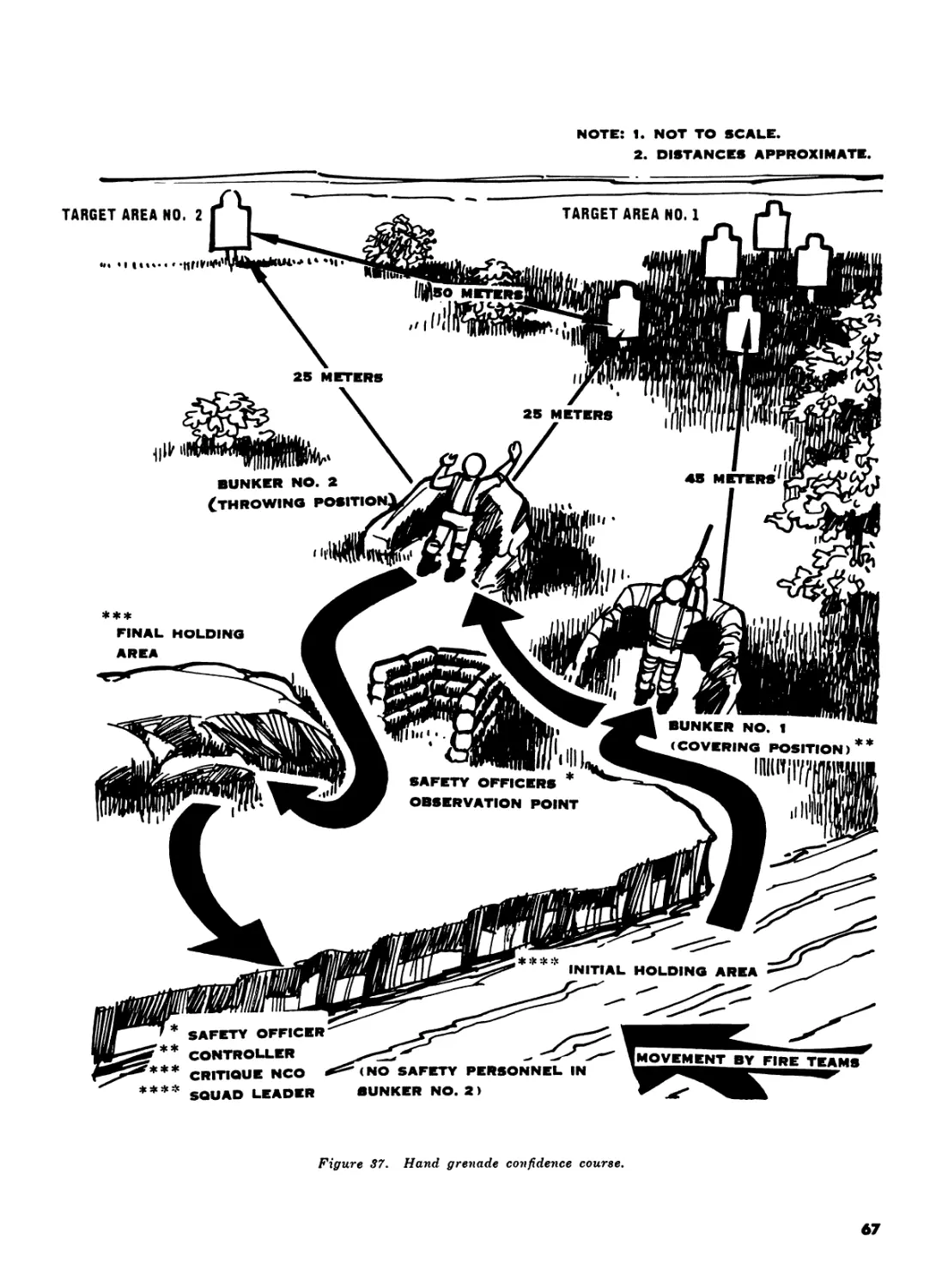
42. Hand Grenade Confidence Course
a. Purpose. Once the soldier has developed his
throwing proficiency and has been introduced to
throwing casualty-producing hand grenades, he
should be given an opportunity to apply his newly
acquired proficiency in a simulated tactical situa-
tion requiring the use of grenades. The Hand
Grenade Confidence Course is designed to accom-
plish this objective. The physical layout of the
course is described in appendix C, and illustrated
in figure 37.
b. Conduct. The Hand Grenade Confidence
Course has a practice and a live course, each con-
sisting of an assembly area, a final coordination
line, an initial holding area, a covering position,
a throwing position, and a final holding area.
(1) The course is started with an orientation
period covering the characteristics and function-
ing of the practice and fragmentation hand
grenades, safety considerations governing the
conduct of training, and a discussion and demon-
stration of the conduct of the course for the entire
unit being trained.
(2) Following the initial orientation, each
platoon (48-60 men) is broken down into 10-man
squads and each man is given a number (1
through 10). Each platoon is moved to a separate
assembly area for the practice course where the
officer in charge (01C) of the range presents a
tactical situation. Unfuzed practice hand grenades
are issued to the platoon for the practice conduct
of the course. All personnel are inspected by the
QIC before they negotiate the course to make cer-
tain that all grenades are properly secured to web
equipment.
(3) The course is conducted as follows:
(a) The first squad moves in a line forma-
tion, ALPHA team on the right, from a tree line
that represents the final coordination line of the
practice course.
(b) Upon arrival at a mound representing
the initial holding area, the squad is taken
30
under fire by a machinegun simulator. The squad
leader sends two men from the right side of the
line to bunker number one near the objective. The
control NCO directs the number one man on the
right to move to bunker number two within hand
grenade range of the objective. From bunker
number two, the soldier observes target area
number one and engages it with an unfuzed prac-
tice hand grenade. When the grenade is thrown,
the safety officer commands ALL DOWN. At this
time, all personnel get behind protective cover.
After the grenade functions (the safety officer
counts to seven which indicates the amount of
time personnel must remain behind the protec-
tive cover), the soldier engages target area num-
ber two with a second unfuzed practice hand
grenade. When the grenade is thrown, the safety
officer commands ALL DOWN.
(c) The soldier who threw the grenades
moves by the most direct route back to the final
holding area where he is critiqued by the critique
NCO. Covering fire is resumed from bunker num-
ber one. The squad leader then sends a new man
to bunker number one where he provides covering
fire for the number two man who moves to bunker
number two to throw his grenades. After the sec-
ond grenade functions (simulated, as in (b)
above), the soldier being critiqued by the critique
NCO moves directly to the initial holding area.
(d) The above sequence is repeated until
all squad personnel have thrown grenades and
provided covering fire. The first soldier to throw
grenades provides covering fire for the last man
to throw.
(e) After the first group has finished the
practice course and has been critiqued, it returns
to the assembly area and then moves to the live
course for the final run with fragmentation gre-
nades. After the first group has completed the
practice course, the practice and live courses are
run concurrently on separate training courts.
Instructor’s Note. In the practice course simu-
lated rifle fire and practice grenades are used. Blank
ammunition and two live grenades are used in the con-
duct of the live course.
(4) The safety officer on the practice course
must carefully observe the actions of soldiers
throwing practice grenades. If the safety officer
detects any unsafe acts or extreme nervousness
on a thrower’s part, the thrower will be identified
to the critique NCO. The critique NCO will point
out the thrower’s mistakes and send him back
through the practice course. In some instances,
it may be necessary to place an individual who
has extreme difficulty in properly handling gre-
nades under the control of an assistant instructor
for detailed instruction. In no instance will a man
be allowed to throw live fragmentation grenades
until he has clearly demonstrated his ability to
throw practice grenades during the practice con-
duct of the course.
(5) The following safety personnel are re-
quired for the Hand Grenade Confidence Course:
(a) Safety Officer. The safety officer
(QIC) is responsible for the overall conduct of
the problem, presentation of bleacher orientation,
and tactical briefing. After issuing the operation
order in the assembly area, the safety officer is
positioned in the safety bunker where he has the
immediate responsibility of supervising hand gre-
nade throwing.
(b) Squad leaders. The squad leaders al-
ternate moving squads to and from the initial
holding areas. They are responsible for insuring
that all personnel are behind protective cover in
the initial holding area when grenades are being
thrown. Squad leaders must check each soldier’s
grenades before he moves from the initial holding
area to bunker number one.
(c) Controller. The controller is the senior
assistant instructor. He is positioned in bunker
number one where he controls the movement of
all personnel both before and after each grenade
is thrown; he also controls the soldier furnishing
covering fire.
(d) Critique NCO. The critique NCO is
positioned in the final holding area. He adminis-
ters a critique to each thrower immediately after
the man arrives from bunker number two. To
insure continuity, the critique NCO will observe
the same squad during both the practice and live
courses. The critique NCO will brief each mem-
ber of the squad after both the practice and live
courses. He then returns to the practice course
to observe another squad.
(6) The training facility for the Hand Gre-
nade Confidence Course consists of a practice
grenade court for throwing the M30 practice gre-
nades and a live grenade court for throwing frag-
mentation grenades. These two courts are con-
structed alike and close together in order to allow
easy movement from one to the other. The Hand
Grenade Confidence Course should be conducted
concurrently with another 2-hour period of in-
struction in order to minimize terrain and per-
sonnel requirements. Time breakdown for the
conduct of training is as follows:
(a) Initial orientation: 20 minutes.
(b) Tactical situation briefing, ammuni-
tion issue, and inspection prior to crossing the
final coordination line: 10 minutes.
(c) Practice run: 35 minutes. (Practice
and live runs are run concurrently after the first
squad completes the practice run.)
(7) The following ammunition is required
for the Hand Grenade Confidence Course:
(a) For each soldier.
1. Cartridge, blank, 5.56-mm.- 20 rounds.
2. Grenade, hand, practice, M30 un-
fuzed : two.
3. Grenade, hand, fragmentation, M26-
series: two.
(b) For each demonstration.
1. Cartridge, blank, 5.56-mm.- 20 rounds.
2. Grenade, hand, practice, M30 un-
fuzed : two.
(8) Upon completion of the Hand Grenade
Confidence Course, the soldier will have obtained
added confidence in his ability to effectively use
grenades in combat, and he will have seen how
grenades are integrated into tactical operations.
Additionally, he will have learned the value of
fire and movement and teamwork when using gre-
nades in an offensive combat role.
43. Hand Grenade Cookoff-Impact
Course
a. Purpose. The “cook-off-impact” course is de-
signed to increase the soldier’s confidence and
proficiency when engaging various nearby enemy
targets using hand grenades. The purpose of the
“cookoff” procedure with time-delay fuzes and
grenades armed with impact fuzes is to prevent
the grenade from rolling away from the target,
from being returned by the enemy, or giving the
enemy time to take evasion action.
b. Conduct. Before conducting the course, the
soldier is given an orientation of the course ob-
jectives and how he is to engage the targets. He
is then given a demonstration of how the course
is conducted. Each soldier is given two fuzed
(time-delay) practice XM69 grenades, two fuzed
(impact) practice XM66 grenades, and one un-
fuzed practice grenade. Each soldier starts at
Station 1. The unfuzed grenade is thrown first
to give the soldier a chance to dry-run the “cook-
off” procedure. After engaging the target with
one fuzed (M228 time-delay) practice XM69 gre-
nade, the soldier moves to Station 2 to engage the
bunker with his second fuzed (M228 time-delay)
practice XM69 grenade. The soldier then moves
to Station 3 to engage the targets with his third
fuzed (XM225 impact) practice XM66 grenade.
The soldier then moves to Station 4 to practice
retrieving a dropped fuzed (XM225 impact)
practice XM66 grenade. Each throwing station
requires one NCO who will insure that the soldier
releases the safety lever, begins his count of “one
thousand, two thousand,” and then throws the
grenade.
31
(1) Station 1. The soldier uses the kneeling
position from behind a low wall to engage a group
of silhouette targets in a trench at a range of 25
meters. He must use the “cookoff” procedure with
his XM69 practice grenade equipped with a time-
delay fuze to engage the target with an airburst.
After his grenade detonates, the soldier quickly
observes the target and moves to the next station.
(2) Station 2. The soldier approaches a
bunker from the rear and uses the “cookoff” pro-
cedure to engage the bunker. He throws his
XM69 practice grenade equipped with a time-
delay fuze into the bunker from either the rear or
the sides. After his grenade detonates, he moves
to the finish line where he waits for the remainder
of his group to complete the course.
(3) Station 3. The soldier uses the kneeling
position from behind a low wall to engage a group
of silhouette targets in the open at a range of 30
meters. He must throw the XM66 practice gre-
nade equipped with an impact fuze over the wire
located midway to the target (to allow the one-
second arming delay time to elapse). After his
grenade detonates, the soldier quickly observes
the target and moves to the next station.
(4) Station 4. The soldier takes the stand-
ing position in a foxhole. After he pulls the pin
from his last XM66 practice grenade equipped
with an impact fuze, he is instructed to drop the
grenade into the foxhole, reach down and retrieve
it, and quickly throw it toward the silhouette
targets.
Instructor's Note. This exercise is designed to de-
velop confidence in the one-second arming delay time and
to point out the danger involved if impact occurs to the
grenade after the one-second arming delay time has
elapsed. The foxhole should have no grenade sump. The
trainee should be instructed not to attempt to kick the
dropped grenade, but immediately retrieve it and throw
the grenade at the targets.
c. Summary. Upon completion of the course,
the soldier will have thrown four fuzed practice
hand grenades. This will acquaint him with the
“cookoff” procedure and enable him to compare it
with impact fuzed grenades. The course provides
him confidence in his ability to use hand grenades
equipped with the time-delay or impact fuzes to
engage various type targets he may encounter on
the battlefield.
Instructor's Note. After the first group has completed
the confidence course, the “cookoff-impact” and confidence
courses are conducted concurrently on separate training
courts.
Section IV. HAND GRENADE TRAINING SAFETY
44. Handling Casualty-Producing Hand
Grenades
Safety instructions governing the handling of
casualty-producing hand grenades are found in
AR 385-63, AR 385-65, TM 9-1330-200, TM 9-
1370-200, and TM 9-1900. In addition to the in-
structions contained in these publications, the
following safety precautions will be adhered to:
WARNING: Unauthorized modification to ser-
vice grenades is prohibited, as a safety hazard may
be created. This is to include any restrictions on
safety pin, lever (hand) with tape, wire, etc.
a. Personnel handling or throwing casualty-
producing hand grenades or who are within this
type of grenade’s danger area (230 meters) will
wear steel helmets.
b. Personnel will throw fuzed practice hand
grenades before throwing casualty-producing
hand grenades.
c. No hand grenades, other than fuzed practice
hand grenades, will be defuzed by any individual
except qualified and authorized supporting unit
maintenance personnel.
d. The guidelines listed in paragraph le for
grenades armed with the M217 impact detonating
fuze will be strictly adhered to.
e. The safety pin on a grenade will not be re-
moved until the grenade is to be thrown. Once the
safety pin is removed, it will not be placed back
into the grenade, and the grenade must be thrown.
f. Grenades found upside down in their pack-
ing containers will not be removed. The con-
tainers will be marked and returned to the issuing
facility.
g. Dud grenades will not be recovered, handled,
or otherwise tampered with by any individual ex-
cept explosive ordnance disposal personnel.
h. All throwing of casualty-producing hand
grenades will be done under the supervision of a
commissioned officer (AR 385-63).
i. If a casualty-producing hand grenade is
dropped accidentally after the safety-pin is re-
moved, the soldier dropping the grenade and the
safety NCO in the throwing bay will—
(1) Shout “GRENADE” to alert other per-
sonnel in the area that a casualty-producing hand
grenade has been dropped.
(2) Insure that the grenade is picked up and
thrown in a low arc into a safe area.
Note. Grenades will not be thrown into a sump,
ditch, or similar area. If protective cover is unavailable
32
when the grenade is thrown into a safe area, personnel
will drop to the prone position with steel helmets facing
the direction of the grenade's detonation point. This pro-
cedure minimizes the area of a man’s body that is exposed
to blast and fragmentation, and it allows the steel helmet
to deflect fragments.
j. In training, fragmentation hand grenades
will not be removed from the bottom half of the
individual grenade containers until just before
use. As each soldier is called to stand and throw
his grenade, he will remove the grenade from the
bottom half of the container, being sure to slide
his thumb over the safety lever before the lever
clears the fiber container or the sleeve inside the
container. This procedure will prevent accidents
due to damaged safety pins or levers. This tech-
nique is followed prior to issuing the grenades
to individuals negotiating the Hand Grenade Con-
fidence Course. The soldier carries the grenades
attached to the ammunition pouch until he reaches
the throwing position.
k. Under no circumstances will grenades be at-
tached to clothing or equipment by the pull ring.
Attaching grenades to clothing or equipment by
the pull ring can easily result in the safety pin
being accidentally removed from the grenade.
I. If grenades are attached to clothing or equip-
ment for extended periods of time, the fuze assem-
bly may become loosened from the grenade
body, allowing moisture to enter the grenade. To
prevent moisture damage to the grenade, the fuze
must be periodically tightened.
m. At least a 5-minute waiting period will be
observed before an HE-loaded grenade dud is
approached. Dud grenades will be removed or
destroyed in place only by authorized explosive
ordnance disposal personnel.
45. Handling Noncasualty Producing
Hand Grenades
a. Practice Hand Grenades. Personnel in-
stalling fuzes in practice hand grenades will in-
stall only the practice fuze designed for use with
a specific practice grenade. Detonating fuzes may
cause the grenade body to shatter, producing dan-
gerous fragments. When reloading practice hand
grenades, no more than one bag of 21 grains of
black powder will be inserted into the grenade
body. More black powder than this will produce
a dangerous explosion which may shatter the gre-
nade body. Practice grenades which fail to func-
tion will not be recovered for at least 10 minutes.
b. Chemical Hand Grenades.
(1) Personnel will be no closer than 10
meters to the AN-M14 TH3 incendiary hand gre-
nade while it burns. Personnel should not look
directly into the burning thermate mixture since
it may cause temporary blindness or permanent
eye damage.
(2) Safety levers of chemical hand grenades
will not be released before throwing because of
the extremely short time delay period.
(3) Riot control hand grenades should not be
used in enclosed areas during training. The M25-
series of riot control hand grenades should not be
detonated nearer than 5 meters to any personnel.
(For further information governing the use of
riot control hand grenades in training, see FM
21-48.)
(4) Smoke hand grenades will not be used
in enclosed areas during training.
(5) At least a 30-minute waiting period will
be observed prior to approaching a chemical gre-
nade dud. Dud grenades will be removed or
destroyed in place only by authorized explosive
ordnance disposal personnel.
33
CHAPTER 4
RIFLE GRENADES AND ACCESSORIES
Section I.
46. Description
a. Rifle grenades, unlike hand grenades, are
projected only from the service rifle and do not
lend themselves to throwing. Rifle grenades are
used to assist in the accomplishment of five
missions:
(1) Antitank.
(2) Antipersonnel.
(3) Signaling.
(4) Screening.
(5) Incendiary.
b. Weapons such as the 40-mm grenade
launcher, M79 and the 66-mm high explosive
antitank rocket, M72, have taken over many of
the combat roles previously assigned to rifle gre-
nades. Despite this, rifle grenades are still in
abundant supply, and the ever-changing world
military picture dictates that training with rifle
grenades be continued so that they may be quickly
and effectively used as the need arises.
47. Characteristics
Rifle grenades can be fired in both the direct and
Section II.
49. General
There are several accessories required for the
projection of rifle grenades from the service rifle.
Rifle grenades require a means of attachment to
the rifle, a means of propelling the grenade to the
intended target, and a means of sighting the rifle
to accurately engage the target.
50. Grenade Launchers and Grenade
Retainer Spring
Although the M14 and M16A1 are the standard
rifles presently in use in the active Army, the Ml
rifle is still used by the reserve components of our
Army and by the armies of many of our allies.
GENERAL
high-angle direct-fire roles (fig. 17). When used
in the high-angle direct-fire role, they are, in
effect, the infantryman’s small unit mortar. In
such a role, rifle grenades are capable of covering
the dead space to the front of defensive positions,
and they can fill the gap existing in high explosive
firepower between the maximum throwing dis-
tance of hand grenades and the minimum safe
supporting ranges of mortar and artillery fire.
48. Main Parts
a. Rifle grenades consist of five main parts.
(1) Grenade body.
(2) Filler.
(3) Fuze assembly.
(4) Stabilizer tube.
(5) Fin assembly.
b. The body, filler, and fuze play the same part
in rifle grenades as they do in hand grenades.
The fin assembly and the stabilizer tube provide
the grenade with its proper ballistic character-
istics, giving the grenade stability in flight.
ACCESSORIES
Accordingly, information on the accessories used
with the Ml rifle is included in this publication.
a. M7A3 Grenade Launcher (1, fig. 18). The
M7A3 grenade launcher is designed for use with
the caliber .30, Ml rifle. The launcher has 9 an-
nular rings and grooves numbered from 6 at the
muzzle end of the launcher to 4A near the launch-
er’s base. These annular rings and grooves have no
metric or yard values as such; however, the closer
the base of the rifle grenade is placed to the 4A
position, the farther the grenade can be projected.
Ball ammunition may be fired from the rifle when
the launcher is attached, although the launcher’s
added weight will slightly disturb the weapon’s
zero. On the forward end of the launcher is a
35
Figure 17. Direct and high-angle direct fire with rifle
grenades.
M7 A3 GRENADE LAUNCHER
GRENADE RETAINER SPRING FOR THE
M16ANDM16A1 RIFLES
Figure 18. Grenade launchers and grenade retainer spring.
36
clip-type retainer spring, which holds the grenade
in the desired position once it is joined to the
launcher. When the launcher is attached to the
rifle, the stud on the frame of the launcher rests
on top of the valve in the gas cylinder lockscrew
of the rifle. When a grenade is fired from the
launcher, a slide and spring assembly in the
launcher frame (fits against the bayonet stud)
allows the launcher to move slightly to the rear.
This slight, independent recoil causes the stud to
open the valve in the gas cylinder lockscrew, per-
mitting the gas to escape. This action prevents
excessive recoil and precludes damage to the
operating parts of the rifle because of excessive
gas pressure. The launcher is returned to its
original position by the action of the compressed
spring in the launcher frame, permitting the valve
in the gas cylinder lockscrew to close.
b. M76 Grenade Launcher (2, fig. 18). The
M76 grenade launcher is used with the 7.62-mm,
M14 rifle. The launcher weighs 7 ounces and is
approximately 15 centimeters (6 inches) long.
The launcher has 9 annular grooves numbered
from 6 near the muzzle of the launcher to 4A near
the base of the launcher. The function of the an-
nular grooves on the M76 launcher is the same
as that of the M7A3 launcher. On the muzzle end
of the launcher is a clip-type retainer spring
which holds the grenade in the desired position
prior to firing. The launcher slides over the flash
suppressor and is secured to the rifle by a clip
latch that snaps over the bayonet stud on the flash
suppressor.
c. Grenade Retainer Spring (3, fig. 18). This
spring is used with the M16 and M16A1 rifles.
Its function is to secure the grenade to the rifle.
This feature eliminates the requirement to use the
M7A3 or the M76 grenade launchers. The grenade
retainer spring must be replaced after 30 grenade
firings.
51. Special Grenade Cartridges
Special grenade cartridges are easily identified
by sight or touch by their five-pointed, star-
crimped ends. There are no authorized special
grenade cartridges for the caliber .30 carbine.
Rifle grenades will not be fired from this weapon.
Field expedient grenade cartridges, such as blank
ammunition or service ammunition, with or with-
out the projectile removed, are not to be used to
project grenades.
a. М3 Rifle Grenade Cartridge (1, fig. 19). The
М3 special grenade cartridge is the .30 caliber
cartridge used with the Ml rifle. It is slightly
longer than its 7.62-mm counterpart, the M64
special grenade cartridge.
b. M6U Rifle Grenade Cartridge (2, fig. 19).
The M64 special grenade cartridge is the 7.62-mm
cartridge used with the M14 rifle.
с. M195 Rifle Grenade Cartridge (3, fig. 19).
The Ml95 special grenade cartridge is the .223
caliber (5.56-mm) cartridge used with the M16
and M16A1 rifles. It is similar in appearance to
the М3 and M64 cartridges but is slightly smaller.
52. Ml 5 Sight
a. The M15 sight (1, fig. 20) is used to accu-
rately deliver a grenade to its intended target.
This sight can be used with either the Ml or the
M14 rifle. The sight is attached to the rifle by a
mounting plate, which is installed and removed
only by supporting unit maintenance personnel.
The mounting plate contains an elevation scale
graduated in 5° increments from 0° to 60°. The
scale is numbered at each 10° mark.
b. The M15 sight consists of a sight bar on
which a front sight post and a rear peep sight
(2, fig. 20) are mounted. These are used in the
same manner as the iron sights on a rifle when
grenades are fired in the direct-fire role. Beneath
the peep sight is an elevation screw which moves
the rear peep sight. On the rear of the peep sight
are 4 graduations, each equal to a 1° change in
elevation. Five clicks on the elevation screw
moves the peep sight 1°. The elevation screw, the
front sight post, and the rear peep sight are not
used for high-angle direct fire. Instead, the sight
bar assembly is rotated until the index line of the
sight mounting bracket is alined with the appro-
priate degree setting on the mounting plate ele-
vation scale. After alining the muzzle of the
grenade launcher with the target, the grenadier
raises or lowers the rifle muzzle until the leveling
bubble in the leveling vial is centered. This pro-
cedure places the rifle on the same angle as indi-
cated on the elevation scale of the sight mounting
plate. No special sight is used with the 5.56-mm
(M16 and M16A1) rifles. ' The marked sling
(chap. 5) is used to obtain correct elevation set-
tings on these weapons.
53. Spindle Valve
(fig. 21)
The spindle valve on the M14 rifle controls the
gases used in firing the rifle and rifle grenades.
To prevent damage to the working parts of the
rifle, the spindle valve slot must be turned to the
closed position (parallel to the barrel) when firing
rifle grenades. This closing permits the full pres-
sure of the gases created by the firing of the spe-
cial grenade cartridge to be utilized in propelling
37
М3 (.30 CAL.)
M64 (7.62-MM
M 195 (5.56-ММ)
© © ©
Figure 19. Rifle grenade cartridges.
the rifle grenade and prevents bypass of the gas
into the gas cylinder.
54. Grenade Projection Adapters
To project hand grenades from the service rifle,
a fourth accessory is required in addition to those
already mentioned—the grenade projection
adapter. There are presently two standard gre-
nade projection adapters: the M1A2 and the
M2A1.
a. M1A2 Grenade Projection Adapter (1, fig.
22). The M1A2 grenade projection adapter is
olive drab in color and consists of a fin assembly,
a stabilizer tube, and three metal claws. The
longest of the claws contains an arming clip,
which is held in place by a brittle piece of metal—
the arming clip retainer. When joining the gre-
nade to the adapter, the grenade’s safety lever is
inserted into the arming clip, and the grenade is
forced down onto the adapter until it is fully
seated in the cup at the top of the stabilizer tube.
The safety pin is removed before the grenade is
fired. Extreme care must be taken to insure that
the arming clip retainer is not broken and that
the striker of the grenade does not have sufficient
room to rotate on its axis and strike the primer.
When the grenade is fired, inertia causes the arm-
ing clip to break the brittle arming clip retainer.
38
REAR PEEP
SIGHT
Q SIGHT MOUNTED ON THE RIFLE
ELEVATING screw
(5 CLICKS EQUAL I °
ELEVATION)
WINDAGE GRADUATION
(NO SET VALUE)
(2) REAR (PEEP) SIGHT ELEVATED 4TED
THREE DEGREES
REAR PEEP SIGHT OF THE MIS SIGHT
Figure 20. Ml 5 sight.
This action releases the safety lever from the gre-
nade and allows the grenade to function in the
normal manner. The M1A2 grenade projection
adapter is used to project the MK2, the M26, and
the M26A1 fragmentation hand grenades, the
M30 practice hand grenade, the M34 WP smoke
hand grenade, and the MKI illuminating hand
grenade.
b. M2A1 Grenade Projection Adapter (2, fig.
22). The M2A1 grenade projection adapter is
gray in color and consists of a fin assembly, a
stabilizer tube, and three short claws. In place of
the arming clip, the М2 Al has a setback band
consisting of a spring and a thin metal band.
When joining the grenade to the adapter, the
grenade is forced down onto the adapter until it
is fully seated and held securely in place by the
adapter’s claws. The setback band is then placed
over the grenade’s safety lever in such a manner
that the spring is centered on the safety lever
and positioned approximately 1/2-inch from its tip.
The safety pin is removed before the grenade is
fired. When the grenade is fired, the thrust of the
grenade being propelled forward drives the set-
back band rearward. This action releases the
safety lever from the grenade and allows the
grenade to function in the normal manner. The
М2 Al grenade projection adapter is used to pro-
ject the M6- and M7-series of riot control hand
grenades, the AN-M8 HC white smoke hand gre-
nade, the AN-M14 TH3 incendiary hand grenade,
and the M18 colored smoke hand grenade.
Note. The rifle must be loaded with a special grenade
cartridge before attaching rifle grenades. This procedure
facilitates quick firing if the grenade’s fuze begins to
function prematurely after removal of the safety pin.
39
SPINDLE VALVE IN
SPINDLE VALVE IN
Figure 21. Spindle valve.
Section III. TYPES OF RIFLE GRENADES
55. M31 High Explosive Antitank Rifle
Grenade
(1, fig. 23)
In the future, the roles of the M31 HEAT rifle
grenade will be fulfilled by the M72 light antitank
weapon when sufficient quantities of that item
become available for the Army’s world-wide
requirements.
a. Body. The body of the grenade is made of
a copper-coated steel alloy. The fin assembly and
the stabilizer tube are made of an aluminum alloy
to reduce the weight of the grenade. The grenade
is painted olive drab and has yellow markings to
identify the filler as a high explosive.
b. Filler. 9.92 ounces of composition В in the
form of a shaped charge.
с. M211 Fuze. This fuze is point initiating and
base detonating. The fuze is armed at a distance
of 6-12 meters from the rifle by setback action.
The nose of the grenade contains a piezoelectric
(lucky) crystal. When the grenade’s impact
crushes the crystal, it sends an electrical impulse
. 40
through a copper wire to the fuze located at the
base of the grenade body. The fuze itself consists
of an arming rotor, a spring-driven contact, and
a small booster pellet. When the electrical im-
pulse reaches the detonator in the fuze, the gre-
nade’s explosive train is initiated.
d. Weight. 25 ounces.
e. Capabilities. The M31 can be fired in the
direct-fire role to a maximum effective range of
115 meters or in the high-angle direct-fire role
to a maximum range of 185 meters. The grenade
has the capability of penetrating 25 centimeters
(10 inches) of homogeneous steel armor or 50
centimeters (20 inches) of reinforced concrete.
In the high-angle direct-fire role, the grenade has
an effective casualty radius of 15 meters. The
M31 archives armor penetration by means of the
Munroe Principle (2, fig. 23) of the shaped
charge. The Munroe Principle is governed by the
following three properties of explosive reactions:
(1) An explosive force reacts against the
weakest force containing it. In the M31, this con-
(7) М1А2 GRENADE PROJECTION ADAPTER
(?) M2A1 GRENADE PROJECTION ADAPTER
Figure 22. Grenade projection adapters.
41
(7)
М 31, HEAT RIFLE GRENADE
Figure 23. MSI HEAT rifle grenade and the Munroe Principle of the shaped charge.
42
taining force is a thin sheet of copper which
forms an inverted cone liner. This cone gives the
filler its shaped effect. The grenade’s hollow nose
provides the proper standoff distance for the ex-
plosive forces to converge.
(2) An explosive force reacts against the
force containing it at right angles. In the case of
the M31, we see them reacting against the copper
cone at right angles and moving toward each
other.
(3) Converging explosive forces combine to
form a third and greater force known as the ex-
plosive jet. In the M31, the jet is a combination
of heat and force which will melt a path through
armor and carry pieces of molten armor through
it. These molten chunks then rapidly return to
solid form. In the case of an armored vehicle, the
jet penetrates the vehicle’s body armor, as de-
scribed above, and also flakes off pieces of the
inner side of the armored hull. This fragmented
armor richochets about the interior of the ve-
hicle’s body, killing personnel and detonating
sensitive ammunition.
56. M19A1 White Phosphorous Smoke
Rifle Grenade
(l,fig. 24)
The roles of the M19A1 white phosphorous smoke
grenade are being fulfilled by the M34 WP smoke
hand grenade and other munitions. The M19A1
grenade is being phased out of use as existing
quantities are exhausted.
a. Body. Sheet steel. (The grenade has the
same markings as the M34 WP smoke hand
grenade.)
b. Filler. 8.5 ounces of white phosphorous.
c. Fuze. The M19A1 rifle grenade employs a
mechanical impact detonating fuze. Prior to
firing the grenade from the rifle, the safety pin,
which passes through the stabilizer tube, must
be removed. When the grenade’s nose strikes a
solid object, the fuze’s firing pin overcomes spring
tension by inertia and strikes the fuze’s primer.
The primer emits an intense flash of heat to ex-
plode the detonator, which in turn ruptures the
grenade body and disperses the filler.
d. Weight. 24 ounces.
e. Capabilities. The M19A1 grenade can be pro-
jected 195 meters from the service rifle. The gre-
nade has an effective casualty radius of 10 meters;
however, particles of white phosphorous may be
projected 20 meters from the grenade’s detonation
point. The white phosphorous will burn for 60
seconds at approximately 5000° F.
57. M22 Series of Colored Smoke Rifle
Grenades
The M22-series of colored smoke rifle grenades
are being replaced by ground pyrotechnic signals
and other chemical munitions. The M22-series of
rifle grenades are issued in three colors: red,
green, and yellow.
a. Body. The grenade body is steel. There is
a nose closing plug at the top of the grenade
which is NOT to be removed. There are five
emission holes at the base of the rifle grenade.
(For color code markings, see app D, table 3.)
The color of the base identifies the color of the
grenade’s smoke.
b. Filler. 6.5 ounces of colored smoke mixture.
c. Fuze. The M22-series of rifle grenades em-
ploy a mechanical impact igniting-type fuze
which ignites the colored smoke charge upon im-
pact. This rifle grenade has a safety clip on the
stabilizer tube which must be removed just prior
to firing.
d. Weight. 20.2 ounces.
e. Capabilities. The M22-series of rifle gre-
nades are used for signaling and laying down
smoke screens. The smoke charge burns approxi-
mately 1 minute. The grenade has a range of over
200 meters.
58. M23A1 Colored Smoke Streamer
Rifle Grenade
(2, fig. 24)
The M23A1 colored smoke streamer rifle grenade
is being replaced by ground pyrotechnic signals
and other chemical munitions. The grenade is
being phased out of use as existing quantities are
exhausted. The M23A1 rifle grenade is issued in
three colors: red, green, and yellow.
a. Body. The grenade body is sheet steel. There
is an air intake hole at the top of the grenade and
four emission holes at its base. (For color code
markings, see app D, table 3.) The color of the
base of the grenade body identifies the color of
the grenade’s smoke.
b. Filler. 6.5 ounces of colored smoke mixture.
c. Fuze. The M23A1 rifle grenade employs an
igniter which is activated by the flash of the
special grenade cartridge being fired. The igniter
sets off the burning smoke charge. The smoke
charge is forced out of the grenade body by the
air pressure created by the intake of air into the
intake hole in the nose of the grenade. This hole
and holes in the base of the body are covered with
adhesive tape to prevent moisture from damaging
the filler. The tape is removed before firing.
d. Weight. 18.5 ounces.
43
SAFETY PIN
HUM PRACTICE RIFLE GRENADE
M19A1, WP SMOKE RIFLE GRENADE.
О
MM PRACTICE RIFLE GRENADE
M23A1 COLORED SMOKE STREAMER RIFLE GRENADE
MU PRACTICE RIFLE GRENADE
Figure 2k. Chemical rifle grenades.
Figure 25. Practice rifle grenades.
e. Capabilities. The M23A1 rifle grenade is
used only for signaling purposes and emits a
trail of colored smoke for 12 seconds. The gre-
nade attains ranges in excess of 200 meters when
fired from the service rifle.
59. Practice and Training Rifle Grenades
There are presently three types of practice rifle
grenades in Army use. Practice grenades are
used to train personnel to handle rifle grenades
before they receive training with live or service
rifle grenades.
a. Mil Ab Practice Rifle Grenade (1, fig. 25).
The M11A4 rifle grenade is used to simulate the
flight characteristics of the M19A1 and M23A1
rifle grenades. The M11A4 grenade is made
of steel and its parts are reusable and
interchangeable.
b. M29 Practice Rifle Grenade (2, fig. 25). The
M29 rifle grenade is obsolete, and is used only
to a limited extent as a replacement item for the
M31 practice rifle grenade. The M29 grenade is
made of cast iron and is entirely inert. It was
originally developed to simulate the flight charac-
teristics of the M28 HEAT rifle grenade, which
has been replaced by the M31 HEAT rifle
grenade.
c. MSI Practice Rifle Grenade (3, fig. 25). The
M31 practice rifle grenade is used to simulate the
ballistic characteristics of the M31 HEAT rifle
grenade. The M31 grenade is made of sheet steel
and aluminum and contains no filler and no fuze.
The M31 practice rifle grenade weighs 25 ounces
and has a maximum range of 150 meters. There
are no replacement parts for the grenade.
45
CHAPTER 5
RIFLE GRENADE TRAINING
Section I. DIRECT-FIRE MARKSMANSHIP TRAINING
60. Introduction
a. Direct fire with rifle grenades is any firing
requiring less than 26° of elevation. In direct fire,
the rifle is fired from the shoulder, except in the
prone position. This type of firing is effective
against point targets, such as tanks, pillboxes, or
windows of buildings. When firing grenades in
the direct-fire role, the grenade must be fully
seated on the launcher. Due to excessive recoil
effects, the M16 and M16A1 rifles will not be used
in the direct-fire role.
b. This section prescribes training for firing
rifle grenades at both stationary and moving
direct-fire targets. This training should follow
rifle markmanship training, because many of the
steps in rifle grenade direct-fire training are
similar to the steps in rifle markmanship training
described in FM 23-71. Direct-fire markmanship
training includes the following:
(1) Positions.
(2) Sighting and aiming.
(3) Trigger control.
(4) Range determination.
(5) Speed estimation.
(6) Lead calculation.
(7) Loading and firing procedures.
61. Positions
a. General. Rifle grenades are fired at direct-
fire targets from the standing, kneeling, and
prone positions. Except in the prone position,
fire the rifle with the rifle butt against your right
shoulder. This allows you to see the target
through the M15 sight. Do not fire from the
shoulder when in the prone position, since your
body cannot move freely with the rifle’s recoil.
Use a stock rest when firing from the prone posi-
tion. In other positions, you should use the
shoulder-fire position at all times unless your body
cannot move freely with the rifle’s recoil. Do not
use the sling when firing in the direct-fire role.
Hold the rifle firmly with your left hand near the
upper sling swivel and your right hand at the
small of the stock. Hold your left elbow well
underneath the weapon, exerting pressure to pull
the rifle butt firmly against the shoulder. In order
to prevent injury to the thumb by the weapon’s
recoil, hold your right thumb along the right side
of the stock, rather than over the small of the
stock. Keep your head away from the sight and
canted slightly to the left. When firing grenades
from the Ml or M14 rifles, you cannot fire in the
direct-fire role from the left shoulder because the
sight is located on the left side of the rifle.
b. Standing Position (1, fig. 26). Face your
target, execute a half right face, and spread your
feet a comfortable distance apart. Rotate the
rifle on its right side so that when you grasp it
with your left hand, your fingers will wrap around
the top of the upper handguard. Without chang-
ing the grip of your left hand, rotate the rifle butt
into your right shoulder. At this point, do not
allow the rifle to cant to either side. Hold your
right elbow at shoulder height to form a pocket
for the rifle butt. Place your right hand at the
small of the stock with your right thumb along-
side the stock. Cant your head slightly to the left
so you can see through the M15 sight. Lean for-
ward with your entire body. This will allow you
to rock back with the recoil of the weapon. Track
moving targets by pivoting evenly and smoothly
at the waist.
c. Kneeling Position (2, fig. 26). Face your
target, execute a half right face, and kneel on
your right knee. Do not sit on your right heel or
use your left knee to support your left elbow.
Place the rifle to your shoulder in the same man-
ner as in the standing position. Lean well for-
ward so that you can rock back with the weapon’s
recoil. Track targets by pivoting evenly and
smoothly at the waist.
d. Prone Position (3, fig. 26). The prone posi-
tion has several disadvantages and should be used
only when necessary. Since you cannot rock back
with the recoil of the weapon, use a stock rest,
such as a tree stump, a wall, or a hole in the
46
PRONE POSITION
SHOULDER IS OVER
STOCK, HOT BEHIND RIFLE
BUTT.
Figure 26. Direct-fire positions.
47
/round to hold your weapon. You may also have
difficulty seeing through the M15 sight When
assuming the prone position, place the rifle butt
against any available rest. Hold your forearm
over the top of the rifle stock to hold it steady.
Do not cant the rifle to either side.
62. Sighting and Aiming
a. Using the M15 Sight. Direct-fire targets are
engaged as follows:
(1) Estimate the range to the target.
(2) Determine the correct angle of elevation
from the range tables (para. 70). Then set the
sight. To do this, rotate the sight bar to the near-
est 5° mark below the desired setting, and turn
the elevating screw the correct number of clicks
from 0° to complete the setting. Be sure the peep
sight is set at 0° before adding the odd number of
degrees to the sight. Remember that 5 clicks on
the elevating screw changes the elevation set-
ting 1°.
(3) Prepare the rifle and the grenade for
firing.
(4) Assume the appropriate position, take
the proper sight picture, and fire the grenade.
b. Sight Alinement and Sight Picture. Sight
alinement with the M15 sight is the same as with
the iron sights on the rifle. However, because the
M15’s sight radius is short, sight alinement is
more critical.
c. Direct-Fire Sighting Exercises. Before you
progress to other steps of markmanship training,
you will be given an opportunity to practice and
demonstrate your knowledge of direct-fire sight-
ing and aiming using the M15 sight. In order to
do this, two sighting exercises have been devised.
A service rifle with the M15 sight mounted, a rifle
rest (1, fig. 27), a sighting disk (2, fig. 27), and
a 1-meter square blank target are needed to ac-
complish these exercises.
(1) Exercise No. 1. The purpose of this
exercise is to provide practice in correct direct-
fire sight alinement using the M15 sight An in-
structor places a rifle in a rifle rest, sets the sight
at zero elevation, and lines up the sighting disk
(tank silhouette) by giving instructions to a
marker who controls the sighting disk. The in-
structor commands HOLD when the sighting disk
is in line for a correct sight picture. He then
moves away and directs the student to look
through the sights to observe the correct sight
alinement. Rifle rests are then placed on line and
blank targets are placed out approximately 10
meters. Firers take position behind the rifles and
sight and direct markers to move the sighting
disks until the correct sight alinement is attained.
(Г) RIFLE REST
Coaches or instructors verify the alinement.
(2) Exercise No. 2. The purpose of this
exercise is to provide practice in correct sight
alinement and sight setting for firing rifle gre-
nades in the direct-fire role. An instructor demon-
strates the method of setting the M15 sight as
described in exercise No. 1. He then resets the
sight at zero elevation. Firers then take a posi-
tion behind the rifles and sight. As the instructor
announces the range, firers refer to the range
table (para 70), find the correct angle of eleva-
tion for that range, and set the angle on the sight.
48
The instructor then alines the sight with the tar-
get by giving instructions to the marker as in
exercise No. 1. Coaches or instructors then verify
the sight setting and alinement.
63. Trigger Control
Trigger control is just as important when firing
rifle grenades as it is when firing service (ball)
ammunition. Correct position, correct sight aline-
ment, and correct speed leads are of no value if
trigger control is faulty. This fact is especially
true in firing at low-angle, direct-fire targets.
You should practice trigger control as described
for the rifle in FM 23-71. You must constantly
bear in mind that trigger control is one of the
most important steps in obtaining first round hits
on a target.
64. Speed Estimation
You can train yourself to estimate speed by ob-
serving tanks and other vehicles traveling in
various directions, at predetermined speeds, and
at various ranges. Ability to estimate speed is
developed by frequent practice. First, you should
estimate speed at known distances and known
speeds, varying the type of vehicle. Then vary
the range and the type of vehicle. Finally, vary
all four factors and, at the same time, practice
sight setting, sight alinement, and lead calcula-
tions. You should not practice speed estimation
on targets traveling at excessive speeds or on
targets beyond the maximum effective direct-fire
range (115 meters) of rifle grenades.
65. Lead Calculation
a. In order to hit a moving target you must aim
at the point where the target will be when the
grenade reaches it. This is done by aiming at a
point a certain distance in front of the center of
mass of the target, rather than aiming directly
at the center of mass. This distance is measured
in “speed leads” instead of meters. One speed lead
is the length of the target as it appears to you
(fig. 28). Leads for moving targets are based on
the speed and direction of the target and the speed
of the grenade in its flight to the target. Moving
at a speed of 24 KMPH (15 MPH), a vehicle will
cover about 7 meters in a second (the average
length of a medium tank). A tank moving 25
meters to your front at this speed would require
a half-speed lead. Remember that the lead is
taken from the center of mass of the target and
maintained throughout firing; thus, for a tank
requiring a half-speed lead, your point of aim
would be the leading edge of the tank. A common
error is to stop tracking when pressure is applied
to the trigger.
Figure 28. Correct sight picture for a target requiring
a one-speed lead.
b. Apply leads by using the length of the target
as it appears to you as a unit of measure. This
procedure eliminates the necessity for corrections
because of the angle at which the target crosses
your line of sight. The sharper the angle, the
smaller the target appears and the less lateral
speed it attains.
c. In addition to compensating for the lateral
movement of a target, you must make allowance
for the movement of a target toward or away
from you. This is done by adjusting the point of
aim to a point above or below the center of mass.
(1) Approaching targets. To hit a target
which is approaching your position, aim slightly
below its center of mass. This allows for the de-
crease in range to the target between the time the
grenade is fired and the time it reaches the tar-
get. The point of aim below the target’s center of
mass depends upon the speed of the target, the
range to it, and the angle at which it is approach-
ing. This will vary as much as 1.5 meters.
(2) Retreating targets. To hit a target
which is moving away from your position, you
must aim slightly above the target’s center of
mass. This compensates for the increase in range
from the time the grenade is fired until it impacts
with the target.
49
(3) Crossing targets. To hit targets moving
at right angles to your line of sight, aim level
with the center of mass using the proper speed
lead.
66. Direct Fire Loading and Firing
Procedure
The loading and firing procedure for engaging
targets with low angle, direct fire is as follows:
a. Open the bolt and clear the rifle.
b. Lock the weapon by engaging the safety.
c. Place the correct angle of elevation on the
M15 sight if the Ml or M14 rifles are used.
d. Load the special grenade cartridge into the
chamber.
e. Close the bolt.
/. When using the M14 rifle, check to see if the
spindle valve is in the closed position.
g. Place the grenade onto the launcher or rifle.
(“Position “full” is used for all low-angle, direct
firing.)
h. Remove any external safety features from
the grenade such as the safety pin on the M22A2
colored smoke rifle grenade.
i. Unlock the weapon by disengaging the safety.
3. Aim the weapon and fire.
Section II. HIGH-ANGLE DIRECT-FIRE MARKSMANSHIP TRAINING
67. Purpose
a. High-angle direct fire with rifle grenades is
accomplished by placing the rifle butt on the
ground and firing the rifle at an angle of 26 or
more degrees of elevation. Because of its relative
inaccuracy, high-angle direct fire is primarily
used to engage large or area targets in the open
or targets in defilade.
b. This section prescribes instruction for firing
rifle grenades at area targets and targets in def-
ilade. This instruction should follow rifle marks-
manship training, and may come before or after
direct-fire grenade markmanship training. High-
angle direct-fire marksmanship training includes
the following:
(1) Positions.
(2) Range estimation.
(3) Use of range tables.
(4) Sighting and aiming.
(5) Trigger control.
(6) Loading and firing procedures.
68. Positions
Three positions are used in high-angle direct fire
with rifle grenades: the sitting, the kneeling and
the modified kneeling. The modified kneeling posi-
tion is used only when the marked sling method
of sighting and aiming is employed.
a. Kneeling Position (1, fig. 29). Face your
target, kneel on your right knee, and point your
left foot in the general direction of the target.
Since moving targets are not tracked in high-
angle fire, sit on your right heel and use your
left knee to support your left elbow. Place the
rifle butt on the ground alongside your right knee.
Grasp the rifle near the upper sling swivel with
your left hand and the small of the stock with
your right hand. Your right thumb should be
placed alongside the stock. Rest your weight on
your right heel. After placing the correct sight
setting on the sight, lower the rifle and sight
along the barrel toward the target to obtain the
correct deflection. Then raise the rifle slowly
until the leveling bubble is centered in its vial.
Lower your head before firing to prevent injury
to your eyes by blowback from the grenade’s
propellant.
b. Modified Kneeling Position (2, fig. 29). This
position is used only when using the marked sling
for sighting and aiming the rifle. Assume the
kneeling position as in a above, except that you
place your left foot on the sling at the desired
point. Lower the rifle so you can sight for deflec-
tion, and then raise the rifle until the sling is taut
and perpendicular to the ground. Then lower
your head and fire.
e. Sitting Position (3, fig. 29). Face your tar-
get and sit down, keeping your right leg flat on
the ground and pointed toward the target. Cross
your left leg over your right knee to provide sup-
port for your elbow. Place the rifle butt alongside
your right hip. From this point, hold and sight
the rifle in the same manner as in the kneeling
position.
69. Use of Range Tables
a. High-angle direct-fire range tables for the
various types of grenades are shown in table 1.
The range depends not only on the angle of eleva-
tion, but also on the position of the grenade on
the launcher. To increase the range for a given
elevation, place the grenade farther down on the
launcher. To place the grenade at the desired
position on the launcher, push the grenade down
until the rear of the stabilizer tube coincides with
the annular groove marked with the desired posi-
tion number; for example, if the range table calls
50
for position 3, push the grenade down on the
launcher until the annular groove marked 3 is
covered by the grenade’s stabilizer tube. You
should still be able to read the number 3 on the
launcher.
b. The range tables are designed to be used as
a guide only. The actual range for a given angle
of elevation and position will vary with different
lots of special grenade cartridges, different rifles
or launchers, and different atmospheric conditions.
Table 1. Range Tables
(1) M31 HEAT rifle grenade (direct fire,
position full).
Range in meters
40
60 .....
80 .....
100 .....
110 .....
120 .....
Angle of elevation
...... 6 2/5°
...... 7 2/5’
...... 11’
..... 15’
..... 17’
..... 18’
(2) M19A1 WP smoke rifle grenade (high-
angle direct fire).
Range in meters Position on launcher .4 ngle of elevation
50 ................... 6..................30°
55 ................... 6..................45°
65 ................... 5 ................. 30°
75 ................... 5 ................. 45°
85 ................... 4 ................. 30°
100 ................... 4 ................. 45°
120 ................... 3 ................. 30°
125 ................... 3 ................. 45°
140 ................... 2 ................. 30°
150.....................2 ................. 45°
165 ................... 1 ................. 30°
180 ................... 1 ................. 45°
185...................full.................30°
195...................full.................45°
Figure 29. High-angle direct fire positions.
(3) Fragmentation hand grenades with the
M1A2 projection adapter (high-angle direct fire).
Range in meters Position on launcher Angle of elevation
55 ............... 6 45°
75 ............... 5 45°
95.................4 45°
115.................3................45°
Ineffective airbursts ob- 2....................45°
tained at these angles 1....................45°
and positions because full...................45°
time of flight is greater
than fuze delay time.
ISO......................2....................30°
150 .................... 1 30°
160....................full...................30°
(4) Chemical hand grenades with М2 Al pro-
jection adapter (high-angle direct fire).
SITTING POSITION
Range in meters • Position on launcher Ancle of elevation
Мб. M7. M18 series AN-M8 grenade АХ-М14 grenade
50 40 35 6 45’
65 55 50 5 45’
80 70 65 4 45’
100 85 80 3 45’
115 105 95 2 45’
135 120 110 1 45’
145 135 120 full 45’
51
THE M-14 RIFLE
Figure SO. The marked sling.
THE M16 0RM1SA1 RIFLE
Figure SO—Continued.
52
70. Sighting and Aiming
a. Ml 5 Sight. High-angle direct fire and aim-
ing with the M15 sight consists of the following
three steps:
(1) Adjusting the sight. From the range
tables, determine the proper angle of elevation.
With the sight attached to the rifle, rotate the
sight bar assembly so that the index line on the
sight mounting bracket is alined with the correct
degree setting on the mounting plate scale.
(2) Alining the rifle for deflection. Assume
a correct firing position and sight along the bar-
rel. Move the rifle laterally until it is alined with
the target.
(3) Centering the leveling bubble. Raise or
lower the rifle until the leveling bubble is centered
in its vial. Be sure that the rifle is not canted.
b. Marked Sling. When the M15 sight is un-
available, lost, or broken, a previously marked
sling will help to determine elevation angles.
There are two methods of marking the sling
(fig. 30).
(1) M15 sight marking method (1, fig. 30).
As soon as you are issued the sight, mark your
sling for use in the event you lose or damage the
sight. To mark the sling, loosen it and assume
the modified kneeling position with your left foot
in the sling. When marking the sling, use the
angles of 30°, 45°, and 60°. Raise or lower the
rifle and adjust the position of your left foot until
the sling is taut and perpendicular to the ground
with the leveling bubble centered in its vial. Mark
the sling with tape or some similar substance at
the point where the sling is held by your left foot.
Also, mark the keeper of your sling to insure that
the marking does not change when the sling is
changed.
(2) Field expedient method (2, fig. 30). This
method is favored because it is unnecessary to use
the Ml5 sight. Unfasten the sling from the lower
sling swivel and loosen the sling to its greatest
length. Assume a modified kneeling position. For
30° elevation, stretch the sling tightly from the
upper sling swivel to a point immediately behind
the trigger guard. Mark that point on the sling
and place your foot on the mark. Position the rifle
so that the sling is taut and perpendicular to the
ground. For 45°, stretch the sling from the upper
sling swivel to a point immediately behind the
crook on the lower part of the stock, and repeat
the procedure used for 30° marking. For 60°,
stretch the sling to a joint just behind the lower
sling swivel, and repeat the procedure used for
marking at 30° and 45°.
Note. When the M16 or the M16A1 rifle is used, the
sling is marked as shown in 2, figure 30.
71. Trigger Control
Trigger control is just as important in high-angle
firing as it is in direct firing. Faulty trigger con-
trol is likely to result in lateral displacement of
the rifle’s muzzle, causing the grenade to be com-
pletely off target. Trigger control should be prac-
ticed as described in FM 23-71.
72. High-Angle Direct-Fire Firing
Procedure
For the firing procedure to use when engaging
high-angle direct-fire targets, see paragraph 67.
Section III. RIFLE GR
73. Firing Casualty-Producing Grenades
For safety instructions governing the firing of
casualty-producing grenades, see AR 385-63,
AR 385-65, TM 9-1330-200, and TM 9-1900. In
addition to the safety precautions contained in
these publications and in paragraph 44, the fol-
lowing will be adhered to:
a. Before joining a rifle grenade to a grenade
launcher, be sure the rifle is loaded and unlocked.
This procedure will facilitate immediate firing if
the grenade’s fuze functions prematurely.
b. Rifle grenades will not be fired with any
munitions other than the authorized special gre-
nade cartridge.
c. Make certain that the appropriate grenade
LDE SAFETY TRAINING
projection adapter is used when hand grenades
are fired from a rifle.
d. When rifle grenades are fired in the high-
angle direct-fire role, make sure that adequate
overhead clearance is available.
e. Do not remove grenade safety pins until just
before you are ready to fire.
f. When using the M14 rifle, always check to
see if the spindle valve is closed before firing rifle
grenades.
g. Personnel handling or firing casualty-
producing rifle grenades, or personnel who are
not under adequate cover within the grenade’s
danger area will wear steel helmets.
53
WARNING: A waiting period of 5 minutes
for high-explosive duds or 30 minutes for chem-
ical duds will be observed. Dud grenades will be
removed or destroyed in place only by authorized
explosive ordnance disposal personnel.
74. Firing Noncasualty-Producing
Grenades
For safety instructions governing the firing of
noncasualty-producing grenades, see paragraph
45.
Section IV. RIFLE GRENADE INSTRUCTION COURSE
75. Purpose of Training
When the soldier has completed the initial phases
of direct-fire and high-angle direct-fire marks-
manship training, he should be given practical
work with rifle grenades. To facilitate such train-
ing, he negotiates the rifle grenade instruction
course. The instruction course allows the soldier
to use practice rifle grenades and to engage a
variety of targets at varying ranges in order to
develop his proficiency in the use of rifle grenades.
76. Conduct of Training
a. Facilities. The rifle grenade instruction
course consists of a zero station and four firing
stations. The stations are described in appendix
C.
b. Conduct. Each soldier starts the course at
station 1 and moves in sequence through the four
firing stations. Before running the course, the
soldier is given a briefing on the objectives of the
course and a demonstration of how the course is
conducted. He is given six practice rifle grenades
with which to zero his weapon. At each of the
four firing stations, he receives two practice rifle
grenades. The course is conducted as follows:
(1) Station 1 (zeroing station). The soldier
uses the firing position of his choice to engage two
direct-fire targets at ranges of 40 meters and 80
meters. He confirms the zero of his weapon by
again engaging the same targets and two addi-
tional area targets at ranges of 90 and 130 meters.
(2) Station 2. The soldier engages two
direct-fire targets at ranges of 40 and 80 meters
to test his proficiency in engaging stationary tar-
gets at known distances. He again uses the firing
position of his choice.
(3) Station 3. The soldier engages two mov-
ing targets at unknown distances to further test
his direct-fire proficiency. He must use the stand-
ing or the kneeling position.
(4) Station 4. The soldier engages two area
targets at known distances of 90 and 130 meters.
These targets test his ability to fire rifle grenades
in the high-angle direct-fire role. He must use the
sitting or the kneeling position.
(5) Station 5. The soldier marks his sling
at 30°, 45°, and 60° using either of the methods
described in paragraph 70. He then engages two
area targets at unknown ranges. He must use the
modified kneeling position.
c. Summary. Upon completion of the rifle gre-
nade instruction course, the soldier will have fired
a total of 14 practice rifle grenades at both point
and area targets in order to develop his profi-
ciency with rifle grenades.
54
CHAPTER 6
GROUND PYROTECHNIC SIGNALS
Section I. GENERAL
77. Introduction
Ground pyrotechnic signals are classified as either
hand-held, rifle projected, or ground smoke sig-
nals. They constitute a family of signals capable
of performing signaling and illuminating missions.
78. Characteristics
a. Rifle Projected Signals. Rifle projected
ground pyrotechnic signals are similar to rifle
grenades in that they are fired from the service
rifle. Ground pyrotechnic signals are composed
of a fin assembly, a stabilizer tube, and a signal
body. Since they are fired almost vertically, gre-
nade sights or firing tables are not required.
Ground signals differ from smoke rifle grenades in
that ground signals rise to a height of 180 to 215
meters before functioning; smoke rifle grenades
function either on impact or shortly after firing.
b. Hand-Held Signals. Hand-held signals are
issued in their own launching mechanism and are
designed to reach a minimum height of 200
meters. Included in this group of signals are
single-star parachutes, five-star clusters, and
and smoke parachutes. The hand-held signals will
eventually replace all rifle projected pyrotechnic
ground signals and chemical grenades.
c. Ground Smoke Signals. These signals are
self-contained units used by ground troops to sig-
nal aircraft or to convey information to each
Section II. RIFLE
80. Star Clusters
(l,fig. 31)
Star clusters are used for signaling and illumi-
nating. They are fired from service rifles in the
same manner as rifle grenades. The signals pro-
duce a cluster of five freely falling stars.
a. Types:
(1) M18A1 and M18A2......white star cluster
(2) M20A1..................green star cluster
(3) M22A1..................amber star cluster
other. The signal consists of a cylindrical smoke
pellet, a fuze (thermalite-type ignitacord), an
igniter cap, an internal retaining ring, and a
striker ring assembled in an aluminum photocan
container. Upon functioning, these signals pro-
duce a smoke cloud that lasts for a period of 13
to 30 seconds. These signals are designed to re-
place rifle-projected smoke signals and to supple-
ment the series of hand-held smoke signals.
79. Capabilities and Uses
a. Communication (signaling). Effective con-
trol of units on the battlefield depends largely on
communication. Radio, telephone, voice, messen-
ger, and hand-and-arm signals are means of com-
munication which at times are made ineffective by
the tactical situation. Pyrotechnic signals are
used in such a situation to supplement or to take
the place of the normal means of communication.
Pyrotechnic signals are prescribed at command
level and are prearranged in accordance with
signal operating instructions (SOFs).
b. Illuminating. The illuminating capabilities
of pyrotechnic signals are somewhat limited be-
cause of their size. They can be used, however,
to light a small area for short periods of time
when two or more illuminating signals are used
at the same time.
PROJECTED SIGNALS
(4) M52A1 and M52A2........red star cluster
b. Functioning. Gases produced when the gre-
nade cartridge is fired launch the signal. The
thrust produced by these gases is insufficient to
project the signal to the desired altitude; there-
fore, a propelling charge, which is ignited by flame
from the grenade cartridge, is assembled into the
base of the signal to provide the necessary addi-
tional boost. The flame from the propelling
charge ignites a black powder delay train of
SS
Q STAR CLUSTERS.
(7) STAR PARACHUTES.
(7) SMOKE STREAMERS.
Figure 31. Ground pyrotechnic signals (rifle projected).
56
about 5.6 seconds duration. This delay train
burns down to an expelling charge which, when
ignited, produces a gaseous pressure at the base
of a series of five star cup assemblies. This pres-
sure forces the cup assemblies out of the nose
portion of the signal body.
c. Maximum Height. 185 meters (600 feet).
d. Identification. At the top of the signal body
is a steel closure cap embossed with the initials of
the type signal (WS for white star, RS for red
star, GS for green star, and AS for amber star).
81. Star Parachutes
(2, fig. 31)
Star parachutes are used for signaling and illumi-
nating. They are fired from service rifles in the
same manner as rifle grenades. The signals pro-
duce a single parachute-suspended pyrotechnic
star.
a. Types:
(1) M17A1 and M1732..white star parachute
(2) M19A1 and M19A2 green star parachute
(3) M21A1...........amber star parachute
(4) M51A1...............red star parachute
b. Functioning. These signals function in the
same manner as star clusters.
c. Maximum Height. 185 meters (600 feet).
d. Identification. At the top of the signal body
is a steel closure cap embossed with the initials
of the type signal (WP for white parachute, GP
for green parachute, AP for amber parachute,
and RP for red parachute).
82. Smoke Streamers
(3, fig. 31)
Smoke streamers are used for signaling. They are
fired from the standard service rifle in the same
manner as rifle grenades. The signals produce a
cluster of six freely falling smoke streamer
pellets.
a. Types:
(1) M62..................red smoke streamer
(2) M64...............yellow smoke streamer
(3) M65................green smoke streamer
(4) M66...............violet smoke streamer
b. Functioning. These signals function in the
same manner as star clusters.
c. Maximum Height. 185 meters (600 feet).
These signals produce 6 smoke streamers approx-
imately 80 meters (250 feet) long from the sig-
nal’s maximum height of trajectory. The signals
can be seen for eight kilometers (five miles) on a
clear day. They will persist for 20 seconds in a
wind of 8 kilometers an hour.
d. Identification. These signals have a one-inch
band around the nose end which is the same color
as the smoke the signals produce.
Section III. HAND-HELD SIGNALS
83. Star Clusters
Star clusters are used for signaling and illumi-
nating. They are issued in an expendable launcher
which consists of a launching tube and a firing
cap (1, 2, 3, and 4, fig. 32). These signals produce
a cluster of five freely falling pyrotechnic stars.
a. Types:
(1) M125 and M125A1.......green star cluster
(2) M158....................red star cluster
(3) M159..................white star cluster
b. Operation (fig. 33). Operation of hand-held
signals should be as follows: (This will not always
agree with the instructions found on the launcher
tube.) For more detailed information on safety
and precautions, see TM 9-1370-200.
(1) Hold the signal in the left hand, red
knurled band down, with the little finger in aline-
ment with the red band.
(2) Withdraw the firing cap from the upper
end of the signal.
(3) Point the ejection end of the signal away
from the body, and slowly push the firing cap onto
the signal until the open end of the cap is alined
with the red band.
(4) Grasp the center of the signal firmly
with the left hand, holding the elbow tight against
the body, with the signal at the desired trajectory
angle and the firing cap at the bottom. Turn the
head down and away from the signal to avoid
injury to the face and eyes from particles ejected
by the small rocket.
(5) Strike the bottom of the cap a sharp
blow with the palm of the right hand, keeping the
left arm rigid.
Note. Prior to firing the signal, the firer must
insure he has overhead clearance.
c. Functioning. When the firing cap is struck,
the firing pin is forced into the base of the
launcher tube at the primer. When the primer
is struck, the flash from the primer ignites an
initiating charge of black powder at the base of
the signal. Gases from the burning initiating
charge expel the signal from the launcher tube
(rocket barrel) with a slight recoil. As the sig-
nal is expelled, four flexible steel fins unfold to
57
(?) SHIPPING CONTAINER FOR HANO-HELD SIGNAL
2 ) THE HAND-HELD SIGNAL (LAUNCHER TUBE AND
S FIRING CAP)
Figure 32. Ground pyrotechnic eignals (hand-held).
58
Figure 33. Firing the hand-held signal.
stabilize the signal during flight. After the signal
rises approximately 6 meters, the rocket motor,
which was ignited by the propelling gases, begins
to burn fully forcing the signal to a height of 200
to 215 meters (650 to 700 feet). At that point,
a delay element ignites an ejecting charge which
in turn forces the five-star illuminant cluster out
of the nose of the signal body.
d. Firing Data. Star clusters burn 6 to 10 sec-
onds. Their rate of descent is 14 meters (45 feet)
per second.
84. Star Parachutes
Star parachutes are used for signaling and illumi-
nating. They are issued in an expendable launcher
which consists of a launching tube and a firing
cap. These signals produce a single parachute-
suspended illuminant star.
a. Types:
(1) M126 and M126A1.....red star parachute
(2) M127 and M127A1..white star parachute
b. Operation. These signals are fired in the
same manner as star clusters.
c. Functioning. These signals function in the
same manner as star clusters.
d. Firing Data. The M126- and the M127-series
of star parachutes rise to a height of 200 to 215
meters. The M126 burns for 50 seconds and the
M127 burns for 25 seconds. Their average rate
of descent is 2.1 meters per second. The signal
can be seen for 50 to 58 kilometers (30 to 35
miles) at night. It burns for 30 seconds.
85. Smoke Parachutes
Smoke parachutes are used for signaling only.
They are issued in an expendable launcher which
consists of a launching tube and a firing cap.
These signals produce a single, perforated colored
smoke cannister which is parachute-suspended.
a. Types:
(1) M128A1..........green smoke parachute
(2) M129A1.............red smoke parachute
b. Operation. These signals are fired in the
same manner as star clusters.
c. Functioning. These signals function in the
same manner as star clusters.
d. Firing data. Smoke parachutes rise to a
height of 200 to 215 meters. The signals emit
smoke for 10 seconds, forming a smoke cloud
which persists for 60 seconds. Their rate of
descent is 4 meters per second.
59
APPENDIX A
REFERENCES
1. Army Regulations (AR)
310-25 385-63 Dictionary of United States Army Terms. Regulations for Firing Ammunition for Training, Tar- get Practice, and Combat.
385-65 Identification of Inert Ammunition and Ammunition Components.
622-5 Qualification and Familiarization.
2. Army Subject Schedule (A Subj Scd)
23-29 Hand Grenades.
3. Army Training Programs (ATP)
21-114 Male Military Personnel Without Prior Service.
4. Department of the Army Pamphlet (DA PAM)
108-1 Index of Army Motion Pictures and Related Audio- visual Aids.
5. Field Manuals (FM)
7-15 Rifle Platoon and Squads Infantry, Airborne, and Mechanized.
20-60 21-5 21-6 21—48 Battlefield Illumination. Military Training Management. Techniques of Military Instruction. Chemical, Biological, and Radiological (CBR) and Nuclear Defense Training Exercises.
23-5 23-8 23-9 23-71 U.S Rifle, Caliber .30, Ml. U.S. Rifle, 7.62-mm, M14 and M14A1. Rifle, 5.56-mm, M16A1. Rifle Marksmanship.
6. Technical Bulletin (ТВ)
9-1300-246/1 Identification of Ammunition Employing the New
Color Coding Standard.
7. Technical Manuals (TM)
9-1300-206 Care, Handling, Preservation, and Destruction of Am- munition.
9-1300-214 9-1330-200 9-1370-200 9-1900 750-5-15 Military Explosives. Grenades, Hand and Rifle. Military Pyrotechnics. Ammunition General. Army Equipment Data Sheets Chemical Weapons and Defense Equipment.
60
APPENDIX В
GUIDANCE FOR INSTRUCTORS
1. Purpose
This appendix is a guide for instructors. Its
contents should not limit an instructor’s initiative
and originality, provided he observes the neces-
sary safety precautions. The methods of instruc-
tion contained in FM 21-6 should be followed.
2. Presentation
a. Instruction should be presented using ex-
planation, demonstration, and practical applica-
tion. The key to success in a hand or rifle grenade
training program is allowing the individual being
trained to progress from the relatively easy to
the more difficult.
b. Each individual’s training should be closely
supervised to insure a high standard of efficiency
and coordination. Many soldiers initially fear
the handling of explosives; others may possess
some physical defect that impairs their throwing
ability. In view of this, competent and patient
assistance must be provided by supervisory per-
sonnel.
3. Training Objectives
a. To provide the soldier with sufficient detailed
information that will enable him to effectively
employ in combat hand grenades, rifle grenades,
and ground pyrotechnic signals.
b. To develop the soldier’s proficiency to use
hand grenades, rifle grenades, and pyrotechnic
signals.
4. Assistant Instructors
Prior to instruction, selected personnel should be
trained as demonstrators and assistant instruc-
tors. Assistant instructors must be able to correct
errors and answer questions pertaining to the
training. Demonstrators must be thoroughly
trained and rehearsed in order to conduct demon-
strations that are correct in every detail.
5. General Training Notes
a. Four hours is the minimum time required to
train a soldier to use hand and rifle grenades.
b. The most valuable training is practical work
using grenades. Other aids, such as charts and
training terrain facilities, are limited in their
employment only by the resourcefulness of the
instructor.
6. Conduct of Training
Army Subject Schedule 23-29 should be used as
a guide by the instructor and the unit commander
in preparing lesson plans and scheduling periods
of instruction. The schedule of instruction and
scope of training may be limited by the amount
of time available, the duties of personnel to be
trained, and the equipment and ammunition avail-
able. Informal instruction can be given in unit
areas during nonscheduled periods in such sub-
jects as throwing techniques, positions, range
determination, and rifle grenade sighting and
aiming exercises.
«1
APPENDIX С
HAND AND RIFLE GRENADE RANGE FACILITIES
Section I. HAND
1. Hand Grenade Distance and
Accuracy Course
(fig. 34)
This course is divided into throwing courts, the
number of which depends on the size of the unit
to be trained and the training time available.
Each court accommodates 20 men at a time, allow-
ing a 240-man company to utilize each court
during a 1-hour period of instruction.
a. Court 1. This court is 30-meters wide and
40-meters deep. It consists of a ready line, a
throwing line, from which soldiers throw gre-
nades from the standing position, and a cable
which is suspended 4.5 meters (16-feet) high
across the court and 15 meters forward of the
throwing line. Six foxhole targets are located 30
meters across the court from the throwing line.
b. Court 2. This court is 30-meters wide and
50-meters deep. It consists of a ready line, a low
wall throwing line, and a cable which is suspended
4.5 meters (16-feet) high across the court, 20
meters forward of the throwing line. A trench
is located across the court 40 meters forward of
the throwing line. The trench must be a minimum
of 1-meter wide and 15-centimeters (6-inches)
deep.
c. Court 3. This court is 30-meters wide, 30-
meters deep, and consists of a ready line and a
throwing line. Students not throwing grenades
may observe from the ready line. Ten meters
forward of the ready line is a low wall throwing
line from which soldiers throw grenades from the
kneeling position. Six window-type targets are
situated across the court at a distance of 20
meters forward of the throwing line. The win-
dows should be approximately one meter from
ground level and one meter square.
2. Hand Grenade Assault/Qualification
Course
(fig.35)
This course is divided into lanes, the number of
which depends on the size of the unit to be trained
GRENADE RANGE
and the training time available. Each lane is
identical and accommodates 50 men in a 1-hour
period of instruction. All lanes include the fol-
lowing stations:
a. Station 1. This is the starting station. It
consists of a chest-high log wall and a foxhole
located 20 meters from the wall.
b. Station 2. This station is located 25 meters
to the left of station 1. It consists of a low log
wall and a window frame target located 20 meters
from the wall.
c. Station 3. This station is located 25 meters
to the left of station 2. It consists of a marker
for a throwing position and a trench located 20
meters from the marker.
d. Station 4. This station is located 25 meters
to the left of station 3. It consists of a log wall
and a foxhole located 25 meters from the wall.
e. Station 5. This station is located 25 meters
to the left of station 4. It consists of a foxhole
throwing position and a cluster of silhouette tar-
gets located 30 meters forward of the foxhole.
/. Station 6. This station is located 25 meters
to the left of station 5. It consists of a bunker
with a 30-centimeter (1-foot) square aperture.
3. Hand Grenade Familiarization Course
(fig. 36)
This phase of training introduces the soldier to
casualty-producing hand grenades. The course
consists of hand grenade throwing bays, the num-
ber of which depends on the size of the unit to be
trained. Behind the throwing bays and centered
on them at a distance of 10 meters is an observa-
tion bay from' which the officer in charge controls
the throwing. A ready wall is located 10 meters
behind the observation bay. Personnel waiting
to throw and those who have completed throwing
are positioned behind the wall.
a. Throwing Bay. This bay is 2.5 meters wide
and 2.5 meters deep. These dimensions allow one
thrower and one safety NCO to be positioned in
the bay during throwing. Walls enclose three
62
TRENCH TARGET
30 METERS t I 30 METERS
30 METERS
COURT 1 COURT 2
COURT 3
Figure 34, Distance and accuracy course.
STATION Б
STATION 5
STATION 4
STATION 3
STATION 2
STATION 1
Figure 35, Hand grenade assault/qualification course.
Figure 36. Hand grenade familiarization course.
sides of the bay. Each wall is 1.5 meters high and
a minimum of 15-centimeters (6-inches) thick,
if they are made of concrete. If sandbags or logs
are used, the wall thickness must be no less than
50 centimeters (20 inches). The floors of the bay
are loose sand or sawdust. There is no grenade
sump or grenade ditch.
b. Observation Bay. This bay’s width, depth,
and wall thickness are the same as the throwing
bay. If at all possible, the bay should have a
sloped observation window to allow the safety
officer in charge to observe the throwing at all
times. The window material must be capable of
withstanding the fragmentation produced by the
M26-series of hand grenades. (A good observa-
tion window is an aircraft plexiglass bubble. The
slope of the window deflects fragments and re-
duces damage to the material.)
c. Ready Wall. The ready wall should be the
height of a standing man (approximately 2
meters [6.5 feet] recommended) and the same
thickness as the walls of the grenade throwing
bays. Although not required, it is desirable that
the wall have several well-spaced observation
windows constructed of the same material as that
used in the observation bay. This arrangement
allows individuals waiting to throw to observe
other personnel throwing.
4. Hand Grenade Confidence Course
The range used for the conduct of this course
consists of two separate areas, each consisting
of an assembly area, a final coordination line, an
initial holding area, a covering position, a throw-
ing position, a final holding area, a safety officer’s
observation point, and two target areas. The
physical layout of the course is illustrated in
figure 37.
a. Assembly Area. This area is used as a
briefing point and an ammunition issue point. It
should be a cleared area, sufficiently large to
accommodate a 48- to 60-man platoon.
b. Final Coordination Line. This line should be
a prominent terrain feature such as a woodline
or stream bed and located between the assembly
area and the objective. Ideally, the area between
the final coordination line and the objective should
slope uphill.
c. Initial Holding Area. This area should be
located 30 to 50 meters forward of the final co-
ordination line. The area should be a mound or a
roadside ditch that is long enough to accommodate
11 men and high enough to afford protection for
a kneeling man.
d. Covering Position. This position should be
a mound or a parapet 1.5-meters (4-feet) high
and 3-meters (8-feet) wide across its front side.
66
The position should be 5 meters forward of the
right flank of the initial holding area.
e. Throwing Position. This position should be
a mound or a parapet 1.5-meters high and 2-
meters wide. The position should be located ap-
proximately 15 meters to the left front of the
covering position.
/. Observation Point. This is the safety officer’s
observation point. It should be a bay affording
the minimum frontal protection prescribed in
paragraph 3 above. The position is located 10
meters to the rear of the throwing position.
g. Final Holding Area. This area should have
characteristics similar to the initial holding area.
The position must accommodate a minimum of
two kneeling men. It is located 5 meters to the
left of the safety officer’s observation point.
h. Targets. There are two separate target
areas in each course (practice or live). The tar-
get areas on the practice confidence course should
clearly be marked “practice targets.”
(1) Target area one. This is the impact area
for the first hand grenade. The target should
be a cluster of E silhouette targets located at
ranges varying from 25 to 40 meters.
(2) Target area two. This is the impact
area for the second hand grenade. The target
consists of a cluster of 10 E silhouettes. This
target should be unmarked and located at ranges
varying from 25 to 40 meters and 50 meters to
the left of target area one.
i. Training Area (general). The training area
should be located on slightly sloping terrain. As
much natural vegetation as possible should be left
on the site.
5. Hand Grenade Cookoff-Impact Course
(fig. 38)
The range used for the conduct of this course
consists of a briefing area and four throwing sta-
tions. The physical layout of the course is illus-
trated in figure 38.
a. Station 1. This station consists of a log wall
and a foxhole located 25 meters from the wall.
b. Station 2. This station is located 25 meters
to the left of Station 1. It consists of a bunker
with a 30-centimeter (1-foot) square aperture.
c. Station 3. This station is located 25 meters
to the left of Station 2. It consists of a log wall
and silhouette targets which are located 30 meters
from the wall. A wire 16 feet off the ground is
placed midway between the wall and the targets
across the throwing line.
d. Station 4. This station is located 25 meters
to the left of Station 3. It consists of a foxhole
and silhouette targets which are located 20 meters
from the foxhole.
NOTE: 1. NOT TO SCALE.
2. DISTANCES APPROXIMATE.
Figure 37. Hand grenade confidence course.
67
Figure .38, Hand grenade cookoff-impact course.
Section II. RIFLE GRENADE RANGE
6. Rifle Grenade Instruction Course
(fig. 39)
This course consists of a zeroing station and four
firing stations. Equipment required for each sta-
tion is one rifle with accessories and one range
table for each student on the firing line.
a. Station 1 (zeroing station). Station 1 is con-
structed in an open area. It consists of a firing
line 20-meters wide, two direct-fire targets (tank
hulls are preferred, one 40 meters and one 80
meters from the firing line), and two clusters of
silhouette targets located at ranges of 90 and 130
meters from the firing line. The area targets
should be defined by a circle 15 meters in diameter
around each cluster of targets.
b. Station 2. This station is the first firing
station and is used for direct-fire exercises. It
consists of a firing line 20-meters wide and 2
direct-fire targets (tank hulls are preferred, one
40-meters and one 80 meters from the firing line).
c. Station 3. This station is used for direct fire
at moving targets. The station consists of a firing
line 20-meters wide and a moving target. A tar-
get tank is desirable. If no target tank is avail-
able, target sleds w’ith tank silhouettes should be
used.
d. Station 4. This station is used for high-angle
direct fire at area targets. It consists of a firing
line 20-meters wide and 2 clusters of silhouette
targets located at ranges of 90 and 130 meters
from the firing line.
e. Station 5. This station is used for high-angle
direct fire at area targets. It is the same as sta-
tion 4, except that 4 area targets are located at
varying ranges between 80 and 160 meters from
the firing line.
7. Rifle Grenade Qualification Course
The range facility described in paragraph 6 above
is used for both the rifle grenade instruction
course and the rifle grenade qualification course.
69
Figure 39. Rifle grenade instruction course.
APPENDIX D
SUMMARY OF GRENADES AND GROUND PYROTECHNIC SIGNALS
THE TABLES IN THIS APPENDIX REFLECT A RECAPITULATION OF THE VARIOUS HAND GRENADES, RIFLE GRE-
NADES, AND GROUND PYROTECHNIC SIGNALS PRESENTLY IN USE BY THE UNITED STATES ARMY.
TABLE 2. HAND GRENADES
NOMENCLATURE BODY FILLER FUZE WEIGHT THROWING DISTANCE RIFLE PROJECTED RANGE DELAY TIME COLOR AND MARKINGS (NEW) (CHECK TEXT FOR OLD). PRIMARY USES ADAPTER REQUIRED FOR RIFLE PROJECTION EFFECTS
MK 1 ILLUMINATING SHEET STEEL 3.5 OZ. ILLUMINATING PYROTECHNIC COMPOSITION. DELAY IGNITING. 10 OZ. 40 M. 200 M. 7 SEC. UNPAINTED WITH BLACK MARKINGS. SIGNALING, ILLUMINATING. M1A2 25 SEC. BURNING TIME, 55,000 CANDLE- POWER, ILLUMINATES AREA 200 M. IN diameter.
MK 2 FRAGMENTATION CAST IRON (SERRATED) 2 OZ. FLAKED TNT. M6A4C M204A1 M204A2 21 OZ. 30 M. 140 M. 4-5 SEC. OD WITH YELLOW BAND. CASUALTY- PRODUCING. M1A2 10 M. EFFECTIVE CASUALTY RADIUS.
MK3A2 OFFENSIVE FIBER. 8 OZ. FLAKED TNT. M206A2 15.6 OZ. 40 M. ---- - 4-5 SEC. BLACK WITH YELLOW MARKINGS. CONCUSSION (DEMOLITION. CASUALTY, BLAST). — — — — — 2M. EFFECTIVE CASUALTY RADIUS IN OPEN AREAS.
M6 RIOT CONTROL SHEET STEEL 10.5 OZ. CN-DM. M201A1 17 OZ. 35 M. 120 M. 1.2-2 SEC GRAY WITH RED BAND AND MARKINGS. RIOT CONTROL. M2A1 20-60 SEC. BURNING TIME.
M6A1 *1ОТ CONTROL SHEET STEEL 9.5 OZ. CN-DM. M201A1 20 OZ. 35 M. 120 M. 1.2-2 SEC. DO DO DO DO
M7 ROIT CONTROL DO 10.25 OZ. CN. M201A1 17 OZ. 35 M. 120 M. DO DO DO DO DO
M7A1 RIOT CONTROL DO 12.5 OZ. CN DO 18.5 OZ. 35 M. 120 M. DO DO DO DO DO
ABC-M7A2 RIOT CONTROL DO 5.5 OZ. BURNING MIXTURE, 3.5 OZ. POWDERED CS. DO 15.5 OZ. 40 M. 120 M. DO DO DO DO DO
ABC-M7A3 RIOT CONTROL DO 7.5 OZ. BURNING MIXTURE, 4.5 OZ. PELLETIZED CS. DO DO DO 120 M. DO DO DO DO DO
AN-M8 WHITE SMOKE DO 19 OZ. HC (HEXACHLOROTHANE). DO 24 OZ. 30 M. 120 M. DO LIGHT GREEN WITH BLACK MARKINGS AND WHITE TOP. SIGNALING AND SCREENING. DO 105-150 SEC. BURNING TIME.
AN-M14 TH3 INCENDIARY DO 26.5 OZ. THERMATE (TH3) DO 32 OZ. 25 M. 120 M. DO LlfihT R£d with BLACK MARKINGS. INCENDIARY DO BURNS 40 SEC. AT 4000 °F. WILL BURN THROUGH 1/4-INCH HOMOGENEOUS STEEL PLATE.
M18 COLORED SMOKE DO 11.5 OZ. COLORED SMOKE MIXTURE. DO 19 OZ. 35 M. 120 M. DO LIGHT GREEN WITH BLACK MARKINGS AND TOP OF SAME COLOR AS SMOKE PRODUCED. SIGNALING AND SCREENING DO BURNING TIME 50-90 SEC.
ABC-M25A1, ABC-M25A2 RIOT CONTROL COMPRESSED FIBER OR PLASTIC. APPROXIMATELY 4 OZ. CN, OR DM. OR CS. NTEGRAL Z-12 7.5-8 OZ. 50 M. — — — — - 1.4-3 SEC. GRAY WITH RED BAND AND MARKINGS. RIOT CONTROL. Ж 5 M. BURSTING RADIUS. FRAGMENTS OCCASIONALLY TRAVEL AS FAR AS 25 M. (PLASTIC GRENADE FRAGMENTS HAVE 25 M. BURSTING RADIUS).
M26, M26A1 FRAGMENTATION SHEET STEEL WITH SERRATED WIRE COIL. 5.5 OZ. COMPOSITION B. 4204A1 OR Л204А2 M26); И204Д2 M26A1) 16 OZ. 40 M. 160 M. 4-5 SEC. OD WITH YELLOW BAND AND MARKINGS. CASUALTY- PRODUCING M1A2 15 M. EFFECTIVE CASUALTY RADIUS.
M 56 DO 6.3 OZ COMPOSITION В M215 15.2 0 DO DO 4-5 SEC. DO DO DO
M57 (FORMERLY M 26 A 2) DO DO M 217 DO DO 1 SEC. AND THEN IMPACT, OR AUTOMA- TICALLY 4 SEC. AFTER SAFETY LEV. ER HAS BEEN RELEASED. OD WITH YELLOW band and mark- ings. "Impact” EMBOSSED ON RED SAFETY LEVER DO DO
M33 STEEL OBLATE SPHERIOD 6.5 OZ COMPOSITION B. M 213 13.9 OZ 42 M — — — — 4-5 SEC OD WITH YELLOW BAND AND MARK- INGS DO — — DO
M 59 DO DO M217 DO DO 1 SEC. AND THEN IMPACT, OR AUTOMA- TICALLY 4 SEC. AFTER SAFETY LEV- ER HAS BEEN RELEASED. OD WITH YELLOW BAND AND MARK- INGS. "IMP ACT" EMBOSSED ON RED SAFETY LEVER DO DO
M30 PRACTICE CAST IRON. — — — ^10A2, M10A3, M205A1 OR M205A2 16 OZ. 40 M. 160 M. 4-5 SEC. LIGHT BLUE WITH WHITE MARKINGS. PRACTICE (TRAINING). M1A2 LOUD POPPING NOISE AND CLOUD OF WHITE SMOKE.
M34 WP SMOKE ROLLED STEEL (SERRATED). 15 OZ. WP. M206A2 27 OZ. 30 M. 120 M. 4-5 SEC. LldMT uREEN WITH YELLOW BAND AND RED MARKINGS. CASUALTY-PRODUCING, SIGNALING, SCREENING, INCENDIARY. M1A2 35 M. BURSTING RADIUS, BURNS FOR 60 SEC.
TABLE 3 RIFLE GRENADES
NOMENCLATURE BODY FILLER FUZE WEIGHT COLOR ANO MARKINGS PRIMARY USES EFFECTS
Ml 1A4 STEEL NONE NONE 24 OZ. 200 M. BLACK WITH WHITE MARKINGS. TRAINING NONE
M19A1 WP SMOKE STEEL 8.5 OZ. MECHANICAL IMPACT DETONATING. 24 OZ. 195 M. GRAY WITH YELLOW MARKINGS (OLD). LIGHT GREEN WITH YELLOW band AND RED MARKINGS (NEW). CASUALTY - PRODUCING SIGNALING SCREENING INCENDIARY. I0M. EFFECTIVE CASUALTY RADIUS. BURNS FOR 60 SEC. AT 5000 OF.
M22 SERIES STEEL 6.5 OZ. COLORED SMOKE MIXTURE. MECHANICAL IMPACT IGNITING. 20.2 OZ. IN EXCESS OF 200 M. GRAY WITH YELLOW MARKINGS AND BASE OF SAME COLOR AS SMOKE PRODUCED (OLD). LIGHT GREEN WITH BLACK MARKINGS AND BASE OF BODY SAME COLOR AS SMOKE PRO- DUCED (NEW). SIGNALING AND SCREENING. APPROX 1 MIN. BURNING TIME
M23AI COLORED SMOKE STREAMER DO 6.5 OZ. COLORED Smoke MIXTURE NONE ^SET OFF BY FLASH OF GRENADE CARTRIDGE). 18.5 OZ IN EXCESS OF 200 M. GRAY WITH YELLOW MARKINGS ANO BASE OF SAME COLOR AS smoke produced (old>. LIGHT GREEN WITH BLACK MARKINGS and base of BODY SAME COLOR AS SMOKE PRODUCED (NEW). SIGNALING 12 SECONDS BURNING TIME PRODUCES TRAIL OF COLORED SMOKE IN FLIGHT.
M29 PRACTICE STEEL NONE NONE 24 OZ. ISO M. BLACK WITH WHITE MARKINGS. TRAINING NONE
M31 PRACTICE SHEET STEEL AND ALUMINUM NONE NONE 25 OZ. ISO m. BLUE WITH WHITE MARKINGS. TRAINING (PRACTICE» NONE
M31 heat COPPER- COATED STEEL ALLOY AND ALUMINUM ALLOY. 9.92 OZ. COMPOSITION B. (SHAPED CHARGE*. М2П 25 OZ. 115 M. (DIRECT FIRE' 185 M. (HIGH ANGLE DIRECT FIREL OO WITH YELLOW MARKINGS. ANTITANK casualty- producing. PENETRATES 10 IN. HOMOGENEOUS STEEL OR 20 in. REINFORCED CON- CRETE. 15 M. EFFECTIVE CASUALTY RADIUS (HIGH-ANGLE DIRECT FIRE».
TABLE 4. RIFLE PROJECTED GROUND PYROTECHNIC SIGNALS.
NOMENCLATURE TYPE APPROXIMATE WEIGHT MAXIMUM HEIGHT TYPE SIGNAL PRODUCED USES METHOD OF PROJECTION
M18A1, M18A2 WHITE STAR CLUSTER 16 OZ. 600 FT. 5 FREELY FALLING WHITE PYROTECHNIC STARS. SIGNALING. ILLUMINATING rifle PROJECTED
M20A1 GREEN STAR CLUSTER DO DO 5 FREELY FALLING GREEN PYROTECHNIC STARS. DO DO
M22A1 AMBER STAR CLUSTER DO DO 5 FREELY FALLING AMBER PYROTECHNIC STARS DO DO
M52A1, M52A2 RED STAR CLUSTER DO DO 5 FREELY FALLING RED PYROTECHNIC STARS DO DO
M17A1, M17A2 WHITE STAR PARACHUTE DO DO SINGLE PARACHUTE-SUSPENDED WHITE PYROTECHNIC STAR. DO DO
M19A1, M19A2 GREEN STAR PARACHUTE DO DO SINGLE PARACHUTE-SUSPENDED GREEN PYROTECHNIC STAR. DO DO
M21A1 AMBER STAR PARACHUTE DO DO SINGLE PARACHUTE-SUSPENDED AMBER PYROTECHNIC STAR. DO DO
M51A1 RED STAR PARACHUTE DO DO SINGLE PARACHUTE-SUSPENDED RED PYROTECHNIC STAR. DO DO
M62 RED SMOKE STREAMER DO DO 6 FREELY FALLING RED SMOKE STREAMER PELLETS. SIGNALING DO
M64 YELLOW SMOKE STREAMER DO DO 6 FREELY FALLING YELLOW SMOKE STREAMER PELLETS. DO DO
M65 GREEN SMOKE STREAMER DO DO 6 FREELY FALLING GREEN SMOKE STREAMER PELLETS. DO DO
M66 VIOLET SMOKE STREAMER DO DO 6 FREELY FALLING VIOLET SMOKE STREAMER PELLETS. DO DO
TABLE 5 HAND-HELD GROUND PYROTECHNIC SIGNALS.
NOMENCLATURE TYPE •approximate WEIGHT MAXIMUM HEIGHT TYPE SIGNAL PRODUCED USES METHOD OF PROJECTION
M1?5, м 125A 1 GREEN STAR CLUSTER 20 OZ. 650 -700 FT. 5 freely falling green PYROTECHNIC STARS. SIGNALING. ILLUMINATING HAND-HELD. ROCKET PROPELLED.
M158 RED STAR CLUSTER DO DO 5 FREELY FALLING RED PYROTECHNIC STARS. DO DO
M159 WHITE STAR CLUSTER DO DO 5 FREELY FALLING WHIT E PYROTECHNIC STARS. DO DO
М126.М126Д1 RED STAR PARACHUTE DO DO SINGLE PARACHUTE- SUSPENDED RED PYROTECH- NIC STAR. DO DO
M127. М127Д1 WHITE STAR PARACHUTE DO DO SINGLE PARACHUTE- SUSPENDED WHITE PYRO- TECHNIC STAR. DO DO
MI3I RED STAR PARACHUTE DO 1500 FT . SINGLE PARACHUTE- SUSPENDED RED PYROTECH- NIC STAR (DISTRESS SIG- NAL). DO DO
Ml28A I GREEN SMOKE PARACHUTE DO 650 -700 FT. SINGLE PARACHUTE- SUSPENDED GREEN SMOKE CANNISTER. SIGNALING DO
Ml 29 Al RED SMOKE PARACHUTE DO DO SINGLE PARACHUTE- SUSPENDED RED SMOKE CANNISTER. DO DO
Ul
APPENDIX E
Color Coding of Grenades
Grrnndrt color coded prior fo
implementation of MIL-STD >09
(Prior to itandard color.
coding rirrem I
Grenade* color coded in ас*
cordnnee irifh VIL-STD "0*
(Standard colnr-coding *\*trm)
Color of
body
Color of
body
Color of
marking
HAND GRENADES
Fragmenta- tion Olive drab Yellow Olive drab Yellow
Illumi- nating Unpainted Black All white or unpainted with white band Black
Practice Blue None or white Blue with brown band None or white
Training Black None Blue2 None
RIFLE GRENADES
High ex- plosive, antitank Olive drab Yellow Black Yellow
WP smoke Gray with yellow band and olive drab stabi- lizer assembly Yellow Light green with olive drab stabi- lizer as- sembly Light red and 1 yellow band
Colored smoke Gray with yellow band and olive drab stabi- lizer assembly Yellow Light green Black (Early production marked in white)3
Practice Black 2 White Blue White
CHEMICAL HAND/RIFLE GRENADES
Riot control
agent................Gray
WP (smoke) ..........Gray
Red and one red band Gray Red and one red band
Yellow and one yellow band Light green Light red and one yellow band
76
Color Coding of Grenades (Cdntinued)
Grenades color coded prior to
implementation of MIL-STD 709
(Prior to standard color-
coding system)
Grenades color coded in ac-
cordance with MIL STD 709
(Standard color-coding system)
Type of Color of
grenade body
Color of
marking
Color of
body
Color of
marking
Chemical Hand/Rifle Grenades (Continued)
Smoke
(M18)1 2 3 4 Gray Yellow and one yellow band Light green Black (Early production marked in white)
Incendiary Gray Purple and one purple band Light red Black
Practice Blue White Blue White, yellow or brown band
Inert Black White (bronze or brass as- semblies are unpainted) Blue White
Offensive Black Yellow Black Yellow
1 May have longitudinal white stripes painted 90° apart around body.
2 This item is completely inert.
3 “CCC,” in the color of smoke produced, is marked on the ogive.
4 In addition to the standard color marking, the top of each M18 grenade is painted the color of the smoke produced by the grenade.
77
APPENDIX F
GRENADE QUALIFICATION COURSES
1. General
Personnel may be tested on their proficiency with
grenades by negotiating grenade qualification
courses. The grenade qualification courses mea-
sure individual proficiency in the use of hand and
rifle grenades, provide additional grenade train-
ing, and instill motivation in grenade training
through competitive spirit. Separate courses are
run for hand and rifle grenade qualification. DA
Form 3517, (Grenade Qualification Scoreboard),
(fig. 40) is for scoring the hand grenade assault/
qualification course and/or the rifle grenade qual-
ification courses. Supply of DA Form 3517 will
be requisitioned through normal publications sup-
ply channels.
2. Hand Grenade Assault/Qualification
Course
The hand grenade assault/qualification course de-
scribed in paragraph 41 is used for hand grenade
qualification.
a. Scoring. The total possible score on the hand
grenade assault/qualification course is 60 points,
each station being worth 10 points. The qualify-
ing scores for the course are as follows:
(1) Expert grenadier.........50 to 60 points
(2) First class grenadier....40 to 49 points
(3) Second class grenadier...30 to 39 points
b. Items Scored. The following three items are
scored in the hand grenade assault/qualification
course:
(1) Use of cover. The proper use of cover
receives a score of 2 points at each of the 6 throw-
ing stations. To receive credit, a thrower must
conceal and protect himself behind adequate cover
at or near his throwing position.
(2) Correct procedure. Correct procedure
receives a score of two points at each station. To
receive credit, a thrower must grip the grenade
properly, use the proper throwing procedure, and
adhere to all applicable safety points.
(3) Target hits. A thrower may obtain
credit for either a first or second target hit, but
not both. If he obtains an effective target hit with
his first grenade, he receives a score of six points.
If he fails to obtain a target hit with his first
grenade, but scores a target hit with his second
grenade, he receives a score of only three points.
A thrower is not allowed to engage the target
more than twice. An effective target hit is defined
as a direct target hit on point targets, such as
windows, doorways, and bunker apertures; or a
detonation within the 15-meter effective casualty
radius of the M26- and МЗЗ-series of fragmenta-
tion hand grenades on area targets, such as troops
in the open, or personnel in uncovered positions.
c. Ammunition. The soldier receives 10 prac-
tice hand grenades (5 fuzed and 5 unfuzed). No
more than two grenades may be used at each sta-
tion. For the conduct of the course, see paragraph
41b.
3. Rifle Grenade Qualification Course
The rifle grenade qualification course is a scored
exercise conducted in the same manner and on the
same type range as the rifle grenade familiariza-
tion course described in paragraphs 75 and 76.
a. Scoring. The total possible score on the rifle
grenade qualification course is 80 points. Each
firing station has 2 targets, each target worth 10
points. Only stations 2 through 5 are scored. The
qualifying scores for the course are as follows:
(1) Expert grenadier........70 to 80 points
(2) First class grenadier...50 to 60 points
(3) Second class grenadier..40 to 49 points
b. Target Hits. The soldier receives points only
for target engagement. A successful target en-
gagement is defined as a direct target hit on
direct-fire targets or an impact within the 15-
meter effective casualty radius of the M31 HEAT
rifle grenade against area targets.
c. Ammunition. The soldier receives six prac-
tice rifle grenades (M11A4, M29, or M31) to zero
his weapon and eight practice rifle grenades to
run the course. Two grenades are used at each
station.
78
GRENADE QUALIFICATION SCORECARD FOR USE OF THIS FORM, SEE FM 23-30; PROPONENT AGENCY IS USCONARC. DATE
[X] HAND GRENADE | , RIFLE GRENADE
GRADE ' S'S<2 SERVICE NUMBER
ORGANIZATION J
c
HANDGRENADE RIFLE GRENADE-''
STA- TION USE OF COVER COR- RECT THROW- ING PROCE- DURE TARGET HI TS TARGET 1 TARGET 2 TOTAL
-Z £
^2,
^^2 G>
к
^2 /<?
/J
QUALIFICATION . TOTAL SCORE . z
SIGNATURE OF FIRER
HAND GRENADE RIFLE GRENADE
Expert: 50-60 pointe
First Class: 40-49 points
Second Class: 30-39 points
Unqualified: 0-29 points
DA.™!".. 3517
Expert:
First Class:
Second Class
Unqualified:
70 to SO points
50 to 60 points
40 to 49 points
Below 40 pointe
1. Hand grenade.
Figure k0. Grenade qualification scorecard.
GRENADE QUALIFICATION SCORECARD FOR USE OF THIS FORM, SEE FM 23-30*. PROPONENT AGENCY IS USCONARC. DATE
| | HAND GRENADE RIFLE GRENADg/ '
NAME (byt, firs/, middle initial) - Z
GRADE xv . X SERVICE NUMBER У
ORGANIZATION л '
STA- TION HAND GRENADE RIFLE GRENADE TOTAL
USE OF COVER COR- RECT THROW- ING PROCE- DURE TARGET HI TS TARGET 1 TARGET 2
/2»
//>
QUALIFICATION yy J TOTAL SCORE /
SIGNATURES FIRER .
SIGNATURE OF OFFICER Л /
QUALIFYING SCOR^fALUES
HAND GRENADE r RIFLE GRENADE
Expert: 50-60 points First Class: 40-49 points Second Class: 30-39 pointe Unqualified: 0-29 points Expert: 70 to 80 points First Class: 50 to 60 points Second Class: 40 to 49 pointe Unqualified: Below 40 points
unqualified: u-^y poi>
DA.™!".. 3517
2. Rifle grenade.
Figure 40—Continued.
79
APPENDIX G
HISTORICAL RESUME OF GRENADES AND PYROTECHNICS
Grenades and pyrotechnics have a history as long as the history of war-
fare itself. The earliest use of grenades is attributed to the ancient Chinese
many centuries before their recorded use by Western civilizations.
The word grenade is derived from the Latin word GRANATUS. The
term was first applied to grenades by the Spanish during the 16th century.
The Spanish called their grenades GRANADA meaning pomegranate
because of the resemblance of early Spanish grenades to that fruit.
Grenades were reported to have been used by the Roman armies in 250
B.C. to combat the elephant assaults of Pierre, King of Epire. It was
not until the 13th century, however, when gunpowder was introduced into
the Western World that explosive grenades were developed.
Published reports concerning the tactical use of grenades were first
written in Western Europe during the Crusades. The grenades mentioned
in such reports were made of glass globes, jars, kegs, and pots. They were
used primarily for incendiary effect, rather than the fragmentation effect
of most modern hand grenades.
The first recorded use of rifle grenades is a description of grenades used
in the defense of the German city of Stettin in 1677. The grenades used
at Stettin were metal fire bombs attached to rods and fired from muskets.
Although this initial technique was rather crude and inaccurate, it pre-
vailed as the best and most effective means of launching rifle grenades
until the early months of World War I.
During the reign of Louis XIV of France, the use of grenades became
an art requiring considerable skill and courage. Grenadiers, due to their
nature as assault troops, were considered the elite of the French Army
and were formed into special grenadier companies to emphasize their
status. The courage and effectiveness of the French grenadier companies
made them the pride of France and the envy of all the armies of Europe.
The prowess of French grenadiers made the word “grenadier” synonymous
with “elite.” By the middle of the 18th century, most European armies
had formed grenadier units and were using them with considerable effec-
tiveness. The improved accuracy of firearms in the 19th century, however,
spelled doom for the brave grenadiers leading their regiments in battle.
The designation of grenadiers remained affixed to the old elite regiments
of European armies to distinguish them as the bravest and most loyal
units of the army. In many of the countries of Western Europe, partic-
ularly Germany, the grenadier designation remains even today to provide
modern units with the heritage and honors of their predecessors.
During the Russo-Japanese War of 1904 and 1905, grenades were used
for the first time on a massive scale in both offensive and defensive opera-
tions. The grenades employed by the Japanese were the first featuring a
time delay fuze. This fuze was open and therefore unreliable. In Western
Europe, the Germans studied Japanese grenades and tactics with interest
and saw the potential of such a weapon for future operations in Europe.
80
By 1913, the Germans had developed the famed “Potato Masher’’ featuring
the first reliable mechanical time delay fuze. This grenade gave the
Germans an early advantage in the trench warfare of 1914 and 1915.
The Allies, seeing the devastating capabilities of the German grenade,
worked feverishly to develop grenades of their own. Of the 25 different
types of grenades developed by the Allies in World War I, only the British
No. 5 grenade, commonly referred to as the “Mills Bomb,” could approach
the effectiveness of the German grenade.
The United States studied both the German “Potato Masher” and the
British “Mills Bomb” and countered by developing our own MKI frag-
mentation hand grenade, commonly referred to as the “Pineapple.” The
versatility of grenades was proven in the trenches of Europe where they
were used not only to deliver fragmentation, but also to dispense chemical
gas with deadly effectiveness. By World War II, the grenade inventory
had expanded to include smoke grenades for signaling and screening,
phosphorous and fragmentation grenades to produce casualties, and gas
grenades for both casualty and riot control effects.
The widespread use of tanks in World War II generated the need for
still another type of grenade—the antitank rifle grenade. Such grenades
were developed first by Germany and France and were tested in the
Spanish Civil War. By the opening days of World War II, Britain, Italy,
Russia, Japan, and the United States all had begun to test or manufacture
antitank grenades of their own. The development of antitank rifle gre-
nades and their principles of employment have also been applied to a more
recent development—the M72 Light Antitank Weapon. This weapon has
now replaced to a large extent, the antitank rifle grenade. Additionally,
other weapons such as the 40-mm grenade launcher, M79 and the family
of hand-held group pyrotechnic signals have largely replaced rifle grenades
in their antipersonnel, signaling, and screening roles.
The grenades being used today in combat in Southeast Asia are in many
respects representative samples of the entire history of the development
of grenades. They range from the crude firebombs used in terrorist attacks
to the sophisticated M68 fragmentation grenade used by American forces.
The grenadier is far from being an extinct breed of infantryman since
now, more than ever before, grenades are being used extensively in almost
all types of infantry operations.
81
INDEX
Paragraph Pagr
ABC-M7A2 and ABC-M7A3 CS riot
control hand grenades ...................... 24 13
ABC-M25A1 and ABC-M25A2, CN1,
DM1, CS1 riot control hand grenades.. 25 16
Alternate prone position, hand grenade.... 36 22
AN-M8 HC white smoke hand grenade.... 18 11
AN-M14 TH3 incendiary hand grenade.. 27 16
Assault/qualification course, hand
grenade .............................40, app C 26, 62
app F 78
C12 integral fuze ........................... 7 6
Carrying hand grenades ..................... 38 23
Chemical smoke hand grenades:
AN-M8 HC white.......................... 18 11
M18 colored ............................ 19 12
M34 white phosphorous................... 17 11
Color coding of grenades ................. app E 76
Conduct of hand grenade training....... 32 21
Confidence course, hand grenade .......42, app C 30, 62
Cookoff and airburst ....................... 37 23
Courses, hand grenade:
Assault/qualification .............40, app C 26, 62
app F 78
Confidence ........................42, app C 30, 62
Cookoff Impact ....................43, app C 31, 62
Distance and accuracy .............89, app C 26, 62
Familiarization ...................41, app C 29, 62
Direct fire loading and firing procedure.. 66 50
Direct fire markmanship training rifie
grenade:
Lead calculation ......................... 65 49
Loading and firing procedure....... 66 50
Positions:
General ............................ 61 46
Kneeling ........................... 61 46
Prone............................... 61 46
Standing ........................... 61 46
Sighting and aiming .................... 62 48
Speed estimation ....................... 64 49
Trigger control ........................ 63 49
Direct fire sighting exercises, rifle
grenade .................................. 62 48
Distance and accuracy course, hand
grenade .............................39, app C 26,62
Familiarization course, hand grenade ....41, app C 29, 62
Firing casualty-producing grenades..... 73 53
Fragmentation hand grenades:
M26 and M26A1 .......................... 11 10
M33 .................................... 14 10
Paragraph Page
M56 ...................................... 12 10
M57 ...................................... 13 10
MK2....................................... 10 8
Fundamentals of hand grenade training:
Carrying hand grenades ....................... 38 23
Cookoff and airburst...................... 37 23
Holding the grenade....................... 34 21
Throwing positions........................ 36 22
Throwing the grenade...................... 35 21
Fuzes and hand grenade safety clip:
Detonating fuzes............................... 7 6
Functioning ............................... 6 5
Igniting fuzes ............................ 8 7
Grenade launchers (for Ml, M14 and
M16A1 rifles) ................................ 50 35
Grenade projection adapters:
M1A2 ......................................... 54 38
M2A1 ..................................... 54 38
Grenade qualification courses................ app F 78
Grenade qualification scoreboard........ app F 78
Grenade retainer spring....................... 50 35
Ground pyrotechnic signals ................ 77-79 55
Guidance for instructors................ app В 61
Hand and rifle grenade range facilities.... app C 62
Hand grenade assault/qualification
course ...............................40, app C 26, 62
app F 78
Hand grenade cookoff-impact course ..43, app C 31,62
Hand grenade confidence course .........42, app C 30, 62
Hand grenade distance and accuracy
course ...............................39, app C 26, 62
Hand grenade familiarization course...41, app C 29, 62
Hand grenades:
Characteristics............................ 4 5
Main parts ................................ 5 5
Hand grenade safety clip ...................... 6 5
Hand grenade training:
Conduct of ................................... 32 21
Objectives ............................... 33 21
Hand grenade training courses:
Assault/qualification ..................40, app C 26, 62
app F 78
Cookoff-Impact .....................43, app C 31,62
Confidence............................42, app C 30, 62
Distance and accuracy.................39, app C 26, 62
Familiarization ....................41, app C 29, 62
Hand grenade training safety:
Handling casualty-producing
grenades ................................ 44 32
83
Handling noncasualty-producing
hand grenades ....................
Hand-held signals:
Smoke parachutes...................
Star clusters .....................
Star parachutes ...................
Handling casualty-producing hand
grenades ..............................
Handling noncasualty-producing hand
grenades ..............................
High-angle direct-fire marksmanship
training:
Positions:
Kneeling .......................
Modified kneeling ..............
Sitting.........................
Purpose ...........................
Sighting and aiming ...............
Trigger control ...................
Use of range tables ...............
Historical resume of grenades and
pyrotechnics ..........................
Holding the grenade....................
Kneeling position:
Hand grenade ......................
Rifle grenade, direct fire.........
Rifle grenade, high-angle direct fire..
Lead calculation, direct fire .........
Loading and firing procedure, direct fire
Marked sling, high-angle direct fire ..
Modified kneeling position, rifle grenade,
high-angle direct fire ................
MKI illuminating hand grenade..........
MK2 fragmentation hand grenade ........
MK3A2 offensive hand grenade...........
M1A2 grenade projection adapter........
M2A1 grenade projection adapter........
М3 rifle grenade cartridge ............
M6 and M6A1 CN-DM riot control hand
grenades ..............................
M7 and M7A1 CN riot control hand
grenades ..............................
M7A3 grenade launcher .................
M11A4 practice rifle grenade...........
M15 sight .............................
M18 colored smoke hand grenade ........
M19A1 WP smoke rifle grenade ..........
M22-series of colored smoke rifle
grenades ..............................
M23A1 colored smoke streamer rifle
grenade ...............................
M26 and M26A1 fragmentation hand
grenades ..............................
M29 practice rifle grenade ............
M30 practice hand grenade .............
M31 high explosive antitank rifle
grenade ...............................
M31 practice rifle grenade ............
M33 fragmentation hand grenade.........
M34 WP smoke hand grenade .............
M56 fragmentation hand grenade.........
M57 fragmentation hand grenade.........
M59 fragmentation hand grenade.........
M64 rifle grenade cartridge ...........
Paragraph Page Paragraph Page
M76 grenade launcher 50 35
45 33 M195 rifle grenade cartridge 51 37
M201A1 fuze 8 7
85 59 M204A1 and M204A2 fuzes 7 6
83 57 M205A1 and M205A2 fuzes 8 7
84 59 M206A2 fuze 7 6
M213 and M215 fuzes 7 6
44 32 M217 fuze 7 6
45 33 Positions, rifle grenade:
Direct fire:
Kneeling 61 46
Prone 61 46
68 50 Standing 61 46
68 50 High-angle direct fire:
68 50 Kneeling 68 50
67 50 Modified kneeling 68 50
70 53 Sitting 68 50
71 53 Practice grenades:
69 50 Hand 28 16
Rifle 59 45
app G 80 Prone position, rifle grenade, direct fire.. 61 46
**34 21 Phone to kneeling position, hand grenade 38 23
Range tables, high-angle direct fire 69 50
36 22 References app A 60
61 46 Rifle grenade accessories:
68 50 Grenade launchers 50 35
Grenade projection adapters 54 38
65 49 Grenade retainer spring 50 35
66 50 M15 sight 52 37
Special grenade cartridges 51 37
70 53 Spindle valve 53 37
Rifle grenade cartridges 51 37
68 50 Rifle grenade instruction course 75, 76 54
29 17 app C 62
10 8 Rifle grenades:
30 17 M19A1 WP Smoke 56 43
54 38 M23A1 colored smoke streamer 58 43
54 38 M31 HEAT 55 40
51 37 Practice:
M11A4 59 45
22 12 M29 59 45
M31 59 45
23 13 Rifle grenade qualification course app C 62
49 35 app F 78
59 45 Rifle grenade safety training 73, 74 53,54
52 37 Rifle projected signals:
19 12 Smoke streamers 82 57
56 43 Star clusters 80 55
Star parachutes 81 57
57 43 Riot control agents 21 12
Riot control hand grenades:
58 43 ABC-M7A2 and ABC-M7A3 CS 24 13
ABC-M25A1 and ABC-M25A2, CN1,
11 10 DM1, CS1 25 16
59 45 M6 and M6A1 CN-DM 22 12
28 16 M7 and M7A1 CN 23 13
55 40 Scoreboard, grenade qualification app F 78
59 45 Sighting and aiming, rifle grenade:
14 10 Direct fire 62 48
17 11 High-angle direct fire 70 53
12 10 Sitting position, rifle grenade, high-angle
13 10 direct fire 68 50
15 10 Smoke parachutes 85 59
51 37 Smoke streamers 82 57
84
Paragraph Page
Special grenade cartridges ....................... 51 37
Specal igniter.................................... 8 7
Special purpose hand grenades:
AN-M14 TH3 incendiary ............................ 27 16
M30 practice ................................ 28 16
MK1 illuminating............................. 29 17
MK3A2 offensive.............................. 30 17
Speed estimation, direct fire..................... 64 49
Spindle valve ................................... 53 37
Standing position, hand grenade............ 36 22
Standing position, rifie grenade, direct
fire ............................................. 61 46
Star clusters:
Hand-held........................................ 83 57
Rifle projected ............................ 80 55
Paragraph Page
Star parachutes:
Hand-held..................................... 84 59
Rifle projected .......................... 81 57
Summary of grenades and ground
pyrotechnic signals.......................... app D 71
Throwing position, hand grenade:
Alternate prone............................... 36 22
Kneeling ................................. 36 22
Prone to kneeling......................... 36 22
Standing ................................. 36 22
Throwing the grenade.......................... 35 21
Trigger control:
Direct fire................................... 63 49
High-angle direct fire.................... 71 53
By Order of the Secretary of the Army:
Official:
W. C. WESTMORELAND,
General, United States Army,
Chief of Staff.
KENNETH G. WICKHAM,
Major General, United States Army,
The Adjutant General.
Distribution:
To be distributed in accordance with DA Form 12-11 requirements for Grenades and Pyro-
technics.
☆ US GOVERNMENT PRINTING OFFICE 1®78-257-1в7
8S
DEPARTMENT OF THE ARMY
US ARMY AG PUBLICATIONS CENTER
2*00 EASTERN BOULEVARD
BALTIMORE MARYLAND 21220
POSTAGE AND FEES PAID
DEPARTMENT OF THE ARMY
DOD 314
OFFICIAL BUSINESS
PENALTY FOR PRIVATE USE $300
FOURTH CLASS
FM 23-30 GRENADES AND PYROTECHNIC SIGNALS—1969