/


Теги: military affairs military equipment grenade launchers
Год: 1972


Текст
FM 23-31
FIELD MANUAL
40-MM GRENADE LAUNCHERS
M203 AND M79
HEADQUARTERS, DEPARTMENT OF THE ARMY
MAY 1972
*FM 23-31
Field Manual ]
No. 23-31 |
HEADQUARTERS
DEPARTMENT OF THE ARMY
Washington, D.C., 1 May 1972
40-MM GRENADE LAUNCHERS M203 and M79
Paragraph Page
Chapter 1. INTRODUCTION 1-1 — 1-3 1-1
2. characteristics, launcher controls, and sighting
EQUIPMENT OF 40-MM GRENADE LAUNCHER, M203
Section I. Characteristics 2-1 — 2-3 2-1
II. Controls 2-4 — 2-6 2-2
III. Sighting equipment 2-7 , 2-8 2-4 , 2-5
Chapter 3. MECHANICAL TRAINING, OPERATION AND FUNCTIONING
Section I. Disassembly and assembly 3-1 — 3-3 3-1
II. Operation and functioning 3-4 , 3-5 3-2
III. Stoppages and immediate action 3-6 — 3-8 3-6 , 3-7
Chapter 4. AMMUNITION 4-1 — 4-9 4-1 _ 4-3
5. MAINTENANCE 5-1 — 5-6 5-1 _ 5-3
6. MARKSMANSHIP TRAINING (M2O3)
Section I. Introduction 6-1 , 6-2 6-1
II. Sight, aiming and sight manipulation 6-3 — 6-5 6-1 , 6-2
III. Positions and rapid fire 6-6 — 6-14 6-2 — 6-9
IV. Sensing and adjustment of fire 6-15— 6-17 6-11, 6-12
V. Zeroing procedure and range determination 6-18— 6-21 6-12, 6-13
Chapter 7. RANGE CONSTRUCTION 7-1 , 7-2 7-1
8. RANGE FIRING 8-1 — 8-4 8-1 — 8-4
9. CHARACTERISTICS, LAUNCHER CONTROLS, AND SIGHTING
EQUIPMENT OF 40-MM GRENADE LAUNCHER, M79
Section I. Characteristics 9-1 — • 9-3 9-1
II. Controls 9-4 — 9-6 9-2 , 9-3
III. Sighting equipment 9-7 , 9-8 9-5 _ 9-7
Chapter 10. MECHANICAL TRAINING: OPERATION AND FUNCTIONING:
AND MAINTENACE
Section I. Disassembly and assembly 10-1 — -10-3 10-1
II. Operation, functioning, and troubleshooting 10-4 — -10-6 10-3 , 10-4
III. Maintenance 10-7 , 10-8 10-7
Chapter 11. MARKSMANSHIP TRAINING (M79) 11-1 — -11-4 П-1 -11-4
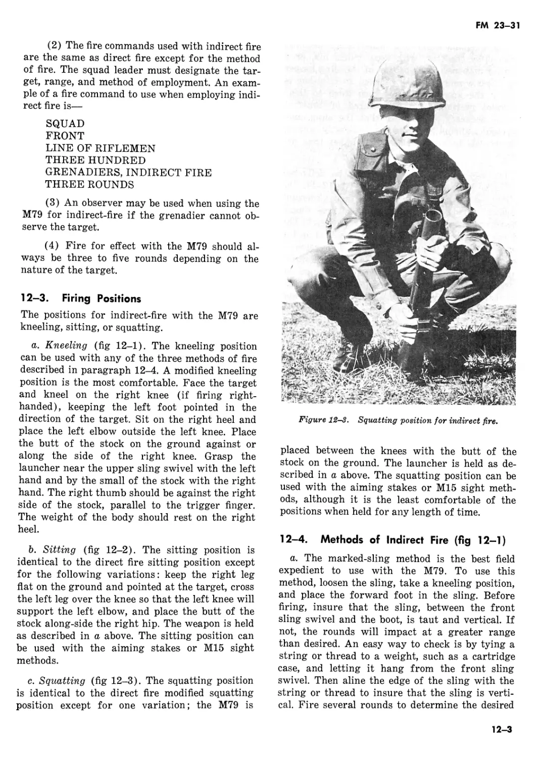
12. INDIRECT FIRE ROLE, M79 12-1 — 12-5 12-1 -12-5
Appendix A. B. C. REFERENCES A-l
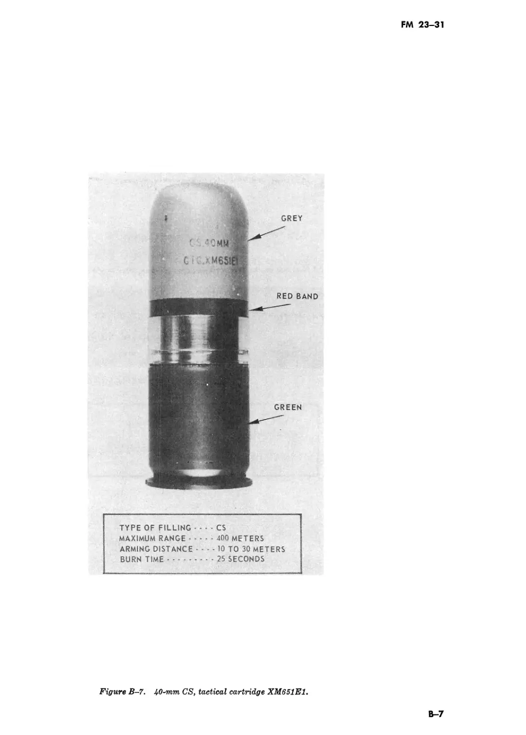
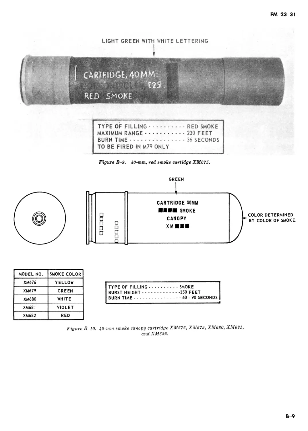
AMMUNITION B-l
LESSON OUTLINE—40-MM GRENADE LAUNCHERS, M203/M79 C-l
De TRAINING AIDS D-l
Index Index-1
Thit manual supersedes FM 23-31, 10 May 1965; (C) FM 23-4, 22 September 1964 and TC 23-10, 7 April 1966, including all changes.
FM 23-31
CHAPTER 1
INTRODUCTION
1-1. Purpose
Chapters 1 through 8 of this manual provide guidance for training with the 40-mm grenade launcher,
M203 and Chapters 9 through 12 provide guidance for training with the 40-mm grenade launcher, M79.
1-2. Scope
This manual contains a discussion of the launchers and their characteristics, disassembly/assembly pro-
cedures, launcher controls and sighting equipment, operation and functioning, types and functioning of
standard ammunition, safety precautions, and marksmanship training.
1-3. Recommended Changes
Users of this manual are encouraged to submit recommended changes or comments to improve it. Com-
ments should be keyed to the specific page, paragraph, and line of text in which the change is recom-
mended. Reasons will be provided for each comment to insure understanding and complete evaluation.
Comments should be prepared using DA Form 2028 (Recommended Changes to Publications) and
forwarded to the Commandant, US Army Infantry School, Fort Benning, Georgia 31905.
1-1
FM 23-31
CHAPTER 2
CHARACTERISTICS, LAUNCHER CONTROLS, AND SIGHTING
EQUIPMENT OF 40-MM GRENADE LAUNCHER, M203
Section I. CHARACTERISTICS
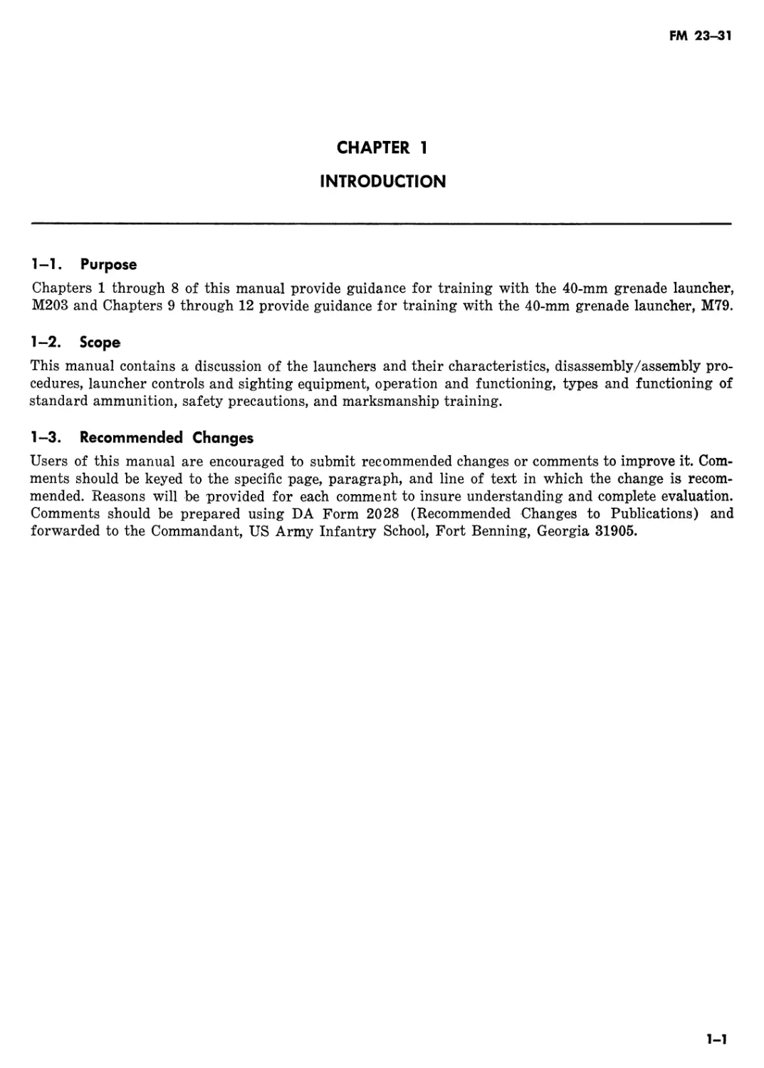
2-1. Description
The 40-mm grenade launcher, M203, is a light-
weight, single-shot, breech loaded, pump action
(sliding barrel), shoulder-fired weapon attached
to the M16/M16A1 rifle (fig 2-1). It consists of a
handguard and sight assembly group, receiver as-
sembly, quadrant sight assembly, and barrel as-
sembly.
2-2. Ammunition
a. The grenade launcher uses fixed type ammu-
nition. The two major assemblies of a round are
the cartridge case and the projectile. There are
varieties of high explosive, training, multiple pro-
jectile (buck shot), illuminating, and signaling
rounds (both standard and developmental types)
available for use in the M203.
b. For detailed information on ammunition, see
chapter 4.
2-3. Data
a. Weapon.
Length of launcher_____________15 Л in.
Length of barrel---------------12 in.
Weight (unloaded)______________ 3 lb (approx)
Weight (loaded) _________________ 3.5 lb (approx)
Weight (loaded) (M16A1 and M203) 11 lb (approx)
Trigger pull--------------------- 5 lb
b. Ammunition.
Caliber__________________________40-mm;
Weight___________________________ 8 oz (approx)
c. Operational Characteristics.
Action __________________________Pump
Maximum range____________________400 m (approx)
Maximum effective range (area
targets) ______________________350 m
Maximum effective range (point
target)________________________150 m
Minimum safe firing ranges
(HE and TP):
Training _____________________80 m
Combat_______________________31 m
(1) Left side view.
Figure 2—1. The kO-mm grenade launcher, M203 attached to the M16A1 rifle.
2-1
FM 23-31
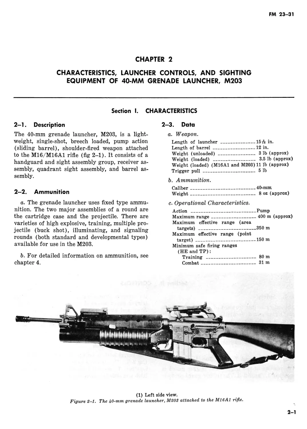
SIGHT
LEAF
(2) Controls and identifications.
Figure 2-1.—Continued.
Section II.
CONTROLS
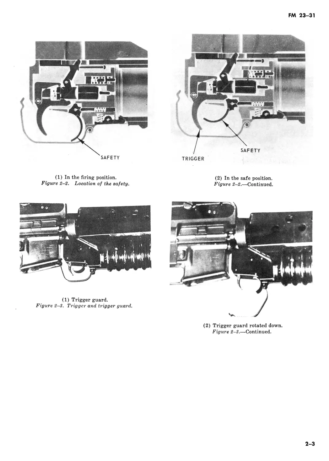
2-4. Safety
The safety is just forward of the trigger, inside
the trigger guard. To fire the launcher, the safety
must be in the forward position (1, fig 2-2). To
place the launcher on safe the safety must be in
the most rearward position (2, fig 2-2). The
safety must be manually placed on the safe or fire
position.
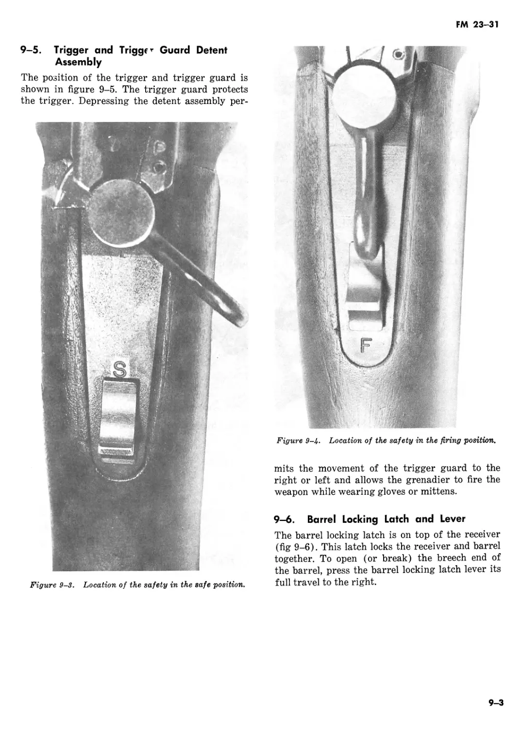
2-5. Trigger and Trigger Guard
The position of the trigger and trigger guard is
shown in 1, figure 2-3. The trigger guard protects
the trigger. Depressing the rear portion of the
trigger guard allows the trigger guard to rotate
down and away from the magazine well of the
rifle thus allowing the grenadier to fire the
weapon while wearing gloves or mittens (2, fig
2-3).
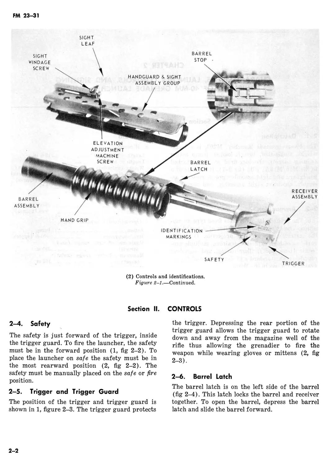
2-6. Barrel Latch
The barrel latch is on the left side of the barrel
(fig 2-4). This latch locks the barrel and receiver
together. To open the barrel, depress the barrel
latch and slide the barrel forward.
2-2
FM 23-31
SAFETY
TRIGGER
(1) In the firing position.
Figure 2-2. Location of the safety.
(2) In the safe position.
Figure 2-2.—Continued.
(1) Trigger guard.
Figure 2-3. Trigger and trigger guard.
(2) Trigger guard rotated down.
Figure 2-3.—Continued.
2-3
FM 23-31
Figure 2-4. Operating the barrel latch.
Section III. SIGHTING EQUIPMENT
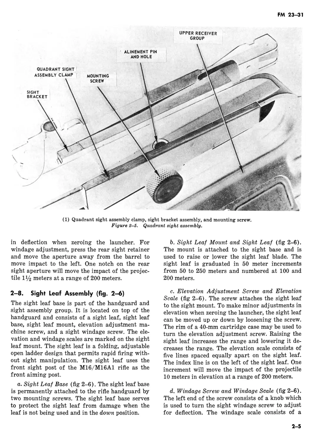
2-7. Quadrant Sight
The Quadrant sight assembly mounts on the
left side of the carrying handle of the М16/
M16A1 rifle. The quadrant sight assembly con-
sists of a mounting screw, quadrant sight assem-
bly clamp, sight bracket assembly, sight latch,
rear sight aperture, sight aperture arm, front
sight post, and sight post arm.
a. Quadrant Sight Assembly Clamp, Sight
Bracket Assembly and Mounting Screw (1, fig
2-5). The quadrant sight assembly clamp and
sight bracket assembly hold the quadrant sight
assembly to the carrying handle of the М16/
M16A1 rifle and are secured by a mounting screw
inserted through the right side of the quadrant
sight assembly clamp, into the sight bracket as-
sembly.
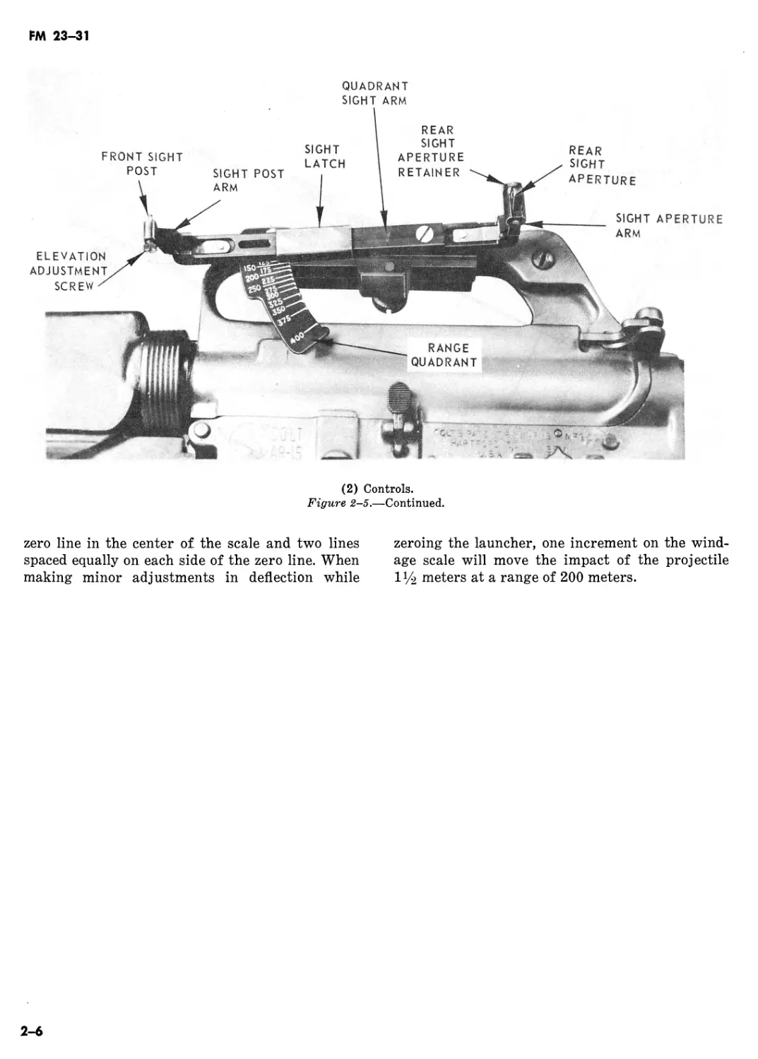
b. Quadrant Sight Arm and Range Quadrant
(2, fig 2-5). The quadrant sight arm serves a dual
purpose. It mounts the sight aperture arm (which
holds the sight aperture) and the sight post arm
(which holds the front sight post). This permits
the sight to pivot on the range quadrant to the
desired range setting. The range quadrant is grad-
uated in 25-meter increments from 50 to 400 me-
ters. To move the quadrant sight arm along the
range quadrant, move the sight latch rearward.
This rearward pressure unlocks the quadrant
sight arm allowing it to move along the range
quadrant so that the desired range number can be
centered in the window on the quadrant sight
arm. To lock the sight in position, release the
sight latch.
c. Front Sight Post (2, fig 2-5). The front sight
post mounts on the quadrant sight arm by means
of a pivot bracket that can be opened when the
sights are in use or closed when not in use, to
prevent damage to the sights. The sight post can
be used to make minor adjustments in elevation
when zeroing the launcher. For elevation adjust-
ments, turn the elevation adjustment screw on the
sight post to the right to decrease elevation and to
the left to increase elevation. One full turn on the
elevation adjustment screw will move the impact
of the projectile 5 meters at a range of 200 me-
ters.
d. Rear Sight Aperture (2, fig 2-5). The rear
sight aperture connects to the sight aperture arm,
which is attached to the rear portion of the quad-
rant sight arm. The sight aperture arm serves the
same purpose as the sight post arm. The rear
sight aperture can be adjusted for minor changes
2-4
FM 23-31
(1) Quadrant sight assembly clamp, sight bracket assembly, and mounting screw.
Figure 2-5. Quadrant sight assembly.
in deflection when zeroing the launcher. For
windage adjustment, press the rear sight retainer
and move the aperture away from the barrel to
move impact to the left. One notch on the rear
sight aperture will move the impact of the projec-
tile meters at a range of 200 meters.
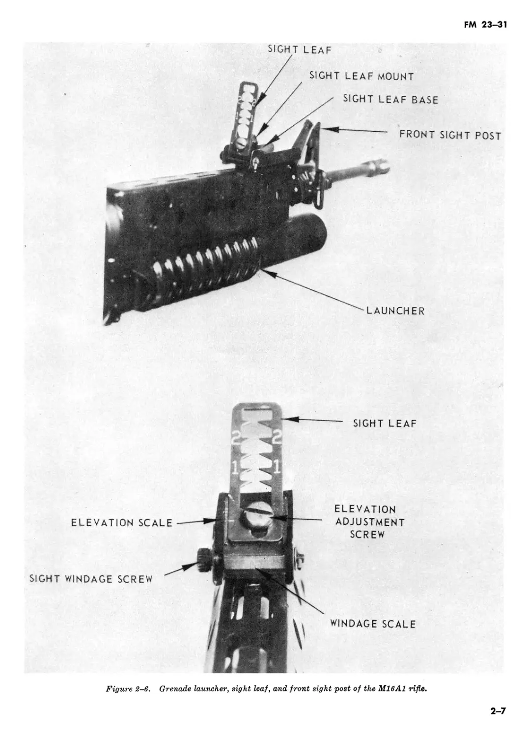
2-8. Sight Leaf Assembly (fig. 2-6)
The sight leaf base is part of the handguard and
sight assembly group. It is located on top of the
handguard and consists of a sight leaf, sight leaf
base, sight leaf mount, elevation adjustment ma-
chine screw, and a sight windage screw. The ele-
vation and windage scales are marked on the sight
leaf mount. The sight leaf is a folding, adjustable
open ladder design that permits rapid firing with-
out sight manipulation. The sight leaf uses the
front sight post of the M16/M16A1 rifle as the
front aiming post.
a. Sight Leaf Base (fig 2-6). The sight leaf base
is permanently attached to the rifle handguard by
two mounting screws. The sight leaf base serves
to protect the sight leaf from damage when the
leaf is not being used and in the down position.
b. Sight Leaf Mount and Sight Leaf (fig 2-6).
The mount is attached to the sight base and is
used to raise or lower the sight leaf blade. The
sight leaf is graduated in 50 meter increments
from 50 to 250 meters and numbered at 100 and
200 meters.
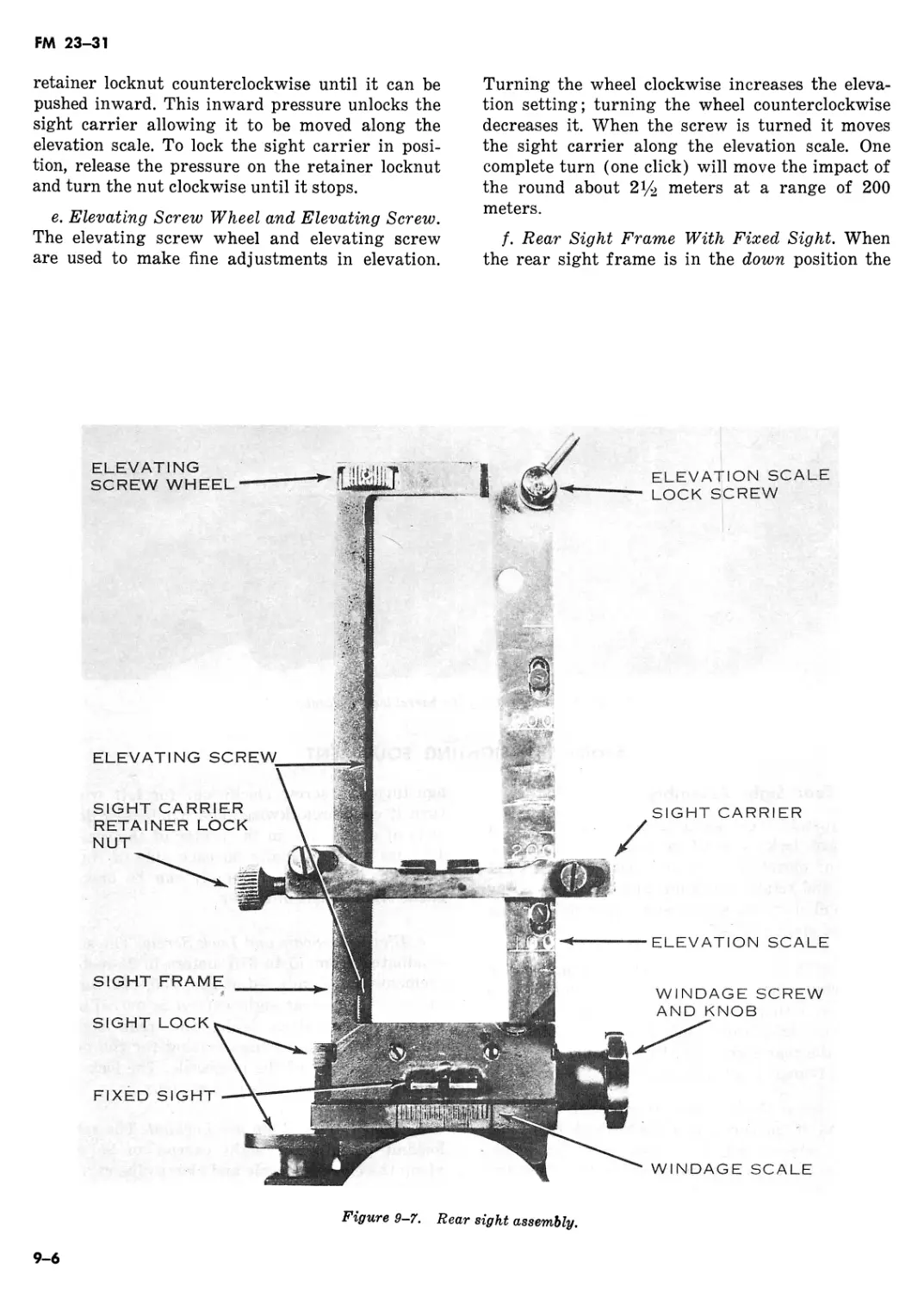
c. Elevation Adjustment Screw and Elevation
Scale (fig 2-6). The screw attaches the sight leaf
to the sight mount. To make minor adjustments in
elevation when zeroing the launcher, the sight leaf
can be moved up or down by loosening the screw.
The rim of a 40-mm cartridge case may be used to
turn the elevation adjustment screw. Raising the
sight leaf increases the range and lowering it de-
creases the range. The elevation scale consists of
five lines spaced equally apart on the sight leaf.
The index line is on the left of the sight leaf. One
increment will move the impact of the projectile
10 meters in elevation at a range of 200 meters.
d. Windage Screw and Windage Scale (fig 2-6).
The left end of the screw consists of a knob which
is used to turn the sight windage screw to adjust
for deflection. The windage scale consists of a
2-5
FM 23-31
(2) Controls.
Figure 2-5.—Continued.
zero line in the center of the scale and two lines
spaced equally on each side of the zero line. When
making minor adjustments in deflection while
zeroing the launcher, one increment on the wind-
age scale will move the impact of the projectile
1У2 meters at a range of 200 meters.
2—6
FM 23—31
SIGHT LEAF
SIGHT LEAF MOUNT
SIGHT LEAF BASE
LAUNCHER
FRONT SIGHT POST
ELEVATION SCALE
SIGHT WINDAGE SCREW
ELEVATION
ADJUSTMENT
SCREW
WINDAGE SCALE
Figure 2-6. Grenade launcher, sight leaf, and front sight post of the M16A1 rifle.
SIGHT LEAF
2-7
FM 23-31
CHAPTER 3
MECHANICAL TRAINING, OPERATION AND FUNCTIONING
Section I. Disassembly and Assembly
3-1.
This chapter contains instructions for mechanical
training, operation and functioning of the 40-mm
grenade launcher, M203.
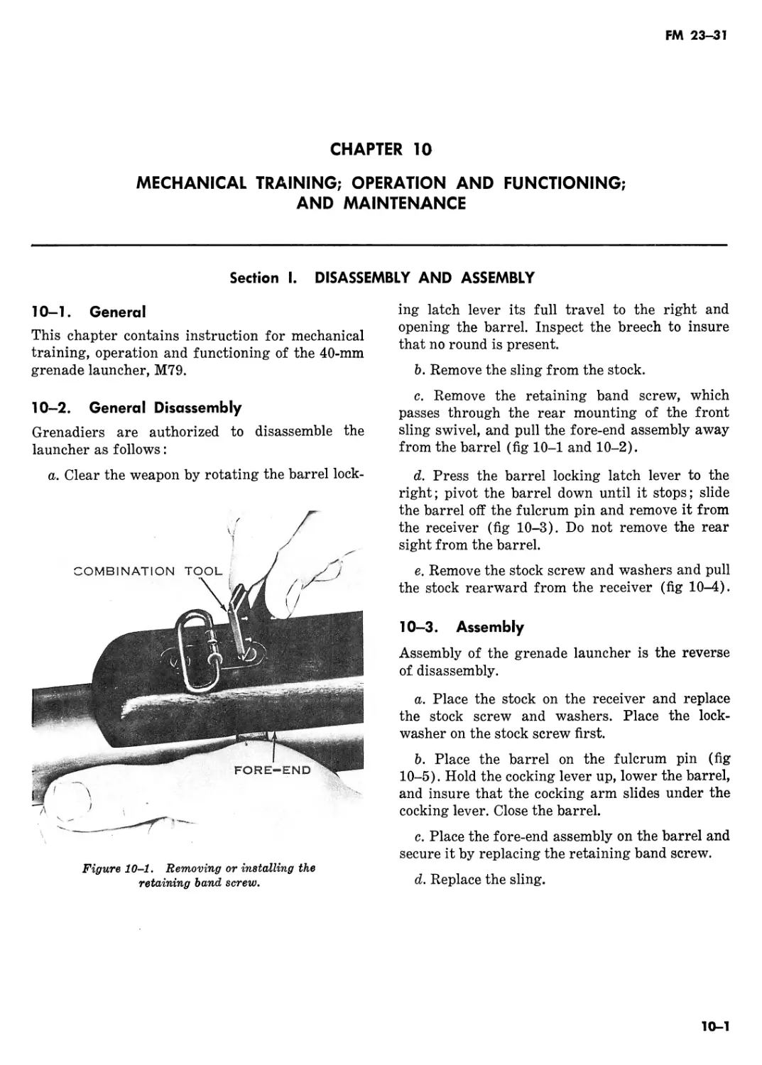
3—2. General Disassembly
Grenadiers are authorized to disassemble the
launcher as follows:
a. Clear the weapon by depressing barrel latch
and sliding the barrel assembly forward (fig 2-4).
Inspect the breech to insure that no round is pres-
ent.
b. Loosen the mounting screw and remove the
quadrant sight assembly from carrying handle of
the M16/M16A1 rifle (1, fig 2-5).
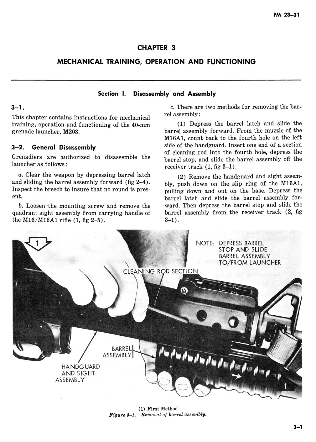
c. There are two methods for removing the bar-
rel assembly:
(1) Depress the barrel latch and slide the
barrel assembly forward. From the muzzle of the
M16A1, count back to the fourth hole on the left
side of the handguard. Insert one end of a section
of cleaning rod into the fourth hole, depress the
barrel stop, and slide the barrel assembly off the
receiver track (1, fig 3-1).
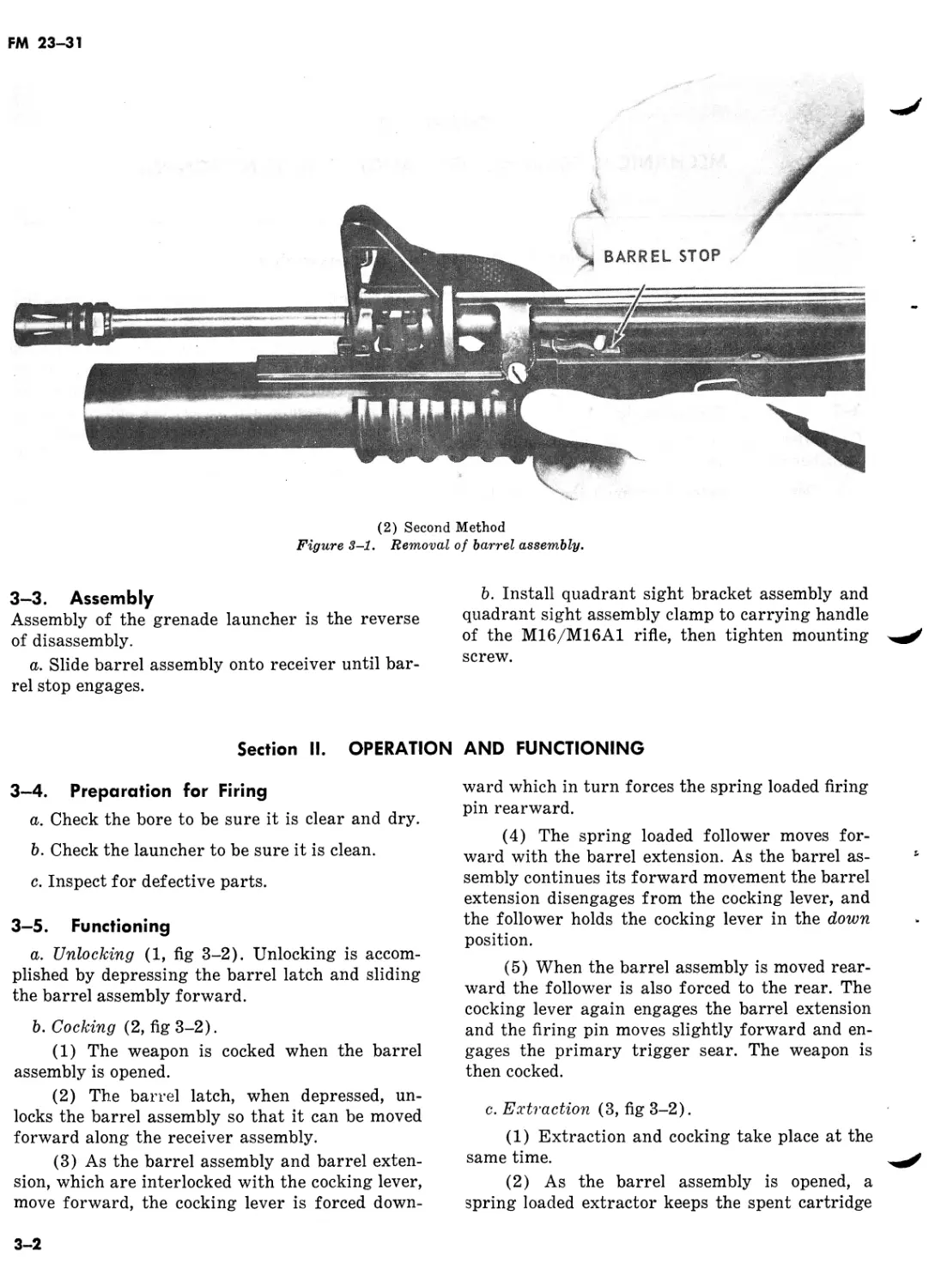
(2) Remove the handguard and sight assem-
bly, push down on the slip ring of the M16A1,
pulling down and out on the base. Depress the
barrel latch and slide the barrel assembly for-
ward. Then depress the barrel stop and slide the
barrel assembly from the receiver track (2, fig
3-1).
NOTE:
DEPRESS BARREL
STOP AND SLIDE
BARREL ASSEMBLY
TO/FROM LAUNCHER
HANDGUARD
AND SIGHT
ASSEMBLY
(1) First Method
Figure 3-1. Removal of barrel assembly.
3-1
FM 23-31
(2) Second Method
Figure 3-1. Removal of barrel assembly.
3-3. Assembly
Assembly of the grenade launcher is the reverse
of disassembly.
a. Slide barrel assembly onto receiver until bar-
rel stop engages.
b. Install quadrant sight bracket assembly and
quadrant sight assembly clamp to carrying handle
of the M16/M16A1 rifle, then tighten mounting
screw.
Section II. OPERATION AND FUNCTIONING
3-4. Preparation for Firing
a. Check the bore to be sure it is clear and dry.
b. Check the launcher to be sure it is clean.
c. Inspect for defective parts.
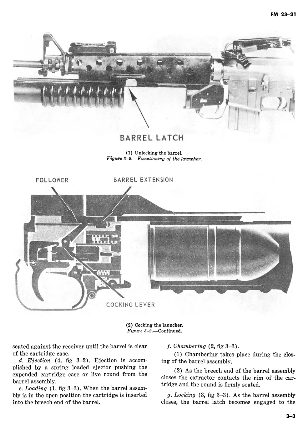
3-5. Functioning
a. Unlocking (1, fig 3-2). Unlocking is accom-
plished by depressing the barrel latch and sliding
the barrel assembly forward.
b. Cocking (2, fig 3-2).
(1) The weapon is cocked when the barrel
assembly is opened.
(2) The barrel latch, when depressed, un-
locks the barrel assembly so that it can be moved
forward along the receiver assembly.
(3) As the barrel assembly and barrel exten-
sion, which are interlocked with the cocking lever,
move forward, the cocking lever is forced down-
ward which in turn forces the spring loaded firing
pin rearward.
(4) The spring loaded follower moves for-
ward with the barrel extension. As the barrel as-
sembly continues its forward movement the barrel
extension disengages from the cocking lever, and
the follower holds the cocking lever in the down
position.
(5) When the barrel assembly is moved rear-
ward the follower is also forced to the rear. The
cocking lever again engages the barrel extension
and the firing pin moves slightly forward and en-
gages the primary trigger sear. The weapon is
then cocked.
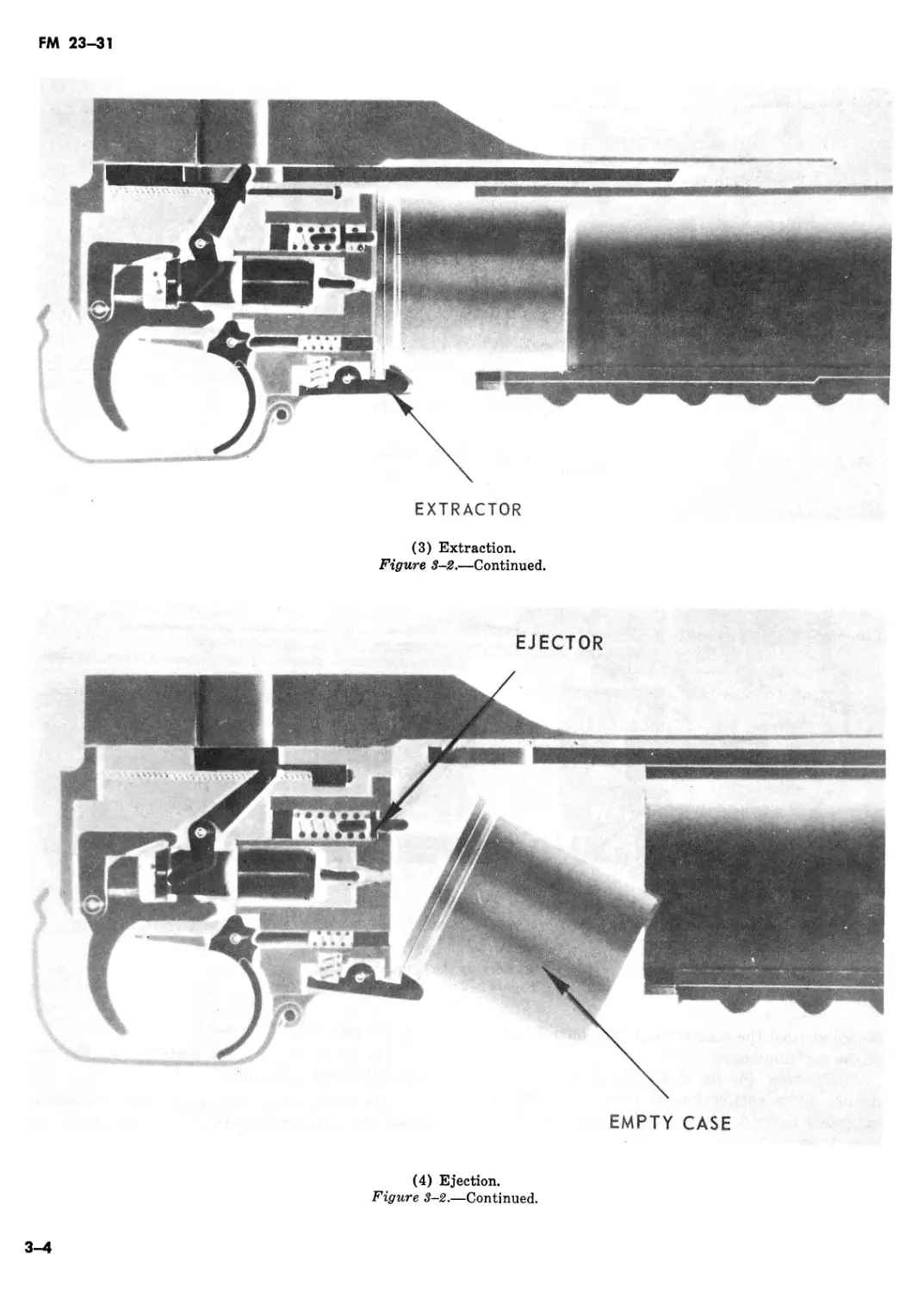
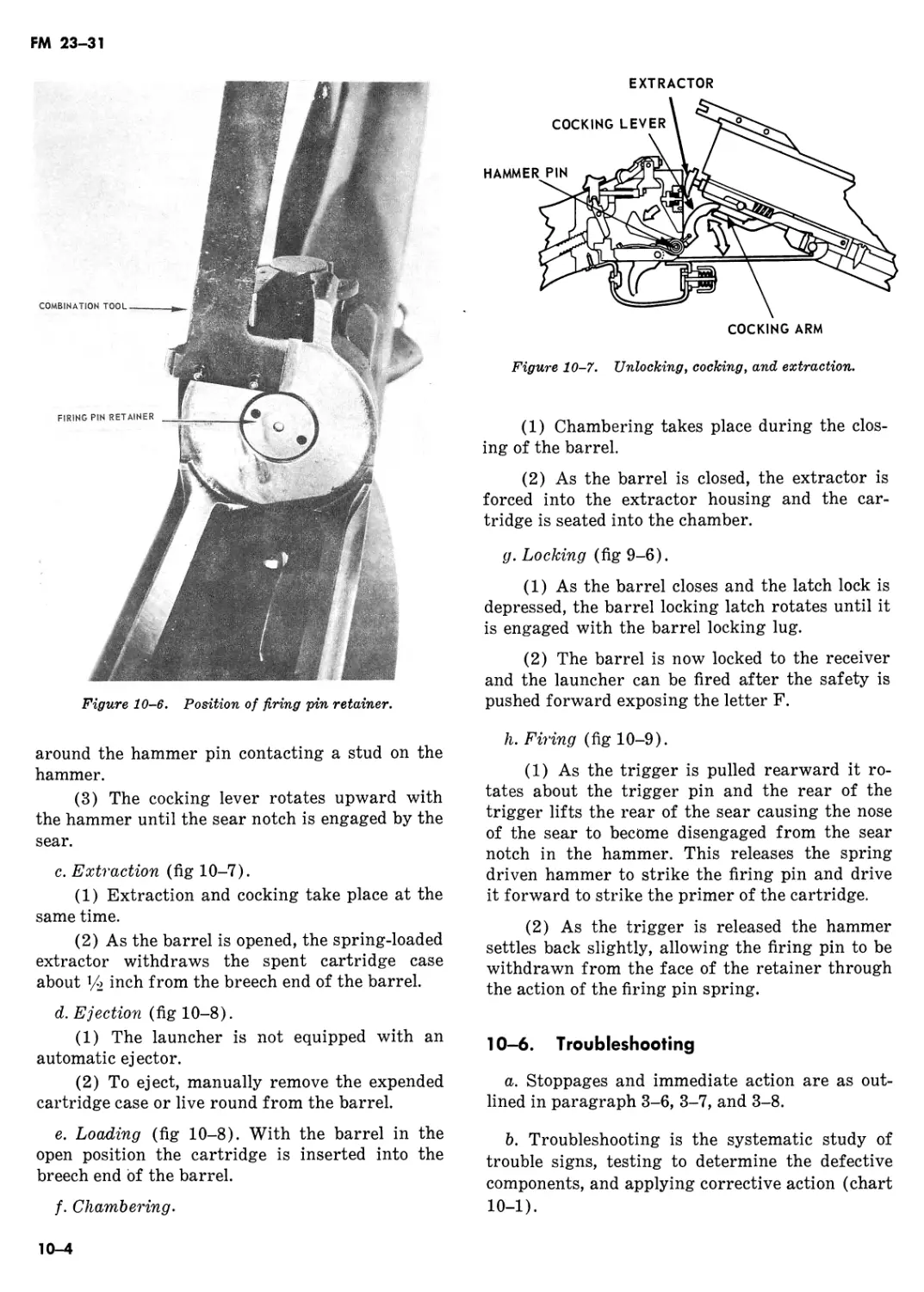
c. Extraction (3, fig 3-2).
(1) Extraction and cocking take place at the
same time.
(2) As the barrel assembly is opened, a
spring loaded extractor keeps the spent cartridge
3-2
FM 23-31
BARREL LATCH
(1) Unlocking the barrel.
Figure 3—2. Functioning of the launcher.
FOLLOWER BARREL EXTENSION
(2) Cocking the launcher.
Figure 3-2.—Continued.
seated against the receiver until the barrel is clear
of the cartridge case.
d. Ejection (4, fig 3-2). Ejection is accom-
plished by a spring loaded ejector pushing the
expended cartridge case or live round from the
barrel assembly.
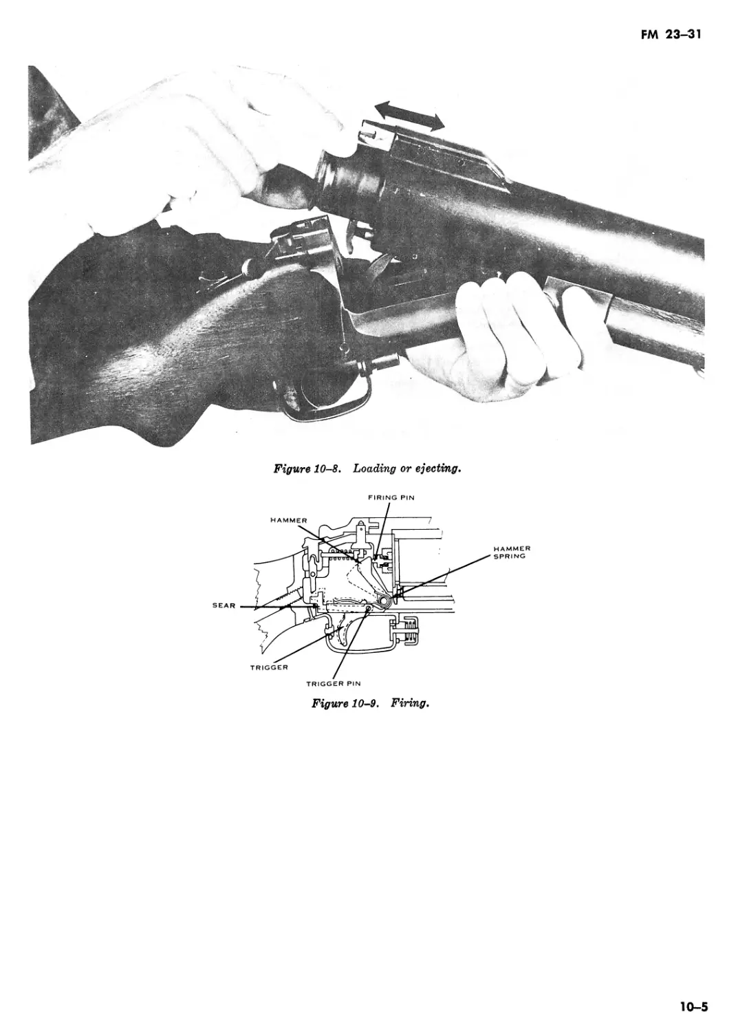
e. Loading (1, fig 3-3). When the barrel assem-
bly is in the open position the cartridge is inserted
into the breech end of the barrel.
f. Chambering (2, fig 3-3).
(1) Chambering takes place during the clos-
ing of the barrel assembly.
(2) As the breech end of the barrel assembly
closes the extractor contacts the rim of the car-
tridge and the round is firmly seated.
g. Locking (3, fig 3-3). As the barrel assembly
closes, the barrel latch becomes engaged to the
3-3
FM 23-31
EXTRACTOR
(3) Extraction.
Figure 3-2.—Continued.
EJECTOR
EMPTY CASE
(4) Ejection.
Figure 3-2.—Continued.
3-4
FM 23-31
barrel assembly and the cocking lever engages the
barrel extension so that it cannot be moved for-
ward along the receiver assembly.
Л. Firing (4, fig 3-3). As the trigger is pulled
rearward, the primary trigger sear is disengaged
from the bottom sear surface of the firing pin,
releasing the spring driven firing pin and causing
it to be forced forward against the primer of the
cartridge.
(1) Loading the launcher.
Figure 3-3. Operating the launcher.
FOLLOWER BARREL EXTENSION
(2) Chambering.
Figure 3-3.—Continued.
3-5
FM 23-31
(3) Locking the barrel.
Figure 3-3.—Continued.
FIRING PIN
TRIGGER
(4) Firing.
Figure 3-3.—Continued.
Section III. STOPPAGES AND IMMEDIATE ACTION
3-6. Stoppage
a. A stoppage is any unintentional interruption
in the functioning of the weapon. Some common
stoppages are: a failure to fire, a failure to cham-
ber, a failure to extract, a failure to cock.
b. Immediate action is the unhesitating applica-
tion of a probable remedy without considering the
cause of the stoppage. To apply immediate action,
follow the same procedure prescribed for a failure
to fire in paragraph 3-8.
3-6
FM 23-31
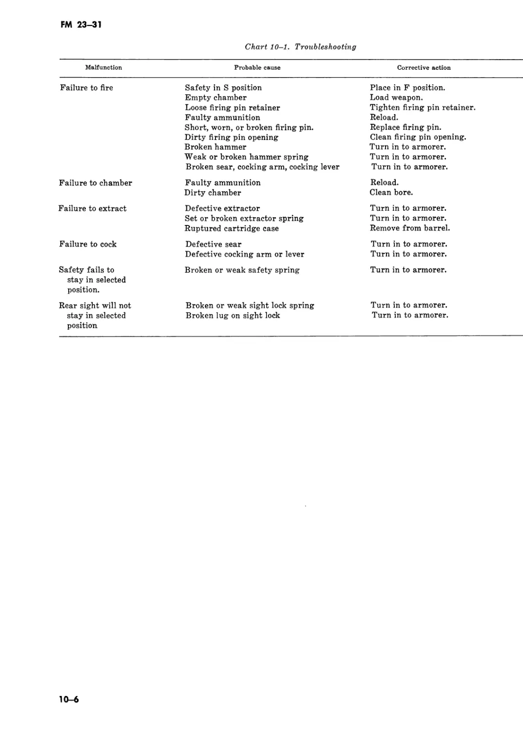
c. Troubleshooting is the systematic study of
trouble signs, testing to determine the defective
part, and applying corrective action (chart 3-1).
3—7. Hangfire and Misfire
a. Hangfire. A hangfire is a delay in the func-
tioning of a propelling-charge-explosive-train at
the time of firing. The amount of delay is unpre-
dictable, but in most cases it falls in the range of a
split second to 30 seconds. Any failure to fire must
be considered to be a hangfire until that possibil-
ity has been eliminated.
b. Misfire. A misfire is a complete failure to fire.
A misfire in itself is not dangerous, but since it
cannot be immediately distinguished from a delay
in the functioning of the firing mechanism or a
hangfire, it must be considered to be a hangfire
until proven otherwise. A delay in the functioning
of the firing mechanism could result from the
presence of grit, sand, frost, ice, or excess oil or
grease.
3-8. Failure to Fire
After a failure to fire, due to the possibility of a
misfire or hangfire, the following precautions
must be observed until the round has been re-
moved from the weapon and cause of failure de-
termined :
a. Shout “MISFIRE,” keep the weapon trained
on the target, and all troops clear of the muzzle.
Warning: Before attempting to remove the
round from the grenade launcher, men not re-
quired for the operation must be cleared from
the vicinity.
b. Wait 30 seconds from the time of failure to
fire before opening the breech for unloading pro-
cedures.
c. Exercise extreme caution during unloading
procedures; where circumstances permit, either
catch the ejected round or reduce the distance of
free fall to ground.
d. After the round has been removed from the
receiver, determine whether the round or the
firing mechanism is defective. Examine the pri-
mer to see if it has been dented. If the primer has
not been dented, the firing mechanism is at fault.
The round may be reloaded and fired after the
cause of the failure to fire has been corrected.
e. If the primer has been dented, keep the round
separate from other ammunition until it can be
properly disposed of.
f. Shouting “MISFIRE” should apply only to
training situations.
Chart 3-1. Troubleshooting
Malfunction Probable cause Corrective action
Failure to fire Safety on Empty chamber Faulty ammunition Water or excess lubricant in firing pin well Worn or broken firing pin Dirt or residue in firing pin recess Burred sear or firing pin Dirty firing pin well opening Weak or broken firing pin spring Place in fire position. Load Weapon. Reload. Hand cycle wpn several times to include pulling the trigger. Replace.* Clean. Replace.* Clean firing pin well opening.* Replace.*
Failure to cock __ Broken sear Improper assembly of cocking lever Loose, broken, or missing cocking lever spring pin Replace.* Reassemble.* Replace.*
Failure to lock Excess plastic on breech end of barrel assembly Dirty follower assembly or receiver cavity Trim excess plastic until barrel assembly will lock.* Clean.
Failure to chamber. Faulty ammunition Dirty chamber Reload. Clean bore and chamber.
Failure to extract. Defective extractor on spring or spring pin Ruptured cartridge case Replace.* Remove from barrel.
♦Procedures to be accomplished by DS/GS Maintenance.
3-7
FM 23-31
Chart 3—1. Troubleshooting—Continued
Malfunction Probable cause Corrective action
Failure to eject _ Worn, broken, or missing ejector spring or Replace.* retainer.
Safety fails to stay in position. Broken or worn safety or missing spring pin Replace.*
Sight will not stay in selected position. Sight mounting machine screw loose Tighten screw or replace if dented or broken.
♦Procedures to be accomplished by DS/GS Maintenance.
3-8
FM 23^31
CHAPTER 4
AMMUNITION
4-1. General
The 40-mm cartridge is a fixed-type munition
which consists of two major assemblies (fig 4-1):
the cartridge case and the projectile.
4—2. Cartridge Case
The aluminum cartridge case is made with an in-
tegral propellant retainer. Into this retainer is in-
serted a thin-walled brass cup containing the pro-
pellant. An aluminum base plug which seals the
base of the cartridge case is then pressed into the
propellant retainer.
4—3. Types
a. There are five standard “A” types of 40-mm
ammunition for use with the launcher: HIGH
EXPLOSIVE (HE), HIGH EXPLOSIVE AIR-
BURST (HE AIRBURST), HIGH EXPLOSIVE
SMOKELESS AND FLASHLESS, AND HIGH
EXPLOSIVE DUAL PURPOSE (HEDP), and
TRAINING PRACTICE (TP) (fig 4-2).
(1) The HIGH EXPLOSIVE ROUNDS con-
tain a grenade 1.5 inches in diameter with about
1.25 ounces of explosive (fig 4-1). The grenade is
formed of rectangular-wrapped steel wire. The
wire is notched at intervals to allow for fragmen-
tation upon detonation of the grenade.
(2) The PRACTICE ROUND is ballistically
matched to the high explosive (HE) round and is
filled with a yellow dye powder. Upon impact, the
fuze booster breaks open the grenade and dis-
perses the powder as a puff of yellow smoke
which is visible out to the maximum range of the
launcher.
b. Both standard and developmental ammuni-
tion (app B) designed for the 40-mm grenade
launcher, M79, is normally adaptable to the M203
grenade launcher.
Warning: MAKE NO ATTEMPT UNDER
ANY CONDITIONS TO FIRE 40-MM HIGH
VELOCITY AMMUNITION IN THE M203 GRE-
NADE LAUNCHER. (This ammunition is for
use in automatic grenade launchers. Those
rounds are longer and more powerful than the
ammunition made for the M203/M79 weapons.)
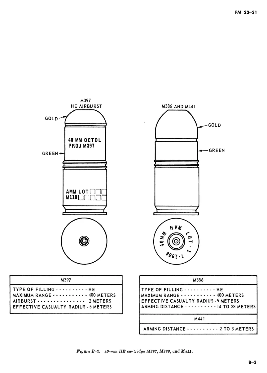
4-4. Identification (fig 4-2)
The HE (406), HE (463), and TP (M407A1) are
identical in size and shape. However, the weight
of the M463 is slightly greater than the M406 or
the M407A1. There are two notches on the rim of
the M463 to identify it during the hours of limited
visibility. The appearance of the HE airburst
round differs from the M406, M463, and M407A1,
in that the skirt is longer and the ogive is smaller.
However, the size and weight of the HE airburst
and the HE (M433) dual purpose round are al-
most identical. The M406, M433, and M397 have
gold colored ogives, while the M407A1 has a silver
colored ogive and the M463 has a black colored
ogive.
4—5. Fuzes
The M552 and M551 impact detonating fuzes are
used with the HE and the TP rounds. The M552
fuze arms by a spin action and is armed about 3
meters from the muzzle. The M551 fuze arms by a
spin and setback action and must travel between
14 and 28 meters before being armed (fig 4-1).
The HE airburst round is equipped with the M536
fuze that incorporates the same spin and setback
action as well as the same arming distance as the
M551 fuze. Upon impact the fuze ignites a separa-
tion charge assembly which ejects a grenade into
the air. At a height of about 5 feet the grenade
explodes into fragments.
4—6. High-Low Propulsion System (fig 4-3)
To propel a 40-mm projectile from a shoulder
fired weapon requires a high-low propulsion sys-
tem. This system functions as follows: when the
firing pin strikes the primer, the primer flash ig-
nites the propellant which is contained within the
brass powder-charge cup inside the high pressure
chamber. The burning propellant creates a pres-
4-1
FM 23-31
VENTHOLES
LOW PRESSURE
CHAMBER-----
ALUMINUM OGIVE
PRESSURE PLATE
FUZE ASSEMBLY
PROJECTILE SKIRT
DETONATOR
CARTRIDGE CASE
RETAINER CUP
Figure 4-1. Cross section of the 40-mm cartridge, HE round.
HIGH PRESSURE
CHAMBER
BASE PLUG PRIMER
GRENADE
EXPLOSIVE
sure of 35,000 pounds per square inch within the
high pressure chamber, causing the brass pow-
der-charge cup to rupture at the vent holes. As
the vent holes rupture, the gases flow into the low
pressure chamber (interior portion of the car-
tridge case). As the gases enter the larger area,
the pressure is reduced toJLOOO pounds per square
inch which is sufficient to propel the projectile
through the barrel and to the target. The grenade
leaves the barrel of the launcher with a muzzle
velocity of 250 feet per second and a right-hand
spin of 37,000 revolutions per minute. The spin
stabilizes the grenade during flight and provides
rotational forces .necessary to arm the fuze.
FM 23-31
GOLD
CARTRIDGE , 40mm: HE
M38) OR M406
SILVER
CARTRIDGE, 40mm: TP
M382 OR M407
CARTRIDGE, 40mm: HE
DUAL PURPOSE M433
Figure 4-2, Some standard 40-mm cartridges available for use with the
grenade launcher, M203,
Ar-7. Effective Casualty Radius
The high explosive grenade has an effective cas-
ualty radius of 5 meters. The effective casualty
radius is defined as the radius of a circle about
the point of detonation in which it may be ex-
pected that 50 percent of exposed troops will
become casualties.
4—8. Combat Load
The recommended minimum combat load is 36
rounds of HE 40-mm ammunition.
4-9. Packing (fig 4-4)
All HE and TP ammunition is packed in wooden
boxes containing 12 bandoleers of 6 rounds each
for a total of 72 rounds.
4-3
FM 23-31
WHEN IGNITED BY THE PRIMER, THE PROPELLANT ENCLOSED IN THE
BRASS POWDER CHARGE CUP (HIGH PRESSURE CHAMBER) RUPTURES
THE CUP AT THE VENT HOLES AND IS VENTED INTO THE REMAINDER
OF THE CARTRIDGE CASE (LOW PRESSURE CHAMBER)
Figure 4-3. High-low propulsion system.
4-4
FM 23-31
PLAST I
Figure 4-4- 40-wwn ammunition bandoleer and packaging.
4-5
FM 23-31
CHAPTER 5
MAINTENANCE
5—1. General
Maintenance includes all measures taken to keep
the launcher in operating condition. This includes
cleaning, inspection for defective parts, lubrica-
tion, and repair.
5-2. Cleaning Material, Lubricants, and
Equipment
a. Cleaning Materials.
(1) Rifle bore cleaner (RBC) is used for
cleaning the bore of the launcher and provides
temporary protection from corrosion.
(2) Any dry cleaning solvent that does not
contain acid can be used for cleaning the launcher
of grease, oil, or corrosion-preventive compounds.
b. Lubricants.
(1) Military lubricant, MIL-L-46000A
(LSA) is used for lubricating the launcher at
temperatures of —35° Farenheit and above.
(2) Weapons lubricating oil MIL-L-141078
is used at temperatures below 0° F.
c. Equipment.
(1) A set of maintenance equipment is shown
in figure 5-1.
(2) Maintenance equipment is carried in a
canvas case that can be attached to the universal
small arms ammunition pouch or to the front of
the universal load carrying equipment harness
(fig 5-2).
5-3. Cleaning and Launcher
a. The launcher must be cleaned after it has
been fired because firing produces deposits of pri-
mer fouling, powder ashes, carbon, and metal
fouling. These deposits may collect moisture and
promote rust if not removed. The cleaning proce-
dure described below will remove all deposits
except metal fouling which should be removed by
the unit armorer.
b. After firing, field strip the launcher and clean
it as follows:
(1) Bore. Attach a clean, dry rag (the size of
a handkerchief) to the thong and thoroughly
moisten the rag with rifle bore cleaner. Pull the
rag through the bore several times. Attach the
bore brush to the thong, pull it through the bore
several times, and follow this with more damp
rags (fig 5-3). Pull dry rags through the bore and
inspect each rag as it is removed. The bore is
clean when a dry rag is removed which shows no
evidence of fouling. Finally, pull a lightly oiled
CLEANING
BRUSH
SCREWDRIVER AND WRENCH COMBINATION
(M 79 GRENADE LAUNCHER ONLY)
BORE
BRUSH
THONG
Figure 5-1. Maintenance equipment.
5-1
FM 23-31
Figure 5-2.
Small arms accessories case attached to the universal
ammunition pouch or harness.
Figure 5-3. Cleaning the bore with thong and bore brush.
(LSA) rag through the bore to leave a light coat
of oil inside the barrel.
(2) Breech insert. Clean the face of the
breech insert retainer with a patch and bore
cleaner. Remove the bore cleaner with dry rags,
and oil lightly.
(3) All other parts. Use a brush and dry rag
to clean all other parts and exterior surfaces.
Apply a light coat of LSA to the exterior of the
launcher after cleaning.
5-4. Normal Maintenance
Inspect the launcher daily for evidence of rust,
burred, worn, or cracked parts. Report defects to
the armorer for correction. Authorized organiza-
tional maintenance for the M203 is shown in
chart 5-1.
5-5. Special Maintenance
a. Where the temperature falls below freezing
5-2
FM 23-31
Chart 5-1. Authorized Organizational Maintenance (203)
Grenadier Armorer
Grenade launcher:
Installation/removal on rifle____________________________________________________ __________ x
Cleaning and lubrication_________________________________________________________ x
Handguard and sight assembly group:
Removal/installation_____________________________________________________________ x x
Replace machine screw (sight leaf and sight leaf base)___________________________ — x
Replace key washer_______________________________________________________________
Replace sight leaf_______________________________________________________________ __________ x
Replace handguard________________________________________________________________ __________ x
Cleaning and lubrication_________________________________________________________ x x
Quadrant sight assembly:
Removal/installation_____________________________________________________________ x x
Replace mounting screw_______________________________________________________________________________ x
Replace sight clamp__________________________________________________________________________________ x
Replace sight post___________________________________________________________________________________ X
Cleaning and lubrication__________________________________________________________________ x x
Barrel assembly:
Removal/installation______________________________________________________________________ x x
Cleaning and lubrication__________________________________________________________________ x x
Receiver assembly:
Replace back plate_______________________________________________________________ __________ x
Replace barrel extension follower________________________________________________ — x
the launcher must be kept free of moisture and
excess oil by wiping all metal parts with a clean
dry rag after performing normal maintenance.
Moisture and excess oil on the working parts
cause them to operate sluggishly or fail com-
pletely. The launcher must be disassembled and
wiped with a clean dry cloth. It is best to keep the
launcher as close as possible to outside tempera-
tures at all times to prevent the collection of mois-
ture which occurs when cold metal comes in
contact with warm air. If the launcher is brought
into a warm room it should be allowed to reach
room temperature and be cleaned.
b. In hot, humid climates, or when exposed to a
salt water atmosphere, inspect the launcher thor-
oughly each day for signs of moisture and rust.
c. In hot, dry climates the launcher must be
cleaned daily or more often to remove sand or
dust from the bore and working parts. In sandy
areas the launcher must be kept dry to prevent
the collection of sand. The muzzle and receiver
should be kept covered during sand and dust
storms. The launcher should be lubricated when
sandy or dusty conditions decrease or when it be-
gins to show rust or corrosion.
d. Instruction on caring for the launcher when
it is subjected to nuclear, biological, or chemical
contamination is in FM 21-40.
5-6. Storage
Thoroughly clean and dry the bore, the firing
mechanism, and the exterior of the weapon. After
the launcher has been dried, be careful not to
touch it with bare hands. Coat the launcher with
LSA. Never store a launcher in a cloth or similar
cover and never plug the bore. This will cause the
launcher to collect moisture and rust.
5-3
FM 23-31
CHAPTER 6
MARKSMANSHIP TRAINING (M203)
Section I. INTRODUCTION
6-1. General
Marksmanship training is to teach the grenadier
how to fire the grenade launcher and to prepare
him mentally and physically to employ it in
combat. His previous rifle marksmanship training
provides a sound basis for training with the gre-
nade launcher.
6—2. Elements of Marksmanship
a. Marksmanship training with the grenade
launcher develops skill in—
(1) Sighting, aiming, and sight manipulation.
(2) Position and rapid fire.
(3) Sensing and adjusting fire.
(4) Zeroing procedure.
(5) Range determination.
b. The skills learned from previous marksman-
ship training with other weapons are similar to
those skills required for firing the grenade
launcher. Proficiency in all skills listed above is
essential and can only be attained by proper
training.
Warning: Be sure the sling is clear of the
weapon muzzle prior to firing.
Section II. SIGHT, AIMING AND SIGHT MANIPULATION
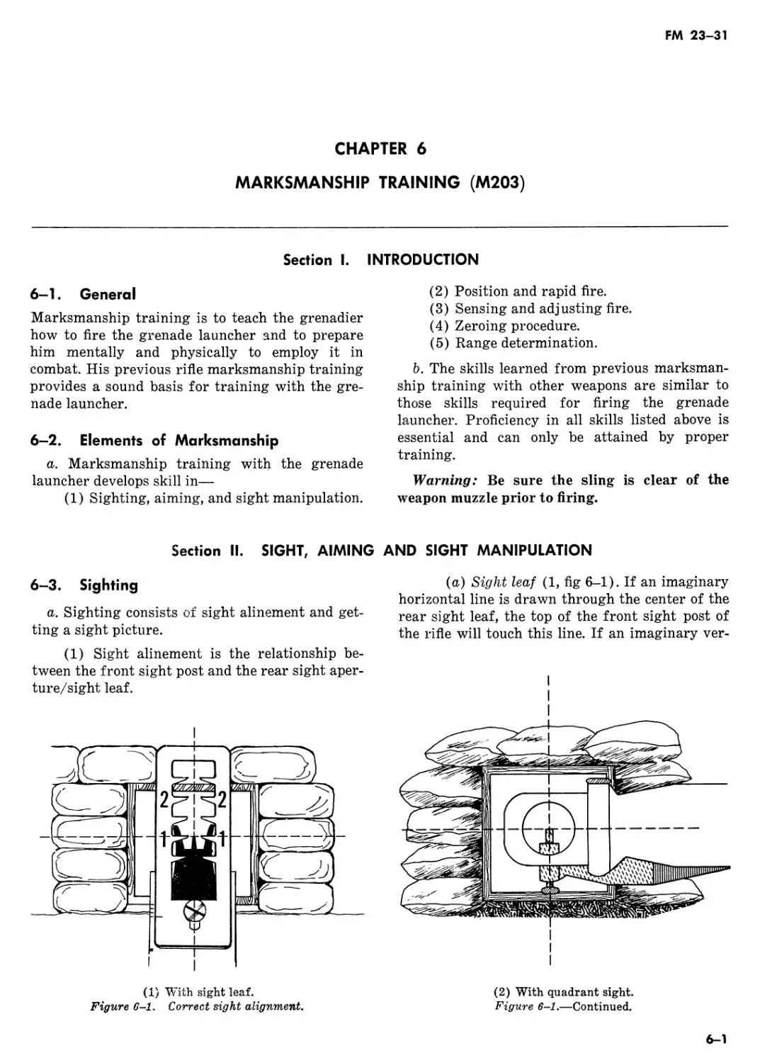
6-3. Sighting
a. Sighting consists of sight alinement and get-
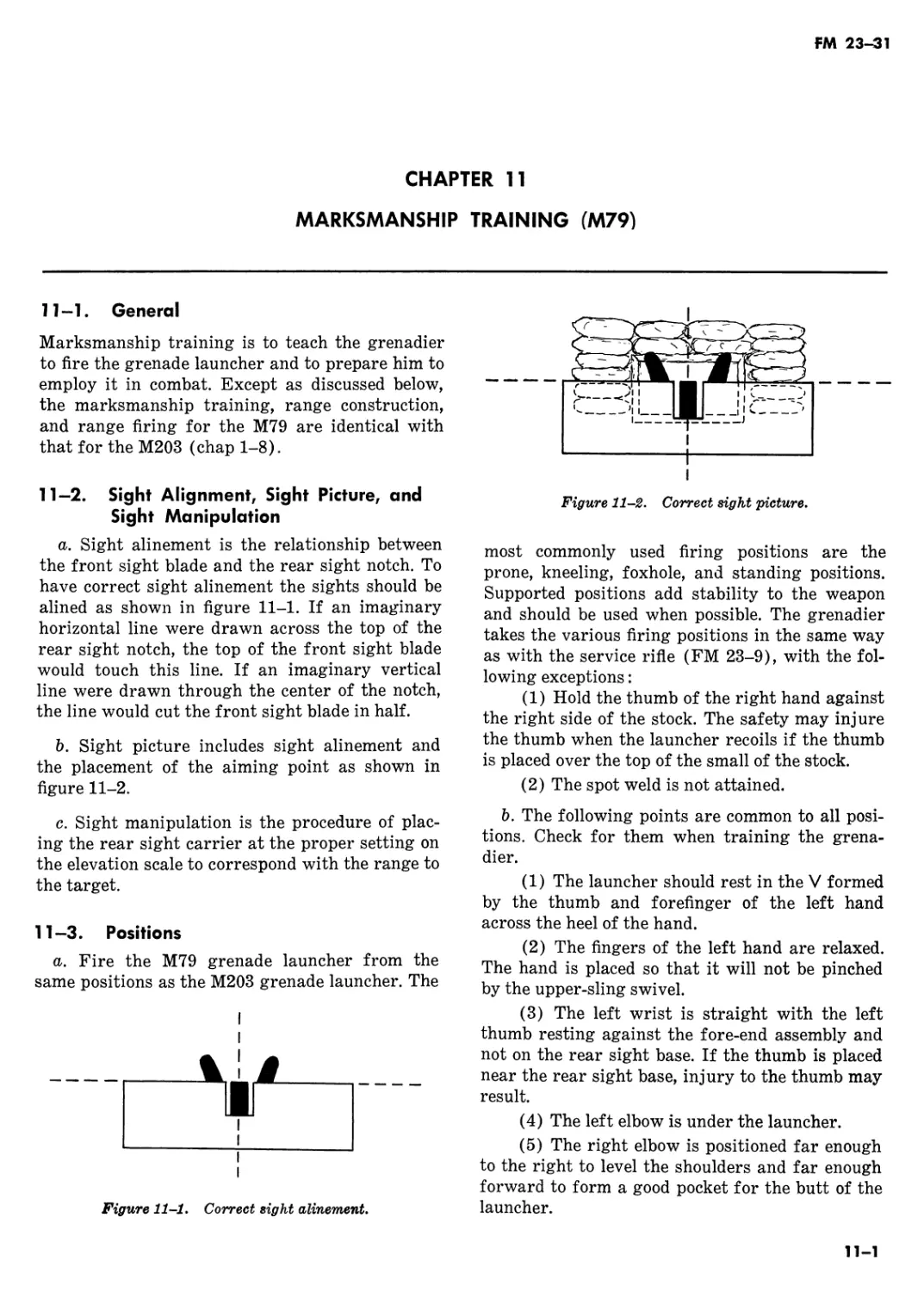
ting a sight picture.
(1) Sight alinement is the relationship be-
tween the front sight post and the rear sight aper-
ture/sight leaf.
(a) Sight leaf (1, fig 6-1). If an imaginary
horizontal line is drawn through the center of the
rear sight leaf, the top of the front sight post of
the rifle will touch this line. If an imaginary ver-
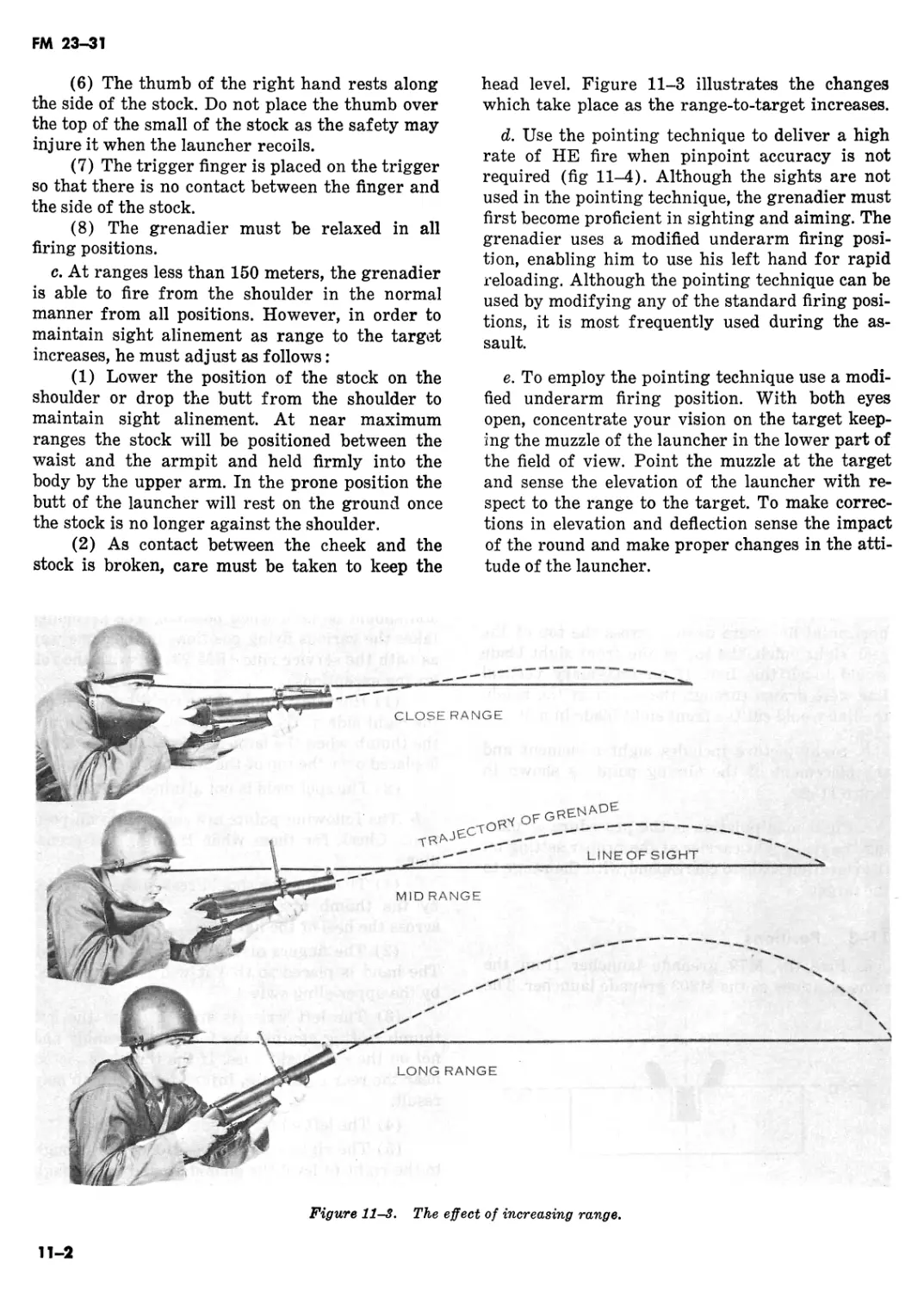
ity With sight leaf.
Figure 6-1. Correct sight alignment.
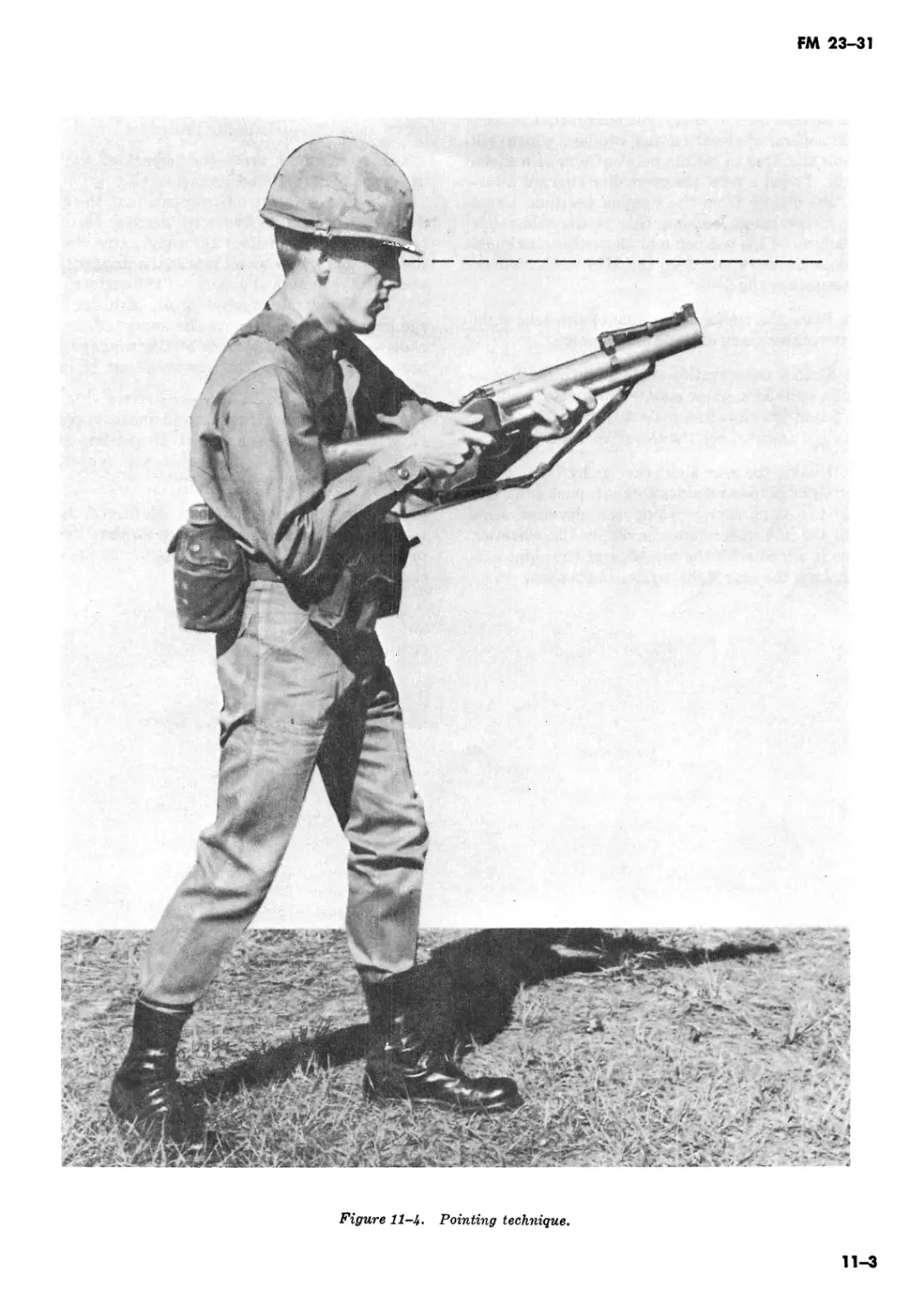
(2) With quadrant sight.
Figure 6-1.—Continued.
6-1
FM 23-31
tical line is drawn through the center of the rear
sight, the line will cut the front sight post in half.
(b) Quadrant sight (2, fig 6-1). If an imag-
inary horizontal line is drawn through the center
of the rear sight aperture, the top of the front
sight post will touch this line. If an imaginary
vertical line is drawn through the center of the
rear sight aperture, the line will cut the front
sight post in half.
(2) Getting the sight picture includes sight
alinement and placement of the aiming point. To
get a correct sight picture, aline the sights as de-
scribed above, and position the top edge of the
front sight post on the center of the target.
b. Sight alinement is more important than sight
picture. An error in sight alinement results in a
miss that becomes proportionately greater as the
range to the target increases, whereas an error in
sight picture will remain constant at all ranges.
6—4. Aiming
a. Initially, the firer should get correct sight
alinement and then shift his focus to the target
and get a correct sight picture. As he presses the
trigger the firer continues this shifting of the
focus of his eye. With practice these steps become
a continuous automatic process.
b. Controlled breathing is an essential element
of marksmanship. When firing the grenade
launcher the grenadier must practice controlled
breathing j ust as he would when firing the rifle.
6—5. Sight Manipulation
a. Sight manipulation is the procedure of plac-
ing the quadrant sight in the proper position for
firing and placing the proper range setting on the
sight to engage the target. Since the sight leaf is a
fixed ladder-type sight, sight manipulation is done
only during zeroing procedures.
b. The purpose of a sight manipulation exercise
with the quadrant sight is to teach the grenadier
to place the rear sight at the proper index mark
on the elevation scale accurately and quickly. The
sight manipulation exercise is conducted as fol-
lows :
(1) The exercise is performed first from the
prone position but should be repeated in all other
positions as proficiency increases. The exercise
may be performed on a range or any other suita-
ble training area.
(2) The rear sight is set initially at 200 me-
ters elevation. This allows maximum sight adjust-
ments either up or down. For this exercise, use
three elements of a standard fire command. The
instructor gives the direction to the target—iden-
tifies the target—and gives a range (e.g. right
front—troops—300). The range element is the
command of execution. On the command of execu-
tion:
(a) The firer moves the sight arm along
the range quadrant until it is alined with the
proper index mark (300), takes the firing posi-
tion, aims at the target, and calls “UP.”
(b) The assistant instructor checks to see
that the proper setting is on the sight. If an error
exists, the firer is required to make corrections.
(c) The assistant instructor then resets the
quadrant sight arm at 200 meters elevation. He
raises his hand to signify that the grenadier is
ready for another command from the instructor.
Section III. POSITIONS AND RAPID FIRE
6-6. General
a. The most commonly used firing positions are
the prone, kneeling, foxhole, and standing posi-
tions. Supported positions add stability to the
weapon and should be used whenever possible;
however, the grenadier must insure that no part
of the launcher touches the support. The employ-
ment considerations, methods of indirect fire, and
modifications to firing positions described in chap-
ter 12 for the M79 may also be used with the
M203. The grenadier takes the various firing posi-
tions with the M203 in the same way as with the
M16A1 rifle (FM 23-9), except that the spot weld
is not used with either the sight leaf or quadrant
sight.
Warning: Be sure the sling is clear of the
weapon muzzle prior to firing.
b. There are two methods for holding the
weapon:
(1) The left hand grips the magazine of the
M16A1 rifle with the left index finger positioned
in the trigger guard of the M203 while the right
hand grips the pistol grip of the M16A1 rifle.
6-2
FM 23—31
(2) The right hand grips the magazine of the
M16A1 rifle with the right index finger positioned
in the trigger guard of the M208 while the left
hand grasps the hand grip of the barrel assembly.
c. At ranges up to 150 meters, the grenadier can
fire from the shoulder in the normal manner from
all positions using the sight leaf or the quadrant
sight. However, in order to maintain sight aline*
ment at ranges greater than 150 meters he must
make the following adjustments:
(1) Use the quadrant sight at ranges in
excess of 250 meters.
(2) In the modified prone position, the posi-
tion of the butt of the rifle stock depends on the
configuration of the grenadier’s body, and position
of the grenadier’s hands on the weapon, and the
range to the target.
(3) In other firing positions, lower the stock
to an underarm position in order to maintain
sight alinement.
elbow. Place the butt of the rifle into the pocket of
the right shoulder. Grasp the rifle’s pistol grip
with the right hand and lower the right elbow to
the ground so that the shoulders are level. This
insures that the weight of the body is behind the
weapon so that the fir er can recover quickly after
each round is fired. Grasp the magazine of the
rifle with the left hand. The upper body is
straight, and the legs are spread a comfortable
distance apart. The toes are pointing outward and
the ankles are relaxed so that the heels will rest
on the ground if possible. The weight of the upper
body is relaxed forward onto the left arm.
c. In the modified prone position, the placement
of the butt of the rifle stock depends on the con-
figuration of the grenadier’s body, and the posi-
tion of the grenadier’s hands on the weapon for
ranges greater than 150 meters.
d. Use the quadrant sight at ranges in excess of
200 meters.
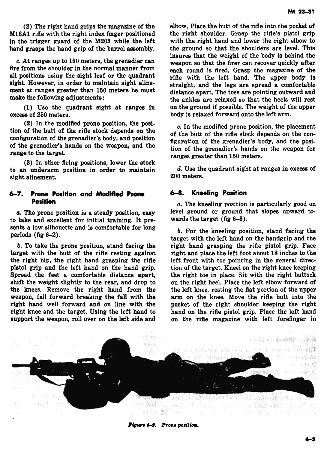
6-7. Prone Position and Modified Prone
Position
a. The prone position is a steady position, easy
to take and excellent for initial training. It pre-
sents a low silhouette and is comfortable for long
periods (fig 6-2).
b. To take the prone position, stand facing the
target with the butt of the rifle resting against
the right hip, the right hand grasping the rifle
pistol grip and the left hand on the hand grip.
Spread the feet a comfortable distance apart,
shift the weight slightly to the rear, and drop to
the knees. Remove the right hand from the
weapon, fall forward breaking the fall with the
right hand well forward and on line with the
right knee and the target. Using the left hand to
support the weapon, roll over on the left side and
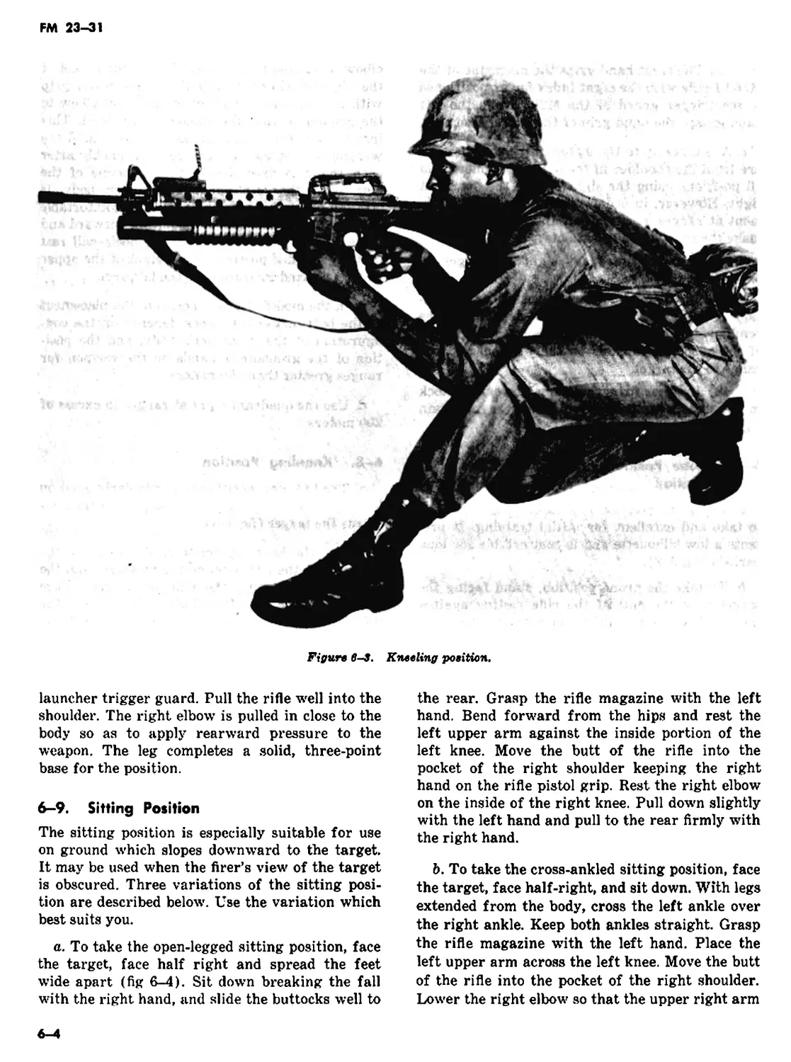
6—8. Kneeling Position
a. The kneeling position is particularly good on
level ground or ground that slopes upward to-
wards the target (fig 6-3).
b. For the kneeling position, stand facing the
target with the left hand on the handgrip and the
right hand grasping the rifle pistol grip. Face
right and place the left foot about 18 inches to the
left front with toe pointing in the general direc-
tion of the target. Kneel on the right knee keeping
the right toe in place. Sit with the right buttock
on the right heel. Place the left elbow forward of
the left knee, resting the flat portion of the upper
arm on the knee. Move the rifle butt into the
pocket of the right shoulder keeping the right
hand on the rifle pistol grip. Place the left hand
on the rifle magazine with left forefinger in
Fifuro s-s. Ртом petition.
FM 23-31
Figure 6—3, Kneeling position.
launcher trigger guard. Pull the rifle well into the
shoulder. The right elbow is pulled in close to the
body so as to apply rearward pressure to the
weapon. The leg completes a solid, three-point
base for the position.
6—9. Sitting Position
The sitting position is especially suitable for use
on ground which slopes downward to the target.
It may be used when the firer’s view of the target
is obscured. Three variations of the sitting posi-
tion are described below. Use the variation which
best suits you.
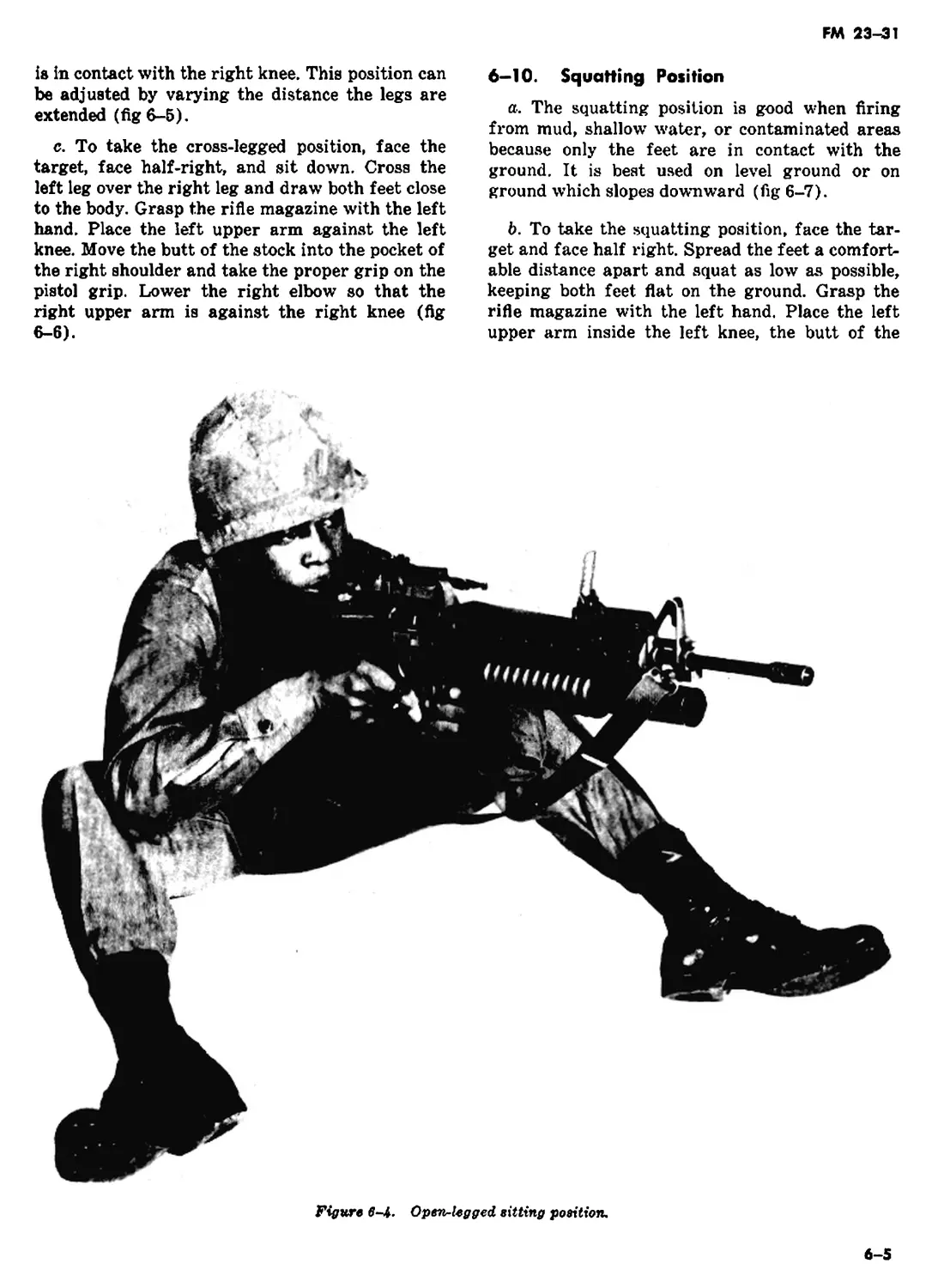
a. To take the open-legged sitting position, face
the target, face half right and spread the feet
wide apart (fig 6-4). Sit down breaking the fall
with the right hand, and slide the buttocks well to
the rear. Grasp the rifle magazine with the left
hand. Bend forward from the hips and rest the
left upper arm against the inside portion of the
left knee. Move the butt of the rifle into the
pocket of the right shoulder keeping the right
hand on the rifle pistol grip. Rest the right elbow
on the inside of the right knee. Pull down slightly
with the left hand and pull to the rear firmly with
the right hand.
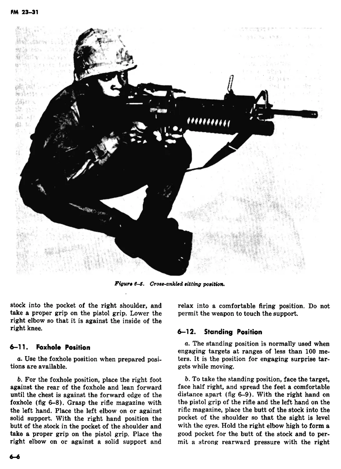
b. To take the cross-ankled sitting position, face
the target, face half-right, and sit down. With legs
extended from the body, cross the left ankle over
the right ankle. Keep both ankles straight. Grasp
the rifle magazine wTith the left hand. Place the
left upper arm across the left knee. Move the butt
of the rifle into the pocket of the right shoulder.
Lower the right elbow so that the upper right arm
FM 23-31
is in contact with the right knee. This position can
be adjusted by varying the distance the legs are
extended (fig 6-5).
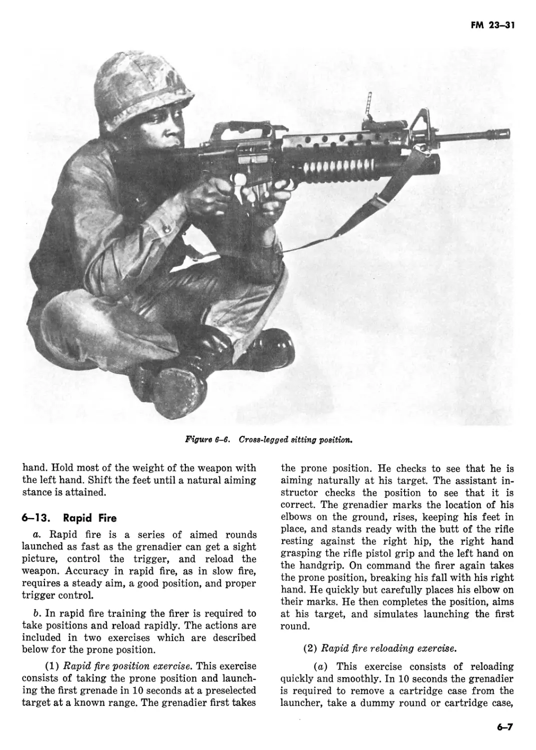
c. To take the cross-legged position, face the
target, face half-right, and sit down. Cross the
left leg over the right leg and draw both feet close
to the body. Grasp the rifle magazine with the left
hand. Place the left upper arm against the left
knee. Move the butt of the stock into the pocket of
the right shoulder and take the proper grip on the
pistol grip. Lower the right elbow so that the
right upper arm is against the right knee (fig
6-6).
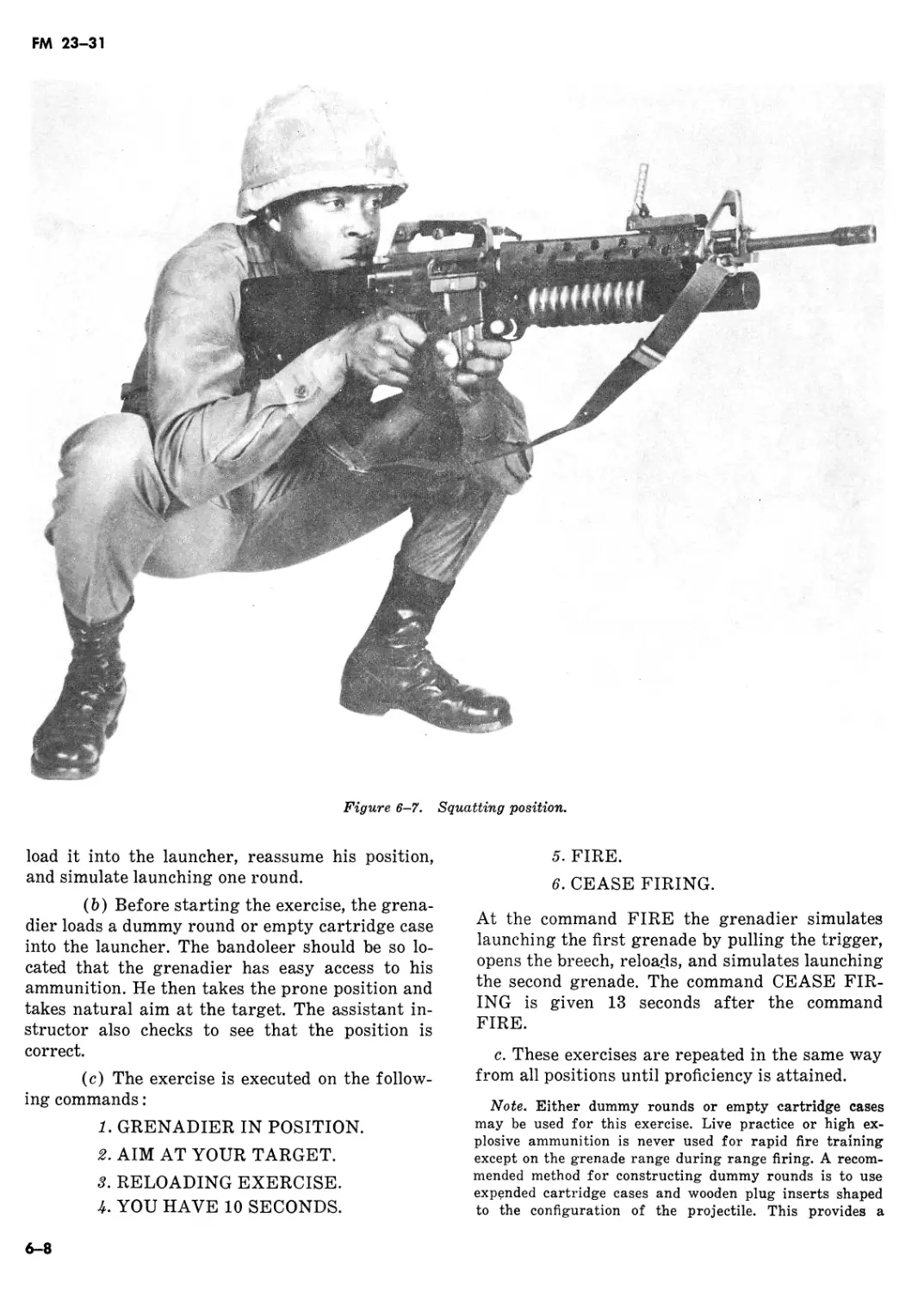
6-10. Squatting Position
a. The squatting position is good when firing
from mud, shallow water, or contaminated areas
because only the feet are in contact with the
ground. It is best used on level ground or on
ground which slopes downward (fig 6-7).
b. To take the squatting position, face the tar-
get and face half right. Spread the feet a comfort-
able distance apart and squat as low as possible,
keeping both feet flat on the ground. Grasp the
rifle magazine with the left hand. Place the left
upper arm inside the left knee, the butt of the
Figure 6-i. Open-legged sitting position.
6-5
FM 23-31
Figtiro в-И. CroBS-ankled fitting position.
stock into the pocket of the right shoulder, and
take a proper grip on the pistol grip. Lower the
right elbow so that it is against the inside of the
right knee.
6-11 ♦ Foxhole Position
a. Use the foxhole position when prepared posi-
tions are available.
b. For the foxhole position, place the right foot
against the rear of the foxhole and lean forward
until the chest is against the forward edge of the
foxhole (fig 6-8). Grasp the rifle magazine with
the left hand. Place the left elbow on or against
solid support. With the right hand position the
butt of the stock in the pocket of the shoulder and
take a proper grip on the pistol grip. Place the
right elbow on or against a solid support and
relax into a comfortable firing position. Do not
permit the weapon to touch the support.
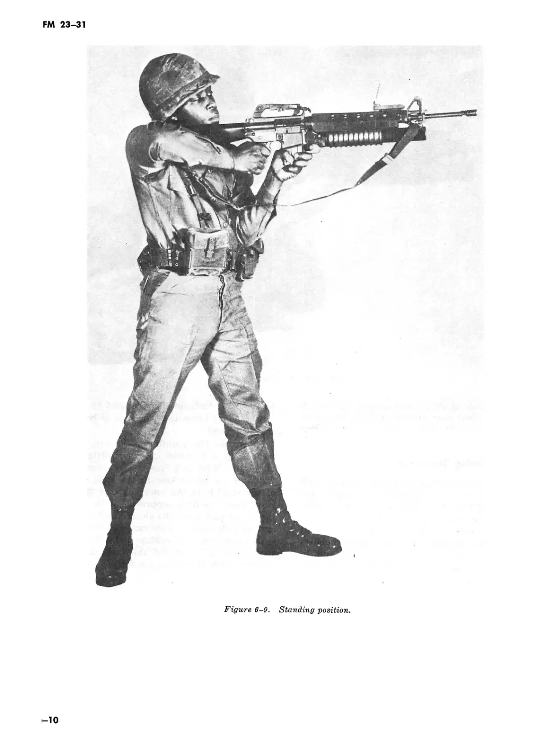
6-12. Standing Position
a. The standing position is normally used when
engaging targets at ranges of less than 100 me-
ters. It is the position for engaging surprise tar-
gets while moving.
b. To take the standing position, face the target,
face half right, and spread the feet a comfortable
distance apart (fig 6-9). With the right hand on
the pistol grip of the rifle and the left hand on the
rifle magazine, place the butt of the stock into the
pocket of the shoulder so that the sight is level
with the eyes. Hold the right elbow high to form a
good pocket for the butt of the stock and to per-
mit a strong rearward pressure with the right
FM 23-31
Figure 6-6. Cross-legged sitting position.
hand. Hold most of the weight of the weapon with
the left hand. Shift the feet until a natural aiming
stance is attained.
6-13. Rapid Fire
a. Rapid fire is a series of aimed rounds
launched as fast as the grenadier can get a sight
picture, control the trigger, and reload the
weapon. Accuracy in rapid fire, as in slow fire,
requires a steady aim, a good position, and proper
trigger control.
b. In rapid fire training the firer is required to
take positions and reload rapidly. The actions are
included in two exercises which are described
below for the prone position.
(1) Rapid fire position exercise. This exercise
consists of taking the prone position and launch-
ing the first grenade in 10 seconds at a preselected
target at a known range. The grenadier first takes
the prone position. He checks to see that he is
aiming naturally at his target. The assistant in-
structor checks the position to see that it is
correct. The grenadier marks the location of his
elbows on the ground, rises, keeping his feet in
place, and stands ready with the butt of the rifle
resting against the right hip, the right hand
grasping the rifle pistol grip and the left hand on
the handgrip. On command the firer again takes
the prone position, breaking his fall with his right
hand. He quickly but carefully places his elbow on
their marks. He then completes the position, aims
at his target, and simulates launching the first
round.
(2) Rapid fire reloading exercise.
(a) This exercise consists of reloading
quickly and smoothly. In 10 seconds the grenadier
is required to remove a cartridge case from the
launcher, take a dummy round or cartridge case,
6-7
FM 23-31
Figure 6-7. Squatting position.
load it into the launcher, reassume his position,
and simulate launching one round.
(b) Before starting the exercise, the grena-
dier loads a dummy round or empty cartridge case
into the launcher. The bandoleer should be so lo-
cated that the grenadier has easy access to his
ammunition. He then takes the prone position and
takes natural aim at the target. The assistant in-
structor also checks to see that the position is
correct.
(c) The exercise is executed on the follow-
ing commands:
1. GRENADIER IN POSITION.
2. AIM AT YOUR TARGET.
3. RELOADING EXERCISE.
4. YOU HAVE 10 SECONDS.
5. FIRE.
6. CEASE FIRING.
At the command FIRE the grenadier simulates
launching the first grenade by pulling the trigger,
opens the breech, reloads, and simulates launching
the second grenade. The command CEASE FIR-
ING is given 13 seconds after the command
FIRE.
c. These exercises are repeated in the same way
from all positions until proficiency is attained.
Note. Either dummy rounds or empty cartridge cases
may be used for this exercise. Live practice or high ex-
plosive ammunition is never used for rapid fire training
except on the grenade range during range firing. A recom-
mended method for constructing dummy rounds is to use
expended cartridge cases and wooden plug inserts shaped
to the configuration of the projectile. This provides a
6-8
FM 23-31
Figure 6-8. Foxhole position.
satisfactory training aid for marksmanship exercises. If
expended cartridge cases are not available, the dummy
round may be fashioned from wood or some other suitable
material.
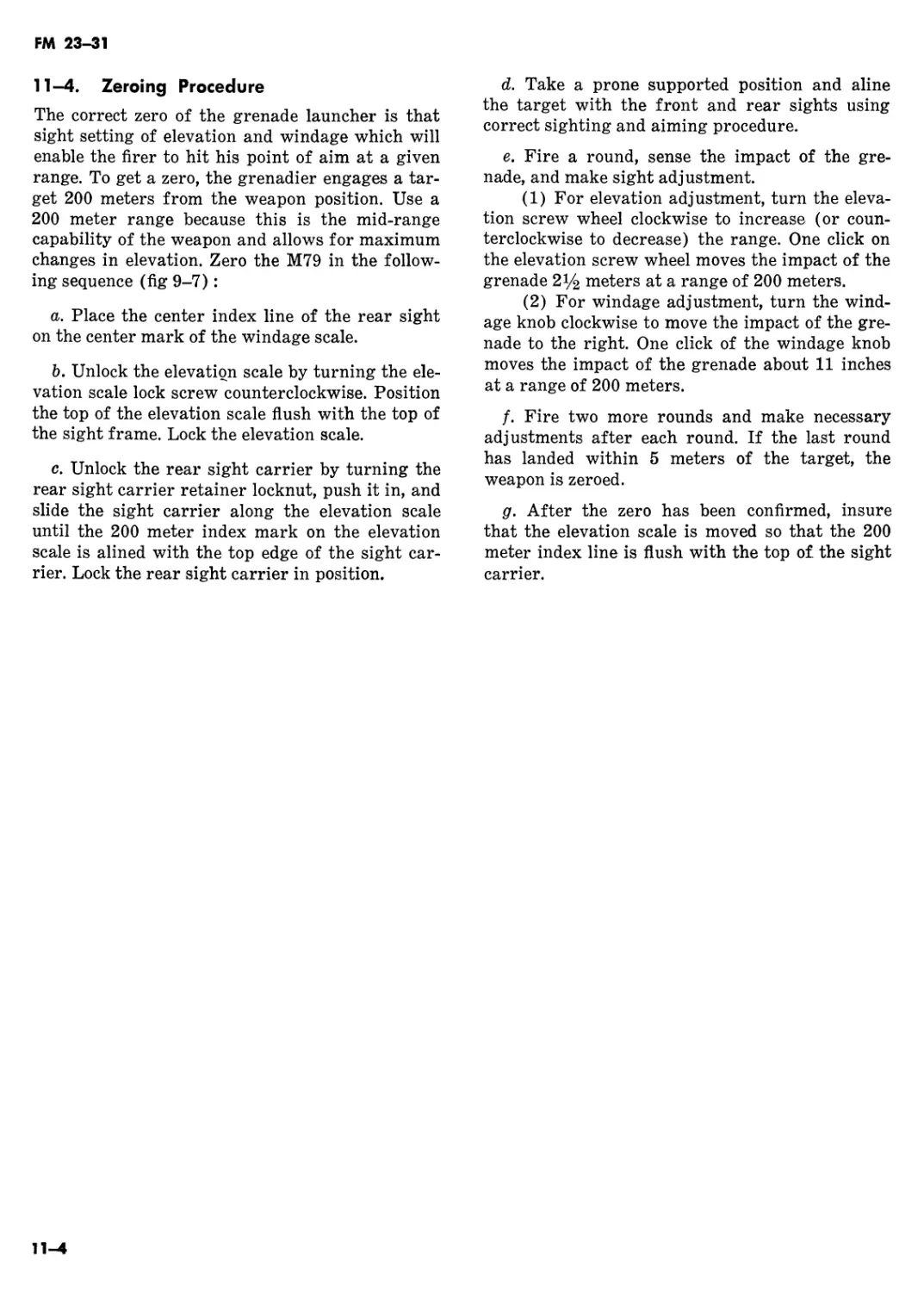
6-14. Pointing Techniques
a. Use the pointing technique to deliver a high
rate of HE fire when pinpoint accuracy is not
required. Although the sights are not used in the
pointing technique, the grenadier must first be
proficient in sighting and aiming using the sight
leaf and quadrant sight. He uses a modified under-
arm firing position (FM 23-9), enabling him to
use his left hand for rapid reloading. Although
the pointing technique can be used by modifying
any standard firing position, it is to be used dur-
ing the assault.
b. To use the pointing technique, bring the
weapon to a modified underarm firing position
(fig 6-10). With both eyes open, concentrate your
vision on the target keeping the flash suppressor
of the RIFLE in the lower part of the field of
view. Point the flash suppressor of the RIFLE at
the target and sense the elevation of the weapon
system with respect to the range to the target. To
make corrections in elevation and deflection sense
the impact of the round and make appropriate
changes in the attitude of the weapon system.
6-9
FM 23-31
Figure 6-9. Standing position.
10
FM 23-31
Figure 6-10. Modified underarm firing position.
Section IV. SENSING AND ADJUSTMENT OF FIRE
6-15. General
If a first round hit is not made, determine where
the grenade landed in relation to the target (sen-
sing) and make the required adjustments in eleva-
tion and deflection to bring the next grenade on
target (adjustment of fire).
6-11
FM 23-31
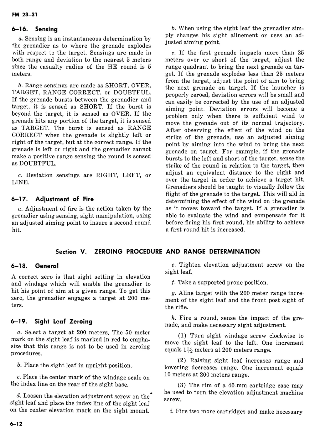
6-16. Sensing
a. Sensing is an instantaneous determination by
the grenadier as to where the grenade explodes
with respect to the target. Sensings are made in
both range and deviation to the nearest 5 meters
since the casualty radius of the HE round is 5
meters.
b. Range sensings are made as SHORT, OVER,
TARGET, RANGE CORRECT, or DOUBTFUL.
If the grenade bursts between the grenadier and
target, it is sensed as SHORT. If the burst is
beyond the target, it is sensed as OVER. If the
grenade hits any portion of the target, it is sensed
as TARGET. The burst is sensed as RANGE
CORRECT when the grenade is slightly left or
right of the target, but at the correct range. If the
grenade is left or right and the grenadier cannot
make a positive range sensing the round is sensed
as DOUBTFUL.
c. Deviation sensings are RIGHT, LEFT, or
LINE.
6-17. Adjustment of Fire
a. Adjustment of fire is the action taken by the
grenadier using sensing, sight manipulation, using
an adjusted aiming point to insure a second round
hit.
b. When using the sight leaf the grenadier sim-
ply changes his sight alinement or uses an ad-
justed aiming point.
c. If the first grenade impacts more than 25
meters over or short of the target, adjust the
range quadrant to bring the next grenade on tar-
get. If the grenade explodes less than 25 meters
from the target, adjust the point of aim to bring
the next grenade on target. If the launcher is
properly zeroed, deviation errors will be small and
can easily be corrected by the use of an adjusted
aiming point. Deviation errors will become a
problem only when there is sufficient wind to
move the grenade out of its normal trajectory.
After observing the effect of the wind on the
strike of the grenade, use an adjusted aiming
point by aiming into the wind to bring the next
grenade on target. For example, if the grenade
bursts to the left and short of the target, sense the
strike of the round in relation to the target, then
adjust an equivalent distance to the right and
over the target in order to achieve a target hit.
Grenadiers should be taught to visually follow the
flight of the grenade to the target. This will aid in
determining the effect of the wind on the grenade
as it moves toward the target. If a grenadier is
able to evaluate the wind and compensate for it
before firing his first round, his ability to achieve
a first round hit is increased.
Section V. ZEROING PROCEDURE AND RANGE DETERMINATION
6-18. General
A correct zero is that sight setting in elevation
and windage which will enable the grenadier to
hit his point of aim at a given range. To get this
zero, the grenadier engages a target at 200 me-
ters.
6-19. Sight Leaf Zeroing
a. Select a target at 200 meters. The 50 meter
mark on the sight leaf is marked in red to empha-
size that this range is not to be used in zeroing
procedures.
b. Place the sight leaf in upright position.
c. Place the center mark of the windage scale on
the index line on the rear of the sight base.
d. Loosen the elevation adjustment screw on the*
sight leaf and place the index line of the sight leaf
on the center elevation mark on the sight mount.
e. Tighten elevation adjustment screw on the
sight leaf.
/. Take a supported prone position.
g. Aline target with the 200 meter range incre-
ment of the sight leaf and the front post sight of
the rifle.
h. Fire a round, sense the impact of the gre-
nade, and make necessary sight adjustment.
(1) Turn sight windage screw clockwise to
move the sight leaf to the left. One increment
equals 13/2 meters at 200 meters range.
(2) Raising sight leaf increases range and
lowering decreases range. One increment equals
10 meters at 200 meters range.
(3) The rim of a 40-mm cartridge case may
be used to turn the elevation adjustment machine
screw.
i. Fire two more cartridges and make necessary
6-12
FM 23-31
adjustments after each round. If the last round
has landed within 5 meters of the target the
weapon is zeroed.
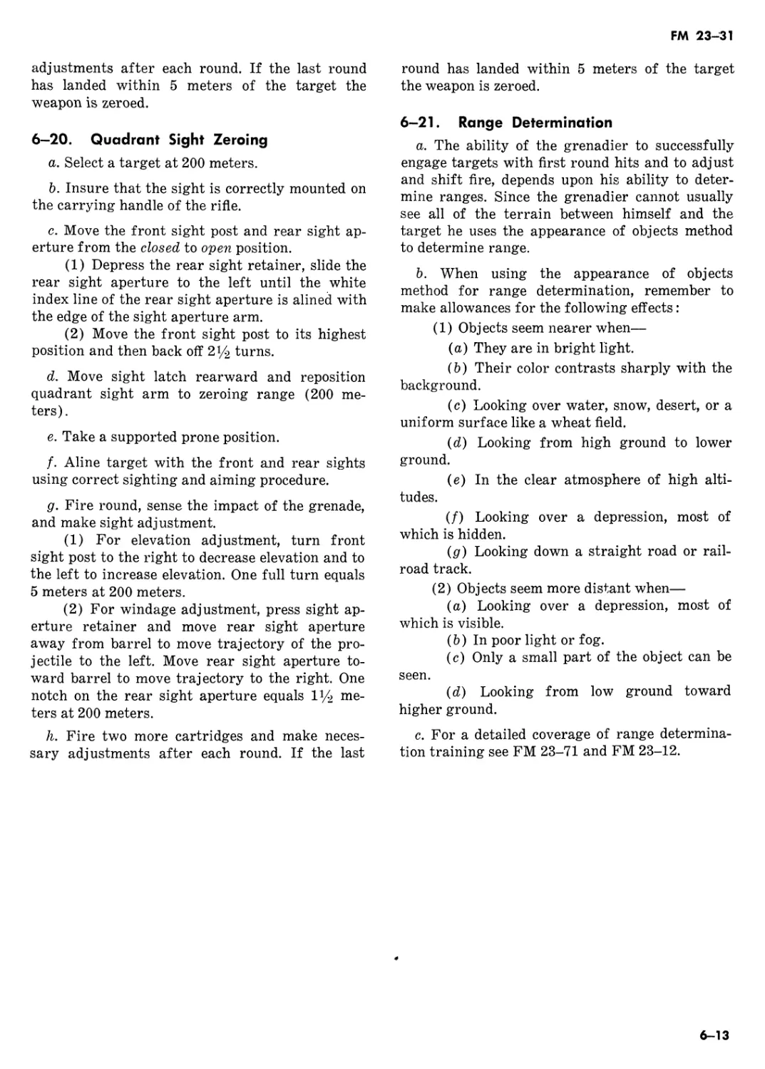
6—20. Quadrant Sight Zeroing
a. Select a target at 200 meters.
b. Insure that the sight is correctly mounted on
the carrying handle of the rifle.
c. Move the front sight post and rear sight ap-
erture from the closed to open position.
(1) Depress the rear sight retainer, slide the
rear sight aperture to the left until the white
index line of the rear sight aperture is alined with
the edge of the sight aperture arm.
(2) Move the front sight post to its highest
position and then back off 2^2 turns.
d. Move sight latch rearward and reposition
quadrant sight arm to zeroing range (200 me-
ters).
e. Take a supported prone position.
f. Aline target with the front and rear sights
using correct sighting and aiming procedure.
g. Fire round, sense the impact of the grenade,
and make sight adjustment.
(1) For elevation adjustment, turn front
sight post to the right to decrease elevation and to
the left to increase elevation. One full turn equals
5 meters at 200 meters.
(2) For windage adjustment, press sight ap-
erture retainer and move rear sight aperture
away from barrel to move trajectory of the pro-
jectile to the left. Move rear sight aperture to-
ward barrel to move trajectory to the right. One
notch on the rear sight aperture equals iy> me-
ters at 200 meters.
h. Fire two more cartridges and make neces-
sary adjustments after each round. If the last
round has landed within 5 meters of the target
the weapon is zeroed.
6-21. Range Determination
a. The ability of the grenadier to successfully
engage targets with first round hits and to adjust
and shift fire, depends upon his ability to deter-
mine ranges. Since the grenadier cannot usually
see all of the terrain between himself and the
target he uses the appearance of objects method
to determine range.
b. When using the appearance of objects
method for range determination, remember to
make allowances for the following effects:
(1) Objects seem nearer when—
(a) They are in bright light.
(b) Their color contrasts sharply with the
background.
(c) Looking over water, snow, desert, or a
uniform surface like a wheat field.
(d) Looking from high ground to lower
ground.
(e) In the clear atmosphere of high alti-
tudes.
(/) Looking over a depression, most of
which is hidden.
(g) Looking down a straight road or rail-
road track.
(2) Objects seem more distant when—
(a) Looking over a depression, most of
which is visible.
(6) In poor light or fog.
(c) Only a small part of the object can be
seen.
(d) Looking from low ground toward
higher ground.
c. For a detailed coverage of range determina-
tion training see FM 23-71 and FM 23-12.
6-13
FM 23-31
CHAPTER 7
RANGE CONSTRUCTION
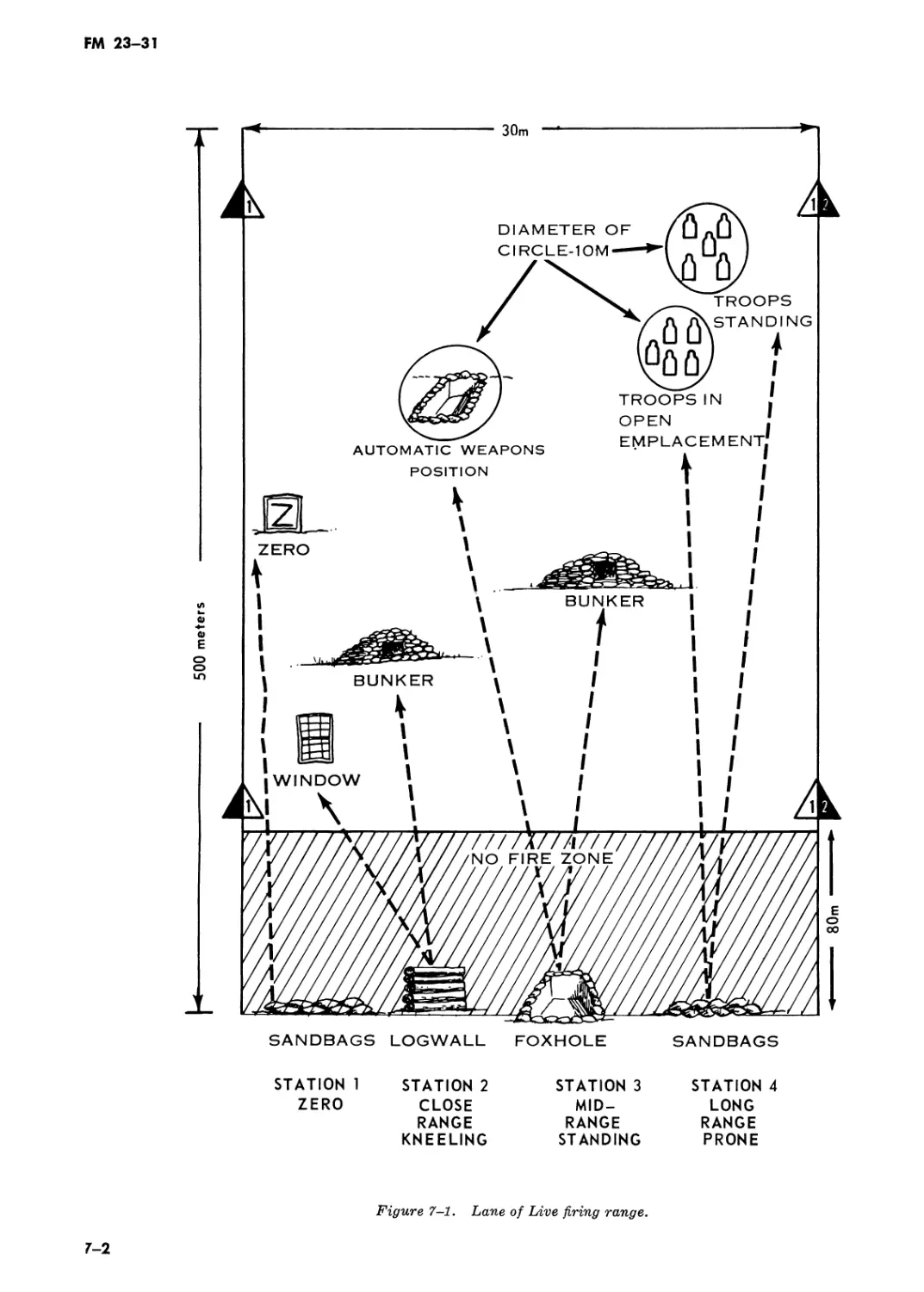
7—1. General
Figure 7-1 is a schematic illustration of one lane
of the grenade launcher range. Any number of
parallel lanes may be established depending on the
terrain available for constructing this range. This
range is to be used when firing the courses of fire
outlined in chapter 8. Consult Army Regulation
385-63 and local range and safety regulations to
determine safety requirements.
7-2. Description of Area
a. The range consists of one or more lanes, with
each lane complete within itself. Allow a mini-
mum width of 30 meters and a depth of 500 me-
ters for each lane. Targets within the lane are
grouped and spaced so that the grenadier may fire
at close range, midrange, and long range targets
in that order.
b. Divide each lane into four stations:
(1) Station 1 consists of a prone firing posi-
tion with a log or sandbag support and a zeroing
target at 200 meters range. The target may be
made of logs or other suitable material. It must
have a surface at least 6 feet high and 6 feet wide.
The zeroing target should be clearly marked by
painting a large Z with color that will contrast
with the surrounding background.
(2) Station 2 consists of an upright log or log
wall firing point about 4 feet high and two point-
type targets. The targets are a simulated window
or door of a building and a simulated small
bunker or covered firing position. The range to
the two targets is shown in table 8-1. The targets
may be constructed of logs, sandbags, or other
suitable material.
(3) Station 3 consists of a foxhole firing
point and two targets. The targets consist of a
simulated two-man bunker and an uncovered
weapon position. The ranges to the two targets
are shown in table 8-1, chapter 8. The bunker
represents a point target and the weapon position
represents a target which can be engaged using
area-type fire.
(4) Station 4 consists of a prone firing point
with a log or sandbag support and two area tar-
gets. The log or sandbags on the firing point are
used for support and cover. The area targets are
to simulate troops in the open. The range to the
two targets is shown in table 8-1.
c. The impact area must be kept free of vegeta-
tion other than short grass. This is to facilitate
the location and destruction of duds. Ideally, the
terrain should slope downward for the first 100 to
200 meters and then slope gently upward out to a
range of about 500 meters.
d. After considerable use, the impact area will
probably have many duds in it. Therefore, targets
should be constructed of a long-lasting, durable
material that will withstand constant use and
need little maintenance. Targets should be con-
structed of salvaged oil drums filled with sand or
from other durable salvaged material.
7-1
FM 23-31
500 meters
SANDBAGS LOGWALL FOXHOLE
80m
SANDBAGS
STATION 1 STATION 2 STATION 3 STATION 4
ZERO CLOSE MID- LONG
RANGE RANGE RANGE
KNEELING STANDING PRONE
Figure 7-1. Lane of Live firing range.
7-2
FM 23—31
CHAPTER 8
RANGE FIRING
8-1. General
a. Schedule range firing only after the soldier
has demonstrated his ability to apply the steps of
marksmanship training. The three courses of fire
for the grenade launcher are: Instructional firing,
qualification firing, and instruction course (modi-
fied).
b. Observe safety precautions during all range
firing. The surface danger area and range safety
requirements vary with the type of ammunition
being used. Consult Army Regulation 385-63 and
local range and safety regulations to determine
current safety requirements.
8-2. Instructional Firing
a. Conduct instructional firing prior to qualifi-
cation firing to provide the grenadier with addi-
tional training in sighting, aiming, sight manipu-
lation, positions, rapid loading, sensing, and ad-
justment of fire while engaging targets.
b. Instructional firing consists of firing table
8-1 one time on the grenade launcher range de-
scribed in chapter 7.
Table 8-1. Instructional Firing (Total Rounds—12)
Station* Position Target (s) ** Range Rourtds Time limit
1 Prone supported Zeroing panel 200m 3 2 minutes
2 Kneeling supported 2 point targets: Window Bunker 90-100m 105-115m 3 2 minutes
3 Foxhole 1 point target: Bunker 1 area target: Automatic weapon position 135-150m 200-250m 3 2 minutes
4 Prone supported 2 area targets: Troops in open emplacement Troops in open 275-300m 325-350m 8 2 minutes
♦See figure 7-1.
♦♦Targets may be simulated.
(1) Station 1 is to permit the grenadier to
zero the grenade launcher. After the completion
of firing, the launcher will be cleared. It is cleared
when the breech end of the barrel assembly is
open, the cartridge or cartridge case removed, and
a visual check has been made of the barrel assem-
bly. Aho ays carry the launcher with the breech
open on the range.
(2) Station 2 is to instruct and test the gren-
adier in the kneeling supported position, range
determination, sight setting, firing, sensing, and
adjustment of fire at close-in point targets. The
grenadier may engage either of the two targets in
the station, but once he fires at one target, he
must not engage the other target until he has hit
the first target.
(3) Station 3 is to instruct and test the gren-
adier in firing from the foxhole position at point
and area targets. The sequence of fire and engage-
ment of targets is as prescribed in (2) above.
(4) Station 4 is to instruct and test the gren-
adier in firing from the prone supported position
at area targets. The sequence of fire and engage-
ment of targets is as in (2) above.
(5) Each station within the lane will be su-
pervised by an assistant instructor who is also
8-1
FM 23-31
responsible for scoring. The assistant instructor
will also observe the impact of all grenades, keep
a record of the number and location of all duds
within the station, and report these when re-
quired. An ammunition point will be established
on each lane and supervised by the safety non-
commissioned officer. Ammunition will be drawn
and issued by the assistant instructors at each
station. Grenadiers are organized into orders. Ro-
tate in a clockwise direction. Order one will com-
plete firing on station 1 and move to stations 2, 3,
and 4 in that order. Order two follows order one
through the stations. When the first order has
reached station 4, all stations should be occupied
or all orders should be on the line.
(6) Fire commands are given as follows:
(a) On command from the officer in charge
of firing, the grenadier moves to his station and
QUALIFICA- TION SCORE SCORER (Initial)
STATION 2
TARGET VALUE
1 5 s DES
2 5 5 DE5
BONUS 5 О DES
SUBTOTAL /0
STATION 3
TARGET VALUE
1 5 5 DE5
2 5 DES
BONUS 5 5 DES
SUBTOTAL /Е
STATION 4
T ARGET VALUE
1 5 E DES
2 5 E DES
BONUS 5 DES
SUBTOTAL /5
TOTAL SCORE + 0
QU ALI FIC ATION EXPERT
Expert - 40 or 45
First Class - 30 or 35
Second Class - 20 or 25
Unqualified - 0 to 15
SIGNATURE OF FIRER
SIGNATURE OF OFFICER
SCORECARD FOR 40mm GRENADE LAUNCHER For use of this form, see FM 23-3i; THE PROPONENT AGENCY IS USCONARC.
name (First Name - Middle Initial - Last Name) MICHAEL D. HAYES
SSN I grade Z4/-O9-?4-/7 5P/4
ORGANIZATION CO. A, IsF BN, бб+й INF
DATE 13 MAY TO
сея О blev PETERS
INSTRUCTION SCORE SCORER (Initial)
STATION 2
TARGET VALUE
1 5 DES
2 5 S' DES
BONUS 5 s DES
SUBTOTAL /Е
STATION 3
TARGET VALUE
1 5 E DES
2 5 5 DES
BONUS 5 E DES
SUBTOTAL /Е 1
STATION 4
TARGET VALUE
1 5 DES
2 5 E DES
BONUS 5 5 DES
SUBTOTAL IE
(See Reverse Side)
DA FORM 2946, 1 MAR 65
Figure 8-1. Scorecard.
8-2
FM 23-31
takes the firing position specified by the range
officer.
(b) The officer in charge of firing will then
announce: THE FIRING LINE IS NO LONGER
CLEAR. GRENADIERS DESIGNATE THE
TARGET; DETERMINE THE RANGE TO THE
TARGET; PLACE THE PROPER SETTING ON
THE REAR SIGHT. ASSISTANT INSTRUC-
TORS DRAW THREE ROUNDS OF TRAINING
PRACTICE (HIGH EXPLOSIVE) AMMUNI-
TION AND ISSUE THEM TO THE GRENA-
DIERS.
(c) At the command DESIGNATE THE
TARGET, the grenadier will identify the target
he intends to engage by announcing: WINDOW,
BUNKER, AUTOMATIC WEAPON, TROOP
EMPLACEMENT; or TROOPS IN THE OPEN,
as appropriate for his station. At the command
DETERMINE THE RANGE, the grenadier will
announce the range to the target. At the command
ASSISTANT INSTRUCTORS DRAW THREE
ROUNDS OF TRAINING PRACTICE (HIGH
EXPLOSIVE) AMMUNITION AND ISSUE
THEM TO THE GRENADIER, the assistant in-
structor will pick up the ammunition at the am-
munition point and issue it to the grenadier.
(d) When the grenadier has made his sight
setting and the ammunition has been issued, the
assistant instructor on each lane will signal that
his lane is ready.
(e) When all lanes are ready, the officer in
charge will command: YOU HAVE TWO MIN-
UTES TO COMPLETE THIS EXERCISE. ON
THE FIRING LINE, ONE ROUND OF (TP)
(HE) AMMUNITION—LOAD. READY ON
THE RIGHT? READY ON THE LEFT?
READY ON THE FIRING LINE. COMMENCE
FIRING.
(f) After each grenade is fired the assist-
ant instructor will call out HIT or MISS, which-
ever is correct. The grenadier is not permitted to
engage the second target until the first target has
been hit.
(g) After 2 minutes have elapsed the
officer in charge of firing commands: CEASE
FIRING—CLEAR ALL WEAPONS. ASSIST-
ANT INSTRUCTORS TURN IN ALL UNEX-
PENDED ROUNDS AND REPORT ALL DUDS.
GRENADIERS ROTATE.
(h.) After completing firing on station 4,
the grenadier will have his weapon cleared and
move off the firing line.
8—3. Qualification Firing
a. Qualification firing is conducted to test the
grenadier’s ability to apply the techniques of
marksmanship.
b. Instructional firing and qualification firing
should be conducted on the same day. When this is
not possible, station 1, the zeroing station, must
be fired as an unscored part of the qualification
course in order to let each grenadier get or con-
firm his zero of the launcher he will fire for quali-
fication.
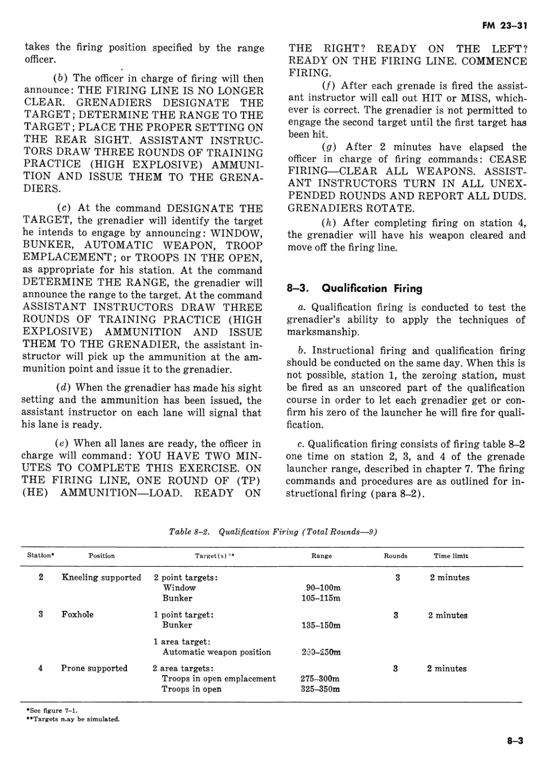
c. Qualification firing consists of firing table 8-2
one time on station 2, 3, and 4 of the grenade
launcher range, described in chapter 7. The firing
commands and procedures are as outlined for in-
structional firing (para 8-2).
Table 8-2. Qualification Firing (Total Rounds—9)
Station* Position Target(s) *♦ Range Rounds Time limit
2 Kneeling supported 2 point targets: Window Bunker 90-100m 105-115m 3 2 minutes
3 Foxhole 1 point target: Bunker 135-150m 3 2 minutes
1 area target: Automatic weapon position 2j0-250m
4 Prone supported 2 area targets: Troops in open emplacement Troops in open 275-300m 325-350m 3 2 minutes
♦See figure 7-1.
♦♦Targets may be simulated.
8-3
FM 23-31
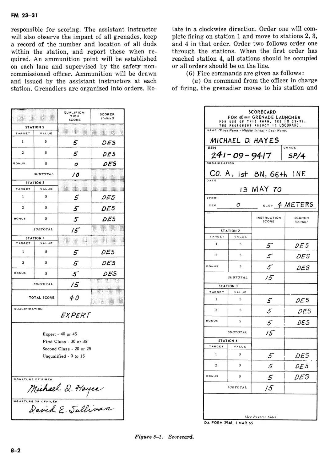
d. Qualification scores are rated for the qualifi-
cation firing course (table 8-2) as follows:
(1) Qualification scores.
EXPERT GRENADIER__________40 to 45
FIRST CLASS GRENADIER
(SHARPSHOOTER) __________30 to 35
SECOND CLASS GRENADIER
(MARKSMAN)_______________20 to 25
UNQUALIFIED _______________ 0 to 15
(2) Scorecard. DA Form 2496 (Scorecard for
40-mm grenade launcher) for use on the qualifica-
tion course is shown in figure 8-1. Each time the
grenadier moves from one station to another he
must carry his scorecard with him. All scoring
entries on the card are made and initialed by the
assistant instructor at the station being fired.
After completion of qualification firing, the grena-
dier must sign the scorecard.
(3) Target scoring. When scoring, the assist-
ant instructor will evaluate each grenade fired as
outlined below :
(a) Window or door. The grenade must go
through the opening in the center of the target.
(6) Bunker. Credit will be given for a hit
if the grenade impacts anywhere on the face of
the bunker.
(c) Automatic weapon. Credit will be
given for a hit only if the grenade impacts within
a 10 meter (diameter) circle surrounding the tar-
get.
(d) Troops. Credit will be given for a hit
only if the grenade impacts within a 10 meter
(diameter) circle surrounding the targets.
(4) Scoring. Issue each grenadier three gre-
nades for each of the qualification firing stations.
Each hit is worth five points. The grenadier gets a
five-point bonus score if he achieves first round
hits on both targets at a station. So, each station
is worth 15 points. For example, station 3 has two
targets, a point target and an area target. The
grenadier may select either target to engage first.
If he scores a hit on the first target selected, he
receives a score of five points. He is then permit-
ted to engage the second target on the station. If
he hits the second target, he earns another five
points. If he scores a hit on both targets on the
station with first round hits, he is given a five-
point bonus for a total of 15 points. He then gives
the unexpended round to the assistant instructor.
Do not allow the grenadier to change from one
target to the other within the station until the
first target he selected has been hit. Scoring for
station 2 and 4 is the same as for station 3.
8-4. Familiarization Course
This course may be conducted on station 1 and 3
of the grenade launcher range described in chap-
ter 7. It consists of firing table 8-3 one time with
no time limit and is not scored. The firing com-
mands and procedures are as outlined for instruc-
tional firing (para 8-2) except that the grenadier
is given the range to each target he engages.
Table 8—3 . Familiarization Course (Total Rounds—5)
Station* Position Target (s) ** Range Rounds Time limit
1 Prone supported Zeroing panel 200m 3 None
3 Foxhole 1 point target: Bunker 1 area target: Automatic weapon position 135-150m 200-250m 2 None
♦See figure 7-1.
♦♦Targets may be simulated.
8-4
FM 23-31
CHAPTER 9
CHARACTERISTICS, LAUNCHER CONTROLS, AND SIGHTING
EQUIPMENT OF 40-MM GRENADE LAUNCHER, M79
Section I. CHARACTERISTICS
9—1. Description
The 40-mm grenade launcher, M79, is a single
shot, breakopen, breech-loading, shoulder-fired
weapon (fig 9-1). It consists of a receiver group,
fore-end assembly, barrel group, sight assembly,
and stock assembly (fig 9-2). A rubber recoil pad
is attached to the butt of the stock to partially
absorb the recoil. A sling is provided to carry the
weapon.
9-2. Ammunition
Standard and developmental ammunition designed
for use with the 40-mm grenade launcher, M203
(fig 4-2), is used with the M79 grenade launcher.
The grenadier carries part of his ammunition in
two universal ammunition pouches, each of which
can hold three rounds (fig 5-2). Ammunition is
also carried in the two-pocket bandoleer in which
the ammunition is packed. Each pocket contains a
plastic support which holds three rounds.
9-3. Data
a. Weapons.
Length of launcher
(overall)______________29 in (approx)
Length of barrel group 15 in (approx)
Length of barrel only _ 14 in
Weight of launcher loaded 6.5 lbs (approx)
Weight of launcher unloaded 6 lbs (approx)
b. Ammunition.
Caliber_____________________40-mm
Weight _____________________8 oz (approx)
c. Operational Characteristics.
Action________________________Breakopen,
single shot
Sights:
Front _ Blade
Rear .Folding leaf, adjustable
Chamber pressure _3,000 lbs per square in.
Muzzle velocity -250 ft per second. 76 meters per second
Maximum range -400 m (approx)
Maximum effective range
(area targets) -350 m
Maximum effective range
(point targets) -150 m
Minimum safe firing range:
Training _80 m
Combat _31 m
9-1
FM 23-31
Figure 9-1. The 40-mm grenade launcher, M79, left side view,
with rear sight in UP position.
BARRELGROUP
. RECEIVERGROUP
Figure 9-2. Five major subassemblies and groups of M79.
Section II. CONTROLS
9—4. Safety
The location of the safety is shown in figure 9-3.
To fire the launcher the safety must be in the
forward position (fig 9-4). In this position the
letter F is visible near the rear end of the safety.
When the letter S is visible just forward of the
safety, the launcher will not fire. The safety is
automatically engaged when the barrel locking
latch is operated to open the breech.
9-2
FM 23-31
9-5. Trigger and Trigger Guard Detent
Assembly
The position of the trigger and trigger guard is
shown in figure 9-5. The trigger guard protects
the trigger. Depressing the detent assembly per-
Figure 9-3. Location of the safety in the safe position.
Figure 9-4. Location of the safety in the firing position.
mits the movement of the trigger guard to the
right or left and allows the grenadier to fire the
weapon while wearing gloves or mittens.
9-6. Barrel Locking Latch and Lever
The barrel locking latch is on top of the receiver
(fig 9-6). This latch locks the receiver and barrel
together. To open (or break) the breech end of
the barrel, press the barrel locking latch lever its
full travel to the right.
9-3
FM 23-31
Figure 9-5. Position of trigger and trigger guard.
9-4
FM 23-31
BARREL LOCKING LUG
Figure 9-6. Operating the barrel locking latch.
Section III. SIGHTING EQUIPMENT
9-7. Rear Sight Assembly
The adjustable rear sight assembly consists of a
rear sight lock, a windage screw and windage
scale, and elevation scale and lock screw, a sight
carrier and retainer locknut, and elevating screw
wheel and elevating screw, and a rear sight frame
and fixed sight (fig 9-7).
a. Rear Sight Lock. The lock is spring loaded
and permits the rear sight frame assembly to be
locked in either the гср or down position. To
unlock the sight frame push down on the flat sur-
face of the rear sight lock. By releasing the pres-
sure the frame is locked in the desired position.
b. Windage Screw and Windage Scale. The
right end of the screw is a knob which turns the
windage screw to adjust the rear sight for deflec-
tion. One click of the windage screw will move the
impact of the grenade about 28 centimeters or 11
inches at a range of 200 meters. For right wind-
age turn the screw clockwise; for left windage
turn it counterclockwise. The windage scale con-
sists of a zero line in the center of the scale and
10 lines spaced equally on each side of the zero
line. The rear sight assembly can be moved 42
clicks right or left of center.
c. Elevation Scale and Lock Screw. The scale is
graduated from 75 to 375 meters in 25-meter in-
crements and numbered at 100, 200, 300, and 375
meters. As the rear sight carrier is moved up the
adjustable elevation scale, the rear sight is
cammed to the left compensating for the normal
right-hand drift of the projectile. The lock screw
holds the elevation scale in position.
d. Sight Carrier Retainer Locknut. The retainer
locknut permits the sight carrier to be moved
along the elevation scale and clamps the carrier to
the sight frame in the desired position. To move
the sight carrier along the elevation scale turn the
9-5
FM 23-31
retainer locknut counterclockwise until it can be
pushed inward. This inward pressure unlocks the
sight carrier allowing it to be moved along the
elevation scale. To lock the sight carrier in posi-
tion, release the pressure on the retainer locknut
and turn the nut clockwise until it stops.
e. Elevating Screw Wheel and Elevating Screw,
The elevating screw wheel and elevating screw
are used to make fine adjustments in elevation.
Turning the wheel clockwise increases the eleva-
tion setting; turning the wheel counterclockwise
decreases it. When the screw is turned it moves
the sight carrier along the elevation scale. One
complete turn (one click) will move the impact of
the round about 2Ц> meters at a range of 200
meters.
f. Rear Sight Frame With Fixed Sight. When
the rear sight frame is in the down position the
ELEVATION SCALE
LOCK SCREW
Figure 9—7. Rear sight assembly.
9-6
FM 23-31
fixed sight may be used to engage targets, at
ranges up to 100 meters.
9—8. Front Sight
The front sight consists of a tapered front sight
blade and two front sight blade guards (fig 9-8).
Figure 9-8. Front sight.
9-7
FM 23-31
CHAPTER 10
MECHANICAL TRAINING; OPERATION AND FUNCTIONING;
AND MAINTENANCE
Section I. DISASSEMBLY AND ASSEMBLY
10-1. General
This chapter contains instruction for mechanical
training, operation and functioning of the 40-mm
grenade launcher, M79.
10—2. General Disassembly
Grenadiers are authorized to disassemble the
launcher as follows:
a. Clear the weapon by rotating the barrel lock-
Figure 10-1. Removing or installing the
retaining band screw.
ing latch lever its full travel to the right and
opening the barrel. Inspect the breech to insure
that no round is present.
b. Remove the sling from the stock.
c. Remove the retaining band screw, which
passes through the rear mounting of the front
sling swivel, and pull the fore-end assembly away
from the barrel (fig 10-1 and 10-2).
d. Press the barrel locking latch lever to the
right; pivot the barrel down until it stops; slide
the barrel off the fulcrum pin and remove it from
the receiver (fig 10-3). Do not remove the rear
sight from the barrel.
e. Remove the stock screw and washers and pull
the stock rearward from the receiver (fig 10-4).
10—3. Assembly
Assembly of the grenade launcher is the reverse
of disassembly.
a. Place the stock on the receiver and replace
the stock screw and washers. Place the lock-
washer on the stock screw first.
b. Place the barrel on the fulcrum pin (fig
10-5). Hold the cocking lever up, lower the barrel,
and insure that the cocking arm slides under the
cocking lever. Close the barrel.
c. Place the fore-end assembly on the barrel and
secure it by replacing the retaining band screw.
d. Replace the sling.
10-1
FM 23-31
>«. a”mb"''
Figure IOS. Removing or installing the barrel group.
10-2
FM 23-31
BARREL GROUP
AND i SIGHT ASSEMBLY
SLING
Figure 10-4. Grenade launcher, general disassembly.
Figure 10-5. Assembling barrel group and receiver group.
Section II. OPERATION, FUNCTIONING, AND TROUBLESHOOTING
10—4. Preparation for Firing
a. Check the bore to be sure it is clear and dry.
b. Check the launcher to be sure it is clean.
c. Inspect for defective parts.
d. Insure that the firing pin retainer is tight
(fig 10-6). Turn it clockwise with the combina-
tion tool. A loose firing pin retainer is the most
probable cause for a failure to fire.
10-5. Functioning
a. Unlocking (fig 10-7).
(1) Unlocking is done by pressing the barrel
locking latch lever its full travel to the right. This
unlocks the barrel from the receiver and moves
the safety to the safe position.
(2) The barrel locking latch is held in the
open position by a spring-loaded latch lock (fig
10-10).
b. Cocking (fig 10-7).
(1) The weapon is cocked when the barrel is
opened.
(2) As the barrel is opened the cocking arm
lifts the cocking lever and causes it to rotate
10-3
FM 23-31
Figure 10-6. Position of firing pin retainer.
around the hammer pin contacting a stud on the
hammer.
(3) The cocking lever rotates upward with
the hammer until the sear notch is engaged by the
sear.
c. Extraction (fig 10-7).
(1) Extraction and cocking take place at the
same time.
(2) As the barrel is opened, the spring-loaded
extractor withdraws the spent cartridge case
about % inch from the breech end of the barrel.
d. Ejection (fig 10-8).
(1) The launcher is not equipped with an
automatic ejector.
(2) To eject, manually remove the expended
cartridge case or live round from the barrel.
e. Loading (fig 10-8). With the barrel in the
open position the cartridge is inserted into the
breech end bf the barrel.
f. Chambering.
EXTRACTOR
COCKING ARM
Figure 10-7. Unlocking, cocking, and extraction.
(1) Chambering takes place during the clos-
ing of the barrel.
(2) As the barrel is closed, the extractor is
forced into the extractor housing and the car-
tridge is seated into the chamber.
g. Locking (fig 9-6).
(1) As the barrel closes and the latch lock is
depressed, the barrel locking latch rotates until it
is engaged with the barrel locking lug.
(2) The barrel is now locked to the receiver
and the launcher can be fired after the safety is
pushed forward exposing the letter F.
h. Firing (fig 10-9).
(1) As the trigger is pulled rearward it ro-
tates about the trigger pin and the rear of the
trigger lifts the rear of the sear causing the nose
of the sear to become disengaged from the sear
notch in the hammer. This releases the spring
driven hammer to strike the firing pin and drive
it forward to strike the primer of the cartridge.
(2) As the trigger is released the hammer
settles back slightly, allowing the firing pin to be
withdrawn from the face of the retainer through
the action of the firing pin spring.
10-6. Troubleshooting
a. Stoppages and immediate action are as out-
lined in paragraph 3-6, 3-7, and 3-8.
b. Troubleshooting is the systematic study of
trouble signs, testing to determine the defective
components, and applying corrective action (chart
10-1).
10-4
FM 23-31
Figure 10-8. Loading or ejecting.
Figure 10-9. Firing.
10-5
FM 23-31
Chart 10—1. Troubleshooting
Malfunction Probable cause Corrective action
Failure to fire Safety in S position Place in F position. Empty chamber Load weapon. Loose firing pin retainer Tighten firing pin retainer. Faulty ammunition Reload. Short, worn, or broken firing pin. Replace firing pin. Dirty firing pin opening Clean firing pin opening. Broken hammer Turn in to armorer. Weak or broken hammer spring Turn in to armorer. Broken sear, cocking arm, cocking lever Turn in to armorer.
Failure to chamber Faulty ammunition Reload. Dirty chamber Clean bore.
Failure to extract Defective extractor Turn in to armorer. Set or broken extractor spring Turn in to armorer. Ruptured cartridge case Remove from barrel.
Failure to cock Defective sear Turn in to armorer. Defective cocking arm or lever Turn in to armorer.
Safety fails to stay in selected position. Broken or weak safety spring Turn in to armorer.
Rear sight will not stay in selected position Broken or weak sight lock spring Turn in to armorer. Broken lug on sight lock Turn in to armorer.
10-6
FM 23-31
Figure 10-10. Barrel release latch lock.
Section III. MAINTENANCE
10-7.
Maintenance of the M79 is the same as that for
the M203 in chapter 5.
10-8.
Authorized organizational maintenance is shown
in chart 10-2.
10-7
FM 23-31
Chart 10-2. Authorized Organizational Maintenance (M79)
Grenadier Armorer
Barrel group:
Cleaning and lubrication x Fore-end assembly: X
Cleaning and lubrication x Replace machine screw Receiver group: X X
Cleaning and lubrication x Replace firing pin Replace firing pin retainer Replace firing pin spring Sight assembly: X X X X
Cleaning and lubrication x Stock assembly: X
Cleaning and lubrication x Replace stock screw Replace flat washer Replace lockwasher X X X X
10-8
FM 23-31
CHAPTER 11
MARKSMANSHIP TRAINING (M79)
11—1. General
Marksmanship training is to teach the grenadier
to fire the grenade launcher and to prepare him to
employ it in combat. Except as discussed below,
the marksmanship training, range construction,
and range firing for the M79 are identical with
that for the M203 (chap 1-8).
11—2. Sight Alignment, Sight Picture, and
Sight Manipulation
a. Sight alinement is the relationship between
the front sight blade and the rear sight notch. To
have correct sight alinement the sights should be
alined as shown in figure 11-1. If an imaginary
horizontal line were drawn across the top of the
rear sight notch, the top of the front sight blade
would touch this line. If an imaginary vertical
line were drawn through the center of the notch,
the line would cut the front sight blade in half.
b. Sight picture includes sight alinement and
the placement of the aiming point as shown in
figure 11-2.
c. Sight manipulation is the procedure of plac-
ing the rear sight carrier at the proper setting on
the elevation scale to correspond with the range to
the target.
11—3. Positions
a. Fire the M79 grenade launcher from the
same positions as the M203 grenade launcher. The
Figure 11-1. Correct sight alinement.
Figure 11-2. Correct sight picture.
most commonly used firing positions are the
prone, kneeling, foxhole, and standing positions.
Supported positions add stability to the weapon
and should be used when possible. The grenadier
takes the various firing positions in the same way
as with the service rifle (FM 23-9), with the fol-
lowing exceptions:
(1) Hold the thumb of the right hand against
the right side of the stock. The safety may injure
the thumb when the launcher recoils if the thumb
is placed over the top of the small of the stock.
(2) The spot weld is not attained.
b. The following points are common to all posi-
tions. Check for them when training the grena-
dier.
(1) The launcher should rest in the V formed
by the thumb and forefinger of the left hand
across the heel of the hand.
(2) The fingers of the left hand are relaxed.
The hand is placed so that it will not be pinched
by the upper-sling swivel.
(3) The left wrist is straight with the left
thumb resting against the fore-end assembly and
not on the rear sight base. If the thumb is placed
near the rear sight base, injury to the thumb may
result.
(4) The left elbow is under the launcher.
(5) The right elbow is positioned far enough
to the right to level the shoulders and far enough
forward to form a good pocket for the butt of the
launcher.
11-1
FM 23-31
(6) The thumb of the right hand rests along
the side of the stock. Do not place the thumb over
the top of the small of the stock as the safety may
injure it when the launcher recoils.
(7) The trigger finger is placed on the trigger
so that there is no contact between the finger and
the side of the stock.
(8) The grenadier must be relaxed in all
firing positions.
c. At ranges less than 150 meters, the grenadier
is able to fire from the shoulder in the normal
manner from all positions. However, in order to
maintain sight alinement as range to the target
increases, he must adjust as follows:
(1) Lower the position of the stock on the
shoulder or drop the butt from the shoulder to
maintain sight alinement. At near maximum
ranges the stock will be positioned between the
waist and the armpit and held firmly into the
body by the upper arm. In the prone position the
butt of the launcher will rest on the ground once
the stock is no longer against the shoulder.
(2) As contact between the cheek and the
stock is broken, care must be taken to keep the
head level. Figure 11-3 illustrates the changes
which take place as the range-to-target increases.
d. Use the pointing technique to deliver a high
rate of HE fire when pinpoint accuracy is not
required (fig 11-4). Although the sights are not
used in the pointing technique, the grenadier must
first become proficient in sighting and aiming. The
grenadier uses a modified underarm firing posi-
tion, enabling him to use his left hand for rapid
reloading. Although the pointing technique can be
used by modifying any of the standard firing posi-
tions, it is most frequently used during the as-
sault.
e. To employ the pointing technique use a modi-
fied underarm firing position. With both eyes
open, concentrate your vision on the target keep-
ing the muzzle of the launcher in the lower part of
the field of view. Point the muzzle at the target
and sense the elevation of the launcher with re-
spect to the range to the target. To make correc-
tions in elevation and deflection sense the impact
of the round and make proper changes in the atti-
tude of the launcher.
Figure 11-3. The effect of increasing range.
11-2
FM 23-31
Figure ll-Ь. Pointing technique.
11-3
FM 23-31
11-4. Zeroing Procedure
The correct zero of the grenade launcher is that
sight setting of elevation and windage which will
enable the firer to hit his point of aim at a given
range. To get a zero, the grenadier engages a tar-
get 200 meters from the weapon position. Use a
200 meter range because this is the mid-range
capability of the weapon and allows for maximum
changes in elevation. Zero the M79 in the follow-
ing sequence (fig 9-7):
a. Place the center index line of the rear sight
on the center mark of the windage scale.
b. Unlock the elevation scale by turning the ele-
vation scale lock screw counterclockwise. Position
the top of the elevation scale flush with the top of
the sight frame. Lock the elevation scale.
c. Unlock the rear sight carrier by turning the
rear sight carrier retainer locknut, push it in, and
slide the sight carrier along the elevation scale
until the 200 meter index mark on the elevation
scale is alined with the top edge of the sight car-
rier. Lock the rear sight carrier in position.
d. Take a prone supported position and aline
the target with the front and rear sights using
correct sighting and aiming procedure.
e. Fire a round, sense the impact of the gre-
nade, and make sight adjustment.
(1) For elevation adjustment, turn the eleva-
tion screw wheel clockwise to increase (or coun-
terclockwise to decrease) the range. One click on
the elevation screw wheel moves the impact of the
grenade 2Ц meters at a range of 200 meters.
(2) For windage adjustment, turn the wind-
age knob clockwise to move the impact of the gre-
nade to the right. One click of the windage knob
moves the impact of the grenade about 11 inches
at a range of 200 meters.
/. Fire two more rounds and make necessary
adjustments after each round. If the last round
has landed within 5 meters of the target, the
weapon is zeroed.
g. After the zero has been confirmed, insure
that the elevation scale is moved so that the 200
meter index line is flush with the top of. the sight
carrier.
FM 23-31
CHAPTER 12
INDIRECT-FIRE ROLE, M79
12—1. General
a. This chapter describes the use of the 40-mm
grenade launcher, M79, in the indirect-fire role.
Although the M79 is designed for direct fire, it
can fire indirect-fire as an expedient means of
placing high explosive fragmentation fire on area
targets which cannot be observed.
b. By massing the indirect fire of several M79s,
the small unit leader has organic firepower with
which to suppress fire when the enemy’s position
is screened by vegetation, in defilade, or located on
a steep slope above the friendly unit. During peri-
ods of limited visibility this fire can supplement
the indirect fires of other weapons supporting the
unit.
12—2. Employment Considerations
a. Employment. When using the M79 for indi-
rect-fire, its accuracy is limited. Range adjust-
ment can be made in 25-meter increments to the
maximum range of about 400 meters.
b. Sighting System. The sighting system for the
M79 is graduated up to 375 meters which corre-
sponds to a 32° quadrant elevation. However, the
rear sight carrier can be raised higher so that a
maximum quadrant elevation of 40° is possible.
At elevations greater than 40°, where the rear
sight cannot be used, the range will decrease as
the angle of elevation is increased.
c. Adjustments for Elevation and Deflection.
(1) Indirect fires with the M79 are adjusted
by moving the barrel slightly for elevation or de-
flection to bring succeeding rounds nearer the tar-
get.
(2) Deflection is attained by sighting over or
along the side of the barrel at an aiming point.
When opportune, an aiming stake should be used.
If time permits, greater accuracy can be attained
by placing a string or straight stick on the ground
in the direction of an aiming point or stake.
(3) The correct elevation is achieved by esti-
mating the range to the target and moving the
barrel either up or down. Table 12-1 (Range Esti-
mate/Elevation) is a guide for setting the proper
elevation on the weapon:
Table 12-1. Range Estimate/Elevation
Range Elevation Distance from front sling swivel to ground
200 meters 69° 21*4 inches
300 meters 58° 19% inches
400 meters 41е 13% inches
Figure 12-1. Kneeling position using marked sling method.
12-1
FM 23-31
d. Ammunition.
(1) If available, use the cartridge, 40-mm
practice, M407, for training and zeroing. On
impact, it emits a puff of yellow smoke which aids
the grenadier in adjusting his fire. The possibility
of a training injury is greatly reduced by using
this round, as there is very little fragmentation.
(2) Ammunition should be conserved in both
training and combat.
(3) The projectile takes nearly twice as much
time to reach its target when fired indirect.
Therefore, wind, snow, or rain may cause the pro-
jectile to deviate from its normal trajectory.
(a) Before firing, the grenadier should
evaluate the wind and compensate for it, whether
it is a crosswind or blowing on the same axis as
the grenade. This evaluation (Kentucky windage)
will increase his chances of getting a first round
hit and reduce the chances of a round impacting
closer than desired.
(b) Use caution when a wind 5 miles per
hour or greater is coming from the direction of
the target. This wind condition must be consid-
ered when firing at all ranges and especially when
firing at the minimum range of 200 meters.
e. Fire Control.
(1) The responsibility for the use of indirect
fire with the M79 should be delegated to the squad
leader. The methods of fire control used should be
prescribed in the squad SOP. This SOP should
state that the grenadiers will not fire indirect fire
without specific command.
Figure 12-2. Sitting position for indirect fire.
12-2
FM 23-31
(2) The fire commands used with indirect fire
are the same as direct fire except for the method
of fire. The squad leader must designate the tar-
get, range, and method of employment. An exam-
ple of a fire command to use when employing indi-
rect fire is—
SQUAD
FRONT
LINE OF RIFLEMEN
THREE HUNDRED
GRENADIERS, INDIRECT FIRE
THREE ROUNDS
(3) An observer may be used when using the
M79 for indirect-fire if the grenadier cannot ob-
serve the target.
(4) Fire for effect with the M79 should al-
ways be three to five rounds depending on the
nature of the target.
12-3. Firing Positions
The positions for indirect-fire with the M79 are
kneeling, sitting, or squatting.
a. Kneeling (fig 12-1). The kneeling position
can be used with any of the three methods of fire
described in paragraph 12-4. A modified kneeling
position is the most comfortable. Face the target
and kneel on the right knee (if firing right-
handed), keeping the left foot pointed in the
direction of the target. Sit on the right heel and
place the left elbow outside the left knee. Place
the butt of the stock on the ground against or
along the side of the right knee. Grasp the
launcher near the upper sling swivel with the left
hand and by the small of the stock with the right
hand. The right thumb should be against the right
side of the stock, parallel to the trigger finger.
The weight of the body should rest on the right
heel.
b. Sitting (fig 12-2). The sitting position is
identical to the direct fire sitting position except
for the following variations: keep the right leg
flat on the ground and pointed at the target, cross
the left leg over the knee so that the left knee will
support the left elbow, and place the butt of the
stock along-side the right hip. The weapon is held
as described in a above. The sitting position can
be used with the aiming stakes or M15 sight
methods.
c. Squatting (fig 12-3). The squatting position
is identical to the direct fire modified squatting
position except for one variation; the M79 is
Figure 12-3. Squatting position for indirect fire.
placed between the knees with the butt of the
stock on the ground. The launcher is held as de-
scribed in a above. The squatting position can be
used with the aiming stakes or M15 sight meth-
ods, although it is the least comfortable of the
positions when held for any length of time.
12-4. Methods of Indirect Fire (fig 12—1)
a. The marked-sling method is the best field
expedient to use with the M79. To use this
method, loosen the sling, take a kneeling position,
and place the forward foot in the sling. Before
firing, insure that the sling, between the front
sling swivel and the boot, is taut and vertical. If
not, the rounds will impact at a greater range
than desired. An easy way to check is by tying a
string or thread to a weight, such as a cartridge
case, and letting it hang from the front sling
swivel. Then aline the edge of the sling with the
string or thread to insure that the sling is verti-
cal. Fire several rounds to determine the desired
12-3
FM 23-31
range. Then mark the sling, where it is held to the
ground by the foot, with tape, paint, ink, or a
similar material. The position of the sling keeper
and buckle must also be marked so if either is
moved the grenadier can return them to their
original positions and be assured of constant
range accuracy. Remember that the sling may
stretch or shrink if it gets wet, indirectly causing
the rounds to impact closer or farther than de-
sired.
b. Preplanned indirect fire can be delivered
with the M79 using aiming stakes (fig 12-4). The
aiming stakes must be placed and their alinement
verified during daylight. Preplanned fires should
be recorded on a range card or sector sketch. The
fore-end assembly of the weapon is placed on top
of an elevation support. A slight depression is
scooped out of the ground for the toe of the weap-
on’s stock. Adjust the weapon for the range de-
sired and then drive a stake into the ground be-
hind the toe of the weapon’s stock to absorb and
prevent the weapon from digging into the ground.
Place two deflection stakes behind the front eleva-
tion support to control lateral movement of the
barrel. Place another elevation support beneath
the stock of the weapon and two additional deflec-
tion stakes behind this support, but closer to-
gether than the two front stakes, to control lateral
movement of the stock.
c. The most accurate way to fire the M79 for
indirect fire is with an M15 rifle grenade sight
fitted to the weapon’s stock (fig 12-5). The M15
rifle grenade sight consists of a mounting scale
plate and a sight bar assembly. The mounting
plate is attached to the side of the stock of the
launcher by two short wood screws. (Insure that
the screws do not protrude through the stock or
disassembly of the weapon will be a problem.)
When the weapon is in a horizontal position, the
mounting plate should be positioned so that the
two screw holes are vertical. The holes in the
stock should be predrilled if possible, to prevent
cracking the wood. When the Ml5 sight is at-
tached to the M79, the degree scale on the mount-
ing plate is not used. A short piece of masking
tape can be placed on the stock above the mount-
ing plate. The grenadier adjusts his fires until the
rounds impact at the desired range. After the
sight setting has been determined, the grenadier
can draw a line along the top of the sight bar on
the tape. Each line should be labeled for the ap-
propriate range. Indirect-fire sighting and aiming
with the M15 sight consists of the following three
Figure 12-lp. Preplanned fires using aiming stakes.
12-4
FM 23-31
Figure 12-5. M79 with Ml 5 rifle grenade sight.
steps: adjusting the sight, alining the launcher
for deflection, and centering the leveling bubble.
(1) Adjusting the sight. By firing several
rounds during zeroing, the grenadier can deter-
mine what elevation graduation is required on the
M15 sight to cause the round to impact at a given
range. This graduation can be marked on the
stock for quick reference.
(2) Alining the launcher for deflection. Take
a correct firing position and sight over or along
the barrel. Move the launcher so that the barrel is
alined toward the target.
(3) Centering the leveling bubble. Raise or
lower the muzzle of the launcher until the leveling
bubble is centered in its vial. Insure that the
weapon is not canted; this can cause the grena-
dier to miss his area target.
(4) Determining the angle of elevation. If
enough light is available, the M15 sight will pro-
vide a quick easy method for determining the
proper angle of elevation.
12-5. Safety Precautions
a. The grenadier must keep his head behind and
below the muzzle of the launcher when firing.
b. Be cautious, and insure overhead clearance
when firing indirect fire. Remember that the M406
40-mm cartridge arms itself 14 to 28 meters from
the muzzle of the launcher.
c. Absolutely no rounds should be fired at less
than 200 meters.
d. These safety precautions are in addition to
those in AR 385-63, and local range regulations.
12-5
FM 23-31
APPENDIX A REFERENCES
AR 385-63 Regulations for Firing Ammunition for Training, Target Practice, and Combat.
ASubjScd 7-2 ASubjScd 7-llB(C)(H)10 Rifle Squad Tactical Training. MOS Technical Training of Light Weapons Infantryman, Infantry In- direct Fire Crewman, and Infantry Direct Fire Crewman. .
ATP 7-16 Headquarters and Headquarters Company, Infantry, Airborne Infantry, and Mechanized Infantry Battalions.
ATP 7-18 Rifle Company, Infantry, Airborne, Airmobile and Light Infantry Bat- talions.
СТА 23-100-1 Ammunition, Rockets, and Missiles for Basic and Advanced Individual Training (by MOS).
DA Form 2946 DA Pam 108-1 FM 5-25 FM 21-75 FM 23-8 FM 23-9 FM 23-12 FM 23-30 FM 23-71 TF 9-3292 TM 9-1010-205-12 Scorecard for 40-mm Grenade Launcher, M79. Index of Army Films, Transparencies, GTA Charts and Recordings. Explosives and Demolitions. Combat Training of the Individual Soldier and Patrolling. US Rifle 7.62-mm, M14 and M14A1. US Rifle 5.56-mm, M16A1. Technique of Fire of the Rifle Squad and Tactical Application. Grenades and Pyrotechnic Signals. Rifle Marksmanship. Grenade Launcher, M79, Operation, Disassembly and Assembly (15 min). Operator and Organizational Maintenance Manual: 40-mm Grenade Launcher, M79.
TM 9-1010-205-24P Combined Organizational, DS, GS, and Repair Parts and Special Tools List for Launcher, Grenade, 40-mm: M79.
TM 9-1010-221-14 Operator’s, Organizational DS and GS Maintenance Manual: 40-mm Gre- nade Launcher, M203.
TM 9-1300-206 TM 9-1300-200 TM 9-6920-210-14 Care, Handling, Preservation and Destruction of Ammunition. Ammunition, General. Operator, Organizational, Direct Support and General Support Mainte- nance Manual Including Basic Issue Items List and Repair Parts List: Small Arms Targets and Target Material.
TV Tape—FP 175 Review of M79 Grenade Launcher.
A-l
FM 23-31
APPENDIX В
AMMUNITION
This appendix lists in table B-l the standard and developmental ammunition used with 40-mm grenade
launchers M203/M79. The letters XM preceding a numerical designation indicates that the round is de-
velopmental (Example: XM583). Figures B-l through B-10 illustrate the more common types of am-
munition used with the M203/M79.
Table B-l. JkO-mm Cartridge Identification
Cartridge Color identification
Body Ogive* Lettering
40-mm, HE M381 and M406 Green Gold Yellow
40-mm, HE, M386 and M441 Green Gold Yellow
40-mm, HE, M463 (smokeless, flashless) Green Black Yellow
40-mm, HE, M397 (airburst) Green Gold Yellow
40-mm, HE, M433 (dual purpose) Green Gold Yellow
40-mm, practice, M382 and M407A1 Green Silver Yellow
40-mm, multiple projectile, XM576E1 Green Black (SABOT) White
40-mm, multiple projectile, XM576E2 Green None White
40-mm, green smoke parachute, XM658 Green Green Black
40-mm, white star parachute, XM583 White White Black
40-mm, red smoke parachute, XM659 Green Red Black
40-mm, white star cluster, XM585 White White Black
40-mm, yellow smoke parachute, XM660 Green Yellow Black
40-mm, violet smoke parachute, XM669 Green Violet Black
40-mm, tactical CS, XM651E1 Green Gray Black
40-mm, yellow smoke streamer, XM696 Green Yellow Black
40-mm, green star parachute, XM661 White Green Black
40-mm, green smoke streamer, XM697 Green Green Black
40-mm, red star parachute, XM662 White Red Black
40-mm, orange smoke streamer, XM698 Green Orange Black
40-mm, green star cluster, XM663 White Green Black
40-mm, red smoke streamer, XM699 Green Red Black
40-mm, red star cluster, XM664 White Red Black
40-mm, brown smoke streamer, XM700 Green Brown Black
40-mm, yellow smoke canopy, XM676 Green Yellow Black
40-mm, violet smoke streamer, XM701 Green Violet Black
40-mm > green smoke canopy, XM679 Green Green Black
40-mm, white smoke canopy, XM680 Green White Black
40-mm, violet smoke canopy, XM681 Green Violet Black
40-mm, red smoke canopy, XM682 Green Red Black
40-mm, riot control CS, XM674 (E24)** Gray N/A Black
40-mm, riot control CS, XM675 (E25 RS)** Light Green N/A Black
40-mm, orange star parachute, XM695 White Orange Black
♦The ogive is the nose end of the cartridge.
♦♦Not authorized for use with M203 grenade launcher.
B-l
FM 23-31
CARTRIDGE 40-mm HE
M 381 OR M 406
CARTRIDGE 40-mm TP
M 382 OR M 407A1
M406
TYPE OF FILLING...........HE
MAXIMUM RANGE............. 400 METERS
EFFECTIVE CASUALTY RADIUS -5 METERS
ARMING DISTANCE...........14 TO 28 METERS
M381
ARMING DISTANCE.............2 TO 3 METERS
M407A1
TYPE OF FILLING ------ YELLOW SMOKE
MAXIMUM RANGE -.......... 400 METERS
ARMING DISTANCE -.........14 TO 28 METERS
M382
ARMING DISTANCE...........2 TO 3 METERS
CARTRIDGE, 40mm: HE, SF M463
TYPE OF FILLING---------------COMP В
MAXIMUM RANGE----------------- 400 METERS
EFFECTIVE CASUALTY RADIUS-----5 METERS
ARMING DISTANCE---------------14-28 METERS
CARTRIDGE, 40mm: HEDP M433
TYPE OF FILLING---------------RDX
MAXIMUM RANGE-----------------400 METERS
EFFECTIVE CASUALTY RADIUS-----COMPARABLE TO
THE M406
ARMING DISTANCE---------------14 TO 28 METERS
PENETRATION-------------------2 INCHES OF STEEL
ARMOR AT 0
Figure B-l. 40-mm HE cartridge, M381, M406, M382, M433 and М46З.
B—2
FM 23-31
M397
M397
M386
TYPE OF FILLING...........HE
MAXIMUM RANGE............. 400 METERS
AIRBURST.................. 2 METERS
EFFECTIVE CASUALTY RADIUS 5 METERS
TYPE OF FILLING...........HE
MAXIMUM RANGE............. 400 METERS
EFFECTIVE CASUALTY RADIUS -5 METERS
ARMING DISTANCE...........14 TO 28 METERS
M441
ARMING DISTANCE............2 TO 3 METERS
Figure B-2. 40-mm HE cartridge M397, M386, and M441>
B-3
FM 23-31
CASE CARTRIDGE
XM199 (GREEN1
PROPELLANT
SABOT
(BLACK)
PELLET
OBTURATOR
CUP PELLET
ASSEMBLY
TYPE OF FILLING...........20 PELLETS
MAXIMUM RANGE.............50 METERS
MAXIMUM EFFECTIVE RANGE • 35 METERS
Figure B-3. 40-mm MP cartridge XM576E1—cutaway view.
B-4
FM 23-31
PLUG, BASE
TYPE OF FILLING...........27 PELLETS
MAXIMUM RANGE..............50 METERS
MAXIMUM EFFECTIVE RANGE - - -35 METERS
Figure B-^. MP cartridge XM576E2—cutaway view.
B-5
FM 23-31
WHITE
AMM LOT CASE 40N XM195[j CARTRIDGE 40MM WHITE STAR
1 — 1 nr nrnr-1 IM: PRIME JLj L Jl j PARACHUTE XM583
COLOR DETERMINED BY
COLOR OF STAR.
EMBOSSED WITH
RAISED LETTERS
W. G. R. ORO.
XM NO. COLOR
583 WHITE (W)
661 GREEN (G)
662 RED (R)
695 ORANGE (0)
TYPE OF FILLING..........
BURST HEIGHT.............
CANDLE BURN TIME.........
ILLUMINANT CANDLE
550 FEET
40 SECONDS
Figure B-5.
40-mm star parachute cartridge XM583, XM661, XM662,and XM695.
CLUSTER.
XM NO. COLOR
585 WHITE (W)
663 GREEN (G)
664 RED (R)
TYPE OF FILLING • - FIVE ILLUMINANT CANDLES
BURST HEIGHT - - - 550 FEET
CANDLE BURN TIME - - - - - --7 - 11 SECONDS
Figure B-6. 40-mm star cluster cartridge XM585, XM663, and XM664-
B-6
FM 23-31
TYPE OF FILLING • • • CS
MAXIMUM RANGE....... 400 METERS
ARMING DISTANCE - - - - 10 TO 30 METERS
BURN TIME...........25 SECONDS
Figure B-7. 40-mm CS, tactical cartridge XM651E1.
B-7
FM 23-31
GRAY WITH RED LETTERING
TYPE OF FILLING -.........CS
MAXIMUM RANGE........ 230 FEET
BURN TIME............36 SECONDS
FIRED FROM M79 ONLY
Figure B-8. 40-mm CS, riot-control cartridge XM674.
B-8
FM 23-31
LIGHT GREEN WITH WHITE LETTERING
TYPE OF FILLING...........RED SMOKE
MAXIMUM RANGE............. 230 FEET
BURN TIME.................36 SECONDS
TO BE FIRED IN M79 ONLY
Figure B-9. ЬО-тт, red smoke cartidge XM675.
GREEN
COLOR DETERMINED
BY COLOR OF SMOKE.
MODEL NO. SMOKE COLOR
XM676 YELLOW
XM679 GREEN
XM680 WHITE
XM681 VIOLET
XM682 RED
TYPE OF FILLING
BURST HEIGHT - -
BURN TIME......
SMOKE
•350 FEET
- 60 - 90 SECONDS
Figure B—10. 40-mm smoke canopy cartridge XM676, XM679, XM680, ХМ.681,
and XM682.
B—9
FM 23-31
APPENDIX C
LESSON OUTLINE
40-MM GRENADE LAUNCHERS, M203/M79
This appendix is a guide for instructors. This les-
son outline is for training, from 1 to 5 hours, on
the M203 or M79. The scope depends on the avail-
ability of time, equipment, and ammunition. In-
struction can be given in unit areas during non-
scheduled periods in subjects such as firing posi-
tions, sighting and aiming, and range determina-
tion.
C—1. Period I. Functioning of M203/M79
a. Learning Objective. The soldier can—
(1) Apply the characteristics, capabilities,
and functioning of the grenade launcher.
(2) Identify the types and capabilities of
standard 40-mm ammunition.
b. Lesson Outline.
(1) Characteristics of M203.
(a) Designed to be attached and used with
the M16A1 rifle.
(b) Weight.
(c) Size.
(d) Singleshot.
(e) Breechloaded.
(f) Pump action.
(g) Adjustable sights.
(Л.) Maximum range.
(г) Maximum effective range for point tar-
gets.
(?) Maximum effective range for area tar-
gets.
(fc) Rate of fire.
(2) Characteristics of M79.
(a) Weight.
(b) Size.
(c) Singleshot.
(d) Breechloaded.
(e) Break open.
(/) Adjustable sights.
(g) Maximum range.
(h) Maximum effective range for point
targets.
(г) Maximum effective range for area tar-
gets.
(j) Rate of fire.
(3) Functioning of M203.
(a) Locking.
(b) Cocking (extraction and ejection).
(c) Firing.
(4) Functioning of M79.
(a) Locking.
(b) Cocking (extraction and ejection).
(c) Firing.
(5) Ammunition.
(a) Authorized standard A and develop-
mental ammunition.
(b) Effective casualty radius.
(c) Identification by color and form.
(d) Weight.
(e) Functioning of high explosive rounds.
(6) Summarize.
C-2. Period II. Preparatory Marksmanship
a. Learning Objective. The soldier can apply the
steps of preparatory marksmanship with the
M203/M79.
b. Lesson Outline.
(1) Sighting and aiming with M203.
(a) Sight picture.
(b) Sight alinement.
(c) Pointing technique.
(2) Sighting and aiming with M79.
(a) Sight picture.
(b) Sight alinement.
(c) Pointing technique.
(3) Sensing.
(a) Determine impact of grenade in rela-
tion to target.
(b) Sense first for range and then for de-
viation.
C-l
FM 23-31
(c) Sensing made to nearest 5 meters.
(4) Adjustment of fire.
(a) When using sight leaf of M203, use an
adjusted aiming point if impact of round is less
than 50 meters from target. Sight change must be
made if the impact of the round is more than 50
meters from target.
(b) When using quadrant sights of M203
or M79 sights, use an adjusted aiming point if
impact of round is less than 25 meters from tar-
get. Sight changes must be made if the impact of
the round is more than 25 meters from the target.
(5) Zeroing procedures for M203.
(a) Quadrant sight.
1. Select target at 200 meters.
2. Position front and rear sight perpen-
dicular to barrel.
3. Move range selector latch rearward
and reposition quadrant sight arm to 200 meters.
4- Choose firing position (prone).
5. Aline target with front and rear
sights.
6. Fire round; sense; and adjust.
(a) Turn elevation adjustment screw
clockwise to decrease range.
(b) Turn elevation adjustment screw
counterclockwise to increase range.
(c) Depress sight aperture retainer.
(d) Move rear sight aperture away
from barrel to move impact of round to the left.
(e) Move rear sight aperture toward
barrel to move impact of round to the right.
(f) Fire additional rounds as neces-
sary to make adj ustments and confirm zero.
(6) Sight leaf.
1. Select a target at 200 meters.
2. Raise the sight leaf.
3. Place the center mark of the windage
scale on the index line on the rear of the sight
base.
4. Loosen the elevation adj ustment screw
on the sight leaf.
5. Place the index line on the sight leaf
on the center elevation mark on the sight mount.
6. Tighten elevation adjustment screw
on the sight leaf.
7. Select firing position (prone).
8. Aline the target with the front sight
post of the M16A1 rifle and the 200 meter mark
on the sight leaf, using correct sighting and aim-
ing procedures.
9. Fire round. Sense the impact of the
grenade and make sight adjustment, if necessary,
by loosening the elevation adjustment screw and
moving the sight leaf up or down.
(a) Move sight leaf up to increase
range.
(b) Move sight leaf down to decrease
range.
(c) Move sight leaf to the left to move
the impact of the round to the left.
(d) Move sight leaf to the right to
move the impact of the round to the right.
(e) Fire additional rounds as neces-
sary to make adj ustments and confirm zero.
(6) Zeroing procedures with M79.
(a) Select target at 200 meters.
(b) Set windage scale at zero.
(c) Move adjustable elevation scale until
flush with top of rear sight frame.
(d) Set sight carrier on 200 meters.
(e) Choose firing position (prone).
(/) Aline target with front and rear sight.
(g) Fire round; sense; and adjust.
1. Turn elevation screw-wheel clockwise
to increase range.
2. Turn elevation screw-wheel counter-
clockwise to decrease range.
3. Turning windage knob clockwise
moves impact of the round to the right.
4. Turning windage knob counterclock-
wise moves impact of the round to the left.
5. Fire additional rounds as necessary to
mark adjustments and confirm zero.
(7) Range determination.
(a) 100 meter units of measure method.
(b) Appearance of objects method.
(8) Firing positions with M203.
(a) Positions are basically the same as
those of the standard service rifle.
(b) Left hand grasps the magazine of
M16A1 rifle.
(c) Right hand grasps pistol grip of rifle.
(d) Right hand grasps the magazine of
M16A1 rifle.
(e) Left hand grasps handgrips.
(/) As range to the target increases in
excess of 250 meters, the grenadier must modify
his position.
(g) Grenadier must maintain direct line of
sight when sighting.
(h) Standing.
(i) Prone.
(/) Pointing.
(9) Firing positions with M79.
(a) Left hand grasps the fore-end assem-
bly of the M79.
C-2
FM 23-31
(b) Right hand grasps small of the stock
with finger inserted into trigger guard.
(c) Standing.
(d) Kneeling.
(e) Prone.
(/) Pointing.
C-3. Period III. Mechanical Training and
Maintenance
a. Learning Objective. The soldier can—
(1) Disassemble and assemble the grenade
launcher.
(2) Maintain the grenade launcher.
b. Lesson Outline.
(1) Disassembly of M203.
(a) Clear weapon.
(b) Depress barrel latch and slide barrel
assembly forward.
(c) Into fourth hole on left side of hand-
guard insert cleaning rod section and depress bar-
rel stop. Slide barrel assembly from receiver as-
sembly.
(d) Remove handguard and sight assem-
bly.
(e) Depress barrel stop and slide barrel
assembly from receiver assembly.
(/) To remove quadrant sight assembly,
loosen mounting screw.
(2) Assembly of M203. Reverse above proce-
dure.
(3) Disassembly of M79 into fozir groups.
(a) Clear weapon.
(6) Remove sling.
(c) Unscrew retaining band screw.
(d) Remove fore-end assembly.
(e) Break weapon open and remove barrel
from receiver.
(/) Unscrew stock assembly screw.
(</) Separate stock from receiver group.
(4) Assembly of M79. Reverse above proce-
dure.
(5) Maintenance of M203/M79.
(a) Run bore brush through barrel until
clean.
(b) Clean firing pin retainer well (M79).
(6) Sztmmarize.
C-4. Period IV. Instruction Course Modified
a. Learning Objective. The soldier can success-
fully engage targets.
b. Lesson Outline.
(1) Safety precaictions.
(a) Keep head behind and below muzzle.
(b) Insure overhead clearance.
(c) Be cautious when head wind is 5 miles
per hour or greater.
(d) Insure sling of M203 is clear of muzzle
prior to firing.
(2) Immediate action.
(a) Keep weapon trained on target.
(b) Wait 30 seconds before opening breech.
(c) Check to see if primer has been dented
(M79).
(d) Catch the ejected round and check to
see if primer has been dented (M203).
(e) Load and attempt to fire.
(/) Call for safety officer.
(3) Condicct firing.
(4) Critique.
Note. Establish remedial training station on one end of
the firing line. Inept soldiers should be identified early in
the firing and given individual instruction.
C-5. Period V. Qualification Firing Course
a. Learning Objective. The soldier will qualify
with the 40-mm grenade launcher, M203 during
the conduct of the qualification firing course.
b. Lessovi Outline.
(1) Orientation on the qualification firing
course and safety review.
(2) Conduct of the qualification firing course.
(3) Critique.
C-3
FM 23-31
APPENDIX D
TRAINING AIDS
Figure D-l illustrates a type of chart that may be used as a training aid. Similar charts may be made
of any other illustrations that instructors need. Those recommended include 2-1, 2-5, 4-1, 9-2, 9-7,
and 10-4.
STEFS OF
PREPARATORY MARKSMANSHIP
I. SIGHTING, AIMING,SIGHT MANIPULATION
I^m
2. POSITIONS AND RAPID FIRE
3. SENSING AND ADJUSTMENT OF FIRE
4. ZEROING PROCEDURE
5. RANGE DETERMINATION
Figure D-l. Chart of steps of preparatory marksmanship.
FM 23-31
Index
Paragraph Page
Adjustment of fire____________________ 6-17 6-13
Aiming________________________________6-4 6-2
Ammunition:
M203/M79___________________________Арр В B-l
M79________________________________9-2 9-1
M203:
Fuzes__________________________4-5 4-1
High-low propulsion System____4-6 4-1
Identification ________________4-4 4-1
Types__________________________4-3 4-1
Characteristics________________________2-1 2-1
Cleaning material, lubricants
and equipment__________________________5-2 5-1
Controls:
M79:
Barrel locking latch
and lever_____________________9-6 9-3
Safety _______________________9-4 9-2
Trigger and trigger guard
detent assembly______________9-5 9-3
M203:
Barrel latch __________________2-6 2-2
Safety ________________________2-4 2-2
Trigger and trigger
guard assembly_________________2-5 2-2
Data:
M203 ____________________________2-3 2-1
M79 ____________________________9-3 9-1
Disassembly/assembly:
M203:
Assembly_______________________3-3 3-2
Disassembly ___________________3-2 3-1
M79 ______________________________10-1 10-1
Employment considerations
(indirect fire role) _________________12-2 12-1
Firing:
Instructional _________________________8-2 8-1
Qualification______________________8-3 8-3
Functioning:
M203 _____________________________ 3-5 3-2
M79 ______________________________10-5 10-3
Paragraph Page
Hangfire and misfire_____________________3-7 3-7
Lesson outline___________________________Арр С C-l
Methods of indirect fire________________12-4 12-3
Pointing technique_____________________6-14 6-9
Positions, M203/M79:
Foxhole ___________________________6-11 6-9
Kneeling __________________________ 6-8 6-3
Prone______________________________6-7 6-3
Sitting____________________________ 6-9 6-4
Squatting _________________________ 6-10 6-5
Standing __________________________6-12 6-6
M79 _______________________________11-3, 11-1,
12-3 12-3
Preparation for firing, M79____________10-4 10-3
Quadrant sight, M203 __________________2-7 2-4
Range construction ____________________7-1 7-1
Range determination____________________6-21 6-13
Rapid fire_____________________________6-13 6-7
References_____________________________Арр A A-l
Scoring, qualification_________________ 8-3 8-3
Sensing _______________________________6-15 6-11
Sight alinement, sight picture,
and sight manipulation, M79_____________11-2 11-1
Sighting, M203:
Sight leaf___________________________6-3 6-1
Quadrant sight_______________________6-3 6-1
Sighting equipment, M79 ---------------- 9-7 9-5
Special maintenance, M203 -------------- 5-5 5-2
Stoppages _______________________________3-6 3-6
Storage, M203 ---------------------------5-6 5-3
Training aids----------------------------App D D-l
Troubleshooting, M79 -------------------10-6 10-4
Zeroing:
Sight leaf zeroing_________________6-19 6-12
M79 ________________________________11-4 H-4
Quadrant sight zeroing------------ 6-20 6-13
Index-1
FM 23-31
By Order of the Secretary of the Army:
Official:
VERNE L. BOWERS,
Major General, United States Army,
The Adjutant General.
W. C. WESTMORELAND,
General, United States Army,
Chief of Staff.
Distribution:
To be distributed in accordance with DA Form 12-11 requirements for 40MM Grenade Launcher,
M79.