/


Теги: weapons military affairs firearms military intelligence ammunition
Год: 1943


Текст
UNCLASSIFIED
TACTICAL AND TECHNICAL TRENDS
No. 31
12 August 1943
№ t«MW*T** ••
FILI
Prepared for
ARMY GROUND, AIR, AND SERVICE FORCES
by
MILITARY INTELLIGENCE SERVICE,
WAR DEPARTMENT
UNCLASSIFIED
9N6LASSIFIED
CONTENTS
SECTION I Page
Air
1. Junkers 52........................................ 1
Antiaircraft
2. Japanese Antiaircraft Gun Installations................ 2
Antitank
3. Tactics of Russian Antitank Regiments.................. 8
4. A German Antitank Tactic.............................. ц
Armored
5. Cooperation of German Infantry and Tanks.............. 11
6. Japanese Light Tank................................... 11
Artillery
7. Observations on German Artillery Tactics.............. 16
Chemical Warfare
8. German Weapon Decontaminant........................... 15
Engineers
9. British Demolition and Gapping of Antitank
Obstacles................................................ 16
10. German Improvised Antipersonnel Mine . .'............. 18
Infantry
11. Construction of a German Battalion Defense Area
in North Africa........................................... 20
12. Japanese Conduct of the Defense....................... 25
Medical
13. Immersion Foot........................................ 33
Ordnance
14. German 105-mm Hollow Charge Shell..................... 35
15. Gudol Powders......................................... 37
16. More Details of the German MG 42...................... 37
17. Prematures in German Four-Barrelled
AA Gun.................................................... 40
Transportation Corps
18. Notes on German Rolling Stock......................... 41
General
19. Deception Used by German PWs.......................... 42
SECTION Д
Operation^ of Axis Mountain Troops............................ 45
Corrections........................................................ 52
UNCLASSIFIED
UNCLASSIFIED
Readers are invited to comment on the use that they are making of this
publication and to forward suggestions for future issues. Such correspondence
may be addressed directly to the Dissemination Unit, Military Intelligence Ser-
vice, War Department, Washington, D. C.
Other publications of the Military Intelligence Service include:
Special Series (published at least once a month);
Intelligence Bulletin (monthly);
Military Reports on the United Nations (monthly).
Requests for additional copies of all publications of the Military Intelli-
gence Service should be forwarded through channels for approval.
* * *
Divisions and higher echelons may reproduce items from Tactical and
Technical Trends provided the classification is maintained and the source is
cited.
UNCLASSIFIED
UNCLASSIFIED
SECTION I
UNCLASSIFIED
AIR
1. JUNKERS 52
The Junkers 52 which first made its appearance as a commercial plane in
1931 was designed with a view to its ultimate conversion to a bomber. It was one
of the most widely used types on German airlines and was also operated in Bel-
gium, Holland, Austria, Denmark, Sweden, Norway, Finland, and several South
American countries. Military versions of the Ju-52 equipped the bomber squadrons
of the Luftwaffe in 1935 and remained as the standard heavy bomber in company
with the Ju-86 until 1937. Ju-52’s were used extensively in the early days of the
Spanish Civil War and were also employed in the attack on Rotterdam. The bomber
model was outdated by faster bombers at the outbreak of the war, and the aircraft
was put into service as a troop and freight carrier and is still being produced for
this purpose. Several guns have been added to transform it into an armed trans-
port. The original passenger cabin is a bare storage compartment with broad
entrance and exit hatches from which paratroopers can jump, and through which
reserve supplies are dropped to the fighting troops. It has glider-towing fittings
incorporated into the tail and is frequently used as a glider tug.
The Ju-52 is a three-engined low-wing monoplane with cantilever wings
and semi-cantilever stabilizer, the latter being braced to the fuselage with a
single strut on either side. The span is 95 feet 11 inches and the length 62 feet.
It is of all-metal construction, with a deep rectangular fuselage, a fixed landing
gear, and air-cooled radial engines, one in the nose, and the other two in nacelles
in the wings outboard of the landing gear. A distinctive feature is the use of cor-
rugated metal for wing and fuselage covering. The so-called Junkers “double-
wing” is employed. The inner portions vary the camber; the outer portions act
differentially as ailerons. There is a single fin and rudder. This plane may be
equipped with floats for sea operations or skis for winter flying.
The engines consist of three B.M.W. 132 A or T air-cooled 9-cylinder
radials, each developing 660 hp at sea level. The maximum speed of the Ju-52
is 170 mph at 4,500 feet; 165 mph at sea level. The cruising speed is 132 mph
at sea level. The service ceiling is 16,000 feet with maximum load, 21,000 feet
at finish. The normal range is 530 miles with a 5,000 pound load, or 790 miles
with maximum fuel and a 4,000 pound load. The normal fuel load is 436 U.S;
gallons, with a possible maximum of 645 U.S. gallons.
The armament varies, but the maximum so far found consists of four MG
15 7,92-mm machine guns. Reports have been received that 20-mm cannons are
being used, but to date no aircraft with this armament have been found. The most
usual combination on the freight version consists of one upper-rear MG 15 machine
^un in a ring mounting, one lower-rear MG 15 machine gun in the retractable
“dust bin”, and two lateral machine guns firing out of the windows on each side
aft of the wing. Occasionally, one of the machine guns has been found mounted as
an upper-front gun, in a perspex dome over the second pilot’s seat on the right-
hand side of the cockpit.
UNCLASSIFIED
1
'4
UNCLASSIFIED
The crew ordinarily consists of three, a pilot, a co-pilot, and a radio
operator, the latter two manning the guns. When used as a troop transport, there
is a fourth member who combines the duties of rear-gunner and checker of the
parachutists and their equipment.
The official German maintenance handbook for the Ju-52 lists no fewer
than 37 different uses and loadings, of which the following are examples:
1. Troop transport -- carries 15 to 20 fully-equipped men
2. Freight transport -- maximum pay-load, 5,260 lbs
3. Ambulance aircraft -- accomodation for 12 stretchers
4. Parachute troop carrier -- 12 fully-equipped men
5. Glider tug -- can normally tow one Go-242 with 23 men or 3 small
gliders carrying 10 to 12 men each
6. Flying classroom -- especially for training in night flying.
Throughout the African campaign this aircraft has been extensively used
for transporting troops, munitions and supplies of every kind from Italy and Sicily
to Africa. During the height of the Tunisian campaign, from 50 to 150 per day
were running a shuttle service across the Mediterranean, carrying on the return
trip wounded men from Africa. Wherever possible, fighter escort is provided be-
cause the Ju-52 lacks speed, armor, and adequate armajnent. This accounts for
the high attrition rate of this aircraft in all operations.
ANTIAIRCRAFT
2. JAPANESE ANTIAIRCRAFT GUN INSTALLATIONS
A study by the official U.S. Navy Pacific Photo-Interpretation Unit of aerial
photographs of Japanese occupied areas in the Solomon Islands, reveals that the
2
UNCLASSIFIED
UNCLASSIFIED
plan of enemy medium and heavy antiaircraft battery positions usually follows one
of three patterns: that of an arc, a triangle, or a rectangle. A typical battery
position is shown in figure 1.
a. Ground Patterns
(1) Arc Pattern
The arc pattern includes 3 to 10 emplacements. The radius of the arc
usually varies directly with the number of guns in the pattern. These batteries
are frequently reinforced with a few scattered light AA positions. The CP of the
arc battery is located back of the battery, approximately equidistant from the
ends (see figure 2). Gun crew quarters and ammunition dumps can usually be
observed at the edge of the clearings in which the batteries are installed. One
noteworthy battery consists of a series of three arc patterns, the center one of
the three being reversed in direction from the end two. This battery is located
at Vila.
(2) Triangular Pattern
This is a three-gun installation in the shape of a triangle. The CP is
usually located in the center of the position. It is similar to the arc and rectangular
positions in all other respects (see figure 3).
3 UNCLASSIFIED
UNCLASSIFIED
(3) Rectangular Pattern
The rectangular position is a four-gun battery built -in a roughly rectangu-
lar pattern. This pattern is more of a trapezoid but for purposes of classification,
patterns of this type are classified as rectangular. This type of battery has a
CP in the center of the position. Crew quarters, ammunition dumps, etc., are
removed from the position as in the case of the arc pattern; if the position Is in
a clearing they are located at the edge of Lt (see figure 4).
FIG. 5
b. Revetment Types
(1) Circular Revetment
The revetments that the Japs build are usually circular. In most instances
they have no entrances. Some have been observed with a protected entrance, and
a few with an unprotected gap. These revetments vary in size from 12 to 33 feet
inside diameter. Most of them appear to be slightly countersunk. The revetment
is probably built up of sandbags or some similar material (see figure 3).
(2) Modification of Circular Revetment
At Vila a new type revetment has been observed. This consists of a ramp
leading down into the opening of a covered shelter, probably for ammunition stor-
age, which in turn opens directly into a circular gun revetment. Another revet-
5
UNCLASSIFIED
UNCLASSIFIED
ment is built around the first. Several of this type were observed in a battery
(see figure 5).
(3) Spiral Revetments for MG or Light AA
At Munda a spiral sloped revetment was observed. The inside diameter
was approximately 10 feet. The purpose of the spiral was to form a protected
entrance. The spiraled wall continued about 3 feet beyond its beginning.
c. Location of Batteries
The location of batteries relative to a landing strip is highly variable. In
most instances batteries have been built in natural clearings and elevations. This
is illustrated by a comparison of figures 6 to 9.
ANTITANK
3. TACTICS OF RUSSIAN ANTITANK REGIMENTS
The following article from the “Red Star*’ shows the tactics employed by
the Russians in combating enemy tank attacks, as well as the organization of a
Russian antitank regiment.
♦ * *
There is no more powerful or deadly weapon in the struggle against tanks
than the antitank gun, which can by its intensive and accurate fire frustrate the
attack of great masses of tanks. This weapon is the basic means for the defense
of troops, communications, and defensive objectives against tanks.
When the enemy, in organizing his attack concentrates his tanks on separ-
ate narrow sectors of the front, and uses them in masses as a battering ram, ruth-
less defense must be organized, and in the first place, antitank defense. Without
powerful fighting units equipped for the purpose this would be difficult to achieve,
and one such unit is the destroyer antitank artillery regiment. These regiments
can operate Independently, in the form of an army reserve, covering points of the
front where there is a danger from tanks, or they can operate within the frame-
work of an infantry division, supporting it at such points as may be necessary,
and also operating with the supporting tank group.
In a sector where there is danger from enemy tank attack, the regiment
can cover with its fire quite a large area, keeping a few batteries in a first
echelon and a few in a second. Guns are usually sited so as to be mutually sup-
porting. Each battery forms a separate antitank defense center mutually
supporting, and within effective range of, the other batteries.
UNCLASSIFIED 8
UNCLASSIFIED
This makes it possible to increase the field of fire.
a. The Antitank Regiment in Action
The mission of the antitank regiment is to stop at nothing in its battle
against tanks, even if it involves the sacrifice of a considerable part of its strength.
The regiment will be carrying out its task even if it loses its guns, provided that
it destroys and puts out of action a large number of enemy tanks, and provided that
against the loss of the guns can be offset the time gained, the holding of territory,
or the restoring of a position.
In any circumstances, guns will only open fire on tanks from a distance of
500 to 600 yards, and will do nothing before that to disclose their position. In
order to attack the gun position, a tank, allowing for a speed of 12 miles per hour,
will require two minutes. During this time, allowing for average conditions of
fire, 12 to 14 shots can be fired. Let us suppose that the percentage of effective
hits will be 20 to 25. This means that each gun will put out of action two to three
tanks, before it is annihilated, assuming that the enemy continues to advance with
complete disregard for losses. The whole regiment under such conditions can
put out of action several dozen tanks in one attack, and moreover, only the batteries
in the first echelon will suffer substantial losses.
Such Is the destructive potentialities of the tank-destroying regiment, and
they have not in any way been exaggerated. The correctness of these calculations
has been borne out by actual combat. In addition there have been not a few cases
where one gun has put out of action not two, but six, or eight or even more tanks.
A few batteries have thus shattered a German attack.
b. How the Regiment Is Organized in Defense
Let us examine the organization for defense within the regiment. The most
usually adopted battle formation for the regiment is a diamond shape center of
resistance, consisting of nests of resistance each of battery strength, with all-
around defense within each battery. In the case of such a formation it is useful
to keep one battery in reserve, because the possibility exists that the enemy
tanks will go around the flanks of one of the batteries within the first echelon.
The speed with which the reserve of fire power can be developed and brought into
action is an Important factor in success,
Each battery has Its main and its alternate positions, for which all data
are prepared; dummy positions are prepared if there is time. When a battery
has to leave its main position for its alternate position, the former becomes the
dummy position. Changing position must only take place during a lull in the
fighting, and Ln all circumstances under cover of darkness. Before the battle
positions are taken up, daylight reconnaissance is necessary. During this
reconnaissance, the directions from which tank attacks are threatened are noted,
battery control points and the tasks of each are fixed, and fire is coordinated.
When tiie batteries take up their positions, the rearward elements of the regi-
ment are moved back sufficiently far for them to be but of range of fire of
9 UNCLASSIFIED
UNCLASSIFIED
enemy tanks and artillery in an attack.
To ensure more effective and flexible control over the regiment, the com-
mander has, in addition to his command post, an observation post in the area of
the'batteries of the second echelon (in the center of this defensive area, or on
its flank). It is very important that it should be possible to observe from the OP
the approach of tanks at every point within the regimental area. If this is not
possible, the OP is chosen to cover the most vital parts of the defended area.
The regimental commander coordinates the fire of the batteries, order-
ing them to switch or concentrate their fire as the situation requires. He also
determines the time and place for the reserve battery to come into action. If
communications with the batteries break down, staff officers are immediately
sent out to the batteries to ensure coordination.
c. The Reserve Battery
It Is desirable to discuss in greater detail the employment of the reserve
battery, since the question is one of importance. This battery can be employed
in the following tasks: it can be brought into action at a point where the enemy
has made a mass tank attack, in order to stiffen resistance; or on a flank which
is open and where enemy tanks would get through to the rear; finally, to prevent
further penetration at a point where the enemy tanks have driven a wedge into
our lines. In all these cases, the time at which the reserve battery is deployed
for action is of decisive importance; this, is what determines both its position
and the route by which it moves over to the required point.
The reserve battery can either be in the center of the defensive zone
(the second echelon) as a whole, or can be split into its platoons and used nearer
the flanks. The latter is possibly the better method. For example, if one of the
flanks should become exposed, one platoon immediately goes into action, while
the second can come up under cover of its fire. In case of a forward move, both
platoons can converge simultaneously on the prearranged position.
If a battery (or platoon) is being moved any distance up to about 500 yards,
it is best to move the guns by hand, since to bring up the prime movers will
take nearly as long' Often, in order to conceal movement of guns, it is better
to move them forward several times a short distance by hand, rather than to
use the prime movers to move them a considerable distance in a single bound.
Moving the reserve battery by prime movers is practicable when the time is
available, when the distance to be moved exceeds 600 yards and when the move-
ment is lateral. (A diversion rearwards is desirable in the interests of conceal-
ment).
UNCLASSIFIED
10
UNCLASSIFIED
4. A GERMAN ANTITANK MEASURE
A report from a British source states that in the North African campaign,
the German tanks and antitank guns, after they had hit and immobilized enemy
armored vehicles, continued to fire at them until they were either blown apart or
were burning.
ARMORED
5. COOPERATION OF GERMAN INFANTRY AND TANKS
A tank exercise observed in Germany late in 1942 Indicated that the Germans
were developing a new type of combined tank and infantry tactics. These tactics
have now been reported as standard German tactics on the Eastern front. A des-
cription of these tactics reported through a British source follows:
Five medium tanks are drawn up in line and immediately behind them two
armored troop-carrying vehicles carrying nine men each, armed with autojnatic
weapons. The center tank leads off, followed by the remaining four tanks moving
in pairs; bringing up the rear are the two armored troop-carrying vehicles. The
moment the leading tanks open fire the men in the troop-carriers dismount and
advance at the double in extended order. Then four very large trucks come up,
each carrying about 25 riflemen who dismount and advance in three “waves” be-
hind the tanks.
6. JAPANESE LIGHT TANK
a. General
Three basic designs of Japanese tanks have been encountered in Southern
Asia and the Southwest Pacific. The “tankette” is a lightly-armored machine-
gun carrier of from 3 to 4.5 tons, which has had many models. The light tank, of
from 7 to 9 tons, which mounts one 37-mm gun and two machine guns, has also
appeared in several variations. The medium “cruiser” tank, mounting a 57-mm
gun and either two or three machine guns, weighs from 14 to 16 tons. This latter
model may also be encountered fitted with a 47-mm or other caliber gun in place
of the 57-mm weapon. A larger tank, of from 25 to 28 tons, is known to exist but
has not yet been met with in any theater of operation.
A report from Australia on a Japanese light tank, (see sketch) a variation
of Model 2595, captured at Milne Bay draws attention to the following features
not Included in the “Handbook on Japanese Military Forces” published last
September as TM 30-480.
(1) Exceedingly cramped fighting compartment;
(2) High quality of workmanship, material, and excellence of design
"““Unclassified „
(3) Solidly constructed Carden-Loyd type suspension with the weight of
the vehicle supported by horizontal compression springs, protected by curved
4-mm (16 in) armor plate;
(4) Adequate provision of exits for all personnel;
(5) Exceedingly fine workmanship on all transmission components, with
extravagant use of self-aligning ball bearings;
(6) All gears are profile-ground, and mating surfaces of gear boxes and
housings are hand-scraped for accuracy. Transmission gears are not case-
hardened, but are heat-treated;
(7) Ball races are either of German manufacture or else have no name
or type number imprinted on them;
(8) Combined rivetted and welded construction of hull, the whole being
built around a channel- and angle-iron frame;
(9) Design generally very light, with extensive use of aluminum and
light alloys;
(10) Lightly armored, the maximum thickness of armor being .47 inch
even for the vertical plate at the rear;
(11) Insulation of the engine compartment against heat from outside
sources and to prevent the heat from the engine penetrating to the fighting
compartment;
(12) Woven asbestos paddings, separated from the inside surfaces of the
tank by an air space, to prevent direct radiation from the hull to the crew in
hot climates, and also to guard against injury to the crew vhen travelling over
rough ground;
(13) Numerous vision slits at vital points, but unprotected by glass visor-
blocks except directly in front of driver;
(14) Sturdy air-cooled Diesel engine;
(15) High power-weight ratio (approximately 25 HP per ton).
b. Comparison with the German PzKw 2
The Jap light tank and the PzKw 2 are of about the same vintage.
They compare as follows:
12
Jap Lt Tk PzKw 2
Dimensions Weight (in action) 8-9 tons 9-10 tons
Length 14 ft 4 1/2 in 15 ft 5 in
Width 6 ft 9 in 7 ft 3 in
Height 7 ft 0.5 in 6 ft 6 in
Clearance 15.5 in 13 in
Armor Front .47 in .79 in
Sides .47 In to .39 in .71 in
Rear .47 in .71 in
Turret .47 in .79 in
Top .35 to .24 in .59 in
Armament 1 37 mm 1 20 mm
1 MG (in turret, 1 MG (coaxial, in
right rear) turret)
Engine 1 MG (in hull, forward) 6 cyl in line OHV Maybach, 6 cyl OHV
Diesel, 240 HP gasoline, 140* HP,
at 2,000 rpm, air water cooled
Speed cooled, 5.12inbore, 7.09 in stroke comer. ratio 15.05:1 28 mph 25 to 36
Fuel capacity 29 gal 44 gal
Drive Front Front
*Rated hp; the engine would probably develop considerably more actual
power than the Japanese at about 1,800 rpm.
JAPANESE LIGHT TANK
13
c. Additional Details of the Japanese Tank
(1) Armor
The .47 inch armor is face-hardened; the .35 inch, is non-machineable
homogeneous plate, only slighly softer than the .24 inch, which is homogeneous
hardened. The recoil mechanism of the 37-mm gun is protected by a manganese
steel casting, and the machine guns by hardened pressed steel sheaths.
(2) Ammunition Carried
For the 37-mm gun, 130 rounds are carried and for the machine guns,
2,340.
(3) Engine and Drive
On a fighting weight of 9 tons, power-weight ratio is 26.7 HP per ton. Fuel
is carried in a main tank of 23 gallons with six in the reserve. The clutch is
of the multi-disk type bolted to the fly-wheel, operating through a manual-control
gear box with four speeds forward, one reverse. The steering is of the clutch-
brake principle, with multi-disk clutches working external contracting type
brake drams and operated by steering levers. The suspension is front drive
sprocket, rear idler, with 4 bogie wheels in pairs on bell cranks, sprung by com-
pression springs.
(4) Tracks
The tracks are full floating, of manganese steel, 10 inches wide. Ground
contact is 7 feet 8 inches, giving a pressure of 9.9 pounds per sq inch.
(5) Intercommunication
The communication system is by radio.
Comment: The light armor and unprotected vision slits would seem to
make this tank rather vulnerable, even to rifle and machine-gun fire. Japanese
tanks are not manufactured on the assembly-line system; consequently, several
variations of the original design will be encountered. Improvised mechanized
units have been used by the Japanese in China repeatedly with considerable success.
Such units, while probably without elaborated tables of organization and equipment,
are organized on the basis of expediency and availability of materiel with the usual
reconnaissance, ground-holding, shock, and supply components which characterize
the mechanized brigades and divisions of foreign armies.
14
ARTILLERY
7. OBSERVATIONS ON GERMAN ARTILLERY TACTICS
A recently returned American officer reports that in North Africa the
Germans frequently made a practice of firing a few salvoes from a battery;
then, moving out, about the time the American forward observers had the position
taped. Our own guns would plaster the observed position only to find that the
enemy guns, apparently on self-propelled mounts, opened fire from some other
point.
An extremely clever trick was reported to have been turned by a German
tank unit upon which a British 25-pounder (88 mm) battery was attempting to
adjust. After the first salvo hit at some distance from the tanks, a second was
fired which apparently fell wide, and the third salvo went wider; the forward
observer was frantic.
This is what had happened: the German tanks had timed the first salvo
from the report to the instant of burst, which can be done with a low-velocity
piece such as the 25-pounder, and fired a salvo from their own guns so that
their own shells burst on the ground some distance away from the tanks at the
same moment when the battery’s shells struck. The forward observer was
attempting to correct his own fire from German shell bursts.
The most dangerous German artillery fire was not from HE bursting on
impact, but HE time fuze air bursts, and ricochet fire. In this latter type of
shelling, the projectiles would strike the ground and ricochet upward, bursting
over the headLs of the troops.
A rather surprising percentage of the German shells were duds. Whether
this was caused by defective fuzes, or for the reason that the projectiles were
AP, used when the supply of HE had been exhausted, was not known.
CHEMICAL WARFARE
8. GERMAN WEAPON DECONTAMINANT
The following report is taken from information prepared by the Office of
the Chief of Chemical Warfare. This weapon decontaminant called Waffenentgift-
ungsmittel is a small, semi-opaque, red brown, flat plastic flask 2 1/2 x 2 1/2
x 11/16 inches in size, having a screw top, attached by a cord to prevent loss.
Each German soldier carries one.
It contains about 56 grams of a yellow decontaminating liquid, having a
strong odor of chlorine, and shown, by analysis, to contain methyl sulphon mono-
or di-chloramide dissolved in tri (B-chloro-ethyl) phosphate. It is applied to all
weapon parts with a rag or wadding and wiped off after a brief period. Tests show
that it is an effective decontaminant. The solvent is also effective as a powder
solvent for weapon barrels.
15
ENGINEERS
9. BRITISH DEMOLITION AND GAPPING OF GERMAN ANTITANK OBSTACLES
In the early phases of the present war the German successes were in no
small part due to their offensive use of tanks and mechanized equipment. As
they have gone on the defensive the Germans have paid equal attention to the
development of antitank obstacles. The antitank ditch is one of the principal anti-
tank obstacles, to which the Germans have devoted considerable study.
German-designed antitank ditches normally have vertical faces on both
sides and not only on the side farthest from the approaching tank. Both faces
must be broken down, but the face which the tank must climb up presents the
greatest difficulty. The pick and shovel is likely to be the simplest and quickest
method of breaking down a vertical face. The shovels should be specially pre-
pared beforehand by bending the heads at right angles to the handle, so that the
men can work on a face from inside the trench and pull it down towards them.
It will be necessary to use explosives where the soil is hard or the face is
high. Various methods have been tried including the placing of charges against
the vertical face or dug into the vertical face. Both of these methods have been
unsuccessful as the resulting ramp has proved to be far too steep for the tank to
z'.limb. The only method that has been universally successful has been the placing
of charges as shown in Fig. 1, though it has the disadvantage of exposing the men
while placing the charge. In this method a minimum width of gap of 12 feet is
required. The charge is placed on the original ground level, or dug in flush with
the original ground level and tamped if time permits. Boxes containing 25 pounds
of TNT, or equivalent explosive, are placed in a line across the gap desired. If
the soil is not too compact, the charges pan be placed 9 inches apart. If the soil
is hard and compact the boxes containing the charges should be touching so as to
increase the total charge. An alternative that has proved successful is the plac-
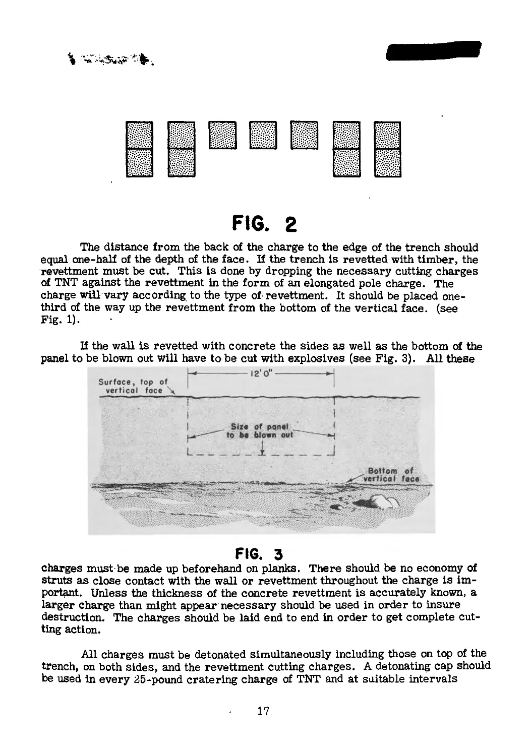
ing of double charges at the ends where the tank tracks will cross (see Fig. 2).
16
FIG. 2
The distance from the back of the charge to the edge of the trench should
equal one-half of the depth of the face. If the trench is revetted with timber, the
revettment must be cut. This is done by dropping the necessary cutting charges
of TNT against the revettment in the form of an elongated pole charge. The
charge will vary according to the type of- revettment. It should be placed one-
third of the way up the revettment from the bottom of the vertical face, (see
Fig. 1).
If the wall is revetted with concrete the sides as well as the bottom of the
panel to be blown out will have to be cut with explosives (see Fig. 3). All these
H-----------12' 0"-----------H
Surface, top of
vertical face \
T
FIG. 3
charges must be made up beforehand on planks. There should be no economy of
struts as close contact with the wall or revettment throughout the charge is im-
portant. Unless the thickness of the concrete revettment is accurately known, a
larger charge than might appear necessary should be used in order to insure
destruction. The charges should be laid end to end in order to get complete cut-
ting action.
All charges must be detonated simultaneously including those on top of the
trench, on both sides, and the revettment cutting charges. A detonating cap should
be used in every 25-pound cratering charge of TNT and at suitable intervals
17
along the revettment cutting charges. The entire demolition setup is inter-
connected by means of primacord and leads are brought out to a central junction
where detonation can be safely initiated. In order to be on the safe side, all
primacord mains should be in duplicate. The junction box should be placed so
that the detonating waves go forward along the primacord with no undue bends.
The explosion which breaks down the sides of the ditch leaves loose pul-
verized earth ramps on each face and loose earth in the bottom of the trench,
which must be leveled off with pick and ehovel. The spoil forming the ramps is
likely to be very loose and soft, so that tanks will dig themselves in when climb-
ing the ramp and get stuck. It is the rear of the tank’s tracks which tend to dig
in and belly the tank as it opens its throttle to climb out of the trench. To pre-
vent this, brushwood fascines must be made ready to provide a good surface on
the bottom of the ditch and resist the digging in by the rear end of the tank.
The fascines are laid crosswise and must be carefully made or they will
tend to provide a track that will be too steeply cambered and the tank will slip
off sideways. To prevent such sliding the fascines must be made wider at the
ends, than in the middle by placing the brushwood, of which the fascines are made,
with the thick ends outwards and the thinner parts towards the center (see Fig,
12' o*
FIG. 4
4). To insure strength, the center of the fascines must be very securely and
tightly bound with wire. A reserve of fascines must be kept ready in the ditch
to strengthen the tank gap as it shows signs of breaking up. It is essential that
there be continuous maintenance of the gap while it is in use.
10. GERMAN IMPROVISED ANTIPERSONNEL MINE
A German improvised concrete antipersonnel mine is shown in the ac-
companying sketch.
It is used with a trip mechanism. One type of igniter which has been found
with this mine is a modified type of the German pull-release igniter (Z and ZZ35)
18
having no hole in the top of the firing pin for attaching a trip wire. Instead the
trip wire is attached to the release pin; when the release pin is pulled out by the
trip wire, the firing pin is released and detonation takes place. The igniters (on
which is stamped Nur Zugzunder - pull only) are packed in a standard ZZ 35 box
but with a label pasted on describing them as percussion igniters. The firing of
the mine causes a belt of shrapnel (pieces approximately 3/8 x 1/4 inch) to be
thrown out all around the mine. The concrete is reduced to dust. The effective
radius is approximately 30 yards.
19
INFANTRY
11. CONSTRUCTION OF A GERMAN BATTALION DEFENSE AREA
IN NORTH AFRICA
As stated in Tactical and Technical Trends, No. 27, p. 21, the German
doctrine as applied to defense calls for the concentration of the available forces
in a few, very strong islands of resistance. In contrast to the pre-1940 French
“linear” practice of setting up the defense in platoon “strong-points” supported
by field artillery in the rear, Major F. 0. Miksche a well known Czech military
writer, pointed out in “Blitzkrieg” published in 1942 that the Germans favor the
use of defense areas containing at least a rifle company, reinforced by appro-
priate supporting weapons, organized for all-around defense, wired-in behind
mine fields, and provided with their own infantry artillery. Even a battalion may
be employed in one of these positions, which,when developed to their fullest ex-
tent, are self-sustaining defense areas, capable of resisting armored attack. An
example of such an island of resistance will be found in the following translation
of a German document entitled “Training Publication for the Installation of
Battalion Defense Areas” issued by the Commander-In-Chief of the Panzer Army
in Africa. A combat officer very recently returned from southern Tunisia re-
ports that defenses of this type were met with there.
♦ ♦ *
In order to strengthen the power of defense, the troops will organize de-
fense areas which they can hold against attacks coming from any direction.
a. Dimensions
The normal battalion front in a defensive position may be from 3,500 to
4,000 yards; company defense areas (see figure 1) are some 700 yards wide by
300 in depth, and spaced about 500 yards apart.
b. Garrison of Company Positions
A battalion sector is divided into several company defense areas. In general,
a rifle company with infantry heavy weapons attached occupies each of the four
sub-defense areas. The unit command posts are also to be installed within these
defense areas. Artillery is stationed behind the forward company defense areas
on terrain protected by the rear company defense area of the battalion sector.
[Note: Whether this artillery is composed of the infantry guns, or attached
field artillery is not clear but field artillery was found in such defense areas in
Tunisia. Obviously, while the lay-out is such that infantry guns could cover the
forward company positions, some field guns of greater range could be used, if
available?]
20
c. Weapons
Weapons are distributed so as to give mutual supporting fire. Every com-
pany defense area is provided with infantry light and heavy weapons. Armor-
piercing weapons, and antiaircraft guns are attached.
d. Defenses
The company defense area is to be fenced in with wire. However, platoon
areas within such company areas are not to be inclosed by wire. Qiote: Perhaps
sufficient wire for both Inside and outside entanglements was not available as
wired-in platoon areas have been encountered?] The distance of the wire entangle-
ments from the most forward weapons is about 50 to 100 yards.
To facilitate reconnaissance activity, narrow lanes through the wire en-
tanglements are to be laid out on the enemy side. Wide lanes are permitted only
on the flanks.
To defend the protective minefields, and wire entanglements ^rifle pits,
listening posts, observation posts, and weapon emplacements are installed. Dug-
outs are constnicted for the garrison of the area.
Communication trenches are to be dug only between the firing positions or
observation posts and nearby dugouts. Extensive communication trenches give
the attacking enemy a chance to gain a foothold inside. In stony terrain the para-
pet is to be made of sandbags or stone, but trenches must first be dug deep
enough into the ground (by blasting, if necessary) to prevent the position from
showing above the surface.
As a matter of principle, no installations, as seen from the enemy side,
must stand out above the surface of the grounds. Defended areas are not to be
laid out on the crests of ridges but on the slopes [whether forward or reverse
slopes, is not made clear] . Although the highest positions are normally the
most desirable for observation an<^ antiaircraft purposes, such installations must
not be placed on forward slopes in view of the enemy, but somewhat further to the
rear, masked by the crest.
Dummy positions (also for artillery and antiaircraft) are to be used for
the purpose of diverting enemy artillery fire. Distance from the other positions
must be great enough to protect the latter from the natural dispersion of artillery
fire. -
The sections of trenches inside a position must have frequent traverses or
angles to reduce the splintering effect (see figure 2). Good camouflage is the best
protection against enemy fire.
e. Transport
In rolling country, vehicles must be completely hidden from the view of the
22
enemy. In level country, this result is obtained by keeping the vehicles well to
the rear of the combat positions, and by using camouflage with nets. These nets
can be improvised with open mesh wire covered with any sort of brush or camel
thorn.
* * *
Comment: Figure 1 indicates in diagramatic form the lay-out for a hattai inn
defense area on more or less level ground. In actual practice, of course, natural
defense positions would be entrenched. The front-line wire, naturally, would
scarcely be laid out in a straight line. Both diagrams are based on German
sketches, and are notable for their simplicity.
The three forward company defense areas are composed of several platoon
strong-points subdivided into squad positions like the ones illustrated in figure 2.
The large number of heavy and automatic weapons is worth noting. A squad area
provided with an AA/AT gun, a mortar, a Hv MG, a LMG all well dug in and
mutually supporting, flanked by similar squad areas and reinforced with the fire
of infantry cannon from the support position, make a defensive position of great
power, entirely aside from the garrison’s rifle and grenade fire. Such a defense
area could, if necessary, be supplied from the air if ground communications were
cut off.
By necessity, the plan here outlined bears a superficial similarity to de-
fensive layouts found in our own field manuals, but it should be noted that the
method prescribed in the above document is based on the German theory of de-
fense against the principal effort in a German armored attack. Such an attack
combines overwhelming local superiority in men and equipment, the onset of tanks
with motorized infantry and artillery following, combined with a fire from massed
artillery, mortar and heavy weapons of the utmost possible violence, supported by
dive-bombing. All Is concentrated on a narrow front of perhaps 1,500 yards. The
theory of defense assumes that the Islands of resistance must allow the tanks to
pass through since they can not prevent it, but do endeavor to stop by fire especially
from the flank, the motorized infantry and artillery which follow behind. Cut off
from their supporting infantry, the tanks are expected to be stopped by the rear
elements~of the defense and destroyed. A counterattack launched by the rear ele-
ments follows to eject any remaining enemy forces that retain a foothold in the
defense system.
The extraordinarily wide frontage, 3,500 yards, is remarkable, as well
as the wide spaces between the company defense areas - 500 yards. One com-
mentator suggested that this defense would be far easier to pierce than our own
more closely-knit system, but it must be remembered that the German plan here
outlined is based on no theoretical study but upon the hardest possible school of
African battle.
23
Another interesting feature is the concentration of heavy weapons entirely
within the company defense areas.
A third feature is in the extensive use of minefields. Whether these mine-
fields are laid by the garrison or by engineers is not made clear in the instructions,
but as each German infantry company contains a group of men trained to lay and
lift mines, it seems reasonable to suppose that the minefield in front of the battalion
area was to be laid by the garrison. The absence of any indication of mines be-
tween the company defense areas is rather odd. It would seem logical to mine
these avenues rather heavily. The failure to indicate such mining should, however,
not necessarily preclude the possibility that mines might be found there. The
system here Illustrated would appear vulnerable to infantry attack. This, in fact,
was the method used by Montgomery at Alamein, where, reversing the German
practice, infantry and engineers equipped with mine detectors led the assault, be-
hind a devastating artillery barrage. It is understood, however, that the British
had a substantial superiority in both guns and tanks.
In southern Tunisia was found a rather unusual lay-out for a German pla-
toon on the defensive. American officers report that inside the wired-in company
GERMAN PLATOON DEFENSE AREA
defense areas, were wired-in platoon defense areas, laid out in a more or less Y
shape. The accompanying sketch Is schematic, and not to any scale, but Illustrates
24
the plan of such a position.
One branch of the Y, or the broad angle might be pointed forward, or
occasionally, one branch ran over a crest with the other two limbs on the reverse
slope. Automatic weapons were placed at the ends of the trenches; the trenches
themselves were sometimes blasted out of the rock. Mutually supporting cross-
fire, of course, was provided throughout the company area.
12. JAPANESE CONDUCT OF THE DEFENSE
When forced on the defensive the Japanese have striven to attain the ele-
ment of surprise by means of silence and concealment; employed deceptive
measures wherever possible; made extensive use of snipers; and attempted to
disrupt the enemy advance by infiltration tactics. The following data on Japanese
defensive tactics is taken from a recent British publication.
* * *
Unless attacked, Japanese troops occupying forward positions very seldom
open fire, for fear of disclosing their location, even if the target offered is a good
one. From the Japanese point of view, the defensive battle begins only when the
assaulting troops are too close to be missed by their light and heavy machine guns.
Carefully-concealed machine-gun positions then come to life when the assaulting
troops are too close to the objective to receive support from their own artillery.
If the assault is up hill the Japanese add showers of grenades.
Following normal practice the Japanese make the machine gun the principal
weapon of defense. Automatic weapons are sited to fire along prepared lines, lanes
being cut in the jungle if necessary. Heavy machine guns are sited well forward
and are generally sub-allotted to platoon areas; they are often to be found on high
ground or dug into the banks of “tanks,” (water reservoirs); they are also sited
to cover the main lines of approach; they are often placed singly, and frequently
alternative positions are provided. An important point to remember is that dur-
ing the defensive battle heavy machine guns sometimes fire along a line not more
than ten yards from the forward edge of the Japanese main line of resistance, and
assaulting troops, if unprotected by smoke or darkness, may therefore suffer
heavy casualties just in front of the enemy position, particularly if they have be-
come bunched in converging on the objective. Moytars and grenade dischargers
come next in importance to the machine gun. Mortars of 3-inch or larger caliber
may be allotted to rifle companies at the scale of one per company, but the weapon
most frequently used by forward units is the 2-inch grenade discharger of which
there are three in each platoon. This weapon throws a heavy grenade 700 yards.
Once an attack is launched mortar and grenade discharger shelling is frequently
25
directed on areas which cannot be reached by flat trajectory weapons. Particular
attention is paid to probable lines of approach and likely assembly areas.
Although the extent to which snipers are employed varies greatly with each
front there are certain places where snipers may be expected; namely, above
small advanced positions, on the flanks of defense areas, covering lines of approach
to Japanese positions, and covering paths in our own ^ritish] area. Patrols, vary-
ing in strength, are very active at night and attempt to infiltrate between positions
held by our troops - particularly those new to a sector.
The Japanese, so far, have made little use of artillery in defense. They
tunnel into hill sides and build dugouts which afford adequate protection against
all but a direct hit from a field gun. Well-built enemy earthworks often render
his destruction by the normal supporting weapons impossible. Supporting fire
shakes him and makes him keep his head down, but if the assault does not go in
with all possible speed after the supporting fire has lifted, he is quick to seise
the momentary advantage which slow troops may give him.
The Japanese launch immediate counterattacks against troops who have
captured part of a position. These small local counterattacks may be made by
only a dozen men led by an officer; they are preceded by a shower of grenades
from grenade dischargers and the charge is made with automatic weapons. This
immediate counterattack may be launched five to ten minutes after the position
has been penetrated. A wild war cry, to which is sometimes added the shout
“Charge l” in English, gives warning of what is impending.
Two examples of the Japanese conduct of the defense, are illustrative of
most of the tactics commonly employed.
a. Example 1
In one case the Japanese placed a forward defense area on the hill illustra-
ted in the accompanying sketch. All earthworks were carefully camouflaged and
had it not been for sentries in our own forward positions, about 50 yards down the
left slope of the hill, hearing the Japanese talk at night, it would not have been
possible to say definitely that they were there.
Our reconnaissance parties, exposing themselves boldly on a ridge facing
this position and 400 yards from it, were never fired upon, and many rounds of
3-inch mortar bombs were fired into it without producing any reaction.
The general line A-В was nearest to the point of observation. The position,
however, continued on the right of A following the high ground which curved back
slightly. It also receded behind В following the highest contour.
The position around A-В was probably held by a platoon as part of a com-
pany holding the main hill of which this feature was only a part.
26
The information available to the attacking troops, was that there were
some enemy on the hill who had never been seen. They had been heard to talk
at night and were believed to consist, at the very outside, pi one platoon.
After an intensive mortar bombardment one company launched an attack
up both sides of the spur from C. The black arrows indicate approximately the
line of advance of the main assaulting parties.
The leading assaulting troops made good progress until they were about
30 yards from the general line A-В; then a veritable hurricane of fire was let
loose upon them. They were engaged by light machine-gun and grenade-discharger
fire and began for the first time to suffer appreciable casualties. Shouting their
war cries they continued to climb the hill, making use of such meager cover as
the small bushes and folds in the ground offered. As the action grew in intensity
camouflage began to slip off the parapet of what could now be identified as a con-
tinuous trench, part of which ran along the front A-В. When the leading troops
were about ten yards from the parapet, they were subjected to accurate Japanese
heavy machine-gun fire from a gun sited in another position. Although greatly
weakened by casualties, they, theUritisQ' continued to advance and, led by their
company commander, hurled grenade after grenade into the Japanese position.
They finally stormed and occupied the trench, killing or driving out all Japanese
in that sector.
27
About ten minutes later there was a wild howl, as of jackals and hyenas;
a shower of grenades from grenade dischargers fell among our troops, and with
shouts of “Charge!*’ the Japanese counterattacked with automatic weapons, forc-
ing our troops off the hill.
Comment: This company battle serves as a vivid example of Japanese
methods in the defense. Their positions were well concealed and nothing tempted
them to give them away; thus at zero hour, the attackers could be certain neither
of the extent of the position nor the strength in which it was held. They had heard
Japanese talking in this area at night and with the Japanese predilection for
occupying commanding ground, they could reasonably be expected to have organ-
ized a position there.
Fire was held until the attackers were 30 yards or less away, and not until
10 yards from the parapet were they engaged by heavy machine-gun fire from a
nearby position. This is a common Japanese method of achieving surprise in the
defense.
Finally, the successful assault, which was not reinforced, was turned to
failure by a small but determined local counterattack. The immediate counter-
attack is a common, though not invariable Japanese maneuver. There have been
cases in which captured positions have been made untenable by fire alone.
b. Example 2
In another instance, an attack against a strong Japanese defensive position
in Burma was made.
(1) Plan of British Attack
The plan of attack was divided into four phases:
Phase _1--At 0545 A Battalion to capture the eastern half of the Chaung
River as far west as M16 (see accompanying sketch).
Phase 2—At 0645 В Battalion to capture the jungle area as far as line
marked ™A.”
Phase 3_— At 0710 C Battalion to extend their position on Twin Knobs to as
tar south as the line marked “B.”
Phase 4—At 0850 В Battalion to exploit to line marked “C.”
Artillery and heavy machine guns supported the attack with a barrage and
concentrations.
(2) Japanese Position
The Chaung Itself is a strong, natural obstacle, which the Japanese made
28
%
into an excellent defensive position, by building an intricate system of communi-
cating weapon pits and defense areas, and at least one pillbox at S 5 (see accom-
panying sketch). AH positions were mutually supporting.
The pillbox or bunker, which consisted of an outer covered weapon pit,
and an inner chamber which is reported to have included both metal and concrete
materials, was sufficiently well built to withstand no less than three direct hits
from a 3.7-inch howitzer at point-blank range. It follows, therefore, that assault-
ing troops on and around the pillbox could be subjected to heavy mortar fire with-
out any detrimental effects to the occupants.
All other works were dug well down and presumably provided with dugouts,
for although approximately 124 tons of shell were fired into the Chaung area
immediately prior to the attack, there was no indication that the enemy’s fire
power had been Impaired.
The Chaung is overlooked from the east by two commanding positions, Hills
823 and 500. These are both steep and densely wooded. Although no weapons were
29
pin-pointed on these hills, mortars, heavy machine guns and at least two 75-mm
mountain guns undoubtedly fired from there. These weapons could thus put
down defensive fire anywhere in the area, by day, by night, or through smoke.
Unlike other Japanese defensive positions, weapon pits and fox holes near
the Chaung were clearly visible from the air and in many cases could be seen
from OP*s. This does not mean that any movement, or guns were visible, but it
was possible to determine where earthworks had been dug. However, in the
jnngi a and on the Jiills 823 and 500 positions were so well concealed that with the
exception of the two strong points which held up В and C Battalions, they remained
undiscovered to the end of the battle.
(3) Course of the Battle
A Battalion commenced their advance without appreciable opposition, but
soon the company attacking the Chaung from the north experienced the now familiar
Japanese tactics of withholding their fire until the last moment, and it was not until
they were crossing low, loose strands of wire, about 15 yards from bunkers at S 4
and S 5 (see sketch) that intense fire was brought to bear on them. These two
bunkers were attacked repeatedly, but without success; our troops could find no
opening through which to throw grenades and while on and about these bunkers
they were subjected to mortar fire to which the bunkers themselves were immune.
The other two companies were more fortunate, and although they were subjected
to showers of grenades from grenade dischargers and hand grenades while advanc-
ing down the Chaung, succeeded in taking their objective, which included M 16.
A proportion of these troops advanced up the small Chaung and cleared it as far
as S 4 where they in their turn were held up. As the light improved, and as presum-
ably the Japanese realized the situation, showers of projectiles from all weapons
were fired Into and around the Chaung, and heavy machine guns opened up from the
flanks.
Meanwhile Phase 2 began and В Battalion advanced only to be held up by
what was described as a defense area similar to S 5 (M 52 on .the sketch). В
Battalion was unable to reduce this position and was subsequently withdrawn.
Phase 3 commenced according to plan, but C Battalion almost immediately
suffered the same experience as В Battalion, in that they ran into a cunningly con-
cealed heavy machine gun position just beyond the line of departure. This position
was so well hidden, that it escaped notice when the area was reconnoitered prior
to the attack. This position also held out
Comment: The attack failed through no lack of courage; the dash and dar-
ing of the attackers has been aptly described as an epic of collective gallantry.
Why then did the defense succeed? There are Important reasons:
Following his normal practice the Japanese held his fire until the assault-
ing troops were almost upon him; only then did his machine gun nests come to
life—machine gun nests about whose strength or existence we knew little or nothing.
To quote from a British defense pamphlet ‘‘the main task of medium [j.S. heavy]
30
machine guns. . .will be to take toll of enemy unarmored troops. . and no
heavy machine gun is better sited to fulfill this role than one in an undetected
nest with a big enough covering of earth, timber, and perhaps steel and concrete,
to withstand the preliminary bombardment. In fact, by continually improving
their positions and by careful attention to camouflage, the enemy had achieved
surprise in the defense.
Strong positions which could withstand the fire of our artillery could also
withstand the fire of Japanese mortars which gave additional protection to their
garrisons.
The first and chief problem then, which the Japanese defensive position
presents, is the problem which has faced every modern army for more than 25
years—it is the detection and neutralization of the machine gun firing from a
well-built nest.
It will be noticed that no counterattack was launched in this battle, ele-
ments which had penetrated the position being dealt with by intensive mortar and
grenade-discharger fire alone. This practice of bringing down defensive fire
on one’s own positions is likely to be a common feature of Japanese defensive
tactics. In fact either byn immediate fire or immediate counterattack the Japanese
will attempt to make an overrun position untenable.
* * *
American Observers* Notes
Officers just back from the New Guinea and Munda fronts describe a
Japanese defense system containing rather unusual features.
The area to be covered is fortified with bunkers set as closely as five
yards apart with a second line of bunkers covering the gaps and a third line be-
hind the second. The bunkers themselves are made of three layers of springy
palm logs covered with earth and skillfully camouflaged. So strong are they
that one officer reported he had seen British 25-pounder shells and our own 81-
mm-mortar projectiles “bounce off them.” A 105-mm howitzer shell, however,
would penetrate (see accompanying photographs for typical bunkers.)
Behind the lines of bunkers the Japanese sited mortars.
The armament of individual bunkers was apt to be an automatic weapon,
which the Japs operated until killed.
Instead of fire-lanes, passages about 2 feet square were cut through the
brush or grass, down which the Japanese wou|d fire. Such rabbit-runs were
practically impossible to detect until the garrison of the bunker opened fire.
31
Frequently, bunkers would be protected on each side by rifle pits, con-
nected to the bunker by a shallow crawl trench. Access to the bunker was by
holes so small an average American could not wiggle through. r<The Japs/’
stated the observer, “burrowed like gophers.”
Another favorite defense was to dig in among the roots of a banyan tree—
a large tree that stands up above the ground on a mass of stilt-like legs.
Canister fired by a 37-mm gun proved effective against such a defense.
Its balls tore through the jungle growth for 150 yards, delivering a cone of fire
about 30 yards wide at 100 yards range, sufficient to hit both the bunkers and its
protecting riflemen with the same charge.
The bunkers shown in the accompanying photographs, were part of a
Japanese defensive position in New Guinea. It is reported that they were thorough-
ly “worked over” with artillery before their capture, which may account for the
lack of camouflage. The timber in this case is probably cocoanut logs. Else-
32
where a type of palmetto is used. Both woods are springy and therefore tend to
absorb the shock on contact of a shell. In the first photograph note how close
the bunker in the background is to the one in the foreground. It was this type of
Japanese field fortification that has caused U.S. troops such difficulty in the
Munda area.
MEDICAL
13. IMMERSION FOOT
General
“immersion foot” is an ailment, normally rare, which results from hav-
ing the feet wet, as in a lifeboat, for days on end. It is aggravated by cold, and
since the freezing point of sea-water is lower than that of human blood, the feet
and lower legs of persons in lifeboats and on life rafts are apt to exhibit.symptoms
of freezing if kept wet for hours and days with ice cold sea water.
33
Torpedo victims are often huddled together with little chance for move-
ment; Immersion foot is the result. Technical experiment has also demonstrated
that vitamin deficiency plays a great part in lowering the patients’ resistance.
It was discovered that immersion foot could occur in warm southern waters as
well as in the North Atlantic.
With no or improper first-aid or medical treatment, amputation is fre-
quently necessary, and intense suffering almost inevitable. However, with proper
precautions, first-aid and correct hospital treatment, much of this pain and in-
jury can be avoided. Three medical officers of the Canadian Royal Navy, Surgeon
Commander D. R. Webster, Surgeon Lt. F. M. Woolhouse and Sturgeon Lt. J. L.
Johnston have developed such methods, described in the April 1943 issue of the
Royal Canadian Navy Monthly Review, from which this article is extracted.
Symptoms
Victims of immersion foot report that they felt no pain after the first cold
in their feet and legs. However, as their feet grew colder, and the circulation
slowed down, the tissues were damaged, and as time went on, the skin became
waxy-white in color, and insensitive to pain or temperature. Their extremities
were practically dead with no more than a spark of life to be nurtured back to
health through a gradual rise in temperature. Under such conditions, infection
develops easily in the injured tissues and gangrene would be an almost certain
result.
Dangers of Improper First Aid
Sympathetic rescuers have massaged these pitifully swollen feet and
covered them with blankets and hot water bottles. Soon began, “intense, inter-
mittent, stabbing, shooting pains, which started in the ankle joint and radiated to
the tips of the toes with a generalized tingling sensation.” Some victims of such
misdirected treatment developed gangrene, which sometimes resulted in ampu-
tation. This happened to the survivors of one internationally known ship which
was sunk in European waters. Of those picked up by trawlers, almost all had to
have their feet amputated.
Precautions
It is most important to keep the feet dry and warm and to exercise the legs
and feet—two things next to impossible in a crowded life boat or a raft. The first
thing to be done, if possible, is to cover the legs and feet with a thick coating of
grease as do long distance swimmers. Constricting clothing and shoes must be
removed—they are useless in keeping the feet warm in the water anyway.
Correct First Aid
The first-aid rules are simple. The patient is to be kept dry and warm ex-
cept for his feet. Any wounds, cuts or sores are to be dusted lightly with sulphaniii-
mide powder. The legs are wrapped in some clean, soft material and laid on pillows
34
Treatment
Doctors Webster, Woolhouse and Johnston used as their basic theory,
“treat cold with cold.” The affected areas were slowly brought back to normal
temperature over a period of weeks. At first when it became necessary to de-
vise a treatment in line with this theory, the patient’s legs were placed, elevated,
covered with a sterile towel, and packed with ice bags. Later, Instead of ice,
a cold blast from a fan was used, and at another time, the patient’s feet were left
exposed in a cold room while his body was warmly covered. Finally, a refriger-
ator was developed, with two openings for the legs, like a prisoner’s stocks.
So effective was this treatment in relieving pain in one case when the
cooling system failed, a patient fled to a window and promptly put his feet out to
cool in the winter air.
There are some “must nots” which are most important:
No rubbing or massage;
No heat of any kind near the affected parts;
The patient must not stand or walk and his legs and feet must be gently
handled;
The legs and feet must not be washed or soaked;
No lotions or antiseptic? except sulphanilimide may be applied.
Results
At an eastern Canadian port, of 150 cases so treated, only seven ampu-
tations were necessary.
Men who were cured had to learn to walk all over again, and had an unusual
and awkward gait until they regained the use of their limbs. Severe cold, too,
would bring aches and pains to their feet.
ORDNANCE
14. GERMAN 105-MM HOLLOW-CHARGE SHELL
The use of hollow-charge ammunition by the Axis armies was referred to
111 Tactical and Technical Trends, No. 18, p. 27.
The following description and accompanying sketch will serve to bring
out some details covering the German 105-mm (4.13 in) hollow-charge shell
called the 10-cm Gr 39. This ammunition is used in the German 105-mm gun
howitzer.
35
a. General
to keep the filling firm.
Weight, filled, unfuzed
Weight, filled, fuzed
Weight^bursting charge
Penetration (estimated)
Homogeneous armor
Homogeneous armor
Color
25 lb 7 1/8 oz
25 lb 9 oz
3 lb 14 5/8 oz
3.15 in at 30°
3.74 in at normal
Olive green, red
band above rotating
band.
An interesting point in the design of
this shell is the shape of the cavity in the nose,
which differs from that of the 75-mm hollow-
charge shell (see Tactical and Technical
Trends, No. 19, p. 27). In the latter case the
cavity is cylindrical for the greater part of
its length, being rounded off at the rear, hi
this case the cavity is conical except at the
extreme rear, which, too, is rounded.
b. Method of Filling
The charge is supported on a ring of
moulded plastic material fitting the base of
the shell cavity. The charge, together with
the plastic ring, central tube and cavity liner
fits into a waxed paper container. It is prob-
able that the charge is loaded into a hot shell lined with a bituminous composition
c. Bursting Charge
The bursting charge consists of tnree pellets of cyclotol (TNT) wax, hot
pressed, details of which are;
Composition
Weight Density Cyclotol TNT Montan Wax
Nose 561 gm (19 oz 12.5 dr) 1.56 57.7% 39.6% 2.7% '
Middle 720 gm (25 oz 6.25 dr) 1.58 57.1% 39.8% 3.1%-
Base 490 gm (17 oz 4.5 dr) 1.58 55.5% 41.7% 2.8%
Note: It-is probable that fuze AZ 38 and booster Zdlg 40 are fitted. These
are shown in the accompanying sketch.
36
15. GUDOL POWDERS
Frequently within recent months technical descriptions of German ord-
nance contained the word “Gudol” or “Gudol-type powder”. A description of
this flashless propellant has recently become available. Its chief constituents
are triglycoldinitrate, nitro-cellulose and nitroguanidine in equal parts. Nitro-
guanidine made by nitrating guanidine, which is a urea compound made from cal-
cium cyanamide, releases large quantities of ammonia when discharged as a pro-
pellant While the ammonia lowers the gas temperature below the flash-point,
when used in large quantities as artillery ammunition, it produces enough ammonia
gas to unfavorably affect the gun crews, particularly on a still day.
16. MORE DETAILS OF THE GERMAN MG 42
While an account of the new model 42 dual-purpose machine gun was
published in Tactical and Technical Trends, No. 20, p. 28, further details of this
light and fast-shooting weapon are now available. The locking mechanism is
novel to those familiar with machine guns other than the Russian Degtyarev. The
present standard dual purpose machine gun of the German Army is the MG 34;
the latest known type of German machine gun to have been captured is the MG 42.
It seems evident that this weapon is designed to replace the MG 34 although the
actual extent of replacement is not known. (For additional details on these
weapons' see “German Infantry Weapons”, Military Intelligence Service,
Special Series No. 14 dated May 25, 1943.)
Weight with bipod
Length overall
Length of barrel
Weight of barrel
Cyclic rate of fire
Mounting
Caliber
23 3/4 lbs
48 in
21 3/4 in
3 lb 14 1/4 oz
1,100-1,350 rpm
bipod or tripod
7.92 mm (.311 in)
There is no provision for single shots.
37
a. Comparison with MG 34
By comparison with the MG 34, several interesting new features are
noted:
(1) Locking System
In place of the Solothurn rotating bolt-head of the MG 34, the locking of
the bolt to the breech of the barrel is achieved by a.wedge, which forces outward,
and into suitable recesses in an extension of the breech of the barrel, two rollers
on the head of the bolt. As the principle is not familiar to many, at least in its
application to ordnance, a simplified diagram illustrative of its action is shown
in figures 1 and 2, and a detailed sketch of its
application to the M 42 machine gun is shown
FIG. I
FIG. 2
in figure 3.
(a) Explanation of the Principle
It is desired to lock interior tube В
(figure 1) securely, but temporarily, to exterior
tube A, This locking is accomplished by means
of circular (or in some cases spherical) bodies
C, which are forced outward through holes E in
tube B, into recesses in tube A by means of
wedge F, actuated by spring G. When the spherical
bodies C are in the position shown in figure 1,
inner tube В is free to move within exterior
tube A, but when spherical bodies C are thrust
outward through the apertures in tube В and
engage tn the recesses in tube A,
the two tubes, A and В are firmly locked to-
gether (see figure 2).
(b) Application in Model 42 MG
This principle is applied in the Model
42 machine gun as follows (see figure 3). On
firing barrel A and barrel extension В recoil to the rear until rollers C are
cammed inward by fixed cams D unlocking bolt head E and retracting firing pin
F. The bolt carrier G and bolt-head continue to the rear guided by fixed guides
H while barrel and barrel extension return to battery. On the return of the bolt,
the Impact of the roller with the camming surfaces I, the “spherical bodies” of
figure 1 and 2 on the barrel extension carry the rollers from their seats, and,
together with surfaces J on the bolt head, force the rollers outward locking the
bolt head to the barrel extension. The initial outward motion of the roUers also
frees the firing pin holder К which is driven forward by spring pressure insuring
complete locking (by wedging rollers outward) before the firing pin can strike the
primer. To extract the bolt-head from the barrel extension, the rollers must be
pressed back with the thumb and finger inserted into grooves in the receiver.
38
FIG. 3
BREECH BOLT, GERMAN MODEL 42 MG
The bolt-head can then be pulled out.
By this system, the gun attains a rate of fire^ef 1,100 to 1,350 rpm which
would appear to be unnecessarily high for a ground gun, though of obvious value
for AA fire; the cyclic rate of fire of the MG 34 is from 800 to 900 rpm. Prelimin.
ary trials show, however, that this high rate of fire has not been obtained without
a certain decrease in accuracy compared with the MG 34.
b. Barrel Changing
The frequent barrel changing necessitated by the high rate of fire is met
by the introduction of a rapid and efficient barrel-changing device. A barrel-
change lever is hinged in the right side of the barrel casing, and can be swung
outward bringing with it the barrel, which lies in a metal loop attached to the in-
side of the change lever. The barrel can then be slid out to the rear.
c. Unusual Feed Mechanism
Feed is by continuous metal belt through a feed block. As in the MG 34,
operation is by a feed arm housed in the feed cover. In the MG 42, however, two
feed pawls are linked to the front end of the arm by an intermediate link, in such
a way that when one is feeding, the other is riding over the next round in the belt.
The effect of this is that feed is in two steps instead of one step as in the MG 34,
and is therefore much smoother.
d. Construction
The extensive use of pressing, rivetting and spot-welding in the construction
(there are very few machined parts) gives the gun a less-finished appearance than
is usual in German weapons. Considerable effort has been made to lighten the
gun without the loss of strength - for example by making holes in the operating
handle. There is no reason for assuming, however, that its life and performance
are not up to the usual German standard.
17. PREMATURES IN GERMAN 20-MM FOUR-BARRELED AA GUN
A communication from a German battery commander that fell into Allied
hands complains of frequent premature explosions of the shells in the gun barrels
before the closing of the breech. In the case cited, the premature had ignited
about ten rounds in the magazine, which in turn set off the magazine of an adjoin-
ing gun. Two men were killed, four badly injured.
The writer suggested substituting for the over-sensitive ammunition, made
between 1938 and 1942 with fuze AZ 5045, the armor-piercing Panzergranate 41.
This ammunition may also be loaded with the 20-mm AP tracer self-destroying
shell. As the complaint about the 20-mm four barreled AA gun applies with equal
force to the single-barreled 20-mm Flak 38, appropriate precautions would appear
advisable in handling any captured weapons of these types.
40
TRANSPORTATION CORPS
18. NOTES ON GERMAN ROLLING STOCK
It has been stated that the Nazis have accorded number-1 priority to
transportation even to the extent of taking precedence over airplanes. Germany
is vitally dependent on the smooth functioning of her transportation system. If
this vital system which connects Nazi factories with their sources of supply and
with their battle fronts, is put out of operation or seriously damaged, their
whole war effort must obviously be retarded.
Some interesting developments affecting the transportation set-up, tending
to reduce the consumption of construction materials and other valuable economies,
have been recently reported in connection with the German locomotive and freight
car situations.
GERMAN CLASS "52" LOCOMOTIVE
As was indicated in Tactical and Technical Trends, No. 24, p. 40, it was
thought probable that the construction of the class "42” locomotive is to be
started in 1944. This new type is said to be a refinement of type “52” (see
sketch), has greater tractive power and is designed to meet the requirements of
heavy freight traffic.
The same informed technical source responsible for the information
mentioned in the foregoing paragraph,states that the dead weight of the railway
41
freight cars now manufactured in Germany has been reduced from pre-war levels
by 25 per cent in the case of baggage cars, 34 for refrigeration cars, 29 for flat
cars, 38 for box cars. However, the average carrying capacity for all types in-
creased by 10 per cent.
The use of these new cars will provide the following chief advantages:
saving of time and labor in manufacture, saving in construction materials, and
enabling locomotives to pull additional cars.
The number of types of steam locomotives was reduced by the end of 1942
from 119 to 12. This included locomotives for military and privately operated
railways (mostly small gauge), and in the case of electric locomotives, from 11 to
2, and from 97 to 5 for internal combustion locomotives.
The manufacture of additional types is continued in former locomotive
works in Poland, Czechoslovakia and Hungary.
The chief types manufactured in 1942 were freight models “50” and “52”
(see Tactical and Technical Trends, No. 24, p. 34) with “52° scheduled for almost
exclusive production in 1943.
GENERAL
19. DECEPTION USED BY GERMAN PW’S
It has been reported that German prisoners of war about to be captured,
in some cases have resorted to a trick which enables them to keep their weapons.
Just prior to the time they are captured, the aluminum canteen is emptied
of water and then slit from the base of the bottle to the neck. The short German
automatic pistol is placed Inside the canteen. The sides are then pressed down
together again over the weapon, thus keeping it from rattling, and the canvas
canteen cover is then drawn over the canteen. The weight of the pistol is approxi-
mately equal to a canteen filled with water. In a great many cases, tfhen this
method is resorted to, the prisoner is able to carry the weapon into an intern-
ment camp, where it might be used for an attempted escape, or in any other similar
situation which may be detrimental to his captors.
42
SECTION II
OPERATIONS OF AXIS MOUNTAIN TROOPS
OPERATIONS OF AXIS MOUNTAIN TROOPS
Before the war comes to a close, squads of American troops may well be
roping across Alpine glaciers, groping for hand-holds up Balsan rock pinnacles,
or dodging ice falls on the bleak crags of Norway. A description of how Axis
mountain troops operate, taken from German sources except where elsewhere
noted, would therefore appear timely.
It must be remembered that many of the European mountains are, as a
rule, higher, rockier, more jagged, and desolate than those with which most Ameri-
cans are familiar. Like the Canadian Selkirks, the Alps culminate in such tremen-
dous snow-capped peaks as Mont Blanc or the Matterhorn, rising from ice fields
and glaciers, storm-swept and dangerous, with deep-cut, stony valleys between.
Rockfalls and avalanches are the ordinary risks of the Alpine mountaineer.
Eastward in the Tyrol the peaks are lower, and in the Balkans they are not
high enough to wear snow in summer. Only two Balkan summits rise over 9,000
feet. However, the jagged Tyrolese and Balkan crags and pinnacles spring from
jumbled masses of huge mountains, especially in Albania. They are extremely
rugged, often forest covered, and riven by terrific gorges. Passes are few, and
like the men of that land, rough and hard.
The forbidding Norwegian ranges, many lying north of the parallel of Nome,
Alaska, or Labrador, are chilled by gales that roar across the ice floes straight
down from the Pole. While not more than a thousand feet loftier than our Great
Smokies or White Mountains, these wild peaks, with their low snow-line, great ice
fields that come almost down to salt water, and sub-arctic weather, make them
similar in many respects to the Alps. A peculiarity of the Norwegian mountain
terrain consists of innumerable long, narrow lakes.
In visualizing operations in such highlands, one basic factor must always
be borne in mind--the slowness of all military movement due to terrain, cold, and
exhaustion, and the difficulty of command and supply.
What follows is based on German sources, except as otherwise noted.
*
a. Marching
A time allowance of one hour per 1,000 feet of climb and 1,600 feet of
descent must be made in addition to that called for by the map distance. Because
of the limited number of trails and the slowing-down of both men and animals due
to fatigue, troops should be marched in smaller units than is customary on lowland
45
terrain. The maximum practical formation, is a company, reinforced by a battery,
with a platoon of engineers pushed well forward to help clear the trail. Qt may be
noted here that our own Field Service Regulations suggest a reinforced battalion,
which may be more practicable here than in Europe]
This division into small self-sustaining units minimizes the risk of ambush,
and each column can fight independently. To prevent small bodies of snipers from
holding up the advance, single guns are placed near the head of the column. Both
stationary flank guards and mobile patrols should be thrown out to secure high
positions to the flanks. These elements rejoin the column as it passes. Where the
climbing is particularly stiff, the infantry mingles with the artillery and pack train
to help when necessary. Pack artillery moves at a walking pace. Rest-halts of
three or four hours to permit the unloading of both men and animals are required
every six hours. Short rests without removing packs are of little use. COur
regulations suggest regular short rests as well, which would appear to be absolutely
necessary?]
b. Command
Warfare among the peaks is a severe test of the skill and leadership of
the junior officers, as the operations of these small groups call for a high stan-
dard of training and discipline. Communications between forces scattered over
many square miles of forest, rock or ice is difficult to maintain, and command
problems are far more complex than in the lowlands.
c. Supplies
While transport aircraft may sometimes be used, one- or two-ton trucks,
horses and mules, aerial cableways, pack animals, and manpower may all be re-
quired. A man will pack from 45 to 75 pounds; horses and mules not over 200
pounds. * Man-packing cuts heavily into the effectiveness of a fighting unit, because
of fatigue and the employment of men needed for other purposes. (In the landing
on Attu, a caterpillar tractor hitched to a pulley made fast to a “dead man” at
the top of a cliff was used to haul up supplies.) Care should be taken to see that
supplies are packed at the base in containers suitable for such transport. Norm-
ally, supply columns are organized into valley and mountain columns, the former
carrying supplies for two days, the latter for one or two days.
d. Weapons
Naturally greater reliance is placed on lighter weapons than in ordinary
combat. Light machine guns, and an extensive use of mortars tend to replace
heavy machine guns and light artillery. Antitank and heavy machine guns are
usually sited to cover road blocks. The effectiveness of artillery fire from valleys
depends on carefully selected observation posts in communication with single guns.
How difficult it is for artillery to operate in mountainous country cannot be over-
emphasized.
♦U.S. Army load—no German figures given in source material.
46
The Germans have several types of mountain guns. Onp is the 75-mm
Infantry howitzer (7.5-cm 1. LG. 18--leichtes Infanteriegeschutz--light infantry
gun) without the shield. It is only 10 calibers long, horsedrawn, and capable of
being broken down into six loads of 165 pounds, maximum, each, for pack trang-
port. With a 12 degree traverse, it has an elevation of from minus 10 degrees to
plus 73. The projectile is a 12-pound high explosive shell with a percussion or
time fuze, the latter in British opinion much more effective .against rocks, where
the instantaneous fuze is of little value. Five different charges are used with the
following ballistic performance:
Charge Muzzle Velocity (f/s) Max. Range (yds)
1 310 930
2 368 1,260
3 440 1,750
4 565 2,680
5 730 3,880
This is probably the type of weapon most likely to be encountered.
A heavier gun, perhaps obsolescent, is the 75-mm mountain gun (7.5-cm
Geb. K. 15—Gebirgskannone—mountain cannon). This 15.4-caliber gun weighs
1,380 pounds. The elevation varies from minus 9 degrees to plus 50 and the
traverse is only 7 degrees. It is slightly more powerful than the weapon just des-
cribed. The ballistics of the four charges with a 12-pound HE shell, with or with-
out tracer, are:
Charge Muzzle Velocity (f/s) Max. Range (yds)
1 770 4,280
2 865 4,990
3 1,000 5,890
4 1,270 7,250
The gun breaks down into seven pack-loads, of which the heaviest, 330 pounds,
would appear too heavy for packing by horse or mule.
Another gun is the 75-mm mountain gun (7.5 cm Geb. G 36). Why it is
called a “gun” (“G”. is abbreviation for ‘*Geschutz”~meanlng "gun”) when the
other is railed a “cannon” is not obvious. The Germans, like ourselves, use the
terms interchangeably. No details of the piece are available, but is reported to
fire the same projectile (not “ammunition”) as the airborne gun (7.5-cm LG 40)
described in Tactical and Technical Trends No. 26, p. 15. That weapon is a 320-
pound recoilless, rifled, breechloader, throwing a 12.56-pound HE shell or a
10.05-pound hollow-charge shell, with a velocity reported to be 1,197 f/s and a
range of 7,410 yards. Such a gun might, due to its lightness, be used as a moun-
tain gun. It also can be broken down into separate parts.
47
There is a report of a 105-mm mountain howitzer (10.5-cm Geb. H. 40)
but no details are yet available.
In the weapons list, grenades are not mentioned - perhaps they are taken
for granted. In the East African mountain campaign in Eritrea during 1940-41,
the Italians used a very light hand grenade, which the British report, produced
“devastating effect”. The resourceful British countered them with corrugated
iron shields, and fabricated slings and catapults which threw them back at the
Italians “with considerable accuracy” at ranges up to 100 yards.
Recently, a German publication suggested a mountain tank capable of taking
gradients up to 45 degrees, narrow enough to travel mountain trails and of such a
construction as to make possible sharp turns. The engine would have to be capable
of functioning at 12,000 feet. Nothing definite is known concerning such a tank.
e. Training
In general, German mountain units initially receive the same basic train-
ing as infantry, with specialized training afterward. Battalion officers must be
trained army mountaineering guides and each year pass tests. All guides must
be adept at map reading and familiar with the use of the altimeter, be able to
judge the weather and recognize mountain dangers. They must be capable of
reaching difficult observation posts. As sound travels farther in the mountains
than across flat country, great emphasis is placed on movement without noise.
Troops are trained to be most economical in their expenditure of ammunition.
As troops may be away from their organizations for days at a time, a high standard
of discipline and hardness is required.
£. Notes on Reconnaissance, Communication and Engineers
Aside from its usual functions, mountain reconnaissance calls for the mark-
ing of trails where pack transport must be used, where the path should be improved,
where the path is under enemy observation, and where troops will have to be respon-
sible for their own transport.
“in the valleys, motorcyclists may be used for communication; on the
heights, wire laying is most difficult and radio is the primary means of communi-
cation.'” The above abridged quotation fails to mention the fact that among the
peaks are many dead areas where radio, especially short range, is unreliable, and
wire or visual signals must supplement the radio. Jamming is possible and was
experienced in the Attu operation. Heliograph, blinker, rockets and smoke all
appear practicable. In their East African warfare, the British made extensive use
of visual signals, with a curious development--the sewing of colored patches on
the backs of assault troops’ uniforms, so that they may be identified at long range
and not fired upon by their own supports.
Engineers must understand the bridging of torrents, the making of mule
trails, and the construction of aerial cableways. The British in Africa report
such other activities as road maintenance, mine laying and lifting, demolitions,
48
reconnaissance, water supply, and when not otherwise usefully occupied, fighting.
In Europe, protection against snow and the clearing of snowed-in roads and trails
would be part of the engineers* work as well as the construction of defensive
positions by blasting. In the more static phase of mountain warfare during World
War I, a great deal of tunneling and underground warfare was waged on the Italian
front, involving some blasts of the most gigantic proportions. An articlfe on this
subject appeared in Tactical and Technical Trends, No. 29, p, 39.
g. Tactics
(1) Attack
The early possession of commanding heights is essential for the security
of forces moving in the valleys. The main attack, generally, will have to follow
the valleys, as they alone give freedom of movement to a strong force and its
supply trains. In attacking uphill with artillery support, there is danger of rock
slides caused by the shells of the covering fire. Downhill attack is easier for
assault troops, but presents tactical and ballistic problems for artillery.
Ordinary artillery was found by the British in Eritrea to be of little.value,
but pack-howitzers with a very high trajectory, and medium howitzers, if they can
be gotten up, were most effective. It is to be presumed that the Germans will
make full use of this experience.
(2) Defense
In defense it is better to have only the foremost defense areas on, or in
front of, the crest, and to have the heavy weapons on the rear slope. This the
British found to be the Italian method, augmented by machine-gun and mortar.fire.^
The ancient, effective defense common to all primitive warfare, of rolling or
blasting down rocks on attackers is not mentioned by either British or German
sources used here, but the advantage of well-placed mines to start rock-slides is
too obvious to be over-looked. In retreat, every single avenue of pursuit must,
if possible, be blocked or mined, forcing the pursuers to storm high crags in the
face of delaying fire. Demolition operations to blast roads or cover them with
avalanches are particularly effective.
The British report frequent use of road-blocks covered by fire, and the
use of intense defensive mortar- and machine-gun fire by the Italians, together
with very wasteful fire at night that gave away their positions. British troops
that had attained their objective were subjected to violent fire and counterattack.
In their withdrawal through the mountains toward Keren in Eritrea, the Italians
made full use of demolition tactics to delay pursuit.
On Atta, where the terrain was mountainous, the Japs used fog as cover
and followed the edge of it up the mountain side. However, among the high peaks,
according to experienced mountaineers, fog is apt to be unreliable cover.
49
h. Combat in Extreme Cold
The following German memoranda appear to be of unusual practical value:
(1) Marching
(a) Weapons must be covered.
(b) It is emphasized that clothing must not be too warm.
(c) Plenty of towing ropes should be loaded on the trucks.
(d) Advance guards should be strong, with heavy weapons and artillery
well forward.
(e) Antitank weapons are distributed along the column.
(f) Ski and sleigh-borne troops are deployed to guard the flanks.
(g) Horse-drawn sleighs and handsleds are valuable for the transport of
weapons and supplies.
(2) Halts
As opposed to normal mountain practice, halts must be short when the
temperature is low.
Here occurs a rather unusual direction, worth quoting in full. “Motor
vehicles must be parked radiator to radiator, snow removed from under the
vehicles and some sort of foundation placed under the wheels.” Presumably, dur-
ing a lengthy halt, the trucks are pulled off the road, into deeper snow, which
obviously must be dug away from the wheel tracks to prevent possible stalling.
Probably, they are parked in woods or under cover, or camouflaged. Placed
radiator to radiator, a tarpaulin could be thrown over the hoods and the engines
kept warm. The foundation under the wheels would give starting traction. A
suggestion as to camouflaging wheel tracks with fresh snow might have been in
order.
(3) Restrictions to Movement
At zero temperatures the use of tanks and motorized equipment is limited.
Tractors can negotiate snow slightly over a foot deep, but motorcycles are useless
at six or seven inches. Snow is a tank obstacle when higher than the ground clear-
ance of the tank. Gas consumption at very low temperatures is calculated to be
five times normal. “Snow over 16 inches is not passable for pack animals.” [It
is to be doubted if Custer, Miles, or some of the other generals of the Indian Wars
would accept this limitation; but the reason, perhaps, may be that in the Alpine
variety of mountains, 16 inches of snow or over on the level will drift and block
the trails until it is impractical to attempt pack train transport]
Here it should be noted, that during the Norwegian campaign in April and
May of 1940, the Germans drove motorized spearheads, including tanks and motor-
cycles, eastward from the Osterdal (valley) north of Oslo toward Hjerkinn and Inset
through high passes, over narrow, sharply twisting roads where the snow lay from
50
six to ten feet deep. How it was done has not come to our knowledge, but neither
the Norwegians', toho certainly knew the country, nor the British, had considered
it a possibility. The results would indicate that such snoW'-fighting equipment as
bulldozers, rotary ploughs, and similar machinery were included in the German
materiel.
(4) Weapons
Ranges are usually under-estimated in clear weather and over-estimated
in fog. At low temperatures, weapons at first fire dhort. When visibility is bad,
ammunition consumption rises.
(5) Reconnaissance, Communication, and Engineers
Among the extra tasks of reconnaissance caused by cold are, information
as to the depth of snow, load capacity of iced streams, and danger of avalanches.
Scouts must remember that the enemy will use tracks in the snow to lead
patrols into ambush.
Signs on stakes well above the snow or the marking of rocks or trees and.
the setting up of flags on poles are necessary to mark roads.
Line construction takes longer in extreme cold, and the cold and damp
lower the efficiency of electrical equipment.
Engineers must understand the bridging of iced surfaces, bridge protection
and maintenance against ice, and the blasting of the frozen surface of marshes.
(6) Tactics
(a) Attack
Assembly areas, in view of the difficulty of movement, must be farther
forward than normal. Deployment must often be delayed till contact with the enemy
is made. As a rule, limited objectives only are possible, but combined frontal and
flank attacks will be made where possible. Commanding positions, which assume
added value in cold weather, must be seized early in the action. To prevent sur-
prise, or deal with surprise attacks, heavy weapons must be decentralized. In
attack, ski troops are valuable.
(b) Defense
It must be remembered that obstacles take much longer to build in the cold.
To make the enemy deploy early, strong outposts are required. The usefulness of
snow as a protection against fire is often over estimated but ice fortifications and
ice concrete can be employed as described in Tactical and Technical Trends, No.
22, p. 20.
51
CORRECTIONS
Index
No. 30, p. 46: Tn the section Antitank, opposite the reference to the “75-
mm Antitank-"jun,'""reported in issue No. 2Й, the page number should read 6 in-
stead of 66.