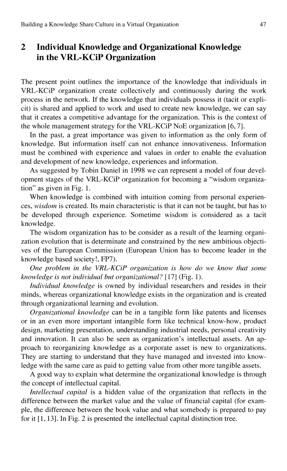
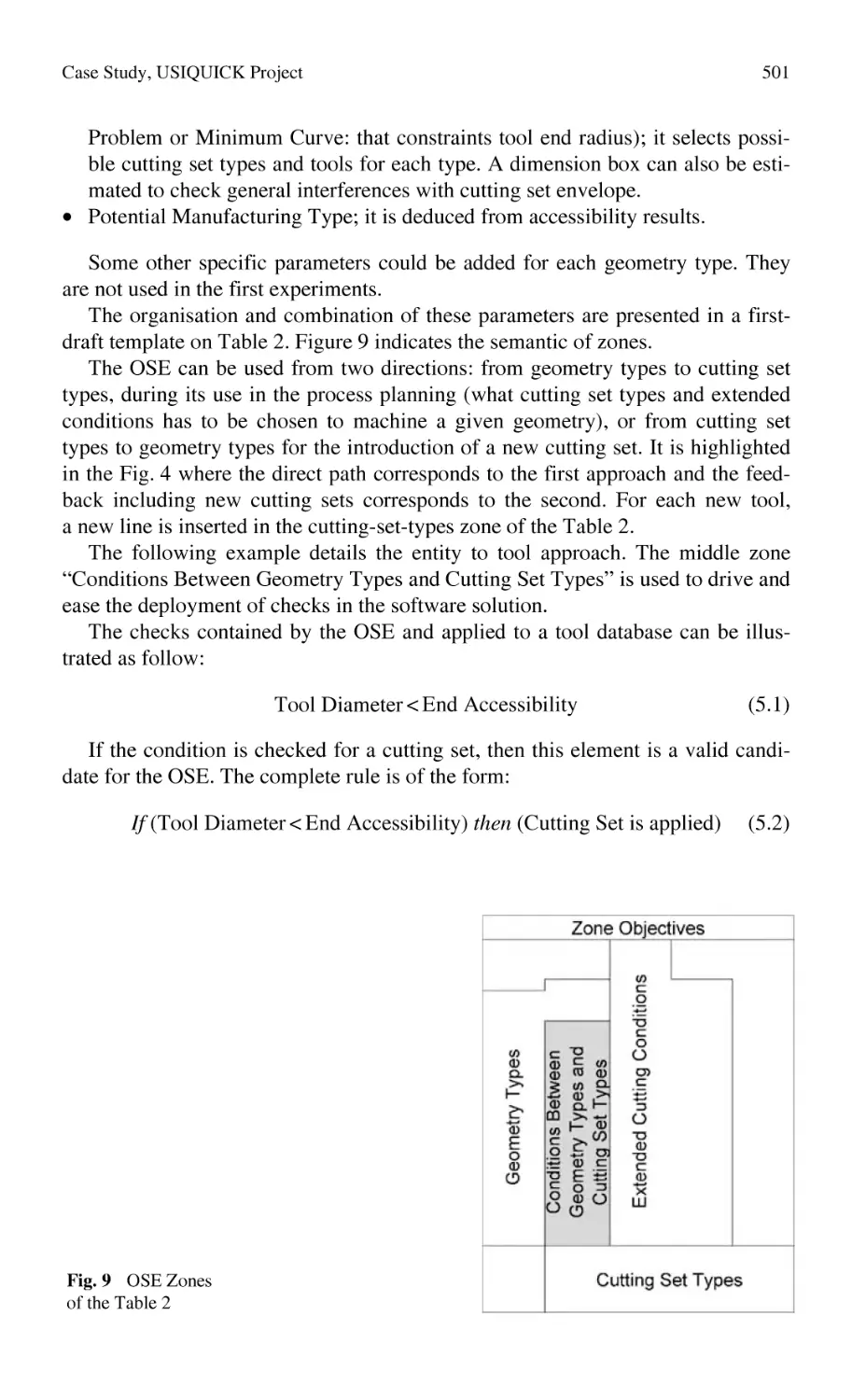
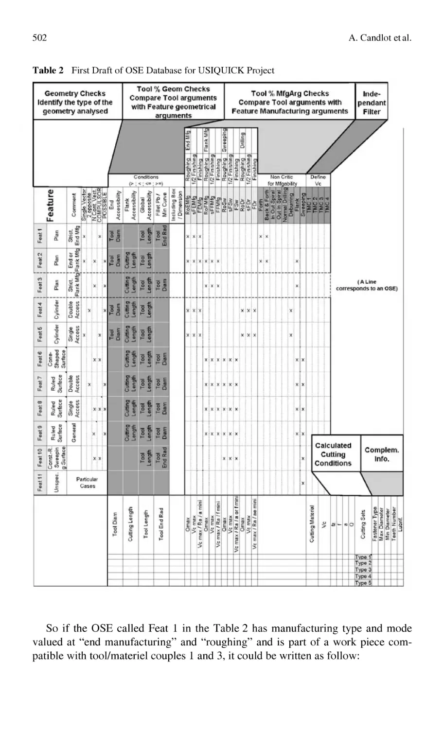
/


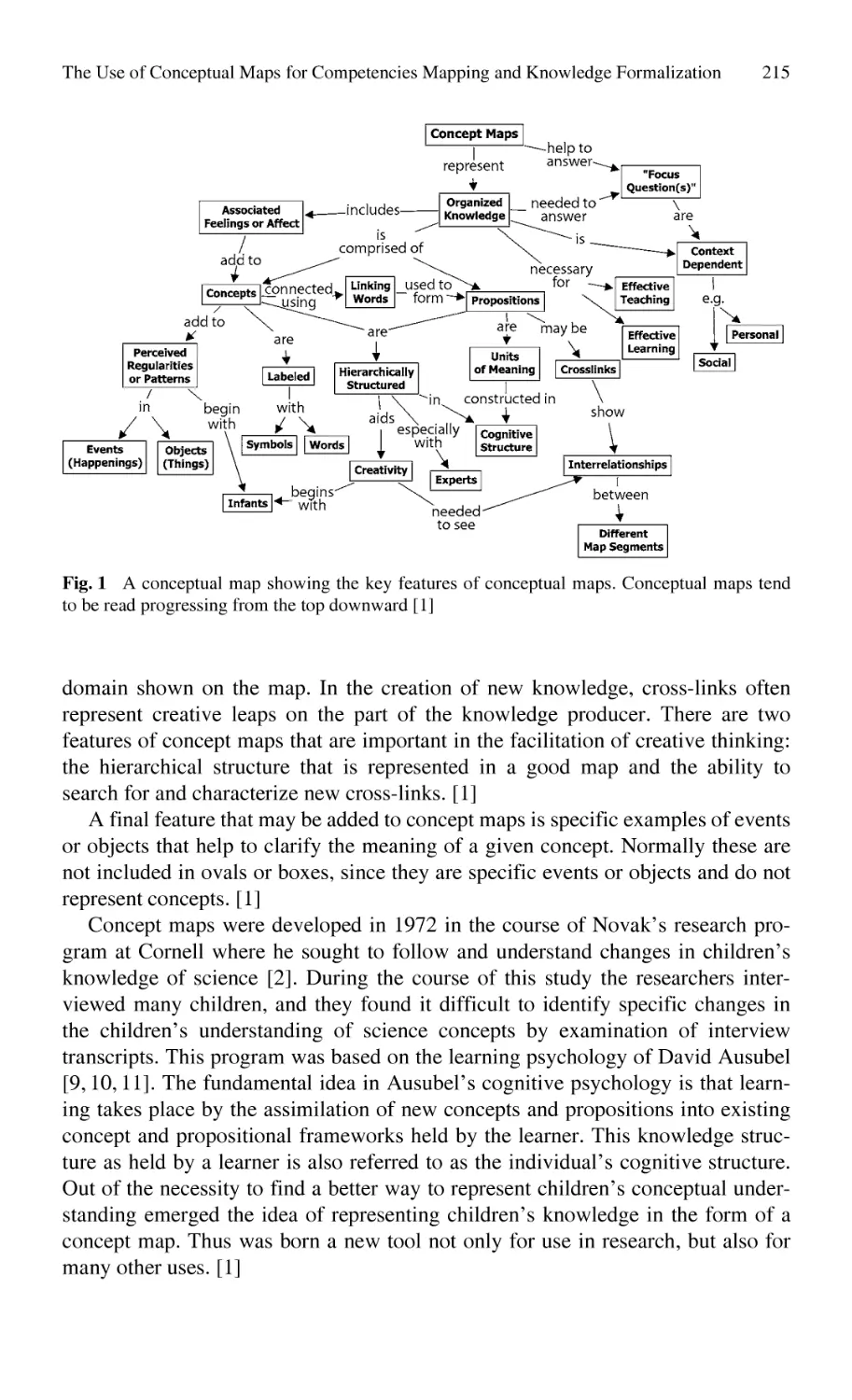


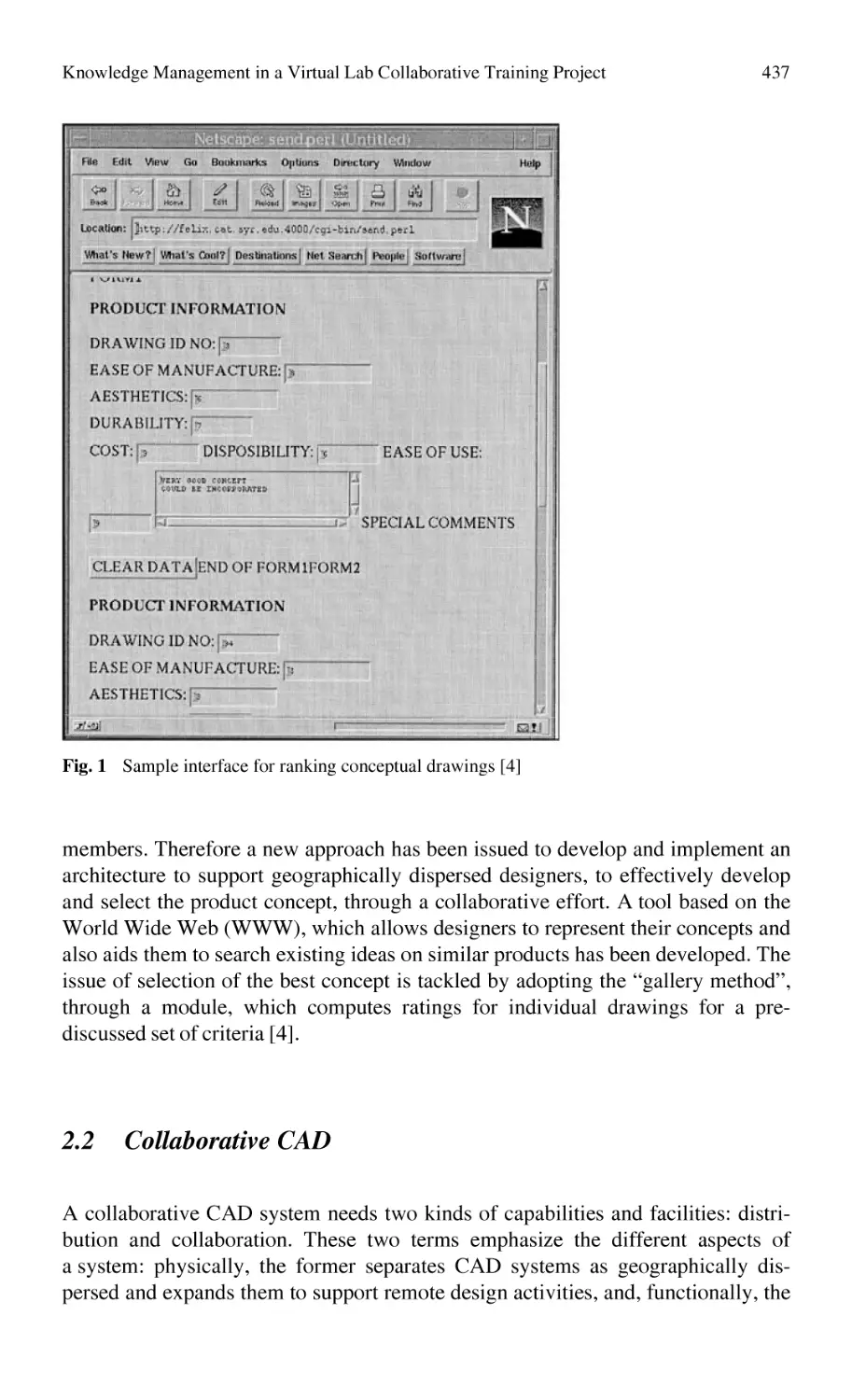


Автор: Bernard Alain Tichkiewitch Serge
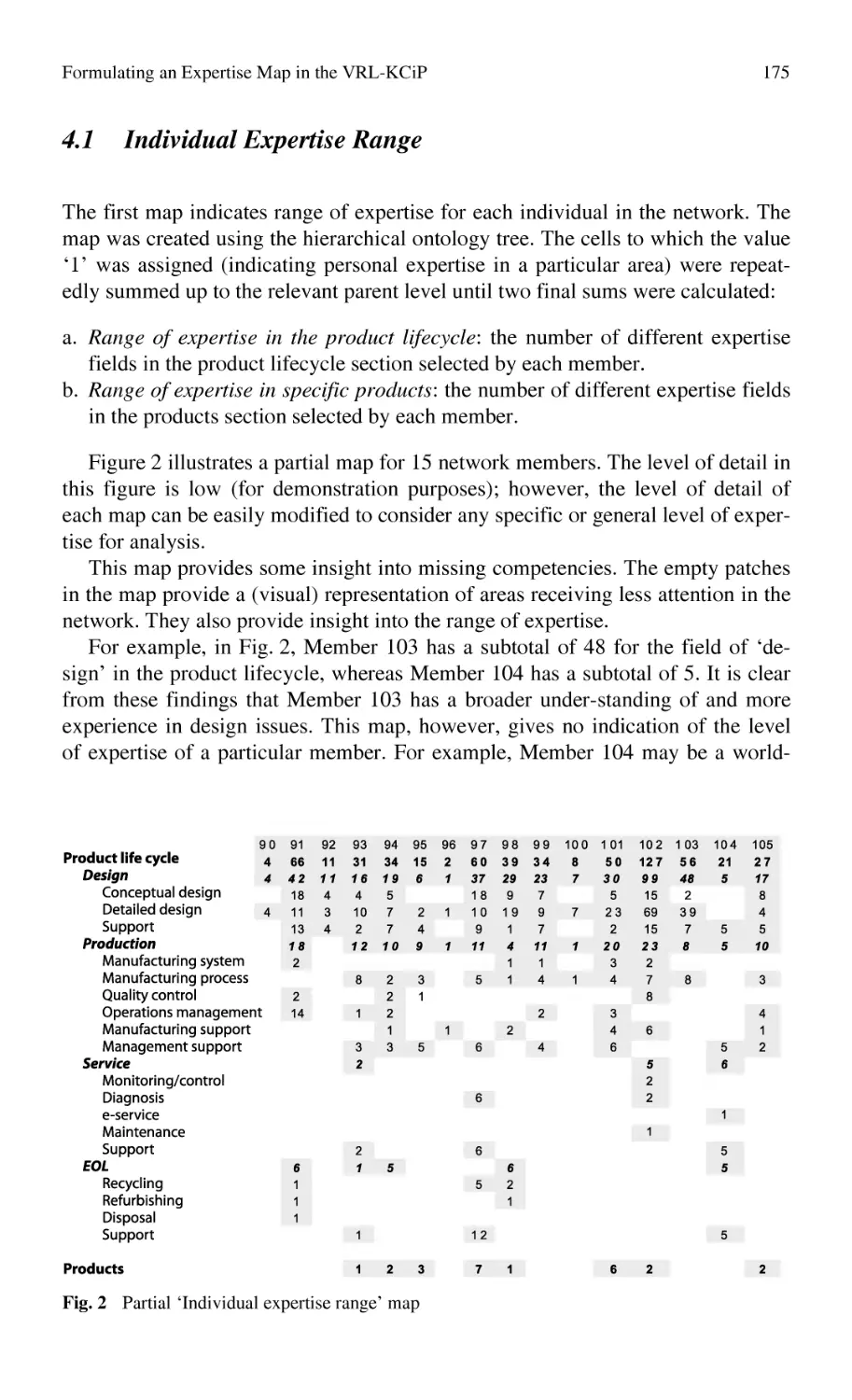
Теги: engineering technology
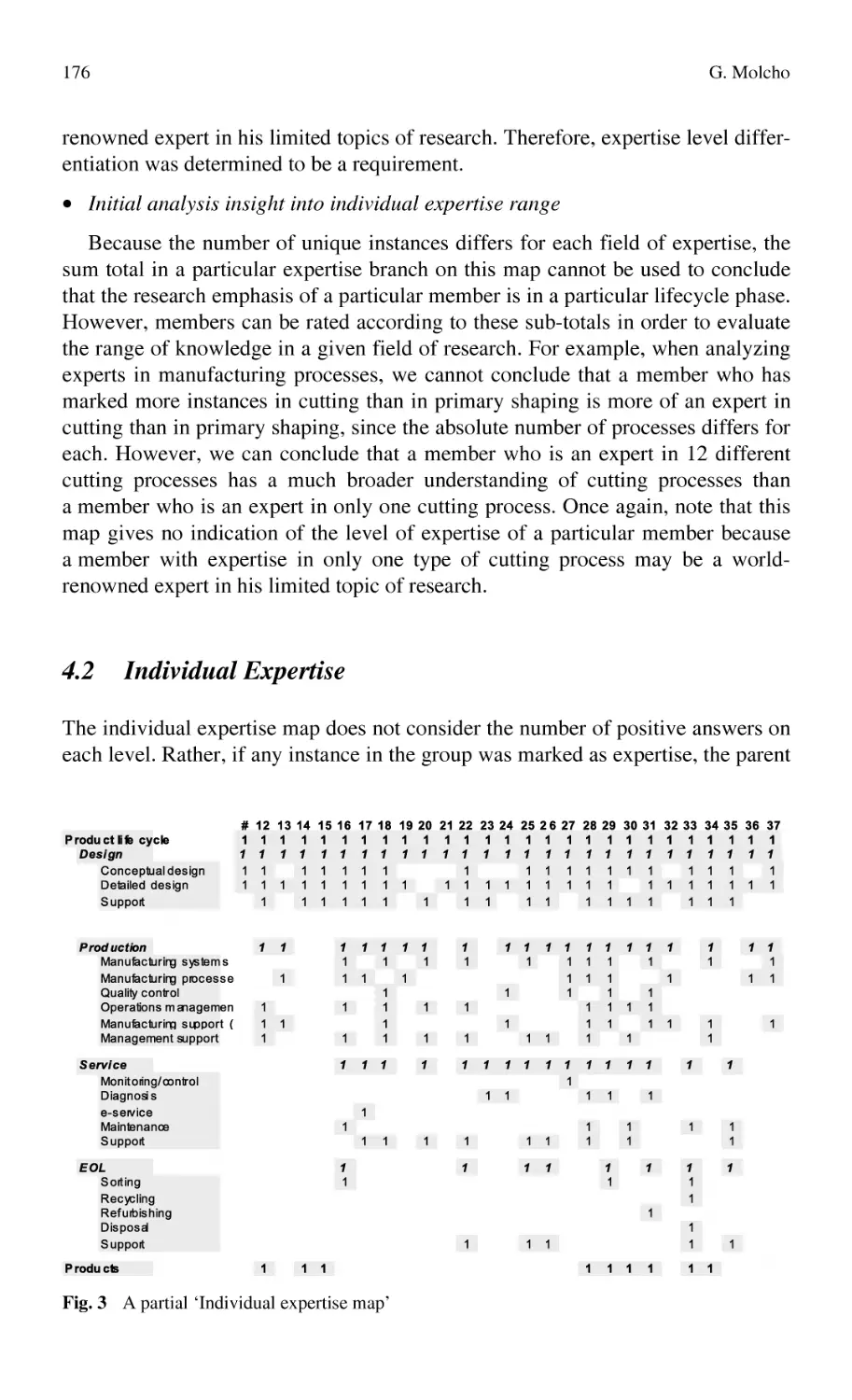
ISBN: 978-3-540-78430-2
Год: 2008


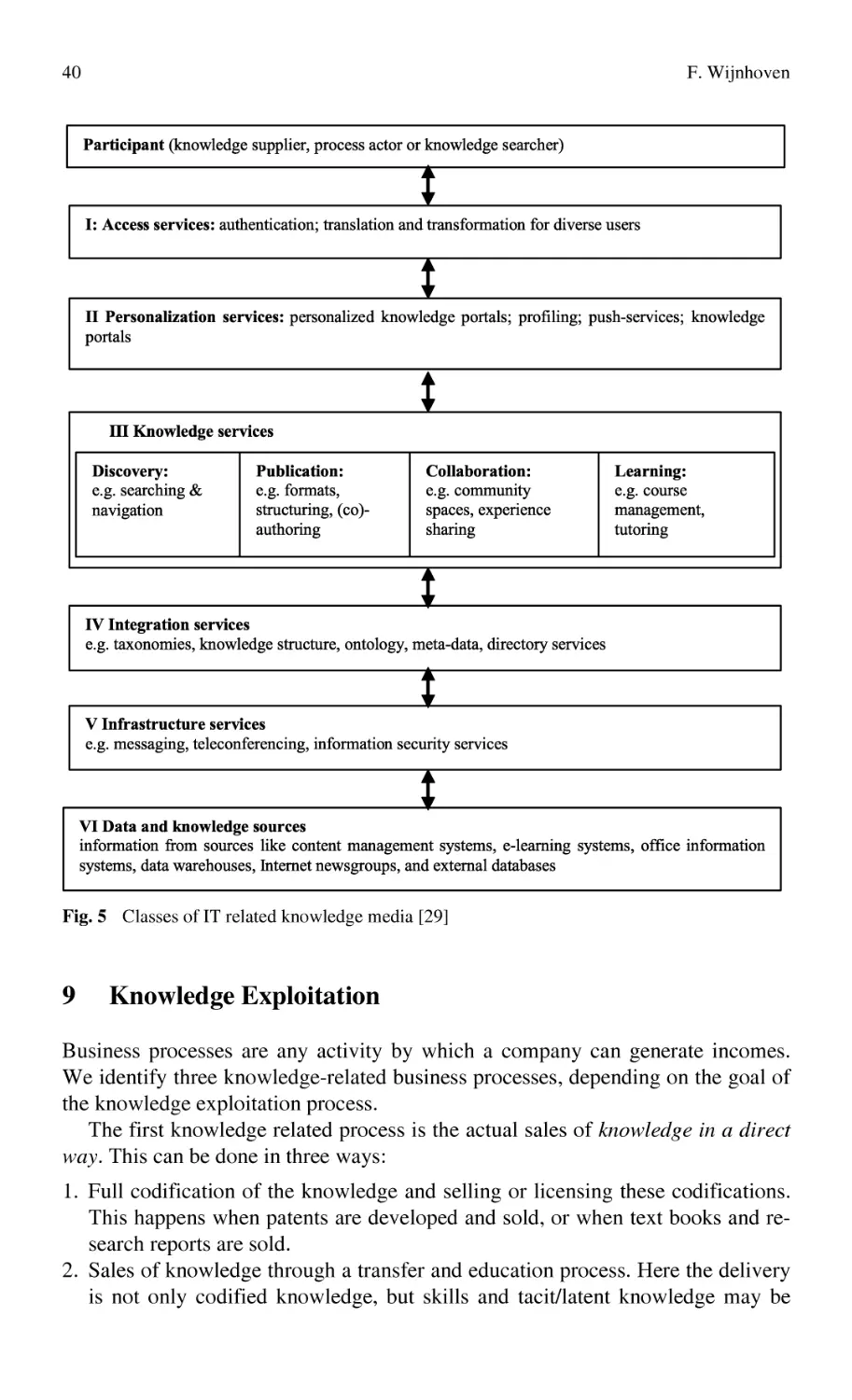
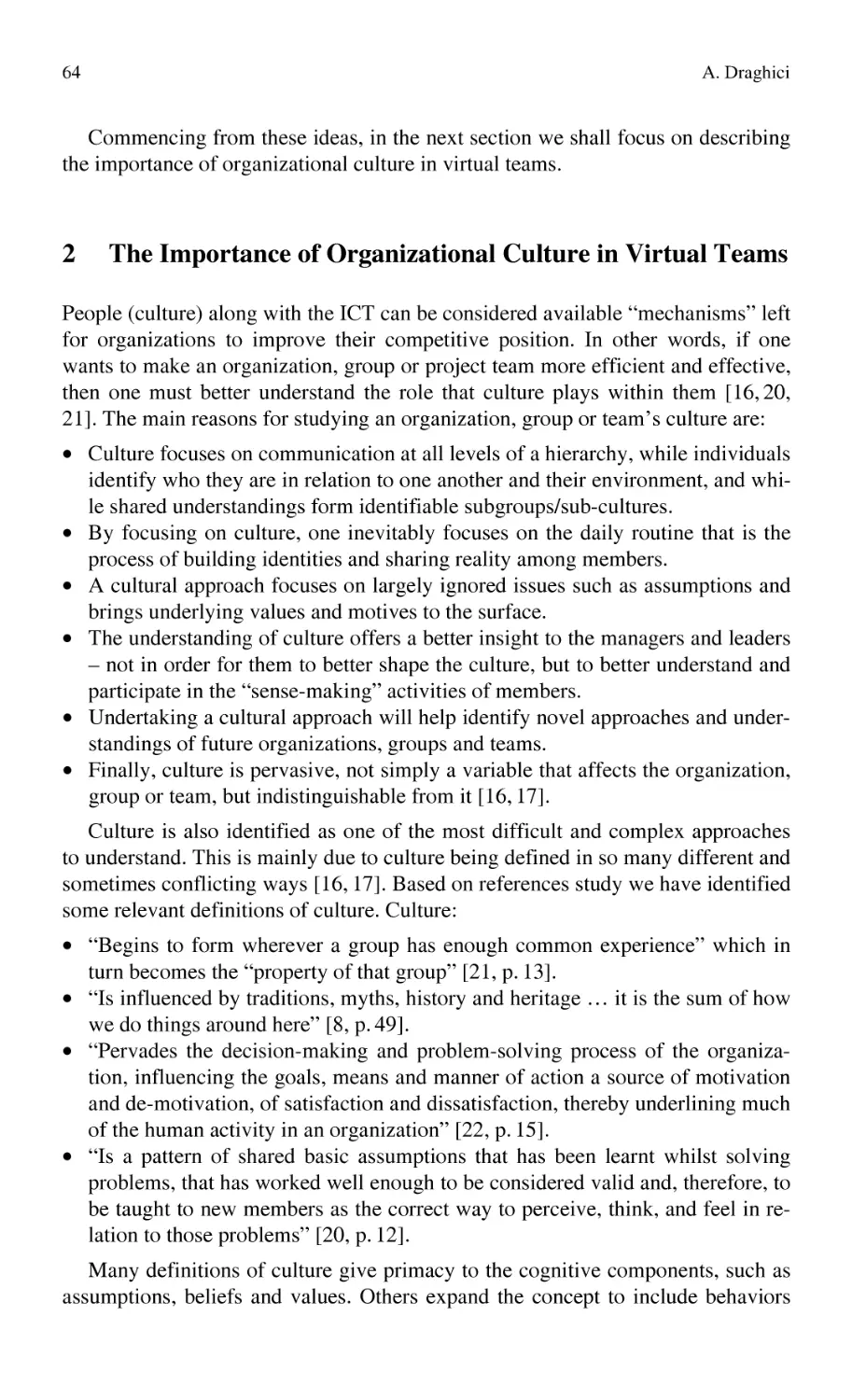
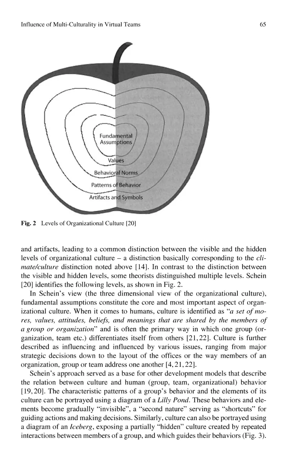
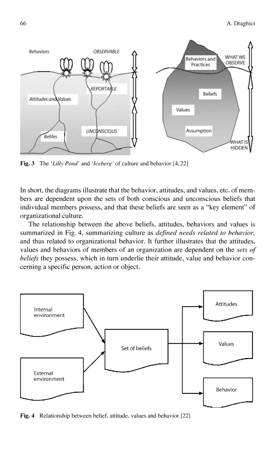
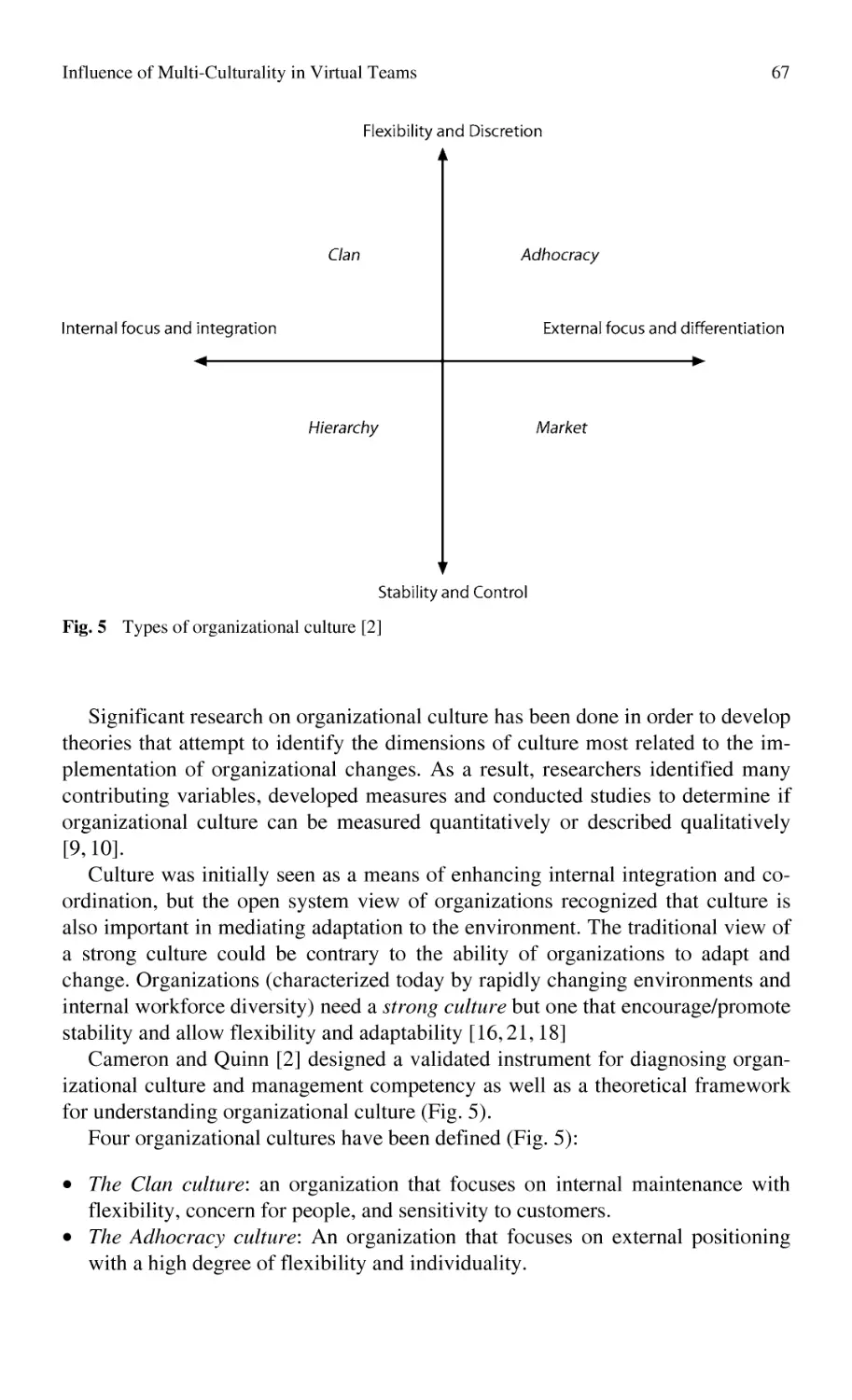
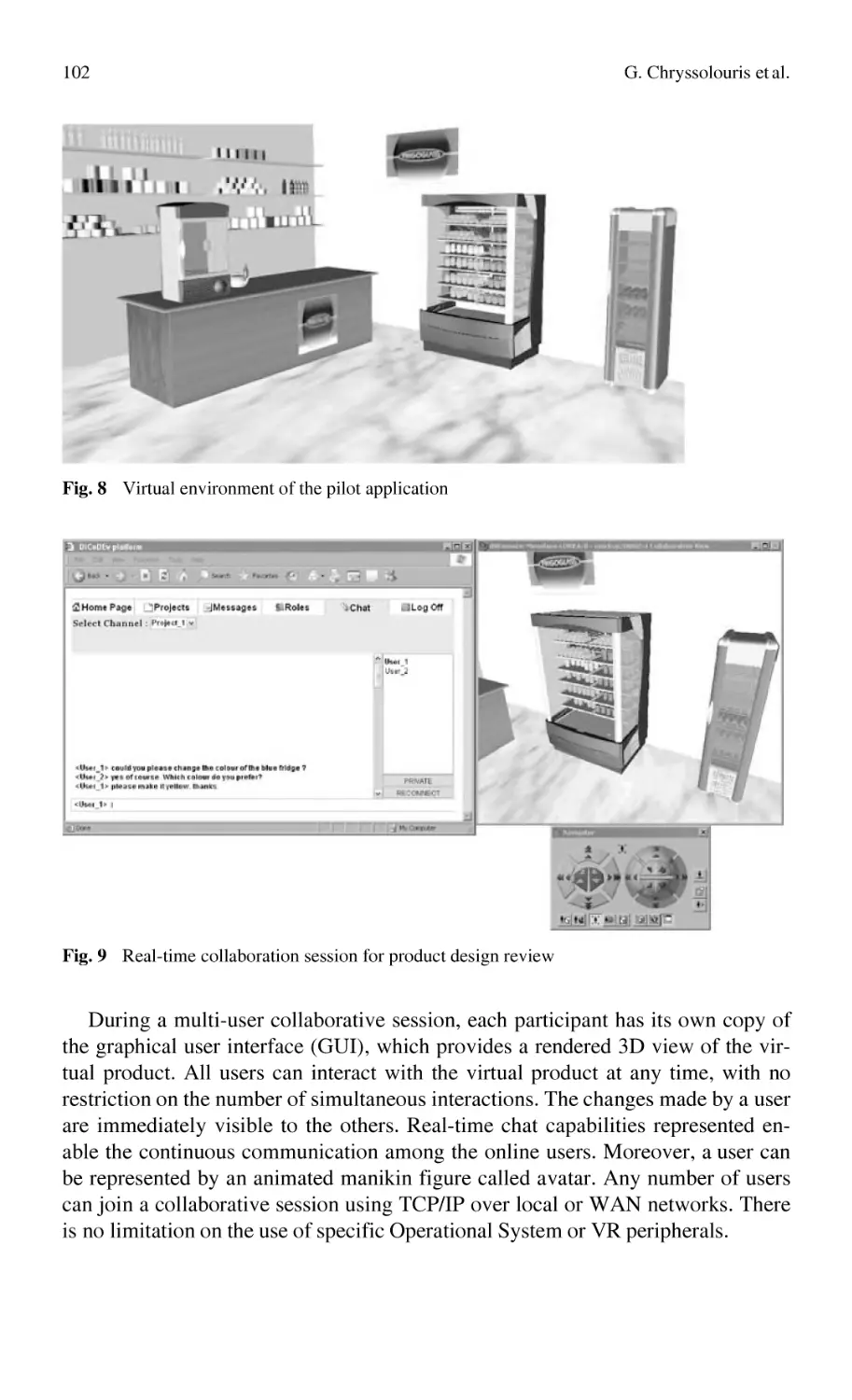
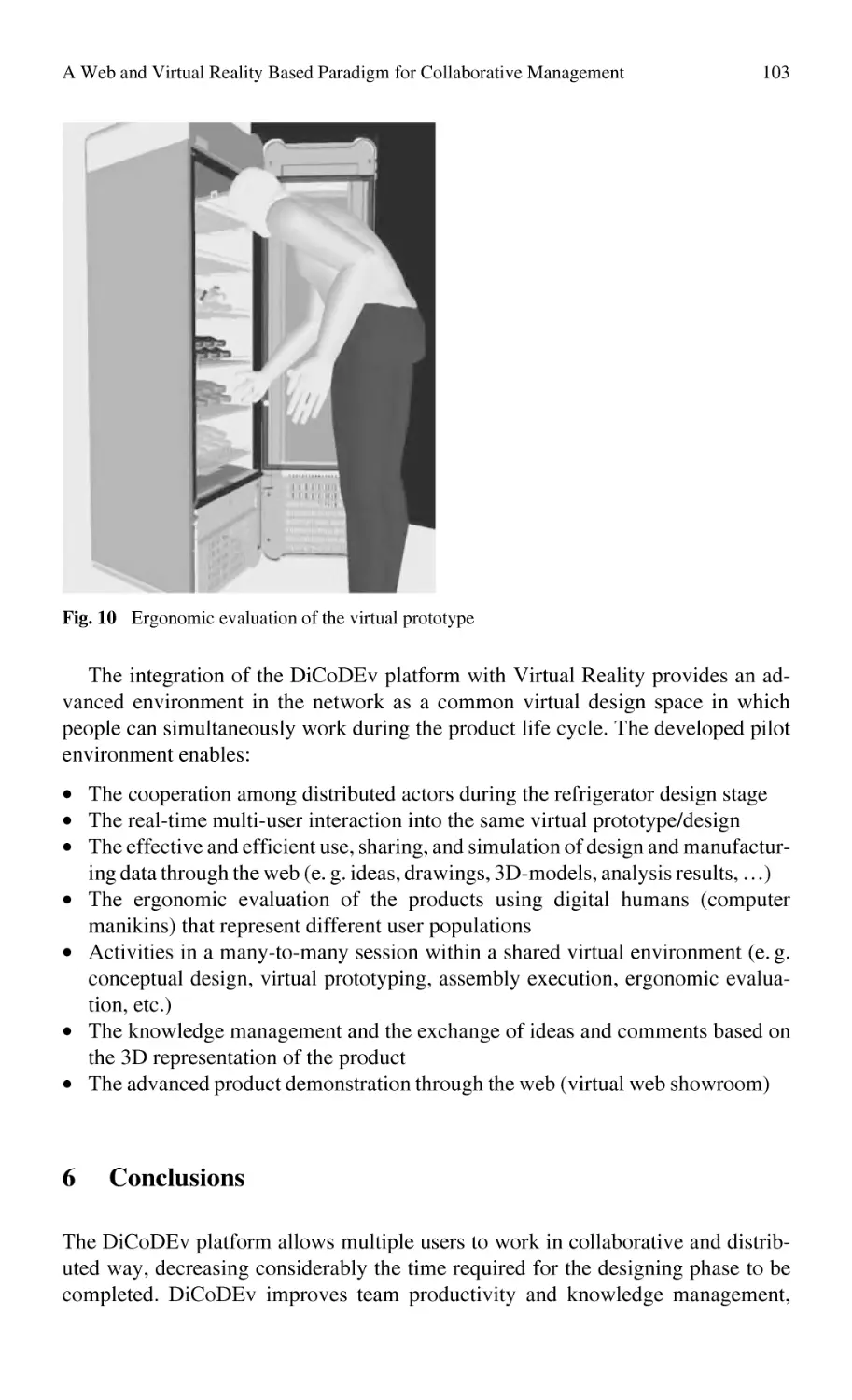
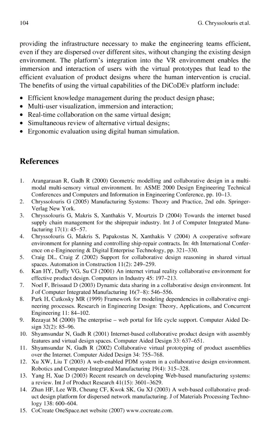
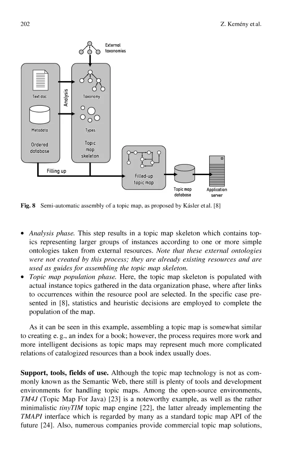
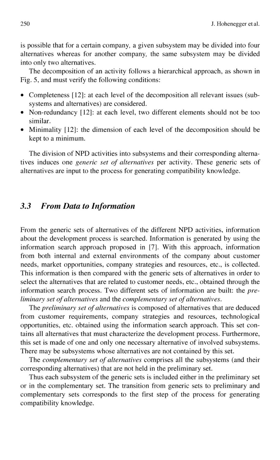
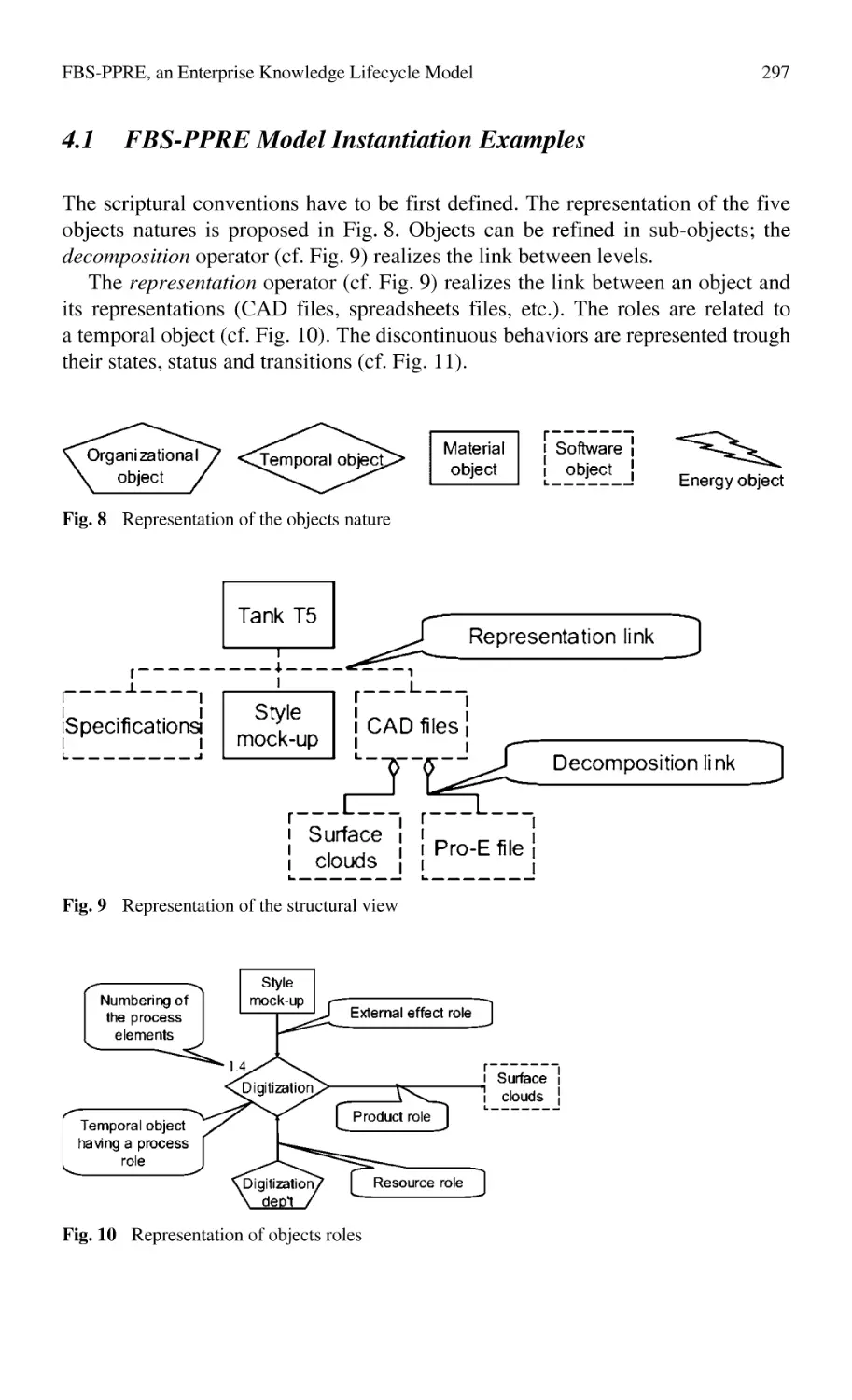
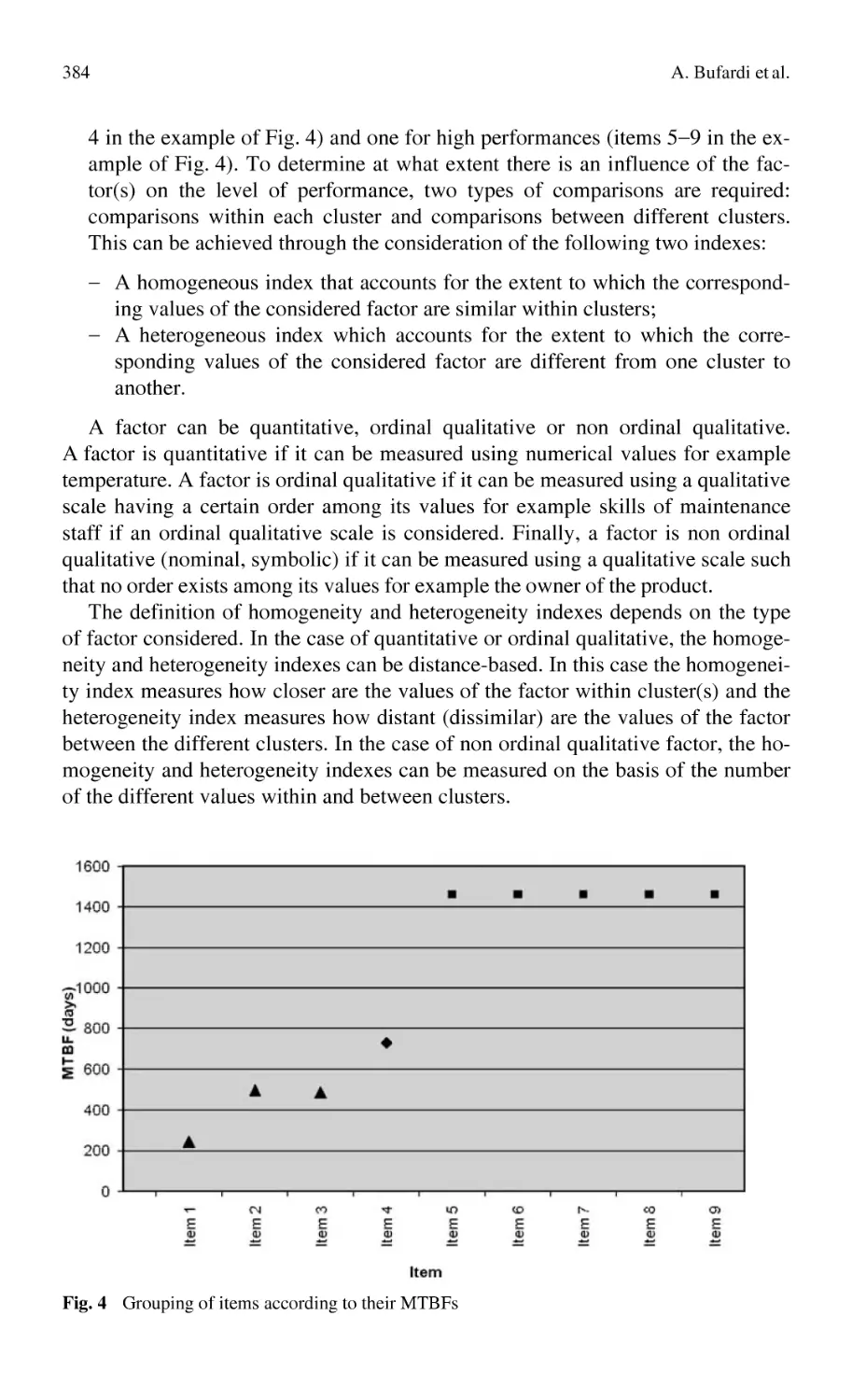
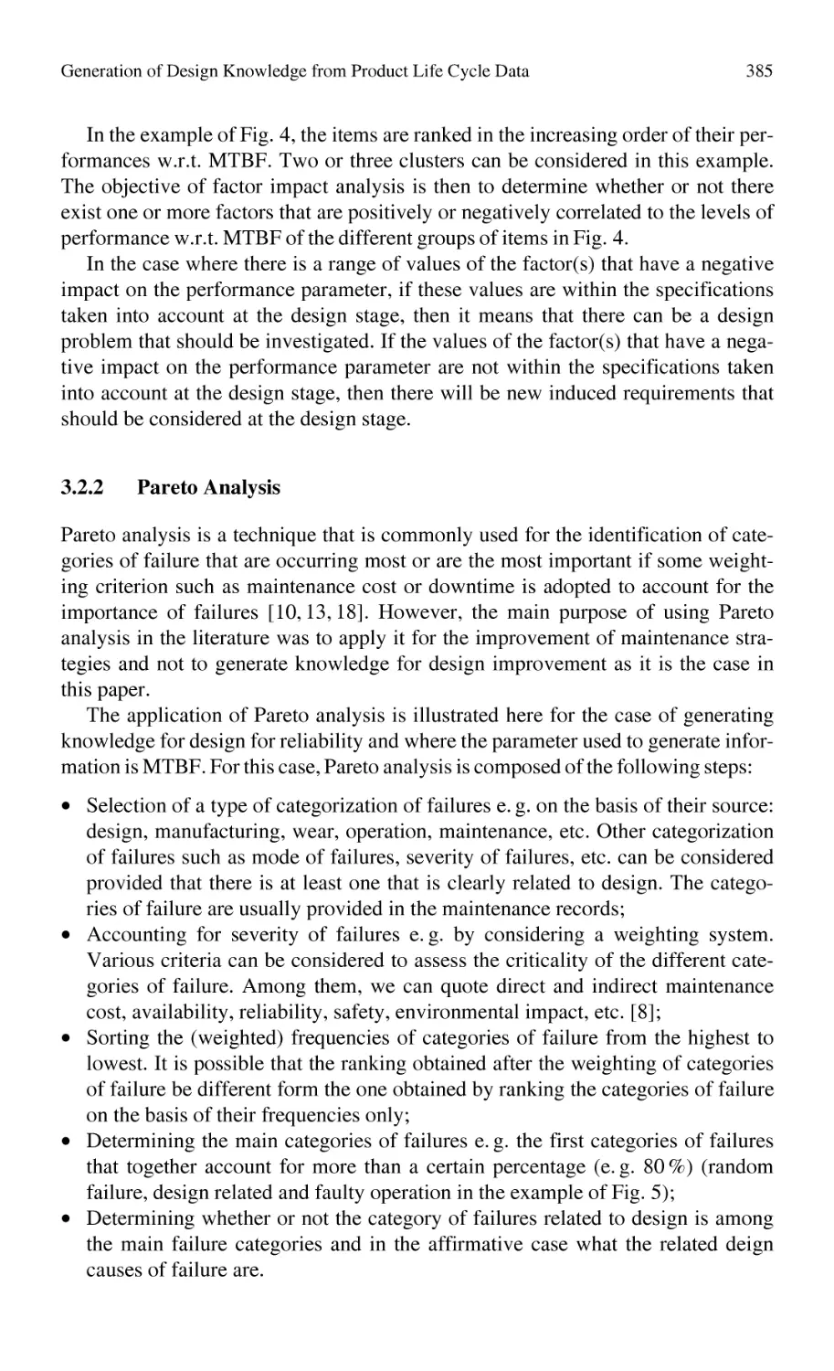
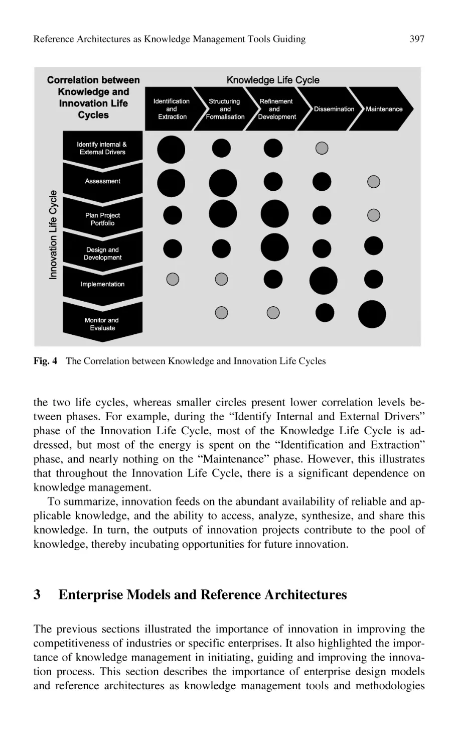
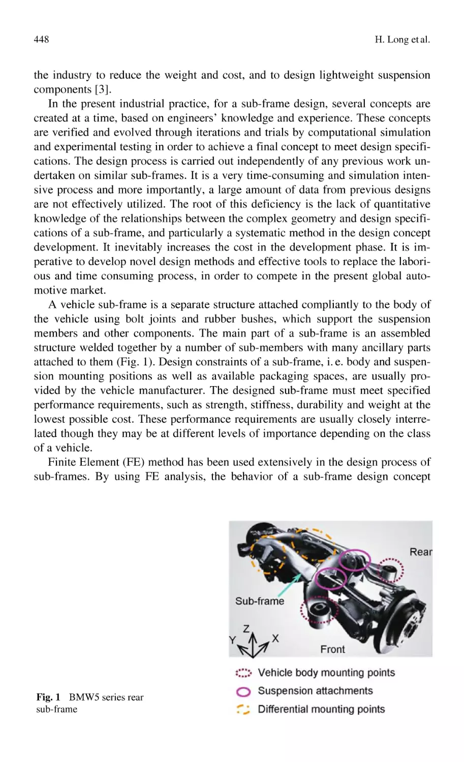
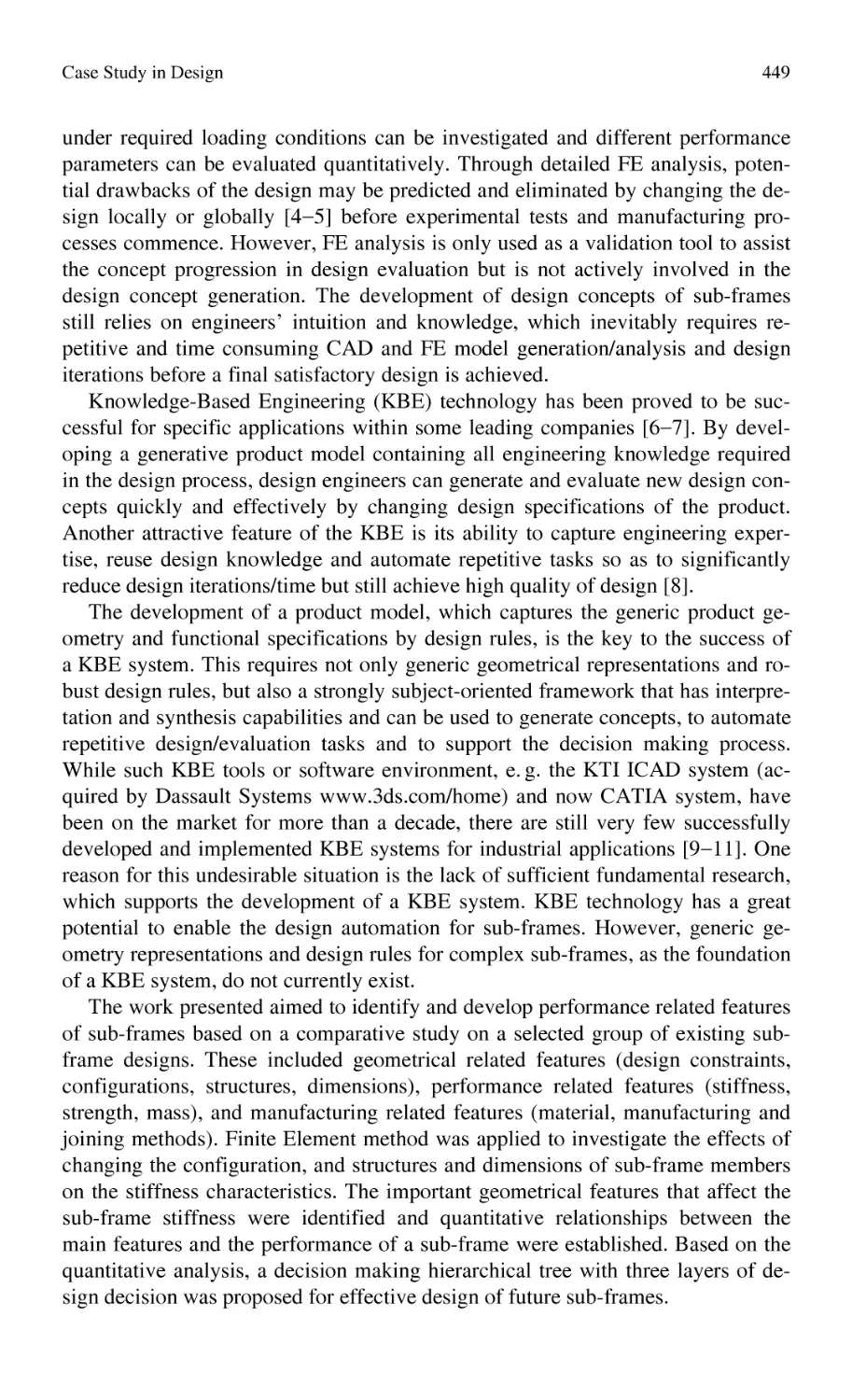
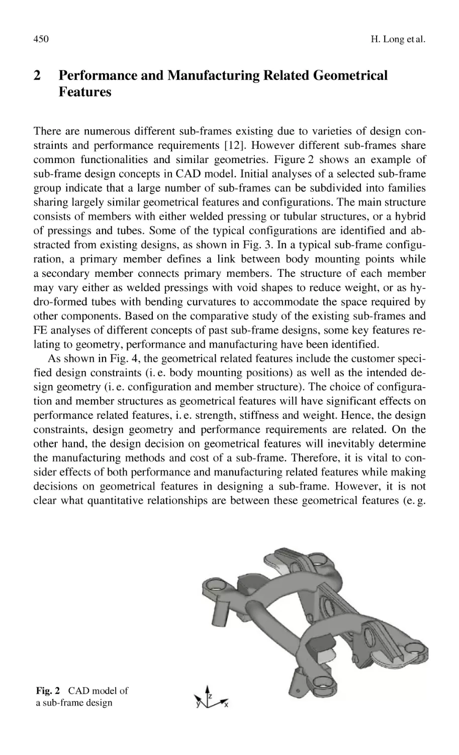
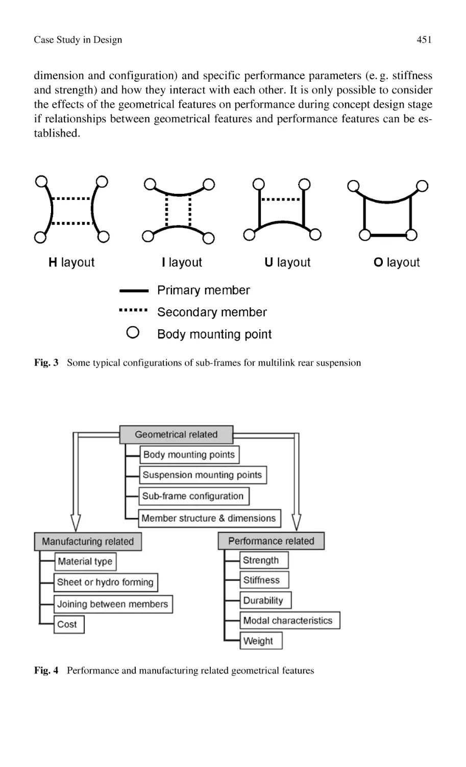
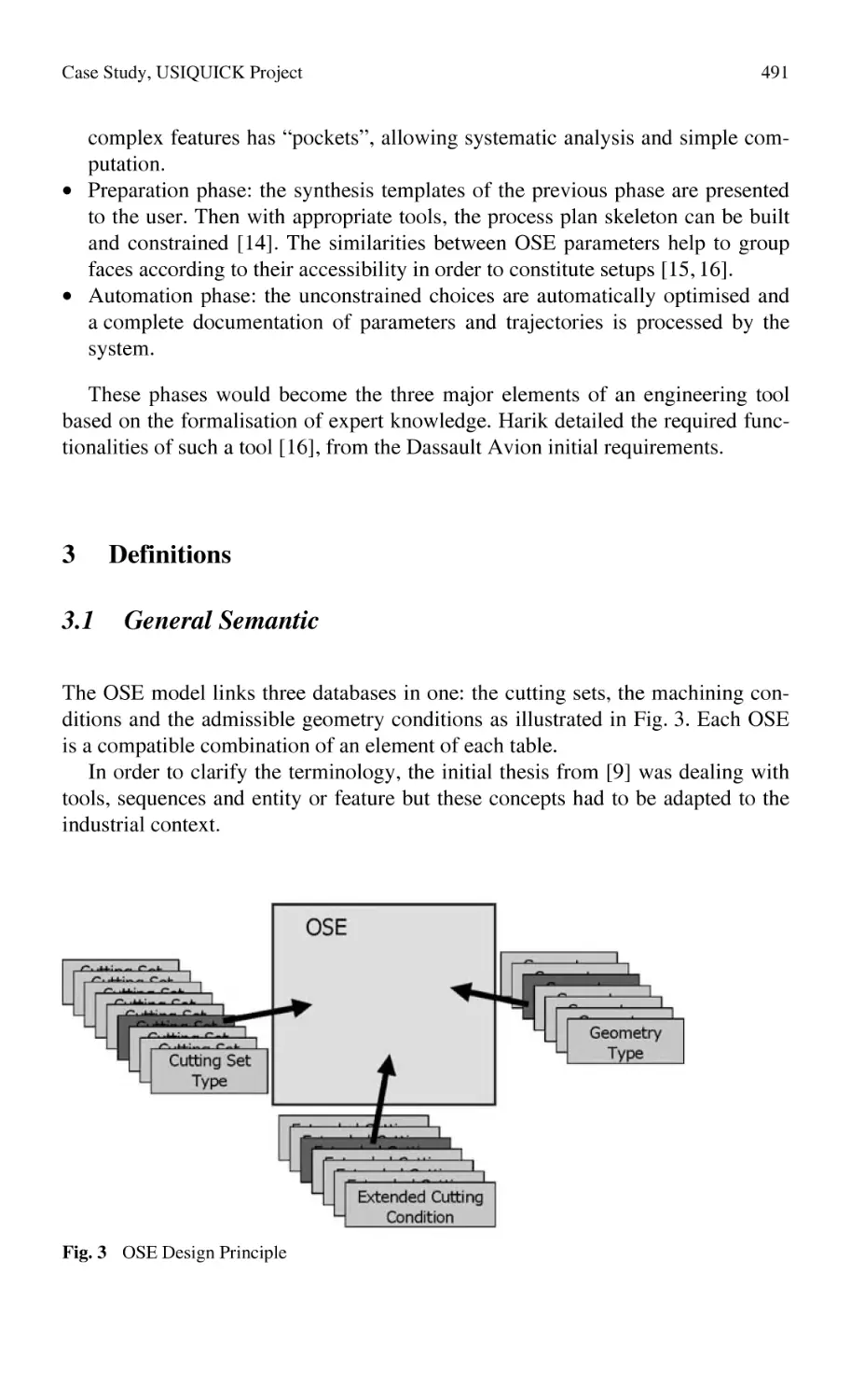
Текст
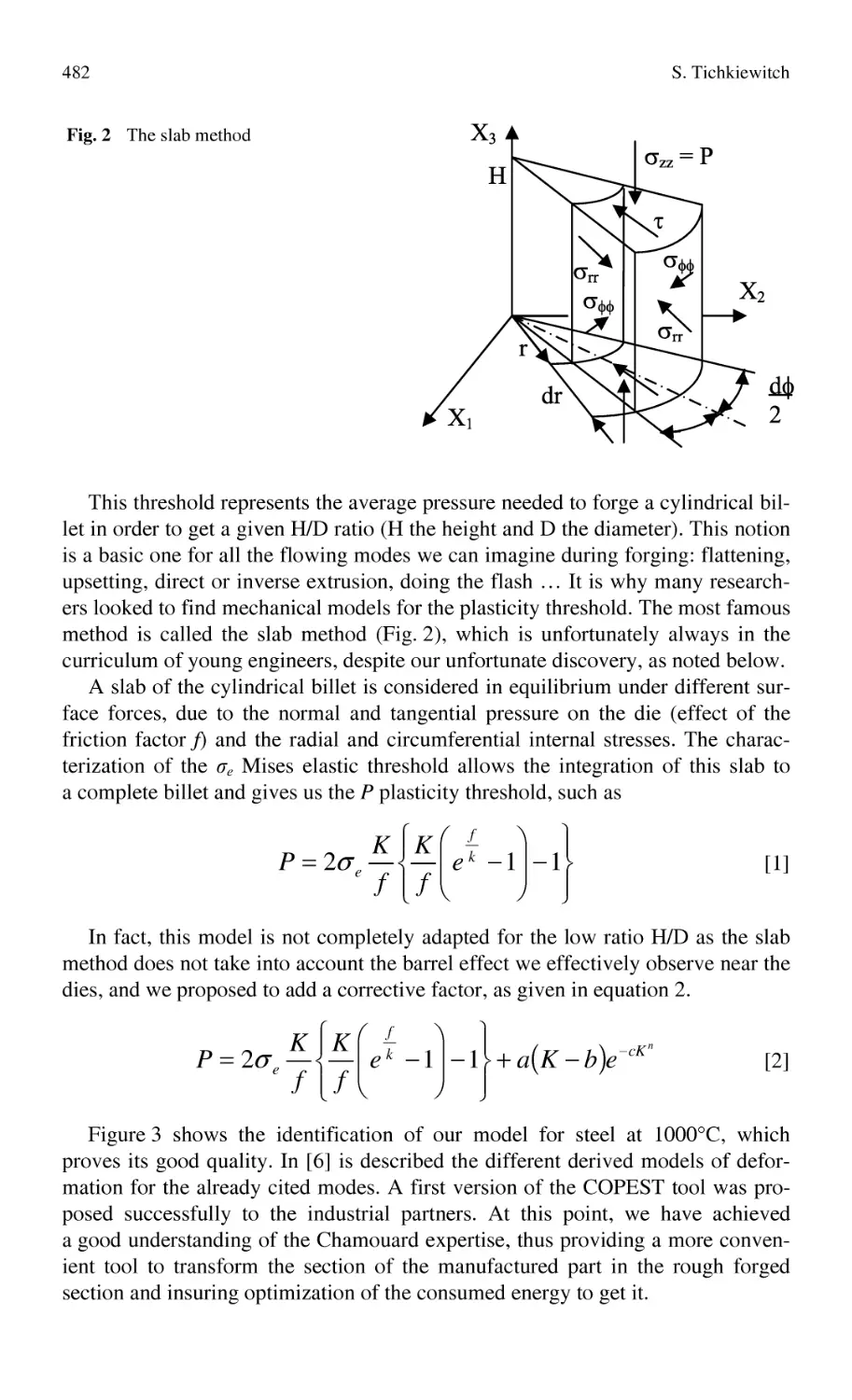
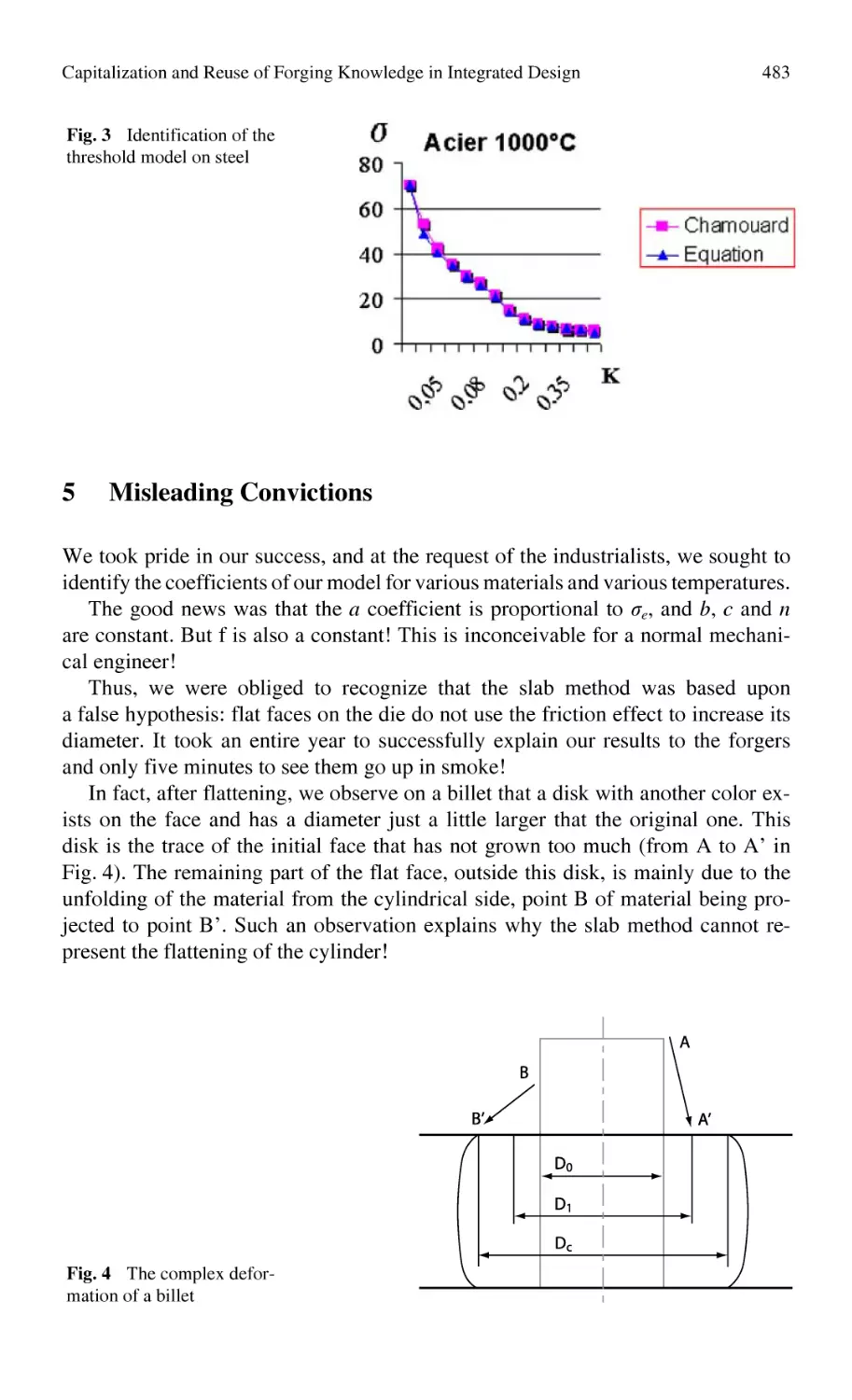
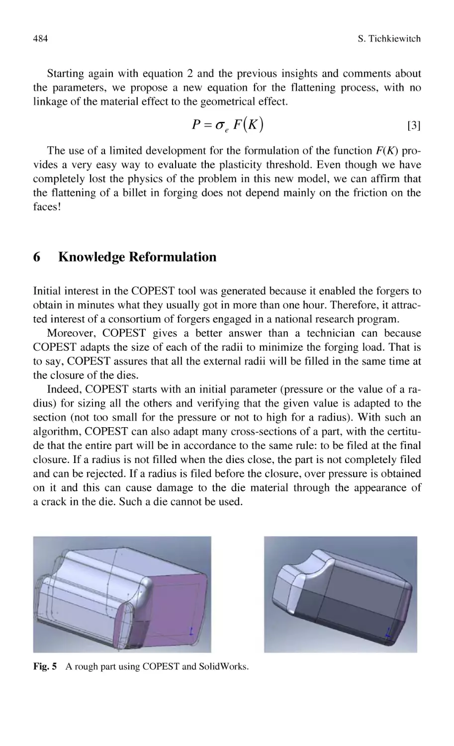
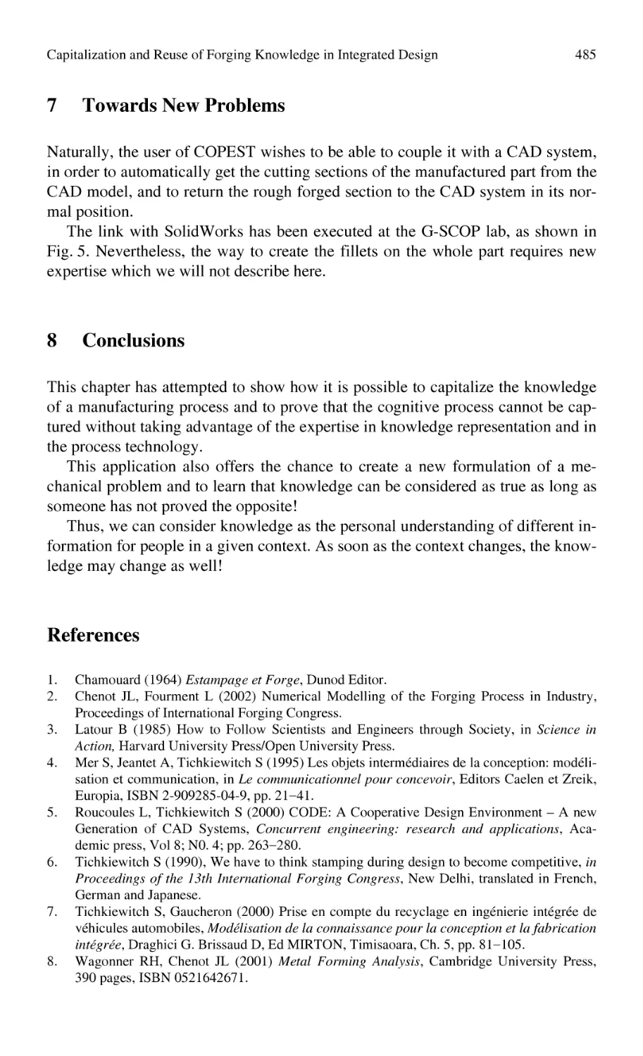
Methods and Tools
for Effective Knowledge Life-Cycle-Management
Alain Bernard ∙ Serge Tichkiewitch
Editors
Methods and Tools
for Effective Knowledge
Life-Cycle-Management
123
Professor Alain Bernard
Ecole Centrale de Nantes
IRCCyN, CNRS, UMR 6597
1 rue de la Noë
44321 Nantes Cedex 03
France
alain.bernard@ec-nantes.fr
Professor Serge Tichkiewitch
Grenoble Institute of Technology
Laboratoire G-SCOP
46 Avenue Félix Viallet
38031 Grenoble Cedex 1
France
serge.tichkiewitch@inpg.fr
ISBN 978-3-540-78430-2
e-ISBN 978-3-540-78431-9
DOI 10.1007/978-3-540-78431-9
Library of Congress Control Number: 20089222196
© 2008 Springer-Verlag Berlin Heidelberg
This work is subject to copyright. All rights are reserved, whether the whole or part of the material is
concerned, specifically the rights of translation, reprinting, reuse of illustrations, recitation, broadcasting, reproduction on microfilm or in any other way, and storage in data banks. Duplication of this
publication or parts thereof is permitted only under the provisions of the German Copyright Law of
September 9, 1965, in its current version, and permissions for use must always be obtained from
Springer. Violations are liable to prosecution under the German Copyright Law.
The use of general descriptive names, registered names, trademarks, etc. in this publication does not
imply, even in the absence of a specific statement, that such names are exempt from the relevant protective laws and regulations and therefore free for general use.
Cover design: F. Steinen-Broo, eStudio Calamar, Spain
Printed on acid-free paper
987654321
springer.com
Preface
Knowledge Management is a wide, critical and strategic issue for all the companies, from the SMEs to the most complex organizations. The key of competitiveness is knowledge, because of the necessity of reactivity, flexibility, agility and
innovation capacities. Knowledge is difficult to measure itself but what is visible,
this is the way of improving products, technologies and enterprise organizations.
During the last four years, based on the experience of most of the best experts
around the World, CIRP (The International Academy for Production Engineering)
has decided to prepare and structure a Network of Excellence (NoE) proposal. The
European Community accepted to found the VRL-KCiP (Virtual Research Laboratory – Knowledge Community in Production). As its name indicates it, the aim
of this NoE was really to build a «Knowledge Community in Production ». This
was possible and realistic because the partners were representative of the most
important universities in Europe and also because of strong partnerships with
laboratories far from Europe (Japan, Australia, South Africa, USA, etc…).
Based on such powerful partnership, the main issue was to help European
manufacturing industry to define and structure the strategic knowledge in order to
face the strategic worldwide challenges.
Manufacturing in Europe currently has two essential aspects:
1. It has to be knowledge intensive given the European demands for high-tech
products and services (e.g. electronics, medicines).
2. Given the relatively high labor costs compared to developing countries, manufacturing processes in Europe require high levels of expertise to realize innovation with a very high productivity.
Consequently in Europe, knowledge management (KM) and more widely
Knowledge Life-cycle Management (KLCM) has become a major issue in academia and industry in the last 30 years, and it is recognized that the knowledge issue
is important for a firm’s manager as well as for an operational work.
This book helps to understand what is knowledge, why knowledge is one of the
most strategic issues of the future manufacturing competitiveness, mainly based
v
vi
Preface
on high level technologies and very innovative products and how to capitalize
knowledge.
The collective experience that contributed to the elaboration of this book is
unique because it is based on 34 contributions, very complementary, very representative of Knowledge Life-Cycle Management state and issues.
The knowledge map of the consortium has been built and is the base of an efficient collaboration within the NoE. The use of conceptual maps for competencies
mapping and knowledge formalization in a Virtual Lab is also one of the contributions of the book. The fundamental knowledge and knowledge management concepts are described. In particular, the benefit of networks of expertise is highlighted and mainly knowledge sharing between multi-cultural communities.
Ontology constitutes the base of knowledge formalization and mapping with respect to the different points of view. Knowledge integration mechanisms within
the extended enterprise and more over the value chain, depending on context characteristics, are also described and illustrated, through methods, tools and experiences. Concrete experiences are described and commented, mainly for product,
process and resource description and management along the life-cycle of mechanical systems. The role of knowledge life-cycle management and of documents
in supporting a radical innovation project is also highlighted. Experience feedbacks are described about knowledge engineering approaches for design, manufacturing, and more generally for enterprise engineering. Several case studies are
also provided in design and manufacturing fields, and also related to European
level manufacturing knowledge sharing.
The specific context given by the VRL-KCiP NoE community involved in the
realization of this book constitutes the main original value-added of this book.
This means that this book is unique because it is based on a theoretical and practical experience of the authors who are for most of them members of the CIRP, the
best referenced International Academy in Production Engineering.
We hope that you will enjoy this book and have a maximum benefit of it.
The co-editors,
Alain BERNARD, Serge TICHKIEWITCH
Content
Part 1 KM Needs and Concepts
1.1
1.1.1
1.1.2
1.2
1.2.1
What Is Knowledge?
From Data to Knowledge
An Overview on Knowledge Management ..........................................
S. Ammar-Khodja, A. Bernard
What is Knowledge Management
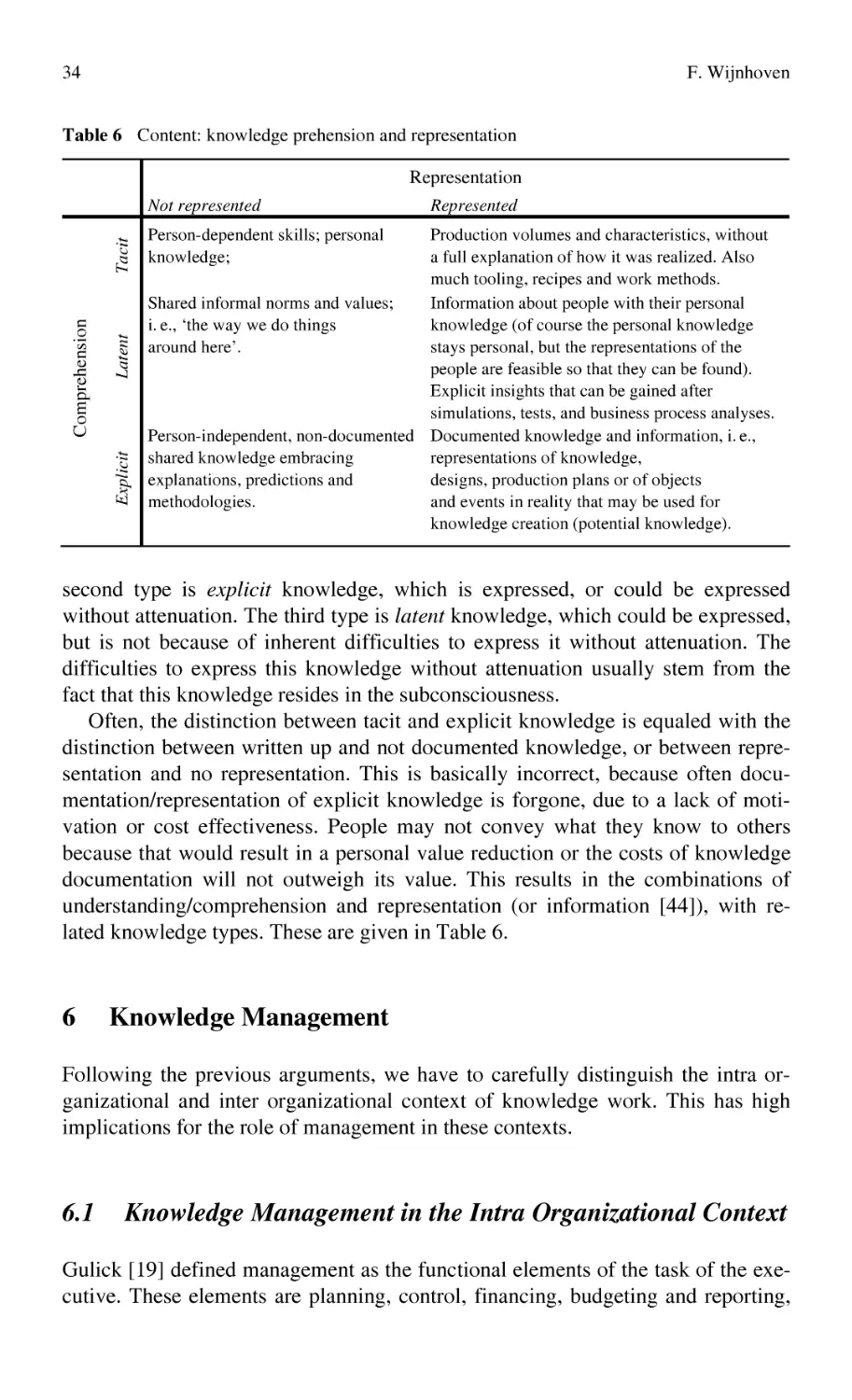
Manufacturing Knowledge Work: The European Perspective .............
F. Wijnhoven
Networks of Expertise
Knowledge Sharing
Social Needs for Knowledge Sharing
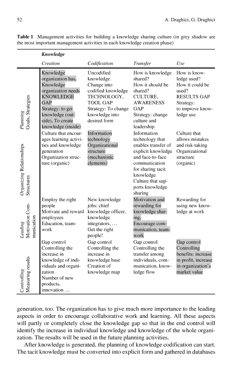
Building a Knowledge Share Culture in a Virtual Organization.
Case Study for VRL-KCiP NoE...........................................................
A. Draghici, G. Draghici
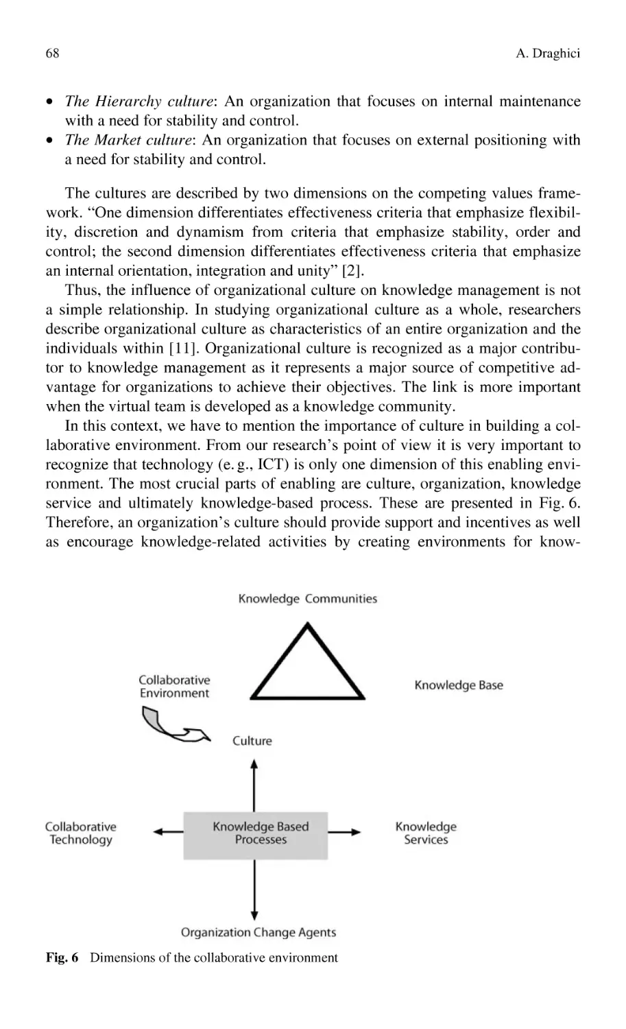
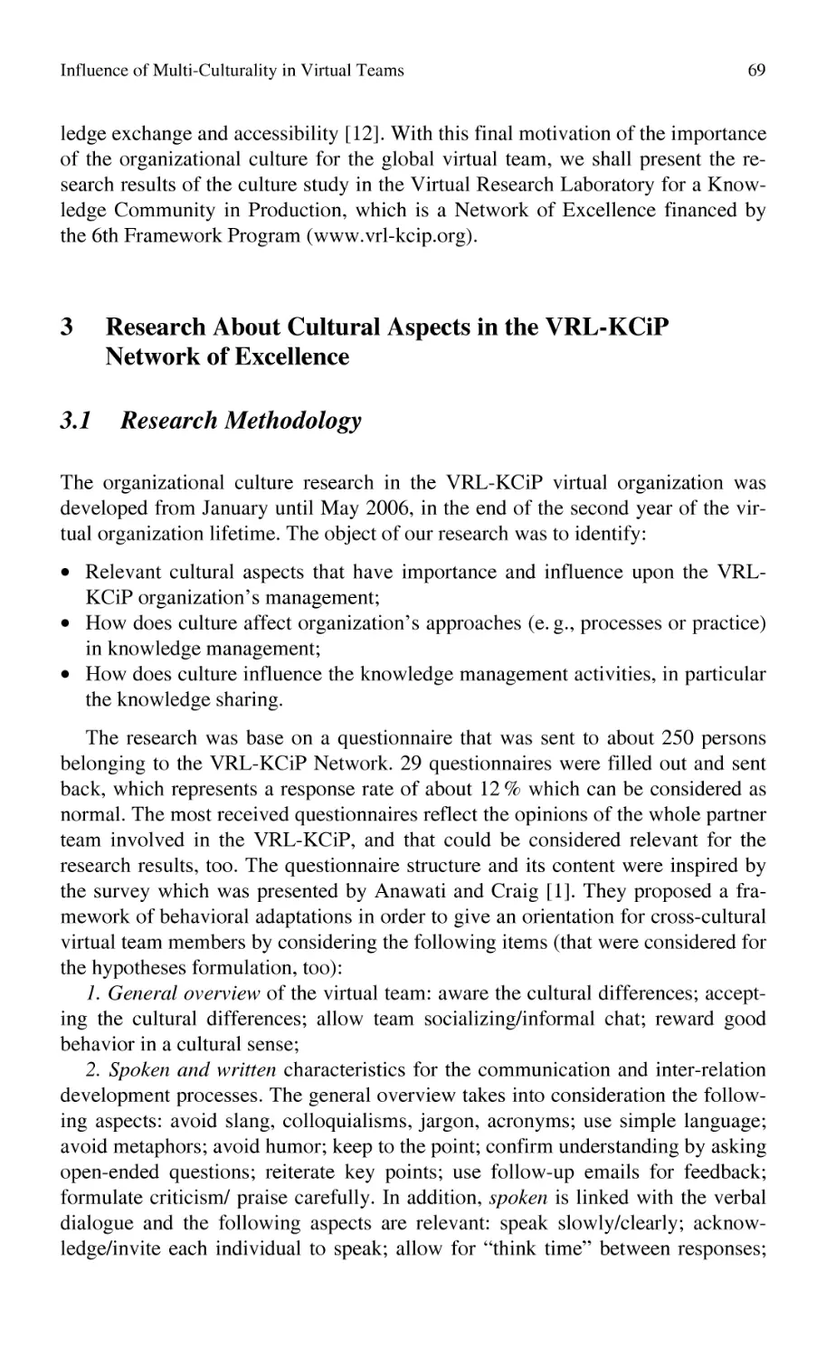
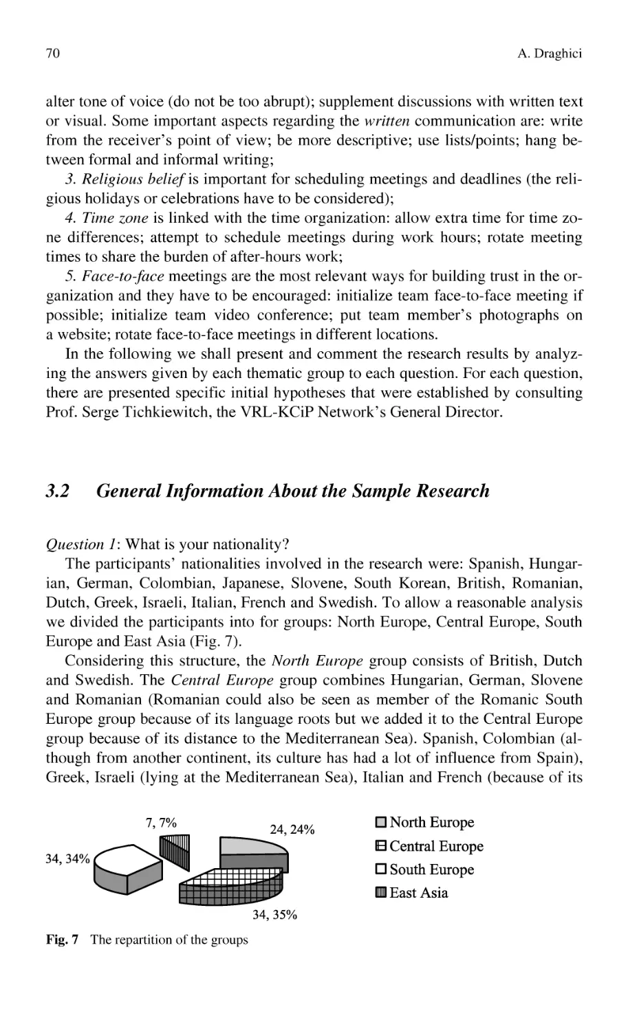
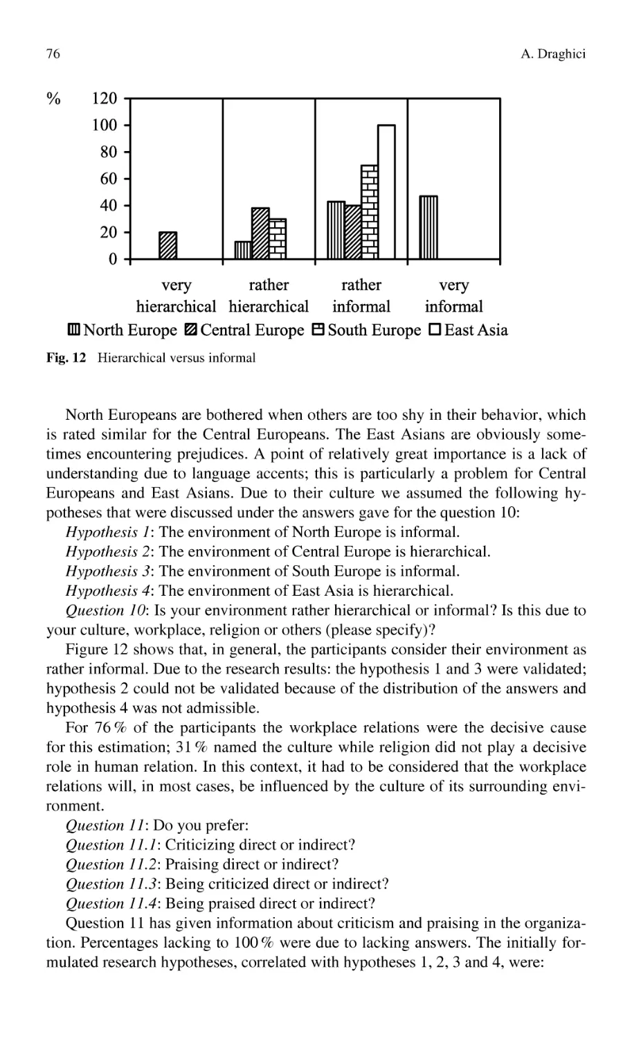
Influence of Multi-Culturality in Virtual Teams ..................................
A. Draghici
1.2.2
Knowledge Integration
Web Tools for Knowledge Integration
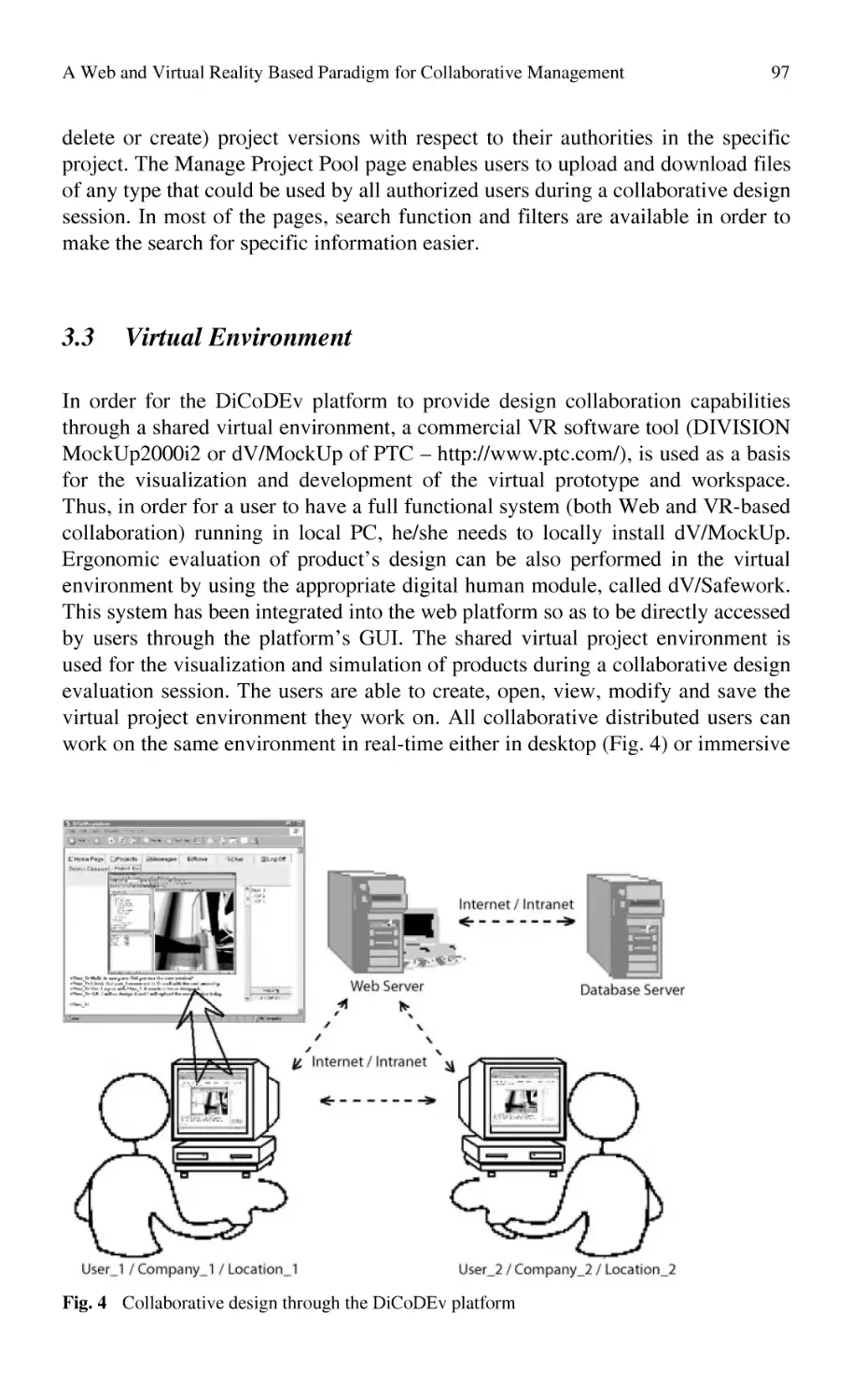
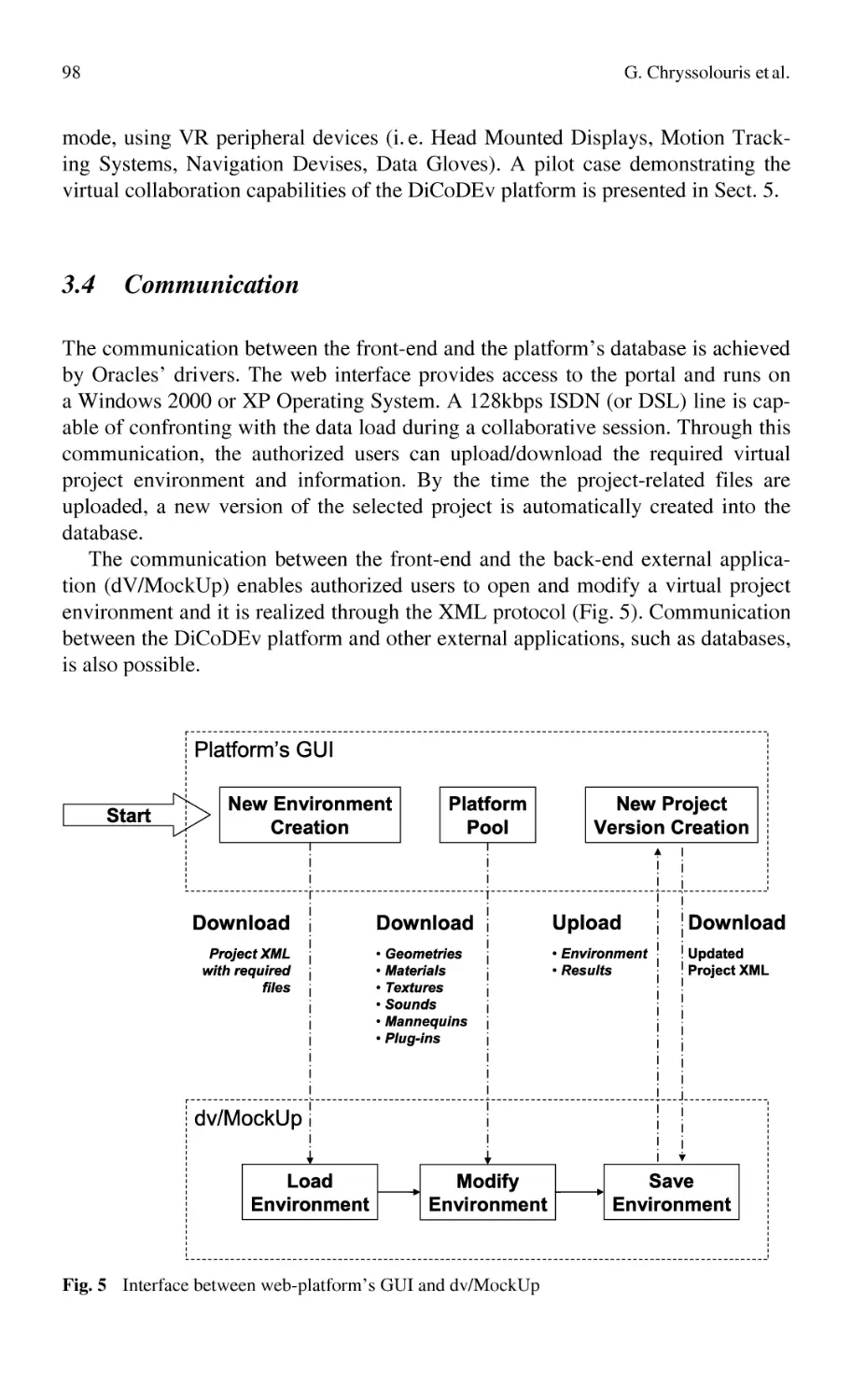
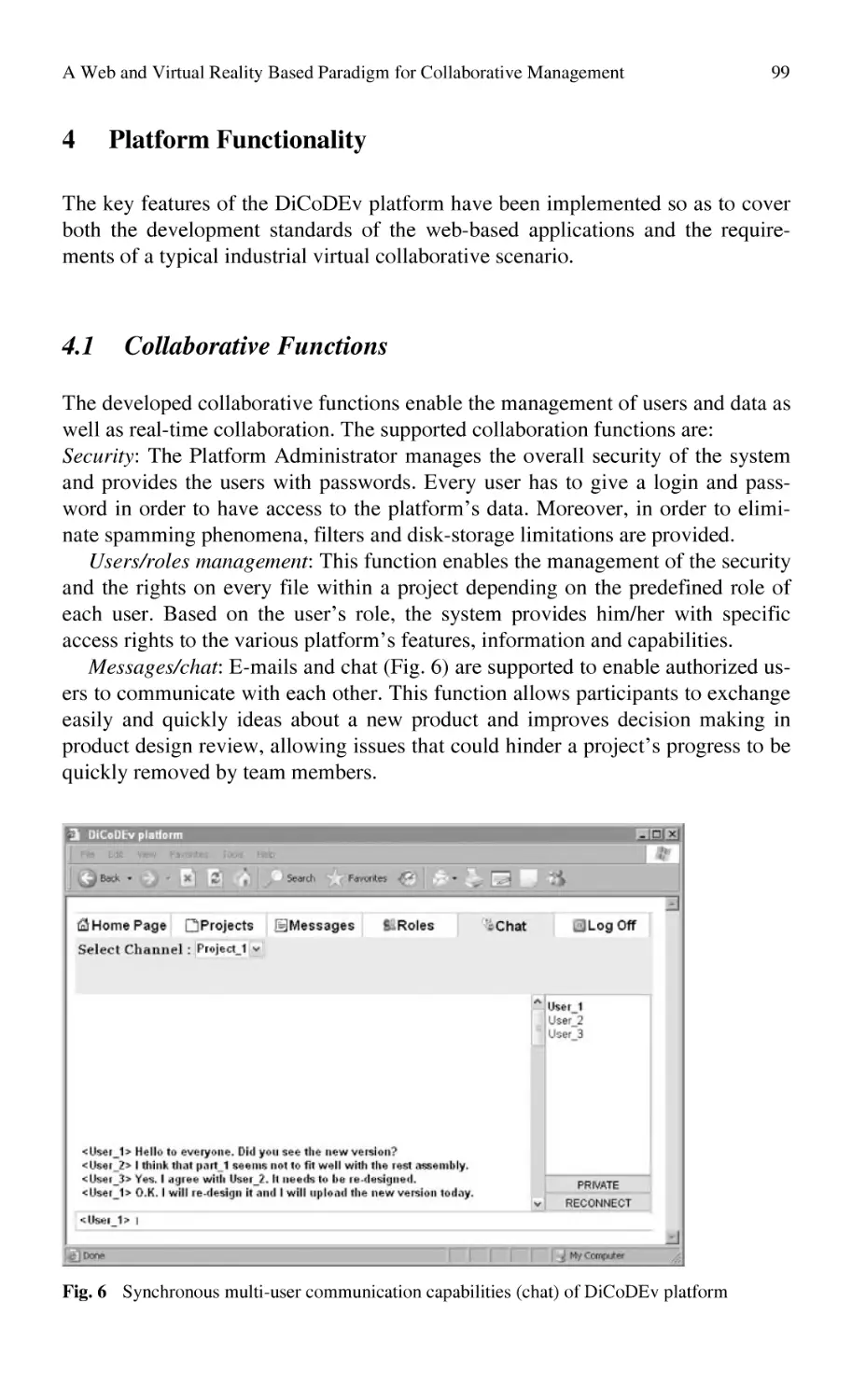
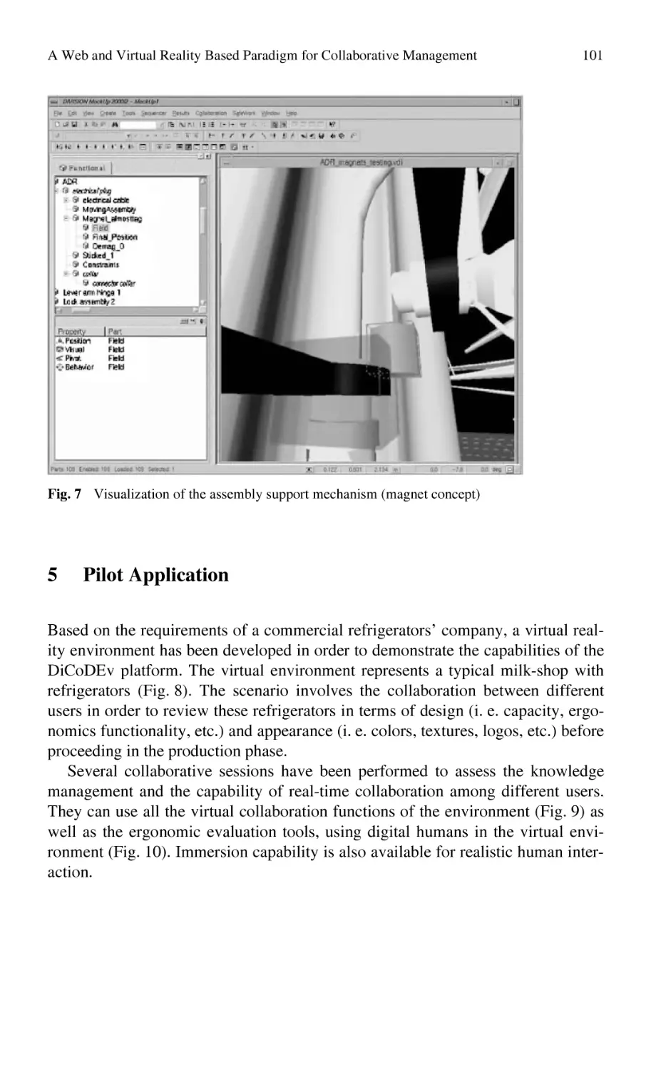
A Web and Virtual Reality Based Paradigm
for Collaborative Management and Verification
of Design Knowledge...........................................................................
G. Chryssolouris, D. Mavrikios, M. Pappas
3
23
45
61
91
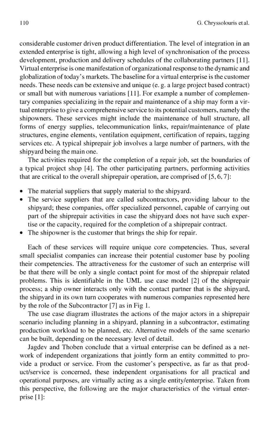
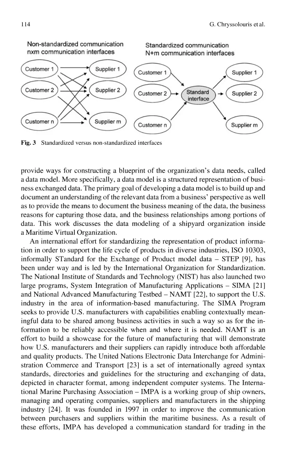
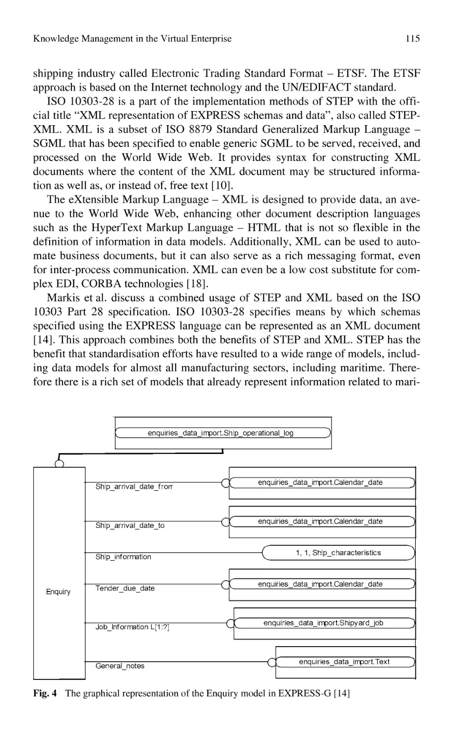
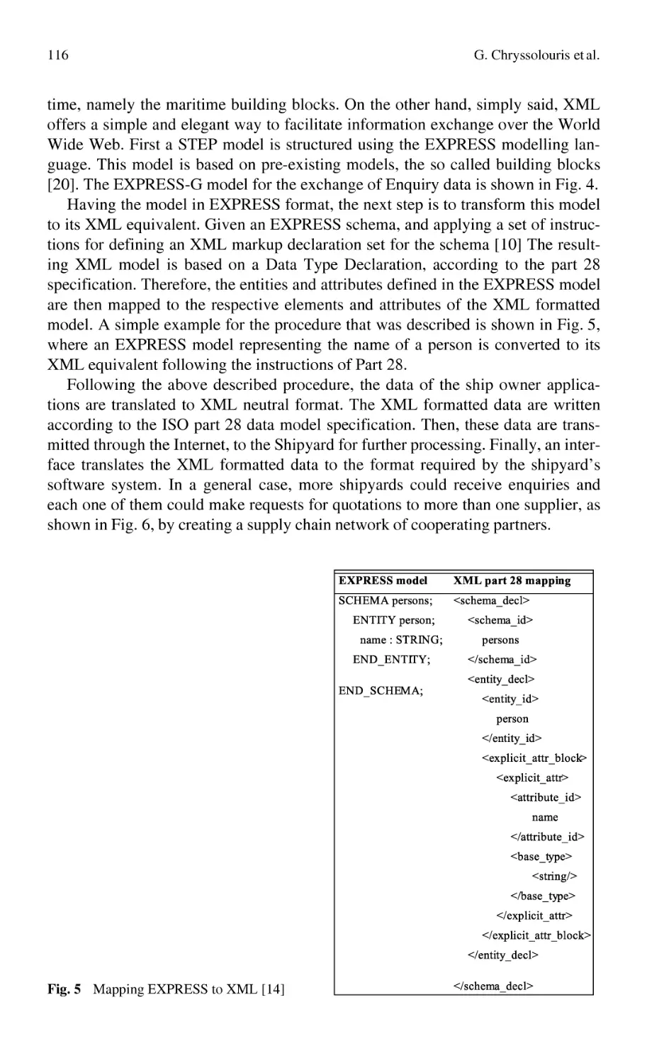
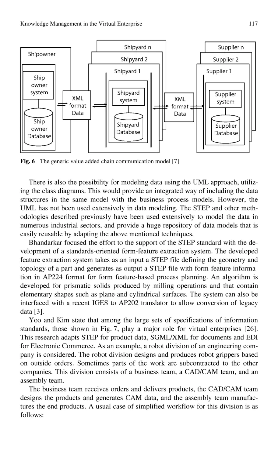
Knowledge Management in the Virtual Enterprise:
Web Based Systems for Electronic Manufacturing.............................. 107
G. Chryssolouris, S. Makris, D. Mourtzis, N. Papakostas
vii
viii
Content
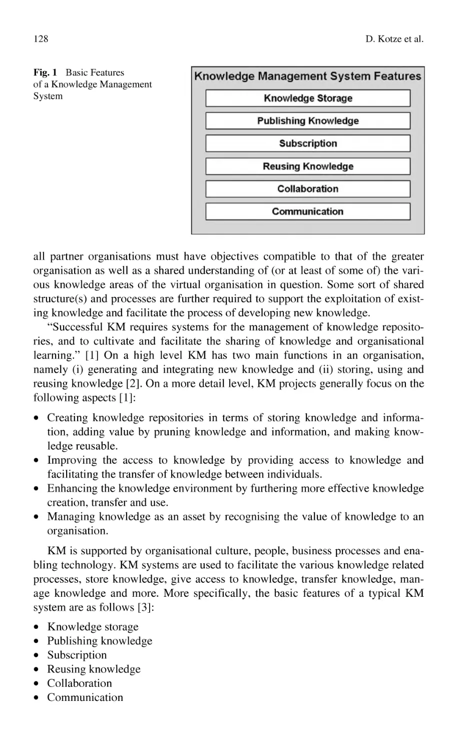
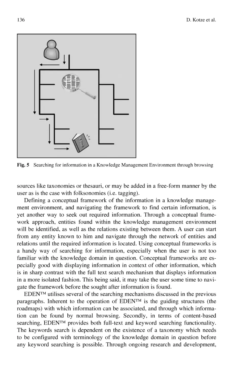
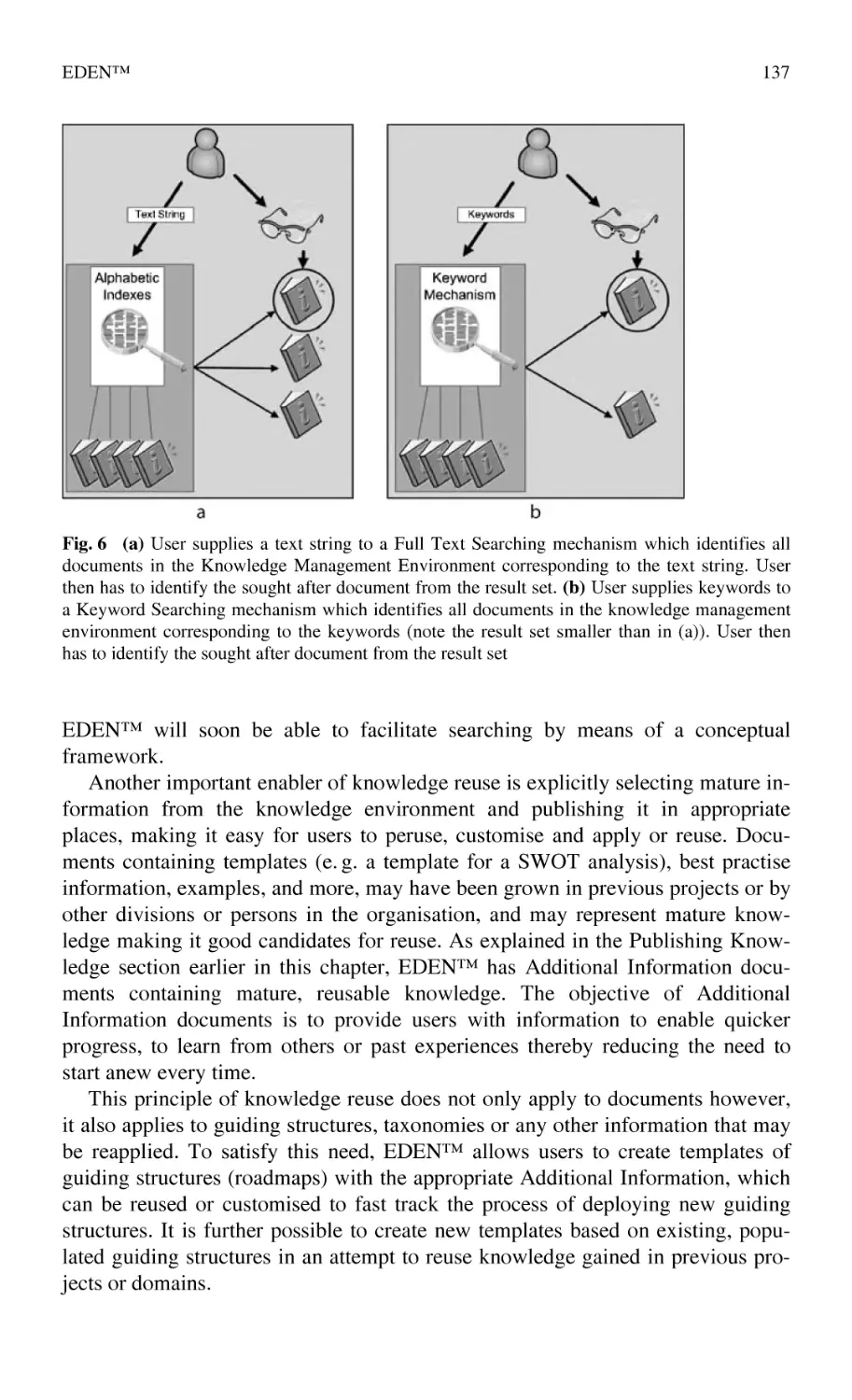
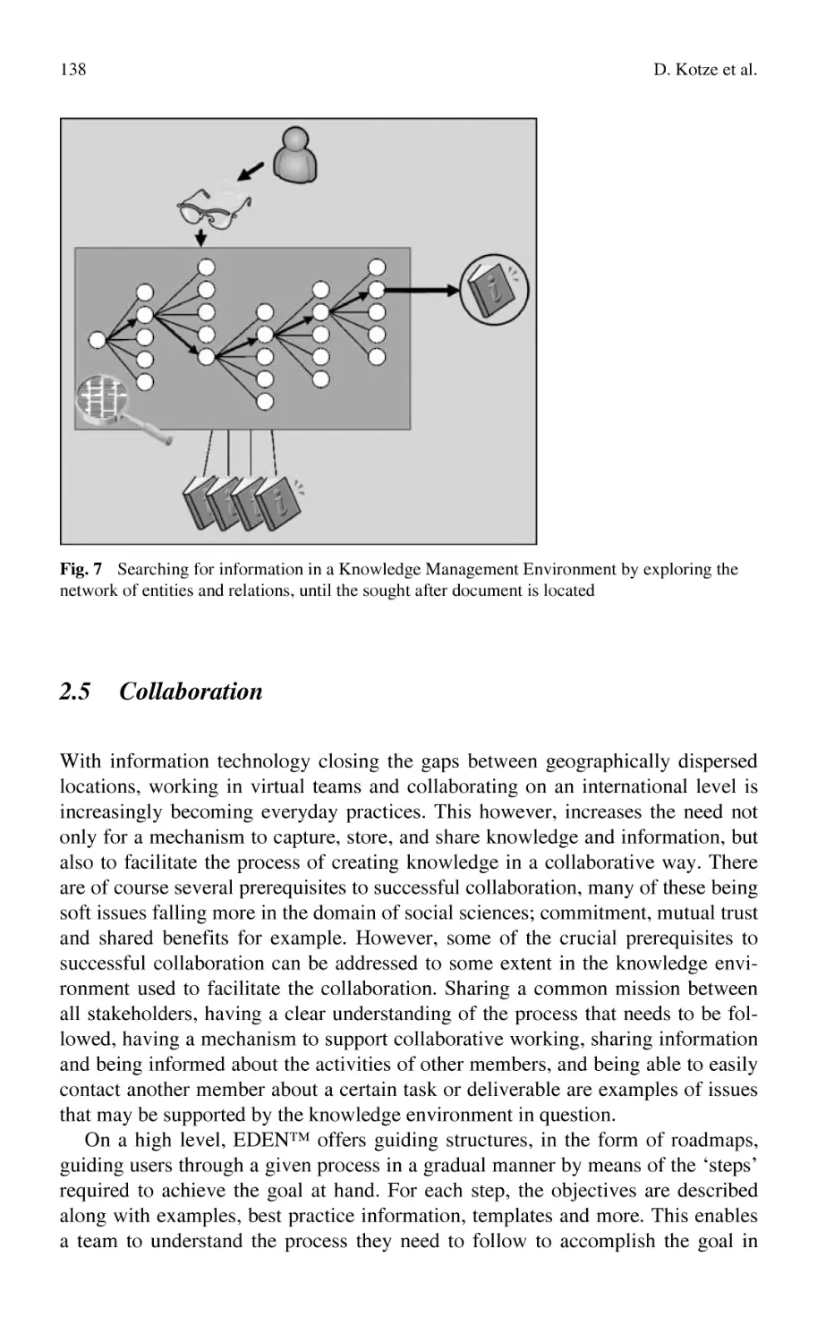
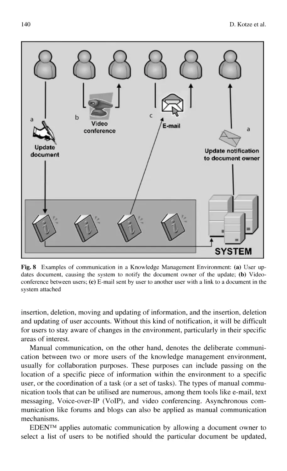
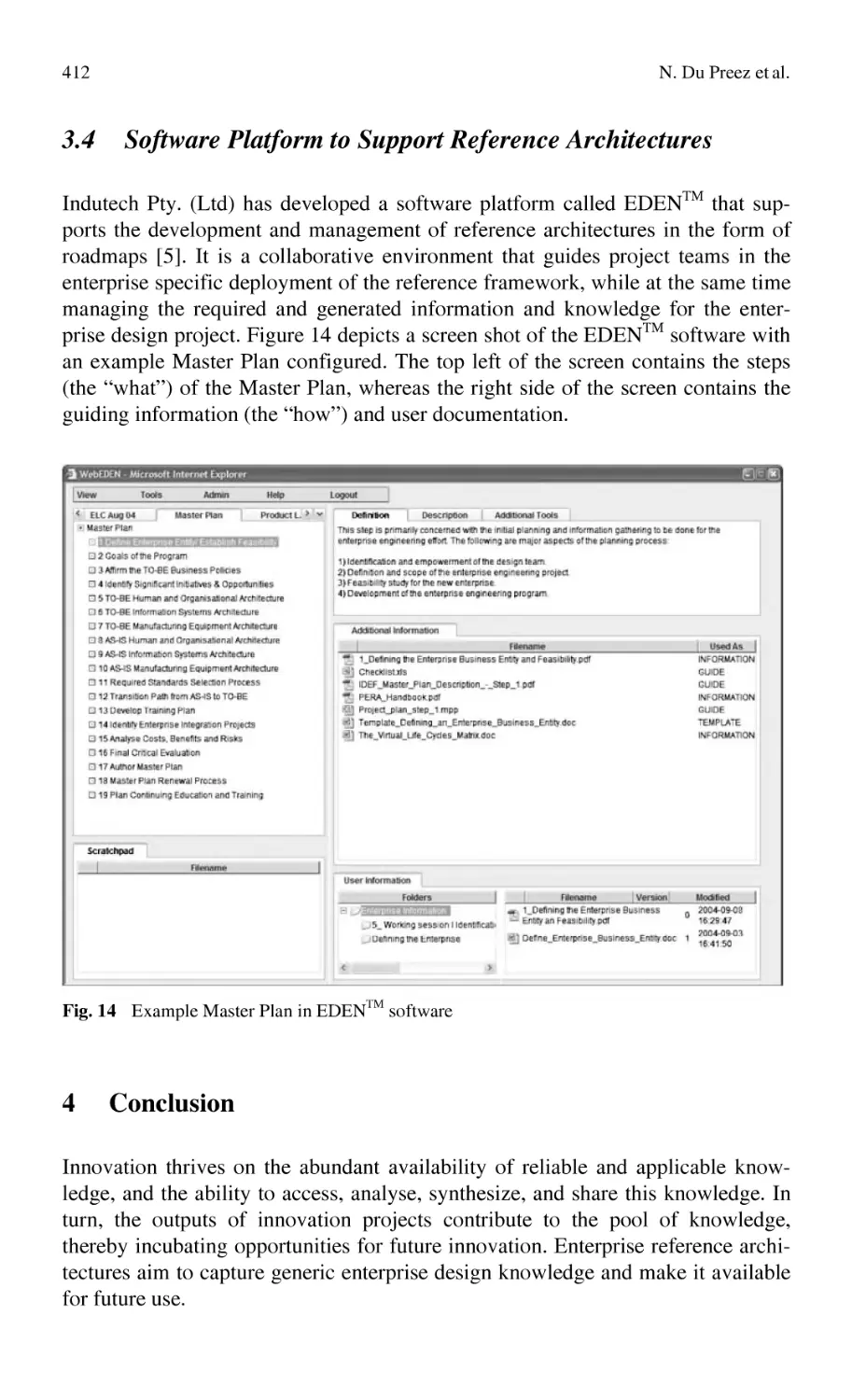
EDEN™ ............................................................................................... 127
D. Kotze, W. Uys, N. Du Preez
Contextual issue of knowledge integration
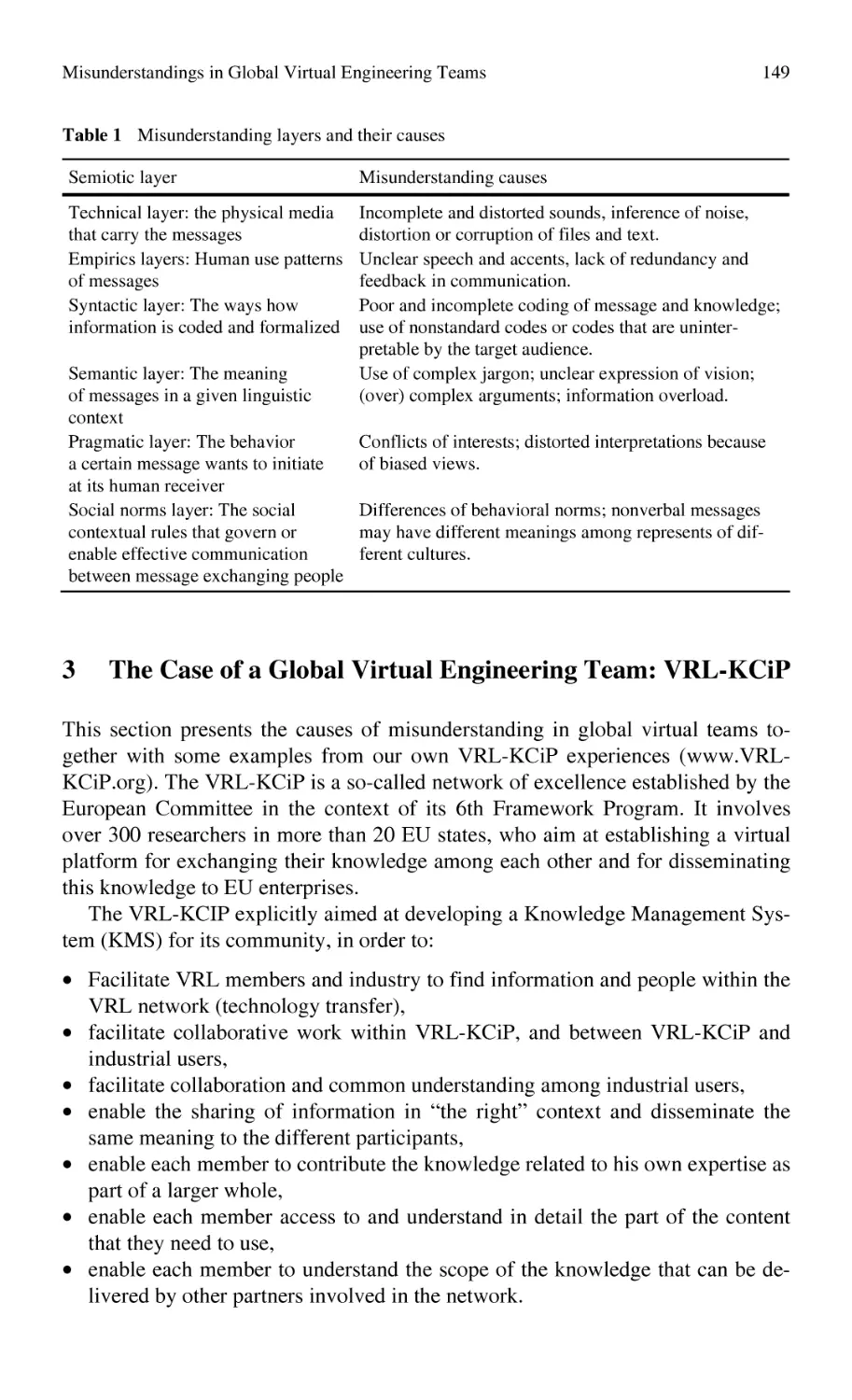
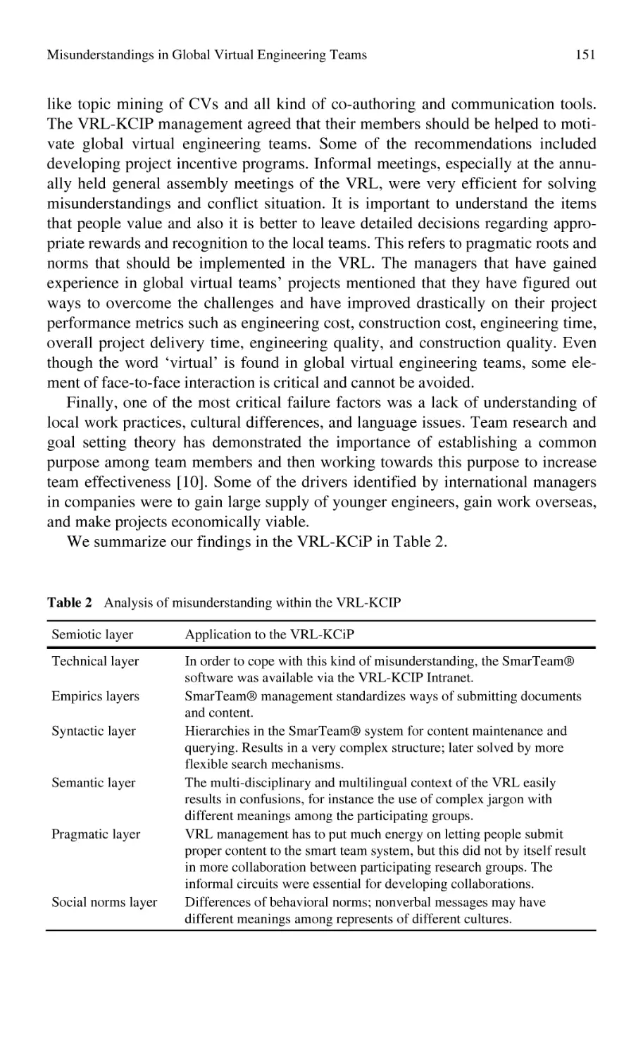
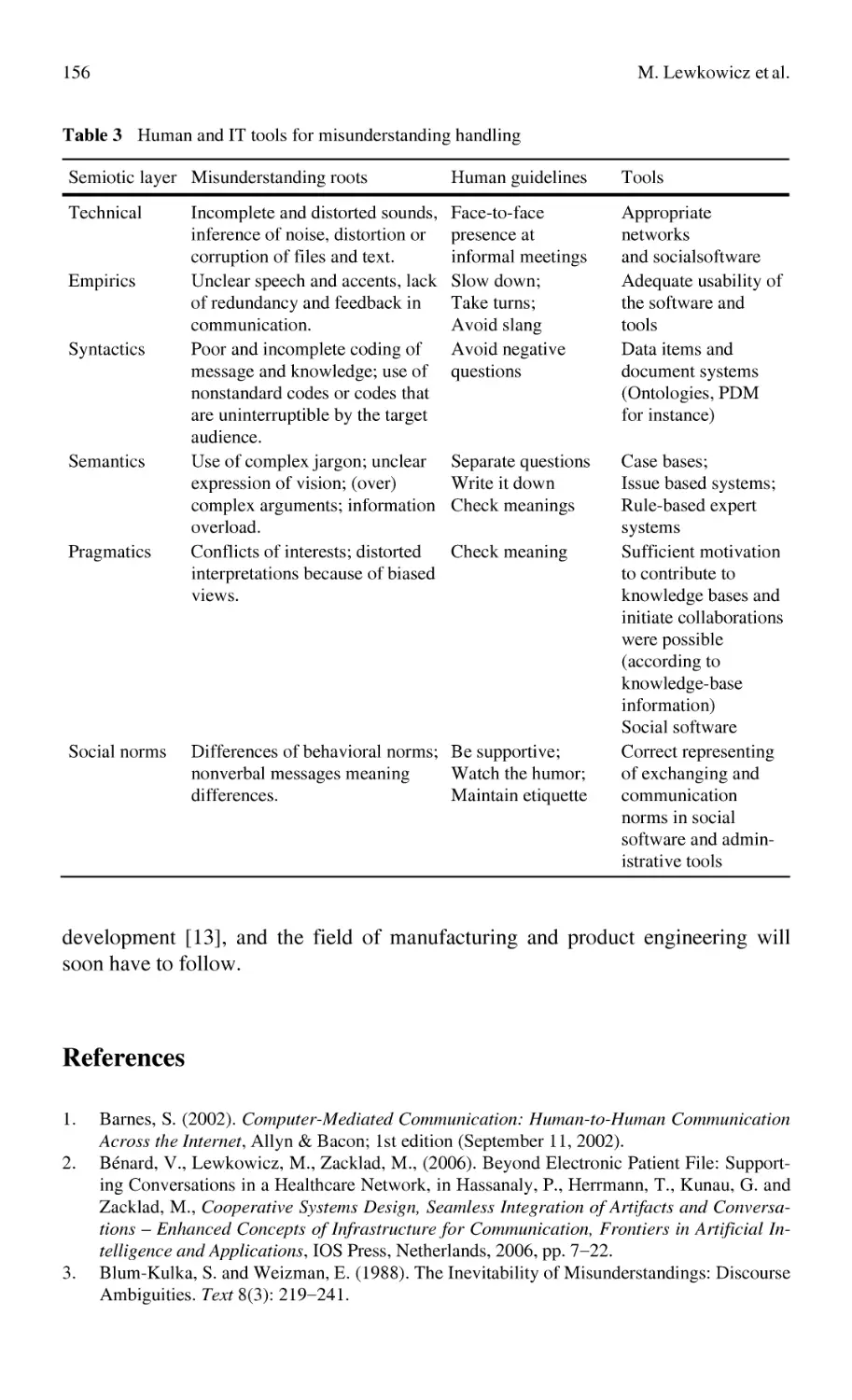
Misunderstandings in Global Virtual Engineering Teams:
Definitions, Causes, and Guidelines
for Knowledge Sharing and Interaction ............................................... 145
M. Lewkowicz, F. Wijnhoven, A. Draghici
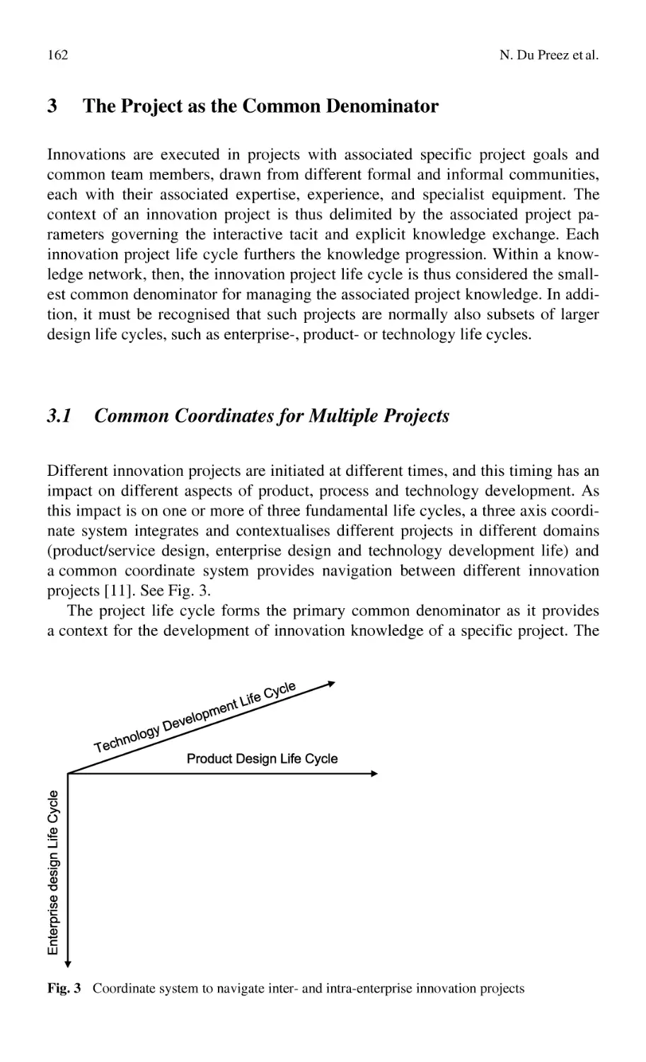
A Knowledge Network Approach Supporting the Value Chain............ 159
N. Du Preez, L. Louw, E. Lutters
Knowledge Mapping
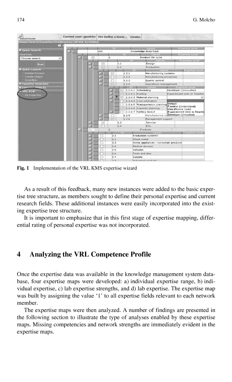
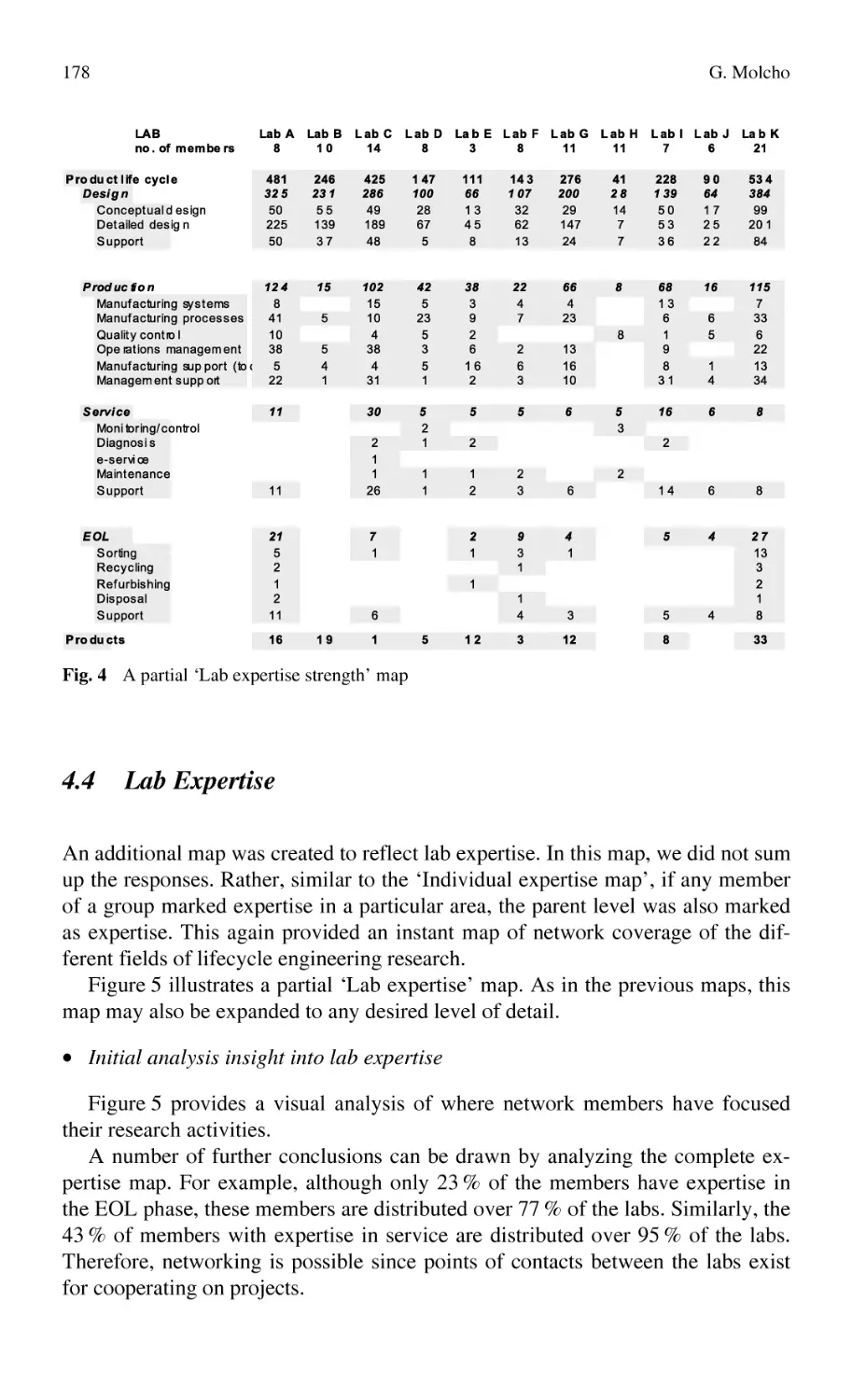
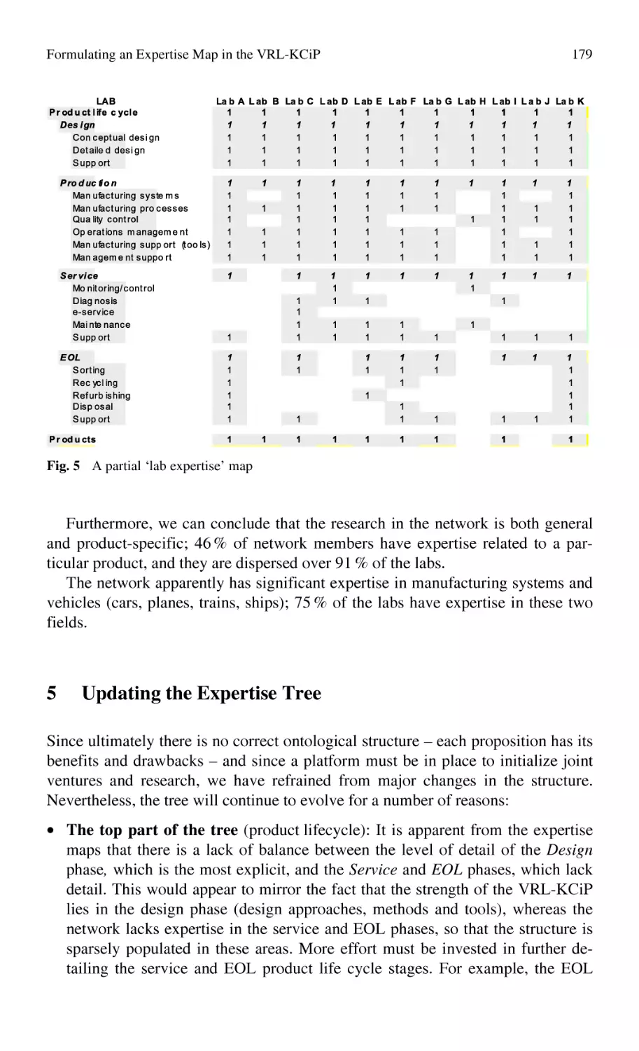
Formulating an Expertise Map in the VRL-KCiP ................................ 169
G. Molcho
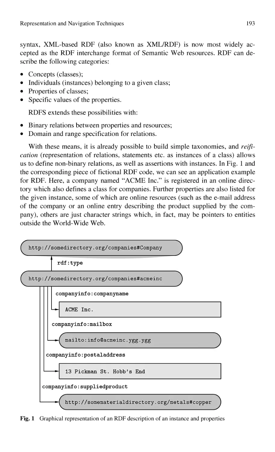
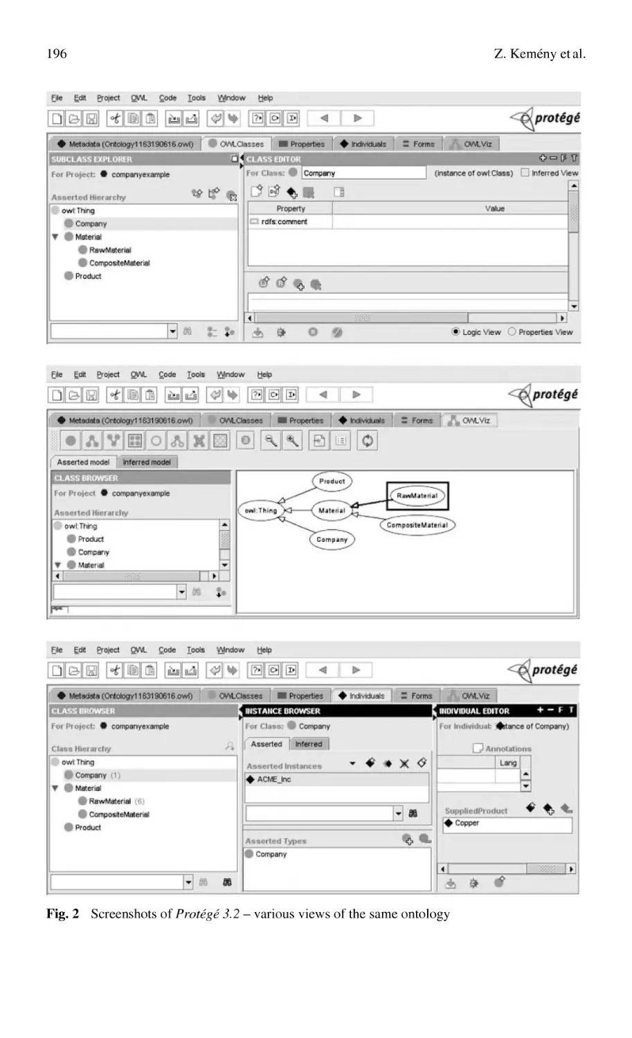
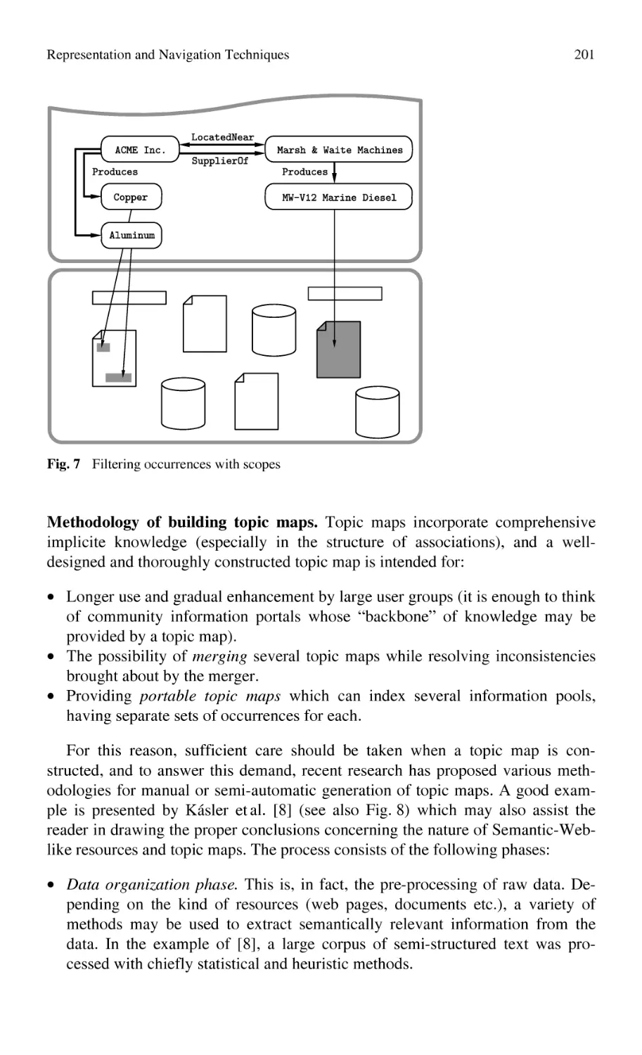
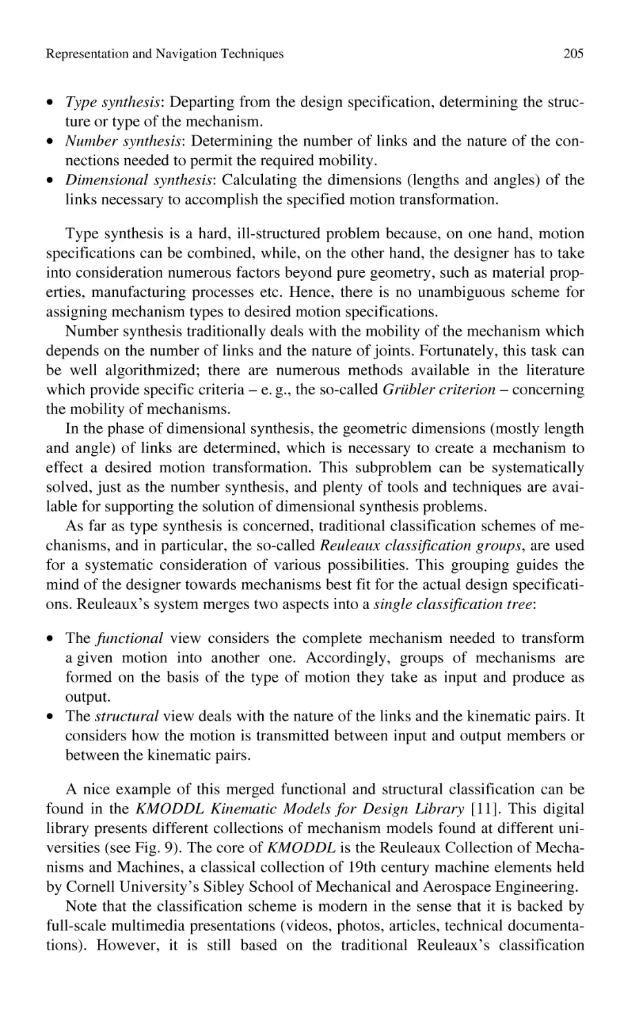
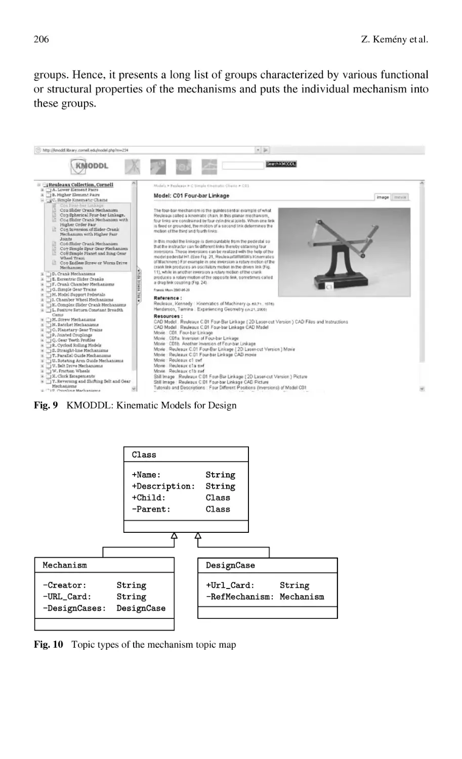
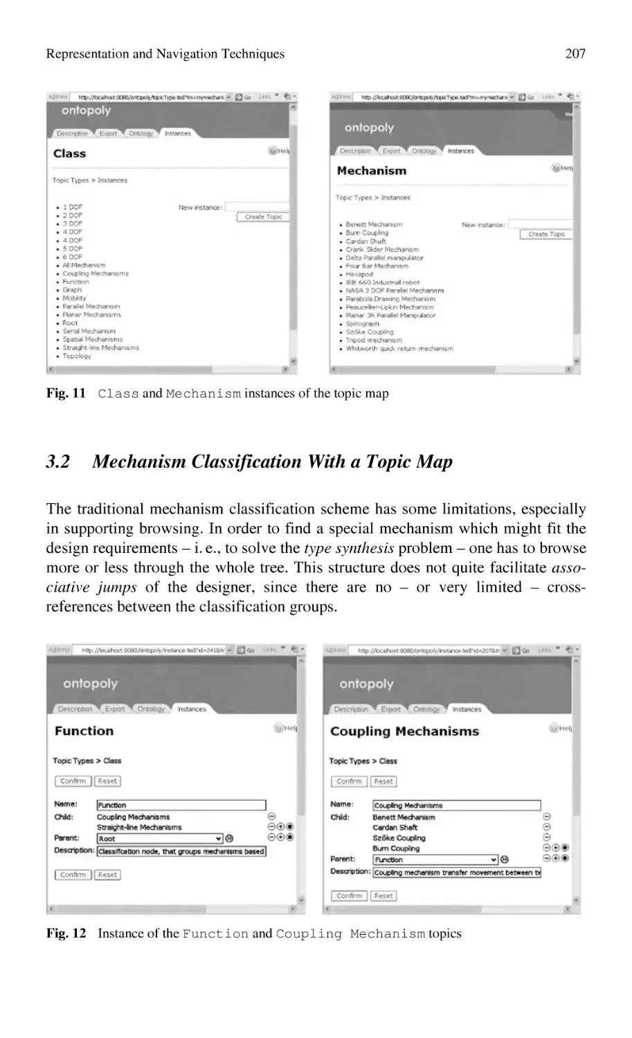
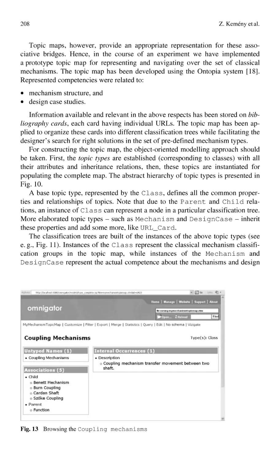
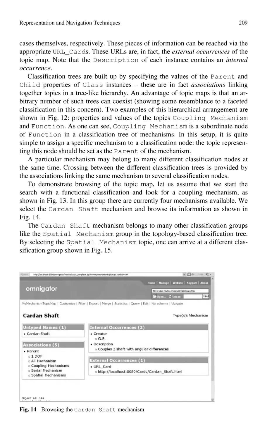
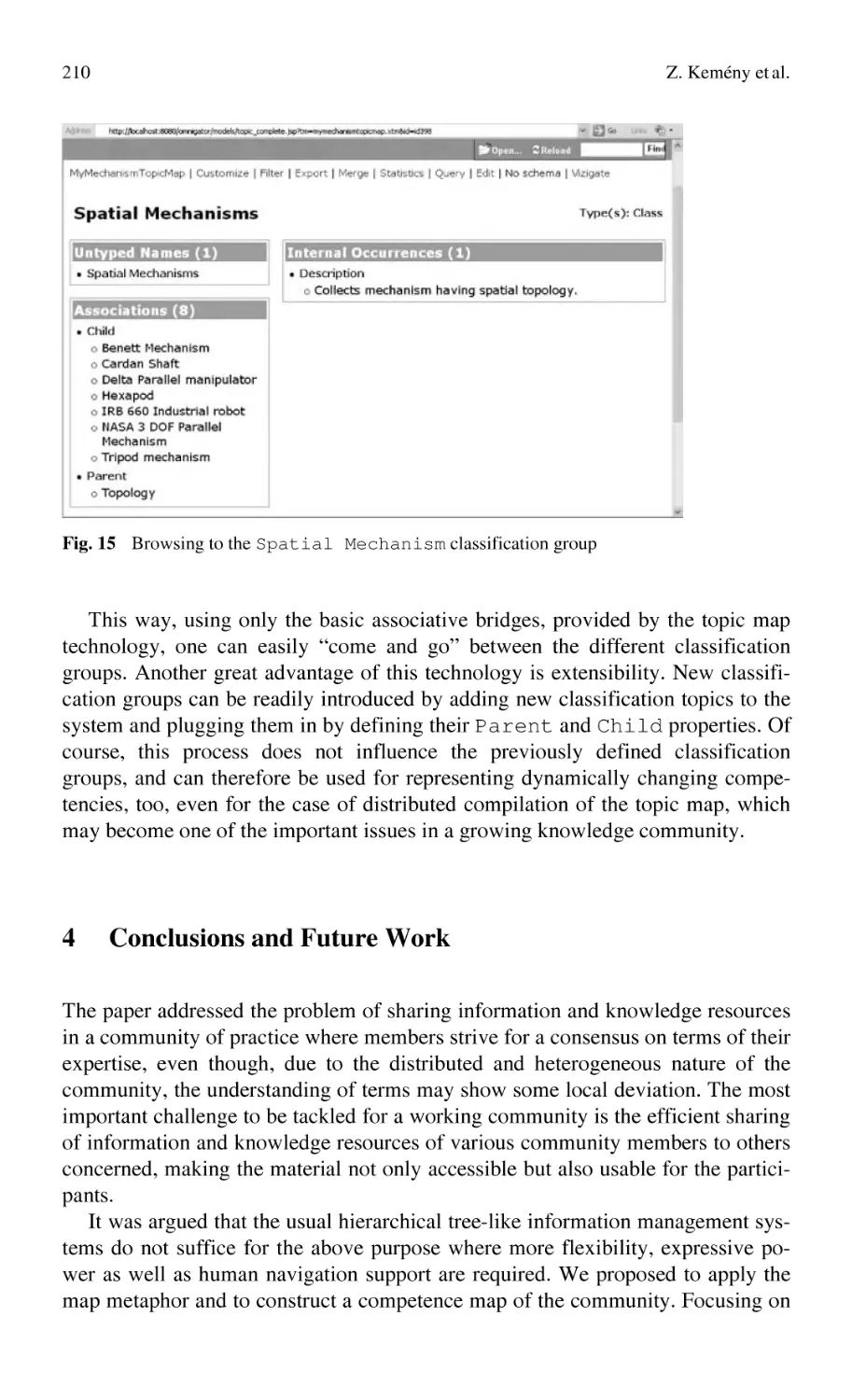
Representation and Navigation Techniques
for Semi-Structured Knowledge in Collaborating Communities ......... 185
Z. Kemény, G. Erdős, J. Váncza
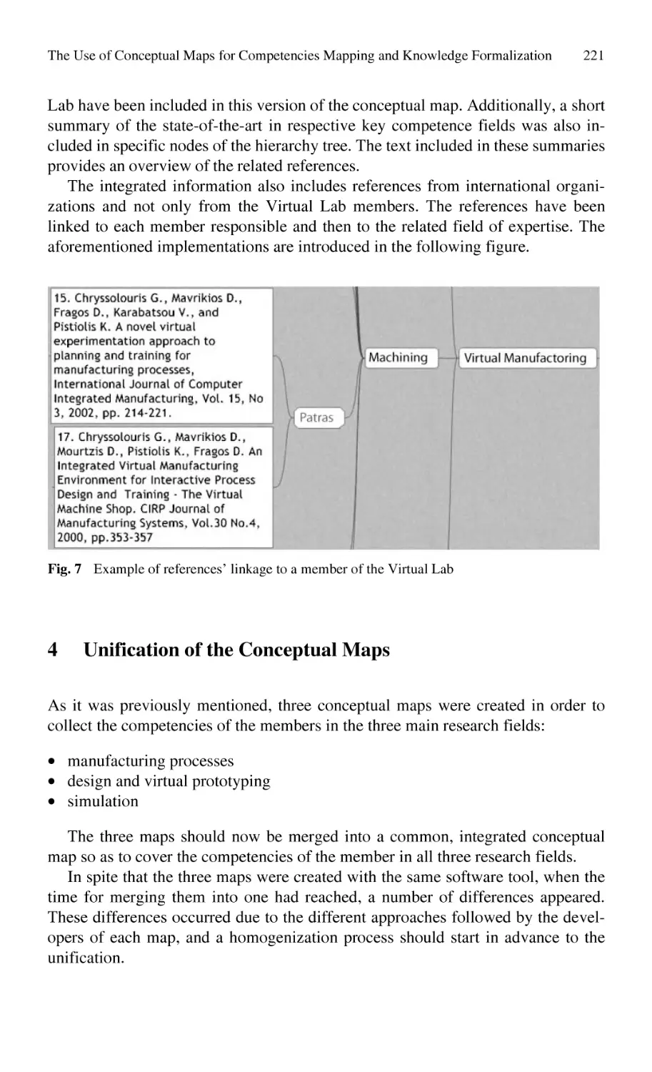
The Use of Conceptual Maps for Competencies Mapping
and Knowledge Formalization in a Virtual Lab ................................... 213
G. Chryssolouris, D. Mavrikios, S. Xeromerites, K. Georgoulias
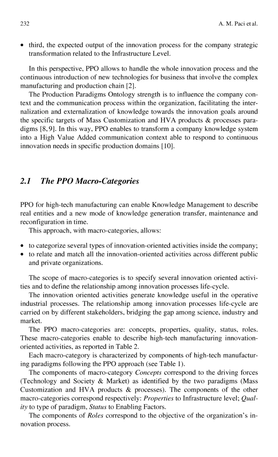
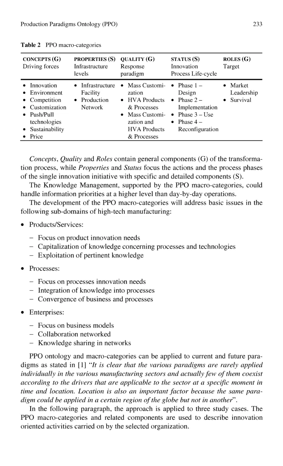
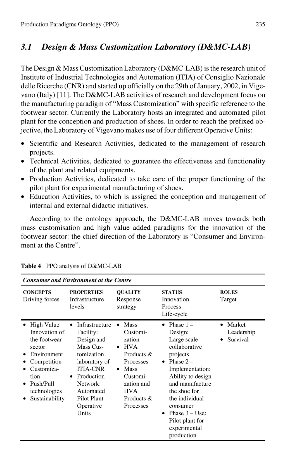
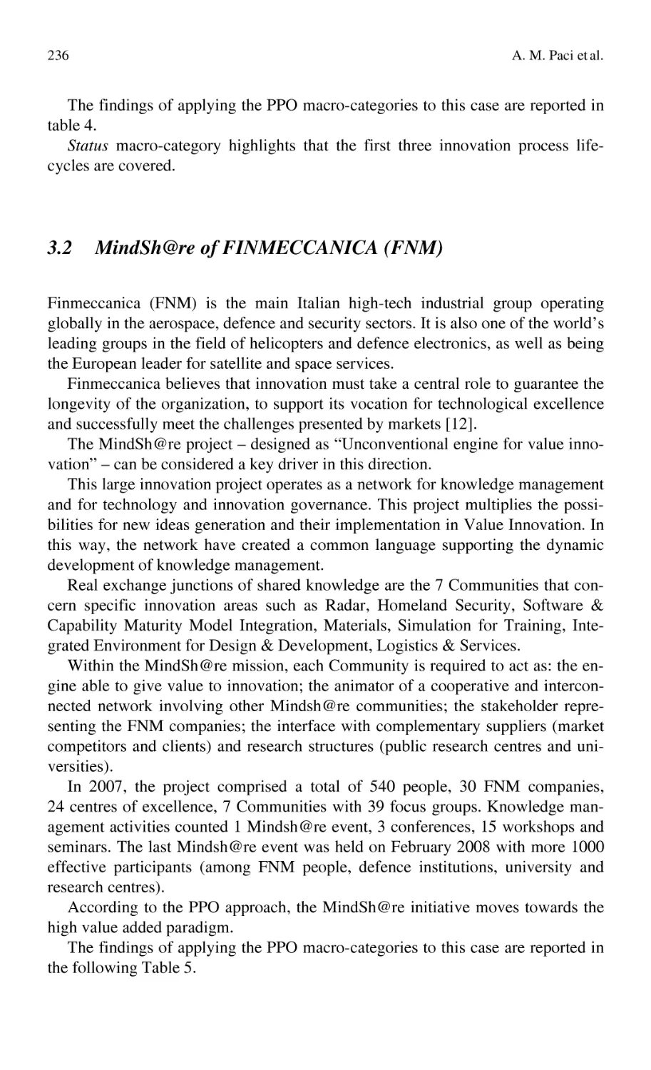
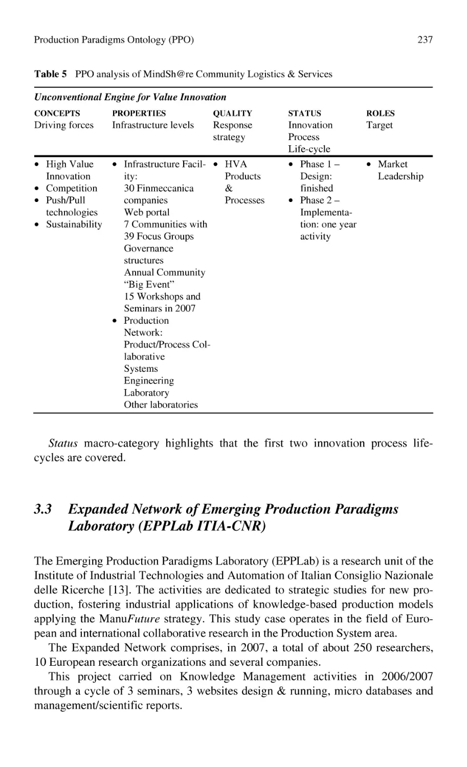
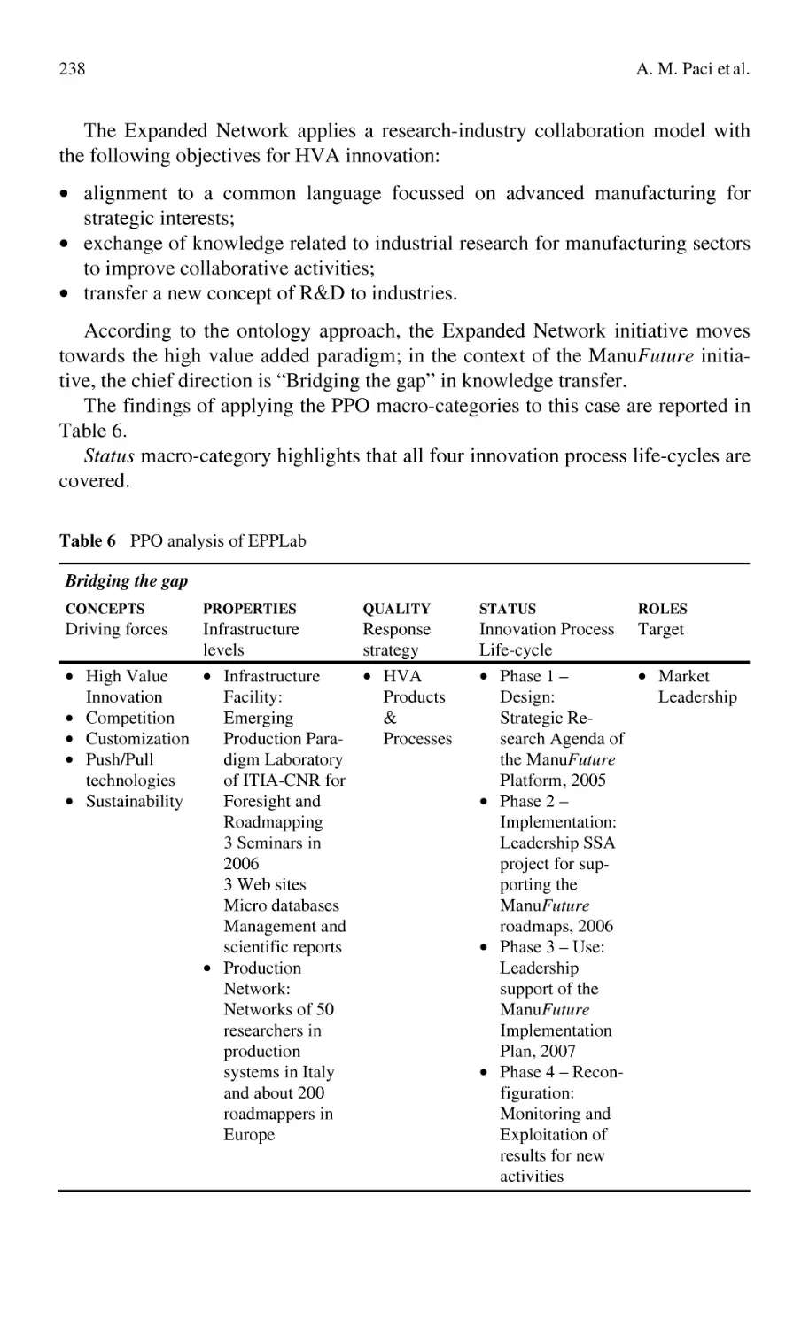
Production Paradigms Ontology (PPO):
a Response to the Need of Managing Knowledge
in High-Tech Manufacturing................................................................ 227
A. M. Paci, M. S. Chiacchio, C. Lalle
Part 2 KM Models, Methods and Tools
2.1
Design Product Oriented Models
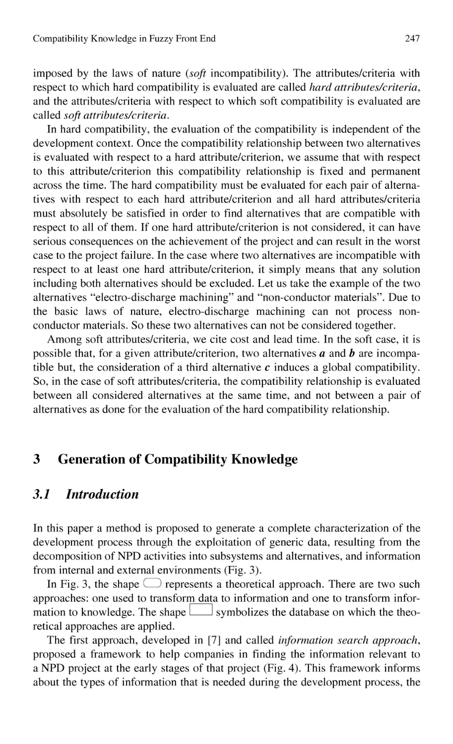
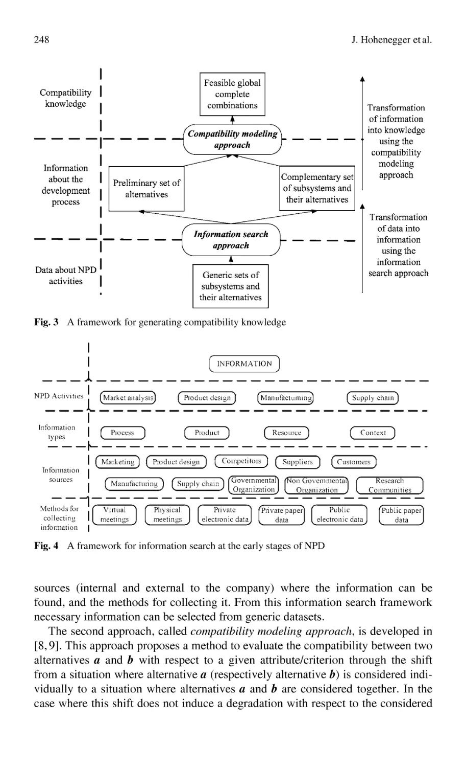
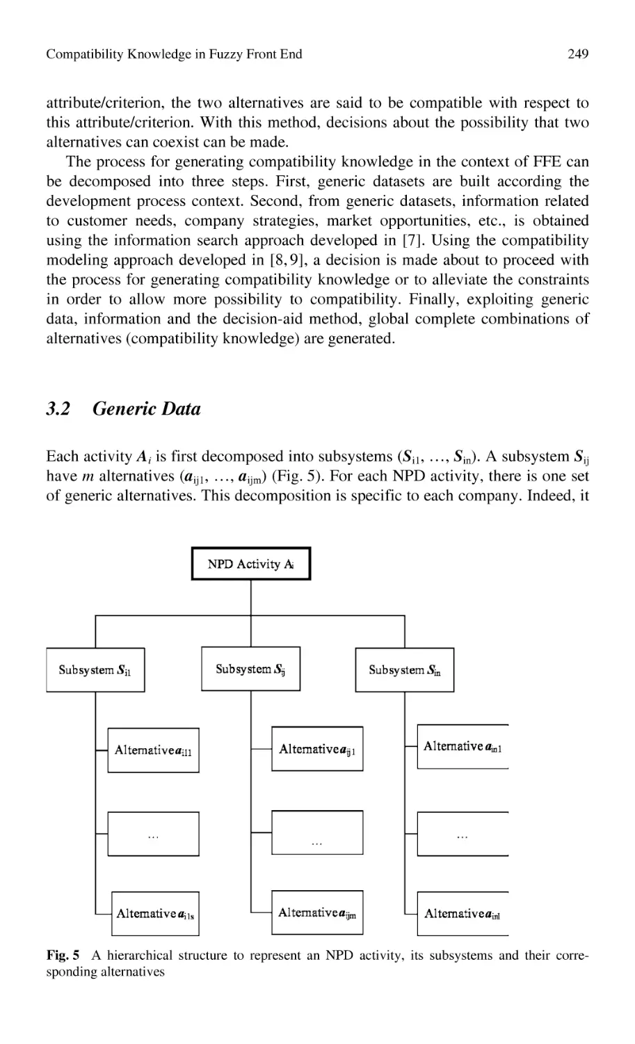
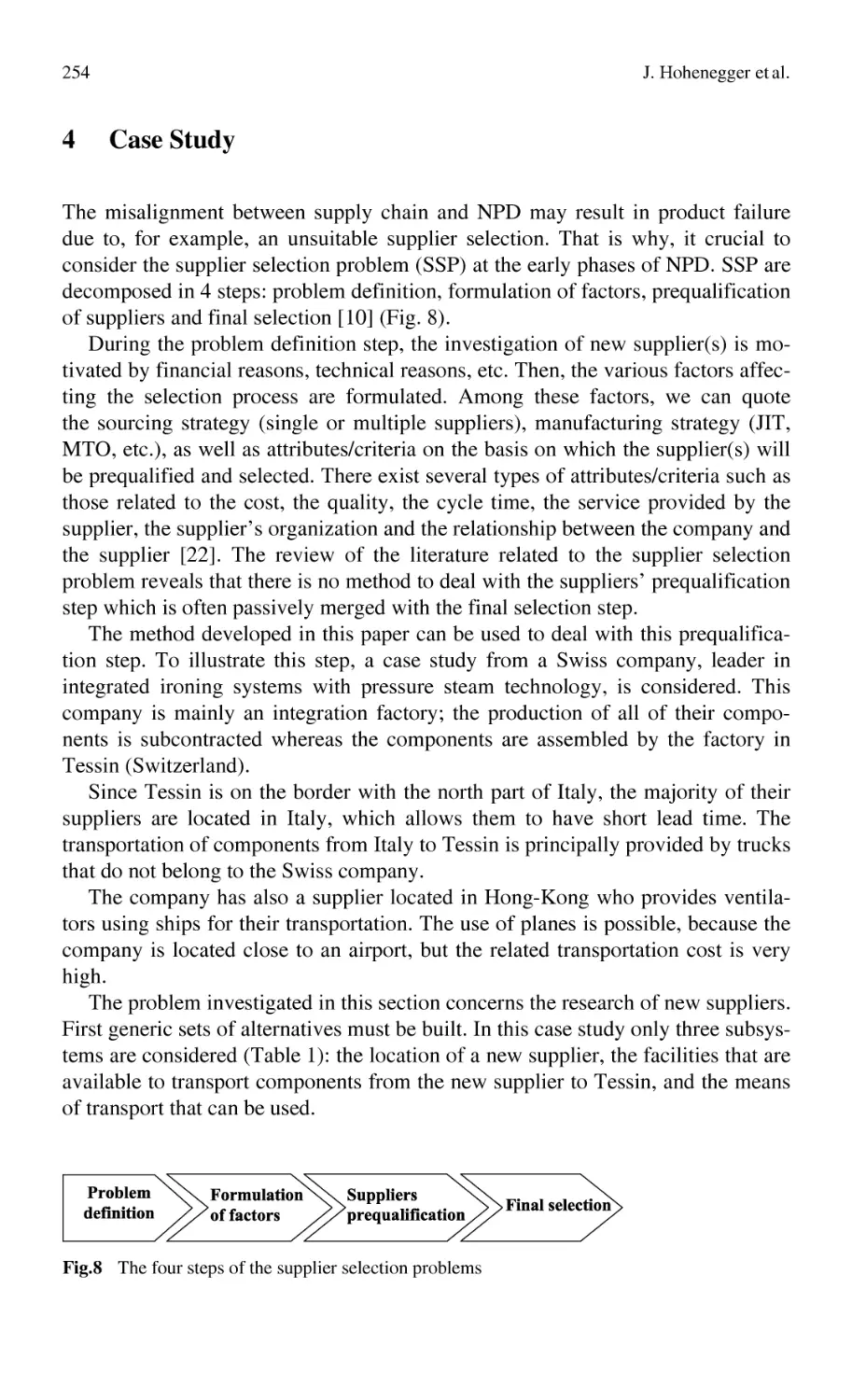
Compatibility Knowledge in Fuzzy Front End..................................... 243
J. Hohenegger, A. Bufardi, P. Xirouchakis
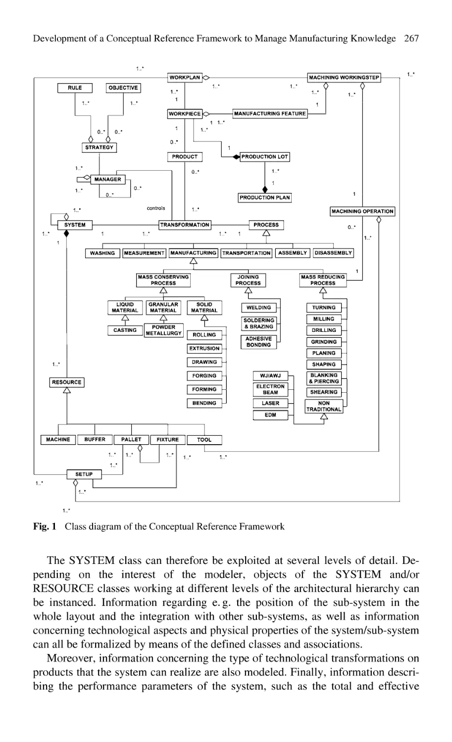
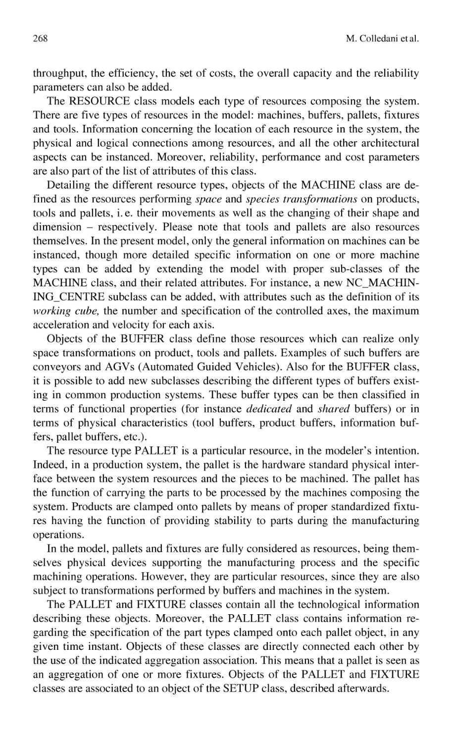
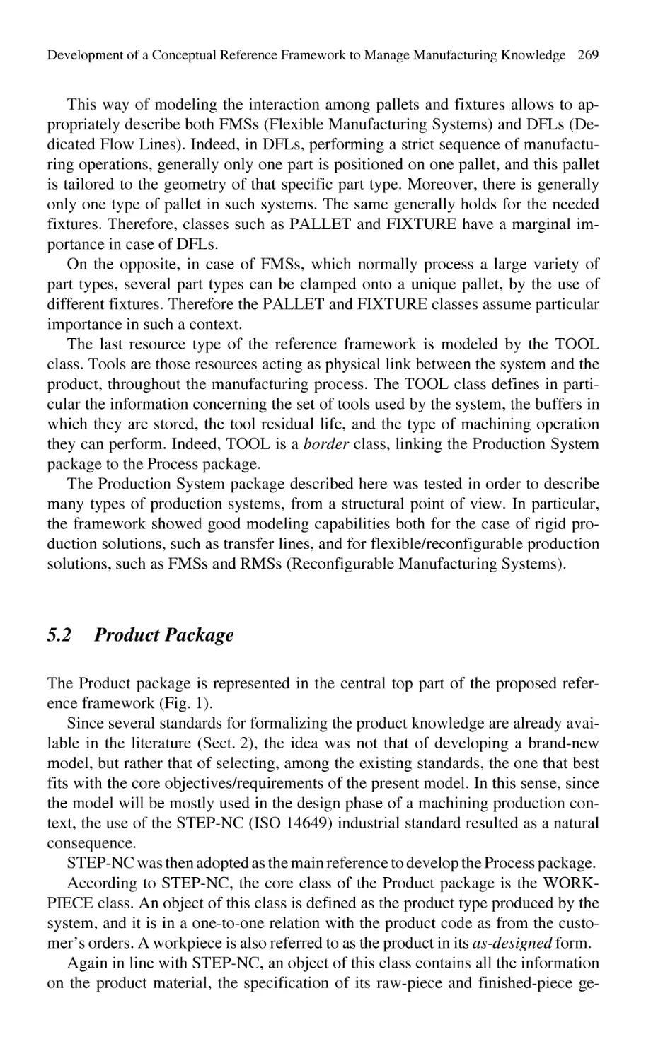
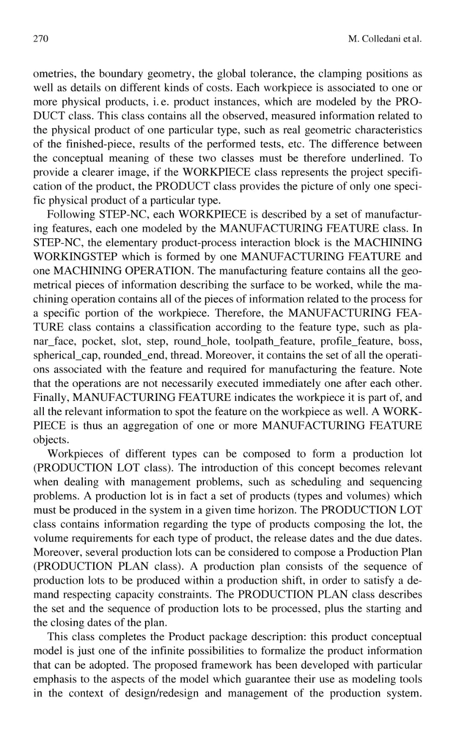
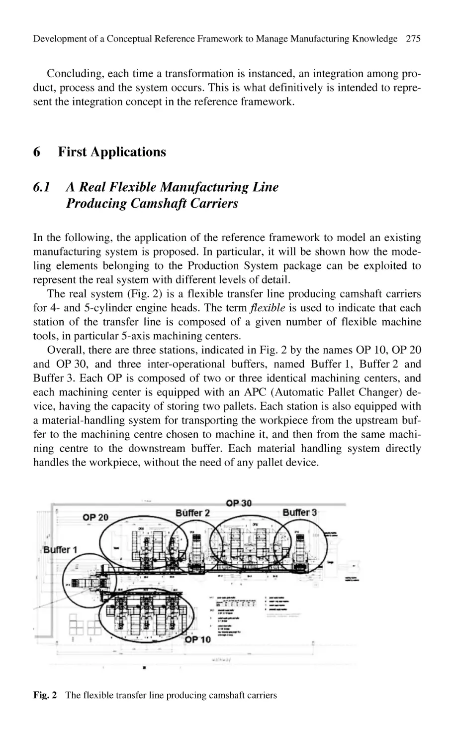
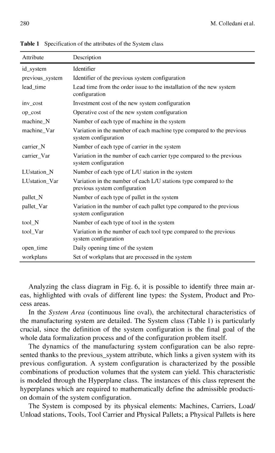
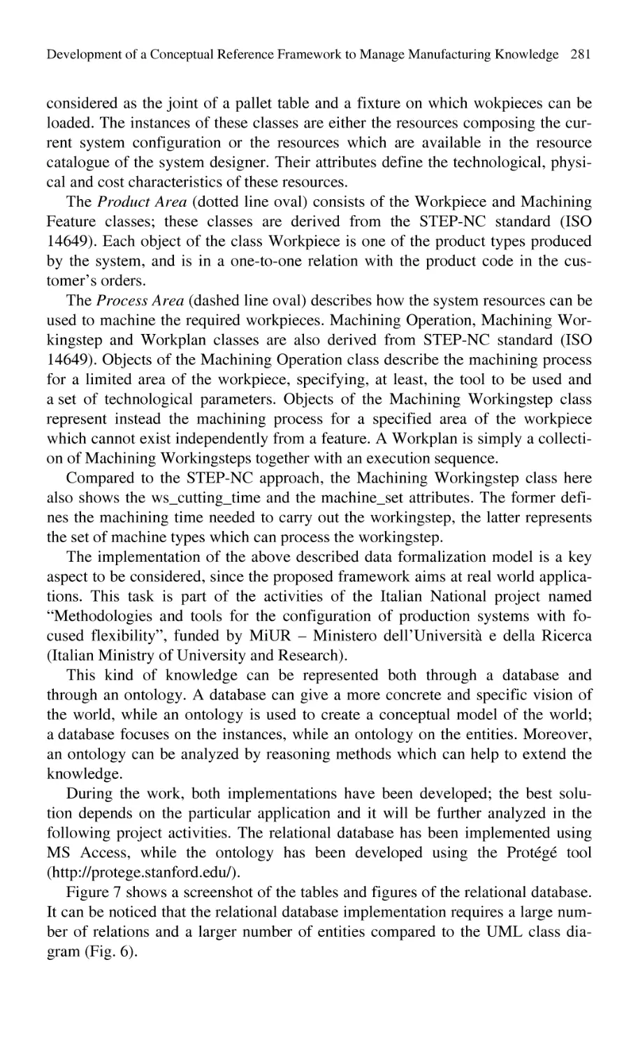
Development of a Conceptual Reference Framework to Manage
Manufacturing Knowledge Related to Products, Processes
and Production Systems ....................................................................... 259
M. Colledani, W. Terkaj, T. Tolio, M. Tomasella
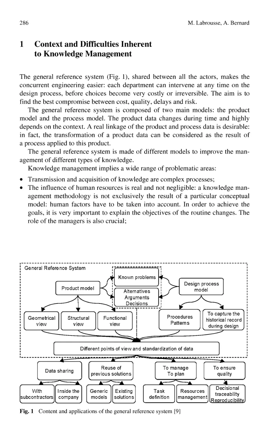
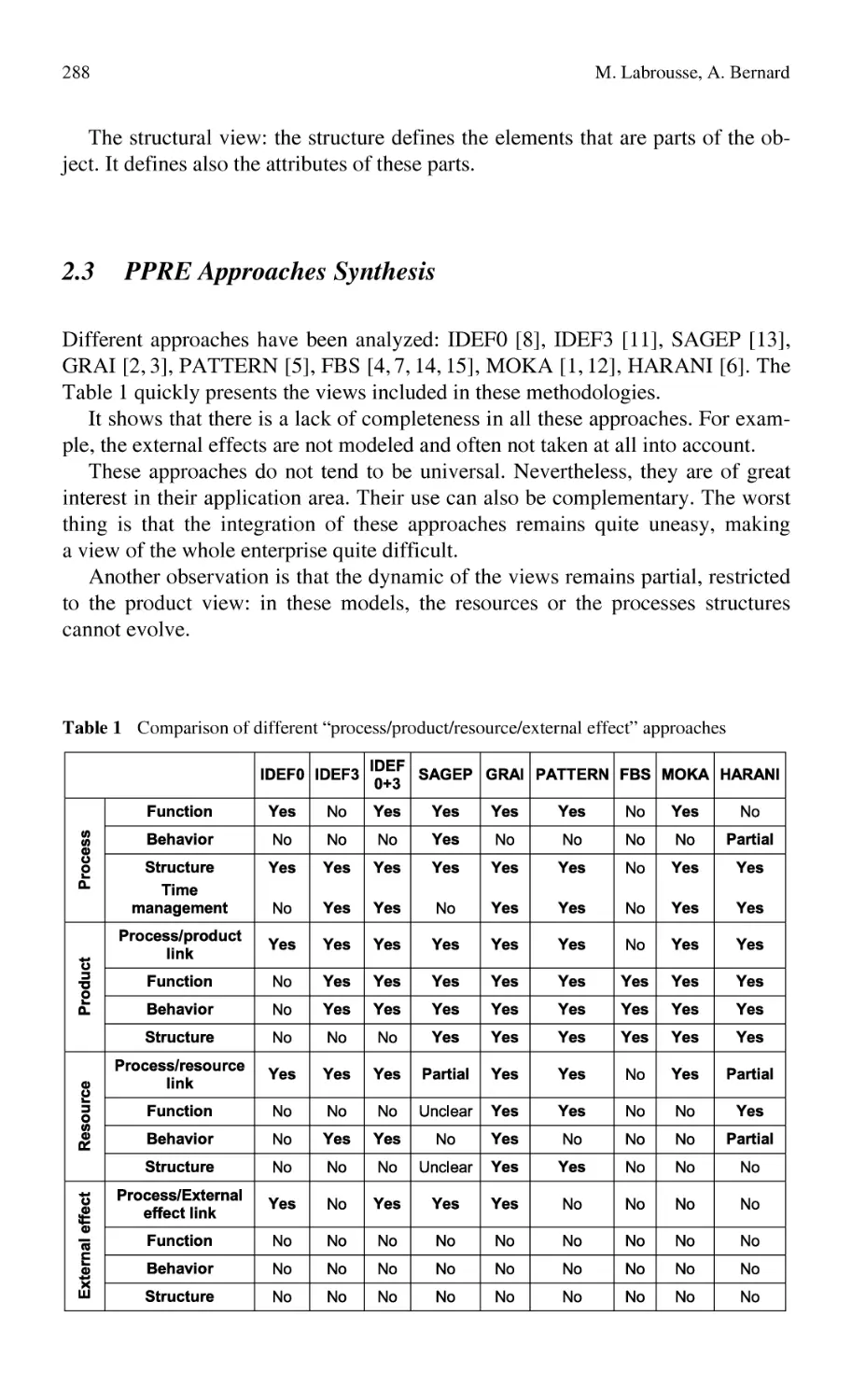
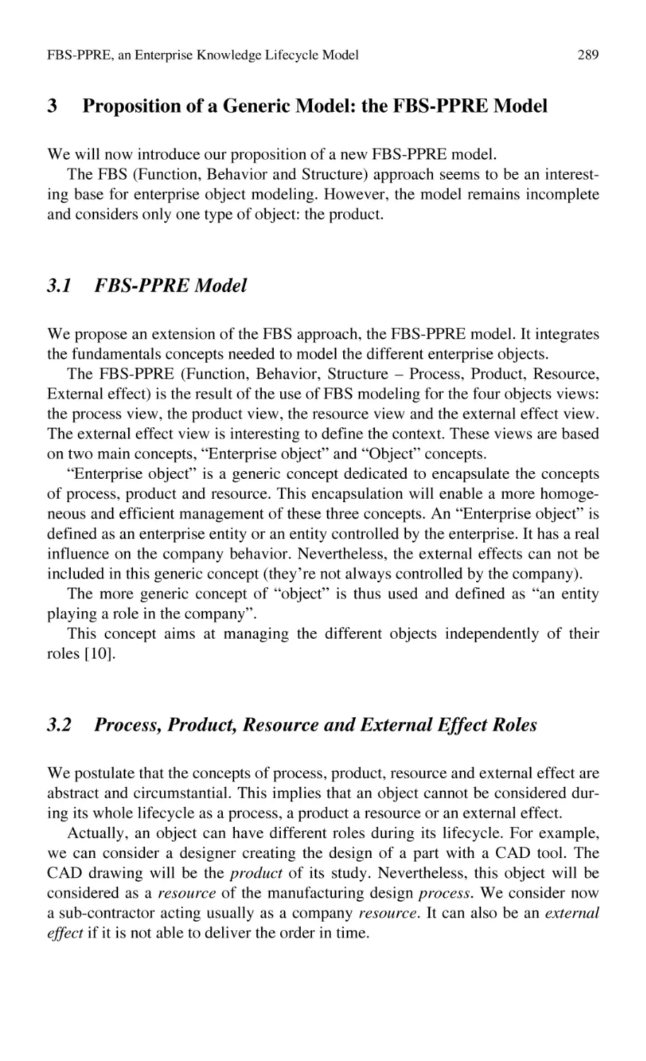
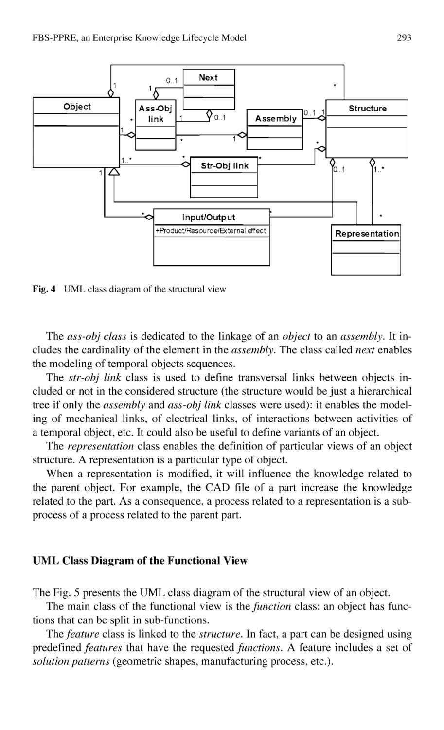
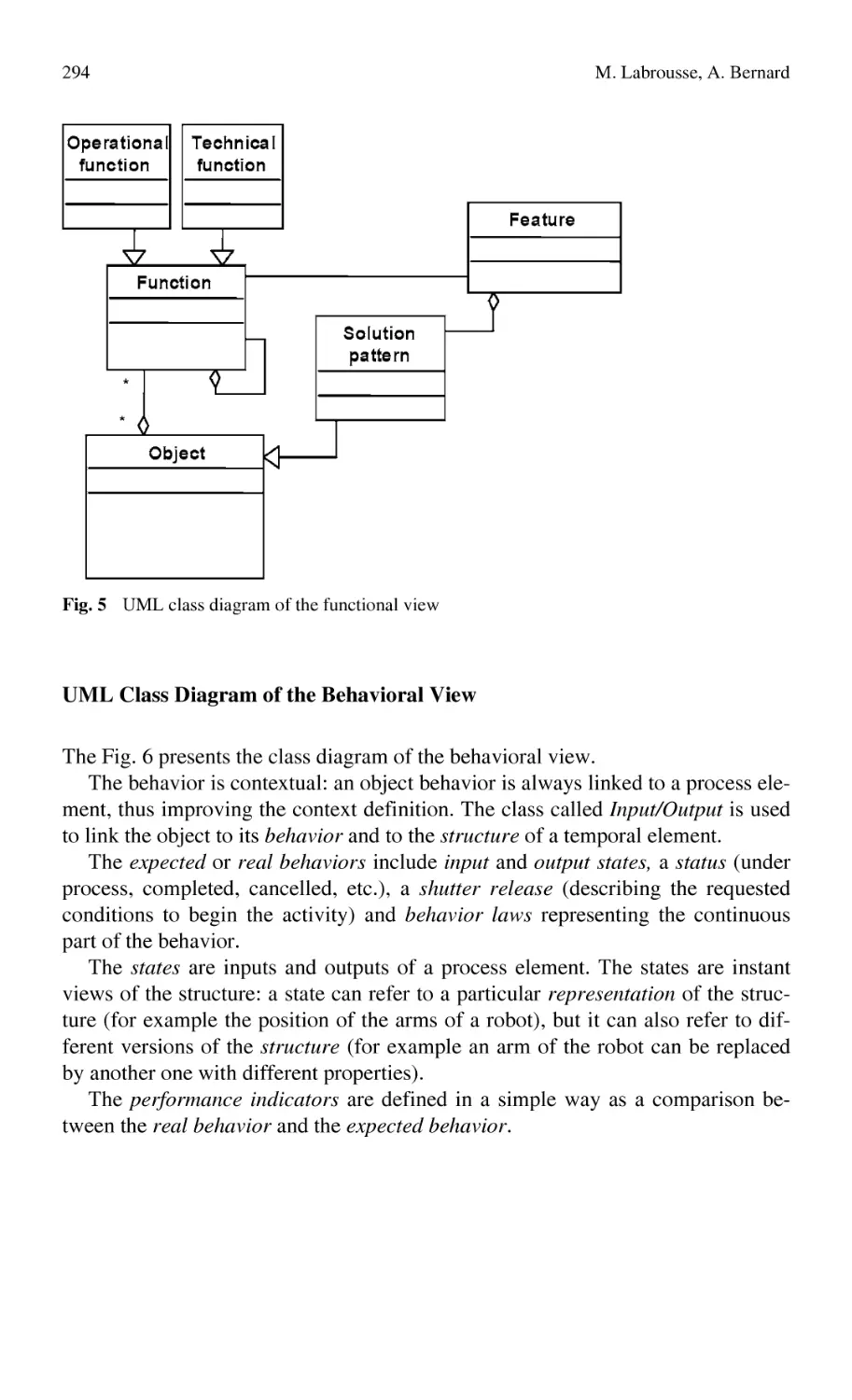
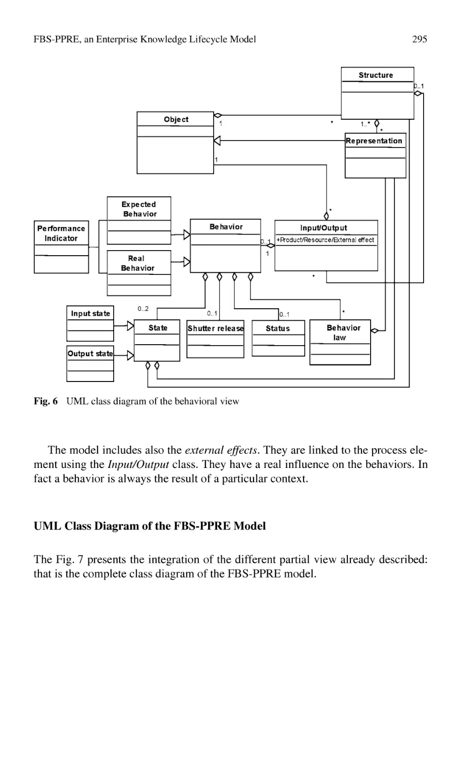
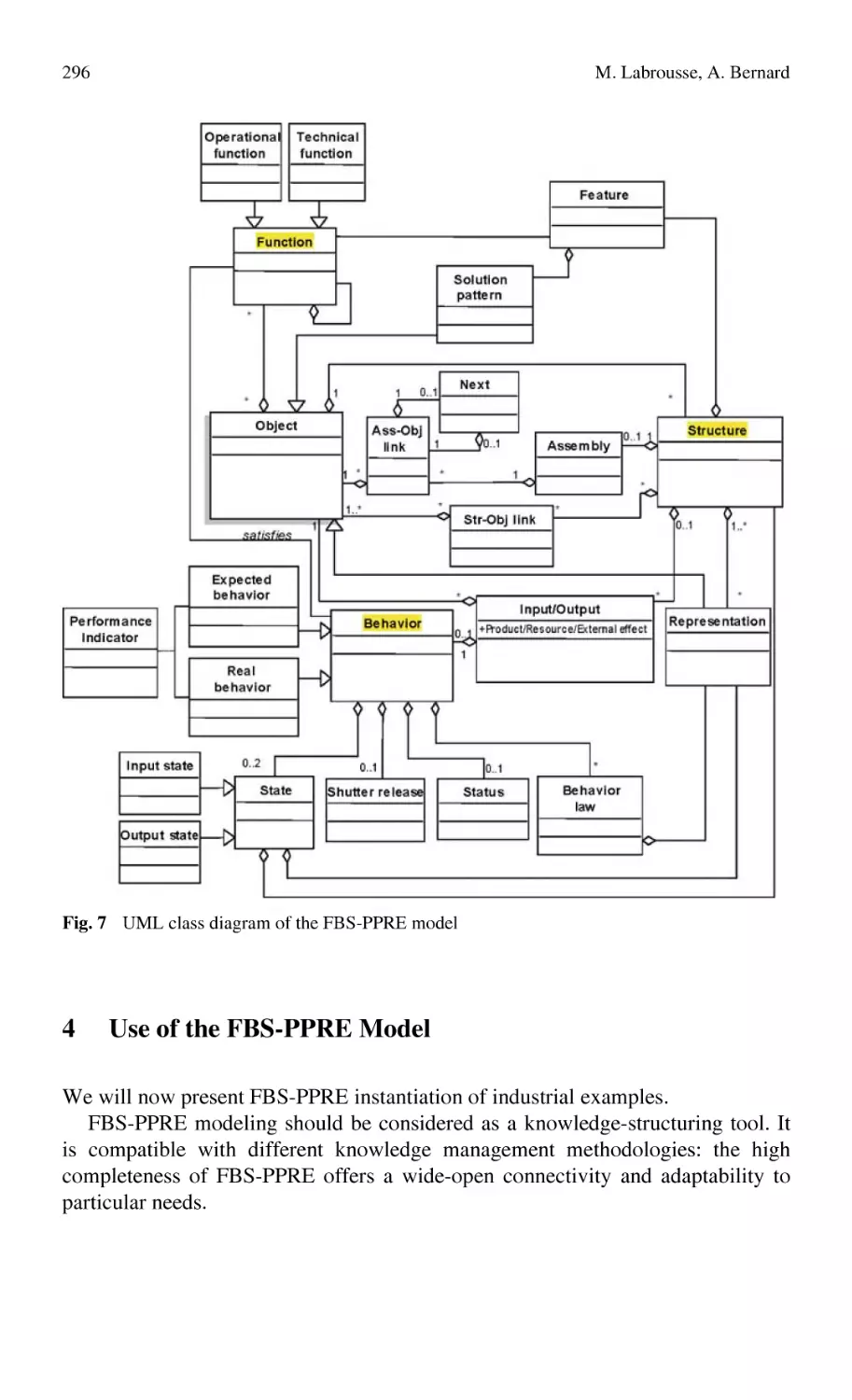
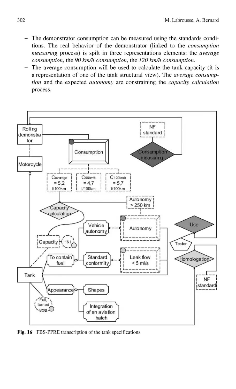
FBS-PPRE, an Enterprise Knowledge Lifecycle Model ...................... 285
M. Labrousse, A. Bernard
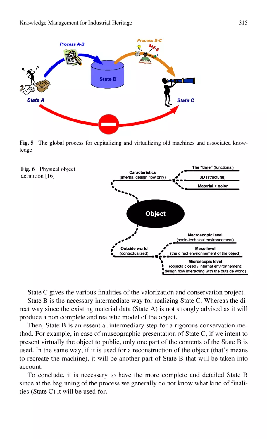
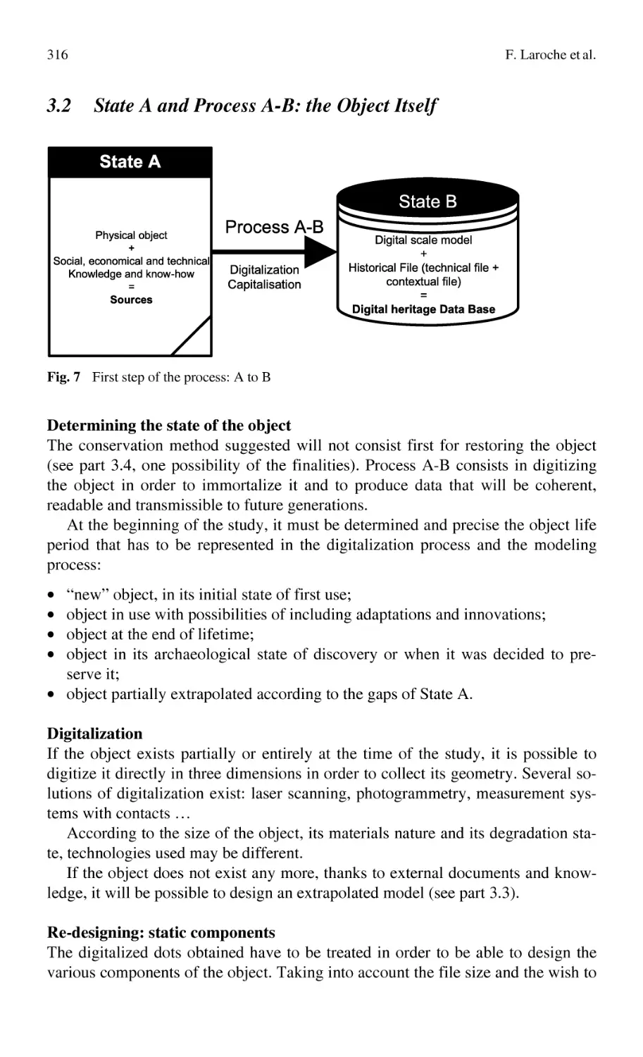
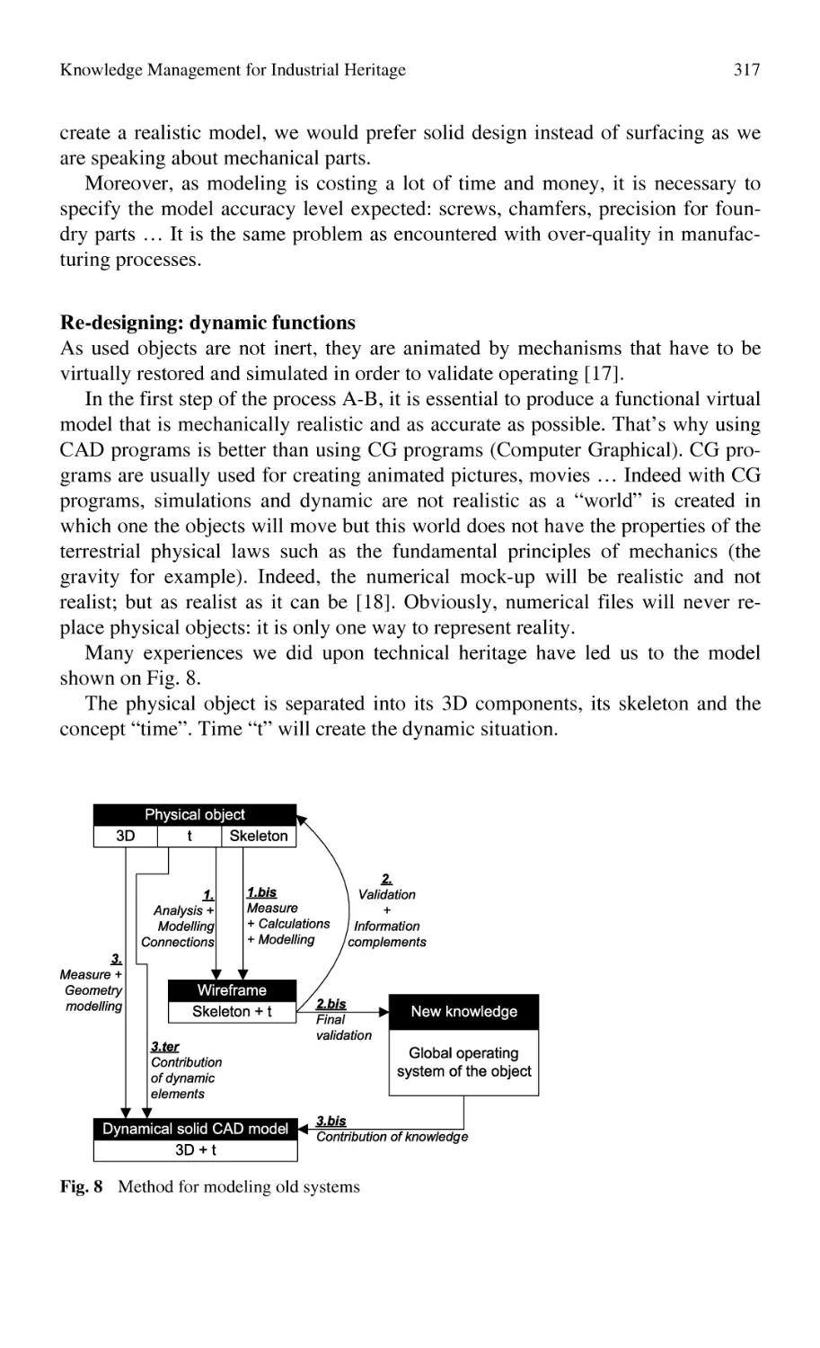
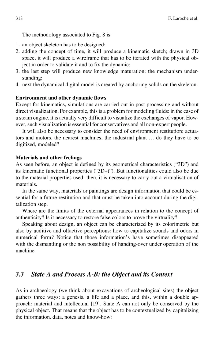
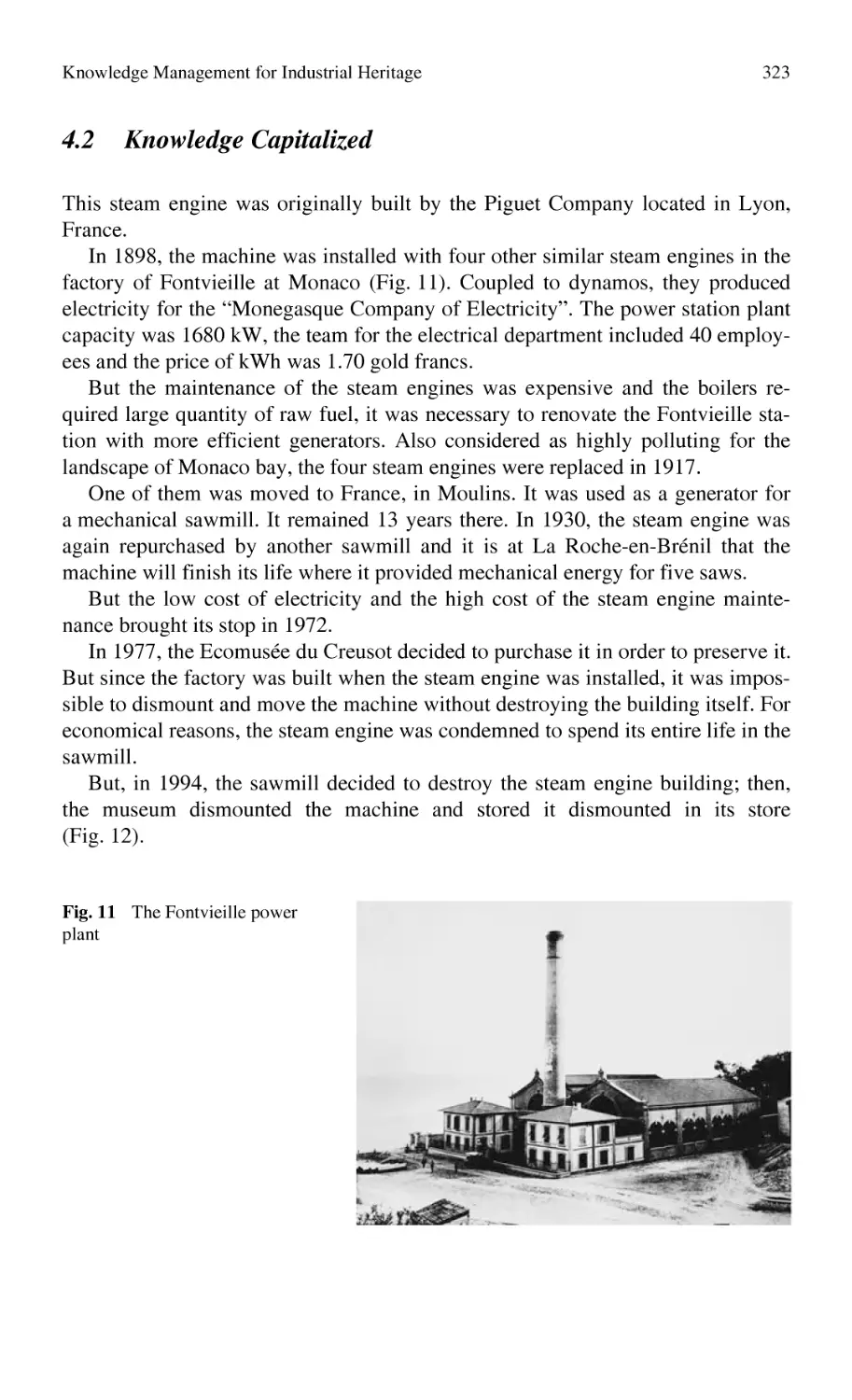
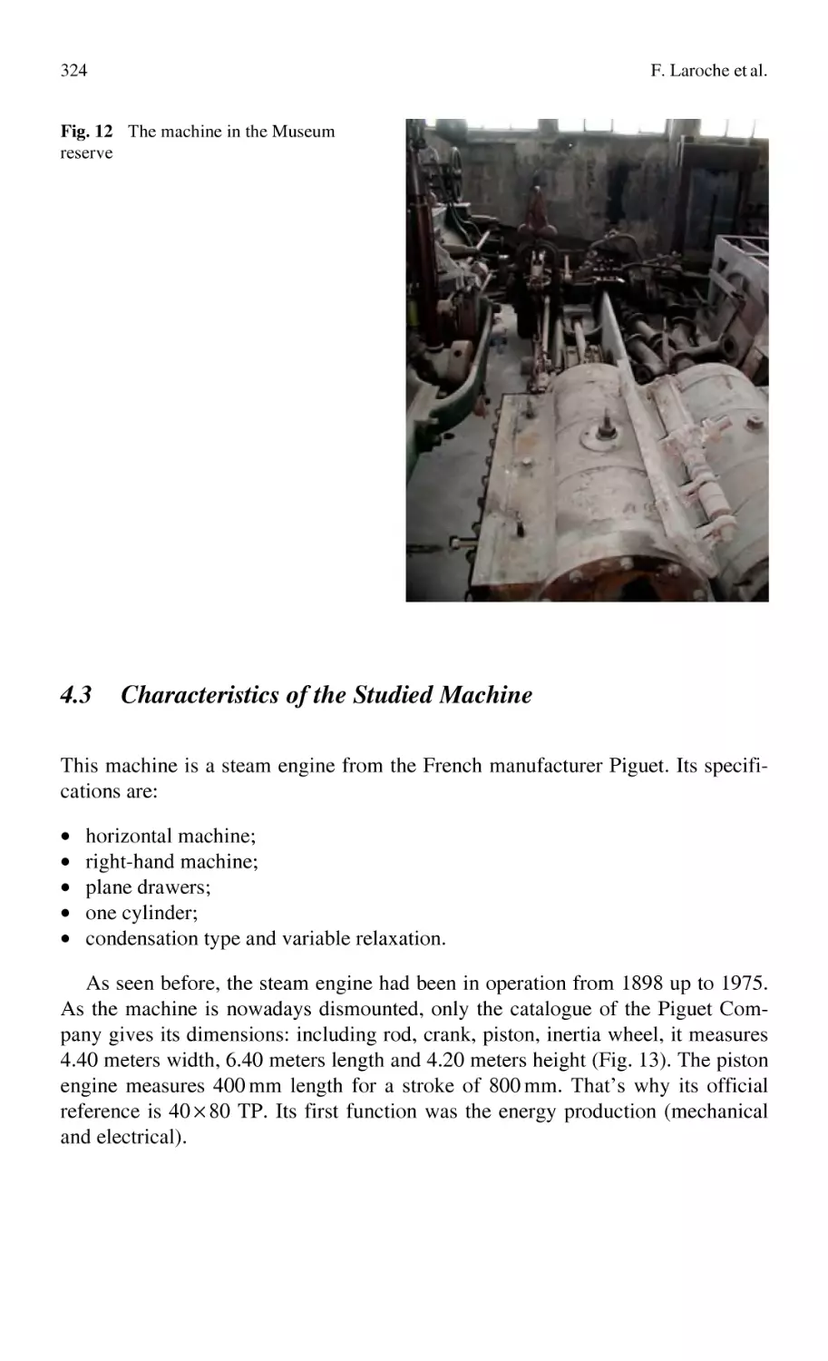
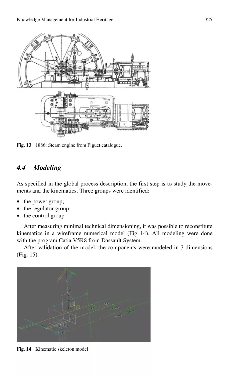
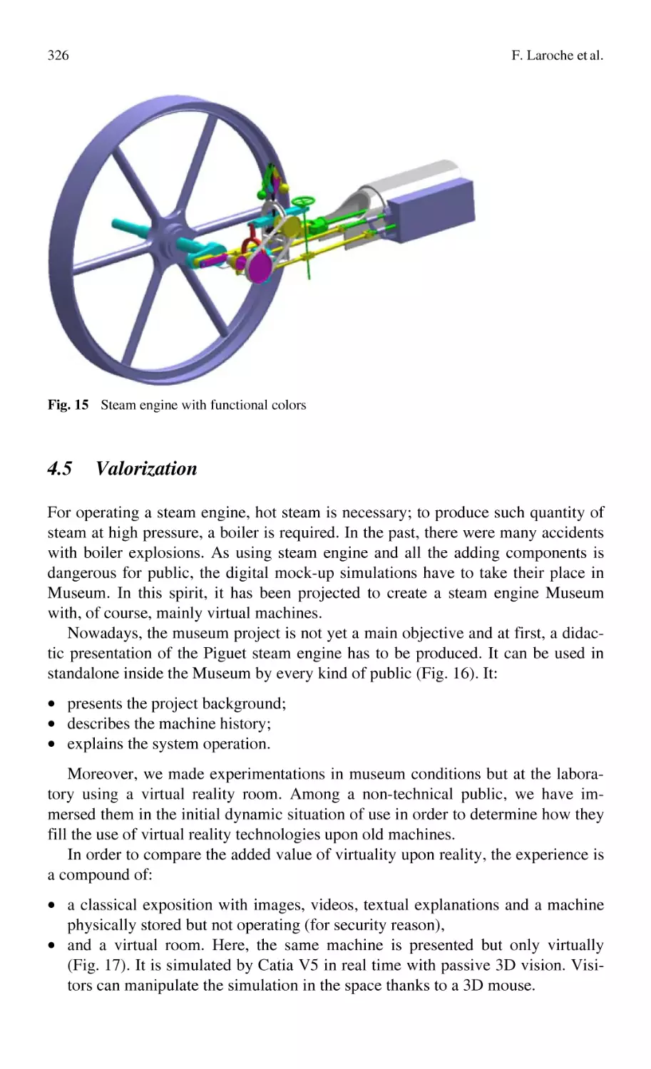
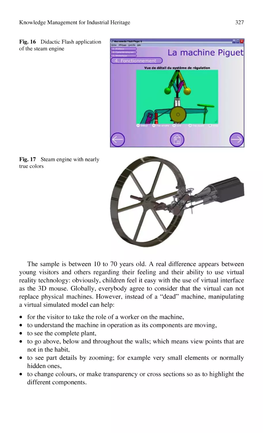
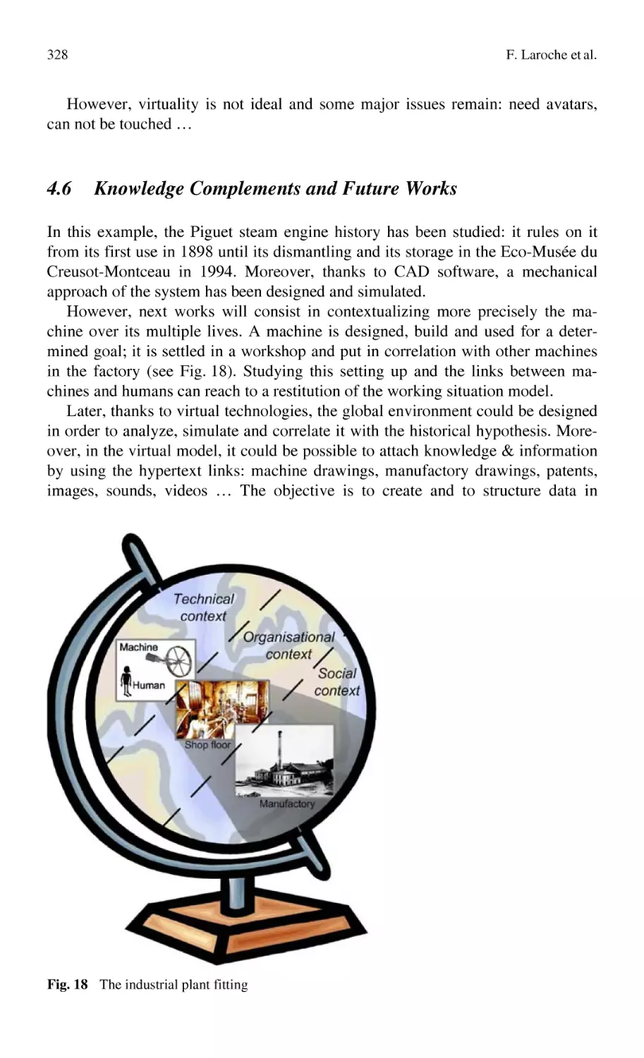
Knowledge Management for Industrial Heritage................................... 307
F. Laroche, A. Bernard, M. Cotte
2.2
Design Process Oriented Models
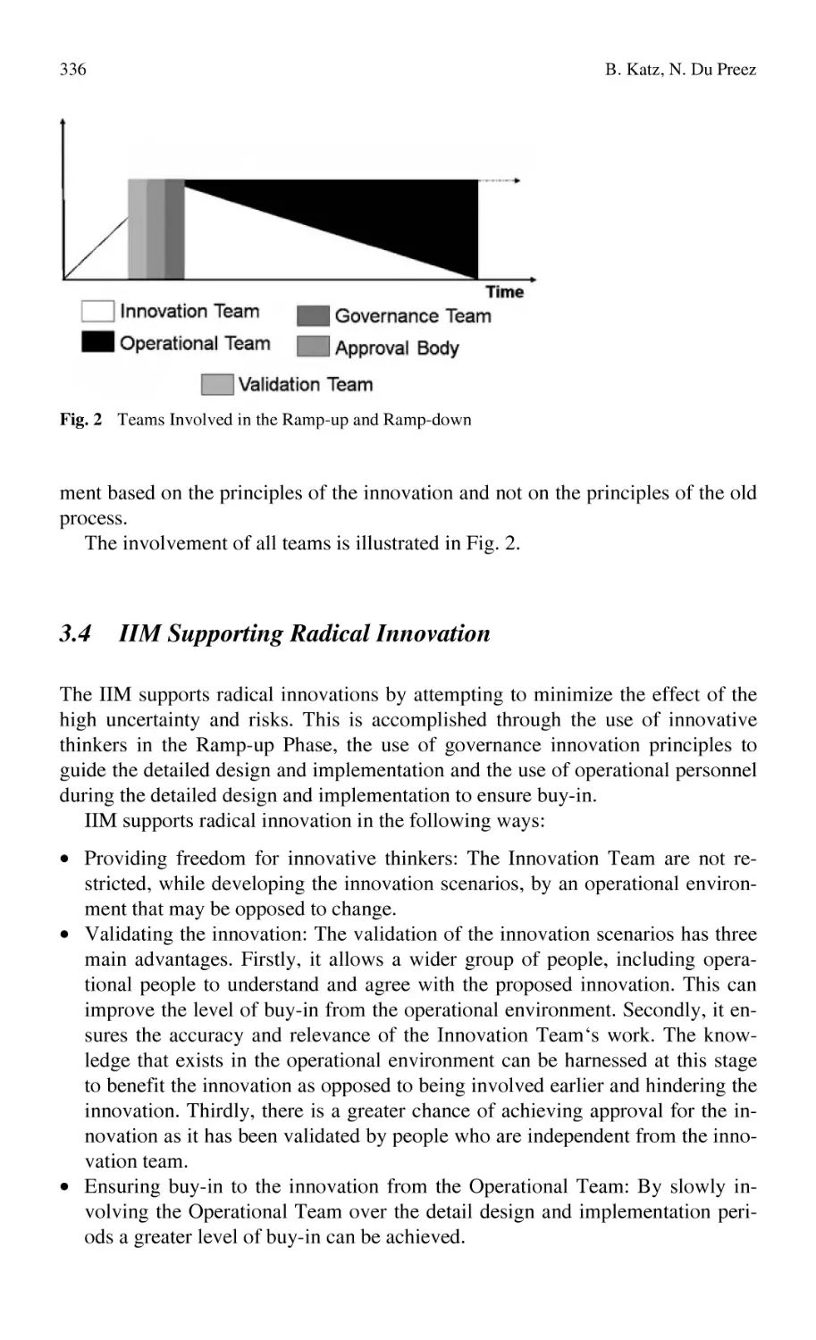
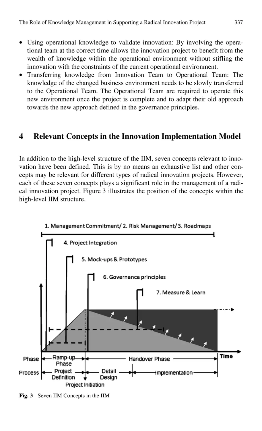
The Role of Knowledge Management
in Supporting a Radical Innovation Project.......................................... 331
B. Katz, N. Du Preez
Content
ix
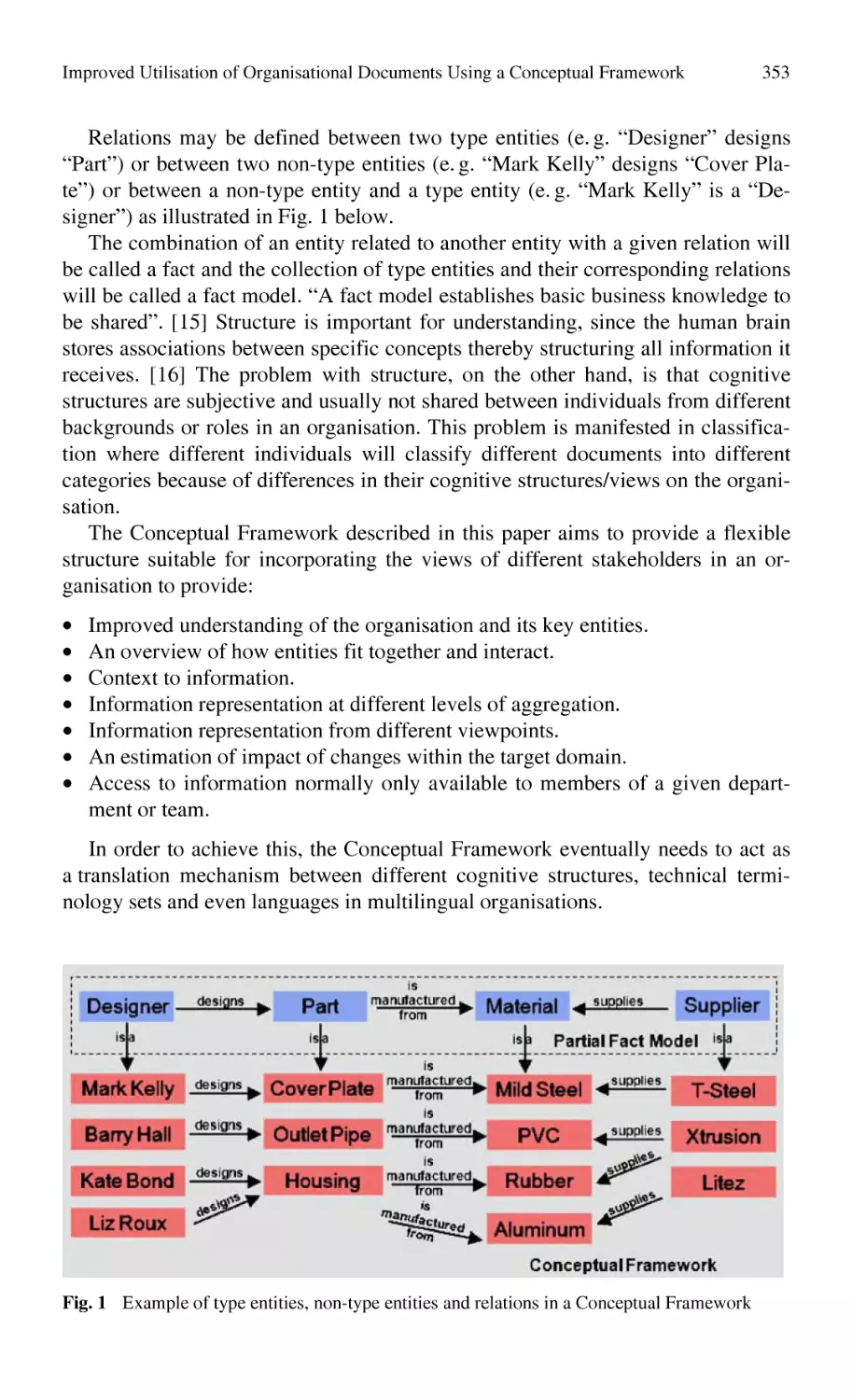
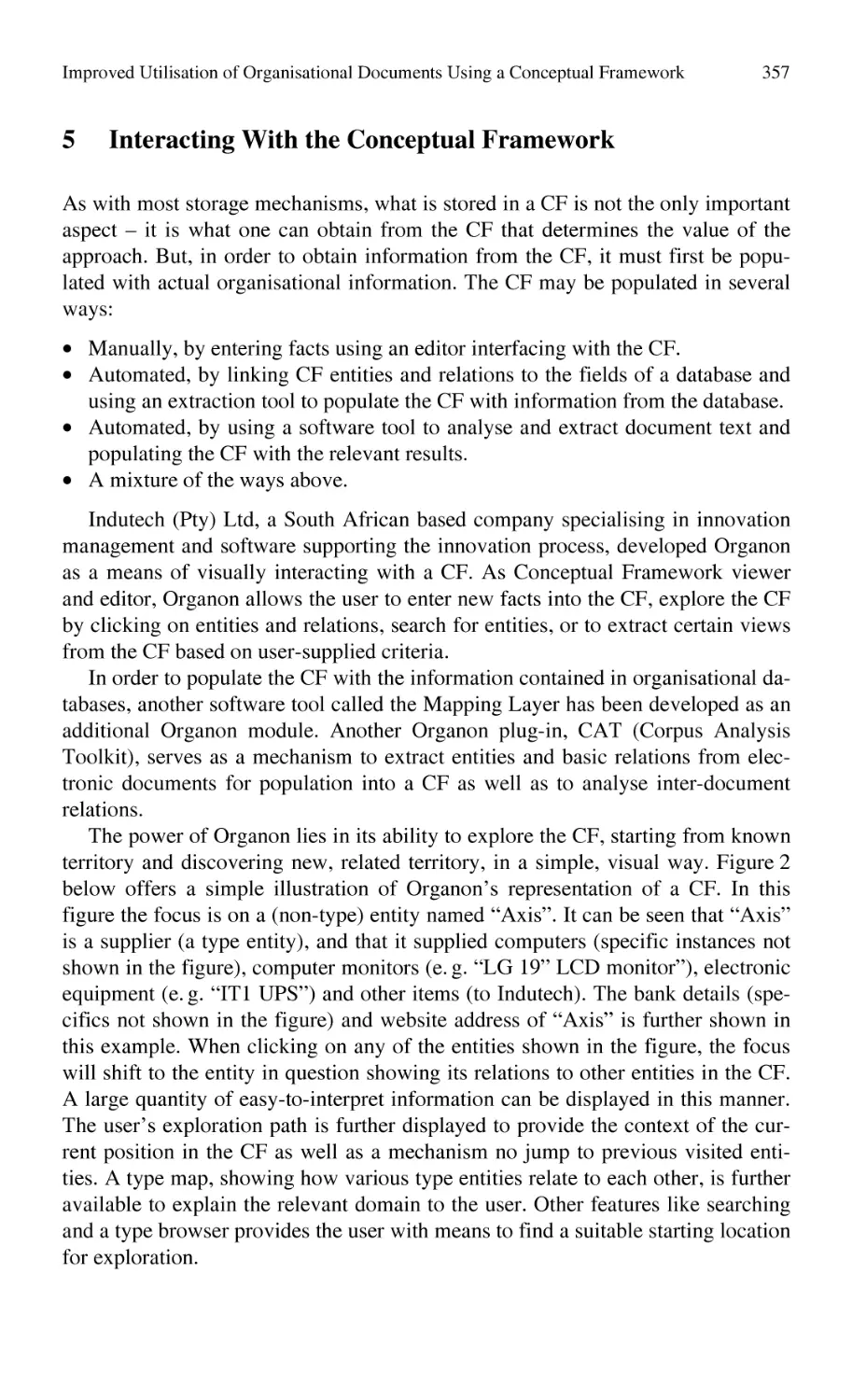
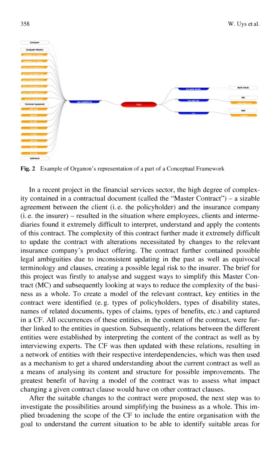
Improved Utilisation of Organisational Documents
Using a Conceptual Framework ........................................................... 347
W. Uys, E. Uys, E. Lutters, N. Du Preez
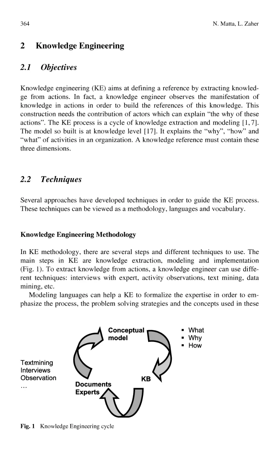
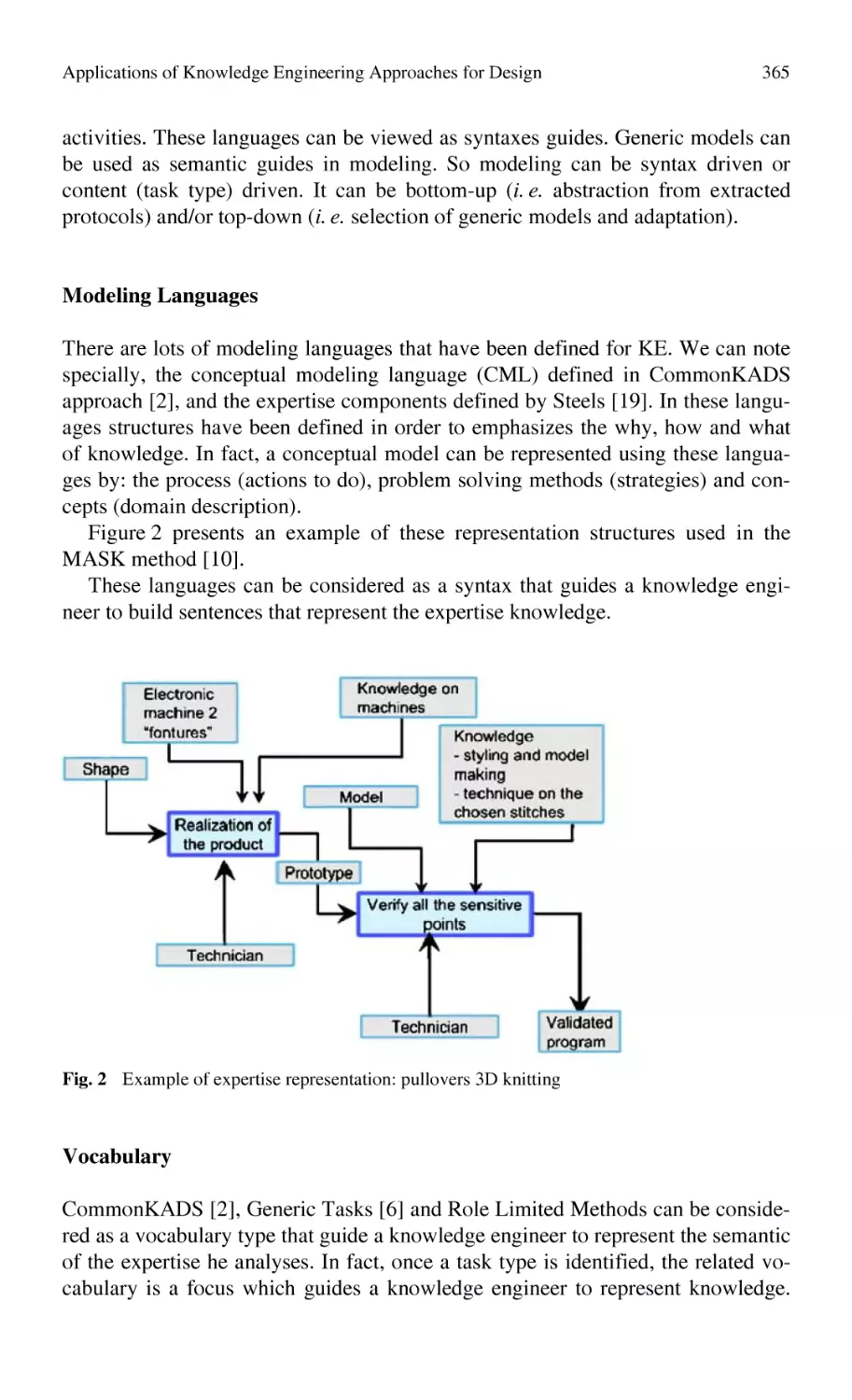
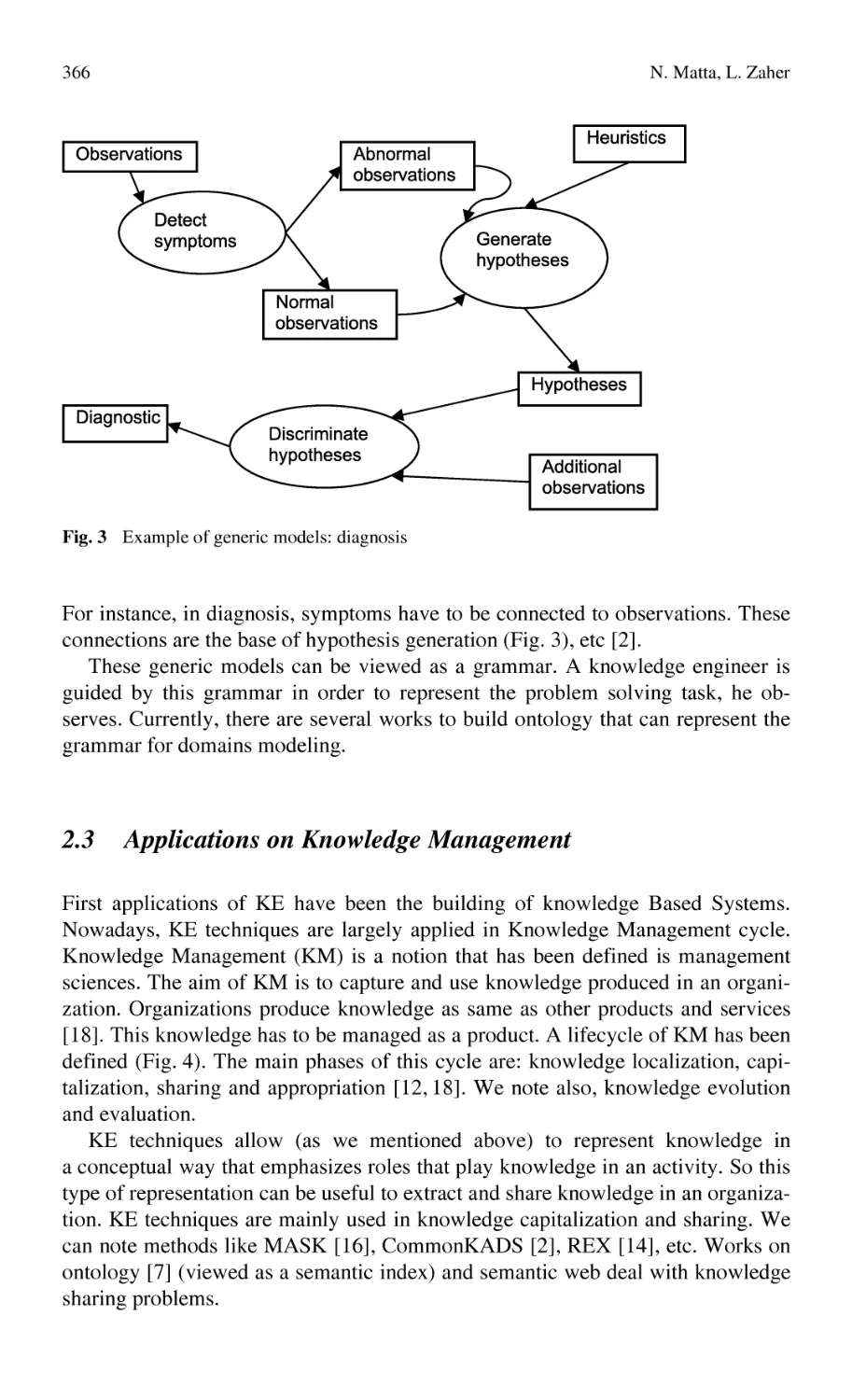
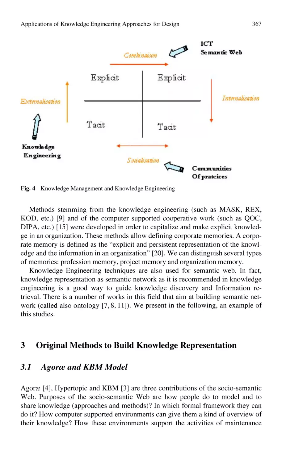
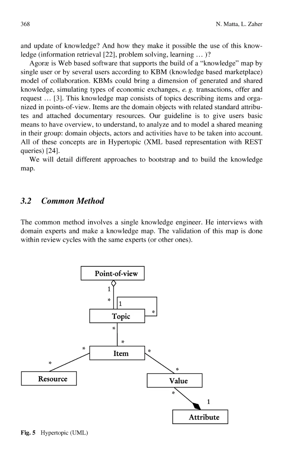
Applications of Knowledge Engineering Approaches for Design........ 363
N. Matta, L. Zaher
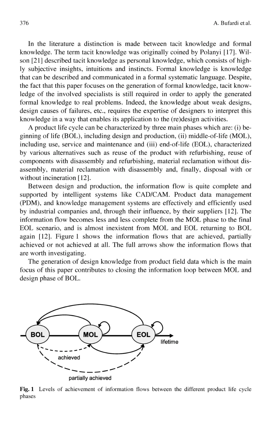
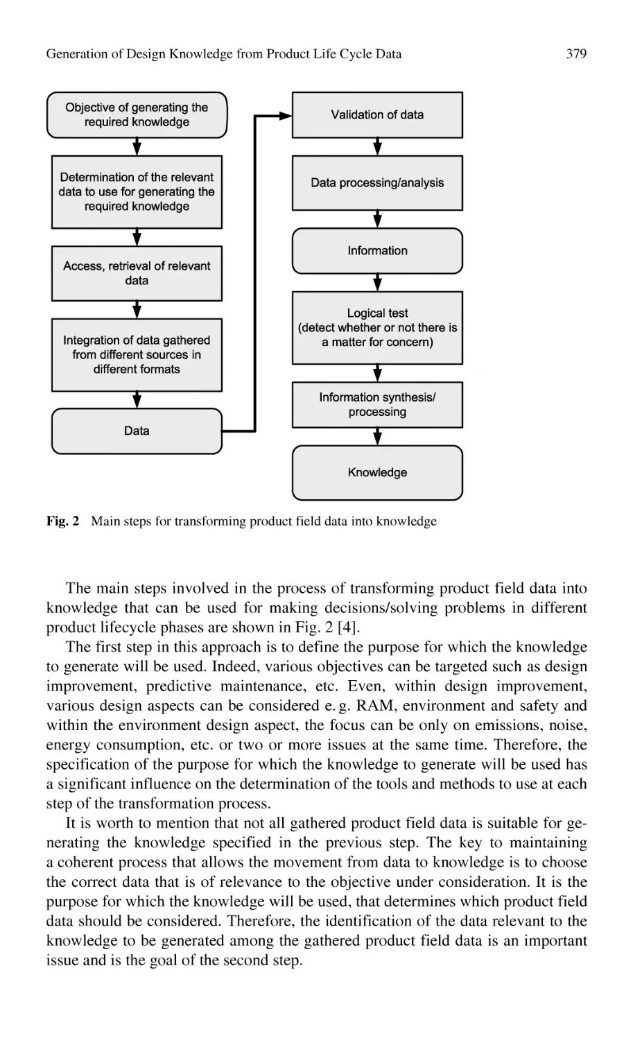
Generation of Design Knowledge from Product Life Cycle Data........ 375
A. Bufardi, D. Kiritsis, P. Xirouchakis
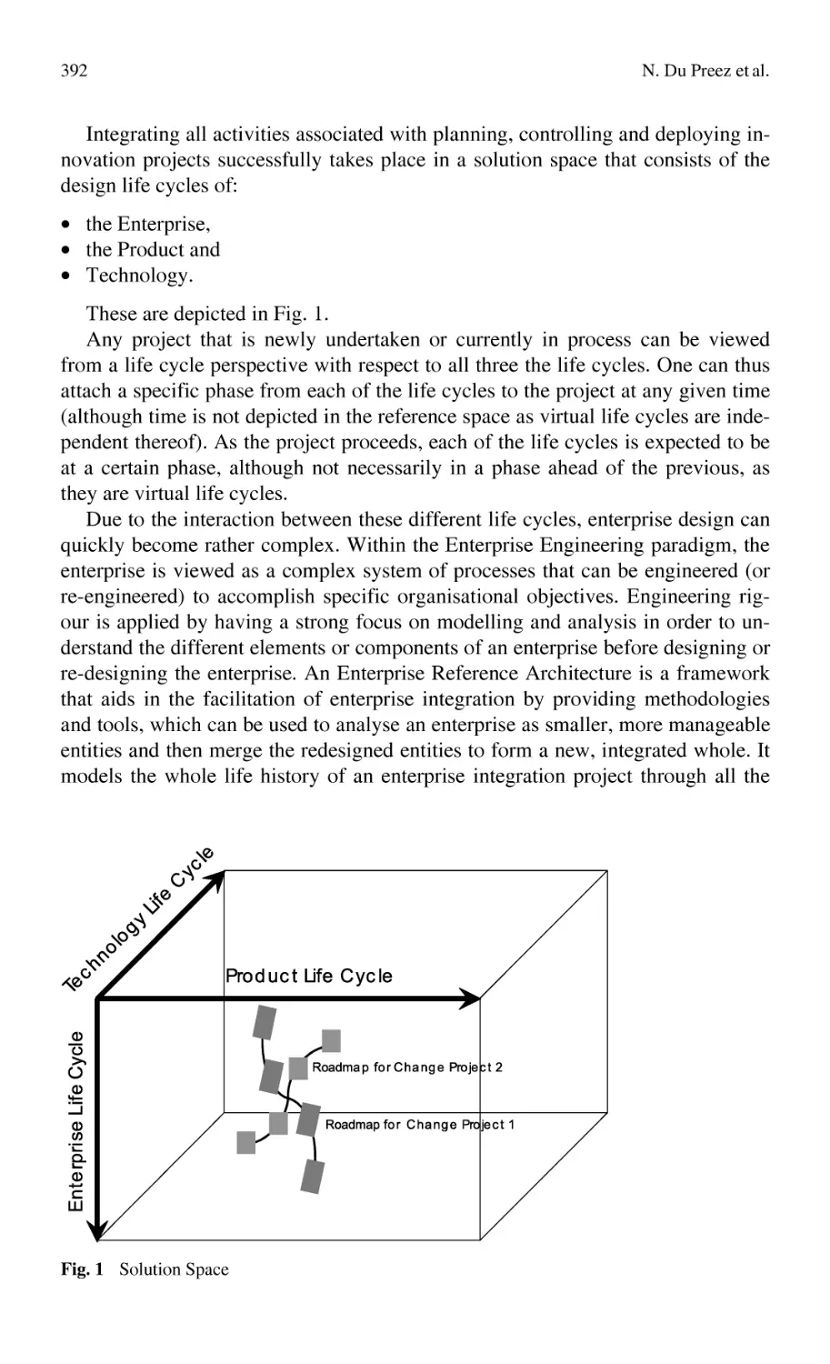
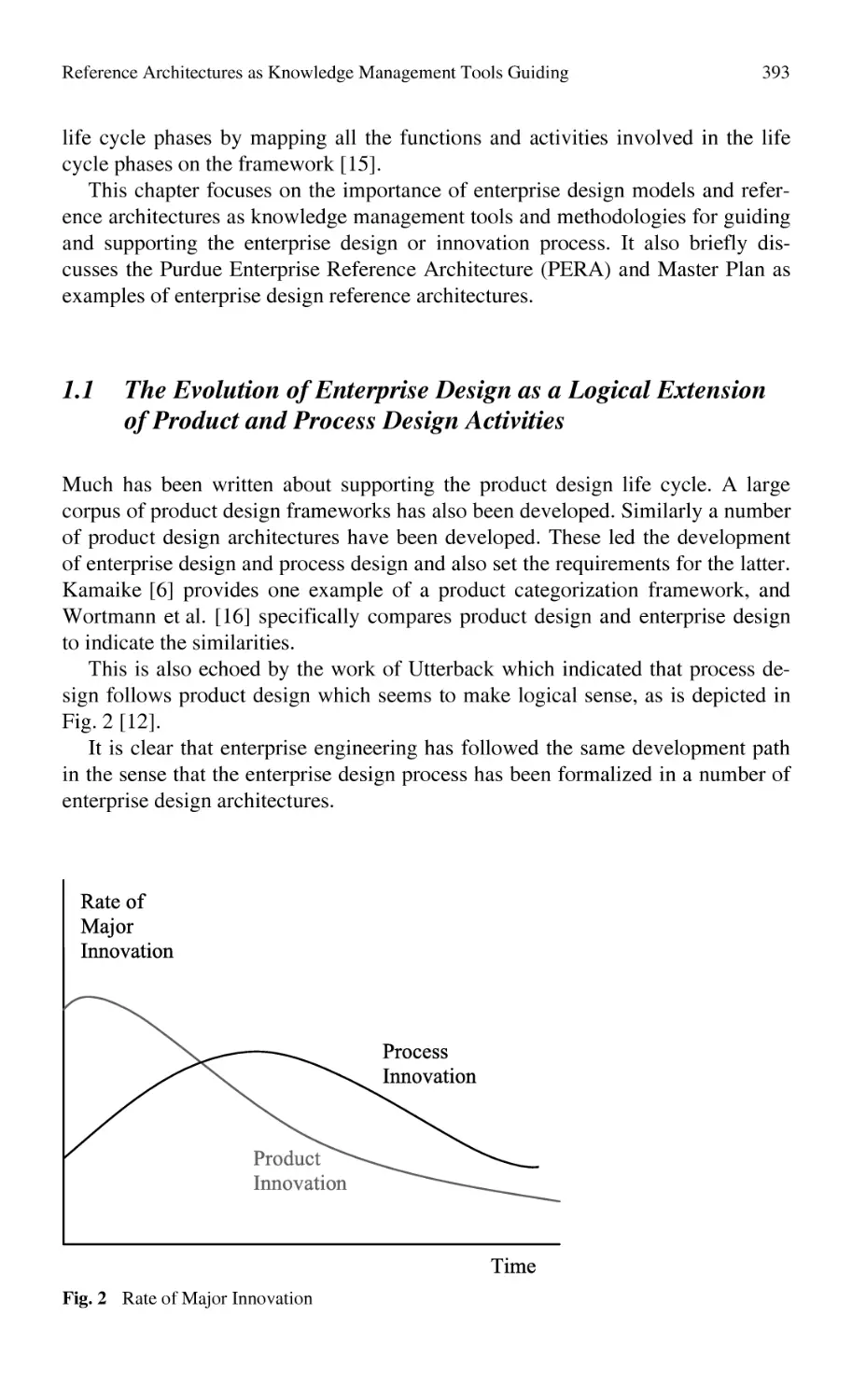
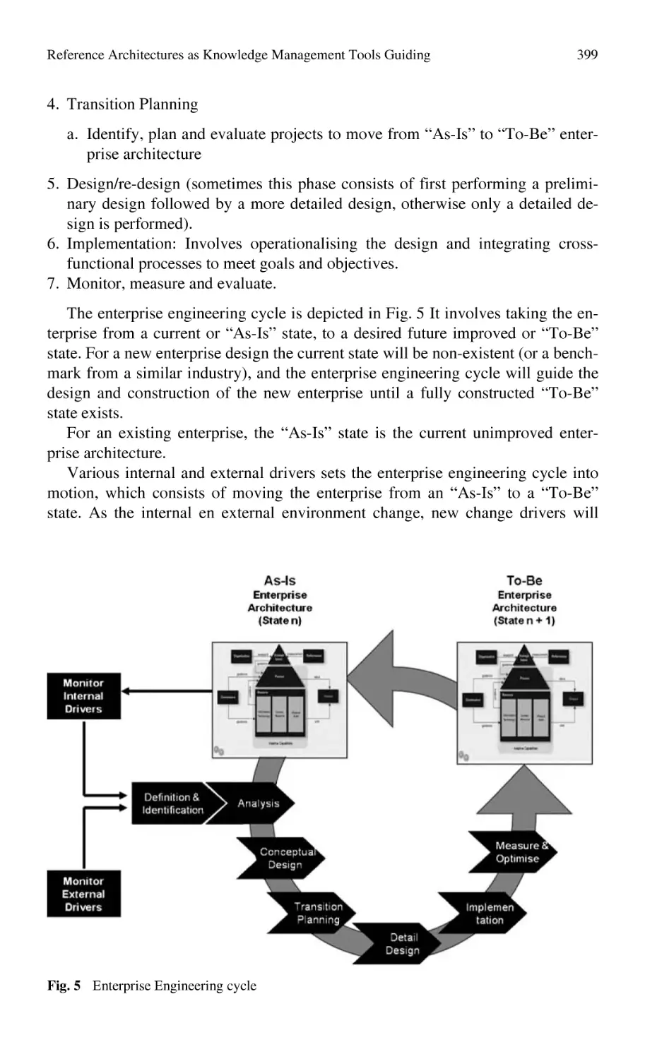
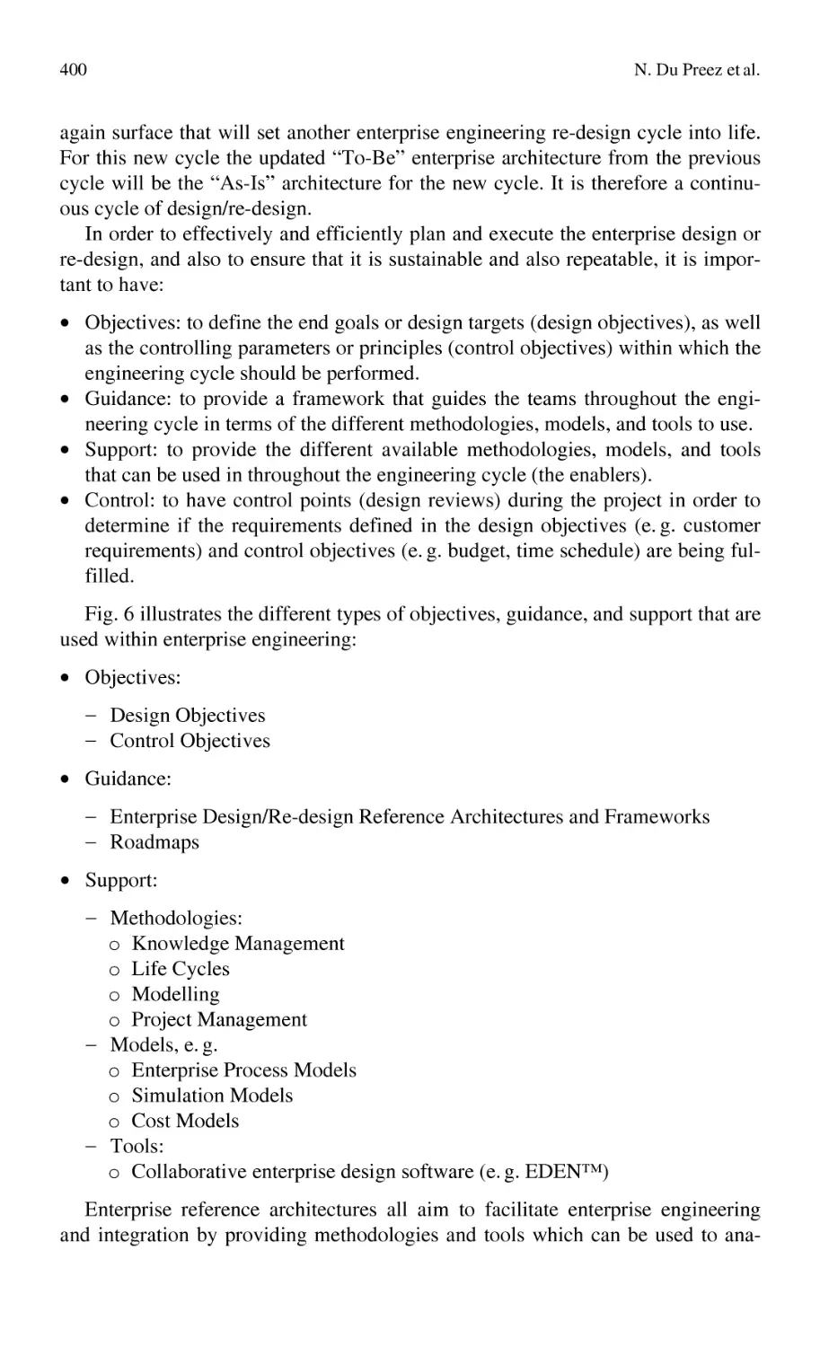
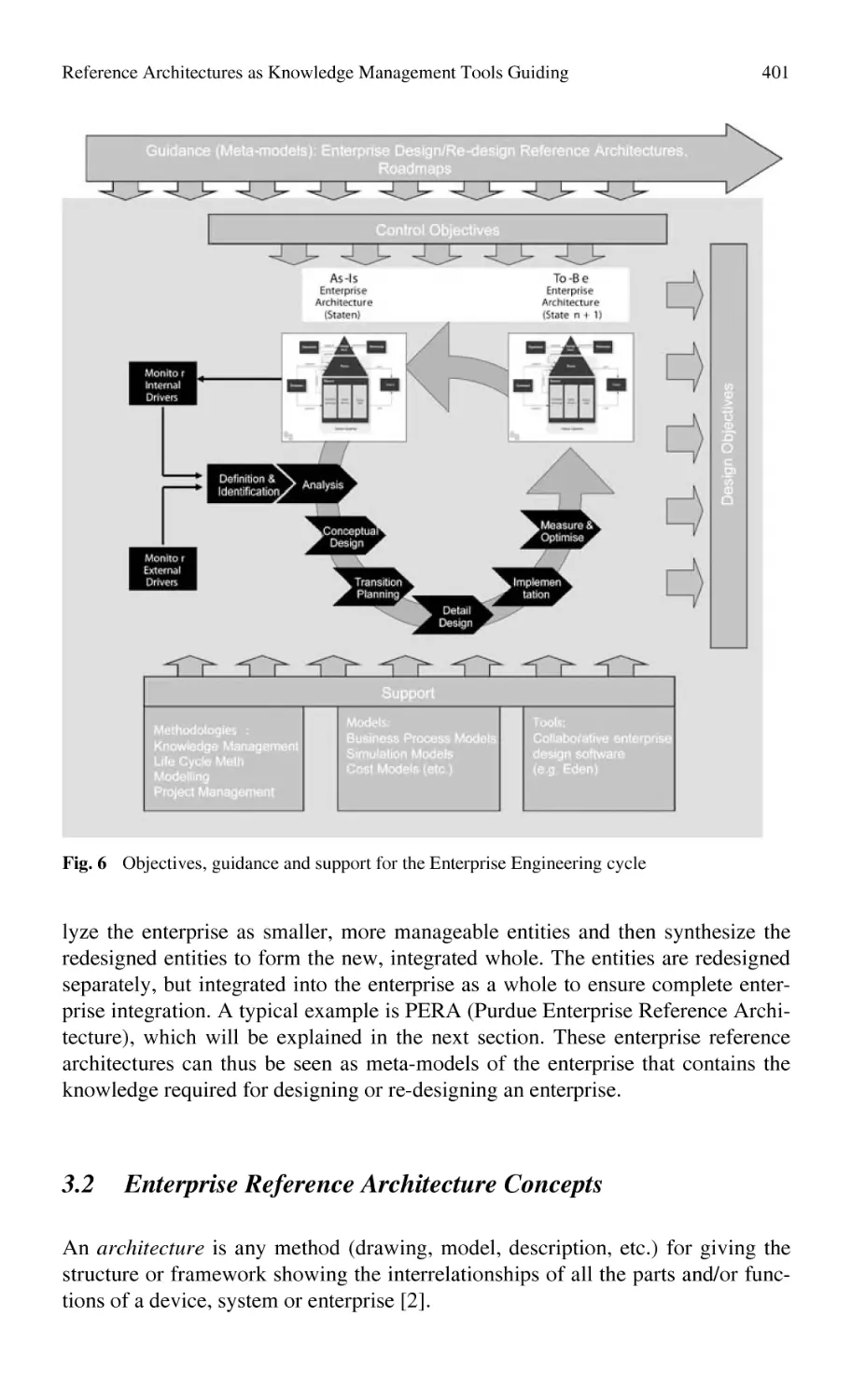
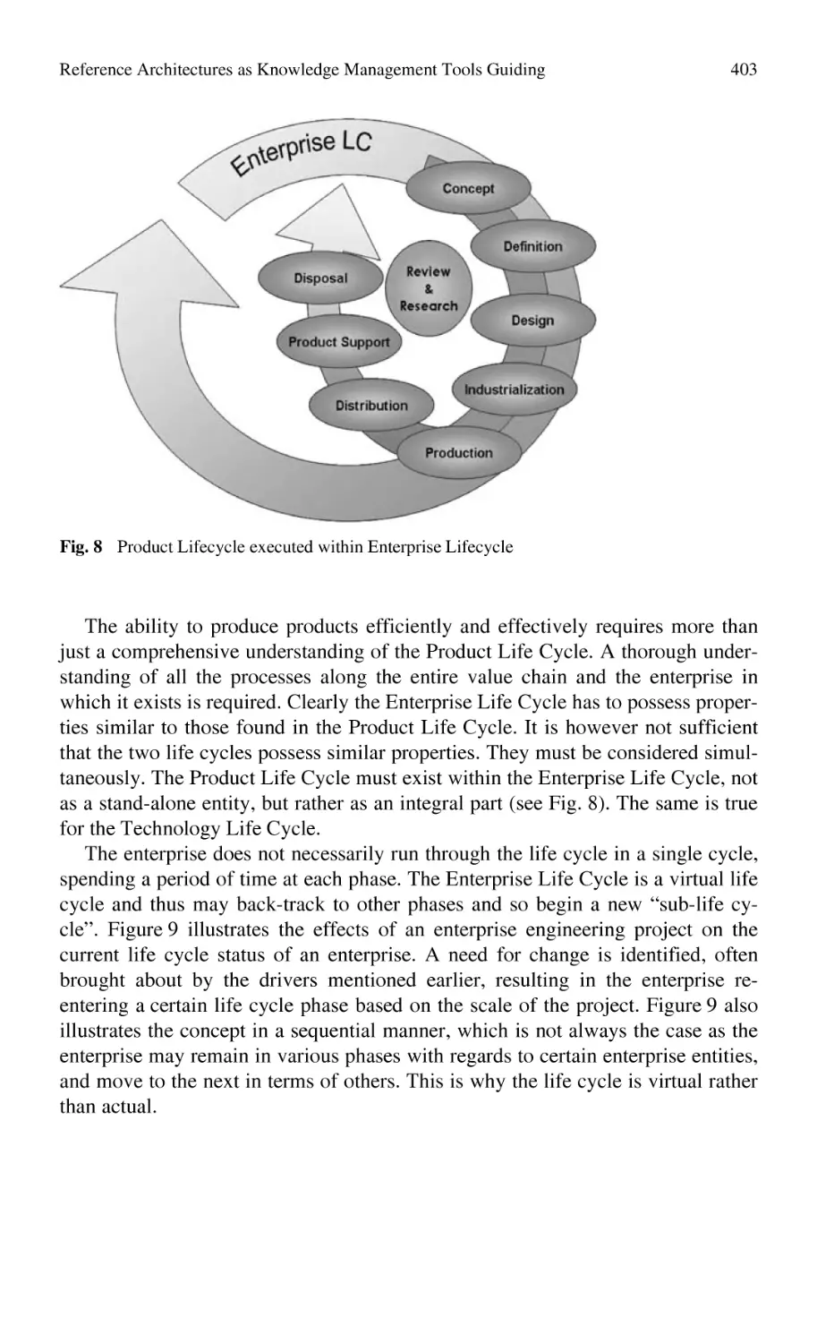
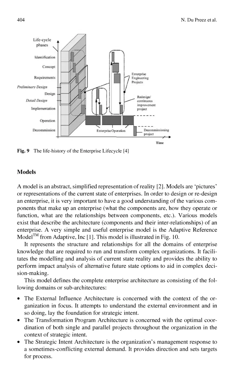
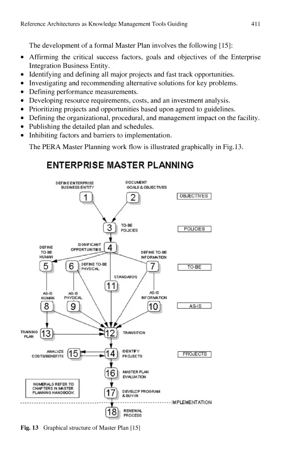
Reference Architectures as Knowledge Management Tools Guiding
and Supporting Enterprise Engineering................................................ 391
N. Du Preez, L. Louw, H. Essmann, C. Grové, L. van der Walt
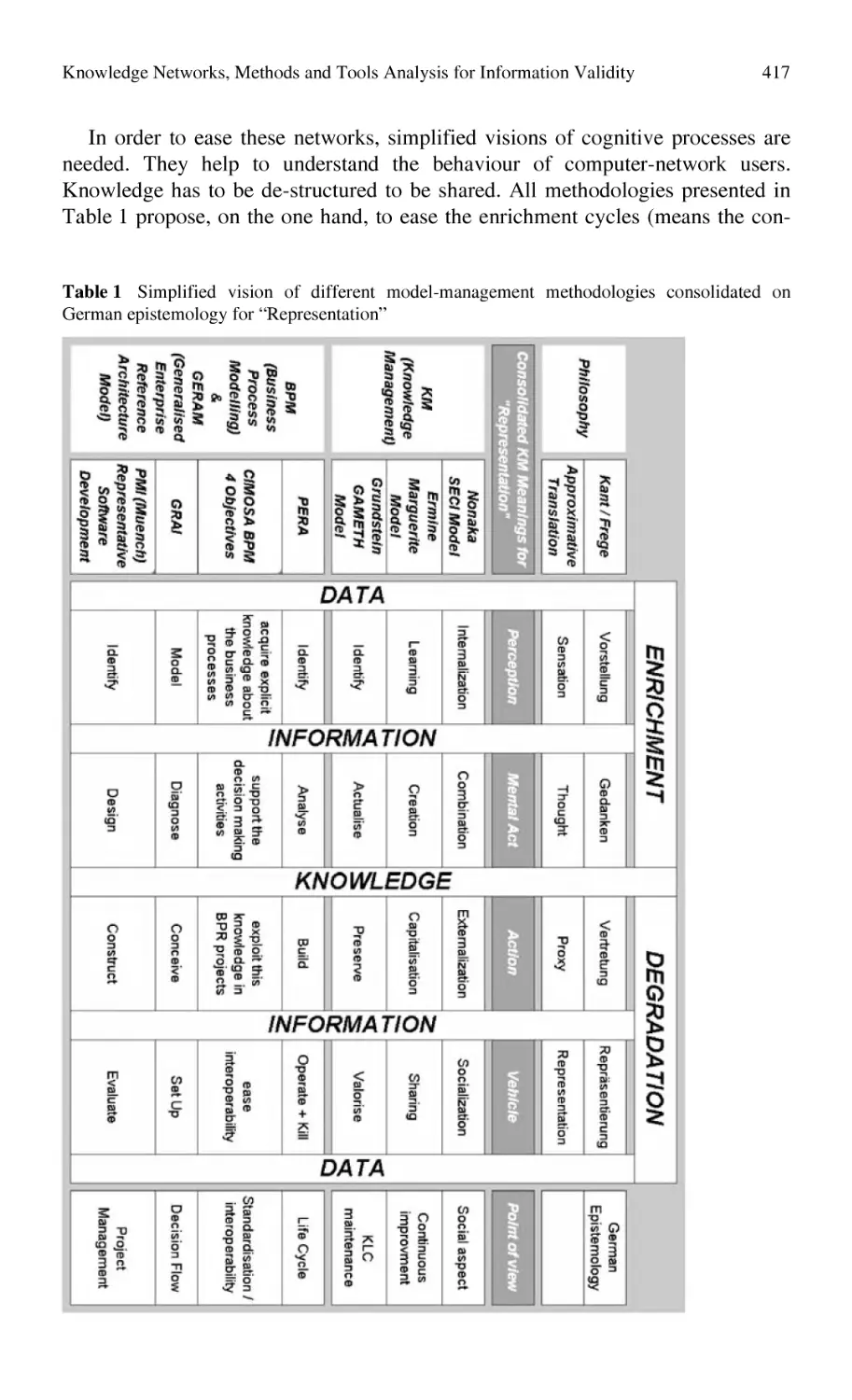
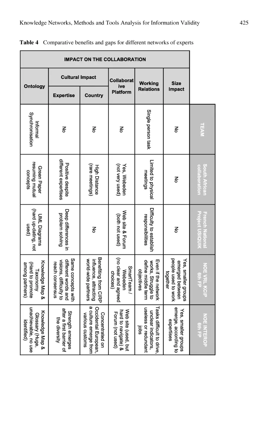
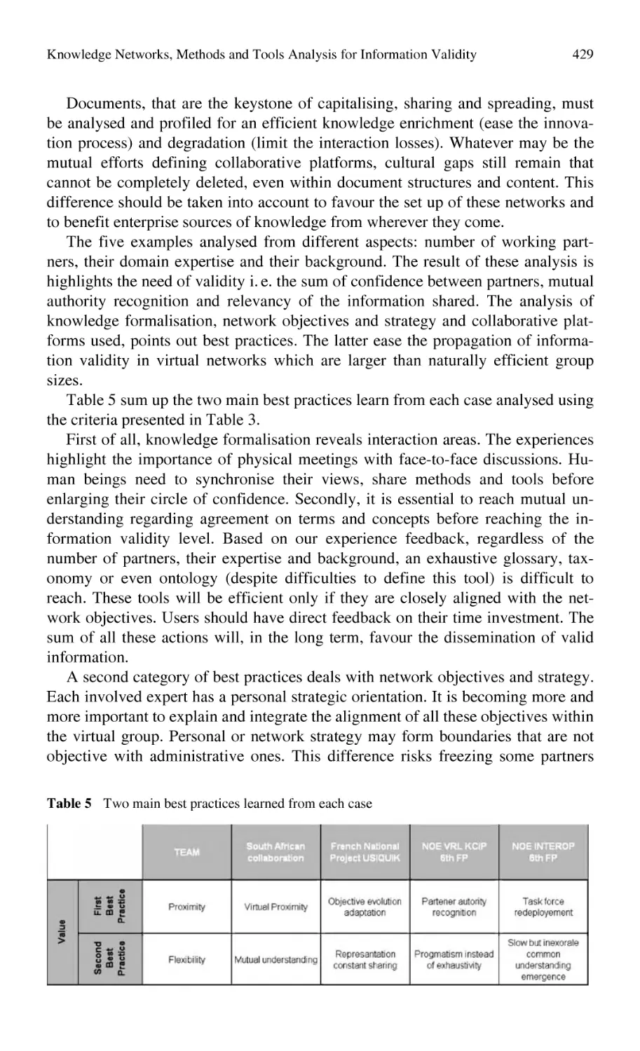
Knowledge Networks, Methods and Tools Analysis
for Information Validity: Case Study Feed Back ................................. 415
N. Perry, A. Candlot
Part 3 Case in Manufacturing Knowledge Management
3.1
Case Studies in Design
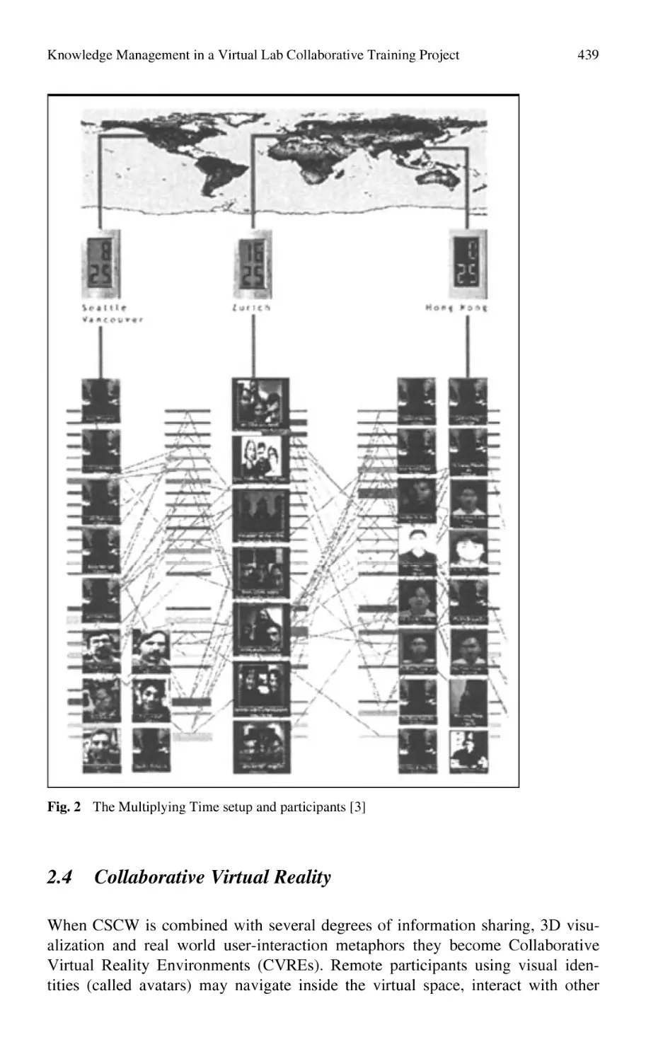
Knowledge Management in a Virtual Lab
Collaborative Training Project:
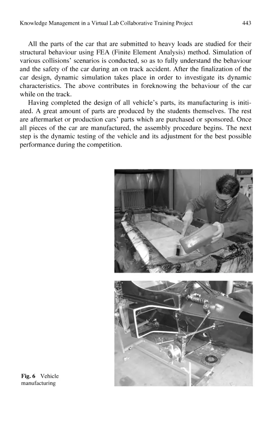
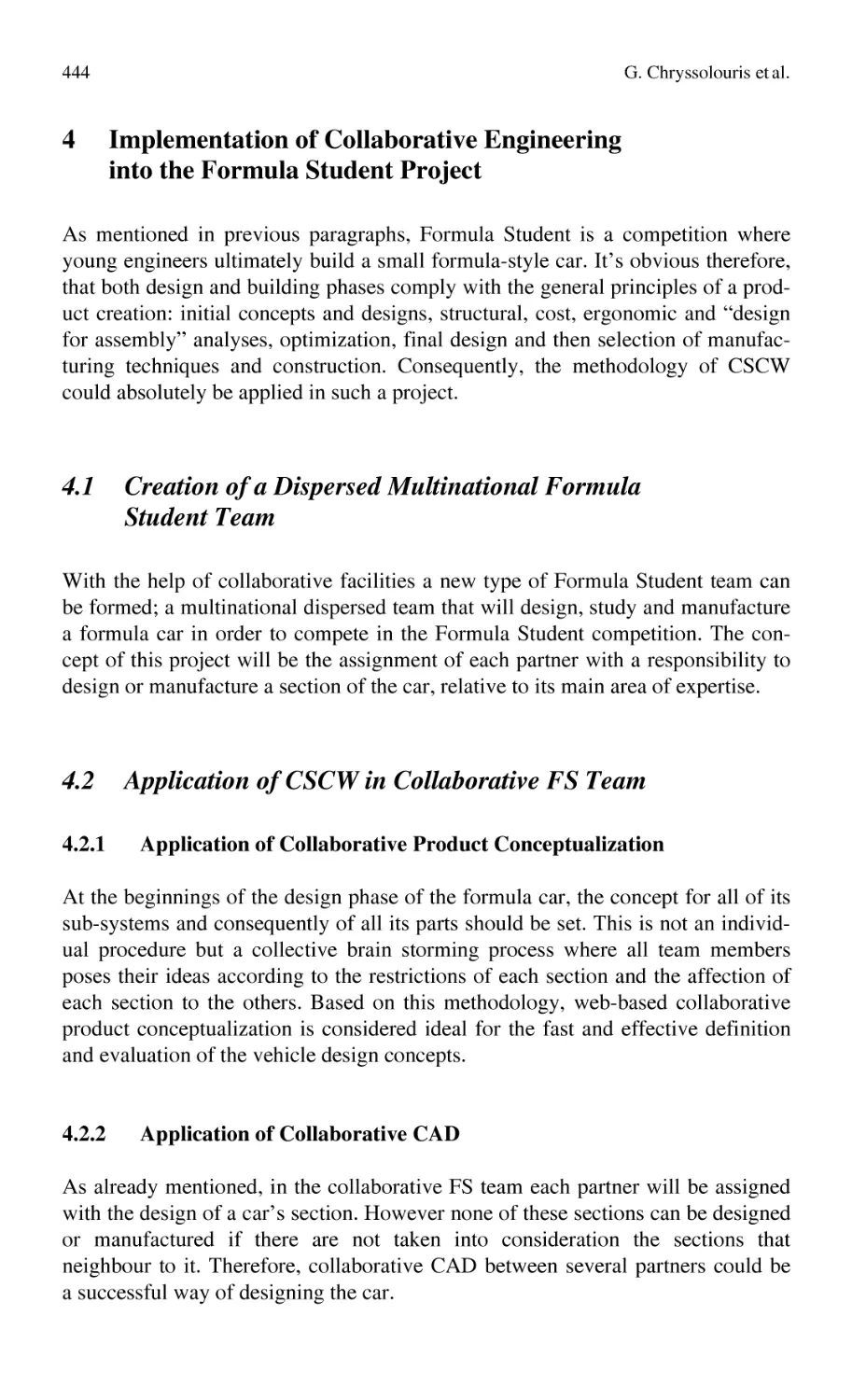
A Mini-Formula Student Car Design ................................................... 435
G. Chryssolouris, D. Mourtzis, P. Stavropoulos, D. Mavrikios,
J. Pandremenos
Case Study in Design: Generation of Design Knowledge
for Vehicle Sub-frames
Based on Finite Element Simulation .................................................... 447
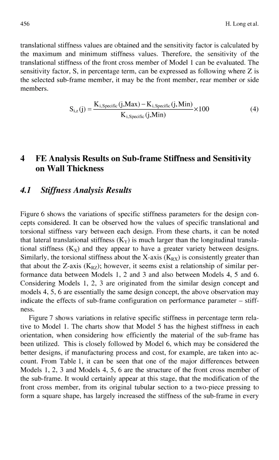
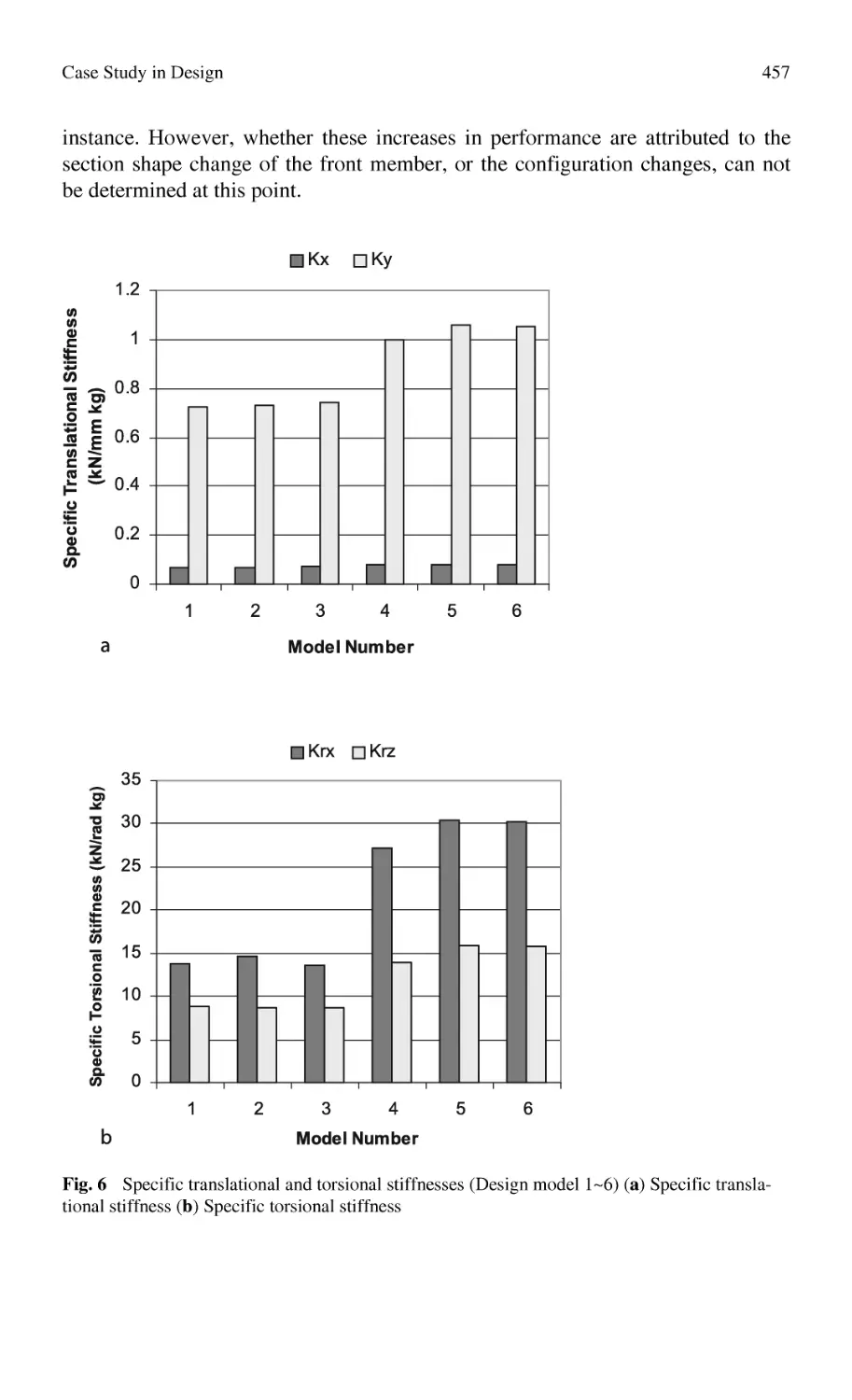
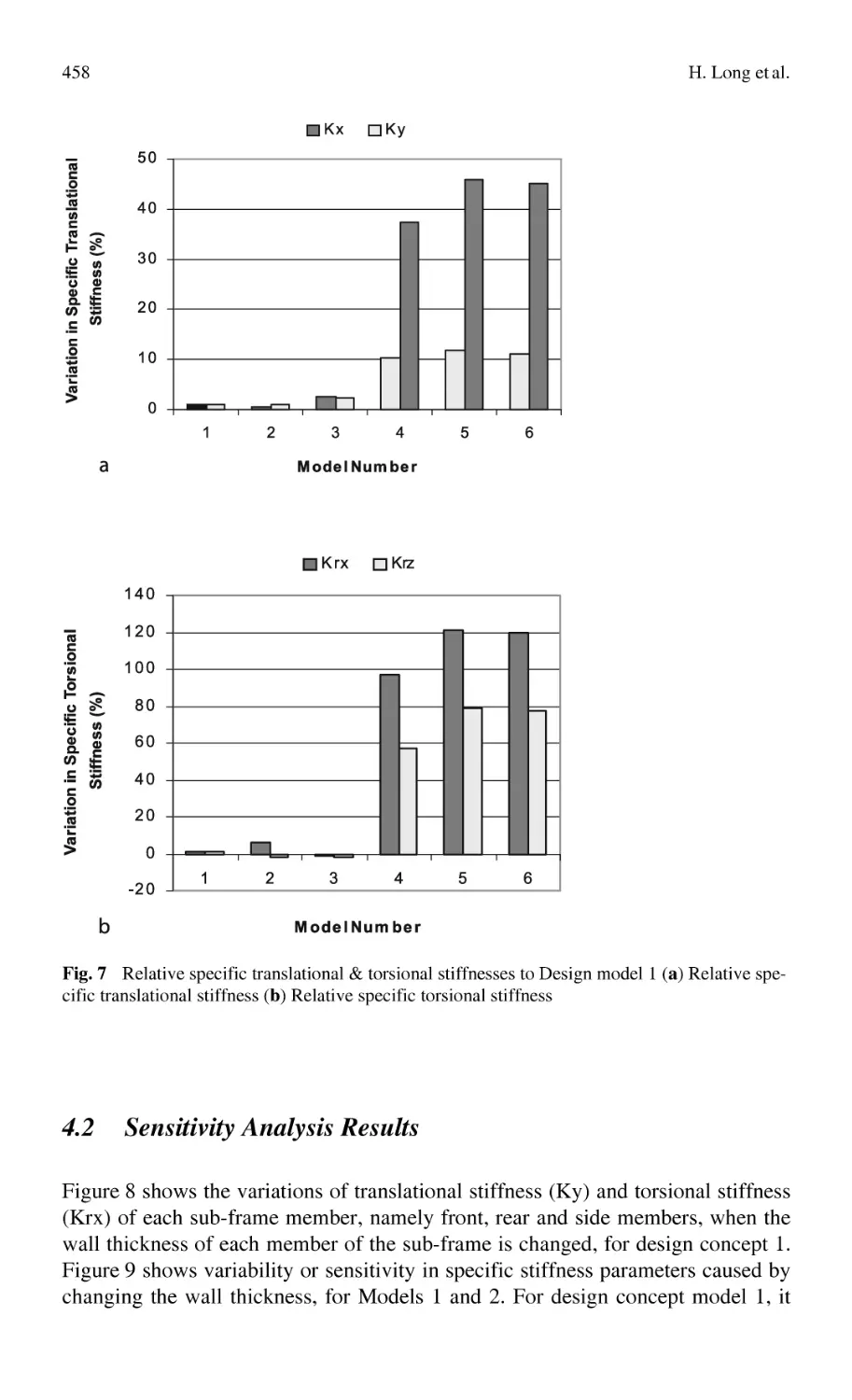
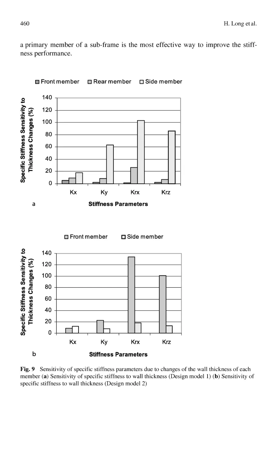
H. Long, A. Fanourakis, P. Oliver
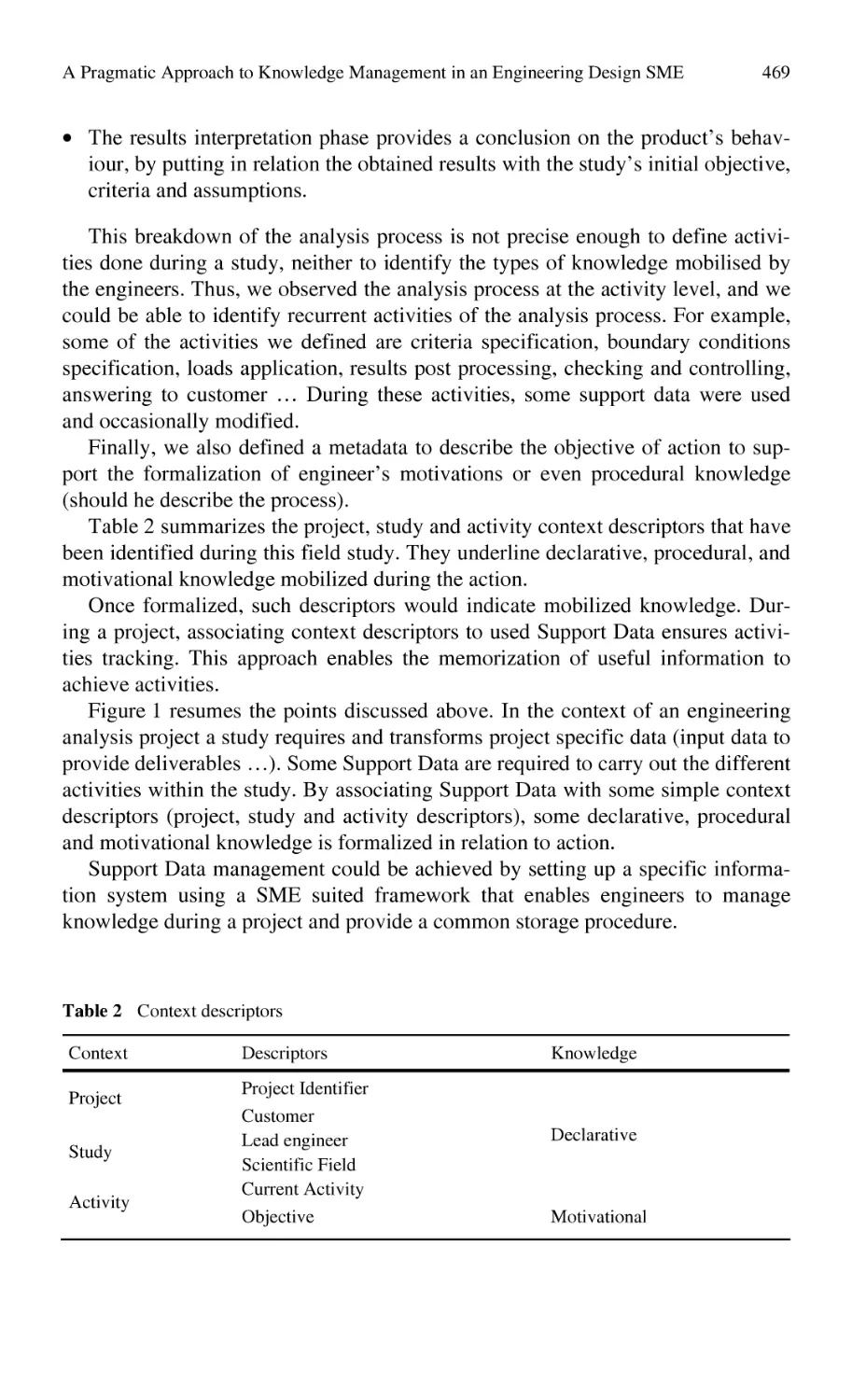
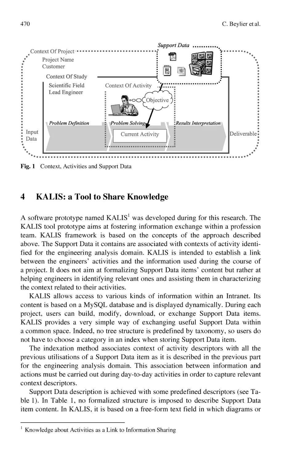
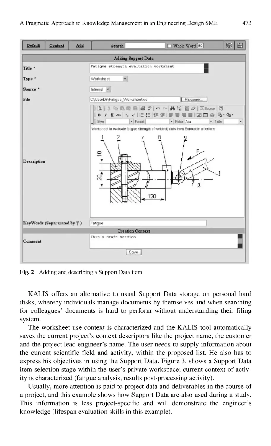
A Pragmatic Approach to Knowledge Management
in an Engineering Design SME ............................................................ 463
C. Beylier, F. Pourroy, F. Villeneuve
Capitalization and Reuse of Forging Knowledge
in Integrated Design ............................................................................. 479
S. Tichkiewitch
3.2
Case Studies in Manufacturing
Case Study, USIQUICK Project: Methods to Capitalise
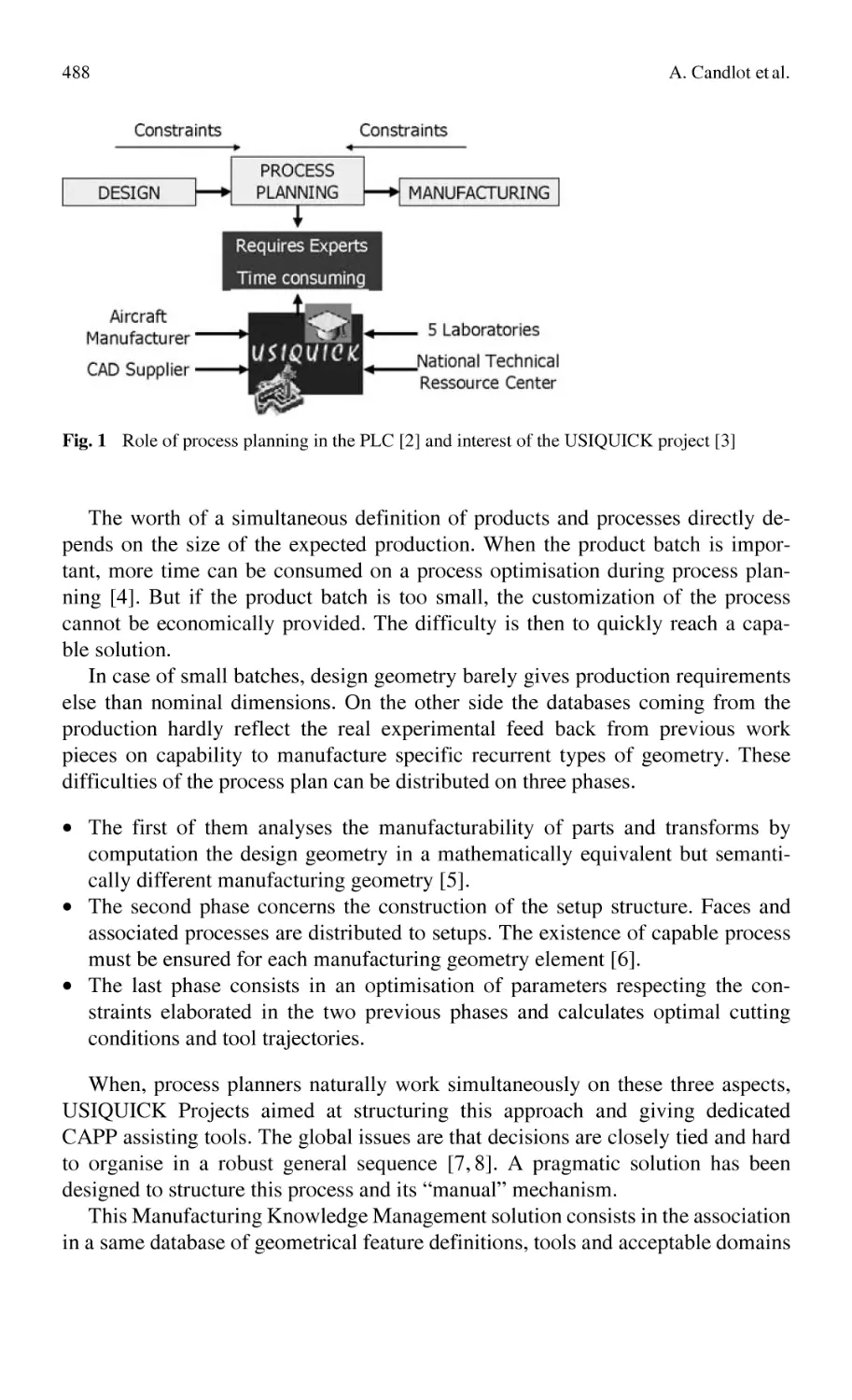
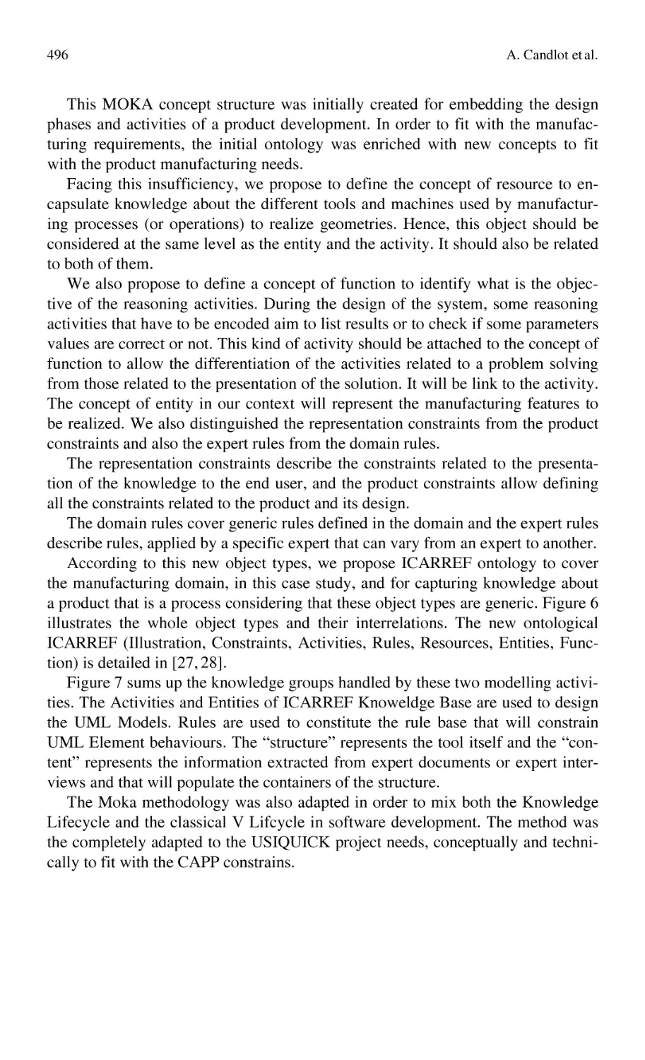
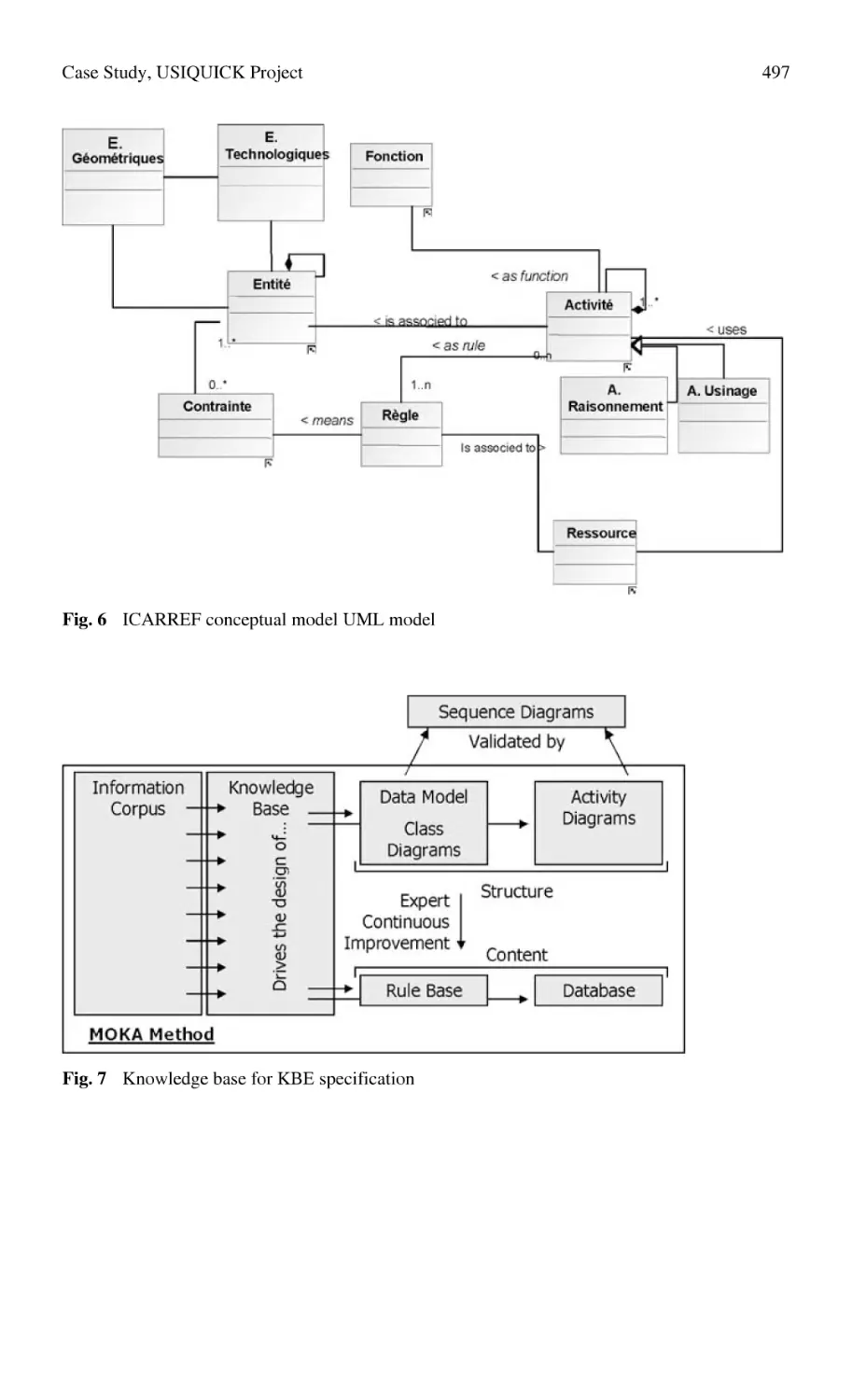
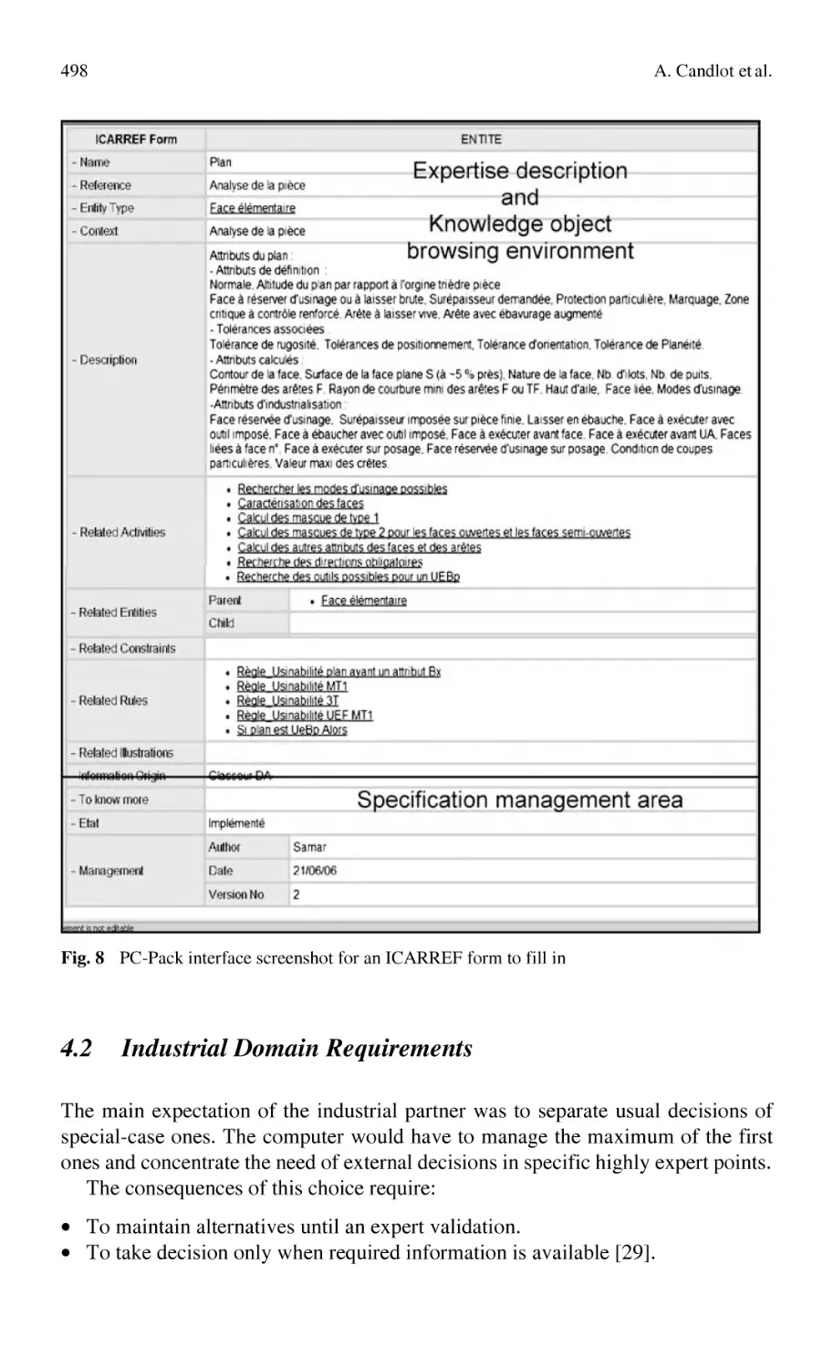
and Reuse Knowledge in Process Planning.......................................... 487
A. Candlot, N. Perry, A. Bernard, S. Ammar-Khodja
Knowledge Management in Manufacturing Process Modeling:
Case Studies in Selected Manufacturing Processes.............................. 507
G. Chryssolouris, N. Papakostas, D. Mourtzis, S. Makris
x
Content
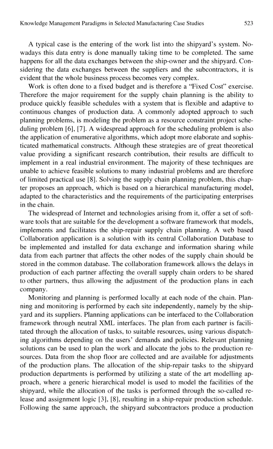
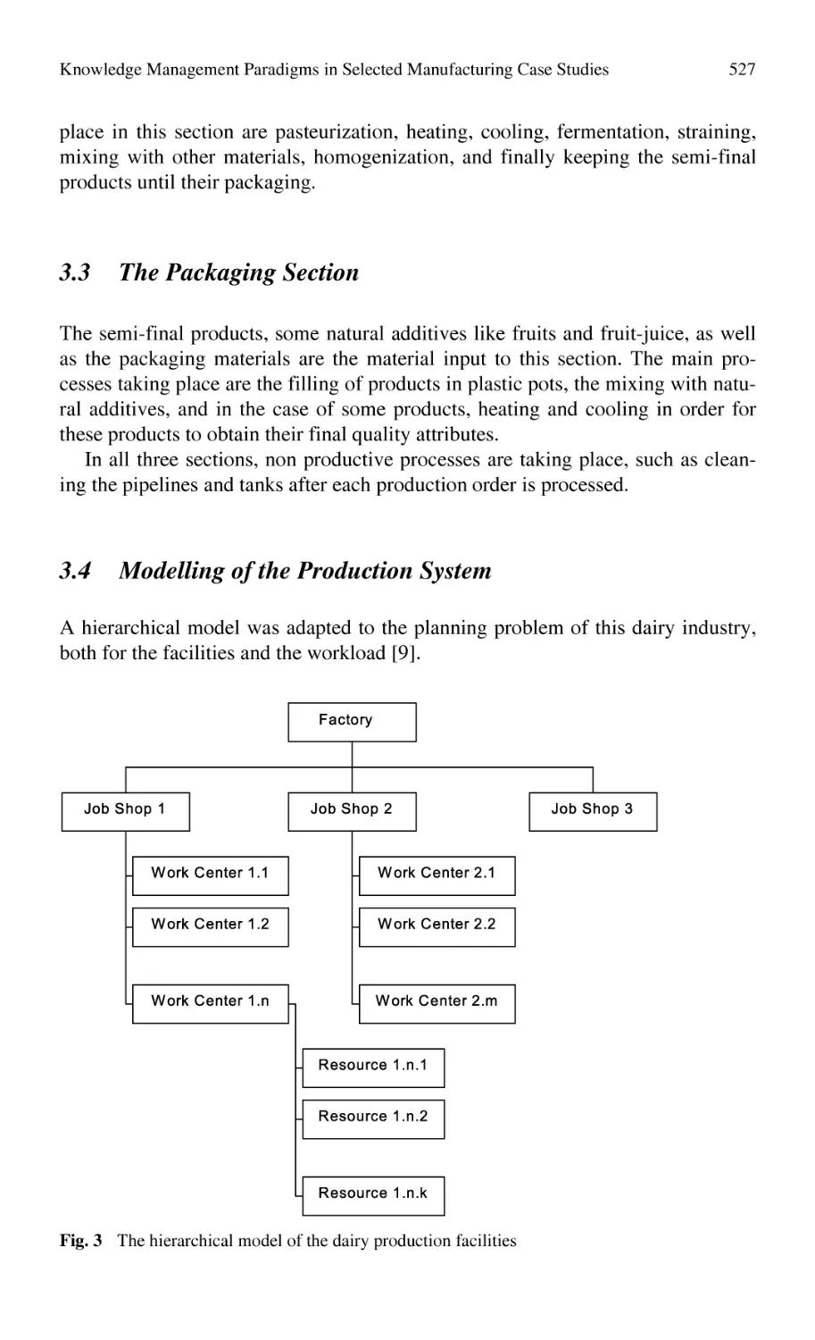
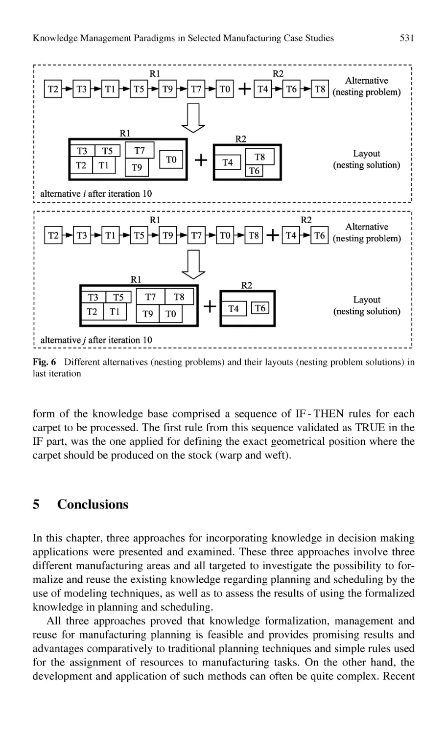
Knowledge Management Paradigms in Selected Manufacturing
Case Studies ......................................................................................... 521
G. Chryssolouris, D. Mourtzis, N. Papakostas, Z. Papachatzakis,
S. Xeromerites
3.3
The VRL-KCiP: Cases in European-Level
Manufacturing Knowledge Sharing
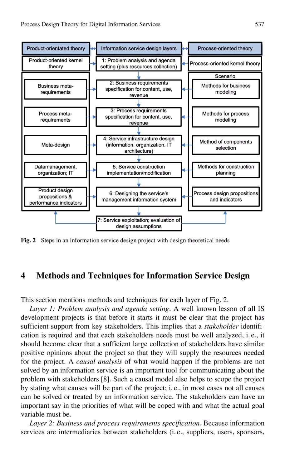
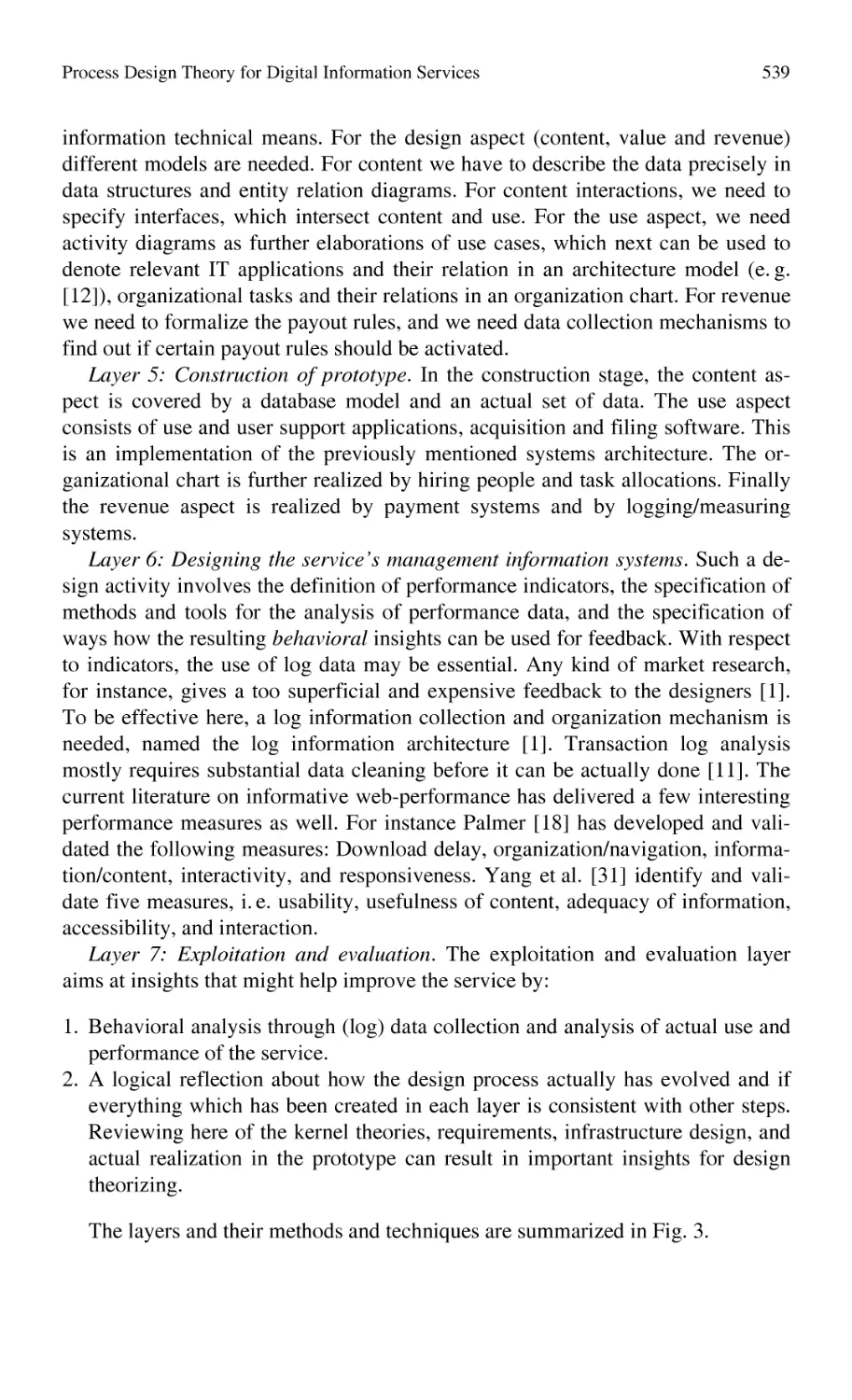
Process Design Theory for Digital Information Services..................... 533
F. Wijnhoven
The VRL-KCiP Software Demonstration and Exchange Platform –
An Example for Web-Based Knowledge Management
and Representation ............................................................................... 547
L. Aldinger, J. Westermann, E. Westkämper
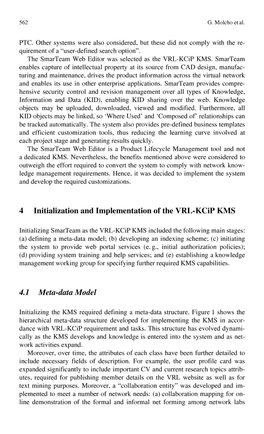
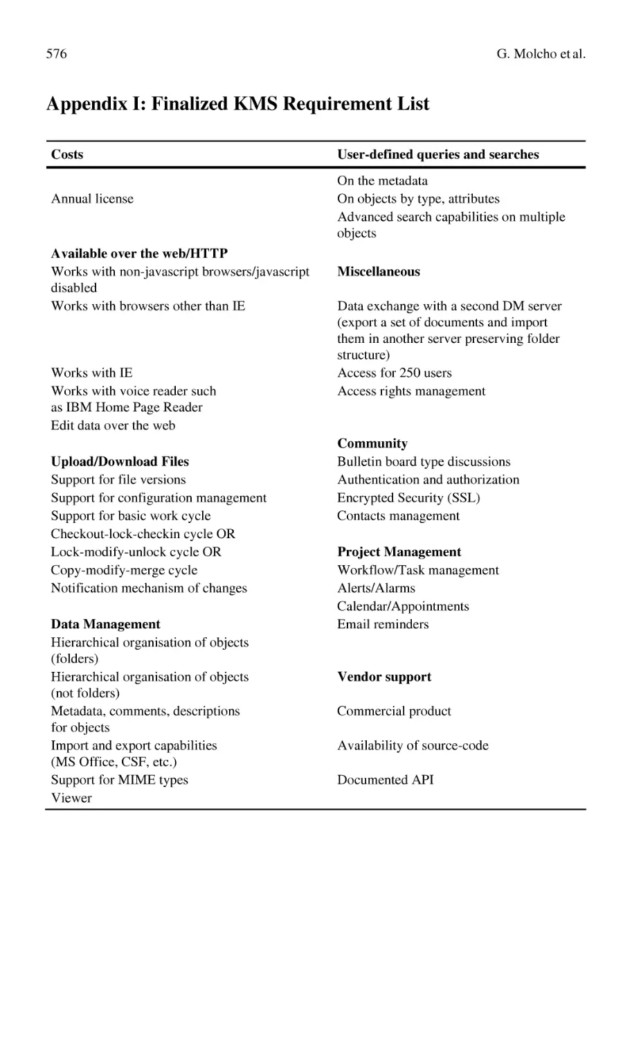
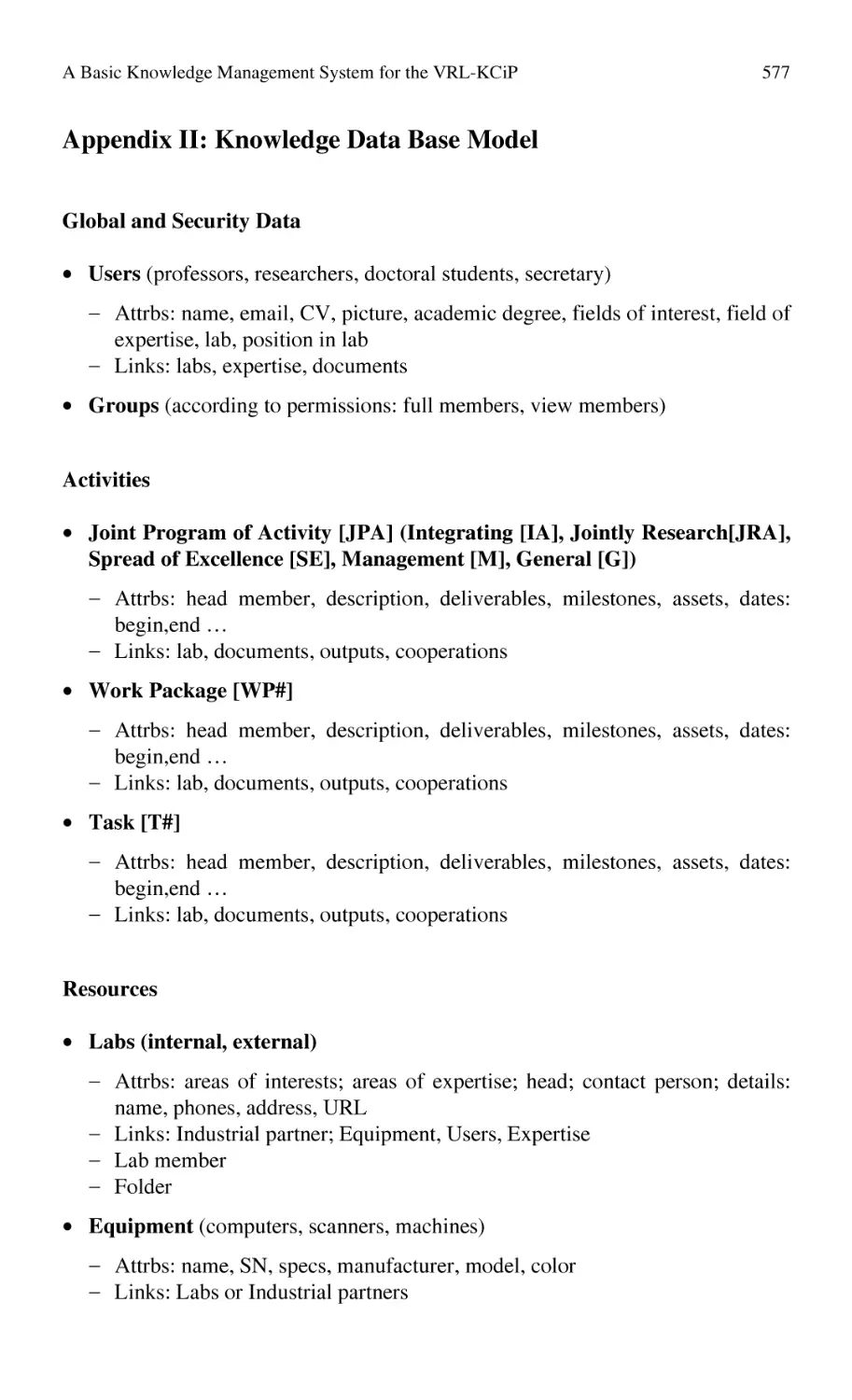
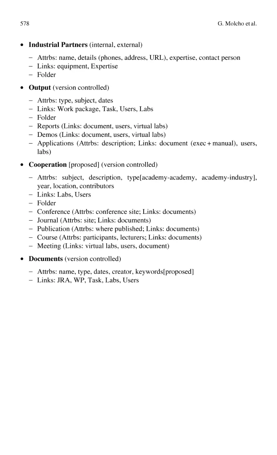
A Basic Knowledge Management System for the VRL-KCiP............. 559
G. Molcho, R. Schneor, D. Bossin
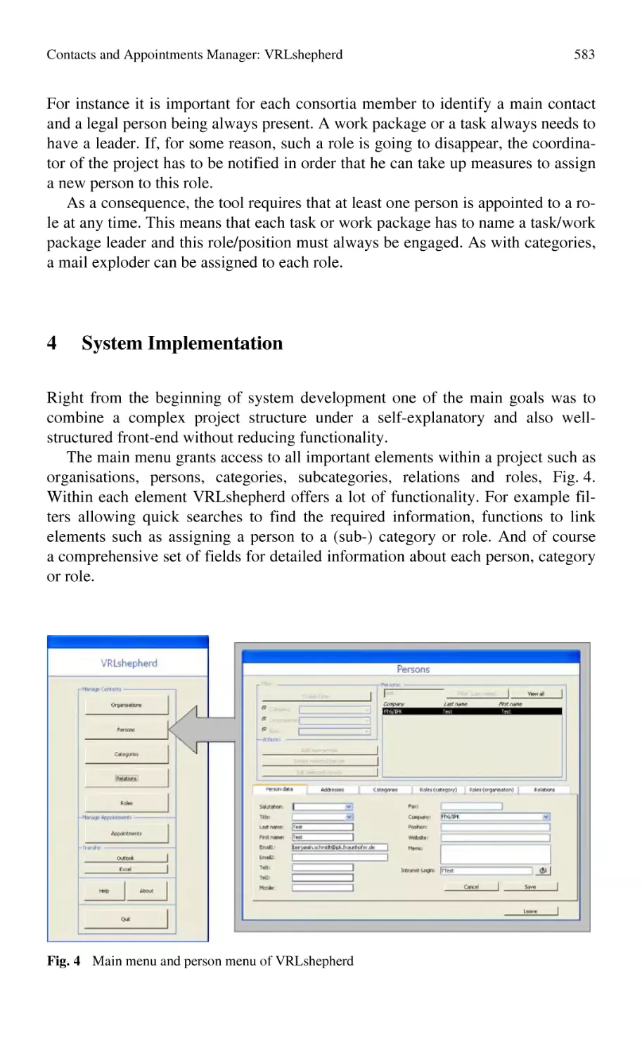
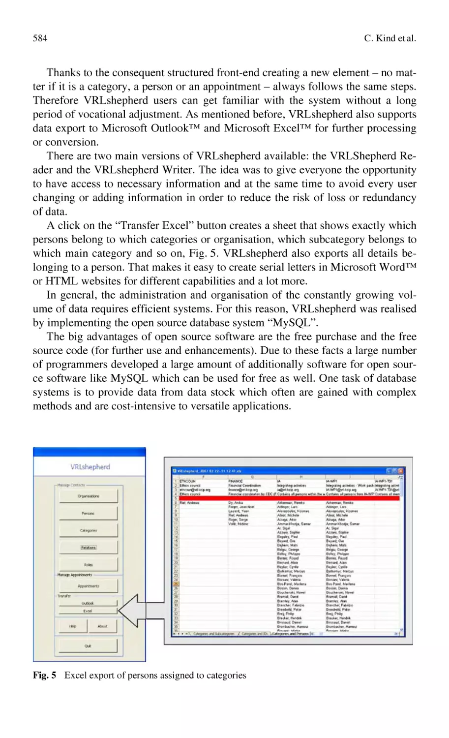
Contacts and Appointments Manager: VRLshepherd .......................... 579
C. Kind, O. Arpinar, A. Finnah, B. Schmidt
Part 1
KM Needs and Concepts
1.1
What Is Knowledge?
1.1.1 From Data to Knowledge
An Overview on Knowledge Management ............................................
3
1.1.2 What is Knowledge Management
Manufacturing Knowledge Work: The European Perspective ...............
23
1.2
Networks of Expertise
1.2.1 Knowledge Sharing
Social Needs for Knowledge Sharing
Building a Knowledge Share Culture in a Virtual Organization.
Case Study for VRL-KCiP NoE .............................................................
Influence of Multi-Culturality in Virtual Teams – The Case
of the VRL-KCiP Network of Excellence ..............................................
45
61
1.2.2 Knowledge Integration
Web Tools for Knowledge Integration
A Web and Virtual Reality Based Paradigm for Collaborative
Management and Verification of Design Knowledge ............................ 91
Knowledge Management in the Virtual Enterprise:
Web Based Systems for Electronic Manufacturing ................................ 107
EDEN™ ................................................................................................. 127
Contextual issue of knowledge integration
Misunderstandings in Global Virtual Engineering Teams:
Definitions, Causes, and Guidelines
for Knowledge Sharing and Interaction.................................................. 145
A Knowledge Network Approach Supporting the Value Chain.............. 159
Knowledge Mapping
Formulating an Expertise Map in the VRL-KCiP ..................................
Representation and Navigation Techniques
for Semi-Structured Knowledge in Collaborating Communities............
The Use of Conceptual Maps for Competencies Mapping
and Knowledge Formalization in a Virtual Lab .....................................
Production Paradigms Ontology (PPO):
a Response to the Need of Managing Knowledge
in High-Tech Manufacturing ..................................................................
169
185
213
227
An Overview on Knowledge Management
S. Ammar-Khodja, A. Bernard
Ecole Centrale de Nantes, IRCCyN, 1 rue de la Noë, BP 92101, 44321 Nantes
Cedex 3, France
Abstract This first chapter has to be considered like a general entry in the problematic of Knowledge Life-Cycle Management. Some general issues are addressed. First a literature review is proposed that is supposed to highlight the domain and the corresponding concepts and aims through definitions. Knowledge
Life-Cycle (KLC) is more especially considered and the strategic dimensions of
KLC are described and commented. Then Knowledge Management is positioned
with respect to information technology. A conclusion paragraph closes the paper.
Keywords: Knowledge Management; Knowledge Life-Cycle
1
Introduction
The capacity of innovation and the performance of activities become currently
a major stake for the success of companies. Companies act today more than ever
in a very competing environment. Thus, to play an important role in the global
market, it is necessary to combine, more than before, satisfaction of the customers,
productivity and competitiveness. One has also to face the growth of technology
with a significant increase in the volume of available and accessible information.
This information being diversified, delocalized and not easily controllable led to
the development of many information systems management tools to exploit it as
well as possible [34].
Currently, this information is processed and managed by taking into account its
meaning and its semantic, this means that we manage knowledge. Knowledge is
regarded nowadays as a strategic resource and a factor of stability, bringing
a decisive competing advantage.
A. Bernard, S. Tichkiewitch (eds.),
Methods and Tools for Effective Knowledge Life-Cycle-Management,
DOI: 10.1007/978-3-540-78431-9_1, © Springer 2008
3
4
S. Ammar-Khodja, A. Bernard
Knowledge management (KM) is necessary to the company to innovate on
products, processes, services and on the organization. It allows at the same time to
reduce its design costs, production, distribution, etc. Managing knowledge is not
a new problem. The difference with the past is that currently companies attack this
problem explicitly according to a conscious approach, controlled and voluntary.
This was done in the past without thinking of it [24].
KM as a discipline appeared in response to a vast range of problems resulting
from losses of memory due to the departures in retirement, development of technologies, and innovation. It is seen as a procedure that requires specific approaches
with the aim of increasing the added value of design and production processes.
Each Company’s strategy is different, but all tend to maximize the profits, to improve the image of the company and to occupy a dominating place on the market.
However, setting up a KM including all the activities of a company, increases its
spending of time and costs in an exponential way.
The Knowledge management problem is a complex one. It relates to capitalization (long and hard mission: bearing of the teams, personnel retirement, training
new recruits), re-use, management and project accompaniment, cooperative work
and experience feedback [24]. From case to case, it is a question of learning from
the past (to capitalize), learning from the present (project accompaniment, to organize), anticipating the future (to create, innovate) and reducing the costs and the
deadlines. And still to more ensure the survival of the company in a strongly competing environment. Several concepts and definitions have been associated to
knowledge management. Next sections introduce them.
2
Literature Review
The need for knowledge management has increased as a result of the rapid changes in the business environment today. First, applications of customization require
knowledge on diverse customer needs and preferences. Second, multiplicity of end
applications of technology and acceleration of technical change requires KM,
which includes codification, personalization and knowledge process controls.
Third, the growing diversity of knowledge sources from greater use of outsourcing
and deconstruction of the value-chain requires management of these increased
sources [11].
Knowledge management has received widespread attention in recent years.
Companies and academics have highlighted the importance of knowledge as the
basis for competitive advantage [4, 30, 34], while a vast body of literature has been
generated around the creation and exploitation of knowledge in organizations. We
begin this section with an overview of the knowledge management definitions as it
relates to incentive structures, followed by an introduction of its related concepts.
An Overview on Knowledge Management
2.1
5
Definitions
Though there is general agreement and acceptance of the importance and relevance of knowledge and KM. There exist a number of perceptions and definitions
of knowledge and KM. Before proceeding further, it is necessary to define them:
• Knowledge is a whole set of intuition, reasoning, insights, experiences related
to customers, products, processes, markets, competition and so on that enables
effective action.
• Knowledge Management is a systematic, organized, explicit and deliberate
ongoing process of creating, disseminating, applying, renewing and updating
the knowledge for achieving organizational objectives.
Starting from this definition, KM can be considered as a business activity with
two primary aspects:
• Treating the knowledge component of business activities as an explicit concern
of business reflected in strategy, policy and practice at all levels of the organization;
• Making a direct connection between an organization’s intellectual assets – both
explicit and tacit – and growth [2].
Considering these two aspects, KM “in practice often encompasses identifying
and mapping intellectual assets within the organization, generating new knowledge for competitive advantage within the organization, making vast amounts of
corporate information accessible, sharing of best practices, and technology that
enables all of the above – including group-ware and intranets” [2].
KM has also been more concisely defined as “the leveraging of collective wisdom to increase responsiveness and innovation,” [20]. While others have represented it as: “… the
process by which the organization generates wealth from its intellectual or knowledgebased assets” [8]. Dan Holtshouse, Xerox’s Director of business strategy and knowledge
initiatives, writes in the forward to Information Technology for Knowledge Management,
Berlin Springer-Verlag 1998; that KM “… is about creating a thriving work and learning
environment that fosters the continuous creation, aggregation, and use/reuse of both organizational and personal knowledge in the pursuit of new business value.”
The usefulness of these definitions is not that they describe KM and establish
its purpose but that they illuminate four principles which management must be
cognizant of when considering how to manage knowledge for competitive advantage. The KM common implications to these definitions are:
• Knowledge is connected. It is collective wisdom that exists in experiences and
perspectives, it’s usefulness is derived from its contextual relationships and attributes surrounding its content;
• Knowledge is applicable in new environments. Information applied to address
a novel situation for which no precedent exists results in new knowledge, competitive action and growth;
6
S. Ammar-Khodja, A. Bernard
• KM is a catalyst. It is an action. Knowledge is always relevant to environmental conditions and stimulates action in response to these conditions; and
• KM solutions are dependent on a knowledge sharing culture [20].
Despite differences in diction, these definitions let the concept of KM being
operational and communicate the role of knowledge as a necessary constituent for
business activities and organizational competitiveness. Furthermore, these KM
thinkers have established the framework to conduct an intelligent discussion on
the distinction between KM and information management (IM).
2.2
What is Managed in Knowledge Management?
KM emerged several years ago just when managers and organizations had finally
become comfortable with IM (Information Management). At that time managers
perceived that this new “business fad” was nothing more than terminology inflation, dignifying IM with the term knowledge, [14]. In some respects the sceptics
are correct, as there is a large amount of IM in KM; however, true KM moves
beyond IM in several ways.
2.2.1
Relationship Between Data, Information and Knowledge
Within different fields of research many authors have developed definitions for
data, information and knowledge [3, 15, 31, 33], these definitions have been reviewed extensively by Court [12] within the context of engineering design.
Court concludes that information is comprised of a number of data parts and of
their descriptions, and that knowledge is the ability of an individual to understand
information and to describe the manner in which it handles, applies and uses it in
a given situation. This corresponds with work in the management sector, which
defines knowledge as information within people’s minds [13].
Combined with the fact that data, information and knowledge are often considered to be synonyms of one another severely frustrate the ability to identify information or knowledge, and develop requirements for their capture. The authors
consider that whilst each is related there are differences between them, and these
differences hold the key to better enabling their effective identification, capture
and reuse of these resources. The following paragraphs define each resource as
well as describing their relations within the context of engineering design.
• Data
Data is usually considered to be textual, either numeric or alphabetical
(http://dictionary.cambridge.org, 2001). Some authors distinguish structured
data from unstructured ones, however, it is arguable that any representation of
data is structured, whether it is computer information stored in a file or a stack
of paper based documents, these are both indirectly structured or ordered.
An Overview on Knowledge Management
7
• Information
A number of authors provide discussions on the definition of information, often
with respect to data. These discussions led to a definition of an information
element as ‘describing a fact’, where the fact is an occurrence of a measure or
inference of some quantity or quality. The fact does not have to be true and fair,
it may be subjective or objective. Thus, information can be defined as being
what data becomes when humans interpret it and contextualize it. It is also the
carrier we use to express and communicate knowledge in business. Information
has more value than data and is more ambiguous. This is evident from the litany of predictions economists produce from the same economic information.
Some authors differentiate the information in two classes: formal and informal.
− Formal information is an element of information that provides a specific
context and measure. It provides a structure or a focus so that individuals
exposed to it may infer the same knowledge from it, such as formal education, where the content and order is prescribed. In order to achieve this, formal education is structured and sufficiently decomposed to describe all the
necessary information, which includes facts and relations, upon which the
inferred knowledge is based.
− Informal information is considered by the authors to encompass unstructured
information. The majority of which is either personal information or information that is developed through interaction between two or more individuals. Here the subjects and predicates may not be clearly defined; the information may change dynamically as content is altered or added. Indeed this
varied and dynamic information set provides for the generation of various
knowledge perspectives for the individuals taking part, and it is this variation that both stimulates and develops the creative and decision-making
processes.
• Knowledge
Knowledge is information within people’s minds and is valuable as new ideas;
insights and interpretations can be applied to information in an effort to generate competitive power and value. From a management perspective, employees’
knowledge is difficult to administer, as it is intangible, therefore stimulating
its flow for sharing, use/re-use and capturing it in a corporate memory relies
on human motivation, an individual’s ability to articulate their knowledge and
apply it.
Despites these separated definitions, in practice, it is difficult to determine
when data becomes information and when information becomes knowledge. For
practical purposes managers can consider data, information and knowledge, points
along a continuum of increasing value and human contribution [14]. Davenport
and Marchand [13] and Stewart [29], advocate that managers spend little energy
on this debate and a lot of energy on adding value to what they have by advancing
it along the continuum [29].
8
2.2.2
S. Ammar-Khodja, A. Bernard
Enhanced Information Management
The rationale for the link between IM and KM is derived from the fact that employees in organizations are constantly transforming knowledge into various forms
of information such as memos, e-mails, manuals and reports while they acquire
information from others to improve their knowledge. This perpetual regeneration
of knowledge into information and information into knowledge is necessary, as
people are not always able to share their own knowledge with others due to constraints such as time, the number of people to be informed and geographical location differences. Therefore, KM improves IM by developing easily accessible
repositories of information about knowledge. This information guides the employee to the required source of knowledge, whether a document or an expert.
Such corporate knowledge maps or expertise directories “… describe a set of
knowledge categories, the location of the knowledge and, in some cases, its condition and value” [13]. Bukowitz and Williams [8], Davenport and Marchand [13],
Davenport and Prusak [14], Nonaka and Takeuchi [25], Stewart [29] and Koulopoulos and Frappaolo [20] all espouse that the most important knowledge is in
people’s heads and that the human mind is the primary repository of knowledge;
consequently, facilitating access to it through improved IM via knowledge cartography and employee profiling is an important part of KM.
In addition, as an organisation exists to achieve specific goals and objectives,
their members are encouraged to share their knowledge. KM promotes this
through enhanced IM regarding where knowledge resides and its use/reuse. What
this means is that KM depends less on the amount of information than on the
number of connections that link employee to knowledge and employee to information. This dynamic distinction between KM and IM is a critical distinguishing
feature reflecting on the connected aspect of knowledge.
2.2.3
Knowledge Application
The other challenging aspect of KM that differentiates it from IM relates to the
way employees apply and use knowledge in contrast to information. Knowledge,
like information, is of no value to business unless applied to decisions that result
in competitive action. Plugging information into a previously encountered situation is not the application of knowledge for competitive advantage, as this is easily
imitated. This implies that populating electronic and paper-based corporate repositories with information on knowledge is not knowledge management but the intermediate storage of information en-route among employees’ heads [20]. KM is
not created unless attention is paid to how employees apply and use their knowledge for generating new ideas for future business [13].
An Overview on Knowledge Management
9
Comprehending this difference is essential for understanding KM as “information management consists of pre-planned responses to anticipated stimuli while
KM embodies unplanned responses to surprise stimuli” [20]. The significance of
this stimulus/response aspect is that knowledge must be internalized to be functional as opposed to information. It must co-exist with human aptitude in order to
make intelligent decisions. Successful knowledge internalization should result in
actions that reflect a change in human behavior. The way knowledge is applied
and stored in the human mind is a critical difference between KM and IM, one
which managers must fully appreciate in order to implement an effective KM
initiative. If an organization’s KM initiative is limited to better IM or application
of the latest IT without consideration for how knowledge is applied, growth may
be limited as the exploitation of collective knowledge to innovate and grow the
business is unlikely [13].
Knowledge creation, application and its use are complex issues determined by
corporate culture, reward schemes, structure, strategy, skills, staff, management
style, values and the design of processes for knowledge work. The continuous
conversion of knowledge into information and information into knowledge is
a key element of what companies must do to develop and apply knowledge successfully. There is no doubt that KM incorporates both IM and the use of IT to
acquire and map information on knowledge and connect employees to knowledge.
However, “if knowledge resides primarily in people and it is people who decide to
create, use and share their ideas to attain business results, then KM is as much
about managing people as it is about managing information and IT” [13].
2.3
Knowledge Life-Cycle
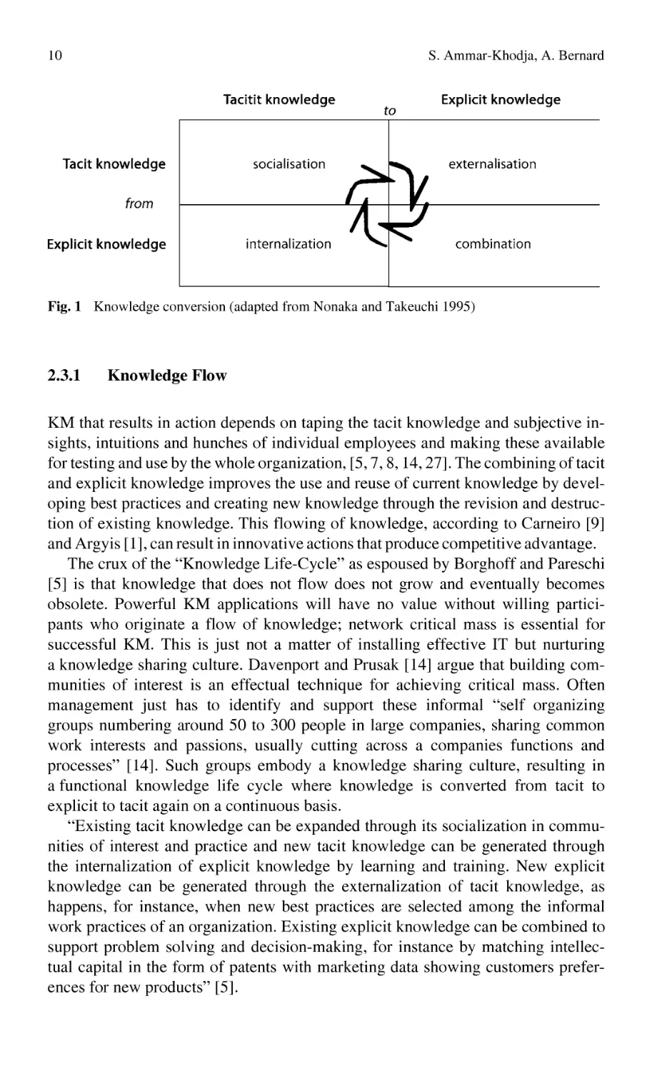
Information is converted into knowledge through a human social process of shared
understanding and sense making at both the personal level and the organizational
level. Nonaka and Takeuchi [25] refer to this flow as the “Knowledge Life-Cycle”
(see Figure next page) and it hinges on the distinction between tacit knowledge
and explicit knowledge. Explicit knowledge is formal knowledge that has been
captured by the corporate memory. It defines the intellectual assets of an organization independently of its employees, thus it is structural knowledge [29]. Tacit
knowledge is practical knowledge, know how that produces action, it’s the key to
getting things done. It has an important cognitive dimension, consisting of “…
mental models, beliefs, and perspectives so ingrained that we take them for
granted, and therefore cannot easily articulate them” [25]. Tacit knowledge is
personal knowledge that is difficult to formulate, measure or value; consequently,
management has ignored it in the past. The recent management interest in tacit
knowledge can be explained by the fact that it’s deeply rooted in action and individual commitment to specific context [25].
10
S. Ammar-Khodja, A. Bernard
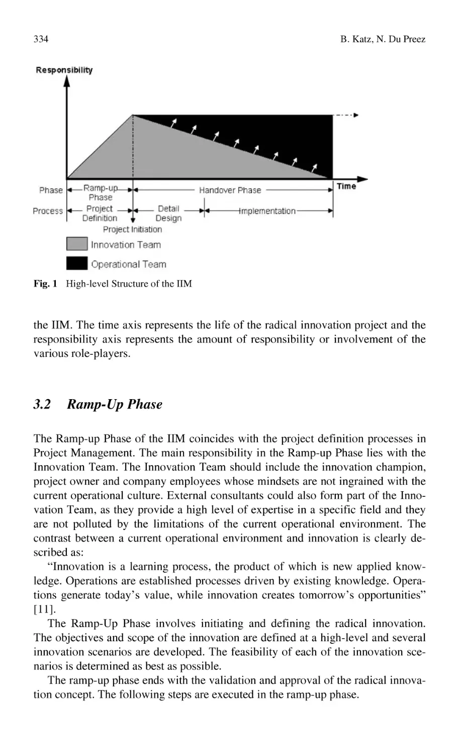
Fig. 1 Knowledge conversion (adapted from Nonaka and Takeuchi 1995)
2.3.1
Knowledge Flow
KM that results in action depends on taping the tacit knowledge and subjective insights, intuitions and hunches of individual employees and making these available
for testing and use by the whole organization, [5, 7, 8, 14, 27]. The combining of tacit
and explicit knowledge improves the use and reuse of current knowledge by developing best practices and creating new knowledge through the revision and destruction of existing knowledge. This flowing of knowledge, according to Carneiro [9]
and Argyis [1], can result in innovative actions that produce competitive advantage.
The crux of the “Knowledge Life-Cycle” as espoused by Borghoff and Pareschi
[5] is that knowledge that does not flow does not grow and eventually becomes
obsolete. Powerful KM applications will have no value without willing participants who originate a flow of knowledge; network critical mass is essential for
successful KM. This is just not a matter of installing effective IT but nurturing
a knowledge sharing culture. Davenport and Prusak [14] argue that building communities of interest is an effectual technique for achieving critical mass. Often
management just has to identify and support these informal “self organizing
groups numbering around 50 to 300 people in large companies, sharing common
work interests and passions, usually cutting across a companies functions and
processes” [14]. Such groups embody a knowledge sharing culture, resulting in
a functional knowledge life cycle where knowledge is converted from tacit to
explicit to tacit again on a continuous basis.
“Existing tacit knowledge can be expanded through its socialization in communities of interest and practice and new tacit knowledge can be generated through
the internalization of explicit knowledge by learning and training. New explicit
knowledge can be generated through the externalization of tacit knowledge, as
happens, for instance, when new best practices are selected among the informal
work practices of an organization. Existing explicit knowledge can be combined to
support problem solving and decision-making, for instance by matching intellectual capital in the form of patents with marketing data showing customers preferences for new products” [5].
An Overview on Knowledge Management
2.3.2
11
Effective Knowledge Application
If the primary role of KM is to stimulate the flow of knowledge throughout the
organization, then how is this behavior to be achieved in such a way that individuals and groups understand the knowledge and its context so as to apply it effectively and Strauss [23] suggest that taping tacit knowledge and stimulating its flow
is possible through a managed process they call “Creative Abrasion”. The centerpiece of “Creative Abrasion” is a recruiting and selection policy that is deliberately designed to staff the organization with a full spectrum of cognitive and
communication styles. Such a human resource (HR) policy can result in a whole
brain organization where the voicing of different perspectives and opinions enhances problem solving. Nonaka [25] agrees with the concept of creative abrasion
but goes further, espousing a model he refers to as the “Spiral of Knowledge”.
According to Nonaka, making tacit knowledge available to others is the central
activity of the knowledge creating company. He contends that this is possible
through the disciplined and systematic use of metaphors, analogies and models to
convert tacit knowledge to explicit knowledge.
This use of figurative language and models to create new knowledge and express
what seems inexpressible is routinely used by organizations such as Xerox, which
used a beer can analogy to invent the photo-copier drum and Honda, which used the
slogan “the theory of automobile evolution” to design the successful Honda Civic.
The pre-eminent organizational theorist, Chris Argyris [1], believes that the
successful articulation of tacit knowledge and the creation of new knowledge depends on the ability to escape “Single Loop Learning” and deploy “Double Loop
Learning” at the individual and organizational level. An example of “Single Loop
Learning” is the use of a particular tool to perform a repetitive function that quickly
wears the tool out, resulting in the technician replacing the tool. If “Double Loop
Learning” were applied the technician would ask, “why does this function have to
be performed?” or “why does this particular design of tool have to be used?” and
then explore whether or not the activity could be eliminated or if some other more
robust tool could be used economically. Argyris espouses that “Double Loop
Learning” moves beyond “Single Loop Learning”, which is premised on preplanned responses to anticipated stimuli, by questioning the appropriateness of preplanned actions. Argyris challenges the common assumption that getting employees to learn and share knowledge is a matter of motivation alone and that when
people have the right attitude and commitment learning and sharing automatically
follows. He contends that incentive schemes and organizational structures designed
to create commitment and motivation don’t affect employees’ cognitive programming. Effective “Double Loop Learning” is a reflection of how employees and
managers think “… that is the cognitive rules or reasoning they use to design and
implement their actions” [1]. This cognitive programming is the aggregate of
a lifetime of experiences, environmental influences and education.
The first step towards “Double Loop Learning” is to teach senior managers
how to reason about their behavior in more productive and effective ways. Argyris
argues that any educational program designed for managers should be connected
12
S. Ammar-Khodja, A. Bernard
to real business issues. He offers one simple approach, having participants produce
a case study concerning a current business issue they are facing. The case becomes
the focal point of a group analysis and discussion that results in the questioning of
all taken for granted assumptions. In effect the case study exercise legitimizes the
discussion of issues that have not been addressed before. “Double Loop Learning”
requires employees to question the relevance of past experience and its appropriateness in current and future situations. It means learning that produces radical
behavior changes in the value chain, resulting in innovative actions and processes
that increase competitiveness. Efforts at double loop learning should be augmented with Leonard and Strauss’s “Creative Abrasion” and Nonaka and Takeuchi’s “Spiral of Knowledge” as diverse views, figurative language and models of
concepts facilitate the social process of articulating tacit knowledge into public
information, permitting its internalization.
2.3.3
Knowledge Market
Davenport and Prusak [14] argue that the above management prescriptions are necessary but on their own are not sufficient to stimulate the flow of tacit knowledge or
produce effective application of knowledge. They believe that market forces power
tacit knowledge movement, working similarly to markets for more tangible goods.
Like markets for goods and services, the knowledge market has buyers and sellers
who negotiate to reach a mutually satisfactory price for the knowledge transaction.
Employees search for knowledge because they expect it to help them succeed in
their work as knowledge is the most sought after remedy to uncertainty.
The knowledge market, like any other is a system in which participants exchange a scarce unit for present or future value. From economic perspective knowledge market transactions occur because all the participants believe they will maximize their utility from them.
Many KM initiatives have been based on the naive assumption that knowledge
flows without friction or economic motives, “… that people will share knowledge
with no concern for what they may gain or lose by doing so” [14]. Organizations
install IT expecting knowledge to flow freely trough the electronic network and
blame the technology, employee skills or employee attitudes when the knowledge
does not flow. Such an outcome is predictable as “… knowledge initiatives that
ignore the dynamics of markets (and, of course human nature) are doomed to fail”
[14]. Davenport and Prusak and Stewart [29], believe that to have a knowledge
market that works well management must understand three market realities:
• Knowledge is a commodity and market forces exist for it;
• Market failures exist and must be captured in order to transform knowledge
into corporate value; and
• Try to understand how knowledge markets operate.
The implication that knowledge markets exist indicates the apparent need to
link the KM initiative to the organizations’ incentive scheme by converting in
An Overview on Knowledge Management
13
money the value of proactive participation. In their research Davenport and Prusak
[14], have found that organizations get what they pay for. Short-term trinkets such
as frequent flyer miles may motivate a single transaction of a KM system but will
not establish the consistent culture of knowledge sharing. To institute a KM culture, organizations must use a valuable currency such as substantial monetary
awards, salary increases, promotions and employment benefits as the primary
lever for creating a knowledge-sharing culture, [Quinn, Anderson & Finkelstein
96]. In order for the KM system to add value it must achieve critical mass
throughout the entire organization. Financial incentive is one method to achieve
this but other non-financial motivating mechanisms, [20] must augment it.
A crucial activity in KM is the stimulation and transfer of knowledge that results in competitive action. However, according to the above cited thinkers this is
dependent on organization structure, incentive scheme, staffing policy, the ability
to articulate tacit knowledge and the motivation and commitment to participate in
the KM initiative.
2.3.4
Structured Knowledge
Knowledge can be reduced to a basic level. At this level all employees can be
aware of various facts and use data from sources such as contracts, annual reports,
market data and production processes. Stewart [29] refers to this type of knowledge, which depreciates quickly, as “intellectual working capital, workaday information – the price of a stock, the name and phone number of XYZ Corp.’s
purchasing executive, the number of gaskets in the warehouse, a nation’s merchandise trade balance – changes all the time”.
As requirements become more technical, knowledge tends to be specialized and
contextually related to other knowledge. This semi-permanent body of specialized
knowledge is intellectual capital according to Stewart and its value is derived from
expertise and the application of knowledge to provide meaning and context to
information and data. At this level, knowledge workers such as researchers, professional engineers, marketers, consultants, lawyers, librarians and accountants are
able to offer insights into what Rittel [28] refers to as wicked problems. According
to Rittel, wicked problems display a number of unique traits as follows:
•
•
•
•
•
•
Cannot be easily defined;
Require complex judgments to define problem;
Have better or worse solutions; not right or wrong;
Have no objective measure of success;
Require trial and error process; and
No alternative; solutions must be discovered.
The above paraphrase reveals the connection between wicked problems and the
knowledge workers’ specialized knowledge and capacity to produce innovative
solutions. This connection and the difference between intellectual working capital
14
S. Ammar-Khodja, A. Bernard
and intellectual capital justify the categorized structuring of knowledge and differentiation of knowledge domains. This is necessary because decision-making processes can become dysfunctional if all knowledge domains are considered similar
resulting in an ineffective corporate knowledge repository. Research indicates that
all “successful knowledge management projects benefit from some degree –
though not much – of a knowledge structure,” [14]. In one case Davenport and
Prusak researched, a large professional services firm that attempted to create
a wholly unstructured knowledge repository, searchable on all words in the database. It was virtually unusable, yielding too many or too few items and retrieving
items that where not in context with the search terms. Firms building a knowledge
repository or Intranet should consider creating knowledge categories within critical business processes and key search terms with a thesaurus to assist users [14].
2.3.5
Organizing Around Knowledge
When designing support schemes for knowledge work, management must evaluate
the structure of the organization and its resource configuration. Organizational and
KM thinkers like Argyris [1], Drucker [16], Stewart [29] all agree that designing
organizational structure around learning, critical examination of past experience,
openness and required knowledge for success provide the optimum environment
for knowledge workers to perform. Such a learning structure has been described as
“an organization skilled at creating, acquiring, and transferring knowledge and at
modifying its behavior to reflect new knowledge and insights” [17].
The learning organization abandons hierarchical structures in an effort to increase responsiveness and organizes itself in patterns specifically tailored to support the particular way its knowledge workers create value, [27]. Such reorganization often involves breaking away from traditional thinking about the role of the
centre as a directing mechanism. By organizing around the work of its value-adding employees management can achieve considerable leverage with the organization’s resources and competencies by eliminating whole layers of management in
the value chain. The reason is straightforward: “It turns out that whole layers of
management neither make decisions nor lead. Instead, their main, if not their only,
function is to serve as relays – human boosters for faint, unfocused signals that pass
for communications in the traditional pre-information organization” [16].
Management in the learning organization functions as a support mechanism for
the knowledge worker focusing individual employees on the joint performance of
the organization, [16]. The function of management changes from issuing orders
to removing barriers, expediting resources, conducting studies and acting as an
internal consultant to the knowledge worker. Management’s main role is to articulate and support the new corporate culture while the traditional departments serve
as guardians of standards, providers of professional development and ensuring
regulatory compliance. The main challenge facing management in the learning
organization is to focus and discipline the creative process without stifling it [29].
An Overview on Knowledge Management
2.3.6
15
Knowledge Management Culture
In short, knowledge workers’ specialized skills and intellect directly influences an
organization’s competitiveness and therefore its growth. Considering their strategic objectives, organizations should define the level of knowledge and what type
of knowledge will be more important to take care of. However, without being
differentiated and stimulated, knowledge may stay in a static relation within functional areas, despite projects being performed by a multi-disciplinary team. Thus,
if KM is charged with stimulating and supporting knowledge flows in an effort to
promote growth, managers should develop the ability to identify critical knowledge, motivate knowledge workers, improve their understanding of knowledge
work and improve their appreciation of how people relate to information.
From this social/cultural approach to the KM philosophy, KM can be explained
as the management of the environment that makes knowledge flow through all the
different phases of its life cycle [25]. Managing knowledge then begins with the
importance of stressing people, their work practices and formal and informal corporate culture in order to differentiate knowledge and stimulate its flow, use/re-use
and creation in the quest for growth.
3
Knowledge Management and Information Technology
Nonaka and Takeuchi’s [25] theories are fundamental to knowledge management
but they fail to recognize IT’s role in enabling the flow of knowledge, capturing
knowledge, combining knowledge and developing knowledge communities. The
management of the IT infrastructure for KM is a critical success factor for an
organization. Indeed in today’s information driven society, much of an organization’s environment is determined by its IT infrastructure.
As Brown [7], Drucker [16], Stewart [29] and Quinn, Anderson and Finkelstein
[27] make clear, past KM and associated IT initiatives that have failed, are a result
of several management misconceptions regarding knowledge work, business strategy and IT:
• Management often neglects to align technology and KM with corporate strategy. IT and KM are only worth investing in the context of strategy.
• Many managers have not accepted that knowledge work is fundamentally
different in character from routine white-collar procedures resulting in the application of technology that does not fit knowledge work processes.
• Traditional organizational structure and human resources policy does not support the fact that knowledge work is cross-disciplinary and therefore knowledge
work teams function in an ad hoc fashion and are completely immersed in
a networked computing environment that is hindered by functional boundaries.
• Management has focused on capturing all organizational knowledge on corporate databases. This is both impractical and impossible.
• Too much KM is inward focused. Too little is about serving customer. Stewart
believes this to be reflection of KM that is driven by HR or Information Systems.
16
S. Ammar-Khodja, A. Bernard
Designing an effective IT information architecture to support a KM initiative is
an important management challenge. Carneiro [9], Borghoff and Pareschi [5] and
Botkin [6] espouse that it is necessary to pay attention to the IT architecture and
implement it in accordance with the organizational functions that use knowledge
and information to make decisions that realize objectives. They, along with Ward
[32], advocate that IT systems must be comprehensive, highly integrated and that
the electronic corporate memory must maximally contribute to the competitiveness of the organization. Furthermore, Borghoff and Pareschi [5] maintain that the
KM IT architecture must improve competitive power by supporting three types of
learning: individual learning, organizational learning through communication and
continuous development of an electronic corporate knowledge repository.
During the industrial era organizations maintained their competitive advantage
by keeping materials and processes secret. For the most part the technology and
higher education levels of the new economy make it almost impossible to prevent
competitors from copying or improving on a new product or new process fairly
quickly. “… In an era characterized by mobility, the free flow of ideas, reverse
engineering, and widely available technology” [14], sustainable competitive advantage from the possession of unique technology has disappeared as technology
is now available to all organizations and its half-life has diminished. The advantage of new products and efficiencies are more and more difficult to sustain. To
remain competitive in the dynamic and complex environment of the new economy
Kotler [18] believes that every company should work hard to obsolete its own
product line before competitors do. The key to this is continuous innovation.
According to Davenport and Prusak [14], knowledge by contrast to materials
and processes can provide sustainable competitive advantage as it generates increasing returns and continuing advantage. Stewart [29] makes it clear that knowledge assets increase with use as ideas propagate ideas and sharing knowledge
enriches the receiver. So what KM approaches are organizations pursuing to leverage the knowledge advantage? Koulopoulos and Frappaolo [20] point out three
approaches that are not mutually exclusive, currently being undertaken by industry.
Two of them are the following and will be commented in the following paragraphs:
• The learning organization;
• The knowledge library.
3.1
The Learning Organization
As discussed earlier the learning organization is concerned with enabling organizations to handle new business strategies. The learning organization is orientated
to cultural reform of organizational attitudes and practices surrounding knowledge. The organization focuses on the way people think and learn competencies,
rather than on the way they organize their knowledge. The learning organization
values team learning through the exchange of tacit knowledge. In this way the
learning organization manages the risk of the loss of key employees by mitigating
An Overview on Knowledge Management
17
knowledge monopolies and developing team knowledge. The ultimate objective of
team learning is to improve the levels of organizational innovation.
3.2
The Knowledge Library
The knowledge library “approach to KM focuses on enhancing the organisations
ability to manage new projects or processes” [20]. As explained by Borghoff and
Pareschi [5] this approach is best suited for environments in which the basic stimuli are not subject to dynamic and complex change. Typically the objective of the
initiative is to establish a corporate knowledge base, capital structure, for the capture and dissemination of best practices and project related knowledge. The function of the database is to share insights gleaned from the organization’s previous
experiences, in the hope that they may find application in future projects in an
effort to avoid reinventing the wheel. Projects, processes and case studies are
documented with relevant supporting documents. Management challenges in this
KM approach are the classification and organization of knowledge/information in
a fashion that matches the work needs of people with knowledge held by others
and encouraging the use of the knowledge base.
4
Knowledge Management Approaches
According to the organization objectives, two knowledge management approaches
appeared: the former considers the informational resources as the experiment of
the organization (“information oriented”), while the latter becomes essentially
attached to the knowledge (“knowledge oriented”). These two approaches distinguish themselves by the nuance between information and knowledge. Indeed, if
basic stages are common (Acquisition/Generation, Memorization, Treatment and
Communication), the objects that they manipulate are as for them different [10].
These differences have significant ramifications for the elaborated tools: those of
IS, for example, don’t include the phases of knowledge extraction near the actors
of the company, like in the case of the knowledge management, without forgetting
the knowledge obtained by the practice which one generally doesn’t find in documents, as well as the reasoning mechanisms of the actors that are not taken in
account. However, the experiment is a significant type of knowledge that is not in
the documentary mass of the company.
4.1
Information Oriented Approach
In this approach, we consider that the documents constitute knowledge [26] or that
the information management is a source of experiment of the company [21]. In
18
S. Ammar-Khodja, A. Bernard
this sense, some company’s memories projects were essentially interested in the
existing documents in the company of which it is going to be about organizing the
access and the exploitation. Among the tools conceived in this setting, it is possible to distinguish:
• Those that rest on the documents themselves (under all their forms, papers,
electronic ...) as it is the case in DIADEME system [26] developed for the direction of research at EDF. This tool is essentially based on the existing documents and those generated by this service: technical reports, congress articles,
experiment reports in paper, audio or video format. These documents are neither transformed nor modeled. The tool permits storage and indexing so that
they are easily accessible. Several methods of interrogation exist, however
keyword search is most common.
• Those that rest on the representation of these documents, these tools will permit
modification in the way documents are reached [10]. These representations authorize more advanced means of exploitation. To alleviate the formalization
phase that can be time-consuming and expensive (from the mobilized personnel
point of view) the designers tend to automate this task. These representations
are not intended for the users, who would have to assimilate the formalism of it,
but allow the research’s systems that use them to have a finer picture of the
content of the document than that given by simple key words. In Knowledge
Organizer of [21] the user browses a semantic network that categorizes different references to available documents visually. The nodes of the network include some basic information regarding the document: the title, the date of last
update, the author's number identifier, the address URL of the document. The
ties of the network comprise a label that describes the nature of the relation between two documents. In other cases, the representations of the documents are
built to be exploited in an automatic way by Workflow’s tools in quest of information.
The oriented information approach for knowledge management has an essential
advantage that can influence the choice of an experiment management strategy:
simplicity of implementation and low cost. Resting on the existing documentation
basis, it doesn’t require a knowledge extraction phase. Besides, it can rely on the
available tools within the company as those already integrated within the IS. However, it has the disadvantage of exploiting, for experiment transfer, documents that
have not necessarily been produced accordingly (management reports, technical
documentation, etc.) [22] and it sometimes cuts down to only one type of document (internal and external mails).
4.2
Knowledge Oriented Approach
The knowledge-oriented approach tends to model expert knowledge in order to
build automatic problem resolution tools in order to protect the experience gained
An Overview on Knowledge Management
19
by an organization. Declarative and procedural knowledge transcribed in the form
of rules, facts, cases, procedures of reasoning will translate a part of the experience
acquired by the staff of the organization. Several works have been given in this
approach and a significant number of methods were elaborated and standardized.
This knowledge management and capitalization approach has considerable advantages particularly in the capacity of work in a global manner [10]. However,
this capacity is at the origin of the increased delays and of the costs of setting in
work and update of the systems.
5
Conclusion
In the age of international markets and increased worldwide competition, many
enterprises are looking for new ways to gain and maintain competitive advantage.
One way is the use of their intellectual capital. Since most companies have access
to the same processes, cost management techniques and material management
systems, the only thing that separates them is the knowledge held within each
company. Research conducted by Kock and al [18] has shown that, in a typical
company, approximately ninety per cent of all exchange processes involve the
exchanging of data. Approximately seventy-five percent of this data is classed as
information or knowledge. This percentage is set to rise, due to the advances in
expert knowledge-based technologies and an increase in their use.
The management of this intellectual capital comes true by a complete loop of
identification, structuring, modeling, and setting in work of capitalization techniques and reuse of knowledge in the organization. In order to be profitable, this
loop must be efficiently managed, being analyzed and subject to management
rules. It must not only lean on individual knowledge but on the whole organization’s knowledge, and also includes structuring, storage and sharing tools.
References
1.
2.
3.
4.
5.
Argyris C (1991). ‘Teaching Smart People How to Learn’, Harvard Business Review: on
Knowledge Management
Barclay, RO and Murray PC (2000). What is knowledge management? Knowledge Praxis,
Available from http://www.media-access.com/whatis.html
Benyon D (1990). Information and data modelling. Henley-on-Thames UK: Alfred Waller
Ltd.
Boisot M (1998). Knowledge Assets: Securing Competitive Advantage in the Information
Economy. Oxford: Oxford University Press
Borghoff M and Pareschi R (1998). ‘Information Technology for Knowledge Management’,
Berlin, Springer-Verlag
20
S. Ammar-Khodja, A. Bernard
6.
Botkin J and Hawkins S (1999) ‘Building the Knowledge Advantage’, paper presented at
the Lyceum Series Conference, 1999, Available from www.pwcglobal.com
Brown S (1991) ‘Research That Reinvents the Corporation’, Harvard Business Review: on
Knowledge Management
Bukowitz W and Williams R (1999) ‘The Knowledge Management Fieldbook’, Great
Britain, Pearson Education Limited
Carneiro A (2000) ‘How does knowledge management influence innovation and competitiveness?’ Journal of Knowledge Management, 2000 v4 n2, pp. 87−98
Caussanel J and Chouraqui E (1999) ‘Information et Connaissances: quelles implications
pour les projets de Capitalisation des Connaissances’, Revue Document numérique – Gestion des documents et Gestion des connaissances, vol. 3−4, pp. 101−119, Numéro spécial
Contractor FJ and Lorange P (2002). The growth of alliances in the knowledge-based economy. International Business Review, 11, 485–502
Court A W (1995). Modelling and classification of information for engineering design.
Ph.D. Thesis, University of Bath, UK
Davenport T and Marchand D (2000) ‘Is KM just good information management’, Financial
Times Mastering Information Management: Complete MBA Companion In Information
Management. Great Britain, Pearson Education Limited
Davenport T and Prusak L (2000) ‘Working Knowledge: How Organisations Manage What
They Know’, United States of America, Harvard Business School Press
Devine DJ and Kozlowski SWJ (1995). Domain-specific knowledge and task characteristics
in decision-making. Organisational Behaviour and Human Decision Processes, 64(3),
294−306
Drucker PF (1988) ‘The coming of the New Organization’, Harvard Business Review Review: on Knowledge Management
Garvin DA (1993) ‘Building a Learning Organisation’, Harvard Business Review: on
Knowledge Management
Kock NF, McQueen RJ, Corner JL (1996) ‘The nature of data, information and knowledge
exchanges in business processes: implications for process improvement and organisational
learning’, The Learning Organisation, Volume 4, Number 2, pp. 70−80
Kotler P (2000) Marketing Management the Millennium Edition, New Jersey, Prentice Hall
Inc
Koulopoulos T and Frappaolo C (1999) Smart Things To Know About Knowledge Management, United Kingdom, Capstone Publishing Limited
Kuwata Y (1997) ‘Managing Knowledge using a Semantic-Network’, proceedings of AAAI
Spring Symposium on Artificial Intelligence in Knowledge Management, pp. 94−98
Lemoigne, J-L (1990) ‘La modélisation des systèmes complexes’, Dunod
Leonard D and Strauss S (1997) ‘Putting Your Company’ Whole Brain to Work’, Harvard
Business Review: on Knowledge Management
Mille A (2001) ‘Connaissances et coopération dans les systèmes industriels’, Gestion des
connaissances: problématiques actuelles, Hermes
Nonaka I and Takeuchi H (1995) The Knowledge Creating Company, New York, Oxford
University Press, Inc
Poitou JP (1995) ‘Documentation is Knowledge: An Anthropological Approach to Corporate Knowledge Management’, Proceedings of ISMICK'95, pp. 91−103, Compiègne, France
Quinn JB, Anderson P and Finklestein S (1996) ‘Managing Professional Intellect: Making
the Most of the Best’, Harvard Business Review: on Knowledge Management
Rittel HWJ (1972−1973); cited by Borghoff and Pareschi (1998) Information Technology
for Knowledge management, Berlin, Springer-Verlag
Stewart TA (1999) Intellectual Capital: The New Wealth of Organisations, London, Nicholas Brealey Publishing
Teece D (1998). ‘Capturing Value from Knowledge Assets: The New Economy, Markets
for Know-How, and Intangible Assets’. California Management Review. Vol. 40, No. 3,
55−79
7.
8.
9.
10.
11.
12.
13.
14.
15.
16.
17.
18.
19.
20.
21.
22.
23.
24.
25.
26.
27.
28.
29.
30.
An Overview on Knowledge Management
21
31. Tomiyama T (1995). A design process model that unifies general design theory and empirical findings. ASME Design Engineering, 83(2), 329–340
32. Ward J (1995) ‘Principles of Information Systems Management’, London, Routledge Publishing
33. Wilson P (1987). Information Modeling. IEEE Computer Graphics and Applications
(pp. 65–67) December 1987
34. Zacklad MH (1999). Managing codified knowledge Sloan Management Review, 40, 4,
45−58
Manufacturing Knowledge Work:
The European Perspective
Fons Wijnhoven
University of Twente, Enschede, The Netherlands
a.b.j.m.wijnhoven@utwente.nl
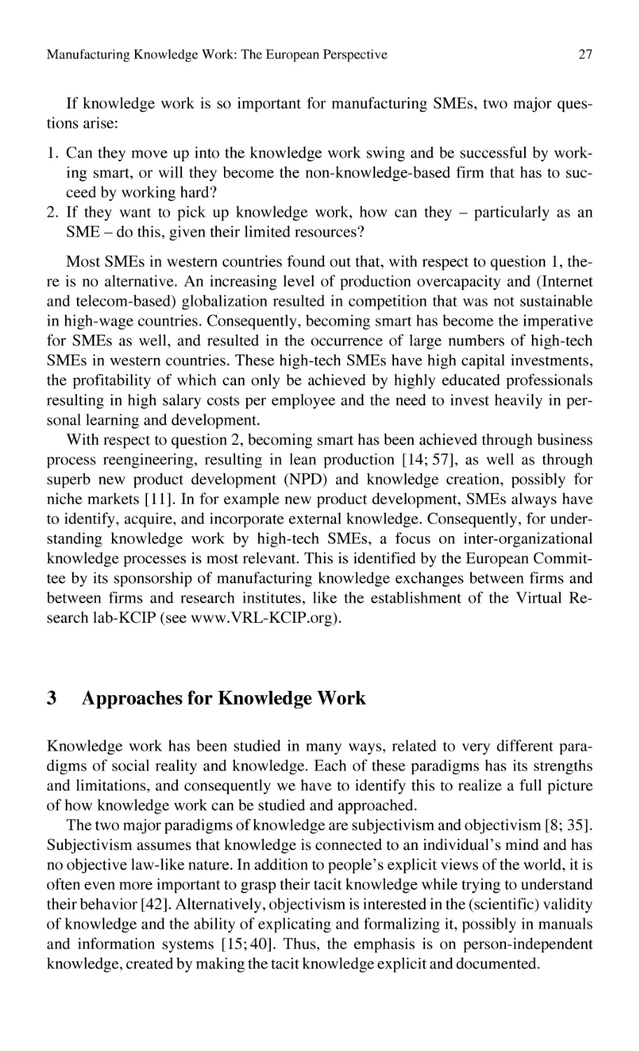
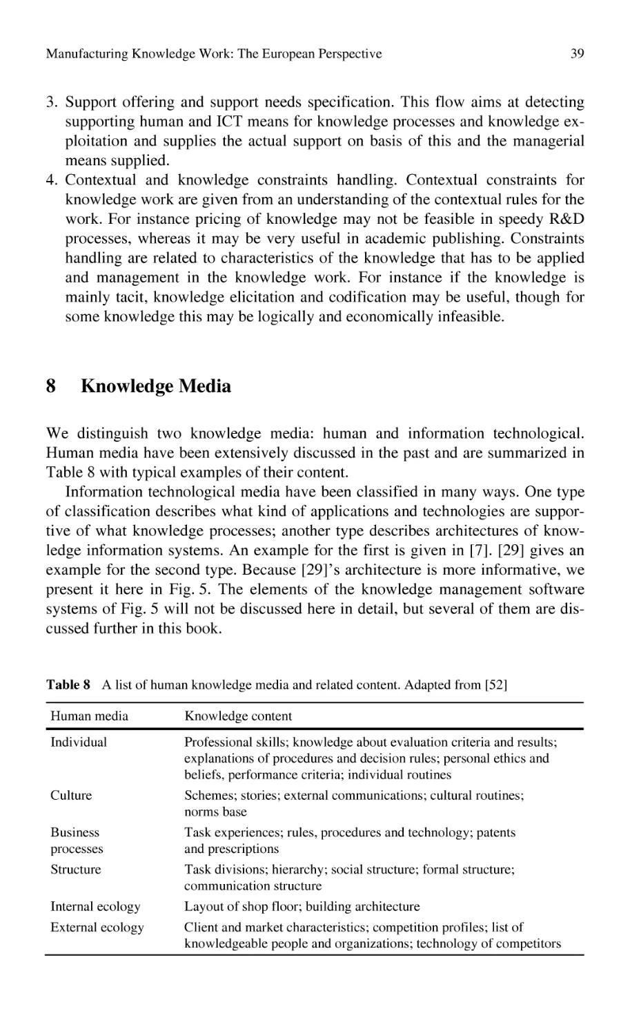
Abstract The handling of knowledge in specific contexts is often labeled knowledge management. A more precise analysis of the literature in the knowledge
management field, though, distinguishes four different domains with regard to the
handling of knowledge in context, i. e., knowledge management, knowledge processes, knowledge media, and knowledge exploitation. These domains we name
knowledge work. We also introduce four approaches to the study of knowledge
work, and operationalize the domains of knowledge work, knowledge contexts and
the knowledge concept itself, to help researchers and practitioners in the manufacturing field to be more precise with regard to their analyses of knowledge work.
Keywords: knowledge work; knowledge management; knowledge processes;
knowledge media.
1
Introduction
Manufacturing in Europe currently has two essential aspects:
1. It has to be knowledge intensive given the European demands for high-tech
products (e. g. electronics, medicines).
2. Given the relatively high labor costs compared to developing countries, manufacturing processes in Europe require high levels of expertise to realize very
high productivity.
Consequently in Europe, knowledge management (KM) has become a major issue in academia and industry in the last 30 years [21], and it is recognized that the
knowledge issue is important for a firm’s managers as well for operational work.
This article will describe the main areas and concepts related to knowledge work.
A. Bernard, S. Tichkiewitch (eds.),
Methods and Tools for Effective Knowledge Life-Cycle-Management,
DOI: 10.1007/978-3-540-78431-9_2, © Springer 2008
23
24
F. Wijnhoven
Knowledge work has at least four roots.
1. Products and services for western economies have become increasingly complex, incorporating larger amounts of public and proprietary knowledge and
technologies ([6; 11; 13]. Consequently, companies who want to stay in business have to develop management practices that incorporate a view on knowledge and technologies that are needed in the future [20; 39]. The field of strategic management has recognized this and developed the idea that the optimal
use of intellectual capabilities may be the best source for sustaining competitiveness [3, 17, 39].
2. Organization and human relations professionals and academics have recognized
the need for more academically challenging jobs and for using the opportunities
of an increasingly highly educated work force in modern societies [3, 42,
43, 47]. This also resulted in insights concerning new work practices and processes for the creation, maintenance, and reuse of knowledge [32, 34, 35], and
the development of ideas concerning organizational and inter-organizational
knowledge processes.
3. Suppliers of information technology and academics in this field have developed
opportunities of supporting knowledge reuse and knowledge creation by, among
others, artificial intelligence, knowledge-based systems, and Internet applications [15, 28].
4. All these management, organizational, and information technological efforts
have to result in better (i. e. more suitable to the new market realities) products,
services, and manufacturing processes. In all cases knowledge work is not
“l’art pour l’art” but intended to contribute to business processes. Research in
the area of knowledge flows [24]) emphasizes this fact and also recognizes that
this flow from insight into application is not always easy [26, 35, 57].
Consequently innovations in information technology, organization, and organizational strategies jointly realize the development of knowledge work. The aimedat knowledge leverage [51] requires a supportive context which is mostly not limited to a task unit, or one organization, but often requires inter-organizational collaboration. This is particularly so for high-tech SMEs, which need much advanced
knowledge that, because of SMEs limited organization size, must to a far extent be
identified and acquired from other organizations, and be finally internally used [24].
These processes of external knowledge identification, acquisition, and internal
utilization of external knowledge are named knowledge integration (KI).
While discussing knowledge work, we have to be aware of the huge diversity
of the knowledge construct. Knowledge may for instance include person-dependent skills, explicitly described insights (like explanations, formulas, designs,
predictions, and patents), effective work procedures, rules and methodologies, and
databases [24; 54]. These different types of knowledge may need different ways of
treatment in the four areas of knowledge work, an issue we will come back to
further on.
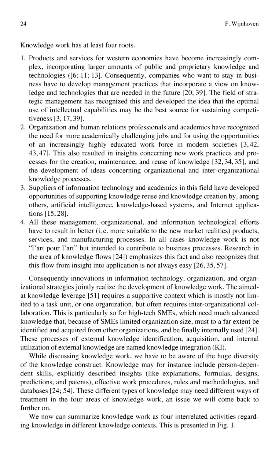
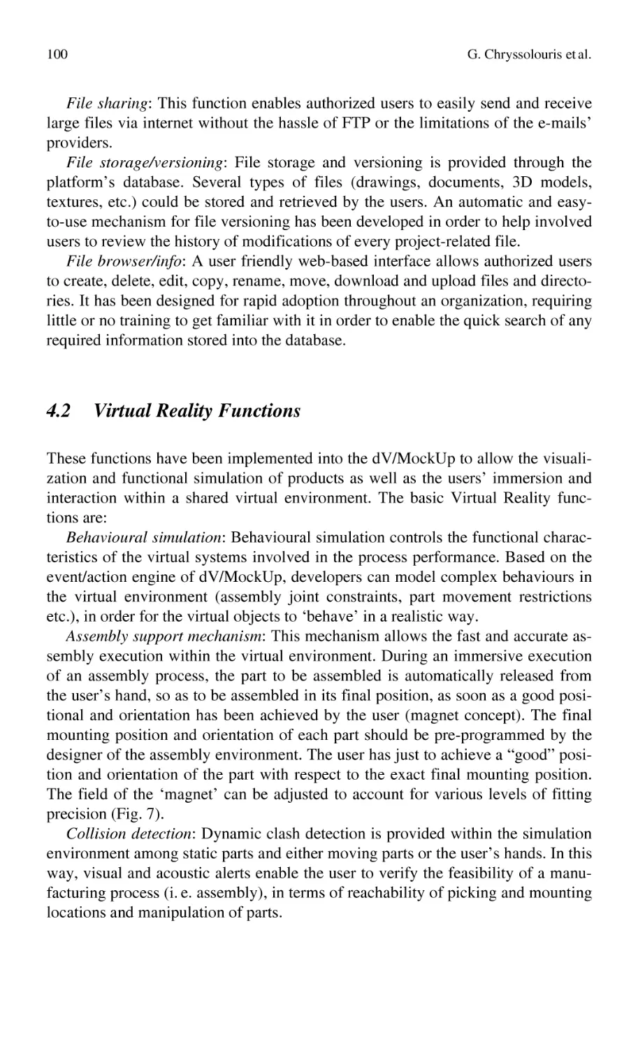
We now can summarize knowledge work as four interrelated activities regarding knowledge in different knowledge contexts. This is presented in Fig. 1.
Manufacturing Knowledge Work: The European Perspective
25
Fig. 1 A model of knowledge work based on [55]
This article discusses each of the six aspects of knowledge work, related key
concepts and issues of knowledge work for research and practice in manufacturing. Before doing so, we will give some more evidence of the relevance for
knowledge work for manufacturing in Sect. 2 and we will described four different
ways of approaching knowledge work in Sect. 3.
2
The Relevance of Knowledge Work for Manufacturing
Knowledge work is particularly important to high-tech firms, because high-tech
firms create most of their value-added by knowledge-intensive activities, like
26
F. Wijnhoven
engineering, management of high-tech facilities, research, and new product development. Unfortunately, however, it is difficult to implement knowledge work in
manufacturing, because manufacturing-specific knowledge work theories, methods and techniques are rare. Most of the current knowledge work concepts have
been developed in the context of large firms, particularly from the service industry
(e. g. consulting). This is illustrated by Table 1, which presents a few of the major
knowledge work concepts and their organization of origin.
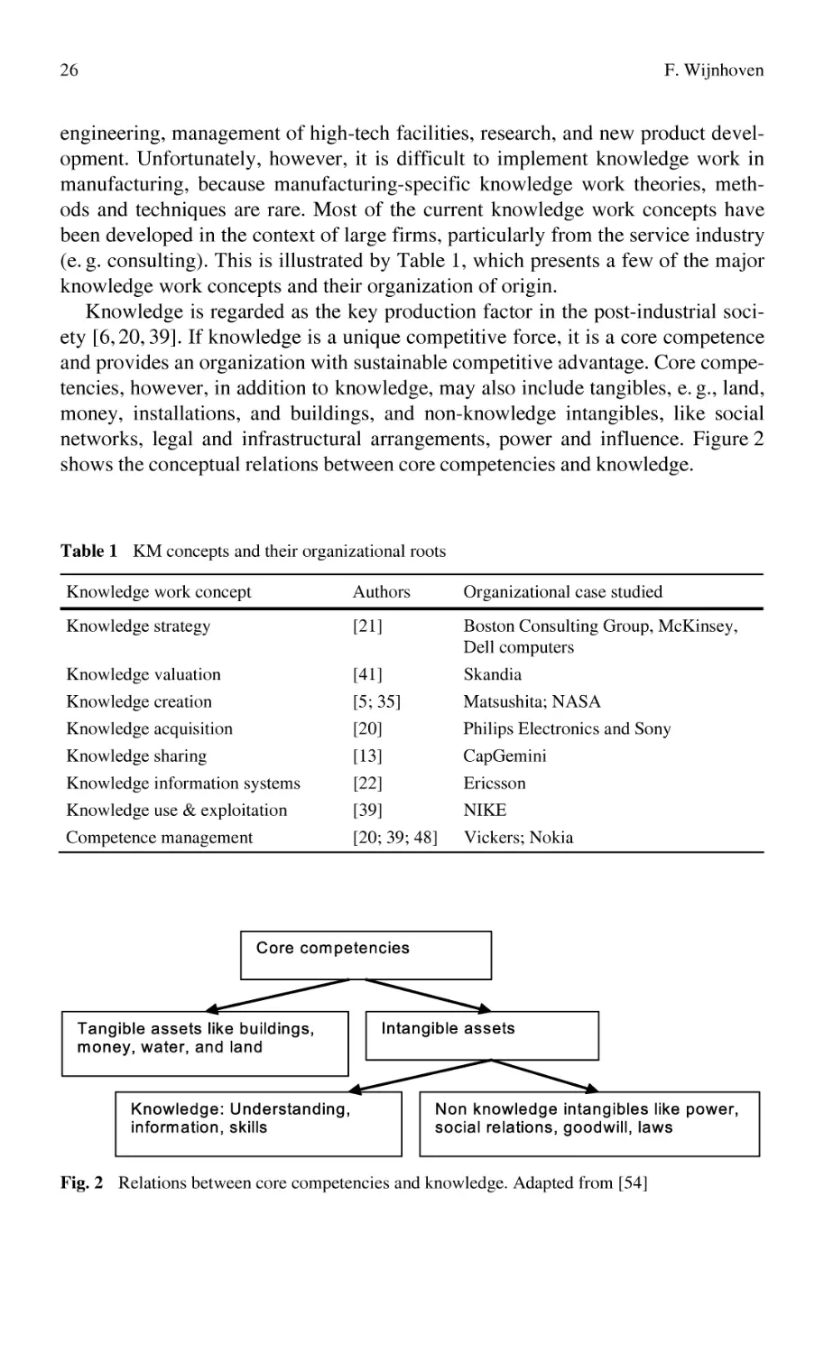
Knowledge is regarded as the key production factor in the post-industrial society [6, 20, 39]. If knowledge is a unique competitive force, it is a core competence
and provides an organization with sustainable competitive advantage. Core competencies, however, in addition to knowledge, may also include tangibles, e. g., land,
money, installations, and buildings, and non-knowledge intangibles, like social
networks, legal and infrastructural arrangements, power and influence. Figure 2
shows the conceptual relations between core competencies and knowledge.
Table 1 KM concepts and their organizational roots
Knowledge work concept
Authors
Organizational case studied
Knowledge strategy
[21]
Boston Consulting Group, McKinsey,
Dell computers
Knowledge valuation
[41]
Skandia
Knowledge creation
[5; 35]
Matsushita; NASA
Knowledge acquisition
Knowledge sharing
[20]
[13]
Philips Electronics and Sony
CapGemini
Knowledge information systems
Knowledge use & exploitation
[22]
[39]
Ericsson
NIKE
Competence management
[20; 39; 48]
Vickers; Nokia
Fig. 2 Relations between core competencies and knowledge. Adapted from [54]
Manufacturing Knowledge Work: The European Perspective
27
If knowledge work is so important for manufacturing SMEs, two major questions arise:
1. Can they move up into the knowledge work swing and be successful by working smart, or will they become the non-knowledge-based firm that has to succeed by working hard?
2. If they want to pick up knowledge work, how can they – particularly as an
SME – do this, given their limited resources?
Most SMEs in western countries found out that, with respect to question 1, there is no alternative. An increasing level of production overcapacity and (Internet
and telecom-based) globalization resulted in competition that was not sustainable
in high-wage countries. Consequently, becoming smart has become the imperative
for SMEs as well, and resulted in the occurrence of large numbers of high-tech
SMEs in western countries. These high-tech SMEs have high capital investments,
the profitability of which can only be achieved by highly educated professionals
resulting in high salary costs per employee and the need to invest heavily in personal learning and development.
With respect to question 2, becoming smart has been achieved through business
process reengineering, resulting in lean production [14; 57], as well as through
superb new product development (NPD) and knowledge creation, possibly for
niche markets [11]. In for example new product development, SMEs always have
to identify, acquire, and incorporate external knowledge. Consequently, for understanding knowledge work by high-tech SMEs, a focus on inter-organizational
knowledge processes is most relevant. This is identified by the European Committee by its sponsorship of manufacturing knowledge exchanges between firms and
between firms and research institutes, like the establishment of the Virtual Research lab-KCIP (see www.VRL-KCIP.org).
3
Approaches for Knowledge Work
Knowledge work has been studied in many ways, related to very different paradigms of social reality and knowledge. Each of these paradigms has its strengths
and limitations, and consequently we have to identify this to realize a full picture
of how knowledge work can be studied and approached.
The two major paradigms of knowledge are subjectivism and objectivism [8; 35].
Subjectivism assumes that knowledge is connected to an individual’s mind and has
no objective law-like nature. In addition to people’s explicit views of the world, it is
often even more important to grasp their tacit knowledge while trying to understand
their behavior [42]. Alternatively, objectivism is interested in the (scientific) validity
of knowledge and the ability of explicating and formalizing it, possibly in manuals
and information systems [15; 40]. Thus, the emphasis is on person-independent
knowledge, created by making the tacit knowledge explicit and documented.
28
F. Wijnhoven
Table 2 Approaches for the study of knowledge work. Adapted from [54]
Subjectivism
Epistemology
Objectivism
Ontology
Order
Conflict
Cybernetic perspective.
Scientific Management.
Knowledge work is discovering
objective reality.
Requires: data and models.
Individualistic developing and testing
of knowledge.
Knowledge is about the production
process (organizational technology).
This approach is most useful when
there are no conflicting perceptions
of reality and information systems
can handle all the knowledge needed
unambiguously.
Knowledge work is used to change power
relations.
Requires detecting sources of conflict,
and latent dysfunctions.
Knowledge work is mainly done by the
power elite.
Knowledge is the technology of
domination.
This approach explains knowledge as
power, which is relevant when knowledge owners (and firms) are in mutually
competitive relations with each other.
Soft Systems.
Organization Development.
Knowledge work is about perceptions
that motivate behaviour and about
organizational change.
Requires feeling with ‘reality’, by soft
modeling.
Individuals interacting in a specific
social context (culture).
Knowledge is, e. g., work attitudes,
collaboration, leadership, and understanding cause-effect relationships.
This approach is most useful when
people have to develop collaborative
knowledge work settings and in which
information systems may be used to
facilitate work.
Knowledge work is about understanding
dysfunctions caused by routine processes
and problems of change.
Requires: open communications, mutual
feelings of trust and willingness to
change.
People interacting in a specific social
setting (power relations).
Knowledge is about social and political
issues influencing organizational
processes and thought.
This approach is most useful when
substantial efforts are needed
to develop collaboration between
teams and organizations.
With respect to the nature of social reality, again, two paradigms may be distinguished, one based on order and regulation, and a second one based on conflict
and radical change. Knowledge has an obvious role in both of them. In regulation,
it can provide or help to define the solution to shared problems and increase organizational integration and efficiency [1, 5, 7]. In radical change, knowledge may
be used as an instrument for outperforming competitors in the market place, as
well as a source for internal power [12, 13].
Table 2 describes the four knowledge management perspectives that result from
combining the approaches on knowledge (epistemology) and social reality (ontology). The perspectives differ on:
• definition of knowledge work (process and purpose),
• requirements for knowledge work (data, views, etc.),
Manufacturing Knowledge Work: The European Perspective
29
• definition of knowledge actors (a group or an individual, a specific elite, all
organization members or the organization), and
• definition of knowledge (that changes under the influence of learning).
• value of an approach to knowledge work.
Our approach to knowledge work is rooted in pragmatics [10; 33], i. e. we regard all different paradigms and approaches as valuable in delivering insights that
fit into each specific paradigm, but each paradigm is pragmatically valuable only
in a specific situation. This implies that we need all paradigms and apply them
when appropriate. In the rest of this article, we will go in more depth into each
aspect of knowledge work (i. e. context, content, management, processes, media
and exploitation) as presented shortly in Fig. 1 before.
4
Knowledge Context
We identify at least two contexts for knowledge work: 1) the intra organizational
context, which may be more or less under control of a hierarchical regime, and
2) the inter-organizational context, which is governed by network and or market
principles.
4.1
The Intra Organizational Context of Knowledge Work
Task and firm/industry setting are important contexts for knowledge work within
an organization. Following this division, Nordhaug [36] distinguishes background
knowledge, industry-based knowledge, intra-organizational knowledge, standard
technical knowledge, technical trade knowledge, and unique knowledge, as shown
in Table 3.
Background knowledge is general knowledge with often a significant tacit component like individual literacy, knowledge of foreign languages and mathematics.
Industry-based knowledge is relevant for role-related organizational activities and
Table 3 Knowledge and contexts. Adapted from [36]
High Low
Task
specificity
Firm/industry specificity
Low
Medium
High
Background knowledge
Industry knowledge
Intra organizational
knowledge
Standard technical
knowledge
Technical trade
knowledge
Unique knowledge
30
F. Wijnhoven
comprises, for instance, knowledge of the industry structure, its current state of
development, the key individuals, networks and alliances. Intra-organizational
knowledge is highly firm- and industry-specific, but not specific to organizational
tasks or activities. This is firm-specific background knowledge and comprises,
e. g., knowledge about organizational culture, communication channels, informal
networks, organizational strategy and goals. Standard technical knowledge is taskspecific and involves a wide range of operationally-oriented knowledge that is
generally available to all actors, like financial and accounting practices, knowledge
of computer programming and software packages, knowledge of craft and engineering principles. Technical trade knowledge is task- and industry-specific, i. e.,
generally available among firms in an industry, like knowledge of automobile
construction methods and knowledge of techniques for computer hardware construction. Unique knowledge is specific across all dimensions. It consists, at the
individual level, of self-knowledge and skills, and, at the organizational level, of
unique organizational routines, production processes, and IT infrastructures.
4.2
The Inter-organizational Context of Knowledge Work
The knowledge work models developed so far by other authors (see e. g. Table 1)
do not explicitly consider the need for activities to go outside the firm and detect
knowledge from other organizations. Additionally, much is known in the knowledge work literature on internal (hierarchical context) knowledge work, but not so
much is known about identifying, acquiring and using external knowledge. Section one explained that at least three stages of KI can be distinguished 1) identification, 2) acquisition, and 3) utilization.
The economic literature has extensively discussed two types of inter-organizational exchange mechanisms which have high implications for how knowledge
work happens: markets and networks [27, 56]. For market exchanges to work
properly, the goods to be exchanged must be very precisely defined (that is, codified), prices act as communication mechanisms, and coordination is realized via
the price mechanism. The actors involved must be fully independent and, if the
existing exchange mechanism does not work properly (e. g., a buyer cannot find an
existing supplier or the costs of negotiating prices are too high), brokers can be
useful intermediaries. In the context of KI, this involves the exchange of explicit
knowledge, such as knowledge documented in patents and software, or specified
commercial services (e. g., accounting and legal and financial consultation).
In the context of network exchanges, economic actors collaborate and, thus, are
mutually beneficial to each other. The collaboration is mainly based on mutual
trust and respect and, in such a situation, pricing is not needed (and, in addition, is
a too expensive coordination mechanism, because it requires a lot of negotiations
that obstruct effective collaborations). The network exchange context also enables
the exchange of ambiguously and non-codified knowledge and, thus, enables the
Manufacturing Knowledge Work: The European Perspective
31
Table 4 Comparison of knowledge exchange models
Exchange Market
governance
Network
Hierarchy
Tacit, latent
and explicit
Tacit, latent
and explicit
Interorganizational
knowledge context
Knowledge type
Explicit
Coordination
Formalization of
exchange process
Price mechanism Collaboration
High
Low
Supervision
Bureaucratic or based
on authority
Means of communication
Prices
Relational
Routines
Network participant
dependency
Independent
Interdependent
Dependent
Tone or climate
Intermediation
Suspicion
Broker
Mutual benefits
Network facilitation
Power
Administration
and communication
offices
exchange of latent knowledge and the joint development of explicit and tacit
knowledge in collaboration efforts.
Both the market and the network exchange mechanisms are radically different
from the hierarchical context. Hierarchies for knowledge work may work sometimes in large firms but are mostly insufficient for SMEs, given the latter's limited
knowledge resources. Table 4 summarizes the KI context variables and how these
behave compared with hierarchical contexts.
5
5.1
Knowledge Content
Knowledge and Information
Knowledge is frequently defined in relation to information and data. Table 5 gives
an impression of the diversity of interpretations of these three terms in the current
literature. It shows that there is no unanimity on either of them, but the distinction
between data, information and knowledge seems to be a very popular way of
thinking about what it is what we want to identify and acquire in KI contexts.
Because this chapter is on knowledge work and not on information or computer
science, the distinction between data and information is not as interesting as the
distinction between types of knowledge is.
32
F. Wijnhoven
Table 5 Definitions of data, information, and knowledge (based on [45])
Data
Information
Knowledge
Author
Not yet interpreted
symbols
Data with meaning
The ability to assign meaning
[50]
Simple observations
Data with relevance
and purpose
A message meant
to change the
receiver’s perception
Text that answers the
questions who, what,
or where
Valuable information from the
human mind
Experience, values, insights, and
contextual information
[12]
A set of discrete facts
Text that does not
answer questions to
a particular problem
[13]
Text that answers the questions why
or how
[38]
Facts and messages
Data vested with
meaning
Justified, true beliefs
[9]
Signs/carriers
Representations with
linguistic meaning
Norms & values, explicit
understanding, skills
[54]
Carriers of information and knowledge
Description carried
by data
Correlational and causal associations
[26]
–
Facts organized to
describe a situation
or condition
A flow of meaningful
messages
Truths, beliefs, perspectives,
judgments, know-how and
methodologies
Commitments and beliefs created
from these messages
[53]
–
5.2
[35]
Different Types of Knowledge
The Table 5 does not only show that knowledge, information and data can be
differently distinguished, but also that many definitions of knowledge exist. It is
difficult to be complete with classifications, but a rather interesting classification
largely based on [2] is given in Fig. 3.
This classification gives some bit of the large diversity of possible knowledge
classifications. The knowledge management literature has currently emphasized
the semiotic distinction between tacit and explicit knowledge, which implies
a focus on the problem of how tacit knowledge can be codified (if at all) and how
codified knowledge can be internalized as part of personal believes. Although the
other classification dimensions are as interesting, we will shortly only review
some of the insights along the semiotic dimension.
Manufacturing Knowledge Work: The European Perspective
33
Fig. 3 A classification of knowledge types based on [2]
5.3
A Semiotic Classification of Knowledge
The semiotic dimension distinguishes besides of tacit and explicit knowledge also
latent knowledge. These distinctions are useful because these three types of knowledge require very different processes, involve different problems, and demand
different solutions. The distinction between tacit and explicit knowledge has been
well described by the philosopher Polanyi who said that “we can know more than
we can tell” [37: 4]. In short, the part that we can tell is the explicit part and the
part that we cannot tell is the tacit part of knowledge. Polanyi has stressed that
knowledge always has both a tacit and an explicit dimension. For example, the
knowledge represented in this book is explicit because it can be explained in detail
in text, figures, and tables. However, the extent to which you as a reader are able
to understand this book is what Polanyi would have called the tacit part of knowledge. It is tacit since you cannot explain exactly why you understand it (or not).
Just like Nonaka and Takeuchi did in the early 90s [34; 35], however, we treat
these two dimensions as a distinct typology: there is tacit and explicit knowledge.
While Polanyi, Nonaka, and Takeuchi have made the distinction between
knowledge that can and knowledge that cannot be expressed, their distinction is
often confused with the distinction between knowledge that is and knowledge that
is not expressed (for example in documents). In this book, we distinguish three
levels of explicitness of understanding or prehension in order to reflect this difference. The first type is tacit knowledge, which is not and cannot be expressed. The
34
F. Wijnhoven
Table 6 Content: knowledge prehension and representation
Representation
Latent
Explicit
Comprehension
Tacit
Not represented
Represented
Person-dependent skills; personal
knowledge;
Production volumes and characteristics, without
a full explanation of how it was realized. Also
much tooling, recipes and work methods.
Shared informal norms and values;
Information about people with their personal
i. e., ‘the way we do things
knowledge (of course the personal knowledge
around here’.
stays personal, but the representations of the
people are feasible so that they can be found).
Explicit insights that can be gained after
simulations, tests, and business process analyses.
Person-independent, non-documented Documented knowledge and information, i. e.,
shared knowledge embracing
representations of knowledge,
explanations, predictions and
designs, production plans or of objects
methodologies.
and events in reality that may be used for
knowledge creation (potential knowledge).
second type is explicit knowledge, which is expressed, or could be expressed
without attenuation. The third type is latent knowledge, which could be expressed,
but is not because of inherent difficulties to express it without attenuation. The
difficulties to express this knowledge without attenuation usually stem from the
fact that this knowledge resides in the subconsciousness.
Often, the distinction between tacit and explicit knowledge is equaled with the
distinction between written up and not documented knowledge, or between representation and no representation. This is basically incorrect, because often documentation/representation of explicit knowledge is forgone, due to a lack of motivation or cost effectiveness. People may not convey what they know to others
because that would result in a personal value reduction or the costs of knowledge
documentation will not outweigh its value. This results in the combinations of
understanding/comprehension and representation (or information [44]), with related knowledge types. These are given in Table 6.
6
Knowledge Management
Following the previous arguments, we have to carefully distinguish the intra organizational and inter organizational context of knowledge work. This has high
implications for the role of management in these contexts.
6.1
Knowledge Management in the Intra Organizational Context
Gulick [19] defined management as the functional elements of the task of the executive. These elements are planning, control, financing, budgeting and reporting,
Manufacturing Knowledge Work: The European Perspective
35
organizing and staffing, coordinating and directing. Additionally, the executive
tasks involve responsibility for operational management and information systems
[32]. A major question is whether it is feasible to manage knowledge. Because it
involves much person-dependent tacit knowledge and information, KM has obvious limitations. If we group the general management concepts under the headings
of strategic, tactical and operational management [4], we find the following workable list of KM activities:
1. Knowledge management at the strategic level consists of the definition of the
organization’s knowledge architecture [20]. The organization’s knowledge architecture is a view on which “functionalities” will be offered to customers
over the next decade or so, on what new core competencies will be needed to
create those benefits, and on how the customers’ interface will have to change
to allow customers to access those benefits most effectively [20: 107–108].
More concretely, knowledge architecture is about the knowledge and information needed in the longer term, how this knowledge and information will be acquired and handled, and how effective use can be made of it. This means that
knowledge and information policies and plans must be well in line with the organization’s ambitions and environments. Furthermore, within strategic knowledge management, knowledge is evaluated on its strategic relevance, by stating
which competencies should be given superior attention and what control policy
is needed so that knowledge is defended against fraud and theft. This activity is
called knowledge control.
2. Knowledge management at the tactical level is concerned with the acquisition
of resources, determination of plant locations, new product initiation, establishing and monitoring of budgets. At the tactical knowledge management level,
general rules should be set for the handling of knowledge in terms of responsibilities, procedures, and means (motivational and financial). This involves organizing, financing and budgeting of knowledge management activities.
3. Knowledge management at the operational level is concerned with the effective
and efficient use of existing facilities and resources within given budget constraints. For knowledge management, this implies that concrete ways of developing, storing, disseminating, using (reusing) and adjusting of knowledge and
information must be established, in line of course with the strategic and tactical
outlines [1, 46].
6.2
Knowledge Management in the Inter Organizational Context
In the organizational context we have to add a few important tasks to the management job. At the strategic level, we have to consider how we want to collaborate with others (if we want to do this at all), and how we want to profitability
exploit knowledge in relation with the environment. Consequently, we have to
develop knowledge acquisition and collaboration strategies, and we have to develop property rights and exploitation policies.
36
F. Wijnhoven
Fig. 4 A model of knowledge management. Adapted from [54]
At the tactical level, we have to consider how we can successfully interorganizationally collaborate, how we manage and lead cross organizational teams,
what co-development methods, techniques and resources we need, and how interorganizational project management can be facilitated.
At the operational level, we have to monitor inter-organizational projects, monitor and supervise consultants, and exploit knowledge products (like patents and
advice).
Figure 4 summarizes the knowledge management activities at the different management levels.
7
Knowledge Processes
Many different knowledge processes can be recognized in organizations. Much of
the knowledge work literature, e. g., [13 and 26], focuses on knowledge process as
the development, maintenance, storage, dissemination and removal of knowledge.
These are basically knowledge evolutions. From a knowledge work perspective,
this is too limited because the actual utilization of the knowledge gives the ultimate reason for knowledge work activities. Knowledge utilization and exploita-
Manufacturing Knowledge Work: The European Perspective
37
tion, though, are treated in our framework as a separate knowledge area to be
discussed in Sect. 9. Also knowledge management activities and knowledge media
activities are needed to complete the list of knowledge processes. Therefore, Fig. 1
distinguished knowledge work processes.
7.1
Knowledge Evolution Processes
The KM literature contains several possible groupings or schemas of knowledge
evolution processes, as shown in Table 7.
Alavi and Leidner’s [2] framework of knowledge processes – creating, storing
and retrieving, transferring and applying – provides a representative schema,
which we adopt, although, according to our model of knowledge work “applying”
belongs to the knowledge exploitation aspect.
Table 7 Knowledge evolution schema from the KM literature
Author
Knowledge evolution schema
Alavi & Leidner [2]
Allee [3]
McAdam & McCreedy [30]
McCampbell et al. [31]
Holsapple & Joshi [23]
creating, storing & retrieving, transferring, applying
creating, sustaining, applying, sharing, renewing
Constructing, embodying, disseminating, using
identifying, capturing, leveraging
acquiring, selecting, internalizing, using
(generating, externalization)
Knowledge Creation
Following Nonaka [34], knowledge creation consists of four interaction processes
between explicit and tacit knowledge:
• Externalization: This is the creating of new explicit knowledge through research, problem solving and testing.
• Socialization: This is the acquisition of tacit knowledge from others, which
mostly goes hand in hand with the mutual sharing of insights.
• Synthesizing: This is the creation of new knowledge from integrating different
pieces of explicit knowledge and information. Nonaka uses the term ‘combination’ for this process, but we believe that this term is not so precise, and may be
confused with organizational structuring of the knowledge (or what Galunic &
Rodan [16] refer to as ‘configuration’).
• Internalization: This is the integration of explicit knowledge with existing implicit knowledge as, for instance, when a new technology becomes part of an everyday work practice (including existing norms, values, and tacit understandings).
38
F. Wijnhoven
Storage and Retrieval
Storage and retrieval involves two elementary processes of an organization’s memory [2]:
• Acquisition of tacit or explicit knowledge by the organization and the possibility for organizational members to re-use memory resources;
• Organizing and structuring memory for individuals in an effort to add value
beyond that of individual memories. This property of organizational memories
is also named ‘configuration’ [16].
Knowledge Transfer
Knowledge transfer [18] is not a pure technical process of transferring messages
from a sender to a receiver. Rather, it implies the detection of knowledge needs and
values as well as motivational dispositions of the parties to transfer, receive and
internalize. It also requires sufficient media richness, insight into what the receivers
actually need, and sufficient absorptive capacity of the receiver [49]. Thus, due to
the richness of knowledge transfer we prefer the concept of knowledge sharing,
which implies that knowledge transfer always involves the active engagement of
sender and receiver.
To summarize, thus far we have established four key knowledge processes:
1) creating, 2) acquiring, 3) configuring, and 4) sharing.
7.2
Knowledge Work Processes
Figure 1 gave some knowledge work processes related to knowledge management,
knowledge media, knowledge processes, and knowledge exploitation. Here we
further describe what knowledge work processes occur between these knowledge
management areas.
1. Management reporting and priorities setting. This flow aims at communicating
managerial priorities and means for the knowledge processes, the knowledge
exploitation and knowledge media. Additionally it gives information back to
knowledge management so that decisions can be made, also on basis of contextual and content understanding of the knowledge work.
2. Knowledge offering and knowledge need statement. This information flow
states needs for knowledge processes from the business processes (where the
knowledge exploitation happens) and supplies results of knowledge processes
for knowledge exploitation.
Manufacturing Knowledge Work: The European Perspective
39
3. Support offering and support needs specification. This flow aims at detecting
supporting human and ICT means for knowledge processes and knowledge exploitation and supplies the actual support on basis of this and the managerial
means supplied.
4. Contextual and knowledge constraints handling. Contextual constraints for
knowledge work are given from an understanding of the contextual rules for the
work. For instance pricing of knowledge may not be feasible in speedy R&D
processes, whereas it may be very useful in academic publishing. Constraints
handling are related to characteristics of the knowledge that has to be applied
and management in the knowledge work. For instance if the knowledge is
mainly tacit, knowledge elicitation and codification may be useful, though for
some knowledge this may be logically and economically infeasible.
8
Knowledge Media
We distinguish two knowledge media: human and information technological.
Human media have been extensively discussed in the past and are summarized in
Table 8 with typical examples of their content.
Information technological media have been classified in many ways. One type
of classification describes what kind of applications and technologies are supportive of what knowledge processes; another type describes architectures of knowledge information systems. An example for the first is given in [7]. [29] gives an
example for the second type. Because [29]’s architecture is more informative, we
present it here in Fig. 5. The elements of the knowledge management software
systems of Fig. 5 will not be discussed here in detail, but several of them are discussed further in this book.
Table 8 A list of human knowledge media and related content. Adapted from [52]
Human media
Knowledge content
Individual
Professional skills; knowledge about evaluation criteria and results;
explanations of procedures and decision rules; personal ethics and
beliefs, performance criteria; individual routines
Culture
Schemes; stories; external communications; cultural routines;
norms base
Task experiences; rules, procedures and technology; patents
and prescriptions
Task divisions; hierarchy; social structure; formal structure;
communication structure
Layout of shop floor; building architecture
Client and market characteristics; competition profiles; list of
knowledgeable people and organizations; technology of competitors
Business
processes
Structure
Internal ecology
External ecology
40
F. Wijnhoven
Fig. 5 Classes of IT related knowledge media [29]
9
Knowledge Exploitation
Business processes are any activity by which a company can generate incomes.
We identify three knowledge-related business processes, depending on the goal of
the knowledge exploitation process.
The first knowledge related process is the actual sales of knowledge in a direct
way. This can be done in three ways:
1. Full codification of the knowledge and selling or licensing these codifications.
This happens when patents are developed and sold, or when text books and research reports are sold.
2. Sales of knowledge through a transfer and education process. Here the delivery
is not only codified knowledge, but skills and tacit/latent knowledge may be
Manufacturing Knowledge Work: The European Perspective
41
transferred as well through an educational process (i. e. that the knowledge will
probably become part of the adopting organization) or by hiring people with
certain skills for some time (i. e. that the knowledge may be gone after completion of the hiring period).
3. Sales of knowledge institutes and departments. This implies that a knowledge
owning institute may become the property of the acquirer. This implies that the
institutes will maintain its people, procedures, processes and systems, and that
the institute will serve the interest of another formal owner of the institute.
The second knowledge related process is the use of knowledge as a production
factor in a production system. Here the goal of the knowledge is not to be sold, but
to become part of a better production system, so that it improves the output volumes, quality and efficiency of the production system. As stated in Fig. 2, knowledge is often one of the production factors to generate incomes for a company.
This is even the case when a company sells knowledge in a direct way, because
for example marketing and legal systems will be required as well. In most manufacturing firms, knowledge is a production factor besides of land, machinery/
equipment, people, money, marketing mechanisms etc. The importance of the
other production factors has been clearly evident in the past e. g. by Philips Electronics, which developed a technologically superior consumer video system which
run out of business because of Matsushita’s better capabilities in marketing of its
own VHS technology [20]. We identify two ways of exploiting knowledge as
a production factor:
1. Utilizing the knowledge in the manufacturing process so that manufacturing
can be done better and more efficiently.
2. Realizing the means and infrastructures to generate the commercial opportunities of the knowledge.
The third knowledge related process is the embedding of knowledge in products
and solutions as part of solutions (new consulting concept). We identify three
ways of embedding knowledge in products and solutions:
1. Realizing knowledge-intensive products, also named smart products, like washing machines with high tech facilities and automobiles with advanced motor
management systems.
2. Knowledge in services, i. e. the delivery of very knowledge-intensive quality
services by using advanced knowledge without actually delivering the knowledge itself. This is often the case in the consulting industry which focuses on
client problem solving and not on delivering the knowledge so that the client
can solve the problems itself.
3. Knowledge application in research & development and product innovation. The
actual product in that case is not necessarily high-tech, but the ways of realizing
it may require high levels insights. Example may be the development of new
packaging material for soft drinks (e. g. keep the liquid cool without energy
consumption). The core problem is the detection of proper material and making
the material manufactured and usable for low prices per bin.
42
F. Wijnhoven
10 Summary and Implications
This chapter was intended to introduce the readers in some key concepts related to
knowledge work. We detected six areas of knowledge work, and for each of these
areas some key terms can be identified that have different related academic and
managerial challenges (see Table 9). We will not go into the details of these challenges, but it is clear that knowledge work can be hardly treated easily as a homogeneous phenomenon by practitioners and academics. This requires for practice
and academic to apply more nuances in focus and tasks and challenges.
Table 9 Knowledge work areas, key concepts and implications
Knowledge area
Key concepts
Knowledge context
Task related knowledge; Organizational knowledge context;
Inter-organizational context
Knowledge content
Semiotic aspects; Ownership and reach; Generalizability;
Propositionality
Knowledge management
Strategic KM; Tactical KM; Operational KM
Knowledge process
Knowledge evolution; Knowledge work processes
Knowledge media
ICT for knowledge work; Human knowledge media
Knowledge exploitation
Knowledge sales; Knowledge as production factor; Embedded
knowledge
References
1.
2.
3.
4.
5.
6.
7.
8.
9.
Ackerman MS (1994) Augmenting the Organizational Memory: A Field Study of Answer
Garden. In: CSCW’94, pp. 243–252. ACM Press, Chappel Hill (NC).
Alavi M and Leidner D (2001) Knowledge management and knowledge management systems: Conceptual foundations and research issues. Management Information Systems Quarterly, 25(1), 107–135.
Allee V (2003) Evolving business forms for the knowledge economy. In: C.W. Holsapple
(ed.), Handbook on knowledge management, vol. 2, pp. 605–622.
Anthony RN (1965) Planning and Control Systems: A Framework for Analysis. Harvard
University Press, Cambridge (MA).
Becerra-Fernandez, I. & R. Sabherwal (2001), Organization Knowledge Management:
A Contingency Perspective. Journal of Management Information Systems, 18 (1): 23–55.
Bell D (1979) Communications technology for better or for worse, Harvard Business Review, 57 (3): 20–42.
Binney D (2001) The knowledge management spectrum: Understanding the KM landscape.
Journal of Knowledge Management, 5 (1): 33–42.
Burrell G, Morgan, G (1979) Sociological Paradigms and Organizational Analysis: Elements of the Sociology of Corporate Life. Heinemann Educational, London.
Choo CW, Detlor B, Turnbull D (2000) Web Work: Information Seeking and Knowledge
Work on the World Wide Web. Kluwer Academic Publishers, Dordrecht, The Netherlands
Manufacturing Knowledge Work: The European Perspective
43
10. Churchman, C.W. (1971), The Design of Inquiring Systems: Basic Concepts of Systems and
Organizations. New York: Basic Books.
11. Clark K, Wheelwright, S (eds.) (1994) The product development challenge: Competing
through speed, quality and creativity. Harvard Business School Press, Boston (MA).
12. Davenport TH (1997) Information Ecology. Oxford University Press, New York.
13. Davenport ThA, Prusak L (1997) Working Knowledge: How Organizations Manage What
They Know. Harvard Business School Press, Cambridge (MA).
14. Davenport Th, Short JE (1990) The New Industrial Engineering: Information Technology
and Business Process Redesign. Sloan Management Review, 31 (4): 11–27.
15. Gaines BR (2003) Organizational knowledge acquisition. In: C.W. Holsapple (ed.), Handbook on knowledge management, vol. 1: 317–348
16. Galunic D and Rodan S (1998) Resource combinations in the firm: Knowledge structures and the potential of Schumpeterian innovation. Strategic Management Journal, 19,
1193−1201.
17. Grant RM (1991) The Resource-Based Theory of Competitive Advantage: Implications for
Strategy Formulation, California Management Review, Spring 1991: 114–135.
18. Gupta A and Govindran V (2000) Knowledge flows within multinational corporations.
Strategic Management Journal, 21, 473–496.
19. Gulick L. (1937) Notes on the Theory of Organization. In: Gulick, L. and L. Urwick (eds.),
Papers on the Science of Administration: 3-45. Institute of Public Administration, Columbia
University, New York.
20. Hamel G, Prahalad, CK (1994) Competing for the future. Harvard Business School Press,
Boston (MA).
21. Hansen MT, Nohria N, Tierney, Th (1999) What’s Your Strategy for Managing Knowledge,
Harvard Business Review, 77 (2): 106–116.
22. Hellström T, Kemlin P, Malmquist U (2000) Knowledge and Competence Management
at Ericsson: Decentralization and Organizational Fit. Journal of Knowledge Management.
4 (2): 99–110.
23. Holsapple CW and Joshi K (2002) Knowledge manipulation activities: Results of a Delphi
study. Information and Management, 39(2), 477–490.
24. Jetter, A., Kraaijenbrink, J., Schroeder, H-H, Wijnhoven, F. (eds.) (2005): Knowledge
integration: The practice of knowledge management in small and medium sized enterprises.
Springer, Physica-Verlag, Heidelberg.
25. Kraaijenbrink J and Wijnhoven F (2006) Stages and processes of external knowledge integration. In Encyclopedia of Knowledge Management (Schwartz D, Ed), pp. 180–187, Idea
Group Reference, Hershey, Pennsylvania.
26. Kock N, Murphy F (2001) Redesigning Acquisition Processes: A New Methodology Based
on the Flow of Knowledge and Information. Defense Acquisition University Press, Defense
Systems Management College, Fort Belvoir, Virginia
27. Liebeskind JP, Lumerman Oliver A, Zucker L, Brewer M (1996), Social Networks, Learning, and Flexibility: Sourcing Scientific Knowledge in New Biotechnology Firms, Organization Science, 7 (4): 428–443.
28. Lucas HC (1996) The T-Form Organization: Using Information Technology to Design
Organizations for the 21st Century. Jossey Bass, San Francisco.
29. Maier R (2004) Knowledge management systems: Information and communication technologies for knowledge management. Springer, Berlin.
30. McAdams R and McCreedy S (1999) A critical review of knowledge management models.
International Journal of the Learning Organisation 6(3), 91–100.
31. McCampbell AS, Clare LM and Gitters SH (1999) Knowledge management: The new
challenge for the 21st century. Journal of Knowledge Management 3(3), 171–179.
32. Mintzberg H (1983) Structures in Fives: Designing Effective Organizations. Prentice-Hall,
Englewood Cliffs (NJ).
33. Murphy, J.P. (1990), Pragmatism from Pierce to Davidson. Boulder (Col): Westview press.
44
F. Wijnhoven
34. Nonaka I (1994) A Dynamic Theory of Organizational Knowledge Creation, Organizational
Science, 5 (1): 14–37.
35. Nonaka I, Takeuchi H (1995) The Knowledge-Creating Company: How Japanese Companies Create the Dynamics of Innovation. Oxford University Press, New York.
36. Nordhaug O (1994) Human capital in organizations: Competence, training and learning.
Oxford University Press, New York.
37. Polanyi M (1966) The Tacit Dimension. Anchor Books, Garden City (NY).
38. Quigley EJ, Debons A (1999) Interrogative Theory of Information and Knowledge. ACM
Press, New Orleans, LA, pp. 4–10
39. Quinn JB (1992) Intelligent Enterprise: A Knowledge and Service Based Paradigm for
Industry. The Free Press, New York.
40. Remus U, Schub S (2003) A blueprint for the implementation of process-oriented knowledge management. Knowledge and Process Management, 10 (4): 237–253.
41. Roos G, Roos J (1997) Measuring your company’s intellectual performance. Long Range
Planning, 30 (3): 413–426
42. Senge P (1990a) The Fifth Discipline: The Art and Practice of The Learning Organization.
Doubleday Currency, New York.
43. Senge P (1990b) The Leader’s New Work: Building Learning Organizations, Sloan Management Review, 32 (1): 7–23.
44. Stamper RK (1973) Information in Business and Administrative Systems. John Wiley, New
York.
45. Stenmark D (2001) The Relationship Between Information and Knowledge. In: IRIS 24,
Ulvik, Norway
46. Stein EW, Zwass V (1995) Actualizing Organizational Memory with Information Systems,
Information Systems Research, 6 (2): 85–117.
47. Swan J, Newell S, Robertson M (2000) Knowledge management: when will people enter
the debate? Proceedings of the 33rd Hawaii International Conference on Systems Sciences,
file DDOML07.pfd. http://www.sigmod.org/sigmod/dblp/db/conf/hicss/.
48. Syndanmaanlakka, P. (2002), An intelligent organization: Integrating performance, competence and knowledge management. Oxford: Capstone.
49. Te’eni D (2001) A cognitive-affective model of organizational communication for designing IT. Management Information Systems Quarterly 25(2), 251–313.
50. Van der Spek R, Spijkervet A (1997) Knowledge Management: Dealing Intelligently with
Knowledge. CIBIT, Utrecht
51. Venkatrama N, Henderson J (1998), Real strategies for virtual organizing. Sloan Management Review, 40 (1): 33–48.
52. Walsh JP, Rivera Ungson G (1991) Organizational Memory, Academy of Management
Review, 16 (1): 57–91.
53. Wiig KM (1993) Knowledge Management Foundations: Thinking About Thinking: How
People and Organizations Create, Represent, and Use Knowledge. Schema Press, Arlington,
TX
54. Wijnhoven F (1999) Development Scenarios for Organizational Memory Information Systems. Journal of Management Information Systems, 16 (1) 121–146.
55. Wijnhoven, F. (2005), Knowledge management: More than a buzz word. In: Jetter, A.,
Kraaijenbrink, J., Schroeder, H-H, Wijnhoven, F. (eds.) (2005): Knowledge integration.
Springer, Physic Verlag, Berlin, pp. 1–16.
56. Williamson OE (1991) Comparative economic organization: The analysis of discrete structural alternatives. Administrative Science Quarterly, 36: 269–196.
57. Womack JP, Jones DT, Roos D (1990) The Machine That Changed the World. The Story of
Lean Production. Harper Perennial, New York.
Building a Knowledge Share Culture
in a Virtual Organization. Case Study
for VRL-KCiP NoE
Anca Draghici, George Draghici
“Politehnica” University of Timisoara, Integrated Engineering Research Center,
Timisoara, Romania
{adraghici, gdraghici}@eng.upt.ro
Abstract The knowledge-sharing culture is a type of organizational culture in
which knowledge, in all its diversity and representations, is willingly made available and effectively utilized for realizing the mission and goals of the organization. The increasing attention given in the last years to knowledge management in
organization, in particular to the valuing of the role of knowledge management
practices in creating a rich information knowledge environment, infrastructure and
resource for learning, has also generated considerable discussion centering on how
effective knowledge management might be enabled, and how a knowledge sharing
culture might be established. In the following, we discuss some important aspects
for building the knowledge sharing culture in a virtual organization and we shall
debate the case of the Virtual Research Laboratory for a Knowledge Community
in Production, Network of Excellence (NoE). The main subchapters are:
(1) Individual Knowledge and Organizational Knowledge in the VRL-KCiP Organization;
(2) Knowledge Creation Process – the Core of Building the VRL-KCiP Knowledge-Share Culture;
(3) The Way of Building the Knowledge Sharing Culture in the VRL-KCiP NoE
Organization;
(4) Final Comments and Conclusions.
Keywords: Knowledge creation; Knowledge sharing culture; Virtual organization; Network of excellence.
1
Introduction
Recent research has focused more on implementing knowledge management in
organizations, which identify knowledge as a new weapon in competitive wars [8].
The value of knowledge can be recognized if organizations use the knowledge
A. Bernard, S. Tichkiewitch (eds.),
Methods and Tools for Effective Knowledge Life-Cycle-Management,
DOI: 10.1007/978-3-540-78431-9_3, © Springer 2008
45
46
A. Draghici, G. Draghici
resources and make them available and accessible to other users. Knowledge management approaches are implemented in virtual organizations to change its classical paradigm with dynamic external environment change and provide effective
services internally to meet market demand as well as enhance entire organizational
services. Virtual teams have the advantage of global benefits because they have
international partners in the area of business. All partners are, in a sense, experts in
their own economy and each one contributes a large part to the virtual corporation,
or group of corporate partners involved [3, 9, 22].
Virtual organization is one of the potential and ideal places for knowledge management processes since knowledge is a ‘culture’ among teams or partners. Therefore, it becomes a suitable place to apply the knowledge management practice to
support its functional and operational process [15]. Increasing product complexity,
shrinking design cycle times, and explosive global competition are forcing organizations around the world to collaborate in ways not previously considered [14].
The virtual organization focuses around the idea of a group, which is not constrained by traditional boundaries of space and time.
A strong virtual organization has to identify the strategic options for building
the knowledge sharing culture in order to become competitive. In this context, the
paper presents the potential implications of the knowledge sharing culture in virtual organizations and discusses the correlation between the management functions and the knowledge cycle. The knowledge-sharing culture is a type of organizational culture in which knowledge, in all its diversity and representations, is
willingly made available and effectively utilized for realizing the mission and
goals of the organization. The increasing attention given in the last years to knowledge management in organization, in particular to the valuing of the role of knowledge-management practices in creating a rich information knowledge environment, infrastructure and resource for learning, has also generated considerable
discussion centering on how effective knowledge management might be enabled,
and how a knowledge sharing culture might be established. In the following, we
shall discuss some important aspects for building the knowledge sharing culture in
a virtual organization and we shall debate the case of the Virtual Research Laboratory for a Knowledge Community in Production [21].
This chapter represents some results and perceptions of our work in the Virtual
Research Laboratory for a Knowledge Community in Production (VRL-KCiP)
Network of Excellence (NoE), project financed by the European Commission in
the 6th Framework Program. 24 teams from 15 different countries want to create
in a near future a new delocalized research structure at the European level, sharing
research strategies, knowledge and resources, responsibilities, rights and duties,
and able to contract with industry. The idea behind such a network (that is a virtual organization) is to overcome fragmentation by applying the network principle to
research. Obviously, such a network is not primarily hierarchical in nature, and cooperation cannot be dictated from above. The topics and subjects covered and
researched are extremely diverse, to some extent uncontrolled, and are constantly
changing. Thus we can assume that networks of excellence are adaptive and flexible but hard to manage and co-ordinate [14].
Building a Knowledge Share Culture in a Virtual Organization
2
47
Individual Knowledge and Organizational Knowledge
in the VRL-KCiP Organization
The present point outlines the importance of the knowledge that individuals in
VRL-KCiP organization create collectively and continuously during the work
process in the network. If the knowledge that individuals possess it (tacit or explicit) is shared and applied to work and used to create new knowledge, we can say
that it creates a competitive advantage for the organization. This is the context of
the whole management strategy for the VRL-KCiP NoE organization [6, 7].
In the past, a great importance was given to information as the only form of
knowledge. But information itself can not enhance innovativeness. Information
must be combined with experience and values in order to enable the evaluation
and development of new knowledge, experiences and information.
As suggested by Tobin Daniel in 1998 we can represent a model of four development stages of the VRL-KCiP organization for becoming a “wisdom organization” as given in Fig. 1.
When knowledge is combined with intuition coming from personal experiences, wisdom is created. Its main characteristic is that it can not be taught, but has to
be developed through experience. Sometime wisdom is considered as a tacit
knowledge.
The wisdom organization has to be consider as a result of the learning organization evolution that is determinate and constrained by the new ambitious objectives of the European Commission (European Union has to become leader in the
knowledge based society!, FP7).
One problem in the VRL-KCiP organization is how do we know that some
knowledge is not individual but organizational? [17] (Fig. 1).
Individual knowledge is owned by individual researchers and resides in their
minds, whereas organizational knowledge exists in the organization and is created
through organizational learning and evolution.
Organizational knowledge can be in a tangible form like patents and licenses
or in an even more important intangible form like technical know-how, product
design, marketing presentation, understanding industrial needs, personal creativity
and innovation. It can also be seen as organization’s intellectual assets. An approach to reorganizing knowledge as a corporate asset is new to organizations.
They are starting to understand that they have managed and invested into knowledge with the same care as paid to getting value from other more tangible assets.
A good way to explain what determine the organizational knowledge is through
the concept of intellectual capital.
Intellectual capital is a hidden value of the organization that reflects in the
difference between the market value and the value of financial capital (for example, the difference between the book value and what somebody is prepared to pay
for it [1, 13]. In Fig. 2 is presented the intellectual capital distinction tree.
48
A. Draghici, G. Draghici
Fig. 1 The process of VRL-KCiP NoE evolution into a wisdom organization [6, 7]
Intellectual Capital
Human capital
Structural capital
Competence: knowledge, skills, talents,
know-how
Intellectual agility: innovation, creativity,
imitation, adaptation, integration
Attitude: motivation, behavior, ambition,
tenacity, conduct
Relationships: partners integration, industrial
partners; alliances, relation with EC
Renewal and development
Organization: infrastructure, processes,
culture, management
Fig. 2 The Intellectual Capital distinction tree (adapted from [13])
When we have started our collaboration, at the VRL-KCiP organization level the
human capital consist of a sum of different partners’ human capital. It is important
Building a Knowledge Share Culture in a Virtual Organization
49
by collaboration, integration and synergy of all partners’ human capital to obtain
an exponentially increasing of the VRL-KCiP human capital during the project
(4 years and considering the 24 partners involved in the project).
HC > HC1 + HC2 + … + HC24
(1)
when we start the project. We expected that the VRL-KCiP legal structure organization will have an increasing human capital HC’:
HC’ >> HC1 + HC2 + … + HC24
(2)
Human capital can be divided into competencies, attitude and intellectual agility (Fig. 2). Competence generates value through the knowledge, skills, talents and
expertise of the VRL-KCiP researchers. Attitude depends mostly on personality
traits and can be improved very little by organization efforts. It covers the value
generated by the behavior of VRL-KCiP researchers in each lab, workplace. Intellectual agility is determinate by the ability to transfer knowledge from one context
to another, the ability to see common factors and link them together and the ability
to improve knowledge and the VRL-KCiP output through integration, innovation
and adaptation.
Structural capital of VRL-KCiP includes all databases, deliverables and intellectual property of the organization and is clearly owned. Extremely important
relationships with outside parties such as industrial partners can be built through
longterm exchange of information. Organizational value includes physical and
non-physical manifestation of intellectual capital related to the internal structure of
the day-to-day operations. If we analyze VRL-KCiP organization from the perspectives of: infrastructure, human capital and culture we converge to the VRLKCiP Network’s vision: to become a “long lasting European structure, more efficient for industry, society needs, sustainability …” [16]. The fact is that VRL-KCiP
is a very young organization, a Network of Excellence in the process of development by integrating the infrastructure, processes and different involved partners’
culture but in a synergetic manner for becoming a strong research structure. Renewal and development values include the intangible side of everything that can
generate value, like new product development, reengineering and restructuring
efforts, development of new training programs, research and development, etc.
The development of the VRL-KCiP organization as a long lasting European
structure is a feasible and realistic mission, considering the background of the
organization. “The work already done by the Orientation Board in the framework
of the Scientific Technical Committee “Design” of CIRP gave us a basic common
vision for the future – to create a European Virtual Research Laboratory with
a legal structure where members will share common research objectives, responsibilities, rights and duties” [16, 18].
From the intellectual capital distinction tree it can be observed that individual
researchers’ knowledge presents one part of the total knowledge of VRL-KCiP
organization. Organization knowledge is more than a sum of knowledge of individuals. Individual researchers in organization are connected with each other (indi-
50
A. Draghici, G. Draghici
vidual research units, laboratories are connected). Therefore, their knowledge not
only influences how they work and behave, but because of relationships between
them, it also influence the others behavior. The result is a synergetic effect, creating more knowledge and value added for the whole organization and for the different partners, too. In order to have large organizational knowledge, individuals’
knowledge should not be completely different, neither the same. It must be
complementary and adjusted to the needs of the VRL-KCiP organization.
3
Knowledge Creation Process – the Core of Building
the VRL-KCiP Knowledge-Share Culture
The discussed aspects for building a knowledge sharing culture in the VRL-KCiP
NoE organization determine the knowledge creation process analyze. Also, for
determinate a realistic strategic direction at the organization level we have to understand the transfer or the transformation modality of the individual knowledge
into the organization knowledge.
The dynamic model of knowledge creation is based on th assumption that human knowledge is created through social interaction between tacit and explicit
knowledge [4]. This interaction is called knowledge conversion and is going on
between individuals. There are four models of knowledge conversion: socialization, externalization, combination and Internalization [6, 7]. They are created when
tacit and explicit knowledge interacts with each other and constitute the engine of
the entire knowledge-creation process (Fig. 3).
Fig. 3 The spiral of organization knowledge creation (adapted from [10]
Building a Knowledge Share Culture in a Virtual Organization
51
Socialization is conversion from tacit to tacit knowledge. It is a process of sharing experiences and thereby creating tacit knowledge such as shared mental models and technical skills. An individual can acquire tacit knowledge directly from
others without using language but through observation, imitation and practice.
Conversion from tacit to explicit knowledge is called externalization. It is a process of articulating tacit knowledge into explicit concepts with the help of language in writing or in dialogue or collective reflection. Externalization is the key to
knowledge creation because it creates new, explicit concepts from tacit knowledge. Conversion from explicit to explicit knowledge, combination is a process of
systemizing concepts into a knowledge system. This involves combining different
bodies of explicit knowledge. Individuals exchange and combine knowledge
through such media as documents, meetings, telephone conversation or computerizing communication network. Reconfiguration of existing information through
sorting, adding, combining and categorizing of explicit knowledge can lead to new
knowledge. Internalization is conversion from explicit to tacit knowledge and is
closely related to learning by doing. When experience through socialization, externalization and combination are Internalized into an individual’s tacit knowledge
base in the form of shared mental models or technical know-how, they becomes
part of the organization culture [10]. When tacit knowledge accumulated at an
individual level is socialized with other organizational members, a new spiral of
knowledge creation starts.
The knowledge creation process in organization starts at the level of individual’s tacit knowledge. When this knowledge is shared among the organization’s
members and goes through all four models of conversion, it moves up to the group
level. The spiral process then continues and crosses sectional, departmental, divisional and organizational boundaries, creating organizational and inter-organizational knowledge [10].
Based on the dynamic model of knowledge creation process, the VRL-KCiP
organization’s development depends on how the epistemological and ontological
dimensions are combined and piloted from the (individual, tacit knowledge) position to the (inter-organization, explicit knowledge) position [6, 7].
When talking about knowledge management, most of the authors use the term
to explain the activities we include in the organizational learning process. They
don’t refer to management functions. Through we could say that as we manage the
business cycle (purchasing, production, sales, employees, and finance), we could
also manage the knowledge cycle, including all the previous activities. Therefore,
knowledge management would rightfully include all the activities that would assure the purposeful creation and usage of knowledge. Table 1 describes an approach
for building a knowledge sharing culture by analyzing knowledge management
activities more systematically. The description is based on the processes in the
VRL-KCiP organization [5].
At the beginning, the organization must start by identifying knowledge that already exists and compare it to its knowledge needs (dictated by the goals, objectives, and tasks). This is the role of planning for knowledge generation. The organization’s culture has to encourage collaborative work and learning, and knowledge
52
A. Draghici, G. Draghici
Table 1 Management activities for building a knowledge sharing culture (in grey shadow are
the most important management activities in each knowledge creation phase)
Controlling
Measuring results
Leading
Motivation Communication
Organizing Relationships
Structures
Planning
Goals, Strategies
Knowledge
Creation
Codification
Transfer
Use
Knowledge
organization has,
Knowledge
organization needs
KNOWLEDGE
GAP
Strategy: to get
knowledge (outside), To create
knowledge (inside)
Culture that encourages learning activities and knowledge
generation
Organization structure (organic)
Uncodified
knowledge
Change into
codified knowledge
TECHNOLOGY,
TOOL GAP
Strategy: To change
knowledge into
desired form
How is knowledge used?
How it could be
used?
RESULTS GAP
Strategy:
to improve knowledge use
Employ the right
people
Motivate and reward
employees
Education, teamwork
New knowledge
jobs: chief
knowledge officer,
knowledge
integrators, …
Get the right
people!
Gap control
Controlling the
increase in
knowledge base
Creation of
knowledge map
How is knowledge
shared?
How it should be
shared?
CULTURE,
AWARENESS
GAP
Strategy: change
culture and
leadership
Information
technology that
enables transfer of
explicit knowledge
and face-to-face
communication
for sharing tacit
knowledge
Culture that supports knowledge
sharing
Motivation and
rewarding for
knowledge sharing,
Encourage communication, teamwork
Gap control
Controlling the
transfer among
individuals, communication, knowledge flow
Gap control
Controlling the
increase in
knowledge of individuals and organization
Number of new
products,
innovation …
Information
technology
Organizational
structure
(mechanistic
elements)
Culture that
allows mistakes
and risk-taking
Organizational
structure
(organic)
Rewarding for
using new knowledge at work
Gap control
Controlling
benefits: increase
in profit, increase
in organization’s
market value
generation, too. The organization has to give much more importance to the leading
aspects in order to encourage collaborative work and learning. All these aspects
will partly or completely close the knowledge gap so that in the end control will
identify the increase in individual knowledge and knowledge of the whole organization. The results will be used in the future planning activities.
After knowledge is generated, the planning of knowledge codification can start.
The tacit knowledge must be converted into explicit form and gathered in databases
Building a Knowledge Share Culture in a Virtual Organization
53
by using information technology tools. If the organization doesn’t have the needed
tool, the second gap appears (the technology tools gap). In this phase, the biggest
importance goes to information technology. In the end, by control, it will be checked how the tool gap has been closed and what is the actual increase in the knowledge base as well as the organization’s knowledge map has been defined.
After the knowledge has been codified it is transferred across entire organization (make it available, share). The third gap here has two aspects:
• The culture, awareness aspect (as a result of the difference between the way in
which knowledge transfer or sharing is actually performed and how it should
be) and,
• The technological infrastructure aspect (that facilitate communication, access to
knowledge databases, knowledge acquisition or disposal etc.).
Therefore, the organization has to change its culture and define the right motivating tools for knowledge sharing activities. By controlling, the improvements in
knowledge transfer, flow and communication have to be recognized.
In the last phase, the attention has to be turned to the usage of knowledge and
to discovering the gap between how the knowledge that is shared among people is
used at work in order to create results. The organization must develop a culture
that allows mistakes and risk-taking and organization will again be mostly organic. In the end the control will discover the benefits of the whole process in terms
of profit or value creation etc.
In conclusion, three essential “ingredients” contribute to the development of the
knowledge sharing culture strategy in the VRL-KCiP organization:
• Imagination, reading the future, creating possibilities, generating scenarios.
Imagination is linked with creativity and innovation in the whole research process developed in VRL-KCiP;
• Engagement, defining a common starting point; finding the knowledgemanagement hot spot and building from the ground up. The development of the
virtual organization VRL-KCiP is based on the partners (the teams and the individual members) engagement in the research activity. This has support the
entire organization results but the development of collateral projects, too. Finding a “fertile” knowledge support for common research, many individual
members have the courage (and the trust) to work in particular fields of research with new partners from VRL-KCiP;
• Alignment, fit with the structures and goals of the organization: convincing,
inspiring, trusting, uniting and devising. From this point of view each researcher involved in the VRL-KCiP organization has to find and define his or her
own role and objectives in the virtual organization but it have to be convergent
with the global and specific (considering each task or work packages) objectives. This is a difficult process that takes into consideration not only the VRLKCiP organization’s culture and objectives but also the different teams’ culture.
This approach has to be focus on people needs for development (e. g. the lear-
54
A. Draghici, G. Draghici
ning needs integrated in their career development) and to their education for
a new behavior, new attitude regarding the knowledge transfer and processes.
Building professional relationships based on expertise or competences in a virtual environment create the opportunity for the development of the knowledge
sharing strategy implementation.
4
The Way of Building the Knowledge Sharing Culture
in the VRL-KCiP NoE
An important aspect of the VRL-KCiP organization development is to define its
culture, based on the knowledge management principles. The specificity of the
VRL-KCiP culture is based on the fact that VRL-KCiP is knowledge based organization, a knowledge community in production. The culture consists of the complex
system of rules, norms, conveniences, values and appreciation criterion that are
consider essential and representatives for the organization and by who are defined
the specific direction of action, the way to attend objectives and the way of performance evaluation. In the VRL-KCiP organization, culture has to include [10]:
the specific norms and criterions; the value scale; the organizational climate and
behavior; the management style; the specific action procedures; the organization
structure and the communication system between the organization’s members.
Parts of these elements have been already defined: the organization structure,
decision-making procedures and the communication system. These have positive
effects on: the improvement of organization’s innovation, efficiency and productivity; communication benefits of knowledge sharing; trust creation within the organization; knowledge sharing into organizational culture; to overcome resistance;
to provide incentives to maintain and encourage a knowledge sharing culture; to
maintain a high quality database; to use integration and co-operation to assist in
the culture change.
Building a knowledge sharing organization on databases brings along a range
of other problems: motivation of employees (researchers and partners’ team, in the
VRL-KCiP) to contribute and to use them, updating the data and assuring the
quality. So, just because knowledge is available does not necessarily mean that
one has created knowledge sharing. For this reason it is lamentable when organizations adopt knowledge strategies purely based on making knowledge available
or accessible – availability is only one of the many elements in a good knowledge
sharing culture. In a culture that encourages knowledge sharing there are many
different channels through which knowledge can be disposed and many channels
trough, which you can acquire it. Therefore the following six principles must all
be considered in a knowledge strategy [2, 12]:
1. Knowledge storing deals with – as described above – availability. The Intranet or databases appear to be splendid ways of storing know-ledge. But they are
often inappropriate for storing professional knowledge or “problem solving” know-
Building a Knowledge Share Culture in a Virtual Organization
55
ledge. In a knowledge sharing process, there is always a sender and a receiver. The
sender is not always able to convey his knowledge: We always know more than we
can say – and we always say more than we can write down.
2. Knowledge distribution is about pre-availability. Good staff journals containing information on the organization’s woes and joys are a good idea, and the
enhanced effectiveness of a printed version compared to an electronic version
must not be ignored – typically this is reading matter that employees read while
commuting or at home. Organization news sites are also a way of ensuring preavailability. But in knowledge sharing culture, pre-availability should not only be
about expecting employees to seek information actively.
3. Knowledge exposure is about visibility. The daily journey to the canteen
could be made into a long stream of information and input by boards, pictures,
product displays and other symbols illustrating the knowledge that resides in the
organization. In one organization, a particular project team hung up a poster on
their project office door explaining their project and they received an amazing
number of inquiries from their colleagues because what they were doing had suddenly become visible. But instead of displaying (indifferent) artworks on the
walls, they could benefit from using office space and corridors to show who they
are and current projects.
4. Knowledge transfer is about old-fashioned education such as courses,
workshops and lectures. It is important for all organizations to get and assimilate
new knowledge. Often the organizations seek to solve this problem by sending
employees on external courses, but this is not always the ideal solution.
5. Knowledge exchange is about communication across time and place. Many
employees find that the most valuable knowledge sharing takes place while talking
to colleagues about a specific problem or assignment. For this reason it is important that employees can get in contact with colleagues experienced in the area and
have a dialogue. This can be difficult if you are a large multinational organization
operating across time and space, but it is not impossible. As a result, knowledge
exchange is one of the most important principles of knowledge sharing that exists.
6. Knowledge collectivism is about cohesion. Trust is essential to a good knowledge sharing culture and trust is created when people know each other and feel
secure. For this reason, it is important that there is time to talk to each other on an
informal level to promote social relations between employees.
The above six principles of knowledge sharing require employees to be ready to
share. Management literature often stresses the fact that incentives are crucial if
knowledge sharing is to succeed. Traditionally, incentives equal bonus and promotion, i. e. visible testimonials that it is advantageous to share knowledge – both
economically and career-wise. However, organizations that have implemented
such incentive systems, e. g. in connection with performance appraisals, still have
problems with motivation and other barriers related to knowledge management.
And rewarding quantitative knowledge sharing instead of qualitative knowledge
sharing does not necessarily improve the value of the organization’s knowledge!
Very few employees will mention money when are questioned about what could
make them share knowledge. Instead, they will talk about culture, structure and
56
A. Draghici, G. Draghici
management. It has to be a part of the organization culture, that knowledge sharing
is expected, and that it matters whether you do it or not. Knowledge sharing should
be incorporated into daily procedures and routines, thus making it part of the work
and not an extracurricular, time-consuming activity where you feed reports into
some system and you never know if someone else might use it. The structure must
promote knowledge sharing rather than create barriers. For example, project organizations enhance the chance of keeping knowledge in the organization when an
employee leaves, because their project colleagues to a certain degree possess the
same knowledge. Separate profit centers are often a barrier because departments
rake in assignments, which they are not the most competent one to solve. And there
is a reluctance to lend out one’s employees to other departments, thus hindering
mobility and thus also the knowledge flows in the organization.
Finally, it is still possible to trace a discrepancy between what is said and what
is done within the knowledge sharing area in many organizations. Top management often gives ambiguous signals: They make statements like “knowledge sharing is important” while, at the same time, they do not alter some of the structures,
which contribute to raising barriers. Maybe it would be an idea to reduce the difference between saying and doing while setting in resources on more fronts.
The six principles of knowledge management lead on to three further corollaries [11]:
Knowledge sharing is at some point confused with IT – We don’t know of any
organization trying to share knowledge where at some point building the knowledge sharing program has not been confused with building an information management system. Successful knowledge organizations have learned that building
web sites and offering knowledge management IT tools neither create nor transfer
knowledge by themselves. They have discovered that employees will stop visiting
these web sites or use these IT tools if a community of practice is not bringing
credibility and contributing content. IT tools are made to facilitate knowledge
sharing among users.
Middle management resists – Knowledge sharing strategies are usually attractive to forward-looking chief executives who are anticipating efficiency gains,
quality improvements and innovation. It is equally appealing to front-line employees who see the value in carrying out their work. When a knowledge sharing culture takes roots, employees seek solutions among their peers across traditional organizational boundaries. They stop looking solely up to their managers to solve their
problems. Middle managers are often less enthused. In knowledge sharing, the
role of managers changes from control to facilitation and mentoring. It is not therefore surprising that middle management often resists such changes. This is
a widespread phenomenon observed when introducing knowledge sharing in an
organization. Middle managers have often built their lives and careers on mastering the hierarchical pathways of organizations. They can feel threatened by the
emergence of new non-hierarchical workflow, which no longer requires command-and-control management behaviors.
Vibrant communities of practice attract new talents – The rapidly evolving
knowledge economy is creating greater mobility among skilled workers. Organi-
Building a Knowledge Share Culture in a Virtual Organization
57
zations are competing for these workers as never before. Those organizations that
nurture communities of practice and let passion permeate the workplace offer
a work environment more attractive to the best talents while retaining the knowledge workers they already have. Conversely, those that resist building communities can end up with a work environment with little interest to their employees and
unattractive to new talents, whatever compensation packages are offered.
The combination of the six “laws” of knowledge sharing and their three “corollaries” opens new perspectives:
• In organizations sharing knowledge, we see evidence of a virtuous circle emerging. Knowledge is shared. Communities are nurtured. The head and heart are
integrated in the workplace. The process leads to greater economic productivity. Where this is occurring, organizations are more efficient and effective by offering an environment that builds employees satisfaction and loyalty [4];
• At the same time, we see organizations that are trapped in a vicious cycle. Rigid
hierarchical organizational structures prevent the sharing of knowledge, and
undermine existing natural communities. Top-down approaches demotivate the
workforce and lead to the growth of bureau-cracy, depleting the social capital
of the organization. The organizations find it difficult to innovate, or how to get
out of the vicious cycle;
• In some organizations, both phenomena – the virtuous circle and the vicious
cycle – are simultaneously happening in different parts of the organization;
• The phenomenon appears to be global. These transformations are occurring
initially in those parts of the global economy where email and the Web have
reached the greatest penetration. This enables the formation and rapid growth
of global communities. Knowledge sharing principles, however, are inexorably
making their way across the entire global eco-nomy [4].
A wider and deeper understanding of these trends would enable the virtuous
circle to occur sooner and faster than it otherwise would. This would avoid counter-productive efforts to promulgate and reinforce ever-more tightly engineered
hierarchical structures with all their attendant problems.
The most challenge problem for greater knowledge sharing among team members in VRL-KCiP organization is the new form of working development known
as ‘global virtual teams’. As information and communication technologies permeate every aspect of organizational life and impact the way teams communicate,
work and structure relationships, global virtual teams require innovative communication and learning capabilities for different team members effectively work
together across cultural, organizational and geographical boundaries. Whereas
information technology-facilitated communication processes rely on technologically advanced systems to succeed, the ability to create a knowledge-sharing culture within a global virtual team rests on the existence and maintenance of intrateam respect, mutual trust, reciprocity and positive individual and group relationships [16, 17, 18].
58
5
A. Draghici, G. Draghici
Final Comments and Conclusions
Based on the literature review and our inter-related work reported in the VRLKCiP Network, in this chapter we have described the principles and the corollaries
for building the knowledge sharing culture in a virtual organization. We have
presented the evolution from individual knowledge to the VRL-KCiP organizational knowledge as an important issue of VRL-KCiP process of becoming a wisdom
organization. Finally, we have detailed the management activities for building
a knowledge sharing culture and every aspect was explained by taking into consideration the environment specificity of VRL-KCiP organization.
Some key dimensions for the VRL-KCiP organization in building the knowledge sharing culture by considering the organization development (since 2004) will
be discussed. We do not consider them exhaustive but they will contribute to underline the difficulties in the process of building the knowledge sharing culture in
a virtual organization.
A knowledge oriented culture was first a declarative way of being and acting in
the VRL-KCiP organization. This has determined the partners and each member to
recognize that common work and interactions will construct their own new knowledge and understanding for the development of the virtual community in production. This was based on being willing to listen to a range of viewpoints, openly
encouraging people to share their ideas without threat or judgment; acknowledging and profiling the rich expertise, knowledge, experiences and insights held by
people in the virtual laboratory. Communication management plays an important
role even if there were face-to-face meeting as workshops or the General Assemblies or virtual training sections using the videoconference system existing at
all partners. It is visible that researchers are more willing to share knowledge and
change information, to interact in the research field, to plan manufacturing research specific initiative for the common benefit. Finally, synergetic effects have
been created and the cultural dimension of team working (individual’s outcomes
are less important then the groups results) was established an important value of
the VRL-KCiP organizational culture. Knowledge-management initiatives are
clearly linked to improve the quality of research and learning. Research, learning
and their outcomes are the common ground of the VRL-KCiP and knowledge
management initiatives that can demonstrate improvements in the quality of research and learning. Success is built on common ground and trust.
Senior management support for building the knowledge sharing culture was given by the activity of the Directory Board (DB) and the Orientation Board (OB).
Their role is very important at the strategic level of the virtual organization but at
the operational level the task leaders and the work packages leaders play the decisive role. Strong support from the VRL-KCiP executives in encouraging researchers to improve individual functions (by developing new skills or competences)
and processes is essential and determine relevant outcomes of the whole work
(research and learning) and finally the VRL-KCiP’s position in the European Research Area community. Encouraging researchers to develop common researches
Building a Knowledge Share Culture in a Virtual Organization
59
in teams that are cross organization one and working together in a proper virtual
environment have quickly developed organization wide visibility.
Building a knowledge sharing culture in a virtual team as the VRL-KCiP is
a process oriented approach. Nothing happens without commitment, planning,
diagnosis and action. The Joint Program of Activities is a very good proof of this.
The task and work packages leaders do not act as “know-all” managers but they
ensure that the work and research processes are open, invite feedbacks, critiques,
lead rather than control, be patient. The successful ongoing process or project is
one that attracts other members to get initiatives and to be involved in the common
work.
Clarity of vision and language are the important issues of building trust in the
virtual organization. People are motivated by individual initiative, passion and
creativity to express their ideas and they demonstrate commitment to specific and
general goals of the VRL-KCiP. They are encouraged to share their experiences
and expertise because they trust one-each-other and they are motivated by the
particular outcomes that converge to their career development objectives (capitalize opportunities for building professional esteem and pride).
In the last three years of the VRL-KCiP organization (and project) there have
been developed many solutions related to the technical and organizational
infrastructure for the support of the knowledge transfer. These are the most important aspects that contribute to the knowledge sharing culture establishment. The
information and communication technology (Internet, Intranet, videoconference
system etc.) have offered a great support to knowledge sharing. The key of knowledge sharing is accessibility and responsiveness to information behaviors under
the researchers.
As Zakaria mentioned [22], “information and communication technologies are
not just simple tools, they need to be integrated and aligned with team design,
behavior and the processes of collaboration and communication. Notwithstanding,
it is more often than not the human component in the virtual environment and the
interactive relational bonds that facilitate or hinder the development of a shared
knowledge base and organizational learning. Similarly, the quality and depth of
intra-team member relationships also impacts the creation and maintenance of
a shared knowledge base”.
References
1.
2.
3.
4.
Brooking A (1997) The Management of Intellectual Capital. In: Long Range Planning, vol
30, Issue 3: 364−365.
Buckman B (2005) Building a Knowledge Driven Organization. In: www.who.int/kms/
resources/Building_a_knowledge_driven_organization_bookreview.pdf.
Dessert T (2001) Haute Innovations International Virtual Teams Case Scenario, SMSU.
Davenport T, Prusak L (2000) Working Knowledge: How Organizations Manage What
They Know, United States of America, Harvard Business School Press: 12.
60
A. Draghici, G. Draghici
5.
Draghici A (2005) Building a Knowledge Share Culture in VRL-KCiP NoE, presentation at
the VRL-KCiP Knowledge Management workshop, Nantes, France.
Draghici A, Draghici G (2006) Strategic Options for Building a Knowledge Sharing Culture
in Virtual Collaborative Design Teams, IDMME 2006, Grenoble, France.
Draghici A, Draghici G (2006) New Business Requirements in the Knowledge-Based Society, in Cunha M. M., Cortes B. C. and Putnik G. D. (Eds), Adaptive Technologies and Business Integration: Social, Managerial and Organizational Dimensions, Idea Group Publishing, Information Science Publishing, IRM Press, CyberTech Publishing and Idea Group
Reference: 209−241.
Fahey L, Prusak L (1998) The Eleven Deadliest Sins Of Knowledge Management, California Management Review, 40(3): 265−276.
Hofstede GJ, Vermunt A, Smits M, Noorderhaven N (1997) Wired International Teams:
Experiments in Strategic Decision Making by Multi-Cultural Virtual Teams. In: Galliers R
et al. (eds), Proceedings of the Fifth European Conference on Information Systems, vol I,
Cork Publishing, Ireland: 321–336.
Nonaka I, Takeuchi H (1995) The Knowledge Creating Company, New York, Oxford
University Press Inc.
Pommier M, Shneier L, Denning S (2000) The Springboard: How Storytelling Ignites Action in Knowledge-Era Organizations, Boston, London, Butterworth Heinemann.
Poulfelt F, Petersen N (2005) 6 Principles of Knowledge Sharing In: www.providersedge.
com/docs/km_articles/6_Principles_of_K-Sharing.pdf.
Roos J (1997) Intellectual Capital: Navigating the New Business Landscape, Houndmills
Macmillan Press Ltd.: 143.
Shpitalni M, Guttman G, Bossin D (2005) Forming Task-Oriented Groups in Networks
based on Knowledge Mapping. In proceeding of the 15th International CIRP Design Seminar – New Trend in Engineering Design, Shanghai, China: 233−240.
Sieber P, Griese J (1997) Virtual Organizing as a Strategy for the “Big Six” to Stay Competitive in a Global Market, 30th Annual Hawaii International Conference on System Sciences
(HICSS-30), IEEE, vol. 3, pp. 381−391.
Tichkiewitch S (2005) Strategic plan, Deliverable of the Rex VRL-KCiP, n° D1-V1.0.
Tichkiewitch S, Shpitalni M, Krause F-L (2006) Virtual Research Lab: A New Way to Do
Research. Keynote paper STC Dn, CIRP Design Seminar, August 2006, Kobe, Japan, Annals of the CIRP, vol 55/2.
Tichkiewitch S (2005) Knowledge Management for the “Virtual Research Lab for a Knowledge Community in Production”. In: Weiss Z. (Ed.), Virtual Design and Automation,
Publishing House of Poznan University of Technology: 29−46.
Tobin D (1998) The Knowledge-Enabled Organization: Moving From Training to Learning
to Meet Business Goals, New York, American Management Association: 214.
VRL-KCiP, project no. NMP2-CT-2004-507487, Report V2.1, http://www.vrl-kcip.org/
IMG/pdf/JPA-months24-42__finalVersion_CE.pdf
VRL-KCiP web site, www.vrl-kcip.org.
Zakaria N, Amelinckx A., Wilemon D (2004) Creativity and Innovation Management, In:
Working Together Apart? Building a Knowledge-Sharing Culture for Global Virtual
Teams, Creativity and Innovation Management, Blackwell Publishing Ltd, USA, vol 13,
Issue 1: 15.
6.
7.
8.
9.
10.
11.
12.
13.
14.
15.
16.
17.
18.
19.
20.
21.
22.
Influence of Multi-Culturality in Virtual Teams
Anca Draghici
“Politehnica” University of Timisoara, Faculty of Management in Production
and Transportation, Timisoara, Romania
adraghici@eng.upt.ro
Abstract In the context of this article, virtual teams are considered not only
separated by time and space, but also different in national, cultural, linguistic attributes, and use information and communication technologies as their primary
means of communication and work structure. The potential advantages of virtual
teams are that they can create culturally synergistic solutions, enhance creativity
and cohesiveness among team members, promote a greater acceptance of new
ideas and provide a competitive advantage for the whole organization. Yet, culture
has been identified as not a sure or stand-alone remedy to improved organizational
performance, described as being complex, multileveled and deeply rooted –
a concept that must be observed and analyzed at its every level before it can be
fully understood or successfully changed and managed. The theoretical aspects are
sustained by presenting the results of the organizational culture research within the
Virtual Research Laboratory for a Knowledge Community in Production. The
questionnaire used in research was inspired by the survey which was presented by
Anawati and Craig [1]. They proposed a framework of behavioral adaptations in
order to give an orientation for cross-cultural virtual team members by considering
the following items: general overview of the virtual team; spoken and written
characteristics for the communication; religious belief importance for scheduling
meetings and deadlines; time zone linked with the time organization; face-to-face
meetings are the most relevant ways for building trust in the organization. The
research underline that cultural aspects have an important influence on the VRLKCiP network; the culture emphasizes the individual teams’/partners culture, and
the culture is in a state of transition.
Keywords: Virtual team; Organizational culture; Multi-culturally research
A. Bernard, S. Tichkiewitch (eds.),
Methods and Tools for Effective Knowledge Life-Cycle-Management,
DOI: 10.1007/978-3-540-78431-9_4, © Springer 2008
61
62
1
A. Draghici
Introduction – Virtual Teams Concept Description
The information and communication technology (ICT) has enabled the creation
of a new type of work team that is usually called “virtual teams”. In the last
years they have proliferated exponentially. Organizations assemble and support
them for a variety of activities, such as new product development, knowledge
sharing and education. The advantages of such teams are obvious: people no
longer have to work in the same physical location in order to work together;
participants can contribute from any part of the world, at any time of the day (or
night). By breaking down barriers of space and time, a virtual team fully utilizes
the expertise of the members of an organization (or of several organizations)
without drawing them from other projects or incurring relocation expenses.
Hence, at least notionally, such teams have immense potential for improving
organizational effectiveness.
In this context, a group of organizationally and/or geographically dispersed
workers brought together to work on a common project through communication
and information technologies is considered a virtual team [23]. Koulopoulos and
Frappaolo [13] define ad-hoc or virtual team as a recombinant work structure that
pulls quickly together people and resources to solve a particular problem or client
issue.
Such a team conducts all or most of its interactions via electronic means [7]. It
holds few, if any, face-to-face meetings, since its members are not proximate
in physical space. In fact, the team members may be widely geographically dispersed in different countries, or on different continents. They may be members of
different organizations, brought together due to their expertise or interests, to find
a common solution to a problem [6].
ICT and virtuality have influenced the work groups in three ways:
• They introduce new dimensions of communication among members by breaking down traditional barriers of space and time;
• They modify traditional group processes, and
• They enormously enhance the group’s capacity for information access, sharing,
manipulation, retrieval, and storage.
While there has been a substantial amount of research on each of these three effects of technology, the preponderance of it has focused on individuals rather than
groups. Also, technologically-mediated or computer-mediated communication
between individuals promotes equality and flexibility of roles, but is less “rich”
than traditional face-to-face communication and often leads to feelings of isolation
and de-individuation [6]. In this context, there were suggested three main attributes for virtual teams:
• It is a functioning team – interdependent in task management, having shared
responsibility for outcomes, and collectively managing relationships across organizational boundaries;
• Team members are geographically dispersed, and
Influence of Multi-Culturality in Virtual Teams
63
• They rely on technology-mediated communications rather than face-to-face
interaction to accomplish tasks. In essence, team members are not collocated
and definitely use technology-mediated communication such as information
and communication technologies.
Using technology does not necessarily make a team virtual because collocated
teams frequently rely on technological support. What is more important is the
extensive usage of electronic communication that increases the “virtuality”, as
virtual teams have no option as to whether or not to use it, but they depend on it.
In the context of this chapter we consider that virtual teams or global virtual
teams [24] are not only separated by time and space, but differ in national, cultural
and linguistic attributes, and use information and communication technologies as
their primary means of communication and work structure. The potential advantages of global virtual teams are that they can create culturality synergistic solutions, enhance creativity and cohesiveness among team members, promote a greater
acceptance of new ideas and provide a competitive advantage for the whole organization (e. g. multinational companies). Dube and Pare [5] suggest that global virtual
teams face more challenges than localized virtual teams. The possible disadvantages are that they tend to have more time consuming decision-making processes
and when miscommunication and misunderstandings occur, stress and conflicts
among team members are heightened and less easily dispelled. Dube and Pare [5]
provide two key issues (illustrated in Fig. 1) to develop or build global virtual
teams. In this chapter we shall discuss most the “people” key issues.
Also, the modern knowledge management approaches are implemented in virtual organizations to change their classical paradigm with dynamic external environment change and provide effective internal services to meet market demand as
well as enhance entire organizational services [3] Virtual teams have the advantage of global benefits because they have international partners. All partners are,
in a sense, experts in their own field and each one contributes to a large part to the
virtual organization, or group of partners involved [11]. Some enabling factors for
team-based virtual organizations have been identified:
• Lacking rigid formal obligations, trust among the partners of a virtual organization is considered as a vital requirement for collaboration.
• The ability to build flexible teams is highly important to ensure the organization’s flexibility to react to market demands.
• As the virtual organization is less structured than other organizations, communication and cooperation procedures require special organizational and technical support.
People
Information Technology
Culture
Language
Information technology proficiency
Accessibility, reliability and compatibility
Appropriate technology use
Fig. 1 Key Issues in developing/building global virtual teams [5]
64
A. Draghici
Commencing from these ideas, in the next section we shall focus on describing
the importance of organizational culture in virtual teams.
2
The Importance of Organizational Culture in Virtual Teams
People (culture) along with the ICT can be considered available “mechanisms” left
for organizations to improve their competitive position. In other words, if one
wants to make an organization, group or project team more efficient and effective,
then one must better understand the role that culture plays within them [16, 20,
21]. The main reasons for studying an organization, group or team’s culture are:
• Culture focuses on communication at all levels of a hierarchy, while individuals
identify who they are in relation to one another and their environment, and while shared understandings form identifiable subgroups/sub-cultures.
• By focusing on culture, one inevitably focuses on the daily routine that is the
process of building identities and sharing reality among members.
• A cultural approach focuses on largely ignored issues such as assumptions and
brings underlying values and motives to the surface.
• The understanding of culture offers a better insight to the managers and leaders
– not in order for them to better shape the culture, but to better understand and
participate in the “sense-making” activities of members.
• Undertaking a cultural approach will help identify novel approaches and understandings of future organizations, groups and teams.
• Finally, culture is pervasive, not simply a variable that affects the organization,
group or team, but indistinguishable from it [16, 17].
Culture is also identified as one of the most difficult and complex approaches
to understand. This is mainly due to culture being defined in so many different and
sometimes conflicting ways [16, 17]. Based on references study we have identified
some relevant definitions of culture. Culture:
• “Begins to form wherever a group has enough common experience” which in
turn becomes the “property of that group” [21, p. 13].
• “Is influenced by traditions, myths, history and heritage … it is the sum of how
we do things around here” [8, p. 49].
• “Pervades the decision-making and problem-solving process of the organization, influencing the goals, means and manner of action a source of motivation
and de-motivation, of satisfaction and dissatisfaction, thereby underlining much
of the human activity in an organization” [22, p. 15].
• “Is a pattern of shared basic assumptions that has been learnt whilst solving
problems, that has worked well enough to be considered valid and, therefore, to
be taught to new members as the correct way to perceive, think, and feel in relation to those problems” [20, p. 12].
Many definitions of culture give primacy to the cognitive components, such as
assumptions, beliefs and values. Others expand the concept to include behaviors
Influence of Multi-Culturality in Virtual Teams
65
Fig. 2 Levels of Organizational Culture [20]
and artifacts, leading to a common distinction between the visible and the hidden
levels of organizational culture – a distinction basically corresponding to the climate/culture distinction noted above [14]. In contrast to the distinction between
the visible and hidden levels, some theorists distinguished multiple levels. Schein
[20] identifies the following levels, as shown in Fig. 2.
In Schein’s view (the three dimensional view of the organizational culture),
fundamental assumptions constitute the core and most important aspect of organizational culture. When it comes to humans, culture is identified as “a set of mores, values, attitudes, beliefs, and meanings that are shared by the members of
a group or organization” and is often the primary way in which one group (organization, team etc.) differentiates itself from others [21, 22]. Culture is further
described as influencing and influenced by various issues, ranging from major
strategic decisions down to the layout of the offices or the way members of an
organization, group or team address one another [4, 21, 22].
Schein’s approach served as a base for other development models that describe
the relation between culture and human (group, team, organizational) behavior
[19, 20]. The characteristic patterns of a group’s behavior and the elements of its
culture can be portrayed using a diagram of a Lilly Pond. These behaviors and elements become gradually “invisible”, a “second nature” serving as “shortcuts” for
guiding actions and making decisions. Similarly, culture can also be portrayed using
a diagram of an Iceberg, exposing a partially “hidden” culture created by repeated
interactions between members of a group, and which guides their behaviors (Fig. 3).
66
A. Draghici
Fig. 3 The ‘Lilly Pond’ and ‘Iceberg’ of culture and behavior [4, 22]
In short, the diagrams illustrate that the behavior, attitudes, and values, etc. of members are dependent upon the sets of both conscious and unconscious beliefs that
individual members possess, and that these beliefs are seen as a “key element” of
organizational culture.
The relationship between the above beliefs, attitudes, behaviors and values is
summarized in Fig. 4, summarizing culture as defined needs related to behavior,
and thus related to organizational behavior. It further illustrates that the attitudes,
values and behaviors of members of an organization are dependent on the sets of
beliefs they possess, which in turn underlie their attitude, value and behavior concerning a specific person, action or object.
Fig. 4 Relationship between belief, attitude, values and behavior [22]
Influence of Multi-Culturality in Virtual Teams
67
Fig. 5 Types of organizational culture [2]
Significant research on organizational culture has been done in order to develop
theories that attempt to identify the dimensions of culture most related to the implementation of organizational changes. As a result, researchers identified many
contributing variables, developed measures and conducted studies to determine if
organizational culture can be measured quantitatively or described qualitatively
[9, 10].
Culture was initially seen as a means of enhancing internal integration and coordination, but the open system view of organizations recognized that culture is
also important in mediating adaptation to the environment. The traditional view of
a strong culture could be contrary to the ability of organizations to adapt and
change. Organizations (characterized today by rapidly changing environments and
internal workforce diversity) need a strong culture but one that encourage/promote
stability and allow flexibility and adaptability [16, 21, 18]
Cameron and Quinn [2] designed a validated instrument for diagnosing organizational culture and management competency as well as a theoretical framework
for understanding organizational culture (Fig. 5).
Four organizational cultures have been defined (Fig. 5):
• The Clan culture: an organization that focuses on internal maintenance with
flexibility, concern for people, and sensitivity to customers.
• The Adhocracy culture: An organization that focuses on external positioning
with a high degree of flexibility and individuality.
68
A. Draghici
• The Hierarchy culture: An organization that focuses on internal maintenance
with a need for stability and control.
• The Market culture: An organization that focuses on external positioning with
a need for stability and control.
The cultures are described by two dimensions on the competing values framework. “One dimension differentiates effectiveness criteria that emphasize flexibility, discretion and dynamism from criteria that emphasize stability, order and
control; the second dimension differentiates effectiveness criteria that emphasize
an internal orientation, integration and unity” [2].
Thus, the influence of organizational culture on knowledge management is not
a simple relationship. In studying organizational culture as a whole, researchers
describe organizational culture as characteristics of an entire organization and the
individuals within [11]. Organizational culture is recognized as a major contributor to knowledge management as it represents a major source of competitive advantage for organizations to achieve their objectives. The link is more important
when the virtual team is developed as a knowledge community.
In this context, we have to mention the importance of culture in building a collaborative environment. From our research’s point of view it is very important to
recognize that technology (e. g., ICT) is only one dimension of this enabling environment. The most crucial parts of enabling are culture, organization, knowledge
service and ultimately knowledge-based process. These are presented in Fig. 6.
Therefore, an organization’s culture should provide support and incentives as well
as encourage knowledge-related activities by creating environments for know-
Fig. 6 Dimensions of the collaborative environment
Influence of Multi-Culturality in Virtual Teams
69
ledge exchange and accessibility [12]. With this final motivation of the importance
of the organizational culture for the global virtual team, we shall present the research results of the culture study in the Virtual Research Laboratory for a Knowledge Community in Production, which is a Network of Excellence financed by
the 6th Framework Program (www.vrl-kcip.org).
3
3.1
Research About Cultural Aspects in the VRL-KCiP
Network of Excellence
Research Methodology
The organizational culture research in the VRL-KCiP virtual organization was
developed from January until May 2006, in the end of the second year of the virtual organization lifetime. The object of our research was to identify:
• Relevant cultural aspects that have importance and influence upon the VRLKCiP organization’s management;
• How does culture affect organization’s approaches (e. g., processes or practice)
in knowledge management;
• How does culture influence the knowledge management activities, in particular
the knowledge sharing.
The research was base on a questionnaire that was sent to about 250 persons
belonging to the VRL-KCiP Network. 29 questionnaires were filled out and sent
back, which represents a response rate of about 12 % which can be considered as
normal. The most received questionnaires reflect the opinions of the whole partner
team involved in the VRL-KCiP, and that could be considered relevant for the
research results, too. The questionnaire structure and its content were inspired by
the survey which was presented by Anawati and Craig [1]. They proposed a framework of behavioral adaptations in order to give an orientation for cross-cultural
virtual team members by considering the following items (that were considered for
the hypotheses formulation, too):
1. General overview of the virtual team: aware the cultural differences; accepting the cultural differences; allow team socializing/informal chat; reward good
behavior in a cultural sense;
2. Spoken and written characteristics for the communication and inter-relation
development processes. The general overview takes into consideration the following aspects: avoid slang, colloquialisms, jargon, acronyms; use simple language;
avoid metaphors; avoid humor; keep to the point; confirm understanding by asking
open-ended questions; reiterate key points; use follow-up emails for feedback;
formulate criticism/ praise carefully. In addition, spoken is linked with the verbal
dialogue and the following aspects are relevant: speak slowly/clearly; acknowledge/invite each individual to speak; allow for “think time” between responses;
70
A. Draghici
alter tone of voice (do not be too abrupt); supplement discussions with written text
or visual. Some important aspects regarding the written communication are: write
from the receiver’s point of view; be more descriptive; use lists/points; hang between formal and informal writing;
3. Religious belief is important for scheduling meetings and deadlines (the religious holidays or celebrations have to be considered);
4. Time zone is linked with the time organization: allow extra time for time zone differences; attempt to schedule meetings during work hours; rotate meeting
times to share the burden of after-hours work;
5. Face-to-face meetings are the most relevant ways for building trust in the organization and they have to be encouraged: initialize team face-to-face meeting if
possible; initialize team video conference; put team member’s photographs on
a website; rotate face-to-face meetings in different locations.
In the following we shall present and comment the research results by analyzing the answers given by each thematic group to each question. For each question,
there are presented specific initial hypotheses that were established by consulting
Prof. Serge Tichkiewitch, the VRL-KCiP Network’s General Director.
3.2
General Information About the Sample Research
Question 1: What is your nationality?
The participants’ nationalities involved in the research were: Spanish, Hungarian, German, Colombian, Japanese, Slovene, South Korean, British, Romanian,
Dutch, Greek, Israeli, Italian, French and Swedish. To allow a reasonable analysis
we divided the participants into for groups: North Europe, Central Europe, South
Europe and East Asia (Fig. 7).
Considering this structure, the North Europe group consists of British, Dutch
and Swedish. The Central Europe group combines Hungarian, German, Slovene
and Romanian (Romanian could also be seen as member of the Romanic South
Europe group because of its language roots but we added it to the Central Europe
group because of its distance to the Mediterranean Sea). Spanish, Colombian (although from another continent, its culture has had a lot of influence from Spain),
Greek, Israeli (lying at the Mediterranean Sea), Italian and French (because of its
Fig. 7 The repartition of the groups
Influence of Multi-Culturality in Virtual Teams
71
Table 1 Congruence between the group nationality and resident country
Nationality group
Resident
country
North Europe
Central Europe
South Europe
East Asia
North
Europe
Central
Europe
South
Europe
East Asia
7
–
–
–
–
10
–
–
1
–
9
–
1
1
–
–
Romanic roots) are included in the South Europe group. Finally, the East Asia
group consists of Japanese and South Korean. The ratio of different groups is
shown in Fig. 7.
The repartition shows that the European groups are not very different in terms
of numbers, but, on the contrary, the small East Asian proportion will not be representative for our research and for the VRL-KCiP organization’s culture, too.
Question 2: In which country do you work?
The participants worked in Spain, Hungary, Germany, Netherlands, Slovenia,
Switzerland, United Kingdom, Greece, Israel, Italy, France, Romania and Sweden.
As the working environment does probably have an impact on the cultural behavior, we related the results of question 1 and 2 in order to identify if there is a congruence of the group nationality and the country resident (Table 1).
Table 1 shows that the supposed congruence is generally applied, except for the
East Asian participants who did not work in their home countries, fact not surprising as the research was conducted only in Europe.
Question 3: Age and Question 4: Gender
The average age of the participants that answered the questionnaire was 37.07
years old. This can be considered as a low average (and an advantage for the
VRL-KCiP organization) as researchers tend to have a higher age if we take into
consideration the general tendency of the population in Europe and of the research
community in particular. The youngest participant (involved in the research) was
24 years old while the oldest one was 62. 24 % of the participants were female
while 76 % were male.
Question 5: Do you have the sense of affiliation to a certain group?
The answers show that there is a very strong affiliation to nation, residence
country and to local workgroup (Fig. 8). They do not feel very strongly affiliated
to their religious community and the VRL-KCiP network is mainly of average
importance to the participants. The sense of affiliation described by the answer
“others” was, in general, explained by the responders’ special relations with: family and friends or hobby and sport.
72
A. Draghici
Fig. 8 Affiliation to groups
3.3
Inter-relationship Development Inside the Organization
Question 6: How do you rate the importance of socializing (e. g. informal chat,
subjects out of work, jokes)?
As it can be seen in Fig. 9 the participants mainly rate the importance of socializing as very high or high, no one rated it as rather or completely unimportant.
Fig. 9 Importance of socializing
Influence of Multi-Culturality in Virtual Teams
73
Fig. 10 Allowing for religious beliefs
Question 7: Do you allow the religious beliefs (e. g. prayer time, religious holidays)?
The results (Fig. 10) do not show a significant tendency. While most of the participants are paying attention to this topic, there are others that are concerning it as
less important, the possible causes for this could be either that religion does not
have a great importance for them or they think that religion is a private matter that
should be kept out of work.
Question 8: Should the other team members be aware of your culture?
According to the proposals of Anawati and Craig [1] this should be the case.
And in fact for 31 % of the participants it is very important that the others are
aware of their culture and for 45 % this is sometimes the case; 24 % of the participants think that culture should not be of importance.
Question 8.1: Why?
This was an open question in which the responders were asked to explain their
answer to the question below. The following situations have been identified:
• Participant 2 stated as reason that “Knowing the history of the person’s culture
could ease the understanding of his/her thinking and behavior for the other
team members”, so this points out the relation between culture and behavior
which was also rated important by others;
• Participant 6 was concerned that “In certain moments (e. g. conferences, videoconferences) some gestures or words may be a problem”;
• Participant 8 illustrated one of the possible intercultural problems: “Often ‘minor’ differences in behavior or cultural background lead to big misunderstandings. Example: In German you talk about third persons without a ‘Herr’/‘Frau’
in front of the name, and it is in no way impolite. For English people this would
sound rather rude”;
• As “the knowledge of culture improves the relationship and the communication” (participant 21) the cultural awareness is necessary, and
• For participant 19 “in order to conduct a work process in team efficiently”.
74
A. Draghici
The participants that considered culture as less important did this because they
think that:
• “My culture is not substantially different than other cultures in the network”
(participant 20) or
• Because they think that this issue is “not relevant” (participant 9).
Question 8.2: How should they do this?
This was an open question and it clarifies the inter-cultural aspects in the organization. Some relevant answers are:
• The way of being aware of another cultures as it was proposed by participant
15 is “watch me, listen to me, talk to me, ask me” which aims on tolerance and
good communication.
• “Asking (polite) questions and showing interest” (participant 28) was one of the
most quoted ways, this helps to “try to find the common part of the different cultures and to harmonize the differences for creating synergy” (participant 25).
• The answer of participant 16, “part of the informal discussions”, confirms the
answers to question 6.
• Participant 12 explains that: “In my case, years of experience within a multicultural environment helped me understand how different cultures influence the
working and life style. This has been done via friendship relations, informal
discussions (coffee breaks, social events etc.) and via tacit observation. But
a kind of guide like that referred in question 20 is a very good start!” and
• Participant 22 thinks, “in a general manner everybody should pay more attention to the communication path of the other person. Even if the subject is technological, sometimes there are cultural matters behind decisions, ways of discussing, used words etc.”
In conclusion, cultural aspects have to be regarded in the virtual team by taking
care of the communication aspects and through embracing a tolerant attitude by
both the speaker and the listener. Culture is an important issue for establishing
relationships and for developing trust between researchers.
3.4
General Differences
Question 9: Have other team members sometimes behaved in a way that bothered
you?
In order to obtain the answers to this question, the comparable answers were
assigned with a value (3/often, 1/sometimes, 0/never) and than scaled in relation to
the number of each group’s participants. The results are shown in Table 2 and in
the graph with a point scale (Fig. 11).
Influence of Multi-Culturality in Virtual Teams
75
Table 2 Behavior of concern
Lack of participation
Too much participation
Prejudices
Harsh criticism
False praise
Lack of team commitment due
to other work
Bad humor
Too direct
Too shy
Speaking too fast
Speaking too slow
Language accent makes understanding difficult
North
Europe
Central
Europe
South
Europe
East
Asia
∑
15.7
0
5.7
5.7
7.1
21.4
18
10
9
4
7
17
6
0
1
2
2
6
5
0
15
5
5
15
44.7
10
30.7
16.7
21.1
59.4
5.7
1.4
12.9
2.9
4.3
10
4
6
7
10
9
15
4
3
1
3
1
3
0
0
5
0
0
15
13.7
10.4
25.9
15.9
14.3
43
Fig. 11 Behavior of concern (1 – lack pf participation; 2 – too much participation; 3 – prejudices; 4 – harsh criticism; 5 – false praise; 6 – lack of team commitment due to other work; 7 –
bad humor; 8 – too direct; 9 – too shy; 10 – speaking too fast; 11 – speaking too slow, 12 –
language accent makes understanding difficult)
At a first glance, it seems that Central and North Europeans are generally more
often concerned with behavior aspects, while South Europeans seem to have rather
a relaxed attitude. The most important point of concern is lack of team commitment due to other work. This might have similar causes as the lack of participation
and it is quite often a problem of teams whose members have a lot of work to do
in their usual workplace. But there are still Central Europeans that think that other
participants are sometimes too eager in their participation.
76
A. Draghici
Fig. 12 Hierarchical versus informal
North Europeans are bothered when others are too shy in their behavior, which
is rated similar for the Central Europeans. The East Asians are obviously sometimes encountering prejudices. A point of relatively great importance is a lack of
understanding due to language accents; this is particularly a problem for Central
Europeans and East Asians. Due to their culture we assumed the following hypotheses that were discussed under the answers gave for the question 10:
Hypothesis 1: The environment of North Europe is informal.
Hypothesis 2: The environment of Central Europe is hierarchical.
Hypothesis 3: The environment of South Europe is informal.
Hypothesis 4: The environment of East Asia is hierarchical.
Question 10: Is your environment rather hierarchical or informal? Is this due to
your culture, workplace, religion or others (please specify)?
Figure 12 shows that, in general, the participants consider their environment as
rather informal. Due to the research results: the hypothesis 1 and 3 were validated;
hypothesis 2 could not be validated because of the distribution of the answers and
hypothesis 4 was not admissible.
For 76 % of the participants the workplace relations were the decisive cause
for this estimation; 31 % named the culture while religion did not play a decisive
role in human relation. In this context, it had to be considered that the workplace
relations will, in most cases, be influenced by the culture of its surrounding environment.
Question 11: Do you prefer:
Question 11.1: Criticizing direct or indirect?
Question 11.2: Praising direct or indirect?
Question 11.3: Being criticized direct or indirect?
Question 11.4: Being praised direct or indirect?
Question 11 has given information about criticism and praising in the organization. Percentages lacking to 100 % were due to lacking answers. The initially formulated research hypotheses, correlated with hypotheses 1, 2, 3 and 4, were:
Influence of Multi-Culturality in Virtual Teams
77
Fig. 13 Criticizing
Hypothesis 5: Members of the North European group prefer direct criticizing.
Hypothesis 6: Members of the Central European group prefer direct criticizing.
Hypothesis 7: Members of the South European group prefer indirect criticizing.
Hypothesis 8: Members of the East Asian group prefer indirect criticizing.
The answers distribution is presented in Fig. 13. As expected in hypotheses 1
and 2, in North and Central Europe direct criticizing is preferred while East Asians
criticize indirectly (hypothesis 4). Contrarily to the hypothesis 3, the South Europeans are not necessarily criticizing indirectly. The preferred direct criticizing in
North Europe and indirect criticizing in South Europe and Asia may be linked
with the answers to question 9 of the North Europe group when they stated that
other participants tend to be too shy. As a consequence to the above hypotheses
we formulate the following:
Hypothesis 9: Members of the North European group prefer direct praising.
Hypothesis 10: Members of the Central European group prefer direct praising.
Hypothesis 11: Members of the South European group prefer direct praising.
Hypothesis 12: Members of the East Asian group prefer direct praising.
The hypotheses 9, 10 and 12 were admissible while hypothesis 11 could not be
validated as the answers from the South Europe group show no preference regarding this behavior aspect (Fig. 14). The working hypotheses for question 11.3 were:
Hypothesis 13: Members of the North European group prefer being criticized
directly.
Fig. 14 Praising
78
A. Draghici
Fig. 15 Being criticized
Hypothesis 14: Members of the Central European group prefer being criticized
directly.
Hypothesis 15: Members of the South European group prefer being criticized
indirectly.
Hypothesis 16: Members of the East Asian group prefer being criticized indirectly.
The answers to this question had showed (Fig. 15) that only the North and Central Europeans are convinced that they should be criticized directly, which is as
expected in the hypotheses 13 and 14, but the South Europeans and East Asians
were not as much opposed to this, as expected (hypotheses 15 and 16 cannot be
validated).
The working hypotheses, for the 11.4 question were:
Hypothesis 17: Members of the North European group prefer being praised directly.
Hypothesis 18: Members of the Central European group prefer being praised
directly.
Hypothesis 19: Members of the South European group prefer being praised directly.
Hypothesis 20: Members of the East Asian group prefer being praised directly.
As it can be seen in Fig. 16, the hypotheses 17, 18 and 20 were admissible, but
there was a proportion of South Europeans who like to be praised indirectly (hypothesis 19 was not validated).
Fig. 16 Being praised
Influence of Multi-Culturality in Virtual Teams
3.5
79
Behavioral Adaptation
With the next two questions was tested the relevance within the VRL-KCiP Network of the Anawati and Craig [1] dimensions and their description. The working
hypotheses were:
Hypothesis 21: The behavior within a team should be adapted to the recipient.
Question 12: If the behavior within a team should be adapted, to whom should
it be adapted?
As it was proposed in hypothesis 21, we expected that most of the participants
would choose the recipient, but in fact it seems that the VRL-KCiP participants
are major orientated to the industry as many of them chose the answer “enterprise”
(Fig. 17).
The answer “team manager” was the second often choice and this may be caused by the wish for efficient recipient.
Question 13: In which way do you adapt your behavior when working in
a cross-cultural team?
The results obtained by the interpretation of the answers showed that the participants are already aligned to the Anawati and Craig [1] dimensions and their
description. They did not have the opinion that avoiding humor is very important
(Fig. 18). They think that humor is an important part of socializing, and as there
has been attributed a high importance to socializing (as seen in question 6) this
would be the reason of this attitude.
Fig. 17 Factors of behavior adaptation
80
A. Draghici
Fig. 18 Behavioral adaptation
3.6
English Communication Skills
The working hypotheses, in this case, were:
Hypothesis 22: Members of the North European group have mainly native
speaker/excellent English communication skills.
Hypothesis 23: Members of the Central European group have mainly excellent/good English communication skills.
Hypothesis 24: Members of the South European group have mainly
good/sufficient English communication skills.
Hypothesis 25: Members of the East Asian group have mainly good/sufficient
English communication skills.
Question 14: How do you rate your English communication skills?
The answers showed (Fig. 19) that North Europeans’ English skills are quite
distributed, so that hypothesis 22 cannot be validated. We have to admit that in
this group there are naturally some native speakers as the researchers from the
United Kingdom that contribute to this result. The Central Europeans have rather
good or excellent skills as predicted (hypothesis 23 validated). The hypothesis 24
and 25 can be validated, but there are some South Europeans that have advanced
English communication skills.
Influence of Multi-Culturality in Virtual Teams
81
Fig. 19 English communication skills
It is rather astonishing that even the native English speakers from North Europe
do not claim to understand everything (Fig. 20) during the working sections in
VRL-KCiP, but this may be caused by the effect that non-native English speakers
have less difficulty to understand the language accents that are particular to nonnative English speakers.
Question 16: What do you do if you have (spoken) English understanding difficulties?
In Fig. 20 can be seen that the participants prefer to solve the problem as quick
as possible by asking for repetition or a colleague. Consulting a dictionary book is
not a popular option, whereas online or software alternatives are sometimes used.
Fig. 20 Reaction on difficulties
82
3.7
A. Draghici
Advanced Language Skills
In this section we tried to analyze if the researchers who speak many languages
(polyglot) do have remarkable advantages over the rest (non-polyglot). To do this
we first asked how many languages the participants speak.
Question 17: How many additional languages apart from English do you
speak?
If someone speaks 2 or more additional languages we considered him polyglot.
It turned out that 69 % of the participants are polyglot, 31 % are non-polyglot. In
this context we have formulated the working hypothesis for the next question:
Hypothesis 25: In the presence of others, polyglot persons avoid to use languages that others do not understand more often than non-polyglot persons do.
Question 18: Do you sometimes use your own language during a virtual meeting so that/although some of the others can’t understand you?
The answers to this question showed that 45 % of all participants said that they
“never” use their own language in front of others with the purpose of not being
understand, 38 % answered “rarely” and 10 % answered “sometimes”. Figure 21
shows that the non-polyglot participants are using their own language less often
and this is contrary to our supposition in hypothesis 25.
Question 19: Are you bothered by others using their own languages that you
don’t understand?
The working hypothesis, in this case, was formulated by taking into consideration the answers given for the questions 17 and 18:
Hypothesis 26: Polyglot persons are less bothered by others using their own
languages than non-polyglot persons.
The answers to this question (Fig. 22) shows that only 17 % of all participants
said they are “never” bothered and 38 % are “rarely” bothered; 34 % are “sometimes” bothered, 7 % are “regularly” bothered and 3 % are even “very often” bothered (taking into consideration the average between polyglot and non-polyglot
answers). A discrepancy between the answers to question 18 and 19 can be seen. It
is possible that the participants are not always conscious of the situation when they
Fig. 21 Using own language
Influence of Multi-Culturality in Virtual Teams
83
Fig. 22 Bothered by other languages
are bothering or disturbing (embarrass) others by using their own language. As it
can be seen in Fig. 22, the hypothesis 26 is not validated.
3.8
Information About Culture
Question 20: Would you be interested in short culture summaries for a better understanding of other team members?
In this context we discovered that giving some basic information to sensitize
the participants to specific issues of different cultures would be appreciated much
by 28 % of the participants, 52 % stated “slightly” and only 17 % “no”.
3.9
The Preferred Communication Environment
Question 21: Which is for you the preferred communication/collaboration environment for technical discussion? (Answers distribution are shown in Fig. 23)
Why?
The most preferred communication ways between the VRL-KCiP members is
the e-mail (65 %) followed by the video-conference system (37 %). The motivations for these answers are explained by the following argumentations.
The answers given showed that e-mail is the favorite communication environment because:
• “It is easier as you have time to understand and time to think what you want to
write and how you want to express it” (participant 1);
• It is “easier to review it whenever it is necessary” (participant 7).
A video-conference has its advantages as it:
• “Comes closest to real life interaction” (participant 15);
• “Because you can see your counterpart during the discussion and you are able
to show/demonstrate things if necessary” (participant 17);
84
A. Draghici
Fig. 23 The preferred communication environment
• Desktop conferences and collaborative tools are also appreciated by some participants as “video-conferences usually take place in special rooms where I
don’t have at hand all the material which may be needed” (participant 12);
• “It seems to me quite effective; it depends on the matter and on participants”
(participant 19).
But there were also critical remarks like: “video conference is often too difficult
– the coordination of all participants” (participant 18);
3.10 Face-to-Face Meetings
Question 22: Would you prefer to have more face-to-face meetings with other
virtual team members?
The working hypothesis was:
Hypothesis 27: The VRL-KCiP researchers would like to have more face-toface meetings.
As 7 % answered to this question with “much more” and 66 % with “some more” while only 10 % said “less”, it can be seen that face-to-face meetings still have
a high importance although 3 % thought that no face-to-face meetings are necessary. Hypothesis 27 was validated.
Question 23: If there were more than one face-to-face meeting, where should
they take place?
In this case, the working hypothesis was:
Hypothesis 28: The preferred face-to-face meeting places are the different
countries of the team members.
83 % researchers thought that the meetings should take place in the different
countries of the team members, the rest prefers always the same place, and no one
would like to have them in a neutral place. Hypothesis 28 was therefore confirmed.
Influence of Multi-Culturality in Virtual Teams
85
3.11 Methodic Approaches Preferences
The following two questions were posed in order to see if visible differences can be
identified for deductive or inductive approaches in the VRL-KCiP NoE. For showing
the general tendency the answering possibilities were reduced to only two options.
Question 24: Do you rather prefer the top-down (deductive) or the bottom-up
(inductive) approach?
Figure 24 shows that the top-down approach is preferred for the North and
Central Europe groups, while in East Asia the bottom-up approach is the favorite.
Question 25: Do you rather prefer a fast decision that may not satisfy anyone or
a slow decision everyone approves of?
In Fig. 25 is shown that East Asians prefer rather a consensus while North and
Central Europeans are trying to get faster decisions. As in the previous questions
there is no tendency visible for the South Europeans.
Fig. 24 Top-down versus bottom-up
Fig. 25 Fast decision versus consensus
3.12 Closing Questions
Question 26: Do you think there is a benefit from cross-cultural work? (i. e. higher
creativity, higher knowledge synergy)
86
A. Draghici
Fig. 26 Benefit from cross-cultural work
Figure 26 showed that most of the participants were convinced that there is
a benefit from cross-cultural work. Only 3 % think that this benefit rather does not
exist.
Question 27: Do you have any additional comments about this topic?
In the context of this question, the participants’ answers expressed the interest
about the outcome of the survey and there were also general considerations about
the VRL-KCiP network:
• “Generally very interesting topic. I wonder what the results of your questionnaire will be, in particular concerning the VRL-KCiP project. May the results
(or parts of them) be published via the network homepage?” (participant 8);
• “Many obstacles stand in the way of achieving our goals in the VRL. It is extremely important to have face-to-face meetings which then enable the virtual
collaborations due to the informal connections since all members of the labs
are multi-tasking units that need to make time to achieve the VRL goals along
side there own. These informal connections speed up the work and aid in creating real collaboration” (participant 16).
3.13 Conclusions Regarding the Research
As the number of participants has been small and the analysis is also subject to the
general problems of cultural studies mainly in virtual organizations, the results
should not be overrated. Also, the survey shows that cultural aspects have an important influence on the VRL-KCiP network.
The participants have recognized that socializing is a very important issue.
Events like the general assemblies are a good measure to improve the relationships
between them. It seems that they make worthy efforts in trying to understand each
other and to prevent the appearance of intercultural problems.
Influence of Multi-Culturality in Virtual Teams
87
The most occurring behavior of concern, which is lack of team commitment
due to other work, is rather difficult to resolve. The situation may be improved
when the joint work results in successful achievements. The behavior concerning
praise and critic shows distinct differences. In discussions with people from other
cultures, one should be careful and possibly avoid habitual diction. The behavioral
adaptations of the participants are generally according to the dimensions presented
by Anawati and Craig [1], except for the avoiding of humor which could be due to
its importance for socializing.
The English communication skills of the VRL-KCiP researchers are generally
good but should be further improved in order to minimize misunderstandings. The
participants should be very careful in using languages that other virtual team
members do not understand as this may sometimes bother.
Information about other cultures, that are summed up in order to give an introduction and some basic rules, arouse interest in the participants and should be applied.
The most appreciated communication/collaboration environment is the e-mail,
as it enables the participants to express themselves with good formulations and archive their documents. Video-conferencing follows in the second place because it
comes closer to a face-to-face meeting. Desktop conferences and collaborative tools
are appreciated by certain participants who have already good experiences with
them. The need for face-to-face meetings is confirmed by a major part of the participants. The General Assemblies of the VRL-KCiP Network of Excellence are good
examples for meetings that take place in the different countries of the participants.
One should be aware that the principle working methods can differ from nationality to nationality and if this issue is not considered severe problems could
arise. Intercultural collaboration is, in spite of its challenges, seen as a highly beneficial working manner.
4
Final Conclusions
During our study we have focused on discovering and depicting the influence of
multi-culturality in virtual teams, and in particular in VRL-KCiP Network of Excellence. Starting from a comprehensive literature review we have debated the
actual problems regarding virtual organizations and organization culture. As we
have previously noted, the potential advantages of global virtual teams are that
they can create culturality synergistic solutions, enhance creativity and cohesiveness among team members, promote a greater acceptance of new ideas and, hence,
provide a competitive advantage for the multinational corporations.
After an introduction of the topic, we have analyzed the results of the research
conducted within the setting of VRL-KCiP. The limitations of the results are the
small number of participants and the general problems of cultural studies. It turned
out that it is very difficult to formalize cultural issues as every individual finally
acts differently. But when the virtual team members are behaving in a tolerant and
88
A. Draghici
endeavoring way they will overcome culture-related difficulties. If the commitment to the common task is granted to the required extent, this task will be accomplished successfully. Desktop conferencing/collaboration tools can be a very
good support for the intercultural collaboration process as they offer many possibilities to express and explain even complex matters and can be therefore recommended as useful investments. Finally, even if today’s technology provides astonishing possibilities to cross-cultural virtual teams, the classical face-to-face
meeting rests indispensable as a decisive part of effective team building.
The research, statements and observations regarding the VRL-KCiP organizational culture point out two largely shared perspectives:
• The culture emphasizes the individual teams’ (partners) culture, and
• The culture is in a state of transition.
Real organizations expect and encourage the development and implementation
of virtual teamwork. As organizations worry about their bottom lines and reduce
travel, they will more strongly support the existence of virtual teams. They will
focus, too, on increasing the productivity of those teams [6].
In the new millennium, the competence of most organizations will depend on
innovative deployment of new technologies for effectively managing knowledge
networks for organizational performance. Many such “virtual” organizations using
information and knowledge as their fundamental bases are redefining the “reality”
of their traditional environment. In the process, they are also posing challenges
and opportunities by redefining traditional thinking about industries, organizations, competition, products, services, technologies, people and economy [15].
5
Acknowledgement
I would like to thank to Mr. Martin Roland Muller from the Technische Universität Darmstadt, Germany, that has developed a student research project (Communication Tools for and Cultural Aspects of Synchronous Distant Collaborative
Engineering), during a six month scholarship program at Institut National Polytechnique de Grenoble, Laboratoire G-SCOP, France. His research project was
a valuable material for building this chapter.
Also, I would like to thanks to our partners in the VRL-KCiP for cooperating
with us by submitting the questionnaires and their very constructive comments.
References
1.
2.
Anawati D, Craig A (2006) Behavioral Adaptation within Cross-Cultural Virtual Teams.
IEEE Transactions on Professional Communication, vol 49, vo 1: 44−56.
Cameron K, Quinn R (1999) Diagnosing and Changing Organizational Culture. AddisonWesley Publishing Company Inc., USA.
Influence of Multi-Culturality in Virtual Teams
3.
4.
5.
6.
7.
8.
9.
10.
11.
12.
13.
14.
15.
16.
17.
18.
19.
20.
21.
22.
23.
24.
89
Draghici A, Draghici G (2006) New Business Requirements in the Knowledge-Based Society. In: Cunha MM, Cortes BC and Putnik GD (eds), Adaptive Technologies and Business
Integration: Social, Managerial and Organizational Dimensions, Idea Group Publishing. Information Science Publishing, IRM Press, CyberTech Publishing and Idea Group Reference: 209−241.
Duarte DL, Snyder NT (2001) Mastering Virtual Teams: Strategies, Tools, and Techniques
that Succeed. Jossey-Bass Inc., San Fransisco.
Dube L, Pare G (2001) Global Virtual Teams, Communication to the Association for Computing Machinery (CACM), 44(12): 71−73.
Godar S, Ferris SP (2004) Virtual and Collaborativ Teams, Idea Group Publishing, USA.
Grosse CU (2002) Managing Communication within Virtual Intercultural Teams. Business
Communication Quarterly. 65(4): 22−39.
Hensey M (2001) Collective Excellence: Building Effective Teams, American Society of
Civil Engineers (ASCE) Press, Virginia.
Hofstede G, Neuijen B, Ohayv DD, Sanders G (1990) Measuring Organization Cultures:
A Qualitative and Quantitative Study Across Twenty Cases. Administrative Science Quarterly, 35: 286−315.
Hofstede G, Bond MH, Luk C (1993) Individual Perceptions of Organizational Cultures:
A Methodological Treatise on Levels of Analysis, Organization Studies, 14: 4: 483−503.
Hofstede GJ, Vermunt A, Smits M, Noorderhaven N (1997) Wired International Teams:
Experiments in Strategic Decision Making by Multi-Cultural Virtual Teams. In: Galliers R
et al. (eds), Proceedings of the Fifth European Conference on Information Systems, vol I,
Cork Publishing, Ireland: 321–336.
Janz BD, Prasarnphanich P (2003) Understanding the Antecedents of Effective Knowledge
Management: The Importance of a Knowledge-Centered Culture. In: Decision Sciences,
34(2): 351−384.
Koulopoulos T, Frappaolo C (eds) (1999) Smart Things to Know About Knowledge Management, Capstone Publishing Limited, United Kingdom.
Kotter J, Heskett JL (1992) Corporate Culture and Performance. The Free Press, New York.
Malhotra Y (2002) Knowledge Management and Virtual Organizations, Idea Group Publishing. From: http://www.idea-group.com/books/details.asp?id=4.
Meudell K, Gadd K (1994) Culture and Climate in Short Life Organizations: Sunny Spells
or Thunderstorms, International Journal of Contemporary Hospitality Management, vol
6(5).
Pepper GL (1995) Communications in Organizations: A Cultural Approach. McGraw-Hill
Inc., New York: 231−245.
Schneider W.E. (2000) Why Good Management Ideas Fail: The Neglected Power of Organizational Culture. Strategy & Leadership, vol 4(3): 14−23.
Schein EH (1980, copyright 1965) Organizational Psychology. Englewood Cliffs, Prentice
Hall, New York.
Schein EH (1992, copyright 1985) Organizational Culture and Leadership, Jossey-Bass
Publishers, San Francisco.
Schein EH (1999) The Corporate Culture Survival Guide: Sense and Nonsense about Cultural Change. Jossey-Bass Publishers, San Francisco.
Williams A (1993) Changing Culture: New Organizational Approaches, Institute of Personal Management (IPM), London.
Townsend A, DeMarie S, Hendrickson A (1998) Virtual Teams: Technology and the Workplace of the Future. Academy of Management Executive, 12(3): 17−29.
Zakaria N, Amelinckx A, Wilemon D (2004) Working Together Apart? Building a Knowledge-Sharing Culture for Global Virtual Teams. In: Creativity and Innovation Management,
13:1: 15−29.
A Web and Virtual Reality Based Paradigm
for Collaborative Management and Verification
of Design Knowledge
George Chryssolouris, Dimitris Mavrikios, Menelaos Pappas
Laboratory for Manufacturing Systems and Automation (LMS), Department
of Mechanical Engineering and Aeronautics, University of Patras, Rio-Patras,
Greece
xrisol@lms.mech.upatras.gr, mavrik@lms.mech.upatras.gr,
pappas@lms.mech.upatras.gr
Abstract This chapter presents a paradigm for collaborative management and
verification of design knowledge through a platform that is based on the seamless
integration of Web services and Virtual Reality technology. The DiCoDEv (Distributed Collaborative Design Evaluation) platform enables online collaboration
among distributed design expert groups or individuals, through a shared virtual
environment. The developed platform supports efficient knowledge management
and facilitates synchronous and asynchronous communication during the whole
design phase of a new product. The use of Virtual Reality enables the advanced
multi-user visualization and interaction with the virtual prototype. The aim of this
work is to present a robust Web-based collaboration tool for the efficient use of
designer’s knowledge for improving the group decision making capabilities during
the product development.
Keywords: Design knowledge; Web-based collaboration; Shared virtual environment; Ergonomic evaluation
1
Introduction
Manufacturing companies need to innovate themselves frequently, both by designing new products and by enhancing the quality of the existing ones [2]. Usually,
during product design, all the persons involved share a great amount of drawings
and assembly models. Often, different components or sub-assemblies of the product are designed by different groups of designers at geographically different locations. Companies are frequently out-sourcing engineering activities, performed
internally, in order to accelerate the design and the product development process
[8]. Nowadays, almost 50–80 % of all the components manufactured by original
equipment manufacturers are out-sourced to external suppliers [9].
A. Bernard, S. Tichkiewitch (eds.),
Methods and Tools for Effective Knowledge Life-Cycle-Management,
DOI: 10.1007/978-3-540-78431-9_5, © Springer 2008
91
92
G. Chryssolouris et al.
However, this policy often creates many comprehension problems due to the
lack of an internet based collaborative product design tool, which would effectively disseminate and manage product design knowledge. These problems are
typically resolved through meetings or via e-mails and phone discussions. Colleagues are not easily capable of collaborating and exchanging their ideas if they
work in different places or even worst, in different countries. A web-based collaborative environment could solve this problem by eliminating unnecessary meetings, repetitive emails and costly product mistakes and delays. The use of such
a system aims at identifying, quickly and efficiently, the feasible and the optimal
designs through collaboration among product development partners at different
locations.
The main goal of the present work is the conceptualization, design and development of a web-based platform for supporting both product data and knowledge
management and real-time collaboration through a shared Virtual Environment.
The DiCoDEv (Distributed Collaborative Design Evaluation) platform provides
both Web-based collaboration capabilities among distributed design groups and
individuals, and multi-user navigation and interaction capabilities through a shared
virtual environment. Collaboration features related to users, roles, events, projects
and files management together with simulation features, related to product design
verification using VR, have been developed and incorporated into the integrated
Web-based platform.
2
Background Work
Various web-based manufacturing systems have been developed in the past decade for supporting collaborative activities and knowledge management in different
life-cycle phases of product development, including marketing, design, process
planning, production, distribution, service, etc., and associating these distributed
product development life-cycle activities into a globally integrated environment
using internet as well as web technologies [3, 4]. Many product development software systems, such as CAD, CAM, database management, intelligent knowledgebased, etc., have also been integrated, through web technologies, into these webbased collaboration systems [13].
An asynchronous collaborative system has been presented [5], called Immersive Discussion Tool (IDT), which emphasizes on the elaboration and transformations of a problem space and underlines the role that unstructured verbal communication and graphic communication can play in design processes. A prototypical
system called cPAD has been developed [10, 11] that enables designers to visualize product assembly models and perform real time geometric modifications,
based on polygonized representations of assembly models. The Detailed Virtual
Design System (DVDS) for shape modelling in a multi-modal, multi-sensory Virtual Environment (VE) has been presented [1], enabling collaborative design and
interactions among multiple designers both at the same site and at remote site
A Web and Virtual Reality Based Paradigm for Collaborative Management
93
virtual environments. An Internet-based virtual reality collaborative environment
called Virtual-based Collaborative Environment (VRCE) developed with the use
of Vnet, Java and VRML [6], demonstrates the feasibility of collaborative design
for small to medium size companies that focus on a narrow range of low cost
products. A web-enabled PDM system which facilitates various collaborative
design activities [12] has been developed providing also 3D visualization capabilities. Another tool for dynamic data sharing in collaborative design has been developed [7], ensuring that experts may use it as a common space to define and share
design entities. A web-based collaborative product design platform for dispersed
network manufacturing has been proposed [14]. This platform enables authorized
users in geographically different locations to have access to the company’s product data, such as product drawing files stored at designated servers and to carry out
product design work simultaneously and collaboratively on any operating systems.
Further to the research activities at the field of web-based collaborative product
design, a few commercial tools are available to support such functionalities.
OneSpace.net [15] is a lightweight web collaboration tool that supports online
team collaboration for project development. It combines architecture for web services with familiar concepts, such as organized projects, secure messaging, presence awareness and real time online meetings. IBM’s Product Lifecycle Management Express Portfolio is designed specifically for medium-sized companies that
design or manufacture products. This system mainly focuses on business processes
but also allows design engineers to share 3D data, created with diverse authoring
tools and thus, product development can be managed. It includes CATIA V5 Instant Collaborative Design software and ENOVIA SmarTeam [16] for product
data and release management. ENOVIA MatrixOne [17] is designed to support
deployments of all sizes. It includes PLM business process applications that cover
a wide range of processes including product planning, development and sourcing
and program management. The tool furthermore, allows diverse design disciplines
to be synchronized around design activities and changes, by reducing the critical
errors and cost associated with poor collaboration. SolidWorks eDrawings [18] is
an email-enabled communication tool that eases the review of 2D and 3D product
design data across extended product development teams. UGS TeamCenter [19]
powers innovation and productivity by connecting people and processes with
knowledge. Teamcenter’s portfolio of digital lifecycle management solutions is
built on an open PLM foundation. Teamcenter solutions link users with secure,
global access to a single source of product knowledge.
Despite the investment made in the last years, both in research and in industrial
fields, the global market still lacks in collaboration tools, capable of providing
Virtual Reality techniques as well for product and process design evaluation. Most
collaborative tools are more related to Product Lifecycle Management and less to
a purely web-based collaborative platform. Thus, the development of a lightweight
web platform that supports the collaborative knowledge management, validation
and dissemination of product designs/projects as well as the immersive interaction
of multiple users with the virtual prototypes, comprise the goals of this chapter.
The proposed shared VE provides collaboration capabilities among multiple users,
94
G. Chryssolouris et al.
as well as multi-user immersion and interaction on virtual product prototypes
under evaluation. Collaboration features related to users, roles, events, projects
and files management have also been developed into a web-based platform in
order to support the simulation features, which are provided by the shared environment and which are related to product design verification.
3
Platform Implementation
The DiCoDEv platform was designed based on an open architecture and
Browser/Server technology. The development of the DiCoDEv platform was
driven by standard technologies applied to the J2EE language. Such technologies
include Java Server Pages (JSP) for visualizing data by creation of HTML pages
and Servlets for data manipulation and user interaction. For the Web Server and
Servlets container ‘Apache Jakarta Tomcat 4.0.4’ was used. The development was
assisted by ‘Borland JBuilder X’ as the Integrated Development Environment
(IDE) and InterDev together with Oracle 9i development and administration tools
for the database design and creation. The development as well as the installation
took place on Windows XP Professional Edition operating systems but the same
tools, technologies and development processes could be applied to other operating
systems, such as Unix.
3.1
Architecture
The web platform architecture is following the 3-tier example and includes three
layers (Fig. 1):
• The Data Layer
• The Business Layer, and
• The Presentation Layer
These layers communicate through Internet or Intranet, depending on the type
of communication.
Data layer (1st tier): includes the application’s database and the connections
with all the other external systems as for example an external database for the
recovery and storing of data. Some characteristics, such as data locking, consistency and replication ensure the integrity of data. Oracle 9i was used for the platform’s database implementation.
Business layer (2nd tier): consists of the business logic. The architecture of this
level can be divided and analyzed furthermore into: the connection mechanism
between the mainframe PC and the application (JavaServer), the Java Bean Architecture, which contains the work-division planning algorithm and the database
A Web and Virtual Reality Based Paradigm for Collaborative Management
95
Fig. 1 3-tier system architecture
interactions, and finally an independent XML unit, which is going to manage the
connection between the platform database and the external applications.
Presentation layer (3rd tier): concerns the clients and consists of the Netscape
and Internet Explorer web browsers for this application.
3.2
User Workflow
The connection among users complies with the browser user interface models, in
a user-friendly Windows environment, which allows the exploitation of all netplace capabilities by using any desired web browser. The user workflow is presented in Fig. 2.
User Home Page is the first page and presents information about the number of
the new messages in the user’s inbox and the number of projects that he/she participates in. Through the Manage Profile page users can change their personal
profile. Users can also manage (send/view) all their messages for all the projects
they participate in, through the message pages (Manage Messages & Send/View
Message). Once a user has been authorized to the platform he/she is able to participate in an on-line communication and cooperation by exchanging thoughts and
ideas with other authorized users through the Chat page. A list of the online users
also appears in this page. Moreover, users are able to join specific project-related
chat channels.
All projects in which a user participates are presented in a list form, in the Manage Workspace page. Information, such as the project’s description, the owner and
starting date, also appear in this list. If a user is the project owner then he/she has
the right to modify the project-related information (name, description, etc.) through
the Manage Project page (Fig. 3), otherwise he/she can only view this data.
96
G. Chryssolouris et al.
Fig. 2 DiCoDEv platform user workflow
Fig. 3 Project management capabilities of DiCoDEv platform
Through the Manage Users page, the project owners can add/remove active users to their own project, from the list of the authorized users and select their roles
for the specific project. Roles are project-related and are specified by the project
owners. Through the Manage Project Versions page, the users can manage (view,
A Web and Virtual Reality Based Paradigm for Collaborative Management
97
delete or create) project versions with respect to their authorities in the specific
project. The Manage Project Pool page enables users to upload and download files
of any type that could be used by all authorized users during a collaborative design
session. In most of the pages, search function and filters are available in order to
make the search for specific information easier.
3.3
Virtual Environment
In order for the DiCoDEv platform to provide design collaboration capabilities
through a shared virtual environment, a commercial VR software tool (DIVISION
MockUp2000i2 or dV/MockUp of PTC – http://www.ptc.com/), is used as a basis
for the visualization and development of the virtual prototype and workspace.
Thus, in order for a user to have a full functional system (both Web and VR-based
collaboration) running in local PC, he/she needs to locally install dV/MockUp.
Ergonomic evaluation of product’s design can be also performed in the virtual
environment by using the appropriate digital human module, called dV/Safework.
This system has been integrated into the web platform so as to be directly accessed
by users through the platform’s GUI. The shared virtual project environment is
used for the visualization and simulation of products during a collaborative design
evaluation session. The users are able to create, open, view, modify and save the
virtual project environment they work on. All collaborative distributed users can
work on the same environment in real-time either in desktop (Fig. 4) or immersive
Fig. 4 Collaborative design through the DiCoDEv platform
98
G. Chryssolouris et al.
mode, using VR peripheral devices (i. e. Head Mounted Displays, Motion Tracking Systems, Navigation Devises, Data Gloves). A pilot case demonstrating the
virtual collaboration capabilities of the DiCoDEv platform is presented in Sect. 5.
3.4
Communication
The communication between the front-end and the platform’s database is achieved
by Oracles’ drivers. The web interface provides access to the portal and runs on
a Windows 2000 or XP Operating System. A 128kbps ISDN (or DSL) line is capable of confronting with the data load during a collaborative session. Through this
communication, the authorized users can upload/download the required virtual
project environment and information. By the time the project-related files are
uploaded, a new version of the selected project is automatically created into the
database.
The communication between the front-end and the back-end external application (dV/MockUp) enables authorized users to open and modify a virtual project
environment and it is realized through the XML protocol (Fig. 5). Communication
between the DiCoDEv platform and other external applications, such as databases,
is also possible.
Fig. 5 Interface between web-platform’s GUI and dv/MockUp
A Web and Virtual Reality Based Paradigm for Collaborative Management
4
99
Platform Functionality
The key features of the DiCoDEv platform have been implemented so as to cover
both the development standards of the web-based applications and the requirements of a typical industrial virtual collaborative scenario.
4.1
Collaborative Functions
The developed collaborative functions enable the management of users and data as
well as real-time collaboration. The supported collaboration functions are:
Security: The Platform Administrator manages the overall security of the system
and provides the users with passwords. Every user has to give a login and password in order to have access to the platform’s data. Moreover, in order to eliminate spamming phenomena, filters and disk-storage limitations are provided.
Users/roles management: This function enables the management of the security
and the rights on every file within a project depending on the predefined role of
each user. Based on the user’s role, the system provides him/her with specific
access rights to the various platform’s features, information and capabilities.
Messages/chat: E-mails and chat (Fig. 6) are supported to enable authorized users to communicate with each other. This function allows participants to exchange
easily and quickly ideas about a new product and improves decision making in
product design review, allowing issues that could hinder a project’s progress to be
quickly removed by team members.
Fig. 6 Synchronous multi-user communication capabilities (chat) of DiCoDEv platform
100
G. Chryssolouris et al.
File sharing: This function enables authorized users to easily send and receive
large files via internet without the hassle of FTP or the limitations of the e-mails’
providers.
File storage/versioning: File storage and versioning is provided through the
platform’s database. Several types of files (drawings, documents, 3D models,
textures, etc.) could be stored and retrieved by the users. An automatic and easyto-use mechanism for file versioning has been developed in order to help involved
users to review the history of modifications of every project-related file.
File browser/info: A user friendly web-based interface allows authorized users
to create, delete, edit, copy, rename, move, download and upload files and directories. It has been designed for rapid adoption throughout an organization, requiring
little or no training to get familiar with it in order to enable the quick search of any
required information stored into the database.
4.2
Virtual Reality Functions
These functions have been implemented into the dV/MockUp to allow the visualization and functional simulation of products as well as the users’ immersion and
interaction within a shared virtual environment. The basic Virtual Reality functions are:
Behavioural simulation: Behavioural simulation controls the functional characteristics of the virtual systems involved in the process performance. Based on the
event/action engine of dV/MockUp, developers can model complex behaviours in
the virtual environment (assembly joint constraints, part movement restrictions
etc.), in order for the virtual objects to ‘behave’ in a realistic way.
Assembly support mechanism: This mechanism allows the fast and accurate assembly execution within the virtual environment. During an immersive execution
of an assembly process, the part to be assembled is automatically released from
the user’s hand, so as to be assembled in its final position, as soon as a good positional and orientation has been achieved by the user (magnet concept). The final
mounting position and orientation of each part should be pre-programmed by the
designer of the assembly environment. The user has just to achieve a “good” position and orientation of the part with respect to the exact final mounting position.
The field of the ‘magnet’ can be adjusted to account for various levels of fitting
precision (Fig. 7).
Collision detection: Dynamic clash detection is provided within the simulation
environment among static parts and either moving parts or the user’s hands. In this
way, visual and acoustic alerts enable the user to verify the feasibility of a manufacturing process (i. e. assembly), in terms of reachability of picking and mounting
locations and manipulation of parts.
A Web and Virtual Reality Based Paradigm for Collaborative Management
101
Fig. 7 Visualization of the assembly support mechanism (magnet concept)
5
Pilot Application
Based on the requirements of a commercial refrigerators’ company, a virtual reality environment has been developed in order to demonstrate the capabilities of the
DiCoDEv platform. The virtual environment represents a typical milk-shop with
refrigerators (Fig. 8). The scenario involves the collaboration between different
users in order to review these refrigerators in terms of design (i. e. capacity, ergonomics functionality, etc.) and appearance (i. e. colors, textures, logos, etc.) before
proceeding in the production phase.
Several collaborative sessions have been performed to assess the knowledge
management and the capability of real-time collaboration among different users.
They can use all the virtual collaboration functions of the environment (Fig. 9) as
well as the ergonomic evaluation tools, using digital humans in the virtual environment (Fig. 10). Immersion capability is also available for realistic human interaction.
102
G. Chryssolouris et al.
Fig. 8 Virtual environment of the pilot application
Fig. 9 Real-time collaboration session for product design review
During a multi-user collaborative session, each participant has its own copy of
the graphical user interface (GUI), which provides a rendered 3D view of the virtual product. All users can interact with the virtual product at any time, with no
restriction on the number of simultaneous interactions. The changes made by a user
are immediately visible to the others. Real-time chat capabilities represented enable the continuous communication among the online users. Moreover, a user can
be represented by an animated manikin figure called avatar. Any number of users
can join a collaborative session using TCP/IP over local or WAN networks. There
is no limitation on the use of specific Operational System or VR peripherals.
A Web and Virtual Reality Based Paradigm for Collaborative Management
103
Fig. 10 Ergonomic evaluation of the virtual prototype
The integration of the DiCoDEv platform with Virtual Reality provides an advanced environment in the network as a common virtual design space in which
people can simultaneously work during the product life cycle. The developed pilot
environment enables:
• The cooperation among distributed actors during the refrigerator design stage
• The real-time multi-user interaction into the same virtual prototype/design
• The effective and efficient use, sharing, and simulation of design and manufacturing data through the web (e. g. ideas, drawings, 3D-models, analysis results, …)
• The ergonomic evaluation of the products using digital humans (computer
manikins) that represent different user populations
• Activities in a many-to-many session within a shared virtual environment (e. g.
conceptual design, virtual prototyping, assembly execution, ergonomic evaluation, etc.)
• The knowledge management and the exchange of ideas and comments based on
the 3D representation of the product
• The advanced product demonstration through the web (virtual web showroom)
6
Conclusions
The DiCoDEv platform allows multiple users to work in collaborative and distributed way, decreasing considerably the time required for the designing phase to be
completed. DiCoDEv improves team productivity and knowledge management,
104
G. Chryssolouris et al.
providing the infrastructure necessary to make the engineering teams efficient,
even if they are dispersed over different sites, without changing the existing design
environment. The platform’s integration into the VR environment enables the
immersion and interaction of users with the virtual prototypes that lead to the
efficient evaluation of product designs where the human intervention is crucial.
The benefits of using the virtual capabilities of the DiCoDEv platform include:
•
•
•
•
•
Efficient knowledge management during the product design phase;
Multi-user visualization, immersion and interaction;
Real-time collaboration on the same virtual design;
Simultaneous review of alternative virtual designs;
Ergonomic evaluation using digital human simulation.
References
1.
2.
3.
4.
5.
6.
7.
8.
9.
10.
11.
12.
13.
14.
15.
Arangarasan R, Gadh R (2000) Geometric modelling and collaborative design in a multimodal multi-sensory virtual environment. In: ASME 2000 Design Engineering Technical
Conferences and Computers and Information in Engineering Conference, pp. 10–13.
Chryssolouris G (2005) Manufacturing Systems: Theory and Practice, 2nd edn. SpringerVerlag New York.
Chryssolouris G, Makris S, Xanthakis V, Mourtzis D (2004) Towards the internet based
supply chain management for the shiprepair industry. Int J of Computer Integrated Manufacturing 17(1): 45−57.
Chryssolouris G, Makris S, Papakostas N, Xanthakis V (2004) A cooperative software
environment for planning and controlling ship-repair contracts. In: 4th International Conference on e-Engineering & Digital Enterprise Technology, pp. 321–330.
Craig DL, Craig Z (2002) Support for collaborative design reasoning in shared virtual
spaces. Automation in Construction 11(2): 249–259.
Kan HY, Duffy VG, Su CJ (2001) An internet virtual reality collaborative environment for
effective product design. Computers in Industry 45: 197–213.
Noel F, Brissaud D (2003) Dynamic data sharing in a collaborative design environment. Int
J of Computer Integrated Manufacturing 16(7−8): 546–556.
Park H, Cutkosky MR (1999) Framework for modeling dependencies in collaborative engineering processes. Research in Engineering Design: Theory, Applications, and Concurrent
Engineering 11: 84–102.
Rezayat M (2000) The enterprise – web portal for life cycle support. Computer Aided Design 32(2): 85–96.
Shyamsundar N, Gadh R (2001) Internet-based collaborative product design with assembly
features and virtual design spaces. Computer Aided Design 33: 637–651.
Shyamsundar N, Gadh R (2002) Collaborative virtual prototyping of product assemblies
over the Internet. Computer Aided Design 34: 755–768.
Xu XW, Liu T (2003) A web-enabled PDM system in a collaborative design environment.
Robotics and Computer-Integrated Manufacturing 19(4): 315–328.
Yang H, Xue D (2003) Recent research on developing Web-based manufacturing systems:
a review. Int J of Product Research 41(15): 3601–3629.
Zhan HF, Lee WB, Cheung CF, Kwok SK, Gu XJ (2003) A web-based collaborative product design platform for dispersed network manufacturing. J of Materials Processing Technology 138: 600–604.
CoCreate OneSpace.net website (2007) www.cocreate.com.
A Web and Virtual Reality Based Paradigm for Collaborative Management
16.
17.
18.
19.
20.
21.
22.
23.
24.
25.
26.
27.
105
ENOVIA SmarTeam website (2007) www.smarteam.com.
ENOVIA MatrixOne website (2007) www.matrixone.com.
SolidWorks eDrawings website (2007) www.solidworks.com/edrawings.
TeamCenter website (2007) www.plm.automation.siemens.com/teamcenter/.
Further Reading
Burdea G, Coiffet P (2003) Virtual Reality Technology, Second Edition, ISBN:
0471360899.
Churchill EF, Snowdon DN, Munro AJ (2001) CollaborativeVirtual Environments (Digital
Places and Spaces forInteraction). Series: Computer Supported Cooperative Work, ISBN:
1-85233-244-1.
Li WD, Ong SK, Nee AYC, McMahon C (2007) Collaborative Product Design and Manufacturing Methodologies and Applications, ISBN: 978-1-84628-801-2.
Luo Y (2004) Cooperative Design, Visualization, and Engineering. First International Conference CDVE 2004, Palma de Mallorca, Spain, September 19−22, 2004, Proceedings Series: Lecture Notes in Computer Science, Vol. 3190, ISBN: 3-540-23149-8.
Sherman WR, Craig AB (2002) Understanding Virtual Reality: Interface, Application, and
Design, ISBN: 1558603530.
Sriram RD, Logcher RD (2002) Distributed and Integrated Collaborative Engineering Design, ISBN: 0972506403.
Stanney KM (2002) Handbook of Virtual Environments: Design, Implementation, and
Applications (Human Factors and Ergonomics), ISBN: 080583270X.
Knowledge Management in the Virtual
Enterprise: Web Based Systems
for Electronic Manufacturing
G. Chryssolouris, S. Makris, D. Mourtzis, N. Papakostas
Department of Mechanical Engineering and Aeronautics, Laboratory for Manufacturing Systems and Automation, University of Patras, 26500, Greece
gchrys@hol.gr
Abstract This chapter discusses the typical characteristics of virtual enterprises. Additionally, web based systems features are analysed. The focus is on
modeling and implementation of such systems with respect to handling the knowledge in the virtual enterprise. Typical applications that have been developed to
support the knowledge management in the virtual enterprise are discussed. Especially, the support of business process execution as the core of a knowledge management approach is discussed. Use of modern technologies for business process
modeling like the UML is discussed. Flexible data exchange standards are compared like the XML to other alternatives and the advantages are demonstrated in
a series of industrial scenarios. Finally, the synthesis of these technologies to implement web based systems is discussed.
Keywords: Virtual enterprise; Knowledge management; Business process modeling; Data exchange.
1
Introduction
Virtual enterprises (VE) are conglomerates of regular enterprises that collaborate
on an ad hoc basis to carry out an inter-organisational business process. The virtual enterprise has a dynamic structure that depends on the particular process that
needs to be carried out. Enterprises can join or leave the virtual enterprise at short
notice, depending on the capacity and the opportunity. A virtual corporation gathers data on markets and customer needs, combines it with the newest design methods and computer-integrated production processes and operates as an integrated
network that includes also suppliers, distributors, retailers and consumers. It looks
edgeless to the outside observer, with permeable and continuously changing interfaces between company, supplier, and customer. And also inside, the view will be
A. Bernard, S. Tichkiewitch (eds.),
Methods and Tools for Effective Knowledge Life-Cycle-Management,
DOI: 10.1007/978-3-540-78431-9_6, © Springer 2008
107
108
G. Chryssolouris et al.
amorphous with operating divisions constantly reforming according to need. On
the one hand, member enterprises (MEs) in a virtual enterprise will keep their
independence and autonomy however they will contribute their core competencies
to the virtual enterprise. Through the combination of the core competencies of
member enterprises, the virtual enterprise may become a best-of-everything enterprise. Nowadays, the virtual enterprise is considered as one of the most promising
paradigms for the future enterprises [11]. A VE, is an ad hoc organisation that
joins core competencies and commits its resources to respond to unexpected business opportunities, such as the one-time production of a specific landing gear in
the case of some unexpected airplane damage, a batch of mobile phones as part of
some promotional activity, or some emerging niche market [1]. An example of
this kind of virtual enterprise include the maritime industry where a number of
partners join their efforts to accomplish the repair of a ship while for another ship
a different set of partners would collaborate with the shipyard depending on the
particular repair that a ship may require. For today’s firms, IT infrastructure capabilities underpin the emergence of the virtual corporation [1].
The virtual enterprise integration can be hierarchically classified into three levels [11]:
• Physical system integration realizes communication among physical components distributed at various member enterprises by means of computer networks
and communication protocols. It addresses system interconnection and data exchange both within individual enterprises and among multiple enterprises. It
can also be called integration at the datum level.
• Application integration realizes interoperability and information sharing among
computerized applications distributed at various member enterprises. It provides interoperability of applications on heterogeneous platforms as well as access to common shared data by distributed applications. It can also be called integration at the information level.
• Business integration realizes business process coordination and knowledge
sharing among functional entities distributed at various member enterprises. It
provides protocols and/or mechanisms to enable functional entities to collaboratively execute the whole business process of the virtual enterprise. It can also
be called integration at the knowledge level.
Economic pressures such as margin erosion, development costs and time-based
competition, are placing emphasis on how organizations operate and interoperate
with other enterprises to achieve a common business goal. Business-to-Business
(B2B) interactions must simply take place, and organizations must work more
directly with their suppliers and customers to respond more quickly to changes. At
the same time, rapid growth of web technologies is beginning to transform traditional inter-enterprise business models and allows virtual enterprise creation. To
enable organizations to adapt to this new business environment, middleware is
required for providing dynamic and flexible integration between partners in the
value chain. Although new technologies are needed to enable such integration,
Knowledge Management in the Virtual Enterprise
109
they have to work seamlessly with both intra-enterprise and inter-enterprise business processes, while maintaining the privacy of information and the autonomy of
participants [16]. The following discussion elaborates concepts that are developed
to facilitate the knowledge management in the virtual enterprise, utilizing emergent information technologies such as the web services, agent based systems, data
exchange technologies including as the eXtensible Markup Language (XML) and
others.
2
Characteristics of the Virtual Enterprise
Virtual enterprises are becoming a major trend in cooperative industry. This is not
only expressed in a rising number of established co-operations, but also by the
development of various new kinds of entrepreneurial co-operation such as ValueAdded Partnerships, Strategic Alliances, Strategic Networks and Virtual Enterprises [15]. Different enterprises coordinate the necessary means to accomplish
shared activities or reach common goals.
One of the most striking characteristics of the VE is its opportunistic nature.
Enterprises may use the VE strategy to meet unexpected change and unforeseen
events and this way become agile. One of the beneficial results is that unused
capacities or planned overcapacity can be made productive. To cope with the momentary unavailability of a particular type of capability, a VE will include several
members with similar capabilities (redundancy). This is opposed to the concept of
lean structure, but it will help the VE itself to achieve agility [1].
These characteristics distinguish the VE from a more long-term inter-organisational structure, such as the supply chain or the extended enterprise.
A supply chain is a stable set of business activities by which several enterprises
have agreed to contribute their expertise towards the completion and supply of
a product that caters to a relatively stable market. Communications among the
supply chain partners have been designed mainly to minimise inventory and lead
times across the whole chain. The Information and Computer Technology (ICT)
integration in a supply chain is based on Electronic Data Interchange (EDI)-like
information flow [23] as an integral part of the operational process, and also involves the exchange of product data, forecasts and production schedules. In the
supply chain, capacities are committed for a longer period of time, and the high
level of ICT integration is needed to provide the necessary performance in terms
of lead time, minimisation of inventory, and customer-order driven product diversity [11].
The extended enterprise can be regarded as a kind of Virtual Corporation that
has evolved from the supply chain. As the supply chain grows into a multi-tiered
enterprise with systems suppliers at multiple tiers, the scope of the collaboration
will reach beyond production into the design, development and costing. The extended enterprise is typical for complex products with large to medium lot sizes, and
110
G. Chryssolouris et al.
considerable customer driven product differentiation. The level of integration in an
extended enterprise is tight, allowing a high level of synchronisation of the process
development, production and delivery schedules of the collaborating partners [11].
Virtual enterprise is one manifestation of organizational response to the dynamic and
globalization of today’s markets. The baseline for a virtual enterprise is the customer
needs. These needs can be extensive and unique (e. g. a large project based contract)
or small but with numerous variations [11]. For example a number of complementary companies specializing in the repair and maintenance of a ship may form a virtual enterprise to give a comprehensive service to its potential customers, namely the
shipowners. These services might include the maintenance of hull structure, all
forms of energy supplies, telecommunication links, repair/maintenance of plate
structures, engine elements, ventilation equipment, certification of repairs, tagging
services etc. A typical shiprepair job involves a large number of partners, with the
shipyard being the main one.
The activities required for the completion of a repair job, set the boundaries of
a typical project shop [4]. The other participating partners, performing activities
that are critical to the overall shiprepair operation, are comprised of [5, 6, 7]:
• The material suppliers that supply material to the shipyard.
• The service suppliers that are called subcontractors, providing labour to the
shipyard; these companies, offer specialized personnel, capable of carrying out
part of the shiprepair activities in case the shipyard does not have such expertise or the capacity, required for the completion of a shiprepair contract.
• The shipowner is the customer that brings the ship for repair.
Each of these services will require unique core competencies. Thus, several
small specialist companies can increase their potential customer base by pooling
their competencies. The attractiveness for the customer of such an enterprise will
be that there will be only a single contact point for most of the shiprepair related
problems. This is identifiable in the UML use case model [2] of the shiprepair
process; a ship owner interacts only with the contact partner that is the shipyard,
the shipyard in its own turn cooperates with numerous companies represented here
by the role of the Subcontractor [7] as in Fig 1.
The use case diagram illustrates the actions of the major actors in a shiprepair
scenario including planning in a shipyard, planning in a subcontractor, estimating
production workload to be planned, etc. Alternative models of the same scenario
can be built, depending on the necessary level of detail.
Jagdev and Thoben conclude that a virtual enterprise can be defined as a network of independent organizations that jointly form an entity committed to provide a product or service. From the customer’s perspective, as far as that product/service is concerned, these independent organisations for all practical and
operational purposes, are virtually acting as a single entity/enterprise. Taken from
this perspective, the following are the major characteristics of the virtual enterprise [1]:
Knowledge Management in the Virtual Enterprise
111
Fig. 1 Partners interactions in the shiprepair virtual enterprise [7]
• The partners in the virtual enterprises are individuals and independent companies who come together and form a temporary consortium to exploit a particular market opportunity. Within the scope of collaboration, partners share vision
and work towards shared goal.
• Partners in virtual enterprises make extensive use of ICT technologies for
communications and sharing information. Most of the day-to-day information
exchange among the partners will almost always be automatic and without human interference.
• Virtual enterprises assemble themselves based on cost effectiveness and product uniqueness without regard to organization size or geographic location.
• Unlike the Supply Chain or the Extended Enterprise, virtual enterprises once
formed will have a unique dynamics, new identity and quiet possibly a new name.
• The efficiency of the virtual enterprise is greatly determined by the speed and
efficiency with which information can be exchanged and managed among business partners. Efficient collaborative engineering, production and logistics require effective electronic management of engineering and production information. Thus it is a prerequisite that participating enterprises have sufficiently
sophisticated IT and decision support tools and mechanisms to make the integration possible.
112
G. Chryssolouris et al.
• Virtual enterprises are often complex networks where each enterprise can be
seen as a node.
• The relationship between nodes in virtual enterprise will mostly be nonhierarchical in nature.
3
Modelling the Virtual Enterprise
For being able to run a Virtual Enterprise the interaction among the business partners needs to be identified. The work process from the initiation of the common
task to its end need to be documented including the roles of all partners, tools to
support the activities, and any input to and output from the activities.
3.1
Business Process Modelling
UML is used extensively as a rather standard approach to represent business processes. Chryssolouris et al used the UML to model the sequence of interactions
within the virtual enterprise [7]. The customer that is the ship owner, interacts only
with the shipyard, Fig. 2.
Then the shipyard takes the responsibility to organize the work with the cooperating companies that are represented by the role of the subcontractor. The business process is modelled in Fig. 2 is as follows [5]:
• The Ship owner sends an Enquiry to the Shipyard, giving abstract information
for the repair, for example that it is a Planned Maintenance and a few details
about the ship, for example the size and weight.
• The Shipyard then decides if they can do the work, if they have the appropriate
equipment (big enough docks) and if they have previous experience with the
Ship owner and they ask ford detailed information.
• The Initial Work List is sent from Ship owner to the Shipyard. The Shipyard
performs an estimation of the work to be performed.
• The Shipyard produces a Tender. The tender is actually a list of quotes on the
work specification to the Ship owner.
• The Tender is forwarded to the Ship owner for processing and either acceptance or comments. Negotiations are reflected on the work list and the prices.
The Ship owner accepts the Tender, the Initial Contract is signed between Ship
owner and the yard according to the Tender.
• The ship arrives at the yard and repair work is initiated. During the repair the
work list is continuously updated to reflect actual work done. New items are attached to the Initial Contract and others are Cancelled.
• When the shiprepair work has finished, the Invoice is sent by Shipyard to Ship
owner.
Knowledge Management in the Virtual Enterprise
113
Fig. 2 UML sequence diagram for the shiprepair virtual enterprise [7]
3.2
Data Modelling
It is evident that as the number of partners within the virtual enterprise increases,
the number of software systems that cooperate within the supply chain increases
accordingly. The software systems used in the process must be flexible in terms of
the information that exchange. They have to be able to plug in-plug out to the
process independently of the specific software systems that participate in the supply chain. Thus, in this case, open standards are used that allow for seamlessly
switch to another trading partner when necessary. A set of standards has been used
to facilitate the data exchange in the virtual enterprise.
Over the years, formal information modeling languages have been developed facilitating the development of a large scale, networked, computer environments that
behaves consistently and correctly [12]. These information-modeling languages
114
G. Chryssolouris et al.
Fig. 3 Standardized versus non-standardized interfaces
provide ways for constructing a blueprint of the organization’s data needs, called
a data model. More specifically, a data model is a structured representation of business exchanged data. The primary goal of developing a data model is to build up and
document an understanding of the relevant data from a business’ perspective as well
as to provide the means to document the business meaning of the data, the business
reasons for capturing those data, and the business relationships among portions of
data. This work discusses the data modeling of a shipyard organization inside
a Maritime Virtual Organization.
An international effort for standardizing the representation of product information in order to support the life cycle of products in diverse industries, ISO 10303,
informally STandard for the Exchange of Product model data – STEP [9], has
been under way and is led by the International Organization for Standardization.
The National Institute of Standards and Technology (NIST) has also launched two
large programs, System Integration of Manufacturing Applications – SIMA [21]
and National Advanced Manufacturing Testbed – NAMT [22], to support the U.S.
industry in the area of information-based manufacturing. The SIMA Program
seeks to provide U.S. manufacturers with capabilities enabling contextually meaningful data to be shared among business activities in such a way so as for the information to be reliably accessible when and where it is needed. NAMT is an
effort to build a showcase for the future of manufacturing that will demonstrate
how U.S. manufacturers and their suppliers can rapidly introduce both affordable
and quality products. The United Nations Electronic Data Interchange for Administration Commerce and Transport [23] is a set of internationally agreed syntax
standards, directories and guidelines for the structuring and exchanging of data,
depicted in character format, among independent computer systems. The International Marine Purchasing Association – IMPA is a working group of ship owners,
managing and operating companies, suppliers and manufacturers in the shipping
industry [24]. It was founded in 1997 in order to improve the communication
between purchasers and suppliers within the maritime business. As a result of
these efforts, IMPA has developed a communication standard for trading in the
Knowledge Management in the Virtual Enterprise
115
shipping industry called Electronic Trading Standard Format – ETSF. The ETSF
approach is based on the Internet technology and the UN/EDIFACT standard.
ISO 10303-28 is a part of the implementation methods of STEP with the official title “XML representation of EXPRESS schemas and data”, also called STEPXML. XML is a subset of ISO 8879 Standard Generalized Markup Language –
SGML that has been specified to enable generic SGML to be served, received, and
processed on the World Wide Web. It provides syntax for constructing XML
documents where the content of the XML document may be structured information as well as, or instead of, free text [10].
The eXtensible Markup Language – XML is designed to provide data, an avenue to the World Wide Web, enhancing other document description languages
such as the HyperText Markup Language – HTML that is not so flexible in the
definition of information in data models. Additionally, XML can be used to automate business documents, but it can also serve as a rich messaging format, even
for inter-process communication. XML can even be a low cost substitute for complex EDI, CORBA technologies [18].
Markis et al. discuss a combined usage of STEP and XML based on the ISO
10303 Part 28 specification. ISO 10303-28 specifies means by which schemas
specified using the EXPRESS language can be represented as an XML document
[14]. This approach combines both the benefits of STEP and XML. STEP has the
benefit that standardisation efforts have resulted to a wide range of models, including data models for almost all manufacturing sectors, including maritime. Therefore there is a rich set of models that already represent information related to mari-
Fig. 4 The graphical representation of the Enquiry model in EXPRESS-G [14]
116
G. Chryssolouris et al.
time, namely the maritime building blocks. On the other hand, simply said, XML
offers a simple and elegant way to facilitate information exchange over the World
Wide Web. First a STEP model is structured using the EXPRESS modelling language. This model is based on pre-existing models, the so called building blocks
[20]. The EXPRESS-G model for the exchange of Enquiry data is shown in Fig. 4.
Having the model in EXPRESS format, the next step is to transform this model
to its XML equivalent. Given an EXPRESS schema, and applying a set of instructions for defining an XML markup declaration set for the schema [10] The resulting XML model is based on a Data Type Declaration, according to the part 28
specification. Therefore, the entities and attributes defined in the EXPRESS model
are then mapped to the respective elements and attributes of the XML formatted
model. A simple example for the procedure that was described is shown in Fig. 5,
where an EXPRESS model representing the name of a person is converted to its
XML equivalent following the instructions of Part 28.
Following the above described procedure, the data of the ship owner applications are translated to XML neutral format. The XML formatted data are written
according to the ISO part 28 data model specification. Then, these data are transmitted through the Internet, to the Shipyard for further processing. Finally, an interface translates the XML formatted data to the format required by the shipyard’s
software system. In a general case, more shipyards could receive enquiries and
each one of them could make requests for quotations to more than one supplier, as
shown in Fig. 6, by creating a supply chain network of cooperating partners.
Fig. 5 Mapping EXPRESS to XML [14]
Knowledge Management in the Virtual Enterprise
117
Fig. 6 The generic value added chain communication model [7]
There is also the possibility for modeling data using the UML approach, utilizing the class diagrams. This would provide an integrated way of including the data
structures in the same model with the business process models. However, the
UML has not been used extensively in data modeling. The STEP and other methodologies described previously have been used extensively to model the data in
numerous industrial sectors, and provide a huge repository of data models that is
easily reusable by adapting the above mentioned techniques.
Bhandarkar focused the effort to the support of the STEP standard with the development of a standards-oriented form-feature extraction system. The developed
feature extraction system takes as an input a STEP file defining the geometry and
topology of a part and generates as output a STEP file with form-feature information in AP224 format for form feature-based process planning. An algorithm is
developed for prismatic solids produced by milling operations and that contain
elementary shapes such as plane and cylindrical surfaces. The system can also be
interfaced with a recent IGES to AP202 translator to allow conversion of legacy
data [3].
Yoo and Kim state that among the large sets of specifications of information
standards, those shown in Fig. 7, play a major role for virtual enterprises [26].
This research adapts STEP for product data, SGML/XML for documents and EDI
for Electronic Commerce. As an example, a robot division of an engineering company is considered. The robot division designs and produces robot grippers based
on outside orders. Sometimes parts of the work are subcontracted to the other
companies. This division consists of a business team, a CAD/CAM team, and an
assembly team.
The business team receives orders and delivers products, the CAD/CAM team
designs the products and generates CAM data, and the assembly team manufactures the end products. A usual case of simplified workflow for this division is as
follows:
118
G. Chryssolouris et al.
Fig. 7 Three major data exchange standards in virtual enterprise environments
a.
b.
c.
d.
e.
Buyer’s request is accepted in the business department.
The CAD/CAM team starts design process.
Send the completed design and Bill of Materials (BOM) to the assembly team.
Outsource parts if available.
Assemble and ship the products.
In virtual enterprises, all the inter-company communications (Steps (a), (c), and
(d)) are performed via networks using EDI or internal documents. Upon receiving
an order, the engineers in this company design the product first. In Step (b), the
engineer searches the internal or external design DB first in order to locate existing designs that are similar to the current order. Using the metadata interface, the
engineer finds similar designs in as many respects as possible, e. g., name of product, function description, technical specifications, and date. This search can be
further more effective through the expansion of the keywords using ontology as
explained in the previous section. In Step (d), the engineer also searches available
parts from external part DB’s, where metadata and ontology can be applied in
a similar fashion. Once an existing design is found or new design is made, the
design information can be translated into EDI or internal documents.
In Fig. 8, an Enquiry is created for the repair of a ship. These data have to be
exported and transmitted to a shipyard. This is done by the use of a software interface using XML data, as seen in Fig. 9.
In [14] an implementation for transferring XML data to legacy databases is discussed. A software application is developed that is able to read enquiry data that
are stored in an XML formatted document, identify the document structure and
map the XML document elements to entities residing in the database of the legacy
system, thus implementing a bridge from an XML file to a legacy system. Additional transformations are possible, by reading XML formatted files and mapping
them to database entities and vice versa.
Knowledge Management in the Virtual Enterprise
119
Fig. 8 Creating an outgoing enquiry for costing a ship repair
Fig. 9 Example of bridging XML formatted production data with legacy database [14].
3.3
Web Based Applications
The architecture that lies behind web based applications is the so-called 3-tier
architecture. Its main advantage is the separation of functionality from the presentation layer, thus providing a better understanding to the developers, while leading
120
G. Chryssolouris et al.
Fig. 10 Model view controller implementation [5]
to well defined components and limiting the software changes, throughout its life
cycle. This approach involves a “Presentation” layer, an “Application” layer and
a “Data” layer. The “Presentation” layer implements the “look and feel” of an
application. The “Application” layer implements the business logic of the application and the “Data” layer manages the persistence (storage) of information.
Technologies that are quite popular in enterprise computing are the so called
“Servlets”, which make it easier to implement server-side applications using Java
technology. Combined with “Java Server Pages”, it is possible to generate databased content [25].
In Fig. 10, the Servlet delegates the collection of data for the request to a Java
Bean. The Java Bean collects the needed data to satisfy the request, by making
calls to enterprise components like Enterprise Java Beans and databases, and when
Fig. 11 Software modules deployment in the extended enterprise [5]
Knowledge Management in the Virtual Enterprise
121
it is finished collecting the needed data returns control back to the Servlet. The
Servlet then forwards the request to the JSP, which constructs the HTML response
using the data from the Java Bean and its own HTML code. After construction, the
response is sent to the browser for display.
In [5], a web based software package was developed that consists of two individual though complementary modules, the Collaboration and the MonitoringPlanning module. Fig. 11 demonstrates a generic cooperation scenario, where
a customer submits an enquiry, the producer receives it and requests details, the
customer then receives the request, in a similar way, requests and quotations are
exchanged with suppliers and subcontractors via the Internet enabled software
system.
3.4
Multi Agent Systems
Multi agent systems have been utilized to support the management of knowledge
in terms of modeling rules of partners interactions. In [17] a multi agent system is
suggested that is composed of a set of “processors” (nodes in a network of manufacturing resources), each one with its own particular capabilities, that has to exchange and process information in order to contribute to finding a solution to the
global scheduling problem.
Turofski support that data exchange between manufacturers and their suppliers
can be handled efficiently and in a timely manner using e-commerce techniques
paired with agent technology. This approach can further help to coordinate distributed production processes. The use of technology enabling communications
such as protocols (e. g. transport control protocol – TCP, hypertext transfer protocol – HTTP), or platform-independent programming languages (e. g. Java), across
organizations using heterogeneous application systems is necessary, but not sufficient for mass customization (MC). Only combining ecommerce techniques with
EDI or EDI related technologies such as standardized data exchanges. makes the
links between manufacturers and suppliers efficient and responsive, as manual
interfaces can be omitted and costs reduced [19].
Gou et al. developed a research on virtual enterprise operation into a framework for VE operation management. As shown in Fig. 12, the framework provides
a well-defined system that can realize business integration for virtual enterprises.
The figure also contains the other two levels of virtual enterprise integration (i. e.
VE application integration and VE physical system integration), which provide
basic supporting structures for VE business integration [8].
Wang et al. describe that agent-based technology provides the workflow coordination at both inter- and intra-enterprise levels while Web service-based technology provides infrastructures for messaging, service description and workflow
enactment. A proof-of-concept prototype system simulating the order entry, partner search and selection, and contracting in a virtual enterprise creation scenario is
implemented to demonstrate the dynamic workflow definition and execution for
122
G. Chryssolouris et al.
Fig. 12 A framework for VE operation management [8]
inter-enterprise collaboration. In the implemented prototype system, the Web
services technology is utilised. Specifically, the Web portal, broker agent, UDDI
server are implemented on one computer and three supplier agents’ Web portals
and Web services are running separately on three other computers [27].
The Web portals and Web services are developed using the Java Web Services
Development Pack (SUN, JWSDP). It is a superset of Java XML package. The
main software tools for system implementation are:
•
•
•
•
•
Java APIs for Web services such as JAXP, JAXM, and JAXR.
Tomcat as a Web portal test environment for Java Servlet or JSP.
JSSE (Java Secure Socket Extension) for secure Web connections.
Ant build tool for platform-independent build management.
Java WSDL registry server which is a private UDDI server that can be deployed internally for service publication and discovery.
Knowledge Management in the Virtual Enterprise
123
For simplicity of implementation, functions of the workflow planner agent are
combined into the broker agent. The user places an order through a Web portal.
The broker agent, which is implemented also as a run-time workflow engine, has
the functions of service discovery, coordination and mediation. The broker agent
searches the ontology agent, negotiates with supplier agents, and provides supplier
bids to the customer. However, the decision of bid selection and order contracting
depends on the choice made by the customer in the current prototype.
After the customer selects the best order bid based on his knowledge and the
award is accepted by the chosen supplier agent, a contract is generated automatically with the proposed cost, quality, and time schedule in the bid. The contract
can be seen from the Web portal and each chosen supplier will receive a copy
once it is confirmed.
As for service discovery, only the UDDI is implemented for ontology agent to
search about. Several organizations (supplier agents) together with services, descriptions, and service binding information are registered on the UDDI server.
In a similar way, Makris et at., exchange web based messages regarding arrival
and completion date, specification of work and other details for a shiprepair, utilising web based data exchange that is coordinated by a well-defined business flow
[13] as can be seen in Fig. 13.
Fig. 13 Web based tender confirmation in shiprepair contract negotiations [13]
124
4
G. Chryssolouris et al.
Conclusion and Outlook
The work discussed here demonstrates the major approaches that have been developed in the academia and their industrial application. Basic elements of this research include modeling of the business processes that take place in the virtual
enterprise. It also includes methods for modeling the exchanges of data and demonstrates the modeling of the exchanged data by using the STEP and XML protocols that are the major ones used nowadays. Additionally, the business process and
data exchange models are utilized in the form of web based software systems
capable of materializing an efficient virtual enterprise coordination mechanism.
Such systems are demonstrated that enable the efficient execution of the business
process and the reliable exchange of business data. Additional concepts such as
the integration of multi agent systems, implemented in the form of web services or
other similar technologies, have been discussed and demonstrated in the form of
representative industrial cases.
Difficulties in today’s industrial environments have appeared concerning the
infrastructure of the companies that participate in the virtual enterprises, which
seem not to be ready yet to adapt high tech solutions due to the cost of internet
connections and mainly due to lack of familiarization with use of computers.
However it is believed that these burdens are only temporary and in the next years
use of computers will be possible by everyone.
References
1.
Aerts ATM, Szirbik NB (2002) Goossenaerts, JBM., A flexible agent-based ICT architecture for virtual enterprises, Computers in Industry, 49, 311−327.
2. Alhir, Sinan Si, (1998) UML in a nutshell – a quick desktop reference; O’Reilly.
3. Bhandarkar MP, Nagi R (2000) STEP-based feature extraction from STEP geometry for
Agile Manufacturing, Computers in Industry, 41, 3–24.
4. Chryssolouris G (2006) Manufacturing Systems Theory and Practice. Springer-Verlag, New
York, 2nd edition.
5. Chryssolouris G, Mourtzis D, Makris S, Papakostas N (2005) e-Collaboration for ship repair
supply chain management, Proceedings of the 10th IEEE International Conference on
Emerging Technologies and Factory Automation, Catania, Italy, 713−718.
6. Chryssolouris G, Makris S, Xanthakis V, Mourtzis, D (2004) Towards the Internet based
Supply Chain Management for ship repair industry, International Journal of Computer Integrated Manufacturing, 17, 45−57.
7. Chryssolouris G, Makris S, Xanthakis V, Konstantinis V (2003) An XML based implementation of the Value Added Chain in Manufacturing: A Ship repair Case Study, CIRP Journal
of Manufacturing Systems, Vol. 32, No.6, pp. 507−511.
8. Gou H, Huang B, Liu W, Li X (2003) A framework for virtual enterprise operation management, Computers in Industry, 50, 333–352.
9. ISO 10303-1 (1994) Industrial Automation Systems and Integration – Product Data Representation and Exchange – Part 1: Overview and Fundamental Prnciples.
10. ISO/PDTS 10303-28. ISO TC184/SC4/WG11 N140 (2000) Product data representation and
exchange: Implementation methods: XML representation of EXPRESS schemas and data.
Knowledge Management in the Virtual Enterprise
125
11. Jagdev HS and Thoben KD (2001) Anatomy of enterprise collaborations, Production Planning and Control, Vol. 12, No. 5, 437−451.
12. Lee TY (1999) An Overview of Information Modeling for Manufacturing Systems Integration. NISTIR 6382, Manufacturing Systems Integration Division National Institute of Standards and Technology, Gaithersburg. MD.
13. Makris S, Mourtzis D, Papakostas N, Chryssolouris G and Gaviotis I (2005) An
e-Collaboration Software Framework for the Ship Repair Supply Chain, Proceedings of the
12th International Conference on Computer Applications in Shipbuilding (ICCAS), Busan,
Korea, pp. 717−727.
14. Makris S, Xanthakis V, Mourtzis D, Chryssolouris G (2007) On the information modeling
for the electronic operation of supply chains: A maritime case study, to be published in the
Robotics and Integrated Manufacturing.
15. Odendahl C, Wieland P, Weitzenbock E, Jaramillo D, Makris S, Cacho A, Soares GC
(2000) Marvin, a Virtual Enterprise Network for the Maritime Domain, Computer Applications and Information Technology in the Maritime Industries-COMPIT’2000, 323−14.
16. Perrin O, Godart C (2004) A model to support collaborative work in virtual enterprises,
Data and Knowledge Engineering, 2004, 50, 63−86.
17. Rabelo RJ, Camarinha-Matos LM, Afsarmanesh H (1999) Multi-agent based agile scheduling, Robotics and Autonomous Systems, 27, 15−28.
18. Smith E (2000) Using XML for supply chain integration business case and technical issues.
http://www.gca.org/papers/xmleurope2000/papers/s10-04.html.
19. Turowski K (2002) Agent-based e-commerce in case of mass customization, Int. J. Production Economics, 75, 69–81.
20. Turner T (1997) ISO TC184/SC4/WG3/N701 – AP Development Guidelines for Shipbuilding. Lloyd’s Register of Shipping.
21. URL SIMA. http://www.mel.nist.gov/div826/msid/sima/sima.htm, 2005.
22. URL NAMT. http://www.mel.nist.gov/namt/, 2005.
23. URL UN/EDIFACT. http://www.unece.org/trade/untdid/welcome.htm, 2003.
24. URL IMPA_ETS. http://www.spectec.co.uk/impa_ets/index.htm, 2003.
25. URL sun.com, http://java.sun.com/developer/technicalArticles/xml/WebApp Dev/, 2004.
26. Yoo SB, Kim Y (2002) Web-based knowledge management for sharing product data in
virtual enterprises, Int. J. Production Economics, 75, 173–183.
27. Wang S, Shen W, Hao Q (2006) An agent-based Web service workflow model for interenterprise collaboration, Expert Systems with Applications, 31, 787–799.
Further Reading
• Shapiro JF (2001) Modeling the Supply Chain, (Duxbury, Thomson Learning Inc.
• URL XML, http://www.xml.com/pub/a/98/10/guide0.html?page=2#AEN 58, 2005.
• Chryssolouris G., Papakostas N., Makris S. and Mourtzis D.(1999) Planning and Scheduling
of Shipyard Processes, Application of Information Technologies to the Maritime Industries,
C. Guedes Soares, J. Brodda (Eds.), 255−274, ISBN: 972-689-157-4.
• Chryssolouris, G., D. Mourtzis and S. Makris (2003) An Approach to Planning and Control
of Ship Repair Manufacturing Operations, CIRP Journal of Manufacturing Systems, Vol. 32,
No.1.
• Chryssolouris, G., Bechrakis, K., Makris, S., Xeromerites, S., Mourtzis, D., Papakostas, N.
(1999) A Planning and Control Method for Shipyard Processes: A Shiprepai Yard Case
Study, Proceedings of 10th International Conference on Computer Applications in Shipbuilding (ICCAS99), MIT, pp. 127−135.
• Jaramillo, D., Haenisch, J., Makris, S., Weitzenbock, E. (2000) Validation of the Product
Data Model for Ship Operation, PDT Europe 2000, Noordwijk, pp. 323−330.
126
G. Chryssolouris et al.
• Odendahl, C., R. Angeli, J. Haenisch, D. Jaramillo, S. Makris and E. Weitzenbock, (2000)
Web-based Virtual Enterprise Network for the Maritime Industry, Proceedings of the
e-business & e-work, Conference and Exhibition, Madrid, Spain, pp. 559−565.
• Quatrani, T., (1998) Visual Modeling with Rational Rose and UML, Addison-Wesley.
• Chryssolouris, G., Mourtzis, D., Makris, S. (2001) An Approach to Planning & Control of
Shiprepair Manufacturing Operations, Proceedings of the 34th International CIRP Seminar on
Manufacturing Systems, Athens, Greece, pp. 11−16.
• Chryssolouris, G., S. Makris, V. Xanthakis and V. Konstantinis, “An XML based implementation of the value added chain in Manufacturing: A ship repair case study”, Proceedings of
the 34th International CIRP Seminar on Manufacturing Systems, Athens, Greece, (May
2001), pp. 389−392.
• Chryssolouris, G., S. Makris, N. Papakostas and V. Xanthakis, “A cooperative software
environment for planning and controlling ship-repair contracts”, Proceedings of the 4th International Conference on e-Engineering & Digital Enterprise Technology, Leeds Metropolitan
University, UK., (September 2004), pp. 321−330.
• Chryssolouris, G., Makris, S., Papakostas, N., Mourtzis, D. (2004) An integrated software
framework for synchronizing internal business functions of a ship-repair yard, Proceedings of
the 4th International Conference on e-Engineering & Digital Enterprise Technology, Leeds
Metropolitan University, UK, pp. 255−264.
• Makris, S., Mourtzis, D., Papakostas, N., Chryssolouris, G. Gaviotis, I. (2005) An
e-Collaboration Software Framework for the Ship Repair Supply Chain, Proceedings of the
12th International Conference on Computer Applications in Shipbuilding (ICCAS), Busan,
Korea, pp. 717−727.
• Makris, S., Mourtzis, D., Papakostas, N. Chryssolouris, G. (2005) e-Collaboration for Ship
repair Supply Chain Management, Proceedings of the 10th IEEE International Conference on
Emerging Technologies and Factory Automation (ETFA 2005), Catania, Italy, pp. 713−718.
• Wall, M. (1996) A Genetic Algorithm for Resource-Constrained Scheduling, PhD Thesis,
Department of Mechanical Engineering, Massachusetts Institute of Technology.
EDEN™
Dirk Kotze, Wilhelm Uys, Nicolaas Du Preez
Global Competitiveness Centre (GCC), Department of Industrial Engineering,
University of Stellenbosch, Stellenbosch, South Africa
dirk@indutech.co.za, wilhelm@indutech.co.za, niek@indutech.co.za
Abstract Knowledge management focuses on the effective utilisation of an
organisation’s knowledge assets, with a view to furthering the organisation’s objectives. For virtual organisations however, performing effective knowledge management can become quite complex. The reason for this being that such organisations have additional requirements over and above those of regular organisations
as to ensure shared understanding and effective dissemination of information to its
various units. A solution that addresses the knowledge management requirements
of a virtual organisation, have to provide functionality for (at least) the following
aspects: Knowledge storage, Publishing knowledge, Subscription, Reusing knowledge, Collaboration, and Communication. EDEN™ is a software environment
developed to facilitate the efforts of individuals working on innovation projects in
multi-disciplinary teams, enabling them to follow the same project structure
(roadmap) and giving them access to each others’ information as well as best practice information from current and past projects. This chapter discusses how
EDEN™ supports the aspects listed above, and concludes by listing existing
EDEN™ implementations in the 6th Framework’s VRL-KCiP.
Keywords: EDEN™; software environment; knowledge management system;
roadmaps
1
Basic Knowledge Management Concepts
“Knowledge Management (KM) is concerned with the exploitation and development of the knowledge assets of an organisation with a view to furthering the
organisation’s objectives.” [1] When the organisation in question is in fact a virtual one – comprised of units of other organisations in several countries – the
challenge of exploiting and developing knowledge assets becomes a great one
indeed. For such a virtual organisation to deliver the required knowledge assets,
A. Bernard, S. Tichkiewitch (eds.),
Methods and Tools for Effective Knowledge Life-Cycle-Management,
DOI: 10.1007/978-3-540-78431-9_7, © Springer 2008
127
128
D. Kotze et al.
Fig. 1 Basic Features
of a Knowledge Management
System
all partner organisations must have objectives compatible to that of the greater
organisation as well as a shared understanding of (or at least of some of) the various knowledge areas of the virtual organisation in question. Some sort of shared
structure(s) and processes are further required to support the exploitation of existing knowledge and facilitate the process of developing new knowledge.
“Successful KM requires systems for the management of knowledge repositories, and to cultivate and facilitate the sharing of knowledge and organisational
learning.” [1] On a high level KM has two main functions in an organisation,
namely (i) generating and integrating new knowledge and (ii) storing, using and
reusing knowledge [2]. On a more detail level, KM projects generally focus on the
following aspects [1]:
• Creating knowledge repositories in terms of storing knowledge and information, adding value by pruning knowledge and information, and making knowledge reusable.
• Improving the access to knowledge by providing access to knowledge and
facilitating the transfer of knowledge between individuals.
• Enhancing the knowledge environment by furthering more effective knowledge
creation, transfer and use.
• Managing knowledge as an asset by recognising the value of knowledge to an
organisation.
KM is supported by organisational culture, people, business processes and enabling technology. KM systems are used to facilitate the various knowledge related
processes, store knowledge, give access to knowledge, transfer knowledge, manage knowledge and more. More specifically, the basic features of a typical KM
system are as follows [3]:
•
•
•
•
•
•
Knowledge storage
Publishing knowledge
Subscription
Reusing knowledge
Collaboration
Communication
EDEN™
129
The rest of this chapter explains how EDEN™ – a web-based, enterprise-wide,
innovation management platform – supports the dispersion of knowledge in
a distributed organization, and concludes by listing the different EDEN™ implementations that currently exists in the 6th Framework’s Virtual Laboratory Knowledge Community in Production (VRL-KCiP).
2
EDEN™ as Knowledge Management Platform
EDEN™1 (Enterprise DEsign Navigator) is a software environment designed to
facilitate the efforts of individuals working on innovation projects in multidisciplinary teams, enabling them to follow the same project structure (roadmap)
and giving them access to each others’ information as well as best practice information from current and past projects. EDEN™ offers various structures and techniques enabling the effective management of knowledge. These structures will
subsequently be discussed in terms of the basic features of a KM system, as discussed previously.
2.1
Knowledge Storage
Maybe the most important requirement with regards to the knowledge storage
aspect of knowledge management is for users to move away from a dispersed,
isolated and user-managed information storing mentality, towards one where information is stored in a non-isolated manner. In addition, all information should be
retrievable from any point within a set environment, whilst abiding to the rules
and guidelines defined for users of such an environment. In this way repositories
of specific information can be grown at the time when the information is generated. These repositories may then serve as a knowledge base providing certain
communities with information and ultimately knowledge.
Should a project be conducted within such an environment, the participating
team-members would experience some difficulty in keeping all the information
pertaining to their project together without the aid of some sort of structure to
which the information can be linked. In order to ensure buy-in from team members, an agreed upon structure is required; not one that is forced upon them by an
external party. The idea of such a structure is not to lead the teams’ actions at
every turn, but rather to give them some guidance, while providing them with
enough freedom to apply the totality of their creative abilities to any challenge
they might encounter.
In EDEN™, such an environment is created by firstly providing users with an
exclusive area in which information can be stored. The exclusivity is created
1
EDEN™ is developed by Indutech (Pty) Ltd, a South African company specialising in supporting enterprise-wide innovation management. (Web site: http://www.indutech.co.za)
130
D. Kotze et al.
Fig. 2 The difference between the storage of information in an isolated manner, and the storage
of information in a set environment
through access control, by means of user accounts and passwords, protecting the
knowledge environment from ill-usage (security is addressed in greater detail in
the section about Subscription). Furthermore, structures (roadmaps) can be defined
within the EDEN™ environment to guide the respective teams through the execution of the given project, whilst still allowing for the generation and manipulation
of information in such a way that the team’s creativity is not restricted. A typical
EDEN™ roadmap consists of the actions (steps) required to realise the goal of the
specific roadmap (e. g. implementing an ERP system in a company); each step
may have any number of sub-steps representing more detailed actions required for
each higher level action. A roadmap also serves as a knowledge repository by
allowing the storage of documents coinciding with its structure, in order to ensure
that specific knowledge is kept in context of the relevant project.
2.2
Publishing Knowledge
The accessibility of knowledge stored within the environment, mentioned in the
previous section, is quite an important consideration as it influences the ease with
which users of the environment can extract and use information stored within the
environment.
EDEN™
131
Fig. 3 Knowledge Management Environment on a single computer, accessible through a local
area network (LAN), or accessible via the Internet
One of the first considerations for accessing such an environment is the physical location of the environment. Depending on the application of the environment,
access may be limited to a single personal computer (PC), but in this age of networking and the Internet it seems more progressive to make the environment accessible from within a local area network (LAN), or even the World Wide Web
(WWW). Having WWW-access to the knowledge management environment neutralises the physical location consideration and allows users to gain access to the
environment from anywhere in the world given the availability of a sufficient
Internet connection.
In EDEN™, the environment can be configured to provide access using a single PC, any PC connected to a local area network or access through the Internet,
depending on the need. In this way provision is made for access to the environment independent of the physical location of the users.
Having dealt with the physical location the different types of information that
can exist within the environment, given the nature of its (intended) use, will be
addressed. Two main groups of information can be defined, namely task-specific
documents and reference documents. Task-specific documents are documents
generated in the completion of a specific task by the users of the knowledge management environment. These documents are typically changed frequently and only
have value in a specific situation at a specific point in time (i. e. in a certain context). While contributing to task-specific documents, users might make use of
132
D. Kotze et al.
reference documents – documents that are usually characterised by less changes
and longer-lasting value and which are included in the environment as guides,
templates, examples, best-practice documentation, tools and techniques, etc. Reference documents serve to enrich the content and reduce the time spent on the
generation of task-specific documents. It leaves to reason that some task-specific
documents might end up becoming reference documents, should their content be
valuable enough in the end.
Reference documents in EDEN™ are called Additional Information documents, and are stored separately from output documents and shared in a read-only
mode. It is therefore freely available for anyone to read, but only selected persons
are allowed to update or delete it. Additional Information documents mostly represent mature knowledge of the domain in question such as example documents,
template documents, articles, case studies, best practice information, etc. The aim
of Additional Information documents is to provide users with information to enable quicker progress and to reduce the need to start anew every time. For example, template documents may be used to start new task-specific documents, example documents may be viewed to better understand a given concept and so on.
Task-specific documents are divided into two groups: personal documents
(called Scratchpad documents), and shared documents (called User Information
documents). Scratchpad documents are kept separate from all other shared documents, as these are typically documents in early stages of completion that individuals work on before sharing it with others. Converse to Additional Information
documents that represent mature knowledge, Scratchpad documents generally
represents evolving knowledge. A specific user only has access to his/her own
Scratchpad documents unless they explicitly share it with other users. When
a Scratchpad document is ready to be shared for collaboration purposes, the user
moves the document to the User Information area, where all users with sufficient
security permissions can read and make changes to the document. All documents
in the User Information area are stored in an easily customisable folder structure in
context of the roadmap to which it belongs.
When working on a document, constant editing can annihilate a great amount
of information and experience if no record exists of the different document versions that have existed from the creation of the document. All the different document versions should therefore be held, preferably in the same place. The user can
do this manually, or it can be done automatically by the knowledge management
environment. This way it is always possible to review all previous versions of
a given document, and in the extreme case, to discard the current version and
revert to a previous one. In the User Information area of EDEN™, a document
versioning system ensures that all changes to documents are recorded with appropriate metadata (e. g. description of change, date of change, etc.).
Another danger manifesting in a KM environment is the modification of the
content of key documents without the consent all the relevant stakeholders,
thereby changing the content without their knowledge. In order to prevent this
situation, functionality is required to communicate the changes made to documents
to the relevant stakeholders. This may be done by means of an e-mail notification,
EDEN™
133
a pop-up window, SMS message, etc. In this way, stakeholders are immediately
aware of any changes to key documents and may review and respond to these
changes in an appropriate fashion. In EDEN™, e-mail notifications can be set on
User Information documents in order to notify stakeholders of any changes to
selected documents.
2.3
Subscription
For the information in the knowledge management environment to retain its
value, it is important that access to information be effectively controlled. Having
a system through which users have to subscribe to gain access to the environment, enables it to maintain a sufficiently high level of information integrity and
consistency.
From a security point of view, the system will only allow access to users that is
known to it, and who can be held accountable for any actions occurring in the
environment. User accounts, or profiles, further lend itself to being grouped into
different departments, institutions, roles, etc., ensuring that users perform only
permitted actions on the information they are allowed to access. Records of all
actions performed by users, on any piece of information, should be kept to ensure
complete traceability within the system. Record keeping may also be used for
profiling users in order to organise information in such a manner that it will be of
most use to a particular user and easier to locate information.
When working as a team on the same documents, a semaphore approach is required to guard against more than one person working on the same piece of information simultaneously, as this will give rise to information becoming inconsistent.
Probably the simplest solution might be the classical library-style checking in and
checking out of documents. When a user needs to access a document, it can be
extracted from the knowledge management environment, but only once other users
have been prevented from accessing it (checking out the document). Once the
particular user has concluded the action which he/she wanted to perform on the
specific piece information, it would be re-submitted to the knowledge management environment and once more made available to other users (checking in the
document). Should another user attempt to access the document while it is
checked out, he/she should receive a notification informing the user that the relevant document is checked out along with the name of the user who checked it out.
After this notification the user should be given the alternative to view the requested document without being able to update its content (i. e. read-only access).
EDEN™ only allows access to the knowledge management environment
through the use of unique user accounts. User accounts can also be grouped together
in various user groups, which allows EDEN™ to control access to specific information on individual or a group level. When users interact with documents in the system, a record of the transaction is kept. These transaction records can provide, in
addition to their basic function, different kinds of peripheral information such as
134
D. Kotze et al.
Fig. 4 (a) Knowledge Management Environment containing users and documents (b) User
checking out a document, causing the document to be locked, so that other users can only obtain
a read-only version of the document (c) User checking a document back in, causing a new version of the document to be created
details about the specific information needs and interests of different users, and
which users contributed to the development of a specific document, etc.
Furthermore, EDEN™ provides an information locking mechanism to protect
the integrity of its content, enabling a user to lock a specific piece of information
for editing, and only providing read-only access to other users wanting to access
the piece of information. When a user works with a document contained in the
EDEN™ environment, the relevant document is merely locked (i. e. not allowing
the updating of the version of the document) for the period in which the document
is open. The document is then unlocked once the user closes the document; in
cases where the document has been changed, a new version is created along with
relevant metadata as supplied by the user. Documents can also be extracted (i. e.
checked out) from the EDEN™ environment, used, and resubmitted (i. e. checked
in) to EDEN™. As previously, a new version of the document will be created if
changes have been made to the document.
2.4
Reusing Knowledge
A direct correlation can be drawn between the reusability of a piece of information, and its value. An important consideration of a knowledge management envi-
EDEN™
135
ronment is not necessarily to influence the value of the information, but rather to
provide the means for reusing information with little effort.
An initial consideration when discussing knowledge reuse is the concept of
searching and effective information retrieval. It makes little sense to have an environment in which information can be stored, without having the ability to locate
and extract it again. The fact that different users use different searching mechanisms to retrieve sought-after information complicates the nature of the required
knowledge environment. Some users are more comfortable with locating information through the traversal of a fixed hierarchical (categorisation) structure, whilst
others prefer that a content-based searching mechanism provide them with information from the knowledge environment based on their respective information
requirements, Yet another way to find information can be to explore a network,
consisting of entities that exist within a knowledge environment, by navigating
through the relations that exist among the entities of this network. Unfortunately,
it is difficult and costly to cater for preferences of all users implying that serious
consideration should be given to the choice of searching mechanism to be included in a knowledge management environment.
Searching by means of a predefined structure (i. e. browsing) does have its
benefits given that the structure is known to the searcher. Searching through
a known structure can assist a user in locating the sought-after information in
a very short time. Since predefined structures tend to be subjective to the view of
a certain user or group, this will only be the case if the user who is trying to locate
the information has taken part in the construction of the structure, or has at least
familiarised himself with it.
Searching by means of content-based searching mechanism may yield slightly
less accurate results than the traversal of a categorisation structure (since the context of information is ignored), but can be easier utilised by persons having no
prior knowledge of the contents of the knowledge management environment. The
results of a content-based search may also be from a wider scope than that afforded by a categorisation structure. Various types of content-based searching
mechanisms can be employed. Full text searching takes a string of text (i. e. query
string) supplied by the searcher and compares it with alphabetical indexes consisting of all unique words in all the information located in the environment along
with the various documents containing each respective word. These indexes are
then used to determine which documents contain the words supplied by the user
and to what degree (usually given in terms of a score for each document in the
result set). Full text searches cannot readily provide for the context of information,
which means that a search may yield a very large set of documents as result whose
contents may be of very low value to the searcher.
Keyword searching, a searching mechanism that considers the keywords associated to a document by its creator and/or users, generally yields much better results when compared to full-text searching (given that all documents have keywords associated with them). These keywords can be used to capture the context
of a specific piece of information, and can either be taken from pre-configured
136
D. Kotze et al.
Fig. 5 Searching for information in a Knowledge Management Environment through browsing
sources like taxonomies or thesauri, or may be added in a free-form manner by the
user as is the case with folksonomies (i.e. tagging).
Defining a conceptual framework of the information in a knowledge management environment, and navigating the framework to find certain information, is
yet another way to seek out required information. Through a conceptual framework approach, entities found within the knowledge management environment
will be identified, as well as the relations existing between them. A user can start
from any entity known to him and navigate through the network of entities and
relations until the required information is located. Using conceptual frameworks is
a handy way of searching for information, especially when the user is not too
familiar with the knowledge domain in question. Conceptual frameworks are especially good with displaying information in context of other information, which
is in sharp contrast with the full text search mechanism that displays information
in a more isolated fashion. This being said, it may take the user some time to navigate the framework before the sought after information is found.
EDEN™ utilises several of the searching mechanisms discussed in the previous
paragraphs. Inherent to the operation of EDEN™ is the guiding structures (the
roadmaps) with which information can be associated, and through which information can be found by normal browsing. Secondly, in terms of content-based
searching, EDEN™ provides both full-text and keyword searching functionality.
The keywords search is dependent on the existence of a taxonomy which needs
to be configured with terminology of the knowledge domain in question before
any keyword searching is possible. Through ongoing research and development,
EDEN™
137
Fig. 6 (a) User supplies a text string to a Full Text Searching mechanism which identifies all
documents in the Knowledge Management Environment corresponding to the text string. User
then has to identify the sought after document from the result set. (b) User supplies keywords to
a Keyword Searching mechanism which identifies all documents in the knowledge management
environment corresponding to the keywords (note the result set smaller than in (a)). User then
has to identify the sought after document from the result set
EDEN™ will soon be able to facilitate searching by means of a conceptual
framework.
Another important enabler of knowledge reuse is explicitly selecting mature information from the knowledge environment and publishing it in appropriate
places, making it easy for users to peruse, customise and apply or reuse. Documents containing templates (e. g. a template for a SWOT analysis), best practise
information, examples, and more, may have been grown in previous projects or by
other divisions or persons in the organisation, and may represent mature knowledge making it good candidates for reuse. As explained in the Publishing Knowledge section earlier in this chapter, EDEN™ has Additional Information documents containing mature, reusable knowledge. The objective of Additional
Information documents is to provide users with information to enable quicker
progress, to learn from others or past experiences thereby reducing the need to
start anew every time.
This principle of knowledge reuse does not only apply to documents however,
it also applies to guiding structures, taxonomies or any other information that may
be reapplied. To satisfy this need, EDEN™ allows users to create templates of
guiding structures (roadmaps) with the appropriate Additional Information, which
can be reused or customised to fast track the process of deploying new guiding
structures. It is further possible to create new templates based on existing, populated guiding structures in an attempt to reuse knowledge gained in previous projects or domains.
138
D. Kotze et al.
Fig. 7 Searching for information in a Knowledge Management Environment by exploring the
network of entities and relations, until the sought after document is located
2.5
Collaboration
With information technology closing the gaps between geographically dispersed
locations, working in virtual teams and collaborating on an international level is
increasingly becoming everyday practices. This however, increases the need not
only for a mechanism to capture, store, and share knowledge and information, but
also to facilitate the process of creating knowledge in a collaborative way. There
are of course several prerequisites to successful collaboration, many of these being
soft issues falling more in the domain of social sciences; commitment, mutual trust
and shared benefits for example. However, some of the crucial prerequisites to
successful collaboration can be addressed to some extent in the knowledge environment used to facilitate the collaboration. Sharing a common mission between
all stakeholders, having a clear understanding of the process that needs to be followed, having a mechanism to support collaborative working, sharing information
and being informed about the activities of other members, and being able to easily
contact another member about a certain task or deliverable are examples of issues
that may be supported by the knowledge environment in question.
On a high level, EDEN™ offers guiding structures, in the form of roadmaps,
guiding users through a given process in a gradual manner by means of the ‘steps’
required to achieve the goal at hand. For each step, the objectives are described
along with examples, best practice information, templates and more. This enables
a team to understand the process they need to follow to accomplish the goal in
EDEN™
139
question. One project may have several roadmaps, each addressing a specific area
or view. Different users may also use different roadmaps in accordance to their
role in the organisation and the different projects they participate in. All documentation generated throughout the project is captured in context of the relevant roadmap(s) that guides the task at hand. Roadmaps may also be implemented as a pure
classification structure used to classify and share information for a given team or
project. Information associated with such a kind of roadmap may also be associated with guidance roadmaps where applicable and vice versa. Within roadmap
steps flexible folders may be used to group and share similar documents together
where required. EDEN™ allows users to send e-mail ‘shortcuts’ to roadmap steps,
folders and documents to other users with appropriate instructions. This facilitates
the process of sharing information between users in a given project or domain.
Once an e-mail shortcut is received, users may read the relevant instructions provided by the sender and subsequently click on a link provided as part of the e-mail
message. EDEN™ will then open and will automatically navigate to the step,
folder or document in question. This mechanism can also serve as a means to
realise informal workflow. Furthermore, documents and folders may also be configured to notify a certain user or group of users about any changes that occurs to
the documents in question. This mechanism is handy of keeping track of the status
of a certain document as well as of the actions of other users.
It is further possible that certain information may overlap between roadmaps,
steps and folders, for example a document may be defined as the output of one
step/team and may also be the input for another step/team. Steps, folders and
documents therefore need to be shared between roadmaps in order to preserve its
context. When a certain user is interested in a step, folder or document – as it is at
a given point in time – the user may create an exact copy of that information and
place it somewhere in a roadmap he/she is working with. When the original information changes, the copy will remain unchanged however. On the other hand,
if the user is interested in the latest version of a given step, folder or document
he/she can place a link to the relevant information at a desired location in selected
roadmap. This will ensure that the user always has access to the latest version of
the information in question.
2.6
Communication
The need for effective communication is especially important in large or distributed
organisations, as the absence of communication will (in most cases) prevent coordinated tasks from being completed on schedule and to specification. In a knowledge
management environment, two types of communication can be distinguished:
automated (system) communication, and manual (user) communication.
Automated communication generally denotes messages and notifications generated by a system in response to some event. Events could typically be associated
with actions on information in the knowledge management environment, like the
140
D. Kotze et al.
Fig. 8 Examples of communication in a Knowledge Management Environment: (a) User updates document, causing the system to notify the document owner of the update; (b) Videoconference between users; (c) E-mail sent by user to another user with a link to a document in the
system attached
insertion, deletion, moving and updating of information, and the insertion, deletion
and updating of user accounts. Without this kind of notification, it will be difficult
for users to stay aware of changes in the environment, particularly in their specific
areas of interest.
Manual communication, on the other hand, denotes the deliberate communication between two or more users of the knowledge management environment,
usually for collaboration purposes. These purposes can include passing on the
location of a specific piece of information within the environment to a specific
user, or the coordination of a task (or a set of tasks). The types of manual communication tools that can be utilised are numerous, among them tools like e-mail, text
messaging, Voice-over-IP (VoIP), and video conferencing. Asynchronous communication like forums and blogs can also be applied as manual communication
mechanisms.
EDEN™ applies automatic communication by allowing a document owner to
select a list of users to be notified should the particular document be updated,
EDEN™
141
deleted, etc. EDEN™ further provides a user with a dash-board, providing information on the usage of documents in the environment in general, but also providing information on documents pertaining specifically to him/her.
On the manual communication side, EDEN™ provides e-mail notification
functionality (as mentioned earlier), enabling a user to send an e-mail notification
message to another user, including either a link (or ‘shortcut’) to the specific
document(s) or a copy of the document(s) in question. On the receipt of an
EDEN™ e-mail notification message, the recipient can open the message and
click on the relevant link to directly navigate to the target document(s).
3
Additional EDEN™ Capabilities
In addition to the features outlined in the previous section, EDEN™ has a wide
variety of functionality that does not directly relate to the KM categories discussed
previously. A few of these features will briefly be discussed in this section.
Some of the additional features are part of EDEN™ itself, while others are
available as plug-in modules. EDEN™ roadmap structures can be created in one
of three ways to suit the needs of different users. Firstly, by using a module specifically designed for this purpose (called the EDEN™ Configuration Manager or
ECM for short), secondly by importing and customising a Microsoft Project project plan, or thirdly by importing a Mindjet MindManager mind map file.
Since there may be a large number of roadmaps available in a given EDEN™
environment, the principle of a user view is implemented in EDEN™ to allow
each user to specify the roadmaps he/she wants to see in their specific EDEN™
session. The user can change the roadmaps in his/her user view at any time only
limited by having the correct security permissions to do this. The different user
views and access permissions of roadmaps is managed by a module called the
EDEN™ Navigator.
Another EDEN™ plug-in module, Organon, can be used to display an interwoven network of the various EDEN™ entities – users, roadmaps, steps, folders,
documents, keywords, dates, etc. – along with the relations existing between. This
network, called a conceptual framework, can be utilised to find similar documents,
establish which users interact with which roadmaps, steps, folders, and documents
and in which manner, view the profile of each user in terms of keywords linked to
documents, to name a few (see also Reusing Knowledge section).
4
EDEN™ Implementations
This section briefly discusses the current EDEN™ implementations within the 6th
Framework’s Virtual Laboratory Knowledge Community in Production (VRLKCiP).
142
D. Kotze et al.
Institut de Recherche en Communications et Cybernétique de Nantes (France)
EDEN™ has been implemented at the ‘Institut de Recherche en Communications
et Cybernétique de Nantes’ (IRCCyN), which is associated with the ‘Ecole Centrale de Nantes’ in France. The implementation was intended for internal LAN use
only, aimed mainly at providing a centralised storage for documentation, and also
to introduce students to the concept of roadmapping.
Institut National Polytechnique de Grenoble (France)
EDEN™ has been implemented at the 3S Laboratory of the ‘Institut National
Polytechnique de Grenoble’ (INPG) in France. The implementation was intended
to provide INPG with the means for collaborators taking part in the VRL-KCiP
initiative to effectively exchange documentation and coordinate research efforts
via the Internet.
Fraunhofer-Instituts für Produktionsanlagen und Konstruktionstechnik (Germany)
EDEN™ has been implemented at the ‘Fraunhofer-Instituts für Produktionsanlagen und Konstruktionstechnik’ (FhG/IPK) in Germany. FhG/IPK has developed
a business process modeling tool, named MO²GO, and is currently collaborating
in a project through which the integration of EDEN™ with MO²GO is investigated. The rational behind the project is to attempt in defining a toolset through
which business process models can be developed, and information pertaining to
the process models be stored in context.
University of Stellenbosch (South Africa)
EDEN™ has been implemented at the Department of Industrial Engineering at the
University of Stellenbosch (US) in South Africa. It was implemented to be accessible over the Internet, and is being used as follows:
• To manage the structure, information and outputs of a number of subjects presented by the department;
• To manage the progress, research and outputs of final year bachelors degree
projects, also aiding in the dissemination of research;
• As a training aid in enterprise engineering courses to illustrate concepts like life
cycles and roadmapping;
• To manage the progress, research and outputs of the various research projects,
also aiding in the dissemination of research of a post-graduate innovation management research group; and finally
• To facilitate collaborative research efforts with IRCCyN and FhG/IPK and the
University of Twente.
University of Twente (The Netherlands)
EDEN™ has been implemented at the Faculty of Engineering Management at the
University of Twente (UT CIPV) in The Netherlands. The implementation was
intended for internal LAN use only, and was used to support a course given on
roadmap development for product design [4].
EDEN™
5
143
Conclusion
This chapter has discussed some of aspects concerning the basic features of
a typical Knowledge Management System. It further discussed how an existing
Knowledge Management System, EDEN™, provides these features for practical
use. The document concluded by providing some information on current EDEN™
implementation in the VRL-KCiP.
References
1.
2.
3.
4.
Rowley J, Farrow J (2000) Organizing Knowledge: An Introduction to Managing Access to
Information. Gower.
Wilkesmann U, Rascher I (2002) Motivational and Structural Prerequisites of Knowledge
Management. XV World Congress of Sociology, Brisbane Australia.
Conway S, Sligar C (2002) Unlocking Knowledge Assets. Microsoft Press.
Lutters D, Johnson M, Toxopeus ME, Du Preez ND (2007) Introducing the roadmap concept to inexperienced users: a case study. Proceedings of the International Conference on
Competitive Manufacturing (COMA ’07), Stellenbosch, South Africa.
Misunderstandings in Global Virtual
Engineering Teams: Definitions, Causes,
and Guidelines for Knowledge Sharing
and Interaction
Myriam Lewkowicz1, Fons Wijnhoven2, Anca Draghici3
1
ICD/Tech-CICO (FRE CNRS 2848), Université de Technologie de Troyes
(UTT), Troyes, France
myriam.lewkowicz@utt.fr
2
School of Management & Governance, University of Twente, Enschede, Netherlands
a.b.j.m.wijnhoven@utwente.nl
3
Management Faculty, Politehnica University of Timisora, Timisoara, Romania
adraghici@eng.upt.ro
Abstract This chapter defines the misunderstandings which might occur in
engineering, especially when teams are “virtual”, and the risks linked to these
misunderstandings. Based on related work and our experience in particular in the
VRL-KCiP network of excellence, we make the assumption that if we intend to
manage these risks; we have to focus on communication errors, which are rooted
in six interrelated semiotic layers. We suggest general guidelines in terms of crosscultural communications and discuss the role that IT-based tools could play in
solving misunderstanding problems in virtual engineering teams.
Keywords: Virtual engineering teams; Misunderstanding; Network of excellence;
Risks management
1
Introduction
Engineering is a collaborative effort aiming at both organizational and team member objectives. Collaborative work combines team member capabilities to perform
complex tasks, which individual members will not be able to achieve on their own.
Moreover, in the engineering process, team members learn from each other and
mutually motivate each other. However, collaboration in engineering can also be
complex, because it requires the involvement of different professions, with different goals, objectives and belief systems, and rarely do they share a common educational foundation [8].
The heterogeneous backgrounds of the participating professionals, the various
professional interactions (among the team members, and with clients and suppliers), the pressure of time in attaining tasks, and the challenges that need to be met
A. Bernard, S. Tichkiewitch (eds.),
Methods and Tools for Effective Knowledge Life-Cycle-Management,
DOI: 10.1007/978-3-540-78431-9_8, © Springer 2008
145
146
M. Lewkowicz et al.
can generate various kinds of misunderstandings, leading to errors and conflicts.
Despite all the new means of communication (like social software tools; see e. g.
http://en.wikipedia.org/wiki/Social_software) and engineering conventions and
standards (e. g. conventions for drawings, three-dimensional models, and ISO
specifications), the problem of misunderstandings in engineering teams still remains. In fact, misunderstandings interrupt everyday activities and the anticipated
patterns of interaction [7]. Many business decisions are made (and later regretted)
due to a misunderstanding of the available information. In other words, engineering team meetings, which are assumed to provide a creative forum in which designers and researchers can interact and share knowledge, often are confronted
with large complexities because of accumulations of misunderstandings [25].
In order to know how we can handle these problems, we need a better understanding of misunderstandings and their origins in virtual engineering team contexts. Virtual teams have been around for over 20 years [22], but it was only
within the past 10 years that larger scale multi-office execution strategies for engineering began. The business model for many organizations in the next five years
will have global execution at its core [16]. Global engineering in the near future
may even require collaboration of people from multiple sites, resulting in increasing problems of mutual understanding, especially if we take into consideration the
multi-cultural environment of a virtual global team.
Organizations have begun to consider various strategies to reduce the cost of
their capital projects. One such strategy is through globally competitive sourcing
of engineering services. Companies are also keen to complete new facilities faster
so they can release the final product to the market as early as possible. This leads
to organizations focusing more on schedule driven projects. Also global virtual
engineering teams can be favorably considering the project location so that organizations may locate engineering services close to the equipment, client and
vendor locations.
In this context, a general definition can be adopted: A Global Virtual Engineering Team is a group of geographically dispersed and potentially mobile individuals organized through communication and information technologies that need to
overcome space, time, functional, organizational, national, and cultural barriers
for the completion of a specific engineering task. Besides, global virtual engineering teams have many cultural, economic, political, and technological aspects that
must be addressed in order to be successful.
This chapter focuses on the communication aspect of collaboration. We make
here the hypothesis that the condition for an effective collaboration (avoiding
misunderstandings) is a common understanding of the situation (e. g. context,
objects, goals and language), made possible by communication between the team
members [23]. We start by giving general definitions of misunderstandings and
a classification of their causes in global virtual engineering teams. We are then
able to analyze misunderstandings in the concrete situation of the VRL-KCIP, and
suggest guidelines and tools to avoid them. We conclude with ideas for further
research.
Misunderstandings in Global Virtual Engineering Teams
2
147
Definitions and Causes of Misunderstanding
According to the Free Dictionary1, misunderstanding is: (1) a failure to understand
or interpret correctly or (2) a disagreement or quarrel. The same source gives other
details in explanation of the term: Misunderstanding – putting the wrong interpretation on; synonyms: misinterpretation, mistaking. The term is connected with:
• Interpretation – an explanation that results from interpreting something;
• imbroglio – a very embarrassing misunderstanding;
• misconstrue, misconstruction – a kind of misinterpretation resulting from connecting the wrong meanings to words or actions (often deliberately);
• misreading – misinterpretation caused by inaccurate reading.
The definitions below underline the causes and the effects of misunderstanding
in its different ways. The International standard ISO/IEC 11179-4 has an interesting view on misunderstanding: “Precise and unambiguous data element definitions
are one of the most critical aspects of ensuring data share-ability. When two or
more parties exchange data, it is essential that all are in explicit agreement on the
meaning of that data. One of the primary vehicles for carrying the data’s meaning
is the data element definition. Therefore, it is mandatory that every data element
has a well-formed definition; one that is clearly understood by every user. Poorly
formulated data element definitions foster misunderstandings and ambiguities and
often inhibit successful communication”.
Communication is a very important tool for managing an engineering team and
for facilitating knowledge sharing among team members. During the communication process misunderstandings and errors can appear as a consequence of its
communication complexity [23].
Paek and Horvitz [17] suggested an interdisciplinary taxonomy of communication errors based on four levels of coordination for grounding mutual understanding: channel, signal, intention, and conversation. For example, if uncertainty exists
at the intention level, then there must be uncertainty at the conversation level since
the conversation level builds upon the intention level. Likewise, it may be the case
that uncertainty at the intention level is caused by uncertainty at lower levels.
There cannot, however, be uncertainty at the channel level with mutual understanding at higher levels. Notice that when there is no uncertainty about joint understanding at any level, the utterance has been fully grounded.
At this point, it is important to note that what is not listed are “communication
errors” that remain under the surface. For example, Blum-Kulka and Weizman [3]
classify “non-negotiated misunderstandings” in which speakers choose not to
show that their intentions were misinterpreted. Instead, they choose to accept whatever interpretation the listener gave to their utterance. In such a case, it is unclear
whether a communication error did in fact occur since the speaker has chosen not
to treat the misinterpretation as an error.
1
http://www.thefreedictionary.com/misunderstandings
148
M. Lewkowicz et al.
Given that all the members of a team have been educated into their own ways
of seeing and understanding the world, it is inevitable that there will be conflicts
between their socially constructed realities. Kalay [12] suggests three steps in
resolving such conflicts to facilitate collaboration:
1. Recognize that different worldviews exist.
2. Develop means that can help each participant at least to understand if not to
agree with the worldviews of the other participants.
3. Develop a consensual worldview that will recognize the legitimate concerns
and goals of each participant and maximize the overall utility of the project.
Were professionals have different educational backgrounds, they often have
different understandings of “common” concepts and events. On the one hand one
word or issue can have more than one meaning, thereby allowing for different
understandings by different interpreters. And on the other hand, two different
words or issues can have the same meaning, thereby leading to miscommunication. The question is then: who establishes this meaning in a project team? Each of
the participants has developed its own language to facilitate discourse within its
own sub-culture, and much information in virtual teams is not explicit in meaning,
i. e. its meanings must be inferred from contextual and experiential evidence.
A shared understanding relies on the exchange of information and mutual agreements as to the relevance and meaning of shared information [6]. Within a multidisciplinary team, where engineers from multiple organizations work together
supported by computer-based systems, design occurs as a social process of reaching a “shared understanding” [24] of the design problem, requirements and process itself. The success of collaborative design thus depends on two factors: 1) social interaction and 2) knowledge sharing. Concerning social interaction, design
engineers bring with them their own language, jargon and perspectives to the design team, which may result in incompatible viewpoints among team members
probably resulting in ineffective collaborative, sub-optimal decision-making and
impaired projects [11]. Moreover, team meetings might be unproductive if information is brought to bear that is of relevance to only a few individuals. Some
members may use too much jargon in their communication, separating their voice
undesirably from the group’s voice. While one cannot ignore the organizational
and social barriers of getting to a shared understanding among team members,
identifying barriers to overcome offers a crucial first step [11].
Concerning knowledge sharing, effective multi-disciplinary shared understanding can be enhanced through a combination of representational approaches, each
capable of supporting one component of the meaning. For instance, Kalay [12] has
chosen objects, project and context as the domains of such comprehensive semantic representation. By promoting shared understanding, it will facilitate evaluations
and negotiations that are based on explicit facts and assumptions.
All these definitions of misunderstandings, the groundings, and mentioned causes can be integrated in the six semiotic layers mentioned by Stamper [20, 21].
These layers and their causes of error are summarized in Table 1.
Misunderstandings in Global Virtual Engineering Teams
149
Table 1 Misunderstanding layers and their causes
Semiotic layer
Misunderstanding causes
Technical layer: the physical media
that carry the messages
Empirics layers: Human use patterns
of messages
Syntactic layer: The ways how
information is coded and formalized
Incomplete and distorted sounds, inference of noise,
distortion or corruption of files and text.
Unclear speech and accents, lack of redundancy and
feedback in communication.
Poor and incomplete coding of message and knowledge;
use of nonstandard codes or codes that are uninterpretable by the target audience.
Use of complex jargon; unclear expression of vision;
(over) complex arguments; information overload.
Semantic layer: The meaning
of messages in a given linguistic
context
Pragmatic layer: The behavior
a certain message wants to initiate
at its human receiver
Social norms layer: The social
contextual rules that govern or
enable effective communication
between message exchanging people
3
Conflicts of interests; distorted interpretations because
of biased views.
Differences of behavioral norms; nonverbal messages
may have different meanings among represents of different cultures.
The Case of a Global Virtual Engineering Team: VRL-KCiP
This section presents the causes of misunderstanding in global virtual teams together with some examples from our own VRL-KCiP experiences (www.VRLKCiP.org). The VRL-KCiP is a so-called network of excellence established by the
European Committee in the context of its 6th Framework Program. It involves
over 300 researchers in more than 20 EU states, who aim at establishing a virtual
platform for exchanging their knowledge among each other and for disseminating
this knowledge to EU enterprises.
The VRL-KCIP explicitly aimed at developing a Knowledge Management System (KMS) for its community, in order to:
• Facilitate VRL members and industry to find information and people within the
VRL network (technology transfer),
• facilitate collaborative work within VRL-KCiP, and between VRL-KCiP and
industrial users,
• facilitate collaboration and common understanding among industrial users,
• enable the sharing of information in “the right” context and disseminate the
same meaning to the different participants,
• enable each member to contribute the knowledge related to his own expertise as
part of a larger whole,
• enable each member access to and understand in detail the part of the content
that they need to use,
• enable each member to understand the scope of the knowledge that can be delivered by other partners involved in the network.
150
M. Lewkowicz et al.
A specific task was dedicated to specify the services of the KMS from the
users’ perspective. The work was done in a collaborative work between several
members of the VRL-KCiP. During 6 months, the work group met in regular Video conferences, about once a week, and during a workshop. Use cases were used
as a method to identify the KMS functional requirements.
In order to define a system that would be really useful and actually used by the
VRL-KCiP members, the team which was dedicated to the KMS specification
concluded that the system usability is crucial – usability in the meaning of ease of
use, but also in the meaning of providing an adequate functionality. They stated
that even if many exciting functionalities can be imagined, it is of specific importance to provide usability in the basic areas of posting/editing and searching/browsing information. The group then specified that:
• When posting information, knowledge and documents, the member should not
be restricted to one hierarchy of structuring or defining concepts, specifically
since the members of VRL-KCiP come from different cultures and have different ways of defining their competence. In addition, the relations between items
should be possible to change when new insights emerge.
• When searching/browsing, the search should not be restricted to following one
path, but it should be possible to access information from various “directions”,
i. e. going from a competence key word to finding labs working in the key word
area to finding out who these labs collaborate with to finding other key words
related to that collaboration to finding other labs working in the areas of these
new key words, to finding the location of these labs to finding out what other
labs or companies are co-located in that area etc.
The VRL-KCiP KMS was then developed using the SmarTeam® ProductData-Management application. The basic operating principle of SmarTeam is that
users create tree structures. They characterize each item’s attributes, author identification, right to access, and other factors in profile cards, and store related documents into a secure vault. Users can search for information by defining queries, by
navigating through profile cards, or by navigating through the on-screen tree description. Trees may be product structure, or document folders. Objects in trees,
whatever their type, may be visualized, redlined, annotated, published, sent
through a release or other process, or exported.2
The necessary underlying formal (tree) structure of this platform lead to a very
difficult access to the specific items in the KMS for most of the people. These have
been adjusted by creating specific links in the VRL-KCiP web page. The meaningful management of the content, though, still remained complex. People were invited to send in their CVs and research interests, and this quickly resulted in a very
extensive list of expertises. This list had over nine layers of subdivisions.
It was also very difficult to motivate people to submit their CV and maintain the
content, and alternative attempts for people and expertise finding were developed,
2
www.coe.org
Misunderstandings in Global Virtual Engineering Teams
151
like topic mining of CVs and all kind of co-authoring and communication tools.
The VRL-KCIP management agreed that their members should be helped to motivate global virtual engineering teams. Some of the recommendations included
developing project incentive programs. Informal meetings, especially at the annually held general assembly meetings of the VRL, were very efficient for solving
misunderstandings and conflict situation. It is important to understand the items
that people value and also it is better to leave detailed decisions regarding appropriate rewards and recognition to the local teams. This refers to pragmatic roots and
norms that should be implemented in the VRL. The managers that have gained
experience in global virtual teams’ projects mentioned that they have figured out
ways to overcome the challenges and have improved drastically on their project
performance metrics such as engineering cost, construction cost, engineering time,
overall project delivery time, engineering quality, and construction quality. Even
though the word ‘virtual’ is found in global virtual engineering teams, some element of face-to-face interaction is critical and cannot be avoided.
Finally, one of the most critical failure factors was a lack of understanding of
local work practices, cultural differences, and language issues. Team research and
goal setting theory has demonstrated the importance of establishing a common
purpose among team members and then working towards this purpose to increase
team effectiveness [10]. Some of the drivers identified by international managers
in companies were to gain large supply of younger engineers, gain work overseas,
and make projects economically viable.
We summarize our findings in the VRL-KCiP in Table 2.
Table 2 Analysis of misunderstanding within the VRL-KCIP
Semiotic layer
Application to the VRL-KCiP
Technical layer
In order to cope with this kind of misunderstanding, the SmarTeam®
software was available via the VRL-KCIP Intranet.
SmarTeam® management standardizes ways of submitting documents
and content.
Hierarchies in the SmarTeam® system for content maintenance and
querying. Results in a very complex structure; later solved by more
flexible search mechanisms.
The multi-disciplinary and multilingual context of the VRL easily
results in confusions, for instance the use of complex jargon with
different meanings among the participating groups.
VRL management has to put much energy on letting people submit
proper content to the smart team system, but this did not by itself result
in more collaboration between participating research groups. The
informal circuits were essential for developing collaborations.
Differences of behavioral norms; nonverbal messages may have
different meanings among represents of different cultures.
Empirics layers
Syntactic layer
Semantic layer
Pragmatic layer
Social norms layer
152
4
M. Lewkowicz et al.
Avoiding Communication Misunderstandings
We are now going to expose advices for avoiding communication errors in order
to facilitate collaborative work in engineering teams. The theory, as well as the
VRL-KCiP experiences, indicate that solutions for misunderstandings in global
virtual engineering teams need to consists of (1) general communication guidelines to solve problems related to the different cultural and linguistic background,
and (2) data or knowledge sharing tools.
4.1
General Communication Guidelines
Context communication is everything. The English language is full of meaning
nuances; a word may have multiple meanings based upon the context that it is
used.
Here are some advices [9] to help you improve your cross-cultural communication skills:
• Slow Down – Even when English is the common language in a cross-cultural
situation, this does not mean you should speak at normal speed. Slow down,
speak clearly and ensure your pronunciation is intelligible.
• Separate Questions – Try not to ask double questions such as, “Do you want to
carry on or shall we stop here?” In a cross cultural situation only the first or
second question may have been comprehended. Let your listener answer one
question at a time.
• Avoid Negative Questions – Many cross cultural communication misunderstandings have been caused by the use of negative questions and answers. In
English we answer ‘yes’ if the answer is affirmative and ‘no’ if it is negative. In
other cultures a ‘yes’ or ‘no’ may only be indicating whether the questioner is
right or wrong. For example, the response to “Are you not coming?” may be
‘yes’, meaning ‘Yes, I am not coming.’
• Take Turns – Cross-cultural communication is enhanced through taking turns
to talk, making a point and then listening to the response.
• Write it Down – If you are unsure whether something has been understood
write it down and check. This can be useful when using large figures.
• Be Supportive – Effective cross-cultural communication is in essence about
being comfortable. Giving encouragement to those with weak English gives
them confidence, support and a trust in you.
• Check Meanings – When communicating across cultures never assume the
other party has understood. Be an active listener. Summarize what has been
said in order to verify it. This is a very effective way of ensuring accurate
cross-cultural communication has taken place.
• Avoid Slang – Even the most well educated foreigner will not have a complete
knowledge of slang, idioms and sayings. The danger is that the words will be
understood but the meaning missed.
Misunderstandings in Global Virtual Engineering Teams
153
• Watch the humor – In many cultures business is taken very seriously. Professionalism and protocol are constantly observed. Many cultures will not appreciate the use of humor and jokes in the business context. When using humor
think whether it will be understood in the other culture. For example, British
sarcasm usually has a negative effect abroad.
• Maintain Etiquette – Many cultures have certain etiquette when communicating. It is always a good idea to undertake some cross cultural awareness training or at least do some research on the target culture.
Cross-cultural communication is about dealing with people from other cultures
in a way that minimizes misunderstandings and maximizes your potential to create
strong cross-cultural relationships. The above tips should be seen as a starting
point to greater cross-cultural awareness.
4.2
The role of Data or Knowledge Sharing Tools in Reducing
Misunderstandings
The simple fact that the participants of a design team cannot meet physically because of the distance, lead engineering companies to use new tools. Among them
we find shared spaces, video conferencing, and shared product databases (PDM).
But, as we described in Sect. 2 and 3, new difficulties appear that were less apparent in the past, i. e., cultural differences which may lead to misunderstandings [4].
In fact, tools which permit to share product representations (numerical models
for instance) can help engineers all to have the same technical information, and to
coordinate during the collaborative design work. Boujut and Blanco [5] for instance observed that the design participants of a project were coordinating their
activity up to a certain extent by means of these representations. But when describing cooperative design processes, these authors also showed that this cooperation was fairly incomplete and far from systematic. This led to some crisis during
the process. Their interpretation (validated by interviews with the designers) is
that the representations involved were quite poor and not adapted to the context of
use. More precisely the information required was not present although it existed
somewhere else. They then drew the conclusion that there is a need to provide
means for developing a more systematic co-operation, and to provide more relevant information to the participants earlier in process.
This is contradictory with what PDM vendors claim [12]: the idea according to
which by providing a single, shared representation, there will be less need for
individual disciplinary translations, and that interpretation will also be enhanced if
the semantic relationships between the various objects are represented explicitly.
While automation was intended to eliminate human errors, it seems that often
automation itself becomes an underlying cause of human error [19]. Increasing the
level of automation has resulted in both system performance and human interaction problems [15].
154
M. Lewkowicz et al.
We can then summarize our point of view on the actual devices used during
cooperative design phases by following Kikin-Gil [14: 77]: “computers and mobile devices […] are built around tasks and functions rather than around people
and behaviours.” In order to improve this situation, two directions could be followed. On one hand, eliciting domain expert knowledge to reach a shared understanding, and on the other hand providing computer-mediated-communication
tools [1] to improve human-human interactions.
Eliciting Domain Expert Knowledge to Reach a Shared Understanding [12]
Different kinds of tools aim at eliciting domain expert knowledge: case bases,
issue-based systems, repositories of shared practices, rule-based expert systems,
and thus aim at highly rich semantic knowledge sharing. Examples here are:
• Case bases, which aim at inferencing and interpreting by providing comprehensive referential information, including contextual data. Such references inform the interpretive process. However, while case-based design representation
of references is a powerful descriptive tool, it is insufficient, in and of itself, to
convey meaning: it lacks the particular frame-of-reference of the specific design it acts as a referent for.
• Issue-based systems aim at providing explicit representation to capture the
deliberative aspects of the design decision-making process. This representation
describes design issues, and arguments in favor of or against the proposed design actions. These systems have helped explicate and understand the deliberative nature of the design process, but suffer from the inherent difficulty of encoding design knowledge in computational constructs. Therefore, they tend to
work well only in very restricted domains,
• Rule-based expert systems come from a conceptual framework developed by
artificial intelligence researchers. It relies on the hypothesis that the reasoning
of an expert can be represented in the form of rules. But what may appear to be
a rule to one professional may not be so for another professional within the
same discipline, and is likely to be completely incomprehensible for someone
from another discipline.
Favouring Human-Human Interactions
According to Hulnick quoted by Powell et al. [18: 11], “if technology is the foundation of the virtual business relationships, communication is the cement”. We
observed this phenomenon within a healthcare network [2]. This network, composed of 190 members, includes mainly private health professionals, as well as
hospital workers and other actors in the medical and social fields. Its objective is
to carry out all activities such as prevention, care, services, training and research
for the benefit of elderly people suffering from cognitive disorders. The only relevant computer-based tool here on the market is dedicated to sharing patient’s data.
Misunderstandings in Global Virtual Engineering Teams
155
So, even if the field is different (healthcare instead of engineering), the situation
faced by the members is the same: they are remotely located, they come from
different cultural or organizational backgrounds, and they want to build something
together (here this is a care trajectory, and good care practices). After one year and
a half observation, we noted that in many cases the conversations between the
members of the network during the meetings were not task-centred. We also demonstrated that even conversations which are not directly related to problem-solving
play a relevant role in the life of the team; they should therefore not be neglected
and must, on the contrary, be taken into account in designing a tool favouring
cooperation within a network. These exchanges seem to be essential because they
create a common sense of identity between all the members having different professions, and enable them to get to know each other better, which is a prerequisite
to avoiding misunderstandings.
But Information Systems for Virtual Engineering Teams often do not take into
account exchanges of this kind; they focus on data, information and document
management functions relating directly to the ongoing task. What is produced during conversations is therefore generally neglected. From our point of view, based
on our empirical findings, they should, on the contrary, be taken into account in
designing a tool favouring cooperation in the everyday activities of a virtual team.
Besides, it would certainly be interesting to be able to trace previous exchanges in
order to make full use of the information available and to be able to assess the
efficiency of the work carried out by the network. We therefore claim that the socalled social software tools like co-authoring, people finding, tagging and community building tools, which focus on building efficient conditions for knowledge
sharing could be very useful to support communication between virtual teams.
5
Conclusion
We summarize the means of coping with misunderstandings in global virtual engineering teams in Table 3.
Identifying when design teams have reached a shared understanding or not
could be (1) an important management aid for example, by helping to detect and
diagnose non-functioning design teams, (2) an advancement in understanding how
design teams acquire and maintain their collective identity, and (3) a means for
understanding the evolution of information needs in design teams. Currently, no
well developed tool exists for identifying the level of understanding and especially
detecting misunderstanding and its potential risks with regard to this in a global
virtual engineering team. This paper has argued for the urgency to develop such
a tool, and we have given an elementary framework to further build such a tool by
further literature research, survey studies (also to know more precisely the business magnitude of this problem), possible experiments of such tools, and making
these tools part of common project management practices for virtual teams. Some
first attempts for such research have already started in the field of off-shored IT
156
M. Lewkowicz et al.
Table 3 Human and IT tools for misunderstanding handling
Semiotic layer Misunderstanding roots
Human guidelines
Tools
Technical
Face-to-face
presence at
informal meetings
Slow down;
Take turns;
Avoid slang
Avoid negative
questions
Appropriate
networks
and socialsoftware
Adequate usability of
the software and
tools
Data items and
document systems
(Ontologies, PDM
for instance)
Separate questions
Write it down
Check meanings
Case bases;
Issue based systems;
Rule-based expert
systems
Sufficient motivation
to contribute to
knowledge bases and
initiate collaborations
were possible
(according to
knowledge-base
information)
Social software
Correct representing
of exchanging and
communication
norms in social
software and administrative tools
Empirics
Syntactics
Semantics
Pragmatics
Social norms
Incomplete and distorted sounds,
inference of noise, distortion or
corruption of files and text.
Unclear speech and accents, lack
of redundancy and feedback in
communication.
Poor and incomplete coding of
message and knowledge; use of
nonstandard codes or codes that
are uninterruptible by the target
audience.
Use of complex jargon; unclear
expression of vision; (over)
complex arguments; information
overload.
Conflicts of interests; distorted
interpretations because of biased
views.
Check meaning
Differences of behavioral norms; Be supportive;
nonverbal messages meaning
Watch the humor;
differences.
Maintain etiquette
development [13], and the field of manufacturing and product engineering will
soon have to follow.
References
1.
2.
3.
Barnes, S. (2002). Computer-Mediated Communication: Human-to-Human Communication
Across the Internet, Allyn & Bacon; 1st edition (September 11, 2002).
Bénard, V., Lewkowicz, M., Zacklad, M., (2006). Beyond Electronic Patient File: Supporting Conversations in a Healthcare Network, in Hassanaly, P., Herrmann, T., Kunau, G. and
Zacklad, M., Cooperative Systems Design, Seamless Integration of Artifacts and Conversations – Enhanced Concepts of Infrastructure for Communication, Frontiers in Artificial Intelligence and Applications, IOS Press, Netherlands, 2006, pp. 7−22.
Blum-Kulka, S. and Weizman, E. (1988). The Inevitability of Misunderstandings: Discourse
Ambiguities. Text 8(3): 219−241.
Misunderstandings in Global Virtual Engineering Teams
4.
5.
6.
7.
8.
9.
10.
11.
12.
13.
14.
15.
16.
17.
18.
19.
20.
21.
22.
23.
24.
25.
157
Boujut J.F. (2002) Annotation and Knowledge creation, in: Proc. of the 7th DESIGN 2002
Conference, 7th INTERNATIONAL DESIGN CONFERENCE, Dubrovnik, Mai 2002, Org.
Andreasen, M.M., Birkhofer, H., Marjanovic, D.Ê.D. Marjanovic Ed., vol.1, pp. 301−307.
Boujut J.F., Blanco E. (2003) Intermediary Objects as a Means to Foster Co-operation in
Engineering Design, Int. Journ. of computer supported collaborative work, 12 (2): 205−219.
Citera, M., McNeese, M.D., Brown, C.E., Selvaraj, J.A., Zaff, B.S., and Whitaker, Randall
D. (1995). Fitting Information Systems to Collaborating Design Teams, Journal of the
American Society for Information Science, 46 (7): 551−559.
Clases, C., Wehner, T. (2002). Steps Across the Border – Cooperation, KnowledgeProduction and Systems Design, The Journal of Computer Supported Cooperative Work, 11 (1−2):
39−54.
Draghici, A. and Draghici G. (2006). New Business Requirements in the Knowledge-Based
Society. In: Cunha, M.M., Cortes B.C. and Putnik G.D., Adaptive Technologies and Business Integration: Social, Managerial and Organizational Dimensions, Idea Group Publishing, pp. 211−243.
Draghici, A. (2007). Human Resources Management, Editura Politehnica, Timisoara.
Hacker, E.M., and Lang, D.J. (2000). Designing a performance measurement system for
a high technology virtual engineering team – a case study. International Journal of Agile
Management Systems, 2 (3): 225−232.
Hill, A., Song, S., Dong, A., Agogino, A. (2001). Identifying Shared Understanding in
Design using Document Analysis, in Proceedings of the ASME Design Theory and Methods
Conference 2001, ASME CD ROM DETC2001/DTM-21713.
Kalay, Y.E., (2001). Enhancing multi-disciplinary collaboration through semantically rich
representation, Automation in Construction, 10 (6): 741−755.
Kernkamp, J. (2007), Alignment of requirements and architectural design in a blenced
delivery model. University of Twente, Enschede: M.Sc thesis.
Kikin-Gil, R. (2006). Affective is effective: how information appliances can mediate relationships within communities and increase one’s social effectiveness. Personal and Ubiquitous Computing. 10 (2): 77−83.
Klein G. (1997) The recognition-primed decision (RPD) model: looking back, looking
forward Naturalistic Decision Making. Erlbaum, Nahwah, pp. 285–29.
McQuary, J. (2003). Plant Contracting: Engineering, Procurement And Construction Contractors at the Point of Change. Process Engineering, Centaur Communications Limited,
London, England.
Paek, T. and Horvitz, E. (2000). Conversation as Action Under Uncertainty. In Proceedings
of the 16th Conference on Uncertainty in Artificial Intelligence, Morgan Kaufmann,
pp. 455−464.
Powell, A., Piccoli, G., Ives, B., (2004). Virtual teams: a review of current literature and
directions for future research. ACM SIGMIS Database. 35 (1): 6−36.
Shu, Y., Furuta, K. (2005), An inference method of team situation awareness based on
mutual awareness, Cognition, Technology & Work, 7 (4): 272–287.
Stamper, R. (1973). Information in business and administrative systems. John Wiley, Chichester, UK
Stamper, R. (1996), Organisational semiotics. F. Stowell and J. Mingers (eds.), Information
systems: an emerging discipline?, McGraw-Hill, London, pp. 267−283.
Tapscott, D. and A. Williams (2006). Wikinomics: How mass collaboration changes everything. New York: Portfolio.
Te’eni, D. (2001). A cognitive-affective model of organizational communication for designing IT. Management information systems quarterly, 25 (2): 251−312.
Toye, G., Cutkosky, M.R., Leifer, L.J., and Glicksman, J. (1993). SHARE: A Methodology
and Environment for Collaborative Product Development, in Proceedings of IEEE Infrastructure for Collaborative Enterprises, pp. 33−47.
Weick, K. (1979), The social psychology of organizing, Mc Graw Hill, Inc., 2nd Edition,
New York, USA.
A Knowledge Network Approach Supporting
the Value Chain
Nicolaas Du Preez1, Louis Louw1, Eric Lutters2
1
Global Competitiveness Centre (GCC) in Engineering, Stellenbosch University,
South Africa
nddp@sun.ac.za; Louis@indutech.co.za
2
Faculty of Engineering Technology, University of Twente, Enschede, The Netherlands
e.lutters@utwente.nl
Abstract Pro-active management of the knowledge supply chain facilitates
rapid technology, product and enterprise innovation. Collaboration has become an
imperative for innovation. The knowledge “explosion” and abundant connectivity
hampers rapid innovation and leads to communication overload. Structuring collaborative knowledge, exchanged via an integrated knowledge network, fosters the
rapid exploitation of knowledge. An adequate (adaptable) configuration of network components within a domain of knowledge is required. This paper provides
a framework for such an Integrated Knowledge Network (IKN); it also provides
a navigation space to access knowledge contextualized with project life cycles.
A practical case study that facilitates innovation research in this manner, spanning
different private and public domains and including more than 100 projects, 130
users and in excess of 30.000 documents is briefly discussed.
Keywords: Design methodology; Knowledge management; Innovation management
1
Introduction
All enterprises are increasingly under pressure to innovate in order to compete [1].
Some of the reasons are changing markets and intensified competition, the rapid
pace of technological change, product complexity and globalisation. Enterprise
competitiveness is promoted by the innovation of products, processes and technologies, also referred to as a material supply chain, supported by a knowledge
supply chain [2].
A Knowledge Network signifies a number of people and resources, and the relationships between them, that are able to capture, transfer and create knowledge
for the purpose of creating value. An Integrated Knowledge Network spans all
A. Bernard, S. Tichkiewitch (eds.),
Methods and Tools for Effective Knowledge Life-Cycle-Management,
DOI: 10.1007/978-3-540-78431-9_9, © Springer 2008
159
160
N. Du Preez et al.
domains, communities, and trust relationships with the goal of fostering sustainable innovation that will continue to promote the competitiveness of its users.
The purpose of using Integrated Knowledge Networks is to initiate, facilitate
and govern the innovation processes in an organisation. This is done in such way
that the Integrated Knowledge Network and the innovation process together create
much more added value than any innovation process can produce in isolation.
The innovation process within an organisation is the result of evolutionary and
repetitive cycles of tacit and explicit knowledge creation and knowledge exchanges between different members of the participating innovation teams within
a knowledge value chain. Figure 1 indicates the typical (a) tacit and (b) explicit
knowledge exchange in an innovation project. People who belong to different
communities in both competitive, pre-competitive and user domains (see Sect. 4)
are the essential contributors to this knowledge life cycle.
This chapter presents the framework for an Integrated Knowledge Network that
offers support to and expedites innovation in an era of exponential knowledge
development and abundant connectivity. Understanding the associated knowledge
supply chain and configuring it by using an enterprise-wide innovation management system improves the efficiency of the knowledge.
Fig. 1 Interrelated tacit- and explicit knowledge cycles
A Knowledge Network Approach Supporting the Value Chain
2
161
Innovative Design Knowledge Evolution
During any design project, an interrelated tacit and explicit knowledge development cycle evolves until the final project objectives are reached or the project
timeline is reached. This process (depicted in Fig. 2) reflects the knowledge creation process as described by Nonaka and Takeuchi [3].
It is important that the associated tacit and explicit knowledge networks that
support an innovation project are efficiently managed. This is eloquently described
in Seufert et al. [4] who give specific emphasis to the integration of the epistemological and ontological dimensions of knowledge work. Linking structured knowledge to design is common engineering knowledge of which there are many referenced examples (see [5]). However, innovation also requires the right (heterogenic)
combination of knowledge, know-how and tools [6], and such combinations in
Knowledge Frameworks is not a new approach ([7] and [8] provide examples).
Configuring integrated knowledge networks, however, requires proactive knowledge management and knowledge processing to facilitate the competitive speed
required in innovation ([9] and [10]). A well-defined network consisting of different communities who participate in many different innovation projects is important. A project aimed at improving product, service, process or technology is thus
seen as the common smallest unit of innovation.
Fig. 2 Interrelated knowledge life cycle.
Note that in Fig. 2 the vertical axis is an indication of the tacit and explicit knowledge and is not
a conventional + and – axis. Explicit knowledge actually increases over time
162
3
N. Du Preez et al.
The Project as the Common Denominator
Innovations are executed in projects with associated specific project goals and
common team members, drawn from different formal and informal communities,
each with their associated expertise, experience, and specialist equipment. The
context of an innovation project is thus delimited by the associated project parameters governing the interactive tacit and explicit knowledge exchange. Each
innovation project life cycle furthers the knowledge progression. Within a knowledge network, then, the innovation project life cycle is thus considered the smallest common denominator for managing the associated project knowledge. In addition, it must be recognised that such projects are normally also subsets of larger
design life cycles, such as enterprise-, product- or technology life cycles.
3.1
Common Coordinates for Multiple Projects
Different innovation projects are initiated at different times, and this timing has an
impact on different aspects of product, process and technology development. As
this impact is on one or more of three fundamental life cycles, a three axis coordinate system integrates and contextualises different projects in different domains
(product/service design, enterprise design and technology development life) and
a common coordinate system provides navigation between different innovation
projects [11]. See Fig. 3.
The project life cycle forms the primary common denominator as it provides
a context for the development of innovation knowledge of a specific project. The
Fig. 3 Coordinate system to navigate inter- and intra-enterprise innovation projects
A Knowledge Network Approach Supporting the Value Chain
163
full product and enterprise design life cycles provide inter- and intra-enterprise
contextualisation coordinates as they link the innovation knowledge of different
design projects. The fourth dimension of time allows for the integration and sequencing of knowledge creation components. This “journey” makes it possible to
exploit the associated knowledge from different past projects in order to expedite
and improve the quality of a current innovation project.
4
Components Contributing to Innovation
To be effective in supporting innovation, Integrated Knowledge Networks must
encompass the following interrelated components:
• People organised into different communities that interact with different formal
and informal,
• Trust relationships and contracts that allow different collaborative arrangements to share in innovation experience,
• Competencies and experience of the people organised in,
• Formal organisational structures such as institutes, research units and departments at universities that have access to,
• Various resources like laboratories, networks and technologies,
• Making use of the said tacit, latent and explicit knowledge that resides in the
different communities,
• Different role players are participating in,
• The public domain, private domain and the user’s domain to exploit,
• Pre-competitive, competitive and user domain knowledge,
• In innovation of products, processes, enterprises and technologies.
These components are represented in Fig. 4; which dissects the knowledge supply chain into different knowledge domains, different corresponding supply chain
outputs and different role players. In many cases the different role-players are also
organised into smaller, less formal Knowledge Networks.
Some aspects are clear when analysing this diagram:
• Public and private domain information together constitute an abundance of
knowledge. This implies an extensive risk of information overload.
• The innovation process that offers support the material supply chain is much
too complex to be addressed by a single team in a single project, it is imperative to divide the work in order to conquer it.
• Thus, a multiple-team approach of proactive knowledge creation, evaluation,
filtering and deployment is advised.
• Extensive interaction between public domain activities and private domain
development work is an essential.
If such a hierarchy of interrelated teamwork were devised, it would facilitate
the rate at which innovation is deployed.
164
N. Du Preez et al.
Fig. 4 Components of the knowledge supply chain
5
Networking Different Components Contributing
to Innovation
The largest single community networked for sharing explicit knowledge comprises
the users of the Internet. This network is, however, not agile or focussed enough to
facilitate the rapid innovation required, and also lacks the facility for the exchange
of tacit knowledge.
On the other end of the spectrum is a much smaller community, comprising the
team members of a specific innovation project. In between these two extremes
exists a wide range of different communities who are all focussing on innovation.
Two examples of this spectrum may be found in the EU Networks of Excellence
and Integrated Projects of the Sixth Framework Programme. However, an Integrated Knowledge Network should provide access to all these different communities. (The VRL-KCiP is an example of such access.)
6
Structuring an Integrated Knowledge Network
to Support Innovation
Ontologies are used to describe and depict relationships between entities within
a knowledge network. Such relationships are not static but vary over time, across
different projects and as the objectives of particular communities are modified.
A Knowledge Network Approach Supporting the Value Chain
165
However, it is necessary to decide on some of the parameters of an integrated
network in order to start collaborating and knowledge sharing, and a conceptual
framework may be used to model and modify applicable relationships as the network evolves [12].
6.1
Project Types: Internal and External
In every organisation, (sub-) projects can be divided in two groups: internal and
external. Internal projects entail primary responsibility for execution. The execution of external projects is the responsibility of external partners.
6.2
Project Categories
As project life cycles are important drivers of the contextualisation of knowledge,
categorising projects is an effective way of distinguishing the various types. In an
academic environment this includes all projects (undergraduate, masters, doctoral
and those of industrial partners). Existing knowledge repositories, completed projects and knowledge are then categorised and project documentation indexed.
Knowledge Matrices or knowledge maps that represent some graphical categorisation of such knowledge repositories are used as tools to navigate through the IKN.
Conceptual frameworks are then constructed that model and maintain the relationships and entities, such as different communities of expertise, domains of knowledge and resource availability. In addition, extensive evaluation of a number of
professional society publications in fields such as manufacturing engineering is
also executed and such knowledge entries updated regularly.
6.3
Collaborative Enterprise-Wide Innovation Platform
Integrated Knowledge Networks are operated within an Enterprise-wide Innovation Management Platform. Generic project roadmaps are available to each project
team, who can then configure their individual project roadmaps to suit their specific requirements. Configured security and access control, e-mail notification of
document activities, as well as progress checklists facilitate the collaborative creation, refinement and reuse of knowledge.
7
Integrated Component View: Case Study
As a case study, the foundation of the Integrated Knowledge Network of the
Global Competitiveness Centre (Stellenbosch University, SA) was assessed. This
166
N. Du Preez et al.
IKN provides selective context access to more than 100 individual projects, over
30.000 documents and about 50 generic life cycle roadmaps. About 100 internal
and 30 external users are registered. Based on the analysis in Fig. 4, the following
scalable and configurable components were identified as elements of the IKN (this
list is indicative rather than complete):
• Project life cycle (Primary Building Block)
−
−
−
−
Common objective(s)
Team members
Configured roadmap(s)
Documents in context of project life cycle
• Within a 3D solution space
− Based on Bodies Of Knowledge, best practices and generic reference architectures
− Product design life cycle
− Enterprise design life cycle
− Technology development life cycle
− Innovation program instances
− Concurrent project roadmaps with context information linked to a common
research programme
• Other repositories
− Publications of professional institutes
o IEEE
o South African Institute of Industrial Engineers
o CIRP
− Proceedings of specific conferences
o COMA
o CIRP Design Conference
• Specialist networks and focus groups (EU and others)
− Networks of Excellence
o VRL-KCiP
− Integrated Projects
− Design courses/projects
• Public domain
− Selection of technology roadmaps and foresight studies
o Regional level
o Country
o Industry
o Supply chain
A Knowledge Network Approach Supporting the Value Chain
167
• Conventional electronic library access
− Books
− Dissertation
− Electronic journals
• Broader Internet access
− Search engines
In addition, there are relationships between these elements that are affected
over time, through project team dynamics, through technology development and
competitor activities, to name but a few. For example, public domain technology
roadmaps may provide start-up input for a new product development innovation
project and the experience of the various industrial partners may then have an
impact on the choice of team members.
The different dynamic interrelationships are accommodated by using an innovation management platform. Dividing up and managing smaller portions assists
in meeting the knowledge management challenge. Within interrelated projects
with common goals, a lot of common information can be shared. This was demonstrated in multiple courses/projects that were aimed at different target groups,
ranging from second year students to final year projects, and even graduate research projects.
The projects all had different time frames, varied in complexity and levels of
aggregation/detail, and group sizes, with up to 50 different teams involved in one
project. Advice from external consultants and domain experts both locally and
internationally was made available and lead to substantiated improved designs by
four integration teams.
8
Concluding Remarks
Turning innovation initiatives into practical solutions is for most companies not
only a day-to-day challenge; but is often the real barrier to success. Behind this
lies an overwhelming amount of information, knowledge and communication that
is involved in innovative design processes. Added to this, the innovation process
itself brings an enormous amount of information, knowledge and communication.
However, innovation also intercepts with a company’s primary processes and their
own store of information, knowledge and communication.
Many existing approaches attempt to reduce complexity by prescribing partial
solutions in one domain, phase or aggregation level. However, when such borders
are crossed into other areas (as is often the case when being innovative) the complexity increases greatly.
Integrated Knowledge Networks is an approach that ameliorates the explosion
of complexity, as it provides a broad, encompassing structure that is dynamic,
deals with knowledge in real-time, that is content-based, and that can accommo-
168
N. Du Preez et al.
date the knowledge realm of anything from a small project to the largest organisation. Because it is non-prescriptive, an Integrated Knowledge Network offers
additional ways to address project con tent, and thu provides an organisation with
tools for addressing that content at the required time, in an appropriate manner and
to the desired level of detail.
The case study indicates that every project can indeed be seen as part of a larger whole, and that mapping that larger whole in itself makes a valuable contribution to better understanding and sharing the complete content. By using adequate
software tools, this content can be made accessible in a well-ordered, dynamically
navigable manner. This not only helps to avoid projects being drowned in complexity, but it also enormously reduces the gap between innovation initiatives and
practical solutions.
References
1.
Commonwealth of Australia, 2001, Technology Planning for Business Competitiveness,
A Guide to Developing Technology Roadmaps.
2. NGM Group, 1997, Knowledge Supply Chains: A Next-Generation Manufacturing Imperative, Agility Forum.
3. Nonaka, I., Takeuchi, H., 1995, The Knowledge-Creating Company, Oxford University
Press, Oxford.
4. Seufert, A., von Krogh, G, and Bach, A., 1999 Towards knowledge networking, Journal of
Knowledge Management, 3:180–190.
5. Meijer, B.R., Tomiyama, T., van der Holst, B.H.A., and van der Werff, K., Knowledge
Structuring for Function Design, CIRP Annals, 52(1): Stc Dn.
6. Noël, F., Brissaud, D., Tichkiewitch, S., Integrative Design Environment to Improve Collaboration between Various Experts, CIRP Annals, 52(1): Stc Dn.
7. Thannhuber, M., Tseng, M.M., Bullinger, H., 2002, An Autopoietic Approach for Building
Knowledge Management Systems in Manufacturing Enterprises, CIRP Anals, 50(1):Stc O.
8. Heebyung, K., Sungdo, H., Taesoo, K., Hyung-Min R., Soo, H.L., 2003, Design Knowledge
Management with Reconstructible Structure, CIRP Annals, 52(1):Stc Dn.
9. Rozenfeld H., 2002, An Architecture for Shared Management of Explicit Knowledge Applied to Product Development Processes, CIRP Anals, 51(1):Stc O.
10. Maropoulos, P.G., Rogers, B.C., Chapman, P., McKay, K.R. and Bramall, D.G., 2003,
A Novel Digital Enterprise Technology Framework for the Distributed Development and
Validation of Complex Products, CIRP Annals, 52(1):Stc O.
11. Lutters, D., Uys, W., DuPreez, N.D., 2007, Design(er) support based on Conceptual Frameworks, COMA 07 proceedings, ISBN 0797211640, pp. 371−376.
12. Uys, W., 2007, The Implementation of a Conceptual Framework Based Approach for the
Improved Viewing and Utilisation of Organisational Information, COMA 07 proceedings,
ISBN 0797211640, pp. 363−370.
Formulating an Expertise Map
in the VRL-KCiP
Gila Molcho
Department of Mechanical Engineering, Technion – Israel Institute of Technology
Haifa, Israel 32000
gila@technion.ac.il
Abstract The Virtual Research Laboratory for a Knowledge Community in
Production (VRL-KCiP) is a network of 27 carefully selected partner research
laboratories located in 16 different countries that have coordinated to build a knowledge community in the field of design and manufacturing research (www.vrlkcip.org). The VRL-KCiP comprises over 300 multilingual, multicultural and
multidisciplinary researchers, both permanent staff and graduate students. Expertise mapping was identified as a key process for integrating the network researchers
to create the desired cooperation, collaboration and synergy required for network
success, due to the inherent nature of the network.
Keywords: Expertise; Mapping; Networks; Knowledge
1
Introduction
The central aim of the VRL-KCiP is to create synergy by integrating the research
expertise and capabilities of the different member teams to support research in the
field of product life cycle engineering in the modern manufacturing environment
[1]. Hence, knowledge sharing and collaborative research constitute the core potential for the network’s success, and the essence of its existence.
Expertise mapping was identified as the basis for this knowledge sharing and
collaborative research, as it enables (a) analysis of network strengths and weaknesses; (b) formulation of efficient and effective project groups; (c) identification
of potential research synergy and (d) enhanced expertise visibility.
This chapter describes the process of creating an online expertise map for the
VRL-KCiP Network of Excellence (NoE).
A. Bernard, S. Tichkiewitch (eds.),
Methods and Tools for Effective Knowledge Life-Cycle-Management,
DOI: 10.1007/978-3-540-78431-9_10, © Springer 2008
169
170
1.1
G. Molcho
Opportunities Envisioned
Developing an expertise map was identified as the first step for structuring knowledge in the network. Structuring knowledge is a key means for people to highlight
similar ideas and build cooperation, collaboration and synergy among experts in
particular fields of research. Furthermore, structured knowledge is of extreme
importance in the digital domain for enhancing and extending both internal and
external communication and collaboration [2].
Targeted users of the expertise map include both internal VRL members and
external researchers or industries seeking experts in a given field. The expected
uses of the map are many and include:
• Analyzing network competencies to reduce duplication of research and identify
missing expertise, which could then be acquired via new members, subcontractors or industrial support.
• Determining strategic research trends based on the strengths and weaknesses of
the network.
• Learning about the current expertise of each network member and lab as a basis
for collaboration, cooperation and synergy in the VRL-KCiP NoE.
• Improving knowledge sharing within the network by determining how to assemble the collective knowledge in order to work together and enable easy access and synergy of research tools, methods and results.
• Improving the network position to respond to new calls from the EU or to obtain projects driven by industry.
• Providing a basis for internal project team formulation by combining groups
from the network under different constraints to put together the best team to
carry out different projects.
• Providing contact details for experts in the different fields.
• Providing a marketing tool for joint research with external partners, either academic or industrial.
• Facilitating an improved visualization of related fields of research. This will
enable the user to focus on his/her area of interest while at the same time being
able to see the surrounding and related fields.
The overall goal was therefore to create an infrastructure for knowledge sharing, spatial analysis, resource decision-making and policy-making. Making this
knowledge available and accessible will increase communication and synergy of
researchers in similar or complementary fields, thus increasing coordination and
reducing redundancy.
1.2
Challenges
The most difficult challenge in developing the expertise maps was to determine
how to map everything in a sensible way that could be expanded and searched
with ease.
Formulating an Expertise Map in the VRL-KCiP
171
Additional challenges and issues that were addressed included:
• Analyzing the type of scenarios expected for internal and for external partners
regarding use and updating of the expertise maps;
• Enabling both internal and external members to use the map without getting
lost in a sea of words;
• Ensuring map consistency – making sure that everyone and everything is included with minimal bias;
• Considering the question of willing participation of the VRL members;
• Defining topic scope – The goal of knowledge mapping for the VRL network is
to be able to find competencies from a knowledge map to tackle a given problem in modern manufacturing (the entire product lifecycle). Care was taken to
limit the scope and collect only network-relevant expertise within the project
scope of lifecycle engineering.
• Developing search capabilities – The expertise map and its realization within
the VRL Knowledge Management System (KMS) must enable software agents
to search for relevant information, as well as facilitate human examination and
search.
For this holistic endeavor to come to fruition, information visualizations had to
be constructed effectively, allowing users to search efficiently while understanding the overall scope. We found nothing in the current literature with a focus on
mapping this kind of knowledge for these purposes.
2
Creating Map Coordinates
In order to understand the network strengths and weaknesses it was decided to
develop a spatial map to demonstrate and analyze network expertise. The first step
in this process was defining the expertise map “coordinates”.
For this purpose it was decided to build a network ontology that would (a) provide the coordinates of the spatial expertise map, clearly defining expertise and
location of experts within the network; (b) ensure a common understanding of
specific terms describing members’ fields of expertise and research relevant to life
cycle engineering in the multilingual, multidisciplinary network; and (c) provide
the structured context required to cultivate high quality knowledge bases for accessing, archiving and validation of knowledge objects.
Because the ontology was considered to have a major impact on the success of
the network, much emphasis was placed on defining the ontology and mapping the
knowledge of all network members.
2.1
Creating a Network Ontology
Ontologies have been defined as explicit specifications of a particular conceptualization [3]. They aim at explicating the knowledge for a particular domain contained
172
G. Molcho
within software applications and/or within an organization and its business procedures. An ontology expresses, for a particular domain, the set of terms, entities,
objects and classes and the relationships among them, and provides formal definitions and axioms that constrain the interpretation of these terms [4]. Ontology definition is an art. Even with the aid of the many tools that have been developed to help
build ontologies, the process is often based on years of research. Since the results of
ontology-building were required as a basis for the VRL-KCiP network to function,
lengthy research over the course of years was not viable, and compromises had to be
made. While the consensus was that the success of this task was central to the success of the network, many concerns were raised:
• Ontology construction is not yet a well understood process.
• The size and complexity of the research domain is large; therefore, care had to
be taken to clearly define the scope.
• There is no single correct methodology for ontology building.
Many discussions were held to decide how to achieve the best results given the
available time frame. Two decisions were taken that shaped the process of the
ontology formulation:
a. The first stage of creating an ontology to be used as map coordinates would be
a two-dimensional hierarchical taxonomy tree (the expertise tree), which would
provide the outline for bisecting the field of life cycle engineering.
b. It was decided that although the top-down approach of ontology construction
and validation may perhaps be the most common, the time constraints of the
network determined we had to work interactively to achieve the best possible
results. Hence, a bottom-up approach was adopted, based on input from network members
The process of developing a VRL-KCiP network ontology continues based on
the expertise tree. This work should be completed by the end of this year and will
include, among other activities, creating a profile for each instance in the tree.
2.2
Developing the Expertise Tree
The process of developing the expertise tree began with a face-to-face brainstorming session. At this meeting the participants contributed their fields of research and
built a preliminary structure that incorporated all of these contributions. Next, the
task of developing a stable structure for the tree began.
Based on the input from the brainstorming session, a preliminary form was developed to validate the proposed structure and content and gather further instances. This structure (form) was distributed to all the network labs. A number of
key lab members were requested to (a) comment on the structure of the tree and
(b) complete the form regarding their specific lab expertise. The goal of this information-gathering was to collect further instances and to force each lab to confront the problems in expertise definition within the evolving structure.
Formulating an Expertise Map in the VRL-KCiP
173
Eighteen member labs responded to this preliminary evaluation. The main input
from the feedback was that the proposed structure was not consistent and that this
would be problematic both for knowledge management and for expertise location.
In addition, a large number of new instances and research topics were added that
could not be intuitively added to the existing structure.
It was then decided to implement a combined top-down/bottom-up approach.
A top-down approach was applied to define the tree structure and determine its
highest levels. For example, it was decided that at the highest level, member expertise would be divided into (a) lifecycle-related knowledge and (b) productspecific knowledge. At the next level, the lifecycle-related knowledge was further
detailed to specific lifecycle stages (Design, Manufacture, Service, and EOL).
These lifecycle stages were then further divided into sub-stages. Next, emphasis
was placed on collecting (i) approaches, (ii) methods and (iii) tools.
A bottom-up approach was then applied to explicate further levels of detail and
to gather instances and documents with respect to each type of expertise.
The changes in the tree structure from the first to the second distribution were
based upon two major considerations: a) greater emphasis on the product lifecycle and on relevant topics and research; and b) creation of a more consistent structure, to be implemented in the VRL KMS.
The hierarchical tree – both structure and content – was then further developed by iterative steps of collecting, analyzing, brainstorming, revising and redistributing for further feedback. This process continued until a relatively stable
structure and content were formulated, similar to the process described in Van
Heijst, et al. [5].
3
Collecting VRL Competence Profiles
Once the map coordinates were more or less defined and stabilized, a questionnaire in the form of the expertise tree was once again distributed. This time all
network members were requested to fill in the form regarding their own personal
expertise. To date, 250 responses have been received and entered into a collective
knowledge base. These responses made it possible to map the expertise of the
individual members of the network as well as to combine the input from individuals belonging to each separate lab for the purpose of analyzing the fields of expertise available in each lab.
Incorporating the expertise mapping data in the VRL KMS knowledge base
was carried out in two phases. For those members who responded quickly to the
expertise-gathering form, all expertise areas were automatically updated in the
knowledge base. Subsequently, members entered their expertise profiles manually
by means of the “My Expertise” wizard developed for building and updating user
expertise (Fig. 1). Each user is authorized to update his or her own expertise only.
The “My Expertise” wizard creates a link between the users and the relevant fields
of expertise to accommodate user searches.
174
G. Molcho
Fig. 1 Implementation of the VRL KMS expertise wizard
As a result of this feedback, many new instances were added to the basic expertise tree structure, as members sought to define their personal expertise and current
research fields. These additional instances were easily incorporated into the existing expertise tree structure.
It is important to emphasize that in this first stage of expertise mapping, differential rating of personal expertise was not incorporated.
4
Analyzing the VRL Competence Profile
Once the expertise data was available in the knowledge management system database, four expertise maps were developed: a) individual expertise range, b) individual expertise, c) lab expertise strengths, and d) lab expertise. The expertise map
was built by assigning the value ‘1’ to all expertise fields relevant to each network
member.
The expertise maps were then analyzed. A number of findings are presented in
the following section to illustrate the type of analyses enabled by these expertise
maps. Missing competencies and network strengths are immediately evident in the
expertise maps.
Formulating an Expertise Map in the VRL-KCiP
4.1
175
Individual Expertise Range
The first map indicates range of expertise for each individual in the network. The
map was created using the hierarchical ontology tree. The cells to which the value
‘1’ was assigned (indicating personal expertise in a particular area) were repeatedly summed up to the relevant parent level until two final sums were calculated:
a. Range of expertise in the product lifecycle: the number of different expertise
fields in the product lifecycle section selected by each member.
b. Range of expertise in specific products: the number of different expertise fields
in the products section selected by each member.
Figure 2 illustrates a partial map for 15 network members. The level of detail in
this figure is low (for demonstration purposes); however, the level of detail of
each map can be easily modified to consider any specific or general level of expertise for analysis.
This map provides some insight into missing competencies. The empty patches
in the map provide a (visual) representation of areas receiving less attention in the
network. They also provide insight into the range of expertise.
For example, in Fig. 2, Member 103 has a subtotal of 48 for the field of ‘design’ in the product lifecycle, whereas Member 104 has a subtotal of 5. It is clear
from these findings that Member 103 has a broader under-standing of and more
experience in design issues. This map, however, gives no indication of the level
of expertise of a particular member. For example, Member 104 may be a world-
Fig. 2 Partial ‘Individual expertise range’ map
176
G. Molcho
renowned expert in his limited topics of research. Therefore, expertise level differentiation was determined to be a requirement.
• Initial analysis insight into individual expertise range
Because the number of unique instances differs for each field of expertise, the
sum total in a particular expertise branch on this map cannot be used to conclude
that the research emphasis of a particular member is in a particular lifecycle phase.
However, members can be rated according to these sub-totals in order to evaluate
the range of knowledge in a given field of research. For example, when analyzing
experts in manufacturing processes, we cannot conclude that a member who has
marked more instances in cutting than in primary shaping is more of an expert in
cutting than in primary shaping, since the absolute number of processes differs for
each. However, we can conclude that a member who is an expert in 12 different
cutting processes has a much broader understanding of cutting processes than
a member who is an expert in only one cutting process. Once again, note that this
map gives no indication of the level of expertise of a particular member because
a member with expertise in only one type of cutting process may be a worldrenowned expert in his limited topic of research.
4.2
Individual Expertise
The individual expertise map does not consider the number of positive answers on
each level. Rather, if any instance in the group was marked as expertise, the parent
Fig. 3 A partial ‘Individual expertise map’
Formulating an Expertise Map in the VRL-KCiP
177
level was also marked as expertise, receiving the value ‘1’ regardless of the number of expertise fields in the relevant group. This allowed us to rapidly identify
those areas where expertise is missing. Figure 3 illustrates the responses of 27 network members at a very low level of detail.
• Initial analysis insight into individual expertise
Figure 3 allows easy identification of existing expertise or lack of expertise in
different fields of expertise in life cycle engineering. It is evident from the figure
that a higher percentage of members have expertise in design and manufacturing
than in service and EOL (indicated by the empty white patches). The VRL-KCiP
leaders need to identify strengths and weaknesses and decide what needs to be
reinforced and what should be marketed as the core network capabilities.
4.3
Lab Expertise Strengths
It was decided that lab expertise would be collected from the bottom up and not in
a top-down centralized manner. Therefore, as the expertise of the individual members of the labs was collected, it was assigned to and summarized in the associated
lab entity. This can be accomplished in two ways: (a) not taking duplication into
consideration – to analyze coverage; and (b) including duplication (numerous
experts for a single expertise area) – to analyze the strengths of the particular lab.
All the inputs of the individual members were summed up for each instance in
the ontology tree structure to generate a map of lab expertise strengths. These
numbers were then summed up, similar to the process used in devising the ‘individual expertise range’ map. It is important to note that the numbers calculated
cannot stand alone and must be considered relative to the number of responses
received from each lab. Nevertheless, the map provides insight into the major
focus of the different network labs.
Figure 4 illustrates a partial ‘Lab expertise strength’ map.
• Initial analysis insight into lab expertise strengths
One use of this type of lab expertise map is to rate or compare the range of expertise in different labs. For example, if we compare Lab A and Lab D (both returned eight expertise forms), we can see that Lab A has indicated approximately
four times as many instances in design than Lab D. This indicates that Lab A has
a broader spectrum of understanding of design processes, methods, and tools,
while Lab D has more focused research in the product design field. Note that this
provides no indication of the level of expertise but rather points to the range or
spectrum of insight in a field.
178
G. Molcho
Fig. 4 A partial ‘Lab expertise strength’ map
4.4
Lab Expertise
An additional map was created to reflect lab expertise. In this map, we did not sum
up the responses. Rather, similar to the ‘Individual expertise map’, if any member
of a group marked expertise in a particular area, the parent level was also marked
as expertise. This again provided an instant map of network coverage of the different fields of lifecycle engineering research.
Figure 5 illustrates a partial ‘Lab expertise’ map. As in the previous maps, this
map may also be expanded to any desired level of detail.
• Initial analysis insight into lab expertise
Figure 5 provides a visual analysis of where network members have focused
their research activities.
A number of further conclusions can be drawn by analyzing the complete expertise map. For example, although only 23 % of the members have expertise in
the EOL phase, these members are distributed over 77 % of the labs. Similarly, the
43 % of members with expertise in service are distributed over 95 % of the labs.
Therefore, networking is possible since points of contacts between the labs exist
for cooperating on projects.
Formulating an Expertise Map in the VRL-KCiP
179
Fig. 5 A partial ‘lab expertise’ map
Furthermore, we can conclude that the research in the network is both general
and product-specific; 46 % of network members have expertise related to a particular product, and they are dispersed over 91 % of the labs.
The network apparently has significant expertise in manufacturing systems and
vehicles (cars, planes, trains, ships); 75 % of the labs have expertise in these two
fields.
5
Updating the Expertise Tree
Since ultimately there is no correct ontological structure – each proposition has its
benefits and drawbacks – and since a platform must be in place to initialize joint
ventures and research, we have refrained from major changes in the structure.
Nevertheless, the tree will continue to evolve for a number of reasons:
• The top part of the tree (product lifecycle): It is apparent from the expertise
maps that there is a lack of balance between the level of detail of the Design
phase, which is the most explicit, and the Service and EOL phases, which lack
detail. This would appear to mirror the fact that the strength of the VRL-KCiP
lies in the design phase (design approaches, methods and tools), whereas the
network lacks expertise in the service and EOL phases, so that the structure is
sparsely populated in these areas. More effort must be invested in further detailing the service and EOL product life cycle stages. For example, the EOL
180
G. Molcho
phase should have approximately the same number of instances as the production stage, since it mirrors the production process. Bottom-up methodologies
more commonly applied in ontology development (topic mapping or text mining methodologies) will be applied in the network to identify further detailing
of the expertise tree. This work is currently underway in the network, and involves text mining of member CVs and descriptions of member’s current areas
of research that are being collected on the central KMS.
• The lower part of the tree (products section): The products section of the tree
will be built applying the bottom-up approach, and branches are likely to be
added as new members with new expertise in specific product types join the
network.
New instances are added to the ontology as new members join the network and
new fields of research evolve and research projects begin. Hence, the bottom-up
process of expanding the tree to include new fields of research relevant to the
network and new tools or methodologies developed within the labs will continue.
The structure will continue to expand both in depth (further detailing of existing
branches) and in breadth (by introducing additional fields of expertise not yet
included in the structure).
6
Expertise Differentiation
Due to participant personality differences, it appears that on the first competence
profile some members filled in only those instances for which they are very highly
knowledgeable, whereas others filled in all the instances for which they had any
basic knowledge. This obviously does not provide a balanced picture for understanding lab capabilities. Hence, a differential rating was required.
For each direct instance (leaf in the tree structure), the user will be requested to
select the appropriate level of expertise (Familiar, Novice User, Experienced User
or Teacher, and Innovator or Developer). These levels will provide insight into the
level of expertise of the user in each field.
In a pilot test, the members of one lab were requested to enter the VRL KMS
and, based upon their previous input, indicate the level of expertise for each
marked instance. Two types of analyses were then carried out:
1. The user was requested to remark on the process. These remarks were analyzed, and changes will be implemented where required.
Numerous attempts were made to initiate the process of collecting the level of
expertise, but due to software bugs and communication interrupts on SmarTeam,
these attempts were not successful. Consequently, results could not be saved correctly and therefore could not be analyzed. We have finally overcome these difficulties and have collected a number of inputs for an initial analysis.
Formulating an Expertise Map in the VRL-KCiP
181
In addition, members pointed out that even when using the expertise wizard in
SmarTeam, the task of expertise definition is tedious. Two different solutions were
proposed. One solution was to send a form to each member that included only
his/her particular expertise; this form would include a drop-down menu next to
each selected area for completing the level of expertise.
This solution was not chosen for it would remove one of the benefits of this
process: expanding the spectrum of member expertise by offering the option of
selecting fields of expertise in which a person is not an “expert” but is knowledgeable, as discussed in point (b) below.
The second solution was to invest efforts in improving (shortening) the process
of completing this task in SmarTeam.
The most significant request by users was to enable the tree to expand to the
most detailed level at once, instead of the current situation where the tree expands
level by level and branch by branch. This expansion takes time due to web performance issues and is also confusing with respect to which branches have already
been completed. This change is currently being implemented.
2. The added value of the insight provided by the added information was analyzed.
Including level of expertise makes the following contributions: (a) It offers
a broader spectrum of member and lab expertise, since on average 16 % more
instances were selected by members in this process (Table 1). (b) It offers insight
into the expertise profile of each individual member. For example, a particular
member may have only a few fields of expertise, but all of them are at level ‘3’ or
‘4’, indicating that he is an innovator and leader in these areas. This profile is very
different from that of a member who also has only a few fields of expertise but at
an expertise level of ‘1’, ‘2’, probably indicating this member is a student or is
new to the fields of research relevant to the network.
Based on these results, the process of expertise differentiation will continue lab
by lab, until the level of expertise is mapped as well. This process should take at
least one year if reliable and meaningful results are to be obtained.
Table 1 Increase in number of instances selected due to expertise level differentiation
Member
1
2
3
4
5
6
7
8
9
AVERAGE
Number of instances
selected to date
Number of instances
previously selected
Increase in the number of
instances selected
65
93
63
53
40
41
93
53
65
49
74
58
52
29
39
93
40
65
33 %
26 %
9%
2%
38 %
5%
0%
33 %
0%
16 %
182
7
G. Molcho
An Implementation – Project Team Formulation
To cope successfully in today’s competitive atmosphere, partners and teams in
geographically distributed locations must collaborate. A group consisting of various expert teams from different locations must be created for every new network
project.
Selecting the appropriate teams for a particula cooperative project in order to
achieve the desired expertise coverage is known to be a difficult, nonpolynomial
problem. Such a problem can become almost intractable very fast, and can be
particularly problematic when the number of labs grows. One way to cope with
the coverage problem is to use AI-based algorithms. A genetic-algorithm based
tool has been developed [6] to solve the problem of building an optimal team for
multiple projects within a given time frame, based on the expertise maps both at
the level of the labs and the level of the individual member.
8
Conclusion
This chapter has discussed the construction of an expertise tree and expertise map
for the virtual research network VRL-KCiP with a collaborative environment.
To date the expertise tree is being applied (a) as a reference for a common understanding of terms in the fields of research relevant to the VRL-KCiP; (b) for
collaboration definition and initiation; (c) as one of the indexes for the dual-index
KMS; (d) as the coordinates for the VRL-KCiP knowledge map describing the
current expertise of each member in the network, thus representing its intellectual
capability; and (e) as the database for the project team formulation expert system.
Implementation of (c) and (d) in the VRL KMS has created a “Yellow Pages”
capability that enables members to locate experts in all the fields of life cycle
engineering. This capability also allows cross-referencing by enabling location of
members with multiple fields of expertise.
The expertise maps, which were developed based on the expertise tree and implemented in the VRL KMS, are used for enhancing structural integration among
the partners in the virtual organization and for providing the organizations with
a competitive advantage. Such knowledge sharing can only be achieved if the
members of the group are convinced that the group is stronger than the individual.
Much effort has been invested in the network to complete the mapping of the
entire team (approx 320 researchers) and work continues to enhance and upgrade
the maps and to build further implementations upon them.
Formulating an Expertise Map in the VRL-KCiP
183
References
1.
2.
3.
4.
5.
6.
Draghici, A., Draghici, G., (2006). New business requirements in the knowledge based
society”, Adaptive Technology and Business Integration: Social, Managerial and Organizational Dimension, Idea Group Pb., USA.
Wexler, M.N. (2001). The who, what and why of knowledge mapping, Journal of Knowledge Management, Vol. 5 (3), pp. 249−263.
Gruber, T.R. (1993). A Translation Approach to Portable Ontologies. Knowledge Acquisition, 5(2), 199−220.
Gomez-Perez, A. (1998). Knowledge Sharing and Re-Use. In J. Liebowitz, (Ed.), The
Handbook of Applied Expert Systems Boca Raton: 10:1−10:36.
Van Heijst, G., Schreiber, A., & Wielinga B. (1997). Using Explicit Ontologies in KBS
Development. International Journal of Human Computer Studies, 46, 22−35.
Guttman, G. and Shpitalni, M., (2006). “Linear Programming and Genetic Algorithms
Methods for Creation of Groups in Networks of Excellence,” Annals of the CIRP,
55/1:143−146.
Representation and Navigation Techniques
for Semi-Structured Knowledge
in Collaborating Communities
Zsolt Kemény1, Gábor Erdős1, József Váncza1, 2
1
Computer and Automation Institute, Hungarian Academy of Sciences, H-1111
Budapest, Kende u. 13–17, Hungary
2
Budapest University of Technology and Economics, H-1111 Budapest, Műegyetem rkp. 3–9, Hungary
{kemeny,erdos,vancza}@sztaki.hu
Abstract The paper addresses problems inherent to gathering, managing and
browsing knowledge relevant for maintaining and serving a collaborating group
with common interests, i. e., a knowledge community. First, current solutions for
information management will be examined, highlighting the need of more flexible
means of information storage and retrieval. Hereafter, two of the most common –
currently available – paradigms, i. e., semantic web technologies and topic maps,
will be presented in an overview, and finally, the most suitable of these will be
explained in a practical example.
Keywords: Knowledge community; Semantic web; Topic map
1
1.1
Introduction
Motivation: Towards a Knowledge Community
In this paper we discuss the problem of how to make information, and later on,
knowledge resources of a research community, usable and accessible to the members of the group in concern. Our work is specifically motivated by the objectives
of the Virtual Research Laboratory for a Knowledge Community in Production
(VRL KCiP). Research entities – both individual and organizational – associated
in this network are aimed at creating a common culture for information, and eventually, for knowledge sharing [21]. VRL KCiP is going to realize a new kind of
academy-industry cooperation as well, as it is meant to provide intellectual support to industrial partners in the development, design, manufacturing and marketing of high-tech products.
In its formation stage, members of the VRL KCiP community constituted
a loosely connected network of various organizations and people, each having
A. Bernard, S. Tichkiewitch (eds.),
Methods and Tools for Effective Knowledge Life-Cycle-Management,
DOI: 10.1007/978-3-540-78431-9_11, © Springer 2008
185
186
Z. Kemény et al.
competencies and disposing over some information resources in distinct – mostly
design and production related – domains. The network is, however, large and
distributed; competencies of people are partly implicit and most of their information resources are hidden.
In general, we assume a community of practice whose members – both individuals and organizations, forming geographically distributed groups – have some
partially overlapping areas of interest and expertise. Each community member
disposes over various information resources such as research papers, reports,
technical documents, presentations, web-based and multimedia materials; these
distinct information resources being heterogeneous as far as their format, content,
amount, quality, stability and relevance is concerned. Members of the community
are willing to make well-defined sets of their information resources public and
accessible, thus i) contributing to a common information repository, and ii) giving
an expression of their specific expertise and domain knowledge as well. This expression of knowledge is implicit, fragmentary, and far from being coherent across
the community.
Our main motivation is finding an appropriate match between community
members, the information resources they possess and/or contribute to in any way,
and their domain knowledge. Our hypothesis is that this mapping is a necessary –
albeit not sufficient – condition to a transition from information to knowledge
management in the community. As a vehicle for this transition process, we suggest
to establish a competence map of the network which facilitates navigating through
the VRL KCiP, finding the right persons and organizations, locating the right
information resources (documents), and using them in solving particular problems.
In what follows we give main requirements of a system which could assist in
transforming information management into knowledge management. These requirements point towards the application of the map metaphor. We discuss alternative
representation technologies (semantic web and topic maps) and argue in favour of
the latter. Finally, by making use of the topic map technology, we demonstrate
a novel way for organizing and presenting the domain knowledge of a classical
design problem, the synthesis of mechanisms.
1.2
Competence Map
A distributed and potentially incoherent collection of information can be turned
into a kind of knowledge repository if we can attach a semantic annotation to the
information resources which is accepted, developed, shared and used by members
of the community.
The primary method for structuring information is the development of subject
hierarchies, directories, classification schemes or taxonomies. All these are simple
yet efficient ways of organizing large volumes of information, especially when
coupled with a search function, yet an increasing demand for flexibility quickly
sheds light on some severe limitations of any one-dimensional classification:
Representation and Navigation Techniques
187
• It provides only a single point of view for keeping similar objects together,
which may lead to difficulties in putting an item into the right class if there are
several possibilities. In fact, the proper place does not even exist in such a case,
which makes either duplication or omission of entries necessary, both cases
leading to a truncated or difficult-to-handle model of reality.
• Relationships between objects on the same level cannot be captured, even
though these could very well make up the better part of (implicit) knowledge
about the given area.
• Only rudimentary visualization, if any, can be supported, even though this
would substantially assist numerous cases of manual search.
• Navigation becomes increasingly difficult as the tree structure grows – often,
users have the impression that they must already know the tree before they can
start searching an item in it.
For representing both the global and local competencies of a community we
suggest to employ the metaphor of a map. In broad terms, a map is such a representation of a space which i) provides an overview and ii) highlights relations
between components (objects, regions) of that space, as well as iii) captures some
of its local properties. As far as human users are concerned, a map can be attractive because:
• Relationships between components and various groups of components offer
users multiple paths to the same content and stimulate alternative content exploration;
• Visualization is supposed to give the user an overall conceptual model, and
give a feeling of being in a “relational space”;
• While a map is organized following general principles adopted by all of its
creators, and accordingly, has an approved structure, it can be modified, augmented and deepened locally.
Whether the map can be used for information storage, indexing and retrieval, or
for knowledge management, depends on the way users think of and work with it.
We foresee a maturation process that starts at information management and ends
up in collaborative knowledge management. In the ideal case, this map can be
a vehicle for knowledge diffusion that helps to turn the community of practice –
both via its creation and usage – into a so-called collaborative network [19], or
knowledge network [15]. To cover the whole spectrum from information to
knowledge, we call it competence map: a representation that i) reveals the underlying relationships of various information and/or knowledge sources using the map
metaphor, and, at the same time, ii) provides links to these resources. The main
requirements towards the competence map are as follows:
• Support should be given for constructing individual and organizational profiles
with facets dedicated both for internal and external use.
• There is a definite demand of the community for a well-structured organization
with controlled content quality.
188
Z. Kemény et al.
• At the same time, asynchronous, decentralized profile building and content
updating is to be supported.
• Navigation services for human users should be provided: both search and
browsing functions are expected.
• Access should be granted to heterogeneous information resources – including
research papers, technical documents, presentations and multimedia materials –
made public by the network partners.
• The development of a common understanding, and if possible, of a common
language among different research groups should be promoted.
• There should be an option to support joint, collaborative work of network
partners.
While the first five requirements are essential for making accessible and exchanging information among network partners of the Virtual Research Laboratory,
the last two issues are pre-requisites of establishing a knowledge management
system for the VRL.
1.3
Related Work: the Map Metaphor in Information
and Knowledge Management
The application of the map metaphor in revealing abstract relationships for objects
of interest in an information space is by no means a novelty. Below we present
some approaches which are closely related to our notion of the competence map.
Concept maps. Concept mapping has a history of use in several disciplines, both
as a formal, or more frequently, rather as a semi-formal organization, representation and visualization technique [16]. Structurally, concept maps are typed hypergraphs – i. e., generalized graphs where nodes can enclose other nodes (thus edges
can connect sets of nodes). Each node has a type, a label and content, which may
also be structured itself. Labelling is also extended to links. Visualization attributes are attached to specific node types, allowing an attractive and consistent appearance which can transcend the “flatland” of 2D display [25]. This general
structure encompasses a wide range of diagrammatic knowledge representation
techniques [4].
The concept map is flexible enough to associate alternative, evolving meaning
to complex, even contradictory, sets of information. Recently, it has been used as
a computational vehicle for supporting interpretation and argumentation over the
corpus of technical documentation stored in distributed digital libraries [26].
The idea of concept maps underlies also the recently developed system Waypoint which provides services for information search and retrieval in large engineering document collections [14]. The system implements a faceted classification
in which different classification categories are assigned to individual concepts,
allowing the interconnections of concepts to be traced in several directions. The
system has been used in knowledge management applications in engineering companies, as well as in healthcare and archaeology [7].
Representation and Navigation Techniques
189
In contrast, so-called mind maps have a simple tree-like structure where nodes
are linked by parent-child relations. Mind maps are organized around a focal topic
represented by the root of the tree.
Technology and patent maps. It is a common practice of technological intelligence to draw so-called technology maps conveying topics of interest, main players and patterns in the development of a particular target technology. In [28], over
the same set of information resources – abstract and patent databases – several
maps are generated. A principal component map represents the relationships
among main concepts, while a keyword map represents the relationships among
frequently occurring subject index terms. An affiliation map is used for capturing
the relationships of research topics on the level of organizations, based on terms
they use in their documents, while there are similar maps for authors, countries
and publication forums (such as journals, proceedings etc.). The family of maps
allows the user to get an intuitive feeling of research and development activities in
a specific domain. Navigation may take various kinds of routes: one can i) follow
links in professional network, ii) have a view of the dispersion of activities on
a specific field (e. g., medical applications of nano-technology R&D), or iii) identify latent relationships.
Similarly, patent information professionals apply patent mapping methods
[3], [2] and set up so-called patent networks [27]. The methods look for the cooccurrence of specific terms or keywords; if they crop up together in the documents more frequently than expected, their relationship is represented in the map.
Recently, the search for meaningful relationships has been supported by domainspecific ontologies [20].
Technology roadmaps. Disruptive technologies, emerging from the interaction
of apparently diverse technological advances, change entirely the status quo on
a market through the introduction of products and services which are dramatically
cheaper, better, and more convenient. Technology roadmaps are drawn with the
specific goal of identifying, developing and implementing such disruptive technologies.
In [10], an integrated roadmap is presented, consisting of research, development, capability, and requirement levels. Interlinked nodes in the research and
development levels represent existing or proposed R&D programs, while nodes in
the capability level represent necessary capabilities for executing them. Actual
goals, objectives and requirements are represented in a separate layer.
As a technique for drawing roadmaps, database tomography (DT) has been
suggested [9]. DT extracts multi-word phrase frequencies from textual databases,
performs phrase proximity analysis, and finally, relying on domain experts, transforms disorganized data into an ordered representation. The roadmap is credible
only if it covers all techniques necessary for meeting the requirements, and represents completely the relevant R&D efforts in the given community of practice.
A roadmap consists of multi-attribute nodes and links covering many dimensions; hence, any visualization requires the capability to traverse these dimensions
190
Z. Kemény et al.
rapidly and easily. Dimensionality is added to the intrinsically 2D visualization by
the application of colours, shading and, last but not least, by the use of hyperlink
techniques.
Self-organizing document maps. For creating document maps, the method of
self-organization has been applied recently [12]. This method groups various
kinds of information resources according to their contents, and maps them to
a two-dimensional array of cells. Documents that are considered similar are
mapped to the same or neighbouring cells, with links pointing to the corresponding records in the document database. The document map allows a search with
soft matches: beyond locating documents matching a given search expression,
further relevant matches can be found along the links in the nearby cells, even if
they did not meet the search criterion exactly.
For instance, departing from sources available on the Internet, both onedimensional hierarchical lists and 2D self-organizing maps have been created over
news documents related to finance and health [17]. The resulting hierarchical
knowledge map – so-called NewsMap – could be used for browsing business intelligence and medical knowledge hidden in news articles. Comparative empirical
studies have shown that the map representation and its visual cues increased the
performance of the users considerably.
2
Representation Techniques
As it was already pointed out in the previous section, a knowledge community
where experts and distributed knowledge may have to join in new ways for meeting new challenges, often calls for a repository of resources which transcends
today’s widespread single-classification hierarchies and provides more expressivity with respect to common terms and more flexibility for browsing and directed
search. It should be also clear that this capability is a matter of the right representation (i. e., the mapping of content elements and their relations onto an image
with sufficient expressive power), rather than presentation (which determines how
the user perceives the image hidden behind a “front end”). If the capabilities of the
repository itself are sparse (especially with respect to structure), no presentation
can offer the possibility of escaping a dead-end in a search through cross-links, or
making oneself a general picture of a domain by browsing. To reformulate these
ideas already proposed in the previous section, a practically usable representation
of a common domain and its experts, information pool etc. should exhibit the
following properties:
• The possibility to depart from the relatively rigid structure of one or more hierarchical trees, i. e., the possibility of cross-links, such as “similar to”, “sounds
like”, “see also”, “recommended reading” etc.
• Usable definition of objects and relations between them, as well as possible
context and rules or statements, which should either facilitate easy human un-
Representation and Navigation Techniques
191
derstanding and browsability or automated inference, whichever is needed in
the given case. Note that as for now, browsing by humans is likely to receive
more attention than automatic inference.
• The capability of the representation to deal with temporary incompleteness or
inconsistency (this deserves strong emphasis especially in domains which are
quickly evolving and should go hand in hand with methods for detecting and
resolving these flaws of the representation).
The first two requirements may sound familiar in the context of computer science, since these two are named most commonly as key properties of an ontology.
For the past 15–20 years, ontologies and ontological engineering have been subject to intense research, and some notable practical results have already emerged
from these efforts. In the early generation of ontologies, much emphasis was laid
on complete machine readability – and not least on consistency and completeness
– to allow automatic inference. Also, an ontology was regarded as a more or less
persistent achievement of mutual consensus in understanding terms, rules etc.
The 1990s and the beginning of the 2000s witnessed the emergence of another
group of knowledge representation techniques where formal inference was not as
much in the focus of interest. In turn therefor, information exchange, human operation and distributed development (associated with merging and mediation between knowledge representations) gained more attention, such concepts as Cyc
[13] doing the first steps with managing microtheories. This moderation of goals
was, most probably, due to the fact that the limits of present-day machine inference still do not allow inference-based applications to permeate everyday technology
to a significant degree (and humans have to perform some of the tasks envisaged
to be automated), as well as the growing demand for structured information interchange and searchable or human-readable images of semantic content. Also, recent advances appear to pay more attention to the problems of distributed and
possibly uncoordinated development as it commonly occurs in loose communities
of users and contributors.
Next, two of the most widespread answers to these demands will be described
in more detail: the semantic web and topic maps.
2.1
The Semantic Web and Associated Languages
The term Semantic Web refers to distributed resources which are, much like the
World-Wide Web, accessible online and linked to each other. What sets the Semantic Web apart is the additional machine-readable semantic information, i. e.,
not only mere data can be accessed in the documents but their meaning as well.
This is the fundament of such applications as semantic search (as opposed to finding mere keywords or regular expressions in documents or analyzing them statistically at best), automated mediation between different forms of data representation,
or, if syntax and semantics allow, even inference by machines. Although the need
of the inclusion of semantic information with online resources was already ad-
192
Z. Kemény et al.
dressed in 1994 at the first World-Wide Web Conference, most of the actual development of Semantic Web technologies and languages has taken place in recent
years [1]. Intense research and development has been going on in numerous working groups and communities, resulting in a multitude of possible (competing)
solutions, description languages and suggestions for standards or recommendations. Although refinement of the technological background of the Semantic Web
still goes on, it became more or less clear by now that one given stack of markup
languages is most likely to gain dominant acceptance with the users worldwide;
therefore, this set will be now described in detail.
XML. The abbreviation stands for eXtensible Markup Language. XML belongs,
syntactically, to the SGML (short for Standard Generalized Markup Language)
family which includes, for example, the HyperText Markup Language HTML as
well. XML has been created to be primarily used for data format description (although even definition of simple event sequences in robotics or automation are
known as application examples), and is now commonly used as such, not only for
online resources but also for structuring of documents, embedding exposure information in digital images etc. It should be noted that the URI (Uniform Resource
Identifier) notation used in XML is defined flexibly enough to address resources
outside the World-Wide Web, so that it is possible to use XML to store, e. g.,
pointers to physical entities (books, institutions, people etc.) and handle them
uniformly together with URLs (Universal Resource Locators) which do realize
online addresses. The underlying ideas of XML are:
• Format description is done by labelling data, i. e., placing a pair of appropriate
opening and closing tags around the given piece of data, referred to as element
(optionally, opening tags can be given attributes as well, and tagged elements
can be embedded into further pairs of tags, too).
• Tags can be freely defined (hence the extensibility) upon mutual consensus, so
that resources marked with the agreed tags can be interpreted and processed by
an XML interpreter which also recognizes the given tags (such as a script embedded in an HTML file which then visualizes the XML-tagged data received);
• A set of tag definitions is grouped into a namespace, so that the same name of
a tag can have an independent interpretation in all namespaces concerned (specifying the namespace unambiguously identifies how the given tag should be
interpreted).
• It is possible to define a fixed structure for an XML document either with
a DTD (Document Type Definition), or an XML schema.
RDF(S). While XML is largely used for data format description only, RDF (short
for Resource Definition Framework, now accepted by the W3C as a recommendation) and RDFS (RDF Schema) venture a further step towards semantic contents.
RDF is mainly meant to enrich Web resources with metadata providing semantic
information according to the semantic network formalism of resources, properties
and statements, while RDFS describes relationships between properties and resources [5]. Although there are several suggestions for realizing a possible RDF
Representation and Navigation Techniques
193
syntax, XML-based RDF (also known as XML/RDF) is now most widely accepted as the RDF interchange format of Semantic Web resources. RDF can describe the following categories:
•
•
•
•
Concepts (classes);
Individuals (instances) belonging to a given class;
Properties of classes;
Specific values of the properties.
RDFS extends these possibilities with:
• Binary relations between properties and resources;
• Domain and range specification for relations.
With these means, it is already possible to build simple taxonomies, and reification (representation of relations, statements etc. as instances of a class) allows
us to define non-binary relations, as well as assertions with instances. In Fig. 1 and
the corresponding piece of fictional RDF code, we can see an application example
for RDF. Here, a company named “ACME Inc.” is registered in an online directory which also defines a class for companies. Further properties are also listed for
the given instance, some of which are online resources (such as the e-mail address
of the company or an online entry describing the product supplied by the company), others are just character strings which, in fact, may be pointers to entities
outside the World-Wide Web.
Fig. 1 Graphical representation of an RDF description of an instance and properties
194
Z. Kemény et al.
<?xml version="1.0"?>
<rdf:RDF xmlns:rdf=http://www.w3.org/.../rdf-syntax-ns#
xmlns:companyinfo="http://somedirectory.org/companies#">
<companyinfo:Company
rdf:about="http://somedirectory.org/companies#acmeinc">
<companyinfo:companyname>ACME Inc.</companyinfo:companyname>
<companyinfo:mailbox rdf:resource="mailto:info@acmeinc.ygg.ygg"/>
<companyinfo:postaladdress>
13 Pickman St. Hobb's End
</companyinfo:postaladdress>
<companyinfo: suppliedproduct
rdf:resource="http://somematerialdirectory.org/meta
ls#copper"/>
</companyinfo:Company>
</rdf:RDF>
As the example shows us, there are several ways of expressing the same content defined in RDF – this makes it possible to implement human-readable interfaces as well as retain machine-readability of the code and thus allow further processing such as sophisticated queries. However, RDF(S) still lacks some features
which may be useful for a desired degree of expressivity:
•
•
•
•
Decomposition description (disjoint, exhaustive, partitioning etc.) of subclasses;
Cardinality constraints, default values and value restrictions for attributes;
Functions;
Axioms.
OWL. The Web Ontology Language OWL was accepted as a recommendation by
the W3C in 2004 and has its roots in the fusion of two ontology languages built on
top of RDF(S): DAML (DARPA Agent Markup Language) and OIL (Ontology
Inference Layer or Ontology Interchange Language). OWL carries on the efforts
of RDF(S) and adds further possibilities up to the point where the trade-off between the feasibility of computable and decidable inference (i. e., first-order logic)
and power of rich description has to gain attention. OWL is thus subdivided into
three layers:
• OWL Lite provides basic description means at the lowest possible formal
complexity and is thus meant to be used when rudimentary classification hierarchies and simple constraints are to be expressed or efficient processing is required.
• OWL DL implements the maximum in description abilities to remain within the
limits of first-order logic (DL stands for Description Logic). In some cases, this
is only guaranteed by adhering to certain rules in the application of language
constructs, therefore, care should be taken when resources are transformed into
OWL documents.
Representation and Navigation Techniques
195
• OWL Full grants maximal expressivity (e. g., instances and classes can be randomly combined in a hierarchy, pre-defined meanings can be further extended
etc.), however, at the cost of transcending the limits of first-order logic. Therefore, this layer is meant for cases where a sufficiently rich description in needed
rather than automatic reasoning over the semantic information.
In comparison with RDF(S), more elements of set theory can be used for subclass description in OWL (intersection, union, complement, disjoint class etc.),
although such cases as exhaustive decomposition and partitioning can only be
implemented with cumbersome workarounds. Restrictions can be enforced on
properties, such as existential and number constraints, value restrictions, role fillers and inverse roles [5]. Properties can be placed into a hierarchy of subproperties and property equivalencies, symmetry or transitivity can be defined.
Also, equivalence or difference between instances can be expressed in OWL.
Aside from the additions to the possibilities of RDF(S), however, OWL still
lacks some features which other ontology languages do very well exhibit, such as
description of procedures, rules and formal axioms. Whether these will be implemented in further layers – especially in view of the targeted purposes of the Semantic Web – is left to future development.
Support, tools, fields of use. The idea of the Semantic Web can be traced back to
the needs of enriching “plain” data with semantic information in a form which can
be read and interpreted by machines as well. As a consequence, much emphasis
has been put on machine readability and reasoning while developing description
languages for the Semantic Web. This, however, does not altogether hamper the
possibility of manually navigating through the Semantic Web if a suitable user
interface is given.
The XML – RDF(S) – OWL stack of languages has become quite popular with
researchers and developers in recent years, and as a consequence, many tools and
environments are available, a lot of them on an open-source basis. Aside from
syntax highlighting and specific macros provided by numerous text editors for
XML, and in some cases for RDF, there are dedicated editors available for
constructing sources in XML, RDF(S) and OWL. Also, ontology editors may be
able to create OWL ontologies or export existing ones to OWL. One of the most
widely used of these editors is Protégé, whose development at Stanford University
is ongoing. The figures below show screenshots of Protégé 3.2, showing parts of
an example ontology in various views.
An important step of creating Semantic Web resources is the annotation of
already existing web documents with semantic information. A leading example
for an editor specifically created for this task is SMORE (short for Semantic
Markup, Ontology and RDF Editor), developed at the University of Maryland’s
MINDSWAP working group (see Fig. 3). This is also a fitting example to represent
the distributed construction philosophy of the Semantic Web: documents and
semantic information are not necessarily stored separately, i. e., semantic information can reside within the document/resource itself as well, aside from generic
ontologies accessible online.
196
Fig. 2 Screenshots of Protégé 3.2 – various views of the same ontology
Z. Kemény et al.
Representation and Navigation Techniques
197
Fig. 3 Screenshot of the SMORE annotation editor
Last, but not least, reasoning over Semantic Web resources is also possible with
a wide variety of inference engines. Just to name a few (and most widespread)
examples, the JENA and RACER engines can already look back on a long history
of development and gradual improvement, and reasoning capabilities can also be
included into the most commonly used Protégé editor, e. g., via the Jess engine
and the SWRL rule language for OWL ontologies.
2.2
Topic Maps
The development of topic maps was less layered (as opposed to Semantic Web
languages and technologies) and led much earlier to a more or less finalized consensus which culminated in the topic map specification being accepted as an ISO
norm in 2000. The topic map paradigm is often mistaken for a “competitor” of the
Semantic Web. Contrary to these views, topic maps can rather be considered
a “complementary idea” to the Semantic Web, the more so as these two technologies, though being similar in some respect, were created for two separate fields of
use and differ in their conceptual structure as well. While the primary goal in creating Semantic Web components was machine readability and processability including reasoning, topic maps are rather thought of as an intelligent support for
human browsing, not unlike a flexible index or map which can take on different
shapes for different users and can offer services which were technically not possible with printed or “conventional” directories.
Topic maps can be considered comprehensive images mapping to a given field
of knowledge – just as a table of contents, an index or a map can be a brief imprint
of the contents of a book or a geographical area etc. – but they are not especially
designed to reside together with the field they are depicting. Topic maps them-
198
Z. Kemény et al.
Fig. 4 Overview of a simplified topic map structure
selves revolve around three concepts – often referred to as the TAO of topic maps
– namely, topics, associations and occurrences (see also Fig. 4).
Topics. One of the usual key components of semantic modelling techniques is the
representation of “subjects” or “things” in the domain to be depicted. In topic
maps, this is done through topics which represent “things” in general, regardless
of where they reside (i. e., resources directly addressable by the computer or physical entities which can only be referred to by a description but cannot be reached
directly by the computer). Each topic exhibits the following characteristics:
• an identity (usually given by a unique identifier which is used by the topic map
management software only, and is thus not always mentioned in works dealing
with topic maps);
• one or more names, one of which can be appointed a base name, while the rest
then become variant names, analogous to synonyms in a natural language;
• occurrences, i. e., references that link a topic to resources of the modelled domain which are of relevance to the given topic;
• specific roles played in associations with other topics.
Occurrences. As already outlined previously, resources relevant to a topic may be
linked to it as occurrences. Since a domain represented by a topic map can have
elements in machine-addressable form (such as online documents) as well as
physical entities existing outside the computer system, topic maps should be able
to establish references to both kinds.
Representation and Navigation Techniques
199
• If a subject is accessible within the computer system, it is called an addressable
subject. A link to such a subject can be established, e. g., using the XLink/
XPointer URI notation.
• Entities not reachable by the computer can be referred to in a textual form, such
as through a subject identifier URI pointing to a subject indicator, i. e., the description itself.
• Also, specific values may be directly assigned to a topic in an occurrence-like
fashion which is then called a resource data occurrence. An example may be
direct entries for the density, boiling temperature etc. of a material represented
by a topic (even though it is likely that a structured document will describe
these parameters in a real application case). In the topic map standard, all resource data occurrences are, in fact, character strings, yet it is possible to specify various ways of their interpretation as an analogy to data types.
Associations. Various kinds of relations can exist between topics which are represented by associations. The topic map specification leaves a wide range of
possibilities for associations, as it does not restrict the number of topics involved
(i. e., not only binary relations are possible) and it does not constrain the direction
of the relations. Should this, however, be needed, roles can be defined for the
topics taking part in the association, so that their place therein is unambiguously
specified.
Abstraction: classes and instances. Means for abstraction and group-wise handling of topics, associations and occurrences are provided by instantiation and
subclass-superclass relations. Their closer examination outlines the following (see
also Fig. 5):
• All three kinds of components – i. e., topics, associations and occurrences –
may be instances of various classes. A class itself is also a topic and may be,
while functioning as a class, still be an instance of another class, or may be in
a subclass-superclass relation with other classes. This also implies that the topic
map standard itself does not guarantee first order logic for classes and instances. Should this be needed, e. g., for machine reasoning over the topic map,
additional constraints must be enforced.
• Topics can be quite freely arranged as instances, classes and superclasses.
Aside from the possibility of a topic being instance and class at the same time,
it is also possible to place a given topic into several – overlapping – classes at
a time. An example for such a case is the so-called faceted representation
where the same set of items is arranged along several independent abstraction
hierarchies.
• The assignment of associations and occurrences to various classes is more
restricted, since they can be instances of only one class at a time. Also, in this
context, the instance-class relationship is not considered transitive anymore,
i. e., the instance of a class is no more held for the instance of its superclass.
These constraints are necessary to ensure efficient filtering of the topic map’s
contents with scopes.
200
Z. Kemény et al.
Fig. 5 Instance and subclass hierarchies in the simplified topic map example
Representing viewpoints with scopes. Topic maps provide the possibility of
displaying information according to various viewpoints by “filtering” what becomes visible of the characteristics of various topics, as well as associations and
occurrences. Referred to as scopes (Figs. 6, 7), several views can be exploited for
such purposes as:
• Representing the same contents in various languages, with only the names,
properties etc. of (one or more) selected languages being shown.
• Filtering associations and occurrences to suit the spectator’s field(s) of interest
(e. g., if one is only interested in a given range of products of various companies, these could be filtered out if the associations of these products is typified
so that scopes can select those of relevance).
• Realizing access control (multi-level if needed), with, e. g., confidential occurrences shown for authorised viewers only.
Fig. 6 Filtering associations with scopes
Representation and Navigation Techniques
201
Fig. 7 Filtering occurrences with scopes
Methodology of building topic maps. Topic maps incorporate comprehensive
implicite knowledge (especially in the structure of associations), and a welldesigned and thoroughly constructed topic map is intended for:
• Longer use and gradual enhancement by large user groups (it is enough to think
of community information portals whose “backbone” of knowledge may be
provided by a topic map).
• The possibility of merging several topic maps while resolving inconsistencies
brought about by the merger.
• Providing portable topic maps which can index several information pools,
having separate sets of occurrences for each.
For this reason, sufficient care should be taken when a topic map is constructed, and to answer this demand, recent research has proposed various methodologies for manual or semi-automatic generation of topic maps. A good example is presented by Kásler et al. [8] (see also Fig. 8) which may also assist the
reader in drawing the proper conclusions concerning the nature of Semantic-Weblike resources and topic maps. The process consists of the following phases:
• Data organization phase. This is, in fact, the pre-processing of raw data. Depending on the kind of resources (web pages, documents etc.), a variety of
methods may be used to extract semantically relevant information from the
data. In the example of [8], a large corpus of semi-structured text was processed with chiefly statistical and heuristic methods.
202
Z. Kemény et al.
Fig. 8 Semi-automatic assembly of a topic map, as proposed by Kásler et al. [8]
• Analysis phase. This step results in a topic map skeleton which contains topics representing larger groups of instances according to one or more simple
ontologies taken from external resources. Note that these external ontologies
were not created by this process; they are already existing resources and are
used as guides for assembling the topic map skeleton.
• Topic map population phase. Here, the topic map skeleton is populated with
actual instance topics gathered in the data organization phase, where after links
to occurrences within the resource pool are selected. In the specific case presented in [8], statistics and heuristic decisions are employed to complete the
population of the map.
As it can be seen in this example, assembling a topic map is somewhat similar
to creating e. g., an index for a book; however, the process requires more work and
more intelligent decisions as topic maps may represent much more complicated
relations of catalogized resources than a book index usually does.
Support, tools, fields of use. Although the topic map technology is not as commonly known as the Semantic Web, there still is plenty of tools and development
environments for handling topic maps. Among the open-source environments,
TM4J (Topic Map For Java) [23] is a noteworthy example, as well as the rather
minimalistic tinyTIM topic map engine [22], the latter already implementing the
TMAPI interface which is regarded by many as a standard topic map API of the
future [24]. Also, numerous companies provide commercial topic map solutions,
Representation and Navigation Techniques
203
such as Infoloom or Ontopia [18] whose entire product spectrum revolves around
topic maps.
2.3
Comparing Semantic Web and Topic Map Technologies
As already mentioned, semantic web and topic map technologies are held for
competing paradigms by many. This view is, however, far from correct as they are
rather complements with respect to their intended field of use and the possibilities
they provide. Next, a few points of view will be examined which will reveal the
complementary nature of the two approaches.
Location of meta-information. The semantic web technology primarily intends
to enrich online resources with local semantic information which either resides
within or closely linked to the annotated document, or serves as a central repository of more or less subject-independent semantic background information.
In contrast to this, topic maps are intended to serve as directories or maps
which are disjoint from the pool of resources itself, linking its topics to the specific resource instances through occurrence pointers.
Support of machine reasoning. The languages employed to build the Semantic
Web pay much attention to preserving first-order logic which ensures the possibility of machine inference. Numerous inference engines and tools are provided to
exploit this, and it seems that machine reasoning will indeed contribute much to
the future use of the Semantic Web.
Contrary to this, the topic map standard does not envisage to maintain firstorder logic (it is enough to think of topics being class and instance at the same
time), and most activities in recent research and development are rather concerned
about compiling topic maps from resources of various degrees of organisation, as
well as maintaining and visualizing them through front-ends.
Use or processing. The Semantic Web is an effort to present distributed online
resources in machine-readable form, so that various automated agents or algorithms could process the semantic data and use machine reasoning to obtain further implicit information or draw additional conclusions. These could serve many
purposes, but one of the original goals was the development of intelligent search
services which are aware of the semantics of the resources rather than gather mere
keywords.
Topic maps, on the other hand, are concerned about good readability by humans; all of its features – indexing and filtering of associations and occurrences
for easier overview, “human-friendly” naming recommendations etc. – point towards this end. Here, either humans would draw conclusions about the information depicted, or the topic map already implements contents inferred earlier, mainly during map construction.
204
Z. Kemény et al.
Concluding remark. As it can be concluded from the above comparison, the Semantic Web is rather a terrain of resources well-prepared for semi-automatic or
automatic search, while a topic map is rather the result of a complex search-like
(and possibly ongoing) process, most akin to a very versatile index which is already
a compressed abstraction of a larger set of resources. Not only does this mean that
both paradigms have their own specific field of use, they can also very well complement each other: resources in the Semantic Web can form a pool prepared for
extracting semantic information which could then be condensed in a topic map built
for the domain of concern.
As for the goals focused on in this paper, topic maps seem more suitable, since
the initial phase of design and the search for new partners and solutions is certain
to remain a manually steered activity in the next future.
3
Application Example
As a working example for demonstrating the capabilities of a topic map based
representation, we selected the mechanism synthesis problem. Note that in general,
engineering design is of particular relevance for us, due to the following reasons:
• Engineers have to look for, access to and work with many kinds of information
resources, from technical drawings to textual documents. Normally, both search
and browse access to these documents are needed.
• The documents are usually distributed in a number of heterogeneous repositories.
• The design process involves several designers who exchange information
throughout a collaborative process.
• Product design covers more and more the complete life-cycle of products; consequently, designers have to take an increasing range of disciplines into account, from manufacturing to production, maintenance and recycling.
• There is a need to attach design rationale to the decisions, as well as appropriate documentation to the result of the design process.
• Last but not least, much of the main competencies of the VRL KCiP community relate also to design.
3.1
Mechanism Design and Classification
Mechanism design is a classical problem of mechanical engineering. The crux of
this design problem is kinematic synthesis, because it involves the creation of new
hardware to meet particular specifications concerning motion: displacement, velocity, and/or acceleration. Hartenberg and Denavit [6] divided the overall problem of kinematic synthesis into three phases:
Representation and Navigation Techniques
205
• Type synthesis: Departing from the design specification, determining the structure or type of the mechanism.
• Number synthesis: Determining the number of links and the nature of the connections needed to permit the required mobility.
• Dimensional synthesis: Calculating the dimensions (lengths and angles) of the
links necessary to accomplish the specified motion transformation.
Type synthesis is a hard, ill-structured problem because, on one hand, motion
specifications can be combined, while, on the other hand, the designer has to take
into consideration numerous factors beyond pure geometry, such as material properties, manufacturing processes etc. Hence, there is no unambiguous scheme for
assigning mechanism types to desired motion specifications.
Number synthesis traditionally deals with the mobility of the mechanism which
depends on the number of links and the nature of joints. Fortunately, this task can
be well algorithmized; there are numerous methods available in the literature
which provide specific criteria – e. g., the so-called Grübler criterion – concerning
the mobility of mechanisms.
In the phase of dimensional synthesis, the geometric dimensions (mostly length
and angle) of links are determined, which is necessary to create a mechanism to
effect a desired motion transformation. This subproblem can be systematically
solved, just as the number synthesis, and plenty of tools and techniques are available for supporting the solution of dimensional synthesis problems.
As far as type synthesis is concerned, traditional classification schemes of mechanisms, and in particular, the so-called Reuleaux classification groups, are used
for a systematic consideration of various possibilities. This grouping guides the
mind of the designer towards mechanisms best fit for the actual design specifications. Reuleaux’s system merges two aspects into a single classification tree:
• The functional view considers the complete mechanism needed to transform
a given motion into another one. Accordingly, groups of mechanisms are
formed on the basis of the type of motion they take as input and produce as
output.
• The structural view deals with the nature of the links and the kinematic pairs. It
considers how the motion is transmitted between input and output members or
between the kinematic pairs.
A nice example of this merged functional and structural classification can be
found in the KMODDL Kinematic Models for Design Library [11]. This digital
library presents different collections of mechanism models found at different universities (see Fig. 9). The core of KMODDL is the Reuleaux Collection of Mechanisms and Machines, a classical collection of 19th century machine elements held
by Cornell University’s Sibley School of Mechanical and Aerospace Engineering.
Note that the classification scheme is modern in the sense that it is backed by
full-scale multimedia presentations (videos, photos, articles, technical documentations). However, it is still based on the traditional Reuleaux’s classification
206
Z. Kemény et al.
groups. Hence, it presents a long list of groups characterized by various functional
or structural properties of the mechanisms and puts the individual mechanism into
these groups.
Fig. 9 KMODDL: Kinematic Models for Design
Fig. 10 Topic types of the mechanism topic map
Representation and Navigation Techniques
207
Fig. 11 Class and Mechanism instances of the topic map
3.2
Mechanism Classification With a Topic Map
The traditional mechanism classification scheme has some limitations, especially
in supporting browsing. In order to find a special mechanism which might fit the
design requirements – i. e., to solve the type synthesis problem – one has to browse
more or less through the whole tree. This structure does not quite facilitate associative jumps of the designer, since there are no – or very limited – crossreferences between the classification groups.
Fig. 12 Instance of the Function and Coupling Mechanism topics
208
Z. Kemény et al.
Topic maps, however, provide an appropriate representation for these associative bridges. Hence, in the course of an experiment we have implemented
a prototype topic map for representing and navigating over the set of classical
mechanisms. The topic map has been developed using the Ontopia system [18].
Represented competencies were related to:
• mechanism structure, and
• design case studies.
Information available and relevant in the above respects has been stored on bibliography cards, each card having individual URLs. The topic map has been applied to organize these cards into different classification trees while facilitating the
designer’s search for right solutions in the set of pre-defined mechanism types.
For constructing the topic map, the object-oriented modelling approach should
be taken. First, the topic types are established (corresponding to classes) with all
their attributes and inheritance relations, then, these topics are instantiated for
populating the complete map. The abstract hierarchy of topic types is presented in
Fig. 10.
A base topic type, represented by the Class, defines all the common properties and relationships of topics. Note that due to the Parent and Child relations, an instance of Class can represent a node in a particular classification tree.
More elaborated topic types – such as Mechanism and DesignCase – inherit
these properties and add some more, like URL_Card.
The classification trees are built of the instances of the above topic types (see
e. g., Fig. 11). Instances of the Class represent the classical mechanism classification groups in the topic map, while instances of the Mechanism and
DesignCase represent the actual competence about the mechanisms and design
Fig. 13 Browsing the Coupling mechanisms
Representation and Navigation Techniques
209
cases themselves, respectively. These pieces of information can be reached via the
appropriate URL_Cards. These URLs are, in fact, the external occurrences of the
topic map. Note that the Description of each instance contains an internal
occurrence.
Classification trees are built up by specifying the values of the Parent and
Child properties of Class instances – these are in fact associations linking
together topics in a tree-like hierarchy. An advantage of topic maps is that an arbitrary number of such trees can coexist (showing some resemblance to a faceted
classification in this concern). Two examples of this hierarchical arrangement are
shown in Fig. 12: properties and values of the topics Coupling Mechanism
and Function. As one can see, Coupling Mechanism is a subordinate node
of Function in a classification tree of mechanisms. In this setup, it is quite
simple to assign a specific mechanism to a classification node: the topic representing this node should be set as the Parent of the mechanism.
A particular mechanism may belong to many different classification nodes at
the same time. Crossing between the different classification trees is provided by
the associations linking the same mechanism to several classification nodes.
To demonstrate browsing of the topic map, let us assume that we start the
search with a functional classification and look for a coupling mechanism, as
shown in Fig. 13. In this group there are currently four mechanisms available. We
select the Cardan Shaft mechanism and browse its information as shown in
Fig. 14.
The Cardan Shaft mechanism belongs to many other classification groups
like the Spatial Mechanism group in the topology-based classification tree.
By selecting the Spatial Mechanism topic, one can arrive at a different classification group shown in Fig. 15.
Fig. 14 Browsing the Cardan Shaft mechanism
210
Z. Kemény et al.
Fig. 15 Browsing to the Spatial Mechanism classification group
This way, using only the basic associative bridges, provided by the topic map
technology, one can easily “come and go” between the different classification
groups. Another great advantage of this technology is extensibility. New classification groups can be readily introduced by adding new classification topics to the
system and plugging them in by defining their Parent and Child properties. Of
course, this process does not influence the previously defined classification
groups, and can therefore be used for representing dynamically changing competencies, too, even for the case of distributed compilation of the topic map, which
may become one of the important issues in a growing knowledge community.
4
Conclusions and Future Work
The paper addressed the problem of sharing information and knowledge resources
in a community of practice where members strive for a consensus on terms of their
expertise, even though, due to the distributed and heterogeneous nature of the
community, the understanding of terms may show some local deviation. The most
important challenge to be tackled for a working community is the efficient sharing
of information and knowledge resources of various community members to others
concerned, making the material not only accessible but also usable for the participants.
It was argued that the usual hierarchical tree-like information management systems do not suffice for the above purpose where more flexibility, expressive power as well as human navigation support are required. We proposed to apply the
map metaphor and to construct a competence map of the community. Focusing on
Representation and Navigation Techniques
211
the representation (rather than the presentation) issue, two possible vehicles –
semantic web technologies and topic maps – were examined. We concluded that
topic maps are better for the given demands including human browsing, search,
navigation as well as extensibility. Finally, a practical example of mechanism
classification explained some details of the topic map.
The ultimate goal is to construct and maintain the competence map of our
community of practice in a semi-automatic way. We can depart from a given,
manually assembled taxonomy of the domain of interest of community members
as the first foothold for gathering terms of more or less common understanding.
Gathering resources (in our case, individual CVs and research topic descriptions in
a well-structured format, with several links to external technical documents) provides raw material for manual or semi-automatic population of a competence map
with instances. This construction process is regarded by us as a transition from
information to knowledge management in our community of practice.
5
Acknowledgement
This work has been supported by the “Virtual Research Lab for a Knowledge
Community in Production” FP6-NMP2-CT-2004-507487-2 grant and the 6th
Framework EU project TraSer “Identity-Based Tracking and Web-Services for
SMEs” under grant No. IST 033512.
References
1.
2.
3.
4.
5.
6.
7.
8.
Berners-Lee T, Hendler J, Lassila, O (2001) The semantic web. Scientific American May
2001:34–43.
Camus C, Brancaleon R (2003) Intellectual assets management: from patents to knowledge.
World Patent Information 25:155–159.
Fattori M, Pedrazzi G, Turra R (2003) Text mining applied to patent mapping: a practical
business case. World Patent Information 25:335–342.
Gaines BR, Shaw MLG (1995) Concept maps as hypermedia components. International
Journal of Human-Computer Studies 43:323–361.
Gómez-Pérez A, Fernández-López M, Corcho O, (eds) (2004) Ontological engineering.
Springer-Verlag London Ltd.
Hartenberg RS, Denavit J (1964) Kinematic synthesis of linkages. McGraw-Hill Book
Company.
Hicks B, Culley S, Allen R, Mullineux G (2002) A framework for the requirements of
capturing, storing and reusing information and knowledge in engineering design. Int. Journal of Information Management 22:263–280.
Kásler L, Venczel Zs, Varga LZs (2006) Framework for semi automatically generating topic
maps. In: Stein B, Kao O, (eds) Proc. of the 3rd International Workshop on Text-Based Information Retrieval (TIR-06), pp. 24–29.
212
9.
10.
11.
12.
13.
14.
15.
16.
17.
18.
19.
20.
21.
22.
23.
24.
25.
26.
27.
28.
Z. Kemény et al.
Kostoff RN, Toothman DR, Eberhart HJ, Humenik JA (2001) Text mining using database
tomography and bibliometrics: a review. Technological Forecasting & Social Change
68:223–253.
Kostoff RN, Boylan R, Simons GR (2004) Disruptive technology roadmaps. Technological
Forecasting & Social Change 71:141–159.
KMODDL-Kinematic Models for Design Library
(http://kmoddl.library.cornell.edu/).
Lagus K, Kaski S, Kohonen T (2004) Mining massive document collections by the websom
method. Information Sciences 163:135–156.
Lenat DB, Guha RV (eds) (1990) Building large knowledge-based systems: Representation
and inference in the Cyc project. Addison-Wesley, Boston, MA.
McMahon C, Lowe A, Culley S, Corderoy M, Crosslan R, Shah T, Stewart D (2004) Waypoint: An integrated search and retrieval system for engineering documents. Journal of
Computing and Information Science in Engineering 4:329–338.
Nerkar A, Paruchuri S (2005) Evolution of R&D capabilities: the role of knowledge networks within a firm. Management Science 51:771–785.
Novak J, Gowin D (1984) Learning how to learn. Cambridge University Press.
Ong TH, Chen H, Sung W, Zhu B (2005) Newsmap: a knowledge map for online news.
Decision Support Systems 39:583–597.
Ontopia, Official Website. (http://www.ontopia.net/).
Singh J (2005) Collaborative networks as determinants of knowledge diffusion patterns.
Management Science 51:756–770.
Soo V, Lin SY, Yang SY, Lin SN, Cheng SL (2006) A cooperative multi-agent platform for
invention based on patent document analysis and ontology. Expert Systems with Applications 31:766–775.
Tichkiewitch S, Shpitalni M, Krause FL (2006) Virtual research lab: a new way to do research. CIRP Annals – Manufacturing Technology 55:769–792.
tinyTIM – a tiny Topic Map Engine and TMAPI implementation
(http://tinytim.sourceforge.net/).
TM4J – Topic Maps for Java; documentation
(http://tm4j.org/documentation.html).
TMAPI – Common Topic Map Application Programming Interface; official website
(http://tmapi.org/).
Tufte ER (1990) Envisioning information. Graphics Press.
Uren V, Shum SB, Bachler M, Li G (2006) Sensemaking tools for understanding research
literatures: design, implementation and user evaluation. International Journal of HumanComputer Studies 64:420–445.
Yoon B, Park Y (2004) A text-mining-based patent network: Analytical tool for hightechnology trend. Journal of High Technology Management Research 15:37–50.
Zhua D, Porter AL (2002) Automated extraction and visualization of information for technological intelligence and forecasting. Technological Forecasting and Social Change
69:495–506.
The Use of Conceptual Maps for Competencies
Mapping and Knowledge Formalization
in a Virtual Lab
George Chryssolouris, Dimitris Mavrikios, Stathes Xeromerites,
Konstantinos Georgoulias
Laboratory for Manufacturing Systems and Automation – University of Patras,
Patras, Greece
xrisol@lms.mech.upatras.gr
Abstract In this work we address the need to formalize knowledge in a systematic way in order to productively explore it. We present a methodology on how to
capture and archive information and then transform this plain information into
valuable knowledge. In a specific case study, the competencies of each node/organization of a networked Virtual Laboratory have been identified. Conceptual
maps aiming to host the identified competencies are structured based on specific
rules; the population of the conceptual maps and the mapping of the competencies
give a user-friendly overview of the Virtual Lab’s overall knowledge and expertise, considering both internal and cross-organizational aspects. The benefits of
this work are described and guidelines for the implementation and introduction of
the proposed work to multi-stakeholders environments are provided. The results of
this work are expected to be of value to both industrial and academic audience
with interests on topics such as knowledge mapping, knowledge formalization,
competencies mapping, conceptual maps, tacit knowledge, and ontologies.
Keywords: Knowledge formalization; Conceptual map; Competencies mapping;
Virtual Laboratory
1
Introduction
The strength of knowledge formalization comes from its impact and integration
with individual experience and expertise. The results of knowledge formalization
are not evaluated by how well they meet some ideal definitions and expectations,
but by how effectively the achievements permit and support the use of existing
organizational knowledge to generate, retain or expand research activities. Sometimes, this can be also referred as the conversion of plain information to valuable
knowledge.
A. Bernard, S. Tichkiewitch (eds.),
Methods and Tools for Effective Knowledge Life-Cycle-Management,
DOI: 10.1007/978-3-540-78431-9_12, © Springer 2008
213
214
G. Chryssolouris et al.
The concept of the Virtual Laboratory is, that instead of having individuals and
teams working (perhaps without knowing it) in parallel with each other, or what is
worse – at cross purposes, organizations that effectively practice good knowledge
management will have everyone working in a careful alignment towards the objectives, without reinventing any wheels or overlooking any opportunities, and being
certain to reuse and reapply as much of the past information and work as possible.
2
2.1
The Use of Conceptual Maps to Formalize Knowledge
Defining the Conceptual Map
Conceptual Maps are simple and practical knowledge representation tools that
allow conveying complex conceptual messages in a clear, understandable way.
Concept maps are graphical tools for organizing and representing knowledge. [1]
They include concepts, usually enclosed in circles or boxes of some type, and
relationships between concepts indicated by a connecting line linking two concepts. Words on the line, referred to as linking words or linking phrases, specify
the relationship between the two concepts. Sometimes more than two concepts can
be directly or − more frequently − indirectly related. Concept is defined as a perceived regularity in events or objects, or records of events or objects, designated
by a label. The label for most concepts is a word, although sometimes symbols
such as + or % are used, and sometimes more than one word is used. Propositions
are statements about some object or event in the universe, either naturally occurring or constructed. Propositions contain two or more concepts connected using
linking words or phrases to form a meaningful statement. Sometimes these are
called semantic units, or units of meaning. Figure 1 shows an example of a concept map that describes the structure of concept maps and illustrates the above
characteristics. [1]
Another characteristic of conceptual maps is that the concepts are represented
in a hierarchical fashion with the most inclusive, most general concepts at the top
of the map and the more specific, less general concepts arranged hierarchically
below. The hierarchical structure for a particular domain of knowledge also depends on the context in which that knowledge is being applied or considered.
Therefore, it is best to construct conceptual maps with reference to some particular
question we seek to answer, which is called a focus question. The concept map
may pertain to some situation or event that we are trying to understand through the
organization of knowledge in the form of a concept map, thus providing the context for the concept map. [1]
Another important characteristic of conceptual maps is the inclusion of crosslinks. These are relationships or links between concepts in different segments or
domains of the conceptual map. Cross-links help us see how a concept in one
domain of knowledge represented on the map is related to a concept in another
The Use of Conceptual Maps for Competencies Mapping and Knowledge Formalization
215
Fig. 1 A conceptual map showing the key features of conceptual maps. Conceptual maps tend
to be read progressing from the top downward [1]
domain shown on the map. In the creation of new knowledge, cross-links often
represent creative leaps on the part of the knowledge producer. There are two
features of concept maps that are important in the facilitation of creative thinking:
the hierarchical structure that is represented in a good map and the ability to
search for and characterize new cross-links. [1]
A final feature that may be added to concept maps is specific examples of events
or objects that help to clarify the meaning of a given concept. Normally these are
not included in ovals or boxes, since they are specific events or objects and do not
represent concepts. [1]
Concept maps were developed in 1972 in the course of Novak’s research program at Cornell where he sought to follow and understand changes in children’s
knowledge of science [2]. During the course of this study the researchers interviewed many children, and they found it difficult to identify specific changes in
the children’s understanding of science concepts by examination of interview
transcripts. This program was based on the learning psychology of David Ausubel
[9, 10, 11]. The fundamental idea in Ausubel’s cognitive psychology is that learning takes place by the assimilation of new concepts and propositions into existing
concept and propositional frameworks held by the learner. This knowledge structure as held by a learner is also referred to as the individual’s cognitive structure.
Out of the necessity to find a better way to represent children’s conceptual understanding emerged the idea of representing children’s knowledge in the form of a
concept map. Thus was born a new tool not only for use in research, but also for
many other uses. [1]
216
2.2
G. Chryssolouris et al.
Capturing and Archiving Expert Knowledge
One of the fast growing uses of conceptual maps is their use for capturing the
“tacit” knowledge of experts. Experts know many things that they often cannot
articulate well to others. This tacit knowledge is acquired over years of experience
and derives in part from activities of the expert that involve thinking, feeling and
acting. Often experts speak of a need to “get a feeling for what you’re working
on”. [1]
Prior to the use of conceptual maps, most of the knowledge capturing methods consisted of various forms of interviews and analyses with experts. Such
methods are still in use and in some cases very popular, but in many cases they
allow gaps in the representation of knowledge. Furthermore, they are usually not
flexible in updates regarding how the knowledge of the experts is changing over
time.
While it is expected that interviews, case study analyses, “critical incident”
analyses and similar techniques have value in extracting and representing expert
knowledge, it is likely that the results of these studies might still be best represented in the form of concept maps. [1]
In order to identify the competencies of a virtual laboratory and accordingly the
expertise fields of the organizations, appropriate questionnaires were prepared and
distributed. The feedback was afterwards analyzed in order to identify the main
competencies that would eventually be integrated to the conceptual map. [4]
3
Mapping the Competencies of a Virtual Laboratory
The virtual lab of our case consists of several European universities, laboratories,
institutes and research organizations that joined in a network of excellence in
order to create a Knowledge Community in Production, which will aim to integrate the particular cultures in the development of new products, systems and
services and to build a knowledge sharing culture.
One of the major issues identified even from the beginning of this Virtual Lab,
was the need for creating a Knowledge Map, which will depict the competencies
of all the participating members. These competencies in the research and scientific
fields would represent the knowledge accumulated by each one of the network
members. Additionally, knowledge mapping is a first and mandatory step in ontology definition [5].
One problem that had to be faced was how to distinguish the individual from
the organizational knowledge. Individual knowledge is owned by individual researchers and resides in their minds, whereas organizational knowledge exists in
The Use of Conceptual Maps for Competencies Mapping and Knowledge Formalization
217
the organization and is created through organizational learning and evolution.
Organizational knowledge can be in a tangible form like patents and licenses or in
an even more important intangible form like technical know-how, product design,
marketing presentation, understanding industrial needs, personal creativity and
innovation. It can also be seen as organization’s intellectual assets. An approach to
reorganizing knowledge as a corporate asset is new to organizations. They are
starting to understand that they have manage and invest into knowledge with the
same care as paid to getting value from other more tangible assets [3, 8].
Another problem was the format to be followed in the creation of the Knowledge Map, in order to follow a common, understandable, easy to search and trace
format. After having examined several methods and approaches, it was decided to
create a conceptual map for each one of the three main research fields so as to
collect:
• Competencies on manufacturing processes
• Competencies on design and virtual prototyping (presented as example in this
chapter)
• Competencies on simulation
The formalization and structuring of the available information, within the context of the conceptual map, was implemented by utilising a commercial tool for
the construction of conceptual maps. The specific tool was selected as it provides
a number of features that assist the user towards this effort. One of the main reasons is that this application provides a user-friendly interface in order to generate
a hierarchical structure of information, just as the objective of this task suggests.
The application demonstrates a number of helping features to further enhance
the usability of the categorised information and the conception of valuable conclusions. The ability to attach files, add notes or other material in any node of the
map was also a very important feature since the conceptual map can in this way be
integrated to cover all the analysis for a specific field of expertise: From the capital competence area downwards to the last but very important level of an attached
related publication. Furthermore, the filtration of the available information according to multiple criteria is a feature which proves very useful since it can support
the easy handling of vast information. [6]
3.1
Constructing the Conceptual Map
The procedure that was followed in order to implement the conceptual map is
schematically presented in the next figure. As shown, this procedure can in general terms, be summarized in the following four main steps:
218
G. Chryssolouris et al.
Fig. 2 Basic steps towards the implementation of the conceptual map
The first node of the map was named “NoE Competencies Map” and it was
then gradually expanded. The two main areas of competencies were presented
next as shown in the figure below. These two main topics were further expanded
to competence areas, fields of expertise in each area, methods and tools used and
so on.
Fig. 3 Main areas of the map
Fig. 4 Initial expansion of the main areas
The Use of Conceptual Maps for Competencies Mapping and Knowledge Formalization
219
Fig. 5 Gradual expansion to further levels of detail
The integration of the Conceptual Map includes the mapping of each partner to
a specific field of expertise. Hence, a new tree of all organisations should be created and then each organisation should be linked to a specific field of expertise.
The “organizations” tree, additionally customised for visual optimization, can
be found in Fig. 6. In every field of expertise, the organizations that claimed competencies are linked to it. This tree can continuously be updated in order to finally
include all the members of the Virtual Lab with specific expertise in the “Design”
and “Virtual Prototyping” areas.
220
G. Chryssolouris et al.
Fig. 6 Organizations tree and claimed competencies
The Conceptual Map was implemented and enhanced with advanced features in
order to improve its usability and to further assist the cooperation between the
NoE partners.
Finally, it is of value to mention that the Conceptual Map that was implemented
can be easily customized according to each organisation’s specific needs. The customization could include new visual sorting techniques, new filtering mechanisms
and much more. A variety of other complementary features like hyper-linking or
additions of notes in any node are also available to be used. Furthermore, a number
of these features will be used for the implementation that will take place under the
context of the next paragraph for populating the Conceptual Map.
3.2
Populating the Conceptual Map
In order to have a holistic view on the background of the competencies of the NoE
partners, the Conceptual Map was populated with useful information. Indicatively,
references to related scientific literature produced by the members of the Virtual
The Use of Conceptual Maps for Competencies Mapping and Knowledge Formalization
221
Lab have been included in this version of the conceptual map. Additionally, a short
summary of the state-of-the-art in respective key competence fields was also included in specific nodes of the hierarchy tree. The text included in these summaries
provides an overview of the related references.
The integrated information also includes references from international organizations and not only from the Virtual Lab members. The references have been
linked to each member responsible and then to the related field of expertise. The
aforementioned implementations are introduced in the following figure.
Fig. 7 Example of references’ linkage to a member of the Virtual Lab
4
Unification of the Conceptual Maps
As it was previously mentioned, three conceptual maps were created in order to
collect the competencies of the members in the three main research fields:
• manufacturing processes
• design and virtual prototyping
• simulation
The three maps should now be merged into a common, integrated conceptual
map so as to cover the competencies of the member in all three research fields.
In spite that the three maps were created with the same software tool, when the
time for merging them into one had reached, a number of differences appeared.
These differences occurred due to the different approaches followed by the developers of each map, and a homogenization process should start in advance to the
unification.
222
4.1
G. Chryssolouris et al.
Methodological Approach
A decision on the detailed format for the final unified conceptual map was required for securing a straightforward unification of the conceptual maps. The three
maps had to be examined in detail so as to identify the important points of difference in their concept and construction, and then decide on a qualified approach for
the unification process. Their differences and similarities should be identified.
Moreover, the interesting features presented by each implementation will be recorded for adoption and future use in the unified conceptual map.
The general aim was not to decide which was the best of the three approaches,
but to select the most commonly used mapping aspects enhanced by the bestidentified practices. This way, two main objectives could be accomplished [4]:
• The unified conceptual map should be more consistent to its features, scalability, visual representation, tree information structure and general format.
• All the identified interesting features should be integrated to the unified conceptual map.
Starting from the visual representation, the visual format of the conceptual
maps should be examined and the more user-friendly representation scheme
should be indicated. The visual representation of the several knowledge branches
would assist the user to easily locate the information of interest. A hierarchy tree
structure was also examined in relation to the visual representation scheme of the
unified conceptual map.
The identification of best practices and the most interesting developed features
took place, so as to be incorporated to the unified conceptual map. These practices
included features and mechanisms for visual differentiation of the expertise fields,
or mechanisms that easily define groups and respective sub-groups of experts.
Similarly, integrated search methods were identified and incorporated into the
unified conceptual map. Concurrently with the search methods, “data filtering”
mechanisms were also defined so as to enable the user to focus only on the most
interesting features.
Furthermore, the different approaches concerning the standardization of the included knowledge data were identified. The most suitable approaches for the standardization were selected so as to promote the information consistency and to
assist on the formalization of the information. Standardized information plays an
integral role in ensuring the success of any information quality initiative. To correctly analyze, report and eventually utilize information, each conceptual map
information branch should meet the established quality requirements.
The following figure presents the most important aspects that had to be examined for the three conceptual maps [7].
The Use of Conceptual Maps for Competencies Mapping and Knowledge Formalization
223
Fig. 8 Conceptual map unification approach
4.2
The Unification Process
The unification process should be done within the context of the methodological
approach as described before. The procedure should be executed with respect to
the updated developments. The unification process should start from the visual
representation and then should gradually extend to the more detailed aspects.
After the visual representation, which is in close connection with the hierarchy
tree structure, the supplementary features should be included in all the related
points. Especially the search methods should be employed together with the smart
data filtering so as to establish a straightforward approach for every user that interacts with the unified conceptual map.
Moreover, it must be noted that the unification process should take place with
respect to the intended integration of the knowledge. The unification at all times
should be considered as a step towards an integrated knowledge map.
The following implementation phases were considered in order to finally achieve
the unified conceptual map.
1. A responsible team for the unification process was organized.
2. The examination of the various aspects of the currently developed conceptual
maps took place afterwards.
3. A decision was made for the final picture of the unified conceptual map in
terms of visual representation, contents and enabling features.
224
G. Chryssolouris et al.
4. The conceptual maps were assembled and a unified conceptual map was deployed.
5. The responsible for the unification team ensured that map consistency is expanded to all the elements of the unified conceptual map.
6. Interesting features such as search capabilities, information filtering and supplementary tools were included.
7. A test phase took place for ensuring the correct operation.
8. Members of the Virtual Lab verified the quality of the included information.
Comments were provided concerning the optimization of the developed features and enhancements were implemented where needed.
9. Documentation and Tutorials for the unified conceptual map and its usage were
also provided.
5
Conclusions
Within the context of this work we explore the benefits of competencies mapping
and knowledge formalization when achieved through the development of appropriate conceptual maps. However, the purpose/focus of this work goes a step further by presenting the procedure and guidelines for the successful implementation
and introduction of the proposed conceptual maps to real practice. Accordingly,
the significant benefits expected from this work have been identified. It is expected that the findings will be of value to both industrial and academic audience
with interests on topics such as knowledge mapping, knowledge formalization,
competencies mapping, conceptual maps, tacit knowledge, ontologies and even
more, by also considering internal and cross-organizational aspects. Finally, we
conclude by expressing our belief that this work will assist towards an important
objective, the conversion of plain information to valuable knowledge.
References
1.
2.
3.
4.
5.
6.
Novak JD, Cañas AJ (2008), The Theory Underlying Concept Maps and How to Construct
them, Technical Report IHMC CmapTools 2006-01 Rev 01-2008, Florida Institute for Human and Machine Cognition, www.ihmc.us.
Novak JD, Musonda D (1991) A twelve-year longitudinal study of science concept learning.
American Educational Research Journal, 28(1), 117−153.
VRL-KCiP NoE (2005) Deliverable No.1 Strategic plan.
Georgoulias K, Mavrikios D, Xeromerites S, Chryssolouris G (2007) Knowledge mapping
for supporting collaborative engineering activities, Working paper.
Dori D, Shpitalni M (2005) Mapping Knowledge about Product Lifecycle Engineering for
Ontology Construction via Object-Process Methodology, Annals of the CIRP, Vol. 54/1,
pp. 117−120.
VRL-KCiP NoE (2005) Deliverable No24.2 Knowledge formalization and structuring.
The Use of Conceptual Maps for Competencies Mapping and Knowledge Formalization
7.
225
VRL-KCiP NoE (2006) Deliverable No.103.1 Specification of the knowledge map of the
network and examples in selected technical areas.
8. Davenport, T and Prusak, L (2000) Working Knowledge: How Organizations Manage What
They Know, United States of America, Harvard Business School Press.
9. Ausubel, DP (1963) The psychology of meaningful verbal learning. New York: Grune and
Stratton.
10. Ausubel, DP (1968) Educational psychology: A cognitive view. New York: Holt, Rinehart
and Winston.
11. Ausubel, DP, Novak, JD, & Hanesian, H (1978) Educational psychology: A cognitive view
(2nd ed.). New York: Holt, Rinehart and Winston.
Production Paradigms Ontology (PPO):
a Response to the Need of Managing Knowledge
in High-Tech Manufacturing
Augusta Maria Paci1, Maria Stella Chiacchio2, Cecilia Lalle3
Emerging Production Paradigms Laboratory (EPPLab) of Institute of Industrial
Technologies and Automation (ITIA) of Consiglio Nazionale delle Ricerche
(CNR), Via dei Taurini, 19 – 00185 Roma – Italy
augusta.paci@itia.cnr.it, maria.chiacchio@itia.cnr.it, cecilia.lalle@itia.cnr.it
Abstract Innovation issues require knowledge management to support the
innovation process towards the new industrial goals. The Mass Customization and
the High Value Added products & processes paradigms constitute the target of the
most important innovation initiatives. These two manufacturing paradigms have
been deeply analyzed in relation to both Technology and Market & Society, driving forces of the industrial innovation. The research object is to develop a topdown ontology approach – the Production Paradigms Ontology (PPO) – to enable
Knowledge Management to support the innovation process towards Mass Customization and HVA products and processes for competitiveness and sustainability of industry. This paper consists of three parts concerning the Production Paradigm Ontology approach, the macro-categories and three study cases. PPO
approach implies relevant elements that are the Time Horizon, the Driving Forces
Technology and Society & Market, the Enabling Factors of the Innovation process
life-cycle (design, implementation, use and reconfiguration) and the Infrastructure
Level. The macro-categories describe real entities. The three study cases, analyzed
through the three phases of the innovation process (implementation, use and reconfiguration), show how PPO could support knowledge management in the innovation process that each organization is carrying on to respond to turbulent and
competitive markets.
Keywords: Innovation process ontology; Knowledge management; HVA products and processes; Best practices
1
2
3
Dr. A.M. Paci is the main author. She wrote chapters 1, 2, 3, 3.1, 3.2 and 4.
Ing. M.S. Chiacchio has contributed to chapter 3.2.
Dr. C. Lalle wrote chapters 2.1 and 3.3.
A. Bernard, S. Tichkiewitch (eds.),
Methods and Tools for Effective Knowledge Life-Cycle-Management,
DOI: 10.1007/978-3-540-78431-9_13, © Springer 2008
227
228
1
A. M. Paci et al.
Introduction
Companies are becoming aware of the importance of the industrial transformation
to High Value Added (HVA) products, processes and services to keep their business competitive through an innovation process.
This innovation process is considered the enabler of the achievement of the
transformation within complex organizations. Innovation issues require knowledge management to support the innovation process towards the new industrial
goals.
The Mass Customization and the HVA products & processes paradigms constitute the target of the most important innovation initiatives.
These innovation initiatives are due to shortened product/process life-cycle,
rapid progress in technologies and turbulent business environment. Therefore,
high-tech manufacturing involves great investments in innovation especially in
knowledge management through different layers of the organization: multiple
industrial locations, different industrial departments/divisions, methods for supporting industrial products and processes, methods and tools to motivate employees, tools for measuring performance.
To respond to the users’ innovation needs and to maximize the use of knowledge within organizations, it becomes essential to develop an ontology that enables to link what the company shares and reuses – as already known – and what
the company should learn and know to achieve higher levels of innovation.
The Production Paradigm Ontology (PPO) allows categorizing innovation activities according to a system approach needed in complex transformation processes. This approach permits:
• at company level, the introduction of several types of innovation-oriented activities into operative industrial processes;
• at stakeholders level, to relate different organizations (i. e. public, private) that
collaborate to achieve shortened time-to-market of products and processes
through bridging the gap among science, industry and market.
The PPO is a contribution to the governance of innovation providing trial applications. It allows on one side to define the evolution towards the main objectives of the industrial transformation and on the other side to provide the control
mechanisms of the innovation processes. These two aspects are fundamental to
rule the shortened life-cycle of innovation processes in complex contexts.
The research background are the Production Paradigms that – inside Production
Engineering area – are conceptual tools that aim to identify the driving forces that
influence technology developments and industrial transformations in the past and
in the future [1]. Nowadays, “Mass Customization” is the paradigm of the industrial strategies to survive to the market challenges started in the ‘90.
Production Paradigms Ontology (PPO)
229
Looking towards 2020, the new emerging “High Value Added paradigm” states
the need to integrate R&D knowledge into the continuous generation of HVA
products/processes.
The research elaborates, in the ontology perspective, the published frame of
production demand/response paradigms (Fig. 1) that maps the history of industrial
developments to respond to the demand of new products and processes [1, 2]. The
two mentioned manufacturing paradigms are currently deeply analyzed in relation
to both Technology and Society & Market as driving forces of the industrial innovation and are discussed in strategic research agendas, foresight studies and roadmaps carried on at European level to assure the manufacturing in Europe [3, 4].
In detail, it exploits part of the frame, focusing on Customization and Innovation industrial research areas as the basis for the proposed innovation oriented
ontology for new production engineering. Therefore, the research aim is to develop an ontology approach – the Production Paradigms Ontology – to enable
Knowledge Management to address the innovation process towards Mass Customization and HVA products & processes for sustainability.
This paper consists of three parts concerning the Production Paradigm Ontology approach, the PPO macro-categories and three study cases related to the
phases (Design, Use, Implementation and Reconfiguration) of the innovation
process.
2
The PPO Approach
The research object is to develop an ontology approach – the Production Paradigms Ontology (PPO) – as a “domain ontology” for high-tech research-based
manufacturing in the knowledge economy [5].
This Ontology can support Knowledge Management in the innovation process
towards Mass Customization and HVA products & processes paradigms, as strategic innovation industrial areas, for competitiveness and sustainability of industry.
The PPO approach has been built upon the reference frame published in 2003
and reported in Fig. 1.
The architecture of the Production Paradigms Ontology (Table 1) allows encapsulating and handling core concepts of high-tech manufacturing strategies managing dynamically the current meanings that are generated and used in the innovation process of the company.
Table 1 is the basic architecture for industrial innovation as a response to market competitiveness relating the two new paradigms to the four elements of the
PPO time horizon, the driving forces of the innovation process (Technology and
Society & Market), the enabling factors, the infrastructure level. These four elements are described below:
230
A. M. Paci et al.
Fig. 1 NEST context demand Paradigms and Industrial Response Paradigms (Source [1])
Table 1 PPO approach to High-Tech Manufacturing Paradigms
PARADIGMS
Mass Customization
HVA Product & Process
TIME HORIZON
Nowadays
2020
DRIVING FORCES
TECHNOLOGY
Push & Pull technologies
Emerging Technologies
DRIVING FORCES
SOCIETY & MARKET
Environment
Product Customization
Price
ENABLING FACTORS
Innovation process life-cycle
(design, implementation, use,
reconfiguration)
Environment
HVA Product & Customization
Price
Continuous Innovation
Innovation process life-cycle
(design, implementation, use,
reconfiguration)
INFRASTRUCTURE
LEVEL
Infrastructure Facility
Production Network
ELEMENTS
Time Horizon: defined by Visions and Strategic Research Agendas documents
issued by the European Technology Platforms.
Driving forces: are Technology and Society & Market influencing the need of the
industry to change.
Production Paradigms Ontology (PPO)
231
Technology is considered a key-driver for high-tech manufacturing. Infact,
existing taxonomies for manufacturing technologies are at a critical point. Technologies’ descriptions, used in current taxonomies, are unable to group complex
phenomena related to continuous development (i. e. the IMTI taxonomy for Manufacturing sector, which has been a major source, is now under deep revision). The
five new main Research & Development Areas identified by the ManuFuture
Strategic Research Agenda are [6, 7]:
1.
2.
3.
4.
5.
New business models
Adaptive manufacturing
Networking in manufacturing
Digital, knowledge-based engineering
Emerging technologies
Technology may be divided in:
• a large number of push/pull enabling technologies described in the above mentioned transectoral Roadmaps;
• innovation time scale strategies to be worked out by single enterprise and collective projects.
The Driver Society & Market is considered another Key Driver for high-tech manufacturing and refers to:
•
•
•
•
Eco-sustainability
Socio economic environment
Regulation
Values-public acceptability
Enabling Factors: are the innovation process phases (Design, Implementation,
Use and Reconfiguration/Dismission) – with related input/output controls and
means. The enabling factors characterize the life cycle of engineering and manufacturing issues of products/services, processes and enterprises.
Infrastructure Level: this element refers to the level of infrastructure innovation
(single Process/Work Station, component/Group, Machine/Area, Factory/Facility,
and Network) and is characterized by hard & soft technology and ICT development.
Summing up, PPO elements in real cases, moving towards the new production
paradigms, provide the support for the definition of:
• first, the concepts behind the company strategic goals (environmental, price,
customization, push/pull innovation) to be related to the driving forces Technology and Society & Market;
• second, the meanings related to the Enabling Factors that form the planning of
the innovation process life-cycle (design, implementation, use and reconfiguration with the appropriate controls and means);
232
A. M. Paci et al.
• third, the expected output of the innovation process for the company strategic
transformation related to the Infrastructure Level.
In this perspective, PPO allows to handle the whole innovation process and the
continuous introduction of new technologies for business that involve the complex
manufacturing and production chain [2].
The Production Paradigms Ontology strength is to influence the company context and the communication process within the organization, facilitating the internalization and externalization of knowledge towards the innovation goals around
the specific targets of Mass Customization and HVA products & processes paradigms [8, 9]. In this way, PPO enables to transform a company knowledge system
into a High Value Added communication context able to respond to continuous
innovation needs in specific production domains [10].
2.1
The PPO Macro-Categories
PPO for high-tech manufacturing can enable Knowledge Management to describe
real entities and a new mode of knowledge generation transfer, maintenance and
reconfiguration in time.
This approach, with macro-categories, allows:
• to categorize several types of innovation-oriented activities inside the company;
• to relate and match all the innovation-oriented activities across different public
and private organizations.
The scope of macro-categories is to specify several innovation oriented activities and to define the relationship among innovation processes life-cycle.
The innovation oriented activities generate knowledge useful in the operative
industrial processes. The relationship among innovation processes life-cycle are
carried on by different stakeholders, bridging the gap among science, industry and
market.
The PPO macro-categories are: concepts, properties, quality, status, roles.
These macro-categories enable to describe high-tech manufacturing innovationoriented activities, as reported in Table 2.
Each macro-category is characterized by components of high-tech manufacturing paradigms following the PPO approach (see Table 1).
The components of macro-category Concepts correspond to the driving forces
(Technology and Society & Market) as identified by the two paradigms (Mass
Customization and HVA products & processes). The components of the other
macro-categories correspond respectively: Properties to Infrastructure level; Quality to type of paradigm, Status to Enabling Factors.
The components of Roles correspond to the objective of the organization’s innovation process.
Production Paradigms Ontology (PPO)
233
Table 2 PPO macro-categories
CONCEPTS (G)
Driving forces
•
•
•
•
•
Innovation
Environment
Competition
Customization
Push/Pull
technologies
• Sustainability
• Price
PROPERTIES (S) QUALITY (G)
Infrastructure
levels
Response
paradigm
• Infrastructure • Mass CustomiFacility
zation
• Production
• HVA Products
Network
& Processes
• Mass Customization and
HVA Products
& Processes
STATUS (S)
Innovation
Process Life-cycle
ROLES (G)
Target
• Phase 1 –
• Market
Design
Leadership
• Phase 2 –
• Survival
Implementation
• Phase 3 – Use
• Phase 4 –
Reconfiguration
Concepts, Quality and Roles contain general components (G) of the transformation process, while Properties and Status focus the actions and the process phases
of the single innovation initiative with specific and detailed components (S).
The Knowledge Management, supported by the PPO macro-categories, could
handle information priorities at a higher level than day-by-day operations.
The development of the PPO macro-categories will address basic issues in the
following sub-domains of high-tech manufacturing:
• Products/Services:
− Focus on product innovation needs
− Capitalization of knowledge concerning processes and technologies
− Exploitation of pertinent knowledge
• Processes:
− Focus on processes innovation needs
− Integration of knowledge into processes
− Convergence of business and processes
• Enterprises:
− Focus on business models
− Collaboration networked
− Knowledge sharing in networks
PPO ontology and macro-categories can be applied to current and future paradigms as stated in [1] “It is clear that the various paradigms are rarely applied
individually in the various manufacturing sectors and actually few of them coexist
according to the drivers that are applicable to the sector at a specific moment in
time and location. Location is also an important factor because the same paradigm could be applied in a certain region of the globe but not in another”.
In the following paragraph, the approach is applied to three study cases. The
PPO macro-categories and related components are used to describe innovation
oriented activities carried on by the selected organization.
234
A. M. Paci et al.
The PPO analysis of the study cases adds a common view of different innovation experiences across different public and private organizations and different
process phases.
3
Presentation of Study Cases
Three study cases of industrial research for innovation initiatives are presented to
show how PPO can support Knowledge Management in three different innovation
processes. Each of these cases adopts a response strategy that may be interpreted
as a paradigm (Mass Customization, HVA products & processes) (Table 3).
The first case presents the footwear laboratory for HVA products; the second
one refers to leading high-tech products and services; the third reflects knowledge
products for collaborative research networks.
Then each case has been analysed and described through the PPO macrocategories (Concepts, Properties, Quality, Status, Roles). Properties and Status characterize the actions and the innovation process life-cycle of the single initiatives.
This exercise shows the PPO approach and representation as capable to handle
heterogeneous contexts and compare strategies in different types of organizations.
These real cases report highly different context in managing knowledge and
share the common objective of organization to integrate RTD base innovation.
Table 3 PPO common view of study cases
STUDY CASES
ELEMENTS
and PARADIGMS
DRIVING FORCES
ENABLING FACTORS
INFRASTRUCTURE LEVEL
TARGETED PARADIGMS
D&MC-LAB
MindSh@re
Expanded Network
• Technology
• Society & Market
Phase 3 –
Use
• Infrastructure
Facility
• Production
Network
• Mass Customisation
• HVA Product &
Process
• Technology
• Society & Market
Phase 2 –
Implementation
• Infrastructure
Facility
• Production
Network
• Technology
• Society & Market
Phase 4 –
Reconfiguration
• Infrastructure
Facility
• Production
Network
• HVA Product &
Process
• HVA Product &
Process
Production Paradigms Ontology (PPO)
3.1
235
Design & Mass Customization Laboratory (D&MC-LAB)
The Design & Mass Customization Laboratory (D&MC-LAB) is the research unit of
Institute of Industrial Technologies and Automation (ITIA) of Consiglio Nazionale
delle Ricerche (CNR) and started up officially on the 29th of January, 2002, in Vigevano (Italy) [11]. The D&MC-LAB activities of research and development focus on
the manufacturing paradigm of “Mass Customization” with specific reference to the
footwear sector. Currently the Laboratory hosts an integrated and automated pilot
plant for the conception and production of shoes. In order to reach the prefixed objective, the Laboratory of Vigevano makes use of four different Operative Units:
• Scientific and Research Activities, dedicated to the management of research
projects.
• Technical Activities, dedicated to guarantee the effectiveness and functionality
of the plant and related equipments.
• Production Activities, dedicated to take care of the proper functioning of the
pilot plant for experimental manufacturing of shoes.
• Education Activities, to which is assigned the conception and management of
internal and external didactic initiatives.
According to the ontology approach, the D&MC-LAB moves towards both
mass customisation and high value added paradigms for the innovation of the
footwear sector: the chief direction of the Laboratory is “Consumer and Environment at the Centre”.
Table 4 PPO analysis of D&MC-LAB
Consumer and Environment at the Centre
CONCEPTS
PROPERTIES
QUALITY
STATUS
ROLES
Driving forces
Infrastructure
levels
Response
strategy
Innovation
Process
Life-cycle
Target
• Phase 1 –
Design:
Large scale
collaborative
projects
• Phase 2 –
Implementation:
Ability to design
and manufacture
the shoe for
the individual
consumer
• Phase 3 – Use:
Pilot plant for
experimental
production
• Market
Leadership
• Survival
• High Value
• Infrastructure • Mass
CustomiInnovation of
Facility:
zation
the footwear
Design and
• HVA
sector
Mass CusProducts &
• Environment
tomization
Processes
• Competition
laboratory of
• Mass
• CustomizaITIA-CNR
Customition
• Production
zation and
• Push/Pull
Network:
HVA
technologies
Automated
Products &
• Sustainability
Pilot Plant
Processes
Operative
Units
236
A. M. Paci et al.
The findings of applying the PPO macro-categories to this case are reported in
table 4.
Status macro-category highlights that the first three innovation process lifecycles are covered.
3.2
MindSh@re of FINMECCANICA (FNM)
Finmeccanica (FNM) is the main Italian high-tech industrial group operating
globally in the aerospace, defence and security sectors. It is also one of the world’s
leading groups in the field of helicopters and defence electronics, as well as being
the European leader for satellite and space services.
Finmeccanica believes that innovation must take a central role to guarantee the
longevity of the organization, to support its vocation for technological excellence
and successfully meet the challenges presented by markets [12].
The MindSh@re project – designed as “Unconventional engine for value innovation” – can be considered a key driver in this direction.
This large innovation project operates as a network for knowledge management
and for technology and innovation governance. This project multiplies the possibilities for new ideas generation and their implementation in Value Innovation. In
this way, the network have created a common language supporting the dynamic
development of knowledge management.
Real exchange junctions of shared knowledge are the 7 Communities that concern specific innovation areas such as Radar, Homeland Security, Software &
Capability Maturity Model Integration, Materials, Simulation for Training, Integrated Environment for Design & Development, Logistics & Services.
Within the MindSh@re mission, each Community is required to act as: the engine able to give value to innovation; the animator of a cooperative and interconnected network involving other Mindsh@re communities; the stakeholder representing the FNM companies; the interface with complementary suppliers (market
competitors and clients) and research structures (public research centres and universities).
In 2007, the project comprised a total of 540 people, 30 FNM companies,
24 centres of excellence, 7 Communities with 39 focus groups. Knowledge management activities counted 1 Mindsh@re event, 3 conferences, 15 workshops and
seminars. The last Mindsh@re event was held on February 2008 with more 1000
effective participants (among FNM people, defence institutions, university and
research centres).
According to the PPO approach, the MindSh@re initiative moves towards the
high value added paradigm.
The findings of applying the PPO macro-categories to this case are reported in
the following Table 5.
Production Paradigms Ontology (PPO)
237
Table 5 PPO analysis of MindSh@re Community Logistics & Services
Unconventional Engine for Value Innovation
CONCEPTS
PROPERTIES
QUALITY
STATUS
Driving forces
Infrastructure levels
Response
strategy
Innovation
Target
Process
Life-cycle
• Phase 1 –
• Market
Design:
Leadership
finished
• Phase 2 –
Implementation: one year
activity
• High Value
• Infrastructure Facil- •
Innovation
ity:
• Competition
30 Finmeccanica
• Push/Pull
companies
technologies
Web portal
• Sustainability
7 Communities with
39 Focus Groups
Governance
structures
Annual Community
“Big Event”
15 Workshops and
Seminars in 2007
• Production
Network:
Product/Process Collaborative
Systems
Engineering
Laboratory
Other laboratories
HVA
Products
&
Processes
ROLES
Status macro-category highlights that the first two innovation process lifecycles are covered.
3.3
Expanded Network of Emerging Production Paradigms
Laboratory (EPPLab ITIA-CNR)
The Emerging Production Paradigms Laboratory (EPPLab) is a research unit of the
Institute of Industrial Technologies and Automation of Italian Consiglio Nazionale
delle Ricerche [13]. The activities are dedicated to strategic studies for new production, fostering industrial applications of knowledge-based production models
applying the ManuFuture strategy. This study case operates in the field of European and international collaborative research in the Production System area.
The Expanded Network comprises, in 2007, a total of about 250 researchers,
10 European research organizations and several companies.
This project carried on Knowledge Management activities in 2006/2007
through a cycle of 3 seminars, 3 websites design & running, micro databases and
management/scientific reports.
238
A. M. Paci et al.
The Expanded Network applies a research-industry collaboration model with
the following objectives for HVA innovation:
• alignment to a common language focussed on advanced manufacturing for
strategic interests;
• exchange of knowledge related to industrial research for manufacturing sectors
to improve collaborative activities;
• transfer a new concept of R&D to industries.
According to the ontology approach, the Expanded Network initiative moves
towards the high value added paradigm; in the context of the ManuFuture initiative, the chief direction is “Bridging the gap” in knowledge transfer.
The findings of applying the PPO macro-categories to this case are reported in
Table 6.
Status macro-category highlights that all four innovation process life-cycles are
covered.
Table 6 PPO analysis of EPPLab
Bridging the gap
CONCEPTS
Driving forces
PROPERTIES
QUALITY
Infrastructure
Response
levels
strategy
• HVA
• High Value
• Infrastructure
Products
Innovation
Facility:
&
• Competition
Emerging
Processes
• Customization
Production Para• Push/Pull
digm Laboratory
technologies
of ITIA-CNR for
• Sustainability
Foresight and
Roadmapping
3 Seminars in
2006
3 Web sites
Micro databases
Management and
scientific reports
• Production
Network:
Networks of 50
researchers in
production
systems in Italy
and about 200
roadmappers in
Europe
STATUS
ROLES
Innovation Process Target
Life-cycle
• Market
• Phase 1 –
Leadership
Design:
Strategic Research Agenda of
the ManuFuture
Platform, 2005
• Phase 2 –
Implementation:
Leadership SSA
project for supporting the
ManuFuture
roadmaps, 2006
• Phase 3 – Use:
Leadership
support of the
ManuFuture
Implementation
Plan, 2007
• Phase 4 – Reconfiguration:
Monitoring and
Exploitation of
results for new
activities
Production Paradigms Ontology (PPO)
4
239
Concluding Remarks
Considering that the most important innovation initiatives aim at achieving Mass
Customization and HVA products & processes paradigms, the Production Paradigms Ontology (PPO) approach may support Knowledge Management in the
innovation process for competitiveness and sustainability of industry.
The PPO approach shows that the driving forces Technology and Society &
Market are the broad influencing factors and the life-cycle (design, implementation, use and reconfiguration) orientation is the enabling factor of the innovation
process.
The three study cases illustrate how PPO could support knowledge management in the innovation process that each organization is carrying on to respond to
turbulent and competitive markets.
Therefore, PPO approach permits to build a common view of different and
complex innovation initiatives that are carried on by public and private organizations with the aim to shorten time-to-market of products and processes and bridge
the gap among science, industry and market.
The PPO is a contribution to the governance of HVA innovation with trial application. It allows on one side to define the evolution towards the main objectives
of the industrial transformation and on the other side to provide the control
mechanisms of the innovation processes. These two aspects are fundamental to
rule the shortened life-cycle of innovation processes in complex contexts.
References
1.
2.
3.
4.
5.
6.
7.
8.
9.
Jovane F, Koren Y, Boer CR (2003) A present and future of flexible automation: towards
new paradigms in Annals of the CIRP, Page. 18, Vol. 53(2003), n. 1.
Andersson Pl H, Salminen KI (2007) FMS in 2010 and beyond in Manufacturing Summit,
Tampere, Finland, 6–7 June.
European Commission ManuFuture Platform (2006) ManuFuture Strategic Research
Agenda: Assuring the future of manufacturing in Europe (Report of the High Level Group),
Luxembourg, September 2006, ISBN 92-79-01026-3.
Paci AM (2008) Manufacturing Roadmaps as Information Modelling Tools in the Knowledge Economy, in Information Modelling and Knowledge Bases XIX, H. Jaakkola, Y. Kiyoki, T. Tokuda (eds), IOS Press, Amsterdam, pp. 354–358.
Mostefai S, Bouras A (2006) What ontologies for PLM: a critical analysis, in Proceedings:
12th International Conference on Concurrent Enterprising, Milan, Italy, 26–28 June 2006,
pp. 423–430.
Westkaemper E (2006) ManuFuture RTD Roadmaps: from vision to implementation,
ManuFuture Conference, Tampere, October http://manufuture2006.fi/presentations/
Paci AM (2006) Towards the new global production in the knowledge economy, Working
Paper for CIRP Working Group Manufacturing Paradigms – Assessment & Future, August.
IMS-NoE SIG 3 (2005) Network Future human factors research needs to increase manufacturing productivity and employability, in TNO Report, 28 November.
Nonaka I (1998) The Knowledge-Creating Company, in: Harvard Business Review on
Knowledge Management. Harvard Business School Press, pp. 21–45.
240
10.
11.
12.
13.
A. M. Paci et al.
ITEA (2004) Technology Roadmap for Software Intensive Systems, 2nd edition, May.
Vigevano Laboratory http://www.itia.cnr.it/en/index.php?sez=7&ssez=5
Finmeccanica Group (2006) MindSh@re event Rome, 22–23 November.
EPPLab http://www.itia.cnr.it/en/index.php?sez=7&ssez=3
Part 2
KM Models, Methods and Tools
2.1
2.2
Design Product Oriented Models
Compatibility Knowledge in Fuzzy Front End.......................................
Development of a Conceptual Reference Framework to Manage
Manufacturing Knowledge Related to Products, Processes
and Production Systems..........................................................................
FBS-PPRE, a Lifecycle Enterprise Model..............................................
Knowledge Management for Industrial Heritage.....................................
Design Process Oriented Models
The Role of Knowledge Management
in Supporting a Radical Innovation Project............................................
Improved Utilisation of Organisational Documents
Using a Conceptual Framework .............................................................
Applications of Knowledge Engineering Approaches for Design..........
Generation of Design Knowledge from Product Life Cycle Data ..........
Reference Architectures as Knowledge Management Tools Guiding
and Supporting Enterprise Engineering..................................................
Knowledge Networks, Methods and Tools Analysis
for Information Validity: Case Study Feed Back ...................................
243
259
285
307
331
347
363
375
391
415
Compatibility Knowledge in Fuzzy Front End
Julie Hohenegger∗, Ahmed Bufardi, Paul Xirouchakis
Institute of Production and Robotics, Ecole Polytechnique Fédérale de Lausanne
(EPFL), Lausanne, Switzerland
Abstract During the early stages of the new product development, several
decisions related to design, manufacturing, supply chain, etc. have to be made.
This paper presents a framework for generating compatibility knowledge from
data about new product development activities to help companies in making such
decisions. This framework comprises two main approaches: an approach for information search and an approach for evaluating compatibility between alternatives. Compatibility knowledge is obtained through the investigation of the compatibility between information from the internal and external environments of the
company. A case study illustrating the evaluation of compatibility between alternatives is provided.
Keywords: New product development; Knowledge; Compatibility evaluation;
Information
1
1.1
Introduction
New Product Development
New product development (NPD), which is one of the most knowledge intensive
processes [21], can be defined as the transformation of an opportunity and a set of
assumptions into a product available for sale [14].
An opportunity is a business or technology gap in the current product development situation that the company can exploit in order to e. g. improve the product,
have a better position on the market and can be induced by e. g. new customer
requirements, new resources emergence, etc. NPD can be characterized as an
∗
Corresponding author, e-mail: julie.hohenegger@a3.epfl.ch
A. Bernard, S. Tichkiewitch (eds.),
Methods and Tools for Effective Knowledge Life-Cycle-Management,
DOI: 10.1007/978-3-540-78431-9_14, © Springer 2008
243
244
J. Hohenegger et al.
Fig. 1 A model of the fuzzy front end of NPD [13]
interdisciplinary process [3] requiring the contributions from various activities
such as market analysis, manufacturing, product design, etc. [16]. NPD can be
divided into a set of activities that can also be decomposed into subsystems. As
NPD relies heavily on collaboration between and within the NPD activities, the
generation of knowledge that should be managed and disseminated within the
activities is crucial [21].
Motivated by the observation that most projects do not fail at the end of NPD
but at its beginning, NPD is divided into two processes: Fuzzy Front End (FFE)
and NPD execution (Fig. 1).
Fig. 2 From data to knowledge [6]
Compatibility Knowledge in Fuzzy Front End
245
This paper focuses on FFE, which is the process where customer needs and
market opportunities are determined, ideas for new products are generated, product concepts are developed and evaluated until a decision is made about whether
to proceed or not with the development [24].
Knowledge is the basis for making decisions and taking actions [23] and is relied on data and information. Data represents the raw facts without meaning,
judgment, and information is what is obtained when data is organized in a meaningful context (Fig. 2).
Knowledge is obtained through the selection, the organization, the dissemination and the transfer of data and information that are relevant for the development
process. First, data is selected and analyzed to provide relevant information and
second information is selected and combined to generate knowledge. Rowley and
Farrow [15] emphasized that “information should influence decisions, affect what
an organization does and how it does it and ultimately, these actions and decisions
will influence the information that is available for the next decision-cycle.” So,
information is an essential resource for generating knowledge.
1.2
Motivation
During the early stages of FFE, each company must reap information from customers to understand their needs, from NPD activities to consider all available resources, technical opportunities, strategies, etc. Information from both internal and
external environments of the company constitutes an important resource in FFE
[2] to accomplish internal tasks, to coordinate diverse activities, and to interpret
the external environment.
Generally, the early stages of FFE are affected by uncertainty that represents
the difference between the amount of information required to perform a task and
the amount of information already gathered by the company [5]. As information is
an important resource in decision-aid situations, the diminution of the information
incompleteness is essential to make the right decisions.
The lack of information occurs at two levels:
• First, information from both internal and external environments is needed in
order to have a complete description of customer needs, company resources,
etc. This is a necessary information for the development process. If some information is missing, it is possible that the development project does not meet
customer requirements or company strategies, etc., resulting in a project failure.
So, for the good continuation of the development process, it is crucial to have
a complete set of necessary information. We deal with this problem by considering an information search approach as described in Sect. 3.1.
• Second, to have a complete definition of the entirety of the development process,
the necessary information described above is not sufficient. Information about
all subsystems of the development process is needed and not only about some of
246
J. Hohenegger et al.
them. So, the set of necessary information must be completed with other information that is compatible with it, until a complete set of information regarding
the different NPD activities is obtained. We deal with this problem by considering a compatibility modeling approach as described in Sect. 3.1.
This paper is structured as follows. Section 2 is devoted to a brief explanation
of the notion of compatibility used in this paper. In Sect. 3, a method to generate
compatibility knowledge from information acquired during the early stages of FFE
is proposed. This method is illustrated with a case study in Sect. 4, and Sect. 5
concludes this paper.
2
Compatibility
The NPD process involves various activities such as market analysis, product
design, supply chain, etc. Each NPD activity can be decomposed following the
idea of Singhal [20] who divided the design and the manufacturing activities into
subsystems. Generally for each subsystem, there are several potential alternatives.
An alternative of a subsystem is an instantiation of that subsystem. Let us consider
the subsystem “means of transport” of the activity supply chain. This subsystem
can be divided into several alternatives such as “truck”, “plane”, etc. An alternative of one subsystem may be compatible or incompatible with an alternative of
another one. As a development process is composed of several subsystems, the
main objective is to choose a combination of alternatives that incorporates one
alternative from each subsystem such that the combination is compatible.
In this paper, two alternatives from two different subsystems are incompatible
if there is a violation of one or more of the technical feasibilities of one or more of
the basic laws of nature or of the NPD requirements. Among the technical feasibilities, Dhavale and Singhal [4] quoted technical (operational, architectural and
technological) constraints, Carbonell-Foulquié et al. [1] noticed technology availability. Among the main basic laws of nature, Singhal et al.[19] quoted chemical
and physical laws. Concerning the NPD requirements, economics factors are cited
in [11, 19], and marketing factors in [18]. So, compatibility means that the alternatives can coexist. In [8, 9], two alternatives are considered as compatible if it is
better or at least not worse to consider the two alternatives together than each one
individually with respect to an attribute/criterion.
Contrary to incompatibility, which designates a permanent and irremediable disagreement or contradiction between two alternatives, compatibility denotes an
agreement state between different alternatives. Compatibility corresponds to the
absence of all types of incompatibility.
In this paper, a distinction is noticed between incompatibility induced by chemical, physical, operational, architectural and technological violations (hard incompatibility) and incompatibility induced by the violation of the desired requirements of the development process other than those that are technical or
Compatibility Knowledge in Fuzzy Front End
247
imposed by the laws of nature (soft incompatibility). The attributes/criteria with
respect to which hard compatibility is evaluated are called hard attributes/criteria,
and the attributes/criteria with respect to which soft compatibility is evaluated are
called soft attributes/criteria.
In hard compatibility, the evaluation of the compatibility is independent of the
development context. Once the compatibility relationship between two alternatives
is evaluated with respect to a hard attribute/criterion, we assume that with respect
to this attribute/criterion this compatibility relationship is fixed and permanent
across the time. The hard compatibility must be evaluated for each pair of alternatives with respect to each hard attribute/criterion and all hard attributes/criteria
must absolutely be satisfied in order to find alternatives that are compatible with
respect to all of them. If one hard attribute/criterion is not considered, it can have
serious consequences on the achievement of the project and can result in the worst
case to the project failure. In the case where two alternatives are incompatible with
respect to at least one hard attribute/criterion, it simply means that any solution
including both alternatives should be excluded. Let us take the example of the two
alternatives “electro-discharge machining” and “non-conductor materials”. Due to
the basic laws of nature, electro-discharge machining can not process nonconductor materials. So these two alternatives can not be considered together.
Among soft attributes/criteria, we cite cost and lead time. In the soft case, it is
possible that, for a given attribute/criterion, two alternatives a and b are incompatible but, the consideration of a third alternative c induces a global compatibility.
So, in the case of soft attributes/criteria, the compatibility relationship is evaluated
between all considered alternatives at the same time, and not between a pair of
alternatives as done for the evaluation of the hard compatibility relationship.
3
3.1
Generation of Compatibility Knowledge
Introduction
In this paper a method is proposed to generate a complete characterization of the
development process through the exploitation of generic data, resulting from the
decomposition of NPD activities into subsystems and alternatives, and information
from internal and external environments (Fig. 3).
represents a theoretical approach. There are two such
In Fig. 3, the shape
approaches: one used to transform data to information and one to transform inforsymbolizes the database on which the theomation to knowledge. The shape
retical approaches are applied.
The first approach, developed in [7] and called information search approach,
proposed a framework to help companies in finding the information relevant to
a NPD project at the early stages of that project (Fig. 4). This framework informs
about the types of information that is needed during the development process, the
248
J. Hohenegger et al.
Fig. 3 A framework for generating compatibility knowledge
Fig. 4 A framework for information search at the early stages of NPD
sources (internal and external to the company) where the information can be
found, and the methods for collecting it. From this information search framework
necessary information can be selected from generic datasets.
The second approach, called compatibility modeling approach, is developed in
[8, 9]. This approach proposes a method to evaluate the compatibility between two
alternatives a and b with respect to a given attribute/criterion through the shift
from a situation where alternative a (respectively alternative b) is considered individually to a situation where alternatives a and b are considered together. In the
case where this shift does not induce a degradation with respect to the considered
Compatibility Knowledge in Fuzzy Front End
249
attribute/criterion, the two alternatives are said to be compatible with respect to
this attribute/criterion. With this method, decisions about the possibility that two
alternatives can coexist can be made.
The process for generating compatibility knowledge in the context of FFE can
be decomposed into three steps. First, generic datasets are built according the
development process context. Second, from generic datasets, information related
to customer needs, company strategies, market opportunities, etc., is obtained
using the information search approach developed in [7]. Using the compatibility
modeling approach developed in [8, 9], a decision is made about to proceed with
the process for generating compatibility knowledge or to alleviate the constraints
in order to allow more possibility to compatibility. Finally, exploiting generic
data, information and the decision-aid method, global complete combinations of
alternatives (compatibility knowledge) are generated.
3.2
Generic Data
Each activity Ai is first decomposed into subsystems (Si1, …, Sin). A subsystem Sij
have m alternatives (aij1, …, aijm) (Fig. 5). For each NPD activity, there is one set
of generic alternatives. This decomposition is specific to each company. Indeed, it
Fig. 5 A hierarchical structure to represent an NPD activity, its subsystems and their corresponding alternatives
250
J. Hohenegger et al.
is possible that for a certain company, a given subsystem may be divided into four
alternatives whereas for another company, the same subsystem may be divided
into only two alternatives.
The decomposition of an activity follows a hierarchical approach, as shown in
Fig. 5, and must verify the following conditions:
• Completeness [12]: at each level of the decomposition all relevant issues (subsystems and alternatives) are considered.
• Non-redundancy [12]: at each level, two different elements should not be too
similar.
• Minimality [12]: the dimension of each level of the decomposition should be
kept to a minimum.
The division of NPD activities into subsystems and their corresponding alternatives induces one generic set of alternatives per activity. These generic sets of
alternatives are input to the process for generating compatibility knowledge.
3.3
From Data to Information
From the generic sets of alternatives of the different NPD activities, information
about the development process is searched. Information is generated by using the
information search approach proposed in [7]. With this approach, information
from both internal and external environments of the company about customer
needs, market opportunities, company strategies and resources, etc., is collected.
This information is then compared with the generic sets of alternatives in order to
select the alternatives that are related to customer needs, etc., obtained through the
information search process. Two different sets of information are built: the preliminary set of alternatives and the complementary set of alternatives.
The preliminary set of alternatives is composed of alternatives that are deduced
from customer requirements, company strategies and resources, technological
opportunities, etc. obtained using the information search approach. This set contains all alternatives that must characterize the development process. Furthermore,
this set is made of one and only one necessary alternative of involved subsystems.
There may be subsystems whose alternatives are not contained by this set.
The complementary set of alternatives comprises all the subsystems (and their
corresponding alternatives) that are not held in the preliminary set.
Thus each subsystem of the generic sets is included either in the preliminary set
or in the complementary set. The transition from generic sets to preliminary and
complementary sets corresponds to the first step of the process for generating
compatibility knowledge.
Compatibility Knowledge in Fuzzy Front End
3.4
251
From Information to Compatibility Knowledge
To continue with the process, the alternatives of the preliminary set must be compatible. So the next step deals with the evaluation of the compatibility relations
between the alternatives of the preliminary set. According to the distinction between hard and soft compatibility, only the hard compatibility is investigated at this
stage. Using the approach developed in [8, 9], which provides a method to evaluate the compatibility, a decision can be made about to proceed or not with this
preliminary set. If the alternatives within the preliminary set are two-by-two compatible with respect to all hard attributes/criteria, they form a partial combination
of alternatives and the process can be pursued. If an incompatibility occurs, the
preliminary set of alternatives can not be considered as a partial combination and
the process of information search must be re-investigated in order to generate
a new preliminary set containing solely alternatives that are two-by-two compatible with respect to all hard attributes/criteria.
From a partial combination of alternatives one or more global complete combinations of alternatives can be generated. A complete combination is formed of one
and only one alternative from each subsystem. A complete combination is called
hard complete combination (soft complete combination and global complete combination, respectively) if the alternatives that composed the complete combination
are compatible with respect to all hard attributes/criteria (all soft attributes/criteria,
and all hard and soft attributes/criteria, respectively). To satisfy all the requirements such as customer needs, company resources, etc., identify through the information search, the complete combination is composed of the partial combination of alternatives and one alternative of each subsystem of the complementary set.
With respect to the distinction between hard and soft compatibility, the alternatives must be two-by-two compatible with respect to all hard attributes/criteria and
globally compatible with respect to all soft attributes/criteria. First the hard compatibility is evaluated for each pair of alternatives that composes the complementary set and between the partial combination, considered as an alternative, and
each alternative of the complementary set. For each hard attribute/criterion, a compatibility matrix, similar to that proposed in [3, 17, 19, 20], is generated (Fig. 6).
In this matrix, four subsystems and a partial combination are considered. S0
represents the partial combination of alternatives and SA, SB, SC and SD represent
the various subsystems of the complementary set and their alternatives. For
example, the subsystem SA has four alternatives a1, a2, a3 and a4, whereas the
subsystem SB has only two alternatives b1 and b2.
First, for each pair of alternatives, the hard compatibility is evaluated with respect to each hard attribute/criterion and the result of this evaluation is transferred
to a compatibility matrix. In this paper, two alternatives are either fully compatible
or not. So, the compatibility relation between two alternatives is either 0 or 1,
where the number “1” indicates that the two alternatives are compatible whereas
“0” indicates an incompatibility between the two considered alternatives.
252
J. Hohenegger et al.
Fig. 6 An example of compatibility matrix in the case of crisp evaluation
For each hard attribute/criterion, one compatibility matrix is built. Through the
aggregation of these matrices, a global matrix is generated. Next, all hard complete combinations of alternatives that do not contain hard incompatibilities can be
identified from the global matrix. Let us consider the case where the matrix in
Fig. 6 represents a global matrix.
If an alternative for a subsystem Sp is incompatible with every alternative of
another subsystem Sq (p≠q), it should be deleted. Hence, an alternative for a subsystem will appear in at least one system if, and only if, it is compatible with at
Fig. 7 Reduced compatibility matrix
Compatibility Knowledge in Fuzzy Front End
253
least one alternative for each of the remaining subsystems. According to Fig. 6,
the two alternatives a3 and d2 must be deleted. The alternative a3 must be removed
from the global matrix because it is incompatible with all alternatives of subsystem SD, and the alternative d2 must be deleted because it is incompatible with the
partial combination. The new matrix after deleting these alternatives is shown in
Fig. 7.
Notwithstanding the reduction of the compatibility matrix, not all remained
combinations of alternatives are compatible. The matrix still contains some 0’s
which means that some alternatives are still two-by-two incompatible. In this
example, the two alternatives a1 and b1 are incompatible as well the two alternatives a4 and d3. Therefore, no complete combination may contain any of the two
incompatible pairs (a1, b1) and (a4, d3).
When the matrix is identified, we can extract all hard complete combinations of
alternatives. From this matrix, eight hard complete combinations can be extracted:
•
•
•
•
•
•
•
•
(partial combination, a1, b2, c1, d1),
(partial combination, a1, b2, c1, d3),
(partial combination, a2, b1, c1, d1),
(partial combination, a2, b1, c1, d3),
(partial combination, a2, b2, c1, d1),
(partial combination, a2, b2, c1, d3),
(partial combination, a4, b1, c1, d1),
(partial combination, a4, b2, c1, d1).
Then the soft compatibility is evaluated for each hard complete combination.
For the problems where the pair-wise evaluation of compatibility between alternatives is not sufficient, the method developed in [8, 9] should be adapted, such that
the compatibility between more than two alternatives can be evaluated.
As soft attributes/criteria are deduced from customer requirements, company
strategies and opportunities, etc., generally they have not the same importance with
regard to customer, company, etc. This is why different weights can be assigned to
each of them. Thus, the decision-maker can trade-off soft attributes/criteria, for
example by modifying their weights.
If there is no global complete combination (compatible with respect to all hard
and soft attributes/criteria), a new partial combination must be investigated.
The last step of this process is to compare the global complete combinations
with respects to constraints imposed during the development process. A global
complete combination that satisfies the considered constraints represents a feasible
global complete combination. If more than one global complete combination is
feasible, the best combination can be found using decision making methods. In the
case where none of the global complete combinations is feasible, the constraints
should be alleviated if possible, to allow finding feasible global complete combinations. Indeed, constraints are deduced from information (from both internal and
external environments of a company) such as customer requirements, company
strategies, market opportunities, competitor activities, etc. that are not static but
vary with the time and the context in which the product is being developed.
254
4
J. Hohenegger et al.
Case Study
The misalignment between supply chain and NPD may result in product failure
due to, for example, an unsuitable supplier selection. That is why, it crucial to
consider the supplier selection problem (SSP) at the early phases of NPD. SSP are
decomposed in 4 steps: problem definition, formulation of factors, prequalification
of suppliers and final selection [10] (Fig. 8).
During the problem definition step, the investigation of new supplier(s) is motivated by financial reasons, technical reasons, etc. Then, the various factors affecting the selection process are formulated. Among these factors, we can quote
the sourcing strategy (single or multiple suppliers), manufacturing strategy (JIT,
MTO, etc.), as well as attributes/criteria on the basis on which the supplier(s) will
be prequalified and selected. There exist several types of attributes/criteria such as
those related to the cost, the quality, the cycle time, the service provided by the
supplier, the supplier’s organization and the relationship between the company and
the supplier [22]. The review of the literature related to the supplier selection
problem reveals that there is no method to deal with the suppliers’ prequalification
step which is often passively merged with the final selection step.
The method developed in this paper can be used to deal with this prequalification step. To illustrate this step, a case study from a Swiss company, leader in
integrated ironing systems with pressure steam technology, is considered. This
company is mainly an integration factory; the production of all of their components is subcontracted whereas the components are assembled by the factory in
Tessin (Switzerland).
Since Tessin is on the border with the north part of Italy, the majority of their
suppliers are located in Italy, which allows them to have short lead time. The
transportation of components from Italy to Tessin is principally provided by trucks
that do not belong to the Swiss company.
The company has also a supplier located in Hong-Kong who provides ventilators using ships for their transportation. The use of planes is possible, because the
company is located close to an airport, but the related transportation cost is very
high.
The problem investigated in this section concerns the research of new suppliers.
First generic sets of alternatives must be built. In this case study only three subsystems are considered (Table 1): the location of a new supplier, the facilities that are
available to transport components from the new supplier to Tessin, and the means
of transport that can be used.
Fig.8 The four steps of the supplier selection problems
Compatibility Knowledge in Fuzzy Front End
255
Alternatives
Table 1 A decomposition of the subsystems location of a new supplier, facility and means of
transport into generic alternatives
Location of a new supplier
Facility
Means of transport
China (Hong-Kong)
Eastern Europe (Bucharest)
Road freight
Rail freight
Sea freight
Air freight
Road & rail f.
Road & sea f.
Road & air f.
Rail & sea f.
Rail & air f.
Air & sea f.
Road & rail & sea f.
Road & rail & air f.
Rail & sea & air f.
Road & rail & sea & air f.
Truck
Train
Ship
Truck & train
Truck & ship
Train & ship
Truck & train & ship
Since the workforce is cheaper in China and Eastern Europe, the possibility to
work with suppliers from these parts of the world is worth to investigate. Thus, the
subsystem related to the location of a new supplier is decomposed into two alternatives: China (Hong-Kong) and Eastern Europe (Bucharest). The cost of transportation by plane is proportional to the weight of the components whereas the
cost of transportation by ship is proportional to the overall dimensions of the component. This is why for relatively heavy components it is cheaper to convey components by ship rather than by plane. So the plane is not considered as a potential
means of transport. However the transportation by ship is slower than that by
plane. To avoid such time annoyance, components are ordered earlier than that it
would have been done if the company had chosen the plane as means of transport.
Thus, seven means of transport are retained: truck, train, ship and their combinations. Concerning facilities, there are fifteen alternatives: road freight, rail freight,
sea freight, air freight and their combinations.
From the information search process, the choice concerning the location of
a potential new supplier falls on a supplier located in Bucharest. So, Bucharest is
an alternative of the partial combination. Since the partial combination is formed
by only one alternative, no compatibility must be evaluated.
After the evaluation of the compatibility between the different alternatives and
the aggregation of all compatibility matrices, the global matrix proposed in Fig. 9
is obtained.
In this matrix, the compatibility between the alternatives from means of transport and locations informs on the means of transport that are available at each
location. To be considered as compatible, we impose that the means of transport
must belong either to the Swiss company, or the supplier. Since the considered
256
J. Hohenegger et al.
Fig. 9 An example of a compatibility matrix between alternatives from facilities, locations, and
means of transport subsystems
company does not possess any means of transport, it must necessary belong to the
supplier. In this case study, we assume that the supplier from Bucharest possesses
a truck but neither train nor ship.
From this global compatibility matrix, all combinations that are compatible
with respect to hard attributes/criteria can be selected. We obtain 6 combinations
that are represented in Fig. 10.
According to Fig. 9, the following pairs of alternatives are incompatible: (Rail
freight; truck), (Road and rail freights; truck), (Road and sea freights; truck), (Rail
and sea freights; truck), (Road, sea and rail freights; truck).
Therefore only one combination among the six shown in Fig. 10 is compatible.
This combination is (Eastern Europe, road freight, truck). The next step is the evaluation of the soft compatibility between the alternatives of the combination (Eastern Europe, road freight, truck). From [7], it appears that this combination of alternative is compatible with respect to cost criterion but incompatible with respect to
lead time criterion. So, this combination of alternative does not represent a solution
for the problem investigated by the Swiss company. As explained in Sect. 3, the
constraints can be alleviated to find global complete combinations, or the Swiss
Compatibility Knowledge in Fuzzy Front End
257
Fig. 10 Six hard complete combinations
company can investigate another city in Eastern Europe in order to decrease the
lead time and produce a compatibility between truck and Eastern Europe.
5
Conclusion and Future Works
In this paper, we presented a framework consisting in the generation of a specific
type of knowledge called compatibility knowledge that allows the selection of
compatible combinations of alternatives. This framework is composed of two
main approaches: one for information search and one for compatibility modeling.
With such framework, the decision about whether to proceed or not with the development process can be made during the early stages of FFE provided that all the
required information is available.
The strengths of this framework are its ability to provide a basis for making decisions and taking actions, the possibility to reuse this knowledge for similar cases
and the simultaneous consideration of the different NPD activities already at FFE.
In the literature there is no method to evaluate the compatibility between more
than two alternatives. Therefore, a generalization of the approach developed in
[8, 9] in the case where the compatibility between more than two alternatives has
to be evaluated represents a follow up of this research area.
258
J. Hohenegger et al.
References
1.
2.
3.
4.
5.
6.
7.
8.
9.
10.
11.
12.
13.
14.
15.
16.
17.
18.
19.
20.
21.
22.
23.
24.
Carbonell-Foulquié P, Munuera-Aleman JL, Rodriguez-Escudero AI (2004) Criteria
employed for go/no-go decisions when developing successful highly innovative products.
Ind Market Manage 33:307−316
Daft RL, Lengel RH (1986) Organizational information requirements, media richness and
structural design. Manage Sci 35:554−571
Davila T (2000) An empirical study on the drivers of management control systems’ design
in new product development. Account Org Soc 25:383−409
Dhavale DG, Singhal K (1981) A statistical investigation of feasible network plans with
compatibility matrix. Int J Prod Res 19:657−666
Galbraith J (1973) Designing complex organizations. Reading MA Addison-Wesley
Hicks BJ, Culley SJ, Allen RD, Mullineux G (2002) A framework for the requirements of
capturing, storing and reusing information and knowledge in engineering design. Int J Inf
Manag 22:263−28
Hohenegger J, Bufardi A, Xirouchakis P (2006) Information search modeling at the early
stage of new product development. In Proc. TMCE 2006 1:117−126
Hohenegger J, Bufardi A, Xirouchakis P (2007a) Fuzzy compatibility structure in new
product development. Adv Eng Inform 21:41−54
Hohenegger J, Bufardi A, Xirouchakis P (2007b) A new concept of compatibility structure
in new product development. Adv Eng Inform 21:101−116
Hong GH, Park SC, Jan DS, Rho HM (2005) An effective supplier selection method for
constructing a competitive supply-relationship. Exper Sys Appl 28:629−639
Katz JL, Singhal J (1988) Structural properties of the compatibility matrix: existence of
mathematical relationships. Inform Syst Op Res 26:163−169
Keeney RL, Raiffa H (1976) Decisions with multiple objectives: preferences and value
tradeoffs. John Wiley and Sons, New York
Khurana A, Rosenthal SR (1998) Towards holistic front end in new product development.
J Prod Inno Manage 15:57−74
Krishnan V, Ulrich KT (2001) Product development decisions: A review of the literature.
Manage Sci 47:1−21
Rowley J, Farrow J (2000) Organizing knowledge: An introduction to managing access to
information. Ashgate publishing Gower house, Aldershot
Shankar SR (1993) A generalized methodology for manufacturability evaluation. Ph.D.
thesis, Texas A&M University, Texas
Singhal J, Singhal K (1996) The number of feasible designs in a compatibility matrix. Eur
J Op Res 94:186−193
Singhal J, Singhal K (2002) Supply chain and compatibility among components in product
design. J Op Manage 20:289−302
Singhal J, Singhal K, Weeks JK (1988) Long range process design and compatibility among
operations. Manage Sci 34:619−632
Singhal K (1978) Integrating production decisions. Int J Prod Res 16:383−393
Söderquist K E (2006) Organising knowledge management and dissemination in new product development – Lessons from 12 global corporations. Long Range Planning 39:497−523
Sonmez M (2006) A review and critique of supplier selection process and practices. Loughborough university
Ullman D (2001) Robust decision-making for engineering design. J Eng Des 12:3−13
Verganti R (1997) Leveraging on systematic learning to manage the early phases of product
innovation projects. R&D Manage 27:377−392
Development of a Conceptual Reference
Framework to Manage Manufacturing
Knowledge Related to Products, Processes
and Production Systems
Marcello Colledani, Walter Terkaj, Tullio Tolio, Maurizio Tomasella
Dipartimento di Meccanica, Politecnico di Milano, Milano, Italy
marcello.colledani@polimi.it, walter.terkaj@polimi.it, tullio.tolio@polimi.it,
maurizio.tomasella@polimi.it
Abstract The present work proposes a conceptual reference framework for the
integrated modeling of product, production process and system data. The framework is flexible (easily adaptable to different production contexts), extendible and
scalable (in terms of levels of details) and integrated (products, processes and
systems are all considered and described). The framework has been developed as
an object-oriented model by means of the UML (Unified Modeling Language) defacto standard. In particular, the class diagram of this UML model, representing
the core portion of the framework, is described in detail.
The conceptual reference framework was developed to support both researchers
and industrialists – in different manufacturing domains – in the modeling activities
behind their problem solving methodologies, also aiding them in exactly modeling
the information they need. The basic idea behind the work is that a more effective
use of the heterogeneous decision support methods, normally employed at the
different enterprise levels, can be obtained if these methods are based a common
conceptual model. The first two applications of the proposed reference framework
are also described in the final sections.
Keywords: Manufacturing knowledge representation; Production systems; Manufacturing processes; STEP-NC
1
Introduction
The manufacturing sector is nowadays characterized by a continuously increasing
level of complexity, basically because of both the large number of requirements
that must be met at a production level and the presence of many different sources
of uncertainties in the market.
This high level of complexity affects both the physical and the architectural aspects of manufacturing companies, together with the managerial, financial and
A. Bernard, S. Tichkiewitch (eds.),
Methods and Tools for Effective Knowledge Life-Cycle-Management,
DOI: 10.1007/978-3-540-78431-9_15, © Springer 2008
259
260
M. Colledani et al.
organizational aspects. The increasing complexity of production requirements and
environment complicates the problems of configuration/reconfiguration, implementation, management, control and continuous improvement of products, processes and production systems.
To manage such a complexity, it is necessary to capture the most important relationships among the different objects composing the overall system, by adopting
a holistic and highly integrated view. For this purpose, knowledge-based analysis
methodologies and tools have been developed by system engineers to support the
decision making processes all over the product/process/system lifecycles. However, depending on the lifecycle phase in which each decision maker operates,
different levels of detail of the required and available information are needed.
Therefore, the methodologies and tools developed to support such decision making processes must be tuned to these different needs.
For instance, in the phase of production system configuration starting from “green
field”, very aggregate information on the production requirements and on the capabilities is available. At this point, exact analytical techniques [1, 2] are frequently used to support the decision making process; these techniques require very few
and aggregate information on product, process and production systems to provide
general configurations that are suitable enough to meet production requirements.
On the other hand, approximate analytical techniques [3, 4] fit better with the
problem requirements during the phase of detailed system reconfiguration, when
some knowledge concerning the system dynamics and unexpected events affecting
performance is already available. These techniques need more precise information
concerning the dynamic behavior of the system and the new production requirements and provide as output a set of detailed alternative suitable configurations,
after having evaluated the overall set of system performance measures.
When dealing with system management problems, the level of the available information is more complete and detailed (e. g. problems such as products dispatching and machine loading [5]). Generally, in solving these problems, the decision
maker is supported by simulation [6, 7] which enables to evaluate the system reactions in terms of performance to different management policies and rules.
Finally, when controlling and improving the performance of a production system, the level of detail is even higher, because specific information on the behavior of each resource and on each process is required. In such problems, statisticsbased theories and methods such as SPC (Statistical Process Control) [8] or DOE
(Design of Experiments) [9] were introduced and are often used.
In order to be effectively used in an integrated and harmonic way by both industrialists and researchers, all the methods supporting decision making at the
different levels, should share the same production conceptual model. In fact, one
of the most difficult and unsolved problems in manufacturing is the lack of such
a framework for manufacturing information management, which is able:
• to practically support the user in the production modeling activity, in different
phases of the manufacturing context life-cycle;
• to feed the used decision support tools with exactly the required information.
Development of a Conceptual Reference Framework to Manage Manufacturing Knowledge 261
In the following, the main requirements of such a knowledge management framework are outlined in terms of flexibility, extendibility, scalability [10] and integration.
• Flexibility: the model must be easily adaptable in order to describe many different production system architectures, processes and product features.
• Extendibility: the model must guarantee the possibility for the user to rapidly
extend the level of detail if needed.
• Scalability: the model must be able to support the description of product, process and production system at different levels of detail.
• Integration: products, production processes and systems, together with the
relationships among them, must be considered and described in the same framework, since they are all part of the manufacturing environment.
Integration can be seen as a means to make models interoperable. In case of old
or new modeling tools, an optimal knowledge management framework should be
“flexible” enough to fit with different approaches, even if it is likely that these
modeling tools will need to be redesigned or adapted to be compatible with the
general framework.
An academic viewpoint on the problem is that of the “Technology and Manufacturing Systems Lab” at Politecnico di Milano, Italy. In this Lab, the following
research areas are covered: Manufacturing Systems (Quality, System Configuration, System Management, Performance Analysis), Manufacturing Technologies
(metal cutting, waterjet/abrasive waterjet cutting, LASER cutting and welding,
plasma-arc cutting) and Computer-Aided Methodologies (Computer-Aided Process Planning, Computer-Aided Tolerancing).
Different groups are dedicated to different research topics and also collaborate
in the same research projects and academic activities. The development of a conceptual framework for managing the product, process and production system
knowledge is therefore strictly connected to the following needs:
• sharing the same vocabulary while collaborating in projects;
• saving the results achieved in projects in a unique and above all consistent
repository, in order to create a knowledge basis for the Lab, to be exploited for
knowledge re-use and dissemination;
• creating a structured collection of the real cases studied in the Lab;
• managing a unique data structure and production model for different decision
support methodologies and tools developed and/or used inside the Lab.
2
A Brief Literature Review
In literature, the problem of developing a knowledge management framework has
been traditionally faced by proposing several solutions which can be in some cases
262
M. Colledani et al.
easily adapted to different situations, but which are generally not complete, since
they do not take into account all of the requirements defined above. The main
drawback is that existing models generally consider products, processes and production systems separated from one another.
Regarding the production system, many works concern the use of objectoriented modeling language for the development of conceptual models. In these
works, the model of the manufacturing system is based on the decomposition of
the system into objects grouped into classes. Each object has an identity, a state
and a behavior following the object-oriented paradigm. The real system is, in most
cases, considered from three points of view: the physical, the functional and the
dynamical point of view [11]. The main drawback of object-oriented methodologies, until the creation of a standardized language (merely the end of the 90s), was
the confusion generated by the use of different languages to represent similar
concepts [12]. Here follow some examples.
Park et al. [13] propose an object-oriented modeling framework called JR-net
for a generic AMS (Automated Manufacturing System). In this work resourcetype, job-type and control-type objects compose the model of a generic AMS.
Three modeling levels are considered and called respectively the “layout model”
level, the “functional JR-net model” level and the “control model” level. The first
level refers to the architectural aspects of the system; in the second, jobs are connected with resources needed for their production; finally, in the third level the
conditional transfer of jobs among resources is modeled.
Kellert et al. [14] propose a conceptual model for FMSs (Flexible Manufacturing Systems), again based on a three-level decomposition: logical, physical and
decisional. M2PO is used as a modeling language, while SADT (Structured Analysis and Design Technique) method is chosen to specify material and information
flows.
Liu et al. [15] use different modeling languages to create the models for the
same three levels of analysis of the system. For instance, different diagrams are
used to represent the static structure of the system, i. e. the association, aggregation and propagation diagrams. DFD (Data Flow Diagram) is used to model the
dynamic structure of the system. In this work, the managerial level is not treated
in detail.
Booch et al. [16] propose another object-oriented model for FMSs. The authors
use the OMT (Object Modeling Technique) formalism to model the static portion
of the system, DFD for the dynamic and functional models and STD (State Transition Diagram) for the control aspects.
These works are some of the most relevant papers related to the “pre-UML era”,
i. e. they were published before the UML standard for object modeling purposes
was defined and accepted as a unique modeling language.
Among the approaches of the “UML era”, Bruccoleri et al. [12] and Matta et al.
[11] propose a UML-based modeling approach to describe all static and dynamic
aspects of respectively a cell controller and a complete FMS.
In particular, the work from Matta et al. [11] was developed in the framework
of a Italian national FIRB project named “Software frameworks and technologies
Development of a Conceptual Reference Framework to Manage Manufacturing Knowledge 263
for the development and maintenance of open-source distributed simulation code,
oriented to the manufacturing field”, in which the “Technology and Manufacturing Systems Lab” at Politecnico di Milano was deeply involved at the modeling
level.
Other interesting contributions in the literature of the “UML-era” are the papers
by Van Brussel et al. [17, 18], in which UML class diagrams are used to present
a Holonic Reference Architecture for manufacturing systems, as it was developed
in the 90s at the KU in Leuven, Belgium. This architecture is based on a highlydistributed control paradigm thought to ease the constant adaptation of manufacturing systems to frequent changes in production requirements.
Again on object-oriented modeling of production systems, Narayanan et al. [19]
presents a detailed review on existing large-scale object-oriented formalisms and
related tools specifically developed for the simulation of manufacturing systems.
In particular, the work analyzes the following approaches: BLOCS/M, DEVS,
Laval, OOSIM, OSU-CIM and SmartSim/SmarterSim.
Beyond the research efforts coming from the Academia, also the Industry has
shown in the last years many interesting contributions in the area of manufacturing
systems modeling. Among the others, an approach very close to the rationale
of the present work has been presented for the first time by the world-leading
Italian machine tool builder MCM (Machining Centers Manufacturing) during the
2006 CIRP January meeting, on the occasion of the first meeting of the CIRP
“SPECIES-Production System Evolution” Working Group. The developed approach is based on an object-oriented framework for knowledge management in the
domain of reconfigurable and flexible production systems. This reference model
has the practical objective of supporting the system design process, both from
a mechanical and a control point of view, in an highly integrated framework [20].
Concerning the formalization of product information, an interesting contribution by Krause et al. [21] presents an overview of the state of the art and practice
of product modeling, in terms of product models and process chains.
Many remarkable product information models are provided by the industrial
standards which have been developed during the years in research fields such as
PLM (Product Lifecycle Management). Some of the most important standards are
STEP (ISO 10303) and PLCS (ISO 10303-239).
New developments in this area are currently being carried out by the FP6 Integrated Project named PROMISE (PROduct lifecycle Management and Information tracking using Smart Embedded systems), where the first steps towards a new
open standard covering the whole set of product lifecycle phases were made. For
a first reference to this approach please refer to the work by Bufardi et al. [22].
Moving to the field of process knowledge formalization, one interesting approach is that of the PSL (Process Specification Language) project (ISO/CD18629
2002) [23], which aims at developing a general ontology for representing manufacturing processes and for exchanging process information and knowledge. PSL
provides a language for process data exchange to integrate multiple applications
related to processes throughout the manufacturing context life cycle.
264
M. Colledani et al.
Focusing then on integration aspects between the product and the process, the
STEP-NC standard (ISO 14649) [24] presents a model of data interoperability
between CAD/CAM systems and CNC machine tools.
Finally, regarding the integration of information on products, processes and
production systems, Kimura [25] proposes a modeling framework for product and
process under a virtual manufacturing point of view.
Martin et al. [26] propose a tool called “Ontoforge” to support the integrated
design of a forged product considering the knowledge about the process and the
information about the resources realizing the process. The knowledge formalization domain is therefore limited to forging.
Ortega et al. [27] present a meta-model using the Express-G formalism to include STEP in a flexible manufacturing domain.
More oriented to the integration at the enterprise level are works such as Harding et al. [28], which describes an ontology for supporting globally extended manufacturing teams to share a common understanding of manufacturing terms, to
reach interoperability and to reuse knowledge resources. The authors extend to
a global network level their previous work [29] regarding the development of an
MSE (Manufacturing System Engineering) moderator to be used within a single
enterprise.
Bernard et al. [30] propose a meta-model structure to link the function/behavior/
structure applied to either product, process or resources and external effects.
Important contributions in the field of knowledge formalization for enterprise
integration can be found in other works [31, 32, 33, 34] where the manufacturing
system information model CIMOSA is presented.
To conclude this short overview of literature contributions, none of the existing
works seems to be able to jointly represent products, processes and production
systems data, information and knowledge, satisfying all the requirements previously highlighted.
3
Objective of the Research
The objective of the present work is to propose a flexible, scalable, extendible
and integrated object-oriented model which is able to formalize product, process
and production system knowledge. The adopted modeling language is UML and,
in particular, its formalism known as the class diagram. The model has been developed to meet the requirements coming from several different users, including
research teams with multi-disciplinary competences, industrial production managers and system designers, manufacturing system users and production system
vendors.
The rest of the chapter outlines as follows. In Sect. 4, the modeling criteria are
briefly explained, motivating the modeling language selection and focusing on the
main characteristics of the model. In Sect. 5, the conceptual model is presented in
detail, starting from an overall view and then deeply describing each element of
Development of a Conceptual Reference Framework to Manage Manufacturing Knowledge 265
the model. In Sect. 6, the first applications of the proposed reference framework
are presented, to show the advantages of such an approach and its applicability to
real industrial problems. Finally, Sect. 7 draws some conclusions and future steps
towards the direction traced by the presented reference framework.
4
Modeling Criteria
The first requirement raised by was to precisely define the modeling scopes of the
different users and the problems they have to solve in their practice.
This activity led to a basic understanding of the modeling requirements raised
by the different users and to the informal textual documentation of a defined set of
use cases.
Starting from these use cases, the following step was to move towards an abstraction of the collected requirements, in order to develop a meta-model which
could easily become a conceptual reference framework adopted transversally by
all of the identified users.
Particular importance was given to the static view of the objects to be modeled,
i. e. to the description of their architectural components, their attributes and the
relationships among them.
UML, the de-facto standard for (mainly software) systems modeling, was adopted as the modeling language, because of its high capabilities in modeling all the
different aspects of complex systems. For more details on UML, the reader can
refer to [35, 36].
The core of the reference framework is a so-called class diagram representing
products, production processes and systems. The class diagram formalism enables
the modeler to describe the relevant features of a system, in terms of the objects
out of which it is built, the attributes describing the main features of these objects,
and the inter-relationships existing among them. This diagram will be presented in
detail in Sect. 5.
The object-oriented nature of the framework is a key feature of the model, in
view of an easy reuse of the modeling elements by the different targeted users, and
definitely in view of meeting the four basic requirements defined in Sect. 1.
This object-orientation of the model is well explained by the following characteristics of the modeling framework, which are common to all real object-oriented
models:
• classification abstraction: it enables the description of the objects, only in the
terms which are really interesting for the subsequent analysis, thus ignoring
minor details;
• encapsulation: it is the capability of hiding unnecessary details related to the
implementation of a given object;
• modularity: this means that the elements of the model are highly decoupled but
at the same time consistent with one another;
266
M. Colledani et al.
• inheritance: it refers to the possibility of specifying hierarchies of modeling
elements;
• aggregation: it refers to the possibility of defining an object as composed of
other objects.
5
The Conceptual Reference Framework
The UML class diagram constituting the proposed conceptual reference framework is shown in Fig. 1. In the diagram, four main areas can be distinguished,
called in the following Production System package (left bottom in Fig. 1), Product
package (center top in Fig. 1), Process package (center in Fig. 1) and Management
package (left top in Fig. 1).
The classes belonging to these four areas represent together the different aspects of any given production domain, at least at a high-level; they are not considered in isolation but rather interact by means of the relationships (links between
classes) in the UML class diagram. The most important class in direction of this
integration is the TRANSFORMATION class, acting as the link among the four
packages. In the following, each package will be presented in detail.
5.1
Production System Package
The core of the Production System package is the SYSTEM class, which represents the set of physical sub-systems and resources building up the system as
a whole, and grouped according to some pre-defined logics, such as architectural
properties, nature of the performed technological transformations or physical location in the system. The production system is represented in the model by an object
of the SYSTEM class, which is in turn composed of at least one elementary resource (i. e. at least one object of the RESOURCE class) and/or of one or more
sub-systems (i. e. objects of the SYSTEM class). Moreover, each SYSTEM class
instance must be linked to at least one object of the TRANSFORMATION class
(Sect. 5.5).
The possibility of hierarchically generating sub-systems by creating a closed
loop on the SYSTEM class with the aggregation association shown in the diagram,
is introduced to meet the requirements of scalability, flexibility and extendibility
of the developed model, at the system level. Indeed, this logical scheme allows to
create models of production systems with several levels of details, according to the
specific list of requirements specified by the user. Moreover, at each level, all the
pieces of information contained in the SYSTEM class can be instanced as needed,
thus guaranteeing the necessary flexibility of the model, not forcing the user to
add unnecessary minor details. A first example of this use of the model is provided
in Sect. 6.1.
Development of a Conceptual Reference Framework to Manage Manufacturing Knowledge 267
Fig. 1 Class diagram of the Conceptual Reference Framework
The SYSTEM class can therefore be exploited at several levels of detail. Depending on the interest of the modeler, objects of the SYSTEM and/or
RESOURCE classes working at different levels of the architectural hierarchy can
be instanced. Information regarding e. g. the position of the sub-system in the
whole layout and the integration with other sub-systems, as well as information
concerning technological aspects and physical properties of the system/sub-system
can all be formalized by means of the defined classes and associations.
Moreover, information concerning the type of technological transformations on
products that the system can realize are also modeled. Finally, information describing the performance parameters of the system, such as the total and effective
268
M. Colledani et al.
throughput, the efficiency, the set of costs, the overall capacity and the reliability
parameters can also be added.
The RESOURCE class models each type of resources composing the system.
There are five types of resources in the model: machines, buffers, pallets, fixtures
and tools. Information concerning the location of each resource in the system, the
physical and logical connections among resources, and all the other architectural
aspects can be instanced. Moreover, reliability, performance and cost parameters
are also part of the list of attributes of this class.
Detailing the different resource types, objects of the MACHINE class are defined as the resources performing space and species transformations on products,
tools and pallets, i. e. their movements as well as the changing of their shape and
dimension – respectively. Please note that tools and pallets are also resources
themselves. In the present model, only the general information on machines can be
instanced, though more detailed specific information on one or more machine
types can be added by extending the model with proper sub-classes of the
MACHINE class, and their related attributes. For instance, a new NC_MACHINING_CENTRE subclass can be added, with attributes such as the definition of its
working cube, the number and specification of the controlled axes, the maximum
acceleration and velocity for each axis.
Objects of the BUFFER class define those resources which can realize only
space transformations on product, tools and pallets. Examples of such buffers are
conveyors and AGVs (Automated Guided Vehicles). Also for the BUFFER class,
it is possible to add new subclasses describing the different types of buffers existing in common production systems. These buffer types can be then classified in
terms of functional properties (for instance dedicated and shared buffers) or in
terms of physical characteristics (tool buffers, product buffers, information buffers, pallet buffers, etc.).
The resource type PALLET is a particular resource, in the modeler’s intention.
Indeed, in a production system, the pallet is the hardware standard physical interface between the system resources and the pieces to be machined. The pallet has
the function of carrying the parts to be processed by the machines composing the
system. Products are clamped onto pallets by means of proper standardized fixtures having the function of providing stability to parts during the manufacturing
operations.
In the model, pallets and fixtures are fully considered as resources, being themselves physical devices supporting the manufacturing process and the specific
machining operations. However, they are particular resources, since they are also
subject to transformations performed by buffers and machines in the system.
The PALLET and FIXTURE classes contain all the technological information
describing these objects. Moreover, the PALLET class contains information regarding the specification of the part types clamped onto each pallet object, in any
given time instant. Objects of these classes are directly connected each other by
the use of the indicated aggregation association. This means that a pallet is seen as
an aggregation of one or more fixtures. Objects of the PALLET and FIXTURE
classes are associated to an object of the SETUP class, described afterwards.
Development of a Conceptual Reference Framework to Manage Manufacturing Knowledge 269
This way of modeling the interaction among pallets and fixtures allows to appropriately describe both FMSs (Flexible Manufacturing Systems) and DFLs (Dedicated Flow Lines). Indeed, in DFLs, performing a strict sequence of manufacturing operations, generally only one part is positioned on one pallet, and this pallet
is tailored to the geometry of that specific part type. Moreover, there is generally
only one type of pallet in such systems. The same generally holds for the needed
fixtures. Therefore, classes such as PALLET and FIXTURE have a marginal importance in case of DFLs.
On the opposite, in case of FMSs, which normally process a large variety of
part types, several part types can be clamped onto a unique pallet, by the use of
different fixtures. Therefore the PALLET and FIXTURE classes assume particular
importance in such a context.
The last resource type of the reference framework is modeled by the TOOL
class. Tools are those resources acting as physical link between the system and the
product, throughout the manufacturing process. The TOOL class defines in particular the information concerning the set of tools used by the system, the buffers in
which they are stored, the tool residual life, and the type of machining operation
they can perform. Indeed, TOOL is a border class, linking the Production System
package to the Process package.
The Production System package described here was tested in order to describe
many types of production systems, from a structural point of view. In particular,
the framework showed good modeling capabilities both for the case of rigid production solutions, such as transfer lines, and for flexible/reconfigurable production
solutions, such as FMSs and RMSs (Reconfigurable Manufacturing Systems).
5.2
Product Package
The Product package is represented in the central top part of the proposed reference framework (Fig. 1).
Since several standards for formalizing the product knowledge are already available in the literature (Sect. 2), the idea was not that of developing a brand-new
model, but rather that of selecting, among the existing standards, the one that best
fits with the core objectives/requirements of the present model. In this sense, since
the model will be mostly used in the design phase of a machining production context, the use of the STEP-NC (ISO 14649) industrial standard resulted as a natural
consequence.
STEP-NC was then adopted as the main reference to develop the Process package.
According to STEP-NC, the core class of the Product package is the WORKPIECE class. An object of this class is defined as the product type produced by the
system, and it is in a one-to-one relation with the product code as from the customer’s orders. A workpiece is also referred to as the product in its as-designed form.
Again in line with STEP-NC, an object of this class contains all the information
on the product material, the specification of its raw-piece and finished-piece ge-
270
M. Colledani et al.
ometries, the boundary geometry, the global tolerance, the clamping positions as
well as details on different kinds of costs. Each workpiece is associated to one or
more physical products, i. e. product instances, which are modeled by the PRODUCT class. This class contains all the observed, measured information related to
the physical product of one particular type, such as real geometric characteristics
of the finished-piece, results of the performed tests, etc. The difference between
the conceptual meaning of these two classes must be therefore underlined. To
provide a clearer image, if the WORKPIECE class represents the project specification of the product, the PRODUCT class provides the picture of only one specific physical product of a particular type.
Following STEP-NC, each WORKPIECE is described by a set of manufacturing features, each one modeled by the MANUFACTURING FEATURE class. In
STEP-NC, the elementary product-process interaction block is the MACHINING
WORKINGSTEP which is formed by one MANUFACTURING FEATURE and
one MACHINING OPERATION. The manufacturing feature contains all the geometrical pieces of information describing the surface to be worked, while the machining operation contains all of the pieces of information related to the process for
a specific portion of the workpiece. Therefore, the MANUFACTURING FEATURE class contains a classification according to the feature type, such as planar_face, pocket, slot, step, round_hole, toolpath_feature, profile_feature, boss,
spherical_cap, rounded_end, thread. Moreover, it contains the set of all the operations associated with the feature and required for manufacturing the feature. Note
that the operations are not necessarily executed immediately one after each other.
Finally, MANUFACTURING FEATURE indicates the workpiece it is part of, and
all the relevant information to spot the feature on the workpiece as well. A WORKPIECE is thus an aggregation of one or more MANUFACTURING FEATURE
objects.
Workpieces of different types can be composed to form a production lot
(PRODUCTION LOT class). The introduction of this concept becomes relevant
when dealing with management problems, such as scheduling and sequencing
problems. A production lot is in fact a set of products (types and volumes) which
must be produced in the system in a given time horizon. The PRODUCTION LOT
class contains information regarding the type of products composing the lot, the
volume requirements for each type of product, the release dates and the due dates.
Moreover, several production lots can be considered to compose a Production Plan
(PRODUCTION PLAN class). A production plan consists of the sequence of
production lots to be produced within a production shift, in order to satisfy a demand respecting capacity constraints. The PRODUCTION PLAN class describes
the set and the sequence of production lots to be processed, plus the starting and
the closing dates of the plan.
This class completes the Product package description: this product conceptual
model is just one of the infinite possibilities to formalize the product information
that can be adopted. The proposed framework has been developed with particular
emphasis to the aspects of the model which guarantee their use as modeling tools
in the context of design/redesign and management of the production system.
Development of a Conceptual Reference Framework to Manage Manufacturing Knowledge 271
Further efforts will be dedicated in the future for including product lifecycleoriented aspects in the model.
5.3
Process Package
As already outlined in the previous section, the STEP-NC standard has been adopted to formalize the product and process information in the present reference framework.
However, STEP-NC is up to now only capable of modeling a limited set of
manufacturing processes, i. e. milling, turning and EDM processes. These capabilities have been enough to test the effectiveness of the proposed framework in
several cases in the manufacturing area. However, this surely represents a limitation of the current state of the STEP-NC model.
The core class of the Process package is the MACHINING WORKINGSTEP
class. A machining workingstep is the elementary product-process interaction
block, representing the machining process for a specified area of the workpiece
surface. A machining workingstep cannot exist without one manufacturing feature
and one machining operation. This last is modeled by the MACHINING
OPERATION class.
The MACHINING OPERATION class contains all the information regarding
the technological contents of a machining workingstep, i. e. the toolpath, the tool
orientation, the retract plane, the starting point of the process and the machine
functions connected with the operation, such as coolant provision, chip removal,
etc. Moreover, for the feature to which the operation refers, the tool to be used
during the operation must be specified as well as the technological parameters of
the machining operation, such as spindle speed, tool feed, etc. These data form an
integral part of the operation and cannot be normally changed during its execution.
Note also that the machining operation is directly associated with the tool to be
used during the operation. This link represents an active link among the Process
package and the Production System package.
The MACHINING WORKINGSTEP class is composed by one manufacturing
feature and one machining operation. Note that one manufacturing feature as well
as one machining operation can be part of more than one machining workingstep,
i. e. this association does not represent a one-to-one relation. The class contains the
description of the final effect of the workingstep, i. e. the change to the geometry
of the workpiece effected by the operation, as well as the security plane for the
workingstep, in order to prevent disruptive collisions.
Machining workingsteps are building blocks that are not necessarily executed
in strict sequence. Only the workplan, modeled by the WORKPLAN class, determines the final order for the workingsteps to be executed. Therefore, the manufacturing of parts will typically not occur workingstep by workingstep, but rather
according to technological criteria such as minimization of the number of tool
changes. The workplan is defined as a collection of workingsteps with an execution
272
M. Colledani et al.
sequence. An example of coded workplan is the classical ISO-like part program.
Since workingsteps are building blocks, they can be also organized in a network
structure, considering the constraining technological precedence set among them.
This property allows to structure a given set of workingsteps in a so-called NPP
(Network Part Program). An Italian national project named “Net.P.P. – Sviluppo
del Network Part Program e sua introduzione nella lavorazione di parti prismatiche
mediante asportazione di truciolo” (Development of the Network Part Program and
its introduction in machining prismatic workpieces), has been financed and started
to study the structure of the NPP and the effects of its implementation in the manufacturing context. Therefore, the WORKPLAN class can be substituted with the
NPP class in the future, if needed.
Both the MACHINING WORKINGSTEP and the WORKPLAN are linked to
the class of the Production System package named SETUP. A Setup indicates
a particular configuration of the product, clamped onto the pallet by the use of
fixtures allowing the system to realize a particular set of workingsteps. For this
reason, a setup aggregates a set of workingsteps. Moreover, each machining workingstep can be associated to one or more setups. A setup is also associated with
the workplan. This relation is present in the diagram by means of the aggregation
association between the SETUP class and the MACHINING WORKINGSTEP
class. However, the choice of making this relation explicit is due to the fact that
sometimes, in the phase of configuration of production systems, it is useful to
consider a workplan as an ordered sequence of setups instead of a sequence of
workingsteps. Indeed, in this case, the number of setups for the realization of the
workplan and the time used for a setup can be directly estimated. Since the viewpoint adopted to develop the model is mostly a production system viewpoint, this
direct relation was included. The described relation links the Product package with
the Process package.
Following the same logic as that used for the Product package, also here the
process as-designed is distinguished from the process as-realized. To model this
last concept, the PROCESS class has been introduced. This class contains all of
the process pieces of information related to the single manufacturing transformation. The need of such a modeling tool will be clearer to understand after having
introduced the TRANSFORMATION class. The PROCESS class contains all the
measured information related to the physical process realization of one particular
type. A process is therefore directly associated with one or more transformations.
Moreover, since the model has the aim of being general and applicable to several
different production cases, the PROCESS class was specified according to the
type of realized process. To formalize the process area of the diagram, six main
process categories have been spotted: Manufacturing, Assembly, Disassembly,
Transportation, Measurement and Washing.
Such a classification (Fig. 1) has been detailed following the formalization proposed by Alting [37], who considers three classes of manufacturing processes:
mass conserving process, joining process and mass reducing process. The mass
conserving processes can be divided into processes which involve liquid (e. g.
casting), granular (e. g. powder metallurgy) or solid (e. g. rolling, extrusion, draw-
Development of a Conceptual Reference Framework to Manage Manufacturing Knowledge 273
ing, etc.) materials. The typical joining processes are welding, soldering and adhesive bonding. The mass reducing processes refer to milling, turning, drilling, grinding, etc., and also to non traditional processes such as water-jet, abrasive-waterjet, laser and EDM (Electrical Discharge Machining).
The mass reducing manufacturing process class is linked with the MACHINING OPERATION class derived from STEP-NC (ISO 14649), because these
processes can be formalized using the STEP-NC standard, as outlined above. In
particular the milling (ISO 14649 Part 11/111), turning (ISO 14649 Part 12/112)
and EDM (ISO 14649 Part 13 and Part 14) processes have already been fully specified in the context of the standard.
5.4
Management Package
The Management package was added to model the structure of a production context where decisions are made, based on the observation of the state of the production environment and on an overall strategy. The main difficulties in modeling the
management structure deal with the different type of decisions and monitoring
actions to be formalized, starting from the control of the parts flow up to the
control of each execute process. To model the organization of a management subsystem, four additional classes have been introduced. The main class at this level
is the MANAGER class. This class can be recursively instantiated (such as the
SYSTEM class of the Production System package) and represents the decision
maker controlling the behavior of the production environment. The possibility of
creating a hierarchy in the structure of managers is given by the aggregation association linking the class with itself. Indeed, it is frequent that in real production
environments, more than one hierarchical level of managers, in turn characterized
by different levels of control responsibilities, are available. In addition to the hierarchical structure of the MANAGER class, each higher-level manager in the
hierarchy is associated to the lower-level ones via an association named controls.
Moreover, in order to link the Management package to the other packages in
the framework, the manager is linked to several transformations it is responsible
for, via another association also named controls. Therefore, the manager is dedicated to the control of one or more transformations and of the lower-level managers.
The MANAGER class contains information regarding which transformations
and which sub-managers to control, information regarding the control scheme,
such as parameters to control, control limits, nominal paths, adjustments, alarms to
be generated etc., and information regarding the type of parameters and actions to
decide. In order to take decisions, each manager is supported and guided by
a strategy; the strategy is modeled through the introduction of the STRATEGY
class. The logical connection between the strategy and each level of the manager
hierarchy is represented through the association “applies”, i. e. each manager applies a strategy. The strategy is an aggregation of a series of rules and objectives
which provides a set of actions that can be taken by the decision maker. The ob-
274
M. Colledani et al.
jectives of the strategy are modeled by the OBJECTIVE class. This class contains
the information regarding the motivations of the control action at a particular level
of aggregation. These can be for instance to reduce costs or to improve the speed
of a spatial transformation, etc., at a low level, or to decrease the time to market,
reduce environmental impact, etc., at a higher level. The RULE class finally includes the set of management rules which are available to the strategy for meeting
the required goals. Thus, the STRATEGY class contains a set of objectives and
rules which can be used by the Manager to realize the management function.
5.5
Integration: the TRANSFORMATION Class
This class plays a crucial role in the framework since it doesn’t belong to any
package but rather represents the integration among the four defined packages. In
particular, the TRANSFORMATION class expresses the interactions inside a system while realizing a given process applied to a specific product.
Again, transformations can be species or space transformations. Recall that the
former are applied to change geometrical or physical properties of a product, while
the latter are applied to modifying the location of products in the production system. Being composed by a set of physical resources, the system can be the object
to which a transformation is applied. This is the case in which, for instance, some
resources, generally of type buffer, are moved from a location to another one. In
this case, no product is involved in the transformation but the system resources are
themselves the products of the application of a given process. This is the reason
for including in the model the possibility that product is not involved in a transformation, by attributing to the association between TRANSFORMATION and
PRODUCT minimum multiplicity equal to zero on the product side.
In addition to physical objects, also decision makers are involved in a transformation and thus are linked with the class. In particular, it is assumed that the monitoring and management actions taken by managers on the production environment are applied at the moment a transformation takes place. This assumption is
the result of several cases of application of management actions. Thinking about
production flow control actions, they are applied at the moment a product is processed by a spatial transformation. Moving to process control actions, these have
an impact on the production behavior when a species transformation takes place.
Again, thinking about the tool-change actions, these are performed after a species
transformation is finished or before a species transformation starts.
Therefore, the most frequent decisions which are made to manage a production
context have an impact once a certain transformation takes place. It can be definitely assumed that managers control the realization of transformations.
The TRANSFORMATION class contains information regarding the global
transformation time occurrence, the transformation duration, the list of the systems
involved, the physical product involved, the physical processes involved, and the
managers involved in the control action, plus the list of control actions applied.
Development of a Conceptual Reference Framework to Manage Manufacturing Knowledge 275
Concluding, each time a transformation is instanced, an integration among product, process and the system occurs. This is what definitively is intended to represent the integration concept in the reference framework.
6
6.1
First Applications
A Real Flexible Manufacturing Line
Producing Camshaft Carriers
In the following, the application of the reference framework to model an existing
manufacturing system is proposed. In particular, it will be shown how the modeling elements belonging to the Production System package can be exploited to
represent the real system with different levels of detail.
The real system (Fig. 2) is a flexible transfer line producing camshaft carriers
for 4- and 5-cylinder engine heads. The term flexible is used to indicate that each
station of the transfer line is composed of a given number of flexible machine
tools, in particular 5-axis machining centers.
Overall, there are three stations, indicated in Fig. 2 by the names OP 10, OP 20
and OP 30, and three inter-operational buffers, named Buffer 1, Buffer 2 and
Buffer 3. Each OP is composed of two or three identical machining centers, and
each machining center is equipped with an APC (Automatic Pallet Changer) device, having the capacity of storing two pallets. Each station is also equipped with
a material-handling system for transporting the workpiece from the upstream buffer to the machining centre chosen to machine it, and then from the same machining centre to the downstream buffer. Each material handling system directly
handles the workpiece, without the need of any pallet device.
Fig. 2 The flexible transfer line producing camshaft carriers
276
M. Colledani et al.
The material flow behaves as follows. Workpieces enter from the rear part of
Buffer 1 (from the left, looking at Fig. 2), and are first stored into the buffer. Then,
one after the other, the workpieces are taken to station OP 10, to be loaded onto a
free position of the APC device of one of the machining centers, where they are
then machined. The transportation is carried out by a pick-up device. The same
device takes the machined workpiece from the machining centre again to Buffer 1;
if one of the APC device is able to receive the workpiece, then it is transferred to
the OP 20 station, otherwise the workpiece is temporarily stored into a proper
position inside Buffer 1. Downstream, from station OP 20 on, the material flow
basically repeats what has been described for station OP 10, first towards Buffer 2,
then towards station OP 30 and finally reaching Buffer 3.
Station OP 10 is mainly reserved for milling operations, together with some basic drilling operations. In station OP 20 the set of drilling operations is completed,
and most of the tapping operations executed. Finally, station OP 30 is reserved for
the last tapping operations and two fundamental boring operations.
It is interesting to analyze the dynamic behavior of such a system, keeping at
the same time things as simple as possible. With reference to the model presented
in the previous section, the flexible manufacturing line can be described (Fig. 3) as
a system composed of the following subsystems: OP 10, OP 20, OP 30, Buffer 1,
Buffer 2 and Buffer 3, as from the aggregation association between the SYSTEM
class of the reference class diagram and itself. Each subsystem is thus itself a system, in the sense that it is a complex system possibly having a set of subsystems
and/or a set of resources. If not needed, the details related to these subsystems can
be hidden and the analysis can be stopped at the previous level, only defining
general attributes such as the capacity of buffers, or the service time and number
of machines at each station. Basic attributes such as these can in fact be enough,
for modeling purposes.
Fig. 3 Object diagram of the real flexible transfer line
Development of a Conceptual Reference Framework to Manage Manufacturing Knowledge 277
Fig. 4 Detailed specification of the system buffers and OPs
But when the purpose of the analysis requires more detailed information concerning the subsystems and components of OPs and Buffers, then the objects and
attributes of Fig. 3 are not sufficient.
In the hypothesis that additional information is available, as shown by the scheme
in Fig. 4, a more detailed model of the manufacturing line can be developed.
With reference to Fig. 5, Buffer B1 is composed, specifically, by the buffer itself, an overhead traveling crane, two slides and the previously cited pick-up. All
Fig. 5 Object diagram of Buffer 1
278
M. Colledani et al.
these objects are connected to Buffer B1 by means of the composition association,
as from the reference framework. Attributes in this case are more low-level oriented, such as the velocity of the pick-up, or the velocity of each slide.
The scalability of the model, as introduced in Sect. 1, and specified in Sect. 5,
is thus shown in the case of the present flexible manufacturing line. This scalability was exploited to develop object-oriented simulation templates to perform discrete event simulations of the real system at different levels of detail.
6.2
The Manufacturing System Configuration Problem
The application of the general reference framework to the Manufacturing System
Configuration problem is presented in this section. The application aims at describing manufacturing systems which perform machining operations; in particular, the attention is focused on Automated Manufacturing Systems consisting of
NC machines tools with automated material-handling devices (e. g. FMS with
parallel machines, FMS having a multi-cell layout consisting of non-identical
cells, Focused Flexibility Manufacturing Systems). The following data formalization can be useful for a system designer when a system configuration or reconfiguration must be studied.
The system configuration phase plays a key role for the overall performance
of competitive manufacturing systems having to face the trade-off between productivity and flexibility. The problem consists in designing the optimal system
configuration, i. e. the number and typology of resources needed to properly
satisfy the demand. Technological requirements of the products to be produced
lead to the selection of the typologies of resources to be configured, while the
production volumes requirements drive the choice of the number of resources to
be configured.
The system configuration is highly critical from the industrial point of view,
because many economical and technological issues must be considered. The process can be time consuming and expensive, since many qualitative and quantitative aspects must be analyzed; some of the related decisions must be taken involving the top management of the firm and this leads to high costs, thus highlighting
the need of support tools to make the procedure of system configuration more
efficient, reducing the process time, and more effective, increasing the chance to
design the best configuration. A support tool could help to explore more than one
possible solution, thus providing a competitive advantage in case of complex
problems, which would on the opposite be poorly described and tackled by a nonsupported approach.
An effective support tool needs a complete and precise data formalization, in
order to work properly. For this purpose, the reference framework described in
Sect. 3 of this chapter was applied. In particular, the attention was focused on the
Flexible Manufacturing System (FMS) architectural type of manufacturing system.
Development of a Conceptual Reference Framework to Manage Manufacturing Knowledge 279
Fig. 6 UML class diagram for the Manufacturing System Configuration Problem
Figure 6 presents an UML class diagram with the conceptual data structure developed for the Manufacturing System Configuration problem. Many of the classes
belonging to the reference framework could be reused also in this specific case.
Comparing this application to the reference framework, it can be noticed the lack
of classes belonging to the Management Area, and the low level of detail in the
description of process information.
280
M. Colledani et al.
Table 1 Specification of the attributes of the System class
Attribute
Description
id_system
Identifier
previous_system
lead_time
Identifier of the previous system configuration
Lead time from the order issue to the installation of the new system
configuration
Investment cost of the new system configuration
Operative cost of the new system configuration
inv_cost
op_cost
machine_N
machine_Var
Number of each type of machine in the system
Variation in the number of each machine type compared to the previous
system configuration
carrier_N
carrier_Var
Number of each type of carrier in the system
Variation in the number of each carrier type compared to the previous
system configuration
LUstation_N
Number of each type of L/U station in the system
LUstation_Var
Variation in the number of each L/U stations type compared to the
previous system configuration
pallet_N
Number of each type of pallet in the system
pallet_Var
Variation in the number of each pallet type compared to the previous
system configuration
tool_N
tool_Var
Number of each type of tool in the system
Variation in the number of each tool type compared to the previous
system configuration
open_time
Daily opening time of the system
workplans
Set of workplans that are processed in the system
Analyzing the class diagram in Fig. 6, it is possible to identify three main areas, highlighted with ovals of different line types: the System, Product and Process areas.
In the System Area (continuous line oval), the architectural characteristics of
the manufacturing system are detailed. The System class (Table 1) is particularly
crucial, since the definition of the system configuration is the final goal of the
whole data formalization process and of the configuration problem itself.
The dynamics of the manufacturing system configuration can be also represented thanks to the previous_system attribute, which links a given system with its
previous configuration. A system configuration is characterized by the possible
combinations of production volumes that the system can yield. This characteristic
is modeled through the Hyperplane class. The instances of this class represent the
hyperplanes which are required to mathematically define the admissible production domain of the system configuration.
The System is composed by its physical elements: Machines, Carriers, Load/
Unload stations, Tools, Tool Carrier and Physical Pallets; a Physical Pallets is here
Development of a Conceptual Reference Framework to Manage Manufacturing Knowledge 281
considered as the joint of a pallet table and a fixture on which wokpieces can be
loaded. The instances of these classes are either the resources composing the current system configuration or the resources which are available in the resource
catalogue of the system designer. Their attributes define the technological, physical and cost characteristics of these resources.
The Product Area (dotted line oval) consists of the Workpiece and Machining
Feature classes; these classes are derived from the STEP-NC standard (ISO
14649). Each object of the class Workpiece is one of the product types produced
by the system, and is in a one-to-one relation with the product code in the customer’s orders.
The Process Area (dashed line oval) describes how the system resources can be
used to machine the required workpieces. Machining Operation, Machining Workingstep and Workplan classes are also derived from STEP-NC standard (ISO
14649). Objects of the Machining Operation class describe the machining process
for a limited area of the workpiece, specifying, at least, the tool to be used and
a set of technological parameters. Objects of the Machining Workingstep class
represent instead the machining process for a specified area of the workpiece
which cannot exist independently from a feature. A Workplan is simply a collection of Machining Workingsteps together with an execution sequence.
Compared to the STEP-NC approach, the Machining Workingstep class here
also shows the ws_cutting_time and the machine_set attributes. The former defines the machining time needed to carry out the workingstep, the latter represents
the set of machine types which can process the workingstep.
The implementation of the above described data formalization model is a key
aspect to be considered, since the proposed framework aims at real world applications. This task is part of the activities of the Italian National project named
“Methodologies and tools for the configuration of production systems with focused flexibility”, funded by MiUR – Ministero dell’Università e della Ricerca
(Italian Ministry of University and Research).
This kind of knowledge can be represented both through a database and
through an ontology. A database can give a more concrete and specific vision of
the world, while an ontology is used to create a conceptual model of the world;
a database focuses on the instances, while an ontology on the entities. Moreover,
an ontology can be analyzed by reasoning methods which can help to extend the
knowledge.
During the work, both implementations have been developed; the best solution depends on the particular application and it will be further analyzed in the
following project activities. The relational database has been implemented using
MS Access, while the ontology has been developed using the Protégé tool
(http://protege.stanford.edu/).
Figure 7 shows a screenshot of the tables and figures of the relational database.
It can be noticed that the relational database implementation requires a large number of relations and a larger number of entities compared to the UML class diagram (Fig. 6).
282
M. Colledani et al.
Fig. 7 MS Access Database implementation
7
Conclusions and Future Implementations
This work presented a conceptual framework for the knowledge-based integrated
description of products, processes and production systems. The proposed conceptual model meets the requirements of flexibility, scalability, extendibility and
integration according to the user needs.
Two initial applications have been proposed and for one of them a specific
implementation (relational database) was shown. In the future it will be interesting
to develop both a database and an ontology for the general framework and not
only for a particular application. Further steps of the information formalization
activity will be oriented towards the adaptation of APIs (Application Programming Interfaces) to call the proposed database and the development of userfriendly interfaces.
A further level of formalization of the production knowledge, by defining an
ontology starting from the developed conceptual framework, will be achieved by
properly linking the objects through methods.
The first applications of the framework as a conceptual model for supporting
object-oriented database development will be also used in FlowLine (software for
performance evaluation of production systems) and TPS (software for production
Development of a Conceptual Reference Framework to Manage Manufacturing Knowledge 283
management and scheduling in Small and Medium Enterprises) softwares developed at the Manufacturing Lab at Politecnico di Milano, Italy. Further applications
will be within the research projects “Net.P.P. – Network Part Program” and “PRIN
– Methodologies and tools for the configuration of production systems with focused flexibility”; moreover, it will be possible to formalize and consolidate previously analyzed industrial cases with the aim of creating a common repository for
real systems data.
8
Acknowledgements
This work was partially funded by “PRRIITT – Programma Regionale per la Ricerca Industriale, l’Innovazione e il Trasferimento Tecnologico – Misura 3.4A”
(Regional Program for Industrial Research, Innovation and Technology Transfer)
issued by the Italian region Emilia Romagna.
References
1.
2.
3.
4.
5.
6.
7.
8.
9.
10.
11.
12.
13.
Papadopoulos HT, Heavey C, Browne J (1993) Queueing theory in Manufacturing Systems
Analysis and Design. Chapman and Hall.
Buzacott JA, Shantikumar JG (1993) Stochastic Models of Manufacturing Systems, Prentice
Hall.
Dallery Y, Gershwin SB (1992) Manufacturing Flow Line Systems: A Review of Models
and Analytical Results. Queueing Systems Theory and Applications, Special Issue on
Queueing Models of Manufacturing Systems 12:3−94.
Colledani M, Tolio T (2005) A Decomposition Method to Support the Configuration/Reconfiguration of Production Systems. Annals of the CIRP 54/1: 441−445.
Terkaj W, Tolio W (2006) A Stochastic approach to the FMS Loading Problem. CIRP J. of
Manufacturing Systems 35:481−490.
Bley H, Wuttke CC (1997) Distributed Simulation Applied to Production Systems. Annals
of the CIRP 46/1:361−364
Toma S, Tolio T, Semeraro Q, Grieco A (1995) Simulation of tool and part flow in FMSs.
Int. J. of Production Research 33:643−658.
Alwan LC (2000) Statistical Process Analysis. McGraw-Hill.
Montgomery DC (2000) Design and Analysis of Experiments. John Wiley.
Casati F, Pernici B (2001) Linguaggi per la modellazione dei processi aziendali. In: Batini
C, Pernici B, Santucci G (eds) Sistemi informativi. Vol. II: Modelli e progettazione. Franco
Angeli.
Matta A, Tolio T, Tomasella M, Zanchi P (2004) A detailed UML model for general flexible manufacturing systems. Proceedings of the 4th CIRP International Seminar on Intelligent Computation in Manufacturing Engineering CIRP ICME ‘04. June 30th−July 2nd,
2004, Sorrento, Italy, 113−118.
Bruccoleri M, Noto La Diega S, Perrone G (2003) An Object-Oriented approach for flexible
manufacturing system control system analysis and design using unified modeling language.
Int. J. of Flexible Manufacturing Systems 15:195−216.
Park TY, Han KH, Choi BK (1997) An object-oriented modelling framework for automated
manufacturing system. Int. J. of Computer Integrated Manufacturing 10/5:324−334.
284
M. Colledani et al.
14. Kellert P, Tchernev N, Force C (1997) Object-oriented methodology for FMS modeling and
simulation. Int. J. of Computer Integrated Manufacturing 10:404−434.
15. Liu CM, Chien CF, Ho IY (1998) An object-oriented analysis and design method for shop
floor control systems design method. Int. J. of Computer Integrated Manufacturing
11:379−400.
16. Booch G, Jacobson I, Rumbaugh J (2004) The Unified Modelling Language Reference
Manual, Second Edition. The Addison-Wesley Object Technology Series.
17. Van Brussel H, Valckenaers P, Bongaerts L, Wyns J (1995) Architectural and System
Design issues in Holonic Manufacturing Systems. Pre-prints of IMS‘95, IFAC workshop,
Bucharest, Romania, October 1995.
18. Van Brussel H, Wyns J, Valckenaers P, Bongaerts L, Peeters P (1998) Reference Architecture for Holonic Manufacturing Systems: PROSA. Computers In Industry, Special Issue on
Intelligent Manufacturing Systems 37:255−274.
19. Narayanan S, Bodner DA, Sreekanth U, Govindaraj T,McGinnis LF, Mitchell CM (1998)
Research in object-oriented manufacturing simulations: an assessment of the state of the art.
IIE Transactions 30(9):795−810.
20. http://www.species.polimi.it/downs/SPECIES_MCM.pdf.
21. Krause FL, Kimura F, Kjellberg T, Lu SCY (1993) Product Modelling. Annals of the CIRP
42/2:695−706.
22. Bufardi A, Kiritsis D, Xirouchakis P (2003) Research issues on product lifecycle management and information tracking using smart embedded systems. Advanced Engineering Informatics 17:189–202.
23. http://www.mel.nist.gov/psl/.
24. http://www.step-nc.org/.
25. Kimura F (1993) Product and Process Modelling as a Kernel for Virtual Manufacturing
Environment. Annals of the CIRP 42/1:147−150.
26. Thibault A, Siadat A, Bigot R, Martin P (2006) Method for Integrated Design Using
a Knowledge Formalization. Proceedings of 3rd Conference on Digital Enterprise Technology, Setubal, Portugal, September 18th−20th 2006.
27. López-Ortega O, Moramay R (2005) A STEP-based manufacturing information system to
share flexible manufacturing resources data. J. of Intelligent Manufacturing 16:287−301.
28. Lin HK, Harding JA, Shahbaz M (2004) Manufacturing System Engineering Ontology for
Semantic Interoperability Across Extended Project Teams. Int. J. of Production Research
42:5099−5118.
29. Harding JA, Popplewell K, Cook D (2003) A Manufacturing System Engineering Moderator: An Aid for Multi-discipline project teams. Int. J. of Production Research 41:1973−1986.
30. Bernard A, Labrousse M, Perry N (2006) LC universal model for the enterprise information
system structure. In: Brissaud D, Tichkiewitch S, Zwolinski P (eds) Innovation in Life Cycle Engineering and Sustainable Development, Springer 429−446.
31. Zhao J, Cheung WM, Young RIM, Bell R (1999) An Object Oriented Manufacturing Data
Model for a Global Enterprise. Proceedings of 15th International Conference on ComputerAided Production Engineering (CAPE‘99), Durham, UK, April 19th−21st 1999 582−588.
32. Fox MS, Gruninger M (1997) On Ontologies and Enterprise Modelling. International Conference on Enterprise Integration Modelling Technology ‘97, Springer-Verlag.
33. Kosanke K, Vernadat F, Zelm M (1999) CIMOSA: enterprise engineering and integration.
Computers in Industry 40:83−97.
34. Zimmermann JU (2005) Informational Integration of Product Development Software in the
Automotive Industry – The ULEO Approach. Ph.D. Thesis, University of Twente.
35. Rumbaugh J (1991) Object-Oriented Modeling and Design. Prentice Hall
36. Fowler M (2003) UML Distilled: A brief guide to the Standard Object Modelling Language,
Third edition. Addison-Wesley Professional.
37. Alting L (1994) Manufacturing Engineering Processes. Marcel Dekker Inc.
FBS-PPRE, an Enterprise Knowledge Lifecycle
Model
M. Labrousse, A. Bernard
IRCCyN, Ecole Centrale de Nantes, Nantes, France
Abstract The stages of an industrial product life-cycle can be described using
process networks. A more generic and complete modeling is requested to improve
the effectiveness of the knowledge life-cycle management related to the product.
Three aspects have to be considered.
• First, knowledge is extracted from specific processes and is often of a high
complexity level. It is used by different users at different times, transmitted
from one user to one another even if they are concerned by different points of
view.
• Second, modeling is highly influenced by the used software that often considers
particular views. The consequences are information redundancy, lack of integration of the different views and lack of information completeness.
• Third, knowledge is not static: the whole enterprise processes affect it. As a result, the transformations of knowledge have to be modeled but this is still a major
difficulty for the usual models.
Consequently, a new generic and structuring model based on the FBS concepts
(Function, Behavior and Structure) is proposed. These concepts are applied to four
objects (PPRE): the Processes, the Products (objects stemming from the processes), the Resources (objects needed to realize the processes) and the External
effects (constraints having an influence on the processes).
Keywords: FBS; Lifecycle; knowledge; information system
A. Bernard, S. Tichkiewitch (eds.),
Methods and Tools for Effective Knowledge Life-Cycle-Management,
DOI: 10.1007/978-3-540-78431-9_16, © Springer 2008
285
286
1
M. Labrousse, A. Bernard
Context and Difficulties Inherent
to Knowledge Management
The general reference system (Fig. 1), shared between all the actors, makes the
concurrent engineering easier: each department can intervene at any time on the
design process, before choices become very costly or irreversible. The aim is to
find the best compromise between cost, quality, delays and risk.
The general reference system is composed of two main models: the product
model and the process model. The product data changes during time and highly
depends on the context. A real linkage of the product and process data is desirable:
in fact, the transformation of a product data can be considered as the result of
a process applied to this product.
The general reference system is made of different models to improve the management of different types of knowledge.
Knowledge management implies a wide range of problematic areas:
• Transmission and acquisition of knowledge are complex processes;
• The influence of human resources is real and not negligible: a knowledge management methodology is not exclusively the result of a particular conceptual
model: human factors have to be taken into account. In order to achieve the
goals, it is very important to explain the objectives of the routine changes. The
role of the managers is also crucial;
Fig. 1 Content and applications of the general reference system [9]
FBS-PPRE, an Enterprise Knowledge Lifecycle Model
287
• Modeled objects are of high complexity: the granularity of the systems and the
interactions between its elements implies emergent properties difficult to grasp.
The understanding of the whole did not enable the understanding of its parts.
Thus, the model should be multilevel and homogeneous.
• The system is always evolving: the knowledge about this system can be uncertain or incomplete. It would be interesting to provide a dynamic management of
the information. A coherent and homogeneous management of the “Process/
Product/Resource/External effect” information may help.
2
Different Approaches to Model the Enterprise Objects
We will present hereafter different PPR and PPRE approaches found in literature
and we will compare their application domains.
The objective of these models is to model the information of the whole product
lifecycle. To reach this goal, different objects have to be modeled: the bibliographical study is thus PPR or PPRE oriented. We define the PPRE objects hereafter.
2.1
The Enterprise Objects
The process object is a sequential, spatial and hierarchical organization of activities using resources to make products (or outputs).
The resource object is an object contributing to the process without being its
purpose.
The product object is the result of the process, the object that the process intends to modify.
The external effect object is an object acting as a constraint (positive or not) on
the process/product/resource system. It is a part of the context, which is foreseeable or not and that can disturb the process progress.
2.2
Different Views for a Same Object
The functional view: the functions describe in an abstract way the aim of an object. The operational functions are formulated independently of any particular
solution. On the opposite, the technical functions depend of the technical choices.
The behavioral view: the behavior describes the dynamic aspect of an object. It
includes a set of rules (continuous models) and sequential states graph (discrete
model) representing the transformation of an object stimulated during a process.
288
M. Labrousse, A. Bernard
The structural view: the structure defines the elements that are parts of the object. It defines also the attributes of these parts.
2.3
PPRE Approaches Synthesis
Different approaches have been analyzed: IDEF0 [8], IDEF3 [11], SAGEP [13],
GRAI [2, 3], PATTERN [5], FBS [4, 7, 14, 15], MOKA [1, 12], HARANI [6]. The
Table 1 quickly presents the views included in these methodologies.
It shows that there is a lack of completeness in all these approaches. For example, the external effects are not modeled and often not taken at all into account.
These approaches do not tend to be universal. Nevertheless, they are of great
interest in their application area. Their use can also be complementary. The worst
thing is that the integration of these approaches remains quite uneasy, making
a view of the whole enterprise quite difficult.
Another observation is that the dynamic of the views remains partial, restricted
to the product view: in these models, the resources or the processes structures
cannot evolve.
Table 1 Comparison of different “process/product/resource/external effect” approaches
FBS-PPRE, an Enterprise Knowledge Lifecycle Model
3
289
Proposition of a Generic Model: the FBS-PPRE Model
We will now introduce our proposition of a new FBS-PPRE model.
The FBS (Function, Behavior and Structure) approach seems to be an interesting base for enterprise object modeling. However, the model remains incomplete
and considers only one type of object: the product.
3.1
FBS-PPRE Model
We propose an extension of the FBS approach, the FBS-PPRE model. It integrates
the fundamentals concepts needed to model the different enterprise objects.
The FBS-PPRE (Function, Behavior, Structure – Process, Product, Resource,
External effect) is the result of the use of FBS modeling for the four objects views:
the process view, the product view, the resource view and the external effect view.
The external effect view is interesting to define the context. These views are based
on two main concepts, “Enterprise object” and “Object” concepts.
“Enterprise object” is a generic concept dedicated to encapsulate the concepts
of process, product and resource. This encapsulation will enable a more homogeneous and efficient management of these three concepts. An “Enterprise object” is
defined as an enterprise entity or an entity controlled by the enterprise. It has a real
influence on the company behavior. Nevertheless, the external effects can not be
included in this generic concept (they’re not always controlled by the company).
The more generic concept of “object” is thus used and defined as “an entity
playing a role in the company”.
This concept aims at managing the different objects independently of their
roles [10].
3.2
Process, Product, Resource and External Effect Roles
We postulate that the concepts of process, product, resource and external effect are
abstract and circumstantial. This implies that an object cannot be considered during its whole lifecycle as a process, a product a resource or an external effect.
Actually, an object can have different roles during its lifecycle. For example,
we can consider a designer creating the design of a part with a CAD tool. The
CAD drawing will be the product of its study. Nevertheless, this object will be
considered as a resource of the manufacturing design process. We consider now
a sub-contractor acting usually as a company resource. It can also be an external
effect if it is not able to deliver the order in time.
290
M. Labrousse, A. Bernard
Thus, an object is not, but plays a role of process, product, resource or external
effect at a particular stage of its lifecycle. An “object role” defines the circumstantial use an object. The roles can be process, product, resource or external effect.
3.3
Objects Nature
The objects cannot be classified by roles (they are circumstantial). They will be
classifed by nature.
We will consider five objects nature:
•
•
•
•
•
Material (object that can have a concrete form);
Organizational;
Temporal (object that can play a process role);
Software (including the generated documents);
Energetic.
“Object nature” is a concept linked to intrinsic parameters of the object. The
nature can be temporal, material, software, organisational or energetic.
To say that an object is material will not implicate that this object physically exists. Only at the end of the processes (design, manufacturing) will the material
product be created. For example, a car is material object (its main function “move
people and objects” implies that this object is material). Different representations
(often of software nature) will help to define the object before it becomes concrete.
3.4
Objects Structure
The objects structures could be mainly considered as the decomposition of an
object into sub-objects. The main classes are thus object and assembly (used to
define decompositions).
Nevertheless, these two classes are not sufficient. To take into account the sequence of temporal objects, the class next is used.
3.5
Functions of an Enterprise Object
The functions of an object are independent of the roles. The functions describe the
behavior of the object when it is used (the object has a resource role).
The functions will be linked directly to the object, not to their roles.
FBS-PPRE, an Enterprise Knowledge Lifecycle Model
3.6
291
Behavior of an Enterprise Object
The behavior management is an originality of the FBS-PPRE model. The Fig. 2
presents a graphical representation aiming at making this management more explicit.
In order to simplify the script, an “object playing a role of process” will be replaced by “process element” and the script simplifications will be the same for the
products, the resources and the external effects.
The process element (in the center of the representation) plays a major role in
the FBS-PPRE model:
• It links the different objects playing a role in the activity. It helps at defining
the context;
• It also helps at managing the behavior of the product, of the resources and of
the external effects.
The states are representative of the structure changes. They are the inputs and
outputs of the process element. They represent the discontinuous behavior of the
objects.
Fig. 2 FBS-PPRE behavior management
292
3.7
M. Labrousse, A. Bernard
UML Class Diagram of the FBS-PPRE Model
Simplified UML Class Diagram of an Object
The different objects share the same UML class diagram tough they can play different roles and they can have different natures (cf. Fig. 3). It avoids any objects
conversion from one role to one another.
Fig. 3 Simplified UML class diagram of an object
Each object is represented using the usual views of the FBS approach: the function, the behavior, and the structural views.
As previously mentioned, the behavior is not directly linked to the object: the
link is made through the input/output class. This class is dedicated to associate
a temporal object (which could have a process role) to other objects (having a role
of product, resource or external effect). The behavior of an object is thus relative
to a particular process object: the objects can have as many behaviors as links to
temporal objects.
UML Class Diagram of the Structural View
The Fig. 4 presents the UML class diagram of the structural view.
The main classes of the structural model are structure and assembly: an object
is composed of sub-objects, which could also be composed of sub-objects.
The usual assembly types are AND, OR, XOR. For the temporal objects is made
the distinction between the synchronous AND and the asynchronous AND (in the
same way the synchronous OR and the asynchronous OR).
FBS-PPRE, an Enterprise Knowledge Lifecycle Model
293
Fig. 4 UML class diagram of the structural view
The ass-obj class is dedicated to the linkage of an object to an assembly. It includes the cardinality of the element in the assembly. The class called next enables
the modeling of temporal objects sequences.
The str-obj link class is used to define transversal links between objects included or not in the considered structure (the structure would be just a hierarchical
tree if only the assembly and ass-obj link classes were used): it enables the modeling of mechanical links, of electrical links, of interactions between activities of
a temporal object, etc. It could also be useful to define variants of an object.
The representation class enables the definition of particular views of an object
structure. A representation is a particular type of object.
When a representation is modified, it will influence the knowledge related to
the parent object. For example, the CAD file of a part increase the knowledge
related to the part. As a consequence, a process related to a representation is a subprocess of a process related to the parent part.
UML Class Diagram of the Functional View
The Fig. 5 presents the UML class diagram of the structural view of an object.
The main class of the functional view is the function class: an object has functions that can be split in sub-functions.
The feature class is linked to the structure. In fact, a part can be designed using
predefined features that have the requested functions. A feature includes a set of
solution patterns (geometric shapes, manufacturing process, etc.).
294
M. Labrousse, A. Bernard
Fig. 5 UML class diagram of the functional view
UML Class Diagram of the Behavioral View
The Fig. 6 presents the class diagram of the behavioral view.
The behavior is contextual: an object behavior is always linked to a process element, thus improving the context definition. The class called Input/Output is used
to link the object to its behavior and to the structure of a temporal element.
The expected or real behaviors include input and output states, a status (under
process, completed, cancelled, etc.), a shutter release (describing the requested
conditions to begin the activity) and behavior laws representing the continuous
part of the behavior.
The states are inputs and outputs of a process element. The states are instant
views of the structure: a state can refer to a particular representation of the structure (for example the position of the arms of a robot), but it can also refer to different versions of the structure (for example an arm of the robot can be replaced
by another one with different properties).
The performance indicators are defined in a simple way as a comparison between the real behavior and the expected behavior.
FBS-PPRE, an Enterprise Knowledge Lifecycle Model
295
Fig. 6 UML class diagram of the behavioral view
The model includes also the external effects. They are linked to the process element using the Input/Output class. They have a real influence on the behaviors. In
fact a behavior is always the result of a particular context.
UML Class Diagram of the FBS-PPRE Model
The Fig. 7 presents the integration of the different partial view already described:
that is the complete class diagram of the FBS-PPRE model.
296
M. Labrousse, A. Bernard
Fig. 7 UML class diagram of the FBS-PPRE model
4
Use of the FBS-PPRE Model
We will now present FBS-PPRE instantiation of industrial examples.
FBS-PPRE modeling should be considered as a knowledge-structuring tool. It
is compatible with different knowledge management methodologies: the high
completeness of FBS-PPRE offers a wide-open connectivity and adaptability to
particular needs.
FBS-PPRE, an Enterprise Knowledge Lifecycle Model
4.1
297
FBS-PPRE Model Instantiation Examples
The scriptural conventions have to be first defined. The representation of the five
objects natures is proposed in Fig. 8. Objects can be refined in sub-objects; the
decomposition operator (cf. Fig. 9) realizes the link between levels.
The representation operator (cf. Fig. 9) realizes the link between an object and
its representations (CAD files, spreadsheets files, etc.). The roles are related to
a temporal object (cf. Fig. 10). The discontinuous behaviors are represented trough
their states, status and transitions (cf. Fig. 11).
Fig. 8 Representation of the objects nature
Fig. 9 Representation of the structural view
Fig. 10 Representation of objects roles
298
M. Labrousse, A. Bernard
The representation of functions and behavior rules is proposed in Fig. 12. As
commented in Fig. 12, expected and realized behavior rules and laws are represented by frames. The Fig. 13 presents the representation of the links between
temporal objects.
Fig. 11 Representation of discontinuous behaviors
Fig. 12 Representation of functions and behaviors
Fig. 13 Representation of the links between temporal objects
FBS-PPRE, an Enterprise Knowledge Lifecycle Model
299
The FBS-PPRE representation is now defined. We will propose hereafter instantiations of the model trough the study of industrial examples.
4.2
Case Study Number 1: Design of a Motorcycle Tank
The tank is a part on the top of the motorcycle. Its design is constrained by different parameters:
• Its shape needs to be perfectly complementary to the other parts in order to
maximize its capacity;
• The top part of the tank remains visible (the part is just painted). The shape
needs to looks really nice and to be compatible with the ergonomic constraints
(it influences the driver position);
• The legislation affects also the design.
In order to validate the ergonomic and style constraints, the reverse engineering
process is selected to realize the top part of the tank shape. Nevertheless, the bottom part of the shape can be designed directly using a CAD tools.
The amount of production is small. For this reason, a roto-molding process is
used. This manufacturing process will add specific constraints.
A FBS-PPRE instantiation example of the tank design is proposed in Fig. 14
and Fig. 15.
In order to improve the legibility of the representation, the process elements sequence (cf. Fig. 14) is not represented on the diagram including the product elements, the resources and the external effects (cf. Fig. 15).
In fact, the completeness of the model is very high and it is thus necessary to
extract different partial representations to avoid too much links crosses.
Fig. 14 Activities of the tank design
300
M. Labrousse, A. Bernard
Fig. 15 FBS-PPRE representation of the tank design
The Fig. 15 highlights the interest of the representation class of the FBS-PPRE
model (cf. paragraph after Fig. 4):
FBS-PPRE, an Enterprise Knowledge Lifecycle Model
301
• Top-level processes interact with the product (in this example, the tank) and its
states;
• Sub-level processes enable the definition of product representations. The products of these processes (the outputs) are representations (physical mock-up,
CAD file, etc.) but not the product itself.
The representation links indicate that the knowledge included in the various
documents describes particular views of the tank.
An interesting point is that a partial uncoupling between levels and activities is
possible: the users of a particular representation (consider for example the activity
of digitization) do not need to have in mind all the knowledge related to the tank.
4.3
Case Study Number 2: Definition of the Tank Specifications
This case study will present the use of the functional and behavioral views of the
FBS-PPRE model.
In the first case study, the specifications of the tank were just composed of two
documents: the technical specifications and the marketing specifications.
If this approach remains compatible with the FBS-PPRE model, it is not optimal. In this case study, the functional views and the expected behaviors of the
model will be used. This other modeling option has the advantage of presenting
the specifications elements in the object lifecycle i. e. in their context.
The example studied here is not exhaustive (very few functions of the tank are
considered), the objective is just to present the transcription methodology from
specifications to functional and behavioral entities.
The Fig. 16 presents the simplified transcription result of the tank specifications.
The function to contain fuel is considered. It can be split in vehicle autonomy
and standard conformity:
• An expected behavior linked to standard conformity is the leak flow when the
tank is full and turned over: for this reason, it is quite logical to link the standard conformity function to the leak flow expected behavior. This behavior is
defined relatively to the homologation process and constrained by the NF standard. This process also indicates the tank state during the homologation process: full and turned over.
• The vehicle autonomy function results from a wide range of parameters. Nevertheless it can be considered as resulting from the vehicle consumption and from
the tank capacity. The consumption will be evaluated in order to calculate the
expected tank capacity:
− The consumption is linked to the motorcycle object. At this stage of the design process, a material representation of the motorcycle already exists: the
rolling demonstrator. It is a prototype using the majority of the mechanical
parts of the final motorcycle. Nevertheless, the shapes of the aesthetic parts
are not finalized at this stage.
302
M. Labrousse, A. Bernard
− The demonstrator consumption can be measured using the standards conditions. The real behavior of the demonstrator (linked to the consumption
measuring process) is spilt in three representations elements: the average
consumption, the 90 km/h consumption, the 120 km/h consumption.
− The average consumption will be used to calculate the tank capacity (it is
a representation of one of the tank structural view). The average consumption and the expected autonomy are constraining the capacity calculation
process.
Fig. 16 FBS-PPRE transcription of the tank specifications
FBS-PPRE, an Enterprise Knowledge Lifecycle Model
5
303
Conclusion and Prospects
The study of the products lifecycles is one of the main industrial issues. It highlights the role of knowledge capitalization and management.
The significance attached to the processes, to their aim and to their modeling
enables the identification of the needs and of the knowledge flows.
The development of the content implies a real integration: the main difficulty
remains the representation of the knowledge in order to insure its interpretation, its
sharing and its keeping.
The FBS-PPRE model allows advances principally in three domains: the completeness of the modeling, the management of the dynamic of the objects, the
conceptual unification.
As regards completeness, the model offers a wider view than the usual approaches. Each object having an influence on the enterprise processes (defined as
a temporal, spatial and hierarchical organization of activities) is taken into account
trough its role of product (the object is then is the result of the process), of resource (the object is then contributing to the process without being its purpose) or
of external effect (the object is then acting as a constraint – positive or not – on the
process). Furthermore, each object is modeled with the same views: the functional,
the behavioral and the structural views.
The process elements are playing a structural role: they link the products, the
resources and the external effects. Due to its definition, the behavior of an object
is always linked to a process element: it enables a fine modeling of the dynamic
transformation of the modeled elements. In fact, different behaviors can be taken
into account: the model makes it possible to characterize the behavior of an object
during its use process (the object has then a role of resource), but it also makes it
possible to keep the evolution of an object during a process of design, of realization, of dismantling, of recycling, etc (the object has then a role of product).
Moreover, this modeling of the dynamic applies whatever the nature of the object: it also makes it possible to manage natively the transformation of the temporal objects.
This strongly increased completeness, in particular with the management of the
dynamic of all the objects, could have been reached by an increasing the complexity of the model. That is not the case: due to the generic views of the FBS-PPRE
modeling, the enterprise objects can be described according to the same formalism
independently of their circumstantial roles of process, of product, of resource, or
of external effect.
Furthermore, this conceptual unification is not challenged by the existence of
objects of various natures (temporal, material, software, organizational or energy).
The model is thus very compact and easier to apprehend: its implementation and
its maintenance will also be easier.
These conceptual elements can thus constitute an essential support for the representation of knowledge.
304
M. Labrousse, A. Bernard
The adoption and the deployment of the FBS-PPRE model can contribute to the
analysis, the specification and the follow-up of the enterprise processes. They can
lie with an ISO 9001 quality certification process: the objectives of the new standard are indeed in perfect adequacy with FBS-PPRE.
To use this model in the company, a reliable and effective information system
should be implemented. A demonstrator already allowed checking the interest of
the handled concepts, but it remains inadequate in an industrial context.
The model needs to be validated in large companies in the future. In particular,
the companies’ profits have to be evaluated. The human and economic parameters
as well as the deadlines are generally the limiting factors in this type of projects.
Because of its good completeness, the model can be used as a support for more
specific methodologies. One can for example think of:
• The automated reorganization of process elements in order to optimize their
execution;
• The extraction of reusable knowledge from the capitalized knowledge thanks to
dedicated processes;
• The definition of particular views;
• The specification and the instantiation of specific objects;
• The definition of performance indicators based on the expected and realized
behaviors of the FBS-PPRE model.
The avenues worth exploring to this work are thus diversified, and fit in the
current scientific trends.
References
1.
2.
3.
4.
5.
6.
7.
Daimler Chrysler, Methodology and tools Oriented to Knowledge-based engineering Applications, MOKA project – ESPRIT 25418, Deliverable D4.3, final version, June 26, 2000.
Doumeingts, G., Méthode GRAI, méthode de conception des systèmes en productique,
Thèse de doctorat d’état, Université Bordeaux 1, 1984.
Eynard, B., Modélisation du produit et des activités de conception. Contribution à la conduite et à la traçabilité du processus d’ingénierie, Thèse de Doctorat de l’Université Bordeaux 1, Bordeaux, June 30, 1999.
Gero, J.S., 1990, Design Prototypes: A Knowledge Representation Schema for Design, AI
Magazine, Vol. 11, No. 4, pp. 26−36.
Gzara, L., Les patterns pour l’ingénierie des systèmes d’information produit, Thèse de
l’Institut National Polytechnique de Grenoble, December 12, 2000.
Harani, Y., Une Approche Multi-Modèles pour la Capitalisation des Connaissances dans le
Domaine de la Conception, Thèse de l’Institut National Polytechnique de Grenoble, November 19, 1997.
Hu, X., Pang, J., Pang, Y., Atwood, M., Sun, W., Regli, W.C., A survey on design rationale: representation, capture and retrieval, Proceedings of DETC’00, 2000 ASME Design
Engineering Technical Conferences, September 10−13, 2000, Baltimore, Maryland,
DETC2000/DFM-14008.
FBS-PPRE, an Enterprise Knowledge Lifecycle Model
8.
9.
10.
11.
12.
13.
14.
15.
305
Draft Federal Information Processing Standards Publication 183, Announcing the Standard
for Integration Definition for Function Modeling (IDEF0), http://www.idef.com, December
21, 1993.
Labrousse, M., Proposition d’un modèle conceptuel unifié pour la gestion dynamique des
connaissances d’entreprise, PhD Thesis, Ecole Centrale of Nantes and University of Nantes,
1994.
Labrousse, M., Bernard, A., Véron, P., Generic FBS concept for Process/Product/Resource
integration, in Tools and Methods of Competitive Engineering, Edited by Imre Horwvath,
Paul Xirouchakis, Volume 1, pp. 384−394, Millpress Rotterdam Netherlands, ISBN
90-5966-018-8, 2004.
Mayer, R.J., Menzel, C.P., Painter, M.K., deWitte, P.S., Blinn, T., Perakath, B., Information
integration for concurrent engineering (IICE) IDEF3 process description capture method
report, http://www.idef.com, September 1995.
MML Working Group, Methodology and tools Oriented to Knowledge-based engineering
Applications, MOKA User Guide (MOKA Modeling Language Core Definition), MOKA
project – ESPRIT 25418, Deliverable D1.3 – Annex B, June 28, 2000.
Ouazzani-Touhami, M.A., Représentation dynamique du processus de conception: une
perspective de capitalisation des historiques de conception, la méthode SAGEP, Thèse de
doctorat de l’Ecole Centrale Paris, December 6, 1999.
Qian, L., Gero, J.S., Function-Behavior-Structure Paths and Their Role in Analogy-Based
Design, AIEDAM 10 (4), pp. 289−312, 1996.
Umeda, Y., Tomiyama, T., Yoshikawa, H., Function, Behavior and Structure, in J.S. Gero
(ed.): Applications of Artificial Intelligence in Engineering V, Vol 1: Design, Proceedings
of the Fifth International Conference, Boston, USA, July 17−20, 1990, Computational Mechanics Publications, Southampton, Boston, Springer-Verlag, Berlin, pp. 177−193, 1990.
Knowledge Management for Industrial Heritage
Florent Laroche1, Alain Bernard2, Michel Cotte3
1
IRCCyN UMR CNRS, Ecole Centrale de Nantes; Centre François Viète for
science and technical history, University, Nantes, France
florent.laroche@irccyn.ec-nantes.fr
2
IRCCyN UMR CNRS, Ecole Centrale de Nantes, Nantes, France
alain.bernard@irccyn.ec-nantes.fr
3
Centre François Viète for science and technical history, University, Nantes,
France
michel.cotte@univ-nantes.fr
Abstract All along history, humans have always invented, created to improve
their standard of living. Many machines have been built, sometimes simple and
others very complex.
In order to achieve the best results for customers, machines, industrial plants
and humans are moved, displaced and replaced. It is the global humanity technical
knowledge that disappears.
Indeed, there is a lack in the actually conservation methods: sciences and technologies have to be considered and not only architecture. Our heritage research
focuses on the mechanical and technical point of view. For instance, in a factory,
there is the building but also actuators, motors and machines that produce product:
taking into account the technical point of view can reach to a better understanding
of the past.
That’s why preserving the national technical patrimony has now become the
priority of governments and world organizations. Our approach proposes a new
kind of finality: as saving and maintaining physical object cost a lot for museums,
and sometimes dismantling is impossible as the machine falls in ruin, we propose
to preserve it as a numerical object.
The aim of this research is to define the global process and technologies used
for implementing a numerical model of old machines. The final aim is to constitute a new reference for museologic actors, using actual techniques and methods
for putting old machines and technical means in “virtual use”, taking into account
the working situation including human being at work.
This process is illustrated by an example we performed: a steam engine.
Keywords: Knowledge Management; Reverse Engineering; Technical Heritage;
Industrial archaeology
A. Bernard, S. Tichkiewitch (eds.),
Methods and Tools for Effective Knowledge Life-Cycle-Management,
DOI: 10.1007/978-3-540-78431-9_17, © Springer 2008
307
308
1
F. Laroche et al.
Introduction
All along past centuries, humans have always invented, created so as to improve
their standard of living. Many machines have been built, from the very simple
ones up to very complex ones.
In order to achieve the best results for customers, machines, industrial plants
and humans are moved, upgraded and replaced. When out of operation, industrial
machines are generally destroyed and sometimes, they are stored and collected by
Museums.
Nevertheless, preserving the national technical heritage is now becoming a priority for governments and world organization. We will explain this point of view
in the Sect. 2.1.
This knowledge, testimony of the past, raises questions regarding its management and the valorization of the museums and the industrial plants: how to preserve the technical information contained in the collections, the files and the heritage plants [1]?
More and more, Knowledge Management is applied by enterprises in a nearly
systematic way:
• tools and methods exist but questions still exist for technical history?
• which methods for capitalizing this knowledge?
• what kind of old technical should we have to conserve?
Understanding an old technical machine can be easy to achieve for former workers or for a museum conservative but at the opposite its popularization can be
difficult and highly delicate.
Considering that saving and maintaining physical objects is very costly for museums, and sometimes dismantling is nearly impossible as the machine crumbles
to dust, our approach proposes a new kind of finality: we propose to preserve it as
a numerical object.
In the first part of this communication, the research context is explained. It demonstrates how two scientifical domains can merge: Engineering science & Social
science; thus, for one side according to Industrial Manufacturing & Design and on
Fig. 1 Methodology macroscopic model
Knowledge Management for Industrial Heritage
309
the other side Technical history. Next, the methodology developed for virtualizing
technical machine and its environment is detailed. As shown by Fig. 1 which is
a macroscopic overview, the final step of the methodology consists in conserving
and vulgarizing the numerical model. All along the methodology description, an
example is used so as to illustrate the global process.
2
Background
Before explaining the methodology, it is essential to consider the background of
the research project and the way it was born. After identifying the conservation
need, we try to point out why there is a lack in the actually conservation methods:
sciences and technologies have to be considered and not only architecture. For
instance, in a factory, there is the building but also actuators, motors and machines
that produce product: taking into account the technical point of view can reach to
a better understanding of the past. More, experiences individually done do not
emphasize dynamic concepts of old machines: manufacturing a product means
there are mechanical kinematics and processes. That’s why merging engineering
sciences and social sciences can be profitable for each one.
2.1
The Idea Birth
The protection of scientific, technical and industrial heritage is a relatively recent
idea. It is in England, in the Sixties, that was born what British people call the
“industrial archaeology”.
The first experimentation object for the capitalization and the valorization of
the heritage was the Ironbridge (this one was the first iron bridge, built in 1779
and classified to the world heritage of UNESCO in 1986 [2]). In his PhD related to
the Seguin family history, Michel Cotte, technical history professor, introduced
the concept of systemic objects for modeling processes … [3]. This approach,
already strongly exploited in the Engineer Sciences, is not yet anthropocentered as
it would be in Social sciences. Consequently, merging the two communities can
enrich semantic and can create new methodologies.
For example, coming from the Social sciences, the methodology called “systemic” applied to old technical objects demonstrates the genetic of an object: who
are the parents and the children, reasoning in term of technology? This approach is
the same one called MKSM method based on the historical model, the lines model
and the antagonists model [4]; MKSM was developed by Engineering sciences
and is used as a method for capitalizing knowledge.
It is in this context that the subject of this research was born. After several experiments on old industrial objects, it has appeared that the conservation of the
technical heritage encounters several major difficulties issued mainly from:
310
F. Laroche et al.
• a no-sensitizing of industrial world regarding the value of their technical heritage and the interest about the possibilities of heritage backup;
• financial difficulties to conserve, to maintain and to ensure the transportation of
large size objects;
• a human difficulty due to the lack and the loss of the users consciousness
and/or the disappearance of the machine manufacturers.
2.2
The World Heritage Conservation: What About Sciences
and Technologies?
According to what is said in the previous section, there is a real problem for capitalizing knowledge related to local heritage, national heritage, and more widely …
international heritage. For a part, it was the mission given up to UNESCO in 1972
which convention clearly states three categories of knowledge considered as cultural heritage [5]:
• monuments: architectural works, monumental sculpture and painting, elements
or structures of an archaeological nature, inscriptions, cave dwellings and features combinations, which are of outstanding universal value from an historic
point of view, art or science;
• groups of buildings: groups of separate or connected buildings which, due to
their architecture, their homogeneity or their place in the landscape, are of outstanding universal value from the point of view of history, art or science;
• sites: works of men or the combined works of nature and men, and areas including archaeological sites which are of outstanding universal value from the
historical, aesthetic, ethnological or anthropological point of view.
In 2003, at the ICHIM conference, Jean-Pierre Dalbéra from the French culture
and communication Ministry laid the stress of the need for a capitalization and
a valorization of the French heritage [6]. Since this communication, many research
programs have been started in France; among them, we can quote:
• GALLICA, digitalization and diffusion on the Web of books coming from the
French National Library “François Mitterand”;
• CNUM, digitalization and diffusion on the Web of books coming from the
French National Science and Technology Academy “Musée des Arts et Métiers”
However, they are focused on historical documents, images, art objects or architectural monuments … The technical industrial heritage has not been targeted
as a priority for conservation. Some attempts are carried out independently by
conservatives and by the “Musée des Arts et Métiers”. At the “Arts-et-Métiers”
museum, valorization of the technical and scientist heritage is the priority since the
law of 1792 related to the French heritage conservation.
Although other experiences in other domains usually use those tools (for example archaeology [7]); the proposed approach focuses upon science and technology.
Knowledge Management for Industrial Heritage
311
All the studied objects (and their context) come from industrial plants. Moreover,
studies are focused on the technical and mechanical point of view.
Jocelyn de Noblet proposes to classify the technical objects, scientific objects
and/or industrial objects according to three categories [8]:
• objects of daily life that we own;
• objects of daily life that we use but we do not own;
• objects we do not use and do not own but that are necessary for manufacturing
and/or using for objects of everyday life.
Our research belongs to the third category: objects we do not use and do not
own but that are necessary for manufacturing and/or using for objects of everyday
life. Objects considered are testimonies of the past and that could have become
leaders of an old star technology. Discovering old machines allow discovering old
technical cultures.
2.3
The Heritage Valorization: What About Dynamic?
Initiated in 1992 by the French culture and communication Ministry, the French
research and technology Ministry and the French Education Ministry, the REMUS
project was the first one that had developed interdisciplinary teams in order to find
new solutions for the museology of sciences and technology. Several works and
studies were finalized: the main point was to advise for using audio-visual technologies [9].
Many case studies have already been carried out but only in static situation:
“3D”. Taking into account time concept “t” will give kinematics that is necessary
for creating dynamic situations. Modeling and re-designing “3D+t” models will
constitute a new step for museology (see part 3.2).
But videos can not be as realistic as immersion system used for example in Virtual
Reality Center. Consequently, more have to be done about simulations of mechanical kinematics, product flows, fluids … in order to re-create working situations.
Moreover, setting up a virtual dynamic situation can go further. The World fair of
the 19th century has been a real progress star. It has been the place for theatre representations playing with restored machines, brushed machines, smoothed machines,
nice machines, in the silence and the light of the big showrooms (see Fig. 2 and 3).
Nowadays, in Museums, “we are very far from the factory and the workshop,
the noise and dust, tiredness and sweat, […] the violence of the social relationship
which however contribute to the technologies history” as Paul Rasse said [10].
Conserving technical machines necessary means that the object has to be capitalized but also its mechanism operating by taking into account its technical and
social context. Mechanically, operating is defined by functions and associated
kinematics but also with process and used situation. Consequently, historical
knowledge just like historical tools and methods are not enough for a complete
understanding. Other knowledge has to be brought out.
312
F. Laroche et al.
Fig. 2 1876 Philadelphia World
exposition
Fig. 3 1876 Philadelphia World exposition –
The Corliss engine
2.4
The Contributions of Mechanical Engineering
and Digital Tools for Museums: a New Way
for the Heritage Valorization
Consequently, engineers and industrial engineering tools and methods can bring
answers for capitalization, conservation and valorization of old machines.
Our proposition consists in reversing the design time axis from end of lifetime
back to the initial need. Thanks to a re-design by modeling of the technical machines and a contextualization in its environment, then, it can be possible to restore it for multiple finalities and more widely to restore the working situation of
the socio-technical production system [11]:
Knowledge Management for Industrial Heritage
313
• control and measurement tools: from homemade measurement tools to laser
scanning of the architects (systems with physical contacts, passive/active systems without physical contacts);
• design: from CAD tools to synthesis imagery;
• dynamic: technical machines with real kinematics with the representation of the
flows, the fluids, the workers and the manufacturing environment;
• virtual visualization: from Web visualization to virtual reality;
• physical visualization: from the intermediate representation models of objects
[12] thanks to rapid prototyping to a realistic and/or functional reconstruction
of the machine.
Indeed, in France and all over the world, vulgarization experiences performed
in Museums related to sciences and techniques usually refers to architecture plants
or archaeological plants. The virtual technologies are used so as to create an imaginary world where the visitor can walk. The main objective is to give tools for
a better understanding of the past: that’s why colours are beautiful, and rendering
is realistic … Although the virtual system creates interactions with the visitor, it
presents only buildings and static old machines [13].
However, some Museums propose a new kind of use for virtual technologies:
the “Virtual Visit”. Nowadays, the most advanced country in the world that has
virtualized all the museums is Canada. Using internet, it is possible to visit each
Canadian museums. Moreover, all the sites are interconnected and switching from
one museum to an other one can be done being at home. In 2004, the Canadian
Heritage Information Network made a survey in order to know if the museum
virtualization is useful [14]. The results demonstrate that it allows everybody to
have access to knowledge. Among all the positive elements, we can notice that:
• it reduces the distance and allows people far away from Canada to visit Museums,
• it is accessible for handicapped,
• families can, at home, prepare their visit and their cultural holidays.
It is a new kind of publicity: communication is knowledge oriented. However,
although web sites can interact with visitors, shown objects remain static.
Introducing new technology can be a real benefit both for visitors and for Museums. As usually, old machines do not operate or can not be exposed in the Museum, it can be a real and realistic new solution for capitalizing heritage. Globally,
the problem of cost and security remains for preserving the machine functionalities: components wearing, the need of a machine driver … Consequently, using
virtual technologies can be a real benefit for visitors and conservatives: Virtual
Reality is a new mediation tool. On the opposite to videos and thanks to interactivity, it is easier to understand the operating situation: the visitor is no longer a spectator but an actor. As he is immersed in the system, he drives himself the virtual
machine up to the possibilities to test the machine limits. Moreover, the mediation-tool detail level can be adapted by the conservatives to the targeted public.
314
2.5
F. Laroche et al.
Case Studies and Interest
The proposed model (see Fig. 5 in part 3) has been built thanks to experiences
carried out during four years by French researchers. The first two studies began at
the University of Technology of Belfort-Montbéliard (France), on a steam engine
and a press.
Next, experiences were made up with students of the IUT de Nantes (France):
in order to learn the use of CAO programs, it was decided to take as studied object
an old printing machine coming from a museum (see Fig. 4) [15].
Nowadays, the team has accumulated other experiences that permit building the
global process that will be used for capitalizing, digitalizing, modeling, conserving
and valorizing old machines and associated knowledge in dynamic situation of use.
Fig. 4 Printing press “La Minerve”: manufacturer catalogue drawing & CAD model.
3
3.1
Process for a Numerical Heritage
Overview
Figure 5 presents the model we propose.
State A is the starting point of the global process. It gives the statement of the
object and its environment at the beginning of the conservation study. State A
characterizes the object with its physical properties and the “outside world” as
shown by Fig. 6 as explained later in Sect. 3.2 and 3.3.
Knowledge Management for Industrial Heritage
315
Fig. 5 The global process for capitalizing and virtualizing old machines and associated knowledge
Fig. 6 Physical object
definition [16]
State C gives the various finalities of the valorization and conservation project.
State B is the necessary intermediate way for realizing State C. Whereas the direct way since the existing material data (State A) is not strongly advised as it will
produce a non complete and realistic model of the object.
Then, State B is an essential intermediary step for a rigorous conservation method. For example, in case of museographic presentation of State C, if we intent to
present virtually the object to public, only one part of the contents of the State B is
used. In the same way, if it is used for a reconstruction of the object (that’s means
to recreate the machine), it will be another part of State B that will be taken into
account.
To conclude, it is necessary to have the more complete and detailed State B
since at the beginning of the process we generally do not know what kind of finalities (State C) it will be used for.
316
3.2
F. Laroche et al.
State A and Process A-B: the Object Itself
Fig. 7 First step of the process: A to B
Determining the state of the object
The conservation method suggested will not consist first for restoring the object
(see part 3.4, one possibility of the finalities). Process A-B consists in digitizing
the object in order to immortalize it and to produce data that will be coherent,
readable and transmissible to future generations.
At the beginning of the study, it must be determined and precise the object life
period that has to be represented in the digitalization process and the modeling
process:
•
•
•
•
“new” object, in its initial state of first use;
object in use with possibilities of including adaptations and innovations;
object at the end of lifetime;
object in its archaeological state of discovery or when it was decided to preserve it;
• object partially extrapolated according to the gaps of State A.
Digitalization
If the object exists partially or entirely at the time of the study, it is possible to
digitize it directly in three dimensions in order to collect its geometry. Several solutions of digitalization exist: laser scanning, photogrammetry, measurement systems with contacts …
According to the size of the object, its materials nature and its degradation state, technologies used may be different.
If the object does not exist any more, thanks to external documents and knowledge, it will be possible to design an extrapolated model (see part 3.3).
Re-designing: static components
The digitalized dots obtained have to be treated in order to be able to design the
various components of the object. Taking into account the file size and the wish to
Knowledge Management for Industrial Heritage
317
create a realistic model, we would prefer solid design instead of surfacing as we
are speaking about mechanical parts.
Moreover, as modeling is costing a lot of time and money, it is necessary to
specify the model accuracy level expected: screws, chamfers, precision for foundry parts … It is the same problem as encountered with over-quality in manufacturing processes.
Re-designing: dynamic functions
As used objects are not inert, they are animated by mechanisms that have to be
virtually restored and simulated in order to validate operating [17].
In the first step of the process A-B, it is essential to produce a functional virtual
model that is mechanically realistic and as accurate as possible. That’s why using
CAD programs is better than using CG programs (Computer Graphical). CG programs are usually used for creating animated pictures, movies … Indeed with CG
programs, simulations and dynamic are not realistic as a “world” is created in
which one the objects will move but this world does not have the properties of the
terrestrial physical laws such as the fundamental principles of mechanics (the
gravity for example). Indeed, the numerical mock-up will be realistic and not
realist; but as realist as it can be [18]. Obviously, numerical files will never replace physical objects: it is only one way to represent reality.
Many experiences we did upon technical heritage have led us to the model
shown on Fig. 8.
The physical object is separated into its 3D components, its skeleton and the
concept “time”. Time “t” will create the dynamic situation.
Fig. 8 Method for modeling old systems
318
F. Laroche et al.
The methodology associated to Fig. 8 is:
1. an object skeleton has to be designed;
2. adding the concept of time, it will produce a kinematic sketch; drawn in 3D
space, it will produce a wireframe that has to be iterated with the physical object in order to validate it and to fix the dynamic;
3. the last step will produce new knowledge maturation: the mechanism understanding;
4. next the dynamical digital model is created by anchoring solids on the skeleton.
Environment and other dynamic flows
Except for kinematics, simulations are carried out in post-processing and without
direct visualization. For example, this is a problem for modeling fluids: in the case of
a steam engine, it is actually very difficult to visualize the exchanges of vapor. However, such visualization is essential for conservatives and all non-expert people.
It will also be necessary to consider the need of environment restitution: actuators and motors, the nearest machines, the industrial plant … do they have to be
digitized, modeled?
Materials and other feelings
As seen before, an object is defined by its geometrical characteristics (“3D”) and
its kinematic functional properties (“3D+t”). But functionalities could also be due
to the material properties used: then, it is necessary to carry out a virtualisation of
materials.
In the same way, materials or paintings are design information that could be essential for a future restitution and that must be taken into account during the digitalization step.
Where are the limits of the external appearances in relation to the concept of
authenticity? Is it necessary to restore false colors to prove the virtuality?
Speaking about design, an object can be characterized by its colorimetric but
also by auditive and olfactive perceptions: how to capitalize sounds and odors in
numerical form? Notice that those information’s have sometimes disappeared
with the dismantling or the non possibility of handing-over under operation of the
machine.
3.3
State A and Process A-B: the Object and its Context
As in archaeology (we think about excavations of archeological sites) the object
gathers three ways: a genesis, a life and a place, and this, within a double approach: material and intellectual [19]. State A can not only be conserved by the
physical object. That means that the object has to be contextualized by capitalizing
the information, data, notes and know-how:
Knowledge Management for Industrial Heritage
319
• at a technological and industrial level: in order to understand its operation and
its insertion in the industrial plants;
• at a social and economic level: so as to contextualize the object in order to
determine the technological developments.
This first step of taking into account the environment knowledge requires:
• the technologist know-how which knowledge capitalization methods are fully
rising in industries;
• however, it is important to notice that it does not exist yet methods nor tools for
capitalizing the environment of patrimonial objects;
• the competences of archaeologists and technical historians;
• however, it is also important to notice that a systematic method within a technical study framework does not exist.
Indeed, understanding and studying an old technical object requires a multiple
jobs crossing and a large contextualisation. Consequently, we will have to consider many various sources. Here are some examples of sources:
•
•
•
•
•
machine drawings published by manufacturers;
plant layout, cartography of the factory, physical mock-up;
catalogues, patents, general documents of the manufacturer;
handbooks, specialized reviews, World Fair reports;
private industrial files or public funds (J series of the French departmental records);
• technical and industrial public files (M and S series of the French departmental
records, public records);
• interviews, anthropological and sociological investigations;
• …
Sometimes, the physical object is in a so advanced degradation state that digitalization will be without interest or impossible as the object does not exist any
more in the industrial plant. That’s why, if additional capitalized knowledge is
sufficient, it will be possible to carry out an extrapolated virtual reconstitution but
sure that will not be authentic.
3.4
State B: the Digital Heritage Reference Model
If the object could have been modeled in a virtual form, the mock-up becomes
a new object we can call: “reference model”. Moreover, if environmental and associated knowledge are capitalized, then State B constitutes a new kind of file for
conservatives: the “technical heritage work file” (in French, we would prefer the
wording “dossier d’œuvre patrimonial technique”; indeed, the French word “œuvre” gives more authenticity and value than the English word “work”). Centered on
320
F. Laroche et al.
the virtual reference model, this file combines complementary technical data of the
object, environmental data and also the social and economical context.
The Digital Heritage Reference Model is a new conceptual idea introduced by
our team in order to sensitize to the add-in it provides.
Then, in order to be as functional as possible, this new patrimonial file will have to be on a digital and virtual form. But we mention that nowadays there are no
recommendations for this kind of document that combine textual information,
videos, 2D images, 3D mock-up, dynamic simulations, sounds, odors …
Moreover, multiple computational formats exist for constituting knowledge
bases but few, even none, can integrate such different nature of data with hypertext. This format must be interoperable and easy to handle by any today systems
and especially must be able to be preserved and understandable for the future
generations.
3.5
Process B-C and State C
Once the Digital Heritage Reference Model made up, it is possible to consider
various finalities for the virtual object among which, we can distinguish:
• a patrimonial record;
• a restoration/a reconstruction;
• a didactic engineering use for students or by experts in order to use it as springboard for innovation;
• a museologic and scenographic valorization in a virtual form as 3D Web which
can be assisted by Virtual Reality technologies in order to immerse the visitor
in the system.
Fig. 9 Second step of the process: B to C
Knowledge Management for Industrial Heritage
321
For last case, for instance in a valorization for Museums, several approaches
can be developed. They can consequently fix objectives of State C:
• 3D+t modeling and/or knowledge management access;
• visualization in 3D Web;
• immersion in a system of Virtual Reality.
3D Web allows user to visualize 3D and 3D+t models of virtual objects on
a standalone computer in Museum or at home.
One of the most thinkable purposes consists in transferring model in an immersion system intended for didactic finalities or Museums. Virtual Reality technologies are fully increasing and numerous solutions nowadays exist as well at a commercial level and at an experimental level. Many interfaces exist among which
there are:
•
•
•
•
forced feedback, pressure feedback;
eyes tracking;
stereoscopic vision;
…
It is important to notice that once the final state C is defined, it is necessary to
iterate with state A in order to take into account documents needed. Indeed, determining the State A document package is difficult as we do not know how the
object and its context will be exploited. Consequently, the amount of work and the
way of capitalizing and digitalizing knowledge will be a little bit different.
4
Example: the Creusot Steam Engine
Here is sum up one experimentation we did. The global process is not complete as
long as we are regularly iterating with conservative needs.
However, it gives a preview of what can be done merging two communities:
history and mechanical engineering.
The Fig. 10 on the next full page shows the global process followed according
to the points explained in part 3 of this communication.
4.1
Background
In 2000, the history of a steam engine currently “stored” in the warehouses of the
Ecomusée du Creusot had begun. Its life was recalled and also its memberships, its
functions …
In order to complete the steam engine know-how and as the machine cannot
any longer operates and that all components are dismantled, a modeling of the
steam engine operation had begun in 2003. It resulted in its kinematic diagram for
322
F. Laroche et al.
illustrating its basic operation (piston engine, rod, and wheel) and it produced
a numerical model at scale 1:1 of the steam engine. The dead machine was operating again but without dust!
Nowadays, we are working upon a didactic presentation for the Museum.
Fig. 10 The global methodology used for the Piguet steam engine
Knowledge Management for Industrial Heritage
4.2
323
Knowledge Capitalized
This steam engine was originally built by the Piguet Company located in Lyon,
France.
In 1898, the machine was installed with four other similar steam engines in the
factory of Fontvieille at Monaco (Fig. 11). Coupled to dynamos, they produced
electricity for the “Monegasque Company of Electricity”. The power station plant
capacity was 1680 kW, the team for the electrical department included 40 employees and the price of kWh was 1.70 gold francs.
But the maintenance of the steam engines was expensive and the boilers required large quantity of raw fuel, it was necessary to renovate the Fontvieille station with more efficient generators. Also considered as highly polluting for the
landscape of Monaco bay, the four steam engines were replaced in 1917.
One of them was moved to France, in Moulins. It was used as a generator for
a mechanical sawmill. It remained 13 years there. In 1930, the steam engine was
again repurchased by another sawmill and it is at La Roche-en-Brénil that the
machine will finish its life where it provided mechanical energy for five saws.
But the low cost of electricity and the high cost of the steam engine maintenance brought its stop in 1972.
In 1977, the Ecomusée du Creusot decided to purchase it in order to preserve it.
But since the factory was built when the steam engine was installed, it was impossible to dismount and move the machine without destroying the building itself. For
economical reasons, the steam engine was condemned to spend its entire life in the
sawmill.
But, in 1994, the sawmill decided to destroy the steam engine building; then,
the museum dismounted the machine and stored it dismounted in its store
(Fig. 12).
Fig. 11 The Fontvieille power
plant
324
F. Laroche et al.
Fig. 12 The machine in the Museum
reserve
4.3
Characteristics of the Studied Machine
This machine is a steam engine from the French manufacturer Piguet. Its specifications are:
•
•
•
•
•
horizontal machine;
right-hand machine;
plane drawers;
one cylinder;
condensation type and variable relaxation.
As seen before, the steam engine had been in operation from 1898 up to 1975.
As the machine is nowadays dismounted, only the catalogue of the Piguet Company gives its dimensions: including rod, crank, piston, inertia wheel, it measures
4.40 meters width, 6.40 meters length and 4.20 meters height (Fig. 13). The piston
engine measures 400 mm length for a stroke of 800 mm. That’s why its official
reference is 40 × 80 TP. Its first function was the energy production (mechanical
and electrical).
Knowledge Management for Industrial Heritage
325
Fig. 13 1886: Steam engine from Piguet catalogue.
4.4
Modeling
As specified in the global process description, the first step is to study the movements and the kinematics. Three groups were identified:
• the power group;
• the regulator group;
• the control group.
After measuring minimal technical dimensioning, it was possible to reconstitute
kinematics in a wireframe numerical model (Fig. 14). All modeling were done
with the program Catia V5R8 from Dassault System.
After validation of the model, the components were modeled in 3 dimensions
(Fig. 15).
Fig. 14 Kinematic skeleton model
326
F. Laroche et al.
Fig. 15 Steam engine with functional colors
4.5
Valorization
For operating a steam engine, hot steam is necessary; to produce such quantity of
steam at high pressure, a boiler is required. In the past, there were many accidents
with boiler explosions. As using steam engine and all the adding components is
dangerous for public, the digital mock-up simulations have to take their place in
Museum. In this spirit, it has been projected to create a steam engine Museum
with, of course, mainly virtual machines.
Nowadays, the museum project is not yet a main objective and at first, a didactic presentation of the Piguet steam engine has to be produced. It can be used in
standalone inside the Museum by every kind of public (Fig. 16). It:
• presents the project background;
• describes the machine history;
• explains the system operation.
Moreover, we made experimentations in museum conditions but at the laboratory using a virtual reality room. Among a non-technical public, we have immersed them in the initial dynamic situation of use in order to determine how they
fill the use of virtual reality technologies upon old machines.
In order to compare the added value of virtuality upon reality, the experience is
a compound of:
• a classical exposition with images, videos, textual explanations and a machine
physically stored but not operating (for security reason),
• and a virtual room. Here, the same machine is presented but only virtually
(Fig. 17). It is simulated by Catia V5 in real time with passive 3D vision. Visitors can manipulate the simulation in the space thanks to a 3D mouse.
Knowledge Management for Industrial Heritage
327
Fig. 16 Didactic Flash application
of the steam engine
Fig. 17 Steam engine with nearly
true colors
The sample is between 10 to 70 years old. A real difference appears between
young visitors and others regarding their feeling and their ability to use virtual
reality technology: obviously, children feel it easy with the use of virtual interface
as the 3D mouse. Globally, everybody agree to consider that the virtual can not
replace physical machines. However, instead of a “dead” machine, manipulating
a virtual simulated model can help:
•
•
•
•
for the visitor to take the role of a worker on the machine,
to understand the machine in operation as its components are moving,
to see the complete plant,
to go above, below and throughout the walls; which means view points that are
not in the habit,
• to see part details by zooming; for example very small elements or normally
hidden ones,
• to change colours, or make transparency or cross sections so as to highlight the
different components.
328
F. Laroche et al.
However, virtuality is not ideal and some major issues remain: need avatars,
can not be touched …
4.6
Knowledge Complements and Future Works
In this example, the Piguet steam engine history has been studied: it rules on it
from its first use in 1898 until its dismantling and its storage in the Eco-Musée du
Creusot-Montceau in 1994. Moreover, thanks to CAD software, a mechanical
approach of the system has been designed and simulated.
However, next works will consist in contextualizing more precisely the machine over its multiple lives. A machine is designed, build and used for a determined goal; it is settled in a workshop and put in correlation with other machines
in the factory (see Fig. 18). Studying this setting up and the links between machines and humans can reach to a restitution of the working situation model.
Later, thanks to virtual technologies, the global environment could be designed
in order to analyze, simulate and correlate it with the historical hypothesis. Moreover, in the virtual model, it could be possible to attach knowledge & information
by using the hypertext links: machine drawings, manufactory drawings, patents,
images, sounds, videos … The objective is to create and to structure data in
Fig. 18 The industrial plant fitting
Knowledge Management for Industrial Heritage
329
an informational model that would be a representation of the machine in one or
several considered periods. Obviously, all the informational levels described by
Fig. 18 must be inquired and put in correlation together.
5
Conclusion
The global process given in this communication is the first one that merges two
communities: Mechanical Engineering and Social Sciences. Actually, it represents
a new investigation way for technical and scientifical museums; it gives a new
dimension for heritage allowing the use of Virtual Reality tools for other application cases than architecture … The main and strong advantage of the method is
that it gives a scientifical accuracy to the produced images.
But, finding common vocabulary is not so easy and in addition, culture and heritage, practices differ from one country to another.
However, France would like to continue in this way: the idea of using engineer
tools and methods for technical heritage and the proposal method have been found
with open arms by few international scientific Museums.
The example given previously can be considered as a simple experimentation
as the Ecomusée du Creusot is the French national site for old files and reports
about steam engines and boilers. Indeed, the city of Le Creusot was the heart of
the metallurgic industrial revolution during the two last centuries with the famous
Schneider Company.
Recently, we made one other experimentation with a salt washing machine with
firstly a laser digitalization. Moreover, instead of having 25 CAD components as
for the Piguet steam engine, the machine includes approximately 550 CAD components and was a fully homemade machine leading to mechanism understanding
but inducing a more difficult modeling.
Although it was not at all foreseen, the team noticed that all the analysed examples were from the 19th and 20th centuries. In fact, there is a real divergence
and barrier when comparing the conservation and valorization methods before and
after the 2nd industrial revolution. The question is what were the mechanisms used
before the 19th century? It must be reminded that in the past, only natural energy
was used such as water, wind, animals or humans; but nowadays, controlled energy is the basic with nuclear, gas, fuel, or even coal … The transition corresponds
to the period when industries have widely mechanized the factories; moreover, it
must be noticed also that it is the time when the world fairs appeared. Concerning
industrial heritage, capitalization tools have also to be customized to the knowledge and the concerned machines. Consequently, methods and tools commonly
used in modern sciences and techniques must ensure their own role.
Thus, it is necessary to review the understanding methods for old technical objects as Jocelyn Jocelyn de Noblet illustrates it: “We are in 1910, a 70 years old engineer is visiting the Eiffel Tower in Paris with his young son. Taking into account the
monument as an example, he explains him what is the material resistance, a mesh …
330
F. Laroche et al.
Nowadays, the same engineer with his young son are visiting the Millau Bridge in
France, but the engineer says to him: I would explain it to you when you will be older
as it is a little bit complicated.” [8]
Knowledge Management is become a necessity for future generation …
References
1.
2.
3.
4.
5.
6.
7.
8.
9.
10.
11.
12.
13.
14.
15.
16.
17.
18.
19.
Cotte M., Deniaud S. (2005) Possibilités offertes par les maquettes numériques aux actions
de patrimoine scientifiques et techniques, Revue Archéologie Industrielle en France, n°46,
33−38
Rolland-Villemot B. (2001) Le traitement des collections industrielles et techniques, de la
connaissance à la diffusion, La lettre de l’OCIM n°73, 13−18
Cotte M. (1995) Le fonds d’archives Seguin: aux origines de la révolution industrielle en
France, phD thesis, Ecole des Hautes Etudes en Sciences Sociales
Ermine J.-L., Chaillot M., Bigeon P., Charreton B., Malavieille D. (1996) MKSM: Méthode
pour la gestion des connaissances Ingénierie des systèmes d’information, AFCET, Editions
Hermès, Vol. 4, n° 4, 236 p.
UNESCO (1972) Convention concerning the Protection of the World Cultural and Natural
Heritage, adopted by the General Conference at its seventeenth session, 15 p.
Dalbéra J.-P., Foulonneau M. (2003) Recherche et numérisation du patrimoine culturel,
ICHIM, conference proceedings, 23 p.
Pillon D. (2005) Des hypothèses archéologiques, au travail d’archives e à la mise en scène
virtuelle: la ville de Laval au Moyen-Age, OSTIC workshop, Institut de l’Homme et de la
Technologie, France
de Noblet J. (2005) Patrimoine et avant-garde scientifique et technique au XXIième siècle,
OSTIC workshop, Institut de l’Homme et de la Technologie, France
REMUS (1991) La muséologie des sciences et des techniques, REMUS, conference proceedings, ISBN 2-11-08753218-23
Rasse P. (1991) Communication et muséologie des techniques, REMUS, conference proceedings, ISBN 2-11-08753218-23
Bernard A., Hasan R. (2002) Working situation model as the base of life-cycle modeling of
socio-technical production systems, CIRP Design Seminar, conference proceedings
Bougé P., Champin P.-A. (2002) Une représentation épisodique des connaissances pour
l’assistance à la réutilisation en CAO, 13th French Knowledge Engineering Workshop, conference proceedings, 175−183
Flon E. (2005) Musée archéologique, paysage et contextualisation: la mise en scène des
sites archéologiques, phD thesis
Canadian Heritage Information Network (2004) Report Survey, http://www.rcip.gc.ca/
Francais/Membres/Rapports/MVC_Sondage_Visiteur_2004.pdf
Laroche F., Le Loch S. (2005) Culture technique et CAO par les machines anciennes,
CETSIS, conference proceedings, 6 p.
Laroche F., Bernard A., Cotte M. (2006) Methodology for simulating ancient technical
systems, International Review of Numerical Engineering, Integrated Design and Production,
Vol. 2 n°1−2/2006, pp. 9−28, Hermès-Science, Ed. Lavoisier, ISBN 978-2-7462-1679-2riin.revuesonline.com
Van Houten F.J.A.M., Kimura F. (2000) The virtual maintenance system: a computer-based
support tool for robust design, product monitoring, fault diagnosis and maintenance planning, Manufacturing Technology, Annals of the CIRP, 49/1, 91−94
Eversheim W., Schenke F.-B., Weber P. (2000) Virtual engineering for an integrated product and process development, CIRP Design Seminar, conference proceedings, 111−116
Réflexion, www.archeologia.be, web site seen the 01/05/2006
The Role of Knowledge Management
in Supporting a Radical Innovation Project
Bernard Katz1, Nicolaas Du Preez2
1
Indutech (Pty) Ltd, Pinotage House, Brandwacht Office Park, Trumali Road,
Stellenbosch 7600, South Africa
bernard@indutech.co.za
2
Global Competitiveness Centre (GCC) in Engineering, Stellenbosch University,
South Africa
nddp@sun.ac.za
Abstract This chapter discusses the role Knowledge Management plays in the
management of a radical innovation project. A radical innovation produces a fundamental change in the activities of a company [1]. A company’s capacity to innovate is dependent on its capability to integrate internal processes and to understand
the larger market and technological environment [2]. Knowledge Management
supports a company’s efforts to understand its internal and external environments.
A method for managing a radical innovation project is presented. This method,
called the Innovation Implementation Method (IIM) consists of a high-level structure and seven supporting concepts. This chapter highlights the aspects of the IIM
which promote Knowledge Management and explains how each aspect supports
the successful implementation of a radical innovation. The chapter ends with an
overview of a case study in the insurance industry, where the IIM was used to implement a radical innovation project.
Keywords: Innovation; Method; Project
1
Introduction
The French novelist, Alphonse Karr (1808–90) wrote, “The more things change
the more they stay the same”. The question is why; if change is happening do
things remain the same. This statement is true in many facets of today’s world,
especially so in the context of companies. Despite many company’s best efforts
successful innovation projects remain elusive and rare [3]. Therefore, the failure of
innovation projects, in companies, results in an entrenchment of the status quo,
a comfort in the current situation and an increased fear of and resistance to change.
The quote could read; the more things fail to change the more they stay the same.
This chapter investigates the role of Knowledge Management in supporting
the implementation of a successful radical innovation in a company. The chapter
A. Bernard, S. Tichkiewitch (eds.),
Methods and Tools for Effective Knowledge Life-Cycle-Management,
DOI: 10.1007/978-3-540-78431-9_18, © Springer 2008
331
332
B. Katz, N. Du Preez
presents an innovation implementation model (IIM), which incorporates Knowledge Management. A case study of the use of the model, based on the implementation of a radical innovation project in a financial services company is also presented.
While the entire model is explained, the focus of this chapter is on the role
Knowledge Management plays in the model and in a radical innovation project
and therefore the chapter highlights the role of Knowledge Management, in the
model.
There are different types of innovation. These include; product, process and
strategic innovations. The IIM focuses mainly on process and strategic innovations
and therefore the role of Knowledge Management in process and strategic innovations is discussed in this chapter.
2
Defining Innovation
The definitions for innovation are almost as varied as the number of researchers
that have studied the concept. A possible reason for this is because of the variety
of different disciplines that have focused their attention on innovation and based
on their particular perspective and experiences a definition was formed. Despite
these differences certain themes seem to be repeated throughout the literature.
Based on these themes innovation in this chapter is described as the:
• successful generation, development and implementation of new and novel ideas,
WHICH
• introduce new products, processes and/or strategies to a company OR
• enhance current products, processes and/or strategies LEADING TO
• commercial success and possible market leadership AND
• creating value for stakeholders, driving economic growth and improving standards of living.
Martensen and Dahlgaard [4] explain that excellence in innovation requires that
companies are able to react quickly to changes in their business environment as
well as identifying and taking advantage of new possibilities through creative
solution development. A range of company characteristics have been identified,
which have been shown to improve a company’s ability to react efficiently, effectively and innovatively to change. These characteristics include:
•
•
•
•
•
•
•
Senior management passion and commitment [5]
Managers with staff support and integrity [6]
Integrated internal processes [2]
Understanding the larger market and technological environment [2]
A culture and structure which promotes innovation [7]
An open market for capital investment and rewards [7]
Managing the risks [7]
The Role of Knowledge Management in Supporting a Radical Innovation Project
333
In the last decade there has been a dramatic increase in the popular press and
academic literature perpetuating the idea of innovation providing companies with
a competitive advantage [8]. Research conducted by Neely et al. indicated that
positive outcomes in innovations provide a company with a significantly improved
market share, competitive position and a significant increase in customer value.
The level of innovation can be measured based on the concept of newness. This
measure can range from incremental innovation to radical innovation. Damanpour
describes the difference between radical and incremental innovation as follows:
“Radical innovations are those that produce fundamental changes in the activities of an organization and large departures from existing practices, and incremental innovations are those that result in a lesser degree of departure from existing practices.”
Therefore a radical innovation project has higher levels of uncertainty and risk
compared with an incremental innovation project.
3
The Innovation Implementation Model (IIM)
Project management processes often fail to manage the complex and uncertain
environment of most radical innovation projects [9]. Furthermore the use of project management techniques may restrict the creativity and flexibility required for
a successful innovation as well as stifles an innovative culture. Therefore the Innovation Implementation Model (IIM) is focused mainly on supporting the implementation of radical innovation projects.
Wycoff [10] explains there is a distinction between a non-innovation and radical innovation projects as, radical innovation projects:
•
•
•
•
Often start with loose, unclear objectives
Require a more experimental approach
Require more diverse teams who are not afraid of failure
Require higher levels of risk management and a philosophy of, “fail fast and
fail smart”
The IIM is designed to manage these characteristics of a radical innovation
project.
3.1
Innovation Implementation Model Structure
The structure of the IIM is based on the concept of an innovation being “rampedup” quickly and then slowly “ramping-down” as it is implemented and handed
over to the operational environment. Figure 1 illustrates the high-level structure of
334
B. Katz, N. Du Preez
Fig. 1 High-level Structure of the IIM
the IIM. The time axis represents the life of the radical innovation project and the
responsibility axis represents the amount of responsibility or involvement of the
various role-players.
3.2
Ramp-Up Phase
The Ramp-up Phase of the IIM coincides with the project definition processes in
Project Management. The main responsibility in the Ramp-up Phase lies with the
Innovation Team. The Innovation Team should include the innovation champion,
project owner and company employees whose mindsets are not ingrained with the
current operational culture. External consultants could also form part of the Innovation Team, as they provide a high level of expertise in a specific field and they
are not polluted by the limitations of the current operational environment. The
contrast between a current operational environment and innovation is clearly described as:
“Innovation is a learning process, the product of which is new applied knowledge. Operations are established processes driven by existing knowledge. Operations generate today’s value, while innovation creates tomorrow’s opportunities”
[11].
The Ramp-Up Phase involves initiating and defining the radical innovation.
The objectives and scope of the innovation are defined at a high-level and several
innovation scenarios are developed. The feasibility of each of the innovation scenarios is determined as best as possible.
The ramp-up phase ends with the validation and approval of the radical innovation concept. The following steps are executed in the ramp-up phase.
The Role of Knowledge Management in Supporting a Radical Innovation Project
335
Table 1 Steps in the Ramp-up Phase
Steps
Step Description
Objectives
Defining the project objectives and aligning with strategic objectives.
Defining the project scope – only to level of detail possible at this stage of
a radical innovation project.
Development of high-level innovation scenarios. These scenarios should
include high-level process maps and cost estimates where possible, as well as
a description of the benefits of each scenario.
Validation of the various innovation scenarios can be done by a validation
team. This team should consist of the innovation team members plus other
individuals who are involved in the operational environment, but who still
have an open mind towards innovation. The validation team ensures that the
scenarios developed by the innovation team are accurate.
Project approvals are done in different ways in different companies. In this
step the Innovation Team presents the validated innovation scenarios to an
approval body and the approval body selects the scenario, which they feel is
most appropriate for the company.
Scope
Scenarios
Validation
Approval
3.3
Ramp-Down Phase
The Ramp-down Phase of the IIM (also called the Handover Phase) coincides with
the detailed design and implementation processes in Project Management. In the
ramp-down phase the Operational Team becomes more involved in the innovation.
It is during this phase where hand-over of the innovation to the operational environment occurs.
The ramp-down phase begins once the approval body has selected a specific
innovation scenario. After approval a Governance Team is formed. The Governance Team consists of the Innovation Team plus individuals from the operations
area, who have the ability to see beyond their current environment. This team will
play a role for the remainder of the radical innovation project. At this point a series of governance workshops are held. At theses workshops the governance team
will accomplish the following
•
•
•
•
Development of governance innovation principles
Selection of the Detail Design Team personnel
Development of sub-project mandates
Development of sub-project design objectives
The detailed design will be executed by Detailed Design Teams operating in
sub-projects. The number of sub-projects depends on the size and nature of the
radical innovation project.
The implementation of the radical innovation will follow-on from the detailed
design and will involve the Operational Team to a large extent. This is a vital part
of the innovation as the Operational Team will have to manage the new environ-
336
B. Katz, N. Du Preez
Fig. 2 Teams Involved in the Ramp-up and Ramp-down
ment based on the principles of the innovation and not on the principles of the old
process.
The involvement of all teams is illustrated in Fig. 2.
3.4
IIM Supporting Radical Innovation
The IIM supports radical innovations by attempting to minimize the effect of the
high uncertainty and risks. This is accomplished through the use of innovative
thinkers in the Ramp-up Phase, the use of governance innovation principles to
guide the detailed design and implementation and the use of operational personnel
during the detailed design and implementation to ensure buy-in.
IIM supports radical innovation in the following ways:
• Providing freedom for innovative thinkers: The Innovation Team are not restricted, while developing the innovation scenarios, by an operational environment that may be opposed to change.
• Validating the innovation: The validation of the innovation scenarios has three
main advantages. Firstly, it allows a wider group of people, including operational people to understand and agree with the proposed innovation. This can
improve the level of buy-in from the operational environment. Secondly, it ensures the accuracy and relevance of the Innovation Team‘s work. The knowledge that exists in the operational environment can be harnessed at this stage
to benefit the innovation as opposed to being involved earlier and hindering the
innovation. Thirdly, there is a greater chance of achieving approval for the innovation as it has been validated by people who are independent from the innovation team.
• Ensuring buy-in to the innovation from the Operational Team: By slowly involving the Operational Team over the detail design and implementation periods a greater level of buy-in can be achieved.
The Role of Knowledge Management in Supporting a Radical Innovation Project
337
• Using operational knowledge to validate innovation: By involving the operational team at the correct time allows the innovation project to benefit from the
wealth of knowledge within the operational environment without stifling the
innovation with the constraints of the current operational environment.
• Transferring knowledge from Innovation Team to Operational Team: The
knowledge of the changed business environment needs to be slowly transferred
to the Operational Team. The Operational Team are required to operate this
new environment once the project is complete and to adapt their old approach
towards the new approach defined in the governance principles.
4
Relevant Concepts in the Innovation Implementation Model
In addition to the high-level structure of the IIM, seven concepts relevant to innovation have been defined. This is by no means an exhaustive list and other concepts may be relevant for different types of radical innovation projects. However,
each of these seven concepts plays a significant role in the management of a radical innovation project. Figure 3 illustrates the position of the concepts within the
high-level IIM structure.
Fig. 3 Seven IIM Concepts in the IIM
338
4.1
B. Katz, N. Du Preez
Concept 1: Management Commitment
Management commitment takes the form of both making resources available as
well as practically being involved in the innovation. Top managers who play an
active role in an innovation have fewer problems motivating others to accept the
innovation. This is evident in research by Oke [12], which revealed that companies whose management was committed to the innovation had superior innovation
performance over companies whose management lacked commitment.
Simon clearly explains the importance of top management commitment by writing, “Senior management must be passionate. The support, involvement, commitment, and championing of the CEO and senior management is perhaps the
most critical success factor”.
4.2
Concept 2: Risk Management
The increased uncertainty in radical innovation projects increases the importance
of risk management but also makes the identification and analysis of risks far
harder.
In the early stages of the project, only high-level risks can be identified. As the
project evolves and the levels of uncertainty reduce these risks as well as new ones
can be identified and analyzed in more detail.
Wycoff explains that due to the higher probability of a radical innovation project failure, project teams should be more actively involved in continuously identifying and mitigating risk factors. Wycoff suggests that radical innovation project
teams should learn to, “fail fast and fail smart in order to move on to more attractive options”.
Baker [13] agrees with this principle and suggests that a company’s strategy
should be to fund a number of ideas and through “low-risk experimentation” select
the appropriate innovation.
4.3
Concept 3: Roadmaps
The concepts of roadmaps and roadmapping play a vital role in the IIM and in
successful innovations.
A roadmap can be defined as a path guiding a project team through the highlevel steps required to successfully implement a project. Roadmapping is the process by which a team develops a common roadmap to guide their progress and to
place information in context. Roadmaps and roadmapping are important in the
context of a radical innovation project, for the following reasons:
The Role of Knowledge Management in Supporting a Radical Innovation Project
•
•
•
•
339
Provides a common, high-level view of the required radical innovation path
Places individual team members’ work in context with the overall project
Allows for knowledge capturing and sharing in context
Integrates the work of different sub-projects and of different stakeholders
Kotelnikov reports that roadmapping is an effective way of managing a portfolio of innovation projects and sub-projects and that roadmapping tools provide
a common innovation environment, which brings technologists, customers, suppliers and business managers together.
4.4
Concept 4: Project Integration
The ability of a company to integrate projects has an effect on the company’s
ability to implement radical innovation projects. True integration of a range of
projects allows a company to:
• Share knowledge and experience between project teams thereby reducing rework and time
• Understand the impact of one project on another
• Plan for and balance resources across projects
• Ensure the portfolio of projects are achieving the company’s strategic goals
Therefore project integration can improve the efficiency and effectiveness of
a radical innovation project in a company.
The integration could take the form of shared resources, shared tasks, shared
knowledge and experience.
4.5
Concept 5: Mock-ups and Prototypes
The concept of mock-ups and prototypes is central to the management of a radical
innovation project. Because of the high-levels of uncertainty in a radical innovation project, it is important for the Innovation Team to test ideas and theories in
a quick, cost effective manner. Mock-ups and prototypes provide a formal method
for this testing.
To achieve optimal results from a mock-up or prototype a formal method
should be followed in the development and execution. The use of the scientific
method and the formal design of experiments can be used to formalize an uncertain research and development project [14]. In the same way a formal process for
mock-ups and prototypes can reduce the uncertainty of a radical innovation project.
The purpose of all mock-ups and prototypes should be clearly defined and the
correct processes and systems put in place so that the results of the mock-up and
340
B. Katz, N. Du Preez
prototype can be measured. Mock-ups and prototypes support the management of
a radical innovation project by quickly providing answers to difficult questions
and reducing the levels of uncertainty in the project as early as possible.
4.6
Concept 6: Governance Principles
The governance principles are a set of high-level principles by which the radical
innovation project is governed. They are developed by the Governance Team and
govern all major decisions during the radical innovation project. Whenever an
important decision is to be taken, the Governance Team needs to determine if the
decision is in line with the governance principles. If not than the decision is rethought or an understanding is reached between the team members as to why, in
this situation, the governance principles need to be broken.
The governance principles play an important role in carrying through the ideas
and concepts developed by the Innovation Team to the Detailed Design Teams. As
radical innovation projects are, by definition, highly uncertain, it is not possible
for the Innovation Team or the Governance Team to provide the detail design
teams with detailed requirements. The governance principles are therefore used as
a vehicle to transfer the concepts and goals of the innovation to the Detailed Design Teams.
The Governance Team constantly monitors the progress of the Detailed Design
Teams in relation to the governance principles.
The concept of governance principles is one of the key methods used by the
IIM to allow a Detailed Design Team to continue to design and learn without
a detailed scope or set of requirements. The governance principles should be
shared by all stakeholders and they should be first lived and then enforced. [11]
4.7
Concept 7: Measure and Learn
The concept of measure and learn lies at the heart of the philosophy behind managing a radical innovation project with the IIM.
By definition, radical innovation projects have high levels of uncertainty. When
the project team embarks on such a project the scope, objectives and deliverables
are often unclear. Through formal measuring and learning these key components of
managing a project can be defined with greater certainty as the innovation evolves.
The measure and learn approach is used during the mock-up and prototyping at
start of the radical innovation projects as well as during the detailed design and
implementation.
The Role of Knowledge Management in Supporting a Radical Innovation Project
5
341
Knowledge Management (KM) and Innovation
A company’s capacity to innovate is dependent on its capability to integrate internal processes (i. e. how well a company brings together information and people
from different areas) and its capability to understand the larger market and technological environment [2].
A company has to manage knowledge regarding a variety of different facets of
the business in order to innovate successfully. These facets include:
• External environment (Competitors, Technology, Legislation, Markets).
• Internal environment (Performance data, Strategy, Processes, Products, Organisational structures, Culture, Politics).
• Inter and intra project.
If a company is able to manage the knowledge of these different business facets
then Knowledge Management will support innovation in the following ways:
• Providing a common view of the current company environment thereby supplying the first step in the transition process (AS-IS situation), identifying internal
opportunities for innovation and creating buy-in for the innovation.
• Providing a view of the industry environment thereby focusing the innovation
on improving competitiveness.
• Providing a view of the client requirements thereby ensuring the innovation is
inline with client’s needs and expectations.
• Providing a view of the latest technological developments thereby ensuring the
radical innovation project uses the latest technologies in an optimal way.
• Speeding up innovation by assisting with project integration and knowledge
sharing between projects.
The innovation process is about the generation of new knowledge and companies that wish to gain a competitive advantage through innovation also require the
correct systems, processes and culture to manage knowledge [15].
5.1
Role of Knowledge Management in the Innovation
Implementation Model
Knowledge Management plays a significant role in the IIM both in the overall
structure of the model and in the more detailed concepts. The role of KM in the
IIM can be divided into three categories:
1. Knowledge generation
2. Knowledge capture
3. Knowledge transfer
342
5.2
B. Katz, N. Du Preez
Knowledge Generation
The innovation process generates new knowledge because of the very nature of
innovation. Besides this inherent knowledge generation activities knowledge is
also generated in more formal ways in the IIM. Prototyping and mock-ups generate knowledge about areas of uncertainty in the radical innovation project. They
are used by the Innovation Team to test innovation concepts and the knowledge
generated is pasted onto the Detailed Design Teams and Operational Teams.
Knowledge is also generated through the IIM concept of “measure and learn”
in which measured data is analyzed and lessons identified.
5.3
Knowledge Capture
Roadmapping is the main technique used in the IIM to capture knowledge. Roadmaps provide a common structure to which information can be attached. Because
the structure is common and agreed upon by all team members, it provides context
for the information and therefore away of capturing explicit knowledge.
5.4
Knowledge Transfer
Knowledge transfer is arguably the single most important role of Knowledge Management in a radical innovation project. All efforts in the areas of knowledge
generation and knowledge capture are prerequisites for the ultimate goal of transferring the knowledge.
There are several knowledge transfer relationships that exist in a radical innovation project.
• Operational knowledge transferred to the Innovation Team assists in ensuring
the innovation solution is inline with the objectives of the company; assists in
validating the innovation solution and ensures the innovation is not too ambitious for the current Operational Team to implement and manage.
• Innovation knowledge transferred to the Detailed Design Teams ensures the
innovation is correctly designed and therefore implemented without reducing
the benefits of the innovation solution.
• Innovation knowledge transferred to the Operational Team ensures that the
Operational Team manage the new innovative environment based on the innovation governance principles and that future continuos improvements enhance
the innovation. The IIM suggests that an Innovation Team be involved in the
initial design of the innovation and that the Operational Team is only involved
at a later stage. The Operational Team can start to be involved during the validation of the scenarios and their involvement grows by participating in several
The Role of Knowledge Management in Supporting a Radical Innovation Project
343
of the Detailed Design Teams. Finally the Operational Team become fully involved during the implementation of the innovation. During this gradual involvement process knowledge relating to the technical aspects as well as the
general principles of the innovation is transferred to the Operational Team. This
approach has the following benefits:
1. Operational constraints do not stifle the initial innovation process
2. Operational Team buy-in is slowly achieved
3. Operation knowledge can be used during the validation and detailed design
• Intra-project transfer of knowledge can be achieved with the use of roadmaps.
This knowledge transfer assists with the integration of the designs from the different disciplines (e. g. technologists, human resources, legal)
• Inter-project transfer of knowledge can also be achieved with the use of roadmaps. This knowledge transfer assists with the identification of common resource requirements, common objectives, common knowledge areas and common output between different projects. Sharing knowledge and experience
between project teams can reduce re-work and time
6
Case Study of the Innovation Implementation Model
The IIM has been used to manage a radical innovation project in the financial
services industry. The aim of the project was to develop an innovative New Business process for an insurance company. The old process was based on a traditional
insurance model where the intermediary and the client filled in a paper application
form. This was time consuming and filled with errors and rework.
In the new process the intermediary performs the same sales process as before.
However, instead of filling in a paper application form the intermediary phones
a purpose built call centre, which captures the client and policy information directly into the head office system. The client confirms the information, over the
phone, and this confirmation is used as the client’s voice signature.
The new process also introduced the concept of tele-underwriting to the company. Medical information is captured from the client over the phone and well
over 50 % of cases are rated automatically and an offer given without human intervention. The new process has:
•
•
•
•
•
•
Drastically reduced the time to issue policies
Cut down on courier and administration costs
Increased the efficiency of data collection
Reduced the need for as many quality checks
Improved the speed and cost of underwriting
Increased compliance control
344
B. Katz, N. Du Preez
Based on the experience from this case study, the following valuable lessons
were learned about the use of the IIM for the implementation of radical innovation
projects:
• IIM can assist in achieving project buy-in.
• Initial high-level scope, objectives, mandates schedules and risk plans are sufficient, but formal processes are required to add detail to these as the project evolves
and the uncertainty decreases.
• A formal process modelling management methodology is required to keep the
process models updated through the design and implementation phases of the
project and into the operational environment.
• Governance principles are an excellent way of ensuring the initial innovation
concept is respected throughout the detailed design and achieved after implementation.
• Prototypes and mock-ups are a cost effective way of testing innovative concepts and gathering information in order to make important decisions.
• An overall programme plan can be rolled down into more detailed sub-project
plans, but a project manager is required to manage the execution of the plans.
• Roadmaps are an excellent way of supporting innovation teams, but it is important for the team members to agree on the roadmap structure and to take ownership of the roadmap from the start.
• Management, executive and board commitment is a key factor in the successful
completion of a radical innovation project.
7
Conclusion
A company’s capacity to innovate is dependent on its ability to manage knowledge. The greater a company understands its internal and external environment
the more efficiently and effectively it can innovate. The Innovation Implementation Model (IIM) is designed to support the implementation of a radical innovation
project by providing a structure which guides the interaction between the Innovation Team and the Operational Team.
Knowledge Management plays a significant role in the IIM. Knowledge generation, capture and transfer are all significant features of the IIM and are controlled through various Knowledge Management activities. The generation of
knowledge is an inherent part of an innovation project. In the IIM, knowledge
capturing is supported with use of roadmaps. Knowledge transfer, between the
Innovation Team and the Operations Team and visa-versa as well as knowledge
transfer between different innovation projects is elaborated upon in the overall
structure of the IIM.
The case study in the insurance industry showed that the IIM can indeed support a radical innovation project and that the Knowledge Management aspects of
the IIM are important in successfully implementing a radical innovation.
The Role of Knowledge Management in Supporting a Radical Innovation Project
345
References
1.
2.
3.
4.
5.
6.
7.
8.
9.
10.
11.
12.
13.
14.
15.
Damanpour F, (1996) Organizational complexity and innovation: developing and testing
multiple contingency models, Management Science, Vol. 42 No. 5, pp. 693−716
Neely A, Filippini R, Forza C, Vinelli A, Hii J, (2001) A framework for analysing business
performance, firm innovation and related contextual factors: perceptions of managers and
policy makers in two European regions, Integrated Manufacturing Systems, Vol. 12. No. 2,
2001, 114 ± 124
Cozijnsen AJ, Vrakking WJ, Van IJzerloo M, (2000) Success and failure of 50 innovation
projects in Dutch companies, European Journal of Innovation Management, Vol. 3 No. 3,
2000, pp. 150 ± 159
Martensen A, Dahlgaard JJ, (1999) Strategy and planning for innovation management –
supported by creative and learning organisations, International Journal of Quality & Reliability Management, Vol. 16 No. 9, pp. 878−891
Simon ES, McKeough DT, Ayers AD, Rinehart E, Alexia B, (2003) How to Best Organise
for Radical Innovation?, Industrial Research Institute, Sep−Oct 2003, pp. 17−20
Johannessen J, Olaisen J, Olsen B, (1999) Managing and organizing innovation in the
knowledge economy, European Journal of Innovation Management, Vol. 2. No.3, 1999,
pp. 116 ± 128
Hamel G, (2000) Leading the Revolution, Boston: Harvard Business School Press
Johannessen J, Olsen B, Lumpkin GT, (2001) Innovation as newness: what is new, how
new, and new to whom?, European Journal of Innovation Management, Vol. 4. No. 1, 2001,
pp. 20 ± 31
Williams T, (2005) Assessing and Moving on From the Dominant Project Management
Discourse in the Light of Project Overruns, IEEE Transactions of Engineering Management,
Vol. 52, No. 4, 2005
Wycoff J, (2003) Project management vs. managing innovation projects, www.innovation
tools.com, downloaded August 2006
Kotelnikov V, (2006) http://www.1000ventures.com/business_guide/ innovation_radical
.html, downloaded June 2006
Oke A, (2004) Barriers to Innovation Management in Service Companies, Journal of Change Management, Vol. 4, No. 1, March 2004, pp. 31–44
Baker KA, (2002) Managing Science as a Public Good: Overseeing Publicly Funded Science, Chapter 14, Office of Planning and Analysis, USA Air Force
Alexander G, (2002) How To (Almost) Schedule Innovation, Industrial Research Institute,
Jan−Feb 2002
Carneiro A, (2000) How does Knowledge Management influence innovation and competitiveness?, Journal of Knowledge Management Vol. 4. No 2, 2000. pp. 87 ± 98
Improved Utilisation of Organisational
Documents Using a Conceptual Framework
Wilhelm Uys1, Ernst Uys1, Eric Lutters2, Nicolaas Du Preez1
1
Global Competitiveness Centre (GCC) in Engineering, Stellenbosch University,
South Africa
Wilhelm@indutech.co.za, Ernst@indutech.co.za, nddp@sun.ac.za
2
Faculty of Engineering Technology, University of Twente, Enschede,
The Netherlands
e.lutters@utwente.nl
Abstract For a business to remain competitive in the global marketplace, agile
decision-making capability is vital. A thorough understanding of the organisation’s high-level entities and their relations, modelled in a Conceptual Framework
(CF), facilitates well-informed business decisions. A CF eases the exploitation of
organisational information by means of visual querying using self-explanatory
entity and relation names. The CF is populated with actual information by linking
it to key informational entities residing in electronic, organisational documents.
A Mapping Layer is used to realise and maintain the interface between the relevant electronic documents and the CF.
Keywords: Information; Electronic Documents; Searching; Conceptual Framework
1
Introduction
“Information should influence decisions, affect what an organisation does and how
it does it and ultimately, these actions and decisions will influence the information
that is available for the next decision-making cycle”. [16] With the increase in the
extent and nature of the product and service offerings of organisations – driven by
increasing customer expectations and increasing competition – the amount of
information required and generated by the business processes of a typical organisation is also increasing at a startling rate. Although the speed at which users can
access information is generally increasing, the vast amount of different information sources makes it difficult to decide where to obtain the information. Another
problem is that information is usually segregated between different information
sources, making the process of gaining the integrated complete picture very timeconsuming. Another dimension to consider, is given by Zipf’s Principle of Least
Effort, which states that people will behave so as to minimise their probable averA. Bernard, S. Tichkiewitch (eds.),
Methods and Tools for Effective Knowledge Life-Cycle-Management,
DOI: 10.1007/978-3-540-78431-9_19, © Springer 2008
347
348
W. Uys et al.
age rate of work (i. e. not only to minimise the work they would have to do immediately, but taking due consideration of future work that might result from doing
work poorly in the short term). [18]
Applying this principle to the work of finding information to support business
decisions, a typical information seeker will not tolerate a perceived tedious process to find information. A challenge therefore exists to continuously streamline
the process of information finding.
It is a fact that organisations and people need information to remain competitive, for example by:
• Making the right decisions at the right time.
• Working towards the same goals on all levels of the organisation.
• Working increasingly effectively and efficiently in order to maximise output
with the minimum input.
This can only be achieved if key employees have a common understanding
about the organisation in question, as well as access to ‘right’ information to act
appropriately in a timely fashion.
It is not sufficient however, if organisations have the necessary systems and
processes in place for capturing, organising and sharing information, but the relevant information is not used and reused within the organisation in question. [2]
There are obviously certain barriers to effectively using existing information
sources for organisational decision-making and shared understanding:
• Assessing, interpolating and extrapolating the ever-increasing amount of information available in an organisation requires time – the one thing most professional people claim to have a shortage of.
• Ignorance – one individual cannot be aware of all information that exists in an
organisation, let alone use it.
• Difficulty of communication in terms of difference in language, culture, background, technical terminology sets, geographical location, etc.
Not all information is clearly appropriate, because it may lack objectivity, accuracy, accessibility, relevance, currency, proper formatting, and context.
Information sources can be categorised in many ways, for instance: published
information (books, journals, newspapers, etc.), broadcasted media (television,
radio, news feeds, etc.), people (friends, co-workers, professional contacts, etc.),
one’s environment (road signs, instrumentation, bill boards, etc.). For the purpose
of this paper however, it is the internal information sources inherent to most organisations that are of special interest:
•
•
•
•
•
Employees.
Processes.
Equipment.
Information systems and associated databases, and
Electronic documents.
Employees are sources of tacit knowledge – knowledge that is not necessarily
available in explicit format. The same applies to processes and equipment, of
Improved Utilisation of Organisational Documents Using a Conceptual Framework
349
which the behaviour can be analysed and documented to arrive at explicit information/knowledge.
Information systems may be used in organisations to facilitate the execution of
business processes – partly or entirely – e. g. workflow systems, document management systems, time and attendance systems, and ERP systems. Other information systems are applied in a more ad hoc fashion to address a certain business
need at a given point in time – e. g. decision support systems and expert systems.
Regardless of the purpose and frequency of use of information systems in an organisation, such systems usually have some form of explicit output that may either
be stored in some kind of reusable electronic file format or in a database. The last
and maybe the most interesting source of information in an organisation is internal
documents, which may either be in an electronic format or may be converted readily to electronic format by the process of optical character recognition. Assessing
the information contained in these internal documents is usually not an easy task
due to many reasons, like the large number of these documents that are available,
the distributed locations of these documents, and the question of the validity of the
content. The difficulty of automating the extraction of key information from electronic documents is exacerbated by the complexity of interpreting natural language, which generally lacks the structure characteristic to databases.
Despite the complexities mentioned earlier, organisational documents are rich
sources of information about nearly all areas of an organisation. The remainder of
this paper will explore the process of sharing information contained in (internal)
organisational documents more effectively. Section 2 deals with the topic of organisational documents, Sect. 3 explains the concept of a Conceptual Framework,
Sect. 4 outlines the process of constructing a Conceptual Framework, Sect. 5 highlights the process of analysing document content, Sect. 6 explains how interaction
with the Conceptual Framework occurs, while Sect. 7 points out the shortcomings
of the approach as well as possible future work. Lastly, Sect. 8 presents the concluding remarks.
2
Organisational Documents
These days, the term “Document” has several meanings. WordNet gives the following definitions [10]:
• “Writing that provides information (especially information of an official nature)”.
• “Anything serving as a representation of a person’s thinking by means of symbolic marks”.
• “A written account of ownership or obligation”.
• “A computer file that contains text (and possibly formatting instructions) using
7-bit ASCII characters”.
For the purpose of this paper, the following definition of a document is used:
“Any source of textual information”.
350
W. Uys et al.
Subsequently, it is required to explain what is meant by the term “organisational document”. An organisational document can be described as a document of
or relating to an organisation. A large amount of (organisational) documents are
created, captured, used or exchanged as result of performing everyday activities in
an organisation, e. g. reports, minutes of meetings, spreadsheets, quotations, web
pages, and e-mail. Electronic organisational documents are a sub-set of organisational documents and may contain (ASCII) text, formatting characters, graphics
(in the form of embedded or linked binary data), references to other documents
(e. g. hyperlinks) and even video and sound (also in the form of embedded or
linked binary data).
In most organisations electronic documents are either stored in folders on shared network drives, on the hard disks of employees’ computers, portable storage
media (e. g. CDs, DVDs, tapes, and flash disks). This diversity makes it extremely
difficult to obtain organisational information. In the shared network drive scenario, one has to be guided by non-descriptive file names, folder names and file
dates. Furthermore, one has to open and scan through the content of the document
or a software utility to find instantiations of key words or terms that hopefully
leads to the sought-after information. This can be a painstakingly slow and tedious
process. Since documents usually describe more than one topic, there is further the
problem of subjectivity in allocating documents to pre-defined folders, which
makes the process of finding information difficult due to non-optimal classification structures.
Other organisations employ full-text searching software to index all key documents. Full text searching software works more or less like Internet search engines, except for the fact that the indexed documents resides on the organisation’s
intranet. The user types in a search query and the software returns documents
related to this query. The results are usually ranked according to some kind of
relevancy score. The user can then open any of the documents that are part of the
result set; occurrences of the search string are usually highlighted. The full-text
searching method is a much better means of finding information than the manual
method described previously, but still has its shortcomings. The most significant
shortcomings of this method are as follows [11]:
• The user may plainly not know the name of what he or she is looking for.
• Misspellings lead to poor full-text search results.
• The information seeker might not use the same terminology as the person who
created the relevant information, therefore making it difficult to retrieve.
• An inordinate number of matches (i. e. false positives) in the result set – due to
inadequate precision – substantially increase the effort of searching. On the
other hand, too few matches (i. e. false negatives) – due to unsatisfactory recall
– withhold potentially important information from the information seeker.
• The elements in a text-only document are usually disjointed. One may find
a highly relevant piece of information, but how does one find closely related information pieces within the same document?
Improved Utilisation of Organisational Documents Using a Conceptual Framework
351
Some larger organisations employ off-the-shelf document management systems and knowledge management systems to preserve and share important information. These systems are usually very expensive and not suitable for smaller
organisations.
Taking existing methods of sharing information throughout an organisation into
account, an opportunity still exists to better exploit and share information contained in organisational documents.
In addition to the general uses of information in an organisation mentioned earlier, having applicable information available more readily will positively influence
the following aspects of an organisation:
•
•
•
•
•
Quality and timeliness of business decisions. [16]
Rate of performing day-to-day business activities.
Reusing existing concepts leading to less reinvention of the wheel.
Learning from the mistakes of others.
Obtaining an improved understanding of the big picture, etc.
Achieving all of the abovementioned is of course not a trivial task. Another factor which cannot be ignored is people’s resistance to adopting new working methods. This, however, falls into the realm of industrial psychology and will not be
addressed in this paper.
Promising opportunities further exist in the area of sharing organisational information more effectively, since the tools and methods employed by most organisations to share organisational information, do not address the following aspects:
• Identifying what information or parts of information are important.
• Identifying relations among concepts.
• Identifying deviations between information/knowledge external to the organisation and the organisation’s core internal information/knowledge.
• Point out emerging trends or deviations in terms of new concepts introduced as
well as changes in existing concepts.
• Identifying key information consumer, creator and bearer (i. e. individuals,
departments, teams, documents, etc.); associating these with topics.
We postulate that the creation of a framework of the organisation’s key informational entities including their respective relations, and automatically linking
organisational documents to this framework based on their content, is a possible
means of achieving most of the abovementioned aspects.
This paper attempts to illustrate how the first and second aspects mentioned
above may be achieved using such a framework. Information seekers can subsequently use such a framework as a portal to find the information contained by
organisational documents of the organisation in question. The following section
introduces the notion of Conceptual Frameworks and the link to organisational
information.
352
3
W. Uys et al.
Conceptual Framework
A Conceptual Framework is: “A conceptual framework is a formal way of thinking (i. e. conceptualising) about a process/system under study.” [14] For the purpose of this paper the definition is broadened by substituting the terms “process/system” for the term “domain”. A “domain” is defined as: “An area of knowledge or activity characterised by a set of concepts and terminology understood by
practitioners in that area.” [1]A domain may therefore represent a knowledge area
(e. g. business process modelling), a department in an organisation (e. g. Human
Resources Department), a certain information system (e. g. a Document Management System), etc. A domain further has a defined scope and consists out of certain components (i. e. entities) having interactions/dependencies (i. e. relations) on
other components of the domain. Generally, these domain components can be
modelled as entities and the various interactions/dependencies as relations between the entities of the domain resulting in a network/framework for the given
domain.
For the purpose of this paper the term Conceptual Framework (CF) will mean:
“A formal model of a given domain, consisting out of the domain components (i. e.
entities) and the relations existing among these components, used for understanding and analysing the domain in question.” The Conceptual Framework therefore
contains the entities, or “things” in layman’s terms, that are significant in the domain in question. These entities may be types, i. e. categories of “things”, e. g.
“employees”, “projects”, “suppliers”, “raw material”, “products”, “parts”, “strategic objectives”, “departments”, “deliverables”, “documents”, and “information
systems”.
Moreover, entities may also be non-types being entities that are instantiations
of a given type or entities belonging to no particular type at all. “Mark Kelly”,
“T-Steel”, “Mild Steel”, “Budget 2007” are examples of non-type entities in the
Conceptual Framework of a hypothetical organisation. Note that non-type entities
are not limited to being an instantiation of only one type entity, e. g. “Mark Kelly”
may be a “Designer” as well as a “Manager”.
As a side note, in order to maximise the value embodied in a Conceptual Framework and to avoid misinterpretation and misunderstandings, the syntax (i. e.
structure) and semantics (i. e. meaning) of the entities and relations used in the
Conceptual Framework need to be defined. The term relation is defined as: “An
abstraction belonging to or characteristic of two entities or parts together”. [10]
With regard to Conceptual Frameworks, relations are used to qualify entities in
terms of their interaction with other entities modelled in the Conceptual Framework (e. g. “Entity1” relation “Entity2”). Relations therefore represent how entities of the domain under study interact. A relation usually has an associated orientation, for example:
• “Part” is manufactured from “Material”.
• “Purchaser” orders “Material”.
• “Supplier” supplies “Material”.
Improved Utilisation of Organisational Documents Using a Conceptual Framework
353
Relations may be defined between two type entities (e. g. “Designer” designs
“Part”) or between two non-type entities (e. g. “Mark Kelly” designs “Cover Plate”) or between a non-type entity and a type entity (e. g. “Mark Kelly” is a “Designer”) as illustrated in Fig. 1 below.
The combination of an entity related to another entity with a given relation will
be called a fact and the collection of type entities and their corresponding relations
will be called a fact model. “A fact model establishes basic business knowledge to
be shared”. [15] Structure is important for understanding, since the human brain
stores associations between specific concepts thereby structuring all information it
receives. [16] The problem with structure, on the other hand, is that cognitive
structures are subjective and usually not shared between individuals from different
backgrounds or roles in an organisation. This problem is manifested in classification where different individuals will classify different documents into different
categories because of differences in their cognitive structures/views on the organisation.
The Conceptual Framework described in this paper aims to provide a flexible
structure suitable for incorporating the views of different stakeholders in an organisation to provide:
•
•
•
•
•
•
•
Improved understanding of the organisation and its key entities.
An overview of how entities fit together and interact.
Context to information.
Information representation at different levels of aggregation.
Information representation from different viewpoints.
An estimation of impact of changes within the target domain.
Access to information normally only available to members of a given department or team.
In order to achieve this, the Conceptual Framework eventually needs to act as
a translation mechanism between different cognitive structures, technical terminology sets and even languages in multilingual organisations.
Fig. 1 Example of type entities, non-type entities and relations in a Conceptual Framework
354
W. Uys et al.
The following section explains how such an organisation-wide Conceptual Framework can be created.
3.1
Creating the Conceptual Framework
Although there is no universal procedure for constructing a Conceptual Framework – the following six steps may be employed to create the initial CF for a given domain:
1. Define the scope of the CF in terms of the target domain and sub-domains to be
modelled.
2. Define all entity types of the target domain.
3. Define relations between defined entity types.
4. Collect and associate non-type entities for all entity types defined.
5. Identify data sources (this includes organisational databases as well as organisational documents) containing additional non-type entities and relations between them.
6. Analyse these data sources and associate its content to CF entities.
Step 1 entails the specification of organisational units to represent in the CF
and in what order they will be included in the CF. Step 2 deals with the definition
of all entity types to be included in the CF. To accomplish this, a phased, topdown approach is recommended where the modeller interviews experts representing the different departments of the organisation to obtain a list of all key entity
types, along with suitable descriptions, for the specific department (e. g. “Employee” and “Parts”).
Involving the eventual users of the CF in the early stages of the undertaking
will help to ensure buy-in from users at later stages. Once the entity types have
been collected, a second round of interviews may be held with the various department experts to ascertain the key (intra-department and inter-department) relations
between the various entity types as per step 3. Subsequently, step 4 deals with the
collection and association of the actual non-type entities for each type entity defined (e. g. “Mark Kelly” and “Eve Macrae” may be non-type entities associated
with type entity “Employee”). This step may be accomplished in a similar fashion
as steps 2 and 3. In step 5, as the focus of this paper, a representative document
corpus is collected for each department in the organisation included in the scope of
the CF. The availability of a document management process or system will ease
the completion of this step. The scenario of linking the contents of organisational
databases to a CF is discussed in [17] and will not be discussed as part of this
paper. The sixth and last step implies the analysis of the various document corpora
with the objective of extracting key entities and possibly relations from the document text for association with entities in the CF. This process is described in greater detail in the following section.
Improved Utilisation of Organisational Documents Using a Conceptual Framework
4
355
Analysis of Document Content
“Increasingly, businesses, government agencies and individuals are confronted
with large amounts of text that are critical for working and living, but not well
enough understood to get the enormous value out of them that they potentially
hide.” [12]
Automatically extracting the core concepts/entities from free form text is a considerable challenge. Natural language is constantly changing making it difficult for
computers to master usage patterns, meaning, and the relative importance of different words and sentences. The field of Natural Language Processing (NLP) aims to
solve these problems and is a very active area of research. A large number of NLP
techniques are available, ranging from relatively simple to extremely complex.
These techniques fall into two categories: those that deal with entity mining and
those that deal with the mining of relations. The latter is the most difficult and not
as mature as entity mining.
Single-word entities may be mined from electronic document text by counting
the number of occurrences of a given word in the document in question and repeating this process for all unique words in the document. All stop words (i. e.
words that are so common that they are useless to index or use in searches, e. g.
“a,” “of,” “the,” “I,”, “it,” “you,” and “and”) may be removed from the text before
counting the number of occurrences. A list of words occurring in the document
along with the frequency of occurrence for each word will result.
As a rough approximation, words whose frequency falls in the 80th percentile
can be viewed as the most relevant single-word terms in the given document.
Stemming [8] or lemmatisation [5] may further be applied to group closely related
words in an attempt to arrive at the unique single-word concepts contained in the
text.
Another simplistic way of extracting entities from electronic text is by applying
regular expressions [7] to the text in question. Regular expressions may be formulated to extract different kinds of entities, for example:
•
•
•
•
•
Dates
E-mail addresses
Telephone numbers
Proper nouns and,
Amounts.
Basic relations may further be implied by entities extracted by a given regular
expression, e. g. “Document x” contains dates “Date 1” … “Date n”. More complex, multi-word entities may be extracted using statistical natural language processing techniques to find collocations (i. e. a sequence of words or terms which
co-occur more often than would be expected by chance) in document text.
For each collocation found in a given document, a frequency (i. e. number of
times the collocation occurred in the text), an average mean (i. e. average number
356
W. Uys et al.
of other words found between the constituent words of the given collocation) and
a standard deviation (i. e. an indication of the accuracy of the mean) can be found.
Statistical significance testing may be used to find the truly significant collocations for a given document using the null hypothesis that a given collocation occurs by chance. The effort required to extract multi-word collocations increases
along with the specified window size in terms of the number of words to consider
per collocation candidate.
In order to mine relations between the entities contained in natural language
documents, part-of speech tagging is generally used to identify the specific grammatical form of the words in the text based on definition and the context of the
relevant words [6]. Key relations may be found by focusing on pre-selected verbs
found in the relevant text and finding a subject and object from the CF entities for
each verb, where applicable. Simple facts generally have the form “Subject Entity” verb “Object Entity”.
As an example, the following facts may be extracted from the complex sentence: “M-TEK is also responsible for the stabilised sights fitted to the ATE Vulture and this business will expand when the former company enters the surveillance UAV market.”:
• M-TEK is responsible for Stabilised Sights
• Stabilised Sights fitted to ATE Vulture
• Former company enters Surveillance UAV Market
In the example above it is notable how complex sentence structures, often containing more than one fact, make the process of fact extraction from free form text
very difficult. Another difficulty with automated fact extraction is establishing the
context for which a particular fact is true.
Whereas the previous paragraphs focused on the extraction of relations from
document text, say intra-document relation extraction, another form of relation
extraction, say inter-document relation extraction, is possible. Inter-document
relation extraction deals with the identification of relations between different documents based on their content.
Latent semantic analysis (LSA) may be used to transform a term-document matrix (i. e. a sparse matrix, whose rows correspond to documents and whose columns correspond to terms, which describes the occurrences of terms in documents), into a relation between different concepts, and a relation between the
documents and the same concepts. [4] Using the LSA results, the relatedness of
two or more documents can be calculated based on the conceptual similarity of the
content of the different documents as given by the term-document matrix. [12]
The authors performed several inter-document relation extraction experiments
in an attempt to deduce the conceptual similarity between documents in a given
corpus and satisfactory results were obtained.
The following section explains how interaction with the Conceptual Framework may be realised.
Improved Utilisation of Organisational Documents Using a Conceptual Framework
5
357
Interacting With the Conceptual Framework
As with most storage mechanisms, what is stored in a CF is not the only important
aspect – it is what one can obtain from the CF that determines the value of the
approach. But, in order to obtain information from the CF, it must first be populated with actual organisational information. The CF may be populated in several
ways:
• Manually, by entering facts using an editor interfacing with the CF.
• Automated, by linking CF entities and relations to the fields of a database and
using an extraction tool to populate the CF with information from the database.
• Automated, by using a software tool to analyse and extract document text and
populating the CF with the relevant results.
• A mixture of the ways above.
Indutech (Pty) Ltd, a South African based company specialising in innovation
management and software supporting the innovation process, developed Organon
as a means of visually interacting with a CF. As Conceptual Framework viewer
and editor, Organon allows the user to enter new facts into the CF, explore the CF
by clicking on entities and relations, search for entities, or to extract certain views
from the CF based on user-supplied criteria.
In order to populate the CF with the information contained in organisational databases, another software tool called the Mapping Layer has been developed as an
additional Organon module. Another Organon plug-in, CAT (Corpus Analysis
Toolkit), serves as a mechanism to extract entities and basic relations from electronic documents for population into a CF as well as to analyse inter-document
relations.
The power of Organon lies in its ability to explore the CF, starting from known
territory and discovering new, related territory, in a simple, visual way. Figure 2
below offers a simple illustration of Organon’s representation of a CF. In this
figure the focus is on a (non-type) entity named “Axis”. It can be seen that “Axis”
is a supplier (a type entity), and that it supplied computers (specific instances not
shown in the figure), computer monitors (e. g. “LG 19” LCD monitor”), electronic
equipment (e. g. “IT1 UPS”) and other items (to Indutech). The bank details (specifics not shown in the figure) and website address of “Axis” is further shown in
this example. When clicking on any of the entities shown in the figure, the focus
will shift to the entity in question showing its relations to other entities in the CF.
A large quantity of easy-to-interpret information can be displayed in this manner.
The user’s exploration path is further displayed to provide the context of the current position in the CF as well as a mechanism no jump to previous visited entities. A type map, showing how various type entities relate to each other, is further
available to explain the relevant domain to the user. Other features like searching
and a type browser provides the user with means to find a suitable starting location
for exploration.
358
W. Uys et al.
Fig. 2 Example of Organon’s representation of a part of a Conceptual Framework
In a recent project in the financial services sector, the high degree of complexity contained in a contractual document (called the “Master Contract”) – a sizable
agreement between the client (i. e. the policyholder) and the insurance company
(i. e. the insurer) – resulted in the situation where employees, clients and intermediaries found it extremely difficult to interpret, understand and apply the contents
of this contract. The complexity of this contract further made it extremely difficult
to update the contract with alterations necessitated by changes to the relevant
insurance company’s product offering. The contract further contained possible
legal ambiguities due to inconsistent updating in the past as well as equivocal
terminology and clauses, creating a possible legal risk to the insurer. The brief for
this project was firstly to analyse and suggest ways to simplify this Master Contract (MC) and subsequently looking at ways to reduce the complexity of the business as a whole. To create a model of the relevant contract, key entities in the
contract were identified (e. g. types of policyholders, types of disability states,
names of related documents, types of claims, types of benefits, etc.) and captured
in a CF. All occurrences of these entities, in the content of the contract, were further linked to the entities in question. Subsequently, relations between the different
entities were established by interpreting the content of the contract as well as by
interviewing experts. The CF was then updated with these relations, resulting in
a network of entities with their respective interdependencies, which was then used
as a mechanism to get a shared understanding about the current contract as well as
a means of analysing its content and structure for possible improvements. The
greatest benefit of having a model of the contract was to assess what impact
changing a given contract clause would have on other contract clauses.
After the suitable changes to the contract were proposed, the next step was to
investigate the possibilities around simplifying the business as a whole. This implied broadening the scope of the CF to include the entire organisation with the
goal to understand the current situation to be able to identify suitable areas for
Improved Utilisation of Organisational Documents Using a Conceptual Framework
359
simplification. Several documents were studied and experts interviewed to understand the value chain of the insurer. The CF was expanded throughout this process
with information about, and relations between, significant stakeholders, processes,
business rules, products, key documents, IT systems, benefits, etc. The expanded
CF served as a model of the current organisation and was used to analyse the organisation for possible simplification areas after a common understanding was
reached among the team members. This model further allowed one to assess what
impact changing a single contract clause would have on other entities in the business (e. g. training material, IT system modules, business processes, etc.).
In summary, the CF was used to understand the domain – and the interrelatedness of its key entities – in which the relevant business improvement project was
executed in.
6
Evaluation of the Approach
The approach outlined in this paper seeks to provide a framework to better sharing
information contained in organisational documents. This approach currently has
the following shortcomings:
• Verifying and maintaining the facts, in terms of entities and relations, represented by the CF may require a substantial amount of effort if information
changes frequently.
• Frequency of occurrence is used as main indicator of relevancy for terms contained in electronic documents. The relative position of terms in documents is
not taken into account at this stage (e. g. a term may have a low frequency, but
may be used in the document title
• and section headings therefore being very relevant).
• Results of this approach are highly dependent on quality of entity and relation
mining results. Having too much irrelevant information or missing key entities
and relations will decrease the usefulness of the CF.
• Entity and relation mining is sensitive to changes in information technology,
e. g. electronic file formats.
• Presenting information contained in the CF in a sensible way is not trivial.
Incorporating the viewpoints of different stakeholders and representing information at different levels of aggregation remains an ongoing challenge.
Future work with regards to the approach presented will focus on the following
aspects:
• Improved entity mining and relation mining especially.
• Dealing with the dimension of time in a CF, e. g. keeping track of changes to
the CF.
• Linking the CF to key business processes to ensure that the CF content remains
current.
360
W. Uys et al.
• Considering the aspect of security, e. g. restricting access to sensitive information in CF.
• Considering the concept of mining facts of a CF to arrive at knowledge.
• Presenting the contents of the CF in more useful ways.
• Handling all major electronic document types.
• Interfacing between different CFs.
• Definition and implementation of a query language that exploits the structure of
a CF.
7
Concluding Remarks
Information is a critical resource in organisational decision-making, effectiveness
and also competitiveness. Organisational documents are under-exploited informational resources in many organisations. A mechanism is required to provide employees of an organisation with a common understanding and improved access to
information contained in organisational documents. A Conceptual Framework can
help to create a unified view of an organisation’s informational resources and
may be explored or queried to access information contained in organisational
documents.
After constructed, the CF may be populated with entities and relations extracted
from organisational documents using natural language processing techniques.
Although good results have been obtained by applying this approach, several opportunities exist to improve the approach. Scaling this approach to span Integrated
Knowledge Networks consisting of components like Communities of Practice,
Networks of Excellence and Virtual Research Laboratories will in itself pose further challenges to improve access to appropriate information. This will extend the
research questions and provide another dimension to the information challenge –
that of sharing information beyond the traditional borders of organisation, geographical location and common ownership. [13]
References
1.
2.
3.
4.
5.
6.
7.
8.
9.
Booch, G. and J. Rumbaugh and I. Jacobson (1998). The Unified Modelling Language –
User Guide. Addison-Wesley.
Conway, S. and C. Sligar (2002). Unlocking Knowledge Assets. Microsoft Press.
http://en.wikipedia.org/wiki/Collocation
http://en.wikipedia.org/wiki/Latent_semantic_analysis
http://en.wikipedia.org/wiki/Lemmatisation
http://en.wikipedia.org/wiki/Part-of-speech_tagging
http://en.wikipedia.org/wiki/Regular_expressions
http://en.wikipedia.org/wiki/Stemming
http://en.wikipedia.org/wiki/Stop_words
Improved Utilisation of Organisational Documents Using a Conceptual Framework
361
10. http://wordnet.princeton.edu/
11. http://www.kmconnection.com/Fulltext_search_and_retrieval.htm
12. Manning, C. and H. Schütze (1999). Foundations of Statistical Natural Language Processing. The MIT Press.
13. Loebbecke C. and A. Angehrn (2004). “Decision Making Challenges in Co-operative
Learning and Knowledge Exchange Networks” The IFIP TC8/WG8.3 International Conference 2004, pp. 490−500.
14. Racunas, S. and N. Shah (2003). A Conceptual Framework for Hypothesis Testing and
Evaluation, The Pennsylvania State University.
15. Ross, R. (2003). Principles of the Business Rule Approach. Addison-Wesley.
16. Rowley, J. and J. Farrow (2000). Organizing Knowledge: An Introduction to Managing
Access to Information. Gower.
17. Uys, J. and E. Lutters and N. Du Preez (2006). Improved Utilisation of Organisational Databases Using a Conceptual Framework Approach. University of Stellenbosch.
18. Zipf, G. K. (1949) Human Behaviour and the Principle of Least Effort: An Introduction to
Human Ecology (Addison-Wesley, Cambridge, MA).
Applications of Knowledge Engineering
Approaches for Design
Nada Matta, L’Hédi Zaher
Tech-CICO, University of Technologie of Troyes, ICD, CNRS FRE 2848, 12 rue
Marie Curie, BP 2060, 10010 Troyes Cedex – France
{nada.matta,hedi.zaher}@utt.fr
Abstract In this chapter, we present knowledge engineering (KE) and knowledge management (KM) techniques and applications in design. Then, we introduce an original model of knowledge representation called Hypertopic, and different methods of building collective knowledge representations based on Hypertopic.
Keywords: Knowledge engineering; Hypertopic; collective knowledge representation; methods of building
1
Introduction
Knowledge Management is defined as techniques that help to recognize organization’s knowledge. The underlying idea is that an organization produces knowledge
as same as other products and services [18]. Several approaches are used to handle
knowledge Management (community of practices, operational learning, knowledge engineering, semantic web, etc.). In this chapter, we present a review of knowledge engineering literature. We introduce these concepts, and show main principles of knowledge engineering methodologies, languages and applications.
Then, their use as knowledge externalization and representation is then illustrated
in examples.
In fact, we detail four methods of building knowledge representations based on
Hypertopic model and Agoræ platform.
A. Bernard, S. Tichkiewitch (eds.),
Methods and Tools for Effective Knowledge Life-Cycle-Management,
DOI: 10.1007/978-3-540-78431-9_20, © Springer 2008
363
364
2
2.1
N. Matta, L. Zaher
Knowledge Engineering
Objectives
Knowledge engineering (KE) aims at defining a reference by extracting knowledge from actions. In fact, a knowledge engineer observes the manifestation of
knowledge in actions in order to build the references of this knowledge. This
construction needs the contribution of actors which can explain “the why of these
actions”. The KE process is a cycle of knowledge extraction and modeling [1, 7].
The model so built is at knowledge level [17]. It explains the “why”, “how” and
“what” of activities in an organization. A knowledge reference must contain these
three dimensions.
2.2
Techniques
Several approaches have developed techniques in order to guide the KE process.
These techniques can be viewed as a methodology, languages and vocabulary.
Knowledge Engineering Methodology
In KE methodology, there are several steps and different techniques to use. The
main steps in KE are knowledge extraction, modeling and implementation
(Fig. 1). To extract knowledge from actions, a knowledge engineer can use different techniques: interviews with expert, activity observations, text mining, data
mining, etc.
Modeling languages can help a KE to formalize the expertise in order to emphasize the process, the problem solving strategies and the concepts used in these
Fig. 1 Knowledge Engineering cycle
Applications of Knowledge Engineering Approaches for Design
365
activities. These languages can be viewed as syntaxes guides. Generic models can
be used as semantic guides in modeling. So modeling can be syntax driven or
content (task type) driven. It can be bottom-up (i. e. abstraction from extracted
protocols) and/or top-down (i. e. selection of generic models and adaptation).
Modeling Languages
There are lots of modeling languages that have been defined for KE. We can note
specially, the conceptual modeling language (CML) defined in CommonKADS
approach [2], and the expertise components defined by Steels [19]. In these languages structures have been defined in order to emphasizes the why, how and what
of knowledge. In fact, a conceptual model can be represented using these languages by: the process (actions to do), problem solving methods (strategies) and concepts (domain description).
Figure 2 presents an example of these representation structures used in the
MASK method [10].
These languages can be considered as a syntax that guides a knowledge engineer to build sentences that represent the expertise knowledge.
Fig. 2 Example of expertise representation: pullovers 3D knitting
Vocabulary
CommonKADS [2], Generic Tasks [6] and Role Limited Methods can be considered as a vocabulary type that guide a knowledge engineer to represent the semantic
of the expertise he analyses. In fact, once a task type is identified, the related vocabulary is a focus which guides a knowledge engineer to represent knowledge.
366
N. Matta, L. Zaher
Fig. 3 Example of generic models: diagnosis
For instance, in diagnosis, symptoms have to be connected to observations. These
connections are the base of hypothesis generation (Fig. 3), etc [2].
These generic models can be viewed as a grammar. A knowledge engineer is
guided by this grammar in order to represent the problem solving task, he observes. Currently, there are several works to build ontology that can represent the
grammar for domains modeling.
2.3
Applications on Knowledge Management
First applications of KE have been the building of knowledge Based Systems.
Nowadays, KE techniques are largely applied in Knowledge Management cycle.
Knowledge Management (KM) is a notion that has been defined is management
sciences. The aim of KM is to capture and use knowledge produced in an organization. Organizations produce knowledge as same as other products and services
[18]. This knowledge has to be managed as a product. A lifecycle of KM has been
defined (Fig. 4). The main phases of this cycle are: knowledge localization, capitalization, sharing and appropriation [12, 18]. We note also, knowledge evolution
and evaluation.
KE techniques allow (as we mentioned above) to represent knowledge in
a conceptual way that emphasizes roles that play knowledge in an activity. So this
type of representation can be useful to extract and share knowledge in an organization. KE techniques are mainly used in knowledge capitalization and sharing. We
can note methods like MASK [16], CommonKADS [2], REX [14], etc. Works on
ontology [7] (viewed as a semantic index) and semantic web deal with knowledge
sharing problems.
Applications of Knowledge Engineering Approaches for Design
367
Fig. 4 Knowledge Management and Knowledge Engineering
Methods stemming from the knowledge engineering (such as MASK, REX,
KOD, etc.) [9] and of the computer supported cooperative work (such as QOC,
DIPA, etc.) [15] were developed in order to capitalize and make explicit knowledge in an organization. These methods allow defining corporate memories. A corporate memory is defined as the “explicit and persistent representation of the knowledge and the information in an organization” [20]. We can distinguish several types
of memories: profession memory, project memory and organization memory.
Knowledge Engineering techniques are also used for semantic web. In fact,
knowledge representation as semantic network as it is recommended in knowledge
engineering is a good way to guide knowledge discovery and Information retrieval. There is a number of works in this field that aim at building semantic network (called also ontology [7, 8, 11]). We present in the following, an example of
this studies.
3
3.1
Original Methods to Build Knowledge Representation
Agoræ and KBM Model
Agoræ [4], Hypertopic and KBM [3] are three contributions of the socio-semantic
Web. Purposes of the socio-semantic Web are how people do to model and to
share knowledge (approaches and methods)? In which formal framework they can
do it? How computer supported environments can give them a kind of overview of
their knowledge? How these environments support the activities of maintenance
368
N. Matta, L. Zaher
and update of knowledge? And how they make it possible the use of this knowledge (information retrieval [22], problem solving, learning … )?
Agoræ is Web based software that supports the build of a “knowledge” map by
single user or by several users according to KBM (knowledge based marketplace)
model of collaboration. KBMs could bring a dimension of generated and shared
knowledge, simulating types of economic exchanges, e. g. transactions, offer and
request … [3]. This knowledge map consists of topics describing items and organized in points-of-view. Items are the domain objects with related standard attributes and attached documentary resources. Our guideline is to give users basic
means to have overview, to understand, to analyze and to model a shared meaning
in their group: domain objects, actors and activities have to be taken into account.
All of these concepts are in Hypertopic (XML based representation with REST
queries) [24].
We will detail different approaches to bootstrap and to build the knowledge
map.
3.2
Common Method
The common method involves a single knowledge engineer. He interviews with
domain experts and make a knowledge map. The validation of this map is done
within review cycles with the same experts (or other ones).
Fig. 5 Hypertopic (UML)
Applications of Knowledge Engineering Approaches for Design
369
In our first experiment involving a European industrial group (aeronautical),
a single knowledge engineer had made a topic map of all knowledge and competencies using this method [4] This map (about 2000 topics covering one branch of
the group) was peopled by the employees. They create their own card and index it
by topics from the map. The employees did not have possibility to edit the
“knowledge” map. The map was used like yellow pages of competences, and the
members used it to retrieve other ones who have “the knowledge”.
Generally, Agoræ is just used to save and to present the topic map to “final users”. Hypertopic proposes an understandable and intuitive organization of knowledge. In our experience, Agoræ gives moreover the possibility to “users” of adding their card, and this, thanks to the co-operative features.
3.3
Centralized Co-building Method
“Centralized co-construction method” supposes a semantic facilitator’s intervention in the bootstrap phase. We tested this method in several cases using the Knowledge-Based Marketplace (KBM) co-construction model [3]. This model uses
three typical generic roles: semantic editor, contributor and reader. In the Yeposs
experiment [5] that we shall take now as an example, Hypertopic and these KBM
roles were used to co-construct a map aimed at classifying hundreds of Open
Source Software (OSS) projects. The map behaves like the index of a yellow pages directory for OSS, easing the access through the Web to descriptive resources
about each of them. Users of the map can try to compare tools depending on business goals (for instance, integrate some software in an application, make a longterm choice, choose a mature product, evaluate future enhancements, etc.).
In this experiment, the “Centralized co-construction method” was employed
with a Hypertopic-based tool (Agoræ). This method permitted to a few distant codesigners from different universities to discuss and work together in an asynchronous manner, to effectively “bootstrap” the OSS Hypertopic map.
In the bootstrap priming phase, a group of 5 members highlighted during
distant meetings several dimensions of software evaluation: the selection criteria
between competitor tools, the technical feasibility of components assembly, the
juridical aspects, etc. Participating to these meetings, the “semantic facilitator”
then resumed a proposition of a consensual set of points-of-view (VP), allowing
creating in the Agoræ tool the Hypertopic skeleton:
• VP-1: by features: software development, system tools, games …
• VP-2: software engineering: methods and tools for development, integration,
deployment;
• VP-3: by business models (model of hardware and services, defensive model,
Linux distribution model … );
• VP-4: legal aspects: types of licenses used by the project, third parties rights,
patents …
370
N. Matta, L. Zaher
Each point-of-view matched specific languages of stakeholder roles; for instance one can distinguish between people providing software (developer, software vendor) and other ones wanting to get software, to use them.
3.4
Positive Conflict Co-building Method
We have recently developing this “Conflicting co-construction method” in the
context of the UNESCO supported DKN project (Diaspora Knowledge Network)
[23]. In attempts to share knowledge, groups frequently experience cognitive conflicts due to a plurality of points-of-view, semantic heterogeneity and interpretative disagreement. This approach doesn’t need a semantic facilitator’s intervention
to knowledge sharing, and is “conflict acceptant”, in order to support (and take
into account) cognitive divergence. This implies studying and understanding how
groups proceed concretely in managing their cognitive conflicts.
The experiment, led with Agoræ during summer 2006, concerned a subset of
the DKN project: the SeqXAM (Sequencing genome of bacteria Xanthomonas
axonopodis pv. manihotis (XAM)) project team (a small R&D project in the plant
genomic field, with members working simultaneously in France and Colombia).
The bootstrapping agenda, that the SeqXAM group has followed, organized accurately the action of three successive roles: at t0, a first “conflicting designer”
CD1 (non-expert) uses documents to give an example in building a provocative
“candid bootstrap map”. At t0 + 1 month, CD1 stops. Then, in the same Agoræ
workspace, a second “conflicting designer” CD2 builds his map representing his
point of view.
Then, at t0 + 2 months, D2 stops his design and a third “conflicting designer”
CD3 begins to express similarly his view.
A further step could be the building of a “synthesis map” within the whole
group, by discussion and comparison of the partial maps of CD2 and CD3. During
this step, which will be led in the same Agoræ space, the modeling with SeeMe
will be useful to define specific actions to compare, discuss, and implement all
these operations in the Agoræ tool.
3.5
Towards a Wiki-Like Method
It is a method inspired of the practices of Web 2.0 and not yet experimented on
a broad scale (experimentation envisaged in the ending of 2008). Our principal
inspirers are del.icio.us (folksonomy and sharing) and wikipedia (collaborative
edition and participatory drafting). Idea is to give to all the members of a community – within the meaning of community of practice [13, 21] – of the wide possibilities of edition of the knowledge map.
Applications of Knowledge Engineering Approaches for Design
371
Fig. 6 The “DKN-SeqXAM” Agoræ map includes 3 points-of-view: “Carolina’s Viewpoint”,
“Oriane’s Viewpoint”, “Candid Viewpoint”
Members could add their points of view, add and/or edit and/or change topic
and topic classification (indexation), add or edit items and documentary resources.
Agoræ will be able to support not only the manipulations of the topic map, but
also the debate and negotiation between members.
4
Conclusion
Knowledge engineering offers a rational framework allowing a representation of
knowledge obtained through the experiments. This technique found a great application in knowledge management and especially to capitalize knowledge. In fact,
the rational representation of knowledge allows their exploitation and their re-use.
It is a necessary condition to allow a re-use and a knowledge appropriation. Behaviour laws provide strong semantics to observe as well as an argumentation of
this behaviour, ready to be reproduced to solve new problems. The knowledge
management must take into account this dimension of knowledge, since its first
concern is to keep a persistent knowledge, ready to be re-used and adapted.
This chapter presents at one hand an overview of techniques of knowledge engineering and at another hand, examples of their applications in knowledge management. The main objective of our studies is to integrate knowledge management
in the work environment of organization’s actors. So, we present a method Agorae
that help to co-build concepts and points-of-view in an organisation and support
372
N. Matta, L. Zaher
the re-use of knowledge. We define a hyper structure based on Topic Maps (Hypertopic) as a support to Agorae method.
References
1.
2.
3.
4.
5.
6.
7.
8.
9.
10.
11.
12.
13.
14.
15.
16.
17.
Aussenac-Gilles N (1994) How to combine data abstraction and model refinement: a methodological contribution in MACAO. In: proceedings of the Workshop of European Knowledge Acquisition (EKAW‘94), Lecture Notes in AI N.867, Springer Verlag, Bonn,
pp. 262−282.
Breuker J, Van de Velde W (1994) Common-KADS Library for expertise modelling Reusable problem solving components, Frontiers. In Breuker J and Van de Velde W (eds), Artificial Intelligence and Applications, IOS.Press, Amsterdam.
Cahier J-P, Zacklad M (2002) Towards a Knowledge-Based Marketplace model (KBM) for
cooperation between agents. In: Proceedings of COOP‘2002 conference, IOS Press, Amsterdam.
Cahier J-P, Zacklad M, Monceaux A (2004) Une application du Web socio-sémantique à la
définition d’un annuaire métier en ingénierie. In: Matta N (eds) actes des 15ème journées
francophones d’Ingénierie des Connaissances IC 2004, PUG, Grenoble, pp. 29−40.
Cahier J-P, Zaher L’H, Leboeuf J-Ph, Pétard X, Guittard C (2005) Experimentation of
a socially constructed Topic Map by the OSS community. In: proceedings of the IJCAI-05
workshop on Knowledge Management and Ontology Management (KMOM) Edimbourg,
August 1, 2005.
Chandrasekaran B, Johnson B, Smith J (1992) Task-structure Analysis for Knowledge
Modelling. In: Communications of the ACM, vol 35, No 9.
Charlet J (2003) L’ingénierie des connaissances: développements, résultats et perspectives
pour la gestion des connaissances médicales. Mémoire d’Habilitation à Diriger des Recherches, université Pierre et Marie Curie.
Charlet J, Zacklad M, Kassel G, Bourigault D (2000) Ingénièrie des connaissances, Evolution récentes et nouveaux défis, Eyrolles.
Dieng-Kuntz R, Corby O, Gandon F, Giboin A, Golebiowska J, Matta N, Ribière M (2002)
Méthodes et outils pour la gestion des connaissances, 3eme édition. Dunod éditeur.
Ermine J-L (2002) La gestion de connaissances. Hermès sciences publications.
Fensel D (2002) Ontology-Based Knowledge Management. J IEEE Computer, Vol. 35,
No. 11, pp. 56−59.
Grundstein M (2000) From capitalizing on Company Knowledge to Knowledge Management. In Morey D, Maybury M, Thuraisingham B (Eds) Knowledge Management, Classic
and Contemporary Works, The MIT Press, Cambridge, Massachusetts, pp. 261−287.
Lave J, Wenger E (1991) Situated learning: Legitimate peripheral participation. Cambridge
University Press, Cambridge, UK.
Malvache P, Prieur P (1993) Mastering Corporate Experience with the REX Method. In:
Proceedings of ISMICK’93, International Synopsium on Management of industrial and corporate knowledge, Compiegne, October.
Matta N, Ribière M, Corby O, Lewkowicz M, Zacklad M (2000) Project Memory in Design. In: Roy R (ed) Industrial Knowledge Management: A Micro Level Approach,
SPRINGER-VERLAG.
Matta N, Ermine JL, Aubertin G, Trivin JY (2002) Knowledge Capitalization with a knowledge engineering approach: the MASK method. In: Dieng-Kuntz R, Matta N (Eds) Knowledge Management and Organizational Memories, Kluwer Academic Publishers.
Newell A (1982) The Knowledge level. J Artificial Intelligence Journal, 19:2.
Applications of Knowledge Engineering Approaches for Design
373
18. Nonaka I, Takeuchi H (1995) The knowledge-Creating Company: How Japanese Companies Create the Dynamics of Innovation, Oxford University Press.
19. Steels L (1993) Corporate knowledge management. Proceedings of ISMICK’93, Compiègne, France, pp. 9−30.
20. Van Heijst G, Schreiber A, Wielinga B (1997) Using Explicit Ontologies in KBS Development. International Journal of Human Computer Studies, Vol. 46.
21. Wenger E (1998) Communities of Practice. Learning as a social system, Systems Thinker,
url > http://www.co-i-l.com/coil/knowledge-garden/cop/lss.shtml. Accessed November 3,
2006.
22. Zaher L’H, Cahier J-P, Zacklad M (2006a) Information retrieval and e-service: Towards
Open Information Retrieval. In: Proceedings of the IEEE International Conference on Service Systems and Service Management (IC SSSM’2006), IEEE.
23. Zaher L’H, Cahier J-P, Turner WA, Zacklad M (2006b) A conflictual co-building method
with Agoræ. In: Workshop on Knowledge Sharing in Organizations, (COOP 2006).
24. Zhou C, Lejeune C, Bénel A (2006) Towards a standard protocol for community-driven
organizations of knowledge. In: Proccedings of the 13th conferance Concurrent Engineering: Research and Applications (CE’2006).
Generation of Design Knowledge
from Product Life Cycle Data
Ahmed Bufardi∗, Dimitris Kiritsis, Paul Xirouchakis
Institute of Production and Robotics, Ecole Polytechnique Fédérale de Lausanne
(EPFL), Switzerland
ahmed.bufardi@a3.epfl.ch, dimitris.kiritsis@epfl.ch, paul.xirouchakis@epfl.ch
Abstract This paper addresses the problem of generating design knowledge
from product field data. The main motivation to consider this issue is the fact that
in many companies there is quite a substantial history of collection and analysis of
products field data which can be exploited in the generation of valuable knowledge to aid designers in improving specific aspects of their (re)design activities for
products of the same family. Currently, field data is mainly used for managerial,
marketing or logistical purposes. A product oriented framework with an appropriate analysis of this data and a deliberate focus on issues related to design aspects
such as reliability, maintainability, environment and safety can enable the generation of useful knowledge which can aid designers in improving the considered
aspects of their (re)design activities. In this paper, we present a general approach
for generating design knowledge from product field data and we illustrate the
main steps of this approach for the case of generating reliability knowledge from
maintenance field data.
Keywords: Field data; Knowledge; Pareto analysis, Factor impact analysis
1
Introduction
In knowledge management (KM) literature, knowledge generation is considered as
an important issue of KM. Indeed, Bassi [3] defined KM as the process of creating, capturing and using knowledge to enhance organisational performance. Also,
Alavi and Leidner [2] distinguished four processes in KM: creation, storage and
retrieval, transfer and application. In this paper, we deal with the generation of
knowledge from product field data to improve the design of similar products. This
fits to the knowledge creation process of KM.
∗
Corresponding author
A. Bernard, S. Tichkiewitch (eds.),
Methods and Tools for Effective Knowledge Life-Cycle-Management,
DOI: 10.1007/978-3-540-78431-9_21, © Springer 2008
375
376
A. Bufardi et al.
In the literature a distinction is made between tacit knowledge and formal
knowledge. The term tacit knowledge was originally coined by Polanyi [17]. Wilson [21] described tacit knowledge as personal knowledge, which consists of highly subjective insights, intuitions and instincts. Formal knowledge is knowledge
that can be described and communicated in a formal systematic language. Despite,
the fact that this paper focuses on the generation of formal knowledge, tacit knowledge of the involved specialists is still required in order to apply the generated
formal knowledge to real problems. Indeed, the knowledge about weak designs,
design causes of failures, etc., requires the expertise of designers to interpret this
knowledge in a way that enables its application to the (re)design activities.
A product life cycle can be characterized by three main phases which are: (i) beginning of life (BOL), including design and production, (ii) middle-of-life (MOL),
including use, service and maintenance and (iii) end-of-life (EOL), characterized
by various alternatives such as reuse of the product with refurbishing, reuse of
components with disassembly and refurbishing, material reclamation without disassembly, material reclamation with disassembly and, finally, disposal with or
without incineration [12].
Between design and production, the information flow is quite complete and
supported by intelligent systems like CAD/CAM. Product data management
(PDM), and knowledge management systems are effectively and efficiently used
by industrial companies and, through their influence, by their suppliers [12]. The
information flow becomes less and less complete from the MOL phase to the final
EOL scenario, and is almost inexistent from MOL and EOL returning to BOL
again [12]. Figure 1 shows the information flows that are achieved, partially
achieved or not achieved at all. The full arrows show the information flows that
are worth investigating.
The generation of design knowledge from product field data which is the main
focus of this paper contributes to closing the information loop between MOL and
design phase of BOL.
Fig. 1 Levels of achievement of information flows between the different product life cycle
phases
Generation of Design Knowledge from Product Life Cycle Data
377
It is worth noticing that the use of product field data to generate knowledge for
design improvement is essential for products with intensive usage phase such as
heavy vehicles, machine tools, electric and electronic equipment (EEE), etc. where
the observation of condition/behaviour of the product during the usage phase is
very important, and the service and maintenance are frequently required and represent a significant amount of life cycle cost (LCC).
The regular improvement of the design especially through the use of knowledge generated from product field data is essential to offer for customers, products
fitting better to their requirements and favours a long term relationship with them.
According to Oh and Bai [16] field data is superior to laboratory data because it
captures the actual usage profiles and the combined environmental exposures that
are difficult to simulate in the laboratory. Coit and Dey [6] indicate that even the
most faithful and rigorous laboratory testing will fail to precisely simulate all field
conditions. Therefore the principal advantage of using field data is that the operational and environmental stresses are those which are of most importance, i. e., the
actual usage environment. In the field, the stresses are applied simultaneously and
variable interactions are implicitly considered by any analysis using these data
whereas even the most faithful and rigorous laboratory testing will fail to precisely
simulate all field conditions. Hence, products field data is an important source for
generating knowledge for the design of similar products if appropriately processed
and analyzed.
In addition to the conventional ways of gathering field data such as the recording of maintenance operations by the maintenance staff, there is an enormous
progress in the development of sensors and other product embedded information
devices (PEIDs) such as Radio Frequency Identification tags (RFIDs), and measurement technology which allows collecting field data about various aspects of
products such as reliability, availability and maintainability (RAM), safety, environment, etc.
An important source for gathering data from the usage phase is maintenance/repair operations. According to Takata et al. [20] it is important to collect
empirical data from the actual maintenance operations, extract applicable knowledge from them and feed it back to improve the design, operation and maintenance planning. Therefore, the data about maintenance operations can be exploited in
two different ways: (i) to improve maintenance strategies for current products and
(ii) to improve design aspects related to maintenance such as reliability, maintainability and availability of the next generation of products of the same family. In
this paper, we are concerned with the second way of using maintenance field data.
The transformation and analysis of product field data can provide valuable
knowledge which can aid designers in improving specific aspects of their
(re)design activities such as RAM, safety and environment provided that the data
is gathered with a deliberate focus on these aspects. The analysis of the problems
related to the aspect under consideration that have occurred in the past can aid in
gaining insight into how to improve this aspect for future similar products.
Three related notions are addressed in this paper: data, information and knowledge. It is widely recognized that there is a difference between them. However,
378
A. Bufardi et al.
this difference is difficult do define clearly and they are often used interchangeably. There are no common agreed definitions of these terms [14]. One explanation for this can be the fact that they are widely used and in so many different
contexts that their meaning and use can vary from one context to another. Indeed,
data, information and knowledge are polymorphic concepts that cannot be defined
by a classical definition i. e. as a set of necessary and sufficient features that are
universally valid [1]. The meaning of a polymorphic (non-classical) concept
should be understood within a particular context i. e. in relation to some purpose or
intended use, and seen from a certain perspective [7]. In this paper, the following
definitions are used:
• Data – all that is collected by individuals (such as maintenance personnel) or
devices (such as sensors, PEIDs, RFIDs, etc.) concerning the behaviour/status/function of the systems under consideration; these data can be provided in
different formats such as symbols, numbers, graphs, figures, text, etc. The data
is without a specific context.
• Information – data worked out so as to situate it in a context and give them
a meaningful format or structure.
• Knowledge – information worked out eventually influenced by tacit experiences, ideas, insights, values and judgments of involved experts so as to enable
making decisions, solving problems, taking actions, etc.
These definitions are closer to that of Davenport and Prusak [9]. In this paper,
we are interested in explicit knowledge that consists of formal models, rules procedures and so forth [19].
It is worth noticing that there are two types of field data that can be used to generate knowledge: (i) historical (static) field data that is already gathered and stored in databases and (ii) real time (dynamic) field data (in reality “sufficiently
small” interval times data) that is obtained through a continuous monitoring of the
item under consideration by means of appropriate devices. In this paper, we consider historical field data.
The reminder of this paper is organized as follows. Section 2 is devoted to the
description of a general approach for generating knowledge from product field
data. In Sect. 3, an approach for generating design knowledge from product field
data is presented and illustrated for the case of generating reliability knowledge
from maintenance field data. Concluding remarks are provided in Sect. 4.
2
A General Approach for Generating Knowledge
from Product Field Data
Product field data can be used to generate knowledge for various purposes such as
design improvement, predictive maintenance, adaptation of production processes,
EOL scenario for product retirement, etc.
Generation of Design Knowledge from Product Life Cycle Data
379
Fig. 2 Main steps for transforming product field data into knowledge
The main steps involved in the process of transforming product field data into
knowledge that can be used for making decisions/solving problems in different
product lifecycle phases are shown in Fig. 2 [4].
The first step in this approach is to define the purpose for which the knowledge
to generate will be used. Indeed, various objectives can be targeted such as design
improvement, predictive maintenance, etc. Even, within design improvement,
various design aspects can be considered e. g. RAM, environment and safety and
within the environment design aspect, the focus can be only on emissions, noise,
energy consumption, etc. or two or more issues at the same time. Therefore, the
specification of the purpose for which the knowledge to generate will be used has
a significant influence on the determination of the tools and methods to use at each
step of the transformation process.
It is worth to mention that not all gathered product field data is suitable for generating the knowledge specified in the previous step. The key to maintaining
a coherent process that allows the movement from data to knowledge is to choose
the correct data that is of relevance to the objective under consideration. It is the
purpose for which the knowledge will be used, that determines which product field
data should be considered. Therefore, the identification of the data relevant to the
knowledge to be generated among the gathered product field data is an important
issue and is the goal of the second step.
380
A. Bufardi et al.
Once the relevant data has been determined, it becomes important to know
where it is located, how it can be accessed, and whether it can be retrieved or not.
The enormous progress made in data storage and access provides many techniques
and tools to achieve these tasks. These issues are addressed in the third step of the
approach.
According to Jauw and Vassiliou [11] field data often suffer from various deficiencies. Indeed, field data when collected it is stored in different locations with
little or no integration among data sources and uniformity in format. Field data can
also suffer from inaccuracy and lack of validity. In these cases, a coherent analysis
is difficult even impossible. The issue of integrating data gathered from different
sources and/or in different formats is addressed in the fourth step.
The fifth step is about the validation of data. Two types of validation are worth
to be considered: (i) the data should be free of all types of error and (ii) the data
should be relevant for the type of analysis it will undergo. To ensure the validity
of the data regarding the type of analysis it must undergo, some precautions
should be observed such as the size of data sample and the time span over which
the items were observed and related data concerning them collected.
The objective of data analysis/processing in the sixth step is to obtain accurate
information about a specific aspect of the system under consideration. There exists
a variety of mathematical and statistical methods and tools that can be used for the
analysis of field data and the selection of an appropriate one depends both on the
purpose for which the knowledge to generate will be used and the characteristics
of the data to be analysed.
The goal in the seventh step is to detect whether or not there is a matter of concern. In this step, it has to be decided whether the data analysis results reveal an
underlying problem or not related to the purpose of data transformation. This step
can be followed by making decision about whether to go further with the process,
to stop it or to pursue other objectives. If no matter of concern is detected after the
processing/analysis of data, it may be preferable to redefine the objectives of the
analysis, to consider additional data or simply to stop the process.
The information generated from product field data analysis may concern the
status, operational condition, specific performance or other issues of an item.
Sometimes this information needs more processing to yield the necessary knowledge for making decisions and taking actions. Hence, if a matter of concern is
detected then this information should be worked out further in the eighth step by
considering other data and/or information in order to determine the nature of
problem detected, what are its main causes and what are its potential consequences. An appropriate processing and synthesis of all these information is aimed to
generate the required knowledge. According to Davenport and Pursak [9] there
are various methods that can be used for transforming information into knowledge such as comparison and connection. The comparison technique consists of
comparing the obtained information about a given situation to other known situations. Another known technique is the connection technique that consists of connecting the obtained information to other pieces of data, information or knowledge. For example if the analysis of the reliability of an item reveals that the item’s
Generation of Design Knowledge from Product Life Cycle Data
381
reliability is abnormally low, this information should be connected to the search
for the main cause(s) of this low reliability; and the identification of the cause(s)
negatively impacting the reliability can be used as knowledge to improve the
reliability during re(design) of similar items. It is worth noticing that in this step
the tacit knowledge of the involved experts in terms of experience, ideas, insights,
values and judgments is crucial.
It is worth to mention that depending on the type of application some of these
steps may not be necessary for the generation of the required knowledge.
3
An approach for Generating Design Knowledge
from Product Field Data
The approach for generating design knowledge from product field data is composed of two main steps: (i) information generation through the analysis/processing of product field data, and (ii) knowledge generation on the basis of the
results of the information generation step. The purpose of the information generation step is to determine how well is the component/subsystem/system performing
with respect to the design aspect under consideration and the purpose of the knowledge generation step is to determine the main causes behind the level of performance achieved with respect to the design aspect considered.
In this approach, we consider a set of systems of the same family for which
field data is gathered throughout a quite long period of time. The best case consists
of having field data collected during the whole life time of the systems. However,
in most real cases, field data is only available for contractually defined times (e. g.
validation phase or warranty).
In this section the approach to generate design knowledge from product field
data is illustrated through the consideration of the case of generating reliability
knowledge from maintenance field data. However, the approach can be easily
adapted to other design aspects.
3.1
Information Generation
In many companies producing products with an intensive usage phase requiring
significant service and maintenance, there is quite a substantial amount of data
collected from the usage phase and especially maintenance operations. This data
needs to be analyzed in order to provide information about specific design aspects
such as reliability, environment and safety.
To determine how a component/subsystem/system is performing with respect
to a design aspect, one or more parameters related to that aspect should be calculated. For RAM, some related parameters are mean time between failures (MTBF),
failure rate per failure category, mean time to repair (MTTR), mean time to maintain (MTTM), mean life span of part, etc. For the environment aspect, some rela-
382
A. Bufardi et al.
ted parameters are end-of-life (EOL) scenario, noise, vibration, energy consumption, pollution per severity category, etc. For safety, some related parameters are
failure rate per failure category, hazard ignition point, etc.
Information generation is composed of two main steps:
• Calculation of the selected parameter for each individual product and over all
products in addition to the min, max and mean and eventually standard deviation values, and
• Comparison of the levels of performance of the different items with respect to
the selected parameter in order to determine whether or not the different levels
of performance are disparate.
The performances of a parameter calculated from field data alone do not provide any information regarding how well is the component/subsystem/system performing with respect to the aspect under consideration. To obtain this information
the calculated performances of the parameter should be compared with each other
and/or with existing values such as predicted values of the parameter if they exist
otherwise the involved experts should make a judgment about whether the calculated values correspond to a satisfactory level of performance or not. To support this
process, the mean, max and min and eventually standard deviation values of the
parameters can be used. The standard deviation accounts better for the dispersion
of the different values of the parameter than the range (max – min).
Two main cases can be distinguished; either the performances are disparate or
not disparate.
The flowchart of transformation of product field data into design knowledge is
shown in Fig. 3.
Fig. 3 Flowchart of transforming product field data into design knowledge
Generation of Design Knowledge from Product Life Cycle Data
383
It is worth to mention that the parameters can also be calculated for specific
groups of products e. g. on the basis of their owner, technical class, geographical
situation, etc. which can provide other ways of transforming products field data
into design knowledge. In such a case, clustering techniques can be very useful.
3.2
Knowledge Generation
In the case of disparate performances, one possible approach to follow is factor
impact analysis and in the case of non disparate performances one possible approach to follow is Pareto analysis.
In the case of disparate performances, the disparity may be caused by one or
more factors such as operating conditions, environmental conditions, etc. The
objective of factor impact analysis is to investigate whether or not there are one or
more factors that have an impact on the level of performance.
The fact that different individual products working in different environments
and under different conditions have similar performances suggests that may be
some intrinsic causes (design, manufacturing, etc.) are behind the level of performance achieved. The objective of Pareto analysis is to identify the main causes of
the level of performance achieved and to determine whether or not design causes
are among the most significant causes.
3.2.1
Factor Impact Analysis
The objective of factor impact analysis is to determine whether or not there is
some correlation between the levels of performance achieved by the different
items with respect to the performance parameter under consideration and ranges of
values of the factor(s) considered.
Factors are those elements that may have an influence (negative or positive) on
one or more performance parameters. Various categories of factors can be considered among which we can quote:
• Operating factors such as operative hours.
• Environmental factors such as temperature and humidity.
• Maintenance/repair factors such as skills of maintenance staff, frequency of
preventive maintenance and maintenance/repair solutions.
• Etc.
Factor impact analysis is composed of the following steps:
• Selection of factor(s) for which the impact on the level of performance will be
investigated;
• Definition of clusters representing different levels of performance of the parameter. For example, it is possible to define three clusters: one for low performances (items 1−3 in the example of Fig. 4), one for medium performances (item
384
A. Bufardi et al.
4 in the example of Fig. 4) and one for high performances (items 5−9 in the example of Fig. 4). To determine at what extent there is an influence of the factor(s) on the level of performance, two types of comparisons are required:
comparisons within each cluster and comparisons between different clusters.
This can be achieved through the consideration of the following two indexes:
− A homogeneous index that accounts for the extent to which the corresponding values of the considered factor are similar within clusters;
− A heterogeneous index which accounts for the extent to which the corresponding values of the considered factor are different from one cluster to
another.
A factor can be quantitative, ordinal qualitative or non ordinal qualitative.
A factor is quantitative if it can be measured using numerical values for example
temperature. A factor is ordinal qualitative if it can be measured using a qualitative
scale having a certain order among its values for example skills of maintenance
staff if an ordinal qualitative scale is considered. Finally, a factor is non ordinal
qualitative (nominal, symbolic) if it can be measured using a qualitative scale such
that no order exists among its values for example the owner of the product.
The definition of homogeneity and heterogeneity indexes depends on the type
of factor considered. In the case of quantitative or ordinal qualitative, the homogeneity and heterogeneity indexes can be distance-based. In this case the homogeneity index measures how closer are the values of the factor within cluster(s) and the
heterogeneity index measures how distant (dissimilar) are the values of the factor
between the different clusters. In the case of non ordinal qualitative factor, the homogeneity and heterogeneity indexes can be measured on the basis of the number
of the different values within and between clusters.
Fig. 4 Grouping of items according to their MTBFs
Generation of Design Knowledge from Product Life Cycle Data
385
In the example of Fig. 4, the items are ranked in the increasing order of their performances w.r.t. MTBF. Two or three clusters can be considered in this example.
The objective of factor impact analysis is then to determine whether or not there
exist one or more factors that are positively or negatively correlated to the levels of
performance w.r.t. MTBF of the different groups of items in Fig. 4.
In the case where there is a range of values of the factor(s) that have a negative
impact on the performance parameter, if these values are within the specifications
taken into account at the design stage, then it means that there can be a design
problem that should be investigated. If the values of the factor(s) that have a negative impact on the performance parameter are not within the specifications taken
into account at the design stage, then there will be new induced requirements that
should be considered at the design stage.
3.2.2
Pareto Analysis
Pareto analysis is a technique that is commonly used for the identification of categories of failure that are occurring most or are the most important if some weighting criterion such as maintenance cost or downtime is adopted to account for the
importance of failures [10, 13, 18]. However, the main purpose of using Pareto
analysis in the literature was to apply it for the improvement of maintenance strategies and not to generate knowledge for design improvement as it is the case in
this paper.
The application of Pareto analysis is illustrated here for the case of generating
knowledge for design for reliability and where the parameter used to generate information is MTBF. For this case, Pareto analysis is composed of the following steps:
• Selection of a type of categorization of failures e. g. on the basis of their source:
design, manufacturing, wear, operation, maintenance, etc. Other categorization
of failures such as mode of failures, severity of failures, etc. can be considered
provided that there is at least one that is clearly related to design. The categories of failure are usually provided in the maintenance records;
• Accounting for severity of failures e. g. by considering a weighting system.
Various criteria can be considered to assess the criticality of the different categories of failure. Among them, we can quote direct and indirect maintenance
cost, availability, reliability, safety, environmental impact, etc. [8];
• Sorting the (weighted) frequencies of categories of failure from the highest to
lowest. It is possible that the ranking obtained after the weighting of categories
of failure be different form the one obtained by ranking the categories of failure
on the basis of their frequencies only;
• Determining the main categories of failures e. g. the first categories of failures
that together account for more than a certain percentage (e. g. 80 %) (random
failure, design related and faulty operation in the example of Fig. 5);
• Determining whether or not the category of failures related to design is among
the main failure categories and in the affirmative case what the related deign
causes of failure are.
386
A. Bufardi et al.
Fig. 5 Example of Pareto analysis for categories of failure
It is the investigation of the main causes of design failures that provides the appropriate knowledge regarding what should be improved and how for next generation of products of the same family. The tacit knowledge of the designers who
contributed to the development of the products from which the field data is collected is crucial for generating useful knowledge for the improvement of the design
of the next generation of products.
In the example of Fig. 5, we can see that the categories of failure that account
for at least 80 % are random failures, design related failure and faulty operation
failures. Since design related failures are among the main categories of failures
then it is worth to investigate what the main causes of the design related failures
are in order to generate knowledge that is useful for design improvement.
When, field data is not gathered for the purpose of generating knowledge for
design improvement, several problems can occur. For example, the failure causes
are recorded in a free style which means that the same cause written by the same
person at different times may be expressed in different ways which prevent from
applying a Pareto analysis to determine which causes are the most frequent or the
most important if weighting is considered.
4
Conclusion
It is worth to mention that a prerequisite for generating design knowledge from
product field data is to use an appropriate method which is able to collect all relevant data that is needed to generate the specified design knowledge. Indeed, Moss
Generation of Design Knowledge from Product Life Cycle Data
387
[15] emphasized that inappropriate data collection is a major source of uncertainty
in system reliability assessments. Bufardi et al. [5] proposed a method for collecting data relevant for generating design for maintainability knowledge. This method can be easily adapted for generating knowledge for other design aspects such
as reliability, environment and safety.
Despite the fact that this paper focuses on the generation of design knowledge
through an appropriate analysis of field data, the general approach described in
Sect. 2 is suitable for generating knowledge for other purposes such as predictive
maintenance, EOL product treatment and adaptation of production processes.
The approach described in Sect. 3 is parameter based since the information is
generated through the comparison of the performance of the different individual
products composing the fleet with respect to the parameter under consideration. It
is composed of two main steps: (i) information generation and (ii) knowledge
generation on the basis of the results of information generation step. Depending on
the results of the information generation step, different approaches can be pursued
in the knowledge generation step: factor impact analysis in the case of disparate
performances and Pareto analysis in the case of non disparate performances.
In the case of disparate performances, the disparity may be caused by one or
more factors such as operating conditions, environmental conditions, etc. Hence,
the objective of factor impact analysis is to investigate whether or not there are
one or more factors that have an impact on the level of performance.
In the case of non disparate performances of the items, a Pareto analysis is pursued. Indeed, the fact that different products working in different environments
and under different conditions have similar performances suggests that may be
some intrinsic causes (design, manufacturing, etc.) are behind the level of performance achieved. In the case of generating knowledge for design for reliability, an
objective of Pareto analysis can be the determination of the main causes of failures
and whether design causes are among them.
Other approaches like those using clustering data mining techniques such as
k-means clustering which do not consider any parameter in advance as a basis for
obtaining the clusters can also be considered to obtain clusters such that data objects in the same cluster are more similar to each other than those belonging to
different clusters. These approaches provide a support for a more detailed analysis
of field data in order to generate valuable design knowledge.
The problem of generating design knowledge from product field data is
complex in the sense that it involves various design aspects and their related performance parameters, and uses products’ field data from various sources. Indeed,
various design aspects can be considered e. g. RAM, environment and safety and
within the environment design aspect, the focus can be only on emissions, noise,
energy consumption, etc. or two or more issues at the same time. This makes it
difficult to develop one single algorithm underlying the whole transformation
process of field data into design knowledge. Various statistical and other types of
analysis techniques are used at different steps of the approach and for different
types of design aspects. For the seek of simplification, we illustrated the transformation process of product field data into design knowledge through one example
388
A. Bufardi et al.
that consists of generating “reliability knowledge” through the investigation of the
information provided by the calculation of MTBFs of a set of items. However the
approach can be adapted to other design aspects such as environment and safety
by selecting the appropriate inputs and techniques at each step of the overall approach.
The main application of this approach is design/redesign of similar products
through the consideration of design knowledge generated from observed products’
field data. The results of the approach aid designers by pointing out (i) weak designs and eventually related causes and (ii) proven designs that perform well on
the field. Weak designs have to be improved through the investigation of related
causes and factors and proven designs should be reused.
References
1.
2.
3.
4.
5.
6.
7.
8.
9.
10.
11.
12.
13.
14.
15.
Aamodt A, Nygård M (1995) Different roles and mutual dependencies of data, information,
and knowledge — An AI perspective on their integration. Data Knowl Eng 16: 191−222.
Alavi M, Leidner D (2001) Knowledge management and knowledge management systems:
conceptual foundations and research issues. MIS Quart 25: 107−136.
Bassi L (1998) Harnessing the power of intellectual capital. J Appl Manuf Syst 9:29−35.
Bufardi A, Folan P, Kiritsis D, Xirouchakis P (2006) Transformation of product field data
into knowledge. In Proc. INCOM’06 2: 241−246.
Bufardi A, Allard S, Kiritsis D, Gheorghe R, Xirouchakis P (2004) Data modelling for
design for maintainability. In Proc. Global Conference on Sustainable Product Development
and Life Cycle Engineering 51−57.
Coit DW, Dey KA (1999) Analysis of grouped data from field-failure reporting systems,
Reliab Eng Syst Safe 65: 95−101.
Compton P, Jansen R (1989) A philosophical basis for knowledge acquisition. In: J. Boose,
B. Gaines and J.G. Ganascia, Editors, EKAW 89, Third European Workshop on Knowledge
Acquisition for Knowledge-Based systems, 75–89 (ECCAI/AFCET/ARC).
Crespo Márquez A, Sánchez Herguedas A (2004) Learning about failure root causes
through maintenance records analysis. J Qual Maint Eng 10: 254−262.
Davenport TH, Prusak L (1998) Working Knowledge: How Organizations Manage What
They Know. Harvard Business School Press, Boston.
Hall RA, Knights PF, Daneshmend LK (2000) Pareto analysis and condition-based maintenance of underground mining equipment. IMM Transactions, section A: Mining Technology 109: 14−22.
Jauw J, Vassiliou P (2000) Field data is reliability information: implementing an automated
data acquisition and analysis system In Proc. Annual Reliability and Maintainability Symposium 86−93.
Kiritsis D, Bufardi A, Xirouchakis P (2003) Research issues on product lifecycle management and information tracking using smart embedded systems. Adv Eng Inform
17:189−202.
Knights PF (2001) Rethinking Pareto analysis: maintenance applications of logarithmic
scatterplots. J Qual Maint Eng 7: 252−263.
Meadow CT, Yuan W (1997) Measuring the impact of information: Defining the concepts.
Inform Process Manag 33: 697−714.
Moss TR (1991) Uncertainties in reliability statistics. Reliab Eng Syst Safe 34: 79−90.
Generation of Design Knowledge from Product Life Cycle Data
389
16. Oh YS, Bai DS (2001) Field data analyses with additional after-warranty failure data. Reliab Eng Syst Safe 72:1−8.
17. Polanyi M (1966) The Tacit Dimension. Routledge & Kegan Paul, London.
18. Smith DJ (2005) Reliability, Maintainability and Risk. Butterworth Heinemann, Seventh
edition.
19. Spiegler I (2003) Technology and knowledge: bridging a “generating” gap. Inform Manage
40: 533−539.
20. Takata S, Inoue Y, Kohda T, Hiraoka H, Asama H (1999) Maintenance data management
system. Annals of the CIRP 48: 389−392.
21. Wilson DA (1996) Managing knowledge. Butterworth Heinnmann, Oxford.
Reference Architectures as Knowledge
Management Tools Guiding and Supporting
Enterprise Engineering
Prof. Nicolaas Du Preez, Dr. Louis Louw*, Heinz Essmann,
Christiaan Grové, Lizenka van der Walt
Global Competitiveness Centre (GCC), Department of Industrial Engineering,
University of Stellenbosch, South Africa
*louis@indutech.co.za
Abstract Knowledge management is an essential requirement for innovation,
especially in initiating, guiding and improving the innovation process. It is a significant challenge to capture the planning and deployment of innovation that takes
place within a company. It is not only the individual components of innovation
that are challenging, but also integrating all of those activities in a focused manner. This chapter describes the importance of enterprise design models and reference architectures as knowledge management tools and methodologies for guiding
and supporting the enterprise design or innovation process. It also briefly discusses the Purdue Enterprise Reference Architecture (PERA) and Master Plan as
examples of enterprise design reference architectures.
Keywords: Reference architectures; Enterprise models; Enterprise design; Innovation
1
Introduction
Competitiveness of nations, industries and individual companies are all determined by their ability to appropriately innovate in a sustainable manner. Such
innovations are rarely done without collaboration in both the pre-competitive
domain as well as the competitive domain (and are normally linked to activities
both outside and inside the company). It is the ability to collaborate in both domains that distinguishes more successful enterprises (entities) form the less successful ones in terms of competitiveness.
It is a significant challenge to capture the planning and deployment of innovation that takes place within a company. It is not only the individual components of
innovation that are challenging, but also integrating all of those activities in a focused manner.
A. Bernard, S. Tichkiewitch (eds.),
Methods and Tools for Effective Knowledge Life-Cycle-Management,
DOI: 10.1007/978-3-540-78431-9_22, © Springer 2008
391
392
N. Du Preez et al.
Integrating all activities associated with planning, controlling and deploying innovation projects successfully takes place in a solution space that consists of the
design life cycles of:
• the Enterprise,
• the Product and
• Technology.
These are depicted in Fig. 1.
Any project that is newly undertaken or currently in process can be viewed
from a life cycle perspective with respect to all three the life cycles. One can thus
attach a specific phase from each of the life cycles to the project at any given time
(although time is not depicted in the reference space as virtual life cycles are independent thereof). As the project proceeds, each of the life cycles is expected to be
at a certain phase, although not necessarily in a phase ahead of the previous, as
they are virtual life cycles.
Due to the interaction between these different life cycles, enterprise design can
quickly become rather complex. Within the Enterprise Engineering paradigm, the
enterprise is viewed as a complex system of processes that can be engineered (or
re-engineered) to accomplish specific organisational objectives. Engineering rigour is applied by having a strong focus on modelling and analysis in order to understand the different elements or components of an enterprise before designing or
re-designing the enterprise. An Enterprise Reference Architecture is a framework
that aids in the facilitation of enterprise integration by providing methodologies
and tools, which can be used to analyse an enterprise as smaller, more manageable
entities and then merge the redesigned entities to form a new, integrated whole. It
models the whole life history of an enterprise integration project through all the
Fig. 1 Solution Space
Reference Architectures as Knowledge Management Tools Guiding
393
life cycle phases by mapping all the functions and activities involved in the life
cycle phases on the framework [15].
This chapter focuses on the importance of enterprise design models and reference architectures as knowledge management tools and methodologies for guiding
and supporting the enterprise design or innovation process. It also briefly discusses the Purdue Enterprise Reference Architecture (PERA) and Master Plan as
examples of enterprise design reference architectures.
1.1
The Evolution of Enterprise Design as a Logical Extension
of Product and Process Design Activities
Much has been written about supporting the product design life cycle. A large
corpus of product design frameworks has also been developed. Similarly a number
of product design architectures have been developed. These led the development
of enterprise design and process design and also set the requirements for the latter.
Kamaike [6] provides one example of a product categorization framework, and
Wortmann et al. [16] specifically compares product design and enterprise design
to indicate the similarities.
This is also echoed by the work of Utterback which indicated that process design follows product design which seems to make logical sense, as is depicted in
Fig. 2 [12].
It is clear that enterprise engineering has followed the same development path
in the sense that the enterprise design process has been formalized in a number of
enterprise design architectures.
Fig. 2 Rate of Major Innovation
394
1.2
N. Du Preez et al.
Positioning External and Internal Domains of Research
and Development and Innovation
It is important to distinguish between activities that take place outside the enterprise and activities that are executed within the enterprise. Also the difference
between pre-competitive research and innovation and competitive research and
development needs to be considered.
Innovation and the invention of new concepts, technologies, products and services collectively originate form two distinct domains:
1. Activities that are done external to the company or enterprise.
2. Those activities that are done internal to the company or enterprise.
The former is normally pre-competitive of nature whilst the latter is competitive and provides the enterprise with the competitive edge. Figure 3 illustrates in
concept the external and internal hierarchy as well as the concepts of top down
planning, then allocation of mandates and resources and lastly the deployment of
the plan.
It also illustrates the position of strategy and tactics in the innovation cycle.
Strategy normally dictates how external planning and deployment is countered
by internal planning and deployment to achieve the objective of the company to
meet their strategic objectives and beat the competitors.
Similarly tactics will dictate how resources are allocated and how the timing of
the innovation is scheduled and deployed internally.
Fig. 3 Diagram of the hierarchical innovation landscape with some distinction between strategy
and tactics in the deployment of innovation
Reference Architectures as Knowledge Management Tools Guiding
1.3
395
Differentiation Between External and Internal Activities
Collaborative research and scanning of technology and market trends, as well as
the interrelationship between different industries and sectors are normally done in
the pre-competitive domain as it requires not only a huge amount of resources, but
also multi-dimensional expertise. Thus a lot of pre-competitive work is being done
and even more being commissioned in an endeavor to better understand the direction and rate at which innovation opportunities are developing.
Innovation activities are therefore divided into pre-competitive (largely external) and competitive (largely internal) categories. These activities also span different planning horizons that may range from as long as 30 years to as short as one
month or even less. Integrating such a vast range of activities and results obviously requires a framework and reverence space to coordinate and integrate all
elements.
On the external domain, the use of technology roadmaps has over the last 25
years proliferated rapidly [10]. It also improved the collaboration within industries
and sectors of the economy. Supported by Information and Communication Technology (ICT) it will increase to facilitate rapid innovation deployment. Roadmaps
supporting the development of technologies are used in conjunction with science
and technology roadmaps.
For internal use, (planning and designing the enterprise and product) Reference
Architectures have been developed since the late 1970’s. Such Reference Architectures, translated into design roadmaps, are used to capture the current and future states of the enterprise and products of today.
2
The Relationship Between Knowledge
and Innovation Life Cycles
Park et al. [8] notes that the relation between Knowledge Management (KM) and
Research and Development (R&D) management is intrinsically close, because
R&D processes can primarily be seen as KM processes, transforming information
on technological advancements and market demands into the knowledge needed
for new product concepts and process designs. Interestingly and even surprisingly,
however, the link between KM and R&D management has been virtually inexistent. They conclude that, no matter how large the database is, how fast the engine
is, or how exquisite the portal is, the KM system is futile unless it contributes to
the creation of lucrative innovations and the development of new products.
Pérez-Bustamante [9] explains different types of innovation as a flux of knowledge: defensive innovations take into account information about the competitive
situation and the market demand, while offensive innovations exploit information
about scientific and technical advances in order to reach a favorable position in the
market. Radical innovations are the product of putting together unlikely bits of
396
N. Du Preez et al.
information in an irregular, serendipitous process which is not encouraged by
bureaucratic and non-agile organizations. Agility and speed to innovate in response to the environment may arise from: commitment to activities that create
new knowledge bases, deployment of incremental innovations, exploitation of
corporate intelligence, adoption of a horizontal management style that avoids
unnecessary communication layers with management, and achieving a full integration and dissemination of knowledge within the organization while maintaining its
flexibility.
Swan et al. [11] concluded that KM initiatives that encourage active networking
are key to interactive innovation processes, but warns that an over-emphasis on
building IT-based network links may ironically undermine rather than increase
this.
There is thus consensus that successful and sustainable innovation is dependent
on the ability of innovators to use knowledge management tools and techniques to:
1. Analyse market needs, trends and opportunities,
2. Capture the outputs of innovation projects to preserve “corporate memory” for
analysis and future use,
3. Re-use the outputs from previous projects or other groups, to accelerate the
current innovation efforts with the co-operative knowledge captured before,
and
4. Link innovation project members together and collaborate with other groups so
as to expand the participating community, therefore expanding the ability to
learn from others and innovate faster.
Both innovation and knowledge have specific, but related life cycles. The
Knowledge Life Cycle consists of the following phases:
1. Identification and Extraction: Knowledge is identified and extracted from other
sources.
2. Structuring and Formalisation: Knowledge is structured and formalised in the
selected knowledge management tools.
3. Refinement and Development: Knowledge is analysed, refined and further
developed.
4. Dissemination: The distribution of applicable knowledge to people that requires
it.
5. Maintenance: Maintaining the knowledge, to ensure it remains up to date and
applicable to the domain.
An innovation project will typically incorporate more than one Knowledge Life
Cycle. The authors argue that there is actually a Knowledge Life Cycle “spiral”
that happens during the execution of an innovation project, whereby the knowledge is repeatedly captured, refined, disseminated and maintained, depending on
the progress and success of each phase of the innovation project, and the knowledge sub-domains under investigation during the project phase. Figure 4 illustrates the correlation between the Knowledge and Innovation Life Cycles. The
large circles in this figure depict strong, positive correlation between the phases of
Reference Architectures as Knowledge Management Tools Guiding
397
Fig. 4 The Correlation between Knowledge and Innovation Life Cycles
the two life cycles, whereas smaller circles present lower correlation levels between phases. For example, during the “Identify Internal and External Drivers”
phase of the Innovation Life Cycle, most of the Knowledge Life Cycle is addressed, but most of the energy is spent on the “Identification and Extraction”
phase, and nearly nothing on the “Maintenance” phase. However, this illustrates
that throughout the Innovation Life Cycle, there is a significant dependence on
knowledge management.
To summarize, innovation feeds on the abundant availability of reliable and applicable knowledge, and the ability to access, analyze, synthesize, and share this
knowledge. In turn, the outputs of innovation projects contribute to the pool of
knowledge, thereby incubating opportunities for future innovation.
3
Enterprise Models and Reference Architectures
The previous sections illustrated the importance of innovation in improving the
competitiveness of industries or specific enterprises. It also highlighted the importance of knowledge management in initiating, guiding and improving the innovation process. This section describes the importance of enterprise design models
and reference architectures as knowledge management tools and methodologies
398
N. Du Preez et al.
for guiding and supporting the enterprise design or innovation process. It also
briefly discusses the Purdue Enterprise Reference Architecture (PERA) as an
example of an enterprise design reference architecture.
3.1
The Enterprise Design/Re-Design Process
Pioneers of the concept and discipline of Enterprise Engineering, Liles et al. and
Vernadat, respectively provided the following definitions therefore:
“Enterprise Engineering is defined as that body of knowledge, principles, and
practices having to do with the analysis, design, implementation and operation of
an enterprise. In a continually changing and unpredictable competitive environment, the Enterprise Engineer addresses a fundamental question: “how to design
and improve all elements associated with the total enterprise through the use of
engineering and analysis methods and tools to more effectively achieve its goals
and objectives” [7].
“The art of understanding, defining, specifying, analysing and implementing
business processes for the entire enterprise life- cycle so the enterprise can
achieve its objectives, be cost- effective and be more competitive” [13].
Enterprise Engineering is therefore basically about how to design and transform
the complex system called the enterprise. Enterprise Engineering provides both
a road map and a vehicle for an enterprise’s journey into the future. The Enterprise
Engineering life cycle involves a multi-phased approach that coordinates strategic,
operational, and organizational demands. The following is a typical Enterprise
Engineering (design) life cycle:
1. Definition and Identification:
a. Define the enterprise and establish initial program – describe the enterprise
mission in a brief statement of purpose: what the enterprise does, how, and
for whom.
b. Establish goals and objectives and measures linked to the enterprise mission.
c. Define the guiding principles for the enterprise and program (policies, control objectives).
d. Identify significant initiatives and opportunities (identification of enterprise
engineering internal and/or external drivers for change).
2. Analysis
a. Do an “As-Is” analysis of the current existing enterprise architecture (identify improvement areas if the enterprise is already in existence)
3. Conceptual Design
a. Define the “To-Be” enterprise architectures (conceptual design of future enterprise architecture)
Reference Architectures as Knowledge Management Tools Guiding
399
4. Transition Planning
a. Identify, plan and evaluate projects to move from “As-Is” to “To-Be” enterprise architecture
5. Design/re-design (sometimes this phase consists of first performing a preliminary design followed by a more detailed design, otherwise only a detailed design is performed).
6. Implementation: Involves operationalising the design and integrating crossfunctional processes to meet goals and objectives.
7. Monitor, measure and evaluate.
The enterprise engineering cycle is depicted in Fig. 5 It involves taking the enterprise from a current or “As-Is” state, to a desired future improved or “To-Be”
state. For a new enterprise design the current state will be non-existent (or a benchmark from a similar industry), and the enterprise engineering cycle will guide the
design and construction of the new enterprise until a fully constructed “To-Be”
state exists.
For an existing enterprise, the “As-Is” state is the current unimproved enterprise architecture.
Various internal and external drivers sets the enterprise engineering cycle into
motion, which consists of moving the enterprise from an “As-Is” to a “To-Be”
state. As the internal en external environment change, new change drivers will
Fig. 5 Enterprise Engineering cycle
400
N. Du Preez et al.
again surface that will set another enterprise engineering re-design cycle into life.
For this new cycle the updated “To-Be” enterprise architecture from the previous
cycle will be the “As-Is” architecture for the new cycle. It is therefore a continuous cycle of design/re-design.
In order to effectively and efficiently plan and execute the enterprise design or
re-design, and also to ensure that it is sustainable and also repeatable, it is important to have:
• Objectives: to define the end goals or design targets (design objectives), as well
as the controlling parameters or principles (control objectives) within which the
engineering cycle should be performed.
• Guidance: to provide a framework that guides the teams throughout the engineering cycle in terms of the different methodologies, models, and tools to use.
• Support: to provide the different available methodologies, models, and tools
that can be used in throughout the engineering cycle (the enablers).
• Control: to have control points (design reviews) during the project in order to
determine if the requirements defined in the design objectives (e. g. customer
requirements) and control objectives (e. g. budget, time schedule) are being fulfilled.
Fig. 6 illustrates the different types of objectives, guidance, and support that are
used within enterprise engineering:
• Objectives:
− Design Objectives
− Control Objectives
• Guidance:
− Enterprise Design/Re-design Reference Architectures and Frameworks
− Roadmaps
• Support:
− Methodologies:
o Knowledge Management
o Life Cycles
o Modelling
o Project Management
− Models, e. g.
o Enterprise Process Models
o Simulation Models
o Cost Models
− Tools:
o Collaborative enterprise design software (e. g. EDEN™)
Enterprise reference architectures all aim to facilitate enterprise engineering
and integration by providing methodologies and tools which can be used to ana-
Reference Architectures as Knowledge Management Tools Guiding
401
Fig. 6 Objectives, guidance and support for the Enterprise Engineering cycle
lyze the enterprise as smaller, more manageable entities and then synthesize the
redesigned entities to form the new, integrated whole. The entities are redesigned
separately, but integrated into the enterprise as a whole to ensure complete enterprise integration. A typical example is PERA (Purdue Enterprise Reference Architecture), which will be explained in the next section. These enterprise reference
architectures can thus be seen as meta-models of the enterprise that contains the
knowledge required for designing or re-designing an enterprise.
3.2
Enterprise Reference Architecture Concepts
An architecture is any method (drawing, model, description, etc.) for giving the
structure or framework showing the interrelationships of all the parts and/or functions of a device, system or enterprise [2].
402
N. Du Preez et al.
Enterprise reference architectures must be accompanied by a methodology.
Generally speaking, a structured approach or methodology is a set of steps to be
followed to solve a problem which gives detailed instructions to user project development groups on how to use the architecture to guide the conduct and progress
of their study [2]. The methodology should also detail the nature and use of all
available techniques and tools valuable to the user group at each stage of the development and operation of the integration program and/or project.
The structured approach must cover all of the life-cycle of the integration project and every step must be precisely defined as well. During each step some models are built [2].
Lifecycles
A life cycle is a graphical or narrative description that captures the progressive
stages in the life time of any entity. Different Life Cycles include the following:
• Product Life Cycle,
• Enterprise Life Cycle,
• Technology Life Cycle.
The Enterprise Life Cycle is the basis for most Enterprise Reference Architectures and represents the life span of an enterprise from conceptualisation, through
to de- commissioning and all phases in between. The life cycle not only represents
the phases of an enterprise, but also serves as a model for the application of various methodologies which accompany the specific reference architectures to form
a complete set of aids for the engineer contemplating an enterprise engineering or
related project. Typical steps in the Enterprise Life Cycle include: identification,
concept, requirements, preliminary design, detailed design, implementation, operation and finally decommission (see Fig. 7 below).
Fig. 7 Generic Enterprise
Lifecycle [4]
Reference Architectures as Knowledge Management Tools Guiding
403
Fig. 8 Product Lifecycle executed within Enterprise Lifecycle
The ability to produce products efficiently and effectively requires more than
just a comprehensive understanding of the Product Life Cycle. A thorough understanding of all the processes along the entire value chain and the enterprise in
which it exists is required. Clearly the Enterprise Life Cycle has to possess properties similar to those found in the Product Life Cycle. It is however not sufficient
that the two life cycles possess similar properties. They must be considered simultaneously. The Product Life Cycle must exist within the Enterprise Life Cycle, not
as a stand-alone entity, but rather as an integral part (see Fig. 8). The same is true
for the Technology Life Cycle.
The enterprise does not necessarily run through the life cycle in a single cycle,
spending a period of time at each phase. The Enterprise Life Cycle is a virtual life
cycle and thus may back-track to other phases and so begin a new “sub-life cycle”. Figure 9 illustrates the effects of an enterprise engineering project on the
current life cycle status of an enterprise. A need for change is identified, often
brought about by the drivers mentioned earlier, resulting in the enterprise reentering a certain life cycle phase based on the scale of the project. Figure 9 also
illustrates the concept in a sequential manner, which is not always the case as the
enterprise may remain in various phases with regards to certain enterprise entities,
and move to the next in terms of others. This is why the life cycle is virtual rather
than actual.
404
N. Du Preez et al.
Fig. 9 The life-history of the Enterprise Lifecycle [4]
Models
A model is an abstract, simplified representation of reality [2]. Models are ‘pictures’
or representations of the current state of enterprises. In order to design or re-design
an enterprise, it is very important to have a good understanding of the various components that make up an enterprise (what the components are, how they operate or
function, what are the relationships between components, etc.). Various models
exist that describe the architecture (components and their inter-relationships) of an
enterprise. A very simple and useful enterprise model is the Adaptive Reference
ModelTM from Adaptive, Inc [1]. This model is illustrated in Fig. 10.
It represents the structure and relationships for all the domains of enterprise
knowledge that are required to run and transform complex organizations. It facilitates the modelling and analysis of current state reality and provides the ability to
perform impact analysis of alternative future state options to aid in complex decision-making.
This model defines the complete enterprise architecture as consisting of the following domains or sub-architectures:
• The External Influence Architecture is concerned with the context of the organization in focus. It attempts to understand the external environment and in
so doing, lay the foundation for strategic intent.
• The Transformation Program Architecture is concerned with the optimal coordination of both single and parallel projects throughout the organization in the
context of strategic intent.
• The Strategic Intent Architecture is the organization’s management response to
a sometimes-conflicting external demand. It provides direction and sets targets
for process.
Reference Architectures as Knowledge Management Tools Guiding
405
Fig. 10 Adaptive Enterprise Reference Model [1]
• The Process Architecture covers the consolidation and optimization of the entire
business process. It describes the process in terms of inputs, outputs, governance
and enablers and tracks timing and life-cycles of primary business objects.
• The Organization Architecture is the formal organization structure, as defined
by management in pursuit of the strategic intent.
• The Governance Architecture strives to create a sense of predictability and
accountability by stipulation of different types of governances. e. g. laws, policies, guidelines, standards, best practices, etc.
• The Performance Architecture is a collection of measurements and measurement types as defined by strategic intent and measures on process and resource.
• The Financial Architecture describes the Revenue, Cost of Sales & Expenses.
• The Information Technology Architecture reflects the blueprint of information
technology with regard to applications, information, platforms and networks in
the context of the business process it supports.
• The Human Resource Architecture is concerned with the optimum staffing and
utilization of skill sets within the organization.
• The Physical Asset Architecture tracks physical assets with a profound impact
on the process and maximizes their utilization.
406
N. Du Preez et al.
Methodologies
In order to manage the change process of the business effectively, enterprise integration methodologies are needed [2]. Methodologies exist in the framework of an
architecture, and rely on modelling techniques, languages and implementation
know-how (such as previous knowledge of typical successful management-, process-, and organizational structures).
The term methodology means a consistent set of components which are [2]:
• A reference model globally and generically showing the structure of the project
system to be studied.
• One or more modeling formalisms enabling the build up of the model in order
to study and evaluate it.
• A structured approach for the overall program leading step-by-step from an
existing system to a future system taking into account evolution objectives and
specific constraints.
• Performance evaluation criteria with which the system can be evaluated in
relation to several points of view (economics, reliability, etc.).
Generally speaking, a structured approach or methodology is a set of steps to be
followed to solve a problem [2]. The structured approach must cover all of the
life-cycle of the integration project and every step must be precisely defined as
well. During each step some models are built.
Frameworks
In general a framework can be considered as the skeleton upon which various
objects are integrated for a given solution. The terms frameworks and architectures are used interchangeably when referring enterprise reference architectures.
Gartner [3] provides the following definition: “Enterprise architecture is a complex subject with abstract components – frameworks are important because they
provide a context within which the organizational thinking can be structured, and
consistent use of a framework in all components of an enterprise architecture
program is a best practice. A good framework will define the components of an
enterprise architecture and the relationships between them, providing the architecture team and the organization a set of shared semantics and concepts with
which to describe their architecture.”
Reference Architectures
An architecture is any method (drawing, model, description, etc.) for giving the
structure or framework showing the interrelationships of all the parts and/or functions of a device, system or enterprise [2]. A reference architecture is a collection
Reference Architectures as Knowledge Management Tools Guiding
407
of the overall generic functions, descriptions, or behaviours of many types of systems and their associated structures or frameworks [2]. Reference architectures are
intellectual paradigms which facilitate analysis and accurate discussion and specification of a given area of discourse. They provide a way of viewing, conceiving,
and talking about an issue [13].
A formal definition for an Enterprise Reference Architecture (ERA) is “The
body of classified knowledge for designing, building, operating, and modeling
enterprises. The architecture contains guidelines and rules for the representation
of the enterprise framework, systems, organization, resources, products, and
processes” [2].
An Enterprise Reference Architecture models the whole life history of an enterprise integration project through all the lifecycle phases. The architecture becomes a relatively simple framework upon which all of the functions and activities
involved in the lifecycle phases of the enterprise integration project can be
mapped.
Due to the different resolutions of an enterprise design effort, different types of
Enterprise Reference Architectures exist [15]. They are:
1. Type 1 – presents a pictorial description or model of the physical organization
or structure of an enterprise, and thus the architecture of a physical system as
used in enterprise integration such as a computer system, a communications
system, the plant itself, etc. This is, by far, the most common architecture encountered in enterprise integration studies.
2. Type 2 – describes or models the steps of the process of development of enterprise integration, and therefore, the framework or the structure of the relationship of these development steps to one another. Type 2 architectures thus describe or model the process of analysis, design and development of the systems
described by Type 1 architectures.
The following reference architectures are examples of type 2 architectures:
• CIMOSA – European CIM Architecture
• GRAI/GIM – Integrated Methodology
• PERA – (Purdue Enterprise Reference Architecture).
3.3
Master Plan and PERA
The Purdue Enterprise Reference Architecture (PERA) and Master Plan architecture have been developed by the University of Purdue, Indiana (USA). Williams &
Rathwell [15] provides the following definitions: “The PERA Model is a graphic
overview representation of all components of an enterprise during its full life cycle
from initial business concept to enterprise dissolution.” “The PERA Master Planning Methodology provides a structured way to plan the enterprise. It is initially
408
N. Du Preez et al.
used at the beginning of the enterprise, typically during the Conceptual Engineering Phase and it may be repeated or renewed at various points during the enterprise life cycle. This renewal could even be done at the beginning of the Commissioning Phase, and during the Operations Phase whenever major changes or
additions are undertaken.”
The Master Plan is a part of the PERA structure. It forms the top part of the
whole PERA structure. The Master Plan development covers the first four phases
of the Enterprise Life Cycle since this allows the Enterprise Integration Planning
Team to prepare all the information required for a management decision on
whether or not to proceed with the Enterprise Integration Program while incurring
the minimum necessary costs [15].
The PERA structure will first briefly be discussed as a whole, and then the discussion will focus on the Master Plan.
PERA
PERA provides a formal methodology for designing an enterprise. It accommodates existing methodologies for Engineering Design, Construction, Operations,
and other functions. Thus the PERA Model is a graphic overview representation of
all components of an enterprise during its full life cycle from initial business concept to enterprise dissolution. The structure takes in all existing documents and
tools of the enterprise. As the enterprise develops, and increasing levels of detail
are defined, it is possible to see how each of the contributing groups and their
deliverables are related to the others.
PERA can be used to represent any enterprise. According to the PERA Handbook [15], there are only 3 major components of any enterprise:
• Physical Plant
• People
• Information Systems
PERA provides a life cycle model which demonstrates how to integrate Enterprise Systems, Physical Plant Engineering and Organizational Development from
enterprise conception to closure.
PERA is a Type 2 architecture in the sense that it describes graphically the
steps or structure of the analysis, design and development of an enterprise integration project. The PERA Model breaks the enterprise life cycle into different
phases. This is not the only possibility, but rather one which has proven itself in
a large number of projects and in various industries. For the implementation of
smaller projects, some phases may be combined to reduce overhead costs, but the
deliverables between phases generally remain the same [15]. Figure 11 illustrates
the main phases of the PERA structure.
Reference Architectures as Knowledge Management Tools Guiding
409
Fig. 11 PERA structure
Extended PERA
Indutech Pty. (Ltd.), a South-African company, specializing in Enterprise Engineering, recognized a gap in the PERA structure, and developed the Extended
PERA (refer to Fig. 12). The extension is in the addition of the right column,
named Decision Architecture. The Decision Architecture offers guidelines as to
the documentation of decisions made during all phases of enterprise design and
operation [5]. It ads value to the existing PERA structure, since decisions are
documented for future reference. The Extended PERA is a tool based on a virtual
timeline and can thus be used in a modular fashion. Decisions and processes are
well documented so that it can be used as inputs for future Enterprise Integration
Projects. It also encourages awareness of the inter-actions between the various
components of an enterprise.
Master Plan
The development of a Master Plan requires a comprehensive look at the business
goals and critical success factors of an enterprise as well as a review and study of
its processes, equipment, facilities, customer demands, personnel structure and
roles, and the scheduling and control requirements (the enterprise integration
component), among others.
410
N. Du Preez et al.
Fig. 12 Extended PERA structure [5]
This results in a detailed plan, the Master Plan, to carry out the necessary coordination and integration action to provide enterprise integration for the factory,
plant or other business entity [15]. The key to the Purdue Master Planning Methodology is that every program of enterprise integration or systems engineering
project should start with the preparation of a master plan outlining the specifications of the proposed program or project, its schedule, its benefits, its risks, etc.
Reference Architectures as Knowledge Management Tools Guiding
411
The development of a formal Master Plan involves the following [15]:
• Affirming the critical success factors, goals and objectives of the Enterprise
Integration Business Entity.
• Identifying and defining all major projects and fast track opportunities.
• Investigating and recommending alternative solutions for key problems.
• Defining performance measurements.
• Developing resource requirements, costs, and an investment analysis.
• Prioritizing projects and opportunities based upon agreed to guidelines.
• Defining the organizational, procedural, and management impact on the facility.
• Publishing the detailed plan and schedules.
• Inhibiting factors and barriers to implementation.
The PERA Master Planning work flow is illustrated graphically in Fig.13.
Fig. 13 Graphical structure of Master Plan [15]
412
3.4
N. Du Preez et al.
Software Platform to Support Reference Architectures
Indutech Pty. (Ltd) has developed a software platform called EDENTM that supports the development and management of reference architectures in the form of
roadmaps [5]. It is a collaborative environment that guides project teams in the
enterprise specific deployment of the reference framework, while at the same time
managing the required and generated information and knowledge for the enterprise design project. Figure 14 depicts a screen shot of the EDENTM software with
an example Master Plan configured. The top left of the screen contains the steps
(the “what”) of the Master Plan, whereas the right side of the screen contains the
guiding information (the “how”) and user documentation.
Fig. 14 Example Master Plan in EDENTM software
4
Conclusion
Innovation thrives on the abundant availability of reliable and applicable knowledge, and the ability to access, analyse, synthesize, and share this knowledge. In
turn, the outputs of innovation projects contribute to the pool of knowledge,
thereby incubating opportunities for future innovation. Enterprise reference architectures aim to capture generic enterprise design knowledge and make it available
for future use.
Reference Architectures as Knowledge Management Tools Guiding
413
Product design frameworks and architecture research has been followed by
a focus on the enterprise design life cycle. Particular emphasis is placed by Williams [15] from Purdue University, with his work on the Purdue Enterprise Reference Architecture. Several other Enterprise Reference Architectures have been
developed and generic and specific application working groups such as the
GERAM [14] project, all of which are efforts to provide an integrated holistic
approach to enterprise design.
A further interesting development is the focus on service design. In more recent
years emphasis has been placed on supporting the service design life cycle. This is
important as up to 75 % of the GDP of a country like Germany is actually dependent on Services. It is also interesting to see how there is a migration of new ideas
transferred between product design concepts to service design and similarly enterprise design.
Many different frameworks and reference architectures are also documented to
guide and support the design and acquisition processes of products, enterprises
and technology in a more integrated way. Some frameworks are even more generic and include also enterprise management as part of the context. In order to
expedite and integrate innovation efforts, the enterprise engineer needs to understand the context of different frameworks. He/she also has to contextualise different efforts and to provide a common framework and understanding for the efforts
of individual teams.
Further, the use of roadmaps is advocated to coordinate the internal project efforts for innovation in both green field projects (totally new innovative designs) as
well as improvement projects.
None of the existing Enterprise Reference Architectures can claim to be fully
comprehensive, covering all different views for all application areas. The opposite
is true. There are just too many variables impacting on the design process for one
framework to provide a “one size fits all” solution. Furthermore, different teams
also have different reference frameworks and expertise thus requiring unique
roadmap approaches per project and per team.
The reader is advised to obtain ideas form the different frameworks and to learn
from the different models in order to obtain a suitable solution for the specific
design challenge at hand. It is similarly important for the project leader to ensure
that all team members actually agree with a proposed framework of a roadmap
before embarking on project execution.
References
1.
2.
3.
4.
Adaptive (2006), www.adaptive.com.
Bernus, P., Nemes, L. & Williams, T. J. (1996), Architectures for Enterprise Integration,
London: Chapman & Hall.
Gartner (2005), Gartner’s Enterprise Architecture Process and Framework Help Meet 21st
Century Challenges.
GERAM V1.6.3 (1999), IFIP-IFAC Task Force.
414
5.
6.
7.
8.
9.
10.
11.
12.
13.
14.
15.
16.
N. Du Preez et al.
Indutech (2006), www.indutech.co.za.
Kamaike, M.(2003), “The Overview of the Produc Design Framework – The Concept Classification for Product Design”, 6th Asian Design International Conference.
Liles, D. H., Johnson, M.E., Meade, L. (2005) The Enterprise Engineering Discipline,www.arri.uta.edu/eif/ent_eng.htm.
Park, Y and Kim, S (2005), Linkage between knowledge management and R&D management. Journal Of Knowledge Management, vol. 9, no. 4, pp. 34–44.
Pérez-Bustamante, G (1999), Knowledge management in agile innovative organizations.
Journal of Knowledge Management, vol. 3, no. 1, pp. 6−17.
Phaal,R., Farrukh, C.J.P. and Probert, D.R. (2003), “Technology Roadmapping: linking
technology resources to business objectives”, Centre for Technology Management, University of Cambridge.
Swan, J, Newell, S, Scarbrough, H and Hislop, D (1999), Knowledge management and
innovation: networks and networking. Journal of Knowledge Management, vol. 3, no.4,
pp. 262−275.
Van Zyl, H. (2006), “Innovation models and the front-end of product innovation”, Unpublished masters thesis, University of Stellenbosch.
Vernadat, F. B.(1996), Enterprise modelling and integration: principles and applications,
Chapman and Hall, London.
Williams T.J. & Li, H. A (1995), Specification and Statement of the requirements for
GERAM (The Generalized Enterprise Reference Architecture and Methodology).
Williams, TJ; Rathwell, GA (1996), A Handbook on Master Planning and Implementation
for Enterprise Integration Programs; Report Number 160; Purdue Laboratory for Applied
Industrial Control; June 1996
Wortmann, J.C., Hegge, H.M.H., & Goossenaerts, J.B.M. (2001), “Understanding enterprise
modeling from product modelling”, Production Planning and Control, 12(3), 234−244.
Knowledge Networks, Methods and Tools
Analysis for Information Validity:
Case Study Feed Back
Nicolas Perry, Alexandre Candlot
Research Institute of Communication and Cybernetics of Nantes, UMR CNRS
6597, Ecole Centrale Nantes, 1, rue de la Noé, 44321 Nantes, France
{Nicolas.Perry,Alexandre.Candlot}@irccyn.ec-nantes.fr
Abstract Ontology previously belonged to the field of philosophy. It is now
applied in practical computer applications. Through NICT, globalisation encourages the emergence of networks that overcome traditional organisation boundaries. Knowledge is now a key resource that confuses traditional, organisational,
economic and innovative models. International enterprises, European-Community
Networks of Excellence or French Competitiveness Poles indicate the need to
define a new way of thinking. This new way moves towards an agile, continuous
innovative use of knowledge. Based on an epistemic study of knowledge management best practices, four examples show the barriers that can be encountered
today. Best practices from collaborative platforms enable the design of high standard information systems and initiate knowledge ecosystems. A balance has to be
obtained between the formalism required to apply knowledge and the fuzziness of
social networks that triggers new initiatives. This ensures the validity of information exchange through virtual collaboration. It helps to maintain group coherence
despite exceeding the natural maximum number of collaborators. The transition
from economic-driven to expertise-driven models is then facilitated.
Keywords: Symbiotic networks; Information validity; Collaborative platform
1
Introduction
At the end of the political and economic Manichean century, geographical, linear
and organisational boundaries disappeared. The increasing economic network is
undergoing the influence of a new resource: knowledge-ware.
New technologies in information and communication have initiated an industrial revolution. Collaborative behaviour has to be redefined [1]. A new vision of
progress and innovation is required. Today innovation needs to focus on attractive
product/process or services by a rational use of knowledge to keep companies
competitive. The empowerment is both technical and organisational. Structures
A. Bernard, S. Tichkiewitch (eds.),
Methods and Tools for Effective Knowledge Life-Cycle-Management,
DOI: 10.1007/978-3-540-78431-9_23, © Springer 2008
415
416
N. Perry, A. Candlot
continuously seek more technical breakthroughs which impact every phase of the
Product Life Cycle [2].
Du Plessy highlights the major role of knowledge management and its significant value in today’s business world [3]. He identifies the drivers of knowledge
management. The geographical dispersion of work environments leads to new
involvement mechanisms. New knowledge browsing devices tend to manage the
increasing volume of information, and ease the information consolidation for decision making. The evolution of new communication and information technologies
opens new perspectives and modifies behaviour. But there is still a high risk of
loss in knowledge exchange between experts due to representation mechanisms.
A network organisation should limit this risk.
Companies try to adapt their policies to the two main consequences of the drift
from an economic model to a knowledge model. First, because of globalisation,
decisions require more information and the system becomes harder to optimise.
The second consequence is the difficulty to evaluate manpower knowledge value.
It points out the limits of the present economic models.
A way to face such problems is foreseen in collaborative evolution, leading to
symbiotic networks, breaking old habits and initiating new ways of sharing
knowledge. Because they are organic and seemingly unstructured, the actors often
feel unarmed when facing this new challenge. Ontology seems a way to facilitate
expertise integration [4, 5].
This discussion is a first step towards strategic consideration of symbiotic organisation improvements. As an example, knowledge management is an integral
part of customer relationship management and e-Business. For organisations,
external knowledge becomes more important than internal knowledge. Customer
relationship management in the global and digital economy has forced organisations to strengthen their relationships [6].
But, organisations are neither ready for these new interactions nor in favour of
rewards for actor involvement. New economic models are coming from day-today NTIC practices. The tendency seems to drift from a value centred on artefacts
to a value centred on the flow of artefacts [7].
In this perspective, knowledge-based projects are analysed in order to understand collaborative work. In this paper we are studying interactions in five examples: a research team, long distance bilateral research collaboration, a project financed by the French Ministry of Industry and two European Networks of
Excellence. The expertise partners’ background, the size of networks, the collaborative processes and tools [8] are indicators to the understanding of the benefits
and disadvantages of these projects.
First of all the evolution from customer-oriented enterprises to knowledgeoriented networks has to be taken into account. Ontology solutions give perspectives to browse and find solutions within this mass of more or less structured information. Therefore communities emerging from the use and the share of new
tools derived from NTIC are the pioneers of a new knowledge-based economy.
New value models create another perception of information validity. Symbiotic
network best practices result from these models.
Knowledge Networks, Methods and Tools Analysis for Information Validity
417
In order to ease these networks, simplified visions of cognitive processes are
needed. They help to understand the behaviour of computer-network users.
Knowledge has to be de-structured to be shared. All methodologies presented in
Table 1 propose, on the one hand, to ease the enrichment cycles (means the conTable 1 Simplified vision of different model-management methodologies consolidated on
German epistemology for “Representation”
418
N. Perry, A. Candlot
textualisation and integration for the human interpretation) and, on the other hand,
to limit the degradation of knowledge (means the loss between users separated by
a numerical management system). This knowledge cycle is analysed using the
German epistemology for Representation Cycle (in the columns). In the lines, we
highlighted the correspondences of each step of this life cycle comparatively with
classical KM models and enterprise management models (we postulate that enterprise models are some views of the organisation knowledge).
The collaborative platform should continuously adapt to actor understanding
and needs. The de-structuring/structuring exchange process means that the value is
in not in knowledge but in knowledge exchange. Ontology-based tools help map
and stimulate potential interactions between actors.
2
Ontology and Knowledge Networks
The balance between information structuring and use flexibility is not a new problem. Partial solutions have been already used, for instance indexes, summary,
keywords or tables of content.
For a desynchronised and now numeric transfer of expertise, the degradation of
knowledge in data necessitates new navigation tools to correct the lack of context
for interpretation. The multi-user approach of collaborative platforms or networks
requires a common language between experts, to confirm relevance, authority and
confidence in resources and the information therein. These terms can be defined as
follows:
• Validity = Relevance + Authority + Confidence
• Relevance = corresponds to my interest
• Authority =
− has been assessed by a mediator I am confident in,
− recognised by a large community,
− could be assumed as proof
• Confidence =
− seems interesting to me,
− is something I personally trust
These concepts should help users to assess in real time the validity of the observed knowledge network. The use of these terms appears progressively in different tools. The following list is composed of similar language-synchronisation and
document-navigation tools illustrating the evolution of indexing tools towards
a naturally valid and dynamic system:
• Terminology: list of terms
• Glossary: list of definitions
• Taxonomy: structured list of definitions (like trees)
Knowledge Networks, Methods and Tools Analysis for Information Validity
419
• Thesaurus: semantic and structured groups of definitions organised in networks
• Ontology: objective networks of defined concepts
The introduction of ontology in the world of engineering creates ambiguity
with philosophy. What could be called Information System (IS) ontology corresponds in philosophy to conceptualisation [9]. The difference lies in the fact that
philosophy seeks a perfect objectivity in ontology whereas engineering reaches an
inter-subjectivity that becomes the local objectivity of a community. Local agreements enable multi experts to reach consensus and smooth misunderstandings and
concept gaps.
2.1
Ontology Solutions
Research on ontology and attempts to use it as a knowledge reference in knowledge networks has led to three main research categories.
• Consensual vision between different stakeholders: it is often difficult to make
people agree on common words with common definitions. Definitions are
slightly different from one expert to another, but it is often enough to stop convergence [10]. The quest for a real objectivity in a particular expert domain is
unrealistic. An unusable extensive aggregation of points of view may result
from this approach.
• Model comparison in computer science: some methodologies or tools try to
allow comparison between different models [11, 12]. Ontology is then required
to align the models. Even if it may be easier because of formalisms used, it then
comes back to the previous difficulty which is to define the common analysis
reference.
• Decision-making or case-based reasoning: information concerning previous
experiences is extracted from a marked-up corpus. Ontology is used as an indexing tag library at a high semantic level. Here again, the difficulty consists in
the construction of the initial common understanding. The analysed corpus may
be formed by very different sources (Internet) and the difficulty consists in rebuilding enough contexts to assess information validity. Classical modelling references (static, humanly mastered) usually try to solve this issue when a breakthrough in dynamic and fuzzy approaches is required. Different algorithm
strategies already perform well (e. g.: Google, Del.icio.us).
Each of these uses may imply different architectures and interfaces.
Most attempts at using ontology finish in a cul-de-sac due to imprecise understanding and definition. The tool deployment that was supposed to facilitate collaboration often becomes an infinite fruitless task. The operational failure of
a collaborative platform is due to the confusion regarding aims introduced in the
previous discussion between objectivity and inter-subjectivity. It appears necessary to create a tool that helps users to quickly assess the relevance, authority and
420
N. Perry, A. Candlot
confidence of information, through context, interpretation and meaning. The most
used search engines on the web focus on time-to-information and most-visited
places. Their practice transforms the relevance into worldwide confidence. Validity shifts towards confidence. Information validity is evaluated by the the number
of people who shared it. It is not evaluated on its objective relevance.
In a nutshell, the previous analysis insists on:
• The complexity of the knowledge exchange through context loss (document
definition issue, representation mechanism).
• The necessity to propose some tools to reduce the semantic reconstruction gap
between virtual representations and real systems (validity – sum of relevance,
confidence, authority – and ontology).
Collaboration implies multiple points of view. The value of new knowledge
comes from their synergy and not from their reduction to a single minimum view.
The task of numerical tools is to absorb and redirect some potential knowledge
and ease its activation by new users. But the selection criterion is no longer the
relevancy but the frequency. Flows become more strategic than contents.
New research perspectives on ontology should focus on the agility of constantly evolving information flows and on stabilising the balance between relevance and confidence. These new tools would then contribute to establishing
a new authority that could be the base of collaborative ecosystems [13].
2.2
Knowledge Networks
The capitalisation of some kinds of knowledge has already evolved through several generations of management.
• First of all companies have focused on the product.
• Secondly a broader focus has highlighted the process and project management
of innovation.
• Thirdly the whole company has been considered as a field of innovative project
management, and not only a production area.
• Innovation then overcame the boundaries to reach the client, first to take its
opinion into account and then to acquire an agility to anticipate its choices and
propose new alternatives.
• This evolution described in [14, 15] ends by a fifth generation that corresponds
to global, innovative and symbiotic networks of knowledge workers.
These steps are summed up in Table 2. Each between-level gives an idea of the
interaction needed to improve the maturity of the organisation and emphases the
level of decision making (Human – Computer – Human should be read: a human
interact wit a computer that interact with other human).
Knowledge Networks, Methods and Tools Analysis for Information Validity
421
Table 2 Evolution of knowledge management maturity
The corresponding evolution of tools is illustrated by the following [16, 17]:
•
•
•
•
•
Personal Best Practices
Shared Databases
Expert tools (AI, KBS, Road maps, Master Plan …)
NTIC, Groupware (Internet, Networks, ERP)
Ecosystems (Collaborative Platforms, Community Networks)
We have highlighted the evolution of knowledge sharing in companies from
a human-centred use to a decentralised network. NICT evolutions coupled with
ontology-based approaches help breakthrough innovations in order for companies
422
N. Perry, A. Candlot
to remain competitive. The next part of the article analyses new knowledge-based
networks, which are experiments for new collaboration environments and provide
some examples of best practises.
3
Examples
In this paper some real cases are studied. Table 3 introduces the five networks,
from the single team to the European networks of excellence. It compares them in
order to analyse the impact on collaborations. Each lines of the first section point
out some key characteristics needed to collaborate between peoples. Then Table 4
called “Impact of the collaboration” tries to highlight the key factors or solutions
found or that had to be clear in order to make the collaborative network works.
The symbiotic network relies on mutual recognition of partners and user-friendly
tools in order to work together. Moreover, information validity needs relevance of
response, confidence in the collaborator and mutual authority recognition in the
network.
The analysis of the five different networks is based on several parameters:
• Quantitative: the number of collaborators involved and their space distribution,
• Contextual: the expertise background and their differences,
• Strategic: the partners’ specific definition of strategy and the potential agreement on common ones.
We will try to highlight the good practices. Some results regarding the efficiency of the network will be discussed.
3.1
Team Level
The team is the smallest link of collaboration and is composed of geographically
and thematically closes workers. Different research scientists working on their
own specific subjects enrich a common general research domain.
• Formalisation: the core group formed by a day-to-day contact and informal
meetings. Discussions seem to be enough to maintain a common conceptsharing and formalisation. The informal Exchanges stimulate information flows
between experts and favour serendipity. However, for a specific domain, when
more in-depth work is carried out (technically or conceptually), it seems that
a formal synchronisation phase is required to upgrade the synergy of all the collaborators.
• Objectives and strategy: even for a small team, a poor definition of objectives
for the global team leads to limited collaboration within the team on elementary
tasks.
Knowledge Networks, Methods and Tools Analysis for Information Validity
423
• Collaborative platform: the last feedback from this level is the difficulty in
involving people in the use of common tools. Workers argues for PC versus
Mac choice, Microsoft© versus Open Source, different software or even different updates. The company solution of imposing software ignores the specific
skills of each worker and may fix a low reference. If workers could pick their
tools from a larger set, they may choose what they master the best and then exchange best practices, convincing the others by giving examples. The drawbacks are the price of software and files sharing, problems that are addressed to
all Internet businesses. Emerging solutions have still to be assessed and partners’ wishes taken into account. Heterogeneity and diversity is a wealth and
should be preserved.
At this level, the validity of information shared is automatic and every question
is immediately solved by proximity. It favours serendipity. Human flexibility
enables the creation of synergy even with a poor definition of objectives. The
community of knowledge is maintained on a day-to-day basis and is enforced or
adjusted by the physical presence of the collaborators.
3.2
Long-Distance Research Team Collaboration
The analysis of the collaboration between two French and South African teams
[18, 19] highlights the efficiency of a first round of physical meetings and their
fruitful and relevant results.
• Formalisation: in this case it would not be possible to work together without
a first round of mutual description and understanding. This step started with the
writing of a green paper describing both side concepts and the different points
of view and areas of interest. This was done after the equivalent of two
man/months of physical meetings. It creates a common ontology from the conceptualisation of each culture.
• Objectives and strategy: no specific deliverables are expected, so the network is
reactivated only for specific projects, student internships, co-written papers,
and software specification tests done before and during the exchange. But longterm actions are more difficult to do, as day-to-day business backlog is time
consuming.
• Collaborative platform: because of cultural diversity, the first physical exchange helps to understand, share and agree on different expertise or different
viewpoints of the same issue. A web-solution-based tool for document exchange and versioning, in a structured space, has been set up for distant working collaboration (Webeden©), in addition to classical ones such as MSN tools.
But their use is sporadic as the collaboration only works when partners are in
the same place.
424
Table 3 Different Networks description
N. Perry, A. Candlot
Knowledge Networks, Methods and Tools Analysis for Information Validity
Table 4 Comparative benefits and gaps for different networks of experts
425
426
N. Perry, A. Candlot
Information validity took one year of collaboration to develop an expertise on
partners’ expertise. The relevance and confidence of shared documents, the
emerging of cross-combined knowledge has led to mutual authority recognition.
We have created a network but the use of its virtual avatar is not being managed
efficiently. This network is a potential of action activated depending on the needs.
Consequently, methods should be found to prepare the networks for the action.
Ecosystems should be defined in this perspective.
3.3
National Research/Industrial Projects
The French national USIQUIK project [20] faces more organisational problems:
• Formalisation: two attempts were made to model all knowledge used in the
objects. The first was based on UML formalism (activity, sequence and class
diagrams). This model was not flexible enough to follow each partner evolution. The second attempt enriched MOKA ICARE files [21] with organisation
data for each object [22]. In both cases, the change dynamic was not manageable if the changes were not directly made in workers’ environments.
• Objectives and strategy: each partner, from different organisations, maintains
a high degree of freedom. The project is then difficult to manage due to a lack
of hierarchy. Even if well-defined project objectives are not commonly shared.
Partner’s responsibilities are fuzzy or rejected. As a result, no clear common
working methodologies are used.
• Collaborative platform: despite the formalisation of the complete project’s
concepts and phases (manufacturing terms and project steps using UML formalism) and the set up of a web site and forum, each partner works with the minimum of interaction with the others. Partners spontaneously recombine their
relation in pairs and seldom share their visions and work.
If the symbiosis between network members cannot be ensured by a common
reference, this network cannot benefit from its potential. The relevance of the
common reference should be ensured directly by all the project stakeholders. The
lack of recognised authority and confidence of initially shared information has
broken the trust between partners and induced a divergence of objectives. The
reference model should maintain a consensus agreement on objective evolutions.
3.4
European Network of Excellence
Two networks of excellence from the Sixth Framework Program of the European
Community constitute an analysis panel for bigger networks [23, 12]. In these
cases, the number of partners becomes a new difficulty to face. In both cases, the
Knowledge Networks, Methods and Tools Analysis for Information Validity
427
size makes smaller groups emerge. We recognise that different aspects of information validity are pre-requisites for the mutual recognition of actors.
On the one hand, in VRL-KCiP, the partners share the production domain of
expertise of the CIRP community. Subgroups result either from already existing
networks (from previous European experiences for example) or from existing
structures outside of the network (from CIRP structures for example) and naturally
from previous existing collaborations. These subgroups are set up from mutually
recognised confidence and authority.
In INTEROP there is the combined expertise of enterprise modelling, ontologies and software architecture and platforms and aims at interoperability. As
a result, subgroups have been spontaneously formed based on similar expertise,
and, within the domain, are composed of partners already working together. In this
case, the groups are formed from relevance and confidence.
In these two different ways, the small groups progressively reconstruct an environment which is propitious to information validity. A big challenge is to regularly
break and recombine the groups in order to encourage cross-knowledge fertilisation and make the global network efficient.
• Formalisation: in order to have cross fertilisation and knowledge sharing, we
need to have global mutual understanding. This task is time consuming. The
INTEROP knowledge map and glossary are steel being built after almost three
years. Considering this amount of work, the attempt may be difficult. More
than 2000-shared terms in the glossary are almost unmanageable. VRL-KCiP
has recently started a similar task. There is now? a question of balance between
scientific exhaustiveness (ontology) and engineering efficiency (conceptualisation) of the knowledge reference. Optimisation needs to be done regarding the
size of the studied domain, the number of partners and the objectives to fulfil.
These three parameters are interlinked. After an optimum number of partners,
the increase of partner numbers will not increase the potential of the network
for each partner. The limit depends on the number of confident people from
which sustainable interaction could be expected. Confidence is the only prerequisite of validity shared by the two networks. Thus, these emerging ecosystems imply a balanced distribution of influence as a key to objective fulfilment.
• Objectives and strategy: Considering working relations, no indicators are available to measure the efficiency of the collaboration, except the final deliverable
agreement. Thus tasks and work-group management only rely on partner involvement and goodwill. At the global management level it is not possible to follow all the actions. Thus and because of the size, some works could be redundant and even sometime useless. Moreover, partners’ involvement depends on
benefit feedback. The first phase is critical. It should be aimed at building
a win-win environment. So the network reinforces the links for partners who
are already collaborating. In the middle term, the network benefits new partners
that first have to weave connections and be recognised as valid by others.
• Collaborative tools: one of the advantages of working in such a big European
project is to understand Western European cultural habits, learn to decode and
428
N. Perry, A. Candlot
work with them. Germanic rigor, Anglo-Saxon pragmatism, Latin adaptation,
Scandinavian synthesis, are pluses and minuses that must be combined to become a strength and not a cultural wall. Understanding this nuance between
partners helps knowledge-sharing and collaborators confidence in such a way
that answers can be customised depending on the country in question.
• VRL-KCiP chooses a collaborative tool without the full agreement of the partners and struggles to make people use it. Other solutions are used in parallel for
some cases. Moreover, one unique partner owns the database and the codes to
configure the environment. Due to the lack of confidence between partners, the
legitimacy is discussed and decisions do not reach global agreement and involvement.
• INTEROP has developed a web-portal for document repository and information
sharing. Its use is easy even if navigation is difficult because of the project size.
No partner personally owns the database; the service is rented to a company.
• So the following recommendations should be followed: neutral database localisation, full web interface efficient enough to avoid duplication on personal
computers and to facilitate browsing in this huge knowledge space.
The Interop network highlights partners’ authority recognition and the need of
pragmatism instead of exhaustiveness. On the other hand, VRL-KCiP network
emphasises the need of group redeployment and the slow but inexorable common
understanding emergence. Both show the limits of numerous groups and the difficulty to efficiently share with all partners. A controlled size of these knowledge
networks should enable an optimum configuration to be reached.
4
Conclusions and Perspectives
The major assets of a company move from financial to human. The improvement
in knowledge capital has triggered the creation of many knowledge management
projects in companies. The next step, for enterprise capitalisation awareness, is
network valorisation. The collaboration of experts, most of the time coming from
different structures, owns more knowledge than the sum of each expert. It feeds
the innovation process. New engineering approaches, derived from philosophical
points of view and IT system adaptation, speed up this innovating process.
Consequently, mentalities and practices in organisations have to change and integrate the new informal groups which are setting up around similar objectives.
First, teams or project leaders have to be mature enough in order to identify the
most efficient connection to develop. To favour this team empowerment, the structures have to decentralise information spread, support it technically and hierarchically, and finally to promote the symbiotic-network gains. As cross fertilisation
maintains healthy seeds and plants cross expertise knowledge sharing guaranties
intellectual emulation and innovation.
Knowledge Networks, Methods and Tools Analysis for Information Validity
429
Documents, that are the keystone of capitalising, sharing and spreading, must
be analysed and profiled for an efficient knowledge enrichment (ease the innovation process) and degradation (limit the interaction losses). Whatever may be the
mutual efforts defining collaborative platforms, cultural gaps still remain that
cannot be completely deleted, even within document structures and content. This
difference should be taken into account to favour the set up of these networks and
to benefit enterprise sources of knowledge from wherever they come.
The five examples analysed from different aspects: number of working partners, their domain expertise and their background. The result of these analysis is
highlights the need of validity i. e. the sum of confidence between partners, mutual
authority recognition and relevancy of the information shared. The analysis of
knowledge formalisation, network objectives and strategy and collaborative platforms used, points out best practices. The latter ease the propagation of information validity in virtual networks which are larger than naturally efficient group
sizes.
Table 5 sum up the two main best practices learn from each case analysed using
the criteria presented in Table 3.
First of all, knowledge formalisation reveals interaction areas. The experiences
highlight the importance of physical meetings with face-to-face discussions. Human beings need to synchronise their views, share methods and tools before
enlarging their circle of confidence. Secondly, it is essential to reach mutual understanding regarding agreement on terms and concepts before reaching the information validity level. Based on our experience feedback, regardless of the
number of partners, their expertise and background, an exhaustive glossary, taxonomy or even ontology (despite difficulties to define this tool) is difficult to
reach. These tools will be efficient only if they are closely aligned with the network objectives. Users should have direct feedback on their time investment. The
sum of all these actions will, in the long term, favour the dissemination of valid
information.
A second category of best practices deals with network objectives and strategy.
Each involved expert has a personal strategic orientation. It is becoming more and
more important to explain and integrate the alignment of all these objectives within
the virtual group. Personal or network strategy may form boundaries that are not
objective with administrative ones. This difference risks freezing some partners
Table 5 Two main best practices learned from each case
430
N. Perry, A. Candlot
and then killing the symbiosis. Again, a fair participation should ensure feedback to
actors. The collaborative platform should help to solve this main issue.
Some easy requirements could ensure a good start to this network collaborative
platform. Among them, a neutral hosting guaranties an equal distribution of responsibilities and the respect of intellectual property. A full web solution keeps
interaction potentially activated in order to maximise fruitful opportunities. Ergonomics of its interface and browsing facilities will ensure an instinctive use of
assessing relevancy, confidence and authority of a problematic analysis. This
validity guaranty increases the synergies.
Common interest collaborative networks are new opportunities to benefit from
the NTIC and knowledge exchanges within and outside the structures.
In the context of globalisation, the optimisation of expertise potential relies on
the development of sustainable synergies. It implies an in-depth redefinition of
working interactions. The NTIC has given an undeniable value to these groups.
Organisations have to adjust their management, their information privacy policies
and their innovation processes. By replacing previous financially-based consortia,
where relations were less dependent on core competences, these knowledge-based
ecosystems have become a major centre of interest for future extended companies.
References
1.
Gardoni, M. (1999) Maîtrise de l’information non structurée et capitalisation de savoir et
savoir-faire en Ingénierie Intégrée, Cas d’étude Aérospatiale, PhD thesis, Metz University
(Fr).
2. Mevellec, P., Perry, N. (2006) Whole Life Cycle Cost: a new approach, International Journal of Product Lifecycle Management, vol 2, ISSN (Online) 1743-5129 – ISSN (Print)
1743-5110.
3. Du Plessis M. (2005) Drivers of knowledge management in the corporate environment,
International Journal of Information Management, Volume 25, Issue 3, ISSN: 0268-4012,
June 2005, pp. 193−202.
4. Du Preez N., Perry N., Candlot A., Bernard A., Uys W. and Louw L. (2005) Customised
high-value document generation, CIRP Annals, Vol. 54/1/2005, Edition Colibri Publishers,
ISBN 3-905 277-43-3, pp. 123−126.
5. Candlot A., Perry N., Bernard A. (2005) Method to Capitalise and Reuse Knowledge in
Process Planning, IMACS’2005, Paris.
6. Du Plessis M., Boon J.A. (2004) Knowledge management in eBusiness and customer relationship management: South African case study findings, International Journal of Information Management, Volume 24, Issue 1, ISSN: 0268-4012, February 2004, pp. 73−86.
7. Fogel, J.F., Patino, B. (2005) Une Presse sans Gutenberg ISBN: 2246699517, Ed°Grasset.
8. Petiot, J.F., Martin, F.O. and Bennis, F. (2001) A distant mechanical design experiment 5th
World Multiconference on Systemics, Cybernetics and Informatics SCI 2001, Orlando,
USA.
9. Zuniga, G. L. (2001) Ontology: Its Transformation From Philosophy to Information Systems, FOIS’01, Ogunquit, Maine, USA, October.
10. Guarino N. (1995) Formal Ontology, Conceptual Analysis and Knowledge Representation,
International Journal of Human and Computer Studies, 43(5/6): 625−640.
11. @METIS, http://www.trouxmetis.com
Knowledge Networks, Methods and Tools Analysis for Information Validity
431
12. @INTEROP, 6th FP Network of Excellence on Interopability Research for Networked
Enterprises Applications and Software: http://www.interop-noe.org/
13. @CORDIS http://www.cordis.lu/ist/fet/uie.htm
14. Amidon D.M. (1997) Innovation Strategy for the Knowledge Economy- The Ken Awakening, Butterworth Heinemann, ISBN: 0750698411.
15. Savage C. (1991) Fifth Generation Management, Co-creating through Virtual Enterprising,
Dynamic Teaming and Knowledge Networking, Butterworth Heinemann, ISBN 0-75069701-6.
16. Gunnlaugsdottir J. (2003) Seek and you will find, share and you will benefit: organising
knowledge using groupware systems, International Journal of Information Management,
Volume 23, Issue 5, ISSN: 0268-4012, October 2003, Pages 363−380.
17. Benbya H., Passiante G. and Belbaly N.A. (2004) Corporate portal: a tool for knowledge
management synchronization, International Journal of Information Management, Volume
24, Issue 3, ISSN: 0268-4012, June 2004, Pages 201−220.
18. @IVGI, Industrial Engineering for Virtual Engineering team at the Research Institute on
Cybernetic and communication of Nantes, http://www.irccyn.ec-nantes.fr/irccyn/d/en/equipes/Ivgi/presentation
19. @GCC, Global Competitiveness Centre in Engineering of Stellenbosch University,
http://www.ie.sun.ac.za/09.%20Institutes/3.%20GCC.php
20. @USI, http://www.usiquick.com
21. MOKA (2001) Managing Engineering Knowledge, MOKA: Methodology for Knowledge
Based Engineering Application, Edited by Melody Stokes for the MOKA Consortium.
22. Ammar Khoja S., Candlot, A & Bernard A. (2005) Confrontation de la méthodologie
MOKA à une expérience de développement d’outil KBE dans l’indutrie aéronautique, 6eme
congrès international de génie industriel, Besançon, Juin 2005.
23. @VRL-KCiP, 6th FP Network of Excellence, Virtual Lab on Knowledge Community in
Production, http://www.vrl-kcip.org/
Part 3
Case in Manufacturing Knowledge Management
3.1
Case Studies in Design
Knowledge Management in a Virtual Lab
Collaborative Training Project:
A Mini-Formula Student Car Design .....................................................
Case Study in Design: Generation of Design Knowledge
for Vehicle Sub-frames
Based on Finite Element Simulation ......................................................
A Pragmatic Approach to Knowledge Management
in an Engineering Design SME ..............................................................
Capitalization and Reuse of Forging Knowledge
in Integrated Design ...............................................................................
435
447
463
479
3.2
Case Studies in Manufacturing
Case Study, USIQUICK Project: Methods to Capitalise
and Reuse Knowledge in Process Planning............................................ 487
Knowledge Management in Manufacturing Process Modeling:
Case Studies in Selected Manufacturing Processes ................................ 507
Knowledge Management Paradigms in Selected Manufacturing
Case Studies ........................................................................................... 521
3.3
The VRL-KCiP: Cases in European-Level
Manufacturing Knowledge Sharing
Process Design Theory for Digital Information Services .......................
The VRL-KCiP Software Demonstration and Exchange Platform –
An Example for Web-Based Knowledge Management
and Representation .................................................................................
A Basic Knowledge Management System for the VRL-KCiP ...............
Contacts and Appointments Manager: VRLshepherd ............................
533
547
559
579
Knowledge Management in a Virtual Lab
Collaborative Training Project:
A Mini-Formula Student Car Design
George Chryssolouris, Dimitris Mourtzis, Panagiotis Stavropoulos,
Dimitris Mavrikios, John Pandremenos
Laboratory for Manufacturing Systems and Automation, Department of Mechanical
Engineering and Aeronautics, University of Patras, Greece
xrisol@lms.mech.upatras.gr
Abstract Aim of this chapter is to introduce reader to Collaborative Engineering (CE), a method providing concepts, technologies and solutions for product
development in dispersed engineering teams. Initially, a reference is made to the
main features of CE along with its advantages and some basic CE methodologies.
Some of the methodologies mentioned in the chapter are collaborative product
conceptualization, collaborative CAD, multiplying time project and collaborative
virtual reality. Afterwards, the aforementioned CE methodologies are applied in
a case study, so as to better explain them. More precisely, the study deals with the
creation of a dispersed multinational team, having as main objective the design,
analysis and manufacture of a mini formula student single seater car.
Keywords: Collaborative engineering; Formula student
1
Introduction
Today’s globalization and rapid development of the Information and Communication Technologies (ICT) have brought about great changes in the product development process [1]. Network-based collaborative engineering has become a major
product development practice of the 21centry in the world class manufacturing;
both small and large manufacturers are increasingly adopting the philosophy in
designing and developing new products to shorten product development time while
maintaining higher product quality, lower manufacturing costs, and satisfying
customer’s requirements [2]. Besides, working together in an electronically linked
team is a most useful addition to working individually. It can foster synergies and
lead towards a goal much faster, because the combined knowledge of the partners
can easily result in a breakthrough. Computer Supported Collaborative Work
(CSCW) is possible only in networked computer environments. The largest and
A. Bernard, S. Tichkiewitch (eds.),
Methods and Tools for Effective Knowledge Life-Cycle-Management,
DOI: 10.1007/978-3-540-78431-9_24, © Springer 2008
435
436
G. Chryssolouris et al.
most accessible network today is the Internet, through which partners distributed
world wide can organize collaboration. CSCW supports different types of communication, each of which has specific technical prerequisites. Depending on the task
and on how many people are cooperating, a CSCW environment needs e-mail,
video, audio, a common drawing platform (white board), direct written communication (talk), file transfer, and the shared use of programs (application sharing).
CSCW has been even established as a possible form of education. Typical applications are the transmission of lectures and exercises; enabling the communication
between students and professors; the follow-up on experiments or examining models in distant laboratories; the collaborative work on design problems; and finally
the presentation and critique of a project through the network [3].
Product design engineering is a field where CSCW can be successfully applied
as it not alone, consists of design and engineering activities that should be shared
among a multidisciplinary team distributed within or beyond organizational
boundaries. Complex engineering design projects generally require the cooperation of multidisciplinary design teams and the readily accessibility to various engineering tools (such as CAD, FEA, dynamic and kinematics analysis, simulation,
and optimization packages), databases and knowledge bases. In order to coordinate multiple engineering design activities in a design project and to guarantee the
integration of different engineering tools, it is very important to have an efficient
collaborative engineering environment. The environment should not only automate individual tasks in the manner of traditional computer-aided engineering
tools, but also mediate between individual tasks to promote collaboration within
the context of a product design project [1].
2
Collaborative Design Methodologies
For the facilitation of product design and realization processes, presently, research
is actively carried out for developing methodologies and technologies of collaborative design systems to support design teams geographically dispersed based on
the quickly evolving information technologies. In the following paragraphs such
methodologies are described.
2.1
Collaborative Product Conceptualization
Generation of concept ideas and selection of the best concept are two activities
involved in any product conceptualization stage of the design process. Whereas
generation of concepts is both a creative as well as an exploratory activity, the selection process requires general agreement or a methodology among the participating
Knowledge Management in a Virtual Lab Collaborative Training Project
437
Fig. 1 Sample interface for ranking conceptual drawings [4]
members. Therefore a new approach has been issued to develop and implement an
architecture to support geographically dispersed designers, to effectively develop
and select the product concept, through a collaborative effort. A tool based on the
World Wide Web (WWW), which allows designers to represent their concepts and
also aids them to search existing ideas on similar products has been developed. The
issue of selection of the best concept is tackled by adopting the “gallery method”,
through a module, which computes ratings for individual drawings for a prediscussed set of criteria [4].
2.2
Collaborative CAD
A collaborative CAD system needs two kinds of capabilities and facilities: distribution and collaboration. These two terms emphasize the different aspects of
a system: physically, the former separates CAD systems as geographically dispersed and expands them to support remote design activities, and, functionally, the
438
G. Chryssolouris et al.
latter associates and co-ordinates individual systems to fulfil a global design target
and objective.
According to the functions and roles of users participating in a design activity,
a collaboration CAD can be organized as either a horizontal or a hierarchical manner. The horizontal collaboration emphasizes on collocating a design team from the
same discipline to carry out a complex design task in a synchronous or asynchronous way. The hierarchical collaboration can establish an effective communication
channel between upstream design and downstream manufacturing, and it can enrich
principles and methodologies of concurrent engineering to link diversified engineering tools dynamically.
Future challenge to this field is the integration of horizontal and hierarchical
collaboration. It is important to establish a vertically seamless linkage between the
upstream design and the downstream manufacturing processes through the creation of intelligent strategies for effective information interchange, and the horizontally interpersonal linkage of group work in the upstream design phases [5].
2.3
Multiplying Time Project
Multiplying time is a concept that allows at the same time the continuous work on
a design or a set of designs through different time zones around the world. The
task of this project was to design a house for a painter and a writer on an island
west of Seattle, USA. Three academic partners from different Nations agreed on
the common design project for one week in three different time zones, thus multiplying one week into three working weeks. On the morning of the first day, students in Hong Kong started with the design. At the end of their eight hour working
day, they placed the results in the common data base that could be seen by all
partners through the browser interface. Students from Zurich began eight hours
later and could thus base their decisions on the results achieved by their Hong
Kong partners. After eight hours, they also placed their designs in the common
data base, so that the participants from Seattle were able to explore the designs
from Zurich and Hong Kong by the time they started to work. In addition, video
conferences took place about every eight hours, during which students could share
and explain their ideas. The setup thus created an intense global think-tank, operating twenty four hours a day [3].
Knowledge Management in a Virtual Lab Collaborative Training Project
439
Fig. 2 The Multiplying Time setup and participants [3]
2.4
Collaborative Virtual Reality
When CSCW is combined with several degrees of information sharing, 3D visualization and real world user-interaction metaphors they become Collaborative
Virtual Reality Environments (CVREs). Remote participants using visual identities (called avatars) may navigate inside the virtual space, interact with other
440
G. Chryssolouris et al.
Fig. 3 Principles of networked collaborative virtual environments [8]
remote avatars, and propagate changes to neighbouring objects [6]. All collaborative distributed users can work on the same environment, in real-time, either on
desktop or immersive mode, by using VR peripheral devices. Some of the tasks
that can be performed in a CVRE are:
1. Behavioural simulation: Behavioural simulation controls the functional characteristics of the virtual systems involved in the process performance. Developers
can model complex behaviours in the virtual environment (assembly joint constraints, part movement restrictions etc.), in order for the virtual objects to ‘behave’ in a real-life like manner.
2. Assembly: This function allows the accurate assembly execution within the
virtual environment. During an assembly process, the part to be assembled is
released from the user’s hand, so as to be assembled in its final position, as
soon as a good positional and rotational orientation has been achieved (magnet
concept). This orientation is very close to the exact final mounting position.
3. Collision detection: Dynamic clash detection is provided within the simulation
environment among static parts and either moving parts or the user’s hands. In
this way, visual and acoustic alerts enable the users to verify the feasibility of
a process, in terms of reachability of picking and mounting locations and ease
of parts handling [7].
2.5
Tool & Machine Selection
on Web-Based Manufacturing Environments
Web-based tool and machine selection system (WTMSS) is efficiently interfaced
with design and process planning through the Internet. In order to carry out these
selections, the system requires the sequence of operations from process planning
and part information from design. The part information includes DXF file, material types, hardness and tolerance. WTMSS mainly consists of databases, java
applets, and a virtual reality modeling language (VRML) browser. Java database
connectivity (JDBC) and EAI are used to connect the system with databases
Knowledge Management in a Virtual Lab Collaborative Training Project
441
through the Internet and to efficiently communicate with two different platforms –
Java and VRML, respectively. In WTMSS, well-organized and structured databases are used to integrate and share all resources in Web-based manufacturing
environments. Using EAI, a visualized simulation to evaluate the appropriateness
of the selection of tools and machines can be performed dynamically on Web
environments. In the client side, object-oriented databases (OODB) that consist of
properties and methods are used to temporarily deal with process information
generated from modules such as feature management, face management, tools and
machines selection modules, which are developed and modularized in this research [9].
3
Formula Student Project
Formula Student is an international, annual, student competition, held in UK. Aim
of this competition is to promote careers and excellence in engineering, by challenging university students to design, build, develop, market and compete as
a team with a small single seater racing car. To give teams the maximum design
flexibility and the freedom to express their creativity and imaginations there are
very few restrictions on the overall vehicle design. The competition itself gives
teams the chance to demonstrate and prove both their creation and their engineering skills in comparison to teams from other universities around the world [10].
The typical characteristics of a Formula Student vehicle are presented in table
below.
Table 1 Typical characteristics of a Formula Student car
General specifications
Weight
Frame
250 kg
Main frame
Rear subframe
Monocoque
Spaceframe
Suspension specifications
Suspension
Wheelbase
Track
Wheels
Double anequal A-Arm. Pushrod activated mountain
bike coil-over units
1800 mm
Front
1280 mm
Rear
1220 mm
10 inch
Performance
Engine Power
Engine Torque
Acceleration (0−100 Km/h)
Maximum speed
70 HP
5,6 Nm
4,5 sec
180 Km/h
442
3.1
G. Chryssolouris et al.
Creation of a Formula Student Car
Teams typically spend eight to twelve months designing, building, testing and
preparing their vehicles before a competition. Until the end of spring the car must
be ready to participate in the Formula Student contest. It is obvious that the time is
short, considering that the designers are students. Within four months the students
must have finished completely the design and determined every detail. Therefore
organizing the work that has to be accomplished is most essential.
Fig. 4 Typical Formula Student car design
Fig. 5 Vehicle’s parts structural analysis
Knowledge Management in a Virtual Lab Collaborative Training Project
443
All the parts of the car that are submitted to heavy loads are studied for their
structural behaviour using FEA (Finite Element Analysis) method. Simulation of
various collisions’ scenarios is conducted, so as to fully understand the behaviour
and the safety of the car during an on track accident. After the finalization of the
car design, dynamic simulation takes place in order to investigate its dynamic
characteristics. The above contributes in foreknowing the behaviour of the car
while on the track.
Having completed the design of all vehicle’s parts, its manufacturing is initiated. A great amount of parts are produced by the students themselves. The rest
are aftermarket or production cars’ parts which are purchased or sponsored. Once
all pieces of the car are manufactured, the assembly procedure begins. The next
step is the dynamic testing of the vehicle and its adjustment for the best possible
performance during the competition.
Fig. 6 Vehicle
manufacturing
444
4
G. Chryssolouris et al.
Implementation of Collaborative Engineering
into the Formula Student Project
As mentioned in previous paragraphs, Formula Student is a competition where
young engineers ultimately build a small formula-style car. It’s obvious therefore,
that both design and building phases comply with the general principles of a product creation: initial concepts and designs, structural, cost, ergonomic and “design
for assembly” analyses, optimization, final design and then selection of manufacturing techniques and construction. Consequently, the methodology of CSCW
could absolutely be applied in such a project.
4.1
Creation of a Dispersed Multinational Formula
Student Team
With the help of collaborative facilities a new type of Formula Student team can
be formed; a multinational dispersed team that will design, study and manufacture
a formula car in order to compete in the Formula Student competition. The concept of this project will be the assignment of each partner with a responsibility to
design or manufacture a section of the car, relative to its main area of expertise.
4.2
4.2.1
Application of CSCW in Collaborative FS Team
Application of Collaborative Product Conceptualization
At the beginnings of the design phase of the formula car, the concept for all of its
sub-systems and consequently of all its parts should be set. This is not an individual procedure but a collective brain storming process where all team members
poses their ideas according to the restrictions of each section and the affection of
each section to the others. Based on this methodology, web-based collaborative
product conceptualization is considered ideal for the fast and effective definition
and evaluation of the vehicle design concepts.
4.2.2
Application of Collaborative CAD
As already mentioned, in the collaborative FS team each partner will be assigned
with the design of a car’s section. However none of these sections can be designed
or manufactured if there are not taken into consideration the sections that
neighbour to it. Therefore, collaborative CAD between several partners could be
a successful way of designing the car.
Knowledge Management in a Virtual Lab Collaborative Training Project
4.2.3
445
Application of Multiplying Time
Multiplying time can be a very useful methodology for the FS project, especially
in cases where deadlines are approaching and the hours become valuable. However a restriction of this method is that partners should be coming from countries
with a big difference in their time zones.
4.2.4
Application of Collaborative Virtual Reality
It can be a very useful tool for checking or improving the ergonomy of a design
with the use of several avatars at the same time as anthropometrical data. Moreover, the virtual assembly of the car can be simulated by the several avatars-team
members. Thus, assembly discrepancies between vehicle parts would be eliminated. Additionally, team members would have the ability to be trained in the
assembly of their car. The later would decrease considerably the assembly time
that is very important for such a project.
4.2.5
Application of Tool & Machin Selection
on Web-Based Manufacturing Environments
It can be effectively applied in the tool and machine selection of the machined
parts of the formula car. Through this methodology the production cost and time
could be extensively reduced.
5
Conclusions
The main CE technologies and the manner these can be applied into a real design
project (the design of a small formula style single seater racing car), were presented
within this chapter. The advantages of this implementation are more than obvious:
well team structure, high level of expertise, reduced design and production time as
well as more efficient design and thus final product. Hence, it can be easily concluded that a multinational dispersed Formula Student team that would utilize all
the aforementioned CE tools for the development of a formula car, would be very
effective, well organized and therefore competitive in Formula Student contest.
References
1.
2.
Hao Q, Shen W, Zhang Z, Park S, Lee J (2006) Agent-based collaborative product design
engineering: An industrial case study. Computers in Industry 57: 26–38
Park H (2003) An Internet-Based Collaborative Engineering System. Lecture Notes in
Computer Science 2722: 451−454
446
3.
G. Chryssolouris et al.
Schmitt G (1998) A New Collaborative Design Environment for Engineers and Architects.
Artificial Intelligence in Structural Engineering, ed.Ian Smith, Lecture Notes in Artificial
Intelligence 1454, Springer, New York, pp. 384−397
4. Roy U, Kodkani S (2000) Collaborative product conceptualization tool using web technology. Computers in Industry 41: 195–209
5. Lia WD, Lua WF, Fuhb JYH, Wongb YS (2004) Collaborative computer-aided design –
research and development status. Computer-Aided Design 37: 931–940
6. Theoktisto V, Fairen M (2005) Enhancing collaboration in virtual reality applications.
Computers & Graphics 29: 704–718
7. Pappas M, Karabatsou V, Mavrikios D, Chryssolouris G (2006) Development of a webbased collaboration platform for manufacturing product and process design evaluation using
virtual reality techniques. International Journal of Computer Integrated Manufacturing 19:
805−814
8. Joslin C, Pandzic IS, Thalmann NM (2003) Trends in networked collaborative virtual environments. Computer Communications 26:430–437
9. Chung C, Peng Q (2004) The selection of tools and machines on web-based manufacturing
environments. International Journal of Machine Tools & Manufacture 44: 317–326
10. Formula Student official Website: www.formulastudent.com
Case Study in Design: Generation of Design
Knowledge for Vehicle Sub-frames
Based on Finite Element Simulation
Hui Long1, Angelo Fanourakis2, Paul Oliver1
1
School of Engineering, Durham University, Durham, England, United Kingdom
hui.long@durham.ac.uk
2
GKN Autostructures Limited, Telford, England, United Kingdom
angelo.fanourakis@autostructures.gknplc.com
Abstract This article reviewed the present industrial practice and challenges
facing the automotive industry in designing the complex suspension component –
the sub-frame. It revealed that the lack of design knowledge in terms of generic
geometry representations and design rules is the root of the current repetitive and
time-consuming process in the design concept development. Based on a comparative study of a selected group of existing sub-frame designs, this work identified
performance and manufacturing related geometrical features of sub-frames. These
include geometrical related features (design constraints, configurations, structures,
dimensions), performance related features (stiffness, strength, mass), and manufacturing related features (material, manufacturing and joining methods). Finite
Element method was applied to investigate the effects of changing the configuration, structures and dimensions of sub-frame members on the stiffness characteristics. The important geometrical features that affect the sub-frame stiffness were
identified and quantitative relationships between the main features and the performance were established. Based on the quantitative analysis, a decision making
hierarchical tree with three layers of design decisions was proposed for the effective design of future sub-frames.
Keywords: Conceptual design; Geometrical representation; Finite Element analysis; Suspension sub-frame
1
Introduction
Design and manufacturing of complex suspension components, such as vehicle
sub-frames, are highly competitive owing to both fast-moving vehicle technology
and ever-increasing customer expectations [1−2]. Increasing demands to improve
fuel efficiency, safety and environmental compatibility bring further challenges to
A. Bernard, S. Tichkiewitch (eds.),
Methods and Tools for Effective Knowledge Life-Cycle-Management,
DOI: 10.1007/978-3-540-78431-9_25, © Springer 2008
447
448
H. Long et al.
the industry to reduce the weight and cost, and to design lightweight suspension
components [3].
In the present industrial practice, for a sub-frame design, several concepts are
created at a time, based on engineers’ knowledge and experience. These concepts
are verified and evolved through iterations and trials by computational simulation
and experimental testing in order to achieve a final concept to meet design specifications. The design process is carried out independently of any previous work undertaken on similar sub-frames. It is a very time-consuming and simulation intensive process and more importantly, a large amount of data from previous designs
are not effectively utilized. The root of this deficiency is the lack of quantitative
knowledge of the relationships between the complex geometry and design specifications of a sub-frame, and particularly a systematic method in the design concept
development. It inevitably increases the cost in the development phase. It is imperative to develop novel design methods and effective tools to replace the laborious and time consuming process, in order to compete in the present global automotive market.
A vehicle sub-frame is a separate structure attached compliantly to the body of
the vehicle using bolt joints and rubber bushes, which support the suspension
members and other components. The main part of a sub-frame is an assembled
structure welded together by a number of sub-members with many ancillary parts
attached to them (Fig. 1). Design constraints of a sub-frame, i. e. body and suspension mounting positions as well as available packaging spaces, are usually provided by the vehicle manufacturer. The designed sub-frame must meet specified
performance requirements, such as strength, stiffness, durability and weight at the
lowest possible cost. These performance requirements are usually closely interrelated though they may be at different levels of importance depending on the class
of a vehicle.
Finite Element (FE) method has been used extensively in the design process of
sub-frames. By using FE analysis, the behavior of a sub-frame design concept
Fig. 1 BMW5 series rear
sub-frame
Case Study in Design
449
under required loading conditions can be investigated and different performance
parameters can be evaluated quantitatively. Through detailed FE analysis, potential drawbacks of the design may be predicted and eliminated by changing the design locally or globally [4−5] before experimental tests and manufacturing processes commence. However, FE analysis is only used as a validation tool to assist
the concept progression in design evaluation but is not actively involved in the
design concept generation. The development of design concepts of sub-frames
still relies on engineers’ intuition and knowledge, which inevitably requires repetitive and time consuming CAD and FE model generation/analysis and design
iterations before a final satisfactory design is achieved.
Knowledge-Based Engineering (KBE) technology has been proved to be successful for specific applications within some leading companies [6−7]. By developing a generative product model containing all engineering knowledge required
in the design process, design engineers can generate and evaluate new design concepts quickly and effectively by changing design specifications of the product.
Another attractive feature of the KBE is its ability to capture engineering expertise, reuse design knowledge and automate repetitive tasks so as to significantly
reduce design iterations/time but still achieve high quality of design [8].
The development of a product model, which captures the generic product geometry and functional specifications by design rules, is the key to the success of
a KBE system. This requires not only generic geometrical representations and robust design rules, but also a strongly subject-oriented framework that has interpretation and synthesis capabilities and can be used to generate concepts, to automate
repetitive design/evaluation tasks and to support the decision making process.
While such KBE tools or software environment, e. g. the KTI ICAD system (acquired by Dassault Systems www.3ds.com/home) and now CATIA system, have
been on the market for more than a decade, there are still very few successfully
developed and implemented KBE systems for industrial applications [9−11]. One
reason for this undesirable situation is the lack of sufficient fundamental research,
which supports the development of a KBE system. KBE technology has a great
potential to enable the design automation for sub-frames. However, generic geometry representations and design rules for complex sub-frames, as the foundation
of a KBE system, do not currently exist.
The work presented aimed to identify and develop performance related features
of sub-frames based on a comparative study on a selected group of existing subframe designs. These included geometrical related features (design constraints,
configurations, structures, dimensions), performance related features (stiffness,
strength, mass), and manufacturing related features (material, manufacturing and
joining methods). Finite Element method was applied to investigate the effects of
changing the configuration, and structures and dimensions of sub-frame members
on the stiffness characteristics. The important geometrical features that affect the
sub-frame stiffness were identified and quantitative relationships between the
main features and the performance of a sub-frame were established. Based on the
quantitative analysis, a decision making hierarchical tree with three layers of design decision was proposed for effective design of future sub-frames.
450
2
H. Long et al.
Performance and Manufacturing Related Geometrical
Features
There are numerous different sub-frames existing due to varieties of design constraints and performance requirements [12]. However different sub-frames share
common functionalities and similar geometries. Figure 2 shows an example of
sub-frame design concepts in CAD model. Initial analyses of a selected sub-frame
group indicate that a large number of sub-frames can be subdivided into families
sharing largely similar geometrical features and configurations. The main structure
consists of members with either welded pressing or tubular structures, or a hybrid
of pressings and tubes. Some of the typical configurations are identified and abstracted from existing designs, as shown in Fig. 3. In a typical sub-frame configuration, a primary member defines a link between body mounting points while
a secondary member connects primary members. The structure of each member
may vary either as welded pressings with void shapes to reduce weight, or as hydro-formed tubes with bending curvatures to accommodate the space required by
other components. Based on the comparative study of the existing sub-frames and
FE analyses of different concepts of past sub-frame designs, some key features relating to geometry, performance and manufacturing have been identified.
As shown in Fig. 4, the geometrical related features include the customer specified design constraints (i. e. body mounting positions) as well as the intended design geometry (i. e. configuration and member structure). The choice of configuration and member structures as geometrical features will have significant effects on
performance related features, i. e. strength, stiffness and weight. Hence, the design
constraints, design geometry and performance requirements are related. On the
other hand, the design decision on geometrical features will inevitably determine
the manufacturing methods and cost of a sub-frame. Therefore, it is vital to consider effects of both performance and manufacturing related features while making
decisions on geometrical features in designing a sub-frame. However, it is not
clear what quantitative relationships are between these geometrical features (e. g.
Fig. 2 CAD model of
a sub-frame design
Case Study in Design
451
dimension and configuration) and specific performance parameters (e. g. stiffness
and strength) and how they interact with each other. It is only possible to consider
the effects of the geometrical features on performance during concept design stage
if relationships between geometrical features and performance features can be established.
Fig. 3 Some typical configurations of sub-frames for multilink rear suspension
Fig. 4 Performance and manufacturing related geometrical features
452
3
H. Long et al.
FE Stiffness Analysis of Sub-frame Design Concepts
In order to establish qualitative and quantitative relationships between geometrical
features and performance features, investigations have been carried out at two different levels based on FE analysis. At the global level, effects of sub-frame configuration on one of the primary performance features, sub-frame stiffness, have
been evaluated. At the detailed level within selected configurations of the subframe, effects of individual member structures and dimensions on sub-frame stiffness have been investigated by sensitivity analysis based on FE analysis results.
3.1
FE Analysis Models of Selected Design Concepts
Six existing sub-frame design concepts developed for a specific vehicle have been
selected for the analysis. A summary of the key geometrical features of these subframe design concepts is given in Table 1. The changes between each design concept can be classified into the following five types of changes:
•
•
•
•
•
Type A: Sub-frame configuration (i. e. primary/secondary members);
Type B: Member structure (i. e. tubular/square);
Type C: Member dimensions (i. e. diameter/width/depth/thickness);
Type D: Joining method (welded butt joint/welded through joints);
Type E: Detailed features on members (i. e. drilling a hole/adding a plate).
Among the selected design concepts, Models 1, 2, and 3 are originated from the
similar design idea but with variations in sub-frame configuration, member structure and dimensions, and joining methods. While Models 4, 5 and 6 are essentially
the same design concept with variations in joining methods and detailed features
added to the rear member. The combination of changes represented by these six
design concepts will help to develop the understanding of the effects of the above
five types of changes on sub-frame stiffness, one of the most important and essential performance measures in the vehicle sub-frame design.
Finite element analysis models are generated for all design concepts considered. Figure 5 shows the finite element mesh and the suspension model of the design concept 2. Simple triangular and quadrilateral plate elements are used to represent the mid-surfaces of individual members of the subframe whose thickness is
specified within the material properties of elements. The overall suspension model
is constructed from a series of two-dimensional beam elements with an infinite
stiffness, which defines the actual geometrical locations of the suspension design.
This is because the interest of the analysis is the stiffness of the sub-frame in isolation from its ancillary components. In this way, the displacement measured, and
hence stiffnesses calculated, will be independent of the suspension system. The
four hard points of the sub-frame are constrained at the bush centers so that they
have no translational degrees of freedom, but are free to rotate about each of the
Case Study in Design
453
Table 1 Sub-frame design concepts selected for Finite Element stiffness analysis
three axes. In this way, the sub-frame is assumed to be attached to a rigid body,
but at the same time will allow bowing and local deformations away from the bush
centers to occur. The material used for FE analyses is steel with Young’s modulus
of 206.8 GPa and Poisson’s ratio of 0.29.
454
H. Long et al.
Fig. 5 Finite Element mesh and suspension model of design concept 2
3.2
Stiffness Calculations and Sensitivity Analysis
Finite Element stiffness analyses are carried out by using commercial FE analysis
software ABAQUS (www.abaqus.com). Four stiffness parameters are calculated
from the translational and rational displacements (di and ri) at the wheel centre of
the rear sub-frame, by applying unit forces Fi (= 1 kN) or unit torques Ti (= 1 kNm)
at the wheel centre. The definition of these stiffness parameters is given below:
Longitudinal translational stiffness (kN/mm):
K X = FX / d X
Lateral translational stiffness (kN/mm):
K Y = FY / d Y
Torsional camber stiffness (kNm/rad):
KRX = TRX / rRX
Torsional toe stiffness (kNm/rad):
KRZ = TRZ / rRZ
Where subscript X and Y define the longitudinal and lateral directions of the
vehicle, respectively, as shown in Fig. 1; while subscript RX and RZ specify the
rotational motion directions about X and Z, respectively. The general definition of
Case Study in Design
455
the stiffness parameters for a sub-frame design concept j, Ki (j), can be combined
into one equation:
K i (j) =
Fi
d i (j)
or
K i (j) =
Ti
ri (j)
(1)
where i = X, Y, RX, RZ, represents translational and rotational directions; j = 1~6,
represents the concept model number. To take the effect of mass of the sub-frame
into consideration, specific stiffness, Ki, Specific (j), which is defined as stiffness per
unit mass, is calculated for all design concepts selected. To compare specific stiffness changes between each design concept, the values of specific stiffness of Model
1 are selected as reference values to calculate the relative specific stiffness of other
design concept models, i. e. the increase/decrease of specific stiffness of other models, Models 2, 3, 4, 5 and 6, when comparing with Model 1. The specific stiffness,
Ki, Specific (j), and the relative specific stiffness, Ki, Specific/Relative (j), with respect to
Model 1 are defined as following
K i,Specific (j) =
K i,Specific/Relative (j) =
K i (j)
M(j)
K i,Specific (1) − K i,Specific (j)
× 100
K i,Specific (1)
(2)
(3)
where M (j) is the mass of design concept j.
To evaluate the sensitivity of sub-frame stiffness parameters due to the changes
of dimensions of sub-frame members, design concepts 1 and 2 are selected for FE
analyses and the effects of changing the wall thickness of sub-frame’s front, side
and rear members on stiffness parameters are investigated. Model 1 and 2 are selected because they represented two different sub-frame configurations, namely H
and U layouts as shown in Table 1. The wall thickness of sub-frame member is
chosen to test stiffness sensitivity as this dimensional feature is the most easily
modified parameter in FE analysis models therefore to minimize efforts on CAD
model and FE mesh generation. The wall thickness also has an important effect on
the weight of sub-frame therefore affects both the performance and cost for manufacturing of a sub-frame.
The wall thickness of the front cross member, rear cross member and side
member of Models 1 and 2 was varied from 1 mm to 3 mm, where the initial
thickness of the members was 2 mm. In order to assess whether or not the stiffness
of the sub-frame is sensitive to thickness changes made to a specific sub-frame
member, a sensitivity factor is calculated by comparing the highest and lowest
values of each specific stiffness parameter in each series of data obtained by varying the thickness of a specific member. For example, the thickness of the front
member of Model 1 is varied from 1 mm to 3 mm in 1 mm interval, three specific
456
H. Long et al.
translational stiffness values are obtained and the sensitivity factor is calculated by
the maximum and minimum stiffness values. Therefore, the sensitivity of the
translational stiffness of the front cross member of Model 1 can be evaluated. The
sensitivity factor, S, in percentage term, can be expressed as following where Z is
the selected sub-frame member, it may be the front member, rear member or side
members.
Si,z (j) =
4
4.1
K i,Specific (j,Max) − K i,Specific (j, Min)
× 100
K i,Specific (j,Min)
(4)
FE Analysis Results on Sub-frame Stiffness and Sensitivity
on Wall Thickness
Stiffness Analysis Results
Figure 6 shows the variations of specific stiffness parameters for the design concepts considered. It can be observed how the values of specific translational and
torsional stiffness vary between each design. From these charts, it can be noted
that lateral translational stiffness (KY) is much larger than the longitudinal translational stiffness (KX) and they appear to have a greater variety between designs.
Similarly, the torsional stiffness about the X-axis (KRX) is consistently greater than
that about the Z-axis (KRZ); however, it seems exist a relationship of similar performance data between Models 1, 2 and 3 and also between Models 4, 5 and 6.
Considering Models 1, 2, 3 are originated from the similar design concept and
models 4, 5, 6 are essentially the same design concept, the above observation may
indicate the effects of sub-frame configuration on performance parameter – stiffness.
Figure 7 shows variations in relative specific stiffness in percentage term relative to Model 1. The charts show that Model 5 has the highest stiffness in each
orientation, when considering how efficiently the material of the sub-frame has
been utilized. This is closely followed by Model 6, which may be considered the
better designs, if manufacturing process and cost, for example, are taken into account. From Table 1, it can be seen that one of the major differences between
Models 1, 2, 3 and Models 4, 5, 6 are the structure of the front cross member of
the sub-frame. It would certainly appear at this stage, that the modification of the
front cross member, from its original tubular section to a two-piece pressing to
form a square shape, has largely increased the stiffness of the sub-frame in every
Case Study in Design
457
instance. However, whether these increases in performance are attributed to the
section shape change of the front member, or the configuration changes, can not
be determined at this point.
Fig. 6 Specific translational and torsional stiffnesses (Design model 1~6) (a) Specific translational stiffness (b) Specific torsional stiffness
458
H. Long et al.
Fig. 7 Relative specific translational & torsional stiffnesses to Design model 1 (a) Relative specific translational stiffness (b) Relative specific torsional stiffness
4.2
Sensitivity Analysis Results
Figure 8 shows the variations of translational stiffness (Ky) and torsional stiffness
(Krx) of each sub-frame member, namely front, rear and side members, when the
wall thickness of each member of the sub-frame is changed, for design concept 1.
Figure 9 shows variability or sensitivity in specific stiffness parameters caused by
changing the wall thickness, for Models 1 and 2. For design concept model 1, it
Case Study in Design
459
Fig. 8 Variations of specific stiffnesses of Design model 1 with the change of the wall thickness
of each member (a) Specific translational stiffness (b) Specific torsional stiffness
can be seen that the stiffness of the sub-frame in each orientation (Kx, Ky, Krx,
Krz) experiences significant changes when the wall thickness of the side member
is varied. Rear member of the sub-frame has a small impact on the stiffness parameters while the front member has little effects on stiffness changes. However,
for design concept 2, when the wall thickness is changed, the front member becomes the most dominant factor affecting the stiffness parameters of the subframe, especially for the torsional stiffnesses, Krx and Krz. It becomes clear that
the type of the sub-frame configuration plays an important role in these changes.
As can be seen in Table 1, Model 1 may be classified as H layout and the side
members are the primary members which form the links between the front and
rear members and are directly connected to vehicle mounting points. For Model 2,
it can be regarded as U layout and the front member becomes the primary member. Therefore, it can be concluded that the changes to dimensional features of
460
H. Long et al.
a primary member of a sub-frame is the most effective way to improve the stiffness performance.
Fig. 9 Sensitivity of specific stiffness parameters due to changes of the wall thickness of each
member (a) Sensitivity of specific stiffness to wall thickness (Design model 1) (b) Sensitivity of
specific stiffness to wall thickness (Design model 2)
Case Study in Design
5
461
Design Decision Hierarchical Tree
Important design decisions have to be made at different stages in generating a design
concept depending on design specifications. Quantitative relationships between subframe geometrical features and stiffness identified by FE analyses provide a better
understanding between the complex geometry and performance measures of a subframe. It shows that the subframe configuration, the member structure and the wall
thickness of the primary member have significant effects on the sub-frame stiffness.
Further investigations are required to extract design rules to determine these geometrical features in order to generate design concepts effectively. These design rules
will provide guidance to assist engineers in making decisions to ensure that the design concept generated meets performance requirements without extensive trail and
error iterations.
A decision making hierarchical tree may be developed, as shown in Fig. 10,
which defines the key decision actions and associated design rules at the different
stages in design concept generation. This hierarchical tree includes three layers of
decision making processes, i. e. configuration decision, structure decision and dimension decision. Guided by the detailed design rules, this decision making method would lead to a more effective and converged generation of best possible design concepts.
Fig. 10 Design decision hierarchical tree for sub-frames
462
6
H. Long et al.
Conclusions
The work has identified and captured the key features related to geometry, performance, and manufacturing in designing a sub-frame. Four types of the subframe configuration were identified, namely, H, I, U and O Layouts. Sensitivity
analyses based on FE stiffness analyses showed that FE method could be used effectively to extract the design knowledge for future use. FE analysis results also
suggested that the sub-frame configuration in terms of primary and secondary
members played an important role in the final performance of a sub-frame design.
The investigation of the quantitative relationships between sub-frame geometrical
features and stiffness parameters led to the development of a decision making
hierarchical tree for the effective design of future sub-frames.
References
1.
Jambor A, Beyer M (1997) New cars – new materials. Materials and Design 18(4):
203−209.
2. Kim C, Ro PI, Kim H (1999) Effect of the suspension structure on equivalent suspension
parameters. Proc. Instn. Mech. Engrs. Part D: J. of Automobile Engineering 213: 457−470.
3. http://www.ulsab-avc.org/ulsac/index.htm
4. Lee H, Seo H, Park, GJ (2003) Design enhancements for stress relaxation in automotiveshell-structures. Int. J. of Solids and Structures 40: 5319−5334.
5. Lee KH, Shin JK, Song S, Yoo YM, Par, GJ (2003) Automotive door design using structural optimization and design of experiments. Proc. Instn. Mech. Engrs. Part D, J. of Automobile Engineering 217: 855−865.
6. Chen G, Zhou J, Cai W, Lai X, Lin Z, Menassa R (2006) A framework for an automotive
assembly process design system. Computer-Aided Design 38: 531−539.
7. Zhu F, Lu G, Zou R (2008) On development of a knowledge-based design support system
for energy absorbers. Materials & Design 29: 484−491.
8. Roller D, Kreuz I (2003) Selecting and parameterising components using knowledge based
configuration and a heuristic that learns and forgets. Computer-Aided Design 35:
1085−1098.
9. Skarka W (2007) Application of MOKA methodology in generative model creation using
CATIA. Artificial Intelligence 20: 677−690.
10. La Rocca G, Krakers L, van Tooren MJL (2002) Development of an ICAD generative model for aircraft design, analysis and optimization. International ICAD Users Group conference.
11. Harper AP (1999) Knowledge-based engineering. Engineering Designer.
12. Heisler H (1991) Advanced Vehicle Technology. Edward Arnold.
A Pragmatic Approach to Knowledge
Management in an Engineering Design SME
Cyril Beylier, Franck Pourroy, François Villeneuve
G-SCOP Laboratory, University of Grenoble, France
Firstname.Surname@g-scop.fr
Abstract In small and medium-sized enterprises (SMEs), knowledge management systems cannot be considered as in large companies. In this paper, we argue
that knowledge management can be achieved within SMEs by the creation of
a knowledge sharing culture. In this context, our aim is not to formalize specific
technical job know-how, but rather to formalize some simple contextual knowledge descriptors associated with the technical objects handled by actors. A prototype software tool, called KALIS, has been developed to foster collaboration and
to support information and knowledge sharing between engineers. The framework
of the tool is based on knowledge repository principles and on three kinds of
workspaces associated with a showroom concept to improve information retrieval.
By the means of two examples we demonstrate the support brought to engineers
during projects.
Keywords: Knowledge sharing; SMEs; Communities of practice; Knowledge
repository
1
Introduction
Computational mechanics is becoming more and more an essential activity in
product design. However, due to the specificity and complexity of the FiniteElement Analysis activity, current industrial trends tend to externalise it, either by
developing specialized and centralized in-house services, or by subcontracting
projects to external engineering analysis offices. In this domain, collaboration
remains mainly established on customer-supplier relationships. In order to fulfil
customer requirements (deadlines, quality and costs), engineering analysis providers have to become more competitive.
Such engineering analysis offices are mainly small enterprises (SMEs) managing projects of different sizes, involving customers from different industrial sectors
A. Bernard, S. Tichkiewitch (eds.),
Methods and Tools for Effective Knowledge Life-Cycle-Management,
DOI: 10.1007/978-3-540-78431-9_26, © Springer 2008
463
464
C. Beylier et al.
and with a large variety of problems. In such SMEs, the engineering analyst’s activities rely on Computer Aided Engineering (CAE) software and mainly consist in
simulating and analysing the physical behaviour of mechanical devices under
a particular focus. Each engineer is in charge of one or more projects. Deliverables
are presented in the form of documents synthesizing relevant results and concluding on the product’s behaviour regarding the customer’s requirements. Thus, during each project engineers have to develop particular solutions to solve their customers’ needs. However, deadline pressure restricts the time allowed to develop
solutions.
A way to overcome quality and lead-time issues is to manage knowledge created during projects to enable the reuse of reliable solutions developed within the
engineering analysis office. The present work is based on the assumption that
intensive collaboration between engineers will support knowledge sharing, thus
increasing the efficiency of the engineering analysis projects. This paper presents
a simple and pragmatic way of fostering this collaboration and building collective
knowledge within an engineering analysis provider SME.
The first part of the paper describes our knowledge management approach.
Starting from our investigations in design offices, it points out the need for IT
tools to enhance collaboration and an alternative to formalise know-how within
procedures. The second part presents the results of an investigation within an engineering analysis office, and shows how we intend to support engineers in formalising themselves their technical knowledge in their day-to-day activities. The
third part presents KALIS, a tool developed during this study, intended to support
knowledge sharing. A simple example of engineering analysis project is described
to highlight the support brought by KALIS during engineering projects.
2
2.1
Toward a Pragmatic Knowledge Management Approach
Engineering Analysis Teams as Communities of Practice
Observing collaboration issues within R&D teams of small and large enterprises
[11] identified some specificities of SMEs. This study points out some characteristics of SMEs project teams like reduced size teams where collaboration is fostered
by team self-organisation (large scope for decisions about working process and
collaboration) and spatial proximity (teams members are often located in the same
building).
Those specificities of SME R&D project teams can be extended to services or
job units. In such job units, teams of professionals can be considered as a group of
people who share the same professional skills. After many investigations [12, 2]
within the engineering analysis offices of several enterprises, we observed that
teams of engineering analysts are generally self-organised. In addition, they share
common characteristics with communities of practices because they “share a con-
A Pragmatic Approach to Knowledge Management in an Engineering Design SME
465
cern, a set of problems, or a passion about a topic, and who deepen their knowledge and expertise in this area by interacting on an ongoing basis” [14].
For example, teams of engineering analysts are generally located in the same
office and they often define their own working methods. In such teams, job specific knowledge has an important social aspect because engineers often recognize
skills of colleagues from a knowledge point of view. Such behaviour is similar to
communities of practice.
In addition, SMEs are more flexible organisations than larger enterprises to the
introduction of knowledge sharing and collaboration culture. Developing a knowledge sharing culture should be accomplished by promoting a community of practice culture. These communities present the following characteristics [13]: joint
enterprise continually renegotiated by its members, mutual engagement relationships that bind members together into a social entity and a shared repertoire of
communal resources that members have developed over time. Joint enterprise and
mutual engagement depend on team objectives and cohesion that need to be facilitated by enterprise management. IT tools can foster this shared repertoire construction by offering members a common space to store, share or exchange information. IT tools also have to facilitate interpersonal relationships to develop
knowledge sharing mainly by face-to-face interaction on particular topics.
2.2
Towards Simple Tools That Fit Engineering SMEs Practices
The aim of our approach is to provide small structures with well suited tools and
methods that foster collaboration by supporting their practices without leading to
strong organisational changes. As these systems remain separated from job specific tools, they must provide a framework that is as simple as possible to overcome knowledge management issues without overloading engineers’ activities.
Especially in the case of SMEs, it is far more difficult to involve knowledge
experts in the development of knowledge management solutions. Even when such
methods are adequately developed, it is often difficult to ensure that they are put
into place and used by the engineers. Therefore, knowledge management tools
have to enable engineers to perform knowledge management activities themselves.
2.3
Theoretical Basis of the Approach
Two main knowledge management approaches exist, one focused on knowledge
characterization and another centred on “knowing” (which is inherent in action).
Work practices analysis (see [4, 6] for example) shows how professionals use
knowledge to find, use or modify information and to develop strategies of action.
The assumption of these analyses is that action is the link between knowledge and
information. However, Ackerman and Halverson [1] argue that people need more
466
C. Beylier et al.
than information to act: context has also to be considered. Our knowledge management approach in engineering design SMEs is strongly based on these hypotheses. First of all, it is imperative to help engineers formalise their technical
knowledge, and we intend to overcome some reuse issues by fostering the collaboration between engineers by making them aware of the information items owned
by their colleagues.
The formalisation of technical knowledge could be achieved by associating the
technical information related to their know-how to the action carried out by the
engineers. Zack [15] shows that action is based on declarative knowledge (“about
the situation”), on procedural knowledge (“how to perform”) and on motivational
knowledge (“why”). Documenting information items is imperative in a knowledge
management approach but is still difficult as it is time-consuming and often without any short-time benefits [8]. Our aim is to support engineers in formalising
their knowledge about an information item when they use it. Specifying relevant
metadata could make possible the formalisation of declarative, procedural and
motivational knowledge mobilised during the use of an information item. During
the course of their project, engineers are focused on project accomplishment and it
is therefore difficult for them to describe the context of their actions. Moreover, it
is often not possible to anticipate reuse contexts [1] and potential reusers expertise
level [10]. The characterisation process of the context of activities has to be as
simple as possible.
It is neither possible to formalise all elements of the use context, nor the engineers’ knowledge about information. Thus, we argue that the description of information items has just to contain enough elements to orient reusers toward past use
context (project, user …). This simple description is possible within a professional
team because people share common characteristics with communities of practices
and have shared domain knowledge. People interested in reusing an information
item can identify relevant elements for their current activity and discuss the capabilities and limitations of the object with past users. Thus, thanks to the formalised
knowledge about an information item and also thanks to a socialisation process
about this, boundary object knowledge can be shared between engineers. Collaboration on technical information allows to manage engineers’ knowledge in a nonexpensive (time-consuming) manner.
3
Applying Knowledge Management Approach Within a SME
We now present the results of a three-month field study in the form of participative observation undertaken within an engineering analysis provider SME. During
this period, we identified technical objects (information) handled during experts
activities. The aim was also to be able to associate these objects with some descriptors of their use context (action). We started this investigation on the identification of knowledge objects that were shared and reused in other projects.
A Pragmatic Approach to Knowledge Management in an Engineering Design SME
3.1
467
An Identification of Knowledge Sharing Support
During a project, engineers handle two kinds of technical information, characterized by their finality, their evolution and their management methods.
The first one is specific to the project and could be defined as project data.
They consist in deliverables or input data (plans, planning, product data …) sometimes provided by the customer or by the engineering analysis office (analysis
models and reports for example). The evolution of such information depends on
project evolution (deadlines, customer requests …). Thanks to the company’s
quality management system, such project data are often well managed by engineering and design departments.
The second type of information is a resource for the accomplishment of project
activities. We define them as Support Data. They are used punctually during a project. They are generally not specific to the project, and can be reused or adapted in
other contexts. Consequently, the evolution of Support Data in terms of specificity
and reliability depends on the context of study in which they were used. This category of data includes technical standards, scientific papers, calculation worksheets, Web sites, etc. … For the field of computational mechanics, some kinds of
Support Data were described in [3]. Within companies, Support Data are often
personal and we observed that few common policies exist to manage them.
To carry out his job, an engineering analysts uses a wide range of Support Data
(for instance, he may use a personal database for defining mechanical properties of
constitutive materials, a calculation worksheet for post-processing calculation
results …). Support Data are progressively built, tested and validated through successive projects. Such objects are particularly of interest as they can reveal engineers expertise. However, because of the lack of appropriate global information
management strategies, Support Data tend to be filed on the engineers’ hard disk.
Although this storage method presents short-term advantages, it decreases reuse
possibilities and awareness within the company. Sometimes the same Support Data
are created again for another project or by another engineer. In addition, Support
Data represent a strong opportunity for sharing knowledge between engineers by
discussing these boundary objects concerning particular engineering problems.
A simple approach to formalise knowledge about these Support Data is to specify some metadata that describe their use context.
3.2
Supporting Engineers in Formalising Knowledge
About Support Data
As we explained above, our approach consists in helping engineers formalise their
knowledge about support data. On one hand, the engineer has to describe the support data item itself. On the other, he is required to formalise elements of the use
context to the support data.
468
C. Beylier et al.
Table 1 Support Data Descriptors
Descriptors
Knowledge
Title
Type
Support Data
Origin
Declarative
Version
Description
Declarative or Procedural
Comment
Motivational
The Dublin Core Metadata Initiative [5] proposes a set of metadata for describing resources. This standard set of metadata has been developed to facilitate the
finding, sharing and management of information. We adapted this work to our
research and identified some relevant metadata from this set (see Table 1). These
metadata must provide a support towards formalising declarative, procedural and
motivational knowledge to correspond to knowledge mobilised during the action
[15]. Most of the metadata in Table 1 is to provide help in formalising declarative
knowledge. Regarding the description metadata, some procedural knowledge can
be formalised if the engineer explains how to use a Support Data Item. Motivational knowledge about the support data creation or modification has to be specified. Thus, a comment metadata has to be defined to enable engineers to formalise
their motivational knowledge.
Memorizing these descriptors could help potential reusers in identifying Support Data content; nevertheless, use context might be lost. This is the reason why
we specified context of activity descriptors. Some of these descriptors are generic
and give some general information about the project. Others are more specific to
the engineering analysis domain as they characterize the local activity for which
the Support Data was used.
Regarding the global characterization of the project, we observed that projects
are often broken up into several independent studies, implying reduced size teams
since a single engineer generally carries out the whole study. In our approach, we
use these two levels to define the general framework of the action:
• The name of the project in progress and the customer specifying the context of
the project.
• The scientific field and the executive engineer’s name characterizing the context of the study.
Regarding the local activity, the analysis process is often made of three main
phases in which different activities are successively achieved.
• The problem definition phase consists in understanding the problem and formulating assumptions that lead to define a physical model.
• The problem-solving phase relates to effective study accomplishment. Various
tools may be used to build and process the simulation model.
A Pragmatic Approach to Knowledge Management in an Engineering Design SME
469
• The results interpretation phase provides a conclusion on the product’s behaviour, by putting in relation the obtained results with the study’s initial objective,
criteria and assumptions.
This breakdown of the analysis process is not precise enough to define activities done during a study, neither to identify the types of knowledge mobilised by
the engineers. Thus, we observed the analysis process at the activity level, and we
could be able to identify recurrent activities of the analysis process. For example,
some of the activities we defined are criteria specification, boundary conditions
specification, loads application, results post processing, checking and controlling,
answering to customer … During these activities, some support data were used
and occasionally modified.
Finally, we also defined a metadata to describe the objective of action to support the formalization of engineer’s motivations or even procedural knowledge
(should he describe the process).
Table 2 summarizes the project, study and activity context descriptors that have
been identified during this field study. They underline declarative, procedural, and
motivational knowledge mobilized during the action.
Once formalized, such descriptors would indicate mobilized knowledge. During a project, associating context descriptors to used Support Data ensures activities tracking. This approach enables the memorization of useful information to
achieve activities.
Figure 1 resumes the points discussed above. In the context of an engineering
analysis project a study requires and transforms project specific data (input data to
provide deliverables …). Some Support Data are required to carry out the different
activities within the study. By associating Support Data with some simple context
descriptors (project, study and activity descriptors), some declarative, procedural
and motivational knowledge is formalized in relation to action.
Support Data management could be achieved by setting up a specific information system using a SME suited framework that enables engineers to manage
knowledge during a project and provide a common storage procedure.
Table 2 Context descriptors
Context
Project
Study
Activity
Descriptors
Project Identifier
Customer
Lead engineer
Scientific Field
Current Activity
Objective
Knowledge
Declarative
Motivational
470
C. Beylier et al.
Fig. 1 Context, Activities and Support Data
4
KALIS: a Tool to Share Knowledge
A software prototype named KALIS1 was developed during for this research. The
KALIS tool prototype aims at fostering information exchange within a profession
team. KALIS framework is based on the concepts of the approach described
above. The Support Data it contains are associated with contexts of activity identified for the engineering analysis domain. KALIS is intended to establish a link
between the engineers’ activities and the information used during the course of
a project. It does not aim at formalizing Support Data items’ content but rather at
helping engineers in identifying relevant ones and assisting them in characterizing
the context related to their activities.
KALIS allows access to various kinds of information within an Intranet. Its
content is based on a MySQL database and is displayed dynamically. During each
project, users can build, modify, download, or exchange Support Data items.
KALIS provides a very simple way of exchanging useful Support Data within
a common space. Indeed, no tree structure is predefined by taxonomy, so users do
not have to choose a category in an index when storing Support Data item.
The indexation method associates context of activity descriptors with all the
previous utilisations of a Support Data item as it is described in the previous part
for the engineering analysis domain. This association between information and
actions must be carried out during day-to-day activities in order to capture relevant
context descriptors.
Support Data description is achieved with some predefined descriptors (see Table 1). In Table 1, no formalized structure is imposed to describe Support Data
item content. In KALIS, it is based on a free-form text field in which diagrams or
1
Knowledge about Activities as a Link to Information Sharing
A Pragmatic Approach to Knowledge Management in an Engineering Design SME
471
pictures can be added. Thus anyone can update the description text depending on
his Support Data knowledge. Such collaborative description of the Support Data is
based on wikies self-regulating principle. According to users access rights, Support Data description can be modified without intervention of a moderator [9].
A history of interventions2 on a Support data item is memorized in order to provide users with the opportunity to view the evolutions.
Preserving and formalizing these simple context descriptors by associating
them with Support Data may help engineers manage knowledge; however, it is
not sufficient to ensure knowledge sharing within the team or company, and collaboration between engineers has also to be considered. In KALIS, this has been
done through two main features: a three-workspace framework and a showroom
concept.
The three workspaces implemented in KALIS allow a progressive way of putting
information in a public domain while controlling access to it. Private, proximity and
public workspaces fit within the three levels of knowledge treatment defined by
Girod [7]: individual, collective decentralized and collective centralized.
• Private workspaces contain only information accessible by their creator. The
owner of Support Data item will manage information content by his own methods. There exist as much private workspaces as users.
• Proximity workspaces contain information shared by a restricted number of
engineers within the organization. As in communities of practices, Support
Data of proximity workspaces belong to engineers who collaborate voluntary
about a particular topic. As proximity workspace relates to information shared
by a community of users, there are as much workspaces as communities. Proximity workspaces’ content would be the results of interactions between actors
and would point up collective informal knowledge. Every member can modify
information; thus, trust is a crucial condition. In a trust context, wiki selfregulating principle is well suited for that kind of proximity workspaces.
• A public workspace contains public information accessible by every member of
the organisation and therefore information reliability and validity have to be
carefully considered. Consequently, a manager is necessary to coordinate and
validate information content and evolution.
This three-workspace framework could overcome people’s troubles with real
time information storing especially when information has to be public from the
outset. Some feel hard to store in public workspace information they consider
personal or not finalized. In addition, every Support Data do not have a vocation
for being in a public workspace and this framework is intended to help engineers
in identifying the most useful that point out some crucial knowledge for the company.
KALIS information storage framework is also based on a showroom concept
that is meant to support local knowledge sharing between engineers. The idea
behind the showroom concept is to make engineers aware of relevant information
2
Creation, modification, validation
472
C. Beylier et al.
existence within collaborator’s workspaces. This showroom concept makes possible the identification of information through restricted access workspaces. The
example of virtual libraries like Google Book (http://books.google.com) can illustrate the principle of the showroom. When looking for a book in Google Book, the
user might be aware of its existence and location. He also has access to the table of
content and the summary. However, it is not possible to access the complete book
directly.
The principle of this type of showroom has been developed in KALIS. Thus, all
Support Data contained in KALIS are visible; however all are not directly accessible. That is to say that depending on access rights, users might be aware that
a Support Data item exists in his colleagues’ private or proximity workspace;
nevertheless, they cannot reach its content. They can access the description part of
the support data, the list and description of its past uses. The engineers will negotiate their access with Support Data item owners, discussing for example usage
limitations. As a result, efficient knowledge sharing a particular topic will occur
by face-to-face communication.
5
An Example of KALIS’ Use
Following the information handled through the example of two theoretical projects, this section is illustrating KALIS functions.
5.1
Supporting Knowledge Creation
We first consider a project that aims at validating the behaviour of a mechanical
assembly according to a technical standard. At the beginning, an information gathering phase occurs in order to understand the customer’s requirements and input
data disposal. The experienced lead engineer in charge of the study decides to
evaluate the system’s fatigue strength referring to the standard specified by the
customer. Using specific CAE software, a static analysis is carried out. As a result
of a post-processing activity, the structural stress variations are obtained from the
software. According to those values and the standard’s requirements, the lifespan
of welded joints can be determined. A calculation worksheet has been especially
created to process the results according to stress values and the relevant standard’s
categories.
The engineer stores the worksheet in KALIS, so as to be able to retrieve it more
easily if needed at a later stage. Figure 2 shows worksheet description and the file
upload browser in KALIS. The engineer can store the worksheet in his private
workspace, as it is not yet completely finalized. However, thanks to the showroom
concept, the other engineers can be aware of its existence by viewing the last entries in KALIS, from several search facilities or filtered views of the database.
A Pragmatic Approach to Knowledge Management in an Engineering Design SME
473
Fig. 2 Adding and describing a Support Data item
KALIS offers an alternative to usual Support Data storage on personal hard
disks, whereby individuals manage documents by themselves and when searching
for colleagues’ documents is hard to perform without understanding their filing
system.
The worksheet use context is characterized and the KALIS tool automatically
saves the current project’s context descriptors like the project name, the customer
and the project lead engineer’s name. The user needs to supply information about
the current scientific field and activity, within the proposed list. He also has to
express his objectives in using the Support Data. Figure 3, shows a Support Data
item selection stage within the user’s private workspace; current context of activity is characterized (fatigue analysis, results post-processing activity).
Usually, more attention is paid to project data and deliverables in the course of
a project, and this example shows how Support Data are also used during a study.
This information is less project-specific and will demonstrate the engineer’s
knowledge (lifespan evaluation skills in this example).
474
C. Beylier et al.
Fig. 3 Description of the context of use
The next case study will describe a knowledge sharing scenario from the Support Data created during the first project.
5.2
Sharing and Reusing Knowledge
In this example, the project, the analysis objectives and the lead engineer are different from the previous project. The aim of this project is to explain crack apparition on a jack support. The method consists in identifying worst loading cases
from a static analysis to characterize the part’s fatigue strength. Three research
methods can help identify information that supports project accomplishment in
KALIS:
• Full text search: search engine processes descriptions added to information to
provide links towards Support Data and their past users.
• Contextual filters: returns filtered sets of information depending on project
context descriptors, such as customer, scientific field, current activity …
• Keyword search: returns a list of keywords added to information.
A uses and modifications history listing enable relevant information identification by specifying:
• Information validity,
• Similar projects,
• Related experts.
Without consulting a Support Data item’s content, users could access its detailed description page (Fig. 4). Search results on Fig. 4, led to identify that two
other collaborators dealt with fatigue of mechanical components. In addition, the
engineer knows that a technical standard is generally used for this kind of study.
By specifying his current context of activity and scientific domain, the engineer
can visualise the Support Data available for this area. Therefore, he can see if
a worksheet and macro would be useful for post-processing results (Fig. 5). For
example, he could identify the worksheet created during the first project.
A Pragmatic Approach to Knowledge Management in an Engineering Design SME
475
The lead engineer starting the project is aware that relevant objects exist.
Moreover, he knows when (which activity in the process) Support Data could be
useful during the project.
Fig. 4 Detailed Description and History Trace Of Support Data
Fig. 5 List of Support Data filtered by context of activity
476
C. Beylier et al.
However, for this example, the red signpost denotes that the coveted worksheet
was stored in a collaborator’s private workspace. Nevertheless, thanks to the
showroom concept, the lead engineer can access object description and use history. Thus, he is aware that information exists and the objective that it was designed and reused for. He consequently contacts the worksheet’s owner, and explains his project. Following their discussion, the collaborator can choose to share
access to the worksheet and explain how to use it (advices, limitations …).
At the end of this collaboration process, the worksheet is moved from the first
engineer’s private to proximity-based workspace. It is now shared between the
two engineers. The fact that the worksheet has moved into a proximity workspace
shows that a collaboration process occurred between the engineers about a fatigue
result post-processing problem.
KALIS thus enhances knowledge sharing by suggesting face-to-face communication about Support Data. The collaboration could be initiated by the context
descriptors, as they enable identification of relevant information through users’
workspaces.
The lead engineer could have to adapt this worksheet to use it in the new project. The original Support Data item will then be used in another context. Thus, it
can be improved and modified to become more generic and mature. This example
illustrates the support provided by KALIS. It concerns mostly real time tracking of
Support Data and helps in finding useful information and competent colleagues.
6
Conclusions
This paper presents a knowledge management approach adapted to engineering
design SMEs. A case study shows the implementation of an easy to deploy knowledge management system. In this context of SME the knowledge management
approach consists in helping engineers formalise their knowledge on the support
data handled in projects. Fostering knowledge sharing around these technical data
is an efficient way to manage knowledge because it increases the awareness on
others projects content and engineers skills.
We presented the mains concepts of KALIS, a software tool developed during
this study. It associates some context descriptors with the support data used during
a project. Thus, by tracking the usage of support data, it enables to identify crucial
knowledge for the engineering analysis activities. This crucial knowledge is worth
being shared between several engineers and reused in many projects. Thus,
KALIS assists engineers in making the useful support data they reuse more generic and reliable.
KALIS has been deployed within the engineering analysis office of an industrial
partner. After being used for a few months by five engineers, it is possible to say
that KALIS has been well accepted by the team of the engineering analysis office.
Currently, it contains more than one hundred support data and some of them have
already been used in different projects. We have observed that engineers improved
A Pragmatic Approach to Knowledge Management in an Engineering Design SME
477
support data when they were reused. This way of progressive development of tool
is an efficient manner to manage knowledge when few resources are available in
SMEs.
The acceptance of KALIS in an industrial context validates some concepts of
this knowledge management approach. This approach seems to be adaptable to
other engineering domains. Although it was developed within an SME context, we
believe that it could be developed in larger enterprises. Such a knowledge management approach is efficient when engineers contribute voluntary to the repository. This is the reason why it is important that engineers manage and develop the
support data by their own methods and practices. Support data are becoming more
reliable when several engineers have shared them as they benefit from the peer
review principle of wiki. In this context, it is crucial to care about the quality of
support data contained in KALIS. Thus, we are currently developing a maturity
indicator that would reveal support data’s reliability.
References
1.
Ackerman, M.S. and Halverson, C.A. (2004) Organizational Memory as objects, processes,
and trajectories: An examination of Organizational Memory in use. Computer Supported
Cooperative Work (CSCW), 13(2): pp. 155–189.
2. Baizet, Y. (2004) Knowledge management in design: Application to the computational
mechanics at Renault – BED. Ph.D Thesis University of Grenoble.
3. Beylier, C., Pourroy, F. and Villeneuve, F. (2006) A way to foster knowledge sharing in
engineering design SMEs. In: International Conference on Integrated Design and Manufacturing in Mechanical Engineering IDMME 06, Grenoble, France.
4. Bou, E., Sauquet, A. and Bonet, E. (2004) Exploring the dynamics of knowledge in practice
comparing bundles of knowledge of experts and novices. In: 5th European conference on
Organizational Knowledge, Learning and Competencies, OKLC 2004, Innsbruck, Australia.
5. DCMI (2006) DCMI Metadata Terms.
6. Del-Rey-Chamorro, F., Wallace, K. and Bracewell, R. (2004) Rationale as a link between
information and knowledge. In: International Design Conference, DESIGN 2002, Dubrovnik, Croatia.
7. Girod, M. (1995) La mémoire organisationnelle. Revue Française de Gestion, 105:
pp. 30−42.
8. Kankanhalli, A., Tan, B.C. and Wie, K. (2005) Contributing knowledge to electronic knowledge repositories: an empirical investigation. MIS Quarterly, 29: pp. 113–143.
9. Leuf, B. and Cunningham, W. (2001) The Wiki Way. Addison-Wesley Longman.
10. Markus, M.L. (2001) Toward a theory of knowledge reuse: Types of knowledge reuse
situations and factors in reuse success. Journal of management information systems, 18(1):
pp. 57–93.
11. Steinheider, B. and Al-Hawamdeh, S. (2004) Team coordination, communication and
knowledge sharing in SMEs and large organisations. Journal of Information & Knowledge
Management, 3(3): pp. 223–232.
12. Troussier, N., Pourroy, F. and Tollenaere, M. (2002) A method and a support for a better
integration of mechanical simulation in the design process. In: C. Mascle et al (eds) 3rd International Conference on Integrated Design and Manufacturing in Mechanical Engineering,
IDMME‘02.
478
C. Beylier et al.
13. Wenger, E. (1998) “Communities of Practice”, Learning, Meaning, and Identity. Cambridge
University Press, New York.
14. Wenger, E., Richard, M. and Snyder, W.M. (2002) Cultivating Communities of Practice:
A Guide to Managing Knowledge. Harvard Business School Press.
15. Zack, M.H. (1999) Managing codified knowledge. Sloan Management Review, 40(4):
pp. 45–57.
Capitalization and Reuse of Forging Knowledge
in Integrated Design
Serge Tichkiewitch
G-SCOP Laboratory, INPG, 46 Avenue Félix Viallet, 38031 Grenoble Cedex 1,
France
Serge.Tichkiewitch@inpg.fr
Abstract The interest of the integration of the manufacturing processes during
the design product has already been strongly demonstrated. For some of these
processes, it needs first the capitalization and reformulation of the knowledge
transmitted by apprenticeship, in order to create specific computer aided design
systems and applications. This paper presents such work for the forging process
and particularly the difficulties to transform the huge quantity of non structured
information into generic knowledge. The capitalization of knowledge being dependant of the human context, we demonstrate here that it is not a definitive process, as the reformulation can induce new applications than put in default the initial hypothesis.
Keywords: Knowledge; Capitalization; Integrated Design; Forging
1
Introduction
The forging process is a very old one, transmitted from generation to generation
by means of apprenticeship. Capitalization of forging knowledge began 20 years
ago in a very nice experiment and is not yet complete. The purpose of this chapter
is to demonstrate how such capitalization gives new power and new interest to
CAD systems. Nonetheless, in the chapter we also prove that knowledge must be
manipulated with extreme caution, as it does not always remain relevant or correct
for eternity.
A. Bernard, S. Tichkiewitch (eds.),
Methods and Tools for Effective Knowledge Life-Cycle-Management,
DOI: 10.1007/978-3-540-78431-9_27, © Springer 2008
479
480
2
S. Tichkiewitch
Context and Motivation
Globalization and relentless competition have made it absolutely evident that the
design of a part or a system has to be good from the first try in order to decrease
time to market. Reduction of the real cost of the system also enables assuming the
best financial benefits so as to be less sensitive to the attacks of competitors. Integration of manufacturing processes constraints and requirements already in the
early design stages has been one way of addressing these two issues, avoiding
repeated “back and forth” between the design office and the manufacturing plants
whilst still allowing global optimization of the system. However, this is not sufficient for getting designers and manufacturing process specialists together around
the same table because they work in separate worlds, as defined in [3]. That is to
say, they do not develop the same logic for action, do not have the same scale of
values and do not share collective knowledge [4]. Integrated design requires the
creation of tools and organizations that permit the two types of actors to share
some common interests, common vocabulary and a common meeting space. Unfortunately, commercial software can only be in interest with specific field using
general knowledge such the universal knowledge as defined in [7], in order to get
a market, the vehicular or vernacular knowledge being restrained to a few panel of
actors. It is why, in the forging area, we mainly found today simulation software
for the deformation of billets using F.E.M. [2, 8]. To allow the use of more specific views in the design process, the G-SCOP lab proposes a Computer Aided Integrated Design Modeler called CoDeMo [5]. It can particularly include some
manufacturing process views such as process planning or forging, processes worked since a long time in the team.
It was in 1985 that we began collaboration with ADETIEF1 with the goal of capitalizing the knowledge of forgers to create these necessary tools and organizations.
Since the first goal was to give specific tools to the designers, our work did not
interest the forgers, and we had great difficulties interviewing them and obtaining
their critical input. Therefore, we had to change our approach by first developing
COPEST, a tool for forgers that transforms manufactured shapes into a rough forged shape. By providing forgers with a useful tool, a proof of the good quality of
the inside knowledge, we were able to attract their interest. Only in a third step
were we able to collect new knowledge and place it at the disposal of the designers.
3
From Experimental Abacuses to Mechanical Models
In 1985, the main expertise on forging was capitalized by Chamouard, the Technical Director of the French Forging Association, with his lifetime study of more
1
ADETIEF: The French association for the development of the stamping techniques belonging
to the French Forging Association
Capitalization and Reuse of Forging Knowledge in Integrated Design
481
than 10,000 different forged parts. His expertise was recorded in five books containing a number of abacuses [1].
Other available expert knowledge in the field of forging is the property of the
technicians of 72 French forging enterprises. Of course, we cannot consider the
proposal of Mr Grignon2 who said in 1775: “I would speak with my forgers, but
these workers only use a barbarian language; they all use the same words; without
any structure, they cannot explain any operation”. But we have to admit that in
1985, the cultural level of most forgers was still quite low (only five functioned as
engineers in French companies), and that it was obviously impossible to interview
them in order to capitalize their expertise. So we began to build an expert system
based on our own understanding, proposing some case studies to our forgers. In
such a situation, they were better able to say why our answer was wrong and adding knowledge to our system. Is it not easier to find the straw in the eyes of our
neighbor than the beam we have in ours?
At the same time, we tried to use the modern view of mechanical science to begin modeling the forging process in order to find numerical models more easy to
use in applications than abacuses.
4
Model and Hypothesis
One of Chamouard’s main inputs was to define what he called the plasticity
threshold3, shown in Fig. 1.
Fig. 1 The plasticity threshold as described by Chamouard
2
3
Mr Grignon was the forge-master in the Buffon's forge, near Dijon, France
Be careful that the same words do not have the same meaning today!
482
S. Tichkiewitch
Fig. 2 The slab method
This threshold represents the average pressure needed to forge a cylindrical billet in order to get a given H/D ratio (H the height and D the diameter). This notion
is a basic one for all the flowing modes we can imagine during forging: flattening,
upsetting, direct or inverse extrusion, doing the flash … It is why many researchers looked to find mechanical models for the plasticity threshold. The most famous
method is called the slab method (Fig. 2), which is unfortunately always in the
curriculum of young engineers, despite our unfortunate discovery, as noted below.
A slab of the cylindrical billet is considered in equilibrium under different surface forces, due to the normal and tangential pressure on the die (effect of the
friction factor f) and the radial and circumferential internal stresses. The characterization of the σe Mises elastic threshold allows the integration of this slab to
a complete billet and gives us the P plasticity threshold, such as
K
P = 2σ e
f
⎧⎪ K ⎛ f
⎞ ⎫⎪
⎨ ⎜⎜ e k − 1⎟⎟ − 1⎬
⎪⎩ f ⎝
⎠ ⎪⎭
[1]
In fact, this model is not completely adapted for the low ratio H/D as the slab
method does not take into account the barrel effect we effectively observe near the
dies, and we proposed to add a corrective factor, as given in equation 2.
P = 2σ e
K
f
⎧⎪ K ⎛ f
⎞ ⎫⎪
− cK n
⎨ ⎜⎜ e k − 1⎟⎟ − 1⎬ + a (K − b )e
⎪⎩ f ⎝
⎠ ⎪⎭
[2]
Figure 3 shows the identification of our model for steel at 1000°C, which
proves its good quality. In [6] is described the different derived models of deformation for the already cited modes. A first version of the COPEST tool was proposed successfully to the industrial partners. At this point, we have achieved
a good understanding of the Chamouard expertise, thus providing a more convenient tool to transform the section of the manufactured part in the rough forged
section and insuring optimization of the consumed energy to get it.
Capitalization and Reuse of Forging Knowledge in Integrated Design
483
Fig. 3 Identification of the
threshold model on steel
5
Misleading Convictions
We took pride in our success, and at the request of the industrialists, we sought to
identify the coefficients of our model for various materials and various temperatures.
The good news was that the a coefficient is proportional to σe, and b, c and n
are constant. But f is also a constant! This is inconceivable for a normal mechanical engineer!
Thus, we were obliged to recognize that the slab method was based upon
a false hypothesis: flat faces on the die do not use the friction effect to increase its
diameter. It took an entire year to successfully explain our results to the forgers
and only five minutes to see them go up in smoke!
In fact, after flattening, we observe on a billet that a disk with another color exists on the face and has a diameter just a little larger that the original one. This
disk is the trace of the initial face that has not grown too much (from A to A’ in
Fig. 4). The remaining part of the flat face, outside this disk, is mainly due to the
unfolding of the material from the cylindrical side, point B of material being projected to point B’. Such an observation explains why the slab method cannot represent the flattening of the cylinder!
Fig. 4 The complex deformation of a billet
484
S. Tichkiewitch
Starting again with equation 2 and the previous insights and comments about
the parameters, we propose a new equation for the flattening process, with no
linkage of the material effect to the geometrical effect.
P = σ e F (K )
[3]
The use of a limited development for the formulation of the function F(K) provides a very easy way to evaluate the plasticity threshold. Even though we have
completely lost the physics of the problem in this new model, we can affirm that
the flattening of a billet in forging does not depend mainly on the friction on the
faces!
6
Knowledge Reformulation
Initial interest in the COPEST tool was generated because it enabled the forgers to
obtain in minutes what they usually got in more than one hour. Therefore, it attracted interest of a consortium of forgers engaged in a national research program.
Moreover, COPEST gives a better answer than a technician can because
COPEST adapts the size of each of the radii to minimize the forging load. That is
to say, COPEST assures that all the external radii will be filled in the same time at
the closure of the dies.
Indeed, COPEST starts with an initial parameter (pressure or the value of a radius) for sizing all the others and verifying that the given value is adapted to the
section (not too small for the pressure or not to high for a radius). With such an
algorithm, COPEST can also adapt many cross-sections of a part, with the certitude that the entire part will be in accordance to the same rule: to be filed at the final
closure. If a radius is not filled when the dies close, the part is not completely filed
and can be rejected. If a radius is filed before the closure, over pressure is obtained
on it and this can cause damage to the die material through the appearance of
a crack in the die. Such a die cannot be used.
Fig. 5 A rough part using COPEST and SolidWorks.
Capitalization and Reuse of Forging Knowledge in Integrated Design
7
485
Towards New Problems
Naturally, the user of COPEST wishes to be able to couple it with a CAD system,
in order to automatically get the cutting sections of the manufactured part from the
CAD model, and to return the rough forged section to the CAD system in its normal position.
The link with SolidWorks has been executed at the G-SCOP lab, as shown in
Fig. 5. Nevertheless, the way to create the fillets on the whole part requires new
expertise which we will not describe here.
8
Conclusions
This chapter has attempted to show how it is possible to capitalize the knowledge
of a manufacturing process and to prove that the cognitive process cannot be captured without taking advantage of the expertise in knowledge representation and in
the process technology.
This application also offers the chance to create a new formulation of a mechanical problem and to learn that knowledge can be considered as true as long as
someone has not proved the opposite!
Thus, we can consider knowledge as the personal understanding of different information for people in a given context. As soon as the context changes, the knowledge may change as well!
References
1.
2.
3.
4.
5.
6.
7.
8.
Chamouard (1964) Estampage et Forge, Dunod Editor.
Chenot JL, Fourment L (2002) Numerical Modelling of the Forging Process in Industry,
Proceedings of International Forging Congress.
Latour B (1985) How to Follow Scientists and Engineers through Society, in Science in
Action, Harvard University Press/Open University Press.
Mer S, Jeantet A, Tichkiewitch S (1995) Les objets intermédiaires de la conception: modélisation et communication, in Le communicationnel pour concevoir, Editors Caelen et Zreik,
Europia, ISBN 2-909285-04-9, pp. 21−41.
Roucoules L, Tichkiewitch S (2000) CODE: A Cooperative Design Environment – A new
Generation of CAD Systems, Concurrent engineering: research and applications, Academic press, Vol 8; N0. 4; pp. 263−280.
Tichkiewitch S (1990), We have to think stamping during design to become competitive, in
Proceedings of the 13th International Forging Congress, New Delhi, translated in French,
German and Japanese.
Tichkiewitch S, Gaucheron (2000) Prise en compte du recyclage en ingénierie intégrée de
véhicules automobiles, Modélisation de la connaissance pour la conception et la fabrication
intégrée, Draghici G. Brissaud D, Ed MIRTON, Timisaoara, Ch. 5, pp. 81−105.
Wagonner RH, Chenot JL (2001) Metal Forming Analysis, Cambridge University Press,
390 pages, ISBN 0521642671.
Case Study, USIQUICK Project:
Methods to Capitalise and Reuse Knowledge
in Process Planning
Alexandre Candlot, Nicolas Perry, Alain Bernard, Samar Ammar-Khodja
Research Institute of Communication and Cybernetics of Nantes, UMR
CNRS 6597, Ecole Centrale Nantes, 1, rue de la Noé, 44321 Nantes, France
{Alexandre.Candlot, Nicolas.Perry, Alain.Bernard, Samar.AmmarKhodja}@irccyn.ec-nantes.fr
Abstract Designers, process planners and manufacturers naturally consider
different concepts for a same object. The stiffness of production means and the
design specification requirements mark out process planners as responsible of the
coherent integration of all constraints.
First, this paper details an innovative solution of resource choice, applied for aircraft manufacturing parts. In a second part, key concepts are instanced for the
considered industrial domain. Finally, a digital mock up validates the solution
viability and demonstrates the possibility of an in-process knowledge capitalisation and use. Formalising the link between Design and Manufacturing allows
enhancements of simultaneous Product/Process developments.
Keywords: Resource; Knowledge; Management
1
Introduction
In Manufacturing, product definition tends to integrate a wider range of skills to
take in account the whole product life cycle. It implies new monitoring tools for
cost management [1], for planning or for process definition and deployment.
Among the whole product life cycle, this paper focuses on a particular sensitive
point of manufacturing: process planning.
Between design and manufacturing, the process planner receives from one side
the definition of the geometry and from the other the process capabilities of the
workshop. This activity has been analysed in the context of a project for assisting
tool design, called Usiquick. It is illustrated on Fig. 1 The efficiency of this activity directly influences the possible flexibility to configure the process according to
the product definition.
A. Bernard, S. Tichkiewitch (eds.),
Methods and Tools for Effective Knowledge Life-Cycle-Management,
DOI: 10.1007/978-3-540-78431-9_28, © Springer 2008
487
488
A. Candlot et al.
Fig. 1 Role of process planning in the PLC [2] and interest of the USIQUICK project [3]
The worth of a simultaneous definition of products and processes directly depends on the size of the expected production. When the product batch is important, more time can be consumed on a process optimisation during process planning [4]. But if the product batch is too small, the customization of the process
cannot be economically provided. The difficulty is then to quickly reach a capable solution.
In case of small batches, design geometry barely gives production requirements
else than nominal dimensions. On the other side the databases coming from the
production hardly reflect the real experimental feed back from previous work
pieces on capability to manufacture specific recurrent types of geometry. These
difficulties of the process plan can be distributed on three phases.
• The first of them analyses the manufacturability of parts and transforms by
computation the design geometry in a mathematically equivalent but semantically different manufacturing geometry [5].
• The second phase concerns the construction of the setup structure. Faces and
associated processes are distributed to setups. The existence of capable process
must be ensured for each manufacturing geometry element [6].
• The last phase consists in an optimisation of parameters respecting the constraints elaborated in the two previous phases and calculates optimal cutting
conditions and tool trajectories.
When, process planners naturally work simultaneously on these three aspects,
USIQUICK Projects aimed at structuring this approach and giving dedicated
CAPP assisting tools. The global issues are that decisions are closely tied and hard
to organise in a robust general sequence [7, 8]. A pragmatic solution has been
designed to structure this process and its “manual” mechanism.
This Manufacturing Knowledge Management solution consists in the association
in a same database of geometrical feature definitions, tools and acceptable domains
Case Study, USIQUICK Project
489
of cutting conditions. It would allow process planners to choose and tune efficiently
the deployed resources. Allowing automation of recurrent steps, it should lighten
the work of the expert and ensure at long term a better coherency between products
and processes. Based on a theoretical method called OSE (French acronym for
Tool, Sequence, Feature) has been proposed by Ben Younes [9]. The paper presents
its deployment possibility in a CAM tool for small-batch aircraft manufacturing.
At first the scope of the project is detailed. Then in following, theoretical concepts are introduced and defined and detailed in USIQUICK example context. The
general requirements induced by the industrial partners are then taken into account. From the aircraft manufacturer, all the expertise is detailed in a full paper
form, in natural languages, schema and tables. Moreover, the final use is fully
detailed but with little requirements regarding the human / computer interaction or
the working environment design.
Finally an OSE deployment is detailed and analyses, based on a simple case
presented in Fig. 2 (not coming from an aeronautic part in order to simplify the
expert’s rules and logic to develop). This part is a compound of a pump and has
some different kind of surface to machine (planes, holes, pockets etc …). The
geometrical requirements are not represented in this picture but theses criteria will
highly influence the setting, the surface machining scheduling and their machining
strategy, the tools selection and the machining conditions.
Fig. 2 Pump carter part Example
490
2
2.1
A. Candlot et al.
Project Context
Partners and Scope
The works presented here is an output of a project financed by the French Ministry
of Industry, called USIQUICK [3]. It involved eight partners:
• An aircraft manufacturer specified the expected results and proposed its expertise on process planning.
• A CAD/CAM development leader worked on mock-ups and output industrialisation in its software solution.
• Five laboratories ensured the scientific coherence of the project and proposed
innovative solutions to solve strategic locks.
• A French-government institute analyses the possible use in other industrial
fields and proposes extra test cases and tool databases.
The project focused on the definition of milling process plans in aircraft manufacturing with a high amount of re-engineering. It implies particular geometries
and processes. Because of the sizes of batches induced by frequent re-engineering,
process planning must be fast and flexible. Solutions must be almost but not necessarily completely optimum. The theoretical solutions and the integration reality
had to be balanced
A major difficulty of Knowledge Management deployment has been to identify
what were the knowledge elements to be kept customisable and from those to be
definitely validated and integrated. Concepts maturation has been done through
several structured phases: Identification, Extraction, Structuration and Formalisation. Then the have been refined for their deployment [10, 11].
2.2
Knowledge-Based Engineering Tool
In product life cycles, engineers face increasing information flows that are difficult to handle for decision-making. These flows come from different experts or
departments or from previous works. The control of these flows is called knowledge management [12] and may require supporting software. Tools designed in
this context are called Knowledge-based engineering (KBE) tools [13].
In order to optimise the information flow from design to production, a threestep method is proposed in the USIQUICK Project according to the three phases
highlighted in the introduction.
• Transformation phase: an analysis of the part to compute a maximum of information registered in an appropriate level of feature. In this phase computer assess the machinability of faces by evaluating OSE parameters. The major
breakthrough of this level is to consider elementary faces has features and not
Case Study, USIQUICK Project
491
complex features has “pockets”, allowing systematic analysis and simple computation.
• Preparation phase: the synthesis templates of the previous phase are presented
to the user. Then with appropriate tools, the process plan skeleton can be built
and constrained [14]. The similarities between OSE parameters help to group
faces according to their accessibility in order to constitute setups [15, 16].
• Automation phase: the unconstrained choices are automatically optimised and
a complete documentation of parameters and trajectories is processed by the
system.
These phases would become the three major elements of an engineering tool
based on the formalisation of expert knowledge. Harik detailed the required functionalities of such a tool [16], from the Dassault Avion initial requirements.
3
3.1
Definitions
General Semantic
The OSE model links three databases in one: the cutting sets, the machining conditions and the admissible geometry conditions as illustrated in Fig. 3. Each OSE
is a compatible combination of an element of each table.
In order to clarify the terminology, the initial thesis from [9] was dealing with
tools, sequences and entity or feature but these concepts had to be adapted to the
industrial context.
Fig. 3 OSE Design Principle
492
A. Candlot et al.
The aircraft-manufacturing partner prefers to manage tools with their attachment to the machine. Tools thus become cutting sets including fasteners to ease
the tool-gauge dimension management in the workshop.
Possibilities concerning feature recognition did not allow managing highsemantic element like notably pockets [17]. Computation is easier with geometrical elements. The project obtained a list of manufacturing geometries, corresponding to the machining possibilities of milling tools and machines.
The definition of a coherent list of geometrical elements is one of the main issues of the transformation phase [18]. An analysis of process possibilities gives
a list of typical elementary machinable geometries.
It has been obtained by the analysis of a set of typical parts. Mawussi proposes
a scientific approach of this typology analysis applied on die manufacturing that
has been used to refine the USIQUICK project list [19]. This list of types that has
been selected to be deployed on the 5-axis aircraft-manufacturing project is the
following:
•
•
•
•
•
•
Plan
Cylinder
Cone-Shaped Surface
Ruled Surface
Constant-Radius Sweeping Surface
Unspecified
These features must be considered exclusive even if they classically are not.
For example, a plan must not be considered as a ruled surface and a ruled surface
is not a plan. A given geometry has to belong to the more restrictive group it can.
These categories have been sorted out on three real case parts. The results are
presented in the Table 1. It actually points out that these categories could be further refined. Notably some works in the project aimed to differentiate real cylinders constrained by design from manufacturing fillet that should be suppressed to
become an edge attribute. Unspecified features still represent a major number.
They are usually managed by sweeping (with a special case of constant radius
sweeping that has been separated). Works are analysing how to transform some of
the unspecified features in ruled faces in case of minor differences. It could result
in a new category or increase the number of ruled faces. Please refer to [20, 21] for
further details.
These geometrical elements simplify the definition of sequences that in the
original work of Ben Younes should have been lists of operations [9]. As faces are
considered, the sequence is closer to an operation and thus, only a single cuttingcondition set has to be considered. A cutting-condition set and associated parameters of application are here called extended cutting conditions.
The construction of wider sequences is managed in a later step of the preparation phase when similar operations of same setups are grouped, according to some
accessibility priorities [16]. After the breakdown of phases in setups, each setup
contains faces and associated processes that can be compared to identify similari-
Case Study, USIQUICK Project
493
Table 1 Number and percentage of faces identified by type on three examples
ties in potential OSE. An optimisation algorithm can then regroup complementary
faces. For example, a pocket flank of several faces can be recognised if all the
faces have a same candidate in its OSE list.
This late recognition is the consequence of the collaboration of two working
systems. The human system could recognise high semantic elements in the early
steps and then breaks it according to smaller machining operation. It is a top/down
semantic approach [17]. The computer system does not have access to meaning
and cannot instinctively link particular typologies with conceptual process principles. It can only manage logical information as geometry and compare parameters.
If it has access to relevant parameters, it can rebuild higher-level structures. It is
a bottom/up syntax-based approach.
In a nutshell, the role of OSE is to help the expert to formalise its process planning knowledge in computer-understandable pieces [22]. Then this embedded
information is sent in the early computer phases to help its parameter recognition
for a maximum use of computation. The information flows selected are:
• USIQUICK features, or geometry sets, defined by their capacity to be managed
by both human and computers and according to a significant sample of parts.
• Extended cutting conditions making the link between manufacturing geometry
parameters and process capabilities. (Including kinetic machine parameters).
• Cutting set types, grouping tools according to their actual attachment and to
their main geometrical and manufacturing characteristics. The final selection
depends on the cutting conditions required.
3.2
Main Association Principles
The introduction of types avoid combinatory explosion. For example, two plans
defined with a different topology but corresponding to a same kind of process can
then be managed in a homogeneous way if they are identified only by their common parameters. Planar faces can be for example sorted out according to their
494
A. Candlot et al.
Fig. 4 OSE used in USIQUICK process
outlines and their manufacturing mode. Thus each plan unlimited by other faces
and requiring only a roughing operation could be linked with general surfacing
conditions. Other plans limited by other faces and requiring a finishing operation
could be associated with the common process used for pocket fonts.
Thus, for one machining condition, two lists of checks give possible couples of
cutting sets and geometry are obtained.
For a specific work part, the checks are run to identify which faces are belonging to each geometry set or “family”. A list of OSE containing these sets is then
obtained and with them, relevant potential cutting sets. The whole process is detailed in the Fig. 4.
The main difficulty relies in the accuracy of the set definitions. The first expert
populating the database must ensure that each rule set is coherent with the whole
Fig. 5 Difficulty to assess rule relevance
Case Study, USIQUICK Project
495
database as for instance in the Fig. 5 This already difficult task becomes even
more difficult if several experts have to work together on a long period. The first
reflex is to try to fix the system in a definitive and robust configuration. But in this
case, the OSE system cannot ensure to reflect the enterprise process capability. By
definition, the KBE tool must stay open to process-planner tuning.
Thus a method is required to support experts in the refinement of the OSE database during its construction and later during its use. The informal phase of the
MOKA method has been selected to support the deployment of the project [23].
The resulting knowledge base could be used later to sustain the system during its
life cycle.
This method and the general expert requirements for the final KBE tool it contributed to organised are detailed in the following section.
4
4.1
Analysis of Domain and Software Constraints
Methodology and Tools for Knowledge Extraction,
Structuring and Formalisation
The relevance of the database depends on its coherency towards industrial requirements and the actual possibilities of software solution. The mapping of these
two models is difficult to obtain from the available resources mainly expressed in
natural language. This lack of formalisation induces an increased difficulty to
justify a well-formed database design.
To face this issue, two complementary works of formalisation have been run.
The first analysed the specifications to construct a consensual relevant data model
and the activity flow to handle it. The formalism chosen was class, activity and
sequence diagrams from UML 2 standards [24]. The second work aimed to list the
key instances of the data model in the text resources in order to first validate the
previous consensual model and then to build a knowledge base that would pilot
a coherent deployment of the rule and database. The informal phase of the MOKA
methodology assumes this task [25].
This methodology is composed of four main phases that are the project definition, the product representation, the process representation and the generation of
the knowledge base. The extraction tool used is Pc-Pack [26].
The product model is divided in functional and structural breakdowns. These two
diagrams have to be bound. Then identified constraints are allocated. The process
model is made of an activity breakdown to which rules are allocated. Finally the
knowledge base groups the product and process models and is completed by the
links between them. For each element of all these representations, an ICARE card is
produced to capitalise relative knowledge. (ICARE stands for Illustration, Constraints, Activity, Rules and Entity, is the basic ontology of the MOKA method).
496
A. Candlot et al.
This MOKA concept structure was initially created for embedding the design
phases and activities of a product development. In order to fit with the manufacturing requirements, the initial ontology was enriched with new concepts to fit
with the product manufacturing needs.
Facing this insufficiency, we propose to define the concept of resource to encapsulate knowledge about the different tools and machines used by manufacturing processes (or operations) to realize geometries. Hence, this object should be
considered at the same level as the entity and the activity. It should also be related
to both of them.
We also propose to define a concept of function to identify what is the objective of the reasoning activities. During the design of the system, some reasoning
activities that have to be encoded aim to list results or to check if some parameters
values are correct or not. This kind of activity should be attached to the concept of
function to allow the differentiation of the activities related to a problem solving
from those related to the presentation of the solution. It will be link to the activity.
The concept of entity in our context will represent the manufacturing features to
be realized. We also distinguished the representation constraints from the product
constraints and also the expert rules from the domain rules.
The representation constraints describe the constraints related to the presentation of the knowledge to the end user, and the product constraints allow defining
all the constraints related to the product and its design.
The domain rules cover generic rules defined in the domain and the expert rules
describe rules, applied by a specific expert that can vary from an expert to another.
According to this new object types, we propose ICARREF ontology to cover
the manufacturing domain, in this case study, and for capturing knowledge about
a product that is a process considering that these object types are generic. Figure 6
illustrates the whole object types and their interrelations. The new ontological
ICARREF (Illustration, Constraints, Activities, Rules, Resources, Entities, Function) is detailed in [27, 28].
Figure 7 sums up the knowledge groups handled by these two modelling activities. The Activities and Entities of ICARREF Knoweldge Base are used to design
the UML Models. Rules are used to constitute the rule base that will constrain
UML Element behaviours. The “structure” represents the tool itself and the “content” represents the information extracted from expert documents or expert interviews and that will populate the containers of the structure.
The Moka methodology was also adapted in order to mix both the Knowledge
Lifecycle and the classical V Lifcycle in software development. The method was
the completely adapted to the USIQUICK project needs, conceptually and technically to fit with the CAPP constrains.
Case Study, USIQUICK Project
Fig. 6 ICARREF conceptual model UML model
Fig. 7 Knowledge base for KBE specification
497
498
A. Candlot et al.
Fig. 8 PC-Pack interface screenshot for an ICARREF form to fill in
4.2
Industrial Domain Requirements
The main expectation of the industrial partner was to separate usual decisions of
special-case ones. The computer would have to manage the maximum of the first
ones and concentrate the need of external decisions in specific highly expert points.
The consequences of this choice require:
• To maintain alternatives until an expert validation.
• To take decision only when required information is available [29].
Case Study, USIQUICK Project
499
The formalised expert knowledge has to be introduced as early as possible to
reduce possible combinatory explosion. Thus OSE should be used as proposed at
the early steps of the feature construction, during the transformation phase. It
participates to the machinability validation.
The second added value of OSE is to help to capitalise and manage alternatives
during the preparation phase. The chosen implemented formalism must be carefully designed to help the expert understanding. The semantic of the three information flows represented in each OSE (Fig. 3) must be clear to understand.
5
5.1
OSE Database Modeling Process
Initial State
To construct a first OSE Database for the project, the process plan of a simple part
(24 faces, see Fig. 2) is studied. It starts by the identification of the geometry type
for each face. Then a list of the choices that led to the operations concerning
a particular face is constituted. It gives a base for a first OSE candidate.
The next step is to formulate the OSE association rules with project identified
keywords. It contributes to highlight the relevance of what has been identified in
the knowledge base.
It has been also decided to separate rules in “if … then … else …” in two rules
“if … then …“. In this case an OSE is separated in two. There are two reasons to
this decision. First, OSE aims to capitalise the favourite expertise of an enterprise:
exceptional case should stay out of the system and the process planner should
always keep the possibility to adapt results according to his interpretation of the
context. So there is no need to store all particular cases. The second reason resides
in the formalism choice. To handle easily parameters, checks have been selected.
A check (that can be represented by “if … then ok/not ok”) constitutes an elementary brick of knowledge and can be applied to different OSE with less modifications than a more dedicated rule in “if … then … else …”.
The first list of OSE is then completed by a “What if” analysis [30] on each parameter choice in order to identify with manufacturing experts what are the combinations that are relevant and need to be capitalised. For example, if an OSE
describes how to process a specific plan with surfacing parameters in roughing,
the database builder may analyse what would be the situation if finishing were
required.
Finally, the OSE database obtained can be compared, completed and validated
by the rule and database of previously described MOKA analysis.
The number of parameters rapidly induces a high number of OSE. To lighten
this number, the priority is given to the link between geometry and compatible
tools. In a second time, for a given couple, the available manufacturing parameters
are indicated. It allows a flexible user mode in three levels:
500
A. Candlot et al.
• At first and by default, the best extended-cutting-condition configuration is
selected.
• If the software or the expert detects a problem, the expert can access all the
other configurations that have been validated (by experts or by experiment
feedback) and can select one.
• If none of the proposed solutions is satisfying, the expert can tailor his own
solution.
5.2
Complements on Parameters
The configurations of manufacturing parameters correspond to a selection in the
parameter breakdown of “extended cutting conditions” of the modified OSE previously introduced. There are three categories:
• Manufacturing types (end manufacturing, flank manufacturing, sweeping, drilling) and modes (roughing, semi-finishing, finishing);
• Trajectory strategy [31] (Forth, Back & Forth, In Out Spiral, Out In Spiral,
Normal Drilling, Deburring, Flank, Sweeping …); some of these alternatives
are not refined enough to differentiate efficiently faces more than the manufacturing types. This category is used in the automation phase of the project that
has not been yet completed.
• Tool/Material couple – TMC (Cut Material, Cutting Material, Cutting Conditions Constraints, Lubrication)
The cutting set types are defined through the following list of principle parameters (can be refined or extended according to experts):
• Dimension ranges: Tool Diameter, Cutting Length, Tool Length, Tool End
Radius.
• Cutting conditions ranges: Cutting Speed (global, by tooth), Advance (X & Z),
Feed Rate
• Cutting Material
• And finally, the following parameters must be evaluated for each face:
• Outline openness; if edges are “open” (concerning less than 180° of material)
or “closed” (concerning less than 180° of material) influences the accessibility
of the face.
• Accessibility directions (Single Vector, two opposite Vectors, N. Vectors (continuously)); it is used to evaluate the potential manufacturing type and to build
the setup breakdown. A single face may have several directions. It must be also
specified if a direction is compulsory or not.
• Accessibility dimensions (End Accessibility: to indicate the smaller dimension
of the face; Flank Accessibility: to indicate the longer dimension of the face;
Global Accessibility: to indicate the depth level of the face in the part; Fillet
Case Study, USIQUICK Project
501
Problem or Minimum Curve: that constraints tool end radius); it selects possible cutting set types and tools for each type. A dimension box can also be estimated to check general interferences with cutting set envelope.
• Potential Manufacturing Type; it is deduced from accessibility results.
Some other specific parameters could be added for each geometry type. They
are not used in the first experiments.
The organisation and combination of these parameters are presented in a firstdraft template on Table 2. Figure 9 indicates the semantic of zones.
The OSE can be used from two directions: from geometry types to cutting set
types, during its use in the process planning (what cutting set types and extended
conditions has to be chosen to machine a given geometry), or from cutting set
types to geometry types for the introduction of a new cutting set. It is highlighted
in the Fig. 4 where the direct path corresponds to the first approach and the feedback including new cutting sets corresponds to the second. For each new tool,
a new line is inserted in the cutting-set-types zone of the Table 2.
The following example details the entity to tool approach. The middle zone
“Conditions Between Geometry Types and Cutting Set Types” is used to drive and
ease the deployment of checks in the software solution.
The checks contained by the OSE and applied to a tool database can be illustrated as follow:
Tool Diameter < End Accessibility
(5.1)
If the condition is checked for a cutting set, then this element is a valid candidate for the OSE. The complete rule is of the form:
If (Tool Diameter < End Accessibility) then (Cutting Set is applied)
Fig. 9 OSE Zones
of the Table 2
(5.2)
502
A. Candlot et al.
Table 2 First Draft of OSE Database for USIQUICK Project
So if the OSE called Feat 1 in the Table 2 has manufacturing type and mode
valued at “end manufacturing” and “roughing” and is part of a work piece compatible with tool/materiel couples 1 and 3, it could be written as follow:
Case Study, USIQUICK Project
• If (Face. Mfg Type = End Manufacturing
Face. Access = Single Vector
Face. Access Type = Compulsory)
Then (Feat 1 is compatible with Face)
503
and
and
(5.3)
and
• If (Tool Diameter < End Accessibility
and
Tool Length > Global Accessibility
Minimum Fillet Radius > = Tool End radius)
Then (Cutting Set verifies geometrical compliance)
• If (Tool Mfg Type = End Mfg
Tool Mfg Mode = Roughing
Tool TMC = TMC 1 OR TMC 3)
Then (Cutting Set is a candidate
(5.4)
and
and
and
Cutting Condition Calculus Priority = Qmax)
(5.5)
The first formula corresponds to the geometry-type definition (see Fig. 7 and
Table 2). The two last formula highlight the two kinds of attributes supported by
the geometry that are geometrical attributes and manufacturing attributes and
corresponding to the cutting set and extended cutting condition choices (they
correspond to the two zones above Cutting Set Types zone on Fig. 7). Remembering previous sections, these attribute values are obtained during the transformation phase. The equality in formula (5) must be understood as follow: “the list
corresponding to this attribute of the cutting set must contain the following elements”. It allows defining cutting sets compatible with several modes or types.
For example, a same generalist cutting set could be used for roughing and finishing. The OSE can also be refined with trajectory types either at this phase or
later in the process planning details definition.
It has been presented from entities to tools through the example of rules introduced above. If a new cutting set were introduced, it would be automatically integrated through the rules contained by each OSE. If there is no OSE calling this
new tool, then its relevance must be analyzed and finally a new OSE could be
defined.
5.3
Normal Use
The OSE database is difficult to tune and definitely requires synthesis tables. Once
deployed, after a ramp up period, the system should be stable for a given kind of
manufacturing parts. New tools should naturally be sorted out by the already existing OSE. Modifications of checks using existing parameters should be easy, even
if the global coherence of the system would be hard to assess. For example,
a modified OSE could replace another one for an unchecked configuration.
504
A. Candlot et al.
Moreover, users may need to refine categories by creating new OSE (precising
for example two kinds of cylinders: concave and convex or fillet and normal).
These modifications that should be easy for cutting sets (their parameters are accessible by tool database) could be much more difficult for geometry types or
extended cutting conditions. It could require new detection algorithms and so an
extra programming effort. It highlights the importance of mock-up activities.
6
Conclusion
Compared to classical tool databases, OSE creates a link between geometry and
processes. This link offers several advantages:
• From manufacturing point of view, it gives the opportunity to manage cutting
sets or tool databases according to real process needs and to tune their number
to the minimum. Tool demand is directly driven by the OSE uses.
• From process planning point of view, which is the first aim of the system, it
allows capitalising expert knowledge. Actually, process planning is so complicated that the “style” of expert can be recognised from a part to another. If the
OSE database is sufficiently documented and justified, it will contribute to rationalise these activities and help to transfer knowledge from a person to others.
• From design point of view, it could help to check the relevance of a design
toward the process possibilities. Designers could use the tool function corresponding to the automatic transformation phase to analyse if the studied part is
well covered by OSE.
• From computational point of view, the OSE database introduced here is designed to maximise the tasks that a computer can handle. This knowledge
breakdown offers expert analysis to the early automatic steps.
The main drawback outlined in the previous sections is the amount of work between the specifications of the KBE tool and the corresponding OSE database and
the real deployment in an end user environment. If batch algorithms validate scientific and industrial hypothesis, there is still an important factor determining the
viability of the system to assess: the human acceptance. For this reason, ergonomics must be carefully studied:
• The expert wants to control the decision of software. There is a confidence link
to build that can go through an interactive documentation. This automaticdecision control can become a learning tool.
• The different reviews that can be performed during the process plan and notably the final validation require an overview of a studied case.
• Database modifications are difficult to estimate. An overview of the OSE database could be useful. The Table 2 is a first draft of such a solution.
Between the competitive study and the industrialisation phase, the main concepts have been validated and the associated typologies are in the late refining
Case Study, USIQUICK Project
505
phases. For instance, the level of geometry complexity for features is fixed but the
selected elements that will be managed can still evolve. The future works will aim
at organising this object for a maximum user understanding.
7
Acknowledgments
The different partners of the USIQUICK project are greatly acknowledged for the
existing synergy developed in this project. The CRAN Laboratory team is specially thanked for their transformation phase mock up.
The two industrial partners are also thanked.
References
1.
2.
3.
4.
5.
6.
7.
8.
9.
10.
11.
12.
13.
Delplace J.-C. (2004) L’Ingénierie numérique pour l’amélioration des processus décisionnels et opérationnels en fonderie, Nantes University and Ecole Cen-trale de Nantes PhD,
France.
Van Houten F.J.A.M., Van’t Erve A.H., Jonkers F.J.C.M., Kals H.J.J. (1989) PART,
a CAPP System with a flexible Architecture, Proc. Of the first Interna-tional CIRP Workshop on CAPP, Hanover University.
@usiquick: www.usiquick.com
Martin P., D’Acunto A., Abt L., Arzur, J. (2001) Integration Produit-Process: Méthodologie de conception d’un système de fabrication dédié à la grande série, CPI, Fès, Morocco.
Derigent W., Lombard M. (2005) Proposition d’une architecture de poste de travail du
mécanicien: Définition d’un modèle produit de référence, 17ème French Mechanical Congress, Troyes, France.
Bernard A., & al. (2003) Fabrication assistée par ordinateur, ISBN 2-7462-0618-8.
Paris H. (1995) Contribution à la conception automatique des gammes d’usinage: le
problème du posage et du bridage des pièces, Joseph Fourier PhD, Grenoble I.
Paris H. (2003) Contribution à la coopération multi-acteurs: modélisation des contraintes de
fabrication pour la conception simultanée d’un produit et de son process de fabrication, Direction Research Habilitation Synthesis, J. Fourier University-Grenoble I.
Ben Younes J. (1994) Modélisation des Ressources en Fabrication mécanique, Application
au Choix des Outils Coupants dans un Environnement orienté Objet, École Centrale Paris
PhD, France.
Amidon D.M. (1997) Innovation Strategy for the Knowledge Economy, Butter-worth Heinemann, ISBN 0 7506 9841 1.
Candlot A. (2006) Principes d’assistance a la maitrise d’ouvrage pour la modelisation et
l’integration d’expertise, Nantes University and Ecole Centrale de Nantes PhD.
Du Preez N., Perry N., Candlot A., Bernard A., Uys W., Louw L. (2005) Customised highvalue document generation, CIRP General Assembly, Antalya, ISBN 3-905 277-43-3, ISSN
007-8506.
Sainter P., Oldham K., Larkin A., Murton A., Brimble R. (2000) Product Knowledge Management within Knowledge-Based Engineering Systems DETC00/DAC-14501, ASME
2000 Design Engineering Technical Conference, Baltimore, Maryland, September.
506
A. Candlot et al.
14. Capponi V. (2005) Les interactions homme-machine dans la génération assistée de gammes
d’usinage – Application aux pièces aéronautiques de structure, PhD Thesis, University of
Grenoble 1.
15. Derigent W. (2005) Méthodologie de passage d’un modèle CAO vers un modèle FAO pour
des pièces aéronautiques: Prototype logiciel dans le cadre du projet USIQUICK Thèse de
Doctorat, PhD at Université Henri Poincaré, Nancy, Fr.
16. Harik R. (2007) Spécifications de fonctions pour un système d’aide à la génération automatique de gamme d’usinage: Application aux pièces aéronautiques de structure, prototype logiciel dans le cadre du projet RNTL Usiquick, PhD at Université Henri Poincaré, Nancy, Fr.
17. Shah J.J., Sreevalsan P., Rogers M., Billo R., Matthew A. (1988) Current status of features
technology, Report for task 0, Technical Report R-88-GM-04.4, CAM-I, Inc., Arlington,
TX.
18. Candlot A., Perry N., Bernard A. (2005) Method to Capitalise and Reuse Knowledge in
Process Planning, IMACS’2005, Paris,, ISBN 2-915913-04-8.
19. Mawussi K., Bernard A. (1996) Feature-based CAPP system for the machining of dies,
Proc. Of the 16th International ASME Conference on Computers in Engineering (CIE 96),
Irvine California.
20. Harik R., Capponi V., Lombard M., Ris G. (2006) Enhanced functions supporting aeronautical process planning, CESA’2006 Proceedings, Computational Engineering in Systems
Applications, Beijing, China, October 4−6.
21. Harik R., Ris G. (2006) Aeronautical planar flank milling automation: Computing the
G-zones, IDETC/CIE 2006 Proceedings, ASME International Design Engineering Technical Conferences & Computers and Information in Engineering Conference, Philadelphia,
Pennsylvania USA, September 10−13.
22. Stojkovic M., Manic M., Trajanovic M. (2005) Knowledge-Embedded Template Concept,
CIRP Journal of Manufacturing Systems, Vol 34, No 1.
23. Klein, R. Knowledge Modelling in Design – the MOKA framework, Proceedings of the
International AI en Design, J.S.Gero (éd.), Kluwer, Worcester, MA, June, 2000.
24. @uml: http://www.uml.org/
25. @kbe: http://www.kbe.cov.ac.uk/moka/
26. @epistemics: http://www.epistemics.co.uk/
27. Ammar-Khodja S (2007), Processus d’aide a la specification et a la verification d’application d’ingenierie a base de connaissances experts, PhD at Nantes University and Ecole
Centrale de Nantes, France.
28. Ammar-Khodja S., Perry N., Bernard A. (2007), Processing Knowledge to sup-port,
Knowledge Based Engineering Systems specification, International Journal of Concurrent
Engineering: Research and Applications (CERA), Special Issue on Collaborative Product
Development, Sage Publication, ISSN: 1063-293X.
29. Brissaud D. (1992) Système de conception automatique de gamme d’usinage pour les industries manufacturières, Joseph Fourier University PhD, Grenoble, France.
30. Lutters D., Vaneker T.H.J., Van Houten F.J.A.M. (2004) “What if design” − A generic
approach based on information management, COMA ’04, ISBN 0-7972-1018-0, South Africa.
31. Okano A., Sakamoto C., Kakishita N., Saito Y., Takata S. (2003) Open CAM Framework
with Feature-Based Machining Database, CIRP Journal of Manufacturing Systems, Vol 32,
No 6.
Knowledge Management in Manufacturing
Process Modeling: Case Studies in Selected
Manufacturing Processes
George Chryssolouris, Nikolaos Papakostas, Dimitris Mourtzis,
Sotiris Makris
Laboratory for Manufacturing Systems and Automation, Department of Mechanical
Engineering and Aeronautics, University of Patras, Greece
xrisol@lms.mech.upatras.gr
Abstract In this chapter, a diverse set of applications in different manufacturing areas is examined in order to demonstrate the different approaches followed
for the knowledge management in manufacturing process modeling. The discussion includes: the information technology platforms for knowledge management in
manufacturing, the automotive assembly process, the knowledge management for
the estimation of the cost of an aircraft engine, a case for the knowledge-based
process planning, an approach for the knowledge management for materials processing, and a short presentation of a rule-based system for quality control and
maintenance. In all cases, the knowledge management process was a part of larger
projects and the implemented software modules had to be interfaced with other
systems with the objective to incorporate and reuse formal and tacit knowledge.
Even though most of these systems were experimental prototypes, they prove that
knowledge management for manufacturing process modeling may yield a lot of
advantages to the users and the organizations, although, on the other hand, the
development is often quite complex and costly.
Keywords: Manufacturing process modeling; Process planning
1
Introduction
The key factors in the present age lie in the firms’ ability to create, transfer, utilize
and protect difficult to imitate knowledge assets [1, 2]. In the last decade, the increasing sizes of digitally available information have impelled a considerable
amount of research and development effort towards the introduction of more effective corporate knowledge management systems in the manufacturing and business level. On top of this fact, there have been dramatic changes in business enterprise knowledge management since Internet technology has been widely applied.
The increasingly preferred trend for every user and organization is to rely on the
A. Bernard, S. Tichkiewitch (eds.),
Methods and Tools for Effective Knowledge Life-Cycle-Management,
DOI: 10.1007/978-3-540-78431-9_29, © Springer 2008
507
508
G. Chryssolouris et al.
Internet for having access to the most up-to-date and accurate knowledge or information [3]. Companies, in particular, either evolved to adopt, or grew up with
digital assets being essential to their core business. The “real-time” enterprisestreamlined supply chains, increased sales, achieved faster time to market and
close communication with customers and employees, depending on the accuracy
and accessibility of corporate knowledge. Without it, companies risk alienating
customers and business partners, losing valuable market share to competitors [4].
At the same time, estimates suggest that more than 75 % of engineering activity
comprises reuse of previous design knowledge to address a new design problem
[5]. Being able to effectively use design knowledge has great potential to improve
product and service quality, shorten lead time, and reduce cost.
2
Information Technology Platforms
for Knowledge Management in Manufacturing
The risks and uncertainties inherent in manufacturing environments have increased
the importance of organizational knowledge integration in cross-functional orientation [6]. To this direction, data and knowledge management approaches in manufacturing have been used, including modern computer-aided design (CAD) systems, which have the potential to organize and manage some types of product data
[7]. More conventional database approaches, adopted in the industry, are related
with configuration management (CM) and product data/lifecycle management
(PDM/PLM), with some overlap with enterprise resource planning (ERP) [7].
PDM systems are claimed as capable of speeding up the process of distributing
engineering information and knowledge, while centralizing control of the overall
engineering design work. PLM systems, on the other hand, constitute a collaborative product development supply ecosystem that enables manufacturers to manage
a product from its early concepts to its retirement [8]. There are a number of shortcomings in the current generation of commercially available systems, such as the
lack of: design knowledge sharing, links with ERP systems and a generic standard
for PDM system implementation [9]. Moreover, commercial PDM systems are still
considered weak in knowledge management [9]. A few research prototype tools [9]
have been reported, aiming at integrating Artificial Intelligence (AI) into PDM
systems such as the Distributed Open Intelligent PDM System [10].
ERP systems, on the other hand, are less product-focused, are designed to integrate and optimize various business processes, multifunctional in scope but complex, time-consuming, difficult and expensive to implement [11]. Knowledge,
related to the manufacturing processes integrated in an ERP, is often stored in
non-systematic way, requiring much effort to discover and utilize. Mature Supply
Chain Management (SCM) applications have been available in the last 5−10 years,
most of the times as a part of ERP systems. There have been significant develop-
Knowledge Management in Manufacturing Process Modeling
509
ments in the neutral, non-proprietary representation of product information and
therefore knowledge. The standard for the exchange of product model data (STEP)
is an ISO standard (ISO 10303) that describes mechanisms and formats for representation, exchange and archiving of digital product information, covering a product’s life cycle, from design to manufacture, inspection, test and product support.
The backbone of the standard is the application protocols (APs), which act as the
primary vehicles for STEP implementation. An AP for a particular field is largely
a specification of all the required data [7]. However, STEP-based implementations
are very few, without indications of further market penetration. In an effort to
combine the power of web with that of data modeling, the W3C-driven Semantic
Web provides a common framework that allows data to be shared and reused across application, enterprise, and community boundaries. It is based on the Resource Description Framework (RDF), which integrates a variety of applications
using XML for syntax and URIs for naming [12].
Knowledge mapping systems, which would be used as “enterprise knowledge
dictionaries” [13] or IT systems featuring the so-called managerial dashboard, may
be used. The latter usually combine business knowledge process visualization with
simulation of alternative courses of action along with their potential impacts [14].
Agent-based approaches have also been proposed [15], allowing for the simultaneous use of tacit and explicit knowledge with the help of intelligent agents,
within material requirements and manufacturing resource planning systems.
A number of research projects have been dealing with building manufacturing
and product life-cycle information models and applications, such as the INTEREST ESPRIT AIT Project (25584) [16, 17]. Other projects, including the On-toKnowledge project [18], which has developed a methodology for ontology, as well
as OntoLearn, which assists domain ontology building from Web documents [19]
and ArchiMate (http://archimate.telin.nl) are aiming to contribute to the integration of enterprise systems using meta-modeling and visualization tools creation
and management. Other prototype systems using metadata, ontology and mapping
relationships have also been presented [20]. The Design Repository Project at
NIST aims at providing a technical foundation for repositories supporting design
knowledge, with particular focus on the concept stage. Another meta-modeling
framework integrating different aspects (views) is the Knowledge Intensive Engineering Framework (KIEF). This serves as an intelligent CAD design system,
using a pluggable meta-model mechanism to link to different design and analysis
tools [21]. The Manufacturing System Engineering (MSE) Ontology and Moderator were proposed [22] for enhancing semantic interoperability and reuse of
knowledge resources.
At the same time, current best of the breed Content and Knowledge Management implementations offer web-based content organization and publishing, relying mostly on user-defined metadata taxonomies and metadata capturing forms.
Knowledge capturing, however, especially in the domain of manufacturing and
supply chain business, is a target, still requiring a lot of work to be carried out [23].
510
3
G. Chryssolouris et al.
The Automotive Assembly Process
Knowledge related to product design, process and production planning in the automotive industry is integrated through the use of advanced simulation tools and
models, computer aided design/manufacturing (CAD/CAM) software packages,
enterprise resource planning (ERP) and supply chain management (SCM) systems,
based on computer-integrated manufacturing (CIM) concepts, along with Product
Lifecycle Planning and Management (PLM) methods.
One of the today’s widely used PLM solutions is the one featuring the Generative Car concept [24]: a solution aiming to reduce design cycle time on all facets
of automotive development processes, including body, interior and exterior trim,
chassis, power-train, electrical, and vehicle synthesis and assembly by enabling
simultaneous engineering and fast design change from early styling to final manufacture, according to what the company claims. The solution uses computer models to incorporate component and knowledge rules that reflect design practice and
past experience. Other software systems, such as Delmia Igrip, employ physicsbased models and associated knowledge, to provide scalable robotic simulation
solutions for modeling and off-line programming complex, multi-device robotic
workcells [25]. Delmia’s V5 DPM Assembly [26] is designed to improve both
process engineering and the assembly manufacturing process by enabling users to
author, simulate, and validate the manufacturing process plan when it is most
productive and cost-effective, in the planning stage, before equipment is installed
or moved inside the plant. V5 DPM Assembly is claimed to follow the concurrent
design and manufacturing paradigm, providing assembly feasibility studies, manufacturability studies, serviceability studies, 3D process planning, and authoring of
assembly process specifications, thus encapsulating important assembly knowledge. One of the objectives is to allow users to capture assembly process information in a way that is re-usable to leverage information across products and across
the extended enterprise. Assembly Process Planner, a system developed by UGS
PLM Solutions and Tecnomatix Technologies, is claimed to support the manufacturing process lifecycle from process planning and detailed engineering to full
production. It aims at connecting all members of the manufacturing chain – from
OEM designers, engineering and manufacturing, to plants and suppliers – into one
organization. According to UGS PLM Solutions, it would allow manufacturers to
evaluate alternatives, coordinate resources, balance throughput, plan for multiple
variants, implement changes and estimate costs and cycle times [27], thus managing critical knowledge across the supply chain. eMPower is another Manufacturing Process Management (MPM) solution for the collaborative development and
management of manufacturing processes and knowledge across the extended enterprise. It is claimed that eMPower is capable of allowing global automotive
manufacturers to build production strategies to succeed in their increasingly complex environments [28]. eM-Assembler, developed by Tecnomatix Technologies,
is a tool that facilitates part assembly and disassembly planning processes, by
modeling technical knowledge about assembly/disassembly. Using original CAD
Knowledge Management in Manufacturing Process Modeling
511
data, a static analysis may be conducted in order to detect design errors early in
the design phase of the process. Optimal insertion and extraction paths can be
defined along with the best assembly and disassembly sequence of operations.
eM-Assembler also enables the examination of the service and maintenance procedures prior to building the first physical prototype [29]. Moreover, Tecnomatix
Technologies propose XFactory for managing day-to-day knowledge for plant
operations, in an attempt to integrate process design, simulation, and execution
knowledge [30]. It has to be noted, however, that the wealth of IT systems creates
a major issue, which is the integration of the information usually available or shared among these IT systems [31]. Furthermore, the integration issue increases
a great deal the complexity and costs of the relevant implementation projects; on
top of that, highly skilled engineers in the use of CAx/PLM systems are required
and a uniform digital mentality throughout the company, its departments and all
technical levels is mandatory.
Despite of the existence of some digital factory planning models and tools for
the different sections of a car or truck production, in today’s manufacturing projects in the automotive industry, there is a clear separation of planning and realization phases; while the planning is mainly done by the OEMs themselves, the realization is assigned to production equipment suppliers [32]. In principle, the
integration of knowledge pertaining to control systems, CAD/CAM and scheduling systems as well as real-time knowledge management and control based on the
data from distributed networking systems between sensors and control devices
[33, 34] currently constitute key research topics.
4
Knowledge Management in an Aeronautics Case:
Aircraft Engine Cost Estimation
The modeling, representation and management of knowledge in the aerospace
domain have long been an important challenge for both aerospace manufacturers
and their suppliers. Among different types of projects having been reported, one
representative and to some extent intuitive is the one (DATUM project) featuring
the Design Analysis Tool for Unit-cost Modeling [35]. This project aimed at producing a knowledge-based system, which would be capable of estimating the cost
of an aircraft engine and its subcomponents, and generating a process plan for the
manufacturing of the engine.
In particular, the primary focus of this project was related to obtaining the cost
of a part or subassembly/assembly at different stages in the design process. In
principle, the information available about a part/assembly gets more detailed and
precise as the design process materializes into production process, where a process
plan is developed and followed for manufacturing the part/assembly. While at the
first stages, only parametric equations can be used [36] for estimating the cost
using past data, at the latest stages the available information may be used for much
512
G. Chryssolouris et al.
more accurate cost estimations. According to [36], in this latter case, a “Generative Costing” procedure may be followed, comprising detailed simulation of the
manufacturing processes and/or the use of the information related to the final
process parameters, thus leading to better cost estimations.
The system implemented required the modeling of existing information and
knowledge in a well-structured form, allowing for easily accessing and using the
information in the developed cost models as well as for sharing the knowledge
among different users/departments. In this specific project, a set of ontologies
were developed, taking advantage of an object oriented database to hold information about libraries of objects and parts. The system was based on an open architecture, thus allowing easy interfacing with other e-commerce/e-procurement
systems, such as Exostar (e-commerce system formed in March 2000 by BAE
Systems, Boeing, Lockheed Martin and Raytheon, Rolls-Royce joined in June
2001; this system hosts thousands of 2nd and 3rd tier suppliers), in order to extend
its cost estimation capabilities over the supply chain. Other ontologies, such as the
ones developed as parts of STEP (Standard for the Exchange of Product Model
Data) and PSL (Process Specification Language) projects could also be integrated.
For the knowledge representation, XML was used along with XML meta-data
tags for organizing the information on a semantic web basis. Queries and calculations on the information available are performed with the aid of the Scalable Vector Graphics (SVG) standard, a specific variety of XML for modeling and displaying diagrams and graphs, such as an engineering component [36]. SVG was also
tested for visualizing the cost for each node in a sequence diagram: cost is represented by the size of each node and uncertainty by variation of shape (from square
indicating low uncertainty to circle for indicating high uncertainty).
The DATUM system was also able to be integrated with simulation models in
order to simulate dynamic and stochastic cost elements. The overall conclusion is
that the prototype system proved appropriate for the creation of an elegant cost
model structure to enable direct integration with a CAD representation of a part
and the integration of the costing capability within an automated design search and
optimization environment [35].
Other systems reported as being able to model aerospace products knowledge,
such as the knowledge pertaining to a gas turbine engine [7], refer to the modeling
of complex product specifications, down to component feature details, allowing
for the representation of manufacturing operations, process chains and costs. The
prototype system discussed [7] was able to model key product characteristics
down to the detailed feature level along with the associated variability and capability assessed. The system demonstrated a full scale of capabilities for modeling
the engineering characteristics of all parts of a gas turbine (including drawings,
dimensions, tolerances, materials) and the process options for each feature of
a part. The system was able to estimate the cost for a process chain based on materials and resource capabilities.
Knowledge Management in Manufacturing Process Modeling
5
513
Knowledge-Based Process Planning
Process Planning activities determine the necessary manufacturing processes and
their sequence in order to produce a given part economically and competitively
[37]. CAPP systems, an essential component of CIM environments, aim at automating process planning tasks so that the process plans are generated consistently [36].
Although CAPP systems exist for a quite a long time [32], the representation of
the knowledge required for generating process plans is often a hard task. In [38]
a system called ProPlanner (Fig. 1) is proposed for integrating a series of IT tools
using multiple knowledge and reasoning models for representing process limits
and machining capabilities in existing shop-floor facilities.
This system is able to combine CAD and knowledge-based modules for overcoming CAD systems’ inefficiencies. In particular, the system integrates five modules for information acquisition, feature recognition, machining operation planning, tool selection, setup planning and operation sequencing. The system utilizes
a knowledge base containing information related to the parts to be produced and
Fig. 1 ProPlanner Platform [38]
514
G. Chryssolouris et al.
a series of databases with material, cutting tool and process information. Two
external off-the-shelf software systems are integrated: the feature-based Pro/Engineer CAD system and the KAPPA-PC expert system development tool. The
process the system follows is explained in the following paragraph:
The CAD file of the part is analyzed so that the part features are identified. The
next step comprises the identification of all machining schemes capable of producing each feature of the part. For instance, there may be two different machining
schemes for processing a hole with a certain diameter and tolerance requirements:
drilling and boring or drilling and reaming. Constraints in sequences of features
are modeled with precedence constraints in directed graphs. Then, all machining
operations and associated tools are identified for each feature. The proposed approach suggests the least costly machining scheme for the features, and finds continuous runs of vertices and all feasible cutting tools for processing the features. In
the end, a tool change minimization algorithm determines the operation sequencing and the tools to be used for every machining operation.
The main concept of the proposed system is that every possible machining
scheme (set of ordered machining Numerical Control (NC) sequences generated
by the domain procedural knowledge) should be suggested for each part feature,
thus expanding the solution space. This way, every shop-floor engineer may suggest different machining solutions (schemes) for each feature to be processed.
Therefore, a number of possible machining schemes may be analyzed and evaluated. The embedded algorithm in the ProPlanner system may generate all possible
feature sequence combinations, taking into consideration the feature precedence
constraints. Furthermore, every NC sequence may be associated with a number of
cutting tools for each operation. The associated costs are also determined for each
machining scheme and the one with the lowest cost or the one with the smallest
number of tool changes may be identified.
6
Knowledge Management for Materials Processing
Another important challenge in the manufacturing domain is capturing and managing materials processing knowledge. In this section, a framework [39] able to
capture and manage tacit and explicit knowledge about material processing is
discussed. Specifically, the entire process stream from design to service is involved, where product characteristics are not entirely static once the product is
manufactured, but they may change during the product lifecycle, a case often met
in high temperature applications (for instance, nuclear applications).
The first step included the building of a knowledge map, defining the product
attributes of the product and then the list of process stages the product goes
through. From these two lists the knowledge map [39] is developed by forming an
orthogonal matrix, using the list of process stages horizontally and the product
attributes vertically (a part of it is depicted in Fig. 2). This way, all knowledge
related to the effect every process has on any product attribute may be captured
Knowledge Management in Manufacturing Process Modeling
515
Fig. 2 A part of the knowledge map [39]
and partially visualized. The knowledge usually comes from manufacturing experts asked to fill the matrix, preparing the final normalization process where the
relative importance of each process stage on each attribute is considered and
a color coding is adopted to express the character of each intersection (strong,
medium or weak). This type of knowledge maps may be used for identifying and
resolving production defects, for evaluating new processes, to capture knowledge
when production moves to other locations and to document best practice [39].
A full case study on the manufacturing and use of nuclear zircaloy cladding tubes in a nuclear power plant was developed for testing the knowledge map concept
as described above. Specifically, the power plant purchases cladding tubes from
manufacturers and although it is not involved in their manufacturing, the manufacturing process is very important since the performance of the cladding tubes is
defined by the relationships among microstructure, properties and manufacturing
process parameters [39]. The project was completed within 6 months in 3 different
phases:
• Preliminary Phase: the available knowledge was evaluated, the relevant literature was surveyed, a set of expert interviews were conducted and a list of product attributes for zircaloy tubes was defined and classified into 4 categories
(geometrical, mechanical, surface properties and downstream processability);
the empty matrix was developed with process attributes vertically and process
stages horizontally.
• Knowledge Elicitation Phase: the experts were interviewed and for each process stage all attributes affected were marked; when all processes were analyzed, a normalization process followed, identifying the stages with the highest
effect on each product attribute as strong, the ones with moderate effect as medium and so on.
516
G. Chryssolouris et al.
• Software Implementation Phase: the knowledge map was implemented as a demonstrator in an html-based form; the benefits and limitations of the tool were
evaluated by company experts with a background in zirc-aloy tube manufacture
and by experts in other materials. The diverse backgrounds of the experts that
participated in the software evaluation phase helped to assess the applicability
range of the proposed approach in other manufacturing processes.
According to the results of the evaluation phase, the knowledge maps provided
by the tools could help experts to a) understand the whole manufacturing process
of the cladding tubes and how the process parameters could affect the operating
conditions, b) make predictions about the consequences caused by deliberate
changes in manufacturing or service parameters (for instance operating temperature), thus pointing out critical interactions between parameters values and product
attributes and c) document the behavior of different alloying elements [39].
7
Knowledge Management for Quality Control
and Maintenance
Quality Control and Maintenance are considered among the most crucial processes
for maintaining production and product characteristics within acceptable norms,
i. e. controlling the product’s tolerances caused by production process noise.
Many distributed web-based applications have been reported lately for collecting, processing and visualizing quality and maintenance process related information. Some advanced monitoring technologies have been used, including supervisory control and data acquisition (SCADA). In [40], a SCADA-based set of
applications was used for the generation of process knowledge in an oil refinery.
A rule-based expert system was used in combination with the SCADA system to
generate process knowledge about the states of corrosion of some process equipment [40]. The use of a rule-based expert system was considered suitable because
of the relatively static nature of the corrosion expertise and the ability to express
this fact as IF – THEN rules.
The main tasks in this specific application included [40]:
• Determining the corrosion mechanisms of individual equipment components
and their associated risk.
• Determining failures due to corrosion.
• Suggesting non-destructive methods for determining the state of corrosion.
• Analyzing technological, operational, construction factors for determining
critical places or parts of equipment.
• Complementary operation in parallel with inspections for the evaluation of the
knowledge.
• Improving maintenance schedules and processes in general.
Knowledge Management in Manufacturing Process Modeling
517
The processed information could be communicated to the production managers
using configured SCADA screens, thus supporting process management across
a quite wide spectrum both in terms of physical location and product life-cycle.
8
Conclusions
While the need for knowledge management in a systematic way in the today’s
networked manufacturing enterprise domain is quite imperative, current practice
has still a long way to go for effectively addressing KM issues, since: a) knowledge distribution and synchronization is still carried out with 20 years old technology [4], b) there is still a significant absence of robust tools using semantic-based
standards for automated knowledge capturing / discovery, in the area of Computer
Aided Technology (CAx) in manufacturing [5], c) there is still a considerable lack
of support tools for collaborative solutions development for SMEs, while huge
costs emerge for large enterprises [41], d) even current KM systems are designed
in a way that discovering and presenting knowledge is rather governed by the
leading partner / corporation policy and not by the way collaborating partners and
customers would like to: partners and customers are not an integrated part of the
system.
On the other hand, PDM/PLM systems are not usually capable of capturing the
knowledge behind characteristics and properties of a product and therefore they
cannot support on a continuous basis the entire product development process [42].
Moreover, they are sometimes difficult to implement, their implementation is
usually associated with high costs and may lack a user-friendly interface [43],
especially for cases where SMEs constitute a major part of a virtual organization.
Furthermore, ERP and SCM systems’ implementation is almost always associated with huge IT costs, complex business process redesign, lack of integration
with other IT systems and problematic representation of the actual business model
and associated knowledge [44]. In particular, the resulting SCM implementations
often put enormous pressure on the suppliers’ side, since they have to comply with
the central SCM system specifications through complex interfaces and message
interchange schemes (e. g. EDI) [45], thus inhibiting efficient use of networked
knowledge. Fast and reliable incorporation of new companies in virtual organizations through these centrally formed SCM systems is often impossible.
Furthermore, most of the R&D projects described in the literature have not resulted to commercial, easy-to-deploy systems, since they lack the availability
and/or maturity of supporting platforms. In other words, most of these experimental systems are designed and implemented for serving the purpose of proving the
validity of mathematical models and representations of supply chains, without
directly aiming at achieving commercial materializations, explicitly addressing the
networked knowledge integration aspects. In some cases, conventional knowledge-based systems are complementarily used, where knowledge is represented in
the form of if – then rules, which, however (e. g. expert systems), suffers from
518
G. Chryssolouris et al.
several problems such as insufficient understanding of the knowledge structure,
expensive knowledge acquisition, maintenance costs and focus on complete (but
narrow) solutions [20].
Lastly, there have been some promising research projects, but most of the systems and frameworks they propose, have been built on a prototype/experimental
basis, without leading to solid systems/implementations that could be used in
practice by engineering organizations. Even in large manufacturing organizations,
product-data portals are developed as prototypes (e. g. DCVD semantic portal for
Daimler-Chrysler). Only recently, some initiatives have been launched, such as the
Knowledge Web Network of Excellence (NoE) (FP6-507482) for supporting the
transition process of Ontology technology from Academia to Industry.
In this chapter, a quite diverse set of applications in different manufacturing
areas were examined in order to show the different approaches followed for the
knowledge management in manufacturing process modeling. In all cases, the
knowledge management process was a part of larger projects and the implemented
software modules had to be interfaced with other systems with the objective to
incorporate and reuse formal and tacit knowledge. Even though most of these
systems were experimental prototypes, they prove that knowledge management
for manufacturing process modeling is feasible, it can provide a lot of advantages
to the users and the organizations although the development is often quite complex
and costly.
At the same time, most commercial systems, including ERP, are still not considered mature enough in cases where diverse teams from different companies,
using different applications, need to be working together for optimizing the manufacturing process in dynamic and flexible environments, addressing the market’s
needs in near real-time. Such systems have a high cost of change and a high deployment cost [46]. Software architectures and frameworks supporting rapid setup
of knowledge management systems within the networked manufacturing environment would make a large competitive advantage.
All these issues set the boundaries of current and future research not only in the
domain of KM for manufacturing process modeling but for the wider business
scope as well.
References
1.
2.
3.
4.
5.
Berawi MA, Woodhead RM (2005) Application of Knowledge Management in Production
Management. Human Factors and Ergonomics in Manufacturing 15/3:249−257
Teece DJ (2000) Managing intellectual capital. Oxford University Press, New York
Liu PL, Chen WC, Tsai CH (2004) An empirical study on the correlation between knowledge management capability and competitiveness in Taiwan’s industries. Technovation
24:971−977
Interwoven Inc. (2003a) Content Management Goes Global Enforcing Metadata Standards
Across the Global Business. TechBrief, 021217-03-B-1.0
Iyer N, Jayanti S, Lou K, Kalyanaraman Y, Ramani K (2005) Shape-based searching for
product lifecycle applications. Computer Aided Design 37/13:1435−1446
Knowledge Management in Manufacturing Process Modeling
6.
7.
8.
9.
10.
11.
12.
13.
14.
15.
16.
17.
18.
19.
20.
21.
22.
23.
24.
25.
26.
27.
28.
29.
30.
31.
519
Paiva EL, Roth AV, Fensterseifer JE (2002) Focusing information in manufacturing:
a knowledge management perspective. Industrial Management and Data Systems
102/7:381−389
Balogun O, Hawisa H, Tannock J (2004) Knowledge management for manufacturing: the
product and process database. Journal of Manufacturing Technology Management
15/7:575−584
Connolly J (2002) A look at PLM and RPD. Time Compression Technologies, 7/5:16−17
Gao JX, Aziz H, Maropoulos PG, Cheung WM (2003) Application of product data management technologies for enterprise integration. Int J Computer Integrated Manufacturing
16/7−8:491−500
Kim Y, Kang S, Lee S, Yoo S (2001) A distributed, open, intelligent product data management system. International Journal of Computer Integrated Manufacturing 14/2:224–235
Mabert VA, Soni A, Venkataramanan MA (2001) Enterprise resource planning: common
myths versus evolving reality. Business Horizons 44/3:69−76
W3C – World Wide Web Consortium (2006) http://www.w3.org
Galup SD, Dattero R, Hicks RC (2003) The enterprise knowledge dictionary. Knowledge
Management Research & Practice 1:95−101
Jambekar AB, Pelc KI (2006) A model of knowledge processes in a manufacturing company. Journal of manufacturing Technology Management 17/3:315−331
Koh SCL, Gunasekaran A (2006) A knowledge management approach for managing uncertainty in manufacturing. Industrial Management and Data Systems 106/4:439−459
Leal D, Brown D, Remzi-Sirri E (1999) The INTEREST Information Model, INTEREST
Integrated Environment for Durability and Reliability Design Support Tools. Deliverable
D2201 of the ESPRIT AIT Project 25584
Brown D, Leal D, McMahon C, Crossland R, Devlukia J (2004) A Web-enabled virtual
repository for supporting distributed automotive component development. Advanced Engineering Informatics 18:173−190
Sugumaran V, Storey VC (2002) Ontologies for conceptual modeling: their creation, use
and management. Data Knowl Eng 42:251−271
Missikoff M, Navigli R (2002) Integrated approach to web ontology learning and engineering. Computer (IEEE) 35/11:60–63
Yoo SB, Kim Y (2002) Web-based knowledge management for sharing product data in
virtual enterprises. Int J Production Economics 75/1−2:173−183
Yoshioka M, Umeda Y, Takeda H, Shimomura Y, Nomaguchi Y, Tomiyama T (2004)
Physical concept ontology for the knowledge intensive engineering framework. Adv Eng Inform 18/2:95−113
Lin HK, Harding JA, Shahbaz M (2004) Manufacturing system engineering ontology for
semantic interoperability across extended project teams. Int J Prod Res 42/24:5099−5118
Interwoven Inc. (2003b) Driving Knowledge Management with an Enterprise Content
Management System. TechBrief, 021202-03-B-1.0
Toyota Motorsport (2006) Doubling design productivity with V5 PLM.
http://www.3ds.com/fileadmin/your_strategy/customer_stories/TMG/Toyota_Motorsport_8
_page_DDR_brochure_DSonly.pdf#search““toyota motorsport” “doubling design””
Delmia Corporation (2003a) Delmia Igrip software & manual
Delmia Corporation (2003b) Delmia DPM-assembly v5 software and manual
UGS PLM Solutions (2004) Assembly Process Planner software and manual
Tecnomatix Technologies (2002) eMPower software and manual
Tecnomatix Technologies (2003) eM-Assembler software and manual
Tecnomatix Technologies (2004) XFactory software and manual
Papakostas Ν, Makris S, Alexopoulos K, Mavrikios D, Stournaras A, Chryssolouris G
(2006) Modern Automotive Assembly Technologies: Status and Outlook. In: Westkämper E
(eds) Proceedings of the 1st CIRP International Seminar on Assembly Systems, Stuttgart,
Germany, pp. 39−44
520
G. Chryssolouris et al.
32. Schlögl W (2005) Bringing the Digital Factory into Reality – Virtual Manufacturing with
Real Automation Data. In: Zäh M & Reinhart G (eds) CARV International Conference on
Changeable, Agile, Reconfigurable and Virtual Production, pp. 187−192
33. Chryssolouris G, Mourtzis D, Papakostas N (2004) Information Technology in Manufacturing In: Ghryssolouris G, Mourtzis D (eds) Proceedings of the IFAC Conference on Manufacturing, Modeling, Management and Control, pp. 111−116
34. Ranky PG (2004) Automotive robotics. Industrial Robot 31/3:252−257
35. Scanlan J, Rao A, Bru C, Hale P, Marsch R (2006) DATUM Project: Cost Estimating Environment for Support of Aerospace Design Decision Making. Journal of Aircraft
43/4:1022−1028
36. Hale P, Scanlan J, Bru C (2003) Design and Prototyping o Knowledge Management Software for Aerospace Manufacturing. In: Jardim-Gonçalves R, Cha J, Steiger-Garção A (eds)
Proceedings of the 10th ISPE International Conference on Concurrent Engineering,
pp. 1083−1090
37. Cay F, Chassapis C (1997) An IT view on perspectives of computer aided process planning
research. Computers in Industry 34:307−337
38. Göloğlu C (2004) A constraint-based operation sequencing for a knowledge-based process
planning. Journal of Intelligent Manufacturing 15:463−470
39. Rentzscn W, Shercliff H, Bréchet Y, Legras L (2005) Knowledge Management for Materials Processing. Advanced Engineering Materials 7/1−2:30−39
40. Landryová L, Irgens C (2006) Process knowledge generation and knowledge management
to support product quality in the process industry by supervisory control and data acquisition (SCADA) open systems. Production Planning & Control 17/2:94−98
41. Aziz H, Gao J, Maropoulos P., Cheung WM (2005) Open standard, open source and peerto-peer tools and methods for collaborative product development. Computers in Industry
56/3:260−271
42. Weber C, Werner H, Deubel T (2003) A different view on Product Data Management/Product Life-Cycle Management and its future potentials. Journal of Engineering Design 14/4:447−464
43. Liu DT, Xu XW (2001) A review of web-based product data management systems. Computers in Industry 44/3:251−62
44. Gunasekaran A, Ngai EWT (2004) Information systems in supply chain integration and
management. European Journal of Operational Research 159/2:269−295
45. Themistocleous M, Irani Z, Love PED (2004) Evaluating the integration of supply chain
information systems: a case study. European Journal of Operational Research
159/2:393−405
46. Chryssolouris G (2006) Manufacturing Systems: Theory and Practice. Springer Verlag, 2nd
Edition, New York
Knowledge Management Paradigms
in Selected Manufacturing Case Studies
G. Chryssolouris, D. Mourtzis, N. Papakostas, Z. Papachatzakis,
S. Xeromerites
Laboratory for Manufacturing Systems and Automation, Department of Mechanical Engineering and Aeronautics, University of Patras, Greece
Abstract Knowledge Management (KM) refers to a range of practices and
techniques used by organizations to identify, represent and distribute information,
knowledge, know-how, expertise and other forms of knowledge for leverage,
utilization, reuse and transfer of knowledge across the enterprise. This chapter
presents and discusses some typical knowledge management cases for the planning and scheduling problems of real manufacturing systems. The formalization of
the captured knowledge and experience of the personnel, and their inclusion in
a modern software system to support the production planning and scheduling processes was the common objective in the three presented case studies. The specifics
of each case, the approach, the implementation and the results are presented and
discussed.
Keywords: Supply chain planning; scheduling
1
Introduction
Supply chain management is a relatively new term, crystallizing concepts about
integrated business planning, having been suggested by the academic community
since the 1950s [1]. Roughly speaking, strategic planning involves resource acquisition decisions to be taken over long-term planning horizons, tactical planning
involves resource allocation decisions over medium-term planning horizons, and
operational planning involves decisions affecting the short-term execution of the
company’s business [1]. At the strategic level, few decisions are made, but each
decision takes a long time, and its impact is felt throughout the organization, while
at the tactical planning and operational level many decisions are made, each requiring shorter time. The great number of decisions in the tactical and operational
level is taken together in short time and can have significant impact in the overall
performance [2].
A. Bernard, S. Tichkiewitch (eds.),
Methods and Tools for Effective Knowledge Life-Cycle-Management,
DOI: 10.1007/978-3-540-78431-9_30, © Springer 2008
521
522
G. Chryssolouris et al.
In actual manufacturing systems, the assignment of resources to production
tasks at specific times is typically performed ad hoc, or via the application of dispatch rules. Decision-making procedures may provide a comprehensive, fundamentally sound alternative to empirically stated dispatch rules [2]. Knowledge
representation and the rule-based systems are constructed by accumulating problem-solving expertise from human experts and factory log files [11]. The formalization of human knowledge and experience, their modeling and representation in
understandable forms, and the incorporation of knowledge in software systems for
supporting the manufacturing decision making has been a promising approach to
the creation of knowledge based decision support systems. This chapter presents
three different cases of the development of decision support systems based on the
formalization and reuse of knowledge, for three different types of existing manufacturing systems.
2
Shipyard Supply Chain Ship-Repair Planning
This chapter discusses a Knowledge management paradigm for a ship-repairing
shipyard supply chain planning case study. Knowledge Management in supply
chain planning activities is tied to the specific organizational supply chain objectives and is intended to lead to the achievement of improved operational performance, high resource utilization and reduced cost competitive advantage by utilizing
the knowledge available across the organisation.
Operations in the Maritime Industry involve a large number of interrelated
partners, with each of them performing manufacturing or distribution activities,
thus forming a ‘maritime supply chain’. Typical reasons for bringing these partners together may be a routine maintenance ship repair or an emergency situation
that has arisen due to a ship accident at sea. In a routine maintenance case, the
partners involved may be the ship owner and/or the ship owner agent, the shipyard
and/or the shipyard agent, the classification society, and shipyard suppliers [5].
These partners communicate among themselves by exchanging information related to the repair, while each plays his own ‘role’ adding his own value to the
entire chain – the Value Added Chain [1]. The flow of information and other
forms of knowledge in the supply chain is established through the exchange of
data related to the particular ship repair case.
The shipyard is the main partner because it is involved in the work performed
by its own personnel and the work of other partners, such as service and material suppliers, thus playing the key role on the execution of the whole business process [3].
The work list and the accompanied data are enormous and it is very common to
continuously alter this so as to reflect the actual work done. New items are attached to the initial contract and some items are cancelled. The major part of the
work evolves around the use and modification of the work list, which changes
constantly.
Knowledge Management Paradigms in Selected Manufacturing Case Studies
523
A typical case is the entering of the work list into the shipyard’s system. Nowadays this data entry is done manually taking time to be completed. The same
happens for all the data exchanges between the ship-owner and the shipyard. Considering the data exchanges between the suppliers and the subcontractors, it is
evident that the whole business process becomes very complex.
Work is often done to a fixed budget and is therefore a “Fixed Cost” exercise.
Therefore the major requirement for the supply chain planning is the ability to
produce quickly feasible schedules with a system that is flexible and adaptive to
continuous changes of production data. A commonly adopted approach to such
planning problems, is modeling the problem as a resource constraint project scheduling problem [6], [7]. A widespread approach for the scheduling problem is also
the application of enumerative algorithms, which adopt more elaborate and sophisticated mathematical constructs. Although these strategies are of great theoretical
value providing a significant research contribution, their results are difficult to
implement in a real industrial environment. The majority of these techniques are
unable to achieve feasible solutions to many industrial problems and are therefore
of limited practical use [8]. Solving the supply chain planning problem, this chapter proposes an approach, which is based on a hierarchical manufacturing model,
adapted to the characteristics and the requirements of the participating enterprises
in the chain.
The widespread of Internet and technologies arising from it, offer a set of software tools that are suitable for the development a software framework that models,
implements and facilitates the ship-repair supply chain planning. A web based
Collaboration application is a solution with its central Collaboration Database to
be implemented and installed for data exchange and information sharing while
data from each partner that affects the other nodes of the supply chain should be
stored in the common database. The collaboration framework allows the delays in
production of each partner affecting the overall supply chain orders to be shared
to other partners, thus allowing the adjustment of the production plans in each
company.
Monitoring and planning is performed locally at each node of the chain. Planning and monitoring is performed by each site independently, namely by the shipyard and its suppliers. Planning applications can be interfaced to the Collaboration
framework through neutral XML interfaces. The plan from each partner is facilitated through the allocation of tasks, to suitable resources, using various dispatching algorithms depending on the users’ demands and policies. Relevant planning
solutions can be used to plan the work and allocate the jobs to the production resources. Data from the shop floor are collected and are available for adjustments
of the production plans. The allocation of the ship-repair tasks to the shipyard
production departments is performed by utilizing a state of the art modelling approach, where a generic hierarchical model is used to model the facilities of the
shipyard, while the allocation of the tasks is performed through the so-called release and assignment logic [3], [8], resulting in a ship-repair production schedule.
Following the same approach, the shipyard subcontractors produce a production
524
G. Chryssolouris et al.
Fig. 1 Scheduling of work within a supply chain partner
plan for the tasks that they perform, and consequently, a production schedule is
available for each company that participates.
The web based collaboration model has been applied and implemented in
a number of shipyards and a series of real life workloads and also the interactions
with the suppliers and subcontractors were modelled. A small part of the Gantt
chart that demonstrates the schedule within one partner of the supply chain, specifically within a shipyard is shown in Fig. 1.
This model is built using a hierarchical structure that considers information
about the production facilities of the manufacturing system, such as production
resources and resources availability, while in parallel it considers the workload to
be scheduled [8].
The scheduling information of each company is combined and merged in the
form of a collaboration Gantt chart, and it is shared and accessible via the Internet.
Changes in the schedule of each company are shared to the other companies that
can then reschedule their work to fit the changes. Also, the progress of the work is
shared via the collaboration Gantt chart, and is visualized in the form of shaded
bars, Fig. 2.
Fig. 2 Supply chain plan
Knowledge Management Paradigms in Selected Manufacturing Case Studies
525
Selected planning data from each partner which it is desired to be made available to the other partners are then merged in an overall distributed supply chain
plan. The planning and monitoring databases can be integrated having their data
synchronized, thus allowing the user to monitor and control easily the planned/
actual execution of the work.
Interfaces between the existing legacy systems and the modules of the system
database can be developed utilizing the XML standard, exploiting available data
and avoiding duplicate data entry.
Modern information technology and a web based implementation can be adopted to implement a collaborative supply chain planning framework among the
partners that participate before and during the execution of a ship repair contract.
The current paradigm demonstrates the feasibility of the developed approach and
it is considered as a good approach to support communication efforts, while it
improves the communication among the cooperating companies in a ship-repair
contract.
3
Dairy Products Production Planning
The food industry market has become very dynamic and competitive during the last
decades. The production of dairy products is a typical case of a process industry
which however, is facing particular problems in the planning and scheduling processes. These problems mostly refer to the large variety of products, the very short
lifespan of the products, the unpredictable and seasonal customer demand.
In addition to these problems, special procedures for safety and quality must be
rigorously applied in production in order to ensure the standard quality of the final
products. All these issues cause serious disturbances in the application of standard
planning processes. These disturbances and restrictions are usually treated by
applying the experience of the production managers and the personnel of their
departments. This experience has been gained by the involvement of these managers in production for a number of years, and this experience is very difficult to be
transferred to new personnel. It is a great issue to transform this experience into
knowledge, to formalize it and to reuse it.
The formalization of experience and its inclusion in a modern system was the
case in the approach of creating a software system to support the production planning and scheduling in a factory producing dairy products.
The most important problems faced by the dairy products firm were the following:
• The large variety of end products due to the large diversity of consumer consumption and the overall market trends. New products are continuously introduced in an unpredicted way as a result of the dynamic and very competitive
dairy market.
• The raw materials, the semi-final and the final products are very sensitive to
temperature conditions, as well as to pathogenic germs. This fact suggests that
no deviations from the process plans are allowed, while any deviation of this
526
G. Chryssolouris et al.
kind, such as longer than the allowed intermediate storage time, would cause
the loss of a production batch.
• Additional processes are required in order to ensure the safety and quality.
Cleaning operation is typical example of this type of operations, as it must always be performed on time in order for the next batch to be processed. As these
operations are time consuming, they must be considered in the production
scheduling in order to reduce the non-productive times of the facilities.
• The final products have very short lifespan, imposing direct delivery to the
distribution network upon their completion from the production lines.
• The seasonality of demand affects the production scheduling process as regards
the capacity utilization, and very short reaction times in planning are required.
Several attempts for approaching the planning and scheduling problem of the
food industry have been proposed, but most of these approaches were very generic
and not efficient enough to face the particularities of the food industry scheduling
problem.
The planning and scheduling approach introduced, takes into consideration the
human experience, the rules used and advanced techniques in order to capture,
store, reproduce and use the knowledge created in the manufacturing environment
regarding the planning and scheduling of food industry.
This approach, considers the manufacturing system as a system that at each
point in time, comprises of:
• the existing facilities that define the capacity
• a workload that comprises of the product orders and the non productive tasks
that must be performed.
The facility of the specific case consisted of three main sections, the Preparation section, the Production section, and the Packaging section. The main products
produced by this factory are different types of yoghurt and desserts.
3.1
The Raw Materials Preparation Section
The first stage of production includes the preparation of the raw materials. This
preparation involves the mixing of several raw materials according to the recipes,
as well as the addition of additives to the raw materials, each time the processing
of a production order begins.
3.2
The Production Section
The prepared, mixed materials from the preparation section are forwarded for
production to this section. The input materials are accompanied by information
defining the product to be produced and its recipe. The main processes taking
Knowledge Management Paradigms in Selected Manufacturing Case Studies
527
place in this section are pasteurization, heating, cooling, fermentation, straining,
mixing with other materials, homogenization, and finally keeping the semi-final
products until their packaging.
3.3
The Packaging Section
The semi-final products, some natural additives like fruits and fruit-juice, as well
as the packaging materials are the material input to this section. The main processes taking place are the filling of products in plastic pots, the mixing with natural additives, and in the case of some products, heating and cooling in order for
these products to obtain their final quality attributes.
In all three sections, non productive processes are taking place, such as cleaning the pipelines and tanks after each production order is processed.
3.4
Modelling of the Production System
A hierarchical model was adapted to the planning problem of this dairy industry,
both for the facilities and the workload [9].
Fig. 3 The hierarchical model of the dairy production facilities
528
G. Chryssolouris et al.
The facility was modelled in four levels, incorporating the existing structure of
the company, as presented in the following figure. The factory level corresponds
to the entire production site, and includes three sections that are modelled as job
shops. Each job shop consists of production lines, which are modelled as work
centres. Each work centre includes a number of machines, pipelines, tanks, filters
etc. that are modelled as resources.
Corresponding to the hierarch of facilities, there is also a hierarchical breakdown of the workload. The orders consist of jobs, which in turn consist of tasks.
The orders are given to the factory, and they consist of jobs that are released to the
job shops. A job, based on its specification, can be processed only by one work
centre. The tasks can be processed by more than one parallel resource in the work
centre to which they are assigned.
Taking into account the alternative work assignments to the manufacturing resources in time, the resource allocation problem turns into a combinatorial explosive problem. Therefore, the decision logic of the production planners was adopted
and introduced, in the form of assignment policy.
3.5
Introduction of Knowledge in a Decision Support System
The simple “First Come First Serve” rule is one of the main rules followed in food
production. However, in many cases, cost parameters must also be considered,
especially in the case of parallel resources with different attributes which can
process the same production tasks. In these cases, it was very difficult for the
production planning personnel to include such considerations in their planning
process, while having at the same time to plan all the non-productive processes
that are considered as time restrictions to their production.
A complicated algorithm for creating alternative task assignments to the resources was applied. This algorithm creates the alternative assignments for a time
period by the suitability of resources for each task, then calculates the utility of
each alternative assignment in terms of cost, quality and tardiness, and proposes
the assignment with the best utility. This algorithm incorporates the human logic
in the decision making process, while it provides the ability to consider many
decision parameters simultaneously, and finally, calculates the consequences of
this decision to the overall schedule.
3.6
Implementation of the System
A software system was developed according to the previously described approach
in order to support the planning and scheduling of the dairy production. This system has a repository of functional modules, such as Facility, Workload and Policy.
The facility module includes all the information related to the factory, the existing
Knowledge Management Paradigms in Selected Manufacturing Case Studies
529
manufacturing equipment, the capacity and the attributes of this equipment. The
workload module generates the information regarding the orders to be scheduled.
The policy module is used by the planners to define the planning policy they prefer for each one of their schedules.
The system uses event driven simulation for simulating the operation of the factory and the processing of the workload by the resources. The simulation mechanism releases the workload to the job shops and work centres, respecting the
precedence relationships in work processing, as well as respecting the due dates
set for each order.
A decision engine is implemented in the system in order to apply the simple
dispatching heuristics or advanced multi-criteria decision logic each time a new
dispatching decision must be made.
3.7
Experiments and Conclusions
A set of experiments was conducted in order to check the feasibility of the system
and the ability to produce realistic schedules. Apart from the model verification,
a comparison of the multi-criteria scheduling method and a set of dispatch rules
was performed in order to verify the result of incorporating knowledge into a decision support system for planning and scheduling the dairy production. A number
of cost-related performance measures were used in order to evaluate the production schedules. Among these measures, Mean Job Tardiness, Mean Job Cost,
Mean Job Flowtime, Wait-time and Capacity Utilization were considered.
The results from this work clearly indicated that the incorporation of knowledge into a decision support system can be of great value for the case of planning
and scheduling the dairy production. This specific case of food industry faces
a large number of restrictions, and reusing the knowledge that is accumulated by
humans in the form of working experience can be proved very useful. The application of this system to the Packaging section of the dairy factory, showed that the
overall approach brings about reasonable results in terms of the performance
measures applied, especially in the cases of planning with very tight due dates.
4
A Knowledge-Based System for the Combined Nesting
and Scheduling Problem: a Textile Case
This paragraph addresses the knowledge representation required for the scheduling
of the carpet weaving process, which is a problem of nesting rectangular patterns
under complex production constraints (Fig. 4) [2, 11]. A schedule, in cases where
nesting is required, cannot be properly evaluated without first having solved the
nesting problem, since the solution of the nesting problem affects the evaluation of
530
G. Chryssolouris et al.
Fig. 4 A carpet nesting schedule
the schedule. The concept presented includes the use of an alternatives generation
approach in combination with a knowledge representation and a rule-based
mechanism (Fig. 5) [2, 11]. Knowledge representation and the rule-based systems
are constructed by accumulating problem-solving expertise from human experts
and factory log files [11]. The objective is to find a good – not necessarily the
optimum – nesting schedule (Fig. 4), taking into consideration the overall production objectives, such as meeting due dates, minimizing cost, maximizing machine
and stock sheet utilization.
The tasks to be scheduled correspond to the product items of the customers’ orders and they may be dispatched to parallel machines. Each task corresponds to
a product item, which is characterized by a specific rectangular pattern (tasks T0−
T9 in Fig. 6). Each product item is defined by a set of attributes such as size and
type, whilst on the other hand, each machine is characterized by the production
attributes, namely, maximum width, production rate and sequence dependent times.
The approach (Fig. 5) involves the generation of scheduling alternatives, their
transformation through a rule based mechanism into nesting solutions (Fig. 6) [11]
and finally their evaluation using four different criteria that reflect the overall
production objectives: tardiness minimization, cost minimization and maximization of the machine and stock sheet utilization.
The interesting part in this approach is the way the knowledge for the weaving
process modelling is captured and represented in the form of IF – THEN rules. The
production experts were asked to define all different weaving cases and analyse
them with IF – THEN rules. Then, all rules were validated against production
capabilities and constraints and they were prioritised by the experts. The final
Fig. 5 An alternatives generation approach with a rule-based mechanism
Knowledge Management Paradigms in Selected Manufacturing Case Studies
531
Fig. 6 Different alternatives (nesting problems) and their layouts (nesting problem solutions) in
last iteration
form of the knowledge base comprised a sequence of IF - THEN rules for each
carpet to be processed. The first rule from this sequence validated as TRUE in the
IF part, was the one applied for defining the exact geometrical position where the
carpet should be produced on the stock (warp and weft).
5
Conclusions
In this chapter, three approaches for incorporating knowledge in decision making
applications were presented and examined. These three approaches involve three
different manufacturing areas and all targeted to investigate the possibility to formalize and reuse the existing knowledge regarding planning and scheduling by the
use of modeling techniques, as well as to assess the results of using the formalized
knowledge in planning and scheduling.
All three approaches proved that knowledge formalization, management and
reuse for manufacturing planning is feasible and provides promising results and
advantages comparatively to traditional planning techniques and simple rules used
for the assignment of resources to manufacturing tasks. On the other hand, the
development and application of such methods can often be quite complex. Recent
532
G. Chryssolouris et al.
initiatives for supporting the introduction of Ontology technology to Industry are
expected to push towards the development of solid knowledge management systems that could be used in practice by manufacturing companies for supporting
their production planning and scheduling processes.
References
1.
2.
Shapiro F (2001) Modeling the Supply Chain, Duxbury, Thomson Learning Inc.
Chryssolouris G (2006) Manufacturing Systems Theory and Practice, Springer-Verlag, New
York, Inc., 2nd edition
3. Chryssolouris G, Makris S, Xanthakis V, Konstantinis V (2003) An XML based implementation of the Value Added Chain in Manufacturing: A Ship repair Case Study, CIRP Journal
of Manufacturing Systems, Vol. 32, No.6
4. Chryssolouris G, Mourtzis D, Makris S (2003) An Approach to Planning and Control of
Ship Repair Manufacturing Operations, CIRP Journal of Manufac-turing Systems, Vol. 32,
No.1
5. Chryssolouris G, Makris S, Xanthakis V, Mourtzis D (2004) Towards the Internet based
Supply Chain Management for ship repair industry, International Journal of Computer Integrated Manufacturing, Vol. 17, pp. 45−57
6. Kolisch R, Sprecher A (1996) PSPLIB – A Project Scheduling Problem Library, European
Journal of Operational Research 96, 205 – 216
7. Cheng R, Gen M (1998) An evolution Program for the Resource-Constrained Project Scheduling Problem, Computer Integrated Manufacturing, Vol. 11, No 3, 274−287
8. Jain AS, Meeran S (1999) Deterministic job-shop scheduling: Past, present and future,
European Journal of Operational Research, Volume 113, Issue 2, Pages: 390−434
9. Mourtzis D, Xeromerites S, Chryssolouris G (1999) A Multiple-Criteria Scheduling Method
for Planning of Continuous Manufacturing Processes. A Food Industry Case Study, Proceedings of the AMST 5th International Conference on Advanced Manufacturing Systems
and Technology, Udine, Italy, pp. 197−206
10. Gargouri E, Hammadi S, Borne P (2002) A study of scheduling problem in agro-food manufacturing systems, Mathematics and Computers in Simulation, Vol. 60, Issues 3−5, 277−291
11. Chryssolouris G, Papakostas N, Mourtzis D (2000) A Decision-Making Approach for Nesting Scheduling: A Textile Case, International Journal of Production Research (Vol. 38,
No. 17), pp. 4555−4564
Process Design Theory
for Digital Information Services
Fons Wijnhoven
School of Management & Governance, University of Twente, Enschede,
Netherlands
a.b.j.m.wijnhoven@utwente.nl
Abstract Information services transfer information goods from a creator to
a user. Information services have three design aspects, i. e. content, value, and
revenue, and their design has an evolutionary nature, i. e. that information gained
in the service’s usage stages is part of their (re)design efforts. The literature
abounds of fragmented insights for information services design. This article gives
a literature review of methods and techniques that are useful in the representation
and analysis of the above-mentioned aspects for each evolving step of information
service design. The article also describes several scenarios for information service
design projects. These insights have considerable consequences for information
services design practices and a list of topics for new design theory research is
given.
Keywords: Information services; Information service development; Networks of
expertise
1
Introduction
Numerous information services – also named information brokers, infomediaries
or information intermediaries – have been established to intermediate between
producers and consumers of information [30]. We identify four classes of information services:
1. Corporate web-sites. These websites help to communicate certain messages to
an audience, while keeping full control over content and property rights by the
website owner. Such websites may be customer support websites [18] or they
may be content-business (like publishers) of their own [31].
2. Content aggregators serve interest groups to find and compose their own information goods on their specific area. An example is the www.hornplayer.net,
A. Bernard, S. Tichkiewitch (eds.),
Methods and Tools for Effective Knowledge Life-Cycle-Management,
DOI: 10.1007/978-3-540-78431-9_31, © Springer 2008
533
534
F. Wijnhoven
which has only little information about itself, but has many internetlinks for
French horn enthusiasts. Such website also may be integrated in a so-called
webring (see www.crickrock.com), by which it is easy to switch to thematically
related websites.
3. Community builders provide ways of community building by meta-data processing. An example here is www.YouTube.com which allows members of the
community to share meta-data on music and so help develop communities of
people with common interests.
4. Data integrators aim at the consolidation of data from different sources by
a common data standard or ontology. For this purpose the semantic web community tries to realize solutions [2] and W3.org.
Information services, like any service, need a viable business model, processes
and infrastructures for 1) acquiring, aggregating, displaying, processing, creating
and delivering content according to client needs, 2) delivering additional use features to increase opportunities of data use and contribute to the value experience
for information service, and 3) realizing a stream of revenues for the information
good supplier and the information service owners [3, 22, 25, 317). Therefore, we
identify three design aspects, i. e., content, value and revenue.
Information systems design processes aim at detecting information system
needs and translating these needs to a new working system via a set of design
steps, so-called design layers [23]. The information systems literature identifies
here at least requirements identification and analysis, and the (detailed) design of
solutions. More modern views on information systems development also include
the development of a prototype and its evaluation as part of information system
design activities, especially in cases of high ambiguity and complexity of understanding the requirements [1, 13, 15]. Also problem analysis, as a step before the
actual requirements steps is regarded as a key activity. The e-business literature
(i. e. information services are a class of e-business) has refined requirements
analysis in two steps, i. e., business modeling (who wants to deliver what to whom
under what conditions) and process modeling (what set of activities and in what
sequence do actors exchange values and information) [9, 26]. Given the three
design aspects and the mentioned design steps, Fig. 1 summarizes the design space
Fig. 1 Design space and performance criteria for information services
Process Design Theory for Digital Information Services
535
for information services and we anticipate on possible consequences of failing in
each design activity.
2
The Research Problem
As many information services have cost coverage problems, have poor levels of
(content) maintenance, or ceased to exist soon after an initial success, it is apparent that it is not self-explanatory how an information service should cope with
these challenges [19, 20, 22, 30]. The large amount of design options and the lack
of theory for information services design make information services design challenging. Consequently, this paper aims to fill in part of this theoretical gap by
contributing to a design theory, i. e., “… a prescriptive theory based on theoretical
underpinnings which says how a design process can be carried out in a way which
is both effective and feasible” [28, 37]. Such design theories consist of “… an
integrated prescription consisting of a particular class of user requirements, a set
of system solutions (…), and a set of effective development practices” [15, 180].
Markus et al. [15] and Walls et al. [28] distinguish between product-oriented
and process-oriented design theories. Product-oriented design theories focus on
features of the end product; i. e. provides meta-requirements and meta-designs that
help to solve classes of problems and create classes of artifacts [28, 42]. Requirements consist of specified goals or solutions for a problem. For an information
service this implies the specification of the content, use features, and revenue
mechanisms that are needed to make the service effective as intermediary between
content suppliers, information goods consumers, supportive service providers, and
sponsors. A meta-design for information services describes the set of components
(i. e. databases, organizational structures, and information technologies) and relations between them, according to which (sub)systems for information services can
be designed. Product-oriented design theories require kernel theories that explain
which requirements are most suitable for a certain situation or certain actors and
that explain what components may be most useful, how they can be related in
a system, and why they meet the requirements. As part of design theories, productoriented design propositions empirically link meta-requirements to meta-designs.
If the design propositions are incorrect, any design built according to this design
theory will show mismatches with agreed requirements.
A process-oriented design theory prescribes kernel theories, design methods
and research propositions with regard to the process of design. Following information systems design literature [10, 23, 29] information systems design requires
a few steps from abstract understanding to concrete solution. These steps are
named design layers, and range form abstract notions of a system (the mission and
business model) to its realization in an infrastructure for organizational processes
consisting of databases, organizational support, and technical means [17]. The
business process model is an operationalization of a business model to concrete
536
F. Wijnhoven
service actions. Knowing these actions enables a designer to select appropriate
infrastructure means to facilitate these processes.
For accomplishing a design process, designers may use specific methods and
techniques for representing and analyzing their impressions related to each design
layer. They also need design scenarios, i. e., prescriptions of how their design
work has to evolve from start to finish, where different sequences among the layers and aspects may be taken, in one sequence or through iterations.
This article aims at contributing to a design theory on basis of a literature review. Fragments of a design theory for information services are given by authors
from different disciplines (especially economics, knowledge management, and
information systems). Because of space limitations here, we will only present
elements for the design process theory, and because this is a literature study, we
will not discuss process design propositions, which need empirical evidence. This
literature review will answer two questions 1) What methods and techniques are
useful for each layer in an information service design process, and 2) What design
scenarios can be prescribed for information service design processes?
3
Process-Oriented Kernel Theories
Section 2 discussed two dimensions of design processes, i. e., methods and techniques to be used in each layer, and the scenarios that place design activities in
a ‘proper’ work order.
The design layers can be executed by using different methods and techniques
for each layer (e. g. [23]). We identify the following layers: problem and agenda
setting, business and process requirements identification and analysis, design of
the infrastructure, construction of the prototype, and exploitation and evaluation.
Exploitation and evaluation, although often falling outside the scope of the design
process, are regarded as an essential element in information services design, because it is extremely difficult to know in advance what the actual needs of the
information market are. The client group is geographically often dispersed (sometimes all over the globe), and consequently a market analysis in advance may be
too superficial [1]. The development of a system for monitoring client needs is
therefore a critical design layer [18]. Consequently, we split the exploitation design (e. g., selecting key performance indicators and ways of analyzing the performance data) from the actual evaluation and feedback.
We believe that besides of process-oriented methods & techniques and design
scenarios, a designer needs information from several design product-oriented
sources of the body of knowledge. This results in a sequence of design layers with
theoretical needs as given in Fig. 2.
Process Design Theory for Digital Information Services
537
Fig. 2 Steps in an information service design project with design theoretical needs
4
Methods and Techniques for Information Service Design
This section mentions methods and techniques for each layer of Fig. 2.
Layer 1: Problem analysis and agenda setting. A well known lesson of all IS
development projects is that before it starts it must be clear that the project has
sufficient support from key stakeholders. This implies that a stakeholder identification is required and that each stakeholders needs must be well analyzed, i. e., it
should become clear that a sufficient large collection of stakeholders have similar
positive opinions about the project so that they will supply the resources needed
for the project. A causal analysis of what would happen if the problems are not
solved by an information service is an important tool for communicating about the
problem with stakeholders [8]. Such a causal model also helps to scope the project
by stating what causes will be part of the project; i. e., in most cases not all causes
can be solved or treated by an information service. The stakeholders can have an
important say in the priorities of what will be coped with and what the actual goal
variable must be.
Layer 2: Business and process requirements specification. Because information
services are intermediaries between stakeholders (i. e., suppliers, users, sponsors,
538
F. Wijnhoven
and support providers), the existence of an information service depends on its
ability to enable value exchanges between these stakeholders, which result in
sufficient satisfaction for all to be members of the business network. Consequently, the kernel theory for information services at the business level is value
nets [9, 24]. The business requirements can be represented in a business model,
which is a (explicit or tacit) business proposal for all actors involved in an information service. Some actors deliver or collect content, user features, and revenues,
and some of these are required and others are optional for a successful service.
Thus, a viable information service thus must have a business model that specifies
what stakeholders have to deliver what in return for what, and this business model
must realize sufficient means to (at least) cover the costs of the information service [6]. The E3Value method can be used to test if the business requirements are
met for all relevant stakeholders [9]. Sponsors are often important for realizing
information services [30] but attempts of services to raise advertising incomes
may result in clutter costs, which are fictive prices for the consumers [5].
Layer 3: Process requirements specification. Regarding the process requirements, an information service delivers content, facilitates content use, and collects
revenues. These processes are interlinking mechanisms between the network actors. Three core processes interlink the activities of the actors:
1. Ordering and delivering, which can be content logistic or content transformation. Content logistic activities consist of acquiring, storing, and delivering of
content. Content transformation improves content value on top of what the supplier delivered to the service by modifying the information good’s representation level (reducing overload) and its conceptualization (reducing cognitive distance and misunderstanding). The related process models are named content
service models. These service models and can be presented by content-user interactions.
2. An information service may deliver use content facilitation to its customers via
delivering content interaction means or meta-information (e. g. quality indicators) about the content [27]. To know what interactions have to be supported,
use support models can be created by use case and tasks descriptions.
3. Transaction processing compensates suppliers and external use facilitators and
collects funds to cover the service’s costs by applying rules concerning quality
demands and performance [25]. The related process models we name transaction processing models. A good transaction processing model also works explicitly with the revenue rules stated in the business model, i. e. that it accesses
client bank accounts when there are contracts that say that this is allowed. This
must of course be defined very precisely in terms of prices per content and use
units, use measuring mechanisms, and billing procedures.
Layer 4: Service infrastructure design. For the infrastructure layer, knowing the
process activities will facilitate the determination of the informational, human, and
Process Design Theory for Digital Information Services
539
information technical means. For the design aspect (content, value and revenue)
different models are needed. For content we have to describe the data precisely in
data structures and entity relation diagrams. For content interactions, we need to
specify interfaces, which intersect content and use. For the use aspect, we need
activity diagrams as further elaborations of use cases, which next can be used to
denote relevant IT applications and their relation in an architecture model (e. g.
[12]), organizational tasks and their relations in an organization chart. For revenue
we need to formalize the payout rules, and we need data collection mechanisms to
find out if certain payout rules should be activated.
Layer 5: Construction of prototype. In the construction stage, the content aspect is covered by a database model and an actual set of data. The use aspect
consists of use and user support applications, acquisition and filing software. This
is an implementation of the previously mentioned systems architecture. The organizational chart is further realized by hiring people and task allocations. Finally
the revenue aspect is realized by payment systems and by logging/measuring
systems.
Layer 6: Designing the service’s management information systems. Such a design activity involves the definition of performance indicators, the specification of
methods and tools for the analysis of performance data, and the specification of
ways how the resulting behavioral insights can be used for feedback. With respect
to indicators, the use of log data may be essential. Any kind of market research,
for instance, gives a too superficial and expensive feedback to the designers [1].
To be effective here, a log information collection and organization mechanism is
needed, named the log information architecture [1]. Transaction log analysis
mostly requires substantial data cleaning before it can be actually done [11]. The
current literature on informative web-performance has delivered a few interesting
performance measures as well. For instance Palmer [18] has developed and validated the following measures: Download delay, organization/navigation, information/content, interactivity, and responsiveness. Yang et al. [31] identify and validate five measures, i. e. usability, usefulness of content, adequacy of information,
accessibility, and interaction.
Layer 7: Exploitation and evaluation. The exploitation and evaluation layer
aims at insights that might help improve the service by:
1. Behavioral analysis through (log) data collection and analysis of actual use and
performance of the service.
2. A logical reflection about how the design process actually has evolved and if
everything which has been created in each layer is consistent with other steps.
Reviewing here of the kernel theories, requirements, infrastructure design, and
actual realization in the prototype can result in important insights for design
theorizing.
The layers and their methods and techniques are summarized in Fig. 3.
540
F. Wijnhoven
Fig. 3 Grouping of relevant methods and techniques for information service design
5
Design Scenarios
The information systems discipline has addressed design strategies intensively,
particularly for the design layers [23]. Several authors have proposed 1) top down
business-led approaches, 2) bottom up approaches, or 3) business and information
process based approaches (see e. g. [7]). These approaches also have been incorporated in information systems development methodologies. For instance the top
down approach has been advocated by the BSP methodology. The aspects of design have been emphasized by [23], and implemented in modern views on the
design of information systems [21]. Probably most of the current information
services design efforts have started from the content aspect, as a way of improving
communications with their audience. This is manifest from attempts of, e. g.,
newspapers to regard their internet versions as a simple shoveling of their paper
version’s content [19]. It has become clear to internet newspaper designers that the
Internet offers them additional opportunities to serve their readers, and new ways
of distinguishing themselves from others. This may result in a more use-features
focused scenario. A key point in a revenues driven scenario is the opportunities
that the internet version may give for extra incomes from advertising or subscrip-
Process Design Theory for Digital Information Services
541
Fig. 4 Seven design scenarios for information services
tions. Likely, the sequence of design actions taken in a design scenario is dependent on which stakeholder is leading in the design project. In information services
design, therefore, a project may be mainly driven from the content-side (supplier,
or customer is leading), the revenue side (the information services management is
leading), or the use value side (driven by the interests of the subcontractor, the
sponsor, or the customer).
Because we have three design aspects and seven design layers, theoretically
a huge number of scenarios may be possible, when we assume that each intersection of aspects and layers need to be taken at least once in a design scenario. Each
aspect or layer also may be executed in parallel sets, increasing the possible number of scenarios even more. Because of space limitations but also because the
presented scenarios are closest to current theory, we only describe seven scenarios
here: four scenarios that differ on the sequence of layers, with two extremes i. e.
the waterfall approach and prototyping and two related scenarios described in the
literature [1, 13], and three scenarios that take respectively content, use, and revenue as it initiation object of analysis. See Fig. 4 for an overview.
1. The waterfall scenario. Business models in fact are never complete, so such
a scenario in its purest sense is difficult to find. Nevertheless, there are examples
where an information service provider wants to fully consider what it wants to
deliver, to whom, what the clients want, and who pays before going to any further
process and infrastructure. An example is the publishing industry, which actually
responded rather late on the opportunities that the Internet gave them. The reasons
for these hesitations have not been the technology, but rather the business model.
542
F. Wijnhoven
They had to answer the question of how they could earn money if the entrance
barrier on the Internet is so low and how they can safe-guard proper management
of the intellectual property so that quality and pay-outs can be guaranteed [22].
2. Multiple cycles scenario [13]. Although Lindgren et al.’s study is not explicitly about information services, but about competence management systems, their
work is very relevant here. They mention that they started to develop a competence management system with a number of Swedish companies, but that the exact
requirements for such a system were not clear, and some of the aimed at requirements were organizationally and socially not acceptable. Consequently the first
prototype they made was aiming too much at managerial control over personnel,
resulting in non cooperative behavior of the employees, which resulted in the
delivery of incorrect data or no data at all to the competence management system.
These were hard lessons, and only two of the initially six companies decided to
give it a second try using better description of the content needed by distinguishing between three types of competence, and by assigning more ownership of the
system to the people it concerns (i.e, the employees). This system became a success. This may be a feasible scenario when the actual design errors can be detected, although it may be quite risky, because the errors also may block any motivation of trying again.
3. GIST [1] describes the GIST scenario as gather, infer, segment, and track.
Their approach is based on the assumption that informative website often have
very diverse and heterogeneous clients. In such situations one can best follow
a marketing-like approach, which focuses on the ability to learn from client behaviour. Therefore the requirements and infrastructure design layers are kept very
short, and a working service is delivered as soon as possible. Key thing is to develop performance indicators, collect data (client behaviour logs) and analyze
these to find new business opportunities (e. g. new market segments which can be
served much better with rather limited resources). GIST therefore mainly focuses
on what we call “exploitation”. The authors demonstrate by a case study in the
financial service sector, that such a strategy can be commercially extremely rewarding. The authors also plead for optimizing information services with regard to
abilities to permanently learn from client behaviour, and therefore exploitation
design is key to information services success.
4. Prototyping. The prototyping scenario is similar to the multiple cycles scenario and GIST in the sense that:
1. It assumes that not all requirements can be know in advance, which implies that
at least two cycles are needed to find the real requirements.
2. It assumes that the best way of finding requirements is the construction of
a prototype.
3. Prototypes have to be evaluated by use(r) data of any kind (maybe surveys, or
log data).
4. After several cycles, the insights gained to the systems requirements may be
only marginal, and consequently the system design can be handed over to the
system builders.
Process Design Theory for Digital Information Services
543
But, once the system is build it can be put in production and only marginal
maintenance may be needed. Consequently, prototyping is mainly a requirements
analysis approach. This results in less flexibility than the GIST method. For some
information services with a very stable structure and context (e. g. corporate websites and product information services) this may be the best approach. For information services with high diversity in content, use, and clients (e. g. websites with
frequently developing services like in the music and financial service industry),
prototyping is probably not effective and GIST is more useful.
5. Traditional website development. This strategy focuses on delivering more
value for customers from improved interactions with an existing content-base.
Because the business strategy is never ended and difficult to specify, this design
scenario starts with what is possible to realize at the business, process and infrastructure levels. This is typical for the exploratory way of the development of
electronic newspapers and information services, which have huge and interesting
collections of content and have to think about all kinds of opportunities to improve
their exploitation. Interesting example here is LexisNexis (www.lexisnexis.com)
which offers all kind of customized data packages and related use features for
private or business purposes.
6. E-commerce. Currently, paying content per unit of delivery is often not considered, because this may result in rather high administrative costs. Micropayment systems (MPS) though have been developed to reduce these costs, as
MPSs enable the financial handling of many small transactions (e. g. less than 5$
per unit) by collecting all the transactions and processing these transactions in
a certain period at once. This results in rather low transaction costs per unit traded.
Some companies that trade MPSs are also in the business of internet services and
content management systems, which indicates that they even may try to aggregate
content for creating business for the MPSs.
7. Hosting. This strategy focuses on owners of internet and cablenet infrastructure which organize use features (software, internet access, security etc) for their
clients, so that the clients can build their own websites. Hosting is mostly done
using a content-blind approach [14], although in the context of mobile internet the
internet providers do currently organize content and define the requirements, use
options, delivery processes and business model. A trend to open mobile internet
recently started (see http://www.3g.co.uk/PR/July2005/1694.htm). Software owners can specialize on solving information search and use problems on the Internet,
and also enable full hosting of their clients’ websites (for instance Google and
yahoo). The competition between these providers is clearly one of who has the
best use features (and the winner will take most of the advertising incomes).
6
Conclusions and Further Research
We stated the following research questions: 1) What design process can be prescribed for information service design projects, and 2) What methods and tech-
544
F. Wijnhoven
niques are useful for each step in an information service design process? The answers to these questions have been given in Sect. 4 and 5 and Fig. 3 and 4 summarize the findings. With respect to question one, it is also important to note that
information services design mostly requires incorporating construction (like in
prototyping) and even involves exploitation activities. This implies that design
validation and improvement of information services is not only a logical activity
(through tracing of decisions made and checking consistencies in design) but also
an empirical research activity. With respect to question two, we want to note that
a huge number of design scenarios can be identified along the aspect and layers of
the information service design space. Very likely though, several of the possible
scenarios will not be suitable, but we leave the discussion about their suitability to
further research.
This paper has some other limitations, which should be addressed by future research:
1. We have not discussed the product-oriented design issues (i. e. the metarequirements and meta-designs of information services), it is unlikely that these
would not have any effect on our outcomes, because each method or technique
is just a means to reach some goals, and in information systems design not the
methods should be the goals themselves, but the concrete substantive designs
should be the goals.
2. We have also not discussed design propositions. The specification of concrete
design propositions is essential to validate this research. Several propositions
are possible with regard to methods and techniques and project scenarios. The
propositions may be stated in terms of the effectiveness and efficiency of the
methods and techniques chosen for each cell in Fig. 3. More fundamentally, the
design space framework (Fig. 1) could be subject for (empirical) research. For
instance one may question the classification of aspects and design layers and
argue for alternative structures or more or less subdivisions. These choices have
large consequences for views on design projects’ execution and management.
3. With respect to the design scenarios, we only presented seven scenarios. Many
more scenarios may be possible, and empirical research may be valuable in finding a better classification of scenarios and for discovering what scenarios may
be most useful or applicable in certain information markets or information exchange networks.
References
1.
2.
Albert, T., Goes, P. and Gupta, A. “GIST: A model for design and management of content
and interactivity of customer-centric web sites”, Management Information Systems Quarterly (28: 2), 2004, pp. 161−182.
Berners-Lee, T., Hendler, J. and Lassila, O. “The semantic web”, Scientific American,
http://www.sciam.com/2001/0501issue/0501berners-lee.html.
Process Design Theory for Digital Information Services
3.
4.
5.
6.
7.
8.
9.
10.
11.
12.
13.
14.
15.
16.
17.
18.
19.
20.
21.
22.
23.
24.
25.
26.
545
Bhargava, H. and Choudhury, V. “Economics of an Information Intermediary with Aggregation Benefits”, Information Systems Research (15: 1), 2004, pp. 22−36.
Broadbent, M. and Weill, P. “Management by maxim: How business and IT managers can
create IT infrastructures”, Sloan Management Review (38: 3), 1997, pp. 77−92.
Dewan, R., Freimer, M. and Zhang, J. “Managing web sites for profitability: Balancing
content and advertising”, Proceedings of the 35th Hawaii International Conference on Systems Science; IEEE Computer Society, 2002.
Dodd, J. “Information Brokers”, Special Libraries, Fall 1996, pp. 307−317.
Earl, M. “Experiences in strategic information systems planning”, Management Information
Systems Quarterly (17: 1), 1993, pp. 1−24.
Gregor, S. “The nature of theory in information systems”, Management information systems
quarterly (30: 3), 2006, pp. 611−642.
Gordijn, J. and Akkermans, H. “Designing and evaluating e-business models”, IEEE intelligent systems (16: 4), 2001, pp. 11−17.
Hirschheim, R., Klein, H. and Lyytinen, K. “Exploring the intellectual structures of information systems development: a social action theoretic analysis”, Accounting, Management
& Information Technology (6: 1/2), 1996, pp. 1−64.
Jansen, B. “Search log analysis: What it is, what’s been done, how to do it”, Library &
Information Science Research (28: 3), 2006, pp. 407−432.
Jonkers, H., Lankhorst, M. Van Buuren, R., Hoppenbrouwers, S., Bonsangue, M. & Van der
Torre, L. “Concepts for Modelling Enterprise Architectures”, International Journal of Cooperative Information Systems (13: 3), 2004, pp. 257−287.
Lindgren, R., Henfridsson, O. and Schultze, U. “Design principles for competence management systems: A Synthesis of an action research study”, Management Information Systems Quarterly (28), 2004, pp. 435−472.
MacKie-Mason, J., Shenker, S. and Varian, H. “Service architecture and content provision:
The network provider as editor”, Telecommunications Policy (20: 3), 1996, pp. 203−218.
Markus, M., Majchrzak, A. and Gasser, L. “A design theory for systems that support emergent knowledge processes”, Management Information Systems Quarterly, (26: 3), 2002,
pp. 179−212.
McIlraith, S. (ed.) “The semantic web- ISWC 2004”, Lecture notes on computer science
3298, 2004, pp. 32−46, Berlin/Heidelberg.
Meyer, M. and Zack, M. “The Design and Development of Information Products”, Sloan
Management Review (37: 3), 1996, pp. 43−59.
Palmer, J. “Web site usability, design, and performance metrics”, Information Systems
Research (13: 2), 2002, pp. 151−167.
Picard, R. “Changing Business Models of Online Content Services: Their Implications for
Multimedia and Other Content Producers”, Journal of Media Management (2: 2), 2000,
pp. 60−68.
Rose, F. Information age and economy: the economics, concepts, and design of information
intermediaries. Springer, Heidelberg (Ger.), 1999.
Scheer, A. Aris: Business process frameworks, Springer, Heidelberg (Ger), 1998.
Shapiro, C. and Varian, H. Information Rules: A Strategic Guide to the Network Economy,
Harvard Business School Press, Boston (MA), 1999.
Sowa, J. and Zachman, J. “Extending and formalizin the framework for information systems
architecture”, IBM Systems Journal (31: 3), 1992, pp. 590−616.
Stabell, C. and Fjeldsted, O. “Configuring value for competitive advantage: On chains,
shops, and networks”, Strategic Management Journal (19), 1998, pp. 413−437.
Strens, R., Martin, M., Dobson, J. and Plageman, S. “Business and market models of brokerage in network-based commerce”, S. Trigilia et al. (Eds.), Intelligence in Services and
Networks. LNCS, 1430, 1998, pp. 315−326.
Timmers, P. Electronic Commerce: Strategies and Models for Business-to-Business Trading. Wiley, Chichester, UK, 1998.
546
F. Wijnhoven
27. Vishik, C. and Whinston, A. “Knowledge Sharing, Quality, and Intermediation”, Software
Engineering Notes (24: 2), 1999, pp. 157−166.
28. Walls, J., Widmeyer, G. and El Sawy, O. “Building an information system design theory for
vigilant EIS”, Information Systems Research (3: 1), 1999, pp. 36−59.
29. Wand, Y. and Weber, R. “Information systems and conceptual modeling: A research
agenda”, Information Systems Research (13: 4), 2002, pp. 363−376.
30. Womack, R. “Information Intermediaries and Optimal Information Distribution”, Library &
Information Science Research (24), 2002, pp. 129−155.
31. Yang, Z., Cai, S., Zhou, Z. and Zhou, N. “Development and validation of an instrument to
measure user perceived service quality of information presenting Web portals”, Information
& Management (42), 2004, pp. 575−589
The VRL-KCiP Software Demonstration
and Exchange Platform – An Example
for Web-Based Knowledge Management
and Representation
Dipl.-Ing. Lars Aldinger, Jürgen Westermann, Univ. Prof. Dr.-Ing. Prof.E.h.
Dr.-Ing.E.h. Dr.h.c. mult. Engelbert Westkämper
Institute of Industrial Manufacturing and Management, Universität Stuttgart,
Nobelstraße 12, 70569 Stuttgart
www.iff.uni-stuttgart.de
Abstract This chapter provides an overview on a web based knowledge management platform developed for the “Virtual Research Lab for a Knowledge
Community in Production – Network of Excellence” (VRL-KCiP NoE). The platform accumulates all software tools developed by the NoE partners. This software
representing expertise of the VRL-KCIP partners is made available to prospective
clients of the VRL.
Keywords: Knowledge management; eSimulation; Software Demonstration and
Exchange Platform; Web-platform
1
Introduction
This chapter is divided into four main parts. Part one culminates the tasks the
platform has to fulfill. The second and third parts are focused on the realisation of
the platform and a description of the implemented structure, the fourth and last
part provides an outlook into the future. It provides potential extensions of the
existing concept and indicates what could be features of a future development.
2
Task Aims and Requirements to the “Software
Demonstration and Exchange Platform (SDEP)”
The original idea of this project task focuses on the supply of specific software
tools to different internal and external partners. The tools exclusively addresses
A. Bernard, S. Tichkiewitch (eds.),
Methods and Tools for Effective Knowledge Life-Cycle-Management,
DOI: 10.1007/978-3-540-78431-9_32, © Springer 2008
547
548
L. Aldinger et al.
software developed by internal partners of the VRL-KCiP. The Exchange Platform
provides interested internal and external partners access to these software tools
either by providing self installing packages or by making them available through
the internet. On the one hand this platform displays the NoEs expertise and promotes it. On the other hand the platform can be used to directly provide different
services, based on theses tools to external customers.
Based on these objectives two major tasks can be derived (see Fig. 1):
Fig. 1 Major tasks of the “Software Demonstration and Exchange Platform”
The task “Presentation/Demonstration” adresses the challenge of easily and
quickly displaying the NoEs expertise. This means that a prospective customer
must be supplied quickly and openly with the most relevant information to the
tools. Based on this information he must be able to decide, whether the tool can
help him to solve his current problem, or if he has to go on with his search. This
means that this task has to be divided further into first short information to enable
a first decision and more extensive information on all relevant features of the tool.
The information displayed reaches form aspects of the problems which can be
solved, to minimum system requirements and information on the training effort.
Besides this also the Contact Data of a person in charge is provided to enable
direct call backs.
The second major task “Sharing of Software among NoE partners” puts higher
claims to the platform concept. Here either a self installing package or a small demonstrator has to be provided. In case of the provision of self installing packages this
task is connected to severe security problems for the provider of the software. For
example the property rights must be marked out and communicated very clearly.
The VRL-KCiP Software Demonstration and Exchange Platform
549
For the realisation of the VRL-KCiP SDEP these tasks have been worked out
precisely. They led to a comprehensive information concept that meets the stated
requirements. The following chapter deals with the selection process of the platform concept on which the information concept was implemented.
3
Platform Concept
To make sure that the right platform system for the realisation of the VRL-KCiP
SDEP is chosen an analysis on possible systems was made. The question to answer was, whether a Knowledge Management System or a simple html website
would be the best solution. To answer this question, a set of criteria was defined
and the available systems analysed.
A simple html website seemed to provide the best solution for the realisation
of the SDEP. Especially the question of easy access and quick handling was an
important aspect in this decision. A big emphasis was set on the question: “What
meets best the industries requirements”, because the VRL-KCiP SDEP could be
one “product” industrial partners are interested in. For potential partners from
industry it is very interesting to find out, which software tools are available
within the VRL-KCiP NoE to support them in solving their current problems.
This requires an easy to browse interface with aligned information and some
demonstrations. The opportunity to create a consistent look and feel for the platform, which is similar to the general VRL-KCiP web page, was seen as a big
advantage for the html solution.
Based on this analysis the html website solution was chosen for the realisation
of the platform.
3.1
Realisation of the Platform Concept With ASP.NET 2.0
For the realisation of the html based platform concept ASP.NET 2.0, one of the
most common computer languages for html sites was chosen. The system was
selected, because it shows the biggest growth among the network partners.
ASP.NET is a set of web application technologies marketed by Microsoft. [1]
It can be used to program dynamic web sites, web applications and XML web
services. ASP.NET is based on the Common Language Runtime (CLR), which
is shared by all Microsoft.NET applications. This runtime environment enables
programmers – as the name suggests – to write ASP.NET code in any of the different programming languages supported by the .NET Framework, such as C#,
JScript.Net, Perl, Python or – the language we used in this tool – Visual Basic.NET. This feature to use different languages is one of the big advantages of the
550
L. Aldinger et al.
.NET framework. It is based on the MSIL (Microsoft Intermediate Language) in
which every application in any of the languages can be compiled.
Another advantage of ASP.NET 2.0 – at least compared to previous versions –
is the independence of the browser that is used. The effects and applications of the
versions 1.x mostly worked much better on the Microsoft internet explorer than on
other available browsers. This deficit is almost completely annulled with version 2.0.
4
VRL-KCiP SDEP Interface
Combining the information concept and the possibilities of an html based platform, the following interface and navigation concept were developed.
The structure for the data content has been elaborated taking into account other
tasks within the NoE, allocating basic research to Life Cycle Management. The
content structure has to cover all different application and consists of merging
aspects of the well known Porter Enterprise Model and Life Cycle components.
The elaborated content structure is shown in Fig. 2.
The figure above depicts the master structure for the delivered contents. The
tools provided by the member labs are structured according to the indicated topics.
This structure perfectly meets the requirements of the NoE partners, especially of
those from industry. In order to find a solution for its specific problem, the user
can navigate through the different layers of the structure (see Fig. 3).
Once the user reached the sector where his problem is located he will find a set
of tools which are available in the VRL-KCiP NoE to solve specific problems in
this area. By selecting the listed tools, the user will be provided with detailed information about each tool. This enables him to decide whether a tool can help him
with the current problem and which alternative will best serve his needs. To make
Fig. 2 Content structure
The VRL-KCiP Software Demonstration and Exchange Platform
551
Fig. 3 Schematic legend of the VRL-KCiP SDEP
sure that the tools can be easily compared, a standardized interface for the demonstration of each tool is installed.
This information structure is also mapped within the structure of the database
(see Fig. 4).
As displayed in Fig. 4, all relevant information is linked to the central element,
the tool itself. As displayed in Fig. 4, the database consists of several tables that
contain all the information of each tool as it was exposed in the fact sheets. The
central element is the tool table that has all information concerning the tool itself,
such as tool name, classification, version, release date, status and reference description. All other tables are referring to the tool table in a cardinality of 1:n. The
important tables are listed below and shown in the diagram:
• contact: Contains all contact data to the institute and the responsible person.
• phase: Defines, in which phase the tool can be used.
• phase details: This table is specially referred to the phase table and it contains
the information about the area (logistics, production, etc.) the tool can be used.
• property rights: Contains information about the owner and the range of the
property rights.
• description: Contains detailed information about which problems can be solved,
the procedure and the way the tool is used.
• system requirements: Defines the requirements to the computer system.
• training: Gives information about the training effort for the tool.
• keyword: For a quick search the tools were characterized by keywords according to the VRL-KCiP ontology.
552
L. Aldinger et al.
Fig. 4 Structure of the information database
5
Current Status and Prospects on Possible Extensions
Currently 11 internal partners of the KCiP NoE have handed in about 20 tools.
The number of tools and the quality of information has reached a critical mass,
which allows it now, to open the platform to external partners. The hosted tools
mainly adress problems in the manufacturing phase and support the solution of
problems in the production department.
This emphasis on the production also drives the question, “What kind of extensions or services should be integrated in the future?” In discussions questioning
partners from industry, it has turned out that first of all, the integration of learning
environments and offering the core performance of the tool on the Internet should
be the main focus of future development. The following paragraphs provide an
overview of the possible benefits and the requirements future challenges imply.
The VRL-KCiP Software Demonstration and Exchange Platform
5.1
553
Benefits of Integration of Learning Environments
One future goal it is to extend the “pure software supply” towards a conceptual
integration plan of existing learning environments for the VRL-KCiP NoE. This
also includes the identification of relevant already existing virtual learning platforms and the development of an approach to integrate the provided tools in
a consistent framework for knowledge transfer. Thus the client is provided not
only with the pure software tool, but also with the opportunity to train his experts
online. This makes it much easier for the clients to ensure an efficient implementation and utilisation of the tools provided by the VRL-KCiP NoE.
5.2
Benefits by Providing Services Via Internet
Providing electronic services via the internet requires focussing on many different
aspects. Meier and Stormer give an overview of a comprehensive eBusiness Framework [2]:
Fig. 5 Overview of eBusiness [2]
This analysis of providing services via internet for members of the VRL-KCiP focuses on eProducts & eServices, eContracting and ePayment in the special requirements of the network with several providers from different countries. This requirement addresses the problem of e. g. different legal forms or different currencies.
554
5.2.1
L. Aldinger et al.
eProducts & eServices
As stated in the paragraph dealing with the current status of the platform, most of
the tools collected focus on manufacturing and production. The characteristics of
the tools can be mostly described with “Simulation Tools”. This implies that the
dynamic behaviour of products and systems is at the center of interests. The use of
these tools especially for small and medium sized enterprises is mostly impacted
by specific constraints like the availability of simulation experts, simulation models and platforms etc. To overcome these problems a web based simulation could
provide a solution.
The internet service e-simulation, developed in the scope of the research project
e-industrial services by the Fraunhofer-Institute for Manufacturing Engineering
and Automation, enables the simulation service provider to allow their customers
to utilize the simulation models via internet. This improves collaboration during
generation as well as after completion of the simulation models. The client gets
the opportunity to parameterize, then start the simulation runs, subsequently receive and interpret the simulation results independently from his own personal computer, making use of a browser. The numerical and graphical simulation results are
deposited by the e-service in a secure area in the intranet/internet. In that way,
searches can be accomplished in an easy way. [4, 5]
For the future development on the VRL-KCiP SDEP it has to be evaluated,
whether basic ideas of the e-simulation research results can be integrated or not.
5.2.2
eContracting
The term eContracting implies the electronic process of negotiation with the following topics:
•
•
•
•
•
Logging of negotiation positions
Management and electronic filing of the contract parts
Agreement of rights and duties
Legal conclusion of an agreement (with digital signature)
Controlling of the contract fulfilment
The result of a successful negotiation is the legal Electronic Contract which
comprises the rights and duties of the partners but also rules the modalities of
indemnity. The attributes of the VRL-KCiP being on the one hand a multi-national
network and on the other hand consisting of different legal forms of the members
render it impossible to have one common eContracting for all members. It will
most likely be necessary to create one service per provider of an online tool, which
would unfortunately not produce any synergistic effects.
eContracting as relief for the provider has to render several generic services to
address the following questions:
The VRL-KCiP Software Demonstration and Exchange Platform
•
•
•
•
555
Who are the contract partners?
What is the content of the contract?
How is the electronic contract implemented?
Which legal framework is valid?
The generic services that would have to be provided to answer these questions
are [3]:
• Validation Service (VS) supports the process of ensuring, that a contract satisfies certain contract validity rules of the nominated contract domain. E. g. it has
to be checked if there are items in the contract which are not in accordance with
existing laws or which would not be accepted by the contracting parties. Other
functions of the Validation Service could be to check certificates of authentication or to check doubts about the possible fulfilment by one of the contracting
parties (e. g. the check of mortgage notes etc.).
• Negotiation Service (NS) will support a multi-step process, in which parties
with conflicting interests come to a mutual assent, regarding the terms and conditions of the contract. In relation to the concept of contract templates, negotiation can be regarded as the refinement of a contract template into a mutual
agreeable contract.
• Monitoring Service (MS) deals with the process of observing activities and
furthermore measures the performance of parties that are determined by a contract, with the aim of ensuring that those activities correspond to the contract.
In the case of non-performance the Monitoring Service will have to inform the
enforcement service to initiate an enforcement activity.
• Enforcement Service (ES) supports the process of indicating that the contract
has not been honoured by another party and performs the resulting corrective
action. The Enforcement Service can be basically divided into two different
sorts of actions:
Proactive enforcement including all actions that can be enforced within the current market transaction;
Reactive enforcement including all actions that protect market members from
future non-performance (e. g. black lists, ranking).
• Arbitrating Service (AS) helps in settling a dispute between the contracting
partners within the electronic business medium. Therefore the arbitrating court
has to be specified in the arbitration clause in the contract. The process and protocol through which an arbitration process will be performed have to be represented electronically in order to perform the arbitrating processes within the
business medium.
• Repository Service (RS) provides contracting domain wide information that is
mainly used by the Validation Service but also contributes information services
for all contracting parties. The RS provides information about the
− Contracting Parties (e. g. Certification)
− Business activities of the parties (e. g. mortgage note)
556
L. Aldinger et al.
− Legal expert systems
− Legal restrictions (e. g. embargo on a certain country)
All these services would have to provide well defined interfaces on which the
actual processes could be implemented. A requirement to support an entire market
transaction in an open environment is that all generic services of different market
phases should be accessible through standardized interfaces.
Also important in the process of eContracting is the use of digital signatures to
enhance the security. Due to the fact that clients and providers normally don’t
know each other, and are not in personal contact, digital signatures are essential to
clearly identify the partner and to ensure the originality of documents, etc. The use
and the generating of digital signatures are pretty complex, among others because
of the cooperation with a Certification Authority or a Trust Center.
The result of these prevailing circumstances is the following: if the VRL-KCiP
would decide to implement eBusiness, to cooperate with an eBusiness-expert
company. This would of course mean a preceding invest for the participating
members.
One catchword in the context of eBusiness is the special case of providing an
open source service to clients. For providers of open source solutions the important disadvantage is of course that they do not earn money with their tool. But
open source also features a lot advantages: The liability of the provider is much
less than in commercial solutions. There is no need to consider the situation of
different currencies and different legal restrictions in different countries. Out of
these facts the technical requirements are relatively low, comparing to non open
source products. The conclusion out of these arguments could be that open source
solutions could be used as a chance to come in contact with potential customers
for downstream dealings.
5.2.3
Payment
In most B2B transactions it is common to pay by remittance or cheque after receiving an invoice for the delivered service. This procedure would be also applicable
for the members of the VRL-KCiP, as it could be easily integrated in the procedures of each institute. This arrangement would also provide the advantage of no
extra fees for the vendor as would apply to the payment via credit card.
Most solutions for ePayment are designated for use in B2C transactions and require mostly a credit card and/or the membership in an ePayment-system, such as
PayPal or Firstgate Click & Buy, which are all charging the vendor some commission. Nevertheless ePayment is increasingly gaining ground also in B2B transactions. There are different providers and solutions available in the market. Thus
a short overview of different classifications and solutions are provided:
ePayment describes the electronic execution of payment transactions. For ePayment there are different solutions that can be classified as follows [2]:
The VRL-KCiP Software Demonstration and Exchange Platform
557
• Height of the price:
There are three classes to difference: Picopayment (less than 1 Cent to 1 Euro),
Micropayment (1 Euro to 10 Euro) and Macropayment (more than 10 Euro).
• Date of the payment:
There are also three classes to difference: prepayment (e. g. cash before delivery), pay-now (pay on delivery) and pay-later (billing).
• Technological concept:
Possible classes are characterised in the technology of the different dates of the
payment and the way of the storage of the electronic money.
• Anonymous or not:
In ePayment there is the possibility to do anonymous transactions (in non ePayment the paying with cash) or non-anonymous transactions (e. g. by credit card).
The conclusion of these different solutions is that the members of the VRLKCiP should find an agreement whether an e-solution or the traditional way of
payment is preferred and if the decision would be the e-solution, an appropriate
partner has to be chosen.
6
Conclusion
This chapter shows that the VRL-KCiP SDEP is actively addressing core issues
involving the NoEs knowledge management activities. It accumulates the experience of all partners in self developed software and makes it accessable to internal
and external partners. Especially providing external partners access to these tools
increases the value of the platform. It can become one of the core products in the
VRL-KCiP product portfolio.
The possible extensions discussed in chapter 4 have to be revised by all network partners. It has to be finally decided which of them should be integrated in
order to fully align them with the network strategy. The question “What is a realistic and feasible challenge for the realisation of these services to be handled by
the network?” needs to be addressed.
References
1.
2.
3.
www.microsoft.com (09.01.2007)
Meier, Andreas; Stormer, Henrik: eBusiness & eCommerce: Management der digitalen
Wertschöpfungskette. Berlin u. a.: Springer, 2005
Runge (09.01.2007): The management of Business Transactions through Electronic Contracts (http://ieeexplore.ieee.org/iel5/6448/17217/00795289.pdf)
558
4.
5.
L. Aldinger et al.
Sihn, Wilfried; Graupner, Tom-David; Mußbach-Winter, Ute; Wiedenmann, Harald: E-Business requires the simulation of logistics processes. In: Kuljanic, Elso (Hrsg.); CISM –
Centre International des Sciences Mécaniques: Advanced manufacturing systems and technology: Proceedings of the Sixth International Conference, June 2002, Udine – AMST ‘02.
Wien; New York: Springer, 2002, S. 291−298 (Courses and Lectures 437)
Sihn, Wilfried; Mandel, Jörg; Graupner, Tom-David: Collaboration support in factory
planning by means of e-simulation. In: Monostori, László (Hrsg.) u. a.; Hungarian Academy
of Sciences <Budapest> u. a.: Intelligent Manufacturing Systems – IMS ‘03 – Preprints: 7th
IFAC Workshop, April 6−8, 2003. Budapest, 2003, S. 239−242
A Basic Knowledge Management System
for the VRL-KCiP
Gila Molcho, Ronit Schneor, Donna Bossin
Department of Mechanical Engineering, Technion – Israel Institute of Technology
Haifa, Israel 32000
gila@technion.ac.il
Abstract The central aim of the Virtual Research Laboratory for a Knowledge
Community in Production (VRL-KCiP) Network of Excellence (NoE) is to create
research synergy by integrating the expertise and capabilities of the different network members to support product life cycle engineering in the modern manufacturing environment. Knowledge, the basis of expertise, is therefore the core asset
of the network, and as a result knowledge management is the focus of numerous
network tasks and activities. This chapter details the implementation of a central
Knowledge Management System (KMS) in the VRL-KCiP NoE – a virtual, multilingual, multidisciplinary, multicultural network – to enable basic knowledge
management capabilities.
Keywords: Knowledge; Knowledge management; Virtual Networks; KMS implementation
1
Introduction
The VRL-KCiP Network of Excellence sees itself as a durable, long-lasting, unique, independent virtual center of excellence that provides research and development projects and services to industry while at the same time advances the state of
the art by performing research related to “knowledge communities in production
technologies and life cycle engineering”.
The central aim of the VRL-KCiP NoE is to create research synergy by integrating the expertise and capabilities of the different network members to support
product life cycle engineering in the modern manufacturing environment. The
vision of the VRL-KCiP is for its members to belong to a new and long-lasting
European structure, in order to be more efficient and effective for industry, for
the needs of society, and for sustainability. Knowledge, the basis of expertise, is
A. Bernard, S. Tichkiewitch (eds.),
Methods and Tools for Effective Knowledge Life-Cycle-Management,
DOI: 10.1007/978-3-540-78431-9_33, © Springer 2008
559
560
G. Molcho et al.
therefore the core asset of the network, and as a result knowledge management is
the focus of numerous network tasks and activities.
This chapter details the implementation of a central Knowledge Management
System (KMS) in the VRL-KCiP NoE – a virtual multilingual, multidisciplinary,
multicultural network – to enable basic knowledge management capabilities. Such
a KMS is essential for fostering communication and collaboration among the
members of the virtual research network in order to: (a) fulfill the VRL-KCiP
vision; (b) create a common knowledge base to support collaborative R&D; and
(c) provide knowledge management capabilities to support network synergy.
Industrial interest in KMS is high, and implementation efforts are constantly
on the rise. While the technological foundations for KMS implementation vary
greatly, the major concerns remain focused on providing the correct amount and
type of accurate knowledge and on garnering support for contributing to the KMS
[1]. KMS implementation is always challenging [2]. In the case of the VRLKCiP, the difficulties are increased immensely due to the network’s virtual nature
as well as the difficulties inherent in a multicultural, multidisciplinary and multilingual organization.
2
Knowledge Management Overview
Knowledge management is a broad concept that encompasses the full range of
processes by which an organization deploys knowledge: capture, archiving, distribution, retrieval, validation and use. Knowledge management is not a product that
can be purchased, but rather a capability that needs to be built over time. It is an
organizational capability that allows people in organizations – individuals, teams,
projects, or other such communities of interest – to create, capture, share, and
leverage their collective knowledge to improve organization performance [2].
In the literature and in practice, knowledge management is used to describe
everything from organizational learning efforts to database management tools. The
diverse perspectives of knowledge have combined, both in theory and in practice,
with the versatility, capabilities and applications of Information Technology (IT)
and the organizational aspects of knowledge management applications. All these
elements have converged to a single topic that incorporates cognitive science,
expert systems, computer-supported collaborative work (groupware), library and
information science, technical writing, document management, decision support
systems, relational and object databases, simulation and organizational science.
Knowledge Management Systems (KMS) refer to a class of information systems applied to managing organizational knowledge. That is, they are IT-based
systems developed to support and enhance the organizational processes of knowledge storage/retrieval, transfer, and application of knowledge in organizations
[4]. A variety of IT tools may be drawn upon to support the various knowledge
management processes in organizations. The Internet, intranets, extranets, browsers, data warehouses, data mining techniques and software agents are used to
A Basic Knowledge Management System for the VRL-KCiP
561
systematize, enhance and expedite large-scale intra- and inter-lab knowledge
management [4]. These tools create an infrastructure and environment that contribute to organizational knowledge management by actualizing, supporting,
augmenting, and reinforcing knowledge processes. The tools operate by enhancing the underlying dynamics, scope, timing, and overall synergy of knowledge
processes and by expanding the communication network, thus exposing members
to new ideas and knowledge sources [2].
3
Selecting a KMS for the Network
The key knowledge management challenges facing companies today involve determining what robust KMS to implement, which convenient user-friendly processes and practices to institute, and what added value intellectual capital to capture 5.
During the first year of the VRL-KCiP project, the network members focused
on investigating existing knowledge management solutions and gathering expertise and requirements for the tools and methodologies to be implemented. The
main goals of these activities were to (a) define the goals of the VRL KMS; (b)
compile a list of specifications for the system, including IT needs for network joint
research activities and interface requirements; and (c) select the system in accordance with these specifications.
Since, as noted above, knowledge management is used to describe everything
from organizational learning efforts to database management tools, clearly defining the requirements of the KMS was crucial. The main issues discussed included:
• Providing a framework for capturing, storing (in a logical and structured format) and retrieving knowledge on the VRL-KCiP member teams, the researchers’ skills (expertise base), technical solutions (methodologies or tools) and
product designs.
• Providing a web-based interface to enable distributed network members to
enter and retrieve knowledge in the knowledge base.
• Facilitating interface with expert systems that can utilize the knowledge stored
in the knowledge base to generate new knowledge (e. g. expert systems to create working groups for specified projects).
• Enabling users to retrieve knowledge by predefined and user-defined queries.
A detailed requirement list was defined iteratively based on input and feedback
from member labs participating in this task. The finalized requirement document
(Appendix I) specified required KMS capabilities: web portal, document sharing,
search mechanisms and data management (for expertise specification and identification).
Several systems proposed by network members were then examined according
to the KMS requirements document, among them the SmarTeam Community
workspace, the SmarTeam Web Editor, BSCW and Windchill ProjectLink by
562
G. Molcho et al.
PTC. Other systems were also considered, but these did not comply with the requirement of a “user-defined search option”.
The SmarTeam Web Editor was selected as the VRL-KCiP KMS. SmarTeam
enables capture of intellectual property at its source from CAD design, manufacturing and maintenance, drives the product information across the virtual network
and enables its use in other enterprise applications. SmarTeam provides comprehensive security control and revision management over all types of Knowledge,
Information and Data (KID), enabling KID sharing over the web. Knowledge
objects may be uploaded, downloaded, viewed and modified. Furthermore, all
KID objects may be linked, so ‘Where Used’ and ‘Composed of’ relationships can
be tracked automatically. The system also provides pre-defined business templates
and efficient customization tools, thus reducing the learning curve involved at
each project stage and generating results quickly.
The SmarTeam Web Editor is a Product Lifecycle Management tool and not
a dedicated KMS. Nevertheless, the benefits mentioned above were considered to
outweigh the effort required to convert the system to comply with network knowledge management requirements. Hence, it was decided to implement the system
and develop the required customizations.
4
Initialization and Implementation of the VRL-KCiP KMS
Initializing SmarTeam as the VRL-KCiP KMS included the following main stages:
(a) defining a meta-data model; (b) developing an indexing scheme; (c) initiating
the system to provide web portal services (e. g., initial authorization policies);
(d) providing system training and help services; and (e) establishing a knowledge
management working group for specifying further required KMS capabilities.
4.1
Meta-data Model
Initializing the KMS required defining a meta-data structure. Figure 1 shows the
hierarchical meta-data structure developed for implementing the KMS in accordance with VRL-KCiP requirement and tasks. This structure has evolved dynamically as the KMS develops and knowledge is entered into the system and as network activities expand.
Moreover, over time, the attributes of each class have been further detailed to
include necessary fields of description. For example, the user profile card was
expanded significantly to include important CV and current research topics attributes, required for publishing member details on the VRL website as well as for
text mining purposes. Moreover, a “collaboration entity” was developed and implemented to meet a number of network needs: (a) collaboration mapping for online demonstration of the formal and informal net forming among network labs
A Basic Knowledge Management System for the VRL-KCiP
563
Fig. 1 Meta-Data Structure
and members; (b) raising network members’ awareness of open calls for proposals; and (c) managing collaboration projects.
4.2
Developing an Index Scheme
Knowledge indexing is necessary for efficient and intuitive knowledge retrieval. It
was decided to adopt a dual indexing scheme in the VRL KMS. The first index
was compiled based on the network’s Joint Programme of Activities (JPA) formulated as part of the network contract with the European Commission. The second
index was constructed based on the expertise tree that mapped member expertise
and represented the topics relevant to the network’s research scope. The dual indexing scheme facilitates an intuitive interface with the KMS, an obligatory condition for successful KMS implementation. The assumption was that materials collected in the system would always be related either to the ongoing tasks or to
research. The dual indexing scheme and its realization within the KMS enable
software agents to search for relevant information as well as facilitate human examination and search.
The VRL-KCiP product life cycle expertise tree was implemented in the KMS
as a hierarchical tree of ‘knowledge area’ objects. The expertise tree by nature is
564
G. Molcho et al.
dynamic and evolves over time. Hence, the VRL KMS has been adapted to support tree modifications, such as copying/moving branches and adding/deleting
leaves.
Additional uses for this expertise tree include:
• Defining user and lab expertise by linking between a user/lab and the relevant
knowledge area. These knowledge areas and their paths are then added to the
‘expertise’ attributes of the users or labs.
• Structured key-wording for collaboration definitions, documentation and current fields of interest.
It is important to note that knowledge objects and personal expertise cannot be
linked to all nodes in the expertise tree. Linking is limited to the lower levels. This
requirement forces lab members to classify their work at the most exact level possible, hence allowing improved location and retrieval of KID objects in the future.
It also creates momentum for updating the expertise tree if a particular field of
expertise does not exist in the current structure.
4.3
The Implementation
The meta-data structure described above was implemented in the SmarTeam tool,
along with the initial authorization policies for all VRL members. The meta-data
structure was realized by defining relevant classes and their appropriate attributes.
These included: authentication policies, classes (users, groups), activities classes
(JRA, Work Package, Task and Deliverables), resources classes (members, labs,
equipments, documents, reports, collaboration) and a knowledge area class for
defining the expertise tree. Bi-directional links between classes, such as users and
their labs and users and their expertise, were also defined.
Further implementation activities included:
• Improving the SmarTeam GUI according to anticipated system uses (e. g.,
developing customized wizards for expected repetitive operations).
• Developing predefined searches to facilitate efficient use of the system.
• Defining the requirements to enable interfacing with additional engineering and
management tools.
All network members were then asked to enter their personal data and to carry
out the procedure for storing and retrieving documents using the VRL KMS.
4.4
System Training and Help Services
System initialization included training selected network members to maintain the
system, define required customizations and develop further capabilities. This dedi-
A Basic Knowledge Management System for the VRL-KCiP
565
cated team wrote instruction manuals for entering the database via the web and for
document sharing procedures; the manuals were distributed to all VRL members.
To demonstrate the wide range of VRL KMS capabilities and teach users how
to take advantage of them, a number of tutorial films were created to demonstrate
frequently performed activities. These demo movies complement frontal tutorials
held at the annual general assemblies and a virtual training session conducted via
videoconferencing.
Additional online technical support for network users includes the following:
• Frequently asked questions (FAQs) and their answers are regularly posted on
the VRL KMS forum. All members have access to this forum.
• A comprehensive help file was compiled and is constantly updated as new
functions, entities and wizards are realized in the system.
• Technical problem are resolved via e-mail. Network members who encounter
problems or who wish to propose improvements often send e-mails to the support team. These e-mails are handled on an individual basis, and solutions are
provided whenever possible.
4.5
The Knowledge Management Working Group
At the end of the first year of the network, once the system was in place, it became
evident that a “thinking group” was needed to debate and specify detailed knowledge management requirements. This group has met both in person and via the
videoconference system to define these needs. The group’s recommendations were
then developed and implemented in the VRL KMS. The working group is comprised of interested parties from a number of labs and tasks, thus facilitating
a broad spectrum of relevant opinions and expertise. For this reason, the group
was limited to ten participants to enable a common consensus.
5
Knowledge Management Processes in the VRL KMS
The VRL-KCiP adopted a process viewpoint toward knowledge management that
focuses not only on the knowledge object but also on the activities and processes
required to functionalize the knowledge available in the network. This section
describes the capabilities implemented to carry out the different knowledge management processes (Fig. 2). To date, the VRL KMS enables capturing, classifying,
storing and distributing knowledge. The additional processes of applying and
creating knowledge have minimal support, and no validation process has been
implemented.
566
G. Molcho et al.
Fig. 2 Knowledge Management Processes
5.1
Knowledge Procurement
Knowledge can be procured externally, e. g., from existing literature, or can be
created and developed internally, e. g., from research and development [5]. Thus,
two methods of knowledge procurement exist – knowledge creation (internal) and
knowledge adoption (external).
The main aim of the VRL KMS is to enable collection of all the knowledge
created (or readily available) in the network labs, as well as of readily available
relevant knowledge adopted from external sources.
The VRL KMS does not, as yet, directly support knowledge creation and adoption processes. Additional innovative knowledge creation capabilities will be reviewed by the Knowledge Management Working Group and then implemented in
the system according to the resulting specifications.
5.2
Knowledge Packaging
Knowledge management rests on the ability to capture and store collective knowledge in the form of knowledge objects, i. e., modules of value-added information
A Basic Knowledge Management System for the VRL-KCiP
567
that are self contained and preserve the content and context from the original setting for reuse in other settings [3].
Knowledge packaging is required to preserve knowledge by encoding the relevant experience of experts and making this expertise available as a resource to
other people. To be useful for others, knowledge needs to be documented, structured and related to additional knowledge objects. It must be prepared such that it
can be shared, and organized so that it can be found when needed. Knowledge
packaging includes two central aspects – capturing and classifying.
Capturing knowledge: The knowledge captured in the VRL KMS includes documents, algorithms and software applications. The capturing process brings relevant knowledge objects of interest to network research into the system knowledge
vault. An important consideration regarding capturing knowledge is how much
context to include. Storing the knowledge without sufficient contextual detail can
lead to losing the essence of the knowledge [2]. However, requiring a detailed
context description causes large overhead, which can prove counterproductive to
efforts required to encourage knowledge contribution.
Beyond the question of how much knowledge to capture is the question of how
much knowledge to code and store. Readily available knowledge is more likely to
be applied and referenced. On the other hand, large unorganized knowledge repositories make it more likely that knowledge will be misapplied due to lack of
contextual understanding.
Knowledge object capture in the VRL KMS is web-based (http://vrl-kcip.
technion.ac.il/). Each new knowledge object captured is assigned the following
information: unique ID, title (40 characters), description (250 characters), file type
and file location. Capture of the newly created document requires locating the file
on the local computer and checking it in to the database.
Classifying knowledge (index/structure): Locating relevant explicit knowledge
is inherently problematic. The difficulties stem, in part, from record incompleteness and from classification problems (i. e. indexing) [7]. A major challenge in
classification is deciding how to divide knowledge into meaningful object categories [6].
As described above, the VRL-KCiP has developed a dual indexing scheme based on (a) the expertise tree formulated for VRL-KCiP expertise mapping and (b)
the NoE activity tree (work packages, tasks, etc). Knowledge object classification
involves linking a knowledge object to its relevant expertise areas and/or NoE
activities. This dual classification was decided upon to enable access to the knowledge vault repository from a number of different points of view. The links to the
documents serve as keywords in searching the KID repository.
A user-friendly wizard has been developed for knowledge capture and classification. This wizard was required for two main reasons: (a) based on user feedback,
an improved GUI was needed for document packaging, as the original process was
tedious; and (b) the wizard ensures that no floating KID objects enter the system
(i. e., all KID objects are classified using at least one of the two classification
schemes). The wizard allows users to capture and classify knowledge by means of
three convenient and easy-to-use screens:
568
G. Molcho et al.
Screen 1: A convenient window for defining the knowledge object profile, in
the form of a Document Profile Card that contains all document attributes. Work
is underway to enable authorization assignment to each document (viewing,
downloading, editing) in this first screen as well.
Screen 2: A drill-down tree for linking a knowledge object to relevant expertise
areas.
Screen 3: A drill-down tree for linking a knowledge object to relevant NoE
activities.
5.3
Knowledge Storage
The knowledge in the VRL KMS consists of metadata, files, and profile cards of
all resource objects (users, labs, knowledge areas (expertise), equipment, collaborations). All knowledge is stored in the SmarTeam server at the Technion. Specifically, when a knowledge object (file) is uploaded, the system copies it to a vault
server on the Technion SmarTeam server.
5.4
Knowledge Distribution
Before knowledge can be applied, it needs to be brought to the people who need
it. “Dissemination of knowledge can take place in three ways: push, pull and
point” [8].
• push refers to knowledge being sent to one or more individuals as it becomes
available;
• pull refers to individuals going to a knowledge repository and requesting information;
• point refers to receiving instructions on where to find knowledge.
Push (transfer/transmit): Considering the distributed nature of cognition within
the network, an important knowledge management process is to transfer knowledge to locations where it is needed, without causing knowledge overload. The push
mode of knowledge distribution entails setting up user profiles and determining
distribution cycles and filtering methodologies. The SmarTeam Web Editor provides a notification capability using the SmartBox mechanism or via e-mail. These
capabilities were customized for the VRL KMS, so that all members complying
with a given set of attributes resulting from any defined search can be notified by
e-mail. This mechanism is to be used for pushing knowledge (notification) to
members.
Pull: In order for knowledge that has been captured to be useful, it should be
easy to retrieve. Thus, “user-friendly” retrieval mechanisms are an essential
aspect of any knowledge management strategy. The search capabilities provided
A Basic Knowledge Management System for the VRL-KCiP
569
by the SmarTeam Web Editor enable users to “pull” knowledge objects by text
filtering on attributes (for example, title and description of documents) and to
“pull” information by searching on the links between specified objects (that can
also be text-filtered by attribute). For example, to find all documents linked to
a specific knowledge area of expertise in the CAD field, a user selects the two
linked objects (documents and knowledge areas) and then applies CAD* as a text
filter on knowledge areas. The results of this search will be all documents linked
to all knowledge areas containing the string CAD in their path. In addition, the
SmarTeam Web Editor provides a tool for full text search on documents. Application of this tool is in progress.
As part of the customization process, a “Yellow Pages” capability has also been
developed for locating experts or expertise in a given field.
Point: The point function enables users to access knowledge via a link, without
needing to define a search question. In the VRL KMS system, the point function is
implemented by pre-defined searches. These pre-defined searches provide users
a quick and easy way to retrieve knowledge objects. Knowledge linkage challenges require answers to the following questions: (a) What knowledge do I need? (b)
What knowledge am I going to get? Currently, the pre-defined searches in the
system are relatively basic. In the future, more sophisticated searches will be defined based upon members’ answers to the above questions. Moreover, individual
users can define a specific search that meets their needs and save it for future use.
5.5
Applying Knowledge
Knowledge management experts emphasize that knowledge per se is not the final
aim of their science, but rather the application of the knowledge in achieving organizational goals. The SmarTeam Web Editor supports knowledge retrieval for
viewing, downloading and editing with a version control capability, though with
no lessons learned capabilities currently available. It enables users to view or
download documents in most known file formats (e. g., MS Office formats, pdf
files, AutoCAD, CATIA, SolidWorks, etc.). This knowledge stored in the VRL
KMS repository should facilitate network synergy and provide network members
with up-to-date knowledge sources on relevant network research topics.
5.6
Knowledge Validation
To date, no knowledge validation processes have been implemented in the VRL
KMS, though this may actually be one of the main requirements of the system. For
example, if a member submits a paper or a dissertation, he or she may request
input and feedback from other members on the work. Such a request may motivate
other members to submit materials to the KMS database. For such a system to
570
G. Molcho et al.
work, it must be based upon trust and member confidentiality, two core requirements for the network to succeed.
Furthermore, by means of a notepad attached to all knowledge objects, members can comment on the content of the object and refer future readers to additional sources that enhance or contradict the knowledge object. The requirements
of knowledge validation will be further specified and developed in accordance
with network growth and prioritization of network efforts.
6
6.1
Additional Capabilities Developed on the VRL KMS
Yellow Pages
A Yellow Pages capability has been developed in the system to aid members in
locating experts, labs, collaborations or equipment. These resources are catalogued
according to knowledge areas (expertise). As in a Yellow Pages telephone directory, these resources can be located by specifying the relevant knowledge areas by
means of text filtering and Boolean searches on relevant attributes. For example,
to find all the VRL experts in the areas of Reverse Engineering or CATIA, apply
Boolean text filtering ‘Reverse’|‘CATIA’ on the attribute “name” of the knowledge area object. The result will be a list of all members with expertise in Reverse
Engineering or in CATIA. A search capability for locating users with multiple
expertise areas is under development and will be implemented in the near future.
6.2
Authorization Process
A global authorization policy has been defined for the knowledge, information and
data in the VRL KMS. For example, authorization to edit member information,
such as contact details, expertise, CV, is given only to that particular member.
Along with such global authorizations, additional authorization capabilities were
required for differential access to knowledge in the system. This capability has been
incorporated in the uploading wizard, where knowledge is tagged as: (a) “public”
(of interest for the external networks), (b) “internal” (available for all network
members) or (c) “confidential” (limited to a specific group of users).
The authorization differentiation includes: viewing the document’s profile card
(which contains the title and a short description), viewing the document using the
system viewer, copying the file to the local PC, editing the profile card fields and
performing a life-cycle operation for editing the document (check-out, release).
Authorizations are classified according to members, labs, and logical groups in the
network (e. g. Orientation Board members, Directory Board members, etc.).
A Basic Knowledge Management System for the VRL-KCiP
571
A number of issues motivated implementation of the authorization capability:
• to enable opening the database to external networks.
• to motivate members to capture their knowledge in the KMS.
• to avoid legal issues related to tools or confidential documents. Any contributor
of knowledge (documents, algorithms, tools etc.) may define “specific users” or
“specific user groups” authorized to use, view or edit the knowledge object. In
addition, the authorization capability will enable members to share knowledge
still in draft form (confidential), as well as finalized results to be shared by
network members and results and knowledge to be disseminated outside the
VRL-KCiP network.
• to enable capture of confidential documents related to network management.
6.3
Publishing VRL Knowledge
A number of goals can be achieved by opening the VRL network to external networks.
• Publicizing the network – compulsory for meeting the goal of becoming selfsupporting within the next few years.
• Disseminating the results of the VRL-KCiP. Dissemination is one of the main
strategic goals of the network: to aid the EU in becoming “the most competitive
knowledge-based economy in the world, capable of sustained economic
growth, with more and better jobs and greater social cohesion, while respecting
the environment,” as stated in the “Lisbon Strategy” (March 2000).
• Opening the network to external networks will also provide the foundation for
offering numerous services to industry, such as Yellow Pages, reference look
up, tool demonstration, etc.
A publishing capability has been developed to enable viewing “public” knowledge from the VRL database on the VRL-KCiP website. This knowledge is published to web pages and updated periodically. This capability supports knowledge
dissemination and helps publicize network capabilities to motivate interest among
external researchers or industry. Publishing the knowledge on the website using
regular web pages has two major advantages: (a) Knowledge will become accessible by standard web search engines; (b) Browsing through this material is intuitive
and does not require prior training or experience with the VRL KMS tool.
Much effort was invested in formulating a site map that ensures maximal visibility and efficiency for promoting the network and its capabilities and enabling
intuitive navigation of the VRL knowledge base. An easy to navigate space has
been developed that enables a comprehensive overview of the network, its members, their expertise, their publications, and their collaborations.
Both policy issues and technical issues had to be tackled in the process of publishing knowledge on the web. The more complicated legal aspects of knowledge
sharing (internal and external) are still under debate. These issues will be settled as
572
G. Molcho et al.
part of the legal contracts to be signed between all the VRL partner labs regarding
the statutory status of the network, which will also include a section dedicated to
this topic.
6.4
Mapping Member Expertise
Collecting members’ expertise: Member expertise as defined in the VRL KMS is
based upon a hierarchical knowledge area tree. Originally, the procedure for viewing and modifying user expertise in the KMS was very tedious and complex.
Therefore, in response to user feedback, a user-friendly wizard was developed for
viewing and modifying a user’s expertise profile in the form of a drill-down tree.
The wizard enables updating the relevant areas of expertise as well as defining
members’ level of expertise in each expertise field. For each field, level of expertise is indicated by assigning a relevant attribute on the member-expertise area
link. The values are: (1) Familiar (understand); (2) User (Novice user); (3) Experienced user or teacher; (4) Developer (innovator).
Generating knowledge maps: An additional utility was developed for exporting
VRL members’ expertise from the KMS for use by all network members First,
a flat list (matrix) of member or lab expertise (in accordance with user selection) is
exported to an Excel file. Then, the flat list is transformed to the expertise map
structure, as defined in the network. These maps are hierarchical and illustrate
(a) whether or not members or labs possess certain expertise and (b) the range of
expertise in each field or the number of lab experts in each field. Four such maps
are available: a) individual expertise, b) individual expertise range, c) lab expertise, and d) lab expertise strengths. These maps are described in detail in the chapter
on “Formulating an expertise map in the VRL-KCiP”.
6.5
Interfacing With Engineering Tools
It was decided that most of the advanced knowledge management tools and additional engineering tools will not be developed within the VRL KMS. Instead, they
will be interfaced with the system and the KMS database. The VRL KMS will
serve as a backbone (pointer) or an updated database for other engineering tools in
the network. In developing and implementing such interfaces between software
tools and KID repositories, two issues need to be considered: (a) KID repository
structuring and content, and (b) KID extraction for use. Both are dependent on
how the intended tools are to be applied, taking into consideration current needs
and forecasted requirements, as well as authorization requirements that depend on
user-group definitions.
Project team group formulation: One example of such an engineering tool is
the “project team group formulation” tool.
A Basic Knowledge Management System for the VRL-KCiP
573
To cope successfully in today’s competitive atmosphere, partners and teams in
geographically distributed locations must collaborate. A group consisting of various expert teams from different locations must be created for every new network
project.
Selecting the appropriate teams for a particular cooperative project in order to
achieve the desired expertise coverage is known to be a difficult, nonpolynomial
problem. Such a problem can become almost intractable very fast, and can be
particularly problematic when the number of labs grows. One way to cope with
the coverage problem is to use AI-based algorithms. A genetic algorithm based
tool has been developed [9] to solve the problem of building an optimal team for
multiple projects within a given time frame.
The interface between this tool and the VRL KMS has been completed, and the
tool is available for all network members. The interface enables exporting data
required to run this tool, based on the updated database.
6.6
Synchronizing the VRL Control System and the VRL KMS
The Shepherd tool serves as the control system for the VRL-KCiP network. Network management uses the Shepherd tool to control the active members list,
member roles in the network, and contact details. A fully automatic synchronization capability has been developed in the VRL KMS to synchronize the KMS
database with the updated data stored in the Shepherd tool control system This
synchronization ensures that the list of members and their contact details are always up to date. In addition, fields in the VRL KMS that refer to data from the
Shepherd control tool have been disabled for editing in the system (read-only). All
other user details can be updated by the individual user, for example CV information, phone numbers and other information that may require updating.
6.7
Incorporating Project Management Capabilities
The task of incorporating project management capabilities is ongoing. These capabilities are currently being tested and debugged on a separate test site to reduce
the chance of failures and problems when implemented on the web. The VRLKCiP network is comprised of work packages, tasks and deliverables. The proposal is to develop each deliverable as a separate project, with its own detailed
project tasks, timetables and resource requirements. This approach will improve
network management by enabling detailed planning and monitoring of relevant
milestones and accomplishments for each task in the network. It will also make it
possible to plan in advance how the different tasks interact and the expected inputs
and outputs flowing between the tasks.
574
6.8
G. Molcho et al.
Monitoring Usage of the SmarTeam Tool (KPI)
Organizational culture has been identified as a major catalyst, or alternatively
a major hindrance, to knowledge creation and sharing [2], since social, cultural,
and technical attributes of organizational settings either encourage and facilitate or
impede knowledge capture and flow. Successful knowledge transfer or reuse requires a complete solution. It is not just a matter of providing access to IT and
repositories. It also requires careful attention to the design of incentives for contributing to and using repositories and to the roles of intermediaries required to
develop and maintain repositories and facilitate reuse. Such incentives and intermediaries are important due to the extensive effort required in creating good repositories and using them.
In setting the general Key Performance Indicators (KPIs) for measuring network success, specific KPIs were defined to monitor VRL KMS usage in order to
assess the success of implementing knowledge management capabilities in the
network. A capability for monitoring system usage was implemented in the VRL
KMS to enable tracking of actual system usage. The date, user details, and specific
action performed in the system are all monitored and saved. This information can
then be (a) analyzed – to enable system improvements and (b) displayed – to motivate labs to use the system and to monitor achievement of network goals.
7
Conclusion
Knowledge management experience shows that few people contribute knowledge
to repositories or search them for needed knowledge. Three key factors have often
been mentioned to account for the non-use of knowledge repositories:
• Contributing knowledge to a repository amounts to an extra documentation task
required of researchers. Unless researchers perceive some immediate benefit,
they cannot justify this extra effort. Researchers must be given proper incentives to contribute, share and adopt new knowledge. For example, defining lab
expertise will facilitate responses to new calls from the EU or help in obtaining
projects driven by industry (combining groups from our network under different constraints to put together the best team).
• Knowledge sharing requires that the source and the recipient share a common
knowledge framework, but people from different backgrounds speaking different languages and using diverse and evolving terminology approach and process knowledge differently. This issue was one of the central motivations for
developing the expertise tree.
• Typically, knowledge repository designs focus on storing ‘content’, i. e., artifacts such as presentations, references such as best practices, and lessons learned. This content tends to provide little of the process context, such as who
created the content and what task was being performed when, where, and why.
A Basic Knowledge Management System for the VRL-KCiP
575
Without contextual information, researchers cannot fully understand the rationale or trust the source of the knowledge; therefore, they decide not to adopt it.
Standard, context-rich knowledge templates have been developed to create
a sufficient context for all knowledge objects in the system.
The basic implementation and customization of the SmarTeam Web Editor has
been completed. The system was customized to enable basic knowledge management processes in the network for realizing the goal of efficient knowledge sharing. In effect, during the last two years, the VRL KMS has been developed to
serve as the backbone of the VRL-KCiP network, thus constituting a central hub
for navigating and searching for knowledge or experts in the network.
In the customization process, emphasis was placed on developing an efficient,
user-friendly interface. The VRL KMS is continually being maintained, supported,
developed, expanded, enhanced and refined to support network knowledge management requirements. Additional advanced knowledge management capabilities
will be realized by incorporating external tools and interfacing them with the system. GUI improvements and specialized capabilities for fulfilling specific KMS
goals will continue to be developed as the need arises. In addition, efforts are
underway to motivate members to use this tool and to collect the network knowledge in a structured manner.
References
1.
2.
3.
4.
5.
6.
7.
8.
9.
Alavi, M. and Leidner, D.E. (1999). “Knowledge management systems: Issues, challenges
and benefits”, Communications of the AIS, 1(2): 1−37
Alavi, M. and Leidner, D.E. (2001). “Review: Knowledge management and knowledge
management systems: Conceptual foundations and research issues”, MIS Quarterly, 25 (1):
107−136
Balasubramanian, P., Nochur, K., Henderson, J.C., and Kwan M.M. (1999). “Managing
process knowledge for decision support”, Decision Support Systems, 27: 145−162.
Markus M.L. (2001). “Towards a theory of knowledge reuse situations and factors in reuse
success”, Journal of Management Information Systems, 18(1): 57−93.
Lin, C., Yeh, J., Tseng, S. (2005). “Case study on knowledge-management gaps”, Journal of
knowledge management, 9(3): 36−50.
Allweyer, T (1998). Modellbasiertes Wissensmanagement, in Information Management, 1:
37−45 (translation).
Markus M.L. (2001). “Towards a theory of knowledge reuse situations and factors in reuse
success”, Journal of Management Information Systems, 18(1): 57−93.
Gray, P. and Tehrani, S. (2003). “Technologies for disseminating knowledge”, in Holsapple,
C.W. (ed.), Handbook on Knowledge Management, Springer, Volume 2, 109−12
Guttman, G. and Shpitalni, M., (2006), “Linear Programming and Genetic Algorithms
Methods for Creation of Groups in Networks of Excellence,” Annals of the CIRP,
55/1:143−146.
576
G. Molcho et al.
Appendix I: Finalized KMS Requirement List
Costs
Annual license
Available over the web/HTTP
Works with non-javascript browsers/javascript
disabled
Works with browsers other than IE
Works with IE
Works with voice reader such
as IBM Home Page Reader
Edit data over the web
Upload/Download Files
Support for file versions
Support for configuration management
Support for basic work cycle
Checkout-lock-checkin cycle OR
Lock-modify-unlock cycle OR
Copy-modify-merge cycle
Notification mechanism of changes
Data Management
Hierarchical organisation of objects
(folders)
Hierarchical organisation of objects
(not folders)
Metadata, comments, descriptions
for objects
Import and export capabilities
(MS Office, CSF, etc.)
Support for MIME types
Viewer
User-defined queries and searches
On the metadata
On objects by type, attributes
Advanced search capabilities on multiple
objects
Miscellaneous
Data exchange with a second DM server
(export a set of documents and import
them in another server preserving folder
structure)
Access for 250 users
Access rights management
Community
Bulletin board type discussions
Authentication and authorization
Encrypted Security (SSL)
Contacts management
Project Management
Workflow/Task management
Alerts/Alarms
Calendar/Appointments
Email reminders
Vendor support
Commercial product
Availability of source-code
Documented API
A Basic Knowledge Management System for the VRL-KCiP
577
Appendix II: Knowledge Data Base Model
Global and Security Data
• Users (professors, researchers, doctoral students, secretary)
− Attrbs: name, email, CV, picture, academic degree, fields of interest, field of
expertise, lab, position in lab
− Links: labs, expertise, documents
• Groups (according to permissions: full members, view members)
Activities
• Joint Program of Activity [JPA] (Integrating [IA], Jointly Research[JRA],
Spread of Excellence [SE], Management [M], General [G])
− Attrbs: head member, description, deliverables, milestones, assets, dates:
begin,end …
− Links: lab, documents, outputs, cooperations
• Work Package [WP#]
− Attrbs: head member, description, deliverables, milestones, assets, dates:
begin,end …
− Links: lab, documents, outputs, cooperations
• Task [T#]
− Attrbs: head member, description, deliverables, milestones, assets, dates:
begin,end …
− Links: lab, documents, outputs, cooperations
Resources
• Labs (internal, external)
− Attrbs: areas of interests; areas of expertise; head; contact person; details:
name, phones, address, URL
− Links: Industrial partner; Equipment, Users, Expertise
− Lab member
− Folder
• Equipment (computers, scanners, machines)
− Attrbs: name, SN, specs, manufacturer, model, color
− Links: Labs or Industrial partners
578
G. Molcho et al.
• Industrial Partners (internal, external)
− Attrbs: name, details (phones, address, URL), expertise, contact person
− Links: equipment, Expertise
− Folder
• Output (version controlled)
−
−
−
−
−
−
Attrbs: type, subject, dates
Links: Work package, Task, Users, Labs
Folder
Reports (Links: document, users, virtual labs)
Demos (Links: document, users, virtual labs)
Applications (Attrbs: description; Links: document (exec + manual), users,
labs)
• Cooperation [proposed] (version controlled)
− Attrbs: subject, description, type[academy-academy, academy-industry],
year, location, contributors
− Links: Labs, Users
− Folder
− Conference (Attrbs: conference site; Links: documents)
− Journal (Attrbs: site; Links: documents)
− Publication (Attrbs: where published; Links: documents)
− Course (Attrbs: participants, lecturers; Links: documents)
− Meeting (Links: virtual labs, users, document)
• Documents (version controlled)
− Attrbs: name, type, dates, creator, keywords[proposed]
− Links: JRA, WP, Task, Labs, Users
Contacts and Appointments Manager:
VRLshepherd
Christian Kind, Ozan Arpinar, Anke Finnah, Benjamin Schmidt
Virtual Product Creation, Fraunhofer-Institute for Production Systems
and Design Technology IPK, Berlin, Germany
christian.kind@ipk.fraunhofer.de
Abstract For large and complex projects a dedicated tool for the central management of contact data of project participants is essential. On the strength of past
experience commercially available groupware tools turned out to be not sufficient
to meet the various requirements on contact data handling. For these reasons a tool
has been developed, which aims at a comfortable, consistent, and efficient administration for both contact and appointment data. Core features of this tool are the
structural representation of organizations and projects including the assignment of
participants. This comprises categories assigning group participants to tasks, a role
concept to emphasize specific functions of person within categories, and the possibility to define relations between project participants. Furthermore, functions for
the management of appointments and the creation of mailing lists are provided. To
become independent of operating systems and user location, a new web based
version is planned.
Keywords: Contact management; Communication; Large projects
1
Introduction
As projects become larger and more complex in size and scope, the effective management of these becomes proportionally more significant. Accordingly, people
and IT-systems with the ability to coordinate multiple partners and tasks have
become a valuable asset to any company and other kinds of organisations. For
large projects the consequences of decisions on the quality of the project management will generally far outweigh the consequences of how well a specific technical role is performed. The tighter the schedule, the more this need is magnified. In
particular, communication and coordination is concerned.
The required skills for project management personnel are thus different from
the technical qualification usually associated with most projects. On large complex
A. Bernard, S. Tichkiewitch (eds.),
Methods and Tools for Effective Knowledge Life-Cycle-Management,
DOI: 10.1007/978-3-540-78431-9_34, © Springer 2008
579
580
C. Kind et al.
projects there are aspects outside of the scope of these technical areas that have to
be well managed, if the project objectives are to be met. For this reason, great
emphasis must be placed on the project management team, backed by broadly
based specialised resources.
Besides an appropriate management organisation form and the goal oriented
deployment of a project management system a key factor to the successful management of any large project is highly dependent upon the prompt dissemination
of information and the correct involvement of all project participants.
2
Motivation and Basic Approach
Indeed, a consistent and centrally administered member contact data management
for a joint research project has been turned out to be a crucial success factor for
the team being in charge of project coordination. Being assigned with similar tasks
in the past, Fraunhofer IPK has experienced a number of contact data handling
requirements that are not fulfilled by commercially available CRM (Customer
Relationship Management) and other groupware tools (like Microsoft Outlook™).
Based on these experiences IPK developed for the VRL-KCiP network project the
“VRLshepherd” tool that provides special features to support the coordination of
research projects with a large number of participants.
VRLshepherd mainly aims at a comfortable and efficient administration facility
for both contact and appointment data. Core features are the unique management of
the organisations the participants are belonging to, the support to group participants
into different tasks or subprojects (categories), the ability to emphasise special
elements in categories like “task lead” (so called “roles”) and to define relations
Fig. 1 Structural overview of VRLshepherd data model
Contacts and Appointments Manager: VRLshepherd
581
between those elements, Fig. 1. A direct benefit is an inherent functionality to generate mail exploder lists automatically by transferring email addresses from the
VRLshepherd database into a mailing list server which is Sympa™ for the VRLKCiP network [1]. These features are described in more detail in the following
chapters.
The VRLshepherd tool is based on Microsoft Access™, a Microsoft Office™
professional suite module. It gives access to a central database (SQL database
server) in which contact data is stored. The contact data can be transferred into
a groupware tool for further use. Currently the transfer into a Microsoft Outlook™
arbitrary contact folder and the structured export of the database into Microsoft
Excel™ sheets is supported.
Combined with the contact management, appointment management functionality allows to organise meetings for the project members and to invite participants
by just assigning them to the particular meeting with ease. Meeting information
can be derived from the database in order to generate a web-page notifying the
participants assigned to the tasks concerned about schedules and other relevant
information.
3
System Concept
Commercially available tools used for contact management (such as Microsoft Outlook™) are lacking a number of features for the distributed, simultaneous management of the stored information. Some of those problems are illustrated in Fig. 2 [2].
Fig. 2 Identified problems using MS Outlook for simultaneous contact management
582
C. Kind et al.
Coordinating a joint research project with a large number of participants (approx. 50 project partners, more than 300 participants), IPK discovered several
problems using MS Outlook™ to manage all the contact information. Moreover
many necessary features were missing that were needed to assure consistency of
the stored data. Because of these problems IPK decided to develop a new contact
management tool with data management in one central database to avoid redundancies and to ensure access to up-to-date information.
A central concept of the data model used for contact management is the handling of unique ID´s for organisations and persons, in other words: a unique ID for
each “member element” of the project consortium. Therefore the tool asks the user
to first specify the organisations the participants should belong to. Subsequently
individual information for each person (the “contact”) can be entered. In a second
step relationships between these (contact) persons can be established and contacts
can be assigned to roles and categories (see Fig. 3).
Relationships are used to express hierarchical associations between persons (like “is_secretary_to” or “is_reporting_to”).
Categories are used to compose arbitrary subgroups within the project (e. g. all
members of a work package, a task or a board). The aim of building categories is
to address members of the subgroup as a whole. For instance, a mail exploder can
be assigned to each category in order to send mails to this group (e. g. sending an
e-mail to task-xy@project.org would dispatch this mail to all members of task xy
in the project).
Within the scope of this tool, roles designate an emphasised subset of contacts
within an organisation or within a category. The concept of a role was introduced
to enable the handling of important functions of special persons within the project.
Fig. 3 The concept of categories, roles and relationships
Contacts and Appointments Manager: VRLshepherd
583
For instance it is important for each consortia member to identify a main contact
and a legal person being always present. A work package or a task always needs to
have a leader. If, for some reason, such a role is going to disappear, the coordinator of the project has to be notified in order that he can take up measures to assign
a new person to this role.
As a consequence, the tool requires that at least one person is appointed to a role at any time. This means that each task or work package has to name a task/work
package leader and this role/position must always be engaged. As with categories,
a mail exploder can be assigned to each role.
4
System Implementation
Right from the beginning of system development one of the main goals was to
combine a complex project structure under a self-explanatory and also wellstructured front-end without reducing functionality.
The main menu grants access to all important elements within a project such as
organisations, persons, categories, subcategories, relations and roles, Fig. 4.
Within each element VRLshepherd offers a lot of functionality. For example filters allowing quick searches to find the required information, functions to link
elements such as assigning a person to a (sub-) category or role. And of course
a comprehensive set of fields for detailed information about each person, category
or role.
Fig. 4 Main menu and person menu of VRLshepherd
584
C. Kind et al.
Thanks to the consequent structured front-end creating a new element – no matter if it is a category, a person or an appointment – always follows the same steps.
Therefore VRLshepherd users can get familiar with the system without a long
period of vocational adjustment. As mentioned before, VRLshepherd also supports
data export to Microsoft Outlook™ and Microsoft Excel™ for further processing
or conversion.
There are two main versions of VRLshepherd available: the VRLShepherd Reader and the VRLshepherd Writer. The idea was to give everyone the opportunity
to have access to necessary information and at the same time to avoid every user
changing or adding information in order to reduce the risk of loss or redundancy
of data.
A click on the “Transfer Excel” button creates a sheet that shows exactly which
persons belong to which categories or organisation, which subcategory belongs to
which main category and so on, Fig. 5. VRLshepherd also exports all details belonging to a person. That makes it easy to create serial letters in Microsoft Word™
or HTML websites for different capabilities and a lot more.
In general, the administration and organisation of the constantly growing volume of data requires efficient systems. For this reason, VRLshepherd was realised
by implementing the open source database system “MySQL”.
The big advantages of open source software are the free purchase and the free
source code (for further use and enhancements). Due to these facts a large number
of programmers developed a large amount of additionally software for open source software like MySQL which can be used for free as well. One task of database
systems is to provide data from data stock which often are gained with complex
methods and are cost-intensive to versatile applications.
Fig. 5 Excel export of persons assigned to categories
Contacts and Appointments Manager: VRLshepherd
585
To name just a few of the reasons why MySQL was used to implemented
VRLshepherd are:
• Broad API (Application Programming Interface) functionality:
Interface to different programming languages, e. g. C, C++, Java, Perl, Python
and TCL;
• Different data categories:
Enhanced data categories, e. g. SET and ENUM;
• Open Database Connectivity (ODBC):
Interface to WINDOWS™ operating systems;
• Replication:
Function to mirror databases, allowing redundant copies of Database Management Systems for backup [3].
5
System Deficits
At the beginning of the systems development the deployment of Microsoft Access
2000™ was very obvious since it offers a lot of useful functions from scratch.
Shortly after, it turned out, that some functions in Microsoft Access 2000™ where
not compatible to Access XP or Access 2002. Therefore, developing completely
different versions was necessary to ensure that every partner has full access to all
information needed. As the read-only versions were affiliated to the assortment,
the number of different releases that needed to be administrated increased to at
least 6. That means, if there is a new function that has to be implemented, all versions of the VRLshepherd are affected and need to be adjusted. With the release of
Microsoft Windows Vista™ and Microsoft Office 2007™ the number of versions
will increase again and it is unforeseeable which kind of problems will occur and
which amount of work it will take to solve them.
An additional consequence of the addiction to Microsoft Access™ is the dependence on Microsoft Windows™ as operating system. Nowadays a lot of people
and companies use Linux or Mac OS, as well – no matter if in private or on business use. So far there is no possibility to run VRLshepherd on these platforms.
Another deficit refers to the fact that, as mentioned above, two main versions of
VRLshepherd are available – the VRLShepherd Reader and the VRLshepherd
Writer. Because of unauthorised and uncontrollable spreading of versions of both
Reader and Writer a security issue rises since until now there is no control mechanism to ensure that only authorised project members are in possession of the
VRLshepherd Writer.
The synchronisation of the mail listing server (Sympa™) with the VRLshepherd
database was one of the main issues when VRLshepherd was introduced. The synchronisation took place by executing a simple script based on VBA for Microsoft
Access™ automatically every night. It turned out that the use of VRLshepherd was
bigger than expected and therefore synchronising once a day was not enough to
586
C. Kind et al.
ensure an up-to-date mail exploder. Moreover, every added component of a system
is a potential risk factor. If one of these components like the automatically executed
synchronisation script crashes, the whole system could be engaged.
6
Conclusions and Future Approach
The VRLshepherd is a software tool, offering a comfortable, consistent, and efficient administration for both contact and appointment data. Core features are the
structural representation of organizations and projects including the assignment of
participants. This is realized by categories as-signing group participants to tasks
and a role concept to emphasize specific functions of person within categories.
During the last years VRLshepherd proved itself as very beneficial and essential for the scheduling and coordination of the VRL-KCiP-Network. Therefore it is
a huge contribution to the success of the whole VRL-KCiP-Project. For this reason
it is indispensable to improve it continually. To solve the problems mentioned
above, it is necessary to get over the traditional view of how software usually
works. The idea is to create a new web based VRLshepherd. That means a whole
new dimension of accessibility. The only user interface that is needed is a web
browser, no matter where the users are or which operating system they use.
A project member could even access the system with its PDA or other mobile
devices with support of a web browser.
As a positive consequence there is just one version that needs to be administrated and maintained. Additionally, the user no longer needs downloads and installations because updates take effect immediately on the web server. Even user
rights could be set by a simple login mechanism that allows checking if a user is
able to change/add information or if he or she is only allowed to read specific
information.
Furthermore latest Techniques like AJAX (Asynchronous JavaScript and
XML) allow very fast web applications that react like a normal client-serverapplication such as the actual version of VRLshepherd.
To reduce sources of error and enhance functionality the process of synchronising the mail listing server should be reconsidered. A direct communication between the two systems (VRLshepherd and Sympa™) without any script that needs
to be executed allows updating all databases in real-time to keep the mail exploders up-to-date at any time.
References
1.
2.
3.
http://www.sympa.org/
http://www.microsoft.com/
http://mysql.com/