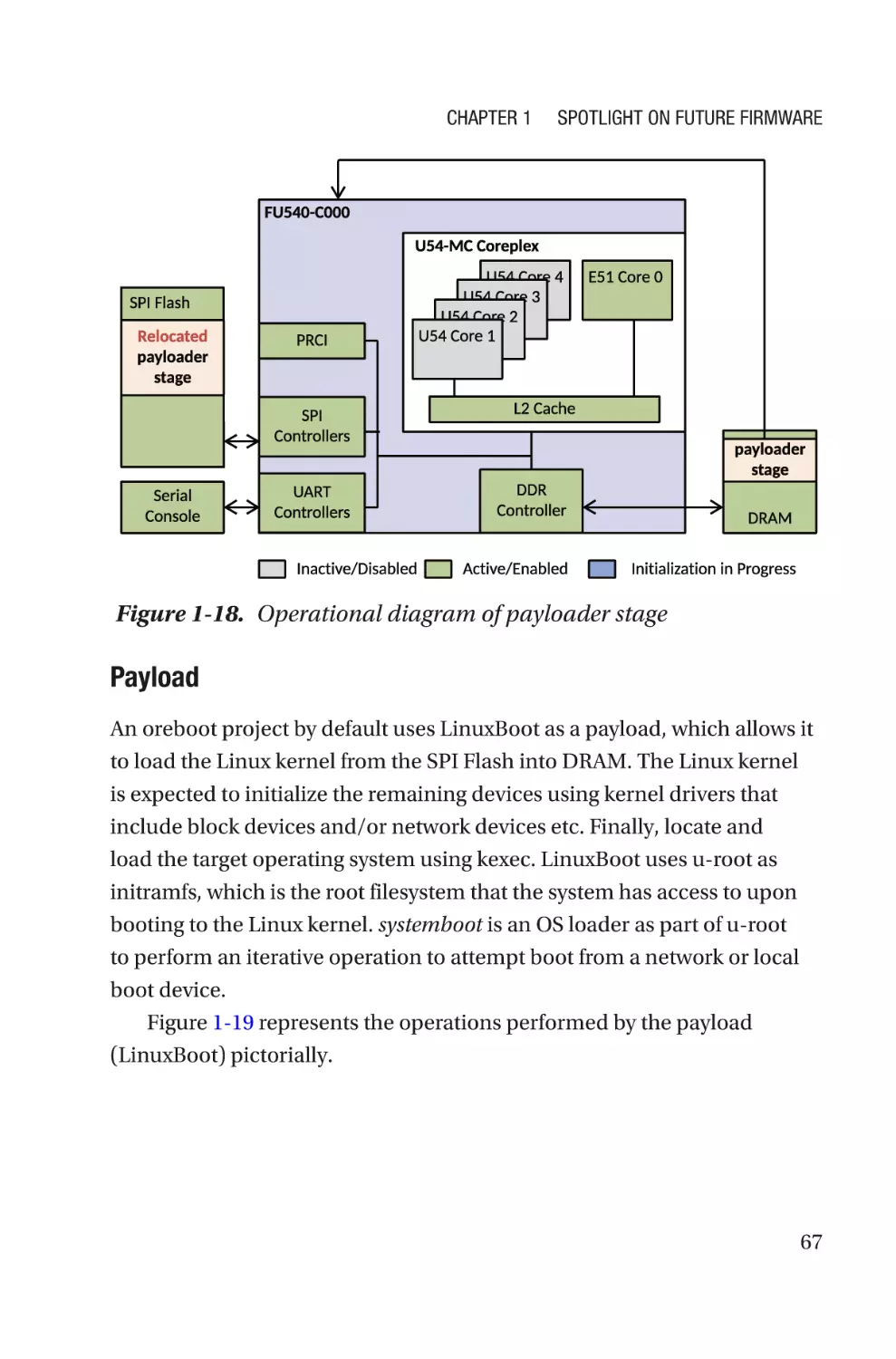
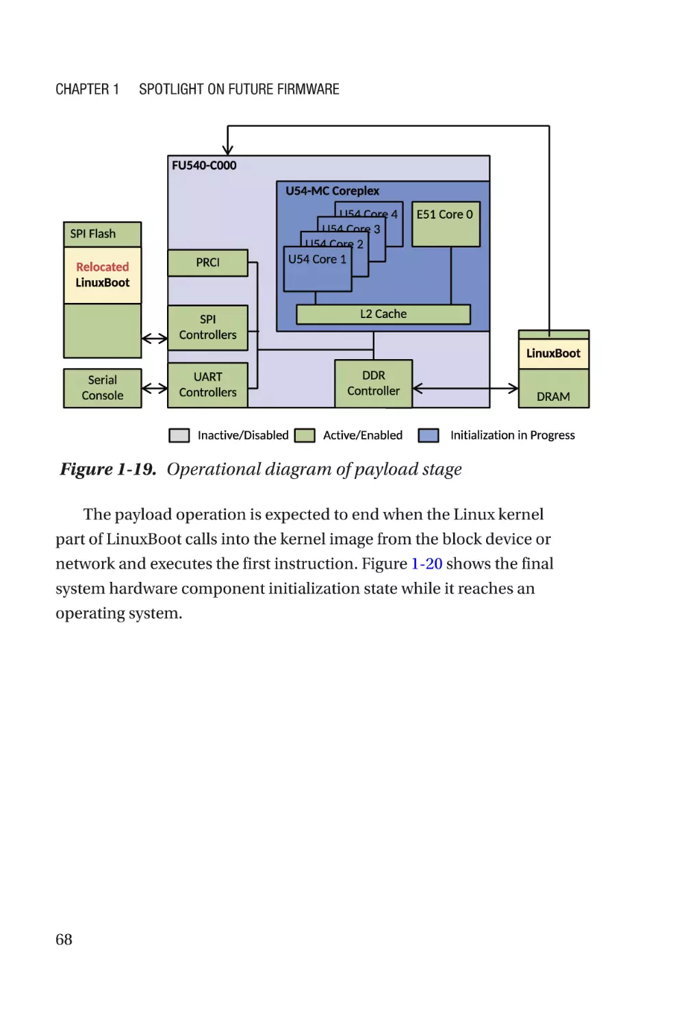
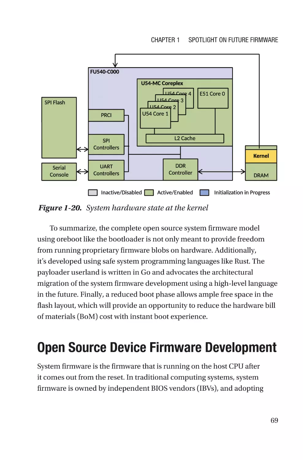
/


Похожие


Текст
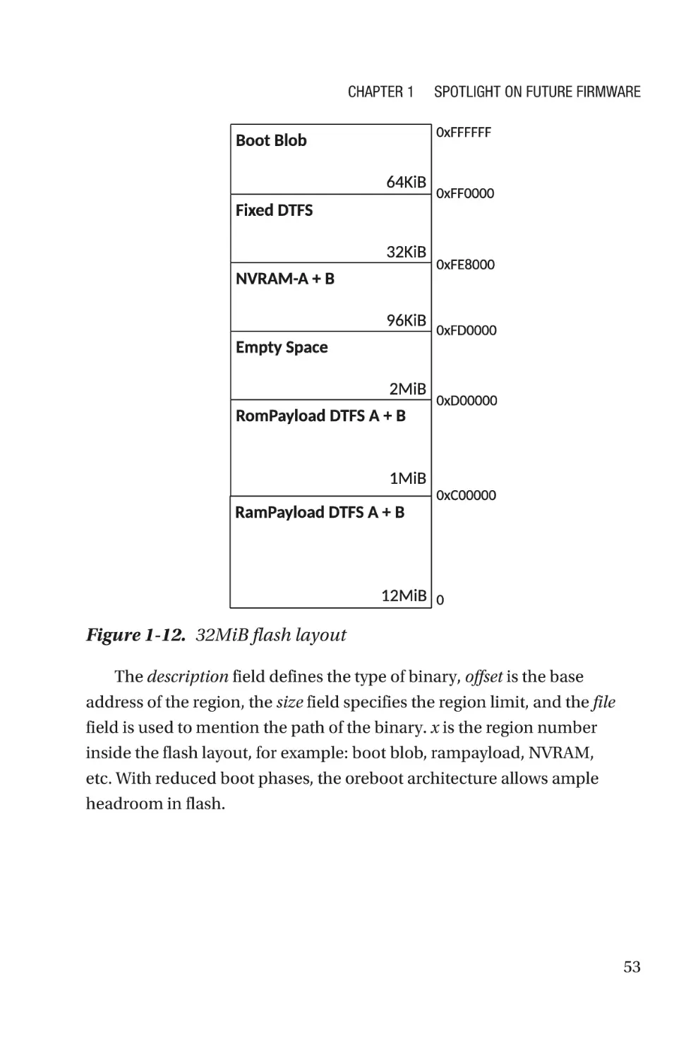
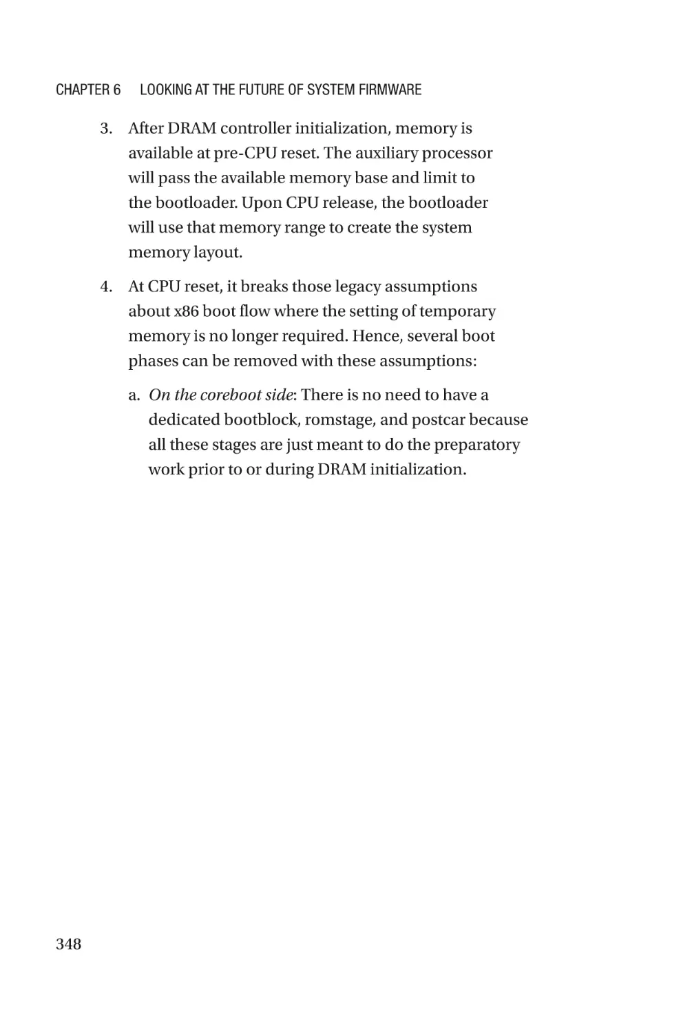
Firmware
Development
A Guide to Specialized Systemic
Knowledge
—
Subrata Banik
Vincent Zimmer
Firmware
Development
A Guide to Specialized
Systemic Knowledge
Subrata Banik
Vincent Zimmer
Firmware Development: A Guide to Specialized Systemic Knowledge
Subrata Banik
Bangalore, Karnataka, India
Vincent Zimmer
Issaquah, WA, USA
ISBN-13 (pbk): 978-1-4842-7973-1
https://doi.org/10.1007/978-1-4842-7974-8
ISBN-13 (electronic): 978-1-4842-7974-8
Copyright © 2022 by Subrata Banik and Vincent Zimmer
This work is subject to copyright. All rights are reserved by the Publisher, whether the whole or
part of the material is concerned, specifically the rights of translation, reprinting, reuse of
illustrations, recitation, broadcasting, reproduction on microfilms or in any other physical way,
and transmission or information storage and retrieval, electronic adaptation, computer software,
or by similar or dissimilar methodology now known or hereafter developed.
Trademarked names, logos, and images may appear in this book. Rather than use a trademark
symbol with every occurrence of a trademarked name, logo, or image we use the names, logos,
and images only in an editorial fashion and to the benefit of the trademark owner, with no
intention of infringement of the trademark.
The use in this publication of trade names, trademarks, service marks, and similar terms, even if
they are not identified as such, is not to be taken as an expression of opinion as to whether or not
they are subject to proprietary rights.
While the advice and information in this book are believed to be true and accurate at the date of
publication, neither the authors nor the editors nor the publisher can accept any legal
responsibility for any errors or omissions that may be made. The publisher makes no warranty,
express or implied, with respect to the material contained herein.
Managing Director, Apress Media LLC: Welmoed Spahr
Acquisitions Editor: Susan McDermott
Development Editor: Laura Berendson
Coordinating Editor: Jessica Vakili
Copyeditor: Kim Wimpsett
Distributed to the book trade worldwide by Springer Science+Business Media New York, 1 NY
Plaza, New York, NY 10004. Phone 1-800-SPRINGER, fax (201) 348-4505, e-mail orders-ny@
springer-sbm.com, or visit www.springeronline.com. Apress Media, LLC is a California LLC and
the sole member (owner) is Springer Science + Business Media Finance Inc (SSBM Finance Inc).
SSBM Finance Inc is a Delaware corporation.
For information on translations, please e-mail booktranslations@springernature.com; for reprint,
paperback, or audio rights, please e-mail bookpermissions@springernature.com.
Apress titles may be purchased in bulk for academic, corporate, or promotional use. eBook
versions and licenses are also available for most titles. For more information, reference our Print
and eBook Bulk Sales web page at http://www.apress.com/bulk-sales.
Any source code or other supplementary material referenced by the author in this book is available
to readers on the Github repository: https://github.com/Apress/Firmware-Development. For more
detailed information, please visit http://www.apress.com/source-code.
Printed on acid-free paper
Table of Contents
About the Authors�������������������������������������������������������������������������������vii
About the Technical Reviewer�������������������������������������������������������������ix
About the Foreword Author�����������������������������������������������������������������xi
Foreword by Christian Walter������������������������������������������������������������xiii
Preface�����������������������������������������������������������������������������������������������xv
Acknowledgments�����������������������������������������������������������������������������xix
Introduction���������������������������������������������������������������������������������������xxi
Chapter 1: Spotlight on Future Firmware���������������������������������������������1
Migrating to Open Source Firmware���������������������������������������������������������������������3
Ring -1: System Firmware�������������������������������������������������������������������������������5
Ring -2: System Management Mode���������������������������������������������������������������5
Ring -3: Manageability Firmware��������������������������������������������������������������������6
Open Source System Firmware Development����������������������������������������������������10
Hybrid System Firmware Model��������������������������������������������������������������������12
Open Source System Firmware Model����������������������������������������������������������47
Open Source Device Firmware Development������������������������������������������������������69
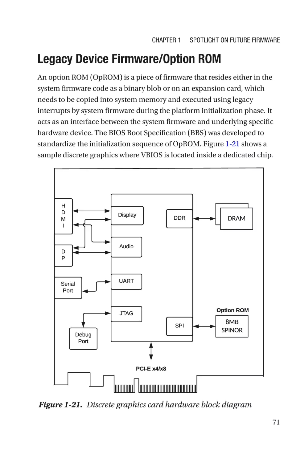
Legacy Device Firmware/Option ROM�����������������������������������������������������������71
UEFI OpROM��������������������������������������������������������������������������������������������������77
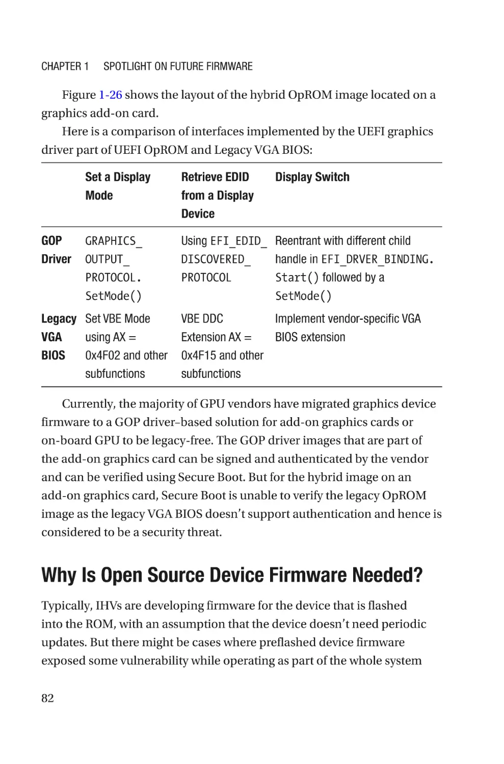
Why Is Open Source Device Firmware Needed?�������������������������������������������82
iii
Table of Contents
Open Source Manageability Firmware Development������������������������������������������84
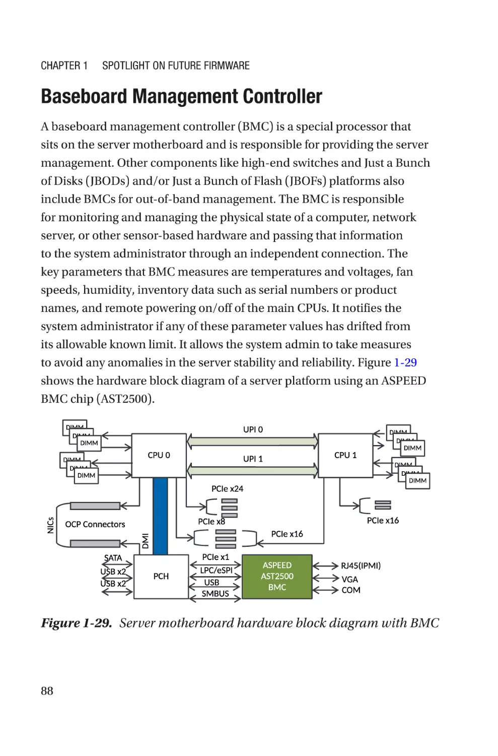
Baseboard Management Controller���������������������������������������������������������������88
Zephyr OS: An Open Source Embedded Controller Firmware
Development�����������������������������������������������������������������������������������������������102
Summary����������������������������������������������������������������������������������������������������������126
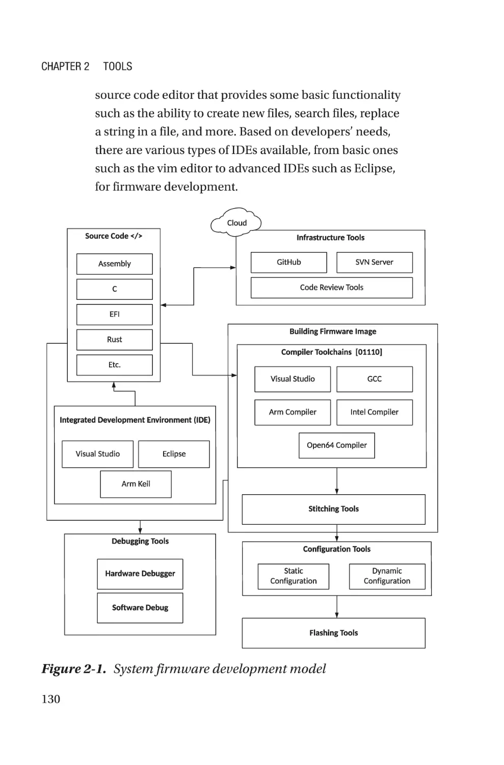
Chapter 2: Tools��������������������������������������������������������������������������������129
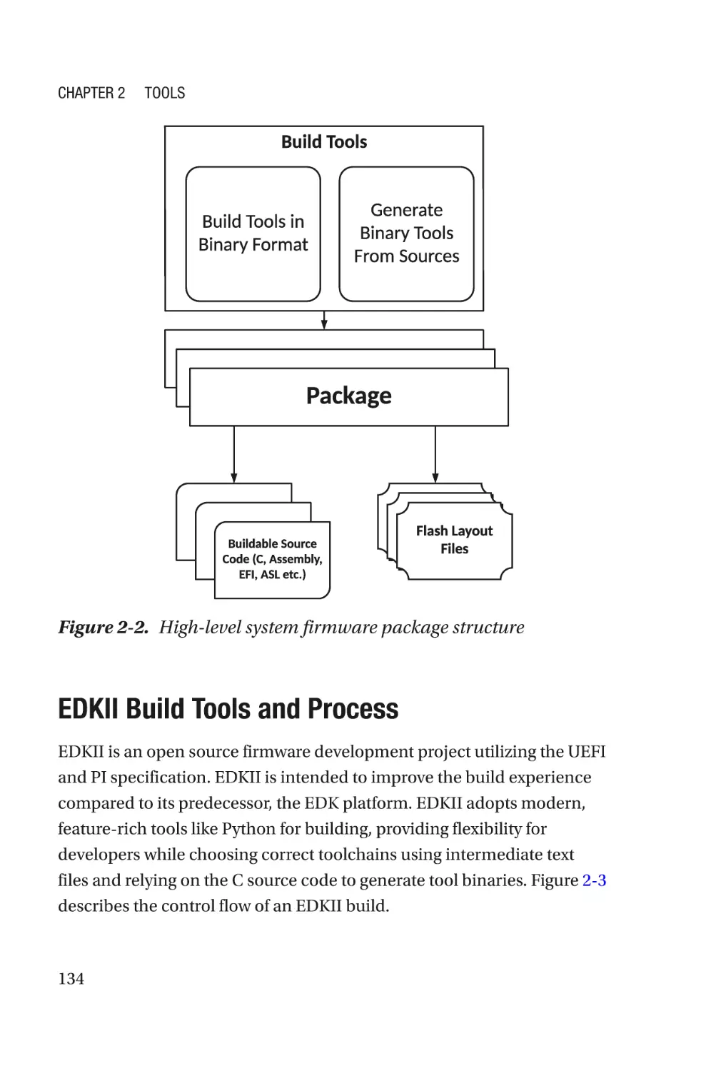
Build Tools���������������������������������������������������������������������������������������������������������132
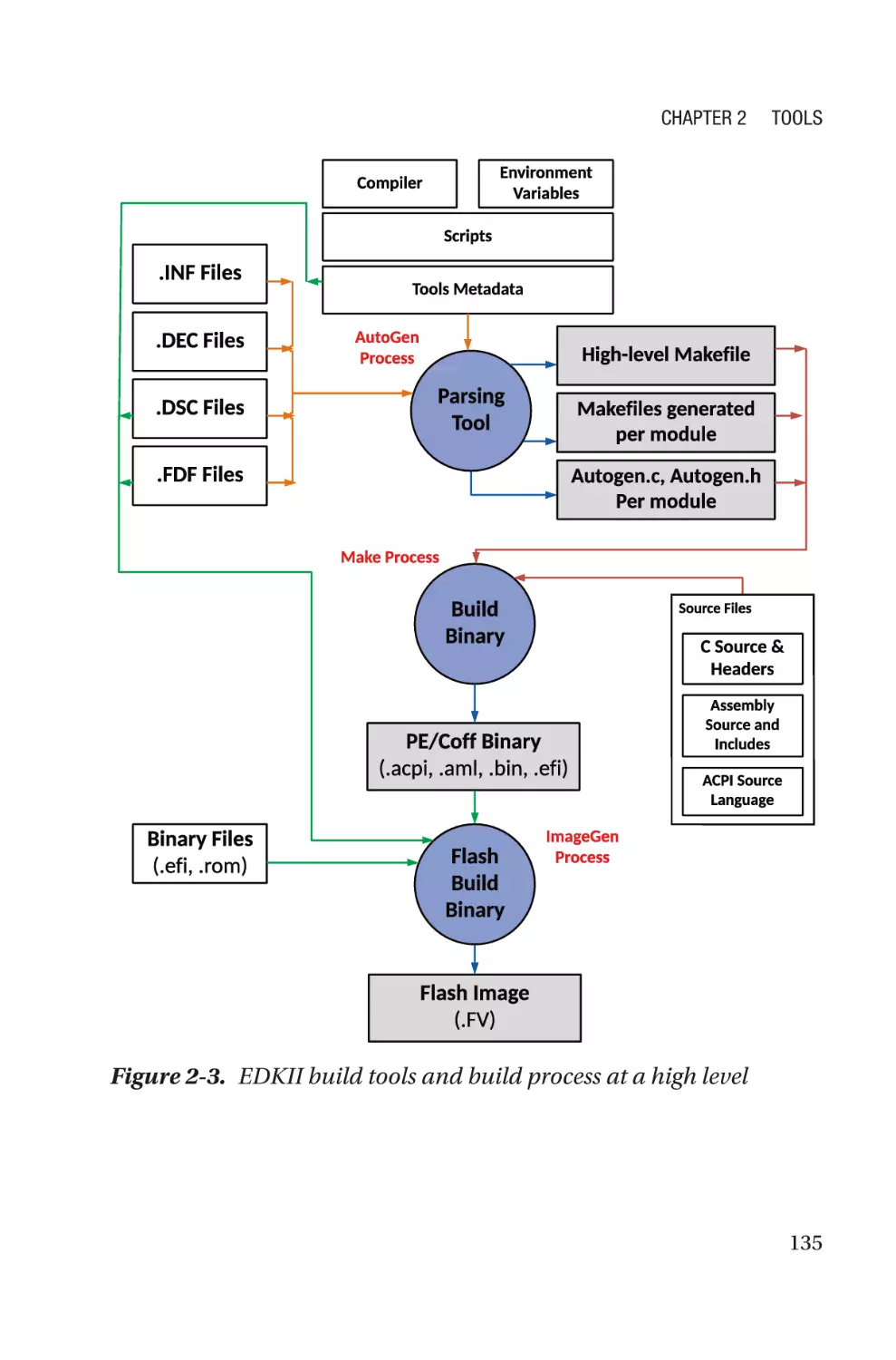
EDKII Build Tools and Process���������������������������������������������������������������������134
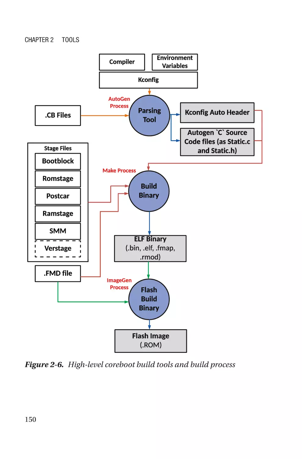
coreboot Build Tools and Process����������������������������������������������������������������149
Configuration Tools�������������������������������������������������������������������������������������������162
Human Interface Infrastructure�������������������������������������������������������������������163
YAML-Based Configuration��������������������������������������������������������������������������166
Firmware Configuration Interface����������������������������������������������������������������168
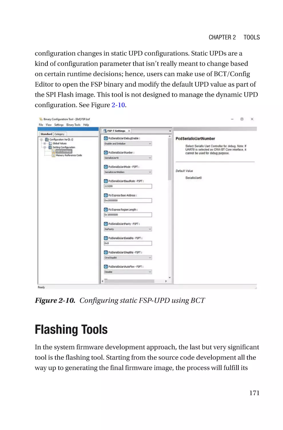
Binary Configuration Tool (BCT)/Config Editor���������������������������������������������170
Flashing Tools���������������������������������������������������������������������������������������������������171
Hardware-Based Tools���������������������������������������������������������������������������������172
Summary����������������������������������������������������������������������������������������������������������174
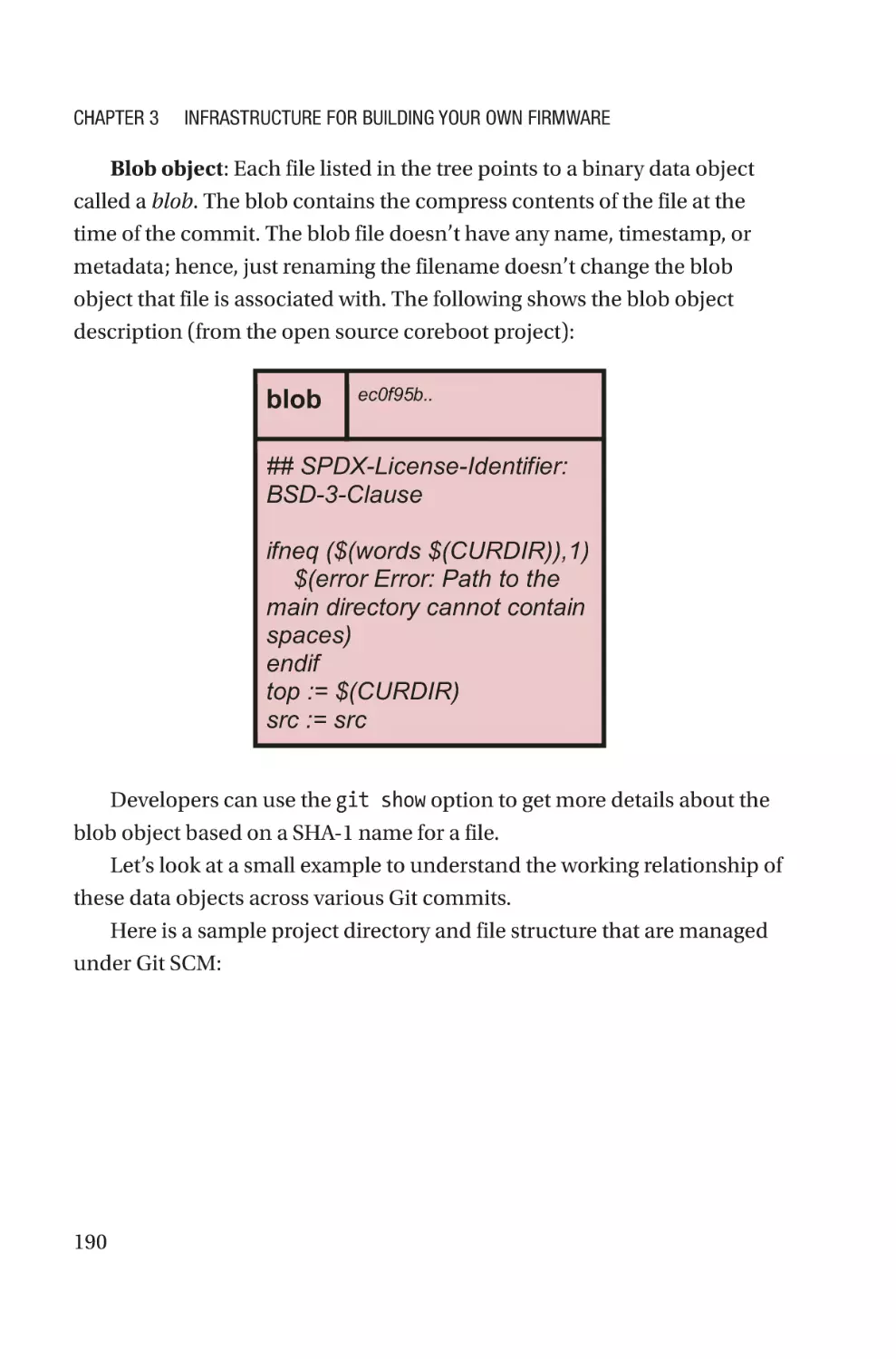
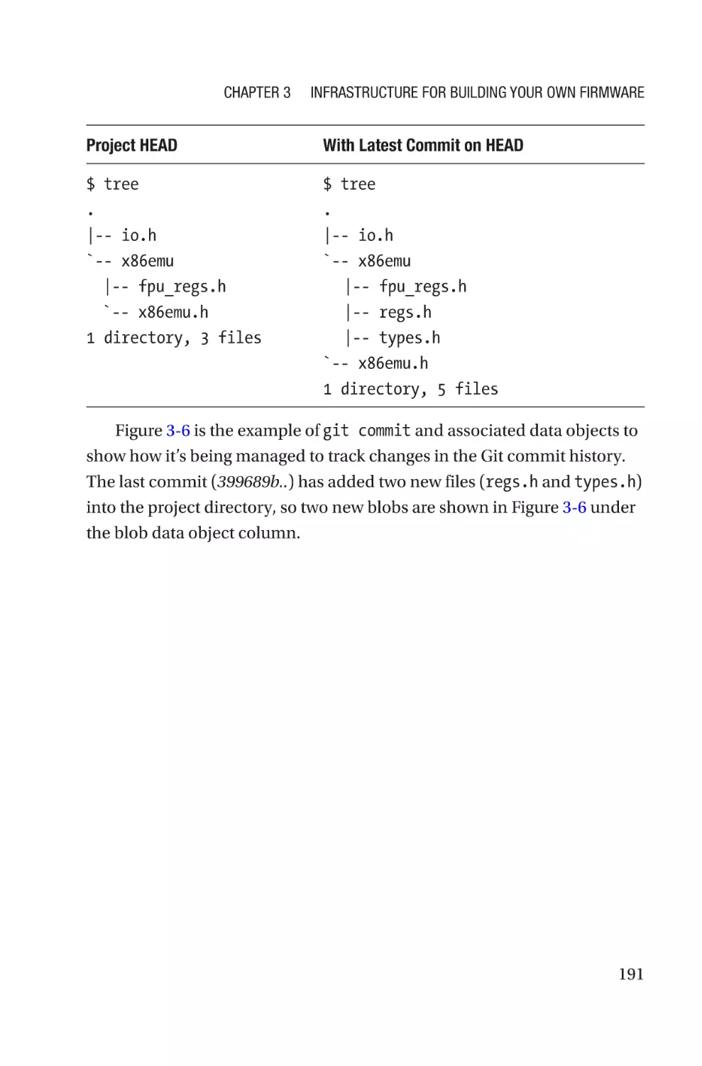
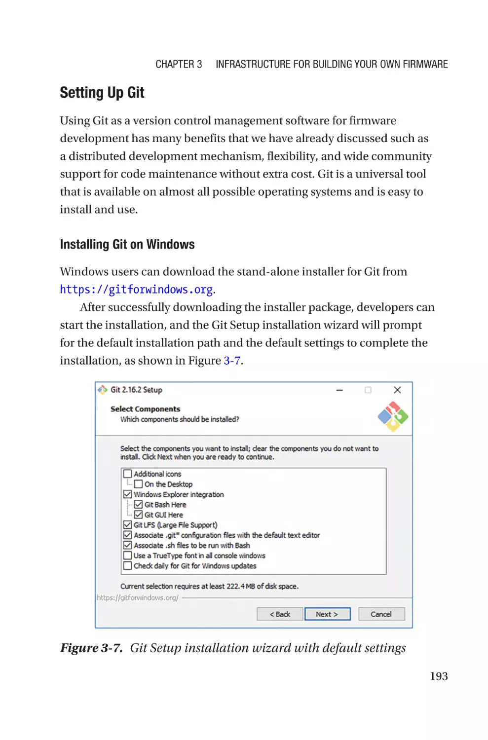
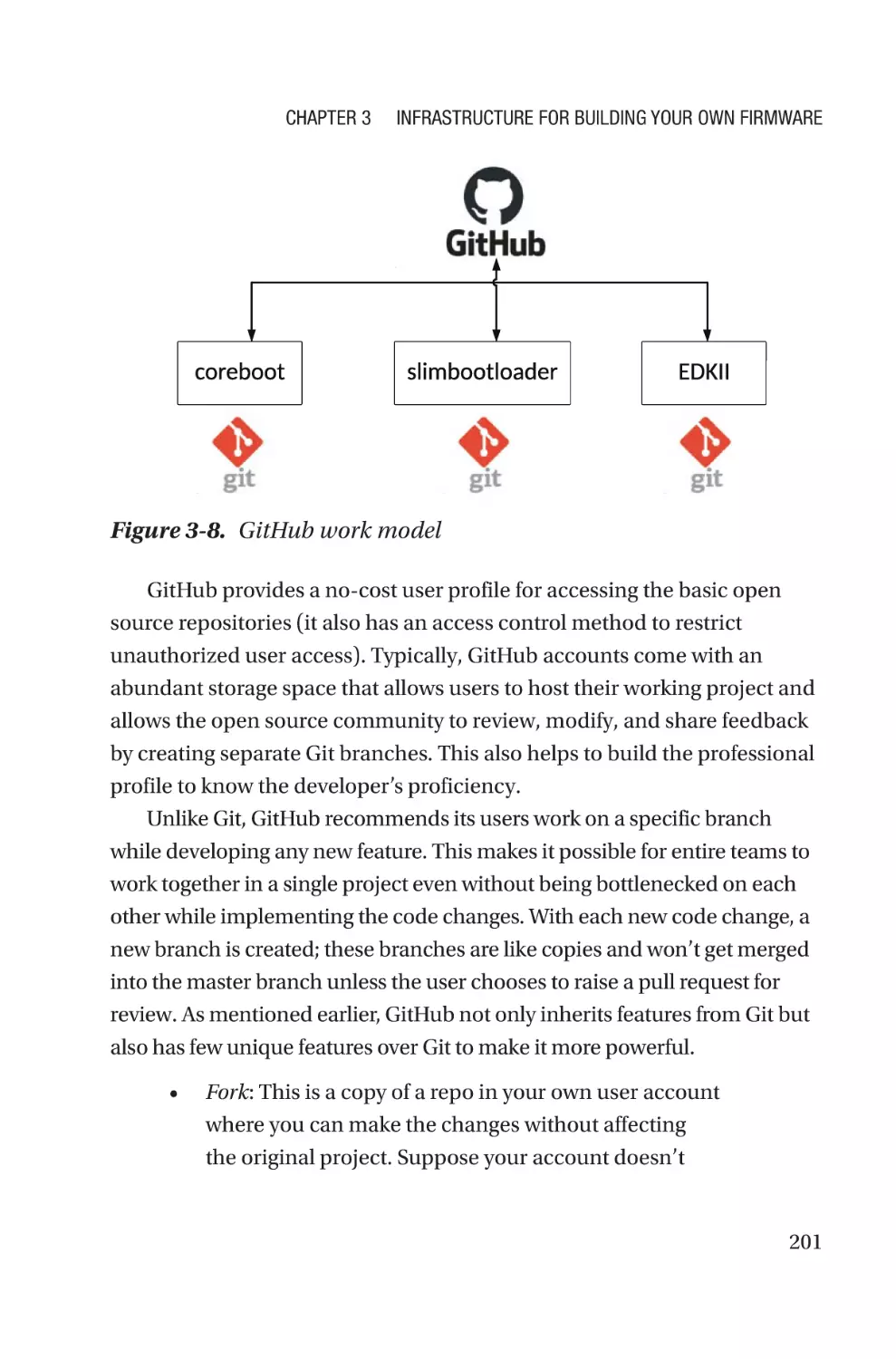
Chapter 3: Infrastructure for Building Your Own Firmware��������������177
Overview of Source Control Management��������������������������������������������������������178
Version Control System�������������������������������������������������������������������������������179
Version Control Repository Hosting Service������������������������������������������������200
Code Review Application�����������������������������������������������������������������������������203
Best Known Mechanism of Source Code Management�������������������������������208
Code of Conduct������������������������������������������������������������������������������������������������210
Coding Standard�����������������������������������������������������������������������������������������������212
Indentation��������������������������������������������������������������������������������������������������214
Maximum Columns per Line������������������������������������������������������������������������215
iv
Table of Contents
Using Braces�����������������������������������������������������������������������������������������������216
Need for Spaces������������������������������������������������������������������������������������������217
Naming Conventions�����������������������������������������������������������������������������������218
Typedefs������������������������������������������������������������������������������������������������������219
Commenting������������������������������������������������������������������������������������������������220
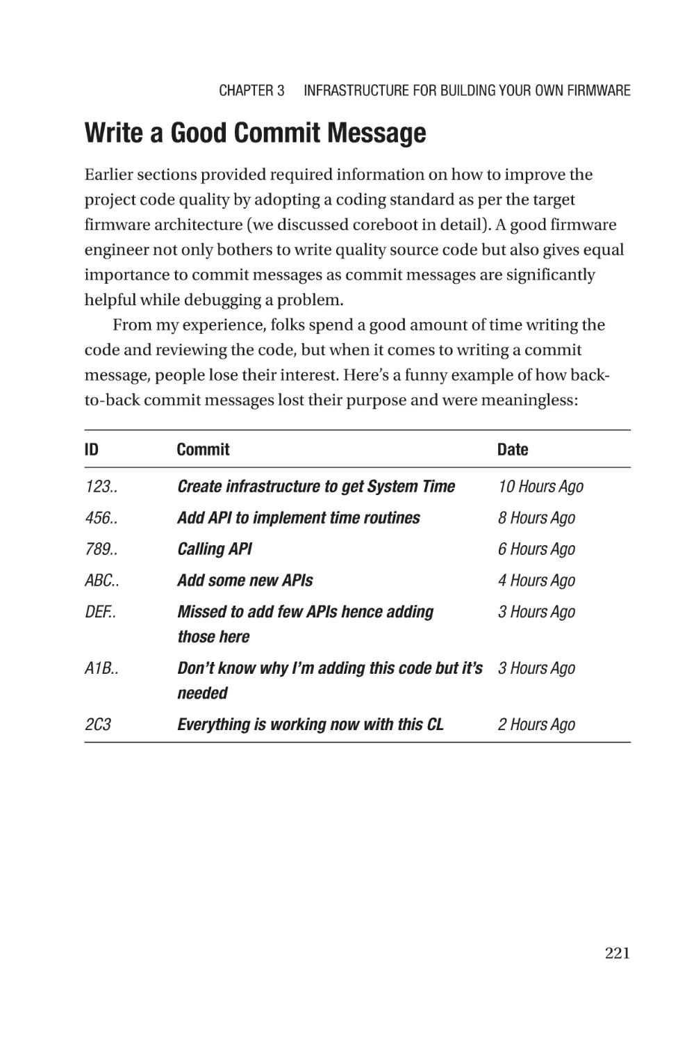
Write a Good Commit Message�������������������������������������������������������������������221
Summary����������������������������������������������������������������������������������������������������������225
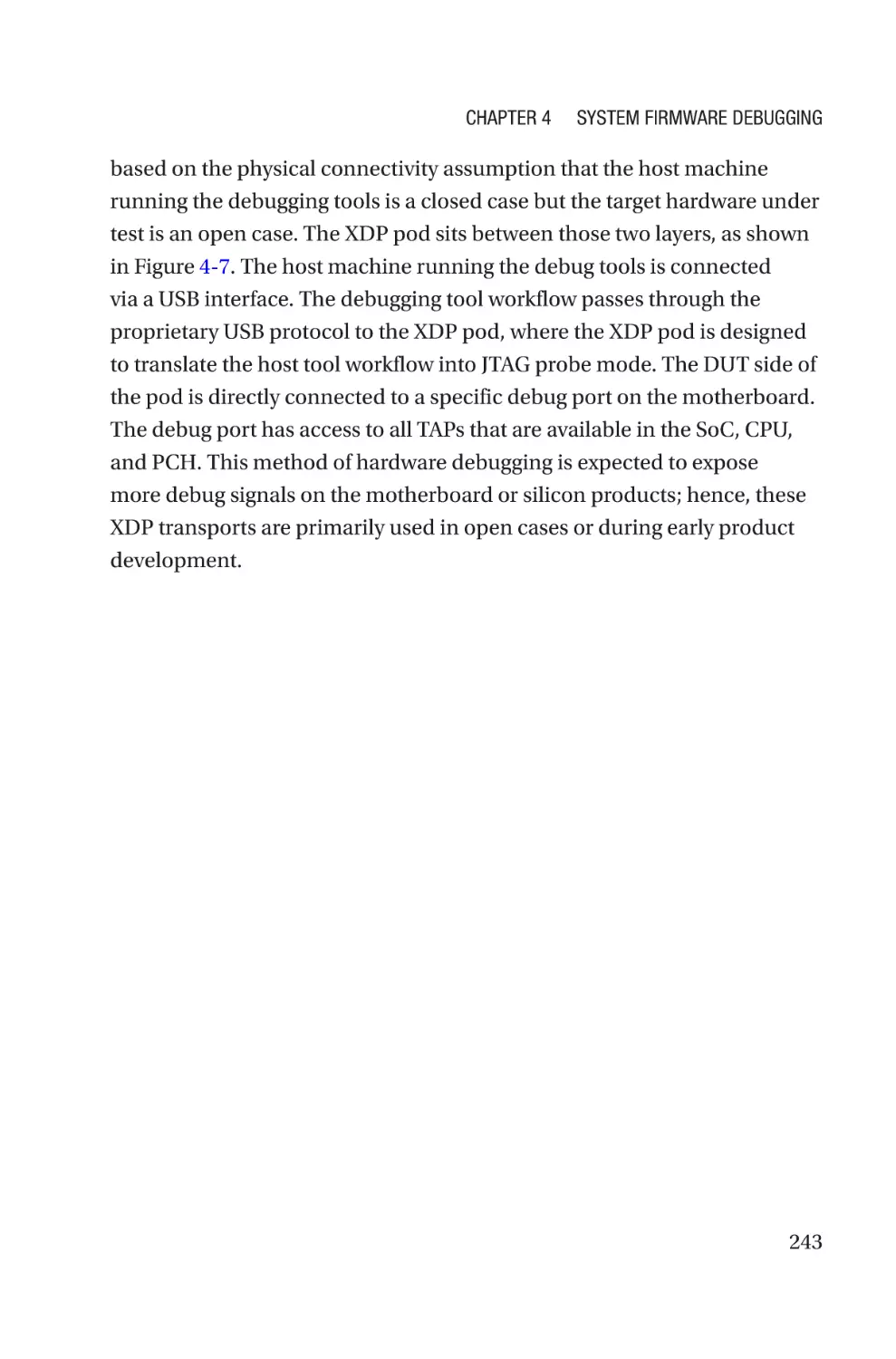
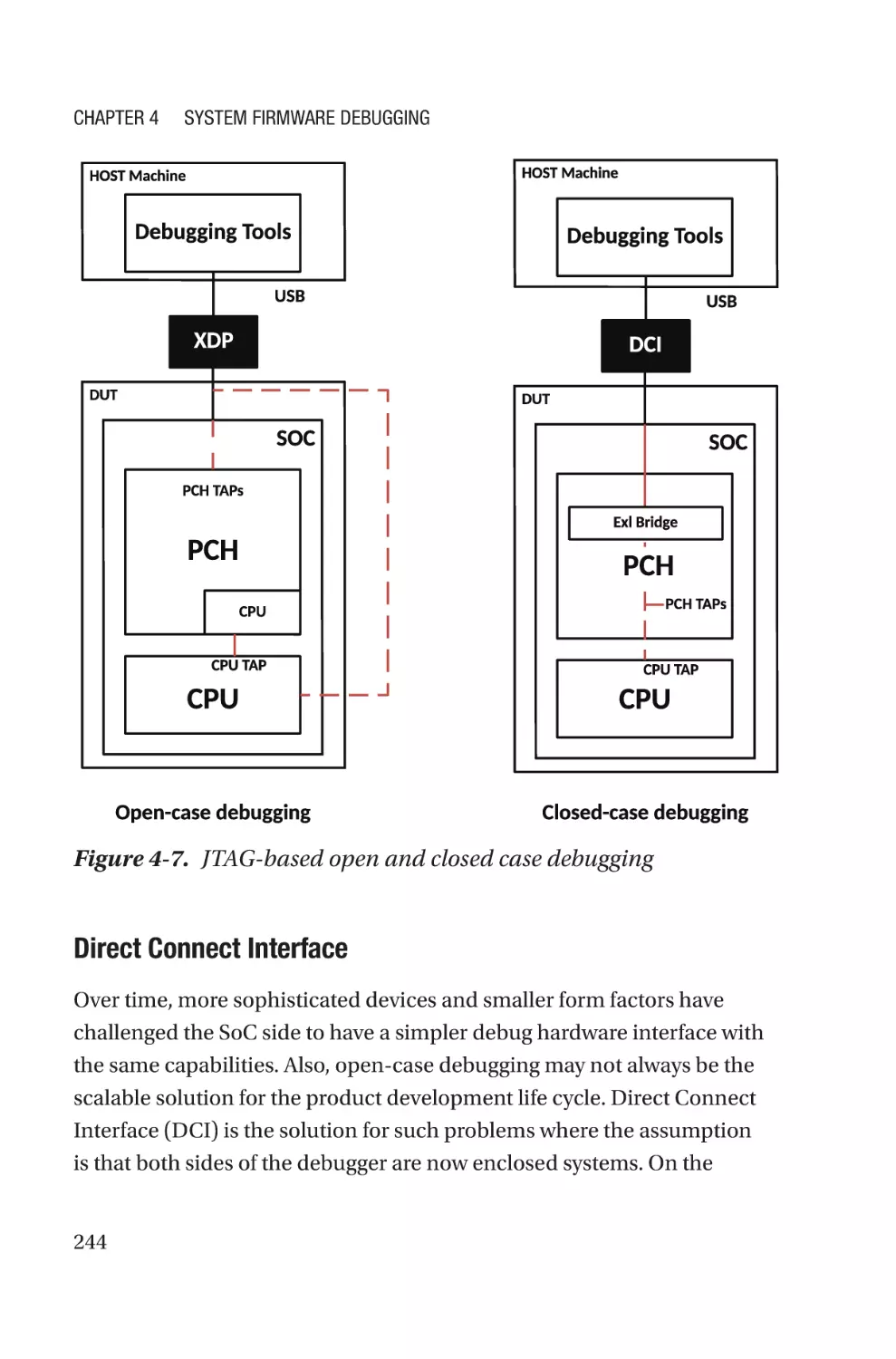
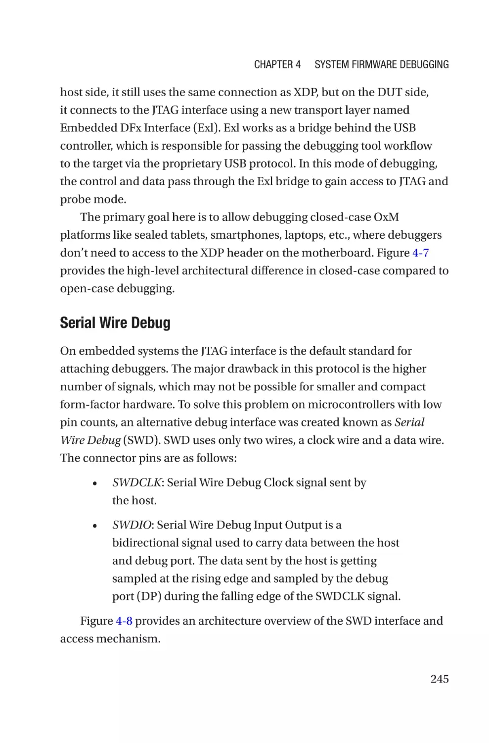
Chapter 4: System Firmware Debugging������������������������������������������227
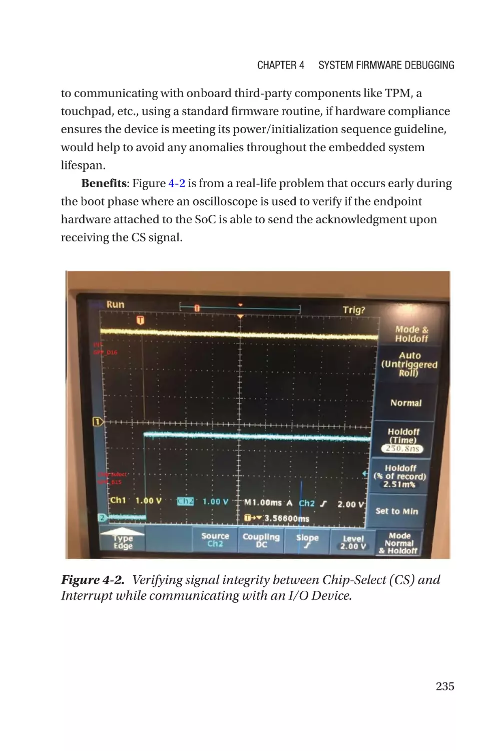
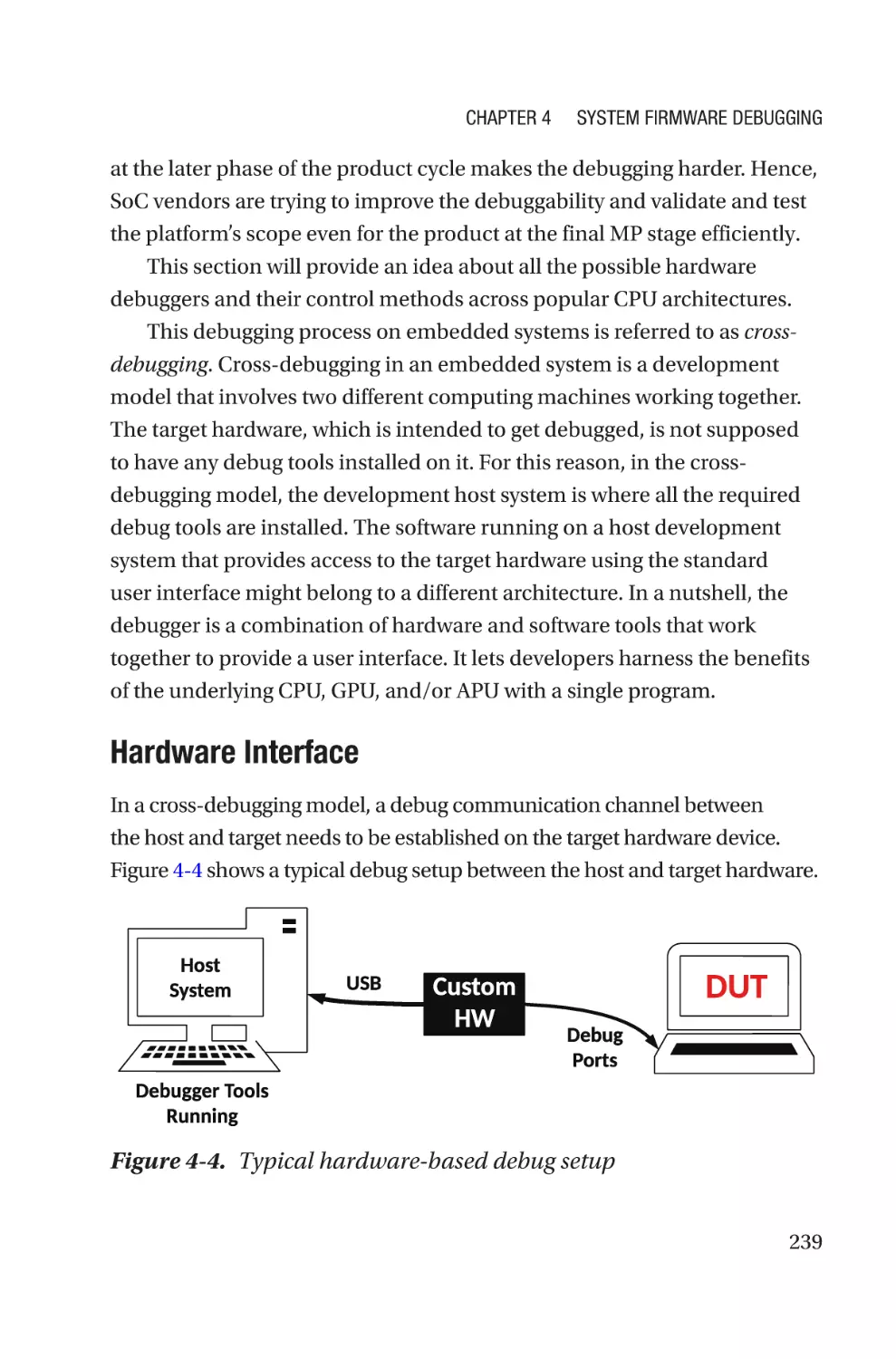
Hardware-Assisted Debugging�������������������������������������������������������������������������233
Generic Debugging��������������������������������������������������������������������������������������234
SoC-Specific Debugging������������������������������������������������������������������������������238
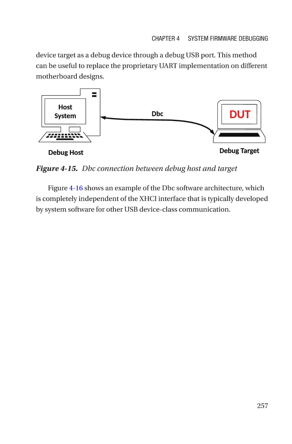
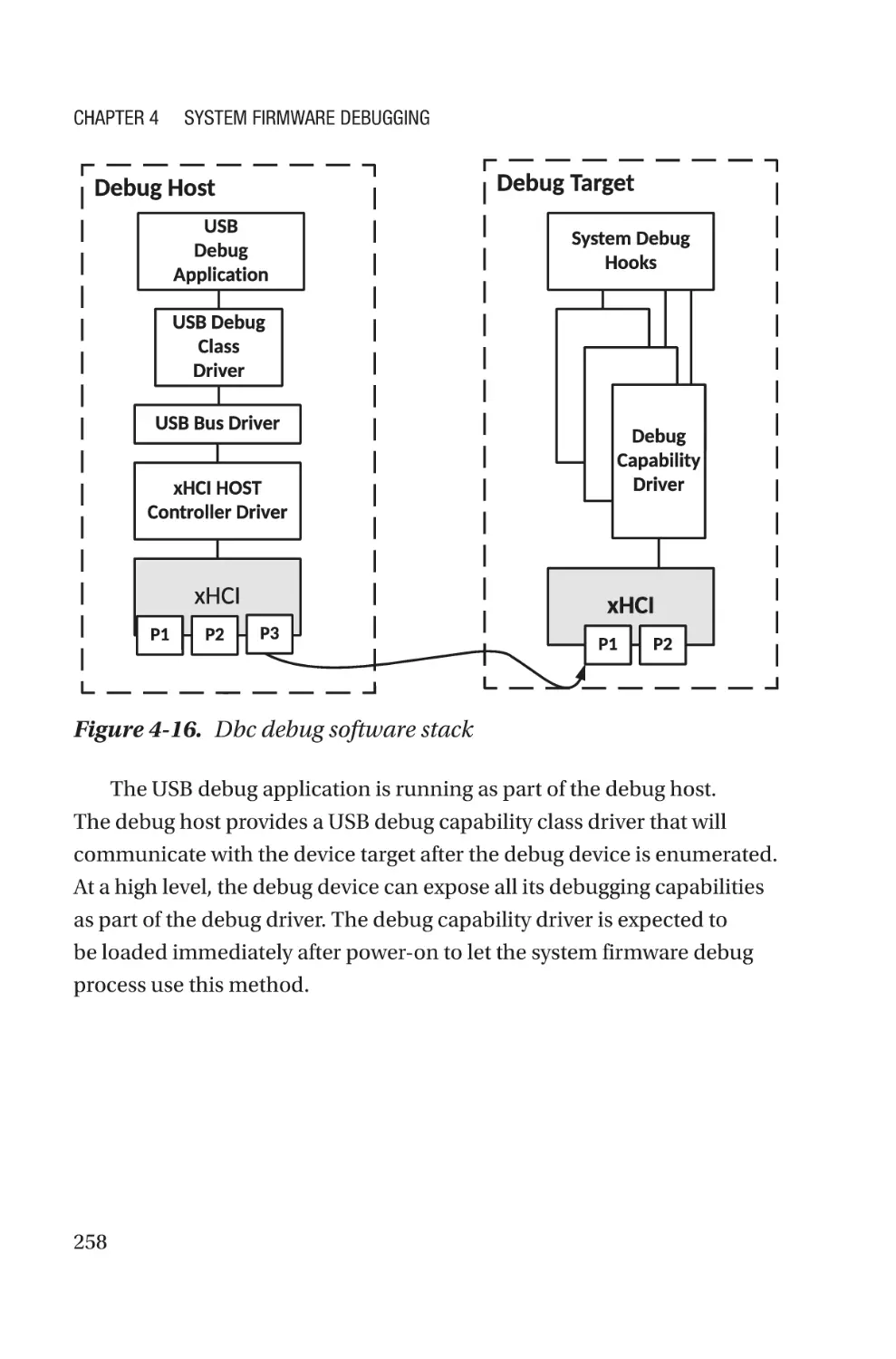
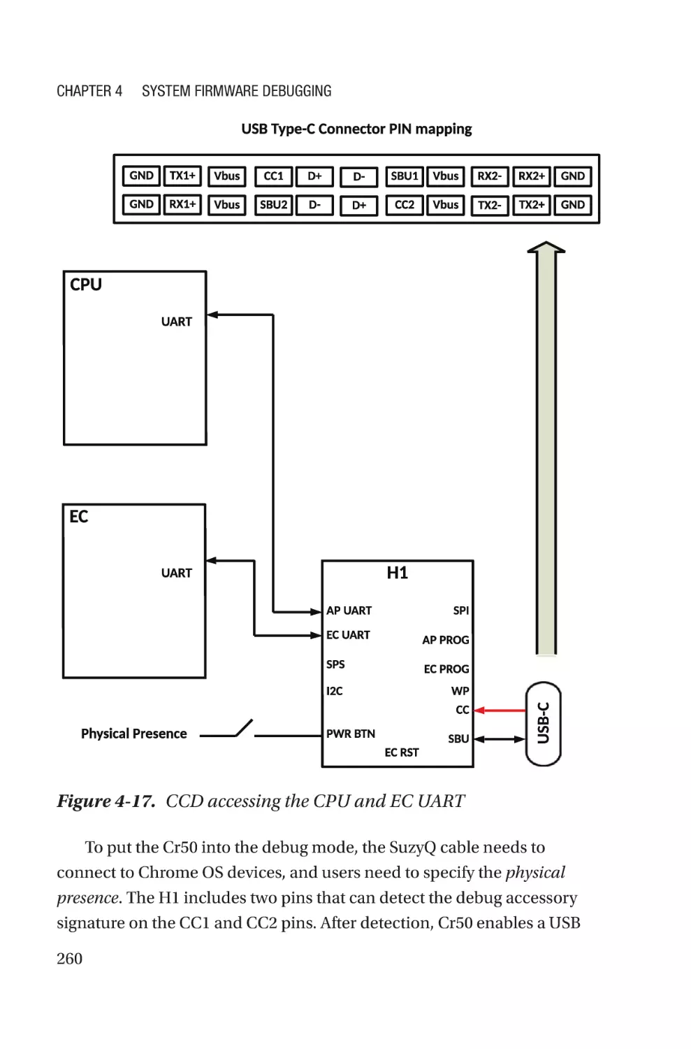
OxM-Secific Debugging�������������������������������������������������������������������������������256
Software-Assisted Debugging��������������������������������������������������������������������������261
Traditional Breakpoint���������������������������������������������������������������������������������261
I/O-Based Checkpoint����������������������������������������������������������������������������������262
Serial Message or Serial Buffer�������������������������������������������������������������������265
Preboot Environment�����������������������������������������������������������������������������������266
ACPI Debug��������������������������������������������������������������������������������������������������267
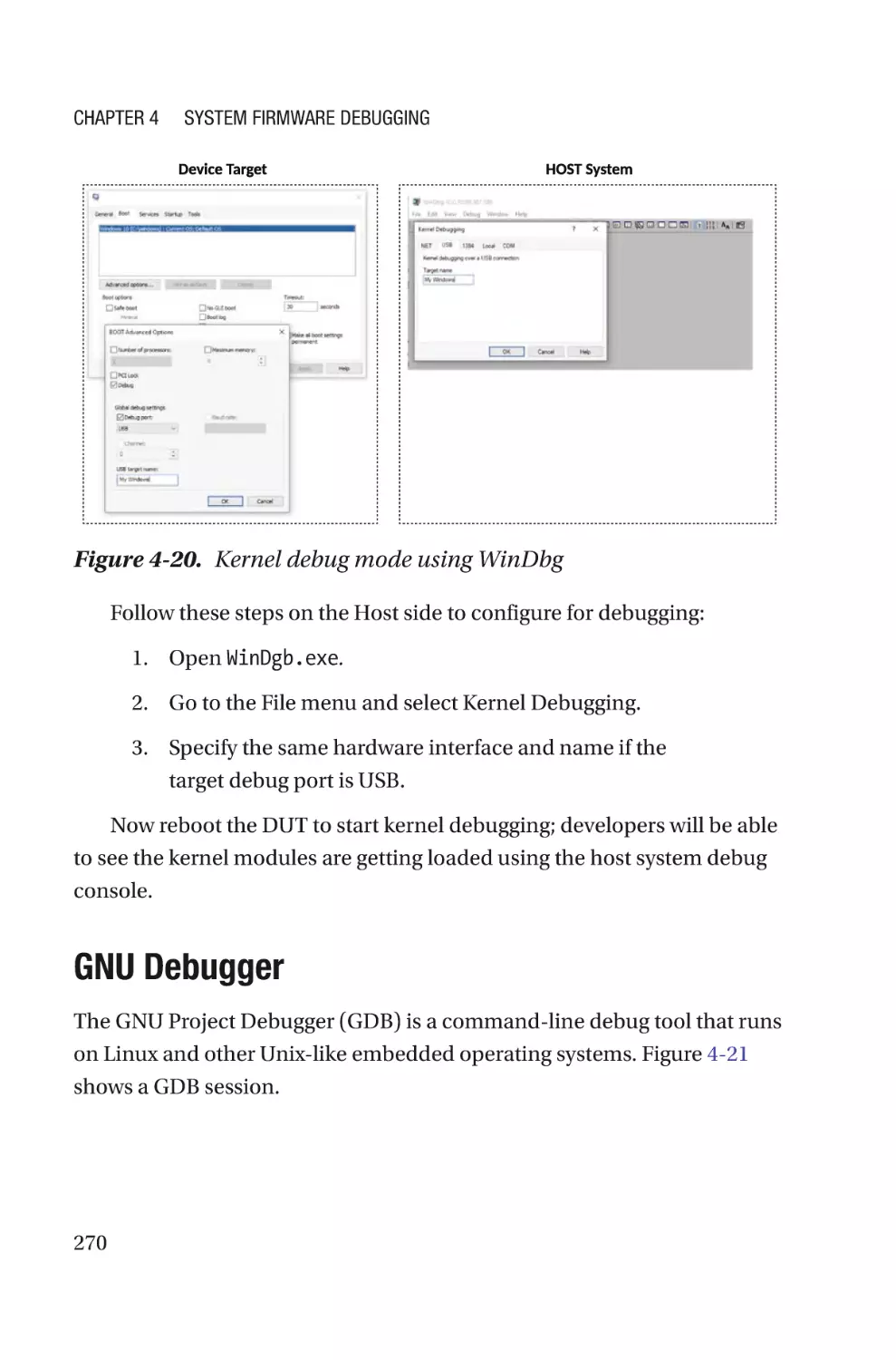
Windows Debugger�������������������������������������������������������������������������������������268
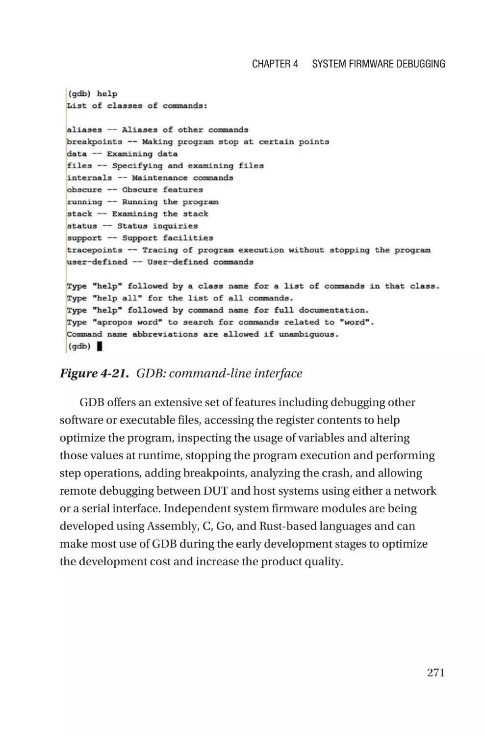
GNU Debugger���������������������������������������������������������������������������������������������270
Summary����������������������������������������������������������������������������������������������������������272
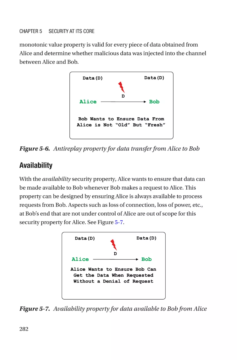
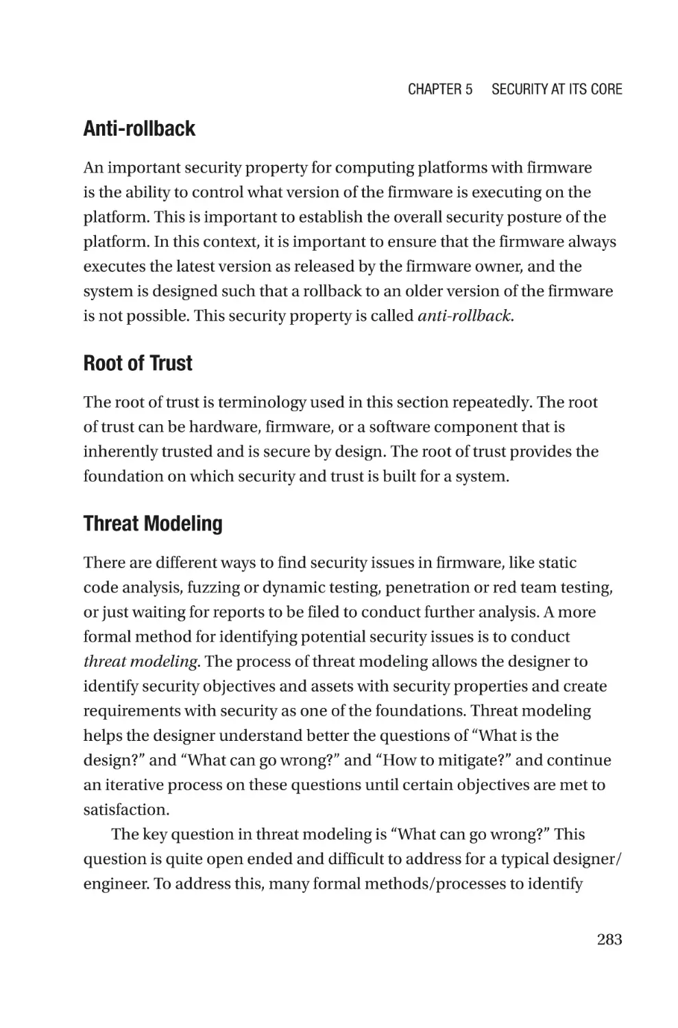
Chapter 5: Security at Its Core���������������������������������������������������������273
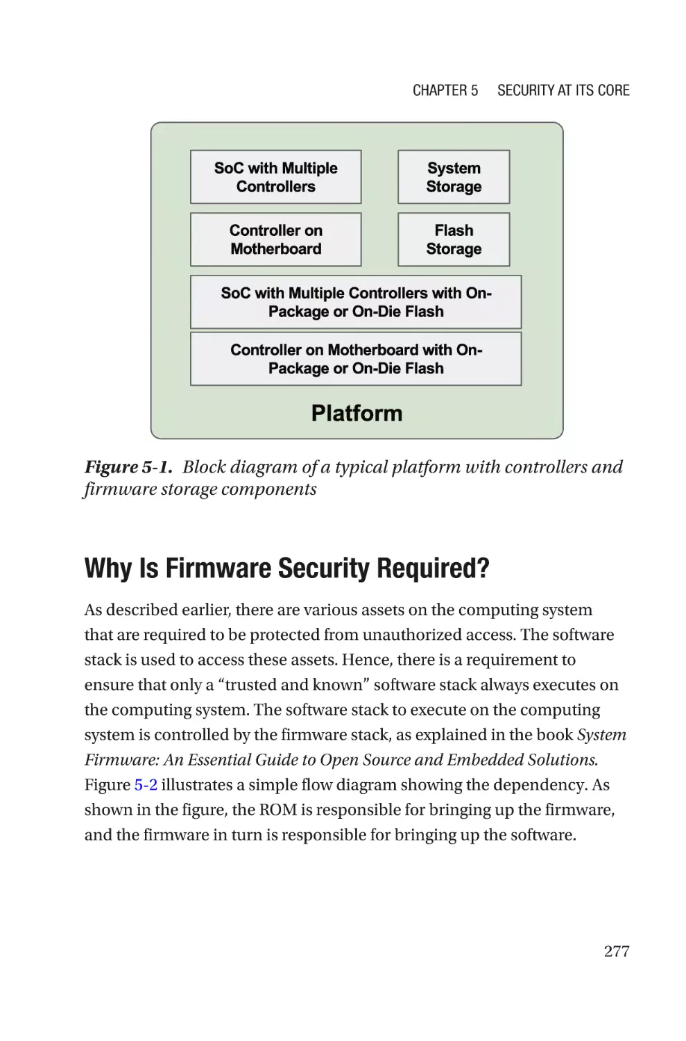
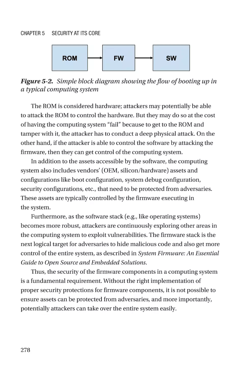
Revisiting the Definition of Firmware with a Security Mindset�������������������������276
Why Is Firmware Security Required?����������������������������������������������������������277
Platform Configuration for Firmware����������������������������������������������������������������286
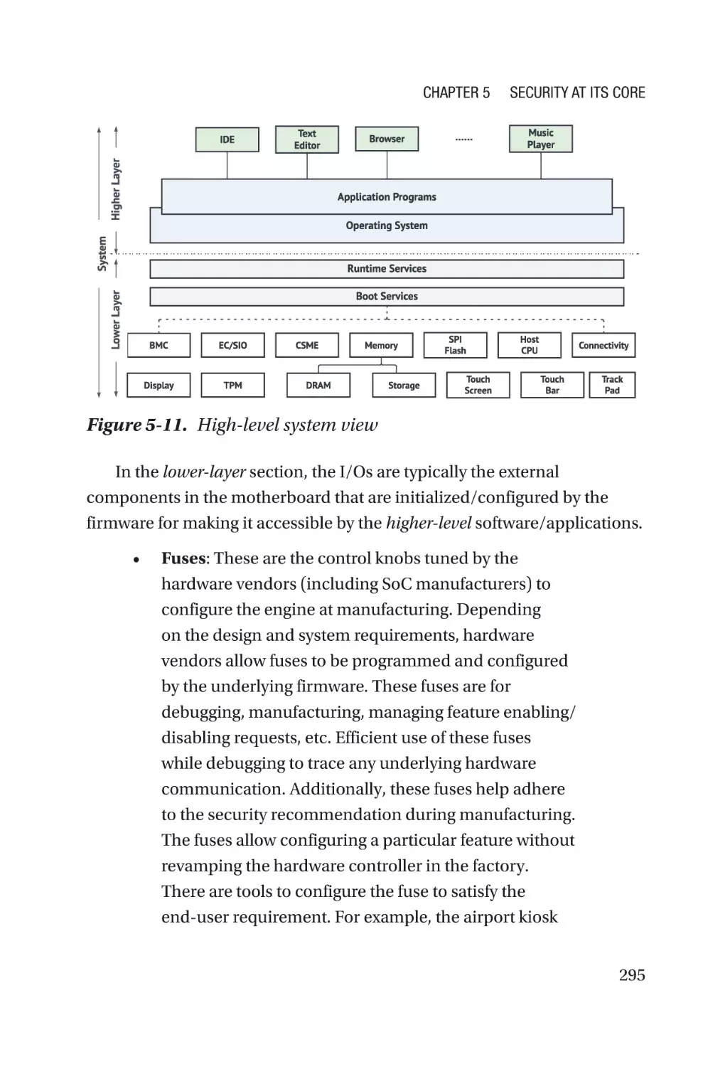
Firmware with Security Mindset in a Computing System���������������������������287
Summary����������������������������������������������������������������������������������������������������������303
v
Table of Contents
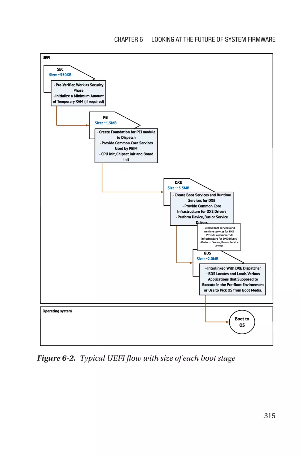
Chapter 6: Looking at the Future of System Firmware���������������������305
Designing LITE Firmware����������������������������������������������������������������������������������309
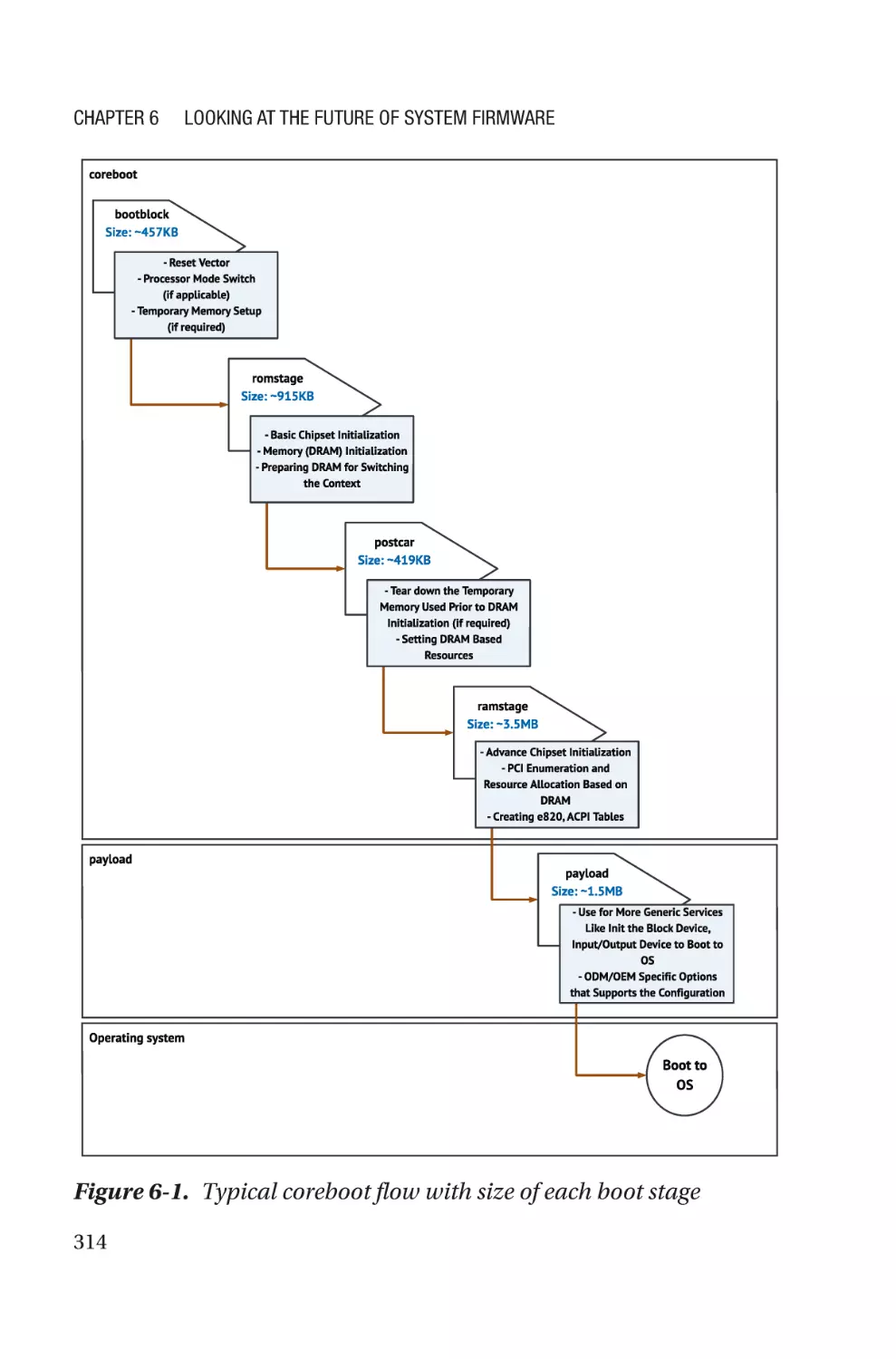
Design Principle������������������������������������������������������������������������������������������313
Conclusion���������������������������������������������������������������������������������������������������325
Designing a Feature Kernel�������������������������������������������������������������������������������326
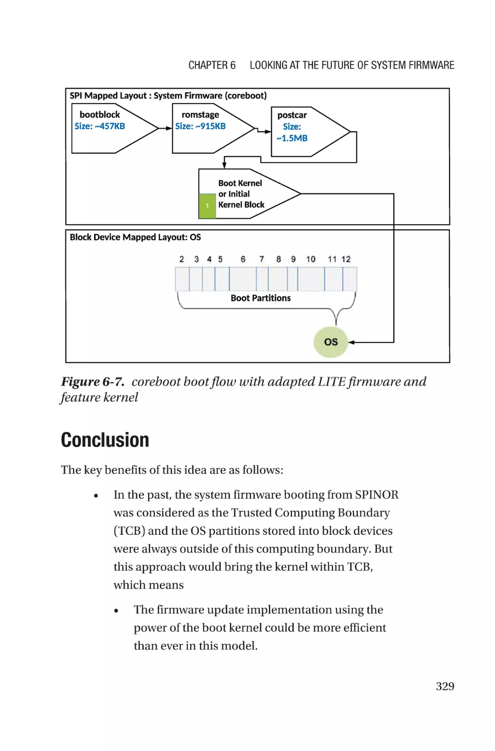
Design Principle������������������������������������������������������������������������������������������328
Conclusion���������������������������������������������������������������������������������������������������329
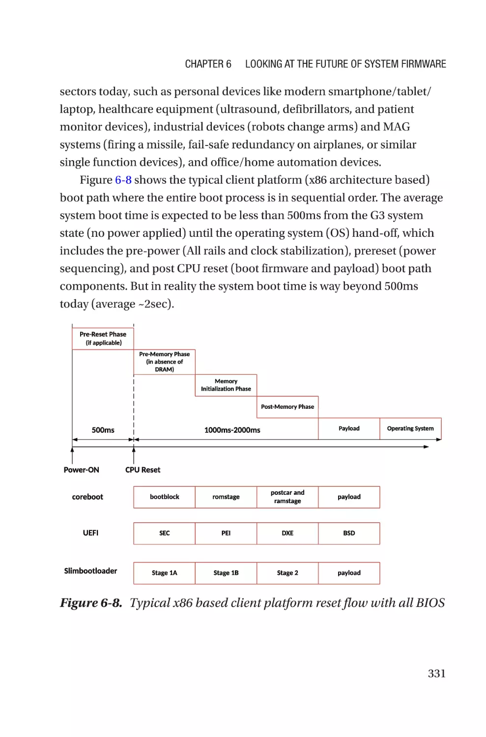
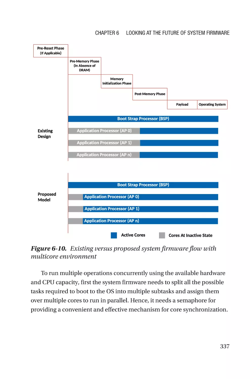
Design Multithreaded System Firmware�����������������������������������������������������������330
Design Principles�����������������������������������������������������������������������������������������334
Conclusion���������������������������������������������������������������������������������������������������341
Innovation in Hardware Design�������������������������������������������������������������������������342
Design Principles�����������������������������������������������������������������������������������������344
Conclusion���������������������������������������������������������������������������������������������������351
Summary����������������������������������������������������������������������������������������������������������352
Appendix A: The Evolution of System Programming Languages������353
The History of System Programming Languages����������������������������������������������354
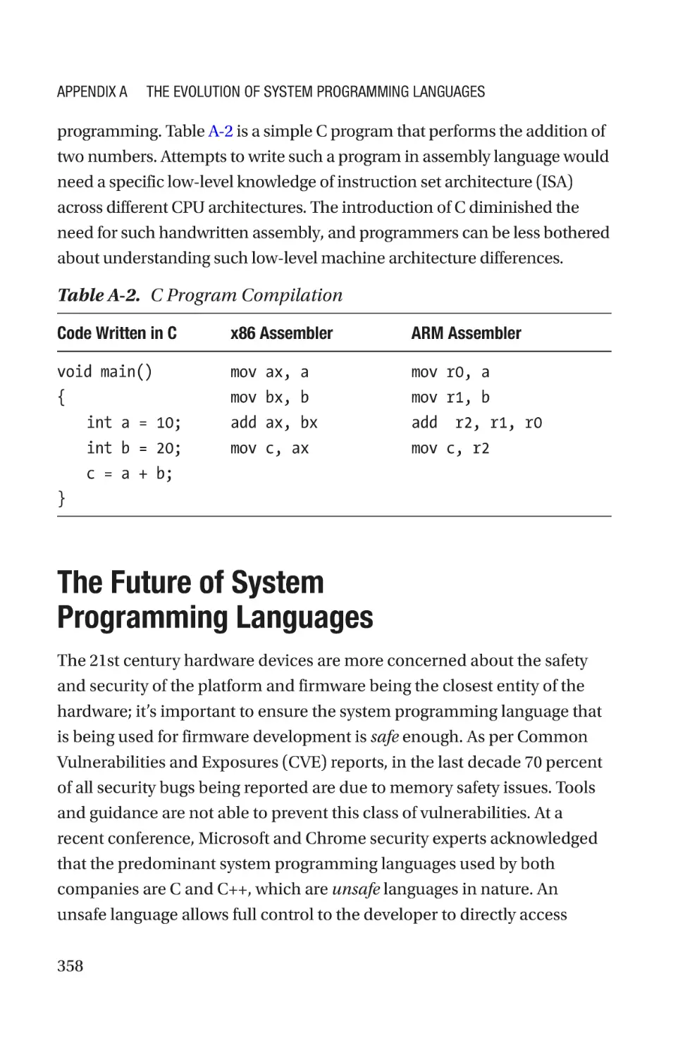
System Programming Languages Today�����������������������������������������������������������356
The Future of System Programming Languages�����������������������������������������������358
Appendix B: initramfs: A Call for Type-Safe Languages�������������������367
Glossary��������������������������������������������������������������������������������������������373
Reference������������������������������������������������������������������������������������������379
W
ebsites�����������������������������������������������������������������������������������������������������������379
Books, Conferences, Journals, and Papers�������������������������������������������������������383
Index�������������������������������������������������������������������������������������������������385
vi
About the Authors
Subrata Banik is a firmware engineer
with more than a decade of experience
in the computer industry, with hands-on
experience in system firmware design,
development, and debugging across various
firmware architectures like UEFI, coreboot,
Slim bootloader, etc., for the x86 and ARM
platforms. Subrata has extensive experience on
platform enablement, which led to working for
all the leading PC makers’ products. Subrata
is an active member of open source firmware
(OSF) development across different projects
like coreboot, oreboot, flashrom, EDKII, etc., where he is one of the leading
contributors in open firmware (coreboot) development. Subrata holds
multiple U.S. patents and is passionate about learning new technology
and sharing knowledge with enthusiast engineers. Subrata has presented
his technical talks at industry events such as the Open Source Firmware
Conference, Institute for Security and Technology, Intel Developer Forum,
and more.
When not writing or working, he enjoys watching sports (especially
football) and spending time with his daughter. A fun fact about Subrata is
that he is a strong believer in the existence of time travel.
You can chat with Subrata on Twitter (@abarjodi) or at https://www.
linkedin.com/in/subrata-banik-268b3317/.
vii
About the Authors
Vincent Zimmer has been working on
embedded firmware for the last 30 years.
Vincent has contributed to or created firmware
spanning various firmware initiatives,
including the Extensible Firmware Interface,
where Vincent presently leads the Security
subteam in the UEFI Forum. Vincent has also
co-authored various papers and books, along
with being a named co-inventor on more than
450 U.S. patents.
viii
About the Technical Reviewer
Ron Minnich is a software engineer at Google.
He has been writing firmware for 40 years,
starting with the z80 and 6800. He’s also
a long-time contributor in the Unix, BSD,
Plan 9, and Linux communities. He started
the LinuxBIOS project in 1999, which was
renamed to coreboot in 2008 and is now used
in tens of millions of Chromebooks. His most
recent effort, LinuxBoot, is now part of the
Linux Foundation and aims to bring the benefits of a full Linux kernel to
several firmware environments, including coreboot, u-boot, and UEFI.
ix
About the Foreword Author
Christian Walter is a firmware engineer who
started working with open source firmware
five years ago. Christian is passionate about
open source and is heavily involved in
various open source firmware projects like
coreboot, LinuxBoot, and EDKII for different
architectures.
Christian is the cofounder of the Open
Source Firmware Foundation and is actively
involved in defining specifications around open source firmware. He is
part of 9elements, which is one of the main contributors within the open
source firmware ecosystem driving the community into an open world.
Christian has been involved in multiple technical talks around open
source firmware and its development model for the industry, and he has
held multiple talks around testing and building an ecosystem for open
source firmware.
You can connect with him on Twitter (@nablahero).
xi
Foreword by Christian Walter
Nowadays, firmware is one of the most critical parts within every device
and every security concept. Typically, x86 firmware is hidden from the
user, and little to no interaction is needed. Firmware has been closed
source for the last 20 years. Whereas there are some exceptions to the
general rule, the core parts of firmware are and will most likely remain
closed source in the near future. From an outside perspective, this is not
logical. Today, most of the software stack running on x86 platforms can
be open sourced, beginning from the bootloader through the operating
system up to the application level. Large hyperscalers make open source
a requirement for some parts, and consumers love the freedom that open
source software provides to them. Firmware is the last bastion that has not
fallen. However, in recent years, the open source firmware community has
leaped forward; thus, the industry is changing. Hyperscalers adopt open
source firmware as the de facto firmware standard, and customers can buy
open source firmware-enabled products off the shelf.
The idea of open source is not to open up the existing code base. It is
rather about giving the community the ability to develop and maintain
the code themselves. Two things are needed to reach this goal: sharing
knowledge and providing the technical documentation. Obviously,
both influence each other. Technical documentation is something that
hardware vendors, OEMs, and ODMs can provide and are responsible for.
This documentation enables developers to write the actual code and thus
produce and maintain open source firmware. It is impossible, or at least
extremely complicated, to write proper firmware code without technical
documentation. Technical documentation is not about opening up the
xiii
Foreword by Christian Walter
intellectual property but rather providing a path to bring up and configure
the hardware components.
In addition, the community needs knowledge and experienced people
who share this knowledge. Sharing knowledge enables others to become
firmware developers, to understand the concepts, and ultimately to grow
the community. Firmware and its development are among the most
complex software systems a developer can dive into. Even though most of
the components themselves are not complicated, the interaction between
them makes it complex. Keeping this technical documentation closed
source makes the components (unnecessarily) complicated.
This book shares some of the missing pieces in system firmware
development and guides the reader through various topics. We are
engineers who are passionate about open source and driving this effort
forward.
xiv
Preface
Firmware is the first piece of code that runs on the target hardware after
the end user has turned on a device. Depending on the types of target
hardware, the operations being performed by the firmware may differ, but
the fundamental operations of firmware remain the same across the target
hardware: performing the bare minimal hardware initialization and either
waiting for host-centric communication to initiate or handing off control to
the high-level system software that allows the end-user interaction. Based
on the target market segment, an OS can have multiple virtual machines,
and/or various types of applications are installed that satisfy the end-user
needs. Although the control goes to the OS, an instance of the firmware
is still alive and available to manage a few critical tasks that for OS-based
applications or drivers cannot perform.
Over time, CPU architectures have gotten more complicated, and
platform requirements have evolved. This has pushed the firmware
boundary and caused firmware to extend its services too.
Back in the 1950s, the only possible way to instruct a computer system
to perform some operation was using assembly language. The processors
were simple enough, and hence the expectations from the firmware were
also minimal. Porting to different kinds of CPUs involved redundant effort.
In the 1970s, with the evolution of microprocessors, which demanded
the enhancement of firmware features, all firmware development started
migrating to the low-level system programming language C. Later C
became the de facto standard for firmware development as it’s easily
ported from one generation to the next. Since then, a different flavor of
xv
Preface
a C-based proprietary technology or framework evolved that made the
hardware programming easier and created an abstraction such that it’s
easy for programmers to contribute to the system programming without
a deep understanding of the hardware. When technology evolves in an
enclosed environment like this, it actually limits the spread of specialized
knowledge and positively affects the entire ecosystem.
In the 2010s, access to the Internet became cheaper, and hence
demands for personal computing devices were booming. With new sets
of devices becoming popular, the ecosystem was changing. Statistics
suggest that between 2000 and 2019 in the United States the number of
Internet users tripled. Having more computing devices meant demand
for advanced user experiences. For example, an instant system response
refers to less device latency, trillions of data transfers in seconds requires
secure systems, and more users means the backend server capacity needs
to be enhanced. These are all the driving forces for the industry to look
beyond the traditional system development model and demand more
transparent development of the system, be it hardware, firmware, or
software. With the openness in the firmware development approach, many
product differentiating ideas are evolving and intercepting in firmware
which are enough to challenge the existence of traditional System
Firmware development approach. This demands a revamp of the firmware
development model. We wrote this book to be a bridge from the present
firmware development model to the future and make sure the readers
are well equipped with such knowledge that makes them ready for such a
migration in future.
In other words, we wrote this book for people who want to learn
about the future of firmware and prepare themselves with all required
knowledge to excel. This book covers the essential knowledge that is
required for a firmware developer, debug engineer, testing or validation
engineer or even someone is working in a project as a DevOps engineer.
Chapters 2 to 4 cover the specialized systematic knowledge needed for
xvi
Preface
firmware development. Chapter 6 illustrates the concepts that are relevant
for future development and can be learned by analyzing end-user usecase scenarios. The concepts presented as part of this book are based on
practical results, and the data illustrates why we believe those ideas will
definitely merge into the product line in the future. We present a large
number of examples that are aligned to system firmware development as
many developers have visibility into this area compared to other firmware
developments.
xvii
Acknowledgments
Understanding firmware development is key before venturing into
low-level hardware-centric projects. The topic requires subject-matter
experts to share their journey with new engineers. This book involved
contributions from talented industry experts who we were honored to
work with, and they deserve acknowledgement.
We would like to thank Kumar N. Dwarakanath for his significant
contribution in preparing Chapter 5. Understanding firmware security
is essential knowledge, and we know our audience will benefit from his
contributions.
Subrata thanks Vincent Zimmer, Ronald G. Minnich, and Stefan
Reinauer for their expertise and making this venture enjoyable and
learnable. Above all, Subrata is thankful to his family, especially his wife,
Barnali, and daughter, Samriddhi, who were patient with many nights and
weekends consumed by this effort, and his parents, who influenced him to
translate his technical curiosity into a book.
Vincent thanks Subrata for the great collaboration on this project
and in other endeavors. Along with Subrata, he would also like to thank
collaborators across different communities, standards groups, and his
employer.
xix
Introduction
“Learning never exhausts the mind.”
—Leonardo da Vinci
The era that we are currently living in is famous for its continuous
evolution; things around us are changing quite rapidly, legacy
technologies are fading over time, and modern development ideas are
mature enough to fill the void. The only constant in this volatile world is
continuous learning. Albert Einstein said it best: “Once you stop learning,
you start dying.”
A study suggests that people who are actively involved in continuous
learning and have passion toward learning something new are able to
connect well with an industry that is migrating toward newer technology,
compared with other who rely on a narrow set of skills and experiences.
There are lots of materials available on the Internet that motivate people to
start engaging in development activity without even paying attention to the
details of the technology such as its architecture, intrinsic operations, and
interfaces that are used while communicating with other components to
define a complete system.
Focusing on depth while learning will help to expand the scope of
learning. For example, understanding system firmware in depth will help
to understand the working operational model of an operating system
due to its interface with underlying firmware, realize different hardware
components while initializing, and recognize the value of the compiler,
toolchains, and so many other components that are an extrinsic part of
firmware being operational. It also helps to level up and look beyond
the traditional boundary of existing offerings to discover something that
xxi
Introduction
is more applicable for future needs. The value of in-depth knowledge is
something that can easily be described as the deeper the roots, the greater
the fruits. Like a gardener who nurtures a sapling and creates a tree for
tomorrow, we have prepared the soil for harvesting using our previous
book, System Firmware: An Essential Guide to Open Source and Embedded
Solutions. The purpose of Firmware Development: A Guide to Specialized
Systemic Knowledge is to cultivate on that foundation and anchor the
developers’ journey into the firmware world.
Firmware Development is not intended to teach any particular
programming language (except for the appendix that highlights the
evolution of system programming languages) or method that can be used
for developing firmware. Rather, this book explains the operational model
of different technologies or frameworks being used for developing various
types of firmware. Firmware is an essential entity that is used to bring all
forms of hardware to life. Additionally, the book will prepare its readers to
be ready for a future of possible architecture migration and understand the
need to adopt a different framework or technology over the conventional
approach that best meets the product’s need.
Over time, device manufacturers and consumers have started realizing
the power of developing a transparent product development ecosystem
where components that are combined to create a computing system are
visible enough. It helps to remove the dependency from a limited group
of people and make the scope wider where things can be taken care of
differently. For example, over the years firmware layers are preferred for
making awful workarounds due to limited or even no visibility into the
operating system and its driver operational model. This might induce
unwanted latency while the device transitions between different system
states. Traditionally, computing devices were developed with proprietary
firmware, which limits innovation and restricts the essential knowledge
of the system. Firmware is the closest possible entity to the hardware, and
the best way to learn system knowledge is by exploring the hardware and
xxii
Introduction
firmware communications. Unless the firmware development is open, it
will always remain under the influence of a specific group that decides
what goes into certain hardware.
Let’s take a real-world example of Baseboard Management Controller
(BMC) firmware development. For several years, the BMC firmware
was developed using proprietary source code, and its innovation was
also limited until 2014 when Facebook created a prototype open source
BMC stack named OpenBMC. In 2018, OpenBMC became a Linux
Foundation project. The introduction of OpenBMC on the server platform
also influenced the industry and gave birth to u-bmc (u-bmc is a open
source firmware for baseboard management controllers, or BMCs)
and RunBMC (RunBMC is a smarter, simpler, open approach to outof-band management for servers). The key highlight that we would like
to emphasize here is the evolving nature of firmware. You should start
preparing yourself to gain the required knowledge that makes you ready
for any such architecture migration.
Firmware Development is based on two firmware engineers’ real-
world experiences, and the book captures the specialized systemic
knowledge that typically a firmware engineer needs to possess after the
base foundation is created. In a software project development cycle,
development is one of the key pillars that is being highlighted, but there
are other essential components that remain cloaked, and without them,
the project development might not be productive. A software project cost
evaluation model suggests that the cost of debugging, integration, testing,
and verification is estimated at 50 to 75 percent of the total budget. This
book includes those components as part of specific chapters and stresses
the value of having specialized knowledge.
Additionally, this book simplifies the need to enforce firmware security
as firmware is the most privileged entity of the system stack. Modern
systems on chip (SoC) are getting complicated, and typically a computing
system has multiple firmware to manage during boot, implements a
robust upgrade methodology to ensure the system never goes out of
xxiii
Introduction
maintenance, and has the provision to comprehend any bug fixes through
firmware updates. Hence, it’s important to build the security principles for
the platform, and it’s essential that all firmware ingredients adhere to the
principles without failure to define a sustainable security solution.
This introduction gives an overview of the firmware development
model and expectations for future firmware and also describes what
readers can expect in the remainder of this book.
Identifying a Better Firmware
Development Model
Firmware development is considered essential knowledge that can bring
hardware to life. While the user presses the power button or connects the
power supply to the computing system (be it consumer, industrial, and/
or data centers), an autonomous entity called firmware starts its execution
and performs the essential hardware initialization prior to handing
over power to the higher-level software like the operating system. In a
computing system, there are various types of firmware that exist; one can
assume that almost each independent hardware block that belongs to the
computing system contains firmware. Depending on the complexity of
the operation that the hardware block performs, it contains a Boot ROM
(which is typically nonupdatable in-field) and/or a updatable firmware if
the hardware block has its dedicated nonvolatile storage or shares it with
the other components on the motherboard. Being the device manufacturer
or system integrator or owner of the device, it’s the fundamental right to
know what is running on the device. It’s also a prevailing reason to have
visibility into firmware development as firmware is running at the utmost
privileged layer, and several vulnerabilities have been reported in past
years due to compromised firmware.
xxiv
Introduction
The minimal expectation for future firmware is to have visibility into its
operational model and empower firmware wizards to build and boot their
target hardware with it. The objective is to be able to configure all possible
hardware knobs using the open source system firmware. It’s important to
ensure that in case the silicon firmware block is not instantly available in
the open source to meet the primary objective but still the open source
firmware development effort is unblocked by adhering to a standard
specification that defines the interfacing requirement between various
firmwares and documents its basic operational model.
The future of firmware development can be predicted as it might not
only be limited to the low-level firmware programming language and its
technique rather it might start migrating towards the advanced or
high-level programming languages. Also, future firmware may have a
smaller firmware boundary and extended trusted boundary beyond
firmware to use the powerful kernel as a replacement of the advanced
firmware stage that maximizes the code reusability across platform
components (i.e., low-level firmware and high-level software), running
more validated code on top of the hardware with confidence. For example,
the OpenBMC image contains a bootloader (u-boot), a Linux kernel,
open source and board-specific packages. oreboot is another open source
firmware, written in Rust, that has support for booting an ASpeed AST2500
ARM BMC. Many internet devices have adapted to open source device
firmware as well. For example, the TP-Link and Xiaomi router firmwares
are derived from OpenWrt, an open source firewall/router distribution
based on the Linux kernel.
Motivation for This Book
This book provides the specialized knowledge that an engineer needs
to have while working on a low-level hardware project. It’s presumed
that a person working on a overall system development or on firmware
xxv
Introduction
development, validation, and/or integration should equipped with
essential knowledge of the computer architecture; several hardware blocks
like memory, I/Os, bus, etc.; and specific firmware interface knowledge
such as ACPI, SMBUS, Device Tree, etc., to be able to communicate with
the operating system. System Firmware: An Essential Guide to Open Source
and Embedded Solutions, from the same authors, creates that foundation.
The current book in your hands covers the specific knowledge that
engineers might encounter while working on day-to-day tasks such as the
following:
Firmware development: Having architecture
knowledge is essential, but outcomes from that
knowledge are also expected. An engineer needs
to understand what it takes to create the firmware
that can boot on the target hardware. Hence,
understanding different technologies is important.
Build tools: Writing a firmware module wouldn’t
be enough to solve a problem unless developers
understand what it takes to convert this piece of
source code into executables that runs on the device
while it’s powering on.
Configuration: Having a solid testing and
verification infrastructure is crucial for a product to
meet its quality milestones and claim to be a best-
in-class product that has negligible user-visible
defects. In hardware-driven project development,
a lot depends on validation to ensure all possible
hardware interfaces are operational to meet the
wider user requirements. Hence, every firmware
is expected to provide a possible configuration
xxvi
Introduction
option during product development that allows
configuration of all possible hardware interfaces.
Source control management (SCM): In an
organization that has more than one developer
working on the project or that wants to maintain the
source code in a more structured way, one needs to
understand the value of source code management.
As the majority of future firmware development
models are expected to adapt the open source
model, it’s kind of inevitable to avoid the need to
have SCM for firmware development.
Developing the open source mindset: In the future,
the majority of firmware product development will
be breaking its internal-only development model
and starting to adapt to the culture of upstreaming
(a term typically used in open source development,
which suggests that downstream forks of the project
are also contributing into the source). Based on
our personal experience, this requires a change in
mindset. Working on open source projects demands
persistence toward solving a problem, which is
entirely different than working on proprietary source
code where no one has visibility into what the
developers check in at the end of the day. Statistical
data shows that people working or learning in open
environments have a wider and more diverse social
circle. Open source firmware development helps to
network with industry leaders (by attending various
conferences throughout the year or listening them
weekly basis during open forum that discuss the
scope for firmware improvement) who are providing
xxvii
Introduction
the vision as technologies are evolving rapidly.
This book highlights the best-known practices that
one should have while working on an open source
project.
Knowledge of debugging: According to a CVP survey,
a programmer typically spends 49.9 percent of
their time debugging. Debugging is an art that
can come only with an in-depth understanding
of the domain and technology. Most of the time,
engineers are short of ideas about what it takes to
start debugging a defect. A skillful debug engineer
always keeps their arsenal full of key tools (which
can be hardware and/or software depending on
the nature of the defaults). Also, there is no rule of
thumb for debugging, and the debug methodology
is also widely varied among different architectures.
Chapter 4 covers the different debug techniques
that can be used while debugging system firmware
defects, describes the architecture of different
hardware-based debugging tools applicable across
architectures, and illustrates certain real-world
scenarios where developers can apply those tools.
The purpose of the book is to give engineers the more specialized
knowledge that is required to build their own system firmware for target
embedded systems. As specified, the book includes knowledge that
is specific for firmware development like understanding the firmware
build procedure that involves compilers and toolchain knowledge,
understanding the need for product-specific utilities, integrating the
several pieces of the firmware and allowing configuration, updating the
firmware, creating a development infrastructure for allowing multiparty
collaboration in firmware development, and debugging advanced system
xxviii
Introduction
firmware. This book covers such advanced knowledge to ensure readers
assume better control while developing their own firmware and interacting
with native hardware while debugging. Additionally, it provides guidance
for developing secured system firmware for the target hardware.
After reading this book, you will be ready for the future with this
specialized systemic knowledge as well as understand key principles for
developing future firmware using newer technology.
Who Is This Book For?
This book is related to embedded system and firmware programming
models. Readers are expected to be comfortable with low-level
programming languages such as assembly and C. A few topics require
specific knowledge on UEFI technology and an understanding of modern
programming languages like Rust and Go.
As this book will focus on advanced firmware development, the
expectation from its audience is to have an essential understanding of
system firmware, its architecture, and basic hardware. If you don’t already
understand these topics, read System Firmware: An Essential Guide to
Open Source and Embedded Solutions from the same authors.
Firmware development is a unique art, and the wider the audience, the
better the scope of evolution in technology; hence, the target audience of
this book ranges from students interested in STEM topics to recent college
graduates working on developing skill sets as per the market needs to
embedded firmware/software engineers wanting to improve their skill sets
to be ready for any architecture migrations in the future.
Also, it would be benefitting for engineers currently working in open
source firmware development.
xxix
Introduction
The book will do the following:
xxx
•
Describe different types of firmware that a computing
system is typically equipped with, such as system
firmware (running on the host CPU), device firmware
(firmware running on peripherals attached with
motherboard), and manageability firmware (the
firmware part of special hardware that allows out-of-
band access into the computing system).
•
Explain the current working model of the different
firmware types and analyze the scalable firmware
development model in the future that provides the
required visibility into the most privileged stack
running on computing systems.
•
Describe the infrastructure required for creating
your own firmware for targeted hardware. This book
explains the build procedure of different technologies
being used while creating system firmware.
•
Highlight the importance of proper infrastructure for
seamless firmware development where multiple parties
can collaborate.
•
Debugging is a fine art. The expectation from this book
is that you will be able to understand the different
debug tools used across architectures and learn the
different debugging methodologies used during various
phases of firmware product development. It will help
engineers to develop their skills to easily distinguish a
defect between various components of a system and
prepare a debug environment for the root cause of the
defects.
Introduction
•
Understand the definition of platform security and
how much of it is actually dependent on underlying
firmware. Firmware is the initial code block that runs
immediately after power-on; hence, defining the trust
in firmware is the minimal requirement for calling a
system secure.
•
Set up key expectations for future firmware, including
thinner firmware footprints and faster execution
time, easier configuration, and increased transparent
security.
Overview of the Book
In general, this book assumes readers are reading the chapters in
sequence, where each chapter builds on a knowledge block gained from
earlier chapters. As the book progresses, we will look at the application of
that knowledge.
Chapters can be divided into two categories: concepts and application.
In the concept chapters, readers will learn about various aspects such
as understanding the different types of firmware, using various types of
tools required for firmware projects, building project infrastructure, and
realizing the need for firmware security to ensure a secured system. In the
application chapters, we’ll build a few applications using the knowledge
learned from the concept chapters.
Spotlight on Future Firmware: Chapter 1 covers a subset of the total
number of firmwares that exist on a typical computing system. (System
Firmware: An Essential Guide to Open Source and Embedded Solutions
provides the specific details on the boot firmware and payload.) Chapter 1
is like a spotlight on the other firmwares such as device and manageability
xxxi
Introduction
firmware along with system firmware. It explains the different technologies
being used in modern firmware development and highlights that several
firmware development models are transitioning from closed source to
open source in the future.
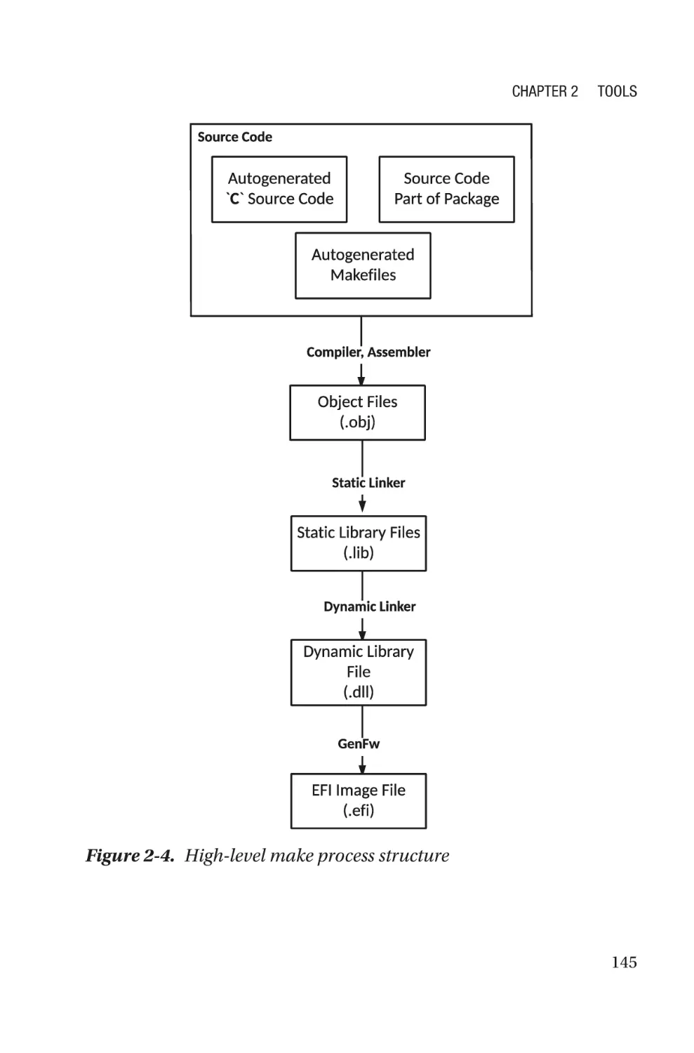
Tools: Chapter 2 focuses on the details on various types of tools that
a user should be equipped with while creating their own firmware. It
includes the following:
•
Build tool: Developing source code and converting it
into the final binary that can be flashed on the SPINOR
involves several intermediated steps and involves
various tools.
•
Configuration tool: The need for configuration tools
becomes inevitable when firmware development
follows the hybrid work model as explained in
Chapter 1. The need for configuration tools increases
when the ability to modify the source code is limited
during product development.
•
Flashing/update tool: There might be several instances
where product integrators or users would like to update
the preflash boot firmware without the hardware-based
utilities.
Infrastructure for Building System Firmware: Chapter 3 provides an
infrastructure overview required for open source firmware development.
In this process of firmware migration, knowing the correct infrastructure
and setting it up is required for efficient communication during the
firmware development process. Additionally, defining the correct
standards for open source firmware development is important to support
seamless architecture migration without any additional cost (in terms of
effort and time).
xxxii
Introduction
System Firmware Debugging: Chapter 4 explains the different
debugging methodologies used in boot firmware such as legacy methods,
advanced software-based debugging, hardware-based debugging, source
code debugging, etc.
Security at Its Core: Chapter 5 covers that firmware is closed to
hardware and explains how abstracting the operating system from
the underlying hardware provides another reason to ensure the
communication channel is secure. This chapter focuses on designing the
boot firmware, keeping security in mind.
The Future of System Firmware: Chapter 6 shares knowledge for
creating firmware based on the market need. This chapter will discuss a
few futuristic proposals and their implementation details to reduce the
firmware boundary by adopting these principles: performance, simplicity,
security, and open source.
The appendixes support the claim that firmware development in the
future is looking into the possibility of high-level system programming
language adaptation.
The glossary and index are applicable for connecting back to the
main topics.
xxxiii
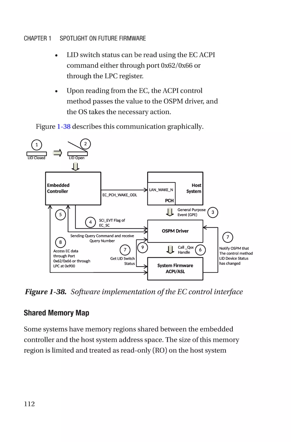
CHAPTER 1
Spotlight on Future
Firmware
“In real open source, you have the right to control your
own destiny.”
—Linus Torvalds
When purchasing a computing device, users are concerned with the
hardware configuration of the device and whether it has the latest versions
of the software and applications. Most computer and consumer electronics
device users don’t realize that there are several layers of programs that run
between the user pressing the power button of the device and when the
operating system starts running. These programs are called firmware.
Firmware is responsible for bringing the device into its operational
state and remains active while the OS is running, even when the device
is in low-power mode. A computing system, irrespective of consumer,
server, or IoT type, contains many different types of firmware. Firmware
that runs on the host CPU is known as system firmware, and firmware that
is specific to devices is called device firmware. In addition, there are other
microcontrollers being used to manage the device, and firmware running
on those controllers is called manageability firmware. The firmware code
that runs on these devices has certain responsibilities prior to handing
over control to the higher-level system software. For example, the system
© Subrata Banik and Vincent Zimmer 2022
S. Banik and V. Zimmer, Firmware Development,
https://doi.org/10.1007/978-1-4842-7974-8_1
1
Chapter 1
Spotlight on Future Firmware
firmware upon platform reset is the main interface for initializing CPUs,
configuring the physical memory, communicating with peripheral devices,
and finally picking the OS loader to boot an operating system. Every
computing device is equipped with peripherals such as input and output
devices, block devices, and connectivity devices. While system firmware is
focusing on the host CPU and its associated interface initialization, device
firmware has started its execution either by executing a self-start program
or by waiting for an initiation command from the system firmware to
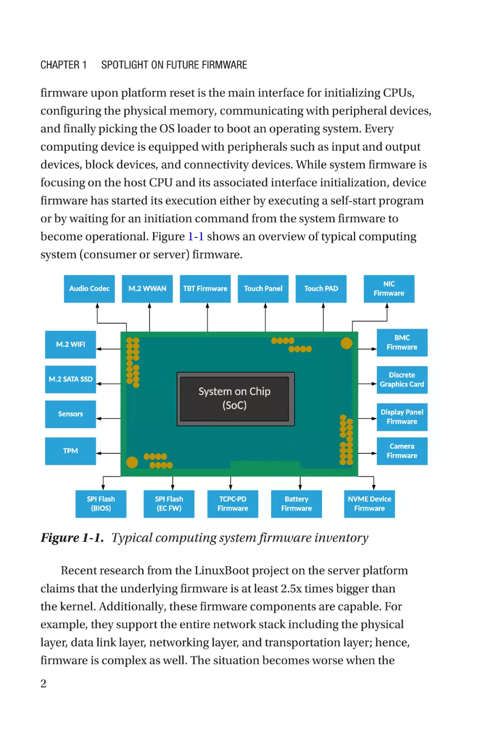
become operational. Figure 1-1 shows an overview of typical computing
system (consumer or server) firmware.
Figure 1-1. Typical computing system firmware inventory
Recent research from the LinuxBoot project on the server platform
claims that the underlying firmware is at least 2.5x times bigger than
the kernel. Additionally, these firmware components are capable. For
example, they support the entire network stack including the physical
layer, data link layer, networking layer, and transportation layer; hence,
firmware is complex as well. The situation becomes worse when the
2
Chapter 1
Spotlight on Future Firmware
majority of the firmware is proprietary and remains unaudited. Along
with end users, tech companies and cloud service providers (CSPs) may
be at risk because firmware that is compromised is capable of doing a lot
of harm that potentially remains unnoticed by users due to its privileged
operational level. For example, exploits in Base Management Controller
(BMC) firmware may create a backdoor entry into the server, so even if a
server is reprovisioned, the attacker could still have access into the server.
Besides these security concerns, there are substantial concerns regarding
performance and flexibility with closed source firmware.
This chapter will provide an overview of the future of the firmware
industry, which is committed to overcoming such limitations by
migrating to open source firmware. Open source firmware can bring
trust to computing by ensuring more visibility into the source code that
is running at the Ring 0 privilege level while the system is booting. The
firmware discussed in this chapter is not a complete list of possible
firmware available on a computing systems, rather just a spotlight on
future firmware so you understand how different types of firmware could
shape the future. Future firmware will make device owners aware of what
is running on their hardware, provide more flexibility, and make users feel
more in control of the system than ever.
Migrating to Open Source Firmware
Firmware is the most critical piece of software that runs on the platform
hardware after boot, and it has direct access to hardware registers and
system memory. Firmware is responsible for bringing the system into a
state where higher-level software can take control of the system and the
end user can make use of the peripheral devices. Prior to that, the user
doesn’t have any control of the system while the system is booting. A
misconfiguration in firmware might make the system unusable or create
security loopholes. Hence, it’s important to know what is running at the
3
Chapter 1
Spotlight on Future Firmware
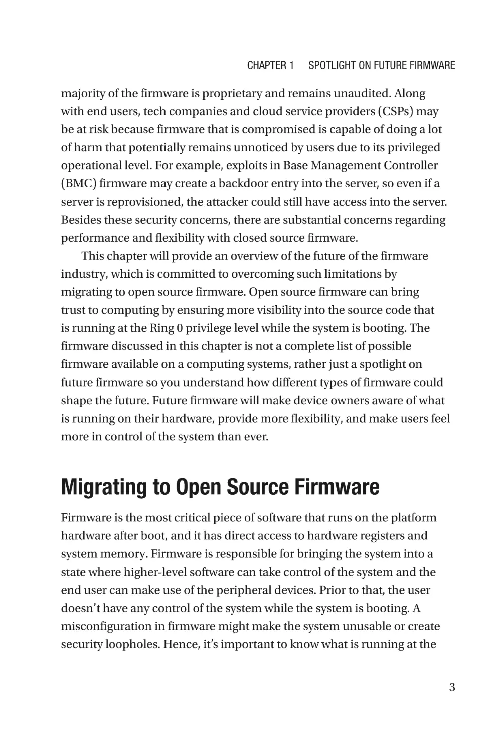
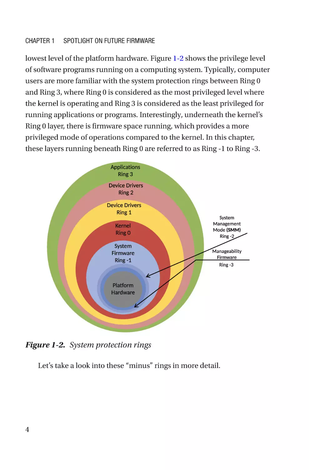
lowest level of the platform hardware. Figure 1-2 shows the privilege level
of software programs running on a computing system. Typically, computer
users are more familiar with the system protection rings between Ring 0
and Ring 3, where Ring 0 is considered as the most privileged level where
the kernel is operating and Ring 3 is considered as the least privileged for
running applications or programs. Interestingly, underneath the kernel’s
Ring 0 layer, there is firmware space running, which provides a more
privileged mode of operations compared to the kernel. In this chapter,
these layers running beneath Ring 0 are referred to as Ring -1 to Ring -3.
Figure 1-2. System protection rings
Let’s take a look into these “minus” rings in more detail.
4
Chapter 1
Spotlight on Future Firmware
Ring -1: System Firmware
System firmware is a piece of code that resides inside the system boot
device, i.e., SPI Flash in most of the embedded systems, and is fetched by
the host CPU upon release from reset. Depending on the underlying SoC
architecture, there might be higher-privileged firmware that initiates the
CPU reset (refer to the book System Firmware: An Essential Guide to Open
Source and Embedded Solutions for more details).
Operations performed by system firmware are typically known as
booting, a process that involves initializing the CPU and the chipsets part
of systems on chip (SoCs), enabling the physical memory (dynamic RAM,
or DRAM) interface, and preparing the block devices or network devices
to finally boot to an operating system. During this booting process, the
firmware drivers can have access to direct hardware registers, memory,
and I/O resources without any restrictions. Typically, services managed by
system firmware are of two types: boot services, used for firmware drivers’
internal communication and vanished upon system firmware being
booted to the OS; and runtime services, which provide access to system
firmware resources to communicate with the underlying hardware. System
firmware runtime services are still available after control has transferred to
the OS, although there are ways to track this kind of call coming from the
OS layer to the lower-level firmware layer at runtime.
System firmware belonging to the SPI Flash updatable region qualifies
for in-field firmware update, and also supports firmware rollback
protection to overcome vulnerabilities.
Ring -2: System Management Mode
System Management Mode (SMM) is the highest privileged mode of
operations on x26-based platforms. There are two widely used ways to
allow the system to enter into SMM:
5
Chapter 1
Spotlight on Future Firmware
•
Hardware-based method: This triggers a system
management interrupt (SMI), a dedicated port 0xb2
with the unique SMI vector number.
•
Software-based method: This uses a general-purpose
interrupt through the Advanced Programmable
Interrupt Controller (APIC).
During initialization of the system firmware, a code block (program)
can get registered with an SMI vector, which will get executed while
entering into SMM. All other processors on the system are suspended, and
the processor states are saved. The program that is getting executed when
in SMM has access to the entire system, i.e., processor, memory, and all
peripherals. Upon exiting from SMM, the processor state is restored and
resumes its operations as if no interruption had occurred. Other higherlevel software doesn’t have visibility about this mode of operation.
SMM exploits are common attacks on computer systems, where
hackers use SMI to elevate the privilege level, access the SPI control
registers to disable the SPI write protection, and finally write BIOS rootkits
into the SPI Flash.
The major concern with SMM is that it’s completely undetectable, so
one doesn’t know what kind of operation is running in SMM.
Ring -3: Manageability Firmware
Ring -3 firmware consists of the separate microcontrollers running its
firmware and later booted to a real-time operating system (RTOS). This
firmware always remains on and is capable of accessing all the hardware
resources; it’s meant to perform the manageability operations without
which one might need to access these devices physically. For example,
it allows the remote administration of the enterprise laptops and servers
by IT admins, such as powering on or off the device, reprovisioning the
hardware by installing the operating system, taking the serial log to analyze
6
Chapter 1
Spotlight on Future Firmware
the failure, emulating the special keys to trigger recovery, performing
active thermal management like controlling the system fans, and handling
the critical hardware device failure like a bad charger, failure of storage
device, etc.
Although this firmware has access to system resources (access to the
host CPU, unlimited access to the host system memory and peripherals)
of the host CPU (based on how it is being interfaced with the host CPU),
the operations performed by these processors are “invisible” to the host
processor. The code that is running on these processors is not publicly
available. Moreover, these codes are provided and maintained by the
silicon vendors; hence, they are assumed to be trusted without verifying
through any additional security layer like a verified boot or secure boot.
The fact to consider here is that all these software codes are developed
by humans and reviewed by other sets of humans. It’s possible to have
some bugs exist irrespective of which layer of ring it’s getting executed in,
and the concern is that the more privileged layer that gets executed, the
more opportunity there is for hackers to exploit the system.
As per the National Vulnerability Database (NVD), there are several
vulnerabilities being reported or detected by security researchers on
production systems every year. Among those security defects there are
many that exist within the “minus” rings. For example, CVE-2017-3197,
CLVA-2016-12-001, CLVA-2016-12-002, CVE-2017-3192, CVE-2015-3192,
CVE-2012-4251, etc., are vulnerabilities reported in firmware from
the NVD.
Most of the firmware being discussed was developed using closed
source, which means the documentation and code source to understand
what’s really running on a machine is not publicly available. When a
firmware update is available, you may be worried about clicking the accept
button because you don’t have any clue whether this update is supposed
to run on your machine. The user has a right to know what’s really running
on their device. The problem with the current firmware development
model is not the security; a study done on 17 open source and closed
7
Chapter 1
Spotlight on Future Firmware
source software showed that the number of vulnerabilities existing in a
piece of software is not affected by the source availability model that it
uses. The problem is lack of transparency.
Transparency is what is missing in closed source firmware if we park
the argument about the code quality due to internal versus external code
review. All these arguments will point back to the need to have visibility
into what is really running on the device that is being used. Having the
source code available to the public might help to get rid of the problem of
running several “minus” rings.
Running the most vulnerable code as part of the highest privileged
level makes the entire system vulnerable; by contrast, running that code
as part of a lesser privileged level helps to meet the platform initialization
requirement as well as mitigates the security concern. It might also help to
reduce the attack surface.
Additionally, performance and flexibility are other concerns that can
be improved with transparency. For example, typically closed source
firmware development focuses on short-term problems such as fixing the
bugs with code development without being bothered about redundancy
if any. A case study presented at the Open Source Firmware Conference
2019 claimed that a system is still functional and meets the booting
criteria even after 214 out of 424 firmware drivers and associated libraries
were removed, which is about a 50 percent reduction. Having more
maintainers of the code helps to create a better code sharing model that
overcomes such redundancy and results in instant boot. Finally, coming
to the security concerns, having a transparent system is more secure
than a supposed secure system that hides those potential bugs in closed
firmware.
This is a summary of the problems with the current firmware:
•
8
Firmware is the most critical piece of code running on
the bare hardware with a privileged level that might
allure attackers.
Chapter 1
Spotlight on Future Firmware
•
A compromised firmware is not only dangerous for the
present hardware but all systems that are attached to it,
even over a network.
•
Lower-level firmware operations are not visible to
upper-level system software; hence, attacks remain
unnoticed even if the operating system and drivers are
freshly installed.
•
Modern firmware and its development models are less
transparent, which leads to multiple “minus” rings.
•
Having a transparency firmware development model
helps to restore trust in firmware as device owners
are aware of what is running on the hardware. In
addition, better design helps to reduce the “minus”
rings, represents less vulnerability, and provides better
maintenance with improved code size and higher
performance.
Open source firmware (OSF) is the solution to overcome all of
these problems. The OSF project performs a bare-minimum platform
initialization and provides flexibility to choose the correct OS loader based
on the targeted operating system. Hence, it brings efficiency, flexibility,
and improved performance. Allowing more eyes to review the code while
firmware is getting developed using an open source model provides
a better chance to identify the feature detects, find security flaws, and
improve the system security state by accommodating the community
feedback. For example, all cryptographic algorithms are available in
GitHub publicly. Finally, to accommodate the code quality question, a
study conducted by Coverity Inc. finds open source code to be of better
quality. All these rationales are adequate to conclude why migrating
to OSF is inevitable. Future firmware creators are definitely looking
into an opportunity to collaborate more using open source firmware
development models.
9
Chapter 1
Spotlight on Future Firmware
This chapter will emphasize the future firmware development models
of different firmware types such as system firmware, device firmware, and
manageability firmware using open source firmware.
pen Source System Firmware
O
Development
Most modern system firmware is built with proprietary firmware where the
producer of the source code has restricted the code access; hence, it allows
private modification only, internal code reviews, and the generation of new
firmware images for updates. This process might not work with a future
firmware development strategy where proprietary firmware is unreliable,
or the functionality is limited in cases where device manufacturers relied
on a group of firmware engineers who know only what is running on
the device and therefore are capable of implementing only the required
features. Due to the heavy maintenance demands of closed source
firmware, often device manufacturers defer regular firmware updates
even for critical fixes. Typically, OEMs are committed to providing system
firmware updates two times during the entire life of the product, once
at the launch and another six months later in response to an operating
system update. System firmware development with an open source model
in the future would provide more flexibility to users to ensure that the
device always has the latest configuration. For that to happen, future
system firmware must adhere to the open source firmware development
principle. The open source firmware model is built upon the principle of
having universal access to source code with an open source or free license
that encourages the community to collaborate in the project development
process.
10
Chapter 1
Spotlight on Future Firmware
This book provides the system architecture of several open source
system firmware types including the bootloader and payload. Most open
source bootloaders have strict resistance about using any closed source
firmware binary such as binary large objects (BLOBs) along with open
source firmware. Typically, any undocumented blobs are dangerous for
system integration as they could be rootkits and might leave the system
in a compromised state. But, the industry recognizes that in order to
work on the latest processors and chipsets from the silicon vendors, the
crucial piece of the information is the silicon initialization sequence. In
the majority of cases, this is considered as restricted information prior
to product launch due to innovation and business reasons and may be
available under only certain legal agreements (like NDAs). Hence, to
unblock the open source product development using latest SoCs, silicon
vendors have come up with a proposal for a binary distribution. Under
this binary distribution model, the essential silicon initialization code is
available as a binary, which eventually unblocks platform initialization
using open source bootloaders and at the same time abstracts the
complexities of the SoC programming and exposes a limited set of
interfaces to allow the initialization of SoC components. This model is
referred to in this book as the hybrid work model.
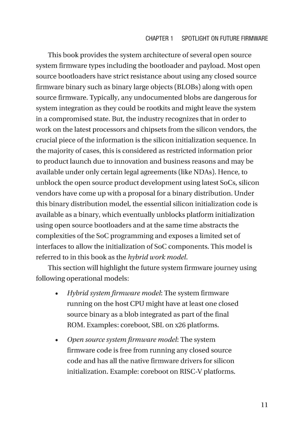
This section will highlight the future system firmware journey using
following operational models:
•
Hybrid system firmware model: The system firmware
running on the host CPU might have at least one closed
source binary as a blob integrated as part of the final
ROM. Examples: coreboot, SBL on x26 platforms.
•
Open source system firmware model: The system
firmware code is free from running any closed source
code and has all the native firmware drivers for silicon
initialization. Example: coreboot on RISC-V platforms.
11
Chapter 1
Spotlight on Future Firmware
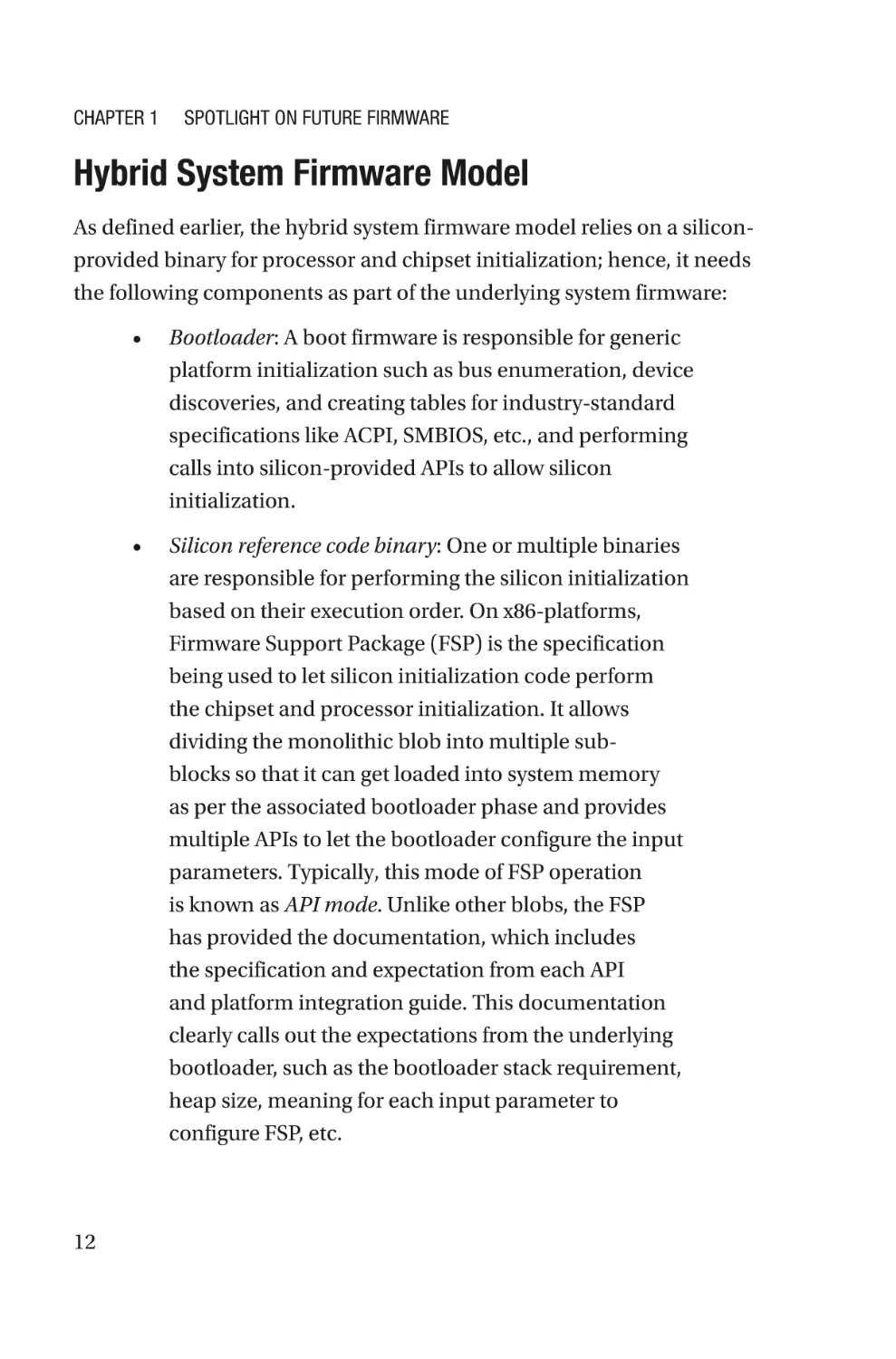
Hybrid System Firmware Model
As defined earlier, the hybrid system firmware model relies on a siliconprovided binary for processor and chipset initialization; hence, it needs
the following components as part of the underlying system firmware:
12
•
Bootloader: A boot firmware is responsible for generic
platform initialization such as bus enumeration, device
discoveries, and creating tables for industry-standard
specifications like ACPI, SMBIOS, etc., and performing
calls into silicon-provided APIs to allow silicon
initialization.
•
Silicon reference code binary: One or multiple binaries
are responsible for performing the silicon initialization
based on their execution order. On x86-platforms,
Firmware Support Package (FSP) is the specification
being used to let silicon initialization code perform
the chipset and processor initialization. It allows
dividing the monolithic blob into multiple subblocks so that it can get loaded into system memory
as per the associated bootloader phase and provides
multiple APIs to let the bootloader configure the input
parameters. Typically, this mode of FSP operation
is known as API mode. Unlike other blobs, the FSP
has provided the documentation, which includes
the specification and expectation from each API
and platform integration guide. This documentation
clearly calls out the expectations from the underlying
bootloader, such as the bootloader stack requirement,
heap size, meaning for each input parameter to
configure FSP, etc.
Chapter 1
Spotlight on Future Firmware
Facts Intel FSP Specification v2.1 introduces an optional FSP boot
mode named Dispatch mode to increase the FSP adaptation toward
PI spec bootloaders.
•
Payload: An OS loader or payload firmware can be
integrated as part of the bootloader or can be chosen
separately, which provides the additional OS boot logic.
The book System Firmware: An Essential Guide to Open Source and
Embedded Solutions provides the detailed system architecture of the
bootloader and payload and defines the working principle with hybrid
firmware as FSP. This section will focus on defining the work relationship
between open source boot firmware with FSP.
•
coreboot using FSP for booting the IA-Chrome platform
•
EDKII Minimum Platform Firmware for Intel Platforms
coreboot Using Firmware Support Package
Firmware Support Package (FSP) provides key programming information
for initializing the latest chipsets and processor and can be easily
integrated with any standard bootloader. In essence, coreboot consumes
FSP as a binary package that provides easy enabling of the latest chipsets,
reduces time-to-market (TTM), and is economical to build as well.
FSP Integration
The FSP binary follows the UEFI Platform Initialization Firmware Volume
Specification format. Hence, each firmware volume (FV) as part of FSP
contains a phase initialization code. Typically, FSP is defined as a single
firmware device (FD) binary, but because it contains several FVs and
each FV represents a different initialization phase and runs at different
13
Chapter 1
Spotlight on Future Firmware
noncontiguous addresses, a monolithic binary wouldn’t work here. Since
the FSP 2.0 specification, the FSP binary can be split into three blobs as
FSP-T, called FSP for Temporary RAM Initialization; FSP-M, called FSP for
Memory Initialization; and FSP-S, called for Silicon Initialization. Here are
some required steps for the FSP integration:
14
•
Configuration: The FSP provides configuration
parameters that can be customized based on target
hardware and/or operating system requirements by the
bootloader. These are inputs for FSP to execute silicon
initialization.
•
eXecute-in-place and relocation: The FSP is not position
independent code (PIC), and each FSP component
has to be rebased if it needs to support the relocation,
which is different from the preferred base address
specified during the FSP build. The bootloader has
support for both these modes where components need
to be executed at the address where it’s built, called
eXecute-In-Place (XIP) components and marked
as --xip, for example, FSP-M binary. Also, positionindependent modules are modules that can be located
anywhere in physical memory after relocation.
•
Interfacing: The bootloader needs to add code to set up
the execution environment for the FSP, which includes
calling the FSP with correct sets of parameters as inputs
and parsing the FSP output to retrieve the necessary
information returned by the FSP and consumed by the
bootloader code.
Chapter 1
Spotlight on Future Firmware
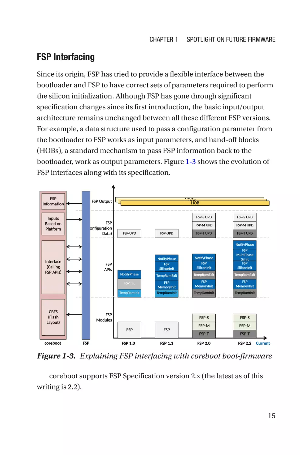
FSP Interfacing
Since its origin, FSP has tried to provide a flexible interface between the
bootloader and FSP to have correct sets of parameters required to perform
the silicon initialization. Although FSP has gone through significant
specification changes since its first introduction, the basic input/output
architecture remains unchanged between all these different FSP versions.
For example, a data structure used to pass a configuration parameter from
the bootloader to FSP works as input parameters, and hand-off blocks
(HOBs), a standard mechanism to pass FSP information back to the
bootloader, work as output parameters. Figure 1-3 shows the evolution of
FSP interfaces along with its specification.
Figure 1-3. Explaining FSP interfacing with coreboot boot-firmware
coreboot supports FSP Specification version 2.x (the latest as of this
writing is 2.2).
15
Chapter 1
Spotlight on Future Firmware
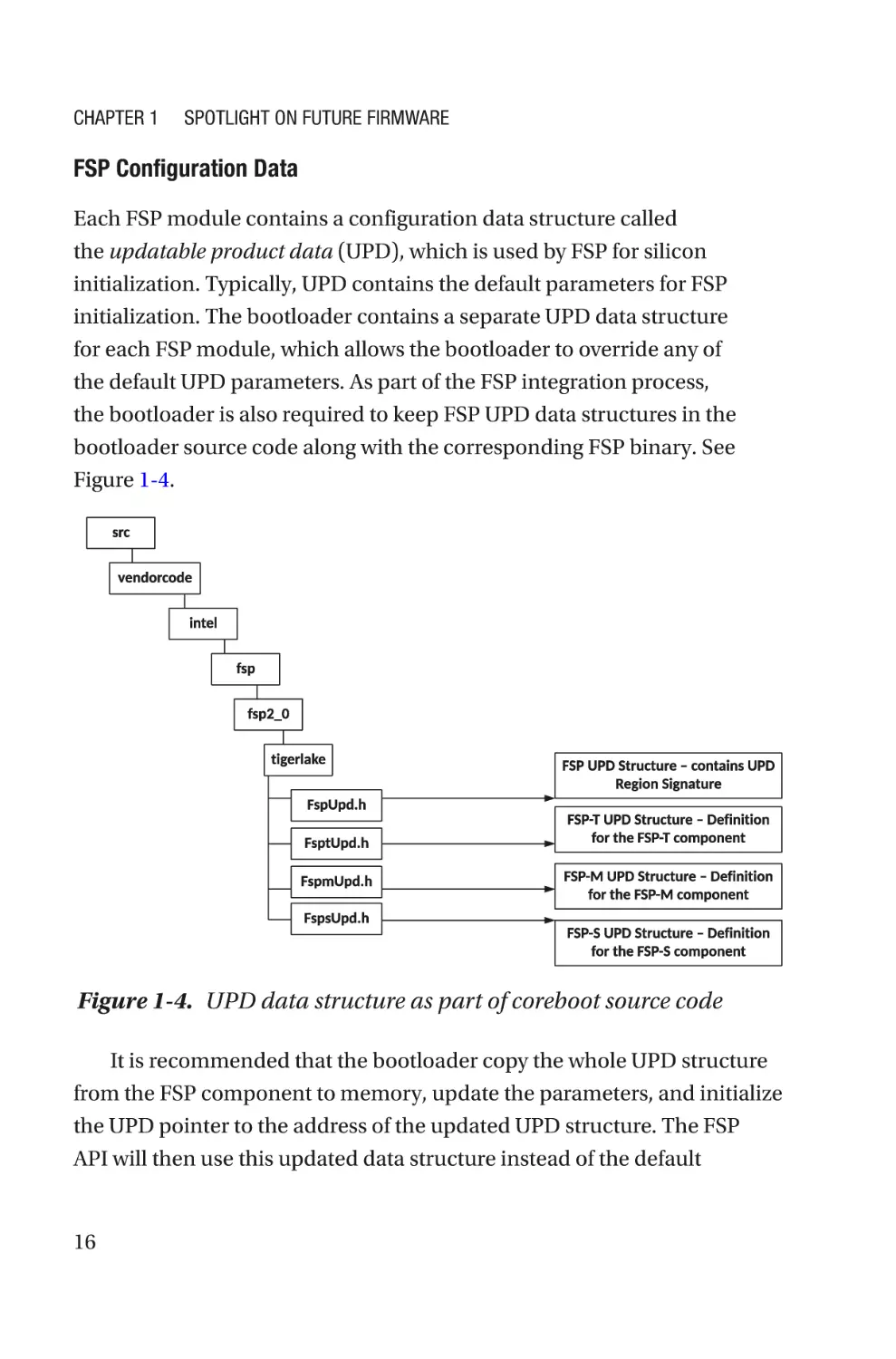
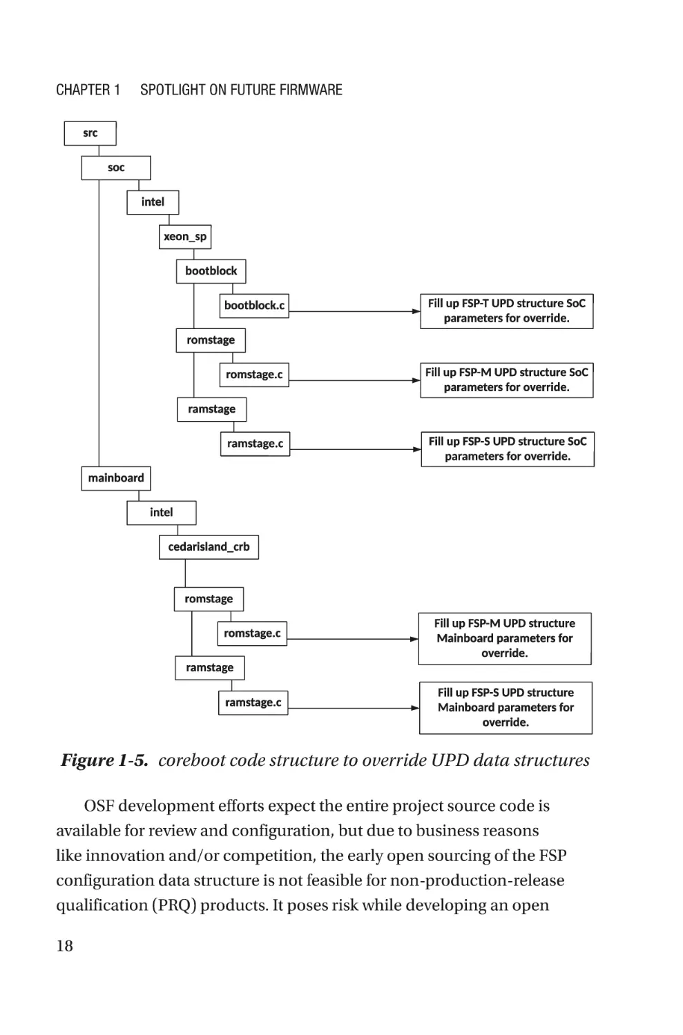
FSP Configuration Data
Each FSP module contains a configuration data structure called
the updatable product data (UPD), which is used by FSP for silicon
initialization. Typically, UPD contains the default parameters for FSP
initialization. The bootloader contains a separate UPD data structure
for each FSP module, which allows the bootloader to override any of
the default UPD parameters. As part of the FSP integration process,
the bootloader is also required to keep FSP UPD data structures in the
bootloader source code along with the corresponding FSP binary. See
Figure 1-4.
Figure 1-4. UPD data structure as part of coreboot source code
It is recommended that the bootloader copy the whole UPD structure
from the FSP component to memory, update the parameters, and initialize
the UPD pointer to the address of the updated UPD structure. The FSP
API will then use this updated data structure instead of the default
16
Chapter 1
Spotlight on Future Firmware
configuration region as part of the FSP binary blob while initializing the
platform. In addition to the generic or architecture-specific data structure,
each UPD data structure contains platform-specific parameters.
Open Source Challenges with FSP Configuration Data
FSP configuration data structures are crucial for the hybrid system
firmware development model as it is used to configure the default builtin UPD configuration data, which might not be applicable for the current
open source project to ensure the correct silicon initialization. Hence,
while integrating the FSP blobs with the bootloader, it is recommended to
ensure it has the same version of UPD structures as part of the bootloader
source code. FSP is responsible for the entire silicon-related initialization
process and feature enabling, and only inputs from the bootloader
are in the UPD data structure. Hence, while calling the FSP APIs like
TempRamInit(), FspMemoryInit(), and FspSiliconInit(), the bootloader
needs to pass a pointer that provides the updated data structure. Figure 1-5
shows the bootloader code structure that ensures the initialization of the
FSP configuration data for an open source firmware development project.
17
Chapter 1
Spotlight on Future Firmware
Figure 1-5. coreboot code structure to override UPD data structures
OSF development efforts expect the entire project source code is
available for review and configuration, but due to business reasons
like innovation and/or competition, the early open sourcing of the FSP
configuration data structure is not feasible for non-production-release
qualification (PRQ) products. It poses risk while developing an open
18
Chapter 1
Spotlight on Future Firmware
source project using the latest SoC prior to PRQ. Consequences of this
restriction would be incomplete SoC and mainboard source code per
platform initialization requirements and incomplete feature enabling.
To overcome this problem, a solution is being developed that is open
source friendly even for open project development using non-PRQ SoC,
called partial FSP configuration data structure (also known as partial
header). Here are the working principles of the partial FSP configuration
data structure generation process:
•
This structure consists only of platform UPDs required
for a specific bootloader to override for the current
project.
•
The rest of the UPDs are renamed as reserved. For any
project, reserved fields are not meant for bootloader
overrides.
•
Embargoed UPD parameters’ names and descriptions
are being abstracted.
Partial headers are generated using a Python-based tool. This tool
will generate the partial headers for those bootloaders that do not need
the full list of UPD data structures. It takes two arguments for the header
generation process.
•
First argument: This is the path for the complete FSPgenerated UPD data structure. The tool will run on
this header itself to filter out only the required UPD
parameters as per the second argument.
•
Second argument: This is a file that provides the lists of
required UPD parameters for bootloader overrides.
This effort will ensure complete source code development on the
bootloader side along with enabling new features without being bothered
about the state of the silicon release. Post SoC PRQ, after the embargo is
19
Chapter 1
Spotlight on Future Firmware
revoked, the complete FSP UPD data structure gets uploaded into FSP on
GitHub, which replaces all reserved fields of the partial header with the
proper naming.
coreboot and FSP Communications Using APIs
Since the FSP 2.1 specification, FSP supports two possible boot flows
based on the implementation of the bootloader and its selection for the
operational mode of FSP. The majority of the open source bootloaders are
working with FSP and are using the API mode boot flow. Figure 1-6 shows
the coreboot boot flow using FSP in API mode.
Figure 1-6. coreboot boot flow using FSP in API mode
Here is the detailed boot flow description:
1. coreboot owns the reset vector.
2. coreboot contains the real mode reset vector
handler code.
3. Optionally, coreboot can call the FSP-T API
(TempRamInit()) for temporary memory setup using
(CAR) and create a stack.
20
Chapter 1
Spotlight on Future Firmware
4. coreboot fills in the UPD parameters required for
the FSP-M API, such as FspMemoryInit(), which
is responsible for memory and early chipset
initialization.
5. On exit of the FSP-M API, either coreboot tears
down CAR using the TempRamExit() API, if the
bootloader initialized the temporary memory in
step 3 using the FSP-T API, or coreboot uses the
native implementation in coreboot.
6. It fills up the UPD parameters required for
silicon programming as part of the FSP-S API,
FspSiliconInit. The bootloader finds FSP-S and
calls into the API. Afterward, FSP returns from the
FspSiliconInit() API.
7. If supported by the FSP, the bootloader enables
multiphase silicon initialization by setting FSPS_
ARCH_UPD.EnableMultiPhaseSiliconInit to a
nonzero value.
8. On exit of FSP-S, coreboot performs PCI
enumeration and resource allocation.
9. The bootloader calls the FspMultiPhaseSiInit()
API with the EnumMultiPhaseGetNumberOfPhases
parameter to discover the number of silicon
initialization phases supported by the bootloader.
10. The bootloader must call the
FspMultiPhaseSiInit() API with the
EnumMultiPhaseExecutePhase parameter n
times, where n is the number of phases returned
previously. The bootloader may perform boardspecific code in between each phase as needed.
21
Chapter 1
Spotlight on Future Firmware
11. The number of phases, what is done during each
phase, and anything the bootloader may need to
do in between phases, will be described in the
integration guide.
12. coreboot continues the remaining device
initialization. coreboot calls NotifyPhase() at
the proper stage like AfterPciEnumeration,
ReadyToBoot, and EndOfFirmware before handing
control over to the payload.
Facts If FSP returns the reset required status from any API, then
the bootloader performs the reset as specified by the FSP return
status return type.
FSP Drivers
The bootloader implements a corresponding version driver to support
the calling convention of the FSP entry point. Ideally, the purpose of these
drivers are as follows:
22
•
Find the FSP header to locate the dedicated entry point,
and verify the UPD region prior to calling.
•
Copy the default value from the UPD area into the
memory to allow the required override of UPD
parameters based on the target platform using driverprovided callbacks into the SoC code, for example:
before calling into memory init or before silicon init.
•
Fill out any FSP architecture-specific UPDs that are
generic like NvsBufferPtr for MRC cache verification.
Chapter 1
Spotlight on Future Firmware
•
Finally, call the FSP-API entry point with an updated
UPD structure to silicon initialization.
•
On failure, handle any errors returned by FSP-API and
take action; for example, manage the platform reset
request to either generic libraries or SoC-specific code.
•
On success, retrieve the FSP outputs in the form of
hand-off blocks that provide platform initialization
information. For example, FSP would like to notify
the bootloader about a portion of system memory
that is being reserved by FSP for its internal use, and
coreboot will parse the resource descriptor HOBs
produced by the FSP-M to create a system memory
map. The bootloader FSP driver must have capabilities
to consume the information passed through the HOB
produced by the FSP.
Current coreboot code has drivers for the FSP 1.1 and FSP 2.0
specifications. The FSP 2.0 specification is not backward compatible but
updated to support the latest specification as FSP 2.2.
Mitigate Open Source Challenges with FSP Driver
Typically, system firmware development using an open source model has
expectations that all new silicon feature-related documentation should be
available to the public to allow the development of the new feature. But in
reality, with the latest processors and chipsets, the feature programming
lists are growing and expected to grow even more in future. With more
capable and complex SoC solutions in the future, there might be some
cases where certain feature programming might be classified as restricted;
hence, it is not feasible to implement using an open source bootloader.
For example, the current coreboot is capable enough to handle the
23
Chapter 1
Spotlight on Future Firmware
multiprocessor (MP) initialization on the x26-platform using the coreboot
native cpu and mp drivers. The Boot Strap Processor (BSP) performs the MP
initialization and typically involves two major operations.
•
Bringing-up process: This enables application
processors (APs) from a reset. It loads the latest
microcode on all cores and syncs the latest Memory
Type Range Register (MTRR) snapshot between BSP
and APs.
•
Perform CPU feature programming: Allow vendorspecific feature programming to run such as to ensure
higher power and performance efficiency, enable
overclocking, and support specific technologies like
Trusted eXecution Technology (TXT), Software Guard
Extensions, Processor Trace, etc.
Typically, the bringing-up process for APs is part of the open
source documentation and generic in nature. But, the previously listed
CPU feature programming lists are expected to grow in the future and
be considered proprietary implementations. If the system firmware
implementation with the open source bootloader isn’t able to perform
these recommended CPU features, programming might resist the latest
hardware features. To overcome this limitation, the hybrid system
firmware model needs to have an alternative proposal as part of the
FSP driver.
Currently, coreboot is doing CPU multiprocessor initialization for the
IA platform before calling FSP-S using its native driver implementation and
having all possible information about the processor in terms of maximum
number of cores, APIC IDs, stack size, etc. The solution offered here is a
possible extension of coreboot support by implementing additional sets of
APIs, which are used by FSP to perform CPU feature programming.
24
Chapter 1
Spotlight on Future Firmware
FSP uses the Pre-EFI Initialization (PEI) environment defined in the
PI Specification and therefore relies on install/locate PPI (PEIM to PEIM
Interface) to perform certain API calls. The purpose of creating a PPI
service inside the bootloader is to allow accessing its resources while FSP
is in operation. This feature is added into the FSP specification 2.1 onward
where FSP is allowed to make use of external PPIs, published by boot
firmware and able to execute by FSP, being the context master.
In this case, coreboot publishes a multiprocessor (MP) service PPI,
EFI_MP_SERVICES_PPI, as per PI Specification Volume 1, section 2.3.9.
coreboot implements APIs for the EFI_MP_SERVICES_PPI structure with its
native functions as follows:
APIs as per the
Specification
coreboot Implementation APIs Description
of APIs
PeiGetNumberOf
Processor
get_cpu_count() to get Get the number of
CPUs.
processor count
PeiGetProcessorInfo
Fill
Get information on a
ProcessorInfoBuffer: specific CPU.
- Processor ID: apicid
- Location: get_cpu_
topology_from_
apicid()
PeiStartupAllAps
Calling the mp_run_on_
all_aps() function
Activate all the
application processors.
PeiStartupThisAps
mp_run_on_aps()
based on the argument
logical_cpu_number
Activate a specific
application processor.
(continued)
25
Chapter 1
Spotlight on Future Firmware
APIs as per the
Specification
coreboot Implementation APIs Description
of APIs
PeiSwitchBSP
Currently not being
implemented in coreboot
due to scoping limitations
Switch the bootstrap
processor.
PeiWhoAmI
Calling to activate the
cpu_index() function
Identify the currently
executing processor.
PeiStartupAllCpus
Only available in EDKII_
PEI_MP_SERVICES2_PPI
mp_run_on_aps()
based on MP_RUN_ON_
ALL_CPUS
Run the function on
all CPU cores (BSP +
APs).
PeiEnableDisableAP
Enable or disable an
application processor.
Here is code flow between coreboot and FSP while running the
restricted CPU feature programming:
1. coreboot selects either CONFIG_MP_SERVICES_
PPI_V1 or CONFIG_MP_SERVICES_PPI_V2 from the
SoC directory as per the FSP recommendation
to implement the MP Services PPI for FSP usage.
coreboot does the multiprocessor initialization
as part of ramstage early, before calling the FSP-S
API. All possible APs are out of reset and ready to
execute the restricted CPU feature programming.
2. coreboot creates the MP (MultiProcessor) Services
APIs as per PI Specification Vol 1, section 2.3.9, and
is assigned into the EFI_MP_SERVICES or EDKII_
PEI_MP_SERVICES2_PPI structure as per the MP
specification revision.
26
Chapter 1
Spotlight on Future Firmware
3. FSP-S to install EFI_MP_SERVICES or EDKII_PEI_MP_
SERVICES2_PPI based on the structure provided by
coreboot as part of the CpuMpPpi UPD. At the later
stage of FSP-S execution, locate the MP Services PPI
and run the CPU feature programming on APs.
4. While FSP-S is executing multiprocessor
initialization using Open Source EDKII UefiPkg, it
invokes a coreboot-provided MP Services API and
runs the “restricted” feature programming on APs.
Figure 1-7 shows the pictorial representation of the boot flow.
Figure 1-7. coreboot-FSP multiprocessor init flow
27
Chapter 1
Spotlight on Future Firmware
This design would allow running SoC vendor-recommended restricted
CPU feature programming using the FSP module without any limitation
while working on the latest SoC platform (even on non-PRQ SoC) in the
hybrid system firmware model. The CPU feature programming inside FSP
will be more transparent than before as it’s using coreboot interfaces to
execute those programming features. coreboot will have more control over
running those programming features as the API optimization is handled by
coreboot.
This solution is future-proof, because in the future this design of the
PEIM-PEIM interface (PPI) can be expanded beyond just running the
restricted CPU feature programming in a coreboot context. Here is a
list of other opportunities to scale this solution for future hybrid system
firmware:
•
Today on the CrOS platform, the cbmem -c command is
capable only of redirecting the coreboot serial log into
the cbmem buffer using the bootloader driver. With this
approach, the coreboot serial library may be used by
FSP to populate serial debug logs.
•
The same can be used for post code-based debug
methods as well.
•
Rather than implementing a dedicated timer library
inside FSP, this method can be used by FSP to inject
any programmable delay using the bootloaderimplemented PPI, which natively uses the bootloader
timer driver.
To summarize, a hybrid system firmware model in the future provides
the ease of porting to a new silicon. It allows for bootloaders (coreboot,
SBL, UEFI MinPlatform, etc.) to have an FSP interfacing infrastructure for
finding and loading FSP binaries, configuring FSP UPDs as per platform
need, and finally calling FSP APIs.
28
Chapter 1
Spotlight on Future Firmware
EDKII Minimum Platform Firmware
Since the introduction of the Unified Extensible Firmware Interface (UEFI)
firmware in 2004, all Intel architecture platforms have migrated from
legacy BIOS to UEFI firmware implementations. With a blistering speed,
UEFI firmware has taken over the entire PC ecosystem to become the
de-facto standard for system firmware. Historically, platforms that use
UEFI firmware have been nourished and maintained by a closed group;
hence, the source used in a platform that uses UEFI firmware remains
closed source although the specifications are open standards. Details
about the UEFI architecture and specification are part of System Firmware:
An Essential Guide to Open Source and Embedded Solutions.
Over the years the platform enabling activity has evolved and demands
more openness due to firmware security requirements, cloud workloads,
business decisions for implementing solutions using more open
standards, etc.
Minimum Platform Architecture
The Minimum Platform Architecture (MPA) provides the design guidelines
for implementing platform initialization using the open source EDKII
standard to meet the industry expectations from the UEFI firmware.
Figure 1-8 shows the high-level firmware stack used in the MPA.
29
Chapter 1
Spotlight on Future Firmware
Figure 1-8. MPA diagram
The MPA firmware stack demonstrates the hybrid-firmware
development work model where it combines the several closed and open
source components for platform initialization.
Core
Tianocore is an open source representation of the UEFI. EDKII is
the modern implementation of UEFI and Platform Initialization (PI)
specifications. Typically, the EDKII source code consists of standard
drivers based on the various industry specifications such as PCI, USB,
TCG, etc.
30
Chapter 1
Spotlight on Future Firmware
Silicon
A closed source binary model was developed and released by silicon
vendors (example: Intel, AMD, Qualcomm etc.) with an intention to
abstract the silicon initialization from the bootloader.
Prior to the MPA architecture, the FSP API boot mode was the de facto
standard for silicon initialization when the bootloader needs to implement
a 32-bit entry point for calling into the APIs as per the specification. This
limits the adaptation of SoC vendor-released silicon binaries aka FSP
toward a bootloader that adheres to the UEFI PI firmware specification.
Traditionally, the UEFI specification deals with firmware modules
responsible for platform initialization and dispatched by the dispatcher
(Pre-EFI Initialization aka PEI and Driver eXecution Environment aka DXE
core). To solve this adaptation problem in the UEFI firmware platform
enabling model, a new FSP boot mode has been designed with the FSP
External Architecture Specification v2.1 known as dispatch mode.
Dispatch Mode
FSP API boot mode requires bootloaders to perform a call into the FSP
entry points like FSP-M (for Memory Init) and FSP-S (for Silicon Init) for
initiating the silicon initialization. The dispatch mode is more aligned with
the UEFI specification where FSP-M and FSP-S are containers that expose
firmware volumes (FVs) that can be directly used by a UEFI PI–compliant
bootloader. For example, the UEFI bootloader known as an FSP wrapper
uses FSP the same way as any other firmware file system partition. The
PEIM in these FVs are executed as is in the PEI environment with the
bootloader being the context master. All the FSP entry points introduced
31
Chapter 1
Spotlight on Future Firmware
as part of API boot mode (i.e., FspMemoryInit(), FspSiliconInit(), and
NotifyPhase()) are not in use. Figure 1-9 shows the work relationship
between a UEFI PI bootloader and FSP in dispatch mode.
32
•
The UEFI PI bootloader adhering to the MPA
is equipped with a PCD database to pass the
configuration information between bootloaders to
FSP. This includes hardware interface configuration
(typically, configured using UPD in API mode) and
boot stage selection. Refer to the “Min-Tree” section
to understand the working principle and MPA stage
approach for incremental platform development.
•
PEI Core as part of Silicon Reference code blob aka
FSP is used to execute the modules residing into the
firmware volumes (FVs) directly.
•
The PEIMs belonging to these FVs are communicating
with each other using PPI as per the PI specification.
•
The hand-off-blocks are being used to pass the
information gathered in the silicon initialization phase
with the UEFI PI bootloader.
•
The UEFI bootloader doesn’t use NotifyPhase APIs;
instead, FSP-S contains a DXE driver that implements
an equivalent implementation using a DXE native
driver that is getting invoked at NotifyPhase() events.
Chapter 1
Spotlight on Future Firmware
Figure 1-9. FSP work model in dispatch mode with UEFI bootloader
UEFI Bootloader and FSP Communications Using Dispatch Mode
The communication interface designed between the UEFI bootloader
and FSP in dispatch mode is intended to remain as close as possible to
the standard UEFI boot flow. Unlike API mode, where the communication
between the bootloader and FSP takes place by passing configuration
parameters known as UPD to the FSP entry points, in dispatch mode
the Firmware File Systems (FFSs) that belong to FVs consist of Pre-EFI
Initialization Modules (PEIMs) and get executed directly in the context
of the PEI environment provided by the bootloader. This can also be
referred to as the firmware volume drop-in model. In dispatch mode,
the PPI database and HOB lists prepared by FSP are shared between the
bootloader and FSP.
Here is the detailed boot flow description:
1. The bootloader owns the reset vector and SecMain
as part of the bootloader getting executed upon the
platform start executing from the reset vector.
33
Chapter 1
Spotlight on Future Firmware
2. SecMain is responsible for setting up the initial
code environment for the bootloader to continue
execution. Unlike the coreboot workflow with
FSP in API mode, where coreboot does the
temporary memory initialization using its native
implementation on the x86 platform instead calling
the FSP-T API, dispatch mode tries to maximize
the usage of FSP and uses FSP-T for initializing
temporary memory and setting up the stack.
3. The bootloader provides the boot firmware volume
(BFV) to the FSP. The PEI core belonging to FSP uses
the BFV to dispatch the PEIMs and initialize the
PCD database.
4. In addition to the bootloader PEI modules, FSP
dispatches the PEI module part of FSP-M to
complete the main memory initialization.
5. The PEI core continues to execute the post-memory
PEIMs provided by the bootloader. During the
course of dispatch, the PEIM included within
FSP-S FV is executed to complete the siliconrecommended chipset programming.
6. At the end of the PEI phase, all siliconrecommended chipset programming is done using
the closed source FSP, and DXE begins its execution.
7. The DXE drivers belonging to the FSP-S firmware
volume are dispatched. These drivers will register
events to be notified at different points in the boot flow.
For example, NotifyPhase will perform the callbacks to
complete the remaining silicon-recommended security
configurations such as disabling certain hardware
34
Chapter 1
Spotlight on Future Firmware
interfaces, locking the chipset register, and dropping
the platform privilege level prior to handing control off
to the payload or operating system.
8. The payload phase executes the OS bootloader and
loads the OS kernel into the memory.
9. The OS loader signals the events to execute the
callbacks, registered as part of the DXE drivers to ensure
the pre-boot environment has secured the platform.
Platform
In the past, UEFI firmware development has used closed source for platform
initialization, but with MPA, this limitation is diminished by creating a
platform standard known as the EDKII Minimum Platform Specification.
This approach allows the platform using UEFI firmware to open source
and improves customer engagement, brings transparency to product
development, establishes the trust in the community, and finally establishes
the ecosystem that encourages the community to contribute toward platform
implementation. The key innovation in this architecture is the layered
approach called stages, which are based on the development phase and the
functionality for specific use cases. Each stage builds upon its previous stage
with extensibility to meet silicon, platform, or board requirements. The MPA
tries to split the platform implementation into two parts.
•
Generic: This part remains generic in nature by
providing the required APIs to define the control flow.
This generic control flow is being implemented inside
MinPlatformPkg ( Edk2-Platforms/Platform/Intel/
MinPlatformPkg), such that the tasks performed by the
MinPlatformPkg can be reused by all other platforms
(belonging to the board package) without any
additional source modification.
35
Chapter 1
•
Spotlight on Future Firmware
Board package: This part focuses on the actual
hardware initialization source code aka board package.
Typically, the contents of this package are limited to the
scope of the platform requirements and the feature sets
that board users would like to implement. As described
in Figure 1-8, the board package code is also open
source and represented as Edk2-Platforms/Platform/
Intel/<xyz>OpenBoardPkg, where xyz represents
the actual board package name. For example,
TiogaPass, a board supported by Open Compute
Project (OCP) based on Intel’s Purley chipset, uses the
PurleyOpenBoardPkg board package.
Facts A closed source representation of the OpenBoardPkg is
just BoardPkg, which still directly uses the MinPlatformPkg from
EDKII platforms.
The board package consists of a standard EDKII package along with
the following items and must implement the guidelines:
–– A board package may consist of one or more supported
boards. These boards are sharing the common
resources from the board package.
–– Board-specific source code must belong to the board
directory and name after the supported board. For the
previous example, the board directory for TiogaPass is
named as BoardTiogaPass.
–– All the board-relevant information is made available to
the MinPlatformPkg using board-defined APIs.
36
Chapter 1
Spotlight on Future Firmware
To summarize MPA, it consists of a closed source FSP package for
silicon initialization, and the rest of the source code is potentially open
source where MinPlatformPkg and a board package are combined together
to call the platform.
Min-Tree
MPA is built around the principle of a structural development model. This
structural development model can be referred to as a min-tree, where the
source code tree is started with a minimalistic approach and enriched
based on the required functionality getting included over time as the
platform is getting matured. To make this model structural, the design
principle relied on dividing the flow, interfaces, communication, etc., into
a stage-based architecture (refer to “Minimum Platform Stage Approach”
section).
Figure 1-10 shows the min-tree development model over the product
life cycle. Typically, in the product development cycle, the early phase is
always focusing on creating the bare-minimum source code. The target
is to make sure the early silicon-based simulation or emulation platform
is able to perform the basic boot to an operating system. To meet this
goal, the platform development starts by leveraging the source code of
the previous generation platform (typically referred to as n-1 where n
is the current generation platform) and existing feature sets. This often
includes creating the new sets of silicon and platform code on top of the
prior platform after analyzing the basic differences between the new
target platform from its prior generation. Hence, at the start of the product
development cycle, the min-tree just consists of silicon and platformrelated changes that are applicable for the present platform and leverages
existing features from the prior generation platform.
37
Chapter 1
Spotlight on Future Firmware
Figure 1-10. Min-tree evolution over product timeline
The later product development stages are targeted more toward
meeting the product milestone releases; hence, it focuses on the code
completion that includes development of the full feature sets applicable
for this platform. Next is platform development, which focuses on the
enablement of the product differentiator features, which is important
for product scaling. Finally, the platform needs to be committed to
sustenance, maintenance, and derivative activities. The staged platform
approach is a more granular representation form of the min-tree where
based on product requirement, timeline, security, feature sets, etc.,
one can decide the level of the tree to design the minimum platform
architecture. For example, product-distinguishing features are not part
of the essential or minimum platform or advanced feature list, and the
board package is free to exclude such features using boot stage PCD
(gMinPlatformPkgTokenSpaceGuid.PcdBootStage). This may be used
to meet a particular use case based on the platform requirement. For
example, a board may disable all advanced features by setting the board
38
Chapter 1
Spotlight on Future Firmware
stage PCD value to 4 instead of 6 to improve the boot time. Decrementing
the additional stages might also be used for SPINOR size reduction as the
final bootloader executable binary size is expected to get reduced.
Minimum Platform Stage Approach
The MPA staged approach describes the minimal code block and binary
components required while creating system firmware. The flexible
architecture allows modifying the FD image to make it applicable for
the target platform. In this architecture, each stage will have its own
requirement and functionality based on the specific uses. For example,
Stage III, Boot to UI, is focused on interfacing with console I/Os and
other various hardware controllers using the command-line interface.
Additionally, decrementing a stage might also translate to reducing the
platform feature set. For example, a Stage III bootloader won’t need to
publish ACPI tables as this feature is not useful for the platform.
Figure 1-11 describes the stage architecture, including the expectations
from the stage itself. Each stage is built upon the prior stage with
extensibility to meet the silicon, platform, or board requirements.
Stage I: Minimal Debug
Stage I (Minimal Debug) is the base foundation block for the later stages
supported by this architecture to add more complexity by introducing
advanced functionality.
39
Chapter 1
Spotlight on Future Firmware
Figure 1-11. Minimum platform stage architecture
40
Chapter 1
Spotlight on Future Firmware
Stage I is contained within the SEC and PEI phases; hence, it should
get packed and uncompressed inside the firmware volume. The minimal
expectation from this stage is to implement board-specific routines that
enable the platform debug capability like serial output and/or postcode to
see the sign of life.
The major responsibilities of Stage I are as follows:
•
This is similar to all other bootloaders that come up on
a memory-restricted environment like x86. Perform
initialization of temporary memory and set up the code
environment.
•
Perform pre-memory board specific initialization
(if any).
•
Detect the platform by reading the board ID after
performing the board-specific implementation.
•
Perform early GPIO configuration for the serial port
and other hardware controllers that are supposed to be
used early in the boot flow.
•
Enable the early debug interface, typically, serial
port initialization over legacy I/O or modern PCHbased UARTs.
The functional exit criteria of Stage I is when temporary memory is
available and the debug interface is initialized where the platform has
written a message to indicate that Stage I is now getting terminated.
Stage II: Memory Functional
Stage II (Memory Functional) is primarily responsible for ensuring the
code path that executes the memory initialization code for enabling the
platform permanent memory. This stage extends the operations on top
41
Chapter 1
Spotlight on Future Firmware
of Stage I and performs the additional/mandatory silicon initializations
required prior to memory initialization. Because of the memory-restricted
nature of platform boot, this stage is also packed uncompressed. Stage II
is more relying on the FSP-M firmware volume in terms of finding the PEI
core and dispatching the PEIMs.
The following of the major responsibilities of Stage II:
•
Perform pre-memory recommended silicon policy
initialization.
•
Execute memory initialization module and ensure the
basic memory test.
•
Switch the program stack from temporary memory to
permanent memory.
The functional exit criteria of Stage II are that early hardware
devices like GPIOs are being programmed, main memory is initiated,
temporary memory is disabled, memory type range registers (MTRRs)
are programmed with main memory ranges, and the resource description
HOB is built to pass that initialization information to the bootloader.
Stage III: Boot to UI
The primary objective of Stage III (Boot to UI) is to be able to successfully
boot to the UEFI Shell with a basic UI enabled. The success criteria of this
stage is not to demonstrate that every minimum platform architecture
should be equipped with the UEFI Shell, but rather more focuses on the
generic DXE driver execution on top of the underlying stages like Stages
I and II (mainly targeted for silicon and board). The bare-minimal UI
capability required for Stage III is a serial console.
Stage III is contained with the Driver Execution Environment (DXE)
and Boot Device Selection (BDS) for booting to the UEFI Shell. The major
responsibilities of Stage III are as follows:
42
Chapter 1
Spotlight on Future Firmware
•
Bring generic UEFI-specific interfaces like DXE Initial
Program Load (IPL), DXE Core, and dispatch DXE
modules. This includes installing the DXE architectural
protocols.
•
Perform post-memory silicon-recommended
initialization.
•
Have a provision to access the nonvolatile media
such as SPINOR using UEFI variables. Additionally,
capabilities that can be enabled as part (but not only
limited to this lists) of this phase allow various input
and output device driver access such as USB, graphics,
storage, etc.
The functional exit criteria of Stage III is to ensure all generic device
drivers are not operational and the platform has reached the BDS phase,
meaning the bootloader is able to implement minimal boot expectations
for the platform.
Stage IV: Boot to OS
Leveraging on the previous stage, Stage IV (Boot to OS) is to enable a
minimal boot path to successfully boot to an operating system (OS). The
minimal boot path is the delta requirement over Stage III that ensures
booting to an OS.
The minimal boot path for Stage IV includes the following:
•
Add minimum ACPI tables required for booting an
ACPI-compliant operating system. Examples are ACPI
tables, namely, RSDT (XSDT), FACP, FACS, MADT,
DSDT, HPET, etc.
•
Based on the operating system expectation, it might
additionally publish DeviceTree to allow the operating
system to be loaded.
43
Chapter 1
Spotlight on Future Firmware
•
Trigger the boot event that further executes the
callbacks being registered by the FSP-S PEIMs to ensure
locking down the chipset configuration register and
dropping the platform privilege prior to launching the
application outside trusted boundaries.
•
This phase will also utilize the runtime services
being implemented by the UEFI bootloader for
communication like Timer and nonvolatile region
access from the OS layer.
After the platform is able to successfully boot to a UEFI-compliant
OS with a minimal ACPI table being published, it is enough to qualify
Stage IV to call its termination. Additionally, this stage implements SMM
support for x86–based platforms where runtime communication can get
established based on software triggering SMI.
Stage V: Security Enable
The basic objective of Stage V (Security Enable) is to include security
modules/foundations incrementally over Stage IV. Adhering to the basic/
essential security features is the minimal requirement for the modern
computing systems. Chapter 5 is intended to highlight the scenarios to
understand the security threat models and what it means for the platform
to ensure security all around even in the firmware.
The major responsibilities of Stage V are as follows:
44
•
Ensure that the lower-level chipset-specific security
recommendation such as lockdown configuration is
implemented.
•
Hardware-based root of trust is being initialized and
used to ensure that each boot phase is authenticated
and verified prior to loading into the memory and
executing it as a chain throughout the boot process.
Chapter 1
Spotlight on Future Firmware
•
Protect the platform from various memory-related
attacks if they implement the security advisory well.
•
At the end of this phase, it will allow running any
trusted and authenticated application including the
operating system.
Stage VI: Advanced Feature Selection
Advanced features are the nonessential block in this min-tree structural
development approach. All the essential and mandatory features required
for a platform to reach an operating system are developed using stages I
to V. The advanced feature selection is focused on developing firmware
modules based on a few key principles such as modularization, reducing
interdependencies over other features, etc. It helps these modules to get
integrated with min-tree as per the user requirements, product use cases,
and even the later product development cycle.
The design principles behind Stage VI are as follows:
•
Platform development models become incremental
where more essential features are integrated and
developed at an early phase. Otherwise, the complex
but generic advanced features can be developed
without being bottlenecked on the current silicon and
board but can be readily shared across platforms.
•
Advanced feature modules necessarily do not contain
functionality that is unrelated to the targeted feature.
•
Each feature module should be self-content in nature,
meaning it minimizes the dependencies to the other
feature.
45
Chapter 1
•
Spotlight on Future Firmware
The feature should expose a well-defined software
interface that allows easy integration and configuration.
For example, all modules should adhere to EDKII
configuration options such as PCD to configure the
feature.
Stage VII: Optimization
In the scope of current architecture, Stage VII (Optimization) is a proposed
architectural stage reserved for future improvements. The objective of this
stage is to provide an option for the platform to ensure optimization that
focuses on the target platform. For example, on a scaling design without
Thunderbolt ports, there should be a provision using PCD that disables
dispatching of Thunderbolt drivers (including host, bus, and device). This
is known as a configurable setting.
Additionally, there could be compilation-time configuration attached
to the PCD that strips unused components from the defined FV. For
example, FSP modules are used for API boot mode. It is intended that such
optimization/tuning can be intercepted in the product even at a later stage
without impacting the product milestone aka schedules.
These are just examples that demonstrate the architecture freedom
to improve the platform boot time and SPINOR size reduction at the
later stage.
To summarize, a hybrid system firmware development using EDKII
MPA is intended to improve the relationship between open source and
closed source components. An MPA design brings transparency to
platform development even with EDKII platform code. The min-tree
design serves as a basic enablement vehicle for the hardware power-on
and allows cross-functional teams to get started on feature enablement.
The feature enablement benefits from its modular design that is simple to
maintain.
46
Chapter 1
Spotlight on Future Firmware
Open Source System Firmware Model
The ideal philosophy of open source system firmware is to make sure
that all pieces of the firmware are open source, specifically, the ones
required for the boot process post CPU reset. This effort of achieving the
system firmware code is 100 percent open source and has significant
dependency over the underlying platform hardware design. Typically,
due to the unavailability of the detailed hardware interface document
and programming sequence for boot-critical IPs like memory controller,
system firmware projects should choose the hybrid system firmware model
over complete open source system firmware. RISC-V is a good example
of an open standard hardware specification that allows pure open source
system firmware development on RISC-V-based embedded systems,
personal computers, etc. The word pure being used here intentionally
to differentiate a firmware project that supports closed source blobs for
platform pre-reset flow from the transparent system reset flow (pre and
post CPU reset) with all possible open source firmware.
There are several open source system firmware projects available, and
this section is about having a detailed overview about expectations from
the future open source system firmware. Hence, future system firmware
will focus not only on getting rid of proprietary firmware blobs but also
on adopting a modern programming language for developing system
firmware. oreboot is an aspiring open source system firmware project that
is slowly gaining momentum by migrating its supports from evaluation
boards to real hardware platforms. oreboot has a vision of pure open
systems, meaning firmware without binary blobs. But to add the latest
x26-based platforms, it had made an exception to include only bootcritical blobs (for example, manageability firmware, AMD AGESA, FSP for
performing specific silicon initialization), where feature implemented by
blobs during boot is not possible to implement in oreboot.
This section will provide an architecture overview of oreboot and its
internals, which will be valuable for developers to learn for preparing
47
Chapter 1
Spotlight on Future Firmware
themselves for system firmware architecture migration into a more
efficient and safe programming language. It’s like a recurrence of events
that happened a few decades back that had migrated the present system
firmware programming language to C from assembly.
oreboot = Coreboot - C + Much More
At a high level, it’s easy to define oreboot as downstream of the coreboot
project, which is developed without the C programming language. The
oreboot system firmware project has zero C code, very minimal code
written in assembly to just set up the programming environment, and
remaining code in the Rust language. With the introduction of the Rust
code for system firmware development, it offers better security and
reliability. The oreboot image is licensed under the GPL, version 2. Here
are the design principles of oreboot, which make it different from the other
boot firmware used on embedded systems:
48
•
oreboot is focused on reducing the firmware boundary
to ensure instant system boot. The goal for oreboot is to
have fewer than one boot on embedded devices.
•
It improves the system firmware security, which
typically remains unnoticed by the platform security
standards with a modern, safe programming language.
Refer to Appendix A for details about the usefulness
of Rust in system firmware programming, which deals
with direct memory access and even operations that
run on multithreaded environments.
•
It removes dedicated ramstage usage from the boot
flow and defines a stage named Payloader Stage. This
will help to remove the redundant firmware drivers and
utilities from LinuxBoot as payload.
Chapter 1
•
Spotlight on Future Firmware
It jumps to the kernel as quickly as possible during
boot. Firmware shouldn’t contain the high-level device
drivers such as network stack, disk drivers, etc., and it
can leverage the most from LinuxBoot.
Currently, oreboot has support for all the latest CPU architecture, and
adding support for the newer SoC and mainboards are a work in progress.
Currently the RISC-V porting being done using oreboot is fully open
sourced. In addition, it’s able to boot an ASpeed AST2500 ARM-based
server management processor as well as a RISC-V OpenTitan “earlgrey”
embedded hardware.
oreboot Code Structure
The source code organization of an oreboot project is similar to coreboot
with a more simplified build infrastructure. The makefile parts of oreboot
directories are much simpler; unlike coreboot, they don’t contain the
control flow. The .toml-based configuration file is used to define and
configure sets of tasks to run as part of control flow. A task is Rust code that
needs to be executed. Tasks can have dependencies that are also tasks that
will be executed before the current task itself. The following table describes
the oreboot code structure:
Directory
Description
src/arch
Lists of supported CPU architecture, for example: armv7, armv2,
risc-v, x26, etc.
src/drivers
Supported firmware drivers, written in Rust, that follow oreboot
unique driver model, for example: clock, uart, spi, timer, etc.
src/lib
Generic libraries like devicetree, util, etc.
(continued)
49
Chapter 1
Directory
Spotlight on Future Firmware
Description
src/mainboard Lists of supported mainboards as part of the oreboot project.
This list contains emulation environments like qemu, engineering
board such as upsquared based on x26, and HiFive the RISC-V
based development board, BMC platform ast2500, etc.
Each mainboard directory contains a makefile and Cargo.toml
file to define the build dependencies, which will allow it to build
all boards in parallel.
Example of Cargo.toml:
[dependencies]
cpu = { path = "../../../cpu/armltd/cortex-a9"}
arch = { path = "../../../arch/arm/armv7"}
payloads = { path = "../../../../payloads"}
device_tree = { path = "../../../lib/device_
tree" }
soc = { path = "../../../soc/aspeed/ast2500" }
[dependencies.uart]
path = "../../../drivers/uart"
features = ["ns16550"]
Include source files written in Rust (.rs) and assembly (.S) as
per the boot phase requirements.
Two special files reside in the mainboard directory as fixeddtfs.dts to create the flash layout and describe system
hardware configuration as mainboard.dts. mainboard.dtb
is the binary encoding of the device tree structure.
(continued)
50
Chapter 1
Spotlight on Future Firmware
Directory
Description
src/soc
Source code for SoC that includes clock programming, early
processor initialization, setting up code environment, DRAM
initialization sequence, chipset registers programming, etc.
Each SoC directory also contains Cargo.toml that defines
the dependent drivers and library required for SoC-related
operations.
payloads/
Library for payload-related operations like loading into memory
and executing.
tools/
Tools directory that contains useful utilities like layoutflash
to create an image from binary blobs, as described in the layout
specified using device tree, bin2vmem to convert binary to
Verilog VMEM format, etc.
README.md
Describes the prerequisites to getting started with oreboot,
cloning source code, compilation, etc., useful for the first-time
developer.
Makefile.inc
This makefile is included by the project mainboard directory
makefile.
oreboot Internals
This section will guide developers through the various key concepts
of oreboot that are required to understand its architecture. Without
understanding these architectural details, it would be difficult to
contribute to a project. Also, these are the key differentiating features for
oreboot, compared to the coreboot project.
51
Chapter 1
Spotlight on Future Firmware
Flash Layout
Flash layout specifies how different binaries as part of oreboot are getting
stitched together to create the final firmware image (ROM) for flashing
into the SPI Flash. This file is named fixed-dtfs.dts, belonging to each
mainboard directory.
oreboot has replaced the coreboot file system (CBFS) with the Device
Tree File System (DTFS). It is easy to expose the layout of the flash chip
without any extra OS interface. DTFS provides an easy method to describe
the different binary blobs.
Here is sample code to describe the different regions belonging to the
flash layout (see Figure 1-12):
area@x {
description = "Boot Blob";
offset = <0xff0000>;
size = <0x20000>; // 512KiB
file = "$(TARGET_DIR)/bootblob.bin";
};
52
Chapter 1
Spotlight on Future Firmware
Figure 1-12. 32MiB flash layout
The description field defines the type of binary, offset is the base
address of the region, the size field specifies the region limit, and the file
field is used to mention the path of the binary. x is the region number
inside the flash layout, for example: boot blob, rampayload, NVRAM,
etc. With reduced boot phases, the oreboot architecture allows ample
headroom in flash.
53
Chapter 1
Spotlight on Future Firmware
Build Infrastructure
coreboot uses make menuconfig to allow configuration, but oreboot
doesn’t have such a provision; hence, it relies on conditional compilation.
An oreboot build starts when the developer executes the make command
from a specific mainboard directory. The code inside src/mainboard/*/*/
src/main.rs starts with assembly instruction first, which performs
the minimal amount of initialization that is required to call into the
Rust program. Compared to other C-based firmware modules, which
have predefined entry points such as main(), here main.rs has the pub
extern "C" fn 'entry_func_name' method that is being called from the
assembly to start the program. The code written in Rust does the platform
initialization and prepares the system to load and run the payload.
The mainboard code uses only the core library, which means no heap
allocated structures and that arrays should be with statically allocated size.
See Figure 1-13.
54
Chapter 1
Spotlight on Future Firmware
Figure 1-13. oreboot build flow
The binary generation process is a two-step approach.
•
Create an executable and linking format (ELF) binary
from source code using the cargo build command.
•
Convert the .elf file to binary format (.bin) with the
rust objcopy command.
The output binary (.bin) belongs to a region specified using the file
field as part of the flash layout file. Now these binaries need to construct an
image that will be flashed into the device. The tool name layoutflash is
55
Chapter 1
Spotlight on Future Firmware
(source code belongs to the tools directory as mentioned earlier) used to
construct the final binary (.ROM). It takes arguments as an oreboot device
tree to specify the image layout and compiled binary files generated by the
compilation process.
Device Tree
The DTS specification specifies a construct called a device tree, which is
typically used to describe system hardware. A device tree is a tree data
structure with nodes that describe the device present in the system.
Each node has a value that describes the characteristics of the device.
At compilation, the boot firmware prepares the device information in
the form of device tree that can’t necessarily be dynamically detected
during boot, and then during boot, the firmware loads the device tree
into the system memory and passes a pointer to the device for the OS
to understand the system hardware layout. Unlike coreboot, the device
tree structure prepared by oreboot is more scalable and can be parsed by
existing OSs without any modification.
In oreboot, the device tree is mainly used to serve two different
purposes.
•
Hardware device tree: Part of the mainboard directory,
this is used to describe the system hardware that the
system firmware is currently running. This is typically
named after the mainboard; for example, a device tree
name for RISC-V processor–based development board
HiFive is hifive.dts.
•
oreboot device tree: This is the device tree used to define
the layout of the image that is flashed into the device.
The device_tree library inside the src/lib source code is used to
operate on the device tree data structure. Device Tree Syntax (DTS) is a
human-friendly text representation of the device tree, which is used by
56
Chapter 1
Spotlight on Future Firmware
the Device Tree Compiler (DTC) to convert into either Device Tree Blob
(DTB) format or Flattened Device Tree (FDT) format, a binary encoding
of the device tree structure. Figure 1-14 shows an example representation
of a simple hardware device tree that represents the HiFive board. Device
nodes are shown with properties and values inside each node.
Figure 1-14. Device tree example from oreboot HiFive mainboard
In the previous example, cpus, memory, refclk, and serial are node
names, and root node is identified by a forward slash (/). @ is used to
specify the unit-address to the bus type on which the node sits.
57
Chapter 1
Spotlight on Future Firmware
Driver Model
oreboot defines an unique driver model that creates a driver trait, an
interface that implements four functions: init(), read(), write(), and
shutdown(). The details of these functions are as follows:
Driver Functions Description
init()
Initializes the device.
pread()
Positional read. It takes two arguments:
- First argument: A mutable buffer that will get filled data from
the driver.
- Second argument: The position that one would like to read
from.
The function returns the result; the type of the result could be
either a number, defined the number of bytes being read, or an
error. If there are no more bytes to read, it returns an end-of-file
(EOF) error.
pwrite()
Positional writing. It takes two arguments:
- First argument: A buffer that contains data is used by the driver
to write on the hardware.
- Second argument: The position that one would like to write into.
The function returns the number of bytes written.
shutdown()
Shuts down the device.
This model is useful for different types of devices like block devices and
character devices since the driver could ignore the position like the offsets
while operating on hardware devices. Here are some examples of different
driver types that oreboot supports:
58
Chapter 1
Spotlight on Future Firmware
•
Physical device drivers: The drivers that are used to
operate on real hardware devices like memory drivers
are capable of performing reads/writes to physical
memory addresses, serial drivers used to read/writes
to serial devices, clock drivers to initialize the clock
controller present on the hardware, and DDR drivers to
perform DRAM-based device initialization.
•
Virtual drivers: Drivers that are not associated with
any real hardware device but rather used to create
the interface for accessing the hardware device. For
example, the union driver is capable of stream input or
output to multiple device drivers; refer to the following
example of mainboard, which implements the union
driver for a serial device; and section reader, which
reads a section from another device window specified
using offset and size and returns EOF when the end of
the window is reached.
The following is an example of a mainboard implementing more than
one UART. The system firmware would like to use all of them and hence
implements the union driver as shown. The oreboot mainboard code
creates an array of these drivers, and the union driver uses this array.
Meanwhile, the console calls the init() function, initializes all these
UART controllers, and then writes a string using the pwrite() function to
write into all these UARTs.
let mut uarts = [
&mut PL011::new(0x1E72_3000, 115200) as &mut dyn Driver,
// UART 1
&mut PL011::new(0x1E72_D000, 115200) as &mut dyn Driver,
// UART 2
&mut PL011::new(0x1E72_E000, 115200) as &mut dyn Driver,
// UART 3
59
Chapter 1
Spotlight on Future Firmware
&mut PL011::new(0x1E72_F000, 115200) as &mut dyn Driver,
// UART 4
];
let console = &mut Union::new(&mut uarts[..]);
console.init();
console.pwrite(b"Welcome to oreboot\r\n", 0).unwrap();
oreboot Boot Flow
The boot flow defined by oreboot is similar to coreboot, except for the fact
that oreboot has accepted that a firmware boundary has to be reduced,
so it makes sense to leverage more from the powerful payload offerings as
LinuxBoot with a more mature Linux kernel driver. oreboot replaces the
need to have a dedicated stage like ramstage, which is meant to perform an
operation that can be replaced by a powerful payload and load a payload.
The oreboot boot flow provides an option to load the Linux kernel as part
of the flash image as the payload from the payloader stage.
Facts Some of the work done in a coreboot project is separating
the payload loading and running operations from a dedicated stage
like ramstage and having a flexible design where the bootloader is
free to decide which stage can be used to load the payload. This
work is known as Rampayload or coreboot-Lite, which influences the
design of oreboot having an independent stage for payload operations
and being called from prior stages as per the platform requirements.
The following sections explain the oreboot boot flow in detail with
a hardware porting guide. The oreboot boot process is divided into
three stages.
60
Chapter 1
Spotlight on Future Firmware
•
Bootblob: This is the first stage post CPU reset, which
is executed from the boot device. It holds the first
instruction being executed by the CPU. This stage is
similar to coreboot’s first stage called bootblock.
•
Romstage: This is functionally similar to the coreboot
romstage boot phase, which is intended to perform the
main memory initialization.
•
Payloader stage: This is only intended to load and run
the payload. This is a feature differentiator from the
coreboot, where the ramstage boot state machine has
tasks to load and run payload at the end of hardware
initialization.
Here is a more detailed description of each stage operations based
on the real hardware. The hardware used for this demonstration of the
oreboot boot flow is the open source HiFive Unleashed Board based on the
SiFive FU540 processor. Figure 1-15 shows the hardware block diagram.
Figure 1-15. Hardware block diagram of SiFive-HiFive Unleashed
61
Chapter 1
Spotlight on Future Firmware
In this example, RISC-V SoC has four pins (0001, MSEL0 is 1 and
MSEL1-3 are set to 0) called MSEL to choose where the bootloader is, and
Zeroth Stage Boot Loader (ZBL) is stored in the ROM of the SoC. ZBL loads
oreboot from the SPI Flash, and control reaches the bootblob.
Bootblob
In the oreboot boot flow architecture, bootblob is the first stage, which
gets control upon the CPU coming out from the reset. In a multiprocessor
boot environment, it’s getting executed by the Boot Strap Processor (BSP)
using temporary memory. Operations performed by the bootblock phase
include the following:
•
The early piece of the code in bootblob is written in
assembly, which is executed by the CPU immediately
after release from power-on reset. It performs the
processor-specific initialization as per the CPU
architecture.
•
It sets up the temporary RAM as Cache as RAM, aka
CAR or SRAM, as physical memory is not yet available.
•
It prepares the environment for running Rust code like
setting up the stack and clearing memory for BSS.
•
It initializes UART(s) to show the sign-of life using the
debug print message “Welcome to oreboot.”
•
It finds the romstage from the oreboot device tree and
jumps into the romstage.
Here is some sample bootblob code written in assembly belonging to
the SoC directory:
62
Chapter 1
Spotlight on Future Firmware
soc/sifive/fu540/src/bootblock.S
/* Early initialization code for RISC-V */
.globl _boot
_boot:
# The previous boot stage passes these variables:
#
a0: hartid
#
a1: ROM FDT
# a0 is redundant with the mhartid register. a1 might not
be valid on
# some hardware configurations, but is always set in QEMU.
csrr a0, mhartid
setup_nonboot_hart_stack:
# sp <- 0x02021000 + (0x1000 * mhartid) - 2
li sp, (0x02021000 - 2)
slli t0, a0, 12
add sp, sp, t0
# 0xDEADBEEF is used to check stack underflow.
li t0, 0xDEADBEEF
sw t0, 0(sp)
# Jump into Rust code
call _start_nonboot_hart
Figure 1-16 represents the operations performed by the bootblob stage
pictorially.
63
Chapter 1
Spotlight on Future Firmware
Figure 1-16. Operational diagram of bootblob stage
Romstage
The romstage is the stage invoked right after the bootblob in the boot
flow. This stage gets executed from the SPI Flash and performs DRAM
initialization. The responsibilities of the romstage are as follows:
64
•
Perform early device initialization, for example
configuring memory-mapped control and status
register for controlling component power states, resets,
clock selection and low-level interrupts, etc.
•
Initiate the DRAM initialization. Configure memory
controllers as part of the SoC hardware block. This
process involves running SoC vendor-specific routines
that train the physical memory or implementing
memory reference code in Rust (basically a direct
porting from C to Rust). For the HiFive Unleashed
platform, oreboot has implemented DDR initialization
Chapter 1
Spotlight on Future Firmware
code in Rust belonging to soc/sifive/fu540/
src/ddr*.rs by referring to open source FSBL
implementation.
Here is some sample romstage code written in Rust that
initializes clocks:
// Peripheral clocks get their dividers updated when the PLL
initializes.
let mut clks = [spi0 as &mut dyn ClockNode, spi1 as &mut dyn
ClockNode, spi2 as &mut dyn ClockNode, uart0 as &mut dyn
ClockNode];
let mut clk = Clock::new(&mut clks);
clk.pwrite(b"on", 0).unwrap();
Figure 1-17 represents the operations performed by the romstage
pictorially.
Figure 1-17. Operational diagram of romstage
65
Chapter 1
Spotlight on Future Firmware
Payloader Stage
The Payloader stage is the first stage on the RISC-V platform running from
the DRAM after physical memory is available. Unlike coreboot, where the
ramstage boot phase has many other tasks along with loading and running
the payload at the end of the ramstage, in oreboot, the payloader stage has
only one job: find, load, and run a payload. The payloader stage doesn’t
have any high-level firmware device drivers like storage device, audio
device, etc. This helps to reduce the complexity and save the SPI footprint
compared to other system firmware. Here is a sample payloader stage code
written in Rust that loads a payload file by the path specified in the oreboot
device tree and jumps into it:
use payloads::external::zimage::PAYLOAD;
let p = PAYLOAD;
writeln!(w, "Loading payload\r").unwrap();
p.load();
writeln!(w, "Running payload entry 0x{:x} dtb 0x{:x}\r",
p.entry, p.dtb).unwrap();
p.run();
Figure 1-18 represents the operations performed by the payloader
stage pictorially.
66
Chapter 1
Spotlight on Future Firmware
Figure 1-18. Operational diagram of payloader stage
Payload
An oreboot project by default uses LinuxBoot as a payload, which allows it
to load the Linux kernel from the SPI Flash into DRAM. The Linux kernel
is expected to initialize the remaining devices using kernel drivers that
include block devices and/or network devices etc. Finally, locate and
load the target operating system using kexec. LinuxBoot uses u-root as
initramfs, which is the root filesystem that the system has access to upon
booting to the Linux kernel. systemboot is an OS loader as part of u-root
to perform an iterative operation to attempt boot from a network or local
boot device.
Figure 1-19 represents the operations performed by the payload
(LinuxBoot) pictorially.
67
Chapter 1
Spotlight on Future Firmware
Figure 1-19. Operational diagram of payload stage
The payload operation is expected to end when the Linux kernel
part of LinuxBoot calls into the kernel image from the block device or
network and executes the first instruction. Figure 1-20 shows the final
system hardware component initialization state while it reaches an
operating system.
68
Chapter 1
Spotlight on Future Firmware
Figure 1-20. System hardware state at the kernel
To summarize, the complete open source system firmware model
using oreboot like the bootloader is not only meant to provide freedom
from running proprietary firmware blobs on hardware. Additionally,
it’s developed using safe system programming languages like Rust. The
payloader userland is written in Go and advocates the architectural
migration of the system firmware development using a high-level language
in the future. Finally, a reduced boot phase allows ample free space in the
flash layout, which will provide an opportunity to reduce the hardware bill
of materials (BoM) cost with instant boot experience.
Open Source Device Firmware Development
System firmware is the firmware that is running on the host CPU after
it comes out from the reset. In traditional computing systems, system
firmware is owned by independent BIOS vendors (IBVs), and adopting
69
Chapter 1
Spotlight on Future Firmware
the open source firmware model will help to get visibility into their code.
This will help to design a transparent system by knowing the program
is running on the underlying hardware, and it provides more control
over the system. Earlier sections highlighted the path forward for system
firmware development in the future using open source system firmware as
much as possible. In a computing system, there are multiple devices that
are attached to the motherboard, and each device has its own firmware.
When a device is powered on, firmware is the first piece of code that
runs and provides the required instructions and guidance for the device
to be ready for communicating with other devices or for performing a
set of basic tasks as intended. These types of firmware are called device
firmware. Without device firmware being operational, the device wouldn’t
be able to function. Based on the type of the devices, a complexity in the
firmware is introduced. For example, if a device is a simple keyboard
device, then it has only a limited goal and no need to worry about regular
updates, whereas more complex ones, like graphics cards, need to define
an interface that allows it to interact with the system firmware and/or an
operating system to achieve a common goal, which is to enable the display.
The majority of device firmware present on consumer products
is running proprietary firmware that might lead to a security risk. For
example, at the 2014 Black Hat conference, security researchers first
exposed a vulnerability in USB firmware that leads to a BadUSB attack, a
USB flash device, which is repurposed to spoof various other device types
to take control of a computer, pull data, and spy on the user. A potential
solution to this problem is that device firmware should be developed using
open source so that the code can be reviewed and maintained by others
rather than only the independent hardware vendors (IHVs).
This section will describe the evolution in device firmware
development for discrete devices that has a firmware burned into
its SPINOR.
70
Chapter 1
Spotlight on Future Firmware
Legacy Device Firmware/Option ROM
An option ROM (OpROM) is a piece of firmware that resides either in the
system firmware code as a binary blob or on an expansion card, which
needs to be copied into system memory and executed using legacy
interrupts by system firmware during the platform initialization phase. It
acts as an interface between the system firmware and underlying specific
hardware device. The BIOS Boot Specification (BBS) was developed to
standardize the initialization sequence of OpROM. Figure 1-21 shows a
sample discrete graphics where VBIOS is located inside a dedicated chip.
Figure 1-21. Discrete graphics card hardware block diagram
71
Chapter 1
Spotlight on Future Firmware
A common example of OpROM is the Video BIOS (VBIOS), which
can be used to program either on-board graphics or discrete graphics
cards and is specific to the device manufacturer. In this section, VBIOS is
referred to and used to initialize the discrete graphics card after the device
is powered on. It also implements an INT 10h interrupt (interrupt vector
in an x26-based system) and VESA BIOS Extensions (VBE) (to define a
standardized software interface to display and audio devices) for both the
pre-boot application and system software to use.
A video services BIOS interrupt sets up a real mode interrupt handler;
meaning, to get this interrupt serviced, the system needs to enter into real
address mode. As real mode is limited to 20-bit addressing, it provides
a limited space for OpROMs. A total 122KB (between 0xc0000 to 0xdffff,
sometimes if it’s extended and then stored at 0xe0000–0xeffff, and so on) is
shared by all option ROMs. An OpROM typically compacts itself by getting
rid of some initialization code (leaving behind a smaller runtime code).
During the power-on self-test (POST), the BBS specifies that the BIOS
will detect and shadow VBIOS into 0xc0000, and it will traverse the PCI
configuration space to check the Expansion ROM base address (PCI config
space header type 00 and 20 devices only have an expansion ROM base
address to support an add-on ROM) and copy the discrete card OpROM
from MMIO space to the predefined OpROM region. The system firmware
then scans the region and detects if the OpROM has a PnP option ROM
header. The following table describes the PnP OpROM header structure:
Offset
Length
Value
Description
0x00
0x02
0xAA55
Signature
0x02
0x01
Varies
Option ROM length
0x03
0x4
Varies
Initialization vector
0x07
0x13
Varies
Reserved
0x12h
0x02
Varies
Offset to PCI data structure
0x1A
0x02
Varies
Offset to PnP expansion Header structure
72
Chapter 1
Spotlight on Future Firmware
•
Signature: All ISA expansion ROMs are currently
required to identify themselves with a signature word of
AA55h at offset 0. This signature is used by the system
firmware as well as other software to identify that an
option ROM is present at a given address.
•
Length: The length of the option ROM in 512 byte
increments.
•
Initialization vector: The system BIOS will execute
a far call to this location to initialize the option
ROM. The field is four bytes wide even though most
implementations adhere to the custom of defining
a simple three-byte NEAR JMP. The definition of the
fourth byte may be OEM specific.
•
Reserved: This area is used by various vendors and
contains OEM-specific data and copyright strings.
•
Offset to PCI data structure: This location contains a
pointer to a PCI data structure, which holds the vendorspecific information.
•
Offset to PnP expansion header: This location contains
a pointer to a linked list of option ROM expansion
headers.
The system firmware performs a read operation to read the first two
bytes of the PnP OpROM structure and verifies the signature as 0xAA55. If
a valid option ROM header is present, then the system firmware reads the
offset + 02h to get the length of the OpROM and then performs a far call
to offset + 03h to initialize the device. After video OpROM has initialized
the graphics controller, it provides lists of services like setting the video
mode, character and string output, and other VBE functions to operate in
graphics mode.
73
Chapter 1
Spotlight on Future Firmware
Here is a list of a few supported functions implemented by
OpROM. The system BIOS needs to hook INT 10h to call these functions as
per programming requirements.
General Video Service Functions (AH = 00 to FF, except 0x4F)
Operation
Function Subfunction
Set Video Mode
AH=0x00 AL=Video Mode
Set Cursor
Characteristics
AH=0x01 CH bits 0-4 = start line for cursor in character
cell
bits 5-6 = blink attribute (00=normal,
01=invisible, 10=slow, 11=fast)
CL bits 0-4 = end line for cursor in character cell
Set Cursor Position
AH=0x02 DH,DL = row, column
BH = page number (0 in graphics modes;
0–3 in modes 2 and 3; 0–7 in modes 0&1)
Write String (AT, VGA) AH=0x13 AL = mode
BL = attribute if AL bit 1 clear
BH = display page number
DH,DL = row,column of starting cursor position
CX = length of string
ES:BP -> start of string
VBE Functions (AH = 0x4F and AL = 0x00 to 0x15)
Return VBE Controller AH=0x4F AL = 0x00; ES:DI = Pointer to buffer in which to
Information
place VbeInfoBlock Structure.
Return VBE Mode
Information
AH=0x4F AL = 0x01; CX = Mode Number; ES:DI = Pointer
to ModeInfoBlock Structure.
Set VBE Mode
AH=0x4F AX = 02h
BX = Desired Mode to set
ES:DI = Pointer to CRTCInfoBlock structure
74
Chapter 1
Spotlight on Future Firmware
Figure 1-22 describes the communication between video OpROM and
system firmware.
Figure 1-22. Discrete graphics card hardware block diagram
In this sample implementation, the system firmware calls video OpROM
to initialize the graphics controller and uses video services to set the display
to show the pre-OS display screen or OS splash screen during boot.
Figure 1-23 decodes the video OpROM from the system memory 0xc0000
location, and Figure 1-24 shows the OpROM initialization code in assembly.
Figure 1-23. Display video BIOS option ROM at address 0xC0000
75
Chapter 1
Spotlight on Future Firmware
Offset + 03h specified the initialization vector, which will transfer the
call into video OpROM initialization code for display initialization, which
is referred as jmp 0xbd11.
Figure 1-24. Initialization vector address at address 0xC0003
This execution of OpROM for device initialization has several
limitations while working with modern firmware solutions. Option ROM
attacks can be considered an initial infection or ones to spread malicious
firmware from one firmware component to another. Compromised
OpROM firmware can be viewed as an initial method of infection that
remains persistent even after modifying the system firmware. There is
still a legacy implementation, where the system firmware and/or payload
relies on the option ROM for device initialization and runtime services.
Therefore, modern devices like discrete graphics cards and network cards
still need to support legacy OpROMs.
76
Chapter 1
Spotlight on Future Firmware
U
EFI OpROM
The Graphics Output Protocol replaces the legacy video BIOS and
eliminatew the VGA hardware functionality from the discrete graphics
card or on-board graphics controller. It’s an UEFI implementation to create
the generic GOP UEFI display driver image that can be either located on
the device ROM or present inside system firmware. GOP has some unique
advantages over legacy OpROM.
•
It has a modern and well-defined interface, which is
implemented using an industry-standard specification.
•
All GPUs within a platform become “equal,” and there’s
no more unique “VGA-enabled VGA.”
•
Code is written in C and doesn’t need a legacy interrupt
handler to communicate between the platform
and GPU.
•
Implementing UEFI graphics OpROM using EBC (EFI
Byte Code) allows a single image to operate on multiple
CPU architectures.
•
There are clearer and portable solutions that allow new
features to be implemented.
The services implemented by the GOP driver are available only until
EFI Boot Time Services are available (prior to ExitBootServices()).
However, the framebuffer populated by the GOP driver persists,
meaning the OS graphics driver and applications can continue to use
the framebuffer for graphics output. The implementation of the UEFIcompliant video option ROM starts with an implementation of the UEFI
GOP driver. The GOP driver follows the UEFI driver model and hence
installs a driver binding protocol at the entry point of the UEFI driver. The
77
Chapter 1
Spotlight on Future Firmware
GOP driver binding protocol implements functions such as Supported(),
Start(), and Stop().
78
•
Supported(): The “Supported” method of the GOP
driver binding protocol tests to see whether the given
handle is a manageable adapter. Also, check that
EFI_DEVICE_PATH_PROTOCOL and EFI_PCI_IO_PROTOCOL
are present to ensure that the handle that is passed is
a valid PCI device. The PCI I/O protocol gets the PCI
configuration header from the device and verifies that
the device is supported by the present GOP driver.
•
Start(): The “Start” method of the GOP driver binding
protocol tells the graphics driver to start managing the
controller. The GOP driver uses the device-specific
knowledge to perform the following operations:
•
Initialize the graphics adapter.
•
Initialize platform parameters like LID Present,
Dock Supported, etc.
•
Initialize the display manager module that
enumerates all the supported displays and checks
its live status and EDID to detect the enabled
display device.
•
Create child handles for each detected and enabled
physical output device and install the EFI_DEVICE_
PATH_PROTOCOL.
•
Get EDID information from each enabled physical
output device and install EFI_EDID_DISCOVERED_
PROTOCOL on the child handle.
Chapter 1
•
Spotlight on Future Firmware
•
Create child handlers for each valid combination
of two or more video output devices and install
EFI_DEVICE_PATH_PROTOCOL.
•
Set the initial mode, required to initialize the mode
field of GOP.
•
Install the GRAPHICS_OUTPUT_PROTOCOL on the
selected device.
Stop(): The Stop function performs the opposite
operation of the Startfunction. In general, Stop()
functions uninstall all protocols, close the protocol
instances, release all resources, and disable the
graphics adapter.
Figure 1-25 shows an example of GOP driver stack implementation.
Figure 1-25. GOP driver implementation
79
Chapter 1
Spotlight on Future Firmware
Apart from initializing the graphics adapter, the GOP protocol
publishes three functions: QueryMode(), SetMode(), and Blt(). They
allow the system firmware to communicate with the device hardware
to configure the display capabilities. These functions replace the legacy
OpROM VBE functionality.
•
The QueryMode() function is used to return extended
information on one of the supported video modes. It’s
important that QueryMode() only return modes that can
actually be displayed on the attached display device.
•
The SetMode() function allows system firmware to
select the specific mode based on the mode argument,
between 0 and numModes.
•
The Blt() function is used for transferring information
to and from the video buffer. It allows graphics contents
to be moved from one location of the video frame
buffer to another location of the video frame buffer.
The GRAPHICS_OUTPUT_PROTOCOL.Mode pointer is populated when
the graphics controller is initialized and gets updated with the SetMode()
function call. The FrameBufferBase member of this object may be used
by a UEFI OS loader or OS kernel to update the contents of the graphical
display after ExitBootServices() is called and the Graphics Output
Protocol services are no longer available. A UEFI OS may choose to use this
method until a graphics driver can be installed and started.
The EDKII build infrastructure tools allows one to convert one or more
UEFI drivers in PE/COFF image formats into a single PCI Option ROM
image that can be included with a discrete add-in card. When a discrete
add-in card, for example, a graphics card, is attached over a PCI slot into
a target platform, the PCI Bus Driver detects the presence of PCI OpROM
contents, and the UEFI driver is loaded into memory and executed
automatically. See Figure 1-26.
80
Chapter 1
Spotlight on Future Firmware
Figure 1-26. Hybrid ROM layout
EfiRom is the utility located inside the EDKII source code at
BaseTools/Source/C/EfiRom and is used to build PCI OpROM images
containing UEFI drivers, Legacy OpROM, or both. It also allows UEFI
drivers to be compressed using the UEFI compression algorithm as per
the UEFI specification. The following command shows the method to
generate a single PCI OpROM image that combines one UEFI binary and
one legacy OpROM:
EfiRom -o FinalOpRom.rom -f <vendor_id>-i <device_id> -ec
File1.efi -b Legacy.bin
81
Chapter 1
Spotlight on Future Firmware
Figure 1-26 shows the layout of the hybrid OpROM image located on a
graphics add-on card.
Here is a comparison of interfaces implemented by the UEFI graphics
driver part of UEFI OpROM and Legacy VGA BIOS:
GOP
Driver
Set a Display
Mode
Retrieve EDID
from a Display
Device
GRAPHICS_
OUTPUT_
PROTOCOL.
SetMode()
Using EFI_EDID_ Reentrant with different child
DISCOVERED_
handle in EFI_DRVER_BINDING.
PROTOCOL
Start() followed by a
SetMode()
Legacy Set VBE Mode
VGA
using AX =
BIOS
0x4F02 and other
subfunctions
Display Switch
VBE DDC
Implement vendor-specific VGA
Extension AX =
BIOS extension
0x4F15 and other
subfunctions
Currently, the majority of GPU vendors have migrated graphics device
firmware to a GOP driver–based solution for add-on graphics cards or
on-board GPU to be legacy-free. The GOP driver images that are part of
the add-on graphics card can be signed and authenticated by the vendor
and can be verified using Secure Boot. But for the hybrid image on an
add-on graphics card, Secure Boot is unable to verify the legacy OpROM
image as the legacy VGA BIOS doesn’t support authentication and hence is
considered to be a security threat.
Why Is Open Source Device Firmware Needed?
Typically, IHVs are developing firmware for the device that is flashed
into the ROM, with an assumption that the device doesn’t need periodic
updates. But there might be cases where preflashed device firmware
exposed some vulnerability while operating as part of the whole system
82
Chapter 1
Spotlight on Future Firmware
and communicating with other devices and the host CPUs. Also, these
devices have dedicated firmware storage for to keep the device firmware
in, which is not accessible by the host CPU and hence unable to provide
a patch over the runtime kernel or system firmware during boot. Here are
several factors that highlight the need for an open source model while
developing the device firmware:
•
Performance: As most device firmware is not able to
handle the runtime updates and becomes stale over
the period of time, it may not be able to work with the
latest processor and chipsets. Open source firmware
development would provide an opportunity to update
the device firmware code with the latest algorithm
and research that would provide better performance
compared to proprietary firmware.
•
Security: Open source device firmware doesn’t allow
any hidden backdoor for snooping into the system.
As device firmware would get regular maintenance,
common vulnerabilities are expected to get fixed and
updated without any delay.
•
Extensibility: While vendor device firmware comes with
fixed sets of capability, open source firmware would
expose its capability beyond its fixed scope.
•
Community support: The open source community
provides more eyes and hands for maintaining
the code.
•
Cost: The product source code is available freely
using a GPL license and hence doesn’t require any
subscription and licensing fees.
83
Chapter 1
Spotlight on Future Firmware
Many wireless routers are using open source device firmware. For
example, TP-Link, which is Xiaomi router firmware, is derived from
OpenWrt, an open source firewall/router distribution based on the
Linux kernel.
pen Source Manageability Firmware
O
Development
In computing, the system owner typically has access to control and
manage all the required hardware and software services for the target
device. To satisfy the need for hardware management, the system
administrator might set up an in-band management system through
Virtual Network Computing (VNC) and Secure Shell (SSH) that provides
remote access for the device over the network or using serial ports. This
mechanism to access the device is typically cost effective because software
that is required for remote management is installed on the system itself
and works only after the system has booted to an operating system. Hence,
in-band management has limited scope, and when the system is off, it’s
not possible to be managed by in-band management. It also isn’t capable
of meeting the remote IT infrastructure management requirements, where
an IT administrator would like to access system firmware settings, reinstall
the operating system remotely, or provide a fix for when the system
is unable to boot. Figure 1-27 shows the in-band management block
diagram.
84
Chapter 1
Spotlight on Future Firmware
Figure 1-27. High-level diagram of in-band remote management
This mode of managing the remote systems doesn’t have any
dependency over the underlying firmware running on the remote
system. When the network is down or the system is in an off state, one
needs physical access to bring the system back into the network; it needs
someone to travel near to the device, which might not be a feasible
solution for data centers and remote sites. The Natick project from
Microsoft is building the world’s first underwater data center. Therefore,
out-of-band management provides an alternative path for managing the
remote system. Even when the system is not on a network, it is turned off,
in sleep mode, hibernated, or inaccessible to any mode of in-band access.
This mode of operation relies on the remote management hardware,
which is completely independent of the main processor power supply
and network connection and can even perform remote operations such as
reboot, shutdown, and monitoring the hardware sensors (i.e., fan speed,
power voltages, hard disk health, chassis intrusion, etc.). Figure 1-28 shows
the out-of-band remote management hardware block diagram.
85
Chapter 1
Spotlight on Future Firmware
Figure 1-28. High-level diagram of out-of-band remote management
The modern server motherboards are the default coming with a builtin remote management controller. The out-of-band remote management
can use either dedicated network interface controllers (NICs) or shared
NICs for remote access. The shared NIC can be used for multiplexing the
Ethernet connection between the host system operating system and the
remote management controller so that while incoming traffic flows on
the hardware, it is routed to the remote management controller before
reaching the host system. It also has multiple interfaces like Enhanced
Serial Peripheral Interface (LPC/eSPI), PCIe, SMBUS, USB, etc., to
communicate with the host system.
Here are the operations that a remote admin can perform with out-ofband enabled:
•
86
Keyboard-video-mouse (KVM): Out-of-band
management allows access to host CPU resources
like the keyboard, video, and mouse, which provides
broadcasting of video output to the remote terminals,
and receiving the input from the remote keyboard and
mouse can be used to configure the system firmware
settings even prior to booting the OS.
Chapter 1
Spotlight on Future Firmware
•
Perform remote recovery: An admin can also access
remote system disk images from the local boot media
or over a network and therefore can be used to recover
the system in case the OS crashes and the system
reaches an OS recovery.
•
Remote power on/off: The remote administrator can
schedule wake and update-like features to ensure the
system is always updated with critical security patches.
It also ensures the system’s availability over the network
24/7 using resource preservation by keeping the device
in low-power mode after an update.
•
Remote sessions: It allows client-initiated remote
sessions to monitor, manage, and troubleshoot any preOS and OS-related defects.
Out-of-band management requires seamless access of the system,
and the remote management controller belongs to the platform hardware.
The firmware that is running as part of the remote management controller
is considered to be highly privileged components (Ring -3 as described
earlier). This firmware remains active during the entire life of the system
and can even control the system when it is powered off. Thus, any
vulnerability that exists in the manageability firmware can easily remain
hidden from the traditional security measures and put the entire system
at risk where intruders can take over the system remote management and
allow data exfiltration attacks.
This section will provide a brief overview of some manageability
firmware that was developed using proprietary firmware and looking at the
possibilities of migrating to the open source firmware.
87
Chapter 1
Spotlight on Future Firmware
Baseboard Management Controller
A baseboard management controller (BMC) is a special processor that
sits on the server motherboard and is responsible for providing the server
management. Other components like high-end switches and Just a Bunch
of Disks (JBODs) and/or Just a Bunch of Flash (JBOFs) platforms also
include BMCs for out-of-band management. The BMC is responsible
for monitoring and managing the physical state of a computer, network
server, or other sensor-based hardware and passing that information
to the system administrator through an independent connection. The
key parameters that BMC measures are temperatures and voltages, fan
speeds, humidity, inventory data such as serial numbers or product
names, and remote powering on/off of the main CPUs. It notifies the
system administrator if any of these parameter values has drifted from
its allowable known limit. It allows the system admin to take measures
to avoid any anomalies in the server stability and reliability. Figure 1-29
shows the hardware block diagram of a server platform using an ASPEED
BMC chip (AST2500).
Figure 1-29. Server motherboard hardware block diagram with BMC
88
Chapter 1
Spotlight on Future Firmware
Figure 1-30 shows the AST2500 BMC chip, which is the leading BMC
chip used on the server platform (the latest is AST2600 with ARM Cortex
A7) using an ARM11-based SoC with these features:
•
Ethernet: The Reduced Media-Independent Interface
(RMII) and Reduced Gigabit Media-Independent
interface (RGMII) are interfaces to connect an Ethernet
MAC block to a PHY chip.
•
Flash memory: This is the Serial Peripheral Interface
(SPI) flash memory that contains the BMC firmware for
booting the SoC.
•
Memory: This is 800Mbps DDR3 or 1600Mbps DDR4
memory with 16-bit data bus width. Having more
memory provides increased performance.
•
PCIe: The on-chip PCIe 2D VGA provides a local
display capability with resolution up to 1920×1200
without adding an extra VGA add-on card.
•
USB: The USB 2.0 virtual hub controller allows up to
five devices and a USB 1.1 HID device controller for
keyboard and mouse support.
•
LPC/eSPI: This is a Low Power Count (LPC) or
Enhanced SPI (eSPI) bus for communicating with
the host.
89
Chapter 1
Spotlight on Future Firmware
Figure 1-30. AST2500 hardware block diagram
BMC allows system administrators to make use of KVM functionality
for remote redirection of the keyboard, video, and mouse to a remote
network-attached management console. Hence, it allows the remote
admin to perform the low-level tasks while the operating system is not yet
available.
Intelligent Platform Management Interface
The Intelligent Platform Management Interface (IPMI) is an interface
specification that allows manageability firmware to monitor or manage the
host system independent of the host CPU, system firmware, and operating
system. IPMI is a message-based, hardware-level interface specification
that is used by the system admin for out-of-band management of
90
Chapter 1
Spotlight on Future Firmware
computer systems. This specification, jointly developed by Intel, Hewlett
Packard, Dell, and NEC, is intended to perform the following operations:
•
OS-independent scenarios: Regular monitoring of
platform-critical components like temperature. Various
built-in sensors in the computer system and power
supply voltage allow remote access to the system if
the host system is powered off. It allows changing the
BIOS settings for recovery boot and/or installing new
operating systems into the block device.
•
While the OS is running: It allows the admin to access
the operating system login console remotely to manage
services such as installing virtual drives, populating
management data and structures to the system
management software, etc.
IPMI supports the extension of platform management by connecting
additional management controllers to the system. Figure 1-31 shows
the IPMI subsystem block diagram, which consists of BMC as the main
controller and other management controllers distributed among different
system components that are referred to as satellite controllers. The BMC is
the heart of the IPMI architecture that manages the interface between the
system management software and the platform management hardware.
It provides autonomous monitoring, event logging, and recovery control,
and it works as the main channel between the system management
software and the IPMB and ICMB. The Intelligent Platform Management
Bus/Bridge (IPMB) is an I2C-based bus that provides a standardized
interface between BMC and the satellite controllers within a chassis. It also
serves as a standardized interface for auxiliary management add-in cards.
The Intelligent Chassis Management Bus (ICMB) provides a standardized
interface for connecting satellite controllers and/or the BMC in another
chassis. By providing the standardized interface, a baseboard can be
easily integrated into a variety of chassis that have different management
91
Chapter 1
Spotlight on Future Firmware
features. The Field Replaceable Unit (FRU) information is used to provide
the inventory information, such as vendor ID and manufacturer, etc.,
about the boards that the FRU information device is located on. A sensor
data record (SDR) repository provides the properties of the individual
sensors (i.e., temperature, fan speed, and voltage) present on the board.
Physical interfaces to the BMC include SMBUSs, the RS-232 serial console,
and IPMB, which enables the BMC to accept IPMI messages from other
management controllers in the system.
Figure 1-31. IPMI subsystem block diagram
92
Chapter 1
Spotlight on Future Firmware
There is a significant concern that the BMC is a closed infrastructure
that allows administrators to have direct access to the host systems. A
direct serial connection to the BMC is not encrypted, and the connection
over the LAN may or may not use encryption and might raise the platform
security risks. The following sections provide some serious security
concerns with BMC and the reason for open source adaptation in the BMC
project.
Figure 1-32 shows the typical server platform remote management that
allows remote accesses with BMC implementing IPMI specifications.
Figure 1-32. Remote server management using BMC-IPMI
93
Chapter 1
Spotlight on Future Firmware
The assumption was that the admins would be managing the
computer systems over the trusted and controlled network, and the IPMI
stack doesn’t pay great attention to ensuring security. Many BMC firmware
doesn’t implement Secure Boot. The BMC is the ultimate security liability
due to its privileged operations, and a compromised BMC would allow
attackers to have access to a remote network connection, which had been
in the realm of physical administrative access.
The BMC would allow the remote admin to access the OS console
and mount the virtual media, typically used for recovering remotely or
installing a custom OS image. A group of security researchers has found
a severe BMC vulnerability on a server platform where the virtual media
service allows plaintext authentication, allows unencrypted data over
network, uses a weak encryption algorithm using a fixed key compiled
into the BMC firmware, and possibly allows authentication bypass while
authenticated to the virtual media service. These weaknesses would
allow an attacker to gain unauthorized access to the virtual media. The
BMC hardware allows the creation of virtual USB devices. Hence, upon
authenticating using a well-known default username and password for
the BMC, an attacker would be able to perform any of a USB-based attacks
against the server remotely including data exfiltration, booting from
untrusted OS images, or direct manipulation of the system using a virtual
keyboard and mouse. A study also reveals that more than 47,000 BMCs
from different countries are exposed to the Internet. Also, an attacker
who compromises the host system could use it to attempt to compromise
the BMC as well, as BMC always remains on without power-off. Hence, it
would be difficult to remove such malware from the BMC. A BMC rootkit
could provide the attacker with backdoor access that remains hidden from
IPMI access logs and insusceptible to host OS reinstallation or password
changes. In 2019, a vulnerability was detected on the BMC chip, where
malware could be installed on the BMC from the local host via the PCIe or
LPC interface. Because of the closed nature of the IPMI implementation,
once attackers gain control of the BMC, it’s difficult to know their presence
94
Chapter 1
Spotlight on Future Firmware
and remove them from the system. Such requirements lead the data
centers to adopt the BMC firmware that is getting developed using open
source projects.
OpenBMC
The OpenBMC project is a Linux Foundation project, which is intended
to replace the proprietary BMC firmware with a customizable, open
source firmware implementation. OpenBMC is a Linux distribution for
management controllers that is used in devices such as servers, rack
switches, telecommunications, etc. In 2014, four Facebook engineers at
Facebook’s hackathon event created the first prototype of the open source
BMC firmware, called OpenBMC for BMC inside the Wedge (a rack switch
developed by Facebook) platform. In 2018, OpenBMC became a Linux
Foundation project. OpenBMC uses the Yocto Project for creating the
building and distribution framework. It uses D-Bus as an interprocess
communication (IPC) method. OpenBMC includes a web application for
interacting with the firmware stack. OpenBMC added Redfish support for
hardware management.
Facts Redfish is an open industry-standard specification used for
hardware management. It is defined by the Distributed Management
Task Force (DMTF). OpenBMC uses Redfish as a replacement for IPMI
over LAN.
The features being implemented by the OpenBMC include the
following:
•
Host management: power on/off, cooling, LEDs,
inventory, and events
•
Compliant to the IPMI 2.0 specification
95
Chapter 1
Spotlight on Future Firmware
•
Code update support for multiple BMC/BIOS images
•
Provides web-based user interface
•
REST management: BMCWeb Redfish, host
management using REST APIs
•
SSH-based SOL
•
Remote KVM
•
Virtual media, etc.
This section provides the implementation details of OpenBMC running
on Wedge. As described earlier in Figure 1-26, BMC hardware is a reducedfeature computer system; hence, OpenBMC is designed as a complete
Linux distribution so that it can extend the support for other BMC vendor
SoCs and boards. The OpenBMC project includes a bootloader as u-bootb,
a Linux kernel with a minimal rootfs that contains all the tools and binaries
needed to run OpenBMC, and board-specific packages:
96
•
Both the bootloader and the Linux kernel include
various SoC-specific firmware and hardware drivers
like I2C, USB, PWM, and SPI drivers, etc.
•
The open source packages include common
applications such as busybox, i2c tools, openssh,
and Python.
•
The board-specific package includes initialization
scripts and tools that are specific to a board. Examples
are a tool that dumps inventory from the EEPROM and
a fan-controller daemon to control the fan speed based
on environment readings.
Chapter 1
Spotlight on Future Firmware
Figure 1-33 illustrates the OpenBMC package running on the BMC
inside the Wedge platform.
Figure 1-33. OpenBMC Stack on the Wedge platform
97
Chapter 1
Spotlight on Future Firmware
All packages in OpenBMC are grouped into three layers, as
shown here:
Common
Layer
This layer includes packages that can be used across different SoCs
and boards. For example:
common/recipes-rest
common/recipes-connectivity
common/recipes-utils
SoC Layer The SoC layer includes packages that are specific to BMC SoCs.
Figure 1-29 shows the SoC layer is part of both the bootloader and
Linux driver as it implements a specific driver to communicate with the
Aspeed BMC chipset. For example:
meta-aspeed/recipes-bsp/u-boot
meta-aspeed/recipes-core
meta-aspeed/recipes-kernel/linux
Board
Layer
The packages being included in this layer are specific for the current
board. Figure 1-29 shows the configuration, initialization scripts, and
tools that are specific for Wedge. For example:
meta-aspeed/recipes-core
meta-aspeed/recipes-kernel
meta-aspeed/recipes-wedge
Generating an OpenBMC image for a specific board requires these
three layers: the common layer, a SoC layer for the BMC SoC used in the
board, and a board-specific layer for the targeted BMC board.
u-bmc
u-bmc is a project that was developed almost at the same time as
OpenBMC. u-bmc is a Linux OS distribution for the BMC that was
developed using open source firmware. The goal of u-bmc is to ensure
that critical and highly privileged code like the BMC is easy to audit
98
Chapter 1
Spotlight on Future Firmware
and adheres to modern security. u-bmc was written in Go and replaces
the industry-standard IPMI with gRPC to reduce the attack surface and
provide improved security.
u-bmc uses u-root as a framework to create a minimal Linux
distribution that gets loaded after bare-minimal initialization by the BMC
bootloader. Figure 1-34 shows the u-bmc boot flow where it loads the
Linux kernel after the basic platform initialization as part of u-bmc.
Facts u-root incorporates four different projects as follows:
• Go versions for standard Linux tools, for example: ls,
cp, etc.
• To compile many Go programs into a single binary
• To create a Go-based userland that works as initramfs
for the Linux kernel
• Go bootloaders that use kexec to boot Linux kernels
99
Chapter 1
Spotlight on Future Firmware
Figure 1-34. u-bmc firmware boot flow
It’s possible to ship the entire server firmware development using open
source firmware where the system firmware is developed using coreboot,
and u-bmc can be used for the BMC to boot the Linux distribution.
RunBMC
The benefit of open source is not only limited to firmware and software.
Using open source projects has security advantages over closed source
firmware software, where with more eyes and hands for review, testing
and bug fixes provide improved code quality. Within Open Compute
100
Chapter 1
Spotlight on Future Firmware
Project (OCP), the community has started looking into designing open
source hardware that provides more efficient, flexible, secure, and scalable
design. RunBMC is an open source hardware specification that defines the
interface between the BMC subsystem and OCP hardware platforms, such
as network or computer motherboards. The BMC is built around a SoC that
provides access to common functionality like RMII, and RGMII provides
access to the Ethernet, PCIe, or LPC/eSPI interface to interact with the
host system. Typically, the BMC chip is soldered onto the motherboard.
The RunBMC design separates the BMC from the host motherboard by
creating a RunBMC daughterboard card that interfaces with the host
system through a 260-pin SODIMM DDR4 connector. Figure 1-35 shows
an example of RunBMC daughterboard I/O connectivity. The RunBMC
interface includes specifications such as RGMII, RMII, LPC/ESPI, PCIe,
USB and various serial interfaces, and GPIOs for communication.
Figure 1-35. RunBMC daughterboard card block diagram
This design is more stable and secure because it modularizes the
BMC subsystem, where the entire security effort is now shifted onto a
single BMC card. It provides an opportunity to vendors for hardening the
101
Chapter 1
Spotlight on Future Firmware
hardware security independently by adding security features like Titan,
Cerberus, or TPM chips into the daughter card to implement a hardwarebased root of trust. Also, a swappable BMC card is easy to replace if
detected vulnerable or updated, without impacting the entire host system.
To summarize, out-of-band management for computing systems is
an innovation that saves costs and minimizes the computer downtime on
failure without physically visiting the data centers. But the availability of
monitoring, accessing, and controlling the host system using BMC might
increase the platform attack surface due to the closed source nature of
BMC firmware and the higher privileged level that it operates. In the past,
the security researchers have done ample studies to highlight the BMC
vulnerabilities. The OpenBMC project sets the stage for BMC firmware
and hardware development using an open source model. Having an open
source hardware interface and BMC firmware developed with open source
firmware provides visibility into the utmost privileged rings of the platform
security, which was always closed otherwise.
Z ephyr OS: An Open Source Embedded Controller
Firmware Development
This section provides a brief overview of the embedded controller (EC)
that is often found in low-power embedded systems and is responsible
for managing various tasks that the system firmware and an operating
system can’t handle. It’s important to understand the EC hardware control
block, its communication with the host system, etc. This knowledge is
essential to establish the trust in the system boot process, as the firmware
that is running as part of the EC is an independent entity in the computing
system that is capable of accessing the platform components directly.
The majority of EC projects are developed using proprietary code;
hence, it’s important to have visibility into all firmware that is part of the
computing system.
102
Chapter 1
Spotlight on Future Firmware
Embedded Controller
The embedded controller can refer to the heart of the client and IoT
computing device. The EC is the first microcontroller unit (MCU) on
an embedded system that receives power when the user presses the
power button or any other possible source to power on the system. The
EC is responsible for orchestrating the platform power sequencing in
recommended order (as per the platform design guide) so that it can
release the host CPU from reset. In addition, it does lots of other things.
•
Battery charging: Tasks includes managing the battery
charger and the battery, detecting the presence of AC,
and reporting its change status.
•
Thermal management: Tasks include measuring the
temperature of board components (CPU, GPU, several
sensors on board) and taking action to control the fan
speeds, CPU throttling, or force power off based on
critical sensor data.
•
Keyboard: The EC is also referred to as the keyboard
system controller (KSC), which takes care of receiving
and processing signals from the keyboard.
•
Hardware buttons and switches: Tasks include receiving
and processing signals from hardware buttons (typically
laptop/tablet button array) and switches (laptop lid).
•
Backlight, LEDs: The EC implements the LED’s control
indicators (RGB) for battery, power, AC, caps lock, num
lock, scroll lock, sleep, etc. Also, it is able to control the
display and keyboard backlight.
•
Peripheral control: The EC is able to turn on and off
several platform components like WiFi, Bluetooth,
USB, etc.
103
Chapter 1
•
Spotlight on Future Firmware
Debug interface: The EC controller provides a UART
port for serial debug and a Port 80h BIOS debug port.
These are primarily used for testing, debugging, and
remote administration of the device.
The embedded controller is a separate chip that is soldered on the
motherboard, which includes a low-power processor, memory (SRAM
and ROM), several I/Os, and an interface with the host system through
one of the common interfaces such as Low Pin Count (LPC), eSPI, and
I2C. It’s being designed as a stand-alone microcontroller that can operate
in low-power mode. The EC can access any register in the EC address
space or host address space. The LPC/eSPI host controller can directly
access peripheral registers in the host address space. Figure 1-36 shows
a generic embedded controller block diagram. The embedded controller
always remains on if the system has power attached. With the release of
the internal reset signal that resets the processor in the EC control block,
the processor will start executing code from the ROM. The boot code part
of ROM executes a secure bootloader, which downloads user code from
an external SPI Flash and stores it in the SRAM. After that, the boot code
jumps into the user code and starts executing.
Facts There are two possible ways that define how the EC should
access its user code from SPI Flash.
• Master attached flash sharing (MAFS): In this mode, the
EC won’t have a dedicated SPI Flash; rather, it shares
the SPI Flash with the host system PCH. EC will access
SPI Flash over the eSPI flash sharing channel.
• Slave attached flash sharing (SAFS): The EC will have access
to dedicated SPI Flash using the SPI interface, and PCH will
access SPI Flash over the eSPI flash sharing channel.
104
Chapter 1
Spotlight on Future Firmware
Figure 1-36. Generic embedded controller block diagram
After the user code starts executing, it configures the GPIOs as per
the platform needs and initializes the host interface. The EC and host
system can communicate with each other using EC HOST commands
and trigger ACPI events for interrupting host system and memorymapped regions shared between EC and Host CPU address space. The
following is an embedded controller firmware architecture overview so
you can understand the internals of EC operations that help to perform
independent tasks in a timely manner.
105
Chapter 1
Spotlight on Future Firmware
EC Firmware Architecture
Embedded controller firmware is responsible for performing the platform
power sequencing and remains active all the time even when the
platform control reaches the operating system. It needs to perform several
independent tasks such as thermal monitoring, battery management,
keyboard control, etc. This section will provide a high-level firmware
architecture overview so you can understand the innards operations being
managed by the EC.
Tasks
Most of the operations being performed by the embedded controller are
in the context of a task. Since embedded controllers are not multicore,
the scheduling of the tasks is done using some time slicing algorithm to
achieve the multitask execution. Each task has its own fixed stack size
assigned. There is no heap (malloc) to use, and all variable storage is
explicitly declared at build time. Each task has its given priority, and it
continues to run until it exits or a higher-priority task wakes up and takes
control away from a lower-priority task. At a high level, it’s a loop that
initiates all tasks unless there are wait eventsor a define sleep duration
before resuming a task.
Callbacks
Callbacks allow you to register a function to get executed at a later point of
time when a particular event occurs such as a callback to handle all button
change events. Typically, these callbacks are registered by one module and
invoked by different modules. If more than one callback needs to be run at
the same time, then it’s getting called as per the priority order.
106
Chapter 1
Spotlight on Future Firmware
GPIOs
The board-specific code inside the EC source is to configure the GPIOs
to allow SoC power transition and system transitions. The GPIOs can be
configured as inputs, outputs, and interrupts. Typically, these are getting
configured as part of the board init() function or based on certain
callbacks like power off() while the system is transiting its state. The
interrupt handles part of each module to read the GPIO status prior to
transferring the call into the handle functions.
Modules
Operations being managed by the embedded controller are grouped
into modules, and each module is self-contained after the GPIOs are
configured. This includes initialization sequence, state machines,
and interrupt handlers. Examples of such modules are peripheral
management, power sequencing, SMC host, battery management, thermal
management, KBC host, etc.
Debugging
EC firmware provides a set of debug services such as serial console,
exception handler, and port 80 display.
•
Serial console: This is the traditional approach while
developing or debugging EC firmware, where a serial
console would be handy to indicate the problem. Also,
some EC implementations use the static console buffer
for ease of debugging, while the host reset doesn’t clear
this buffer and persists across multiple reboots. An
interactive EC console would help to run various key
commands and system management independent of
the host system.
107
Chapter 1
Spotlight on Future Firmware
•
Exception handler: If the EC firmware runs into an
error, the easiest way to inform the user about the
problem is by dumping the current operating stack.
The exception handler contains some interesting
information like the program counter (pc) and link
register (lr), which indicates the code that the EC was
running when the panic occurred.
•
Port 80 display: Initialize the port 80 display and use
this to indicate any error in the following format: ECxx,
where xx refers to the specific error code.
Host CPU to EC Communication
The embedded controller provides a unique feature that allows you to
perform complex low-level functions through a simple interface to the host
CPU. The most commonly used embedded controllers include different
communication channels that connect the embedded controller to the
host CPU, allowing bidirectional communications. It helped to reduce the
host processor latency in communicating with the embedded controller.
There are different methods by which the host CPU communicates with
the embedded controller.
•
Host commands
•
Embedded controller interface
•
Shared memory map
Host Commands
The host CPU communicates with the EC by issuing host commands.
These commands are identified by a command ID. When a host CPU is
intended to issue a command (and data) to the EC, depending on the
current operation phase (i.e., system firmware/BIOS or OS), it involves
108
Chapter 1
Spotlight on Future Firmware
other software components. If system firmware is sending the host
commands, it can directly send them to the EC, but from the OS layer, it
first communicates via the EC kernel drivers, and then it receives the raw
commands and sends them on the EC. The host packet is received by the
EC board-specific code, which further sends the command to the common
layer that runs the host command. While this is happening, the EC needs
to indicate to the host that it is busy processing and not yet ready to give a
response. If the host command expects a response, then the EC responds
with the result and data to the host CPU. An example of a host command is
to read the board ID by sending the SMCHOST_GET_FAB_ID command 0x0D
to the EC.
Embedded Controller Interface
The Embedded Controller Interface connects embedded controllers to
the host data bus, allowing bidirectional communications. The embedded
controller is accessed at 0x62 and 0x66 in the host system I/O space.
Port 0x62 is called a data register (EC_DATA) and allows bidirectional
data transfers to and from the host and embedded controller. Port 0x66
is called the command/status register (EC_SC); it returns port status
information upon a read and generates a command sequence to the
embedded controller upon a write. Figure 1-37 shows that this interface is
implemented using the ACPI specification. The figure defines more than
one type of communication using the host interface.
•
The embedded controller command set allows
operating system–directed configuration and Power
Management (OSPM) to communicate with the
EC. The ACPI defines the commands between 0x80
and 0x84 to tell the EC to perform an operation. For
example, the Read Embedded Controller (RD_EC)
command 0x80 allows OSPM to read a byte in the
address space of the embedded controller.
109
Chapter 1
Spotlight on Future Firmware
•
The host waits for the Input Buffer Full (IBF) flag on
the EC_SC to be 0.
•
The host writes the command byte to port 0x66 and
the address byte to port 0x62.
•
The EC generates SCIs in response to this
transaction from the SMC ACPI handler.
•
The SMC command handler passes control to the
actual EC SoC code. To receive data from the EC,
wait for Output Buffer Full (OBF) to be set, which
indicates there is incoming data.
Figure 1-37. Embedded controller shared interface
•
110
When the embedded control has detected a system
event that must need to communicate to OSPM, it first
sets the SCI_EVT flag in the EC_SC register, generates
an SCI, and then waits for OSPM to send the Query
Chapter 1
Spotlight on Future Firmware
Embedded Controller (QR_EC) command 0x84. The
OSPM driver detects the EC SCI when the SCI_EVT
(SCI event is pending) flag in the EC_SC register is
set and sends the QR_EC command. Upon receipt of
the QR_EC command byte, the embedded controller
places a notification byte value between 0x00 and
0xFF, indicating the cause of the notification. OSPM
driver query ACPI control method with that value in
the form of _Qxx where xx is the number of the query
acknowledged by the embedded controller. Here’s an
example to explain the scenario better:
•
A change in the LID switch status would trigger an
GPE from the GPE bit (LAN_WAKE_N) tied to an
embedded controller.
•
The OSPM driver queries the EC to know the
query number.
•
The host system firmware has implemented a
control method (_Qxx) corresponding to the
OSPM query.
•
The ACPI control method notifies OSPM that the
LID switch status has changed to Notify (LID0,
0x80); LID0 is ACPI device entry for LID.
•
The OSPM driver further calls the LID ACPI
device control method to read the LID switch
status (LIDS).
111
Chapter 1
Spotlight on Future Firmware
•
LID switch status can be read using the EC ACPI
command either through port 0x62/0x66 or
through the LPC register.
•
Upon reading from the EC, the ACPI control
method passes the value to the OSPM driver, and
the OS takes the necessary action.
Figure 1-38 describes this communication graphically.
Figure 1-38. Software implementation of the EC control interface
Shared Memory Map
Some systems have memory regions shared between the embedded
controller and the host system address space. The size of this memory
region is limited and treated as read-only (RO) on the host system
112
Chapter 1
Spotlight on Future Firmware
side. This memory is maintained by the EC to pass various interesting
information such as battery status, thermal sensor data, battery
information, fan speed, LID switch status, etc. A system that doesn’t
support this shared memory needs to send host commands to read that
information.
Challenges with Closed Source EC Firmware
The firmware that is running as part of the embedded controller is working
at a higher privileged level where unauthorized access won’t be detected
by the security controller running as part of the system firmware or an
OS. Also, if proprietary EC firmware code doesn’t implement Secure Boot
or verified boot, then it’s allowed to run even unsigned and untrusted
images. There have been several vulnerabilities being reported in the past
where the EC can run unsigned firmware, and having a compromised EC
firmware results in a denial-of-service (DoS) attack on the system. To bring
more reliability and efficiency to computing systems and allow visibility
into the most privileged code that is running prior to the host CPU reset,
the industry is promoting an open source and collaborative embedded
controller development using the Zephyr OS.
The next section will provide details about developing EC firmware
using an open source advantage, but prior that, let’s understand the
reference hardware design that enables independent EC development
using a Modular Embedded Control Card (MECC).
Modular Embedded Controller Card
Typically, the embedded controller chip is soldered onto the motherboard,
and many system firmware updates also ensure the EC firmware is
upgraded. If the platform has detected a bug in the EC firmware boot
code and the system firmware doesn’t provide the provision to update the
EC firmware, it’s impossible to replace the defective EC firmware as it’s
integrated into the motherboard design. To mitigate this problem and have
113
Chapter 1
Spotlight on Future Firmware
an independent, modular EC firmware development that supports various
EC SoC vendors, the MECC card was developed. The host system using
open source EC firmware may take advantage of the MECC specification,
where different EC SoC vendors can develop and validate their solution
through an add-on card rather than creating multiple hardware designs
with a dedicated on-board EC. Figure 1-39 shows the MECC card design
and interfacing with the host system through the MECC connector. The
MECC AIC board design is an independent solution that combines the
processor, memory, ROM, and different I/Os as part of the MECC board,
for example, serial port for debug, SPI Flash, keyboard connector, etc., and
interfacing with the host system is through the MECC (AIC) connector
using the LPC/eSPI interface. Hence, it’s easy to replace the AIC if broken;
just upgrade the EC firmware using an external SPI programmer.
Figure 1-39. MECC AIC interfacing with the host system
Open source embedded controller firmware development using
Zephyr-OS provides a scalable architecture that enables different MECC
cards with different EC SoC vendors. The vendor added Hardware
114
Chapter 1
Spotlight on Future Firmware
Abstraction Layer (HAL) and EC SoC Board Support Package (BSP)
support along with Zephyr RTOS.
Zephyr-Based EC Firmware
The Zephyr OS is a small-footprint kernel that is designed for use on
resource-constrained and embedded systems. The kernel has support for
cross-architectures and is distributed under the Apache 2.0 license. Zephyr
is an open source project managed by the Linux Foundation. Zephyr
provides a huge set of features.
Threads: Typically, the operations performed by the embedded
controllers are task based, and hence, migrating to Zephyr for embedded
controller firmware development would be effective with scheduling
algorithms provided by Zephyr for creating a multithreaded environment.
The creation of a thread in Zephyr uses a statically defined approach using
K_THREAD_DEFINE. The thread may be scheduled for immediate execution
or a delayed start. Zephyr provides a comprehensive set of thread
scheduling choices that use a time slicing algorithm to achieve a multitask
environment.
•
Cooperative time slicing: Each thread should
intermediately release the CPU to permit the other
threads also to execute. It can be achieved using
predefined sleep between tasks or explicitly releasing
the CPU.
•
Preemptive time slicing: Use the Zephyr scheduler that
allows other threads to get their chance for execution
without causing a starvation.
The tasks performed by the embedded controller are non-time-critical
tasks; hence, cooperative time slicing is more applicable where each task
would sleep for some predefined amount of the time before becoming
ready to perform the task again.
115
Chapter 1
Spotlight on Future Firmware
Memory: Zephyr allows the static allocation of
memory with a fixed-stack size. It implements
memory protection and prevents the EC stack
from getting overflowed, having access permission
tracking for kernel objects and device drivers.
Provides user-space support using MMU/MPU.
A platform without MMU/MPU support combines
BSP code with a custom kernel to create a
monolithic image where both the BSP and the
kernel code share the same address space.
Resource definition at compile time: Zephyr ensures
all system resources are defined at compile time to
reduce the code size and increase performance.
Security: A dedicated team is responsible for
maintaining and improving the security. Also,
having visibility via the open source development
significantly increases the security.
Device tree: The device tree is used to describe the
hardware. Information from the device tree is used
to perform various device-related operations inside
the BSP and/or application layer.
The embedded controller firmware development using ZephyrOS
is a new and a growing area where the introduction and support of new
protocols and peripherals help to go beyond the traditional I/Os from what
is being available in stand-alone microcontroller units. Figure 1-40 shows
the Zephyr-based EC firmware architecture diagram.
116
Chapter 1
Spotlight on Future Firmware
Figure 1-40. Zephyr-based embedded firmware architecture diagram
The modular and configurable architecture of ZephyrOS-based
embedded controller firmware development is hardware and vendor
agnostic. It allows switching the underlying hardware abstraction layer
(HAL) and drivers based on different EC SoCs, while the middleware and
logic remains intact. To use a different MECC card with different EC SoC
vendors, the developer needs to add its HAL and board support package
(BSP) to the Zephyr EC firmware repository.
117
Chapter 1
Spotlight on Future Firmware
The following table describes the components inside the EC firmware
that are required while performing low-level operations:
Board
Board-specific code and configuration details. This includes GPIO
map, battery parameters, routines to perform board-specific init.
SoC/vendor-
specific HAL
MCU-specific code that deals with lower-level hardware like
registers and hardware blocks.
Drivers
Lower-level drivers for UART, GPIO, Timer, I2C, etc. These drivers
are using a device tree and vendor-specific HAL to access the
underlying embedded controller hardware block.
The ZephyrOS layer provides upper-level code that manages the
thread, memory management, I/Os management, etc. This includes
high-level drivers that publish Zephyr APIs to allow the host interface to
access the embedded controller. The host interface defines the hardware
link between the embedded controller and host system (PCH and CPU) to
work on a computing system. This link can be between LPC or eSPI or I2C,
which is the section that covers all the basic applications of EC firmware
on an eSPI-enabled platform.
Power Sequencing
This section describes the application of embedded controller firmware
that handles the platform power sequencing, and at the end of this flow,
the host processor is able to come out from the reset. The embedded
controller firmware follows the host system platform design guideline that
specifies the power sequence and its timings. Any platform state transition
has to pass through this module. These events that trigger platform state
transitions can be power signals that either come from a host system like
ACPI system transitions or are generated by board circuitry like the power
button, AC supply, etc. Refer to the following table that demonstrates
system transitioning from G3 to S0:
118
Chapter 1
Spotlight on Future Firmware
System Transitions Between G3->S0
1. The power good (PWRGD) signal to the embedded controller hardware indicates
when the main power rail voltage is on and stable. The processor part of the
embedded controller will start executing code from the ROM. The boot code is used
to download code (user code) from an external flash via the shared flash interface.
The downloaded code must configure the device’s pins according to the platform’s
need. Once the device is configured for operation, the user code must de-assert the
system’s Resume Reset signal (RSMRST#). Any GPIO may be selected for RSMRST#
function. The board designer needs to attach an external pull-down on the GPIO
pin being used for the RSMRST# function; this will ensure that the RSMRST# pin is
asserted low by default.
2. Perform a deep sleep exit handshake, where PCH sends the SUS_WARN signal to
the EC and the EC acknowledges by sending the SUS_ACK signal.
3. The EC indicates the PCH using the BATLOW signal that there is a valid power
source or enough battery capacity to power up the system.
4. SLP_Sx (where x is based on the supported sleep state of the host system)
signals from PCH to the EC indicate that the host system is transiting from the sleep
state as per the platform guide.
5. Wait for ALL_SYS_PWRGD, the all-system power good (ALL_SYS_PWRGD) input
generated from the board circuitry indicates to the EC that the SoC power rails are
stable.
6. Based on this, the embedded controller will generate the PWROK signal.
7. PCH de-asserts PLTRST# after PWROK is stable. The PLTRST# is the main
platform reset to other components.
8. The processor will begin fetching code from the SPI Flash via SPI interface.
119
Chapter 1
Spotlight on Future Firmware
Figure 1-41 shows the graphical representation of the system state
transition between the embedded controller and host system.
Figure 1-41. Power sequencing with Zephyr- based EC firmware
Peripheral Management
This section describes the embedded controller managing the human
interface device, which mainly handles buttons and switches attached to
the motherboard.
Button Array Devices
All sorts of buttons that are present on the motherboard and need human
interaction are managed by the embedded controller. For example, the
Power Button is the input to EC, which is default-driven high with a pull-up.
This signal goes low upon pressing the power button and triggers an
interrupt. Apart from that, Volume up/down buttons, Home button, etc., are
also being managed by this module.
Switches
This module is also responsible for tracking the state of laptop lid switches
and other modules like the screen rotation lock.
The main job of this module is to deal with the undesirable effect any
mechanical button/switch has when it strikes together (either pressed and
120
Chapter 1
Spotlight on Future Firmware
released or open and closed), causing electrical rebound before settling
down after the electrical transient time. Mechanical switch debouncing
is implemented using cooperative threading to track the short and
long presses of all buttons registered within the system. It also sends a
notification to the host. Callbacks per button/switch are registered within
the GPIO driver to track state transitions for button and switches. See
Figure 1-42.
Figure 1-42. Peripheral management with Zephyr-based EC firmware
Facts The embedded controller can be used to detect the docking
status of the platform, whether it is in a docking station or not. Based
on this status, the EC can perform additional tasks such as switching
the system power source to the dock, routing signals from onboard
interfaces to the dock, and reporting the docking status to the
operating system.
121
Chapter 1
Spotlight on Future Firmware
System Management Controller
The section describes the role of the embedded controller as a system
management controller, which is used to manage the following items.
Thermal Management
The EC uses the I2C/SMBUS interface to read the platform sensor data,
and based on the criticality of the platform state, the EC may have PWM
interfaces that can be used to control system fans.
Power Monitoring
The embedded controller ADC signal can be used to monitor the voltage,
and based on the usage of the sense resistor, it can also monitor the
current consumption of specific power rails. This information could be
useful to monitor the battery charging and inform the user or system
administrator about any potential problematic power supply condition or
detection of a bad charger.
Battery Management
The EC can be used to control the charging of the battery, switch between
the battery and AC adapter as the active power source, or monitor the
various battery status metrics such as temperature, charging level and
battery health, etc.
ACPI Host Interface
The earlier section about “Embedded Controller Interface” provided the
required details to understand the host CPU and EC communication
using the ACPI host interface. The EC is capable of providing an ACPIcompliant operating system with status and notifications regarding power
122
Chapter 1
Spotlight on Future Firmware
management events. Also, it is capable of generating wake events to bring
the system out from the low-power states.
The SMC host module is implemented as a cooperative thread that
registers multiple callbacks within different modules to track events in the
system. See Figure 1-43.
Figure 1-43. SMC with Zephyr-based EC firmware
Keyboard Controller
Typically, the EC is also referred to as a keyboard system controller
(KSC), as it allows AT-compatible and PS/2-compatible support for the
keyboard and mice via reads/writes to I/O ports 0x60 and 0x64. The main
responsibility of this module is to inform the CPU when a key is pressed or
released. It also supports auxiliary devices such as a mouse. On modern
computing systems, embedded controller chips have implemented
support for 8,042 commands, which means the EC can receive 8,042
commands from either the system firmware or the PS/2 operating system
driver. Figure 1-44 shows the implementation aspect of an embedded
controller kbchost application, where the EC firmware application can
pass the received command from the operating system driver to the
Zephyr PS/2 driver, which performs PS/2 communication with a mouse
123
Chapter 1
Spotlight on Future Firmware
and/or keyboard. Alternatively, the EC firmware can also receive the
command and process it prior to sending a response to the OS driver.
For example, kbchost gets the command 0xD4 (Send to Mouse) at KBC
Command/Status Register 0x64 that indicates the destination device; then
it sends a command 0xF4 (Enable) through the KBC Input/Output Buffer
Register 0x60. When the host expects to receive any response, the data
arrives through port 0x60.
Figure 1-44. KBC with Zephyr-based EC firmware
Keyboard Scan Matrix
All keyboards have their keys arranged into a matrix of rows and columns;
this is known as the keyboard matrix. Because of the number of signals
required to represent those rows and columns, the external keyboard uses
an on-board keyboard controller (KSC). It continuously scans the state
of the whole grid; a circuit in the grid is closed when a key is pressed, and
this is eventually sensed by the firmware running in the EC. Once the row
and column have been determined, the EC maps the grid coordinates to a
124
Chapter 1
Spotlight on Future Firmware
scan code, which is sent back to the EC firmware kbchost application and
further sent the data to OS PS/2 driver as the eSPI message. Figure 1-45
shows the implementation of the keyboard scan matrix as part of the
Zephyr-based OS.
This implementation allowed ODM/OEMs to have specific hotkeys
as part of the laptop keyboard layout, which is not supported by the
international keyboard standard, for example: change screen brightness,
enable/disable wireless networking, control audio volume, etc.
Figure 1-45. Managing a KeyScan event with Zephyr-based EC
firmware
To summarize, the embedded controller is a special microcontroller
that is part of the majority of mobile computing systems. The firmware
that is running on the EC chip is operating at a much higher privilege level,
which does various operations that are not possible to perform by even an
operating system. This firmware started operating since platform power
on and remains active even if the system is at a power-off state; hence,
it’s important to ensure the visibility of operations that are running part
125
Chapter 1
Spotlight on Future Firmware
of the EC firmware. The EC firmware project is being developed with the
open source Zephyr OS that has provided visibility into the EC firmware
operations. The introduction of Zephyr OS makes EC development easy at
the EC vendors and OEMs sides while supporting different EC SoC chips
with the same host system using the MECC card.
Summary
This chapter provided an opportunity to understand the different types
of firmware that exist and execute on a computing system. Typically, they
are categorized as system firmware, device firmware, and manageability
firmware. All these types of firmware are running at a higher privilege level
compared to the kernel. In this chapter, those privileged levels are being
specified as “minus” rings since any vulnerability existing in these layers is
tough for any high-level security controller to detect. Hence, this chapter
highlighted the need for an open source approach while developing this
firmware in the future. This would finally help to restore the trust in the
platform and also would provide visibility into the most privileged level
firmware, which was not done before.
This chapter proposed two working principles while developing system
firmware in the future for embedded systems: hybrid system firmware,
where a portion of silicon vendor code is binary and communication with
open source firmware is using a standard specification-defined interface,
and a true open source system firmware development on an open
hardware specification using a modern system programming language
such as Rust. Appendix A provides the reasoning behind migrating
the system firmware using Rust, an open source system programming
language.
126
Chapter 1
Spotlight on Future Firmware
Additionally, this chapter specified the well-known mechanism for
designing and developing the device firmware using closed source models
like option ROM (OpROM). The legacy implementation of the OpROM
might increase the platform attack surface. Hence, developing modern
OpROM using the open source EDKII source code and toolchain helps to
get the initial visibility into the device firmware space, but the ideal goal
would be to use the open source firmware model even for developing the
device-specific firmware.
The remote management for server platforms and enterprise systems
demands out-of-band (OOB) access into the system using a special
manageability controller to perform certain tasks when the host system is
not available or demands any maintenance. The firmware that is running
on these MCUs are at the highest privilege level in the ring and hence
always pose the security risk if an intruder had access into the remote
system. This chapter provided a brief overview of system architecture of
the two widely used microcontrollers, BMC and EC, on the computing
system. This will help developers perform a migration to open source
firmware development for these manageability controllers in the future.
The goal of this chapter was to explain why firmware architecture is
expected to evolve in the future, and it’s fairly possible that the majority of
firmware development will migrate to open source. Hence, it’s important
that developers understand the industry’s need and prepare themselves
for the future.
Chapter 6 represented some innovation in system firmware design and
development using an open source firmware approach that addresses the
ongoing concerns with extensible firmware architecture that increases the
firmware boundary and inherits responsibility while booting the platform.
127
CHAPTER 2
Tools
“If the only tool you have is a hammer, it’s hard to eat
spaghetti.”
—David Allen
Looking back at history, tools have been the impetus for the evolution
of the human race. Starting from the Stone Age through the Iron
Age and to the modern computing age, tools have eased the work
that humans have to do. Having the right tools for developing a boot
firmware product is absolutely necessary to ease the development
effort as well, provide a flexible interface for configuration, and offer
seamless upgradability. This chapter focuses on the details of the
various types of tools that a system developer should be equipped with
for creating their own boot firmware.
The system firmware development journey includes various tools
from its creation until deployment, as shown in Figure 2-1. This book
is committed to providing detailed knowledge about various tooling
requirements for each phase to prepare developers to work with the
prerequisite software development kits (SDKs).
Typically, to get started with firmware development, a developer has to
be equipped with these tools:
•
Integrated development environment: An integrated
development environment (IDE) is software that helps
developers ease their development process. It typically is a
© Subrata Banik and Vincent Zimmer 2022
S. Banik and V. Zimmer, Firmware Development,
https://doi.org/10.1007/978-1-4842-7974-8_2
129
Chapter 2
Tools
source code editor that provides some basic functionality
such as the ability to create new files, search files, replace
a string in a file, and more. Based on developers’ needs,
there are various types of IDEs available, from basic ones
such as the vim editor to advanced IDEs such as Eclipse,
for firmware development.
Figure 2-1. System firmware development model
130
Chapter 2
•
Infrastructure tools: Chapter 3 provides ample details
about the usage of infrastructure tools in system
firmware development. Hence, this chapter will refrain
from discussing the topic.
•
Debugging tools: Refer to Chapter 4 for a detailed
overview of the debug methodology and debug tools
usage on cross-architecture platforms. That chapter
highlights the different types of tools used in system
firmware development.
•
Build tools (compiler and stitching tools): Build tools
are the first step toward creating a firmware image for
embedded systems. This process involves taking source
code as input and generating binary files as output. The
next step combines all the binaries and produces the
final firmware image. This process is highly dependent
on the chip architecture, firmware architecture, and
technology being used to create the system firmware.
•
Configuration tools: Configurability is a fundamental
right for system integrators and validation engineers
working on an embedded system. Relying on the
development engineers to alter the source code to
allow configuration and re-generate firmware images
is not a scaled solution. This approach is a bottleneck
for innovation. For example, it limits the scope for
performing boundary testing with a wide range of
data inputs. Even not a sustained model when the
goal is to enable more ODM/OEM platforms with
reduced development cost. Configuration tools allow
developers to generate firmware images based on
SoC and board-level configuration changes without
rebuilding the system firmware image.
Tools
131
Chapter 2
•
Tools
Flashing tools: The most important step to bring an
embedded system to life is programming the flash
parts. The purpose of flashing tools is to ensure
the firmware image is correctly burned into the
embedded system boot devices. The flashing process
and mechanisms vary a lot, based on the underlying
hardware design, target operating system, firmware
architecture, technology being used, etc. A flashing
tool might have a different interface and mechanism
to consider based on the product lifecycle. The tooling
process is different on the development side, factory
side, and end-user side. Another consideration is that
some firmware updates are over the air (OTA), meaning
accomplished via a network.
The purpose of this chapter is to limit the discussion to the three major
tooling needs (build, configuration, and flashing tools) while creating
the system firmware and focus on the tools architecture across different
system firmwares.
Build Tools
The most effective way to understand a system firmware architecture is
by understanding its building blocks. Different firmware systems have
much in common: they mostly use C, with some assembly, for example.
The differentiating factors among these different system firmware are the
underlying build tools.
This section provides a detailed overview of the build tools and
processes of two popular system firmware products for embedded
systems: EDKII and coreboot. Typically, at a high level, all system firmware
packages consist of the same structures, as specified in Figure 2-2.
132
Chapter 2
•
Refer to the Open Source EDKII project GitHub
repository:
•
•
Tools
https://github.com/tianocore/edk2
Refer to the open source coreboot project GitHub
repository:
•
https://github.com/coreboot/coreboot
The BaseTools or Util directory consists of build tool binaries,
or source code that needs to be compiled, prior to starting to build
the package. The package does not have a dependency on the build
environment. The package might consist of two types of files.
•
Source code files: Files get compiled to generate object
files or binaries that need further processing.
•
Flash layout files: Files are processed to combine
various binaries to create the final firmware image.
The build process includes three main phases.
1. Set up the environment.
2. Build the package components.
3. Package the components to create the final
firmware image.
133
Chapter 2
Tools
Figure 2-2. High-level system firmware package structure
EDKII Build Tools and Process
EDKII is an open source firmware development project utilizing the UEFI
and PI specification. EDKII is intended to improve the build experience
compared to its predecessor, the EDK platform. EDKII adopts modern,
feature-rich tools like Python for building, providing flexibility for
developers while choosing correct toolchains using intermediate text
files and relying on the C source code to generate tool binaries. Figure 2-3
describes the control flow of an EDKII build.
134
Chapter 2
Tools
Figure 2-3. EDKII build tools and build process at a high level
135
Chapter 2
Tools
Prior to discussing the build process and understanding how
the underlying build tools are getting used, let’s first understand the
prerequisites to initiate the build process.
Build Environment Setup
Several build environments must be prepared prior to development for
EKDII. Some of these tools are dependent on host machines and host
operating systems.
Operating Systems
Compiler Tool Chains
Microsoft Windows
Visual Studio C compiler and Windows Driver Kit (WDK)
Linux
Native GCC Installation 4.4 onward
Some other build tools may also be required, depending on the source
package, as part of system firmware development needs, in addition to the
previous list.
Additional Compilers
Details
Nasm
Nasm is required for the EDKII build if the source package
has Intel-style assembly code.
iASL
This is needed to compile ACPI Source Language (ASL)
and generate .aml files.
Python
EDKII has adopted Python for several build-related tools;
hence, developers are expected to install Python to
run Python-based tools from source. Examples: Build,
GenFds, Trim, etc.
136
Chapter 2
Tools
The EDKII prebuild phase ensures that the required basic
environment variables are set, by executing script files named edksetup.
bat or edksetup.sh, depending on the host system. Here is a list of
environmental variables that the EDKII build process depends on:
Environment Variables
Description
WORKSPACE
The first variable to be set is WORKSPACE. This variable
points to the root directory of an EDKII directory tree.
More than one development tree can exist, and this
environment variable is used to identify the current
working directory tree.
PACKAGES_PATH
This variable points out all possible required
repositories for building the target project. For example,
for building MinPlatformPkg, the developer needs to
point to these three repositories:
• Edk2
• Edk2Platforms/Platform/Intel
• Edk2Platforms/Silicon/Intel
EDK_TOOLS_PATH
This points to the BaseTools directory belonging to
the EDKII package. It contains binaries as mentioned in
the EDK_TOOLS_BIN environment variable.
EDK_TOOLS_BIN
This is the path to point out build tool binaries. This
depends on the operating system.
CONF_PATH
This is the variable to point out tool metadata files.
The CONF_PATH environment variable is used to point at the
configuration files. The configuration file tools_def.txt is used to provide
compiler path information, assembler information, linker information,
etc., while another file, target.txt, is used to describe the build process.
137
Chapter 2
Tools
ACTIVE_PLATFORM
Path to the .dsc file that represents the target embedded
system
TARGET
Characteristics of system firmware like DEBUG or RELEASE
TARGET_ARCH
Underlying SoC or CPU architecture of target hardware
TOOL_CHAIN_TAG
To specify the compiler name example: GCC5 or VS2015x86
BUILD_RULE_CONF
Path to the build rule file (build_rule.txt) that specifies
the build process, usage of build tools based input and output
file types and specifies the type of cross-architecture platform.
At this stage, the EDKII prebuild is done with all prerequisites except
the build tools, which is required to start the build process.
Build Binaries
The EDKII package consists of both the package source code and tools
source code, separately. EDKII has introduced two sets of tools source
code, as shown in the following tree structure:
|-- BaseTools
| |-- Bin
| |-- gcc
| |-- Scripts
| |-- Source
| | |-- C
| | | |-| | | |-| | | |-| | | |-| | | |-| | | |-| | | |-138
EfiRom
GenFfs
GenFv
GenFw
GenSec
GenVtf
Makefiles
Chapter 2
Tools
| | | |-- Split
| | | |-- TianoCompress
| | | |-- VfrCompile
| | | `-- VolInfo
| | `-- Python
| | |-- AutoGen
| | |-- build
| | |-- GenFds
| | |-- Trim
|-- Conf
|-- CryptoPkg
|-- EdkSetupFsp.sh
|-- IntelFsp2Pkg
|-- MdeModulePkg
|-- MdePkg
|-- PcAtChipsetPkg
`-- UefiCpuPkg
Developers to build the BaseTools directory at least once to create
build tool executables and update EDK_TOOLS_BIN before compiling the
target platform package (.dsc) to generate the final Flash Descriptor
(FD) file.
Depending on the host machine, perform the following command to
generate executable Build Tools:
For Windows: nmake all
For Linux: make -C Edk2/BaseTools
All the required utilities will be copied into the path specified by
the EDK_TOOLS_BIN environment variable. This is a manual process
and expected to execute once, unless the developer cleans the entire
workspace.
The build_rule.txt file is intended to provide detailed input and the
expected outcome from each build tool taking part in the build process.
139
Chapter 2
Tools
Let’s look at a few widely used build tools in detail and their usage
prior to discussing the build process.
Utilities
Description
build.py
The main interface to complete the entire build process. This tool
is written in Python. The build calls the AutoGen process; then it
calls make process, and finally the ImageGen process to create
the final FD binary.
AutoGen.py
Another key tool in the build process; this gets called by the build
command. This tool is written in Python to work as a parsing tool
to parse metadata files (INF, DSC, DEC, FDF) to autogenerate C
source code files, makefiles per module, and the master makefile
for the project with the help of other sets of libraries such as the
following:
GenC Library: Used by AutoGen.py to create AutoGen.h and
AutoGen.c after parsing the metadata files to resolve PCDs,
GUIDs, etc.
GenMake Library: Used to create a makefile for each module
and the top-level makefiles that can be further processed by
nmake or gmake or cmake
GenFw.exe
Part of the C source code tool. Responsible for creating UEFI
Firmware Image (.efi) files based on the module types listed in
the INF files as part of each module.
GenSec.exe
Used to generate a valid EFI_SECTION type based on INF files.
For example, as part of the .efi binary, each module also has
several sections such as name sections, GUIDed sections, version
sections, etc., based on associated fields in the INF file.
(continued)
140
Chapter 2
Tools
Utilities
Description
GenFfs.exe
Part of ImageGen process to create FFS files based on FDF to
take part into firmware volume (FV). One can make use of the
GenFds tool as well to create the FFS file.
GenFds.py
To process the files generated as part of the build binary and
associated binary files that are listed in the FDF and DSC files to
be part of the final Flash Device (FD) image.
In addition to the previous list, there are other useful utilities that are
used for some specific purposes such as compression, generating an EFI
option ROM image from the .efi file, creating a configuration file and/or
patching a binary module, and creating an FD image.
Build Process
Figure 2-3 already provided the high-level build process flow for the EDKII
platform, where a build command has triggered the build process. The
entire build process can be divided into three major stages.
•
AutoGen process
•
Make process
•
ImageGen process
Every build process listed here involves certain build tools (described
in earlier sections), driven by a fixed set of input files, that generate output
files, which are used as input to the next build process. This process
continues until a final firmware file (a so-called FD file) is generated.
141
Chapter 2
Tools
AutoGen Process
This process was introduced in the EDKII build infrastructure. The
major drawback that EDK had was each module needed to create its
own makefile (similar to the C programming logic) to link the required
libraries, GUID, etc., prior to compiling a module. It is difficult for a new
developer who is transitioning into an EDK-based framework for firmware
development.
EDKII has introduced this concept of AutoGen to parse the metadata
files as part of the target package and/or individual module to generate
some C source code files, the makefiles for each module, and even the
master makefile for the target project.
Parsing Tools: This process has involved more than one tool and
associated libraries. All tools that are part of this build process are written
in Python. Refer to the build tools discussion for more details.
•
AutoGen.py: This tool is used to parse the metadata
files with the help of another two libraries, GenC and
GenMake, to create AutoGen.c, AutoGen.h, and other
makefiles.
Input Files: At a high level, the parsing tools takes the following files
as input:
File
Name
Description
.dsc
Platform Description
Each package has one DSC file to describe the
build rules, libraries, and components (INF) being
used.
A platform build process starts with this file.
.dec
142
Package Declaration
Declares the interfaces that are being used in that
package.
(continued)
Chapter 2
Tools
File
Name
Description
.inf
Module Definition
Each module has one INF file to define the
interface, source code, libraries, usage of GUID,
etc.
.fdf
Flash Description File
File in each package that provides the flash
layout and associated firmware volumes. Each
component that is described in this file will take
part in final binary creation.
Output Files: As mentioned earlier, the purpose of the parsing tool is
to ease the development effort; hence, the output binaries that are part of
this process are as follows:
•
Top-level makefile: This is the makefile for the entire
package that resolves all libraries, GUIDs, and any
global definitions as part of the package.
•
Makefiles per module: A C-based module can’t really
compile without having a dedicated makefile. The
parsing tool will generate a makefile for each module
based on the INF file, after resolving the required
dependencies using other packages.
•
Autogenerated C source code: The source code as
mentioned in the INF files is mostly written in C, where
it relies on C-based data structures. With the metadata-
based implementation in EDKII, it needs a parser to
create an autogenerated AutoGen.h or .AutoGen.C file
based on the need to provide macro definitions and
resolve external symbols for the next build process
(which is the make process).
143
Chapter 2
Tools
Make Process
The make process is not exceptional from any standard C-based
compilation process to generate binary files that are further processed
by special build tools to create EFI firmware image type files. Figure 2-4
describes the make process control flow:
Build binary: This process involves standard
C-compilers, assemblers, static linkers, and dynamic
linkers to generate PE/PE32+/COFF images from
component or module types listed in the INF files.
Additionally, the GenFw tool is used to generate EFI
firmware image files.
144
Chapter 2
Tools
Figure 2-4. High-level make process structure
145
Chapter 2
Tools
Input files: The make process takes two types of files
as inputs. The source code belongs to the target
and associated packages (C source, headers, ASM
source and includes, ACPI and ASL files, etc.) and
the autogenerated C source code headers and
makefiles.
Output files: The purpose of the make process is to
generate EFI file images that can be further used
during the ImageGen process. But based on the
input files, it can also generate .acpi, .aml, and
.bin binaries. Figure 2-4 has provided a detailed
control flow for generating EFI files based on
input C source code. This process involves several
intermediate steps, as shown here:
1. The standard C-based compiler has compiled
the source code to generate .obj files.
2. .obj files have been given as input to the static
linker to generate static library files (.lib),
which further process into dynamic library files
(.dll) with the help of a dynamic linker.
3. Finally, the GenFw tool as part of the $(make)
phase converts the .dll into an EFI_SECTION
type. The EFI file format is compatible with the
PE32/PE32+/COFF format.
ImageGen Process
This phase is responsible for taking the EFI format files generated as part of
the make process and parsing the package metadata files to verify whether
all those EFI file types are intended to be part of the final flash image.
146
Chapter 2
Tools
This process can also take binary files as input, which is not part of the target
DSC file or not the outcome of the build process while creating the final
firmware image. Figure 2-5 describes the ImageGen process control flow.
Figure 2-5. High-level ImageGen structure
Build binary: Once the EFI section files have been
created in the previous step, they need to be placed
within an FFS file. GenFfs is the build tool that
generates FFS files after combining those EFI_
SECTION type binaries with the FFS header. GenFds
is used to construct the final firmware binary.
In addition, there might be a few modules and
components that are part of the DSC files that are
not meant to be part of a final firmware binary like
Option ROM (OpROM). The EfiRom tool builds an
option ROM image from an EFI file.
147
Chapter 2
Tools
Input files: At this stage, all components or modules
that are part of the target platform package DSC file
are now converted into build binaries. Out of those
build binaries, module types with UEFI applications
and OpROM are excluded from being part of the
final Flash Descriptor (FD) creation process. This
final build process depends on the FDF file to create
the flash layout.
Output files: The FDF file section provides an
overview of generating one or more firmware
volumes (FVs). The FV section describes how to
combine FFS files to create FV files. Multiple FV
files are combined to create the final firmware
image as a flash device (FD). FD tokens provide the
BaseAddress, Size, ErasePolarity, BlockSize, and
NumBlocks fields.
BaseAddress
$(FLASH_BASE) | gSiPkgTokenSpaceGuid.
PcdBiosAreaBaseAddress
Size
$(FLASH_SIZE) | gSiPkgTokenSpaceGuid.
PcdBiosSize
ErasePolarity
1
BlockSize
$(FLASH_BLOCK_SIZE)
NumBlocks
$(FLASH_NUM_BLOCKS)
At the end of this phase, the final firmware binary at a size of
$(FLASH_SIZE) is ready to use the EDKII framework to flash on the target
embedded system.
148
Chapter 2
Tools
This section provided an overview of the build system for an EDKII-
based system firmware development. The next section will focus on
the build tool and its creation process using another system firmware
architecture, known as coreboot.
coreboot Build Tools and Process
coreboot was developed based on the open source firmware development
principle that relies more on C-standard build tools and build
environments to generate the final firmware binary. This process doesn’t
require high-level build tools and is much simpler compared to the EDKII
build process described in earlier sections. Figure 2-6 shows the coreboot
high-level build process.
149
Chapter 2
Tools
Figure 2-6. High-level coreboot build tools and build process
150
Chapter 2
Tools
For a better understanding and to be able to compare the build process
with EDKII, this section presents the coreboot build flow almost in the
same manner as was presented in the previous section.
Build Environment Setup
This section provides the prerequisites to download the coreboot source
code, which includes both the package source code and the source code
for build tools. Additionally, it provides details about the compiler based
on the host systems and environment variables that are expected to be set
based on the target embedded system architecture.
The coreboot build process is based on GNU make; hence, developers
need to have a Linux and UNIX-equivalent operating system on the host
side with native GCC installed. GCC is the compiler for building coreboot
(alternatively, one can also use LLVM/clang to build coreboot).
Some other build tools may also be required depending on the source
package as part of the system firmware development needs in addition to
the previous list:
Additional Compilers
Details
iASL
This compiles ACPI Source Language (ASL) and generate
.aml files.
Flex
The GNU flex tool is used to parse the device tree field as
it works as a lexical parser.
Bison
The GNU bison tool works as a grammar parser for device
tree files.
The coreboot prebuild phase is to ensure that all associated coreboot
project-related files are also getting synced from their respective
repositories prior to building the target project or mainboard. These
associated projects are maintained separately as part of Git submodules
151
Chapter 2
Tools
and checked out automatically after fresh coreboot code sync using git
submodule update --init --checkout. The reason for maintaining these
submodules separately is because they might be additional firmware
projects by themselves like vboot or might be some SoC-specific closed
source binary blobs like FSP, CSE, or PSP, etc., used to generate the final
firmware binary.
The prebuild phase also sets up the required basic environment
variables.
Here is a list of environmental variables that the coreboot build process
is dependent on:
Environment Variables
Description
FIRMWARE_ARCH
This variable points to the target hardware
architecture for which these files are getting
compiled. Values can be used as x86, arm, etc.
KCONFIG_CONFIG
This variable points to the input config file. Typically,
this is referred to as $(DOTCONFIG).
KCONFIG_STRICT
The value assigned to this variable is build/util/
kconfig/conf --oldconfig src/Kconfig.
Define to enable warning as errors.
KCONFIG_AUTOHEADER
This variable points to the path and filename of the
auto.conf file.
The tool chain configuration file (toolchain.inc) is meant to provide
paths for compiler, assembler, and linkers based on the target hardware
architecture.
At this stage, the coreboot prebuild has been done with all
prerequisites except the build tools, which are required to start the build
process.
152
Chapter 2
Tools
Build Binaries
The coreboot package consists of both source code and tools source code
separately, as shown in the following tree structure:
|-- 3rdparty
|-- configs
|-- Documentation
|-- payloads
|-- src
|-- util
| |-- abuild
| |-- acpi
| |-- amdfwtool
| |-- amdtools
| |-- apcb
| |-- cbfstool
| |-- cbmem
| |-- crossgcc
| |-- futility
| |-- ifdtool
| |-- kconfig
| |-- sconfig
To start the final firmware binary generation process based on the
target hardware, coreboot needs to build the cross-compiler, such as x86,
arm, risc v, etc. For coreboot, the entire build process is designed based on
GNU make; hence, running a make help command would list the possible
tool chain options.
To build the coreboot for all supported architectures, developers can
use the following command:
make crossgcc CPUS=n [n = number of CPU cores to use.]
153
Chapter 2
Tools
Additionally, developers need to build other tools as per package
source support or build flow needs.
Let’s understand a few widely used build tools/utilities in detail and
their usage prior to discussing the build process.
Kconfig
Kconfig is a widely used tool in Linux kernel projects to allow configuration
mechanisms by selecting the required modules based on developer
input. Similar to a coreboot project, Kconfig is used to allow developers to
select the SoC feature or platform feature to create an autogenerated file
that can be given to the make process for further processing. The Kconfig
utility in coreboot gets built from the source code in util/kconfig.
The Kconfig language is designed to describe a series of menu entries,
and each Kconfig line starts with keywords like config, menuconfig,
choice/endchoice, menu/endmenu, if/endif, etc. All Kconfig symbols in
the coreboot project are referred to with the CONFIG_ prefix. Because of this
advantage, the Kconfig language can be used easily to enable or disable
any feature at build time. While building the coreboot project, developers
are mostly familiar with the following modes to use Kconfig:
•
config: Text mode configuration; asks developer about
each configuration option
•
menuconfig: Menu-driven configuration tool (added
from Linux 2.5.45) still in Text mode
Output: After parsing all the source files, the Kconfig tool generates
a HEADER file with a list of values inside build/auto.conf, which will be
further used by the source code and makefiles of the project.
154
Chapter 2
Tools
Sconfig
The coreboot device tree is one of the most important concepts in the
coreboot project. The device tree is designed to represent the platform
hardware device structure in the form of a device node that can be the
bridge, the underlying bus architecture, and then finally the endpoint
device. Sconfig is the tool that is used to compile the device tree files in a
coreboot project to generate the static device configuration. The Sconfig
utility is built from the source code inside util/sconfig. The Sconfig tool
is internally using the Lex and Yacc tools to parse device tree files to create
C source code, which can be further used by C-based compilers.
•
Lex: The GNU flex tool is used as a lexical analysis tool
that can parse the .cb file to identify specific text strings
such as chip, register, device, pci, on, off, domain,
cpu_cluster, irq, etc.
•
Yacc: This is a grammar parser. The GNU bison tool is
used to provide this functionality. The output of the
flex tool is used as input for this tool to understand
what action to take when a token is being identified.
Examples: for Interrupts INT[A-D], for decimals [0-9.]+,
for hexadecimal 0x[0-9 a-f A-F.]+, etc.
Output: The main goal of Sconfig is to convert the mainboard (and
SoC if any) device tree files to create static C source and header files. It
takes a few steps to generate desired output files.
1. util/sconfig/lex.yy.c_shipped is converted to
lex.yy.c as a source file.
2. YACC takes lex.yy.c as input and creates the
sconfig.tab.c and sconfig.tab.h files that
contain the macros for the tokens.
155
Chapter 2
Tools
3. The Sconfig utility is generated from the combined
output from lex and YACC.
4. Finally, the Sconfig utility is used to generate
static.c, static.h, and static_fw_config.h files.
cbfstool
cbfstool is a utility for managing the coreboot file system (CBFS)
components during the final firmware image (ROM) generation process.
The basic operations that cbfstool supports are add and remove modules
into or from ROM images. For the platform using SPINOR as a boot device,
one also needs to be aware that SPINOR memory is getting mapped into
system runtime memory. Module relocation is not an option for early
coreboot modules or .elf binaries in absence of physical memory at
reset on x86 platforms. Thus, cbfstool needs to take care of two types of
modules.
156
•
eXecute-In-Place (XIP): cbfs components marked
as --xip will execute from the address where they’ve
been mapped in SPINOR. Examples: verstage, FSP-M
binary. To support XIP components with a higher
SPINOR (32MB), cbfs has introduced concepts called
extended window and extended window size that are
mapped anywhere outside (4GB to 16MB) the system
memory range.
•
Position-independent modules: Modules can be
relocated anywhere in physical memory after it’s being
available. The raw binaries like data or configuration
files also belong to this category.
Chapter 2
Tools
There could be more than one cbfs inside the coreboot final binary
based on project design. For example, on Chrome OS projects there are
three CBFSs per image: COREBOOT, FW_MAIN_A, and FW_MAIN_B.
cbfstool is built using the coreboot source code inside util/cbfstool.
Inside the cbfstool directory there is source code to create other binaries as
follows:
fmaptool: This is the Flashmap Descriptor language
and compiler. It’s a tool that is able to parse the
textual representation of an .fmd file and describe
the layout of the flash chips that might contain more
than one CBFS. This tool creates an intermediate file
called fmap_config.h with the start and size of each
component that would like to be part of fmap blobs.
The final output of this tool is fmap.fmap.
rmodtool: This is another tool that is part of cbfstool,
which is intended to parse and convert ELF type
files to rmodules. For .elf files as part of the
coreboot project, those that are supposed to get
executed after the physical memory is initialized
and not using SPI mapped memory, they are using
rmodtool to generate position-independent code
and data blocks.
157
Chapter 2
Tools
In addition to the generic build tools, there are few important SoC
vendor-specific tools that are used to generate the final firmware binary or
perform key platform initialization or reset operation as follows:
Utility
Description
ifdtool
Intel Flash Descriptor (IFD), an open source tool that is used on
the Intel platform to stitch boot-critical binaries (referred to as
SI_ALL in .fmd) like Intel ME, GbE, EC, and Flash Descriptor
along with coreboot BIOS region, referred as SI_BIOS in the
.fmd file. Developers can use this tool to override the Flash
Descriptor fields as well as part of the manufacturing flow.
apcb
AMD Platform Security Processor (PSP) Control Block Tools.
This tool is capable of patching an existing APCB binary into
the PSP blob. A part of this tool (apcb_edit.py) is allowed to
patch the AMD PSP Customization Block (APCB). A binary has
been integrated into the PSP to provide the SPD information
and perform the required GPIO programming to select and load
the right SPD.
amdfwtool
This tool is used to inject various images needed by the PSP to
complete the reset flow. This tool takes image name, size, and
intended location in the firmware structure. The output of this
tool is amdfw.rom, which holds headers, pointers, and added
firmware images.
amdcompress
A utility to generate a compressed BIOS image for AMD Family
17h. This compressed image is added into PSP’s amdfw.
rom binary. The modern AMD system has the PSP, which is
able to bring up DRAM prior to x86 reset; hence, the PSP
decompresses (the PSP has support for zlib engine) the BIOS
image into the DRAM and starts execution.
158
Chapter 2
Tools
Build Process
Figure 2-6 has already provided the high-level build process flow for the
coreboot platform where the GNU make command has initiated the build
process. From opening up the terminal on the host system until the final
firmware (.ROM) file generation process, the entire build process can be
divided into three major stages.
•
AutoGen process
•
Make process
•
ImageGen process
Every build process listed here involves picking up the correct build
tools (described in earlier sections) and having a fixed set of input files,
and the target is to generate the output files that can be further worked
as input for the next builder script. This process continues unless a final
firmware file is generated.
AutoGen Process
This process involves parsing the Kconfig source language files (.kconfig)
and package device tree files (.cb) for generating two types of files.
•
Autogenerated C header that holds the value of lists of
Kconfig being used on the project package (CONFIG_*).
The auto.conf header file is the outcome of parsing the
Kconfig file by the Kconfig build tool.
•
Static C source and header files are being generated
as part of this process by the Sconfig tool. These files
are getting used further to provide the hardware
configuration snapshot to the system firmware
during boot.
159
Chapter 2
Tools
File
Name
Description
*.CB
Device Tree
Files
Each package should have at least one devicetree.
cb file, which allows for the board-level configuration
along with providing the snapshot of the CPU and PCI bus
endpoint devices. At runtime this snapshot is being used to
enable/disable the hardware interface or initialize a device.
Make Process
The top-level makefile for the project and all the package makefiles
are used in the make process. The input for the make process includes
autogenerated C source and headers from the previous stage; coreboot
provides assembly and C source code per stage such as bootblock,
romstage, postcar, ramstage, and SMM. The coreboot build process is
flexible enough to make any boot stage optional. For example, if the
system firmware design doesn’t need to have a dedicated ramstage as
a stage for loading the payload, then coreboot can generate the final
ROM image without compiling files for ramstage. These coreboot stages
are independent enough in this build process to generate the ELF
file after using the FIRMWARE_ARCH-specific compiler, assemblers, and
linkers.
On the x86 platform where SPINOR is being used as a boot device
and in absence of physical memory, it needs to ensure that the bootblock
is able to patch at the reset-vector where coreboot is able to execute the
bootblock instruction upon hitting CPU reset. In addition, there are a few
stages (.ELF) that would like to load as a position-independent binary;
hence, there is a need to use rmodtool to generate a special .rmod binary
for stages that are typically getting executed after DRAM is initialized.
160
Chapter 2
Tools
ACPI modules are also getting compiled using the iASL compiler and
generated in this process. The fmap tool is used in this process to parse the
FMD file to create a flash descriptor file with the names of possible CBFSs.
File
Name
Description
.fmd
Flashmap File
Each board package is equipped with one .fmd file to
provide the description about flash layout. This .fmd file
might consist of more than one region (SI_ME, SI_EC,
etc.) in addition to the BIOS region, specified as SI_BIOS.
Based on the project requirement, this FMD file might
have more than one CBFS as well.
ImageGen Process
This phase is responsible for creating the final firmware image (ROM) after
adding all those build binaries from the previous stage into the CBFS.
This process basically divided into two phases:
•
Create CBFSs: The coreboot build process relies on the
cbfstool build to add the .elf and .bin binaries into
sections into cbfs as per the following example where
different coreboot stages and raw binary is getting
injected to create the final ROM image:
printf " CBFS
fallback/romstage\n"
CBFS fallback/romstage
build/util/cbfstool/cbfstool build/coreboot.pre.
tmp add-stage -f build/cbfs/fallback/romstage.elf -n
fallback/romstage -c none -r COREBOOT -a 64 -S ".car.
data" --xip
printf " CBFS
fallback/ramstage\n"
CBFS fallback/ramstage
161
Chapter 2
Tools
build/util/cbfstool/cbfstool build/coreboot.pre.
tmp add-stage -f build/cbfs/fallback/ramstage.elf -n
fallback/ramstage -c LZMA -r COREBOOT
printf " CBFS
fallback/dsdt.aml\n"
CBFS fallback/dsdt.aml
build/util/cbfstool/cbfstool build/coreboot.pre.tmp
add -f build/dsdt.aml -n fallback/dsdt.aml -t
raw -c none -r COREBOOT
•
Add SoC/CPU vendor-specific binary: This process
involves using vendor-specific binaries and tools to
inject into coreboot.rom to call it the final firmware
binary. For example, on the Intel platform, ifdtool is
used to inject a descriptor, ME and EC, whereas on the
AMD platform, an additional step has to be performed
to compress the bootblock (using amdcompress) and
create the build binary (amdfw.rom using amdfwtool)
into PSP; it can then be added directly into the
coreboot image.
At the end of this phase, the final firmware binary (ROM) at a size of
CONFIG_ROM_SIZE is ready using the coreboot open source firmware model
to flash on the target embedded system.
Configuration Tools
The configuration tools are intended to allow changes in the final firmware
image without going through the entire build process. The scope of
configuration can vary between static and dynamic based on the system
where this tool is running. For example, a tool can be running as part of the
host system. Taking a final firmware binary (FD or ROM) as input to modify
its default configuration value is known as static configuration. Or, if during
162
Chapter 2
Tools
the runtime execution on the target hardware a native configuration
interface allows modification of the configuration database, this is called a
dynamic configuration tool.
In this section, we will discuss a few widely used tools in the scope of
different system firmware architectures like coreboot, EDKII, and Slimboot
that are allowed to modify the configuration database.
Human Interface Infrastructure
Legacy system firmware was lagging in terms of allowing a unified
approach to configure the underlying hardware with different hardware
vendors providing their own configuration tools and access mechanisms.
This made it harder for system integrators to design a robust interface for
end users and various other users of system firmware.
On the UEFI platform, the Human Interface Infrastructure (HII) is used
to provide a flexible and standard way to configure the target hardware.
HII allows the platform configuration to access the hardware interface
and store the data using the form browser. The form browser is like a web
page that uses display and input devices for configuration to take place.
Figure 2-7 shows the high-level operational model of HII.
HII is designed to create the platform configuration in the form of a
data structure that needs localized text and a GUI to interface with the
user. It needs six types of components to allow platform configuration
using HII.
•
HID devices: Input devices are used for configuration
in the form of localization. HII supports localization, a
process that helps a product adapt to the local market.
HII supports keyboard mapping to allow users to
choose their own language as input.
163
Chapter 2
Tools
Figure 2-7. High-level operational model of HII
164
•
Display devices: The output devices support the
localization. HII supports Unicode characters, which
allows it to support all possible languages to display as
part of the form.
•
HII database: The HII database is created dynamically
as the system boots. The UEFI driver is required to
register a list of HII packages into the HI database. The
package list provides different types of binary data. The
data types could be font, string, image, keyboard layout,
form, etc.
•
Driver: The UEFI driver provides the Config Routing
Protocol as ExtractConfig, RouteConfig, and Callback to
retrieve and save configuration information associated
with HII forms.
Chapter 2
•
NV Storage: The NV Storage is to store any data which
remains persistent even after the system is resuming
from the mechanical off state. The NVRAM is getting
used as the NV storage. The HII form retrieves the
configuration data from NV Storage and allows
modification of these parameters from the available
configuration list. The EFI variable services protocol is
used to access the NV Storage.
•
Forms Browser: This is a GUI to represent the HII and
allow users to configure the options. HII has its own
standard architecture and language as IFR and VFR to
present the browser with the help of a Unicode string.
•
IFR : Internal Forms Representation is the
architectural binary encoding used to present the
user interface pages. The Vfr compiler takes VFR
files as input and generates output IFR files.
•
VFR: Visual Forms Representation is the source
code language that is used by developers to design
a form page.
Tools
The following table provides a conversion from VFR to IFR for
developers’ understanding:
165
Chapter 2
Tools
VFR
IFR
form formid = 1,
title = STRING_TOKEN(
STR_FORM1_TITLE
),
typedef struct _EFI_IFR_FORM {
EFI_IFR_OP_HEADER Header;
UINT16
FormId;
EFI_STRING_ID
FormTitle;
} EFI_IFR_FORM;
Figure 2-8 represents a UEFI browser setup page created using HII.
Figure 2-8. EDKII setup browser using HII
YAML-Based Configuration
YAML-based configuration is part of Slim Bootloader (SBL) configuration
process to provide a simple and flexible method to modify the board-
specific parameter to support new boards. SBL provides configuration
parameters that are getting used for platform initialization and are
typically categorized into memory; SoC hardware interfaces like USB,
PCIE, and GPIO; and OS boot options.
166
Chapter 2
Tools
SBL configuration parameters are packed in a configuration
binary blob. This binary blob is stitched with BIOS regions to apply the
configuration at runtime (during Stage 1B phase of SBL).
The idea of the configuration binary block is to support multiple
board configurations using a single system firmware image; hence, this
blob contains configuration parameters for multiple different boards.
The configuration binary block starts with a configuration blob header
and is followed by the configuration parameters that are organized in
configuration blocks. Each configuration block contains a block header
followed by the parameter structure. Each configuration block is identified
by a unique tag as PLATFORM_CFG_DATA, MEMORY_CFG_DATA, etc.
In SBL firmware architecture, the platform configuration relies on
YAML files. Figure 2-9 shows the high-level view of the YAML-based
configuration.
Figure 2-9. High-level YAML-based configuration
YAML is a data serialized language that can be used for generating
the configuration blobs while working with other modern programming
167
Chapter 2
Tools
languages. The idea here is to create all possible configuration options in
SBL source code in the form of YAML syntax inside cfgdata. For example, a
template of Debug Consent configure is shown here:
- DebugInterfaceEnable :
name : Enable or Disable processor debug features
type : Combo
option : $EN_DIS
help : >
Enable or Disable processor debug
features; <b>0- Disable</b>; 1- Enable.
length : 0x01
value : 0x00
Users can open the CfgDataDef.yami file using the ConfigEditor GUI
tool to allow the default value to be overridden.
All configuration YAML files will be processed by configuration
tools like GenCfgData, CfgDataTool, and CfgDataStitch to generate
configuration header files and binary blobs.
Finally, use the CfgDataStitch tool to patch the new configuration data
file into the final firmware binary.
Firmware Configuration Interface
Traditionally, coreboot has limited dynamic configuration capabilities
compared to other system firmware used on the embedded system.
Because coreboot was designed with the principle of instant boot and a
small footprint, it doesn’t provide much scope for a preboot configuration
environment like a UEFI browser. This eventually results in source-based
modifications to enable/disable certain hardware interfaces as per system
firmware users’ needs.
The firmware configuration interface in coreboot is designed to
overcome such limitations and allow users to configure the possible
168
Chapter 2
Tools
hardware interface at runtime. This interface will also help to maintain a
single firmware image that can work seamlessly on different motherboards
where the base schematics is the same but the I/Os might be different.
The coreboot Kconfig option CONFIG_FW_CONFIG can be used to
enable this feature where the platform has decided to provide a bunch
of configuration options as part of the devicetree.cb source code for
runtime configuration.
The firmware configuration structure today is limited to a 64-bit
value where the bitmask is used to determine the feature that needs to
be configured at runtime. There are two possible implementations for
enabling the firmware configuration interface in coreboot.
CBFS
A 64-bit raw value can be stored into CBFS with the
name CONFIG_CBFS_PREFIX/fw_config. To enable
this feature, coreboot needs to be built with the
CONFIG_FW_CONFIG_CBFS option.
At runtime while the fw_config_probe() function
is getting called, it will check the Kconfig option and
load the CBFS filename to get this configuration
value. cbfstool can be also used to override this
binary blob at build time.
Embedded Controller
On the Chrome OS platform, the embedded
controller interface will read and write the firmware
configuration value using the CrOS Board Info (CBI)
command. Mainboard users can select CONFIG_
FW_CONFIG_CHROME_EC_CBI options to read the
fw_config value from EC CBI.
169
Chapter 2
Tools
The ectool command can also be used to configure
this value using the ChromeOS environment.
Firmware Configuration Table
The firmware configuration table, which is part of
the mainboard devicetree.cb file, starts with a
special token as fw_config and terminates with end.
The SCONFIG tool is used to parse this fw_config
token to generate a static_fw_config.h file after
understanding the grammar, where each field is
defined by providing the field name, the start bit,
and the end bit. Inside each field block, the option
is used to provide the possible option name and
associated value. This example configures the
EMMC boot using fw_config:
field BOOT_DEVICE_EMMC 22
option BOOT_EMMC_DISABLED 0
option BOOT_EMMC_ENABLED 1
end
Binary Configuration Tool (BCT)/Config Editor
The hybrid firmware development model is where the open source
firmware development model gets stitched with closed binary blobs
like the Firmware Support Package (FSP) to create the final firmware
binary for embedded systems. Previous sections discussed in detail the
possible options to configure the open source boot firmware, and this
section will provide mechanisms to allow changes in the configuration
settings for FSP binaries. The Binary Configuration Tool (BCT) (almost
deprecated and replaced with a newer utility named Error! Hyperlink
reference not valid.Config Editor) was developed by Intel to allow
170
Chapter 2
Tools
configuration changes in static UPD configurations. Static UPDs are a
kind of configuration parameter that isn’t really meant to change based
on certain runtime decisions; hence, users can make use of BCT/Config
Editor to open the FSP binary and modify the default UPD value as part of
the SPI Flash image. This tool is not designed to manage the dynamic UPD
configuration. See Figure 2-10.
Figure 2-10. Configuring static FSP-UPD using BCT
Flashing Tools
In the system firmware development approach, the last but very significant
tool is the flashing tool. Starting from the source code development all the
way up to generating the final firmware image, the process will fulfill its
171
Chapter 2
Tools
purpose only if the embedded system is able to boot after flashing the final
image on the targeted embedded system’s boot device. The flashing tools
are highly specific to the target embedded system; they need to know the
hardware interface that can be used to flash into the boot device from the
local or remote host. At the high level, these flashing tools can be divided
into two categories: hardware-based tools and software-based tools.
In this section, we will discuss a few popular flashing tools used on the
target hardware for flashing the system firmware. The assumption being
made here is that all these embedded systems are using SPINOR as the
boot device.
Hardware-Based Tools
Hardware-based tools are used to flash the embedded systems in some
specific scenarios like a device with an empty SPINOR as the very first boot
during the manufacturing process, a corrupted SPINOR, or the device
being unable to boot to the OS or pre-boot console to allow flashing using
a software-based mechanism. This type of tool requires the host system
to be connected to the target device where the host and the target device
will connect using the hardware interface like USB or serial and where
the host system is running the flashing software to write into the target
device SPINOR.
SPINOR Programmer
Mostly in all the latest embedded platforms, the SPINOR is the default
and soldered onto the board; hence, either the board design has an SF
programming header where the SPINOR programmer can be attached
to flash the firmware image or you need to make use of some custom clip
solution to attach directly onto the SPINOR chip itself for flashing. Dediprog
SF100 and SF600 are the widely used in system programing. Programmers
can flash the firmware on the target system using a USB interface.
172
Chapter 2
Tools
Servo
Servo is a debug board used for Chrome OS projects for multipurpose
operations. One such operations is to allow the developer to flash the CPU
and EC SPINOR using the USB interface. Over the generations, the Servo
hardware specification has evolved from v2 to v4. Flashrom is the utility for
updating the SPI Flash using Servo while running from the Host machine
as well. The utility expects to mention the external SPI programmer
support using the -p option followed by the name of the FTDI FT2232
device. For example:
sudo flashrom -V -p ft2232_spi:type=google-servo-v2 -w $IMAGE
This ensures the recovery of the bricked system by flashing the EC and
system firmware using Servo.
Software-Based Tools
The software-based tools don’t have any prerequisites for the underlying
hardware interface or any dependency over the host system. These kinds
of tools run on the target device to allow read, write, or erase on the
SPINOR using the pre-OS or OS environment. The following are a few
popular software-based flashing utilities being used on cross-firmware
projects.
Flashrom
An open source flashing utility is used across various operating systems
and motherboards for detecting, reading, writing, erasing, and verifying
the flash chips. The Flashtom tool can be used to flash coreboot/EFI
images on the supported mainboard. Flashrom has support for various
AICs like network, graphics, and storage.
173
Chapter 2
Tools
It also supports a wide range of SPI programmers using USB interfaces
like FTDI FT2232/FT4232H. The flashing mechanism is different from
flashrom while using hardware-based tools like Servo to run as a user
space application on the DUT itself.
Users can run the flashrom -p -w $IMAGE command to write the
final firmware image into the SPINOR using the DUT OS command line.
The flashrom source code is getting managed inside https://github.
com/flashrom/flashrom, and users are expected to build the flashrom
source code to generate the flashrom tool binary. While working inside the
Chrome OS project repository, developers can run the following command
to generate the flashrom tool:
cros_workon --host start flashrom; sudo emerge flashrom
UEFI Tools and Utility
Different vendors have created their own platform flashing tools using
UEFI pre-boot services or native OS-based drivers to access the underlying
SPI Flash device with the highest privilege.
AMI Firmware Update (AFU) is one popular tool (AfuEfix64.efi) used
on the Aptio platform either from the pre-boot environment or from the
OS layer to update the SPINOR. Many OEMs are using the uefiflash.efi
binary to update the final firmware image from the EFI Shell environment
as part of the shell automated script.
Summary
This chapter has provided detailed analysis of various system firmware
development tools such as build tools, configuration tools, and flashing
tools that a developer has to be equipped with prior to starting their
own system firmware development. This chapter might also be useful
for firmware developers to understand the underlying tools architecture
174
Chapter 2
Tools
and build process for popular boot firmware like EDKII and coreboot.
This knowledge can be directly applied while creating your own system
firmware using a new SoC/CPU architecture that is not yet supported by
existing system firmware (EDKII or coreboot).
The book System Firmware: An Essential Guide to Open Source and
Embedded Solutions has a case study about adding support for a new
RISC-based CPU using EDKII.
We also discussed possible configuration options across different
leading system firmware solutions so that developers can make the
right decision when choosing the correct boot firmware for their target
embedded system. Understanding flashing tools and the underlying
hardware interface is useful to ensure guaranteed recovery even from the
bricking state of the target device.
175
CHAPTER 3
Infrastructure
for Building Your Own
Firmware
“Talk is cheap. Show me the code.”
—Linus Torvalds
Open source firmware development without the right infrastructure is
like fighting a battle without proper weapons and trained troops. The idea
behind open source development is to provide an inclusive environment
across various parties, not limited to only certain companies. As source
code development is an important piece while creating your own
firmware for target hardware, having that code be reviewed by the open
source community with the proper visibility in a timely manner is also
key. This process might also involve migration, where in the future open
source firmware will be used for embedded system development; hence,
developers either need to open their existing infrastructures to the external
world or adopt the available open source infrastructures for product
development.
© Subrata Banik and Vincent Zimmer 2022
S. Banik and V. Zimmer, Firmware Development,
https://doi.org/10.1007/978-1-4842-7974-8_3
177
Chapter 3
Infrastructure for Building Your Own Firmware
This chapter will provide an overview of the existing open source
infrastructure offerings and help the product development team make the
right decision for creating their own firmware. Additionally, this chapter
will focus on reducing the onboarding gap between firmware architecture
migration and open source firmware development by reviewing the code
of conduct and coding standard differences between different firmware
versions.
Overview of Source Control Management
Firmware development is a process that involves creating source code
from scratch and modifying the source code based on the hardware
behavior. In most cases, the firmware code is used to testify the hardware
interface and eventually results in the platform specification.; hence, this
source code development process might involve trial and error to create
the final working version. Source code management (SCM) is important
to ensure that the working code base never gets tampered with due to the
trial-and-error part of the development process.
This process gets more complicated with more engineers working
on the same project, which means there is a need to share the code in a
central location rather than maintaining it on a local machine. This type
of source control management is also referred to as version control and
can work as a central database to host the source code for multiparty
development. One developer might need to work on a module for
developing new features, and others might need to make some bug fixes
on the same module; hence, there might be a chance that while merging
their individual code changes, they override each other’s work by mistake.
Version control helps the team to solve such problems by tracking the
changes for every individual and resolves any conflicts by rebasing the
changes onto the branch master.
178
Chapter 3
Infrastructure for Building Your Own Firmware
The source control also needs to be shared for peer review. While
developing the firmware with the open source community, this step is
important to submit code changes for review and generate pull requests
for a reviewer to review your code changes.
Based on the previous discussion, it’s clear that any firmware is looking
for three major features from SCM.
•
A free, open-source-friendly, high-quality version
control system
•
A cloud-based repository hosting service that allows
multiple teams to collaborate and share source code
•
An application that can provide the code review
functionality
Keeping these requirements in mind, let’s look at the existing offerings
to select the correct SCM for firmware development.
Version Control System
Using version control software (VCS) for firmware development provides
flexibility for the development team to travel back and forth on a
development branch without fear of losing the current project status. This
process is sometimes sufficient to identify a regression by just filtering the
branch based on different commit IDs and finding the culprit code change
list (CL) without requiring any additional debugging.
Subversion
Subversion (SVN) is a free and open source software tool for performing
source control management. SVN is considered the successor to the
widely used Concurrent Version System (CVS) tool on Windows operating
systems. Many open source projects such as FreeBSD and SourceForge
have used SVN for code management.
179
Chapter 3
Infrastructure for Building Your Own Firmware
SVN provides an improvement over CVS by adopting the concept
of atomic operations, which prevents databases from being corrupted
due to partial changes. Hence, most DevOps teams that relied on CVS
in the past have switched to SVN for the improved features and fast
response compared to CVS. Although SNV has support for almost all
leading operating systems, it still provides better support with Windows
OS. It provides easy plug-ins for integrating with modern IDEs, such as
Visual Studio.
One of the most popular VCS tools that is used by various projects is
called Git. As per the survey data conducted by Stack Overflow in 2018, Git
is the dominant choice for VCS; approximately 88 percent of developers
are checking in their source code using Git; the next most popular is
Subversion with 16.1 percent.
Git
Git is a free and open source project originally developed by Linus
Torvalds to support the development of the Linux operating system kernel.
Many open source projects such as the Linux kernel and Eclipse use Git for
version control.
Git is an example of a distributed VCS (DVCS) because Git supports
the installation and maintenance of the source tree in the local machine
without any need of a remote cloud. Unlike other popular VCSs like SVN or
CVS, where the full version history resides in a single place, in the case of
Git, each local repository consists of the full history of project check-ins.
Here are the underlying principles of Git:
•
180
Performance: The performance of the Git while doing
tasks such as committing new changes, branching,
merging, and comparing different versions is much
better than any other version control software.
Chapter 3
Infrastructure for Building Your Own Firmware
Git was designed with the concept of a file system;
hence, it makes the versioning easier compared to
other SCMs. Git relies more on file content rather than
on the name of the file. The filename is something that
can change over the time by different developers based
on project need.
•
Distributed development: Unlike other version control
management solutions, Git sets itself apart with
its branching model. This allows for a distributed
development where each developer’s local repo is self-
sustaining in terms of the project development history
and code changes. Later these changes can be pushed
into the mainline branch from the local branch. See
Figure 3-1.
Figure 3-1. Git distributed development model
This distributed development model provides flexibility
to developers to experiment with the source code
without creating any new repository when enabling a
new feature that might need to add, modify, or delete
files from the working branch.
181
Chapter 3
•
Infrastructure for Building Your Own Firmware
Security: Git uses SHA-1 to ensure the integrity of
the source code branch from accidental corruption.
Starting from the content of the files, version, commits,
tags, and other data objects for Git are secured with a
cryptographically secure hash. The method to see the
Git history is associated with the commit ID, which
is also generated using a unique combination of the
following:
•
The source code tree
•
The patent commit SHA-1
•
The author information
•
The committer information (if it’s different from
the author)
•
The commit message
Figure 3-2 shows the Git unique commit ID.
Figure 3-2. Git commit ID with commit message
182
Chapter 3
Infrastructure for Building Your Own Firmware
Git Working Model
The single biggest difference on Git that separates it from other source
control management software is its branching model. As shown in
Figure 3-1, Git supports distributed development that allows you to create
an independent local repository upon syncing the source code from
the remote repository. Working on the local branch is almost similar to
working on the remote repository in terms of making any code changes,
adding the changes, committing the changes, and merging into the local
branch. Later you can submit those changes to the remote repository.
Figure 3-3 describes the Git branching model that allows developers
to share the code with each other by creating development Git branches.
These Git branches are an independent line of code compared to the
default branch where typically developers start their work after syncing
the code from the remote repository, known as the main branch or
master branch. Any changes that are part of this Git local branch don’t
automatically reach the master branch unless you perform a pull/push
request.
Figure 3-3. Git branching model between remote and local branches
183
Chapter 3
Infrastructure for Building Your Own Firmware
At a high level, the Git working model can further divided into three
major categories.
184
•
Remote repository: This is typically referred to as a
unified sharable code database, which is shareable
across various developers based on either their
access account or open access. The idea here is to
allow seamless access of the source code beyond
the local repository; hence, anyone in this world can
contribute to the source code or even browse the
code. This remote repository can hold one or more
than one project repository. Typically it is the job of
the DevOps team to create a remote repository for
project development so that development resources
can be shared, but this eventually reduces the
development time.
•
Local repository: After the DevOps team has provided
you with the remote repository where you can check
in the project files and folders, you still need to have a
way to browse or modify the source files or directory
structure in your local system. To support this, Git
provides cloning, a mechanism by which developers
can sync the source code from remote repositories
(referred to as the origin) to their local machine. By
default the source code resides in the branch known as
the master branch. Figure 3-4 shows this cloning model
to create the local repository.
Chapter 3
Infrastructure for Building Your Own Firmware
Figure 3-4. Git workflow between working directory and
staging area
•
Working directory: After syncing the source code from
the origin to the master branch, the developer creates
the local branch to ensure an unpolluted master
branch. Developers are now free to modify the changes
as per the project requirements. These changes reside
in files and/or directories that are still not merged into
the local branch.
a.
Staging area: The staging area is for the
intermediate process by which the developer
can prepare the snapshot of the local changes
into the working directory prior to committing
them into the local branch to keep track of those
changes as part of the project change history.
Figure 3-5 provides a few examples of widely used Git commands and
working relationships between these work streams (remote repository,
local repository, and working directory) while using Git for source code
management across teams.
185
Chapter 3
Infrastructure for Building Your Own Firmware
Figure 3-5. Git workflow between working directory and
staging area
Data Structure
The internals of Git were designed with keeping the file system concept in
mind, which later extended to support a full set of features expected from
a traditional SCM. Here, a detailed understanding of the information is
stored by each commit uniquely in the form of a file system. Git has two
data structures: a stage or cache index, to provide information about the
186
Chapter 3
Infrastructure for Building Your Own Firmware
working directory and the revision supposed to be committed next on the
working directory; and an object database. Each Git object consists of three
pieces of information: type, size, and content. The size is the size of the
contents of the file. Git uses three types of objects: commit, tree, and blobs.
Commit object: A commit object contains the metadata such as the
tree, parent, author, committer, and commit information. The following
diagram shows the commit object description (from the open source
coreboot project):
commit
0603902..
tree
733f5fd..
parent
492a79..
author
Subrata
committer
Subrata
Developers can use the git show command with the --pretty=raw
option to get more details about the commit object.
$ git show -s --pretty=raw 0603902
commit 06039025250e0908c8da63f879eafd2b3581db19
tree 733f5fd080bb87a9880441f9041ac17e4def6e64
parent 492a792d3872ee2683db169fb011daf87b71bff9
author Subrata Banik <subrata.banik@intel.com> 161528439 +0530
committer Subrata Banik <subrata.banik@intel.com>
1615439203 +0000
soc/intel/common/block/cpu: Use tab instead of space
Convert the lines starting with whitespace with tab as
applicable.
187
Chapter 3
Infrastructure for Building Your Own Firmware
TEST=Built google/brya0 and ADLRVP with BUILD_TIMELESS=1:
no changes.
Signed-off-by: Subrata Banik <subrata.banik@intel.com>
Here is a description of the fields that are part of the commit object
from the previous example:
•
tree: The SHA-1 name points to the tree object. Each
commit object is linked to a dedicated tree object to
represent the contents of the directory at the time this
commit is being made.
•
parent: The SHA-1 name refers to the previous commit
rather than the current one. If the current commit
doesn’t have any previous comment, then the parent
commit is “nil,” and the current commit is considered
to be a “root” commit.
•
author: The name string is the name of the author who
wrote this code change.
•
committer: The name string refers to the name of the
person who committed the code change. In some
cases, the author name and committer name could
be different, such as if the author has sent the code
changes to the committer to check into the database.
•
comment: This describes the purpose for this
code change.
Tree object: Each commit object points to a tree object, and each
tree object further holds multiple points to blobs and other tree objects.
Typically, a tree represents the directory structure in the project database
and contains a list of filenames. Each filename points to a blob. The
following diagram shows the tree object description (from the open source
coreboot project):
188
Chapter 3
Infrastructure for Building Your Own Firmware
tree
733f5fd..
blob
ec0f95b..
Makefile
tree
db803ce..
src
blob
14879c1..
README.md
tree
3f4fd34..
util
Developers can use the git ls-tree option to get more details about
the tree object based on a SHA-1 name for a tree.
189
Chapter 3
Infrastructure for Building Your Own Firmware
Blob object: Each file listed in the tree points to a binary data object
called a blob. The blob contains the compress contents of the file at the
time of the commit. The blob file doesn’t have any name, timestamp, or
metadata; hence, just renaming the filename doesn’t change the blob
object that file is associated with. The following shows the blob object
description (from the open source coreboot project):
blob
ec0f95b..
## SPDX-License-Identifier:
BSD-3-Clause
ifneq ($(words $(CURDIR)),1)
$(error Error: Path to the
main directory cannot contain
spaces)
endif
top := $(CURDIR)
src := src
Developers can use the git show option to get more details about the
blob object based on a SHA-1 name for a file.
Let’s look at a small example to understand the working relationship of
these data objects across various Git commits.
Here is a sample project directory and file structure that are managed
under Git SCM:
190
Chapter 3
Infrastructure for Building Your Own Firmware
Project HEAD
With Latest Commit on HEAD
$ tree
.
|-- io.h
`-- x86emu
|-- fpu_regs.h
`-- x86emu.h
1 directory, 3 files
$ tree
.
|-- io.h
`-- x86emu
|-- fpu_regs.h
|-- regs.h
|-- types.h
`-- x86emu.h
1 directory, 5 files
Figure 3-6 is the example of git commit and associated data objects to
show how it’s being managed to track changes in the Git commit history.
The last commit (399689b..) has added two new files (regs.h and types.h)
into the project directory, so two new blobs are shown in Figure 3-6 under
the blob data object column.
191
Chapter 3
Infrastructure for Building Your Own Firmware
Figure 3-6. Relationship between Git data objects
The rest of the blob doesn’t change with the latest commit; hence, the
tree links to the blobs from the previous commit. This method of reusing
the blobs between commits helps to make the internal Git operations
faster with optimized space.
192
Chapter 3
Infrastructure for Building Your Own Firmware
Setting Up Git
Using Git as a version control management software for firmware
development has many benefits that we have already discussed such as
a distributed development mechanism, flexibility, and wide community
support for code maintenance without extra cost. Git is a universal tool
that is available on almost all possible operating systems and is easy to
install and use.
Installing Git on Windows
Windows users can download the stand-alone installer for Git from
https://gitforwindows.org.
After successfully downloading the installer package, developers can
start the installation, and the Git Setup installation wizard will prompt
for the default installation path and the default settings to complete the
installation, as shown in Figure 3-7.
Figure 3-7. Git Setup installation wizard with default settings
193
Chapter 3
Infrastructure for Building Your Own Firmware
At this stage, Windows users can open Git Bash to start syncing the
source code from the remote repository or pushing the code into the
remote branch. Prior to that, the user needs to configure the username and
email to allow Git to use this information to add during Signed-off-by
when running git commit -s.
$ git config --global user.name 'Subrata Banik'
$ git config --global user.email hello@git.com
Installing Git on Linux
With the Linux distribution package, the user can choose to make use of
either apt or yum to install the Git package.
From the Linux terminal, install Git using apt-get on Debian/Ubuntu.
$ sudo apt-get update
$ sudo apt-get install git
Or make use of dnf/yum to install Git on Fedora.
$ sudo yum install git
After installing the Git package, users can run git --version to verify
the installation version. Linux users also can download the Git source
code and dependent package to be able to build the code to create the Git
installer. After successful installation, the user needs to add a username
and email ID in a similar manner to what’s being done for Windows Git
installation.
Create and Register Git SSH
User authentication works slightly differently when working with Git.
Instead of using a username and email ID to log in to Git, Git uses an
SSH key (an access credential for the SSH network protocol) to create
a public/private key pair to initiate a trusted communication with
194
Chapter 3
Infrastructure for Building Your Own Firmware
the remote branch. SSH keys are generated using a key cryptographic
algorithm (typically, RSA) for which the SSH command line has included
the key generation tool. The public key is registered with the Git remote
repository, while the private key is stored on the development machine.
The combination of public/private key pairs will help users to pull/push
the source code changes from/to remote repositories.
The process for creating the SSH key is the same across different
operating systems (note: on Windows OS, users need to use the Git Bash
shell to run these commands). Typically, these operations are taking place
inside the .ssh directory (create it if it is not available by default).
Step 1: Use the SSH keygen tool and run the following command:
$ ssh-keygen -t rsa
This command will create a new SSH key pair and prompt you to enter
a file in which to save the key. Users can either specify the new file location
or press Enter to accept the default path as /Users/<user_name>/.
ssh/id_rsa.
Step 2: Additionally, it will ask to enter the passphrase, which may
work as an additional layer of security in case someone has access to your
development machine and might access the remote repository. Adding a
passphrase will reduce the risk even with a physical attack.
$ ssh-keygen -t rsa
Enter a file in which to save the key (/Users/Subrata/.ssh/
id_rsa): [Press enter]
Enter passphrase (empty for no passphrase): [Type a passphrase]
Enter same passphrase again: [Type passphrase again]
Your identification has been saved in /Users/Subrata/.
ssh/id_rsa.
Your public key has been saved in /Users/Subrata/.ssh/id_
rsa.pub.
195
Chapter 3
Infrastructure for Building Your Own Firmware
The new SSH key is now registered, and users can make use of the Git
repository.
Git Cheat Sheet
This section provides lists of basic, useful, and advanced Git commands
that might be helpful for new users who have migrated from other SCM
versions to Git and started managing the project database. From my
experience, while migrating the project from internal or closed source
SCM to open source Git, the initial few weeks are tough because of the
number of Git commands used for pulling/pushing the repository,
rebasing, resetting the HEAD, etc. Ideally this effort will be useful for
developers and eventually save development time as well.
Basic Commands
git init
<directory
name>
This is the first step to bring a directory under Git control. Run
this command with a directory name specified to create an
empty Git repository. Not specifying the directory name will
result in initializing Git into the current directory.
git clone
<repo>
Run this command to clone the remote repository specified
with the repo into the local machine to create the local repo.
The remote repository can be located in a remote machine and
accessed via HTTP or SSH.
git diff
This command shows the unstaged changes in the working
directory.
git log
List the entire commit history from the local repo using the
default format. Appending --oneline will show each commit
to a single line, and -p will display the full diff of each commit
changes.
(continued)
196
Chapter 3
Infrastructure for Building Your Own Firmware
Basic Commands
git status
Show the current changes in the working directory. This
command lists the files in three categories as staged, unstaged,
and untracked.
git add
<file(s)/
directory
name>
Run this command to stage all the changes from the working
directory to the local repository.
git rm
<file(s)/
directory
name>
Run this command to remove a file(s) or directory from the
working directory to the local repository.
git commit -s Commit the staged snapshot and add a description about the
changes. Use --amend instead of -s to modify the existing
commit.
git format-
patch
-<commit
count>
Run this command to create patch files from the current branch
HEAD based on the commit count. It’s a useful command to
share working patch files between teams without review.
git am
<patch-file>
Apply patch-file generated from the format-patch
command on the local repo. All changes as part of this
command will be part of the staged changes and in a committed
state.
git apply
<diff file>
Apply changes from the diff file to the working directory. All
changes will be listed under unstaged files.
git rebase -i Interactively rebase the current branch onto the base SHA
<base SHA-ID> ID. Users can specify the mode of changes for each commit
using rebase.
(continued)
197
Chapter 3
Infrastructure for Building Your Own Firmware
Basic Commands
git rebase
--continue
Run this command to migrate to the current branch’s latest
commit after finishing the rebasing process.
Undo Commands
git revert
<commit id>
Create a new commit by reverting any previous commit
specified by the commit ID.
git reset
<file>
Remove the file from the staging area to the unstage area
without overriding the changes being made to the file.
git reset
Use this command to undo the changes from the staging area to
match the recent commit.
git reset
--hard
Use this command to undo the changes from the staging area
to match the recent commit and overwrite all changes in the
working directory.
git reset
--hard
<commit id>
Move the current branch HEAD backward to a commit
specified by a commit ID. This process will eventually delete all
uncommitted changes.
git undo
A good thing about Git is that there’s a “undo” command that is
capable of recovering from an undue state, such as correcting
the last commit to include that small change. Revert a whole
commit because that feature isn’t necessary anymore.
Managing Branches
git branch
List all the branches in the local repo. Specify a branch name to
create a new branch.
(continued)
198
Chapter 3
Infrastructure for Building Your Own Firmware
Basic Commands
git checkout
-b <branch>
Create and check out to a new branch specified with the branch
name. Don’t use the -b flag if an existing branch is available
with the same branch name.
git merge
<branch>
Merge a branch into the current branch.
git reflog
Reference the log (reflog) to record the changes made on the
tips of branches and other references in the local repo. This is a
useful command to travel between various changes in the local
branch without impacting the remote repo.
Accessing Remote Repository
git remote
Create a new connection to a remote repo.
add <remote
name> <remote
url>
git fetch
Fetch a specific branch from the remote repo.
<remote name>
<branch>
git pull
Fetch the code from a specific remote repository into the current
<remote name> local branch.
git push
This command pushes the branch specified with the branch
<remote_name> name to remote. If the branch name is not specified, then it will
<branch>
push changes ahead of HEAD in a local branch to the remote
repository.
199
Chapter 3
Infrastructure for Building Your Own Firmware
Version Control Repository Hosting Service
Earlier we provided details about version control and using Git because
it’s the most efficient way to handle version control management. Unless
you have a hosting service to manage your version control outside your
local machine, it’s not possible to allow a wider audience to contribute to
your project development and review the activity. This section discusses
a version control repository hosting service to manage more than one Git
version control efficiently.
A most common way to explain the version control hosting service is
that it’s like LinkedIn, a web-based hosting service for your professional
work where you can add your work details, experiences, achievements,
etc., for others to see and comment on. Similarly, GitHub is a web-based
version control repository hosting service for Git. Git allows you to manage
the version control over a local host or server, whereas GitHub provides
a cloud-based hosting service that lets you manage your multiple Git
repositories after creating a free account on GitHub.
GitHub
GitHub is a web-based Git repository hosting service that allows all of the
distributed development features, version revision control, and source
code management functionality of Git as well as its own features. GitHub
provides a graphical user interface so that an individual Git repository can
be remotely accessed by an authorized person from any computer without
cloning the code into a local machine. From the user standpoint, it looks
as if a hub that allows docking of several different Git repositories that
users can browse. Figure 3-8 shows the high-level GitHub work model with
hosting various Git repositories.
200
Chapter 3
Infrastructure for Building Your Own Firmware
Figure 3-8. GitHub work model
GitHub provides a no-cost user profile for accessing the basic open
source repositories (it also has an access control method to restrict
unauthorized user access). Typically, GitHub accounts come with an
abundant storage space that allows users to host their working project and
allows the open source community to review, modify, and share feedback
by creating separate Git branches. This also helps to build the professional
profile to know the developer’s proficiency.
Unlike Git, GitHub recommends its users work on a specific branch
while developing any new feature. This makes it possible for entire teams to
work together in a single project even without being bottlenecked on each
other while implementing the code changes. With each new code change, a
new branch is created; these branches are like copies and won’t get merged
into the master branch unless the user chooses to raise a pull request for
review. As mentioned earlier, GitHub not only inherits features from Git but
also has few unique features over Git to make it more powerful.
•
Fork: This is a copy of a repo in your own user account
where you can make the changes without affecting
the original project. Suppose your account doesn’t
201
Chapter 3
Infrastructure for Building Your Own Firmware
have access to write into a repository; then this feature
allows you to copy one user’s repository into your
own account and modify it. Later you can raise a pull
request to the project owner to allow merging into the
original project.
•
Pull request: Unlike Git, this pull request is different
from what pull does in Git. This allows a GitHub user
to share the code changes with the project owner once
the change is ready after copying the original project
repo. Using pull requests, you can notify others about
changes you’ve pushed to a branch in a repository on
GitHub. Once a pull request is opened, you can discuss
and review the potential changes with project owners
and add follow-up commits before your changes are
merged into the master branch. This is equivalent to
reviewing record creation in Gerrit.
•
•
Pull: Just for reference, git pull is a convenient
operation that a user does while working at the Git
command line for getting the latest changes from
the remote repository.
Merge: After the user has raised the pull request and the
project owner has approved the changes, the project
owner can merge these changes found in your repo
into the original repository just by clicking the “Merge
pull request” button.
Users often get confused between the original purpose of Git and
GitHub as they’re tightly coupled, but here are the differences between Git
and GitHub:
202
Chapter 3
Infrastructure for Building Your Own Firmware
Git
GitHub
Git is a command-line
software/tool.
GitHub is a GUI enabled, web-based repository
hosting service.
The purpose of Git is to track
the changes being done in the
different local repositories to
provide the VCS and SCM.
GitHub provides an abundant storage space to
upload several Git repositories. GitHub not only
inherits features from Git like VCS or SCM but
also has its own few key features like forks, pull
requests, and merges.
Code Review Application
In earlier sections, you learned how to use the version control system on
local machines and make it available in the cloud for much wider access.
The power of Git and GitHub also provides a responsibility to its users
(developers and maintainers) to make sure each code change goes through
a proper review process and there is a way to track the review comments.
Assume a developer came back a year after the code submissions and
asked a very basic question about the integrity of the code. Without a
backup system that points back to the code review database, it would be
difficult to answer such questions. Hence, there is a need to have a code
review model as well as part of the firmware development infrastructure.
In general, one could argue that GitHub by default provides options
to review the code changes as soon as someone adds changes and raises
a pull request. But there are some serious concerns while reviewing the
code in that format where one might lose track of the comments in the
code, and viewing the exact code changed since the last commit is really
difficult. There are some offline tools that will allow you to manually diff
the code changes, but doing this for every pull request makes the reviewer
lose interest in reviewing the code.
203
Chapter 3
Infrastructure for Building Your Own Firmware
Gerrit
Gerrit is a free web-based open source software application that provides
the code review functionality. The purpose of Gerrit is to make the
code review easier and more efficient. Gerrit application serves as an
intermediate between developers and the Git repositories. It also can
be viewed as a web-based Git repository hosting service for code review
purposes.
Unlike GitHub, Gerrit doesn’t support multiple commits under a single
pull request. The fundamental idea for Gerrit is that one code change
is like one node in the overall commit. For example, once you are done
with your code changes and generate a commit using the git commit -s
command, you will add the unique change ID to track the changes and
submit the code for review using git push <remote-name> HEAD:refs/
for/master. Gerrit will generate a unique commit ID for each code change
being submitted, and any incremental changes on top of that commit ID
using the same change ID would create a new patchset. Because each
patchset is treated separately in Gerrit, any review comments given for
a particular patchsets would be part of the tracking process unless the
developer has addressed the comments and marked them resolved.
At a high level, this process is much simpler compared to the GitHub
review process where a developer first needs to fork the remote repo into
the user’s own account and then clone that code into a local machine,
create a branch, make the changes, push the changes, and then finally
create the pull request for review. With Gerrit, developers just need to
clone the remote repo, do the changes, and push it directly into the master
branch for review. Here are the primary functions of Gerrit that make it a
powerful review medium:
Asking for code review: Gerrit provides a simple
and open code review process. Submitters can add
the reviewer name (or email ID), and Gerrit will
204
Chapter 3
Infrastructure for Building Your Own Firmware
notify the reviewer once they have been added. Also,
this is a very open cultured environment where
anyone can add to a Gerrit review. See Figure 3-9.
Figure 3-9. Gerrit My Review view from Gerrit dashboard
•
Reviewing the code changes: A Gerrit code review
provides a nice side-by-side representation to compare
the original and modified code. Each code change
ranges from -2 to +2 (by default the code review
starts with the Code-Review as 0), and a code review
requires a minimum Code-Review +2 (looks good to
me, approved) vote to get merged into the mainline.
We will discuss code review etiquettes in the “Code of
Conduct” section. If the reviewer has some concerns,
then the reviewer could initiate a discussion by adding
a review comment for each new line of code added. See
Figure 3-10.
205
Chapter 3
Infrastructure for Building Your Own Firmware
Figure 3-10. Gerrit adding review comments
•
206
New patchset: If the reviewer is not satisfied with the
code review and added the code review comments
with a suggestion to improve the code qualification,
then the submitter would need to push a new patchset
to address those review comments. This process
continues until the submitter resolves all review
comments and the reviewer has casted the vote to let
go of this code change.
Chapter 3
Infrastructure for Building Your Own Firmware
In Gerrit, each patchset refers to a separate code review.
Each time the submitter addresses the review comments
and updates the commit using git commit
--amend, it regenerates the new commit hash. The
difference between the old commit hash and new
commit hash will allow Gerrit to show the delta code
between two patchsets. This process is very efficient
while reviewing significant big code changes that involve
multiple files; hence, reviewers don’t need to review
all the code changes every time. Rather, the difference
between the current (n patchset) and previous patchsets
(n-1) would help to list the modified files between
those two patchsets. If there are no changes in those
two patchsets (may be a rebase), then a Gerrit GUI will
explicitly mention “nothing new to see.” See Figure 3-11.
Figure 3-11. Multiple patchsets to address review comments
207
Chapter 3
•
Infrastructure for Building Your Own Firmware
Submitting code changes: After the code review is done
and the patchset has required the correct number
of votes for Code-Review, All-Comments-Resolved,
and Verified (and others some third-party plug-ins
if applicable like IP scan, etc.), a project maintainer
can allow the code changes into the mainline of the
repository by clicking the Submit button. This process
of allowing code changes into the master branch
of the project repository might need special access
permission.
If the purpose is just a code review in a much simpler and efficient way
and ensures that the code review process is being maintained separately
from managing the Git repositories, then Gerrit is the best option for you
while developing your own firmware for embedded systems.
est Known Mechanism of Source
B
Code Management
SCM not only provides the version controlling mechanism but also
provides a flexible, collaborative code development environment that
is a must-have for the firmware development approach using the open
source firmware development model. SCM is a huge boost for the
engineering team to be able to manage the code development and project
history without any additional resource code. Here are some best known
mechanisms to handle the SCM efficiently:
Commit frequently: Commits don’t cost anything
to anyone, and they’re easy to create. Don’t try
to combine unnecessary code changes into one
commit just to avoid meaningful multiple commits
if possible. Ideally developers should make the
commit as an incremental approach toward the
208
Chapter 3
Infrastructure for Building Your Own Firmware
firmware development process. Frequent and small
commits also help while debugging the issue by
using git bisect.
Latest to upstream master: Working in a distributed
development environment, it’s important to always
be in sync with the latest upstream code. It’s been
seen that many developers don’t bother updating
their local copy with the latest upstream master
code. This eventually creates a problem while trying
to commit a change sitting in a local copy that is
far behind the latest upstream master. Hence, it’s
recommended to update the local copy on a regular
basis to avoid merge conflicts.
Provide details in commit: Commit is the face of the
underlying code change, and everyone might not
have the time and interest to go through the entire
code while using git bisect. Having a meaningful
commit message with ample details allows
developers to understand why the code changes are
being made and what is in the code at a high level
without deep dive into each commit.
Make use of branches: Git provides a powerful
branching model where developers can create their
own branch derived from the master to continue
their development. This process ensures the master
always remains untouched or unpolluted. Once
development is done on a specific branch, then it
can be merged into the master.
209
Chapter 3
Infrastructure for Building Your Own Firmware
Prompt addressing review comments: Avoid
outstanding review comments for more than 24
hours. It’s the patch owner’s responsibility to ensure
all of the review comments are addressed. Don’t
leave your patch at the half-done stage. If you
think your patch is not progressing in the review,
seek help and ask for review. Also, avoid rebasing
the entire patch tree repeatedly. It’s painful for
reviewers as it will spam their inboxes.
Code of Conduct
Working on a firmware project using an open source firmware
development model means collaborating with a wider technical
community. This community involves a mixture of professionals with
different domain expertise, volunteers, and students from all over the
world. They all are working together for their mutual interest in making the
virtual workplace inclusive to connect with people, learn from each other,
and provide mentorship as and when required.
Such a diverse environment might also lead to a communication gap
and unpleasant situations if not managed with some standard protocols,
which are also referred to as a code of conduct (CoC). The CoC provides
some basic ground rules that the community should follow to make the
workplace free from bad experiences. The point of defining the CoC is to
bring equality to folks with vast technical knowledge and experience, even
to the youngest contributor who has just started their professional journey
in firmware. Here is some common community etiquette that every
individual can follow:
•
210
Be friendly and supportive in all possible forms of
communication including the Gerrit code review,
mailing lists, IRC chat rooms, reporting bugs, and
virtual or physical meetings in events or conferences.
Chapter 3
•
Infrastructure for Building Your Own Firmware
Be open while giving comments and receiving
comments as well. In the majority of cases, unpleasant
situations happen during the code review.
For each code change, the Gerrit code review provides
a range between -2 to +2. The way it works is if the
reviewer gives -2 to a code change, it means there
is something very wrong fundamentally, and the
reviewer doesn’t accept the code change and also
forbids the code changes from being merged into the
mainline. Typically, reviewers should provide ample
details to justify the -2 vote and provide a path forward
to overcome this vote in the coming patchset. A -1
vote shows the same preference as -2 but on a slightly
lighter note where reviewers don’t want to merge this
code change as is. A good reviewer not only casts their
vote but also provides equally good review comments
for the submitter so that the submitter can move ahead
with the code changes and fix the problem. Note: in
general, each code change has its own purpose, so it’s
better not to create a roadblock for others.
•
Be sensitive about the fact that due to the distributive
development approach of open source firmware,
many active project contributors are not native English
speakers; hence, they might have misunderstood the
review comments or provided some comments that
might appear rude.
•
Be careful with any words that might spread hatred,
commenting on someone’s sexual orientation, gender,
race, religion, educational qualification, color, or
disability. Also, avoid inappropriate physical contact and
unwelcome sexual attention during face-to-face meetings.
211
Chapter 3
Infrastructure for Building Your Own Firmware
If you come across any of these situations, then please reach out to
the concerned team via email. Typically, all open source communities
have strict CoC policies to ensure that the community doesn’t encourage
unacceptable behavior. The best practice to avoid such unpleasant
situations is to stop such issues at their core, and once an issue is raised,
people are expected to comply immediately. Making the same mistake in
a repetitive manner might result in a temporary ban or permanent block
from the community.
Although this is not the exhaustive list of dos and don’ts in the open
source firmware development community, while you are focusing on
creating your own firmware, these are basic guidelines to make developers
and reviewers understand their roles and responsibility while they are
taking part in such technical communities.
Coding Standard
The purpose of this book is to provide all the required details to prepare
developers for architecture migration from closed source firmware
development to open source firmware development. In this migration
process, one important thing that remains unnoticed is the coding
standard.
Developing firmware is more than just writing the code that will work
on embedded systems. Rather, the firmware engineer also needs to ensure
there is a long-term maintenance plan for the written code. This process
involves the following:
212
•
Define a coding style that can be easily adopted by
all developers, even the most recent ones, with a
minimum learning curve.
•
Write code in such a way that provides ample
information about the change requirements.
Chapter 3
Infrastructure for Building Your Own Firmware
•
Code maintenance should be independent of the
original author; that means the written code can
be maintained by others without having detailed
knowledge about the intricacies of the code.
•
Provide documentation wherever possible to explain
the accurate code changes to minimize the learning
curve for new engineers.
The most popular firmware uses the C programming language because
of its simplicity, flexibility, and wide adoption in embedded systems. But
the problem that the C programming language faces is the inconsistent
ways it’s used among various developer groups. This lack of uniformity in
developing firmware using C makes it harder to use unless a unified coding
standard is enforced.
Although each firmware has its own coding standard and guidelines
for developing the source code, this section will discuss the open source
firmware development approach using coreboot. The topics covered in
this coding standard include the following:
•
C language rules and guidelines
•
Naming conventions
•
Commenting rules
•
Standard way to create commit message
Ideally these guidelines will be helpful for engineers migrating their
architecture from closed source firmware development to open source.
The major benefit that coreboot provides to its developers is the
similarity with the Linux kernel coding style. Hence, it’s easy to adopt
among developers.
213
Chapter 3
Infrastructure for Building Your Own Firmware
Indentation
The idea behind indentation is to make it easy for the developer to look at
the code. It helps to define where a block of control starts and ends. Tabs
are eight characters, and hence indentations are also eight characters.
Refer to the following example:
int azalia_enter_reset(u8 *base)
{
>> /* Set bit 0 to 0 to enter reset state (BAR +
0x8)[0] */
>> return azalia_set_bits(base + GCTL_REG, GCTL_CRST, 0);
}
Using eight characters for multiple indentation levels in a switch
statement would be difficult; therefore, you can align the switch and
its subordinate case labels in the same column. Refer to the following
example:
>> switch (src) {
>> case EC_SMI_BATTERY_LOW:
>> >> printk(BIOS_DEBUG, "Battery low. Shutting
down\n");
>> >> outl(ACPI_PM1_CNT_SLEEP(S5), ACPI_PM1_CNT_BLK);
>> >> break;
>> default:
>> >> printk(BIOS_DEBUG, "EC_SMI event 0x%x\n", src);
>> }
The intention here is to provide better code readability for the
developer; hence, it’s recommended not to make a cluttered single line,
which is tough to read and understand. The following example shows the
difference between bad and good programming practices, although the
compiler grammar would be able to understand both:
214
Chapter 3
Infrastructure for Building Your Own Firmware
Bad Programming Practice
int a = 1, b = 2, c, d;
c = a + b; d = b - a;
if (expression is true) return true;
return false;
Good Programming Practice
int a = 1;
int b = 2;
int c = a + b;
int d = b - a;
if (expression is true)
return true;
return false;
vim is a widely used source code editor for the Linux OS. In addition,
there are many advanced feature integrated development environments
(IDEs) available like Eclipse that make life easy for developers and don’t
leave space at the end of lines; also, avoid having unnecessary blank lines
between two source code lines.
coreboot supports a special file for configuration called Kconfig. This
file consists of several configuration tokens called config. config supports
mixed indentation where all definitions are indented with one tab but help
text is indented with an additional two whitespaces. Here’s an example:
config CONFIGURABLE_CBFS_PREFIX
>> bool
>> help
>> ..Select this to prompt to use to configure the prefix
for cbfs files.
Maximum Columns per Line
Coding standards are also necessary to make it easy for reviewers to
understand the code with a single glance. Having a longer code line with
too many characters in it makes it harder to follow the purpose of that line
and reduces the code readability.
Typically, many firmware coding standards recommend limiting the
single line by 80 columns. In the latest version of coreboot, this limit is
215
Chapter 3
Infrastructure for Building Your Own Firmware
96 columns per line. If you need to write a longer line than 96 characters,
then make use of the newline character to break the line onto the next
line. There are some exceptions such as printk functions, where breaking
such functions onto multiple lines is not recommended as it will break the
ability to grep a user-visible line while debugging.
Using Braces
For conditional statements there is a need to combine all the required
actions under the statement to make it more readable. In the C
programming language, braces are used for this purpose. Here’s an
example:
if (!rom) {
printk(BIOS_ERR, "%s failed\n", __func__);
return current;
}
This applies to all conditional statements such as if, switch, do, while,
for, etc., where the opening brace is the last character on the line, and the
closing brace is first on the next line.
You don’t need to use unnecessary braces for a single statement, as
follows:
if (!rom)
rom = pci_rom_probe(device);
The previous recommendation doesn’t apply if a conditional
statement doesn’t have a single statement in both cases. The following
example uses braces even if one conditional statement still has a single
statement:
if (dock_present()) {
printk(BIOS_DEBUG, "dock is connected\n");
216
Chapter 3
Infrastructure for Building Your Own Firmware
dock_connect();
} else {
printk(BIOS_DEBUG, "dock is not connected\n");
}
The starting of the brace rule certainly doesn’t apply for functions
where the opening brace starts at the beginning of the next line, as
shown here:
void __noreturn pcidev_die(void)
{
die("PCI: dev is NULL!\n");
}
Need for Spaces
This is why you need to use spaces:
•
Recommendation for keywords and functions: Typically,
you will use spaces after most of the keywords such
as if, else, switch, do, while, and for, but there are
exceptions like sizeof, typeof, etc., which look similar
to a function call. Refer to the previous examples where
whitespace is used between if and expression. Also,
note that there is no whitespace between the function
name and passing argument. Do not add spaces
around (inside) parenthesized expressions.
217
Chapter 3
Infrastructure for Building Your Own Firmware
Bad Programming Practice
Good Programming Practice
if (!rom)
if(!rom)
rom = pci_rom_probe ( device);
rom = pci_rom_probe(device);
addr -= sizeof (struct cpu_info);
addr -= sizeof(struct cpu_info);
•
Recommendation for operators: Use one space
around the most binary and ternary operators, but
there are exceptions like no space after the unary
operators, no space before the postfix increment and
decrement unary operators, and no space after the
prefix increment and decrement unary operators. Also,
there is no space around the period (.) and arrow
operators (->).
Bad Programming Practice
Good Programming Practice
unsigned int a=1;
unsigned int a = 1;
unsigned int b = 2;
unsigned int b = 2;
unsigned int c= ! (++ a + b --)
unsigned int c = !(++a + b--)
N
aming Conventions
Each firmware programming standard has its own naming conventions for
defining variables (local and global) and function names.
•
218
Recommendation for variable name: Avoid using
CamelCase while defining a new variable, for example:
VariableNameIsTmp. Use variable names that are short
and meaningful.
Chapter 3
Infrastructure for Building Your Own Firmware
It’s recommended to make limited usage of global
variables and to have a descriptive global variable
name to use across different functions. In the case of
UEFI, a global variable should start with m followed by
a variable name.
The scope of local variables is limited; hence, variable
names also need to be short.
•
Recommendation for function name: The function
name should represent an action, so the name should
be something that makes it clear what it does, for
example, do_something() instead of tmp_function().
Here is the rule of thumb: variable names are often
nouns, and making function names verbs in the code
can be more readable.
void cpu_set_max_ratio(void)
{
/* Check for configurable TDP option */
if (get_turbo_state() == TURBO_ENABLED)
cpu_set_p_state_to_turbo_ratio();
}
Typedefs
Using typedef is controversial among different firmware.
As per the coreboot coding standard, it’s recommended not to use
typedefs for structures and enums, whereas in UEFI, it’s mandatory to use
typedefs and not use structs in source files.
219
Chapter 3
Infrastructure for Building Your Own Firmware
coreboot Coding Style
UEFI Coding Style
struct reset_mapping {
uint32_t logical;
uint32_t chipset;
};
struct reset_mapping map;
typedef struct {
uint32_t logical;
uint32_t chipset;
} reset_mapping;
reset_mapping map;
The only exceptions to this recommendation are u8/u16/u32/u64
types in coreboot, these are typedef of the standard datatypes like unsigned
int/long, etc.
Commenting
Comments are good, but over-commenting defeats their purpose. The only
purpose that commenting serves is to let the code live on for many years;
in other words, comments are helpful to understand the code at a high
level without going deep into it. The recommendation is to provide what
your code does in comment sections rather than being explicit about how
it’s doing it. Also, avoid commenting on each line, which makes code look
ugly. The coreboot style for commenting is the C89 /* ..*/. The following
is an example of the preferred approach for commenting:
Short Comments
Long Comments
/* This structure will be used
to
describe a community or each
group within a community. */
/*
* This structure will be used
to
* describe a community or each
* group within a community.
*/
220
Chapter 3
Infrastructure for Building Your Own Firmware
Write a Good Commit Message
Earlier sections provided required information on how to improve the
project code quality by adopting a coding standard as per the target
firmware architecture (we discussed coreboot in detail). A good firmware
engineer not only bothers to write quality source code but also gives equal
importance to commit messages as commit messages are significantly
helpful while debugging a problem.
From my experience, folks spend a good amount of time writing the
code and reviewing the code, but when it comes to writing a commit
message, people lose their interest. Here’s a funny example of how back-
to-back commit messages lost their purpose and were meaningless:
ID
Commit
Date
123..
Create infrastructure to get System Time
10 Hours Ago
456..
Add API to implement time routines
8 Hours Ago
789..
Calling API
6 Hours Ago
ABC..
Add some new APIs
4 Hours Ago
DEF..
Missed to add few APIs hence adding
those here
3 Hours Ago
A1B..
Don’t know why I’m adding this code but it’s 3 Hours Ago
needed
2C3
Everything is working now with this CL
2 Hours Ago
221
Chapter 3
Infrastructure for Building Your Own Firmware
Here are the seven golden rules when creating a great commit
message:
•
Maintain a separate submit from the body with a
blank line.
•
Try to limit the subject line to 50 characters.
•
Capitalize the subject line.
•
Don’t end the subject line with a period.
•
Write the subject line in imperative tense.
•
Don’t exceed the body beyond 72 columns per line.
•
Use the body to explain what’s new and why it’s
changing and how.
Figure 3-12 shows a sample commit message that adheres to these
recommendations.
222
Chapter 3
Infrastructure for Building Your Own Firmware
Figure 3-12. Sample commit message following the golden rule
Figure 3-13 shows the actual commit that was submitted for a Gerrit
review after following the golden rule, as described in Figure 3-13. A
quality commit message always increases your chances to get a quick
review and required vote to merge compared to a partial or an incomplete
commit message.
223
Chapter 3
Infrastructure for Building Your Own Firmware
Figure 3-13. Actual Gerrit commit based on the golden rule
In conclusion, this section provided the basic principle behind
creating a qualified source code by adhering to a specification. It’s
recommended that all users should follow this specification without
failure. By default many development environments/studios have
224
Chapter 3
Infrastructure for Building Your Own Firmware
integrated the checkpatch-like script that does the coding style check
and expects to run this script while creating the code changes prior to
submitting the code for review.
S
ummary
This chapter helped you understand the value of infrastructure tools
while doing the firmware development. Typically, software/firmware
engineers place a high precedence on creating source code and fixing
bugs on embedded systems. Maintaining the source code and sharing
across multiple teams are also equally important in the firmware
journey. Source control management is an invaluable tool for firmware
development. This chapter provided a detailed analysis of the best possible
SCM available for open source development and its feature sets. Many
engineers use Git, GitHub, and Gerrit in their day-to-day activity but are
unable to understand the working relationship between these infra tools
and choose the best one for their needs. Finally, this chapter highlighted
the basic developers rights while working in a distributed development
environment, including the best practices to create the code changes by
adhering to the coding standard and submitting the code changes that
help your chances of getting code merged into the remote repository after
a quick review.
225
CHAPTER 4
System Firmware
Debugging
“Programming allows you to think about thinking, and
while debugging you learn learning.”
—Nicholas Negroponte
If system firmware development is an art, then debugging that firmware
is a fine art. The debugging process primarily depends on a thorough
understanding of the platform capabilities (for both the SoC and board
design), system architecture, and system boot state. Additionally, requires
an appropriate debug methodology to deliver a solution. Embedded
systems are highly customized to address the market needs. As the
smartphone, tablet, personal computer, and household robot markets
expand, silicon and platform designers have a challenge to provide ample
hardware capabilities to debug the platform at the many different stages
of the product life cycle. In addition, most embedded systems have a
limited dedicated debug capability due to their small form factor (SFF)
and fewer hardware revisions possible between prototype and mass
production (MP).
System failures are expected at any phase of the product development
cycle and even after the product launch while the device is in use.
Firmware, being the closest possible entity to the underlying SoC and
© Subrata Banik and Vincent Zimmer 2022
S. Banik and V. Zimmer, Firmware Development,
https://doi.org/10.1007/978-1-4842-7974-8_4
227
Chapter 4
System Firmware Debugging
hardware, is responsible for diagnosing a defect and providing a solution
if possible. System firmware running into those embedded platforms has
its own debug architecture and methodology that needs an adaptations
based on the target hardware. For example, the system firmware debug
methodology will undergo changes from the early stages of product
development (proto, engineering validation test [EVT]) in an open case
or bench environment to the advanced/final stage (design validation test
[DVT] to platform MP) in a closed case.
The system firmware needs to inherit a variety of debugging
methodologies to overcome such dynamics to the platform hardware
design and provide SoC architecture-agnostic solutions. This functionality
may need to be implemented at the firmware architecture level to ensure
easier migration of system firmware without any visible impact on
platform debug capabilities.
At a high level, these debug capabilities can be divided into two
categories.
Hardware-assisted debugging: The key reason to use hardware-
assisted debugging methods is the nature of the defects, such as if
the detects are seen early in the boot phase, where software-based
debugging is not feasible, or there is a need to access a CPU register in a
multithreaded environment where attempting to enable software-based
debugging might result in unpredictable system behavior.
This hardware-assisted debugging can be further divided into the
following subcategories:
228
•
Generic debugging: The kind of hardware debugger is
attached neither with any SoC or CPU architecture nor
with any OxM-specific hardware. These debug aids
are very generic and can be applicable based on the
hardware interface.
•
SoC/CPU-based debugging: The hardware debugger
used in this process is very specific to the target CPU or
Chapter 4
System Firmware Debugging
SoC architecture. No matter which target SoC or CPU
you want to debug and which debugger you choose to
use, there will always be some common features that
every debugger will offer. For instance, every debugger
will provide ways to do the following:
•
•
Connect to the target hardware
•
Download the software programming on the
host system
•
Allow start, stop, and step through program
execution
•
Dump memory and register contents
ODM/OEM hardware-based debugging: This approach
is independent of the target CPU or SoC architecture.
This method will rely more on utilizing the common
hardware capabilities that OxM hardware is proving to
access the underlying hardware resource. For example,
Closed Case Debug (CCD) is a widely used method on
all Chrome platforms irrespective of the underlying
SoC architecture like ARM, AMD, or Intel. Typically,
hardware vendors use the common practice methods
across CPU designs while creating such common
hardware debuggers.
Software-based debugging: The idea is to be able to debug firmware
without any additional cost or hardware-based tools. The most widely
used debug method in the system firmware development model is to
utilize the software-based methods or firmware’s own capabilities to
debug the defects. Firmware development, debugging, and providing
resolution toward the coding issues has always been one of the most
time-consuming aspects while working in a product development
229
Chapter 4
System Firmware Debugging
cycle. Debugging is sometimes a complex affair due to multilayered
communication between various boot firmware, the host CPU, and the
underlying IP firmware communication in a multithreaded environment.
The most common method that developers or debug engineers are using
to monitor the execution flow is printf. This approach may be useful in
most cases where the developer is highly aware of all layers of the system
firmware stack or when the problem is known to a single code block or
module in question. Keep track of all the different types of problems or
unexpected dependencies with other components in the firmware stack;
the system firmware should be equipped with different debug methods.
This software-based firmware debugging can be further divided into
subcategories as follows:
•
Traditional breakpoints
•
I/O-based checkpoints
•
Serial messages or serial buffers
•
Preboot environments
•
Runtime debugging
•
ACPI debug message or ACPI buffer
•
Windows Debugger (WinDbg)
•
GNU Debugger (GDB)
This chapter will present an in-depth overview of system firmware
debug techniques on embedded systems for the x86 and ARM
architectures. The topics discussed in this chapter will identify the debug
methodology used for different microcontrollers as part of the hardware
block. Additionally, it will present the different ways to debug coding
issues and show debugging techniques for complex issues such as cache
eviction, finding the local variable value in a multithreaded environment,
and techniques to help bring different components of the embedded
system stack to maturity.
230
Chapter 4
System Firmware Debugging
Figure 4-1 illustrates a typical ARM-based platform block diagram with
possible hardware components associated with it. The idea here is to show
the different debug capabilities that each hardware block is permitting. For
example, the system firmware running on the ARM CPU can use a serial
UART to debug the CPU, and the embedded controller (EC) ROM can be
used to debug the EC interfaces such as the battery information, sensor
values, key sequence, etc. The physical security chip, TPM, can also have
its own serial console to debug those private registers and have special
access to the CPU and EC SPINOR as well. A hardware-based debugger
can be used over Serial Wire Debug Port (SW-DP) to allow accessing CPU
registers and memory blocks; similarly, a native USB debug interface can
be used to route CPU, EC, and TPM debug interfaces to avoid dedicated
debug interface needs on hardware. Other devices such as storage, panel,
and audio codec firmware need special driver-based access methods that
can be done using higher-level debuggers like the Windows Debugger
(WinDbg) or special debug kernel drivers for Linux-like OSs.
231
Chapter 4
System Firmware Debugging
Figure 4-1. Debug view of an ARM-based platform hardware
232
Chapter 4
System Firmware Debugging
Let’s start with a detailed analysis of each debugging method and its
debug aid in this section.
Hardware-Assisted Debugging
As mentioned, the most advanced form of system firmware debugging
is utilizing the hardware capability. Typically, this form of debugging
is a combination of the hardware interface exposed as part of the CPU
architecture and a connector on board, enabling the SoC or CPU capability
using the native firmware and high-level software. In many cases, this
debugging method requires a debugger and a cross-development
environment. Based on the complexity of the problem, which requires
a debug aid, a debug engineer might decide to use this approach over
traditional ones. Every SoC vendor has their own hardware debugger and
associated software that can be used while debugging the target hardware.
The major consideration point in this approach is the cost: the cost
involved to purchase the hardware debugger, the amount of debug signals
needed to get routed on the board layout to allow hardware debugging,
and the purchasing cost of a software license to allow cross-development.
In this section, we will discuss the widely used hardware-based debug
aids in the system firmware development and debugging process. As
explained, all the hardware-assisted debug tools can be divided into three
categories.
•
Generic debugging
•
SoC/CPU architecture-specific debugging
•
OxM hardware-specific debugging
233
Chapter 4
System Firmware Debugging
Generic Debugging
This method involves investing a higher cost into purchasing oscilloscopes
like hardware equipment along with other tools. The only consideration
point is that the cost involved here is a generic investment, so the same
hardware can be used across different embedded systems.
Oscilloscope
A traditional misconception around debugging the embedded system
is that it always relies on the hardware rework to bring out various
probe points and attach them with an oscilloscope. Debugging with an
oscilloscope is not a scalable solutions due to various reasons.
•
It requires dedicated rework to attach the probe points
to monitor the signal. The test points might be present
at different sides of the board, which makes it difficult
to handle a reworked board efficiently.
•
Debugging with oscilloscope has a limited scope;
hence, oscilloscope users are also equipped with other
hardware instruments like the following:
•
•
Digital voltmeter
•
Logic analyzer
•
Protocol analyzer
The main purpose of the oscilloscope in early
embedded system development is to discover signal
anomalies. Typically, the correct expectation from
hardware validation is to probe around the design and
to get a sense of whether any anomalies exist.
Figure 4-2 provides a debugging scenario where oscilloscope-based
debugging is useful for embedded system development cycles. Prior
234
Chapter 4
System Firmware Debugging
to communicating with onboard third-party components like TPM, a
touchpad, etc., using a standard firmware routine, if hardware compliance
ensures the device is meeting its power/initialization sequence guideline,
would help to avoid any anomalies throughout the embedded system
lifespan.
Benefits: Figure 4-2 is from a real-life problem that occurs early during
the boot phase where an oscilloscope is used to verify if the endpoint
hardware attached to the SoC is able to send the acknowledgment upon
receiving the CS signal.
Figure 4-2. Verifying signal integrity between Chip-Select (CS) and
Interrupt while communicating with an I/O Device.
235
Chapter 4
System Firmware Debugging
Protocol Analyzers
It’s the fact that Modern embedded system designs are getting
complicated. Devices belonging to the advanced technology families
like PCIe, USB, NVMe, SATA, I2C, and SPI are getting attached to the
motherboard design (as shown in Figure 4-1). The protocol analyzers
are the answer to performing the test solution for these computer buses
and network communication standards. The protocol analyzer is an
indispensable tool for embedded engineers.
A protocol analyzer works by capturing the data across the
communication bus in the embedded system and then displaying it using
GUI tools. With the help of a protocol analyzer, hardware engineers can
design an embedded system, while firmware engineers can develop any
new firmware module for these hardware interfaces listed earlier, and
validation engineers can test the hardware product.
A protocol analyzer is a combination of dedicated hardware and
software tools. The hardware captures the data, and the software displays
the captured data. The hardware block typically needs three-way
communication such as the following:
•
Connecting to DUT: An interface that is attached to the
device under test to capture the data.
•
Connecting to HOST: To show the captured data in
real time, it needs another interface to the HOST
CPU. Engineers are using the HOST machine to detect
the anomalies if any are in the bus communication.
•
Input interface: This is an optional interface to attach
the external devices like USB or Ethernet, which
emulate attaching the device directly to the DUT.
Let’s take a look at some popular protocol analyzers used during the
system firmware development and debug phase:
236
Chapter 4
System Firmware Debugging
•
USB protocol analyzer: The most commonly used
communication protocol in the computer machines
is the USB protocol. The USB protocol analyzer is also
referred to as a USB sniffer; it is a connection between
the host computer and the DUT to capture and decode
raw bus data and event information in a human-
readable format. This information is useful to identify
the bus errors.
•
I2C protocol analyzer: In embedded system design,
there are more devices that are getting attached with
the I2C protocol due to its low power and simple bus
communication. The I2C protocol analyzer can be
used to debug any communication issue where the
slave device address is not known or sees a timeout-
related error.
•
SPI protocol analyzer: This is another commonly used
hardware interface in embedded systems where the SPI
protocol analyzer can be used to connect multiple slave
devices.
•
PCIe protocol Analyzer: A PCIe bus is the default
de facto industry standard for any high-speed
communication between the CPU and motherboard
component. Each PCIe specification has its own criteria
in terms of speed, operating voltage, etc., to meet the
PCIe compliance test for certification. This tool is used
to monitor and interpret data transferred over a PCIe
bus and generate error reports.
Benefits: The protocol analyzer provides output in the form of a
report that covers the error type, recommendations, and directly captured
data format. Traditional test tools relied on oscilloscopes for doing such
237
CHAPTER 4
SYSTEM FIRMWARE DEBUGGING
compliance tests, which need manual effort and are eventually timeconsuming. To reduce the product development cost and to meet a faster
time to market (TTM), a protocol analyzer is the only logical solution. See
Figure 4-3.
Figure 4-3. USB protocol analyzer to trace USB bulk transfer
SoC-Specific Debugging
For embedded system developers and security researchers, a SoC/CPUbased debugger is the minimal requirement while debugging. This method
is capable of providing access to microprocessor registers and system
memory while the system is operational. There are different SoC debug
interfaces being explored to allow debugging on different hardware phases
efficiently. For example, during the early development cycle, because the
hardware is bare metal, the platform remains open chassis, which makes
debugging comparatively easier. A more sophisticated form factor design
238
Chapter 4
System Firmware Debugging
at the later phase of the product cycle makes the debugging harder. Hence,
SoC vendors are trying to improve the debuggability and validate and test
the platform’s scope even for the product at the final MP stage efficiently.
This section will provide an idea about all the possible hardware
debuggers and their control methods across popular CPU architectures.
This debugging process on embedded systems is referred to as cross-
debugging. Cross-debugging in an embedded system is a development
model that involves two different computing machines working together.
The target hardware, which is intended to get debugged, is not supposed
to have any debug tools installed on it. For this reason, in the cross-
debugging model, the development host system is where all the required
debug tools are installed. The software running on a host development
system that provides access to the target hardware using the standard
user interface might belong to a different architecture. In a nutshell, the
debugger is a combination of hardware and software tools that work
together to provide a user interface. It lets developers harness the benefits
of the underlying CPU, GPU, and/or APU with a single program.
Hardware Interface
In a cross-debugging model, a debug communication channel between
the host and target needs to be established on the target hardware device.
Figure 4-4 shows a typical debug setup between the host and target hardware.
Figure 4-4. Typical hardware-based debug setup
239
Chapter 4
System Firmware Debugging
The debug port is the interface between the host and the DUT debug
access port. For embedded systems, the de facto standard for hardware-
based debugging and accessing the hardware registers is the Joint Test
Action Group (JTAG). The IEEE 549.1 standard defines a “Standard Test
Access Port and Boundary-Scan Architecture” for Test Access Port (TAP)
used for testing printed circuit boards (PCBs). This standard is commonly
referred to as the JTAG debug interface. Since its origin, the JTAG debug
interface has become a widely used interface for debugging the system
firmware. Figure 4-5 shows a JTAG debug probe connected to a CPU. The
JTAG interface allows access to the various systems on chip (SoC) test
access ports (TAPs) like CPU and PCH. The JTAG protocol provides a serial
interface to add to a chip device. The host system running the debug tools
can use the serial link to reach those TAPs to access memory and registers
that are running on the target hardware chip logic.
Today most of the embedded devices are equipped with a JTAG port
to support early hardware debugging and firmware development. The
JTAG-based debug port doesn’t require any special firmware programming
to access the TAPs; hence, this mechanism can be used while debugging
early CPU reset issues and early platform boot stages like SEC and PEI for
UEFI and bootblock and romstage in coreboot.
240
Chapter 4
System Firmware Debugging
Figure 4-5. Debugger attached to the JTAG debug port
Depending on the specification of JTAG, typically this interface
supports four PINs as follows:
•
TMS: Test Mode Select
•
TCK: Test Clock
•
TDI: Test Data In
•
TDO: Test Data Out
In modern embedded systems, every device is equipped with
multicore CPU architecture. Hardware-based debugging is absolutely
necessary to debug CPU features such as SGX, VMX, etc. In such a
multicore boot environment, hardware debuggers should be capable of
halting all possible cores using a single JTAG scan chain. Figure 4-6 shows
a daisy-chained technique that CPU designers can use where the output of
the one core is acting as the input to the next core.
241
Chapter 4
System Firmware Debugging
Figure 4-6. Daisy-chained JTAG interface for multicore CPU
architecture
Different SoC vendors are utilizing this JTAG interface to create their
own hardware debug tool.
•
The Intel architecture has with different hardware
debuggers for open-case and closed-case debugging
using the JTAG interface.
•
ARM architecture processors come with JTAG
support as well. Sometimes it supports another debug
interface with a lower PIN count such as serial wire
debug (SWD).
eXtended Debug Port
The traditional way to do hardware-assisted debugging on Intel platforms
is to use a proprietary 60-pin connector known as eXtended Debug Port
(XDP), an extension of the JTAG specification. XDP communications are
242
Chapter 4
System Firmware Debugging
based on the physical connectivity assumption that the host machine
running the debugging tools is a closed case but the target hardware under
test is an open case. The XDP pod sits between those two layers, as shown
in Figure 4-7. The host machine running the debug tools is connected
via a USB interface. The debugging tool workflow passes through the
proprietary USB protocol to the XDP pod, where the XDP pod is designed
to translate the host tool workflow into JTAG probe mode. The DUT side of
the pod is directly connected to a specific debug port on the motherboard.
The debug port has access to all TAPs that are available in the SoC, CPU,
and PCH. This method of hardware debugging is expected to expose
more debug signals on the motherboard or silicon products; hence, these
XDP transports are primarily used in open cases or during early product
development.
243
Chapter 4
System Firmware Debugging
Figure 4-7. JTAG-based open and closed case debugging
Direct Connect Interface
Over time, more sophisticated devices and smaller form factors have
challenged the SoC side to have a simpler debug hardware interface with
the same capabilities. Also, open-case debugging may not always be the
scalable solution for the product development life cycle. Direct Connect
Interface (DCI) is the solution for such problems where the assumption
is that both sides of the debugger are now enclosed systems. On the
244
Chapter 4
System Firmware Debugging
host side, it still uses the same connection as XDP, but on the DUT side,
it connects to the JTAG interface using a new transport layer named
Embedded DFx Interface (Exl). Exl works as a bridge behind the USB
controller, which is responsible for passing the debugging tool workflow
to the target via the proprietary USB protocol. In this mode of debugging,
the control and data pass through the Exl bridge to gain access to JTAG and
probe mode.
The primary goal here is to allow debugging closed-case OxM
platforms like sealed tablets, smartphones, laptops, etc., where debuggers
don’t need to access to the XDP header on the motherboard. Figure 4-7
provides the high-level architectural difference in closed-case compared to
open-case debugging.
Serial Wire Debug
On embedded systems the JTAG interface is the default standard for
attaching debuggers. The major drawback in this protocol is the higher
number of signals, which may not be possible for smaller and compact
form-factor hardware. To solve this problem on microcontrollers with low
pin counts, an alternative debug interface was created known as Serial
Wire Debug (SWD). SWD uses only two wires, a clock wire and a data wire.
The connector pins are as follows:
•
SWDCLK: Serial Wire Debug Clock signal sent by
the host.
•
SWDIO: Serial Wire Debug Input Output is a
bidirectional signal used to carry data between the host
and debug port. The data sent by the host is getting
sampled at the rising edge and sampled by the debug
port (DP) during the falling edge of the SWDCLK signal.
Figure 4-8 provides an architecture overview of the SWD interface and
access mechanism.
245
Chapter 4
System Firmware Debugging
Figure 4-8. SWD architectural overview in multicore CPU
environment
Unlike the JTAG interface, which uses a daisy-chain topology to
connect multiple debug components, the SWD interface uses a bus called
Debug Access Port (DAP). The external debug interface connects to the
DAP through a DP. There are three different debug ports available to access
the DAP.
246
•
JTAG Debug Port (JTAG-DP): This is similar to the JTAG
interface and protocol to access the access ports (APs).
•
Serial Wire Debug Port (SW-DP): This uses the SWD
protocol to access the AP.
•
Serial Wire/JTAG Debug Port (SWJ-DP): This allows
external debuggers to attach to SoC using either
JTAG or SWD DP. It provides a mechanism to select
between the JTAG and SWD interfaces. It allows an easy
migration between the JTAG and SWD interfaces where
Chapter 4
System Firmware Debugging
SWDIO and SWCLK can be overlaid on the JTAG TMS
and TCK pins.
Multiple access ports can be attached to the DAP. This APs can further
access different debug components, for an example:
•
JTAG access port (JTAG-AP): This allows access to JTAG
equipped cores.
•
Memory access port (MEM-AP): This provides access
to system memory, bus-based debugging, and device
registers such as AMBA Advanced High-performance
Bus Access Port (AHB-AP) or AMBA AXI Access Port
(AXI-AP) or AMBA Advanced Peripheral Bus Access
Port (APB-AP)
Software Interface
After understanding the different hardware interfaces to connect hardware
debuggers between the host system and target device for debugging, it’s
time to take a look at different debugging tools provided by various CPU
vendors while accessing the debug ports to get into system memory or
registers.
The first step in this cross-debugging setup is to have the required
debugging tools installed on the host machine. Typically, every SoC
vendor provides the flexibility of installing the debugging tools on all
leading operating systems. Debugging the system firmware requires access
to various different debug components like CPU registers, device registers,
system memory and local variables, etc. A cross-debugging session with an
integrated development environment (IDE) would make it very simple.
On AMD platforms the debugging is done through CodeXL, whereas
on the Intel architecture, it’s the Intel System Debugger, and on the ARM-
based platform, the ARM debugger as part of ARM Development Studio is
used for debugging the embedded systems.
247
Chapter 4
System Firmware Debugging
CodeXL
CodeXL is the comprehensive tool suite used on AMD-based platforms
to access the CPU, GPU, and APUs with a single program. It includes
powerful GPU/CPU/APU debugging and CPU and GPU profiling as well. It
works as a stand-alone application on both Windows and Linux OS.
After downloading the installer package on the host system and
installing the package, developers can start using CodeX. The CodeXL GUI
window should appear as Figure 4-9 with debug explorer view notes.
Figure 4-9. CodeXL debug mode: no project loaded
The CodeXL debugger will allow developers to access the runtime
behavior of the target hardware based on the control programming
buttons while debugging.
248
Chapter 4
System Firmware Debugging
These controls are as follows (left to right): Debug Mode, Switch to
Profile Mode for GPU, Analyze Mode, Start, Pause and Stop Debugging,
Step In, Step Over, and Step Out.
In order to perform source code based debugging, you need to connect
the target device and load the debug symbols to map the program running
in the target device memory to its original source file. Figure 4-10 shows
the source code view after starting the debugger program as described
earlier and then hit the Break button to interrupt it program execution to
inspect the current execution state (i.e., memory view, register view etc.).
Figure 4-10. CodeXL source code view
Intel System Debugger
The Intel System Debugger is the GUI-based system software debugger
to allow access to the system state, processor registers, platform device
registers, and system memory via a JTAG-based hardware interface. The
debugger GUI provides complete control over the debugging process by
allowing the basic functions such as stepping in, stepping through, and
249
Chapter 4
System Firmware Debugging
displaying memory by clicking the menu toolbar button. The GUI also
supports source code debugging after loading the symbols files of the same
program running into the target hardware memory.
Figure 4-11 shows the options to connect the target hardware debugger
after loading the Intel System Debugger. After successfully connecting
with the target hardware, the debugger command will modify from xdb_D>
to xdb_R> unless the developer uses the following control programmer
buttons to pause the execution on the target system:
These controls are as follows (left to right): Connect, Disconnect, Load/
Unload the debug symbols, Reset the target system, Start, Pause and Stop
debugging, Step In, Step Over, and Step Out.
Figure 4-11. Intel System Debugger: connecting the debugger
250
Chapter 4
System Firmware Debugging
The Intel System Debugger also allows source code–level debugging
for any bootloader, even coreboot, which is an open source firmware
project. To start debugging coreboot with the Intel System Debugger,
developers need to load the symbol files manually. Figure 4-12 shows the
default loading process by selecting File ➤ Load/Unload Symbol File after
halting the target.
Figure 4-12. Intel System Debugger: loading the symbol files
After loading the necessary .debug files, you can start debugging
coreboot. Figure 4-13 shows how to debug coreboot using the Intel System
Debugger where developers can make use of the source code viewer to
view the assembly code, CPU registers, local variables, memory dump, and
access to the global descriptor table (GDT). Developers can make use of
the debug console or directly override the registers or memory values.
251
Chapter 4
System Firmware Debugging
Figure 4-13. Intel System Debugger: source code debugging
Arm Debugger
Arm Debugger is capable of providing a GUI-based environment that
allows users to debug the complex SoC bringing-up scenarios and debug
multicore environments like symmetric (SMP) and asymmetric (AMP) and
252
Chapter 4
System Firmware Debugging
also heterogeneous systems. Figure 4-14 provides a high-level overview
of ARM DS-5, a powerful development toolkit with an IDE for ARM-based
processors, an ARM compiler, support for a simulation model for software
development without the target hardware, streamlined tools for analyzing
software performance, JTAG debug, and trace support.
Figure 4-14. ARM-DS5: development studio
All these debugging tools are the same in terms of the underlying
capabilities such as the register access, memory access, etc. Here is a list
of common semantics used by different debuggers irrespective of CPU
architecture:
Debugger
Features
Description
Connection type
All debuggers will give you the option to connect to the target
using different methods, for example single-core and multicore
access using the JTAG daisy-chain method and SWD star
topology. The idea is to halt all available cores using a single
command.
(continued)
253
Chapter 4
Debugger
Features
System Firmware Debugging
Description
Loading program Most debugging sessions are focused on debugging some type
of program. This process might involve loading a program into
the target device, or the target is already loaded with a program
while debugging connects or loads the same program on the
host side to allow source code debugging. In most system
firmware debugging processes, the SPINOR already has the
program preloaded, and in the debugging process either the
SPINOR is mapped into system memory or the system firmware
is responsible for copying them into memory.
Reset target
Being able to reset the target hardware is the minimum
expectation from a hardware debugger. Allowing the target to
reset will help to restore the target to a known working state. The
CPU architecture-specific part is the reset mechanism, which is
different across different SoCs.
Run control
Most debuggers provide run control options such as start, pause
or stop, step in, step through, and step out. These options will
impact the state of system registers, memory, local variables,
etc.
Breakpoints
Almost all debuggers are capable of setting breakpoints. There
are two types of breakpoints that developers can use while
debugging.
•H
ardware breakpoints: Special hardware registers are used to
create logic that halt the CPU execution.
• S oftware breakpoints: It’s much easier to create software
breakpoint by adding an assembly instruction.
Implementing breakpoints on embedded systems is CPU
architecture specific.
(continued)
254
Chapter 4
System Firmware Debugging
Debugger
Features
Description
Watcher
Also referred to as watchpoints, this is a feature that many
debuggers provide to set a watchpoint on a particular memory
value or I/O port value. Execution on the target system will
autobreak upon hitting the watchpoint either on memory or on
I/O watched addresses.
Semihosting
Some custom debuggers provide this option where the target
hardware can make use of I/O facilities on the host machine.
For example, a program running on the target machine will use
the host system console out to redirect the console message.
This feature is useful while doing remote debugging where all
required outputs are coming into single units applicable on the
host system.
Registers,
memory (system
memory), special
bus like PCI,
AMBA, etc.
These allow access toward all possible CPUs, PCH registers,
system memory, and special bus architecture. Depending on
access points, the debugger will allow you to view and modify
the system memory and registers.
Low-power mode Debuggers are equipped with a special mode when the OS
debugging
has put the system into lower power mode and all cores
are in power-down mode. The other low-power, always-on
microcontroller APs can be used to monitor limited device
registers without impacting the device’s operational state.
255
Chapter 4
System Firmware Debugging
OxM-Secific Debugging
The major drawbacks in SoC-specific debugging are the cost of hardware
debuggers, usage of proprietary software tools (in many cases, available
only under nondisclosure agreements), and lack of applicability of these
in cross-architecture debugging. To solve this problem, many ODM/
OEMs have come up with more generic approaches that can be used for
hardware-based debugging even on cross-architecture platforms. This
section provides an overview of a few low-cost, handheld debug tools.
AMIDebug Rx
System firmware developers have been relying on checkpoint cards to
debug early boot stages where the serial console is not available. This
debug method is tightly coupled with open-case debugging where a PCI-
based card is attached to the motherboard. AMIDebug Rx is designed as a
replacement for the PCI port 80 POST checkout card and makes port 80–
based debugging a scalable solution on closed-case devices as well.
AMIDebug Rx is built around the debug port feature on USB 2.0 EHCI
controllers. To enable this mode of debugging, system firmware is needed
to program USB 2.0 controller PCI configuration space and implement
base address register (BAR) address space for communication. Typically,
system firmware has a native USB 2.0 debug driver that uses the “USB
debug port” to transmit the checkpoint data on the device.
XHCI Debug Capability
The XHCI debug capability (Dbc) is an open specification part of the
XHCI host controller that allows low-level system firmware debugging
over USB without any additional cost. Figure 4-15 shows the Dbc interface
connecting two systems; one system is the debug host and another is the
DUT as the debug target. After the Dbc is initialized, it will present the
256
Chapter 4
System Firmware Debugging
device target as a debug device through a debug USB port. This method
can be useful to replace the proprietary UART implementation on different
motherboard designs.
Figure 4-15. Dbc connection between debug host and target
Figure 4-16 shows an example of the Dbc software architecture, which
is completely independent of the XHCI interface that is typically developed
by system software for other USB device-class communication.
257
Chapter 4
System Firmware Debugging
Figure 4-16. Dbc debug software stack
The USB debug application is running as part of the debug host.
The debug host provides a USB debug capability class driver that will
communicate with the device target after the debug device is enumerated.
At a high level, the debug device can expose all its debugging capabilities
as part of the debug driver. The debug capability driver is expected to
be loaded immediately after power-on to let the system firmware debug
process use this method.
258
Chapter 4
System Firmware Debugging
Closed Case Debug
Legacy Chrome OS devices were using a custom debug header known as
Servo to access the CPU and EC serial console, SPINOR, etc., in a generic
way across cross-architecture platforms. Newer Chrome OS devices have
introduced a multipurpose secure microcontroller, referred to as H1 and
running an embedded OS called Cr50. The debugging method using Cr50
is called closed-case debug, which replaces the need to have a dedicated
servo header to allow access to the CPU, EC UART, and SPI interface on the
device under test.
The Chrome OS devices and H1 microcontroller are communicating
using a custom USB Type-C cable called SuzyQ. The debug architecture
has been built around the USB Type-C specification. Figure 4-17 shows the
debugger architecture and communication flow.
259
Chapter 4
System Firmware Debugging
Figure 4-17. CCD accessing the CPU and EC UART
To put the Cr50 into the debug mode, the SuzyQ cable needs to
connect to Chrome OS devices, and users need to specify the physical
presence. The H1 includes two pins that can detect the debug accessory
signature on the CC1 and CC2 pins. After detection, Cr50 enables a USB
260
Chapter 4
System Firmware Debugging
full-speed USB 2.0 slave interface that connects to the SBU pins on the
USB-C connector. Cr50 makes several USB endpoints available to the host
to communicate with the consoles. For example, Figure 4-17 shows the
access of the CPU and EC UART. In addition, Cr50 also allows access to the
H1 console.
Software-Assisted Debugging
The most cost-effective debug method in the system firmware
development model is utilizing the software and firmware’s own
capabilities without being dependent on hardware debuggers. Adapting
hardware debuggers has its own difficulties during later stages of SoC and/
or product development where many CPU interfaces are required to be
disabled by default; hence, it needs a special firmware image to enable all
the required debug interfaces. In many cases, the timing-related issues
are not possible to replicate with a hardware debugger attached due to
an induced delay in the debug workflow between the host to the target
access points. For such reasons, firmware developers need to rely on their
traditional debugging techniques and skill sets to identify a defect and
provide a solution.
This section will highlight a few known good debugging methods that
developers are using on embedded systems and that are even applicable
across architectures.
Traditional Breakpoint
Traditional breakpoints are the most common debugging technique being
used developers to track the code flow. While debugging the unknown
defects, every developer is trying to get ahold of the code flow without
adding any new piece of code. There are different ways to introduce
breakpoints.
261
Chapter 4
System Firmware Debugging
Usage
Method to Apply a Breakpoint
In
assembly
files
The most difficult code block in system firmware to debug is the
assembly instructions. The most common usage of the breakpoint in
assembly code is jmp.
The syntax for JMP is JMP <label>. The level specifies an address to
which the code will jump upon execution. In this case, . specifies the
current address; hence, this special symbol works as an infinite loop unless
the developer overrides the program counter (PC) or instruction pointer (IP).
In C Files
It’s much easier to apply the breakpoint in a C-based programming
file. Developers can either choose to generate a break on the CPU or
execute an infinite loop.
void CpuBreakpoint (void)
{
__asm__ __volatile__ ("int $3");
}
void CpuDeadLoop (void)
{
volatile uint32_t Index;
for (Index = 0; Index == 0;);
}
A debugger may be used to skip past the loop and continue the code
execution if needed.
I/O-Based Checkpoint
Another traditional and popular debug technique for system firmware
debugging without impacting much of the program execution flow is POST
codes, also known as progress codes. The I/O ports on the X86 platform,
262
Chapter 4
System Firmware Debugging
0x80 and 0x81, are used for such debugging while checkpoint cards can
be either a PCI add-in card or an onboard LED display or rely on EC to
sample the POST codes at regular intervals. Every BIOS vendor has their
own predefined error codes or POST code implementation to identify the
underlying system firmware block if executed.
Usage
Method to Apply an I/O Checkpoint
In
Implementing the I/O checkpoints depends on the underlying assembly
Assembly, C instructions due to an out operation to write into the legacy port. Put
files
any byte value intended to write into CONFIG_POST_IO_PORT(Port
0x80) into AL.
movb
$value, %al;
outb
%al, $CONFIG_POST_IO_PORT
In ASL files This method helps debug runtime communication issues between the
OS and firmware layer. For example: performing sleep state transitions
(S3 to S0 and vice-versa). While debugging, ACPI source code (ASL)
writes into the debug port (address 80h) using ACPI operating region.
Here is the code snippet to illustrate this operation.
OperationRegion(PRT0,SystemIO,0x80,1)
Field(PRT0,WordAcc,Lock,Preserve)
{
P80B, 8
}
Method(D80H,1,Serialized)
{
If(LEqual(Arg0,0))
{
Store(Arg0, P80T)
// Write into the Port 80h
}
}
263
Chapter 4
System Firmware Debugging
For hybrid system firmware development models with integration of
closed-source binary blobs (FSP), it’s important to clearly understand the
postcode debugging model for FSP.
FSP outputs 16-bit postcode to indicate which API and inside that
which module is getting executed. The postcode is in the following format:
Bit Range
Description
Bit 15 : Bit 12 (X)
Indicate the phase/API under which the code is
executing
Bit 5 : Bit 18 (Y)
Indicate the module
Bit 7 (ZZ bit 7)
Reserved for error
Bit 6 : Bit 0 (ZZ)
Individual codes
Figure 4-18 represents the 16-bit postcode usage model in FSP.
Figure 4-18. FSP Postcode block diagram
264
Chapter 4
System Firmware Debugging
Serial Message or Serial Buffer
The most trusted debugging method on embedded systems is using
printf and redirecting the output over the serial UART of the processor.
Based on the motherboard designer, there could be different hardware
interfaces that the system firmware needs to provide while making use of
serial UART. Here are some examples:
•
Legacy CPU UART ports: On an X86 platform, this
makes use of 0x3F8 or 0x2F8 legacy ports to get serial
consoles. System firmware (in this case coreboot) uses
CONFIG_DRIVERS_UART_8250IO and 8-bit I/O-based
serial drivers to set up the console and read and write
operations.
•
PCH UART ports: Another alternative for serial console
debugging is using MMIO-based UART controllers
on modern chipsets. System firmware (in this case
coreboot) uses CONFIG_DRIVERS_UART_8250MEM_32,
which is 32-bit MMIO access for setting up the console
for debugging.
•
UART over SuperI/O: Many motherboards designed
with SuperI/O controllers also provide access to serial
ports for debugging. The developer needs to select
the applicable driver for the SuperI/O controller. For
example, the delta lake OCP platform is using Aspeed
SuperI/O and hence enabling the corresponding driver
by selecting CONFIG_SUPERIO_ASPEED_AST2400 Kconfig
(for coreboot as the underlying boot firmware).
While developers are comfortable using the serial console for
debugging and redirecting various messages to the serial console using
printf, they don’t even realize the problem that this debugging technique
often causes. Many times developers complain that the issue is seen with
265
Chapter 4
System Firmware Debugging
only the release build but not with the debug binary. They are ignorant
about an unseen delay due to redirecting those debug message characters
into a serial port using native serial UART driver implementation. In
a single-threaded environment, calling a serial write method would
eventually pause the execution until every intended debug character
is successfully transmitted to the serial console. As all microcontrollers
inside the SoC are running their own firmware, such a delay might be
useful for restoring their state into a good working condition compared to
a release binary, without any delay in execution.
The best method to overcome this problem is to rely on a serial buffer
rather than a serial message. System firmware would create a reserved
memory during POST, and a native serial write implementation would
write into that memory rather than writing to the serial port. One would
argue that it is a waste of system resources if the system hangs prior to
fetching this serial buffer. The counter argument is that using some basic
hardware debugger functionality to retrieve this memory is the best
solution to reduce the gap between the debug and release system firmware
binaries while debugging a defect.
Preboot Environment
All modern system firmware is equipped with a basic preboot environment
to provide minimum access to CPU registers, system memory, and chipset
registers prior to booting to the OS such as EFI Shell, Embedded Boot
Loader (EBL), u-root console, depthcharge console, etc. The preboot
environment serves as an important debug vehicle to narrow down an
issue between the system firmware and OS. It provides open access to
all chipset registers without connecting any hardware debugger prior
to boot to OS; hence, developers can dump the required registers in the
firmware space to ensure the recommended hardware registers have been
programmed correctly by system firmware drivers.
266
Chapter 4
System Firmware Debugging
ACPI Debug
The majority of modern operating systems are adhering to the Advanced
Configuration and Power Interface (ACPI) specification. This forces the
adaptation responsibility on the underlying system firmware as well. The
ACPI specification has introduced a whole new language called the ACPI
Source Language (ASL) to implement the required communication in
the firmware layer. Debugging this layer is more challenging because of
its usage model. For example, the ASL implementation doesn’t conform
with native C-based serial libraries that typically get used across firmware
debugging. The communication is at runtime level and hence can’t make
use of boot services data or protocols. Developers need various different
techniques to debug ACPI source code.
Method
Details
Serial
console
The system firmware needs to implement a whole new serial I/O
function in ASL so that the runtime firmware drivers can make use of it
while debugging. coreboot has a unique implementation called APRT and
ADBG in UEFI to redirect any debug string to serial.
Serial
buffer
This method overcomes the limitation of the serial console
implementation due to its serialized implementation and might cause
anomalies while loading the kernel driver. The system firmware reserves
runtime memory so that both system firmware and OS ACPI driver can
access it.
(continued)
267
Chapter 4
Method
System Firmware Debugging
Details
Debug
The ACPI Component Architecture (CA), Linux ACPI core, and ACPI
using the drivers can combine to generate the debug output. Kernel developers
kernel
can enable the CONFIG_ACPI_DEBUG Kconfig to start getting more
advanced options for acpi debug.
For example, use the following command-line argument to enable all
acpi debug output:
acpi.debug_layer=0xffffffff acpi.debug_level=0x2
Windows Debugger
Windows Debugger (WinDbg) is a free, powerful debugger available as
part of Windows OS to allow debugging the kernel, user mode drivers,
and applications. It also provides the provision to load and analyze the
crash dump. WinDbg is a host-based software debugger and is capable of
working in different modes based on developers’ needs. In stand-alone
mode, WinDbg can be used to debug an application or kernel driver after
loading either the executable or the driver source files.
Figure 4-19 shows an example of how to use WinDbg to debug an
application after importing the debug symbols (PDB) from the Microsoft
debug server. WinDbg is also a useful tool to debug the DUT using USB,
a network, or a serial interface. This method is used frequently to debug
early kernel hang or blue screen of death (BSOD), a normal phenomenon
on Windows devices. Figure 4-20 shows the required configuration
changes both at the DUT and host sides to enable kernel debugging
over USB.
268
Chapter 4
System Firmware Debugging
Figure 4-19. Debugging Windows applications using WinDbg
Follow these steps on the DUT side to configure for debugging:
1. Press Windows Key+R to open the Run box.
2. Type msconfig to enable the debug configuration.
3. Select the Boot tab and then select “Advanced
options.”
4. Select the Debug check box.
5. Select the Debug Port options, either COM and
USB. In the case of a USB interface, specify the USB
target name. See Figure 4-20.
269
CHAPTER 4
SYSTEM FIRMWARE DEBUGGING
Figure 4-20. Kernel debug mode using WinDbg
Follow these steps on the Host side to configure for debugging:
1. Open WinDgb.exe.
2. Go to the File menu and select Kernel Debugging.
3. Specify the same hardware interface and name if the
target debug port is USB.
Now reboot the DUT to start kernel debugging; developers will be able
to see the kernel modules are getting loaded using the host system debug
console.
GNU Debugger
The GNU Project Debugger (GDB) is a command-line debug tool that runs
on Linux and other Unix-like embedded operating systems. Figure 4-21
shows a GDB session.
270
Chapter 4
System Firmware Debugging
Figure 4-21. GDB: command-line interface
GDB offers an extensive set of features including debugging other
software or executable files, accessing the register contents to help
optimize the program, inspecting the usage of variables and altering
those values at runtime, stopping the program execution and performing
step operations, adding breakpoints, analyzing the crash, and allowing
remote debugging between DUT and host systems using either a network
or a serial interface. Independent system firmware modules are being
developed using Assembly, C, Go, and Rust-based languages and can
make most use of GDB during the early development stages to optimize
the development cost and increase the product quality.
271
Chapter 4
System Firmware Debugging
Summary
This chapter provided detailed information about the popular hardware
and software debuggers and their usage on cross-architecture platforms
while debugging a defect. It also provided some guidelines and tips on how
to identify a problem and choose the right debugging method between
hardware-assist and software-assist after considering the cost factor, the
stage of product, and the criticality of the defect. Based on my experience,
during critical debugging, debug engineers spend the most time trying to
figure out the best method to attack the problem.
This chapter was a good starting point for developers and embedded
system engineers to understand the underlying architecture of various
hardware debuggers like JTAG and SWD and their interfaces across
different CPU architectures. This information might be useful while
migrating the system firmware development across various SoC
architectures.
272
CHAPTER 5
Security at Its Core
“It takes 20 years to build a reputation and few minutes of
a cyber-incident to ruin it.”
—Stephane Nappo
Today most computing devices (laptop, smart phone, smart appliances,
etc.) are connected to the Internet, which poses challenges for the device
manufacturers because they have to think about platform security. For
any device, platform security is a combination of hardware, software,
and associated configurations. Users are always equipped with these
devices, and they are used to perform financial and/or personal data
transfers. Hence, the security specification demands continuous evolution.
Firmware, being closest to the hardware, assumes the primary role of
enforcing the security configuration because it is within the Trusted
Compute Boundary (TCB). Firmware is also responsible for abstracting
the operating system from the underlying hardware, which provides more
reason to ensure that the communication channel is secure.
This chapter focuses on designing the boot firmware, keeping security
in mind. As the industry is moving toward more cloud-driven services,
we need to ensure that the firmware communication is secure within the
firmware space and even from the OS to the firmware using trusted APIs.
© Subrata Banik and Vincent Zimmer 2022
S. Banik and V. Zimmer, Firmware Development,
https://doi.org/10.1007/978-1-4842-7974-8_5
273
Chapter 5
Security at Its Core
A typical computing system handles a variety of assets owned by
users, software vendors, OS vendors, OEM vendors, and silicon vendors.
It is essential that the components in the computing system are trusted to
handle these assets, lest these assets are compromised.
The building blocks of the computing system can be categorized into
the following groups:
•
Silicon or hardware (hardware): This includes the
system on-chip or micro-controllers or application-
specific integrated circuits (ASICs).
•
Firmware (firmware): This is the first piece of code
executing on the hardware and is essential for
configuring and operating the hardware. Typically,
without the firmware, the hardware device will not
operate.
•
Software (software): This is the component on the
computing system through which users typically
interact with the hardware. The firmware is a subset
of the software; the firmware has very limited or no
interactions with the user.
Attackers are constantly looking for vulnerabilities in all areas of a
computing system for information theft, espionage, ransom, sabotage of
nation-state security, etc. Thus, it is paramount that security objectives
are built into every facet of a computing system to ensure that complex
systems can be built from the ground up with the appropriate security
requirements. While developing a product, the security cannot be an
afterthought. Security is fundamental to any computing system and needs
to be designed into the entire stack of a computing system (hardware,
firmware, and software).
274
Chapter 5
Security at Its Core
As noted, as hardware and software stacks become more robust,
attackers are increasingly researching vulnerabilities in firmware stacks. It
is more effective to hide exploitation tools such as rootkits in the firmware
because the firmware on a computing system is typically not updated
frequently and antivirus tools are unable to scan the firmware components
in a system. A rootkit in the firmware can be used to compromise
information such as memory contents, system storage contents, etc., and
can effectively alter the operation of the system by compromising the
hardware configuration and controlling the software that executes on
the computing system. There are several published reports, papers, and
articles on firmware attacks.
A secure computing system implies that the hardware, firmware, and
software can all be trusted to handle various assets as per the defined
security objectives. Starting from the foundation of the computing system,
the hardware is considered to be immutable. Attacks on the hardware
requires physical access to the computing system. Software (e.g., an
operating system, word processor, etc.) is loaded after the hardware comes
up and the firmware is executed. Continuing to build on this foundation,
assuming the hardware is immutable, it is important that the firmware
be secure to ensure that the rest of the stack loaded by the firmware is
also secure.
Facts Hardware can be attacked using physical attacks such as
fault injection through voltage/thermal differentials, etc. You can learn
more about physical attacks from the bibliography.
Attacks on software by exploiting bugs, etc., is beyond the scope
of this book. You can learn more about software vulnerabilities and
security from the bibliography.
This chapter focuses on aspects of the firmware security relevant for a
secure computing environment.
275
Chapter 5
Security at Its Core
evisiting the Definition of Firmware
R
with a Security Mindset
Typically, a platform (as shown in Figure 5-1) consists of several hardware
components that may or may not be equipped with underlying firmware.
As discussed earlier, the components without firmware are just hardware
blocks and considered to be immutable. For the components with
firmware in them, the firmware can be obtained from various nonvolatile
storage attached to the computing platform such as system storage,
platform boot flash, component-specific flash on the board, components
in-package, or components on-die flash. During the boot or runtime of
the computing system, the hardware component powers on and retrieves
the underlying firmware from the nonvolatile storage and executes this
firmware. Once the firmware executes, any additional high-level software
like an operating system is loaded by the firmware and jumps into it. The
software stack is used by the user to interact with the hardware and access
resources on the computing device.
276
Chapter 5
Security at Its Core
Figure 5-1. Block diagram of a typical platform with controllers and
firmware storage components
Why Is Firmware Security Required?
As described earlier, there are various assets on the computing system
that are required to be protected from unauthorized access. The software
stack is used to access these assets. Hence, there is a requirement to
ensure that only a “trusted and known” software stack always executes on
the computing system. The software stack to execute on the computing
system is controlled by the firmware stack, as explained in the book System
Firmware: An Essential Guide to Open Source and Embedded Solutions.
Figure 5-2 illustrates a simple flow diagram showing the dependency. As
shown in the figure, the ROM is responsible for bringing up the firmware,
and the firmware in turn is responsible for bringing up the software.
277
Chapter 5
Security at Its Core
Figure 5-2. Simple block diagram showing the flow of booting up in
a typical computing system
The ROM is considered hardware; attackers may potentially be able
to attack the ROM to control the hardware. But they may do so at the cost
of having the computing system “fail” because to get to the ROM and
tamper with it, the attacker has to conduct a deep physical attack. On the
other hand, if the attacker is able to control the software by attacking the
firmware, then they can get control of the computing system.
In addition to the assets accessible by the software, the computing
system also includes vendors’ (OEM, silicon/hardware) assets and
configurations like boot configuration, system debug configuration,
security configurations, etc., that need to be protected from adversaries.
These assets are typically controlled by the firmware executing in
the system.
Furthermore, as the software stack (e.g., like operating systems)
becomes more robust, attackers are continuously exploring other areas in
the computing system to exploit vulnerabilities. The firmware stack is the
next logical target for adversaries to hide malicious code and also get more
control of the entire system, as described in System Firmware: An Essential
Guide to Open Source and Embedded Solutions.
Thus, the security of the firmware components in a computing system
is a fundamental requirement. Without the right implementation of
proper security protections for firmware components, it is not possible to
ensure assets can be protected from adversaries, and more importantly,
potentially attackers can take over the entire system easily.
278
Chapter 5
Security at Its Core
Threats and Issues
The lack of firmware security can potentially expose the computing system
to various vulnerabilities. The risks similar to the vulnerable software stack
apply. For example, adversaries can do the following:
•
Spy on activities in the computing system
•
Siphon data from the computing system
•
Access and control computing system remotely
•
Potentially cause bodily or monetary harm (e.g., attacks
on utility grid, ransomware, etc.)
•
Make the computing system inoperable
There are many examples of attackers taking advantage of firmware
vulnerabilities to attack a computing system and the environment it is
located in. A few examples are described in the “Reference” section of the
book. The general perception is that firmware is easier to attack because
firmware vendors do not develop firmware with a security mindset from
the bottom up. Furthermore, monitoring and controlling firmware security
is a difficult problem. Hence, it is important to ensure that every firmware
component in a computing system is kept up-to-date based on the
firmware vendor’s recommendations.
Security Primer
In this section, we provide a short overview of the security concepts used
to describe the security design principles for firmware security.
Terminology
For the examples in this section, we will use two users, Alice and Bob.
These two parties want to exchange information securely. The attacker,
Eve, wants to access the information, modify the information, replay the
279
Chapter 5
Security at Its Core
information, pose as an imposter, and so on, to affect the secure channel of
communication between Alce and Bob.
Integrity
Figure 5-3 shows a scenario where Alice wants to send data (D) to Bob but
wants to ensure that when Bob receives D, Bob can verify that D has not
been tampered with. This security property is called integrity, and it can
typically be achieved using techniques such as message authentication
codes (MACs). The MAC of data D is computed and transmitted along with
the data by Alice. Bob then computes the MAC of the data upon receipt
of the message and compares that with the transmitted MAC by Alice to
ensure that the integrity of data is maintained during the transmission.
Figure 5-3. Integrity property for data transfer from Alice to Bob
Confidentiality
In Figure 5-4, Alice wants to send data D to Bob and wants to ensure that
only Bob can read the clear-text data D. This security property is called
confidentiality and is typically achieved using symmetric (or asymmetric)
encryption techniques such as NIST’s Advanced Encryption Standard (AES)
algorithms. In symmetric encryption, both Alice and Bob have a key known
only to both of them. Alice encrypts D using the key to create the encrypted
message cipher_D, which is transmitted over the channel. Bob uses the
same key to decrypt the cipher_D text to get access to the clear-text data D.
280
Chapter 5
Security at Its Core
Figure 5-4. Confidentiality property for data transfer from Alice to Bob
Authenticity
As per Figure 5-5, Bob wants to ensure that the data received is actually from
Alice and no one else. This is called the authenticity security property and is
typically achieved by using an RSA signature on the data to be sent by Alice.
Bob can verify the signature to ensure that the content is indeed sent by Alice.
Figure 5-5. Authenticity property for data transfer from Alice to Bob
Anti-replay
In Figure 5-6, Bob wants to ensure that the data received from Alice is fresh
and is not a playback of older data from Alice. This is called the anti-replay
security property, and it is typically achieved by sending a monotonically
increasing value along with the data sent by Alice. Bob can check if the
281
Chapter 5
Security at Its Core
monotonic value property is valid for every piece of data obtained from
Alice and determine whether malicious data was injected into the channel
between Alice and Bob.
Figure 5-6. Antireplay property for data transfer from Alice to Bob
Availability
With the availability security property, Alice wants to ensure that data can
be made available to Bob whenever Bob makes a request to Alice. This
property can be designed by ensuring Alice is always available to process
requests from Bob. Aspects such as loss of connection, loss of power, etc.,
at Bob’s end that are not under control of Alice are out of scope for this
security property for Alice. See Figure 5-7.
Figure 5-7. Availability property for data available to Bob from Alice
282
Chapter 5
Security at Its Core
Anti-rollback
An important security property for computing platforms with firmware
is the ability to control what version of the firmware is executing on the
platform. This is important to establish the overall security posture of the
platform. In this context, it is important to ensure that the firmware always
executes the latest version as released by the firmware owner, and the
system is designed such that a rollback to an older version of the firmware
is not possible. This security property is called anti-rollback.
Root of Trust
The root of trust is terminology used in this section repeatedly. The root
of trust can be hardware, firmware, or a software component that is
inherently trusted and is secure by design. The root of trust provides the
foundation on which security and trust is built for a system.
Threat Modeling
There are different ways to find security issues in firmware, like static
code analysis, fuzzing or dynamic testing, penetration or red team testing,
or just waiting for reports to be filed to conduct further analysis. A more
formal method for identifying potential security issues is to conduct
threat modeling. The process of threat modeling allows the designer to
identify security objectives and assets with security properties and create
requirements with security as one of the foundations. Threat modeling
helps the designer understand better the questions of “What is the
design?” and “What can go wrong?” and “How to mitigate?” and continue
an iterative process on these questions until certain objectives are met to
satisfaction.
The key question in threat modeling is “What can go wrong?” This
question is quite open ended and difficult to address for a typical designer/
engineer. To address this, many formal methods/processes to identify
283
Chapter 5
Security at Its Core
what can go wrong have been created. One such example is the STRIDE
method, which stands for Spoofing, Tampering, Repudiation, Information
disclosure, Denial of service, and Elevation of privilege. More details on
the STRIDE process for threat modeling are available in the “Reference”
section of the book.
Adversary Modeling
An adversary is defined as any entity not authorized to access or modify
an asset or who works to defeat any protections on the asset. It is
important to understand the capabilities of the adversary to understand
what can go wrong during threat modeling. A rather simple adversary
(e.g., an unprivileged software adversary) with the following capabilities
(the adversary model prescribed by Intel) may not have the ability to
compromise firmware assets as this adversary is unaware of the presence
of firmware in the computing platform:
•
Can read memory mapped into the address space by
the system software
•
Can write memory mapped into the address space with
the write privilege granted by the system software
•
Can execute Ring 3 instructions from memory mapped
into the address space with the execute privilege
granted by the system software
Therefore, it is important to understand the right capabilities of the
adversary and use them for the right threat modeling. Once the adversary
model is clear, the threat modeling then becomes a question of “What can
go wrong if the adversary has this capability?” This leads to more clarity
into threat modeling and aids in defining the right security design to
mitigate against attacks by the adversary on the assets.
A taxonomy of adversaries based on capabilities is the foundation for
any security analysis and the appropriate security design.
284
Chapter 5
Security at Its Core
Security Assumptions
Assumptions are one of the key parameters of the design of security
solutions. Security design is based on mitigating attacks on assets; it is
practically impossible to list all the attacks possible on an asset to begin
with; hence, a design for security always starts with the key assumptions
on which the design is created. The assumptions can be aspects like
“physical attack on the hardware needs sophisticated and expensive
equipment that this becomes a barrier to attack,” “reverse engineering
the key for encryption will take enough time that the value of knowing the
clear text key is lost,” etc.
Approach to Security Design for Firmware
Designing the security solution for a system requires the designer to
understand various aspects of the system to provide a comprehensive
solution to address the security issues. This is the same with security for
firmware on a computing system. The following is a typical approach to
take to develop the security design:
1. Understand the system architecture.
2. Create the list of assumptions on which the security
design will be based.
3. Create the list of assets in the system and their
appropriate security properties.
4. Create the threat models for the assets.
5. Create security design to address the threat models.
Obviously, in the context of security, a designer can never provide
a perfect solution. The security design is not constant and has to
continuously improve by iterating over steps 2–4. As the designer learns
more about new attack vectors that modify the assumptions and the threat
285
Chapter 5
Security at Its Core
models, new solutions/technologies have to be created or devised to
address the new findings.
This section creates an understanding of the security for firmware
based on the previous approaches.
•
Understanding the components in a system that
contain firmware
•
Understanding the threats in scope
•
Understanding the assets
•
Describing security design concepts that address the
threat models and continuously assess the design
Platform Configuration for Firmware
This section will review the basic framework of a computing platform that
includes firmware for various components in the platform.
A typical computing platform consists of a motherboard with the
following components on it:
–– One or more system-on-chip (SoC) components
–– One or more microcontrollers
–– Multiple sensors
–– Flash storage and memory devices
–– Cooling units, power supply
–– Input/output devices, etc.
The microcontroller and SoCs themselves may have SRAM in them for
firmware or software to use for execution. In addition, the microcontroller
or SoCs may also have flash memory in them either as on-die flash
memory or on-package flash memory. As described in previous chapters,
286
Chapter 5
Security at Its Core
the firmware for the computing platform is resident either in the flash
storage on the board or in on-die/on-package flash. Depending on where
the firmware is at rest, where the firmware executes at runtime, etc., the
security properties for the firmware is determined.
For example, let’s assume that a certain piece of firmware has
confidentiality properties, implying that the firmware should be protected
from being visible in the clear to anyone except the components that are
allowed to execute the firmware. In this example, consider if the firmware
is resident in the flash on the motherboard; then this firmware has to be
encrypted because an adversary with physical access to the system will be
able to “dump” the content of the flash on the motherboard using simple
tools such as a “dediprog.” On the other hand, if the firmware was resident
in the on-die flash, it may not be necessary to encrypt the firmware
because it is deemed to be more difficult to do a physical attack on the die.
F irmware with Security Mindset in a
Computing System
Before we get into the details of what security constructs are required for
firmware security, let’s first understand what attacks are in scope for the
discussion and how to address them. Figure 5-8 shows attack vectors for
various firmware components in the platform. Let’s look at each of them.
287
Chapter 5
Security at Its Core
Figure 5-8. Block diagram showing attack vectors in scope for
discussion
In Figure 5-8, for the callouts marked as 1 and 4, the firmware is
assumed to be loaded into a controller and executed locally in the
controller. For the callouts marked 2 and 3, the firmware is stored at rest in
either system storage or flash storage.
Attack vectors in scope for firmware at rest do the following:
1. The firmware at rest needs protection from getting
tampered with by any skilled or unskilled software,
system software, or firmware. It ensures that any
attacks like illegal or unwanted firmware updates
are prohibited from tampering with the firmware to
brick the system.
2. The firmware at rest must be able to detect physical
attack on the firmware in the storage. An attacker
with physical access to the system may be able to
modify the firmware directly in the storage; while
288
Chapter 5
Security at Its Core
preventing this attack can be expensive for typical
computing systems, being able to detect the attack
is sufficient to ensure that illegal or unwanted
firmware cannot be loaded into the system.
Attack vectors in scope for firmware at runtime do the following:
1. The firmware in runtime must be protected from
skilled or unskilled software/system software or
firmware tampering the firmware at runtime. This
ensures that the firmware executes as expected
and does not cause the system’s security to be
compromised.
2. The firmware in runtime must be protected from
physical attacks; this ensures that attackers cannot
use physical side channel attacks, probe attacks,
etc., to modify the runtime firmware and cause the
system security to be compromised.
To address these attack vectors, the following security properties are
typically attached to each firmware:
•
Authenticity: This security property ensures that
firmware that executes on a computing system is
always coming from the right authority.
•
Integrity: This security property ensures that firmware
that executes has not been tampered with by an
attacker.
289
Chapter 5
Security at Its Core
•
Confidentiality: This security property ensures that
firmware cannot be obtained in clear text while at rest
or during execution. Typically, this security property is
required for firmware executing in computing systems
such as set-top boxes, etc., as the cost of compromise
of the firmware can lead to media content being
compromised.
•
Availability: This security property ensures that
firmware is always available, so the system can function
even if the firmware complies with the previous
security properties but may have bugs causing the
system to malfunction or stop functioning.
•
Access control: This security property ensures that only
the authorized firmware can access certain resources,
and other components in the computing system cannot
access these resources. For example, the fingerprint
sensor data can be designed to be made available
only to the security engine firmware and no other
component in the system.
Typical technologies used to accomplish the previous security
properties are secure boot, trusted execution environment, firmware
resiliency, security assurance, etc. The rest of this section highlights the
design constructs that are typically used and how to achieve security for
firmware components in a computing system.
Before we delve into the security design constructs, let’s look at a few
resources required in the hardware to achieve the security properties
highlighted earlier. Figure 5-9 shows the hardware resources available to
an embedded engine in a computing system. Note: similar resources may
be available to the firmware for the application processor as well.
290
Chapter 5
Security at Its Core
Figure 5-9. Typical resources available to an embedded engine in a
computing system
Let’s understand these components in detail.
•
Read-on memory (ROM): This is typically known as
Boot ROM as well. It is a nonvolatile memory that
contains the boot code, fetched and executed by the
controller immediately after coming out from reset.
Ideally, the boot ROM contains a minimal code block
that requires the controller to come to life. A simplest
embedded system might only have ROM that is
sufficient for the platform to complete all the required
hardware initialization prior to loading the high-level
software without the overhead of a post-production or
in-field firmware update.
291
Chapter 5
Security at Its Core
Facts National Institute of Standards and Technology (NIST)
publications NIST SP 800-147, “BIOS Protection Guidelines for
Clients,” and NIST SP 800-147B, “BIOS Protection Guidelines for
Servers,” address the issue of protecting the integrity of a platform’s
host processor boot firmware and its update mechanisms.
292
•
Memory: A volatile storage is required to complement
the memory-restricted nature of hardware controllers
while coming out from the reset. This is required for the
runtime execution of the firmware. There are two main
types of memory: static RAM (SRAM) and dynamic
RAM (DRAM).
•
SRAM: This type of random access memory uses
flip-flop circuitry to keep the data. Unlike DRAM, this
memory type doesn’t require periodic refreshing. It
is typically used for the cache and internal registers
in powerful microprocessors and on several other
microcontrollers.
•
DRAM: This is most widely used as main memory
in the computer system. This type of random access
memory uses memory cells (made of a tiny capacitor
and transistor) for storing the data. DRAM has to be
refreshed periodically to avoid data leaking due to slow
discharge of the capacitors. DRAM memory is much
cheaper compared to the SRAM and hence more often
used on computer systems.
Chapter 5
Security at Its Core
Facts By the nature of its operational model, DRAM is a soft target
for security attack. Rowhammer is one such security exploit that
took advantage of memory cells to possibly change its contents
by repetitive neighboring cell access that caused leakage in
their charge.
Figure 5-10 shows the different types of DRAM memory types being
used on the embedded system.
Figure 5-10. Types of memory used in embedded systems
293
Chapter 5
294
Security at Its Core
•
Storage: In computer systems, storage devices are
referred to as secondary memory. The information
stored persists across multiple power-cycle, power-
off, etc., scenarios. It’s also important to highlight
here that, based on the boot criticality of the firmware
components, there are many firmware versions that
reside even in the storage devices like eMMC, NVMe,
etc. The nonboot critical firmware needs to get loaded
into the hardware controller using OS software driver
models rather than pre-boot communication methods.
For example, the AsoC Linux kernel driver is capable
of registering the digital signal processing (DSP) and
firmware.
•
Crypto: Hardware-based cryptographic primitives are
required to accelerate or isolate assets from the other
resources. The objective of crypto in firmware space
is to increase the security while ensuring seamless
firmware updates for the in-field devices. The firmware
update process involves downloading a binary image,
which may include code, data, configuration and/
or calibration value, authentication information, and
other product details, etc. Now a security threat always
exists on the asset since the update operation has
initiated; hence, the cryptographic algorithms provide
the means to protect the privacy of the content and also
verify the integrity and authenticity.
•
I/Os: Logically, at a high level, an embedded system
can be considered to be separated into two blocks, the
lower layer and higher layer. Figure 5-11 illustrates the
high-level system view to understand the I/Os.
Chapter 5
Security at Its Core
Figure 5-11. High-level system view
In the lower-layer section, the I/Os are typically the external
components in the motherboard that are initialized/configured by the
firmware for making it accessible by the higher-level software/applications.
•
Fuses: These are the control knobs tuned by the
hardware vendors (including SoC manufacturers) to
configure the engine at manufacturing. Depending
on the design and system requirements, hardware
vendors allow fuses to be programmed and configured
by the underlying firmware. These fuses are for
debugging, manufacturing, managing feature enabling/
disabling requests, etc. Efficient use of these fuses
while debugging to trace any underlying hardware
communication. Additionally, these fuses help adhere
to the security recommendation during manufacturing.
The fuses allow configuring a particular feature without
revamping the hardware controller in the factory.
There are tools to configure the fuse to satisfy the
end-user requirement. For example, the airport kiosk
295
Chapter 5
Security at Its Core
system utilizes the Intel Next Unit of Computing (NUC)
without any specific use case for keeping the Image
Processing Unit (IPU) enabled. Hence, the system
integrator would have to leverage the advanced tooling
to turn off IPU features on the target device.
Access Control
The concept of access control was defined earlier. The goal of access
control is to ensure that assets are protected from other components
in the system. For example, in a bank, the safe/locker is not allowed
to be accessed by any one other than a group of employees. Similarly,
in a computing system, access control is used to block access to
unauthorized users.
In the context of firmware security, access control in a system is
used to determine which entity can access the storage area (i.e., the
firmware at rest area), access the memory in the controller, access assets
of the controller, and so on. This access control design ensures that only
authorized components that are identified by construction are trusted
by the controller, and the firmware executing on the controller will allow
access to resources within the firmware. This concept is used as a security
design concept to protect the resources of the firmware on a controller
or system.
Secure Boot or Firmware Authentication
As discussed earlier, the typical boot of a system starts with the ROM,
followed by mutable code loaded from the storage such as firmware,
firmware applications, and/or software depending on the controller or
computing system. The concept of Secure Boot ensures that every piece
of mutable code loaded from the storage is securely verified before it
is executed. Secure verification includes verifying the authenticity of
the firmware, integrity of the firmware, security version number of the
296
Chapter 5
Security at Its Core
firmware, and any confidentiality properties of the firmware. To prevent
attackers from tampering with the firmware, it is required that Secure
Boot be rooted in the hardware. Secure Boot ensures that attacks on the
firmware at reset are now addressed.
Consider the high-level Secure Boot flow shown in Figure 5-12. The
ROM is considered as a root of trust for the Secure Boot flow. As the ROM
is considered equivalent to hardware, by design it is difficult to attack the
ROM and requires the attacker to have physical access and use special
equipment to conduct an attack on the ROM. All modern and future
systems are adding capabilities to thwart physical attacks. You can learn
more about these new techniques in the “Reference” section of this book.
The ROM as the root of trust is responsible for starting the Secure Boot
trust chain by securely verifying the first piece of mutable code read by the
ROM from the storage for execution.
Figure 5-12. High-level Secure Boot flow
The system diagram for a typical implementation of secure boot is
shown in Figure 5-13.
297
Chapter 5
Security at Its Core
Figure 5-13. System diagram for a typical Secure Boot
implementation
The following are the different components that are part of the Secure
Boot system architecture:
298
•
High security module (HSM): The responsibility of this
module is to store the private key used for signing the
firmware binary and never exposing the private key to
any user. Typically, this module is kept in a restricted
area, and only authorized users are allowed to use
this system to sign the firmware binary. This is one of
the key assumptions for the security of a Secure Boot
flow. If the signing key is compromised, then the only
option is to use a different private key, and this requires
potentially providing new computing systems into
the field.
•
ROM: As described earlier, the read-only memory is
considered as the root of trust.
Chapter 5
Security at Its Core
•
Fuses or one-time programmable region: This
component is required to hold the hash of the public
key part of the key pair generated by the HSM. Storing
the hash of the public key in the hardware gives the
binding between the secret private key used to sign
the firmware binary and the system on which the
verification is conducted.
•
Storage for replay protection: The security version
number is different from a typical version number.
The security version number is updated only when a
security issue is fixed, whereas the firmware version
number can be updated if a new feature is added or a
functional bug is fixed. This storage in the hardware is
used to provide the minimum security version number
that can execute on the system. This number is updated
by the firmware during the firmware update process.
•
Firmware in storage: To ensure that the firmware is
verified correctly, a header or verification record or
manifest is attached with the actual firmware binary.
This header typically contains the security information
used to verify the binary.
•
Header: The header contains information such as
the actual public key used to verify the signature;
the result of signing the firmware binary (called the
signature) using the private key at the HSM location;
hash of the firmware binary to ensure that firmware
is not tampered; the security version number of this
firmware in the storage; and so on. All the information
in the header is used by the verifier to ensure that
the firmware binary is exactly what the manufacturer
intended from a security perspective.
299
Chapter 5
Security at Its Core
As discussed in Figure 5-12 with the high-level Secure Boot flow, the
ROM starts the Secure Boot chain by verifying the first piece of firmware
read from the storage. The ROM reads the firmware binary and the header
and then uses the contents of the header to verify the security properties of
the firmware binary. Let’s go through a simple process:
1. The hash of the public key in the header is
compared with the hash in the hardware storage.
This ensures the binding between the HSM and the
hardware. Only if this step is successful, go to the
next step.
2. The signature in the header is verified using
the public key in the header. Only if this step is
successful, go to the next step.
3. The hash of the firmware binary is compared with
the hash in the header; if successful, go to the
next step.
4. The security version number in the header must be
equal or greater than the security version number in
the hardware; if successful, go to the next step.
5. All the security properties are properly verified, so
continue with the next stage of boot.
In the previous flow, if any of the steps fail, then depending on the
design of the system, the boot of the system can fail, and the system can be
designed to go into recovery.
As discussed earlier, the goal of secure boot is to ensure that any
firmware binary executing on the controller/system is verified before it can
be loaded for execution. The mechanics of the Secure Boot process can be
applied to any controller with its own ROM or a root of trust in the system
that controls the security for the controller.
300
Chapter 5
Security at Its Core
Security Assurance
As we discussed earlier, the security of firmware is a task that is not
something that is ever complete; it is an evolving problem as more features
are added to the firmware and also as the following occur:
•
Sophisticated attack vectors become more accessible to
everyone.
•
New techniques are created to attack firmware. Given
this, it is important for any firmware vendor to have a
solid security development life cycle (SDL) plan. This
plan must include the following:
•
Architectural analysis: Security starts with
understanding the architecture and what problem
is actually being solved. Hence, it is important to
constantly reevaluate the architecture when significant
functional changes are added to the firmware. This will
help you understand if existing security assumptions
continue to hold or new assumptions need to be
created.
•
Code reviews: The security architecture and design
are only as good as the code that is developed to
implement the architecture. Hence, an open source
firmware development approach will help address this
along with detailed code reviews to be conducted with
the design and development teams to ensure that all
security assumptions and dependencies are properly
documented and implemented.
•
Code scan using tools: While code reviews are great,
some fundamental problems in the security of the
design or implementation can be caught using tools
301
Chapter 5
Security at Its Core
such as BlackDuck, etc. The goal of these tools is to
analyze the code and binaries to determine common
security vulnerabilities and provide alternatives.
•
Security validation: This is an important step in the
SDL process. Functional validation ensures that
the firmware functions as expected and it is easy to
create test cases to cover all the functional aspects
of the design. The test cases help unearth bugs that
can be fixed. But these functional tests do not test for
the “security” of the firmware. The goal of security
validation is to create tests to break the security
architecture aspects of the design, break the security
assumptions, try to expose assets, and so on.
For example, let’s assume a design in which a user is required to
provide a login and password to access the firmware options. Functional
testing would ensure that an user can provide the login and password
correctly and ensure that a wrong login/password combination does not
allow access. However, typical functional validation does not capture
aspects such as the following: What happens if the user provides a login
that is longer than allowed? What if the user provides special characters as
a login or password? And so on. Some of these conditions can potentially
cause misbehaviors in the system and expose security vulnerabilities.
Security assurance is an important aspect of the life cycle of firmware
required to ensure that vendors are constantly monitoring and improving
the security of the firmware.
Firmware Update and Resiliency
Another important construct required to ensure the security of the
firmware is the ability to keep the firmware updated to the latest version
that has all the known security issues addressed. One of the key issues
302
Chapter 5
Security at Its Core
firmware vendors face is how to deploy the updates; a full-fledged system
is required with a server to push the update, and the firmware on the
targeted device must accept the update and verify the update before
writing the update into the storage where the firmware is at rest. However,
these issues are being addressed comprehensively lately because of the
concerns of attacks one can launch with compromised firmware.
Security for the firmware update process is required to ensure that
unauthorized firmware is not written into the storage and potentially cause
the system to brick. Verifying the update pushed by the server is similar
to the process described earlier. Similar steps are used to ensure that the
firmware modules received from the update server are valid and can safely
be written into the storage area.
While the security for the update process ensures that firmware
pushed by the update server is valid, there can still be nonsecurity issues
with the pushed update. For example, functional bugs that have escaped
validation can cause the system to brick or stop functioning. Hence,
it is imperative for the security of the system that the firmware design
considers resiliency. NIST 800-193 spells out the requirements for a design
that considers firmware update and resiliency. Modern computing systems
are designed to meet the NIST 800-193 requirements.
Summary
The firmware on a system is critical for the operation of a system. Attackers
are constantly looking for not only new methods but also new entry points
into the system, and the firmware (being a critical foundation of a system)
is one entry that must be protected with strong defenses. Yes, attackers will
constantly be looking to identify vulnerabilities and exploit them, but the
right foundation for security is that firmware vendors have to be nimble to
address the exploits and ensure the systems are not compromised and also
resilient.
303
Chapter 5
Security at Its Core
This chapter highlighted different security constructs such as
assurance, secure boot, update, and resiliency that are used to create the
foundation for firmware security. Ideally you will find a suitable space
in your product development journey to be able to apply this knowledge
when implementing your own system firmware to ensure the firmware
is secured. You can learn more about the technical details of security
advisories in the book’s “Reference” section.
304
CHAPTER 6
Looking at the Future
of System Firmware
“If everything you try works, you aren’t trying hard
enough.”
—Gordon Moore
The evolution of system firmware over the last three decades has involved
inheriting lots of complexity to support the underlying hardware and
complement the limitations in legacy operating systems in a more flexible
way for device manufacturers. This has resulted in unnecessary complexity
in the entire system firmware boot process, requiring significant
development cost and time to restructure the firmware design. This trend
of designing complex system firmware has continued, without realizing the
current end-user demands, offerings from modern hardware, and more
competent operating systems that have overcome such legacy limitations.
Boot firmware does not necessarily need to do a lot work, as it used to do
in the past. Rather, future system firmware should have boundaries with
end users and industry needs.
System firmware goals will evolve in the future, and if we could foresee
those goals and align the designs of all available boot firmware (BIOS),
then this would improve the ecosystem of future firmware. There are
© Subrata Banik and Vincent Zimmer 2022
S. Banik and V. Zimmer, Firmware Development,
https://doi.org/10.1007/978-1-4842-7974-8_6
305
Chapter 6
Looking at the Future of System Firmware
several key areas inside the system firmware premises where the industry
is looking to improve firmware design. The fundamental principles that
future system firmware will focus on are as follows:
306
•
Performance: In the modern computing era, billions
of devices are connected to the Internet and doing
trillions of data transfers per second. Turning a device
off to perform a system update is too much to ask for.
For example, if a Facebook or Google server has a
scheduled reboot and the system restoration time is
way higher then expected, it would significantly impact
users and business. Hence, the minimum ask from
future firmware would be an instant boot.
•
Simplicity: For any solution to get accepted by the wider
community, it has to be simple enough that it doesn’t
expect too much from its users. Since the origin of
the boot firmware, it has been maintained by a closed
set of communities. Hence, it’s easy to implement
system firmware with a high-level programming
language and build a specification around it. But this
results in resistance in the open community to accept
such complex solutions and adapt to them. Also, the
community wants to explore the best methodology
to get rid of such complex solutions; hence, the idea
is to use a basic programming language and software
engineering methods, rather than being attached to
something that needs specific skill sets.
•
Security: Over the years system firmware has been the
method to provide access from the operating system
(OS) to the hardware layer due to its operational
privilege level. ODM/OEMs are using legacy
techniques like System Management Mode (SMM)
Chapter 6
Looking at the Future of System Firmware
and Option ROM (OpRom) to perform platform device
initialization, which remains unnoticed by the high-
level monitoring layer like OS-driven security policies.
This might expose security risks. The expectation from
future hardware and SoC would be to define security
into its core so that firmware can avoid having such
legacy implementations, which not only increases
the firmware footprint but also might increase the
security risk.
•
Open source: Any future firmware development and
maintenance is expected to be in an open and inclusive
environment, rather than limited to a few companies
to make the decision on behalf of everyone. Having
visibility into open source is kind of a blessing in many
ways. It helps to resolve the trust issue that is normally
there with any proprietary system firmware. Open
source generally helps users adapt to a specification and
provides a continuous feedback path for improvements.
Reducing development cost is also another key benefit
of open source for device manufacturers.
•
Exploring hardware: In the past, firmware has
been designed to ease the communication with
the underlying hardware. Hence, when it comes
to designing an efficient platform with reduced
firmware space and an instant boot experience, device
manufacturers usually pick the easiest solution by
introducing a pre-initialized hardware controller. This
results in a higher bill of material (BoM) cost and puts
an extra burden on end users. But the real exploration
would be on utilizing the existing CPU capabilities
and offerings in hardware or refactoring the hardware
307
Chapter 6
Looking at the Future of System Firmware
capabilities to design a better platform with combined
hardware-firmware innovations, without increasing the
platform BoM cost.
This chapter focuses on such key forward-looking firmware initiatives
that have been built around the principles discussed earlier.
308
•
Designing LITE firmware: The real need of firmware
is to perform essential hardware initialization to boot
the platform to the operating system. But the firmware
boundary has grown so much in the last decade that
sometimes it’s referred to as “beyond BIOS.” This
chapter will cover how to design a LITE boot firmware
to shrink the firmware boundary.
•
Designing a feature kernel: The book System Firmware:
An Essential Guide to Open Source and Embedded
Solutions provides details about the payload and its
usage model. The only purpose that a typical payload
serves is to pick the correct boot services like console
input, console output, and block device or network
device to boot to the OS (and additionally perform
some crypto-related operations to verify the kernel
partitions prior to loading). In addition, there could be
some ODM/OEM-specific customization to allow users
to configure the BIOS. The feature kernel concept is to
utilize the kernel as part of the payload to reduce the
firmware boundary and use early OS-like environments
to further boot to the OS.
•
Design multithread boot firmware: In the past, boot
firmware has been designed to work over a single-
threaded environment. Modern and future processor
designs are more capable of supporting more logical
Chapter 6
Looking at the Future of System Firmware
processors. But because of the legacy design of
system firmware, it never works in a multithreaded
environment to provide better opportunities for future
boot firmware and reduce platform boot time.
•
Innovative hardware design: Today system firmware
looks more complicated because of the underlying SoC
and/or hardware design. Ideally, the system firmware
should just be responsible for performing basic CPU
and chipset initialization, and the rest hands over
the control to the operating system. But because of
several factors such as not having enough memory to
access hardware resources early in the boot process
and the need to set up temporary memory to continue
the hardware access, such cyclic dependencies in
hardware design limits the innovation in firmware and
tries to make system firmware act as legacy firmware.
This chapter will discuss the possible innovation
in hardware or SoC architecture to make the future
firmware get rid of this legacy.
Designing LITE Firmware
Basic Input/Output System (BIOS) was originally meant to perform basic
hardware (CPU and chipset) initialization during the boot process and
when booting to the operating system. Over time, to support complex
SoC and platform designs, the BIOS has also become reasonably complex
and mammoth in nature. Today, the de facto successor to BIOS is Unified
Extensible Firmware Interface (UEFI), which is also known as “beyond
BIOS.” Having said that, there are some ecosystem concerns due to its
closed source nature.
309
Chapter 6
Looking at the Future of System Firmware
Because of the increasing concerns of security, complexity, and closed
firmware, the industry is heading toward platform development under
the open source umbrella, by an initiative driven by the Open Compute
Project (OCP, https://www.opencompute.org/). This effort has led market
leaders to also adopt open source firmware development approaches.
This provides an opportunity for the OEM/ODM to pick a suitable
BIOS for their platform from a wide range. As discussed earlier in this
book, there are currently three main successors to the BIOS: coreboot,
Slimboot, and UEFI.
Typically closed source BIOSs for client and server platforms have the
following shortcomings:
•
The firmware has become an operating system.
•
The system firmware is archaic, complex, and often
quite buggy.
•
Closed source firmware is hard to maintain and can’t
forward/backport features and fixes.
•
Vendor-specific tools are used in the case of closed
source firmware.
•
Closed source firmware has a large number of features
and complexity required to support shrinkwrap
operating systems and the vagaries of ‘compatibility’
therein.
•
Closed source firmware has more challenges in
robustness, ability to debug, and flexibility in both
build and deployment.
OEM/ODMs are looking forward to overcoming these barriers by
adopting open source firmware approaches. Open source firmware provides
the opportunity to achieve feature parity, support for many generations of
equipment, and curating both unified and adaptable toolkits.
310
Chapter 6
Looking at the Future of System Firmware
coreboot is the most popular and is an extended firmware platform, built
on the principles of open source software; it provides key advantages from
having various CPU architecture support available by default to all OxMs.
As a firmware developer, what matters most is how to initialize various
hardware intellectural property (IP) blocks in order to boot a SoC and
hand it over to the operating system (OS). This process involves writing
various components/IP initialization code for different SoC. But today
any system firmware, be it open source or closed source, has unnecessary
or redundant and complex blocks to perform hardware initialization.
The majority of those complex and redundant hardware initialization
blocks were introduced when operating systems were not as advanced as
today and there was not much hardware knowledge to perform platform
initialization. Here are some examples:
•
PCI enumeration and resource allocation: All boot
firmware does PCI enumeration and resource
allocation before booting to the operating system. In
reality, PCI enumeration was required in the BIOS
space only when the operating system was not capable
of doing it. It was late 1999 when Linux had limitations
to performing PCI device initialization, and the BIOS
was responsible for the PCI configuration.
•
Multiprocessor initialization: Boot firmware does CPU
core initialization, brings APs out of reset, and runs
some basic tasks such as range register programming
with DRAM-based resources. But because of the BIOS
topology of running in a single-threaded environment,
it never uses those APs to run tasks in parallel. In the
past, operating systems were unable to perform SMP
initialization. Hence, it was kind of a requirement to
perform those initializations in the boot firmware
space. But today Linux-like kernels are capable of doing
SMP setup at an early stage of OS booting.
311
Chapter 6
Looking at the Future of System Firmware
•
Provide runtime services: System firmware has
provided runtime hooks to operating systems using
SMI handlers. Recently, many security researchers
have strongly discarded this practice of using runtime
services via SMI.
•
Storage block initialization: At the end of boot firmware
initialization, it’s expected that firmware should
initialize the block devices like UFS/emmc, NVMe/
SATA or USB to boot to the kernel. This means that
system firmware should have the required storage
drivers in it to perform those initializations. Having
those advanced drivers inside the firmware space
makes it more complex and increases the maintenance
costs as well. For example, to boot from NVMe, one has
to add NVMe driver support in the firmware space. But
in general that support has already been added into
Linux-like kernels by default.
With the previous examples, it’s clear that there are many redundant
blocks that exist inside system firmware today. Different individuals
writing the same initialization code for different firmware blocks will
increase the enabling time, as well as the validation time and the review
time. All SoC vendors have to support all possible BIOS solutions; hence,
we’re not gaining anything by doing repeated work in system firmware.
Rather, it is increasing the liability of validating it across platforms.
312
Chapter 6
Looking at the Future of System Firmware
Design Principle
Let’s focus on implementing solutions with respect to the open source
firmware space, i.e., coreboot. (Similar designs can be made for UEFI and
Slimboot as well in the future.) coreboot is an extended firmware platform
that delivers a lightning-fast and secure boot experience on modern
computers and embedded systems. Figure 6-1 provides a simplistic view
of the coreboot flow and other population boot firmware so you can
understand the size impact of each BIOS phase and where this philosophy
of LITE firmware can fit in.
Figure 6-1 and 6-2 provide the typical boot flow of the boot firmware
for any SoC platform and the estimated size for each stage. Without having
a detailed understanding of its boot flow and where the majority of boot
time and boot firmware footprint lies, it would be difficult to design the
LITE firmware solutions.
Note The boot flow between coreboot and the Slim bootloader are
similar, where the bootblock can be referred as Stage 1A, romstage
as Stage 1B, and ramstage as Stage 2; hence, the estimated size for
those stages are almost identical.
313
Chapter 6
Looking at the Future of System Firmware
Figure 6-1. Typical coreboot flow with size of each boot stage
314
Chapter 6
Looking at the Future of System Firmware
Figure 6-2. Typical UEFI flow with size of each boot stage
315
Chapter 6
Looking at the Future of System Firmware
The takeaway from these figures is that ramstage as an individual stage
is consuming around 80 percent of the total coreboot volume, and DXE is
similar in the case of UEFI.
Today both firmware and the OS have an equal share of complexity in
their domains. As we are interested in open source firmware development,
let’s discuss coreboot and the possibilities for designing LITE firmware.
•
Ramstage has grown over time from a simple PCI
configurator to a complex firmware programming block
that does something beyond its basic needs and thus
creates redundancy.
•
Operating systems have also grown in capacity over the
years. Hence, the things that were not possible decades
ago in the OS and relied on the system firmware are
now very much possible to perform using the kernel
layer itself.
•
The OS for sure can handle more than what
ramstage does.
•
Hence, we are now at an “intersection point” of the
ramstage and operating systems.
•
So, the real question is, do we really need a ramstagelike programming block?
The answer is simple: no, we can adopt a “LITE” model.
The system firmware needs to explore the possibility of being LITE
where the proposal is to have a minimum functional firmware block with
an original boot firmware methodology to boot to the operating OS. The
basic agenda of a LITE system firmware would be removing the redundant
firmware initialization and making as much use of the operating system as
possible.
316
Chapter 6
Looking at the Future of System Firmware
Over the years ramstage in coreboot and DXE in UEFI have grown
beyond their boundaries, and system firmware space has been a bit of a
dumping ground to put more OS-like services and applications.
Many features provided by ramstage are not required to be explicitly
added into ramstage and don’t have a real product need. For example:
•
SMM: The limited usage model should depend on CPU
vendors and product design requirements.
•
Support S3/Sleep: Modern computing systems have
support for connected standby, lucid sleep, or runtime
suspend where such underlying legacy Sleep/S3
support can be moved from being mandatory to
optional based on the platform design.
•
Runtime services: This depends on the targeted
operating system; hence, there is no point in publishing
more runtime services than the OS is actually able to
consume.
Using the LITE model, the system firmware can perform the limited
initialization of chipsets components that are getting used “only” in
firmware space to reduce the firmware boundary.
Mandatory PCI device enumeration and resource allocation:
Figure 6-3 illustrates the current PCI device enumeration and resource
allocation flow, where ramstage for example in the case of coreboot is
responsible for picking all PCI devices from the available PCI tree and
performing the predevice initialization and early chipset initialization,
specifically to compute and assign the bus resources, enable devices
on the bus, and finally initialize the devices on the bus. This iterative
process of the PCI tree parsing and resource assignment and finally device
initialization can take a significant amount of time in the boot process.
This scenario is also the same with UEFI and Slimboot, being responsible
for doing the entire PCI tree enumeration irrespective of being used in the
firmware space or not.
317
Chapter 6
Looking at the Future of System Firmware
Figure 6-3. Typical coreboot PCI enumeration process in ramstage
318
Chapter 6
Looking at the Future of System Firmware
In the LITE firmware design principle, the system firmware only needs
to initialize and enable PCI devices that are getting used in the firmware
space and perform the minimum operations prior to transferring the
control to the payload or OS.
To adhere to the LITE firmware development strategy on coreboot, a
new tag of “mandatory” was added into the PCI tree generation process
to skip all the unnecessary device initialization in the firmware space and
save a significant amount of system firmware boot time.
During static parsing of the PCI tree structure in coreboot in the LITE
firmware model, all PCI device initialization will be skipped unless the
“mandatory” keyword is tagged with that PCI device.
The following is the pseudocode from a coreboot reference where a
minimum PCI enumeration can be achieved by adding the additional
“mandatory” keyword checks to save on boot time. CONFIG_LITE_FIRMWARE
is the token being used in the coreboot open source firmware to identify
the platform using the LITE system firmware development model.
/*
* Probe all devices/functions on this bus with some
optimization for
* non-existence and single function devices.
*/
for (devfn = min_devfn; devfn <= max_devfn; devfn++) {
if (CONFIG(LITE_FIRMWARE)) {
dev = pcidev_path_behind(bus, devfn);
if (!dev || !dev->mandatory)
continue;
}
/* First thing, set up the device structure. */
dev = pci_scan_get_dev(bus, devfn);
....
....
}
319
Chapter 6
Looking at the Future of System Firmware
The following example from the X86-based QEMU emulation shows
the reduction in PCI enumeration effort significantly in coreboot by
performing only the mandatory PCI device initialization (host bridge and
LPC in the following example), which is the minimum system firmware
requirement to boot to the payload and further to the OS. The mandatory
PCI device list might differ between platform designs, hence making it
flexible for platform owners to add the minimum device initialization list
as required.
Figure 6-4 explains the proposed LITE firmware-based PCI
enumeration to avoid complexity and further reduce the firmware
footprint and improve system boot time.
In the following example, the system firmware will perform the
initialization and resource allocation for two devices alone (the devices are
tagged with the “mandatory” keyword), compared to all possible devices
in the existing model.
320
Chapter 6
Looking at the Future of System Firmware
Figure 6-4. Adopted LITE firmware model in coreboot for PCI
enumeration
Minimum CPU initialization: In a multiprocessor environment,
the system firmware brings up only a single bootstrap processor after
the power-on reset. Later in the boot process, the system firmware
also needs to bring up all the applicable logical processors to perform
simultaneous operations in parallel. Because of the limited knowledge in
previous generation operating systems for bringing up all of the logical
processors, it needs to rely on the system firmware. Typically, ramstage
(in coreboot), like an advanced stage, is responsible for performing this
multiprocessor (MP) initialization operation. It’s also a fact to consider
321
Chapter 6
Looking at the Future of System Firmware
that each operation to bring up the other logical processor into action
has its own latency as per CPU vendor design guide. Hence, the possible
solutions to ensure minimum CPU initialization are as follows:
–– Based on the real needs, design the system firmware to
perform operations in a multithreaded environment.
–– Early initialization of the processors during boot.
–– Deferring initialization of all of the processors in
the kernel.
Reduced ACPI table creation: ACPI stands for Advanced
Configuration and Power Interface. The purpose of ACPI is to describe
the underlying hardware and its interface to the operating system to let
you understand that the hardware is present and how to configure it. It
controls hardware actions such as the power button behavior, system sleep
states, etc.
In the existing model, the creation of ACPI tables have been tied to the
PCI enumeration using the dynamic ASL generation method; hence, the
BIOS may perform any of the two possible operations as follows:
Option 1: Attach the required ACPI dynamic generation process to the
PCI tree device marked as mandatory as follows, where ChromeOS needs
an ACPI device for the embedded controller and hence attaches the device
to the LPC interface:
device domain 0 mandatory
device pci 1f.0 mandatory
chip ec/google/chromeec
device pnp 0c09.0 mandatory end
end
end # LPC Interface
end
322
Chapter 6
Looking at the Future of System Firmware
Option 2: Let the system firmware completely get rid of the ACPI
creation process and try to utilize the kernel driver rather than relying on
the underlying runtime firmware services. There is a kernel command-line
parameter named acpi.
acpi: Many hardware platforms ship with buggy or out-of-specification
ACPI firmware, which may cause unspecified problems. If the platform
is randomly powering off or failing to boot due to potential ACPI-
related issues, disabling ACPI is recommended in such scenarios. To
potentially get rid of the additional complexity of pulling the required
ACPI infrastructure into the prior boot stage, one could also explore this
acpi=off kernel command to skip ACPI creation in the system firmware.
The downside of this approach is that the system loses its capabilities to
communicate with the system firmware, and the user space application or
driver needs to create direct access to the underlying hardware to retrieve
some key information like battery status, power-off, shutdown, etc.
Figure 6-5 illustrates the modified coreboot boot flow using the LITE
firmware development model.
323
Chapter 6
Looking at the Future of System Firmware
Figure 6-5. coreboot boot flow with adapted LITE firmware model
324
Chapter 6
Looking at the Future of System Firmware
Figure 6-5 shows how this LITE model benefits the open source system
firmware development approach. This approach to LITE system firmware
development on coreboot could be applied to UEFI firmware development
as well. In the case of UEFI, it would reduce the DXE stage by keeping only
the required DXE modules to boot to the BDS stage.
Conclusion
•
A reduction of ramstage (in coreboot) eventually
reduces the code by 50 percent.
•
Improved boot performance is able to reduce the boot
time by an additional ~500ms.
•
This effort might help the OEM/ODM to reduce the SPI
Flash size and eventually optimize the platform bill of
material cost.
•
Given that operating systems are more sophisticated
and feature-rich, this approach of moving more of
the traditional firmware flows into the OS kernel will
provide a more balanced approach long term.
•
From a platform engineering team perspective, there
will be very minimal firmware support required if this
proposal is implemented successfully. There is a good
amount of resource savings.
•
People do not have to learn a specific boot state
machine/PCI enumeration process/payload or
complex protocol/services-oriented firmware
development tricks. Instead, they can focus on the early
kernel boot process.
325
Chapter 6
Looking at the Future of System Firmware
Designing a Feature Kernel
The payload is an additional firmware entity used in system firmware to
boot to the operating system. Boot firmware can be used with various
payloads to provide a complete system firmware solution where ideally
a payload’s job is to find the required boot services like console input,
console output, and block device or network device to boot to the OS. In
addition, there could be some ODM/OEM-specific customization like a
pre-boot environment to launch an application to certify the bootloader or
diagnose the underlying hardware.
But the problem is that all payloads are different in nature from each
other, and they have their own expectations from the boot firmware.
Hence, there is no unification possible to boot to the operating system,
although the targeted OS might be the same in all these cases.
Having a different payload for the same boot firmware creates various
problems while developing system firmware:
326
•
The underlying boot firmware needs to provide various
interfaces as expected by different payloads, resulting
in interfaces that are unused without any consumer of
any service on the payloader side, resulting in higher
development and validation time.
•
The storage device is required to boot the OS from
firmware therefore, the payload is likely to have such
hardware support. For example: next generation
block device support like UFS and NVME been added
recently. Often this support is backported from the
equivalent upstream kernel driver into the more
limited firmware environment.
Chapter 6
Looking at the Future of System Firmware
•
There is a need to custom hardware initialization flows
in the payload prior to the OS due to the lack of full OS
system services and features. For example, the payload
requires a boot beep for error reporting in case of
faulty hardware. To implement the requirement either
a dedicated hardware circuit or an audio driver in
payload is required to generate an audio tone.
•
The maintenance of the payload infrastructure is also
difficult due to limited open source community support.
•
The typical payload size is from 1.5MB (compressed) to
about 6MB, which is eventually sitting in SPINOR and
will result in additional BoM cost.
Figure 6-6 provides the overview of modern system firmware with
different payloads, booting to the OS.
Figure 6-6. coreboot boot flow in a current scenario
327
Chapter 6
Looking at the Future of System Firmware
Look at the “Boot Partitions” block 1, highlighted in Figure 6-6: it is the
initial kernel block, typically sized about 4MB. During the platform boot,
the payload tries to locate the initial kernel block from the boot media
(NVME, eMMC, SATA, UFS, etc.) and then verifies it prior to loading it into
the main memory. The initial kernel block is then run over memory to
perform the root file system mount, followed by the boot kernel picking up
the runtime kernel block to complete the boot sequence.
Design Principle
The idea of a “feature kernel” is to avoid having a dedicated payload
attached to the BIOS to boot to the OS and possibly simplify the system
firmware boot flow by using the LITE firmware model plus the feature
kernel to further reduce the firmware boundary and improve the system
booting time.
Figure 6-7 illustrates the proposed “feature kernel” boot flow with an
open source firmware model, where the initial kernel block (about 4MB)
would be part of SPI Flash, and the bootloader would load the boot kernel
from SPINOR and run over the memory to perform the root filesystem
mount, followed by the boot kernel to pick the runtime kernel from
the bootable media. In that process, the payload dependencies can be
removed as well.
328
Chapter 6
Looking at the Future of System Firmware
Figure 6-7. coreboot boot flow with adapted LITE firmware and
feature kernel
Conclusion
The key benefits of this idea are as follows:
•
In the past, the system firmware booting from SPINOR
was considered as the Trusted Computing Boundary
(TCB) and the OS partitions stored into block devices
were always outside of this computing boundary. But
this approach would bring the kernel within TCB,
which means
•
The firmware update implementation using the
power of the boot kernel could be more efficient
than ever in this model.
329
Chapter 6
Looking at the Future of System Firmware
•
It is more scalable for future usages (i.e., support for
advance boot devices/specs is native).
•
There is no need to create a special hardware
interface or driver support in the payload/
bootloader to bypass the audio codec to implement
special solutions like boot beep, etc.
•
There is a reduction in system firmware complexity
to create dedicated interfaces for various payloads.
•
We can avoid the additional porting effort of any
new controller and interface in the payload from
the kernel as and when required.
•
There is a possible reduction of SPINOR size and
dedicated development effort to create support for
a newer SoC in the payload.
Design Multithreaded System Firmware
In the modern-day world, where usage of IoT devices (like automotive
and navigation devices and home appliance devices) and client devices
are rapidly increasing, performance is key. Users are expecting to see
the device operational as soon as they press the power button or hold
the device.
The increase in the complexity of compute, software updates, and the
I/O subsystem has created new challenges to meet customer expectations,
such as a better user experience with a faster boot to the OS, providing an
instant-on experience.
As part of the enhanced user experience (UX), many applications using
advanced computer systems now demand an instant system bootup time.
A faster system response time is a key performance indicator (KPI) used
by OEMs/ODMs for their product requirements for almost all computing
330
Chapter 6
Looking at the Future of System Firmware
sectors today, such as personal devices like modern smartphone/tablet/
laptop, healthcare equipment (ultrasound, defibrillators, and patient
monitor devices), industrial devices (robots change arms) and MAG
systems (firing a missile, fail-safe redundancy on airplanes, or similar
single function devices), and office/home automation devices.
Figure 6-8 shows the typical client platform (x86 architecture based)
boot path where the entire boot process is in sequential order. The average
system boot time is expected to be less than 500ms from the G3 system
state (no power applied) until the operating system (OS) hand-off, which
includes the pre-power (All rails and clock stabilization), prereset (power
sequencing), and post CPU reset (boot firmware and payload) boot path
components. But in reality the system boot time is way beyond 500ms
today (average ~2sec).
Figure 6-8. Typical x86 based client platform reset flow with all BIOS
331
Chapter 6
Looking at the Future of System Firmware
It is important to note that the most time-consuming phase of the
total boot path is the execution of the system firmware as mentioned in
Figure 6-8, hence making it a critical phase to optimize to provide a fast
boot experience.
Another point to consider is that an increased number of I/O
subsystems attached to the motherboard, and every subsystem having
its own device firmware, poses increasing challenges for product
manufacturers to ensure periodic firmware updates with an instant system
power-on experience.
Figure 6-9 shows a typical OEM platform design that more than 15
independent IP/device FW updates take place when the OS initiates the
FW update. As the FW update takes place during the boot path where
the entire boot process is in a sequential order, it’s impossible to meet
the expectation that the system firmware would be able to complete all
device (SoC and Platform) firmware updates (measuring FW components,
verifying FW components, loading FW into device, reading firmware
version back to ensure successful FW update) within the regular time
window, which is expected to be less than 500ms to 1sec from the G3
system state (no power applied) to the operating system (OS), hands off.
332
Chapter 6
Looking at the Future of System Firmware
Figure 6-9. Typical OEM client platform design with possible
firmware update requirement
As the entire BIOS boot takes place in a single-threaded environment,
running only over the Boot Strap Processor (BSP) (even after multicores
are available typically at ~650ms since CPU reset), it results in an indolent
wait time on the BIOS side. Eventually this results in discrete and serial
platform initialization where each independent IP/device initialization/
update is waiting for its execution time or turn. This entire process makes
the platform slower while operating firmware updates and creates a
bad user experience. Subsequently, this makes users afraid of accepting
firmware updates, meaning the users will push out firmware updates
without knowing the criticality of the update that might potentially fix
some platform security issues.
Another use case is Windows 10X where the OS is moving to an AB
servicing model and the operating system will update itself while running
(i.e., while running OS version A, it will provision a new version B),
333
Chapter 6
Looking at the Future of System Firmware
versus today’s scenario with the blue screen and percent countdown.
Microsoft is now constraining the preboot time for doing BIOS/capsule
updates, so having a speedier reboot is necessary to meet these emergent
UX requirements.
All device manufacturers are looking toward an instant platform boot,
without bothering whether the platform has mundane or bulky devices
attached to it, whether the boot process is going through a firmware
update initiated by the OS, etc. But the legacy boot process always runs in
a single core, irrespective of modern-day CPUs being multicore processors
in nature, where two or more cores are capable of running in parallel to
execute tasks. This in turn forces the firmware code to run sequentially,
leading to a slower boot time and ineffective usage of processor power and
system resources to initiate SoC components, and/or platform devices
update/initialization process, and thereby resulting in a higher platform
boot time and ultimately a bad user experience.
Design Principles
The proposal is to enhance the boot process by adding concurrency to
it by isolating boot functions and platform configurations, which will be
executed with the boot firmware as the context master. Additionally, the
method proposes configuring the platform components with additional
cores for running concurrent processes. Finally, this method will also be
applied in the process of firmware updates during the boot phase.
This section will explain the necessary changes in system firmware
flow to create a multithreaded system firmware boot solution that
overcomes the limitations mentioned in the previous sections.
334
Chapter 6
Looking at the Future of System Firmware
Multithreading is the ability of a CPU to execute multiple processes
concurrently. In the multicore platform, it is the responsibility of the BSP to
perform multiprocessor initialization to bring application processors (APs)
out from reset. In a multiprocessor (MP) environment, each processor can
perform independent execution of assigned tasks.
The design principle is to provide an option to ensure a multithreaded
environment where the BIOS can perform its tasks concurrently. To design
a multicore environment, there might be some potential hardware or CPU/
SoC architecture changes also required; the details can be found in the
section “Innovation in Hardware Design.”
The assumption is that the platform has made some hardware changes
to support this system firmware design change proposal.
•
This method decouples unidirectional communication
flow in the boot firmware to allow independent BIOS
tasks to perform over parallel threads.
•
This method provides options for boot firmware to
execute its tasks in a parallel thread-safe mechanism
(without worrying about core synchronization between
multiple firmware back-and-forth calls).
•
This method provides flexibility to perform
multiprocessor initialization early in the boot flow to
maximize CPU resource utilization by the BIOS.
•
The hardware design change proposal provides
significantly larger temporary memory at the
prememory phase in terms of the SRAM or LLC cache
to execute independent tasks over dedicated cores
in parallel in absence of physical memory or prior to
DRAM initialization.
335
Chapter 6
Looking at the Future of System Firmware
•
This method implements a high-level synchronization
construct as a “monitor” type inside system firmware
to ensure tasks are getting performed in multiple cores
and remain in sync to avoid any duplicate access. The
“monitor” construct ensures that only one processor at
a time can be given access to a task.
•
Using the MONITOR/MWAIT instruction inside system
firmware reduces latency between the core operations
and wake time from idle.
•
Use a semaphore to access potential shared resources
inside the bootloader in normal mode.
Figure 6-10 illustrates the modified firmware boot flow of a system to
leverage the new design proposal.
In the existing design, no tasks are getting executed over cores other
than the BSP, although Aps are available and active later in the boot flow.
In this proposed model, the BIOS is designed to work in a multithreaded
environment, where all possible cores are available and active right at the
reset break or within a very short time after reset.
336
Chapter 6
Looking at the Future of System Firmware
Figure 6-10. Existing versus proposed system firmware flow with
multicore environment
To run multiple operations concurrently using the available hardware
and CPU capacity, first the system firmware needs to split all the possible
tasks required to boot to the OS into multiple subtasks and assign them
over multiple cores to run in parallel. Hence, it needs a semaphore for
providing a convenient and effective mechanism for core synchronization.
337
Chapter 6
Looking at the Future of System Firmware
Here are the design principles to build this multithreaded system
firmware logic:
•
Implement monitor/mwait logic inside the system
firmware to avoid idle time while resting the core, upon
completion of a task and prior to assigning a new task.
•
A single task is attempted by a single core at a time, and
a task is assigned to the core if both the task and the
core are available and free, respectively.
•
To implement this solution, some data variables are
needed, as shown here:
a.
Shared region: In the multicore environment,
to avoid synchronization issues, a shared data
region is needed where the interprocessor
communication (IPC) variables will be stored.
Task state variables will also be located in
such shared data regions for allowing core
synchronization.
b. Task state variable: A “task” and “state” data
structure is created with “n” number of planned
tasks in it.
i. Each task has its state tag to notify it if a task
is waiting for the actual core to get assigned,
if the task is in progress, or if the task is
completed.
c.
338
Initialization code: Prior to entering into the
critical region where each core will perform the
independent hardware controller initialization
task, the initialization code assigns all those
tasks to its default state.
Chapter 6
Looking at the Future of System Firmware
d. Scheduler: Create a scheduler inside the system
firmware to assign the waiting tasks to the
available cores, where “mwait” initially treated
as “nop” and “monitor” would assign the next
task instruction and immediately change the
task state to “in progress.” Once a core is done
with its assigned task, it will mark the task state
as “done” and wait an “mwait” for the next
available task assignment.
i. Respective cores would execute those
assigned tasks and update the shared data
variable. This step continues until all tasks
are migrated to “done” states.
e.
Task assignment: The idea here is to perform
only the independent boot tasks to perform
over a multithreaded environment, whereas the
BSP would still continue to perform the typical
hardware controller interdependent tasks.
339
Chapter 6
Looking at the Future of System Firmware
Figure 6-11. Schematic view of a monitor
•
340
Prior to booting to the payload or operating system,
all the available cores would need to reach a
synchronization point, where the BSP would monitor
the shared data region to check the state of the assigned
tasks and the current condition of the cores. Ideally,
all the tasks should get tagged with “done,” and all the
available cores should park into the “mwait” state and
remain in active state.
Chapter 6
Looking at the Future of System Firmware
The book System Firmware: An Essential Guide to Open Source and
Embedded Solutions demonstrates a case study done on an x86 platform
using this multithreaded system firmware design principle to perform
the dynamic optimization of the system boot time without any additional
hardware modification.
Conclusion
The following are the key benefits of this idea:
•
This innovation helps to nullify legacy system firmware
assumptions of a serialized boot or even static
multithread boot to optimize the boot time. Rather,
this method proposes an opportunistic platform boot
by predicting when to initiate a multithreaded boot to
optimize the boot time.
•
This proposed solution might be useful for running the
entire system firmware update shown in Figures 6-9
and 6-10 using all the available core’s capacity. This
will significantly improve the firmware update latency
problems and ensure that the system never goes out of
service.
•
A proof-of-concept trial of informed multicore
boot has been produced. It demonstrates the boot
performance savings compared to the normal firmware
boot method. (refer to the book System Firmware:
An Essential Guide to Open Source and Embedded
Solutions for more details)
341
Chapter 6
Looking at the Future of System Firmware
Innovation in Hardware Design
Today system firmware is more complicated because of the underlying
SoC and/or hardware design. Ideally the system firmware should just be
responsible for performing the basic CPU and chipset initialization and
then handing over control to the operating system. But because of several
factors, like not having enough memory to access hardware resources early
in the boot process and the need to set up temporary memory to continue
the hardware access, such cyclic dependency in hardware design limits
the innovation in firmware and tries to make the system firmware act like
legacy firmware.
This section discusses such possible hardware limitations in the
existing CPU and platform design and identifies the possible solution to
design a simplified version of the system firmware to either reduce the
boot boundary or optimize the platform BoM cost with a more complex
hardware design.
Refer to Figure 6-12 to understand that the existing system firmware
boot flow on any architecture has a significant dependency on the physical
memory available during the early boot phase.
Take for example the x86 platform, where the legacy CPU design or the
modern SoC design doesn’t have a dedicated pre-initialization memory
controller such as static RAM (SRAM), which is available in other CPU
architectures like ARM. But as per the system firmware design, it needs
memory after reset to perform chipset initialization using advanced
firmware programming logic, which needs a basic programming
infrastructure like a stack, heap, and functions to make the firmware
development more modular. Rather, on the x86 platform, to mitigate
the problem of not having ample memory at reset, the SoC architecture
proposes using a shared cache between the various underlying hardware
blocks inside CPU/SoC, as per Figure 6-12.
342
Chapter 6
Looking at the Future of System Firmware
Figure 6-12. Cache architecture on x86 architecture
Because LLC is bigger in size than other available caches, it should be
used in the absence of real physical memory or SRAM on x86 platforms.
The process of cache being used as temporary memory is known as cache
as RAM (CAR). This has its own complexity with several model-specific
registers (MSR) that need to be programmed. Also, this programming
recommendation might evolve generation after generation due to
improved the cache architecture. Because CAR or temporary memory
is quite limited, the entire chipset initialization can’t really rely on this
memory; rather, this limited memory is being served as the minimum
memory required to set up the stack and initial programming requirement,
until the time physical memory is initialized. Typically in the system
firmware boot process on the x86 platform, early stages like bootblock and
romstage in coreboot, SEC and PEI phases in UEFI, Stage 1A and Stage 1B
in Slim Bootloader, are just for the preparatory work being done to mitigate
the design limitation. Eventually this limitation also results in delaying the
initialization of the security controller that is sitting deep into the SoC/
CPU hardware layer and unable to communicate with the host CPU in the
absence of a good amount of physical memory.
343
Chapter 6
Looking at the Future of System Firmware
Design Principles
The proposal is to create a platform design by combining the hardware
and firmware-centric innovations. A simple system firmware design has a
bottleneck on the platform hardware design. This section will highlight a
futuristic system firmware design where the firmware-level complexities
are being nullified by the hardware design to make a system firmware that
is more generic, simpler, and robust.
Hardware Design Principles
Ideally, having a simplified SoC design will also reflect the simple system
firmware design, without added complexity and so much preparatory
work needed to perform basic chipset initialization even using the LITE
firmware design principle.
This section will provide several hardware modification proposals for a
simplified boot process.
Scenario 1:
Figure 6-13 provides a SoC design with an on-chip SRAM controller
and reasonable numbers of SRAM attached for initializing CPU and I/O
components and allocating resources without really depending on the
DRAM initialization sequence.
344
Chapter 6
Looking at the Future of System Firmware
Figure 6-13. Proposed SoC design with on-chip SRAM
These kinds of SoC designs are costly compared to a DRAM-based
hardware design, and at the same time the available SRAM memory is
supposed to be limited. On a typical x86-based client and IoT platform, to
complete the entire static device initialization (without off-board graphics
or a network card), the system firmware requires about 32MB of memory,
which is possible to accommodate using such hardware design. SRAM has
a lower access time, so it’s faster compared to DRAM; hence, it’s efficient to
meet the low-level access latency requirement on the boot firmware.
345
Chapter 6
Looking at the Future of System Firmware
Scenario 2
Figure 6-14 provides an alternative proposal, where there is no need
to increase the BoM cost by introducing SRAM like costly and dedicated
hardware components into the SoC design, instead utilizing the existing
SoC design and providing an additional interface to access the DRAM
controller by an auxiliary processor sitting in the SoC.
Figure 6-14. Proposed SoC design with auxiliary processor initialize
DRAM at prereset
346
Chapter 6
Looking at the Future of System Firmware
The auxiliary processor at the prereset stage would utilize its boot ROM
to perform self-initialization and fetch the auxiliary patch firmware from
the IFWI layout (present inside the SPINOR or block device) to initialize
the DRAM controller and train the memory prior to the x86 cores hitting
reset. After the CPU reset, the system firmware running on the host CPU
won’t necessarily perform that temporary memory setup; rather, it’s able to
perform flat access to physical memory.
Firmware Design Principle
The proposed hardware design changes described earlier in scenarios 1
and 2 would help to simplify the job of system firmware and also help to
nullify the legacy requirement where the system firmware has to perform a
few additional steps just to mitigate the problems described.
The following sections will provide the modified system firmware
design to accommodate either of the hardware change proposals.
Figure 6-15 provides a high-level boot flow of the system firmware
where either SRAM is available or an auxiliary processor like PSP in the
AMD SoC reset architecture can be used to perform memory controller
initialization.
1. Upon powering on the system, the auxiliary
processor present inside the SoC will start execution
immediately from its ROM. This is followed by
fetching the updatable patch from the IFWI layout.
The reason for having such an updatable patch
into IFWI is so that it’s easy to provide bug fixes
if required and send new patches over firmware
updates during system use in the field.
2. The auxiliary processor patch firmware has the
required foundation code to initialize the DRAM
memory controller and train the memory device.
347
Chapter 6
Looking at the Future of System Firmware
3. After DRAM controller initialization, memory is
available at pre-CPU reset. The auxiliary processor
will pass the available memory base and limit to
the bootloader. Upon CPU release, the bootloader
will use that memory range to create the system
memory layout.
4. At CPU reset, it breaks those legacy assumptions
about x86 boot flow where the setting of temporary
memory is no longer required. Hence, several boot
phases can be removed with these assumptions:
a. On the coreboot side: There is no need to have a
dedicated bootblock, romstage, and postcar because
all these stages are just meant to do the preparatory
work prior to or during DRAM initialization.
348
Chapter 6
Looking at the Future of System Firmware
Figure 6-15. Reduced system firmware boot flow with pre-initialized
DRAM at reset
b. On the UEFI side: The SEC and PEI phases can be
eliminated as memory can be default initialized.
All the necessary pre-work can be done in the DXE
phase directly.
349
Chapter 6
Looking at the Future of System Firmware
With memory available at reset, the reset vector can
now be patched at DRAM mapped memory, rather
than SPI mapped memory. The auxiliary processor
loads the OBB image from SPINOR into DRAM prior
to hitting CPU reset. The system firmware will start
executing the code from the ramstage in coreboot
(as per Figure 6-15) or DXE (as per Figure 6-16).
Figure 6-16. Reduced UEFI boot flow with pre-initialized DRAM
at reset
350
Chapter 6
Looking at the Future of System Firmware
5. This process will help to reduce the firmware
boundary, and the system firmware is now
responsible for doing only the recommended
chipset and CPU initialization. The BIOS will create
its own system memory map as shown Figure 6-17
and break the barrier between different boot stages
with the only goal to perform the minimum and
mandatory operations to boot to payload.
Figure 6-17. UEFI DXE being the first stage after CPU reset
Conclusion
The key benefits in this idea are as follows:
•
Provide flexibility in system firmware design and don’t
really focus on implementing all the boot phases.
•
Reduce the system firmware boundary by one-third,
which eventually results in high optimization of system
boot time and reduction of the SPINOR footprint.
351
Chapter 6
•
Looking at the Future of System Firmware
Having an auxiliary processor doing DRAM
initialization prior to CPU reset and copying the
OBB BIOS region into DRAM would provide a better
opportunity to enforce the hardware assistant security
rather than building security blocks using the system
firmware.
Summary
This chapter provided an overview of the futuristic aspects of system
firmware. It also explained several examples of its possible usages and
all the opportunities to design better system firmware considering
simplicity, performance, security, and open source philosophy. After
reading this chapter, you should have a general understanding of the
uniqueness of system firmware and hardware design. The idea here is to
make sure you understand where the industry might be heading in the
future. System firmware design in the future might expect to have such
requirements as a minimum for any boot firmware working on any SoC/
CPU architecture. The common traits across all these application examples
of future system firmware design is the need for instant platform boot with
reduced functionality and effective use of system resources without any
additional cost of platform hardware. This chapter may also be useful to
break the assumption about any BIOS or system firmware design where
application engineers or designers might consider all the boot phases
to be mandatory, rather to make it clear that those stages are flexible.
Firmware designers could choose to pick the correct boot flow as per their
platform design and hardware needs, to do meaningful and minimum
tasks in the system firmware design to make life simple during the product
development life cycle and after-life support as well.
352
APPENDIX A
The Evolution of
System Programming
Languages
A system programming language is a programming language that is
used to create system software. In the context of this book, we will
refer to this type of language while developing firmware. Firmware
development requires you to understand the underlying hardware and
CPU architecture. Firmware development techniques should focus on the
optimal usage of system resources while performing critical operations
such as using memory or system power.
Here are some characteristics of system programming languages:
•
System programming languages have a great deal of
knowledge about the underlying CPU architecture. It is
intended to create a machine-level language that will
execute on the target hardware.
•
The programming languages created by a system
programming language can operate in a memoryconstrained manner.
© Subrata Banik and Vincent Zimmer 2022
S. Banik and V. Zimmer, Firmware Development,
https://doi.org/10.1007/978-1-4842-7974-8
353
Appendix A
The Evolution of System Programming Languages
•
A system programming language can directly use the
system memory, CPU registers, and I/O components
without any access restriction.
•
In a firmware development project, more than one type
of system programming language may be used. For
example, a coreboot project is a combination of C, C++,
assembly language, ASL, etc.
•
Typically, these system programming languages are
intended to create their own libraries that allow access
to different hardware components such as input/
output and even to specific CPU architecture.
This appendix will walk you through the journey of system
programming language where applicable to system firmware
development. It will underline the need for a modernized approach in
the future.
T he History of System Programming
Languages
Originally, system firmware was developed using assembly language.
Assembly language is used for one-to-one resemblance of the mnemonics
and machine language. The mnemonics are specific to CPU architecture;
hence, assembly language needs another system program, named
Assembler, to translate the assembly language statements into the
machine language as per the target CPU architecture.
Assembly language was first developed in the 1950s. It eliminated the
need for programmers to use a first-generation programming language
and remember numeric codes and how to calculate addresses. Here are
some advantages of assembly languages:
354
Appendix A
The Evolution of System Programming Languages
•
Typically, the majority of CPUs are powered on with
a memory-constrained environment; hence, running
early programming using an assembly language
doesn’t require any specific infrastructure like other
high-level system programming language demands.
For example, running a C program makes use of the
stack, which is set by the low-level assembly program.
•
Assembly language, being a lower-level programming
language, allows direct access to the hardware
depending on the nature of the operations.
By the 1970s, assembly language was starting to be replaced with the
evolution of high-level system programming languages that reduced the
need for handwritten assembly codes with compiler-generated code. The
knowledge of low-level hardware instructions no longer was essential
as the high-level programming language introduced an abstraction that
could remove the barrier of writing CPU architecture-specific code while
performing an operation. For example, writing memcpy is much simpler in
a high-level system programming language rather than implementing it in
assembly.
Today, the scope of assembly language is limited only to early
bootblock code that was intended to set the infrastructure to high-level
programming execution or to execute specific processor instructions.
Although the scope of assembly language is limited in modern
firmware projects, there are enormous benefits of understanding assembly
language. In fact, it can be useful to understand any CPU architecture
such as its register sets, memory and I/O operational model, specific CPU
features, etc. Most high-level languages also provide an option to include
assembly programming to perform some operations that are not possible
without using inline assembly.
355
Appendix A
The Evolution of System Programming Languages
System Programming Languages Today
The most widely used modern system programming language, C, has been
used for firmware development for the last 30 years. In parallel to the early
development of the Unix operating system, the journey of C started in the
years 1969–1973 by Dennis M. Ritchie. It was derived from the typeless
language BCPL (grandparent) and the language B (parent), and it evolved
as a type-based structural programming language that is suitable for
both system software and application software. With compilers becoming
available on every machine architecture, it omits the need for writing
assembly code and generating efficient object programs. Therefore, C
became a popular programming language for personal computers.
Finally, in the 1980s, the language was officially standardized by the
ANSI X3J11 committee. Since the early 1980s, its use has spread much more
widely so that it is clearly efficient enough to replace assembly language,
sufficient enough to abstract the hardware as a high-level language, and
provides specific implementation to access hardware like any low-level
language. Undoubtedly, Unix’s use of C was important for its success.
Here are some unique features of C that make it popular today:
356
•
C remains a simple and small language, translatable
with simple and small compilers.
•
The language is sufficiently abstract from the machine
details; hence, a program that is written for one
architecture can be easily migrated with minimal
changes in the tools.
•
C provides a lot of built-in functions as part of the
central library.
•
It supports the feature of dynamic memory allocation
where a program is able to allocate or free the
previously allocated memory.
Appendix A
•
The Evolution of System Programming Languages
Perhaps the most significant feature of C is pointers. It
can directly interact with the memory by using pointers.
Table A-1 provides the steps for C program execution. For easy
understanding, a programmer can remember the mnemonic EPCALL.
Table A-1. C Program Execution
Execution Step Details
Editor
The programmer writes the source code using an integrated
development environment (IDE), and the entire execution flow
starts to ensure the written program can generate a binary that is
loaded into memory for execution.
Preprocessor
The preprocessor is responsible for converting preprocessor
directives to create an expanded source code.
Compilation
The expanded source code is sent to compiler, which converts the
source code into the assembly code.
Assembler
The assembler is responsible for converting the assembly code
into machine language. This is typically referred to as object code
(.obj files).
Linker
The object code is sent to a linker, which links it to the included
libraries. It converts it into executable code (.exe). Depending
on the type of program, the executable format is converted into
binary (.bin).
Loader
The loader is responsible for loading the executable code into memory,
and then it gets executed. Based on the nature of the program, it
accesses the system resources (either software or hardware).
Now let’s take a look at the third step in the C execution flow, which is
compilation (see Table A-2). This signifies why a programming language
with the caliber of C was needed to replace assembly language from system
357
Appendix A
The Evolution of System Programming Languages
programming. Table A-2 is a simple C program that performs the addition of
two numbers. Attempts to write such a program in assembly language would
need a specific low-level knowledge of instruction set architecture (ISA)
across different CPU architectures. The introduction of C diminished the
need for such handwritten assembly, and programmers can be less bothered
about understanding such low-level machine architecture differences.
Table A-2. C Program Compilation
Code Written in C
x86 Assembler
ARM Assembler
void main()
{
int a = 10;
int b = 20;
c = a + b;
}
mov
mov
add
mov
mov r0, a
mov r1, b
add r2, r1, r0
mov c, r2
ax, a
bx, b
ax, bx
c, ax
T he Future of System
Programming Languages
The 21st century hardware devices are more concerned about the safety
and security of the platform and firmware being the closest entity of the
hardware; it’s important to ensure the system programming language that
is being used for firmware development is safe enough. As per Common
Vulnerabilities and Exposures (CVE) reports, in the last decade 70 percent
of all security bugs being reported are due to memory safety issues. Tools
and guidance are not able to prevent this class of vulnerabilities. At a
recent conference, Microsoft and Chrome security experts acknowledged
that the predominant system programming languages used by both
companies are C and C++, which are unsafe languages in nature. An
unsafe language allows full control to the developer to directly access
358
Appendix A
The Evolution of System Programming Languages
any memory address using pointers and doesn’t restrict or warn or alert
developers when they are making basic memory management errors.
Later, the attackers try to find those vulnerabilities and exploit them.
Memory safety is a property of system programming languages that defines
the mechanism for the firmware/software when dealing with memory
access. It’s basically a protection methodology maintained by the system
programming language. Building the firmware/software (OS kernels,
networking stack etc.), which allows easier access to the hardware using a
memory-safe language, will help to mitigate such problems.
System programming languages are used in modern hardware, which
was created several decades ago when security exploitation and attacks
were not in consideration while developing system programs. The industry
has started exploring other opportunities for low-level system program
development using safe system programming languages. In the 2010s,
Graydon Hoare at Mozilla Research designed a language called Rust for
performance and safety, especially for safe concurrency. Since then it has
gained use in the industry, and Microsoft has also started experimenting
with it. As part of Project Verona, Microsoft’s goal is to create a Rust-like
safe system programming language that can help to create a safer platform
for memory management.
The Rust programming language is designed for modern and
future platforms where security and reliability are major concerns. It’s a
multimodel system programming language that provides the comfort of a
high-level programming language and still is able to provide the low-level
control. Here are some unique features of Rust that are the reasons behind
its continuous popularity:
•
Memory safety: Typically, being vulnerable to software bugs
is caused due by coding errors such as buffer overflows,
no provision for boundary checks, dangling pointers, etc.
Tools like Coverity allow static memory analysis for C to
ensure the program is free of memory errors. The Rust
359
Appendix A
The Evolution of System Programming Languages
programming language implements a borrow checker for
ensuring memory safety. It follows these principles:
•
All variables are initiated before they are used.
•
Movement of a variable value is not allowed while it
is borrowed.
•
When a variable goes out of scope, Rust
automatically calls the drop function and cleans up
the heap memory for that variable.
Table A-C is an example that shows both data pointers pointing to the
same location using the C and Rust programming languages to highlight
what the memory safety signifies and how Rust ensures safety at compile
time rather than running into the undefined behavior error at runtime.
Table A-C. Example
Implementing Code in C
#include <stdio.h>
void main()
{
char *src = "Hello";
char *dst = src;
printf("%s World!\n", src);
printf("Writing %s World Program.\n", dst);
}
Output
Hello World!
Writing Hello World Program.
(continued)
360
Appendix A
The Evolution of System Programming Languages
Table A-C. (continued)
Implementing Code in Rust
1| fn main() {
2|
let src = String::from("Hello");
3|
let dst = src;
4|
5|
println!("{} World!", src);
6|
println!("Writing {} World Program", dst);
7| }
Output
error[E0382]: borrow of moved value: `src`
--> main.rs:5:27
|
2 |
let src = String::from("Hello");
5 |
--- move occurs because `src` has type
`std::string::String`, which does not
implement the `Copy` trait
3 |
let dst = src;
5 |
--- value moved here
4 |
5 |
println!("{} World!", src);
5 |
^^^ value borrowed
here after move
error: aborting due to previous error
For more information about this error, try `rustc --explain E0382`.
361
Appendix A
362
The Evolution of System Programming Languages
•
Executable size: Rust uses static linking to compile
its programs, meaning all different types of libraries
required by the Rust program will be compiled
and be part of the executable. Typically, when a
C executable runs, it actually makes a system call
that transfers control to the operating systems to
perform the required operation. For example, when
the C executable wants to printf a message such as
“Hello World!” it just makes the write system call to
the standard output. But for the Rust programming
language, it bundles all the required standard libraries
so that it doesn’t need to rely on OSs.
•
Better access to hardware registers: Memorymapped hardware registers are numerous in the
firmware programming space, and unknowingly or
unintentionally modifying a bit might be sufficient
to change the behavior of the hardware. Hence, it’s
important to ensure that the compiler is able to detect
any such scenarios where the given value is within
the prescribed register boundary. Using a type-level
programming to get more advanced checking on the
memory-mapped register at compile time would help
to make a safer system program.
•
Namespaces: For any language, the names are the
way to uniquely identify an entity and can be labels,
variables, functions, etc. In Rust, a namespace is a
logical grouping of declared names. It allows the
occurrence of the same name in different namespaces
without any conflict. For example, to maintain the
semantics in function names in a system firmware
project that involves cross-architectures, you need to
Appendix A
The Evolution of System Programming Languages
maintain different techniques in the C programming
language such as weak symbols and NULL pointer
checks to ensure only one instance of the function call
is getting included. Also, it’s hard to debug and figure
out which function is actually in use. In Rust, within
a namespace, names are organized in a hierarchy,
where each level of the hierarchy has its own name.
The double colon (::) is an operator that is used to
define the namespace. In Rust, calling arch::halt()
is enough from the mainboard directory to resolve the
symbol issues without any additional overhead.
The mainboard directory calls these functions:
src/mainboard/sifive/hifive/src/main.rs:154: arch::halt()
src/mainboard/aaeon/upsquared/src/main.rs:39: arch::halt()
The SoC directory implements the halt() function:
src/arch/riscv/rv32/src/lib.rs:9:pub fn halt() -> ! {
src/arch/x86/x86_64/src/lib.rs:13:pub fn halt() -> ! {
In the previous example, HiFive, a mainboard built around RISC-V SoC
and upsquared, is a x86-based platform.
•
Replacement of the makefile: A makefile is the set of
instructions that you use to tell how to build your
program. Typically, a handwritten makefile is too errorprone as you need to instruct the machine to include a
set of files during compilation. Many high-level system
programming languages are trying to remove the
handwritten makefile dependency from programmers.
In Rust, the cargo-make task runner is able to define
and configure sets of tasks via Cargo.toml files and run
them as a flow.
363
Appendix A
•
The Evolution of System Programming Languages
Hygienic macros: For safe system programming,
hygienic macros ensure there are no accidental
captures of identifiers. Macros are getting preprocessed
and expand the scope of the code prior passing the
expanded source code to the compiler. A programming
language embedded with a non-hygienic macro
system has a problem where an existent variable may
get hidden during the macro creation or even during
its expansion, which finally would result in incorrect
output. A system programming language that supports
hygienic macros prevents macros from interfering with
variables that are declared outside of the macro.
Demonstrate the Nonhygienic Macro Problem Using C
#include <stdio.h>
#define f(a,b) a*z
int main()
{
int a = 2, b = 5, z = 3;
printf("Multiplication Macro in `C` = %d\n", f(a, b));
return 0;
}
Output:
Multiplication Macro in `C` = 6
In this example, after preprocessing the input variable, b is getting replaced by the
local variable z, which results in unexpected output from this multiplication function.
Let’s rerun the same multiplication operation in Rust that supports
hygienic macros.
364
Appendix A
The Evolution of System Programming Languages
Demonstrate the Hygienic Macro Using Rust
macro_rules! f{
($a:expr,$b:expr)=>{
{
$a*$z
}
}
}
fn main() {
let (a, b, z) = (2, 5, 3);
println!("Multiplication Macro in Rust = {}", f!(a, b));
}
Output
error: expected expression, found `$`
--> main.rs:12:16
|
12 |
$a*$z
|
^^ expected expression
...
19 |
println!("Multiplication Macro in Rust = {}", f!(a, b));
|
-------- in this macro invocation
|
= note: this error originates in the macro `f` (in Nightly
builds, run with -Z macro-backtrace for more info)
error: aborting due to previous error
The hygienic macro in Rust allows metaprogramming. Unlike macros in C
languages, Rust macros are expanded into abstract syntax trees, rather than just
string preprocessing, so programmers won’t run into unexpected problems as
illustrated earlier with the usage of nonhygienic macros.
365
Appendix A
The Evolution of System Programming Languages
In summary, a safe system programming language like Rust has the
potential to perform low-level operations when needed with efficient
access to the hardware register, has easy memory management, and also
provides rich libraries that makes a programmer’s job easier. In addition
to platform security, another key area that all future firmware projects are
continuously focusing on is system boot time. System boot time is critical,
and there are several ways to reduce the boot time such as doing more
operations in parallel even during the scope of system firmware. Today,
performing parallel operations using C code might be a little risky due to
its lack of memory safety techniques; otherwise, one of the key advantages
of Rust as a system programming language for the future is its fearlessness
during concurrency.
366
APPENDIX B
initramfs: A Call for
Type-Safe Languages
Boot time is a key performance indicator (KPI) for modern computing
devices, and development cost is an indispensable factor for calculating
firmware development projects. Firmware is the first piece of the code that
runs after a processor reset, and due to its privileged operation model, any
exploits in the firmware are extremely difficult to detect. The majority of
modern firmware development is based on the C system programming
language, where the most skilled programmers even make simple mistakes
that remain hidden from the compiler. These mistakes make firmware an
ideal place for advanced persistent threats, and the system may become
fatal to the attackers. To overcome these performance, development cost,
and security issues in the firmware space over the past several years, the
industry has started looking into the possibility of bringing the maturity of
the Linux-like kernel (which is widely used and tested) to the proprietary
firmware to establish trust in the computing system. Firmware projects
have started accommodating embedded kernels as part of SPI Flash as a
replacement for complex firmware drivers. This technique of embedding
the kernels into the firmware’s trusted computing boundary could help to
improve boot time performance and allow platform configuration. Almost
all new firmware stacks include a multiprocessing operating system with
drivers, various protocol stacks, and a file system. Having an embedded
© Subrata Banik and Vincent Zimmer 2022
S. Banik and V. Zimmer, Firmware Development,
https://doi.org/10.1007/978-1-4842-7974-8
367
Appendix B
initramfs: A Call for Type-Safe Languages
kernel is not enough, as it needs a root file system known as initramfs
(which stands for “initial RAM file system”). initramfs is a root file system
that is embedded into the kernel, and when the kernel starts, it checks for
the presence of initramfs. If it’s available then the kernel sets up a RAM
file system and extracts initramfs into the RAM file system, so that the
kernel can execute '/init'. The init program is typically a script-based
implementation such as Perl Linux. In most cases, the kernel SPI Flash is
used to boot to another kernel from the bootable media. These embedded
root file systems contain a set of standard Unix-style programs written in C.
Over a period of time, there have been several successful attacks against
the C-based firmware, such as a buffer overflow issue named GHOST
(GetHOST) in 2015 and a stack buffer overflow vulnerability allowed the
remote attackers to induce a denial of service (crash). The more details can
be found in the CVE-2021-3382 vulnerability report.
U-root is an embeddable root file system that is packed as an LZMAcompressed initramfs in cpio format, contained in a Linux compressed
kernel image (bzImage), and placed in an SPI Flash device as part of the
payload for a boot firmware image. The goal of u-root as a root file system
is to provide minimal binary support, unlike most root file systems, which
embed only binaries. Typically, u-root has only five essential programs: an
init program (that contains minimal lines of code) and four Go-compiled
binaries. The rest of the root file system contains the source, which can be
compiled on demand as libraries and a set of u-root source files for basic
commands. Currently, u-root packed into the firmware space is no longer
a support source to binary generation. All these u-root utilities correspond
to standard Unix utilities and are written in the Go language.
Go (often referred to as Golang) is a programming language created
in 2009 by Google. Go is a modern programming language that provides
memory safety, garbage collection, type-safe support, concurrency
features, and interprocess communication. Here are some of the key
benefits of the Go programming language:
368
Appendix B
initramfs: A Call for Type-Safe Languages
•
Fast: Go is a compiled language, which means it
needs a compiler that converts the written code into a
machine-level language. Brad Fitzpatrick highlighted
at the GoCon conference in 2014 that Go in terms of
performance is still comparable with the C language
(although C is most efficient) but easier for developers
to learn. Go, being a modern programming language,
can utilize the multiprocessing nature of the modern
computing system, which makes it performance
efficient compared to the others, easy to learn, and
more user friendly. Go manages to maintain a unique
position because of its fast operation and easy-to-
learn nature.
•
Concurrency: Modern computing systems demand
parallelized operations, and the Go language has
built-in concurrency features. Go offers a light-weight
process that has been implemented using a native
goroutine; a function call prefixed with the go keyword
starts a function in a new goroutine. Implementing
multithreading with other languages like C is not that
straightforward. For example, coreboot (built using the
C programming language) has been unable to meet the
expectation of concurrency for several decades.
•
Garbage collection: Go has a strong commitment to
garbage collection, and different Go releases have tried
to improve the garbage collector logic.
•
Mixed language: The Go language blurs the line
between a high-level and low-level language; it is a
high-level language, but it can be used to perform
operations as a low-level programming language as
needed. Having such a type-safe, high-level language
369
Appendix B
initramfs: A Call for Type-Safe Languages
that can be used for low-level embedded firmware
might make the firmware security stronger than the
user programs because an efficient static compiler
might nullify all possible firmware-level exploits.
•
Open source: Go is an open source programming
language that makes it easy to build reliable and
efficient software. Developers can get many useful
libraries readily available at https://golang.org/pkg/
for use.
In response to increasing security concerns on embedded devices,
u-root was developed using the Go language, a modern language that
provides memory safety, that was developed with minimal binaries and
that delivers fast operations (the response time is about a millisecond
while compiling the source to binary). The initial layout of a u-root file
system is described as follows: the /src directory contains a set of u-root
source files for basic commands such as cat, cmp, date, etc. The /go/
bin directory is for any Go tools built after boot; the /go/src/ for source
package and toolchains is needed for these programs; the /go/pkg/tool/
directory contains binaries for supporting the target OS and architecture,
and one init binary. When a Linux kernel starts, it locates initramfs, sets up
a RAM file system, and extracts initramfs into the RAM file system. Finally,
the kernel starts the /init process, and the init binary as part of u-root
sets up some basic directories, symlinks, and files and builds a command
installer. u-root can create an initramfs file system in two different modes.
•
370
Busybox mode: One busybox-like binary comprises
all the Go tools that users are asked to include. In this
mode, u-root copies and rewrites the source of the tools
that the user was asked to include to be able to compile
everything into one busybox-like binary. This is the
only supported mode for the firmware.
Appendix B
•
initramfs: A Call for Type-Safe Languages
Binary mode: Each specified binary is compiled
separately, and all binaries are added to initramfs.
u-root is the initramfs file system for the LinuxBoot project. The user
can then boot to the kernel using kexec from a block device or over a
network. u-root contains boot policy tools, also written in the Go language
that supports fbnetboot and localboot.
The benefits of the Go language are that it is simple, fast, secure,
type-safe, and concurrent. Additionally, when developing initramfs using
u-root over traditional scripts, compared to a fixed set of commands being
available, this approach of having source code as part of a binary while
doing a firmware project provides more flexibility to create new commands
using on-demand compilation. Further, init could build a special shell at
boot time that pulls in built-ins to extend the shell without modifying the
whole binary.
371
G
lossary
ACPI
Advanced Configuration and Power Interface
AHB
Advanced High-performance Bus
AMBA
Advanced Microcontroller Bus Architecture
APB
AMBA Advanced Peripheral Bus
APCB
AMD PSP Control Block
AXI-AP
AMBA AXI Access Port
BBS
BIOS Boot Specification
BCT
Binary Configuration Tool
Blobs
Binary Large Objects
BMC
Baseboard Management Controller
BSP
BootStrap Processor
CBI
CrOS Board Info
CCD
Closed Case Debug
CoC
Code of Conduct
CodeXL
A comprehensive tool suite used on AMD-based platforms
to access the CPU, GPU, and APUs with a single program
CPU
Central Processing Unit
CrOS
Chrome/Chromium OS
CSP
Cloud Service Providers
© Subrata Banik and Vincent Zimmer 2022
S. Banik and V. Zimmer, Firmware Development,
https://doi.org/10.1007/978-1-4842-7974-8
373
Glossary
DCI
Intel Direct Connect Interface
DTB
Device Tree Blob
DTC
Device Tree Compiler
DTFS
Device Tree File System
EC
Embedded Controller
EDKII
A modern, feature-rich, cross-platform firmware
development environment for the UEFI and UEFI Platform
Initialization (PI) specifications
ELF
Executable and Linking Format
FD
Firmware Device
FRU
Field Replaceable Unit
FSP
Firmware Support Package; a specification designed with a
standard API interface to perform silicon initialization and
provide information to the boot firmware
FV
Firmware Volume
GCC
GNU Compiler Collection
GDB
GNU Debugger
GDT
Global Descriptor Table
Gerrit
A code review and project management tool for Git-based
projects
Git
An open source version control system
GitHub
A web-based version control repository hosting
service for Git
GOP
Graphics Output Protocol
HII
Human Interface Infrastructure
374
Glossary
ICMB
Intelligent Chassis Management Bus; provides a standardized
interface for connecting satellite controllers and/or BMC in
another chassis
IDE
An integrated development environment used for software
development
IFR
Internal Forms Representation
IPMI
Intelligent Platform Management Interface
JTAG
Joint Test Action Group, an industry standard for verifying
the hardware design
KVM
Keyboard-Video-Mouse
MP
Multi-Processor
MTRR
Memory Type Range Register
OpenTitan An open source project for building a transparent, highquality reference design and integration guidelines for
creating silicon root of trust (RoT) chips
OpROM
Option ROM
OS
Operating System
PEI
Pre-EFI Initialization
PI
Platform Initialization
PIC
Position Independent Code
PPI
PEIM to PEIM Interface
375
Glossary
Rings
Used to define the criticality or privilege level that different
system components use to operate on the host system; On
IA architecture Ring 0 is considered the most privileged
operation and typically the kernel is operating in that ring,
whereas on the ARM platform, Ring 3 is considered the most
secure and involves running secured firmware from SoC
vendors, Secure Monitor, and Trusted ROM firmware
RunBMC
A smarter, simpler, open approach to out-of-band
management for servers
Rust
A modern system programming language designed for
performance and safety, especially safe concurrency
SCM
Source Control Management
SDK
Software Development Kit
SFF
Small Form Factor
SMBUS
System Management Bus
SoC
System on Chip
SSH
Secure Shell
SVN
Subversion
SW-DP
Serial Wire Debug Port
SWD
Serial Wire Debug
SWJ-DP
Serial Wire/JTAG Debug Port
TTM
Time-To-Market
TXT
Trusted eXecution Technology
u-bmc
An open source firmware for baseboard management
controllers
UEFI
Unified Extensible Firmware Interface
376
Glossary
UPD
Updatable Product Data; a data structure that holds
configuration regions that are part of the FSP binary
VBE
VESA BIOS Extensions
VBIOS
Video BIOS; used to program either onboard graphics
or discrete graphics card and is specific to the device
manufacturer
VCS
Version Control System
VESA
Video Electronics Standards Association
VFR
Visual Forms Representation
VNC
Virtual Network Computing
WinDbg
Windows Debugger
XDP
eXtended Debug Port
XIP
eXecute-In-Place
ZBL
Zeroth Stage Boot Loader; an SoC bootloader for RISC-V
that loads an ODM/OEM bootloader from the SPI Flash
377
R
eference
W
ebsites
Coredna. What is Open Source Software?, Comparing open source software
and closed source software (introduction): https://www.coredna.com/
blogs/comparing-open-closed-source-software
GCFGlobal. Open source vs. closed source software, Understanding
different types of computer software (Chapter 1): https://edu.
gcfglobal.org/en/basic-computer-skills/open-source-vs-closed-
source-software/1/
Wikipedia. Comparison of open-source and closed-source software,
Understanding different types of computer software (Chapter 1): https://
en.wikipedia.org/wiki/Comparison_of_open-source_and_closedsource_software
Wikipedia. Intelligent Platform Management Interface, Understanding
IPMI interface specifications that provide management and monitoring
capabilities independently of the host system software (Chapter 1):
https://en.wikipedia.org/wiki/Intelligent_Platform_Management_
Interface
OpenBMC: A Linux Foundation Project. OpenBMC Github, Steps to
access OpenBMC code repository (Chapter 1): https://github.com/
openbmc/openbmc
Intel Corporation. EC FW application modules, Zephyr-based
embedded controller firmware documentation (Chapter 1): https://
intel.github.io/ecfw-zephyr/reference/modules.html
© Subrata Banik and Vincent Zimmer 2022
S. Banik and V. Zimmer, Firmware Development,
https://doi.org/10.1007/978-1-4842-7974-8
379
REFERENCE
Intel Corporation. Microchip MEC15xx modular embedded control
card (MECC), The reference hardware used to showcase EC FW open
source (Chapter 1): https://intel.github.io/ecfw-zephyr/reference/
supported_hw.html
Jessie Frazelle. Open-source Firmware, Open-source firmware step
into the world behind the kernel (Chapter 1): https://queue.acm.org/
detail.cfm?id=3349301
UEFI org. Embedded Controller Interface Description, ACPI_
Embedded_Controller_Interface_Specification (Chapter 1): https://
uefi.org/specs/ACPI/6.4/12_ACPI_Embedded_Controller_Interface_
Specification/embedded-controller-interface-description.html
Weibeld net. Smartphone Modem Access with AT Commands,
Explaining what AT commands are and how they can be used to issue
direct commands to the baseband processor of a smartphone (Chapter 1):
https://weibeld.net/mobcom/at-commands.html
Aspeed. AST2500, ASPEED’s sixth-generation server management
processor (Chapter 1): https://www.aspeedtech.com/server_ast2500/
Jordan Mulcare. Baseboard management controller solution is costeffective, Understanding the cost effective solution of BMC (Chapter 1):
https://www.electronicspecifier.com/products/boards-and-
backplanes/baseboard-management-controller-solution-is-cost-
effective
Inspur Electronic Information Industry Co., Ltd. NF5280M5
Product Technical White Paper, The Inspur Yingxin NF5280M5 server is
dedicated toward meeting Internet, Internet Data Center (IDC), cloud
computing, enterprise markets, and telecommunications application
requirements (Chapter 1): https://www.inspur.com/eportal/fileDir/
defaultCurSite/resource/cms/2020/04/2020040211224398612.pdf
Matthew Lee, Intel Corporation. White Paper: Embedded Controller
Usage in Low Power Embedded Designs, This white paper is intended
to give readers an overview of embedded controller usage (Chapter 1):
380
REFERENCE
https://www.intel.com/content/dam/www/public/us/en/documents/
white-papers/controller-usage-low-power-designs-paper.pdf
NXP. Zephyr™ OS for Edge Connected Devices, The Zephyr Project
strives to deliver the best-in-class RTOS for connected resourceconstrained devices, built to be secure and safe (Chapter 1): https://www.
nxp.com/design/software/embedded-software/zephyr-os-for-edge-
connected-devices:ZEPHYR-OS-EDGE
Mazen Gedeon and Anas Nashif, Intel Corporation. Zephyr™ OS
on Embedded Controller, open source embedded controller firmware
development with the Zephyr OS (Chapter 1): https://zephyrproject.
org/open-source-embedded-controller-firmware-development-with-
the-zephyr-os/
Maurice Ma, Intel Corporation. Python Setup Browser for UEFI VFR,
Demonstrate how to convert the UEFI VFR setup into YAML format and
browse setup options on target or host (Chapter 2): https://github.com/
mauricema/uefi_vfr_cfg
Slim Bootloader. SBL Configuration, Slim Bootloader Open
Source Project (version 1.0) documentation (Chapter 2): https://
slimbootloader.github.io/developer-guides/configuration.html
Susan Potter. Gerrit vs. Github, Highlighting code review and codebase
management differences between Gerrit and GitHub (Chapter 3):
https://gist.github.com/mbbx6spp/70fd2d6bf113b87c2719
OpenGenus Foundation. Gerrit vs. GitHub vs. GitLab, Understanding
the advantages of Gerrit as compared to GitHub and GitLab (Chapter 3):
https://iq.opengenus.org/gerrit-vs-github-vs-gitlab/
Atlassian. Git Tutorials, Learn Git with Bitbucket Cloud (Chapter 3):
https://www.atlassian.com/git/tutorials/learn-git-with-
bitbucket-cloud
Atlassian. Version Control for Beginners, Explaining what version
control is (Chapter 3): https://www.atlassian.com/git/tutorials/
what-is-version-control
381
Reference
Beepsend. Understanding Gerrit, Abandoning Gitflow and GitHub
in favor of Gerrit (Chapter 3): https://www.beepsend.com/2016/04/05/
abandoning-gitflow-github-favour-gerrit/
GeeksforGeeks. Open-Source Version Control Tools, Top five free
and open source version control tools (Chapter 3): https://www.
geeksforgeeks.org/top-5-free-and-open-source-version-controltools-in-2020/
DevMountain. Git vs. GitHub, Understanding the difference between
Git and GitHub (Chapter 3): https://blog.devmountain.com/git-vs-
github-whats-the-difference/
Intel Corporation. Power Management Controller Debugging, Debug
methodology for low-power platform state using power management
controller (PMC) core driver and telemetry driver (Chapter 4):
https://01.org/blogs/2019/using-power-management-controller-
drivers-debug-low-power-platform-states
Maxim Goryachy, Mark Ermolov, HITBSecConf 2017 CommSec,
Amsterdam. Intel DCI Secrets, x86 hardware debugging (Chapter 4):
https://conference.hitb.org/hitbsecconf2017ams/materials/
D2T4%20-%20Maxim%20Goryachy%20and%20Mark%20Ermalov%20-%20
Intel%20DCI%20Secrets.pdf
ARM Limited. Debugger usage on Armv8-A, Learn the architecture:
debugger usage on Armv8-A (Chapter 4, System Debugging): https://
developer.arm.com/documentation/102140/latest/Program-load
Asmita Jha. IoT Security, hardware attack surface: JTAG, SWD
(Chapter 4): https://payatu.com/blog/asmita-jha/hardware-attack-
surface-jtag-swd
Kudelski Security Research, SWD – ARM’S ALTERNATIVE TO JTAG,
Understanding the ARM Debug Interface (Chapter 4): https://research.
kudelskisecurity.com/2019/05/16/swd-arms-alternative-to-jtag/
382
Reference
Universal Scalable Firmware. Linux Payload, To build a basic Linux
payload conforming to universal payload standard (Chapter 6): https://
github.com/UniversalScalableFirmware/linuxpayload
Coreboot GitHub. Starting from scratch, A document for how to build
coreboot (Chapter 6): https://doc.coreboot.org/tutorial/part1.html
References for Chapter 5
UEFI. Getting a Handle on Firmware Security, A document to explain
why Firmware is an easy target for attacker: https://uefi.org/sites/
default/files/resources/Getting%20a%20Handle%20on%20Firmware%20
Security%2011.11.17%20Final.pdf
Cybersecurity Dive. A security expert’s guide to the top-exploited
vulnerabilities, The biggest and baddest ransomware groups love an easy
vulnerability: https://www.cybersecuritydive.com/news/CISA-CVE-
most-common-vulnerability-2020-2021-ransomware/604426/
Kim Zetter. Inside the Cunning, Unprecedented Hack of Ukraine’s Power
Grid, The hack on Ukraine’s power grid was a first-of-its-kind attack that
sets an ominous precedent for the security of power grids everywhere:
https://www.wired.com/2016/03/inside-cunning-unprecedented-
hack-ukraines-power-grid/
Naked Security. HP LaserJet printers at risk of fiery hacker attack,
A study discovered a security vulnerability in “tens of millions” of HP
LaserJet printers that could allow a remote hacker to install malicious
firmware: https://nakedsecurity.sophos.com/2011/11/29/hp-
laserjet-printers-at-risk-of-fiery-hacker-attack/
Books, Conferences, Journals, and Papers
–– M. Howard and S. Lipner, The Security Development Lifecycle,
Redmond, WA, USA: Microsoft Press, 2006.
383
Reference
–– S. Myagmar, A. J. Lee, and W. Yurcik, “Threat modeling as a
basis for security requirements,” in Symposium on
Requirements Engineering for Information Security, 2005,
pp. 1–8.
–– Varghese and A. K. Bose, “Threat modeling of industrial
controllers: A firmware security perspective,” 2014
International Conference on Anti-Counterfeiting, Security and
Identification (ASID), 2014, pp. 1–4, doi: 10.1109/
ICASID.2014.7064951.
384
Index
A
B
Access control, 201, 290, 296
Advanced Configuration and
Power Interface (ACPI),
267, 322, 323
Advanced Programmable Interrupt
Controller (APIC), 6, 24
Adversary, 284
AMIDebug Rx, 256
AMI Firmware Update (AFU), 174
Anti-replay security property, 281
Anti-rollback, 283
API mode, 12
Application processors
(APs), 24, 335
ARM-based platform
hardware, 232
Arm Debugger, 252, 253
ASPEED BMC chip, 88
Aspeed BMC chipset, 98
Assembly languages, 354, 355
Assumptions, 285
Attack vectors, 288, 289
Authenticity, 281, 289
AutoGen process, 159
Availability, 290
Availability security property, 282
Baseboard management
controller (BMC)
AST2500 BMC chip, 89, 90
closed infrastructure, 93
EC firmware (see EC firmware
architecture)
hardware, 94
ICMB, 91
IPMB, 91, 92
IPMI, 90–92
JBODs, 88
key parameters, 88
OpenBMC project, 95–98
remote server management, 93
rootkit, 94
RunBMC, 101, 102
security liability, 94
server motherboard hardware
block diagram, 88
server stability and
reliability, 88
typical server platform remote
management, 93
u-bmc, 98–100
vulnerability, 94
BaseTools/Util directory, 133
© Subrata Banik and Vincent Zimmer 2022
S. Banik and V. Zimmer, Firmware Development,
https://doi.org/10.1007/978-1-4842-7974-8
385
INDEX
Basic Input/Output System (BIOS),
309–313, 322, 328, 331, 333,
335, 336, 351, 352
Beyond BIOS, 308, 309
Bill of material (BoM) cost, 307
Binary Configuration Tool
(BCT), 170
Binary large objects (BLOBs), 11
BIOS Boot Specification
(BBS), 71, 72
BlackDuck, 302
Blt() function, 80
bootblob, 62, 64
Boot firmware, 12, 13, 25, 48, 56,
273, 305, 326
Boot firmware volume (BFV), 34
Booting, 3, 5, 8, 13, 42, 43, 67,
87, 89, 94
Boot ROM, 291
Boot services, 5
Boot Strap Processor (BSP),
24, 62, 333
Build process, 133
Build tools
Build tools, 131, 132
BaseTools/Util directory, 133
coreboot build tools (see
Coreboot build tools)
EDKII (see EDKII build tools)
C
Cache as RAM (CAR), 343
cbfstool tool, 156–158
386
Computing system, 274
C execution flow, 357
CfgDataStitch tool, 168
Closed Case Debug (CCD), 229,
244, 259
Closed source EC firmware, 113
Closed source firmware, 3, 8, 10
binary, 11
development, 8
software, 100
Cloud-driven services, 273
Cloud service providers (CSPs), 3
Code maintenance, 213
Code of conduct (CoC), 210–212
Code review database, 203
Coding standard, 212, 213, 215
commenting, 220, 221
commit messages, 221–225
indentation, 214, 215
maximum columns per line, 216
naming conventions, 218, 219
process, 212
typedef, 219–220
use spaces, 217, 218
using braces, 216, 217
Commit, 209
Compilers, 356, 357, 362
Computing device, 2
Computing platform, 276, 286
Computing system, 1, 278
Concurrent Version System (CVS)
tool, 179
Confidentiality, 280, 290
Config Editor, 170
INDEX
Configurability, 131
Configuration tools, 131
BCT/Config Editor, 170, 171
firmware configuration
interface, 168, 169
HII, 163, 164
YAML-based
configuration, 166–168
coreboot boot flow, 327
coreboot build tools
AutoGen process, 159
build environment setup, 151
build process, 159
cbfstool, 156–158
coreboot package, 153
environmental variables, 152
high-level build process,
149, 150
ImageGen process, 161, 162
Kconfig, 154
make process, 160
Sconfig, 155, 156
Coreboot file system
(CBFS), 52, 156
Coreboot romstage boot phase, 61,
62, 64, 65
C program, 213, 363
compilation, 357, 358
firmware development, 356
steps for C program
execution, 357
unique features, 356
Unix’s use, 356
Cross-debugging, 239
Cryptographic algorithms, 9, 294
C system programming
language, 367
D
Debug capabilities, 228
hardware-assisted debugging,
228, 229
software-based debugging, 229
Debugging, 131, 230
Debug services, 107
dediprog, 287
Device firmware, 1, 2, 70
Device tree, 56
Device Tree File System (DTFS), 52
Digital signal processing (DSP), 294
Direct Connect Interface (DCI),
244, 245
Dispatch mode, 31
Distributed VCS (DVCS), 180
DRAM controller initialization, 348
DRAM memory, 293
Dynamic configuration tool, 163
Dynamic RAM (DRAM), 292
E
EC chip, 113, 123
EC firmware architecture
callbacks, 106
CPU to EC communication
EC Interface, 109–112
host commands, 108
387
INDEX
EC firmware architecture (cont.)
debugging, 107
GPIOs, 107
modules, 107
tasks, 106
EDKII build infrastructure tools, 80
EDKII build tools
AutoGen process, 142
build environments setup, 136
build process, 141
build_rule.txt file, 139
CONF_PATH environment
variable, 137
control flow, 134, 135
environmental variables, 137
ImageGen process, 147–150
make process, 144–146
parsing tools, 142, 143
Python for building, 134
two sets of tools source code, 138
UEFI and PI specification, 134
EDKII Minimum Platform
Firmware for Intel
Platforms, 29, 30
EDKII Minimum Platform
Specification, 35
EDKII source code, 81, 127
EfiRom, 81
Embedded controller
(EC), 102–105
Embedded Controller
Interface, 109–112
Embedded systems, 227, 230, 234,
236, 293
388
Essential silicon initialization
code, 11
eXecute-In-Place (XIP), 156
eXtended Debug Port (XDP),
242, 243
F
Faster system response time, 330
Feature kernel, 308, 328
Field Replaceable Unit (FRU)
information, 92
Firmware, 273, 274
BMC firmware (see also Base
management
controller (BMC))
description, 1
device, 1
manageability firmware, 1
misconfiguration, 3
platform configuration, 286
in storage, 299
system, 1
as system firmware, 1
UEFI firmware (see Unified
Extensible Firmware
Interface (UEFI))
update and resiliency, 302
Firmware-centric innovations, 344
Firmware code, 1, 47
Firmware configuration interface,
168, 169
Firmware development, 178, 353
Firmware File Systems (FFSs), 33
INDEX
Firmware programming
standard, 218
Firmware projects, 367
Firmware security, 279
Firmware space running, 4
Firmware stack, 278
Firmware Support Package
(FSP), 12, 13
configuration data, 16–18
definition, 13
integration, 14
configuration, 14
eXecute-in-place (XIP)
components, 14
interfacing, 14, 15
Firmware volume drop-in
model, 33
Firmware vulnerabilities, 279
Flashing tools, 132
hardware-based, 171, 172
Servo, 172, 173
SPINOR programmer, 172
software-based, 172, 173
UEFI tools and utility, 174
Flash layout, 52, 53
Flashmap Descriptor language, 157
Flashtom tool, 173
fmap tool, 161
FSP API boot mode, 31
FSP drivers, 24–30
Functional testing, 302
Fuses, 295
Future hybrid system firmware, 28
Future system firmware, 305
Future system firmware,
fundamental principles
exploring hardware, 307
feature kernel concept, 308
innovative hardware
design, 309
open source, 307
performance, 306
security, 306
simplicity, 306
G
Gerrit
application, 204
code review, 204, 205, 208, 211
commit ID, 204
free web-based open source
software application, 204
fundamentals, 204
new patchset, 206
Git, 180
branching model, 183
commands, 196
commands and working
relationships, 185
data structure
blob object, 190–192
commit object, 187, 188
internals, 186
stage/cache index, 186
tree object, 188–191
distributed development,
181, 183
389
INDEX
Git (cont.)
distributed development
model, 181
DVCS, 180
file system, 181
free and open source
project, 180
and GitHub, 203
GitHub (see GitHub)
ID with commit message, 182
installation, Git on Windows,
193, 194
performance, 180
principles, 180
security, 182
SSH key, 194, 195
universal tool, 193
version control, 200
GitHub, 200
features, 201, 202
graphical user interface, 200
high-level GitHub work
model, 200
web-based Git repository
hosting service, 200
Git working model
local repository, 184
remote repository, 184
working directory, 185
Global descriptor table (GDT), 251
GNU Project Debugger (GDB),
270, 271
GOP driver stack
implementation, 79
390
Go programming language, 368
benefits, 368, 371
compiled language, 369
concurrency, 369
garbage collection, 369
mixed language, 369
modern programming
language, 368
modes, 370
open source, 370
H
Hardware, 274
Hardware-assisted debugging, 228
CPU register, 228
generic debugging, 228
ODM/OEM hardware-based
debugging, 229
SoC/CPU-based debugging, 228
Hardware-assisted debug tools, 233
generic debugging
oscilloscope, 234, 235
protocol analyzers, 236, 237
OxM-specific debugging (see
OxM-specific debugging)
SoC-specific debugging (see
SoC/CPU architecture-
specific debugging)
Hardware-based cryptographic
primitives, 294
Hardware-based debugging, 241
Hardware-based tools, 172
Servo, 172, 173
INDEX
SPINOR programmer, 172
Hardware-centric innovations, 344
Hardware components, 276
Hardware design, 342
Hardware limitations, 342
Header, 299
HID devices, 163
HiFive, 363
High-level system firmware
package structure, 134
High security module (HSM), 298
HII database, 164
Human Interface Infrastructure
(HII), 163, 164
Hybrid-firmware development
work model, 30
Hybrid system firmware
development, 46
Hybrid system firmware model, 11
bootloader, 12
coreboot using FSP
configuration data, 16–18
FSP communications using
APIs, 20–22
FSP drivers, 23–29
FSP integration, 14
FSP interfacing, 15
EDKII Minimum Platform
Firmware (see EDKII
Minimum Platform
Firmware for Intel
Platforms)
payload, 13
silicon reference code binary, 12
Hybrid work model, 11
Hygienic macros, 364, 365
I
I2C protocol analyzer, 237
IFWI layout, 347
ImageGen process, 140, 141, 146,
147, 159
In-band management system, 84
In-band remote management, 85
Independent BIOS vendors
(IBVs), 69
Independent hardware vendors
(IHVs), 70
Infrastructure tools, 131
init program, 368
Initialization code, 312, 338
Initialization vector, 73, 76
Integrated development
environment (IDE), 129,
215, 247
Integrity, 280, 289
Intelligent Chassis Management
Bus (ICMB), 91
Intelligent Platform Management
Bus/Bridge (IPMB), 91, 92
Intelligent Platform Management
Interface (IPMI), 90–92
Intel System Debugger, 249–251
Internal Forms Representation
(IFR), 165
Internet, 94, 273, 306
I/Os, 39, 114, 116, 118, 168, 294, 295
391
INDEX
J
Joint Test Action
Group (JTAG), 240
JTAG access port (JTAG-AP), 247
JTAG-based debug port, 240, 241
JTAG Debug Port (JTAG-DP),
241, 246
Just a Bunch of Disks (JBODs)
platforms, 88
Just a Bunch of Flash (JBOFs)
platforms, 88
K
Kconfig tool, 154
Keyboard-video-mouse (KVM), 86
Key performance indicator (KPI),
330, 367
KVM functionality, 90
L
Language, 356
Legacy system firmware, 163
LinkedIn, 200
LinuxBoot project, 2
Linux kernel, 67, 68, 84, 96, 99
Linux-like kernel, 367
LITE firmware
BIOS, 309, 310
design principle, 319
ACPI, 322–325
minimum CPU initialization,
321, 322
392
PCI device enumeration and
resource allocation, 317–320
typical boot flow, 313, 315
OCP, 310
OEM/ODMs, 310
PCI enumeration, 311
platform initialization, 311
Lower-level firmware operations, 9
M
Manageability controllers, 127
Manageability firmware, 1, 10, 47,
87, 90, 126
access to system resources, 7
closed source, 7
OSF project, 9
performance and flexibility, 8
remote administration, 6
Ring-3 firmware, 6
transparency, 8
Master attached flash sharing
(MAFS), 104
MECC AIC board design, 114
Memory, 292, 293
Memory access port (MEM-AP), 247
Memory-mapped hardware
registers, 362
Message authentication codes
(MACs), 280
Minimum Platform Architecture
(MPA), 29, 30, 33
core, 30
dispatch mode, 31, 32
INDEX
firmware stack, 30
high-level firmware stack, 29
min-tree, 37, 38
platform, 35–37
silicon initialization, 31
stage-based architecture (see
Minimum Platform Stage
approach)
UEFI Bootloader and FSP
Communications using
dispatch mode, 33–35
Minimum Platform Stage approach
advanced feature selection, 45, 46
Boot to OS, 43, 44
Boot to UI, 42, 43
features, 39
memory functional, 41, 42
minimal debug, 39, 41
optimization, 46
security enable, 44, 45
Min-tree, 37, 38
Min-tree development model, 37
Misconfiguration, 3
Mnemonics, 354
Modern embedded system
designs, 236
Modern firmware
development, 9, 367
Modern server motherboards, 86
Modern system firmware, 10, 327
Modern system programming
language, 356
Modular Embedded Control Card
(MECC), 114, 117, 126
Multiprocessor
initialization, 311
Multiprocessor (MP)
environment, 25, 335
Multithreaded system
firmware, 334–345
Multithreading, 335
N
Namespaces, 362
National Vulnerability Database
(NVD), 7
Network interface controllers
(NICs), 86
Non-hygienic macro system,
364, 365
O
OEM/ODMs, 310, 325
OEM platform design, 332, 333
OpenBMC project, 95–98
Open Compute Project (OCP),
36, 101, 310
Open source bootloaders, 11
Open source coreboot project
GitHub repository, 133
Open source device firmware
development
community support, 83
cost, 83
device firmware, 70
extensibility, 83
393
INDEX
Open source device firmware
development (cont.)
legacy device firmware/option
ROM, 71–76
performance, 83
security, 83
UEFI OpROM, 77–82
Open Source EDKII project GitHub
repository, 133
Open source embedded controller
firmware
development 103–105
Open source firmware
development, 177, 316
Open source firmware (OSF), 3, 9,
10, 47, 70, 98, 100, 102, 126
Open source manageability
firmware development
BMC (see Baseboard
management
controller (BMC))
in-band management
system, 84, 85
out-of-band management, 85, 86
Open source system firmware
development
hybrid system firmware (see
Hybrid system
firmware model)
OEMs, 10
open source bootloaders, 11
open source firmware model, 10
operational models, 11
payload, 11
394
Open source system firmware
model, 11, 70
future system firmware, 47
oreboot (see also oreboot)
RISC-V, 47
Option ROM (OpROM), 71–77, 80,
127, 141, 147, 307
oreboot, 47
build infrastructure, 54
code structure, 49–51
coreboot project, 48
device tree, 56, 57
driver model, 58
flash layout, 52, 53
internals, 51
payload, 67–69
Rust language, 48
source code organization, 49
supports, 49
oreboot boot flow, 61
boot flow, definition, 60
Linux kernel, 60
process
bootblob, 61, 62, 64
payloader stage, 61, 66, 67
romstage boot phase, 61
oreboot mainboard code, 59
oreboot supports, 58
oreboot system firmware
project, 48
Oscilloscope-based
debugging, 234
OSF development, 18
OS loader/payload firmware, 13
INDEX
Out-of-band management,
85–87, 102
Out-of-band remote
management, 86
OxM-specific debugging
AMIDebug Rx, 256
Closed Case Debug
(CCD), 259–261
XHCI Dbc, 256–258
P
Partial FSP configuration data
structure, 19
Patchset, 207
Payload, 326
Payloader stage, 66, 67
PCIe bus, 237
PCI enumeration, 311
PCI tree structure, 319
PEIM-PEIM interface (PPI), 28
PI Specification, 25
Position-independent
modules, 156
Preboot environment, 266
Pre-EFI Initialization Modules
(PEIMs), 33
Printed circuit boards (PCBs), 240
Protocol analyzers, 236, 237
Python-based tool, 19
Q
QueryMode() function, 80
R
RAM file system, 368
Rampayload/coreboot-Lite, 60
Read-on memory (ROM), 277, 278,
291, 296–298, 300
Real-time operating system
(RTOS), 6
Redfish, 95
Resource allocation, 311
Ring-3 firmware, 6
RISC-V-based embedded systems, 47
romstage, 61, 62, 64, 65
Rootkits, 275
Root of trust, 283, 297, 298, 300
RunBMC, 101, 102
Runtime services, 5
Rust, 359, 366
Rust macros, 365
Rust programming languages, 359,
360, 362
S
Satellite controllers, 91
SBL configuration parameters, 166
Sconfig tool, 155, 156
SecMain, 34
Secure Boot, 290, 297, 298, 300, 304
Secure computing system, 275
Security, 274
for firmware, 285, 286
for firmware update
process, 303
395
INDEX
Security assumptions, 285
Security assurance, 302
Security primer, 279
Security validation, 302
Sensor data record (SDR)
repository, 92
Serial UART, 265
Serial Wire Debug Port
(SW-DP), 246
Serial Wire Debug (SWD), 231, 242,
245, 246
Serial Wire/JTAG Debug Port
(SWJ-DP), 246
Servo, 172, 173, 259
SetMode() function, 80
Silicon, 31
Silicon initialization, 11, 12, 14–17,
21, 23, 31, 37
Silicon reference code binary, 12
Slave attached flash sharing
(SAFS), 104
SoC/CPU architecture-specific
debugging
cross-debugging, 239
hardware interface
daisy-chained
technique, 241
DCI, 244, 245
debug port, 240
debug setup, 239
specification of JTAG, 241
SWD, 245, 246
XDP, 242, 243
software interface
396
Arm Debugger, 252, 253
CodeXL, 248, 249
cross-debugging setup, 247
Intel System
Debugger, 249–251
Software, 274, 275
Software-assisted debugging
ACPI debug, 267
GDB, 270, 271
I/O-based checkpoint, 262, 264
preboot environment, 266
serial message/serial buffer,
265, 266
traditional breakpoints, 261, 262
WinDbg, 268–270
Software-based debugging, 229
ARM-based platform block
diagram, 231
subcategories, 230
Software-based tools, 173
Software bugs, 359
Software codes, 7
Software development kits
(SDKs), 129
Software stack, 277, 278
Source code management
(SCM), 178
features, 179
source control, 179
VCS (see Version control
software (VCS))
as version control, 178
version controlling
mechanism, 208–210
INDEX
SPI Flash, 5, 6, 52, 62, 64, 67, 104,
114, 119, 368
SPINOR memory, 156
SPI protocol analyzer, 237
Static configuration, 162
Static RAM (SRAM), 292,
335, 342–347
Subversion (SVN), 179, 180
System boot time, 366
System failures, 227
System firmware, 1, 5, 6, 69,
228, 354
fundamental principles (see
Future system firmware,
fundamental principles)
System firmware development, 10,
23, 48, 70, 227
model, 130
tools, 129, See Tools
System firmware packages, 132
System Management Mode
(SMM), 5, 6
attacks on computer systems, 6
hardware-based method, 6
software-based method, 6
on x26-based platforms, 5
System programming
language, 353
C, 356 (see C program)
C and C++, 358
characteristics, 353
history, 354, 355
memory safety, 359
in modern hardware, 359
System protection rings, 4
Systems on chip (SoCs), 5, 240
T
Temporary memory, 309, 335, 342,
343, 347, 348
Test Access Port (TAP), 240
Threat modeling, 283
Tianocore, 30
Tooling process, 132
Tools
build tools, 131
configuration tools (See also
Configuration tools)
debugging tools, 131
flashing tools (See also
Flashing tools)
history, 129
IDEs, 129
infrastructure tools, 131
TP-Link, 84
Traditional
breakpoints, 261
Traditional test tools, 237
Transparency, 8
Transparency firmware
development model, 9
Trusted Computing Boundary
(TCB), 273, 329, 367
typedefs, 219
Type-safe support, 368, 369, 371
Typical computing system
firmware inventory, 2
397
INDEX
U
u-bmc, 98–100
UEFI firmware
development, 325
UEFI PI bootloader, 32
UEFI pre-boot services, 174
UEFI tools, 174
Unified Extensible Firmware
Interface (UEFI), 29, 309,
310, 313, 316, 317, 322, 343,
349, 350
Unix’s use of C, 356
U-root, 368, 370, 371
USB debug application, 258
USB protocol analyzer, 237
V
Version control, 178
Version control repository hosting
service, 200
Version control software (VCS)
for firmware development, 179
Git (see Git)
SVN, 179, 180
VESA BIOS Extensions (VBE),
72–74, 76, 80
Video BIOS (VBIOS), 71, 72, 75, 77
398
Virtual Network Computing
(VNC), 84
Visual Forms Representation
(VFR), 165
W
Windows 10X, 333
Windows Debugger (WinDbg),
231, 268–270
Wireless routers, 84
X
x86-based platform, 363
X86-based QEMU emulation, 320
x86 platform, 341–343
XHCI debug capability
(Dbc), 256–258
Y
YAML-based configuration, 166–168
Z
Zephyr-based EC firmware,
115–118, 120, 123–126
Zephyr OS, 113–115