/


Теги: weapons military affairs
Год: 1966


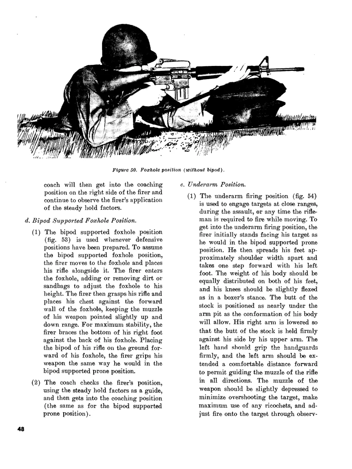
Текст
MH I
COPY
FM 23-9
DEPARTMENT OF THE ARMY FIELD MANUAL
RIFLE,
5.56-MM,
XM16E1
' г
HEADQUARTERS, DEPARTMENT OF THE ARMY
JULY 1966
FM 23-9
С 1
Change
No. 1
HEADQUARTERS
DEPARTMENT OF THE ARMY
Washington, D.C., £ February 1968
RIFLE, 5.56-MM, M16A1
EM 23-9, 12 July 1966, is changed as follows:
The title is changed to read as shown above.
In paragraphs 1, 3, 5, 6, 10, 15, 16, 20, 22,
23, 25, 31, 32, and 35, wherever the term “XM
16E1” appears, it is changed to read “M16A1.”
In figures 1 and 19, the term “XM16E1” is
changed to read “M16A1.”
Page 3, paragraph 3&. In line 3 “or” is changed
to read “of.”
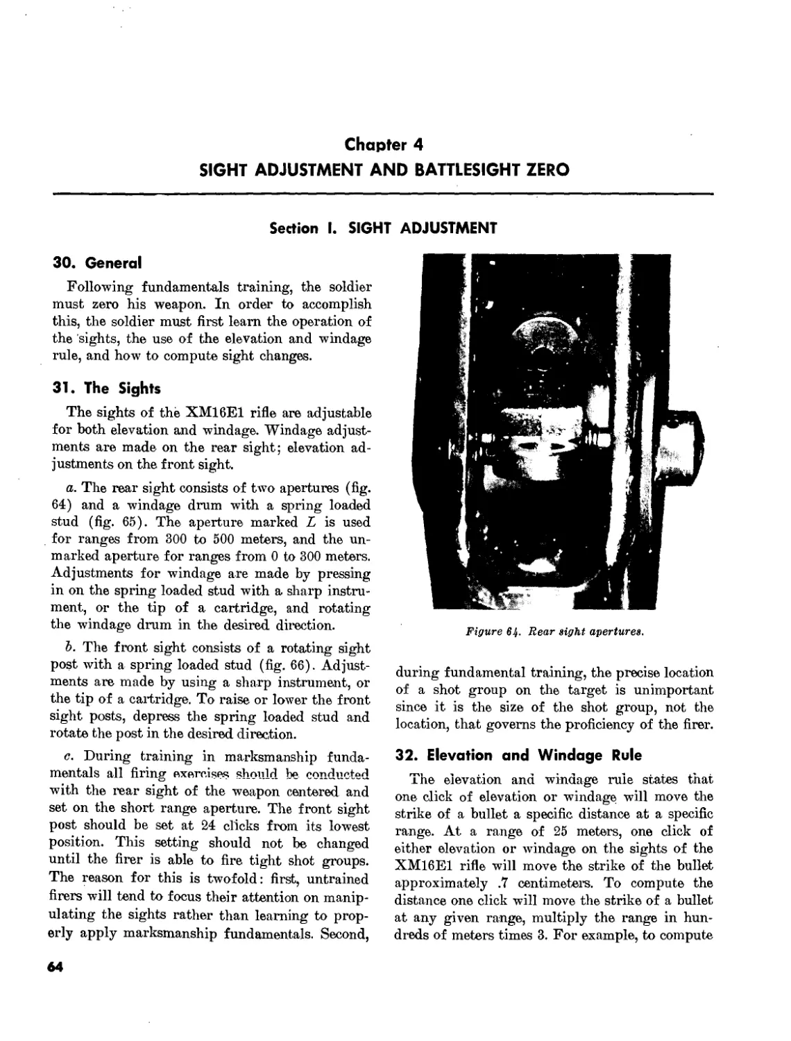
Page 3. Paragraph 4a is superseded as follows:
a. Weights.
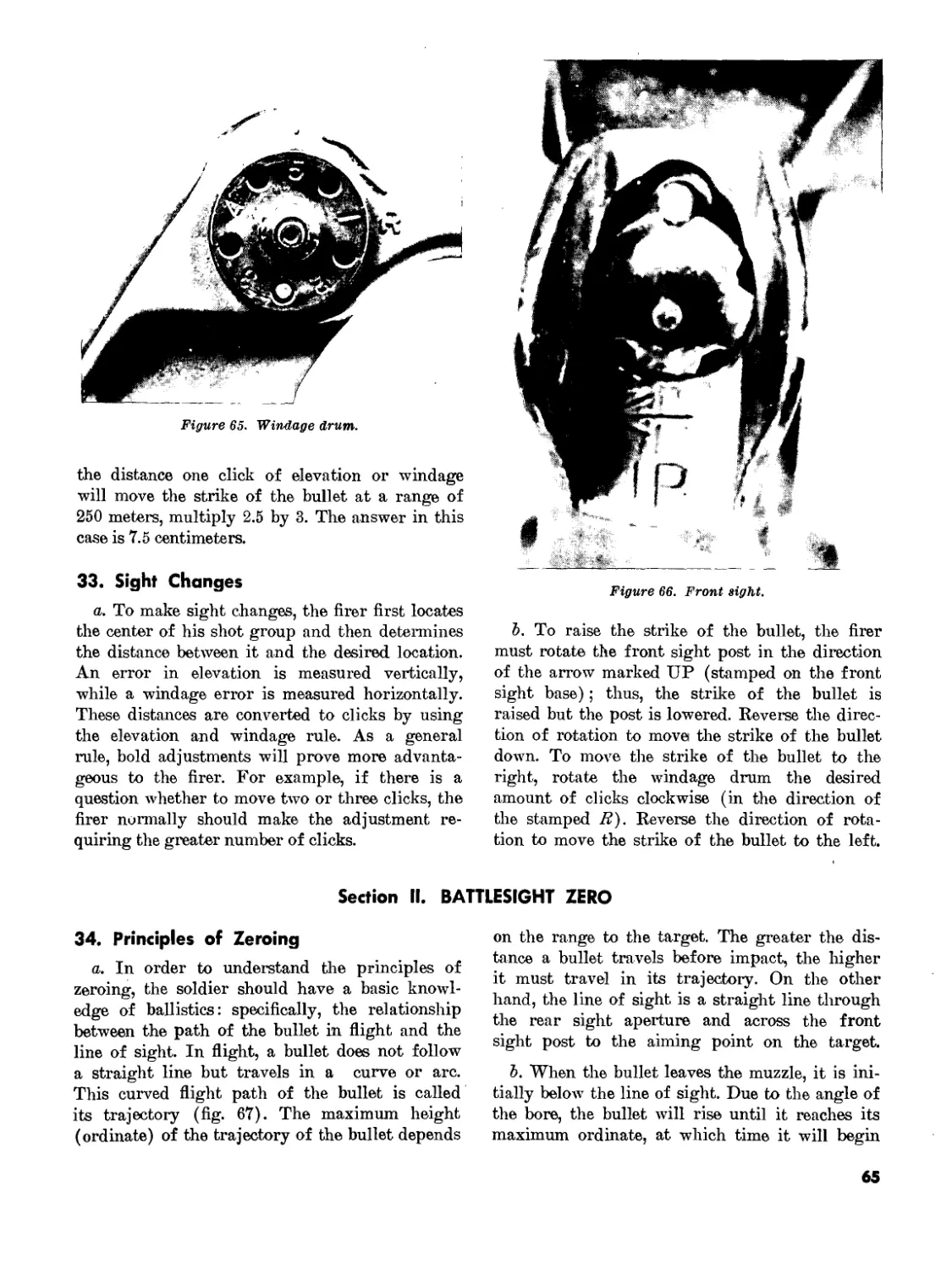
Pounds
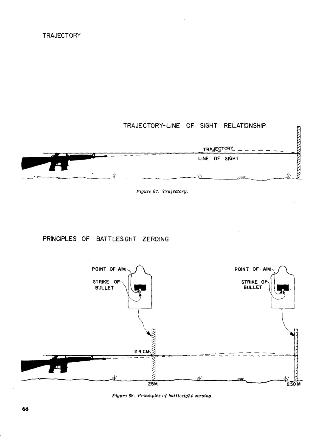
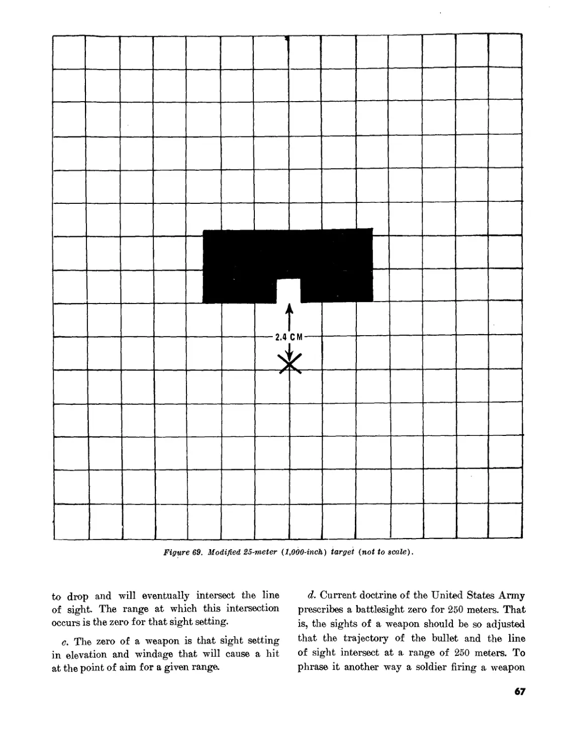
Rifle without magazine and sling__________________6. 5
Empty magazine (aluminum, 20 rounds)______________ .2
Full magazine (20 rounds)______________________ .7
•Sling, Ml________________________________________ . 4
Firing weight (fully loaded with sling)___________7. 6
Bipod, М3_________________________________________ .6
Bipod case________________________________________ . 2
Bayonet-knife, M7_________________________________ . 6
Scabbard, M8A1____________________________________ . 3
•Sling, small arms, FSN 105-714-9749, is an authorized sub-
stitute for sling Ml. This sling is extra long and will allow a
firer to carry the weapon slung across the front of his body in
a position which allows him to take both hands from the weapon,
but keep it available for use. It would be especially useful for
personnel designated as automatic riflemen or for people who must
carry such equipment as radios and binoculars.
Page 5, paragraph 4e. In line 1, “3,150 feet per
second (approx.)” is changed to read “3,250 feet
per second (approx.).”
Page 6. Paragraph I is superseded as follows:
7. Field Stripping
a. Remove the sling.
Ъ. Remove the handguards by placing the butt
of the rifle on a flat surface with the muzzle up.
Pull down on the slipring until the lower lip of
the handguard is clear; pull out and down on the
handguard until the upper lip is free of the hand-
guard cap (fig 18). Repeat the same operation to
remove the second handguard. Considerable pres-
sure must be used to force the slipring down.
Note: Handguards should not be removed when the
upper and lower receiver groups are separated because of
potential damage to the forward assist assembly.
c. Place the weapon on a flat surface on its right
side with the muzzle to the left. Use the nose of the
cartridge to press the takedown pin (fig. 7) until
the upper receiver swings free of the lower re-
ceiver (fig. 8).
Caution: The takedown pin does not come out
of the receiver.
d. Again using the nose of a cartridge, press
the receiver pivot pin (fig. 9). Separate the upper
and lower receiver groups (fig. 10) and place the
lower receiver group on the table.
Caution: The receiver pivot pin does not come
out of the receiver.
e. Pick up the upper receiver group; keep the
muzzle to the left. Grasp the charging handle,
pressing in on the latch, and pull to the rear (fig. 5)
to withdraw the bolt carrier from the receiver.
Grasp the bolt carrier and pull it from the receiver
(fig. 11). When the bolt carrier is removed, the
charging handle will fall free of its groove in the
receiver when pulled to the rear (fig. 12). Place the
receiver on the table.
f. To disassemble the bolt carrier group, press
out the firing pin retaining pin by using the nose of
a cartridge (fig. 13). Elevate the front of the bolt
carrier and allow the firing pin to drop from its
well in the bolt (fig. 14). Rotate the bolt until the
cam pin is clear of the bolt carrier key and remove
the cam pin by rotating it 90° (Di-turn) and lifting
it out of the well in the bolt and bolt carrier (fig.
15). After the cam pin is removed, the bolt can be
removed easily from its recess in the bolt carrier
(fig. 16). Remove the extractor by first pushing the
extractor pin out with the firing pin, then, while
maintaining pressure on the extractor with the in-
dex finger, withdraw the firing pin from the ex-
tractor pinhole. Release the pressure from the
extractor and remove. The extractor should be dis-
assembled only when necessary for cleaning, and
disassembly should be supervised. Since the ex-
tractor pin is quite small, it should be handled with
care to prevent loss or damage.
Note. The extractor spring should not be removed from
the extractor. If the spring falls out of its recess it should
be replaced by the unit armorer.
g. Using the index finger of the right hand, push
in on the buffer assembly. With the nose of a car-
TAGO 767A—Jan. 300-171”—68
1
tridge, or the tip of the firing pin, push down on
the buffer retainer. Depress the hammer to the rear
(downward) sufficiently to allow the buffer as-
sembly to clear the hammer. Remove the buffer
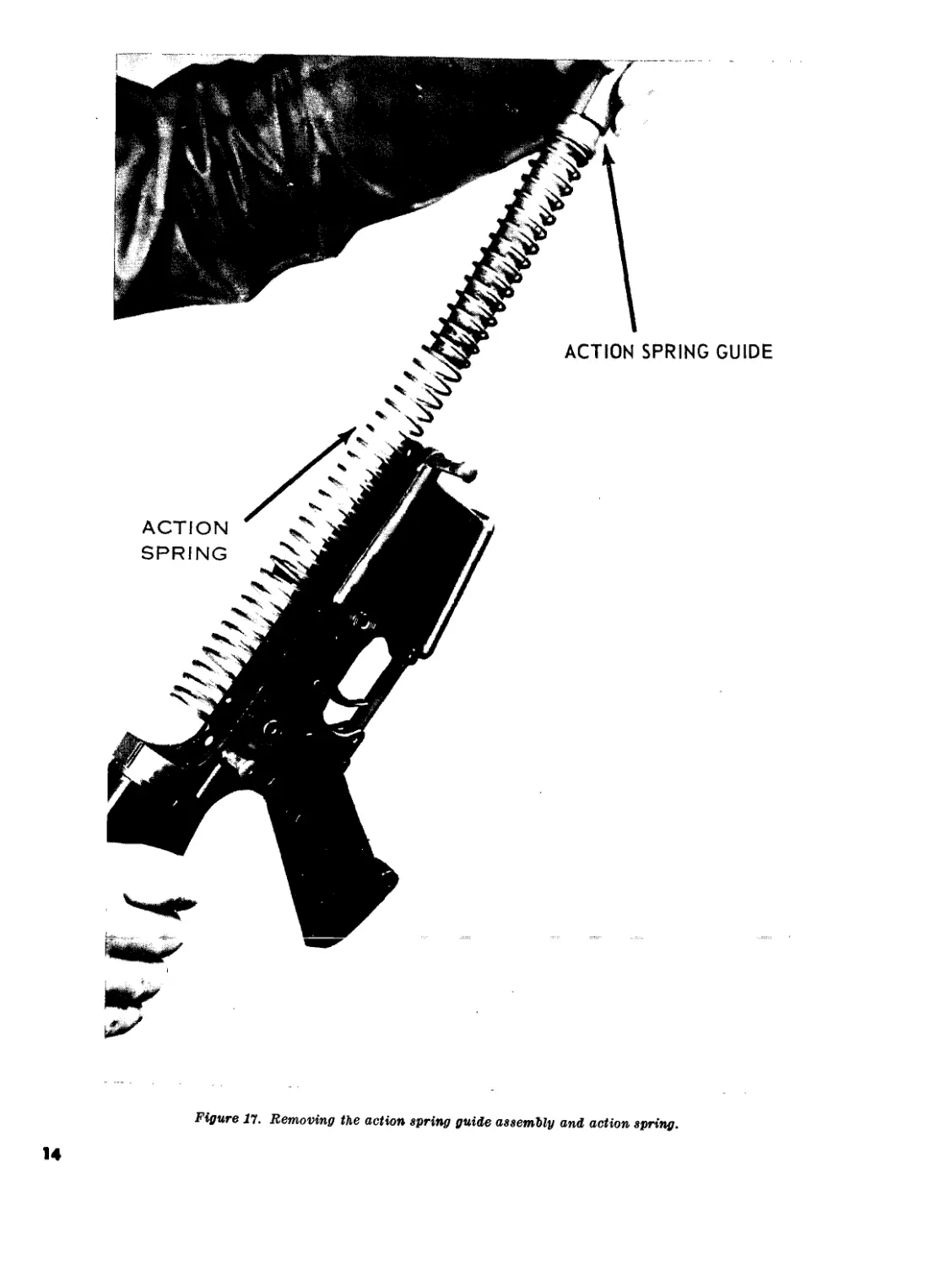
assembly and the spring (fig. 17).
Note. The action spring is under pressure and care
must be taken in removing it.
h. This completes field stripping (fig. 19).
Note. Detailed disassembly consists of removing the re-
maining operating parts from the lower receiver (flg. 20)
and is not authorized at user and/or organizational level.
The individual soldier has no need to disassemble the
weapon beyond field stripping. Only qualified maintenance
personnel are authorized to remove any other parts from
the weapon.
Caution: Steps b and g above should be per-
formed only when absolutely necessary for
care and cleaning.
Page 13. Paragraph 8 is superseded as follows:
8. Assembly
To assemble the rifle, reverse the procedures of
disassembly.
a. To assemble the buffer assembly, insert the
assembly, spring end first, into the lower receiver
extension, depress the cocked hammer to allow pas-
sage of the buffer assembly, depress the buffer re-
tainer with the nose of a cartridge, or tip of the
firing pin, seat the buffer assembly and release the
buffer retainer.
~b. To assemble the bolt carrier group, grasp the
bolt and the extractor with spring. Seat the ex-
tractor in the extractor recess, apply pressure on
the extractor to aline the pinhole and insert the
extractor pin. Pick up the bolt carrier, key up and
to the front, insert the bolt into the front of the
bolt carrier, insuring that the ejector is down and
to the left. Replace the cam pin into its well and
rotate the cam pin 90° (14-turn) to aline the holes
for the firing pin in the bolt and cam pin. Grasp the
lugged rim of the bolt and turn until the cam pin is
directly under the bolt carrier key. Insert the firing
pin through the open end of the bolt carrier and
seat fully. Insert the firing pin retaining pin (if
resistance is encountered, rotate pin while
inserting).
Caution: Do not attempt to spread the slotted
end of the firing pin retaining pin.
Note. Check for proper assembly by elevating the front
of the bolt. If the firing pin drops out, the firing pin re-
taining pin is not between the front and rear spool and
the bolt carrier group is improperly assembled.
c. Grasp the upper receiver with the carrying
handle up. Place the charging handle into the
groove in the top of the upper receiver. The lugs
on the charging handle must be seated in their
grooves in the receiver. Place the bolt carrier
group into the open end of the receiver, insuring
that the bolt carrier key is in the slot on the under-
side of the charging handle and the bolt is for-
ward in the unlock position. Push forward on the
bolt carrier group and charging handle until fully
seated.
d. Place the upper receiver group and lower
receiver group together and reseat the receiver
pivot pin.
e. With the hammer cocked and selector lever
in the safe position, close the weapon and seat the
takedown pin.
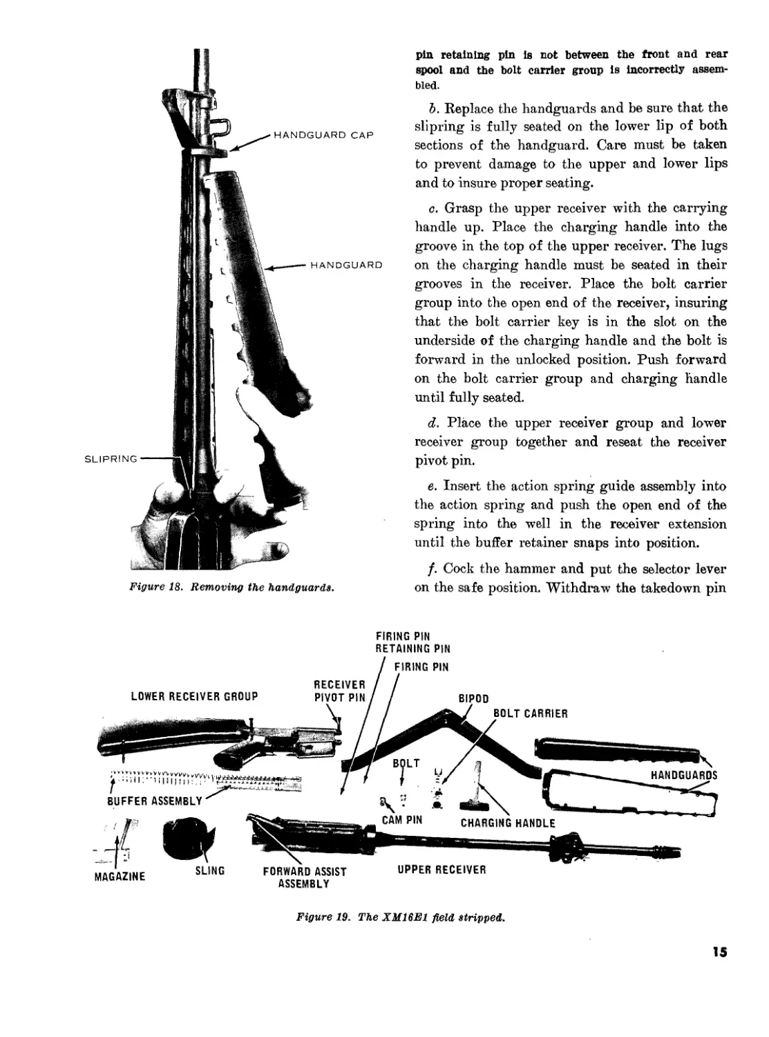
/. Replace the handguards and be sure that the
slipring is fully seated on the lower lip of both
sections of the handguards. Care must be taken
to prevent damage to the upper and lower lips
and to insure proper seating.
g. A complete function check of the rifle con-
sists of checking the operation of the weapon while
the selector is in the SAFE, SEMI, and AUTO
positions. The following sequence is used for a
rapid, complete check. Any portion of the check
may be used alone to determine the operational
condition of any specific fire selection.
Note. Disengage the takedown pin and open receivers.
Hammer shall be in the cocked position.
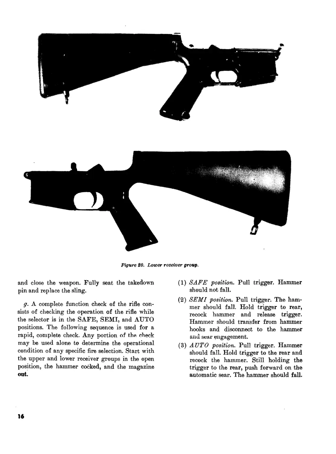
(1) SAFE position. Pull trigger, hammer
should not fall.
(2) SEMI position. Pull trigger, hammer
should fall. Hold trigger to rear, recock
hammer and release trigger. Hammer
should transfer from hammer hooks and
disconnect to the hammer and sear en-
gagement.
(3) AV TO position. Pull trigger, hammer
should fall. Hold trigger to the rear and
recock hammer. Hammer is now under
the automatic sear. Still holding trigger
to the rear, push forward on automatic
sear. The hammer should fall. Still hold-
ing trigger to the rear, recock hammer,
release trigger and push forward on auto-
matic sear. Hammer should transfer to
the sear engagement. Move selector lever
to SAFE or SEMI position. Close re-
ceivers and engage takedown pin.
2
TAGO 767A
Caution: Failure to move selector
lever to SAFE or SEMI position, be-
fore closing receivers, will damage
automatic sear.
(4) SEMI position. Pull charging handle to
the rear. Make certain chamber is clear,
then release charging handle. Pull the
trigger. Hammer should fall.
Page figure 17. In the caption, “action
spring guide assembly” is changed to read “buffer
assembly.”
Page 17. Paragraph 9 is superseded as follows:
9. Operation
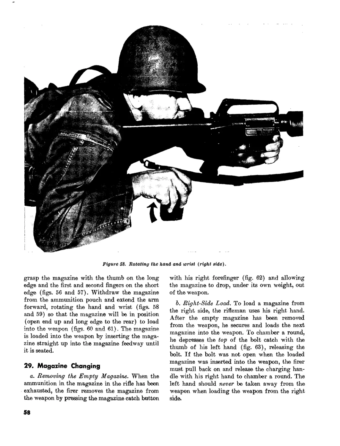
a. Loading the Magazine.
(1) The magazine has a capacity of 20
rounds and may be loaded with any
amount up to that capacity. The maga-
zine follower has a raised portion gen-
erally resembling the outline of a car-
tridge.
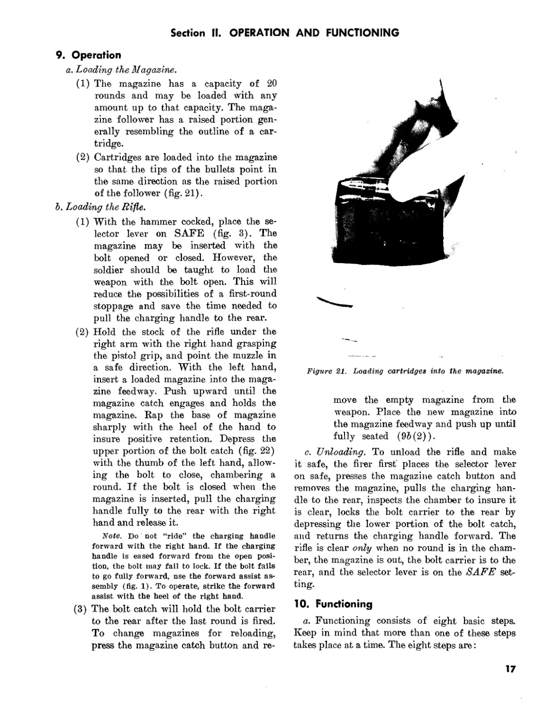
(2) Cartridges are loaded into the magazine
so that the tips of the bullets point in the
same direction as the raised portion of the
follower (fig. 21).
jVoie. Bounds In the magazine should be re-
moved and checked daily for corrosion and dents
and wiped off with a dry cloth.
Caution: Do not load or attempt to
load more than 20 rounds in the maga-
zine. Overloading will deform the lips
of the magazine and cause malfunc-
tions.
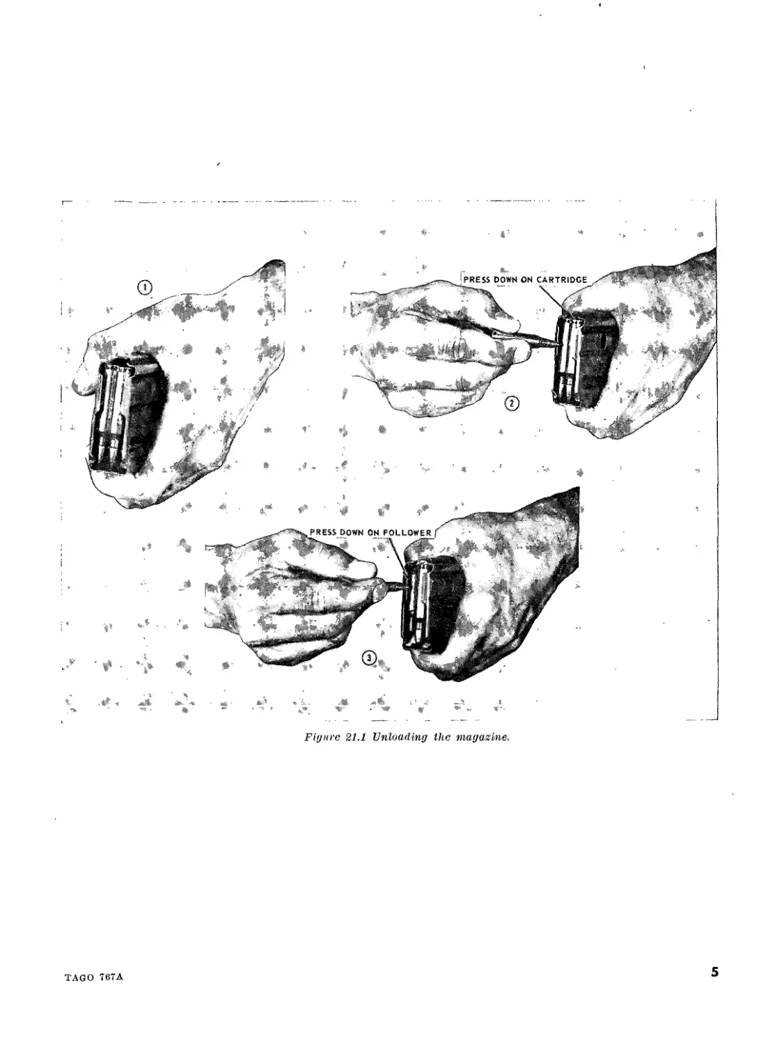
b. Unloading the Magazine. To prevent damage
to the lips of the magazine, removal of ammuni-
tion is accomplished in the following manner:
(1) Hold the magazine in the left hand with
the open end away from the body, nose
of the cartridge down (1, fig. 21.1).
(2) Using the nose of a cartridge, depress the
center of the second round in the maga-
zine allowing the first round to drop out
of the magazine (2, fig. 21.1). This proc-
ess is repeated until all rounds have been
removed from the magazine except the
last.
(3) To remove the last round, use the nose of
a cartridge and depress the follower al-
lowing the last round to drop out of the
magazine (3, fig. 21.1).
c. Disassembly and Assembly of the Magazine.
(1) To properly perform maintenance on the
magazine, it must be disassembled.
(2) The magazine is disassembled in the fol-
lowing manner:
(a) Hold the magazine in the left hand,
open end to the left, short edge near
the body.
(&) Insert the nose of a cartridge into the
hole in the base of the magazine, de-
pressing the spring steel lock band and
at the same time exerting a slight pres-
sure on the base pushing it away from
the body or toward the long edge of the
magazine (1, fig. 21.2).
(c) Slide the base forward until it is free
of the tabs (2, fig. 21.2).
Note. Keep the left thumb over the follower
spring to prevent it from jumping out of the
magazine.
(d) To remove the follower spring, dis-
engage it from the tabs on the maga-
zine first from one side and then the
other until it is free of the magazine
(3, fig. 21.2).
(e) The follower, attached to the end of the
magazine must be “canted” in order to
clear the tabs (4, fig. 21.2).
(/) Clean the exterior and interior of the
magazine with a dry patch. The mar'
zine is kept dry. The maga’ ’'r ..ё
is lightly oiled
(3) To assemble the magazine, the parts are
replaced in the reverse order of removal.
(a) Place the small end of the follower in
the magazine, slipping it under the
spring steel lock band then cant the fol-
lower to clear the magazine tabs; insure
that the follower is seated properly
prior to feeding the spring into the
magazine.
(5) Feed the spring into the magazine by
pushing down and from side to side
until the last coil is under the tabs.
(c) Hold the spring down with the thumb
and insert the base under the first set
of tabs.
(d) Depress the spring steel lock band;
seat the base of the magazine insuring
that the lock band is fully engaged. De-
press the follower several times to in-
sure that it moves freely.
TAGO 767A
3
d. Loading the Rifle.
(1) With the hammer cocked, place the selec-
tor lever on SAFE (fig. 3). The maga-
zine may be inserted with the bolt opened
or closed. However, the soldier should be
taught to load the weapon with the bolt
open. This will reduce the possibilities of
a first round stoppage and save the time
needed to pull the charging handle to the
rear.
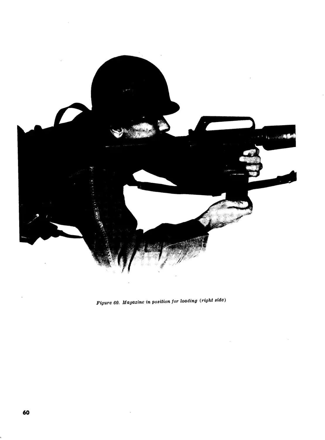
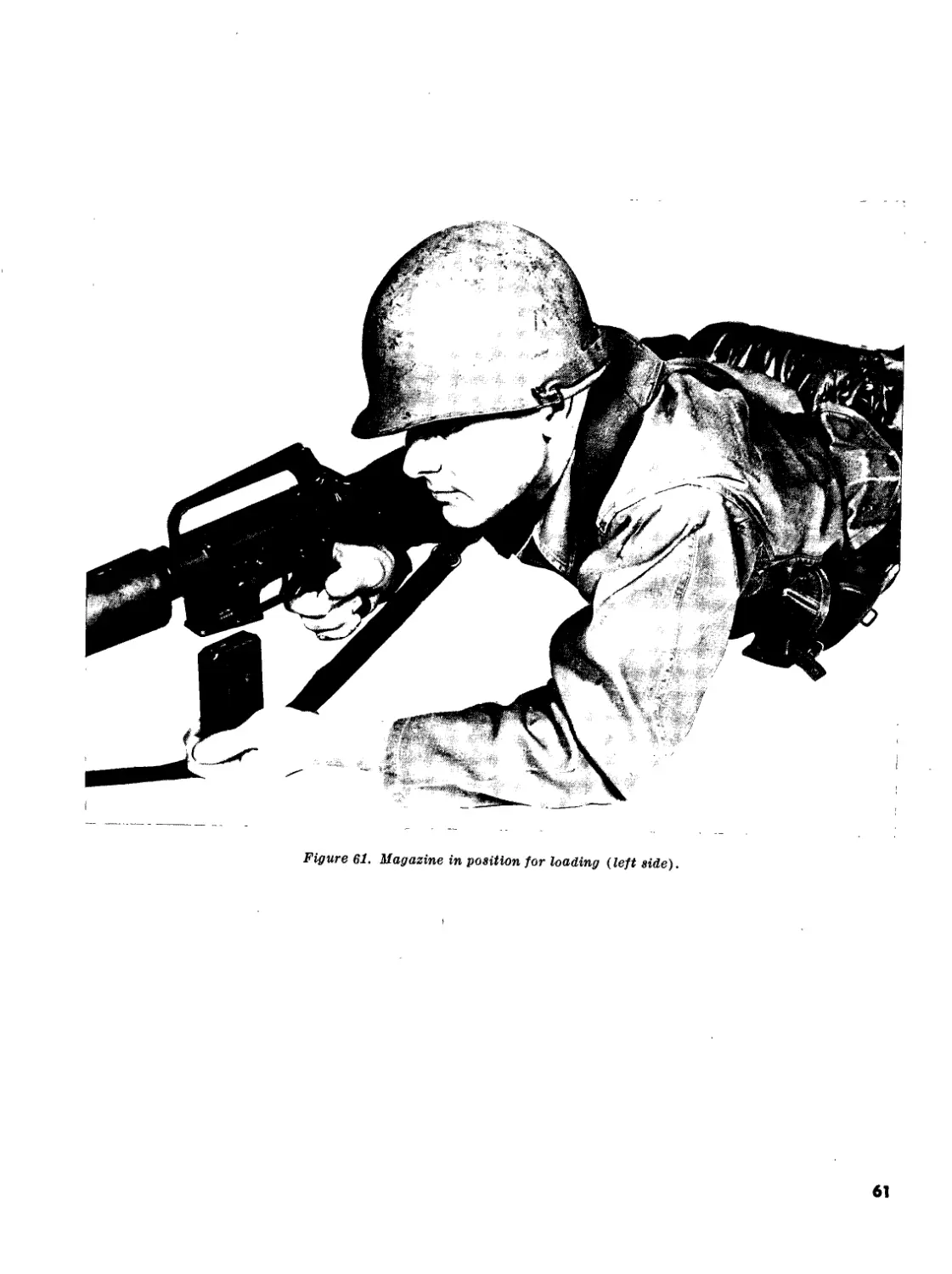
(2) Hold the stock of the rifle under the right
arm with the right hand grasping the pis-
tol grip, and point the muzzle in a safe
direction. With the left hand, insert a
loaded magazine into the magazine hous-
ing. Push upward until the magazine
catch engages and holds the magazine.
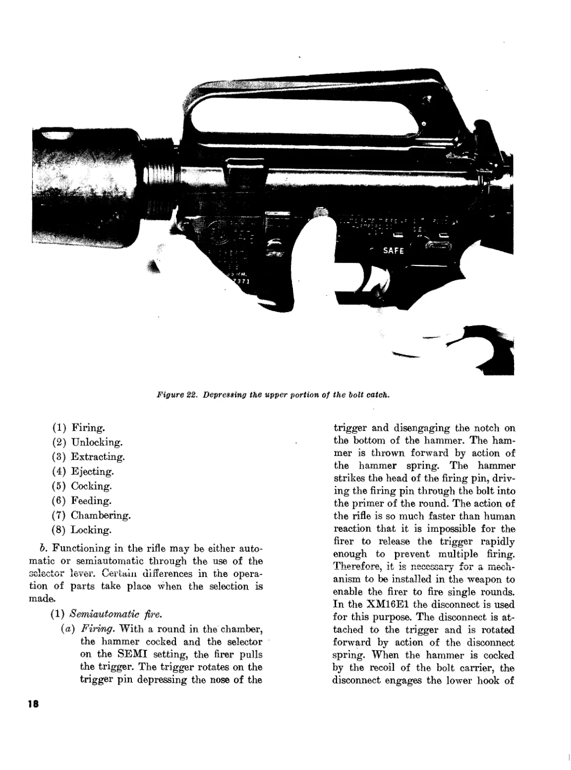
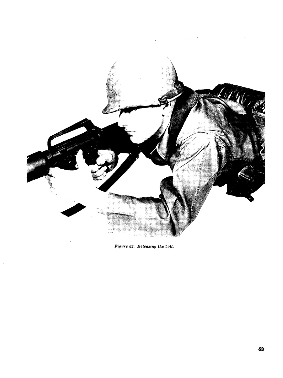
Depress the upper portion of the bolt
catch (fig. 22) with the thumb of the left
hand, allowing the bolt to dose, chamber-
ing a round. If the bolt is closed when the
magazine is inserted, pull the charging
handle fully to the rear with the right
hand and release, it.
Note: Left-handed personnel should follow
the procedure above by reversing the position of
their hands, using the left index Anger to depress
the upper portion of the bolt catch.
Note. Do not “ride” the charging handle for-
ward with the right hand. If the charging handle
is eased forward from the open position, the bolt
may fail to lock. If the bolt fails to go fully for-
ward, use the forward assist assembly (Ag. 1).
To operate, strike the forward assist with the
heel of the right hand.
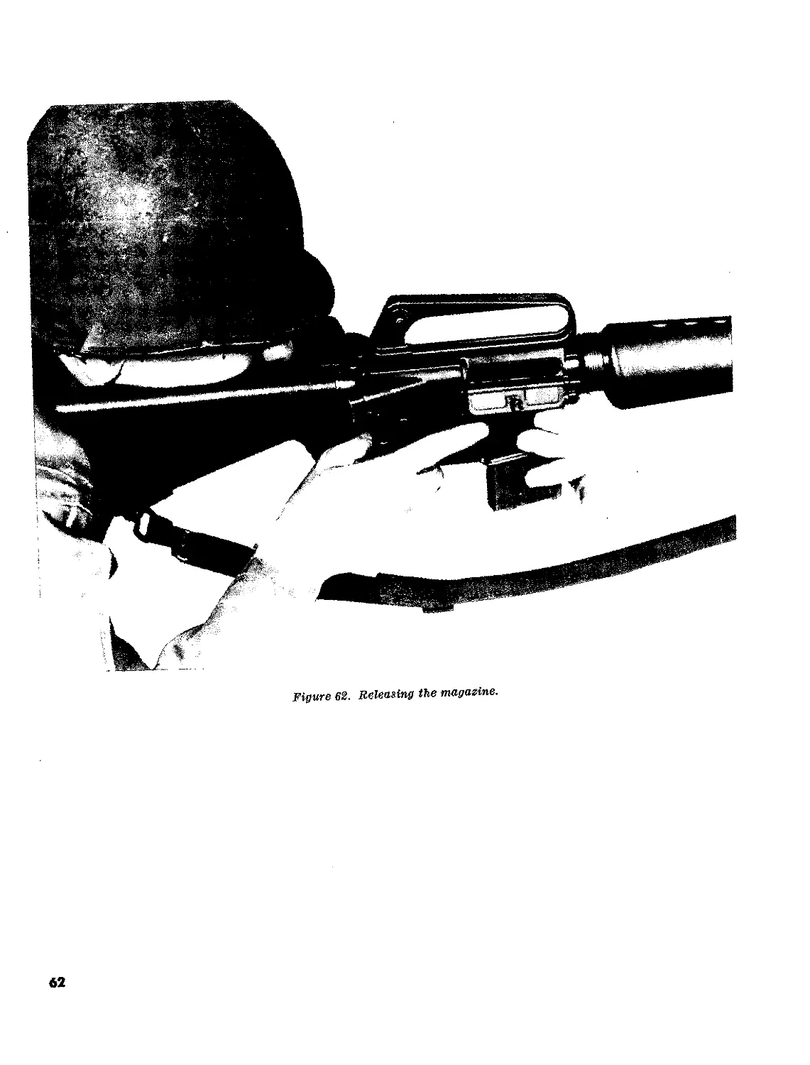
(3) The bolt catch will hold the bolt carrier
to the rear after the last round is fired. To
change magazines for reloading, press the
magazine catch button and remove the
empty magazine from the weapon. Place
the new magazine into the magazine hous-
ing and push up until fully seated (&(2)
above).
e. Unloading. To unload the rifle and make it
safe, the firer first places the selector lever on safe,
presses the magazine catch button and removes
the magazine, pulls the charging handle to the
rear, inspects the chamber to insure it is clear,
locks the bolt carrier to the rear by depressing the
lower portion of the bolt catch, and returns the
charging handle forward. The rifle is clear only
when no round is in the chamber, the magazine is
out, the bolt carrier is to the rear, and the selector
lever is on the SAFE setting.
Figures 21.1 and 21.2 are added as follows:
4
IAGO 767A
Figure 21.1 Unloading the magazine.
5
TAG О 787 A
Figure 21.2. Disassembly of the niaffasine.
Page 27. Paragraph 11 is superseded as follows:
11. Maintenance
a. General. A clean, properly oiled and main-
tamed rifle loaded with clean ammunition will
shoot when needed. In order to keep the M16A1
rifle and ammunition in good condition they must
have daily care and cleaning. Under bad weather
conditions certain key parts of the rifle and am-
munition may need care and cleaning several times
a day. To insure proper functioning of the M16A1
rifle, it is imperative that the following procedures
be followed:
b. Gleaning. Thoroughly clean all metal sur-
faces of the rifle with bore cleaner (solvent clean-
ing compound, CH). Special attention must be
given to the following areas in order of their im-
portance to functioning:
(1) Chamber. Clean the chamber with a
chamber brush dipped in bore cleaner.
Wipe with clean dry swabs (cleaning
patches) and apply a light coat of LSA
(lubricating oil, semifluid, MIL-L-
46000A).
(2) Bolt carrier group.
(a) Gamer key. Clean the bolt carrier key
with a bore brush dipped in bore
cleaner. A used or worn brush should be
used if available. Wipe with a clean,
dry pipe cleaner (FSN 9920-292-9946).
(5) Locking hugs. Clean the locking lugs
of the bolt, extractor and extractor well
using a small brush and bore cleaner.
Remove any accumulation of dirt, car-
bon or oil from the firing pin, the ex-
ternal and internal surfaces of the bolt
and bolt carrier using a small brush
and bore cleaner. Also clean the firing
pin hole of the bolt using a pipe cleaner
soaked with bore cleaner. Wipe all
parts with a clean dry swab, rag or
pipe cleaner. Apply a generous coat of
LSA to the exterior surfaces of the
bolt carrier, a light coat of LSA on the
bolt, interior of the bolt carrier and
one drop of LSA in the carrier key.
(c) Magazine. Must be disassembled and
wiped clean with a clean, dry rag.
Lightly oil the magazine spring only
- by wiping with a rag dipped in LSA.
(<Z) Barrel bore.
1. Attach a bore brush to an assembled
6
TAGO 767A
cleaning rod, dip in bore cleaner, and
brush the bore thoroughly. Brush the
bore from chamber to muzzle using
straight through strokes.
Note. Do not reverse direction of brush
while In the bore. Push the brush through
the bore until it extends beyond the muzzle.
Continue until the bore is well covered
with bore cleaner. Remove the brush from
the cleaning rod, attach the slotted tip, and
dry the bore by pushing through clean dry
swabs. Continue until swabs come out clean
and dry. Care should be used to support
the cleaning rod while inserting to prevent
flexing or breakage.
2. After cleaning, lubricate the bore with
a lightly oiled swab to prevent rust
and pitting. Lightly oil the lugs in
the barrel extension.
(e) Upper receiver.
1. Use a swab or brush to clean the upper
receiver of powder fouling with bore
cleaner.
2. Clean the protruding gas tube in the
receiver with a worn bore brush
attached to a section of cleaning rod.
The top of the gas tube can be
cleaned by inserting the rod and
brush in the back of the receiver. The
sides and bottom of the gas tube can
be cleaned from the bottom of the
receiver.
3. Wipe all parts dry.
4- Apply a generous coat of LSA to
the interior surfaces of the upper
receiver.
(/) Power receiver.
1. Cleaning will not require detailed dis-
assembly of the lower receiver group.
Using a swab or bristle brush with
bore cleaner, remove carbon, dirt and
sand from the lower receiver. Dry
and generously lubricate with LSA.
2. After extensive use, acids caused by
perspiration should be removed from
exterior surfaces using a rag or swab
with bore cleaner, then wipe dry and
apply a light coat of LSA.
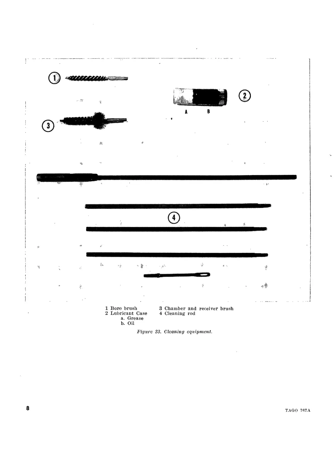
Page 28. Figure 33 is superseded as follows:-
TAGO 767A
7
1 Bore brush 3 Chamber and receiver brush
2 Lubricant Case 4 Cleaning rod
a. Grease
b. Oil
Figure 33. Cleaning equipment.
TAGO 767A
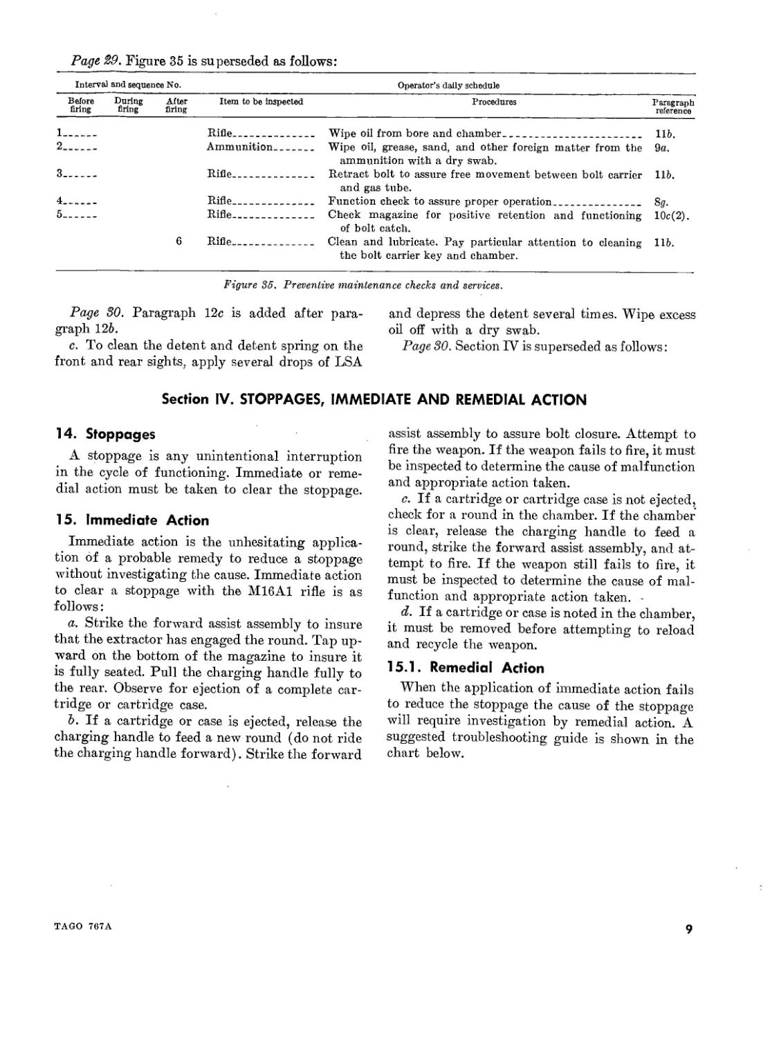
Page 29. Figure 35 is superseded as follows:
Interval and sequence No. Operator’s daily schedule
Before firing During firing After firing Item to be inspected Procedures Paragraph reference
1. 2. 3. 4. 5. — 6 Rifle Ammunition Rifle Rifle Rifle Rifle Wipe oil from bore and chamber Wipe oil, grease, sand, and other foreign matter from the ammunition with a dry swab. Retract bolt to assure free movement between bolt carrier and gas tube. Function check to assure proper operation Check magazine for positive retention and functioning of bolt catch. Clean and lubricate. Pay particular attention to cleaning the bolt carrier key and chamber. lib. 9a. lib. 83. 10c(2). lib.
Figure 35. Preventive maintenance checks and services.
Page 30. Paragraph 12c is added after para-
graph 126.
c. To clean the detent and detent spring on the
front and rear sights, apply several drops of LSA
and depress the detent several times. Wipe excess
oil off with a dry swab.
Page 30. Section IV is superseded as follows:
Section IV. STOPPAGES, IMMEDIATE AND REMEDIAL ACTION
14. Stoppages
A stoppage is any unintentional interruption
in the cycle of functioning. Immediate or reme-
dial action must be taken to clear the stoppage.
15. Immediate Action
Immediate action is the unhesitating applica-
tion of a probable remedy to reduce a stoppage
without investigating the cause. Immediate action
to clear a stoppage with the M16A1 rifle is as
follows:
a. Strike the forward assist assembly to insure
that the extractor has engaged the round. Tap up-
ward on the bottom of the magazine to insure it
is fully seated. Pull the charging handle fully to
the rear. Observe for ejection of a complete car-
tridge or cartridge case.
Ъ. If a cartridge or case is ejected, release the
charging handle to feed a new round (do not ride
the charging handle forward). Strike the forward
assist assembly to assure bolt closure. Attempt to
fire the weapon. If the weapon fails to fire, it must
be inspected to determine the cause of malfunction
and appropriate action taken.
c. If a cartridge or cartridge case is not ejected,
check for a round in the chamber. If the chamber
is clear, release the charging handle to feed a
round, strike the forward assist assembly, and at-
tempt to fire. If the weapon still fails to fire, it
must be inspected to determine the cause of mal-
function and appropriate action taken. -
d. If a cartridge or case is noted in the chamber,
it must be removed before attempting to reload
and recycle the weapon.
15.1. Remedial Action
When the application of immediate action fails
to reduce the stoppage the cause of the stoppage
will require investigation by remedial action. A
suggested troubleshooting guide is shown in the
chart below.
TAGO 767A
9
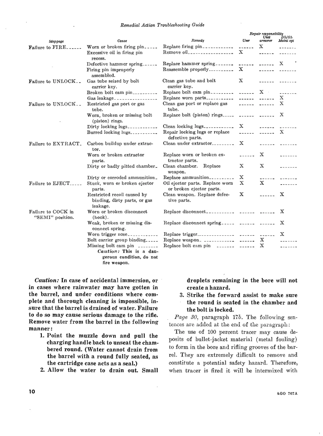
Remedial Action Troubleshooting Guide
Stoppage Cause
Failure to FIRE Worn or broken firing pin Excessive oil in firing pin recess. Defective hammer spring Firing pin improperly assembled.
Failure to UNLOCK.. Gas tube seized by bolt carrier key. Broken bolt cam pin Gas leakage
Failure to UNLOCK.. Restricted gas port or gas tube. Worn, broken or missing bolt
(piston) rings. Dirty locking lugs Burred locking lugs
Failure to EXTRACT. Carbon buildup under extrac- tor. Worn or broken extractor parts. Dirty or badly pitted chamber. Dirty or corroded ammunition.
Failure to EJECT Stuck, worn or broken ejector parts. Restricted recoil caused by binding, dirty parts, or gas leakage.
Failure to COCK in Worn or broken disconnect
“SEMI” position. (hook). Weak, broken or missing dis- connect spring. Worn trigger nose Bolt carrier group binding Missing bolt cam pin Caution: This is a dan- gerous condition, do not fire weapon.
Remedy Replace firing pin Remove oil Repair responsibility
User X Unit armorer X DS/GS Maint spt
Replace hammer spring X
Reassemble properly X — —
Clean gas tube and bolt carrier key. X — —
Replace bolt cam pin X —
Replace worn parts X
Clean gas port or replace gas tube. — — X
Replace bolt (piston) rings — — X
Clean locking lugs X
Repair locking lugs or replace defective parts. — — X
Clean under extractor X — —
Replace worn or broken ex- tractor parts. — X —
Clean chamber. Replace weapon. X X —
Replace ammunition X
Oil ejector parts. Replace worn or broken ejector parts. X X —
Clean weapon. Replace defec- tive parts. X — X
Replace disconnect — — X
Replace disconnect spring — — X
Replace trigger X
Replace weapon. X
Replace bolt cam pin X
Caution: In case of accidental immersion, or
in cases where rainwater may have gotten in
the barrel, and under conditions where com-
plete and thorough cleaning is impossible, in-
sure that the barrel is drained of water. Failure
to do so may cause serious damage to the rifle.
Remove water from the barrel in the following
manner:
1. Point the muzzle down and pull the
charging handle back to unseat the cham-
bered round. (Water cannot drain from
the barrel with a round fully seated, as
the cartridge case acts as a seal.)
2. Allow the water to drain out. Small
droplets remaining in the bore will not
create a hazard.
3. Strike the forward assist to make sure
the round is seated in the chamber and
the bolt is locked.
Page 30, paragraph 175. The following sen-
fences fu6 auQed at tile end of the paragraph •
The use of 100 percent tracer may cause de-
posits of bullet-jacket material (metal fouling)
to form in the bore and rifling grooves of the bar-
rel. They are extremely difficult to remove and
constitute a potential safety hazard. Therefore,
when tracer is fired it will be intermixed with
10
4GO 767A
ball ammunition in a ratio no greater than 1:1
with a preferred ratio of 4:1.
Page 31. Paragraph 19p is added after para-
graph 19/.
g. Badly dented cartridges, cartridges with
loose bullets, or otherwise defective rounds should
not be fired. This ammunition must be reported
promptly to the technical service representative
under whose supervision the ammunition for the
unit involved is maintained and issued.
Page f.3, paragraph 255 (1). In line 3, “magazine
feedway” is changed to read “magazine housing.”
Page 45, paragraph 25<?(1). In line 10, “maga-
zine feedway” is changed to read “magazine
housing.”
Page 55. Paragraph 26a(l) is superseded as
follows:
(1) Semiautomatic fire. Semiautomatic fire is
employed in any situation where a high
degree of accuracy is required to hit a
small point target; e.g., bunker apertures,
windows, and scattered formations or
single enemy personnel or, where the
range to the target is in excess of 460
meters. This method of employment con-
sumes the least amount of ammunition
and is the most effective. Rapid trigger
manipulation should be employed to de-
liver a heavy volume of fire to engage a
small group of the enemy. When engaging
a formation a specific individual in the
group should be selected and engaged for
maximum effectiveness rather than firing
at the group in general.
Page 55. Paragraph 26a(2) (a) is superseded
as follows:
(a) When engaging enemy mass for-
mations at ranges out to 460 meters.
Page 58, paragraph 285. In line 10, “magazine
feedway” is changed to read “magazine housing.”
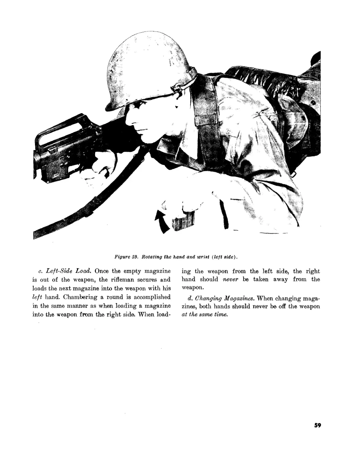
Page 59. After paragraph 29d the following note
is added:
Note. Adjusting the magazine catch: the magazine
catch should hold the magazines firmly but not interfere
with the magazine removal when the catch button is
pressed. To adjust, press in on the catch button with the
nose of a cartridge or the end of the cleaning rod, pushing
the catch out far enough (on left side of weapon) to clear
the catch housing. To tighten turn the magazine catch
clockwise, to loosen turn counterclockwise.
Page 6j, paragraph 31a. In lines 2 and 7 “spring
loaded stud” is changed to read “detent.” In sub-
paragraph 5, lines 2 and 5, “spring loaded stud”
is changed to read “detent.”
By Order of the Secretary of the Army:
Official:
KENNETH G. WICKHAM,
Major General, United States Army,
The Adjutant General.
HAROLD K. JOHNSON,
General, United Stales Army,
Chief of Staff.
Distribution:
To be distributed in accordance with DA Form 12-11 requirements for Rifle 5.56-MM, XM16E1.
U.S. GOVERNMENT PRINTING OFFICE: 1968
TAGO 767A
11
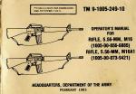
FM 23-9
Field Manual
No. 23-9
HEADQUARTERS
DEPARTMENT OF THE ARMY
Washington, D.C., 12 July 1966
RIFLE, 5.56-MM, XM16E1
Paragraphs Page
Chapter 1. INTRODUCTION
Section I. General 1,2 3
II. Characteristics 3,4 3
Chapter 2. MECHANICAL TRAINING
Section I. Disassembly and assembly 5-8 6
II. Operation and functioning 9,10 17
III. Care and cleaning 11-13 27
IV. Stoppages and immediate action 14,15 30
V. Ammunition 16-18 30
VI. Destruction of materiel to prevent enemy use 20,21 31
Chapter 3. MARKSMANSHIP TRAINING
Section I. Preparatory marksmanship _________________ 22-25 32
II. Automatic fire ____________________________ 26-29 55
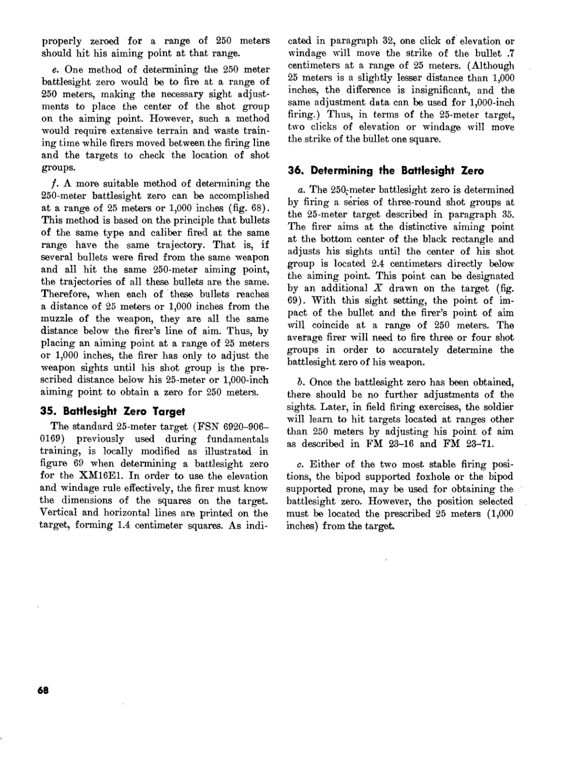
Chapter 4. SIGHT ADJUSTMENT AND BATTLESIGHT ZERO
Section I. Sight adjustment _________________________ 30-33 64
II. Battlesight zero __________________________ 34-36 65
Appendix. REFERENCES _________________________________ ____ 69
‘This manual supersedes FM 23-9, 25 January 1965.
1
Chapter 1
INTRODUCTION
Section I. GENERAL
1. Purpose and Scope
This manual provides guidance for presenting
instruction with the Rifle, 5.56-mm, XM16E1. It
contains a detailed description of the rifle and its
general characteristics, procedures for disassem-
bly and assembly, operation and functioning of
the rifle, types of ammunition, and maintenance.
When supplemented by FM 23-11 and FM 23-16
it provides information in sufficient detail for
conducting marksmanship training with the rifle.
This manual is applicable to both nonnuclear and
nuclear warfare.
2. Responsibilities of Commanders
Users of this manual are encouraged to submit
recommended changes or comments to improve
the manual. Comments should be keyed to the
specific page, paragraph, and line of text in which
the change is recommended. Reasons should be
provided for each comment to insure understand-
ing and complete evaluation. Comments should
be forwarded direct to the Commandant, U.S.
Army Infantry School, Fort Benning, Ga., 31905.
Section II. CHARACTERISTICS
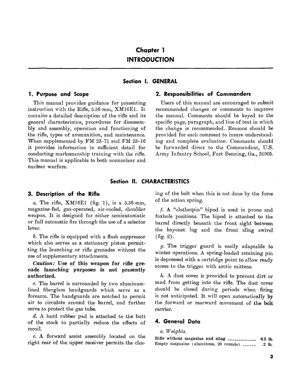
3. Description of the Rifle
a. The rifle, XM16E1 (fig. 1), is a 5.56-mm,
magazine-fed, gas-operated, air-cooled, shoulder
weapon. It is designed for either semiautomatic
or full automatic fire through the use of a selector
lever.
Ъ. The rifle is equipped with a flash suppressor
which also serves as a stationary piston permit-
ting the launching or rifle grenades without the
use of supplementary attachments.
Caution: Use of this weapon for rifle gre-
nade launching purposes is not presently
authorized.
c. The barrel is surrounded by two aluminum-
lined fiberglass handguards which serve as a
forearm. The handguards are notched to permit
air to circulate around the barrel, and further
serve to protect the gas tube.
d. A hard rubber pad is attached to the butt
of the stock to partially reduce the effects of
recoil.
e. A forward assist assembly located on the
right rear of the, upper receiver permits the clos-
ing of the bolt when this is not done by the force
of the action spring.
f. A “clothespin” bipod is used in prone and
foxhole positions. The bipod is attached to the
barrel directly beneath the front sight between
the bayonet lug and the front sling swivel
(fig. 2).
g. The trigger guard is easily adaptable to
winter operations. A spring-loaded retaining pin
is depressed with a cartridge point to allow ready
access to the trigger with arctic mittens.
h. A dust cover is provided to prevent dirt or
sand from getting into the rifle. The dust cover
should be closed during periods when firing
is not anticipated. It will open automatically by
the forward or rearward movement of the bolt
carrier.
4. General Data
a. 'Weights.
Rifle without magazine and sling__________ 6.5 lb.
Empty magazine (aluminum, 20 rounds) _____ .2 lb.
3
Full magazine (20 rounds) ----------------------- .7 lb.
Sling, Ml --------------------------------------- -4 lb.
Firing weight (fully loaded with sling) ________ 7.6 lb.
Bipod, М3 --------------------------------------- .6 lb.
Bipod case -------------------------------------- .2 lb.
Bayonet-knife, M7 _______________________________ .6 lb.
Scabbard, M8A1 ---------------------------------- .3 lb.
b. Lengths.
Rifle with bayonet-knife, M7 _________________ 44.25 in.
Rifle overall with flash suppressor______________ 39 in.
Barrel (with flash suppressor) __________________ 21 in.
Barrel (without flash suppressor) _______________ 20 in.
c. Sights.
Front___________________
Rear___________________
Sight radius_______________
Adjustable click-type post
Each click equals 2.8 centi-
meters per every 100 meters
of range.
Adjustable, flip type. Normal
range setting is for 0 to 300
meters. Long-range setting
(L), 300 to 500 meters.
Each notch of the windage
drum equals 2.8 centimeters
per every 100 meters of
range.
19.75 inches.
CARHYING
Figure 1. Rifle, 5.56-mm, XM16E1, right and left side views.
4
Figure 2. Attaching the bipod.
d. Ammunition.
Caliber 5.56-mm (complete
round) M193-------------179 grains.
Projectile_______________55 grains.
Types--------------------Ball (standard)
Tracer (standard)
Blank (under development).
e. Operational Characteristics.
Muzzle velocity----------;_3,150 feet per second
(approx).
Muzzle energy
(at the muzzle)-------1,300 foot-pounds (approx).
Cyclic rate of Are_______700 to 800 rounds per minute.
Maximum rate of Are:
Semiautomatic____________45 to 65 rounds per minute.
Automatic____________150 to 200 rounds per minute.
Sustained rate of Are_12 to 15 rounds per minute.
Maximum range____________2,653 meters.
Maximum effective range__460 meters.
f. Terms.
Cyclic rate of Are_______The rate at which a weapon
Ares automatically.
Sustained rate of Are____Actual rate of Are that a
weapon can continue to de-
liver for an indeAnlte
length of time without seri-
ously overheating.
Maximum rate of Are______The maximum number of
rounds the average riffeman
can Are in 1 minute, disre-
garding hits on the target.
Maximum range____________.The greatest distance that a
weapon can Are.
Maximum effective range.-.The greatest distance at
which a weapon may be ex-
pected to Are accurately to
InAict casualties or damage.
5
Chapter 2
MECHANICAL TRAINING
Section I. DISASSEMBLY AND ASSEMBLY
5. General
a. The purpose of mechanical training is to
give the individual soldier a knowledge of the
working parts of the XM16E1 so that he will
understand its operation, be able to locate and
reduce stoppages, and properly maintain the
weapon.
Ъ. The individual soldier is authorized to dis-
assemble the XM16E1 to the extent called “field
stripping” (para 7). This can be accomplished
without supervision and is adequate for normal
maintenance.
c. The frequency of disassembly and assembly
should be kept to the minimum consistent with
proper maintenance and instructional require-
ments.
d. The XM16E1 is easily disassembled and
assembled. No force is needed to accomplish dis-
assembly or assembly.
e. As the weapon is disassembled, the parts
should be laid out on a table or other clean sur-
face in the order of removal, from left to right.
This makes assembly easier because the parts are
assembled in the reverse order of disassembly.
Nomenclature (the names of the parts) should
be taught as the weapon is disassembled and
assembled to enable the soldier to better under-
stand further instruction on the weapon.
6. Clearing the ХМ16Ё1
The first consideration in handling any weapon
is to make it safe by clearing it. To clear the
XM16E1 rifle, place the butt against the right
thigh and—
a. Attempt to point the selector lever toward
SAFE (fig. 3). If the weapon is not cocked, the
selector lever cannot be pointed toward SAFE. If
this is the case, do not cock the weapon at this
time; instead, go on to the next step in clearing
the weapon.
Ъ. Remove the magazine by grasping it with
the right hand (the fingers curled around the
front of the magazine, the thumb placed on the
magazine catch button), applying pressure on the
magazine catch button with the thumb, and pull-
ing the magazine straight out of the weapon
(fig- 4)-
c. Lock the bolt open by grasping tire charging
handle with the thumb and forefinger of the right
hand, depressing the charging handle latch with
the right thumb, and pulling to the rear (fig. 5);
press the bottom of the bolt catch with the thumb
or forefinger of the left hand (fig. 6) when the
bolt is fully rearward. Allow the bolt to move
slowly forward until it engages the bolt catch,
and return the charging handle to its forward
position.
d. Inspect the receiver and chamber of the
weapon by looking through the ejection port to
insure that these areas contain no ammunition.
e. Check the selector lever to insure that it
points toward SAFE (fig. 3) and allow- the bolt
to go forward by depressing the upper portion
of the bolt catch.
Caution: Selector must be in the safe posi-
tion to prevent damage to the automatic sear.
7. Field Stripping
a. Remove the sling and place the rifle on a
table or flat surface, muzzle to the left.
Ъ. Keeping the muzzle to the left, turn the
weapon on its right side. Use the nose of a
cartridge to press the takedown pin (fig. 7) until
the upper receiver swings free of the lower re-
ceiver (fig. 8).
Caution: The takedown pin does not come
out of the receiver.
6
1
, Rew-0”1'"'9
figure 4-
tnew^6-
8
Figure 5. Pulling the charging handle rearward.
4-~~
Figure 6. Locking the bolt open.
9
WK-
Figure 7. Pressing the takedown pin to the right.
Figure 9. Pressing out the receiver pivot pin.
Figure 8. Breaking the upper receiver away from the
lower receiver.
10
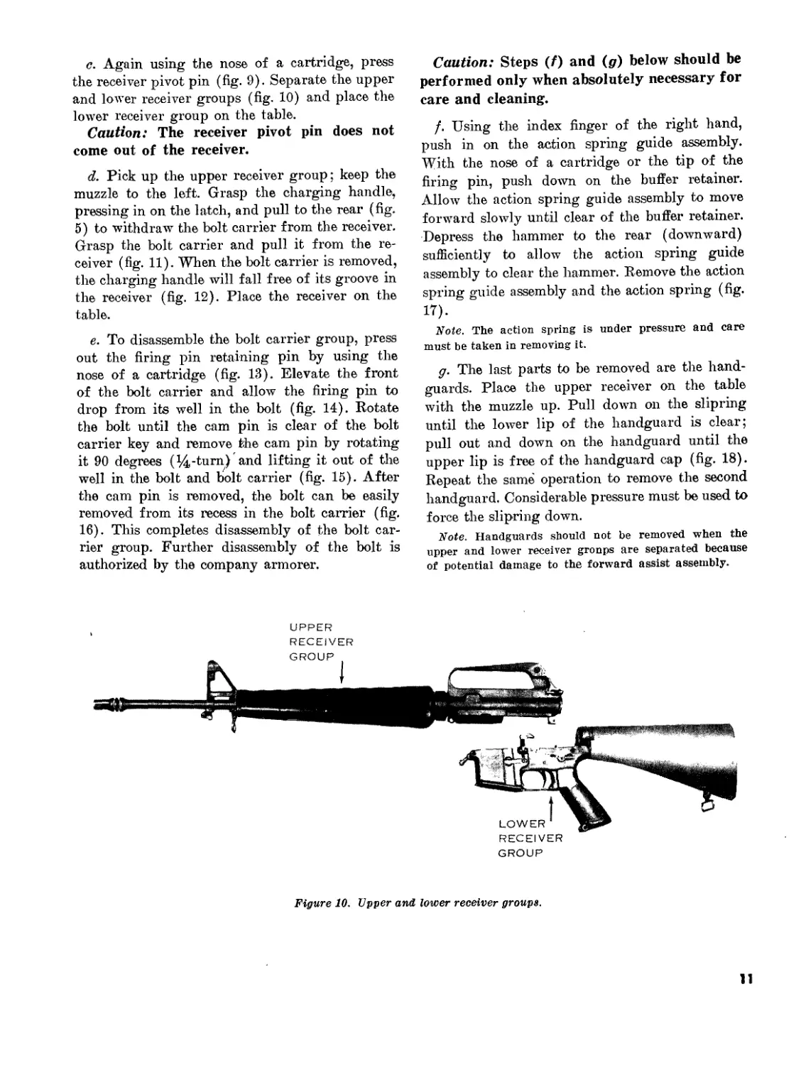
c. Again using the nose of a cartridge, press
the receiver pivot pin (fig. 9). Separate the upper
and lower receiver groups (fig. 10) and place the
lower receiver group on the table.
Caution: The receiver pivot pin does not
come out of the receiver.
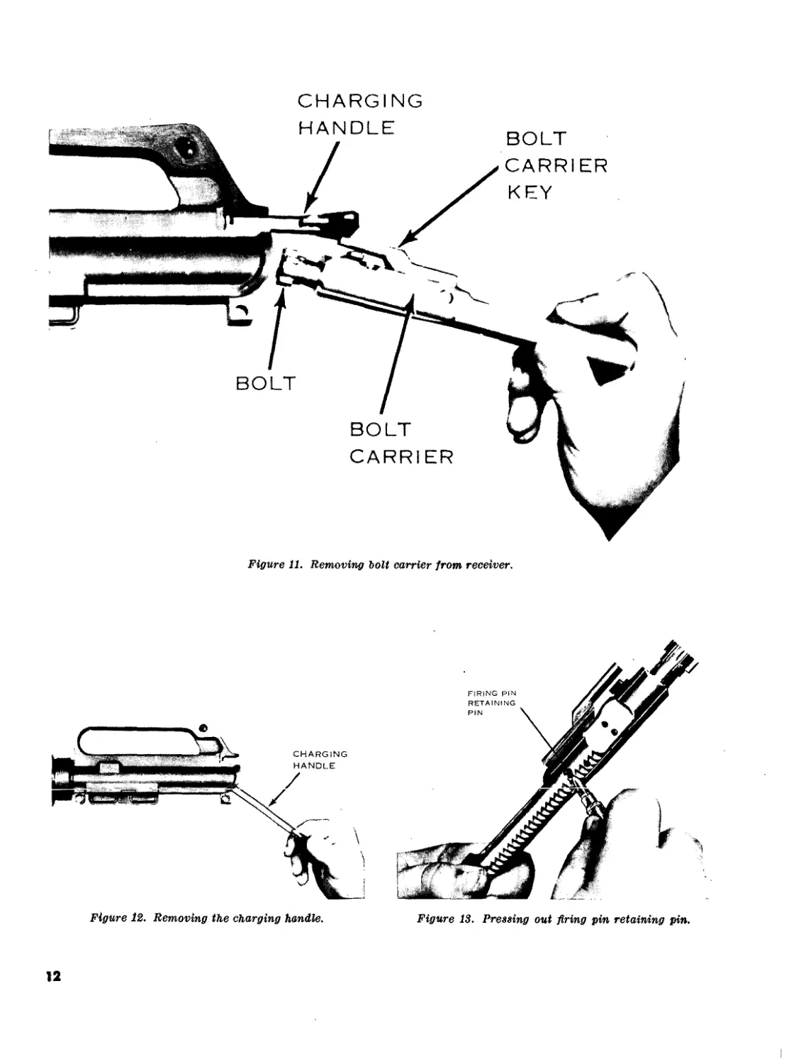
d. Pick up the upper receiver group; keep the
muzzle to the left. Grasp the charging handle,
pressing in on the latch, and pull to the rear (fig.
5) to withdraw7 the bolt carrier from the receiver.
Grasp the bolt carrier and pull it from the re-
ceiver (fig. 11). When the bolt carrier is removed,
the charging handle will fall free of its groove in
the receiver (fig. 12). Place the receiver on the
table.
e. To disassemble the bolt carrier group, press
out the firing pin retaining pin by using the
nose of a cartridge (fig. 13). Elevate the front
of the bolt carrier and allow the firing pin to
drop from its well in the bolt (fig. 14). Rotate
the bolt until the cam pin is clear of the bolt
carrier key and remove the cam pin by rotating
it 90 degrees (%-turn) and lifting it out of the
well in the bolt and bolt carrier (fig. 15). After
the cam pin is removed, the bolt can be easily
removed from its recess in the bolt carrier (fig.
16). This completes disassembly of the bolt car-
rier group. Further disassembly of the bolt is
authorized by the company armorer.
Caution: Steps (f) and (g) below should be
performed only when absolutely necessary for
care and cleaning.
f. Using the index finger of the right hand,
push in on the action spring guide assembly.
With the nose of a cartridge or the tip of the
firing pin, push down on the buffer retainer.
Allow the action spring guide assembly to move
forward slowly until clear of the buffer retainer.
Depress the hammer to the rear (downward)
sufficiently to allow the action spring guide
assembly to clear the hammer. Remove the action
spring guide assembly and the action spring (fig.
17).
Note. The action spring is under pressure and care
must be taken in removing it.
g. The last parts to be removed are the hand-
guards. Place the upper receiver on the table
with the muzzle up. Pull down on the slipring
until the lower lip of the handguard is clear;
pull out and down on the handguard until the
upper lip is free of the handguard cap (fig. 18).
Repeat the same operation to remove the second
handguard. Considerable pressure must be used to
force the slipring down.
Note. Handguards should not be removed when the
upper and lower receiver gronps are separated because
of potential damage to the forward assist assembly.
UPPER
Figure 10. Upper and lower receiver groups.
11
CHARGING
Figure 11. Removing bolt carrier from receiver.
Figure 12. Removing the charging handle.
Figure 13. Pressing out firing pin retaining pin.
12
Figure Ц. Removing the firing pin.
h. This completes field stripping (fig. 19).
Note. Detailed disassembly consists of removing the
remaining operating parts from the lower receiver (fig.
20) and is not authorized at user and/or organization
level. The individual soldier has no need to disassemble
the weapon beyond field stripping. Only qualified mainte-
nance personnel are authorized to remove any other
parts from the weapon.
8. Assembly
To assemble the rifle, reverse the procedures of
disassembly.
a. To assemble the bolt carrier group, grasp the
bolt carrier, key up and to the front, inserting
the bolt into the front of the bolt carrier, insur-
ing that the ejector is down and to the left. Re-
place the cam pin into its well and rotate the
cam pin 90 degrees (l/^-tum) to aline the holes
in the bolt and cam pin. Grasp the lugged rim of
the bolt and turn until the cam pin is directly
beneath the bolt carrier key. Insert the firing
pin through the open end of the bolt carrier and
seat fully. Insert the firing pin retaining pin (if
Figure 15. Removing the cam pin.
Figure 16. Removing the holt.
resistance is encountered, rotate pin while insert-
ing).
Caution: Do not attempt to spread the slot-
ted end of the firing pin retaining pin.
Note. Check for proper assembly by elevating the
front of the bolt. If the firing pin drops out, the firing
13
Figure 17, Removing the action spring guide assembly and action spring.
14
Figure 18. Removing the handguards.
pin retaining pin is not between the front and rear
spool and the bolt carrier group is incorrectly assem-
bled.
b. Replace the handguards and be sure that the
slipring is fully seated on the lower lip of both
sections of the handguard. Care must be taken
to prevent damage to the upper and lower lips
and to insure proper seating.
c. Grasp the upper receiver with the carrying
handle up. Place the charging handle into the
groove in the top of the upper receiver. The lugs
on the charging handle must be seated in their
grooves in the receiver. Place the bolt carrier
group into the open end of the receiver, insuring
that the bolt carrier key is in the slot on the
underside of the charging handle and the bolt is
forward in the unlocked position. Push forward
on the bolt carrier group and charging handle
until fully seated.
d. Place the upper receiver group and lower
receiver group together and reseat the receiver
pivot pin.
e. Insert the action spring guide assembly into
the action spring and push the open end of the
spring into the well in the receiver extension
until the buffer retainer snaps into position.
f. Cock the hammer and put the selector lever
on the safe position. Withdraw the takedown pin
FIRING PIN
Figure 19. The XM16E1 field stripped.
15
Figure 20. Lower receiver group.
and close the weapon. Fully seat the takedown
pin and replace the sling.
g. A complete function check of the rifle con-
sists of checking the operation of the rifle while
the selector is in the SAFE, SEMI, and AUTO
positions. The following sequence is used for a
rapid, complete check. Any portion of the check
may be used alone to determine the operational
condition of any specific fire selection. Start with
the upper and lower receiver groups in the open
position, the hammer cocked, and the magazine
out.
(1) SAFE position. Pull trigger. Hammer
should not fall.
(2) SEMI position. Pull trigger. The ham-
mer should fall. Hold trigger to rear,
recock hammer and release trigger.
Hammer should transfer from hammer
hooks and disconnect to the hammer
and sear engagement.
(3) AUTO position. Pull trigger. Hammer
should fall. Hold trigger to the rear and
recock the hammer. Still holding the
trigger to the rear, push forward on the
automatic sear. The hammer should fall.
16
Section II. OPERATION AND FUNCTIONING
9. Operation
a. Loading the Magazine.
(1) The magazine has a capacity of 20
rounds and may be loaded with any
amount up to that capacity. The maga-
zine follower has a raised portion gen-
erally resembling the outline of a car-
tridge.
(2) Cartridges are loaded into the magazine
so that the tips of the bullets point in
the same direction as the raised portion
of the follower (fig. 21).
Ъ. Loading the Rifle.
(1) With the hammer cocked, place the se-
lector lever on SAFE (fig. 3). The
magazine may be inserted with the
bolt opened or closed. However, the
soldier should be taught to load the
weapon with the bolt open. This will
reduce the possibilities of a first-round
stoppage and save the time needed to
pull the charging handle to the rear.
(2) Hold the stock of the rifle under the
right arm with the right hand grasping
the pistol grip, and point the muzzle in
a safe direction. With the left hand,
insert a loaded magazine into the maga-
zine feedway. Push upward until the
magazine catch engages and holds the
magazine. Rap the base of magazine
sharply with the heel of the hand to
insure positive retention. Depress the
upper portion of the bolt catch (fig. 22)
with the thumb of the left hand, allow-
ing the bolt to close, chambering a
round. If the bolt is closed when the
magazine is inserted, pull the charging
handle fully to the rear with the right
hand and release it.
Note. Do not “ride” the charging handle
forward with the right hand. If the charging
handle is eased forward from the open posi-
tion, the bolt may fail to lock. If the bolt falls
to go fully forward, nse the forward assist as-
sembly (fig. 1). To operate, strike the forward
assist with the heel of the right hand.
(3) The bolt catch will hold the bolt carrier
to the rear after the last round is fired.
To change magazines for reloading,
press the magazine catch button and re-
Figure 21. Loading cartridges into the magazine.
move the empty magazine from the
weapon. Place the new magazine into
the magazine feedway and push up until
fully seated (9Z> (2)).
c. Unloading. To unload the rifle and make
it safe, the firer first' places the selector lever
on safe, presses the magazine catch button and
removes the magazine, pulls the charging han-
dle to the rear, inspects the chamber to insure it
is clear, locks the bolt carrier to the rear by
depressing the lower portion of the bolt catch,
and returns the charging handle forward. The
rifle is clear only when no round is in the cham-
ber, the magazine is out, the bolt carrier is to the
rear, and the selector lever is on the SAFE set-
ting.
10. Functioning
a. Functioning consists of eight basic steps.
Keep in mind that more than one of these steps
takes place at a time. The eight steps are:
17
Figure 22. Depressing the upper portion of the bolt catch.
(1) Firing.
(2) Unlocking.
(3) Extracting.
(4) Ejecting.
(5) Cocking.
(6) Feeding.
(7) Chambering.
(8) Locking.
b. Functioning in the rifle may be either auto-
matic or semiautomatic through the use of the
selector lever. Certain differences in the opera-
tion of parts take place when the selection is
made.
(1) Semiautomatic fire.
(a) Firing. With a round in the chamber,
the hammer cocked and the selector
on the SEMI setting, the firer pulls
the trigger. The trigger rotates on the
trigger pin depressing the nose of the
trigger and disengaging the notch on
the bottom of the hammer. The ham-
mer is thrown forward by action of
the hammer spring. The hammer
strikes the head of the firing pin, driv-
ing the firing pin through the bolt into
the primer of the round. The action of
the rifle is so much faster than human
reaction that it is impossible for the
firer to release the trigger rapidly
enough to prevent multiple firing.
Therefore, it is necessary for a mech-
anism to be installed in the weapon to
enable the firer to fire single rounds.
In the XM16E1 the disconnect is used
for this purpose. The disconnect is at-
tached to the trigger and is rotated
forward by action of the disconnect
spring. When the hammer is cocked
by the recoil of the bolt carrier, the
disconnect engages the lower hook of
18
Figure 23. Firing.
the hammer and holds it until the
trigger is released. When the trigger
is released, the disconnect rotates to
the rear and down, disengaging the
hammer and allowing it to rotate for-
ward until caught by tire nose of the
trigger. This prevents the hammer
from following the bolt carrier for-
ward and causing automatic fire
(fig. 23).
(&) Action of the gas. When the primer
ignites the powder, the projectile is
forced through the barrel. At the same
time the gas moves through the barrel
until, passing the gas port located on
the upper surface of the barrel (un-
der the front sight), a small portion
of the gas passes through the gas port
and into the gas tube (fig. 24). The
gas tube directs the gas into the cylin-
der between the bolt and bolt carrier,
causing the bolt carrier to move rear-
ward.
(c) Unlocking. As the bolt carrier. moves
to the rear, the cam track in its upper
surface acts on the bolt cam pin, ro-
tating the cam pin and bolt until the
locking lugs of the bolt are no longer
in line with the locking lugs of the
barrel extension (fig. 25).
(c?) Extracting. The bolt carrier continues
to the rear, carrying with it the bolt.
By means of the extractor, which is
attached to the bolt, the expended car-
tridge is withdrawn from the cham-
ber. The claw of the extractor is grip-
ping the rim of the cartridge, holding
the base of the round against the face
of the bolt (fig. 26).
19
Figure 2j. Gas tube.
20
Figure 25. Locking and unlocking.
Figure 26. Extracting.
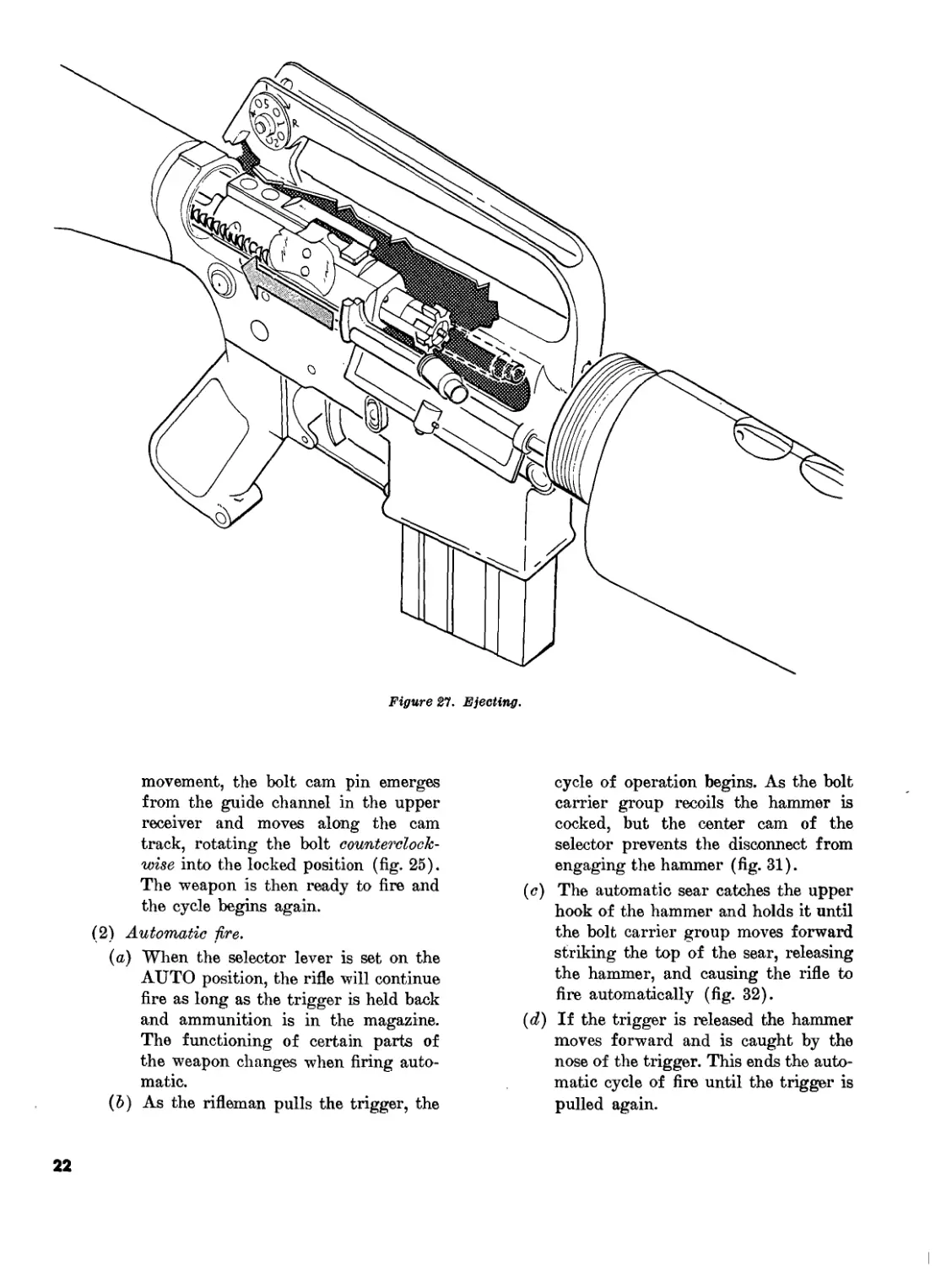
(e) Ejecting. When the base of the round
is against the face of the bolt, the
ejector is compressed. As the bolt car-
rier clears the ejection port, the empty
cartridge is thrown out by action of
the ejector and spring (fig. 27).
(/) Cocking. The rearward movement of
the bolt carrier overrides the hammer,
forcing it down into the receiver, com-
pressing the hammer spring. The
lower hook of the hammer is engaged
by the disconnect. When the trigger is
released the hammer slips from the
disconnect and is caught by the nose of
the trigger. The trigger must be pulled
again before the next round will fire
(fig- 28).
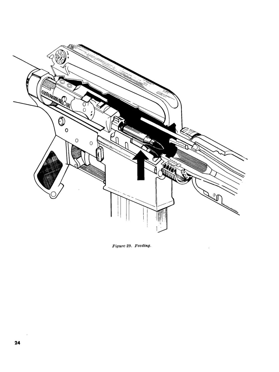
(g) Feeding. As the bolt carrier group
clears the top of the magazine, the
follower and spring in the magazine
push a new round up into the path of
the bolt (fig. 29).
(Л.) Action of the buffer assembly. As the
bolt carrier group is moving rearward,
the head of the action spring guide as-
sembly is struck. This sends the action
spring guide assembly and action
spring rearward into the receiver ex-
tension. The expansion of the action
spring sends the action spring guide
assembly forward with enough force
to drive the bolt carrier group forward
toward the chamber. The buffer assem-
bly is designed to reduce the recoil of
the weapon.
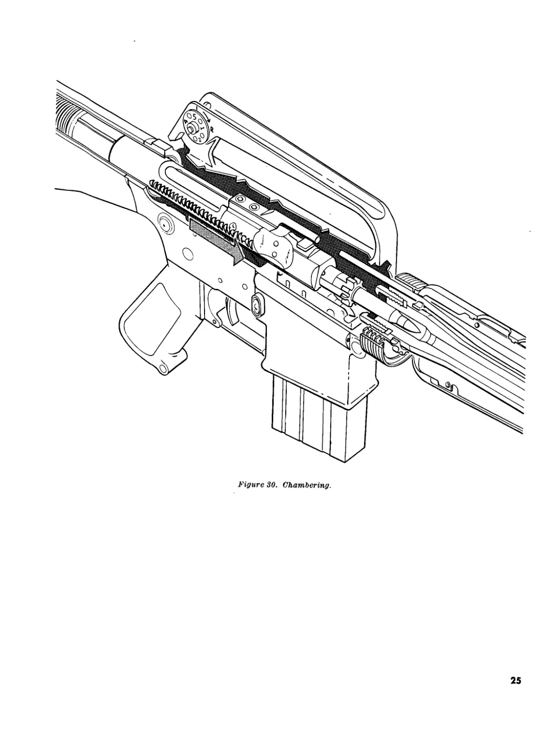
(г) Chambering. On the forward stroke
of the bolt carrier group, the face of
the bolt strips a round from the maga-
zine and thrusts it into the chamber.
At the same time the extractor claw
grips the rim of the cartridge and the
ejector is compressed (fig. 30).
(y) Locking. When the bolt carrier group
enters the last half inch of its forward
21
Figure 27. Ejecting.
movement, the bolt cam pin emerges
from the guide channel in the upper
receiver and moves along the cam
track, rotating the bolt counterclock-
wise into the locked position (fig. 25).
The weapon is then ready to fire and
the cycle begins again.
(2) Automatic lire.
(a) When the selector lever is set on the
AUTO position, the rifle will continue
fire as long as the trigger is held back
and ammunition is in the magazine.
The functioning of certain parts of
the weapon changes when firing auto-
matic.
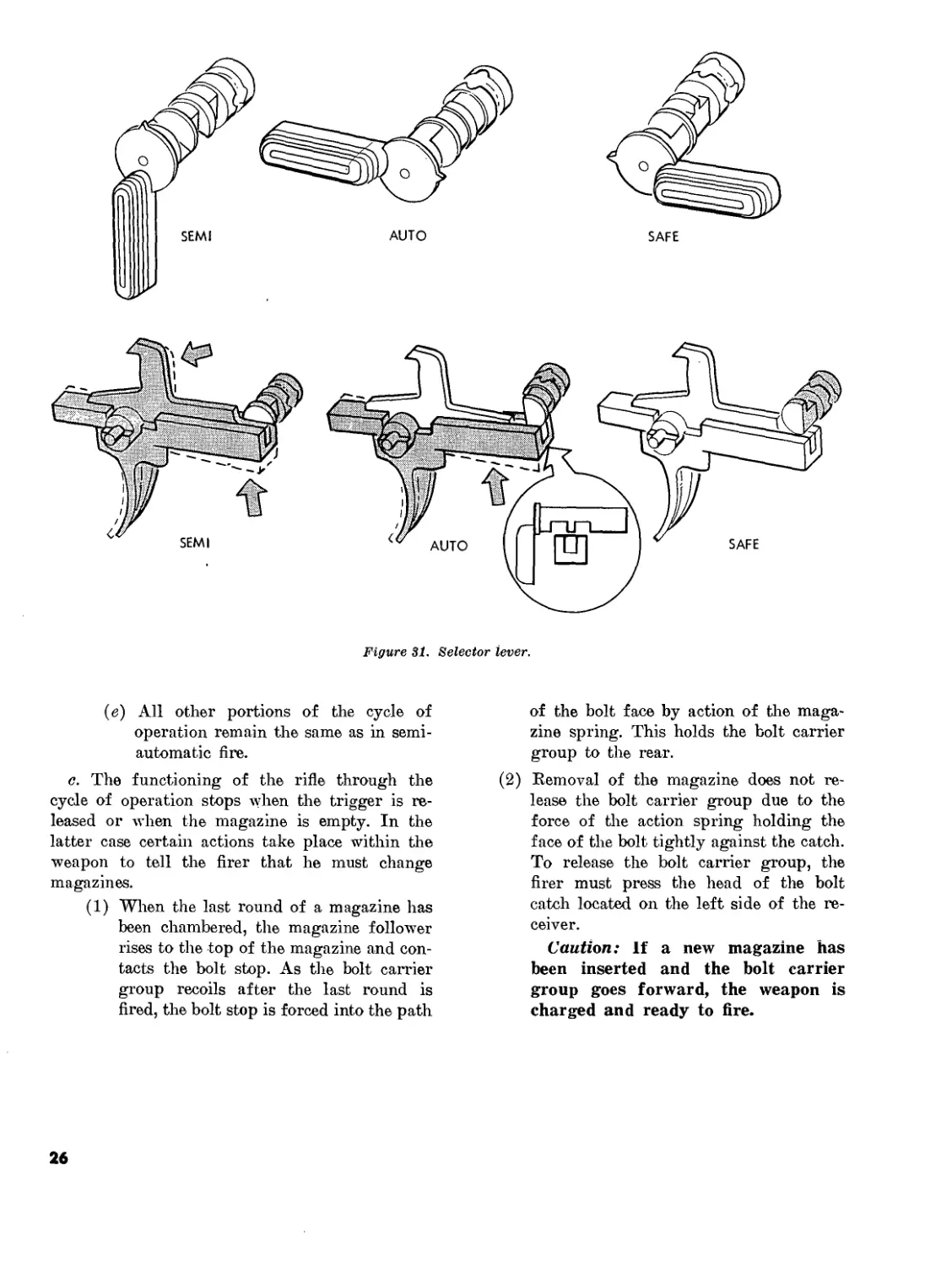
(6) As the rifleman pulls the trigger, the
cycle of operation begins. As the bolt
carrier group recoils the hammer is
cocked, but the center cam of the
selector prevents the disconnect from
engaging the hammer (fig. 31).
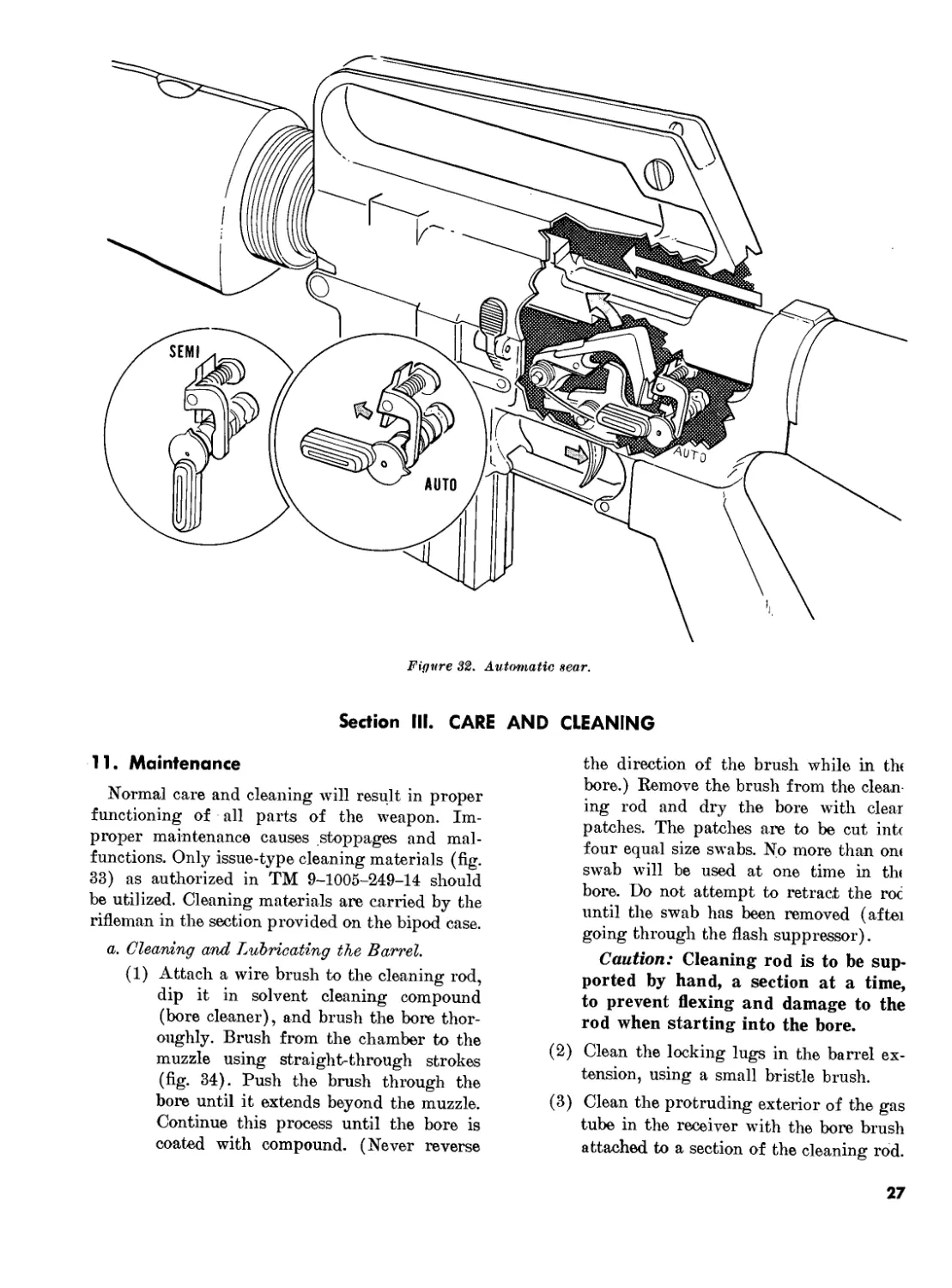
(c) The automatic sear catches the upper
hook of the hammer and holds it until
the bolt carrier group moves forward
striking the top of the sear, releasing
the hammer, and causing the rifle to
fire automatically (fig. 32).
(<7) If the trigger is released the hammer
moves forward and is caught by the
nose of the trigger. This ends the auto-
matic cycle of fire until the trigger is
pulled again.
22
гз
Figure 29. Feeding.
24
Figure 30. Chambering.
25
о
о
о
Figure SI. Selector lever.
(е) All other portions of the cycle of
operation remain the same as in semi-
automatic fire.
c. The functioning of the rifle through the
cycle of operation stops when the trigger is re-
leased or when the magazine is empty. In the
latter case certain actions take place within the
weapon to tell the firer that he must change
magazines.
(1) When the last round of a magazine has
been chambered, the magazine follower
rises to the top of the magazine and con-
tacts the bolt stop. As the bolt carrier
group recoils after the last round is
fired, the bolt stop is forced into the path
of the bolt face by action of the maga-
zine spring. This holds the bolt carrier
group to the rear.
(2) Removal of the magazine does not re-
lease the bolt carrier group due to the
force of the action spring holding the
face of the bolt tightly against the catch.
To release the bolt carrier group, the
firer must press the head of the bolt
catch located on the left side of the re-
ceiver.
Caution: If a new magazine has
been inserted and the bolt carrier
group goes forward, the weapon is
charged and ready to fire.
26
Figure 32. Automatic sear.
Section III. CARE AND CLEANING
11. Maintenance
Normal care and cleaning will result in proper
functioning of all parts of the weapon. Im-
proper maintenance causes stoppages and mal-
functions. Only issue-type cleaning materials (fig.
33) as authorized in TM 9-1005-249-14 should
be utilized. Cleaning materials are carried by the
rifleman in the section provided on the bipod case.
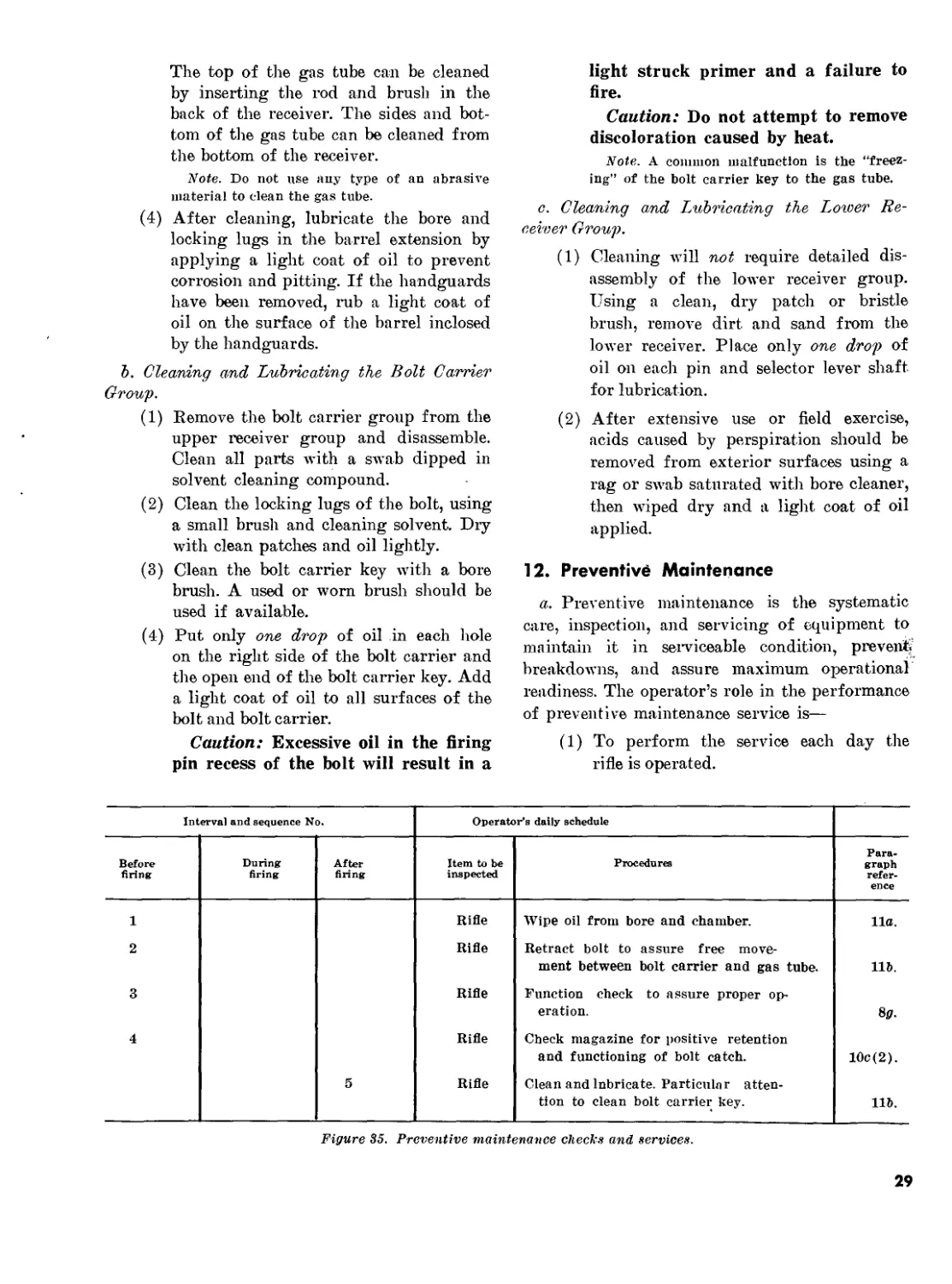
a. Cleaning and Lubricating the Barrel.
(1) Attach a wire brush to the cleaning rod,
dip it in solvent cleaning compound
(bore cleaner), and brush the bore thor-
oughly. Brush from the chamber to the
muzzle using straight-through strokes
(fig. 34). Push the brush through the
bore until it extends beyond the muzzle.
Continue this process until the bore is
coated with compound. (Never reverse
the direction of the brush while in thf
bore.) Remove the brush from the clean-
ing rod and dry the bore with clear
patches. The patches are to be cut int<
four equal size swabs. No more than on<
swab will be used at one time in tht
bore. Do not attempt to retract the roc
until the swab has been removed (after
going through the flash suppressor).
Caution: Cleaning rod is to be sup-
ported by hand, a section at a time,
to prevent flexing and damage to the
rod when starting into the bore.
(2) Clean the locking lugs in the barrel ex-
tension, using a small bristle brush.
(3) Clean the protruding exterior of the gas
tube in the receiver with the bore brush
attached to a section of the cleaning rod.
27
Figure 33. Cleaning equipment.
Figure 3%. Cleaning bore with cleaning rod and brush.
28
The top of the gas tube can be cleaned
by inserting the rod and brush in the
back of the receiver. The sides and bot-
tom of the gas tube can be cleaned from
the bottom of the receiver.
Note. Do not use auy type of an abrasive
material to clean the gas tube.
(4) After cleaning, lubricate the bore and
locking lugs in the barrel extension by
aPPlyinS a light coat of oil to prevent
corrosion and pitting. If the handguards
have been removed, rub a light coat of
oil on the surface of the barrel inclosed
by the handguards.
b. Cleaning and Lubricating the Bolt Carrier
Group.
(1) Remove the bolt carrier group from the
upper receiver group and disassemble.
Clean all parts with a swab dipped in
solvent cleaning compound.
(2) Clean the locking lugs of the bolt, using
a small brush and cleaning solvent. Dry
with clean patches and oil lightly.
(3) Clean the bolt carrier key ivith a bore
brush. A used or worn brush should be
used if available.
(4) Put only one drop of oil in each hole
on the right side of the bolt carrier and
the open end of the bolt carrier key. Add
a light coat of oil to all surfaces of the
bolt and bolt carrier.
Caution: Excessive oil in the firing
pin recess of the bolt will result in a
light struck primer and a failure to
fire.
Caution: Do not attempt to remove
discoloration caused by heat.
Note. A common malfunction is the “freez-
ing” of the bolt carrier key to the gas tube.
c. Cleaning and Lubricating the Lower Re-
ceiver Group.
(1) Cleaning will not require detailed dis-
assembly of the lower receiver group.
Using a clean, dry patch or bristle
brush, remove dirt and sand from the
lower receiver. Place only one drop of
oil on each pin and selector lever shaft
for lubrication.
(2) After extensive use or field exercise,
acids caused by perspiration should be
removed from exterior surfaces using a
rag or swab saturated with bore cleaner,
then wiped dry and a light coat of oil
applied.
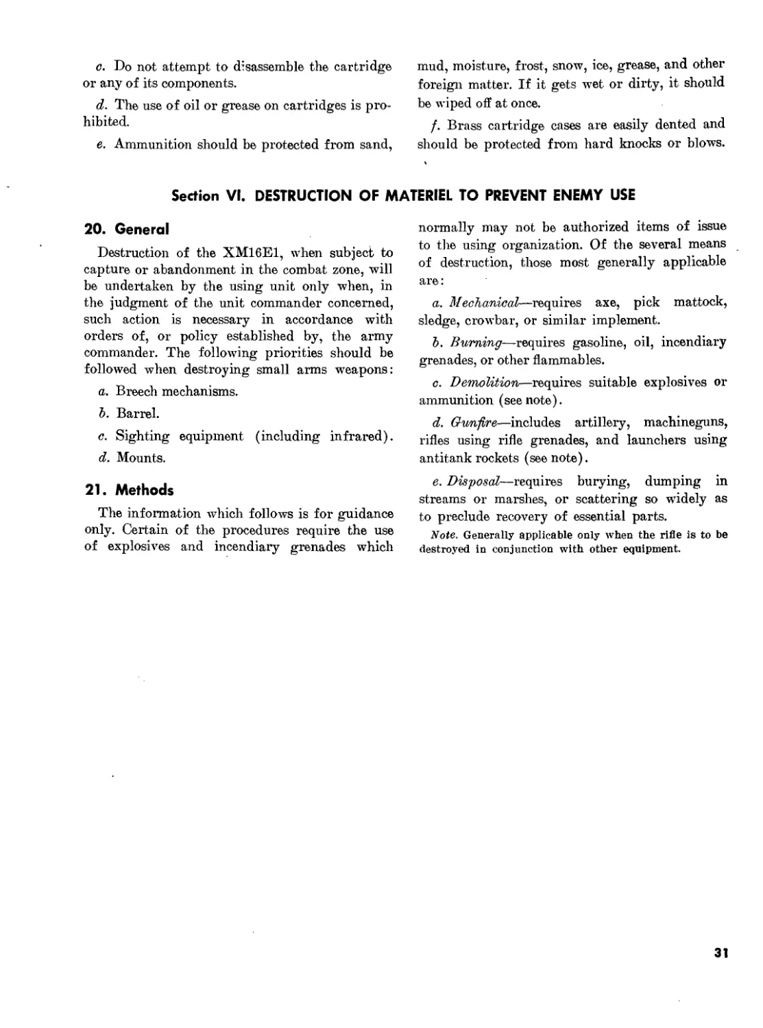
12. Preventive Maintenance
a. Preventive maintenance is the systematic
care, inspection, and servicing of equipment to
maintain it in serviceable condition, prevent,
breakdowns, and assure maximum operational
readiness. The operator’s role in the performance
of preventive maintenance service is—
(1) To perform the service each day the
rifle is operated.
Interval and sequence No. Operator's daily schedule
Before firing During firing After firing Item to be inspected Procedures Para- graph refer- ence
1 Rifle Wipe oil from bore and chamber. lla.
2 Rifle Retract bolt to assure free move- ment between bolt carrier and gas tube. 116.
3 Rifle Function check to assure proper op- eration. 8g.
4 Rifle Check magazine for positive retention and functioning of bolt catch. 10c (2).
5 Rifle Clean and lubricate. Particular atten- tion to clean bolt carrier key. 116.
Figure 35. Preventive maintenance checks and services.
29
(2) To assist the organizational mainte-
nance mechanics in the performance of
any other scheduled periodic services
specified by pertinent technical manuals.
b. Figure 35 gives the specific procedures to
be performed on the rifle by the operator for
each daily service.
13. Functioning Check
Each time the weapon is disassembled and
cleaned, a check should be made to insure that
all parts are properly assembled and the mech-
anisms are working properly in the SAFE,
SEMI, and AUTO settings.
Note. For functioning checks see paragraph 8jl
Section IV. STOPPAGES AND IMMEDIATE ACTION
14. Stoppages
A stoppage is any unintentional interruption
in the cycle of operation. Immediate action must
be taken to clear the stoppage.
15. Immediate Action
Immediate action is the unhesitating applica-
tion of a probable remedy to reduce a stoppage
without investigating the cause. Immediate ac-
tion when clearing a stoppage in the XM16E1
consists of the following steps:
a. Strike upward on the bottom of the maga-
zine to insure that it is fully seated.
b. Pull the charging handle fully to the rear
and release it.
c. Strike the forward assist assembly to insure
that the bolt is fully seated.
d. Attempt to fire the weapon.
Section V. AMMUNITION
16. General
This section includes available information on
the types of ammunition used with the XM16E1
rifle. The types of ammunition are for the pur-
poses indicated.
17. Classification
a. Cartridge, 5.56-mm, ball, M193. The ball
ammunition is a 5.56-mm, center fire cartridge
with a 55 grain, gilding-metal jacketed, lead
alloy core bullet. The primer and case are water-
proofed. The ball round is the basic cartridge
for field use and has no identifying marks.
b. Cartridge. 5.56-mm, tracer, M196. The
tracer ammunition has the same basic charac-
teristics as the ball. It is identified by an orange-
painted tip. Its primary uses are for observation
of fire, incendiary effect, and signaling.
c. Cartridge, 5.56-mm, blank, XMHOO. The
characteristics of the blank ammunition are not
currently known, as the item is still under de-
velopment.
18. Packaging
Presently there are 20 rounds per carton, and
36 cartons (120 rounds) per metal box, M2A1;
2 metal boxes (1,440 rounds) per wire-bound box.
19. Care and Cleaning
a. When necessary to store ammunition in the
open, raise it on dunnage at least 6 inches from
the ground and protect it with a cover, leaving
enough space for circulation of air.
b. Since ammunition and explosives are ad-
versely affected by moisture and high tempera-
ture, due consideration should be given to (1)
and (2) below:
(1) Do not open boxes until ammunition is
to be used. Ammunition removed from
airtight containers, particularly in damp
climates, is apt to corrode.
(2) Protect ammunition from high tempera-
tures and the direct rays of the sun.
More uniform firing is obtained if
rounds are at the same temperature.
30
c. Do not attempt to disassemble the cartridge
or any of its components.
d. The use of oil or grease on cartridges is pro-
hibited.
e. Ammunition should be protected from sand,
mud, moisture, frost, snow, ice, grease, and other
foreign matter. If it gets wet or dirty, it should
be wiped off at once.
f. Brass cartridge cases are easily dented and
should be protected from hard knocks or blows.
Section VI. DESTRUCTION OF MATERIEL TO PREVENT ENEMY USE
20. General
Destruction of the XM16E1, when subject to
capture or abandonment in the combat zone, will
be undertaken by the using unit only when, in
the judgment of the unit commander concerned,
such action is necessary in accordance with
orders of, or policy established by, the army
commander. The following priorities should be
followed when destroying small arms weapons:
a. Breech mechanisms.
Ъ. Barrel.
c. Sighting equipment (including infrared).
d. Mounts.
21. Methods
The information which follows is for guidance
only. Certain of the procedures require the use
of explosives and incendiary grenades which
normally may not be authorized items of issue
to tire using organization. Of the several means
of destruction, those most generally applicable
are:
a. Mechanical—requires axe, pick mattock,
sledge, crowbar, or similar implement.
Ъ. Burning—requires gasoline, oil, incendiary
grenades, or other flammables.
c. Demolition—requires suitable explosives or
ammunition (seenote).
d. Gun-fire—includes artillery, machineguns,
rifles using rifle grenades, and launchers using
antitank rockets (see note).
e. Disposal—requires burying, dumping in
streams or marshes, or scattering so widely as
to preclude recovery of essential parts.
Note. Generally applicable only when the rifle is to be
destroyed in conjunction with other equipment.
31
Chapter 3
MARKSMANSHIP TRAINING
Section I. PREPARATORY MARKSMANSHIP
22. General
With very few exceptions, the preparatory
marksmanship training for the XM16E1 is identi-
cal to that for the M14 (FM 23-71) and M14A2
(FM 23-16) rifles. With any weapon, the foun-
dation upon which good marksmanship is built
is preparatory training. Here the rifleman learns
the fundamentals which must be applied through-
out his training and in combat. This chapter is
devoted to the training necessary to produce an
effective rifleman.
23. The Integrated Act of Shooting
a. Aiming.
(1) In aiming, the firer is concerned with
correctly pointing his rifle so that the
bullet will hit the target when he fires.
To do this, he must have the rear sight,
the front sight, and the target, or aim-
ing point, in their proper relationship.
This relationship is known as sight pic-
ture. Sight picture involves two ele-
ments : sight alinement and placement of
the aiming point.
(2) The techniques of aiming the XM16E1
rifle are the same as for the M14 rifle
(FM 23-71).
J. Stac.dy Hold., Steady hold is the technique
of holding the weapon as steady as possible while
obtaining a sight picture and firing. There are
eight factors which affect holding a weapon
steady. These factors are basically the same for
all firing positions; however, the precise manner
in which they are applied differs slightly with
the various firing positions. This discussion of
the steady hold factors will be as they apply to
the semiautomatic firing positions.
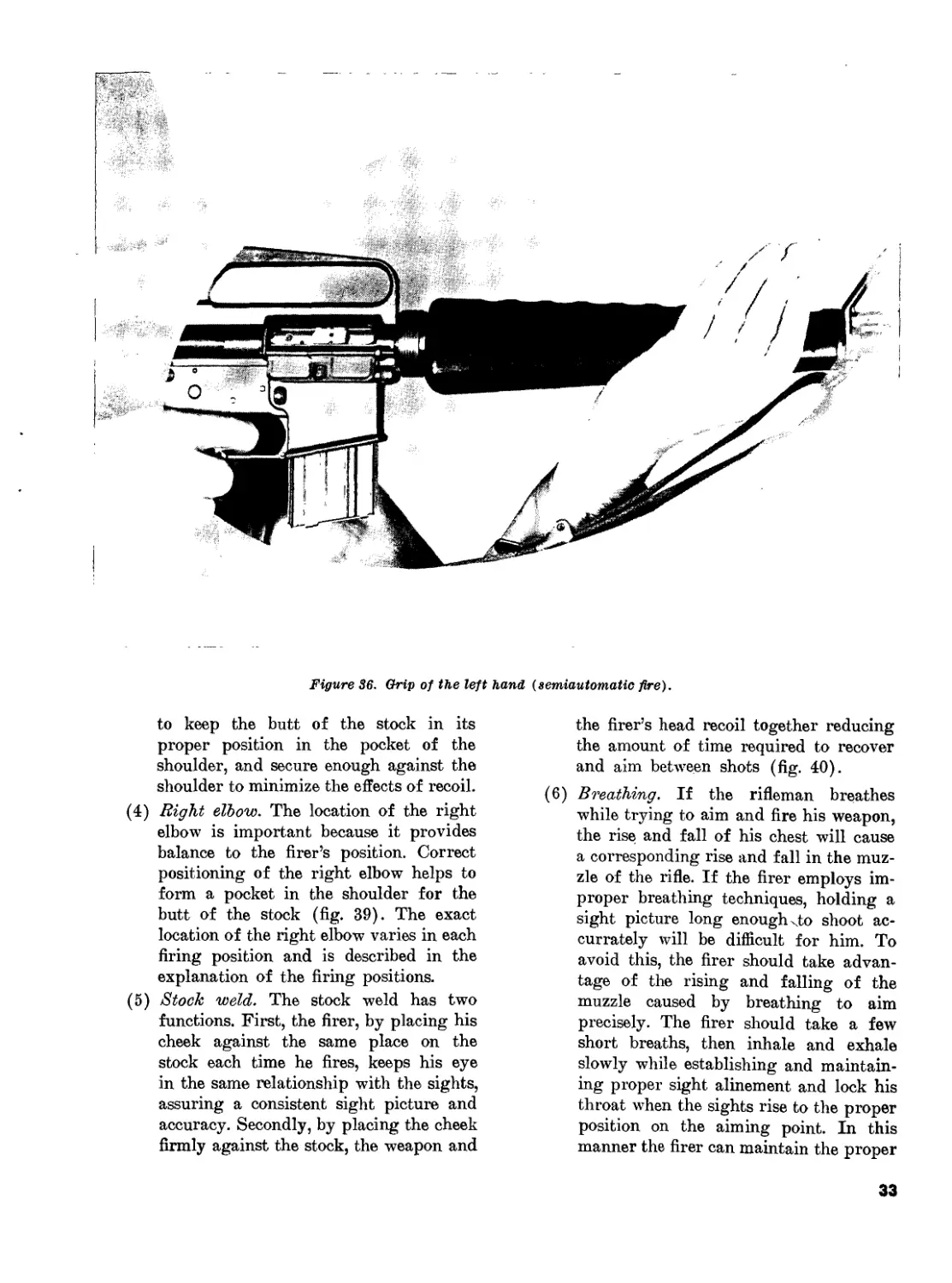
(1) Grasp of the left hand. The rifle should
rest in the V formed by the thumb and
forefinger of - the left hand, and lie
across the heel of the hand. The grip on
the handguard should be relaxed but, at
the same time, exert a slight rearward
pressure. The handguards are gripped at
a point which suits both the conforma-
tion of the firer’s body and the location
of the target. If the target is high, the
left hand is moved closer to the body,
thereby rising the muzzle of the weapon.
Conversely, if the target is low, the left
hand is moved forward, causing a cor-
responding drop in the muzzle of the
weapon. The left wrist should be as
straight as possible, and the left elbow
directly under the receiver of the
weapon, or as close to this position as
the conformation of the firer’s body will
permit (fig. 36).
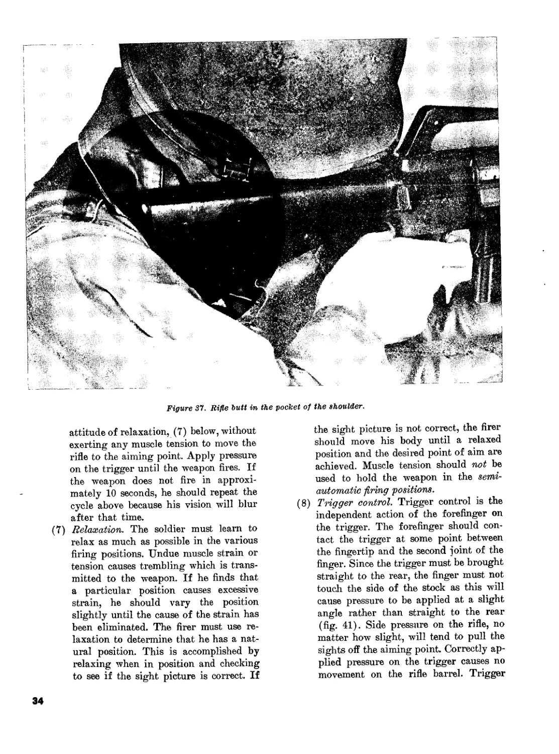
(2) Rifle butt in the pocket of the shoulder.
The firer must place the butt of the
stock firmly into the pocket formed in
his right shoulder (fig. 37). The proper
placement of the butt of the stock les-
sens the effect of recoil, helps steady the
weapon, and prevents the butt of the
stock from riding up on the shoulder.
(3) Grip of the right hand. The right hand
grasps the pistol grip so that the pistol
grip rests in the V formed by the thumb
and forefinger (fig. 38). The forefinger
(trigger finger) is placed on the trigger
so that daylight shows between the side
of the stock and the finger. The remain-
ing fingers are wrapped tightly around
the pistol grip. A firm rearward pres-
sure must be exerted by the right hand
32
Figure 36. Grip of the left hand (semiautomatic fire).
to keep the butt of the stock in its
proper position in the pocket of the
shoulder, and secure enough against the
shoulder to minimize the effects of recoil.
(4) Right elbow. The location of the right
elbow is important because it provides
balance to the firer’s position. Correct
positioning of the right elbow helps to
form a pocket in the shoulder for the
butt of the stock (fig. 39). The exact
location of the right elbow varies in each
firing position and is described in the
explanation of the firing positions.
(5) Stock weld. The stock weld has two
functions. First, the firer, by placing his
cheek against the same place on the
stock each time he fires, keeps his eye
in the same relationship with the sights,
assuring a consistent sight picture and
accuracy. Secondly, by placing the cheek
firmly against the stock, the weapon and
the firer’s head recoil together reducing
the amount of time required to recover
and aim between shots (fig. 40).
(6) Breathing. If the rifleman breathes
while trying to aim and fire his weapon,
the rise and fall of his chest will cause
a corresponding rise and fall in the muz-
zle of the rifle. If the firer employs im-
proper breathing techniques, holding a
sight picture long enough ^to shoot ac-
curately will be difficult for him. To
avoid this, the firer should take advan-
tage of the rising and falling of the
muzzle caused by breathing to aim
precisely. The firer should take a few
short breaths, then inhale and exhale
slowly while establishing and maintain-
ing proper sight alinement and lock his
throat when the sights rise to the proper
position on the aiming point. In this
manner the firer can maintain the proper
33
Figure 31. Rifle butt in the pocket of the shoulder.
attitude of relaxation, (7) below, without
exerting any muscle tension to move the
rifle to the aiming point. Apply pressure
on the trigger until the weapon fires. If
the weapon does not fire in approxi-
mately 10 seconds, he should repeat the
cycle above because his vision will blur
after that time.
(7) Relaxation. The soldier must learn to
relax as much as possible in the various
firing positions. Undue muscle strain or
tension causes trembling which is trans-
mitted to the weapon. If he finds that
a particular position causes excessive
strain, he should vary the position
slightly until the cause of the strain has
been eliminated. The firer must use re-
laxation to determine that he has a nat-
ural position. This is accomplished by
relaxing when in position and checking
to see if the sight picture is correct. If
the sight picture is not correct, the firer
should move his body until a relaxed
position and the desired point of aim are
achieved. Muscle tension should not be
used to hold the weapon in the semi-
automatic -firing positions.
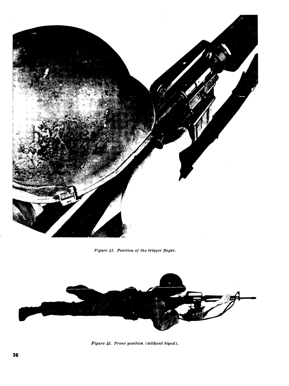
(8) Trigger control. Trigger control is the
independent action of the forefinger on
the trigger. The forefinger should con-
tact the trigger at some point between
the fingertip and the second joint of the
finger. Since the trigger must be brought
straight to the rear, the finger must not
touch the side of the stock as this will
cause pressure to be applied at a slight
angle rather than straight to the rear
(fig. 41). Side pressure on the rifle, no
matter how slight, will tend to pull the
sights off the aiming point. Correctly ap-
plied pressure on the trigger causes no
movement on the rifle barrel. Trigger
34
Figure 38. Grip of the right hand.
control is the most important of the
steady hold factors and without its
proper application, the other marksman-
ship skills are practically useless.
24. Semiautomatic Firing Positions
a. Semiautomatic Fire. Semiautomatic fire nor-
mally is used whenever pinpoint accuracy is re-
quired. To deliver semiautomatic fire, any of the
firing positions taught in rifle marksmanship for
the M14 rifle can be used.
b. Positions. During initial training in the
fundamentals of marksmanship, positions are
taught as a step-by-step process. That is, the firer
is guided through a series of precise movements
until he is in the correct firing position. As pro-
ficiency in assuming a position increases the firer
will take up a good position in one smooth move-
ment.
c. Prone Position (fig. 42). Whenever the
soldier delivers semiautomatic fire from the
prone position, the bipod may be used to gain
the added stability that it provides. The bipod
supported prone position is described in para-
graph 25c. If the bipod is not used, the left hand
grips the handguards as described in paragraph
23b (1) above.
d. Sitting Position. The sitting position is
especially suitable for use on a slope where the
target is approximately the same level as, or
lower than, the firer. The sitting position may be
used whenever the firer needs better observation
35
Figure 39. Right elbow.
than he can get from the prone position. The
firer should use the variation of the sitting po-
sition which best fits the conformation of his
body.
(1) Open-legged sitting position. To get
into the open-legged sitting position, the
firer initially faces the target as when
getting into the prone position, then ex-
4. л л I» 1 •£ —~1 L Л _1 11-1
cC’dico a, ia.ce 3.110. SpreaXiS luS
feet well apart. He removes his right
hand from the pistol grip and sits down,
breaking his fall with his right hand
(1, fig. 43). He slides his buttocks well
to the rear and points his toes inward,
allowing the weight of his legs to rest
on the inside of his heels. The firer bends
his body forward from the hips and
places his left upper arm on the flat por-
tion of his left shin, places the butt of
the stock into the pocket formed in his
right shoulder, and takes the proper grip
on the pistol grip with his right hand.
The firer locks his right elbow on the in-
side of his right knee and exerts a slight
rearward pressure with his right hand.
To complete the position, the firer ob-
tains a stock weld and relaxes (2, fig.
43).
(2) Cross-ankle sitting position (fig. 44).
To get into the cross-ankle sitting posi-
tion, the firer first sits down in the man-
ner prescribed for the open-legged sit-
ting position. He then crosses his left
ankle over his right ankle. The firer
places his left upper arm across the
shin-bone of his left leg. With his right
36
Figure %0. Stock weld.
hand, he positions the butt of the stock
into the pocket formed in his right
shoulder. He places his right elbow so
that his right upper arm is in contact
with the shinbone of his right leg. To
complete the position, the firer obtains
a stock weld and relaxes. This firing po-
sition can be adjusted for a particular
individual by varying the distance the
feet are extended from the body.
(3) Cross-legged sitting position (fig. 45).
To get into the cross-legged sitting posi-
tion, the firer first sits down in the man-
ner prescribed for the open-legged
sitting position. He then crosses his left
leg over his right leg and draws both of
his feet up close to his buttocks. He
places his left upper arm against the
shinbone of his left leg. With his right
hand, he places the butt of the stock
into the pocket in his right shoulder
and takes the proper grip on the pistol
grip. The firer lowers his right elbow so
that his right upper arm is against the
shinbone of his right leg. To complete
the position, the firer obtains a stock
weld and relaxes.
(4) Comparison of the sitting positions. In
the open-legged sitting position, the
body comes into contact with the ground
at three distinct points—the heel of each
foot and the buttocks. In the cross-
ankle sitting position, the body comes
into contact with the ground at two
37
Figure jl. Position of the trigger finger.
Figure 42. Prone position (without bipod).
38
1 Breaking the fall
’ Figure $3. Open-legged sitting position.
points, and in the cross-legged sitting
position, one point. The firer should use
the position which affords him the
greatest stability.
e. Squatting position (fig. 46). The squatting
position is a relatively steady position which can
be gotten into rapidly. Since only the feet come
into contact with the ground, the squatting posi-
tion is an excellent position to use in mud, shal-
low water, or a contaminated area. The squatting
position is best suited for use on level ground or on
ground which slopes gently downward. To assume
the squatting position, the firer initially faces his
target as when getting into the prone position.
He then executes a half-right face, spreads his
feet a comfortable distance apart, and squats as
39
2 Sitting position
Figure 43—Continued.
low as possible. For stability, he must keep both
feet flat on the ground. The left upper arm is
placed firmly against the inside of the left knee.
With his right hand, the firer places the butt of
the stock into the pocket in his right shoulder
and takes the proper grip on the pistol grip. He
then lowers his right elbow and blocks it against
the inside of his right knee. To complete the
position, the firer obtains a stock weld and re-
laxes.
/. Kneeling positions. These positions are suit-
able for use on level ground or on ground which
slopes gently upward, and can be adjusted in
height. The kneeling positions are readily
adapted to support, such as trees, the corners of
buildings, or vehicles.
(1) Kneeling unsupported, position (fig. 47).
To assume the kneeling unsupported
position, the firer initially faces his
target as when getting into the prone
position, then executes a right face and
places his left foot to his left front with
his toe pointing toward the target. He
kneels down on his right knee and sits
on his right heel, the instep of his right
foot being flat on the ground. He places
his left upper arm onto the flat position
of his .left knee. With his right hand,
he places the butt of the stock into the
pocket formed in his right shoulder. His
right elbow should be held approxi-
mately 45 degress below horizontal. To
complete the position, the firer shifts
his weight forward, obtains a stock
weld, and relaxes. Figure 47 shows two
alternate methods of positioning the
right foot when getting into the kneeling
40
Figure !fi- Gross-ankle sitting position.
positions. The firer should use the posi-
tion of the right foot which best suits
the conformation of his body.
(2) Kneeling supported position (fig. 48).
To get into the kneeling supported posi-
tion, the firer first gets into the kneeling
unsupported position. He then shifts his
weight forward and allows his left
shoulder, left arm, and left leg to come
into contact with the support. The rifle
must not touch or rest on the support,
since the contact of the weapon against
the support would slow recovery be-
tween shots and limit the firer’s ability
to rapidly shift his point of aim.
g. Standing position (fig. 49). The standing
position can be used effectively to engage targets
at ranges less than 100 meters when no other
position can be assumed. It is the least stable of
the firing positions and must be used only for
semiautomatic fire. To get into the standing posi-
tion, the firer initially faces his target, then
executes a right face and spreads his feet a com-
fortable distance apart. With his left hand, the
firer grips the handguards. He positions his left
elbow as nearly under the rifle as possible. With
his right hand, lie places the butt of the stock
into the pocket in his right shoulder, then takes
the proper grip on the pistol grip. The firer
holds his right elbow approximately horizontal,
or slightly lower, to provide a good pocket in his
right shoulder and to avoid canting the weapon.
A strong rearward pressure is exerted with his
right hand and arm (he holds most of the weight
of the rifle with his right hand and arm). To
complete the position, the firer shifts his feet
until he is aiming naturally at the target and
distributes his weight evenly on both of his hips,
obtains a stock weld, and relaxes.
41
Figure 45. Cross-legged sitting position.
h. Foxhole Position (fig. 50). The foxhole posi-
tion is the same when using semiautomatic fire
as when using automatic fire, and it is discussed
in paragraph 25</. The bipod may be used to gain
added stability.
i. Semiautomatic Fire Coaching Positions. As
a general rule, the coach’s position is similar to
that of the firer. The coach should locate himself
in relation to his firer in a manner which will
permit observation of the firer’s application of the
steady hold factors. The coach should exercise
care not to place himself so far forward of his
firer as to be in the path of the ejected cartridge
casings.
fundamental of automatic rifle marks-
manship. Without the proper firing posi-
tion, it is impossible for the rifleman to
achieve consistent hits on the target
during firing. After the first round of
a burst has been fired, a correct sight
picture is difficult to maintain. There-
fore, to continue hitting the target with
the remaining rounds in a burst, the
firer must maintain the correct firing
position. A burst of automatic fire is
defined as a series of shots fired from
an automatic weapon by one press of the
trigger.
25. Automatic Firing Positions
a. General.
(1) Position is the single most important
(2) There are three positions used with the
XM16E1 rifle when using automatic
fire. These are the bipod supported
42
Figure 46. Squatting position.
prone, bipod supported foxhole, and
mlerarm positions.
b. Steady Hold. Steady hold for the automatic
firing positions is essentially the same as for the
semiautomatic firing positions discussed in para-
graph 236, except for the following:
(1) Left arm and grip of the left hand. The
left hand grips the forward edge of the
magazine feedway, the fingers of the left
hand on the right side of the feedway,
and the thumb on the left side (fig. 51).
The left hand exerts a firm pressure
rearward to help keep the butt of the
stock into the pocket in the right
shoulder and to increase ground pressure
on the bipod legs, thus minimizing muz-
zle climb.
(2) Right elbow. The location of the right
elbow is important because it provides
balance to the firer’s position. Connect
positioning of the right elbow helps
form a pocket in the shoulder for the
butt of the stock and causes the
shoulders to be level. The right elbow
should be placed on the ground with the
right upper arm forming an angle as
near to 90 degrees with the ground as
is consistent with the shoulders being
level.
(3) Breathing. When firing automatically,
the firer must learn to exhale and inhale
after burst developing a rhythm during
firing.
(4) Muscidar tension. Contrary to the neces-
sity of relaxation in semiautomatic rifle
43
I
1
Figure Hfl. Kneeling unsupported position.
firing, muscular tension (of parts of the
firer’s body) is a necessary steady hold
factor. This can be accomplished only
by tensing the muscles of the upper
arms. The stronger the pressure applied
to the weapon by the tensing of the
muscles of the upper arms (all other
factors being correctly applied), the
less dispersed will be the rounds in a
burst of automatic fire. Although the
muscles tensed are primarily those in his
upper arms, the firer will experience a
certain tensing of his abdominal muscles.
(5) Trigger control. Trigger control is the
independent action of the trigger finger
pressing the trigger straight to the rear
until the desirea iminoer or rouncis nave
been fired in a burst of automatic fire,
then releasing the trigger. The firer
must be taught to press the trigger in a
manner that will permit him to fire a
short burst (2 or 3 rounds). The trigger
finger is placed on the trigger at a
point between the fingertip and second
joint of the finger (fig. 41). The trigger
finger should not touch the side of the
44
2
Figure /,7—Continued.
pistol grip as this will cause pressure
to be applied at a slight angle rather
than straight to the rear. Such pressure,
no matter how slight, will disturb the
weapon.
c. Bipod Supported Prone Position.
(1) The bipod supported prone position is
the most stable position and should be
used whenever possible. To get into the
bipod supported prone position, the firer
initially stands facing his target, hold-
ing the rifle with his left hand on the
handguards, his left arm thrust forward;
his right hand grasps the pistol grip, and
the butt of the stock is held against his
right hip (1, fig. 52). The muzzle of
the weapon is pointed slightly up and
down range. The firer spreads his feet
a comfortable distance apart and drops
to his knees, removing his right hand
from the weapon (2, fig. 52). He falls
forward, breaking his fall with his
right hand well forward of his right
knee, and on line with his right knee
and his target (3, fig. 52). He extends
his left arm forward and places the
rifle on the ground and lowers himself
onto his left side and elbow (4, fig. 52).
He places the butt of the stock into the
pocket in his right shoulder (fig. 37)
with his right hand, and then takes the
proper grip on the pistol grip (fig. 38),
lowering his right elbow to the ground.
The firer takes the proper grip on the
magazine feed way with his left hand
(fig. 51). The firer’s legs should be
spread a comfortable distance apart, and
his heels should be as close to the ground
as the conformation of his body will per-
mit. For maximum stability, his body
should be directly behind the weapon. To
complete the position, the firer obtains
a stock weld (5, fig. 52).
45
Figure }8. The kneeling supported position.
(2) The coach initially takes his position
three steps to the rear of the firer. From
this position, the coach tells the firer
which way to move to obtain correct
body alinement. Correct body alinement
is achieved when the firer’s body is di-
rectly behind his weapon and an imag-
inary line will pass down the long axis
of the weapon, across the firer’s right
shoulder and over his right buttock.
When the firer’s body is in the correct
relationship with his rifle, the coach
moves forward and checks the firer’s
legs and feet. Using the steady hold
factors as a guide, the coach checks the
other characteristics of the firer’s posi-
tion. Having accomplished this, the
coach will move to his initial position
three steps to the rear of the firer and
recheck the firer’s body alinement. The
46
Figure 49. Standing position.
47
Figure 50. Foxhole position (without bipod).
coach will then get into the coaching
position on the right side of the firer and
continue to observe the firer’s application
of the steady hold factors.
d. Bipod Supported Foxhole Position.
(1) The bipod supported foxhole position
(fig. 53) is used whenever defensive
positions have been prepared. To assume
the bipod supported foxhole position,
the firer moves to the foxhole and places
his rifle alongside it. The firer enters
the foxhole, adding or removing dirt or
sandbags to adjust the foxhole to his
height. The firer then grasps his rifle and
places his chest against the forward
wall of the foxhole, keeping the muzzle
of his weapon pointed slightly up and
down range. For maximum stability, the
firer braces the bottom of his right foot
against the back of his foxhole. Placing
the bipod of his rifle on the ground for-
ward of his foxhole, the firer grips his
weapon the same way he would in the
bipod supported prone position.
(2) The coach checks the firer’s position,
using the steady hold factors as a guide,
and then gets into the coaching position
(the same as for the bipod supported
prone position).
e. Underarm Position.
(1) The underarm firing position (fig. 54)
is used to engage targets at close ranges,
during the assault, or any time the rifle-
man is required to fire while moving. To
get into the underarm firing position, the
firer initially stands facing his target as
he would in the bipod supported prone
position. He then spreads his feet ap-
proximately shoulder width apart and
takes one step forward with his left
foot. The weight of his body should be
equally distributed on both of his feet,
and his knees should be slightly flexed
as in a boxer’s stance. The butt of the
stock is positioned as nearly under the
arm pit as the conformation of his body
will allow. His right arm is lowered so
that the butt of the stock is held firmly
against his side by his upper arm. The
left hand should crip the handguards
firmly, and the left arm should be ex-
tended a comfortable distance forward
to permit guiding the muzzle of the rifle
in all directions. The muzzle of the
weapon should be slightly depressed to
minimize overshooting the target, make
maximum use of any ricochets, and ad-
just fire onto the target through observ-
48
Figure 51. Left arm and grip of the left hand (automatic fire).
ing the strike of the bullets on the
ground. The right hand grips the pistol
grip firmly.
(2) The coach, arms extended and palms out,
positions himself two steps behind his
firer. This enables the coach to stabilize
his firer in the event the firer’s position
becomes unbalanced.
(3) The underarm firing position permits
the firer to engage targets in any direc-
tion. To do this, the firer whirls to face
his target by pivoting on the ball of his
lead foot and stepping in the new direc-
tion with his rear foot.
49
1 Starting position, firer taces target
Figure 52. The bipod supported prone position.
50
2 Firer drops to his knees
Figure 52—Continued.
51
3 Firer falls forward
Figure 52—Continued.
4 Firer rolls over on left side and elbow
Figure 52—Continued.
52
Б Proper position
Figure 52—Continued.
Figure 53. The bipod supported foxhole position.
53
Figure 5If. The underarm firing position.
54
Section II. AUTOMATIC FIRE
26. General
a. Automatic fire is the firing of two or more
consecutive rounds without releasing the trigger.
Bursts of two or three rounds are usually fired
to insure minimum dispersion. The rifleman must
understand the nature of automatic fire and the
contracts between automatic and semiautomatic
fire.
(1) Semiautomatic fire. Semiautomatic fire
is employed where the range to the tar-
get is in excess of 460 meters, or in any
situation where a high degree of accu-
racy is required to hit a small point tar-
get; e.g., bunker apertures, windows,
and single enemy personnel.
(2) Automatic fire. Automatic fire is em-
ployed—
(a) When engaging enemy formations at
ranges out to 460 meters.
(&) When engaging large point targets
such as crew-served weapon emplace-
ments, unarmored vehicles, and open-
ings in buildings out to ranges of 460
meters.
(c) To attain fire superiority when war-
ranted by the tactical situation.
Figure 55. Proper method of carrying magazines.
55
Figue 56. Withdrawing magazine from the ammunition pouch (right side).
Ъ. As pointed out in the explanation of the
importance of position stability, automatic fire
will not be as accurate, per round fired, as semi-
automatic fire. This decreased accuracy must be
compensated for by the delivery of a heavy vol-
ume of fire. A heavy volume of fire is attained
in machinegun fire where ammunition is belt-fed
and requires no interruption of fire for reload-
ing. However, with a magazine-fed rifle, volume
of fire is governed by the rifleman’s ability to
load and change magazines. Sustained rifle fire
is limited by the capacity of the magazine. To
attain a heavy volume of fire, the rifleman must
be able to change the magazine in 4 to 5 seconds.
This level of proficiency can only be attained
through thorough and intensive training in the
fundamentals of automatic fire.
c. Automatic fire training develops proficiency
in the rapid, systematic handling and changing
of magazines. This training insures maximum
effective use of the rifle by the firer.
56
Figure 57. Withdrawing magazine from ammunition pouch (left side).
27. Fire Distribution
a. General. The rifleman must be trained to
deliver fire at targets which have one or more
selected aiming points. When fire is delivered at
one aiming point, it is called concentrated fire;
when it is delivered at more the one aiming
point, it is called distributed fire.
b. Concentrated Fire. Concentrated fire is fire
directed at a specific point which requires a high
degree of accuracy. Rifle marksmanship training
has taught the soldier to think principally in
terms of concentrated fire; he must now be
taught to apply the integrated act of automatic
rifle shooting to distribute, as well as to concen-
trate his fire.
c. Distributed Fire. Distributed fire is fire in
depth and width so that a target is effectively
covered. The object of distributed fire is to place
a heavy volume of fire between the known or
suspected flanks of a target. The rifleman must
attempt to place fire within the area of such a
target. It should be strongly emphasized that the
inability to see enemy personnel or positions
should not be a reason for failure to fire into an
area if there is reason to suspect the presence of
a covered or concealed target.
28. Magazine Handling
a. Magazines are placed into each ammunition
pouch with the open end of the magazine down,
long portion toward the body (fig. 55). This
method of placing the magazines into the am-
munition pouches enables the firer to quickly
remove the magazines.
b. Removing a magazine from the ammunition
pouch is the same whether using the right or
left hand. To remove a magazine from the pouch,
57
Figure 58. Rotating the hand and wrist (right side).
grasp the magazine with the thumb on the long
edge and the first and second fingers on the short
edge (figs. 56 and 57). Withdraw the magazine
from the ammunition pouch and extend the arm
forward, rotating the hand and wrist (figs. 58
and 59) so that the magazine will be in position
(open end up and long edge to the rear) to load
intn th А ТСАЯППП fficrq АО япг! \ ТЪа тЯ.<ГЯ.7.1'ПА
-- „ --------- to ~ -— /- o
is loaded into the weapon by inserting the maga-
zine straight up into the magazine feedway until
it is seated.
29. Magazine Changing
a. Removing the Empty Magazine. When the
ammunition in the magazine in the rifle has been
exhausted, the firer removes the magazine from
the weapon by pressing the magazine catch button
with his right forefinger (fig. 62) and allowing
the magazine to drop, under its own weight, out
of the weapon.
b. Right-Side Load. To load a magazine from
the right side, the rifleman uses his right hand.
After the empty magazine has been removed
from the weapon, he secures and loads the next
magazine into the weapon. To chamber a round,
he depresses the top of the bolt catch with the
thumb of his left hand (fig. 63), releasing the
bolt. If the bolt was not open when the loaded
magazine was inserted into the weapon, the firer
must pull back on and release the charging han-
dle with his right hand to chamber a round. The
left hand should never be taken away from the
weapon when loading the weapon from the right
side.
58
Figure 59. Rotating the hand and wrist (left side).
c. Left-Side Load. Once the empty magazine
is out of the weapon, the rifleman secures and
loads the next magazine into the weapon with his
left hand. Chambering a round is accomplished
in the same manner as when loading a magazine
into the weapon from the right side. When load-
ing the weapon from the left side, the right
hand should never be taken away from the
weapon.
d. Changing Magazines. When changing maga-
zines, both hands should never be off the weapon
at the same time.
59
Figure 60. Magazine in position for loading (right side)
60
Figure 61. Magazine in position for loading (left side).
61
^Bure 62. Releasing the magazine.
62
Figure 63. Releasing the bolt.
63
Chapter 4
SIGHT ADJUSTMENT AND BATTLESIGHT ZERO
Section I. SIGHT ADJUSTMENT
30. General
Following fundamentals training, the soldier
must zero his weapon. In order to accomplish
this, the soldier must first learn the operation of
the sights, the use of the elevation and windage
rule, and how to compute sight changes.
31. The Sights
The sights of the XM16E1 rifle are adjustable
for both elevation and windage. Windage adjust-
ments are made on the rear sight; elevation ad-
justments on the front sight.
a. The rear sight consists of two apertures (fig.
64) and a windage drum with a spring loaded
stud (fig. 65). The aperture marked L is used
for ranges from 300 to 500 meters, and the un-
marked aperture for ranges from 0 to 300 meters.
Adjustments for windage are made by pressing
in on the spring loaded stud with a sharp instru-
ment, or the tip of a cartridge, and rotating
the windage drum in the desired direction.
Ъ. The front sight consists of a rotating sight
post with a spring loaded stud (fig. 66). Adjust-
ments are made by using a sharp instrument, or
the tip of a cartridge. To raise or lower the front
sight posts, depress the spring loaded stud and
rotate the post in the desired direction.
c. During training in marksmanship funda-
mentals all firing exercises should be conducted
with the rear sight of the weapon centered and
set on the short range aperture. The front sight
post should be set at 24 clicks from its lowest
position. This setting should not be changed
until the firer is able to fire tight shot groups.
The reason for this is twofold: first, untrained
firers will tend to focus their attention on manip-
ulating the sights rather than learning to prop-
erly apply marksmanship fundamentals. Second,
Figure 64. Rear sight apertures.
during fundamental training, the precise location
of a shot group on the target is unimportant
since it is the size of the shot group, not the
location, that governs the proficiency of the firer.
32. Elevation and Windage Rule
The elevation ana windage rule states that
one click of elevation or windage will move the
strike of a bullet a specific distance at a specific
range. At a range of 25 meters, one click of
either elevation or windage on the sights of the
XM16E1 rifle will move the strike of the bullet
approximately .7 centimeters. To compute the
distance one click will move the strike of a bullet
at any given range, multiply the range in hun-
dreds of meters times 3. For example, to compute
64
Figure 65. Windage drum.
the distance one click of elevation or windage
will move the strike of the bullet at a range of
250 meters, multiply 2.5 by 3. The answer in this
case is 7.5 centimeters.
33. Sight Changes
a. To make sight changes, the firer first locates
the center of his shot group and then determines
the distance between it and the desired location.
An error in elevation is measured vertically,
while a windage error is measured horizontally.
These distances are converted to clicks by using
the elevation and windage rule. As a general
rule, bold adjustments will prove more advanta-
geous to the firer. For example, if there is a
question whether to move two or three clicks, the
firer normally should make the adjustment re-
quiring the greater number of clicks.
Figure 66. Front sight.
Ъ. To raise the strike of the bullet, the firer
must rotate the front sight post in the direction
of the arrow marked UP (stamped on the front
sight base); thus, the strike of the bullet is
raised but the post is lowered. Reverse the direc-
tion of rotation to move the strike of the bullet
down. To move the strike of the bullet to the
right, rotate the windage drum the desired
amount of clicks clockwise (in the direction of
the stamped R). Reverse the direction of rota-
tion to move the strike of the bullet to the left.
Section II. BATTLESIGHT ZERO
34. Principles of Zeroing
a. In order to understand the principles of
zeroing, the soldier should have a basic knowl-
edge of ballistics: specifically, the relationship
between the path of the bullet in flight and the
line of sight. In flight, a bullet does not follow
a straight line but travels in a curve or arc.
This curved flight path of the bullet is called
its trajectory (fig. 67). The maximum height
(ordinate) of the trajectory of the bullet depends
on the range to the target. The greater the dis-
tance a bullet travels before impact, the higher
it must travel in its trajectory. On the other
hand, the line of sight is a straight line through
the rear sight aperture and across the front
sight post to the aiming point on the target.
Ъ. When the bullet leaves the muzzle, it is ini-
tially below the line of sight. Due to the angle of
the bore, the bullet will rise until it reaches its
maximum ordinate, at which time it will begin
65
TRAJECTORY
TRAJECTORY-LINE OF SIGHT RELATIONSHIP
SV\\AA\X\L\W\\\\\\3
TRAJECTORY, _
LINE OF SIGHT
Figure 67. Trajectory.
PRINCIPLES OF BATTLESIGHT ZEROING
66
to drop and will eventually intersect the line
of sight. The range at which this intersection
occurs is the zero for that sight setting.
c. The zero of a weapon is that sight setting
in elevation and windage that will cause a hit
at the point of aim for a given range.
d. Current doctrine of the United States Army
prescribes a battlesight zero for 250 meters. That
is, the sights of a weapon should be so adjusted
that the trajectory of the bullet and the line
of sight intersect at a range of 250 meters. To
phrase it another way a soldier firing a weapon
67
properly zeroed for a range of 250 meters
should hit his aiming point at that range.
e. One method of determining the 250 meter
battlesight zero would be to fire at a range of
250 meters, making the necessary sight adjust-
ments to place the center of the shot group
on the aiming point. However, such a method
would require extensive terrain and waste train-
ing time while firers moved between the firing line
and the targets to check the location of shot
groups.
f. A more suitable method of determining the
250-meter battlesight zero can be accomplished
at a range of 25 meters or 1,000 inches (fig. 68).
This method is based on the principle that bullets
of the same type and caliber fired at the same
range have the same trajectory. That is, if
several bullets were fired from the same weapon
and all hit the same 250-meter aiming point,
the trajectories of all these bullets are the same.
Therefore, when each of these bullets reaches
a distance of 25 meters or 1,000 inches from the
muzzle of the weapon, they are all the same
distance below the firer’s line of aim. Thus, by
placing an aiming point at a range of 25 meters
or 1,000 inches, the firer has only to adjust the
weapon sights until his shot group is the pre-
scribed distance below his 25-meter or 1,000-inch
aiming point to obtain a zero for 250 meters.
35. Battlesight Zero Target
The standard 25-meter target (FSN 6920-906-
0169) previously used during fundamentals
training, is locally modified as illustrated in
figure 69 when determining a battlesight zero
for the XM16E1. In order to use the elevation
and windage rule effectively, the firer must know
the dimensions of the squares on the target.
Vertical and horizontal lines are printed on the
target, forming 1.4 centimeter squares. As indi-
cated in paragraph 32, one click of elevation or
windage will move the strike of the bullet .7
centimeters at a range of 25 meters. (Although
25 meters is a slightly lesser distance than 1,000
inches, the difference is insignificant, and the
same adjustment data can be used for 1,000-inch
firing.) Thus, in terms of the 25-meter target,
two clicks of elevation or windage will move
the strike of the bullet one square.
36. Determining the Battlesight Zero
a. The 250-meter battlesight zero is determined
by firing a series of three-round shot groups at
the 25-meter target described in paragraph 35.
The firer aims at the distinctive aiming point
at the bottom center of the black rectangle and
adjusts his sights until the center of his shot
group is located 2.4 centimeters directly below
the aiming point. This point can be designated
by an additional X drawn on the target (fig.
69). With this sight setting, the point of im-
pact of the bullet and the firer’s point of aim
will coincide at a range of 250 meters. The
average firer will need to fire three or four shot
groups in order to accurately determine the
battlesight zero of his weapon.
Ъ. Once the battlesight zero has been obtained,
there should be no further adjustments of the
sights. Later, in field firing exercises, the soldier
will learn to hit targets located at ranges other
than 250 meters by adjusting his point of aim
as described in FM 23-16 and FM 23-71.
c. Either of the two most stable firing posi-
tions, the bipod supported foxhole or the bipod
supported prone, may be used for obtaining the
battlesight zero. However, the position selected
must be located the prescribed 25 meters (1,000
inches) from the target.
68
Appendix
REFERENCES
FM 23-8
FM 23-15
FM 23-16
FM 23-71
ASubjScd 7-11B10
ASubjScd 23-14
ASubjScd 23-31
TM 9-1005-249-14
GTA 7-1-14
U.S. Rifle, 7.62-mm, M14 and M14A2.
Browning Automatic Rifle, Cal. .30, M1918A2.
Automatic Rifle Marksmanship.
Rifle Marksmanship.
Light Weapons Infantryman, MOS 11B10.
Interim Automatic Rifle, M14(M) and BAR Qualification.
Rifle Marksmanship.
Operation Maintenance, Repair and Replacement Parts, Rifle, 5.56-mm, M16,
and Rifle, 5.56-mm, XM16E1.
Rifle, 5.56-mm, XM16E1, Mechanical Training.
By Order of the Secretary of the Army:
Official:
J. C. LAMBERT,
Major General, United States Army,
The Adjutant General.
HAROLD K. JOHNSON,
General, United States Army,
Chief of Staff.
Distribution:
Active Army:
DCSPER (2) Corps (3)
ACSI (2) Div (5)
DCSLOG (2) Div Arty (1)
ACSFOR (2) Bde (3)
CORC (2) Gp (1)
CNGB (5) CC (2)
CRD (1) Bn (2)
СОА (1) Co/Btry (1)
CINFO (1) USAWC (5)
TIG (1) USAOC&S (1)
USAIB (1) Svc Colleges (2)
USCONARC (5) Br Svc Sch (2)
USAMC (1) USMA (2)
LOGCOMD (1) USATC (2)
Armies (5)
NG: State AG (3) ; units—same as Active Army except allowance is one copy to each unit.
VSAR: Units—same as Active Army except allowance is one copy to each unit.
For explanation of abbreviations used, see AR 320-50.
☆U.S. Government Printing Office: 1966—0 222-102
69