/


Теги: weapons military affairs
Год: 1965
Похожие

Текст
РОММ 9-1005-279-12
Preliminary
Operating and
Maintenance
Manual
5.56-mm Rifle! 223
and Rifle Bipod
Harrington & Richardson, Inc.
Worcester, Massachusetts
This publication is not available through A G publications channels
РОММ 9-1005-279-12
June 1965
TABLE OF CONTENTS
5.56 mm Rifle T225
Paragraphs Page
Chapter 1 Introduction 1
Section I General 1, 2 1
II Description and Data 5 - 5 2
Chapter 2 Operating Instructions 4
Section I Service upon receipt of materiel 6, 7 4
II Controls 5
III Operation under usual conditions 15 - 25 9
IV Operating under unusual conditions 26 - 29 16
Chapter 5 Organizational Maintenance Instructions 18
Section I Repair parts, tools, and Equipment 50 - 55 18
II Lubrication 54 - 55 19
III Preventive-maintenance services 56 - 41 22
IV Troubleshooting 42 - 45 29
V Maintenance of Rifle 44 - 49 55
VI Maintenance of Bipod 50 59
Chapter 4 Maintenance Under Unusual Conditions 51 - 55 59
Chapter 5 Demolition of Rifle To Prevent Enemy Use 54 - 55 40
Appendix I Basic Issue Items, Major Items, Components of Major Items, Repair Parts and Equipment — 42
Appendix II Maintenance Allocation Chart — 45
Appendix III Organizational Maintenance — 46
Repair Parts and Special Tool List
CHAPTER 1
INTRODUCTION
Section I. GENERAL
1. Scope
a. This manual contains instructions for operation
and organizational maintenance of the 5-56 mm. rifle
T225-
b. Appendix I contains a list of basic issue items,
major items, components of major items, repair parts,
tools and equipment applicable to the 5-56 mm. rifle
T225.
c. Appendix II contains the maintenance allocation
chart for 5*56 mm. rifle T223, listing maintenance and
repair operations for authorized maintenance echelons.
d. Appendix III contains an organizational maintenance
repair parts and special tool list.
e. This is a preliminary operating and maintenance
manual published in conjunction with the Small Arms
Weapons Systems (SAWS) program.
2. Maintenance Allocation
a. Operator Maintenance Allocation. The prescribed
maintenance to be performed by the operator will apply
as reflected in the operator-maintenance (first echelon)
of the maintenance allocation chart (app II). In all
cases where the nature of the repair, modification, or
1
adjustment is beyond the scope or facilities of the oper-
ator, trained organizational maintenance personnel with
suitable tools and equipment may be provided or other
instructions issued.
b. Organizational Maintenance Allocation. The pre-
scribed maintenance to be performed by maintenance per-
sonnel of the using organization will apply as reflected
in the organizational-maintenance (second echelon) of
the maintenance allocation chart (app II). In all cases
where the nature of the repair, modification, or adjust-
ment is beyond the scope or facilities of the using
organization, the supporting ordnance maintenance unit
should be informed so that trained personnel with suit-
able tools and equipment may be provided or other in-
structions issued.
Section II. DESCRIPTION AND DATA
5- Description
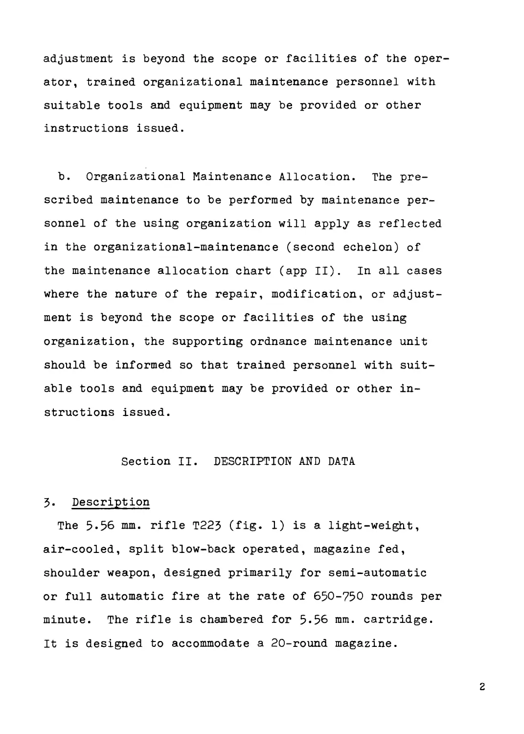
The 5-56 mm. rifle T225 (fig- 1) is a light-weight,
air-cooled, split blow-back operated, magazine fed,
shoulder weapon, designed primarily for semi-automatic
or full automatic fire at the rate of 650-750 rounds per
minute. The rifle is chambered for 5-56 mm. cartridge.
It is designed to accommodate a 20-round magazine.
2
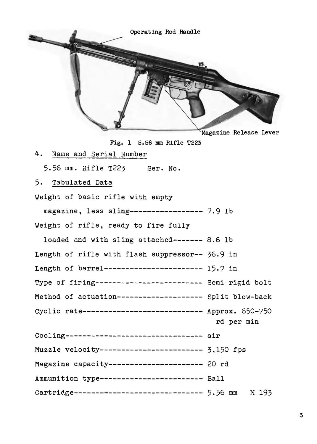
Operating Rod Handle
Magazine Release Lever
Fig. 1 5.56 mm Rifle T223
4. Name and Serial Number
5-56 mm. Rifle T22$ Ser. No.
5- Tabulated Data
Weight of basic rifle with empty
magazine, less sling--------------------7.9 lb
Weight of rifle, ready to fire fully
loaded and with sling attached---------- 8.6 lb
Length of rifle with flash suppressor— $6.9 in
Length of barrel-----------------------15-7 in
Type of firing-------------------------Semi-rigid bolt
Method of actuation--------------------Split blow-back
Cyclic rate----------------------------Approx. 650-750
rd per min
Cooling--------------------------------air
Muzzle velocity------------------------5,150 fps
Magazine capacity----------------------20 rd
Ammunition type------------------------Ball
Cartridge------------------------------5-56 mm M 195
3
CHAPTER 2
OPERATING INSTRUCTIONS
Section 1. SERVICE UPON RECEIPT OF MATERIEL
6. General
a. When a new rifle is first received, it is the re-
sponsibility of the officer in charge to determine whether
the materiel has been properly prepared for service by
the supplying organization and to be sure it is in con-
dition to perform its function.
b. All basic issue items, repair parts, tools, and
equipment will be checked with listing in Appendix I.
c. A record will be made of all missing parts, tools,
and equipment and of any malfunctions. Corrective action
will be initiated as quickly as possible.
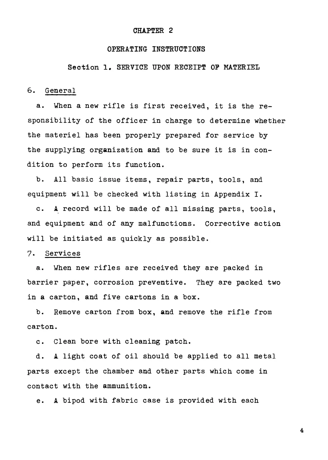
7. Services
a. When new rifles are received they are packed in
barrier paper, corrosion preventive. They are packed two
in a carton, and five cartons in a box.
b. Remove carton from box, and remove the rifle from
carton.
c. Clean bore with cleaning patch.
d. A light coat of oil should be applied to all metal
parts except the chamber and other parts which come in
contact with the ammunition.
e. A bipod with fabric case is provided with each
4
rifle. The bipod should be cleaned, lightly oiled and
inspected to determine that legs lock in the extended
position and retract as required.
Section II. CONTROLS
8. General
This section describes, locates, and illustrates the
various controls provided for the operation and organ-
izational maintenance of the rifle.
9• Selector
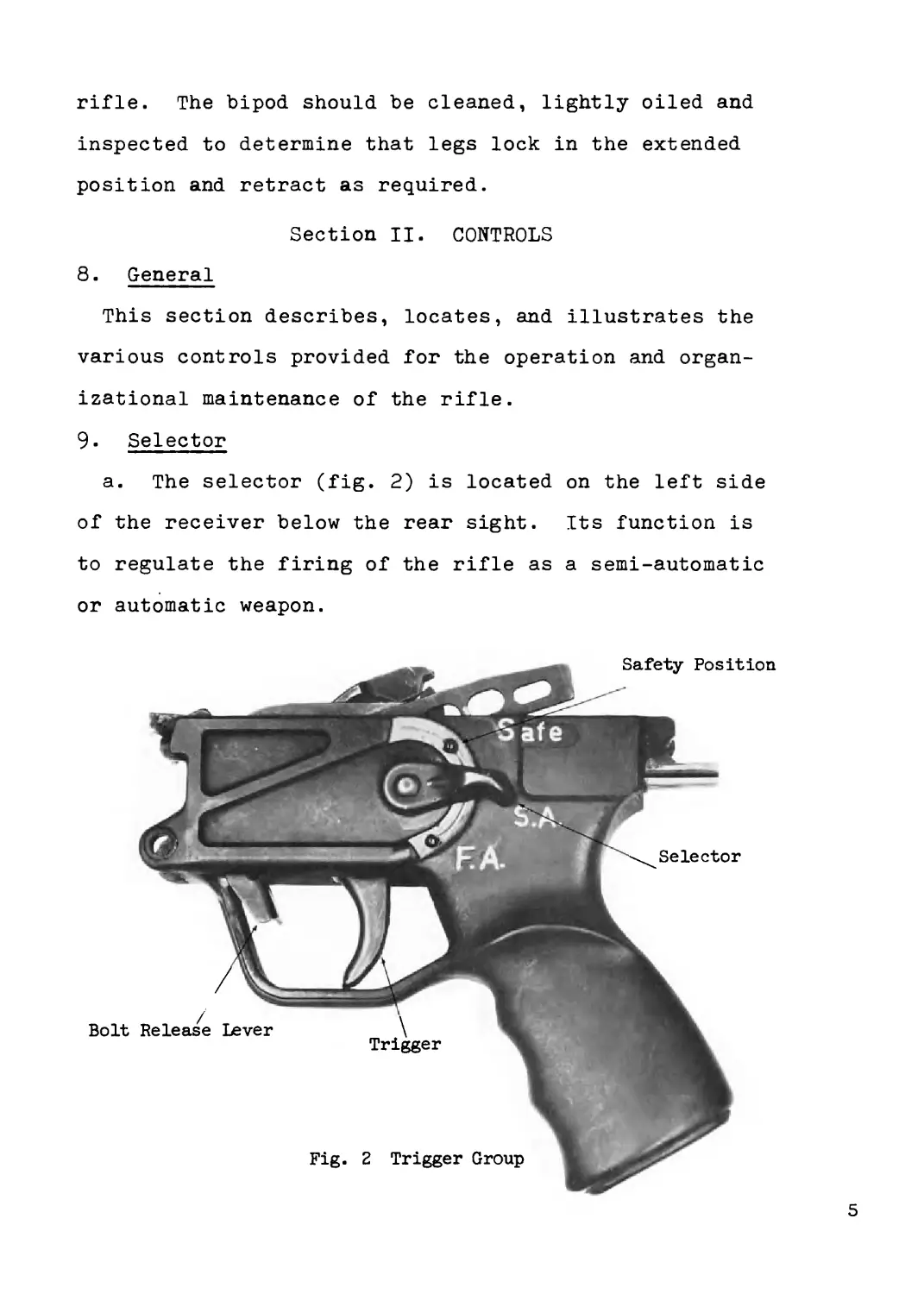
a. The selector (fig. 2) is located on the left side
of the receiver below the rear sight. Its function is
to regulate the firing of the rifle as a semi-automatic
or automatic weapon.
5
b. When the selector is in a horizontal position, at
the letters S.A., the rifle will fire semi-automatically.
When the selector is in a downward vertical position, at
the letters F.A., the rifle will fire automatically.
10. Trigger
a. The trigger (fig. 2) is located inside of the
trigger guard and is part of the firing mechanism. Its
function is to control the firing of the rifle for both
semi-automatic and automatic.
b. In firing the rifle for semi-automatic, squeeze
trigger for each round fired.
c. For automatic firing, squeeze trigger and hold.
11. Safety
a. The safety (fig. 2) is located on the left side of
the receiver, below the rear sight, and integral with
the selector. Its function is to lock trigger, sear,
and hammer, preventing firing of rifle.
b. To prevent firing of rifle, the safety is moved to
an upward vertical position, at the letter S. When ready
to fire, press safety to downward position.
12. Rear Sight Controls
a. A four position rotary rear sight, adjustable for
elevation and windage, is located on top of the receiver
(fig. 5). The four positions include an open notched
auxiliary and three aperture positions.
6
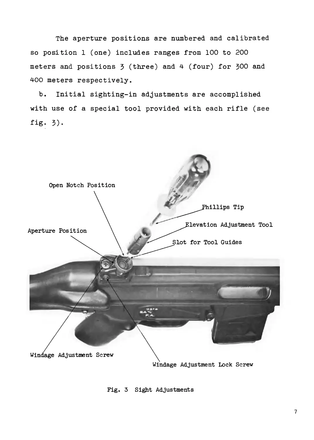
The aperture positions are numbered and calibrated
so position 1 (one) includes ranges from 100 to 200
meters and positions 5 (three) and 4 (four) for 500 and
400 meters respectively.
b. Initial sighting-in adjustments are accomplished
with use of a special tool provided with each rifle (see
fig- 3).
Windage Adjustment Lock Screw
Fig. 3 Sight Adjustments
7
c. Windage adjustments are made by loosening the
Phillips head lock screw on top of the sight. The Phil-
lips head screw on the right side of the sight is now
turned clockwise to move sight to the left and counter-
clockwise to move sight to the right. Each revolution of
the screw moves the point of impact approximately 3*5
inches at 100 meters. The lock screw on top of the sight
should be tightened after adjustment.
d. Initial elevation adjustments are made by inserting
blunt end of tool into the recessed top of sight (fig. 3),
and rotating until spring loaded guides line up in respec-
tive slots. With the Phillips tip inserted in top of
tool, the body of the sight is rotated counter-clockwise
to raise sight and clockwise to lower sight. Each click
(1/4 turn) moves the point of impact approximately one
inch at 100 meters. Once adjusted for a known distance,
the sight can be rotated to the other three relative posi-
tions without use of the tool.
13. Operating Rod Handle
a. The operating rod handle (fig. 1) is located on the
left hand side of barrel. The rifle can be manually oper-
ated by use of this handle.
b. To operate rifle, manually move operating rod han-
dle to rear position and release. This permits the force
of the magazine spring to position the top round in path
of the bolt after the operating rod has moved the bolt
8
to its rearward position. As the bolt moves forward, the
bottom face of the bolt engages the base of the cartridge,
ramming it forward, feeding, and chambering it in the
barrel.
14. Bipod
a. The bipod is attached to the rifle by sliding it
over the collar, located below the chamber area of the
barrel, until the snap lock engages.
b. To remove bipod, release spring loaded snap lock
and slide forward off collar.
Section III. OPERATION UNDER USUAL CONDITIONS
15- General
This section contains instructions for the operation
of the rifle under conditions of moderate temperatures
and humidity. Instructions for operation under unusual
conditions are covered in Section IV of this chapter.
16. Preparation for Firing
a. Check the bore to be sure it is free of foreign
matter or obstructions.
b. Check ammunition to make certain it is clean and
that it is of the proper type and grade.
c. Place the safety in the SAFE position (par. 11).
17. Service Before Firing
Perform the "before firing" operations as indicated
9
in Table I, operator’s preventive-maintenance services.
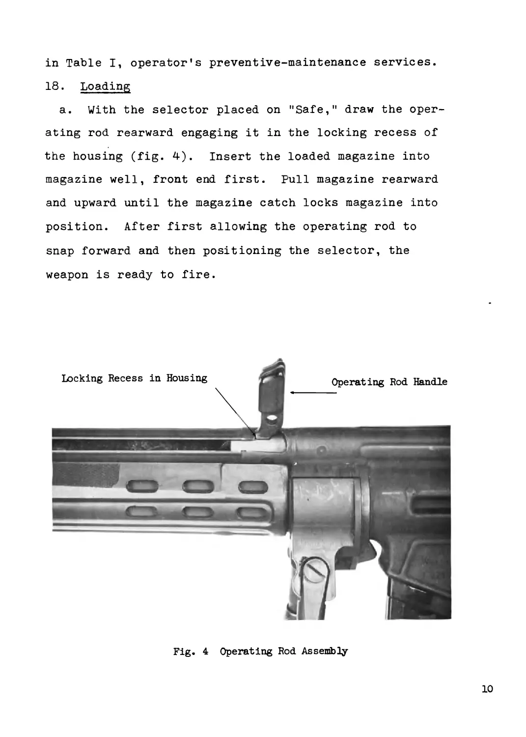
18. Loading
a. With the selector placed on "Safe," draw the oper-
ating rod rearward engaging it in the locking recess of
the housing (fig. 4). Insert the loaded magazine into
magazine well, front end first. Pull magazine rearward
and upward until the magazine catch locks magazine into
position. After first allowing the operating rod to
snap forward and then positioning the selector, the
weapon is ready to fire.
Fig. 4 Operating Rod Assembly
10
19• Firing
a. Semi-automatic Fire - Push the selector downward
to S.A. With each squeeze of the trigger, the rifle will
fire a round.
b. Full Automatic Fire - Push the selector downward
to F.A. Squeeze trigger and hold on target. The rifle
will fire automatically as long as the trigger is squeezed
and there is ammunition in the magazine. Release trigger
to cease firing.
20. Ruptured Cartridge Case
a. A ruptured cartridge case will result in a portion
of the cartridge case remaining in the chamber after the
base portion of the cartridge has been extracted and
ejected. Under usual conditions the next round picked
up by the bolt and chambered (A dummy round should be
used whenever possible), will engage in the remaining
portion of the ruptured cartridge. The weapon will jam
due to the inability of the bolt to lock, and the rifle
will not fire. With the selector placed on ’'SAFE,” the
bolt is manually returned with the operating rod handle.
This will extract and eject the chambered round and the
ruptured portion of the cartridge. If the above does
not occur, evacuate to Ordnance for further inspection
and repair.
21. Misfire, Hangfire, and Cookoff
a. Misfire - A misfire is not dangerous, but since
11
it cannot be immediately distinguished from a delay in
the functioning of the firing mechanism or from a hang-
fire (b. below), it should be considered as a possible
delay in firing until such possibility has been elimin-
ated. A delay in the functioning of the firing mechanism
could result from the presence of foreign matter such as
sand, grit, frost, ice or oil and grease. These might
create a partial mechanical restraint which, after some
delay, is overcome as a result of the continued force
applied by the spring, and the firing pin striking the
primer. In this connection NO round should be left in
a hot weapon any longer than the circumstances require
because of the possibility of a cookoff (c. below).
b. Hangfire - A hangfire is a delay in the functioning
of a propelling charge at the time of firing. The amount
of delay is unpredictable but, in most cases, will fall
within the range of a split second to several minutes.
Thus, a hangfire cannot be distinguished immediately
from a misfire, and therein lies the principal danger of
assuming that a failure of the weapon to fire is a mis-
fire whereas, in fact, it may prove to be a hangfire.
WARNING: During the prescribed time intervals, the
weapon will be kept trained on the target and all per-
sonnel will stand clear of the muzzle.
c. Cookoff - A cookoff is a functioning of the round
chambered in a very hot weapon due to the heat of the
12
weapon. If the primer or propelling charge should
cookoff, the projectile will be propelled from the wea-
pon with normal velocity even though no attempt was made
to fire the primer by actuating the firing mechanism.
In such a case, there may be uncertainty as to whether
or when the round will fire, and precaution should be
observed the same as those prescribed for a hangfire.
To prevent a cookoff, a round of ammunition which has
been loaded into a veiy hot weapon should be fired imme-
diately, or removed after 5 seconds and within 10 sec-
onds .
22. Immediate Action Procedures for Removing a Live
Round in Case of Failure to Fire.
a. General - After a failure to fire, due to a mis-
fire, the following general precautions, as applicable,
will be observed until the round has been removed from
the weapon and the cause of failure determined.
1) Keep the weapon trained on the target and see
that all personnel are clear of the muzzle.
2) Before retracting the bolt and removing the
round, see that personnel, not required for
operation, are cleared from vicinity.
3) Make certain the round, removed from the
weapon, is kept separate from other rounds
until it has been determined whether the
round or the firing mechanism was at fault.
13
If the weapon is determined to be at fault,
the round may be reloaded and fired after
correcting the cause for failure to fire.
b. Time Intervals - The definite time intervals for
waiting, after failure of weapon to fire, are prescribed
as follows: Always keep the round in the chamber for 5
seconds from the time a misfire occurs to insure against
an explosion outside of the gun in event a hangfire de-
velops. If the barrel is hot, and a misfire stops
operation of the gun, wait 5 seconds with the round
locked in the chamber to insure against hangfire dangers;
then extract the round immediately to prevent cookoff.
If the round cannot be extracted within 10 seconds, it
must be locked in chamber for at least 5 minutes due to
the possibility of a cookoff. Also, in the event the
barrel is hot and a misfire occurs when attempting to
resume firing after an intentional cessation of firing,
the round should remain in the chamber for 5 minutes
because of the possibility of a cookoff.
WARNING: Do not retract the bolt when a hangfire
or cookoff is suspected. A hangfire will normally occur
within 5 seconds from the time the primer is struck and
a cookoff after 10 seconds of contact with the chamber
in a hot barrel. One hundred and fifty rounds fired in
a 2 minute period will heat a barrel hot enough to pro-
duce a cookoff.
14
25• Double Feed
A double feed may occur when a cartridge case of a
fired round is not extracted from the chamber and another
cartridge is picked up by the bolt and fed into the re-
ceiver. This can result from a broken extractor or the
extractor flipping off of the base of the cartridge dur-
ing extraction. Care should be exercised in clearing
the rifle. With the selector placed on "SAFE,” the bolt
is manually returned by the operating rod handle. The
magazine is removed (par. 25), allowing all live rounds
to be removed.
Releasing the operating rod handle will allow the bolt
to close and extractor to engage on the base of the cham-
bered cartridge case. Manually returning the bolt will
extract the cartridge case and prepare the rifle for re-
loading (par. 18).
24. Service During Firing
Perform the "during firing" operations as described in
the operations preventative-maintenance services, Table I.
25. Unloading
a. Place the selector in "SAFE" position.
b. Grasp magazine, placing the thumb on the magazine
latch, and squeeze the latch, push the magazine forward
and downward to disengage it and remove the magazine from
the magazine well.
15
c. Pull the operating rod handle rearward to extract
and eject the chambered round. Inspect the chamber,
making certain the rifle is clear.
Section IV. OPERATING UNDER UNUSUAL CONDITIONS
26. General Conditions
a. In addition to the normal preventive-maintenance
service, special care in cleaning and lubrication must
be observed where extremes of temperatures, humidity,
and atmospheric conditions are present or anticipated.
Proper cleaning, lubrication, storage, and handling of
lubricants not only insure operation and functioning,
but also guard against excessive wear of the working
parts and deterioration of the weapon.
b. See Paragraphs 27-29 for instructions on
lubrication under unusual conditions and Table I for
preventive-maintenance checks to be made when material
is subjected to unusual conditions.
27- Operation in Cold Climates
a. In climates where the temperature is consistently
below 0° F., it is necessary to prepare the rifle for
cold-weather operation. Generally, extreme cold will
cause lubricants to congeal. Therefore the weapon
should be thoroughly cleaned of all lubricants or grease,
and lubricated with low temperature type lubricating oil.
b. Exercise the various controls through their entire
16
range, at intervals as required, to aid in keeping them
from freezing in place and to reduce the effort required
to operate them.
c. When weapon is not in use, and must be stored out-
side, pay particular attention to protecting it with
proper cover. Cover should be securely fastened so that
snow, ice, or moisture will be kept from the operating
parts.
28. Operation in Hot Climates
a. In hot climates, the film of oil necessary for
operation will dissipate quickly. Inspect the rifle,
paying particular attention to all hidden surfaces such
as bolt and bolt components, where corrosion might
occur and not be quickly noticed.
b. Due to perspiration from the hands, after handling
weapon, clean, wipe dry, and restore the oil film using
special lubricating oil.
c. When operating in hot, wet or dry climates, clean
and oil the bore and bolt components of the rifle more
frequently than usual. Rapid temperature changes cause
a moisture condensation film to form on the uncoated
metal, resulting in rust. Immediately, when this mois-
ture film occurs on metal parts of the weapon, wipe
briskly until thoroughly dry and coat with special lubri-
cating oil, as required to prevent rusting.
17
29. Operation Under Sandy or Muddy Conditions
a. Sand. Clean and lubricate the weapon more fre-
quently when operating in sandy areas. Use particular
care to keep sand out of mechanisms when carrying out
inspecting and lubricating operations. Shield parts from
flying sand during disassembly and assembly operations.
When operating weapon continuously in sandy areas, remove
lubricant from bolt, barrel and receiver, operating rod,
and firing mechanism, as they will pick up sand and form
an abrasive which will cause rapid wear. With surfaces
dry, there is less wear than when coated with lubricant
contaminated with sand. Clean and lubricate all exposed
parts after completion of continuous usage.
b. Mud. Clean and lubricate rifle as often as
possible when operating in areas which are muddy. Exer-
cise particular care and make certain all mud is removed
and that mechanism is thoroughly dry before lubricating.
Clean and lubricate all exposed parts after use.
CHAPTER 3
ORGANIZATIONAL MAINTENANCE INSTRUCTIONS
Section I. REPAIR PARTS, TOOLS, AND EQUIPMENT
30. General
Repair parts, tools, and equipment are issued to the
using organization for operating and maintaining the
18
rifle. Tools and equipment should not be used for pur-
poses other than prescribed and, when not in use, should
be properly stored.
51• Repair Parts
Repair parts are supplied to the using organization
for replacement of those parts most likely to become
worn, broken, or otherwise unserviceable, providing re-
placement of these parts is a function of the using
organization. Repair parts supplied to the first and
second echelons are listed in Appendix I.
$2. Common Tools and Equipment
Common tools and equipment having general application
to this weapon are authorized by tables of allowance and
tables of organization and equipment.
33• Special Tools and Equipment
Tools and equipment for operation and second echelon
maintenance repair are listed in Appendix I.
Section II. LUBRICATION
34. General Lubricating Instructions
Usual Conditions. Make certain all metal parts, which
come in contact with gases, have been cleaned with rifle
bore cleaner and dried thoroughly. Apply a light coat
of preservative lubricating oil to the following sur-
faces :
19
1) Bolt Head including locking rollers
and recesses
2) Bolt Body and locking lever
5) Bolt Ways in Receiver
4) Operating Rod Tube
55- Lubrication Under Unusual Conditions
a. Unusual Conditions. Reduce or increase lubrica-
tion intervals as required to compensate for abnormal
operation and extreme conditions, such as high or low
temperatures, prolonged periods of high-rate operation,
continued operation in sand or dust, or exposure to
moisture, any one of which may quickly destroy the pro-
tective qualities of the lubricant. Lubrication periods
may be extended during inactive periods.
b. Changing Grade of Lubricants. Lubricants are pre-
scribed in accordance with temperature ranges. The time
to change the grade of lubricants is determined by main-
taining a close check on the operation of the rifle
during the approach to changeover periods, in accordance
with weather forecast data. Ordinarily, it will be nec-
essary to change grade of lubricants only when air
temperatures are consistently in the next higher or
lower range.
c. Extreme Cold-Weather Lubrication. Apply a light
coat of low temperature lubricating oil to the rifle,
and exercise frequently during periods of low tempera-
20
ture to insure proper functioning.
d. Extreme Hot-Weather Lubrication. Special lubri-
cants will ordinarily not be required at extremely high
temperatures, as lubricants prescribed for temperatures
above 0° F. provide adequate protection. However, more
frequent servicing than specified in Tables I and II
is necessary because the heat tends to dissipate the
lubricants.
e. Lubrication for Humid and Salt Air Conditions.
High humidity, moisture, or salt air contaminate lubri-
cants, necessitating more frequent service than speci-
fied in Tables I and II because the heat tends to
dissipate the lubricants.
f. Before-Immersion Lubrication. Grease and lubri-
cate parts listed in paragraph 54. (I) through (4)
before amphibious operation.
g. After-Immersion Lubrication. After immersion,
perform the maintenance described in paragraph 52 which
covers maintenance operations after immersion and in-
cludes special lubrication instructions.
h. Lubrication After Operation Under Sandy or Dusty
Conditions.
If firing or prolonged travel has occurred under
dusty or sandy conditions, clean and inspect all lubri-
cated surfaces for fouled lubricants. Lubricate as
necessary.
21
Section III. PREVENTIVE-MAINTENANCE SERVICES
56. General
a. Responsibility and Intervals. Preventive-
Maintenance services are the responsibility of the using
organization. These consist of before-firing, during-
firing, daily, and weekly services performed by the
operator (Table I), and the scheduled services to be
performed at the weekly, bi-monthly, and semi-annual in-
tervals by the armorer of the using organization (Table
II). Intervals are based on usual conditions. Reduce
or increase intervals for unusual conditions. Intervals
during inactive periods may be extended accordingly.
b. Definition of Terms. The general inspection of
each item applies also to any supporting member or con-
nection and is generally a check to see whether the item
is in good condition, correctly assembled, secure, and
not worn.
(1) The inspection for ’’good condition" is
usually an external visual inspection to
determine whether the unit is damaged
beyond safe or serviceable limits.
(2) The inspection of a unit to see that it
is "correctly assembled" is usually an
external visual inspection to see if it
is in its normal assembled position in
22
the weapon and functions properly when
manually operated.
(3) Inspection of a unit to determine if it
is ’’secure" is usually an external visual
examination or a check by wrench or hand
for looseness.
(4) By "worn" is meant that the item is
approaching unserviceable limits and
a point likely to result in failure
if the unit is not replaced.
37. Preventive-Maintenance by Operator
The operator(s) is expected to perform the necessary
care and cleaning functions, basic preventive-mainten-
ance, and services as outlined in Table I at the speci-
fied intervals.
38. General Care and Cleaning
Instructions are as follows:
(1) Immediately after firing, thoroughly
clean bore with rifle bore cleaner, making
certain that all surfaces, including the
rifling are well coated. The bore should
be swabbed with a saturated flannel clean-
ing patch, making certain no trace of
burned powder or other foreign substances
are left in the bore. Wipe dry and apply
a light coat of lubricating oil.
23
(2) The chamber should be cleaned with a
chamber cleaning brush (fig. 5)♦ wiped
clean, and oiled lightly. Other metal
parts should be cleaned with a dry cloth
to remove dampness, dirt, perspiration,
and oiled lightly.
(3) Use rifle bore cleaner to clean all parts
which have been exposed to powder fouling
during firing. Care should be used to
wipe parts dry and lubricate where neces-
sary .
Chamber Cleaning Brush
39. Basic Preventive-Maintenance
The general preventive-maintenance procedures outlined
in a through d below will be observed in addition to
24
those referred to in Table I. Special maintenance of
specific components of the rifle is covered, when nec-
essary, in the sections pertaining to the components.
a. Rust, dirt, grit, gummed oil, and water cause
rapid deterioration of internal mechanisms and outer
uncoated surfaces. Particular care should be taken
to keep all bearing surfaces clean and properly lubri-
cated. Remove all traces of rust from uncoated bear-
ing surfaces with CROCUS CLOTH, which is the coarsest
abrasive to be used by the using organization for this
purpose.
b. Loose parts will be tightened and broken parts
will be replaced or repaired.
c. Check equipment for completeness. Replace miss-
ing items and turn in for repair al] damaged items.
Use only tools that are provided and see that they are
serviceable. After use, tools must be thoroughly
cleaned, coated with a film of oil, and stored.
d. Inspect and service the weapon, as described in
paragraph 56, at least every 6 months and after any
extended use of the weapon.
40. Specific Procedure for Operator(s)
The item on points to be inspected and serviced by
the operators are listed in Table I.
25
41. Preventive-Maintenance by Organization
Maintenance Personnel
Service by the armorer includes a systematic check
to see that all operators preventive-maintenance has
been properly performed at the prescribed intervals,
and that the rifle is in the best possible operating
condition. The services set forth in Table II are to
be performed or supervised by the armorer at the desig-
nated intervals, in addition to any maintenance required
as a result of the checks and services by the operator.
The frequency of the preventive-maintenance services
prescribed is considered a minimum requirement for
operation of the weapon under usual conditions. Under
unusual operating conditions, such as extreme tempera-
tures, mud, dust or sand, extremely moist or salty
atmosphere, or in rain or snow, it will be necessary
to perform the maintenance services more frequently.
26
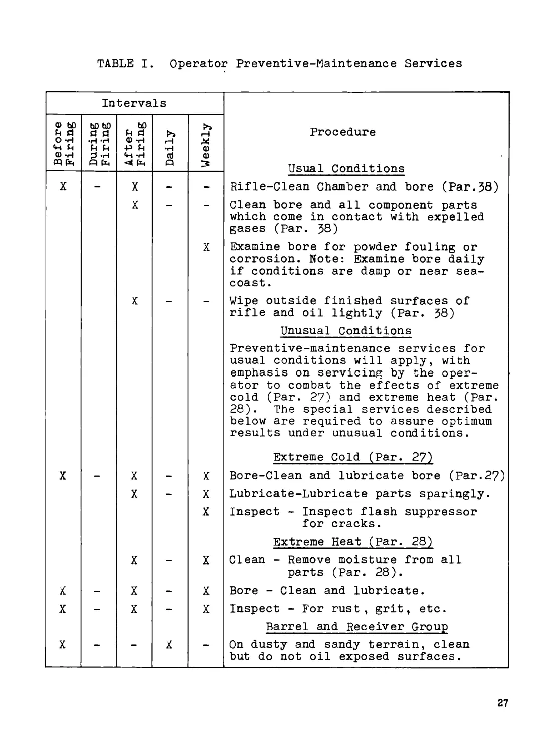
TABLE I. Operator Preventive-Maintenance Services
Intervals
<D ьо й a ьо bO d a b0 й a >5 >5 Procedure
O -H <D *H
«И Й Й Й P Й 0)
0) -H 3 -H «Н -H cd 0)
pq fq Q fq fq Q Usual Conditions Rifle-Clean Chamber and bore (Par.58)
X — X — —
X — — Clean bore and all component parts which come in contact with expelled gases (Par. 58)
X Examine bore for powder fouling or corrosion. Note: Examine bore daily if conditions are damp or near sea- coast .
X - - Wipe outside finished surfaces of rifle and oil lightly (Par. 58)
Unusual Conditions
Preventive-maintenance services for usual conditions will apply, with emphasis on servicing by the oper- ator to combat the effects of extreme cold (Par. 27) and extreme heat (Par. 28). The special services described below are required to assure optimum results under unusual conditions.
Extreme Cold (Par. 27)
X — X — X Bore-Clean and lubricate bore (Par.27)
X — X Lubricate-Lubricate parts sparingly.
X Inspect - Inspect flash suppressor
for cracks.
Extreme Heat (Par. 28)
X — X Clean - Remove moisture from all
parts (Par. 28).
X — X — X Bore - Clean and lubricate.
X — X — X Inspect - For rust, grit, etc.
Barrel and Receiver Group
X — — X — On dusty and sandy terrain, clean but do not oil exposed surfaces.
27
TABLE II. Operator Preventive-Maintenance Services
Intervals
0 <4 j <> & Procedure
X X X X X X — — Usual Conditions Barrel and Receiver Group - Check for unusual wear, erosion, and dam- age to bore. Check rear sight group for functioning; check operating and assembly and guide for proper fitting. Stock and Handguard Group - Check for cracks and proper fitting. Bolt Group - Check for damaged fir- ing pin and function. Check locking rollers, extractor, and ejector for proper functioning. Perform bolt space dimension check. Firing Mechanism - Check for proper functioning of safety. Magazine catch must hold magazine in rifle. Lubricate - Check that all items have been properly lubricated. Equipment - See that equipment and tools are complete, serviceable, and clean. Unusual Conditions Maintenance operations, as prescribed under usual conditions, will apply under unusual conditions except for extreme cold weather. Intervals are shortened in extreme cold weather.
28
Section IV. TROUBLESHOOTING
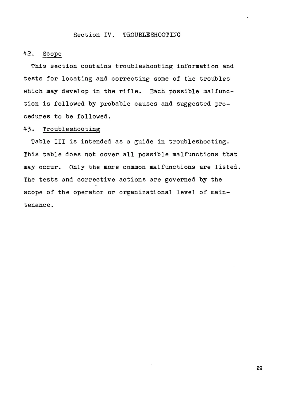
42. Scope
This section contains troubleshooting information and
tests for locating and correcting some of the troubles
which may develop in the rifle. Each possible malfunc-
tion is followed by probable causes and suggested pro-
cedures to be followed.
43. Troubleshooting
Table III is intended as a guide in troubleshooting.
This table does not cover all possible malfunctions that
may occur. Only the more common malfunctions are listed.
The tests and corrective actions are governed by the
scope of the operator or organizational level of main-
tenance.
29
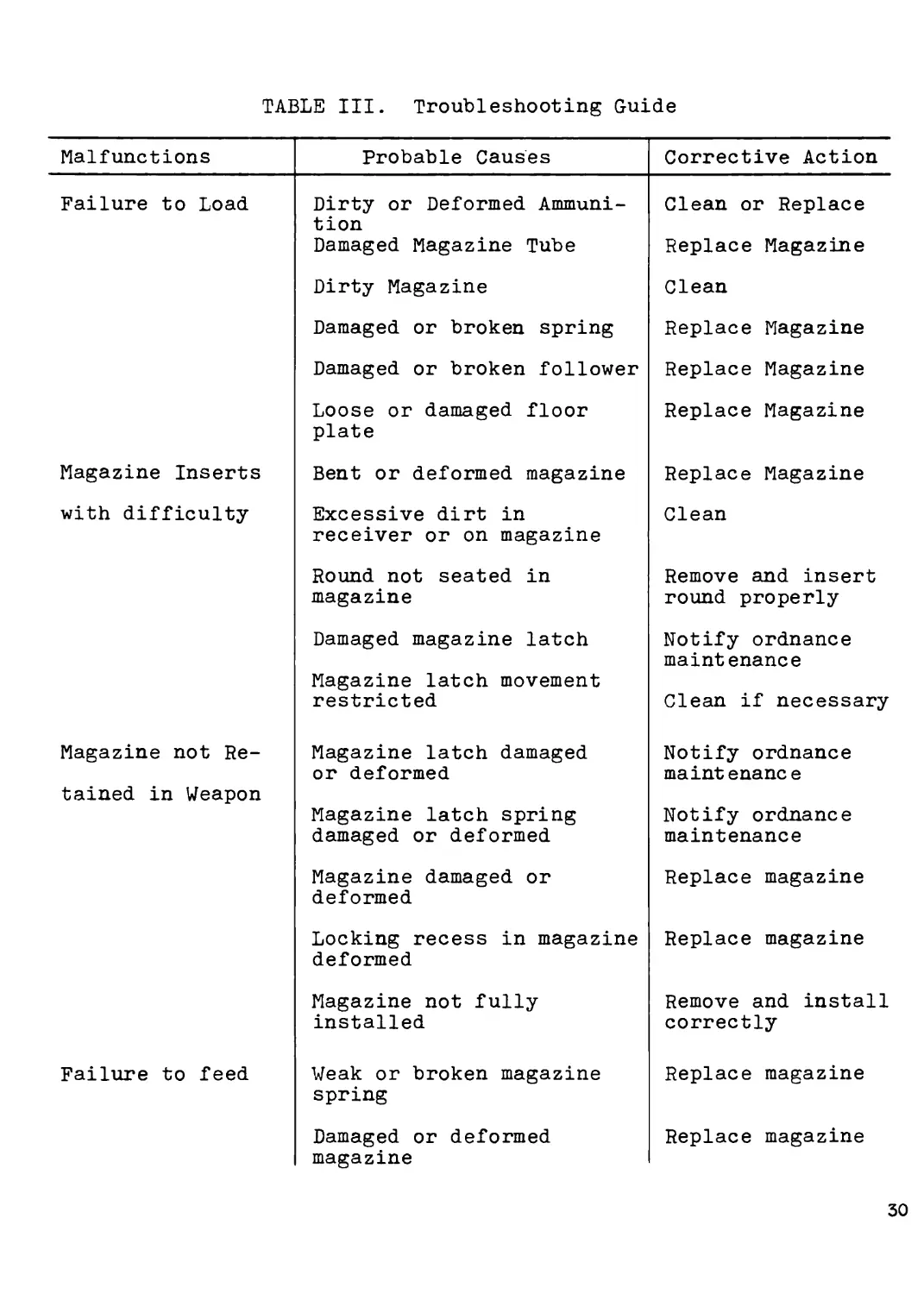
TABLE III. Troubleshooting Guide
Malfunctions Probable Causes
Failure to Load Dirty or Deformed Ammuni- tion Damaged Magazine Tube Dirty Magazine Damaged or broken spring Damaged or broken follower Loose or damaged floor plate
Magazine Inserts Bent or deformed magazine
with difficulty Excessive dirt in receiver or on magazine Round not seated in magazine Damaged magazine latch Magazine latch movement restricted
Magazine not Re- tained in Weapon Magazine latch damaged or deformed Magazine latch spring damaged or deformed Magazine damaged or deformed Locking recess in magazine deformed Magazine not fully installed
Failure to feed Weak or broken magazine spring Damaged or deformed magazine
Corrective Action
Clean or Replace
Replace Magazine
Clean
Replace Magazine
Replace Magazine
Replace Magazine
Replace Magazine
Clean
Remove and insert
round properly
Notify ordnance
maintenance
Clean if necessary
Notify ordnance
maintenance
Notify ordnance
maintenance
Replace magazine
Replace magazine
Remove and install
correctly
Replace magazine
Replace magazine
30
TABLE III. Troubleshooting Guide
Malfunctions Probable Causes Corrective Action
Failure to Feed Bolt Fails to close tightly Failure to fire Short Recoil Short Round Dirty Ammunition and/or magazine Weak or Broken Recoil Spring Cartridge case holding bolt out of battery Dirty or Rusty Chamber Extractor does not snap over rim of cartridge base Bolt not fully engaged in breech of barrel Weak or broken Recoil Spring Insufficient Headspace Safety engaged Bolt not fully for- ward and locked Defective Ammunition Firing pin worn, dam- aged or movement restricted Weak or broken hammer spring (See "Short Recoil") Remove Round Clean as required Replace Spring Hold bolt to rear and remove deformed cart- ridge. Clean ammuni- tion and/or barrel chamber Clean barrel and chamber Clean bolt assembly and extractor recess in breech face of barrel. Replace worn extractor and/or spring assembly. Remove burrs or foreign substances restricting bolt movement. Replace spring Notify ordnance maintenance Release safety (See "Bolt fails to close tightly") Follow procedures for misfires, etc.(Par.21) Clean bolt as required or replace firing pin. Replace spring
31
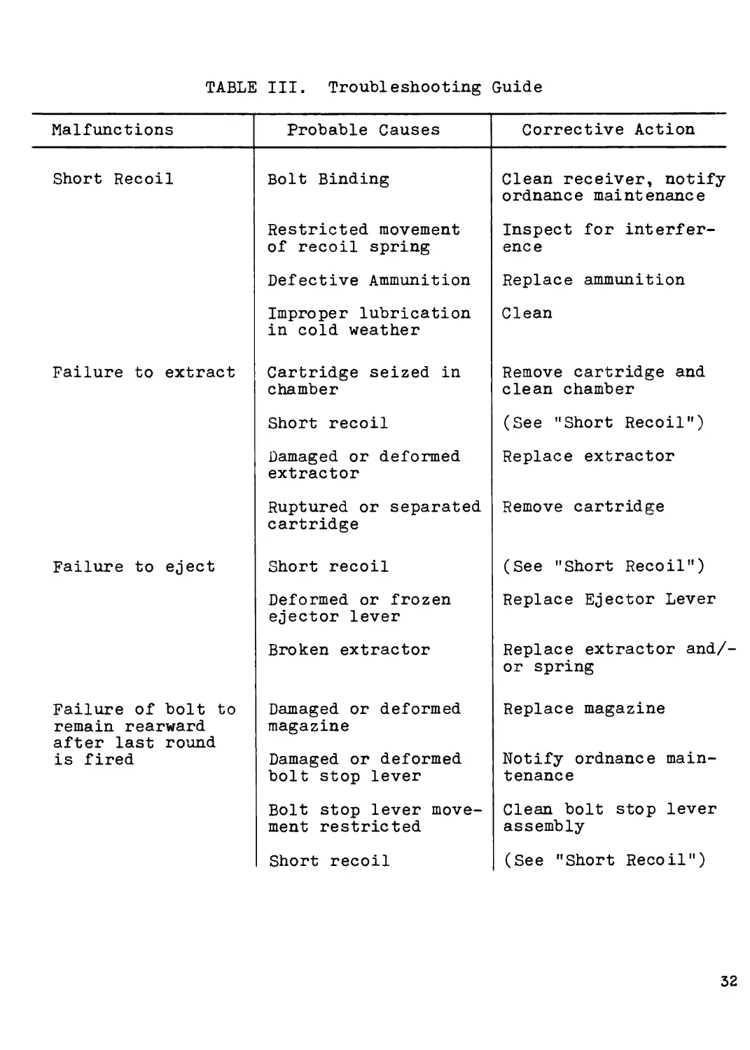
TABLE III. Troubleshooting Guide
Malfunctions Probable Causes Corrective Action
Short Recoil Failure to extract Failure to eject Failure of bolt to remain rearward after last round is fired Bolt Binding Restricted movement of recoil spring Defective Ammunition Improper lubrication in cold weather Cartridge seized in chamber Short recoil Damaged or deformed extractor Ruptured or separated cartridge Short recoil Deformed or frozen ejector lever Broken extractor Damaged or deformed magazine Damaged or deformed bolt stop lever Bolt stop lever move- ment restricted Short recoil Clean receiver, notify ordnance maintenance Inspect for interfer- ence Replace ammunition Clean Remove cartridge and clean chamber (See "Short Recoil") Replace extractor Remove cartridge (See "Short Recoil") Replace Ejector Lever Replace extractor and/ or spring Replace magazine Notify ordnance main- tenance Clean bolt stop lever assembly (See "Short Recoil")
32
Section V. MAINTENANCE OF RIFLE
44. Disassembly
a. Disassembly of the rifle T223 can be accomplished
without the use of tools. Using a cartridge or bayonet,
all major assemblies can be disassembled for purposes
of cleaning, inspection and repair. Fig. 6 illustrates
the field disassembly of the major component groups in
their relative position in the rifle.
b. Field disassembly, as illustrated, can be accom-
plished by hand removal of three snap pins located (1)
at the base of the forward portion of the butt stock,
(2) immediately in front of the trigger guard, and (5)
through the forward part of the hand guard below the
front sight. The bipod is removed as indicated in Par.14.
Barrel and Receiver Assembly
Firing Mechanism
Fig. 6 Major Components Diagram
33
c. Removal of the snap pin located in the forward
portion of the butt stock will allow removal to the bolt
assembly and access to the receiver, chamber and barrel
for cleaning purposes.
d. The magazine is released as described in Par. 25-
e. Reassembly is accomplished by reversing above.
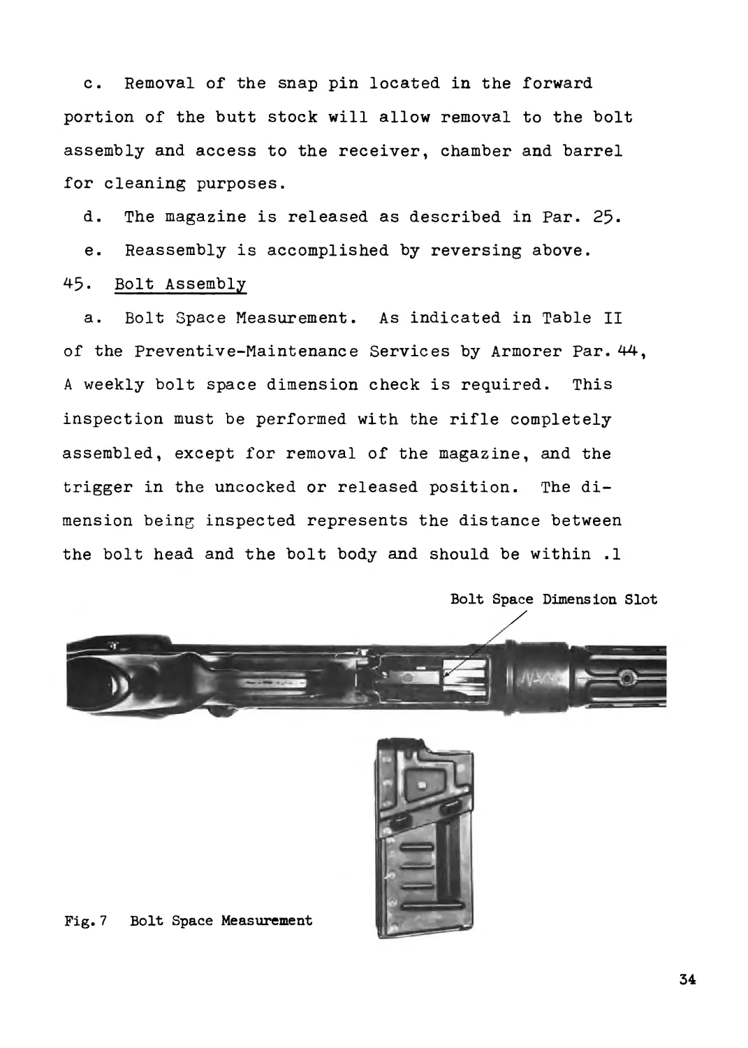
45. Bolt Assembly
a. Bolt Space Measurement. As indicated in Table II
of the Preventive-Maintenance Services by Armorer Par. 44,
A weekly bolt space dimension check is required. This
inspection must be performed with the rifle completely
assembled, except for removal of the magazine, and the
trigger in the uncocked or released position. The di-
mension being inspected represents the distance between
the bolt head and the bolt body and should be within .1
Bolt Space Dimension Slot
Fig. 7 Bolt Space Measurement
34
mm to .5 mm or .004 to .020. A tool, calibrated in
millimeters, is provided with each rifle; however, any
standard feeler gauge is satisfactory. The dimension
is measured through the magazine well as illustrated in
Fig. 7* Care should be exercised that the rifle is com-
pletely assembled and uncocked prior to measurement.
b. The bolt assembly (Fig. 8) consists of bolt head,
bolt body, recoil spring assembly, firing pin, firing pin
spring, locking piece, locking roller assembly, and ex-
tractor assembly. The bolt is removed by detaching the
butt stock and sliding the assembly out the rear of the
receiver. Disassembly is accomplished by rotating the
bolt head counter-clockwise (looking at the bolt face)
one quarter turn and separating. This will allow access
to the firing pin, firing pin spring and locking piece
for cleaning, inspection and repair or replacement of
these components.
Fig.8 Bolt Assembly
35
c. Assembly of the bolt components is the reverse of
disassembly. After inserting the firing pin and spring,
the locking piece is aligned with the bolt body,
compressed and rotated one half turn clockwise. The
bolt head is aligned with and inserted over the locking
piece, allowing about 1/4 inch between bolt head and
bolt body, and rotated one quarter turn clockwise. This
will secure the entire bolt assembly, and allow the lock-
ing rollers to be retracted into the bolt head for in-
sertion into the receiver. If the locking rollers cannot
be retracted into the bolt head, disassembly and reassem-
bly allowing maximum space (approx. 1/4 inch) between the
bolt head and the bolt body is recommended.
46. Butt Stock and Hand Guard Assembly
Disassembly of the butt stock and hand guard assembly
(see Fig. 6) is accomplished as indicated in Par. 44.
The butt stock assembly is equipped with a recoil buffer
assembly and sling loop assembly which are integral with
the stock.
47. Barrel and Receiver Group
The barrel and receiver group (see Fig. 6) are integral
components press fitted and pinned. Disassembly of the
rifle as indicated in Par. 44 will provide the barrel
and receiver group for cleaning and inspection purposes.
Care should be exercised in cleaning the receiver so that
the recesses provided for the rollers are not damaged in
36
any way. Similarly for maximum efficiency and' trouble-
free operation, care should be exercised in cleaning the
gas grooves in the chamber of the barrel. The chamber
cleaning brush provided should always be used, and
cleaning should be thorough.
48. Firing Mechanism
The firing mechanism (Fig. 9) consists of the selector,
bolt stop release, ejector, disconnector, hammer, bolt
stop lever and trigger. Removal of this assembly from
Fig. 9 Firing Mechanism
37
the rifle is accomplished by removal of the two snap
pins, one in the forward portion of the butt stock and
the other just forward of the trigger guard. The firing
mechanism housing is removed by turning the selector one
quarter turn counter-clockwise past the safety position
and removing. Manipulation of the trigger and bolt re-
lease lever will permit removal of the housing. Further
disassembly of the individual components is accomplished
by pressing out the three pins exposed after removal of
the housing. Care should be exercised in removing the
various components in order that reassembly can be accom-
plished by reversing the order of disassembly. Disassem-
bly of the individual components of the firing mechanism
for inspection or repair should be done by second echelon
maintenance personnel.
49. Magazine Assembly
The magazine assembly consists of the tube, base,
spring and follower. The magazine is removed from the
rifle by squeezing the magazine release lever (Fig. 1).
The magazine should be cleaned in order to remove excess
dirt, oil, and grease. To install magazine in rifle,
insert magazine into well at bottom of receiver. Make
certain latch clicks and magazine is firmly locked in
rifle.
38
Section VI. MAINTENANCE OF BIPOD
50. The bipod provided with the rifle requires only
normal maintenance and cleaning. Maintenance at inter-
vals similar to the other exposed metal components of
the rifle should be sufficient. Care should be exer-
cised to avoid getting sand, dirt and gritf in the
retracting mechanism of the bipod legs.
CHAPTER 4
MAINTENANCE UNDER UNUSUAL CONDITIONS
51. Extreme Cold-Weather Maintenance
Refer to Paragraph 27 for information on extreme cold-
weather maintenance.
52. Extreme Hot-Weather Maintenance
a. Corrosive or deteriorating action on all parts of
the rifle may occur and be accelerated in areas having
hot damp climates. Evidence will appear in the form of
rust on metal surfaces and mildew on the sling.
b. Protect uncoated exposed metal surfaces with general
purpose lubricating oil.
c. Make frequent inspections of inactive weapons. Re-
move corrosion from exterior surfaces with Crocus Cloth
and apply a protective coating of oil.
55* Maintenance After Immersion
a. General. Immersion of any type will result in
39
water seepage into bolt and trigger groups, receiver and
operating rod assembly. It is advisable, therefore, that
the service outlined in (b) below be accomplished on all
weapons which have been immersed or completely submerged
in water, especially in salt water, and that precautions
outlined in (1) through (5) below be taken as soon as
practicable to halt deterioration and avoid damage to
the weapon.
(1) After submersion in salt water,
wash in clear water, to remove
corrosive salts.
(2) Perform a complete lubrication
service (Par. 54).
(5) Assemblies which require disassembly
for proper lubrication must be dis-
assembled, dried, and lubricated
as soon as the situation permits.
b. Cleaning and lubrication. Drain or wipe dry all
trapped moisture. Clean all exposed parts and coat
with a film of lubricating oil.
CHAPTER 5
DEMOLITION OF RIFLE TO PREVENT ENEMY USE
54. General
Destruction of the 5*56 mm Rifle T225, when subject to
capture or abandonment in the combat zone, will be under-
40
taken by the using arm only when, in the judgment of the
unit commander concerned, such action is necessary in
accordance with orders of, or policy established by, the
Army Commander.
55- Method of Destruction - If destruction to prevent
enemy use is resorted to, the rifle must be so badly dam-
aged that it cannot be restored to usable condition in
the combat zone either by repair or cannibalization.
a. Method No. 1 - by Mechanical Means. Using an ax,
pick mattock, sledge, or other heavy implement, destroy
the rifle by smashing the receiver assembly, front and
rear sights, trigger and trigger guard, magazine, stock,
and controls. Also bend the barrel of the rifle and cut
the sling into several pieces.
b. Method No. 2 - by Burning
(1) Place the rifle on a suitable pile
of combustible material. Pour gas-
oline or oil over the rifle and the
combustible material. Ignite and
take cover. A hot fire is required
to render the rifle useless.
(2) If a welding or cutting torch is
available, burn through the barrel
and receiver assembly. Destroy
the stock and sling as described
in (a) above.
41
c. Method No. 3 - by Disposal. Bury the rifle in a
suitable hole or dump it into a stream.
APPENDIX I
Basic Issue Items, Major Items, Components of Major
Items, Repair Parts and Equipment.
1. Preface
a. This Appendix provides a listing of the Basic
Issue Items, Major Items, Components of Major Items,
Repair Parts, Tools and Equipment required for opera-
tion and maintenance of the 5-56 mm Rifle T223-
2. Basic Issue Items
a. Rifle T223 with 20 Round Magazine
b. 3 Spare 20 Round Magazines
c. Bipod with Case
d. Bayonet with Case
e. Webbed Sling
f. Preliminary Operating and Maintenance- Manual
3. Major Items and Components - Rifle T223
a. Stock and Handguard Group
Recoil Buffer Assembly
Butt and Front Sling Loops
b. Barrel and Receiver Group
Operating Rod Assembly
Rear Sight Assembly
Front Sight
42
Flash Suppressor
Magazine Release Assembly-
Bolt Stop Actuator Assembly
c. Bolt Assembly
Bolt Head
Bolt Body
Firing Pin Assembly-
Extractor Assembly
Locking Lever Assembly
Locking Roller Assembly
d. Firing Mechanism
Trigger Assembly
Ejector
Hammer
Disconnector
Bolt Stop Assembly
Selector
Safety-
в. Magazine Assembly
f. Bipod Assembly
4. Repair Parts
a. Extractor
b. Extractor Spring
c. Firing Pin
d. Firing Pin Spring
e. Locking Rollers
f. Locking Lever
g. Locking Lever Spring
h. Holding Plate for Locking Rollers
i. Clamping Sleeve
j. Takedown Locking Pin Small
k. Takedown Locking Pin Large
1. Hammer
m. Release Lever
n. Bolt Space Measurement Tool
o. Ejector Lever
5. Tools and Equipment
a. Chamber Cleaning Rod
b. Chamber Brush
c. Sight Adjustment Tool
d. Bolt Space Measurement Tool
44
APPENDIX II
MAINTENANCE ALLOCATION CHART
1. Purpose To allocate specific maintenance operations
to the proper echelon on the basis of time, tools, and
skills normally available to these echelons. The main-
tenance function, for purposes of this manual, will be
performed by either (1) First Echelon - operator - or
(2) Second Echelon - armorer - personnel.
MAINTENANCE ALLOCATION CHART
Group No. Functional Group Maintenance Function Tools & Equipment
Inspect Test Г Service | | Adjust 1 d ьо H <! | Calibrate | 1 Install 1 | Replace | | Repair | | Overhaul | | Rebuild 1
1. Magazine Assembly 1 1 2 2 2 2 1 1 2 2 2
2. Firing Mechanism 1 1 2 2 2 2 1 1 2 2 2
5- Stock and Hand- guard Group 1 1 2 2 2 2 1 1 2 2 2
4. Operating Rod Assembly 1 1 2 2 2 2 2 2 2 2 2
5. Bolt Assembly 1 1 2 2 2 2 1 1 2 2 2 Bolt Space Dimension Tool
6. Barrel and Receiver Group 1 1 2 2 2 2 2 2 2 2 2 Sight Adjust- ing Tool Chamber Clean- ing Rod and Brush
45
APPENDIX III
ORGANIZATIONAL MAINTENANCE REPAIR PARTS
AND
SPECIAL TOOL LIST
Section I.
Preface This section includes a preliminary list of
repair parts and special tools required for the main-
tenance of the 5-% mm Rifle T223- The list is broken
down by component groups and assemblies, and includes
the specific spare parts listed in Appendix I and pro-
vided with the rifle.
Section II.
Repair Parts for Rifle and Bipod
1) Magazine Assembly
Magazine Tube
Spring
Follower
Floor Plate
2) Firing Mechanism
Grip Assembly
Trigger Guard Snap Pin
Selector Lever
Trigger Assembly Complete
Ejector Pin
Ejector Pin Retaining Ring
Ejector Lever
U6
Ejector Spring
Trigger
Trigger Spring
Trigger and Catch Pins
Sear
Sear Pin
Sear Spring
Sear Roll Pin
Hammer
Hammer Pin
Hammer Shank
Hammer Spring
Disconnector Lever
Disconnector Catch
Catch Spring
Bolt Stop Lever
Bolt Stop Spring
5) Butt Stock and Hand Guard Assembly-
Butt Stock Assembly
Butt Stock Snap Pin
Buffer Assembly-
Sling Loop Assembly-
Hand Guard
Hand Guard Snap Pin
U7
4) Barrel and Receiver Group
Receiver
Barrel
Barrel Pin
Barrel Snap Ring
Operating Rod Assembly
Operating Rod Tube
Operating Rod Handle
Operating Rod Spring
Operating Rod Pin
Operating Rod Stop Pin
Rear Sight Assembly
Rear Sight Cylinder
Rear Sight Support
Catch Pins
Catch Pin Springs
Adjusting Screw
Indexing Ball
Indexing Ball Spring
Locking Screw and Washer
Spring Washer
Front Sight Assembly
Front Sight Holder
Front Sight Post
Roll Pin
48
Eye Bolt
Bayonet Adapter
Adapter Plunger
Adapter Spring
Set Screw
Flash Suppressor Assembly
Flash Suppressor Retaining Ring
Magazine Release Lever
Magazine Release Bushing
Magazine Release Spring
Magazine Catch
Magazine Catch Cam
Magazine Catch Lock
Roll Pin
Bolt Stop Actuator
Actuator Spring
Actuator Spring Cap
5) Bolt Assembly
Bolt Body
Locking Lever
Locking Lever Spring
Locking Lever Pin
Bolt Head
Extractor
Extractor Spring
Locking Rollers
49
Locking Roller Holding Plate
Roll Pin
Locking Piece
Firing Pin
Firing Pin Spring
6) Bipod
Bipod Collar
Locking Latch
Latch Spring
Latch Pin
Bipod Legs
Leg Screws
Lock Nuts
Retracting Sleeve
Sleeve Pins
Retracting Rollers
Roller Holders
Tools and Equipment
Bolt Space Dimension Tool
Sight Adjusting Tool
Chamber Brush
Chamber Cleaning Rod
50