/
Теги: weapons military affairs
Год: 1944
Похожие


Текст
WAR tEPARTMEHT TECHNICAL MANUAL
NON-CIRCULATING
\ • « • •
HARMONIZATION OF
AIRCRAFT FIXED GUNS
AND SIGHTS
WAR DEPARTMENT
11 AUGUST 1944
WAR DEPARTMENT TECHNICAL MANUAL
TM 1-495
THIS MANUAL SUPERSEDES TM 1-49S, AIRCRAFT MACHINE-GUN SIGHTS, 26 MARCH 1961
HARMONIZATION OF
AIRCRAFT FIXED GUNS
AND SIGHTS
WAR DEPARTMENT
11 AUGUST 1944
United States Government Printing Office
Washington : 1944
For sale by the Superintendent of Documents, U* S. Government Printing Office 25, Washington, D. C.
Price 10 cents
WAR DEPARTMENT,
Washington 25, D. C., 11 August 1944.
TM 1-495, Harmonization of Aircraft Fixed Guns and Sights, is pub-
lished for the information and guidance of all concerned.
[A. G. 300.7 (13 Jul44).]
By order of the Secretary of War:
G. G. MARSHALL,
Chief of Staff.
Official:
J. A. ULIO,
Major General,
The Adjutant General.
Distribution :
As prescribed in paragraph 9a, FM 21-6:
Annies (10); Sv C (10); Depts (10); Base Comds (5); T of Opn
(5); AAF Schools (2).
For explanation of symbols, see FM 21-6.
Ill
CONTENTS
SECTION I. GENERAL Paragraph
Purpose......................................... 1
Scope........................................... 2
Definition of terms............................. 3
SECTION II. FUNDAMENTALS
Factors making sights necessary................................ 4
Factors affecting path of a projectile.......... 5
Sights.......................................... 6
Harmonization................................... 7
Page
1
1
1
3
3
5
7
SECTION III. STANDARD HARMONIZATION PROCEDURE
General 8
Harmonization—Fixed guns 9
Harmonization range 10
Placing airplane in flying position Lateral leveling of airplane 11 12
Attaching plumb bobs 13
Horizontal sight line 14
Aligning the aiming point of the sight 15
Adjustment of guns 16
Alignment of the gun camera 17
12
12
12
13
13
14
14
14
14
15
SECTION IV. FIXED GUN SIGHTS, OPTICAL SERIES
General........................................................... 18
Description....................................... 19
Operation......................................... 20
Installation and alignment........................ 21
Adjustment of sight............................... 22
Difference between the optical sights............. 23
Inspection and maintenance........................ 24
Protection from excessive sunlight................ 25
Painting of gun-sight name plates................. 26
Light and moisture proofing....................... 27
Reference......................................... 28
16
16
16
17
18
19
19
20
20
21
21
INDEX.................................................
22
V
This manual supersedes TM l-&5> Aircraft Machine-gun Sights, 26 March ВЦ
SECTION I
GENERAL
1. PURPOSE. This manual is intended to serve as a handbook for the
training of, and subsequently for the field use of, aircraft armorers. It
relates to the harmonization of gun sights on aircraft and includes the basic
fundamentals considered necessary for personnel to obtain a full under-
standing of the subject. It also aids them in the solution of common prob-
lems that arise both in peacetime training arid military operations, not only
in keeping equipment in proper condition, but also in effectively using
aircraft gun sights.
2. SCOPE. This manual includes the fundamentals underlying function-
ing and use of aircraft gun sights; trajectory of projectiles; use of mil angles;
detailed description of aircraft gun sights; harmonization of aircraft guns
and sights; bore sighting; and standard types of fixed gun sights.
3. DEFINITION OF TERMS. The following are definitions of some of the
more common terms used in this manual:
Aerial target. A target located in the air.
Bore axis. An imaginary line drawn through the exact center of the bore
of a gun extending from the breech to the muzzle of the barrel and carried
forward to any desired range.
Bore sighting. The process of aligning the gun so that the bore axis inter-
sects the bore-sight target at the proper point. Position of the axis on
the target is determined by sighting through the bore or by means of a
bore-sight tool.
Bore-sight target. An object at which the guns and sight are aimed during
the process of harmonization.
Bore-sight tool. An instrument used to aid in looking along the bore axis.
Bullet drop. The vertical distance a bullet falls below the line of bore dur-
ing its flight.
Deflection. The angle between the bore axis and the line from the bore
axis at the muzzle to the bullet.
Fixed gun mounts. The parts and appliances by which a gun is rigidly
attached to an airplane.
Gun-bore reflector and plug. A gun-bore reflector is an instrument which
will change the line of sight or cause it to be reflected at an angle of 90°
from its original direction. The gun-bore reflector plug is a round device
which has a very small hole drilled through its longer axis to permit the
1
passage of light. The gun-bore reflector plug is used in conjunction
with the bore-sight tool and assists the armorer in bore sighting a gun by
partially eliminating the glare from the lands and grooves of the bore.
It also compels the armorer to hold his eye closer to the axis of bore and
consequently gives more accurate bore sighting.
Harmonization. The alignment of the guns in relation to the sight so as
to cause the line of sight and the trajectories of all the projectiles to inter-
sect at the desired range.
Lead. The distance the gunner must aim ahead of the target in order to
hit the target.
Mil. An angle equal to 1/6400 of a circle.
Muzzle velocity. The speed in relation to the gun at which the projectile
is moving when it leaves the muzzle or the forward end of a gun barrel.
Parallax. In the optical sights the apparent movement or displacement of
the image of a target when the eye is moved across the field of vision of
the sight. Parallax is caused by a maladjustment of the lens assembly
and/or lack of parallelism or excessive departure from a plane in the sur-
faces of the reflector.
Range. The distance from the muzzle of the gun, at the instant the projec-
tile is fired, to the intended point of impact on the target.
Sight. A device used to establish a line of sight to aid in aiming a gun»
T ar get. An object which is to be fired upon.
Tiihe of flight. The time required for the bullet to travel from the gun to
the target or to a given distance from the gun.
Trajectory. The path described by the center of gravity of the projectile in
its flight through space.
Vertical deflection. The deflection measured in the vertical plane contain-
ing the projection of the bore axis.
2
SECTION II
FUNDAMENTALS
4. FACTORS MAKING SIGHTS NECESSARY, a. The pttot has many sight-
ing problems with which to contend in addition to physical difficulties en-
countered in operating his weapon from a rapidly maneuvering airplane.
He should be ready and able to take immediate advantage of any type target,
and should be able to deliver accurate and effective fire upon that target.
b. The problems confronting the pilot are particularly complicated by
the fact that a projectile or bullet fired from a gun does not travel in a
straight line to the target. Forces acting on the bullet after it leaves the
gun cause it to assume a curved path known as the trajectory. If the gun
is in motion during the period the bullet is passing through the bore, an
additional velocity is imparted to the bullet and affects its trajectory. It
would be almost impossible to aim a gun without sights and make proper
allowances for the many factors which cause a bullet to deviate from a
straight line. The pilot must have some means for establishing a line of
sight which will compensate for these known factors.
c. Aircraft gun sights are designed to enable the pilot to fire with accuracy
under combat conditions. However, in order to use the sights effectively,
the pilot must have a thorough knowledge of the factors which affect the
trajectory or flight path of the bullet, the adjustments necessary to compen-
sate or correct for these factors, and the proper use of the various types
of sights.
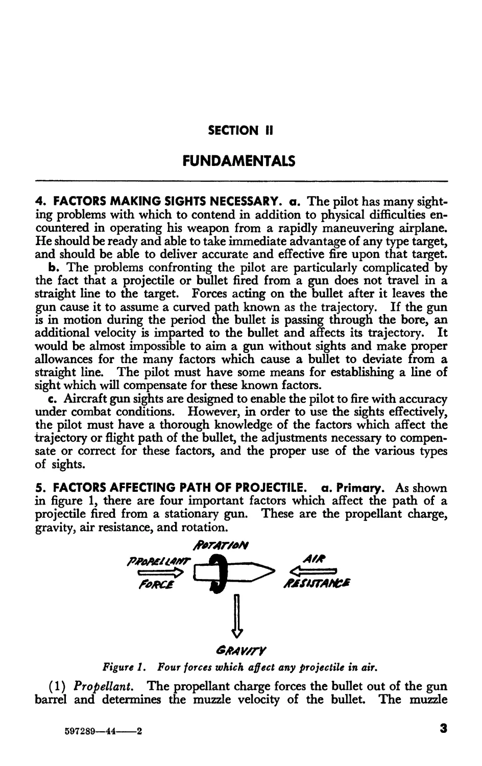
5. FACTORS AFFECTING PATH OF PROJECTILE, a. Primary. As shown
in figure 1, there are four important factors which affect the path of a
projectile fired from a stationary gun. These are the propellant charge,
gravity, air resistance, and rotation.
------MStfTANC*
4
6MWTY
Figure 1. Four forces which affect any projectile in air.
(1) Propellant. The propellant charge forces the bullet out of the gun
barrel and determines the muzzle velocity of the bullet. The muzzle
597289—44----2
3
velocity of the bullet fired from a new gun barrel is a little higher than that
of a bullet fired from a worn barrel. The muzzle velocity varies from one
round to another because of small variations in the powder charge, tempera-
ture, and other factors. However, these variations are small and the pilot
can consider the muzzle velocity the same for all ammunition of the same
type when fired from the same type of gun.
(2) Gravity, The force of gravity pulls the bullet downward at a con-
stantly increasing rate. As soon as the bullet leaves the gun, it begins to
fall. The amount of fall increases at a greater rate (as the square) of the
time the bullet is in flight. Consequently, as the range increases, the drop
greatly increases.
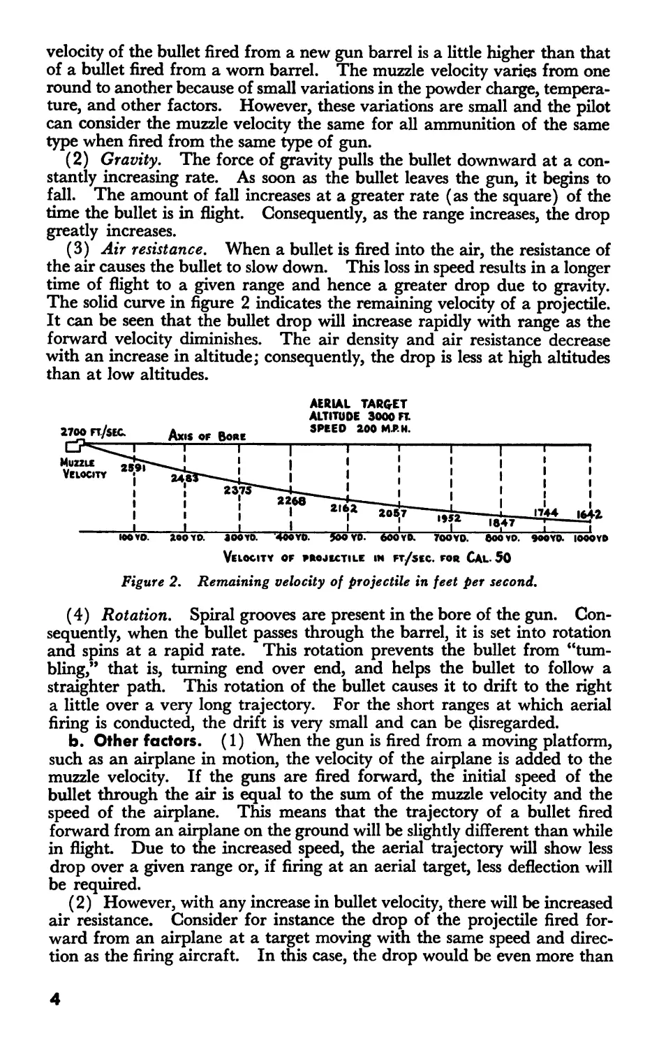
(3) Air resistance. When a bullet is fired into the air, the resistance of
the air causes the bullet to slow down. This loss in speed results in a longer
time of flight to a given range and hence a greater drop due to gravity.
The solid curve in figure 2 indicates the remaining velocity of a projectile.
It can be seen that the bullet drop will increase rapidly with range as the
forward velocity diminishes. The air density and air resistance decrease
with an increase in altitude; consequently, the drop is less at high altitudes
than at low altitudes.
AERIAL TARGET
ALTITUDE 3000 FT.
2700FT/SEG Ax.SorBo» 2°° М'Н’
I-----1-----T------1-----1-----1-----1-----1---1------I
I III
1 I I I I
I III
I I 1 I I
, —йп |7'44 4*
______|_____I______I_____I______I____I______I___lgr7 1____I
ioova 200 YO. 300YO. 4ooyo. 900 YO. 600 YO. 700YO. 600 YO. 9OOY0. I000Y0
Velocity of projectile in ft/sec. for Cal. 50
Figure 2. Remaining velocity of projectile in feet per second,
(4) Rotation, Spiral grooves are present in the bore of the gun. Con-
sequently, when the bullet passes through the barrel, it is set into rotation
and spins at a rapid rate. This rotation prevents the bullet from “tum-
bling,” that is, turning end over end, and helps the bullet to follow a
straighter path. This rotation of the bullet causes it to drift to the right
a little over a very long trajectory. For the short ranges at which aerial
firing is conducted, the drift is very small and can be disregarded.
b. Other factors. (1) When the gun is fired from a moving platform,
such as an airplane in motion, the velocity of the airplane is added to the
muzzle velocity. If the guns are fired forward, the initial speed of the
bullet through the air is equal to the sum of the muzzle velocity and the
speed of the airplane. This means that the trajectory of a bullet fired
forward from an airplane on the ground will be slightly different than while
in flight. Due to the increased speed, the aerial trajectory will show less
drop over a given range or, if firing at an aerial target, less deflection will
be required.
(2) However, with any increase in bullet velocity, there will be increased
air resistance. Consider for instance the drop of the projectile fired for-
ward from an airplane at a target moving with the same speed and direc-
tion as the firing aircraft. In this case, the drop would be even more than
4
the drop of the ground trajectory over the distance measured between the
aircraft due to the increased resistance. In fact, in this situation, the drop
will increase with an increase of airspeed of the target and firing aircraft.
c. Example. (1) For purposes of illustration and clarity, it is advisable
to consider separately the effects of the movement of the airplane upon the
trajectory of a bullet. However, since there are always four or more factors
affecting the bullet simultaneously, it will be found very difficult to isolate
any one factor and attempt to devise means of correcting for that one
factor without taking all the others into consideration. It must be remem-
bered that the effects of the movement of the airplane are added to the ef-
fects of the four primary forces discussed in a above and shown in figure 1.
(2) Take, for example, the case of a gun fired forward parallel with the
flight line of the airplane on which the gun is mounted. The speed of the
bullet is increased by the speed of the airplane. Ground fire tables show
that a caliber .50 М2 projectile fired horizontally from a stationary Browning
machine gun will drop 26.1 inches at an actual range of 300 yards. The
muzzle velocity is 2,700 feet per second. If the gun is fired forward when
mounted on an airplane flying 400 miles per hour true air speed, then it
will be found that the same projectile drops approximately 14.6 inches when
it has traveled to 300 yards from the point of firing. The bullet leaves the
gun at the same velocity as when fired from a stationary base, but its speed
in relation to the ground has been increased by 400 miles per hour or
approximately 600 feet per second. For purposes of sighting, it may be
considered that initial velocity of the bullet has been increased from 2,700
feet per second to 2,700 plus 600 or 3,300 feet per second. The difference
in drop is due principally to the fact that the bullet fired forward from the
airplane covered the range of 300 yards in less time than the bullet fired
from a stationary gun. The bullet fired from the airplane was not exposed
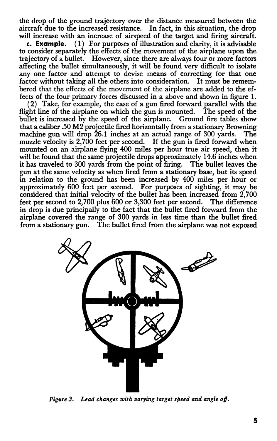
Figure 3. Lead changes with varying target speed and angle off.
5
to the force of gravity for so long a period of time. As a result, it was
not pulled toward the earth as great a vertical distance.
6. SIGHTS, a. General. (1) An ideal sight for fixed aircraft machine
guns would correct automatically—by mechanical, electrical, or optical
means—for all the factors which affect a bullet in flight when fired from
a flying aircraft. • In addition, it should correct for the movement of the
target. The perfect sight would insure hits on any target, regardless of gun,
target speed, or direction, as long as the pilot held the sights on the target.
With available sights, it is essential that the pilot, in using his sight, also use
his experience and knowledge of gunnery.
(2) The various ring sights, generally used as rear sights, correct for the
speed of the target, the approximate range and speed of which must be
known in order to select correctly the size of the ring to be used. But again
the pilot must apply his knowledge of trajectories and ability to estimate
ranges and speeds in order to fire effectively. If the target were always in
the same position to the airplane on which the gun is mounted, the pilot
would have definite reference points and could fire with great accuracy.
However, the target may be in any position—above, below, or on either side
of the airplane (fig. 3)—and the speed of the target may be negligible or
it may move as swiftly as 400 miles an hour. This great speed would be
an important factor.
b. Types for fixed guns. Types of sights for fixed guns may be gen-
erally classified as ring-and-post or optical (reflex).
(1) Ring-and-post. The ring-and-post type sight consists essentially of
two reference points placed preferably at least 2 feet apart and attached to
the airplane in front of the pilot. The front sight may consist of a simple
bead or a modification thereof in the form of an upright or post. The usual
kind of rear sight is a ring of a size designed to correct for the deflection of
moving targets. The ring-and-post type sight makes it necessary for the
pilot to hold his eye steady while aligning the sight on the target. This is
often difficult, especially in rough air.
(2) Optical, (a) In the optical type sight, the mentioned disadvantage
of the ring-and-post type has been overcome and, in addition, the possibility
of obtaining a greater degree of accuracy in firing has been increased. The
basic principle of all optical sights is the projection of the image of a reticle
of some form out to infinity so that the pilot can aim by moving the sight
until the reticle appears to be properly positioned with respect to the target.
With this sight it is not necessary for the pilot to hold his eye very steady
at a fixed distance from the sight while lining up a pair of reference points
with the target. Because the reticle in an optical sight appears to be out
in space with the target airplane, all the pilot must do is to move the sight
by maneuvering the airplane until the reticle is properly related to the target.
The reticle size may be computed to serve as an aid in range estimation in
the same way as the inner ring and frame of a ring sight and also as an aid
in lead estimation in the same way as the outer ring and frame of a ring
sight. The projection of the reticle to infinity may be accomplished in
several ways. The net result is that the target and reticle appear to be at
the same distance from the gunner.
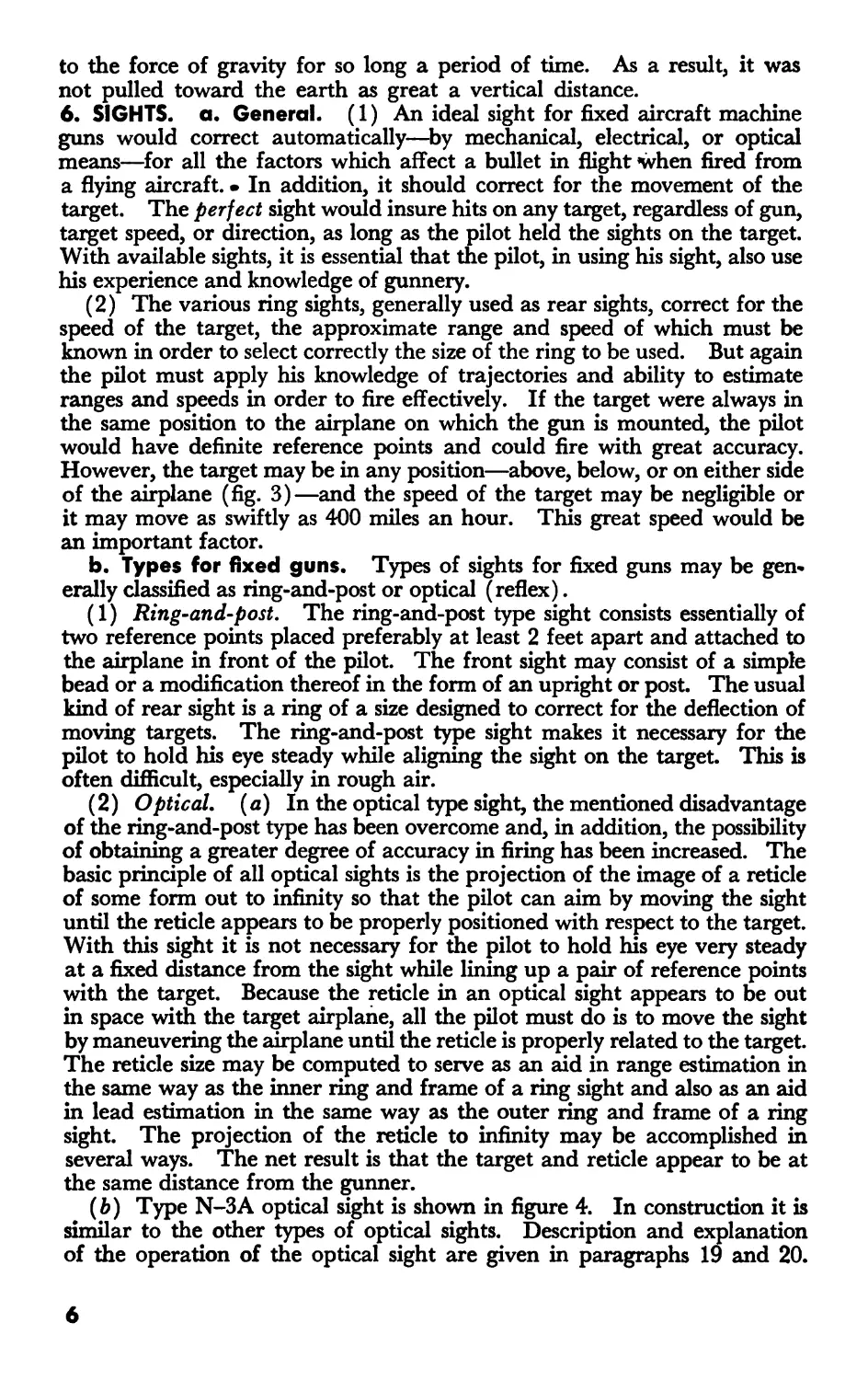
(b) Type N-3A optical sight is shown in figure 4. In construction it is
similar to the other types of optical sights. Description and explanation
of the operation of the optical sight are given in paragraphs 19 and 20.
6
Figure h. Optical eight N-SA.
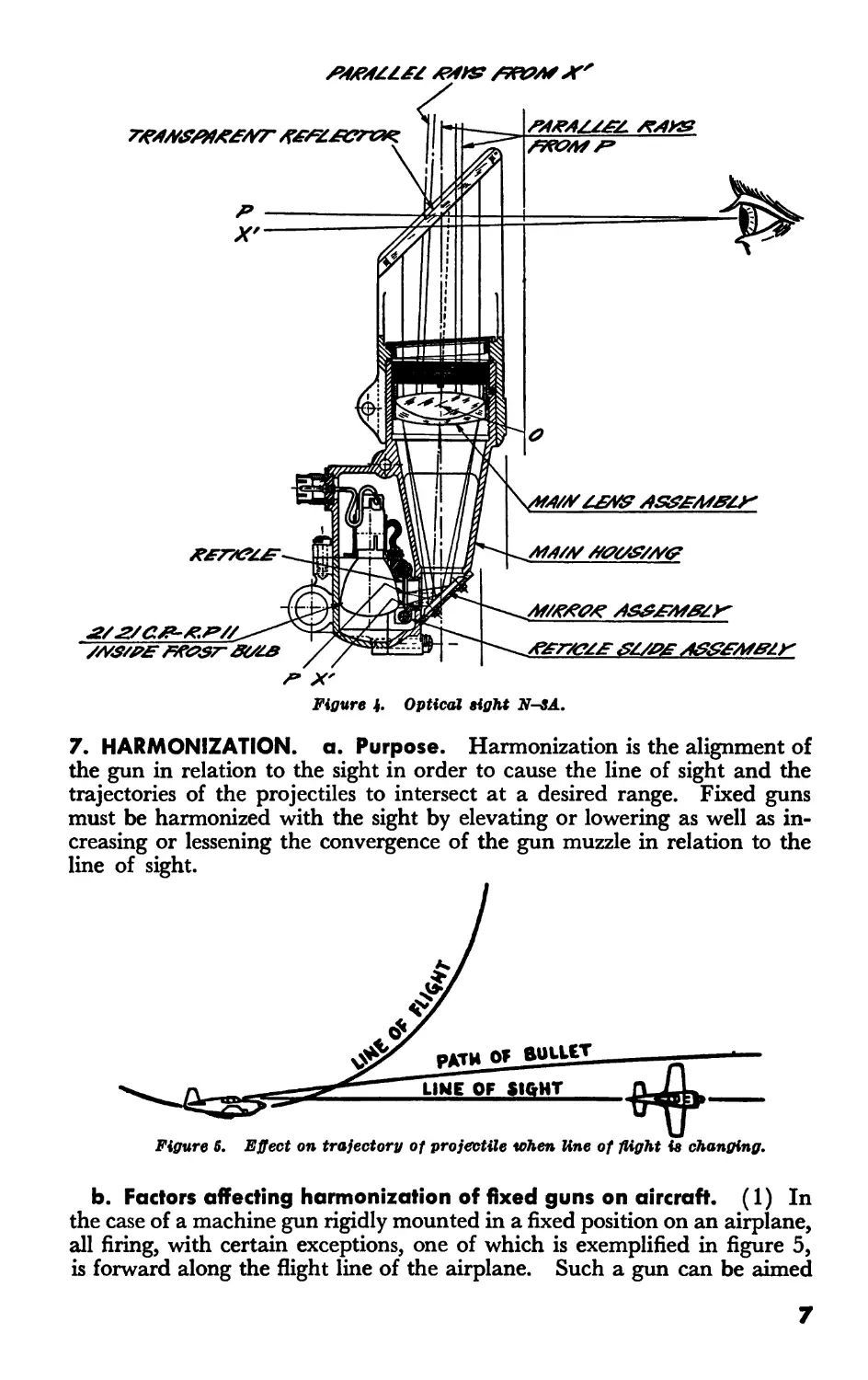
7. HARMONIZATION, a. Purpose. Harmonization is the alignment of
the gun in relation to the sight in order to cause the line of sight and the
trajectories of the projectiles to intersect at a desired range. Fixed guns
must be harmonized with the sight by elevating or lowering as well as in-
creasing or lessening the convergence of the gun muzzle in relation to the
line of sight.
Figure 5, Effect on trajectory of projectile when line of flight ie changing.
b. Factors affecting harmonization of fixed guns on aircraft. (1) In
the case of a machine gun rigidly mounted in a fixed position on an airplane,
all firing, with certain exceptions, one of which is exemplified in figure 5,
is forward along the flight line of the airplane. Such a gun can be aimed
7
only by moving or aiming the airplane in flight. Bullets fired from fixed
guns are subject to factors which are directly traceable to the flying ability
of the pilot. In order to aim the fixed gun, the pilot must have some system
of sights which will enable him to fly the airplane along the proper course
to direct the burst of bullets on the target. Because of the location of the
gun, frequently at some distance from the pilot, the sights cannot be mounted
on the gun but must be placed on the airplane in front of the pilot. The
distance between sights and guns may vary from a few inches to a few feet,
depending on the type of airplane. This separation of sights and gun com-
plicates the sighting problem, but careful harmonization will insure accuracy.
(2) It is necessary in studying factors affecting bullets fired from fixed
guns to consider the gun, sight, and airplane as a single unit. No change
that affects the relative positions of the gun, sight, and airplane can be made
without affecting the flight path of the bullet. The primary factors which
act upon all projectiles, such as gravity, air resistance, etc., are present and
affect the bullet fired from a fixed gun installed in an airplane in exactly
the same manner as they affect bullets fired from any other mount. Varia-
tions in the direction of the bullet path caused by the movement of the air-
plane must be taken into consideration, as exemplified in figure 5. In addi-
tion, the attitude in which the airplane is flown becomes a very important
factor affecting the accuracy of fire from fixed guns. Therefore, it is neces-
sary that the armorer know and understand certain flying characteristics of
the airplane before he can harmonize the sight and guns properly.
(3) Mounting the sight and guns on an airplane in such positions as will
cause the trajectory of the bullets to intersect the line of sight at a given
range is not sufficient harmonization to insure hitting the target consistently.
The pilot must be able to hold the sights on the target long enough to fire
an accurate, effective burst. If the sight indicates a line along which the
airplane cannot possibly be flown because of its design, it is impossible for
any pilot to fly an accurate coordinated course to the target or hold the sight
on the target long enough to insure an effective burst.
----
ANGLE ~ ~ LIME OF FLIGHT
VARIES WITH
AIR SPEED
altitude
AMD LOAD
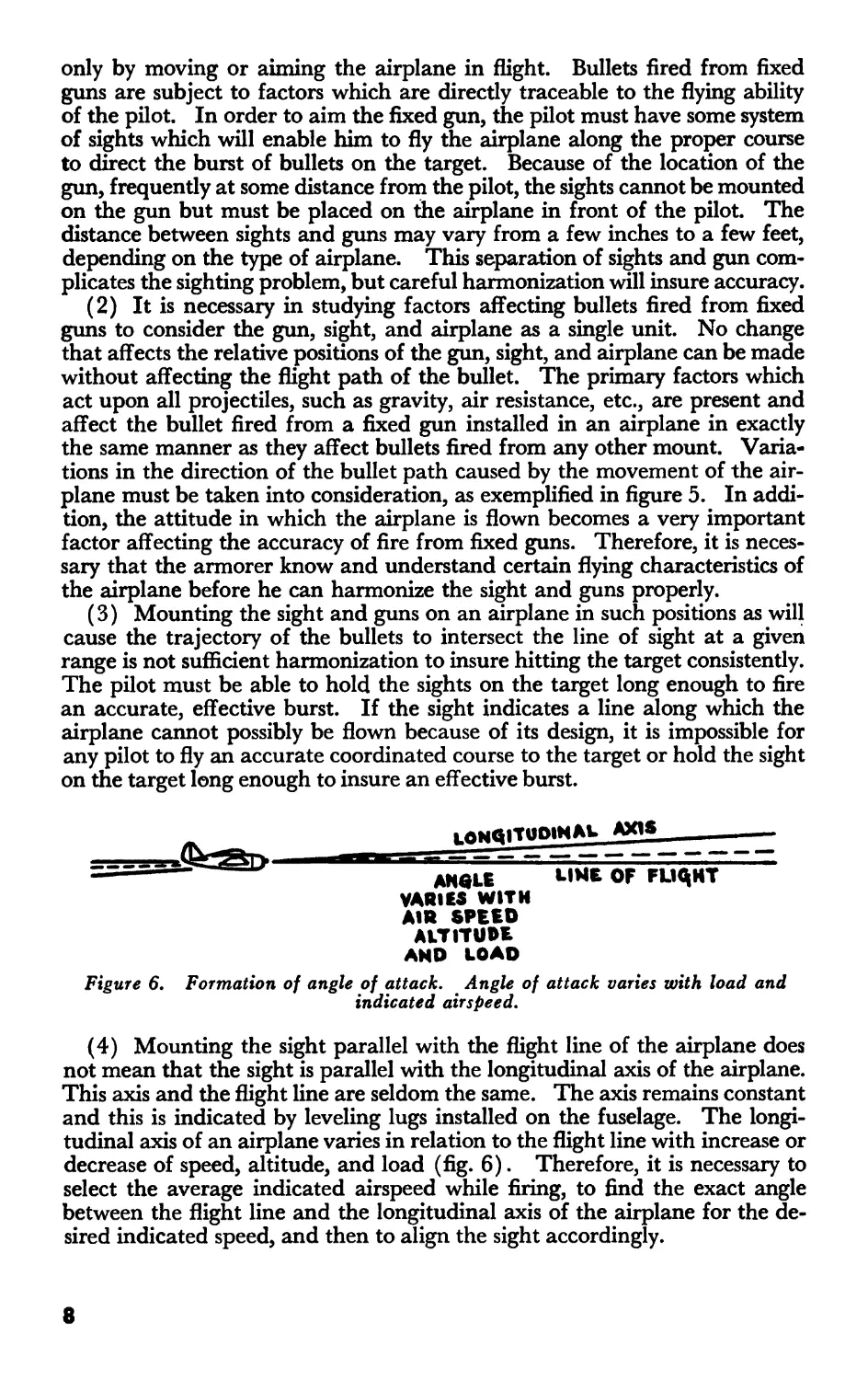
Figure 6. Formation of angle of attack. Angle of attack varies with load and
indicated airspeed.
(4) Mounting the sight parallel with the flight line of the airplane does
not mean that the sight is parallel with the longitudinal axis of the airplane.
This axis and the flight line are seldom the same. The axis remains constant
and this is indicated by leveling lugs installed on the fuselage. The longi-
tudinal axis of an airplane varies in relation to the flight line with increase or
decrease of speed, altitude, and load (fig. 6). Therefore, it is necessary to
select the average indicated airspeed while firing, to find the exact angle
between the flight line and the longitudinal axis of the airplane for the de-
sired indicated speed, and then to align the sight accordingly.
8
FOR use IM ALIGNING GUN SIGHT ON AIRPLANE MODEL P-38E
ARMAMENT INSTALLATION DRAWING NO-233879
CANNON INSTALLATION DRAWING NO-234098
COCKPIT LEVELING PLATES SET PARALLEL TO F.RL
i
$
1
VERTICAL DISTANCE FROM £ GUN
AT TRUNNION BOLT TO 4 OF GUN
SIGHT REFLECTORRCHT UPPER 21.944
RIGHT LOWER 28444
LEFT UPPER 21944
LEFT LOWER 28444
CANNON 28990
VERTICAL DISTANCE FROM <L CAMERA
LENS TO LINE OF SIGHT 42.189
HORIZONTAL DISTANCE FROM £ SHIP
TO 4. OF LINE-UP PLATE NUTS ON
LEFT HAND SIDE 3 7/8
Figure 7. Alignment chart.
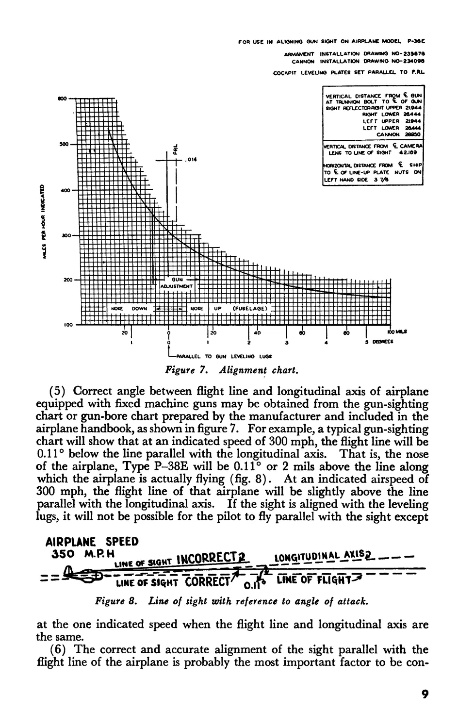
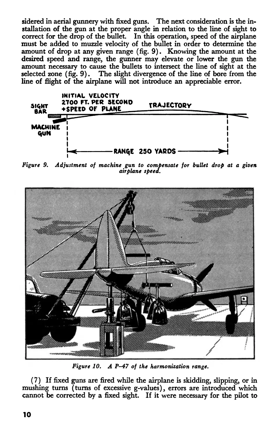
(5) Correct angle between flight line and longitudinal axis of airplane
equipped with fixed machine guns may be obtained from the gun-sighting
chart or gun-bore chart prepared by the manufacturer and included in the
airplane handbook, as shown in figure 7. For example, a typical gun-sighting
chart will show that at an indicated speed of 300 mph, the flight line will be
0.11 ° below the line parallel with the longitudinal axis. That is, the nose
of the airplane, Type P-38E will be 0.11° or 2 mils above the line along
which the airplane is actually flying (fig. 8). At an indicated airspeed of
300 mph, the flight line of that airplane will be slightly above the line
parallel with the longitudinal axis. If the sight is aligned with the leveling
lugs, it will not be possible for the pilot to fly parallel with the sight except
AIRPLANE SPEED
35fWP' Hl.h. « «.ОЫТ JMCORRECTj. iqNGITUDn»AL-AXlSa-
=^5^”IiHEorsiw CORRECT^’ojP’йнГоГгщнт^
Figure 8. Line of sight with reference to angle of attack.
at the one indicated speed when the flight line and longitudinal axis are
the same.
(6) The correct and accurate alignment of the sight parallel with the
flight line of the airplane is probably the most important factor to be con-
9
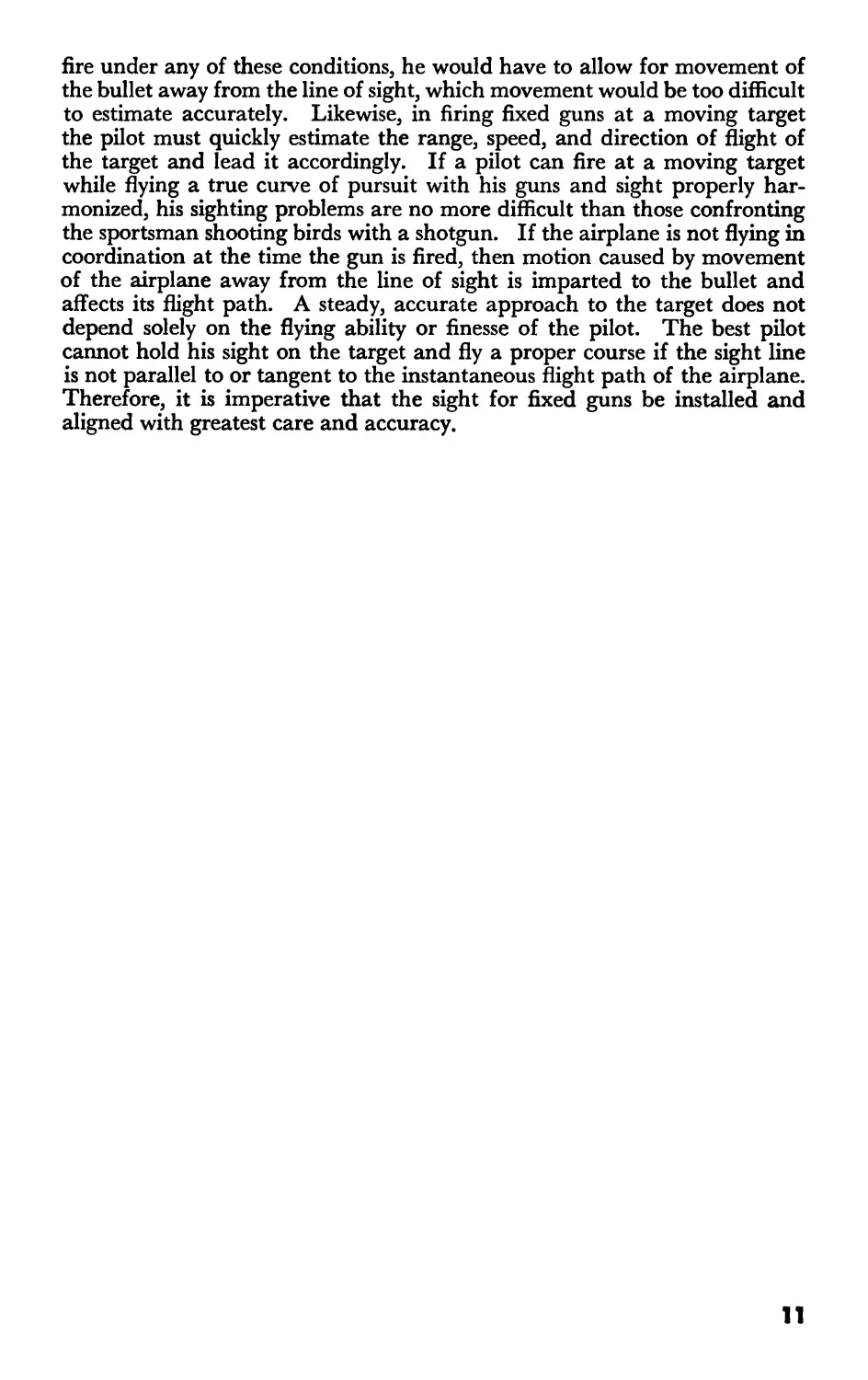
sidered in aerial gunnery with fixed guns. The next consideration is the in-
stallation of the gun at the proper angle in relation to the line of sight to
correct for the drop of the bullet. In this operation, speed of the airplane
must be added to muzzle velocity of the bullet in order to determine the
amount of drop at any given range (fig. 9). Knowing the amount at the
desired speed and range, the gunner may elevate or lower the gun the
amount necessary to cause the bullets to intersect the line of sight at the
selected zone (fig. 9). The slight divergence of the line of bore from the
line of flight of the airplane will not introduce an appreciable error.
siqHT
BAR
INITIAL VELOCITY
2700 FT. PER SECOND rRAJECTORV
* SPEED OF PLANE TRAJECTORY
MACHINE
QUN
RANQE 250 YARDS
Figure 9, Adjustment of machine gun to compensate for bullet drop at a given
airplane speed.
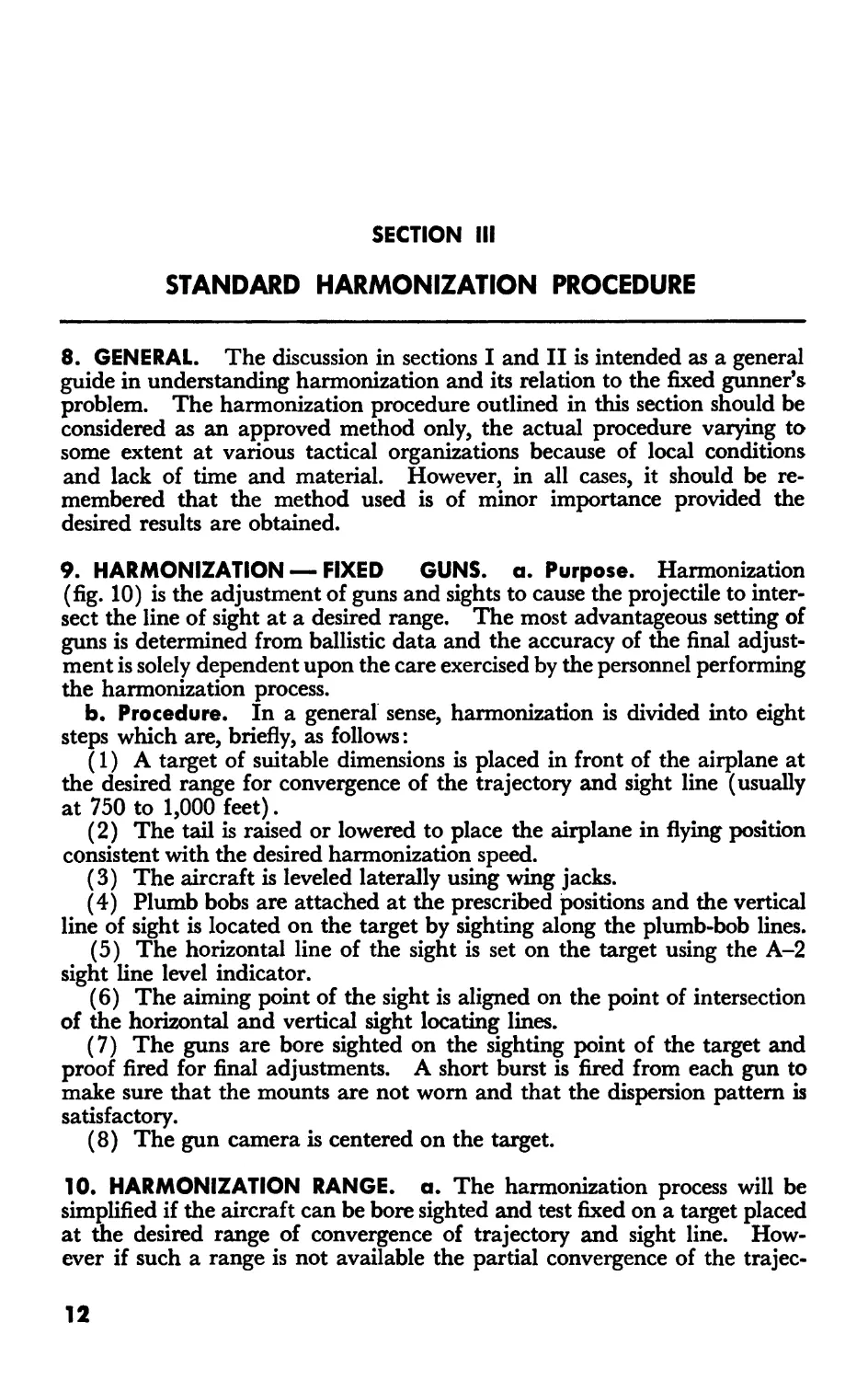
Figure 10. A P-47 of the harmonization range.
(7) If fixed guns are fired while the airplane is skidding, slipping, or in
mushing turns (turns of excessive g-values), errors are introduced which
cannot be corrected by a fixed sight. If it were necessary for the pilot to
10
fire under any of these conditions, he would have to allow for movement of
the bullet away from the line of sight, which movement would be too difficult
to estimate accurately. Likewise, in firing fixed guns at a moving target
the pilot must quickly estimate the range, speed, and direction of flight of
the target and lead it accordingly. If a pilot can fire at a moving target
while flying a true curve of pursuit with his guns and sight properly har-
monized, his sighting problems are no more difficult than those confronting
the sportsman shooting birds with a shotgun. If the airplane is not flying in
coordination at the time the gun is fired, then motion caused by movement
of the airplane away from the line of sight is imparted to the bullet and
affects its flight path. A steady, accurate approach to the target does not
depend solely on the flying ability or finesse of the pilot. The best pilot
cannot hold his sight on the target and fly a proper course if the sight line
is not parallel to or tangent to the instantaneous flight path of the airplane.
Therefore, it is imperative that the sight for fixed guns be installed and
aligned with greatest care and accuracy.
11
SECTION III
STANDARD HARMONIZATION PROCEDURE
8. GENERAL. The discussion in sections I and II is intended as a general
guide in understanding harmonization and its relation to the fixed gunner’s
problem. The harmonization procedure outlined in this section should be
considered as an approved method only, the actual procedure varying to
some extent at various tactical organizations because of local conditions
and lack of time and material. However, in all cases, it should be re-
membered that the method used is of minor importance provided the
desired results are obtained.
9. HARMONIZATION — FIXED GUNS. a. Purpose. Harmonization
(fig. 10) is the adjustment of guns and sights to cause the projectile to inter-
sect the line of sight at a desired range. The most advantageous setting of
guns is determined from ballistic data and the accuracy of the final adjust-
ment is solely dependent upon the care exercised by the personnel performing
the harmonization process.
b. Procedure. In a general sense, harmonization is divided into eight
steps which are, briefly, as follows:
(1) A target of suitable dimensions is placed in front of the airplane at
the desired range for convergence of the trajectory and sight line (usually
at 750 to 1,000 feet).
(2) The tail is raised or lowered to place the airplane in flying position
consistent with the desired harmonization speed.
(3) The aircraft is leveled laterally using wing jacks.
(4) Plumb bobs are attached at the prescribed positions and the vertical
line of sight is located on the target by sighting along the plumb-bob lines.
(5) The horizontal line of the sight is set on the target using the A-2
sight line level indicator.
(6) The aiming point of the sight is aligned on the point of intersection
of the horizontal and vertical sight locating lines.
(7) The guns are bore sighted on the sighting point of the target and
proof fired for final adjustments. A short burst is fired from each gun to
make sure that the mounts are not worn and that the dispersion pattern is
satisfactory.
(8) The gun camera is centered on the target.
10. HARMONIZATION RANGE, a. The harmonization process will be
simplified if the aircraft can be bore sighted and test fixed on a target placed
at tile desired range of convergence of trajectory and sight line. How-
ever if such a range is not available the partial convergence of the trajec-
12
tones can be shown on the target for the proportional range available.
Bore-sighting charts for these shorter ranges are usually given in the Tech-
nical Orders for each type aircraft. Nevetheless, if at all possible to use
the actual converging range for harmonization, this should be done. In
the latter case, there will be less chance for error and small discrepancies
will not be magnified.
b. Sometimes converging all guns on a point will not be desired. In such
instances, the harmonization pattern desired can be constructed on the
target and the guns adjusted to their appropriate boresight points.
11. PLACING AIRPLANE IN FLYING POSITION, a. The tail is raised or
lowered to place the airplane in flying position consistent with the desired
speed. The attitude of the airplane at various speeds with respect to angle
of attack (nose up or down) is shown on the bore-sight chart or in the
Technical Orders pertaining to the airplane. Measurement for the de-
sired setting is normally made from the gun level lugs, except in the case
of P-39D and certain other airplanes. This adjustment is normally ac-
complished by use of a clinometer, provided airplane is not equipped with
a flight-level indicator. In the event the airplane is equipped with a flght-
level indicator, the tail is raised or lowered and the setting is obtained by
properly positioning the level.
b. The airplane is jacked by using tail jacks stationed at either side of the
airplane and resting against a 1-inch diameter, round steel bar inserted
through the appropriate lifting-bar socket near the tail of the airplane. In
some instances a jack lug located just ahead of the tail wheel provides a
satisfactory point of support. Care must be exercised in the use of this
method of elevating the tail to prevent slippage of the jack.
c. Sufficient men should be available whenever the tail of an airplane not
equipped with a nose wheel is to be elevated to insure against accidents
during this operation.
d. In instances where the harmonization procedure is to be performed
on a large number of airplanes of a type not equipped with a nose wheel,
it is advisable to construct a substantial wooden frame for the support of a
chain hoist for use in raising the tail to place the airplane in flying posi-
tion. Such a procedure is usually safer and more satisfactory. During the
adjustment of the guns and sight, however, the major portion of the weight
of the tail should be supported by a tail jack.
e. As a precaution against inadvertent lifting of the tail and to prevent a
possible nose-over when the additional weight of mechanics working on the
gun may unbalance the weight distribution, sandbags or other weights
should be suspended from the lifting bar.
12. LATERAL LEVELING OF AIRPLANE, a. It is essential that airplanes
be leveled laterally and that this be accomplished by means of wing jacks
placed under the jack points of each panel. The desired result is obtained
by raising or lowering the appropriate wing jack and using a spirit level
across the lateral leveling lugs of the airplane.
b. Every precaution must be taken when airplanes are elevated on jacks
to prevent a mishap which might damage the airplane. Screw type jacks
are used if possible, since hydraulic type jacks have a tendency to creep.
c. Wing jacks are essential to prevent deflection of the landing gear dur-
ing the bore-sighting operation.
13
13. ATTACHING PLUMB BOBS. a. Plumb bobs are attached to two No.
10-32 screws, which are inserted into the two red-circle nut plates near the
tail. On airplanes not equipped with nose wheels, these nut plates are
located on the exact center line of the fuselage. On airpjanes equipped
with a nose wheel, the nut plates are located to one sicte of the fuselage
center line.
b. In the event the plumb bob nut plates are not on the center line of the
fuselage, the vertical sight locating line should be moved a corresponding
distance to one side so that it marks the center line of the ship.
c. Plumb bobs should be suspended to rest about 1 inch from the floor or
ground level and, in some instances, it is considered advisable to suspend
the plumb bobs in oil to prevent excessive movement.
14. HORIZONTAL SIGHT LINE. a. The horizontal line of sight is set on
the target by means of an A-2 sight line level indicator.
b. This device has been designed to assist in the establishment of the
gun-sighting line parallel to the flight line of the airplane. It consists of a
commercially available hand level assembled to a frame which permits
attachment to the gun-sight reflector. The hand level is attached to the
frame by means of a pivoted mount which permits the level to swing in a
vertical plane when the indicator is suspended from the gun-sight reflector.
This movement of the level is controlled by a knob which permits a slow
motion in order that the sensitive level bubble may be properly positioned
with respect to its indication mark. To use the sight line-level indicator,
suspend the instrument from the top edge of the gun-sight reflector by
means of the towhook-shaped projections on the frame of the indicator.
The third contact point on the frame extension will rest against the lower
surface of the reflector. The level is rotated by means of the knurled knob
of the frame until the hand level is approximately horizontal with the level
bubble thereof on top. Looking through the small hole in the eyepiece of
the hand level, the knob is adjusted until the bubble, which is visible through
the eyepiece, is centered on its reference mark. The positioning of a refer-
ence mark on the target to coincide with the bubble reference mark in the
level, and adjusting the sight to this mark made on the target, will cause the
sighting line, as indicated by the aiming point, to lie in a true horizontal
plane.
c. Since the airplane was previously set up to level flying position at the
chosen speed, the sight line so established will be parallel to the flight line
of the airplane when it is in flight at the selected indicated air speed.
15. ALIGNING THE AIMING POINT OF THE SIGHT, a. The sight is ad-
justed to align the aiming point of the sight with the sight mark on the
target. This adjustment is accomplished by pivoting the housing of the
sight, either laterally or vertically. The specific method to be used in per-
forming the operation is dependent upon the nature and construction of the
sight mount.
b. Prior to the adjustment of the gun sight or guns, the sight is inspected
to insure that it is in proper operating condition.
16. ADJUSTMENT OF GUNS. a. Usually the bullet drop at close ranges
(1,000 feet or less) is less than one-half the dispersion area. Therefore,
14
when bore sighting guns at these ranges it will be difficult to measure any
appreciable amount of bullet drop. For this reason, the harmonization
process will be simplified if the guns are adjusted by bore sighting on the
desired point of bullet impact. Small adjustments for drop can then be
made by actual proof firing. If the bore sighting is done carefully, it will be
found that the necessary adjustments as shown by actual proof firing will
be very small.
b. It should be borne in mind however, that the ground trajectory will
not be identical to the trajectory of guns fired in the air. The amount of
difference will vary with the speed of the aircraft. The most prominent
variation in trajectories will be the variation of range at which these tra-
jectories intersect the sight line. This point of intersection of sight line
and trajectory will be approximately the same range from the aircraft at
any instant; however, the range from the position of firing will be extended
according to the speed of the firing aircraft. But since the firing range for
any burst is not a constant factor, and since the pilot attempts only to bracket
his most effective ranges, harmonization and proof firing using ground-tra-
jectory data will be the most certain and straightforward method of obtain-
ing harmonization accuracy.
17. ALIGNMENT OF THE GUN CAMERA, a. The gun camera is aligned
to show the target in the upper center of the picture so that the sighting
point and maximum deflection can be recorded on the film.
b. At every harmonization process, checking and aligning the gun camera
should be emphasized since it not only is the basis for aerial gunnery training
but also provides the only accurate combat record.
15
SECTION IV
FIXED GUN SIGHTS, OPTICAL SERIES
18. GENERAL, a. Gun sights N-2 No. 35G2952, N-2A No. 38G1606
(fig. 4), N-3 No. 39G3372, N-3A No. 41G6436, N-3B No. 42G2092, and
N-6 No. 41D9625 have been provided for sighting guns and gun cameras
installed in a fixed position.
b. The principle of operation of these sights is the same. Types N-2 and
N-3B have electrical connections for two-wire systems while types N-2A,
N-3, and N-3A have electrical connections for single-wire grounded system.
19. DESCRIPTION, a. The sight assembly (fig. 4) consists essentially of a
main housing which contains the lamp and the lamp socket, the reticle,
mirror assembly, and lens assembly. In addition, an image reflector sup-
port is provided in some installations. This is attached to the main housing
and constitutes the means by which the reflector is held to the sight proper.
This support is not used in installations requiring the sight housing to be
located at a considerable distance below the windshield and the reflector
to be separated from the housing. In such a case, a special type of sup-
port is attached to the windshield. This is furnished by the airplane manu-
facturer.
b. Connection of the lamp in the type N-2 sight is made by inserting
connector assembly No. 37A2323 over the two terminals contained within
the electrical connector housing located on the side of and near the top
portion of the main housing. Conduit assembly fitted with coupling nut
No. 36A2212-2, which bouses the wires and connector assembly, screws
onto the threaded boss surrounding the terminals and provides the neces-
sary shielding against electrostatic interference. The wire, connector as-
sembly, and conduit are always furnished by the airplane manufacturer.
A stowing plug is also provided in each airplane for the purpose of properly
retaining the conduit assembly when the gun sight is removed. Similarly,
type N-3B sight uses connector assembly, part No. AN3102-12S-3P, and
sights N-2A, N-3, and N-3A use connector assembly, part No. 39A2390.
20. OPERATION, a. The fixed gun sights (fig. 4) are optical instruments
based on the principle of the collimator in which rays of light form the
sight line.
b. The light source which produces the sight lines is supplied by a lamp-
bulb located in the lower portion of the sight housing, which is lightproof.
The light rays pass through the transparent lines engraved on an other-
wise opaque reticle. These rays are diverging or spreading and are directed
onto the main lense system by an inclined mirror located immedately for-
16
ward of the reticle. The main lens assembly then transforms the otherwise
diverging or spreading rays of light into parallel rays. Thus the rays of
light emitted from any single point on the reticle are then parallel to each
other after leaving the lens system.
c. All the parallel rays passing through the lens system are directed upon
a transparent reflector, which is usually attached to the windshield in
line with the pilot’s normal vision forward. Upon the surface of the trans-
parent reflector an illuminated image appears. The types N-2 and N-2A
sights have an image consisting of three horizontal lines divided by a verti-
cal line. When properly adjusted, the sight assembly will cause the top
horizontal line and the vertical line of the reticle image, when viewed by the
pilot, to intersect on an indicated sight line parallel to the line of flight of
the airplane. Since the rays forming this point in the image are all parallel
to one another, the sight line which it indicates will be parallel to the line
of sight at any point on the reflector at which it is seen. The parallel rays
from this point viewed by the pilot may be considered as comparable with
a bundle of tiny tubes contained within the diameter of the main lens,
which is approximately 2 inches. Each of these small tubes may be then
considered as extending forward from the eye of the pilot with their axes
parallel to the line of flight of the airplane.
d. As the eye of the pilot moves over the field of vision, which is the
diameter of the hypothetical bundle of tubes, the effect will be that of peer-
ing through one of the group of tubes regardless of where it may be in the
bundle.
e. Since the rays of light reaching the eye from the target are practically
parallel and the light rays of the reticle image are parallel and because
the eye is unable to differentiate between the two, the image has the ap-
pearance of being superimposed upon the target. Thus the eye will see
clearly the image and the target simultaneously. This feature is peculiar
to the optical type gun sights. In the case of the bar type or open sights,
the eye must focus on either the sight or on the target during which time
only one of the two is seen distinctly.
f. The top line of the three horizontal lines represents the point to be
used at a range of 200 to 500 yards. The next two lines represent points
to be used at ranges of from 500 to 1,000 yards and from 1,000 to 1,500
yards respectively. To place these latter on the target it will be necessary
to elevate the nose of the airplane. This compensates for the difference
in trajectories at the greater ranges.
g. In the types N-3A and N-3B a 70-mil circular reticle with a dot in the
center is used. The dot represents the line of sight. The circle can be
used to establish lead in the same manner as the flexible ring sight.
21. INSTALLATION AND ALIGNMENT, a. There are two methods of in-
stalling the gun sights and the one to be preferred in a given instance de-
pends upon adjustments required to suit best the design of the airplane.
b. One method allows installation of the sight body, reflector support, and
reflector to be made as an integral unit similar to the arrangement pro-
vided in the P-38 series airplanes. The other method permits placement
of the sight body, less the support and reflector, somewhere near the floor.
The reflector is then placed in a suitable adjustable bracket attached
17
directly to the windshield. This system does not present any interference
with the instrument panel and, at the same time, positions the reflector
forward in line with the pilot’s normal path of vision. In the case of the
latter method a dust cap for protecton of the lens system is always supplied
by the airplane manufacturer and must be kept closed when the airplane
is used for purposes not requiring gunnery missions.
c. Regardless of the method used, the mount of the sight is furnished by
the airplane manufacturer and may vary on the different types of airplanes.
However, the mounts must provide the necessary adjusting means for
aligning the sight with the flight line of the airplane.
d. When the installation is such that the reflector support is not used,
provisions for mounting the reflector (usually on the windshield) are also
made by the airplane manufacturer.
e. Details of the method of installation of both sight and reflector for
any particular type of airplane will be obtained from drawings of the gun
sight installation applying to that type.
f. The accuracy with which the fire from a fixed machine gun mounted
within an airplane can be directed against a target depends solely upon
correct alignment of the sight line with the flight path of the airplane
and the proper adjustment of the gun itself from that flight line in order
that the correct compensation will be made for the trajectory of the bullet.
22. ADJUSTMENT OF SIGHT, a. Normally the main lens and reticle
assembly of the N-series gun sights are properly adjusted by the manufac-
turer, the only local adjustment necessary being that of aiming the sight
properly during harmonization. In general, this may be done as described
in b below.
b. If the reticle image is projected to one side or the other of the vertical
center line of the reflector, it is probable that the adjusting knob located
approximately midway of the sight housing has become loosened and
shifted from its original setting. By turning the adjusting knob the slide
assembly holding the reticle is moved laterally with respect to the mirror
assembly. Before readjustment is attempted, it first must be determined
that the reflector and gun sight body are correctly aligned so that the two
units are on the same vertical center line. Slowly turning the adjusting
knob will cause the reticle image on the reflector to move from one side
to the other of the center line thereof. When the dot or the aiming point
of the reticle coincides with the center of the cross on the bore-sight target
during the harmonization procedure, the adjustment is correct. Vertical
adjustment of the sight is performed by pivoting the sight housing itself.
A turnbuckle or some such similar device is provided on the gun sight mount
for this purpose.
c. Although the optical sight assembly should present few maintenance
problems, it should be carefully checked at each harmonization for correct
operation. If the reticle image becomes distorted or seems to move on
a distant target when the eye is moved over the field of vision of the sight,
a malfunction known as parallax is present This difficulty is the result
of the sight being out of focus and may be corrected by focusing the sight
at infinity.
18
(1) In the case of the N-2 and N-3 series sights, the focus adjustment
is made as described below:
(a) Removing the reflector plate support, dust cover, and lens locking
screw.
(b) Screw the lens up or down until there is no movement of the image
on the target as the head is moved over the field of vision of the sight.
(2) An accurate check on the focus of the sight may be made as follows:
Construct a focusing box approximately 4 inches square and 6 to 8 inches
long with an opening on each end. Secure a ground glass plate to one end
of box. On the other end, fasten a lens that can be adjusted toward the cen-
ter of the box until the images of distant objects appear sharply in focus on
the ground glass plate. When this is done, the box will be focused for
infinity. To test a sight, simply aim the lens of the box onto the reflector
plate of the sight or directly down the sight barrel. If the image of the
reticle on the ground glass is sharp and clear, the sight is properly focused
at infinity; if the image is thick or distorted, the sight needs adjustment.
d. If when looking through the reflector there appears to be more than
one image superimposed upon the target, there is a malfunction known as
double image present. This is generally caused by a cracked reflector plate
or one which has nonparallel surfaces. This difficulty is corrected simply
by exchanging the unserviceable reflector for one that is satisfactory. An
unsatisfactory report should be submitted for each rejected reflector.
23. DIFFERENCE BETWEEN THE OPTICAL SIGHTS. In considering the
N-2, N-2A, N-3, N-3A and N-3B sights, the principle differences are:
a. The sights differ in that types N-2 and N-3B have electrical connec-
tors for two-wire systems, while types N-2A, N-3, and N-3A have connec-
tors for single-wire grounded systems.
b. Types N-2A, N-3, and N-3A have certain improvements, among
which is the use of a split type lamp housing which permits easier lamp
replacement.
c. In types N-3A and N-3B a larger opening in the reticle holder is pro-
vided to permit the use of a 70-mil circular reticle.
d. Between the side edges of the reflector and the reflector supports in
types N-A, N-3, and N-3A, and N-3B sights there are cork strips which
hold the glass firmly in the support and act as cushions to reduce breakage
of the reflector due to expansion caused by severe temperature changes.
24. INSPECTION AND MAINTENANCE, a. Periodic inspections as herein
prescribed must be made on aircraft machine gun sights and a record of
such inspections kept on WD AC Form No. 41A (Summary of Inspection
Instructions), opposite Group 18, Gunnery Equipment. The following in-
struction must be complied with in conducting such inspections and in
making records thereof:
(1) Only qualified armament personnel will be allowed to make the
inspections and such inspection must include all necessary adjustments,
repairs, replacements, etc.
(2) Certain inspections will be made prior to the first flight for the day
of each airplane and in addition certain other inspections will be made for
each sight every 40 hours.
19
b. The following instructions cover both the preflight and the 40-hour
inspections:
(1) Pre flight. Prior to the first flight each day during which guns are
to be fired the following inspections and maintenance operations will be
performed:
(a) Clean reflector.
(b) Clean shield assembly over main lens.
(c) Determine that reflector is securely held in its support.
(d) See that gun sight body is held firmly in its mount and no shake or
wobble is present.
(e) Check electrical connections for contact and determine whether both
lamp filaments will bum. Loss of one filament is shown by a reduction in
reticle brilliance. If the lamp is burned out, replace it with an R. P. 11,
21—21 CP double contact candelabra base, inside frosted damp of voltage
corresponding to that of the airplane power supply. The lamp may be
checked in the housing without removing it.
(/) Determine whether rheostat functions to turn sight lamp on and
off and controls the intensity of the light satisfactorily.
(g) See that pattern of reticle is reflected properly on reflector.
(2) 40-hour. At 40-hour intervals, each gun sight will be inspected as
follows:
(a) Check harmonization of gun sight with respect to flight line.
(b) Check general condition of sight assembly and sight mount.
(c) Determine that electrical portion of the sight installation is in proper
working order.
(d) Check reflector for looseness in its support. Tighten if necessary.
(e) Check reflector for cracks or chips. Replace if necessary.
(/) Determine whether machine gun setting with respect to flight line
has changed. Readjust if necessary.
(3) Pre flight, (a) Preflight inspection will cover security of mounting
and general condition of sights.
(b) 40-hour. Forty-hour inspections will cover sight assemblies, mounts,
and, in case of fixed sights, the adjacent structure for evidence of wear
or failure. Reharmonize.
(c) However, one rough landing, one snap roll, one man manhandling a
gun or sight will throw the harmonization off. Furthermore, it is a rare
sight mount that will permit the replacement of the bulb without rehar-
monization of the sight. Therefore, it is considered of vital importance to
check harmonization at every possible opportunity when accuracy of fire
is expected. If it could be made practical, harmonization should be checked
before very mission.
25. PROTECTION FROM EXCESSIVE SUNLIGHT. To prevent the possi-
bility of burning the silver on the reticle by concentration of sun rays
through the lens system and consequent damage to the reticle pattern, a
gun-sight cover will be fabricated for all Type N-series gun sights installed
in airplanes located in tropical climates where the radiant heat from the
sun is excessive. This cover will be placed over the sights when the airplane
is idle and parked in the direct rays of the sun.
26. PAINTING OF GUN-SIGHT NAME PLATES. To prevent a brilliant
reflection of the gun-sight name plate image in the windshield when the
20
sunlight strikes this plate, the name plate on the Type N-series gun sights
installed in aircraft will be evenly coated with flat black enamel (Enamel,
instrument black, flat, Specification 3-98).
27. LIGHT AND MOISTURE PROOFING, a. To reduce the possibility of
light leaking from the lamp housing while on night flights, all Type N-3,
N-3A, and N-3B gun sights will be sealed in accordance with the instruc-
tions provided in Technical Order 11-35-8.
b. When it becomes necessary to remove any part of the subject sights,
the old compound will be removed and fresh compound applied. (Use
Compound, sealing, aircraft instrument, Specification 2-87, Class 07, A. C.
Stock.)
28. REFERENCE. For complete information on the installation, inspection,
and use of gun sights N-2, N-2A, N-3, N-3A, N-3B, and N-6 refer to
Technical Orders 11-35-5 and 11-35-12.
21
INDEX
Air resistance........................................................
Paragraph
5
Page
3
Definition of terms...............................................
3
Gravity, effect on trajectory.................................
Harmonization.................................................
Aligning of aiming point of sight.........................
Gun camera, alignment of..................................
Guns, adjustment of.......................................
Horizontal sight line.....................................
Lateral leveling of airplane..............................
Placing airplane in flying position.......................
Plumb bobs, attaching of..................................
Procedure.................................................
Purpose and factors affecting.............................
Range.....................................................
5
8-17
15
17
16
14
12
11
13
9
7
10
3
12
14
15
14
14
13
1?
14
12
7
12
Optical sights (See also Sights, optical)....................... 6, 18-28 6,16
Projectile, path of, factors affecting................................. 5 3
Propellant............................................................. 5 3
Ring-and-post sight.................................................... 6 5
Rotation of bullet, effect of on trajectory............................ 5 3
Sights:
Necessity for........................................................... 4 3
Optical series................................................. 18-28 16
Adjustment of................................................ 22 18
Description.................................................. 19 16
Difference between types..................................... 23 19
Inspection and maintenance................................... 24 19
Installation and alignment................................... 21 17
Light and moisture proofing.................................. 27 21
Maintenance.................................................. 24 19
Moisture and light proofing.................................. 27 21
Name plates, painting of..................................... 26 20
Operation.................................................... 20 16
Reference literature......................................... 28 21
Sunlight, protection from.................................... 25 20
Types for fixed guns.............................................. 6 5
Terms, definitions of.................................................. 3 1
Trajectory, factors affecting.......................................... 5 3
О
22