/


Теги: weapons military affairs
Год: 1954


Текст
RESTRICTED
I lie Information given In this document
is not to be communicated, either
illicitly oi Indlrectly.'fo the Press or to
any person not authorlied to receive It
I
notes
on
RIFLE, 7-62mm.
• i>w.ibr.....
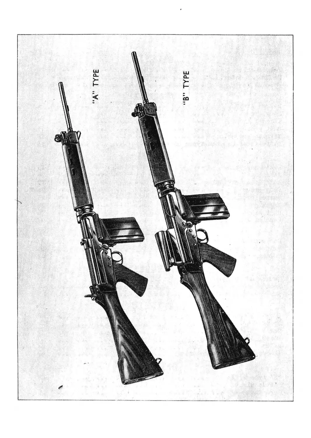
X8EI (known as FN TYPE A)
X8E2 (known as FN TYPE B)
RESTRICTED
I he Information flven In this document
is not to be communicated, either
directly or indirectly, to the Press or to
any person not authorized to receive it.
NOTES
on
RIFLE, 7-62mm.
X8EI (known as FN TYPE A)
X8E2 (known as FN TYPE B)
for
TROOP TRIALS
LAND SERVICE
1954
INSPECTORATE OF ARMAMENTS
NOTES ON RIFLE, 7.62 am.
X8E1 (known as FN TYPE A)
XSE2 (known as FN TYPE в)
for TROOP TRIAIS
LAND SERVICE 1954
AMENDMENTS NO.1
Page 47 -
Delete "Para. JO" and substitute -
"JO. ABNORMAL WEATHER CONDITIONS
When preparing the rifle for use in abnormal weather conditions
all workings parts will be thoroughly dried, before being lubricated
with special oil.
The gas regulator may have to be adjusted to give more gas.
It will assist in the initial stages of firing if the working
parts are hand operated sharply backwards and forwards a few times
before loading takes place.
Lubricants will be used as follows:-*
USB Lubricants to be used for temperature
Over 80°F Between 4O°F Л 80°F Between 0°F & Below 0°F
All working parts in body and trigger grotqo. Oil,OX 52 or Oil, OX 1J Oil, OX 52 or Oil,OX 1J Oil,OX 13 or Grease LG 380 50^0 mixture Oil, OX 1J and Kerosine, vaporizing or 50/50 mixture of Grease LG J80 and Kerosine,vaporizing.
Emergency substitute
Oil,OM 52 Oil, OM 52 — Kerosine, burning
NOTES:- (a) Magazines will also be cleaned and lubricated.
\ (b) In hot, dusty climates the rifle will be very lightly
oiled."
INSBBOTORAIE OF ARMAMENTS
HE/8 Awdt.1 WOOLWICH
RESTRICTED
The information given in this document
is not to be communicated, either
directly or Indirectly, to the Press or to
any person not authorized to receive it.
NOTES ON
RIFLE, 7«»62 mm.
X8E1, X8E2 and X8E5
FOR
TROOP TRIALS
LAND SERVICE
1955
AMENDMENT NO. 4
W.O.
Code No
10826-4
MANUSCRIPT AMENDMENTS
Cover and Title page delete "for TROOP TRIALS”
PAGE 46 Para. 25 - line 10
Delete ”0C 600" and substitute "0X52"
CUT-OUT .^AMENDMENTS
PAGE 48
Delete table of lubricants, and substitute new table attached.
HB.8/1
Arndt. 4/bct/1960
Lubricants to be used, for various temperatures
Use Temperature Lubricant
All working parts in body and trigger mechanism Below 0°F 0°F to 40°F 40°F to 80°F Over 80°F Normal Emergency substitute
50/50 Mixture of Oil, 0X13 and Kerosene В Oil, OX 13 Oil, OX 52 Oil, OX 52 Vaporising oil in lieu of Kerosene Oil, OM 13 Oil, OM 58 Oil, OM 13 Oil. OM 58
Lubricants to be used, for special purposes
Purpose Lubricant
Storage Beach landings Dusty/sandy climates Preservative, PX 11 or PX 4 Grease, LG 380 or Grease, LG 280 Graphited grease XG 340
NOTES: (a) Magazines will also be cleaned and lubricated.
(b) In hot, dusty climates the rifle will be very lightly
oiled*
Inspectorate of Armaments
Woolwich
Hb 8/1
RESTRICTED
The information flven in this document
is not to be communicated, either
directly or indirectly, to the Preu or to
any person not authorized to receive It.
NOTES ON
RIFLE, 7.62 ПЮ.
X8E1 (known as FN TYPE A)
X8E2 (known as FN TYPE B)
for
TROOP TRIALS
LAND SERVICE
1954-
AMENDMENTS (NO. 2)
1. Page 6 para. 5 Delete from "Both" in line 7 to “slide"
in line 8 and Substitute:-
The handle has a rectangular stud which protrudes
into the body to connect with the guide rib on the
slide for cooking the rifle. The auxiliary catch
has a stud also, but this only protrudes when the
oatch is pushed forward. It then connects with
the rear of the slot in the body when the cocking
handle is withdrawn.
Red Barracks
22nd September, 1954-
Inspectorate of Armaments
Woolwich
HB/8 Amdt.2
CONTENTS
Page
SECTION I
Introduction ............................................... 1
Technical details .......................................... 1
Special features ........................................... 2
SECTION II
Barrel group 4
Body group ................................................. &
Trigger group .............................................. 9
Butt group ................................................ 11
Grenade projector ......................................... 12
Differences between types of rifles ....................... 13
SECTION III
Field stripping ........................................... 15
Assembly ••• ............................................. 18
Additional stripping ...................................... 19
Body group ................................................ 24
Barrel group ...................... -.................... 25
Magazine ............................................... 26
Unit sight ................................................ 26
Loading and unloading •••• ........................... • • • 27
SECTION IV
Backward and Forward action ............................. 29
Trigger mechanism 34
Holding open Device ....................................... 42
SECTION V
Causes of stoppages ....................................... 43
Remedy immediate action.................................... 44
Remedy stoppages .......................................... 45
SECTION VI
Cleaning materials ........................................ 46
Before firing ............................................ 46
Gras regulator ............................................ 47
During firing............................................... 47
After firing ............................................... 47
Abnormal weather conditions ................................ 47
SECTION VII
•B1 type rifle ............................................. ЦВ
Battle sight 49
Zero data .................................................. 49
HB.8
Rifle,
SECTION I - GENERAL
1. INTRODUCTION
This rifle provides the user with an easily handled, weapon,
capable of producing either the deliberate accurate rate of fire
of the hand, operated rifle, the rapid single shot rate of the
self loading rifle, or a volume of automatic fire, if fitted with
a special change lever.
It can be fitted with a bayonet for close quarter fighting,
or a launcher for grenade firing.
The rifle has no cooling system other than the effect of
prevailing temperature conditions, and there is a clearance
between handguard and barrel which allows free circulation of air.
With a self loading rifle there will be a tendency to employ
rapid fire unnecessarily at targets at long ranges, this not only
wastes ammunition, but overheats the weapon.
The ability to exploit the many uses of this rifle, will,
as always, depend on the efficiency of the fir er. Previous tests
have shown that the trained man can reach a standard of rapid fire
of about 20 or more accurate single shots per minute, firing at
separate targets, and a high rate of automatic fire when required.
Two types of rifles are undergoing tests $nd these will be
referred to as Type A or Type B. This book is written around
the Type A weapon.
2. TECHNICAL DETAILS
Calibre 7.62-mm.
Length of rifle 41.5 inches
Length of barrel 21 inches
Number of grooves 4 equally spaced
Pitch of rifling 1 in 8.66 indies
Twist of rifling Right hand
Weight of rifle } A 8.9 lb.
) в 9.12 lb.
Weight with full magazine )a 10.43 lb.
)b 10.7 lb.
HB.8
— 2 —
TECHNICAL DETAILS - contd.
Cyclic rate of fire 650-700 R.P.M.
Muzzle Velocity 2,800 ft. sec.
System of operation Gas
Type of sight Unit or Iron
Sight radius iron sight 21.77 inches
Magazine Box type
Magazine Capacity 20 rounds
Magazine Weight empty 8#25~oz*
Magazine Weight full 1.58-lb.
3. SPECIAL FEATURES
(a) Mechanical Safety
A safety sear, operated by the slide, ensures that the
hammer cannot he released to strike the firing pin until
the breech block is fully forward#
The rear end of the firing pin protrudes beyond the rear
face of the slide only when the breech block is in the
locked position, therefore the firing pin cannot be st rude
by the hammer until the breech is sealed.
(b) Applied Safety
Applied safety is provided by the change lever. When the
lever is put to the S (safe) position, the rounded edge of
the change lever spindle is over the trigger platform,
preventing it from rising to engage the tail of the sear.
(c) Gas Regulator
She quantity of gas allowed to escape is controlled by the
gas regulator, the balance being used to drive the piston
to the rear# The adjustment of the gas regulator is simple
and can be done by using a round of amnunition#
(d) Cocking Handle and Auxiliary Cooking Catch
The cocking handle is on the left side of the body. It is
fitted with an auxiliary catch, which, when engaged,
prevents the cocking handle being drawn back further than
3.15 inches, because of this, should it be necessary to
HB.8
— ъ —
draw* the breech block rearwards when a filled or partially
filled magazine is on the rifle, the breech block cannot be
pulled, far enough back to engage the top round in the
magazine, and thus a double feed is prevented#
(e) Change Lever
ffiie change lever can be set to one of two positions, Single
Shot, and Safe. A change lever may be fitted which can be
set in three positions# Safe, Single Shot and Automatic.
(f) Holding Open Device
This device is operated by a rear lip on the magazine
platform, the breech block is held to the rear When the
magazine is empty.
(g) Stripping
The rifle opens similar to a shot gun, and can be field
stripped without the aid of tools#
(h) Loading
Type *A" rifle can be loaded by using clips containing five
rounds} loading is aimi lar to bolt action rifles# A dip
loading device can be used to fill magazines#
(J) Bayonet
The crosspiece of the bayonet is fitted with two prongs
which act as a flash eliminator#
HB.8
— 4 —
SECTION II- DESCRIPTION
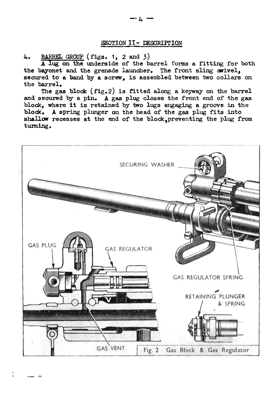
4. BARREL GROUP (figs. 1, 2 and j)
A lug on the underside of the barrel forms a fitting for both
the bayonet and the grenade launcher. The front sling swivel,
secured to a band by a screw, is assembled between two collars on
the barrel.
The gas block (fig.2) is fitted along a keyway on the barrel
and secured by a pin. A gas plug closes the front end of the gas
block, where it is retained by two lugs engaging a groove in the
block. A spring plunger on the head of the gas plug fits into
shallow recesses at the end of the block ^preventing the plug from
turning.
— 5~
If the letter A on the plug is turned uppermost, it indicates
that the rifle is set for hall ammunition firing, in this position,
the gas port in the plug is directly in line with the gas vent in
the barrel.
For rifle grenade firing, when all the gases are needed to
propel the grenade, the letter A is turned downwards, thereby
shutting off the gas from the cylinder.
The forward end of the gas cylinder is threaded and screwed
into the gas block, which is threaded on the outside to take the
gas regulator.
The gas regulator has a number of projections on its outer
surface, for use when adjusting the regulator, and for the
engagement of the gas regulator spring. The forward ends of the
spring are bent over and fit into small holes on each side of the
gas block.
A gas escape hole is drilled at the top of the cylinder
seated immediately in rear of the foresight bed; this hole is
elongated and can be opened or closed by the gas regulator. Two
gas escape holes are drilled into the right and left side of the
cylinder at a distance of 2.4-ins. from the forward end.
The foresight is cone shaped and squared at its base, a round
collar is formed immediately below, and this collar has a number of
indents around its edge. Before assembly it is fitted into a
spring steel washer on which are two lipped projections which
engage in the indents on the collar. The sight is screwed into the
gas block, and it is protected from damage by protectors which are
designed as one piece with the gas block.
HB.8
— 6 —
A bush is fitted over the rear end of the gas cylinder.
Grooves on the outer surface of the bush allow the use of a
tightening tool.
The gas cylinder houses the piston and spring.
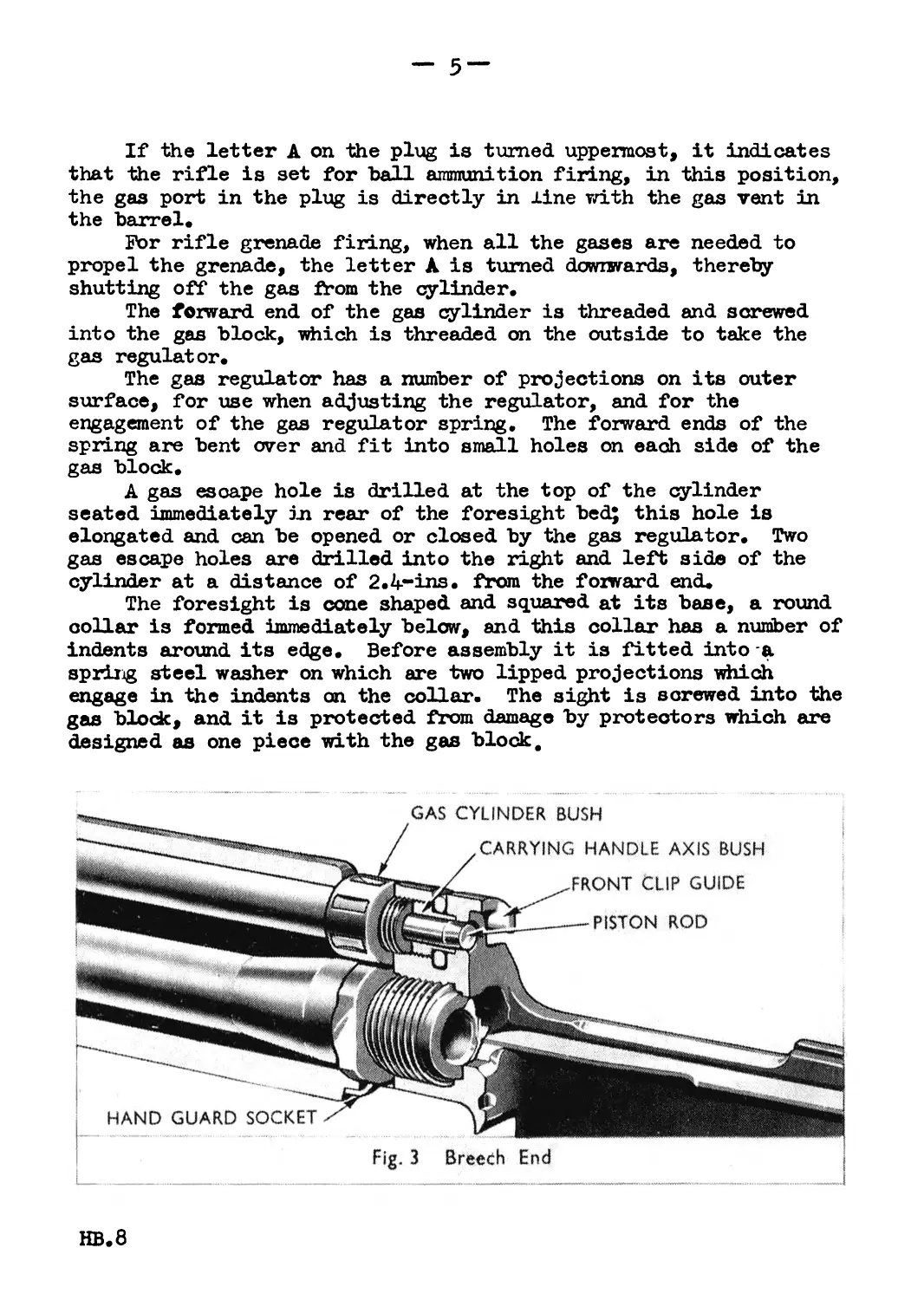
The barrel is threaded at the rear (fig.3) and is breeched
into the body; a hand guard so dee t on the outer surface, holds the
two handguards at the rear, the other ends being secured by a screw
passing through the gas block.
Metal linings are assembled to the front ends of the hand-
guards to form a firm leverage when adjusting the gas regulator.
5o BODY GROUP (figs, 1, 4, 5 and 6)
A carrying handle is fitted to the upper front part of the body
and when not in use it is folded down to the right side of the rifle
A projection on the rear top surface of the body forms a seating
for the front end of the horse shoe clip.
The cocking handle (fig.4) is on the left of the body and has
a spring-loaded auxiliary cocking catch assembled on its extension.
Both the handle and the catch have a rectangular stud which connects
with the breech block slide.
The boc|y cover is positioned by ribs fitting into guide
grooves in the body, it is prevented by being pushed too far
forward by stops on each side of the rear end. The front top
HB.8
— 7 —
surface is fitted with guides to take the rear end of the horse
shoe clip.
The breech block slide (fig.5) forms the housing for the breech
block* It is fitted by ribs into guide grooves in the body. At
its rear end a spring loaded rod is hinged on a pivot pin.
In the rear inner surface of the slide are sloping protrusions
which actuate the shoulders of the breech block.
The breech block (fig.5) has a hole drilled through its length
to house the firing pin and spring; these are retained by a pin
engaging across an elongated reoess. The spring is held under
compression thus keeping the front end of the firing pin clear of
the face of the breech block.
An extractor and spring is fitted at the right side of the
breech block, with the claw of the extractor protruding on to the
face of the block.
HB.8
— 8 —
The under surface of the breech block has an allowance for
the ejector, and the rear bottom face forms a locking shoulder.
The ejector is an integral part of the body (fig.6) and is
positioned in front of the locking shoulder recess. The upper
arm of the safety sear on the left of the ejector, protrudes up
into the body.
At the rear of the magazine housing is the holding open device;
this is spring-loaded and has a thumb catch at it lower end. A
magazine oatch, the upper arm of which protrudes into the magazine
housing, projects to the rear. It is milled on its rear surface to
assist in manipulation. A magazine catch spring is fitted between
catch and body, the magazine catch and the holding open device are
held in position by a screw passing through the body.
The safety sear and spring, housed in the left of the body,
are retained by the butt frame joint pin.
HB.8
— 9 —
6. TRIGGER GROUP (figs. 1, 7 aifd 8)
The forward end of the trigger group housing, (fig.7) hinges
to the body group, ^diere it is secured, by a butt frame joint pin
and. retaining pin.
The hammer and. trigger (fig.8) are retained, by pivot pins
passing through the trigger housing, these pins are prevented, from
moving by a locking plate secured by the spindle of the change
lever. The hammer spring rod is pinned to the hammer and carries
the hammer spring partially covered by a spring housing, the rear
end of the housing is coned and fits into a shallow recess in the
cross frame of the trigger housing.
On the shank of the hammer are two bents, the lower one for
use with the trigger sear, the upper one for the safety sear.
The trigger and sear are held by the same pivot pin, a sear
spring being fitted between sear and trigger. The hole in the sear
is elongated to allow backward and forward movement. The lower
pivot arm of the trigger is held forward by a spring-loaded plunger.
The change lever spindle is positioned directly above the rear arm
of the trigger.
, HB.8
—10 —
On the left of the trigger housing are three indents marked
A, S and R; these are seatings for the spring plunger of the change
lever.
The trigger guard is bent over at the front end, and hooked
into the forward end of the trigger housing. The rear end is
sprung over the trigger plunger housing and held by the upper
surface of the pistol grip.
The pistol grip is secured to the trigger housing by a lock
nut.
The body locking catch assembly is situated at the rear of
the trigger housing.
HB.8
—11 —
7. BUTT GROUP (figs. 1 and 8)
The backsight (fig.8) is of the usual aperture type which can
be moved up or down an inclined ramp. A spring*loaded plunder on
the left side has a projection which fits into recesses on the
ramp. Range figures are engraved on the top surface, the lowest
being 200 yards, the highest 600 yards. The sight is dovetailed
into its seating and there is an adjusting screw on each side of
the sight block.
A return spring tube (fig.1) is screwed into the rear upper
surface of the butt frame, and contains a double return spring
which is held under compression by a screw in the rear end of the
tube.
The butt is secured by two screws, one at the front under the
butt, the other screwed into the butt from the rear.
The butt is drilled for an.oil bottle, and a butt trap is
fitted on the butt plate.
A sling swivel is fitted on the toe of the butt.
8. BAYONET (fig.9)
The bayonet is of the broad bladed type. It is fitted with
two projections on the cross piece to act as a flash hider.
The handle is fitted with a catch and spring which secure it
to the barrel.
The handle is also spring-loaded so that -when firing with the
bayonet fixed,differences in the M.P.I. is negligible.
HB.8
— 12—
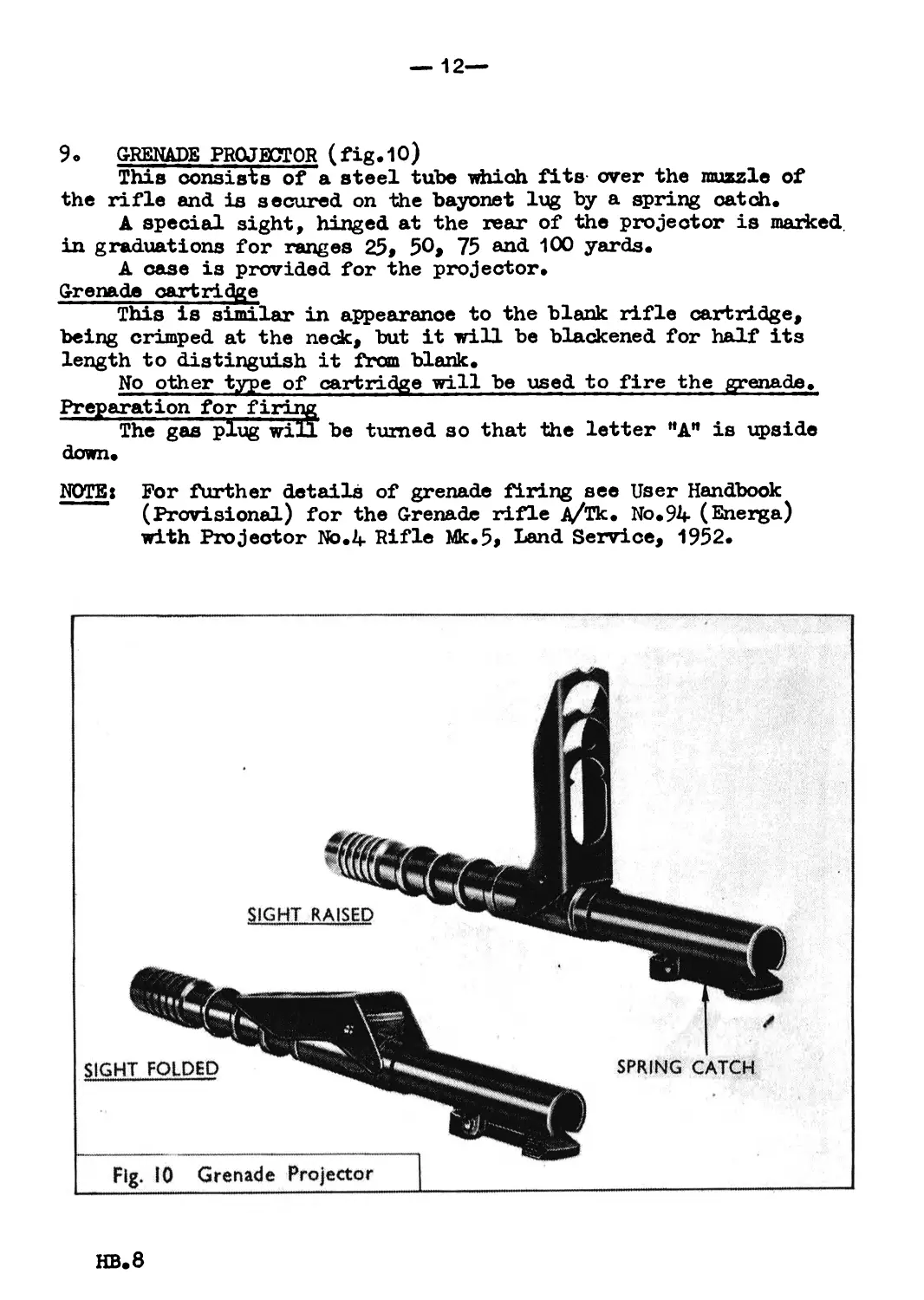
9. GRENADE PROJECTOR (fig.1O)
This consists of a steel tube which fits over the muzzle of
the rifle and is secured on the bayonet lug by a spring catch.
A special sight, hinged at the rear of the projector is marked
in graduations for ranges 25 9 50> 75 and 100 yards.
A case is provided for the projector.
Grenade cartridge
This is similar in appearance to the blank rifle cartridge,
being crimped at the neck, but it will be blackened for half its
length to distinguish it from blank.
No other type of cartridge will be used to fire the grenade.
Preparation for firing
The gas plug will be turned so that the letter "A" is upside
down.
NOTE: For further details of grenade firing see User Handbook
(Provisional) for the Grenade rifle Д/Тк. No.94 (Energa)
with Projector No.4 Rifle Mk.5, Land Service, 1952.
HB.8
— 13 —
10. DIFFERENCES BETWEEN TYPES OF RIFLE
The "B" type rifle differs from the НАИ type as follows
(a) Sights (fig.11)
This rifle is fitted with a UNIT Sight, it consists of a
small telescope-shaped tube fitted with lens. An inverted
pointer and two range lines are etched on the lens inside
the sight.
The pointer is used at ranges up to 200 yards, the two lines
at ЦХ) and 600 yards respectively.
HB.8
—u—
The sight is protected by a cover guard which can be
removed to the rear.
The sight is secured to a bracket by two collars, secured
underneath by screws. The bracket is secured to the body
cover by a lock screw at each end, the front one on top the
rear one underneath. At the forward end is a nut, hexagonal
in shape, and this nut is eccentric so that, when turned it
moves the bracket laterally.
A second hexagonal shaped nut is at the rear; it has a
number of small marks around its edge. This nut has normal
threads and when turned it raises or lowers the rear of the
bracket. These nuts should be turned only when the lock
screws have been loosened.
Battle sights for use at 200 yards are fitted* The backsight
to the rear nut of the unit sight, and a fixed foresight
to the gas block> the foresight is protected on its left side
only. These sights are offset to the left.
(b) Loading
It is not possible to clip load this rifle. The booty cover
slide is strengthened and fits fully forward up to the
breech face, it has an ejector opening and deflector plate
on its right forward end.
HB.8
—15 —
SECTION III - STRIPPING
11. Р1Ш) STRIPPING (figs, 12, 13, 14 and 15)
For field stripping no tools of any kind are required, but it
ay be necessary to use the nose of a bullet to turn the gas plug,
especially after prolonged firing. ?The change lever will be put to
safe before stripping commences, it will not be moved from that
position until the rifle is assembled.
HB.8
— 16—
Cook the hammer by pulli ng back the cocking handle as far
as it will go, look into the breech and body to ensure that
the rifle is clear, allow the breech block to go forward
under the action of the return spring. Set the safety
lever to safe.
With the muzzle held pointing slightly downwards, hold
the barrel group firmly, press the body locking lever 3 to
the rear and open the rifle. Pull the body cover, 4 breech
block 5 and slide 6 to the rear.
Fig. I3 Slide & Breech Block Group
HB.8
— 17—
6
5
Hold the slide 6 inrerted in the right hand with the slide
rod 7 rearwards, pull the block 5 fully to the rear of the
slide 6. Put the forefingers of the left hand on the face
of the breech block 5, and the thumb on the rear eni of the
firing pin 8, press together and lift the front end of the
breech block 5 outwards until it can be removed from the
slide 6*
Fig. 14 To Separate Breech Block & Slide
HB,8
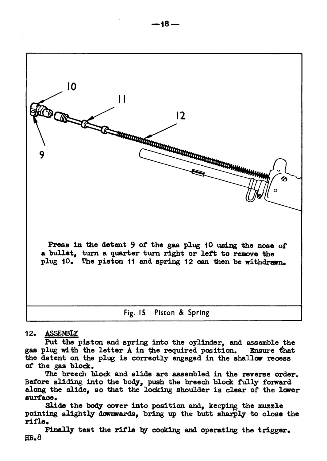
—18 —
12. ASSEMBLE
Put the piston and spring into the cylinder, and assemble the
gas plug with the letter A in the required position. Ensure that
the detent on the plug is correctly engaged in the shallow recess
of the gas block.
The breech block and slide are assembled in the reverse order.
Before sliding into the body, push the breech block fully foxward
along the slide, so that the locking shoulder is clear of the lower
surface.
Slide the body cover into position and, keeping the muzzle
pointing slightly downwards, bring up the butt sharply to close the
rifle.
Finally test the rifle by cooking and operating the trigger.
HB.8
—19 —
13. ADDITIONAL STRIPPING- (figa. 16 to 28)
NOTZ» Additional stripping, (magazine excepted.), will ha done ""ly
by a qualified armourer.
The rifle will first he field stripped.
HB.8
—20 —
HB.8
— 21 —
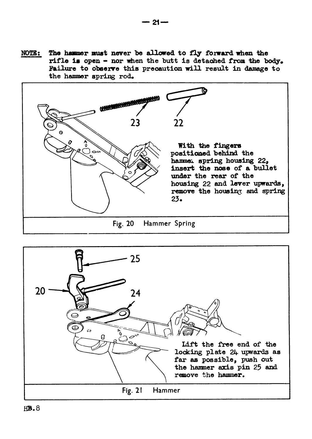
NOTE: The haamer mist never be allowed to fly forward when the
rifle is open - nor when the butt is detached from the body.
Failure to observe this precaution will result in damage to
the hammer spring rod.
HB.8
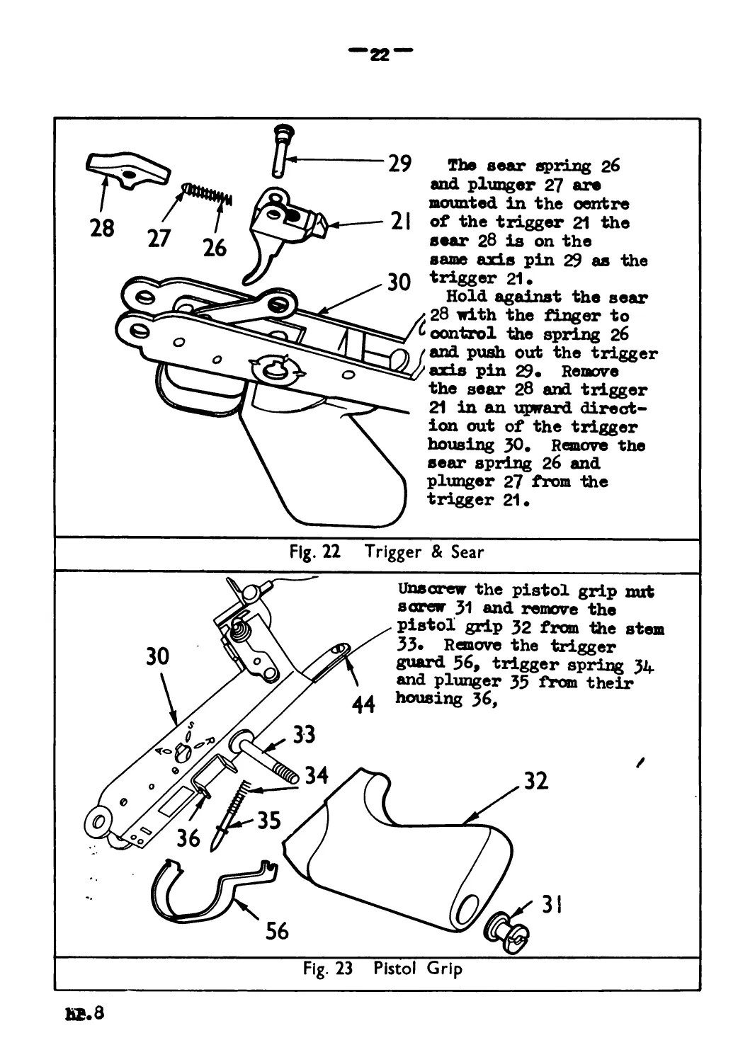
22“
The sear spring 26
and plunger 27 are
mounted in the centre
of the trigger 21 the
sear 28 is on the
same axis pin 29 as the
trigger 21.
Hold against the sear
28 with the finger to
control the spring 26
and push out the trigger
axis pin 29« Remove
the sear 28 and trigger
21 in an upward direct-
ion out of the trigger
housing JO. Remove the
sear spring 26 and
plunger 27 from the
trigger 21.
Fig. 22 Trigger & Sear
30
32
33
35
36
56
Unscrew the pistol grip nut
screw J1 and remove the
pistol grip 32 from the stem
33* Remove the trigger
guard 56, trigger spring 34
and plunger 35 f*om their
44 housing 36,
34
Fig. 23 Pistol Grip
MB. 8
Unscrew the butt plate screw 37 and remove the butt plate
Зв» Using the special tool provided 39» remove the return
spring screw 40 and withdraw the return spring 41 and washer
42.
Care must be exercised when the screw 40 is on its last
threads and the spring 41 should not be permitted to fly put
or distortion of the spring is likely.
To remove the butt 43 unscrew the wood screw 44 which is
positioned at the rear end of the trigger housing 30» and
remove the butt 43 from the return spring tube.
Fig. 24 Butt Group
ВОРТ GROUP
The safety sear 45 with spring 46 attached is turned slightly
anti-clockwise to remove. The spring 46 should not be separated
from the sear 45.
Fig. 25 Safety Sear
Unscrew the magazine catch axis pin 4-7 end remove the
holding open device 4B from its seating. Ease the magazine
catch 4-9 and spring 50 from the body. The spring 50 can
now be separated from the catch 49•
Fig. 26 Magazine Catch & Holding Open Device
HB.8
—25 —
15. BARBEL GROUP
HB.8
—26 —
16. MAGAZINE
Magazines will only be stripped when it is necessary for
cleaning purposes, excessive stripping will be avoided to reduce
wear on the bottom plate.
Lift the forward end of the bottom plate 53 slightly
and slide it off the retaining lug, remove the spring 54
and platform 55 •
Fig. 28 Magazine
/
NOTE: When assembling the magazine it is essential that the spring
is positioned correctly between the retaining lug and the
« guide lug on the platform or stoppages will occur.
The coil of the spring can be seen through the hole at the
top rear of the magazine.
17. THE UNIT SIGHT
Remove the cover guard from the Unit Sight by sliding it
rearwards along the retaining grooves of sight bed until it is free.
HB.8
— 27 —
18. LOADING- AND UNLOADING
(a) Loading
The cocking handle is pulled to the rear, the horse shoe clip
inserted in the guides (fig.29) and the rounds pushed down
firmly into the magazine. The breech block is then freed
from the holding open device. The rifle is now ready to fire.
Loading can also be done by putting on a filled magazine as
for the **BM type rifle.
(b) Unloading
Remove the magazine and pull the cocking handle back, release
the cocking handle, press the trigger and put on an empty
magazine.
(°) Changing Magazines
With the "A" type"rifle this is necessary only when the
magazine in use has been damaged or in anyway rendered
unserviceable.
With the "B*1 type, since it is not possible to clip load the
rifle, the magazine must be changed when empty.
Fig. 29 Loading “A” Type Rifle
HB.8
—28 —
(d) Filling Magazines
A magazine filler (fig.}O)can be used to fill magazines, it
is fitted over the mouth of the magazine and a five round
clip inserted into the guides, the rounds are then forced
down into the magazine.
If the magazine filler is not available filling by hand is
simple and quick.
HB.8
— 29 —
SECTION IV - OPERATION
19. BACKWARD AND FORWARD ACTION (figs. 31 - 36)
(a) Backward action
When the trigger is pressed, the tail of the trigger is
lifted forcing the rear end of the sear upwards, disengaging
the nose of the sear from the bent on the hammer. The hammer
spiring, which is under compression, is now free to force the
hammer forward to strike the firing pin.
The firing pin hits the cap of the cartridge case a sharp
blow (fig.Jl) and detonates the cap which ignites the pro-
pellant in the case, the resultant gases driving the bullet
along the barrel*
As the bullet passes the gas vent in the barrel, (fig.32) a
portion of the gases enter the gas vent and go through the
gas plug into the front end of the gas cylinder.
Unwanted gas is permitted, by means of the regulator, to pass
through the hole at the top of the cylinder, the remaining
gases striking the head of the piston.
— 30—
The piston, moving to the rear, (fig.33) strikes the top
front surface of the breech block slide, driving it rearwards.
The piston, on being driven to the rear, compresses the
piston spring, and when the gases in the cylinder are spent,
the spring forces the piston forward. Gases in the cylinder
are forced out of the gas escape holes at the forward end of
the cylinder.
During the backward movement of the breech block and slide
there are a number of actions taking place.
During its initial movement, the slide lifts the rear end of
the breech block from the locking recess in the body, and the
block can new move rearward with the slide.
The empty case, which is held by the extractor, is drawn from
the chamber and at the same time the rear bottom surface of
the slide is forcing the hammer back against its spring until
the upper bent of the hammer is finally engaged by the safety
sear.
The base of the empty case (fig. 34) is brought into contact
with the top of the ejector, and the case is forced off the
face of the breech block and out of the ejector opening.
HB.8
— 31 —
During the backward movement the slide rod, (fig.35) which
is engaged with the end of the return spring, has been
compressing the spring in the butt, and movement of the
working parts is finally brought to a stop by the rear end of
the slide coming into contact with the butt frame.
When the breech block has moved far enough to the rear to
clear the magazine (fig.}6), the magazine spring forces
upwards and positions the next round ready for loading.
HB.8
—32 —
(b) Forward Action
The breech block and slide, having been pushed backward by
the gases are now pushed forward by the return spring.
During the forward movement (fig.37) the lower front face of
the breech block engages the top of the base of the round in
the magazine and pushes it forward into the chamber (fig.38).
The hammer rotating forward is caught and held by the safety
sear on the upper bent of the hammer. The breech block
comes into contact with the breech and the rear of the block
is forced down (fig.39) by the inclined surfaces in the slide,
and the locking shoulder engages with the locking recess in
the body.
The extractor is now gripping the rim of the cartridge case.
HB.8
-33-
The slide continues its forward, movement and immediately
before reaching its limit of travel a projection on the rear
bottom surface of the slide comes into contact with the
upper arm of the safety sear, and trips it forward releasing
the nose of the safety sear from the upper bent of the hammer.
The hammer rotates forward until the lower bent is engaged
by the trigger sear.
The firing cycle will be repeated each time the trigger is
pressed.
The trigger must be fully released before a second shot can
be fired.
HB.8
—34 —
20. TRIGGER MECHANISM
INTRODUCTION
Positioned directly above the rear am of the trigger is the
change lever spindle. This is formed with a flat surface which
permits upward movement of the rear arm of the trigger.
It is this movement which determines the position of the sear
in relation to the hammer bent.
A second surface, formed by the circumference of the spindle
ensures applied safety.
(a) Single Shot (figs. 40-47)
When the change lever is put to R the flat surface
is immediately above the rear arm of the trigger. The
hammer is held by the nose of the sear engaging in the
bent. The rifle is ready to fire.
HB 8
—35 —
When the trigger is pressed, the rear arm of the
trigger pivots the rear arm of the sear upwards, disengaging
the nose of the sear from the hammer, the hamner flies
forward under the impulse of the spring and strikes the
firing pin> The sear, on being freed from the bent is
moved forward by its spring until the rear arm drops into
the step of the trigger. The nose bears up against the
hammer spindle.
During the backward movement the rear bottom surface
of the breech block slide rotates the hammer to the rear
and downwards.
HB.3
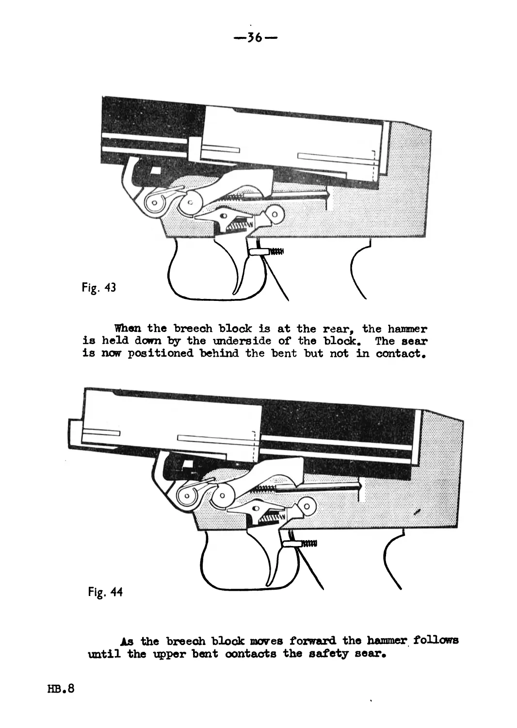
—36 —
When the breech block is at the rear, the hammer
is held dcwn by the underside of the block. The sear
is now positioned behind the bent but not in contact.
As the breech block moves forward the hammer follows
until the upper bent contacts the safety sear.
HB.8
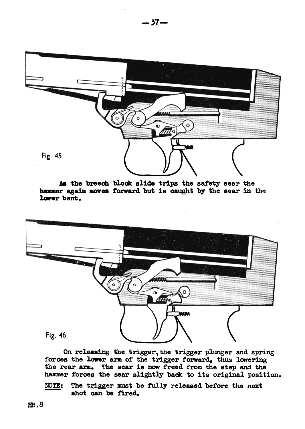
-37-
Ав the breech block slide trips the safety sear the
hammer again moves forward but is caught by the sear in the
lower bent.
On releasing the trigger, the trigger plunger and spring
forces the lower arm of the trigger forward, thus lowering
the rear arm» The sear is now freed from the step and the
hammer forces the sear slightly back to its original position.
NOTE: The trigger must be fully released before the next
shot can be fired»
HB»8
—J8 —
SAFE
When the change lever is put to safe the rounded part
of the spindle is directly over the rear arm of the trigger,
and prevents it from rising to engage with the tail of the
sear.
(b) Automatic (figs. 2»B-53)
A typo of change lever can be fitted which permits the rifle
to fire at the automatic rate.
Externally, this lever is the same shape, but has the letter A
stamped on the detent housing. Internally the spindle has a
second flat surface deeper than the one used for single shot
firing, this surface permits the rear arm of the trigger to be
raised much higher, and in consequence the nose of the sear to
be well dear of the hammer spindle.
The sequence of actions which follow the pressing of the
trigger is the same as in single shot, so also is the sequenoe
when the round has been fired except for the behaviour of the
sear.
rid.8
•39—
When the safety lever is put to A, the deep flat
surface of the spindle is over the rear arm of the
trigger, the hanmer is held Ъу the sear engaging in the
bent» The rifle is ready to fire.
On the trigger being pressed the hanmer is released
and strikes the firing pin» It will be seen that the
nose of the sear is well dear of the safety lever spindle»
HB.8
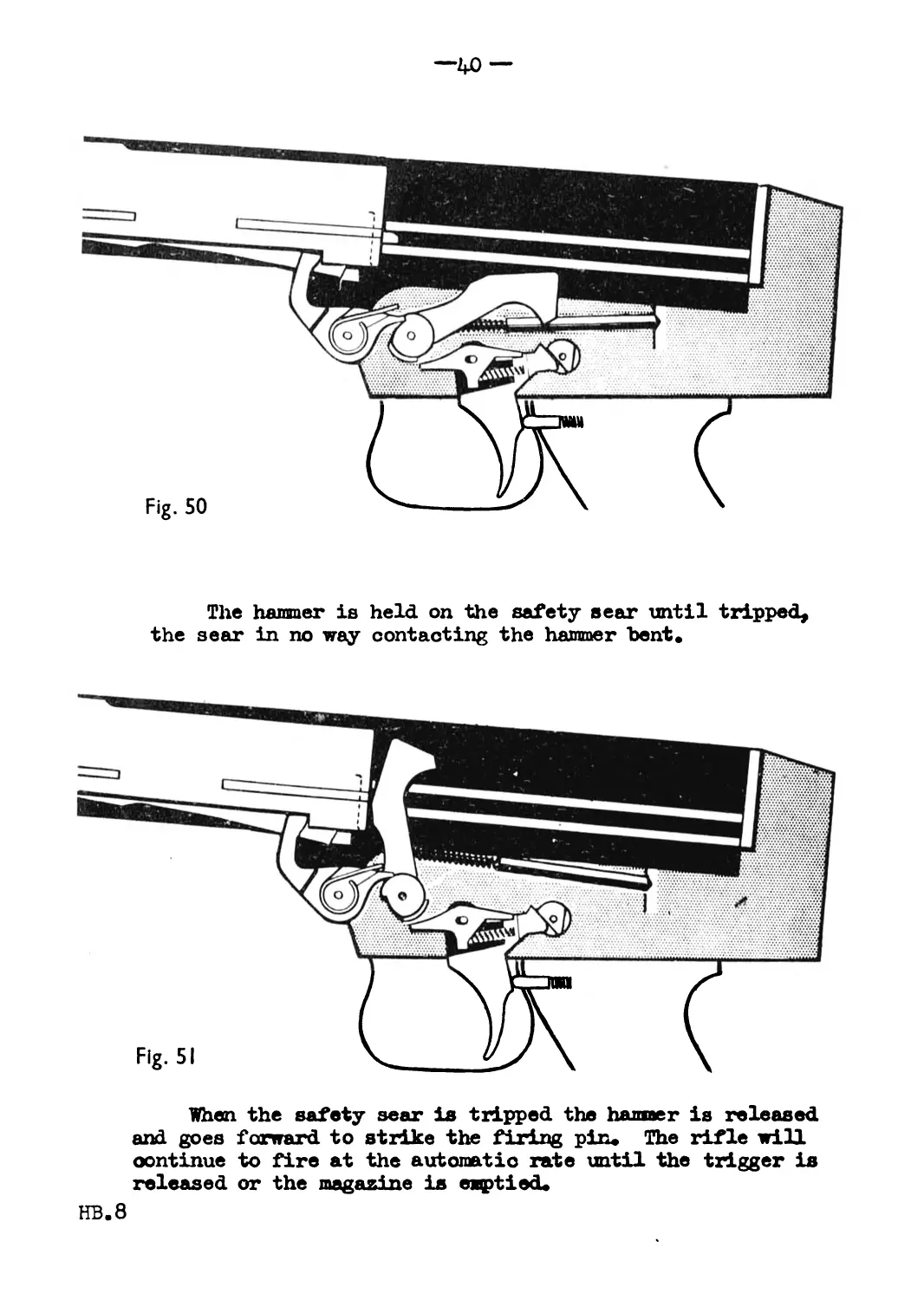
—40 —
The hammer is held on the safety eear until tripped,
the sear in no way contacting the hammer bent»
When the safety sear is tripped the banner is released
and goes forward to strike the firing pin. The rifle will
continue to fire at the automatic rate until the trigger is
released or the magazine is emptied.
HB.8
—41 —
When the trigger is released the sear rises and
engages the hammer bent.
SAM»:
When the change lever is put at safe, the rounded
portion between the two surfaces prevent the trigger being
operated as in single shot.
HB.8
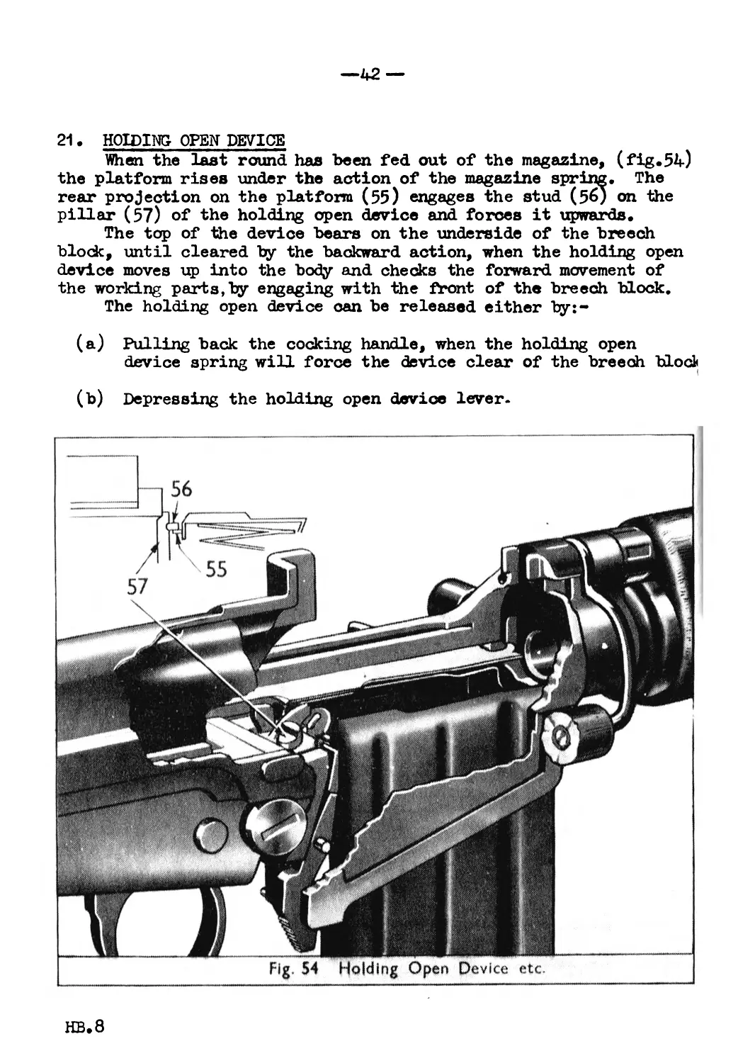
21. HOIDING OPEN DEVICE
When the last round has been fed out of the magazine, (fig.54)
the platform rises under the action of the magazine spring. The
rear projection on the platform (55) engages the stud (56) on the
pillar (57) of the holding open device and forces it upwards.
The top of the device bears on the underside of the breech
block, until cleared by the backward action, when the holding open
device moves up into the body and checks the forward movement of
the working parts,by engaging with the front of the breech block.
The holding open device can be released either by:-
(a) Pulling back the cocking handle, when the holding open
device spring will force the device clear of the breech blodi
(b) Depressing the holding open device lever.
Fig. 54 Holding Open Device etc.
HB.8
—КЗ —
SECTION V - STOPPAGES AND IMMEDIATE ACTION
This section summarizes the mechanical aspect of stoppages
and their remedies. It is not intended as an instructional pamphlet,
but as a guide upon which instructional pamphlets may be based.
22. GAUSES OF STOPPAGES
Although the list mentioned here is somewhat lengthy, it should
not be thought they will occur. Most stoppages are caused by adverse
or abnormal conditions and correct maintenance will do much to keep
their ooourrenoe down to a minimum.
The following are the main causes of stoppages
Snpty magazine
Failure to feed
Hard extraction
Friction
Insufficient gas
Obstruction in the chamber
Broken or worn part
(a) Snpty Magazine
This will occur automatically, the breech block remaining
at the rear.
(b) Failure to feed
In4his case the breech block does not go fully forward.
This stoppage may be due to incorrect handling when the
cocking handle is not released smartly. It may also be due
to a dirty or damaged round, damaged magazine or some
obstruction fouling the face of the breech block slide or
rear face of the breech.
(°) ffircL extraction
The empty case "may be in, or partially in, the chamber.
This stoppage is caused by a dirty round, and because of the
extra work, the gases are not able to perform correctly.
Manual operation will cause the case to be extracted and
once the dirty round is cleared the rifle should give no
further trouble.
(d) Friction
This stoppage may result from a number of causes such as,
dirt, fouling in the cylinder and on the piston, or lack of
lubrication on the recoiling parts.
The breech block may be anywhere along the body and manual
operation may remedy the stoppage tenporarily but only
cleaning will completely cure it.
1Ш.8
— u—
(e) Insufficient Gas
this stoppage should only occur when either conditions are
adverse or abnormal, or when the user has not fired the rifle
before and in consequence does not know the correct setting
required#
Adjustment of the regulator is easily and quickly done as ,
explained in Section VI para.27»
(f) Obstruction in the chamber
This is caused by a separated case, the forward end of which
remains in the chamber. The next round to be fed will go
partially into the chamber and the breech block will be
stopped about half way forward 4
(g) Broken or worn parts
In investigating the cause of such a stoppage, looking into
the body and chamber should disclose to the firer which
part is at fault.
A round in the chamber with the cap struck indicates a
broken extractor or extractor spring.
An unfired round drawn out of the chamber on cocking the
rifle indicates a broken firing pin.
It is the responsibility of the armourer to change broken
parts.
23. REMEDY IMMEDIATE ACTION
Most of the stoppages which may occur can be remedied by the
user applying an immediate action. There are two things he must do
if the rifle fails to fire:-
1. Grasp the cocking handle
2. Look into chamber and body
and from what he sees, apply his immediate action as follows
(a) If the working parts are to the rear
(i) Clip load
(ii) Pull back the cocking handle
(iii) Continue firing
with the ”BM type rifle, change the magazines.
(b) If the working parts are not fully forward
(i) Use the auxiliary cocking catch and pull back to the
stop
(ii'Jl Release the cocking handle
HB.8 (iii) Continue firing
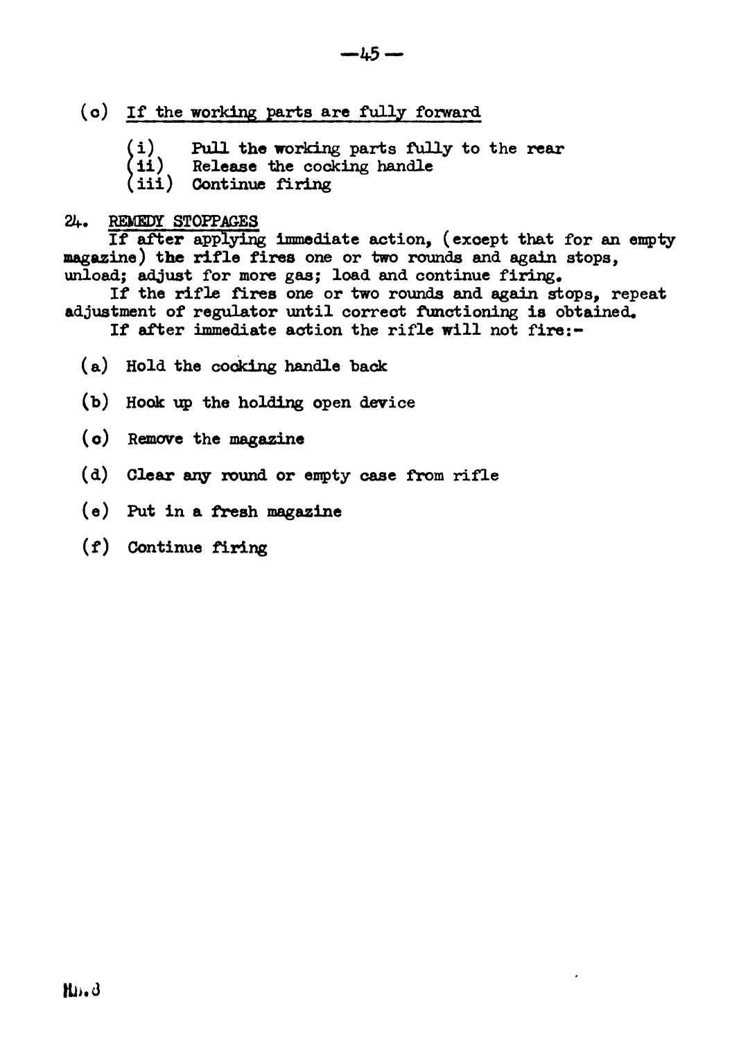
(°) If the working parts are fully forward
i) Pull the working parts fully to the rear
ii) Release the cocking handle
iii) Continue firing
24. REMEDY STOPPAGES
If after applying immediate action, (except that for an empty
magazine) the rifle fires one or two rounds and again stops,
unload; adjust for more gas; load and continue firing.
If the rifle fires one or two rounds and again stops, repeat
adjustment of regulator until correct functioning is obtained.
If after immediate action the rifle will not fire:-
(a) Hold the cooking handle back
(b) Hook up the holding open device
(c) Remove the magazine
(d) Clear any round or empty case from rifle
(e) Put in a fresh magazine
(f) Continue firing
—1*6 —
SECTION VI - CARE. CLEANING- AND MAINTENANCE
25. CMANING MATERIALS
The puilthrough^is made up of & metal weight and a cord. The
weight is pointed and can be used to remare hard fouling from the
gas plug.
The cord has two loops situated about two thirds along its
length, one for use with the wire gauze, the other for flannelette;
A third loop at the end of the cord is used to assist removal of
the cord should it jam in barrel or cylinder.
The oil bottle is the normal type with the spoon. Under norma
conditions the bottle will be kept filled with oiljflMW (Oil ’A’)
Pullthrough and oil bottle are stored in the butti' The oil
bottle will be put in screw top first, followed by the cord which
will be coiled tightly. The butt trap retains these articles in
position.
Normal service flannelette is used for cleaning the barrel and
cylinder.
Rags or cotton waste will be used to dean the remaining parts
of the rifle.
NO ABRASIVE MATERIAL OF ANY KIND WILL BE USED TO CLEAN THE
RIFLE.
26. BEFORE FIRING-
The rifle will be field stripped and all parts exposed will
be dry cleaned. Before assembling, each part will be examined for
wear and burrs.
Worn parts must be exchanged and burrs will be removed by the
armourer.
Parts will be oiled or left dry as under:-
OILED
LEFT DRY
Piston spring
. Inside breech block slide
Guide ribs.
Breech block
Locking shoulder recess
Guide grooves
Holding open device
Magazine catch
Barrel
Gas Cylinder
Gas Plug
Piston, especially tfie forward
end and between the rings
Upper surface
Face of block
Magazine platform
Sights
HB.8
—47 —
17* gas regulator
The gas regulator will be adjusted for correct functioning.
Screw the gas regulator to the right until it is fully forward,
llhen unscrew one and a half turns.
The outer surface of the regulator is marked to indicate its
DOB it ion, but if it is not possible to see these marks, the clicking
device on the regulator is the only means of determining the exact
petition of the regulator.*
There are fourteen clicks to one complete turn, so twenty one
Are needed to put on the first adjustment.
This adjustment may vary with different rifles, and the user
must learn from experience the correct setting under normal
olroumstances.
Magazines,ammunition and clips should be cleaned and examined
for damage.
«8. DURING- FIRING
It may be necessary during firing to readjust the gas regulator.
'Лю rifle will be unloaded and the regulator turned to correct the
balance.
If the rifle has been giving stoppages, screw the regulator
forward by a minimum of two clicks at a time until correct
functioning is obtained.
If there is excessive backward hammering on the shoulder of
b)w firer, unscrew the regulator by a minimum of two clicks at a
Vlino until the balance is adjusted correctly.
Every opportunity should be taken to clean and re-oil the
rifle during non-firing periods, special attention being given
liO the gas affected parts.
To avoid overheating the round in the chamber, when possible
during periods of rapid fire, the breech should be opened and ihe
breooh block held back on the holding open device.
В9» AFTER FIRING
i4eld strip the rifle, and, using the pullthrough and slightly -
Oiled flannelette clean out the barrel and cylinder. Dry and if
Oloon, re-oil.
Olean remainder of rifle with special attention to the gas
Affooted parts. The barrel and cylinder will be cleaned carefully
for two or three days after firing.
Magazines will be cleaned and oiled.
If the bayonet has been used, clean the handle and prongs
Oftrofully and oil slightly.
JO. ABNORMAL WEATHER CONDITIONS
In cold climates the rifle should be carefully dried. The
gAA regulator may have to be adjusted to give more gas.
It will assist in the initial stages of firing, if the working
{ArtВ are hand operated sharply backwards and forwards a few times
tfore loading takes place.
In hot dusty climates the rifle should be carefully dried.
KD.8
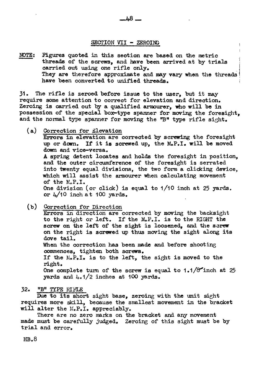
SECTION VII - ZEROING- ,
NOTE: Figures quoted in this section are based on the metric
threads of the screws, and have been arrived at by trials !
carried out using one rifle only.
They are therefore approximate and may vary when the threads I
have been converted to unified threads.
J1. The rifle is zeroed before issue to the user, but it may
require some attention to correct for elevation and direction.
Zeroing is carried out by a qualified armourer, who will be in
possession of the special box*-type spanner for moving the foresight,
and the normal type spanner for moving the "BH type rifle sight.
(a) Correction for Elevation
Errors in elevation are corrected by screwing the foresight
up or down. If it is screwed up, the M.P.I. will be moved
down and vice-versa.
A spring detent locates and holds the foresight in position,
and the outer circumference of the foresight is serrated
into twenty equal divisions, the two form a clicking device,
which will assist the armourer when calculating movement
of the M.P.I.
One division (or click) is equal to 1/Ю inch at 25 yards,
or 0 inch at 100 yards.
(b) Correction for Direction
Errors in direction are corrected by moving the backsight
to the right or left. If the M.P.I. is to the RIGHT the
screw on the left of the sight is loosened, and the screw
on the right is screwed up thus moving the sight along its
dove tail.
When the correction has been made and before shooting
commences, tighten both screws.
If the M.P.I. is to the left, the sight is moved to the
right.
One complete turn of the screw is equal to 1.1 /O'*inch at 25
yards and 4*1/2 inches at 100 yards.
32. "B" TYPE RIFLE
Due to its short sight base, zeroing with the unit sight
requires more skill, because the smallest movement in the bracket
will alter the M.P.I. appreciably.
There are no zero marks on the bracket and any movement
made must be carefully judged. Zeroing of this sight must be by
trial and error.
HB.8
—49 —
(a) Correction for Elevation
The cover must first be removed and the rear lode screw
loosened* The nut is then turned right or left as required
to raise or lower the bracket and the lock screw tightened.
|}tpTE: Care must be used so that the Battle sight is positioned
oorrectly before locking the bracket.
(b) Correct ion for Direction
UiniSbrew the lock screw on the top front surface of the
brqickdt, and turn the eccentric nut right or left to move
t|ie' front of the bracket as required, then tighten the
16ok screw.
33. BATTLE SIGHT
The foresight can be zeroed for elevation by fitting
washers under the collar of the sight.
Direction is obtained by unlocking the rear lock screw and
by moving the sight right or left as required.
34. ZEROING- DATA
ттга ce* RIFLE RANGE YARDS POSITION OP M.P.I. ELEVATION 1 СОМНЕТЕ TURN OF SCREW DIRECTION 1 COMPLETE TURN OF SCREW PERMISSIBLE VARIATION
A 25 2/3" DOWN 1/2"
2" 1.1/8"
100 1.1/2" ОТ 8» 4.1/2" 2"
& 3A"d0wn :•< 9» 8" 1/2"
100 2" ОТ зб" 32" 2"