/


Теги: weapons military affairs
Год: 1917


Текст
No. 1920
DESCRIPTION
AND RULES FOR THE MANAGEMENT OF THE
U. S. MAGAZINE RIFLE
MODEL OF 1898
AND
MAGAZINE CARBINE
MODEL OF 1899
CALIBER <30
WASHINGTON
GOVERNMENT PRINTING OFFICE
1917
(3)
THE U. S. MAGAZINE RIFLE AND CARBINE.
Since the adoption of this arm the following changes have been made
by the authority of the Chief of Ordnance:
Barrel.—Muzzle rounded in Model 1896.
Rear end rounded in July, 1899.
Bayonet Blade.—Bluing stopped, April 1, 1895.
Bayonet Grip.—Sanding stopped, April 12, 1899.
Bayonet Grip Rivets.—Ends rounded, November 9, 1899.
Bayonet Scabbard Hook.—Oscillation limited to 100 degrees,
April 17, 1897.
New pattern adopted, July 22, 1899.
Bayonet Scabbard Mouthpiece.—Aperture for blade made rec-
tangular, July 15, 1895.
Bolt.—About one-fourth of left side of guide rib removed, June 17,
1895.
Slot for securing stud omitted, June 29, 1895.
Length of flat surface on under side of handle increased in
Model 1898.
Butt Plate.—Thickness increased 0.04 inch, toe curved, cap hole
and spring lug added in Model 1896.
Butt Plate Cap, Cap Pin, Cap Spring, and Cap Spring Screw.—
Added in Model 1896.
Butt Plate Screw, Large.—Head made flat in Model 1896.
Carrier.—Magazine spring lug shortened, March 4, 1895.
Arbor made perpendicular to top and shortened 0.02 inch
and distance between lug and bottom side of body decreased
0.02 inch in Model 1898.
Modified to hold up point of first cartridge, November 20,
1899.
Cleaning Rod.—Made jointed and inserted in butt of stock in
Model 1896.
Cocking Piece.—Made of high instead of low steel, August 1, 1895.’
Rear part of lug beveled and locking notch added in Model
1896.
Cut-Off.—Blued instead of spring tempered, July 15, 1895.
Thickness of thumb-piece increased 0.015 inch, and slot for
flat spring replaced by spring spindle hole, April 30, 1895.
Flatting of spindle reversed, length of spindle decreased 0.5
inch, rear upper edge of thumb-piece beveled and fillet
added at junction of spindle and thumb-piece in Model
1898.
Thumb-piece left bright, December 5, 1898.
Only one side of thumb-piece polished, January, 1900.
(5)
6 • • : . ЛТ.. S., MAGAZINE RIFLE AND CABBINE.
Cut-Off Spring.—Flat replaced by spiral pattern, April 30, 1895.
Cut-Off Spring Spindle.—Added April 30, 1895.
Length increased 0.013 inch, August 6, 1895.
Ejector Pin.—Head rounded and length increased, January 28,
1895.
Extractor.—Depth of extractor spring pivot hole increased 0. 028
inch, September 3, 1895.
Extractor pin lug added in Model 1896.
Fillet added at junction of under side of body and heel, Jan-
uary 25, 1896.
Extractor Pin.—Added in Model 1896.
Extractor Screw.—Replaced by extractor rivet in Model 1896.
Front Sight Stud.—Width of slot reduced to 0.05 inch in Model
1896.
Front Sight.—Height of top above axis of bore increased from
0.82 inch to 0.85 inch, June 20, 1894.
Thickness made 0.05 inch throughout and shape of top
changed in Model 1896.
Height of top above axis of bore increased from 0.85 inch to
0.975 inch for use with Model 1901 rear sight.
Front Sight Pin.—Length increased and taper changed in Model
1896.
Gate.—Length of lug reduced 0.0065 inch, April 1, 1895.
Fillet added at junction of lug and hinge, October 8, 1895.
Shape of exterior and interior of front end changed, October
8, 1895.
Curvature of exterior and shape of interior at rear end
changed, and bevel on the front part of the interior of the
top omitted in the Model 1898.
Guide Lip.—Tenon to enter groove in receiver omitted, Septem-
ber 8, 1894.
Thickness increased in Model 1896.
Hand Guard Body.—Extended rearward over tenon of receiver
and heads of rivets countersunk deeper in Model 1896.
Hand Guard Rivets, Front and Rear.—Shortened in 1895.
Hand Guard Springs.—Crimp omitted in Model 1896.
Hinge Bar Head.—Rear right edge rounded, May 11, 1895.
Fillet added at junction of spring and head, June 4, 1895.
Width of lug on spring reduced 0.03 inch, January 30, 1896.
Hinge Bar Pin.—Blued instead of spring tempered, July 15, 1895.
Main Spring.—Length increased from 30| to 33| coils in Model
1896.
Weight reduced from 18 to 22 pounds to 16 to 18 pounds in
Model 1896.
Ramrod.—Omitted in Model 1896.
U. S. MAGAZINE RIFLE AND CARBIKE. 7
Ramrod Stop.—Omitted in Model 1896.
Receiver.—Groove for guide lip tenon omitted, September 8, 1894.
Slot for ejector pin head omitted, January 28, 1895.
Walls of trigger heel slot omitted, May 27, 1895.
Depth of cut-off spring spindle recesses increased, October
15, 1895.
Extractor pin notch added in Model 1896.
The following changes were embodied in the Model 1898,
viz:
Cut-off hole reduced 0.5 inch in depth, and position slightly
changed.
Width of mortise for side plate tenon increased 0.02 inch.
That part of the bolt handle seat projecting beyond tang
omitted.
Outside of right wall over gate beveled.
Bearing for top side of carrier, in carrier arbor cavity, low-
ered 0.02 inch.
That part of the left wall of the magazine spring channel
projecting beyond the bottom wall omitted.
Mark on side of tenon for position of barrel omitted.
Top of carrier arbor ear lowered to project only slightly
above top of gate.
Bottom of magazine spring channel made parallel to bottom
of magazine.
Fillet in tenon added, July, 1899.
Safety Lock.—Thickness of thumb-piece increased; thumb-piece
and spindle made separate, and spring and spring spindle
added in Model 1896.
Safety Lock Spindle.—Depth of safety lock pin groove in Model
1892 reduced (see sleeve). The spindle with deep groove
is known as Model 1892. second pattern, and with the
shallow groove as Model 1892, third pattern.
Safety Lock Pin.—Omitted in Model 1896.
Sear.—Made of low instead .of high steel, October 25, 1895.
Nose shortened 0.005 inch, November 26, 1895.
Sear Spring.—Size of wire changed from 0.041 inch to 0.047 inch,
November 21, 1898.
Side Plate.—Hole for ejector pin head added, January 28, 1895.
Thickness of upper half increased and cartridge rib length-
ened in Model 1896.
Thickness of tenon increased 0.02 inch in Model 1898.
Polishing inside stopped, November 28, 1898.
Rear upper corner rounded, May 5, 1899.
Side Plate Screw.—Shortened in length one thread, June 1, 1894.
8
U. S. MAGAZINE RIFLE AND CARBINE.
Sleeve.—Safety lock pin hole raised 0.03 inch, October 22, 1894.
The sleeve with low safety lock pin hole is known as Model
1892, first pattern, and with high hole as Model 1892, sec-
ond pattern.
Securing stud and rivet omitted, June 29, 1895.
Knurling omitted, June 15, 1895.
The following changes were embodied in the Model 1896,
viz:
Safety lock pin hole omitted.
Front end of barrel shortened 0.0345 inch.
Thickness of extractor arm reduced 0.035 inch.
Countersink for screw head omitted, and lower part of rivet
hole countersunk for rivet head.
Groove with a recess at each end added for safety lock spring
spindle.
Stock.—Changes embodied in model 1896:
Small enlarged.
Toe rounded.
Two holes, 1 inch in diameter, to decrease the weight, and
three small holes for cleaning rod drilled in butt.
Oiler seat cut between large holes.
Channels cut under barrel to decrease the weight.
Ramrod groove and stop slot omitted.
Bolt handle seat changed in .Model 1898.
Size of cleaning rod holes changed from 0.22 inch to 0.24
inch, November 21, 1898.
Striker.—Point rounded, December 2, 1895.
Trigger.—Case-hardened in water instead of oil, April 2, 1894.
Case-hardened in oil instead of water, November 21, 1898.
Width of sear slot changed from 0.24 inch to 0.25 inch,
November 21, 1898.
Trigger Pin.—Length reduced 0.045 inch, November 15, 1895.
Upper Band.—Middle portion over barrel removed, August 16,
1894.
Bushing for ramrod omitted in Model 1896.
Note.—All guns of Models of 1892 have been or are being converted to Model
of 1896. In the Model 1898, and all rifles and carbines since made, that part of
the bolt handle seat projecting beyond the exterior wall of the receiver has been
omitted, and the seat for the bolt handle in the stock correspondingly reduced in
size.
THE RIFLE.
COMPONENT PARTS, EXCLUSIVE OF REAR SIGHT.
(Eighty-seven in number.')
Barrel: Front Sight.
Barrel. Front Sight Pin.
Front Sight Stud. Gate.
Bolt. Guard.
Butt Plate. Guard Screw, front.
Butt Plate Cap. Guard Screw, rear.
Butt Plate Cap Pin. Hand Guard:
Butt Plate Cap Spring. Hand Guard Body.
Butt Plate Cap Spring Screw. Hand Guard Rivets, front (2)
Butt Plate Screw, large. Hand Guard Rivets, rear (2).
Butt Plate Screw, small. Hand Guard Spring, front.
Butt Swivel. Hand Guard Spring, rear.
Butt Swivel Pin. Hinge Bar:
Butt Swivel Plate. Binge Bar Head.
Butt Swivel Plate Screws (2). Hinge Bar Pin.
Carrier. Lower Band.
Cleaning Rod, 1st section. Lower Band Pin.
Cleaning Rod, 2d and 3d sections. Lower Band Swivel.
Cut-off. Lower Band Swivel Screw.
Cut-off Spring. Magazine Spring.
Cut-off Spring Spindle. Main Spring.
Ejector. Receiver:
Ejector Pin. Receiver.
Extractor. Guide Lip.
Extractor Pin. Guide Lip Rivet.
Extractor Rivet. Safety Lock:
Extractor Spring. Safety Lock Spindle.
Firing Pin: Safety Lock Spring.
Cocking piece. Safety Lock Spring Spindle.
Firing Pin Rod. Safety Lock Thumb Piece.
Follower. Sear.
Follower Pin. Sear Spring.
(9)
10
U. S. MAGAZINE RIFLE, MODEL 1898.
Side Plate.
Side Plate Screw.
Sleeve.
Stacking Swivel.
Stacking Swivel Screw.
Stock.
Striker.
Trigger.
Trigger Pin.
Upper Band.
Upper Band Screw.
Bayonet:
Bayonet Blade.
Bayonet Catch.
Bayonet Catch Nut.
Bayonet Catch Spring.
Bayonet Grip Body, right.
Bayonet Grip Body, left.
Bayonet Grip Rivets (2).
Bayonet Grip Washers (4).
Bayonet Guard.
Bayonet Pommel.
DESCRIPTION AND NOMENCLATURE OF RIFLE.
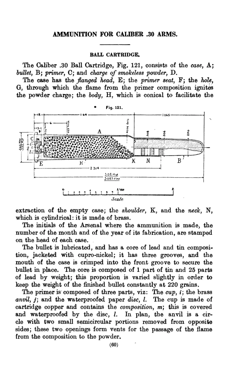
The Barrel, Fig. 3, has the muzzle, A, rounded to
protect the rifling; front sight stud and front sight pin
hole, B; rear sight screw holes, C; tenon, D, on which is
a thread for securing the receiver to the barrel; and the
face, E, which supports the rim of the cartridge case.
The chamber, Fig. 4, is made slightly conical to facilitate
the withdrawal of the cartridge case and has two con-
tractions, the rear one, A, called the shoulder, and the
front one, B, the throat; immediately in front of the
throat the bore is enlarged to form the bullet seat, C.
The rifling begins in the throat. A slot, D, is cut in the
rear end of the barrel to receive the extractor hook.
The muzzle and the front sight stud are shown in Fig. 5.
The stud is brazed to the barrel in manufacture; the slot,
E, is the front sight seat.
и. s. MAGAZINE RIFLE, MODEL 1898.
11
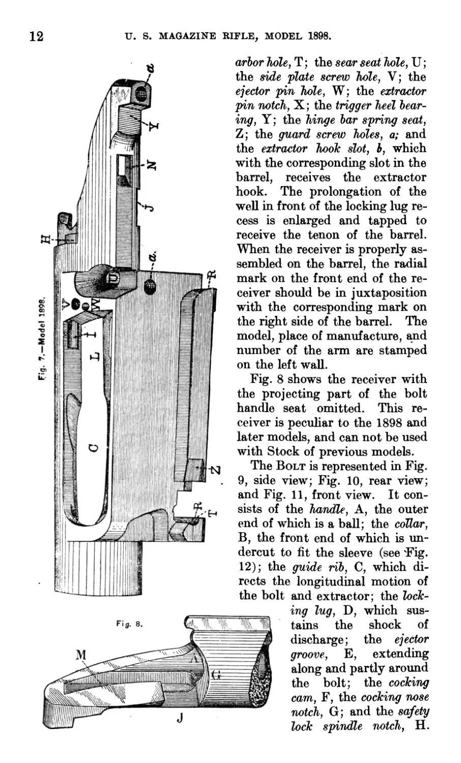
The Receiver is shown in Figs. 6 and 7. The hole, A, called
the well, receives the bolt. The magazine, B, holds five car-
tridges; it is beneath the well, with which it is connected by the
magazine channel, C, shaped to properly direct the passage of the
cartridge from the magazine into
the chamber. The ramp, D, and
the corresponding ramp on the
side plate guide the bullet into the
chamber. Theleft wall, E, is con-
tinuous and guides the bolt and
extractor when moved backward
and forward. Part of the right
wall is cut away for the bolt lugs,
to allow the ejection of the empty
cartridge case, and the loading
when the arm is used as a single
loader. The inside of the right
wall is cut away to permit the free
passage of the locking lug and to
receive the guide rib of the bolt
when the latter is closed. The
front end, F, of the rear part of
the right wall is the locking
shoulder, and the rear end, G,
the cocking shoulder; the upper
parts of these shoulders are heli-
coidal cams. The opening be-
tween the two walls admits the
extractor, guide rib and locking
lug of the bolt, and the extractor
arm of the sleeve, and also pre-
vents the latter from rotating
with the bolt. The cut-off recess,
H, has two small grooves in
which the cut-off spring spindle
works; the cut-off hole, I, ex-
tends from the front end of the
recess forward, over the maga-
zine channel. Other parts are
the bolt handle seat, J; the lock-
the ejector seat, L;
ing lug recess, K, with its shoulder and cam;
the cocking piece groove, M; the sear nose slot, N; the side plate
tenon mortise, O; the guide lip, P, riveted to the receiver in manu-
facture by the guide lip rivet; the extractor spring lip, Q; the
hinge bar holes, R; the magazine spring channel, S; the carrier
12
U. S. MAGAZINE RIFLE, MODEL 1898.
Model 1898.
arbor hole, T; the sear seat hole, U;
the side plate screw hole, V; the
ejector pin hole, W; the extractor
pin notch, X; the trigger heel bear-
ing, Y; the hinge bar spring seat,
Z; the guard screw holes, a; and
the extractor hook slot, b, which
with the corresponding slot in the
barrel, receives the extractor
hook. The prolongation of the
well in front of the locking lug re-
cess is enlarged and tapped to
receive the tenon of the barrel.
When the receiver is properly as-
sembled on the barrel, the radial
mark on the front end of the re-
ceiver should be in juxtaposition
with the corresponding mark on
the right side of the barrel. The
model, place of manufacture, and
number of the arm are stamped
on the left wall.
Fig. 8 shows the receiver with
the projecting part of the bolt
handle seat omitted. This re-
ceiver is peculiar to the 1898 and
later models, and can not be used
with Stock of previous models.
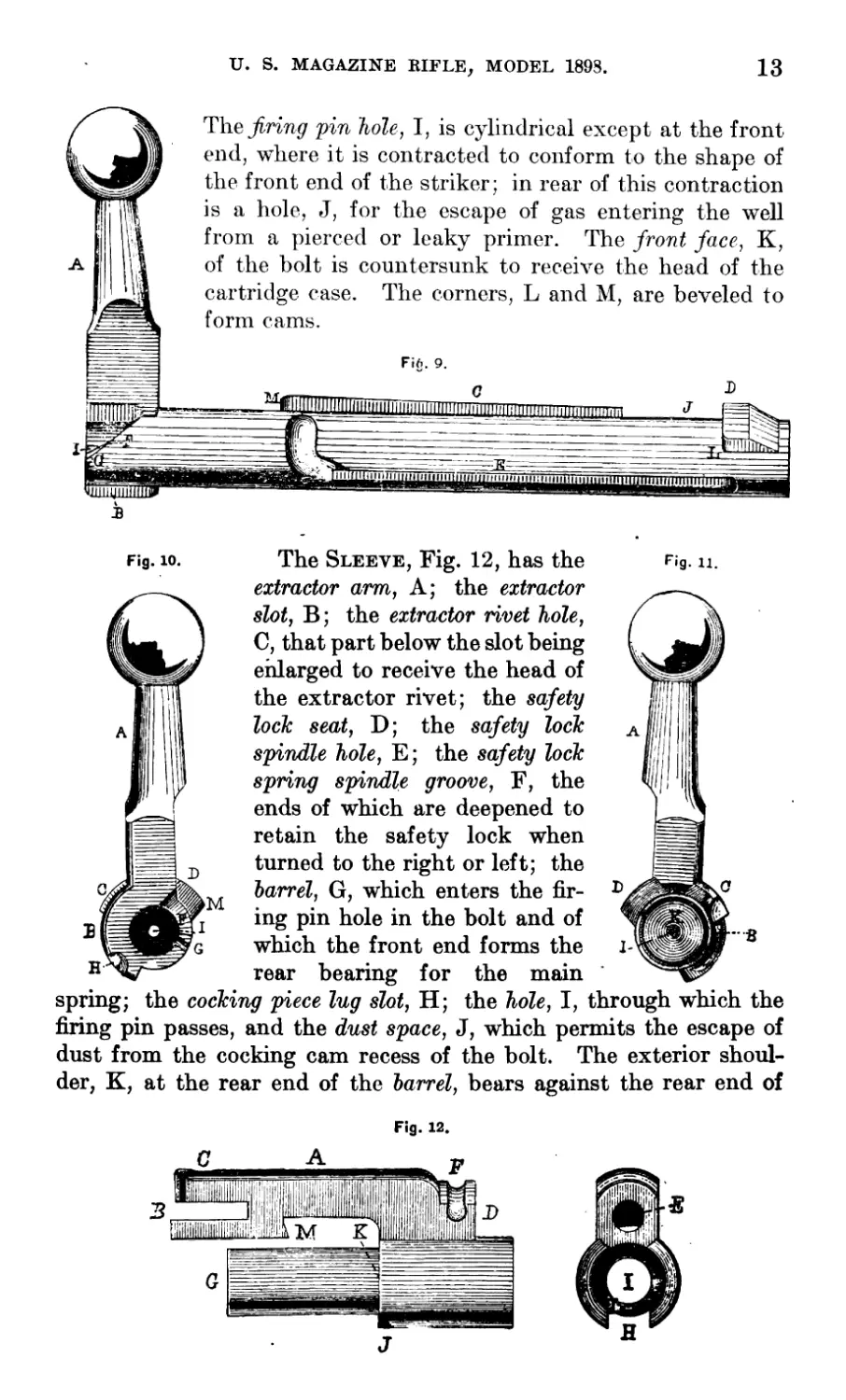
The Bolt is represented in Fig.
9, side view; Fig. 10, rear view;
and Fig. 11, front view. It con-
sists of the handle, A, the outer
end of which is a ball; the collar,
B, the front end of which is un-
dercut to fit the sleeve (see 'Fig.
12); the guide rib, C, which di-
rects the longitudinal motion of
the bolt and extractor; the lock-
ing lug, D, which sus-
tains the shock of
discharge; the ejector
groove, E, extending
along and partly around
the bolt; the cocking
cam, F, the cocking nose
notch, G; and the safety
lock spindle notch, H.
U. S. MAGAZINE RIFLE, MODEL 1898.
13
I
ШЩПш
з
The^rin^ pin hole, I, is cylindrical except at the front
end, where it is contracted to conform to the shape of
the front end of the striker; in real’ of this contraction
is a hole, J, for the escape of gas entering the well
from a pierced or leaky primer. The front face, K,
of the bolt is countersunk to receive the head of the
cartridge case. The corners, L and M, are beveled to
form cams.
Fift. 9.
c
ШШЦ|1Ш111!1<|||11Д1
ПМПППТШШипищШ1ШДЩЩШ1|1
ntnnnni
Fig. 10.
The Sleeve, Fig. 12, has the
extractor arm, A; the extractor
slot, B; the extractor rivet hole,
C, that part below the slot being
enlarged to receive the head of
the extractor rivet; the safety
lock seat, D; the safety lock
spindle hole, E; the safety lock
spring spindle groove, F, the
ends of which are deepened to
retain the safety lock when
turned to the right or left; the
barrel, G, which enters the fir-
ing pin hole in the bolt and of
which the front end forms the
rear bearing for the main
Fig. 11.
spring; the cocking piece lug slot, H; the hole, I, through which the
firing pin passes, and the dust space, J, which permits the escape of
dust from the cocking cam recess of the bolt. The exterior shoul-
der, K, at the rear end of the barrel, bears against the rear end of
Fig. 12.
14
U., S. MAGAZINE RIFLE, MODEL 1898.
the bolt and the interior shoulder, L, limits the forward movement
of the cocking piece. The bevel on the front end of the bolt collar
recess, M, fits the undercut on the front end of the bolt collar and
holds the sleeve on the bolt, allowing the latter to rotate without
the former.
Fig. 14.
Fig. 16L
Fig. 15.
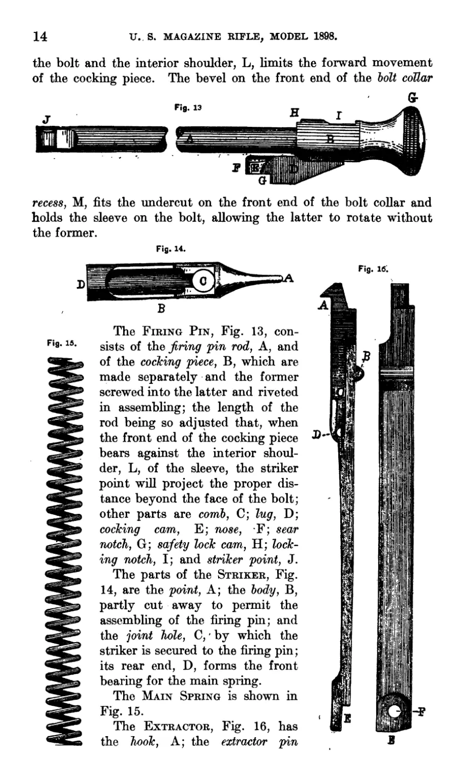
The Firing Pin, Fig. 13, con-
sists of the firing pin rod, A, and
of the cocking piece, B, which are
made separately and the former
screwed into the latter and riveted
in assembling; the length of the
rod being so adjusted that, when
the front end of the cocking piece
bears against the interior shoul-
der, L, of the sleeve, the striker
point will project the proper dis-
tance beyond the face of the bolt;
other parts are comb, C; lug, D;
cocking cam, E; nose, F; sear
notch, G; safety lock cam, H; lock-
ing notch, I; and striker point, J.
The parts of the Striker, Fig.
14, are the point, A; the body, B,
partly cut away to permit the
assembling of the firing pin; and
the joint hole, C, by which the
striker is secured to the firing pin;
its rear end, D, forms the front
bearing for the main spring.
The Main Spring is shown in
Fig. 15.
The Extractor, Fig. 16, has
the hook, A; the extractor pin
в
U. S. MAGAZINE RIFLE, MODEL 1898.
15
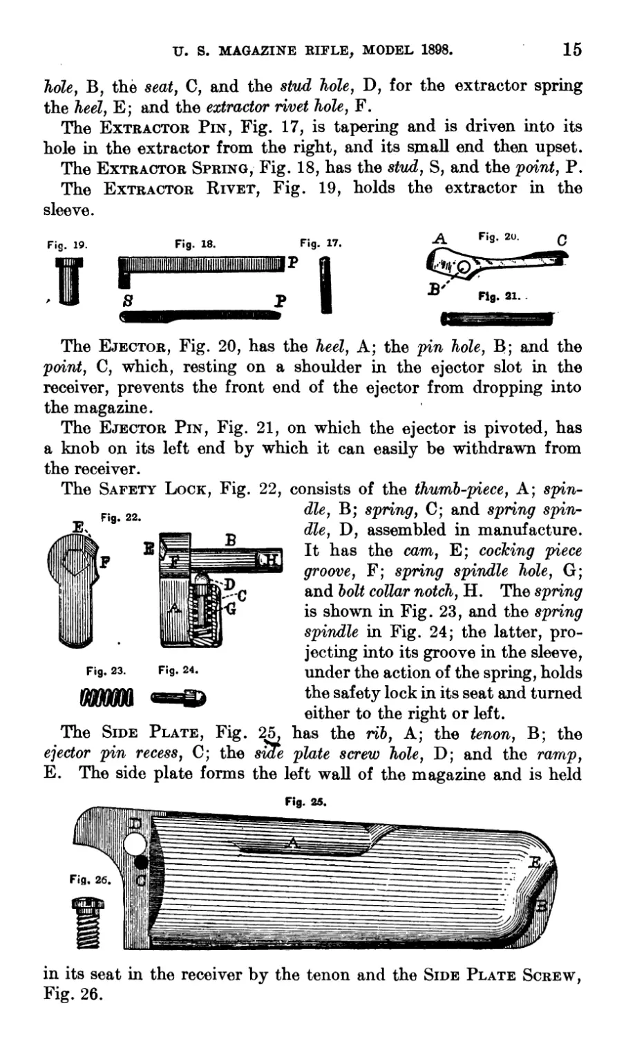
hole, B, the seat, C, and the stud hole, D, for the extractor spring
the heel, E; and the extractor rivet hole, F.
The Extractor Pin, Fig. 17, is tapering and is driven into its
hole in the extractor from the right, and its small end then upset.
The Extractor Spring, Fig. 18, has the stud, S, and the point, P.
The Extractor Rivet, Fig. 19, holds the extractor in the
sleeve.
Fig. 19. Fig. 18. Fig. 17.
The Ejector, Fig. 20, has the heel, A; the pin hole, B; and the
point, C, which, resting on a shoulder in the ejector slot in the
receiver, prevents the front end of the ejector from dropping into
the magazine.
The Ejector Pin, Fig. 21, on which the ejector is pivoted, has
a knob on its left end by which it can easily be withdrawn from
the receiver.
The Safety Lock, Fig. 22, consists of the thumb-piece, A; spin-
dle, B; spring, C; and spring spin-
dle, D, assembled in manufacture.
It has the cam, E; cocking piece
groove, F; spring spindle hole, G;
and bolt collar notch, H. The spring
is shown in Fig. 23, and the spring
spindle in Fig. 24; the latter, pro-
jecting into its groove in the sleeve,
under the action of the spring, holds
the safety lock in its seat and turned
either to the right or left.
The Side Plate, Fig. 25, has the rib, A; the tenon, B; the
ejector pin recess, C; the sme plate screw hole, D; and the ramp,
E. The side plate forms the left wall of the magazine and is held
in its seat in the receiver by the tenon and the Side Plate Screw,
Fig. 26.
16
и. 5. MAGAYINF. RIFLE, MODEL 1898.
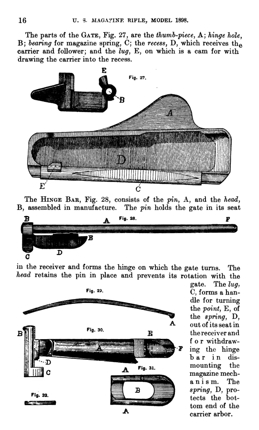
The parts of the Gate, Fig. 27, are the thumb-piece, A; hinge hole,
B; bearing for magazine spring, C; the recess, D, which receives the
carrier and follower; and the lug, E, on which is a cam for with
drawing the carrier into the recess.
The Hinge Bar, Fig. 28, consists of the pin, A, and the head,
B, assembled in manufacture. The pin holds the gate in its seat
in the receiver and forms the hinge on which the gate turns. The
head retains the pin in place and prevents its rotation with the
Fig. 89.
A
gate. The lug,
C, forms a han-
dle for turning
the point, E, of
the spring, D,
out of its seat in
the receiver and
for withdraw-
ing the hinge
bar in dis-
mounting the
magazine mech-
a n i s m. The
spring, D, pro-
tects the bot-
tom end of the
carrier arbor.
и. S. MAGAZINE RIFLE, MODEL 1898.
17
The Magazine Spring, Fig. 29, has a lip, A, on its front end,
which bears in the notch on the heel of the carrier.
The Carrier, Fig. 30, has the curved face, A; the arbor, B; the
Лее?, C; the cam, D; the follower pin hole, E; and the point, F,
which is shaped to raise the cartridges into the magazine channel.
The Follower, Fig. 31, has the pin holes, A; the opening, B,
through which the point of the carrier operates; and the top, C; it
is assembled to the carrier by the Follower Pin, Fig. 32, on which
it swings. This pin is tapering, its small end is inserted from the
top of the follower and, when driven into place, both ends are
upset and the upper filed until all projection above the top of the
follower is removed.
Fig. 33.
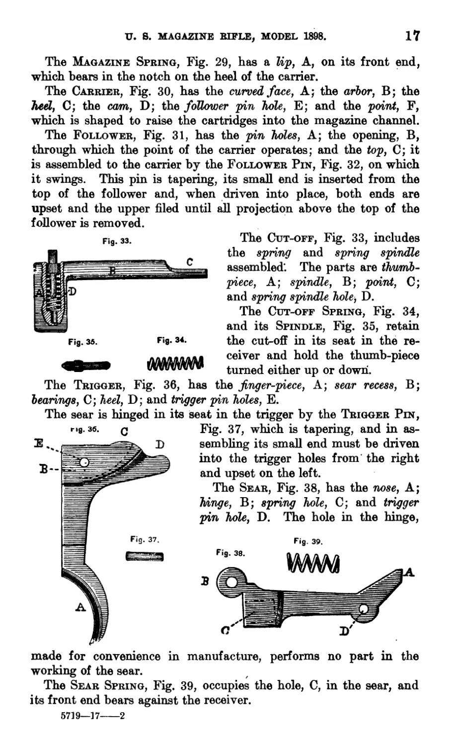
Fig. 35. F'9. 34.
The Trigger, Fig. 36, has
The Cut-off, Fig. 33, includes
the spring and spring spindle
assembled'. The parts are thwmb-
piece, A; spindle, B; point, C;
and spring spindle hole, D.
The Cut-off Spring, Fig. 34,
and its Spindle, Fig. 35, retain
the cut-off in its seat in the re-
ceiver and hold the thumb-piece
turned either up or down.
the finger-piece, A; sear recess, B;
bearings, C; heel, D; and trigger pin holes, E.
The sear is hinged in its seat in the trigger by the Trigger Pin,
Fig. 37, which is tapering, and in as-
sembling its small end must be driven
into the trigger holes from the right
and upset on the left.
The Sear, Fig. 38, has the nose, A;
b/inge, B; spring hole, C; and trigger
pin hole, D. The hole in the hinge,
Fig. 39.
made for convenience in manufacture, performs no part in the
working of the sear.
The Sear Spring, Fig. 39, occupies the hole, C, in the sear, and
its front end bears against the receiver.
5719—17---2
18
U. S. MAGAZINE RIFLE, MODEL 1898.
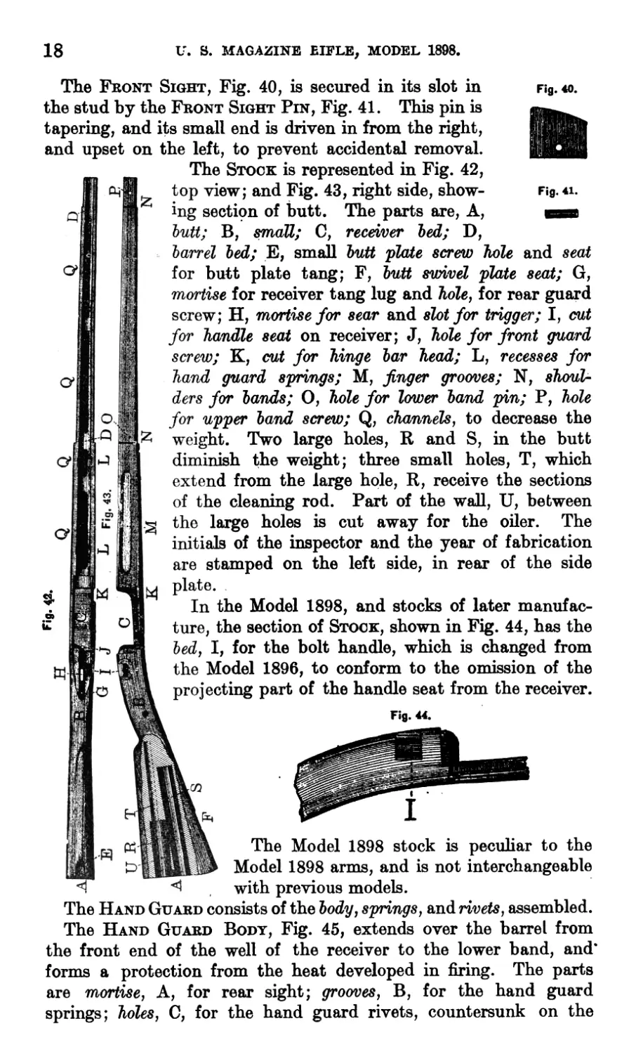
The Front Sight, Fig. 40, is secured in its slot in Fig. 40.
Fig.41.
and seat
the stud by the Front Sight Pin, Fig. 41. This pin is
tapering, and its small end is driven in from the right,
and upset on the left, to prevent accidental removal.
The Stock is represented in Fig. 42,
top view; and Fig. 43, right side, show-
ing section of butt. The parts are, A,
butt; B, small; C, receiver bed; D,
barrel bed; E, small butt plate screw bole
for butt plate tang; F, butt swivel plate seat; G,
mortise for receiver tang lug and "hole, for rear guard
screw; H, mortise for sear and slot for trigger; I, cut
for handle seat on receiver; J, hole for front guard
screw; K, cut for hinge bar head; L, recesses for
hand guard springs; M, finger grooves; N, shoul-
ders for bands; O, hole for lower band pin; P, hole
for upper band screw; Q, channels, to decrease the
weight. Two large holes, R and S, in the butt
diminish the weight; three small holes, T, which
extend from the large hole, R, receive the sections
of the cleaning rod. Part of the wall, U, between
the large holes is cut away for the oiler. The
initials of the inspector and the year of fabrication
are stamped on the left side, in rear of the side
plate.
In the Model 1898, and stocks of later manufac-
ture, the section of Stock, shown in Fig. 44, has the
bed, I, for the bolt handle, which is changed from
the Model 1896, to conform to the omission of the
projecting part of the handle seat from the receiver.
Fig. 44.
The Model 1898 stock is peculiar to the
Model 1898 arms, and is not interchangeable
with previous models.
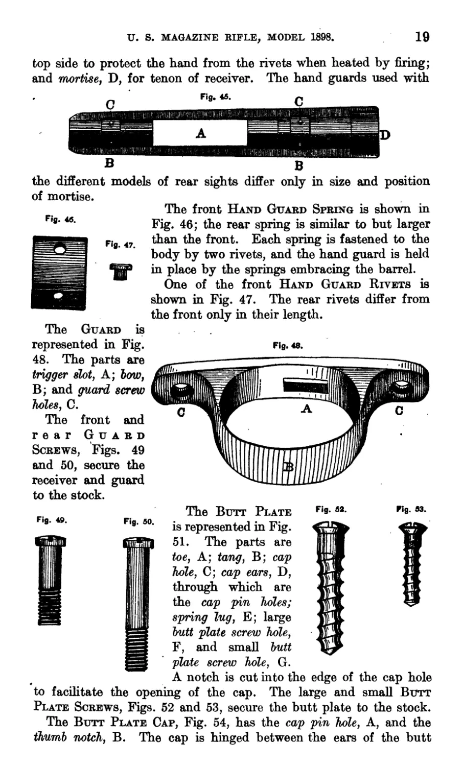
The Hand Guard consists of the body, springs, and rivets, assembled.
The Hand Guard Body, Fig. 45, extends over the barrel from
the front end of the well of the receiver to the lower band, and*
forms a protection from the heat developed in firing. The parts
are mortise, A, for rear sight; grooves, B, for the hand guard
springs; holes, 0, for the hand guard rivets, countersunk on the
U. S. MAGAZINE RIFLE, MODEL 1898.
19
top side to protect the hand from the rivets when heated by firing;
and mortise, D, for tenon of receiver. The hand guards used with
the different models of rear sights differ only in size and position
of mortise.
Fig. 46.
The Guard is
The front Hand Guard Spring is shown in
Fig. 46; the rear spring is similar to but larger
than the front. Each spring is fastened to the
body by two rivets, and the hand guard is held
in place by the springs embracing the barrel.
One of the front Hand Guard Rivets is
shown in Fig. 47. The rear rivets differ from
the front only in their length.
represented in Fig.
48. The parts are
trigger slot, A; bow,
B; and guard screw
holes, C.
The front and
rear Guard
Screws, Figs. 49
and 50, secure the
receiver and guard
to the stock.
Fig. 48.
Fig. 49.
Fig. 50.
Fig. 53.
Fig. 83.
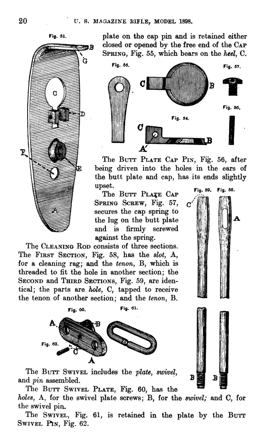
The Butt Plate
is represented in Fig.
51. The parts are
toe, A; tang, B; cap
hole, C; cap ears, D,
through which are
the cap pin holes;
spring lug, E; large
butt plate screw hole,
F, and small butt
plate screw hole, G.
A notch is cut into the edge of the cap hole
to facilitate the opening of the cap. The large and small Butt
Plate Screws, Figs. 52 and 53, secure the butt plate to the stock.
The Butt Plate Cap, Fig. 54, has the cap pin hole, A, and the
thumb notch, B. The cap is hinged between the ears of the butt
20
и. S. MAGAZINE BULE, MODEL 1898.
Fig. 51.
plate on the cap pin and is retained either
closed or opened by the free end of the Cap
Spring, Fig. 55, which bears on the heel, C.
56, after
Fig. 59.
c
I’z- //47ШП1
Fig. 55.
Fig. 54.
Fig. 57.
Fig. 56.
Fig. 58.
The Butt Plate Cap Pin, Fig.
being driven into the holes in the ears of
the butt plate and cap, has its ends slightly
upset.
The Butt Pla^e Cap
Spring Screw, Fig. 57,
secures the cap spring to
the lug on the butt plate
and is firmly screwed
against the spring.
The Cleaning Rod consists of three sections.
The First Section, Fig. 58, has the slot, A,
for a cleaning rag; and the tenon, B, which is
threaded to fit the hole in another section; the
Second and Third Sections, Fig. 59, are iden-
tical; the parts are hole, C, tapped to receive
the tenon of another section; and the tenon, B.
Fig. <». Fi9- 61 •
The Butt Swivel includes the plate, swivel,
and pin assembled.
The Butt Swivel Plate, Fig. 60, has the
holes, A, for the swivel plate screws; B, for the swivel; and C, for
the swivel pin.
The Swivel, Fig. 61, is retained in the plate by the Butt
Swivel P1n, Fig. 62.
U. S. MAGAZINE RIFLE, MODEL 1898.
21
The Butt Swivel Screws are the same as the small butt plate
screw (see Fig. 53).
The parts of the Upper Band, Fig. 63, are^s 64- Fig. бз.
the bayonet stud, A; the stacking swivel ears,
B, which contain the stacking swivel screw
Holes; and the band screw holes, C.
The Upper Band Screw, Fig. 64, secures
the band to the stock, the thread under the
head engaging in the hole on the right side of
the band.
The Stacking Swivel, Fig. 65, is hinged by the lug, A, between
the ears, B, of the upper band, on the Stacking Swivel Screw,
Fig. 66, which, after assembling, has its threaded end upset.
Fig. 67.
Fig. 65. Fig. 66.
Fig. 68.
The lug, A, of the
Lower Band Swivel,
Fig. 67, is inserted be-
tween the ears, A, of
the lower band and the
swivel is held in place
by the Swivel Screw,
Fig. 68, the left or
threaded end of which
is upset when in place.
Fig. 69.
The Lower Band, Fig. 69, has the
swivel ears, A; and swivel screw holes, B;
it is slotted between the ears so that when
the swivel screw is fully inserted, the bar-
rel and stock are brought into close con-
tact. The front or upper end of the band
is indicated by the letter U.
The ends of the Lower Band Pin, Fig.
70, project slightly beyond the stock to
prevent the band from slipping forward. *9’
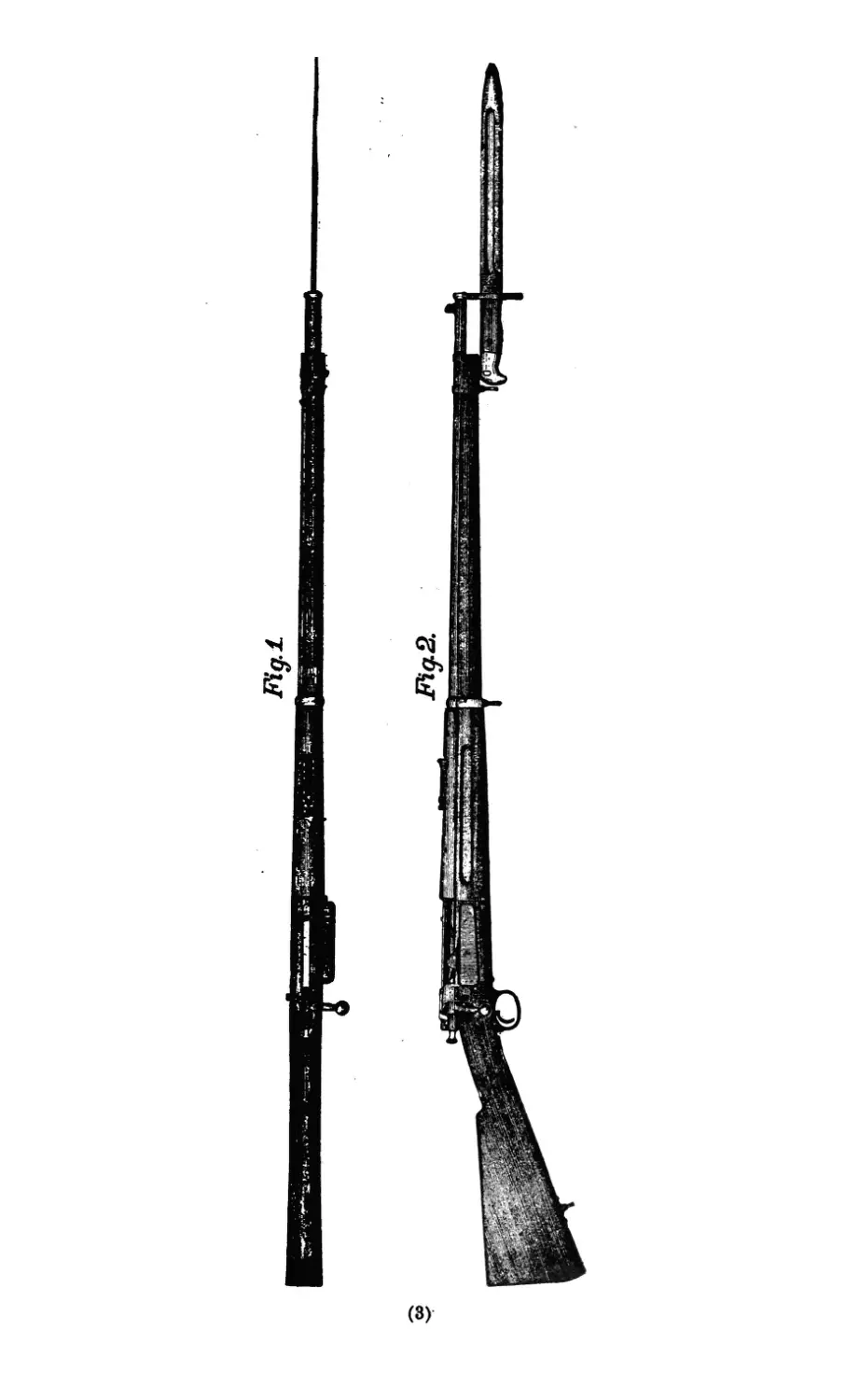
The Bayonet consists of the blade,
guard, pommel, catch, catch nut, catch
spring, grip bodies, rivets and washers, assembled; it is shown on
the rifle in Figs. 1 and 2, and is of the knife pattern.
Fig. 71.
The Blade is represented in Fig. 71. The parts are body, A;
point, B; tang, C; shoulder, D, for the guard; and rivet holes, E.
22
U. S. MAGAZINE RIFLE, MODEL 1898.
Fig. 72.
74,
the
E
M
<1
C
other
Fig. 77.
Fig. 78. Fig. 79.
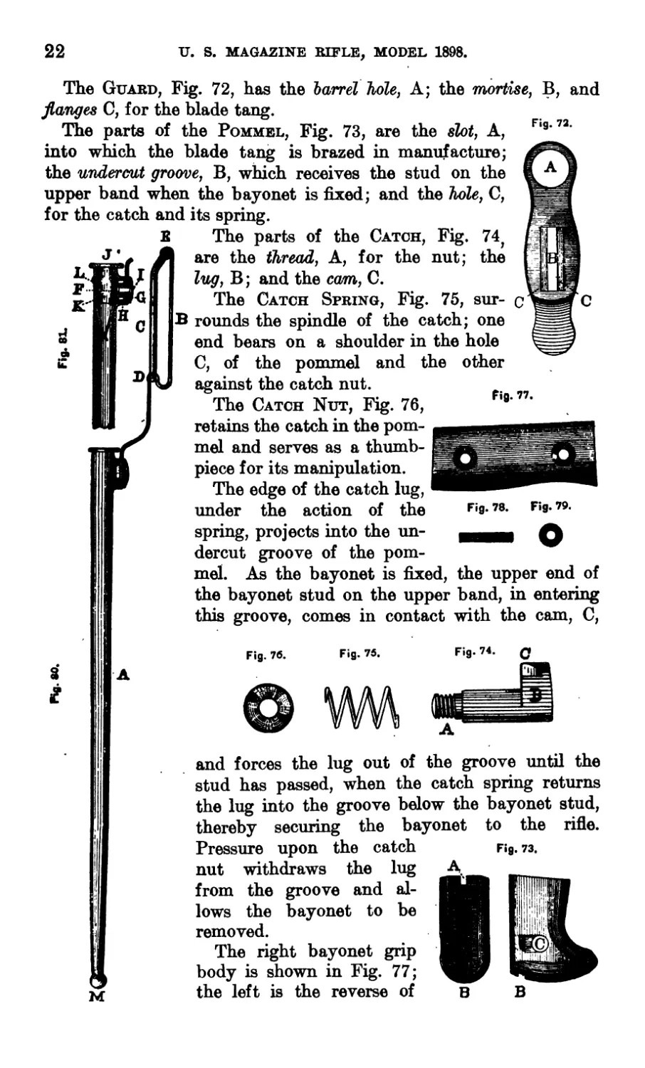
The Guard, Fig. 72, has the barrel hole, A; the mortise, B, and
fianges C, for the blade tang.
The parts of the Pommel, Fig. 73, are the slot, A,
into which the blade tang is brazed in manufacture;
the undercut groove, B, which receives the stud on the
upper band when the bayonet is fixed; and the hole, C,
for the catch and its spring.
The parts of the Catch, Fig.
are the thread, A, for the nut;
lug, B; and the cam,, C.
The Catch Spring, Fig. 75, sur-
B rounds the spindle of the catch; one
end bears on a shoulder in the hole
C, of the pommel and the
against the catch nut.
The Catch Nut, Fig. 76,
retains the catch in the pom-
mel and serves as a thumb-
piece for its manipulation.
The edge of the catch lug,
under the action of the
spring, projects into the un-
dercut groove of the pom-
mel. As the bayonet is fixed, the upper end of
the bayonet stud on the upper band, in entering
this groove, comes in contact with the cam, C,
Fig. 74. Q
Fig. 76. Fig. 76.
I
в
Fig. 73.
and forces the lug out of the groove until the
stud has passed, when the catch spring returns
the lug into the groove below the bayonet stud,
thereby securing the bayonet to the rifle.
Pressure upon the catch
nut withdraws the lug
from the groove and al-
lows the bayonet to be
removed.
The right bayonet grip
body is shown in Fig. 77;
the left is the reverse of
U. S. MAGAZINE RIFLE, MODEL 1898.
23
the right. They cover the tang between the guard and pommel and
are secured to it by two Rivets, Fig. 78, with Washers, Fig. 79,. at
either end.
The Bayonet Scabbard is shown in Fig. 80, and a cross section
of its upper end in Fig. 81. The parts are body, А; hook, B; hook
fastener, C, which hinges at D, and locks at E. The inside washer,
F; the outside washer, G; and the stop washer, H; the hook rivet,
I, which holds the hook to the body, passing through the inside,
outside, and stop washers. The inside and stop washers are riveted
together by two small rivets. Other parts are the mouth-piece
plate, J, and mouth-piece spring, K, brazed together in manufac-
ture; the mouth-piece rivet, L; and knob, M, which protects the
small end of the body, and through which is a hole to permit the
escape of water entering the body. On the lower end of the hook,
and at right angles with it, is a tongue which, moving in a clear-
ance in the stop washer, limits the oscillation of the hook to 50
degrees on each side of the vertical.
Note.—All parts of the Model 1896 Rifle are interchangeable
with the Model 1898, except the Receiver, Stock, Cut-off, and Side
Plate. The receiver and stock are the same as the Model 1898,
with the exception of the bolt handle seat. The spindle of the
cut-off is 0.5 inch longer, and the tenon of the side plate is 0.02
inch thinner than in the Model 1898.
Front Sight.—The height of Front Sight above axis of bore is
as follows:
Rifie.—For Model 1896 rear sight, 0.85 inch.
For Model 1901 rear sight, 0.975 inch.
Carbine.—For Model 1896 rear sight, 0.83 inch.
For Model 1901 rear sight, 0.919 inch.
24
U. S. MAGAZINE CARBINE.
Model 1896.
CARBINE, MODEL 1899.
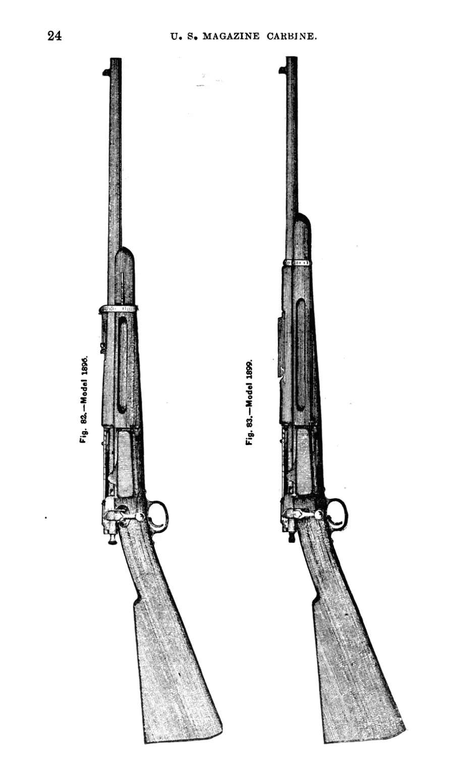
DESCRIPTION AND NOMENCLATURE.
The component parts, 61 in number (exclusive of rear sight),
are the same as in"* the rifle with the exception of the Band, Band
Fig. 86.
Spring, Barrel, and Stock.
The Carbine, Model 1896, with protector band
is shown in Fig. 82, and the Model 1899 in Fig. 83.
Fig. 84 shows the band; the letter U denotes
the upper side.
The Band Spring, Fig. 85, has the notch, A,
which holds the band in place; and the spindle,
B, to retain the spring in the stock.
The Barrel is the same as the rear 22 inches of
the rifle barrel.
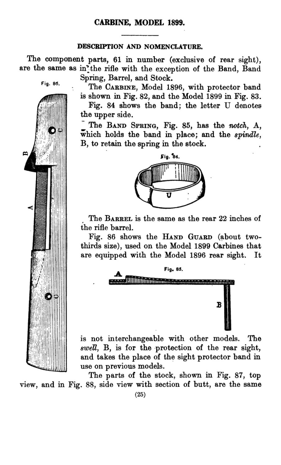
Fig. 86 shows the Hand Guard (about two-
thirds size), used on the Model 1899 Carbines that
are equipped with the Model 1896 rear sight. It
is not interchangeable with other models. The
swell, B, is for the protection of the rear sight,
and takes the place of the sight protector band in
use on previous models.
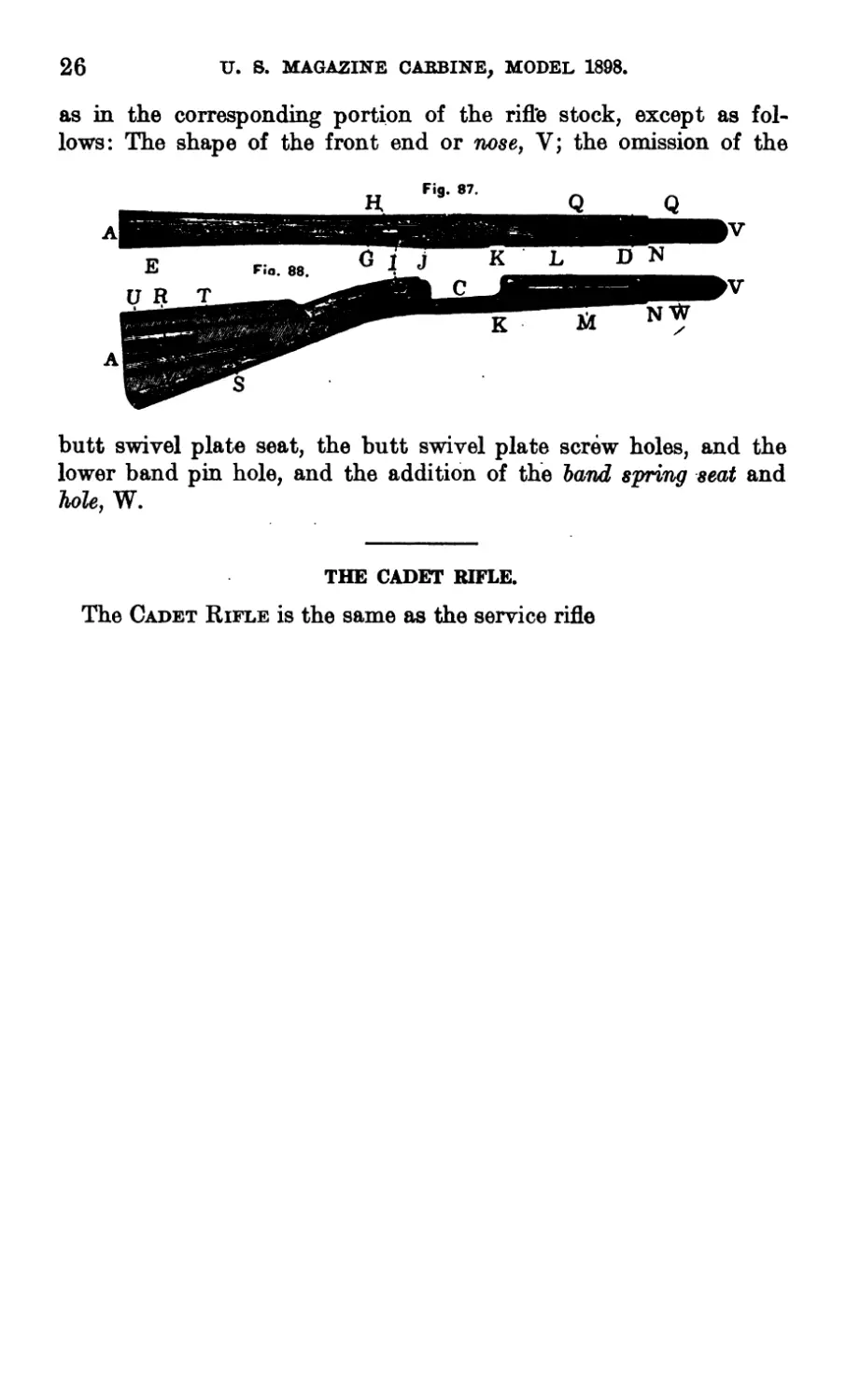
The parts of the stock, shown in Fig. 87, top
view, and in Fig. 88, side view with section of butt, are the same
(25)
26
U. S. MAGAZINE CABBINE, MODEL 1898.
as in the corresponding portion of the rifle stock, except as fol-
lows: The shape of the front end or nose, V; the omission of the
butt swivel plate seat, the butt swivel plate screw holes, and the
lower band pin hole, and the addition of the band spring seat and
hole, W.
THE CADET RIFLE.
The Cadet Rifle is the same as the service rifle
THE REAR SIGHT, MODEL 1896.
The Rear Sight, Model 1896, consists of the following parts:
Base. Base Screw, front. Base Screw, rear. Base Spring. Leaf. Joint Screw. Slide. Slide Cap. Slide Cap Screw. Slide Spring. Slide Screw. Slide Pin.
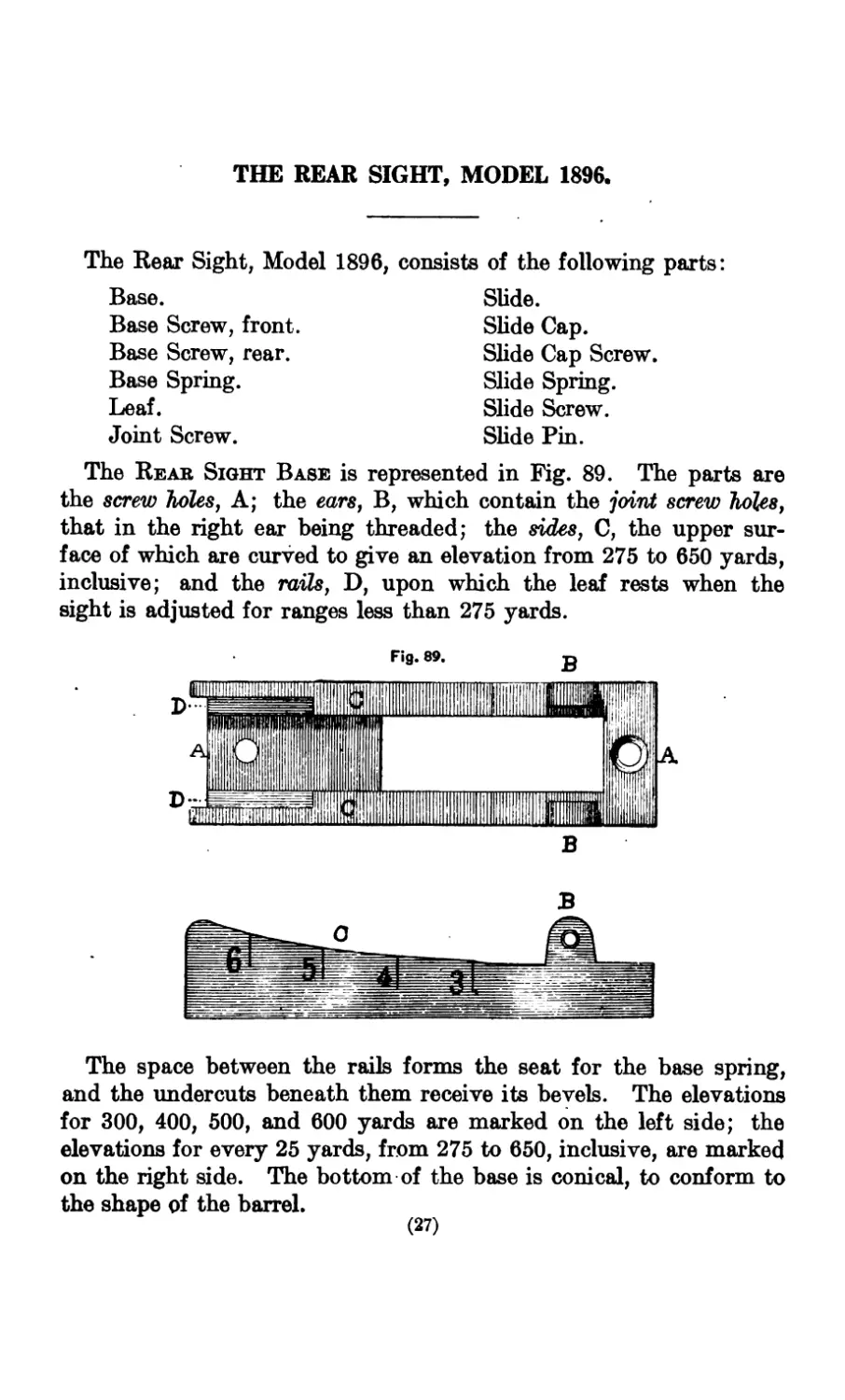
The Reab Sight Base is represented in Fig. 89. The parts are
the screw holes, A; the ears, B, which contain the joint screw holes,
that in the right ear being threaded; the sides, C, the upper sur-
face of which are curved to give an elevation from 275 to 650 yards,
inclusive; and the rails, D, upon which the leaf rests when the
sight is adjusted for ranges less than 275 yards.
The space between the rails forms the seat for the base spring,
and the undercuts beneath them receive its bevels. The elevations
for 300, 400, 500, and 600 yards are marked on the left side; the
elevations for every 25 yards, from 275 to 650, inclusive, are marked
on the right side. The bottom of the base is conical, to conform to
the shape of the barrel.
(27)
28 U. S. MAGAZINE* BIFLE, MODEL 1898.
• »
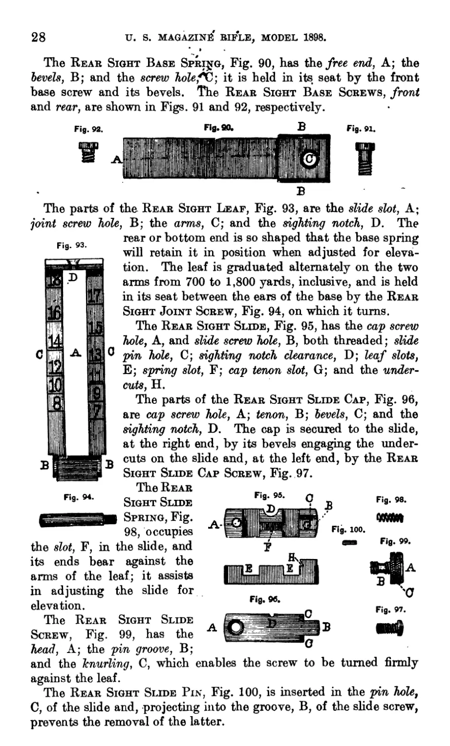
The Rear Sight Base Spring, Fig. 90, has the free end, A; the
bevels, B; and the screw holefC; it is held in its seat by the front
base screw and its bevels. The Rear Sight Base Screws, front
and rear, are shown in Figs. 91 and 92, respectively.
Fig. 92. Fig. 90. В
В
Fig. 91.
The parts of the Rear Sight Leaf, Fig. 93, are the slide slot, A;
joint screw hole, B; the arms, C; and the sighting notch, D. The
rear or bottom end is so shaped that the base spring
will retain it in position when adjusted for eleva-
tion. The leaf is graduated alternately on the two
arms from 700 to 1,800 yards, inclusive, and is held
in its seat between the ears of the base by the Rear
Sight Joint Screw, Fig. 94, on which it turns.
The Rear Sight Slide, Fig. 95, has the cap screw
hole, A, and slide screw hole, B, both threaded; slide
pin hole, C; sighting notch clearance, D; leaf slots,
E; spring slot, F; cap tenon slot, G; and the under-
cuts, H.
The parts of the Rear Sight Slide Cap, Fig. 96,
are cap screw hole, A; tenon, B; bevels, C; and the
sighting notch, D. The cap is secured to the slide,
at the right end, by its bevels engaging the under-
cuts on the slide and, at the left end, by the Rear
Sight Slide Cap Screw, Fig. 97.
The Rear
Sight Slide
Spring, Fig.
98, occupies
the slot, F, in the slide, and
its ends bear against the
arms of the leaf; it assists
in adjusting
elevation.
The Rear
Screw, Fig.
head, A; the pin groove, B;
and the hnurling, C, which enables the screw to be turned firmly
against the leaf.
The Rear Sight Slide Pin, Fig. 100, is inserted in the pin hole,
C, of the slide and, projecting into the groove, B, of the slide screw,
prevents the removal of the latter.
Fig. 93.
Fig. 94.
Fig. 95.
0
I
В
Fig. 98.
Fig. 100.
Fig. 99.
the slide for
Sight Slide
99, has the
И1ИЦ
Fig. 96.
О
В
С
В w
'C
Fig. 97.
THE REAR SIGHT, MODEL 1901.
Leaf Slide Cap.
Leaf Slide Cap Screw.
Leaf Slide. Binding Screw.
Leaf Slide Binding Screw Pin.
Drift Slide.
Drift Slide Pin.
Joint Pin.
Binder.
Binder Screw.
The Rear Sight, Model 1901, consists of the following ^arts:
Fixed Base.
Movable Base.
Base Screw, front.
Base Screw, rear.
Base Screw, Washer.
Base Spring.
Base Spring Screw.
Leaf.
Leaf Slide Body.
The principal parts are shown in Figs. 101, 102, 103, and 104.
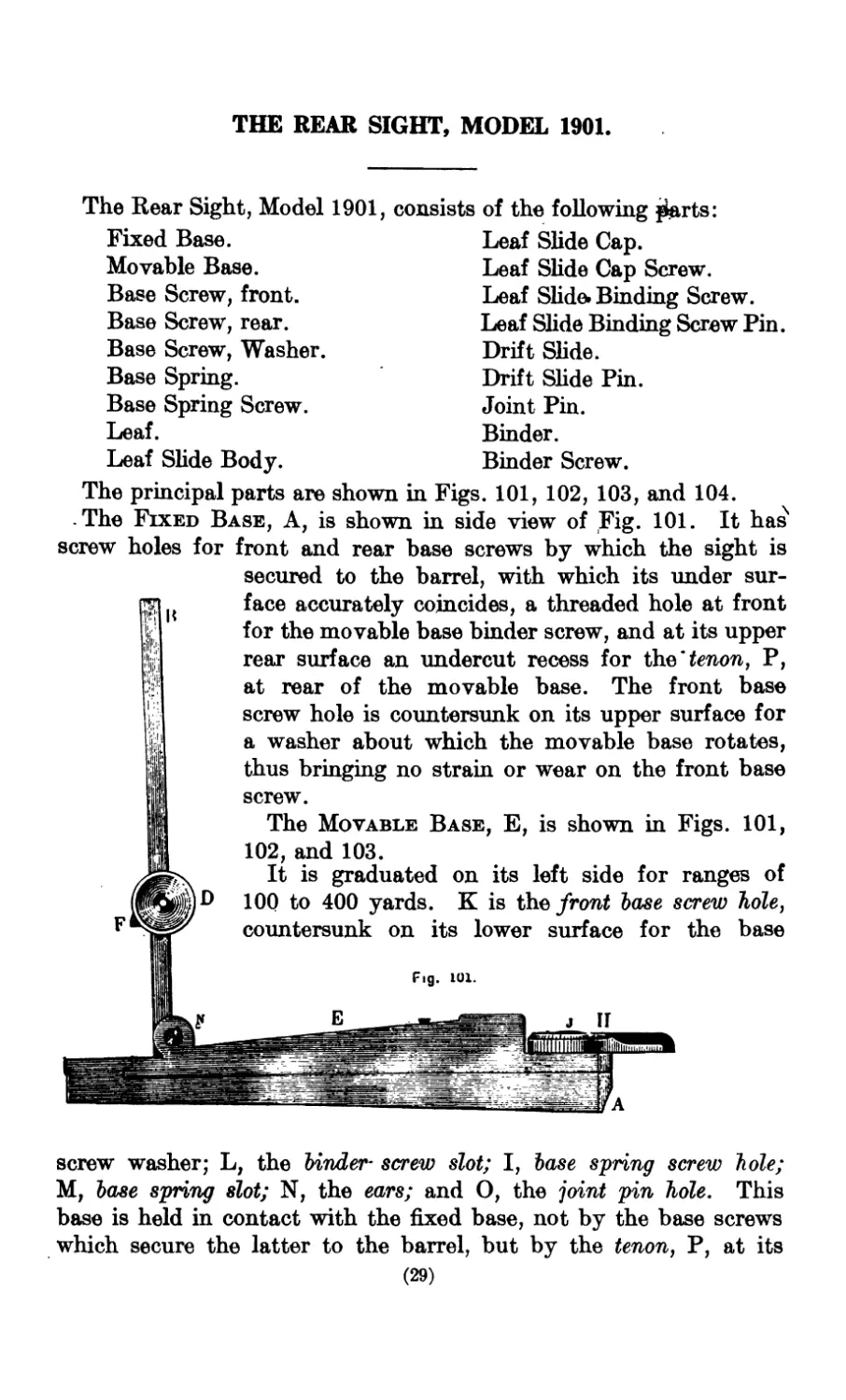
The Fixed Base, A, is shown in side view of Fig. 101. It has
screw holes for front and rear base screws by which the sight is
secured to the barrel, with which its under sur-
face accurately coincides, a threaded hole at front
for the movable base binder screw, and at its upper
rear surface an undercut recess for the'tenon, P,
at rear of the movable base. The front base
screw hole is countersunk on its upper surface for
a washer about which the movable base rotates,
thus bringing no strain or wear on the front base
screw.
The Movable Base, E, is shown in Figs. 101,
102, and 103.
It is graduated on its left side for ranges of
100 to 400 yards. К is the front base screw hole,
countersunk on its lower surface for the base
D
Fig. 101.
screw washer; L, the binder- screw slot; I, base spring screw hole;
M, base spring slot; N, the ears; and O, the joint pin hole. This
base is held in contact with the fixed base, not by the base screws
which secure the latter to the barrel, but by the tenon, P, at its
(29)
30
U. S. MAGAZINE KIFLE, MODEL 1898.
rear entering the undercut recess of the rear of the fixed base and
by the binder, H, at its front. It turns freely about the front
base screw washer, its lateral movement being limited by the
binder screw in
the slot, L, which
prevents the ten-
on, P, from leav-
ing its undercut
slot. The upper
rear surface of
this base is grad-
uated in spaces,
or technically
windage points,
of 0.04 inch each,
Eig. 102.
the outer divi-
sions being marked zero. Two similar zero lines are marked on
the rear overhang of the fixed base. By the rotation of the upper
base a correction may be made for any observed deviation of the
projectile.
If a denote the observed deviation, d the distance between front
and rear sights, r the range, and x the windage necessary to cor-
Fig. 104.
It
rect for the observed deviation, all being ex-
pressed in inches, we shall have:
ad
x = —
r
If it be desired to find the amount of devia-
tion that may be corrected for by one point of
windage, say at 1,000 yards, 36,000 inches, d
being 24.54 inches, we have:
0.04 inch X 36,000 ro o . ,
-----2454--------= 58.8 inches.
The binder screw is screwed into the lower
base, the screw hole in the latter being
countersunk to receive the binder screw head,
which к curved to fit the barrel, with which it
comes into close contact. When assembled,
the lever being to the left, a quarter turn of
the binder to the right will firmly clamp the
two bases together.
The Leaf, with its slide assembled to it, is
shown in Fig. 104. It is graduated from 100
to 2,000 yards. With the open sight notches, leaf up, ranges from
500 to 2,000 yards can be obtained, the 2,000 yards range being
U. S. MAGAZINE RIFLE, MODEL 1898.
31
obtained with open notch at top of leaf similar to those on the slide,
while the ranges from 100 to 400 yards must be obtained with the
leaf down, the corresponding graduations being on the left side of
the upper base. With the leaf up, using the peep sight, ranges from
100 to slightly less than 1,800 yards can be obtained. The base
spring, by its bearing on the squares at lower end of leaf, maintains
the leaf in its vertical or horizontal position.
The Leaf Slide is composed of the body, G; its cap, cap screw,
F; slide binding screw, D; binding screw pin and drift slide, C. Two
grooves cut in the body of the slide receive the branches of the
leaf along which the slide may be moved. The cap which secures
the slide to the leaf is attached to the body of the slide by enter-
ing a dovetailed groove at the right and by the cap screw at the
left. A curved offset, for drift correction, is cut on the inner rear
face of the two branches of the leaf to receive the drift slide, C. A
small pin riveted to the drift slide enters a longitudinal groove on
the inner face of the slide cap. As the slide is moved up or down
the leaf, the drift slide, which carries the sighting notches, moves
with it and at the same time has a lateral movement in the drift
curve, due to the free lateral movement of the pin in the longi-
tudinal groove on the inner surface of cap, thus automatically cor-
recting for drift.1 The slide binding screw is used to secure the
slide to the leaf in any desired position. A small pin at right angles
to the slide binding screw enters for about half its thickness a groove
cut on the binding screw and thus prevents the removal or loss of
the latter.
To assemble the two bases, they must be placed together with
the binder in position, the lever to the left, the binder screw having
been previously screwed into the lower base until its’ point is even
with or slightly below the upper surface of the movable base. This
screw should then be screwed firmly home.
Experimental firing and laboratory experiments show that, all
other conditions being identical, the muzzle velocity of ammuni-
tion loaded with smokeless powder will be increased by exposure
to a higher atmospheric temperature, and decreased by a lower.
Consequently the elevation for any range will vary slightly with
the atmospheric temperature. Moreover, the velocity at 53 feet
stamped upon the paper packages may vary, in different issues
of ammunition, 15 feet on either side of the standard. The muz-
zle velocity obtained in different rifles also varies with the same
ammunition.
1 Extract from Report of Chief of Ordnance for 1884, page 110, relating to rear sight for the Springfield
rifle, model 1884: “ Lieut. W. C. Brown, First United States Cavalry, proposed that drift lines or curves be
marked on the leaf of the rear sight, model ’79, so that adjustment could be made for drift; on this basis, for
which credit is due to him, the automatic arrangement was devised.”
32 U. S. MAGAZINE RIFLE, MODEL 1898.
In adjusting the sight for elevation at any range it must be
borne in mind that, in addition to the allowance made for varia-
tions in the muzzle velocity of the ammunition, allowance must
also be made for the effect of diffeiences in light, the amount of
front sight seen, the effect of mirage on the target, the effect of
heat developed in firing, the personal equation of the firer, the
peculiarities of individual guns, et cetera.
The graduations of the rear sight are correct only for the par-
ticular conditions existing when they were experimentally deter-
mined, consequently, in adjusting the sight for elevation at any
range, allowance must be made for whatever change in the eleva-
tion the difference between the former and the present conditions
produces.
All component parts of rear sights will be issued for repairs in
the hands of troops.
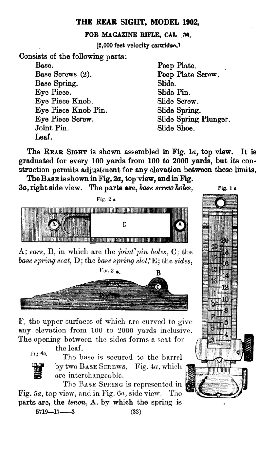
THE REAR SIGHT, MODEL 1902,
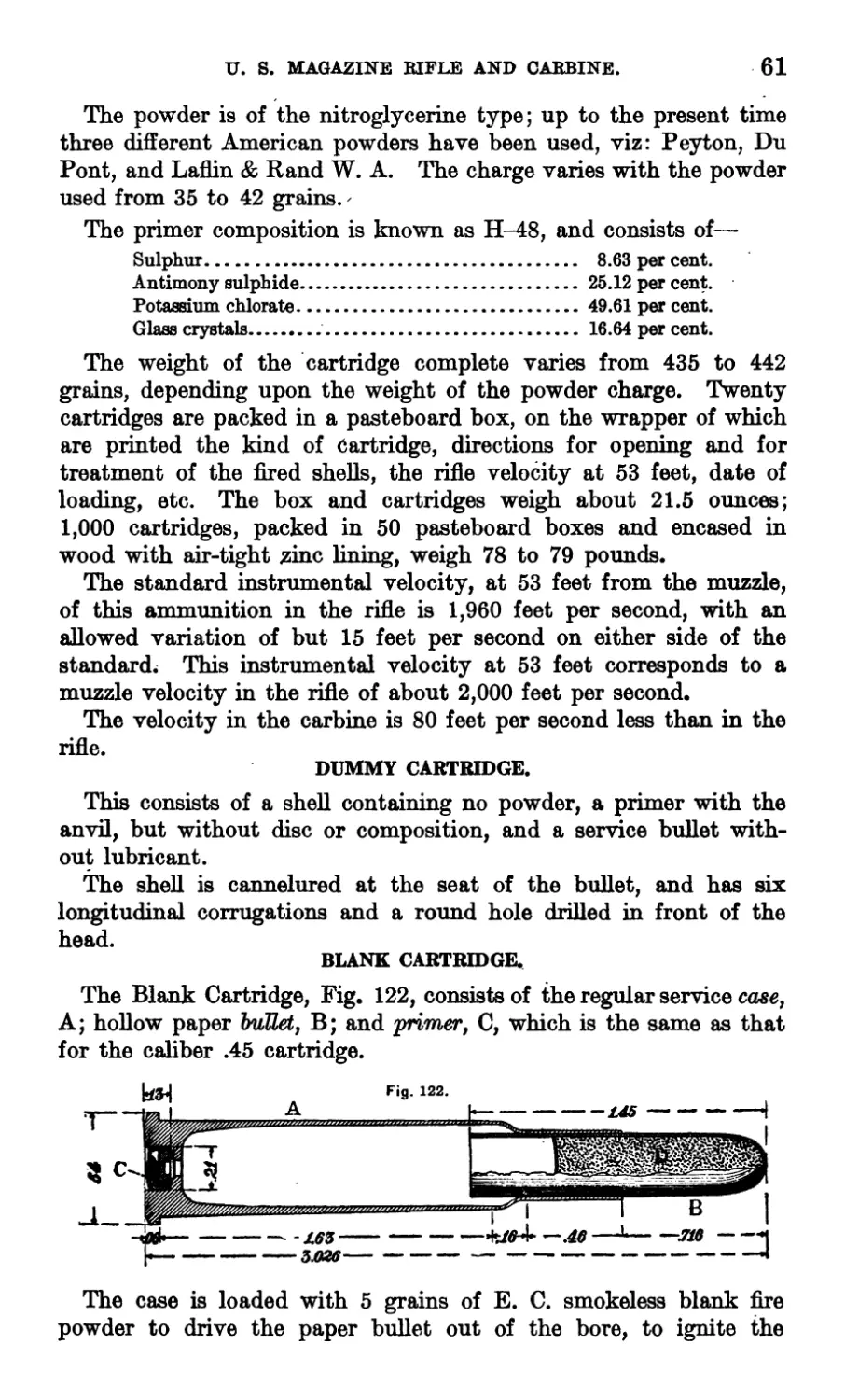
FOR MAGAZINE RIFLE. CAL. Ж
[2,000 feet velocity cartridee.l
Consists of the foUowing parts:
Base.
Base Screws (2).
Base Spring.
Eye Piece.
Eye Piece Knob.
Eye Piece Knob Pin.
Eye Piece Screw.
Joint Pin.
Leaf.
Peep Plate.
Peep Plate Screw.
Slide.
Slide Pin.
Slide Screw.
Slide Spring.
Slide Spring Plunger
Slide Shoe.
The Rear Sight is shown assembled in Fig. la, top view. It is
graduated for every 100 yards from 100 to 2000 yards, but its con-
struction permits adjustment for any elevation between these limits.
The Base is shown in Fig. 2a, top view, and in Fig.
3a, right side view. The parts are, base screw holes,
Fig. 2 a
И11ШИИ1ШШШ
Fig. 1 a.
E
MllllHIIlIlIllUIIWIIIIIt
A; ears, B, in which are the joint'pin holes, C; the
base spring seat, D; the base spring slot'^-, the sides,
В
F, the upper surfaces of which are curved to give
any elevation from 100 to 2000 yards inclusive.
The opening between the sides forms a seat for
the leaf.
IS’ a' The base is secured to the barrel
Wby two Base Screws, Fig. 4a, which
are interchangeable.
The Base Spring is represented in
Fig. 5a, top view, and in Fig. 6a, side view. The
parts are, the tenon, A, by which the spring is
5719—17---------3 (33)
34
THE BEAB SIGHT, MODEL 1902.
secured in its seat in the base; the point, B, which bears against the
front end of the leaf, and holds the front lower edge of the slide in con-
tact with the curves on the base.
The Eye Piece, shown in Fig.
7a, top view, and in Fig. 8a, right
end and rear views, has the hole,
A., and slot, B, by which it is as-
sembled on the rear end of the
leaf; the. ears, C, which project
into the undercuts in the eye-
piece knob and in the head of the eye-piece screw; the open notch,,
D; the clearance, E, and the wind gauge graduations, F, by which the
eye-piece is adjusted to correct for any lateral deviation of the bullet;
To use peep sight, push
the peep plate, G, secured by the screw, H.
Fig. 7 a. Fig. 8 a.
up peep plate
as shown in
outline on Fig.
8a. The ver-
tical line of
white metal on
rear face of
eye-piece and peep plate (shown in Fig. 8a) extending downward from
near the open notch, assists the eye in aiming and in holding the gun
so the front sight will be vertical when using the open sight.
The Eye-Piece Knob, Fig. 9a, has the under- Fig 9 tt
cut, A, which receives the left ear on the eye- p
piece; the eye-piece screw hole, B; the eye-piece M
knob pinhole, C, and theD. The knob
is assembled on the tenon of the eye-piece screw, Я
and is secured to it by the knob pin. The eye-
piece is moved to the left by turning the knob toward the muzzle,
and vice versa.
Fig io® The Ete-Piece Knob Pin, Fig. 10a, is cylindrical, and its
ends, when inserted in its holes in the knob and eye-piece
screw, should be slightly upset to prevent accidental removal.
The Eye-Piece Screw, Fig. Ila, has the
head, A, which is undercut to receive the right Fig. lie.
ear on the eye-piece; the thread, B, which en- A
gages that in the eye-piece screw hole in the
leaf; the tenon,C,which receives the eye-piece
knob; and the knob pin hole, D. The eye-piece screw is assembled
in its threaded hole through the rear end of the leaf on which the
eye-piece is seated; the latter is held between the eye-piece screw
head and knob, so that any revolution of the knob and screw will move
the eye-piece laterally across the leaf. The ears on the ends of the eye-
THE REAR SIGHT, MODEL 1902.
35
piece project into the undercuts in the eye-piece screw head and
knob, so that any blow received by the screw head or knob will be
taken up by the eye-piece, instead of by the eye-piece screw.
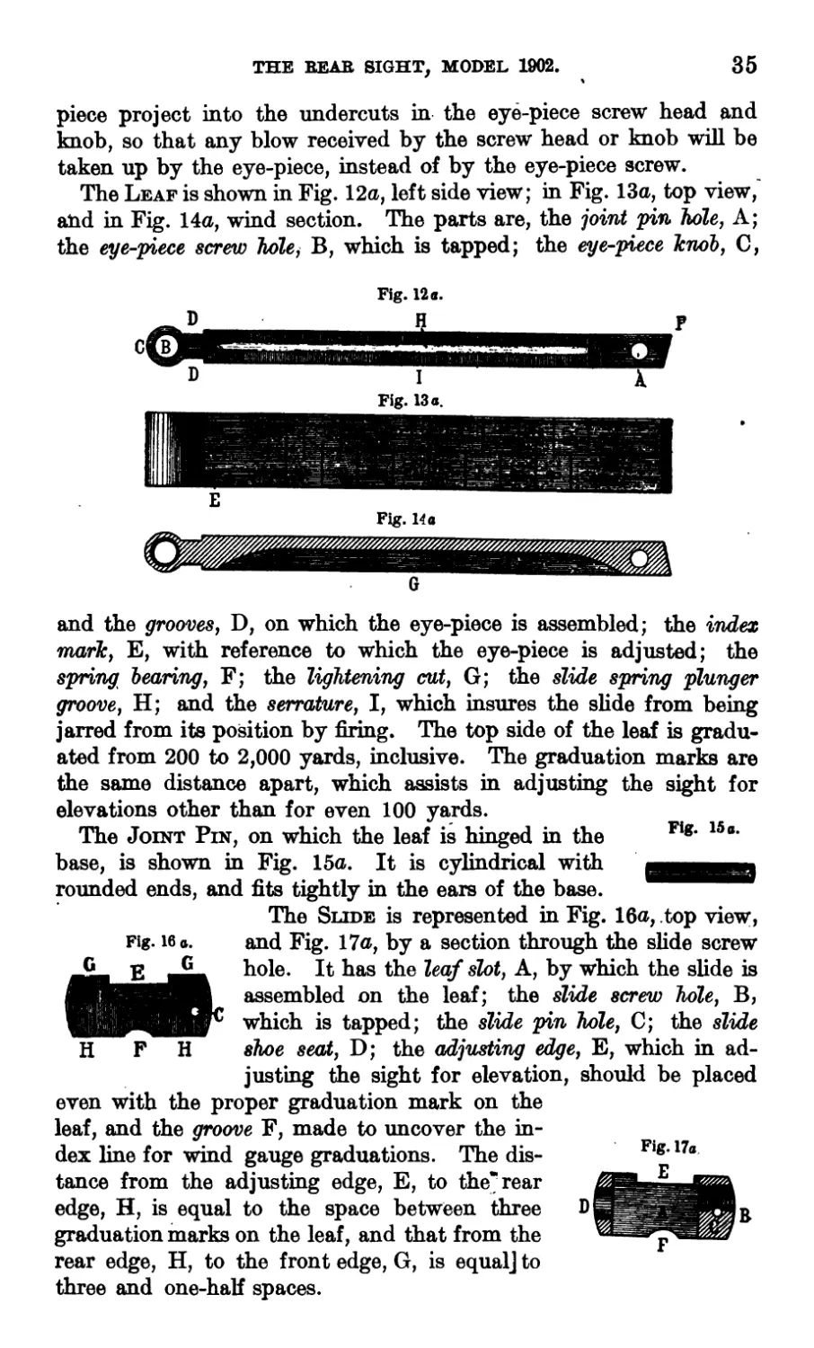
The Leaf is shown in Fig. 12a, left side view; in Fig. 13a, top view,
and in Fig. 14a, wind section. The parts are, the joint pin hole, A;
the eye-piece screw hole, B, which is tapped; the eye-piece knob, C,
Fig. 12 a.
and the grooves, D, on which the eye-piece is assembled; the index
mark, E, with reference to which the eye-piece is adjusted; the
spring bearing, F; the lightening cut, G; the slide spring plunger
groove, H; and the serrature, I, which insures the slide from being
jarred from its position by firing. The top side of the leaf is gradu-
ated from 200 to 2,000 yards, inclusive. The graduation marks are
the same distance apart, which assists in adjusting the sight for
elevations other than for even 100 yards.
The Joint Pin, on which the leaf is hinged in the Fig‘ 15
base, is shown in Fig. 15a. It is cylindrical with дщд
rounded ends, and fits tightly in the ears of the base.
The Slide is represented in Fig. 16a, top view,
Fig. 16 a.
and Fig. 17a, by a section through the slide screw
hole. It has the leaf slot, A, by which the slide is
assembled on the leaf; the slide screw hole, B,
which is tapped; the slide pin hole, C; the slide
shoe seat, D; the adjusting edge, E, which in ad-
justing the sight for elevation, should be placed
even with the proper graduation mark on the
leaf, and the groove F, made to uncover the in-
dex line for wind gauge graduations. The dis-
tance from the adjusting edge, E, to the’rear
edge, H, is equal to the space between three
graduation marks on the leaf, and that from the
rear edge, H, to the front edge, G, is equal] to
Fig. 17a
three and one-half spaces.
36
THE REAB SIGHT, MODEL 1902.
THE REAR SIGHT, MODEL 1902.
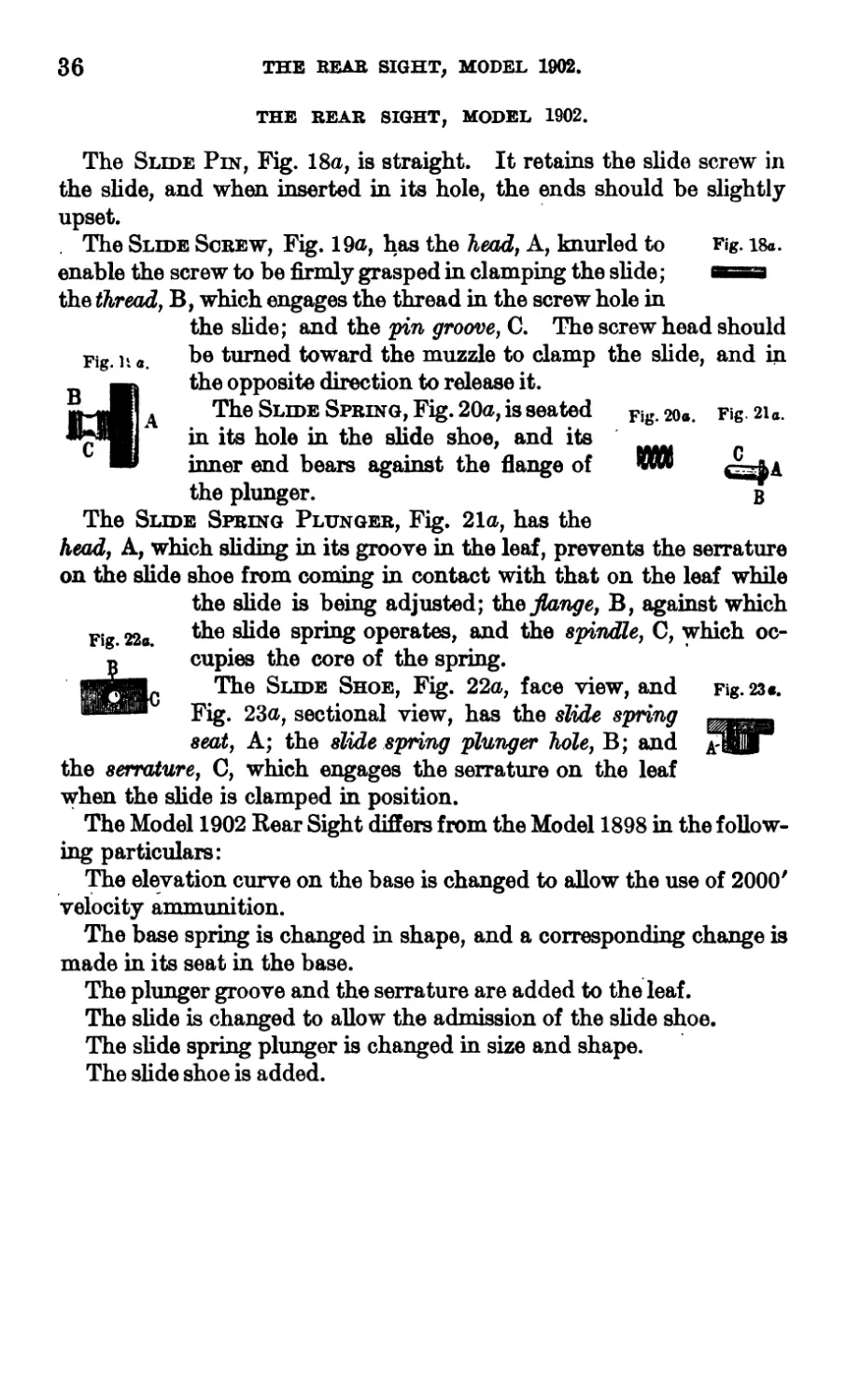
The Slide Pin, Fig. 18a, is straight. It retains the slide screw in
the slide, and when inserted in its hole, the ends should he slightly
upset.
. The Slide Screw, Fig. 19a, has the head, A, knurled to Fig. i8a.
enable the screw to be firmly grasped in clamping the slide; ae
the thread, B, which engages the thread in the screw hole in
the slide; and the pin groove, C. The screw head should
be turned toward the muzzle to damp the slide, and in
the opposite direction to rdease it.
The Slide Spring, Fig. 20a, is seated Fig. 20a.
in its hole in the slide shoe, and its _______
inner end bears against the flange of w*
the plunger.
The Slide Spring Plunger, Fig. 21a, has the
head, A, which sliding in its groove in the leaf, prevents the serrature
on the slide shoe from coming in contact with that on the leaf while
the slide is being adjusted; the flange, B, against which
the slide spring operates, and the spindle, C, which oc-
cupies the core of the spring.
The Slide Shoe, Fig. 22a, face view, and Fig. 23*.
Fig. 23a, sectional view, has the slide spring
seal, A; the slide spring plunger hole, B; and
the serrature, C, which engages the serrature on the leaf
when the slide is clamped in position.
The Model 1902 Rear Sight differs from the Model 1898 in the follow-
ing particulars:
The elevation curve on the base is changed to allow the use of 2000'
velocity ammunition.
The base spring is changed in shape, and a corresponding change is
made in its seat in the base.
Fig. li a.
Fig. 21a.
c . .
В
Fig. 22a.
0
The plunger groove and the serrature are added to the leaf.
The slide is changed to allow the admission of the slide shoe.
The slide spring plunger is changed in size and shape.
The slide shoe is added.
APPENDAGES.
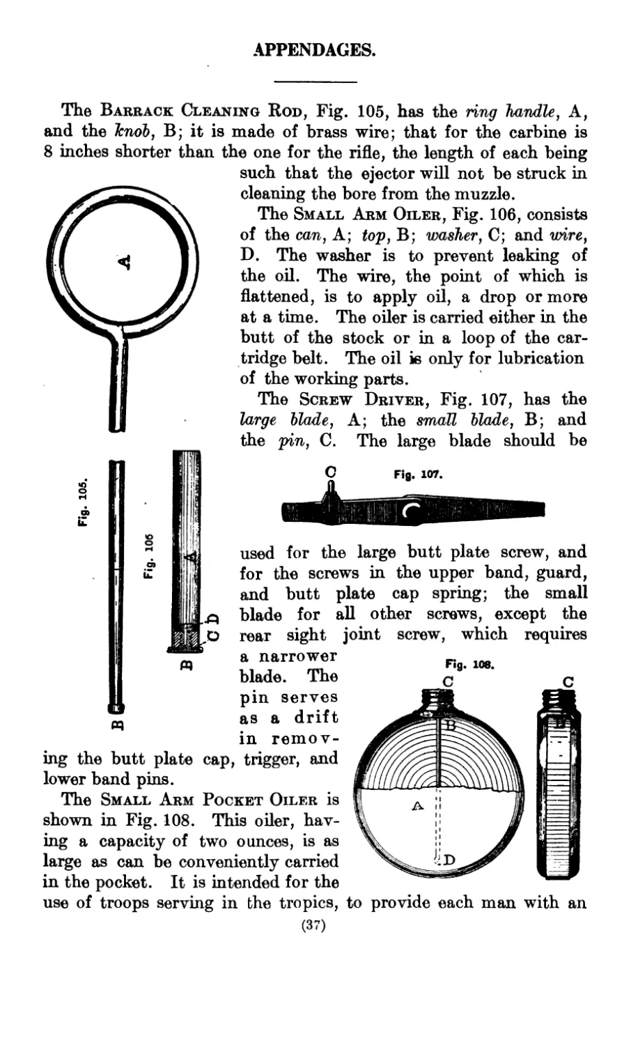
The Barrack Cleaning Rod, Fig. 105, has the ring handle, A,
and the knob, В; it is made of brass wire; that for the carbine is
8 inches shorter than the one for the rifle, the length of each being
such that the ejector will not be struck in
О
cleaning the bore from the muzzle.
The Small Arm Oiler, Fig. 106, consists
of the can, A; top, B; washer, C; and wire,
D. The washer is to prevent leaking of
the oil. The wire, the point of which is
flattened, is to apply oil, a drop or more
at a time. The oiler is carried either in the
butt of the stock or in a loop of the car-
tridge belt. The oil is only for lubrication
of the working parts.
The Screw Driver, Fig. 107, has the
large blade, A; the small blade, B; and
the pin, C. The large blade should be
used for the large butt plate screw, and
for the screws in the upper band, guard,
and butt plate cap spring; the small
blade for all other screws, except the
rear sight joint screw, which requires
a narrower 108.
blade. The л e
pin serves
as a drift
in remov-
ing the butt plate cap, trigger, and
lower band pins.
The Small Arm Pocket Oiler is
shown in Fig. 108. This oiler, hav-
ing a capacity of two ounces, is as
large as can be conveniently carried
in the pocket. It is intended for the
use of troops serving in the tropics, to provide each man with an
38 U. S. MAGAZINE RIFLE, MODEL 1898.
additional supply of oil to that contained in the small oiler carried
in the butt of the arm. It is made of sheet brass, nickel-plated,
with a screw top, to which is attached a wire with spoon end, for
removing the oil in drops. The general dimensions are, diameter,
2.75 inches; thickness, 0.6875 inch.
The parts comprise the body, A; neck, B; cap, C; cap washers,
and spoon, D; the body, neck, and cap are made of sheet brass 0.02
inch thick. The body is punched and drawn in two cup-shaped
parts that overlap when fitted together, and are then soldered.
The neck is punched, drawn, rolled for threading, and soldered on
the body. The cap is punched, drawn, rolled for threading, and
knurled; within the cap are two washers; one of felt to prevent
leakage; and one of steel of smaller diameter, which serves to
reinforce the top of the cap for riveting the spoon.
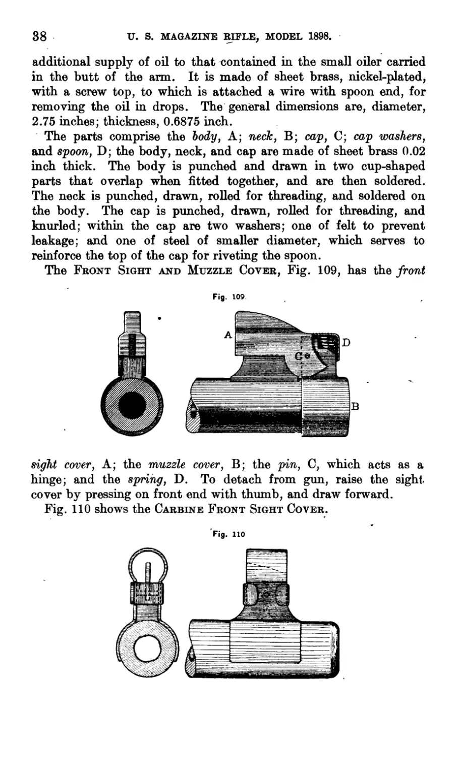
The Front Sight and Muzzle Cover, Fig. 109, has the front
Fig. 109.
sight cover, A; the muzzle cover, B; the pin, C, which acts as a
hinge; and the spring, D. To detach from gun, raise the sight,
cover by pressing on front end with thumb, and draw forward.
Fig. 110 shows the Carbine Front Sight Cover.
Fig. 110
THE ASSEMBLED PARTS AND THEIR OPERATIONS.
Most of the operating parts may be included under the Bolt
Mechanism and the Magazine Mechanism.
The Bolt Mechanism consists of the bolt, sleeve, extractor,
extractor rivet, safety lock, firing pin, striker, and main spring.
The bolt moves backward and forward and rotates in the well
hole of the receiver; it carries a cartridge, either from the maga-
zine or one placed by hand in front of it, into the chamber and
supports its head when fired. The locking lug will sustain any
powder pressure liable to occur, but if worn by usage or upset by
excessive pressures the rear end of the guide rib will bear on the
locking shoulder of the receiver, permitting the continued use of
the arm with safety.
The sleeve unites the parte of the bolt mechanism; its rotation
with the bolt is prevented by its arm occupying the opening between
the walls of the receiver.
The hook of the extractor engages the rim of the cartridge case
and retains the head of the latter in the countersink of the bolt
until the case is ejected. The extractor spring, engaging its lip on
the receiver, prevents the hook from releasing the rim of the car-
tridge case, when the latter is being started from the chamber.
The extractor pin holds the bolt open for convenience in loading
when using single-loader fire.
The safety lock, when turned to the left, is inoperative; when
turned to the right, the point of its spindle enters the notch in the
bolt collar and locks the bolt. If turned to the right when the
piece is cocked, its cam forces the firing pin slightly to the rear,
out of contact with the sear, so that, if the trigger be pulled, the
sear, when the trigger is released, can rise to catch the firing pin,
when the safety lock is turned to the left, thereby preventing acci-
dental discharge. If turned to the right, when the piece is not
cocked, it locks the firing pin as well as the bolt.
The gun having been discharged, to remove the empty cartridge
case, reload and fire; the bolt mechanism operates as follows:
To open the bolt, raise the handle until it comes into contact
with the sleeve, then pull it directly to the rear until the locking
lug strikes the locking shoulder of the receiver.
Raising the handle rotates the bolt. This separates the locking
lug from the shoulder of its recess in the receiver, with which it is
brought into close contact by the powder pressure. This separation
is made easy by the slight inchnation to the axis of the receiver of
the vertical planes containing the rear surface of the locking lug
and the shoulder of its recess.
(39)
40
U. S. MAGAZINE RIFLE AND CABBINE.
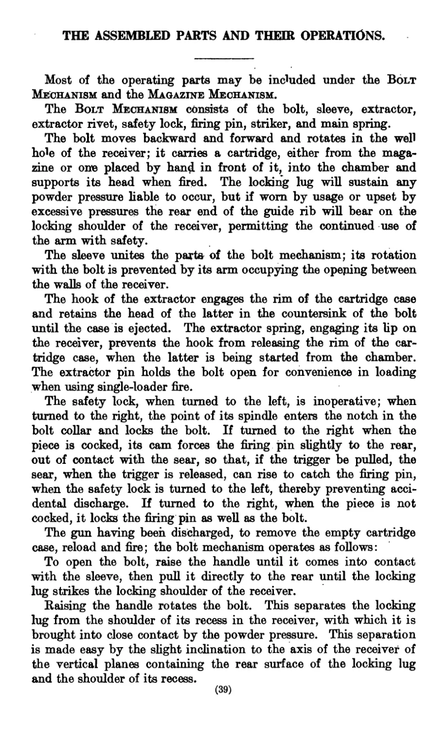
The rotation also causes the cocking cam of the bolt to force the
firing pin to the rear, withdrawing the point of the striker into
the bolt. The rotation of the firing pin is prevented by the lug on
the cocking piece projecting through the slot in the sleeve into its
groove in the receiver. As the
sleeve remains longitudinally sta-
tionary with reference to the bolt,
this rearward motion of the firing
pin, and consequently of the strik-
er, will begin the compression of
the main spring, since the rear end
of the latter bears against the front
end of the barrel of the sleeve,
and the front end against the rear
end of the striker.
When the bolt handle strikes
the sleeve, rotation ceases, during
which the firing pin has been
forced to the rear by the cocking
cam on the bolt until the sear
notch of the cocking piece has
passed the point of the sear, the
cocking-piece nose entered the
notch in the rear end of the bolt,
and the main spring partly com-
pressed; the locking lug will then
be out of its recess and the guide
rib under the extractor.
When the bolt handle is raised
into contact with the cam on the
cocking shoulder of the receiver,
a direct motion to the rear will be
combined with the rotation, so
that the cartridge case will be
started from the chamber by the
action of this cam.
The bolt is then drawn directly
to the rear, the extractor and guide
rib move along the left wall and
through the opening between the
two walls of the receiver. The
parts are retained in position by
the cocking-piece nose remaining in the notch in the rear end of the
bolt, and the main spring is partly compressed.
The relative position of the parts of the bolt mechanism is then
shown in Fig. 111.
U. S. MAGAZINE BIFLE AND CABBINE. 41
To dose the bolt, push the handle forward until it strikes the
cocking shoulder, then turn it down until it comes into contact
with its seat in the receiver. As the handle is turned down, the
rear end of the guide rib, traveling along the cam of the locking
shoulder of the receiver, will move the bolt forward until the locking
lug comes into contact with the cam of its recess in the receiver,
which moves the bolt slightly forward into its closed position.
As all movement of the firing pin is prevented by the point of the
sear engaging the sear notch of the cocking piece, the forward move-
ment of the bolt, produced by these cams, completes the com-
pression of the main spring, the seating of the cartridge in the cham-
ber, and forces the extractor hook over the rim of the cartridge case.
In dosing the bolt, a cartridge from the magazine, if using maga-
zine fire, or one placed by hand in the well of the receiver in front
of the bolt, will be carried forward into the chamber. The gun is
then ready to be fired.
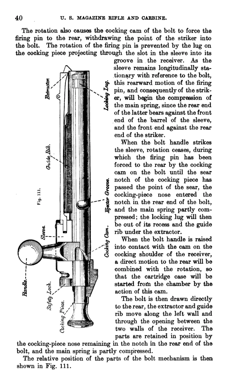
The position then occupied by the parts is shown in Fig. 112.
When the bolt is rotated so the guide rib is under the extractor,
the front end of the guide rib engages a lug on the underside of the
extractor and holds the latter against the left wall of the receiver
so the hook, as the bolt is dosed, will enter its notch in the receiver
and barrel.
To pull the trigger, the finger-piece must be drawn to the rear
until contact with the receiver is transferred from its bearings to
the heel, which gives a creep to the trigger, and then until the point
of the sear is withdrawn from in front of the cocking piece.
The hed of the ejector rises into its groove in the bolt, but just before
the bolt is drawn fully to the rear, the end of the groove suddenly
forces the hed down, causing the point to rise in front of the bolt
and strike the cartridge case. As the bolt is dosed, the hed rises
again into its groove, the curved portion of which permits the bolt
to rotate without operating the ejector. The upper surface of the
front end of the ejector is shaped so as to throw the cartridge case
out of the receiver, upward and to the right.
It is to be noted that, in this system of bolt mechanism, the com-
pression of the main spring, the seating of the cartridge in and the
starting of the empty case from the chamber, are entirdy done by
the action of cams.
The piece may be cocked either by raising the bolt handle until
it strikes the sleeve and then immediately turning it down, or by
pulling the cocking piece directly to the rear.
In firing, unless the bolt handle is turned fully down against its
seat in the receiver, the cam on the cocking piece will strike that in
the rear end of the bolt and the energy of the main spring will be
42
U. S. MAGAZINE RIFLE AND CARBINE.
expended in closing the bolt instead of on the primer; this prevents
the possibility of a cartridge being fired until the bolt is fully closed.
The opening and the closing of the bolt should each be done by
one continuous motion.
Fig. 112.
U. S. MAGAZINE BIFLE AND CABBINE.
43
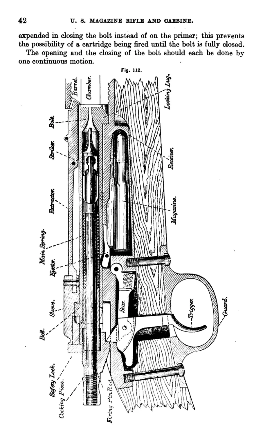
The Magazine Mechanism includes the gate, carrier, follower,
magazine spring, hinge bar and cut-off.
Fig. 113.
Cut-Off
Extractor Sp™V-
\ / Fvri/ng Fin Rod.
z / „.Bolt.
Guide rib.
Receiver.
гяшшт
Side plait
nectar
-Follower.
Magazine
Carrier.
----Hinge Ear Pin.
Magazine Spring.
Fig. 113 represents a cross section of the Model 1896 gun, through
the point of the ejector; the bolt is closed, the magazine contains
five cartridges and is “off.”
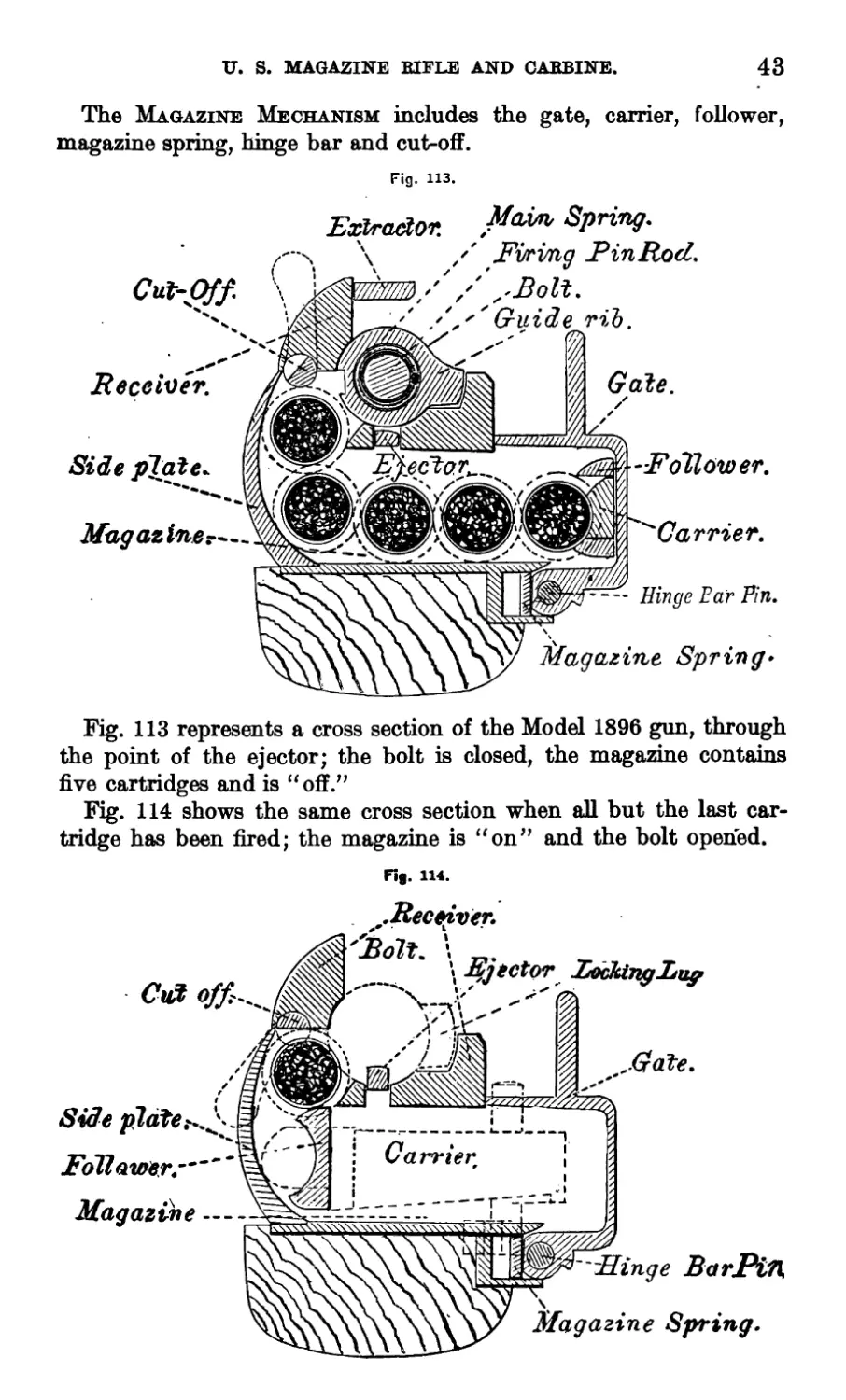
Fig. 114 shows the same cross section when all but the last car-
tridge has been fired; the magazine is “on” and the bolt opened.
Fig. 114.
..Receiver.
Ejector hocking Lug
Side plate
Follower.-
Magazine ----
Carrier
"Singe BarPin
Grate.
Magazine Spring.
44
U. S. MAGAZINE RIFLE AND CARBINE.
To charge the magazine, open the gate, insert the cartridges
from a dip, or from the hand, then dose the gate.
As the gate is opened, its lug, acting on the cam of the^carrier,
Fig. 115, retracts the latter within the recess of the gate, leaving
an unobstructed opening for the insertion of the cartridges. As the
gate is closed, the magazine spring, the front end of which bears
on[the lug of the arbor of the carrier, Fig. 115, swings the carrier
U. S.^ MAGAZINE RIFLE AJ^D CARBINE.
45
into the magazine, against the last cartridge inserted. The point
of the carrier forces the cartridges, in succession, against and up
the curved surface of the side plate, into the magazine channel.
When there is only one cartridge in the magazine, the point of the
carrier forces it up on the top of the follower, which holds it high
enough in the channel to be caught by the bolt. The point of the
carrier then rests against the inner surface of the side plate.
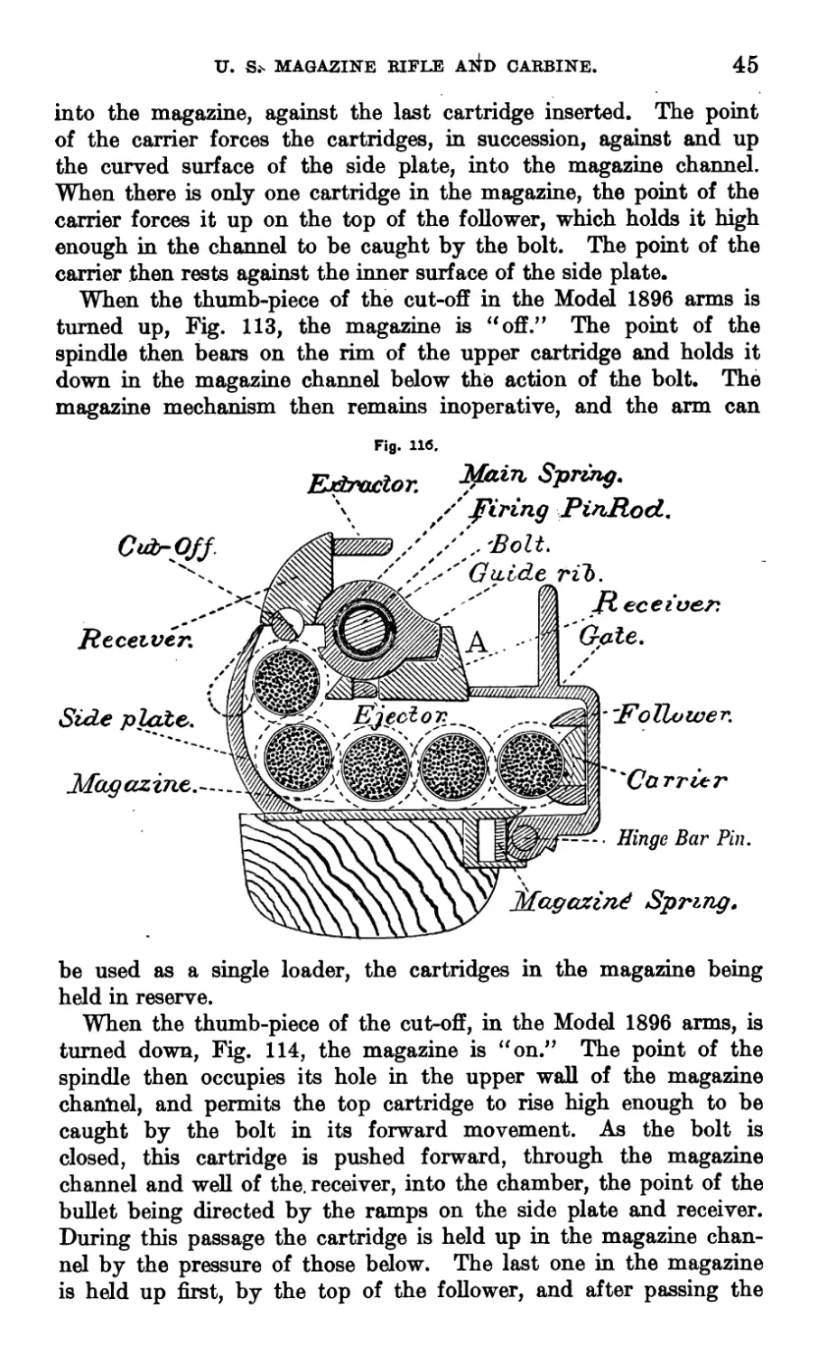
When the thumb-piece of the cut-off in the Model 1896 arms is
turned up, Fig. 113, the magazine is “off.” The point of the
spindle then bears on the rim of the upper cartridge and holds it
down in the magazine channel below the action of the bolt. The
magazine mechanism then remains inoperative, and the arm can
Fig. 116.
Extnctor. ^in SPr£uS-
\ / firing PinRod..
Cub-pjy.
Receiver.
'Bolt.
Guide rib.
Receiver.
Gate.
Side plate.
Magazine.
"FoTLvwer.
Hinge Bar Pin.
Magazine Spring.
Ejector.
''Carrier
be used as a single loader, the cartridges in the magazine being
held in reserve.
When the thumb-piece of the cut-off, in the Model 1896 arms, is
turned down, Fig. 114, the magazine is “on.” The point of the
spindle then occupies its hole in the upper wall of the magazine
channel, and permits the top cartridge to rise high enough to be
caught by the bolt in its forward movement. As the bolt is
closed, this cartridge is pushed forward, through the magazine
channel and well of the. receiver, into the chamber, the point of the
bullet being directed by the ramps on the side plate and receiver.
During this passage the cartridge is held up in the magazine chan-
nel by the pressure of those below. The last one in the magazine
is held up first, by the top of the follower, and after passing the
46
U. S. MAGAZINE RIFLE AND CARBINE.
latter, by the rib of the side plate and left edge of the roof of the
magazine.
Note.—These “cut-offs” are being replaced by those shown in
Fig. 116 for all Model 1896 guns.
In the Model 1898 arms, when the thumb-piece of the cut-off is
turned down, Fig. 116, the magazine is “off,” and when turned up,
is “on;” or the reverse of what it is in the Model 1896. As the
arm is habitually used with the magazine “off,” the thumb-piece
of the cut-off is better protected when turned down.
The magazine can be charged with the bolt closed or open, with
the cut-off turned for magazine or single-loader fire, and, if one or
more cartridges have been fired, can be filled.
The magazine spring actuates the carrier, holds the gate open,
assists in closing it, and holds it closed.
The guide lip prevents the heads of the cartridges from falling
into the well of the gate when charging the magazine.
To open the butt plate cap, insert the rim of an empty cartridge
case in the notch in the cap and draw it open. The joints of the
cleaning rod should be removed before the oiler. In replacing the
oiler and rods, insert the former so its bottom will be next the butt
plate, and, with one joint of the rod, push the oiler into its seat,
then insert the rods.
PRECAUTIONS.
If it is desired to carry the piece cocked, with a cartridge in the
chamber, the bolt mechanism should be secured by turning the
safety lock to the right.
To obtain positive ejection, and to insure the bolt catching the
top cartridge in the magazine, when using magazine fire, the bolt
must be drawn fully to the rear in opening it.
If a cartridge is pushed from the magazine partly into the cham-
ber, and then the bolt fully drawn to the rear, that cartridge will
remain in the well and chamber, and a second will rise from the
magazine in front of the bolt. If the bolt is again pushed forward,
the second cartridge will strike the first and produce a jam. To
avoid this, always close the bolt on a cartridge in front of it to insure
the action of the extractor and ejector on that cartridge, when the
bolt is opened.
If a jam occurs, draw the bolt fully to the rear and, with the right
hand, remove the first cartridge and close the bolt; if the first car-
tridge has been pushed into the chamber, draw the bolt to the rear,
with the thumb of the right hand push the second cartridge back
into the magazine and cut it off; then close the bolt on the first
cartridge.
U. S. MAGAZINE BIFLE AND OABBINE.
47
Unless the bolt handle is fully turned down into contact with its
seat in the receiver, when the trigger is pulled the nose of the cock-,
ing piece will strike against the cocking cam of the bolt, and the
energy of the mainspring will be expended in closing the bolt
instead of igniting the primer, causing a miss-fire.’ Care should
be taken not to raise the bolt handle with the forefinger if the trig-
ger is pulled with the middle one.
It is essential for the proper working and preservation of aU cams
that they be kept lubricated.
DISMOUNTING AND ASSEMBLING BY SOLDIER.
The bolt and magazine mechanism can be dismounted without
removing the stock. The latter should never be done except for
making repairs, and then only by some selected and instructed man.
TO DISMOUNT BOLT MECHANISM.
1. Draw the bolt fully to the rear, then place the piece across
hoUow of left arm.
2. Lift the front end of hook of extractor off bolt with left thumb,
and at the same time turn bolt handle to left with right hand (see
Fig. 117). The bolt can then be drawn from the receiver.
Fig. 117
3. Take bolt handle in left hand, back of hand down, bolt upside
down. Grasp cocking piece with right hand (Fig. 118).
Fig. 118.
48
U. S. MAGAZINE RIFLE AND CARBINE.
4. Slightly draw back cocking piece and turn it toward the
operator until the firing pin can be removed from the bolt.
5. Take firing pin in left hand and bear down on point of striker
with right thumb until it leaves the firing pin; remove mainspring
from firing pin and the latter from sleeve.
TO ASSEMBLE BOLT MECHANISM.
1. Observe that the safety lock is turned to the left. Reverse
the order of the steps of fifth operation in dismounting.
2. Grasp the bolt handle in left hand as in third operation in
dismounting, and the firing pin in right hand, extractor upper-
most. Insert firing pin in bolt.
3. Grasp handle of bolt with fingers of both hands, bolt directed
downward, and with both thumbs on the rear of safety lock (Fig.
119), push strongly forward and turn to right with thumbs until
the arm of the sleeve engages the collar of the bolt.
4. Grasp bolt and cocking piece as in third operation for dis-
mounting. Draw back and turn cocking piece from the operator
until its nose enters the notch on the roar end of the bolt (see
Fig. 118).
U. S. MAGAZINE BIFLE AND CABBINE.
49
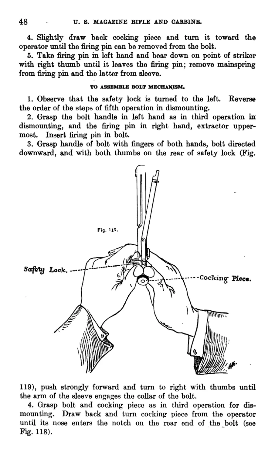
5. Take bolt in right hand and introduce it into the receiver,
keeping the extractor lifted with the right thumb (Fig. 120).
Turn bolt to right and at the same time press strongly with first
finger against right side of extractor.
TO DISMOUNT MAGAZINE MECHANISM.
1. The gate being closed, engage the flanged head of a cartridge
case under the lug on the front end of the hinge bar head and turn
the latter toward the gate, out of its seat; then bear heavily on the
gate with the palm of the right hand, to overcome the pressure of
the magazine spring, and, with the left, press forward against the
lug, drawing the hinge bar pin from the receiver.
2. Remove the gate, magazine spring, carrier and follower.
TO ASSEMBLE MAGAZINE MECHANISM.
1. Hold the piece with right side uppermost. Insert arbor of
carrier into its hole in receiver and place end of left thumb across
magazine to prevent carrier swinging into the latter.
2. Place magazine spring in its channel, convex side up, rounded
end to the rear, particularly observing that the lip at its front end
rests in the notch on heel of carrier.
3. Place gate in its seat, lug entering between earner and maga-
zine spring. Remove left thumb and at the same time press gate
against magazine spring with right hand.
4. Insert hinge bar pin in front hinge hole in receiver with left
hand, and press gate down strongly until the pin can be pushed
through gate into rear hinge hole.
5. After the hinge bar pin is fully home, turn the head into its
seat by opening the gate.
TO COMPLETE DISMOUNTING.
(not to be done by soldieb.)
The bolt and magazine mechanism having been dismounted,
proceed as follows:
1. Remove front sight by driving the front sight pin out of its
hole from the left.
5719—17----4
50 U. S. MAGAZINE RIFLE AND CARBINE.
2. Remove upper band screw and slip band forward off barrel.
3. Loosen lower band screw, remove band.
4. To remove the hand guard: remove the rear sight and force
hand guard springs off barrel by screw-driver blades inserted between
guard and stock.
5. Remove guard screws and guard.
6. Remove receiver and barrel from stock.
7. Remove side plate screw,, then side plate by pushing out the
rear end, until free from the receiver, and drawing it to the rear.
8. Remove ejector pin by means of its knob, then ejector.
9. Press trigger forward until nose of sear is withdrawn from its
slot in receiver; then bearing against right side of sear push it out
of its seat.
10. Turn cut-off down, and with tool No. 5 in armorer’s kit, or
with the blade of a narrow screw-driver, force the spring into the
thumb-piece and draw out.
11. To remove safety lock, turn it vertical and strike the front
face of its thumb-piece a light blow.
The rear sight leaf should never be removed from the base nor
the base from the barrel except for making repairs.
The barrel should never be unscrewed from the receiver,
t.
TO ASSEMBLE AFTER DISMOUNTING.
1. Safety Lock.—Introduce the point of the tang of a small file,
or any tool of similar size and shape, between the thumb-piece and
the spring spindle, thus compressing the spring and forcing the
spring spindle into the thumb-piece; insert the safety lock spindle
in its hole in the sleeve, the thumb-piece being held vertical, push
the safety lock forward, gradually withdrawing the tool.
2. Cut-off.—Insert its spindle, the thumb-piece turned down
into the cut-off hole in the receiver, until the spring spindle strikes
the,receiver; then with the blade of a screw-driver, force the spring
spindle into its hole in the thumb-piece and push the cut-off into
place. Care must be taken that the flattened and not the straight
sides of the spring spindle bear on the curved surface df the recesses
in the receiver.
3. Sear and Trigger.—Insert the spring in its hole in the sear,
start the hinge of the sear into its seat in the receiver, and with a
blade of the screw-driver, compress the spring in its hole until the
sear can be pushed into place.
Reverse and follow in inverse order the other operations of dis-
mounting.
CLEANING AND CARE OF THE ARM.
As the residuum of smokeless powder, if not completely removed,
corrodes the bore in a short time, care is required in cleaning the arm
after firing.
и. 8. MAGAZINE RIFLE AND CARBINE.
51
To clean the barrel, insert in the chamber a cartridge shell, the
front end of which has been filled with a wooden plug, and close the
bolt; clean the bore with rags saturated with soda water, or, if that
is not obtainable, with hot water; wipe thoroughly dry with clean
rags; remove the bolt and cartridge shell; clean and dry the cham-
ber, from the rear, in the same manner; oil both chamber and bore
with cosmoline oil, leaving a light coating. Twenty-four hours after
this first cleaning, the bore should again be cleaned as described
above, as it has been found that the powder gases are probably
forced into the texture of the steel and will, if a second cleaning is
not resorted to, cause rusting, no matter how thoroughly the bore
may have been cleaned at first. When the jointed rod is used,
remove the bolt, clean half of the bore from the muzzle and the
remainder through the receiver, as above prescribed.
CLEANING THE RIFLE.
The proper care of the bore requires conscientious, careful work, but
it pays well in reduced labor of cleaning and in prolonged accuracy-
life of the barrel, and better results in target practice. Briefly stated,
the care of the bore consists in removing the fouling resulting from
firing to obtain a chemically clean surface and coating this surface
with a film of oil to prevent rusting. The fouling which results from
firing is of two kinds—one, the products of combustion of the powder;
the other, cupro-nickel scraped off (under the abrading action of
irregularities or grit in the bore). Powder fouling, because of its
acid reaction, is highly corrosive; that is, it will induce rust and
must be removed. Metal fouling of itself is inactive, but may cover
powder fouling and prevent the action of cleaning agents until
removed, and when accumulated in noticeable quantities it reduces
the accuracy of the rifle.
Powder fouling may be readily removed by scrubbing with hot
soda solution, but this solution has no effect on the metal fouling of
cupro-nickel. It is therefore necessary to remove all metal fouling
before assurance can be had that all powder fouling has been removed
and that the bore may be safely oiled. Normally, after firing a barrel
in good condition, the metal fouling is so slight as to be hardly
perceptible. It is merely a smear of infinitesimal thickness, easily
removed by solvents of cupro-nickel. However, due to pitting, the
presence of dust, other abrasives, or to accumulation, metal fouling
may occur in clearly visible flakes or patches of much greater thick-
ness, much more difficult to remove.
In cleaning the bore after firing, it is well to proceed as follows:
Swab out the bore with soda solution (see below) to remove powder
fouling. A convenient method is to insert the muzzle of the rifle
52
U. S. MAGAZINE RIFLE AND CARBINE.
into the can containing the soda solution and, with the cleaning rod
inserted from the breech, pump the barrel full a few times Remove
and dry with a couple of patches. Examine the bore to see that
there are in evidence no patches of metal fouling which, if present,
can be readily detected by the naked eye, then swab out with the
swabbing solution—a dilute metal-fouling solution. (See below.)
The amount of swabbing required with the swabbing solution can be
determined only by experience, assisted by the color of the patches.
Swabbing should be continued, however, as long as the wiping patch
is discolored by a bluish-green stain. Normally a couple of minutes’
work is sufficient. Dry thoroughly and oil.
The proper method of oiling a barrel is as follows: Wipe the clean-
ing rod dry; select a clean patch and thoroughly saturate it with
sperm oil or warmed cosmic, being sure that the cosmic has pene-
trated the patch; scrub the bore with the patch, finally drawing the
patch smoothly from the muzzle to the breech, allowing the cleaning
rod to turn with the rifling. The bore will be found now to be smooth
and bright, so that any subsequent rust and sweating can be easily
detected by inspection.
If patches of metal fouling are seen upon visual inspection of the
bore, the standard metal-fouling solution prepared as hereinafter pre-
scribed must be used. After scrubbing out with the soda solution,
plug the bore from the breech with a cork at the front end of the cham-
ber, or where the rifling begins. Slip a 2-inch section of rubber hose
over the muzzle down to the sight and fill with the standard solution
to at least one-half inch above the muzzle of the barrel. Let it stand
for 30 minutes, pour out the standard solution, remove hose and breech
plug, and swab out thoroughly with soda solution to neutralize and
remove all trace of ammonia and powder fouling. Wipe the barrel
dean, dry, and oil. With few exceptions, one application is suffi-
cient, but if all fouling is not removed, as determined by careful
visual inspection of the bore and of the wiping patches, repeat as
described above.
After properly cleaning with either the swabbing solution or the
standard solution, as has just been described, the bore should be
dean and safe to oil and put away, but as a measure of safety a patch
should always be run through the bore on the next day and the bore
and wiping patch examined to insure that cleaning has been properly
accomplished. The bore should then be oiled, as described above.
If the swabbing solution or the standard metal-fouling solution is
not available, the barrel should be scrubbed, as already described,
with the soda solution, dried, and oiled with a light oil. At the end
of 24 hours it should again be cleaned, when it will usually be found
to have “sweated”; that is, rust having formed under the smear of
и. 8. MAGAZINE RIFLE AND CARBINE.
53
metal fouling where powder fouling was present, the surface is puffed
up. Usually a second cleaning is sufficient, but to insure safety it
should be again examined at the end of a few days before final oiling.
The swabbing solution should always be used, if available, for it
must be remembered that each puff when the bore “sweats” is an
incipient rust pit.
A clean dry surface having been obtained, to prevent rust, it is
necessary to coat every portion of this surface with a film of neutral
oil. If the protection required is but temporary and the arm is to
be cleaned or fired in a few days, a sperm oil may be used. This is
easily applied and easily removed but has not sufficient body to hold
its surface for more than a few days. If rifles are to be prepared for
storage or shipment, a heavier oil, such as cosmic, must be used.
In preparing arms for storage or shipment they should be cleaned
with particular care, using the metal-fouling solution as described
above. Care should be taken, insured by careful inspection on suc-
ceeding day or days, that the cleaning is properly done and all traces
of ammonia solution removed. The bore is then ready to be coated
with cosmic. At ordinary temperatures cosmic is not fluid. In order,
therefore, to insure that every part of the surface is coated with a
film of oil, the cosmic should be warmed. Apply the cosmic first with
a brush; then, with the breech plugged, fill the barrel to the muzzle,
pour out the surplus, remove the plug, and allow to drain. It is
believed that more rifles are ruined by improper preparation for stor-
age than from any other cause. If the bore is not clean when oiled—
that is, if powder fouling is present or rust has started—a half inch
of cosmic on the outside will not stop its action, and the barrel will
be ruined. Remember that the surface must be perfectly cleaned
before the heavy oil is applied. If the instructions as given above are
carefully followed, arms may be stored for years without harm.
PREPARATION OF SOLUTIONS.
Soda solution.—This should be a saturated solution of sal soda
(bicarbonate of soda). A strength of at least 20 per cent is neces-
sary. The spoon referred to in the following directions is the model
of 1910 spoon issued in the mess outfit.
Sal soda—one-fourth pound, or 4 (four) heaping spoonfuls.
Water—1 pint or cup, model of 1910, to upper rivets.
The sal soda will dissolve more readily in hot water.
Swabbing solution.—Ammonium persulphate—60 grains, one-half
spoonful smoothed off.
Ammonia, 28 per cent—6 ounces, or three-eighths of a pint, or 12
spoonfuls.
Water—-4 ounces, or one-fourth pint, or 8 spoonfuls.
54 TJ. S. MAGAZINE BIFLE AND CABBINE.
Dissolve the ammonium persulphate in the water and add the
ammonia. Keep in tightly corked bottle; pour out only what is
necessary at the time, and keep the bottle corked.
Standard metal-fouling solution.—Ammonium persulphate—1 ounce,
or 2 medium heaping spoonfuls.
Ammonium carbonate—200 grains.
Ammonia, 28 per cent—6 ounces, or three-eighths pint, or 12
spoonfuls.
Water—4 ounces, or one-fourth pint, or 8 spoonfuls.
Powder the persulphate and carbonate together, dissolve in the
water and add the ammonia; mix thoroughly and allow to stand for
one hour before using. It should be kept in a strong bottle, tightly
corked. The solution should not be used more than twice, and used
solution should not be mixed with unused solution, but should be
bottled separately. The solution, when mixed, should be used within
30 days. Care should be used in mixing and using this solution to
prevent injury to the rifle. The ammonia solution should not be
used in a warm barrel. An experienced noncommissioned officer
should mix the solution and superintend its use.
Neither of these ammonia solutions has any appreciable action on
steel when not exposed to the air, but if allowed to evaporate on steel
they attack it rapidly. Care should, therefore, be taken that none
spills on the mechanism and that the barrel is washed out promptly
with soda solution. The first application of soda solution removes
the greater portion of the powder fouling and permits a more effective
and economical use of the ammonia solution. These ammonia solu-
tions are expensive and should be used economically.
It is a fact recognized by all that a highly polished steel surface
rusts much less easily than one which is roughened; also, that a barrel
which is pitted fouls much more rapidly than one which is smooth.
Every effort, therefore, should be made to prevent the formation of
pits, which are merely enlarged rust spots, and which not only affect
the accuracy of the arm but increase the labor of cleaning.
The chambers of rifles are frequently neglected because they are
not readily inspected. Care should be taken to see that they are
cleaned as thoroughly as the bore. A roughened chamber delays
greatly the rapidity of fire and not infrequently causes shells to stick.
A cleaning rack should be provided for every barracks. Rifles
should always be cleaned from the breech, thus avoiding possible
injury to the rifling at the muzzle which would affect the shooting
adversely. If the bore for a length of 6 inches at the muzzle is per-
fect, a minor injury near the chamber will have fit tie effect on the
accuracy of the rifle. The rifle should be cleaned as soon as the
IT. S. MAGAZINE BIFLE AND CABBINE.
55
firing for the day is completed. The fouling is easier to remove
then, and if left longer it will corrode the barrel.
If gas escapes at the base of the cartridge, it will probably enter
the well of the bolt through the striker hole. In this case the bolt
mechanism must be dismounted and the parts and well of the bolt
thoroughly cleaned.
Before assembling the bolt mechanism, the firing pin, the barrel
of the sleeve, the body of striker, the well of bolt, and all cams should
be lightly oiled.
Many of the parts can generally be cleaned with dry rags. All
parts after cleaning should be wiped with an oiled rag.
The best method of applying oil is to rub with a piece of cotton
cloth upon which a few drops of oil have been placed, thereby avoid-
in the use of an unnecessary amount of oil; this method will, even
in the absence of the oiler, serve for the cams and bearings, which
should be kept continually oiled.
Any part that may appear to move hard can generally be freed by
the use of a little oil.
The stock and hand guard may be coated with raw linseed oil and
polished by rubbing with the hand.
Sperm oil should only be used for lubricating metallic bearing and
contact surfaces.
For the chamber and bore, only cosmoline or cosmic should be
used. This should also be applied to all metallic surfaces, to prevent
rusting when arms are stored or when not used for an appreciable
length of time.
INSTRUCTIONS FOR REPAIRING U. S. MAGAZINE ARMS IN THE HANDS
OF TROOPS.
The following component parts only of the Models 1896 and 1898
arms will be issued for repairs in the hands of troops:
RIFLE.
Bayonet.
Bolt.
Butt Plate.
Butt Plate Cap.
Butt Plate Cap Pin
Butt Plate Cap Spring.
Butt Plate Cap Spring Screw.
Butt Plate Screw, large.
Butt Plate Screw, small.
Butt Swivel.
Butt Swivel Screw.
Carrier.
Cleaning Rod, 1st section.
Cleaning Rod, 2d and 3d sections.
Cut-off.
Ejector.
Ejector Pin.
Extractor.
Extractor Pin.
Extractor Rivet.
56 U. S. MAGAZINE RIFLE AND CABBINE.
Extractor Spring. Magazine Spring.
Firing Pin J Main Spring.
Follower.' Safety Lock.
Follower Pin. Sear.
Front Sight. Sear Spring.
Front Sight Pin. Side Plate.
Gate. Side Plate Screw.
Guard. Sleeve.
Guard Screw, front. Stacking Swivel.
Guard Screw, rear. Stacking Swivel Screw.
Hand Guard. Stock.
Hinge Bar. Striker.
Lower Band. Trigger.
Lower Band Pin. Trigger Pin.
Lower Band Swivel. Upper Band.
Lower Band Swivel Screw. Upper Band Screw.
CARBINE*
PARTS SAME AB Ш RIFLE.
Bolt. Follower Pin.
Butt Plate. Front Sight Pin.
Butt Plate Cap. Gate.
Butt Plate Cap Pin. Guard.
Butt Plate Cap Spring. Guard Screw, front.
Butt Plate Cap Spring Screw. Guard Screw, rear.
Butt Plate Screw, large. Hinge Bar.
Butt Plate Screw, small. Magazine Spring.
Carrier. Main Spring.
Cleaning Rod, 1st section. Safety Lock.
Cleaning Rod, 2d section. Sear.
Cut-off. Sear Spring.
Ejector. Side Plate.
Ejector Pin. Side Plate Screw.
Extractor. Sleeve.
Extractor Pin. Striker.
Extractor Rivet. Swivel Screw, rear.
Extractor Spring. Trigger.
Firing Pin. Follower. Trigger Pin.
PARTS PECULIAR TO THE CARBINE.
Band. Rear Sight Slide, Model 1896?
Band Spring. Rear Sight Slide Cap, Model 1896.
Front Sight. Rear Sight Movable Base, Model
Hand Guard. 1901.
Rear Sight Base, Model 1896. Rear Sight Leaf, Model 1901.
Rear Sight Leaf, Model 1896. Stock.
> Includes screw and pin*
U. S. MAGAZINE BIFLE AND CABBINE.
57
[PARISH HIGH ARE MC£T; LIABLE; TO REQT IRE[ RIF AIR.
Bayonet Catch Nut.—Works loose and is lost, if the end of
the catch has not been well riveted over the nut.
Cocking Piece.—Nose worn from neglect to keep it lubricated.
Cut-off.—Thumb-piece knocked off by blow, due to form.
Gate.—Lug broken off by escape of gas into the magazine, due
to defective cartridges.
Hinge Bar.—Head broken off from blow, or attempt to with-
draw it improperly.
Lower Band Swivel and Screw.—Screw, if not riveted in
place, works loose and with swivel is lost.
Stacking Swivel and Screw.—Screw, if not riveted in place,
works loose and with swivel is lost.
Stock.—Bruises, cuts, pieces chipped from different points.
Broken at “small.”
Striker.—Point burned by defective cartridges.
THE REPLACING OF BROKEN PARTS.
Butt Plate Cap Pin.—This pin has both ends upset; the burr
on one end must be filed off and the pin driven out with a drift;
when a new pin is put in, its ends must be upset with light blows
of a hammer.
Ejector.—Loosen the guard screws and relieve the close binding
of the receiver in the stock; then remove the side plate screw, side
plate, ejector pin, and ejector. After inserting the ejector and pin,
replace the side plate and screw; then screw the guard screws firmly
into place, care being taken not to injure their heads.
Extractor.—Place the sleeve on a wooden block with the ex-
tractor rivet ovel a hole in the block, drive the rivet out with a punch,
smaller in diameter than the rivet; remove the old, and enter a new
extractor to the proper distance in its slot in the sleeve; then insert
the rivet in its hole, and drive it into place by light blows of a hammer.
Extractor Pin.—The small end is inserted from the right, and,
when in place, is upset.
Follower Pin.—The small end must be inserted in the hole in
the top of the follower, and when driven into place both ends should
be upset and all projection of the pin carefully removed.
Front Sight.—As the left end of the sight pin is upset, this burr
must be removed with a file, and the pin then driven out from the
left side with a small drift. The new sight having been put in the
slot, a new pin must be used; its small end is inserted from the right
side, and, when in place, the left end should be upset with blows of a
light hammer.
58 U. S. MAGAZINE BIFLE AND CABBINE.
Loweb Band Swivel Screw.—This screw, when in place, has
its end upset and riveted over the band ear. It should never work
loose, if properly assembled, and when it has to be removed to
replace an injured' swivel, the burr on the end should be filed off
and the screw taken out, the end being again upset when the screw
has been returned to its place.
Bear Sight Base.—When it may be necessary to remove the
rear sight for repairs, it must be done by one thoroughly familiar
with the use of the screw-driver, to prevent injury to the head or
point of the base screws.
Before replacing the base, the barrel, bottom of the base, and
screw holes in the barrel should be carefully cleaned; the screws
should be started so as to enter freely the holes in the barrel, and
they must be screwed in firmly against the base, but not with suf-
ficient force to strip the threads or break the head.
Stacking Swivel Screw.—This must be treated in exactly the
same manner as the lower band swivel screw.
Trigger Pin.—The small end must be entered from the right
side of trigger, and when in place, upset on left side.
INJURIES WHICH DO NOT RENDER PARTS UNSERVICEABLE.
Bolt.—The entire flange at the front end may be broken off,
except a small portion on the opposite side from the guide rib
which is required to support the head of the empty case and cause
the case to be drawn to the rear sufficiently far to be acted upon
by the ejector.
If automatic ejection be not considered, the entire flange may be
dispensed with.
Butt Plate.—Bruises, cuts, or wearing.
Butt Swivel.—Bent.
Cocking Piece.—Moderate wearing of nose. The nose can wear
until raising and lowering the bolt handle fails to cock the piece.
Extractor.—Moderate wear or break of edge of hook. Loss of
spring.
Guard.—Bent, bruised, or cut.
Receiver.—Guide lip lost, bent, or loose.
Side Plate.—Edges broken, cut through thin part at shoulder
near screw hole.
Bar and Ring of Carbine Swivel.—Bent.
USING THE ARM WHEN CERTAIN PARTS OF THE BOLT AND MAGAZINE MECHANISM
ARE WANTING.
The parts not essential, or only so to a degree, are the ejector,
the extractor spring, extractor pin, safety lock, cut-off, guide lip,
gate, carrier, follower, side plate,
XT. S. MAGAZINE RIFLE AND CARBIKE. 59
The empty cases drawn to the rear by the extractor can be
removed from the receiver by the finger.
The safety lock being merely a precautionary device, its absence
does not affect the usefulness of the firearm. The absence of the
cut-off does not affect the use of the arm as a single loader, if the
magazine be kept empty, or the feeding can be done entirely through
the magazine, which only prevents the latter from being held full in
reserve.
The want of one or more of the last four parts enumerated above
only prevents the use of the magazine, but in no way affects the use
of the arm as a single loader.
The soldier should be taught to appreciate these facts.
REMARKS. .
1. Complaints have not infrequently been made that a main
spring is too weak to perform its office, when the fault rests with
the soldier, who in sighting inadvertently raised the bolt handle
with his hand before pulling the trigger, and thus caused the force of
the spring to be expended in closing the bolt, instead of in exploding
the cartridge.
2. The cocking piece and gate lug, to prevent wear, must be kept
slightly oiled.
. 3. In assembling the gate, observe that the magazine spring has
its lip on top of the heel of the carrier, and not beneath it.
4. The side plate, when removed, must be returned firmly to its
bearings, or the width of the cartridge way will be too great to cause
the proper feeding of the cartridges.
5. When firing many successive rounds, note must be taken that
unbumed grains of powder do not collect and pack in the locking
lug recess in the receiver, as this will interfere with the perfect
closing of the bolt. Such accumulations can be blown out from
time to time, or, when packed, removed by a knife or the screw-
driver.
6. Except when repairs are needed, the following parts will con-
stantly be injured if allowed to be dismounted by the soldier for
cleaning; and when,repairs are necessary, they should be removed
only by a company artificer, or one familiar with the handling of
tools and delicate mechanisms, viz: Cut-off, Extractor, Front Sight,
Lower Band Swivel Screw, Rear Sight, Safety Lock.
The rear sight is accurately constructed and fitted carefully to the
barrel, and the adjustment of its parts must be preserved to insure
correct aiming. If the soldier be permitted to remove these parts,
they will become worn and injured, and the closeness of their fit be
destroyed.
7. Unless the screw-driver be handled carefully, and with some
skill, the screws are sure to be injured either at the head or thread.
AMMUNITION FOR CALIBER .30 ARMS.
BALL CARTRIDGE.
The Caliber .30 Ball Cartridge, Fig. 121, consists of the case, A;
bullet, B; primer, C; and charge of smokeless powder, D.
The case has the fianged head, E; the primer seat, F; the hole,
G, through which the flame from the primer composition ignites
the powder charge; the body, H, which is conical to facilitate the
Fig. 121.
о j I1** 2
Scale.
extraction of the empty case; the shoulder, K, and the neck, N,
which is cylindrical: it is made of brass.
The initials of the Arsenal where the ammunition is made, the
number of the month and of the year of its fabrication, are stamped
on the head of each case.
The bullet is lubricated, and has a core of lead and tin composi-
tion, jacketed with cupro-nickel; it has three grooves, and the
mouth of the case is crimped into the front groove to secure the
bullet in place. The core is composed of 1 part of tin and 25 parts
of lead by weight; this proportion is varied slightly in order to
keep the weight of the finished bullet constantly at 220 grains.
The primer is composed of three parts, viz: The cup, i; the brass
anvil, J; and the waterproofed paper disc, I. The cup is made of
cartridge copper and contains the composition, m; this is covered
and waterproofed by the disc, Z. In plan, the anvil is a cir-
cle with two small semicircular portions removed from opposite
sides; these two openings form vents for the passage of the flame
from the composition to the powder.
(60)
U. S. MAGAZINE BIFLE AND CARBINE.
61
The powder is of the nitroglycerine type; up to the present time
three different American powders have been used, viz: Peyton, Du
Pont, and Laflin & К and W. A. The charge varies with the powder
used from 35 to 42 grains. -
The primer composition is known as H-48, and consists of—
Sulphur........................................... 8.63 per cent.
Antimony sulphide.................................25.12 per cent.
Potassium chlorate................................49.61 per cent.
Glass crystals.............................16.64 per cent.
The weight of the cartridge complete varies from 435 to 442
grains, depending upon the weight of the powder charge. Twenty
cartridges are packed in a pasteboard box, on the wrapper of which
are printed the kind of Cartridge, directions for opening and for
treatment of the fired shells, the rifle velocity at 53 feet, date of
loading, etc. The box and cartridges weigh about 21.5 ounces;
1,000 cartridges, packed in 50 pasteboard boxes and encased in
wood with air-tight zinc lining, weigh 78 to 79 pounds.
The standard instrumental velocity, at 53 feet from the muzzle,
of this ammunition in the rifle is 1,960 feet per second, with an
allowed variation of but 15 feet per second on either side of the
standards This instrumental velocity at 53 feet corresponds to a
muzzle velocity in the rifle of about 2,000 feet per second.
The velocity in the carbine is 80 feet per second less than in the
rifle.
DUMMY CARTRIDGE.
This consists of a shell containing no powder, a primer with the
anvil, but without disc or composition, and a service bullet with-
out lubricant.
The shell is cannelured at the seat of the bullet, and has six
longitudinal corrugations and a round hole drilled in front of the
head.
BLANK CARTRIDGE.
The Blank Cartridge, Fig. 122, consists of the regular service case,
A; hollow paper bullet, B; and primer, C, which is the same as that
for the caliber .45 cartridge.
The case is loaded with 5 grains of E. C. smokeless blank fire
powder to drive the paper bullet out of the bore, to ignite the
62
U. S. MAGAZINE RIFLE AND CARBINE.
powder in the bullet, and to produce a sufficiently loud report in
firing.
Five grains of the same smokeless powder, D, are compressed
into the interior of the bullet to give the latter the necessary stiff-
ness, and to insure its being broken into fragments when fired.
To prevent the paper bullet from being too susceptible to moisture,
the bullet end of the cartridge, after loading, is coated with paraffine.
The blank cartridge weighs about 202 grains, between 34 and 35
weigning 1 pound. One paper box containing 20 blank cartridges
weighs about 11 ounces. One wooden box containing 50 paper
boxes or 1,000 blank cartridges, weighs 42 pounds.
GALLERY PRACTICE CARTRIDGE.
This cartridge, Fig. 123, consists of the regular service case, A; the
ball, В; and the primer, C, the same as that for the caliber .45
ammunition.
The cartridge is loaded with 5 grains of black or smokeless powder.
When smokeless powder is used, a cardboard wad is inserted in the
shell as far as the cannelure in the neck, and the ball placed on the
wad, keeping the irregularity in surface of ball, due to gate of mould,
up or down; and a nonfulminate H-48 primer is used.
The cannelure, D, forms a seat for the ball and prevents it from
falling or being forced into the powder chamber of the case.
The ball is made of an alloy of 16 parts of lead to 1 of tin; it is
lubricated with Japan wax and weighs 43 grains.
The gallery practice cartridge weighs about 232 grains, or about
30 to the pound. One paper box containing 20 cartridges weighs
about 12 ounces. One wooden box, holding 50 paper boxes or
1,000 cartridges, weighs 45 pounds and 4 ounces.
The components of the gallery practice cartridge are usually
issued to the service separately, to be assembled and reassembled
with the aid of tools and appliances provided for the purpose.
When specially ordered, assembled cartridges are prepared for issue,
in which case the mouth of the shell is slightly curved inward
to retain the ball in place in transportation and handling. This
feature is not shown in Fig. 123.
MEMORANDA OF TRAJECTORIES.
RIFLE AND CARBINE.
1. RAPIDITY OF FIRE.
Forty-two aimed shots have been fired in two minutes with this
arm, used as a single loader, and 43 shots in the same time, using
magazine fire.
Firing from the hip without aim, 36 shots have been fired in one
minute, using single loader fire, and 35 shots in one minute, using
magazine fire.
2. MAXIMUM RANGE.
(computed.)
Maximum range. Elevation. Time of ’ flight.
Yards. Degrees. Seconds.
Rifle 4,066 44 34.6
Carbine 4,016 44 34.3
3. PRESSURE.
The maximum powder pressure in the chamber of the Rifle and
Carbine is about 38,000 pounds per square inch.
4. RECOIL.
(computed.)
The maximum energy of free recoil of the Rifle is 6.73 foot-pounds,
and that of the Carbine 7.01 foot-pounds.
5. ACCURACY.
(DETERMINED ВТ EXPERIMENTAL FIRING.)
Radius of circle of shots.
Range. Rifle. ' Range. Rifle. Range. Rifle.
Yards. Inches. Yards. Inches. I Yards. Inches.
100 1.2 I 700 9.3 1,300 21.8
200 2.1 800 11.1 1,400 i 25.0
300 3.3 900 13.0 1,500 - 28.7
400 4.7 1,000 14.9 1,600 ; 33.0
500 6.2 1,100 16.8 1 Ajvvv ....... ; i,700 ’ 38.0
600 7.7 1 1,200 19.1 1,800 44.0
(63)
64
U. S. MAGAZINE BIFLE AND CABBINE.
6. DRIFT.
The drift proper of the rifle, it having a right-hand twist, should
be to the right, but deductions from experimental firing in connec-
tion with two standard signal service anemometers and two wind
vanes with graduated dials indicate that the bullet deviates to the
left of the line of sight up to about 1,100 yards, when it crosses to
the right of this line. One anemometer and one wind vane were
placed at one-third and the other anemometer and wind vane at
two-thirds the range from the target (as at 500 and 1,000 yards in
a 1,500-yard range), and just off the line of fire.
Range. Left. Right. Range. 1 Left. Right.
Yards. Inches. Inches. 1 Yards. | Inches. Inches.
100... 2.5 1,100. 0.3
200... • - • • 4.3 1,200. 3.5
300... 5.9 1,300. 7.9
400... 7.2 1,400. 12.9
500... 8.1 1,500. 18.5
600... 8.5 1,600. 24.6
700... 8.3 1,700. 31.2
800... 7.4 1,800. 38.1
900... 5.8 1,900. 45.1
1,000. 3.4 2,000. 52.1
With the Carbine, the drift is always to the right.
7. DEVIATIONOF THE BULLET PRODUCED BY A ONE-MILEWIND NORMAL TO THE PLANE
OF FIRE.
(determined by experimental firing.)
Range. Deviation. 1 Range. ! | ! Deviation. Rifle. Range. Deviation. Rifle.
Rifle.
Yards. Inches. Yards. \ Inches. 1 Yards. Inches.
100 0.6 700 8.7 1 i 1,300 1 28.8
200 1.3 1 800 11-1 1,400 33.7
300 2.3 900 ! 13.9 1,500 39.1
400 3.5 । 1,000 17.0 1,600 45.0
500 4.9 ' 1,100 20.5 1,700 51.6
600 6.6 1 1,200 1 24.4 1,800 i: 58.9
8. CORRECTIONS CORRESPONDING TO ONE POINT OF WINDAGE ON THE DEFLECTION
SCALE.
The amount of deviation that may be corrected by one point of
windage is approximately six inches for each one hundred yards for
the model of 1902 sight.
U. S. MAGAZINE RIFLE AND CARBINE.
65
8. ELEVATION.
I Rifle. Carbine.
Range- Computed angle of departure. 1 - Angle of ele- vation found by firing with service sight. Computed angle of departure.
1 Yards. ° " 100 0 04 29 200 0 09 43 300 0 15 51 400 0 23 02 500 1 0 31 35 600 0 41 27 700 0 52 53 800 1 05 47 900 1 20 09 i 0 09 0 0 16 0 I 0 24 .0 0 34 0 0 45 0 0 57 0 1 11 . 0 0 04 52 I 0 10 33 1 0 17 13 0 25 02 0 34 14 0 44 55 0 57 07 1 10 47 1 25 58
1,000....................................... 1 36 01 ' 1 26 0 1 42 34
1,100 .’ 1 53 22 i 1 42 0 ' 2 00 41
1,200 2 12 17 ' 1 59 0 1 । 2 1 20 25
1,300 2 32 47 2 17 0 2 41 47
1,400 2 55 00 1 2 36 0 3 04 53
1,500 3 19 00 2 56 0 з 29 50
1, 600 3 44 24 3 18 0 3 56 09
1,700 4 12 10 3 42 0 4 25 00
1,800 4 41 43 4 09 0 4 55 58
1,900 5 14 08 5 29 34
2,000 5 49 04 - • 6 05 30
9. VELOCITY.
The muzzle velocity of the Rifle bullet is 2,000, and that of the
Carbine 1,920 feet per second.
Remaining velocity. (Computed.)
Range. ' Rifle. 1 Carbine. Range. Rifle. Carbine.
Jfcetper Fed per Fed per Fed per
Yard». eecorid. second. Yards. second. second.
100 1, 783 1, 712 1,100 792 778
200 1,590 1,527 1,200 755 743
300 1,418 1,361 1,300 721 709
400 1,265 1,217 1,400 688 676
500 1,138 1,100 1,500 657 646
600 1,044 1,018 1,600 628 618
700 978 958 1,700 600 591
800 923 905 1,800 575 565
900 874 859 1,900 550 541
1,000 831 816 2,000 527 519
5719—17----5
66 и. S. MAGAZINE RIFLE AND CARBINE.
10. FORCE OF IMPACT.
Remaining energy. (Computed.)
Range. Rifle. Carbine.
Yards. Foot-pounds. Footpounds.
100 1, 553.4 1,432.1
200 1,235.3 1,139.5
300 985.2 905.4
400 781.9 1 723.5
500 632.8 . 591.5
600 532.6 506.6 ;
700 467.4 448.4
800 416.3 400.4
900 373.3 1 360.1 ,
1,000 337.4 325.6 1 1
Range. Rifle. Carbine.
Yards. Foot-pounds. Footpounds.
1,100 1 306.4 296.1
1,200 278.5 269.6
1,300 253.7 । 245.4
1,400 । 231.4 223.6
1,500 210.8 ' 203.8
1,600 ' 192.9 186.6
1,700 175.9 170.6
1,800 1 161.6 156.1
1,900 147.8 143.1
2,000 135.6 131.4
11. PENETRATION IN WHITE PINE.
The penetration was found by firing into pine butts constructed
so that the bullet passed through alternate sections of pine and air,
each 1 inch thick.
Penetration.
53 feet from the muzzle. 500 yards. 1 1,000 yards.
Inches. i Inches. Inches.
Rifle 45.8 19.85 11.44
Carbine 17.96 11.02
Penetration with rifle in sand, loam, and steel.
Range.
Material. 50 H ta?. 100 yards. 200 yards. 500 1,000 yards, yards.
Moist sand in pine box. Box made of |-inch white pine i Inches. Inches. 15.5 Inches. Inches. Inches.' Inches^ 12.8 17.1 6 7 13.5 16.5
Dry sand in bags L5 1
Loam nearly free from sand, cast up in form of a parapet *6
Boiler-plate steel, 0.5 inch, thick 0.13
Low steel plate, 0.375 inch thick 0.26 0.24 ' (3)
Low steel plate, 0.287 inch thick 0.10 (’)
High steel plate (as rolled), 0.153 inch thick.. (2) 1 (2) 1 1 1
1 Penetration in sand at 50 feet is always less than at long ranges. Owing to high velocity of bullet at
short range, the particles of sand struck do not have time to admit of motion among themselves before the
bullets are completely destroyed.
> Through.
U. S. MAGAZINE BIFLE AND CABBINE.
67
12. TIME OF FLIGHT.
(computed.)
Range. Rifle. Carbine. Range. ' Rifle. Carbine.
Yards. Seconds. Seconds. * Yards. | Seconds. Seconds.
100 .159 .165 1,100 ; 2.957 3.041
200 .337 .351 1,200 3.349 3.436
300 .537 .560 1,300 3.758 3.853
400 .761 .793 1,400 4.186 4.289
500 1.012 1.053 ’ ... 1,500 4.634 4.747
600 1.288 1.337 1,600 5.102 5.221
700 1.585 1.641 1,700 [ 5.603 i 5.724
800. 1.901 1.963 1,800 6.112 6.251
900 2.235 2.303 1,900 6.626 6.807
1,000 2.587 2.662 2,000 , 7.231 7.388
IS. ANGLE OF FALL.
(computed.)
Range. Rifle. Carbine. ! 1 Range. Rifle. j 1 Carbine.
Yard». О f tf Yards. О / tf 1 O f ft
100 0 04 50 0 05 15 ! 1,100 3 18 55 3 27 46
200 0 11 19 0 12 17 1,200 3 55 38 4 05 33
300 0 19 55 0 21 38 1,300 4 36 21 4 47 35
400 0 31 12 0 33 55 j 1,400 5 21 28 5 34 09
500 0 45 55 0 49 37 1,500 6 11 29 ; 6 25 33
600 1 04 01 1 08 41 1,600 7 05 38 7 21 34
700 1 25 10 1 30 33 1,700 8 06 10 ! 8 24 24
800 1 49 04 1 55 12 1,800 9 13 05 i 9 33 43
900 2 15 46 2 22 • 48 1,900 10 27 20 ' 10 50 31
1,000.. 2 45 38 2 53 39 2,000 11 49 38 12 14 47
14. ORDINATES OF TRAJECTORY ABOVE LINE OF SIGHT.
(computed.)
o
00
The ordinates of the 500 and 1,000 yard trajectories were found experimentally and were practically identical with those computed.
Rifle.
Horizontal distance. 100 yards. 200 yards. 300 yards. 400 yards. 500 yards. 1 i 600 yards. 700 yards. 800 yards. 900 yards. 1,000 yards.
Yards. Feet. Feet. Feet, Feet. Feet. Feet. Feet. Feet. Feet. Feet.
100-... • 0 \
200.... • • 0.46 0 \ i
300.... 0. 99 1. 07 0 i
400.... 1.62 2.32 1.88 0
500.... 2. 36 3.82 4.12 2. 98 0 1 •
600.... 3,23 5.54 6.70 6.43 4.31 1 ° !
700-... * — 4.22 1 7.53 9.69 10.42 9.30 | 5.99 i 1 0
800-... -- - 5.35 9.79 13.07 14.92 14. 92 : 12.74 7.88 0
900.... 6.60 12.29 16.83 19.94 21.19 ; 20. 26 16. 65 10.03 0
1,000.. 7.99 15.06 20.99 25.48 28.12 28.57 i 26.34 21.10 12.46 0
1,100.. i 9.51 1 18.10 25.54 31. 54 35.69 37. 66 1 36.94 1 33.21 26.08 15.14
1,200.. 1 11.161 21.40 30.49 38.15 43.95 47.56 48.50 46.41 40.93 31.62
1,300.. 12. 95 24. 98 35.87 45.31 52. 90 58.31 61.03 60. 73 57.03 49.51
1,400.. i l 14.89 28.87 41.69 53.08 62.61 69. 95 74. 61 76.25 74.48 68.89
1,500.. 16. 98 33.05 47. 96 61.43 73.05 82.47 89.21 92.92 93.23 89.71
1,600.. 19.27 37.62 54.82 70.57 84.47 96.17 105.19 111. 18 113. 76 112. 51
1,700.. 21. 73 42.54 62.20 80.42 96. 77 110.93 122.40 130. 84 135.86 137. 05
1,800-. 24.37 47.82 70.11 90. 96 109. 95 126. 74 140. 83 i 151.89 159. 52 163.32
1,900.. 27.23 53. 55 78.70 102.41 124. 25 143. 89 160.83 174.73 185. 20 191.83
2,000.. i 30.17 59.42 87. 51 114.16 1 138. 95 161.54 ! 181.45 198.30 211. 75 1 .. 221. 33
d
CD
MAGAZINE RIFLE AND CARBINE.
14. ORDINATES OF TRAJECTORY ABOVE LINE OF SIGHT—Continued.
Rifle—Continued.
Horizontal distance. 1,100 yards. 1,200 yards. 1,300 yards. 1,400 yards. 1,500 yards. ' 1,600 yards. 1,700 yards. 1,800 yards. 1,900 yards. 2,000 yards.
Yards. Feet. Feet. Feet. Feet. Feet. Feet. Feet. Feet. Feet. Feet.
100
200
300 i i
400 ।
500
600
700 1 I
800 ।
900
1,000
1,100 0
1,200 18.13 0
1,300 37. 79 21.45 0
MOO j 59.10 44.68 25.15 0
1,500 ' 82.12 69.52 52.05 29.45 0 1
1,600 107.06 96.96 81. 75 60.90 33.83 0
1,700 : 134.03 126.37 113.58 95 16 70. 55 39.07 °
1,800 162.91 157. 85 147.65 131.81 109. 78 . 80.86 i 44.34 0
1,900 194.24 191.99 184.60 171.57 152. 32 126.18 92.43 50.84 0
2,000 226.80 227. 58 223.22 212. 77 197.11 172. 54 I 143. 76 105.16 57. 51 0
MAGAZINE RIFLE AND OARBINE,
C0
4. ORDINATES OF TRAJECTORY ABOVE LINE OF SIGHT—Continued. -<T
(computed.) °
The ordinates of the 500 and 1,000 yard trajectories were found experimentally and were practically identical with.those computed.
Carbine.
Horizontal distance. 100 yards. 200 yards. 300 yards. 400 yards. 500 yards. 600 yards. 700 yards. 800 yards. 900 yards. 1,000 yards.
Yards. Feet. Feet. Feet. Feet. Fed. Fed. Fed. Fed. Fed. Fed.
100 0
200 0.50 0
300 1.08 1.16 0
400 1.76 2.53 2.05 0
500 2.66 4.13 4.46 3.21 0
600 3.50 6.00 7. 25 6.94 4.66 0
700 4. 56 8.13 10.45 11.20 9.98 6.39 0
800 5. 75 10.51 14.02 15.97 15.94 13.54 8.34 0
900 7.08 13.16 18.00 21.27 22.57 21.49 17.62 10.60 0
1,000 8. 53 16.06 22.35 27.07 29.82 30.19 27.76 22.19 13.03 0
1,100 10.11 19.23 27.09 33.40 37.72 39.67 38.82 34.83 27.25 15.79
1,200 11.84 22.68 32.27 40.29 46.34 50.01 50.88 48.60 42.74 32.99
1,300 13.70 26.41 37.87 47.76 55.67 61.20 63. 93 63.52 59.51 51.62
1,400 15. 72 30.45 43.93 55.84 65. 77 73.32 ; 78.06 79.66 77.66 71.78
1,500 17. 91 34. 82 50.48 64.57 76.69 86.41 93.33 97.11 97.28 93.57
1,600 20.21 39.42 57.38 73.76 88.15 100.15 109.33 115.35 117. 76 116.27
1,700 22. 74 44.48 64.96 83.87 100.78 115.29 126.98 135. 51 140.41 141.41
1,800 25.46 49. 92 73.12 94.73 114.35 131.56 145. 95 157.16 164.75 168.42
1,900 28.42 55. 83 81. 98 106.53 129.09 149.24 166. 55 180. 69 191.19 197.75
2,000 ! 1 31.58 62.16 91.46 119.18 144.89 168.18 ' 188.63 1 1 205.89 i 219.49 229.18
d
QQ
MAGAZINE BIFLE AND CARBINE,
14. ORDINATES OF TRAJECTORY ABOVE LINE OF SIGHT—Continued.
Carbine—Continued.
Horizontal distance. 1,100 yards. 1,200 yards. 1,300 yards. 1,400 yards. 1,500 yards. 1,600 yards. 1,700 yards. 1,800 yards. 1,900 yards. 2,000 yards.
Yards. Feet. Feet. ' Feet. Feet. Feet. ' Feet. Feet. Feet. Feet. Feet.
100 1 i
200 । 1 1
300 1
400
500 i
600
700 i ।
800
900 1 i
1,000 i i
1,100 0 1 1 j i
1,200 18.92 0 1 1 1
1,300 39.40 22.34 0
1,400. 61.56 46.50 26.16 0
1,500 85.47 72. 65 54.38 30.42 0
1,600 110.42 99.70 83. 68 61. 81 33. 52 0
1,700 138.04 129. 79 116. 23 96. 81 70. 95 39.86 0
1,800 167.71 . 162.12 151. 20 134. 41 111. 16 82. 67 45.39 0
1,900 199.94 197. 22 189.17 175.23 154.82 129.15 94.67 52.05 0 i
2,000. 234.44 234.81 229.82 218.93 201. 52 178. 87 147.37 -107.72 58.60 । 0
MAGAZINE BIFLE AND CARBINE,
15. DANGEROUS SPACES.
to
The dangerous spaces were calculated under the assumption that the gun, when fired, is 56 inches above the ground, that the height of a
man is 68 inches, that the head of a man on horseback is 8 feet above the ground, and that the gun is aimed at the middle point of the target.
Rifle against infantry and cavalry.
Distance on line of sight. * Rising branch of trajectory. Falling branch of trajectory. Maximum continuous dangerous space. ' Total. 1
In front. In rear.
Infantry. Cavalry. Infantry. Cavalry. Infantry. ! Cavalry. Infantry. Cavalry. Infantry. Cavalry.
Yards. Yards. Yards. Yards. Yards. Yards. Yard». Yard». Yard». Yard». Yard».
ion. All. All. All. All. 102.49 190.15 202.49 290.15 202.49 290.15
200 AIL All. All. AU. 109.78 166.27 309.78 366.27 309.78 366 27
300 All. All. AU. AU. 92.45 I 132.45 392.45 432.45 392.45 432.45
400 80.39 All. 137.85 AU. 72.74 102.50 210.59 502.50 290.98 502.50
500 44.85 176.63 79. 95 154.41 56.76 79.24 136.71 233.65 181.56 410.28
600 31.31 108.24 54. 70 87.17 43.60 61.11 98.30 148.28 129.61 256.52
700 23.43 79.07 39.99 60.24 34.38 48.31 74.37 108.55 97.80 187.62
800 18.15 61.45 30.88 45.31 27.50 38.83 58.38 84.14 76.53 145.59
900 14.73 49.50 24.59 35.69 22.54 31.74 47.13 67.43 61.86 116.93
1,000 : 12.20 40.85 19.92 28.72 18. 76 26.49 38.68 55 21 50.88 96.06
1,100 10.28 34.34 16.58 23.75 15. 77 22.22 32.35 45.97 42.63 80.31
1,200 8.78 29.28 13.84 19.79 * 13.49 18.99 27.33 38.78 36.11 68.06
1,300 7.58 25.26 11.84 16.83 . 11.47 16.25 । 23.31 33.08 30.89 58.34
1,400 6.60 22.00 10.11 14.43 i 9.94 13.97 1 20.05 28.10 26.65 50.40
1,500 5.80 19.30 8.77 12.50 1 8.41 12.07 ; 17.18 24.57 22.98 43.87
1,600 5.13 17.09 7.67 10.88 7.38 10.58 15.05 21.46 20.18 38.55
1,700 4.56; 15.20 6.71 9.5i: 6.50 9.30 I 13.21 18. 81 17.77 34.01
1,800 4.08 13 59 5.90 8.34 5.75 8.19 I 11.65 1 16.53 15.73 30.12
1,900 3.65 12.17 5.19 7.34 5.11 7.23 10.30 । 14.57 13.95 26.74
2,000 3.28 i 10.94 4.58 6.47 i 1 4.56 6.39 , 9.14 1 12.86 12.42 23.80
a
OD
MAGAZINE BLFLE AND CABBINE
15. DANGEROUS SPACES—Continued.
The НапустАня spaces were calculated under the assumption that the gun, when fired, is 56 inches above the ground, that the height of a
man is 68 inches, that the head of a man on horseback is 8 feet above the ground, and that the gun is aimed at the middle point of the target.
Carbine against infantry and cavalry.
Distance on line of sight. Rising branch of trajectory. Infr Infantry. Falling branch of trajectory, ont. In rear. Maximum continuous dangerous space. | Total.
Infantry. Cavalry. Cavalry. Infantry. Cavalry. Infantry. Cavalry. 1 Infantry. । Cavalry.
Yards. Yards. Yards. Yards. Yards. Yards. Yards. Yards Yards. 1 Yards. Yards.
100... All. AU. AU. AU. 100.25 183.63 ! 200.25 283.63 j 200.25 283.63
200... All. All. All. AU. 105.11 158.79 305.11 358.79 1 305.11 1 358.79
300... All. All. AU. AU. 87.83 125.53 . 387.83 425.53 1 387.83 425.53
400 69.62 All. 121.72 AU. , 68.79 ( 96.80 190.51 496.80 260.13 496/80
500 40.74 153.27 73.18 133.24 53.06 74.39 126.24 207.63 ! 166.98 360.90
600 28.95 98.26 50.23 79.07 j 41.43 57.98 91.66 1 137.05 120.61 235.31
700 . 21.57 72.69 37.09 55.82 | 32.83 46.00 69.92 101.82 91.49 174.51
800 17.01 56.87 28.80 42.33 I 26.51 37.22 55.31 79.55 72.32 136.42..
900 13- 81 46.03 22.76 33.22 22.05 i 30.80 44.81 64.02 58.62 110.05
1,000 11.47 38.17 18.76 , 27.12 18.23 25.54 36.99 52.66 48.46 90.83:*
1,100 I 9.68 32.22 15.69 22.60 15.28 21.39 30.97 43.99 40.65 76.
1,200 8.28 27.56 13.25 18.96 12.94 i 18.22 26.19 37.18 34.47 64. TA.'.
1,300 7.17 23.84 11.32 16.13 ; n.09 15.63 22.41 31.76 29.58 55.6ft.'
1,400 6.26 | 20.82 9.75 13.89 i 9.54 13.42 19.29 27.31 25.55 48.1Д*/
1,500 5.50 18.30 8.46 j 12.01 8.27 11.63 16.73 23.64 22.23 41.9Й*.’
1,600 4.87 16.24 7.37 10.46 7.21 10.16 14.58 20.62 19.45 36.8&V.
1,700 4.34 14.46 6.44 9.13 6.31 8.90 12.75 18.03 17.09 32.49?
1,800 3.88 12.93 5.64 7.99 5.55 7.83 11.19 15.82 15.07 28.78»’
1,900 3.48 11.60 4.95 7.02 4.90 6.90 9.85 13.92 13.33 25.52
2,000 3.13 10.44 4.35 6.18 4.34 6.10 8.69 12.28 11.82 22.72
a
CQ
-J
CO
MAGAZINE BIFLE AND* CABSINE
74 ’ ’* U. s‘:‘ MAGAZINE BIFLE AND CARBINE.
Xnd- weights of the rifle and carbine.
Dimensions.
' Rifle. : Carbine.
Barrel:
Diameter of bore............................................................
Exterior diameter at muzzle.............................................
Exterior diameter at breech............................................
Length of bore..........................................................
Length of travel of bullet in bore......................................
Diameter of chamber, rear end...........................................
Diameter of chamber, front end..........................................
Diameter of neck of chamber, rear end...................................
Diameter of neck of chamber, front end..................................
Length of body of chamber...............................................
Length of shoulder of chamber...........................................
Length of neck of chamber...............................................
Length of chamber, including throat.....................................
Rifling:
Number of grooves...........................................................
Twist, uniform, one turn in.............................................
Width of grooves........................................................
Width of lands..........................................................
Depth of grooves........................................................
Height of front sight above axis of bore...................................
Distance from top of front sight to sighting notch, leaf turned down.......
Distance from top of front sight to sighting notch, leaf vertical..........
Bayonet, length of blade...................................................
Stock:
Length with butt plate..................................................
Crook, i. e.t distance from axis of bore to heel of butt................
Distance from trigger to butt plate.....................................
Arm complete:
Length, without bayonet.................................................
Length, with bayonet fixed..............................................
Weights.
Barrel.......................................................................
Bayonet......................................................................
Butt plate...................................................................
Receiver.....................................................................
Bolt mechanism...............................................................
Magazine mechanism...........................................................
Stock........................................................................
Hand guard...................................................................
Rear sight, with screws......................................................
Cleaning rod.................................................................
Total weight of metal parts, including oiler.................................
Total weight of arm, without bayonet.........................................
Total weight of arm, with bayonet............................................
Weight to compress main spring...............................................
Trigger pull-on..............................................................
Bayonet scabbard.............................................................
Cartridge belt, woven........................................................
Cartridge belt, woven, filled with 100 cartridges............................
Inches. Incites.
0.30 0.30
0.62 0.65
0.98 a 98
30.00 22.00
28.239 2a 239
0.462 ; 0.462
0.419 ' 0.419
0.338 0.338
0.334 0.334
1.62 1.62
0.164 0.164
0.486 0.486
2.33 2.33
4 4
10.00 10.00
0.166 । 0.166
0.0589 0.0589
0.004 0.004
0.85 0.83
22.295 14.295
24.655 16.655
11.73
46.05 30.65
1.85 1.85
13.37 13.37
48.9 40.9
60.7
Pounds. Pounds.
3.117 2.528
0.997
0.277 0.277
1.397 1.397
0.920 0.929
0.393 0.393
1.840 1.400
0.078 0.054
0.200 0.199
0.217 0.144
7.233 6.585
9.187 8.075
10.174
18 to 22 118 to 22
3tO6j 3to6J
0.47
1.11 1.11
7.437 7.437
i Changed in July, 1898, to.16 to 18 pounds.
Wab Department,
Office of the Chief of Ordnance,
Washington, D. C., August 8, 1917.
Revised August 2,1917.
Form No. 1920.
Ed. August 2-17—5,000.
О