/


Текст
Many of the designations used by manufacturers and sellers to distinguish their prod-
ucts are claimed as trademarks. Where those designations appear in this book, and Ad-
dison-Wesley was aware of a trademark claim, the designations have been printed in
initial capital letters or ail capital letters.
The author and publisher have taken care in preparation of this book, but make no
expressed or implied warranty of any kind and assume no responsibility for errors or
omissions. No liability is assumed for incidental or consequential damages in connec-
tion with or arising out of the use of the information or programs contained herein.
The source code in this book was developed by Mark J. Kilgard and is copyright ©
1996 by Mark J. Kilgard. The author's programs are hOt in the public domain, but they
may be freely distributed without licensing fees. (See page 459.) These programs are
provided without guarantee or warranty, expressed or implied.
Library of Congress Cataloging-in-Publication Data
Kilgard, Mark J.
OpenGL programming for the X Window System ! Mark J. Kilgard.
p. cm.
Includes bibliographical references and index.
ISBN 0-201-48359-9
1. Computer graphics. 2. X Window System (Computer system)
3. OpenGL. I. Title.
T385.K347 1996
006.6'dc20 96-23162
CIP
Copyright © 1996 by Mark J. Kilgard
Ail rights reserved. No part of this publication may be reproduced, stored in a retrieval
system, or transmitted, in any form or by any means, electronic, mechanical, photo-
copying, recording, or otherwise, without the prior written permission of the publisher.
Printed in the United States of America. Published simultaneously in Canada.
Sponsoring Editor: Mary Treseler
Project Manager: John Fuller
Production Assistant: Melissa Lima
Cover design: Jean Seal
Text design: Kim Amey
Set in 10-point Sabon by Argosy
Text printed on recycled and acid-free paper.
ISBN 0-201-48359-9
5 6 7 8 9 10 MA 02010099
5th Printing June1999
Addison-Wesley books are available for bulk purchases by corporations, institutions,
and other organizations. For more information please contact the Corporate, Govern-
ment, and Special Sales Department at (800) 238-9682.
For Sharon and Dana
V]J CONTENTS
1.3 GLX: The Glue Between OpenGL and X
1.3.1 A Quick Survey of GLX
1.3.2 The GLX Protocol
1.4 The GLU Library
1.5 An Example Xlib-based OpenGL Program
1.5.1 Initialization
1.5.2 Example: glxsimple.c
1.5.3 Scene Update
1.5.4 Compiling the Example
1.6 Comparing OpenGL to PEX
1.6.1
1.6.2
1.6.3
1.6.4
1.6.5
1.6.6
Subsets and Baselines
Programming Interfaces
Rendering Functionality
Display Lists
Portability
Window System Dependency
23
24
28
29
30
31
31
36
38
39
39
4O
4O
41
41
42
2
Integrating X and OpenGL
2.1 A More lnvolved Xlib Example
2.1.1 Initialization
2.t.2 The Dinosaur Model
2.1.3 Lighting
2.1.4 View Selection
2.1.5 Event Dispatching
2.2 OpenGL and X Visuals
2.3
2.4
2.2.1
2.2.2
2.2.3
More
2.3.1
2.3.2
2.3.3
Using
2.4.1
2.4.2
2.4.3
The Visuals Whose Existence Is Guaranteed by GLX
Example: glxvisuals, c
glXChooseVisual and glXGetConfig
about Colormaps
Colormap Sharing
Managing Multiple Colormaps
lnitializing Writable Colormaps
GLX Contexts
Sharing Display Lists
Binding to GLX Contexts
Copying Context State
44
44
55
65
68
69
73
75
75
81
83
83
83
85
85
86
87
89
CONN'rS
2.5 Rendering X Fonts with OpenGL 89
2.6 Rendering OpenGL into Pixmaps 91
2.6.1 Generating Encapsulated PostScript 94
2.7 Mixing X and OpenGL Rendering 100
2.8 Debugging Tips 102
2.8.1 Finding OpenGL Errors 103
2.8.2 Xll Protocol Errors 104
2.8.3 Specialized OpenGL Debugging Tools 106
3 Using OpenGL with Widgets ...................... 109
3.1 About the X Toolkit and Motif 109
3.2 Using OpenGL Drawing Area Widgets 111
3.2.1 A Short OpenGL-specific Widget Example 112
3.3 Specifics of the OpenGL Drawing Area Widgets 121
3.3.1 The Motif and Non-Motif OpenGL Widget Differences 121
3.3.2 OpenGL Widgets and the Widget Class Hierarchy 122
3.3.3 OpenGL Widget Resources 123
3.3.4 OpenGL Widget Advice 127
3.4 A More Involved Widget Example 130
4
A Simple Toolkit for OpenGL
4.1 Introducing GLUT
4.1.1
4.1.2
4.1.3
4.2 More
4.2.1
4.2.2
4.2.3
4.2.4
4.2.5
4.2.6
4.2.7
..................... 143
A Short Example
User Input and Other Callbacks
Menus
GLUT Functionality
Subwindows
Window Management
Controlling the Cursor Shape
Color Index Mode
Other Input Device Callbacks
State Retrieval
More Menu Management
143
144
148
153
155
155
156
158
160
161
162
162
viii CONTENTS
4.3
4.4
4.2.8 Font Rendering 164
4.2.9 Geometric Shape Rendering 166
4.2.10 Overlay Support 168
Advice and Hints on Use 171
4.3.1 Callback Advice 171
4.3.2 Window Management Advice 172
4.3.3 Current Window/Menu Management Advice 172
4.3.4 Miscellaneous Advice 173
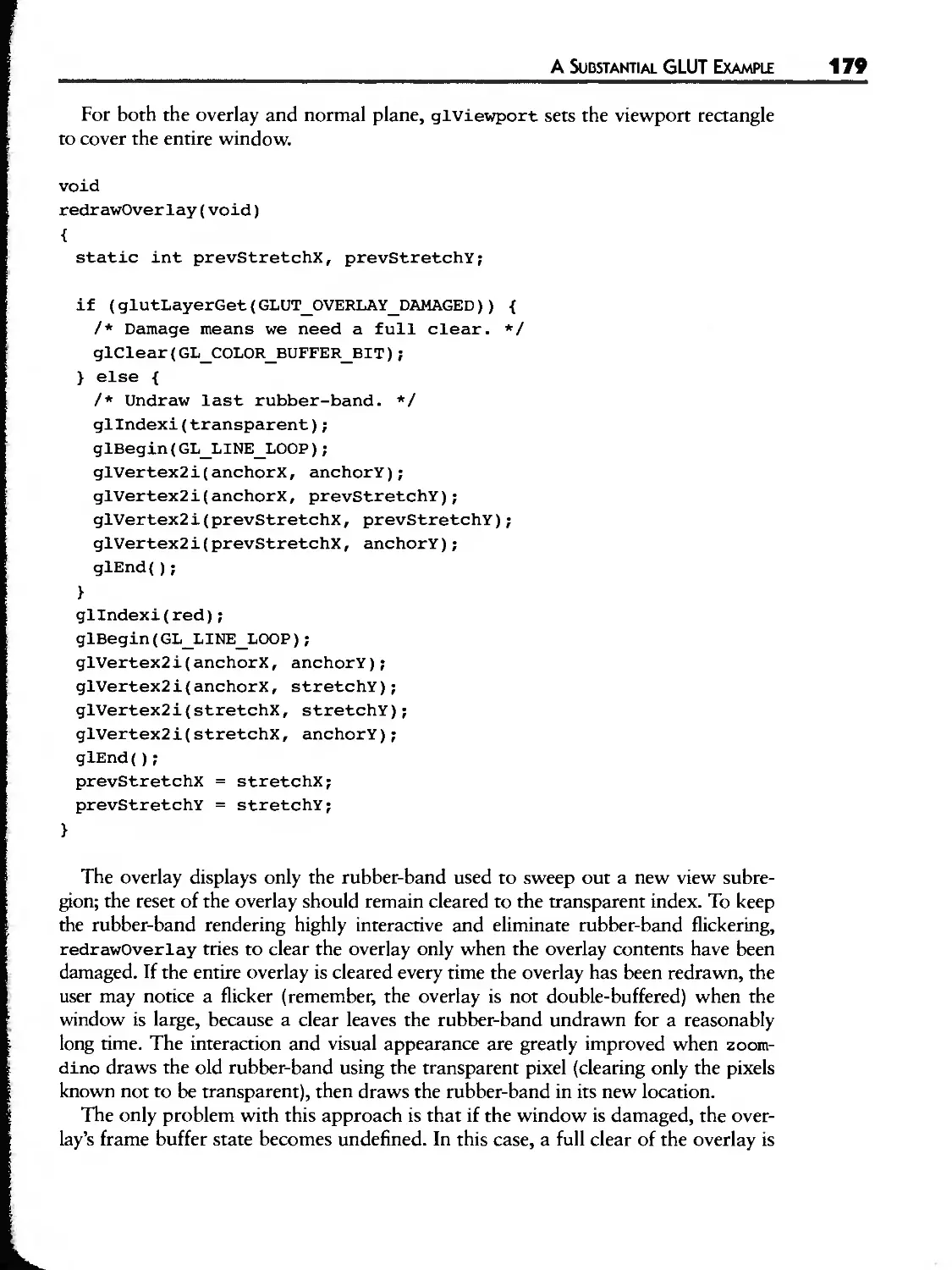
A Substantial GLUT Example 173
4.4.1 Establishing an Overlay for Rubber-Banding 176
4.4.2 Normal Plane and Overlay Rendering 177
4.4.3 Spinning and Rubber-Banding 180
4.4.4 Suspending Animation and Pop-up Menus 184
5 Exploring OpenGL with GLUT ..................... 187
5.1 Exploring Lighting with GLUT 188
5.1.1 The OpenGL LightingModel 188
5.1.2 Using OpenGL's Lighting Model 189
5.1.3 Example: lightlab.c 193
5.2 Exploring OpenGL Texture Mapping with GLUT 201
5.2.1 Using Textures with OpenGL 202
5.2.2 Fun with Textures 207
5.2.3 More on Texture Mapping 209
5.2.4 Example: mjkwarp.c 209
5.3 Exploring Blending Operations with GLUT 216
5.3.1 Uses for Blending 218
5.3.2 Antialiasing through Blending 219
5.3.3 Fog and Atmospheric Effects 221
5.3.4 Hints 222
5.3.5 Example: blender.c 222
$.4 Exploring Images and Bitmaps with GLUT 226
5.4.1 The Pixel Path 226
5.4.2 Bitmaps 232
5.4.3 Reading and Copying Pixels 233
5.4.4 Texturing as the Merging of Geometry and lmagery 234
5.4.5 Example: splatlogo.c 235
5.5 Exploring Curves and Surfaces with GLUT 240
5.5.1 Why Curves and Surfaces? 241
5.5.2 Evaluators 242
CONN OE
5.5.3 The GLU NURBS Routines 244
5.5.4 More Information 247
5.5.5 Example: molehill.c 249
5.6 Exploring the OpenGL Extensions with GLUT 252
5.6.1 OpenGL Extension Naming 252
5.6.2 Available Extensions 253
5.6.3 Extension Interoperability 256
5.6.4 GLX Extensions 257
5.6.5 Extensions as OpenGL's Future 257
5.6.6 The Polygon Offset Extension 257
5.6.7 Example: origami.c 260
5.7 Exploring Open Inventor with GLUT 268
5.7.1 Procedural versus Descriptive 268
5.7.2 Open Inventor in Brief 269
5.7.3 Open Inventor with GLUT 271
5.7.4 Example: glutduck.c++ 274
6
Advanced Topics
6.1 Revisions to OpenGL, GLX, and GLU
6.1.1 OpenGL 1.1
6.1.2 GLX 1.1 and GLX 1.2
6.1.3 GLU 1.1 and GLU 1.2
6.2 X Input Extension
6.3
6.2.1
6.2.2
6.2.3
6.2.4
6.2.5
6.2.6
6.2.7
6.2.8
6.2.9
Using
6.3.1
6.3.2
6.3.3
6.3.4
6.3.5
6.3.6
.............................. 281
Querying the Extension
Types of Extension Devices
Querying Supported Devices
Sample Devices
Opening and Selecting Events from a Device
Other X Input Extension Features
An Xlib-based OpenGL Example
X Toolkit Support for Extension Events
Motif-based OpenGL Examples
Overlays
Utility of Overlays
The Serrer Overlay Visuals Convention
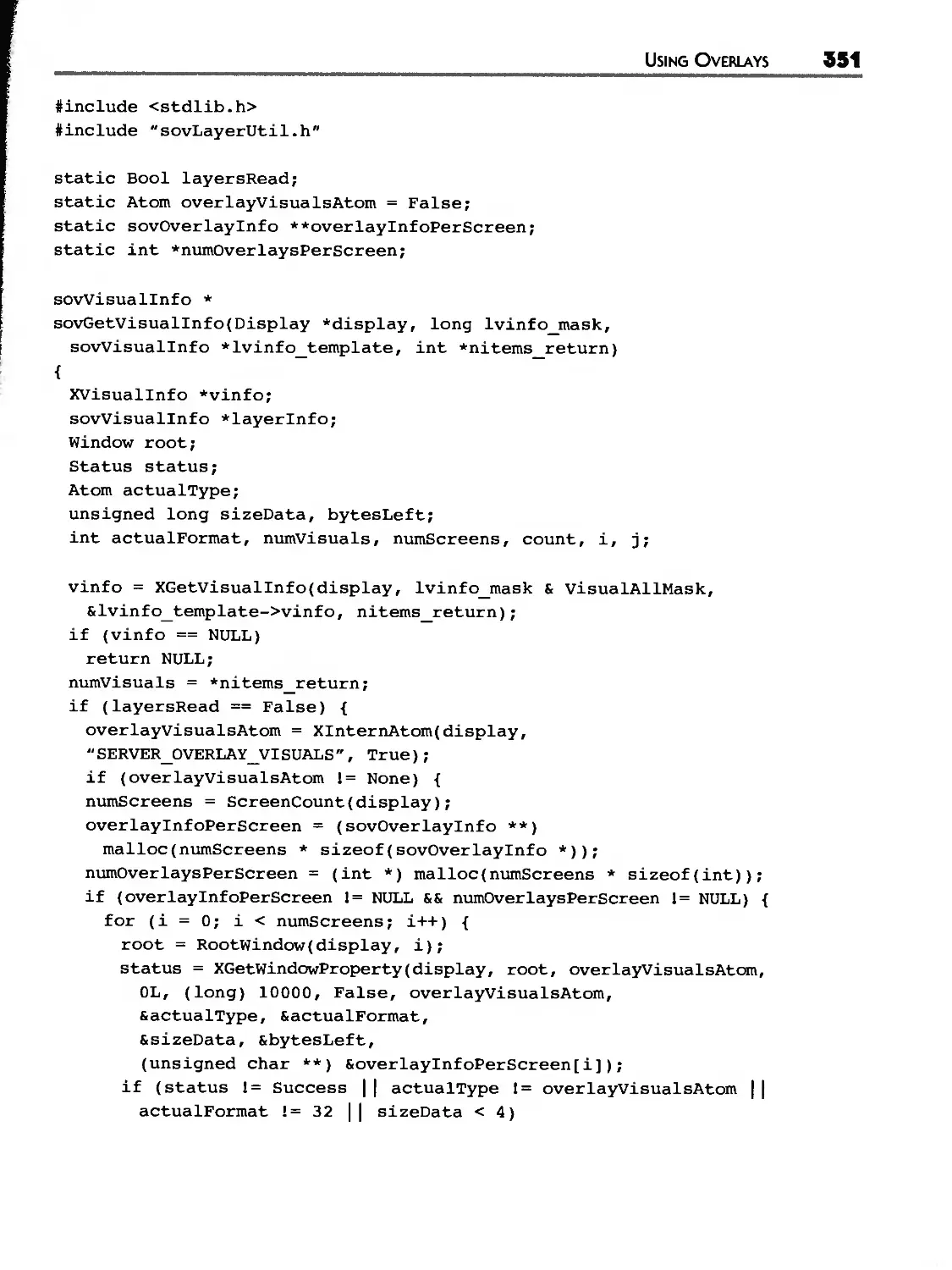
An SOV Programming Interface
Listing Overlay Visuals: sovin«o, c
An Xlib-Only Overlay Example
Vendor Support for Overlays
282
282
294
300
303
304
305
306
311
315
318
318
328
329
345
345
347
349
354
357
362
X CONTENTS
6.3.7 Usage Considerations
6.3.8 Using Overlays with Motif Menus
6.4 Portability and Interoperability
6.4.1 Portability Issues
6.4.2 Interoperability Issues
6.5 Hardware for Accelerating OpenGL
6.5.1 The Graphics Pipeline
6.5.2 A Taxonomy for Graphics Hardware
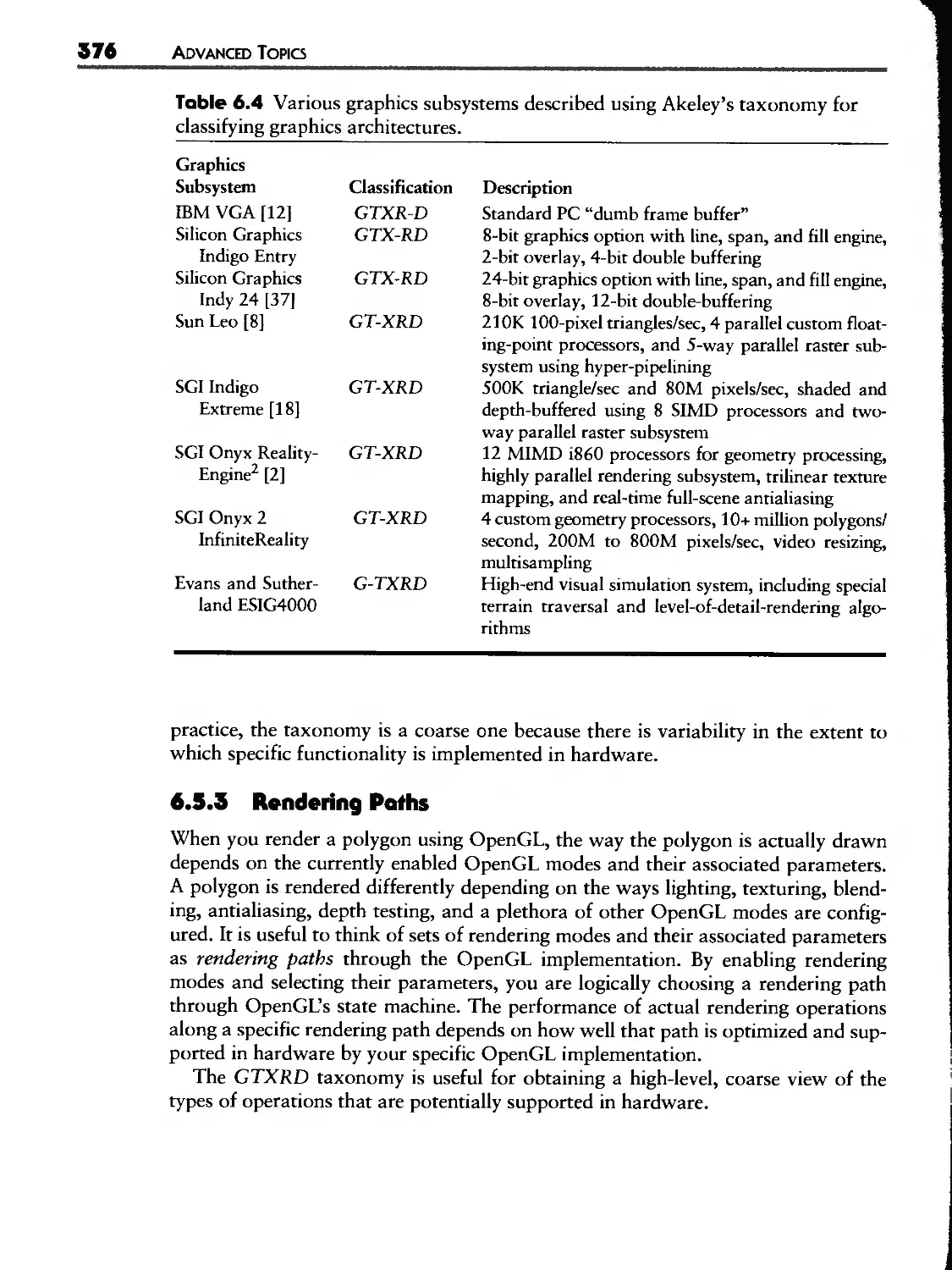
6.5.3 Rendering Paths
6.5.4 Hardware for OpenGL Stages
6.5.5 Display Options
6.5.6 Rasterization
6.5.7 Transforming Geometry
6.5.8 Hardware for Window System Requirements
6.5.9 Graphics Subsystem Bottlenecks
6.6 Maximizing OpenGL Performance
6.6.1
6.6.2
6.6.3
6.6.4
6.6.5
6.6.6
6.6.7
6.6.8
6.6.9
Pipeline-based Tuning
Reducing OpenGL Command Overhead
Minimize OpenGL Mode Changes
Improving Transformation Performance
Improving Rasterization Performance
lmproving Imaging Performance
Improving Texturing Performance
Constructing Application-specific Benchmarks
Beware of Standard Benchmarks
363
365
367
367
369
373
374
375
376
378
378
38O
383
388
391
392
393
395
397
398
401
403
404
405
412
7
Example Application ......................... 415
An
7.1 . Running molview
7.2 The Molecule Data Structure: molview.h
7.3 Data Fi|e Reader: mol file.c
7.4 Virtual Trackba]]: trackball, c
7.5 4o|ecu|e Renderer: render.c
7.6 Picking: pick. c
7.7 User Interface Initia]izadon: gui_init.c
7.8 User Interface Operation: gui_run.c
416
418
42O
425
432
438
441
449
CONTENTS X
A
Obtaining GLUT, Mesa, and the Book's
OpenGL Example Code ......................... 459
A.1 GLUT and the Book's Example Code 459
A.20btaining Mesa 460
B Functional Description of the GLUT API ............... 463
B.1 Initialization 463
B.1.1 glutInit 463
B.1.2 glutInitWindowPosition, glutInitWindowSize 465
B.1.3 glutInitDisplayMode 465
B.2 Beginning Event Processing "466
B.2.1 glutMainLoop 467
B.3 Window Management 467
B.3.1 glutCreateWindow 467
B.3.2 glutCreateSubWindow 468
B.3.3 glutSetWindow, glutGetWindow 469
B.3.4 glutDestroyWindow 469
B.3.5 glutPostRedisplay 469
B.3.6 glutSwapBuffers 470
B.3.7 glutPositionWindow 470
B.3.8 glutReshapeWindow 47|
B.3.9 glutFullScreen 47]
B.3.10 glutPopWindow, glutPushWindow 472
B.3.11 glutShowWindow, glutHideWindow, glutIconifyWindow 472
B.3.12 glutSetWindowTitle, glutSetIconTitle 473
B.3.13 glutSetCursor 473
B.4 Overlay Management 475
B.4.1 gutEstablishOverlay 475
B.4.2 glutUseLayer 475
B.4.3 glutRemoveOverlay 476
B.4.4 glutPostOverlayRedisplay 476
B.4.5 glutShowOverlay, glutHideOverlay 477
B.5 Menu Management 477
B.5.1 glutCreateMenu 477
B.5.2 glutSetMenu, glutGetMenu 478
B.5.3 glutDestroyMenu 478
B.5.4 glutAddMenuEntry 479
xii CONTENTS
I).5.5
I).5.6
I).5.7
I).5 .(5
I).5.9
glutAddSubMenu
glutChangeToMenuEntry
glutChangeToSubMenu
glutRemoveMenuItem
glutAttachMenu, glutDetachMenu
D.6 Callback Registration
.6. glutDisplayFunc
.. glutOverlayDisplayFunc
.. glutReshapeFunc
..4 glutKeyboardFunc
.. glutMouseFunc
.. glutMotionFunc, glutPassiveMotionFunc
.. glutVisibilityFunc
.. glutEntryFunc
.6.9 glutSpecialFunc
.6.0 glutSpaceballMotionFunc
.. glutSpaceballRotateFunc
..| glutSpaceballButtonFunc
.6. glutButtonBoxFunc
.6.|4 glutDialsFunc
.. glutTabletMotionFunc
..| glutTabletButtonFunc
..| glutMenuStatusFunc
..| glutIdleFunc
..| glutTimerFunc
.7 Color Index Colormap Management
.7. glutSetColor
.. glutGetColor
.. glutCopyColormap
B. State Retrieval
.. glutGet
.. glutLayerGet
.. glutDeviceGet
..4 glutGetModifiers
.. glutExtensionSupported
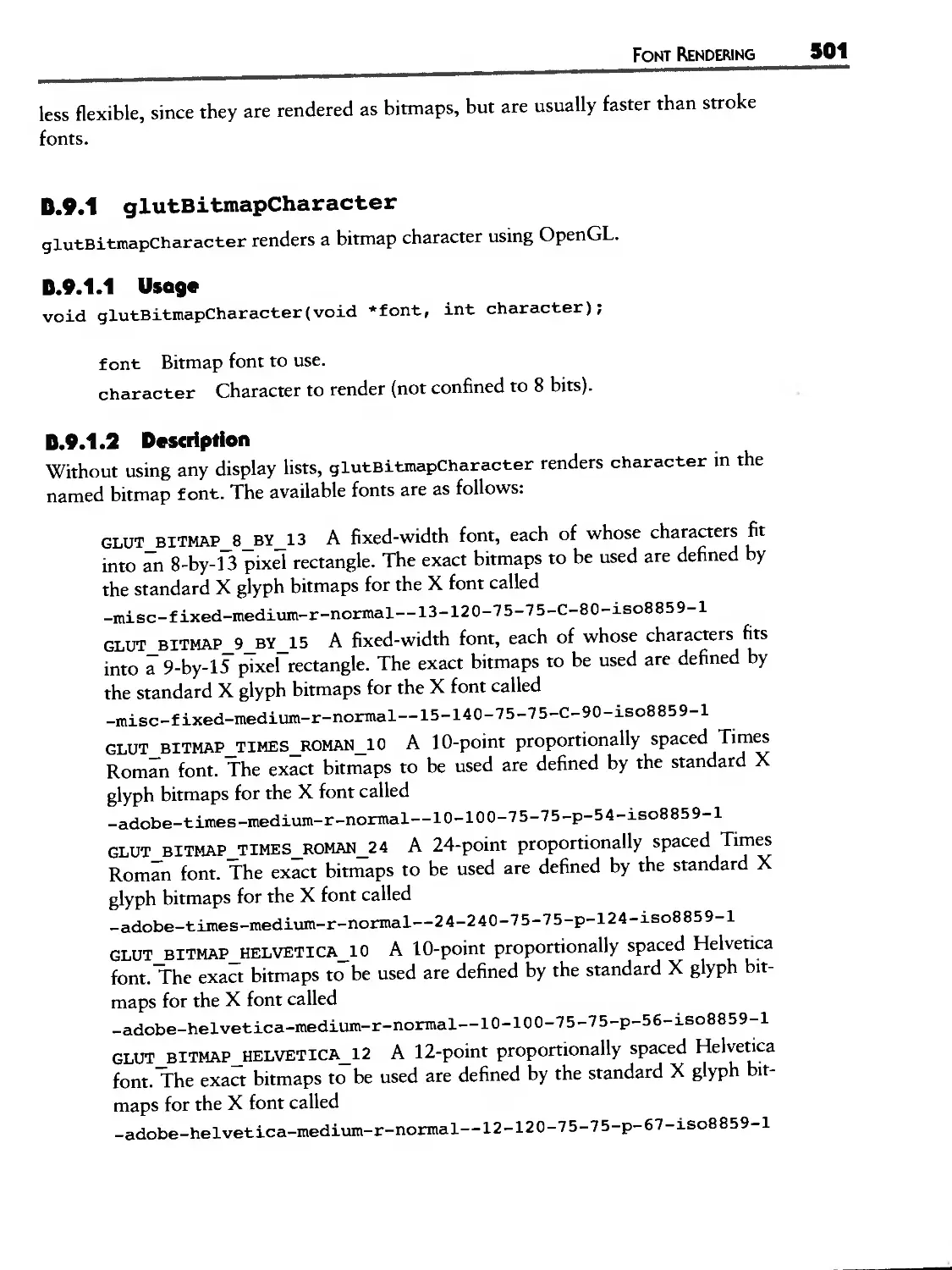
0.9 Font Rendering
.9. glutBitmapCharacter
.. glutBitmapWidth
.. glutStrokeCharacter
..4 glutStrokeWidth
479
479
480
480
481
481
482
483
483
484
484
485
486
486
487
488
488
489
490
490
491
491
492
493
493
494
494
495
495
496
496
498
499
499
500
5OO
501
502
502
503
CONTENTS xiii
B.IO
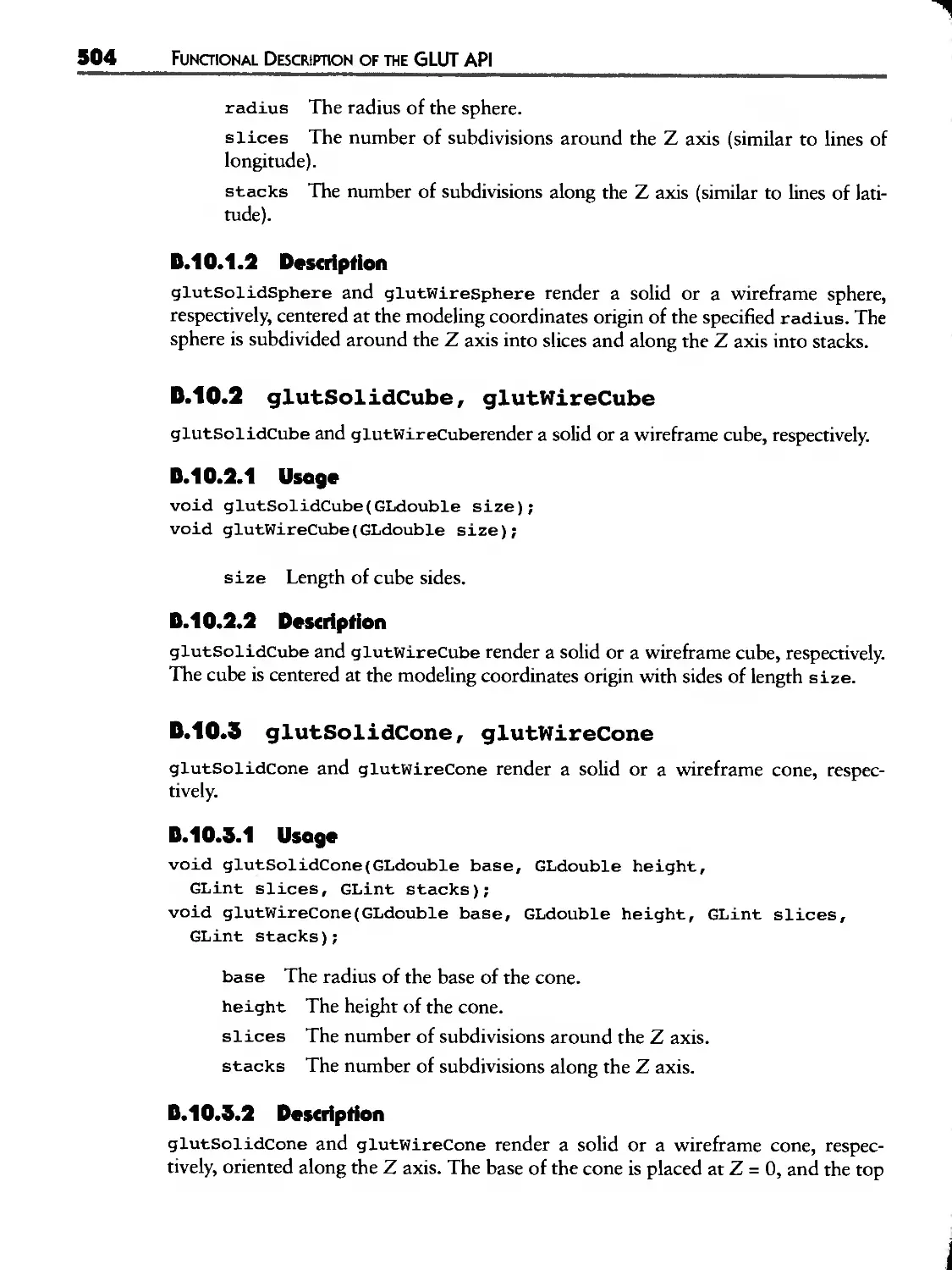
Geometric Object Rendering
B.10.1 glutSolidSphere, glutWireSphere
B.10.2
B.10.3
B.10.4
B.10.5
B.10.6
B.10.7
B.10.8
B.10.9
503
503
glutSolidCube, glutWireCube 504
glutSolidCone, glutWireCone 504
glutSolidTorus, glutWireTorus 505
glutSolidDodecahedron, glutWireDodecahedron 505
glutSolidOctahedron, glutWireOctahedron 505
glutSolidTetrahedron, glutWireTetrahedron 506
glutSolidIcosahedron, glutWireIcosahedron 506
glutSolidTeapot, glutWireTeapot 506
C GLUT State ................................... 509
C.1 Types of State 509
C.2 Global State 510
C.2.1 Program-Controlled State 510
C.2.2 Fixed System-Dependent State 511
C.3 Window State 511
C.3.1 Base State 511
C.3.2 Frame Buffer Capability State 514
C.3.3 Layer State 514
C.4 Menu State 515
Glossary .................................... 517
Bibliography ................................. 525
Index ....................................... 529
LIST OF FIGURES
2.1
2.2
2.3
2.4
2.5
2.6
2.7
2.8
2.9
2.10
2.11
Screen snapshot of glxdino
2D Complex polygons used to model the dinosaur's arm,
leg, eye, and body sides
Resulting GLU tessellation of the dinosaur polygons
Polygon orientation for back-face culling
Arrangement of lights, eye, and dinosaur in modeling space
Static view for gxd±no
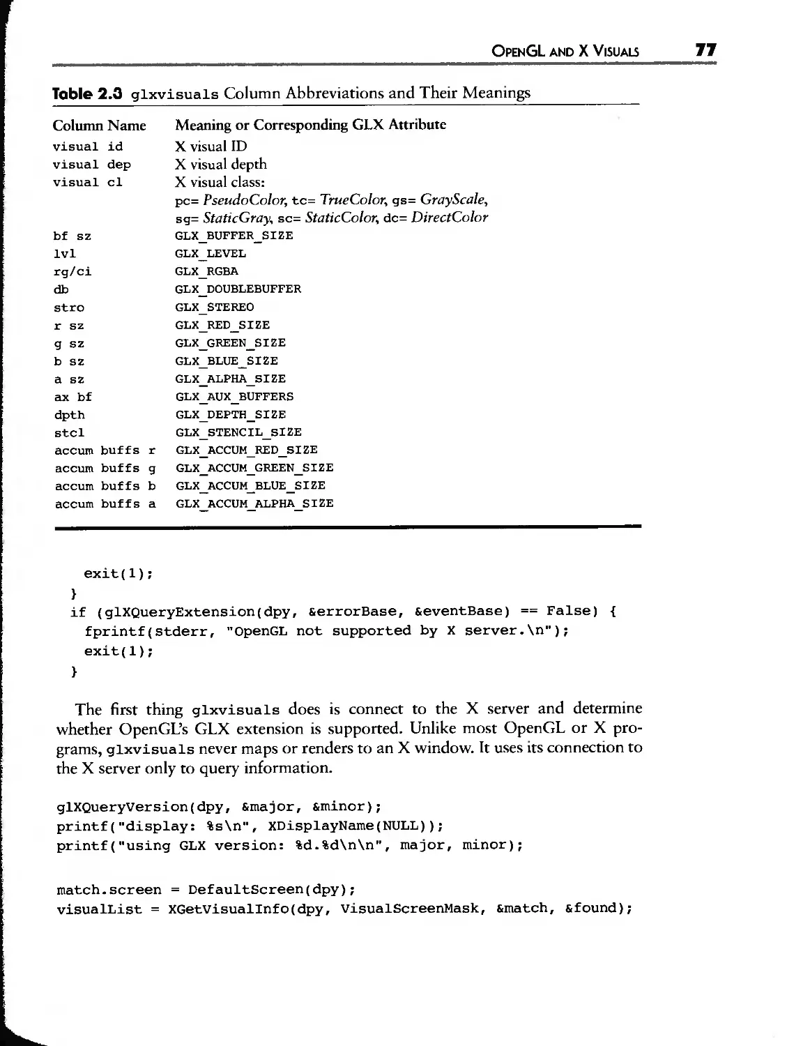
Output of glxvisuals showing the OpenGL-capable visuais
supported on a 24-bit Silicon Graphics Indy
Sharing of OpenGL display lists between two GLX contexts
How OpenGL-capable GLXPixmaps are created from X Pixmaps
First 34 lines of dino. rgb. eps generated by pixmap2eps
Screen snapshot of ogldebug
3.1 Basic software library layering for Motif-based
programs (not including OpenGL)
3.2 Screen snapshot of glw OpenGL drawing area widget example
3.3 The nested widget hierarchy within glw
3.4 Software libraries used by OpenGL widget-based programs
3.5 Partial widget class hierarchy showing the standard
OpenGL widgets
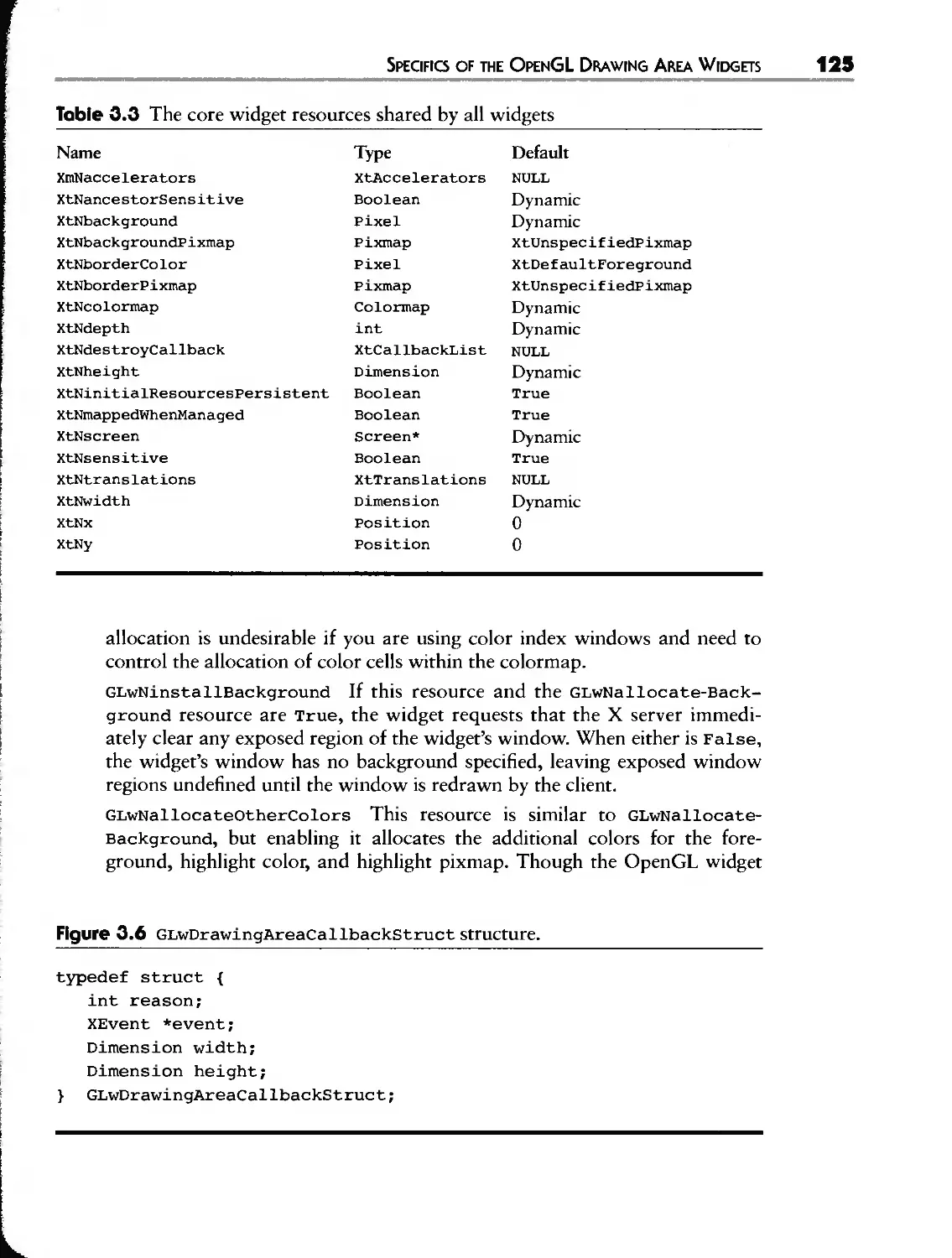
3.6 GLwDr awingAr eaCal ibackSt ruct structure
3.7 Screen snapshot of paperplane
3.8 Diagram of the widget instance hierarchy for paperplane
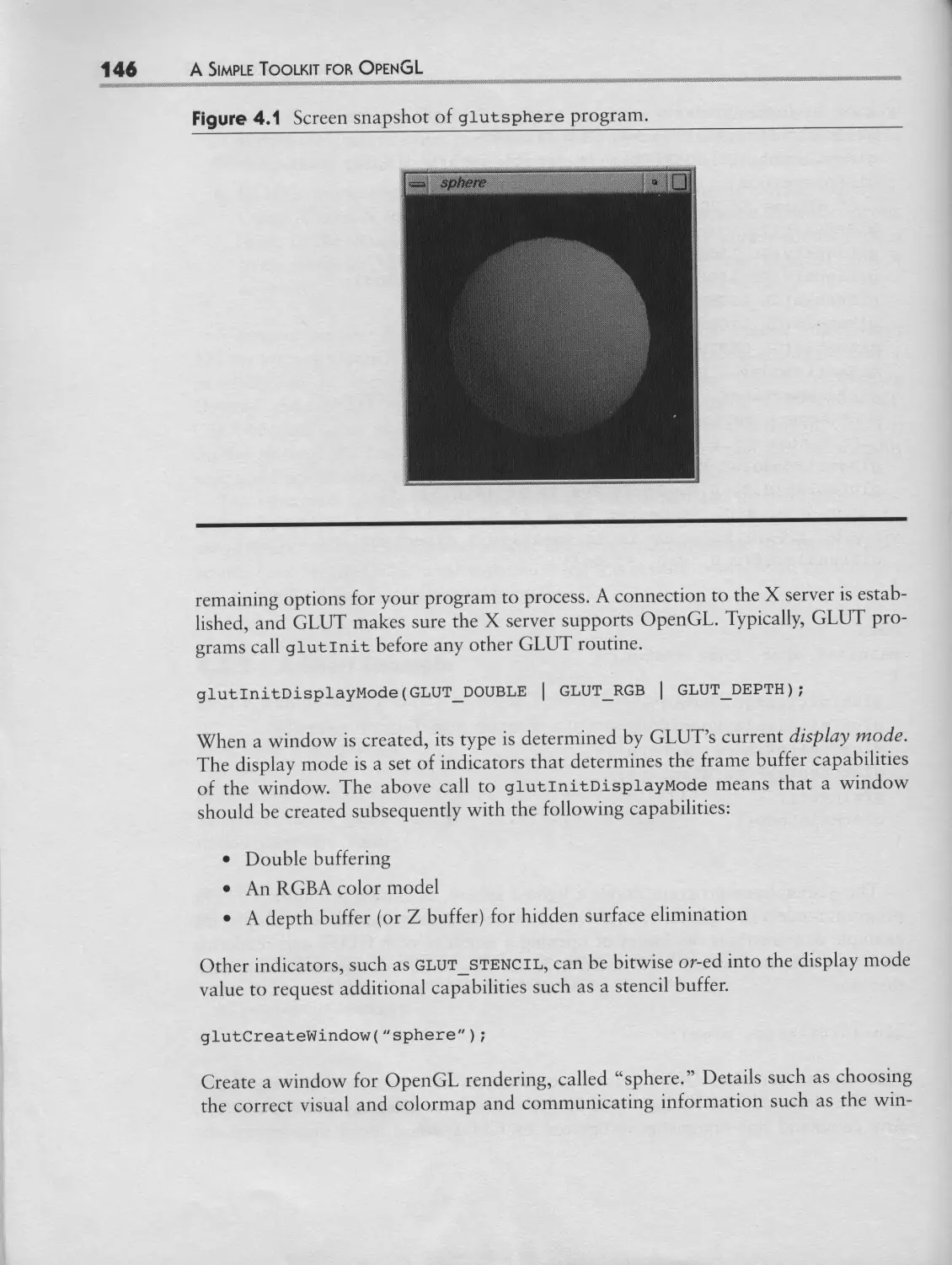
4.1 Screen snapshot of glutsphere program
4.2 The two windows generated by the modified
version of gutsphere
4.3 An example of GLUT cascaded pop-up menus
4.4 The stacking order of sibling windows can be changed
with glutPopWindow and glutPushWindow
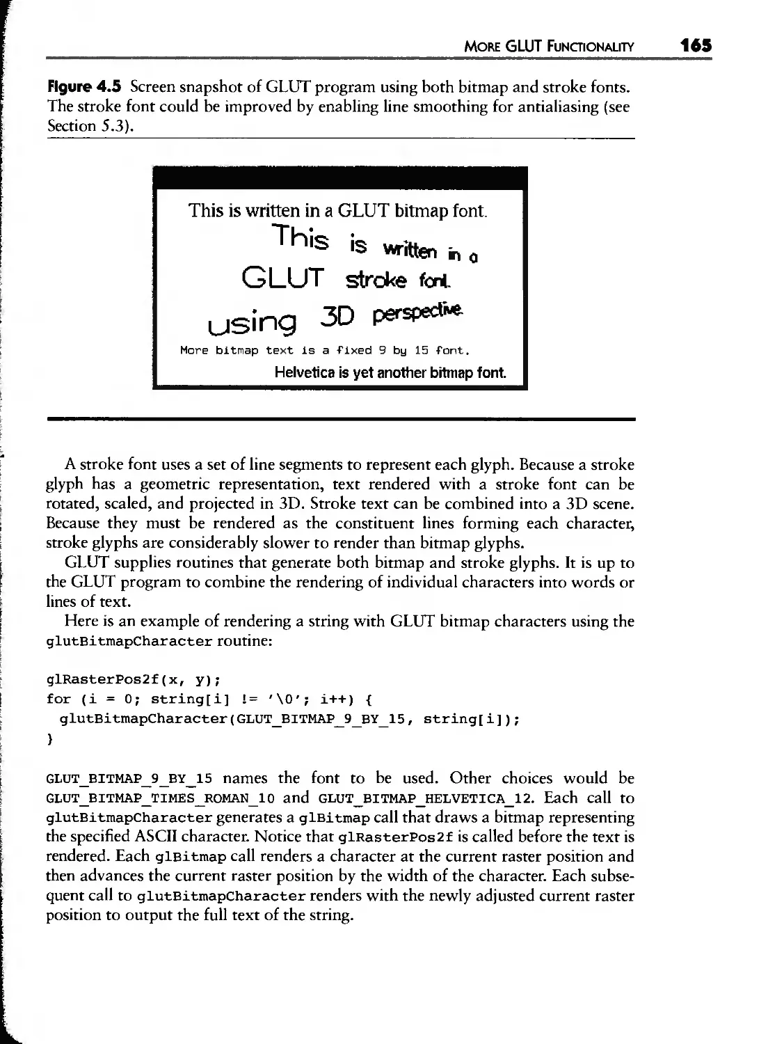
4.5 Screen snapshot of GLUT program using both
bitmap and stroke fonts
4,6 Example renderings using each of the nine GLUT
wireframe geometric shape rendering routines
55
58
63
64
76
87
93
101
106
110
112
116
121
123
125
131
139
146
149
154
157
165
166
LIST OF FIGURES X|
4.7 Example renderings using each of the nine GLUT
solid geometric shape rendering routines
4,8 Zooming in on rubber-banded subregions in zoorad±no
167
174
5.1
5.2
5.3
5.4
5.5
5.6
5.7
5.8
5.9
5.10
5.11
5.12
5.13
5.14
5.15
5.16
5.17
5.18
5.19
5.20
5.21
5.22
5.23
lightlab's initial appearance
The right red light is off; the left light shines red
Both lights are shining white and the picture is bright
lightlab with slate teapot
Cow model texture mapped with a red brick texture
Multiple levels of detail for a texture using mipmaps
Texture coordinates determine how texels in the texture
are mapped to the surface of a triangle in object coordinates
Various modes of rajkwarp. Texturing techniques can be
used to rotate, contort, and shatter an image
Formula 1 racing simulation making extensive use of texture
mapping, including texture-mapped trees
Screen snapshot showing blender example program
Magnified view of the blender example's text
Screen snapshot showing rive teapots growing more distant
from left to right
splatlogo example with menu displayed
How an image will be unpacked ffom host memory
by glDrawPixels
splatlogo demonstrating pixel zooming, scaling, and biasing
OpenGL's pixel path functionality is used to draw pixels,
read pixels, copy pixels, and load textures
Two views of the control points for a spiral B-spline curve
Screen snapshot of molehill
Varying sampling tolerances when tessellating a NURBS surface
Example of a trimmed NURBS surface
Wireframe rendering of the trimmed NURBS surface to
show the tessellation into polygons
OpenGL's extended image processing pipeline
The paper airplane is divided into eight polygons, defined
by the fold lines of the folded plane
193
194
194
195
202
204
206
208
209
218
220
221
227
229
232
235
241
246
247
248
248
256
258
]|| LIST OF FIGURES
5.24
5.25
5.26
5.27
5.28
6.1
6.2
6.3
6.4
6.5
6.6
6.7
6.8
6.9
6.10
6.11
6.12
6.13
6.14
6.15
6.16
6.17
6.18
6.19
6.20
6.21
The origami example program and three different outline modes
Graphical representation of a partial Inventor scene graph
First 25 lines of the duck. iv Open Inventor metafile
containing a 3D duck model
Relationship of Open Inventor libraries and OpenGL
and X libraries
Screen snapshot of glutduck using Open Inventor
OpenGL 1.1 additions
Vertex data interleaved for glInterleavedArrays's
GL C3F V3F configuration
GLX 1.1 and 1.2 additions
GLU 1.1 and 1.2 additions
Sophisticated input devices often used by 3D applications
XDevicelnfo structure
Possible device type names
Data structures describe X Input device characteristics
Physical layout of the valuators and buttons for the
dial-and-button box device supported by Silicon Graphics
Physical layout of the valuators and buttons for the
Spaceball device supported by Silicon Graphics
Physical layout of the valuators and buttons for the tabler
device supporred by Silicon Graphics
The XDevice structure returned by XOpenDevice
Screen snapshot showing the dials example
Screen snapshot showing the new xt tablet example
Example output of sovinfo
Screen snapshot of layerderao
How the OpenGL state machine maps fo the general
graphics pipeline
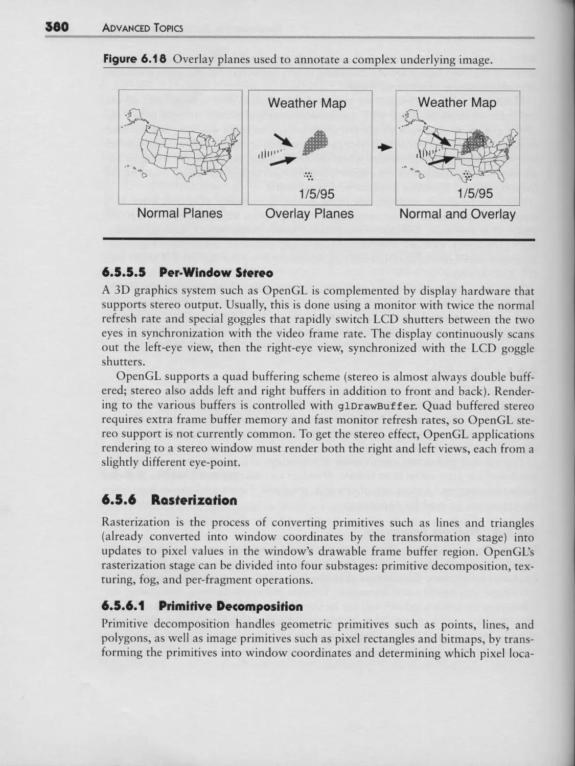
Overlay planes used fo annotate a complex underlying image
Decomposition of a shared polygon to interpolated spans
OpenGL per-fragment operations
Example of a triangle being rasterized into a frame buffer
259
270
271
272
272
282
288
295
300
303
307
307
309
312
313
314
315
319
330
356
357
375
38O
381
383
384
LIST OF FIGURES
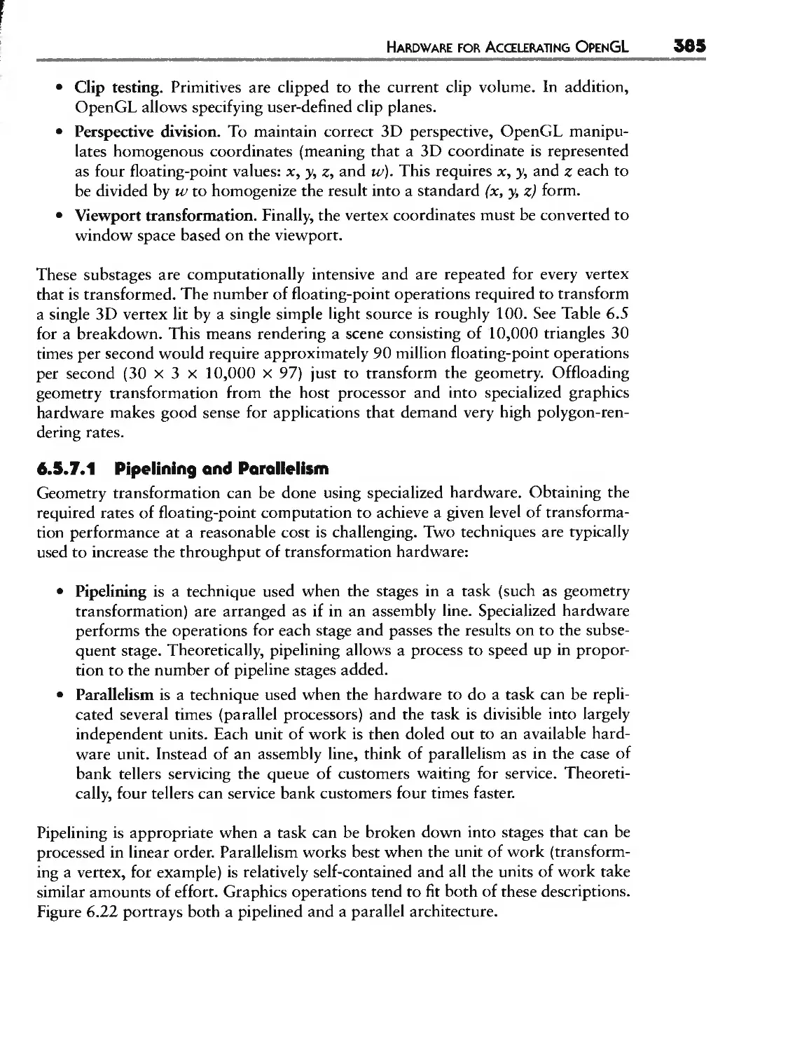
6.22
6.23
6.24
Pipelining versus replicated parallelism
Clip rectangles define the clips for the two windows with
simple drawable regions
Two spheres rendered at different tessellations
7.1 Scree snapshot of molview
7.2 Screen snapshot of molview with its file chooser displayed
7.3 raolview data structure representing a methane molecule
7.4 A .raol file description of a methane (CH 4) molecule
7.5 Widget hierarchy for raolv±ew once it is initialized by raa±n
7.6 Two screen snapshots of raolv±ew tessellated differently
7.7 molview-menu, eps: A screen snapshot of molview
with its pop-up menu
386
390
400
416
417
418
419
442
450
450
xxii LIST OF TABLES
4.4 GLt glutLayerGet Parameters
5.1 OpenGL's Various Pixel Transfer Maps
6.t The Event Categories, Types, Classes, and Structures for the
X Input Extension
6.2 SERRER 0VERLAY VISUALS Property Entry Format
6.3 Minimum lmplementationoDependent Rendering Values for
OpenGL implementations
6.4 Various Graphics Subsystems Described Using Akeley's Taxonomy
for Classifying Graphics Architectures
6.5 Floating-Point Operations Required to Transform a Single
Vertex Using Single-source Lighting
169
23O
317
348
370
376
384
xxlv PREFACE
extension. OpenGL can be used in conjunction with standard X libraries and tool-
kits such as Xlib and OSF/Motif.
What you will learn by reading this book is hOt just how to use OpenGL, but
how to integrate your OpenGL applications tightly with the X Window System.
Previous knowledge of OpenGL is not required, but the coverage of OpenGUs func-
tionality is hardly complete. This book is not an introduction to the X Window Sys-
tem. It assumes that the reader programs in C and has experience with the Xlib and/
or Motif programming interfaces. A background in computer graphics is not
assumed, but is helpful. A basic knowledge of geometry and trigonometry is useful
for some sections.
A typical reader of this book is expected to fall into one or more of the following
categories."
• An Xlib or Motif programmer who wants to use OpenGL to implement 3D
graphics apphcations.
• A programmer proficient in IRIS GE, the predecessor to OpenGL, who would
like to migrate to OpenGL for more portability and access to the fastest cur-
rent and future hardware.
• A non-X programmer (using Windows NT or another window system) who
wants to understand X and OpenGL in order to port graphics applications
from X to Windows or to 6ther non-X window systems.
• A student of computer graphics who wants to develop practical 3D program-
ming skills.
• A technical decision maker who wants to assess the value of using OpenGL
with X for 3D graphics applications.
Unlike previous books in Addison-Wesley's OpenGL series, which present OpenGL
outside the context of a particular window system, this book delves into the ways
real OpenGL applications for the X Window System should be designed and con-
structed. Each chapter contains source code (written in ANSI C and, in one
instance, C++) demonstrating the techniques described. The overriding goal is to
allow the reader to construct real and useful 3D applications using OpenGL and X.
The material is presented in seven chapters. These chapters are tutorial in nature
and each builds on the material in previous chapters. Chapter 1 is an introduction
to OpenGL and to using OpenGL with X. Chapter 2 explains the GLX model for
integrating OpenGL and X using Xlib. Chapter 3 explains how to use OpenGL
with Motif and other widget sets. Chapter 4 describes an Xlib-based toolkit, known
as the OpenGL Utility Toolkit (or GLUT), for constructing quick-and-dirty
OpenGL programs to explore 3D programming. Chapter 5 explores OpenGL's fea-
tures with examples using GLUT. Chapter 6 presents advanced topics for OpenGL
application writers: revisions of OpenGL, how to use alternative input devices, how
to use overlays, how to ensure OpenGL portability and interoperability, approaches
to OpenGL hardware acceleration, and performance tuning. Chapter 7 combines
the techniques explained in earlier chapters to develop a practical OpenGL applica-
tion using Motif. The appendices explain how to obtain the book's source code
examples and the GLUT library source code via the Internet and provide a full
description of the OpenGL Utility Toolkit programming interface.
].'|| ACKNOWLEDGMENTS
Craig Groeschel, Randi Rost, and many of the aforementioned Silicon Graphics
engineers and managers provided invaluable feedback by reviewing this work.
Mark Segal deserves special thanks for his thorough proofreading and suggestions.
Brian Paul and a host of OpenGL Utility Toolkit users on the Internet assisted in the
debugging much of the source code developed for this book.
Much of the material in this book was developed in conjunction with my
"OpenGL and X" column, published in The X Journal. I thank the staff at SIGS
Publications for their publishing efforts, particularly Seth Bookey, Charles Bowman,
Kristina Jukodahr, and Steve Mikes.
Deirdre Tiffany's feedback, patience, and support meant the world to me. Words
cannot say enough.
There are others who have influenced this book indirectly, but fundamentally,
through their influence on my life. I count among these Nancy Denmark, John
Deuel, Michael Hicks, Thomas Kulick, Bernie Luksich, Peter Ostrin, my brothers
Mike and Matt, and certainly my parents Chris and Brenda. Thanks, and play safe!
--MJK
INTRODUC'rlON
Inc. (SGI), based on a decade of experience in computer graphics hardware and soft-
ware design. The GL in OpenGL stands for Graphics Library. To a graphics pro-
grammer, OpenGL is exactly that--a library of approximately 350 distinct graphics
routines. These routines allow a programmer to generate high-quality color images
efficiently. While OpenGL is well suited for interactive rendering of 3D graphics, it
can also be used for 2D graphics and imaging.
OpenGL is a standard originally developed by Silicon Graphics. Silicon Graphics
has turned over control of the OpenGL standard to the OpenGL Architectural
Review Board (ARB), which consists of leaders in the computer industry. Its found-
ing members included DEC, IBM, |ntel, Microsoft, and Silicon Graphics. The board
has since expanded to include (at the time of this writing) two more prominent
computer graphics companies: Intergraph and Evans & Sutherland. The collective
vision underlying OpenGL is that through a common, fast software interface for
programming graphics, 3D graphics can rapidly become a mainstream computer
technology. Much to the benefit of those using interactive 3D computer graphics,
OpenGL has realized this goal. Implementations of OpenGL are widely available,
and applications based on OpenGL are commonplace. In particular, OpenGL
implementations are now available from every major X Window System vendor.
OpenGL provides a layer of abstraction between graphics hardware and an
application program. Together, OpenGL's routines form an application program-
ming interface (API). The routines allow graphics primitives (points, lines, poly-
gons, bitmaps, and images) to be rendered to a frame buffer. Using the available
primitives and the operations that control their rendering, high-quality color images
of 3D objects can be generated.
The most commonly used programming languages for OpenGL are C and C+÷.
The OpenGL API is the saine for both languages. Nearly ail the programs in this
book are written in ANSI C; in Section 5.7, which discusses Open Inventor, a C++
program also appears. OpenGL bindings exist for other languages such as Ada and
FORTRAN. These bindings merely provide a way to call OpenGL routines from
these languages; the functionality of OpenGL is the saine in any language.
1.1.1 OpenGL's Design
The designers of OpenGL specify the graphics system as a state machine [36]* that
controls a well-defined set of drawing operations. The routines that OpenGL supplies
provide a means to manipulate OpenGL's state machine to generate the desired graph-
ics output. Figure 1.1 shows a simplified view of OpenGL's abstract state machine.
Don't be intimidated by the term "state machine"; it is not that complicated.
Think of OpenGL as a virtual device with lots of knobs and levers that controls the
way it operates. You feed geometric descriptions of what you want rendered (in the
form of vertices and images) into OpenGL. Based on the ways the levers and knobs
are set, OpenGL generates a pixelized 2D rendering of your data. For example, one
* References to the Bibliography appear in square brackets throughout this book.
WHAT IS OPENGL? 3
Figure 1.1 High-level, abstract OpenGL machine.
I P" Veex I
Operatione
Primitive
Aeombly
commands J
- I OperatlOns I
. _ I Per
Forapegr,
nt
ons
r
lever controls whether lighting calculations are done on your data, and a knob con-
trois the way your data is blended with other data already rendered. The OpenGL
state machine is hOt a black box. You can read back the value of almost every piece
of OpenGL state you can set. OpenGL's state machine has lots of advantages for
implementation and conceptual reasons. Specifying OpenGL as a state machine
results in a consistent, precise specification and eliminates ambiguity about what a
given operation does and does not do.
The model used for interpretation of OpenGL commands is client-server. This is
an abstract model; it does not demand that OpenGL be implemented as distinct cli-
ent and server processes. A client-server approach means that the boundary
between a program and the OpenGL implementation is well defined, to specify
clearly how data is passed between the application using OpenGL and the OpenGL
implementation. This allows OpenGL to operate over a wire protocol, the way the
X protocol operates, but OpenGL does not require that OpenGL rendering take
place in a separate process. Using a wire protocol means that ail OpenGL opera-
tions can be encoded in a stream of bytes that can be sent across a network. Not
requiring a wire protocol means that OpenGL can bypass the use of the protocol
when direct access to the graphics hardware is available.
In the case of the X Window System, OpenGL is implemented as an extension to
X, meaning that there is an X extension protocol for OpenGL (the GLX protocol).
So just as basic X programs can run on a remote computer while the results are dis-
played to a local workstation, X programs using OpenGL can do the saine.
The OpenGL specification is window systern independent, meaning that it provides
rendering functionality but does not specify how to manipulate windows or receive
events from the window system. This allows the OpenGL interface to be implemented
for different window systems. For example, OpenGL has been implemented for the X
Window System, Windows 95 and NT, OS/2, and the Power Macintosh. While
OpenGL itself is window system independent, for each window system, a window
, JNTRODUCTION
system dependent interface must be used to coordinate OpenGL's functionality with
that of the window system. Each distinct window system has its own interface, but
the basic functionality performed by this window system dependent interface is very
similar to what other window systems provide. The window system dependent inter-
face for the X Window System is called GLX. Note that GLX is both the name of
OpenGL's window system dependent programming interface for X and the naine of
OpenGL's X extension protocol.
One thing to keep in mind about OpenGL, particularly for the X Window System,
is that OpenGL is generally an extension to the base window system. While OpenGL
is becoming a standard feature of most current workstations, some workstations (typ-
ically older workstations and many X terminals) will not support the GLX extension
that provides OpenGL support) Section 1.3 provides further discussion of OpenGL's
X support and how to determine whether the GLX extension, and therefore OpenGL,
is supported by your workstation.
Graphics systems are often classified as one of two types: procedural or descrip-
tive. With a procedural interface, the program specifies exactly what to draw by
issuing a specific sequence of commands. With a descriptive interface, the program-
mer sets up a model of the scene to be rendered and leaves the method of drawing
the scene up to the graphics system. OpenGL is a procedural interface. In a descrip-
tive system, the programmer gives up control of exactly how the scene is tobe ren-
dered. Being procedural allows the programmer a high degree of control over the
way rendering is performed. Descriptive graphics systems are typically implemented
as a layer above a procedural interface. Two popular descriptive graphics systems
that render using OpenGL are Open Inventor [401 and IRIS Performer [35], both
developed by Silicon Graphics. Open Inventor is highly object-oriented and easy to
use. IRIS Performer is designed to optimize the rendering performance of visual sim-
ulation applications, such as flight simulators.
An overriding goal of OpenGL is to allow the construction of portable and
interoperable graphics programs. For this reason, OpenGL's rendering functionality
must be implemented in its entirety. This means ail the complex rendering function-
ality mandated by the OpenGL specification can be used with any OpenGL imple-
mentation. Previous graphics standards often allowed subsetting, meaning that not
ail rendering functionality was mandated; often the results were programs that
could hOt be expected to work on distinct implementations. To ensure compilant
implementations, every OpenGL vendor must validate its implementation using a
comprehensive set of conformance tests.
In practice, well-written OpenGL programs for the X Window System are quite
portable among X workstations from different vendors. Ail the programs presented
For such machines, the freely available Mesa library written by Bnan Paul at the University of Wiscon-
sin, provides an implementation of the OpenGL programming interface that does hot require the GLX
extension. While Mesa is portable and free, it does hot benefit from accelerated graphics hardware and
cannot emulate some detaiis of GLX's operation. To find out how to obtain Mesa, see Appendix A.
WHA]" IS OP[NGL?
in this book have been tested to ensure that they are good examples of writing por-
table OpenGL programs for X.
While OpenGI_ is portable, it is also fast, because OpenGL leverages Silicon
Graphics's design experience, acquired from a decade of building high-performance
graphics workstations. Specialized hardware for 3D rendering greatly improves
graphics performance. OpenGL is designed with such hardware in mind. As com-
puter technology advances, you can expect higher OpenGL performance from
newer hardware for the same money or less. Many of the ways in which hardware
can accelerate OpenGL performance are discussed in Section 6.5.
OpenGL is extensible, meaning that additional functionality can be added to
OpenGL incrementally as new features are warranted. While any OpenGL imple-
mentor can add a new extension, OpenGL's ARB coordinates a set of common
extensions. Many of the available extensions to OpenGL are described later, in Sec-
tion 5.6. By their nature, extensions will hOt exist in ail OpenGL implementations.
Please note that extensions to OpenGL are distinct from extensions to the X Win-
dow System. While GLX is an X extension to support OpenGL, OpenGL exten-
sions do hOt require new X extensions.
1.1.2 History of OpenGL
OpenGL is the successor to a graphics library known as IRIS GL, developed by Sili-
con Graphics as a device-independent graphics interface for use across a full line of
graphics workstations. IRIS GL [27] is used by more than 1,500 3D graphics appli-
cations. IRIS GL has evolved over the last decade and has been implemented on
numerous graphics devices of varying sophistication.
OpenGL is not backward compatible with IRIS GL. OpenGL has removed dated
IRIS GL functionality and made functionality more general in places. The most vis-
ible difference to programmers is that the routines and symbols that make up the
OpenGL API ail start with either 0:t or Gr., to avoid name space conflicts. IRIS GL
provides routines for managing windows and obtaining user input. To gain window
system independence and focus OpenGL on rendering functionality, IRIS GL's win-
dowing functionality was not made part of OpenGL. Ail window system dependent
portions of IRIS GL have been eliminated from OpenGL. What has been preserved
is the spirit of the API. OpenGL retains IRIS GL's ability to render 3D objects
quickly and efficiently. IRIS GL is network-extensible, but only by means of a pro-
prietary protocol called Distributed GL (DGLI. In contrast, OpenGL's GLX proto-
col is both network-extensible and an open standard.
Before OpenGL, every vendor of 3D graphics workstations invented its own
functionally similar, but incompatible, programming interfaces for accessing that
vendor's 3D hardware (IRIS GL was just one such proprietary interface). The result
was that 3D graphics programs for various makes of computer workstations were
quite incompatible.
INTRODUCTION
OpenGL was proposed as a standard to bring 3D graphics programming into the
mainstream of application programming by providing a standard, common, high-
performance interface to interactive 3D graphics hardware. This was the reason
that the OpenGL ARB was formed. Silicon Graphics turned over the OpenGL stan-
dard to the ARB, which now directs and approves OpenGL's further development.
Currently, over 30 companies have licensed OpenGL and many commercial imple-
mentations are available. Numerous universities have also licensed OpenGL for
educational and research purposes. Table 1.1 presents a short time line of important
events in the history of OpenGL.
OpenGL continues to evolve as a standard, and the ARB continues to standard-
ize extensions for OpenGL, enhance the core OpenGL standards, provide bindings
Table 1.1 Important milestones in the development of the OpenGL standard
Yar
1982
1987
1989
1990
1991
1992
1993
1994
1995
1996
Event
Initial development of the IRIS GL.
IRIS GL adds glvertex3 f-style vertex commands.
Kurt Akeley attempts detailed IRIS GL specification.
Disrributed GL (DGL) protocol released (precursor of GLX protocol).
lRIS GL "mixed model" interface released (precursor of GLX API).
Silicon Graphics commits itself fo an OpenGL effort.
Kurt Akeley and Mark Segal begin work on OpenGL specification.
First OpenGL Architectural Review Board (ARB) meetings held.
First OpenGL sample implementarion released to licensees.
OpenGL Re[erence Manual published.
First commercial OpenGL released by DEC and Silicon Graphics.
OpenG L Prograrnrning Guide published.
Open Inventor toolkit (based on OpenGL) released.
OpenGL specification and manual pages distributed via the lnternet.
Microsoft releases Windows NT 3.5, including OpenGL.
Work on standard OpenGL extensions begins.
OpenGL Utility Toolkir distribution announced.
GLX 1.1 approved.
Brian Paul releases Mesa, a free implementation of the OpenGL API.
Intergraph and Evans & Sutherland join the ARB.
GLU 1.2 approved.
Sun and Hewlett-Packard announce plans fo adopt OpenGL.
OpenGL add-on to Microsoft Windows 95 made available.
OpenGL 1.1 and GLX 1.2 publicly released.
OPENGL's RENDERING FUNCI'IONALITY
for additional computer languages (such as those for Ada and FORTRAN), and
promote the OpenGL standard.
The original OpenGL specification was version 1.0. Since that time, the ARB has
approved the upwardly compatible version 1.1. Most of the additions to 1.1 were
extensions to 1.0 that were deemed useful enough tobe made part of the OpenGL
standard itself. This practice of integrating proven extensions into the core OpenGL
standard allows new features tobe released and tested before their inclusion in the
core OpenGL standard. By regularly integrating successful extensions into the core
OpenGL, the ARB can ensure that the OpenGL standard will stay current and
coherent.
The GLX specification has also been revised. GLX 1.1 and GLX 1.2 further
enhance OpenGL's integration with the X Window System. Section 6.1 explains the
various revisions of OpenGL and GLX. The revisions of the OpenGL standards
mostly add advanced features. Unless otherwise noted, the material in this book
applies to the OpenGL 1.0 and GLX 1.0 standards and compatible revisions.
1.20PENGL'$ RENDERING FUS«IOLLIr
OpenGL is nota high-level 3D graphics interface. When you build a graphics pro-
gram using OpenGL, you start with a few simple geometric and image primitives.
The sophistication comes from combining the primitives and using them in various
modes. This section describes OpenGL's rendering functionality. For now, assume
that OpenGL is initialized and things are set up so that OpenGL commands render
to an onscreen window. The details of initializing OpenGL for rendering are dis-
cussed later.
1.2.1 Geometric Primitives
A geometric primitive renders a simple shape, such as a point, a line, or a triangle.
Using these primitives, complex 3D scenes can be rendered. Often scenes are con-
structed using thousands of individual triangles. Figure 1.2 shows the available geo-
metric primitives in OpenGL. Notice the ordering of the vertices, in particular for
primitives such as the GL_TRIANGLE_STRIP and the GL_TRIANGLE_FAN.
A primitive is described using a set of vertices. Figure 1.3 shows one way a poly-
gon might be specified. To begin a geometric primitive, the glBegin routine passes
in the primitive type as an argument. Then a list of vertex coordinates are specified.
Each glVertex3f call sends a vertex represented as three floating-point values
(hence the 3f suffix).
Along with the coordinates of each vertex, per-vertex information such as color,
normals, edge drawing, and texturing can be specified between a glBegin and a
gl.nd. Notice how gcoor3f is used to change the current color. Each vertex is
OP[NGL's RENDERING FuNCrlONALITY
drawn according to the current color. An OpenGL primitive is completed by calling
glEnd.
Looking at the way OpenGL routines are used, you can see OpenGL's naming
convention. Ail OpenGL routines begin with ol, and the remainder of each routine
name is in mixed case (for example, olcopyP±xels). The OpenGL constants ail
begin with Gr,_, and use only capital letters, and words are separated by underscores
(for example, Gr,_TRXANGr,V._FAN). OpenGL defines its own set of basic data types,
ail of which begin with Gr, but are otherwise lowercase (for example, Gr,float and
Gr,sizei). While these OpenGL basic data types are hOt guaranteed to be based on
the built-in C language types, they typically are for most OpenGL implementations.
Ail 14 data types used by OpenGL can be found in Table 1.2
OpenGL tends to be function call intensive. Instead of using a single routine with
many complex parameters, OpenGL's API favors multiple function calls with simple
Table 1.2 The OpenGL data types. Because ANSI C allows the sizes of basic data
types to be implementation-dependent, OpenGL uses these types to ensure that its
data types are properly sized. For Unix workstations, the OpenGL data types' map-
ping to C data types is straightforward--for example, Gr.float to loat and
GLushort to unsigned short. Types such as GLclampf are different from
Gr,loat in the assumptions OpenGL makes about values considered valid, but hOt
in the underlying type used to represent the types. Typically, ANSI C prototypes and
default type conversions make explicit casting between OpenGL and C data types
unnecessary.
OpenGL Type Minimum Number of Bits Description
GLboolean 1 Boolean
GLbyte 8 Signed integer
GLubyte 8 Unsigned integer
GLshort 16 Signed integer
GLushort 16 Unsigned integer
GLint 32 Signed integer
GLuint 32 Unsigned integer
GLsizei 32 Nonnegative integer
GLenum 32 Enumerated integer value
GLbitfield 32 Bit field
GLfloat 32 Ç]oating-point value
GLclampf 32 Floating-point value
clamped between 0 and 1
GLdouble 64 Floating-point value
GLcl ampd 64 Floating-point value
clamped between 0 and 1
10 INTRODUCI"ION
parameters. OpenGL primitives are constructed by calling multiple OpenGL rou-
tines. Calling multiple routines gives the program more flexibility and more control
over the primitives generated.
In many cases, OpenGL is flexible about the format that can be used to pass data
to OpenGL. For many basic operations, there are multiple versions of the same
basic routine and each version accepts data in a different format. For example,
glVertex3i accepts integers, while glVertex3f and glVertex3d take single- and
double-precision floating-point, respectively. For routines in a family such as
glvertex, which generates vertices, or glcoor, which sets the current color, the
suffix of routines in a given family determines the data format and the number of
parameters passed to the routine. So glVertex2f takes a two-dimensional vertex,
whHe glVertex3f takes a three-dimensional vertex. The f sufflx indicates that a
GLfloat is expected. Table 1.3 shows the correspondences between suffix letters
and OpenGL parameter types.
The v suffix indicates that the parameters for a routine are passed via a pointer to
a vector. For example, you could call
static GLfloat vertex[3] = { 1.0, 5.5, -32.0 };
glVertex3fv(vertex);
Having several functionally equivalent routines that accept different data types
allows the programmer flexibility in deciding how to store the data. A programmer
whose data is in integer format does hOt want to convertit to floating-point to pass
it to the graphics system. Another programmer does hot want to convert floating-
point data into integers. Conversions between data types can be expensive. High-
performance graphics hardware can be designed to accept multiple data formats
and offload the task of format conversion from the host processor.
You can start to ste why it makes sense to consider OpenGL as a state machine.
Commands such as glColor3f change the state of the current color. Subsequent
Table 1.3 Correspondences between OpenGL routine name suffix letters and
OpenGL parameter types
Suffix Letters Corresponding OpenGL Type
b GLbyte
ub GLubyte
s GLshort
us GLushort
i GLint
ui GLuint
f GLfloat
d GLdouble
OPENGL's RENDERING FUNCTIONALITY 11
vertices use the updated current colon glBegin puts OpenGL into a state in which
it can start drawing the specified primitive. The multiple glVertex routines load
the vertices one ata rime for a given primitive. Nearly ail of OpenGL's state that can
be set by the programmer can also be queried by the programmer. For example, the
glGetFIoatv(GL_CURRENT_COLOR, &float_array) call will retrieve the setting of
the current colon
1.2.2 Pixel Path Operations
In addition to OpenGL's geometric primitives, the other way to get pixels rendered
(and the way to read them back) is to use OpenGL's pixel operations. Images (2D
arrays of pixel data) are displayed using glDrawPixels and are retrieved from the
frame buffer using glReadPixels. (The frame buffer is the place where rendered
pixels are stored.) OpenGL also provides a means to copy pixel data from one
region of the frame buffer to another with gl¢opypixels. In addition to rectangu-
lar images, OpenGL provides a bitmap primitive, generated by glBitraap. Bitmaps
are like images, but instead of an array of pixel values, a bitmap is an array of bits
that serves as a drawing mask. Typically, bitmaps are used for rendering characters.
The location at which an image or bitmap is rendered is determined by the current
raster position which is set by the glRasterPos family of routines.
While transferring an image to and from the screen can be quite simple, OpenGL
has a sophisticated pixel path that allows pixel data to be zoomed, biased, scaled,
looked up, and further processed on the way to and from the frame buffer. This
makes OpenGL useful hOt just for 3D graphics, but for image processing tasks as
well. There are OpenGL extensions that give OpenGL still more image-processing
capabilities, allowing it to perform operations such as histograms and convolutions.
OpenGUs pixel path is discussed in more detail in Section 5.4.
OpenGL's geometric primitives and pixel operations find a special synergy in
OpenGL's texture mapping facilities. Texture mapping is a feature that allows an
image to be projected onto a geometric primitive such as a 3D triangle. You can
think of texture mapping as the logical equivalent of stretching virtual wallpaper
over polygons you render. Texture mapping is discussed in more detail in Section
5.2. The important point here is that when texture images are downloaded into
OpenGL, they are passed through the same pixel path used by images, so ail the
facilities that bias, scale, and perform lookup table operations can be applied to tex-
tures.
1.2.3 Two Color Models
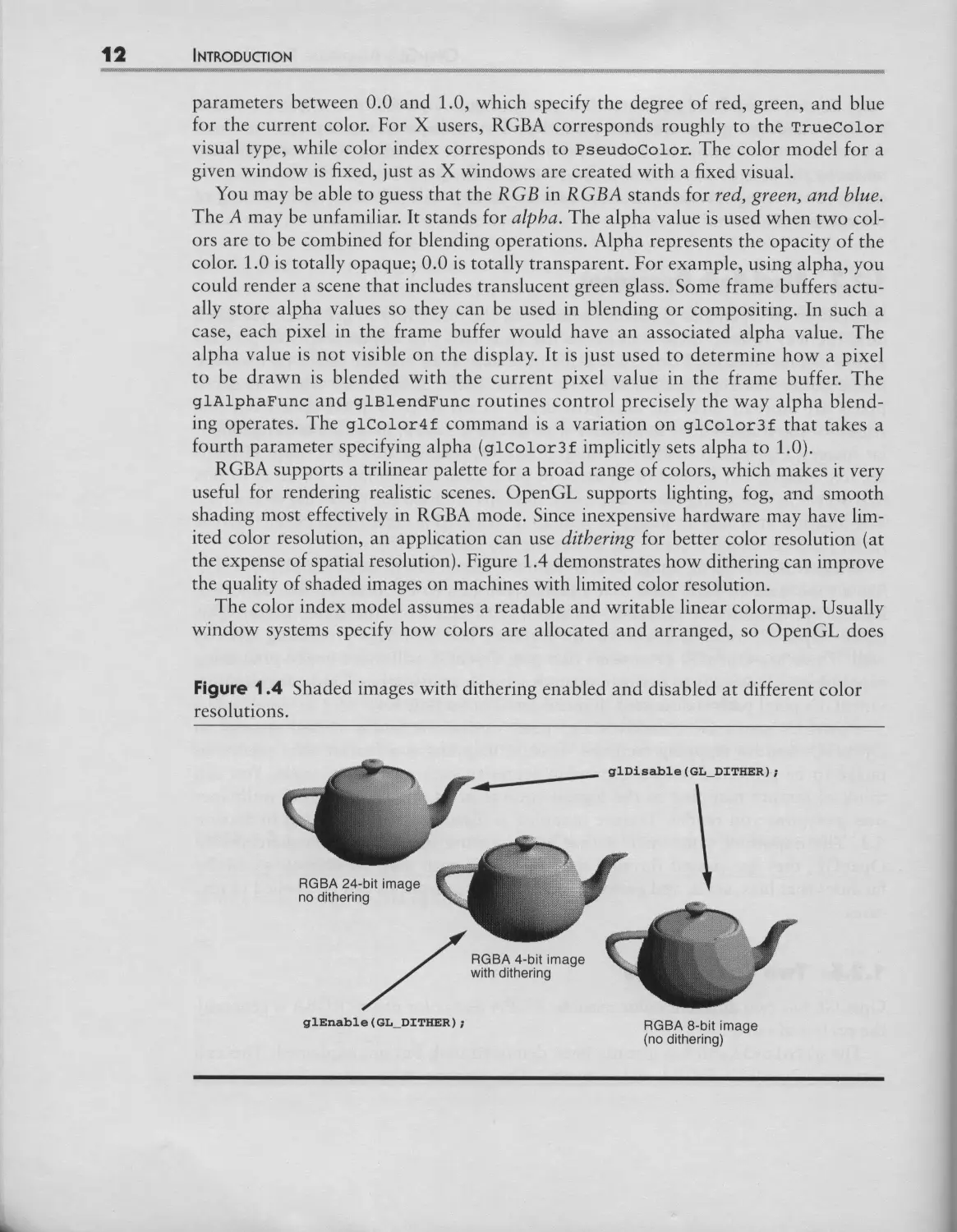
OpenGL has two different color models: RGBA and color index. RGBA is generally
the preferred model.
The glColor3f call has already been demonstrated, but hOt explained. This call
assumes OpenGL's RGBA color mode. The routine takes three floating-point
OPENGL's RENDERING FUNCI'IONALITY
not have any specific routines to allocate colors. For example, in X, an Xlib color
allocation routine such as xA:t:tocco:tor would be used. The gll:nclex family of rou-
tines is used to set the current color index. The advantage of color index is that the
color of a given pixel value can be dynamically changed. There is a level of indirec-
tion (the colormap) between the pixel values in the frame buffet and the colors on
the scrcen. Typically, color index windows will not support more than 8 or 12 bits
of index resolution per pixel, simply because the size of the required colormaps.
Because color index lacks a fixed relationship for the colors available for display,
facilities such as lighting, fog, and shading are more complicated than in RGBA
mode. In color index mode, these facilities, require proper setup of the colormap for
them to operate correctly; other facilities such as texture mapping and alpha blend-
ing, are not available at ail.
Color index mode is typically used on graphics hardware that does not have
enough color resolution to adequately represent an RGB color space. For exam-
pie, a machine with 8 bits of pixel resolution bas to split up those 8 bits among
red, green, and blue components to form an RGB color space. This is typically
done by giving 3 bits to red, 3 bits to green, and 2 bits to blue. This means there
are 8 gradations of red and green and 4 gradations of blue. The resulting color
space makes 8-bit RGBA scenes exhibit quantization errors, so subtle color varia-
tions are lost.
A benefit of color index is that those same 8 bits of resolution permit a palette of
256 distinct colors that can be determined based on the scene being displayed. A
scene showing a rosy sunset could fill the palette with many red, yellow, and orange
shades and few green shades and accurately capture the colors of the scene. How-
ever, RGBA has a fixed colormap arrangement that does not have enough red, yel-
low, and orange shades to represent the scene adequately with only 8 bits of
resolution.
With plenty of bits of resolution per pixel (24 bits or more), color representation
is no longer an issue, and the complications and limitations of color index make
RGBA far superior. Also, the writability of color index colormaps becomes a serious
drawback when multiple applications simultaneously attempt to display windows
that set up differently loaded logical colormaps. Windows whose requested colors
are not loaded will display unexpected colors.
As technology continues to drive down video memory prices, graphics hardware
with higher resolution frame buffers will become common. For this reason and
because color index is harder to use and more limiting, nearly ail the examples in
this book will use the RGBA color model.
1.2.4 OpenGL Modes and Other State
Many modes in OpenGL, such as dithering, are enabled and disabled using the
glV.nabe and gt)isabe commands, respectively. For example, dithering is enabled
by calling O.nable(GL_t)IT.R). Afterwards, drawing is done with dithering
t4 INI"RODUCrlON
enabled. You can think of glEnable and glDisable as ways to affect the operation
of the OpenGL state machine. The enable/disable state of OpenGL modes can be
retrieved using glIsEnabled.
Many modes have additional parameters that control the way the mode operates.
For example, lighting calculations are based on many different lighting parameters.
Parameters associated with the lighting model are controlled using glr,ighttodelf;
the characteristics of individual light sources are controlled using glr, ightf.
OpenGL's lighting model is described in Section 5.1, but here is an example in
which lighting is enabled with various lighting parameters being set:
GLfloat position[] = {0.0, 0.0, 1.5, 1.0};
glLightModelf(GL_LIGHT_MODEL_LOCAL_VIEWER, GL_TRUE);
glLightModelf(GL_LIGHT_MODEL_TWO_SIDE, GL_FALSE);
glLightfv(GL_LIGHT0, GL_POSITION, position);
glEnable(GL LIGHTING);
The first argument of glLightModelf indicates which OpenGL lighting parameter
to update; the final argument supplies the new parameter value. Complex facilities
such as lighting, fog, and texture mapping have many different parameters to con-
trol their operation and are activated by calling glEnable. There are also much
simpler facilities for things such as controlling the width (in pixels) of rendered
lines. The glLineWidth routine sers the line width. Because line width is something
inherent in lines, there is no need for a glEnable option for line width; there is sim-
ply a reasonable default (1.0).
While there are many OpenGL routines for setting parameters for various
OpenGL capabilities, a single family of routines retrieves most OpenGL state:
glGetBooleanv glGetDoublev, glGetFloatv, and glGetIntegerv. For example:
GLint state;
glGetIntergerv(GL LIGHT MODEL TWO SIDE, &state);
After calling glGetIntergerv, state is updated with the current two-sided light-
ing state.
OpenGL state that requires more than one enumerant to naine it (for example,
light zero's position, which takes Gr,_LIGST0 and Gr,_POSITION to specify the state)
requires a special retrieval routine (such as gGetr,ightv).
OpenGL is designed to have sensible default state. When you first instantiate a
context for OpenGL rendering (an instance of an OpenGL state machine that pro-
grams use for rendering), ail OpenGL state is initialized to predefined default val-
ues. Typically, most modes are disabled by default.
State changes immediately affect subsequent rendering. For the most part, the
commands to change OpenGL state can be executed in whatever order makes sense
OPENGL's RENDERING FUNC'rlONALITY 1
to the program. There are exceptions, however. State changes are not allowed when
a geornetric primitive is being specified (rneaning within a glBegin-and-glV.nd
pair).
Often, programs change various OpenGL state and later need to revert to the
state prior to the changes. Sometirnes (often in the case of software libraries layered
on OpenGL), the program does hOt know OpenGL's current state. While the pro-
grarn can retrieve the current values of any state it intends to change, retrieving state
can be slow relative to the rate at which commands can be sent to fast graphics
hardware. The glPushAttrib and glPopAttribute calls manage an attribute
stack that allows groupings of OpenGL state (such as all the lighting-related state)
tobe saved (pushed onto the stack) and later restored (popped from the stack).
The argument of glPushAttrib is a bit mask indicating what state to push.
glPopAttrib needs no argument, since it iust restores the state before the last
glPushAttrib. For example:
glPushAttrib(GL_LIGHTING_BIT);
modifyOpenGLlightingState();
doSomeRenderingWithChangedState();
glPopAttrib();
A/ter execution of this code fragment, OpenGL's lighting state is what it was before
glPushAttrib was called. This is a good deal more convenient than attempting to
retrieve and restore each piece of lighting state individually.
1.2.5 Ancillary Buffers
Typically, the results of OpenGL rendering are directed to a window displayed on a
user's computer. Itis also possible to render OpenGL into an in-memory data struc-
ture (such as an X pixmap) or into dedicated memory within a graphics hardware
device that cannot be displayed.
OpenGL treats the image it renders as an array (or grid) of pixels. The terre
/rame buffer refers to the memory within a graphics hardware device that maintains
the image displayed on a user's computer screen. OpenGL also uses the terre to re/er
to the array of pixel state rnaintained by a drawing surface regardless of its hard-
ware representation. For example, memory for an X pixmap is considered a/rame
bu/fer by OpenGL.
For most 2D rendering interfaces (such as Xlib), the/rame bu/fer simply contains
pixel values that represent a displayable image. OpenGL perrnits considerably more
state to be maintained within the/rame bu/fer. OpenGL considers the/rame bu/fer
to be a set of buffers. Each pixel within the/rame bu/fer has an associated value in
each bu/fer. The most important type of bu/fer is the color (or image) bu/fer, which
contains the color information that represents a displayable image. OpenGL can
actually support more than one image bu/fer within a single/rame bu/fer. As will be
16 INTRODUC'rloN
explained, multiple image buffers make possible double-buffered animation and ste-
reoscopic display.
OpenGL also supports nonimage buffers, which are often referred to as ancillary,
or helper, buffers. Several types of ancillary buffers are supported by OpenGL. The
next subsections will explain how OpenGL's various ancillary and image buffers are
used.
The set of image and ancillary buffers supported by a given frame buffer type is
referred to as a frame buffer configuration. A window system may support multiple
frame buffer configurations, each supporting a different set of buffers. Typically,
multiple windows of different configurations can be displayed atone time. Every X
window or pixmap has a single frame buffer configuration, though.
1.2.5.1 The Depth Buffer
In the rendering of a 3D scene, there is a general need to ensure that obiects that
should be obscured by closer objects in the scene are hot displayed. This is the prob-
lem of hidden line and hidden surface removal (HLHSR).
A general method for solving this problem is the use of a depth buffer (also com-
monly referred to as a Z buffer). Though the screen has only two dimensions (width
and height), 3D graphics attempts to simulate a third dimension. The depth buffer
maintains a depth value for every pixel. When 3D primitives are rendered by
OpenGL, they are rasterized into a collection of fragments. Each fragment corre-
sponds to a single pixel to be updated and includes color and depth information.
The X and Y locations corresponding to a fragment determine which pixel in the
frame buffer the fragment is intended to update. A fragment's depth (or Z value) is
used to determine how "near" the fragment is to the viewer. When OpenGL's depth
testing mode is properly enabled, the fragment is drawn only if its Z value is
"nearer" than the current Z value for the corresponding pixel in the depth buffer.
When the fragment is drawn into the frame buffer, its Z value replaces the previous
value in the depth buffer. Normally, when the scene starts to be rendered, the entire
depth buffer is cleared to the "farthest" value. As a 3D scene is rendered, the depth
buffer automatically sorts the fragments being drawn so only the nearest fragment
at each pixel location remains. Objects visually behind other objects are automati-
cally eliminated from the scene. The resolution of the depth buffer improves the
accuracy of depth testing; most depth buffers have from 24 to 32 bits of precision
per pixel.
You can see the benefit of using depth buffering in Figure 1.5. It shows two ver-
sions of a scene that displays intersecting 3D gears. In one window, OpenGL's depth
testing is enabled with glEnable(GL_DEPTH_TEST), while in the other window
depth testing is disabled with glDisable(GL_DEPTH_TEST). The window using
depth testing looks as it should, but the one with depth testing disabled shows por-
tions of a gear that should be behind the second gear. There are also places where
the "back" of a gear is displayed where the "front » should be showing (this is the
reason the lighting looks incorrect).
OPENGL's RENDERING FUNC'I'IONALITY lç
1.2.5.4 Double Buffering
Double buffering means having two image buffers, one visible front buffer and
another, nonvisible, back buffer. Unlike simple 2D rendering, generating 3D images
may take substantial time. Also, use of the depth, stencil, and accumulation buffers
all means that the image being drawn at any moment may be quite different from
the final image. It would be quite distracting for the viewer to see each scene while it
was "under construction" and would destroy the illusion of a smoothly animated
scene. Double buffering allows one image to be rendered while another is being dis-
played.
OpenGL supports this use of front and back image buffers. The glDrawBuffer
routine can be used to specify which buffer is the target of rendering operations. To
render to the back buffer, a program calls glDrawBuffer(GL_BACK). A window sys-
tem specific routine makes the back buffer visible. For X, that routine is glXSwap-
Buffers.
Double buffering is often achieved by rendering into a nonvisible image buffer in
main memory and then quickly copying the buffer's contents to screen memory. A
better alternative is to build hardware that actually supports two sets of image buff-
ers. Then the cost of a buffer swap can be extremely low, since no data has to be
copied. Instead, the video controller just changes to scanning image pixels out of the
other buffer. This technique is shown in Figure 1.13 and is further discussed in Sec-
tion 6.5.5.
1.2.5.5 Stereo
Stereo is similar to double buffering in that more than one image buffer is supported.
In addition to front and back buffers, left and right buffers are provided. (Typically
stereo and double buffering are combined, requiring four image buffers; this is some-
times called quad-buffering.) Special stereo video hardware can alternate between
scanning out the left and right buffers for every screen refresh. Viewing goggles that
synchronize with the vertical refresh of the screen alternately open and close LCD
shutters so that the left eye sees the left frame and the right eye sees the right frame.
If a program carefully draws the scene twice with slightly different perspectives in the
left and right buffers, the viewer experiences an optical illusion of 3D.
While double buffering is common on graphics workstations, stereo requires spe-
cial hardware and tends to be rather expensive, so most OpenGL implementations
do hOt support stereo.
1.2.6 Modeling and Viewing
One of the most difficult initial hurdles in learning 3D graphics programming is
how to properly set up a scene and the parameters to define a reasonable view of
that scene. It is very easy to get a blank window because the viewing parameters for
the scene are hOt properly initialized.
2J) JNTRODUCTION
Figure 1.7 Stages of vertex transformation.
Object = JModelVlew
v jMatrlx
Coordinates J
Eye
Coordinates
Projection
Matrix
L Perspective I N°emvîoe I
Division [Coordlnates J
Clip
Coordinates I
3D computer graphics uses matrix transformations to orient, view, clip, and map
the model to the screen. OpenGUs various stages in mapping vertices in object coor-
dinates into pixels in window coordinates are shown in Figure 1.7.
An OpenGL programmer is responsible for loading the modelview and projec-
tion matrices. The modelview matrix determines how the vertices of OpenGL prim-
itives are transformed to eye coordinates. The projection matrix transforms vertices
in eye coordinates to clip coordinates.
A number of OpenGL routines deal with manipulating these matrices. The
glHatrixHode routine is called with an argument of G._MODE.VIEW or
GL PROJECTION to specify the matrix to be modified. Then glLoadIdentity may
be called to set the currently modifiable matrix to the identity matrix. Routines such
as glRotatef, glTranslatef, and glscalef may be called to manipulate the cur-
rently modifiable matrix, glLoadHatrixf loads a specific matrix; glHultatrixf
multiplies the current matrix by some specified matrix and stores the resuh as the
current matrix. This book will not explain the theory behind modelview and projec-
tion matrices and will hOt provide much tutorial material on their use. Any intro-
ductory 3D graphics text will cover the topic in detail.
OpenGL provides matrix stacks that, like the attribute stack, allow you to save
and restore the modelview and projection matrices. Use glPushatrix and
glPopatrix to save and restore matrices.
OpenGL and its utility library, called GLU (described in Section 1.4), include sev-
eral routines for initializing the modelview and perspective matrices: glFrustum,
glOrtho, gluOrtho2D, gluPerspective, and so on. To help initialize the model-
view matrix, the gluLookAt routine defines a base viewing transformation. Figure
1.8 shows how changing the projection matrix and the base modelview matrix
affects the way a scene is rendered.
The final step in establishing a view of your scene is the viewport transforma-
tion. It determines how the scene will be mapped onto the computer screen. The
GLX: THE GLUE BETWEEN OPENGL AND X
Figure 1.10 Example of hierarchical display list usage. The single glCallLSst ( 3 )
call will generate 17 OpenGL commands.
IVertex2i(O, O);
glEnd();
.......................... Create display list 5
to render a square.
glPushMatrix | ) ;
Create display list 3.
Execute display list 3
to tender two squares
play lists can even call other display lists, allowing hierarchies of display lists as
shown in Figure 1.10. For networked 3D applications, display lists can greatly min-
imize the network protocol bandwidth needed and increase performance. The rou-
tines glNew.$st and glv.nd.ist are used to create a display list. A created display
list can be executed using the gcalV&st routine.
One thing to keep in mind about OpenGL is that the features described above
are hOt isolated functionalities. Each feature can be combined with others for
advanced effects. For example, lighting, fog, display lists, texture mapping, and
double buffering can ail be used simultaneously.
OpenGL has still more capabilities, but their full introduction is beyond the scope
of this chapter. Explanations and sample code in later chapters, particularly Chapter
5, provide more explanation of many of OpenGL's features and demonstrate their use.
1.3 GLX: THE GLUE BETWEEN OPENGL AND X
As explained earlier, OpenGL is window systern independent. This means that the
basic OpenGL routines do not describe how an OpenGL context is created or how
to create a window for use with OpenGL rendering. Instead, OpenGL leaves the
details of window creation and other window management tasks to the native win-
dow system. This means OpenGL can be implemented for the X Window System,
Windows NT, or any future window system.
Since the OpenGL specification does hOt describe the way OpenGL integrates
with the window system, a supplemental specification must describe the way
OpenGL integrates with a particular window system. GLX is an extension to the
cote X protocol for communicating OpenGL commands to the X server, h also
4 INTRODUC'rlON
supports window system specific operations such as creating rendering contexts for
OpenGL rendering and binding those contexts to windows.
You can tell whether a particular X server supports OpenGL by running the
xdpyinfo (X display info) command and looking for Gr.x in the list of supported
extensions. For example, on Unix systems, you can use the command
xdpyinfo I grep GLX
If GLX is printed, OpenGL is supported.
GLX defines an API that provides the routines (ail prefixed by glX) for interfac-
ing OpenGL with X. GLX also defines a byte-stream protocol for supporting
OpenGL as an X server extension. The GLX protocol allows 3D applications run-
ning on workstations from different vendors to interoperate in the saine way as the
X protocol provides network-extensible 2D graphics interoperability. Be aware that
the terre GLX is sometimes used to describe the GLX protocol and sometimes the
API. Because the API hides the details of the GLX protocol from the programmer,
most of the time GLX is used to refer to the API.
1.3.1 A QuJck Survey of GLX
can support different visuals to describe the different types of windows supported by
the server. When a window is created, a visual is specified that determines the visual
type and frame buffer capabilities of the newly created window. For the core X pro-
tocol, a visual determines how pixel values are mapped to colors on the screen. X
treats a drawable as basically a 2D array of pixels, but OpenGL has a much more
sophisticated view of a drawable's frame buffer capabilities. GLX overloads the core
X notion of a visual by associating additional information about OpenGL's frame
buffer capabilities. In addition to an image buffer, OpenGL can support the types of
ancillary buffers discussed in Section 1.2.5. For example, an OpenGL-capable win-
dow might also have a stencil buffer and a depth buffer. Multiple different frame
buffer configurations can be supported by a single X server by exporting multiple
visuals. The specific OpenGL-capable visuals an X server provides depend on the
OpenGL implementation and the available graphics hardware resources.
Ail OpenGL implementations for the X Window System rnust support at least
one RGBA visual. A color index visual is also required if the X server supports
PseudoColor or StaticColor visuals. These required visuals must support a sten-
cil buffer of at least 1 bit and a depth buffer of at least 12 bits. The required RGBA
visual must have an accumulation buffer. The alpha component of the image buffer
is not required for the RGBA visual (but alpha is still used in ail rendering calcula-
tions). Many implementations will supply many more than two visuals.
The GLX API supplies two routines, glXGetConfig and glXChooseVisual, to
help programmers select an appropriate visual. Once the appropriate visual is
selected, xCreatewindow creates the window with the selected visual.
GLX: THE GLUE BETWEEN OPENGL AND X
GLX supports offscreen rendering to pixmaps. First create a standard X pixmap
of the desired depth, using xcreatepixmap. Then call glXCroatoGLXPixraap with
the desired OpenGL visual. A new drawable of type GLXPixraap is returned: if can
be used for drawing OpenGL into the pixmap.
To render using OpenGL, an OpenGL rendering context must be created.
The glXCreateContext routine creates such a context. The object returned by
glxcreate¢ontext is of type Gr.X¢ontext. Each rendering context is a bundle
of ail the state that affects OpenGL rendering. Think of a rendering context as an
instance of an OpenGL state machine.
Before any OpenGL rendering can occur, a rendering context must be bound to the
desired OpenGL-capable frame buffer resource using glXMakeCurrent. The term
GLX drawable describes any "frame buffer" resource into which OpenGL rendering
can be directed. Two types of GLX drawables are mandated by GLX: X windows and
GLX pixmaps (the GLXPixmap object returned by glXCreatePixmap). 2 Ail GLX
drawables are of type GLXDrawable. Ail OpenGL rendering commands implicitly use
the currently bound rendering context and drawable.
Just as a program can create multiple windows, a program can create multiple
OpenGL rendering contexts. A single thread of control within an OpenGL process
can be bound only to one rendering context and drawable at a rime. (A thread is an
independently scheduled unit of processor execution; standard Unix processes
have a single thread.) Once the thread is bound, OpenGL rendering can begin.
glXMakeCurrent can be called again to bind to a different window and/or
rendering context. This is rather different from the standard Xlib rendering
model, in which every X rendering routine (such as xPutImage, for example) is
given both the X drawable and the X graphics contexr as explicit arguments,
instead of being implicitly determined by the current bound drawable and rendering
context as in OpenGL. Unlike xPutImage, an OpenGL rendering routine such as
glDrawPixels takes neither the GLX drawable nor the rendering context as an
argument. The difference between the two approaches is shown in Figure 1.11.
OpenGL's approach is faster, since fewer arguments are passed with each rendering
routine called. Also, changing rendering contexts is expensive, particularly when
hardware is used to maintain OpenGL's state, glXMakeCurrent discourages unnec-
essary graphics context switches by making them explicit to the programmer.
The analogy shown in Figure 1.12 compares a GLX rendering context and a
GLX drawable to a crayon and a sheet of paper. Just as the crayon's color and the
pressure with which the crayon is used determine how the sheet of paper is drawn
on, the state of an OpenGL rendering contexr determines how pixels in the frame
buffer of a GLX drawable will be updated.
The GLX stream of commands is considered distinct from the stream of X requests.
Sometimes you may want to mix OpenGL and X rendering into the same window. If
so, synchronization can be achieved using the glXWaitGr, and glxWaitx routines. For
It is possible for other types of GLX drawables to be supported through extensions to GLX. For ex-
ample, another type of GLX drawable may support hardware-accelerated rendering into off screen
frame buffer memory.
INTRODUCTION
Figure 1.11 Implicit OpenGL drawable and rendering context specification versus
the explicit specification of drawable and graphics context used by Xlib.
Xlib: Explictly specified per rendering call
Display *display;
Window window; / /
GC xc;
XPutImage (dislay, drawable, xc .... ) ;
OpenGL: Implicitly specified by bound per thread state
Rendering
command
Display *display;
Window window; / I
GLX«ontext glxcontex ;.- t
glXMakeCurrent(dlslay, glxdrawble, glxcontet);
glDrawPixels (...)
most X applications, this synchronization is not an issue, because applications typi-
cally segregate X and OpenGL rendering into distinct windows. OpenGL rendering is
typically done to windows created specifically for 3D rendering, while other X win-
dows for the user interface are rendered with X rendering requests.
To swap the buffers of a double buffered window, glXSwapBuffers can be
called. Figure 1.13 shows how glXSwapBuffers is used for animation.
Figure 1.12 A visual analogy comparing X and GLX rendering objects.
Graphice Context -___.__
Drawable
INTRODUCTION
X fonts can be converted into per-glyph OpenGL display lists using the
g:txusexFon: routine. This means that the saine fonts available for X rendering
are available for OpenGL rendering.
GLX does not demand that OpenGL commands be executed by the X server. The
GLX specification explicitly allows OpenGL to render directly to the hardware if
this feature is supported by the implementation. This is referred to as direct render-
ing, as opposed to indirect rendering, in which rendering requests are passed to the
X server for execution. Direct rendering is possible when the program is running on
the same machine as the graphics hardware. When available, direct rendering
allows extremely high-performance rendering, because OpenGL commands do not
need to be sent through the X server to get to the graphics hardware.
1.3.2 The GLX Protocol
The GLX protocol is an X extension protocol embedded in the Xll protocol
stream, like other X extension protocols such as the Shape extension or the X lnput
extension. In the same way that the Xlib API hides the Xll protocol encoding from
X programmers, OpenGL programmers do not need to be aware of the protocol
encoding because the OpenGL and GLX APIs are transparently translated into
GLX protocol as necessary.
OpenGL rendering requests are combined in GV.XRender requests to reduce over-
head. The batching of GLX protocol, just like the batching of normal Xll protocol,
allows the context switch overhead between the client and the serrer tobe amor-
tized over multiple calls and it allows larger chunks of protocol tobe transported
for greater efficiency.
The overhead of transporting GLX protocol from OpenGL programs to the X
server may be high enough that it can impinge on OpenGL rendering perfor-
mance. The use of display lists to download sequences of OpenGL commands
within the X server can help balance the overhead of issuing OpenGL requests.
Programmers should minimize the number of state retrieving calls such as
g].GeTnegerv, since these demanda roundtrip between the OpenGL client and
the X serrer.
Using direct rendering, when it is available, can eliminate the use of GLX pro-
tocol for OpenGL rendering when programs are running on the local worksta-
tion. Direct rendering can be a tremendous performance boon if it is available.
While ail OpenGL implementations for X are required to support indirect render-
ing so that OpenGL can work across a network, support for direct rendering is
not required. Your program may request that direct rendering be used if available,
but whether OpenGL rendering is done directly or indirectly will not affect the
way your program runs or how itis written, only the speed at which it renders
OpenGL. OpenGL's architecture for direct and indirect rendering is shown in Fig-
ure 1.14.
THE GLU LIBRARY 29
Figure 1.14 The GLX architecture supports both direct rendering (for high-perfor-
mance rendering by local programs) and indirect rendering (for remote programs or
when direct rendering is hOt supported). Indirect programs use the X serrer as a
proxy for OpenGL rendering.
1.4 THE GLU Llnu"
The core OpenGL library is a software interface to graphics hardware, so the imple-
mentation is naturally dependent on the available graphics hardware. In other
words, the core OpenGL library is device-dependent. However, a number of tasks
are common to many OpenGL programs that are device-independent. The OpenGL
Utility library (GLU) collects a set of routines that implement useful operations
common to many OpenGL programs. The GLU routines (ail prefixed with glu) fall
into the following areas:
• Manipulating images for use in texturing (see Section 5.2).
• Transforming coordinates.
• Polygon tessellation (see Section 2.1.2).
• Rendering spheres, cylinders, and disks.
• Non-Uniform Rational B-Spline (NURBS) curves and surfaces (see Section 5.5).
• Describing errors (see Section 2.8).
While GLU is not part of the core OpenGL library, it is a standard interface avail-
able to ail OpenGL programs. The GLU library is window system independent, so
AN EXAMPLE XLIB-BASED OPENGL PROGRAM 1
1.5.1 Initialization
The following is a walk through the steps that set up a window for OpenGL rendering.
The same numbers are used later to discuss the way gxsrap, e performs each step.
1. As in ail X programs, XOpenDisplay should be called to open a connection
to the X server.
2. Using glxQuoryv.xeonsion, make sure the OpenGL GLX extension is sup-
ported by the X server.
3. Before creating the window, the program needs to select an appropriate
visual. The GLX routine gZXChoosoVisuaZ makes it easy to find the right
visual. In the example, an RGBA (and TrueColor) visual with a depth buffer
is desired: if possible, if should support double buffering.
4. Create an OpenGL rendering context by calling glxcroaeoconeoxe.
5. Create a window with the selected visual. Most X programs always use the
default visual, but OpenGL programmers will need to be comfortable with
using visuals other than the default. The selected visual is passed to
XCreateWindow.
6. Using glXMakeCurrent, bind the rendering context to the window. Subse-
quent OpenGL rendering commands will use the current window and render-
ing context.
7. To display the window, XMapWindow should be called.
8. Set the desired OpenGL state. Depth buffering is enabled, the clear coloris set
to black, and the 3D viewing volume is specified.
9. Begin dispatching X events.
Button presses change the angle of rotation for the object tobe viewed and cause
a redraw. Expose events also cause a redraw (without changing the rotation). Win-
dow resizes call glViewpore to ensure that the OpenGL viewport corresponds to
the maximum dimensions of the window.
1.5.2 Example: glxsimple, c
Here is the glxsimple.c program. First include the necessary header files for Xlib
and GLX. The <sedio. h> and <st:dZib. h> headers include basic C library declara-
tions. The <X/XZib.h> header includes declarations for the Xlib library. The
<Gr,/glx.h> header includes declarations for the GLX interface; the <Gr,/gl.h>
header includes declarations for OpenGL's core interface. Note that there are dis-
tinct header files for GLX and for the cote of OpenGL.
#include <stdio.h>
#include <stdlib.h>
INTRODUCTION
#include <Xll/Xlib.h>
#include <GL/glx.h>
#include <GL/gl.h>
Declare needed global variables and variables used by main. The snglBuf and
dblBuf arrays specify a list of frame buffer capabilities to be passed to glXChoose-
Visual to determine what visual to use.
static int snglBuf[] = {GLX_RGBA, GLX_RED_SIZE, i, GLX_GREEN_SIZE,
i, GLX_BLUE_SIZE, i, GLX_DEPTH_SIZE, 12,
None};
static int dblBuf[] = {GLX_RGBA, GLX_RED_SIZE, i, GLX_GREEN_SIZE,
i, GLX_BLUE_SIZE, i, GLX_DEPTH_SIZE, 12,
GLX_DOUBLEBUFFER, None};
Display *dpy;
Window win;
Bool doubleBuffer = True;
/* Initial 3D box orientation. */
GLfloat xAngle = 42.0, yAngle = 82.0,
zAngle = 112.0;
void
main(int argc, char **argv)
{
XVisualInfo *vi;
Colormap cmap;
XSetWindowAttributes swa;
GLXContext cx;
XEvent event;
Bool needRedraw = False, recalcModelView = True;
int dummy;
Step I. Open a connection to the X server. If an unexpected condition occurs,
fatalError will print an explanation and exit.
dpy = XOpenDisplay(NULL) ;
if (dpy == NULL)
fatalError("could not open display");
• • • • • • • • • o o e o
AN EXAMPLE XLIB-BASED OPENGL PROGRAM
Step 2. Make sure OpenGUs GLX extension is supported. The glXQuery-
Extension also returns the GLX extension's error base and event base. For almost
ail OpenGL programs, this information is irrelevant; hence the use of dummy.
if (!glXQueryExtension(dpy, &dummy, &dummy))
fatalError("X server has no OpenGL GLX extension");
Step 3. Find an appropriate OpenGL-capable visual. Look for double buffering
first; if it is not round, settle for a single buffered visual.
ri = glXChooseVisual(dpy, De:aultScreen(dpy), dblBu:);
if (vi == NULL) {
vi = glXChooseVisual(dpy, DefaultScreen(dpy), snglBuf);
if (vi == NULL)
fatalError("no RGB visual with depth buffer");
doubleBuffer = False;
}
if (vi->class != TrueColor)
fatalError("TrueColor visual required for this program");
o o o o o o o • • • • • •
Step 4. Create an OpenGL rendering context.
CX = glXCreateContext(dpy, vi,
/* No sharing of display lists */ None,
/* Direct rendering if possible */ True);
if (cx == NULL)
fatalError("could not create rendering context");
$##p 5. Create an X window with the selected visual. Since the visual selected is
likely not to be the default, create an X colormap for use.
cmap = XCreateColormap(dpy, RootWindow(dpy, vi->screen),
vi->visual, AllocNone);
swa.colormap = cmap;
swa.border_pixel = 0;
swa.event mask = ExposureMask I ButtonPressMask I
StructureNotifyMask;
INTRODUCTION
win = XCreateWindow(dpy, RootWindow(dpy, vi-screen), 0, 0, 300,
300, 0, vi->depth, InputOutput, vi->visual,
CWBorderPixel I CWColormap I CWEventMask,
&swa);
XSetStandardProperties(dpy, win, "glxsimple", "glxsimple", None,
argv, argc, NULL);
Step 6. Bind the rendering context to the window.
glXMakeCurrent(dpy, win, cx);
Step 7. Request that the X window be displayed on the screen.
XMapWindow(dpy, win ) ;
o o o o o o o o • • • • •
Step 8. Configure the OpenGL context for rendering.
/* Enable depth buffering */
glEnable(GL_DEPTH_TEST);
/* Set up projection transform. */
glMatrixMode(GL_PROJECTION);
glLoadIdentity();
glFrustum(-l.0, 1.0, -i.0, 1.0, 1.0,
10.0);
Step 9. Dispatch X events. The program handles only three event types. A mouse
ButtonPress event will rotate the cube. Each button updates a different axis of
rotation and sets the recalcModelView flag. A Con:igureNoti:y event informs
the program when the window is resized. In response, the program updates the
OpenGL viewport to render to the full size of the window. If an Expose event is
received, indicating that the window needs tobe redrawn, this is noted with the
needRedraw flag. To minimize the work to be done, we read as many events as are
ready tobe received before acting on the events.
while (i) {
do {
XNextEvent(dpy, &event);
switch (event.type) {
AN EXAMPLE XLIB-BASED OPENGL PROGRAM
case ButtonPress:
recalcModelView = True;
switch (event.xbutton.button) {
case i:
xAngle += i0.0;
break;
case 2:
yAngle += i0.0;
break;
case 3:
zAngle += i0.0;
break;
}
break;
case ConfigureNotify:
glViewport(0, 0, event.xconfigure.width,
event.xconfigure.height);
/* Fall through... */
case Expose:
needRedraw = True;
break;
}
} while (XPending(dpy)); /* Loop to compress events.
ooooooooooooo
*/
Once the outstanding events have been read, we update the OpenGL modelview
matrix if the recalcModelView flag is set. This ensures that any rotations from but-
ton presses will be applied. Any time the modelview matrix changes, the scene
should also be redrawn so needRedraw is set.
After updating the modelview matrix, determine whether a redraw is needed by
checking the needRedraw flag. If it is, call the redraw routine to update the win-
dow's scene.
if (recalcModelView) {
glMatrixMode(GL_MODELVIEW);
/* Reset modelview matrix to the identity matrix.
glLoadIdentity();
/* Move the camera back three units. */
glTranslatef(0.0, 0.0, -3.0);
/* Rotate by X, Y, and Z angles. */
glRotatef(xAngle, 0.i, 0.0, 0.0);
glRotatef(yAngle, 0.0, 0.I, 0.0);
glRotatef(zAngle, 0.0, 0.0, 1.0);
recalcModelView = False;
*/
INTRODUCrlON
needRedraw = True;
}
if (needRedraw) {
redraw();
needRedraw = False;
}
1.5.3 Scene Update
The redraw routine does all the OpenGL rendering. The code is slightly compli-
cated by constructing a display list to draw the cube. The first time redraw is called,
glNewV,ist and glEndList are used to construct a display list for the object to be
rendered. Subsequent redraws call the display list instead of rendering the object
each time.
Creating a display list potentially allows improved performance, since the com-
mands can be compiled for faster execution. Display lists save having to send ail the
commands to render the scene whenever the window is redrawn.
void
redraw(void)
{
static Bool displayListInited = False;
if (displayListInited) {
/* If display list already exists, just execute it. */
glCallList(1);
} else {
/* Otherwise, compile and execute to create the display
list. */
glNewList(l, GL_COMPILE_AND_EXECUTE);
The commands for rendering the object consist of four 3D rectangles of different
colors. Notice that the rectangles are generated by first calling glBegin(GL_QUAD8)
and are ended with glV.nd. Each rectangle is specified by four glVertex3f calls,
which specify the four vertices of that rectangle. The gl¢olor3f invocations tell in
what color each rectangle should be rendered.
glCIear(GL_COLOR_BUFFER_BIT
glBegin(GL_QUADS);
/* Front face */
glColor3f(0.0, 0.7, 0.i);
I GL_DEPTH_BUFFER_BIT);
/* Green */
AN EXAMPLE XLIB-BASED OPENGL PROGRAM '
glVertex3f(-l.0, 1.0, 1.0);
glVertex3f(l.0, 1.0, 1.0);
glVertex3f(l.0, -I.0, 1.0);
glVertex3f(-l.0, -I.0, 1.0);
/* Back face */
glColor3f(0.9, 1.0, 0.0); /*
glVertex3f(-l.0, 1.0, -I.0);
glVertex3f(l.0, 1.0, -I.0);
glVertex3f(l.0, -i.0, -I.0);
glVertex3f(-l.0, -I.0, -I.0);
/* Top side face */
glColor3f(0.2, 0.2, 1.0); /*
glVertex3f(-l.0, 1.0, 1.0);
glVertex3f(l.0, 1.0, 1.0);
glVertex3f(l.0, 1.0, -i.0);
glVertex3f(-l.0, 1.0, -I.0);
/* Bottom side face */
glColor3f(0.7, 0.0, 0.i); /*
glVertex3f(-l.0, -I.0, 1.0);
glVertex3f(l.0, -I.0, 1.0);
glVertex3f(l.0, -I.0, -I.0);
glVertex3f(-l.0, -i.0, -I.0);
glEnd();
glEndList();
displayListInited = True;
Yellow */
Blue */
Red */
If the window is double buffered, glXSwapBuffers is called on the window. By
default, rendering to double buffered windows takes place in the nonvisible back
buffet. Swapping buffers will quickly swap the front and back buffers, avoiding any
visual artifacts (the contents of the back buffer should be considered undefined after
a swap). In effect, the rendering of each frame can be done "behind the scenes."
glFlush is called to ensure that the OpenGL rendering commands are actually
sent to the graphics hardware. A flush is implicitly done by glXSwapBuffers, so the
glFlush is needed explicitly only in the single-buffered case.
if (doubleBuffer)
/* Buffer swap does implicit glFlush. */
glXSwapBuffers(dpy, win);
else
/* Explicit flush for single buffered case. */
glFlush();
INTRODUCrlON
1.5.4 Compiling the Example
When you compile OpenGL programs, you will need to link your program with
both OpenGL libraries and X libraries. To compile glxsiraple on a Unix worksta-
tion, your compile command would look something like this:
cc -o glxsimple glxsimple.c -IGL -iXext -Ix11
The -IGL option tells the compiler to link with the OpenGL library. The OpenGL
library includes both the core OpenGL routines (those prefixed with gl) and the
GLX routines (those prefixed with glx). The -lXext option tells the compiler to
link with the X extension library. Remember that GLX is an extension to X. The
implementation of GLX uses routines in the X extension library to initialize use of
the GLX extension. Finally, the -lXl 1 option tells the compiler to link with the Xlib
routines for communicating with the X server.
The routines that make up the OpenGL Utility (GLU) library, discussed in Sec-
tion 1.4, are not part of the cote OpenGL library, because they are utility routines
that are not part of the cote OpenGL or GLX interfaces. Instead, the routines are
found in a distinct library. If your program uses routines with the glu prefix, you
will need to supply an additional -1GV,U option to the compiler, telling it to link
with the GLU library.
The OpenGL library is typically implemented as a shared library, meaning that
the code and data associated with the library are not made part of the executable
file that you compile. Instead, the library implementation is dynamically linked into
your program when your program starts execution. The major benefit of shared
libraries (and the reason for their name) is that several programs on the same
machine can share a single copy of the library code instead of each program's hav-
ing its own copy.
Another benefit of shared libraries that is typically used by OpenGL implementa-
tions is that the library implementation itself may be different on different worksta-
tions because different workstations may have different graphics hardware. This is
very important when direct rendering is supported by an OpenGL implementation,
because the way direct rendering is done depends on the graphics hardware avail-
able on a given workstation.
When you compile your OpenGL program with your workstation vendor's
shared OpenGL library that supports direct rendering, this makes it possible for
that same program (without any recompilation) to be copied to another machine
supported by your workstation vendor, but with different graphics hardware, and
still run your OpenGL program. Because the device-dependent OpenGL rendering
code is within the shared library, rather than in your program's executable file, your
program can run on current and future graphics hardware without recompilation, h
also means your vendor can fix bugs and improve the speed of its OpenGL imple-
mentation and your program can immediately benefit from new versions of the
OpenGL shared library.
COMPARING OPENGL TO PEX ç
The glxsimple example is very basic. Section 2.1 has a more involved example
that demonstrates how to better take advantage of OpenGL with the X Window
System.
1.6 CoPlSG OPENGL TO PEX
OpenGL is not the only means for extending the X Window System to support 3D.
PEX [45] is an extension developed by the X Consortium to add 3D capabilities to
X. Readers familiar with PEX may be interested in a brief comparison of OpenGL
and PEX; other readers can proceed to the next chapter.
The most commonly available version of PEX is 5.1. An updated release, PEX
5.2, is intended to address many of PEX 5.1's problems that are discussed here, but
multiple complete PEX 5.2 implementations are not currently available. An in-
depth analysis of PEX 5.1 and OpenGL 1.0 is presented by Akin [3]. The following
discussion focuses on some of the most prominent distinctions between OpenGL
and PEX.
1.6.1 Subsets and Baselines
One thing that makes PEX difficult to compare to OpenGL is that PEX allows
much of its functionality to be optionally implemented. PEX classifies its func-
tionality into one or more of three subsets: the immediate mode subset, the struc-
ture subset, and the PHIGS workstation subset. (PHIGS is a 3D graphics
standard; the abbreviation stands for Programmer's Hierarchical Interactive
Graphics System.) The PEX specification explicitly allows implementations to
support one, two, or ail three subsets. The result is that an application cannot
depend on any given PEX server to supply the subset functionality the application
might require.
OpenGL requires that ail its rendering functionality be supported. Even
advanced features such as depth buffering, fog, lighting, antialiasing, and texturing
must be supported in ail implementations.
Still, not ail OpenGL implementations are totally identical. Rendering function-
ality is nota complete picture of OpenGL's capability. Rendering performance will
depend on the implementation, and OpenGL frame buffer capabilities will vary
among implementations. Different depths of ancillary buffers will be supported; ste-
reo and double-buffering hardware may or may not actually be present; a frame
buffer may or may not support the alpha component. Despite the possibility of vari-
ation, OpenGL's GLX standard does mandate an RGBA visual with frame buffer
capabilities that are sufficient for most common 3D applications. When color index
is supported by the hardware, a color index visual with suitable frame buffer capa-
bilities must also be supported. Stencil and depth buffers must be supported for
these required visuals, and an accumulation buffer must be supported for the RGBA
4,0 INTRODUCTION
visual. These required visuals guarantee that all OpenGL implementations have a
standard baseline of both rendering and frame buffet functionality that applications
can rely on tobe present.
1.6.2 Programming Interfaces
There is an essential difference between PEX and OpenGL, which lies in the ways
the two graphics systems are specified. OpenGL is fundamentally specified as an
application programming interface. As with the X Window System, the fundamen-
tal specification for PEX is a wire protocol.
In PEX, the choice of programming interface is left to the programmer. In
X11R5, a PH1GS-style API has been supplied, but this API for PEX has not gained
much acceptance. Currently, the PEX community is standardizing on the PEXIib
API, which more rcadily exposes the wire protocol and can be implemented inde-
pendent of the PEX protocol (like OpenGL direct rendering). The disadvantage of
PEXlib is that implementation dependencies are also exposcd, leaving the program-
mer to work around the absence of functionality that is missing because of subset-
ting in PEX implementations.
With OpenGL there is a single API, which promises to be standard even across
differing window systems (such as X and Windows NT), and the full functionality
of this API is available in ail OpenGL implementations. The GLX specification does
provide a wire protocol for network-transparent operation, but the wire protocol is
not the fundamental specification of OpenGL.
1.6.3 Rendering Functionality
PEX and OpenGL both support basic 3D rendering functionality. Both allow 3D
and 2D lines and polygons to be rendered using standard modeling and viewing
methods. PEX (depending on the implementation) and OpenGL also support pick-
ing, lighting, depth cueing, and hidden-line and -surface removal.
OpenGL supports a number of sophisticated rendering features that PEX 5.1
lacks. Alpha blending, texture and environment mapping, antialiasing, accumula-
tion buffer methods, and stencil buffering are ail missing from PEX (though some
PEX implementations supply these as nonstandard extensions).
PEX does support features not available in OpenGL. PEX has extensive text sup-
port for stroke fonts that are fully transformable in 3D. B-Spline surfaces and
curves are supported directly by PEX, whereas OpenGL supports NURBS function-
ality via routines that are part of the GLU library. PEX can support cell arrays, but
the functionality is seldom implemented. Markers and quadrilateral meshes are sup-
ported by PEX as rendering primitives; neither is supported as a primitive by
OpenGL. PEX supports self-intersecting contours and polygon lists with shared
geometry; OpenGL does not.
COMPARING OPENGL TO PEX 1
1.6.4 Display Lists
PEX and OpenGL both provide means to store commands for later execution. In
PEX (for implementations that support the structure or PHIGS workstation sub-
sets), editable structures can be created and edited. A structure contains graphics
primitives, such as a polygon. Structures may also contain calls to execute other
structures, allowing them to be arranged in a hierarchical fashion. An entire 3D
model can be constructed out of a hierarchy of structures, so that a redraw requires
only retraversing the structure hierarchy.
OpenGL does not support structures in the same way as PEX does. Instead, dis-
play lists can be constructed that contain sequences of OpenGL commands. Like
structures, a display list can contain a command to execute another display list,
effectively allowing display lists to be combined into arbitrary networks. Unlike
structures, OpenGL display lists are not editable. Once one is created, it is sealed
and cannot be changed (except by destroying and recreating it). This write-only
nature allows optimizations to be performed on display lists that are unavailable to
structures. The commands in a display list can be optimized for faster execution.
Even though display lists cannot be edited, this should not be considered a disad-
vantage. The same effect as that of editing can be achieved by rewriting display lists
called by other display lists.
Display lists and structures both minimize the amount of transfer overhead when
PEX or OpenGL is run over a network, since the commands in a structure or dis-
play list can be executed repeatedly by only calling the "structure or" display list by
naine. The commands themselves need to be transferred across the wire only once.
1.6.5 Portability
While PEX was designed to be vendor-independent and portable, the subsetting
allowed by the PEX standard allows implementations of greatly varying functional-
ity to claim to be "standard" PEX implementations. The fact that PEX explicitly
allows multiple subsets perhaps indicates the PEX standard may be too large to
implement fully and completely in a timely fashion. Anyone who has been disap-
pointed by the functionality of the X Consortium's sample implementation will
understand this problem.
OpenGL does not allow any subsetting of rendering functionality and therefore
can expect much greater application portability. The need for interoperability test-
ing for OpenGL is greatly reduced because OpenGL demands more consistent
implementations.
Neither OpenGL nor PEX is pixel exact. This means neither specification is com-
pletely explicit about what pixels must be modified by each rendering operation (the
core X protocol is largely pixel exact). Pixel exactness is nota desirable feature for
3D since much 3D graphics is done with floating-point where limited numerical pre-
cision make exactness nearly impossible. However, the OpenGL specification is
INTRODUOEION
much more rigorous than PEX about what is considered conformant behavior. Not
only does this make conformance test design easier, but OpenGL programmers can
have high confidence that their scene will be rendered accurately on ail compliant
OpenGL implementations.
The OpenGL release kit includes a suite of conformance tests to verify rendering
accuracy. No standard test suites exist to validate PEX implementations.
1.6.6 Window System Dependency
PEX is very tightly coupled to the X Window System. Not only was it designed in
the context of X but its semantics depend on X notions of drawables, events, and
execution requirements.
But X is not the only significant window system on the market. For this reason,
OpenGL was designed to be window system independent. This means its API can
also be used with Windows NT and future window systems. Application developers
wishing to develop 3D applications for both X and Windows machines will appreci-
ate having a consistent model for 3D across the two window systems.
INTEGRATING X AND OPENGL
2.1 A MORE |NVOLVED XUB EXAMPLE
This section walks through a more involved Xlib example program, called glx-
dino, which renders a 3D dinosaur modcl using OpenGL. Like glxsimple, dis-
cussed in the preceding chapter, the program uses the Xlib interface for
communicating with the X server. However, glxsiraple does little beyond getting a
window onto the screen, rendering the scene, and rudimentary interaction. More
sophisticated OpenGL programs need to do more to abide by X Window System
conventions.
The glxdino program accepts the common X command line options: -display,
-georaetry, and -iconic. The user rotates the model using mouse motion instead
of just button presses. Well-behaved X programs are also expected to communicate
with the window manager about the way the window should be treated by the win-
dow manager. The conventions for doing this are specified in a document called the
Inter-Client Communication Convention Manual (ICCCM for short). |CCCM is an
X Consortium standard, glxdino uses the conventions specified in the ICCCM to
inform the window manager of the application's name, requested size and position
on the screen, and iconification state. These properties are also used to request a
constant aspect ratio for the window. ICCCM conventions are also used to mini-
mize use of colormap resources.
For the most part, you do not have to understand the ICCCM conventions,
because Xlib routines exist for making your requests as to the way your applica-
tion's windows should be treated.
The program also makes more extensive use of OpenGL. Once again, hidden
surfaces are removed using depth buffering, but the dinosaur model used has sub-
stantially more polygons than are used by glxsiraple. A technique known as back-
face culling improves rendering performance by not rendering back-facing poly-
gons. Hierarchical modeling is used to construct the dinosaur and render it via
OpenGL display lists. The OpenGL Utility (GLU) library polygon tessellation rou-
tines divide complex polygons into simpler polygons that are renderable by
OpenGL. Sophisticated lighting lends realism to the dinosaur. And, if available,
double buffering smoothes animation. Figure 2.1 shows a screen snapshot of
glxdino.
2.1.1 Initialization
The program's initialization proceeds through steps that parallel those used by glx-
siraple, though there are some additional steps and some steps are more involved.
1. Process the standard X command line options.
2. Open the connection to the X server.
0. Determine whether OpenGL's GLX extension is supported.
6 INTEGRATING X AND OPENGL
#include <string.h>
#include <math.h>
/* OpenGL header files. */
#include <GL/gl.h>
#include <GL/glx.h>
#include <GL/glu.h>
/* X header files. */
#include <Xll/Xlib.h>
#include <Xll/Xatom.h>
#include <Xll/Xmu/StdCmap.h>
#include <Xll/keysym.h>
Also, the program uses several global variables to keep track of program state:
Display *dpy;
Window win;
GLfloat angle = -150; /* in degrees */
Bool doubleBuffer = True, iconic = False, keepAspect = False;
int W = 300, H = 300;
XSizeHints sizeHints = {0};
GLdouble bodyWidth = 2.0;
int configuration[ ] = {GLX_DOUBLEBUFFER, GLX_RGBA, GLX_DEPTH_SIZE, 12,
GLX_RED_SIZE, i, GLX_BLUE_SIZE, i, GLX_GREEN_SIZE, i, None};
Step 1. After decaring the variables used by main, the first task is to procss any
command line arguments. Users of the X Window System should be familiar with
-d±splay, which specifies the X server to use, -oeoxaetry, which specifies the ini-
tial size and location of the program's main window, and -iconic, which requests
that the window be initially iconified.
While there is no requirement for an X program to accept standard X options,
most do as a matter of consistency and convenience. Most X toolkits automatically
parse the standard set of X options.
An additional -keepaspect option is hOt a standard X command line option.
When specified, it requests that the window manager ensure that the ratio between
the initial width and height of the window be maintained. Often, a 3D program
may benefit from a constant aspect ratio for its rendering window. 1 The -single
Programmers familiar with IRIS GL (OpenGL's predecessor) may recall a routine, named
Reepaspect, that would maintain the aspect ratio of a window. OpenGL has no similar
routine, since OpenGL only supports rendering, so functionality such as maintaining the window
aspect ratio must be implemented via X interfaces.
A MORE INVOLVED XLIB EXAMPLE 47
option requests a single-buffered window even if a double-buffered window is
available. Without the option, glxdino tries to use a double-buffered window, but
will use a single-buffered window if a double-buffered visual is hOt available. The
-Reepaspect and -skngie options are hot standard X or OpenGL options; they
are simply used to demonstrate how additional options for OpenGL programs
might be implemented.
void
main(int argc, char **argv)
XVisualInfo *vi;
Colormap cmap;
XSetWindowAttributes swa;
XWMHints *wmHints;
Atom wmDeleteWindow;
GLXContext cx;
XEvent event;
KeySym ks;
Bool needRedraw = False, recalcModelView = True;
char *display = NULL, *geometry = NULL;
int flags, x, y, width, height, lastX, i;
for (i = i; i < argc; i++) {
if (!strcmp(argv[i], "-geometry")) {
if (++i >= argc)
fatalError( "follow -geometry option with geometry parameter") ;
geometry = argv[i];
} else if (!strcmp(argv[i], "-display")) {
if (++i >= argc)
fatalError("follow -display option with display parameter");
display = argv[i];
} else if (!strcmp(argv[i], '1-iconic"))
iconic = True;
else if (!strcmp(argv[i], "-keepaspect"))
keepAspect = True;
else if (!strcmp(argv[i], "-single"))
doubleBuffer = False;
else
fatalError ( "bad option" ) ;
}
, INTEGRATING X AND OPENGL
The fatalError routine is used to abort glxdino if there is an error such as a
bad command line option. The routine prints out the message and then exits the
program.
Step$ 2 a,d 3. Next, a connection to the X server is established, using XOpen-
Diplay. Since glxdino requires OpenGL's GLX extension, the program checks that
the extension exists, using glXQueryExtension. The routine indicates whether the
GLX extension is supported. As is the convention for X routines that query exten-
sions, the routine can also return the base error code and base event code for the
GLX extension. The current version of GLX supports no extension events, but does
define eight protocol errors. Most OpenGL programs will need neither of these
numbers. You can pass in NUa., as glxdino does, to indicate that you do not need
the event or error base.
dpy = XOpenDisplay(display);
if (dpy == NULL)
fatalError("could not open display");
if (!glXQueryExtension(dpy, NULL, NULL))
fatalError("X server has no OpenGL GLX extension");
While glxdino uses only base OpenGL and GLX functionality, OpenGL is
designed for future extensibility. The glXQueryversion routine returns the major
and minor versions of the OpenGL implementation. GLX 1.0 returns a major ver-
sion of 1 and a minor version of 0; GLX 1.1 returns 1 and 1; GLX 1.2 returns 1 and
2, and so on.
glxdino does hOt use glXQueryversion, but it is useful for any program that
requires functionality available only in later versions of OpenGL. Note that the ver-
sion returned depends on both the OpenGL client program and the X server. The
number returned is the less recent of the two versions if the versions are different.
So a client expecting GLX 1.2 might connect to a server supporting only GLX 1.0,
in which case glXQueryversion would return 1.0. The client would need to be
careful not to use any GLX 1.1 (or later) functionality. The later revisions of the
OpenGL, GLX, and GLU standards are discussed in Section 6.1.
2.1.1.1 Choosing a Visual and Colormap
tep 4. The GLX extension overloads X visuals to denote supported frame buffer
configurations. Before you create an OpenGL window, you should select a visual
that supports the frame buffer features you intend to use. GLX guarantees that an
RGBA mode visual with a depth buffer, a stencil buffer, and an accumulation buffer
must be supported. Also, if color index is supported, a color index mode visual with
A MORE INVOLVED XUB EXAMPLE ç
a depth buffer and stencil buffer must be available. More and less capable visuals
are likely to be supported as well, depending on the implementation.
To make it easy to select a visual, glxChooseVisual takes a list of the capabili-
ties you are requesting and returns an xvisuaiInfo* for a visual meeting your
requirements. NU.. is returned if such a visual is not available. To ensure that your
application will run with any OpenGL GLX server, your program should be written
to support the baseline required GLX visuals. Also, you should ask for only the
minimum set of frame buffer capabilities you require. For example, if your program
never uses a stencil buffer, you will probably waste resources if you request one any-
Since oixdino rotates the dinosaur in response to user input, the program will
run better if double buffering is available. Double buffering helps create the illusion
of smooth animation. Since double buffering support is not required for OpenGL
implementations, Oixdkno resorts to single buffering if no double buffer visuals are
available. The program's configuration integer array tells what capabilities glX-
ChooseVisual should look for. Notice that if a double buffer visual is not round,
another attempt is made, which does not request double buffering by starting after
the GLX DOUBLBUFFER token. And when the -single option is specified, the code
looks oly for a single buffered visual.
glxdino does require a depth buffer (of at least 12 bits of accuracy, the mini-
mum required by GLX) and uses the RGBA color model. The RGBA baseline visual
must support at least a 12-bit depth buffer, sg glxdino should always find a usable
visual. Here is how glxdino finds an appropriate visual and colormap:
/* Find an OpenGL-capable RGB visual with depth buffer. */
if (!doubleBuffer)
goto SingleBufferOverride;
vi = glXChooseVisual(dpy, DefaultScreen(dpy), configuration);
if (vi == NULL) {
SingleBufferOverride:
vi = glXChooseVisual(dpy, DefaultScreen(dpy), &configuration[l]);
if (vi == NULL)
fatalError("no appropriate RGB visual with depth buffer");
doubleBuffer = False;
}
cmap = getShareableColormap(vi);
X has a default visual for each screen; most non-OpenGL X programs default to
using this visual. You should hot assume that the visual you need is the default visual.
Using a nondefault visual means that any window created using the visual will require a
colormap matching the visual. Since the window we are interested in uses OpenGL's
RGBA color model, we want a colormap configured for using RGB. The ICCCM
0 INTEGRATING X AND OPENGL
esmblishes a means for sharing RGB colormaps between clients. XmuLookupStandard-
Colormap is used to set up a co]ormap for the specified visual. The routine reads the
ICCCM RGB_DEFAULT_MAP property on the X server's root window. If the property
does not exist or does not have an entry for the specified visual, a new RGB color-
map is created for the visual and the property is updated (creating it if necessary).
Once the colormap has been created, XGetRGBColormaps finds the newly created
colormap. The work for finding a colormap is done by the getShareableColormap
routine:
Colormap
getShareableColormap(XVisualInfo * vi)
{
Status status;
XStandardColormap *standardCmaps;
Colormap cmap;
int i, numCmaps;
/* Be lazy; using DirectColor too involved for this example. */
if (vi->class != TrueColor)
fatalError("No support for non-TrueColor visual.");
/* if no standard colormap but TrueColor, just make an
unshared one */
status = XmuLookupStandardColormap(dpy, vi->screen, vi->visualid,
vi->depth, XA_RGB_DEFAULT_MAP,
/* replace */ False, /* retain */ True);
if (status == i) {
status = XGetRGBColormaps(dpy, RootWindow(dpy, vi->screen),
&standardCps, &numCmaps, XA_RGB_DEFAULT_MAP);
if (status == i)
for (i = 0; i < numCmaps; i++)
if (standardCmaps [i].visualid == visualid) {
cmap = standardCmaps[i].colormap;
XFree(standardCmaps);
return cmap;
}
}
cmap = XCreateColormap(dpy, RootWindow(dpy, vi->screen),
vi->visual, AllocNone);
return cmap;
If a standard colormap cannot be allocated, glxdino will create an unshared col-
ormap. For some servers, it is possible (though unlikely) that a DirectColor visual
A MORE INVOLVED XUB EXAMPLE 51
will be returned (the GLX specification requires that a TrueColor visual be
returned in precedence to a DirectColor visual if available). To shorten the exam-
pie code by handling only the most likely case, the code bails if a DirectColor
visual is encountered. A more portable (and longer) program would be capable of
initializing an RGB DirectColor colormap.
2.1.1.2 Creating a Rendering Context
Step 5. Once a suitable visual and colormap are found, the program can create an
OpenGL rendering context using glxCreatecontext.
/* Create an OpenGL rendering context. */
cx = glXCreateContext(dpy, vi,
/* No sharing of display lists */ NULL,
/* Direct rendering if possible */ True);
if (cx == NULL)
fatalError("could not create rendering context");
The last parameter allows the program to request a direct rendering context if the
program is connected to a local X server, as discussed in Section 1.3.2. An OpenGL
implementation is not required to support direct rendering, but if it does, faster ren-
dering is possible, since OpenGL will render directly to the graphics hardware. Direct
rendered OpenGL requests do not have tobe sent to the X server. Even when on the
local machine, you may hOt want direct rendering in some cases. For example, if you
want to render to X pixmaps, you should tender through the X server.
GLX rendering contexts support sharing of display lists with one another. To this
end, the third parameter for glxcreatecontext is another, already created GLX
rendering context, or NU.. can be specified to create an initial rendering context. If
an existing rendering context is specified, the display list indices and definitions are
shared by the two rendering contexts. The sharing is transitive, so a share group can
be formed among a whole set of rendering contexts.
To share, ail the rendering contexts must exist in the saine address space. This
means direct renderers cannot share display lists with renderers rendering through
the X server. Likewise, direct renderers in separate programs cannot share display
lists. Sharing display lists between renderers can help to minimize the memory
requirements of applications that need the saine display lists.
2.1.1.3 Setting Up a Window
ties, programmers using OpenGL need to be aware of the steps required to create a
5 INTEGRATING X AND OPENGL
window with a nondefault visual. As mentioned earlier, a colormap created for the
visual is necessary. But the most irksome thing to remember about creating a win-
dow with a nondefauh visual is that the border pixel value re,st be specified if the
window's visual is not the saine as its parent's visual. The border pixel (or border
pixmap) determines the border's color (or pattern); nearly ail X windows specify a
border width of zero, so borders are rarely actually displayed. Still, if a border pixel
is not specified, a BadMatch is generated.
Before the window is actually created, the argument of the -geometry option
should be parsed, using XParseGeometry, to obtain the user's requested size and
location. The size will be needed when the window is created by xCreateW±ndow.
Both the size and the location are needed to set up the ICCCM size hints for
the window manager. If a fixed aspect ratio is requested by the user specifying
-keepaspeet, the right size hints for preserving the aspect ratio are also established.
flags = XParseGeometry(geometry, &x, &y,
(unsigned int *) &width, (unsigned int *) &height);
if (WidthValue & flags) {
sizeHints.flags I = USSize;
sizeHints.width = width;
W = width;
}
if (HeightValue & flags) {
sizeHints.flags I = USSize;
sizeHints.height = height;
H = height;
}
if (XValue & flags) {
if (XNegative & flags)
x = DisplayWidth(dpy, DefaultScreen(dpy)) + x - sizeHints.width;
sizeHints.flags I = USPosition;
sizeHints.x = x;
}
if (YValue & flags) {
if (YNegative & flags)
y = DisplayHeight(dpy, DefaultScreen(dpy)) + y -
sizeHints.height;
sizeHints.flags I = USPosition;
sizeHints.y = y;
}
if (keepAspect) {
sizeHints.flags [= PAspect;
sizeHints.min_aspect.x = sizeHints.max_aspect.x = W;
sizeHints.min_aspect.y = sizeHints.max_aspect.y = H;
A MORE INVOLVED XUB EXAMPLE 53
}
swa.colormap = cmap;
swa.border_pixel = 0;
swa.event mask = ExposureMask I StructureNotifyMask I
ButtonPressMask I ButtonlMotionMask I KeyPressMask;
win = XCreateWindow(dpy, RootWindow(dpy, vi->screen),
sizeHints.x, sizeHints.y, W, H,
0, vi->depth, InputOutput, vi->visual,
CWBorderPixel I CWColormap I CWEventMask, &swa);
After the hints are determined and the window is created, an X property is estab-
lished on the window. An X property is a named piece of data associated with the
window that can be queried by other X clients, most commonly the window man-
ager. xSetStandardPropert±es establishes a standard set of ICCCM-specified
properties. XSetWMHints also sets up properties used by the window manager for
determining the window's state. This is how the -±conic option takes effect.
XSetStandardProperties(dpy, win, "OpenGLosaurus", "glxdino",
None, argv, argc, &sizeHints);
wmHints = XAllocWMHints();
wmHints->initial state = iconic ? IconicState : NormalState;
wmHints->flags = StateHint;
XSetWMHints(dpy, win, wmHints);
wmDeleteWindow = XInternAtom(dpy, "WM DELETE WINDOW", False);
XSetWMProtocols(dpy, win, &wmDeleteWindow, i);
The final addition to the window is the WM_PROTOCOLS property, which indicates
window manager protocols that the client understands. The most commonly used
protocol defined by ICCCM is WM_DE.ETE_WINDO' If this atom is listed in the
WM PROTOCO.S property of a top-level window, then when the user requests that the
program be quit from the window manager, the window manager will politely send
a WM DE.ETE WINDOW message to the client instructing the client to delete the win-
dow-If the wi-dow is the application's main window, the client is expected to termi-
nate. If this property is not set, the window manager will ask the X server to
terminate the client's connection unilaterally, without notice to the client. By
default, a terminated connection is reported by Xlib with an ugly message like this:
X connection to :0.0 broken
(explicit kill or server shutdown).
Asking to participate in the WM_DELETE_WINDOW protocol allows the client to safely
handle requests to quit from the window manager.
INTEGRATING X AND OPENGL
The property has another advantage for OpenGL programs. Many OpenGL pro-
grams doing animation will use xPending to check for pending X events and other-
wise draw their animation. But if ail a client's animation is direct OpenGL
rendering and the client does not otherwise perform any X requests, the client never
sends requests to the X server. Because of a problem in xPending's implementation
on many Unix operating systems, 2 such an OpenGL program may not notice that
its X connection has been terminated for some rime. Using the wrt Dv.r.V.TV. WINDOW
protocol eliminates this problem, because the window manager notifies thelienr by
using a message (tripping xPending) and the client is expected to drop the connec-
tion. Using the WM_DV.r.V.TV.OEINDOW protocol is good practice even if you do not use
xPending and the Xlib message does not bother you.
Ail these steps (besides creating a window with a nondefault visual) are standard
for creating a top-level X window. A top-level window is a window created as a
child of the foot window (the window manager may choose to reparent the window
when itis mapped to add a border). Note that the properties discussed are placed
on the top-level window, not necessarily the saine window into which OpenGL ren-
ders. While glxdino creates a single window, a more complicated program might
nest windows used for OpenGL rendering inside the top-level window. The |CCCM
window manager properties belong on top-level windows only. Most of the work
setting window manager X properties will be done for you if you use a toolkit lay-
ered on top of Xlib such as Motif or the GLUT library discussed in Chapter 4.
Step 7. At this point, a window and an OpenGL rendering context exist. In
OpenGL (unlike Xlib), you do not pass the rendering destination into every render-
ing call. Instead, a given OpenGL rendering context is bound to a window using
glXMakeCurrent:
glXMakeCurrent(dpy, win, cx);
Once itis bound, ail OpenGL rendering calls operate using the current OpenGL
rendering context and the current bound window. A thread can be bound to only
one window and one rendering context ata rime. A context can be bound to only a
single thread ata rime. If you call glXMakeCurrent again, it unbinds from the old
context and window and then binds to the newly specified context and window.
You can unbind a thread from a window and a context by passing Nur.r. for the con-
text and None for the drawable.
Operating systems using FIONREAD ioctl calls on file descriptors using Berkeley nonblocking
I/O cannot differentiate between no data to read and a broken connection; both conditions cause the
FIONREAD ioctl to return zero. MIT's standard implementation of XPending uses Berkeley
nonblocking I/O and FIONREAD ioctls. Occasionally, Xlib does rnake an explicit check on the
socket to see if it is closed, but only after a few hundred calls to XPending.
A MORE INVOLVED XLIB EXAMPLE 55
2.1.2 The Dinosaur Model
Step 8. The task of figuring out how to describe the 3D object you wish to render
is called modeling. Much as a plastic airplane model is constructed from little
pieces, a computer-generated 3D scene must also be built from little pieces. In the
case of 3D rendering, the pieces are generally polygons.
The dinosaur model to be displayed is built from a hierarchy of display lists. Ren-
dering the dinosaur is accomplished by executing a single display list. The raake-
D£nosaur routine creates the display lists, then contextznit initializes OpenGL
state such as enabling lighting so the dinosaur model can be rendered properly:
makeDinosaur ( ) ;
contextInit ( ) ;
O O O O • • • • • • • • •
The strategy for modeling the dinosaur is to construct solid pieces for the body,
arms, legs, and eyes. Figure 2.2 shows the 2D sides of the solids used to construct
the dinosaur. Making these pieces solid is done by extruding the sides (stretching the
Figure 2.2 2D complex polygons used to model the dinosaur's arm, leg, eye, and
body sides.
6 INTEGRATING X AND OPENGL
2D sides into the third dimension). When the solid pieces are correctly situated rela-
tive to each other, they form the complete dinosaur.
The work of building the dinosaur model is done by the raakeDinosaur routine.
A helper routine, extrudeSol£dFrornPolygon, is used to construct each solid
extruded object. The dinosaur model itself requires raw data to represent the model.
The following arrays encode the vertices for the polygons to be extruded that are
shown in Figure 2.2:
GLfloat body[][2] = { {0, 3}, {I, I}, {5, i}, {8, 4}, (i0, 4}, {ii, 5},
{ii, ii.5}, {13, 12}, {13, 13}, {i0, 13.5}, {13, 14}, {13, 15},
{ii, 16}, {8, 16}, {7, 15}, {7, 13}, {8, 12}, {7, Ii}, {6, 6},
{4, 3}, {3, 2}, {i, 2}};
GLfloat arm[][2] = { {8, i0}, {9, 9}, {i0, 9}, {13, 8}, {14, 9},
{16, 9}, {15, 9.5}, {16, i0}, {15, i0}, {15.5, ii}, {14.5, I0},
{14, 11}, {14, 10}, {13, 9}, {11, 11}, {9, 11}};
GLfloat leg[][2] = { {8, 6}, {8, 4}, {9, 3}, {9, 2}, {8, i}, {8,
0.5}, {9, 0}, {12, 0}, {10, 1}, {i0, 2}, {12, 4}, {ii, 6}, {I0,
7}, {9, 7}};
GLfloat eye[][2] = { {8.75, 15}, {9, 14.7}, {9.6, 14.7}, {i0.i,
15}, {9.6, 15.25}, {9, 15.25}};
The display list numbers used to capture the dinosaur model are described by a
set of symbolic values. Values declared with enur begin with zero (an invalid
OpenGL display list naine) unless otherwise reassigned; this is why the first enur
value is RESERVED.
typedef enum {
RESERVED, BODY_SlDE, BODY_EDGE, BODY_WHOLE, ARM_SIDE, ARM_EDGE,
ARM_WHOLE, LEG_SIDE, LEG_EDGE, LEG_WHOLE, EYE_SIDE, EYE_EDGE,
EYE_WHOLE, DINOSAUR
} displayLists;
Using the vertex data, the display list names, and the extrudeSolidFromPoly-
gon routine for generating extruded polygons, makeDinosaur is implemented like
this:
GLfloat skinColor[] = {0.i, 1.0, 0.i, 1.0}; /* Green */
GLfloat eyeColor[] = {i.0, 0.2, 0.2, 1.0}; /* Red */
void
makeDinosaur(void)
{
GLfloat bodyWidth = 3.0;
A MORE INVOLVED XLIB EXAMPLE
extrudeSolidFromPolygon(body, sizeof(body), bodyWidth,
BODY_SIDE, BODY_EDGE, BODY_WHOLE);
extrudeSolidFromPolygon(arm, sizeof(arm), bodyWidth / 4,
ARM_SIDE, ARM_EDGE, ARM_WHOLE);
extrudeSolidFromPolygon(leg, sizeof(leg), bodyWidth / 2,
LEG_SIDE, LEG_EDGE, LEG_WHOLE);
extrudeSolidFromPolygon(eye, sizeof(eye), bodyWidth + 0.2,
EYE_SIDE, EYE_EDGE, EYE_WHOLE);
glNewList(DINOSAUR, GL_COMPILE);
glMaterialfv(GL_FRONT, GL_DIFFUSE, skinColor);
glCalIList(BODY_WHOLE);
glPushMatrix();
glTranslatef(0.0, 0.0,
glCalIList(ARM_WHOLE);
glCalIList(LEG_WHOLE);
glTranslatef(0.0, 0.0,
glCalIList(ARM_WHOLE);
glTranslatef(0.0, 0.0,
glCalIList(LEG_WHOLE);
glTranslatef(0.0, 0.0,
glMaterialfv(GL_FRONT,
glCalIList(EYE_WHOLE);
glPopMatrix();
glEndList();
bodyWidth);
-bodyWidth - bodyWidth / 4);
-bodyWidth / 4);
bodyWidth / 2 - 0.i);
GL DIFFUSE, eyeColor);
First the body, arm, leg, and eye display lists are built by extruding the complex
polygons defining the sides of each object. Then the dinosaur object is built from
these display lists.
2.1.2.1 The GLU Tessellator
The polygons in Figure 2.2 are irregular and complex. For performance reasons,
OpenGL directly supports drawing only convex polygons. The complex polygons
that make up the sides of the dinosaur need to be broken into smaller convex
polygons. Figure 2.3 shows how the comp|ex po|ygons shown in Figure 2.2 dino-
saur can be broken down into simple triangles suitable for rendering with
OpenGL.
Since rendering comp|ex polygons is a common need, OpenGL supplies a set of
utility routines in OpenGL's GLU library that make it easy to tessellate complex
polygons. In computer graphics, tessellation is the process of breaking a complex
geometric surface into simple convex polygons.
58 INTEGRATING X AND Oç£NGL
Figure 2.3 Resuiting GLU tessellation of the dinosaur polygons.
The GLU library routines for tesseilation are as follows:
gluNewTess
gluTessCallback
gluBeginPolygon
gluTessVertex
gluNextContour
gluEndPolygon
gluDeleteTess
Create a new tessellation object.
Define a callback for a tessellation object.
Begin a polygon description to tessellate.
Specify a vertex for the polygon to tessellate.
Mark the beginning of another contour for the polygon to
tessellate.
Finish a polygon being tessellated.
Destroy a tessellation object.
These routines are used by glxdino, c to tessellate the sides of the dinosaur based on
the arrays of 2D vertices that specify the dinosaur's body, arm, leg, and eye polygons.
To use the tessellation package, you first create a tessellation object with
gluNewTess. An opaque handle of type GLUtriangulatorObj* is returned that is
passed into the other polygon tessellation routines. You do hOt need a tessellation
object for every polygon you tessellate. You might need more than one tessellation
object if you were trying to tessellate more than one polygon at a time. In the sain-
pie program, a single tessellation object is used for all the polygons that need tessel-
lation.
A MORE INVOLVED XLIB EXAMPLE 5ç
Once you have a tessellation object, you should set up callback routines using
01uTessCallback. The way the GLU tessellation package works is that you feed in
vertices. Then the tessellation is performed and your registered callbacks are called
to indicate the beginning, the end, and ail the vertices for the convex polygons that
tessellate the points you feed to the tessellator.
Here is the extrudeSolidFromPolygon routine. Observe how it uses the GLU
tessellation routincs:
void
extrudeSolidFromPolygon(GLfloat data[][2], unsigned int dataSize,
GLdouble thickness, GLuint side, GLuint edge, GLuint whole)
static GLUtriangulatorObj *tobj = NULL;
GLdouble vertex[3], dx, dy, len;
int i;
int count = dataSize / (2 * sizeof(GLfloat));
if (tobj == NULL) {
tobj = gluNewTess(); /* Create and initialize a GLU polygon
tessellation object. */
gluTessCallback(tobj, GLU_BEGIN, glBegin);
gluTessCallback(tobj, GLU_VERTEX, glVertex2fv); /* Tricky. */
gluTessCallback(tobj, GLU_END, glEnd);
}
glNewList(side, GL COMPILE);
glShadeModel(GL_SMOOTH); /* Smooth minimizes seeing
tessellation. */
gluBeginPolygon(tobj);
for (i = 0; i < count; i++) {
vertex[0] = data[i][0];
vertex[l] = data[i][l];
vertex[2] = 0;
gluTessVertex(tobj, vertex, &data[i]);
}
gluEndPolygon(tobj);
glEndList();
glNewList(edge, GL_COMPILE);
glShadeModel(GL_FLAT); /* Flat shade keeps angular hands from
being "smoothed".*/
glBegin (GL_QUAD_STRIP);
for (i = 0; i <= count; i++) {
/* mod function handles closing the edge. */
glVertex3f(data[i % count][0], data[i % count][l], 0.0);
60 INTEGRATING X AND OPENGL
glVertex3f(data[i % count][0], data[i % count][l], thickness);
/* Calculate a unit normal by dividing by Euclidean distance.
We could be lazy and use glEnable(GL_NORMALIZE)
so we could pass in arbitrary normals for a very slight
performance hit. */
dx = data[(i + I) % count][l] - data[i % count][l];
dy = data[i % count][0] - data[(i + i) % count][0];
len = sqrt(dx * dx + dy * dy);
glNormal3f(dx / len, dy / len, 0.0);
}
glEnd();
glEndList();
glNewList(whole, GL_COMPILE);
glFrontFace(GL_CW);
glCallList(edge);
glNormal3f(0.0, 0.0, -I.0); /* Constant normal for side.
glCallList(side);
glPushMatrix();
glTranslatef(0.0, 0.0, thickness);
glFrontFace(GL_CCW);
glNormal3f(0.0, 0.0, 1.0); /* Reverse normal for other side. */
glCallList(side);
glPopMatrix();
glEndList();
./
To understand exactly why the callbacks are specified as they are, consult the
OpenGL Reference Manual [30]. The point to notice is the way a single tessellation
object is set up once and callbacks are registered for it. Then gluBeginolygon is
used to start tessellating a new complex polygon. The vertices of the polygon are
specified using gluTessVertex. The polygon is finished by calling gluEndPolygon.
Notice that the code for tessellating the polygon lies between a glNewList and a
glV.ndr.ist; these routines begin and end the creation of a display list. The callbacks
will generate glVertex2fv calls specifying the vertices of convex polygons needed
to represent the complex polygon being tessellated. Once it is completed, a display
list is available that can render the desired complex polygon. Figure 2.3 shows the
resulting GLU tessellation for the dinosaur body, eyes, legs, and arms.
Consider the performance benefits of OpenGUs polygon tessellator as compared
with a graphics system that supplies a polygon primitive that supports nonconvex
polygons. A polygon primitive that supported nonconvex polygons would likely
need to tessellate each complex polygon on the fly. Calculating a tessellation is not
without cost. If you are drawing the saine complex polygon more than once, it is
better to do the tessellation only once. This is exactly what is achieved by creating a
A MORE INVOLVED XLIB EXAMPLE 61
display list for the tessellated polygon. But if you are rendering continuously chang-
ing complex polygons, the GLU tessellator is fast enough for generating vertices on
the fly for immediate-mode rendering.
Having a tessellation object not directly tied to rendering is also more flexible.
Your program might need to tessellate a polygon but not actually need to render it.
The GLU system of callbacks just generates vertices. You can call OpenGL
glvertex calls to render the vertices or supply your own special callbacks to save
the vertices for your own purposes. The tessellation algorithm is accessible for
your own use.
The GLU tessellator also supports multiple contours, allowing disjoint polygons
or polygons with holes to be tessellated. The 01uNext¢ontour routine begins a new
contour.
The tessellation object is just one example of functionality in OpenGL's GLU
library that supports 3D rendering without complicating the basic rendering rou-
tines in the core OpenGL API. Other GLU routines support rendering of curves and
surfaces using Non-Uniform Rational B-Splines (NURBS) and tessellating bound-
aries of solids such as cylinders, cones, and spheres. Ail the GLU routines are a stan-
dard part of OpenGL.
2.1.2.2 Hierarchical Display Liss
After generating the complex polygon display list for the sides of a solid object, the
extrudeSolidFromPolygon routine creates another display list for the perimeter
edge of the extruded solid. The perimeter edge is generated using a QUAD_STRTP
primitive. Along with the vertices, normals are calculated for each quad along the
edge. Later, these normals will be used for lighting the dinosaur. The normals are
computed to be unit vectors. Having normals specified as unit vectors is important
for correct lighting. An alternative would be to use glEnable(GL_NORMALIZE),
which ensures that ail normals are properly normalized before use in lighting calcula-
tions. Specifying unit vectors to begin with and not using glEnable(GT.._RORMALIZE)
saves time during rendering. Be careful when using scaling transformations (often set
up using giscaiif), since scaling transformations will scale normals too. If you are
using scaling transformations, glEnable(GL._RORMALIZE) is almost always required
for correct lighting.
Once the edge and side display lists are created, the solid is formed by cailing the
edge display list, then filling in the solid by calling the side display list twice (once
translated over by the width of the edge}. The raakeDinosaur routine will use
extrudeSolidFromPolygon tO create solids for each body part needed for the
dinosaur.
Then raakeDi nosaur combines these display lists into a single display list for the
entire dinosaur. Translations are used to position the display lists to form the com-
plete dinosaur. The body display list is called; then arms and legs for the right side
are added; then arms and legs for the left side are added; then the eye is added (it is
one solid, which pokes out from each side of the dinosaur's head a little bit).
62 INTEGRATING X AND OPENGL
2.1.2.3 Context Initialization
Step 9. Once the dinosaur model has been created using a hierarchy of display lists,
the OpenGL context to render the mode| shou|d be initialized. The contextInit
routine takes care of enabling back-face culling, enabling depth testing, establishing
and enabling |ighting state, and initializing the modelview and projection matrices.
The explanation of the way this state is used follows the implementation of con-
textInit:
GLfloat lightZeroPosition[] = {i0.0, 4.0, i0.0, 1.0};
GLfloat lightZeroColor[] = {0.8, 1.0, 0.8, 1.0}; /* green-tinted */
GLfloat lightOnePosition[] = {-i.0, -2.0, 1.0, 0.0};
GLfloat lightOneColor[] = {0.6, 0.3, 0.2, 1.0}; /* red-tinted */
void
contextInit(void)
{
glEnable(GL CULL FACE); /* Up to 50% better performance than no
back-face culling. */
glEnable(GL_DEPTH_TEST); /* Enable depth buffering. */
glLightModeli(GL_LIGHT_MODEL_LOCAL_VIEWER, i);
glLightfv(GL_LIGHT0, GL_POSITION, lightZeroPosition);
glLightfv(GL_LIGHT0, GL_DIFFUSE, lightZeroColor);
glLightf(GL_LIGHT0, GL_CONSTANT_ATTENUATION, 0.i);
glLightf(GL_LIGHT0, GL_LINEAR_ATTENUATION, 0.05);
glLightfv(GL_LIGHTl, GL_POSITION, lightOnePosition);
glLightfv(GL_LIGHTl, GL_DIFFUSE, lightOneColor);
/* Enable both lights.
glEnable(GL_LIGHT0);
glEnable(GL LIGHTI);
glEnable(GL_LIGHTING);
*/
/* Set up projection transform. */
glMatrixMode(GL_PROJECTION);
gluPerspective(
40.0, /* Field of view in degree */
1.0, /* Aspect ratio */
1.0, /* Z near */
40.0); /* Z far */
/* Now change to modelview. */
glMatrixMode(GL_MODELVIEW);
gluLookAt(
A MORE INVOLVED XLIB EXAMPOE 63
0.0, 0.0, 30.0,
0.0, 0.0, 0.0,
0.0, 1.0, 0.)
/* Eye is at (0,0,30) */
/* Center is at (0,0,0) */
/* Up is in positive Y direction */
glPushMatrix( ) ;
}
/* Dummy push
recalc. */
so we can pop on model
The lighting initialization is explained in Section 2.1.3 in conjunction with Figure
2.5. The view selection is explained in Section 2. |.4 in conjunction with Figure 2.6.
2.|.2.4 Bc¢k.Face
A common optimization in 3D graphics is a technique known as back-face culling.
The idea is to treat polygons as essentially one-sided entities. A front-facing polygon
needs to be rendered, but a back-facing polygon can be e|iminated.
Consider the dinosaur model. When the model is rendered, the back side of the
dinosaur wi|l hOt be visible. If the direction in which each po|ygon "faced" were
known, OpenGL could simply e|iminate approximately ha|f the polygons (the back-
facing ones) without ever rendering them.
Notice the calls to glFrontFace when each solid display list is created in
extrudeSolidFromPolygon. The argument to the call is either GL_CW or GL_CCW,
meaning clockwise or counterclockwise. If the vertices of a po]ygon, when they are
projected onto the screen, are listed in counterclockwise order and glFrontFace is
set to GL_CCW, the generated polygon is front-facing; if the vertices, when they are
projected onto the screen, are listed in c|ockwise order, the polygon is back-facing.
Figure 2.4 The clockwise and counterclockwise orientations of po|ygon vertices and
the eyeopointing viewing the scene can be used to determine whether a polygon is front-
or back-facing. Based on this determination, back-facing po|ygons can be culled.
Viewpoint A '""%k, .............. () .-" Viewpoint B
Face A
Counterclockwse (front-facing) to Viewpoint A
Clockwise (back-facing) to Viowpoint B
Face B
Clockwise (back-facing) to Viewpoint A
Counterclockwise (front-facing) to Viewpoint B
NTEGRATING X AND OPENGL
Figure 2.8 Arrangement of lights, eyes, and dinosaur in modeling space.
/ + Y axis (out of page)
Green
dinosaur
with red eye
centered ai (0,0,0 ,, +Xaxis
im, red-tinted
liht at infinite
Eye ai 10,0,30)
distance
Iooking ai dinosaur
on
vector (1, -2,11
Blight,
green-tinted
light 110,4,1 O)
+Z axis
Figure 2.6 Static view for glxdino.
One to one
aspect ratio
Far plane
(40 units from eye)
40 degree
field of view
Eye point
(0,0,30)
Near plane
11 unit from eye)
,,Origin
(o,o,o)
A MORE INVOLVED XLIB EXAMPLE 65
By calling glFrontFace with GL_CW you reverse the sense of which polygons face
front and which face back. Figure 2.4 shows how the clockwise and counterclock-
wise orientations (and hence whether a face is back- or front-facing) depend on the
location of the eye-point.
When the OpenGL state is set up by contextInit, as shown previously,
glEnable(G, CU,,_FkCE) is used to enable back-face culling. Any back-facing
polygons will-be eliminated or culled before they are rasterized. Like most modes
that are enabled and disabled using glEnable and glDisable, it is disabled by
default. 3 Actually, OpenGL is hOt limited to back-face culling. The glCullFace
routine can be used to specify that either the back or the front should be culled
when face culling is enabled.
The static data specifying the vertices of the complex polygons is listed in counter-
clockwise order. To make the quads in the quad strip face outward, gFront-
Face(G, CW) is specified. The saine mode ensures that the far side faces outward. But
glFronace(GL_CCW) is needed to make sure the front of the other side faces out-
ward (Iogically, it needs tobe reversed from the opposite side because the vertices were
laid out counterclockwise for both sides, since they are from the saine display list).
When you are developing your 3D program, itis often helpful to disable back-
face culling. That way, both sides of every polygon will be rendered. Then, once you
have your scene correctly rendering, you can go back and optimize your program to
use back-face culling.
Do hOt be left with the misconception that enabling or disabling back-face cull-
ing (or any other OpenGL feature) must be done for the duration of the scene or
program. You can enable and disable back-face culling at will. Itis possible to draw
part of your scene with back-face culling enabled, then disable it, and then later re-
enable culling, but this rime for front faces.
2.1.3 Lighting
The realism of a computer-generated 3D scene is greatly enhanced by adding light-
ing. In the glxsiraple example, glColor3f was used to add color to the faces of
the 3D cube. This adds color to rendered objects but does not use lighting. When
the cube moves, the colors do hOt vary as those of a real cube would as itis affected
by real-world lighting. The dinosaur model rendered by glxdino uses OpenGL's
lighting model to make the scene a bit more realistic.
OpenGL supports a basic 3D lighting model to achieve higher realism. When you
look ata real object, its coloris affected by lights, by the material properties of the
object, and by the angle at which the light shines on the object. OpenGL's lighting
model approximates the real world.
3. Dithering is the only core OpenGL capability enabled by default.
66 INTEGRATING X AND OPENGL
Complicated effects such as the reflection of light and shadows are not supported
by OpenGL's lighting model, though OpenGL-based algorithms are available to
simulate such effects. Such advanced OpenGL rendering techniques are beyond the
scope of this book.
2.1.3.1 Types of I.ighting
The effects of light are complex. In OpenGL, lighting is greatly simplified by divid-
ing the effect of lighting into four different categories: emitted, arnbient, diffuse, and
specular. Ail four categories can be computed independently and then added
together.
Emitted light is the simplest. It is light that originates from an object and is unaf-
fected by any light sources. Self-luminous objects can be modeled using emitted
light.
Ambient iight is light that has been scattered so much by the environment that its
direction is impossible to determine. Even a directed light, such as a flashlight, may
have some ambient light associated with it.
Diffuse light cornes from some direction. The brightness of the light bouncing off
an object depends on the light's angle of incidence with the surface it is striking.
Once it hits a surface, the light is scattered equally in ail directions, soit appears
equally bright independent of the location of the eye.
Specular light cornes from some direction and tends to bounce off the surface in a
certain direction. Shiny metal or plastic objects have a high specular component.
Chalk and carpet have almost none. Specularity corresponds to the everyday notion
of how shiny an object is.
A single OpenGL light source has some combination of ambient, diffuse, and
specular components. OpenGL supports multiple lights simultaneously. The pro-
grammer can control the makeup of a light as well as its position, direction, and
attenuation. Attenuation is the way a light's intensity decreases as the distance from
the light increases. A more thorough exploration of OpenGL's lighting model is
given in Section 5.1.
2.1.3.2 I.ighting in the Example
The example uses two lights. Both use only the diffuse comportent. A bright, slightly
green-tinted positional light is to the right front of the dinosaur. A dira, red-tinted
directional light is coming from the left front of the dinosaur. Figure 2.5 shows how
the dinosaur, the lights, and the eye-point are arranged. A positional light is Iocated
at some finite position in modeling space. A directional light is considered to be
Iocated infinitely far away. Using a directional light allows OpenGL to consider the
emitted light rays to be parallel by the time the light reaches the object. This simpli-
fies the lighting calculations that must be done by OpenGL.
The lightZeroPosition and the lightOnePosition static variables indicate
the positions of the two lights. You will notice that each has hOt three but four coor-
dinates. This is because the light location is specified in homogeneous coordinates.
A MORE INVOLVED XUB EXAMPLE 6'
The fourth value divides the X, Y, and Z coordinates to obtain the true coordinate.
Notice that lightOnePosition (the infinite light) has the fourth value set to zero.
This is how an infinite light is specified. 4
The dinosaur can rotate around the Y axis based on the user's mouse input. The
idea behind the example's lighting arrangement is that when the dinosaur is ori-
ented so that its side faces to the right, it should appear green because of the bright
light. When its side faces leftward, the dinosaur should appear poorly lighted, but
the red infinite light should catch the dinosaur's red eye.
Here, again, is the code from contextInit that sets up the lighting state:
glLightModeli(GL_LIGHT_MODEL_LOCAL_VIEWER, i);
glLightfv(GL_LIGHT0, GL_POSITION, lightZeroPosition);
glLightfv(GL_LIGHT0, GL_DIFFUSE, lightZeroColor);
glLightf(GL_LIGHT0, GL_CONSTANT_ATTENUATION, 0.i);
glLightf(GL_LIGHT0, GL_LINEAR_ATTENUATION, 0.05);
glLightfv(GL_LIGHTl, GL_POSITION, lightOnePosition);
glLightfv(GL_LIGHTl, GL_DIFFUSE, lightOneColor);
/* Enable both lights.
glEnable(GL_LIGHT0);
glEnable(GL_LIGHTI);
glEnable(GL_LIGHTING);
./
The glEnable(GL_LIGHTING) turns on lighting support. The lights' positions
and diffuse components are set via calls to glLightfv using the GL_POSITION and
GL DIFFUSE parameters. Each light is enabled using glEnable.
The attenuation of the green light is adjusted. This determines how the light
intensity fades with distance and demonstrates how individual lighting parameters
can be set. h would hOt make sense to adjust the attenuation of the red light, since it
is an infinite light that shines with uniform intensity.
Neither ambient nor specular lighting is demonstrated in this example, so that
the effect of the diffuse lighting will be clear. Specular lighting might be used to give
the dinosaur's eye a glint.
Recall that when the edge of each solid was generated, normals were calculated
for each vertex along the quad strip. Also, a single normal was given for each com-
plex-polygon side of the solid. These normals are used in the diffuse-lighting calcu-
lations to determine how much light should be reflected. If you rotate the dinosaur,
Actually, ail coordinates are logically manipulated by OpenGL as three-dimensional homogeneous co-
ordinates. The OpenGL Programrning Guide's Appendix G I281 briefly explains homogeneous coor-
dinates. A more involved discussion of homogeneous coordinates and wh), they are useful for 3D
computer graphics can be found in Foley and van Data [131.
6 INTEGRATING X AND OPENGL
you will notice that the color intensity changes as the angle of incidence for the light
varies.
Also notice the calls to glShadeblodel. OpenGUs shade model determines
whether fiat or smooth shading should be used on polygons. The dinosaur model
uses different shading depending on whether a side or an edge is being rendered.
There is a good reason for this. The 6r, SMOOTn mode is used on the sides. If fiat
shading were used instead of smooth, each convex polygon composing the tessei-
lated complex polygon side wouid be a single color. The viewer could notice exactly
how the sides had been tessellated. Smooth shading prevents this, since the colors
are interpolated across each polygon.
But for the edge of each solid, GL_FLAT is used. Because the edge is generated as
a quad strip, quads along the strip share vertices. If we used a smooth shading
model, each edge between two quads would have a single normal. Some of the
edges are very sharp (for instance, the claws in the hand and the tip of the tail).
Interpolating across such varying normals wouid lead to an undesirable visual
effect. The fingers would appear rounded if they were seen straight on. Instead, with
fiat shading, each quad gets its own normal and there is no interpolation, so the
sharp angles are clearly visible.
2.1.4 View Selection
In 3D graphics, viewing is the process of establishing the perspective and orienta-
tion with which the scene should be rendered. Like a photographer properly setting
up his camera, an OpenGL programmer should establish a view. Figure 2.6 shows
how the view is set up for glxdino.
In OpenGL, establishing a view means loading the projection and modelview
matrices with the right contents. To modify the projection matrix, cali glMatrix-
Mode(GL_PROJECTION). Calculating the right matrix by hand can be tricky. The
GLU library has two useful routines that make the process easy.
GLU's gluPerspective routine allows you to specify a field-of-view angle, an
aspect ratio, and near and far clipping planes. It multiplies the current projection
matrix with one created according to the routine's parameters. Since initially the
projection matrix is an identity matrix, glxdino's gluPerspective call effectively
loads the projection matrix.
Another GLU routine, gluLookAt, can be used to orient the eye-point for the
modelview matrix. Notice how glMatrixMode(GL__MODELVIEW) is used to switch to
the modelview matrix. Using gluLookAt requires you to specify the eye-point's
location, a location to look at, and a vector to determine which way is up. Like
gluPerspective, gluLookAt multiplies the matrix it constructs from its parame-
ters with the current matrix. The initial modelview matrix is the identity matrix, so
glxdino's call to gluLookAt effectively loads the modelview matrix.
Check Section 2.1.2 again to see how contextInit uses gluLookAt and glu-
Perspective. After the gluLookAt call, glPushMatrix is called. Both the model-
A MORE INVOLVED XLIB EXAMPLE 6ç
view and projection matrices exist on stacks that can be pushed and popped.
Calling glvushMatrix pushes a copy of the current matrix onto the stack. When a
rotation occurs, this matrix is popped off and another glPushMatrix is done. This
newly pushed matrix is composed with a rotation matrix to reflect the current abso-
lute orientation. Every rotation pops off the top matrix and replaces it with a newly
rotated matrix.
Notice that the light positions are hot set until after the modelview matrix bas
been properly initialized. Because the location of the viewpoint affects the calcula-
tions for lighting, separate the projection transformation in the projection matrix
and the modeling and viewing transformations in the modelview matrix.
2.1.5 Event Dispatching
Steps 10 and 11. At this point, the window has been created, the OpenGL ren-
derer has been bound to it, the display lists have been constructed, and OpenGUs
state has been configured. Ail that remains is to request that the window be mapped
using XMapWindow and begin handling any X events sent to the program. Mapping
the window is straightforward:
XMapWindow(dpy, win);
When the window was created, it was requested that rive types of window events
be sent to the program: v.xpose events, reporting regions of the window to be
drawn; ButtonPress events, indicating mouse button status; KeyPress events,
indicating that a keyboard key has been pressed; MotionNotify events, indicating
mouse movement; and configureNotify events, indicating that the window's size
or position has changed.
X event dispatching is usually done in an infinite Ioop. Most X programs do hOt
stop dispatching events until the program terminates, xNextV.vent can be used to
block waiting for an X event. When an event arrives, its type is examined to deter-
mine what event has been received.
for (;;) {
do {
XNextEvent(dpy, &event);
switch (event.type) {
case ConfigureNotify:
glViewport(O, O,
event.xconfigure.width,
/* fall through... */
case Expose:
needRedraw = True;
break;
event.xconfigure.height);
INTEGRATING X AND OpENGL
case MotionNotify:
recalcModelView = True;
angle -= (lastX - event.xmotion.x);
case ButtonPress:
lastX = event.xbutton.x;
break;
case KeyPress:
ks = XLookupKeysym((XKeyEvent *)event, 0);
if (ks == XK_Escape)
exit(0);
break;
case ClientMessage:
if (event.xclient.data.l[0] == wmDeleteWindow)
exit(0);
break;
}
} while (XPending(dpy)); /* Loop to compress events. */
if (recalcModelView) {
glPopMatrix(); /* Pop old rotated matrix (or dummy matrix if *
first time). */
glPushMatrix();
glRotatef(angle, 0.0, 1.0, 0.0);
glTranslatef(-8, -8, -bodyWidth / 2);
recalcModelView = False;
needRedraw = True;
}
if (needRedraw) {
redraw();
needRedraw = False;
)
}
}
Now consider how the different types of events are handled.
2.1.5.1 Expose Handling
For an Expose event, the example program just sets a flag indicating that the win-
dow needs to be redrawn. The reason is that Expose events indicate a single sub-
rectangle in the window that must be redrawn. The X server will send a number of
Expose events if a complex region of the window bas been exposed.
A MORE INVOLVED XLIB EXAMPLE 11
For a normal X program using 2D rendering, you may be able to minimize the
rendering needed to redraw the window by carefully examining the rectangles for
each v.xposo event. For 3D programs, this is usually too difficult tobe worthwhile,
since it is hard to determine what would need to be done to redraw some subregion
of the window. In practice, the window is usually redrawn in its entirety. For the
dinosaur example, redrawing involves calling the dinosaur display list with the right
view. It is hOt helpful to know that only a subregion of the window actually needs
tobe redrawn. For this reason, an OpenGL program should not begin redrawing
until it has received ail the v.xpose events most recently sent to the window. This
practice, known as expose compression, helps you avoid redrawing more than you
should.
Notice that ail that is done to handle an expose immediately is to set the nood-
Redraw flag. Then XPending is used to determine whether more events are pending.
Not until the stream of events pauses is the rodraw routine really called (and the
needRedraw flag reset).
void
redraw(void)
{
glClear(GL_COLOR_BUFFER_BIT I GL_DEPTH_BUFFER_BIT);
glCalIList(DINOSAUR);
if (doubleBuffer)
glXSwapBuffers(dpy, win);
else
glFlush();
The redraw routine does three things: it clears the image and depth buffers, exe-
cutes the dinosaur display list, and either calls glXSwapBuffers on the window if
double buffered or calls glFlush (glXSwapBuffers performs an implicit glFlush).
The current modelview matrix determines at what angle the dinosaur is drawn.
2.1.5.2 Window Resizing
The server sends a ConfigureNotify event to indicate a window resize. Handling
the event for an OpenGL window generally requires changing the associated OpenGL
rendering context's viewport. The sample program calls glViewport, specifying the
window's new width and height. A resize also necessitates a screen redraw, so the
code "falls through" to the expose code, which sets the needRedraw flag.
When you resize the window, its aspect ratio may change (unless you have nego-
tiated a fixed aspect ratio with the window manager, as the -keepaspect option
does). If you want the aspect ratio of your final image to remain constant, you may
need to respecify the projection matrix with an aspect ratio to compensate for the
2 INTEGRATING X AND OPENGL
window's changed aspect ratio, glxdino.c does not do this, but it is easy to add by
updating the ConfigureNotify case to say
glViewport(0, 0,
event.xconfigure.width, event.xconfigure.height);
glMatrixMode(GL_PROJECTION);
glLoadIdentity();
gluPerspective( /* field of view in degree */ 40.0,
/* aspect ratio */ (float) event.xconfigure.width /
event.xconfigure.height,
/* Z near */ 1.0, /* Z far */ 40.0);
glMatrixMode(GL_MODELVIEW);
Notice that the aspect ratio has been changed to reflect the window's aspect ratio.
2.1.5.3 Handling Input
The example program allows the user to rotate the dinosaur while moving the
mouse by holding down the first mouse button. We record the current angle of rota-
tion whenever a mouse button state changes. As the mouse moves while the first
mouse button is held down, the angle is recalculated. A recalcModelView flag is
set, indicating that the scene should be redrawn with the new angle.
When there is a lull in events, the modelview matrix is recalculated and then the
needRedraw flag is set, forcing a redraw. The recalcModelView flag is cleared. As
discussed earlier, recalculating the modelview is done by popping off the current top
matrix, using glPopMatrix, and pushing on a new matrix. This new matrix is com-
posed with a rotation matrix using glRotatef to reflect the new absolute angle of
rotation. An alternative approach would be to multiply the current matrix by a
rotation matrix reflecting the change in angle of rotation, but such a relative
approach to rotation can lead to inaccurate rotations owing to accumulated float-
ing-point round-off errors.
2.1.5.4 Quitting
Because the WM_DELETE_WINDOW atom was specified on the top-level window's list
of window manager protocols, the event Ioop should also be ready to handle an
event sent by the window manager's asking the program to quit. If glxdino receives
a ClientMessage event whose first data item is the WM DELETE WINDOW atom, the
program calls exit.
When a KeyPress event is received and it is the Esc key, glxdino will also exit.
2.t.5.5 Compiling glxdino
The command line to compile glxdino, c would look something like this:
cc -o glxdino glxdino.c -IGLU -IGL -iXmu -iXext -IX11 -im
OPENGL AND X VlSUALS 73
More options are required than with the command line to compile glxsimple. The
-1GLU option requests linking with the OpenGL Utility library. The -lXrau option
requests linking with the X Miscellaneous Utilities library. The -lra option requests
linking with the Unix math library.
2.20PENGL AND X VISUALS
X visuals are very important to OpenGL and GLX. GLX overloads the X visual
concept with additional OpenGL-related frame buffer capabilities. Before GLX and
OpenGL overloaded X visuals, the core X visual really described the visual charac-
teristics a window could have. Each X visual described a method by which pixel
values in the frame buffet were converted to colors on the screen. For the purpose
of review, Table 2.1 compares the basic X visual classes.
In addition to the core X function of visuals, GLX uses X visuals to define a
[rame buffer configuration consisting of a set of [rame buffer attributes named by
GLX attributes. The basic GLX attributes are described in Table 2.2. For exam-
pie, the GLX attributes for a visual can specify that the visuai is OpenGL-capable,
uses the RGBA color model, has a 20-bit depth buffer, and has a 4-bit stencil
buffer. A window created with this example visual will have those same GLX
attributes.
X visuals provide a way for an OpenGL-capable X server to "advertise" the
frame buffer configurations that are supported by the X server. Ail possible frame
buffer configurations are listed. The choice of the configuration to be used is ruade
by selecting the appropriate visual. The glXGetConfig and glXChooseVisual rou-
tines allow you to query what GLX attributes various visuals provide.
Before GLX, many X servers supported only a single visual; sophisticated X serv-
ers before GLX may have supported 4 or 5 different visuals. Because GLX associ-
ates a good deal more information with each visual, OpenGL-capable X servers are
likely to support many more visuals. Most OpenGL-capable X servers will support
from 4 to 12 visuals, though extremely configurable graphics hardware exists that
advertises 80 or more visuals.
Table 2.1 Classification of Core X Visual Classes.
Type of Colormap Modifiable Fixed
Monochrome/gray GrayScale StaticGray
Indexed color PseudoColor StaticColor
Decomposed RGB color DirectColor TrueColor
74 INTEGRATING X AND OPENGL
Table 2.2 GLX Visual Attributes for Use with glXChooseVisual and
glXGetConfig.
Attribute Type
GLX USE GL Boolean
GLX_BUFFER_S I Z E Integer
GLX_LEVEL Integer
GLX RGBA Boolean
GLX DOUBLEBUFFER Boolean
GLX STEREO Boolean
GLX_RED_S I Z E Integer
GLX_GREEN_SI ZE Integer
GLX_BLUE_S I Z E Integer
GLX_ALPHA_SI ZE Integer
GLX_DEPTH_SI ZE Integer
GLX_STENC IL_SI Z E Integer
GLX AUX BUFFERS lnteger
GLX_ACCUM RED SIZE Integer
GLX_ACCUM_GREEN_S I ZE Integer
GLX_ACCUM_BLUE_S I Z E Integer
GLX_ACCUM_ALPHA_S I ZE lnteger
Notes
True if OpenGL rendering is supported.
Depth of the color buffer.
Frame buffer level, > 0 is overlay.
True il: RGBA color model supported.
True il: front/back color buffer pairs.
True il: left/right color buffer pairs.
Number of bits of red in RGBA color model.
Number of bits of green in RGBA color model.
Number of bits of blue in RGBA color model.
Number of bits of alpha in RGBA color model.
Number of bits in the depth buffer.
Number of bits in the stencil buffer.
Number of auxiliary color buffers.
Accumulation buffer red component.
Accumulation buffer green component.
Accumulation buffer blue component.
Accumulation buffer alpha component.
A disadvantage of OpenGL's overloading of X visuals is that many more visuals
must be supported (though in practice there is no practical problem with supporting
a large number of visuals). The advantage is that X servers are fully explicit about
the frame buffer configurations their graphics hardware provides. The idea of over-
loading visuals was not invented by GLX. Other X extensions and conventions that
predated GLX also associated additional information with X visuals. 5
The additional information associated with X visuals by GLX does not change
the operation of a visual if OpenGL is hOt used with windows created using the
visuai. That is, a non-OpenGL X program could use an OpenGL-capable visual and
expect the visual to work like any other X visual. The overloading may mean that
there are multiple visuals that are indistinguishable based on their core X visual
information, but the visuals could be distinguished based on their GLX attributes.
For example, an X server might advertise three 24-bit TrueColor visuals, but they
might bave different GLX attributes. An X program unaware of GLX could use any
of these three visuals without noticing a difference, because the differences among
the visuals are made apparent only when OpenGI. is being used.
PEX's PEXMatchRenderTargets request, the MVEX vdeo extension's QueryVideo request,
and the SERVER_OVERLAY_VISUALS convention for advertising overlays are a few examples.
OpENGL AND X VISUALS 7
As specified, X permits a visual to be supported at multiple depths, though few X
servers take advantage of this allowance. Because GLX associates capabilities that
are heavily dependent on window depth, GLX permits GLX-capable visuals to sup-
port only a single depth.
Itis important to note that not all X visuals on an OpenGL-capable X server
must support OpenGL rendering. This is the purpose of the Gr.x USv. Gr. boolean
attribute. It is possible for some visuals not to support OpenGL--ren-ering. Even
so, every OpenGL-capable X server is required to have certain guaranteed GLX
configurations.
2.2.1 The Visuals Whose Existence Is Guaranteed by GLX
The GLX extension is very specific about what OpenGL-capable visuals must be
supported by an X server that supports GLX. GLX-capable X servers must export
at least one visual that supports RGBA rendering. If the X server exports a Psoudo-
Color or StaticColor visual on frame buffer level 0 (the main image planes), a
visual that supports color index rendering is also required. One of the visuals that
supports RGBA rendering must have at least one color buffer, a stencil buffer at
least 1 bit deep, a depth buffer at least 12 bits deep, and an accumulation buffer.
Alpha bitplanes (sometimes called destination alpha) are optional in this visual.
However, its color buffer size must be as large as the deepest TrueColor, Direct-
Color, PseudoColor, or StaticColor visual supported on frame buffer level 0,
and it must itself be ruade available on frame buffer level 0. If a color index visual is
required, one such visual musr have at least one color buffer, a stencil buffer at least
1 bit deep, and a depth buffer at least 12 bits deep.
2.2.2 Example: glxvisuals.c
This section presents a simple program, called glxvisuals, that outputs an X
server's OpenGL-capable visuals and their capabilities. Using a program such as
glxv£suals, you can determine a great deal about the capabilities of a particular
OpenGL implementation and the hardware it uses. The X Window System's stan-
dard xdpyLnfo ("X display info") command serves a similar purpose, but its ourput
is limited to non-OpenGL visual information.
Figure 2.7 shows an example of the output returned by glxvisuals. The infor-
mation returned is kept terse so the results are compact. Table 2.3 explains the col-
umn abbreviations.
#include <stdlib.h>
#include <stdio.h>
#include <Xll/Xlib.h>
#include <GL/glx.h>
'6 INTEGRATING X AND OPENGL
I:igu'e 2.70utput of glxvisuals showing the OpenGL-capable visuals supported
on a 24-bit Silicon Graphics Indy.
display: :0.0
using GLX version: I.I
visual bf iv rg d st r g b a ax dp st accum buffs
id dep cl sz 1 ci b ro sz sz sz sz bf th cl r g b a
0x20 2 pc 2 2 c ........
0x21 4 pc 4 c y ...... 24 8
0x22 4 tc 4 r y . 1 2 1 . . 24 8 16 16 16 16
0x23 8 pc 8 c ....... 24 8
0x25 8 tc 8 r . . 3 3 2 . . 24 8 16 16 16 16
0x26 8 pc 8 1 c ..........
0x27 12 pc 12 c ....... 24 8
0x28 12 pc 12 c y ...... 24 8
0x29 12 tc 12 r y . 4 4 4 . . 24 8 16 16 16 16
0x2a 24 tc 24 r . 8 8 8 . 24 8 16 16 16 16
OpenGL vendor string: SGI
OpenGL renderer string: NEWPORT 24
OpenGL version string: 1.0 Irix 5.3
direct rendering: supported
static char *ClassOf(int c);
static char *Format(int n, int w);
void
main(int argc, char *argv[])
{
Display *dpy;
XVisualInfo match, *visualList, *vi, *visualToTry;
int errorBase, eventBase, major, minor, found;
int glxCapable, bufferSize, level, renderType, doubleBuffer,
stereo, auxBuffers, redSize, greenSize, blueSize, alphaSize,
depthSize, stencilSize, acRedSize, acGreenSize, acBlueSize,
acAlphaSize;
dpy = XOpenDisplay(NULL);
if (!dpy) {
fprintf(stderr, "Could not connect to %s.\n",
XDisplayName(NULL));
OPENGL AND X VlSUALS 77
Table 2.3 glxvisuals Column Abbreviations and Their Meanings
Column Name Meaning or Corresponding GLX Attribute
visual id X visual ID
visual dep X visual depth
visual cl X visual class:
pc= PseudoColo tc= TrueColo gs= GrayScale,
sg= StaticGra sc= StaticColo dc= DirectColor
bf sz GLX BUFFER SIZE
ivl GLX LEVEL
rg/ci GLX_RGBA
db GLX DOUBLEBUFFER
stro GLX STEREO
r sz GLX RED SIZE
g sz GLX_GREEN_SIZE
b sz GLX BLUE SIZE
a sz GLX ALPHA SIZE
ax bf GLX AUX BUFFERS
dpth GLX_DEPTH_SIZE
stcl GLX STENCIL SIZE
accum buffs r GLX ACCUM RED SIZE
accum buffs g GLX_ACCUM_GREEN_SIZE
accum buffs b GLX ACCUM BLUE SIZE
accum buffs a GLX ACCUM ALPHA SIZE
exit(1);
}
if (glXQueryExtension(dpy, &errorBase, &eventBase) == False)
fprintf(stderr, "OpenGL not supported by X server.\n");
exit(1);
}
The first thing glxvisuals does is connect to the X server and determine
whether OpenGL's GLX extension is supported. Unlike most OpenGL or X pro-
grams, glxvisuals never maps or renders to an X window. It uses its connection to
the X server only to query information.
glXQueryversion(dpy, &major, &minor);
printf("display: %s\n", XDisplayName(NULL));
printf("using GLX version: %d.%d\n\n", major, minor);
match.screen = DefaultScreen(dpy);
visualList = XGetVisualInfo(dpy, VisualScreenMask, &match, &found);
' INTEGRATING X AND OPENGL
glXQueryversion reports the version of GLX being used. Note that the version
of GLX used is negotiated between the client and the X server in order to agree on a
compatible GLX version. If the client and the server both bave the saine major ver-
sion, they are compatible and the minor version that is returned is the minimum of
the two minor version numbers. Thus, if a GLX 1.1 client connects to a GLX 1.0
server, glXQueryversion will indicate that version 1.0 is in use.
After the outputting of the display naine and the version of GLX being used, all
the visuals for the default screen are queried. For each visual that supports OpenGL
rendering, the associated GLX capabilities are output. Note that glxvisuals
returns information about visuals only on the default screen. If you wanted visual
information on another screen, you would need to change your DISPLAY tO default
to a different screen (for example, :0.1). If desired, the program could be enhanced
to retrieve the OpenGL visual information for ail supported screens.
If an X server supports OpenGL and multiple screens, do hOt assume that each
screen supports the saine OpenGL capabilities or X visuals. It is possible for what is
known as a heterogenous X server to support multiple screens where each screen
bas different hardware capabilities.
Here is how glxvisuals reports the GLX attributes of each visual on the default
screen:
printf(" visual bf iv rg d st r g b
printf(" id dep cl sz 1 ci b ro sz sz sz
printf("- ......
a ax dp st accum buffs\n");
sz bf th cl r g b a\n");
\n");
visualToTry = NULL;
for(vi = visualList; found > 0; found--, vi++) {
glXGetConfig(dpy, vi, GLX_USE_GL, &glxCapable);
if (glxCapable) {
printf("0x%x %2d %s", vi->visualid, vi->depth,
ClassOf(vi->class));
glXGetConfig(dpy,
glXGetConfig(dpy,
glXGetConfig(dpy,
glXGetConfig(dpy,
glXGetConfig(dpy,
glXGetConfig(dpy,
glXGetConfig(dpy,
glXGetConfig(dpy,
glXGetConfig(dpy,
glXGetConfig(dpy,
glXGetConfig(dpy,
glXGetConfig(dpy,
glXGetConfig(dpy,
glXGetConfig(dpy,
vi,
Vl •
Vl «
Vl «
Vl •
Vl «
Vl •
Vl «
Vl,
Vl •
GLX_BUFFER_SIZE, &bufferSize);
GLX_LEVEL, &level);
GLX_RGBA, &renderType);
GLX_DOUBLEBUFFER, &doubleBuffer);
GLX_STEREO, &stereo);
GLX_AUX_BUFFERS, &auxBuffers);
GLX RED SIZE, &redSize);
GLX_GREEN_SIZE, &greenSize);
GLX_BLUE_SIZE, &blueSize);
GLX_ALPHA_SIZE, &alphaSize);
GLX_DEPTH_SIZE, &depthSize);
GLX_STENCIL_SIZE, &stencilSize);
GLX ACCUM RED SIZE, &acRedSize);
GLX_ACCUM_GREEN_SIZE, &acGreenSize);
OPENGL AND X VlSUALS
glXGetConfig(dpy, vi, GLX_ACCUM_BLUE_SIZE,
glXGetConfig(dpy, ri, GLX_ACCUM_ALPHA_SIZE,
printf(" %2s %2s %fs %fs %fs ",
Format(bufferSize, 2), Format(level, 2),
renderType 9 "r" : "c"
doubleBuffer ? "y" : ".",
stereo ? "y" : ".");
printf("%2s %2s %2s %2s ",
Format(redSize, 2), Format(greenSize, 2),
Format(blueSize, 2), Format(alphaSize, 2));
printf("%2s %2s %2s %2s %2s %2s %2s",
Format(auxBuffers, 2), Format(depthSize, 2),
Format(stencilSize, 2),
Format(acRedSize, 2), Format(acGreenSize, 2),
Format(acBlueSize, 2), Format(acAlphaSize, 2));
printf("\n");
visualToTry = vi;
&acBlueSize);
&acAlphaSize);
First the X-specific visual information is output: the visual ID, depth, and visual
class. Then multiple calls to glXGetConfig retrieve the value of each core GLX
attribute for each visual. The routine classof is used to output an abbreviarion of
the visual class. The routine rorraat ensures that numbers are printed with the
appropriate width and thar a zero is output as a period to make the output easier to
read. These routines are listed later.
Once the visual capabilities have been output, information about the OpenGL
implementation is output. The glGotString routine can be used to query the
OpenGL implementation vendor, a renderer naine specifying the hardware the
implementation utilizes, and the version of the OpenGL implementation.
However, to use glGotString (or any other core OpenGL routine), the calling
process must be made current to an OpenGL context and drawable. Otherwise,
there is no context from which the information can be retrieved. During the output
of OpenGL visual capabilities, an OpenGL-capable visual is saved (it does not mat-
ter which one). Based on this visual, an OpenGL context and window are created.
There is no need to render to the window, so the window is never mapped to appear
on the screen, glXMakoCurront is used to bind to the context and the window, and
glGottring is used to retrieve the OpenGL implementation information.
if (visualToTry) {
GLXContext context;
Window window;
Colormap colormap;
XSetWindowAttributes swa;
INTEGRATING X AND OPENGL
context = glXCreateContext(dpy, visualToTry, 0, GL_TRUE);
colormap = XCreateColormap(dpy,
RootWindow(dpy, visualToTry->screen),
visualToTry->visual, AllocNone);
swa.colormap = colormap;
swa.border_pixel = 0;
window = XCreateWindow(dpy, RootWindow(dpy, visualToTry->screen),
0, 0, I00, I00, 0, visualToTry->depth, InputOutput,
visualToTry->visual, CWBorderPixel I CWColormap, &swa);
glXMakeCurrent(dpy, window, context);
printf("\n");
printf("OpenGL vendor string: %s\n", glGetString(GL_VENDOR));
printf("OpenGL renderer string: %s\n", glGetString(GL_RENDERER));
printf("OpenGL version string: %s\n", glGetString(GL_VERSION));
if (glXIsDirect(dpy, context))
printf("direct rendering: supported\n");
} else
printf("No GLX-capable visualsl\n");
XFree(visualList);
glXIsDirect can be used to determine whether a created context supports indi-
rect or direct rendering. When the OpenGL context is created, a direct context is
requested. Therefore, glXZsDirect can be used to report whether the OpenGL
implementation can support direct rendering. If glxvisuals was run from a
remote machine, direct rendering would hOt be available, h is also possible that
some OpenGL implementations may limit the number of simultaneous direct ren-
dering contexts. So the fact that a given context does hOt support direct rendering
does not let you conclude that the OpenGL implementation has no support for
direct rendering. For this reason, an indication about direct rendering support is
output only if the created context does support direct rendering.
Finally, here are Classof and Format. The Format routine is interesting because it
uses a recirculating buffer pool for the formatted strings it returns for use by printf.
static char *
ClassOf(int c)
{
switch (c) {
case StaticGray:
case GrayScale:
case StaticColor:
case PseudoColor:
case TrueColor:
return "sg";
return "gs";
return "sc";
return "pc";
return "tc";
OpENGL AND X VISUALS 1
case DirectColor: return "dc";
default: return "??";
}
static char *
Format(int n, int w)
{
static char buffer[256];
static int bufptr;
char *buf;
if (bufptr >= sizeof(buffer) - w)
bufptr = 0;
buf = buffer + bufptr;
if (n == 0)
sprintf(buf, "%*s", w, ".");
else
sprintf(buf, "%*d", w, n);
bufptr += w + I;
return buf;
The command line to compile glxvisuals would look something like this:
cc -o glxvisuals glxvisuals.c -IGL -iXext -IXll
2.2.3 glXChooseVisual and glXGetConfig
Two GLX routines supply information about OpenGL-capable visuals, glXGet-
Config will retrieve an associated GLX attribute for a specified visual, glXChoose-
Visual is a utility routine providing an easy means to find a visual matching a set
of specified GLX attribute criteria. For most OpenGL programs, glXChoosevisual
is adequate for selecting the right OpenGL-capable visual. The routines bave the
following prototypes:
int glXGetConfig(Display *dpy,
XVisualInfo *vis, int attrib, int *value);
XVisualInfo *glXChooseVisual(Display *dpy,
int screen, int *attriblist);
glXGetConfig returns zero if it succeeds (with correct parameters, it can be
expected always to succeed) and updates the contents of value with the GLX
INTEGRATING X AND OPENGL
attribute named attrib for the specified visual vis. glXChooseVisual will return an
xvisualInfo* for the visual on the specified screen matching the GLX attribute
criteria listed by attriblist. The attriblist is a list of boolean and integer GLX
attribute value/pairs terminated by the value None.
If an attribute is hOt specified, a default is used. The selection criteria used for
each attribute vary. Table 2.4 lists the default and selection criteria for ail the core
GLX attributes. For integer attributes, when the value 0 is specified (and 0 is the
integer default value if the attribute is not explicitly specified), glXChoosevisual
attempts to match a visual with the smallest amount of the attribute. For example,
if the GLX DEPTH SIZE is not specified, glXChooseVisual will prefer a visual with
no depth uffer. -
This can have unexpected (but documented) consequences when a program fails
to specify nonzero amounts for GLX_RED_SIZE, GLX_GREEN_SIZE, and
GLX BLUE SIZE. If the amounts are not specified, glXChoosevisual will favor the
visu-l witffthe smallest red, green, and blue components. This is rarely desired.
Also, note that the boolean attributes match exactly. This means itis possible for
you to search for a single buffered visual and find none, even though there might be
a double buffered visual, meeting ail the other requirements, that you could use by
rendering only into the front buffer. It is generally a good idea to use multiple calls
to glXChooseVisual in case a given X server does not support your application's
most appropriate frame buffer configuration. For example, if you would like a sin-
',ble 2.4 Defaults and Selection Criteria Used by glXChooseVisual
Attribute Default Selection Criteria
GLX USE GL True Exact
GLX BUFFER SIZE 0 Minimum, smallest
GLX LEVEL 0 Exact
GLX RGBA False Exac
GLX DOUBLEBUFFER False Exac
GLX STEREO False Exact
GLX_RED_SI ZE 0 Minimum, largest
GLX GREEN SIZE 0 Minimum, largest
GLX BLUE SIZE 0 Minimum, largest
GLX ALPHA SIZE 0 Minimum, largest
GLX_DEPTH__SI ZE 0 Minimum, largest
GLX STENCIL SlZE 0 Minimum, smallest
GLX AUX BUFFERS 0 Minimum, smallest
GLX ACCUM RED SIZE 0 Minimum, largest
GLX ACCUM GREEN SIZE 0 Minimum, largest
GLX ACCUM BLUE SIZE 0 Minimum, largest
GLX_ACCUM_ALPHA_S I Z E 0 Minimum, largest
MORE ABOUT COLORMAPS 83
gle buffered visual, request one using glXChooseVisual, but if the call fails, try
again, requesting a double buffered visual. By calling glDrawBuffer(GL_FRONT),
you can use a double buffered visual as you would a single buffered visual. There
are some OpenGL implementations that provide only double buffered visuals.
It should be stressed that the glXChoosevisual algorithm merely makes calls to
glXGetConfig to determine the GLX attributes of the visuals it considers. You
could write glXChooseVisual yourself, but you do hOt bave to. Because glX-
ChooseVisual returns only a single matching visual, it does bave to provide a heu-
ristic for choosing a visual when multiple visuals match the specified attribute list.
The heuristic used can vary among different glXChooseVisual implementa-
tions. Do not rely on different implementations to behave identically when more
than one visual matches the specified attribute list.
2.3 MORE ABOUT COLORMAPS
Using X colormaps is more complicated for OpenGL programs, for a number of
reasons. OpenGL programs typically use multiple visuals, and different OpenGL
visuals require different colormaps. Because OpenGL applications use nondefault
visuals, OpenGL windows cannot rely on using the default colormap. This means
OpenGL programs must find other means to share multiple colormaps. Because col-
ormaps are a limited hardware resource, sharing is very important to prevent color-
rnap flashing. Colormap flashing occurs when the number of logical colormaps
displayed on the screen exceeds the number of physical colormaps available. The
undesirable result is that some windows are displayed without their correct color-
maps installed.
2.3.1 Colormap Sharing
The ICCCM conventions for RGB colormaps help X clients share RGB colormaps.
Section 2.1.1 presented a method for sharing colormaps using the ICCCM conven-
tions. Using these conventions is strongly recommended for OpenGL programs
using the RGBA color model.
Unfortunately, there is no standard way of sharing color index colormaps
between OpenGL applications. However, if you are unable to share color index col-
ormaps between clients, you can reduce some potential for colormap flashing by
sharing color index colormaps within your application.
2.3.2 Managing Multiple Colormaps
Often OpenGL programs require more than one colormap. A typical OpenGL pro-
gram may do OpenGL rendering in a subwindow, but most of the program's user
114
INTEGRATING X AND OPENGL
interface is implemented using normal X 2D rendering. If the OpenGL window is 24
bits deep, it would be expensive to require that ail the user interface windows also be
24 bits deep. Among other things, pixmaps for the user interface windows would
need to be 32 bits per pixel instead of the typical 8 bits per pixel, since pixmap pixels
must be padded out to either 1, 2, or 4 bytes for efficient access. So the program may
use the server's (probably default) 8-bit PseudoColor visual for its user interface,
but use a 24 bit TrueColor visual for its OpenGL subwindow. Multiple visuals
demand multiple colormaps. Many other situations may arise when an OpenGL pro-
grain needs multiple colormaps within a single top-level window hierarchy.
Normally, window managers assume that the colormap needed by a top-level
window and ail its subwindows is the colormap used by the top-level window. A
window manager automatically notices the colormap of the top-level window and
tries to ensure that the colormap is installed when the window gains user input
focus.
With multiple colormaps used inside a single top-level window, the window
manager needs to be informed of the other colormaps being used. The Xlib routine
XSetWMColormapWindows can be used to place a standard property on your top-
level window to indicate ail the colormaps used by the top-level window and its
descendants.
Be careful about using multiple colormaps. It is possible that a server will not
have enough colormap resources to support the set of visuals and its associated col-
ormaps that you desire. Unfortunately, there is no standard way to determine what
sets of visuals and colormaps can be simultaneously installed when multiple visuals
are supported. Xlib provides two calls, XMaxCmapsOfScreen and XMinCmapsOf-
Screen, but these do not express hardware conflicts between visuals.
Here are some guidelines:
• If XMaxCmapsOfScreen returns 1, you are guaranteed a single hardware color-
map. Colormap flashing is quite likely. You should write your entire applica-
tion to use a single colormap.
• If an 8-bit PseudoColor visual and a 24-bit Truecolor visual are supported
on a single screen, it is extremely likely that a different colormap for each of
the two visuals can be installed simultaneously.
• If XMaxCmapsOfScreen returns a number greater than 1, it is possible that the
hardware supports multiple colormaps for the saine visual. A rule of thumb is
that the higher the number is, the more likely it is that multiple hardware col-
ormaps exist for the saine visual. If the number is greater than the total hum-
ber of visuals on the screen, it must be true for at least one visual (but you
cannot find out which one via Xlib requests).
It is hoped that multiple hardware colormaps will become more prevalent and, per-
haps, that a standard mechanism to detect colormap and visual conflicts will
USING GLX CON]'EXTS
become available. If you need to know the exact colormap resources for a particular
graphics subsystem, ask the vendor.
2.3.3 Initializing Writable Colormaps
Loading of colormap entries is a window system dependent operation, so OpenGL
leaves it to the native window system to supply the mechanism for loading color-
map cells. OpenGL programs using color index mode with PseudoColor visuals or
RGBA mode with DirectColor visuals must use X's colormap allocation routines
to install colormap entries. XAlloc¢olor and XAlloNaraedColor allocate read-
only color cells within an X colormap. Private writable colormap cells are allocated
with XStoreColor, XStoreColors, and XStoreNamedColor. Ranges of writable
colormap cells are allocated with XAllocColorPlanes. For PseudoColor color
index visuals, most OpenGL programs allocate their own private colormaps, even
though this tends to create colormap flashing. Because color index lighting, fog, and
antialiasing require carefully laid out colormap ramps, it is difficult to share color
index colormaps between different clients. This is one more reason to avoid color
index windows if possible.
2.4 Usls GLX Corrrs
OpenGL commands are executed within the context of an OpenGL rendering con-
text. GLX encapsulates this OpenGL rendering state within GLX contexts. Before
any OpenGL commands can be executed, a rendering context must be created and
«ruade current"to an OpenGL drawable. A process can create multiple OpenGL
contexts, but only a single GLX context can be ruade current to a given thread of
execution with the process. The contexts are created by glxcreatecontext, proto-
typed as follows.-
GLXContext glXCreateContext(Display *dpy,
XVisualInfo *vis, GLXContext shareList, Bool direct);
The GLXContext handle returned by glXCreateContext names the newly created
GLX context. If a GLX context cannot be created, NULL is returned. The visual
named by vis must be an OpenGL-capable visual, and it determines the visual of the
created GLX context. The «r.x osv. er. attribute value for an OpenGL-capable
visual is True. A GLX context can bê ruade current only to a GLX drawable that
bas the saine visual as the context. 6
It is possible a future version of GLX will relax this similanty constraint. One approach to doing this
is SGI's GLX_SGIX_fbconfig GLX extension.
INTEGRATING X AND OPENGL
The direct parameter to glXCreateContext requests that a direct rendering con-
text be created. A direct rendering context requires that the process be running local
to the graphics display, since direct rendering implies direct access to the graphics
hardware. The alternative to direct rendering is indirect rendering. Not ail GLX
implementations will support direct rendering. When available, direct rendering
provides a rendering performance advantage, because commands are sent directly
to the graphics hardware rather than being relayed to the X server for execution.
You can determine whether a GLX context, once created, supports direct rendering
using glXIsDirect. For example:
GLXContext context;
context = glXCreateContext(dpy, vis, NULL,
/* request direct rendering */ True);
if (glXIsDirect(dpy, context)) {
printf("context uses direct rendering\n");
} else {
printf("context uses indirect rendering\n");
printf("direct rendering NOT supported by context\n");
}
2.4.1 Sharing Display Lists
Whether a GLX context uses direct or indirect rendering controls the address space
in which the GLX context resides. Indirect rendering contexts reside within the X
server's address space. Direct rendering contexts reside within the address space of
the process creating the context. The address space in which a context resides deter-
mines the set of contexts with which the context can share OpenGL display lists. 7
The sloareList parameter to glXCreatecontext names an existing GLX context
that must reside in the saine address space as the context being created. Also, the
shareList context and the context being created must reside on the saine screen. The
named and newly created context will share the set of display lists they can use.
These shared display lists are known as a display list arena. Any number of contexts
can share display lists. Figure 2.8 shows an example of two contexts sharing display
lists. Keep in mind that sharing display lists does not imply the sharing of OpenGL
rendering state.
The chier reason to share display lists is to reduce the amount of memory
devoted to display lists when multiple GLX contexts are in use. The memory used
7. OpenGL 1.1 introduces texture objects. GLX contexts that share display lists also share texture ob-
jects. See Section 6.1.1.
USING GLX CONTEXTS 87
Figure 2.8 Sharing of OpenGL display lists between two GLX contexts.
Create a GLX context:
contextl = glXCreateContext(dpy, vil, NULL, True);
display Use contextl to create a display list:
lists glXMakeCurrent (dçy, win, contextl) ;
.........- ...... glNewLit ( 4, GL_COMPILE) ;
makeList ( ) ;
glEndLit ( ) ;
Create second context sharing display Ilsts wlth the first:
context2 = glXCreateContext(dpy, vil, contextl, True);
Ex nt xt
.... C rèeaëe bbyy cCg téext t ha di s lay list
glXMakeCurrent (dpy, wn, context2)
" glCallList (4) ;
to maintain a shared display list arena is not destroyed until ail the contexts sharing
the arena have been destroyed.
Most OpenGL commands are not atomic with respect to the execution of other
OpenGL commands by other contexts, glEndList and glDeleteLists are excep-
tions. The list named in a glNewList call is not created or superseded until
glEndList is called. If one rendering context is sharing a display list arena with
another, it will continue to use the existing definition while the second context is in
the process of redefining it.
2.4.2 Binding fo GLX Contexts
For a thread to make current to a GLX context and an OpenGL-capable drawable,
glXakeCurrent is called. The routine is prototyped as
Bool glXMakeCurrent(Display *dpy, GLXDrawable drawable,
GLXContext context);
The call returns True if it is successful, False otherwise. If False is returned, the pre-
viously current rendering context and drawable (if any) remain unchanged. Once
INTEGRATING X AND OPENGL
bound to a context, subsequent OpenGL commands use the context to modify the
drawable. Only one thread can be ruade current to a given context at any given point
in time. You can release the current context without assigning a new one; call
glXMakeCurrent(dpy, None, NULL);
It is possible for multiple threads of contexts using different GLX contexts to be
simultaneously rendering to a window. While it is possible, do not assume that two
threads of execution, even on a multiprocessor workstation, will be able to render
concurrently faster than a single thread. Particularly when OpenGL is accelerated
by graphics hardware, there are often hidden costs associated with context-switch-
ing the graphics hardware.
Changing the current context and drawable and glXMakeCurrent is a moder-
ately expensive operation. For good performance, do not call glXMakeCurrent
more than necessary. For example, the following code to redraw two windows
simultaneously is extremely inefficient:
for (i=0; i<200; i++) {
glXMakeCurrent(dpy, winl, ctxl);
renderItemNumber(i);
glXMakeCurrent(dpy, win2, ctx2);
renderItemNumber(i);
}
Instead, the code could be rewritten to run much faster as
glXMakeCurrent(dpy, winl, ctxl);
for (i=0; i<200; i++)
renderItemNumber(i);
glXMakeCurrent(dpy, win2, ctx2);
for (i=0; i<200; i++)
renderItemNumber(i);
One practice that is acceptable is to call glXMakeCurrent on the saine context and
drawable already ruade current. The first check ruade by glXMakeCurrent is to see
whether the context and drawable to make current to are already current and, if so,
simply to return. This can occur frequently in callback-driven programs using mul-
tiple windows; different callbacks render to different windows without knowing
what context and drawable might be current. It is often faster and less error-prone
to call glXMakeCurrent for a context and drawable that are probably already ruade
current than to try to cache the current context and drawable within your applica-
tion code to avoid calling glXMakeCurrent.
RENDERING X FONDS WITH OPENGL ç
You can find out what the GLX context and drawable are currently made current
by calling the following routines:
GLXContext glXGetCurrentContext(void);
GLXDrawable glXGetCurrentDrawable(void);
A GLX context can be destroyed by calling glXDestroyContext» prototyped as
follows:
void glXDestroyContext(Display *dpy, GLXContext context);
If the context being destroyed is currently ruade current to by another thread, the
context is destroyed when that thread unbinds from its context; otherwise, the con-
text is destroyed immediately. In either case, the naine used to access the context is
deleted immediately, so no further binds or actions on the context are possible.
2.4.3 Copying Context State
GLX provides the capability to copy OpenGL state with the glXCopcontext rou-
tine, prototyped as
void glXCopyContext(Display *dpy, GLXContext source,
GLXContext destination, unsigned long mask);
When invoked, OpenGL state variables are copied from the source GLX context to
the destination context. The mask parameter is a bitwise or-ing of the saine sym-
bolic names used for glPushAttrib to describe various categories of OpenGL
state. For example, specifying GV._LIGHTING_BIT for mask would just copy the
lighting related state. The single symbolic constant GV._ALV._ATTRIB_B:rTS can be
specified to copy the maximum possible portion of rendering state.
The source and destination contexts must reside in the saine address space and use
the saine screen. The destination context cannot be ruade current while the copy
occurs. An implicit glFlUsh is performed on the source context before being copied.
While glXCopycontext can be useful, itis also very expensive. Avoid calling
glXCopycontext frequently if you call it at ail. For many GLX implementations, it
will be faster to initialize the OpenGL state in two contexts so that itis the saine
rather than to initialize the state for one context and copy it to the other.
2.5 RENDERING X FoKrs w.H OPENGL
Programs rendering 3D scenes with OpenGL often still need to render 2D text for
example, to annotate a 3D scene. OpenGL provides no specialized support for
90 INTEGRATING X AND OPENGL
rendering text. However, GLX provides the glXUseXFont routine, which lets you
create a range of display lists with each individual display list containing a glB±t-
rap command to render the bitmap representing a single character in a specified X
bitmap font. The glXOsexFont routine is prototyped like this:
void glXUseXFont(Font font,
int start, int count, int listBase);
The font argument is an X Font ID, obtained using XLoadFont or XLoadQuery-
Font. The start argument names a font character within the font. Calling glXOsexf-
Font creates a range of count display lists, one for each of the characters of the
named font over the range of characters beginning with the start character in the
font.
One of the chief advantages of glXOsexFont is ensuring that text rendered with
an X font is rendered identically using both X and OpenGL. This means the text in
an application's user interface can exactly match text in a 3D rendering window.
Here is an example of creating a range of display lists for ail the displayable
ASCII characters:
XFontStruct *font;
Font fid;
font = XLoadQueryFont(dpy,
,,-adobe-courier-bold-o-normal--14-140-75-75-m-90-iso8859-1");
fid = font->fid;
glXMakeCurrent(dpy, win, context);
glXUseXFont(fid, 32, 96, 2000 + 32);
The result of this call is to create a range of display lists from 2032 to 2127 (32
through 127), which is the range of displayable 7-bit ASCII characters. The value
2000 is used as the "base" for the font. Adding 2000 to the ASCII value of a char-
acter gives the display list to render that character. For example, the ASCII value for
a capital B is 66, so to render a capital B calh
callList(2066);
OpenGL provides a way to call a sequence of display lists using glCallLists.
While glCallLists is a general-purpose routine that works for any type of display
list, it makes rendering lines of text very easy. Another routine, glListBase, lets
you specify an integer offset to the values passed to glCallLists. Using this offset
makes it possible for ASCII characters to be mapped easily into display-list names.
Continuing the example shown previously, here is code rendering a string of text
with glCallLists and glListBase:
RENDERING O:NGL INTO PXMAPS çt
char *message = "hello world";
glListBase(2000);
glCallLists(strlen(message), GL_UNSIGNED_BYTE, message);
Each character (to OpenGL, each character is an unsigned byte) in the array mes-
sage is called as a display list offset by 2000.
The place where the text is positioned on the screen is determined by the current
raster position, set by glRasterPos2f or by other routines in the glRasterPos
family. The details of establishing a raster position are described in Section 5.4.1.
The glBitmap command in each display list has parameters that will advance the
raster position by the width of the character. This ensures that the raster position is
moved forward by the width of each character after that character is rendered.
You can use the font information contained in Xlib's XFontStruct structure to
calculate how high or wide (in pixels) characters or strings of characters will be
when rendered, iust as you do for X. For example, to find the pixel width of the
message text shown previously, call
int pixel_width;
pixel_width = XTextWidth(fon, message, strlen(message));
glXUseXFont-created display lists position characters just as X does. The character
is rendered relative to a baseline determined by the raster position. The character's
ascent, descent, left bearing, and right bearing are properly accounted for.
For Asian character sets in which characters are either 16-bit or 32-bit values,
you can use GL 2 BYTES or GL 4 BYTES as the second argument to glCallLists.
Note that for large character sets or character sets with large bitmaps, you should
instantiate only ranges of characters you plan to use with glXUseXFont, to save
memory. Arabic or other character sets that render right to left can be handled by
glXUseXFont, because the raster position will be adiusted leftward instead of right-
ward.
2.6 RESDERIS OpEsGL IH,o PIxu)s
OpenGL is typically used for rendering directly into displayed windows on a com-
puter's video screen, but GLX also supports OpenGL rendering into X pixmaps. An
X pixmap is an X drawable residing in offscreen memory as an array of pixel values.
Core X rendering operations can be used to render into both windows and pixmaps.
Rendering OpenGL into pixmaps has advantages over rendering directly to win-
dows. Pixmaps are not obscured or damaged, unlike windows, which can overlap
and obscure each other. This means if you render into pixmaps, you need not be con-
cerned with handling Expose events. Expose events are not generated for pixmaps,
ç INTEGRATING X AND OPENGL
because the pixmap image is always retained. Another benefit of pixmaps is that,
unlike the situation with windows, the renderable area of a pixmap is not bounded
by the screen size.
X pixmaps cannot be used directly for OpenGL rendering. Consider that the
XCreateWindow call takes a Visual » as one of its parameters. When a window is
created, its visual determines what OpenGL frame buffer capabilities (such as ancil-
lary buffers) the window provides. Xlib's xcreatePixmap routine for creating a
pixmap, however, does not take a Visual" as a parameter. For the core X Window
System, this is quite reasonable, because pixmaps are never displayed and, there-
fore, need no visual attributes. However, OpenGL overloads visuals by associating
OpenGL frame buffer capabilities with X visuals, so a pixmap will need some asso-
ciated visual for OpenGL rendering to the pixmap to be possible.
GLX provides the glXCreateGLXPixmap routine to associate a frame buffer con-
figuration with a pixmap. The routine is prototyped as
GLXPixmap glXCreateGLXPixmap(
Display *dpy,
XVisualInfo *visual,
Pixmap pixmap);
glXCreateGLXPixmap is passed a pixmap XID (returned by XCreatePixmap) and a
xvisualInfo vi$ual (typically found using glXChooseVisual); the routine returns
a GLX pixmap XID that has the frame buffer configuration (including associated
ancillary buffers) determined by the xvisualnfo parameter. The X pixmap passed
to glXCreateGLXPixmap is used as the front left buffer of the resulting offscreen
area (any back buffers for double-buffering or right stereo buffers cannot be ren-
dered to with X). Other than the left front buffer, no OpenGL ancillary buffer has
an associated XID for X rendering. The visual must be OpenGL-capable and the
depth of the pixmap must match the depth of the visual. This process is shown in
Figure 2.9.
You can think of creating a GLX pixmap as "wrapping" a standard X pixmap
with an OpenGL-described frame buffer configuration. X rendering can be done to
the pixmap X|D, and OpenGL rendering can be done to the GLX pixmap XID.
OpenGL rendering contexts can be bound to a GLX pixmap created by glX-
CreateGLXPixmap. As in the case of windows, the GLX pixmap and the rendering
context must share the saine screen and visual. Direct rendering to GLX pixmaps is
not necessarily supported. For this reason, OpenGL contexts created for use with
GLX pixmaps should be created as indirect contexts. The only way to determine
whether direct rendering to a GLX pixmap is possible is to create the direct context
and GLX pixmap and attempt a glXMakeCurrent; if this succeeds, direct rendering
to GLX pixmaps is supported.
Since pixmaps are hOt displayed, it is almost certainly the case that applications
will read back or copy to the screen the images rendered into GLX pixmaps. The
ç4 INTEGRATING X AND OPENGL
To destroy a GLX pixmap (and deallocate its associated memory), call glX-
DestroyGLXPixmap, prototyped as follows:
void glXDestroyGLXPixmap(
Display *dpy,
GLXPixmap pix);
Be aware of the visual used to create a GLX pixmap. While double buffered visu-
als are extremely useful for supporting on-screen animation, double buffered visuals
are not generally advised for GLX pixmaps. There are two reasons:
Allocating both a front and a back buffer for a pixmap is generally a waste of
memory. GLX pixmaps do not need a front displayed buffer distinct from the
back rendering buffer, because GLX pixmaps have no displayed buffer.
Hardware double buffering on some machines limits the color resolution to
half the single buffered color resolution (see Section 6.5.5). This is reflected in
the available GLX pixmap color resolution, since the same visuals for on-
screen windows are used for GLX pixmaps. For GLX pixmap uses, the more
color resolution, the better.
Everything that OpenGL can render into a window can be rendered into a GLX
pixmap. 8 Even so, OpenGL does hOt require that an image rendered to the screen
be pixel-per-pixel identical to the GLX pixmap-rendered image. The specifics of on-
screen rendering and GLX pixmap rendering can vary within the bounds of the
OpenGL specification.
2.6.1 Generating Encapsulated PostScript
OpenGL is mostly used for interactive output of graphics to a video screen; how-
ever, applications often need to generate 3D scenes and images for direct output to
color or black-and-white printers or tobe embedded in documents. Rendering
OpenGL into GLX pixmaps is a straightforward way to capture OpenGL-rendered
images. Such images can then be converted to Encapsulated PostScript (EPS) so that
the image can be inserted into other documents or printed to a PostScript printer.
The pixmap2eps example that follows renders the dinosaur scene from glxdino
into a GLX pixmap. The image in the GLX pixmap is then read from the pixmap,
using glReadPixels, and written to a file as EPS. EPS is just an example image for-
In isolated instances, some OpenGL extensions may not be supported for use with GLX pixmaps,
but ail of OpenGUs core functionality must be supported when rendering to pixmaps. An example of
an extension not supported for pixmaps is Silicon Graphic's multisampling extension (see page 254).
RENDERING OPENGL INTO PIXMAPS
mat. The image read from the GLX pixmap could also be written to any of the
other popular image formats, such as TIFF, GIF, or the Silicon Graphics RGB image
format.
The routine generatev.PS writes out an EPS file of the specified width and
height. The in¢olor parameter determines whether the EPS should be color or
black-and-white. Here is the pixmap2eps.c example using generateEPS:
int generateEPS(char *filename, int inColor, unsigned int width,
unsigned int height);
void
main(int argc, char **argv)
{
static int configuration[] = { GLX_DOUBLEBUFFER, GLX_RGBA,
GLX_DEPTH_SIZE, 16, GLX_RED_SIZE, i, GLX_GREEN_SIZE, i,
GLX_BLUE_SIZE, i, None};
Display *dpy;
XVisualInfo *vi;
GLXContext cx;
Pixmap pmap;
GLXPixmap glxpmap;
int imageWidth = 400, imageHeight = 400;
dpy = XOpenDisplay(NULL);
if (dpy == NULL)
fatalError("could not open display");
if (!glXQueryExtension(dpy, NULL, NULL))
fatalError("X server has no OpenGL GLX extension");
So far, an X server connection is ruade and verified to be OpenGL-capable.
/* Find an OpenGL-capable RGB visual with depth buffer */
vi = glXChooseVisual(dpy, DefaultScreen(dpy), &configuration[1]);
if (vi == NULL) {
vi = glXChooseVisual(dpy, DefaultScreen(dpy), &configuration[0]);
if (vi == NULL) {
fatalError("No appropriate RGB visual with depth buffer.");
}
Unlike glxdino, which attempts to use a double buffered visual in preference to
a single buffered visual, pixmap2eps prefers a single buffered visual, because
96 INTEGRATING X AND OPENGL
single buffered GLX pixmaps use less memory and are likely to have more color
resolution.
/* Create an OpenGL rendering context */
cx = glXCreateContext(dpy, vi,
NULL, /* no sharing of display lists */
False); /* direct rendering if possible */
if (cx == NULL)
fatalError("Could not create rendering context");
Unlike glxdino pixmap2eps does not attempt to allocate a direct OpenGL render-
ing context since OpenGL rendering contexts are not always required to support
direct rendering to GLX pixmaps.
pmap = XCreatePixmap(dpy, RootWindow(dpy, vi->screen),
imageWidth, imageHeight, vi->depth);
glxpmap = glXCreateGLXPixmap(dpy, vi, pmap);
glXMakeCurrent(dpy, glxpmap, cx);
Create a 400-by-400-pixel pixmap, then create a GLX pixmap from it with the
visual selected earlier. Make current to the GLX pixmap.
contextInit();
makeDinosaur();
glViewport(0, 0,
redraw();
imageWidth, imageHeight);
Now that we are bound to the GLX pixmap, initialize the rendering context and the
display lists for the dinosaur model by calling the saine routines used in glxd£no.
Set the viewport and draw the scene by calling redraw. Unlike glxd£no, which
watches for a Conf£oureNot±fy to set the viewport and an v.xpose event to draw
the scene, p£xmap2eps renders without waiting for any events, since the pixmap is
retained.
generateEPS("dino.rgb.eps",
imageHeight);
generateEPS("dino.bw.eps",
imageHeight);
/* color */ i, imageWidth,
/* black&white */ 0, imageWidth,
Now that the GLX pixmap contains the image of the dinosaur, call generateEPS to
generate EPS. The second parameter of generateEPS determines if the generated
RENDERING OPENGL INTO PXMAPS
EPS is color or grayscale. If the output is destined for a black-and-white printer, the
black-and-white EPS is one-third the size of the color version.
The routine grabPixels reads the raw pixel color data from the current bound
OpenGL context and drawable. With it, generatev.ps is implemented as follows:
GLvoid *grabPixels(int inColor, unsigned int width, unsigned int
height);
int
generateEPS(char *filename,
unsigned int height)
{
FILE *fp;
GLvoid *pixels;
unsigned char *curpix;
int components, pos, i;
int inColor,
unsigned int width,
pixels = grabPixels(inColor, width, height);
Grab ail the color pixels from the GLX pixmap by calling grabPixels.
if (pixels == NULL)
return i;
if (inColor)
components = 3;
else
components = i;
/* Red, green, blue. */
/* Luminance. */
A color EPS file has three components, for red, green, and blue. A black-and-white
file uses a single luminance (grayscale) component.
fp = fopen(filename, "w");
if (fp == NULL) {
return 2;
}
fprintf(fp,
fprintf(fp,
fprintf(fp,
fprintf(fp,
fprintf(fp,
fprintf(fp,
fprintf(fp,
"%%!PS-Adobe-2.0 EPSF-I.2\n");
"%%%%Creator: OpenGL pixmap render output\n");
"%%%%BoundingBox: 0 0 %d %d\n", width, height);
"%%%%EndComments\n");
"gsave\n");
"/bwproc {\n");
" rgbproc\n");
ç INTEGRATING X AND OPENGL
fprintf(
fprintf(
fprintf(
fprintf(
fprintf(
fprintf(
fprintf(
fprintf(
fprintf(
fprintf(
fprintf(
fprintf(
fprintf(
fprintf(
fprintf(
fprintf(
fprintf(
fprintf(
fprintf(
fprintf(
fprintf(
fprintf(
fprintf(
fprintf(
fp, " dup length 3 idiv string 0 3 0 \n");
fp, " 5 -i roll {\n");
fp, " add 2 1 roll 1 sub dup 0 eq\n");
fp, " { pop 3 idiv 3 -i roll dup 4 -i roll dup\n");
fp, " 3 1 roll 5 -i roll } put 1 add 3 0 \n");
fp, " { 2 1 roll } ifelse\n");
fp, " }forall\n");
fp, " pop pop pop\n");
fp, "} def\n");
fp, "systemdict /colorimage known not {\n");
fp, " /colorimage {\n");
fp, " pop\n");
fp, " pop\n");
fp, " /rgbproc exch def\n");
fp, " { bwproc } image\n");
fp, " } def\n");
fp, "} if\n");
fp, "/picstr %d string def\n", width * components);
fp, "%d %d scale\n", width, height);
fp, "%d %d %d\n", width, height, 8);
fp, "[%d 0 0 %d 00]\n", width, height);
fp, "{currentfile picstr readhexstring pop}\n");
fp, "false %d\n", components);
fp, "colorimage\n");
Open the named file and output an EPS header. This header informs a PostScript
engine that an image follows, and tells a program supporting the embedding of EPS
what the image's bounding box is.
curpix = (unsigned char *) pixels;
pos = 0;
for (i = width * height * components; i > 0;
fprintf(fp, "%02hx", *curpix++);
if (++pos >= 32) {
fprintf(fp, "\n");
pos = 0;
}
}
if (pos)
fprintf(fp,
"\n");
i--) {
Once the header has been written, output each byte of the raw image as a hexadeci-
mal value.
fprintf(fp, "grestore\n");
free(pixels);
fclose(fp);
return 0;
RENDERING OPENGL INTO PXMAS
Finally, output the EPS footer, free the pixels returned by grabPixels, and close the
file.
Here is how grabPixels is written:
GLvoid *
grabPixels(int inColor, unsigned int width,
{
GLvoid *buffer;
GLint swapbytes, isbfirst, rowlength;
GLint skiprows, skippixels, alignment;
GLenum format;
unsigned int size;
unsigned int height)
if (inColor) {
format = GL_RGB;
size = width * height * 3;
} else {
format = GL_LUMINANCE;
size = width * height * i;
}
buffer = (GLvoid *)
if (buffer == NULL)
return NULL;
malloc(size);
Based on whether the image to grab is color or hOt, determine the OpenGL format
to be used for glReadPixels and the size of the buffer. The G. RGB format returns
color pixels. The GL_LUMINANCE format returns luminance (grayscale) pixels.
glGetIntegerv(GL_PACK_SWAP_BYTES, &swapbytes);
glGetIntegerv(GL_PACK_LSB_FIRST, &isbfirst);
glGetIntegerv(GL_PACK_ROW_LENGTH, &rowlength);
glGetIntegerv(GL_PACK_SKIP_ROWS, &skiprows);
glGetIntegerv(GL_PACK_SKIP_PIXELS, &skippixels);
glGetIntegerv(GL_PACK_ALIGNMENT, &alignment);
glPixelStorei(GL_PACK_SWAP_BYTES, GL_FALSE);
glPixelStorei(GL_PACK_LSB_FIRST, GL_FALSE);
'100
INTEGRATING X AND OPENGL
glPixelStorei(GL_PACK_ROW_LENGTH, 0);
glPixelStorei(GL_PACK_SKIP_ROWS, 0);
glPixelStorei(GL_PACK_SKIP_PIXELS, 0);
glPixelStorei(GL_PACK_ALIGNMENT, i);
glReadPixels(0, 0, width, height, format,
GL_UNSIGNED_BYTE, (GLvoid *) buffer);
Save ail the current pixel storage pack modes so they can be restored after the
glRoadP±xols. Load the pixel storage pack modes for reading the pixmap's con-
tents in a tight block of data. The only nondefault pixel storage mode is the
Gr. PACK IGNrV.NT mode. Finally, read the pixmap's contents into the allocated
bu-fer. -
glPixelStorei(GL_PACK_SWA9_BYTES, swapbytes);
glPixelStorei(GL_PACK_LSB_FIRST, Isbfirst);
glPixelStorei(GL_PACK_ROW_LENGTH, rowlength);
glPixelStorei(GL_PACK_SKIP_ROWS, skiprows);
glPixelStorei(GL_PACK_SKIP_PIXELS, skippixels);
glPixelStorei(GL_PACK_ALIGNMENT, alignment);
return buffer;
Restore the original pixel storage pack modes and return the bufr. Reading and
manipulating images are discussed further in Section 5.4.
The result of running pixmap2ops is the creation of two files: dino.rob.ops
and dino. bw. ops, containing the color and grayscale images, respectively. No win-
dows appear when the program is run, since ail the rendering is done to the GLX
pixmap. The beginning of dino. rob. ops appears in Figure 2.10.
2.7 JilxiN¢, X AND OPENGL RENDERING
OpenGL allows its rendering to be mixed with core X rendering into the same win-
dow. 9 You should be careful in doing so, because X and OpenGL rendering requests
are logically issued in two distinct streams. If you want to ensure proper rendering,
you must synchronize the streams. Calling glXWaitGr, will ensure that ail OpenGL
In IRIS GL, the predecessor of OpenGL, rendering into an X window using core X rendering after
IRIS GL has been bound to the window is undefined. This precludes mixing core X rendering with
GL rendering in the same window, but OpenGL specifies that X and OpenGL rendering can be mixed
with predictable results it'the right synchronization is performed.
MIXlNG X AND OPENGL RENDERING 101
2.10 First 34 lines of dino. rgb. eps generated by pixmap2eps.
Adobe-2.0 EPSF-I.2
%%Creator: OpenGL pixmap render output
%%BoundingBox: 0 0 400 400
%%EndComments
gsave
/bwproc {
rgbproc
dup length 3 idiv string 0 3 0
5 -i roll {
add 2 1 roll 1 sub dup 0 eq
{ pop 3 idiv 3 -i roll dup 4 -i roll dup
3 1 roll 5 -i roll put 1 add 3 0 }
{ 2 1 roll } ifelse
} forall
pop pop pop
} def
systemdict /colorimage known not{
/colorimage {
pop
pop
/rgbproc exch def
{ bwproc } image
}def
} if
/picstr 1200 string def
400 400 scale
400 400 8
[400 0 0 400 0 0]
{currentfile picstr readhexstring pop}
false 3
colorimage
0000000000000000000000000000000000000000000000000000000000000000
0000000000000000000000000000000000000000000000000000000000000000
0000000000000000000000000000000000000000000000000000000000000000
rendering has finished before subsequent X rendering takes place. Calling glXWaitX
will make sure ail core X rendering has finished before subsequent OpenGL render-
ing takes place. Both routines take no arguments. During indirect rendering, these
requests do hOt require a protocol round-trip to the X serrer.
t02 INTEGRATING X AND OPENGL
Here is an example in which synchronization would be necessary to ensure the
expected rendering:
glXMakeCurrent(dpy, win, glxcontext);
glCIear(GL_COLOR_BUFFER_BIT);
XDrawLine(dpy, win, gc, 0, 0, 10, 10);
The problem is that the OpenGL color buffer clear could be done afier the XDraw-
,ne request is rendered, because OpenGL and X are hOt synchronized. The prob-
lem can be solved by adding a qxwa±t6, call like this:
glXMakeCurrent(dpy, win, glxcontext);
glCIear(GL_COLOR_BUFFER_BIT);
glXWaitGL();
XDrawLine(dpy, win, gc, 0, 0, 10, 10);
The glXWaitGL ensures that the glClear completes before the XDrawLine executes.
The core OpenGL API also includes the glFinish and glFlush commands,
which are useful for rendering synchronization, glFinish ensures that all rendering
has appeared on the screen when the routine returns (similar to xsync), glFlush
ensures only that the queued commands will eventually be executed (similar to
XFIush).
• Understand that mixing OpenGL and X in the same drawable is not normally
necessary. Many OpenGL programs will use a toolkit such as Motif for their 2D
user interface component and use a distinct X window for OpenGL rendering. This
requires no synchronization, since OpenGL and core X rendering go to distinct X
windows. Only when OpenGL and core X rendering are directed at the saine win-
dow is synchronization of rendering necessary.
Also, OpenGL can be used for extremely fast 2D as well as 3D. When you feel a
need to mix core X and OpenGL rendering into the same window, consider render-
ing what you would do in core X using OpenGL. Not only do you avoid the syn-
chronization overhead, but you can potentially achieve faster 2D using direct
rendered OpenGL as opposed to core X rendering. While mixing OpenGL and X
into the saine drawable is possible if correctly synchronized, itis usually not neces-
sary and not recommended.
2.8 Dnu««#« Tins
Bugs can creep into OpenGL programs just as they do into any other program.
Many rimes, programming bugs in OpenGL or X are reported as errors by OpenGL
or X. Looking for such errors in your programs and understanding them is the first
step toward eliminating the bugs that originated the errors.
DEBUGGING TPS |03
2.8.1 Finding OpenGL Errors
The OpenGL state machine records errors when erroneous commands are issued.
One way to cause an error is to pass an invalid enumerate to an OpenGL routine.
For example:
glBegin(GL_LINE);
glVertex2i(45, 12);
glVertex2i(4, 13);
glEnd();
While this may appear at first glance tobe reasonable, the G, ,IN. enumerant is
invalid when it is passed to glBegin. The programmer probaly intended to call
glBegin(GL_LINES).
Another source of errors is overflowing or underflowing the matrix or attribute
stack. Errors can also occur when an out-of-range value is passed to a command
argument (for example, trying to create a display list zero) or when a requested
operation is illegal in the current state (for example, trying to change lighting
parameters in the middle of a glBegin/glEnd pair). An error can also occur when
OpenGL runs out of memory. In ail cases except for running out of memory,
OpenGL will ignore the erroneous command. If an out-of-memory error occurs, the
results of subsequent OpenGL operations may be undefined.
A correct OpenGL program should not generate any OpenGL errors, but during
debugging it is helpful to check explicitly for errors. A good time to check for errors
is at the end of each frame. Errors in OpenGL are not reported unless you explicitly
check for them, unlike X protocol errors, which are always reported to the client.
OpenGL errors are recorded by setting "sticky" flags. Once an error flag is set, it
will not be cleared until glGetError is used to query the error. An OpenGL imple-
mentation may have several error flags internally that can be set (since OpenGL
errors may occur in different stages of the OpenGL rendering pipeline). When you
look for errors, you should call glGetError repeatedly until it returns
GL NO ERROR, indicating that ail the error flags have been cleared.
The OpenGL error model is suited for high-performance rendering, since error
reporting does not slow down the error-free case. Because OpenGL errors should
hOt be generated by bug-free code, you will probably want to remove error query-
ing from your final program, since querying errors will slow down your rendering
speed.
When an OpenGL error is generated, the command that generated it is not
recorded, so you may need to add more error queries to your code to isolate the
source of the error.
The gluV.rrorString routine in the OpenGL Utility library (GLU) converts an
OpenGL error number into a human-readable string and helps you output a reason-
able error message.
104 INTEGRATING X AND ONGL
Here is a routine you can call within your OpenGL program to isolate locations
where OpenGL errors are being generated:
void
sniff_for_opengl_errors(void)
{
int error;
while ((error = glGetError()) .=, GL NO ERROR)
fprintf(stderr, "GL error: %s\n", gluErrorString(error));
The possible OpenGL error codes are shown in Table 2.5. In ail cases except
Gr, OUT OV Mv.MOR; the behavior of OpenGL is defined to ignore the offending
command when an error occurs. Be aware that if a Gr, out or MEMORY error
occurs, the state of the OpenGL context is undefined.
2.8.2 Xll Protocol Errors
Unlike OpenGL errors, which must be actively queried with glGetError to be
detected, Xll protocol errors are actively sent by the X server to the X program
responsible for the error. X errors arrive as asynchronous error protocol packets. If
an X protocol error is received by Xlib, Xlib's default behavior is to report the error
and exit.
Here is an example of what Xlib might output.-
X Error of failed request: BadMatch (invalid parameter attributes)
Major opcode of failed request: 1 (X_CreateWindow)
Serial number of failed request: 19
Current serial number in output stream: 20
Typically, X protocol errors are caused by passing bad parameters to Xlib or GLX
routines. For OpenGL programs, BadMatch is a common X protocol error. The error
Table 2.50penGL Error Codes
Error Code
GL INVALID ENUM
GL INVALID VALUE
GL INVALID OPERATION
GL STACK OVERFLOW
GL STACK UNDERFLOW
GL OUT OF MEMORY
Description
Gr.enura argument out of range.
Numeric argument out of range.
Operation illegal in current state.
Command would cause a stack overflow.
Command would cause a stack underflow.
Not enough memory left to execute command.
DEBUGGING Ts 10
indicates that parameters were not of the expected matching types. BadMatch is easy
to generate if you do nor make sure that windows, visuals, colormaps, pixmaps, and
GLX contexts properly match each other. For example, if you try to create a window
of a depth not supported by the specified visual, a BadMatch error will result. One
difficulty of debugging BadMatch errors is that the error is not specific about exactly
what fails to match. Incorrect use of the XCreateWindow and XCreateColormap
Xlib calls is the most common source of X protocol errors for OpenGL programmers.
Table 2.6 Reasons for X protocol errors resulting from XCreateWindow and
xcreateColormap Xlib calls. The errors that tend tobe encountered frequently by
OpenGL programmers are marked with a • symbol.
Xlib Call Error
XCreateWindow BadMatch
XCreateColormap
BadValue
BadAlloc
BadCursor
BadWindow
BadPixmap
BadMatch
BadWindow
BadAlloc
Cause
• Visual must support requested depth.
Parent window is Inputonly.
For Inputonly windows, depth must be zero.
Visual must be supported on the screen.
For Inputonly windows, border width must be zero.
Background pixmap must bave same depth and root as
window.
For ParentRelative background pixmap, window re-
quires parent's depth.
• Border pixmap must bave same depth and root as win-
dow.
Border pixel required if no border pixmap and window's
visual is different from parent.
For copyFromParent border pixmap, window requires
parent's depth.
Colormap must match window's visual and roof.
For CopyFromParent colormap window requires par-
ent's visual.
Window width and height must be positive.
Attribute value out of range.
X serrer out memory.
Invalid cursor specified.
Invalid foot window specified.
Invalid background or border pixmap specified.
AllocNone required for StaticGray, StaticColor, and
TrueColor.
Invalid window specified.
• Attempted AllOOAll creating overlay
colormap with reserved transparent pixel,
use AllocNone instead.
X serrer out memory.
DEBUGGING Tins 10
Another type of OpenGL development tool is a profiling system that understands
the performance characteristics of certain graphics hardware configurations to let
you get the optimum performance from your OpenGL application for a particular
piece of hardware. Consult your vendor's OpenGL development documentation to
determine whether ogldebug or other OpenGL development tools are available.
110 USING OPENGL WITH WIDGETS
The X Toolkit provides an object-oriented framework for the graphical user inter-
face of an X application. A programmer can build a program from scroll bars, buttons,
and menus instead of the involved and often cumbersome level of X windows, visuals,
and events. The X Toolkit provides the structure and mechanisms for user interface
objects known as widgets. The X Toolkit also provides its own event dispatch loop so
that programmers use what is called an "inverted" or callback-driven, programming
style, common in graphical user interface programming. This means programmers reg-
ister functions to be called by the toolkit when high-level events occur.
The X Toolkit also takes care of details such as cut-and-paste and most window
manager conventions, and provides extensive customizability through the X resource
mechanism.
Widgets for scroll bars, buttons, menus, and other user interface objects are not
supplied by the X Toolkit itself. Its designers carefully avoided the specification of a
specific "look and feel." Instead, the X Toolkit leaves the construction of a useful
set of widgets up to other libraries layered on top of the X Toolkit. Though it is not
the only available widget set, OSF/Motif is the industry standard widget set used by
most X application writers. Figure 3.1 shows how Motif and the X Toolkit libraries
are layered.
Using OpenGL with the X Toolkit and Motif is a good choice for most 3D appli-
cation writers. The application's graphical user interface can use Motif widgets for a
standard look and feel, while OpenGL can be used for rendering 3D scenes.
Today's 3D graphics applications typically bave ail the trappings of graphical
user interfaces: pulldown menus, dialog boxes, scroll bars, panels with buttons and
sliders. Creating and managing common user interface objects is what Motif does
well. Generally, 3D rendering is confined to one or more 3D rendering areas. This
Figure 3.1 Basic software library layering for Motif-based programs (not including
OpenGL).
Client code
X _ Motif
Toolkit ]
Xlib
USING OPENGL DRAWING AREA WIDGE-I'S 1tl
type of application is typically constructed using standard Motif widgets for ail the
user interface objects and using special OpenGL drawing area widgets for the 3D
rendering areas.
Using OpenGL with Motif has numerous advantages over using Xlib only, as
described in Chapters I and 2. First and most important, Motif provides a well-doc-
umented, standard widget set that gives your application a consistent look and feel.
Second, Motif and the X Toolkit take care of routine but complicated issues such as
cut-and-paste and window manager conventions. Third, the X Toolkit's work pro-
cedure and timeout mechanisms make it easy to animate a 3D window without
blocking out user interaction with your application.
3.2 Usm« OPENGL Dwm« AEA Wll)«S
The easiest way to create an OpenGI rendering area is by instantiating a special
OpenGL widget within your Motif application. After that, you can create an OpenGL
rendering context, bind it to the OpenGL widget's window, and be ready to render
OpenGL.
Motif's drawing area widger would seem a natural widget for OpenGL rendering.
Unfortunately, the X Toolkit's design, on which Motif relies, allows programmers to
specify a widget's visual only if the widget's class is derived from the shell widget class.
Shell widgets are often called top-level widgets because they are designed to commu-
nicate with the window manager and act as containers for other widgets. A nonshell
widget inherits the depth and visual of its parent widget. The Motif drawing area wid-
get class (like most widget classes) is not derived from the shell widget class. It is
impossible, without resorting to programming widget internais, to set the visual of a
nonshell Motif widget differently from that of its ancestor shell widget.
The problem is that OpenGL uses X visuals to determine the OpenGL frame
buffer capabilities of an X window. In many cases, an application's 3D viewing area
is likely to demanda deeper, more capable visual than the X server's default visual,
which Motif normally uses.
If this seems confusing, do not worry. It is confusing, and itis the reason that
there are special OpenGL drawing area widgets. You bave two options:
1. You can use the standard Motif drawing area widget for your OpenGL ren-
dering area and make sure that the top-level shell widget is created with the
correct visual for OpenGL's use. This is both limiting and involved.
2. You can use an OpenGL drawing area widget that is specially programmed to
overcome the X Toolkit's inability to set the visual and depth of a nonshell
widget.
Either approach can work, but the OpenGL widget is much simpler and more flexible.
USING OPENGL DRAWING AREA WlDGS
#include <Xll/Xatom.h> /* For XA RGB DEFAULT MAP. */
#include <Xll/Xmu/StdCmap.h> /* For XmuLookupStandardColormap. */
#include <GL/gl.h>
#include <GL/glu.h>
#include <GL/glx.h>
The OpenGL-specific Motif drawing area widget's header file is then included:
#include <XlI/GLw/GLwMDrawA.h> /* Motif OpenGL drawing area. */
3.2.1.1 Widget Initialization
Next, a set of global variables are defined. These variables include two sets of GLX
attributes that are used when the OpenGL rendering area is being created. Also, a list
of X Toolkit fallback resources supplies reasonable defaults for the program's widgets.
static int snglBuf[] = {GLX_RGBA, GLX_DEPTH_SIZE, 12,
GLX_RED_SIZE, i, None};
static int dblBuf|] = {GLX_RGBA, GLX_DEPTH_SIZE, 12,
GLX_DOUBLEBUFFER, GLX_RED_SIZE, i, None};
static String fallbackResources|] = {
"*glxarea*width: 300", "*glxarea*height: 300",
"*frame*x: 20", "*frame*y: 20",
"*frame*topOffset: 20 ", "*frame*bottomOffset:
"*frame*rightOffset: 20", "*frame*leftOffset:
"*frame*shadowType: SHADOW IN", NULL
};
Display *dpy;
XtAppContext app;
XtWorkProcId workId = 0;
Widget toplevel, form, frame, glxarea;
XVisualInfo *visinfo;
GLXContext glxcontext;
Colormap cmap;
Bool doubleBuffer = True, spinning = False;
The main routine initializes the program's widget hierarchy through the following steps:
|. Call XtAppInitialize 1 to initialize the X Toolkit and return a top-level widget
for the prograrn. Among other things, this starts a connection to the X server.
113
1. In XllR6, XtAppInitialize and XtVaAppInitialize have been superseded by
XtOpenApplication and XtVaOpenApplication, respectively.
11, USING OPENGL WITH WIDGETS
2. Register the mapStateChanged callback tobe triggered when the top-level
window changes iconification state.
O. Find an appropriate GLX-capable visual based on the dblBuf GLX attribute
list (falling back on the snglBuf list if a double-buffered visual is not avail-
able).
4. Embed a Motif frame widget in a Motif form widget. The OpenGL-specific
Motif drawing area widget is placed within the frame.
$. Obtain a colormap for the OpenGL-specific widget using the algorithm pre-
sented in Section 2.1.1. The OpenGL-specific widget creates a colormap auto-
matically if one is not specified explicitly, but the widget lacks an intelligent
colormap allocation algorithm such as the one implemented by get-
ShareableColormap.
6. Create the OpenGL-specific Motif drawing area widget using the colormap
and visual information determined earlier.
7. Register four callbacks to handle graphics initialization, widget exposes, wid-
get resizes, and user input.
0. Finally, realize the complete widget hierarchy and begin event processing.
Comments in the code mark each step. Once event processing begins, the registered
callbacks (discussed after the raain routine) are called as appropriate to handle win-
dow system events from the X serrer.
int
main(int argc, char **argv)
{
/* Step i. */
toplevel = XtAppInitialize(&app, "Glw", NULL, 0,
fallbackResources, NULL, 0);
&argc, argv,
/* Step 2. */
XtAddEventHandler(toplevel, StructureNotifyMask,
False, mapStateChanged, NULL);
/* Step 3. */
dpy = XtDisplay(toplevel);
visinfo = glXChooseVisual(dpy, DefaultScreen(dpy), dblBuf);
if (visinfo == NULL) {
visinfo = glXChooseVisual(dpy, DefaultScreen(dpy), snglBuf);
if (visinfo == NULL)
XtAppError(app, "no good visual");
doubleBuffer = False;
}
USING OPENGL DRAWING AREA WIDGETS 11
/* Step 4. */
form = XmCreateForm(toplevel,- "form", NULL, 0);
XtManageChild(form);
frame = XmCreateFrame(form, "frame", NULL, 0);
XtVaSetValues(frame,
XmNbottomAttachment, XmATTACH_FORM,
XmNtopAttachment, XmATTACH_FORM,
xmNleftAttachment, XmATTACH_FORM,
XmNrightAttachment, XmATTACH_FORM,
NULL);
XtManageChild(frame);
/* Step 5. */
cmap = getShareableColormap(visinfo);
The getShareableColormap algorithm is hOt shown here. See page 50.
/* Step 6. */
glxarea = XtVaCreateManagedWidget("glxarea",
glwMDrawingAreaWidgetClass, frame,
GLwNvisualInfo, visinfo,
XtNcolormap, cmap,
NULL);
/* Step 7. */
XtAddCallback(glxarea, GLwNginitCallback, graphicsInit, NULL);
XtAddCallback(glxarea, GLwNexposeCallback, expose, NULL);
XtAddCallback(glxarea, GLwNresizeCallback, resize, NULL);
XtAddCallback(glxarea, GLwNinputCallback, input, NULL);
/* Step 8. */
XtRealizeWidget(toplevel);
XtAppMainLoop(app);
return 0; /* ANSI C requires main to return int. */
}
Figure 3.3 shows the instance hierarchy of the four nested widgets created during
3.2.1.2 Callbacks
The graphicsInit callback is called after the OpenGL drawing area widget is real-
ized, so that an OpenGL context can be created and its state initialized. The
OpenGL drawing area widget does hOt automatically create an associated GLX
USING OPENGL DRAWING AREA WIDGE'FS 11
glTranslatef(0.0, 0.0, -50.0);
glRotatef(-58.0, 0.0, 1.0, 0.0);
The resize callback is called when the OpenGL drawing area widget is resized.
The new size of the window can be extracted from the GLwDrawingAreaCallback-
Struct (defined later in Figure 3.6) that is passed to the callback as the call
parameter. Notice that it must first be cast to the correct type. Then the OpenGL
viewport is adjusted.
void
resize(Widget w,
XtPointer clientData, XtPointer call)
{
GLwDrawingAreaCallbackStruct *callData;
callData = (GLwDrawingAreaCallbackStruct *) call;
glXMakeCurrent(XtDisplay(w), XtWindow(w), glxcontext);
glXWaitX();
glViewport(0, 0, callData->width, callData->height);
While glw has only a single window, glXMakeCurrent is called to demonstrate
that callbacks are responsible for ensuring that the intended OpenGL context and
drawable are ruade current before calling OpenGL routines. This is vital if there are
multiple OpenGL rendering areas or contexts in use, to avoid unintentionally reno
dering with the wrong context or to the wrong drawable.
Notice that glXWaitX is called before glViewport. This is one of the few situa-
tions in which the OpenGL and X request streams need to be synchronized (see Sec-
tion 2.7). The resizing of the widget window is a potential problem. The resizing is
done with an X request that may execute a/ter the glViewport call updates the
viewport. Potentially, the viewport could get updated based on the window's previ-
ous size. Calling glXWaitx prevents this unintended execution order.
The expose callback is called when the OpenGL drawing area widget is exposed
and needs to be redrawn. Handling the expose consists of calling the draw routine
to redraw the window.
void
expose(Widget w,
XtPointer clientData, XtPointer call)
{
draw();
}
11 USING OPENGL WlTH WIDGE'I'S
The draw routine redraws the OpenGL drawing area's contents. The routine
clears the color and depth buffers, then renders the three polygons. If the window is
double-buffered, glXSwapBuffers shows the newly rendered scene. If the window
is single-buffered, glFlush is called to make sure ail issued OpenGL commands get
processed. If indirect rendering is called, glFinish makes sure complete scenes are
not sent faster than they are rendered.
void
draw(void)
{
glXMakeCurrent(dpy, XtWindow(glxarea), glxcontext);
glCIear(GL_COLOR_BUFFER_BIT I GL_DEPTH_BUFFER_BIT);
glBegin(GL_POLYGON);
glColor3f(0.0, 0.0, 0.0);
glVertex3f(-10.0, -i0.0, 0.0);
glColor3f(0.7, 0.7, 0.7);
glVertex3f(10.0, -i0.0, 0.0);
glColor3f(l.0, 1.0, 1.0);
glVertex3f(-10.0, i0.0, 0.0);
glEnd();
glBegin(GL_POLYGON);
glColor3f(l.0, 1.0, 0.0);
glVertex3f(0.0, -i0.0, -i0.0);
glColor3f(0.0, 1.0, 0.7);
glVertex3f(0.0, -i0.0, i0.0);
glColor3f(0.0, 0.0, 1.0);
glVertex3f(0.0, 5.0, -i0.0);
glEnd();
glBegin(GL_POLYGON);
glColor3f(l.0, 1.0, 0.0);
glVertex3f(-10.0, 6.0, 4.0);
glColor3f(l.0, 0.0, 1.0);
glVertex3f(-10.0, 3.0, 4.0);
glColor3f(0.0, 0.0, 1.0);
glVertex3f(4.0, -9.0, -i0.0);
glColor3f(l.0, 0.0, 1.0);
glVertex3f(4.0, -6.0, -i0.0);
glEnd();
if (doubleBuffer)
glXSwapBuffers(dpy, XtWindow(glxarea));
else
glFlush();
USING OPENGL DRAWlNG AREA WIDGE'TS
/* Avoid indirect rendering latency from queuing.
if (!glXIsDirect(dpy, glxcontext))
glFinish();
*/
An expose from the window system is not the only reason the draw routine
might be called. It can also be called when the scene is rotating. The continuous
rotation of the polygons occurs when an X Toolkit work proc is registered in
response to a user keystroke. An X Toolkit work proc is a callback that is continu-
ously called while it remains registered and whenever there are no other pending
callbacks. Work procs are good for continuous animation.
The input callback adds and removes the work proc to rotate glw's polygons.
The spacebar is used to start and stop the rotation. The actual work proc routine is
called spin.
void
input(Widget w, XtPointer clientData, XtPointer callData)
XmDrawingAreaCallbackStruct *cd = (XmDrawingAreaCallbackStruct *)
callData;
char buffer[l];
KeySym keysym;
switch (cd->event->type) {
case KeyPress:
if (XLookupString((XKeyEvent *) cd->event, buffer, i, &keysym,
NULL) > 0) {
switch (keysym) {
case XK_space: /* The spacebar. */
if (spinning) {
XtRemoveWorkProc(workId);
spinning = False;
} else {
workId = XtAppAddWorkProc(app, spin, NULL);
spinning = True;
}
break;
}
}
break;
}
119
1 USING OPENGL WITH WIDGE'I'S
The spin work proc callback adjusts the modelview matrix with a rotation, then
redraws the scene by calling draw. By returning False, the work proc remains regis-
tered so that the animation will continue.
Boolean
spin(XtPointer clientData)
{
glXMakeCurrent(dpy, XtWindow(glxarea), glxcontext);
glRotatef(2.5, 1.0, 0.0, 0.0);
draw();
return False; /* Leave work proc active. */
The last callback is mapStateChanged. This callback is called when the top-level
widget's window is unmapped and mapped. This corresponds to when glw is iconi-
fied and restored. This callback will remove the spin work proc if registered when
the top-level window is unmapped, to keep the animation from occurring when the
window is iconified. Animating an iconified window just wastes processing rime,
since the window is not visible. When the window is restored, and if the scene
should be spinning, the spin work proc is added again.
void
mapStateChanged(Widget w, XtPointer clientData,
XEvent * event, Boolean * cont)
{
switch (event-type) {
case MapNotify:
if (spinning && workId != 0)
workId = XtAppAddWorkProc(app, spin, NULL);
break;
case UnmapNotify:
if (spinning)
XtRemoveWorkProc(workId);
break;
)
6.2.1.6 Compiling glw
The command line to compile glw. c would look something like this:
cc -o glw glw.c -IGLw -IGLU -IGL -iXm -iXt -iXmu -iXext -IX11
SPECIFICS OF THE OçENGL DRAWlNG AREA WIDGH'S 121
Figure 3.4 Software libraries used by OpenGL widget-based programs.
Client code
IMDrawingArea
[ widget
OpenGL
API
Xlib
The -IGLw option links with the OpenGL widget library. The OpenGL widgets are
nota standard part of Motif, so they reside in a distinct library from the Motif wid-
get set.
3.3 SPECIFICS OF Trie OPENGL DWZN« AF Wm«E*S
When a Motif program uses OpenGL with the OpenGL widgets, the layering of
software libraries is more involved than what was shown in Figure 3.1. Figure 3.4
shows the layering for an application using the OpenGL widgets.
3.3.1 The Motif and Non.Motif OpenGL Widget Differences
It has already been mentioned that the OpenGL widget library has both a Motif and
a generic or widget-set-independent OpenGL widget. The Motif widget class is
called glwMDrawingAreaWidgetClass, the generic widget class is called glwDraw-
ingAreaWidgetClass. The subtle difference between the names is the addition of a
capital M in the Motif name. The implementation difference is that the Motif wid-
get has the additional resources associated with Motif's XmPrimitive widget class.
The XmPrimitive resources are shown in Table 3.1. There is no OpenGL functional-
ity difference between the two widgets. For programs not using the XmPrimitive
resources, the widgets are interchangeable.
To use the generic widget, you would include its header like this:
#include <XlI/GLw/GLwDrawA.h>
1 USING OPENGL WlTH WIDGE'I'S
l'able 3.1 The XmPrimitive resources listed here are available only to the Motif
version of the OpenGL-specific drawing area widget.
Name Type Default
XmNbottomShadowColor Piel Dynamic
XmNbottomShadowPixmap Pixmap Dynamic
XmNforeground Pixel Dynamic
XmNhelpCallback XtCallbackList NULL
XmNhighlightColor Pixel Dynamic
XmNhighlightOnEnter Boolean False
XmNhighlightPixmap Pixmap Dynamic
XmNhighlightThicknes s Dimension 2
XmNnavigationType XmNavigationType XmNONE
XmNshadowThicknes s Dimension 2
XmNtopShadowColor Pixel Dynamic
XmNtopShadowPixmap P ixmap Dynamic
XmNtraversalOn Boolean True
XmNunitType unsigned char Dynamic
XmNuserData Pointer NULL
The difference between this header file name and the Motif header file naine is,
again, a capital M. When instantiating your OpenGL drawing area widget, use the
widget class naine without the capital M. These two changes could be ruade to
glw. e and they would not change the operation of giw in any way, since giw does
hOt make use of any XmPrimitive resources.
While Motif programs can use either widget, Motif programmers are encouraged
to use the Motif version of the widget. Programs using non-Motif widget sers such
as X Consortium's Athena widget set must use the generic version of the OpenGL
widget.
3.3.2 OpenGL Widgets and the Widget Class Hierarchy
oriented, meaning that widget classes are derived or subclassed from simpler base
widget classes. The various widget classes form a widget hierarchy that indicates
how various widget classes are derived from simpler widget classes. Ail widgets are
derived from the X Toolkit's core widget class.
To appreciate how the two OpenGL widget classes fit into the X Toolkit and
Motif widget class hierarchy, see Figure 3.5. Notice that the generic widget (GV.w-
DrawingArea) is derived directly from the core widget class, but the Motif-specific
OpenGL widget (GV.wMDrawingArea) is derived from XmPrimitive.
Notice that Motif's XmDrawingArea widget bas no direct relation to the OpenGL
widgets. Also, neither the Motif drawing area widget nor either of the OpenGL
SPECIFICS OF THE OPENGL DRAWlNG AREA WIDGE'TS 13
widgets is derived from the X Toolkit's shell widget class. Except for the special case
of the OpenGL widgets, only shell and shell-derived widget classes have a resource
for selecting their widget windows' visuals. Because the XraDraw±ngArea widget
class is not derived from the shell widget class and is not specially written like the
OpenGL widgets, its visual cannot be independently specified. This is why the Motif
drawing area widget is difficult to use with OpenGL.
3.3.3 OpenGL Widget Resources
Both OpenGL widgets provide a common set of OpenGL drawing area widget
resources. These resources are shown in Table 3.2. Both OpenGL widgets also pro-
vide the core widget resources shown in Table 3.3 The core resources are common
to ail widgets. As described above, the Motif-specific OpenGL widget also supports
the XmPrimitive resources in Table 3.1.
The following are descriptions of resources specific to the OpenGL widgets. The
various OpenGL widget callbacks are ail passed a pointer to a call data structure of
type GLwDrawingAreaCallbackStruct. This structure is shown in Figure 3.6.
GLwNallocateBackground If this resource is True, the background pixel
and pixmap resources are allocated based on the widget's visual and color-
map. If it is False, the widget's background information will be calculated
using the parent's visual and colormap during widget initialization.
Figure 3.5 Partial widget class hierarchy showing the standard OpenGL widgets.
Widgets beginning with an xm prefix are Motif widgets; the Gr.w prefix is for the
OpenGL widgets; other widgets are part of the X Toolkit intrinsics.
Core
i Sïell
XmPrimitive Com osite
GLwDrawingAre/ Ç t WMShell I
VendorShell
XmLabel XmTextField
GLwMDrawingArea XFrame °pLevelshell
XmDrawinArea
124 USING OPENGL WlTH WIDGETS
Table 3.2 The rêsourcês spêci6c to thê GLwMDrawingArea and GLwDrawingArea
widgets. The lower set of resources provides an alternate means of visual selection
in addition to GLwNvisualInfo resource. If the lower resources rail to select an
acceptable visual, the widget immediately exits your application with an error mes-
sage. For this reason, use of the lower resource set is not recommended.
Name
GLwNallocateBackground
GLwNinstallBackground
GLwNallocateOtherColors
GLwNinstallColormap
GLwNginitCallback
GLwNexposeCallback
GLwNinputCallback
GLwNresizeCallback
GLwNvisualInfo
GLwNattribList
Type Defauit
Boolean False
Boolean True
Boolean False
Boolean True
XtCallbackList NULL
XtCallbackList NULL
XtCallbackList NULL
XtCallbackList NULL
VisualInfo* NULL
int* NULL
GLwNbufferSize
GLwNlevel
GLwNrgba
GLwNdoublebuffer
GLwNstereo
GLwNauxBuffers
GLwNredSize
GLwNgreenSize
GLwNblueSize
GLwNalphaSize
GLwNdepthSize
GLwNstencilSize
GLwNaccumRedsize
GLwNaccumGreenSize
GLwNaccumBlueSize
GLwNaccumAlphaSize
int 0
int 0
Bool False
Bool False
Bool False
int 0
int 0
int 0
int 0
int 0
int 0
int 0
int 0
int 0
int 0
int 0
Applications that want the X server to clear the widget window's front color
buffer when regions of the window are exposed must set this resource to
Truc. Enabling the resource also permits the application to determine the
pixel value that Motif would allocate for the window's background. Most
OpenGL applications clear the widget window as part of the window's
expose callback. Such applications should leave this resource False {the
default). Even if the background is allocated, the GLwNinstallBackground
resource must also be True to enable background clearing by the X server.
When the widget automatically allocates the widget's background color, it
uses the window's associated colormap. You may find that this automatic
SPlCIFICS OF THE OPENGL DSAWING AR Wtx£-rs 1
'able 0.3 The core widget resources shared by ail widgets
Name Type De'uit
XmNaccelerators XtAccelerators NULL
XtNancestorSensitive Boolean Dynamic
XtNbackground Pixel Dynamic
XtNbackgroundPixmap Pixmap XtUnspecifiedPixmap
XtNborderColor Pixel XtDefaultForeground
XtNborderPixmap Pixmap XtUnspecifiedPixmap
XtNcolormap Colormap Dynamic
XtNdepth int Dynamic
XtNdestroyCallback XtCallbackList NULL
XtNheight Dimension Dynamic
XtNinitialResourcesPersistent Boolean True
XtNmappedWhenManaged Boolean True
XtNscreen Screen* Dynamic
XtNsensitive Boolean True
XtNtranslations XtTranslations NULL
XtNwidth Dimension Dynamic
XtNx Position 0
XtNy Position 0
allocation is undesirable if you are using color index windows and need to
control the allocation of color cells wirhin the colormap.
GLwNinstallBackground If this resource and the GLwNallocate-Back-
ground resource are True, the widget requests that the X server immedi-
ately clear any exposed region of the widget's window. When either is False,
the widget's window has no background specified, leaving exposed window
regions undefined until the window is redrawn by the client.
GLwNallocateOtherColors This resource is similar to GLwNallocate-
Background, but enabling it al]ocates the additional colors for the fore-
ground, highlight color, and highlight pixmap. Though the OpenGL widget
Figure 0.6 GLwDrawingAreaCallbackStruct structure.
typedef struct {
int reason;
XEvent *event;
Dimension width;
Dimension height;
} GLwDrawingAreaCallbackStruct;
t6 USING OPENGL WITH WIDGETS
does not use these other colors, the application may query them to match col-
ors between the drawing area and the rest of the Motif user interface. Because
the additional colors are resources belonging to Motif's xmprimit±ve widget,
this resource is used only by the Motif version of the OpenGL widgets.
GLwNinstallColormap If this resource is True, the widget takes responsi-
bility for using XSetWMColormapWindows, as described in Section 2.3.2, so
that the window manager will install the widget window's colormap when
the window's shell has focus. If the resource is disabled, it is up to the applica-
tion to ensure that the window manager is informed of the widget's colormap
installation needs.
For applications with multiple OpenGL widgets sharing a single colormap,
it is more efficient for exactly one of the sharing widgets to enable this
resource.
GLwNginitCallback This resource specifies a list of callbacks that are
called when the widget is first realized. OpenGL rendering context creation
and initialization are often done within this callback. The callback reason is
GLwCR INIT.
GLwNexposeCallback his resource speci6es a list o{ callbacks that are
called when the widget receives an Expose event for redrawing the widget's
window. By default, multiple Expose events are automatically compressed
into a single callback. The expose callback reason is G.wCR_EXPOSE; the call-
back structure also includes an Expose event.
GLwNinputCallback This resource specifies a list of callbacks for keyboard
and mouse input events. The widget's default translation table reports key
press and release events, button press and release events, and mouse motion
via this callback. The translation table specifies
<Key>osfHelp:
<KeyDown>:
<KeyUp>:
<BtnDown>:
<BtnUp>:
<BtnMotion>:
PrimitiveHelp() \n\
glwInput() \n\
glwInput() \n\
glwInput() \n\
glwInput() \n\
glwInput()
The PrimitiveHelp action is provided only by the Motif version of the
OpenGL widgets. The glwInput action invokes this resource's set of input
callbacks. The callback structure includes the associated X input event, and
the callback reason is GLwCR INPUT.
This input callback resource is provided as a programming convenience for
receiving a basic set of X input events through a single callback. If necessary,
a more sophisticated program can specify its own translation table and
actions, overriding the functionality of the GLwNinputCallback resource.
SPECIFICS OF THE OPENGL DRAWING AREA WIDGETS
GLwNresizeCallback This resource specifies a |ist of ca||backs that are
called when the OpenGL drawing area is resized. The ca||back structure
includes the new width and height, and the ca||back reason is GLwCR_RESIZE.
The associated X ConfigureNotify event is hOt in the ca||back structure.
GLwNvisualInfo This resource specifies an XVisualInfo* pointer indicat-
ing the visua| the widget shou|d use. This visua| determines the GLX attributes
for the drawing area. Typica||y, this pointer is obtained by ca||ing glXChoose-
Visual.
The remainder of the resources provide an alternate means of visual selection for
the OpenGL widget based on GLX attributes instead of requesting a visual explic-
itly with G.wNvisualInfo. Using the remaining resources is hot recommended. The
problem with them s that if they fail to match a visual successfully, the widget
immediately exits your application. The X Toolkit is hOt designed for widget cre-
ation to fail, and the widget provides no backup when no visual matching the spec-
ified GLX attributes can be found. Unfortunately, the widget's only effective option
is to print an error message and exit.
lnstead of using GLX attribute selection resources, always determine the widget's
intended visual before creating the widget and specify the visual with the G.w-
NvisualInfo resource.
127
3.3.4 OpenGL Widget Advice
The caveat about visual selection in the preceding section is one important piece of
advice for using the OpenGL widgets. Here is some more advice for using the
OpenGL widgets effectively:
• You cannot make current to the drawing area widget's window until the wid-
get has been realized. It is not until after it is realized that the widget bas an
associated X window.
The graphics initialization (ginit) callback is called when the widget is
realized. This makes it a very appropriate place to initia|ize a rendering con-
text for the widget.
• To determine the widget's window and display, use the XtWindow and Xt-
Display macros. For example, you can make current to an OpenGL wid-
get's window |ike this:
glXMakeCurrent(XtDisplay(glxwidget), XtWindow(glxwidget),
context);
Note that XtWindow does not return a valid window ID until the widget is
realized.
12 USING OPENGL WITH WIDGETS
• It is up to the application to create a rendering context for rendering into the
widget's window. You can get the widget's G.wNv±suallnfo resource value
and then use the returned xv±suallnfo* to create an OpenGL rendering con-
text with glXCreateContext.
• The graphics initialization (g±n±t) callback should be registered before the
widget is realized. If it is registered after the widget is realized, the callbacks
will never be called.
• If the OpenGL widget's GLwNinputCallback callback does not meet your
needs for user input, feel free to add your own actions and translations to the
OpenGL widgets. The default actions and translations are only conveniences.
• In your callbacks, be sure to call glXMakeCurrent at the beginning of every
OpenGL widget callback if your application uses multiple OpenGL contexts.
The order in which callbacks for different windows are called is hOt predict-
able. Making current to the already current rendering context and drawable is
cheap, so always be sale, not sorry.
• If your shell widget's keyboard focus policy is XmEXPLICIT (Motif's default),
as opposed to XmPOINTER, you may find that your Motif OpenGL widget fails
to receive keyboard input. The problem is simply that another widget has the
keyboard focus.
The idea behind the explicit keyboard focus policy is that the keyboard
focus is moved among widgets as appropriate under the application's control.
For example, pressing the Tab key advances the focus to the next widget in a
tab group.
One solution is to change the keyboard focus policy to XmPOINTER, where
the keyboard focus is always directed to the widget where the pointer is cur-
rently located. However, the advantage of the explicit keyboard focus policy is
that the user can interact with the application without continually moving the
mouse.
The better solution that is consistent with the explicit focus policy is fo call
XmProcessTraversal when you want keyboard input to be directed to your
OpenGL widget. For example:
XmProcessTraversal(glxwidget, XmTRAVERSE_CURRENT);
This ensures that the keyboard focus is on your OpenGL widget. You might
call the above routine whenever the user clicks a mouse button inside the wid-
get. Clicking on the OpenGL widget would then always ensure keyboard
focus. The Motif-specific OpenGL widget can also use its XmNtraversalOn
(disabled by default) and XmNnavigationType to participate in keyboard tra-
versal.
Consult a Motif reference for more details about Motif's keyboard focus
policy.
SPECIFICS OF THE OPENGL DRAWING AREA WIDGL:-I'S
• If you do not specify a colormap when your OpenGL widget is realized, the
widget creates a colormap of the appropriate visual type for you. Other
OpenGL widgets within your application that share the saine visual will
automatically share the saine colormap. Unfortunately, the widget does not
automatically share colormaps between applications using the ICCCM con-
ventions.
This is why the glw. c example uses its getShareableColormap routine to
obtain a shared colormap. Using a routine such as getShareableColormap is
recommended for OpenGL widgets, to minimize colormap usage.
• X Toolkit work procs are good for animation. The X Toolkit's XtAppAdd-
WorkProc is used for continuous animation by glw. If you want to pace the
rate of animation within your program, you can use XtAppAddTimeout to
schedule redraws at set intervals.
• Because 3D programs often take more time to redraw than the period between
input events, itis recommended that you not redraw OpenGL windows every
rime an input event is received, lnstead, update application data structures
that control the way the scene is rendered and schedule a work proc, if one is
not already scheduled, to tender the scene based on the current scene state.
Here's an example of routines to do this:
129
static int redisplayPending = 0;
static XtWorkProcId redisplayID;
Boolean
handleRedisplay(XtPointer closure)
{
renderScene(); /* Render scene based on current state. */
redisplayPending = 0;
return True; /* Remove this work proc. */
void
postRedisplay(void)
{
if (!redisplayPending) {
redisplayID = XtAppAddWorkProc(app,
redisplayPending = i;
}
handleRedisplay, 0);
Assuming that renderScene will render the scene based on the current state
of the application's data structures describing the scene, callbacks should
merely update the scene's data structure and call postRedisplay fo ensure
t0 USING OPENGL WITH WIDGETS
that the scene is updated. The actual redraw is done by the handleRedisplay
work proc.
The advantage of this approach is that if a scene update callback is called
right after another, they result in a single redraw. This also means your expose
callback can be written as a single call to postRedisplay. This way, a scene
update and the handling of an Expose event can result in a single redraw.
Avoiding redundant and stale redraws is crucial to the interactivity of your
application.
A more complicated version of this technique is demonstrated in Chapter
7's example application. Also, the GLUT library, discussed in Chapter 4, sup-
plies a glutPostRedisplay routine for this same purpose.
The OpenGL widget library also provides two utility routines."
void GLwDrawingAreaMakeCurrent(Widget w, GLXContext ctx)
void GLwDrawingAreaSwapBuffers(Widget w)
The routines exactly correspond to the following calls, respectively:
glXMakeCurrent(XtDisplay(w), XtWindow(w), ctx)
glXSwapBuffers(XtDisplay(w), XtWindow(w))
Using the OpenGL widget utility routines has no actual advantage over calling
the GLX routines.
Once you understand how to use the OpenGL widgets within Motif programs,
you can build extremely sophisticated user interfaces around your 3D viewing
areas.
3.4 A Mo INVOLVED WIDGET EXAMPLE
This section presents a more involved OpenGL example, using the X Toolkit and
Motif. The paperplane example displays paper airplanes that fly in 3D figure-eight
parterns. The program lets the user stop and start the animating, add and remove
planes, and quit using Motif pulldown menus.
The code can be compiled three different ways." using the Motif OpenGL widget,
using the generic OpenGL widget, and using the standard Motif drawing area wid-
get. To use the Motif OpenGL widget, the program is compiled like this."
cc -o paperplane paperplane.c -IGLw -IGL -iXm -iXt -iXext -IX11 -im
By defining the noMotifGLwidget C preprocessor symbol, you can compile a ver-
sion that uses the generic OpenGL widget. You'll note that the source code differ-
1 " USING OPENGL WITH WIDGETS
#include <Xm/PushB.h>
#include <Xm/ToggleB.h>
#include <Xm/CascadeB.h>
#include <Xm/Frame.h>
#ifdef noGLwidget
#include <Xm/DrawingA.h>
#else
#ifdef noMotifGLwidget
#include <XII/GLw/GLwDrawA.h>
widget. */
#else
#include <XII/GLw/GLwMDrawA.h>
widget. */
#endif
#endif
/* Motif drawing area widget. */
/* Pure Xt OpenGL drawing area
/* Motif OpenGL drawing area
#include <Xll/keysym.h>
#include <GL/gl.h>
#include <GL/glu.h>
#include <GL/glx.h>
#define PI 3.14159265358979323846
#define PI 2 1.57079632679489661923
static int dblBufl] = {
GLX_DOUBLEBUFFER, GLX_RGBA, GLX_DEPTH_SIZE, 16,
GLX_RED_SIZE, i, GLX_GREEN_SIZE, i, GLX_BLUE_SIZE, i,
None
};
static int *snglBuf = &dblBuf[l];
static String fallbackResources[] = {
"*sgiMode: true", /* Enable SGI Indigo Magic lookfeel */
"*useSchemes: all", /* and SGI schemes. */
"*title: OpenGL paper plane demo",
"*glxarea*width: 300", "*glxarea*height: 300 ', NULL
};
Display *dpy;
Bool doubleBuffer = True, moving = False, made current = False;
XtAppContext app;
XtWorkProcId workId = 0;
Widget toplevel, mainw, menubar, menupane, btn, cascade, frame,
glxarea;
A MORE INVOLVED WlDG EXAMPLE t33
GLXContext cx;
XVisualInfo *vi;
#ifdef noGLwidget
Colormap cmap;
#endif
Arg menuPaneArgs[l], args[l];
#define MAX PLANES 15
struct {
float speed; /* Zero speed means not flying. */
GLfloat red, green, blue;
float theta;
float x, y, z, angle;
} planes[MAX_PLANES];
void
draw(Widget w)
{
GLfloat red, green, blue;
int i;
glCIear(GL_DEPTH_BUFFER_BIT);
/* Paint black to blue smooth-shaded polygon for background. */
glDisable(GL_DEPTH_TEST);
glShadeModel(GL_SMOOTH);
glBegin(GL_POLYGON);
glColor3f(0.0, 0.0, 0.0);
glVertex3f(-20, 20, -19);
glVertex3f(20, 20, -19);
glColor3f(0.0, 0.0, 1.0);
glVertex3f(20, -20, -19);
glVertex3f(-20, -20, -19);
glEnd();
/* Render planes. */
glEnable(GL_DEPTH_TEST);
glShadeModel(GL_FLAT);
for (i = 0; i <MAX PLANES; i++)
if (planes[i].speed != 0.0) {
glPushMatrix();
glTranslatef(planes[i].x, planes[i].y, planes[i].z);
glRotatef(290.0, 1.0, 0.0, 0.0);
t, USING OPENGL WITH WIDGETS
glRotatef(planes[i].angle, 0.0, 0.0, 1.0);
glScalef(l.0 / 3.0, 1.0 / 4.0, 1.0 / 4.0);
glTranslatef(0.0, -4.0, -1.5);
glBegin(GL_TRIANGLE_STRIP);
/* Left wing. */
glVertex3f(-7.0, 0.0, 2.0);
glVertex3f(-l.0, 0.0, 3.0);
glColor3f(red = planes[i].red, green = planes[i].green,
blue = planes[i].blue);
glVertex3f(-l.0, 7.0, 3.0);
/* Left side. */
glColor3f(0.6 * red, 0.6 * green, 0.6 * blue);
glVertex3f(0.0, 0.0, 0.0);
glVertex3f(0.0, 8.0, 0.0);
/* Right side. */
glVertex3f(l.0, 0.0, 3.0);
glVertex3f(l.0, 7.0, 3.0);
/* Final tip of right wing. */
glColor3f(red, green, blue);
glVertex3f(7.0, 0.0, 2.0);
glEnd();
glPopMatrix();
)
if (doubleBuffer)
glXSwapBuffers(dpy, XtWindow(w));
if (!glXIsDirect(dpy, cx))
glFinish(); /* Avoid indirect rendering latency
from queuing. */
#ifdef DEBUG
{ /* For help debugging, report any
OpenGL errors that occur per frame. */
GLenum error;
while ((error = glGetError()) != GL NO ERROR)
fprintf(stderr, "GL error: %s\n", gluErrorString(error));
}
#endif
}
If you compile with -DDEBUG, any OpenGL errors will be reported at the end of
each frame. This is good practice when you are debugging your OpenGL widget
applications.
A MORE INVOLVED WIDG EXAMPLE t35
void
tick_per_plane(int i)
{
float theta = planes[i].theta += planes[i].speed;
planes[i].z = -9 + 4 * cos(theta);
planes[i].x = 4 * sin(2 * theta);
planes[i].y = sin(theta / 3.4) * 3;
planes[i].angle = ((atan(2.0) + PI_2) * sin(theta) - PI_2) * 180 /
PI;
if (planes[i].speed < 0.0)
planes[i].angle += 180;
void
add_plane(void)
{
int i;
for (i = 0; i < MAX_PLANES; i++)
if (planes[i].speed == 0) {
#define SET_COLOR(r,g,b) \
planes[i].red=r; planes[i].green=g; planes[i].blue=b; break
switch (rand() % 6) {
case 0:
SET_COLOR(I.0, 0.0, 0.0); /* red */
case i:
SET_COLOR(I.0, 1.0, 1.0); /* white */
case 2:
SET_COLOR(0.0, 1.0, 0.0); /* green */
case 3:
SET_COLOR(I.0, 0.0, 1.0); /* magenta */
case 4:
SET_COLOR(I.0, 1.0, 0.0); /* yellow */
case 5:
SET_COLOR(0.0, 1.0, 1.0); /* cyan */
planes[i].speed = (rand() % 20) * 0.001 + 0.02;
if (rand() & 0xl)
planes[i].speed *= -i;
planes[i].theta = ((float) (rand() % 257)) * 0.iiii;
16 USING OPENGL WlTH WIDGE'rS
tick_per_plane(i);
if (!moving)
draw(glxarea);
return;
XBell(dpy, i00); /* Cannot add any more planes. */
void
remove_plane(void)
{
int i;
for (i = MAX PLANES - i; i >= 0; i--)
if (planes[i].speed != 0) {
planes[i].speed = 0;
if (!moving)
draw(glxarea);
return;
XBell(dpy, i00); /* No more planes to remove. */
void
resize(Widget w, XtPointer data, XtPointer callData)
if (made_current) {
#ifdef noGLwidget
Dimension width, height;
/* Unfortunately, drawing area resize callback does not give
height and width via its parameters. */
glXWaitX();
XtVaGetValues(w, XmNwidth, &width, XmNheight, &height, NULL);
glViewport(0, 0, (GLint) width, (GLint) height);
#else
GLwDrawingAreaCallbackStruct *resize =
(GLwDrawingAreaCallbackStruct *) callData;
glXWaitX();
glViewport(0, 0, (GLint) resize->width, (GLint) resize->height);
#endif
A MORE INVOLVED WIDGET EXAMPLE 137
void
tick(void)
{
int i;
for (i = 0; i < MAX_PLANES; i++)
if (planes[i].speed .=' 0.0)
tick_per_plane ( i ) ;
Boolean
animate(XtPointer data)
{
tick();
draw(glxarea);
return False; /* Leave Xt work proc active. */
}
void
toggle(void)
{
moving = !moving; /* Toggle. */
if (moving)
workId = XtAppAddWorkProc(app,
else
XtRemoveWorkProc(workId);
animate, NULL);
void
quit(Widget w, XtPointer data, XtPointer callData)
{
exit(0);
void
input(Widget w, XtPointer data, XtPointer callData)
XmDrawingAreaCallbackStruct *cd = (XmDrawingAreaCallbackStruct *)
callData;
char buf[l];
KeySym keysym;
if (cd->event->type == KeyPress)
if (XLookupString((XKeyEvent *) cd->event, buf, i, &keysym, NULL)
1 USING OPENGL WITH WIDGE'rS
switch (keysym) {
case XK_space:
if (!moving) { /* Advance one frame if hOt in motion. */
tick();
draw(w);
break;
case XK_Escape:
exit(0);
void
map_state_changed(Widget w, XtPointer data, XEvent * event, Boolean
• cont)
switch (event->type) {
case MapNotify:
if (moving && workId != 0)
workId = XtAppAddWorkProc(app, animate, NULL);
break;
case UnmapNotify:
if (moving)
XtRemoveWorkProc(workId);
break;
}
The widget instance hierarchy created by paperplane is shown in Figure 3.8.
Notice that the glxarea widget can be one of three difffrent widget classes,
depending on how paperplane, c is compiled.
int
main(int argc, char *argv[])
{
toplevel = XtAppInitialize(&app, "Paperplane", NULL, 0, &argc, argv,
fallbackResources, NULL, 0);
dpy = XtDisplay(toplevel);
/* Find an OpenGL-capable RGB visual with depth buffer. */
vi = glXChooseVisual(dpy, DefaultScreen(dpy), dblBuf);
if (vi == NULL) {
vi = glXChooseVisual(dpy, DefaultScreen(dpy), snglBuf);
if (vi == NULL)
A MORE INVOLVED WIDGET EXAMçLE
Figure 3.8 Diagram of the widget instance hierarchy for paperplane. The
glxaroa widget is the only widget rendered using OpenGL.
(XmDrawingArea or
glwMDrawingArea or
glwDrawingArea )
paperplane (Paperplane)
frame (XmRowCo1; (XmSeparatorGadget)
(XmFrame) Separator3
I (xasepara t orGadge t)
Fi i e Plane s popup_menupane
(XmCascadeButton) (XmCa (XmMen
menupane
glxarea (XmRowCo2 uma )
exn°uPwca°îeuemn ' Motion//l
Quit
(XmPushButton) Add plane
(XmPushBut ton)
Remove plane
XtAppError(app, "no RGB visual with depth buffer");
doubleBuffer = False;
/* Create an OpenGL rendering context. */
cx = glXCreateContext(dpy, vi,
/* No display list sharing. */ None,
/* Favor direct rendering. */ True);
if (cx == NULL)
XtAppError(app, "could not create rendering context");
/* Create an X colormap since probably not using default
visual. */
#ifdef noGLwidget
cmap = XCreateColormap(dpy, RootWindow(dpy, vi->screen),
vi->visual, AllocNone);
| USIG OPENGL WlTH WIDGETS
/* Must establish the visual, depth, and colormap of the toplevel
widget before the widget is realized. */
XtVaSetValues(toplevel, XtNvisual, vi->visual, XtNdepth, vi->depth,
XtNcolormap, cmap, NULL);
#endif
For simplicity, paperplane, c does not try to find a sharable colormap. Instead,
the OpenGL widget will automatically create an appropriate colormap if none is
specified. However, compiling to use the standard Motif drawing area, the right col-
ormap, depth, and visual must ail be specified for the top-level widget. Then Motif's
drawing area widget can inherit its visual from the top-level widget.
XtAddEventHandler(toplevel, StructureNotifyMask, False,
map_state_changed, NULL);
mainw = XmCreateMainWindow(toplevel, "mainw", NULL, 0);
XtManageChild(mainw);
/* Create menu bar. */
menubar = XmCreateMenuBar(mainw, "menubar", NULL, 0);
XtManageChild(menubar);
#ifdef noGLwidget
/* Hack around Xt's unfortunate default visual inheritance. */
XtSetArg(menuPaneArgs[0], XmNvisual, vi->visual);
menupane = XmCreatePulldownMenu(menubar, "menupane",
menuPaneArgs, i);
#else
menupane = XmCreatePulldownMenu(menubar, "menupane",
NULL, 0);
#endif
btn = XmCreatePushButton(menupane, "Quit", NULL, 0);
XtAddCallback(btn, XmNactivateCallback, quit, NULL);
XtManageChild(btn);
XtSetArg(args[0], XmNsubMenuId, menupane);
cascade = XmCreateCascadeButton(menubar, "File", args, i);
XtManageChild(cascade);
#ifdef noGLwidget
menupane = XmCreatePulldownMenu(menubar, "menupane",
menuPaneArgs, i);
#else
menupane = XmCreatePulldownMenu(menubar, "menupane",
NULL, 0);
#endif
btn = XmCreateToggleButton(menupane, "Motion", NULL, 0);
XtAddCallback(btn, XmNvalueChangedCallback,
(XtCallbackProc) toggle, NULL);
A MORE JNVOLVED WIDGET EXAMPLE 11
XtManageChild(btn);
btn = XmCreatePushButton(menupane, "Add plane", NULL, 0);
XtAddCallback(btn, XmNactivateCallback,
(XtCallbackProc) add_plane, NULL);
XtManageChild(btn);
btn = XmCreatePushButton(menupane, "Remove plane", NULL, 0);
XtAddCallback(btn, XmNactivateCallback,
(XtCallbackProc) remove_plane, NULL);
XtManageChild(btn);
XtSetArg(args[0], XmNsubMenuId, menupane);
cascade = XmCreateCascadeButton(menubar, "Planes", args, i);
XtManageChild(cascade);
/* Create framed drawing area for OpenGL rendering. */
frame = XmCreateFrame(mainw, "frame", NULL, 0);
XtManageChild(frame);
#ifdef noGLwidget
glxarea = XtVaCreateManagedWidget("glxarea",
xmDrawingAreaWidgetClass, frame, NULL);
#else
#ifdef noMotifGLwidget
/* Notice glwDrawingAreaWidgetClass lacks an 'M' */
glxarea = XtVaCreateManagedWidget("glxarea",
glwDrawingAreaWidgetClass, frame,
GLwNvisualInfo, vi, NULL);
#else
glxarea = XtVaCreateManagedWidget("glxarea",
glwMDrawingAreaWidgetClass, frame,
GLwNvisualInfo, vi, NULL);
#endif
#endif
XtAddCallback(glxarea, XmNexposeCallback, (XtCallbackProc) draw,
NULL);
XtAddCallback(glxarea, XmNresizeCallback, resize, NULL);
XtAddCallback(glxarea, XmNinputCallback, input, NULL);
/* Set up application's window layout. */
XmMainWindowSetAreas(mainw, menubar, NULL, NULL, NULL, frame);
XtRealizeWidget(toplevel);
Notice that the graphics initialization (ginit) callback is not used. You do not
have to use it. If you wait until after XtaealizeWidget realizes the drawing area
widget, you can bind to the window and initialize the OpenGL context then.
glXMakeCurrent(dpy, XtWindow(glxarea),
made current = True;
cx);
1, USING OPENGL WITH WIDGE'rS
/* Set up OpenGL state. */
glClearDepth(l.0);
glClearColor(0.0, 0.0, 0.0, 0.0);
glMatrixMode(GL_PROJECTION);
glFrustum(-l.0, 1.0, -1.0, 1.0, 1.0,
glMatrixMode(GL_MODELVIEW);
20);
/* Add three
srand(getpid
add_plane();
add_plane();
add_plane();
initial random planes. */
());
XtAppMainLoop(app);
return 0; /* ANSI C requires main to return int. */
An even more involved Motif-based OpenGL example is the subject of Chapter 7.
Other Motif code is presented in Section 6.2.8, on the X Input extension, and in Sec-
tion 6.3.8, on using overlays for Motif menus.
SIMPLE TOOLKIT FOR OPENGL
can let you explore OpenGL without worrying about the involved window
system integration issues presented in the previous chapters. This chapter dis-
cusses using GLUT's API for easily constructing OpenGL programs.
GLUT's implementation demonstrates proper handling of a wide variety of
OpenGL and X integration issues. GLUT's implementation makes concrete
many of the topics discussed earlier. Because the GLUT library source code is
freely available, it is a valuable resource for learning how OpenGL and X
interface.
A tangent purpose for GLUT is its existence as a window system independent
API for writing OpenGL programs. Window system independent means the GLUT
interface can be imp|emented on any number of window systems supporting
OpenGL. So a GLUT program could be recompiled to run using X, Windows NT,
OS/2, or some other window system supporting OpenGL. For this reason, GLUT is
careful to limit the functionality it supports to functionality that can be portably
supported across other window systems.
The remainder of this chapter discusses the GLUT API and its theory of opera-
tions. The GLUT programming interface is fully described in Appendix B. Examples
are presented in this chapter and in later chapters to demonstrate the use of GLUT.
Source code for the GLUT implementation for X is readily available on the Internet.
See Appendix A for details on obtaining GLUT.
4.1.1 A Short Example
Here is a short, simple GLUT example, called glutsphe:e, e:
#include <GL/glut.h>
GLfloat light_diffuse[] = {i.0,
GLfloat light_position[] = {i.0,
GLUquadricObj *qobj;
0.0, 0.0, 1.0};
1.0, 1.0, 0.0};
void
display(void)
{
glCIear(GL_COLOR_BUFFER_BIT I GL_DEPTH_BUFFER_BIT);
glCallList(1); /* Render sphere display list. */
glutSwapBuffers();
void
gfxinit(void)
{
INTRODUCING GLUT
qobj = gluNewQuadric();
gluQuadricDrawStyle(qobj, GLU_FILL);
glNewList(l, GL_COMPILE); /* Create sphere display list. */
gluSphere(qobj, /* Radius */ 1.0,
/* Slices */ 20, /* Stacks */ 20);
glEndList();
glLightfv(GL_LIGHT0, GL_DIFFUSE, light_diffuse);
glLightfv(GL_LIGHT0, GL_POSITION, light_position);
glEnable(GL_LIGHTING);
glEnable(GL_LIGHT0);
glEnable(GL_DEPTH_TEST);
glMatrixMode(GL_PROJECTION);
gluPerspective( /* Field of view in degree */ 40.0,
/* Aspect ratio */ 1.0,
/* Z near */ 1.0, /* Z far */ i0.0);
glMatrixMode(GL_MODELVIEW);
gluLookAt(0.0, 0.0, 3, /* Eye is at (0,0,3). */
0.0, 0.0, 0.0, /* Center is at (0,0,0). */
0.0, 1.0, 0.); /* Up is in positive Y direction. */
glTranslatef(0.0, 0.0, -i.0);
void
main(int argc, char **aggv)
{
glutInit(&argc, argv);
glutInitDisplayMode(GLUT_DOUBLE I GLUT_RGB I GLUT_DEPTH);
glutCreateWindow("sphere");
glutDisplayFunc(display);
gfxinit();
glutMainLoop();
The glutsphere program draws a lighted sphere, as shown in Figure 4.1. The
program renders the sphere when the window needs redrawing. Though simple, the
example demonstrates the basics of opening a window with GLUT and rendering
an image into it. Starting with main, here are the GLUT routines used and what
they do:
glutInit(&argc, argv);
This routine initializes GLUZ glutInit processes any command line arguments
GLUT understands (for X, this would be options such as -display and -geometry).
Any command line arguments recognized by GLUT are stripped out, leaving the
JNTRODUCING GLUT 143
dow name to the window manager are ail handled by GLUT. Along with the win-
dow, an associated OpenGL rendering context is created. This means that each
window has its own private set of OpenGL state.
While this example does not use it, glutCreatew£ndow actually returns an inte-
ger identifier for the window. For an application with multiple windows, this fea-
ture lets you control multiple windows. Because of GLUT's design, you will rarely
need a window's identifier. This is because GLUT keeps a current window as part of
its state. Most window operations implicitly affect the current window. When a
window is created, the current window is implicitly set to the new window. This is
why the OpenGL routines in Ofx£n£t implicitly affect the OpenGL context for the
newly created window.
If you do need to change the current window, you can call glutSetWindow-
(w£nnum), where winnum is a window identifier. You can also call olutGetWindow( )
to return the current window identifier.
The way GLUT informs a program when operations need to be performed on
particular windows is by triggering a callback. A callback is a routine that the
GLUT program registers to be called when a certain condition is true. For example,
GLUT lets programs specify a callback to be triggered when a GLUT program
needs to display a given window. Other GLUT callbacks will also be introduced.
The redisplay callback is registered as follows:
glutDisplayFunc(display);
glutDisplayFunc registers the display function as the routine to be called when
the current window needs to be redisplayed. Whenever a callback is made for a spe-
cific window (any window callback, not just a display callback), the current win-
dow is implicitly set to the window prompting the callback. So when the display
callback registered with glutDisplayFunc is called, you know that GLUT has
implicitly changed the current window to the window that needs to be redisplayed.
This means display can call OpenGL rendering routines and the routines will
affect the correct window.
The gfxinit routine takes care of initializing OpenGL rendering state. It uses a
set of GLU routines, including glusphere, to make a display list for rendering a
sphere. Lighting parameters are established and depth buffering is enabled. Finally,
the projection and modelview matrices are set up for rendering the sphere. After
gxinit bas executed, the display callback can render the scene by clearing the
color and depth buffers with glClear, calling the sphere display lists, and swapping
the buffers to display the red sphere. But before this can be done, GLUT must show
the window and begin dispatching callbacks.
GLUT begins managing windows and dispatching callbacks when the program
enters GLUT's main loop:
glutMainLoop();
148 A SIMPLE TOOLKIT FOR OPENGL
For those familiar with Motif and the X Toolkit, this routine serves the saine purpose
as the X Toolkit's XtAppMainr.oop routine, h begins event processing and shows any
windows that have been created, h never exits. Callback functions registered with
GLUT are called as necessary. For example, the display routine in the example will
be cailed whenever Expose events are received by the program from the X server.
Ail the GLUT routines called by glutsphere.c's main routine have now been
shown. The other GLUT routine called by the program is in the display callback
to swap buffers:
glutSwapBuffers();
When the window was being created, the display mode was set to request a double-
buffered window. After dLsplay renders the sphere using OpenGL routines,
glutSwapBuffers is called to swap the current window's buffers to make the
image rendered into the back buffer visible. Double buffering lets the sphere be dis-
played without displaying the rendering in progress.
Supporting more than one window is easy. To create a second window showing
the saine red sphere, add the following calls iust before glutMainLoop:
glutCreateWindow("a second window");
glutDisplayFunc(display);
gfxinit();
Because of the implicit update of the current window, display will also be regis-
tered for the second window and gfxinit will initialize the second window's
OpenGL context. Also, remember that when a callback such as display is called,
the currenr window is implicitly set to the window that needs the callback, so the
rendering done by display will be directed into the correct window. The output of
the resulting program is shown in Figure 4.2.
4.1.1.1 Compiling glutsphere
The command line to compile glutsphere, c would look something like this:
cc -o glutsphere glutsphere.c -iglut -IGLU -IGL -iXmu -iXext -iXll
The -iglut option links with the GLUT library.
4.1.2 User Input and Other Callbacks
An interactive 3D program needs a way to get input from the user. GLUT provides
callback routines to be registered for each window for keyboard and mouse input.
glutKeyboardFunc(keyboard);
|50 A SIMPLE TOOLKIT FOR ONGL
Here is an example callback for handling special keys:
void
special(int key, int x, int y)
{
if(key == GLUT_KEY_INSERT)
printf("The insert key pressed at (%d,%d)\n",
x, y);
}
Callbacks for mouse events can also be registered:
glutMouseFunc(mouse);
glutMotionFunc(motion);
glutPassiveMotionFunc(passive);
These routines register callbacks for mouse button changes and mouse motion for
the current window. The following are example callbacks:
void
mouse(int btn, int state, int x, int y)
{
printf("button %d is %s at (%d,%d)\n",
btn, state == GLUT DOWN ? "down" : "up",
x, y);
}
void
motion(int x, int y)
printf("button motion at (%d,%d)\n",
x, y);
}
void
passive(int x, int y)
{
printf("non-button mouse motion at (%d,%d)\n",
x, y);
}
The motion callback is generated by mouse motion when one or more mouse but-
tons are pressed; the passive motion callback is generated when ail mouse buttons
are released.
INTRODUCING GLUT tt
GLUT supports many other types of callbacks. The glutDisplayFunc routine,
already introduced, lets you know when to redraw the window. The callback regis-
tered by glutReslaapeFune is called when a window is resized. A default handler
exists for handling window resizes that calls glviewport ( 0,0, w, la), where w and la
are the new width and height of the window. This makes the entire window avail-
able for OpenGL rendering. Usually this is appropriate, but you can call glut-
ReslaapeFune to specify your own reshape callback if necessary.
Also, callbacks can be registered for timeouts and when the program is "idling."
A program doing continuous animation redraws each new scene as fast as the sys-
tem will permit. This can be done by specifying an idle function using
glutIdleFunc(idle);
The function idle will be called whenever there is nothing else to do. If each rime
idle is called the program renders a new scene, the window is continuously ani-
mated. Event processing happens between calls to your idle function, so be carefu[
not to spend too much time in your idle function or you risk compromising your
program's interactivity. Only one idle function can be registered at a time. If you call
glutXdleFune with NUv.v., the idle function is disabled, ldle callbacks are very much
like X Toolkit work procedures.
Here is an example idle callback for animating a scene..
void
idle(void)
{
advanceSceneStateOneFrame();
glutPostRedisplay();
}
Notice that the idle routine does not actually render using OpenGL. idle calls the
advanceSceneStateOneFrame routine to update the program's state variables
determining how the scene should be rendered. The glutPostRedisplay tells
GLUT that the window's display callback should be triggered; that is, a redisplay is
necessary. This ensures that the window is rerendered. The display callback will
redisplay the scene based on the state variables updated by advanceScene-
StateOneFrame.
The practice of "posting a redisplay" on a window makes it easier to control
when your program needs to redisplay its windows. You should write your display
callback to be idempotent, meaning that it can be called repeatedly and will reren-
der the saine scene, assuming that the program state determining the scene bas hot
changed. This ensures that if your program is sent an v.xpose event informing the
program that it should redraw the scene, the scene will be redrawn the saine as
before the window was damaged.
SIMPLE TOOLKIT FOR OPENGL
Multiple calls to glutPostRedisplay and any pending Expose events will be
combined, if possible, to minimize the number of redisplays necessary. This causes
GLUT programs to redraw their windows more efficiently than if the window were
redrawn every rime any state changed or any Expose event was delivered. This
saine technique is described for Motif programs on page 129.
GLUT programs can register a callback tobe notified of changes in window visi-
bility:
glutVisibilityFunc(visibility)
Because a program doing continuous animation is wasting its time if the window it
is rendering into is completely obscured or unmapped, GLUT's glutVisibility-
Func routine registers a callback for the current window that is called when the
window's visibility status changes. Here is an example visibility callback:
void
visibility(int status)
{
if(status == GLUT_VISIBLE)
glutIdleFunc(animate);
else /* stop animating */
glutIdleFunc(NULL);
}
Another type of callback is the timer callback that is registered by calling glut-
TimerFunc as follows:
glutTimerFunc(1000, timer, value);
The first parameter indicates the number of milliseconds to wait before calling the
tiraer callback function. The second parameter is the callback routine. Depending on
the calling of other callbacks and the program's scheduling by the operating system, it
may take longer than the specified rime for the callback to be triggered. The third
parameter is an integer that will be passed to the rimer callback. You can register mul-
tiple rimer functions. Timer callbacks are very much like X Toolkit timeout callbacks.
The timer callback could be implemented like this:
void
timer(int value)
{
printf("One second passed since glutTimerFunc called.\n");
printf("Value is %d\n", value);
}
INTRODUCING GLUT t
4.1.3 Menus
A common need for 3D programs is to turn various modes on or off based on user
input. Pop-up menus provide a simple mechanism for this type of input.
GLUT provides an easy-to-use API for cascading pop-up menus. Menus can be
created, changed, and «attached" to a mouse button within a window. If a pop-up
menu is "attached" to a button in a window, pressing the button will trigger the
menu. If a menu entry is selected, the callback function for the menu is called. The
callback is passed the associated value for the selected menu entry. Here's an exam-
pie:
glutCreateMenu(choice_selected);
glutAddMenuEntry("Enable lighting", i);
glutAddMenuEntry("Disable lighting", 2);
glutAttachMenu(GLUT_RIGHT_BUTTON);
The result is a menu with two options to enable or disable lighting. The menu is
associated with the current window and will be triggered when the right mouse but-
ton is pressed within the window. Selecting a menu item will call the
choice_selected callback, which might look like this:
void
choice selected(int value)
if(value == i) glEnable(GL_LIGHTING);
if(value == 2) glDisable(GL_LIGHTING);
glutPostRedisplay();
}
Notice that instead of naively redrawing the window with lighting appropriately
enabled or disabled, glutPostRedisplay is called. The advantage of "posting a
redisplay" instead of performing the redraw explicitly is that removing the pop-up
menu is likely to damage the current window. 1 A "posted redisplay" can be com-
bined with any pending V.xpose events caused by unmapping the pop-up menu.
Like windows, GLUT maintains a current menu and the glutCreateMenu rou-
tines returns an integer identifier for the menu being created. The glutSetMenu and
glutGetMenu routines set and query the current menu. Also, menu callbacks
implicitly set the current menu to the menu generating the callback. The routines
glutAddMenuEntry and glutAttachMenu operate on the current menu.
Actually, GLUT will try to put the pop-up menu in the overlay planes (if overlays are supported) to
avoid the window damage normally generated by pop-up menus. GLUT also has support for OpenGL
rendering into overlays. (See Section 4.2.10.)
MORE GLUT FUNCTIONALITY
155
if(status == GLUT MENU IN USE)
glutIdleFunc(NULL);
else
glutIdleFunc(animate);
4.2 MORE GLUT Fus«lOlS.Ll
So far, GLUT has been used to create and configure windows for OpenGL rendering
and to deliver callbacks for input, pop-up menus, redisplays, and animation. For a
lot of example programs and demos, this is ail that is required. However, there is
more to GLUT. A full description of the GLUT API is given in Appendix B.
4.2.1 Subwindows
A top-level window is a window created by glutCreateWindow that can be moved
independently of other windows. Not only are multiple top-level windows sup-
ported, but GLUT can also manage multiple subwindows within top-level windows.
A subwindow resides within a top-level window. Subwindows are created with
GLUT's glutCreateSubwindow call. A subwindow can become the current win-
dow, just like a top-level window, using glutsetwindow.
Subwindows are logically distinct from their parent windows. A subwindow can
have a different display mode from its top-level parent window and have its own
independent set of menu and input callbacks. Subwindows can even be nested
within other subwindows. The drawable region of a subwindow is limited by its
parent window, and when a parent window moves, the subwindow moves too.
Subwindows have the following benefits..
• Subwindows can have differing display modes, so a subwindow can be RGBA
double-buffered while its parent is color index, single-buffered. Double-buff-
ered subwindows can be swapped independent of other windows on the
screen.
• Input events are distributed to subwindows, so you can use subwindows to
partition or limit the ways events are distributed.
• As described in the next section, subwindows can be positioned, reshaped,
pushed down, and popped up relative to sibling subwindows, shown, and hid-
den. These operations work in essentially the same way as they work on top-
level windows.
Subwindows provide a flexible way to partion top-level windows to suit your appli-
cation's needs.
|56 A SIMPLE TOOLKIT FOR OPENGL
4.2.2 Window Management
In addition to the window operations already introduced for creating windows, reg-
istering callbacks, swapping buffers, and associating menus with windows, GLUT
provides routines to manage windows relative to other windows.
You can control the initial size and position of a top-level window with glut-
InitWindowSize and glutInitWindowPosition. These routines update the initial
window size and the initial window position, respectively. When a top-level window
is created with glutCreateWindow, its size and position are determined by GLUT's
initial window size and initial window position. The following code requests a top-
level window be created as a 500-by-400-pixel window at screen location
(100,100):
glutInitWindowSize(500, 400);
glutInitWindowPosition(100, i00);
glutCreateWindow("Positioned and sized window");
Note that when a user specifies the -geometry option to a GLUT program, its
effect is to set the initial window size and initial window position to the user's
requested size and/or position.
giutDestroyWindow will destroy the specified window, destroying its associated
colormap and OpenGL state. If the destroyed window is the current window, the
current window becomes invalid. The routine is called as follows:
int window;
window = glutCreateWindow("hello");
glutDestroyWindow(window);
glutPositionWindow and glutReshapeWindow change the location and size of the
current window. Examples:
glutPositionWindow(50, 50);
glutReshapeWindow(400, 300);
The positions and dimensions are specified in pixels.
glutPopWindow and glutPushWindow change the stacking order of the current
window relative to its window siblings. The stacking order determines how win-
dows overlap one another; Iower windows in the stacking order are overlapped by
higher windows. A pop places the window at the top of the stack; a push places the
window at the bottom of the stack. Figure 4.4 shows how pushing and popping
windows affect the way they are overlapped, glutShowWindow and glutHide-
Window change the display status of the current window. For example:
MORE GLUT FUNCTIONALITY t 5 '
Figure 4.4 The stacking order of sibling windows can be changed with glutPop-
Window and glutPushWindo
wln3 wlnl
glutSetWindow (winl) ;
glutPushWindow( ) ;
glut SetWindow (win2) ;
lutPopWindow( } ;
glutPopWindow();
glutPushWindow();
glutShowWindow();
glutHideWindow();
Visibility and display callbacks may be called as a side effect of performing these
operations.
There are window management operations that are limited to top-level windows.
These are iconifying the window and setting the window or icon title, glutxconiey-
Window will iconify the current window if it is a top-level window. The qlut-
SetWindowTitle and glutSetIconTitle routines change the window and icon
titles of the current window if itis a top-level window. Here is an example of the use
of these routines:
glutSetWindow(someWindow);
glutXconifyWindow();
glutSetIconTitle("Setting icon title to this");
glutSetWindowTitle("Setting window title to this");
When most of these window management operations are performed on top-level
windows, they should be considered "requests" (hot automatic operations), because
|58 A SIMPLE TOOLKT FOR OPENGL
the management of top-level windows within the X Window System is the responsi-
bility of the window manager. This means that for an operation such as glut-
ReshapeW±ndow, programs should wait for a reshape callback tobe generated to
indicate that the request was actually processed and acknowledged by the window
manager.
Window management operations are also compressed by GLUT. This means that
if you call several GLUT window management routines in a short time, it is likely
that GLUT will process only the most recent operation. For example:
glutPushWindow();
glutPositionWindow(45, 45);
glutPopWindow();
glutPositionWindow(10, i0);
This sequence will pop the window and move it to location (10,10), optimizing
away the first push and the move to location (45,45).
Sometimes 3D applications want to take over the entire screen. Often this is
called "becoming full-screen." Games and visual simulation programs often have
this need. This implies disabling the window manager's border decorations so that
every pixel on the screen belongs to the application. You can use glutPos±tion-
Window and glutReshapeWindow fo make a GLUT window as large as the screen,
but this will not disable the window manager decorations. To accomplish this, call
glutFullScreen when the application's top-level window is current. For example:
glutSetWindow(mainWindow);
glutFullScreen();
Note that the exact behavior of glutFullScreen depends on the window manager
you are using. 2 Also be aware that glutFullScreen does not prevent other win-
dows from obscuring your application. Even though the window is full-screen,
other windows can appear on top of it. A subsequent call to glutPositionWindow
or glutReshapeWindow will re-enable window manager decorations, glut-
FullScreen should be called only on top-level windows.
4.2.3 Controlling the Cursor Shape
The shape of the mouse cursor is often used as an indication of application status or
to indicate the active mouse operation. GLUT provides a means of changing the
To implement full-screen support, the GLUT implementation for X uses the Motif mwra window man-
ager's ._OTZF Wbl HzIqTS property to disable ail window decoration. The window is also resized
to cover the entire screen.
MOE GLUT FUCTOAUT lç
cursor shape within GLUT windows. For example, the following will change the
cursor shape in the current window to that of a spray can (like one a paint program
might use):
glutSetCursor(GLUT_CURSOR_SPRAY);
The available cursor shapes are described in Table 4.1.
By default, windows are created with a cursor of type Gr.uT_CURSO_XNHV.RXT.
Note that a subwindow can have a distinct cursor from its parent (though
Grm CURSOR XHHV.X lets a window share its parent's cursor). When you want to
hide -he cursowhile in a window, use Gr.u_CUSO_ONV.. Some display hardware
supports a full-screen crosshair cursor, meaning that the vertical and horizontal
lines intersecting at the cursor stretch all the way to the sides of the screen.
GLUT_CURSOR_FULL_CROSSHAIR will enable such a cursor if supported; otherwise,
Table 4.1 Available GLUT cursor shapes for use with glutSetCursor and their
descriptions.
Parameter
GLUT CURSOR RIGHT ARROW
GLUT CURSOR LEFT ARROW
GLUT CURSOR INFO
GLUT CURSOR DESTROY
GLUT CURSOR HELP
GLUT CURSOR CYCLE
GLUT CURSOR SPRAY
GLUT CURSOR WAIT
GLUT CURSOR TEXT
GLUT CURSOR CROSSHAIR
GLUT CURSOR UP DOWN
GLUT CURSOR LEFT RIGHT
GLUT CURSOR TOP SIDE
GLUT CURSOR BOTTOM SIDE
GLUT CURSOR LEFT SIDE
GLUT CURSOR RIGHT SIDE
GLUT CURSOR TOP LEFT CORNER
GLUT CURSOR TOP RIGHT CORNER
GLUT CURSOR BOTTOM RIGHT CORNER
GLUT CURSOR BOTTOM LEFT CORNER
GLUT CURSOR NONE
GLUT CURSOR FULL CROSSHAIR
GLUT CURSOR INHERIT
Description
Arrow pointing up and to the right.
Arrow pointing up and to the left.
Pointing hand.
Skull and crossbones.
Question mark.
Arrows rotating in a circle.
Spray can.
Wristwatch.
Insertion point cursor for text.
Simple crosshair.
Bidirectional pointing up and down.
Bidirectional pointing left and right.
Arrow pointmg to top side.
Arrow pomtmg to bottom side.
Arrow ponnng to left side.
Arrow ponung to right side.
Arrow pomtmg to top left corner.
Arrow pomtmg to top right corner.
Arrow pomtmg to bottom left corner.
Arrow pontmg to bottom right corner.
Invisible cursor.
Full-screen crosshair cursor (if available).
Use parent's cursor.
t60 A SIMPLE TOOLKT FOR OPENGL
it is the same as GLUT CURSOR CROSSnAIR. The blank and full-screen crosshair cur-
sors are often used in conjunction with glutFullScreen.
4.2.4 Color Index Mode
While most GLUT programs are expected to use the RGBA color model, support is
also provided for using the color index model. Color index windows are created
with gl utCreateWindow or glutCreateSubwindow just like RGBA windows. The
difference is in the way the display mode is set. The value 6r.uT_INDV.X is bitwise or-
ed into the display mode bitmask set by glutInitD±splayMode to request a color
index window.
Each color index GLUT window has an implicit colormap associated with it.
Three routines are provided for manipulating the colormaps of color index GLUT
windows, glutSetColor will assign an RGB triple to a specified colormap index.
For example:
/* Set index 5 to red. */
glutSetColor(5, 1.0, 0.0, 0.0);
Color components of various indices can be retrieved using glutGetColor. To
retrieve the RGB triple previously assigned to index 5, call
GLfloat red, green, blue;
red = glutGetColor(5, GLUT_RED);
green = glutGetColor(5, GLUT_GREEN);
blue = glutGetColor(5, GLUT_BLUE);
Physical color index colormaps are a limited resource. Not every window can have
its colormap installed simultaneously if there are enough windows using different
colormaps. Because each GLUT window uses its own logical colormap, a GLUT
program may find it difficult even to share colormaps between its own color index
windows. To help in this situation, GLUT provides the glutCopyColormap routine.
h copies the logical colormap from a specified window to the current window. The
GLUT implementation can then share a single X colormap between the two win-
dows if possible (until one window modifies its colormapl.
To promote sharing of GLUT color index colormaps among multiple windows,
programs should create a color index window, allocate cells in that window's color-
map, and, when creating any new color index window, immediately call glutCopy-
colormap after creating the new window.
This approach makes it possible for GLUT color index windows to share color-
maps, but still permits a GLUT program to maintain distinct color index colormaps
per-window if required.
MORE GLUT FUNCTIONALITY t6t
4.2.5 Other Input Device Callbacks
Previously, only a few limited input callbacks were demonstrated, glutKeyboard-
Func, glutMouseFunc, and glutMotionFunc register cllbacs for ASCII characer
input, mouse button canges, and mouse motion when buttons are held down.
GLUT can indicate when special keys, such as function keys and arrow keys, are
used by registering a callback with glutpoc£alFunc.
An example special keyboard callback looks like this:
special_key(int key, int x, int y)
{
if(key == GLUT PAGE UP) {
doPageUp();
)
)
Other special key values are of the form GLUT_KEY_F3 for the F3 key and
Gr.UT_KEX LEFT for the left arrow key.
GLUT à]so provides callbacks to be registered for nonstandard input devices that
are often associated with 3D applications. GLUT generates input callbacks from
events generated by tablet, dial-and-button box, and Spaceball devices.
glutSpaceballMotionFunc, glutSpaceballRotateFunc, and glutSpaceball-
ButtonFunc register callbacks for a 3D input device known as a Spaceball. This
device provides 6 degrees of freedom to support 3D rotation and 3D translation as
well as a set of buttons.
glutButtonBoxFunc and glutDialsFunc register callbacks for a common com-
puter-aided design (CAD) input device known as a dial-and-button box. The device
consists of a set of dials (or knobs) and a set of buttons. The dials turn indepen-
dently.
glutTabletMotionFunc and glutTabletButtonFunc register callbacks for a
2D tablet input device. A tablet reports the absolute location of the tablet's puck (or
locator) on the tablet surface. The puck also has a set of buttons.
More thorough descriptions of these devices are given in Section 6.2. The specific
characteristics of Spaceballs, dial-and-button boxes, and tablets can vary among
various models. For e-xample, the number of buttons on a tablet puck may vary. The
glutDeviceGet routine returns model-dependent device information and tells you
whether the current system bas a given device available. To determine whether a
tablet is available and get the number of buttons on the tablet puck, call
has_tablet = glutDeviceGet(GLUT_HAS_TABLET);
if(has_tablet) {
tablet_btns = glutDeviceGet(GLUT_NUM_TABLET_BUTTONS);
)
|6" A SMPLE TOOLKT FOR OPENGL
You can register callbacks for devices that do not exist, though the callback will obvi-
ously never be called. These callbacks are like other input callbacks in that they register
a callback for the current window. Input from a nonstandard device is typically distrib-
uted (like keyboard input) to the window currently containing the mouse cursor.
4.2.6 State Retrieval
The glutDeviceGet routine demonstrated in the preceding section is one way to
retrieve state from GLUT. GLUT maintains global, per-window, and per-menu state
that can be retrieved by GLUT applications. (See Appendix C.) Unlike the OpenGL
API, where almost ail application-visible state can be queried, GLUT bas a more
limited set of retrievable state.
Whereas glutDeviceGet returns input device related state, glutGet returns
more basic GLUT state. Table 4.2 describes the state returned by glutGet; Table
4.3 describes the state returned by glutDeviceGet. Per-window and per-menu state
returned by glutDeviceGet corresponds to the current window and menu, respec-
tively.
glutExtensionSupported is a helper routine to determine whether a given
OpenGL extension is supported. An application can itself parse the string returned
by glGetString(GL_EXTENSIONS), but glutExtensionSupported provides a con-
venient interface to this cmmon operation. Here is an example:
if (glutExtensionSupported("GL_EXT_texture3D"))
printf("3D textures are supported.\n");
1
Because GLUT is designed as a window system independent interface, GLX
extensions (introduced with GLX 1.11 are not returned by glutExtensionSup-
ported. Typically, such extensions would be supported by extending the GLUT
API. For example, the Gr.UT_MULTISAPLE display mode mask provides access to
the GLX_SGIS_multisample extension supporting hardware antialiasing.
4.2.7 More Menu Management
GLUT's pop-up menus provide a convenient way to manipulate the state of your
application. Section 4.1.3 introduced the basics of creating a menu, adding entries
and submenus toit, and attaching it to a window's mouse button.
In addition to the basics, you can manipulate existing menus. You can change an
arbitrary menu item within a menu to a menu entry using the glutChangeToMenu-
Entry routine. A symmetric glutChangeToSubmenu routine changes an arbitrary
menu item to a submenu trigger. You can also remove menu items from a menu by
calling glutRemoveMenuItem The menu item affected by these routines is specified
as an index into the menu items of the current menu. The topmost menu item is 1.
Remember that if you remove a menu item from a menu, it will change the indices
of ail menu items below the removed item.
Mo GLUT FONOEIONALI' t,
Toble 4.2 Available g].utet parameters and their descriptions
Parameter
GLUT WINDOW X
GLUT WINDOW Y
GLUT WINDOW WIDTH
GLUT WINDOW HEIGHT
GLUT WINDOW BUFFER SIZE
GLUT WINDOW STENCIL SIZE
GLUT WINDOW DEPTH SIZE
GLUT WINDOW RED SIZE
GLUT WINDOW GREEN SIZE
GLUT WINDOW BLUE SIZE
GLUT WINDOW ALPHA SIZE
GLUT WINDOW ACCUM RED SIZE
GLUT WINDOW ACCUM GREEN SIZE
GLUT WINDOW ACCUM BLUE SIZE
GLUT WINDOW ACCUM ALPHA SIZE
GLUT WINDOW DOUBLEBUFFER
GLUT WINDOW RGBA
GLUT WINDOW PARENT
GLUT WINDOW NUM CHILDREN
GLUT WINDOW COLORMAP SIZE
GLUT WINDOW NUM SAMPLES
GLUT WINDOW STEREO
GLUT WINDOW CURSOR
GLUT SCREEN WIDTH
GLUT SCREEN HEIGHT
GLUT SCREEN WIDTH MM
GLUT SCREEN HEIGHT MM
GLUT MENU NUM ITEMS
GLUT DISPLAY MODE POSSIBLE
GLUT INIT WINDOW X
GLUT INIT WINDOW Y
GLUT INIT WINDOW WIDTH
GLUT INIT WINDOW HEIGHT
GLUT INIT DISPLAY MODE
GLUT ELAPSED TIME
Description
X offset from parent window or screen origin
(if top-level).
Y offset from parent window or screen origin
(if top-level).
Width of window in pixels
Height of window in pixels
Total number of bits in each color buffer.
Number of bits in stencil buffer.
Number of bits in depth buffer.
Bits of red in color buffer (RGBA).
Bits of green in color buffer (RGBA).
Bits of blue in color buffer (RGBA).
Bits of alpha in color buffer (RGBA).
Bits of red in accumulation buffer.
Bits of green in accumulation buffer.
Bits of blue in accumulation buffer.
Bits of alpha in accumulation buffer.
If window is double buffered.
If window uses RGBA color model.
Window number of parent (zero if top-level).
Number of direct descendant subwindows.
Size of color index colormap (zero if RGBA).
Number of samples for multisampling.
If window is stereo.
Window cursor naine.
Width of screen in pixels.
Height of screen in pixels.
Width of screen in millimeters.
Height of screen in millimeters.
Number of items in current menu.
If window can be created with current display mode.
X value of initial window position.
Y value of initial window position.
Width value of initial window size.
Height value of initial window size.
Initial display mode bitmask.
Number of milliseconds since GLUT initialized.
Here's one way you might manipulate a menu with these routines:
new_menu = glutCreateMenu(menu_callback);
glutAddMenuEntry("Top entry", 45);
glutAddSubmenu("A submenu trigger", some_submenu_id);
t64 A SIMPOE Tootm FOR OPENGL
Toble 4.3 Available GLUT glutDeviceGet parameters and their descriptions.
Parameter
GLUT HAS KEYBOARD
GLUT HAS MOUSE
GLUT HAS SPACEBALL
GLUT HAS DIAL AND BUTTON BOX
GLUT HAS TABLET
GLUT NUM MOUSE BUTTONS
GLUT NUM SPACEBALL BUTTONS
GLUT NUM BUTTON BOX BUTTONS
GLUT NUM DIALS
GLUT NUM TABLET BUTTONS
Description
If the workstation has a keyboard.
If the workstation has a mouse.
If the workstation has a Spaceball.
If the workstation has a dial-and-button box.
If the workstation has a tablet.
Number of mouse buttons.
Number of Spaceball buttons.
Number of dial-and-button box buttons.
Number of dials.
Number of tablet buttons.
glutChangeToMenuEntry(2, "Was a submenu trigger",
another_submenu_id);
glutChangeToSubmenu(l, "Was a menu entry", 36);
glutRemoveMenuItem(1);
/* Menu now has just "Was a menu entry" submenu trigger.
*/
A menu is destroyed with a glutDestroyMenu routine. To destroy a menu, the
menu to be destroyed is specified by its menu ID. For example:
glutDestroyMenu(new_menu);
An important thing to remember when manipulating GLUT menus is that you
should hot modify menus while they are in use (that is, popped up). This restriction
avoids complications that might arise from doing so. The glutMenuStatusFunc
routine (previously used to demonstrate how to stop animation when menus are in
use) can also be used to track menu use and avoid modifying menus while they are
in use. This restriction does hot usually complicate programs.
4.2.8 Font Rendering
OpenGL's sophisticated 3D graphics capabilities do hOt obviate the need for dis-
playing text. Since OpenGL has no explicit routines for rendering text, GLUT pro-
vides a small set of routines to render text either as bitmaps or as vectors using
OpenGL's underlying rendering routines (glBitmap for bitmap characters and
GL LINE STRIP primitives for stroke characters). Examples of font rendering using
thêGLUT routines are shown in Figure 4.5.
A bitmap character is a single-color image containing a representation of the
character. The image of a character is often referred to as a glyph. Bitmap glyphs
can be rendered quickly, but are not well suited for rendering rotated, scaled, or
projected text.
MORE GLUT FUNCTIONALITY t6
Figure 4.5 Screen snapshot of GLUT program using both bitmap and stroke fonts.
The stroke font could be improved by enabling line smoothing for antialiasing (see
Section 5.3).
This is written in a GLUT bitmap font.
"l'his is itten i <,
GLUT stroke
us ing 5D pers
More bitmap text te a çixed 9 bg 15 çont.
Helvetica is yet another bitmap font
A stroke font uses a set of line segments to represent each glyph. Because a stroke
glyph has a geometric representation, text rendered with a stroke font can be
rotated, scaled, and projected in 3D. Stroke text can be combined into a 3D scene.
Because they must be rendered as the constituent lines forming each character,
stroke glyphs are considerably slower to render than bitmap glyphs.
GLUT supplies routines that generate both bitmap and stroke glyphs. It is up to
the GLUT program to combine the rendering of individual characters into words or
lines of text.
Here is an example of rendering a string with GLUT bitmap characters using the
glutBitmapCharacter routine:
glRasterPos2f(x, y) ;
for (i = 0; string[i] != '\0'; i++) {
glutBitmapCharacter (GLUT_BITMAP 9 BY 15, string[ i ] ) ;
)
GLUT BITMAP 9 BY 15 names the font tobe used. Other choices would be
G,.uT BITP IM.S RO 10 and G,U BIP H«,V«ICA 12. Each call to
glutitmapCaracte--r gener--ates a glBitma--p call tht draws a btmap representing
the specified ASCII character. Notice that glRasterPos2f is called before the text is
rendered. Each glBitmap call renders a character at the current raster position and
then advances the current raster position by the width of the character. Each subse-
quent call to glutBitmapCharacter renders with the newly adjusted current raster
position to output the full text of the string.
168 A SIMPLE TOOLKIT FOR OPENGL
The sphere routines require a radius and number of slices and stacks as parameters.
The cone routines require a base radius, height, the number of slices, and the num-
ber of stacks. The torus routines require an inner radius, an outer radius, and num-
ber of sides and rings. The cube and teapot routines take a scaling factor.
The routines do hOt generate display lists for the objects they create. If you ren-
der these obiects frequently, consider capturing their OpenGL command sequences
in a display list to speed their rendering. The routines generate normals appropriate
for lighting, but do not generate texture coordinates (except in the case of the teapot
rendering routines). For example:
glNewList(40, GL_COMPILE);
glutSolidIcosahedron();
glEndList();
4.2.10 Overlay Support
Some graphics hardware supports more than one frame buffer layer. An extra frame
buffer layer "above" the main frame buffer layer is commonly referred to as an
overlay. The overlay is displayed preferentially to the main frame buffer layer (often
called the normal plane). A special overlay pixel value is called the transparent pixel
value. When an overlay pixel has the transparent value, the color on the screen for
that pixel is the color determined by the normal plane pixel value.
Normally, the overlay is cleared to the transparent pixel value so that what the
user sees on the screen is the contents of the normal plane. You can think of the
overlay being "stacked on top of" the normal plane. Because overlay rendering goes
to a different frame buffer level, you can render into the overlay without disturbing
the image in the normal plane. This makes overlays ideal for tasks such as text
annotation, pop-up menus and dialog boxes, and "rubber-banding," in which an
overlaid rectangle can be stretched across a region of the screen. 3
Overlays rely on graphics hardware support, so not ail workstations support
overlays. Typically, you will find overlays on more expensive graphics hardware.
GLUT automatically makes use of overlays if they exist for pop-up menus. This
means that if the user "pops up" a menu within a window, the menu is rendered in the
overlays. When the menu "pops down" when the user is finished with it, this means
that the contents of the normal plane window were never disturbed and no display
callback will need to be generated. This makes GLUT programs more interactive when
3o
Typically, the way rubber-banding is accomplished without overlays is to render using the XOR logic
function. When a pixel is so rendered, its value is updated with the exclusive or of the pixel value cur-
rently in the frame buffer and the value tobe rendered. If the pixel is updated again using XOR with
the same previously rendered value (that is, rendering again what was just rendered), the pixel re-
sumes its previous value. This means you can generate rubber-banding effects without explicitly read-
ing and restoring the frame buffer continually. The problem with this approach is that the xor-ed pixel
appearance is unpredictable in practice.
MORE GLUT FUNCTIONAUTY 169
you are displaying on hardware that supports overlays, because pop-up menus can be
used without forcing expensive redraws of windows they momentarily obscure.
GLUT also has explicit overlay support for purposes such as annotation and rub-
ber-banding. If overlays are supported, you can call glutV.stabl±shOverlay to
enable an overlay for the current window. Like a subwindow, an overlay has its own
independent OpenGL context and display mode. Unlike a subwindow, an overlay is
nota distinct window with its own unique callbacks and window name. Also, the
overlay completely overlaps the window it belongs to. You should find out whether
the window can support an overlay before you try to establish one. For example:
glutInitDisplayMode(GLUT_SINGLE I GLUT_INDEX);
if(glutLayerGet(GLUT_OVERLAY_POSSIBLE))
glutEstablishOverlay();
else
reportError("No overlay supported.");
Notice that glutInitDisplayMode is used to request a single-buffered, color index
overlay. Typically, you will find that most overlay-capable hardware supports single
buffered, color index overlays. Only the highest-end graphics hardware is likely to
provide double buffered and RGB overlays, glutLayerGet is a special state
retrieval routine that returns layer-related state. Other layer state that can be
retrieved with glutLayerGet is shown in Table 4.4.
Every GLUT window has a current layer, either the normal plane or the overlay
(the current layer is always the normal plane if no overlay is established). You can
switch a window's current layer by calling glutUseLayer. The layer that is current
determines where OpenGL rendering is directed. For example:
glutUseLayer(GLUT_OVERLAY);
renderOverlay(); /* Update what is in the overlay. */
glutUseLayer(GLUT_NORMAL);
renderNormalPlane(); /* Update what is in the normal plane. */
When you establish an overlay, the current layer is implicitly changed to the overlay.
Table 4.4 GLUT glutLayerGet parameters
Parameter
GLUT OVERLAY POSSIBLE
GLUT LAYER IN USE
GLUT HAS OVERLAY
GLUT TRANSPARENT INDEX
GLUT NORMAL DAMAGED
GLUT OVERLAY DAMAGED
Description
Whether an overlay could be established.
Either GLUT_NORMAL or GLUT._OVERr.AY, depending on which is
in use.
If the current window has an overlay established.
The transparent pixel value for the overlay.
If the normal plane needs redrawing because of damage.
If the overlay needs redrawing because of damage.
1]1) A SIMPLE TOOLKIT FOR OPENGL
Transparent rendering is very important for using the overlays. You can query
the transparent color index by calling glutLayerGet(GLUT_TRANSPARENT_INDEX).
The index that is transparent may vary among vendors, so make sure you query the
value. Also, be sure to avoid accidentally using the transparent index value when
you mean to tender opaque pixels. Here is an example of the correct use of overlay
color indices:
int transparent, opaque;
glutEstablishOverlay();
transparent = glutLayerGet(GLUT_TRANSPARENT_INDEX);
glClearIndex(transparent);
opaque = (transparent + i) % glutGet(GLUT WINDOW COLORMAP SIZE);
glutSetColor(opaque, 1.0, 0.0, 0.0); /* Red. */
glIndexi(opaque);
With this initialization, glClear can be used to clear the overlay, and rendering the
opaque index will appear in red. Note how opaque is guaranteed to be a valid
index, but a different index from transparent.
glutOverlayDisplayFunc registers a special overlay display callback that will
be called when the overlay needs to be redrawn. A redisplay can be posted for the
overlay by calling glutOverlayDisplayFunc. If the overlay callback is not regis-
tered but an overlay is established for a window, the window's display callback will
do "double duty" as both the normal plane and the overlay callback. When either
the normal plane or the overlay for the window is damaged or a redisplay is posted,
the window's display callback will be called if no overlay display callback is regis-
tered. If the overlay is being animated with overlay, it may hOt be necessary to bave
two distinct callbacks.
You can remove an overlay that has been established by calling
glutRemoveOverlay();
Destroying an overlay implicitly sets the current layer back to the normal plane.
When you do not want to display the overlay (for example, when rubber-banding is
not active), you can bide and show an overlay without having to remove and re-
establish it. For example:
glutShowOverlay();
glutHideOverlay();
Overlays are discussed further in Section 6.3, which explains how to program
overlays with Xlib, and in Section 6.5.5, which explains overlays in the context of
graphics hardware acceleration features.
ADVICE AND HINTS ON USE
4.3 ACE An HtNTS ON USE
of these are strong recommendations; others are simply hints and tips.
171
4.3.1 Callback Advice
• Do not change state that will affect the way a window will be drawn in a win-
dow's display callback. Your display callback should be idempotent. This will
ensure that you can correctly redraw your scene if itis damaged.
• If you need to redisplay a window, instead of rendering in whatever callback
you happen tobe in, call glutPostRedisplay. As a general rule, code that
renders directly to the screen should be called only from display callbacks;
other types of callbacks should not be rendering to the screen.
• If you use an idle callback to control your animation, use a visibility callback
to determine when the window is fully obscured or iconified and do not waste
processing rime rendering during these times.
• If you register a single function as a callback routine for multiple windows,
you can call glutGetWindow within the callback to determine what window is
generating the callback. Likewise, glutGetMenu can be called to determine
what menu is generating a menu callback.
• Do not select for more input callbacks than you actually need. For example, if
you do not need motion or passive motion callbacks, disable them by passing
NULL tO their callback register functions. Disabling input callbacks allows the
GLUT implementation to limit the window system input events that must be
processed.
• Use the passive motion callback with care. If you register a passive motion
callback for a window, your program receives motion events whenever the
mouse moves across the window. You can remove a passive motion callback
when it is not needed by calling glutPassiveMotionFunc(NULL).
• Remember that it is illegal to create or destroy menus or to change, add, or
remove menu items while a menu (and any cascaded submenus) is in use (that
is, "popped up"). Use the menu status callback to determine when to avoid
menu manipulation.
• By default, timer and idle callbacks may be called while a pop-up menu is
active. On slow machines, slow rendering in an idle callback will compromise
menu performance. Also, depending on how menus are used, it may be desir-
able for motion to stop immediately when a menu is triggered. In this case, use
the menu entry/exit callback set with glutMenuStateFunc to track the use of
pop-up menus.
172 A SIMPLE TOOLKIT FOR OPENGL
The backspace, Del, and Esc keys generate ASCII characters, so detect key
presses for these keys using the glutKeyboardVunc callback, not the
glutSpecialFunc callback.
4.3.2 Window Management Advice
• Neither GLUT nor the window system automatically reshapes subwindows. If
subwindows should be reshaped to reflect a reshaping of the top-level win-
dow, the GLUT program is responsible for doing this.
• Not every OpenGL implementation supports the same range of frame
buffer capabilities, though minimum requirements for frame buffer capa-
bilities do exist. If glutCreateWindow or glutCreateSubWindow is called
with an initial display mode not supported by the OpenGL implementa-
tion, a fatal error will be generated with an explanatory message. To avoid
this, glutGet(GLUT_DISPLAY_MODE_POSSIBLE) should be called to deter-
mine whether the initial display mode is supported by the OpenGL imple-
mentation.
• Keep in mind that when a window is damaged, you should assume that ail of
the ancillary buffers are damaged and redraw them ail.
• Keep in mind that after a glutSwapBuffers, you should assume that the state
of the back buffer becomes undefined.
4.3.3 Current Window/Menu Management Advice
• Do hOt call any GLUT routine that affects the current window or current
menu if no current window or current menu is defined. This can be the case at
initialization time (before any windows or menus have been created) and if
you destroy the current window or current menu. GLUT implementations
should not be expected to generate a warning or otherwise ignore this case,
because checking for this error would slow down the operation of properly
written GLUT programs.
• For most callbacks, the current window and/or current menu is set appropri-
ately at the time of the callback. Timer and idle callbacks are exceptions. If
your application uses multiple windows or menus, make sure that you explic-
itly set the window or menu appropriately, using glutSetWindow or glut-
SetMenu, in idle and timer callbacks.
• It is more efficient to use glutideOveray and gutShowOveray to control
the display state of a window's overlay instead of removing and re-establish-
ing an overlay every time an overlay is needed.
A SUBSTANTIAL GLUT EXAMPLE 1
4.3.4 Miscellaneous Advice
• Avoid using the color index color model if possible (using overlays requires
color index, though). The RGBA color model is more functional and is less
likely to cause colormap swapping effects.
• If you are not using glutSwapBuffers for double-buffered animation,
remember to use glFlush to ensure that rendering requests are dispatched to
the frame buffer. While many OpenGL implementations will automatically
flush pending commands, this is specifically not mandated.
• Few workstations bave support for multiple simultaneously installed overlay
colormaps. For this reason, if an overlay is cleared or otherwise not being used,
it is best to hide it using glutHideOverlay, to keep other windows with active
overlays from being displayed with the wrong colormap. If your application
uses multiple overlays, use glutCopyColormap to promote colormap sharing.
• GLUT has no special routine for exiting the program. GLUT programs should
use ANSI C's exit routine. If a program needs to perform special operations
before quitting the program, use the ANSI C onexit routine to register exit
callbacks. GLUT will exit the program unilaterally when fatal errors occur or
when the window system requests the program to terminate. For this reason,
avoid calling any GLUT routines within an exit callback.
• If you are encountering GLUT warnings or fatal errors in your programs,
try setting a debugger breakpoint in the internal __glutwarning or
__glutFatalError routines to determine where the error occurred within
your program.
• Definitely, definitely use the -gldebug option to look for OpenGL errors
when OpenGL rendering does not appear to be operating properly. OpenGL
errors are reported only if you explicitly look for them! See Section 2.8 for
additional debugging tips.
4.4 A SUnS,A,IAL GLUT EXAMPLE
Now that you have seen the GLUT programming interface and considered advice about
using GLUT effectively, this section demonstrates the practice of GLUT programming.
This section presents a GLUT example program called zoorad±no. The intent of
the program is to show good GLUT programming practice so you can write clean,
efficient GLUT programs. The program renders the dinosaur model presented in
Chapter 2. Like the glxdino example, zoomdino lets the user spin the dinosaur,
but, in addition, the user can impart momentum to the dinosaur so that it keeps
spinning. Spinning is good, but when zoomdino's view window is not visible or
iconified, the rendering is automatically suspended to avoid wasting rendering
A SUBSTANTIAL GLUT EXAMPLE 1
rubber-banding to zoom the viewing area (using the middle mouse button). The vis
callback is used to ensure that the idle callback registered when the dinosaur contin-
ues to spin is deregistered when the window becomes nonvisible and is reregistered
when the window becomes visible again. The code for these routines follows the
explanation of main.
glutCreateMenu(controlLights);
glutAddMenuEntry("Toggle right light", i);
glutAddMenuEntry("Toggle left light", 2);
glutAttachMenu(GLUT_RIGHT_BUTTON);
A two-entry menu attached to the right butron lets the user toggle on and off the
two lights that shine on our model. The eontroiv,ights callback, shown later,
enables and disables the lights.
makeDinosaur();
resetProjection();
gluLookAt(0.0, 0.0, 30.0, /* eye is at (0,0,30) */
0.0, 0.0, 0.0, /* center is at (0,0,0) */
0.0, 1.0, 0.); /* up is in positive Y direction */
glEnable(GL_CULL_FACE);
glEnable(GL_DEPTH_TEST);
glLightModeli(GL_LIGHT_MODEL_LOCAL_VIEWER, I);
glLightfv(GL_LIGHT0, GL_POSITION, lightZeroPosition);
glLightfv(GL_LIGHT0, GL_DIFFUSE, lightZeroColor);
glLightf(GL_LIGHT0, GL_CONSTANT_ATTENUATION, 0.I);
glLightf(GL_LIGHT0, GL_LINEAR_ATTENUATION, 0.05);
glLightfv(GL LIGHTI, GL POSITION, lightOnePosition);
glLightfv(GL_LIGHTl, GL_DIFFUSE, lightOneColor);
glEnable(GL_LIGHT0);
glEnable(GL_LIGHTI);
glEnable(GL_LIGHTING);
The code above initializes OpenGL state for rendering the dinosaur model. This
state is basically like the state setup in glxdino, e's eontextIn±t routine. The only
difference is that resetProjeetion is used to establish the projection matrix
instead of calling gluPerspective. Here is what resetProjection does:
float viewX, viewY, viewX2, viewY2, viewWidth, viewHeight;
void
resetProjection(void)
{
t 76 A SIMPLE TOOLKIT FOR OPENGL
glMatrixMode(GL_PROJECTION);
glLoadIdentity();
viewX = -i.0;
viewWidth = 2.0;
viewY = -i.0;
viewHeight = 2.0;
glFrustum(viewX, viewX + viewWidth,
1.0, 40);
glMatrixMode(GL_MODELVIEW);
viewY,
viewY + viewHeight,
The various view- variables keep track of the near clipping plane rectangle. This
initial perspective projection shows the dinosaur model from a distance. These vari-
ables will be adjusted to zoom a new viewing subregion after the user finishes rub-
ber-banding a new region in the raouse callback.
4.4.1 Establishing an Overlay for Rubber-Banding
Continuing with main, the code attempts to establish an overlay for rendering the
rubber-banding effect used to zoom a new subregion. Overlays are typically single-
buffered and color index, so the initial display mode is modified to make it appro-
priate for establishing an overlay. Then glutLayerGet(GLUT_OVERLAY_POSSIBLE)
can determine whether an overlay can be established. If glutEstablishOverlay is
called and an overlay is not possible for the current window, GLUT will immedi-
ately exit (glutEstablishOverlay, like glutCreateWindow, has no way to report
failure). The lesson is to look before you leap.
If an overlay is not possible, a message is printed informing the user that overlay
rubber-banding will not be enabled. The overlaySupport variable is checked later
in the program to decide whether the overlay rubber-banding code should be
avoided because an overlay is not established.
glutInitDisplayMode(GLUT_SINGLE I GLUT_INDEX);
overlaySupport = glutLayerGet(GLUT_OVERLAY_POSSIBLE);
if (overlaySupport == 0) {
printf("Sorry, no whizzy zoomdino overlay usage!\n");
} else {
glutEstablishOverlay();
glutHideOverlay();
If an overlay can be established, glutEstablishOverlay is called to do so. The
overlay is hidden immediately, because until the user attempts to use rubber-band-
ing, we do hot need to display the overlay. It is good practice not to show an overlay
unless you are using it for rendering. This is because overlays complicate the calcu-
A SUBSTANTIAL GLUT EXAMPLE t
lations done by the X server to manage window real estate, and colormap resources
for overlays are often limited (typically, overlays support color index, not RGBA).
transparent = glutLayerGet(GLUT_TRANSPARENT_INDEX);
glClearIndex(transparent);
red = (transparent + i) % glutGet(GLUT_WINDOW_COLORMAP_SIZE);
glutSetColor(red, 1.0, 0.0, 0.0); /* Red. */
glutOverlayDisplayFunc(redrawOverlay);
glutSetWindowTitle("zoomdino with rubber-banding");
glutMainLoop();
Because the overlay uses color index, the colormap cells must be loaded with the
correct colors. The overlay reserves a cell for the transparent pixel so that the code
retrieves that transparent index. When you are initializing the overlay colormap, be
careful hOt to attempt to allocate the transparent index. A sale index can be deter-
mined by adding 1 to the transparent index modulo the number of colormap cells.
Once the index is determined, glutSetColor loads red into the index's colormap cell.
Establishing an overlay also means that the program takes responsibility for ren-
dering the overlay when an overlay redisplay is required. If the overlay and normal
plane are being animated in lockstep, the window's default display callback could
do "double duty" updating both the overlay and normal plane layers. In the case of
zooradino, the overlay and normal plane are independently updated. For example,
when the user is using rubber-banding to define a subregion, the dinosaur model
may or may not be spinning. In this case, itis best to register a distinct overlay dis-
play callback using glutOverlayDisplayFunc.
To let the user know that rubber-banding is supported, the window's title is
updated to say "zoomdino with rubber-banding."
4.4.2 Normal Plane and Overlay Rendering
The window is created, the callbacks have been registered, a pop-up menu is created
and attached to the window, and an overlay has been established if possible. When
glutMainLoop is entered, the window will be shown and the user can begin inter-
acting with zoomdino. Now the implementation of the callbacks is important.
void
redraw(void)
{
glCIear(GL_COLOR_BUFFER_BIT [ GL_DEPTH_BUFFER_BIT);
glPushMatrix();
glRotatef(angle, 0.0, 1.0, 0.0);
| 10 A SIMPLE TOOLKIT FOR OPENGL
glTranslatef(-8, -8, -bodyWidth /
glCalIList(DINOSAUR);
glPopMatrix();
glutSwapBuffers();
2);
The normal plane redraw routine clears the back color and depth buffers, rotates
the modelview based on the current angle for the displaying dinosaur model, and
executes the display list created by makeDinosaur. Finally, the rotation is undone
and the buffer is swapped. Observe that redraw is idempotent as long as angle is
not changing and no OpenGL state is changed. This ensures that if the window is
damaged, it will be redrawn exactly as it should appear, h is also true that redraw is
the only callback that actually renders to the normal plane. Other callbacks update
OpenGL state or change angle, but they do no actual rendering. Instead, when ren-
dering is required, glutPostRedisplay is called to trigger the display callback.
void
reshape(int w, int h)
{
if (overlaySupport) {
glutUseLayer(GLUT_OVERLAY);
glViewport(0, 0, w, h);
glMatrixMode(GL_PROJECTION);
glLoadIdentity();
gluOrtho2D(0, w, 0, h);
glScalef(l, -i, i);
glTranslatef(0, -h, 0);
glMatrixMode(GL_MODELVIEW);
glutUseLayer(GLUT_NORMAL);
}
glViewport(0, 0, w, h);
W = w;
H = h;
}
The reshape callback updates the normal plane and overlay viewports as well as
the overlay projection matrix. Note that the overlay is updated only if overlay-
Support indicates that the overlay is supported. The overlay projection matrix is set
so that OpenGL can be rendered using window-relative coordinates with the origin
positioned in the upper left-hand corner of the window. This means that window
coordinates reported by input events can be directly used for overlay OpenGL ren-
dering, gluOrtho2D will create a viewing plane of the correct size, but the origin
will be in the lower left-hand corner, glScalef flips the Y axis, and glTranslatef
moves the origin to the window's upper left-hand corner.
A SUBSTANTIAL GLUT EXAMPOE t ç
For both the overlay and normal plane, glViewport sets the viewport rectangle
to cover the entire window.
void
redrawOverlay(void)
{
static int prevStretchX, prevStretchY;
if (glutLayerGet(GLUT_OVERLAY_DAMAGED)) {
/* Damage means we need a full clear. */
glCIear(GL_COLOR_BUFFER_BIT);
} else {
/* Undraw last rubber-band. */
glIndexi(transparent);
glBegin(GL_LINE_LOOP);
glVertex2i(anchorX, anchorY);
glVertex2i(anchorX, prevStretchY);
glVertex2i(prevStretchX, prevStretchY);
glVertex2i(prevStretchX, anchorY);
glEnd();
glIndexi(red);
glBegin(GL_LINE_LOOP);
glVertex2i(anchorX, anchorY);
glVertex2i(anchorX, stretchY);
glVertex2i(stretchX, stretchY);
glVertex2i(stretchX, anchorY);
glEnd();
prevStretchX = stretchX;
prevStretchY = stretchY;
The overlay displays only the rubber-band used to sweep out a new view subre-
gion; the reset of the overlay should remain cleared to the transparent index. To keep
the rubber-band rendering highly interactive and eliminate rubber-band flickering,
redrawOverlay tries to clear the overlay only when the overlay contents have been
damaged. If the entire overlay is cleared every time the overlay has been redrawn, the
user may notice a flicker (remember, the overlay is not double-buffered) when the
window is large, because a clear leaves the rubber-band undrawn for a reasonably
long time. The interaction and visual appearance are greatly improved when zoo,n-
dino draws the old rubber-band using the transparent pixel (clearing only the pixels
known not to be transparent), then draws the rubber-band in its new location.
The only problem with this approach is that if the window is damaged, the over-
lay's frame buffer state becomes undefined. In this case, a full clear of the overlay is
100 A SIMPLE TOOLKIT FOR OPENGL
needed, but this is infrequent and does not typically happen when the user is
actively using rubber-banding. The glutLayerGet(GLUT_OVV.RLAY_DAMAGED) informs
the callback as to whether the callback was generated to repair damage reported by
the window system. If the only reason redrawOverlay is being called is that an over-
lay redisplay posted using glutPostOverlayRedisplay, the ffame buffet will hot
report being damaged and a clear will not be necessary.
The prevStretchx and prevStretch¥ variables keep track of the location
where the last rubber-band was rendered so it can be cleared the next rime redraw-
Overlay is used (assuming no damage).
4.4.3 Spinning and Rubber-Banding
The mouse callback handles both the spinning of the dinosaur using the left mouse
button and the zooming of a subregion view using the middle mouse button.
void
mouse(int button, int state, int x, int y)
{
if (button == GLUT_LEFT_BUTTON) {
if (state == GLUT_DOWN) {
glutSetCursor(GLUT_CURSOR_LEFT_RIGHT);
spinning = i;
spinBegin = x;
angleDelta = 0;
} else if (state == GLUT_UP) {
glutSetCursor(GLUT_CURSOR_INHERIT);
spinning = 0;
if (angleDelta == 0)
glutIdleFunc(NULL);
}
}
The dinosaur can begin spinning when the left mouse button is pressed in the
window. When this occurs, spinning is set to indicate that mouse motion will spin
the dinosaur. The current mouse X position is recorded as spinBegin. The angle-
Delta records the rotational velocity of the dinosaur. When spinning is initiated
(that is, the left button is first pressed down), the rotational velocity is zero. This lets
the user halt the spinning by clicking the left mouse button without moving the
mouse.
When the left button is released, spinn±ng is unset. As will be seen when the
raotion callback is described, when mouse motion occurs while spinning is
enabled, the rotational velocity is updated based on the direction and distance of
A SUBSTANTIAL GLUT EXAMPLE t8t
the mouse motion. Also, an idle callback is registered that continuously updates
angle based on the current rotational velocity, idle is implemented as follows:
idle(void)
{
angle += angleDelta;
glutPostRedisplay();
}
Every time the angle is updated, a redisplay is posted for the normal plane to ren-
der the newly rotated dinosaur.
When the left mouse button is released, if the angular velocity is zero, the idle
callback is deregistered. Otherwise, it is left registered to keep the dinosaur spin-
ning. Maintaining the angular velocity of the dinosaur when the button is released
is similar to imparting angular momentum to the object.
To help indicate to the user that the dinosaur can be rotated while the left mouse
button is held down, glutSetcursor is called to make the cursor appear as a left-
and-right arrow. The default cursor image is restored when the left mouse button is
released.
When the middle button is pressed, rubber-banding begins as the user sweeps out
a new subregion for zooming the view of the dinosaur. The mouse callback contin-
ues:
if
(button == GLUT_MIDDLE_BUTTON) {
if (state == GLUT_DOWN) {
rubberBanding = i;
anchorX = x;
anchorY = y;
stretchX = x;
stretchY = y;
if (overlaySupport)
glutShowOverlay();
rubberBanding is set to indicate that rubber-banding is active so that mouse
motion in the motion callback will redisplay the rubber-band. The anchorx and
anchorY variables maintain the location where the rubber-band is initiated.
stretchX and stretch¥ indicate the region over which the rubber-band is
stretched.
If overlays are supported, the overlay is shown. Since the overlay is hidden when
rubber-banding is not being done, showing the overlay will generate an overlay dis-
play callback to first render the rubber-band. In the motion callback, the rubber-
banded region is redrawn as the mouse position changes.
SIMPLE TOOLKIT FOR OPENGL
When the middle button is released, the new projection matrix must be calcu-
lated to show the newly zoomed view.
} else if (state == GLUT UP) {
if (overlaySupport)
glutHideOverlay();
rubberBanding = 0;
glutUseLayer(GLUT_NORMAL);
#define max(a,b) ((a) > (b) ? (a) : (b))
#define min(a,b) ((a) < (b) ? (a) : (b))
windowX = min(anchorX, stretchX);
windowY = min(H - anchorY, H - stretchY);
windowX2 = max(anchorX, stretchX);
windowY2 = max(H - anchorY, H - stretchY);
windowW = windowX2 - windowX;
windowH = windowY2 - windowY;
if (windowW == 0 II windowH == 0) {
resetProjection();
} else {
viewX2 = windowX2 / W * viewWidth + viewX;
viewX = windowX / W * viewWidth + viewX;
viewY2 = windowY2 / H * viewHeight + viewY;
viewY = windowY / H * viewHeight + viewY;
viewWidth = viewX2 - viewX;
viewHeight = viewY2 - viewY;
glMatrixMode(GL_PROJECTION);
glLoadIdentity();
glFrustum(viewX, viewX + viewWidth, viewY, viewY + viewHeight,
1.0, 40);
glMatrixMode(GL_MODELVIEW);
}
glutPostRedisplay();
When the middle mouse button is released, the overlay (if supported) is hidden
again and rubberBanding is unset. The normal plane projection matrix should
now be zoomed based on the subregion swept during rubber-banding. The layer in
use is not set when an input callback is entered (only display callbacks change the
layer in use), so glutUseLayer(GLUT_NORMAL) ensures that the normal plane pro-
A SUBSTANTIAL GLUT EXAMPLE t
jection matrix, and not the overlay projection matrix, is updated. When you are
using overlays, remember to set the layer in use when in doubt. If the region is
empty (that is, it has zero width or height), rosotvro]oction is used to fall back to
the original view. This lets the user click and release the middle mouse button with-
out sweeping a region to get back to starting view, and intelligently handles the
degenerate case of an empty view region.
Once the subregion originally in window coordinates is converted to the normal
plane's modeling coordinate space, the new perspective projection can be Ioaded.
Calling glutPostRedisplay ensures that the normal plane is redisplayed with the
newly zoomed view.
The mouse callback motion must handle both spinning and rubber-banding
motion.
void
motion(int x, int y)
{
if (rubberBanding) {
stretchX = x;
stretchY = y;
if (overlaySupport)
glutPostOverlayRedisplay();
}
If rubberBanding» the new stretchX and stretchY are recorded and an over-
lay redisplay is requested by calling glutPostOverlayRedisplay if an overlay is
supported.
if (spinning) {
angleDelta = (x - spinBegin) / 2;
if (angleDelta)
glutIdleFunc(idle);
else
glutIdleFunc(NULL);
spinBegin = x;
If spinning, a new rotational velocity is calculated based on the change in the
mouse's X position from the last sampled position. If the rotational velocity is non-
zero, the idle callback will be registered to begin spinning the dinosaur. If the
velocity is zero, the idle callback should be deregistered. Finally, a new spinBegin
is recorded based on the current X position.
SIMPLE TOOLKIT FOR OPENGL
Notice that for neither spinning nor rubber-banding does rendering actually hap-
pen in the rotion callback. Instead, the reclraw and reclrawoverlay do ail render-
ing based on state updated by other callbacks. This means that generating
redisplays will regenerate the overlay and normal plane contents whether the reason
for the redisplay is an explicit redisplay posted by the program or a redisplay gener-
ated by the window system to repair window damage.
4.4.4 Suspending Animation and Pop-up Menus
The ability to leave the dinosaur model spinning means that zoomdino continues
rendering after user interaction stops. If the resulting animation is visible to the user,
the animation is worthwhile. However, if zoordino's window is hidden, obscured
by other windows, or iconified, the visual effect of animating the window is lost. A
well-behaved animated program should disable rendering when its window is not
visible or is iconified.
void
vis(int visible)
{
if (visible != GLUT_VISIBLE)
if (angleDelta)
glutIdleFunc(NULL);
} else {
if (angleDelta)
glutIdleFunc(idle);
}
}
The vis callback is triggered when the visibility of the window changes. If the win-
dow becomes nonvisible (that is, iconified, hidden, or completely obscured), the idle
callback should be deregistered. When the window becomes visible again, the anima-
tion should begin again if the rotational velocity is nonzero. In this case, the idle call-
back should be reregistered.
This callback lets the user spin the dinosaur, then iconify the zoordino window,
and know that the program will not uselessly waste workstation resources render-
ing to no effect.
The final routine is the controlLights menu callback. As with glxdino, two
light sources illuminate the dinosaur model. Using a pop-up menu, these light
sources can be toggled on and off.
int lightZeroSwitch =
i, lightOneSwitch =
A SUBSTANTIAL GLUT EXAMPLE
185
void
controlLights(int value)
{
glutUseLayer(GLUT_NORMAL);
switch (value) {
case i:
lightZeroSwitch = !lightZeroSwitch;
if (lightZeroSwitch)
glEnable(GL_LIGHT0);
else
glDisable(GL_LIGHT0);
break;
case 2:
lightOneSwitch = !lightOneSwitch;
if (lightOneSwitch)
glEnable(GL_LIGHTI);
else
glDisable(GL_LIGHTI);
break;
}
glutPostRedisplay();
}
The lightZeroSwitch and lightOneSwitch keep track of the current states of
the light sources. The lights are initially on. Selecing a menu item will toggle the
appropriate light. Notice that glutUser.ayer(ar.uT_OrU¢r.} is used to ensure that
the layer to use is the normal plane. Remember that itis all right to call glutUso-
Layor(ar.UT._RORMAr.) even when no overlay exists, since the normal layer of a win-
dow always exists. However, glutUser.ayer(ar.U_OVV.aLAY) should be used only
when an overlay is established.
1 EXPLORING OPENGL WITH GLUT
5.1 EXPLOP, nH6 LnGHTnH6 WITH GLUT
This section uses GLUT to demonstrate OpenGL's support for lighting as a tech-
nique to improve the realism of OpenGL-generated graphics. When 3D graphics are
generated on a computer, realism is almost always an underlying goal. If the 3D
image is to be effective, it needs to convey a sense of realism to the viewer. Lighting
is a means to improve the realism of a 3D scene.
5.1.1 The OpenGL Lighting Model
Anyone who has studied optics knows that the physical behavior of light is quite com-
plicated. OpenGL cannot and does hOt try to capture the phenomenon of light com-
pletely. Computer-generated graphics is often a trade-off between realism and
interactivity. OpenGL is designed primarily for interactive graphics and therefore does
hOt go to extremes to simulate the effects of lighting. The point is hOt to simulate light
precisely, but to achieve realistic effects without too much computational burden.
The lighting mode! used by OpenGL approximates real-world lighting effects by
breaking colors into red, green, and blue components. Of course, this is not an
accurate representation of light's physical nature.
OpenGL light sources are described by the proportions of red, green, and blue
light they emit. The materials of surfaces described by OpenGL geometric primi-
rives can be described by the percentages of red, green, and blue light they reflect in
various directions. OpenGL uses a set of lighting equations to approximate the
effect of lighti_ng. The equations are relatively easy to compute and provide a fairly
reasonable lighting effect.
OpenGL allows multiple light sources to be established. They can be separately
enabled and disabled. The effects of the different (enabled) light sources interact
with each other. For example, if you have two lights, a red light and a blue light,
shining on a white object, the object should appear magenta.
OpenGL supports four distinct types of lighting:
Emissive lighting. This is the simplest type of lighting. The object itself emits
light of a certain color. In the real world, this might correspond to something
like pixels on your computer monitor, which emit light of a given color inde-
pendent of the lighting in the room. Using emissive light is simple: assign an
emissive color to a surface.
Ambient lighting. Ambient lighting corresponds to light so scattered that it
can be considered equally uniform and coming from every direction. An
example of ambient lighting is the effect of backlighting in a room. Backlight-
ing keeps the light from shining directly on most objects in the room, but
objects are still visible by the indirect or ambient light.
EXPLORING LIGHTING WITH GLUT 18ç
Diffuse lighting. Unlike arnbient lighting, diffuse lighting cornes from a given
direction. The arnount of the light that is reflected is proportional to the
light's incidence to the surface. Light shining directly on the surface will be
reflected more brightly than light striking the surface at an angle. But once the
light encounters the surface, it is reflected evenly in ail directions.
Specular lighting. Specular lighting is like diffuse lighting, but the light tends
to be reflected frorn the surface in a preferred, reflected direction. Think of a
silver ball held up outside with the sun shining. When you look at the ball
such that the sun reflects directly on it, you can see a bright shiny spot. This is
called a specular highlight. Specularity corresponds well to the everyday
notion of "shininess." For exarnple, chalk has almost no specular cornponent,
while a shiny rnetal or plastic has a high specular component.
A single light source may actually be cornposed of several different types of light-
ing. For exarnple, a flashlight will have both diffuse and specular cornponents (cor-
responding to the flashlight's directed light), but there is also a srnall amount of
ambient light (corresponding to the environrnental light added by the flashlight).
Lights in OpenGL bave an effect on the scene only when they interact with sur-
faces in the scene. If you enable a red light, but do hOt render any geornetric primi-
tives, do hOt expect anything to happen. A light source is hOt itself rendered; it
affects only the way the scene is rendered.
OpenGL provides a reasonable lighting rnodel in that if used effectively, OpenGL
lighting can enhance the illusion of 3D. For exarnple, a moving positional light
source in an anirnated scene will change the coloration of the objects in the scene in
a reasonably realistic rnanner.
There are limitations to OpenGL's lighting rnodel. For example, shadows and
reflective surfaces cannot be generated autornatically. This does hOt rnean you can-
not generate shadows or reflective surfaces in OpenGL, just that you bave to do
much of the work yourself. But to OpenGL's advantage, the machinery for such
effects is a standard part of OpenGL (features such as blending and environrnent
mapping of textures). It is just that OpenGL does not build support for shadows or
reflection into its lighting rnodel.
5.1.2 Using OpenGL's Lighting Model
OpenGL's lighting is disabled by default. To enable lighting, call
glEnable ( GL_LIGHTING ) ;
Without lighting enabled, coloris assigned by the current color established by the
gl¢olor3f farnily of calls. With lighting disabled, the color you assign to geornetric
k
lç EXPLORING OPENGL WITH GLUT
primitives is the color you get (though options such as smooth shading or fog can
affect the color). The more involved case is when lighting is enabled.
5.1.2.1 Defining Light Sources
OpenGL supports (at least) eight simultaneously active light sources. Light sources
can be enabled and disabled individually. For example, to enable light source num-
ber 0, a program would call
glEnable(GL_LIGHT0);
Because each light you enable complicates the lighting equations, performance is
likely to be better with fewer lights enabled.
Each light source has an ambient, a diffuse, and a specular intensity. You can think
of each intensity as the color that the light source emits for each type of light. The
intensity is specified as color with red, green, blue, and alpha components between 0
and 1. (Alpha is used in blending operations and will be discussed in detail in Section
5.3; for now, ignore it.) For example, a light with a bright white diffuse and specular
intensity and a dimmer ambient intensity would be specified like this:
GLfloat amb[ ] = /* dim white */
{ 0.3, 0.3, 0.3, 1.0 };
GLfloat dif[] = /* bright white */
{ 1.0, 1.0, 1.0, 1.0 };
GLfloat spec[] = /* bright white */
{ 1.0, 1.0, 1.0, 1.0 };
glLightfv(GL_LIGHTl, GL_AMBIENT, amb);
glLightfv(GL_LIGHTl, GL_DIFFUSE, dif);
glLightfv(GL_LIGHTl, GL_SPECULAR, spec);
White light is generated by supplying equal amounts of red, green, and blue. The
closer each component is to 1.0, the more intense the light source. Unless alpha is
being explicitly used, alpha is usually specified as 1.0.
Light sources also have a position. Sometimes the position can be "at infinity." In
such a case, the light source is called in[inite, or directional. The sun can be consid-
ered a directional, or infinite, light source because of its great distance from the
earthly objects it illuminates.
In a number of cases, you will find that "simplifications" exist in the OpenGL
lighting model to make the mathematics of calculating lighting effects easier. For
example, the effect of a directional light (positioned "at infinity") is easier to calcu-
late than that of a directional light at some absolute position. For a distant light,
you can get better performance by setting up the light as an infinite, directional light
with little effect on the rendered scene.
EXPLORING LIGHTING WITH GLUT lçl
You can specify a light source's position like this:
GLfloat pos_= { 2.0, 3.0, 5.0, 1.0 };
glLightfv(GL_LIGHTl, GL_POSITION, pos);
Notice that a vector of four values (x,y,z,w) is specified. The x, y, and z parameters
are divided by w to determine the actual (x,y,z) location of the light source. If w is
zero, this indicates that the light is an infinite light (notice the division by zero!). A
light with a zero w would have a direction, but hOt a position. Readers with a math-
ematical background may recognize these as homogeneous coordinates.
5.1.2.2 Defining the Surface Material
Lights are useless without surfaces to shine on. Two types of information about the
surface are used in OpenGL lighting calculations:
Material properties. These are colors specified as red, green, blue, and alpha
components between 0 and 1 for each type of light: ambient, diffuse, specu-
lar, and emissive. Each color type is combined with the light source's color
type intensity to determine what color of light to reflect off the surface. A
specular exponent is also part of the material properties and is roughly a
measure of the surface's shininess.
Surface normals. The normal to a surface at a point is a 3D vector at that
point, determining the orientation of the surface. The diffuse and specular
lighting calculations use the angle of incidence between the light and the sur-
face normal to determine the amount of light reflected. For specular lighting,
the amount of reflection also depends on the viewer's "eye" position.
The material properties are set using the glMaterialfv family of calls. For
example:
GLfloat amb[] = { 0.33, 0.22, 0.03, 1.0 };
GLfloat dif[] = { 0.78, 0.57, 0.ii, 1.0 };
GLfloat spec[] = { 0.99, 0.91, 0.81, 1.0 };
glMaterialfv(GL_FRONT, GL_AMBIENT, amb);
glMaterialfv(GL_FRONT, GL_DIFFUSE, dif);
glMaterialfv(GL_FRONT, GL_SPECULAR, spec);
glMaterialf(GL_FRONT, GL_SHININESS, 27.8);
The values in this example are chosen to give the appearance of brass. Notice that
the blue color components are lower than the red and green components to give a
yellowish tint, and the specular_ color is rather bright.
I ç EXPLORING OPENGL wrrH GLUT
Per-vertex normals for geometric primitives are specified using the glNormal3f
family of calls. For the lighting calculations to work as expected, the normals
should be unit vectors. Even when you specify unit vectors in your calls to
glNorraal3f, modeling operations such as scaling can denormalize your normal
vectors. To avoid this problem (at a slight performance penalty), the following call
will assure that your normal vectors are always properly normalized before lighting
calculations are performed:
glEnable(GL_NORMALIZE);
When GL_NORMALT,E is disabled (the default), it is up to you to make sure that
lighting calculations are done with unit normals.
OpenGL's lighting model has a number of other interesting features that are beyond
the scope of this book to describe in detail, but they are worth mentioning for com-
pleteness.
Spotlights. OpenGL allows positional lights to be restricted so that the shape
of the light generated is a cone. The spotlight direction and cutoff angle can
be specified.
Two-sided lighting. OpenGL can support distinct lighting for the fronts and
backs of polygons. This explains the G_FRONT parameter in the example
calls to glMaterialfv.
Attenuation. In the real world, the intensity of a light source drops off with
distance. OpenGL allows a similar attenuation effect to be specified for posi-
tional light sources.
Global ambient light. A global ambient light source can be established.
Color index mode lighting. OpenGL supports lighting in color index mode.
In general, OpenGL lighting is considerably more straightforward in RGBA
mode.
The lighting parameters for a scene do hOt bave to be static. For example, you
may want to move a positional light source for each frame of an animated scene
(perhaps the light is on a swinging pendulum). Or you could render part of a scene
with lights 1 and 2 enabled, then later disable light 2 for the remainder of the frame.
While normally you will want to keep your light sources fixed for the duration of
the frame you are rendering, this is by no means required.
Abstractly, you can think of OpenGL lighting as a large set of equations for
determining the color of rendered geometric primitives, h is beyond the scope of
this book to examine the mathematical equations for the OpenGL lighting model in
detail, but mathematically inclined readers are invited to read the discussion of
96 EXPLORING OPENGL wrrH GLUT
GLfloat redPlasticAmbient[] = {0.0, 0.0, 0.0},
redPlasticDiffuse[] = {0.5, 0.0, 0.0},
redPlasticSpecular[] = {0.7, 0.6, 0.6},
redPlasticShininess = 32.0;
GLfloat emeraldAmbient[] = {0.0215, 0.1745, 0.0215},
emeraldDiffuse[] = {0.07568, 0.61424, 0.07568},
emeraldSpecular[] = {0.633, 0.727811, 0.633},
emeraldShininess = 76.8;
GLfloat slateAmbient[] = {0.02, 0.02, 0.02,}
slateDiffuse[] = {0.02, 0.01, 0.01},
slateSpecularl] = {0.4, 0.4, 0.4},
slateShininess = .78125;
int shadeModel = GL_SMOOTH;
char *leftLight, *rightLight;
char *icoMaterial, *teapotMaterial, *torusMaterial;
/* printf-style interface for rendering text using a GLUT
stroke font. */
void
output(GLfloat x, GLfloat y, char *format,...)
{
va list args;
char buffer[200], *p;
/* Use stdarg.h macros for variable argument list processing. */
va_start(args, format);
vsprintf(buffer, format, args);
va_end(args);
glPushMatrix();
glTranslatef(x, y, 0);
for (p = buffer; *p; p++)
glutStrokeCharacter(GLUT_STROKE_ROMAN, *p);
glPopMatrix();
void
display(void)
{
glCIear(GL_COLOR_BUFFER_BIT I GL_DEPTH_BUFFER_BIT);
glMatrixMode(GL_MODELVIEW);
glPushMatrix();
glScalef(l.3, 1.3, 1.3);
glRotatef(20.0, 1.0, 0.0, 0.0);
glPushMatrix();
EXPLORING LIGHTING WITH GLUT lç'
glTranslatef(-0.65, 0.7, 0.0);
glRotatef(90.0, 1.0, 0.0, 0.0);
glCalIList(TORUS_MATERIAL);
glutSolidTorus(0.275, 0.85, 10, 15);
glPopMatrix();
glPushMatrix();
glTranslatef(-0.75, -0.8, 0.0);
glCalIList(TEAPOT_MATERIAL);
glutSolidTeapot(0.7);
glPopMatrix();
glPushMatrix();
glTranslatef(l.0, 0.0, -1.0);
glCalIList(ICO_MATERIAL);
glutSolidIcosahedron();
glPopMatrix();
glPopMatrix();
glPushAttrib(GL_ENABLE_BIT);
glDisable(GL_DEPTH_TEST);
glDisable(GL_LIGHTING);
glMatrixMode(GL_PROJECTION);
glPushMatrix();
glLoadIdentity();
gluOrtho2D(0, 3000, 0, 3000);
glMatrixMode(GL_MODELVIEW);
glPushMatrix();
glLoadIdentity();
output(80, 2800, "Torus: %s", torusMaterial);
output(80, 2650, "Icosahedron: %s", icoMaterial);
output(80, 2500, "Teapot: %s", teapotMaterial);
output(80, 250, "Left light: %s", leftLight);
output(1700, 250, "Right light: %s", rightLight);
output(850, 100, "Shade model: %s",
shadeModel == GL_SMOOTH ? "smooth" : "flat");
glPopMatrix();
glMatrixMode(GL_PROJECTION);
glPopMatrix();
glPopAttrib();
glutSwapBuffers();
void
lightSelect(GLenum which, int value, char **label)
{
glEnable(which);
tç EXPLORING OprNGL WITH GLUT
switch (value) {
case LIGHT OFF:
*label = "off";
glDisable(which);
break;
case LIGHT RED:
*label = "red";
glLightfv(which, GL_DIFFUSE, redLight);
break;
case LIGHT WHITE:
*label = "white";
glLightfv(which, GL_DIFFUSE, whiteLight);
break;
case LIGHT GREEN:
*label = "green";
glLightfv(which, GL_DIFFUSE, greenLight);
break;
}
glutPostRedisplay();
void
leftLightSelect(int value)
{
lightSelect(GL_LIGHT0, value, &leftLight);
}
void
rightLightSelect(int value)
{
lightSelect(GL_LIGHTl, value, &rightLight);
}
void
material(int dlist, GLfloat * ambient, GLfloat * diffuse,
GLfloat * specular, GLfloat shininess)
glNewList(dlist, GL_COMPILE);
glMaterialfv(GL_FRONT, GL_AMBIENT, ambient);
glMaterialfv(GL_FRONT, GL_DIFFUSE, diffuse);
glMaterialfv(GL_FRONT, GL_SPECULAR, specular);
glMaterialf(GL_FRONT, GL_SHININESS, shininess);
glEndList();
EXPLORING LIGHTING WITH GLUT lçç
char *
materialSelect(int object, int value)
{
glutPostRedisplay();
switch (value) {
case BRASS:
material(object, brassAmbient,
brassDiffuse, brassSpecular, brassShineiness);
return "brass" ;
case RED PLASTIC:
material(object, redPlasticAmbient, redPlasticDiffuse,
redPlasticSpecular, redPlasticShininess);
return "red plastic";
case EMERALD:
material(object, emeraldAmbient, emeraldDiffuse,
emeraldSpecular, emeraldShininess);
return "emerald";
case SLATE:
material(object, slateAmbient, slateDiffuse,
slateSpecular, slateShininess);
return "slate";
}
return NULL; /* avoid bogus warning! */
void
torusSelect(int value)
{
torusMaterial = materialSelect(TORUS_MATERIAL, value);
}
void
teapotSelect(int value)
{
teapotMaterial = materialSelect(TEAPOT_MATERIAL, value);
}
void
icoSelect(int value)
{
icoMaterial = materialSelect(ICO_MATERIAL, value);
}
EXPLORING OPENGL WlTH GLUT
void
mainMenuSelect(int value)
{
if (value == 666)
exit(0);
glShadeModel(shadeModel = value);
glutPostRedisplay();
}
int
main(int argc, char **argv)
{
int leftLightMenu, rightLightMenu, torusMenu, teapotMenu,
icoMenu;
glutInitWindowSize(400, 400);
glutInit(&argc, argv);
glutInitDisplayMode(GLUT_DOUBLE I GLUT_RGB I GLUT_DEPTH);
glutCreateWindow("Lighting Laboratory");
glutDisplayFunc(display);
#define LIGHT_MENU_ENTRIES() \
glutAddMenuEntry("Disable", LIGHT_OFF); \
glutAddMenuEntry("Red", LIGHT_RED); \
glutAddMenuEntry("White", LIGHT WHITE); \
glutAddMenuEntry("Green", LIGHT_GREEN);
#define MATERIAL MENU ENTRIES() \
glutAddMenuEntry("Brass", BRASS); \
glutAddMenuEntry("Red plastic", RED_PLASTIC);\
glutAddMenuEntry("Emerald", EMERALD); \
glutAddMenuEntry("Slate", SLATE);
leftLightMenu = glutCreateMenu(leftLightSelect);
LIGHT_MENU_ENTRIES();
rightLightMenu = glutCreateMenu(rightLightSelect);
LIGHT_MENU_ENTRIES();
torusMenu = glutCreateMenu(torusSelect);
MATERIAL MENU ENTRIES();
teapotMenu = glutCreateMenu(teapotSelect);
MATERIAL MENU ENTRIES();
icoMenu = glutCreateMenu(icoSelect);
MATERIAL MENU ENTRIES();
glutCreateMenu(mainMenuSelect);
glutAddMenuEntry("Smooth shading", GL_SMOOTH);
EXPLORING OPENGL TEXTURE PPING WITH GLUT 201
glutAddMenuEntry("Flat shading", GL_FLAT);
glutAddSubMenu("Left light", leftLightMenu);
glutAddSubMenu("Right light", rightLightMenu);
glutAddSubMenu("Torus", torusMenu);
glutAddSubMenu("Teapot", teapotMenu);
glutAddSubMenu("Icosahedron", icoMenu);
glutAddMenuEntry("Quit", 666);
glutAttachMenu(GLUT_RIGHT_BUTTON);
glLightfv(GL_LIGHT0, GL_POSITION, leftLightPosition);
glLightfv(GL_LIGHT0, GL_SPECULAR, whiteLight);
glLightfv(GL_LIGHTl, GL_POSITION, rightLightPosition);
glLightfv(GL_LIGHTl, GL_SPECULAR, whiteLight);
leftLightSelect(LIGHT_RED);
rightLightSelect(LIGHT_GREEN);
torusSelect(RED_PLASTIC);
teapotSelect(BRASS);
icoSelect(EMERALD);
glEnable(GL_LIGHTING);
glEnable(GL_DEPTH_TEST);
glEnable(GL_NORMALIZE);
glLineWidth(l.0);
glMatrixMode(GL_PROJECTION);
gluPerspective( /* degrees field of view */ 50.0,
/* aspect ratio */ 1.0, /* Z near */ 1.0, /* Z far */
glMatrixMode(GL_MODELVIEW);
gluLookAt(0.0, 0.0, 5.0, /* eye is at (0,0,5) */
0.0, 0.0, 0.0, /* center is at (0,0,0) */
0.0, 1.0, 0.); /* up is in positive Y direction */
glTranslatef(0.0, 0.0, -1.0);
glutMainLoop();
return 0; /* ANSI C requires main to return int. */
i0.0);
5o2 EXPLORING OPENGL TEXTURE MAPPlNG WlTH GLUT
Texture mapping (often called simply texturing) is the process of applying an image
to the surface of a geometric primitive. In the real world, most surfaces are hOt just
shaded or a single color. For example, a wooden table has a wood-grain pattern
across its surface. If a computer were to tender such a table, attempting to tender the
intricate wood-grain surface using simple triangles and rectangles, it would likely be
too slow. Instead, we can use a 2D image of a wood-grain pattern and texture the
EXPLORING OPENGL TEXTURE ,PPING WITH GLUT 203
texture is applied to the geometry you render. The procedure for using texture map-
ping can be broken up into four steps:
|. Enabling texture mapping.
2. Specifying the texture image.
3. Specifying how the texture is to be applied to the surface.
4. Rendering the primitives, supplying both geometric coordinates and texture
coordinates.
5.2.1.1 Enabling Texturing
Like other OpenGL capabilities, texturing is enabled and disabled using the gl-
v.nable and glDisable calls. Texturing is initially disabled when an OpenGL ren-
dering context is created. The following call enables texturing:
glEnable(GL_TEXTURE_2D);
Because not everything in your scene may require texturing (and textured primitives
typically render more slowly than nontextured primitives), disable texturing when it
is not needed.
5.2.1.2 Specifying a Texture
The simplest texture is defined by a single 2D image (1D and even 3D textures are also
possible). The routine glTexIraage2D specifies a 2D image texture. The parameters for
glTexIraage2D are an array of pixel values for the texture itself, along with the tex-
ture's height, width, type, format, internal resolution, border width, and level-of-detail.
The width and height of a texture must be some (possibly different) power of 2.
Where do the texture images themselves corne from? They can be programmati-
cally generated, but itis more likely that they are generated with a paint program, a
scanner, or a digital camera. The texture of a face used in this section's example pro-
gram (see Figure 5.8) was generated with a Silicon Graphics Indy workstation's
standard digital video camera.
The individual cells that make up a texture image are called texels (texture ele-
ments). OpenGL's texture mapping functionality is supported only for the RGBA
color model and hOt for the color index model.
Because polygons can be arbitrarily scaled, the final size of a textured polygon on
the screen may vary. To avoid the visual artifacts of undersampling a texture to fit a
small polygon in window coordinates (relative to the texture size), OpenGL sup-
ports a technique called rnipmapping that allows several versions of the texture
image at smaller sizes to be used. Figure 5.6 shows how mipmaps are organized as a
set of prefiltered textures at diminishing resolutions. Without mipmapping, small
textured objects might shimmer and flash as they move. When mipmap filtering is
used, OpenGL automatically chooses or interpolates the right level-of-detail from
EXPLORING OPENGL TEXTURE ,PPING WITH GLUT .
g iTexEnvi ( GL_TEXTURE_ENV,
GL_TEXTURE_ENV_MODE, GL_DECAL ) ;
GL MODULATE The color of a textured fragment in modulate mode is a combi-
naon of the texture color and the color values generated by lighting calcula-
tions or explicit vertex color assignment. Using the modulate mode allows
texturing to interact with colors determined by OpenGL's lighting model.
glTexEnvi(GL_TEXTURE_ENV,
GL_TEXTURE_ENV_MODE, GL_MODULATE);
GL BLEND Blend mode is useful for a texture that represents luminance
(b,ghtness). The color of a textured pixel in blend mode is a combination of
the color values generated by lighting calculations or explicit vertex color
assignment blended with a texture environment color, with the blending fac-
tor based on the texture's luminance values.
glTexEnvi(GL_TEXTURE_ENV,
GL_TEXTURE_ENV_MODE, GL_MODULATE);
glTexEnvfv(GL_TEXTURE_ENV,
GL_TEXTURE_ENV_COLOR, &rgba_vector);
Typically, if you use an RGB texture, you should use the modulate mode if you
want texture and lighting to interact. Otherwise, use the decal mode. The default
texture mode is G. MODU.ATE.
OpenGL also al-ows control over the filtering algorithms used to determine tex-
ture values. When the rendered primitive in screen space is smaller than the actual
texture, a minification filter determines how and which texels determine the texture
color for a fragment. For example, the GL NEAREST filter chooses the texel in tex-
ture coordinates nearest the center of the p-[xel, ignoring mipmaps. GL_LXNEAR per-
forms a weighted sum of the four texels nearest in texture coordinates to the tenter
of the pixel, ignoring mipmaps. More sophisticated and computationally expensive
fihering methods use mipmaps. For example, GL NEAREST MXPMAP_LXNEAR (the
default minification filter) samples the nearest texel-in each othe two nearest mip-
map images, then uses a weighted sum of the two samples. The most expensive, but
highest-quality, mode is GL_LINEAR_MIPMAP _LINEAR"
Filtering may also be necessary when the rendered primitive is larger in screen
space than the texture. The texture magnification filter controls this case. Mipmap-
ping works only for minification, so the only magnification filtering options are
GL NEAREST and GL_LINEAR (the default).
etter texture filtering can avoid some of the visual artifacts associated with ani-
mated texture-mapped scenes. A poor filter may allow the texture to "swim" or jitter,
EXPLORING OPENGL TEXTURE "PPING WITH GLUT
207
nates. The texture for a brick pattern can probably be repeated; the texture for a
billboard should be clamped.
5.2.1.5 More Texturing Features
OpenGL texturing also supports a number of features beyond the scope of this
book, but these features are worth mentioning briefly. OpenGL supports the auto-
matic generation of texture coordinates based on the object coordinates of vertices.
This saves you the overhead of specifying texture coordinates when the texture
coordinates can be generated based on the object coordinates. Like modeling coor-
dinates, texture coordinates can be transformed by a texture rnatrix before use. As
mentioned previously, OpenGL supports 1D textures. One-dimensional textures are
useful for scientific visualization, where the 1D texture coordinate might be used to
represent, for example, temperature over the surface of an object. Proposed exten-
sions to OpenGL also permit 3D textures, which are useful for volumetric rendering
of information such as 3D seismic and medical imaging data (see page 254).
If you switch textures repeatedly, it is useful to make a display list for each tex-
ture you use frequently. This allows OpenGL to avoid copying the texture and other
overhead every time glTexIraage2D is executed. This is particularly useful when
OpenGL direct rendering is not available.
5.2.2 Fun with Textures
The mjkwarp example program listed at the end of this section demonstrates using
texture mapping to rotate, contort, and shatter a 2D image, ail while the image
spins. The effects are reminiscent of MTV video effects. The point of including these
effects is to demonstrate a few of the possibilities of texture mapping. Figure 5.8
shows mjkwarp in its various texturing modes:
Elastic sheet. The scene is a 12-by-12 grid of squares with a portion of a
face textured to each square in the grid. The local x and y vertex components
of each square are fixed while the local z component varies sinusoidally over
rime, with the amplitude higher near the center of the grid.
The result is a spinning image that appears to stretch inward and out-
ward as if the image were affixed to a pulsating elastic sheet of rubber.
If "patches" of a texture are rendered onto smaller polygons composing
a smooth surface, textures can appear to deform smoothly over a complex
surface.
Spinning cube. A simpler texturing effect; a face is textured onto four sides
of a spinning cube. The texture is correctly rendered in perspective even when
a cube side is rotated almost out of view.
The distance from the cube to the viewer also varies sinusoidally with
time, so the size of the textured image on the screen varies. Mipmapping
avoids undersampling artifacts when the cube's size in the window is small.
1 EXPLORING OPENGL WITH GLUT
/* External texture image array found in mjkimage.c */
extern unsigned char mjk_image[];
extern int mjk_depth, mjk_height, mjk_width; /* 3, 256, 256 */
float tickl = 0, tick2 = 0, angle, size;
int set_timeout = 0, interval = I00, minify_menu, rate_menu;
#define CUBE 1
#define SQUARES 2
#define DRUM 3
int mode = SQUARES, spinning = I, scaling = I, visible = 0;
void
animate(int value)
if (visible) {
if (spinning II scaling)
if (value) {
if (spinning) {
tickl += 4 * (interval / I00.0);
angle = ((int) tickl) % 360;
}
if (scaling) {
tick2 += 2 * (interval / I00.0);
size = .7 - .5 * sin(tick2 / 20.0);
}
}
}
glutPostRedisplay();
set timeout = I;
void
redraw(void)
int begin, end, elapsed;
int i, j;
float amplitude;
if (set_timeout)
begin = glutGet(GLUT_ELAPSED_TIME);
glCIear(GL_COLOR_BUFFER_BIT I GL_DEPTH_BUFFER_BIT);
glPushMatrix();
if (mode != DRUM)
glScalef(size, size, size);
EXPLORING OPENGL TEXTURE 'PPING WITH GLUT 2|1
switch (mode)
#define SQ_COLS 6
#define SQ_TILE_TEX_W (I.0/SQ_COLS)
#define SQ_ROWS 6
#define SQ_TILE_TEX_H (I.0/SQ_ROWS)
case SQUARES:
glTranslatef(-SQ_COLS / 2.0 + .5, -SQ_ROWS / 2.0 + .5, 0);
for (i = 0; i < SQ_COLS; i++)
for (j = 0; j < SQ_ROWS; j++) {
glPushMatrix();
glTranslatef(i, j, 0);
glRotatef(angle, 0, I, I);
glBegin(GL_QUADS);
glTexCoord2f(i * SQ_TILE_TEX_W, j * SQ_TILE_TEX_H);
glVertex2f(-.5, -.5);
glTexCoord2f((i + i) * SQ_TILE_TEX_W, j * SQ_TILE_TEX_H);
glVertex2f(.5, -.5);
glTexCoord2f((i + I) * SQ_TILE_TEX_W, (j + I) *
SQ_TILE_TEX_H);
glVertex2f(.5, .5);
glTexCoord2f(i * SQ_TILE_TEX_W, (j + i) * SQ_TILE_TEX_H);
glVertex2f(-.5, .5);
glEnd();
glPopMatrix();
}
break;
#define DR COLS 12
#define DR TILE TEX W (1.0/DR COLS)
#define DR ROWS 12
#define DR TILE TEX H (1.0/DR ROWS)
#define Z(x,y) (((DR_COLS-(x))*(x) + (DR_ROWS-(y))*(y)) \
* amplitude) - 28.0
case DRUM:
glRotatef(angle, 0, 0, i);
glTranslatef(-DR COLS / 2.0 + .5, -DR ROWS / 2.0 + .5, 0);
amplitude = 0.4 * sin(tick2 / 6.0);
for (i = 0; i < DR_COLS; i++)
for (j = 0; j < DR ROWS; j++) {
glPushMatrix();
glTranslatef(i, j, 0);
glBegin(GL_QUADS);
glTexCoord2f(i * DR_TILE_TEX_W, j * DR_TILE_TEX_H);
EXPLORING OPENGL WlTH GLUT
glVertex3f(-.5, -.5, Z(i, j));
glTexCoord2f((i + I) * DR_TILE_TEX_W, j * DR_TILE_TEX_H);
glVertex3f(.5, -.5, Z(i + I, j));
glTexCoord2f((i + I) * DR_TILE_TEX_W, (j + I)
• DR_TILE_TEX_H);
glVertex3f(.5, .5, Z(i + I, j + I));
glTexCoord2f(i * DR_TILE_TEX_W, (j + I) * DR_TILE_TEX_H);
glVertex3f(-.5, .5, Z(i, j + I));
glEnd();
glPopMatrix();
}
break;
case CUBE:
glRotatef(angle, 0, I, 0);
glBegin(GL_QUADS);
/* Front. */
glTexCoord2f(0.0, 0.0);
glVertex3f(-l.0, -i.0, 1.0);
glTexCoord2f(l.0, 0.0);
glVertex3f(l.0, -I.0, 1.0);
glTexCoord2f(l.0, 1.0);
glVertex3f(l.0, 1.0, 1.0);
glTexCoord2f(0.0, 1.0);
glVertex3f(-l.0, 1.0, 1.0);
/* Back. */
glTexCoord2f(0.0, 1.0);
glVertex3f(-l.0, 1.0, -I.0);
glTexCoord2f(l.0, 1.0);
glVertex3f(l.0, 1.0, -I.0);
glTexCoord2f(l.0, 0.0);
glVertex3f(l.0, -I.0, -I.0);
glTexCoord2f(0.0, 0.0);
glVertex3f(-l.0, -I.0, -I.0);
/* Left. */
glTexCoord2f(0.0, 0.0);
glVertex3f(-l.0, -I.0, -I.0);
glTexCoord2f(l.0, 0.0);
glVertex3f(-l.0, -i.0, 1.0);
glTexCoord2f(l.0, 1.0);
glVertex3f(-l.0, 1.0, 1.0);
glTexCoord2f(0.0, 1.0);
glVertex3f(-l.0, 1.0, -I.0);
/* Right. */
EXPLORING OPENGL TEXTURE PPING WITH GLUT 213
glTexCoord2f(0.0, 1.0);
glVertex3f(l.0, 1.0, -i.0);
glTexCoord2f(l.0, 1.0);
glVertex3f(l.0, 1.0, 1.0);
glTexCoord2f(l.0, 0.0);
glVertex3f(l.0, -I.0, 1.0);
glTexCoord2f(0.0, 0.0);
glVertex3f(l.0, -I.0, -I.0);
glEnd();
}
glPopMatrix();
glutSwapBuffers();
if (set timeout) {
set timeout = 0;
end = glutGet(GLUT_ELAPSED_TIME);
elapsed = end - begin;
if(elapsed > interval)
glutTimerFunc(0, animate, I);
else
glutTimerFunc(interval - elapsed,
}
animate, I);
void
visibility(int state)
if (state == GLUT_VISIBLE)
visible = i;
animate(0);
} else {
visible = 0;
}
}
void
minify_select(int value)
glTexParameterf(GL_TEXTURE_2D, GL_TEXTURE_MIN_FILTER, value);
gluBuild2DMipmaps(GL_TEXTURE_2D, mjk_depth, mjk_width, mjk_height,
GL_RGB, GL_UNSIGNED_BYTE, mjk_image);
glutPostRedisplay();
}
'1, EXPLORING OPENGL WITH GLUT
void
rate_select(int value)
{
interval = value;
}
void
menu_select(int value)
{
switch (value) {
case I:
spinning = !spinning;
if (spinning)
animate(0);
break;
case 2:
scaling = !scaling;
if (scaling)
animate(0);
break;
case 3:
mode++;
if (mode > DRUM)
mode = CUBE;
switch (mode) {
case CUBE:
glEnable(GL_CULL_FACE);
glDisable(GL_DEPTH_TEST);
break;
case SQUARES:
glDisable(GL_CULL_FACE);
glDisable(GL_DEPTH_TEST);
break;
case DRUM:
glEnable(GL_DEPTH_TEST);
glDisable(GL_CULL_FACE);
break;
}
glutPostRedisplay();
break;
case 666:
exit(0);
}
EXPLORING OPENGL TEXTURE PPING WITH GLUT 2|S
int
main(int argc, char **argv)
{
glutInit(&argc, argv);
glutInitDisplayMode(GLUT_RGB I GLUT_DOUBLE I GLUT_DEPTH);
glutCreateWindow("mjkwarp");
glutDisplayFunc(redraw);
glMatrixMode(GL_PROJECTION);
gluPerspective( /* field of view in degree */ 40.0,
/* aspect ratio */ 1.0, /* Z near */ 1.0, /* Z far */ 70.0);
glMatrixMode(GL_MODELVIEW);
gluLookAt(0.0, 0.0, 5.0, /* eye is at (0,0,30) */
0.0, 0.0, 0.0, /* center is at (0,0,0) */
0.0, 1.0, 0.); /* up is in positive Y direction */
/* Image data packed tightly. */
glPixelStorei(GL_UNPACK_ALIGNMENT, I);
gluBuild2DMipmaps(GL_TEXTURE_2D, mjk_depth, mjk_width, mjk_height,
GL_RGB, GL_UNSIGNED_BYTE, mjk_image);
glTexParameterf(GL_TEXTURE_2D, GL_TEXTURE_WRAP_S, GL_CLAMP);
glTexParameterf(GL_TEXTURE_2D, GL_TEXTURE_WRAP_T, GL_CLAMP);
glTexParameterf(GL_TEXTURE_2D, GL_TEXTURE_MAG_FILTER, GL_NEAREST);
glTexParameterf(GL_TEXTURE_2D, GL_TEXTURE_MIN_FILTER, GL_NEAREST);
glTexEnvi(GL_TEXTURE_ENV, GL_TEXTURE_ENV_MODE, GL_DECAL);
glEnable(GL_TEXTURE_2D);
glutVisibilityFunc(visibility);
minify_menu = glutCreateMenu(minify_select);
glutAddMenuEntry("Nearest", GL_NEAREST);
glutAddMenuEntry("Linear", GL_LINEAR);
glutAddMenuEntry("Nearest mipmap nearest",
GL_NEAREST_MIPMAP_NEAREST);
glutAddMenuEntry("Linear mipmap nearest",
GL_LINEAR_MIPMAP_NEAREST);
glutAddMenuEntry("Nearest mipmap linear",
GL_NEAREST_MIPMAP_LINEAR);
glutAddMenuEntry("Linear mipmap linear",
GL_LINEAR_MIPMAP_LINEAR);
rate menu = glutCreateMenu(rate select);
glutAddMenuEntry(" 2/sec", 500);
glutAddMenuEntry(" 6/sec", 166);
glutAddMenuEntry("10/sec", I00);
glutAddMenuEntry("20/sec", 50);
glutAddMenuEntry("30/sec", 33);
6 EXPLORING OPENGL WITH GLUT
glutCreateMenu(menu_select);
glutAddMenuEntry("Toggle spinning", I);
glutAddMenuEntry(-Toggle scaling", 2);
glutAddMenuEntry("Switch mode", 3);
glutAddSubMenu("Minimum frame rate", rate_menu);
glutAddSubMenu("Minify modes", minify_menu);
glutAddMenuEntry(-Quit-, 666);
glutAttachMenu(GLUT_RIGHT_BUTTON);
menu_select(3);
glutMainLoop();
return 0; /* ANSI C requires main to return int.
*/
5.3 EXPLORING I)LENDING OPERATIONS WI,H GLUT
This section uses GLUT in describing OpenGL's blending operations for effects like
transparency, antialiasing, and atmospheric effects such as fog. It also explains what
alpha is in more detail.
Passing references have been ruade to a color component known as alpha. This
section finally addresses the questions: What is alpha? How does one use it?
OpenGL's RGBA (for red, green, blue, and alpha) color model represents colors as
four floating-point components clamped to between 0.0 and 1.0. The red, green, and
blue components are simple; they measure the intensity of each respective color com-
ponent. A pixel with R, G, and B each at 1.0 appears white; a pixel with R, G, and B
each at 0.0 appears black. Indeed, the red, green, and blue color components readily
translate into the RGB color space generated by standard color monitors.
X programmers will likely recognize the R, G, and B as very similar to the core X
notion of a TrueColor visual. But in core X, TrueColor visuals have no associated
alpha component. So what is the alpha component?
Alpha is nota displayed component like the red, green, and blue components.
Instead, alpha is used to control color blending. It is a measure of the opaqueness of
the color. An alpha value of 1.0 implies complete opacity; an alpha value of 0.0
implies complete transparency. Normally, most objects are rendered with an alpha
of 1.0 because most objects are opaque, but objects such as colored glass or a sheer
fabric can be rendered with an alpha component of less than 1.0 to indicate that the
material is not completely opaque.
Two examples of situations where alpha could be used are in the rendering of
blurred, spinning helicopter rotor blades and the rendering of 3D scientific data
where transparency is used to see through otherwise opaque objects.
OpenGUs RGBA color model logically involves alpha throughout the entire
OpenGL rendering pipeline. The glColor3f routine is really a specialized ver-
sion of the more general glColor4f routine, in which the fourth parameter is
EXPLORING BLENDING OPERATIONS WITH GLUT 1
alpha (glColor3f implicitly generates an alpha component of 1.0). Lighting and
material parameters involving color ail require an alpha component. Textures
and images Iogically contain an alpha component. For image and texture formats
without an explicit alpha component, 1.0 is assumed. OpenGL's generalized
RGBA lighting equations detail the way alpha and lighting interact. The point is
that the alpha component is a first-class component of the OpenGL RGBA color
model throughout the OpenGL rendering pipeline.
Note that alpha exists only in the RGBA color model. There is no support for
alpha in the OpenGL color index model.
If alpha is a part of every RGBA color, when is alpha used? It is used for blending
operations. Alpha blending is a per-pixel operation in which the color value from an
incoming OpenGL rendering fragment I (the source) is combined with the color
value of the corresponding currently stored pixel value (the destination). When
blending is enabled, this combining is based on the source and destination blending
factors set using the glBlendFunc routine.
Blending is relatively expensive because it can require several multiplications and
additions per pixel depending on the blending factors. For this reason, blending is
not enabled by default in OpenGL. To use blending, you must enable it:
glEnable(GL_BLEND);
Every OpenGL implementation supports red, green, and blue components within
the frame buffet to support RGB pixels. Some hardware also supports an alpha
component within the frame buffet in addition to the RGB components. This is
often referred to as destination alpha. Supporting destination alpha is not required
by OpenGL implementations. While there are a few techniques in which destination
alpha is useful, many common blending operations can be supported using only
source alpha.
OpenGL programs that do not need destination alpha should avoid selecting a
visual that has destination alpha. Selecting a visual with destination alpha can hurt
performance because alpha values will be written to the frame buffer even when
blending is disabled. For GLUT, this means you should not specify the G,UT_A,PHA
bitmask when setting the display mode. For Xlib and Motif, this means you should
request a G,X_r.PH_SICE of 0 (the default) when calling glXehooseV£sual.
AIpha can also be used to accept or reject fragments based on their alpha values in
muchthe sameway as the depth and stencil tests work. OpenGL's glAlphaFunc controls
the operation of the alpha test and is enabled by calling
glEnable(GL_ALPHA_TEST);
1. For review, a fragment in OpenGL is generated during the rasterization of geometry; each fragment
contains the information (color, depth} needed to update the pixel to which the fragment corresponds.
EXPLORING BLENDING OPERATIONS WITH GLUT lç
Another example using alpha blending would be a paint program that supports a
painting mode in which the brush color is gradually blended with the canvas color.
Using the saine blend function as before ( G._SrC_r.PtA for the source blend factor
and G. ONE MINUS SrC ;r.Pt for the destination blend factor), drawing the
brush a-10°o alpha-wouTd allow brush strokes to gradually blend the brush color
with the canvas color. Alpha could even be varied across the brush shape to blend
more of the brush color at the brush center (higher alpha) and less at the edges
(Iower alpha).
OpenGL specifies images and textures as rectangular arrays of pixels. Alpha can
also be used to render nonrectangular raster images and textures. By using a pixel
format with an alpha component, an alpha of 0 can be used for "invisible" portions
of the image or texture. As an example of this technique, textures with alpha permit
the rendering of a leafy tree using a single textured rectangle. Though a tree is tree-
shaped and hOt rectangular, a rectangular tree texture image can be constructed
with an alpha of 0 where the tree is hOt present. When the textured rectangle for the
tree is rendered with alpha testing enabled to eliminate texels with 0 alpha, only the
tree shape is rendered.
Something to be careful about when using blending, particularly in 3D scenes, is
that blending operations tend to be order-dependent. This means that the blending
is affected by the order in which the primitives in the scene are drawn. Using depth
buffering, most 3D scenes can be drawn without much regard to ordering (the
depth buffer sorts objects in the scene based on their depth values). However, when
you combine blending and depth buffering, you may find that you need to be care-
fui about rendering order within your scene. Techniques do exist to combine depth
buffering and blending, but they are beyond the scope of this book. A more
involved discussion of blending can be found in Chapter 6, "Blending, Antialiasing,
and Fog," in the OpenGL Prograrnrning Guide [28].
5.3.2 Antialiasing through Blending
The terre aliasing, in computer graphics, refers to visual artifacts caused by map-
ping ideal geometry onto a finite array of pixels. The most common example of
aliasing is informally called "jaggies." This is when a line or the edge of a polygon
appears jagged because the rasterized line or edge is only a set of pixels that approx-
imates an ideal line.
Techniques to reduce the effect of aliasing are known as antialiasing techniques.
Basic line-drawing techniques make a binary decision about whether a given pixel
should be rendered when drawing a line. A more sophisticated line-drawing tech-
nique might calculate the line's coverage value for each pixel. This coverage value is
the fraction of the pixel that the ideal line would cover.
OpenGL can automatically calculate coverage values for points, lines, and poly-
gons. OpenGL can then multiply this coverage value by the alpha value of each
fragment generated by the primitive. The resulting alpha value can be used, in con-
junction with alpha blending, to antialias the primitive.
EXPLORING OPEtGL WITH GLUT
glFogi(GL_FOG_MODE, GL_EXP);
glFogfv(GL_FOG_COLOR, fogColor);
glFogf(GL_FOG_DENSITY, 0.35);
This sequence enables fog and sets the fog blending factor to decay exponentially
with the fogging distance. The fog coloris a medium gray. The fog density deter-
mines the rate of exponential decay.
The other available fog modes are Gr, I",TNEAR and Gr, I.XP 2. The Gr, I",TNEAR mode is
typically used for depth cueing. The GV,--gXP2 mode is of-en used for sinulating smoke.
Fog is available in OpenGL's colœee index mode, but, like coverage-based anti-
aliasing, fog is complicated in color index mode.
5.3.4 Hints
Fog and generating coverage values for antialiasing are relatively expensive and log-
ically per-pixel operations, but optimizations at the expense of quality can be used
to speed fog and coverage calculations. OpenGL provides a way to hint to the
implementation whether speed or correctness is more important by calling o1H£nt.
For example, to obtain the nicest fog result, call
glHint(GL_FOG_HINT, GL_NICEST);
And to generate coverage values optimized for efficiency, call
glHint(GL_POINT_SMOOTH_HINT,
GL FASTEST);
glHint(GL_LINE_SMOOTH_HINT,
GL FASTEST);
glHint(GL_POLYGON_SMOOTH_HINT,
GL FASTEST);
Exact interpretation of the hints is implementation-dependent. Implementations can
even ignore glH£nt. In practice, the glH£nt call provides a way for an application
to indicate whether efficiency or correctness is more important. By default, hints are
set to GL__ONT_CARE, indicating that the OpenGL application has no preference.
5.3.5 Example: blender.c
#include <GL/glut.h>
#include <stdio.h>
#include <math.h>
EXPLORING BLENDING OPERATIONS WITH GLUT
GLfloat light0_ambient[] = {0.2, 0.2, 0.2, 1.0};
GLfloat light0_diffuse[] = {0.0, 0.0, 0.0, 1.0};
GLfloat lightl_diffuse[] = {i.0, 0.0, 0.0, 1.0};
GLfloat lightl_position[] = {i.0, 1.0, 1.0, 0.0};
GLfloat light2_diffuse[] = {0.0, 1.0, 0.0, 1.0};
GLfloat light2_position[] = {-i.0, -i.0, 1.0, 0.0};
float s = 0.0;
GLfloat anglel = 0.0, angle2 = 0.0;
void
output(GLfloat x, GLfloat y, char *text)
char *p;
glPushMatrix();
glTranslatef(x, y, 0);
for (p = text; *p; p++)
glutStrokeCharacter(GLUT_STROKE_ROMAN, *p);
glPopMatrix();
void
display(void)
static GLfloat amb[] =
{0.4, 0.4, 0.4, 0.0};
static GLfloat dif[| =
{i.0, 1.0, 1.0, 0.0};
glCIear(GL_COLOR_BUFFER_BIT I GL_DEPTH_BUFFER_BIT);
glEnable(GL_LIGHTI);
glDisable(GL_LIGHT2);
amb[3] = dif[3] = cos(s) / 2.0 + 0.5;
glMaterialfv(GL_FRONT, GL_AMBIENT, amb);
glMaterialfv(GL_FRONT, GL_DIFFUSE, dif);
glPushMatrix();
glTranslatef(-0.3, -0.3, 0.0);
glRotatef(anglel, 1.0, 5.0, 0.0);
glCallList(1); /* Render icosahedron display list. */
glPopMatrix();
glCIear(GL_DEPTH_BUFFER_BIT);
22 EXPLORING OPENGL WTH GLUT
glEnable(GL_LIGHT2);
glDisable(GL LIGHTI);
amb[3] = dif[3] = 0.5 - cos(s * .95) / 2.0;
glMaterialfv(GL_FRONT, GL_AMBIENT, amb);
glMaterialfv(GL_FRONT, GL_DIFFUSE, dif);
glPushMatrix();
glTranslatef(0.3, 0.3, 0.0);
glRotatef(angle2, 1.0, 0.0, 5.0);
glCallList(1); /* Render icosahedron display list. */
glPopMatrix();
glPushAttrib(GL_ENABLE_BIT);
glDisable(GL_DEPTH_TEST);
glDisable(GL_LIGHTING);
glMatrixMode(GL_PROJECTION);
glPushMatrix();
glLoadIdentity();
gluOrtho2D(0, 1500, 0, 1500);
glMatrixMode(GL_MODELVIEW);
glPushMatrix();
glLoadIdentity();
/* Rotate text slightly to help show jaggies. */
glRotatef(4, 0.0, 0.0, 1.0);
output(200, 225, "This is antialiased.");
glDisable(GL_LINE_SMOOTH);
glDisable(GL_BLEND);
output(160, i00, "This text is not.");
glPopMatrix();
glMatrixMode(GL_PROJECTION);
glPopMatrix();
glPopAttrib();
glMatrixMode(GL_MODELVIEW);
glutSwapBuffers();
void
idle(void)
{
anglel = fmodf(anglel + 0.8, 360.0);
angle2 = fmodf(angle2 + i.i, 360.0);
s += 0.05;
glutPostRedisplay();
EXPLORING BLENDING OPERATIONS WITH GLUT .
v0id
visible(int vis)
{
if (vis == GLUT VISIBLE)
glutIdleFunc(idle);
else
glutIdleFunc(NULL);
}
int
main(int argc, char ** argv)
{
glutInit(&argc, argv);
glutInitDisplayMode(GLUT_DOUBLE I GLUT_RGB I GLUT_DEPTH);
glutCreateWindow("blender");
glutDisplayFunc(display);
glutVisibilityFunc(visible);
glNewList(l, GL_COMPILE); /* Create ico display list. */
glutSolidIcosahedron();
glEndList();
glEnable(GL_LIGHTING);
glEnable(GL_LIGHT0);
glLightfv(GL_LIGHT0, GL_AMBIENT, light0_ambient);
glLightfv(GL_LIGHT0, GL_DIFFUSE, light0_diffuse);
glLightfv(GL_LIGHTl, GL_DIFFUSE, lightl_diffuse);
glLightfv(GL_LIGHTl, GL_POSITION, lightl_position);
glLightfv(GL_LIGHT2, GL_DIFFUSE, light2_diffuse);
glLightfv(GL_LIGHT2, GL_POSITION, light2_position);
glEnable(GL_DEPTH_TEST);
glEnable(GL_CULL_FACE);
glEnable(GL_BLEND);
glBIendFunc(GL_SRC_ALPHA, GL_ONE_MINUS_SRC_ALPHA);
glEnable(GL_LINE_SMOOTH);
glLineWidth(2.0);
glMatrixMode(GL_PROJECTION);
gluPerspective(
40.0, /* Field of view in degree */
1.0, /* Aspect ratio */
1.0, /* Z near */
i0.0); /* Z far */
6 EXPLORING OPEtGL WITH GLUT
glMatrixMode(GL_MODELVIEW);
gluLookAt(
0.0, 0.0, 5.0, /* Eye is at (0,0,5) */
0.0, 0.0, 0.0, /* Center is at (0,0,0) */
0.0, 1.0, 0.); /* Up is in positive Y direction */
glTranslatef(0.0, 0.6, -i.0);
glutMainLoop();
return 0; /* ANSI C requires main to return int. */
5.4 ExP,OmN« IA«S AND Bn4APS WnH GLUT
So far, OpenGL has been used for rendering 3D scenes described with "geometry";
that is, vertices describing lines, points, and polygons. OpenGL also provides accel-
erated image and bitmap rendering. This section describes the facilities OpenGL
provides for rendering images and bitmaps.
OpenGUs imaging capabilities are fairly rich. OpenGL can draw, read, and copy
pixel data. When pixel data is transferred, the data can be altered using color
Iookup tables and linear transformation of color values. Pixels can be converted
between different formats (for example, [uminance data can be expanded into RGB
data) and ail of OpenGL's fragment operations can be performed: blending, mask-
ing, and clipping. OpenGL is also very flexible about how pixel data is extracted
from and placed into host memory.
5.4.1 The Pixel Path
The flow of pixel data through OpenGL is referred to as OpenGUs pixel path or
pixel pipeline. Either terre gives the correct impression that pixel data "flows" from
a source to a destination, with the possibility of applying a set of pixel conversions
and transformations to the data as it is transferred. For now, consider the source to
be an image residing in host memory, using the frame buffer as the destination.
OpenGL's glDrawPixels command transfers an image in host memory to the
frame buffer. Here is the prototype for glDrawPixels:
void glDrawPixels(GLsizei width, GLsizei height,
GLenum format, GLenum type, const GLvoid *pixels);
When called, glDrawPixels will draw a block of pixels of size width by height to
the frame buffer. The pixel data to be transferred is read from pixels as a sequence
of bytes, integers, or floating-point values, depending on the type parameter. The
way the pixel data is interpreted is determined by the format parameter. For exam-
EXPLORING OPENGL WITH GLUT
OpenGL's pixel storage modes, which determine how images are "unpacked" from
memory. Based on the unpack pixel storage modes, glDrawPixels converts
"raw" bytes in memory to pixels for transfer to their destinations. Here is an
example of configuring OpenGL's unpack pixel storage modes:
glPixelStorei(GL_UNPACK_SWAP_BYTES, GL_FALSE);
glPixelStorei(GL_UNPACK_ROW_LENGTH, 0);
glPixelStorei(GL_UNPACK_SKIP_ROWS, 0);
glPixOlStoroi(GL_UNPACK_SKIP_PlXELS, 0)
glPixelStorei(GL_UNPACK_ALIGNMENT, i);
The GL UNPACK SWAP BYTES mode controls the byte order of the image data. Usu-
ally, ths mode sould-be false unless you are transferring multibyte data generated
on a computer with a different byte order. The GL UNPACK_ROW_LENGTH mode
determines the number of pixels within each row of t'e image. You can also think
of this as the pixel stride of your image data. Specifying a row length of 0 means the
width parameter ol c glDrawPixels will be used for the pixel stride. The
GL UNPACK SKIP ROWS and GL UNPACK SKIP PIXELS modes provide a way to off-
set-by thê spec-]fied numbe7 of ro-ws ad pixels into the image. 2 The
Gr. UNPACK_IXGNMV.NT mode specifies the alignment requirements for the start of
each pixel row in memory. Allowed values are 1, 2, 4, and 8. For example, an align-
ment of 4 (the default) indicates that each row begins at a memory address that is a
multiple of 4. Figure 5.14 shows how these modes and the parameters for glDraw-
Pixels define the way an image will be unpacked from host memory.
Once the pixels are unpacked, OpenGL will convert the data as necessary. Each
possible pixel format represents either component or index values. RGB and depth
values are examples of component values; stencil values and color indexes are index
values. Formats that describe colors need to be expanded to RGBA form. For exam-
pie, if the format is luminance, the luminance component value would be expanded
as red, green, and blue with alpha set to 1. Later pixel processing operations on
components are specified as floating-point operations on RGBA components
between 0 and 1. To implement these transformations, OpenGL needs to convert
component data to floating-point representations. Keep in mind that the conver-
sions and transformations being specified are generally optimized by real OpenGL
implementations to avoid trivial conversions and transformations.
5.4.1.2 Converting, Scaling, Biasing, and Remapping Pixels
Once the pixels are unpacked from host memory and converted, there is an oppor-
tunity to scale and bias (shift and offset for index pixel data) and remap the data via
2. The same effect could be achieved by adjusting the pointer passed to glDrawPixels; these modes
exist for convenience.
230 EXPLORING OPENGL WITH GLUT
Table 5.10penGL's various pixel transfer maps
Map Name
GL PIXEL MAP I TOI
GL PIXEL MAP S TO S
GL PIXEL MAP I TO R
GL PIXEL MAP I TO G
GL PIXEL MAP I TO B
GL PIXEL MAP I TO A
GL PIXEL MAP R TO R
GL PIXEL MAP G TO G
GL PIXEL MAP B TO B
GL PIXEL MAP A TO A
Map Function
Maps color indices to color indices
Maps stencil indices to stencil indices.
Maps color indices to red components.
Maps color indices to green components.
Maps color indices to blue components.
Maps color indices to alpha components.
Maps red components to red components.
Maps green components to green components.
Maps blue components to blue components.
Maps alpha components to alpha components.
/* Construct the top half of the map. */
for(i = 16; i<32; i++)
map[i] = 1/32.0 * i;
glPixelTransferi(GL_MAP_COLOR, GL_FALSE);
glPixelMapfv(GL_PIXEL_MAP R TO R, 32, map);
glPixelMapfv(GL_PIXEL_MAP G TO G, 32, map);
glPixelMapfv(GL_PIXEL_MAP B TO B, 32, map);
glPixelMapfv(GL_PIXEL_MAP A TO A, 32, map);
Each component will be sampled to one of 32 values. Values of less than 16 will be
mapped to 0; values of 16 or greater will be mapped back to the original value
(though perhaps with loss of precision due to quantizing the components).
S.4..6 Positioning and Zooming the Image
Once ail the pixel values have been converted and transformed, the image can be ras-
terized. The location in the frame buffer where glDrawVixels should draw its pixels
is determined by OpenGL's current raster position, which is set with the
glRasterVos3f family of routines. The coordinates of the raster position are speci-
fied in modeling coordinates (like vertices). OpenGL transforms the raster position
into window coordinates just as if the location was supplied to glVertex3:. Once
transformed, the raster position either defines a valid pixel location within the frame
buffer for drawing images or an invalid raster position because the raster position
coordinate lies outside the current viewing volume. An invalid raster position means
no image can be drawn. Here is an example of setting the current raster position:
glRasterPos2f(10.0, i0.0);
The advantage of this approach is that images can be positioned in the saine way
that geometry is positioned. Unfortunately, it can also be very frustrating when your
EXPLORING IMAGES AND BITMAPS WITH GLUT
image is clipped because the raster position you specified is invalid. You can query if
the current raster position's location is valid and query its transformed location by
calling
GLfloat rpos[4];
GLboolean valid;
glGetFIoatv(GL_CURRENT_RASTER_POSITION, rpos);
glGetBooleanv(GL_CURRENT_RASTER_POSITION_VALID, &valid);
printf("Raster position (%g,%g,%g,%g) is %s\n",
rpos[0], rpos[l], rpos[2], rpos[3],
valid ? "valid" : "INVALID");
Keep in mind that the image rendered by glDrawP.i.xels has its origin in the
lower left-hand corner of the image, rather than in the upper left-hand corner as in
X's xPutrmage rendering routine.
OpenGL lets you scale the image you are rendering in both the x and y directions
with glPixelZoom, prototyped as
void glPixelZoom(GLfloat xfactor, GLfloat yfactor);
The default xfactor and yfactor values are 1.0 and 1.0, meaning that the image is
not rescaled. Larger magnitudes of xfactor and yfactor will expand the image;
smaller magnitudes will shrink the image. Negative zoom factors reflect the result-
ing image about the current raster position.
5.4.1.4 Fragment Operations
Once the image has been rasterized, each resulting fragment is processed just as if it
had been generated by the rasterization of a geometric primitive. This means that
alpha blending, dithering, stenciling, masking, and ail the other per-fragment opera-
tions supported by OpenGL can be performed on images. If enabled, even opera-
tions such as fog and depth testing that are not typical imaging operations are still
performed when images are rasterized.
Rendering images often does not require these operations. If you have any of
these operations enabled when you do not require them, they may slow down your
image rendering performance. Be sure to disable options you do not require. For
example, if you do hot want depth testing performed, make sure you disable it
before calling glDrawPixels. 3
One handy per-fragment operation that is useful when drawing images is alpha
testing. OpenGL images are pixel rectangles, but using the alpha component of
3. When glDrawPixels is called, the current raster position's z value is used as the uniform depth
for the image when depth testing and fog generation are being performed.
EXPLORING IMAGES AND BITMAPS WITH GLUT
carded. The most common use for bitmaps is to render characters of text. The GLUT
bitmap font rendering routines described in Section 4.2.8 use glB£tmap, glB£tmap is
prototyped as
void glBitmap(GLsizei width, GLsizei height,
GLfloat xorig, GLfloat yorig,
GLfloat xmove, GLfloat ymove,
const GLubyte *bitmap);
Notice that glBitmap lacks the type and format parameters passed to glDraw-
Pixels; however, there are additional parameters. The xorig and yorig arguments
specify the pixel offset of the image's origin relative to the current raster position.
This is useful for text rendering when some character's bitmap descends below the
origin (like the letter j). The xrnove and yrnove parameters specify the x and y pixel
offsets to be added to the current raster position. This is used to advance the raster
position by the width of the character when rendering text.
glBitmap's ability to move the raster position in window-relative coordinates is
handy apart from actually rendering a bitmap. You can use this ability to adjust the
current raster position without risking making the raster position invalid because
the raster position falls outside the window's viewport. For example, you can adjust
a valid current raster position like this:
glBitmap(0, 0, 0, 0, 20, -i0, 0);
This will move the raster position 20 pixels to the right and 10 pixels down. Notice
that the width and height of the bitmap are specified as 0, meaning that no bitmap
image will be rendered.
Pixel transfer state does not affect bitmap image data, though the pixel storage
modes are used. This means you cannot scale, bias, map, or zoom bitmaps.
5.4.3 Reading and Copying Pixels
So far, ail the discussion has been about drawing pixels where an image in host
memory is transferred to the screen. OpenGL also allows pixels to be read from the
frame buffer, as well as copied from one region of the frame buffer to another.
The routine to read pixels is gReadPixes, prototyped as
void glReadPixels(GLint x, GLint y,
GLsizei width, GLsizei height,
GLenum format, GLenum type, GLvoid
*pixels);
The x and y arguments are window-relative pixel coordinates (where the origin is
the lower left-hand corner of the window) specifying the location to read from; the
234
EXPLORING OPENGL WITH GLUT
current raster position is not used for specifying where to read pixels. The width
and height arguments specify the width and height, in pixels, of the frame buffer
region to be read. The type parameter specifies the data type of the pixel data to be
read. For example, G. RGB reads the red, green, and blue color components, while
Gv. DV.VTH ¢OMVONV.NT--reads depth values from the depth buffer. The pixels pointer
teins wherêin host memory to transfer the pixel data.
Just like the pixel unpack storage modes, there is an identical set of pixel pack
storage modes that control the way pixels are packed by glReadVixels into host
memory.
Also, ail the pixel transfer modes operate on pixels being read back from the
frame buffer. This means you can scale and bias (shift and offset for index data),
remap, and convert the pixel data you read in exactly the same manner as you can
transform pixel data being drawn.
The routine to copy pixels from one region of the frame buffer to another is
g]_¢opyvixe]_s, prototyped as
void glCopyPixels(GLint x, GLint y,
GLsizei width, GLsizei height, GLenum type);
A region of pixels of size width by height is copied from the current raster position
to the location specified by the x and y window-relative pixel coordinates. The type
parameter specifies the type of data to be copied (one of ¢._¢ov.o, ¢._DV.Wt, or
G._SV.NCX.). Results of copies from outside the window region, or from regions of
the window that are hOt exposed, are undefined.
The glDrawBuffer routine determines the color buffer in which pixels are
drawn. The g]_eadBuffer routine determines the color buffer from which pixels
are read. Using gl«opyVixels, you can read from the buffer specified by gleacl-
Buffet and copy the data into the buffer specified by glDrawBuffer.
As with reading and drawing pixels, copied pixels pass through the pixel transfer
stage. This means you can scale and bias (shift and offset for index data), remap, and
convert the pixel data you copy in exactly the saine manner as you can transform pixel
data being drawn or read. Because copied pixels are never transferred to host memory,
the pack and unpack pixel storage modes are irrelevant when copying pixels.
5.4.4 Texturing as the Merging of Geometry and Imagery
Texture maps are images. Therefore, it should not be surprising that when you load
a texture with glTexImage2D or glTexImagelD, the OpenGL pixel path's unpack
pixel storage modes and the pixel transfer modes are used when the texture image is
transferred from host memory to texture memory. Ail the functionality described in
this section also applies to loading texture images. Figure 5.16 shows how drawing
pixels, reading pixels, copying pixels, and loading textures ail make use of
OpenGL's pixel path functionality.
EXPLORING IMAGES AND BITMAPS WITH GLUT
Figure 5.16 OpenGL's pixel path functionality is used to draw pixels, read pixels,
copy pixels, and Ioad textures.
235
I Host Memory
Unpack
Pixels
Pixel Transfer
Pixel
Rasterzation
Per-fragment
Operations
I Ho Memow I Ho= Memow
[ Pack ] Unpack
Pixels Pixels
[ Pixel Tmnsfer ] Pixel Transfer -- Teure Memow
I FrameBuffer 1 I FrameBuffer 1 I FrameBuffer 1
Rastedzation
[ Per-fragment
Operations
In a very real sense, textures provide a way to "drape" images over geometry.
One of the achievements of OpenGL is its ability to merge the rendering of geome-
try with the rendering of images. For example, you can rotate an image by loading
it into texture memory and then rendering a rotated rectangle with the texture
applied to it. Images can also be scaled, panned, and even projected by rendering
images out of texture memory.
5.4.5 Example: splatlogo, c
#include <stdlib.h>
#include <stdio.h>
#include <GL/glut.h>
#define MAX SPLATS 20
/* From logo.c containing the data for an OpenGL logo image. */
extern int logo_width; /* = 317 */
extern int logo_height; /* = 85 */
extern unsigned char logo_image[I;
6 EXPLORING OPENGL WITH GLUT
typedef struct _SplatInfo {
int x, y;
GLboolean alphaTest;
GLfloat xScale, yScale;
GLfloat scale[3];
GLfloat bias[3];
} SplatInfo;
int winHeight;
int numSplats = 0;
SplatInfo splatConfig;
SplatInfo splatList[MAX_SPLATS];
SplatInfo splatDefault =
{
0, 0,
GL_TRUE,
1.0, 1.0,
1.0, 1.0, 1.0,
0.0, 0.0, 0.0,
};
void
reshape(int w, int h)
{
glViewport(0, 0, w, h);
glMatrixMode(GL_PROJECTION);
glLoadIdentity();
gluOrtho2D(0, w, 0, h);
glMatrixMode(GL_MODELVIEW);
winHeight = h;
void
renderSplat(SplatInfo * splat)
{
glRasterPos2i(splat->x, splat->y);
if (splat->yScale >= 0)
glBitmap(0, 0, 0, 0, 0, -logo_height * splat->yScale, 0);
if (splat->xScale <0)
glBitmap(0, 0, 0, 0, logo_width * -splat->xScale, 0, 0);
glPixelZoom(splat-xScale, splat->yScale);
glPixelTransferf(GL_RED_SCALE, splat->scale[0]);
glPixelTransferf(GL_GREEN_SCALE, splat->scale[l]);
EXPLORING IMAGES AND BITMAPS
glPixelTransferf(GL_BLUE_SCALE, splat->scale[2]);
glPixelTransferf(GL_RED_BIAS, splat->bias[0]);
glPixelTransferf(GL_GREEN_BIAS, splat->bias[l]);
glPixelTransferf(GL_BLUE_BIAS, splat->bias[2]);
if (splat->alphaTest)
glEnable(GL_ALPHA_TEST);
else
glDisable(GL_ALPHA_TEST);
glDrawPixels(logo_width, logo_height, GL_RGBA,
GL_UNSIGNED_BYTE, logo_image);
void
display(void)
{
int i;
glCIear(GL_COLOR_BUFFER_BIT);
for (i = 0; i<numSplats; i++) {
renderSplat(&splatList[i]);
}
glFlush();
void
mouse(int button, int state, int x, int y)
if (button == GLUT_LEFT_BUTTON) {
if (state == GLUT_DOWN) {
if (numSplats<MAX_SPLATS) {
splatConfig.x = x;
splatConfig.y = winHeight - y;
renderSplat(&splatConfig);
splatList[numSplats] = splatConfig;
numSplats++;
} else {
printf("out of splatsi\n");
}
}
}
void
mainSelect(int value)
, EXPLORING OPENGL wI'rH GLUT
{
GLfloat rpos[4];
GLboolean valid;
switch (value) {
case 0:
numSplats = 0;
glutPostRedisplay();
break;
case i:
splatConfig = splatDefault;
break;
case 2:
splatConfig.xScale *= 1.25;
splatConfig.yScale *= 1.25;
break;
case 3: splatConfig.xScale *= 0.75;
splatConfig.yScale *= 0.75;
break;
case 4: splatConfig.xScale *= -1.0;
break;
case 5:
splatConfig.yScale *= -1.0;
break;
case 6:
splatConfig.alphaTest = GL TRUE;
break;
case 7:
splatConfig.alphaTest = GL_FALSE;
break;
case 411:
glGetFIoatv(GL_CURRENT_RASTER_POSITION, rpos);
glGetBooleanv(GL_CURRENT_RASTER_POSITION_VALID, &valid);
printf("Raster position (%g,%g) is %s\n",
rpos[0], rpos[l], valid ? »'valid" : "INVALID");
break;
case 666:
exit(0);
break;
}
void
scaleBiasSelect(int value)
{
EXPLORING IMAGES AND BITMAS
int color = value » 4;
int option = value & 0xf;
switch (option) {
case i:
splatConfig.bias[color] += 0.25;
break;
case 2:
splatConfig.bias[color] -= 0.25;
break;
case 3:
splatConfig.scale[color] *= 2.0;
break;
case 4:
splatConfig.scale[color] *= 0.75;
break;
}
int
scaleBiasMenu(int mask)
int menu;
menu = glutCreateMenu(scaleBiasSelect);
glutAddMenuEntry("+25% bias", mask I i);
glutAddMenuEntry("-25% bias", mask I 2);
glutAddMenuEntry("+25% scale", mask I 3);
glutAddMenuEntry("-25% scale", mask I 4);
return menu;
int
main(int argc, char *argv[])
int mainMenu, redMenu, greenMenu, blueMenu;
glutInitWindowSize(680, 440);
glutInit(&argc, argv);
splatConfig = splatDefault;
glutCreateWindow("splatlogo");
glutReshapeFunc(reshape);
glutDisplayFunc(display);
glutMouseFunc(mouse);
2 EXPLORING OPENGL W GLUT
glPixelStorei(GL_UNPACK_ALIGNMENT,
glAIphaFunc(GL_GEQUAL, 0.5);
glDisable(GL_ALPHA_TEST);
glEnable(GL_DITHER);
glClearColor(l.0, 1.0, 1.0, 0.0);
1);
redMenu = scaleBiasMenu(0 << 4);
greenMenu = scaleBiasMenu(l << 4);
blueMenu = scaleBiasMenu(2 << 4);
mainMenu = glutCreateMenu(mainSelect);
glutAddMenuEntry("Reset splays", 0);
glutAddMenuEntry("Reset splat config", i);
glutAddSubMenu("Red control", redMenu);
glutAddSubMenu("Green control", greenMenu);
glutAddSubMenu("Blue control", blueMenu);
glutAddMenuEntry("+25% zoom", 2);
glutAddMenuEntry("-25% zoom", 3);
glutAddMenuEntry("X flip", 4);
glutAddMenuEntry("Y flip", 5);
glutAddMenuEntry("Enable alpha test", 6);
glutAddMenuEntry("Disable alpha test", 7);
glutSetMenu(mainMenu);
glutAddMenuEntry("Query raster position", 411);
glutAddMenuEntry("Quit", 666);
glutAttachMenu(GLUT_RIGHT_BUTTON);
glutMainLoop();
return 0; /* ANSI C requires main to return int. */
5.5 EXPLOmS CUVES SUrFaCES wml GLUT
Rendering smooth curves and surfaces efficiently is very important to professionals,
such as mechanical engineers and computer special-effects animators, who work with
objects that are typically modeled with curves and surfaces. Applications for com-
puter-aided design (CAD) often depend on fast rendering of 3D curves and surfaces.
Examples of curves are splines, circles, and spiral paths. What distinguishes a
surface from a curve is that a surface bas area, while a curve has length. A surface
can be a sphere, or a curved patch, or even a fiat surface such as a rectangle (though
for this discussion, we generally assume a curved surface, since fiat surfaces need no
special support to be rendered with OpenGL).
The basic 3D rendering primitive used by OpenGL is the polygon. These poly-
gons are fiat. Complex objects are typically modeled as tens, hundreds, or even
EXPLORING OPENGL WITH GLUT
This approach has several advantages:
• An application can treat curves and surfaces as pure mathematical representa-
tions, meaning that they are compact and exact (hOt approximated).
• When converting a surface to polygons for rendering, the application can con-
trol the precision with which the surface is rendered. An application can trade
off rendering accuracy for rendering speed.
• Hardware acceleration for OpenGL need hOt be burdened by supporting spe-
cialized curve and surface primitives. Curve and surface rendering make use of
the speed of accelerated line- and polygon-rendering hardware.
• Even though curve and surface primitives are hOt supported directly, OpenGL bas
an evaluator facility for generating vertices, normals, colors, and texture coordi-
nates from polynomial mappings that aids rendering curves and surfaces and that
can be accelerated with hardware. The evaluator facility is hOt limited to support-
ing curves and surfaces and has other applications (such as image warping).
OpenGL supports curves and surfaces in two ways: low-level evaluators and utility
routines in the GLU library for generating Non-Uniform Rational B-Splines (NURBS).
Do hOt let yourself be intimidated by the mathematical basis of these techniques;
the intuition that underlies the use of evaluators and NURBS for generating curves
and surfaces is hOt exceedingly complicated. You can use curves and surfaces in
OpenGL without a rigorous mathematical background. A straightforward, intuitive
explanation of curves and surfaces can be found in the "Curves and Surfaces" chap-
ter of The Inventor Mentor [44]. The purpose of this section is to provide a concep-
tual overview of evaluators and NURBS to get you started. The section concludes
with a simple GLUT program that calls the GLU library to tender a few NURBS
surfaces. If you are looking for more detail about OpenGL's programming interface
to evaluators and NURBS, see the "Evaluators and NURBS" chapter in the
OpenGL Programming Guide [28].
5.5.2 Evaluators
OpenGL evaluators provide a means to use polynomial or rational polynomial map-
pings 4 to generate vertices, normals, texture coordinates, and/or colors. Conceptually,
evaluators supply a level of indirection between parameterized values (typically
describing a curve or surface) and the generation of per-vertex information.
Bézier curves and surfaces are convenient representations of curves and surfaces.
Commonly used in computer graphics, Bézier curves and surfaces are easily gener-
ated with evaluators. Pierre Bézier developed the theory of Bézier curves and sur-
4. Evaluators are based on Bernstein polynomials.
EXPLORING CURVES AND SURFACES WITH GLUT
faces for use in designing automobiles at Renault. These curves and surfaces are
described with a set of control points that define the endpoints and shape of the
curve or surface.
Evaluat or polynomial mappings are set up by calling one of the glMap family of
routines. Both 1D and 2D evaluators are supported. A 1D evaluator describes a
curve; a 2D evaluator describes a surface, glEnable and glDisable are used fo
enable and disable the various available evaluators.
Here is an example of generating a Bézier surface with OpenGL evaluators:
GLfloat controlPts[4][4][3] = { /* Not listed. */ };
glMap2f(GL_MAP2_VERTEX_3,
/* min u */ 0.0, /* max u */ 1.0,
/* u stride */ 3, /* u order */ 4,
/* min v */ 0.0, /* max v */ 1.0,
/* v stride */ 3, /* v order */ 4,
&controlPts[0][0][0]);
glEnable(GL_MAP2_VERTEX_3);
glEnable(GL_AUTO_NORMAL);
This code sets up and enables the GL_MAP2_VERTEX_3 evaluator map so that x, y,
and z vertices will be generated when the map is evaluated. Assume that the vari-
ables u and v are the values over which the evaluator mapping varies. The glMap2f
call specifies that u and v vary over the range 0 to 1. Sixteen (4 x 4) control points
are supplied. Each point is an x, y, and z float packed tightly in the controlPts
array, so the stride for extracting points from the array is 3. The splines for both u
and v on the surface are order 4. Enabling Gr._AUTO_NORMAL will compute surface
normal vectors analytically when GL_MAP2_VERTEX_3 is used to generate vertices
(this makes lighting of surfaces easy!). Next, call
glMapGrid2f(
8,
0.0, 1.0,
8,
0.0, 1.0
/* u partitions */
/* range over u */
/* v partitions */
/* range over v */);
This establishes a 9 × 9 grid (8 × 8 steps) over the full u and v range of the mapping.
The evaluator is now set up and ready to use. To render the surface, call
glEvalMesh2(GL_FILL, 0, 8, 0, 8);
This command generates quad strips that will render the Bézier surface defined by
the eontrolPts and automatically generates surface normals across the entire grid.
EXPLORING OPENGL WITH GLUT
The same surface could be evaluated and rendered explicitly by an OpenGL pro-
gram, but using evaluators bas two important advantages:
• The single glEvalMesh2 call above replaces 144 glVertex3f and 144
glNormal3f calls. This may greatly reduce the bus bandwidth to the graphics
hardware (or network bandwidth, if you are using OpenGL on a remote
machine) required to render the surface.
• If the OpenGL implementation supports evaluators in the graphics hardware
subsystem, evaluators offload significant amounts of computation from the
host CPU when rendering curves and surfaces. In the example above, a fourth-
order polynomial evaluation is required for each of 81 grid points.
In addition to supplying parameterized values as a mesh with glEvalMesh2 or
glEvalMeshl, the glEvalCoord family of routines generate evaluated per-vertex
information for explicit parameterized values.
5.5.3 The GLU NURBS Routines
You can use evaluators to describe any polynomial or rational polynomial splines or
surfaces of any degree, including Bézier curves and surfaces, Hermite splines, uni-
form B-splines, and NURBS; however, evaluators operate at a low level. Higher-
level interfaces for rendering curves and surfaces can use evaluators for efficient
implementation, but provide a more sophisticated interface for generating curves
and surfaces. The GLU library provides a powerful set of NURBS routines that
make use of evaluators for actual rendering.
Nonuniform rational B-splines provide a general and convenient description for
curves and surfaces, s A NURBS curve or surface can be converted to an evaluator-
based description. The GLU N-tJRBS routines provide a standard interface to do just
that. This means you can use the GLU N-tJRBS routines to describe curves and surfaces
conveniently and still obtain the potential for hardware acceleration of evaluators.
To specify a NURBS curve, you need a set of control points, a knot sequence, and
the order of the curve.
Control points are points in object space that affect the shape of the curve in
some way. The knot sequence lists nondecreasing values in the parameter domain
that divide the parameter domain into segments. Conceptually, each knot serres as
a boundary for the influence of corresponding control points. Having a knot value
repeated multiple times in the sequence can eliminate the influence of neighboring
control points and thereby decrease the continuity of the curve. The number of
times a knot is repeated for a given control point is called the knot multiplicity of
the control point.
5. The Bézier curves and surfaces renderable with evaluators are a limited case of NURBS curves and
surfaces.
EXPLORING CURVES AND SURFACES WITH GLUT
The order is implicitly determined by the number of knots minus the number of
control points. The order affects how "smooth" the curve will be. Mathematically,
the order is one more than the largest exponent in the parametric polynomial equa-
tions describing the curve.
Particular knot sequences specify various important classes of curves:
Uniform cubic B-splines. Knots are uniformly spaced and each knot is
unique. For example: 0, 1, 2, 3, 4, 5, 6, 7.
Cubic Bézier curves. There are four control points. Knot multiplicity is 4 at
the beginning and end. A knot multiplicity of 4 for the beginning and ending
control points ensures that the curve must pass through the endpoints. For
example: 0, 0, 0, 0, 1, 1, 1, 1.
Uniform cubic B-splines that pass through the endpoints. Multiplicity of 4 at
the beginning and ending control points; uniformly spaced single knots
between. For example: 0, 0, 0, 0, 1, 2, 3, 4, 5, 5, 5, 5.
A NURBS surface varies with two parameters (u and v), so there are two knot
sequences (one for each parameter). The control points are arranged logically as a
grid of points over u and v.
The phrase "non-uniform rational B-spline" denotes a set of mathematical prop-
erties of the NURBS curve or surface description:
Non-Uniform Knot spacing need hOt be uniform.
Rational The parametric equations describing the spline can have a polyno-
mial denominator (that is, they can be ratios). One nice advantage of rational
splines is that, unlike nonrationals, conic sections can be represented exactly.
B-Spline The influence of the control points is based on the B-spline basis
function.
The raoleh±ll.c sample program at the end of this section demonstrates using
the GLU NURBS routines to generate four different NURBS surfaces. The control
points are modified differently for each NURBS surface to demonstrate how differ-
ing control points manipulate the generated surface. Lighting is enabled because
good lighting helps distinguish the curvature across surfaces. The result is shown in
Figure 5.18.
The GLU NURBS routines make it straightforward to generate NURBS curves
and surfaces. First, allocate a NURBS renderer:
nurbsHandle = gluNewNurbsRenderer();
Ail other NURBS routines manipulate the NURBS renderer to perform NURBS oper-
ations. Either curves or surfaces can be generated. Since curves are a simplification of
245
EXPLORING CURVES AND SURFACES WITH GLUT 24ç
on" feel for how NURBS surfaces operate, try changing the molehill.csample pro-
grain (and other OpenGL NURBS examples) to use different control points and knot
mul6plicities. Also, the Open lnventor toolkit, which is layered on top of OpenGL,
contains an object-oriented interface to rendering NURBS curves and surfaces.
5.5.5 xQmple: molehi11.c
#include <GL/glHt.h>
GLfloat
GLfloat
GLfloat
GLfloat
GLfloat
GLfloat
GLfloat
GLfloat
mat_red_diffuse[] = { 0.7, 0.0, 0.i, 1.0 };
mat_green_diffuse[] = { 0.0, 0.7, 0.i, 1.0 };
mat_blue_diffuse[] = { 0.0, 0.i, 0.7, 1.0 };
mat_yellow_diffuse[] = { 0.7, 0.8, 0.1, 1.0 };
mat_specular[] = { 1.0, 1.0, 1.0, 1.0 };
mat shininess[] = { i00.0 };
knots[8] = { 0.0, 0.0, 0.0, 0.0, 1.0, 1.0, 1.0,
ptsl[4][4][3], pts214][4][3];
GLfloat pts314][4][3], pts414][4][3];
GLUnurbsObj *nurb;
int u, v;
static void
display(void)
glCIear(GL_COLOR_BUFFER_BIT I GL_DEPTH_BUFFER_BIT);
glCallList(1);
glFlush();
)
void
main(int argc, char **argv)
{
glutInit(&argc, argv);
glutCreateWindow("molehill");
glMaterialfv(GL_FRONT, GL_SPECULAR, mat_specular);
glMaterialfv(GL_FRONT, GL_SHININESS, mat_shininess);
glEnable(GL_LIGHTING);
glEnable(GL_LIGHT0);
glEnable(GL_DEPTH_TEST);
glEnable(GL_AUTO_NORMAL);
glEnable(GL_NORMALIZE);
nurb = gluNewNurbsRenderer();
1.0 };
EXPLORING OP[tGL WITH GLUT
gluNurbsProperty(nurb, GLU_SAMPLING_TOLERANCE, 25.0);
gluNurbsProperty(nurb, GLU_DISPLAY_MODE, GLU_FILL);
/* Build control points for NURBS molehills.
for(u=0; u<4; u++) {
for(v=0; v<4; v++) {
/* Red. */
ptsl[u][v][0] = 2.0*((GLfloat)u);
ptsl[u][v][l] = 2.0*((GLfloat)v);
if((u==l II U == 2) && (v == 1 II v == 2))
/* Stretch up middle. */
ptsl[u][v][2] = 6.0;
else
ptsl[u][v][2] = 0.0;
*/
/* Green. */
pts2[u][v][0] = 2.0*((GLfloat)u - 3.0);
pts2[u][v][l] = 2.0*((GLfloat)v - 3.0);
if((u==l II u := 2) && (v == 1 II v == 2))
if(u == 1 && v == i)
/* Pull hard on single middle square. */
pts2[u][v][2] = 15.0;
else
/* Push down on other middle squares. */
pts2[u][v][2] = -2.0;
else
pts2[u][v][2] = 0.0;
/* Blue. */
pts3[u][v][0] = 2.0*((GLfloat)u - 3.0);
pts3[u][v][l] = 2.0*((GLfloat)v);
if((u==l II u :: 2) && (v == 1 II v == 2))
if(u == 1 && v == 2)
/* Pull up on single middle square. */
pts3[u][v][2] = ii.0;
else
/* Pull up slightly on other middle squares.
pts3[u][v][2] = 2.0;
else
pts3[u][v][2] = 0.0;
*/
/* Yellow. */
pts4[u][v][0] = 2.0*((GLfloat)u);
EXPLORING CURVES AND SURFACES WITH GLUT "J5t
pts4[u][v][l] = 2.0*((GLfloat)v - 3.0);
if(u::l II u :: 2 II u == 3) (v :: 1 II v :: 2))
if(v == i)
/* Push down front middle and right squares. */
pts4[u][v][2] = -2.0;
else
/* Pull up back middle and right squares. */
pts4[u][v][2] = 5.0;
else
pts4[u][v][2] = 0.0;
}
)
/* Stretch up red's far right corner. */
ptsl[3][3][2] = 6;
/* Pull down green's near left corner a little. */
pts2[0][0][2] = -2;
/* Turn up meeting of four corners. */
ptsl[0][0][2] = i;
pts213][3][2] = i;
pts313][0][2] = i;
pts4[0][3][2] = i;
glMatrixMode(GL_PROJECTION);
gluPerspective(55.0, 1.0, 2.0, 24.0);
glMatrixMode(GL_MODELVIEW);
glTranslatef(0.0, 0.0, -15.0);
glRotatef(330.0, 1.0, 0.0, 0.0);
glNewList(l, GL_COMPILE);
/* Render red hill. */
glMaterialfv(GL_FRONT, GL_DIFFUSE, mat_red_diffuse);
gluBeginSurface(nurb);
gluNurbsSurface(nurb, 8, knots, 8, knots,
4 * 3, 3, &ptsl[0][0][0],
4, 4, GL_MAP2_VERTEX_3);
gluEndSurface(nurb);
/* Render green hill. */
glMaterialfv(GL_FRONT, GL_DIFFUSE, mat_green_diffuse);
gluBeginSurface(nurb);
gluNurbsSurface(nurb, 8, knots, 8, knots,
4 * 3, 3, &pts2[0][0][0],
4, 4, GL_MAP2_VERTEX_3);
gluEndSurface(nurb);
EXPLORING OPENGL WITH GLUT
/* Render blue hill. */
glMaterialfv(GL_FRONT, GL_DIFFUSE, mat_blue_diffuse);
gluBeginSurface(nurb);
gluNurbsSurface(nurb, 8, knots, 8, knots,
4 * 3, 3, &pts3[0][0][0],
4, 4, GL MAP2 VERTEX 3);
gluEndSurface(nurb);
/* Render yellow hill. */
glMaterialfv(GL_FRONT, GL_DIFFUSE, mat_yellow_diffuse);
gluBeginSurface(nurb);
gluNurbsSurface(nurb, 8, knots, 8, knots,
4 * 3, 3, &pts4[0][0][0],
4, 4, GL MAP2 VERTEX 3);
gluEndSurface(nurb);
glEndList();
glutDisplayFunc(display);
glutMainLoop();
5.6 ExP,oms« HE OPENG ! EXTENSlONS WITH GLUT
Compared with other similar graphics standards, OpenGL mandates a rather high
baseline of supported rendering functionality. This is good, because it means you
will not find OpenGL outdated in a year or two. OpenGL's rendering functionality
is state-of-the-art, even for today's most powerful graphics workstations, but com-
puter graphics is a rapidly evolving field. For this reason, OpenGL has been
designed soit can be extended with additional rendering capabilities.
5.6.1 OpenGL Extension Naming
An OpenGL extension defines additional OpenGL functionality beyond what the
OpenGL core defines. An OpenGL implementation may implement 0 or more
OpenGL extensions. Each extension has a unique naine. While OpenGL implemen-
tors are free to implement their own extensions, OpenGL's governing body, the
OpenGL Architectural Review Board (ARB), works to coordinate standard
OpenGL extensions and makes sure vendor-specific extensions do not clash.
Names for extensions are designed to make it clear if an extension is proposed by
only a single vendor or if multiple vendors have endorsed the extension. The EXT
prefix is used to indicate that multiple vendors have endorsed the extension. Ths
EXPLORING THE OP[tGL EXTEtSIONS WITH GLUT 28
may or may not mean that multiple implementations of the extension currently
exist. Vendor-specific extensions are prefixed by a vendor identifier such as HV or
SGI . For vendor-specific extensions, further conventions may exist to distingish
clas-es of vendor-specific extensions. For example, Silicon Graphics uses a trailing S
after its vendor identifier (such as 8GI8_) to indicate that the extension is likely to
be supported only on certain hardware configurations. A trailing X after SGI's ven-
dor identifier (such as 8GIx_) indicates that the extension is considered experimen-
tal and may not be supported in future releases.
The OpenGL extensions supported by an OpenGL implementation are deter-
mined by calling
extensions = glGetString(GL_EXTENSIONS);
The returned string is a space-separated list of OpenGL extension names supported
by the implementation. By convention, every extension naine listed in the string is
prefixed by Gv._. The application program is responsible for parsing the string to
determine whether a particular extension is supported before using it.
An extension adds new routines, constants, and/or types to the OpenGL API. The
names of added routines, types, or constants are suffixed with the extension name's
prefix. A routine, constant, or type with an v.XT_ prefix would be named, respectively:
glRoutineEXT
GL CONSTANT EXT
GLtypeEXT
The specification for an extension documents the way the extension affects the
OpenGL state machine. An OpenGL extension is not limited to adding new rou-
tines to establish new functionality. An extension may provide new enumerants to
be passed to existing OpenGL routines. An extension may also establish new
OpenGL state that can affect the operation of existing OpenGL routines.
5.6.2 Available Extensions
There are currently several dozen specified OpenGL extensions for which imple-
mentations exist or are planned. Extensions are proposed for numerous reasons,
including adding new capabilities, generalizing existing functionality, improving
rendering quality, improving performance, and overcoming design shortcomings.
Vendors are now releasing OpenGL implementations that implement extensions.
Discussing every proposed OpenGL extension is beyond the scope of this book.
Instead, only a few important extensions will be discussed briefly:
GL_EXT_abgr is 8. simple extension to augment the available host-memory
image formats, h provides a reverse-order alternative to the RGBA image
254
EXPLORING OP[tGL WITH GLU]"
format. ABGR refers to the order in which the red, green, blue, and alpha
components are represented in memory. IRIS GL, OpenGL's predecessor,
used the ABGR image format, so many existing applications and their file for-
mats rely on an image format reversed from OpenGL's default. This extension
allows OpenGL to efficiently support images in the ABGR format.
GL_EXT_polygon_offset allows depth values of polygon fragments to be
displaced so that lines, points, and polygons that lie in the saine plane can be
rendered without interaction. The polygon offset extension is useful to avoid
artifacts that occur when lines are used to draw outlines around polygons or
when multiple coplanar polygons need to be rendered. This extension is cov-
ered in more detail later, because this section's example demonstrates the
GL_EXT_polygon_o f f s et extension.
OpenGL 1.1 includes an updated interface for polygon offset. See Section
6.1.1.2.
GL_SGIS_multisample provides a mechanism to antialias ail primitives. The
technique is to sample ail primitives multiple times at different locations
within each pixel (rather than just at the pixel center). The color sample val-
ues are resolved to a single displayable color each time a pixel is updated, so
antialiasing appears automatic at the application level. Multisampling
enables extremely high-quality animated scenes. Currently, multisampling is
implemented only in high-end graphics hardware such as Silicon Graphic's
RealityEngine and InfiniteReality.
GL EXT texture3D supports three-dimensional texture mapping. In the
core OpenGL, texture coordinates are already logically manipulated as
(homogeneous) 3D coordinates. This extension defines in-memory formats
for 3D images and adds pixel formats to support them. 3D textures are use-
fui for volumetric rendering. For example, a 256-×-256-×-256 cube of med-
ical or seismic data could be sliced arbitrarily if it were represented as a 3D
texture (potentially rendered in real rime if 3D textures are supported by
hardware!).
GL_EXT_texture_ob9ect supports named texture objects whose contents
and parameters may be changed after they are defined. Texture objects are
designed to make up for deficiencies in efficiently using display lists to pack-
age textures. For machines with special texture memories, the extension also
provides simple texture memory management. OpenGL 1.1 includes an
updated interface for texture objects. See Section 6.1.1.6.
G. EXT eonvolution adds 1D and 2D convolution operations to OpenGL's
pixel transfer process. Thus, pixel drawing, reading, and copying, as well as
texture image definition, are ail candidates for convolution. Convolution is
an important image processing operation, useful for sharpening, blurring,
and detecting edges in images.
EXPLORING THE OP[tGL ExrEtSlOtS WITH GLUT .
GL HP image_transform adds support for scaling, rotation, and translation
of images to the pixel transfer process. Different resampling methods can be
selected. The extension includes a color table to look up posttransformed
pixel values.
GL_SGI._color_matrix provides a method for reassigning and duplicating
color components and performing simple color space conversions by transform-
ing RGBA pixel values with a 4-by-4 color matrix. As with other matrices sup-
ported by OpenGL, there is a stack of color matrices. After the 4-by-4 matrix
transformation, components can be scaled, biased, and looked up in a color table.
GL_EXT_histogram accumulates image statistics for pixels passed through the
pixel path. Occurrences of specific pixel component values can be counted,
and minimum and maximum pixel component values can be calculated. Pixels
can be discarded before rasterization if only the statistics are desired.
GL_SGIS_sharpen_texture introduces texture magnification filters that
sharpen the resulting image when it is greatly magnifie& Instead of simply
magnifying the texture's highest level-of-detail (the level-0 mipmap), by extrap-
olating from the texture's second highest level-of-detail (the level 1 mipmap) to
the texture's highest level-of-detail (the level-0 mipmap), an apparently sharper
resulting texture can be rendered. Texture sharpening can be specified on a per-
component basis. Often the alpha component of a texture is used to define a
pattern such as a tree shape. Texture sharpening of the alpha component of
such "shaped"textures can be used to avoid blurring shape edges that other-
wise result from a simpler sampling of the alpha values at the edges.
GL_SGIS_detail_texture is yet another texture magnification filter that
blends the texture's highest level-of-detail with a separately defined "detail"
image. The texture for a stretch of road, complete with yellow dividing lines,
might use detail texture to blend a gravel pattern into the road surface. This
way, if the road were viewed up close (that is, if the texture were highly mag-
nified), the gravel detail would be visible.
G*._EXT_vertex_array adds the ability to specify multiple geometric primi-
rives with very few subroutine calls. Instead of calling an OpenGL procedure for
each individual vertex, normal, or color, arrays of vertices, normals, and colors
are prespecified and dispatched via a single subroutine call. The vertex array
extension promises to improve performance for extremely fast graphics hard-
ware where host overhead may be a potential bottleneck or on CPUs where the
cost of a subroutine call is relatively expensive (like the Intel x86 architecture).
OpenGL 1.1 includes an updated interface for vertex arrays. See Section 6.1.1.1.
Note that many of the extensions we have discussed here are either new tex-
ture mapping capabilities or new pixel path capabilities. This is one indication
that OpenGL is expanding to encompass hardware accelerated image processing
256
EXPLORING OPEtGL WITH GLUT
Figure 5.22 OpenGL's extended image processing pipeline.
glPixelTransfer]
glPixelMap[ •
glColorTableEXT
glEnable/glDisable[ •
glConvolutionParameterExt
glEnable/glDisable]
glColorTableEXT
gllmageTransformParameterHP
glEnable/glDisable
glColorTableEXT
glColorMatdxStackSGI
glEnable/glDisable
I
glHistogramEXT
glResetHistogramEXT
glMinmaxEXT
glResetMinmaxEXT
glEnable/glDisable
I
RGBA
Scale
and Bias
Pixel Mapping
Color Table
Convolution
Image
Transform
Color Matrlx
Histogram/
MinMax
RGBA
functionality. Figure 5.22 shows how OpenGL image processing extensions pro-
vide a very sophisticated imaging pipeline.
5.6.3 Extension Interoperability
OpenGL is logically a client/server system. For a program to use an OpenGL exten-
sion, the extension must be supported by both the OpenGL client library and the
OpenGL server implementation. A given extension might not be supported for a
EXPLORING THE OPENGL EXTENSIONS WITH GLUT
257
number of reasons. For example, the OpenGL server implementation might be run-
ning a previous release of OpenGL that predated the extension, or the OpenGl
server might be from a vendor that does not support the extension. OpenGL pro-
grams that use extensions should be careful to properly query the existence of
extensions they will be using. This is not different from what X programs should do
before using X extensions.
In general, applications should ensure that they operate when a given extension
is not available. For example, a program using the G_EX._vertex_array exten-
sion should fall back to the more conventional means of generating vertex, normal,
and color data. Programs using extensions such as GL_SGIS_multisample or
GL_SGIS_sharpen_texture can generally operate wirhout the extension, admit-
tedly at reduced image qt, ality.
5.6.4 GLX Extensions
So far, this discussion has focused on OpenGL extensions, but it is also possible fo
extend the OpenGL window system support API--for example, GLX in the case
of the X Window System. The original GLX 1.0 did not provide support for
extensions, but GLX 1.1 adds support for GLX extensions. Section 6.1.2 describes
GLX 1.1 and various available GLX extensions. GLX extensions involve window
system dependent capabilities, while OpenGL extensions are window system inde-
pendent.
5.6.5 Extensions as OpenGL's Future
Revisions to the OpenGL specification (for example, OpenGL 1.1, described in Sec-
tion 6.1.1) will "roll up" successful OpenGL extensions into the core of OpenGL's
functionality. In this sense, OpenGL extensions are a testing ground for new func-
tionality and a glimpse of what a future revision to OpenGL might contain.
Advances in graphics hardware and rendering support happen quickly. The
OpenGL extension mechanism provides a framework that lets OpenGL vendors
develop new rendering functionality in a controlled and consistent manner. To find
out more about the extensions supported by a given OpenGL implementation, con-
suit the vendor's documentation. Information on supported extensions is often
found on the gllntro and glXlntro manual pages.
5.6.6 The Polygon Offset Extension
This section's example folds and unfolds a paper airplane as the airplane spins in
3D. The orlgaml program works by modeling the paper airplane using eight poly-
gons, as shown in Figure 5.23. The program then translates and rotates these poly-
gons to animate the folding and unfolding of the paper plane. The airplane
EXPLORING OPENGL WlTH GLUT
Figure 5.23 The paper airplane is divided into eight polygons, defined by the fold
lines of the folded plane.
7 8
polygons are rendered in a single color, so outlines around each polygon help delin-
eate the folds and edges of the airplane.
The polygon offset extension is used for this section's example program because
it was one of the early extensions to OpenGL (meaning that many vendors have had
rime to implement the extension) and it helps remedy an annoying visual artifact
common to depth-buffered programs. The extension was made an official part of
the OpenGL standard in version l. 1. Actually, the polygon offset functionality that
was made part of OpenGL 1.1 improved on the original extension's design, demon-
strating how extensions can provide a valuable testing ground for new functionality
migrating into the core OpenGL standard.
In the example, the GL_EXT_polygon_offset extension is used (if available) to
outline the folds and edges of the paper properly. Without the polygon offset exten-
sion, unsightly artifacts are generated when the outline folds and edges are rendered,
as shown in Figure 5.24. If the polygons and outlines are rendered naively with the
same vertex coordinates, each polygon may obscure its associated outline in some
orientations because of the way the depth buffering sorts fragments. One way to
avoid these artifacts is to translate the outline slightly closer to the viewer, but this
can lead to different artifacts. When translated slightly forward, the outline may
sometimes appear to "float" above its polygon at some orientations. The polygon
offset extension can be used to avoid both types of outlining artifacts by providing a
way to offset depth values for polygons without changing the polygon vertices.
EXPLORING OPENGL WlT GLUT
The extension's glPolygonOffsetEXT routine takes two parameters, specifying
the scaling factor which is used to create a variable depth offset for each polygon,
and the bias, which is a constant depth offset. For example:
glPolygonOffsetEXT(/*factor*/ 0.5,
/*bias*/ 0.001);
Initially, the factor and the bias are both zero. Polygon offset is useful for rendering
hidden line images, for applying decals to surfaces, and for rendering surfaces with
highlighted edges.
Notice that in or±gam±.c ail code related to using the polygon offset extension
is guarded by #±fdef C preprocessor directives. This ensures that the code will
compile cleanly on an OpenGL library implementation that does not provide the
polygon offset extension. By convention, each system's OpenGL header file adver-
tises what extensions the system's OpenGL client library provides based on C pre-
processor #defines. The GL EXT_polygon offset macro is defined only if the
polygon offset extension is spported by thê client library OpenGL implementa-
tion.
In addition to the compile-time check, a runtime check should also be made if the
OpenGL server supports the polygon offset extension. As a rule, do not call an
OpenGL extension routine unless you have verified that the extension is supported.
The glutExtensionSupported routine (part of the OpenGL Utility Toolkit) makes
it easy to query whether a named extension is supported. When the extension is
supported, origami will use it; when it is not supported, origami will still run but
will use the "translate hack" instead of the cleaner polygon offset extension.
5.6.7 Example: origami.c
#include <stdlib.h>
#include <stdio.h>
#include <GL/glut.h>
enUm {
FLAT,
FLAPI,
FLAP2,
CENTER2,
WING2,
CENTERI,
WINGI,
FOLDED
}States;
/* Completely flat sheet of paper */
/* Left flap being folded in */
/* Right flap being folded in */
/* Right side folded up at center */
/* Right wing folded down */
/* Left side folded up at center */
/* Left wing folded down */
/* Fully folded paper airplane */
EXPLORING THE OPEGL EXTENSIONS wI'rH GLUT 6t
#if GL_EXT_polygon_offset
int polygon_offset;
#endif
int motion = i;
int spinning = i;
int state = FLAT;
int click = 0;
int delay = 0;
int direction;
float flapl_angle = 0;
float flap2_angle = 0;
float centerl_angle = 0;
float center2_angle = 0;
float wingl_angle = 0;
float wing2_angle = 0;
typedef GLfloat Point[2];
Point polyl[ ] =
{
{-i, 0},
{-i / 3.0, 2 / 3.0},
{-i, 2 / 3.0}
};
Point poly2[ ] =
{
{-i, i},
{-i, 2 / 3.0},
{-i / 3.0, 2 / 3.0},
{0, i}
};
Point poly3 [ ] =
{
{0, i},
{i, i},
{i, 2 / 3.0},
{i / 3.0, 2 / 3.0}
};
Point poly4 [ ] =
{
{i / 3.0, 2 / 3.0},
{i, 2 / 3.0},
{i, 0}
262 EXPLORING OPEGL WH GLUT
};
Point polyS[] =
{
{-1/3.0,2/3.0},
{0, i},
{0, -1.5},
{-1/3.0,-1.5}
Point poly6[] =
{
{0, i},
{i / 3.0, 2 / 3.0},
{i / 3.0, -1.5},
{0, -1.5}
};
Point poly7[] =
{
{-i, 0},
{-1/3.0,2/3.0},
{-1 / 3.0, -1.5},
{-1, -1.5}
};
Point polyS[] =
{
{i, 0},
{i / 3.0, 2 / 3.0},
{1 / 3.0, -1.5},
{i, -1.5}
};
void
polydlist(int dlist, int num, Point points[])
{
int i;
glNewList(dlist, GL_COMPILE);
glBegin(GL_POLYGON);
for (i = 0; i <num; i++)
glVertex2fv(&points[i][0]);
glEnd();
glEndList();
EXPLORIHG THE OPENGL EXTENSIOHS WITH GLUT 26,
void
idle(void)
if (spinning)
click++;
switch (state) {
case FLAT:
delay++;
if (delay >= 80) {
delay = 0;
state = FLAPI;
glutSetWindowTitle("origami (folding)");
direction = i;
}
break;
case FLAPI:
flapl_angle += 2 * direction;
if (flapl_angle >= 180) {
state = FLAP2;
} else if (flapl_angle <= 0) {
state = FLAT;
}
break;
case FLAP2:
flap2_angle += 2 * direction;
if (flap2_angle >= 180) {
state = CENTER2;
} else if (flap2_angle <= 0){
state = FLAPI;
}
break;
case CENTER2:
center2_angle += 2 * direction;
if (center2_angle >= 84) {
state = WING2;
} else if (center2_angle <= 0) {
state = FLAP2;
}
break;
case WING2:
wing2_angle += 2 * direction;
if (wing2_angle> = 84) {
state = CENTERI;
6 EXPLORING OPGL WITH GLUT
} else if (wing2_angle <= 0) {
state = CENTER2;
}
break;
case CENTERI:
centerl_angle += 2 * direction;
if (centerl_angle >= 84) {
state = WINGI;
} else if (centerl_angle <= 0) {
state = WING2;
}
break;
case WINGI:
wingl_angle += 2 * direction;
if (wingl_angle >= 84) {
state = FOLDED;
} else if (wingl_angle <= 0) {
state = CENTERI;
}
break;
case FOLDED:
delay++;
if (delay >= 80) {
delay = 0;
glutSetWindowTitle("origami (unfolding)");
direction = -i;
state = WINGI;
}
break;
glutPostRedisplay();
}
void
draw_folded_plane(void)
{
glPushMatrix();
glRotatef(click, 0, 0, i);
glRotatef(click / 5.0, 0, i, 0);
glTranslatef(0, .25, 0);
glPushMatrix();
glRotatef(centerl_angle, 0, i, 0);
glPushMatrix();
glTranslatef(-.5, .5, 0);
EXPLORING THE OPEGL EXTENSIONS wI'rH GLUT 26
glRotatef(flapl_angle, i, i, 0);
glTranslatef(.5, -.5, 0);
glCallList(2);
glPopMatrix();
glCallList(5);
glPushMatrix();
glTranslatef(-i / 3.0, 0, 0);
glRotatef(-wingl_angle, 0, i, 0);
glTranslatef(l / 3.0, 0, 0);
glCallList(7);
glPushMatrix();
glTranslatef(-.5, .5, 0);
glRotatef(flapl_angle, i, i, 0);
glTranslatef(.5, -.5, 0);
glCallList(1);
glPopMatrix();
glPopMatrix();
glPopMatrix();
glPushMatrix();
glRotatef(-center2_angle, 0, i, 0);
glPushMatrix();
glTranslatef(.5, .5, 0);
glRotatef(-flap2_angle, -i, i, 0);
glTranslatef(-.5, -.5, 0);
glCallList(3);
glPopMatrix();
glCallList(6);
glPushMatrix();
glTranslatef(l / 3.0, 0, 0);
glRotatef(wing2_angle, 0, i, 0);
glTranslatef(-i / 3.0, 0, 0);
glCallList(8);
glPushMatrix();
glTranslatef(.5, .5, 0);
glRotatef(-flap2_angle, -i, I, 0);
glTranslatef(-.5, -.5, 0);
glCallList(4);
glPopMatrix();
glPopMatrix();
glPopMatrix();
66 EXPLORING OPENGL wI'rH GLUT
glPopMatrix();
}
void
display(void)
{
glCIear(GL_COLOR_BUFFER_BIT I GL_DEPTH_BUFFER_BIT);
glPolygonMode(GL_FRONT_AND_BACK, GL_FILL);
glColor3ub(67, 205, 128);
#if GL_EXT_polygon_offset
if (polygon_offset) {
glPolygonOffsetEXT(0.5, 0.0);
glEnable(GL_POLYGON_OFFSET_EXT);
}
#endif
draw_folded_plane();
glPolygonMode(GL_FRONT_AND_BACK, GL_LINE);
glColor3ub(255, 255, 255);
#if GL_EXT_polygon_offset
if (polygon_offset) {
glPolygonOffsetEXT(0.0, 0.0);
glDisable(GL_POLYGON_OFFSET_EXT);
} else {
glPushMatrix();
glTranslatef(0, 0, .05);
}
#else
glPushMatrix();
glTranslatef(0, 0, .05);
#endif
draw_folded_plane();
#if GL_EXT_polygon_offset
if (polygon_offset)
glPopMatrix();
#else
glPopMatrix();
#endif
glutSwapBuffers();
}
void
visible(int state)
{
if (state == GLUT_VISIBLE) {
if (motion)
EXPLORING THE OGL EXTINSIONS WITH GLUT 6'
glutIdleFunc(idle);
} else {
glutIdleFunc(NULL);
}
void
menu(int value)
switch (value) {
case i:
direction = -direction;
if (direction > 0)
glutSetWindowTitle("origami (folding)");
else
glutSetWindowTitle("origami (unfolding)");
break;
case 2:
motion = 1 - motion;
if (motion)
glutIdleFunc(idle);
else
glutIdleFunc(NULL);
break;
case 3 :
spinning = 1 - spinning;
break;
case 666:
exit(0);
}
int
main(int argc, char **argv)
glutInit(&argc, argv);
glutInitDisplayMode(GLUT_RGB I GLUT_DEPTH I GLUT_DOUBLE);
glutCreateWindow("origami");
glutDisplayFunc(display);
glutVisibilityFunc(visible);
glClearColor(.488, .617, .75, 1.0);
glMatrixMode(GL_PROJECTION);
gluPerspective(40.0, 1.0, 0.i, i0.0);
glMatrixMode(GL_MODELVIEW);
gluLookAt(0, 0, 5.5,
6 EXPLORING OPENGL WlTH GLUT
0, 0, 0,
0, i, 0);
glEnable(GL_DEPTH_TEST);
glDepthFunc(GL_LEQUAL);
glLineWidth(2.0);
polydlist(l, sizeof,
sizeof
sizeof
sizeof
sizeof
sizeof
sizeof
sizeof
polydlist(2,
polydlist(3,
polydlist(4,
polydlist(5,
polydlist(6,
polydlist(7,
polydlist(8,
polyl) / sizeof(Point), polyl);
poly2) / sizeof(Point), poly2);
poly3) / sizeof(Point), poly3);
poly4) / sizeof(Point), poly4);
polyS) / sizeof(Point), polyS);
poly6) / sizeof(Point), poly6);
poly7) / sizeof(Point), poly7);
polyS) / sizeof(Point), polyS);
glutCreateMenu(menu);
glutAddMenuEntry("Reverse direction", i);
glutAddMenuEntry("Toggle motion", 2);
glutAddMenuEntry("Toggle spinning", 3);
glutAddMenuEntry("Quit", 666);
glutAttachMenu(GLUT RIGHT BUTTON);
#if GL_EXT_polygon_offset
polygon_offset = glutExtensionSupported("GL_EXT_polygon_offset");
#endif
glutMainLoop();
return 0; /* ANSI C requires main to return int. */
}
5.7 EXPLORING OPEN ISVENTOR WTS GLUT
Programming graphics with OpenGL is fairly low-level. This section describes the
Open Inventor toolkit, which makes it possible to render 3D scenes without ail the
rendering details required by OpenGL. Actually, Open Inventor is layered on top of
OpenGL.
5.7.1 Procedural versus Descriptive
This means that a sequence of OpenGL commands describes a specific procedure
for drawing a 3D scene. An alternative to a procedural graphics system is a descrip-
tive system. An example of a descriptive graphics system is the object-oriented Open
Inventor library (or simply Inventor), developed and licensed by Silicon Graphics.
Implementations of Open Inventor are available for both Silicon Graphics and non-
EXPLORING OPEN INVENTOR WITH GLUT 269
Silicon Graphics workstations. Open lnventor is related to OpenGL because Inven-
tor is layered on top of OpenGL.
With a procedural graphics system such as OpenGL, you draw a scene by execut-
ing a series of graphics commands--for example, "Enable depth buffering, set up
the projection and modelview matrices, set up lighting parameters, set the viewport,
clear the color and depth buffers, generate a triangle strip with these vertices, push
the modelview matrix," and so on. On the other hand, with a descriptive system,
you specify a scene as a description of what is to be rendered--for example, "There
is a light source shining down on the scene, there is a green plastic cylinder at the
origin, there is a brass cube three units left of the cylinder," and so on--in brief, a
descriptive specification of a 3D scene is about objects, while a procedural specifica-
tion is about rendering.
Because a descriptive graphics system permits a higher-level description of 3D
scenes than a procedural one, programmers often find descriptive graphics systems
easier to use.
A descriptive graphics system does not eliminate procedural rendering. When a
descriptive specification of a scene is to be rendered, a procedural specification must
be generated and executed from the higher-level descriptive specification. Also, an
application using procedural graphics systems may still achieve better performance
through efficient use of the lower-level procedural interface.
The efficiency of a descriptive graphics system is largely dependent on how well
the descriptive system's rendering model is adapted to the lower-level procedural
system it is used with. Open Inventor is specifically designed to efficiently makes use
of OpenGL's rendering functionality. When necessary, Open Inventor still provides
access to the lower-level OpenGL library.
S.7.2 Open Inventor in Brief
Open Inventor is an object-oriented 3D toolkit. Language bindings for both C++
and ANSI C are provided (though the C++ binding is more convenient and extensi-
ble). The library itself is written in C++.
Programs use Open Inventor to manipulate scene graphs constructed from node
objects. Each node is an object that holds information, such as a surface material, a
shape, a light, or a camera. A scene graph is a tree of nodes describing a 3D scene.
An example scene graph is presented graphically in Figure 5.25.
The node objects are extensible, meaning that specialized nodes can be sub-
classed from existing nodes. Advanced Inventor programmers are encouraged to
develop their own nodes if necessary. Rendering the scene described by the scene
graph is done by traversing the scene graph and performing the rendering action
associated with each node.
Inventor metafiles provide a way to share 3D scene information between applica-
tions. An Inventor metafile encodes an Inventor scene graph in an ASCII or binary
EXPLORING OPEN INVENTOR WITH GLUT 211
Figure 5.26 First 25 lines of the duck. iv Open Inventor metafile containing a 3D
duck model.
#Inventor V2.0 ascii
Separator {
Separator {
Material {
ambientColor 0.25396 0.25396 0
diffuseColor 1 1 0
specularColor 0.89987 0.89310 0.89682
emissiveColor 0 0 0
shininess 0.68108
transparency 0
}
Separator {
ShapeHints {
vertexOrdering COUNTERCLOCKWISE
shapeType SOLID
faceType CONVEX
NormalBinding {
value PER VERTEX INDEXED
}
Coordinate3 {
point [ 0.43192 -0.48431 -0.061775,
0.42836 -0.47830 -0.078645,
0.38222 -0.50567 -0.78644
5.7.3 Open Inventor with GLUT
The glutduck.c++ source code at the end of this section combines Open Inventor
with GLUT. The program draws a duck in a pond. The duck swims a circle in the
pond, either in response to user input or if continuous animation of the scene is
enabled. Figure 5.28 shows how the program appears onscreen. Since GLUT does
hOt use the X Toolkit or Motif, the libInventorXt library is not used; glutduck's
windowing support is supplied by GLUT.
Looking at the source code, you will notice a host of Inventor related header files.
Ail the header files named <Inventor/nodes/...> declare C++ classes for Inven-
tor's scene graph nodes. A second type of Inventor C++ classes are actions. The
header files called <Inventor/actions/...> declare C++ classes for Inventor's
action objects. Actions are applied to Inventor scene graphs to perform operations on
EXPLORING OPEN INVENTOR WITH GLUT 2'3
Inventor objects, many other object types are supported by Inventor; these are beyond
the scope of this book. The Inventor Mentor [44] is an excellent book for learning
more about Open Inventor.
glutduek's use of Inventor is fairly simple. The program's duckScene routine cre-
ates a scene graph containing the duck in the pond. While the duck model is read
from the duek o iv Inventor file, the pond and the composition of the duck relative to
the pond are done programmatically by calling the necessary Inventor routines.
Updating the scene can be performed by editing and/or manipulating the scene
graph nodes. The animation in glutduek is done by updating the angle of the
duck's rotation node within the scene graph and then redrawing the scene. Inventor
also has sophisticated facilities for more automated mechanisms for controlling and
updating the scene graph, such as sensors, engines, draggers, and manipulators.
To redraw its window, glutduck does the following:
t. Uses glClear to clear the screen.
2. Instantiates a SoGLRenderAction with its viewport set correctly to the size of
the rendering window.
O. Applies the SoGLRenderAct±on object's action to the foot of: the duck pond
scene graph. The action pert:ormed by SoGLRenderAct±on is to traverse the
scene graph invoking each node's OpenGL tender action. This process ren-
ders the duck pond.
4. The window is double-buffered; to display the newly rendered scene,
glutSwapBuffers is called to swap the window's buffers.
The SoGLRenderAction action causes the necessary OpenGL rendering commands
tobe issued. The action assumes that the OpenGL library is already bound to the
correct context and window.
The user can interact with glutduck in several ways. A pop-up menu controls
the animation of the scene. Mouse motion when the left mouse button is held down
controls the duck's rotation, and pressing the spacebar advances the duck's rotation
in steps.
Not demonstrated in the glutduck program is Open Inventor's Xt-based compo-
nent library. This library makes it easy to use Inventor with Motif. Some of the
facilities provided by the library are:
• An SoXtRenderArea object that encapsulates an OpenGL drawing area wid-
get for easy use with Inventor.
• Support for overlay planes.
• User interface components such as a directional light editor, a material editor,
and a scene viewer.
• Clipboard support for passing 3D Inventor scene graph information between
applications.
7 EXPLORING OPENGL WITH GLUT
Open Inventor is a powerful tool for utilizing OpenGL. Because Inventor has a
high-level, object-oriented descriptive model, Inventor simplifies developing pro-
grams that manipulate 3D data. In addition, Open Inventor is designed to efficiently
generate OpenGL commands, so Inventor leverages the low-level tuning and hard-
ware acceleration of the underlying OpenGL implementation.
5.7.4 Example: glutduck.c++
// Based on an example from the Inventor Mentor chapter 13, example 5.
#include
#include
#include
#include
#include
#include
#include
#include
#include
#include
#include
#include
#include
#include
#include
<stdio.h>
<unistd.h>
<GL/glut.h>
<Inventor/SoDB.h>
<Inventor/SoInput.h>
<Inventor/SbViewportRegion.h>
<Inventor/actions/SoGLRenderAction.h>
<Inventor/nodes/SoSeparator.h>
<Inventor/nodes/SoCylinder.h>
<Inventor/nodes/SoDirectionalLight.h>
<Inventor/nodes/SoMaterial.h>
<Inventor/nodes/SoPerspectiveCamera.h>
<Inventor/nodes/SoRotationXYZ.h>
<Inventor/nodes/SoTransform.h>
<Inventor/nodes/SoTranslation.h>
int spinning = 0, moving = 0, begin;
SoSeparator *root;
SoRotationXYZ *duckRotXYZ;
float angle = 0.0;
SbViewportRegion myViewport;
void
reshape(int w, int h)
{
glViewport(0, 0, w, h);
myViewport.setWindowSize(w,h);
}
void
renderScene(void)
{
EXPLORING OPEN INVENTOR WITH GLUT 2.
glCIear(GL_COLOR_BUFFER_BIT J GL_DEPTH_BUFFER_BIT) ;
SoGLRenderAction myRenderAction(myViewport);
myRenderAction.apply(root);
void
redraw(void)
{
renderScene();
glutSwapBuffers();
}
int
duckScene(void)
{
root = new SoSeparator;
root->ref();
// Add a camera and light
SoPerspectiveCamera *myCamera = new SoPerspectiveCamera;
myCamera->position.setValue(0., -4., 8.0);
myCamera->heightAngle = M_PI/2.5;
myCamera->nearDistance = 1.0;
myCamera->farDistance = 15.0;
root->addChild(myCamera);
root->addChild(new SoDirectionalLight);
// Rotate scene slightly to get better view
SoRotationXYZ *globalRotXYZ = new SoRotationXYZ;
globalRotXYZ->axis = SoRotationXYZ::X;
globalRotXYZ->angle = M_PI/9;
root->addChild(globalRotXYZ);
// Pond group
SoSeparator *pond = new SoSeparator;
root->addChild(pond);
SoMaterial *cylMaterial = new SoMaterial;
cylMaterial->diffuseColor.setValue(0., 0.3, 0.8);
pond->addChild(cylMaterial);
SoTranslation *cylTranslation = new SoTranslation;
cylTranslation->translation.setValue(0., -6.725, 0.);
pond->addChild(cylTranslation);
'6 EXPLORING OPENGL WITH GLUT
SoCylinder *myCylinder = new SoCylinder;
myCylinder->radius.setValue(4.0);
myCylinder->height.setValue(0.5);
pond->addChild(myCylinder);
// Duck group
SoSeparator *duck = new SoSeparator;
root->addChild(duck);
// Read the duck object from a file and add to the group
SoInput myInput;
if (ImyInput.openFile("duck.iv")) {
if (!myInput.openFile(
"/usr/share/src/Inventor/examples/data/duck.iv-))
return i;
}
SoSeparator *duckObject = SoDB::readAll(&myInput);
if (duckObject == NULL) return I;
// Set up the duck transformations
duckRotXYZ = new SoRotationXYZ;
duck->addChild(duckRotXYZ);
duckRotXYZ->angle = angle;
duckRotXYZ->axis = SoRotationXYZ::Y; // rotate about Y axis
SoTransform *initialTransform = new SoTransform;
initialTransform->translation.setValue(0., 0., 3.);
initialTransform->scaleFactor.setValue(6., 6., 6.);
duck->addChild(initialTransform);
duck->addChild(duckObject);
return 0;
void
updateModels(void)
{
duckRotXYZ->angle = angle;
glutPostRedisplay();
}
void
animate(void)
{
angle += 0.1;
updateModels();
}
EXPLORING OPEN INVENTOR WITH GLUT "11
void
setAnimation(int enable)
{
if(enable) {
spinning = i;
glutIdleFunc(animate);
} else {
spinning = 0;
glutIdleFunc(NULL);
glutPostRedisplay();
void
keyboard(unsigned char ch,
{
if(ch .... ) {
setAnimation(0);
animate();
}
int x,
int y)
void
menuSelect(int item)
{
switch(item) {
case I:
setAnimation(0);
animate();
break;
case 2:
if(Ispinning) setAnimation(1);
else setAnimation(0);
break;
}
void
vis(int visible)
{
if (visible == GLUT_VISIBLE) {
if (spinning) glutIdleFunc(animate);
} else {
if (spinning) glutIdleFunc(NULL);
2' EXPLORING OPENGL WITH GLUT
}
}
void
mouse(int button, int state, int x, int y)
{
if (button == GLUT_LEFT_BUTTON && state == GLUT_DOWN) {
setAnimation(0);
moving = I;
begin = x;
}
if (button == GLUT_LEFT_BUTTON && state == GLUT_UP) {
moving = 0;
glutPostRedisplay();
}
void
motion(int x, int y)
{
if (moving) {
angle = angle + .01 * (x - begin);
begin = x;
updateModels();
}
int
main(int argc, char **argv)
{
glutInit(&argc, argv);
glutInitDisplayMode(GLUT_RGB I GLUT_DOUBLE I GLUT_DEPTH I
GLUT MULTISAMPLE);
SoDB::init();
if(duckScene()) {
fprintf(stderr, "couldn't read IV file\");
exit(1);
}
glutCreateWindow("GLUT Inventor Duck Pond");
glutReshapeFunc(reshape);
glutDisplayFunc(redraw);
glutCreateMenu(menuSelect);
glutAddMenuEntry("Step", i);
EXPLORING OPEN INVENTOR WITH GLUT
glutAddMenuEntry("Toggle animation", 2);
glutAttachMenu(GLUT_RIGHT_BUTTON);
glutKeyboardFunc(keyboard);
glutMouseFunc(mouse);
glutMotionFunc(motion);
glutVisibilityFunc(vis);
glEnable(GL_DEPTH_TEST);
glClearColor(0.132, 0.542, 0.132, 1.0);
glutMainLoop();
return 0; /* ANSI C requires main to return int.
*/
The command line to compile glutduck, c++ would look something like this:
CC -o glutduck glutduck.c++ -iglut -iInventor -IGLU -IGL -iXmu \
-iXext -IXll -im
The -lInventor option links with the Open Inventor library.
282 ADVANCED TOPICS
6.1 REVlSIONS TO OP|NGL, GLX, AND GLU
OpenGL and its related GLX and GLU standards continue to evolve under the aus-
pices of the OpenGL Architectural Review Board (ARB). The updates are based on
feedback from users and implementors of OpenGL. The revisions are upward-com-
patible, so old programs will continue to work with new OpenGL, GLX, and GLU
revisions. For example, any program that runs with a 1.00penGL implementation
will also run unchanged with a 1.10penGL implementation. Programs using newer
OpenGL programs can operate with older OpenGL-capable X servers, but such
programs need to avoid using newer features not supported by the older X servers.
Programs should query support for newer revisions before using the functionality
they contain.
6.1.1 OpenGL 1.1
OpenGL 1.0 was first released on July 1, 1992. During 1995, Kurt Akeley led an
effort by the ARB to update the OpenGL specification for release as OpenGL 1.1.
Several additions were ruade to OpenGL, especially to the texture-mapping capabil-
ities, but also to the geometry and fragment operations. Figure 6.1 shows the rela-
tionship of OpenGL 1.1 to the base OpenGL functionality. Ail the OpenGL 1.1
additions were based on experience with extensions to OpenGL 1.0, meaning that
the new OpenGL 1.1 functionality was proven before its inclusion in the core of
OpenGL.
Figure 6.10penGL 1.1 additions.
OoenGL 1.1 Additions
Vêrtex arrays
Polygon offset
RGBA Iogic ops
Internal texture image formats
Texture replace environment
Texture proxies
Copy texture
Subtexture
Texture objects
Clarifications
REVSIONS TO OpNGL, GLX, AND GLU 83
Because GLX allows OpenGL programs to connect to a remote X server that may
or may not support OpenGL 1.1, even if the system on which you compile your
OpenGL program supports OpenGL 1.1, it is always a good idea to make sure that
OpenGL 1.1 is supported before you use any OpenGL 1.1 features. This is done by
querying the GL VERSION using glGetString once bound to an OpenGL rendering
context. The folowing routine returns true if OpenGL 1.1 or higher is supported:
int
supportsOneDotOne(void)
const GLubyte *version;
int major, minor;
version = glGetString(GL_VERSION);
if (sscanf(version, "%d.%d", &major, &minor) == 2)
return major > 1 II minor >= I;
return 0; /* OpenGL version string malformed! */
If a program uses OpenGL 1.1 functionality when OpenGL 1.1 is not supported,
the OpenGL 1.1 calls will likely be detected via OpenGL's error mechanism (proba-
bly GL_INVALID_OPERATION or GL_INVALID_ENUM).
6.1.1.1 Ve.ex Arrays
OpenGL's vertex specification command groups (glVertex, glNormal, glTexCoord,
glColor, glInclex, and glEclgeFlag) accept data in any combination of supported
formats. This approach has the advantages of being both flexible and straightforward.
An OpenGL program can send vertex data to OpenGL based on what is most conve-
nient to the program. The disadvantage of the approach is that every piece of vertex
data sent to OpenGL requires the expense of a separate procedure call.
OpenGL 1. l's vertex array addition provides an alternative, more structured way
to send vertex data to OpenGL. Arrays of vertex data may be transferred to
OpenGL with far fewer OpenGL procedure calls than have previously been neces-
sary. Six arrays are defined, one each for vertex positions, normal coordinates, col-
ors, color indices, texture coordinates, and edge flags. The arrays may be specified
and enabled independently, or one of a set of predefined configurations may be
selected with a single command.
The primary goal is to decrease the number of procedure calls required to trans-
fer non-display-listed geometry data to OpenGL. A second goal was to improve the
efficiency of the transfer, especially to allow direct memory access (DMA) hardware
to be used to affect the transfer. OpenGL 1.1's vertex array facility is an updated
version of the GL_EXT_vertex_array extension.
28. ADVANCED TOPICS
The routines to describe the locations and organizations of the six arrays are pro-
totyped as follows:
void glVertexPointer(GLint size, GLenum type,
GLsizei stride, GLvoid *pointer);
void glNormalPointer(GLenum type, GLsizei stride,
GLvoid *pointer);
void glTexCoordPointer(GLint size, GLenum type,
GLsizei stride, GLvoid *pointer);
void glColorPointer(GLint size, GLenum type,
GLsizei stride, GLvoid *pointer);
void glIndexPointer(GLenum type, GLsizei stride,
GLvoid *pointer);
void glEdgeFlagPointer(GLsizei stride, GLvoid *pointer);
The size parameter specifies how many values are sent for each vertex when using
vertex position, texture coordinate, and color arrays (the parameters of the other
arrays are of fixed size). For example, to specify vertices as (x,y,z) coordinates, the
size would be 3. The type parameter specifies the type of the values sent. For exam-
pie, to specify single-precision floating-point values, the type would be G_»V.OAT.
The glEdgeFlagPointer routine has no type parameter, because GLboolean is the
only accepted type for the edge flag. The values that make up each array element are
packed sequentially. The stride parameter specifies the distance in machine units
(typically bytes) between elements within each array. For example, a stride of 32 for
the vertex array indicates that the beginning of the next vertex position to follow a
given vertex position is 32 bytes after the beginning of the given vertex position. A
stride of 0 indicates that elements are stored sequentially. The pointer parameter
specifies the location in memory of the first value of the first element of the array
being specified.
An individual array is enabled or disabled by calling one of the following:
void glEnableClientState(GLenum array);
void glDisableClientState(GLenum array);
The possible array values are GL_VERTEX_ARRA GL_NORMAL_ARRA GL_TEXTURE_
COORD_ARRA GL_COLOR_ARRA GL_INDEX_ARRA and GL_EDGE FLAG_ARRAZ
Here is an example of how the vertex position and co[or arrays coud be set up and
enabled:
static GLint vertex[][2] = {
{ 0, 0 },
{ 0, I },
REVSONS TO OpNGL, GLX, AND GLU 8.
};
static GLfloat color[][3]
{ 0.5, 0.0, 0.3 },
{ 1.0, 0.0, 0.0 },
{ 0.7, 0.7, 0.7 }
};
= {
glVertexPointer(2, GL_INT, 0, vertex);
glColorPointer(3, GL_FLOAT, 0, color);
glEnableClientState(GL_VERTEX_ARRAY);
glEnableClientState(GL_COLOR_ARRAY);
Now the data from the vertex and color arrays are ready to be efficiently trans-
ferred. The simplest way to transfer data from vertex arrays is with
void glArrayElement(GLint i);
This routine transfers the ith element of the currently enabled vertex arrays. For each
enabled array, itis as though the array's corresponding vertex generation routine
were called for element i. If the vertex position array is enabled, the element's vertex
position is issued last, after the data for other enabled arrays is transferred. If the ver-
tex array state were established as described earlier, calling glArrayElement(2)
would be equivalent to executing the following:
glTexCoord3fv(texCoord[2]);
glVertex3fv(vertex[2]);
When the vertex position array is enabled, glArrayElement calls should be
between a glBegin and a glEnd. For example:
glBegin(GL_LINES);
glArrayElement(0);
glArrayElement(1);
glArrayElement(2);
glEnd();
Avoid changing the data within vertex arrays between a glBegin and a glEnd,
because changes to the data may affect the parameters sent by glArrayElement in
nonsequential ways. That is, a call to glArrayEleraent that precedes a change to
array data may access the changed data, and a call that follows a change to array
data may access the original data. The rule of thumb is to avoid changing vertex
2 ADVANCED TOplCS
array data between a glBegin and a glEnd. Outside of glBegin and glEnd,
changes fo the array contents can be ruade and subsequent vertex transfers will use
the updated values.
When a complete geometric primitive can be entirely generated with sequential
data from vertex arrays, you can use the call
void glDrawArrays(GLenum mode, GLint first, GLsizei count);
With glDrawArrays, you can render the saine lines generated by the glArray-
Element example above by calling:
glDrawArrays(GL_LINES, 0, 3);
This single call to glDrawArrays replaces calling glBegin, three glVertex2iv
calls, three glColor3fv calls, and glEnd. Using larger vertex arrays results in even
greater efficiency.
You can also execute vertex array elements contained in a list of array elements with
glDrawElements(GLenum mode, GLsizei count, GLenum type,
GLvoid *indices);
This routine lets you execute vertex array elements in arbitrary sequences and
repeat duplicated vertex element data by referencing a single copy. The vertex ele-
ments in the preceding example can be executed in reverse order, like this:
static GLint reversedList[] = { 2, i, 0 };
glDrawElements(GL_LINES, 3, GL_UNSIGNED_INT, reversedList);
The index list type can be GL_UNSIGNED_IN% GL_UNSIGNED_SHOR% or GL_
UNSIGNED BYTE.
One caveat about the use of glDrawElements and glDrawArrays is that
OpenGL's current edge flag, texture coordinates, color, color index, and normal coor-
dinates are each indeterminate after the execution of these two routines. This caveat
and the earlier caveat about changing vertex array contents between a glBegin and a
glEnd facilitate implementing OpenGL's vertex array facility using direct memory
access (DMA) hardware support. Using specialized graphics DMA and OpenGL
direct rendering, the vertex array calls may direct specialized graphics hardware to
"pull" vertex data directly from the program's address space. This pull rnodel for
transferring vertex data is in contrast to OpenGL's traditional push rnodel, in which
the vertex data is first loaded from memory into the CPU running the OpenGL pro-
grain, then transferred to the graphics hardware. The pull model can achieve higher
bandwidth, and sometimes lower latency, by moving data from main memory directly
REVSONS TO OPENGL, GLX, AND GLU 8
to the graphics hardware. Not ail OpenGL implementations will support DMA trans-
fers for vertex arrays. Even so, vertex arrays reduce the procedure call overhead of
sending vertex data to OpenGL and may improve performance by allowing the
OpenGL implementation to take advantage of data coherence.
To improve the efficiency of initializing vertex arrays, the glInterleaved-
Arrays routine sers up the six arrays to one of 14 common configurations. The idea
is that most programs will use only a small number of the possible vertex array con-
figurations and the arrays used will often be interleaved. Interleaving means that ail
enabled arrays have the same stride and that same-numbered elements of different
arrays are stored together and sequentially.
An example supported configuration is Gv, C3F_V3F. It supplies a color specified
by three GV,floats and a vertex position spe]fied by three GV,floats for each ver-
tex, and the vertex position and color data are interleaved in memory. Here is an
example using glInterleavedArrays:
static GLfloat data[][6] = {
{ 1.0, 0.5, 0.0, /* color 0 */
0.0, 5.0, 0.0 }, /* vertex 0 */
{ 0.0, 0.3, 1.0, /* color 1 */
5.0, 5.0, 0.0 }, /* vertex 1 */
{ 0.3, 0.5, 0.3, /* color 2 */
5.0, 0.0, 1.0 } /* vertex 2 */
};
glInterleavedArrays(GL_C3F_V3F, 0, data);
The single glInterleavedArrays has the same effect as setting up the vertex
arrays like this:
glDisableClientState(GL_EDGE_FLAG_ARRAY);
glDisableClientState(GL_INDEX_ARRAY);
glDisableClientState(GL_TEXTURE_COORD_ARRAY);
glDisableClientState(GL_NORMAL_ARRAY);
glEnableClientState(GL_COLOR_ARRAY);
glColorPointer(3, GL_FLOAT, 0, &data[0][0]);
glEnableCIientState(GL_VERTEX_ARRAY);
glVertexPointer(3, GL_FLOAT, 0, &data[0][3]);
Figure 6.2 shows how the vertex parameters in the data array are interleaved. You are
encouraged to use the configurations supported by glIntorloavodrrays, because
they are likely tobe better optimized than other vertex configurations.
288 ADVANCED TOPICS
Figure 6.2 Vertex data interleaved for glInterleavedArrayss GL C3F V3F coll-
figuration.
Array element groups
are sequential, shortcut:
array stride = 0
/" 24-byte co/ N 24-byte vertex position
'%float = 4 bytes -J
3 floats =12 bytes 3 floats =12 bytes
Beginning address of interleaved arrays
Vertex arrays operate on memory within the address space of the OpenGL pro-
grain, as the routine called glV.nable¢lientstate implies. Vertex arrays are con-
sidered part of the OpenGL client state. Because of this, vertex array commands
cannot be compiled into display lists. Instead, vertex array routines are executed
immediately between glCall.±st and glEndv.ist, with the resuhing vertex and
other commands accumulated in the display list.
On very fast OpenGL implementations, vertex arrays may substantially improve
the rendering performance of some applications by comparison with using
OpenGL's standard vertex generation routines. However, this does not justify
rewriting ail your OpenGL code to use vertex arrays. Organizing your application's
data into vertex arrays may be more cumbersome than using OpenGL's standard
vertex generation routines.
Vertex arrays are just one of several options for improving the efficiency of send-
ing vertex data to OpenGL. Depending on your application, the standard vertex
generation routines, vertex arrays, display lists, and evaluators are each worth con-
sidering on their relative merits. For example, vertex arrays may be of little benefit if
you are using indirect rendering, while executing display lists that contain sers of
repeatedly executed vertices will greatly improve the performance of indirect ren-
dering applications (because indirect rendered display lists reside within the X
server's address space). On the other hand, data within display lists cannot be
changed the way data within vertex arrays can. Evaluators also have their place. If
your vertex data can be described with polynomial mappings (typical of curves and
surfaces), evaluators can be considerably more efficient than vertex arrays.
REVSONS TO OPENGL, GLX, AND GLU 28ç
6.1.1.2 Polygon Offset
The polygon offset extension has already been discussed in Section 5.6.6. This
extension's functionality was added to OpenGL 1.1; however, the functionality
was updated based on experience using the GL_EXT_polygon_offset extension.
This is an excellent example of OpenGL extensions' being used as a "functionality
testing ground" before making new functionality a part of the core OpenGL stan-
dard.
Enabling polygon offset allows depth values of fragments generated by the ras-
terization of a polygon to be shifted toward or away from the origin, as an affine
function of the window coordinate depth slope of the polygon. Shifted depth values
allow coplanar geometry, especially lacet outlines, to be rendered without depth
buffer artifacts. They can also be used by sophisticated shadow algorithms.
The additions match those of the previously discussed GL_EXT_polygon_of fset
extension, with two exceptions. First, the offset is enabled separately for GL_POINT,
GL_LINE, and GL FILL rasterization modes, ail sharing a single affine function defi-
nition. (Shifting -he depth values of the outline fragments, instead of the fill frag-
ments, allows the contents of the depth buffer to be maintained correctly.) Second,
the offset bias is specified in units of depth buffer resolution, rather than in the [0,1]
depth range. Recall from Section 5.6.6 that specifying the offset as a depth range
was somewhat arbitrary because an appropriate bias depended on the depth
buffer's resolution. The OpenGL 1.1 approach avoids this complication.
The OpenGL 1.1 routine for changing the polygon depth offset is
glPolygonOffset(GLfloat factor, GLfloat units);
Unlike the extension version, this routine has no rXT prefix, since it is hOt an exten-
sion but a standard part of OpenGL 1.1.
Here is how polygon offset is enabled for each polygon mode:
glEnable(GL_POLYGON_OFFSET_FILL);
glEnable(GL_POLYGON_OFFSET_LINE);
glEnable(GL_POLYGON_OFFSET_POINT);
6.1.1.3 RGBA Logical Operations
Fragments generated by RGBA rendering can be merged into the frame buffer using
a logical operation, just as color index fragments can be in OpenGL 1.0. Blending is
disabled during such operations because itis rarely desired, because many systems
could not support it, and to match the semantics of the GL_EXT_blend_logic_op
extension, on which this addition is loosely based.
The logical operation is set with glr,ogicop and enabled for RGBA mode using
glEnable(GL_COLOR_LOGIC_OP);
2çO ADVANCED TOPIC3
For consistency, GL_INDEX LOGIC OP is enabled and disabled to control the logical
operation applied to color i-dices or compatibility with OpenGL 1.0, the old sym-
bolic constant GL_LOGIC_OP may also be used).
6.1.1.4 Infernal Texture Image Formats
In OpenGL 1.1, textures have an interna/format, rather than a simple count of
components as in OpenGL 1.0. The internal format is represented as a single enu-
merated value, indicating both the organization of the image data (GL_LUMIUAUCV.,
GL_GB, GL_RGBA, and so on) and the number of bits of storage for each image com-
ponent. OpenGL applications can use the internal format specification to suggest
the desired storage precision of texture images.
While the prototype of the OpenG 1.1 routines for texture image specification
(glTexlmage2D and glTexlmagelD) is identical to that of OpenGL 1.0, the inter-
pretation of the third parameter has been expanded to specify the texture's internal
image format, glTexlmage2D now names its arguments accordingly:
void glTexlmage2D( GLenum target,
GLint level,
GLint internalformat, /* was components in 1.0 */
GLsizei width,
GLsizei height,
GLsizei border,
GLenum format, GLenum type, GLvoid *data);
The internal format can be either a base internal format, such as GI. RGB or
GL_INTENSITY, or a sized internal format, such as GL RGB8 or GL INTENSITY16.
(For compatibility with OpenGL 1.0, internal format values 1, f, 3, and 4 are
equivalent to the base internal formats GL_ALPHA, GL_LUMINANCE_ALPHA, GL_RGB,
and GL._RGBA, respectively.) A base internal format permits OpenGL to store the
resulting texture using an internal component resolution of its own choosing. The
internal component resolution is the number of bits allocated to each value in a
texture image. By specifying a sized internal format when defining a texture, an
application is requesting that OpenGL allocate the texture's internal format tobe
as close as possible to the internal component resolution specified by the internal
format.
A sized internal format requests OpenGL to assign the texture component mem-
ory allocation to be as close as possible to the internal component resolution
requested.
These additions to OpenGL 1.1 match those of a subset of the GL EXT texture
extension.
6.1.1.5 Texture Replace Environment
A common use of texture mapping is to replace the color values of generated frag-
ments with texture color data. This could be specified only indirectly in OpenGL
REVSOm TO OPENGL, GLX, AND GLU "91
1.0, which required that the OpenGL program specify that "white" geometry be
modulated by a texture. OpenGL 1.1 allows such replacements to be specified
explicitly, possibly improving performance.
To use the replace texture environment, call
glTexEnvf(GL_TEXTURE_ENV,
GL_TEXTURE_ENV_MODE, GL_REPLACE);
This addition matches a subset of the GI. EXT texture extension.
6.1.1.6 Texture Proxles
In OpenGL 1.0, it is difficult to determine whether a texture will fit into texture
memory on a given system. The G. mx TEXTURE_S'r,E returned by glG«t-
Int«g«rv assumes the worst case for têxturêallocation and is therefore insufficient
to query the maximum texture size at the various possible texture formats, compo-
nent resolutions, and shapes. The texture proxy mechanism addresses this problem.
Texture proxies allow an OpenGL implementation to advertise different maxi-
mum texture image sizes as a function of some other texture arguments, especially
of the internal image format. An OpenGL program may use the proxy query mech-
anism to tailor its use of texture resources at runtime. The proxy interface is
designed to allow such queries without adding new routines to the OpenGL inter-
face.
The following shows how to use a proxy texture to determine whether a 512-by-
512 texture with no border at mipmap level 0 requesting an RGB internal format
with 4 bits per component can fit in texture memory.
GLint internalFormat;
glTexlmage2D(GL_PROXY_TEXTURE_2D, /*level*/ 0, GL_RGB4,
512, 512, /*border*/ 0,
GL_RGB, GL_UNSIGNED_BYTE,
/* no data */ NULL);
glGetTexLevelParameteriv(GL_PROXY_TEXTURE_2D, 0,
GL_TEXTURE_INTERNAL_FORMAT, &internalFormat);
if (internalFormat != GL_RGB4) {
/* Should be the format requested if texture fits, not zero. */
printf("Texture won't fit!");
} else {
printf("Texture will fit.");
}
The GL_PROXY._TEXTURE_2D target requests a proxy texture. The texture image, for-
mat, and type (the last three arguments) are ignored when a proxy texture is speci-
2ç2 ADVANCED TOPICS
fied, since no actual texture image is loaded. If a texture as specified by
glToxlraago2D can be allocated, the proxy state values for the specified level-of-
detail are updated. Otherwise, if the texture is too large, no error is generated, but
the proxy width, height, border width, and internal format are set to 0.
Note that the proxy texture mechanism reports what the texture memory can
handle based on the current texture parameters, not the available resources. It is
still possible to run out of resources when you try to allocate the real texture.
These additions match those of a subset of the GL EXT texture extension,
except that implementations return allocation information consistent with support
for complete mipmap arrays.
6.1.1.7 Copy Texture and Subtexture
In OpenGL 1.0, textures can be defined only with image data stored in host mem-
ory. OpenGI. 1.1 adds the ability to define textures with image data taken directly
from the frame buffer. Two new routines for 2D and 1D textures are provided:
void glCopyTexImage2D(GLenum target, GLint level,
GLenum internalformat,
GLint x, GLint y,
GLsizei width, GLsizei height,
int border);
void glCopyTexImagelD(GLenum target, GLint level,
GLenum internalformat,
GLint x, GLint y,
GLsizei width,
int border);
The x, y, widtb, and heigbt arguments specify the window coordinates and dimen-
sions for a pixel rectangle within the frame buffer to be used as the source for tex-
ture image data.
In OpenGI. 1.0, to respecify a texture, the entire texture needs to be reloaded.
However, OpenGI. 1.1 adds the capability to respecify rectangular subregions of
existing texture images. One use of subtexture loading is to "roam" through a large
texture. Two new routines support subtexture loading for 2D and 1D textures:
void glTexSubImage2D(GLenum target, GLint level,
GLint xoffset, GLint yoffset,
GLsizei width, GLsizei height,
GLenum format,
GLenum type, GLvoid *data);
void glTexSubImagelD(GLenum target, GLint level,
GLint xoffset,
GLsizei width,
REVlSIONS TO OPENGL, GLX, AND GLU 2ç8
GLenum format,
GLenum type, GLvoid *data);
The xoffset and yoffset arguments specify the lower left texel coordinates of the
widtb-wide by beigbt-high rectangular subregion of the texture array. The texture's
internal format is unchanged. The other arguments correspond to the arguments of
glTexImage2D and glTexlmagelD respectively.
OpenGL 1.1's glCopyTexSubImage2D and glCopyTexSubImagelD routines
combine copying texture image data from the frame buffer and subtexture loading.
These additions match those defined by the GL_EXT_copy_texture and
Gr. EXT subtexture extensions.
6.1.1.8 Texture Objects
OpenGL 1.0 was designed with the assumption that display lists could be used to
cache textures on systems that provide dedicated texture memory. In practice, this
approach proved infeasible; more explicit support for texture management was
needed. OpenGL 1.1 adds texture obiects to provide better support for managing
texture memory. A set of texture arrays and its related texture state can be treated
as a single object. Such treatment allows greater implementation efficiency when
multiple arrays are used. In conjunction with the subtexture capability, it also
allows clients to make gradual changes to existing texture arrays, rather than com-
pletely redefining them.
Like display lists, texture objects are named by unsigned integers. However, the
naine spaces for texture objects and display lists are independent. A texture object is
created by binding an unused name to TEXTURE_ID or TEXTURE_2D. The binding is
done with the routine
void glBindTexture(GLenm target, GLuint textureObject);
When an unused texture object is first bound, it acquires new default texture state.
If bound to the GL_TEXTURE_2D, the texture object becomes a 2D texture until
deleted; likewise for a texture obiect bound to Gr, TV.XTURV. 1D.
Calling glB£ndToxturo on an already existing texture obiect rebinds the texture
to the specified target (and breaks the binding of the previously bound texture).
While a texture obiect is bound, OpenGL operations on the target to which it is
bound affect the bound object, and queries of the target to which the texture object is
bound return the state of the bound obiect. If texture mapping of the object's dimen-
sionality is enabled, the state of the bound texture directs the texturing operation.
Texture objects can be deleted with glDeleteTextures. Unused texture object
names can be generated with glGenTextures, glIsTexture determines whether a
specified unsigned integer names an existing texture obiect. These routines parallel
the display list functionality provided by glDeleteLists, glGenLists, and glIs-
List.
Jç ADVANCED TOPICS
OpenGL implementations for graphics hardware with dedicated texture memory
can choose to provide a working set of resident texture ohjects on which binding
operations are carried out with higher performance. When a texture ohject is already
loaded into texture memory, it will be faster to bind to than if the texture had to be
downloaded from the computer's main memory. The routine glAreTextures-
Resident provides a means to query whether a set of textures are resident.
To help guide an OpenGL implementation to determine what texture objects
should be resident, glPrioritizeTextu:es lets a program assign priorities in the
range of [0,1] to texture objects. Zero indicates the lowest priority, with the least
likelihood of being resident; 1 indicates the highest priority, with the greatest likeli-
hood of being resident.
Texture objects are shared between contexts that are configured to share display
lists.
These additions match those of the GL_EXT_texture_object extension, with
slight additions to the texture residency semantics.
6.1.1.9 Miscellaneous Changes
OpenGL 1.1 also makes a number of miscellaneous minor changes and clarifica-
tions:
• Color indices may now be specified as unsigned bytes.
• Texture coordinates s, t, and r are divided by q during the rasterization of
points, pixel rectangles, and bitmaps. This division was documented only for
lines and polygons in OpenGL 1.0.
• The line rasterization algorithm has been changed so that vertical lines on
pixel borders rasterize correctly.
• Texture alpha values are returned as in OpenGL 1.0 if there is no alpha chan-
nel in the texture array. However, this behavior was unspecified in OpenGL
1.0, and was incorrectly documented in the OpenGL Reference Manual.
• Fog start and end values may now be negative.
• Evaluated color values direct the evaluation of the lighting equation if
glColorMat«rial is enabled.
6.1.2 GLX 1.1 and GLX 1.2
GLX 1.1 adds a mechanism for providing vendor-specified GLX extensions. GLX
1.2 adds glXGetCurrentDisplay to return the current X server display (previ-
ously, the current drawable and context could be queried, but not the display).
Most of the other changes in the 1.1 and 1.2 revisions to GLX are clarifications of
the operation of GLX. Figure 6.3 shows the relationship of GLX 1.1 and GLX 1.2
to the base GLX functionality.
REVISIONS TO OPENGL, GLX, AND GLU 2ç
Flguce 6.0 GLX 1.1 and 1.2 additions.
base
GLX
1.0
Color ind._uf_fe_r!ng Extension
no X and hardware support. (DBE) integration;
Updated for 0 .penGL 1.1. I
6.1.2.1 Vendor.specific GLX Extensions
GLX 1.0 anticipated the need to query the version of GLX using glXQuery-
Version. However, no mechanism like OpenGL's glGetString(GL_EXTENSIONS)
suppo was provided for vendor-specific extensions fo GLX. GLX 1.1 adds such a
mechanism.
Like cote OpenGL extensions, GLX extensions are advertised by a text string
naming the available extensions. The routine that returns this string is
const char *glXQueryExtensionsString(Display *dpy, int screen);
The string returned is zero-terminated and contains a space-separated list of exten-
sion names. The character pointer returned by glXQueryExtensionsString does
not need to be deallocated and should not be modified. Note that different X
screens may support different sets of GLX extensions. This can be the case if the
graphics hardware used by the two screens is different and does hOt provide the
saine extension capabilities.
To help you determine when a GLX extension is supported, here is a function
that returns true if a named GLX extension is supported:
int
glxExtensionSupported(Display * dpy,
{
int major, minor;
const char *extensions, *start;
char *where, *terminator;
int screen,
char *extension)
ç ADVANCED TOPICS
if (glXQueryVersion(dpy, &major, &minor)) {
if (minor >= 1 II major > i) {
extensions = glXQueryExtensionsString(dpy, screen);
start = extensions;
for (;;) {
where = strstr(start, extension);
if (!where)
return 0;
terminator = where + strlen(extension);
if (where == start II *(where - i) .... )
if (*terminator == ' ' Il *terminator == '0')
return i;
start = terminator;
}
}
}
return 0 ;
Because glXQueryExtensionsString is a GiN ].] routine, the query above first
makes sure GLX 1.1 is supported.
GLX extension names use the same naming conventions used by OpenGL exten-
sions described in Section 5.6.1, except that GLX extension names are typically pre-
fixed with G,X_ to help distinguish them from core OpenGL extensions. To provide
a flavor of the types of GLX extensions possible, a set of GLX extensions endorsed
by multiple OpenGL vendors and a few Silicon Graphics-specific extensions are
described here:
GLX EXT visual_info enhances the standard GLX mechanism for querying
information about visuals to better distinguish visuals, glXChooseVisual as
originally specified does not have attributes to select a specific X visual type
(TrueColor versus DirectColor for RGBA, and PseudoColor versus static-
Color for color index) or to obtain information about transparent pixels.
Here is an example of using the extension to match only DirectColor visuals:
int attrib list[] = {
GLX_RGBA,
GLX X VISUAL_TYPE_EXT, GLX_DIRECT_COLOR_EXT,
None
};
visual = glXChooseVisual(dpy, DefaultScreenOfDisplay(dpy),
attrib_list);
REVSOm TO OPENGL, GLX, AND GLU ç]
Without the new GLX X VISUAL TYPE EXT attribute, glXChooseVisual
returns TrueColor visuals in preference to DirectColor visuals. This makes
it difficult to retrieve OpenGL-capable DirectColor visuals.
GLx EXT_visual_rating gives X servers a way to export GLX-capable visuals
th improved features or image quality, but lower performance or greater
system burden, without having these visuals selected in preference to faster,
lighter-weight visuals.
This extension introduces a new visual attribute, GLx VlSUAL
CAVEAT_EXT, that can be used by glXChooseVisual and glXGetConfig.
This attribute distinguishes visuals as either slow (GLX_SLOW_EXT) or without
caveats (GLX_NONE_EXT). If the attribute is hOt specified, glXChooseVisual
gives preference to visuals without caveats.
GLX_SGI_make_current_read allows programs to make current with a differ-
ent "read" drawable that is distinct from the drawable used for writing pixels.
Normally, the saine drawable used for writing pixels is used for reading pix-
els. When a read drawable is specified, the source pixel data for glCopyPix-
els and glDrawPixels cornes from the read drawable. A different read and
write drawable let pixels be copied from one window or pixmap to another.
To select a read drawable, call
glXMakeCurrentReadSGI(Display *dpy, GLXDrawable write,
GLXDrawable read, GLXContext context);
The current read drawable can be retrieved with glXGetCurrentRead-
DrawableSGl.
GLX SGI swap_control a]lows an application to set a minimum period for
bffer-swaps (counted in display retrace periods) performed by glXSwap-
Buffers. This lets the application maintain a constant frame rate, even when
some frames could be rendered faster than the application's sustained frame
rate. Maintaining a constant frame rate is desirable because the animation
may otherwise appear jerky or uneven and distract the viewer.
As an example, an application with a sustained frame rate of 30 frames per
second with a 60-hertz display retrace rate may benefit by calling glXSwap-
IntervalSGI(2). Even though the application may occasionally render a
frame in less than a single display retrace, the frame rate will be held to 30
frames per second.
GLX_SGI_video_sync allows an application to synchronize drawing (or
another activity, such as audio) to the vertical retrace of a monitor, glxwait-
VideoSyncSGI lets a process sleep until a counter corresponding to a number
of screen refreshes reaches a desired value. The current counter value can be
queried with glXGetVideoSyncSGl.
298
ADVANCED TOPICS
GLX_SGIS_multisample adds a new visual attribute used to find visuals that sup-
port multisarnpling, a frame buffet feature that automatically reduces rendering
artifacts caused by aliasing. Multisampling is generally superior to other anti-
aliasing techniques such as those described in Section 5.3.2, because rendering
primitives do hot have tobe sorted back-to-front (a hard task for arbitrary 3D
scenes). Multisampling works by maintaining multiple color, depth, and stencil
samples per pixel; the displayed pixel is the average of ail the samples. Because
these multiple samples require substantial amounts of frame buffet memory
and more computation to tender multisampled primitives, muhisampling is
likely tobe supported only on expensive high-end graphics hardware.
Multisampling is used by creating a window using a multisample-capable
visual. The GLX SAMPLE SGIS visual attribute requests a visual with the given
number of multsamples-For example:
int attributes[] = { GLX_RGB, GLX_SAMPLES_SGIS, 4,
GLX_DEPTH_SIZE, 24, None};
visual = glXChooseVisual(dpy, screen, attributes);
If visual is not NULL, a multisampled visual exists. Windows created with it
will automatically tender with muhisampling enabled.
For a more detailed description of these GLX extensions, consult the GLX manual
pages for the extension routines.
6.1.2.2 GLX Implementation Information
The list of available GLX extensions is one type of GLX implementation informa-
tion that can be retrieved. GLX 1.1 has other new routines to retrieve GLX imple-
mentation information.
The glXGetCl±entString routine returns a character pointer to strings indicat-
ing the version, vendor, and GLX extensions supported by the client GLX imple-
mentation. Here is how the routine is used:
const char *client_version, *client_vendor, *client_extensions;
client version = glXGetClientString(dpy, GLX_VERSION);
client vendor = glXGetClientString(dpy, GLX_VENDOR);
client extensions = glXGetClientString(dpy, GLX_EXTENSIONS);
Note that the list of GLX extensions returned by glXQueryExtensionsString
shows extensions that are supported by botb the GLX client and GLX semer imp]e-
mentations. This is because an extension is avai]ab]e for use on]y if the extension is
suçported by both the client and the serven
REvlSlOm TO OPGL, GLX, AND GLU 299
Another routine, glXQueryServerString allows GLX server implementation
information tobe returned:
const char *server_version, *server_vendor, *server_extensions;
server_version = glXQueryServerString(dpy, screen, GLX_VERSION);
server_vendor = glXQueryServerString(dpy, screen, GLX_VENDOR);
server_extensions = glXQueryServerString(dpy, screen,
GLX_EXTENSIONS);
Notice that the GLX server information can vary with the X screen.
6.1.2.3 Retrieving the Current Display
GLX 1.2 adds a routine named glXGetCurrentDisplay that fixes a glaring omis-
sion in previous GLX versions. While the current bound drawable and rendering
context could be retrieved, before GLX 1.2, there was no way to return the cur-
rently bound X server connection. With GLX 1.2, the current bound display can be
returned like this:
current_display = glXGetCurrentDisplay();
If no X display is currently bound, Nur,r, is returned.
6.1.2.4 Minor GLX Updates
GLX versions 1.1 and 1.2 have made a few minor clarifications and updates to
GLX:
• GLX 1.1: Not ail X servers support PseudoColor and StaticColor visuals,
though most do. For X servers without such visuals, OpenGEs color index
color model cannot be provided. GLX no longer mandates a color index-capa-
ble visual when the graphics hardware is incapable of supporting color index.
But if the X server supports PseudoColor or Staticcolor visuals, color
index is still required.
• GLX 1.2: GLX 1.0 specified that double-buffering window state could be con-
sistent with X's Multi-Buffering Extension (also known as MBX). This exten-
sion was never standardized, and the X Consortium has since abandoned it in
favor of the X Double Buffering Extension (DBE). GLX reflects this state of
affairs by mandating conformance with DBE.
• GLX 1.2: GLX rendering contexts with shared display lists also share
OpenGL 1.1 texture objects.
• GLX 1.2: GLX protocol definitions have been added for new OpenGL 1.1
rendering commands.
3OO
ADVANCED TOPlCS
6.1.3 GLU 1.1 and GLU 1.2
The OpenGL Utility (GLU) library has been updated twice. The GLU 1.1 revision
added a routine to query the GLU library version and GLU extensions that are sup-
ported. GLU 1.1 a|so improved the Non-Uniform Rational B-Splines (NURBS) sup-
port. The GLU 1.2 revision reimplemented the polygon tessellator with a new interface
(the o|d interface, described in Section 2.1.2, remains for backward compatibility). Fig-
ure 6.4 shows the relationships of GLU 1.1 and 1.2 to the base GLU functionality.
6.1.3.1 GLU Implementation Information
GLU 1.1 adds a routine to query the GLU library version and any GLU extensions
supported (no GLU extensions exist at the time of this writing). The routine is very
similar to the OpenGL glGetStr±ng routine. The routine can be called two ways:
const char *glu_version, *glu_extensions;
glu_version = gluGetString(GLU_VERSION);
glu_extensions = gluGetString(GLU_EXTENSIONS);
6.1.3.2 Improved NURBS Support
GLU 1.1 adds more options for the NURBS tessellation support described in Sec-
tion 5.5.3. Instead of a single sampling method based on path |ength, three different
methods can be selected:
GLU PATH LENGTH (the default) makes sure the maximum length, in pixels, of
the êdges f the tessellation polygons are no greater than the sampling toler-
ance (specified by Gv._SiPV.ING_TOV.ENCE).
Figure 6.4 GLU 1.1 and 1.2 additions.
improved NURBS I
support,
tessellation i/
REVISIONS TO OPENGL, GLX, AND GLU
GLU_PARAMETRIC_ERROR specifies that the surface is rendered in such a way
that the parametric tolerance {specified by GLU_PARAMETRIC_TOr.ERANCE)
describes the maximum distance, in pixels, between the tessellation polygons
and the surfaces they approximate.
GLU DOMAIN DISTANCE allows programs to control, in parametric coordi-
nates, the number of sample points per unit length {specified by Gr.U U STEP
and Gr.U V STEP) that are taken in the u and v dimensions.
301
The sampling method and related sampling method parameters are controlled with
gluNurbsProperty. For examp]e:
GLUnurbsObj *surface_gen;
surface_gen = gluNewNurbsRenderer();
gluNurbsProperty(surface_gen,
GLU_SAMPLING_METHOD, GLU_DOMAIN_DISTANCE);
gluNurbsProperty(surface_gen, GLU U STEP, 50);
gluNurbsProperty(surface_gen, GLU V STEP, 25);
The sampling method that is best depends on the surface or curve being tessellated
and is beyond the scope of this book.
6.1.3.3 Updated Polygon Tessellator
GLU 1.2 reimplements the polygon tessellation routines to be more robust and
more functional, and to give more programmable control. The interface and fea-
tures of the new tessellator are described briefly here.
The new tessellator uses the same gluNewTess and gluDeleteTess routines to
create and destroy tessellation objects used by the rest of the interface. Input con-
tours are specified in a slightly different fashion with the following new routines:
void gluTessBeginPolygon(GLUtesselator *tess, void *polygon_data);
void gluTessBeginContour(GLUtesselator *tess);
void gluTessVertex(GLUtesselator *tess, GLdouble coords[3], void
*vertex_data);
void gluTessEndContour(GLUtesselator *tess);
void gluTessEndPolygon(GLUtesselator *tess);
A polygon tessellation is initiated with gluTessBeginPolygon and ended with
gluTessEndPolygon. Between these calls, there must be one or more contours.
Each contour is initiated with gluTessBeginContour and ended with gluTess-
EndContour. Each contour is defined by 0 or more calls to gluTessVertex to
define a closed contour (the last vertex of each contour is automatically linked to
302
ADVANCED TOPICS
the first). At the end of the polygon definition, a set of callbacks is ruade (registered
by giuTessCaiiback) to generate the resulting tessellation.
The following are new features and advantages of the GLU 1.2 tessellator:
• There are two versions of each callback: one with user-specified polygon
data (the opaque handle passed to giuTessBeg±nPoiygon) and one with-
out it.
• A new combine callback exists for combining or merging features. This might
occur, for example, when the tessellator detects an intersection between two
input vertices. The callback allows the program to combine other vertex data
{such as color) between the points being combined.
• A tolerance for merging features to reduce the size of the output tessellation
can be established. The tolerance is specified like this:
GLUtesselator *poly_gen;
gluTessProperty(poly_gen, GLU_TESS_TOLERANCE, 0.00001);
The default tolerance is 0.
The contours partition a plane into regions. The tessellator's winding rule
specifies which of these regions are inside the polygon to be tessellated. The
winding rule can be set like this:
gluTessProperty(poly_gen, GLU_TESS_WINDING_RULE,
GLU_TESS_WINDING_NONZERO);
The default winding rule is GLU TESS WINDING ODD. The two other rules have
constructive solid geometry (CS-G) apications fr computing polygon intersec-
tions {Gr.U_TESS_WINDING_ABS_GEQ_TWO), unions (Gr.U__TESS_WINDING_
POSITIVE), and differences (GLU_TESS_WINDING_POSITIVE).
Also for CSG applications, the tessellator can be used to compute a set of
closed contours separating the polygon interior and exterior instead of a tes-
sellation. The "boundary only" mode can be enabled like this:
gluTessProperty(poly_gen, GLU_TESS_BOUNDARY_ONLY, GL_TRUE);
• The gluGetTessProperty can be used to retrieve tessellator properties:
GLdouble tolerance;
gluGetTessProperty(poly_gen, GLU_TESS_TOLERANCE, &tolerance);
04 ADVANCED TOPCS
The X Input extension's approach is to define requests and events analogous to,
but distinct from, the core requests and events for mouse and keyboard input. This
allows extension input devices to be individually distinguishable from each other
and from the core input devices. The extension can support a wide variety of input
devices. This section introduces the X Input extension's structure and API. Exam-
pies are shown using the X Input extension with both Xlib- and Motif-based
OpenGL programs.
Programs using the X Input extension should link with the extension's client
library, known as l±bXl. Normally, this is done by adding -1xi fo your program's
link line. The X extension library (libXext) and Xlib are required to use libXi, SO
the -lXext and -lXll link options should follow the -lXi option. Source code
using the extension's API should include the following header file:
#include <Xll/extensions/XInput.h>
6.2.1 Querying the Extension
The first step in using the X lnput extension is to query whether the extension is
supported by your X server. Like ail X extensions, the X Input extension is not nec-
essarily supported on ail X servers, so programs should query the existence of the
extension before using it. The following routine determines whether the X lnput
extension is supported and returns the extension's event base:
int *event_base)
int
isXInputSupported(Display *dpy,
{
Bool exists;
int opcode, error_base,
XExtensionVersion *version;
exists = XQueryExtension(dpy, "XInputExtension", &opcode,
event_base, &error_base);
if(!exists)
return 0;
version = XGetExtensionVersion(dpy, "XInputExtension");
if (version == NULL ][ ((int) version) == NoSuchExtension)
return 0;
XFree(version);
return i;
The X lnput extension generates extension events for the input devices it man-
ages. Unlike core events, which are always identified by constant integers for each
core event type, an X extension's events are dynamically assigned a range of integer
X INPUT EXTENSION
event types for however many events the extension provides. The base of this range
is returned when the extension is queried with XQu«ryV.xt«ns±on. Your program
should retain the returned «vent_bas« value, since it will be necessary to interpret
correctly and dispatch X lnput events. Similar to «vent_base, «trot_bas« returns
the base of the dynamically assigned range of extension protocol error types, but
this value is not often needed by applications. The opcode is the dynamically
assigned extension request opcode, and, like the error_base, is rarely required by
applications. 1
The XGetExtensionVersion routine returns the X server's X Input extension
version information. As of the writing of this book, the major version was 1 and the
minor version was 3 for the extension. Though currently not very useful, the ver-
sion information could be used to distinguish future revisions of the X Input exten-
sion. XGetExtensionVersion is passed the text string XInputExtension as a
parameter; this suggests that versions of other extensions could be queried. This is
not currently the case, nor is it likely to be.
305
6.2.2 Types of Extension Devices
The core X protocol supports only a pointer and a keyboard as input devices. The
X pointer is usually implemented as a mouse device. The X pointer has two func-
tions: (1) It generates motion events that client programs can detect, and (2) it can
be used to indicate the current focus and location for events generated by the X key-
board. When the keyboard is not explicitly focused, the keyboard events track the
pointer's location.
The keyboard and pointer are referred to as the core devices, and the input
events they generate (KeyPress, KeyRelease, ButtonPress, ButtonRelease and
MotionNotify) are known as the cote input events. Ail other input devices are
referred to as extension input devices and the input events they generate are known
as extension input events. The X Input extension does not change the behavior or
functionality of the core input device or core events.
In the policy-free X tradition, the X Input extension provides a programming
interface for the use of additional input devices, but the extension does not provide
support for particular input devices. Instead, input devices are abstracted as logical
devices. Any kind of input device may be used as an extension input device. Exten-
sion input devices may bave zero or more keys, zero or more buttons, and zero or
more valuators (axes of motion). Motion may be reported as relative movements
from a previous position or as an absolute position.
Ail valuators reporting motion information for a given extension input device
wil report the saine kind of motion information (absolute or relative). An example
1. This X convention is the reason glXQueryExtension aiso returns the GLX extension event and
error bases.
306
ADVANCED TOPlCS
of a device that returns absolute information is a tablet. A tablet returns absolute
positions along two axes {x and y) identifying the location of the puck. A Spaceball
returns relative information based on the rotation (x, y, and z) and translation (x, y,
and z) forces on the ball.
By treating an input device abstractly as a collection of keys, buttons, and valua-
tors, the extension can accommodate a wide variety of possible input devices within
the X |nput extension framework. The disadvantage of this flexibility is that there
are no standards for the ways rendors advertise functionally identical input devices.
6.2.2.1 Input Classes
The possible information returned by an extension input device is determined by the
input classes the device supports. The X Input extension defines these input classes:
Key The device reports key events.
Button The device reports button events.
Valuator The device reports valuator data in motion events.
proxiraity The device reports proximity events. An input device, such as a
graphics tablet, or touch tabler may send a proximity event to indicate that
a stylus has moved into or out of contact with a positional sensing surface.
Focus The device can be focused and reports focus events.
Feedback The device supports feedback, such as key clicks, bells, or LEDs.
Each extension input device may support multiple input classes. For example, a joy-
stick would support a button class and a valuator class with two axes. The exten-
sion allows server implementors to add new input classes without changing the
extension protocol. For this reason, client programs that use functions such as
XListInputDevices, which return information by input class should avoid using
data for input classes not understood by the client. This allows new classes to be
added without forcing existing clients to be recompiled.
6.2.3 Querying Supported Devices
Once support for the X Input extension has been determined, an application using
the extension should determine whether the devices that the program supports are
supported by the X server. The Xr.±stinputDev±ces routine returns a list of ail
devices that can be opened by the X server. The routine returns a pointer to an array
of XDev±ceInfo structures, or NUr.r. if there are no input devices to list. Xrree-
DeviceList frees the nOn-NULL list returned by XListInputDevices once the list
is no longer needed. The XDeviceInfo structure is shown in Figure 6.6.
The type field in the XDeviceInfo structure is an Ator% which can be converted
to the text string naming the device type using XGetAtoraName. Possible device type
names are listed in Figure 6.7. The name field provides a character string naming the
X INPUT EXTENSION
Figure 6.6 XDeviceInfo structure.
typedef struct XDeviceInfo *XDeviceInfoPtr;
typedef struct XDeviceInfo {
XID id;
Atom type;
char *name;
int num_classes;
int use;
XAnyClassPtr inputclassinfo;
} XDeviceInfo;
device instance. Using the type and name fields, the desired device can be deter-
mined.
The X pointer device and keyboard device, as well as ail available input
devices, are reported by XListInputDevices. The use field in the structure speci-
ries the current use of the device. If the value of the use field is IsxPointer, the
device is the X pointer device. If the value of the field is IsXKeyboard, the device
is the X keyboard device. If the value is IsXExtensionDevice, the device is avail-
able for use as an extension input device. The X Input extension allows clients to
change the physical device that is used as the X pointer or X keyboard with
XChangeKeyboardDevice and XChangePointerDevice.
Each XDeviceInfo entry contains a pointer to a list of structures that describe
characteristics of each class of input supported by the device. The inputclass-
info field is the pointer to this list. The hum classes field contains the number of
entries in this list. The entries in the list vary in length. A length field in each class
information structure determines how many bytes to skip forward to find the next
dass information structure. This design permits input classes to be expanded or
added in future revisions to the X Input extension. The XKeyInfo» XButtonInfo
Figure 6.7 Possible device type names.
BARCODE ID MODULE QUADRATURE
BUTTONBOX KEYBOARD SPACEBALL
CURSORKEYS KNOB BOX TABLET
DATAGLOVE MOUSE TOUCHPAD
EYETRACKER NINE KNOB TOUCHSCREEN
FOOTMOUSE ONE KNOB TRACKBALL
308
ADVANCED TOPlCS
and XValuatorInfo structures describe the characteristics of the key, button, and
valuator input classes, respectively. These structures are shown in Figure 6.8. 2
6.2.3.1 xdevices, c
The foHowing program connects to an X server supporting the X Input extension
and lists the characteristics of ail supported devices:
#include <stdlib.h>
#include <stdio.h>
#include <Xll/Xlib.h>
#include <Xll/extensions/XInput.h>
After the required headers, the list_input_devices routine calls XListInput-
Devices to determine what devices are supported by the X server. The remainder of
the routine decodes and outputs the device list.
XDeviceInfoPtr
list_input_devices(Display * display, int *ndevices)
{
int i, j, k;
XDeviceInfoPtr list, slist;
XAnyClassPtr any;
XKeyInfoPtr key;
XButtonInfoPtr b;
XValuatorInfoPtr v;
XAxisInfoPtr a;
list = (XDeviceInfoPtr) XListInputDevices(display, ndevices);
slist = list;
printf("The number of available input devices is %d\n", *ndevices);
for (i = 0; i < *ndevices; i++, list++) {
printf("\nDevice id is %d\n", list->id);
printf("Device type is %s\n", XGetAtomName(display, list->type));
printf("Device name is %s\n", list->name);
printf("Num_classes is %d\n", list->num_classes);
if (list->num classes > 0)
any = (XAnyClassPtr) (list->inputclassinfo);
for (j = 0; j < list->num_classes; j++) {
printf("\tInput class is %d\n", any->class);
printf("\tLength is %d\n", any->length);
2. These structures, as originally defined, have fieids called class. C++ uses the word class as a key-
word, so in C++, the field is remapped toc class.
X INPUT EXTENSION
Figure 6.8 ŒEhe XKeyInfo, XButtonInfo, and XValuatorInfo structures describ-
ing additional device characteristics. XAnyClassInfo is a generic header for ail
class info structures. Notice that the XValuatorInfo structure has an array of axes
information.
typedef struct _XKeyInfo *XKeyInfoPtr;
typedef struct _XKeyInfo {
XID class;
int length;
unsigned short min_keycode;
unsigned short max_keycode;
unsigned short num_keys;
} XKeyInfo;
typedef struct XButtonInfo *XButtonInfoPtr;
typedef struct XButtonInfo {
XID class;
int length;
short num_buttons;
} XButtonInfo;
typedef struct XAxisInfo *XAxisInfoPtr;
typedef struct XAxisInfo {
int resolution;
int min_value;
int max_value;
} XAxisInfo;
typedef struct
typedef struct
XID
int
unsigned char
unsigned char
unsigned long
XAxisInfoPtr
} XValuatorInfo;
XValuatorInfo
XValuatorInfo
class;
length;
hum_axes;
mode;
*XValuatorInfoPtr;
{
motion_buffer;
axes;
typedef struct _XAnyClassinfo *XAnyClassPtr;
typedef struct _XAnyClassinfo {
XID class;
int length;
} XAnyClassInfo;
1 J) ADVANCED TOPICS
switch (any->class) {
case KeyClass:
key = (XKeyInfoPtr) any;
printf("\tNum_keys is %d\n", key->num_keys);
printf("\tMin_keycode is %d\n", key->min_keycode);
printf("\tMax_keycode is %d\n", key->max_keycode);
break;
A device with a KeyClass input class has a specified number of keys; the generated
keycodes range between the min_keycode and max_keycode fields.
case ButtonClass:
b = (XButtonInfoPtr) any;
printf("\tNum buttons is %d\n",
break;
b->num_buttons);
A device with a ButtonClass input class has a given number of buttons. Generally,
a key is distinguished from a button by whether the face of the key is marked with a
symbol giving it meaning. Keys also tend to auto-repeat, while buttons do not. But-
tons support tracking of valuator motion when held down.
case ValuatorClass:
v = (XValuatorInfoPtr) any;
a = (XAxisInfoPtr) ((char *) v +
sizeof(XValuatorInfo));
printf("\tMode is %d\n", v->mode);
printf("\tNum_axes is %d\n\n", v->num_axes);
for (k = 0; k < v->num_axes; k++, a++) {
printf("\t\tMin_value is %d\n", a->min_value);
printf("\t\tMax_value is %d\n", a->max_value);
printf("\t\tResolution is %d\n\n", a->resolution);
}
break;
A device with a ValuatorClass input class has a specified number of valuators;
each axis has a potentially independent min_value, max__value, and resolution.
default:
printf("unknown class\n");
}
any = (XAnyClassPtr) ((char
*) any + any->length);
X INPUT EXTENSION 11
Notice how the length field is used to skip to the next class info entry.
}
}
)
return slist;
}
main(int argc, char **argv)
{
int ndevices;
Display *display;
XDeviceInfoPtr slist;
xdevices opens a cnnecion to the X serveç but is unlike most X applictions in
that no windows are created. This is because xdevices simply quefies the X server
r its supported devices and has no graphical user interface.
display = XOpenDisplay(NULL);
if (display == NULL) {
printf("Could hot open display.\n");
exit(1);
)
slist = list_input_devices(display, &ndevices);
if (slist) {
XFreeDeviceList(slist);
}
)
The routine XFreeDeviceList is used to ee the nOn-NULL |ist returned by
XListInputDevices when the |ist is no longer needed.
6.2.4 Sample Devices
Because the X Input extension does not mandate the ways specific types of devices
should be advertised, each vendor decides how the devices they wish to support
are advertised. This subsection gives guidance to programmers desiring to use X
Input devices by describing how one vendor, Silicon Graphics, supports various
devices. The information for the described devices can be obtained with the xde-
vices program shown in the preceding subsection, except for the information on
the specific physical layout of the device, which cannot be determined by exten-
sion requests.
X INPUT EXTENSION
6.2.5 Opening and Selecting Events from a Device
Once the desired device is determined, a client program must request that the X
server open the device. This is done with the XOpenDevice routine. Multiple clients
can ail have the saine device open. A àevice_ià parameter uniquely identifies the
device to be opened. The device_id is obtained from the la field of an XDevice-
In=o structure, returned by XListInputDevices. Successfully opening a device
returns an XDevlce*. The XDevice structure contains a pointer to an array of XIn-
put¢lassInfo structures. Each element in that array contains information about
events of a particular input class supported by the input device. The XDevice and
xInput¢lassInfo structures are shown in Figure 6.12.
A client program determines the event type and event class for a given device
event by using macros defined in <xl 1/extensions/XInput. la>. The naine of the
macro corresponds to the desired event (for example, DeviceButtonPress). The
macro is passed an XDevlce* returned by XOpenDevice.
The macro fills in the value of the event class. The event class is an integer that is
used by a client program to indicate to the X server which events the client program
wants to receive. The macro also fills in the value of the event type. The event type
is an integer that a client uses to determine what kind of event it has received from
XNextv.vent. The client compares the type field of the event structure with known
event types to make this determination.
The core event types are constants and are defined in the header file <x11/
x.la>; however, extension event types are not constants. Extension event types are
dynamically allocated by the X server when the extension is initialized. For this
reason, extension event types must be obtained by the client from the server at
runtime.
315
Figure 6.12 The XDevice structure returned by XOpenDevice.
typedef struct {
unsigned char
unsigned char
} XInputClassInfo;
typedef struct {
XID
int
XInputClassInfo
} XDevice;
input_class;
event_type_base;
device_id;
num classes;
*classes;
t 6 ADVANCED TOPICS
For example, the event type and class for a tablet device are determined as fol-
lows:
XDeviceInfoPtr tablet_info;
XDevice *tablet;
int tablet_button_press, tablet_button_release;
XEventClass tablet_press_class, tablet_release_class,
tablet_press_grab_class;
tablet = XOpenDevice(dpy, tablet info->id);
DeviceButtonPress(tablet, tablet_button_press,
tablet_press_class);
DeviceButtonPressGrab(tablet, unused by macro,
tablet_press_grab_class);
DeviceButtonRelease(tablet, tablet_button_release,
tablet_release_class);
Table 6.1 describes the X Input extension's event categories, associated event types,
and event structures. The macro naine for determining the integer values for the
event type and class is the saine as the event class naine.
Device input events are selected using the xselectv.xtens±onV.vent routine. The
routine is passed the window from which events are tobe selected and a list of
XEventClass values that define the desired event classes and devices.
Continuing with the tablet example, XSelectExtensionEvent would be used to
select for tabler motion events on a window like this:
XEventClass event classes[3];
event_classes[0] = tablet_press_class;
event_classes[l] = tablet_press_grab_class;
event_classes[2] = tablet_release_class;
XSelectExtensionEvent(dpy, window, event_classes, 3);
The X Input extension's event classes are analogous fo the core input events. The
one event class with no corresponding equivalent is the DeviceButtonPressGrab.
The event class does not select any event by itself, but instead controls the way the
button release event after a button press is delivered. For core pointer button
presses and releases, the pointer is automatically grabbed between the ButtonPress
and ButtonRelease events on behalf of the client for which ButtonPress was
selected. However, this is not necessarily the case for device button press and release
events. Only when DeviceButtonPressGrab is selected will an implicit passive
grab be enacted between a device button press and release. Because most programs
will want to receive both the DeviceButtonPress and the DeviceButtonRelease
X INPUT EXTENSION 311
Toble 6.t The event categories, types, classes, and structures for the X input
extension.
Event Category
Device key events
Device button events
Device motion events
Device input focus events
Device proximity events
Device state notification
event
Device mapping event
Device change event
Event TypdClass
DeviceKeyPress
DeviceKeyRelease
DeviceButtonPress
DeviceButtonRelease
DeviceOwnerGrabButton
DeviceButtonPressGrab
DeviceMotionNotify
DevicePointerMotionHint
DeviceButtonlMotion
DeviceButton2Motion
DeviceButton3Motion
DeviceButton4Motion
DeviceButton5Motion
DeviceButtonMotion
DeviceFocusIn
DeviceFocusOut
ProximityIn
ProximityOut
DeviceStateNotify
DeviceMappingNotify
ChangeDeviceNotify
Event Structure
XDeviceKeyPres s edEvent
XDeviceKeyRe leas edEvent
XDeviceBut tonPres sedEvent
XDeviceButtonReleasedEvent
a
n/a
XDeviceMotionEvent
XDeviceFocusInEvent
XDeviceFocusOutEvent
XProximityInEvent
XProxlmityOutEvent
XDeviceStateNotifyEvent
XDeviceMappingEvent
XChangeDeviceNotifyEvent
as a pair of events, selecting for DeviceButtonPressGrab is generally recom-
mended whenever DeviceButtonPress and DeviceButtonRelease are selected.
A word of warning: If any client has selected the DeviceButtonPressGrab event
class on some window for a specific device, any requests by other clients to select
for either DeviceButtonPress or DeviceButtonPressGrab on the saine window
and device will cause an X protocol error to be delivered to the newly selecting cli-
ent. Because typically only one client selects for device button presses and releases
on a given window, this is usually not a problem.
XSelectExtensionEvent can be called multiple times for a given window and
device. Subsequent calls replace the previous selected events. XGetSelected-
ExtensionEvents queries two lists of currently selected event classes for a specified
window. One list contains the currently selected events for the calling client; the sec-
ond list contains the list of all events selected by any clients.
t ADVANCED TOPICS
Once a client has selected X Input extension events using XSelectExtension-
Event, the X serrer will deliver X Input extension events to the client as appropri-
ate. XNextEvent and the other Xlib routines for reciving X events will retum X
Input events iust like other events. You cn identify X Input extension events by
comparing the event type field in the XEvent structure with the (dynamicaJJy
assigned) event type of selected X lnput extension events.
6.2.6 Other X Input Extension Features
The remainder of the X Input extension functionality is fairly analogous to the core
X protocol's keyboard and pointer handling. The remaining functionality can be
grouped into various categories..
Control of event propagation. See XChangeDeviceDontPropagateList and
XGetDeviceDontPropagateList.
Sending events. See XSendExtensionEvent.
Getting motion history. See XGetDeviceMotionEvents and XFreeDevic
Mot ionEvent s.
Grabbing an extension device. See XGrabDevice, XUngrabDevice, XGrab-
DeviceKey XUngrabDeviceKey, XGrabDeviceButton, XUngrabDevice-
Button, and XAllowDeviceEvents.
Device focus. See XSetDeviceFocus and XGetDeviceFocus.
Device feedbacks. For controJling key cJicks, beJls, and LED displays. See XGet-
FeedbackControl, XFreeFeedbackList, XChangeFeedbackControl,
and XDeviceBell.
Device encoding. See XGetDeviceKeyMapping, XChangeDeviceKeyMapping,
XGetDevic eModi f ierMapping, XSetDeviceModi f ierMapping XSet-
Device-ButtonMapping and XGetDeviceButtonMapping.
Device state. See XQueryDeviceState and XFreeDeviceState.
Device mode. See XSetDeviceMode and XSetDeviceValuators.
Device controls. For cntrolling devic resolution. See XChangeDevice-
Control, XGetDeviceControl, and XFreeDeviceControl.
Further information on the X Input extension is available [31, 32, 10, 11].
6.2.7 An Xlib-based OpenGL Example
The following example demonstrates how to use OpenGL with an Xlib program.
The program takes input from the dial-and-button box device described in Section
ADVANCED TOPICS
#include <GL/gl.h>
#include <GL/glu.h>
#include <GL/glx.h>
#include <Xll/Xatom.h> /* for XA RGB DEFAULT MAP atom */
#include <Xll/Xmu/StdCmap.h> /* for XmuLookupStandardColormap */
#include <Xll/extensions/XInput.h>
These headers are identical to those required by glxdino, c, with the addition of
the X Input extension header file.
#define PI 3.14159265358979323846
#define NUM DIALS 8
#define NUM BUTTONS 32
#define RELEASE 0
#define PRESS 1
The program assumes that 8 dials and 32 buttons are arranged on the device, as
shown in Figure 6.9.
Display *dpy;
Window win;
AtomwmDeleteWindow;
XDevice *dialsDevice;
int deviceMotionNotify = 0, deviceButtonPress = 0,
deviceButtonPressGrab = 0, deviceButtonRelease = 0;
int dials[NUM_DIALS], buttons[NUM_BUTTONS];
dialsDevice is a handle to the dial-and-button box de, ce. deviceMotionNotify
deviceButtonPress, deviceButtonPressGrab, and deviceButtonRelease are
used to store dynamic event type values for the X Input events the program selects.
The dials and buttons arrays hold the program's most recent snapshot of the
device's state for use when displaying the window.
static void fatalError(char *message)
static Colormap getShareableColormap(XVisualInfo * vi);
static void display(void);
static void resize(int width, int height);
static void initDialsAndButtons(void);
static void processEvents(void);
The main routine creates dials's rendering window and associated resources. The
routines fatalError and getShareableColormap are exactly identical to the
glxdino, c versions.
X INPUT EXTENSION
void
main(int argc, char **argv)
XVisualInfo *vi;
Colormap cmap;
XSetWindowAttributes swa;
GLXContext cx;
int width = 480, height = 420;
int configuration[] = {
GLX_DOUBLEBUFFER, GLX_RGBA,
GLX_RED_SIZE, i, GLX_GREEN_SIZE, i, GLX_BLUE_SIZE, i,
None};
dpy = XOpenDisplay(NULL);
if (dpy == NULL)
fatalError("Could not open display.");
if (!glXQueryExtension(dpy, NULL, NULL))
fatalError("X server has no OpenGL GLX extension.");
/* Find an OpenGL-capable RGB visual with depth buffer.*/
vi = glXChooseVisual(dpy, DefaultScreen(dpy), configuration);
if (vi == NULL)
fatalError("No appropriate double buffered RGB visual.");
cmap = getShareableColormap(vi);
/* create an OpenGL rendering context */
cx = glXCreateContext(dpy, vi,
NULL, /* No sharing of display lists */
True); /* Direct rendering if possible */
if (cx == NULL)
fatalError("Could not create rendering context.");
swa.colormap = cmap;
swa.border_pixel = 0;
swa.event mask = ExposureMask I StructureNotifyMask;
win = XCreateWindow(dpy, RootWindow(dpy, vi->screen),
0, 0, width, height,
0, vi->depth, InputOutput, vi->visual,
CWBorderPixel I CWColormap I CWEventMask, &swa);
XSetStandardProperties(dpy, win, "OpenGL dials & buttons",
"dials", None, argv, argc, NULL);
wmDeleteWindow = XInternAtom(dpy, "WM_DELETE_WINDOW", False);
XSetWMProtocols(dpy, win, &wmDeleteWindow, i);
822 ADVANCED TOPICS
glXMakeCurrent(dpy, win, cx);
glClearColor(0.5, 0.5, 0.5, 1.0);
glLineWidth(3.0);
resize(width, height);
initDialsAndButtons();
XMapWindow(dpy, win);
processEvents();
Ail the work of finding and initializing the dial-and-button box device and selecting
for the desired input events is isolated in the initDialsAndButtons routine. The
event loop is implemented in processEvençs, described laten
The variables that follow are used to record the number of buons and number
of dials (valuators) associated with the dial-and-button box device (if one is round).
dialsResolution is an array of size numDials that records the magnitude of a
complete dial rotation.
int numButtons;
int numDials;
int *dialsResolution;
static void
initDialsAndButtons(void)
XExtensionVersion *version;
XDeviceInfoPtr deviceInfo, device;
XAnyClassPtr any;
XButtonInfoPtr b;
XValuatorInfoPtr v;
XAxisInfoPtr a;
int numDevices, numButtons, numDials;
int i, j, k;
XEventClass eventList[4];
version = XGetExtensionVersion(dpy, "XInputExtension");
if (version != NULL && ((int) version) != NoSuchExtension)
XFree(version);
deviceInfo = XListInputDevices(dpy, &numDevices);
if (deviceInfo) {
for (i = 0; i < numDevices; i++)
device = &deviceInfo[i];
any = (XAnyClassPtr) device->inputclassinfo;
if (!strcmp(device->name, "dial+buttons")) {
X INPUT EXTENSION
v = NULL;
b = NULL;
for (j = 0; j < device->num_classes; j++) {
switch (any->class) {
case ButtonClass:
b = (XButtonInfoPtr) any;
numButtons = b->num_buttons;
break;
case ValuatorClass:
v = (XValuatorInfoPtr) any;
numDials = v->num_axes;
dialsResolution = (int *) malloc(sizeof(int) * numDials);
a = (XAxisInfoPtr) ((char *) v + sizeof(XValuatorInfo));
for (k = 0; k < numDials; k++, a++) {
dialsResolution[k] = a->resolution;
}
any = (XAnyClassPtr) ((char *) any + any->length);
}
This code should look very similar to the code in xdovJ.cos, c. The code determines
whether the X Input extension is supported. If the extension is not supported or if a
device called al±al+buttons cannot be round, d±als displays its window but will
hOt accept any input.
If the device is round, the number of buttons and dials and the resolution of each
full dial rotation is recorded. The dial resolution will be used to scale the dial values
from valuator motion events between 0 and 360 by scaleDialValue.
dialsDevice = XOpenDevice(dpy, device->id);
if (dialsDevice) {
DeviceMotionNotify(dialsDevice, deviceMotionNotify,
eventList[0]);
DeviceButtonPress(dialsDevice, deviceButtonPress,
eventList[l]);
DeviceButtonPressGrab(dialsDevice, deviceButtonPressGrab,
eventList[2]);
DeviceButtonRelease(dialsDevice, deviceButtonRelease,
eventList[3]);
XSelectExtensionEvent(dpy, win, eventList, 4);
XOponDovico is used to open the dial-and-burton box device. If the open succeeds,
look up the event type values for each event to be requested and the event class that
,24 ADVANCED TOPICS
is later passed in an array to XSelectExtensionEvent to select the events in
dials's window.
break;
XFreeDeviceList ( deviceInfo ) ;
static int
scaleDialValue(int axis, int rawValue)
{
return (rawValue * 360.0) / dialsResolution[axis];
}
scaleDialValue scales a raw valuator event value (rawValue) between 0 and 360
degrees for the specified dial (axis). processEvents uses this routine.
static void
processEvents(void)
{
int needRedraw = i;
XEvent event;
while (i) (
do {
XNextEvent(dpy, &event);
switch (event.type)
case ConfigureNotify:
resize(event.xconfigure.width, event.xconfigure.height);
/* Fall through... */
case Expose:
needRedraw = i;
break;
case ClientMessage:
if (event.xclient.data.l[0] == wmDeletewindow)
exit(0);
break;
X INPUT EXTENSION 2
These events are handled in the same way as glxdino.c when the window is
resized, exposed, or told to quit.
default:
if (deviceMotionNotify && event.type == deviceMotionNotify)
XDeviceMotionEvent *devmot = (XDeviceMotionEvent *)event;
if (devmot->deviceid == dialsDevice->device_id &&
devmot->window == win)
int i, first = devmot->first_axis,
count = devmot->axes count;
for (i = first; i < first + count; i++)
if (i <= NUM_DIALS) {
dials [ i ] = scaleDialValue ( i, devmot->axis_data [ i -
first]) % 360;
}
)
needRedraw = i;
)
Note that X Input extension events are hOt hand|ed using the case construct,
boEause the X Input event types are hOt constant but rather dynamica||y assigned
because they are extension event types. For dial motion, the event pointer must be
cast as an XDeviceMotionEvent to inspect the event fields.
The code demonstrates how to make sure that the event corresponds to a particular
window and device. Note that events of the same type can be generated by different
devices and selected for by multiple windows. This is overkill in the case of dials,
since there is only a single window and a single open X Input extension device.
An XDeviceMotionEvent indicates that one or more axes have changed. For
some devices, such as tablets and Spaceballs, it is natural for multiple axes to be
reported simultaneously by a single event, since the event represents a position or
coordinate. In the case of a dial-and-button box, it is very likely that each dial
change is a distinct valuator event. Still, dials should be prepared to handle the
updates from multiple dials in a single XDeviceMotionEvent. The dials array is
updated to reflect each updated dial's angle of rotation. Notice that the window's
display is not immediately redisplayed; instead, needRedraw is set so that multiple
state updates can be batched into a single redraw.
} else if (deviceButtonPress
&& event.type == deviceButtonPress) {
XDeviceButtonEvent *devbtn = (XDeviceButtonEvent *)
& event;
ADVANCED TOPICS
if (devbtn->deviceid == dialsDevice->device_id
&& devbtn->window == win) {
buttons[devbtn->button - i] = PRESS;
needRedraw = i;
)
} else if (deviceButtonRelease
&& event.type == deviceButtonRelease) {
XDeviceButtonEvent *devbtn = (XDeviceButtonEvent *)event;
if (devbtn->deviceid == dialsDevice->device_id
&& devbtn->window == win)
buttons[devbtn->button - i] = RELEASE;
needRedraw = i;
}
)
Unlike valuator events, each dial-and-button-box event cornes in a single event. As
in the valuator event case, the event's device ID and window are checked to make
sure that it is destined for dials' s window. The buttons array is updated with the
button's cuirent state and niidRidraw is set.
)
} while (XPending(dpy)); /* Loop to compress events. */
if (needRedraw) {
display();
needRedraw = 0;
}
)
)
Events are processed repeatedly until there is a lull in the event stream. Then, if a
redraw is requested, display is called to redraw the window and the needRedraw
flag is cleared.
static void
resize(int w, int h)
glViewport(0, 0, w, h);
glMatrixMode(GL_PROJECTION);
glLoadIdentity();
gluOrtho2D(0, w, 0, h);
glScalef(l, -i, i);
glTranslatef(0, -h, 0);
}
X JNPUT EXTENSION 821
The scene rendered by dials is strictly two-dimensional. The resize routine
updates both OpenGL's viewport and its projection matrix. The projection matrix
maps the rendering space in pixel coordinates, with the origin at the upper left cor-
ner of the window. This coordinate space is identical to the window coordinate sys-
rem used by X rendering. Loading the projection matrix in this way makes it easy to
mix OpenGL with X rendering. In the case of dials, Ioading the projection matrix
this way simplifies the layout of the window contents.
The routines that follow display the graphical representation of the dial-and-but-
ton box state.
static void
drawCircle(int x, int y, int r, int dir)
float angle;
glPushMatrix();
glTranslatef(x, y, 0);
glBegin(GL_TRIANGLE_FAN);
glVertex2f(0, 0);
for (angle = 2 * PI; angle >= 0; angle -= PI / 12) {
glVertex2f(r * cos(angle), r * sin(angle));
)
glEnd();
glColor3f(0, 0, i);
glBegin(GL_LINES);
glVertex2f(0, 0);
glVertex2f(r * cos(dir * PI / 180), r * sin(dir * PI / 180));
glEnd();
glPopMatrix();
static void
displayDials(void)
int i;
for (i = 0; i < NUM_DIALS; i++) {
glColor3f(0, i, 0);
drawCircle(60 + ((i + 1) % 2) * i00,
40, dials[NUM_DIALS - 1 - i] - 90);
60 + (i / 2) * i00,
displayDials displays the eight dials on the left side of the window. Each
dial is rendered by calling drawCircle. The circle for each dial is drawn as a
2 ADVANCED TOPICS
triangle fan. A line is drawn on top of the circle to indicate the current dial
orientation.
static void
displayButtons(void)
int i, n;
for (i = 0, n = 0; i < NUM_BUTTONS; i++, n++)
switch (n) {
case 0: /* No button in device's upper left corner. */
No button in device's upper right corner. */
No button in device's lower left corner. */
Skip drawing this location. */
case 5: /*
case 30: /*
n++; /*
}
if (buttons[il
glColor3f(l,
} else {
glColor3f(l,
}
== PRESS) {
0, 0);
i, i);
glRecti((n % 6) * 40 + 240, (n / 6) * 40 + 20,
(n % 6) * 40 + 260, (n / 6) * 40 + 40);
displayButtons renders a rectangle for each button. The rectangle is red if the
button is currently pressed and white if it is released.
static void
display(void)
{
glCIear(GL_COLOR_BUFFER_BIT);
displayDials();
displayButtons();
glXSwapBuffers(dpy, win);
display regenerates the window's display based on the current state of the dials
and buttons arrays. The window is cleared, then the dials are rendered, then the
buttons, and finally a buffer swap is performed.
6.2.8 X Toolkit Support for Extension Events
Using the X Input extension with the X Toolkit is more involved than using the X
Input extension with pure Xlib programs. This is because the X Toolkit's main loop
X INPUT EXTENSION
takes responsibility for dispatching ail X events. Unfortunately, the original X Tool-
kit design did not provide any facility to dispatch X extension events.
Not until the X11R6 version of the X Toolkit was an interface provided for
selecting, dispatching, and registering callbacks for X extension events. 3 The inter-
face consists of three routines, prototyped as follows:
void XtRegisterExtensionSelector(Display *dpy,
int min_event_type, int max_event_type,
XtExtensionSelectProc proc, XtPointer client_data);
XtEventDispatchProc XtSetEventDispatcher(Display *dpy,
int event_type, XtEventDispatchProc proc);
void XtInsertEventTypeHandler(Widget widget,
int type, XtPointer select_data,
XtEventHandler proc, XtPointer closure,
XtListPosition position);
The XtRegisterExtensionSelector registers a routine that the X Toolkit can
use to inform the X server when extension events are selected by a client. The
XtSetEventDispatcher relis the X Toolkit that the specified X extension event
should be dispatched by the X Toolkit (instead of simply discarded) and supplies a
routine that determines the widget to which the event should be dispatched. XtInsert-
EventTypeHandler relis the X Toolkit that a specific widget is interested in receiving
extension events and supplies a callback routine to handle such events when they
are dispatched. The closure argument of XtInsertEventTypeHandler is a handle
to extension-specific data passed along to the routine registered by XtRegister-
ExtensionSelector SO that the event can be selected.
When this new interface is not available, X Toolkit programs must rewrite the
application main loop to intercept X extension events.
If this sounds complicated, it is. The example in the next section demonstrates
how these new X Toolkit routines are used to select for X Input extension events. If
the new routines are not supported by your version of the X Toolkit, another ver-
sion of the example shows how to rewrite the main loop to intercept the events.
6.2.9 Motif-based OpenGL Examples
The following example program, called new xt tablet, demonstrates the use of
the X Input extensions in conjunction with the new X11R6 X Toolkit interfaces for
selecting extension events. The program displays a virtual tabler puck in its
OpenGL rendering area. The virtual puck moves in response to the actual tablet
The original X11R6 implementation suffered from a memory allocation bug. Before the X11R6 fa-
cility, X extension events were simply discarded by the X Toolkit. A source code patch for the bug
was released by the X Consortium; the fix is integrated into the X11R6.1 release.
X INT EXTENSION
#include <Xll/extensions/XIproto.h> /* For IEVENTS,
unfortunately not in
XInput.h */
Various global variables are used.
int attribs[] = {GLX_RGBA, GLX_DOUBLEBUFFER, None};
String fallbackResources[] = {
"*glxwidget*width: 300", "*glxwidget*height: 300",
NULL
};
Display *dpy;
XtAppContext appctx;
Widget toplevel, frame, glxwidget;
XDevice *tablet;
int tabletMotionNotify, tabletPressNotify, tabletReleaseNotify;
GLenum btnState[4] = {GL_LINE, GL_LINE, GL_LINE, GL_LINE};
int axisMin[2], axisRange[2];
int tabletPos[2] = {2000, 2000};
Bool direct, redisplayPosted = False;
The main routine relies on three other routines. Two are callbacks registered for the
OpenGL rendering area widget to handle window exposes and resizes, initialize-
Tablet is called by main and takes care of ail the tablet-related initialization
using the X Input extension and the X Toolkit's extension event selection mecha-
nism.
void expose(Widget w, XtPointer client_data, XtPointer call);
void resize(Widget w, XtPointer client_data, XtPointer call);
void initializeTablet(void);
main(int argc, char *argv[])
{
xVisualInfo *visinfo;
GLXContext glxcontext;
Set up the program's widget instance hierarchy. A Motif OpenGL drawing area wid-
get is nested in a frame widget that is nested in the application's top-level widget.
Then the tabler is initialized.
toplevel = XtOpenApplication(&appctx, "tablet", NULL, 0, &argc, argv,
fallbackResources, applicationShellWidgetClass, NULL, 0);
dpy = XtDisplay(toplevel);
2 ADVANCED TOPICS
frame = XmCreateFrame(toplevel, "frame", NULL, 0);
XtManageChild(frame);
/* Specify visual directly. */
if (!(visinfo = glXChooseVisual(dpy, DefaultScreen(dpy), attribs)))
XtAppError(appctx, "no suitable RGB visual");
glxwidget = XtVaCreateManagedWidget("glxwidget",
glwMDrawingAreaWidgetClass, frame
GLwNvisualInfo, visinfo, XtNwidth, 300, XtNheight,
300, NULL);
XtAddCallback(glxwidget, GLwNexposeCallback, expose, NULL);
XtAddCallback(glxwidget, GLwNresizeCallback, resize, NULL);
initializeTablet();
Realize the widget instance hierarchy. Once the hierarchy is realized, the OpenGL
widget has an associated X window to which an OpenGL rendering context can be
made current. The context's projection matrix is specified to be a 4,000-by-4,000-
unit region.
XtRealizeWidget(toplevel);
glxcontext = glXCreateContext(dpy, visinfo, 0, GL_TRUE);
direct = glXIsDirect(dpy, glxcontext);
GLwDrawingAreaMakeCurrent(glxwidget, glxcontext);
glMatrixMode(GL_PROJECTION);
glOrtho(0, 4000, 0, 4000, 0, I);
glMatrixMode(GL_MODELVIEW);
glClearColor(0.5, 0.5, 0.5, 0.);
Begin the X Toolkit's application main Ioop. Notice the standard XtAppMainLoop,
since the X11R6 interfaces for selecting extension events are used. No custom appli-
cation main loop is needed to intercept extension events.
XtAppMainLoop(appctx);
}
The three following callbacks are registered by initializeTablet for selecting
and dispatching X Input extension events:
void selectXInputEvents(Widget w, int *event_types,
XtPointer * select_data, int count, XtPointer client_data);
X INPUT EXTENSION
Boolean dispatchXInputEvent(XEvent * event);
void tabletHandler(Widget w, XtPointer client_data,
XEvent * event, Boolean * continue to dispatch);
void
initializeTablet(void)
{
Bool exists;
XExtensionVersion *version;
XDeviceInfoPtr deviceInfo, device;
XAnyClassPtr any;
XEventClass tabletMotionClass, tabletPressClass,
tabletPressGrabClass,
tabletReleaseClass;
XButtonInfoPtr b;
XValuatorInfoPtr v;
XAxisInfoPtr a;
int opcode, eventBase, errorBase;
int numDev;
int i, j, k;
Make sure the X Input extension is supported by the X server. If the extension is not
supported, the program reports that no tabler could be found and runs in a crippled
mode, not supporting tabler input.
exists = XQueryExtension(dpy, "XInputExtension", &opcode,
&eventBase, &errorBase);
if (!exists) {
goto noDevices;
}
version = XGetExtensionVersion(dpy, "XInputExtension");
if (version == NULL II ((int) version) == NoSuchExtension)
goto noDevices;
}
XFree(version);
List ail the devices supported.
deviceInfo = XListInputDevices(dpy, &numDev);
if (deviceInfo) {
for (i = 0; i < numDev; i++) {
device = &deviceInfo[i];
any = (XAnyClassPtr) device->inputclassinfo;
4 ADVANCED TOPICS
For each device listed, look for a device called tablet.
if (!strcmp(device->name, "tabler")) {
v = NULL;
b = NULL;
for (j = 0; j < device->num_classes;
switch (any->class) {
case ButtonClass:
b = (XButtonInfoPtr) any;
/* Sanity check: at least 1 button
if (b->num_buttons < i) {
goto skipDevice;
}
break;
case ValuatorClass:
v = (XValuatorInfoPtr) any;
/* Sanity check: exactly 2 valuators? */
if (v->num_axes != 2) {
goto skipDevice;
}
j++) {
(normally 4). */
Once a device named tablet is located, a further check ensures that the device has
at least one button and exactly two valuators (the X and Y axes). If so, the tablet's
X and Y axis ranges are recorded so that the motion events from the tablet X and Y
axes can be normalized:
a = (XAxisInfoPtr) ((char *) v + sizeof(XValuatorInfo));
for (k = 0; k < 2; k++, a++) {
axisMin[k] = a->min_value;
axisRange[k] = a->max_value - a->min_value;
}
break;
}
any = (XAnyClassPtr) ((char *) any + any->length);
If such a device is found, XOpenDevice opens it.
tabler = XOpenDevice(dpy, device->id);
if (tabler) {
Assuming the open succeeds, extract the type and class of the motion notify, button
press, and button release events for the tablet device.
X INPUT EXTENSION
DeviceMotionNotify(tablet,
tabletMotionNotify, tabletMotionClass);
DeviceButtonPress(tablet,
tabletPressNotify, tabletPressClass);
DeviceButtonPressGrab(tablet,
notUsedByMacro, tabletPressGrabClass);
DeviceButtonRelease(tablet,
tabletReleaseNotify, tabletReleaseClass);
Register an event selection routine for the X Input extension events so the X Toolkit
will know how to select for these events for a specific widget when Xt-
InsortEvontTypotlandler is used to supply an event handler for a given X Input
extension event for a given widget.
XtRegisterExtensionSelector(dpy, eventBase,
eventBase + IEVENTS - i, selectXInputEvents, NULL);
Register a dispatch procedure for the various X Input extension events to which
new xt tablet will respond. This relis the X Toolkit how to dispatch these events
instead of discarding them.
XtSetEventDispatcher(dpy, tabletMotionNotify,
dispatchXInputEvent);
XtSetEventDispatcher(dpy, tabletPressNotify,
dispatchXInputEvent);
XtSetEventDispatcher(dpy, tabletReleaseNotify,
dispatchXInputEvent);
Provide an event handler for the OpenGL drawing area widget for the desired X
Input extension events. The single routine, tablettlandler, will dispatch ail tablet-
generated events. The event classes determined earlier will be passed to selectX-
InputEvents which tells the X server to send the selected X lnput extension events
to this client. Notice that the pseudo-event class tabletPressGrabClass ensures
that a passive grab is activated after a tablet button press, so that every press is
guaranteed to be followed by the associated release.
XtInsertEventTypeHandler(glxwidget, tabletMotionNotify,
/* select data */ (XtPointer) tabletMotionClass,
tabletHandler, NULL, XtListTail);
XtInsertEventTypeHandler(glxwidget, tabletPressNotify,
/* select data */ (XtPointer) tabletPressClass,
tabletHandler, NULL, XtListTail);
XtInsertEventTypeHandler(glxwidget, tabletPressNotify,
6 ADVANCED TOPlCS
/* select_data */ (XtPointer) tabletPressGrabClass,
tabletHandler, NULL, XtListTail);
XtInsertEventTypeHandler(glxwidget, tabletReleaseNotify,
/* select_data */ (XtPointer) tabletReleaseClass,
tabletHandler, NULL, XtListTail);
At this point, the tablet device is successfully opened and initialized for use. There is
no need to look any farther through the device list, so free it and return.
XFreeDeviceList(deviceInfo);
return;
}
}
skipDevice:;
}
At this point, ail the devices have been inspected, but no suitable tablet has been
found. Free the device list.
XFreeDeviceList(deviceInfo);
}
Either the X Input extension is not supported or a tablet device was not round.
Either way, report that new xt tablet is running without tabler support.
noDevices:
fprintf(stderr, "new xt tablet: no tablet device found!\n");
fprintf(stderr, " continuing without tablet support.\n");
return;
}
The selectXInputEvents routine is called when the X Toolkit needs to tell the X
server to select a set of extension events (within the X Input extension range of
event types) for a particular widget to be sent to this client, client data is an
array of size count, composed of select data from the calls to XtInsertEvent-
TypeHandler. In this case, each client_data e|ement is of type XEventClass and
is passed to XSelectExtensionEvent.
void
selectXInputEvents(Widget w, int *event_types,
XtPointer * select_data, int count, XtPointer client_data)
{
XEventClass *xcp = (XEventClass *) select_data;
X INPUT EXTENSION
XSelectExtensionEvent(XtDisplay(w),
XtWindow(w), xcp, count);
The dispatchXInputEvent routine is called when the X Toolkit receives a tablet
motion, press, or release event. The routine determines to which widget the event
will be routed for dispatching. Such an event will be routed to the widget associated
with the event's window. For an input device such as a numeric keypad device, it
may be useful to route the event to the window with keyboard focus (determined by
calling XtGetKeyboardFocu sWidget).
Boolean
dispatchXInputEvent(XEvent * event)
{
Widget w;
XAnyEvent *xany = (XAnyEvent *) event;
w = XtWindowToWidget(xany->display, xany->window);
if (!XFilterEvent(event, (w == NULL) ? None
return XtDispatchEventToWidget(w, event);
} else {
return True;
}
: XtWindow(w))) {
tabletPosChange updates the tablet puck's position based on tablet motion notify
events, postRedisplay will make sure the OpenGL rendering area is redrawn to
reflect the current input state.
void tabletPosChange(int first, int count, int *data);
void postRedisplay(void);
tablettlandler dispatches X Input extension motion, press, and release events.
Motion events cause the axis motion data to be passed to tabletPosChange. Press
events will cause the puck's onscreen image tobe a filled diamond, instead of the
outline of a diamond shown when the tablet button is released, postRedisplay is
called to force a redisplay of the window based on the new state.
void
tabletHandler(Widget w, XtPointer client_data,
XEvent * event, Boolean * continue to dispatch)
{
if (event->type == tabletMotionNotify) {
338
ADVANCED TOPICS
XDeviceMotionEvent *devmot = (XDeviceMotionEvent *) event;
tabletPosChange(devmot->first_axis, devmot->axes_count,
devmot->axis_data);
else if (event->type == tabletPressNotify) {
XDeviceButtonPressedEvent *devbtn = (XDeviceButtonEvent *) event;
btnState[devbtn->button - i] = GL_FILL;
postRedisplay();
else if (event->type == tabletReleaseNotify) {
XDeviceButtonReleasedEvent *devbtn = (XDeviceButtonEvent *) event;
btnState[devbtn->button - i] = GL_LINE;
postRedisplay();
normalizeTabletPos maps the x and y positions returned by a tablet motion
notify event to a range between 0 and 4000, inclusive. Remember that the projec-
tion matrix has been established to map this saine range to window coordinates.
queryTabletPos queries the absolute location of the tabler axes.
int normalizeTabletPos(int axis, int rawValue);
void queryTabletPos(void);
If only a subset of the valuators of an X Input device has change& only the changed
values may be reported. For some valuators such as the dials on a dial-and-button
box, this behavior is reasonable, since the valuators change independently. For a
device such as a tablet, where the valuators represent closely coupled axes, report-
ing only x changes when the y axis stays constant is less reasonable, but a client
should be prepared for the axes to be reported independently.
void
tabletPosChange(int first, int count, int *data)
{
int i, value, genEvent = 0;
for (i = first; i < first +count; i++) {
switch (i) {
case 0: /* X axis */
case i: /* Y axis */
value = normalizeTabletPos(i, data[i - first]);
if (value != tabletPos[i]) {
tabletPos[i] = value;
genEvent = I;
X INPUT EXTENSION
}
break;
}
}
It is possible that a client will receive a single-axis update without any previous
knowledge of the other axis. In this case, queryTabletPos queries the combined
location. 4
if (tabletPos[0] == -i
queryTabletPos();
genEvent = i;
}
Il tabletPos[l] == -I) {
A redisplay is posted only if the tablet location has changed (in normalized coordi-
nates) since the last tablet position change.
if (genEvent) {
postRedisplay();
}
int
normalizeTabletPos(int axis, int rawValue)
{
/* Normalize rawValue to between 0 and 4000. */
return ((rawValue - axisMin[axis]) * 4000) /
axisRange[axis];
}
queryTabletPos cal|s XQueryDeviceState fO guery the current state for each
input class of the specified device.
void
queryTabletPos(void)
{
The X Input extension's DeviceStateNotify event (analogous to the core KeymapNotify
event) permits an up-to-date accounting of a device's state for ail its supported input classes imme-
diately following a window's DeviceFocusIn or EnterNotify event. Using DeviceState-
Notify, a client could track device state without ever resorting to queries. Unfortunately, the
DeviceStateNotify event remains unimplemented in X servers based on X releases through
XllR6.
340
ADVANCED TOPICS
XDeviceState *state;
XInputClass *any;
XValuatorState *v;
int i;
state = XQueryDeviceState(dpy, tablet);
any = state->data;
for (i = 0; i < state->num classes; i++) {
switch (any->class) {
case ValuatorClass:
v = (XValuatorState *) any;
if (v->num_valuators < 2)
goto end;
if (tabletPos[0] == -i)
tabletPos[0] = normalizeTabletPos(0, v->valuators[0]);
if (tabletPos[l] == -i)
tabletPos[l] = normalizeTabletPos(l, v->valuators[l]);
}
any = (XInputClass *) ((char *) any + any->length);
}
XFreeDeviceState should be used to ee the device state returned by XQuery-
DeviceState when no longer needed.
end:
XFreeDeviceState(state);
}
So far, in new xt tablet'S code, when the OpenGL rendering area's contents
should be updated, the rendering is not done directly; instead, postRedisplay is
called. The code that follows shows what happens when a redisplay is posted.
Posting a redisplay is generally more efficient than redisplaying the scene on
demand every rime the window's underlying scene state changes. Consider
new xt tablet's display, new xt tablet's OpenGL rendering area should be
updated when the tablet's puck moves, but quickly sliding the puck across the tab-
let's surface may generate hundreds of DeviceMotionNotify events over a very
short period of rime. If the scene cannot be redisplayed as quickly as the events are
generated, a considerable lag builds up between the events generated and the state
of displayed window. A way to avoid this lag is to delay redisplaying the window
until ail pending events have been processed, by "posting a redisplay" in response to
each event instead of actually redrawing the scene in response to every event. In this
way, many pending event-caused state changes are batched and the result is
reflected in a single scene update.
X IIPUT EXTENStON ,4t
The code that follows shows how new xt tablet implements a facility for post-
ing redisplays.
When a redisplay is actually required, drawScene will render the scene based on
the current program state. The doRedisplay routine is called when a redisplay is
actually "posted"; when this happens, drawScene is called and the redisplay-
Posted flag is cleared.
void drawScene(void);
void
doRedisplay(void *client data,
{
drawScene();
redisplayPosted = False;
}
XtIntervalId * id)
When postRedisplay is called, the effect is to register an application timeout using
XtAppAddTimeOut for 5 milliseconds in the future and the redisplayPosted flag is
set. If the flag is already set (indicating that a redisplay is already pending), the rou-
tine returns immediately.
void
postRedisplay(void)
{
if (!redisplayPosted) {
redisplayPosted = True;
XtAppAddTimeOut(appctx, 5, doRedisplay, NULL);
}
new xt tablet's facility for posting redisplays unifies redisplays caused by pro-
grain state changes affecting the way the scene should appear and redisplays caused
by V.xpose events generated by the window system. So the expose callback operates
by calling postRedisplay.
void
expose(Widget w, XtPointer client_data, XtPointer call)
{
postRedisplay();
}
new xt tablet's OpenGL drawing area is redisplayed by rendering four diamonds
(each rendered by diamond) as a virtual representation of the tablet's puck (ren-
dered by puck). Each diamond is either filled or drawn as an outline depending on
342
ADVANCED TOPICS
the btnState array, which is updated in response to DeviceButtonPress and
Dev£ceButtonReZease events in tabZetHandZer, drawScene clears the window,
draws the puck at the current normalized tabler position (as maintained by tablet-
Pos), and performs a buffet swap.
void
diamond(GLenum mode)
glPushMatrix();
glPolygonMode(GL_FRONT_AND_BACK, mode);
glRotatef(45., 0., 0., i.);
glRectf(-0.5, -0.5, i, i);
glPopMatrix();
}
void
puck(void)
/* Make a
puck out of
4 diamonds. */
glTranslatef(0, 1.2, 0);
glColor3f(l.0, 1.0, 0.0);
diamond(btnState[0]);
glTranslatef(-l.2, -1.2, 0);
glColor3f(l.0, 1.0, 1.0);
diamond(btnState[l]);
glTranslatef(l.2, -1.2, 0);
glColor3f(0.0, 0.0, 1.0);
diamond(btnState[2]);
glTranslatef(l.2, 1.2, 0);
glColor3f(0.0, 1.0, 0.0);
diamond(btnState[3]);
void
drawScene(void)
{
glCIear(GL_COLOR_BUFFER_BIT);
glPushMatrix();
glTranslatef(tabletPos[0], tabletPos[l], 0);
glScalef(200, 200, I);
puck();
glPopMatrix();
GLwDrawingAreaSwapBuffers(glxwidget);
X INPUT EXTENSION
343
To improve interactivity when the OpenGL context is indirect, call glFinish to
ensure that the scene completes.
if (!direct)
glFinish();
}
When the OpenGL rendering area is resized, the OpenGL rendering context's view-
port should be updated to reflect the new window size.
void
resize(Widget w, XtPointer client_data, XtPointer call)
{
GLwDrawingAreaCallbackStruct *call_data;
call data = (GLwDrawingAreaCallbackStruct *) call;
glXWaitX();
glViewport(0, 0, call_data->width,
call_data->height);
6.2.9.2 o11 xt table%.c
Before the new Xt extension event-handling interfaces were introduced in X11R6,
Xt's event-dispatching logic would simply discard extension events. To work
around this fate, Xt's XtAppMainLoop must be rewritten to intercept X Input exten-
sion events, xiEventBase must be a global integer initialized to the X Input exten-
sion's event base.
void tabletHandler(Widget w, XtPointer client_data,
XEvent * event, Boolean * continue to dispatch);
int xiEventBase;
void
MyAppMainLoop(XtAppContext app)
{
XEvent event;
Boolean continue to dispatch;
while (I) {
XtAppNextEvent(app, &event);
344
ADVANCED TOPICS
if ((event.xany.type >= xiEventBase)
&& (event.xany.type < xiEventBase + IEVENTS)) {
tabletHandler(
XtWindowToWidget(event.xany.display, event.xany.window),
NULL, &event, &continue to dispatch);
continue;
}
XtDispatchEvent(&event);
The code in initialize_tablet remains mostly unchanged except for the code
that handles initializing the tablet once it is located and opened. First the X Input
extension event base is saved in the xiV.ventBase global for MyAppMainLoop. Then
the desired X Input events must be selected. Without the new R6 Xt interfaces,
XSelectV.xtensionV.vent must be called directly.
tablet = XOpenDevice(dpy, device->id);
if (tabler) {
XEventClass eventList[4];
xiEventBase = eventBase;
DeviceMotionNotify(tablet,
tabletMotionNotify, tabletMotionClass);
DeviceButtonPress(tablet,
tabletPressNotify, tabletPressClass);
DeviceButtonPressGrab(tablet,
notUsedByMacro, tabletPressGrabClass);
DeviceButtonRelease(tablet,
tabletReleaseNotify, tabletReleaseClass);
XtRealizeWidget(toplevel);
Since XSelectExtensionEvent requires a window ID, the widget hierarchy must
be realized before XSelectExtensionEvent can be called.
eventList[0] = tabletMotionClass;
eventList[l] = tabletPressClass;
eventList[2] = tabletPressGrabClass;
eventList[3] = tabletReleaseClass;
XSelectExtensionEvent(dpy, XtWindow(glxwidget), eventList, 4);
XFreeDeviceList(deviceInfo);
return;
JSING OVERLAYS 4
More code using the X Input extension is found in the implementation of the
support for the dial-and-button box, tablet, and Spaceball within the source code
for the GLUT library, because GLUT accesses these input devices through the X
Input extension.
6.3 Usl¢ OVERLYS
Many OpenGL implementations are likely to support graphics hardware that pro-
vides overlay and possibly underlay planes. Overlays are a common feature of high-
end graphics systems. Overlays act as an alternate set of frame buffer bitplanes that
can be preferentially displayed instead of the standard set of bitplanes (usually
called the normal plane). Rendering in the overlay avoids damage to an image
retained in the normal plane. Pop-up menus, dialogs, rubber-banding, and text
annotation are ail common interactions that can make use of overlays to minimize
screen damage.
Because scenes rendered with OpenGL are often expensive to redraw, using over-
lays minimizes screen damage and facilitates more responsive user interfaces. For
example, normally when pop-up and pull-down menus are dismissed, they force the
windows behind them to be redrawn. If menus are created in the overlays, use of
the menus does not damage the application's normal plane windows, so potentially
expensive redraws to windows with OpenGL rendering are eliminated.
It is worth noting that overlays can be generalized to an arbitrary number of
frame buffer layers. Underlays are bitplanes that can defer their pixel values to the
pixel values in the normal plane. In addition, multiple sers of overlay and underlay
layers are possible.
Only overlays are discussed, because overlays tend to be both more common and
more useful. Keep in mind that the same basic mechanisms described can also be
used to support underlay planes.
This section describes the serrer overlay visuals convention, sometimes is
referred to as SOV. While the convention is not an official X Consortium standard,
nearly ail X vendors that support overlays do so using this convention, including
Digital Equipment Corp., Hewlett-Packard, IBM, and Silicon Graphics. Phil Karl-
ton (Silicon Graphics) initially proposed the server overlay visuals convention to the
X Consortium. David Wiggins (Intergraph) contributed to the proposal. Todd New-
man (Silicon Graphics) did the first implementation of server overlay visuals; Peter
Daifuku (Silicon Graphics) implemented and described a fully functional implemen-
tation of the convention.
6.3.1 Utility of Overlays
Overlays can be used in a number of different ways, but in ail cases their benefits
are of two sorts. Overlay planes can reduce screen repainting and permit efficient
overlaid transparency effects.
346 ADVANCED TOPICS
6.3.1.1 MJnJmizing Screen Repaint Costs
Anyone familiar with X, or almost any other window system, understands that pro-
grams must be able to "repair" damaged or freshly exposed regions of their win-
dows. For most simple 2D applications, regenerating a portion of a window is not
very arduous. However, with 3D or imaging applications, redraws can be signifi-
cantly more expensive, so it makes sense to find ways to avoid damaging the frame
buffer contents.
The core X protocol supports a notion of backing store, which can minimize the
client costs of regenerating windows, but it greatly increases the X server's burden
by asking the server to maintain the contents of obscured or unmapped windows in
offscreen memory. A related core X protocol capability, known as save-unders,
saves the contents of windows obscured by a window using save-unders.
Unfortunately, backing store and save-unders are not well suited to OpenGL. An
OpenGL frame buffer holds much more information than just the pixel's color. It also
may contain alpha buffer, accumulation buffer, stencil buffer, and depth buffer infor-
mation. "Deep" frame buffers magnify the costs of moving data offscreen and then
back into the frame buffer again. With OpenGL direct rendering, backing store can
become impossible for an X server to maintain, because the server is not involved in
the rendering, making it impossible to retain backing store for such windows.
Overlays provide another means of minimizing window regeneration. It is nota-
ble that a significant amount of window damage is caused by "popping up" tran-
sient windows such as pop-up or pull-down menus and dialog boxes. Creating such
transient windows in the overlays avoids damage to underlying, more permanent
windows. Notice that overlays gain advantage in the same way as save-unders do:
they both avoid damage to underlying windows.
Because hardware is used to implement overlays, there is little overhead in using
them. Backing store and save-unders both have high software overhead. For save-
unders, even though the client does not need to be aware that windows are being
damaged, the server must still save the pixels in the frame buffer and be ready to
rewrite them to the frame buffer. But in the overlay case, the pixels in the underlying
window never need tobe copied or redrawn, even by the server.
In addition, rendering to a window obscured by an overlay still makes use of the
graphics hardware's faster rendering path instead of diverting rendering into often
slower offscreen pixmaps as backing store does.
6.3.1.2 OvedaJd Transparency
Along with minimizing screen repainting, overlays can be used to generate overlaid
transparency effects efficiently. Usually overlay hardware supports a special trans-
parent pixel value. If this value is drawn into the window, the pixel value in the
layer below "shows through."
This type of overlaid transparency should be differentiated from the rendering
transparency based on alpha values that is described in Section 5.3. The transpar-
USING OVERLAYS 34
ency supported by overlays involves no blending of pixels, but instead works by
deferring display of transparent pixels in a higher frame buffer layer to an underly-
ing pixel in a lower layer.
Consider an application that generates annotated weather maps of the United
States. The map of the United States itself is unchanging, but the front lines and
temperatures and the other symbols that are painted on top of the static map do
change.
If overlays are used, the weather patterns can quickly be changed by redrawing
only the meteorological annotations for the map. To do this, we draw the static
map in a window located in the normal plane. Then we create an overlay window
as a child of the static map's window. The background pixel for this window is the
overlay's transparent pixel. Effectively, we see through the overlay to the map. Now
we can draw the annotations in the overlay window. When a new set of annotations
is tobe drawn, we clear only the overlay window, leaving the static map untouched,
and redraw a new set of annotations. (See Figure 6.18.)
Of course, the same application could be written without overlays, but overlays
allow a much more efficient implementation by eliminating redrawing of the static
map.
Video-game-style animation can also be implemented efficiently using overlays.
Spaceships, asteroids, and sneaker-wearing hedgehogs can be drawn into an overlay
window while an intricate background window scrolls by in a normal plane win-
dow.
6.3.1.3 A Single-Window Hierarchy
One thing worth noting about windows that exist in overlays is that such windows
should exist in the sarne window hierarchy as the normal plane windows. Input
event distribution should work the same for windows in different layers. A user
should be able to push/pop a window at will, regardless of what layer it is in. There
should be no restrictions about the ways windows in different layers should be
parented. Layered windows should observe the same protocol semantics as normal
single-layer X server implementations. The only ways layered windows should
affect the server are that higher layers do not clip layers beneath them and that there
is a transparent pixel.
This mode of operation ensures that X application need not be aware of what
layer a window resides in and is hOt exposed to any layering artifacts, except when
rendering a transparent pixel.
6.3.2 The Server Overlay Visuals Convention
additional requests or events are needed to support overlays, so a true X extension
is unnecessary. The core X protocol's visual mechanism provides a way to create
348
ADVANCED TOPICS
windows of different types, and this mechanism can be overloaded with overlay
information. This overloading is similar to the overloading done by GLX to indicate
the GLX attributes that are provided by different visuals. The only thing required is
an X property on the root window of each screen, encoding which visuals are over-
lay visuals, since the core X notion of a visual does not include layer information.
This can be done without a new extension request.
Using the property, it is up to the client to find an overlay visual appropriate to
the client's needs. Once an overlay visual is found, the standard xCreateWindow
routine, given the overlay visual, can be used to create an overlay window.
The property specified by the server overlay visuals convention is called
SERVER_OVERLAY_VISUALS. You can determine whether your X server supports the
convention by inspecting the root window for the property like this:
% xprop -root [ grep SERVER OVERLAY VISUALS
SERVER_OVERLAY_VISUALS ( SERVER_OVERLAY_VISUALS ) = 0x20, 0xl, 0x0, 0x2,
0x26, 0xl, 0x0, 0xl
If a property called SF.RVER_OVERLAY._VXSUALS is listed like this one, your X server
supports the convention.
The X server itself creates the SV.RVER OVERr.«_VXSUALS property. The property
has a standard format, described in Table 6.2. It consists of elements that specify a
visual, the type of transparency supported by the visual, the layer the visual resides
in, and a transparency value that is treated as a mask or a pixel value depending on
the type of transparency supported. The SERVER OVERLAY VISUALS root window
property is expected to be of type SERVER OVERLAY VISUALS and must be 32-bit in
format.
The transparency type is an enumerated value indicating how transparency
works for the visual. The following transparency types are possible:
Table 6.2 SERVER_OVERLAY_VISUALS Property Entry Format
Name Type
overlay_visual VISUALID
transparent_type CARD32
value CARD32
layer INT32
Description
Visual ID of visual.
None (0).
TransparentPixel (1).
TransparentMask (2).
Pixel value or
transparency mask.
The layer the
visual resides in.
USING OVERLAYS
None There are no transparent pixels. The value field should be ignored.
TransparentPixel The value field explicitly names a transparent pixel value.
TransparentMask Any pixel value that has at least the same bits set as the
value field is transparent.
The same visual may appear more than once in the list. In this case, the union of the
pixel values described by the transparent type and value fields should ail be trans-
parent. The value of the layer field will be the same across ail instances of the multi-
ply listed visual. Generally, there is only one transparent pixel. Use of the
transparent mask by SOV implementations is very rare; most implementations use
the transparent pixel transparency type.
6.3.3 An SOV Programming Interface
The convention does not specify an Xlib interface to query the
SF.RVER OVI.RT.AY VISUALS property. X programmers wishing to use overlay win-
dows have been forced to query and decode the property without help from utility
routines. This section includes routines that mimic the Xlib XGetVisualInfo and
XMatchVisualInfo routines, but are augmented so that they also provide support
for querying the layering and transparency capabilities of visuals.
sovGetVisualInfo works like XGetVisualInfo, but instead of using an
xvisualInfo structure as a template and returning information on each visual,
it uses a sovvisualInfo structure, which bas the xvisualXnfo structure
embedded in it but also contains fields for layer and transparency. The normal
visual information mask bits are extended to support the new fields. The routine
hides ail the work done to query and interpret the SERV.R_OVERLAY_VISUALS
property.
sovMatchVisualInfo works like XMatchVisualInfo but is extended in the
same way as sovGetvisualnfo, using the sovvisualnfo structure. You can
supply an additional layer parameter for matching a visual in a specified layer.
As mentioned earlier, a single overlay visual may support several transparency
values. These routines return only a single transparency type and value.
6.3.3.1 sovLayerUtil.h
Here is the sovLayerUtil.h header file:
#include <Xll/Xlib.h>
#include <Xll/Xutil.h>
#include <Xll/Xmd.h>
30 ADVANCED TOPICS
/* Transparent type values. */
/* None 0 */
#define TransparentPixel 1
#define TransparentMask 2
/* Layered visual info template flags. */
#define VisualLayerMask 0x200
#define VisualTransparentType 0x400
#define VisualTransparentValue 0x800
#define VisualAllLayerMask 0xFFF
/* Layered visual info structure. */
typedef struct sovVisualInfo {
XVisualInfo vinfo;
int layer;
int type;
unsigned long value;
} sovVisualInfo;
/* SERVER OVERLAY VISUALS property element.
typedef struct _sovOverlayInfo {
long overlay_visual;
long transparent_type;
long value;
long layer;
} sovOverlayInfo;
*/
extern sovVisualInfo *sovGetVisualInfo(
Display *display,
long ivinfo_mask,
sovVisualInfo *ivinfo_template,
int *nitems_return);
extern Status sovMatchVisualInfo(
Display *display,
int screen,
int depth,
int class,
int layer,
sovVisualInfo *ivinfo_return);
6.3.3.2 sovlayerutil.c
Here is the imp]mntaton of th sovGetVisualInfo and sovMatchVisualInfo
routines:
USING OVERLAYS
#include <stdlib.h>
#include "sovLayerUtil.h"
static Bool layersRead;
static Atom overlayVisualsAtom = False;
static sovOverlayInfo **overlayInfoPerScreen;
static int *numOverlaysPerScreen;
sovVisualInfo *
sovGetVisualInfo(Display *display, long ivinfo_mask,
sovVisualInfo *ivinfo_template, int *nitems_return)
{
XVisualInfo *vinfo;
sovVisualInfo *layerInfo;
Window root;
Status status;
Atom actualType;
unsigned long sizeData, bytesLeft;
int actualFormat, numVisuals, numScreens, count, i, j;
vinfo = XGetVisualInfo(display, ivinfo mask & VisualAllMask,
&ivinfo_template->vinfo, nitems_return);
if (vinfo == NULL)
return NULL;
numVisuals = *nitems_return;
if (layersRead == False) {
overlayVisualsAtom = XInternAtom(display,
"SERVER_OVERLAY_VISUALS", True);
if (overlayVisualsAtom l = None) {
numScreens = ScreenCount(display);
overlayInfoPerScreen = (sovOverlayInfo **)
malloc(numScreens * sizeof(sovOverlayInfo *));
numOverlaysPerScreen = (int *) malloc(numScreens * sizeof(int));
if (overlayInfoPerScreen l= NULL && numOverlaysPerScreen = NULL) {
for (i = 0; i < numScreens; i++) {
root = RootWindow(display, i);
status = XGetWindowProperty(display, root, overlayVisualsAtom,
0L, (long) 10000, False, overlayVisualsAtom,
&actualType, &actualFormat,
&sizeData, &bytesLeft,
(unsigned char **) &overlayInfoPerScreen[i]);
if (status = Success II actualType = oveçlayVisualsAtom II
actualFormat != 32 II sizeData < 4)
352
ADVANCED TOPICS
numOverlaysPerScreen[i] = 0;
else
numOverlaysPerScreen[i] = sizeData / 4
}
layersRead = True;
} else {
if (overlayInfoPerScreen i = NULL)
free(overlayInfoPerScreen);
if (numOverlaysPerScreen != NULL)
free(numOverlaysPerScreen);
}
}
}
layerInfo = (sovVisualInfo *)
malloc(numVisuals * sizeof(sovVisualInfo));
if (layerInfo == NULL) {
XFree(vinfo);
return NULL;
}
count = 0;
for (i = 0; i < numVisuals; i++) {
XVisualInfo *pVinfo;
int screen;
sovOverlayInfo *overlayInfo;
pVinfo = &vinfo[i];
screen = pVinfo->screen;
overlayInfo = NULL;
if (layersRead) {
for (j = 0; j < numOverlaysPerScreen[screen]; j++)
if (pVinfo->visualid ==
overlayInfoPerScreen[screen][j].overlay_visual) {
overlayInfo = &overlayInfoPerScreen[screen][j];
break;
}
}
if (ivinfo_mask & VisualLayerMask)
if (overlayInfo == NULL) {
if (ivinfo_template->layer .=' 0)
continue;
.=
} else if (ivinfo_template->layer ' overlayInfo->layer)
continue;
USING OVERLAYS
if (ivinfo_mask & VisualTransparentType)
if (overlayInfo == NULL) {
if (ivinfo_template->type ' None)
continue;
} else if (ivinfo_template->type '
overlayInfo->transparent_type)
continue;
if (ivinfo mask & VisualTransparentValue)
if (overlayInfo == NULL)
/* non-overlay visuals have no sense of
TransparentValue */
continue;
else if (ivinfo_template->value = overlayInfo->value)
continue;
layerInfo[count].vinfo = *pVinfo;
if (overlayInfo == NULL) {
layerInfo[count].layer = 0;
layerInfo[count].type = None;
layerInfo[count].value = 0; /* meaningless */
} else {
layerInfo[count].layer = overlayInfo->layer;
layerInfo[count].type = overlayInfo->transparent_type;
layerInfo[count].value = overlayInfo->value;
}
count++;
}
XFree(vinfo);
*nitems return = count;
if (count == 0) {
XFree(layerInfo);
return NULL;
} else
return layerInfo;
Status
sovMatchVisualInfo(Display *display, int screen,
int depth, int class, int layer, sovVisualInfo *ivinfo_return)
{
sovVisualInfo *ivinfo;
sovVisualInfo ivinfoTemplate;
int nitems;
353
354
ADVANCED TOPICS
ivinfoTemplate.vinfo.screen = screen;
ivinfoTemplate.vinfo.depth = depth;
ivinfoTemplate.vinfo.class = class;
ivinfoTemplate.layer = layer;
ivinfo = sovGetVisualInfo(display,
visualScreenMasklVisualDepthMasklVisualClassMasklVisualLayerMask ,
&ivinfoTemplate, &nitems);
if (ivinfo I = NULL && nitems > 0) {
*ivinfo return = *ivinfo;
return i;
} else
return 0;
6.3.4 Listing Oveday Visuals: sovin£o, c
To find out what overlay visuals are provided by a particular X server, the sovinfo
command uses the sovGetVisuallnfo routine to decipher the SERVER OVERLAY
VlSUALS and report the results. Here is the implementation of the sovinfo com-
mand:
#include <stdio.h>
#include <stdlib.h>
#include <string.h>
#include "sovLayerUtil.h"
int
main(int argc, char *argv[])
{
Display *dpy;
char *display_name, *arg, *class;
sovVisualInfo template, *ivinfo;
int nVisuals, i, overlaysOnly = 0;
display_name = NULL;
for (i = i; i < argc; i++) {
arg = argv[i];
if (lstrcmp(arg, "-display")) {
if (++i >= argc) {
fprintf(stderr, "sovinfo: missing argument to -display\n");
exit(1);
}
display_name = argv[i];
USING OVERLAYS
} else if (Istrcmp(arg, "-overlays_only")) {
overlaysOnly = i;
} else {
fprintf(stderr,
"usage: sovinfo [-display dpy] [-overlays_only]\n");
exit(1);
}
}
dpy = XOpenDisplay(display_name);
if (dpy == NULL) {
fprintf(stderr, "sovinfo: cannot open display %s\n",
XDisplayName(NULL));
exit(1);
}
ivinfo = sovGetVisualInfo(dpy, 0L, &template, &nVisuals);
for (i = 0; i < nVisuals; i++) {
if (ioverlaysOnly II ivinfo[i].layer > 0) {
printf(" visual ID: 0x%x\n", ivinfo[i].vinfo.visualid);
printf(" screen: %d\n", ivinfo[i].vinfo.screen);
printf(" depth: %d\n", ivinfo[i].vinfo.depth);
switch (ivinfo[i].vinfo.class) {
case StaticGray:
class = "StaticGray";
break;
case GrayScale:
class = "GrayScale";
break;
case StaticColor:
class = "StaticColor";
break;
case PseudoColor:
class = "PseudoColor";
break;
case TrueColor:
class = "TrueColor";
break;
case DirectColor:
class = "DirectColor";
break;
default:
class = "Unknown";
break;
}
356
ADVANCED TOPICS
printf(" class: %s\n", class);
switch (ivinfo[i].type) {
case None:
printf(" transparent type: None\n");
break;
case TransparentPixel:
printf(" transparent type: TransparentPixel\n");
printf(" pixel value: %d\n", ivinfo[i].value);
break;
case TransparentMask:
printf("
printf("
break;
default:
printf("
break;
}
printf("
transparent type: TransparentMask\n");
transparency mask: %0x%x\n", ivinfo[i].value);
transparent
layer: %d\n",
type: Unknown or invalid\n");
ivinfo[i].layer);
}
}
return 0 ;
Figure 6.]5 show$ the outpur of sovinfo -overlays_only run on a 24-5it Si|i-
con Graphics Indy. Notice that there are actually two overlays, an 8-bit overlay in
Figure 6.15 Output of ovinfo -ovorlay._only showing overlays visuals sup-
ported on a 24-bit Silicon Graphics Indy.
Visual ID: 0x20
screen: 0
depth: 2
class: PseudoColor
transparent type: TransparentPixel
pixel value: 0
layer: 2
Visual ID: 0x26
screen: 0
depth: 8
class: PseudoColor
transparent type: TransparentPixel
pixel value: 0
layer: 1
358
ADVANCED TOPICS
a given server. The code is meant to be a relatively short, simple example to illus-
trate how to use layers in X; it is not intended tobe a piece of production code.
The window created in the lower layer is the parent; the window created in the
higher layer must be the child. It is important that this ordering not be reversed. The
layered transparency effect implies that lower layers show through the transparent
pixels of higher levels, rather than the other way around.
Because the overlay window is a child of the top-level normal plane window, if
we move the client's top-level window, the overlay window moves too. Even though
the windows are in different layers, the window hierarchy still dictates the way win-
dows move and interact.
Also consistent with the window hierarchy is the way events are distributed for
overlay windows. In our example, the child covers the entire normal plane window
soit receives ail button clicks. Note that an overlay window, receives mouse clicks
even if the mouse is located on a transparent pixel. Transparency just affects how
the pixel is displayed. Transparency does hOt affect the clipping region of a window.
Similarly, if a transparent pixel is read from an overlay window using XGetTmage,
the value read is hOt the displayed value but the transparent value for the pixel. So
transparency does not change the value of the pixel in the window; it only affects
the color displayed on the screen.
6.3.5.1 layerdemo.c
Here is the implementation of layerdemo:
#include <stdio.h>
#include <stdlib.h>
#include <math.h>
#include "sovLayerUtil.h"
#define SIZE 400 /* Width and height of window. */
Display *dpy;
Window root, win, overlay;
Colormap cmap;
Visual *defaultVisual;
int screen, black, white, red,
GC normalGC, overlayGC;
XEvent event;
sovVisualInfo template;
sovVisualInfo *otherLayerInfo,
XSetWindowAttributes winattrs;
XGCValues gcvals;
XColor color, exact;
int x = 0, y = SIZE / 2;
nvisuals, i, status;
*defaultLayerInfo;
USING OVERLAYS ç
void
redrawNormalPlanes ( void )
{
/* Draw a black 43-1egged octopus. */
for (i = 0; i < 43; i++)
XDrawLine(dpy, win, normalGC, SIZE / 2, SIZE / 2,
(int) (cos(i * 0.15) * (SIZE / 2 - 5)) + SIZE / 2,
(int) (sin(i * 0.15) * (SIZE / 2 - 12)) + SIZE / 2);
#define MESSAGE1 "This text is in the"
#define MESSAGE2 "OVERLAY PLANES"
void
redrawOverlayPlanes(void)
{
XDrawString(dpy, overlay, overlayGC, x, y,
MESSAGE1, sizeof(MESSAGEI) - i);
XDrawString(dpy, overlay, overlayGC, x, y + 15,
MESSAGE2, sizeof(MESSAGE2) - i);
void
fatalError(char *message)
{
fprintf(stderr, "layerdemo: %\sn", message);
exit(1);
}
void
main(int argc, char *argv[])
{
dpy = XOpenDisplay(NULL);
if (dpy == NULL)
fatalError("cannot open display");
screen = DefaultScreen(dpy);
root = RootWindow(dpy, screen);
defaultVisual = DefaultVisual(dpy, screen);
/* Find layer of default visual. */
template.vinfo.visualid = defaultVisual->visualid;
defaultLayerInfo = sovGetVisualInfo(dpy, VisualIDMask,
&template, &nVisuals);
J) ADVANCED TOPIC5
/* Look for visual in layer "above" default visual with
transparent pixel. */
template.layer = defaultLayerInfo->layer + i;
template.vinfo.screen = screen;
template.type = TransparentPixel;
otherLayerInfo = sovGetVisualInfo(dpy,
VisualScreenMask I VisualLayerMask I VisualTransparentType,
&template, &nVisuals);
if (otherLayerInfo == NULL) {
/* Make sure default visual has transparent pixel. */
if (defaultLayerInfo->type == None)
fatalError("unable to find expected layer visuals");
/* Visual not found "above" default visual, try looking
"below". */
template.layer = defaultLayerInfo->layer - i;
template.vinfo.screen = screen;
otherLayerInfo = sovGetVisualInfo(dpy,
VisualScreenMask I VisualLayerMask, &template, &nVisuals);
if (otherLayerInfo == NULL)
fatalError("unable to find layer below default visual");
/* XCreateColormap uses AllocNone for two reasons: (i)
haven't determined class of visual, visual could have
static colormap, and, more important, (2) transparent
pixel might make AIIocAII impossible. */
cmap = XCreateColormap(dpy, root,
otherLayerInfo->vinfo.visual, AllocNone);
/* Not default colormap, must find our own black and white. */
status = XAllocNamedColor(dpy, cmap, "black", &color, &exact);
if (status == O)
fatalError("could not allocate black");
black = color.pixel;
status = XAllocNamedColor(dpy, cmap, "white", &color, &exact);
if (status == 0)
fatalError("could not allocate white");
white = color.pixel;
winattrs.background_pixel = white;
winattrs.border_pixel = black;
winattrs.colormap = cmap;
win = XCreateWindow(dpy, root, 10, 10, SIZE, SIZE, 0,
otherLayerInfo->vinfo.depth,
InputOutput, otherLayerInfo->vinfo.visual,
CWBackPixel I CWBorderPixel I CWColormap, &winattrs);
status = XAllocNamedColor(dpy, DefaultColormap(dpy, screen),
"red", &color, &exact);
USING OVERLAYS t
if (status == 0)
fatalError("could not allocate red");
winattrs.background_pixel = defaultLayerInfo->value;
winattrs.border_pixel = 0;
winattrs.colormap = DefaultColormap(dpy, screen);
overlay = XCreateWindow(dpy, win, 0, 0, SIZE, SIZE, 0,
DefaultDepth(dpy, screen),
InputOutput, defaultVisual,
CWBackPixel I CWBorderPixel I CWColormap, &winattrs);
} else {
/* Create lower window using default visual. */
black = BlackPixel(dpy, screen);
white = WhitePixel(dpy, screen);
win = XCreateSimpleWindow(dpy, root, 10, 10, SIZE, SIZE, i,
black, white);
/* See note above about AllocNone. */
cmap = XCreateColormap(dpy, root,
otherLayerInfo->vinfo.visual, AllocNone);
status = XAllocNamedColor(dpy, cmap, "red", &color, &exact);
if (status == 0)
fatalError("could not allocate red");
red = color.pixel;
/* Use transparent pixel. */
winattrs.background_pixel = otherLayerInfo->value;
winattrs.border_pixel = 0; /* No border but still
necessary to avoid BadMatch. */
winattrs.colormap = cmap;
overlay = XCreateWindow(dpy, win, 0, 0, SIZE, SIZE, 0,
otherLayerInfo->vinfo.depth,
InputOutput, otherLayerInfo->vinfo.visual,
CWBackPixel I CWBorderPixel I CWColormap, &winattrs);
}
XSelectInput(dpy, win, ExposureMask);
XSelectInput(dpy, overlay, ExposureMask I ButtonPressMask);
XSetWMColormapWindows(dpy, win, &overlay, i);
gcvals.foreground = black;
gcvals.line width = 8;
gcvals.cap_style = CapRound;
normalGC = XCreateGC(dpy, win,
GCForeground I GCLineWidth I GCCapStyle, &gcvals);
gcvals.foreground = red;
overlayGC = XCreateGC(dpy, overlay, GCForeground, &gcvals);
XMapSubwindows(dpy, win);
XMapWindow(dpy, win);
362
ADVANCED TOPICS
while (i) {
XNextEvent(dpy, &event);
switch (event.type) {
case Expose:
if (event.xexpose.window == win)
redrawNormalPlanes();
else
redrawOverlayPlanes();
break;
case ButtonPress:
x = random() % SIZE / 2;
y = random() % SIZE;
XClearWindow(dpy, overlay);
redrawOverlayPlanes();
break;
}
}
6.3.6 Vendor Support for Overlays
Silicon Graphics was the first vendor to implement X overlays using the server over-
lay visuals convention. In IRIX 4.0, 5 overlay support was introduced. Silicon
Graphics's 4Dwrn Motif-based window manager and other Silicon Graphics X cli-
ents, such as the xwsh terminal emulator, make use of the overlays to speed pop-up
menus and support efficient rubber-banding. In addition, the IRIS Graphics Library
allows rendering into the overlays. With the IRIX 5.0 release, the Silicon Graphics
X product's overlay support was substantially reengineered to improve on the origi-
nal implementation.
Hewlett-Packard [20, 34] also supports overlays on some of its workstations, in
particular those with CRX24 and CRX48Z graphics hardware. Hewlett-Packard
implements overlays by causing the default visual to be in an 8-bit overlay (support-
ing a transparent pixel). This approach means that most X clients automatically run
in the overlay planes.
Other vendors, such as IBM and Digital Equipment Corp., have also imple-
mented overlays for X. Supporting layered frame buffers in the X11R5 and the pre-
vious MIT release of X was difficult because the Device Independent X (DIX) code
in the server implicitly assumes that ail windows reside in the same layer. For over-
lays, this assumption is not true. The code to do window tree validation inside the
X server is complicated by layers. With X11R6, hooks were added to the DIX layer
5. IRIX is Silicon Graphics's version of the Unix operating system.
USING OVERLAYS 6
to support frame buffer layers without vendor modification to the DIX layer. This
should help make overlay implementations more commonplace.
The GLUT library, described in Chapter 4, will automatically use overlays for its
pop-up menus if the server overlay visuals convention is supported.
6.6.7 Us«ge Considerations
A number of considerations should be kept in mind when you are using overlay
windows.
6.3.7.1 Shallower Depths
It is common for an overlay frame buffer not to be as deep as the normal plane
frame buffer. For example, the Indigo with Entry graphics and 8-bit Indy graphics
(Silicon Graphics's lowest-end graphics options) support an 8-bit normal plane
frame buffer, but provide only a 2-bit overlay. Mid-range Silicon Graphics graphics
platforms support 4-bit and 8-bit overlays; the normal plane supports up to 24-bit
deep normal plane windows. You can expect deeper overlays to be more common in
the future, but do not be surprised by shallow overlay visuals. Hewlett-Packard
avoids this issue of shallow depths by providing 8-bit overlays.
When you write a program to use overlays, you should remember that the over-
lays may be substantially shallower than the default visual. In the case of a 2-bit
overlay visual, keep in mind that you probably bave only three colors to use (since
one is transparent). Efficient use of color resources is important.
Also, be aware that creating windows in the overlays generally means using visu-
als other than the default visual. You must always specify a colormap and a border
pixel color or pixmap when creating a window not using the default visual. Other-
wise, a BadMatch protocol error will occur. (See Section 2.8.2.)
6.3.7.2 Overlay Colormaps
the default visual, you use the default colormap and allocate colors from it. Since
most windows use the default colormap, occasions when the colormap is not
installed are rare. Because overlays cannot typically use the default colormap and
each client ends up needing to create a unique colormap tobe used with its overlay
windows, it is easy to create colormap flashing problems in the overlay planes. And,
generally, overlays do not support multiple simultaneous colormaps.
However, it is generally true that the overlays have a distinct hardware colormap
from the normal plane. This means that usually a colormap for the overlays and a
colormap for the normal plane can be installed simultaneously. This is the case on
Silicon Graphics graphics hardware.
If you are new to the practice of using nondefault colormaps, you should note
that BlackPixel and WhitePixel return pixel values for the default colormap.
364
ADVANCED TOPICS
Colormaps created with XCreateColormap are not created with preallocated black
and white pixels. If you need black and white pixels, you should allocate them your-
self.
Also remember to use XSetWMColormapWindows if you have a window using a
colormap that is not the saine as the colormap of your top-level window. This
allows a window manager to install the appropriate colormaps for your client. (See
Section 2.3.)
There is one more caveat for using overlay colormaps. Because Silicon Graph-
ics hardware uses 0 for the overlay transparent pixel, the Silicon Graphics X
serrer reserves pixel 0 in overlay colormaps, h is therefore impossible to allocate
ail the colormap cells in a Silicon Graphics overlay colormap. If a colormap for an
overlay visual is created with the AllocAll parameter, Silicon Graphics has opted
to generate a BadAlloc error. To avoid such errors, client programs should use
AllocNone when creating overlay colormaps and allocate colormap cells individ-
ually.
Some rendors, such as Hewlett-Packard, put the default visual in the overlays,
making it possible to use the defauh colormap. However, do not assume this will be
the case for most overlay-capable X servers.
6.3.7.3 Window Manager Interactions
Window managers are another consideration when you are programming with
overlays. Depending on the window manager, border decoration may or may not be
created to be present in the overlays. If the borders are not in the overlays, V.xpose
events for underlying normal plane windows will still be generated when an overlay
window is moved or unmapped, because of the damage caused by the window man-
ager borders. The chief advantage of creating overlay windows is removed. But if
the window manager does create the borders in the overlays, the colormap used by
the window manager will be different from the colormap for the client window,
nearly guaranteeing colormap flashing.
The problem is not as bad as it seems. Since most uses of the overlay planes are
for transient or non-top-level windows and in many cases only one client at a time
is using the overlay planes, the problems of colormap clashes can be kept to a mini-
mUmo
The best advice is to create top-level overlay windows enabling override-redirect
or without any window manager decoration. Since most uses of top-level overlays
are for transient windows, this advice is generally easy to follow.
Another issue for override-redirect overlay windows is colormap installation.
When you map override-redirect overlay windows such as pop-up menus, the win-
dow manager cannot control the way the window is mapped and therefore the time
when the colormap is installed. This means that before you map an override-redi-
rect overlay window, you should be sure to use XInstallColormap to install its
colormap.
USING OVERLAYS 6
6.3.8 Using Overlays with Motif Menus
A common use of overlays in OpenGL programs is for pull-down and pop-up
menus. Use of overlay menus does not damage expensive normal plane OpenGL
rendering, so programs set up to use overlay menus typically bave faster menu inter-
actions. The following code fragments show how to create overlay Motif menus
when available.
The detectOverlayMenuSupport routine below returns a non-zero value if the X
server supports overlays suitable for use by Motif for menus, h uses the sovGet-
VisualInfo routine, from Section 6.3.3, to query what overlay visuals are available.
If a suitable overlay visual is found, the pVisual, pDepth, and pColormap locations
are updated with the visual, depth, and colormap information for the menu overlay
visual. This information can then be used when creating menu widgets.
int
detectOverlayMenuSupport(Display *dpy, int screen,
Visual **pVisual, int *pDepth, Colormap *pColormap)
{
sovVisualInfo template, *overlayVisuals;
int layer, nVisuals, i, entries;
/* Need more than two colormap entries for reasonable menus. */
entries = 2;
for (layer = i; layer <= 3; layer++) {
template.layer = layer;
template.vinfo.screen = screen;
overlayVisuals = sovGetVisualInfo(dpy,
VisualScreenMask I VisualLayerMask, &template, &nVisuals);
if (overlayVisuals) {
for (i = 0; i < nVisuals; i++) {
if (overlayVisuals[i].vinfo.visual->map_entries > entries) {
*pVisual = overlayVisuals[i].vinfo.visual;
*pDepth = overlayVisuals[i].vinfo.depth;
entries = (*pVisual)->map_entries;
}
}
XFree(overlayVisuals);
}
}
if (*pVisual) {
if (DefaultVisual(dpy, screen)->visualid
== (*pVisual)->visualid) {
*pColormap = DefaultColormap(dpy, screen);
366
ADVANCED TOPICS
} else {
*pColormap = XCreateColormap(dpy,
DefaultRootWindow(dpy), *pVisual,
}
return i;
else {
return 0;
AllocNone);
Here is an examp|e using detectOverlayMenuSupport during the creation of a
4otif pull-don menu. Observe tht if detectOverlayMenuSupport succeeds, the
returned visual, depth, and colormap are used when creating the pull-down menu.
The same information can be used when any other overlay menus required by the
program are created.
Widget menubar, menupane;
Visual *overlayVisual;
Colormap overlayColormap;
int menuInOverlay, overlayDepth;
menuInOverlay = detectOverlayMenuSupport(dpy, DefaultScreen(dpy),
&overlayVisual, &overlayDepth, &overlayColormap);
if (menuInOverlay) {
XtSetArg(args[0], XmNvisual, overlayvisual);
XtSetArg(args[l], XmNdepth, overlayDepth);
XtSetArg(args[2], XmNcolormap, overlayColormap);
menupane = XmCreatePulldownMenu(menubar, "menupane", args, 3);
XtAddCallback(XtParent(menupane), XmNpopupCallback,
ensureMenuColormapInstalled, NULL);
else {
menupane = XmCreatePulldownMenu(menubar, "menupane", NULL, 0);
Notice that the ensureMenuColormapInstalled is registered to be called when
the pull-clown menu is popped up. Because the overlay menu may not be using the
default colormap and the window manager cannot be responsible for installing
menu colormaps, an ensureMenuColormapInstalled callback makes sure the
menu's colormap is installed before the menu is mapped.
The ensureMenuColormapInstalled routine just calls XInstallColormap on
the menu's colormap.
PORTABILITY AND JNTEROPERABILITY 67
void
ensureMenuColormapInstalled(Widget w,
XtPointer callData)
{
XtPointer
Colormap cmap;
XtVaGetValues(w, XtNcolormap, &cmap, NULL);
/* Ensure that overlay pulldown menu's colormap
XInstallColormap(dpy, cmap);
clientData,
is installed. */
By using this technique when creating Motif menus, your applications can elimi-
nate expensive OpenGL redraws resulting from pop-up and pull-down menu inter-
actions when overlays are available. Users will appreciate the faster program
responsiveness.
6.4 PORTABILITY AND JNTEROPERABILITY
Because OpenGL is a standard programming interface, code you write using
OpenGL can easily be ported to different OpenGL-capable graphics workstations.
Portability is related to the issue of interoperability, lnteroperability means that
your OpenGL program will work as expected when run against different OpenGL
implementations. Because X applications are network-extensible, you should keep
in mind that users will try to run your OpenGL application over the network to dis-
play it on an OpenGL implementation that you may not have specifically tested
your application against. Interoperability issues can also arise because many ven-
dors use OpenGL in conjunction with shared libraries to provide a single 3D inter-
face across a range of different types of graphics hardware.
6.4.1 Portability Issues
OpenGL rendering code can be ported to window systems other than X that sup-
port OpenGL, such as Windows 95 and NT, OS/2, and the Power Macintosh. Of
course, there is more to an application than OpenGL-based rendering code. Any
window system dependent code (such as any code using Motif, Xlib, or GLX) in
your application will need to be reimplemented when you port to another window
system. If you expect to port your application to another window system, try to iso-
late your windowing code from your OpenGL rendering code. If you structure your
code well, nearly ail the OpenGL rendering code you write can simply be recom-
piled when you port to another window system.
When you plan to port your OpenGL code to different platforms or window sys-
teins, here are some things to keep in mind:
ADVANCED TOPICS
• Many C compilers, particularly for PCs, treat near and far as keywords.
Avoid using near or far (or either of these words in uppercase or in combined
uppercase and lowercase) as variable or macro names, even though they are
obvious names when you are working with projection matrices or depth
buffer ranges.
• Unix workstations typically support large stacks, but other operating systems,
such as Windows, use (by default) a relatively small stack. Avoid allocating
large arrays on the stack.
• The Windows 95 and NT binding API for OpenGL does not have an equiva-
lent of glXCopyContext.
• If you use glXUseXFont, know that the fonts you access are window system
dependent. Other windows systems, such as Windows NT and OS/2, have
routines similar to glXUseXFont, but the way fonts can be accessed, and
which ones, will be different.
• Code that manipulates images and texture data is often susceptible to byte-
order assumptions. DEC and Intel-based systems place the least significant
byte first in a word (often referred to as little-endian), while MIPS, PowerPC,
and SPARC-based systems place the most significant byte first (often referred
to as big-endian).
• If you use GLUT (see Chapter 4) and the platform you are porting to supports
GLUT, you will not have to port the window system independent GLUT code
you have written. In addition to the X implementation of GLUT, implementa-
tions exist for Windows NT and OS/2.
Tbe OpenGL Utility (GLU) library is a standard library, common to all OpenGL
implementations, so portable programs can rely on its existence. If you require any
GLU 1.1 or 1.2 routines, make sure the system you are porting to supports the saine
version of the GLU interface.
OpenGL does bave its own basic types (described previously in Table 1.2 data-
types). While it will almost always be the case that the OpenGL version of a type
will match to the corresponding C type (for example, GLfloat will be a typedef
for float), it is possible for an OpenGL implementation to do otherwise. You
should not need to cast explicitly OpenGL data types to C data types and vice versa
for assignments and correctly prototyped functions. The time when you need to be
careful is when pointers to OpenGL data types are expected. If the size of a basic C
type is different from that of the corresponding OpenGL type, you could get into
trouble. For example:
float vertex[3] = { 0.0, 1.0, 0.0 } ; /* WRONG type! */
glVertex3fv(vertex);
PORTABILITY AND JNTEROPERABILITY
If sizeof (GLfloat) is not equal to sizeof(float), you will be in trouble. If vertex
is declared to be of type GLfloat, you are sure to avoid trouble. In practice, it is
rather unlikely that you will ever encounter an OpenGL implementation in which
the above code would cause a problem.
369
6.4.2 Interoperability Issues
OpenGL goes a long way to ensure that OpenGL code will operate as expected
independent of the implementation it is running on. OpenGL dictates the set of ren-
dering capabilities that compilant implementations must provide. When you write
OpenGL code, you can count on ail core OpenGL rendering capabilities being
available. However, OpenGL's specification does give OpenGL implementations lee-
way in a number of areas. For the most part, these allowances will only rarely
adversely affect the operation of OpenGL programs, but you should be aware of
what allowances are permissible so you do not unintentionally rely on subtle imple-
mentation dependent behaviors.
The ways in which OpenGL implementations are permitted to vary are
• Exceeding minimum rendering implementation requirements.
• Allowed tolerances for rendering.
• Behavior when Gr, OUT OF M.MORY error occurs.
• Varying frame buffer capabilities provided.
• Whether direct rendering is supported.
• Set of supported extensions.
• glGetString returns implementation dependent values.
Each of these differences deserves examination in more detail. The first three differ-
ences are in implementation capacity and quality; the remaining differences are in
implementation capability.
6.4.2.1 Differences of Implementation Capacity and Quality
Implementations are permitted to exceed minimum limits on the capacity of certain
rendering capabilities. For example, ail implementations must implement a mini-
mum attribute stack depth of 16 entries, but applications are permitted to support
more. Table 6.3 shows OpenGL's minimum mandated implementation dependent
values for rendering.
You can use glGetIntegerv (or glGetFloatv for the point size and line width
ranges) to determine a particular implementation's limits. To make it portable,
write your code so it will still operate correctly if an implementation implements
only the minimum value for a limit. Limits to be particularly wary of exceeding
370
ADVANCED TOPICS
Table 6.3 Minimum implementation dependent rendering values for OpenGL
implementations.* The viewport maximum size must be greater than or equal to
the visible dimensions of the display being rendered to.
Description Minimum Get value
value
Maximum number of lights 8
Maximum user clipping planes 6
Maximum modelview matrix 32
stack depth
Maximum projection matrix 2
stack depth
Maximum texture matrix 2
stack depth
Number of bits of subpixel 4
precision in x and y
Maximum height or width of a 64
texture image (without bor-
ders}
Maximum size of a glPixelMap 32
translation table
Maximum selection naine 64
stack depth
Maximum display lisr call nesting 64
Maximum evaluator 8
polynomial order
Maximum viewport dimensions
Maximum attribute stack depth 16
Range of antialiased point sizes 1,
Range of antialiased line widths 1,
GL MAX LIGHT
GLMAX CLIP PLANES
GL MAX MODELVIEW STACK DEPTH
GL MAX PROJECTION STACK DEPTH
GL MAX TEXTURE STACK DEPTH
GL SUBPIXEL BITS
GL MAX TEXTURE SIZE
GL MAX PIXEL MAP TABLE
GL MAX NAME STACK DEPTH
GL MAX LIST NESTING
GL MAX EVAL ORDER
GL MAX VIEWPORT DIMS
GL MAX ATTRIB STACK DEPTH
GL POINT SIZE RANGE
GL LINE WIDTH RANGE
are the projection and texture matrix maximum stack depths (since the limit is
two), the maximum texture dimensions, and the maximum display list nesting.
OpenGL 1.1"s texture proxy mechanism, described on page 291 can assist in
determining texture memory limits.
If you suspect you are running into an implementation limit, you can use glGet-
Error to watch for GL_STACK_OVERFLOW or GL_INVALID_VALUE errors. It is always
a good practice to occasionally poli for OpenGL errors while developing new code or
running your code on a new OpenGL implementation. See Section 2.8.1.
What happens when a Gr. OUT or MV, MORe occurs depends on the OpenGL
implementation. While typicaly you should try to have enough memory to avoid
ever getting a Gr._OUT Or Mv.MORe, be aware that what implementations do once an
out-of-memory condition occurs varies from one implementation to another.
OpenGL is hOt a pixel-exact rendering interface. OpenGL therefore does hOt
guarantee an exact match between images produced by different OpenGL imple-
PORTABILITY AND INTEROPERABILITY 1
mentations. Do not depend on your program to generate exactly the same image on
two different OpenGL implementations. OpenGL does specify an ideal for render-
ing, but because OpenGL transformations depend on floating-point calculations
that can vary in precision depending on the precision of the underlying floating-
point representation used, the quality of the generated picture can vary slightly.
While OpenGL does hOt have exact pixelization rules, do not get the false
impression that there are no rules. Conformance to the OpenGL standard does
require that implementations render the same results, with some bounded leeway
for variation. Also, the OpenGL specification mandates some cases in which images
rendered by the same implementation must match exactly. 6 Rendering conformance
is enforced by the requirement that OpenGL implementations must pass OpenGL's
conformance suite.
6.4.2.2 Differences of Implementation Capability
The biggest challenge for interoperability lies in the differencs in frame buffer
capabilities between OpenGL implementations. OpenGL mandates that its core
rendering functionality be implemented fully; however, the type and resolution of
frame buffer state are not strictly mandated, lmplementations can provide any
number of frame buffer configurations of varying capability, provided that there
exist frame buffer configurations that meet or exceed the base required configura-
tions Isee Section 2.2.1).
Look for the most appropriate visual for your application, but if you cannot
locate such a visual, scale back your requirements until you find a configuration
that is supported. Determine the minimum reasonable frame buffer configuration
your application requires. If possible, use the base RGBA visual required by GLX as
your minimum visual. Avoid requiring a color index visual, since GLX does hOt
require one.
Double buffering is not required by GLX. Try to fall back to single buffering if
double buffering is hOt supported. If you need a single buffered visual and no single
buffered visual matches your requirements, try looking for a double buffered visual
and just render to the front buffer. Some X servers advertise only double buffered
GLX visuals, g:XChooseV±sua: will hOt automatically return double buffered visu-
als (boolean attributes must match exactly) if you request a single buffered visual,
so you will have to use two calls. If glXChooseV±sual does hOt meet your needs for
visual selection, you can implement your own heuristic with GLX attribute infor-
mation returned by g:xGe:config.
Frame buffer features like stereo and the Silicon Graphics multisampling exten-
sion will not be available on most workstations. Fall back to monoscopic mode if
stereo is unavailable, or simply do not use multisampling.
6. These cases are described in an appendix to the OpenGL specification, titled "Invariance."
372
ADVANCED TOPICS
The bottom line is that you should make your best effort to ensure that your
OpenGL application will run on hardware with varying frame buffer configura-
tions. If you have access to low-end and high-end graphics workstations or work-
stations from different vendors, make sure you try your application on different
OpenGL implementations. You cannot try your application on every OpenGL
implementation, but you can verify that your visual selection code chooses reason-
able frame buffer configurations for different implementations.
Direct rendering is hOt always supported. If you develop your application on an
OpenGL implementation that supports direct rendering, you should occasionally
run your application without benefit of direct rendering or try running your appli-
cation from a remote machine (this ensures that you use direct rendering). The fact
that you are developing your application on a local workstation that supports fast
direct rendering does hOt necessarily mean that this will be the only way your appli-
cation is used.
The difference between direct rendering and indirect rendering should be only a
difference of performance; however, if you never consider the indirect rendering
case, you may find the indirect rendering performance of your application is consid-
erably worse than it needs to be. OpenGL commands that retrieve OpenGL state
(such as glGetIntegerv) become considerably more expensive when using indi-
rect- rendering. While a direct rendering program can quickly return state with little
overhead, an indirect rendering program must send a request to the X server and
wait for a reply for each piece of state requested. Sometimes state retrievals can be
replaced by pushing and popping of matrices and attributes. Sometimes the pro-
gram can track the state without having to query it from OpenGL at ail.
Also, your program might greatly benefit from using display lists or texture
objects to minimize the amount of information sent using GLX protocol to the X
server.
The set of extensions provided by an implementation will clearly vary from
implementation to implementation. If possible, your program should be prepared to
operate without an extension. See Section 5.6 for more help with properly detecting
and using extensions.
So far, the interopcrability problems discussed bave been due to allowed differ-
ences between implementations. It is also possible that problems result from bugs in
certain OpenGL implementations that your application is aware of and can work
around.
Using glGetString, you can (in addition to determining the list of supported
extensions) retrieve implementation dependent data about the company responsible
for the implementation (GL_VV, NDOR), the graphics hardware configuration
(GL_RENDERER), and the release number or version of the implementation
(GL_VERSION).
The conventions for the format of the strings returned by glGetString (except for
GL_EXTENSIONS) vary from vendor to vendor. Along with working around known
bugs, you can a]so use the information returned to recognize known platforms to
HARDWARE FOR ACCELERATING OPENGL
modify your application's OpenGL usage based on the performance characteristics
of the platform in use.
A final but important interoperability concern (particularly when you are con-
necting to a remote display) is that OpenGL's GLX extension is hOt supported by ail
X servers, particularly older workstations and low-end X terminals. When your
application runs into this situation, the minimal thing to do is print a message say-
ing that OpenGL is hOt supported and terminate. To be more user-friendly, you can
display a window with your message instead of simply printing it. However, if 3D
graphics is not fundamental to the program (say, a spreadsheet with a 3D graphing
capability implemented in OpenGL), your users will probably prefer that the appli-
cation run despite the lack of OpenGL and simply disable whatever features depend
on OpenGL rendering.
373
6.5 HA)WAE FOR ACCELERATING OPENGL
OpenGL is intended for interactive graphics where specialized graphics hardware
can greatly improve performance. OpenGL is also designed tobe appropriate for a
wide variety of graphics systems. The same OpenGL standard should achieve good
performance on computers ranging from PCs to tomorrow's fastest graphics super-
computers. This is despite a difference of two or more orders of magnitude between
both the expected performance and the cost at each extreme of such a range of com-
puters. If you are going to program with OpenGL extensively, it is good to under-
stand a bit about graphics hardware architecture in the same way as it helps to
understand basic computer architecture for general-purpose programming.
One view of OpenGL is that OpenGL is a high-level description of the function-
ality that an OpenGL-capable graphics subsystem must implement. Within
OpenGL's prescribed functionality, there are numerous approaches for implement-
ing OpenGL at various price/performance levels.
The process of rendering interactive computer graphics is a highly specialized
task that benefits greatly from graphics hardware designed to support the basic
operations that occur repeatedly during graphics operations. As a rule, effectively
utilized graphics hardware results in better graphics performance. At the same rime,
adding specialized hardware to a computer system increases the cost of the system.
The decision as to how many dollars should be devoted to hardware for accelerat-
ing graphics operations is determined by the price/performance requirements of the
complete system.
At a minimum, displaying OpenGL graphics requires video display hardware
connected to a [:rame buffet. A frame buffer is a bank of memory designed to hold
an array of image pixels that can be continuously scanned out to video display
hardware. Beyond this minimum hardware support for displaying graphics, varying
degrees of additional hardware can accelerate OpenGL rendering.
374
ADVANCED TOPICS
6.5.1 The Graphics Pipeline
In simple terms, OpenGL describes a graphics pipe/inc for performing graphics
operations (OpenGL commands) to affect pixels in a frame buffer. A graphics pipe-
line is a logical model for decomposing graphics operations. In general, ail graphics
systems are organized using some type of pipeline partitioning scheme. In a broader
sense (not limited to OpenGL), the general graphics pipeline can be partitioned into
rive stages:
• Generation (G), creation, acquisition, or modification of the information to be
displayed and organization of this information into application data structures.
• Traversal (T) of application data structures, passing on the appropriate graph-
ics data.
• Transformation (X) of the graphics data from object-space coordinates into
eye-space coordinates, performing requested lighting operations, then clipping
the transformed data in clip-space and projection of the resulting coordinates
into window-space.
• Rasterization (R) renders window-space primitives (such as points, lines, and
polygons) into a frame buffer. Iteration of per-vertex shading calculations, tex-
ture lookups and calculations, and per-pixel operations such as depth testing
are performed during this stage.
• Display (D) scans the resulting pixels in the frame buffer, typically to a display
monitor.
The stages make up a rendering pipeline because the outputs from one stage are the
inputs for the next stage. The letters G, T, X, R, and D are used to abbreviate these
stages.
An OpenGL graphics pipeline is actually a subset of the general graphics pipe-
line, specifying the last three stages. OpenGL leaves the generation and traversal
stages to the application program, since these stages are highly dependent on the
particular data to be displayed and the way itis organized. Tasks that are varied
and hihly application-dependent are best left to the system's general-purpose pro-
cessor." Figure 6.17 shows how the components of the OpenGL state machine map
to the general graphics pipeline. Observe that this figure is a more involved version
of Figure 1.1. Higher-level libraries such as Open lnventor [40] and IRIS Performer
[35] can assist applications with the generation and traversal stages.
7. In principle, OpenGL's display list facility does support limited traversal, but OpenGL's display list
functionality is nota general-purpose traversal facility.
HARDWARE FOR ACCELERATING OPENGL 375
6.5.2 A Taxonomy for Graphics Hardware
Using the pipeline framework, OpenGL implementations can be classified by the
extent to which the OpenGL pipeline for each is implemented using specialized
graphics hardware.
In graphics hardware architecture, a computer's general-purpose processor that
drives the graphics hardware is called the host. The decision as to which stages in the
graphics pipe[ine should be performed on the host and in which specia[ized graphics
hardware is an important one when you are designing or evaluating a computer's
graphics subsystem. Often, tasks performed on the host are said to be "implemented
in software", meaning that no specialized hardware is used to perform the stages.
Tasks performed by specia[ized graphics hardware are said to be "implemented in
hardware", because dedicated hardware is used to accelerate the tasks. 8
Kurt Akeley, a coauthor of the OpenGL specification [36], has described a useful
taxonomy and associated nomenclature for classifying graphics subsystems based
on the way the general graphics pipe[ine stages are partitioned between software
imp[ementation on the host and dedicated graphics hardware [1]. 9 The string of
letters GTXRD is an abbreviation indicating the general pipeline stages. A hyphen
is used to indicate which stages are (largely) implemented in hardware. For exam-
pie, a PC graphics board such as the standard VGA adapter would be an example
of a GTXR-D architecture, since only the display stage is implemented in hard-
ware. Table 6.4 describes various graphics subsystems using Akeley's taxonomy. In
Figure 6.17 How the OpenGL state machine maps to the general graphics pipe-
line.
Generation Traversal Xformation
: Operatons
Rasterization Display
8. In practice, some graphics hardware does have specialized software known as microcode.
9. Akeley's original taxonomy, described in [1], referred to the rasterization stage as scan conversion.
376
ADVANCED TOPICS
Table 6.4 Various graphics subsystems described using Akeley's taxonomy for
classifying graphics architectures.
Graphics
Subsystem Classification
IBM VGA [12] GTXR-D
Silicon Graphics GTX-RD
Indigo Entry
Silicon Graphics GTX-RD
Indy 24 [371
Sun Leo [8] GT-XRD
SGI Indigo GT-XRD
Extreme [18]
SGI Onyx Reality- GT-XRD
Engine 2 [2]
SGI Onyx 2 GT-XRD
InfiniteReality
Evans and Suther- G-TXRD
land ESIG4000
Description
Standard PC "dumb frame buffer"
8-bit graphics option with line, span, and fill engine,
2-bit overlay, 4-bit double buffering
24-bit graphics option with line, span, and fill engine,
8-bit overlay, 12-bit double-buffering
210K 100-pixel triangles/sec, 4 parallel custom float-
ing-point processors, and 5-way parallel raster sub-
system using hyper-pipelining
500K triangle/sec and 80M pixels/sec, shaded and
depth-buffered using 8 SIMD processors and two-
way parallel raster subsystem
12 MIMD i860 processors for geometry processing,
highly parallel rendering subsystem, trilinear texture
mapping, and real-time full-scene antialiasing
4 custom geometry processors, 10+ million polygons/
second, 200M to 800M pixels/sec, video resizing,
multisampling
High-end visual simulation system, including special
terrain traversal and level-of-detail-rendering algo-
rithms
practice, the taxonomy is a coarse one because there is variability in the extent to
which specific functiona[ity is implemented in hardware.
6.5.3 Rendering Paths
When you render a polygon using OpenGL, the way the polygon is actually drawn
depends on the currently enabled OpenGL modes and their associated parameters.
A po[ygon is rendered differently depending on the ways lighting, texturing, blend-
ing, antialiasing, depth testing, and a plethora of other OpenGL modes are config-
ured. Itis useful to think of sets of rendering modes and their associated parameters
as rendering paths through the OpenGL implementation. By enabling rendering
modes and se[ecting their parameters, you are logically choosing a rendering path
through OpenGL's state machine. The performance of actual rendering operations
along a specific rendering path depends on how well that path is optimized and sup-
ported in hardware by your specific OpenGL implementation.
The GTXRD taxonomy is useful for obtaining a high-level, coarse view of the
types of operations that are potentially supported in hardware.
HARDWARE FOR ACCELERATING OPENGL
In practice, a system that is considered a GT-XRD architecture may incompletely
support OpenGL's full transformation and rasterization functionality in hardware.
For example, a GT-XRD system may hOt have support for texture mapping in its
rasterization hardware. This means that any rendering path with texturing enabled
will fall back to a software path. Falling back to software means that tasks in the
transformation stage that could potentially have been done in hardware without
texturing enabled must also fall back to software. It is important to realize that hav-
ing a feature supported in hardware does not ensure that the hardware can be used
on every rendering path.
Even when rendering paths for two different sers of modes are supported via spe-
cialized hardware, you are still very likely to find that one path is faster than
another. For example, when OpenGL lighting is enabled, enabling a single light is
quite likely to be faster than enabling ail eight possible lights. And even though
depth testing is supported in hardware, a rendering path with depth testing disabled
is likely to run faster than one without depth testing.
At a high level, the GTXRD nomenclature is a good way to broadly classify the
extent of hardware acceleration for a graphics hardware architecture. At the level of
a specific application's graphics usage, however, itis better to consider the actuai
rendering paths exercised by the application and decide whether a given OpenGL
implementation sufficiently optimizes those paths and whether the available hard-
ware is effectively utilized.
When you are evaluating an OpenGL implementation for a specific application,
find out what graphics functionality is implemented in hardware and what is
implemented in software. Be careful hOt to expect every OpenGL feature to be
supported in hardware. Instead, match your choice of system to your application
performance demands and cost constraints. Be particularly careful about being
misled by "standard" benchmarks, since they may measure graphics performance
for a rendering path that is hOt particularly important to your application. There
is no substitute for your own benchmarking of the particular rendering paths you
care about most.
Considering the performance of specific paths without the context of a specific
application is difficult when you are evaluating OpenGL performance in the overall
selection of a graphics workstation. Instead, let generai considerations guide you
such as the GTXRD classification of the machine and general questions such as
whether a depth buffer is supported in hardware or what type of texture mapping
hardware is provided (assuming these capabilities are broadly desirable for the sys-
rem you are selecting). Benchmarks can be useful, but be wary, because sometimes
benchmarks are selected to show off particularly efficient rendering paths, and
benchmarks more often demonstrate maximum performance than typical perfor-
mance. More on benchmarks later.
The remainder of this section describes the stages of the OpenGL graphics pipe-
line in more detail and considers window system features for enhancing OpenGL's
window system integration.
7 ADVANCED TOPICS
6.5.4 Hardware for OpenGL Stages
If you use a PC or a low-end 2D graphics workstation, you almost certainly have
graphics hardware in your system, but it is likely to be of the GTXR-D variety. Pri-
marily, PC and low-end workstation 2D graphics options are evaluated on the basis
of screen and color resolution and read/write bandwidth to the frame buffer. When
such systems do have hardware acceleration, it is likely for simple primitives like 2D
lines and rectangles. The benchmarks cited for this class of hardware are typically
2D. The 2D transformation and rasterization stages are considerably simpler than
the corresponding stages in 3D graphics. Typically, in 2D graphics, calculations are
done in window coordinates so the transformation stage is sometimes nothing more
than a logical placeholder.
Graphics hardware designed for 3D is more sophisticated. In addition to color
values, the frame buffers for 3D hardware tend to bave ancillary buffers for per-
pixel data such as depth and stencil values. Rasterization and often transformation
tasks are off loaded from the host processor and into the graphics hardware. To
support multiple programs concurrently sending 3D graphics commands to the
graphics subsystem, hardware features are often provided to better integrate 3D
graphics with the window system.
The following sections consider the graphics pipeline, working in reverse order
from the display stage to the transformation stage.
6.5.5 Display Options
OpenGL machines typically have more sophisticated display hardware than 2D
graphics hardware. Display hardware for a 2D system typically displays the frame
buffer in a uniform pixel format for every pixel on the screen.
6.5.5.1 Pixel Formats
As described in Section 1.2.3, OpenGL has two color models: RGBA and color
index. Typically, OpenGL implementations support windows of both color models
on the screen simultaneously. The "depth", or amount of color resolution, for each
window may also vary. So for instance, 8-bit color index windows and 24-bit
RGBA windows may coexist on the screen at the same rime. Such display hardware
needs to scan out not only the value of each pixel in the frame buffer, but also each
pixel's format, to determine what color to display.
6.5.5.2 Double Buffering
OpenGL supports per-window double buffering. A double buffered window has
two color buffers, designated the front and the back buffer. The front buffer is the
displayed buffer; the back buffer is used to compose the next image to be displayed.
HARDWARE FOR ACCELERATING OPENGL 3ç
When a buffer swap is requested, the contents of the back buffer are logically trans-
ferred to the front buffer. Double buffering is very important for 3D, since it enables
smooth animation of rendered frames.
Hardware support obviates the expense of a physical data transfer and allows
the buffer swap to be timed with the monitor's vertical retrace interval (when the
CRT's gun is moving back to the top of the screen to begin scanning out the next
frame of video). Timing the buffer swap with vertical retrace avoids a visual artifact
known as tearing, which occurs when the buffer swap occurs in the midst of the
window's being scanned to the monitor, getting a portion of the image from the old
front buffer and a portion from the new front buffer.
Without hardware support, the back buffer is normally allocated from host
memory. In this case, a buffer swap requires a copy from host memory to the frame
buffer. It is also more difficult to synchronize with vertical retrace. Because render-
ing to off screen memory normally makes it impossible to makes use of graphics
hardware acceleration, double buffering hardware is typical for 3D GTX-RD and
GT-XRD systems.
Normally, hardware double buffering is implemented by dividing the frame
buffer into two color buffers: for example, a 24-bit frame buffer when single buff-
ered would support 12-bit double buffered windows. This introduces additional
pixel formats, not only for 12-bit depth, also to describe which 12-bit buffer is cur-
rently considered the front buffer for specific windows.
6.5.5.3 Overlays
Often OpenGL scenes are intriÇate and take time and resources to redraw. Overlays
are another frame buffer layer that can be displayed preferentially relative to the
normal plane frame buffer. Overlays are common for OpenGL-capable hardware.
Overlays can be supported as part of the X Window System, independent of
OpenGL, as described in Section 6.3.
Pop-up and pull-down menus using the overlays can avoid damaging OpenGL
windows that are expensive to redraw. Overlays can also provide a way to perform
rubber-banding and annotation of OpenGL windows. Figure 6.18 shows how over-
lay planes can be used for annotation.
6.5.5.4 Multiple Colormaps
Because OpenGL systems often support multiple pixel formats and different color
models, display hardware suitable for OpenGL often includes support for multiple
hardware colormaps. This means that multiple windows using differently loaded
colormaps can operate simultaneously without colorrnap flashing. Otherwise, the
colormaps for some windows will not be installed, forcing those windows to be dis-
played with invalid colors. This problem is discussed in Section 2.3. Be careful
though, because even with multiple hardware colormaps, you can still exceed the
number of physical colormaps and get colormap flashing.
382 ADVANCED TOPICS
combine to render a triangle into fragments. Other primitives, such as points or
lines, can also be converted to spans, or supported by special point and line drawing
engines. Similarly, what are known as bit-blit engines can efficiently render image
rectangles and bitmaps. To further minimize the host overhead, graphics hardware
may support direct memory access (DMA) of primitives (particularly effective for
image primitives). DMA lets the graphics hardware obtain data directly from host
memory with minimal host overhead, thereby increasing the transfer speed to the
graphics hardware. OpenGL 1.1 's vertex array facility is designed to take advantage
of DMA.
6.5.6.2 Texturing and Fog
Between scan conversion and processing of fragment operations, the fragment color
can be modified by texturing and fog. Texturing maps a portion of a specified image
(called a texture) onto each primitive for which texturing is enabled. Texturing is
analogous to applying wallpaper over a surface. Based on the fragment's texture
coordinates, the associated texture sample (or texel value) within the texture is com-
bined with the fragment's color based on the texture function. Textures can be
either 1D or 2D, and a host of texturing modes are available in OpenGL.
Then, fog (if enabled) blends the fragment's post-texturing color with the current
fog color based on the eye-coordinate distance and fog mode. The post-fog frag-
ment is then used to update the fragment's associated frame buffer pixel.
Texture mapping hardware tends to be expensive, because texturing is a per-pixel
operation and requires fast memory to store and retrieve the texture image. Texture
mapping hardware is only now becoming available on midrange to low-end work-
stations.
6.5.6.3 Per-Fragment Operations
The frame buffer in OpenGL contains more than color values. Logically, there are
also ancillary (or helper) buffers that hold per-pixel information in the depth, sten-
cil, accumulation, alpha, and auxiliary buffers. And, as discussed in the section on
the display stage, there may be multiple color buffers for double buffering (front,
back) and stereo (left, right). As long as the minimum GLX requirements for
OpenGL's frame buffer functionality are met, an implementation may support a
wide variety of frame buffer configurations with varying buffers and numbers of bit
planes.
These ancillary buffers may be provided by the graphics hardware, usually in
dedicated graphics memory. The alternative is for the host to allocate these buffers
from host memory.
Some per-fragment operations (such as the depth test) affect ancillary buffers
while some such as the scissor test, do not use ancillary buffers. The per-fragment
operations forma pipeline, as shown in Figure 6.20. The operations that are most
expensive are those that require an ancillary buffer read-modify-write, such as the
depth buffer and stencil tests.
HARDWARE FOR ACCELERATING OPEGL 383
Figure 6.20 OpenGL per-fragment operations.
ownershlp test test
associated dat [ test (RGBA only)
Depth buffer
test
Depth buffet Stencil bufter
ly)
Color buffer
I Dltherlng Loglcop
1 I 1 (c°l°r index
only)
I-
Color buffet
Color buffer
Performing per-fragment operations is particularly parallelizable, since each frag-
ment's pixel update operations can be performed independently of other updates to
different pixels. An effective technique for accelerating pixel updates is replication
of numerous pixel processors, each processor updating a subset of the screen's pix-
els. Figure 6.21 shows an example of how 20 pixel processors might be used to par-
allelize fragment processing.
There are cost/performance limits to replicating pixel processors. Suppose every
pixel on the screen had its own pixel processor. Because most pixels are not being
updated at any given moment in time and many polygons tend to be small (less than
40 pixels or so), most of the screen's pixel processors would be underutilized, so the
approach would likely not be cost-effective.
6.5.7 Transforming Geometry
Vertices for OpenGL polygons, lines, and other rendering primitives are specified in
object coordinates. These coordinates and other parameters such as surface normals
and texture coordinates are typically manipulated internally to OpenGL as floating-
point values. OpenGL does permit a wide variety of input formats, so conversion to
the OpenGL implementation's internal format may be necessary. After conversion, the
purpose of the transformation stage is to take the vertices, normals, texture coordi-
nates, and other parameters and convert these to primitives in window coordinates.
HARDWARE FOR ACCELERATIblG OPENGL 385
• Clip testing. Primitives are clipped to the current clip volume. In addition,
OpenGL allows specifying user-defined clip planes.
• Perspective division. To maintain correct 3D perspective, OpenGL manipu-
lates homogenous coordinates (meaning that a 3D coordinate is represented
as four floating-point values: x, y, z, and w). This requires x, y, and z each to
be divided by w to homogenize the result into a standard (x, y, z) form.
• Viewport transformation. Finally, the vertex coordinates must be converted to
window space based on the viewport.
These substages are computationally intensive and are repeated for every vertex
that is transformed. The number of floating-point operations required to transform
a single 3D vertex lit by a single simple light source is roughly 100. See Table 6.5
for a breakdown. This means rendering a scene consisting of 10,000 triangles 30
times per second would require approximately 90 million floating-point operations
per second (30 × 3 × 10,000 × 97) just to transform the geometry. Offloading
geometry transformation from the host processor and into specialized graphics
hardware makes good sense for applications that demand very high polygon-ren-
dering rates.
6.5.7.1 Pipelining and Parallelism
Geometry transformation can be done using specialized hardware. Obtaining the
required rates of floating-point computation to achieve a given level of transforma-
tion performance at a reasonable cost is challenging. Two techniques are typically
used to increase the throughput of transformation hardware:
Pipelining is a technique used when the stages in a task (such as geometry
transformation) are arranged as if in an assembly line. Specialized hardware
performs the operations for each stage and passes the results on to the subse-
quent stage. Theoretically, pipelining allows a process to speed up in propor-
tion to the number of pipeline stages added.
Parallelism is a technique used when the hardware to do a task can be repli-
cated several rimes (parallel processors) and the task is divisible into largely
independent units. Each unit of work is then doled out to an available hard-
ware unit. Instead of an assembly line, think of parallelism as in the case of
bank tellers servicing the queue of customers waiting for service. Theoreti-
cally, four tellers can service bank customers four times faster.
Pipelining is appropriate when a task can be broken down into stages that can be
processed in linear order. Parallelism works best when the unit of work (transform-
ing a vertex, for example) is relatively self-contained and ail the units of work take
similar amounts of effort. Graphics operations tend to fit both of these descriptions.
Figure 6.22 portrays both a pipelined and a parallel architecture.
6 ADVANCED TOPICS
Figure 6.22 (a) portrays a pipelined architecture with four stages; (b) portrays a
parallel architecture with four tasks.
a) -iIStagel l_[Stage2 l_IStage3 l..Stage4 I_
Task 2
b)
Task3 lJ
Task 4
While pipelining and parallelism are discussed here in the context of geometry
transformation (a particularly applicable stage in the general graphics pipeline),
these two techniques can be used throughout the graphics pipeline. The example of
per-fragment operations being performed by multiple image processors shown in
Figure 6.20 is an example of parallelism. In addition, the general graphics pipeline
itself is amenable to pipelining (hence the naine).
While pipelining is straightforward, itis not always as flexible as parallelism. The
stages in a hardware pipeline tend tobe hardwired, meaning that it is difficult to
add new stages and, if the work required for any single stage grows out of propor-
tion to that for the other stages, that stage can undermine the efficiency of the pipe-
line. For example, OpenGL supports up to eight light sources. If a single pipeline
stage performs ail lighting calculations, that stage might back up the pipeline. The
problem could be solved by dividing the lighting stage into eight separate hardware
stages. While this is feasible, most of the rime eight lights are not enabled, so the
extra lighting stages would go largely unused.
Parallelism may be more flexible than pipelining, since each unit of work is
executed largely independently of work executing on other parallel processors. So
in the case of eight lights, each processor simply does more lighting calculations
than the number required for a single light. Unlike a hardware pipeline, parallel
HARDWARE FOR ACCELERATING OpEGL 387
processors can absorb the extra work without leaving other hardware underuti-
lized.
Appreciate that pipelining and parallelism are not conflicting techniques, but can
be complementary. For example, inside each parallel geometry processor, you are
likely to find a floating-point pipeline executing.
Another trade-off when you are designing geometry transformation hardware is
the decision as to whether you will bardwire the hardware to do its specific task, or
design the hardware in a more general way so that it executes its tasks based on spe-
cialized software, normally called microcode. Generally, hardwired hardware can
run faster, but is very inflexible and, when it is very complicated, can be barder to
design. Hardwired hardware is more suitable for tasks that are well defined and
very unlikely to change. Rasterization and display hardware is often hardwired.
Usually hardware for geometry transformation is microcoded.
6.5.7.2 Types of Parallelism
There are two common ways to implement microcoded parallel processors: lock-
step or independent processors. |ndependent processors let each parallel processor
execute a different sequence of instructions. In the bank relier example, this might
amount to one teller's processing a deposit and another teller's processing a with-
drawal. In graphics (which is unlike a bank in this respect), itis often true that the
preceding task is very similar to the current and immediately following tasks. For
example, a triangle tobe rendered is likely tobe followed by several more triangles
to be rendered the same way, but with different coordinates. Parallel processors can
take advantage of the homogeneous nature of graphics calculations by running in
lockstep. Each graphics processor working on one of a set of triangles of exactly
saine type can execute the identical transformation, lighting, and clip testing micro-
code, but execute the code on the coordinates of its triangle.
The advantage of Iockstep execution is that a single microcode memory store is
necessary and the complexity of programming Iockstep processors can be lower
than that of programming independent processors. Having a single microcode
memory store is generally cheaper than having an independent microcode store per
processor. Lock-step execution works well when the workload is homogeneous. If
eight lockstep processors can all be working on different triangles of the saine type,
theoretically the triangles can be transformed eight times faster than with a single
processor. But, if there is an OpenGL mode change so that each triangle is not of the
same type, the advantage of lockstep parallelism breaks down.
Lockstep processors are called SIMD processors, meaning they bave a Single
Instruction stream for Multiple Data streams. Likewise, independent processors are
referred to as MIMD processors, meaning they have Multiple Instruction streams
for Multiple Data streams. The terres SIMD and MIMD are often used to describe
the architectures of geometry transformation hardware. If other performance fac-
tors are equal (though they never are!), a SIMD architecture is likely to be less
388
ADVANCED I"OPICS
expensive than a MIMD architecture, though the MIMD architecture is potentially
better with less homogeneous workloads.
In a pipelined or parallel system, an N-stage pipeline or N-way parallelism does
not necessarily imply a speedup of N times. When the state within a hardware pipe-
line changes, it is likely to require the introduction of stalls into the pipeline. These
stalls undermine performance, since ail the stages are not kept busy with work.
Likewise, for a parallel system, there may not be enough work to keep ail N proces-
sors busy or there may be communication overhead that is necessary to coordinate
the parallel processors.
6.5.8 Hardware for Window System Requirements
So far, this discussion of graphics hardware has focused on the problems of render-
ing and displaying graphics without concern for multiple programs trying to render
graphics concurrently. Graphics workstations generally allow multiple programs to
run at the saine time and share access to the graphics acceleration hardware. This
sharing is generally managed by the window system--in the case of the X Window
System, the X server.
6.5.8.1 Graphics Context Switching
The approach that the X Window System takes to sharing the graphics hardware is
to allow only a single program, namely the X server, to manipulate the graphics
hardware directly. X clients send rendering requests to the X server to be dis-
patched. Effectively, the X server process acts as a rendering proxy for ail X clients.
For accelerated OpenGL graphics hardware, this approach has two problems.
First, OpenGL has a large amount of rendering state that is typically maintained
in hardware by GTX-RD systems and even more state is maintained by GT-XRD
systems. For typical 2D X operations, each rendering operation downloads its nec-
essary hardware state, since this setup overhead is small. For OpenGL, the state is
potentially quite large when ail the lighting parameters, matrices, modes, and tex-
ture memory are considered. For GTX-RD systems, and particularly for GT-XRD
systems, for OpenGL to be feasible within a window system, there must be a way to
context-switch the graphics hardware efficiently.
Second, when accelerated graphics hardware is sufficiently fast, the overhead of
generating, sending, and dispatching X protocol requests as compared to the hard-
ware's rendering speed is high. A fast graphics subsystem cannot meet its perfor-
mance potential if it cannot obtain OpenGL commands fast enough. To remedy this
situation, OpenGL's GLX extension that integrates X with OpenGL provides
OpenGL implementations with the option of supporting direct rendering so that
local OpenGL programs can render directly to the graphics hardware.
When the X server does all rendering to the hardware, the X server context
switches the hardware as necessary. But when direct rendering is supported, graph-
HARDWARE FOR ACCELERATING OPENGL
ics context switching has to be managed among unrelated processes in separate
address spaces. If the graphics hardware supports context switching asynchronous
to rendering, the kernel and window system can "conspire" to virtualize graphics
for OpenGL programs without those programs' knowing [25].
Another approach to speeding context switching is to support multiple contexts
within the graphics hardware. This can be expensive, because OpenGL contexts can
be large and supporting multiple contexts in hardware requires hardware resources.
Devoting hardware resources can be hard to justify, since multiple contexts do not
speed up the performance case of a single renderer. Even with multiple hardware
contexts, the system may still run out of hardware contexts, so context-switching
OpenGL state to and from host memory must still be supported.
6.5.8.2 Fast and Arbitrary WJndow Clipping
In Figure 6.20, showing the per-fragment pipeline, the pixel ownership test is where
fragments are thrown away if they fall outside the window's drawable region. The
drawable region of a window is often called the window's clip.
When the X server performs 2D X rendering, the X server can perform window
clipping in software based on its special knowledge of every window's clip. But in
GTX-RD and GT-XRD architectures, typically the hardware must enforce window
clipping because the pixel ownership test occurs late in the graphics pipeline. Also,
when using direct rendering, an OpenGL program does not generally have knowl-
edge of its current window clip. In such cases, window clipping is typically sup-
ported in the hardware, with the hardware clipping information updated by the X
server as the window layout changes.
There are two common approaches to supporting window clipping in hardware:
Clip rectangles define the window's clip as a limited number of rectangles (one
to four available clip rectangles is typical). Windows with simple clips, repre-
sentable with the available number of available clip rectangles, can be clipped
this way.
Clip ID planes encode per-pixe| state about the window to which a given
frame buffer pixel belongs. The hardware rendering state maintains a current
clip ID value that can be compared with the clip value in the clip ID planes for
every generated OpenGL fragment. When clip ID clipping is enabled, the frag-
ment is rendered only if the current clip ID matches the pixel's clip value. Typ-
ically, 2 to 4 bits of clip ID planes are supported, providing 3 to 15 clip ID
values. 1°
10.
Four clip ID planes would provide sixteen possible clip values, but one clip value is reserved for the
screen region not assigned to any particular clip-ID-assigned window, leaving only fifteen clip values
assignable.
HARDWARE FOR ACCELERATING OPENGL
6.5.8.3 Hardware Cursors
the hardware provides special support for merging the current cursor image at the
current cursor location into the displayed frame buffer image. If a hardware cursor is
not supported, the X server must draw the cursor image into the frame buffer. When
rendering is done or under a software-rendered cursor, the cursor must be undrawn
and redrawn between rendering commands. Not only does this result in a flickering
cursor, but it means that programs rendering to the hardware must know the cursor
location to draw and undraw the cursor. This greatly complicates 3D rendering, so
hardware cursors are extremely common for accelerated OpenGL graphics hardware.
391
6.5.9 Graphics Subsystem Bottlenecks
A bottleneck occurs when one task in a system limits the overall system perfor-
mance to the extent that other tasks in the system cannot reach their performance
potential. There is inevitably some task or tasks that limit system performance, but
the goal is to balance the limitations to avoid over engineering some tasks while
other tasks become bottlenecks.
The motivation for adding hardware to accelerate OpenGL is to achieve better
overall graphics performance. However, if hardware is added in an unbalanced
fashion, expensive hardware resources will go underutilized because of bottlenecks
in the system and overall performance will suffer.
6.5.9.1 Host versus Transform versus Fill Limits
Looking at the general GTXRD graphics pipeline, there are three broad types of
graphics performance bottlenecks:
Fill limits occur in the rasterization stage. Fill-limited programs are limited by
the rate at which pixels in the frame buffer can be updated. Visual simulation
applications such as flight simulators, which draw large, textured polygons,
are often fill-limited. The hardware fill-limit is often expressed in millions of
pixels per second, and the limit depends on what rasterization modes (such as
depth buffering) are enabled.
Transform limits occur in the transformation stage. Transform-limited programs
are limited by the rate at which vertices can be lighted, transformed, and
clipped. A molecule visualization program that renders thousands of atoms as
finely tessellated spheres is likely to be transform, limited. The hardware trans-
form limit is often expressed in thousands of polygons per second, and the limit
depends on what transformation modes (such as the number of lights) are enabled.
Host limits occur in the generation and traversal stages. Host limits reflect the
maximum rate at which the host computer can generate graphics commands
so they can be processed by the graphics subsystem. Some tasks, such as the
392
ADVANCED TOPICS
finite element analysis of a car crash, cannot be done in real time and are
therefore clearly host-limited, but even programs designed to be interactive
may starve a fast graphics pipe if the program has too much overhead.
Notice that what limits a program's performance depends in large part on the applica-
tion. Some applications may demanda machine with excellent fill performance; other
applications may demanda machine with excellent transform performance. A system
architect must make compromises based on the machine's intended purpose.
A good technique for determining whether a program is fill-limited is to resize
the window down to a very small size. If the program speeds up, the program is
very likely fill-limited. Likewise, if resizing the window to the full screen size has no
effect on the program's graphics performance, the program is likely to be host- or
transform-limited. More practical advice for dealing with graphics bottlenecks can
be found in the following sections, particularly Section 6.6.1.
Other limits that do not cleanly fit into the above categories are also possible. If pro-
grams change OpenGL state frequently enough, these mode changes become a bottle-
neck. Downloading texture maps into the hardware is another potential bottleneck.
Understanding the bottlenecks for a given application on a given system is
important for tuning the application. A program that is fill-limited may be able to
make use of better lighting and finer tessellation without affecting application per-
formance. Likewise, a transform-limited program may achieve better performance
by limiting the number of polygons transformed by using coarser tessellations.
6.5.9.20penGL Command Bandwidth
Another performance bottleneck is the rate at which commands are transferred
from the host to the OpenGL implementation. The easiest way to improve OpenGL
command bandwidth is to use direct rendering if the application is running on the
local graphics workstations.
One way to minimize the OpenGL command bandwidth is to use OpenGL dis-
play lists. When you are rendering indirectly, display lists are downloaded into the
X server so that when they are executed, only the command to execute the display
list must be transferred to the X server. This can greatly reduce the network over-
head of indirect rendering. Display lists may also be downloaded into the graphics
hardware so they can be executed with no host overhead to drive the display list.
It is possible for a fast computer and a fast graphics subsystem to be starved by
the interface between them. Make sure that the host's peripheral bus that is used to
connect the graphics subsystem has sufficient bandwidth to drive the graphics at
your required performance.
6.6 MAXIIZIN« OPENGL PERFORMANCE
The essence of computer graphics is letting computer users visualize their data by
creating computer-generated scenes that mimic the sense of reality we find in the
/VIMIZING OPENGL PERFORMANCE
world around us. Because the real world is infinitely more complex than what can
be interactively computed on a graphics workstation, computer graphics is always
an approximation. No marrer how much effort is pur into computing a computer-
generated scene, there is always room for a bit more realism. Along with realistic
rendering, users want interactive rendering. Extra rime spent generating a more
realistic rendering is Iost interactivity, so there is always a trade-off.
Fortunately, the continuing advance of computer graphics hardware makes for
faster and faster systems, improving both the realism and the interactivity of graph-
ics applications.
But fast hardware helps only if itis properly utilized. To improve the realism and
interactivity of your applications, you should learn how to tune your OpenGL ren-
dering code to match the performance characteristics of the OpenGL implementa-
tions you use. This section provides practical advice on tuning your applications to
maximize OpenGL rendering performance.
6.6.1 Pipeline-based Tuning
Software performance tuning is not unique to computer graphics applications. Ail
computer programs can benefit from performance analysis and tuning. The tradi-
tional performance tuning methodology, known as hot-spot tuning, is based on the
observation that computer programs tend to spend most of their rime in a small
fraction of the program's instructions. Often, this is stated as follows: "Ninety per-
cent of the rime is spent running 10% of the code." The exact percentage may vary,
but the idea is still the same. These areas of programs where most of the rime is
spent are called hot-spots. If you concentrate your tuning efforts on these areas of a
program that is being tuned, the improvements you make will have a substantial
effect on the program's overall performance.
6.6.1.1 The Problem of Graphics Bottlenecks
While graphics applications will exhibit this same sort of execution locality result-
ing in hot spots, there is also another performance phenomenon at work in graphics
applications that use specialized, pipelined 3D graphics hardware such as the sort
described in the preceding section. As discussed in Section 6.5.9, pipelines are prone
to bottlenecks, which limit overall rendering throughput because some stage of the
pipeline is slower than the other pipeline stages.
A bottleneck is in many ways more severe than a hot spot. If you tune code out-
side the program's hot spots, you may get some marginal performance increase, but
when a bottleneck exists, no amount of tuning in other pipeline stages will help if
the tuning does not unjam the bottleneck. Still worse, since pipeline stages tend to
be implemented with dedicated, often expensive hardware, a bottlenecked program
leaves expensive resources under utilized, and because the bottleneck itself may
exist in a piece of hardware, it is not so easy to "reimplement "ç the bottlenecked
operation. Finally, even if you can reduce a bottleneck, there is typically some other
limit that will create a new bottleneck. In a program with a hot spot, if you can
ç ADVANCED TOPlCS
halve the time spent in a 90% hot spot, you can increase your program's execution
speed by 80%. Rarely will you find a bottleneck so severe that unjamming the bot-
tleneck creates that kind of improvement, because there is probably another bottle-
neck that you will expose.
It is worth pointing out that ail types of computer systems are prone to bottle-
necks. A very common bottleneck is the bandwidth and latency getting to main
memory, sometimes called the von Neumann bottleneck after the computer scientist
who described today's standard processor- and memory-based computer architec-
ture. Typically, fast memory caches are used to minimize this bottleneck. Caches
reduce the memory access bottleneck because the hot spots discussed above tend to
create memory Iocality that caches exploit. Pipelined RISC processors also encoun-
ter bottlenecks in their fine-grain execution of instructions. For most programmers,
the scheduling of RISC instructions to avoid bottlenecks is a problem best left to
compilers, since the scheduling of RISC instructions for optimal pipelined perfor-
mance is better suited for computers, not for people.
With accelerated graphics hardware, the problem of bottlenecks is more promi-
nent because the graphics pipeline (see Section 6.5.1) has more stages and different
application use patterns are certain to place more stress on different stages. For
example, when a program clears the frame buffet (meaning that every pixel in the
entire frame buffer memory must be written ail at once), this operation can easily
create a rasterization bottleneck. It takes far less time to issue a glClear command
than to perform the actual clear operation.
6.6.1.2 Dealin 9 with Dottlenecks
An ideal pipeline would balance the work done in each stage to maximize the utiliza-
tion of the pipeline stages. In general, designers of computer graphics hardware try
to design a balanced architecture, but the dynamic nature of graphics and the need to
construct general-purpose machines mean that bottlenecks will be encountered. Sec-
tion 6.5.9 has already discussed the major types of graphics hardware bottlenecks:
fill limits, transform limits, host limits, and OpenGL command bandwidth limits.
There are two approaches to dealing with bottlenecks. One is to try to reduce the
bottleneck by reimplementing the work so that it stresses the bottlenecked pipeline
stage less. The other is to make more use of the under utilized nonbottlenecked
stages.
Here is a case in which work can be reimplemented to reduce stress on a bottle-
neck: Consider a system where the bus connecting the processor to the graphics
subsystem is slow relative to the speed of the graphics subsystem and the processor.
The bus is the bottleneck. If a graphics application is rendering detailed curved sur-
faces, trying to tessellate the surfaces into thousands of minute triangles will easily
saturate the bus, leaving the graphics subsystem underutilized. But using OpenGL's
evaluator mechanism, described in Section 5.5.2, and assuming evaluators are
implemented within the graphics subsystem, the surfaces can be respecified as Bézier
h,uKXIMIZING OPENGL PERFORMANCE
surface patches that greatly reduce the bus bandwidth necessary to specify the sur-
faces. Also, if the geometry is static, display lists implemented within the graphics
subsystem can be another means to reduce host-to-graphics-subsystem bus band-
width.
Here is an example of finding work for underutilized nonbottlenecked stages:
Consider a CAD program rendering detailed mechanical parts on a high-end graph-
ics subsystem supporting multisampling (see page 298). Because the program ren-
ders hundreds of finely detailed parts, the program is transform-limited. Using
multisampling for high-quality antialiasing requires the rasterization subsystem to
do significantly more work, but if the overall throughput is limited by geometry
transformation, the CAD application may be able to enable multisampling with no
loss of performance, yet tender a much higher-quality image.
Keep in mind that if you use OpenGL implementations with little or no pipelined
hardware acceleration (such as GTXR-D or GTX-RD architectures), graphics sub-
system bottlenecks are less likely, since more of OpenGL is implemented on the host
processor. This situation is better suited to traditional hot-spot tuning methods. In
this case, you will likely find that much of the time rendering is spent within the
OpenGL library. Since you do not control the implementation of the library, you
will need to tune by conrrolling the choice of calls you make into the library. Tradi-
tional software profiling tools are useful in this case, to determine where your pro-
cessor is spending its rime.
One of the problems with pipelined graphics architectures is that tools such as
traditional host-based software profilers are not useful for detecting bottlenecks
within graphics subsystem hardware. That is why it is important to understand the
hardware architecture of the graphics subsystems you are working with. Most ven-
dors of high-end graphics subsystems will offer valuable tuning advice to help you
maximize the hardware's performance.
While some advice may be very system-specific, there is plenty of good OpenGL
tuning advice to be offered that is appropriate to a wide range of hardware architec-
tures. The rest of this section discusses practical OpenGL performance tuning with-
out delving into any particular hardware architecture.
6.6.2 Reducing OpenGL Command Overhead
The first potential bottleneck in OpenGL is the cost of transferring data to
OpenGL. This is the bottleneck most apparent to the OpenGL programmer, since
the data is passed explicitly by the OpenGL calls written by the programmer. Per-
vertex data, image, and texture data ail require moving large amounts of data
quickly from the host processor to the graphics subsystem.
There are rive common approaches for optimizing vertex transfers: display lists,
OpenGL 1.1's vertex arrays, evaluators, smaller vertex data formats, and using con-
nected primitives.
396 ADVANCED TOPlCS
6.6.2.1 Display Lists
The most general-purpose way to reduce the overhead of OpenGL command trans-
fer involves using display lists, but it works well only when static sets of commands
need tobe frequently reissued. It also requires that the OpenGL implementation
make a copy of the data put into display lists. If you construct numerous or large
display lists, a sizable amount of memory can be taken up storing the display lists.
Be iudicious about what it makes sense to compile as a display list.
When applications use indirect rendering, display lists have a big advantage over
immediate mode rendering, because the display lists reside within the X server and
the overhead to copy OpenGI commands from the application to the X server is
substantial, particularly if the application and the X server are running on different
machines.
Display lists are nota cure-ail even when command sequences are largely static.
In the worst case, display lists can be worse than immediate mode rendering. Take,
for example, a display list containing a sphere tessellated as two million polygon
vertices. If each vertex specifies a floating-point position and a normal vector (12
bytes for the position and 12 bytes for the normal), the entire display list will take
up over 48 megabytes of memory. An OpenGL implementation executing this dis-
play list will have to traverse ail this memory. Because modern computers rely on
good memory locality for good performance, traversing 48 megabytes of memory
may severely affect the overall system performance. Itis very likely that a fast algo-
rithm that computes each vertex on the fly will be more efficient than the monster
display list. Consider the effects of data expansion when creating display lists.
Be aware that there is some extra calling overhead associated with each display
list you create. Minimize the use of display lists containing fewer than 10 or so
primitives, though the precise break-even point depends on your implementation
and is probably lower when programs use indirect rendering.
6.6.2.2 Vertex Arrays
OpenGL 1.1's vertex array facility eliminates most of the procedure call overhead
associated with OpenGL's basic approach of providing a procedure call per item of
vertex data. The information about using vertex arrays starts on page 283. Like dis-
play lists, vertex arrays have setup costs, so verrex arrays may not be faster when
you are using small vertex array transfers.
In the future, higher-level 3D programming interfaces will probably use vertex
arrays as their primary mechanism for transferring vertex data to OpenGL.
6.6.2.3 Evaluators
When you render curves and surfaces that can be described by rational polynomials,
evaluators, as described in Section 5.5.2, offer a way to offload the polynomial eval-
uation to the graphics subsystem. This can greatly reduce the overhead for describ-
ing curves and surfaces and give you control over how finely the curves and surfaces
are tessellated.
/V.KXIMIZING OPENGL PERFORMANCE
While evaluators provide the opportunity for evaluator calculations to be off-
loaded to the graphics subsystem, not ail OpenGL implementations will implement
evaluators this way. Many OpenGL implementations will perform the evaluator
calculations on the host. Even when hardware will offload evaluator calculations,
higher-order polynomial evaluators may not be offloaded.
6.6.2.4 Send Less Per-Ve-ex Data
Do not send per-vertex data that is unnecessary. If you are not using lighting, do not
send normals. If you are hot using texturing, do not send texture coordinates. Avoid
frequent material changes. Try enabling Gr. COr.OR MT.RTAL if you need fre-
quently changing materials. If you are using IoEhting but hot Gr._COr.OR_rT.RT,
do not set current colors. Avoid sending extra components, such as alpha for colors
or the z and w coordinates for 2D texture and vertex coordinates, when you are
sending default values for these extra components or coordinates.
Most OpenGL applications use floating-point values to specify per-vertex data,
but OpenGI_ permits vertex data tobe passed in several formats. For normal vec-
tors, consider using glNorraal3b to represent each normal with 3 bytes, instead of
12 bytes, if floating-point values are used. In many cases, the lower precision of
byte-specified normals has an imperceptible affect on resulting lighting calculations.
Even if you use smaller vertex formats, most OpenGL implementations will pro-
more your data to floating-point for the calculations being performed. The advan-
rage of smaller vertex formats is largely to save memory when storing vertex data,
creating display lists, and transferring the data across the network.
6.6.2.5 Use Connected Primiflves
You can reduce the number of vertices you send if you can structure your geometric
data as connected primitives (see Figure 1.2). The connected primitives are line
strips, triangle strips, triangle fans, and quad strips. Because vertices are reused in
connected primitives, fewer vertices are transferred to draw more primitives.
While it depends on the implementation, try to put about eight or more vertices
into each connected primitive. You may have to reformat your data to use con-
nected primitives with common vertices, but the performance benefit is generally
worth it. If you do need to generate unconnected primitives (triangles, quads, or
lines), try to send multiple primitives per glBegin and glEnd.
Try to generate convex and planar polygons with only three or four vertices.
More complex polygons should be respecified as connected primitives. Any concave
or self-intersecting polygons will need to be tessellated with the GLU tessellator (see
Section 2.1.2).
6.6.3 Minimize OpenGL Mode Changes
Changing rendering modes with routines such as glEnable and glDisable can
reduce rendering performance, because the OpenGL implementation may need to
398
ADVANCED TOPICS
resynchronize internal state based on the mode change. It is best to avoid unneces-
sary mode changes, h can even be advantageous to sort the data for your scene
based on the OpenGL modes they require to minimize mode changes.
The cost of reconfiguring OpenGE internal state is typically significant relative to
the speed at which vertex data can be issued. Often the effect of a mode change is to
introduce a stall into the graphics pipeline while the mode change takes place. This
stall hurts performance.
The expense of a particular mode change depends on the mode itself. Certain
mode changes such as texture changes tend tobe significantly more expensive than
others. A rough ordering of geometry mode grouping, listed from most expensive to
change to least expensive to change, is: texturing, evaluators, projection matrices,
lighting, clipping, fog, modelview matrices, per-fragment modes.
Most OpenGE implementations operate by selecting different rendering paths
(see Section 6.5.3) based on the currently configured OpenGI_ state. When a mode
is implemented by software or microcode, changing the mode may not immediately
cause the new rendering path to be selected. Instead, internal rendering state is
invalidated. When the invalidated rendering path is next used, the OpenGL imple-
mentation first recalculates any internal state used by the rendering path based on
OpenGUs currently configured state. Because of this validation process, it may be
cheaper to change multiple related modes as a group.
Be careful when you are using the matrix and attribute stacks. If you are making
a simple attribute change, it will likely be cheaper to make the change and restore
the original state (assuming you know the current state and do not need to read it
with a glGet ') instead of using glPushAttrib and glPopAttrib. Try to use
glPushAttrib and glPopAttrib only when you are making multiple state changes
or the code making the change does not know how to restore the state explicitly.
The same applies to the matrix stacks. Typically, changes to the projection matrix
are more expensive than modelview matrix changes because substantial internal
lighting and clipping state may need updating when the projection matrix
changes.
In general, avoid calling ail OpenGL routines (typically the glGet routines) that
return OpenGL state. These routines often result in a complete stalling of the graph-
ics hardware pipeline. When developing code, you should use glGetError tO detect
OpenGL errors, but retrieving errors is typically expensive and unnecessary for
debugged programs.
6.6.4 Improving Transformation Performance
A significant amount of computation is done in the transformation stage of the
graphics pipeline, making it a likely source of bottlenecks. Some of the preceding
advice, such as using connected primitives and minimizing mode changes, will
reduce transformation overhead.
.KXIMIZING OPENGL PERFORMANCE
6.6.4.1 Optimizing Lighting
The cost of OpenGL's lighting model varies significantly with the parameters speci-
fied. Assuming an RGBA color model, here is the most basic and highest-perfor-
mance lighting configuration:
• A single enabled infinite light.
• glLightModeli(GL_LIGHT_MODEL_LOCAL_VIEWER GL_FALSE), the default.
• glLightModeli(GL_LIGHT_MODEL_TWO_SIDE, GL_FALSE), the default.
• glDisable(GL_COLOR_MATERIAL), the default.
• glDisable(GL_NORMALIZE), the default.
Be careful about leaving GL NORMALIZE disabled, because it places the burden of
ensuring properly normalize-vectors on your application. When it is disabled, if you
scale objects using the modelview matrix, you risk disturbing your normal vectors
and messing up the lighting calculations. With Gr._Or.T Zv. enabled, OpenGL will
automatically normalize normal vectors sent (at some small performance cost).
When you enable more lighting parameters, keep these performance hints in mind:
• Many OpenGL implementations optimize the single-light case. Enabling a sec-
ond light can noticeably hurt lighting performance; however, any additional
lights after two incur a more gradual associated performance drop.
• Infinite lights bave better performance than local lights, because their lighting
effect is easier to compute. If the light source is far away from the objects
being rendered, approximate it with an infinite light.
• Avoid changing material parameters. Try to use GL_COLORMTERI&G if you
need changing materials. The Gr. SXNTNgSS material parameter is particu-
larly expensive to change. Definely avoid material changes with glMate-
rial* calls between a glBegin and a glEnd.
• Use the local viewer and two-sided lighting models with care, because they
can significantly reduce lighting performance.
6.6.4.2 Reducing Polygon Counts
The best way to avoid a transformation bottleneck is to send less geometric data.
There are three good approaches to doing this: use coarser tessellations of objects,
replace complex geometry with simpler textured geometry, and cull polygons within
the application.
If the models you are rendering permit you to control the level at which they are
tessellated, you can quickly reduce the polygon count of scenes you are rendering by
substituting a coarser tessellation. For example, glutSolidSphere (1.0, 15, 15 )
instead of glutSolidSphere ( 1.0, 20, 20) immediately reduces the polygon
MAXIMIZING OPENGL PERFORMANCE
Various techniques exist for application-level culling, depending on the way the
application organizes its data. This type of culling is an important optimization and
one that is best left to the application. On multiprocessor workstations, the task of
application-level culling is sometimes assigned to a dedicated processor, with the result-
ing nonculled geometry rendered by a processor dedicated to OpenGL rendering.
6.6.5 Improving Rasterization Performance
Once polygons have been transformed, they must be rasterized; the resulting frag-
ments are used to update the frame buffer. Because a single large polygon can result
in many thousands of fragments, the rasterization subsystem can easily become a
performance bottleneck. While the rate at which polygons are transformed is often
touted as the measure of a graphics subsystem's raw performance, the raster sub-
system's ability to update pixels in the frame buffer is just as important.
There is an easy way to determine whether your program is fill-limited. Resize
your rendering window as small as possible. If this improves your application's ren-
dering performance, you know that your application is fill-limited.
6.6.5.1 The Relative Expensive of Per.Fragment Operations
Because per-fragment operations are done per-pixel, the expense of any enabled per-
fragment operation is multiplied by the number of pixels it must be applied to.
Below is a ranking of per-fragment operations, with the OpenGL commands used to
enable each operation, beginning with the least expensive operation and proceeding
through the most expensive:
1. Fiat shading: glShadeModel(GL_FLAT).
2. Gouraud shading: glShadeModel(GL_SMOOTH).
3. Depth testing: glEnable(GL_DEPTH_TEST).
tencI testng: glEnable(GL_STENCIL_TEST).
Logc operatons: glEnable(GL_LOGIC_OP).
4. Alphs 51endng: glEnable(GL__BLEND).
5. exture mappng: glEnable(GL_TEXTURE_2D) and glEnable(GL_TEXTURE_
6. Multisampling: glEnable(Gr._MUr.TISAPLE_SGIS).
Except for fiat and Gouraud shading, these different operations can be combined at
increased expense. Per-fragment operations are typically more expensive if they
require both a read and a write of frame buffer memory. Much of the reason depth
buffering is expensive is that it requires the pixel's depth value to be read, and if the
depth test passes, the fragment's depth value must be written into the frame buffer
memory. Alpha blending, depth, and stencil operations that require a frame buffer
402
ADVANCED TOPICS
read and write are more expensive than versions of these operations that do not
require both the read and the write.
On different hardware architectures, the ordering of this list may change. For
example, on machines with hardware texture mapping support, alpha blending may
be more expensive than texture mapping. One reason texture mapping is more
expensive without special hardware is that transformation work that might other-
wise occur inside the graphics subsystem will need tobe done on the host processor,
where texture lookups must be performed out of host memory.
Here is some advice for efficiently using per-fragment operations:
• Use alpha blending with care. When you are rendering opaque non-antialiased
primitives, you probably do not need blending enabled.
• Disable per-fragment operations you do not need, but avoid toggling opera-
tions excessively.
• While dithering is not typically very expensive, it is enabled by default. If you
know you do not want dithering, try disabling it.
• It may be faster to enable per-fragment operations by changing the operation's
mode instead of using glEnable and glDisable. For example, glDepth-
Func(GL_ALWAYS) may be faster than glDisable(GL__DEPTH_TEST).
6.6.5.2 Depth Buffer Tuning
Sometimes applications render large, and therefore expensive, polygons in the back-
ground of the scene. Flight simulators often do this to render the terrain and sky. It
may be advantageous to disable depth buffering when you are rendering large back-
ground polygons if you can properly sort them, rendering backmost polygons first
(it is best if there are only a few such large background polygons). This can signifi-
cantly improve your rendering performance.
6.6.S.6 Use Backface Culling
Backface culling (see Section 2.1.2) is a very important optimization because it can
typically eliminate half the polygons in your scenes assuming the numbers of back-
and front-facing polygons are about equal. While the polygons must be transformed,
culled polygons are not rasterized. This is most helpful for fill-limited applications.
6.6.5.4 Efficient Clears
Clearing is an important rendering operation, so OpenGL provides a special glClear
command. Multiple ancillary buffers can be simultaneously cleared. For example:
glCIear(GL_COLOR_BUFFER_BIT I GL_DEPTH_BUFFER__BIT);
Be sure to clear ail the buffers you need cleared with a single glcloar. Many graph-
ics subsystems implement special "fast" clearing hardware that clears multiple buff-
MAXIMIZING OPENGL PERFORMANCE
ers in parallel. Some systems also use special tag bits to indicate when a pixel is
cleared instead of writing the entire pixel's color value. Rendering a window-sized
polygon is nota good substitute for glclear.
6.6.6 Improving Imaging Performance
Tuning OpenGL's imaging operations (glDrawPixels» glBitmap, glCopyPixels,
and glReadPixels) is very important for imaging applications. Because OpenGL has
a fairly sophisticated pixel path (see Section 5.4.1), you should be sure not to have
unintended operations enabled, because they can greatly degrade pixel throughput.
Here is some advice for using OpenGL imaging operations:
• In general, it is more efficient to work with larger images.
• Using c3]Pixe]Zoom to magnify a large image is typically fill-limited.
• Some pixel path operations may use DMA to transfer quickly images from
host memory to the graphics subsystem, but typically this is only for basic
OpenGL pixel path configurations. If you enable a pixel path mode that does
not support DMA transfers, performance may be greatly reduced. The pixel
path configurations implemented via DMA vary, and some systems may not
support DMA transfers at ail.
• Byte-sized components, particularly unsigned bytes, tend to be well optimized.
• Use fewer components when possible: GL_LUMINANCE_ALPHA or GL_
LUMINANCE.
6.6.6.1 Getting Fastest Image Performance
When you want to read, draw, or copy pixels as fast as possible, remember to dis-
able pixel path and per-fragment operations that would slow down imaging perfor-
mance. Here is a sequence of OpenGL calls that will turn off ail pixel path and per-
fragment operations that would slow down the pixel path performance:
glDisable
glDisable
glDisable
glDisable
glDisable
glDisable
glDisable
GL_ALPHA_TEST);
GL_BLEND);
GL DEPTH TEST);
GL_DITHER);
GL_FOG);
'GL_LIGHTING};
GL_LOGIC_OP); /* color index only */
#ifdef GL COLOR LOGIC OP
glDisable(GL_COLOR_LOGIC_OP); /* OpenGL I.i, RGBA only */
#endif
glDisable(GL_STENCIL_TEST);
glDisable(GL_TEXTURE_ID);
404
ADVANCED TOPICS
glDisable(GL_TEXTURE_2D);
glPixelTransferi, GL_MAP_COLOR, GL_FALSE);
glPixelTransferi, GL_RED_SCALE, I);
glPixelTransferi,GL_RED_BIAS, 0);
glPixelTransferi,GL_GREEN_SCALE, i);
glPixelTransferiGL_GREEN_BIAS, 0);
glPixelTransferiGL_BLUE_SCALE, i);
glPixelTransferiGL_BLUE_BIAS, 0);
glPixelTransferi GL_ALPHA_SCALE, i);
glPixelTransferilGL_ALPHA_BIAS, 0);
glPixelZoom(l.0, 1.0);
#ifdef GL EXT convolution
glDisable(GL_CONVOLUTION ID EXT); glDisable(GL_CONVOLUTION 2D EXT);
glDisable(GL_SEPARABLE 2D EXT);
#endif
#ifdef GL_EXT_histogram
glDisable(GL_HISTOGRAM_EXT);
glDisable(GL_MINMAX_EXT);
#endif
#ifdef GL EXT texture
glDisable(GL_TEXTURE 3D EXT);
#endif
#ifdef GL_SGIS_multisample
/* Multisample-capable visuals only. */
glDisable(GL_MULTISAMPLE_SGIS);
#endif
For good measure, the routines at the end of the sequence demonstrate disabling a
few common OpenGL extensions. Remember that there are numerous OpenGL
extensions to the pixel path, and if you use them, you should disable them when
you desire the fastest possible pixel performance and do not need them.
In practice, you do not need to disable things that you do not use so you can
probably eliminate most of the calls above in an actual program.
6.6.7 Improving Texturing Performance
When you are using texture mapping, the most important issue is whether the hard-
ware you are running on supports texture mapping with specialized hardware.
While such hardware will likely be commonplace in the near to medium future, at
present many machines do not support texture mapping in hardware.
.KXIMIZING OPENGL PERFORMANCE 4
When texture mapping is not supported in hardware, it may make sense to pro-
vide an option to disable texture mapping if itis not critical to your application.
While the existence of texture-mapping hardware gives a significant performance
boost to texture-mapping speed, OpenGL does not attempt to characterize perfor-
mance aspects of OpenGL implementations. An ad hoc solution is to base a pro-
gram's behavior on the r._vatDv.Rv.R string returned by glçœetstr±ng. A more
adaptive approach is to measure the speed of texture-mapping operations and base
the program's configuration on these measurements.
Here is some advice for using texture mapping:
• Because textures flow through the pixel path, ail the advice for efficiently con-
figuring the pixel path in the preceding section applies when you are down-
loading textures.
• For OpenGL 1.0, itis generally advantageous to make display lists containing
repeatedly used texture definitions done by either glTexImag«2D or
TexIra«lV. Better yet is to use the texture object extension described in
Section 5.6.2 if it is available. With OpenGL 1.1, programs should definitely
use the texture object capabilities described on page 293.
• Accelerated texture memory is generally a limited resource. OpenGL imple-
mentations with specialized texture memory will try to keep commonly used
textures resident in texture memory. Itis faster to switch to a texture already
resident in texture memory.
• Use OpenGL 1.1"s gPrior±t±z««xures to help inform OpenGL as to
which textures are most important to keep resident.
• Use OpenGL 1.1's internal texture formats fo improve performance, conserve
texture memory, and probably improve your textured pixel fill rate. The
Gr. r.UItt¢v, and Gr. r.UXt,¢v. r.p formats are also good ways to
speed texture loading.
• OpenGL supports different texture filtering methods. The Gr._v.v.S mode
is the simplest and lowest-quality. The Gr._r«tv.__XpV_Xtv. is the
highest-quality, but may be slower. Try using Iower-quality texture filtering
methods to improve performance.
In general, texture management is significantly improved in OpenGL 1.1, so heavily
texture-oriented applications should use OpenGL 1.1, or the texturing extensions
subsumed by OpenGL 1.1, when available.
6.6.8 Constructing Application.specific Benchmarks
Mere advice for performance tuning can go only so far. When you are tuning a spe-
cific OpenGL program's rendering performance, there is no substitute for bench-
marking the rendering code you are tuning. If you can isolate the routines in your
program that do rendering, you can benchmark the time they take, change things,
46 ADVANCED TOPICS
rebenchmark, and see what works best. As a rule, empirical benchmarking is supe-
rior to guessing what will probably go fast.
Keep in mind that tuning by benchmarks often means tuning to the particular
OpenGL implementation you are using. Tuning to get the best performance from one
OpenGL implementation may not get the best performance from another implemen-
tation. You might consider running your benchmark on several different OpenGL
implementations with varying degrees of hardware acceleration. If differences
between OpenGL implementations are substantial, you can even let your application
select its best rendering method based on the OpenGL implementation itis using by
testing the Gr._ND.RV.R and Gr._Vv.NDOR strings returned by glG«tstr$ng.
Writing application-specific benchmarks also lets you estimate the performance
benefit of new graphics hardware without porting your entire application to the
new plafform. Using such benchmarks, you can intelligently evaluate vendors'
claires of rendering performance based on the rendering operations that are most
important to your application.
6.6.8.1 Using the GLUT-based Benchmark Harness
GLUT is a good library to use when constructing such application-specific bench-
marks. The glutT±m«roeune routine lets you see how many iterations of your render-
ing routine can complete in at least a given period of time. Also, GLUT's portability
and availability make it easy to compile your benchmark on different platforms.
The end of this section includes a GLUT-based "harness" for constructing appli-
cation-specific benchmarks. It handles the common details such as parsing common
benchmark command line options, iterating your rendering routine for at least
some specified period of time, making sure the window was not damaged or
obscured during the test, reporting OpenGL errors that occurred during the bench-
mark, and reporting the results.
You write two routines:
testlnit initializes OpenGL state in preparation for running your rendering
benchmark.
testRender performs the OpenGL rendering to be benchmarked.
The testInit routine is passed argc- and argv-style variables providing command
line options for your benchmark. First, any GLUT and test harness command line
arguments are stripped out, so you need only parse the remaining options for any
test options for your benchmark. The testInSt routine is also passed the test win-
dow's width and height in pixels.
Here is an example testIn±t and testRender routine that draws a torus. The
-i$ght and -depth command line options are used to enable lighting and depth
testing.
#include <string.h>
#include <GL/glut.h>
NKXIMIZING OPENGL PERFORMANCE '
/* Modify these variables if necessary to control the number of
iterations for per time sample, the GLUT display mode for the
window, and the minimum test running time in seconds. */
extern int testIterationsStep,
testDisplayMode, testMinimumTestTime;
void
testInit(int argc, char **argv, int width, int height)
{
static GLfloat light_diffuse|] = {i.0, 0.0, 0.0, 1.0};
static GLfloat light_position[] = {i.0, 1.0, 1.0, 0.0};
int i;
glViewport(0, 0, width, height);
glMatrixMode(GL_PROJECTION);
gluPerspective(25.0, width/height, 1.0, 10.0);
glMatrixMode(GL_MODELVIEW);
gluLookAt(0.0, 0.0, 5.0,
0.0, 0.0, 0.0,
0.0, 1.0, 0.);
glTranslatef(0-0, 0.0, -1.0);
glColor3f(l.0, 0.0, 0.0);
glLightfv(GL_LIGHT0, GL_DIFFUSE, light_diffuse);
glLightfv(GL_LIGHT0, GL_POSITION, light_position);
for (i = i; i < argc; i++) {
if (!strcmp("-light", argv[i])) {
glEnable(GL_LIGHTING);
glEnable(GL_LIGHT0);
} else if (!strcmp("-depth", argv[i])) {
glEnable(GL_DEPTH_TEST);
}
}
glNewList(l, GL_COMPILE);
glutSolidTorus(0.25, 0.75, 100, 100);
glEndList();
void
testRender(void)
{
glCIear(GL_COLOR_BUFFER_BIT I GL_DEPTH_BUFFER_BIT);
glCallList(1);
}
0 ADVANCED Toplcs
This code is then linked with the harness code at the end of the section to make
your benchmark executable. You can compile the harness into an object file called
gl_harness.o. To compile your benchmark, you would use a compile command
line like this:
cc -o torus_test torus.c gl_harness.o -iglut -IGLU -IGL -iXmu \
-iXext -IX11
Now you run the torus_test executable to measure the torus rendering speed.
With different command line options, you can vary the test being performed. Here
are some sample runs of the torus test benchmark:
% torus test
Renders/second = 2.90951
after 30 iterations over 10.311 seconds
% torus test -iters 40
Renders/second = 2.90846
after 40 iterations over 13.753 seconds
% torus test -time 5 -depth
Renders/second = 2.53678
after 15 iterations over 5.913 seconds
% torus test -depth -light
Renders/second = 1.82515
after 20 iterations over 10.958 seconds
% torus_test -geometry 100xl00 -depth -light
Renders/second = 2.00981
after 25 iterations over 12.439 seconds
Notice that different options control the rate of rendering reported. The last two
runs of torus_test indicate that the torus is very transform-limited. Ail the runs
except the last tender into GLUT's default 300-by-300-pixel window. The last run
uses a 100-by-100-pixel window. Despite updating nine times fewer pixels, the 100-
by-100-pixel window rendering rate is only about 10% faster than the 300-by-300
rate. It is not surprising that the torus test is transform-limited, considering that the
torus is tessellated very finely to contain 10,000 polygons.
Two harness-specific options are supported. The -time option specifies the mini-
mum amount of rime, in seconds, that the test should run. The -iters option lets
you specify how many iterations of your rendering routine should be called between
checking whether the test time for the test bas been exceeded and checking again.
You might want a larger iteration count if the time required to execute your tender-
MAXIMIZING OPENGL PERFORMANCE
ing routine is very short, to minimize the harness overhead included in the test
result. The default iteration count is 10. From the resuhs shown, you can see that
increasing the count to 40 did little to change the benchmark results, since the har-
ness overhead is fairly low. There is also a -mode option that lets you pass in the
value of GLUT's display mode mask if you would like to test the program with a
different frame buffer configuration.
6.6.8.2 The GLUT Benchmark Harness
The source code for the test harness will be shown next. The only tricky part of the
harness is to make sure that the window was not disturbed while the test was run.
At the end of the test, the window is raised. If the window has been obscured by
another window, this generates a display callback to repair the damage. To guaran-
tee that the window raise occurs and we receive any damage that might be reported,
a second (dummy) window is created.
Also, notice that OpenGL errors are queried after the test. You would not want
to query errors during the test because it might influence the test. If OpenGL errors
happen or if the window is disturbed during the test, a message is output, when the
test results are reported, that indicates that the rendering rate is questionable. This
helps you to ensure that the test is properly run.
One thing the test does not ensure is that no other programs are running concur-
rently that might steal processor time or cause work for the graphics hardware. It is
up to you to make sure nothing else is competing for the processor or graphics
hardware when the benchmark is running.
#include <stdlib.h>
#include <stdio.h>
#include <string.h>
#include <GL/glut.h>
extern testInit(int argc, char **argv,
extern testRender(void);
int testIterationsStep, testDisplayMode,
float end, start;
int error;
int renders = 0, damaged = 0;
void
int width, int height);
testMinimumTestTime;
report(int value)
{
float duration;
duration = (end - start) / i000.0;
printf("Renders/second = %g\n",
renders / duration);
410 ADVANCED TOPICS
printf(" after %d iterations over %g seconds\n",
renders, duration);
if (error != GL NO ERROR)
printf(
"OpenGL errors occurred during test; RESULTS ARE DUBIOUS.\n");
if (damaged != I)
printf("Window disturbed during test; RESULTS ARE DUBIOUS.\n");
printf("\n");
exit(damaged != i);
void
ensureEventsGotten(int value)
{
/* Hack. Creating a new window _ensures_that any outstanding
expose event from popping the window will be retrieved. */
glutCreateWindow("dummy");
glutHideWindow();
glutTimerFunc(l, report, 0);
}
void
displayDone(void)
{
if (glutLayerGet(GLUT_NORMAL_DAMAGED))
damaged++;
}
void
done(int value)
{
glFinish();
end = glutGet(GLUT_ELAPSED_TIME);
error = glGetError();
/* Pop the window. If the window was obscured by another
window during the test, raising the window should generate
an expose event we want to catch. */
glutPopWindow();
/* The test is over, so only notice an expose and do not run
the testRender routine. */
glutDisplayFunc(displayDone);
glutTimerFunc(l, ensureEventsGotten, 0);
KXIMIZING OENGL PERFORMANCE
void
display(void)
int i;
if (glutLayerGet(GLUT_NORMAL_DAMAGED)) {
damaged++;
if (damaged == I) {
glutTimerFunc(testMinimumTestTime * 1000, done, 0);
start = glutGet(GLUT ELAPSED TIME);
)
)
for (i = 0; i < testIterationsStep; i++) {
testRender();
renders++;
}
glutPostRedisplay();
void
visible(int state)
if (state == GLUT_NOT_VISIBLE)
damaged++;
int
main(int argc, char **argv)
char *newArgv[100];
int newArgc, i;
/* Defaults; testInit may override these. */
testIterationsStep = 5;
testDisplayMode = GLUT_SINGLE I GLUT_RGB I GLUT_DEPTH;
testMinimumTestTime = 10; /* seconds */
glutInit(&argc, argv);
newArgc = I;
newArgv[0] = argv[0];
for (i = 1; i < argc; i++) {
if (!strcmp("-time", argv[i])) {
i++;
if (argv[i] == NULL) {
fprintf(stderr, "%s: -rime option needs argument\n", argv[0]);
exit(1);
412
ADVANCED TOPlCS
}
testMinimumTestTime = strtol(argv[i], NULL, 0);
} else if (!strcmp("-mode", argv[i])) {
i++;
if (argv[i] == NULL) {
fprintf(stderr, "%s: -mode option needs argument\n", argv[0]);
exit(1);
}
testDisplayMode = strtol(argv[i], NULL, 0);
} else if (!strcmp("-iters", argv[i])) {
i++;
if (argv[i] == NULL) {
fprintf(stderr, "%s: -mode option needs argument\n", argv[0]);
exit(1);
}
testIterationsStep = strtol(argv[i], NULL, 0);
} else {
newArgv[newArgc] = argv[i];
newArgc++;
}
}
newArgv[newArgc] = NULL;
glutInitDisplayMode(testDisplayMode);
glutCreateWindow("OpenGL performance test");
glutDisplayFunc(display);
glutVisibilityFunc(visible);
testInit(newArgc, newArgv,
glutGet(GLUT_WINDOW_WIDTH), glutGet(GLUT_WINDOW_HEIGHT));
glutMainLoop();
return 0; /* ANSI C requires main to return int. */
6.6.9 Beware of Standard Benchmarks
Beware of "standard" graphics benchmarks. The performance that matters is the
performance of your application. That is why the method described in the preced-
ing section for constructing application-specific benchmarks is so important. Ven-
dor-supplied benchmark numbers are often difficult to interpret, because not
enough parameters are specified. For example, a vendor may claim "10 million 3D
lines per second." While this number is high, it does not say whether the lines are
.XIMIZING OpENGL PERFORMANCE
depth-buffered, whether the lines are connected or unconnected, 12 whether the
lines are shaded or textured, and so on. Also, if your application is rendering poly-
gons, line rendering speed is probably irrelevant.
Standard graphics benchmarks often rely on synthetic workloads. Real graphics
programs do not simply render millions of 3D lines. Instead, real programs switch
between various primitives and use various modes. This switching overhead is
rarely measured by benchmarks. Real programs also spend time generating the data
to be rendered, a task not performed in benchmarks. Treat vendor-supplied bench-
mark numbers as "not tobe exceeded" rendering performance for the particular
rendering task measured; do not expect real applications to achieve benchmark
results.
Finally, when you compare OpenGL implementations, either with benchmarks
or in side-byoside comparisons running applications, there are a number of "tricks"
to be wary of:
• Are the two OpenGL implementations updating pixels of the saine depth? For
example, comparing a machine updating 24-bit pixels with another updating
8-bit pixels means the 8-bit system is really only updating one third the num-
ber of bits. This warning applies to ancillary buffer depth, too.
• Is the benchmark running "full-screen'? If so, make sure the two screens actu-
ally bave the saine resolution. Do hot assume this just because the monitors
are the saine size. For example, a 1024-by-768 screen has 40% fewer pixels
than a 1280-by-1024 screen. That is fewer pixels to update, meaning less
work to do. Lower screen resolutions are one reason gaines on PCs appear to
bave faster 3D graphics than workstation graphics.
• Does the vendor claire a high raw-polygon or raw-pixel fill rate, but hot men-
tion both rates? This may be an indication that the system's transformation
and rasterization rates are not well balanced. The ability to render a million
polygons per second may not be as interesting if the polygons have tobe tiny
in order not to exceed the machine's fill rate.
• Favor performance demonstrations that use dynamically changing scenes over
the "static object spinning in 3D" demonstrations. Real applications change
what they are rendering. Not only are you not seeing the effect of mode
changes on performance, but you are likely looking at an OpenGL rendering
path specially tuned for benchmarks.
12.
Rendering N unconnected lines requires 2 × N vertices; rendering connected lines means that each
line starts where the last one ended, so only N + 1 vertices are required. Rendering connected lines
requires half the per-vertex bandwidth of rendering unconnected lines.
,1 , ADVANCED TOPICS
Be wary of "least common denominator" comparisons. What is not being
compared may be just as important as what is being compared. For example,
a vendor may compare a machine without hardware texture mapping to a
machine with hardware texture mapping, but never include any performance
comparisons of texture mapping speeds.
This can also be more subtle, as when a machine supports high-quality tex-
ture sampling modes at the saine rates as Iower-quality texture sampling
modes, but a second vendor's "apples-to-apples" comparison uses only the
Iower-quality texture mapping when the higher-quality texture mapping is "for
free" on the first machine.
When hardware texture mapping is demonstrated, favor performance demon-
strations that show multiple textures in use, particularly changing textures.
Showing a small set of static textures may be an indication that the system can-
not download textures quickly. Ask what the raw texture download rate is.
Be extremely careful when evaluating the results of double buffered bench-
marks. Consider a high-end graphics workstation that is 100 times faster than
a given low-end workstation. However, the low-end workstation vendor con-
structs a naive double buffered benchmark that runs on the Iow-end worksta-
tion at 6 frames per second and on the high-end workstation at 60 frames per
second. According to the benchmark, the low-end workstation appears to be
only 10 times slower than the high-end workstation, not 100 rimes slower as
the high-end vendor claires.
Good double buffering hardware synchronizes the buffer swap operation to
the display's vertical refresh to avoid visual artifacts. If you think about it, it
makes no sense to animate scenes faster than the images can be displayed to
the monitor. This typically means that double buffered rendering will not go
any faster than 60 frames per second (the typical monitor refresh rate).
When the benchmark is run, the high-end workstation is idle most of the time
because the benchmark is so simple (for the high-end workstation, at least)
that a frame of animation renders in one tenth of the monitor refresh interval.
If the glXSwapBuffers calls were removed from the benchmark, the raw ren-
dering performance would validate the high-end vendor's claim that the high-
end workstation is indeed 100 rimes faster than the low-end workstation.
Benchmarks are useful to the extent that they measure the speed of operations that
are important to your application's performance. Few, if any, graphics applications
will replicate the mix of operations measured by vendor benchmarks, h is difficult
to overstate the importance of using application-specific rendering benchmarks
when you compare the performance of different OpenGL implementations.
418 AN EXAMPLE APPLICATION
The command line to compile molview would look something like this:
cc -o molview mol_file.c gui_init.c gui_run.c \
trackball.c render.c pick.c sovlayerutil.c \
-IGLw -iXm -iXt -iXmu -IGL -IGLU -iXext -IX11 -im
7.2 Tll[ MOLECULE DATA STRUCTURE: molview, h
The data structure used to represent the molecule displayed by molview is a struc-
ture with rwo linked lists. The first, a list of atom types (hydrogen, oxygen, carbon,
and so on), describes the color and radius of each particular type of atom. The sec-
ond is the atom instance list that holds the (x, y, z) position of each atom instance.
The extents of the molecule's atoms are also calculated to help center the atom
within the viewing area. To support picking of atoms using OpenGL's selection
mechanism, a selection buffer large enough to hold selection entries for every atom
in the molecule is allocated. Figure 7.3 shows the data structure molview uses to
represent a methane (CH4) molecule.
Here are the structures from molview, h:
typedef struct _AtomType AtomType;
struct _AtomType {
char *name;
float radius;
GLubyte color[3]; /* red, green,
blue */
Figure 7.3 molview data structure representing a methane molecule.
THE MOLECULE DATA 5TP,UCTUP,E: molview, h
AtomType *next;
};
typedef struct AtomInstance AtomInstance;
struct AtomInstance {
AtomType *atom;
float x, y, z;
AtomInstance *next;
};
typedef struct {
int natoms;
AtomType *types;
AtomInstance *instances;
float xmin, ymin, zmin;
float xsize, ysize, zsize;
float maxdim;
GLuint *selbuf;
} Molecule;
The spheres rendered by molview are at two different tessellation levels, depending
on whether the molecule is moving or hot. A coarser tessellation results in faster ani-
mation, but the finer tessellation Iooks better when the model is displayed statically.
The molview, h header also contains symbolic constants for these two display lists:
#define HI RES SPHERE 1
#define LO RES SPHERE 2
The remainder of molview, h contains declarations for routines that are used in
source files different from those where the routines are defined.
Figure 7.4 A .mol file description of a methane (CH4) molecule.
; description of methane, CH4
Carbon = 1.5 (.5,.5,.5)
Hydrogen = 0.9 (I.,I.,I.)
Carbon: 0.257 -0.363 0.000
Hydrogen: 0.257 0.727 0.000
Hydrogen: 0.771 -0.727 0.890
Hydrogen: 0.771 -0.727 -0.890
Hydrogen: -0.771 -0.727 0.000
420 AH EvPLE AJPLICATIOH
7.3 DATA FiLE READER: mol £ile. c
atom instance lines and describe the name, radius, and color of a type of atom, such
as carbon. For example:
Carbon = 1.5 (.5,.5,.5)
An atom instance line names an atom instance and specifies an (x, y, z) position for
it. For example:
Carbon:
0.257 -0.363 0.000
Comment lines are prefixed with semicolons.
The .mol file describing a methane molecule is shown in Figure 7.4.
The fileLoadMolecule routine loads a .mol file into molview's molecule data
structure. The addAtomType and addAtomInstance routines parse the different line
types. Once they are parsed, calculateMoleculeExtents determines a bounding
box for the molecule used to fit the rendering of the molecule into molview's view-
ing area. The freeMolecule routine frees a previously loaded molecule if a new
molecule is Ioaded successfully. If fileLoadMolecule succeeds, NULr. is returned;
otherwise, a text message is returned that will be displayed in a dialog box to the
user to explain why the file could not be Ioaded.
Here is the source code for mol file.c:
#include <stdio.h>
#include <stdlib.h>
#include <string.h>
#include <GL/gl.h>
#include "molview.h"
/* Helper routines for fileLoadMolecule. */
static char *addAtomType(Molecule * mol, char *name, float radius,
float red, float green, float blue);
static char *addAtomInstance(Molecule * mol, char *name,
float x, float y, float z);
static void freeMolecule(Molecule * mol);
static char *calculateMoleculeExtents(Molecule * mol);
#define MAX LEN 256
DATA FLE READER: mol_file, c 42J
char *
fileLoadMolecule(char *filename, Molecule ** return_mol)
{
FILE *file;
char Iine[MAX_LEN], name[MAX_LEN];
float radius, red, green, blue, x, y, z;
char *error, fchar;
Molecule *mol;
int cnt;
file = fopen(filename, "r");
if (Ifile)
return "Could not open file.";
mol = (Molecule *) malloc(sizeof(Molecule));
if (!mol) {
fclose(file);
return "Memory allocation failure";
}
mol->natoms = 0;
mol->types = NULL;
mol->instances = NULL;
mol->selbuf = NULL;
for (;;) {
if (!fgets(line, MAX_LEN, file))
break;
fchar = line[0];
if (fchar :: '!' Il fchar :: ';' Il fchar :: '\n')
continue; /* Comment or blank line. */
cnt = sscanf(line, "%[A-Za-z] = %f ( %f, %f, %f )",
name, &radius, &red, &green, &blue);
if (cnt == 5) {
error = addAtomType(mol, name, radius, red, green, blue);
if (error)
goto ReadError;
continue;
}
cnt = sscanf(line, "%[A-Za-z] : %f %f %f", name, &x, &y, &z);
if (cnt == 4) {
error = addAtomInstance(mol, name, x, y, z);
if (error)
goto ReadError;
continue;
}
error = "File format incorrect.";
22 AN EXAMPLE APPUCATION
goto ReadError;
error = calculateMoleculeExtents(mol);
if (error)
goto ReadError;
/* Select buffer should have room for 4 entries
(#,zl,z2,name) for each atom. */
mol->selbuf = (GLuint *) malloc(4 * mol->natoms * sizeof(GLuint));
if (mol->selbuf == NULL) {
error = "Memory allocation failure";
goto ReadError;
fclose(file);
if (*return_mol)
freeMolecule(*return_mol); /* Free old molecule if
necessary. */
• return mol = mol;
return NULL;
ReadError:
freeMolecule(mol);
fclose(file);
return error;
static char *
addAtomType(Molecule * mol, char *name, float radius,
float red, float green, float blue)
{
AtomType *type;
type = mol->types;
while (type) {
if (!strcmp(type->name, name))
return "Duplicate atom type encountered.";
type = type->next;
}
type = (AtomType *) malloc(sizeof(AtomType));
if (!type)
return "Memory allocation failure.";
type->name = strdup(name);
if (!type->name) {
DATA FILE READER: mol_£ile, c 423
free(type);
return "Memory allocation failure.";
}
type->radius = radius;
type->color[0] = red * 255;
type->color[l] = green * 255;
type->color[2] = blue * 255;
type->next = mol->types;
mol->types = type;
return NULL;
static char *
addAtomInstance(Molecule * mol, char *name, float x, float y, float z)
AtomInstance *inst;
AtomType *type;
type = mol->types;
while (type) {
if (Istrcmp(type->name, name)) {
inst = (AtomInstance *) malloc(sizeof(AtomInstance));
if (!inst)
return "Memory allocation failure.";
inst->atom = type;
inst->x = x;
inst->y = y;
inst->z = z;
inst->next = mol->instances;
mol->instances = inst;
mol->natoms++;
return NULL;
}
type = type->next;
}
return "Name of atom instance not already encountered.";
static void
freeMolecule(Molecule * mol)
{
AtomType *type, *next_type;
AtomInstance *inst, *next inst;
424
AN EXAMPLE APPUCATION
type = mol->types;
while (type) {
free(type->name);
next_type = type->next;
free(type);
type = next_type;
}
inst = mol->instances;
while (inst) {
next inst = inst->next;
free(inst);
inst = next inst;
}
#define MAX(a,b) ((a)>(b)?(a):(b))
#define MIN(a,b) ((a)<(b)?(a):(b))
static char *
calculateMoleculeExtents(Molecule * mol)
{
AtomInstance *inst;
float xmin, xmax, ymin, ymax, zmin, zmax;
float radius;
inst = mol->instances;
if (linst)
return "Must have at least one atom.";
radius = inst->atom->radius;
xmin = inst->x - radius;
xmax = inst->x + radius;
ymin = inst->y - radius;
ymax = inst->y + radius;
zmin = inst->z - radius;
zmax = inst->z + radius;
inst = inst->next;
while (inst) {
radius = inst->atom->radius;
xmin = MIN(inst->x - radius, xmin);
xmax = MAX(inst->x + radius, xmax);
ymin = MIN(inst->y - radius, ymin);
ymax = MAX(inst->y + radius, ymax);
zmin = MIN(inst->z - radlus, zmin);
zmax = MAX(inst->z + radlus, zmax);
inst = inst->next;
VlRTUAL TRACKBALL: trackba.]..]., c
}
mol->xmin = xmin;
mol->ymin = ymin;
mol->zmin = zmin;
mol->xsize = xmax - xmin;
mol->ysize = ymax - ymin;
mol->zsize = zmax - zmin;
mol->maxdim = MAX(MAX(mol->xsize,
return NULL;
mol->ysize), mol->zsize);
7.4 V, TUCKIU trackball, c
The user can spin a loaded molecle model with left mouse button motion.
Through the mouse, the user supplies incremental rotations that must be accumu-
lated to maintain the accurate orientation for the model. The means to accumulate
these incremental rotations are surprisingly complicated.
A naive approach is to perform glRotatef calls for each incremental rotation
around the modelview X axis, and then the Y axis. There are a couple of problems
with this approach. Accumulating multiple rotations directly on OpenGL's model-
view matrix can accumulate floating-point errors. Over rime, the model may shrink
or grow in size as the errors accumulate. Also, accumulating rotations on the mod-
elview stack may work for one rotating object, but makes it difficult to maintain
multiple rotating objects. Both problems could be overcome by reading back the
modelview matrix. The first problem could be solved by renormalizing the matrix
occasionaHy to make sure errors do not accumulate. The second problem is solved
by saving and restoring multiple modelview matrices for each rotating object. Read-
ing back OpenGL state often hurts OpenGL rendering performance, so a method
that accumulates rotations without relying on reading back OpenGL state is prefer-
able.
Another naive approach is to represent each model orientation as three angles,
each representing rotation around the X, then the Y, then the Z modelview axis.
Each absolute angle would be updated as the user rotates the model. The problem is
that rotations do not commute in the mathematical sense. (A set of translations and
scalings of objects can be reordered and they will have the same effect, but this is
hot true of rotations.) Not only is the result of accumulating rotations this way
incorrect, but you can stumble across a situation known as girnbal lock, in which an
axis is "folded" into another axis such that a degree of rotational freedom is lost.
The glxsimple.c example in Section 1.5 performs rotations this way and itis pos-
sible to encounter a gimbal lock when playing with glxsimple.
A third approach, based on a clever mathematical parameterization of rotations
called a quaternion can represent the accumulation of incremental angles in a way
that is both mathematically stable and free from gimbal locks and other anomalies.
,26 A.N EXAMPLE APPLICATION
While the theory underlying quaternions is beyond the scope of this book, molview's
trackball.c implements a set of routines for converting rotations to quaternions,
accumulating quaternions, and converting a quaternion representation of a rotation
to a rotation matrix suitable for muffiplying with the current OpenGL modelview
matrix. The source file to implement quaternion math is called trackball.c,
because using quaternions lets molview spin the molecule models as if the model were
controHed by a trackball.
A set of routines for basic vector operations such as zeroing vectors (vzero), add-
ing vectors (vadd), multiplying vectors to calculate dot- or cross-products (vdot and
vcross), and normalizing vectors (vnormal) are defined for use in converting among
angle increments, quaternions, and matrix representations of rotations.
Each quaternion is represented by four floating-point values. The quaternion repre-
senting an incremental angle can be generated by calling trackball. The routine is
passed beginning and ending window coordinates translated to the center of rotation
and normalized tobe between negative and positive 1. An array of four floating-point
values returns the resulting quaternion. For example, to generate a quaternion repre-
senting a small rotation around the X axis, make the following caH:
float deltaQuat[4];
trackball(deltaQuat,
0.0, -0.i, /* starting X,Y */
0.0, 0.3); /* ending X,Y */
You can accumulate one quaternion with another by calling add_quaZs. The first
two arguments supply the quaternions to be accumulated; the result is placed in the
floating-point array named by the third argument. For example, to accumulate
some current quaternion with the quaternion calculated above, call
float currentQuat[4];
add_quats(deltaQuat, currentQuat, currentQuat);
After a given number of calls to add_quats, the resulting quaternion is renormal-
ized to keep the orientation vector from growing or shrinking in magnitude.
Finally, an accumulated quaternion can be converted with bu±ld__rotmatrix to
a rotation matrix that can be multiplied by OpenGL's modelview matrix to affect
the quaternion's rotation. For example:
GLfloat rotationMatrix[4][4];
build_rotmatrix(rotationMatrix, currentQuat);
glPushMatrix();
VlRTUAL TRACKBALL: trackball, c
glMultMatrixf(&m[0][0]);
/* Render model. */
glPopMatrix();
If your 3D applications use rotations with a full three degrees of freedom, these
routines are very valuable. The code that follows was originally implemented by
Gavin Bell [33, 39, 41]. More information about quaternions and their applica-
tions to computer graphics can be round in more comprehensive graphics texts
[43].
Here is the source code for trackball, c:
#include <math.h>
#include <GL/gl.h>
#include "molview.h"
/* This size should really be based on the distance from the
center of rotation to the point on the object underneath the
mouse. That point would then track the mouse as closely as
possible. This is a simple example, though, so that is left
as an Exercise for the Programmer. */
#define TRACKBALLSIZE (0.8)
static float tb_project to sphere(float, float, float);
static void normalize_quat(float[4]);
void
vzero(float *v)
{
v[0] = 0.0;
v[l] = 0.0;
v[2] = 0.0;
}
void
vset(float *v, float x,
{
v[0] = x;
v[l] = y;
v[2] = z;
}
float y, float z)
void
vsub(const float *srcl, const float *src2, float *dst)
2 AN EXAMPLE AIUCATON
dst[O] = srcl[O] - src2[O];
dst[l] = srcl[l] - src2[l];
dst[2] = srcl[2] - src2[2];
void
vcopy(const float *vl, float *v2)
{
register int i;
for (i = O; i<3; i++)
v2[i] = vl[i];
}
void
vcross(const float *vl, const float *v2, float *cross)
{
float temp[3];
temp[O] = (vl[l] * v212]) - (vl[2] * v2[l]);
temp[l] = (vl[2] * v210]) - (vl[O] * v212]);
temp[2] = (vl[O] * v2[l]) - (vl[l] * v210]);
vcopy(temp, cross);
float
vlength(const float *v)
{
return sqrt(v[O] * v[O] + v[l] * v[l] + v[2] * v[2]);
}
void
vscale(float *v, float div)
{
v[O] *= div;
v[l] *= div;
v[2] *= div;
}
void
vnormal(float *v)
{
vscale(v, 1.0 / vlength(v));
}
VlRTUAL TRACKBALL: trackball, c
float
vdot(const float *vl, const float *v2)
{
return vl[0] * v210] + vl[l] * v2[l] + vl[2] * v212];
}
void
vadd(const float *srcl, const float *src2, float *dst)
{
dst[0] = srcl[0] + src2|0];
dst[l] = srcl[l] + src2[l];
dst[2] = srcl[2] + src2[2];
}
void
trackball(float q[4], float plx, float ply, float p2x, float p2y)
{
float a[3]; /* Axis of rotation. */
float phi; /* How much to rotate about axis. */
float pli3], p213], d[3];
float t;
if (plx == p2x && ply == p2y) {
/* Zero rotation */
vzero(q);
q[3] = 1.0;
return;
}
/* First, figure out z-coordinates for projection of Pl and
P2 to deformed sphere. */
vset(pl, plx, ply, tb_project to sphere(TRACKBALLSIZE, plx, ply));
vset(p2, p2x, p2y, tb_project to sphere(TRACKBALLSIZE, p2x, p2y));
/* Now we want the cross product of PI and P2. */
vcross(p2, pl, a);
/* Figure out how much to rotate around that axis. */
vsub(pl, p2, d);
t = vlength(d) / (2.0 * TRACKBALLSIZE);
/* Avoid problems with out-of-control values. */
if (t>l.0)
1,0 AN EXAMPLE APPLICATION
t = 1.0;
if (t<-l. 0)
t = -1.0;
phi = 2.0 * asin(t);
axis to quat(a, phi, q);
}
/* Given an axis and angle, compute quaternion. */
void
axis to quat(float a[3], float phi, float q[4])
{
vnormal(a);
vcopy(a, q);
vscale(q, sin(phi / 2.0));
q[3] = cos(phi / 2.0);
}
/* Project an x,y pair onto a sphere of radius r OR a
hyperbolic sheet if we are away from the center of the
sphere. */
static float
tb_project to sphere(float r, float x, float y)
{
float d, t, z;
d = sqrt(x * x + y * y);
if (d<r * 0.70710678118654752440)
z = sqrt(r * r - d * d);
} else { /* On hyperbola. */
t = r / 1.41421356237309504880;
z = t * t / d;
}
return z ;
{ /* Inside sphere. */
/* Given two rotations, el and e2, expressed as quaternion
rotations, figure out the equivalent single rotation and
stuff it into dest. This routine also normalizes the result every
RENORMCOUNT times it is called, to keep error from creeping in.
NOTE: This routine is written so that ql or q2
may be the same as dest (or each other). */
VlRTUAL TRACKBALL: trackba11, c 4
#define RENORMCOUNT 97
void
add_quats(float ql[4], float q214], float dest[4])
{
static int count = 0;
float tl[4], t214], t314];
float tf[4];
vcopy(ql, tl);
vscale(tl, q213]);
vcopy(q2, t2);
vscale(t2, ql[3]);
vcross(q2, ql, t3);
vadd(tl, t2, tf);
vadd(t3, tf, tf);
tf[3] = ql[3] * q213] - vdot(ql, q2);
dest[0] = tf[0];
dest[l] = tf[l];
dest[2] = tf[2];
dest[3] = tf[3];
if (++count > RENORMCOUNT) {
count= 0;
normalize_quat(dest);
}
/* Quaternions always obey: a^2 + b^2 + c^2 + d ^2 = 1.0 If they
don't add up to 1.0, dividing by their magnitude will renormalize
them. */
static void
normalize_quat(float q[4])
{
int i;
float mag;
mag = (q[0] * q[0] + q[l] * q[l] + q[2] * q[2] + q[3] * q[3]);
for (i = 0; i < 4; i++)
2 AN EXAMPLE APPUCATION
q[i] /= mag;
}
/* Build a rotation matrix, given a quaternion rotation. */
void
build_rotmatrix(GLfloat m[4][4], float q[4])
{
m[0][0] = 1.0 - 2.0 * (q[l] * q[l] + q[2] * q[2]);
m[0][l] = 2.0 * (q[0] * q[l] - q[2] * q[3]);
m[0][2] = 2.0 * (q[2] * q[0] + q[l] * q[3]);
m[0][3] = 0.0;
m[l][0]
m[l][l]
m[l][2]
m[l][3]
= 2.0 * (q[0] * q[l] + q[2] * q[3]);
= 1.0 - 2.0 * (q[2] * q[2] + q[0] * q[0]);
= 2.0 * (q[l] * q[2] - q[0] * q[3]);
= 0.0;
m[2][0]
m[2][l]
m[2][2]
m[2][3]
= 2.0 * (q[2] * q[0] - q[l] * q[3]);
= 2.0 * (q[l] * q[2] + q[0] * q[3]);
= 1.0 - 2.0 * (q[l] * q[l] + q[0] * q[0]);
= 0.0;
m[3][0] = 0.0;
m[3][l] = 0.0;
m[3][2] = 0.0;
m[3][3] = 1.0;
}
7. MOLECULE RENDERER: render, c
A molecule is rendered by molview as an arrangement of spheres in 3D space. The
code in render, c implements the code to initialize the OpenGL rendering context
and render the scene displayed in an OpenGL drawing area widget.
The routine to initialize the OpenGL rendering context is renderInit. The rou-
tine initializes a quaternion to track the molecule's rotation, enables OpenGL ren-
dering modes including setting up lighting parameters, sets up the modeling space,
and establishes two display lists. One of the display lists renders a sphere at a fine
degree of tessellation, for when the molecule is shown statically; the other display
list renders a sphere ata coarse degree of tessellation, to be used when the model is
spinning.
MooEcuoE RENDERER: render, c
Two lights are used. A specular highlight is specified to capture a white spot on
the spheres to help indicate the light direction. Back-face culling is used to speed
rendering by eliminating any back-facing spheres. Normalization of surface nor-
mais is enabled because glSealef is used to scale the atoms to fit the viewing area.
A second initialization routine, renderReshape, is called when the drawing area
changes size. The routine updates the viewport and adjusts the aspect ratio of the
projection matrix.
The renderseene routine redraws the scene by clearing the screen, rendering the
scene contents, and swapping the back buffer to make it visible if double-buffered.
The way the scene is rendered depends on whether a molecule is Ioaded or not. The
renderNoMolecule routine is called when no molecule is Ioaded, to display a mes-
sage saying "No molecule Ioaded."The display lists created by glXUsexFont are
rendered by glCall,ists to display the message. Xlib's XTextWidth routine is
used to calculate the width of the message in pixels based on the font information
returned by X,oadQueryFont.
When a molecule is Ioaded, renderMolecule is called. The modelview matrix
stack is pushed so that the current quaternion can be converted to a rotation matrix
to orient the molecule based on the current accumulated rotations. The render-
Atoms routine scales and translates the model based on the extents calculated when
the model was Ioaded. Each atom on the instance list is rendered at its specified
position with its material color and radius determined by the atom instance's type.
The sphereVersion variable is either HI_RES_SPHERE or LO_RES_SPHERE, depend-
ing on whether the model is static or in motion.
renderIn±t is called once from rain after the OpenGL rendering context is cre-
ated. renderReshape is called during main and whenever the drawing area widget
is resized, renclerseene is called when the drawing area is damaged or the scene
needs to be otherwise updated.
Here is the source code for tender, c:
#include <GL/gl.h>
#include <GL/glx.h>
#include <GL/glu.h>
#include <stdio.h>
#include "molview.h"
int sphereVersion = LO_RES_SPHERE;
float curquat[4];
float lastquat[4];
static float mat_specular[] = {.72, .8,
static float mat diffuse[] = {I.0, 1.0,
static float mat_shininess[] = {128.0};
.93,
1.0,
1.0};
1.0};
AN EXAMPLE APPLICATION
static float light_ambient[] = {0.I, 0.I, 0.I, 1.0};
static float light_diffuse[] = {I.0, 1.0, 1.0, 1.0};
static float light_specular[] = {I.0, 1.0, 1.0, 1.0};
static float light_position[] = {I.0, 1.0, 1.5, 0.0};
static float light0_position[] = {-I.0, -I.0, 1.5, 0.0};
void
renderInit(void)
{
GLUquadricObj *quadObj;
quadObj = gluNewQuadric();
gluQuadricDrawStyle(quadObj, GLU_FILL);
gluQuadricOrientation(quadObj, GLU_OUTSIDE);
gluQuadricNormals(quadObj, GLU_SMOOTH);
/* hi-detail sphere */
glNewList(HI_RES_SPHERE, GL_COMPILE);
gluSphere(quadObj, 1.0, 32, 32);
glEndList();
/* lo-detail sphere */
glNewList(LO_RES_SPHERE, GL_COMPILE);
gluSphere(quadObj, 1.0, 6, 6);
glEndList();
gluDeleteQuadric(quadObj);
glEnable(GL_DEPTH_TEST);
glEnable(GL_CULL_FACE);
glClearColor(0.4, 0.4, 0.4, 0.0);
glClearDepth(l.0);
glEnable(GL_NORMALIZE);
glShadeModel(GL_SMOOTH);
glLightfv(GL_LIGHTl, GL_AMBIENT, light_ambient);
glLightfv(GL_LIGHTl, GL_DIFFUSE, light_diffuse);
glLightfv(GL_LIGHTl, GL_POSITION, light_position);
glLightfv(GL_LIGHTl, GL_SPECULAR, light_specular);
glLightfv(GL_LIGHT0, GL_POSITION, light0_position);
glMaterialfv(GL_FRONT, GL_SPECULAR, mat_specular);
glMaterialfv(GL_FRONT_AND_BACK, GL_SHININESS, mat_shininess);
glMaterialfv(GL_FRONT, GL_DIFFUSE, mat_diffuse);
MOLECULE RENDERER: render, c 3
glColorMaterial(GL_FRONT, GL_AMBIENT_AND_DIFFUSE);
glEnable(GL_LIGHTI);
glEnable(GL_LIGHTING);
glMatrixMode(GL_MODELVIEW);
glLoadIdentity();
glTranslatef(0, 0, -4);
trackball(curquat, 0.0, 0.0, 0.0, 0.0);
}
static GLfloat winWidth, winHeight;
void
renderReshape(int width, int height)
{
float aspect;
winWidth = width;
winHeight = height;
glViewport(0, 0, winWidth, winHeight);
glMatrixMode(GL_PROJECTION);
glLoadIdentity();
aspect = ((float) winWidth) / winHeight;
gluPerspective(60.0, aspect, 1.0, 7.0);
glMatrixMode(GL_MODELVIEW);
void
renderAtoms(Molecule * mol)
{
AtomInstance *atom;
float radius;
int name;
#define SCALE FACTOR 4.0
atom = mol->instances;
glEnable(GL_COLOR_MATERIAL);
glScalef(SCALE_FACTOR / mol->maxdim,
SCALE FACTOR / mol->maxdim,
SCALE FACTOR / mol->maxdim);
6 AN EXAMPLE APPLICATION
glTranslatef(-(mol->xmin + mol->xsize / 2),
-(mol->ymin + mol->ysize / 2),
-(mol->zmin + mol->zsize / 2));
name = 0;
while (atom) {
glLoadName(name);
glPushMatrix();
glTranslatef(atom->x, atom->y, atom->z);
radius = atom->atom->radius;
glScalef(radius, radius, radius);
glColor3ubv(atom->atom->color);
glCallList(sphereVersion);
glPopMatrix();
atom = atom->next;
name++;
}
glDisable(GL_COLOR_MATERIAL);
#ifdef DEBUG
void
sniff_for_opengl_errors(void)
{
int error;
printf("sniff\n");
while ((error = glGetError()) != GL NO ERROR)
fprintf(stderr, "GL error: %s\n ", gluErrorString(error));
}
#endif
void
renderMolecule(Molecule * mol)
{
GLfloat m[4][4];
glPushMatrix();
build_rotmatrix(m, curquat);
glMultMatrixf(&m[0][0]);
renderAtoms(mol);
glPopMatrix();
#ifdef DEBUG
MooEcuoE RENDERER: rentier, c
sniff_for_opengl_errors();
#endif
void
renderNoMolecule(void)
{
extern XFontStruct *fontInfo;
static char message[] = "No molecule loaded.";
static int width = 0;
if (width == O)
width = XTextWidth(fontInfo, message, sizeof(message));
glPushMatrix();
glLoadIdentity();
glMatrixMode(GL_PROJECTION);
glDisable(GL LIGHTING);
glPushMatrix();
glLoadIdentity();
gluOrtho2D(0, winWidth, 0, winHeight);
glColor3f(0.0, 0.0, 0.0);
glRasterPos2i(0, 0);
glBitmap(0, 0, 0, 0,
winWidth / 2 - width / 2,
winHeight / 2 - (fontInfo->ascent + fontInfo->descent) / 2, 0);
glCallLists(sizeof(message), GL_UNSIGNED_BYTE, message);
glPopMatrix();
glMatrixMode(GL_MODELVIEW);
glPopMatrix();
glEnable(GL_LIGHTING);
void
renderScene(Molecule * mol)
{
glCIear(GL_DEPTH_BUFFER_BIT I GL_COLOR_BUFFER_BIT);
if (mol) {
renderMolecule(mol);
} else {
renderNoMolecule();
}
swap();
Ail EXAMPLE APPLICATION
7.6 P,cN«: pick. c
When the user "picks" an atom by clicking on it with the mouse, OpenGL's selec-
tion mechanism is used to report the picked atom's name, location, and radius. The
code to do this is round in piek.e.
The piekseene routine takes a molecule data structure and an (x,y) pixel posi-
tion within the view window. The position is relative to the upper left-hand corner
of the window. The routine returns an AtoraInstanee for the atom at the specified
position. Nur,r, is returned if no atom is located at the specified position.
To assist in identifying obiects rendered by OpenGL within a scene, OpenGL
provides a mode of operation called selection. The default mode of operation is
tender mode. In this mode, OpenGL rendering commands are used to update the
image in the frame buffer. In selection mode, the frame buffer is not modified.
Instead, loir records are generated for generated OpenGL primitives that inter-
sect with the viewing volume. Each primitive that intersects with the volume
causes a selection bit. The hit records are saved in the selection buffer specified
by glSelectBuf fer.
By restricting the viewing volume to a small region of the viewport, you can
determine what primitives fall within that region. You can identify objects at the
current cursor location by specifying a restricted viewport region around that loca-
tion. Each hit record has a list of associated integer-valued names that help identify
the object to which a selected primitive belongs.
OpenGL's selection mode is the way pickScene determines what atom is at
the specified window position. Picking is set up by setting up a selection buffer
(glSelectBuffer), switching to the selection mode of operation (glRenderMode),
initializing the name stack (glInitNames and glPushName), Ioading the projection
matrix, and multiplying the projection matrix by a specially constructed pick
matrix. The pick matrix is generated by gluPickMatrix based on the viewport and
(x,y) position.
Once picking is initialized, the scene is regenerated using the same OpenGL com-
mands that would be used to redraw the scene. The renderMolecule routine is
called, just as for redrawing the scene. Looking back at renderMolecule, you will
notice a call to glLoadName before each atom is rendered. Each call to glLoadName
tags the primitives for each atom being rendered with the atom's integer index into
the molecule's list. These per-atom names are stashed in selection hit records when
the scene is rendered in selection mode. Exiting selection mode (resuming render
mode) finalizes the selection buffer contents.
The finalized selection buffer is then processed by processHits to determine
what atom was picked. Zero hits in the hit buffer indicate that no atoms were
picked. If there are multiple hit records, the hit record with the lowest depth value
(that is, the hit record for primitives closest to the viewer) is the picked atom. The
atomInfo routine searches the molecule's atom list to find the picked atom by
matching its index.
PICKING: p'i ck. c 4ç
The code in processHits that is marked #ifdef DEBUG helps debug selection
problems by decoding the hit records in the selection buffer.
Here is the source code for pick. c:
#include <stdio.h>
#include <GL/gl.h>
#include <GL/glu.h>
#include "molview.h"
static AtomInstance *processHits(Molecule *mol,
GLint hits, GLuint buffer[]);
AtomInstance *
pickScene(Molecule * mol,
{
GLint viewport[4];
float aspect;
int hits;
int x, int y)
glGetIntegerv(GL_VIEWPORT, viewport);
glSelectBuffer(4*mol->natoms, mol->selbuf);
(void) glRenderMode(GL_SELECT);
glInitNames();
glPushName(-l);
glMatrixMode(GL_PROJECTION);
glPushMatrix();
glLoadIdentity();
gluPickMatrix(x, viewport[3] - y, 1.0, 1.0, viewport);
aspect = ((float) viewport[2])/viewport[3];
gluPerspective(60.0, aspect, 1.0, 7.0);
glMatrixMode(GL MODELVIEW);
renderMolecule(mol);
glMatrixMode(GL_PROJECTION);
glPopMatrix();
glMatrixMode(GL_MODELVIEW);
hits = glRenderMode(GL_RENDER);
return processHits(mol, hits, mol->selbuf);
static AtomInstance *
atomInfo(Molecule *mol, int picked)
440 AN EXAPLE APPLICATION
AtomInstance *atom;
int name;
name = 0;
atom = mol->instances;
while (picked != name) {
atom = atom->next;
name++;
)
return atom;
Atomlnstance *
processHits(Molecule *mol, GLint hits, GLuint buffer[])
(
Atomlnstance *atom;
unsigned int i;
GLint names;
GLuint *ptr;
GLuint minz, z, match;
if(hits < 0 ) {
fprintf(stderr, "WARNING: select buffer overflow!\n");
return NULL;
}
#ifdef DEBUG
printf("hits = %d\n", hits);
ptr = (GLuint *) buffer;
for (i = 0; i < hits; i++) { /* for each hit */
int j;
names = *ptr;
printf(" number of names for hit = %d\n", *ptr);
ptr++;
printf(" zl is %g;", (float) *ptr/0xffffffff);
ptr++;
printf(" z2 is %g\n", (float) *ptr/0xffffffff);
ptr++;
printf(" the name is ");
for (j = 0; j < names; j++) { /* for each name */
printf("%d ", *ptr);
ptr++;
USER JNTERFACE JNITIALIZATION gui._nit. ( 441
)
printf("\n");
)
#endif
if(hits == 0)
return NULL;
minz = 0xffffffff;
ptr = (GLuint *) buffer;
for (i = 0; i < hits; i++) {
names = *ptr;
ptr++;
z = *ptr;
ptr++;
ptr++;
if(z <= minz) {
minz = z;
match = *ptr;
)
ptr += names;
}
atom = atomInfo(mol, match);
return atom;
}
/* for each hit */
7.7 USE INTERFACE INTL4UZATON: gui_init, c
The main entry point for molview is round in gui_init.c. /ithin main, the 5asic
widget hierarchy is established. This includes creating the application main window
containing an OpenGL drawing area widget. The widget hierarchy created by main
for molview is shown in Figure 7.5.
If the OpenGL implementation supports the GLX multisampling extension
for hardware antialiasing, molview tries to find a visual that supports multisam-
pling. Since GLX extensions are supported only in GLX 1.1, the helper routine
isSupportedByGLX finds out whether the named extension passed to it is sup-
ported, first finding out whether GLX 1.1 or higher is supported. C preprocessor
directives are used to control compilation of isSupportedByGLX and the multisam-
pling detection code, based on whether the client supports GLX 1.1 and the GLX
multisampling extension, respectively.
A second helper routine, detectOverlaySupport, uses the sovGetVisualInfo
routine described in Section 6.3.3 to find an overlay visual appropriate for molview's
Motif pop-up and pull-down menus. If an appropriate overlay visual is found, the
442 AN F'XAPLE APPLICATION
Figure 7.5 Widget hierarchy for molview once it is initialized by main.
molview (olvlew)
mainw (XmMalnWindow)
Separatorl
frame menuDar (ool;
»' / k Separator3
/ F popupenupane cmdw
File
r menuane k k Atom Ne:
(glrawlnrea) % %
_ / k k atoinfo
çoço.. en molecule...k L
{enu'ne) (shButton) XYZ Position:
Quit (abeldget)
(sueeo=) atoinfo
p opup (Text)
butto0 // Nbutton 3 Radius:
(abelGadget J
(TogglettonGadge,
button 1 % butt 2 atoinfo
(su t t onGaGe t ) (Toggl eBu t tondget ) (Tt)
Separatorl
(epara torGadGe t )
visual, depth, and appropriate colormap are created and passed to XmCreate-
PulldownMenu and XmCreateSimplePopupMenu. See Section 6.3.8 for details
about udizing Motif overay menus.
At the end of main s but before XtAppMainLoop is entered, XLoadQueryFont and
glXUseXFont are used to establish a set of character display lists for rendering with
OpenGL the "No molecule loaded." message when the program first starts. Only
display lists for the displayable 7-bit ASCII characters are generated, glListBase is
used to set the display list base so that glCallLists can be used to render charac-
ter arrays as text.
Here is the source code for gui_init.e:
#include <stdlib.h>
#include <stdio.h>
#include <Xm/MainW.h>
#include <Xm/RowColumn.h>
USER JNIERFACE JNI]IALIZATION gui_init, c 448
#include <Xm/PushB.h>
#include <Xm/ToggleB.h>
#include <Xm/CascadeB.h>
#include <Xm/Frame.h>
#include <Xm/FileSB.h>
#include <Xm/Text.h>
#include <Xm/MessageB.h>
#include <Xm/LabelG.h>
#include <XlI/GLw/GLwMDrawA.h> /* Motif OpenGL drawing area
widget */
#include <GL/glx.h>
#include "molview.h"
#include "sovLayerUtil.h"
static int config[] = {
None, None, /* Space for multisampling GLX
attributes if supported. */
GLX_DOUBLEBUFFER, GLX_RGBA, GLX_DEPTH_SIZE, 12,
GLX_RED_SIZE, i, GLX_GREEN_SIZE, i, GLX_BLUE_SIZE, i,
None
};
static int *dblBuf = &config[2];
static int *snglBuf = &config[3];
static String fallbackResources[] = {
"*sgiMode: true", /* Try to enable Indigo Magic look & feel */
"*useSchemes: all", /* and SGI schemes. */
"*title: Molecule Viewer",
"*filebox_popup*title: Open molecule...",
"*glxarea*width: 400",
"*glxarea*height: 300",
NULL
);
static XtActionsRec actionsTable[] = {
{"startRotation", startRotation},
{"rotation", rotation},
{"doPick", doPick},
);
XtAppContext app;
Display *dpy;
Bool doubleBuffer = True, madeCurrent = False;
Widget toplevel, mainw, menubar, menupane, btn, cascade,
frame, glxarea, dialog, popup, cmdw;
444 AH EXALE APPLICATION
WidgetList menuWidgets;
Window glxwin;
GLXContext cx;
XVisualInfo *vi = NULL;
Arg args[10];
XFontStruct *fontInfo;
Dimension viewWidth, viewHeight;
char *textLabels[] = {"Atom Name:", "XYZ Position:", "Radius:"};
Widget labels[XtNumber(textLabels)];
Visual *overlayVisual = NULL;
int overlayDepth;
Colormap overlayColormap;
static void
detectOverlaySupport(Display *dpy)
{
sovVisualInfo template, *overlayVisuals;
int layer, nVisuals, i, entries;
/* Need more than two colormap entries for reasonable menus. */
entries = 2;
for (layer = i; layer <= 3; layer++) {
template.layer = layer;
template.vinfo.screen = DefaultScreen(dpy);
overlayVisuals = sovGetVisualInfo(dpy,
VisualScreenMask I VisualLayerMask, &template, &nVisuals);
if (overlayVisuals) {
for (i = 0; i < nVisuals; i++) {
if (overlayVisuals[i].vinfo.visual->map_entries>entries) {
overlayVisual = overlayVisuals[i].vinfo.visual;
overlayDepth = overlayVisuals[i].vinfo.depth;
entries = overlayVisual->map_entries;
)
)
XFree(overlayVisuals);
)
}
if (overlayVisual)
overlayColormap = XCreateColormap(dpy, DefaultRootWindow(dpy),
overlayVisual, AllocNone);
static int
isSupportedByGLX(Display * dpy, char *extension)
USER IN1£RFACE INITIAUZATION gui_nit, c 445
(
#if defined(GLX VERSION 1 i)
static const char *extensions = NULL;
const char *start;
char *where, *terminator;
int major, minor;
glXQueryVersion(dpy, &major, &minor);
/* Be careful hot to call glXQueryExtensionsString if it
looks like the server doesn't support GLX i.i.
Unfortunately, the original GLX 1.0 didn't have the notion
of GLX extensions. */
if ((major == 1 && minor >= i) Il (major>l)) {
if (!extensions)
extensions = glXQueryExtensionsString(dpy, DefaultScreen(dpy));
/* It takes a bit of care to be foolproof about parsing
the GLX extensions string. Don't be fooled by
substrings, etc. */
start = extensions;
for (;;) {
where = strstr(start, extension);
if (!where)
return 0;
terminator = where + strlen(extension);
if (where == start II *(where - i) .... ) {
if (*terminator .... Il *terminator == '\0') {
return i;
)
}
start = terminator;
)
}
#else
/* No GLX extensions before GLX i.i */
#endif
return 0;
)
int
main(int argc, char *argv[])
{
static XmButtonType buttonTypes[] =
446
Ail EXAMPLE APPLICATION
{
XmPUSHBUTTON, XmPUSHBUTTON, XmSEPARATOR, XmCHECKBUTTON,
XmCHECKBUTTON,
};
XmString buttonLabels[XtNumber(buttonTypes)];
int n, i;
toplevel = XtAppInitialize(&app, "Molview", NULL, 0, &argc, argv,
fallbackResources, NULL, 0);
XtAppAddActions(app, actionsTable, XtNumber(actionsTable));
dpy = XtDisplay(toplevel);
#if defined(GLX_VERSION 1 i) && defined(GLX_SGIS_multisample)
if (isSupportedByGLX(dpy, "GLX_SGIS_multisample")) {
config[0] = GLX_SAMPLES_SGIS;
config[l] = 4;
vi = glXChooseVisual(dpy, DefaultScreen(dpy), config);
}
#endif
if (vi == NULL) {
/* Find an OpenGL-capable RGB visual with depth buffer. */
vi = glXChooseVisual(dpy, DefaultScreen(dpy), dblBuf);
if (vi == NULL) {
vi = glXChoosevisual(dpy, DefaultScreen(dpy), snglBuf);
if (vi == NULL)
XtAppError(app, "no RGB visual with depth buffer");
doubleBuffer = False;
)
}
/* Create an OpenGL rendering context. */
cx = glXCreateContext(dpy, vi, /* No display list sharing */ None,
/* Favor direct rendering */ True);
if (cx == NULL)
XtAppError(app, "could hot create rendering context");
mainw = XtVaCreateWidget("mainw", xmMainWindowWidgetClass,
toplevel,
XmNcommandWindowLocation, XmCOMMAND_BELOW_WORKSPACE,
NULL);
XtManageChild(mainw);
XtAddEventHandler(toplevel, StructureNotifyMask, False,
mapStateChanged, NULL);
USER JNRFACE JNITIAUZATION gui_init, c
/* Try to find a good overlay visual for pull-down and pop-up
menus. */
detectOverlaySupport(dpy);
447
/* Create menu bar. */
menubar = XmCreateMenuBar(mainw, "menubar", NULL, 0);
XtManageChild(menubar);
n = 0;
if (overlayVisual) {
XtSetArg(args[n], XmNvisual, overlayVisual);
n++;
XtSetArg(args[n], XmNdepth, overlayDepth);
n++;
XtSetArg(args[n], XmNcolormap, overlayColormap);
n++;
)
menupane = XmCreatePulldownMenu(menubar, "menupane", args, n);
if (overlayVisual) {
XtAddCallback(XtParent(menupane), XmNpopupCallback,
ensurePull-downColormapInstalled, NULL);
}
btn = XmCreatePushButton(menupane, "Open molecule...", NULL, 0);
XtAddCallback(btn, XmNactivateCallback, openMolecule, NULL);
XtManageChild(btn);
btn = XmCreatePushButton(menupane, "Quit", NULL, 0);
XtAddCallback(btn, XmNactivateCallback, quit, NULL);
XtManageChild(btn);
XtSetArg(args[0], XnuNsubMenuId, menupane);
cascade = XmCreateCascadeButton(menubar, "File", args, i);
XtManageChild(cascade);
/* Create framed drawing area for OpenGL rendering. */
frame = XmCreateFrame(mainw, "frame", NULL, 0);
XtManageChild(frame);
glxarea = XtVaCreateManagedWidget("glxarea",
glwMDrawingAreaWidgetClass,
frame, GLwNvisualInfo, vi, NULL);
XtVaGetValues(glxarea, XtNwidth, &viewWidth, XtNheight,
&viewHeight, NULL);
XtAddCallback(glxarea, XmNexposeCallback, draw, NULL);
XtAddCallback(glxarea, XmNresizeCallback, resize, NULL);
XtAddCallback(glxarea, GLwNginitCallback, init, NULL);
4 A [XAMPLE APPLICA]ION
/* Create atom pick result text field. */
cmdw = XtVaCreateWidget("cmdw", xmRowColumnWidgetClass, mainw,
XmNpacking, XmPACK_COLUMN,
XmNnumColumns, XtNumber(textLabels),
XmNisAligned, True,
XmNentryAlignment, XmALIGNMENT_END,
XmNorientation, XmHORIZONTAL,
NULL);
for (i = 0; i < XtNumber(textLabels); i++) {
XtVaCreateManagedWidget(textLabels[i],
xmLabelGadgetClass, cmdw, NULL);
labels[il = XtVaCreateManagedWidget("atom info",
xmTextWidgetClass, cmdw,
XmNeditable, False,
XmNcursorPositionVisible, False,
XmNtraversalOn, False,
XmNcolumns, 25,
NULL);
}
clearPicklnfo();
XtManageChild(cmdw);
/* Create pop-up menu. */
buttonLabels[0] = XmStringCreateLocalized("Solid");
buttonLabels[l] = XmStringCreateLocalized("Wireframe");
buttonLabels[2] = NULL;
buttonLabels[3] = XmStringCreateLocalized("Spin Momentum");
buttonLabels[4] = XmStringCreateLocalized("Auto HiRes");
n = 0;
XtSetArg(args[n], XmNbuttonCount, XtNumber(buttonTypes)); n++;
XtSetArg(args[n], XmNbuttons, buttonLabels); n++;
XtSetArg(args[n], XmNbuttonType, buttonTypes); n++;
XtSetArg(args[n], XmNbuttonSet, 4); n++;
XtSetArg(args[n], XmNsimpleCallback, processMenuUse); n++;
if (overlayVisual) (
XtSetArg(args[n], XmNvisual, overlayVisual); n++;
XtSetArg(args[n], XmNdepth, overlayDepth); n++;
XtSetArg(args[n], XmNcolormap, overlayColormap); n++;
}
popup = XmCreateSimplePopupMenu(frame, "popup", args, n);
XtAddEventHandler(frame, ButtonPressMask, False, activateMenu,
&popup);
XmStringFree(buttonLabels[0]);
XmStringFree(buttonLabels[l]);
XmStringFree(buttonLabels[3]);
XmStringFree(buttonLabels[4]);
USER INTERFACE OPERAON gui._run. C 44ç
XtVaGetValues(popup, XmNchildren, &menuWidgets, NULL);
XmToggleButtonSetState(menuWidgets[3], True, False);
XmToggleButtonSetState(menuWidgets[4], True, False);
/* Set up application's window layout. */
XmMainWindowSetAreas(mainw, menubar, cmdw, NULL, NULL, frame);
XtRealizeWidget(toplevel);
/* Once widget is realized (i.e., associated with a created X
window), we can bind the OpenGL rendering context to the
window.*/
glXMakeCurrent(dpy, xtwindow(glxarea), cx);
madeCurrent = True;
/* Get font for reporting no atom loaded. */
fontInfo = XLoadQueryFont(dpy,
"-adobe-helvetica-medium-r-normal--18-*-*-*-p-*-iso8859-1");
if (fontInfo == NULL) {
fontInfo = XLoadQueryFont(dpy, "fixed");
if (fontInfo == NULL)
XtAppError(app, "no X font available?");
}
glXUseXFont(fontInfo->fid, 32, 96, 1024 + 32);
glListBase(1024);
XtAppMainLoop(app);
return 0;
7.8 UR INTERFACE OPERATION| gui_run, c
Ail the user interface callbacks are contained in gui_run, c. This includes callbacks
for the pop-up and pull-down menus, the file selection box, molecule rotation, mol-
ecule picking, and continuous animation. Figure 7.6 shows molview with interac-
tive and finely detailed tessellations.
Here is the source code for gui_run, c:
#include <stdlib.h>
#include <stdio.h>
#include <unistd.h>
#include <math.h>
#include <Xll/Intrinsic.h>
#include <Xm/RowColumn.h>
USER INTERFACE OPERATION gui_run, c 45q
#include <Xm/FileSB.h>
#include <Xm/Text.h>
#include <Xm/MessageB.h>
#include <XlI/GLw/GLwMDrawA.h> /* Motif OpenGL drawing area
widget */
#include <Xll/keysym.h>
#include <GL/gl.h>
#include <GL/glu.h>
#include <GL/glx.h>
#include "molview.h"
Molecule *mol = NULL;
XtWorkProcId animateID, hiResID, redisplayID;
int spinning;
int pendingAutoHiRes;
int beginx, beginy;
int autoHiRes = i;
int momentum = i;
XtTranslations trans = NULL;
static int redisplayPending = 0;
void postRedisplay(void);
void
stopSpinning(void)
{
if (spinning) {
spinning = 0;
XtRemoveTimeOut(animateID);
}
void
stopAutoHiRes(void)
{
if(pendingAutoHiRes) {
XtRemoveTimeOut(hiResID);
pendingAutoHiRes = 0;
}
}
452
AN EXAMPLE APPLICATION
void
makeHiRes(void)
{
sphereVersion = HI_RES_SPHERE;
postRedisplay();
}
void
hiresTimeout(XtPointer closure, XtIntervalId *id)
{
makeHiRes();
}
void
makeLoRes(void)
{
stopAutoHiRes();
sphereVersion = LO_RES_SPHERE;
}
Boolean
handleRedisplay(XtPointer closure)
{
renderScene(mol);
if(autoHiRes && !spinning && pendingAutoHiRes) {
pendingAutoHiRes = i;
hiResID = XtAppAddTimeOut(app, 2000, hiresTimeout, 0);
}
redisplayPending = 0;
return True;
void
postRedisplay(void)
{
if(!redisplayPending) {
redisplayID = XtAppAddWorkProc(app, handleRedisplay, 0);
redisplayPending = i;
}
void
animate(XtPointer closure, XtIntervalId *id)
{
USER INTERFACE OPERATION gui_run, c 45
add_quats(lastquat, curquat, curquat);
postRedisplay();
animateID = XtAppAddTimeOut(app, i, animate, 0);
void
startRotation(Widget w, XEvent * event, String * params,
Cardinal * num_params)
{
int x, y;
x = event->xbutton.x;
y = event->xbutton.y;
beginx = x;
beginy = y;
stopSpinning();
void
rotation(Widget w, XEvent * event, String * params,
Cardinal * num_params)
{
int x, y;
x = event->xbutton.x;
y = event->xbutton.y;
trackball(lastquat,
(2.0*beginx - viewWidth) / viewWidth,
(viewHeight - 2.0*beginy) / viewHeight,
(2.0*x - viewWidth) / viewWidth,
(viewHeight - 2.0*y) / viewHeight
);
beginx = x;
beginy = y;
if (momentum) {
if(!spinning) {
spinning = i;
makeLoRes();
animateID = XtAppAddTimeOut(app, i, animate, 0);
}
} else {
makeLoRes();
add_quats(lastquat, curquat, curquat);
postRedisplay();
44 AN EXAMPLE APPLICATION
void
updatePickInfo(AtomInstance *atom)
{
char buf[64];
if(atom) {
XmTextSetString(labels[0], atom->atom->name);
sprintf(buf, "(%.3g, %.3g, %.3g)", atom->x, atom->y, atom->z);
XmTextSetString(labels[l], buf);
sprintf(buf, "%g", atom->atom->radius);
XmTextSetString(labels[2], buf);
} else {
XmTextSetString(labels[0], "n/a");
XmTextSetString(labels[l], "n/a");
XmTextSetString(labels[2], "n/a");
}
void
clearPickInfo(void)
{
updatePickInfo(NULL);
}
void
doPick(Widget w, XEvent * event, String * params,
Cardinal * num_params)
{
AtomInstance *atom;
int x, y;
x = event->xbutton.x;
y = event->xbutton.y;
atom = pickScene(mol, x, y);
updatePickInfo(atom);
}
void
activateMenu(Widget w, XtPointer clientData, XEvent *event,
Boolean *cont)
USER INTERFACE OPERATION gUioEUn. C 4.5
if(overlayVisual) {
/* Ensure that overlay popup menu's colormap is installed. */
XInstallColormap(dpy, overlayColormap);
}
XmMenuPosition(popup, &event->xbutton);
XtManageChild(popup);
static char *glxareaTranslations =
"#override\n\
<BtnlDown>:startRotation()\n\
<BtnlMotion>:rotation()\n\
<Btn2Down>:doPick()\n";
void
draw(Widget w, XtPointer data, XtPointer callData)
{
postRedisplay();
}
void
resize(Widget w, XtPointer data, XtPointer callData)
{
GLwDrawingAreaCallbackStruct *resize =
(GLwDrawingAreaCallbackStruct*) callData;
if (madeCurrent) {
viewWidth = resize->width;
viewHeight = resize->height;
glXMakeCurrent(dpy, glxwin, cx);
glXWaitX();
renderReshape(viewWidth, viewHeight);
}
void
fileBoxOk(Widget w, XtPointer data, XtPointer callData)
{
XmFileSelectionBoxCallbackStruct *info =
(XmFileSelectionBoxCallbackStruct *) callData;
char *filename, *error;
XmStringGetLtoR(info->value, XmSTRING_DEFAULT_CHARSET, &filename);
error = fileLoadMolecule(filename, &mol);
456
AN EXAMPLE APPLICATION
if (filename)
XtFree(filename);
if (error) {
XmString text;
if (!dialog) {
dialog = XmCreateErrorDialog(w, "error", NULL, 0);
XtUnmanageChild(XmMessageBoxGetChild(dialog,
XmDIALOG_CANCEL_BUTTON));
XtUnmanageChild(XmMessageBoxGetChild(dialog,
XmDIALOG HELP BUTTON));
}
text = XmStringCreateSimple(error);
XtVaSetValues(dialog, XmNmessageString, text, NULL);
XmStringFree(text);
XtManageChild(dialog);
XtPopup(XtParent(dialog), XtGrabNone);
return;
}
XtPopdown(XtParent(w));
if (dialog)
XtPopdown(XtParent(dialog));
/* Delay setting up user interaction translation until there
is data to interact with. */
if (trans == NULL) {
trans = XtParseTranslationTable(glxareaTranslations);
XtOverrideTranslations(glxarea, trans);
}
updatePickInfo(NULL);
postRedisplay();
void
fileboxCancel(Widget w, XtPointer data, XtPointer callData)
{
XtPopdown(XtParent(w));
if (dialog)
XtPopdown(XtParent(dialog));
}
void
openMolecule(Widget w, XtPointer data, XtPointer callData)
USER INTERFACE OPERATION gui_run, c 45
static Widget filebox = NULL;
widget button;
Arg args[l];
if (filebox == NULL) {
XtSetArg(args[0], XmNpattern, XmStringCreate("*.mol",
XmSTRING_DEFAULT_CHARSET));
filebox = XmCreateFileSelectionDialog(toplevel, "filebox",
args, i);
XtAddCallback(filebox, XmNcancelCallback, fileboxCancel, 0);
XtAddCallback(filebox, XmNokCallback, fileBoxOk, 0);
/* Remove help button. */
button = XmFileSelectionBoxGetChild(filebox,
XmDIALOG_HELP_BUTTON);
XtUnmanageChild(button);
}
XtManageChild(filebox);
XtPopup(XtParent(filebox), XtGrabNone);
void
quit(Widget w, XtPointer data, XtPointer callData)
{
exit(0);
}
void
swap(void)
{
glXSwapBuffers(dpy, glxwin);
}
void
init(Widget w, XtPointer data, XtPointer callData)
{
glxwin = XtWindow(w);
glXMakeCurrent(XtDisplay(w), XtWindow(w), cx);
renderInit();
renderReshape(viewWidth, viewHeight);
void
processMenuUse(Widget w, XtPointer clientData, XtPointer callData)
4 AN EXAMPLE APPLICATION
int button = (int) clientData;
switch (button) {
case 0:
glPolygonMode(GL_FRONT_AND_BACK, GL_FILL);
break;
case I:
glPolygonMode(GL_FRONT_AND_BACK, GL_LINE);
break;
case 2:
momentum = 1 - momentum;
stopSpinning();
break;
case 3:
autoHiRes = 1 - autoHiRes;
if(autoHiRes && !spinning)
makeHiRes();
else
makeLoRes();
break;
}
postRedisplay();
void
ensurePulldownColormapInstalled(Widget w, XtPointer clientData,
XtPointer callData)
{
/* Ensure that overlay pulldown menu's colormap is installed. */
XInstallColormap(dpy, overlayColormap);
}
void mapStateChanged(Widget w, XtPointer data, XEvent * event,
Boolean * cont)
{
switch (event->type) {
case MapNotify:
if (spinning) animateID = XtAppAddTimeOut(app, i, animate, 0);
break;
case UnmapNotify:
if (spinning) XtRemoveTimeOut(animateID);
break;
}
460
OBTAINING GLUT, MESA, AND THE BOOK'S OPENGL EXAMPLE CODE
The files you will retrieve are compressed Unix tar files. Assuming you are using a
Unix workstation, unpack the files like this:
uncompress glut.tar. Z
tar xvf glut.tar
The files and subdirectories in each compressed Unix tar file are extracted as subdi-
rectories from wherever your current directory is.
The sample code is divided up among the three compressed Unix tar files named
above. The contents of the files are
glut.tar. Z The OpenGL Utility Toolkit source code distribution as
described in Chapters 4 and 5 and Appendices B and C. The distribution con-
tains source code for the GLUT library, example GLUT programs, test GLUT
programs, and GLUT documentation.
xlib-examples.tar, z The Xlib-based OpenGL examples round in Chap-
ters 1, 2, and 6.
motif-examples.tar.z The Motif-based OpenGL examples discussed in
Chapters 3, 6, and 7.
Instructions explaining how to build the code are included with each distribution.
Look for the file called README.
These saine files can also be retrieved from the Addison-Wesley ftp server. Look
on the aw.cora ftp serrer in the TCB/authors/k±igard subdirectory for the saine
files described above. Or, using the World Wide Web, retrieve the files by accessing
this URL:
ftp://aw.com/TCB/authors/kilgard
A.20BTAISlSG MESA
If your machine does not support OpenGL, you can use the freely available Mesa
library that implements the OpenGL API. Mesa was written by Brian Paul at the
University of Wisconsin. Mesa is distributed via the lnternet with the GNU Public
License. Because Mesa is nota licensed OpenGL implementation and has not
passed the OpenGL conformance suite, it cannot be officially called "OpenGL."
Information about Mesa can be retrieved using the following World Wide Web
URL:
http://www.ssec.wisc.edu/-brianp/Mesa.html
OBTAINING MESA t
To join the Mesa mailing list, send electronic mail to listproc@iqm.unicamp.br
with a message body reading:
subs mesa (your name)
For example:
subs mesa Jane Doe
You will receive a welcome message from the mai]ing list server that tells you how
to post messages to the list.
464 FUNCTIONAL DESCRIPTION OF THE GLUT API
B.1.1.1 Usage
void glutInit(int *argcp, char **argv);
argcp A pointer to the program's unmodified argc variable from main.
Upon return, the value pointed to by argcp will be updated, because glu-
tInit extracts any command line options intended for the GLUT library.
argv The program's unmodified argv variable from main. As with argcp,
the data for argv will be updated because glutInit extracts any command
line options understood by the GLUT library.
B.1.1.2 Description
glutInit will initialize the GLUT library and negotiate a session with the window
system. During this process, glutXnit may cause the termination of the GLUT pro-
grain with an error message to the user if GLUT cannot be properly initialized.
Examples of this situation include failure to connect to the window system, lack of
window system support for OpenGL, and invalid command line options.
glutxnit also processes command line options, but the options parsed are win-
dow system dependent.
B.1.1.3 X Implementation Notes
The X Window System-specific options parsed by glutInit are as follows:
-display DISPLAY Specify the X server to connect to. If this is not speci-
fied, the value of the DXSPY environment variable is used.
-geometry WxH+X+Y Determines where windows should be created on
the screen. The parameter following -geometry should be formatted as a
standard X geometry specification. The effect of using this option is to change
the GLUT initial size and initial position just as if glutXnitwindowSize or
glutInitWindowPosition were called directly.
-iconic Requests that ail top-level windows be created in an iconic state.
-indirect Forces the use of indirect OpenGL rendering contexts.
-direct Forces the use of direct OpenGL rendering contexts (not ail GLX
implementations support direct rendering contexts). A fatal error is generated
if direct rendering is not supported by the OpenGL implementation.
If neither -indirect or -direct is used to force a particular behavior,
GLUT will attempt to use direct rendering if possible, and otherwise will fall
back to indirect rendering.
-gldebug After processing callbacks and/or events, find out whether there
are any OpenGL errors by calling glGetError. If an error is reported, print
out a warning by looking up the error code with glu.rrorstring. Using this
option is helpful in detecting runtime errors.
INiTIALIZTiON
-sync Enables synchronous X protocol transactions. This option makes it
easier to track down potential X protocol errors.
B.1.2 glutInitWindowPosition, glutInitWindowSize
glutInitWindowPosition and glutInitWindowSize set the initial window posi-
tion and size, respectively.
B.1.2.1 Usage
void glutinitwindowSize(int width, int height);
void glutinitwindowPosition(int x, int y);
width Width in pixels.
height Height in pixels.
x Window X location in pixels.
y Window Y location in pixels.
B.1.2.2 Description
It will be requested that windows created by glutCreatewindow be created with
the current initial window position and size.
The initial value of the initial window position GLUT state is -1 and -1. If either
the x or y component to the initial window position is negative, the actual window
position is left to the window system to determine. The initial value of the initial
window size GLUT state is 300 x 300. The initial window size components must be
greater than 0.
The intent of the initial window position and size values is to provide a sugges-
tion to the window system for a window's initial size and position. The window
system is not obligated to use this information. Therefore, GLUT programs should
not assume the window was created at the specified size or position. A GLUT pro-
grain should use the window's reshape callback to determine the true size of the
window.
B.1.3 glut InitDisplayMode
glutInitDisplayMode sers the initial display mode.
B.1.3.1 Usage
void glutinitDisplayMode(unsigned int mode) ;
mode Display mode, normally the bitwise or-ing of GLUT display mode bit-
masks. See values below:
46
FUNCTIONAL DESCRIPTION OF THE GLUT API
GLUT RGBA Bitmask to select an RGBA mode window. This is the default if
neither GLUT_RGBA nor GLUT_INDEX is specified.
GLUT RGB An alias for GLUT RGBA.
GLUT INDEX Bitmask to select a coor index mode window. This oçerrides
GLUT_RGBA i{ it is also specified.
GLUT SINGLE Bitmask to select a single-buffered window. This is the
defau-[t if neither GLUT__DOUBLE nor GLUT__SINGLE is speci6ed.
GLUT DOUBLE Bitmask to select a double-buffered window. This overrides
GLUT_SINGLE if itis also specHîed.
GLUT ACCUM Bitmask to select a window with an accumulation buffen
GLUT ALPHA Bkmask fo select a window with an alpha component to the
color-buff«(s).
GLUT_DEPTH Bitmask to select a window with a depth buffet.
GLUT STENCIL Bitmask to select a window with a stencil buen
GLUT_MULTISAMPLE Bitmask to select a window with multisampling sup-
port. If multisamp|ing is not available, a non-multisamp|ing window
automadcally be chosen. Note: both the OpenGL c|ient-side and serrer-side
implementa/ons must support the GLX SAMPLE SGIS extension for multi-
samp]ing to be avai]able.
G,UT STERO Bitmask to select a stereo window.
B.1.3.2 Description
The initial display mode is used when creating top-level windows, subwindows, and
overlays to determine the OpenGL display mode for the to-be-created window or
overlay.
Note that GLU._RGBA selects the RGBA color model, but it does not request that
any bits of alpha {sometimes called an alpha buffer or destination alpha) be allocated.
To request alpha, specify G.U_».PHA.
B.2 BE«sss EVEm PocEsss
After a GLUT program has done initial setup, such as creating windows and menus,
GLUT programs enter the GLUT event processing loop by calling glut±n.oop.
WINDOW 9.NAGEMENT 461
B.2.1 glutMainLoop
glutMainLoop enters the GLUT event procssing loop.
void glutMainLoop(void) ;
B.2.1.2 Description
glutMainLoop enters the GLUT event processing loop. This routine should be
called at most once in a GLUT program. Once called, this routine will never return.
It will call, as necessary, any callbacks that bave been registered.
B.3 W.¢DOW MASAS*
GLUT supports two types of windows: top-level windows and subwindows. Both
types support OpenGL rendering and GLUT callbacks. There is a single identifier
space for both types of windows.
B.3.1 glutCreateWindow
glutCreateWindow creates a top-]evel window.
B.3.1.1 Usage
int glutCreateWindow(char *name) ;
name ASCII character string for use as window name.
B.3.1.2 Description
glutCreateWindow creates a top-leve] window, name will be provided to the win-
dow system as the window's name. The intent is that the window system will label
the window with name.
Implicitly, the current window is set to the newly created window.
Each created window bas a unique associated OpenGL context. State changes to
a window's associated OpenGL context can be ruade immediately after the window
is created.
46 FUNCTIONAL DESCRIPTION OF THE GLUT API
The display state of a window is initially for the window to be shown. But the
window's display state is not actually acted upon until glutMainr,oop is entered.
This means that until glutMainr.oop is called, rendering to a created window has
no effect, because the window cannot yet be displayed.
The value returned is a unique small-integer identifier for the window. The range
of allocated identifiers starts at 1. This window identifier can be used when calling
glutSetWindow.
B.3.1.3 X Implementation Notes
The proper X Inter-Client Communication Conventions Manual (ICCCM) top-
level properties are established. The WM_COP.D property, which lists the como
mand line used to invoke the GLUT program, is established only for the first win-
dow created.
B.3.2 glutCreateSubWindow
glutCreateSubWindow creates a subwindow.
B.3.2.1 Usage
int glutCreateSubWindow(int win,
int x, int y, int width, int height);
win Identifier of the subwindow's parent window.
x Window X location in pixels relative to parent window's origin.
y Window Y location in pixels relative to parent window's origin.
width Width in pixels.
he£ght Height in pixels.
B.3.2.2 Description
glutCreateSubW£ndow creates a subwindow of the window identified by wJ-n, Of
size w£dth and he±ght at location x and y within the current window. Implicitly,
the current window is set to the newly created subwindow.
Each created window bas a unique associated OpenGL context. State changes to
a window's associated OpenGL context can be made immediately after the window
is created.
The display state of a window is initially for the window to be shown. But the
window's display state is not actually acted upon until gutbta£nLoop is entered.
This means that until glutbta£n.oop is called, rendering to a created window bas
no effect. Subwindows can not be iconified.
Subwindows can be nested arbitrarily deep.
The value returned is a unique small-integer identifier for the window. The range
of allocated identifiers starts at 1.
WINDOW 9.NAGEMENT 46ç
B.3.3 glutSetWindow, glutGetWindow
glutSetWindow set$ te 6??n no glutGetWindow retur$ te identifier
B.3.3.1 Usage
void glutSetWindow(int win);
int glutGetWindow(void);
win Identifier of GLUT window to make the current window.
B.3.3.2 Description
glutSetWindow sets the current window; glutGetWindow returns the identifier of
the current window. If no windows exist or the previously current window was
destroyed, glutGotW±ndow returns 0. glutSotW±ndow does hot change the layer in
use for the window; this is done using glutUsoV.ayo=
B.3.4 glutDestroyWindow
glutDestroyWindow destroy$ the specified window.
B.3.4.1 Usage
void glutDestroyWindow(int win) ;
win Identifier of GLUT window to destroy.
B.3.4.2 Description
glutDestroyWindow destroys the window specified by win and the window's asso-
ciated OpenGL context, logical colormap (if the window is color index), and over-
lay and related state (if an overlay has been established). Any subwindows of
destroyed windows are also destroyed by glutDestroyWindow. If win was the cur-
rent window, the current window becomes invalid (glutGetWindow will return 0).
B.3.5 glutPostRedisplay
glutPostRedisplay marks the current window as needing tobe redisplayed.
B.3.5.1 Usage
void glutPostRedisplay (void) ;
B.3.5.2 Description
Mark the normal plane of the current window as needing to be redisplayed. During
the next iteration through glutMainV.oop, the window's display callback will be
47 FuNcnoNAL DESCRITION OF THE GLUT API
called to redisplay the window's normal plane. Multiple calls to glutPostRedisplay
before the next display callback opportunity generate only a single redisplay callback.
glutPostRedisplay may be called within a window's display or overlay display
callback to re-mark that window for redisplay.
Logically, normal plane damage notification for a window is treated as a glut-
PostRedisplay on the damaged window. Unlike damage reported by the window
system, glutPostRedisplay will hot set to true the normal plane's damaged status,
returned by glutLayerGet(GLUT NORMAL DAMAGED).
Also, see glutPostOverlayReisplay
B.3.6 glutSwapBuf fers
glutSwapBuffers swaps the buffers of the current window if it is double-buffered.
void glutSwapBuffers (void) ;
B.3.6.2 Description
Performs a buffer swap on the layer in use for the current window. Specifically,
glutSwapBuffers promotes the contents of the back buffet of the layer in use of the
current window to become the contents of the front buffer. The contents of the back
buffer then become undefined. The update typically takes place during the vertical
retrace of the monitor, rather than immediately after glutSwapBuffers is called.
An implicit glFlush is done by glutSwapBuffers before it returns. Subsequent
OpenGL commands can be issued immediately after calling glutSwapBuffers, but
are not executed until the buffer exchange is completed.
If the layer in use is not double-buffered, glutSwapBuffers bas no effect.
B.3.7 glutPositionWindow
glutPositionWindow requests a change to the position of the current window.
void glutPositionWindow(int x, int y);
x New x location of window in pixels.
y New y location of window in pixels.
B.3.7.2 Description
glutPositionWindow requests a change in the position of the current window. For
top-level windows, the x and y parameters are pixel offsets from the screen origin.
For subwindows, the x and y parameters are pixel offsets from the window's parent
window origin.
WINDOW MANAGEMENT
A request by glutPos£t±onW±ndow is hOt processed immediately. The request
is executed after returning to the main event loop. This allows multiple glut-
Pos±t±onW±ndow, glutReshapeW±ndow, and glutFull$creen requests to the
saine window tobe coalesced.
In the case of top-level windows, a glutPos±t±onWindow call is considered only
a request for positioning the window. The window system is free to apply its own
policies to top-level window placement. The intent is that top-level windows should
be repositioned according to glutPositionWindow'S parameters.
glutPos±t±onW±ndow disables the full-screen status of a window if it bas previ-
ously been enabled.
B.3.8 glutReshapeWindow
glutReshapeWindow requests a change to the size of the current window.
B.3.8.1 Usage
void glutReshapeWindow(int width, int height);
width New width of window in pixels.
height New height of window in pixels.
B.3.8.2 Description
glutReshapeWindow requests a change in the size of the current window. The
width and height parameters are size extents in pixels, width and height must be
positive values.
A request by glutReshapeWindow is hot processed immediately. The request is
executed after returning to the main event loop. This allows mukiple glut-
ReshapeWindo%% glutPositionWindo and glutFullScreen requests to the saine
window tobe coalesced.
In the case of top-level windows, a glutReshapeWindow call is considered only a
request for sizing the window. The window system is free to apply its own policies
to top-level window sizing. The intent is that top-level windows should be reshaped
according to glutReshapeW±ndow's parameters. Whether a reshape actually takes
effect and, if so, the reshaped dimensions are reported to the program by a reshape
callback.
glutReshapeW±ndow disables the full-screen status oi c a window if it bas previ-
ously been enabled.
B.3.9 glutFullScreen
glutFullScreen requests that the current window be ruade full-screen.
B.3.9.1 Usage
void glutFul iScreen (void) ;
4'2 FUNCTIONAL DESCRIPTION OF THE GLUT API
B.3.9.2 Description
glutFullScreen requests that the current window be ruade full-screen. The exact
semantics of what full-screen means may vary according to the window system. The
intent is to make the window as large as possible and disable any window decora-
tions or borders added by the window system. The window width and height are
not guaranteed to be the saine as the screen width and height, but that is the intent
of making a window full-screen.
glutFullScreen is defined to work only on top-level windows.
A glutFullScreen request is hot processed immediately. The request is exe-
cuted after returning to the main event loop. This allows multiple glut-
ReshapeWindo%% glutPositionWindo%% and glutFullScreen requests to the saine
window to be coalesced.
Subsequent glutReshapeWindow and glutPositionWindow requests on the
window will disable the full-screen status of the window.
11.3.9.3 X Implementation Notes
In the X implementation of GLUT, full-screen is implemented by sizing and posi-
tioning the window to cover the entire screen and posting the _MOTrF WM HrNTS
property on the window, requesting absolutely no decorations. Non-Motif window
managers may not respond to
B.3.10 glutPopWindow, glutPushWindow
glutPopWindow and glutPushWindow change the stacking order of the current
window relative to its siblings.
B.3.10.1 Usage
void glutPopWindow(void);
void glutPushWindow(void);
B.3.10.2 Description
glutPopWindow and glutPushWindow work on both top-level windows and sub-
windows. The effect of pushing and popping windows does not take place immedi-
ately. Instead, the push or pop is saved for execution on return to the GLUT event
loop. A subsequent push or pop requests on a window replaces the previously saved
request for that window. The effect of pushing and popping top-level windows is
subject to the window system's policy for restacking windows.
B.3.11 glutShowWindow, glutHideWindow,
glut I coni fyWindow
glutShowWindo%% glutHideWindo and glutIconifyWindow change the display
status of the current window.
WINDOW MANAGEMENT 41
B.3.11.1 Usage
void glutShowWindow(void);
void glutHideWindow(void);
void glutIconifyWindow(void);
B.3.11.2 Description
glutShowWindow will show the current window (though it still may not be visible if
it is obscured by other shown windows), glutHideWindow will hide the current
window, glutXconifyWindow will iconify a top-level window, but GLUT prohibits
iconification of a subwindow. The effect of showing, hiding, and iconifying win-
dows does hot take place immediately. Instead, the requests are saved for execution
on return to the GLUT event loop. Subsequent show, hide, or iconification requests
on a window replace the previously saved request for that window. The effect of
hiding, showing, or iconifying top-level windows is subject to the window system's
policy for displaying windows.
B.3.12 glutSetWindowTitle, glutSetIconTitle
glutSetWindowTitle and glutSetIconTitle change he window or icon title,
respectively, of the current top-level window.
B.3.12.1 Usage
void glutSetWindowTitle(char *name);
void glutSetIconTitle (char *name);
name ASCIIcharacterstringforthe window oricon nameto be set forthe
window.
B.3.12.2 Description
These routines should be called only when the current window is a top-level window.
On creation of a top-level window, the window and icon names are determined by the
name parameter of glutCreatewindow. Once the window is created, glutSet-
WindowTitle and glutSetIconTitle can change the window and icon names,
respectively, of top-level windows. Each call requests that the window system
change the title appropriately. Requests are not buffered or coalesced. The policy by
which the window and icon naine are displayed is window system dependent.
B.3.13 glutSetCursor
glutSetCursor changes the cursor image of the current window.
B.3.13.1 Usage
void glutSetCursor(int cursor);
4'4 FUNCTIONAL DESCRIPTION OF "IHE GLUT API
cursor Naine of cursor image to change to.
GLUT_CURSOR_RIGHT_ARROW Arrow pointing up and to the right.
Gr,UT_CURSOR_LEFT_ARROW Arrow pointing up and to the left.
Gr,UT__CURSOR__rNFO Pointing hand.
GLUT CURSOR DESTROY Skull and crossbones.
Gr,UT_CURSOR_HEr,p Question mark.
Gr,UT_CURSOR__CYCr,E Arrows rotating in a circle.
Gr,UT__CURSOR_SPRAY Spray can.
GLUT CURSOR WAIT Wristwatch.
GLUT_CURSOR_TEXT Insertion point cursor for text.
Gr,UT_CURSOR__CROSSHArR Simple crosshair.
Gr,UT_CURSOR UP DOWN Bidirectional pointing up and down.
Gr,UT_CURSOR_LEFT_RrGHT Bidirectional pointing left and right.
Gr,UT_CURSOR_TOP_SrDE Arrow pointing to top side.
Gr,UT_CURSOR_BOTOM_SrDE Arrow pointing to bottom side.
GIUT__CURSOR__LEFT_SrDE Arrow pointing to left side.
Gr,UT__CURSOR__RrGHT_SrDE Arrow pointing to right side.
Gr,UT_CURSOR_TOP_LEFT_CORNER Arrow pointing to top left corner.
GLUT_CURSOR__TOP_RIGHT_CORNER Arrow pointing to top right corner.
Gr,UT__CURSOR_BOTTOM_RrGHT_CORNER Arrow pointing to bortom right corne
GLUT_CURSOR_BOTTOM_LEFT_CORNER Arrow pointing to bottom left corner.
GLUT_CURSOR_FULL_CROSSHAIR Full-screen crosshair cursor (if possible,
otherwise Gr,UT_CURSOR_CROSSHArR).
GLUT CURSOR NONE Invisible cursor.
GLUT_CURSOR_INHERIT Use parent's cursor.
B.3.13.2 Description
glutSetCursor changes the cursor image of the current window. Each call requests
that the window system change the cursor appropriately. The cursor image when a
window is created is Gr,UT CURSOR INHERIT. The exact cursor images used are
implementation-dependent. 'he inteoE is for the image to convey the meaning of the
cursor naine. For a top-level window, Gr,UT CURSOR INHERIT uses the default win-
dow system cursor.
B.3.13.3 X Implementation Notes
GLUT for X uses Silicon Graphics's _SGI CROSSHAIR CURSOR convention [23] to
access a full-screen crosshair cursor if poss-ble. -
OVERLA¥ 4ANAGEMENT 47
B.40VERLAY kNAGEMENT
When overlay hardware is available, GLUT provides a set of routines for establish-
ing, using, and removing an overlay for GLUT windows. When an overlay is estab-
lished, a separate OpenGL context is also established. A window's overlay OpenGL
state is kept distinct from the normal plane's OpenGL state.
B.4.1 glutEstablishOverlay
glutEstablishOverlay establishes an overlay (if possible) for the current window.
B.4.1.1 Usage
B.4.1.2 Description
glutEstablishOverlay establishes an overlay (if possible) for the current window.
The requested display mode for the overlay is determined by the initial display
mode. glutLayerGet(GLUT OVERLAY_POSSIBLE) can be called to determine
whether an overlay is possib]-e for the current window with the current initial dis-
play mode. Do not attempt to establish an overlay when one is not possible; GLUT
will terminate the program.
If glutEstablishOverlay is called when an overlay already exists, the existing
overlay is first removed and then a new overlay is established. The state of the old
overlay's OpenGL context is discarded.
The initial display state of an overlay is shown; however, the overlay is actually
shown only if the overlay's window is shown.
Implicitly, the window's layer in use changes to the overlay immediately after the
overlay is established.
B.4.1.3 X Implementation Notes
GLUT for X uses the SERVER OVERLAY_VlSUALS convention to determine whether
overlay visuals are available. qhile the convention allows for opaque overlays (no
transparency) and overlays with the transparency specified as a bitmask, GLUT
overlay management provides access only to transparent pixel overlays.
Until RGBA overlays are better understood, GLUT supports only color index
overlays.
B.4.2 glutUseLayer
glutUseLayer changes the layer in use for the current window.
B.4.2.1 Usage
void glutUseLayer(GLenum layer) ;
4'6 FUNCTIONAL DESCRIPTION OF THE GLUT API
layer Either GLUT_NORMAL or GLUT_OVERLA selecting the normal plane or
overlay, respectively.
B.4.2.2 Description
glutUseLayer changes the per-window layer in use for the current window, select-
ing either the normal plane or the overlay. The overlay should be specified only if an
overlay exists; however, windows without an overlay may still call glutUse-
Layer(GLUT._NORMAL). OpenGL commands for the window are direcred to the cur-
rent layer in use.
To query the layer in use for a window, call glutLayerGet(GLUT__LAYER IN USE).
B.4.3 glutRemoveOverlay
glutRemoveOverlay reoves the oçeray ( one exists) ro the 6.??en no.
B.4.3.1 Usage
void glutRemoveOverlay (void) ;
B.4.3.2 Description
glutRemoveOverlay removes the overlay (if one exists). It is sale to call glutRemove-
Overlay even if no overlay is currenfly established--it does nothing in this case. Implic-
itly, the window's layer in use changes to the normal plane immediately once the over-
lay is removed.
If the program intends to reestablish the overlay later, itis typically {aster and
less resource-intensive to use glutHideOverlay and glutShowOverlay to change
rhe display sratus of the overlay.
B.4.4 glutPostOverlayRedisplay
glutPostOverlayRedisplay marks the overlay of the current window as needing
tobe redisplayed.
B.4.4.1 Usage
void glutPostOverlayRedisplay (void) ;
B.4.4.2 Description
Mark the overlay of the current window as needing to be redisplayed. The next iter-
ation rhrough glutMa±nLoop, the window's overlay display callback (or simply rhe
display callback, if no overlay display callback is registered) will be called to redis-
play the window's overlay plane. Multiple calls to glutPostOverlayRedisplay
before the next display callback opportunity, (or overlay display caIlback opportu-
nity, if one is registered) generate only a single redisplay, glutPostoverlay-
MENU MANAGEMENT 4''
Redisplay may be called within a window's display or overlay display callback to
re-mark that window for redisplay.
Logically, overlay damage notification for a window is treated as a glutPost-
OverlayRedisplay on the damaged window. Unlike cases in which damage is
reported by the window system, glutPostOverlayRedisplay will not set to true
the overlay's damaged status, returned by glutLayerGet(GLUT_OVERLAY_DAMAGED).
Also, see glutPostRedisplay.
B.4.5 glutShowOverlay, glutHideOverlay
glutShowOverlay shows the overlay o{ the current window; glutHideOverlay
hides the overlay.
B.4.5.1 Usage
void glutShowOverlay(void);
void glutHideOverlay(void);
B.4.5.2 Description
glutShowOverlay shows the overlay of the current window; glutHideOverlay
hides the overlay. The effect of showing or hiding an overlay takes place immedi-
ately. Note that glutShowOverlay will hOt actually display the overlay unless the
window is also shown (and even a shown window may be obscured by other win-
dows, thereby obscuring the overlay). It is typically faster and less resource-inten-
sive to use these routines to control the display status of an overlay than to remove
and re-establish the overlay.
B.5 MESU Mm0mst
GLUT supports simple cascading pop-up menus. They are designed to let a user
select various modes within a program. The functionality is simple and minimalistic
and is meant tobe that way. Do hOt mistake GLUT's pop-up menu facility for an
attempt to create a full-featured user interface.
Itis illegal to create or destroy menus, or to change, add, or remove menu items
while a menu (and any cascaded submenus) are in use (that is, popped up).
B.5.1 glutCreateMenu
glutCreateMenu creates a new pop-up menu.
B.5.1.1 Usage
int glutCreateMenu(void (*func) (int value) ) ;
4' FUNCTIONAL DESCRIPTION OF THE GLUT API
func The callback function for the menu that is called when a menu entry
from the menu is selected. The value passed to the callback is determined by
the value for the selected menu entry.
B.5.1.2 Description
glutCreateMenu creates a new pop-up menu and returns a unique small-integer
identifier. The range of allocated identifiers starts at 1. The menu identifier range is
separate from the window identifier range. Implicitly, the current menu is set to the
newly created menu. This menu identifier can be used when you are calling glut-
SetMenu.
When the menu callback is called because a menu entry is selected for the menu,
the current menu will be implicitly set to the menu with the selected entry before the
callback is made.
B.5.1.3 X Implementation Notes
If available, GLUT for X will take advantage of overlay planes for implementing
pop-up menus. The use of overlay planes can eliminate display callbacks when pop-
up menus are deactivated. The SERVER OVERLAY VISUAr.S convention is used to
determine whether overlay visuals are avilable. -
B.5.2 glutSetMenu, glutGetMenu
glutSetMenu sets the 6.rrent men.; glutGetMenu returns the identifier o{ the «.r-
rent menu.
B.5.2.t Usage
void glutSetMenu(int menu) ;
int glutGetMenu (void) ;
menu The identifier of the menu to make the current menu.
B.5.2.2 Description
glutSetMenu sets the current menu; glutGetMenu returns the identifier of the cur-
rent menu. If no menus exist or the previous current menu was destroyed, glut-
GetMenu returns 0.
B.5.3 glutDestroyMenu
glutDestroyMenu destroys the specified menu.
void glutDestroyMenu ( int menu) ;
menu The identifier of the menu to destroy.
MENU MANAGEMENT
B.5.3.2 Description
glutDestroyMenu destroys the specified menu by menu. If menu was the current
menu, the current menu becomes invalid and will return 0.
B.5.4 glutAddMenuEntry
glutAddMenuEntry adds a menu entry to the bottom of the current menu.
B.5.4.1 Usage
void glutAddMenuEntry(char *name, int value) ;
name ASCII character string to display in the menu entry.
value Value to return to the menu's callback function if the menu entry is
selected.
B.5.4.2 Description
glutAddMenuEntry adds a menu entry to the bottom of the current menu. The
string name will be displayed for the newly added menu entry. If the menu entry is
selected by the user, the menu's callback will be called, passing value as the call-
back's parameter.
B.S.S glutAddSubMenu
glutAddSubMenu adds a submenu trigger to the bottom of the current menu.
B.5.5.1 Usage
void glutAddSubMenu(char *name, int menu) ;
name ASCII character string to display in the menu item from which to cas-
cade the submenu.
menu Identifier of the menu to cascade from this submenu menu item.
B.5.5.2 Description
glutAddSubMenu adds a submenu trigger to the bottom of the current menu. The
string naine will be displayed for the newly added submenu trigger. If the submenu
trigger is entered, the submenu numbered menu will be cascaded, allowing submenu
menu items to be selected.
B.5.6 glutChangeToMenuEnt ry
glutChangeToMenuEntry changes the specified menu item in the current menu into
a menu entry.
480 FUNCTIONAL DESCRIPTION OF THE GLUT API
B.5.6.1 Usage
void glutChangeToMenuEntry(int entry, char *name, int value);
entry Index into the menu items of the current menu (1 is the topmost
menu item).
name ASCII character string to display in the menu entry.
value Value to return to the menu's callback function if the menu entry is
selected.
B.5.6.2 Description
glutChangeToMenuEntry changes the specified menu entry in the current menu
into a menu entry. The entry parameter determines which menu item should be
changed, with 1 being the topmost item. entry must be between 1 and glut-
Get(GLUT_MENU_NUM_ITEMS) inclusive. The menu item to change need not already
be a menu entry. The string name will be displayed for the newly changed menu
entry, value will be returned to the menu's callback if this menu entry is selected.
B.5.7 glutChangeToSubMenu
glutChangeToSubMenu changes the specified menu item in the current menu into a
submenu trigger.
B.5.7.1 Usage
void glutChangeToSubMenu(int entry, char *name, int menu);
entry Index into the menu items of the current menu (1 is the topmost
menu item).
name ASCII character string to display in the menu item to cascade the sub-
menu from.
menu Identifier of the menu to cascade from this submenu menu item.
B.5.7.2 Description
glutChangeToSubMenu changes the specified menu item in the current menu into a
submenu trigger. The entry parameter determines which menu item should be
changed, with 1 being the topmost item. entry must be between 1 and glut-
Get(GLUT_MENU_NUM_ITEMS) inclusive. The menu item to change need hOt be a sub-
menu trigger. The string name will be displayed for the newly changed submenu
trigger. The menu identifier names the submenu to cascade from the newly added
submenu trigger.
B.5.8 glutRemoveMenuItem
glutRemoveMenuItem removes the specified menu item.
CALLBACK REGISTRATION 481
B.S.8.1 Usage
void glutRemoveMenuItem(int entry) ;
entry Index into the menu items of the current menu (1 is the topmost
menu item).
B.S.8.2 Description
glutRemoveMenuItem removes the entry menu item, whether it is a menu entry or
a submenu trigger, entry must be bev¢¢een I and glutGet(GLUT_MENU_NUM_ITEMS)
inclusive. Menu items below the removed menu item are renumbered.
B.S.9 glutAttachMenu, glutDetachMenu
glutAttachMenu aaches a mouse button for the current window to the identifier
of the current menu; glutDetachMenu detaches an attached mouse button from the
current window.
B.5.9.1 Usage
void glutAttachMenu(int button);
void glutDetachMenu(int button);
button Thebuttonto attach or detach a menu.
B.5.9.2 Description
glutAttachMenu attaches a mouse button for the current window to the identifier
of the current menu; glutDetachMenu detaches an attached mouse button from the
current window. If a menu identifier is attached to a button, the named menu will
be popped up when the user presses the specified button, button should be one of
GLUT LEFT BUTTON, GLUT MIDDLE_BUTTON, and GLUT__RIGHT__BUTTON. Note that
the mênu is-attached to thêbutton by identifier, not by reference.
B.6 CAL,hA« Rt«tSmAO#
GLUT supports a number of callbacks to respond to events. There are three types of
callbacks." window, menu, and global. Window callbacks indicate when to redisplay
or reshape a window, when the visibility of the window changes, and when input is
available for the window. The menu callback is set by the glutCreateMenu call
described earlier. The global callbacks manage the passing of time and menu use.
The calling order of callbacks between different windows is undefined.
Callbacks for input events should be delivered to the window the event occurs in.
Events should not propagate to parent windows.
B.6.0.1 X Implementaflon Notes
The X GLUT implementation uses the X Input extension [31, 32] to support
sophisticated input devices: spaceball, dial-and-button box, and digitizing tablet.
482 FUNCTIONAL DESCRIPTION OF TI-IE GLUT API
Because the X Input extension does not mandate the ways particular types of
devices are advertised through the extension, it is possible that GLUT for X will
not correctly support input devices that would otherwise be of the correct type.
The X GLUT implementation will support the Silicon Graphics spaceball, dial-
and-button box, and digitizing tablet as advertised through the X lnput extension.
B.6.1 glutDisplayFunc
glutDisplayFunc sers the display callback for the current window.
B.6.1.1 Usage
void glutDisplyFunc (void (*func) (void)) ;
func The new display callback function.
B.6.1.2 Description
glutDisplayFunc sets the display callback for the current window. When GLUT
determines that the normal plane for the window that needs to be redisplayed, the dis-
play callback for the window is called. Before the callback, the current window is set
to the window that needs to be redisplayed and (if no overlay display callback is reg-
istered) the layer in use is set to the normal plane. The display callback is called with
no parameters. The entire normal plane region should be redisplayed in response to
the callback (this includes ancillary buffers if your program depends on their state).
GLUT determines when the display callback should be triggered based on the
window's redisplay state. The redisplay state for a window can be set either explic-
itly, by calling glutPostRedisplay, or implicitly, as the result of window damage
reported by the window system. Multiple posted redisplays for a window are coa-
lesced by GLUT to minimize the number of display callbacks called.
When an overlay is established for a window, but no overlay display callback is
registered, the display callback is used for redisplaying both the overlay and the
normal plane (that is. it will be called if either the redisplay state or the overlay
redisplay state is set). In this case, the layer in use is hot implicitly changed on entry
to the display callback.
See glutOverlayDisplayFunc to understand how distinct callbacks for the
overlay and normal plane of a window may be established.
When a window is created, no display callback exists for the window. It is the
responsibility of the programmer to installa display callback for the window before
the window is shown. A display callback must be registered for any window that is
shown. If a window becomes displayed without a display callback's being regis-
tered, a fatal error occurs. Passing NULL to glutDisplayFunc is illegal as of GLUT
3.0; there is no way to "deregister" a display callback (though another callback rou-
tine can always be registered).
Upon return from the display callback, the normal damaged state of the window,
returned by calling glutLayerGet(GLUT_NORMAL_DAMAGED), is cleared. If no over-
CALLBACK REGISTRATION
lay display callback is registered, the overlay damaged state of the window, returned
by calling glutLayerGet(GLUT_OVERLAY_DAMAGED)» is also cleared.
B.6.2 glutOverlayDisplayFunc
glutOverlayDisplayFunc sets the overlay display callback for the 6urrent window.
B.6.2.1 Usage
void glutOverlayDisplayFunc (void ( *func ) (void)) ;
func The new overlay display callback function.
B.6.2.2 Description
glutDisplayFunc sets the overlay display callback for the current window. The
overlay display callback is functionally the same as the window's display call-
back, except that the overlay display callback is used to redisplay the window's
overlay.
When GLUT determines that the overlay plane for the window needs to be redis-
played, the overlay display callback for the window is called. Before the callback,
the current window is set to the window that needs to be redisplayed and the layer
in use is set to the overlay. The overlay display callback is called with no parame-
ters. The entire overlay region should be redisplayed in response to the callback
(this includes ancillary buffers if your program depends on their state).
GLUT determines when the overlay display callback should be triggered based
on the window's overlay redisplay state. The overlay redisplay state for a window
can be set either explicitly, by calling glutPostOverlayRedisplay, or implicitly, as
the result of window damage reported by the window system. Multiple posted over-
lay redisplays for a window are coalesced by GLUT to minimize the number of
overlay display callbacks called.
On return from the overlay display callback, the overlay damaged state of the
window, returned by calling glutLayerGet(GLUT_OVERLAY_DAMAGED) is cleared.
The overlay display callback can be deregistered by passing NU.. to glut-
OverlayDisplayFunc. The overlay display callback is initially NUe.r. when an over-
lay is established. See glutDisplayFunc to understand how the display callback
alone is used if an overlay display callback is not registered.
B.6.3 glutReshapeFunc
glutReshapeFunc sets the reshape callback for the current window.
void glutReshapeFunc(void (*func) (int width, int height) ) ;
func The new reshape callback function.
4 FUNCTIONAL DESCrION OF "I'HE GLUT API
B.6.3.2 Description
glutReshapeFunc sets the reshape callback for. the current window. The reshape
callback is triggered when a window is reshaped. A reshape callback is also trig-
gered immediately before a window's first display callback after the window is cre-
ated or whenever an overlay for the window is established. The width and height
parameters of the callback specify the new window size in pixels. Before the call-
back, the current window is set to the window that has been reshaped.
If a reshape callback is not registered for a window or NULL is passed to glut-
ReshapeFunc (tO deregister a previously registered callback), the default reshape call-
back is used. This defauk callback will simply call glViewport ( 0,0, width, height)
on the normal plane (and on the overlay, if one exists).
If an overlay is established for the window, a single reshape callback is generated.
It is the callback's responsibility to update both the normal plane and the overlay
for the windov, (changing the layer in use as necessary).
When a top-level window is reshaped, subwindows are not reshaped. It is up to
the GLUT program to manage the sizes and positions of subwindows within a top-
level window. Still, reshape callbacks will be triggered for subwindows when their
sizes are changed using glutReshapeWindow.
B.6.4 glutKeyboardFunc
glutKeyboardFunc sets the keyboard callback for the current window.
B.6.4.1 Usage
void glutKeyboardFunc (void ( * func ) (unsigned char key,
int x, int y));
func The new keyboard callback function.
B.6.4.2 Description
glutKeyboardFunc sets the keyboard callback for the current window. When a
user types into the window, each key press generating an ASCII character will gen-
erate a keyboard callback. The key callback parameter is the generated ASCII char-
acter. The state of modifier keys such as Shift cannot be determined directly; their
only effect will be on the returned ASCII data. The x and y callback parameters
indicate the mouse location, in window-relative coordinates, when the key was
pressed. When a new window is created, no keyboard callback is initially registered,
and ASCII keystrokes in the window are ignored. Passing NULL to glutKeyboard-
Func disables the generation of keyboard callbacks.
During a keyboard callback, glutGetModifiers may be called to determine the
state of modifier keys when the keystroke generating the callback occurred.
Also, see glutSpecialFunc for a means of detecting non-ASCII key strokes.
B.6.5 glutMouseFunc
glutMouseFunc sets the mouse callback for the current window.
CALLBACK REGISTRATION 4
B.6.5.1 Usage
void glutMouseFunc(void (*func)(int button,
int state, int x, int y));
func The new mouse callback function.
B.6.5.2 Description
glutMouseFunc sets the mouse callback for the current window. When a user
presses and releases mouse buttons in the window, each press and each release gener-
ates a mouse callback. The button parameter is one of GLUT_LEFT_BUTTON,
GLUT MIDDLE BUTTON, or GLUT RIGHT BUTTON. For systems with only vo mouse
buttons, it my not be possibleo geneate a GLUT MIDDLE_BUTTON callback. For
systems with a single mouse button, it may bêpossible to generate only a
GLUT LEFT BUTTON callback. The state parameter is either GLUT__UP or
Gr.OT--DOW7 indicating whether the callback resulted from a release or a press,
respe-tively. The x and y callback parameters indicate the window-relative coordi-
nates when the mouse button state changed. If a Gr.OT_DOW callback for a specific
button is triggered, the program can assume that a Gr.o_v callback for the saine
button will be generated (assuming the window still bas a mouse callback registered)
when the mouse button is released, even if the mouse has moved outside the window.
If a menu is attached to a button for a window, mouse callbacks will not be gen-
erated for that button.
During a mouse callback, glutGetModifiers may be called to determine the
state of modifier keys when the mouse event generating the callback occurred.
Passing Nur.r. to glutMouseFunc disables the generation of mouse callbacks.
B.6.6 glutMotionFunc, glutPassiveMotionFunc
glutMotionFunc and glutPassiveMotionFunc set the motion and passive motion
callbacks respectively for the current window.
B.6.6.1 Usage
void glutMotionFunc(void (*func)(int x, int y));
void glutPassiveMotionFunc(void (*func)(int x, int y));
func The new motion or passive motion callback function.
B.6.6.2 Description
glutMotionFunc and glutPassiveMotionFunc set the motion and passive motion
callbacks, respectively, for the current window. The motion callback for a window
is called when the mouse moves within the window while one or more mouse but-
tons are pressed. The passive motion callback for a window is called when the
mouse moves within the window while no mouse buttons are pressed.
The x and y callback parameters indicate the mouse location in window-relative
coordinates.
486 FUNCTIONAL DESCRIPTION OF THE GLUT API
Passing NULL to glutMotionFunc or glutPassiveMotionFunc disables the gen-
eration of the mouse or passive motion callback, respectively.
B.6.7 glutVisibilityFunc
glutVisibilityFunc sets the visibility callback for the current window.
void glutVisibilityFunc(void (*func) (int state) ) ;
func The new visibility callback function.
B.6.7.2 Description
glutVisibilityFunc sets the visibility callback for the current window. The visi-
bility callback for a window is called when the visibility of a window changes. The
state callback parameter is either GLUT_NOT_VISIBLE or GLUT_VISIBLE, depend-
ing on the current visibility of the window. G.UT VISOEB.E does not distinguish
between a window's being totally and partially vis'le. G.UT_NOT_VOESOEB.E means
no part of the window is visible; that is, until the window's visibility changes, ail
further rendering to the window is discarded.
GLUT considers a window visible if any pixel of the window is visible or if any
pixel of any descendant window is visible on the screen.
Passing NULL to glutVisibilityFunc disables the generation of the visibility
callback.
If the visibility callback for a window is disabled and later reenabled, the visibil-
ity status of the window is undefined. Any change in window visibility will be
reported; that is, if you disable a visibility callback and reenable the callback, you
are guaranteed that the next visibility change will be reported.
B.6.8 glutEntryFunc
glutEntryFunc sets the mouse enter/leave callback for the current window.
B.6.8.1 Usage
void glutEntryFunc(void (*func) (int state) ) ;
func The new entry callback function.
B.6.8.2 Description
glutEntryFunc sets the mouse enter/leave callback for the current window. The
state callback parameter is either GLUT_LEFT or GLUT_ENTERED, depending on
whether the mouse pointer has last left or entered the window.
Passing NUIL to glutEntryFunc disables the generation of the mouse enter/leave
callback.
CALLBACK REGISTRATION
Some window systems may not generate accurate enter/leave callbacks.
6.6.8.6 X Implementation Notes
An X implementation of GLUT should generate accurate enter/leave callbacks.
487
B.6.9 glutSpecialFunc
glutSpecialFunc sets the special keyboard callback for the current window.
B.6.9.1 Usage
void glutSpecialFunc(void (*func)(int key, int x, int y));
func The new special callback function.
B.6.9.2 Description
glutSpecialFunc sets the special keyboard callback for the current window. The
special keyboard callback is triggered when keyboard function or directional keys
are pressed. The key callback parameter is a G'.UT_KEY_* constant for the special
key pressed. The x and y callback parameters indicate the mouse in window-rela-
tive coordinates when the key was pressed. When a new window is created, no
special callback is initially registered and special keystrokes in the window are
ignored. Passing NULL to glutSpecialFunc disables the generation of special call-
backs.
During a special callback, glutGetModifiers may be called to determine the
state of modifier keys when the keystroke generating the callback occurred.
An implementation should do its best to provide ways to generate ail the
G.U_KEX_* special keys. The available G.UT_KEX_ * values are:
GLUT_KEY_FI F1 key.
GLUT_KEY_F2 F2 key.
GLUT_KEY_F3 F3 key.
GLUT_KE__F4 F4 key.
G.UT_KEX_F5 F5 key.
G.UT_KEX_F6 F6 key.
G.UT_KE_F7 F7 key.
G.UT_KE_F8 F8 key.
GLUT_Key_F9
GLUT KEY FI0
GLUT KEY FIl
GLUT KEY FI2
GLUT KEY LEFT
F9 key.
FIO key.
Fll key.
F12 key.
Left directional key.
I:UNCTIONAL DESCRIPTION OF THE GLUT API
Note
GLUT_KEY_UP Up directional key.
GLUT_KEY_RIGHT Right directional key.
G.UT_KEX_DOWN Down directional key.
G.UT_KEX_PAGE_UP Page up directional key.
G.UT_KEX_PAGE_DOWN Page down directional key.
G.UT_KEX_HOME Home directional key.
G.UT KEX END End directional key.
GLUT_KEY_INSERT Ins key.
that the escape, backspace, and delete keys are generated as ASCII characters.
B.6.10 glutSpaceballMotionFunc
glutSpaceballMotionFunc sers the spaceball motion callback {or the 6.rr«nt win-
O/.
B.6.10.1 Usage
vod gu$pcebMoonFunc(vod (*func) (n x, n y, n z) ) ;
func The new spaceball motion callback function.
B.6.10.2 Description
glutSpaceballMotionFunc sets the spaceball motion callback for the current win-
dow. The spaceball motion callback for a window is called when the window has
spaceball input focus (normally, when the mouse is in the window) and the user
generates spaceball translations. The x, y, and z callback parameters indicate the
translations along the X, Y, and Z axes. The callback parameters are normalized to
be within the range of-1000 to 1000 inclusive.
Registering a spaceball motion callback when a spaceball device is not available
has no effect and is not an error. In this case, no spaceball motion callbacks will be
generated.
Passing NU.. to glutSpaceballMotionFunc disables the generation of spaceball
motion callbacks. When a new window is created, no spaceball motion callback is
initially registered.
B.6.11 glutSpaceballRotateFunc
glutSpaceballRotateFunc sets the spaceball rotation callback {or the 6.rr«nl
window.
CALLBACK REGISTRATION 4ç
B.6.11.1 Usage
void glutSpaceballRotateFunc(void (*func)(int x, int y, int z));
func The new spaceball rotation callback function.
glutSpaceballRotateFunc sets the spaceball rotate callback for the current win-
dow. The spaceball rotate callback for a window is called when the window has
spaceball input focus (normally, when the mouse is in the window) and the user
generates spaceball rotations. The x, y, and z callback parameters indicate the rota-
tion along the X, Y, and Z axes. The callback parameters are normalized to be
within the range of-1800 to 1800, inclusive.
Registering a spaceball rotate callback when a spaceball device is not available
has no effect and is not an error. In this case, no spaceball rotate callbacks will be
generated.
Passing NULL to glutSpaceballRotateFunc disables the generation of spaceball
rotate callbacks. When a new window is created, no spaceball rotate callback is ini-
tially registered.
B.6.12 glutSpaceballButtonFunc
glutspaceballButtonFunc sets the spceball button callback {or the current uin-
B.6.12.1 Usage
void glutSpaceballButtonFunc (void ( * func ) ( int button, int state) ) ;
func The new spaceball button callback function.
B.6.12.2 Description
glutspaceballButtonFunc sets the spaceball button callback for the outrent win-
dow. The spaceball button callback for a window is called when the window has
spaceball input focus (normally, when the mouse is in the window) and the user
generates spaceball button presses. The button parameter will be the button num-
ber (starting at 1). The number of available spaceball buttons can be determined
with glutDeviceGet(GLUT__NUM_SPACEBALL_BUTTONS). The state is either
GLUT_UP or G.UT_DOWN, indicating whether the callback was due to a release or a
press, respectively.
Registering a spaceball button callback when a spaceball device is not available
has no effect and is not an error. In this case, no spaceball button callbacks will be
generated.
490
FUNCTIONAL DESCRIPTION OF THE GLUT API
Passing NULL to glutSpaceballButtonFunc disables the generation of spaceball
button cal|backs. When a new window is created, no spaceba|| button callback is
initially registered.
B.6.13 glutButtonBoxFunc
glutButtonBoxFunc sets the dial-and-button box button ca|lback for the current
window.
B.6.13.1 Usage
void glutButtonBoxFunc (void (*func) (int button, int state) ) ;
func The new button box callback function.
B.6.13.2 Description
glutButtonBoxFunc sets the dial-and-button box button ca|lback for the current win-
dow. The dia|-and-button box button callback for a window is ca|led when the window
has dial-and-button box input focus (normally, when the mouse is in the window) and
the user generates dial-and-button box button presses. The button parameter will be
the button number (starting at 1). The number of availab|e dialoand-button box buttons
can be determined with glutDeviceGet(GLUT_NUM_BUTTON_BOX_BUTTONS). The
state is either GLUT_UP Og GLUT_DOWN, indicating whether the callback resulted from
a release or a press, respectively.
Registering a dial-and-button box button callback when a dialoand-button box
device is not avai|able has no effect and is not an error. In this case, no dial-and-but-
ton box button ca|lbacks wil| be generated.
Passing NULL to glutButtonBoxFunc disab|es the generation of dial-and-button
box button callbacks. When a new window is created, no dial-and-button box but-
ton ca|lback is initially registered.
B.6.14 glutDialsFunc
glutDialsFunc sers the dial-and-button box dials callback for the current window.
void glutDialsFunc(void (*func) (int dial, int value) ) ;
func The new dials ca|Iback function.
B.6.14.2 Description
glutDialsFunc sets the dial-and-button box dials callback for the current win-
dow. The dial-and-button box dials callback for a window is called when the win-
dow has dial-and-button box input focus (normally, when the mouse is in the
window) and the user generates dial-and-button box dial changes. The dial
CALLBACK REGISTRATION
parameter will be the dial number (starting at 1). The number of available dial-
and-button box dials can be determined with glutDev±ceGet(G.UT_NUM_DIALS).
value measures the absolute rotation in degrees. Dial values do not "roll over"
with each complete rotation, but continue to accumulate degrees (until the int dial
value overflows).
Registering a dial-and-button box dials callback when a dial-and-button box
device is hot available has no effect and is not an error. In this case, no dial-and-but-
ton box dials callbacks will be generated.
Passing NU.. to glutDialsFunc disables the generation of dial-and-button box
dials callbacks. When a new window is created, no dial-and-button box dials call-
back is initially registered.
B.6.15 glutTabletMotionFunc
glutTabletMotionFunc sets the special keyboard callback for the current window.
B.6.15.1 Usage
void glutTabletMotionFunc(void (*func) (int x, int y) ) ;
fune The new tablet motion callback function.
B.6.15.2 Description
glutTabletMotionFunc sets the tablet motion callback for the current window.
The tablet motion callback for a window is called when the window has tablet
input focus (normally, when the mouse is in the window) and the user generates
tablet motion. The x and y callback parameters indicate the absolute position of
the tablet "puck" on the tablet. The callback parameters are normalized to be
within the range of 0 to 2000, inclusive.
Registering a tablet motion callback when a tablet device is not available has no
effect and is not an error. In this case, no tablet motion callbacks will be generated.
Passing NULL to glutTabletMotionFunc disables the generation of tablet
motion callbacks. When a new window is created, no tablet motion callback is ini-
tially registered.
B.6.16 glutTabletButtonFunc
glutTabletButtonFunc sets the special keyboard callback for the current window.
void glutTabletButtonFunc (void (*func) (int button, int state,
int x, int y));
func The new t8blet button c81lb8ck function.
4ç FUNC]'IONAL DESCRIPTION OF THE GLUT API
B.6.16.2 Description
glutTabletButtonFunc sets the tablet button callback for the current window.
The tablet button callback for a window is called when the window has tablet input
focus (normally, when the mouse is in the window) and the user generates tabler
button presses. The button parameter will be the button number (starting at 1).
The number of available tabler buttons can be determined with glutDeviee-
Get(GLUT_NUM_TABLET_BUTTONS). The state is either GLUT UP or GLUT DOWN,
indicating whether the callback resulted from a release or a prêss, respectivey. The
x and y callback parameters indicate the window-relative coordinates when the tab-
let button state changed.
Registering a tablet button callback when a tablet device is not available has no
effect and is not an error. In this case, no tablet button callbacks will be generated.
Passing NULL tO glutTabletButtonFunc disables the generation of tabler but-
ton callbacks. When a new window is created, no tablet button callback is initially
registered.
B.6.17 glutMenuStatusFunc
glutMenuStatusFunc sets the global menu status callback.
B.6.17.1 Usage
void glutMenuStatusFunc(void (*func)(int status,
void glutMenuStateFunc(void (*func)(int status));
func The new menu status ca]]back function.
int x, int y));
B.6.17.2 Description
glutMenuStatusFunc sets the global menu status callback so a GLUT program can
determine when a menu is or is not in use. When a menu status callback is regis-
tered, it will be called with the value GLUT MENU IN USE for its value parameter
when the user is employing pop-up menus; -he callback will be called with the value
GLUT MENU NOT IN USE for its status parameter when pop-up menus are no
longe in usê. The x and y parameters indicate the location, in window coordinates,
of the button press that caused the menu to go into use, or the location where the
menu was released (may be outside the window). The fune parameter names the
callback function. Other callbacks (except mouse motion callbacks) continue to
operate when pop-up menus are in use, so the menu status callback allows a pro-
gram to suspend animation or other tasks when menus are in use. The cascading
and unmapping of submenus from an initial pop-up menu does not generate menu
status callbacks. There is a single menu status callback for GLUT.
When the menu status callback is called, the current menu will be set to the ini-
tial pop-up menu in both the GLUT MENU IN USE and GLUT MENU NOT IN USE
cases. The current window will be set to the window from wh-ch thêinitial menu
was popped up, also in both cases.
CALLBACK REGISTRATION ç
Passing NULL tO glutMenuStatusFunc disables the generation of the menu sta-
tus callback.
glutMenuStateFunc iS an obsoleted version of the glutMenuStatusFunc rou-
tine. The only difference is that the glutMenuStateFune callback prototype does
not deliver the two additional x and y coordinates.
B.6.18 glutIdleFunc
glutIdleFunc sets the global idle callback.
B.6.18.1 Usage
void glutIdleFunc(void (*func)(void));
func The new idle callback function.
B.6.18.2 Description
glutIdleFunc sets the global idle callback to be func so a GLUT program can per-
form background processing tasks or continuous animation when window system
events are not being received. If enabled, the idle callback is continuously called
when events are not being received. The callback routine bas no parameters. The
current window and current menu will not be changed before the idle callback. Pro-
grams with multiple windows and/or menus should explicitly set the current win-
dow and/or current menu and not rely on their current settings.
The amount of computation and rendering done in an idle callback should be
minimized to avoid affecting the program's interactive response. In general, not
more than a single frame of rendering should be done in an idle callback.
Passing NULL tO glutIdleFunc disables the generation of the idle callback.
B.6.19 glutTimerFunc
glutTimerFunc registers a timer callback to be triggered in a specified number of
milliseconds.
void glutTimerFunc(unsigned int msecs,
void (*func)(int value), value);
msecs Mil]iseconds be{ore triggering callback.
fune The timer callback {unction.
value The timer's associated value.
B.6.19.2 Description
glutTimerFunc registers the timer callback func to be triggered in at least msecs
milliseconds. The value parameter of the rimer callback will be the value of the
494
IuNCrlONAL DESCRIPTION OF THE GLUT API
value parameter to glutTimerFunc. Multiple timer callbacks at the saine time or
at different times may be registered simultaneously.
The number of milliseconds is a lower bound on the time before the callback is
generated. GLUT attempts to deliver the timer callback as soon as possible after the
expiration of the callback's time interval.
There is no support for canceling a registered callback. Instead, ignore a callback
based on its value parameter when it is triggered.
B.7 COLO INDEX COLORMAP MANAGF.MENT
OpenGL supports both RGBA and color index rendering. The RGBA mode is gen-
erally preferable to color index, because more OpenGL rendering capabilities are
available and color index mode requires the loading of colormap entries.
The GLUT color index routines are used to write and read entries in a window's
color index colormap. Every GLUT color index window has its own logical color
index colormap. The size of a window's colormap can be determined by calling
g lutGet ( GLUT_WINDOW_COLORMAP_S I Z E).
GLUT color index windows within a program can attempt to share colormap
resources by copying a single color index colormap to multiple windows using
glutCopyColormap. If possible, GLUT will attempt to share the actual colormap.
Though copying colormaps using glutcopycolormap can potentially allow sharing
of physical colormap resources, logically each window has its own colormap. So
changing a copied colormap of a window will force the duplication of the color-
map. For this reason, color index programs should generally load a single color
index colormap, copy it to ail color index windows within the program, and then
hOt modify any colormap cells.
Use of multiple colormaps is likely to result in colormap installation problems in
which some windows are displayed with an incorrect colormap because of limita-
tions on colormap resources.
I).7.1 glutSetColor
glutSetColor sets the color of a co]ormap entry in the layer ol e use for the current
window.
B.7.1.1 Usage
void glutSetColor(int
blue);
cell, GLfloat red, GLfloat green, GLfloat
cell Color cell index (starting at 0).
red Red intensity (clamped between 0.0 and 1.0, inclusive).
COLOR INDF.X COLORMAP N.KNAGEMENT
green Green intensity (clamped between 0.0 and 1.0, inclusive).
blue Blue intensity (clamped between 0.0 and 1.0, inclusive).
B.7.1.2 Description
Sets the cell color index colormap entry of the current window's logical colormap
for the layer in use with the color specified by red, green, and blue. The layer in
use of the current window should be a color index window, eell should be 0 or
greater and less than the total number of colormap entries for the window. If the
colormap of the layer in use was copied by reference, a glutSetColor call will
force the duplication of the colormap. Do not attempt to set the color of an over-
lay's transparent index.
B.7.2 glutGetColor
glutGetColor retrieves a red, green, or blue component for a given color index col-
ormap entry for the layer in use's logical colormap for the current window.
B.7.2.1 Usage
GLfloat glutGetColor(int cell, int component);
cell Color cell index (starting at 0).
component One O GLUT_RED, GLUT_GREEN, or GLUT_BLUE.
B.7.2.2 Description
glutGetColor retrieves a red, green, or blue component for a given color index
colormap entry for the current window's logical colormap. The current window
should be a color index window, cell should be 0 or greater, and less than the
total number of colormap entries for the window. For valid color indexes, the
value returned is a floating-point value between 0.0 and 1.0, inclusive, glutGet-
Color will return -1.0 if the color index specified is an overlay's transparent
index, less than O, or greater or equal to the value returned by glut-
Get(GLUT_WINDOW_COLORMAP_SIZE); that is, if the color index is transparent or
outside the valid range of color indices.
B.7.3 glutCopyColormap
glutCopyColormap copies the logical colormap for the layer in use from a specified
window to the current window.
B.7.3.1 Usage
void glutCopyColormap(int win) ;
4ç6 FUNCTIONAL DESCRIPTION OF THE GLUT API
w±n The identifier of the window from which the logical colormap should
be copied.
B.7.3.2 Description
glutCopyColormap copies (lazily if possible, to promote sharing) the logical color-
map from a specified window to the current window's layer in use. The copy will be
from the normal plane to the normal plane or from the overlay to the overlay (never
across different layers). Once a colormap has been copied, avoid setting cells in the
colormap with glutsetcolor, since that will force an actual copy of the colormap if
it was previously copied by reference, glutCopyColormap should be called only
when both the current window and the win window are color index windows.
B.8 S,AE
GLUT maintains a considerable amount of programmer visible state. Some (but not
ail) of this state may be directly retrieved.
1.8.1 glutGet
glutGet retrieves simple GLUT state represented by integers.
B.8.1.1 Usage
int glutGet(GLenum state) ;
state Name of state to retrieve.
G,UTOEINDOW X X location in pixels (relative to the screen origin) of the
current windw.
G,UTOE:rNDO_Y Y location in pixels Irelative to the screen origin) of the
current window.
6,UTOENDOWOEDT Width in pixels of the current window.
6,UTOENDO_V,6 Height in pixels of the current window.
GLç WINDOW BçFFER STZE Total number of bits for the current window's
color- buffet. For-an RGBA window, this is the sum of
GLUT__WINDOW_RED_SIZE» GLUT__WINDOW GREEN__SIZE, GLUT WINDOW BLUE
_SIZE, and GLUT_WINDOW_ALPHA SIZE. For color index windws, thi?is the
number of bits for the color indicês.
GLUT WINDOW STENCIL SIZE Number of bits in the 6urr8nt lindol's sten-
cil bufer. - -
GLUT._TNDO._DEPTH_STZE Number of bits in the current window's depth
buffer.
GLUT WTIqDOW RED STZE Number of bits of red stored in the current win-
dow''color bu-ffer.-Zero if the window is color index.
STATE RETRIEVAL 497
GLUT WINDOW GREEN SlZE Number of bits of green stored in the current
wind-w's colœee buffet. 0 if the window is color index.
GLUT WlNDOW BLUE SI,E Number of bits of blue stored in the current win-
dow'-Çcolor bu--ffer. Oir the window is color index.
GLUT WlNDOW ALPHA SI,E Number of bits of alpha stored in the current
wind-w's colœee buffe 0 if the window is color index.
GLUT WINDOW ACCUM RED SIZE Number of bits of red stored in the cur-
rent window's accumulation buffet. 0 if the window is color index.
GLUT WlNDOW ACCUM GREEN SlZE Number of bits of green stored in the
current window's accumulation buffet. 0 if the window is color index.
GLUT WlNDOW ACCUM BLUE SI,E Number of bits of blue stored in the cur-
rent vindow'-accum-latiobuffer. 0 if the window is color index.
GLUT WlNDOW ACCUM ALPHA SlZE Number of bits of alpha stored in the
curre-t windo-w's accu-mulatin buffet. 0 if the window is color index.
GLUT WINDOW DOUBLEBUFFER 1 if the current window is double-buffered; 0
otherwise.
GLUT WlNDOW RGBA 1 if the current window is RGBA mode; 0 otherwise
(i.e., color index).
GLUT WlNDOW PARENT The window number of the current window's par-
ent; Oif the wi-ndow is a top-level window.
GLUT WlNDOW NOM CHILDREN The number of subwindows the current win-
dow as (not c-ount-ng children of children).
GLUT WINDOW COLORMAP SI,E Size of the current window's color index
colorap; 0 fo-r RGBA co-or model windows.
GLUT WlNDOW NOM SAMPLES Number of samples for multisampling for the
current window.
GLUT WlNDOW STEREO 1 if the current window is stereo, 0 otherwise.
GLUT WINDOW CURSOR Current cursor for the current window.
GLUT SCREEN WIDTI Width of the screen in pixels. 0 indicates that the
width is unknown or not available.
GLUT_SCREEN_HEIGHT Height of the screen in pixels. 0 indicates that the
height is unknown or hOt available.
GLUT SCREEN WIDTI MM Width of the screen in millimeters. 0 indicates
that e width-is unkn-own or not available.
GLUT SCREEN HEIGHT MM Height of the screen in millimeters. 0 indicates
that e height is unknown or not available.
GLUT MENU NUM ITEMS Number of menu items in the current menu.
GLUT DISPLAY MODE POSSIBLE Whether the current display mode is sup-
ported or not.
4ç8 FUNCTIONAL DESCRIPTION OF THE GLUT API
GLUT_INIT_DISPLAY_MODE The initial display mode Bitmask.
GLUT_INIT_WINDOW_X The X value of the initial window position.
GLUT_INITOEINDOW_X The Y value of the initial window position.
GLUT INIT WINDOW WIDTH The width value of the initial window size.
GLUT_INIT_WINDOW_EIGHT The height value of the initial window size.
GLUT_E,APSED_TIME Number of mBliseconds since glutInit called (or
first call to glutGet(GLUT_E,APSED_TIME)).
B.8.1.2 Description
glutGet retrieves simple GLUT state represented by integers. The state parameter
determines what type of state to return. Window capability state is returned for the
layer in use. GLUT state names beginning with GLUT WINDOW return state for the
current window. GLUT state names beginning with GLUT MENU return state for the
current menu. Other GLUT state names return global state. Requesting state for an
invalid GLUT state name returns -1.
B.8.2 glutLayerGet
glutLayerGet retrieves GLUT state pertaining to the layers of the current win-
dow.
B.8.2.1 Usage
int glutLayerGet (GLenum info) ;
info Name of device information to retrieve.
GLUT_OVERLAY_POSSIBLE Whether an overlay could be established for the
current window given the current initial display mode. If false, glut-Estab-
lishOverlay will fail with a fatal error if called.
Gr,UT LAYER IN USE Either GLUT NORMAL or GLUT_OVER,AY, depending on
wheter the normal plane or overla is the layer in use.
GLUT_HAS_OVER,AY If the current window has an overlay established.
GLUT_TRANSPARENT_INDEX The transparent color index of the overlay of
the current window; -1 is returned if no overlay is in use.
GLUT_NORMAL_DAMAGED True if the normal plane of the current window bas
been damaged (by window system activity) since the last display callback was
triggered. Calling glutPostRedisplay will not set this true.
GLUT OVERLAY DAMAGED True if the overlay plane of the current window
bas een damaed (by window system activity) since the last display call-
back was triggered. Calling glutPostRedisplay or glutPostOverlay-
Redisplay will hOt set this true. Negative 1 is returned if no overlay is in
use.
STATE RETRIEVAL 499
B.8.2.2 Description
glutLayerGet retrieves GLUT layer information for the current window represented
by integers. The ±nfo parameter determines what type of layer information to return.
1.8.3 glutDeviceGet
glutDeviceGet retrieves GLUT device information represented by integers.
B.8.3.1 Usage
int glutDeviceGet (GLenum info) ;
info Name of device information to retrieve.
GLUT HAS KEYBOARD Nonzero if a keyboard is available; 0 if not available.
For m-ost LUT implementations, a keyboard can be assumed.
GLUT HAS nOUSE Nonzero if a mouse is available; 0 if not available. For
mostLU-T implementations, a keyboard can be assumed.
GLUT HAS SPACEBALL Nonzero if a spaceball is available; 0 if not available.
GLUT HAS DIAL AND BUTTON BOX Nonzero if a dial-and-button-box is
avail-ble; 0 if no avaiable. -
GLUT I-IAS TABLET Nonzero if a tabler is available; 0 if hOt available.
GLUT NUM MOUSE BUTTONS Number of buttons supported by the mouse. If
no mouse is supported, 0 is returned.
GLUT NUM SPACEBALL BUTTONS Number of buttons supported by the spa-
cebal. If n- spaceball i supported, 0 is returned.
GLUT NUM BUTTON BOX BUTTONS Number of buttons supported by the
dial--nd-btton bo de'ce. If no dial-and-button box device is supported, 0
is returned.
GLUT NUn DIALS Number of dials supported by the dial-and-button box
devicê. If -o dial-and-button box device is supported, 0 is returned.
GLUT NUM TABLET BUTTONS Number of buttons supported by the tablet. If
no ta-let i supportêd, 0 is returned.
B.8.3.2 Description
glutDeviceGet retrieves GLUT device information represented by integers. The
info parameter determines what type of device information to return. Requesting
device information for an invalid GLUT device information naine returns -1.
1.8.4 glutGetModifiers
glutGetModifiers returns the modifier key state when certain callbacks were
generated.
500
FUNCTIONAL DESCRIPTION OF THE GLUT API
B.8.4.1 Usage
int glutGetModifiers (void) ;
GLUT_ACTIVE_SHIFT Set if the Shift modifier or CapsLock is active.
GLUT ACTIVE CTRL Set if the Ctrl modifier is active.
GLUT ACTIVE AT Set if the Ait modifier is active.
B.8.4.2 Description
glutGetModifiers returns the modifier key state at the time the input event for a
keyboard, special, or mouse callback is generated. This routine may be called only
while a keyboard, special, or mouse callback is being handled. The window system
is permitted to intercept window-system defined modifier keystrokes or mouse but-
tons, in which case no GLUT callback will be generated. This interception will be
independent of use of glutGetModifiers.
B.8.S glutExtensionSupported
glutExtensionSupported helps to determine whether a given OpenGL extension
is supported.
B.8.5.1 Usage
int glutExtensionSupported(char *extension) ;
extension Naine of OpenGL extension.
B.8.5.2 Description
glutExtensionSupported helps to determine whether a given OpenGL extension
is supported. The extension parameter names the extension to query. The sup-
ported extensions can also be determined with glGetString(GL_EXTENSIONS), but
glutExtensionSupported; does the correct parsing of the returned string.
glutExtensionSupported returns nonzero if the extension is supported, 0 if
not supported.
There must be a valid current window to call glutExtensionSupported.
glutExtensionSupported returns information about OpenGL extensions only.
This means that window system dependent extensions (for example, GLX exten-
sions) are not reported by glutExtensionSupported.
B.9 Fos, RmDEA,Q
GLUT supports two types of font rendering: stroke fonts, in which each character
is rendered as a set of line segments, and bitmap fonts, in which each character is
a bitmap generated with glBitmap. Stroke fonts have the advantage that because
they are geometry, they can be arbitrarily scaled and rendered. Bitmap fonts are
FONT RENDERING SOt
less flexible, since they are rendered as bitmaps, but are usually faster than stroke
fonts.
D.9.1 glutBitmapCharacter
glutBitmapCharacter renders a bitmap character using OpenGL.
B.9.1.1 Usage
void glutBitmapCharacter(void *font, int character);
font Bitmap font to use.
character Character to render (not confined to 8 bits).
B.9.1.2 Description
Without using any display lists, glutBitmapCharacter renders character in the
named bitmap font. The available fonts are as follows:
GLUT BITMAP 8 BY 13 A fixed-width font, each of whose characters fit
into -n 8-by-13 pixel rectangle. The exact bitmaps tobe used are defined by
the standard X glyph bitmaps for the X font called
_misc_ f ixed_medium-r-normal-- 13-120-75-75-C-80-iso8859-1
GLUT BITMAP 9 BY 15 A fixed-width font, each of whose characters fits
into a 9-by-15 pixel rectangle. The exact bitmaps tobe used are defined by
the standard X glyph bitmaps for the X font called
_misc_ f ixed_medim-r-normal-- 15-140- 75-75-C- 90-iso8859-1
GLUT BITMAP TIMES ROMAN i0 A 10-point proportionally spaced Times
Roman font. The exact bim?aps to be used are defined by the standard X
glyph bitmaps for the X font called
_adobe_times-medium-r-normal-- 10-100-75-75-p-54-is°8859-1
GLUT BITMAP TIMES ROMAN 24 A 24-point proportiona|ly spaced Times
Roman font. çhe exact bitrraps to be used are defined by the standard X
glyph bitmaps for the X font called
_ adobe-times-medium-r-normal-- 24-240-75-75-p- 124-iso8859-1
GLUT BITMAP HELVETICA i0 A 10-point proportionally spaced Helvetica
font.oEhe exa bitmaps t-be used are defined by the standard X glyph bit-
maps for the X font called
_adobe_helvetica-medium-r-normal-- 10-100-75-75-p-56-is°8859-1
GLUT BITMAP HELVETICA 12 A 12-point proportionally spaced Helvetica
font.The exa-t bitmaps t-be used are defined by the standard X glyph bit-
maps for the X font called
-adobe-helvetica-medium-r-normal-- 12-120-75-75-p- 67-iso8859-1
502
FUNCTIONAL DESCRIH'ION OF THE GLUT API
GLUT BITMAP HELVETICA 18 A 18-point proportional spaced Helvetica
font.oEhe exac- bitmaps t-be used are defined by the standard X glyph bit-
maps for the X font called:
-adobe-helvetica-medium-r-normal-- 18-180-75- 75-p- 98-iso8859-1
Rendering a nonexistent character has no effect, glutBitmapCharacter automati-
cally sets the OpenGL unpack pixel storage modes it needs appropriately and saves
and restores the previous modes before returning. The generated call to glBitraap
will adjust the current raster position based on the width of the character.
B.9.2 glutBitmapWidth
glutBitmapWidth reurns te widt of a bitmap caracter.
B.9.2.1 Usage
int glutBitmapWidth(GLUTbitmapFont font, int character) ;
font Bitmap font to use.
character Character whose width should be returned (not confined to 8
bits).
B.9.2.2 Description
glutBitmapWidth returns the width in pixels of a bitmap character in a supported
bitmap font. While the width of characters in a font may vary (though fixed-width
fonts do not vary), the maximum height characteristics of a particular font are fixed.
B.9.3 glutStrokeCharacter
glutStrokeCharacter renders a stroke character using OpenGL.
void glutStrokeCharacter (void *font, int character) ;
font Stroke font to use.
character Character to render (not confined to 8 bits).
B.9.3.2 Description
Without using any display lists, glutStrokeCharacter renders character in the
named stroke font. The available fonts are as follows:
GLUT STROKE ROMAN A proportionally spaced Roman Simplex font for
ASCIYcharactêrs 32 through 127. The maximum character top in the font is
119.05 units; the maximum bottom descends 33.33 units.
GEOME'rRIC OBJECT RENDERING
GLUT STROKE MONO ROMAN A monospace Roman Simplex font (saine char-
acter-as GLU__STRO--KE_ROMAN) for ASCII characters 32 through 127. The
maximum character top in the font is 119.05 units; the bottom descends
33.33 units. Each character is 104.76 units wide.
Rendering a nonexistent character has no effect. A glTranslatef is used to trans-
late the current modelview matrix to advance the width of the character.
B.9.4 glutStrokeWidth
glutStrokeWidth returns the width of a stroke character.
B.9.4.1 Usage
int glutStrokeWidth(GLUTstrokeFont font, int character) ;
font Stroke font to use.
character Character whose width should be returned (not confined to 8 bits).
B.9.4.2 Description
glutStrokeWidth returns the width in pixels of a stroke character in a supported
stroke font. While the width of characters in a font may vary (though fixed-width
fonts do not vary), the maximum height characteristics of a particular font are fixed.
B.IO GEOMEm,C O.JE« RES.ERt#«
GLUT includes a number of routines for generating easily recognizable 3D geomet-
ric obiects. These routines reflect functionality available in the aux toolkit described
in the OpenGL Programmer's Guide and are included in GLUT to allow the con-
struction of simple GLUT programs that render recognizable obiects. These rou-
tines can be implemented as pure OpenGL rendering routines. The routines do hot
generate display lists for the obiects they create.
The routines generate normals appropriate for lighting, but do not generate tex-
ture coordinates (except fr the teapot).
B.10.1 glutSolidSphere, glutWireSphere
glutSolidSphere and glutWireSphere tender a solid and a wireframe sphere,
respectively.
B.10.1.1 Usage
void glutSolidSphere(GLdouble radius, GLint slices, GLint stacks) ;
void glutWireSphere(GLdouble radius, GLint slices, GLint stacks);
FUNOEIONAL DESCRIPTION OF THE GLUT API
radius The radius of the sphere.
slices The number of subdivisions around the Z axis (similar to lines of
longitude).
stacks The number of subdivisions along the Z axis (similar to lines of lati-
tude).
B.10.1.2 Description
glutSolidSphere and glutWireSphere render a solid or a wireframe sphere,
respectively, centered at the modeling coordinates origin of the specified radius. The
sphere is subdivided around the Z axis into slices and along the Z axis into stacks.
B.10.2 glutSolidCube, glutWireCube
glutSolidCube and glutWireCuberender a solid or a wireframe cube, respectively.
void glutSolidCube (GLdouble size) ;
void glutWireCube (GLdouble size) ;
size Length of cube sides.
B.10.2.2 Description
glutSolidCube and glutWireCube render a solid or a wireframe cube, respectively.
The cube is centered at the modeling coordinates origin with sides of length size.
B.10.3 glutSolidCone, glutWireCone
glutSolidCone and glutWireCone tender a solid or a wirerame cone, respec-
tively.
B.10.3.1 Usage
void glutSolidCone(GLdouble base, GLdouble height,
GLint slices, GLint stacks) ;
void glutWireCone(GLdouble base, GLdouble height, GLint s lices,
GLint stacks) ;
base The radius of the base of the cone.
height The height of the cone.
slices The number of subdivisions around the Z axis.
stacks The number of subdivisions along the Z axis.
B.10.3.2 Description
glutSolidCone and glutWireCone render a solid or a wireframe cone, respec-
tively, oriented along the Z axis. The base of the coneis placed at Z = O, and the top
GEOMETRIC OBJECT RENDERING 0
at Z : height. The cone is subdivided around the Z axis into slices, and along the
Z axis into stacks.
I).10.4 glutSolidTorus, glutWireTorus
glutSolidTorus and glutWireTorus render a solid or a wire{rame torus (dough-
nut), respectively.
B.10.4.1 Usage
void glutSolidTorus(GLdouble
innerRadius, GLdouble outerRadius, GLint nsides, GLint rings);
void glutWireTorus(GLdouble innerRadius,
GLdouble outerRadius, GLint nsides, GLint rings);
innerRadius Inner radius of the torus.
outerRadius Outer radius of the torus.
nsides Number of sides for each radial section.
rings Number of radial divisions for the torus.
B.10.4.2 Description
glutSolidTorus and glutWireTorus render a solid or a wireframe torus (dough-
nut), respectively, centered at the modeling coordinates origin whose axis is aligned
with the Z axis.
B.10.5 glutSolidDodecahedron, glutWireDodecahedron
glutSolidDodecahedron and glutWireDodecahedron tender a solid or a wire-
frame dodecahedron (12-sided regular solid), respectively.
B.10.5.1 Usage
void glutSolidDodecahedron(void);
void glutWireDodecahedron(void);
B.10.5.2 Description
glutSolidDodecahedron and glutWireDodecahedron render a so[id or a wire-
frame dodecahedron, respectively, centered at the modeling coordinates origin with
a radius of /.
B.10.6 glutSolidOctahedron, glutWireOctahedron
glutSolidOctahedron and glutWireOctahedron render a so]id or wirerame
octahedron (8-sided regular solid), respectively.
06 FUNCTIONAL DESCRIPTION OF THE GLUT API
B.10.6.1 Usage
void glutSolidOctahedron(void) ;
void glutWireOctahedron (void) ;
B.10.6.2 Description
glutSolidOctahedron and glutWireOctahedron render a so|d or a wrerame
octahedron, respectively, centered at the modeling coordinates origin with a radius
of 1.0.
B.10.7 glutSolidTetrahedron, glutWireTetrahedron
glutSolidTetrahedron ad glutWireTetrahedron tender a so|d or a wrerame
tetrahedron (4-sided regular solid), respectively.
B.10.7.1 Usage
void glutSolidTetrahedron(void) ;
void glutWireTetrahedron(void) ;
glutSolidTetrahedron and glutWireTetrahedron tender a so|id or a w{re{rarne
tetrahedron, respectively, centered at the modeling coordinates origin with a radius
of d.
B.10.8 glutSolidIcosahedron, glutWireIcosahedron
glutSolidIcosahedron and glutWireIcosahedron render a solid or a wireframe
icosahedron (20-sided regular solid), respectively.
void glutSolidIcosahedron (void) ;
void glutWireIcosahedron (void) ;
glutSolidIcosahedron and glutWireIcosahedron render a solid or a wireframe
icosahedron, respectively, centered at the modeling coordinates origin with a radius
of 1.0.
B.10.9 glutSolidTeapot, glutWireTeapot
glutSolidTeapot and glutWireTeapot render a solid or a wireframe teapot, 1
respectively.
1. Yes, the classic computer graphics teapot modeled by Martin Newell in 1975 [6].
GEOMETRIC OBJECT RENDERING
B.10.9.1 Usage
void glutSolidTeapot(GLdouble size);
void glutWireTeapot(GLdouble size);
size Relative size of the teapot.
B.10.9.2 Description
glutSolidTeapot and glutWireTeapot render a solid or a wireframe teapot,
respectively. Both surface normals and texture coordinates for the teapot are gener-
ated. The teapot is generated with OpenGL evaluators.
510 GLUT STATE
MenuItem Either a menu entry or a submenu trigger. Both subtypes contain
a String name. A menu entry has an Integer value. A submenu cascade has an
Integer menu name nam,ng its associated submenu.
MenuState Either in use or hot in use.
Stacking An ordering for top-level windows and subwindows that have the
same parent. Higher windows obscure lower windows.
State One of shown, hidden, and iconified.
String A string of ASCII characters.
Timer A triple of a rimer Callback, an Integer callback parameter, and a
time in milliseconds (which expires in real rime).
C.2 GLOBAL STATE
There are two types of global state: program-controlled state, which can be modi-
fied directly or indirectly by the program, and fixed system-dependent state.
C.2.1 Program.Controlled State
Name Type Set/Change
currentWindow Integer glutSetWindow t
currentMenu Integer glutSetMenu 2
initWindow X Integer glutInit-
WindowPos ition
initWindow Y Integer glutInit-
WindowPos ition
initWindow Integer glutInit-
Widtb WindowS i z e
init- Integer glutInit-
Window-Heigbt WindowS i ze
initDisplay- Birmask glutInit-
Mode DisplayMode
idleCallback Callback glutIdleFunc --
3
menuState MenuState -
menuState- Callback glutMenu- -
Callback EntryFunc
timerList list of glutTimerFunc --
Timer
Get Initi
glutGetWindow 0
glutSetMenu 0
GLUT INIT WINDOW X --i
GLUT INIT WINDOW Y
GLUT INIT WINDOW
WIDTH
GLUT INIT WINDOW
HEIGHT
GLUT INIT DISPLAY
MODE
--i
300
300
GLUT_RGB,
GLUT_SINGLE,
GLUT DEPTH
NULL
NotlnUse
NULL
none
1. The currentWindow is also changed implicitly by every window or menu caliback (to the window trig-
gering the callback) and by the creation of a window (to the window being created).
2. -[he currentMenu is also changed implicitly by every menu callback (to the menu triggering the call-
back) and by the creation of a menu (to the menu being created).
3. ïhe menu state callback is triggered when the menuState changes.
WINDOW STATE t t
C.2.2 Fixecl System Depenclent Store
Name Type Gel
screenWidth Integer GLUT_SCREEN_WIDTH
screenHeight Integer GLUT_SCREEN_HE IGHT
$creenWidthMM Integer GLUT_SCREEN_WI DTH_MM
screenHeightMM Integer GLUT_S CRE EN_HE I GH T_MM
basKeyboard Boolean GLUT_HAS_KEYBOARD
hasMouse Boolan GLUT_HAS_MOUSE
hasSpacebal! Boo|ean GLUT_HAS_SPACEBALL
hasDiaIAndButtonBox Boolean GLUT_HAS_D IAL_AND_BUTTON_BOX
hasTablet Boo|ean GLUT_HAS_TABLET
numA4OuBButOnB Integer GLUT NUM MOUSE_BUTTONS
numSpa6alIBuNons Integer GLUT NUM SPACEBALL_BUTTONS
numButtonBoxButtons Integer GLUT_NUM_BUTTON_BOX_BUTTON S
numDials lnteger GLUT NUM DIALS
numTal«tButtons Integer GLUT NUM TABLET_BUTTONS
C.6 Wl#now S,A,
For the purposes of listing the window state elements, window state is classified into
three types: base state, frame buffer capability state, and layer state. The tags top-
level, subwin, and cindex indicate that the table entry applies only to top-level win-
dows, subwindows, or color index windows, respectively.
C.6.1 Dcse Stte
Name Type Set/Change Get
number Integer -- glutGetWindow
x Integer glutPosition- GLUT_WI NDOW_X
Window
y Integer glutPosition- GLUT_WINDOW_Y
window
width Integer glut- GLUT_WINDOW_
ReshapeWindow WIDTH
Initial
top-vek
glutCreate-
Window 1
subwin: glut-
CreateSubWindow I
top-vel:
initWindowX 2
$win:glut-
CreateSubWindow
top-veh
initWindowY 3
$win: glut-
CreateSubWindow
top-vel:
initWindowWidth 4
subwin:lut-
CreateSubWindow
|2 GLUT STATE
Name Type Set/Change Get
height Integer glut- GLUT_WINDOW_
ReshapeWindow HEIGHT
top-ve [ullscreen Boolean glutFullScreen
glutPosition-
Window
glutReshape-
Window 6
cuor Cursor glutSetCursor
GLUT WINDOW
CURSOR
stacking Stacking glutPopWindow --
glutPushWindow
dsplayState Sate 7 glutShowWindow --
glutHideWindow
glutIconify-
Window 8
visibiHty Visibility o
redisplay Boolean glutPost- --
Redisplay II
top-level'. String glutWindow- --
windowTitle Title
top-level: iconTitle String glutIconTitle --
displayCallback Callback glutDisplay- --
Func
reshapeCallback Cailback glutReshape- --
Func
keyboardCallback Cailback glutKeyboard- --
Func
mouseCallback Cailback glutMouseFunc --
motionCallback Callback glutMotionFunc --
passiveMotion- Callback glutPassive- --
Callback MotionFunc
specialCallback Caliback glutSpecial- --
Func
spaceballMotion- Callback glutSpaceball- --
Callback MotionFunc
spaceballRotate- Cailback glutSpaceball- --
Callback Rotatefunc
spacebalIButton- Callback glutSpaceball- -
Callback ButtonFunc
buttonBox- Callback glutButtonBox- --
Callback Func
dialsCallback Caliback glutDialsFunc --
tabletMotion- Caiiback glutTablet-
Callback MotionFunc
Initial
top-level:
initWindow-
Height 5
subwim glutCreate-
SubWindow
False
GLUT CURSOR
INHERIT
top
shown
undefined
False
glutCreateWindow
glutCreateWindow
NULL 12
NULL 13
NULL
NULL
NULL
NULL
NULL
NULL
NULL
NULL
NULL
NULL
NULL
WINDOW STATE t
Naine Type Set/Change Get
tabletButtonCall- Cailback glutTablet- -
back ButtonFunc
visibilityCallback Callback glut- -
VisibilityFunc
entryCallback Caiiback glutEntryFunc -
cindex: colormap array o glutSetColor glutGetColor
Coior- glutCopyColor
Cell
windowParent Integer GLUT_WINDOW_
PARENT
numChildren Integer glutCreate- GLUT_NUM_
subWindow CHILDREN
glutDestroy-
window
leftMenu Integer glutAttachMenu -
glutDetachMenu
middleMenu Integer glutAttachMenu -
glutDetachMenu
rightMenu Integer glutAttachMenu
glutDetachMenu
Initial
NULL
NULL
NULL
undefined
top-level: 0
subwin 14
1. Assigned dynamically from unassigned window numbers greater than 0.
2. If initWindowX is greater than or equal to 0 and initWindowY is greater or equal to 0, then initWin-
dowX, else window location left to window system to decide.
3. If initWindowY is greater than or equal to 0 and initWindowX is greater or equal to 0, then initWin-
dowY, else window location left to window system to decide.
4. If initWindowWidtb is greater than 0 and initWindowHeigbt is greater than 0, then initWindow-
Widtb, else window size left to window system to decide.
5. If initWindowHeigbt is greater than 0 and mitWindowWidtb is greater than 0, then initWin-
dowHeigbt, else window size left to window system to decide.
6. glutFullScreen sets to true; glutPositionWindow and glutReshapeWindow set to
false.
7. Subwindows cannot be iconified.
8. Window system events can also change the displayState.
9. Visibility of a window can change for a window-system-dependent reason; for example, a new win-
dow may occlude the window, glutPopWindow and glutPushWindow can affect window visibil-
ity as a side effect.
10. The visibility callback set by glutVisibilityFunc allows the visibility state to be tracked.
11. The redisplay state can be enabled explicitly by glutRedisplayFunc or implicitly in response to
normal plane redisplay events from the window system.
12. A window's displayCallback must be registered belote the first display callback would be triggered
(or the program is terminated).
13. Instead of being a no-op, as most IqULL callbacks are, a NULL reshapeCallback sets the OpenGL
viewport to render into the complete window, that is, glViewport ( 0,0, width, height).
14. Determined by currentWindow at glutCreateSubWindow rime.
514
GLUT STATE
C.3.2 Frame Buffer Capability State
Name Type get
Total number of bits in coior buffer Integer GLUT_WINDOW_BUFFER_SIZE
Number of bits in stencil buffer Integer GLUT_WINDOW_STENCIL_SIZE
Number of bits in depth buffer Integer GLUT_WINDOW_DEPTH_SIZE
Number of bits of red stored in color Integer GLUT_WINDOW_RED_SIZE
buffer
Number of bits of green stored in coior Integer Gr,UTOEINDOW_GREEN_SIZE
buffer
Number of bits of blue stored in color Integer GLUT_WINDOW_BLUE_SIZE
buffer
Number of bits of alpha stored in coior Integer Gr,uTOEINDOW_r.VH_SIZE
buffer
Number of bits of red stored in accumula- Integer GLUT_WINDOW_ACCUM_RED_SIZE
tion buffer
Number of bits of green stored in accu- Integer
mulation buffer
Number of bits of blue stored in accumu- Integer
iation buffer
Number of bits of aipha stored in accu- Integer
mulation buffer
Color index coiormap size Integer
If double-buffered Boolean
If RGBA coior modei Boolean
If stereo Boolean
Number of samples for multisampling Integer
GLUT WINDOW ACCUM GREEN SIZE
GLUT WINDOW ACCUM BLUE SIZE
GLUT WINDOW ACCUM ALPHA SIZE
GLUT WINDOW COLORMAP SIZE
GLUT WINDOW DOUBLEBUFFER
GLUT WINDOW RGBA
GLUT WINDOW STEREO
GLUT WINDOW MULTISAMPLE
A window's (normal plane) frame buffer capability state is derived from the glo-
bal initDisplayMode state at the window's creation. A window's frame buffer capa-
bilities cannot be changed.
C.3.3 Layer State
Name Type Set/Change Get Initial
basOverlay Boolean glutEstablishOverlay GLUT_HAS_OVERLAY Faise
glutRemoveOverlay
overlayPossible Boolean i GLUT_OVERLAY_POSSIBLE False
layerlnUse Layer glutUseLayer 2 GLUT_LAYER IN USE normal
plane
cindex: Integer -- GLUT_TRANSPARENT_ 3
transparent- INDEX
Index
overlay- Boolean
Redisplay
glutPostOverlay- -- Faise
Redisplay 4
MENU STATE t
Name Type Set/Change Get Initial
overlayDisplay Callback glutOverlayDisplay- -- NULL
Callback Func
overlayDisplay- State glutShowOver lay -- shown
State glutHideOver lay
normalDamaged Boolean s GLUT_NORMAL_ Faise
DGED
overlayDamaged Boolean GLUT_OVERLAY_ Faise
DGED
1. Whether an overlay is possible is based on the initDisplayMode state and the frame buffer capability
state of the window.
2. The layerlnUse is implicitly set to overlay after glutEstablishOverlay; likewise, glutRemove-
overlay resets the state to normal plane.
3. The transparentlndex is set when a color index overlay is established. It carmot be set; it may change
if the overlay is reestablished. When no overlay is in use or if the overlay is hot color index, the trans-
parentlndex is -1.
4. The overlayRedisplay state can be explicitly enabled by glutPostOverlayRedisplay or implic-
itly in response to overlay redisplay events from the window system.
5. Set when the window system reports that a region of the window's normal plane is undefined (f°r ex-
ample, damaged by another window moving or initially being shown). The specifics of when damage
occurs are left to the window system to determine. The window's redisplay state is always set true
when damage occurs, normalDamaged is cleared whenever the window's display callback returns.
6. Set when the window system reports that a region of the window's overlay plane is undefined (for ex-
ample, damaged by another window moving or initially being shown). The specifics of when damage
occurs are left to the window system to determine. The damage may occur independent of damage to
the window's normal plane. The window's redisplay state is always set true when damage occurs.
normalDamaged is deared whenever the window's display callback returns.
When an overlay is established, overlay frame buffer capability state is main-
tained as described in Section C.3.2. The layerlnUse determines whether gluGet
returns normal plane or overlay state when an overlay is established.
C.4 iWsu StAtt
Name Type Set/Change Get Initial
number Integer - glutSetMenu glutCreate Menul
_ glutCreateMenu
select Callback -
items iist of MenuItems - - -
numltems Integer _ GLUT_MENU NOM ITEMS 0
1. Assigned dynamically from unassigned menu numbers greater than O.
| GLOSSARY
improve rendering speed. Whether a polygon is back- or front-facing is deter-
mined by the clockwise or counterclockwise ordering of its vertices.
Bitmap font A representation of a character set in which each character is
rendered as a bitmap. Bitmap characters are typically fast to render. Because
bitmaps are images instead of geometry, they cannot be rotated, scaled, or
projected. See stroke font.
Bottleneck A performance problem that results when one stage of a pipeline
is slower than other pipeline stages. The result is that the slowest stage holds
back the overall pipeline throughput.
Callback An application-supplied routine that is invoked by a toolkit or other
library routine as needed. For example, a callback could be registered to han-
dle key presses. Callbacks supply application-specific handling of events.
Clipping A process of eliminating primitives or portions of primitives that fall
outside a given viewing space.
Color index One of the two color models for OpenGL. This model represents
colors as color indices during rendering and within the frame buffer. See
RGBA.
Colormap Every X window must have a colormap describing the way the
window's pixel values are mapped to displayable colors. There are different
types of colormaps for different types of visuals.
Component A single, continuous range that represents an intensity or quan-
tity. For example, a color in the RGBA color model is a set of four compo-
nents for red, green, blue, and alpha.
Convolution An image-processing operation allowing you to filter images.
Among other uses, convolution can be used to blur and sharpen images.
OpenGL has an extension to support convolution as part of its pixel path.
See pixel path.
Current raster position The OpenGL state that determines where an image or
bitmap primitive will be rendered. The raster position is specified in modeling
coordinates.
Depth buffer This ancillary buffer maintains per-pixel depth information
used for hidden-line and -surface removal. Enabling depth buffering is a sim-
ple way to make sure close objects in a scene properly obscure objects farther
away.
DirectColor This X visual class is like TrueColor except that the red, green,
and blue fields within the pixel value are each passed through modifiable col-
ormaps. OpenGL's RGBA rendering model can render into DirectColor win-
dovs o
Display list A sequence of OpenGL commands identified by an integer name.
Display lists are stored either within the X server or, sometimes, in the
GLOSSARY t ç
graphics hardware. Calling a display list issues the commands within the dis-
play list. Use of display lists can help improve performance.
Dithering A technique for increasing the perceived color resolution at the cost
of spatial resolution. Dithering is similar to the way black and white pixels
can be alternated to form regions that appear as shades of gray from a dis-
tance.
Double buffering A technique for animation that uses a front and a back
color buffer. The front buffer is displayed while the back buffer is used to ren-
der the next frame of animation. A buffer swap operation performs an instan-
taneous or near-instantaneous copy of the back-buffer's contents to the front
buffer.
Drawable A drawing surface maintained by the X server for X rendering;
normally a window or a pixmap.
Encapsulated PostScript A set of conventions for using a subset of Adobe's
page description language. Encapsulated figures and images can be embedded
within PostScript documents.
Evaluator OpenGL can evaluate polynomials to generate vertex information.
Evaluators are used for efficient curve and surface generation.
Extension An optional capability added to a software standard. OpenGL, X,
and GLX all have mechanisms for supporting extensions. GLX is actually an
extension to the X Window System, but GLX also supports extensions to
itself.
Focus The ability to direct input events to a given window. Generally, the
focus is set to the window where the cursor currently resides, but the focus
can also be forced to a specific window.
Fragment Fragments are generated during the rasterization of primitives.
Each fragment corresponds to a single pixel and includes color, depth, and
sometimes texture coordinate information.
Frame buffer This is where rendered pixels are retained. In addition to one or
more color buffers, a frame buffer ma), consist of a number of ancillary buff-
ers. While graphics hardware contains a physical frame buffer, this memory is
divided among displayed windows. Conceptually, OpenGL considers each
window or GLXPixmap to have its own frame buffer. See Drawable and
GLXDrawable.
Frame buffer capability Depth buffering, stereo, and double buffering are ail
examples of frame buffer capabilities.
Frame buffer configuration A ser of frame buffer capabilities. GLX advertises
supported frame buffer capabilities via X visuals. See visual.
GLU The OpenGL Utility library. The GLU contains a standard set of useful
routines common in programming with OpenGL, including routines for
520
GLOSSARY
polygon and NURBS tessellation, mipmap generation, and transforming
coordinates.
GLUT The OpenGL Utility Toolkit. GLUT is a simple, window system inde-
pendent toolkit for constructing portable OpenGL demos and examples. It is
a good vehicle for learning and exploring OpenGL and is used in many of this
book's examples. You can obtain GLUT free of charge over the Internet.
GLX The GLX extension to the X Window System is the means by which
OpenGL is supported in the X environment.
GLX attribute One of the token/value pairs used by GLX to describe frame
buffer capabilities. See frame buffer capability.
GLXDrawable A drawable supporting OpenGL rendering. See drawable.
GLXPixmap, and visual.
GLXPixmap An enhanced X pixmap for OpenGL rendering. See pixmap.
GTXRD A taxonomy for describing graphics hardware architectures, pro-
posed by Kurt Akeley. The letters GTXRD stand for generation, traversal,
transformation, rasterization, and display.
Histogram A histogram over an image counts the occurrences of color com-
ponent values and tracks the minimum and maximum values. This informa-
tion is important for image processing operations such as color quantization.
The histogram is supported by OpenGL as an extension to the pixel path. See
pixel patb.
Homogeneous Coordinates A set of n+l coordinates used to represent points
in n-dimensional proiective space. Points in projective space can be thought
of as points in Euclidean space together with some points at infinity. Homo-
geneous coordinates are very useful in computer graphics.
ICCCM The Inter-Client Communication Conventions Manual, an X stan-
dard describing the ways clients interact with each other and, in particular,
with the window manager.
IRIS GL OpenGL is the successor to IRIS GL, the original graphics library
developed by Silicon Graphics.
Menu entry In GLUT, a selectable menu item with a displayed name and a
returned value.
Menu item In GLUT, an item listed within a pop-up menu. It can be either a
menu entry or a submenu trigger.
Mesa A publicly available implementation of the OpenGL programming
interface, written by Brian Paul at the University of Wisconsin. Mesa sup-
ports a large number of platforms. It is a great way to learn OpenGL if you
do not bave access to a true OpenGL implementation. You can obtain Mesa
free of charge over the Interner.
Modelview matrix This 4-×-4 matrix transforms geometric primitives from
obiect coordinates to eye coordinates. See pro/ection matrix and transformation.
GLOSSARY 21
Motif The most widely used widget set for the X Toolkit. Developed by the
Open Software Foundation. Motif is big and bloated, but it is also the most
full-featured widget set available.
Multisampling An expensive technique for antialiasing that is fast and
requires no enabling of involved program changes. Multisampling maintains
multiple depth and color subsamples for each pixel in the frame buffer. These
samples are blended to obtain the final displayed pixel. Typically, only high-
end graphics hardware will support this feature. OpenGL supports it via an
extension. See antialiasing.
Normal Per-vertex information indicating in what direction a polygon faces.
Normals are used for calculating lighting effects.
Normal plane The default frame buffer layer. See overlay.
NURBS Non-Uniform Rational B-Splines, or NURBS, are common curve and
surface representations used in computer graphics. Rendering NURBS can be
accelerated with OpenGL evaluators. See evaluator.
Open Inventor A descriptive, object-oriented graphics library that renders
using OpenGL.
Overlay A frame buffer layer displayed preferentially to the normal plane,
usually providing a transparent pixel value that shows through to the normal
plane. The overlay is often used for visual effects such as text annotation,
rubber-banding, and pop-up menus. See normal plane.
PEX The other standard 3D graphics system for the X Window System.
Pixel path The pipeline of OpenGL image operations, applied during the
drawing, copying, and reading of images and textures.
Pixmap An array of pixel values maintained in offscreen memory for X ren-
dering. See GLXPixmap.
Pop-up menu In GLUT, a menu that can be activated by a button press. The
menu appears at the current mouse position. If overlays are supported, pop-
up menus use them to avoid damaging the underlying image when the menu
is removed. See menu item and submenu.
Primitive A bitmap, an image, a line, a point, or a polygon.
Projection matrix This 4-×-4 matrix transforms geometric primitives from eye
coordinates to clip coordinates. See modelview matrix and transformation.
PseudoColor An X visual class in which pixel values are converted to display-
able red, green, and blue color components using a colormap. The colormap
can be modified as necessary. PseudoColor is typically used for OpenGL color
index rendering.
Quaternion A means of parameterizing orientation that avoids several nasty
mathematical problems that arise from naive approaches to accumulating 3D
rotations. Quaternions are often used in computer graphics for computing
arbitrary rotations of objects.
22 GLOSSARY
Rasterization The process of converting primitives to fragments and updating
pixels in the frame buffer appropriately. See fragment and transformation.
Rendering Jargon for making pretty pictures with computers.
Rendering context An instance of the OpenGL state machine. OpenGL pro-
grains must make current to a rendering context and GLXDrawable before
OpenGL commands can be issued. Then OpenGL commands affect the cur-
rent rendering context and drawable.
RGBA One of the two color models for OpenGL is RGBA, which stands for
red, green, blue, and alpha. These are the components used to represent col-
ors during rendering and within the frame buffer. This model is typically pref-
erable to OpenGL's color index model because RGBA has more rendering
capabilities and is easier to use. See color index.
Rubber-banding A technique used to select regions of an image by dragging
the outline of a rectangle over the image. When performed in the overlays,
rubber-banding can be done without disturbing the original image.
Server Overlay Visuals convention Nearly ail X vendors that support overlays
do so with the Server Overlay Visuals convention. Overlay windows are cre-
ated using special overlay visuals advertised by the convention.
State machine A conceptual model for specifying OpenGL. Modes within
OpenGL are considered tobe state that is manipulated by OpenGL com-
mands. Primitives are rendered based on OpenGL's current state. See render-
ing context.
Stendl buffer This ancillary buffer keeps per-pixel state that can be used to
control the update of the pixel. The most common use for the stencil buffer is
to constrain rendering to arbitrary regions within the frame buffer.
Stereo In the saine way as double buffering supports a front and back buffer,
stereo provides left and right buffers. Special goggles and display hardware
synchronize the display of the alternating left and right buffers with the
viewer's left and right eyes. If the scene is drawn twice, from a slightly
adjusted perspective for each eye, the viewer sees the scene in stereo.
Stroke font A representation of a character set in which each character is ren-
dered as a set of vectors. Because stroke fonts are represented as 3D geome-
try, they can be translated, rotated, and scaled within 3D scenes. See bitmap
font.
Submenu GLUT allows a pop-up menu to cascade other menus, which are
referred to as submenus.
Submenu trigger In GLUT, a menu item that cascades a submenu when
entered with the mouse cursor. See menu item.
Tessellation The process of breaking geometric representations, such as com-
plex polygons or surfaces, into primitive polygons.
GLOSSARY
Texture mapping A technique for combining images and geometry. The tex-
ture image is applied to a geometric primitive. For example, you could tex-
ture a brick pattern on a rectangle representing the surface of a wall.
Transformation The process of converting primitives from modeling coordi-
nates to window coordinates and performing lighting calculations. See primi-
tive and rasterization.
Transparent pixel value A special pixel value that "shows through" to frame
buffer layers logically beneath the layer supporting transparency. See overlay.
TrueColor An X visual class that directly encodes pixels as RGB colors.
OpenGL's RGBA color model typically uses TrueColor visuals. See Direct-
Color.
Underlay Like an overlay, except displayed deferentially or logically beneath
the the normal plane. See overlay and normal plane.
Vertex A coordinate used to describe a geometric primitive's position in 3D
space. The plural is vertices.
Viewport The viewport determines how normalized device coordinates are
converted to window coordinates. You can think of it as the rectangle within
your window that OpenGL rendering uses. Normally, the viewport is
adjusted when the window is resized.
Visual The configuration for a window that describes the way pixel values
within the window are converted to displayable colors. Each X server adver-
tises a static set of visuals. GLX overloads X visuals with information about
frame buffer capabilities.
Widget The basic user interface object for the X Toolkit.
Window A displayable drawable. In X, windows are lightweight objects
maintained by the X server. See drawable.
Wireframe A solid object rendered as a set of lines. Typically, wireframe ren-
dering is faster than rendering the object as a set of polygons.
X Consortium The organization that develops X Window System technology.
OpenGL is not an X Consortium Standard. See Architectural Review Board.
X Input extension An X extension for controlling and querying X input
devices other than the mouse and the keyboard.
X Toolkit This standard X library provides a framework for using user inter-
face objects called widgets. The X Toolkit is also referred to as the Xt Intrin-
sics. See Motif and widget.
Xlib The lowest-level application programming interface for the X Window
System. The chief responsibility of this interface is to bide the details of com-
municating with the X server via the Xll protocol.
526
BIBUOGRAPHY
t3. Foley, James, Andries van Dam, Steven Feiner, and John Hughes. Computer
Graphics: Principles and Practice, 2d ed. Addison-Wesley, 1990.
t4. Gabbard, Rob. "Addressing the Problems Facing the Integration of 3D
Applications with Modern User Interfaces," SDRC Graphics and User Inter-
face Group, unpublished, July 1992.
t5. Gaskins, Tom. "Using PEXIib with X Toolkits," PEXlit) Programming
Manual, O'Reilly & Associates, 1992.
t6. Haeberli, Paul, Kurt Akeley. "The Accumulation Buffer: Hardware Support
for High-Quality Rendering," Proceedings of SIGGRAPH '90, August
1990, 309-318.
t7. Haeberli, Paul, and Mark Segal. "Texture Mapping as a Fundamental
Drawing Primitive," Proceedings of the Fourth Eurographics Workshop on
Rendering, June 1993.
t8. Harrel, Chandlee, and Farhad Fouladi. "Graphics Rendering Architecture
for a High-Performance Desktop Workstation," Proceedings of S1G-
GRAPH "93, July 1993.
t9. Heckbert, Paul. "Survey of Texture Mapping," IEEE Computer Graphics
and Applications, November 1986.
20. Hiebert, Steven, John Lang, and Keith Marchington. "Sharding Overlay and
Image Planes in the Starbase/X11 Merge System," Hewlett-Packard Jour-
nal, December 1989.
2t. Karlton, Phil, and David Wiggins. "Describing Overlay Visuals," X Consor-
tium communication, 1991.
22. Karlton, Phil. "|ntegrating the GL into the X Environment: A High-Perfor-
mance Rendering Extension Working with and Not Against X," The X
Resource; Proceeding of the 6th Annual X Technical Conference, O'Reilly
& Associates, Issue 1, Winter 1992.
23. Kilgard, Mark J. "Going Beyond the MIT Sample Server: The Silicon
Graphics X11 Server," The X Journal, SIGS Publications, January 1993.
24. Kilgard, Mark J., Simon Hui, Allen A. Leinwand, and Dave Spalding. "X
Server Multi-rendering for OpenGL and PEX," The X Resource: Proceed-
ings of the 8th X Technical Conference, O'Reilly & Associates, Issue 9, Jan-
uary 1994.
25. Kilgard, Mark, David Blythe, and Deanna Hohn. "System Support for
OpenGL Direct Rendering," Proceedings of Graphics Interface "95, 1995.
26. Korobkin, Carl. "Interactive Geometric Image Transformation Using Tex-
ture Mapping," in press, Silicon Graphics, 1994.
27. McLendon, Patricia. Graphics Lit)rary Programming Guide, Silicon Graph-
ics, 1991.
28. Neider, Jackie, Tom Davis, and Mason Woo. OpenGL Programming Guide:
The Oflïcial Guide to Learning OpenGL, Release 1, Addison-Wesley, 1993.
BIBLIOGRAPHY '
29. Newman, Todd. "How Not to Implement Overlays in X," The X Resource;
Proceeding of the 6th Annual X Technical Conference, O'Reilly & Associ-
ates, Issue 1, Winter 1992.
30. OpenGL Architecture Review Board. OpenGL Reference Manual: The oflï-
cial reference document for OpenGL, Release 1, Addison-Wesley, 1992.
3t. Patrick, Mark and George Sachs. Xll Input Extension Library Specifica-
tion, X Consortium Standard, X11R6, April 18, 1994.
32. Patrick, Mark and George Sachs. Xll Input Extension Protocol Specia-
tion, X Consortium Standard, XI 1R6, April 17, 1994.
33. Pletinckx, D. "Quaternion Calculus as a Basic Tool in computer Graphics,"
The Visual Computer, February 13, 1989.
34. Rhoden, Desi, and Chris Wilcox. "Hardware Acceleration for Window Sys-
teins," Computer Graphics, Association for Computing Machinery, vol. 23,
no. 3, July 1989.
35. Rohlf, John, James Helman. "IRIS Performer: A High-Performance Multi-
processing Toolkit for Real-Time 3D Graphics," Proceedings of SIG-
GRAPH '92, July 1994.
36. Segal, Mark, and Kurt Akeley. The OpenGL TM Graphics System: A Specifi-
cation, Version 1.0, Silicon Graphics, June 30, 1992.
37. Silicon Graphics. "Indy Graphics," Indy TM Technical Report, Version 1.0,
1993.
38. Silicon Graphics. The OpenGL Porting Guide, supplied with the |RIX 5.2
development option, 1994.
39. Shoemake, K. "Animating Rotation with Quaternion Curves," Proceedings
of SIGGRAPH '85, August 1985, 245-254.
40. Strauss, Paul, and Rikk Carey. "An Object-Oriented 3D Graphics Toolkit,"
Proceedings of SIG GRAPH '92, July 1992, 341-347.
4t. Chen, Michael, Joy Mountford, and Abigail Sellen, "A Study in Interactive
3D Rotation Using 2D Control Devices," Proceedings of SIGGRAPH '88,
August 1988, 121-129.
42. Teschner, Michael. "Texture Mapping: a new dimension in scientific and
technical visualization," IRIS Universe, Number 29, 1994.
43. Watt, Alan, and Mark Watt. Advanced Animation and Rendering Tech-
niques: Theory and Practice, Addison-Wesley, 1992.
44. Wernecke, Josie. The lnventor Mentor, Addison-Wesley, 1993.
45. Womack, Paula, et al. "PEX Protocol Specification, Version 5.1," The X
Consortium, August 31, 1992.
530
INDEX
Bottlenecks (cont.)
host vs. transform vs. fill limits,
391-392
OpenGL command bandwidth,
392
problem of graphics, 393-394
von Neumann, 394
Buffers
accumulation, 17-18
ancillary, 15-19, 382
back, 19
depth, 16-17
double, 19
frame, 16, 25, 373
front, 19
helper, 382
stencil, 17
stereo, 19
Z, 16
C++ source code xxii
C and C++ programming, xxii, 2
CAD (computer-aided design), 161,
240, 395
Callbacks, 115-120
advice, 171-172
combined, 302
controlLights menu, 184
defined, 147
driven programming styles, 110
expose, 117
graphicsInit, 115
input, 119
miscellaneous input device, 161-162
motion, 150
mouse, 180
registration, 481-494
reshape, 178
resize, 117
timer, 152
vis, 184
Calls, glcolor3f, 11-12
Characters, bitmap, 164
Client-server, 3
Clipping, window, 389-390
Codes
base error, 48
base event, 48
Color
EPS file, 97
index colormap management,
494-496
index mode, 160
Colormaps, 50-51, 83-85
choosing a visual and, 48-51
flashing, 83, 379
initializing writable, 85
management, color index, 494-496
managing multiple, 83-85
overlays, 363-364
and paperplane.c, 140
RGB, 83
sharing, 83
Color models, 11-13
color index, 11-13
RGBA, 11-13, 160
Combine callbacks, 302
Command bandwidth, 392
contextlnit, 55, 62-63
Context initialization, 62-63
controlLights menu callback, 184
Coordinates, homogeneous,
66-67
Copy textures, 292-293
Core devices defined, 305
CRT (cathode-ray tube), 379
CSG (constructive solid geometry)
applications, 302
Current menu, 172
Current window, 172
Cursors
controlling the shape, 158-160
hardware, 391
Curves and surfaces, 240-252,
241-242
INDEX 531
Daifuku, Peter, 345
Data file
reader: mol_file.c, 420-425
structure: molview.h, 418-419
DBE (Double Buffering Extension),
299
Debugging tips, 102-107
finding OpenGL errors,
103-104
specialized OpenGL debugging
tools, 106-107
Xll protocol errors, 104-106
Depth buffers, 16-17
Depth cueing defined, 22
Descriptive system defined, 268
Destination alpha, 75,217
DGL (Distributed GL), 5
Dinosaur models, 55-65
Drectional lights, 66
Direct rendering, 28-29
Dithering, 12
DMA (direct memory access), 283,
286, 382
Double buffers, 19
Drawing area widgets, 111
Encapsulated PostScript (EPS), gener-
ating, 94-100
EPS file, color, 97
Errors
finding OpenGL, 103-104
X11 protocol, 104-106
Event dispatching, 69-73
compiling glxdino, 73
expose handling, 70-71
handling input, 72
quitting, 72
window resizing, 71-72
Event processing, 467
expose callback, 117
Expose compression defined,
71
Extensions; See also GLUT, exploring
the OpenGL extensions; X
input extensions
input devices defined, 305
interoperability, 256-257
namings, 252-253
polygon offset, 257-260
vendor-specific GLX, 295-298
extrudeSolidFromPolygon, 56, 59-60
extrudeSolidFromPolygon routine, 61
Fill limits, 391-392
Filters
magnification, 205
minification, 205
Fog, 382
and atmospheric effects, 221-222
supported by OpenGL, 22
Font rendering, 164-166, 500-503
Formats
base internal, 290
sized internal, 290
texture internal formats, 290
Frame buffers, 25
attributes, 73
capability state, 514
configuration, 16, 73
defined, 373
Front buffers, 19
Geometric primitives, 7-11
Geometric shape rendering, 166-168
Geometry, transforming, 383-388
pipelining and parallelism, 385-387
types of parallelism, 387-388
getShareableColormap, 50
Gimbal lock defined, 425
GL_FLAT, 68
GL_SMOOTH, 68
glCallLists, 90
glColor3f, 11-12, 65
532 INDEX
glDrawPixels, 226-227
glEnable(GL_ALPHA TEST), 217
glEnable(GL_BLEND), 217
glEnable(GL_LIGHTING), 189
glFrontFace, 63
glGetString, 79
GL (Graphics Library), 2
glMatrix-Mode(GL_PROJECTION),
68
Global state, 510-511
glPixelMap routines, 229
glPolygonOffsetEXT, 260
glShadeModel, 68
GLU (OpenGL Utility) libraries,
29-30, 38, 44, 281,300, 368
NURBS routines, 244-247
1.1 and GLU 1.2, 300-302
implementation information, 300
improved NURBS support, 300-301
polygon tessellator routines,
301-303
gluBeginPolygon, 60
gluLookAt, 68
gluNextContour, 61
gluPerspective, 68
GLUT, 143-155
advice and hints on use,
171-173
benchmark harnesses, 409-412
blending operations, 216-226
callback advice, 171-172
color index mode, 160
controlling the cursor shape,
158-160
current window/menu management
advice, 172
curves and surfaces, 240-252
evaluators, 242-244
GLU NURBS routines, 244-247
molehill.c, 249-252
resources, 247-249
why curves and surfaces,
241-242
and example code, 459-460
example (zoomdino), 173-185
exploring OpenGL with, 187-279
exploring Open Inventor with,
268-279
glutduck.c++, 274-279
procedural versus descriptive,
268-269
exploring the OpenGL extensions,
252-268
available extensions, 253-256
extensions as OpenGL's future,
257
GLX extensions, 257
interoperability, 256-257
namings, 252-253
origami.c, 260-268
polygon offset extension,
257-260
font rendering, 164-166
functionality, 155-170
geometric shape rendering, 166-168
glutsphere.c, 144-148
images and bitmaps, 226-240
bitmaps, 232-233
pixels, 226-232
reading and copying pixels,
233-234
splatlogo.c, 235-240
textures, merging of geometry and
imagery, 234-235
input device callbacks, 161-162
menu management, 162-164
menus, 153-155
normal plane and overlay rendering,
177-180
overlays, for rubber-banding,
176-177
spinning and rubber-banding,
180-184
state retrieval, 162
subwindows, 155
supports many callbacks, 151
suspending animation and pop-up
menus, 184-185
texture mapping» 201-216
user input and miscellaneous call-
backs, 148-152
windows management, 156-158,
172
and writing OpenGL programs, 144
glutAddMenuEntry, 479
glutAddSubMenu, 479
GLUT API, functional description of,
463-507
beginning event processing, 467
callback registration, 481-494
color index colormap management,
494-496
font rendering, 500-503
geometric object rendering,
503-507
initialization, 463-466
menu management, 477-481
overlay management, 475-477
state retrieval, 496-500
window management, 467-474
glutAttachMenu, 481
GLUT-based benchmark harnesses,
406-409
glutBitmapCharacter, 501-502
glutBitmapWidth, 502
glutButtonBoxFunc, 490
glutChangeToMenuEntry, 479-480
glutChangeToSubMenu, 480
glutCopyColormap, 495-496
glutCreateMenu, 477-478
glutCreateSubWindow, 468
glutCreateWindow, 146-147, 467
glutDestroyMenu, 478-479
glutDestroyWindow, 469
glutDetachMenu, 481
glutDeviceGet, 499
glutDialsFunc, 490-491
glutDisplayFunc, 147, 482-483
glutduck.c+÷, 271,274-279
JNDF..X
glutEntryFunc, 486-487
gluTessCallback, 59
GLU tessellator, 57-61
glutEstablishOverlay, 169, 475
glutExtensionSupported, 500
glutFullScreen, 471-472
glutGet, 496-498
glutGetColor, 495
glutGetMenu, 478
glutGetModifiers, 499-500
glutGetWindow, 469
glutHideOverlay, 477
glutHideWindow, 472-473
glutIconifyWindow, 472-473
glutIdleFunc, 151,493
glutlnit, 145,463-465
glutlnitDisplayMode, 169, 465-466
glutlnitWindowPosition, 465
glutlnitWindowSize, 465
glutKeyboardFunc, 484
glutLayerGet, 498-499
glutMainLoop, 147-148,467
glutMenuStatusFunc, 492-493
glutMotionFunc, 485-486
glutMouseFunc, 484-485
GLUT (OpenGL Utility Toolkit) xxii
glutOverlayDisplayFunc, 170, 483
glutPassiveMotionFunc, 485-486
glutPopWindow, 156, 472
glutPositionWindow, 470-471
glutPostOverlayRedisplay, 476-477
glutPostRedisplay, 469-470
glutPostRedisplay, multiple calls to,
152
glutPushWindow, 156, 472
glutRemoveMenuItem, 480-481
glutRemoveOverlay, 476
glutReshapeFunc, 483-484
glutReshapeWindow, 471
glutSetColor, 494-495
glutSetCursor, 159, 473-474
glutSetIconTitle, 473
glutSetMenu, 478
533
534 INDEX
glutSetWindow, 469
glutSetWindowTitle, 473
glutShowOverlay, 477
glutShowWindow, 472-473
glutSolidCone, 504-505
glutSolidCube, 504
glutSolidDodecahedron, 505
glutSolidlcosahedron, 506
glutSolidOctahedron, 505-506
glutSolidSphere, 503-504
glutSolidTeapot, 506-507
glutSolidTetrahedron, 506
glutSolidTorus, 505
glutSpaceballButtonFunc, 489-490
glutSpaceballMotionFunc, 488
glutSpaceballRotateFunc, 488-489
glutSpecialFunc, 487-488
glutsphere, compiling, 148
glutsphere.c program, 144-148
GLUT state, 509-515
global, 510-511
types, 509-510
glutStrokeCharacter, 502-503
glutStrokeWidth, 503
glutSwapBuffers, 148,470
glutTabletButtonFunc, 491-492
glutTabletMotionFunc, 491
glutTimerFunc, 493-494
glutUseLayer, 475-476
glutVisibilityFunc, 152, 486
glutWireCone, 504-505
glutWireCube, 504
glutWireDodecahedron, 505
glutWireIcosahedron, 506
glutWireOctahedron, 505-506
glutWireSphere, 503-504
glutWireTeapot, 506-507
glutWireTetrahedron, 506
glutWireTorus, 505
glVertex, 61
glw, compiling, 120-121
glwMDrawingAreaWidgetClass, 121
GLX
1.1 and GLX 1.2, 294-299
GLX implementation informa-
tion, 298-299
minor updates, 299
retrieving current display, 299
vendor-specific GLX extensions,
295-298
contexts, 85-89
binding to, 87-89
copying, 89
sharing display lists, 86-87
extensions, 257
glue between OpenGL and X, 23-29
pixmaps, 92
protocols, 28-29
revised specification, 7
survey of, 24-28
glXChooseVisual, 49, 81-83
glXChooseVisual algorithm, 83
glXCreateContext, 51, 86
glxdino
compiling, 73
does require a depth buffer, 49
program, 44-73
glXGetConfig, 79, 81-83
glXIsDirect, 80
glXMakeCurrent, 54
glXQueryExtension, 48
glXQueryVersion, 48, 78
glxsimple.c, 31-36
glXUseXFont, 90
glxvisuals.c program, 75-81
glXWaitGL, 102
Glyph defined, 164
Graphics
pipeline, 374
portable and interoperable pro-
grams, 4
subsystem bottlenecks, 391-392
systems
descriptive, 4
procedural, 4
graphicsInit callback, 2,115
GTXRD pipeline stages 375, 377-378,
381,388, 395
gui_init.c, 441-449
gui_run.c, 449-458
Hardware
for accelerating OpenGL,
373-392
cursors, 391
display options, 378-380
double buffering, 378-379
multiple colormaps, 379
overlays, 379-380
per-window stereo, 380
pixel formats, 378
graphics pipeline, 374
graphics subsystem bottlenecks,
391-392
hardwired, 387
OpenGL performance, 392-414
for OpenGL stages, 378
rasterization, 380-383
rendering paths, 376-377
taxonomy for graphics, 375-376
transforming geometry, 383-388
for window systems, 388-391
fast and arbitrary clipping,
389-390
graphics context switching,
388-389
hardware cursors, 391
Hardwired hardware, 387
Heckbert, Paul, 209
Helper buffers, 382
Heterogenous X servers, 78
Hierarchical display lists, 61
HLHSR (hidden line and hidden sur-
face removal), 16
Homogeneous coordinates, 66-67
Hosts
defined, 375
limits, 391-392
INDEX
|
ICCCM (Inter-Client Communication
Convention Manual), 44, 83,
129, 468
idempotent defined, 151
Imaging performance
getting fastest, 403-404
improving, 403-404
Independent processors (MIMD),
387
Indirect rendering, 28-29
Initialization, context, 62-63
input callbacks, 119
Internal formats, 290
Internet, obtaining the source code,
459-460
Interoperability
defined, 367
issues, 369-373
implementation capability, 371-373
implementation capacity and quality,
369-371
Inverted programming style, 110
IRIS GL, 5
Karlton, Phil, 345
layerdemo.c, 358-362
Layer state, 514-515
LCD, 380
Libraries
GLU (OpenGL Utilities), 29-30,
38, 44, 281,300, 368
shared, 38
Lighting, 65-68
concepts, 192-193
directional, 66
exploring with GLUT, 188-201
model, 188-193
defining light sources, 190-191
defining the surface material,
191-192
535
536 lax
Lighting (cont.)
miscellaneous lighting concepts,
192-193
optimizing, 399
positional, 66
sources, defining, 190-191
types, 66
lightlab.c, 193-201
lightOnePosition, 66
iightZeroPosition, 66
lightZeroSwitch, 185
Lock-step processors (SIMD), 387
Magnification filter, 205
makeDinosaur routine, 55-56
Mapping, texture, 201-216
MBX (Multi-Buffering Extension),
299
Menus
current, 172
GLUT, 153-155
management, 162-164, 477-481
pop-up, 184-185
state, 515
Mesa, obtaining, 460-461
Microcode defined, 387
MIMD (Multiple Instruction streams
for Multiple Data streams),
387-388
Minification filters, 205
mjkwarp, 207-209
mjkwarp.c, 209-216
Mode changes, minimizing, 397-398
Modeling and viewing, 19-21, 55
Modes and miscellaneous states,
13-15
mol_file.c, 420-425
Molecule; See also molview
data file reader: mol_file.c, 420-425
data structure: molview.h, 418-419
picking: pick.c, 438-441
renderer: render.c, 432-437
virtual trackball: trackball.c,
425-432
molehill.c, 249-252
molview; 415-458 See also Molecule
running, 416-4 18
user interface initialization:
gui_init.c, 441-449
user interface operation: gui_run.c,
449-458
molview.h, 418-419
Motif menus, using overlays,
365-367
Motif programming interface xxii
Motion callback, 2, 150
mouse callback, 2, 180
Naming conventions, 9
new xt tablet, 329-343
new xt tablet.c, 330-343
Newman, Todd, 345
Normal plane, 168, 177-180
NURBS (Non-Uniform Rational
B-Splines), 61,242
improved support, 300-301
routines, 244-247
old xt tabler.c, 343-345
OpenGL
1.1,282-294
copy textures and subtextures,
292-293
miscellaneous changes, 294
polygon offset, 289
RGBA logical operations,
289-290
texture internal image formats,
290
texture objects, 293-294
texture proxies, 291-292
IIDF.X 537
texture replace environment,
290-291
vertex arrays, 283-288
compared to PEX, 39-42
display lists, 41
portability, 41-42
programming interfaces, 40
rendering functionality, 40
subsets and baselines, 39-40
window system dependency, 42
debugging tools, 106-107
design, 2-5
state machine, 2
drawing area widgets, 111
errors finding, 103-104
extensible, 5
graphics system defined, 1-2
hardware for accelerating,
373-392
history of, 5-7
integrating applications xxii
integrating X, 43-107
introduction, 1-42
lighting model, 188-189
maximizing performance
constructing application-specific
benchmarks, 405-412
improving imaging performance,
403-404
improving rasterization perfor-
mance, 401-403
improving texturing performance,
404-405
improving transformation perfor-
mance, 398-401
minimizing mode changes, 397-398
pipeline-based tuning, 393-395
problem of graphics bottlenecks,
393-394
reducing command overhead,
395-397
portable, 5
reducing command overhead
display lists, 396
evaluators, 396-397
sending less per-vertex data,
397
using connected primitives, 397
vertex arrays, 396 toolkit for,
143-185
specific widget example, 112-121
callbacks, 115-120
compiling glw, 120-121
widget initialization, 113-115
standard developed by Silicon
Graphics, 2
Utility libraries, 29-30, 38, 44, 281,
300, 368
widgets, 109-142
class hierarchy, 122-123
drawing area, 121-130
effective uses of, 127-130
example, 130-142
Motif and non-Motif, 121-122
OpenGL-specific widget example,
112-121
resources, 123-127
widget-set-independent, 121
X Toolkit and Motif, 109-111
writing for the X Window System
xxi
Xlib-based programs, 30-39
and X visuals, 73-83
colormaps, 83-85
debugging tips, 102-107
glXChooseVisual, 81-83
GLX contexts, 85-89
glXGetConfig, 81-83
glxvisuals.c, 75-81
mixing X and OpenGL render-
ing, 100-102
rendering into pixmaps, 91-100
rendering X fonts, 89-91
visuals guaranteed by GLX, 75
538 INax
OpenGL Programming Guide, 193,
204, 242, 503
OpenGL Reference Manual, 60
OpenGL Utility Toolkit (GLUT) xxii
Open Inventor, exploring with GLUT,
268-279
glutduck.c++, 274-279
procedural versus descriptive,
268-269
origami.c, 260-268
Overlaid transparencies, 346-347
Overlays
layerdemo.c, 358-362
listing visuals: sovinfo.c, 354-357
management, 475-477
portability and interoperability,
367-373
rendering, 177-180
for rubber-banding, 176-177
server overlay visuals convention
(SOV), 347-349
SOV programming interface,
349-357
support, 168-170
and transparent rendering, 170
usage considerations, 345-367
colormaps, 363-364 Motif
menus, 365-367
shallower depths, 363
window manager interactions,
364
utility of, 345-347
minimizing screen repaint costs,
346
overlaid transparencies, 346-347
single-window hierarchy, 347
vendor support for, 362-363
Xlib-Only example, 357-362
paperplane.c, 131-134, 140
paperplanes, 130-142
Parallelism, 385-388
Paul, Brian, 460
PEX, compared to OpenGL, 39-42
PHIGS (Programmer's Hierarchical
Interactive Graphics Systems),
39
pick.c, 438-441
Picking defined, 22
Pipeline-based tuning, 393-395
dealing with bottlenecks, 394-395
problem of graphics bottlenecks,
393-394
Pipelining, 385-387
Pixels, 226-232
converting, scaling, biasing, and
remapping, 228-230
exacmesses defined, 41
fragment operations, 231-232
paths, 11,226-232
pipelines, 226-232
positioning and zooming the image,
230-231
reading and copying, 233-234
unpacking and converting, 227-228
pixmap2eps, 94-95
Pixmaps
GLX, 92
rendering OpenGI into, 91-100
X, 92
XID, 92
Plane, normal, 177-180
Polygons
offset, 289
offset extensions, 257-260
reducing counts, 399-401
rendering, 376
tessellator routines, 301-303
Pop-up menus, 184-185
Portability and interoperability, 4,
367-373
Positional lights, 66
Procedural standard, 268
Processors
independent, 387
lock-step, 387
Program, glutsphere.c, 144-148
Programming
in C xxii
interfaces
Motif xxii
Xlib xxii
languages, C and C++, 2
styles
callback-driven, 110
inverted, 110
Protocols
GLX, 28-29
Xll errors, 104-106
Pull model, 286
Push model, 286
INDEX
miscellaneous capabilities, 21-23
modeling and viewing, 19-21
modes and miscellaneous states,
13-15
pixel path operations, 11
two color models, 11-13
indirect, 28-29
paths, 376-377
transparencies, 346-347
reshape callbacks, 178
resize callbacks, 117
RGBA (red, green, blue, alpha)
color model, 160
logical operations, 289-290
trilinear palette, 12
RGB (red, green, and blue), 12, 83
RISC processors, 394
Rubber-banding, 180-184
539
Quad-buffering defined, 19
Quaternions, 425-426
Rasterization, 380-383
improving performance, 401-403
back face culling, 402
depth buffer tuning, 402
efficient clears, 402-403
per-fragment operations, 401-402
per-fragment operations, 382-383
primitive decomposition, 380-382
texturing and fog, 382
Rasters, current positions, 11, 91,230
Registration, callback, 481-494
render.c, 432-437
Rendering
context creation, 51
direct, 28-29
functionality, 7-23
ancillary buffers, 15-19
geometric primitives, 7-11
Save-unders defined, 346
Servers, heterogenous X, 78
SGI (Silicon Graphics Inc.), 1-2
Shared libraries, 38
SIMD (Single Instruction stream for
Multiple Data streams), 387
Sized internal formats, 290
Source alpha, 217
Source codes
accessing from the Interner,
459-460
ANSI C xxii
C++ xxii
sovinfo.c, 354-357
sovlayerutil.c, 350-354
sovLayerUtil.h, 349-350
SOV (server overlay visuals conven-
tion), 345, 347-349
programming interface,
349-357
sovlayerutil.c, 350-354
sovLayerUtil.h, 349-350
540
INDEX
Specification, window system indepen-
dent, 3-4
Specular exponents, 191
Specular highlights defined, 189
Spinning, 180-184
splatlogo, 232
splatlogo.c, 235-240
Standard, procedural, 268
States
basic, 511-513
fixed system dependent, 511
frame buffer capability, 514
global, 510-511
GLUT, 509-515
layer, 514-515
machine, 2
menu, 515
program-controlled, 510
retrieval, 496-500
window, 511-515
Stencil buffers, 17
Stereo buffers defined, 19
Structures defined, 41
Subtextures, 292-293
Subwindows, 155
System, descriptive, 268
Taxonomy for graphics hardware,
375-376
Tearing defined, 379
Tessellator, GLU, 57-61
Textures
coordinates, 206-207, 382
coping, 292-293
enabling, 203
features, 207
fun with, 207-209
internal image formats, 290
mapping, 201-216, 209
with GLUT, 201-216
mjkwarp.c, 209-216
merging of geometry and imagery,
234-235
objects, 293-294
primitives, 206-207
proxies, 291-292
replace environment, 290-291
specifying, 203-204
specifying modes, 204-206
using with OpenGL, 202-207
Texturing
defined, 201
and fog, 382
performance, 404-405
Timer callback, 152
Tools, specialized OpenGL debugging,
106-107
Top-level widgets, 111
Topqevel window, 155
trackball.c, 425-432
Transformation
improving performance, 398-401
optimizing lighting, 399
reducing polygon counts, 399-401
Transform limits, 391-392
Transparencies
overlaid, 346-347
rendering, 346-347
Transparent pixel value, 168
User interface
initialization: gui_init.c, 441-449
operation: gui_run.c, 449-458
Values
xfactor, 231
yfactor, 231
Vertex arrays, 283-288, 396
View selection, 68-69
Virtual trackball: trackball.c, 425-432
vis callback, 184
Visual and colormap, choosing, 48-51
von Neumann bottleneck, 394
Widgets
defined, 110
drawing area, 111
top-level, 111
using OpenGL with, 109-142
Wiggins, David, 345
Windows
clipping, 389-390
current, 172
management, 156-158, 172,
467-474
manager interactions, 364
setting up, 51-54
stacking order of current, 156
states, 511-515
basic, 511-513
frame buffer capability, 514
layer, 514-515
menu, 515
top-level, 155
Wire protocol, 3
WM_COMMAND, 468
WM_DELETE_WINDOW, 53-54
WM_PROTOCOLS properties, 53
World Wide Web, 459-460
Xll protocol errors, 104-106
X
heterogeneous servers, 78
implementation notes, 468,472,
474, 478,481-482, 487
and OpenGL
back-face culling, 63-65
choosing a visual and colormap,
48-51
context initialization, 62-63
creating a rendering context, 51
INDEX
GLU tessellator, 57-61
hierarchical display lists, 61
initialization, 44-54
integrating, 43-107
Inter-Client Communication Con-
vention Manual {ICCCM),
44
lighting, 65-68
rendering, 100-102
setting up a window, 51-54
toolkit support for extension
events, 328-329
Window System, writing for the xxi
Xlib example Iglxdino), 44-73
XDeviceMotionEvent, 325
xdevices.c, 308-311
xdpyinfo, 75
xfactor values, 231
X input extensions, 303-345, 481
input classes, 306
miscellaneous X input extension fea-
tures, 318
Motif-based OpenGL examples,
329-345
new xt tablet.c, 330-343
old xt tablet.c, 343-345
opening, selecting events from
devices, 315-318
querying supported devices,
306-311
querying the extension,
304-305
sample devices, 311-314
dial-and-button box, 312
Spaceball, 312-313
tablet, 314
types of extension devices, 305-306
xdevices.c, 308-311
Xlib-based OpenGL example,
318-328
X toolkit support for extension events,
328-329
541
542
Xlib-based OpenGL programs, 30-39
compiling, 38-39
glxsimple.c, 31-36
initialization, 31
scene update, 36-37
Xlib-Only example, 357-362
Xlib programming interface xxii
XmuLookupStandardColormap, 50
XPending, 54
XSetStandardProperties, 53
Xt, 109
XVisuallnfo, 49
yfactor values, 231
Z buffers, 16
zoomdino
GLUT example, 173-185
uses single double-buffered win-
dows, 174
zoomdino.c, makeDinosaur routine,
174