/


Текст
RESTRICTED
ARMY EQUIPMENT
SUPPORT PUBLICATIONS
5805-J-200-201
NOVEMBER 1979
TWO-WIRE FIELD TELEPHONE
UK/PTC/404
OPERATING INFORMATION
(Incorporating Categories.201,301,511,521)
BY COMMAND OF THE DEFENCE COUNCIL
Ministry of Defence
Sponsor: MOD (A); ACGS (OR)
(File Ref: D/GS(OR)35/39 6/6)
Publications Authority MOD (PE). QAD(ORD); Pubhcalions Branch.
RESTRICTED
RESTRICTED
ARMY EQUIPMENT
SUPPORT PUBLICATIONS
5805-J-2OO-201
NOVEMBER 1979
TWO-WIRE FIELD TELEPHONE
UK/PTC/404
OPERATING INFORMATION
(Incorporating Categories.201,301,511,521)
BY COMMAND OF THE DEFENCE COUNCIL
Ministry of Defence
Sponsor: M0D(A);ACGS(0R)
(FileRet: D/GS(0R)35/39/6/6)
Publications Authority: MOD(PE).QAD(ORD); Publications Branch.
Page (i)/(ii)
RESTRICTED
ARMY EQUIPMENT
SUPPORT PUBLICATIONS
RESTRICTED
5805-J-200-201
AMENDMENT RECORD
Arndt Incorporated by Date
1
2
3
4
5
6
7
8
0
10
11
12
13
14
15
16
17
Arndt Incorporated by Date
18
19
20
21
22
23
24
25
26
27
28
29
30
31
32
33
34
Issued NOV 79
RESTRICTED
Page (iii)/(iv)
RESTRICTED
5805-J-200-201
ARMY EQUIPMENT
SUPPORT PUBLICATIONS
CONTENTS
Preliminary material
Title page
Amendment record
Contents (this list)
Related and Associated Publications
Chapters
1 Operating Instructions
2 Technical Description
3 Fault Diagnosis and Repair
4 Preventive Maintenance
5 Destruction Notice
Issued NOV 79
RESTRICTED
Page (v)/(vi)
ARMY EQUIPMENT
RESTRICTED
5805-J-200-201
SUPPORT PUBLICATIONS
RELATED AND ASSOCIATED PUBLICATIONS
1 The Field Telephone UK/PTC/404 Equipment Octad consists
of the publications shown in Table 1. All references are
prefixed 5805-J-200-
TABLE 1. - OCTAD BREAKDOWN
Category (Cat) Sub-Category 1 0 2 0 3 0 4 1 4 2 5 1 5 2 5 3 5 4 6 0 7 0 8 1 8 2
User Information Level 1 101 201 201 * * 201 201 * * * * * *
Unit Maintenance Level 2 * * 302 * * 502 502 502 502 * * * *
Field Maintenance Level 3 * * * * * * * * * * * *
Base Maintenance Level 4 * * * * * * * * * * * * *
%. = Not published
Cat 1 - Purpose and Planning
Information
Cat 2 — Operating Information
Cat 3 - Technical Description
Cat 4.1 - Installation Instructions
Cat 4.2— Preparation for Special
Environments
Cat 5.1 - Fault Diagnosis
Cat 5.2— Repair Instructions
Cat 5.3— Inspection Standards
Cat 5.4— Calibration Procedures
Cat 6 — Maintenance Schedules
Cat 7 — Parts Catalogue and
Related Information
Cat 8.1 - Modification Instructions
Cat 8.2— General Instructions
2 Associated Publications
Complete Equipment Schedule No 44919 for Field Telephone
UK/PTC/404.
Issued NOV 79
RESTRICTED
Page (vii)/(viii)
ARMY EQUIPMENT
SUPPORT PUBLICATIONS
RESTRICTED
5805-J-200-201
Chapter 1
OPERATING INSTRUCTIONS
CONTENTS
Para
1 Introduction
2 Controls, Indicators and Connections
Preparation for Use
3 Confidence Checks
4 Setting the Alarms
5 Whisper Speech Facility
Operating the Equipment
6 General
7 To call a Central Battery Exchange
8 To call Magneto Systems
9 Answering an Incoming Call from a Central
Battery Exchange
10 Answering an Incoming Call from a Magneto
Telephone
11 Operating the Equipment Carried in Satchel
Table Page
1 Controls, Indicators and Connections 3
Fig Page
1 Controls, Indicators and Connections 2
2 Equipment Stowed in Satchel 7
INTRODUCTION
1 This Chapter details the procedure for preparation for
use and for operating the equipment. Details are given for
retaining the main unit and handset in its satchel while
operating it. The same fitting or stowage procedure should
be used when transporting the equipment.
CONTROLS, INDICATORS AND CONNECTIONS
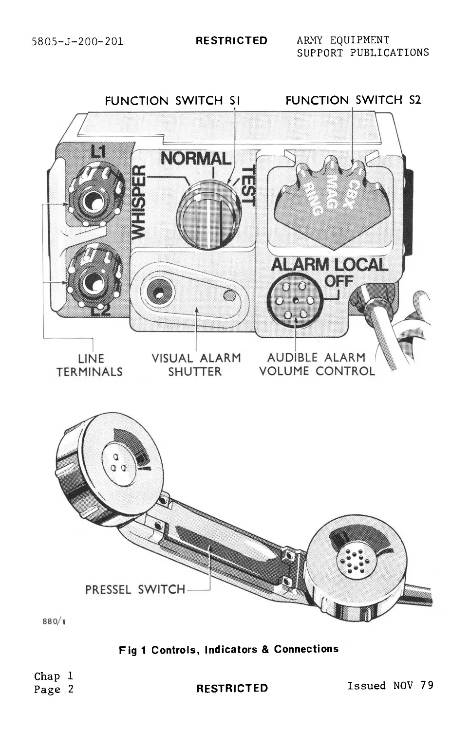
2 Table 1 details all controls, indicators and connections
with which the operator is concerned. These are mounted on
the top panel of the instrument, with the exception of a
pressel switch which is on the handset. No internal
controls are listed, these as they exist are not of user
concern.
Chap 1
Page 1
Issued NOV 79
RESTRICTED
ARMY EQUIPMENT
SUPPORT PUBLICATIONS
5805-J-200-201
RESTRICTED
FUNCTION SWITCH SI FUNCTION SWITCH S2
Fig 1 Controls, Indicators & Connections
Chap 1
Page 2
RESTRICTED
Issued NOV 79
RESTRICTED
5805-J-200-201
ARMY EQUIPMENT
SUPPORT PUBLICATIONS
TABLE 1 - CONTROLS, INDICATORS AND CONNECTIONS (see Fig 1)
SERIAL CONTROLS, etc DESCRIPTION
(1) (2) (3)
1 Function Switch 3 position rotary switch
SI
WHISPER - Switches "whisper
speech" facility into circuit.
NORMAL - Normal operating
position.
TEST - Checks both audible
and visual internal alarms. With S2
Note: When in the TEST posi- function switch at
tion, the switch is RING it causes both
biased back to the alarms to operate
NORMAL position. for 1.5 secs.
2 Function Switch 3 position rotary switch.
S2
RING - Causes a ringing
signal of 1.5 sec duration to be generated.
MAG - Normal 'Standby'
(Magneto) position for working to another telephone. Unit responds to in- coming call signals and allows speech transmission to distant telephone.
CBX - Allows CBX mode of
(Central operation. Completes
Battery line loop between
Exchange) instrument and the central battery
Note: When in the RING posi- tion, the switch is biased back to the MAG position. signalling exchange.
Chap 1
Page 3
Issued NOV 79
RESTRICTED
5805-J-200-201 RESTRICTED ARMY EQUIPMENT
SUPPORT PUBLICATIONS
SERIAL (1) CONTROLS, etc (2) DESCRIPTION (3)
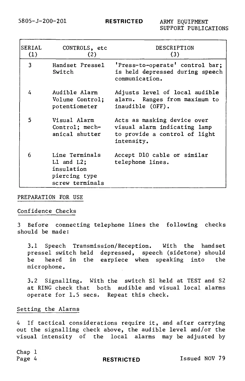
3 Handset Pressel Switch 'Press-to-operate1 control bar; is held depressed during speech communication.
4 Audible Alarm Volume Control; potentiometer Adjusts level of local audible alarm. Ranges from maximum to inaudible (OFF).
5 Visual Alarm Control; mech- anical shutter Acts as masking device over visual alarm indicating lamp to provide a control of light intensity.
6 Line Terminals LI and L2; insulation piercing type screw terminals Accept DIO cable or similar telephone lines.
PREPARATION FOR USE
Confidence Checks
3 Before connecting telephone lines the following checks
should be made:
3.1 Speech Transmission/Reception. With the handset
pressel switch held depressed, speech (sidetone) should
be heard in the earpiece when speaking into the
microphone.
3.2 Signalling. With the switch SI held at TEST and S2
at RING check that both audible and visual local alarms
operate for 1.5 secs. Repeat this check.
Setting the Alarms
4 If tactical considerations require it, and after carrying
out the signalling check above, the audible level and/or the
visual intensity of the local alarms may be adjusted by
Chap 1
Page 4 RESTRICTED Issued NOV 79
ARMY EQUIPMENT RESTRICTED 5805-J-200-201
SUPPORT PUBLICATIONS
fingertip adjustment of the audible alarm control and by
setting the visual alarm mechanical shutter appropriately.
Whisper Speech Facility
5 If there is a requirement for tactical and security
reasons to use the whisper speech facility, the switch SI
should be set to WHISPER.
OPERATING THE EQUIPMENT
General
6 Connect the telephone lines to the terminals LI and L2.
The lines will be connected at their remote end to either a
similar magneto telephone or to a central battery exchange
as required. The operating procedure for both modes is as
follows (this is summarised on an instruction label affixed
to the instrument):
7 To call a Central Battery Exchange
7.1 Set switch S2 to CBX.
7.2 Hold the handset pressel switch depressed to speak
or listen.
7.3 At the conclusion of the call, release the handset
pressel switch and set switch S2 to MAG. Ensure that
switch S2 is retained at MAG.
8 To call Magneto Systems
8.1 Set switch S2 to RING and hold (against the spring).
Depress the handset pressel switch and listen for the
signalling tone.
8.2 When the tone ceases allow switch S2 to return to
MAG. If necessary, repeat the calling tone by again
selecting RING and then releasing to MAG.
8.3 Hold the handset pressel switch depressed to speak
or listen.
Chap 1
Page 5
Issued NOV 79
RESTRICTED
5805-J-200-201
RESTRICTED
ARMY EQUIPMENT
SUPPORT PUBLICATIONS
8.4 At the conclusion of the call, ring down by
selecting RING then MAG with switch S2. Ensure that the
switch S2 is retained at MAG.
9 Answering an Incoming Call from a Central Battery
Exchange.
9.1 When an incoming call is detected, either visually
or audibly, select CBX with switch S2, and depress the
handset pressel switch to talk and listen.
9.2 At the conclusion of the call, release the handset
pressel switch and return switch S2 to MAG position.
10 Answering an Incoming Call from a Magneto Telephone.
10.1 When an incoming call is detected, either visually
or audibly, depress the handset pressel switch to talk
and listen.
10.2 When the call is completed, release the handset
pressel switch.
OPERATING THE EQUIPMENT CARRIED IN SATCHEL
11 It may be found convenient to use the equipment in its
satchel. If so the telephone should be fitted in the
satchel as shown in Figure 2.
Note ...
The handset should be packed with the mouthpiece
positioned at the bottom of the satchel. This enables
the audio alarm, which is emitted from the mouthpiece,
to be heard via the air holes in the bottom of the
satchel.
Chap 1
Page 6
RESTRICTED
Issued NOV 79
RESTRICTED
5805-J-200-201
ARMY EQUIPMENT
SUPPORT PUBLICATIONS
Chap 1
Page 7/8
Issued NOV 79
RESTRICTED
58O5-J-2OO-2O1
RESTRICTED
ARMY EQUIPMENT
SUPPORT PUBLICATIONS
Fig 1 Two-Wire Field Telephone UK/PTC/404
Chap 2
Page 2
RESTRICTED
Issued NOV 79
ARMY EQUIPMENT RESTRICTED 5805-J-200-201
SUPPORT PUBLICATIONS
handset. Additionally a light emitting diode (LED)
indicator lamp on the top panel of the instrument
illuminates as a visual alarm. The action of both alarms
can be controlled by the operator. The audible alarm output
can be reduced or switched off completely, and the visual
alarm lamp output is masked partially or fully (see para 7).
SPEECH COMMUNICATION
Ц With the pressel switch on the handset in the released
position, the earpiece and microphone are switched out of
circuit. With the switch S2 set to either MAG or CBX and
the pressel switch depressed, the receiver and microphone
circuits are energised. The handset receiver is connected
via a matching transformer to the line circuit in order to
receive incoming speech. The microphone with an associated
amplifier is energised from the battery supply and made
operative.
CBX CALLING
5 The switch S2, when set at CBX completes a DC line loop
to the central battery exchange. This operates the alarm
circuitry in the exchange. The microphone and receiver
circuits and line connections operate in the same way as for
the magneto mode. Connection to the exchange is cleared
when the switch S2 is returned to the MAG position, thus
breaking the DC line loop.
WHISPER SPEECH
6 The 'whisper speech' facility is provided to allow the
operator, usually for security reasons, to talk into the
microphone at a very low speech level yet be heard at normal
level by the person receiving the call. A circuit in the
instrument provides a fixed amount of amplification and is
brought into operation when the switch SI is set at WHISPER.
SELF TEST
7 With the switch SI at TEST, an inbuilt test facility is
introduced which causes both the local alarms, audible and
visual, to operate simultaneously. This enables the
operator to set the ALARM LEVEL (audible alarm) volume
control to the required setting; similarly the visual alarm
shutter.
Chap 2
Issued NOV 79 RESTRICTED Page 3
OQ (B
RESTRICTED Issued NOV 79
Fig 2 Simplified Schematic Diagram
880/4
5805-J-200-201 RESTRICTED ARMY EQUIPMENT
SUPPORT PUBLICATIONS
RESTRICTED
5850-J-200-201
ARMY EQUIPMENT
SUPPORT PUBLICATIONS
Chapter 3
FAULT DIAGNOSIS AND REPAIR
CONTENTS
Para
1 Fault Location
2 Replacement of Batteries
Table Page
1 Fault Diagnosis 1
Fig Page
1 Replacing the Batteries 4
FAULT LOCATION
1 Table 1 below details the actions to be taken when
attempting to rectify faults. If it is found necessary to
change the batteries the method of doing this is as
described in paragraph 3, and supported by Figure 1. Any
faults found, whose rectification is beyond the capability
of the user/operator, should be reported to the Unit
Workshop for appropriate repair action.
TABLE 1 - FAULT DIAGNOSIS
SERIAL SYMPTOM (1) POSSIBLE FAULT (2) ACTION (3)
1 Difficulty experienced in receiving a call or call is not received at all. Similar difficulty experienced with received speech. (i) Line con- nections faulty. (a) Tighten the screwheads of the line terminals LI and L2 to ensure that the insula- tion of the field cable is pierced.
Chap 3
Page 1
Issued NOV 79
RESTRICTED
5805-J-200-201
RESTRICTED
ARMY EQUIPMENT
SUPPORT PUBLICATIONS
SERIAL SYMPTOM (1) POSSIBLE FAULT (2) ACTION (3)
2 Difficulty experienced (i) As in (i) above. (a) As in (a) above.
in trans- mitting a (ii) Batteries discharged (b) Replace batteries.
call or call is not trans- mitted at all. Similar diff- iculty exper- ienced with transmitted speech (iii) Batteries incorrectly assembled. (iv) Battery contacts dirty or corroded. (c) (d) Check that batteries are assembled according to the diagram on the out- side of the battery com- partment . Report fault to Unit Workshop.
3 No sidetone (i) As (i) to (iv) above (ii) Fault receiver. (iii) Faulty microphone. (iv) Faulty pressel switch. (a) As for (a) to (d) above. Note: Cleaning the contacts within the battery is the responsibility of Unit Work- shop personnel, not the operator. (b) Replace (c) Replace (d) Report fault to Unit Work- shop .
Chap 3
Page 2
RESTRICTED
Issued NOV 79
RESTRICTED
5805-J-200-201
ARMY EQUIPMENT
SUPPORT PUBLICATIONS
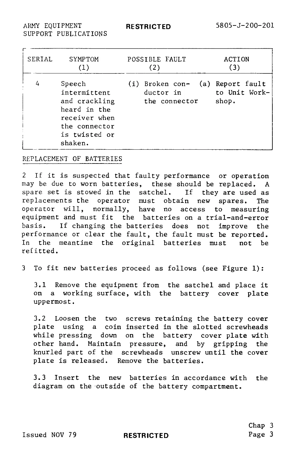
SERIAL SYMPTOM (1) POSSIBLE FAULT (2) ACTION (3)
4 Speech intermittent and crackling heard in the receiver when the connector is twisted or shaken. (i) Broken con- (a) ductor in the connector Report fault to Unit Work- shop .
REPLACEMENT OF BATTERIES
2 If it is suspected that faulty performance or operation
may be due to worn batteries, these should be replaced. A
spare set is stowed in the satchel. If they are used as
replacements the operator must obtain new spares. The
operator will, normally, have no access to measuring
equipment and must fit the batteries on a trial-and-error
basis. If changing the batteries does not improve the
performance or clear the fault, the fault must be reported.
In the meantime the original batteries must not be
refitted.
3 To fit new batteries proceed as follows (see Figure 1):
3.1 Remove the equipment from the satchel and place it
on a working surface, with the battery cover plate
uppermost.
3.2 Loosen the two screws retaining the battery cover
plate using a coin inserted in the slotted screwheads
while pressing down on the battery cover plate with
other hand. Maintain pressure, and by gripping the
knurled part of the screwheads unscrew until the cover
plate is released. Remove the batteries.
3.3 Insert the new batteries in accordance with the
diagram on the outside of the battery compartment.
Chap 3
Page 3
Issued NOV 79
RESTRICTED
5805-J-200-201
RESTRICTED
ARMY EQUIPMENT
SUPPORT PUBLICATIONS
3.4 Press down the battery cover plate until its
locating hole engages with the locating pin on the
mating surface (see Figure 1).
3.5 Screw down both retaining screws while maintaining
the downward pressure on the cover plate and finally
tighten down the screws using a coin in the slotted
screwheads.
Fig 1 Replacing The Batteries
Chap 3
Page 4
RESTRICTED
Issued NOV 79
ARMY EQUIPMENT
SUPPORT PUBLICATIONS
RESTRICTED
5805-J-200-201
Chapter 4
PREVENTIVE MAINTENANCE
OPERATOR MAINTENANCE
1 The following tasks or checks should be carried out at
regular intervals to ensure that the equipment is
maintained in good order.
1.1 Physical and Visual Inspection. The equipment
should be examined for signs of damage or corrosion,
particular attention being paid to the handset, its
cord, the battery compartment and the batteries
themselves. Any apparent corrosion of the contacts
within the battery compartment should be removed, but
only by Unit Workshop personnel. If leakage of the
batteries is suspected, these should be changed.
Note ...
When the equipment is returned to stores the
batteries inside the telephone should be removed
beforehand, thus avoiding possible damage caused by
battery leakage.
1.2 Checks on Control Functions. Periodical checks
should be made on correct functioning of the controls.
The operator should be satisfied that the controls act
in their normal manner when used, for example, for
carrying out the confidence checks, noting that positive
actions are obtained on rotating the controls.
1.3 Cleaning. The equipment should be maintained in a
dry and clean condition and kept in its satchel whenever
possible.
Chap 4
Page 1/2
Issued NOV 79
RESTRICTED
RESTRICTED
5805-J-200-201
ARMY EQUIPMENT
SUPPORT PUBLICATIONS
Chapter 5
DESTRUCTION NOTICE
Para
1 Requirement
2 Equipment Priorities
Table
1 Equipment Destruction Priority Sequence
Page
2
REQUIREMENT
1 It is essential to deny to the enemy the use of equipment
which is abandoned in an operational zone or is about to be
captured. Methods of destruction should achieve such damage
to equipment and essential parts that it would not be
possible to restore the equipment/installation to a usable
condition at its location either by repair or
cannibalisation.
Note ...
Destructive measures will be taken only under the
direction of the Unit Commander and in accordance with
orders or established procedures of the Army or
Divisional Commanders.
EQUIPMENT PRIORITIES
2 Where the equipment cannot be completely destroyed
priority should be given to the destruction of essential
component parts, and the same parts are to be destroyed on
all equipments. The priority sequence for the destruction
of components is given in Table 1.
Chap 5
Page 1
Issued NOV 79
RESTRICTED
5805-J-200-201 RESTRICTED ARMY EQUIPMENT
SUPPORT PUBLICATIONS
TABLE 1 - EQUIPMENT DESTRUCTION PRIORITY SEQUENCE
PRIORITY COMPONENT PART/RECOMMENDED METHOD OF DESTRUCTION
(a) (b)
1 Line Terminals. Sever both terminals at their bases, using.a heavy hammer and cold chisel and applying sideways blows.
2 Control Knobs. If time permits, further dis- able by removing the two control knobs and des- troying them.
Chap 5
Page 2
RESTRICTED
Issued NOV 79