/


Текст
service Manual
ияг and Technical Guide
EASA-PHONE,
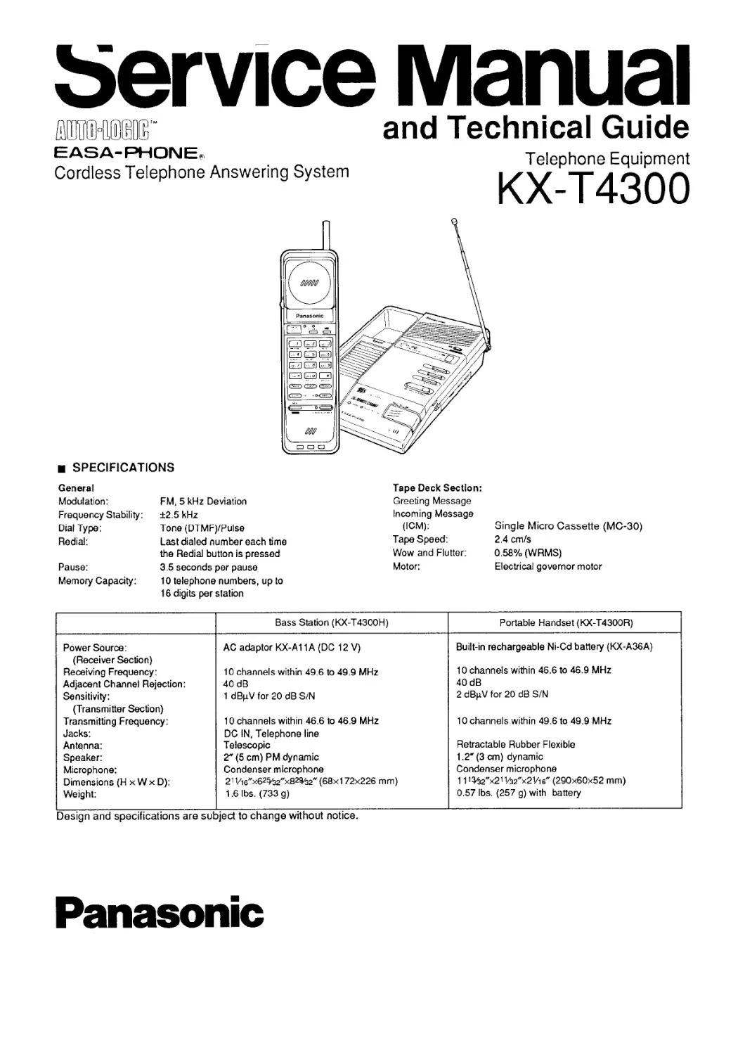
Cordless Telephone Answering System
Telephone Equipment
KX-T4300
SPECIFICATIONS
General
Modulation: FM, 5 kHz Deviation
Frequency Stability: ±2.5 kHz
Dial Type: Tone (DTMF)ZPulse
Redial: Last dialed number each time
the Redial button is pressed
Pause: 3.5 seconds per pause
Memory Capacity: 10 telephone numbers, up to
16 digits per station
Tape Deck Section:
Greeting Message
Incoming Message
(ICM):
Tape Speed:
Wow and Flutter:
Motor:
Single Micro Cassette (MC-30)
2.4 cm/s
0.58% (WRMS)
Electrical governor motor
Bass Station (KX-T4300H) Portable Handset (KX-T4300R)
Power Source: (Receiver Section) Receiving Frequency: Adjacent Channel Rejection: Sensitivity: (Transmitter Section) Transmitting Frequency: Jacks: Antenna: Speaker: Microphone: Dimensions (H x W x D): Weight: AC adaptor KX-A11A (DC 12 V) 10 channels within 49.6 to 49.9 MHz 40 dB 1 dBpVfor 20 dBSZN 10 channels within 46.6 to 46.9 MHz DC IN, Telephone line Telescopic 2" (5 cm) PM dynamic Condenser microphone 211/I6"x62%2"x82%2" (68x1 72x226 mm) 1.6 lbs. (733 g) Built-in rechargeable Ni-Cd battery (KX-A36A) 10 channels within 46.6 to 46.9 MHz 40 dB 2 dBpV for 20 dB S/N 10 channels within 49.6 to 49.9 MHz Retractable Rubber Flexible 1.2' (3 cm) dynamic Condenser microphone 111%г"х21 i/32"x2’/ib" (290x60x52 mm) 0.57 lbs. (257 g) with battery
Design and specifications are subject to change without notice.
Panasonic
с
10
12
14
15
16
17
Notes:
1. SW1: Dialing Mode Selector.
2. SW2: Rings Selector.
3. SW3: CPC Selector.
4. SW4: Message Alert Selector.
5. SW5: Remote Code Selector.
6. SW6: Handset Security Code Selector.
7. SW301: Answer On Switch.
8. SW302: Fast Forward Switch.
9. SW303: Rewind Switch.
10. SW304: Stop Switch.
11. SW305: Message Playbacl
12. SW306: Power On/Off Swi
id Switch.
Switch.
ige Playback Switch.
rOn/Off Switch.
13. SW307: Page/INT’COM Switch.
14. SW308: Greeting Record Switch.
15. SW309: Greeting Check Switch.
16. SW310: Memo Record Switch.
17. DC voltage
measurements are taken with an electronic voltmeter from the negative voltage line. STANDBY position
— Important Safety Notice -
The shaded area on this sc special features important electrical shock hazards.
When servicing it is esse specified parts be used for shaded areas of the schem
SW1DIALING MODE
sw:RINGS
SW:CPC
SW*MESSAGE ARART
SWE REMOTE
SWE SECUR ITY
nt Safety Notice-------------------------------
fed area on this schematic diagram incorporates eatures important for protection from fire and shock hazards.
srvicing it is essential that only manufacturer's parts be used for the critical components in the ireas of the schematic.
This schematic diagram may be modified at any time with development of new technology.
1 I 2 1 3 | 4 | 5 | 6
Notes:
1. S1: Volume Selector Switch in "HIGH” position.
2. S2: Power/Ringer switch in "OFF” position.
3. DC voltage measurements are taken with electronic voltmeter from negative voltage line.
STANDBY position
11
in with electronic
This schematic diagram may be modified at any time with the development of new technology.
Fig. 17
Fig. 25