/


Теги: weapons military affairs
Год: 1985


Текст
FM 23-14
SQUAD AUTOMATIC
WEAPON (SAW),
M249
DECEMBER 1985
DISTRIBUTION RESTRICTION. This publication contains technical or operational
information that is for official government use only. Distribution is limited to US
government agencies. Requests from outside the US government for release of this
publication under the Freedom of Information Act or the Foreign Military Sales Program
must be made to Commander, TRADOC, Fort Monroe, VA 23651-5000.
HEADQUARTERS, DEPARTMENT OF THE ARMY
FM 23-14
FIELD MANUAL
No. 23-14
HEADQUARTERS
DEPARTMENT OF THE ARMY
Washington, DC, 10 December 1985
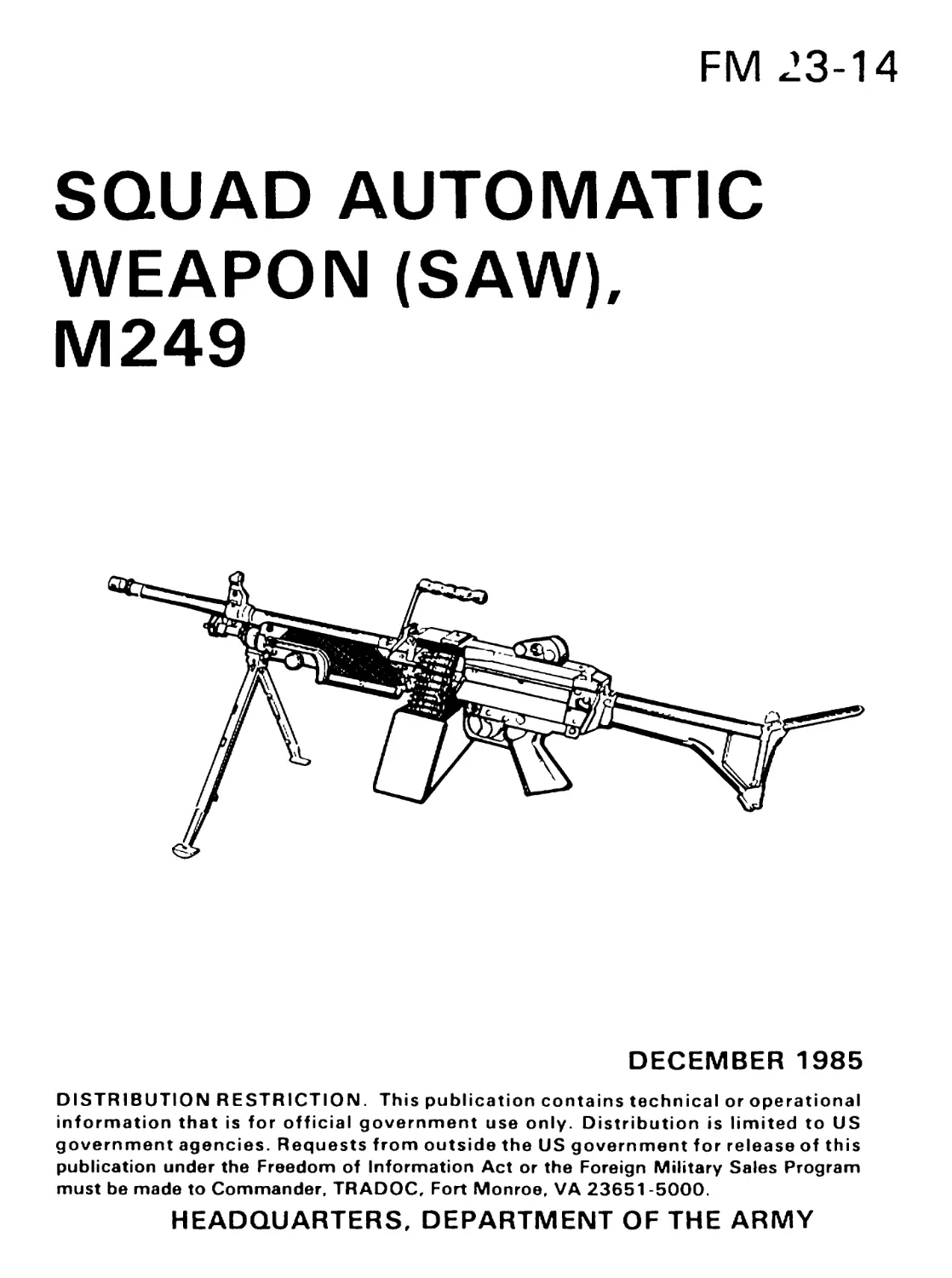
SQUAD AUTOMATIC WEAPON {SAW), M249
PAGE
Preface.........................................................iv
CHAPTER 1. INTRODUCTION......................................1
1 -1. Employment................................1
1-2. Description................................1
CHAPTER 2. DISASSEMBLY AND ASSEMBLY....................7
2-1. General Disassembly........................7
2-2. General Assembly..........................14
2-3. Detailed Disassembly and Assembly
(Unit Armorer).............................16
CHAPTER 3. OPERATION AND CYCLE OF FUNCTIONING...............20
3-1. Operation.................................20
3-2. Loading...................................20
3-3. Unloading and Clearing....................22
3-4. Cycle of Functioning......................22
3-5. Sequence of Functioning...................23
CHAPTER 4. PERFORMANCE PROBLEMS,
MAINTENANCE, AND DESTRUCTION....................................25
4-1. Malfunctions..............................25
4-2. Stoppages.................................26
4-3. Immediate Action..........................28
4-4. Remedial Action...........................29
4-5. Maintenance and Inspection................30
4-6. Cleaning and Lubrication..................32
4-7. Procedures.........................v......33
4-8. Maintenance Under NBC Conditions..........34
4-9. Destruction...............................34
CHAPTER 5. TECHNIQUES OF FIRE
DURING GOOD VISIBILITY..........................................35
Section I. Fundamentals and Firing Techniques..35
5-1. Characteristics of Fire...................35
5-2. Classes of Fire...........................36
5-3. Range Determination.......................39
5-4. Lateral Distance Measure..................41
FM 23-14
PAGE
Section IL Fire Control Requirements...............43
5-5. Methods of Fire Control.......................43
5-6. Purpose of Fire Commands......................44
Section III. Principles of Application of Fire.....52
5-7. Types of Targets..............................52
5-8. Methods of Application of Fire................53
5-9. Target Engagement — Direct Lay................Б5
5-10. Deep Targets.................................57
5-11. Hard-to-Identify Deep Targets................58
5-12. Linear Targets with Depth....................59
5-13. Area Targets.................................50
5-14. Assault Fire Requirements....................61
5-15. Assault Fire Positions.......................61
5-16. Movement. Speed, and Alignment...............64
5-17. Reloading ...................................65
5-18. Fire Adjustment..............................65
5-19. Fire Distribution ...........................65
5-20. Overhead Fire................................65
5-21. Defilade Positions...........................67
5-22. Engagement...................................68
5-23. Laying the SAW for Direction.................68
5-24. Laying the SAW for Elevation.................68
5-25. Controlling Fire.............................68
CHAPTER 6. TECHNIQUES OF FIRE
DURING LIMITED VISIBILITY...........................70
6-1. Terminology..................................70
6-2. Engagement of Visible Targets................71
6-3. Various Targets .............................71
6-4. Predetermined Fires .........................72
CHAPTER 7. MARKSMANSHIP TRAINING ...................................76
7-1. Phases and Organization......................76
7-2. Objectives ..................................76
7-3. Dry-Fire Exercises ..........................77
7-4. Fire Commands ...............................79
7-5. Target Analysis and Scoring .............79
7-6. Obtaining an Accurate Initial Burst..........81
7-7. Distribution of Fire.........................86
7-8. Observation and Adjustment of Fire .........86
7-9. Range Configurations.........................87
7-10. Qualification Firing .......................91
7-11. Qualification Standards.....................93
7-12. Utilization Training .......................93
FM 23-14
PAGE
APPENDIX A. QUALIFICATION TRAINING PROGRAM..................97
A-1. Areas....................................97
A-2. Period 1 — Introduction (3-Hour Period) .97
A-3. Period 2 — Preliminary Marksmanship Training
and Dry-Fire (3-Hour Period)............ 98
A-4. Period 3 — Proficiency (Performance)
Examination (1-Hour Period)..............99
A-5. Period 4 — Ten-Meter Practice and
Qualification (4-Hour Period)............99
A-6. Period 5 — Transition Range Practice Record
Qualification Firing (4-Hour Period) . 100
A-7. Period 6 — Transition Range Qualification
Firing (4-Hour Period) ................ 100
APPENDIX B. PROFICIENCY (PERFORMANCE
EXAMINATION................................... 102
B-1. Dry-Fire Proficiency Examination....... 102
B-2. Tasks ................................. 103
APPENDIX C. AMMUNITION............................ 108
C-1. Classification......................... 108
C-2. Identification......................... 109
C-3. Storage................................ 109
C-4. Care, Handling, and Preservation....... 109
C-Б. Packaging.............................. 110
APPENDIX D. SAFETY................................ 111
D-1. Safety Precautions..................... 111
D-2. Range Procedures....................... 111
APPENDIX E. M249 SAW IN AIR DEFENSE....................... 114
E-1. Passive and Active Measures............ 114
E-2. Rules of Engagement.................... 115
E-3. Firing Position.........................115
APPENDIX F 116
References...................................................... 119
Index........................................................... 120
iii
FM 23-14
Preface
This manual is intended to provide technical information, training techniques,
and guidance on the squad automatic weapon. Unit leaders and the designated
gunners will find this information invaluable in their efforts to successfully
integrate this automatic weapon into their combat operations.
The tactical positions shown in this manual are not tactically correct, but were
drawn to enhance the reader’s understanding of related subject material.
Unless otherwise stated, whenever the masculine gender is used, both men and
women are included.
The proponent of this publication is HQ TRADOC. Submit changes for
improving this publication on DA Form 2028 (Recommended Changes to
Publications and Blank Forms) and forward it to Commandant, US Army
Infantry School, ATTN: ATSH-IN-2B-C, Fort Benning, GA 31905-5593.
FM 23-14
CHAPTER 1
Introduction
1-1. EMPLOYMENT
The squad automatic weapon (SAW) gunner supports the infantry squad in
both offense and defense. He is capable of engaging targets with a heavier
volume of fire than that of the individual rifleman. The weapon provides the
infantry squad with improved suppressive fire and a high volume of close and
continuous assault fire. There is no change in movement techniques used by a
SAW gunner from those used by M16A1 automatic riflemen. In the defense, the
SAW is sited by the squad leader. The SAW gunner’s fighting position is the same
as that for the automatic rifleman and is represented by the AR symbol on the
squad sector sketch. The SAW gunner uses aiming stakes in defining his sector.
1-2. DESCRIPTION
The SAW is an air-cooled, belt-fed, gas-operated automatic weapon which fires
from the open-bolt position. It has a regulator for selecting normal (750 rounds
per minute) or maximum (1,000 rounds per minute) rate of fire. The maximum
rate of fire is authorized only if the weapon’s firing rate slows under adverse
conditions. Ammunition is fed into the weapon from a 200-round ammunition
box holding a disintegrating metallic split-link belt. The SAW also has an
alternate feeding provision for use in emergencies — the 20- and 30-round M16
rifle magazines. The weapon has a quick-change barrel; however, barrels must
not be interchanged with those from other SAWs unless their headspace has been
set for that weapon by direct support personnel.
a. COMPONENTS. The major components of the SAW and their pur-
poses are shown in Table 1-1.
TABLE 1-1. COMPONENTS AND PURPOSES
COMPONENTS PURPOSES
Barrel assembly Houses cartridges for firing, directs projectile, and supports fixed front sight. Butt group assembly Serves as a shoulder support for aiming and fir- ing SAW. Contains a folding shoulder rest. Operating rod assembly Absorbs recoil from bolt and operating rod as- sembly at the end of recoil movement.
1
FM 23-14
TABLE 1-1. COMPONENTS AND PURPOSES (CONTINUED)
COMPONENTS PURPOSES
Piston assembly Transfers power from propelling gases to bolt and slide assemblies in the functioning of the SAW (moves recoiling parts rearward).
Bolt assembly Provides feeding, stripping, chambering, firing, and extraction, using the propellent gases and recoil spring for power.
Slide assembly Houses firing pin and roller assembly.
Trigger mechanism assembly Controls the firing of the weapon.
Cover/feed mechanism assembly Feeds linked belt ammunition, and positions and holds cartridges in position for stripping, feeding, and chambering.
Rear sight assembly Rear sight is adjustable for both windage and elevation.
Handguard assembly Provides thermal insulation to protect the oper- ator's hands from heat, and houses the cleaning equipment.
Bipod assembly Supports SAW in prone position. The telescopic legs can be individually adjusted to three different lengths.
Receiver assembly Serves as a support for all major components. Houses action of weapon and, through a series of cam ways, controls functioning of weapon.
Cocking handle assembly Pulls the moving parts rearward. Moves in a guide rail fixed to the right side of the receiver.
Gas cylinder assembly Locks bipod in place on receiver and provides passageway for operating gases.
2
FM 23-14
. -.iir-'V-
A - BARREL ASSEMBLY
В — REAR SIGHT ASSEMBLY
C — COVER AND FEED MECHANISM ASSEMBLY
D - FEED PAWL ASSEMBLY
E - COCKING HANDLE ASSEMBLY
F - BUTT STOCK AND SHOULDER ASSEMBLY
G - PISTON ASSEMBLY
H - BOLT ASSEMBLY
-S' .A '
I - SUDEAS8EMBLY^:’1®HE»:
J — OPERATING ROD ASSEM®WT?:
К - RECEIVER ASSEMBLYr^^^
L - TRIGGER MECHANISM ASSEMBLY
M - HANDGUARD ASSEMBLY*^ -
N - BIPOD MACHINE GUN ^M
О - GAS CYLINDER ASSEMBLY
THE SAW AND COMPONENTS OF THE SAW
3
FM 23-14
b. SIGHTS. The SAW has a hooded and semi-fixed front sight. The rear
sight is mounted on the top cover of the ammunition feed mechanism
assembly. The elevation knob drum is marked for each 100 meters of range,
from 300 meters to a maximum of 1,000 meters. Range changes are made on
the SAW sight by rotating the elevation knob to the desired range setting
Rotation of the peep sight is used for fine elevation or range adjustments,
such as during zeroing. Each click of the peep sight (180-degree turn) equals
a 1/2-mil change in elevation. The sight is adjusted for windage by
rotating the windage knob. Each click of windage adjustment also equals a
1/2-mil change.
4
FM 23-14
c. SAFETY, The safety is on the trigger housing. Pushing the safety from
left to right (red ring NOT visible) renders the weapon SAFE, and the bolt
cannot be released to go forward. Pushing the safety right to left (red ring
visible) renders the weapon off SAFE and ready to fire. The cocking handle
on the right side of the weapon is used to pull the bolt to the rear.
CAUTION
THE COCKING HANDLE MUST BE MANUALLY RETURNED TO THE
FORWARD POSITION EACH TIME THE BOLT IS MANUALLY PULLED TO
THE REAR.
TABLE 1-2. GENERAL DATA
Ammunition
5.56-mm ball, tracer, blank, and dummy ammunition
ispackaged in 200-roundboxeseach weighing
6.92 pounds (3.140 kilograms), or 30-round
magazines each weighing 1.07 pounds (0.485
kilogram).
Tracer burnout.........................900 meters (+)
Length of SAW..........................40.87 inches (1,038 millimeters)
5
FM 23-14
TABLE 1-2. GENERAL DATA (CONT)
Weight of SAW with
200-round box..................22.08 pounds (10.015 kilograms}
Maximum range....................3,600 meters
Rates of fire:
Sustained.........................85 rounds per minute
Rapid.........................200 rounds per minute
Cyclic........................750 rounds per minute
Basic load, ammunition............600 rounds carried by gunner. (Ammunition
carried in three 200-round boxes.)
Maximum extent of grazing fire
obtainable over uniformly
sloping terrain.........................600 meters
6
FM 23-14
CHAPTER 2
Disassembly and Assembly
2-1. GENERAL DISASSEMBLY
The M249 SAW can be disassembled and assembled without special tools or
equipment except for the handguard assembly, the gas regulator, and the gas
regulator collar. Detailed disassembly requires special tools.
As each part is removed in disassembly, it should be placed on a clean, flat
surface such as a table, shelter half, or disassembly mat. This makes it easy to
keep track of parts, and it aids in the assembly, since the parts are assembled in
reverse order from disassembly.
Disassembly of the SAW beyond that described in this manual must be done by
ordnance personnel
a. TYPES. There are two types of disassembly and assembly:
(1) General disassembly and assembly pertain to removing and
replacing the eight major groups.
(2) Detailed disassembly and assembly pertain to removing and re-
placing the parts of those major groups.
b. GROUPS. The eight major groups of the SAW are:
(1) Operating rod group
(2) Buttstock and shoulder assembly group
(3) Trigger group
(4) Handguard group
(5) Barrel group
(6) Gas cylinder group
(7) Bipod group
(8) Receiver group
7
FM 23-14
c. CLEARING. Clearing is always the first step upon receiving a SAW or
when preparing it for disassembly. To clear the SAW:
(1) Cock the weapon.
(2) Put the safety on SAFE and return the cocking handle to its forward
position.
(3) If the SAW is belt-fed, raise the cover, inspect the tray, and remove
links or ammunition.
(4) If the SAW is magazine-fed, push down on the magazine release tab
and remove the magazine. Then raise the cover.
(5) Raise the tray and inspect the chamber to ensure that no rounds are
present.
(6) Close the cover, place the safety on FIRE, pull the cocking handle to
the rear, and pull the trigger while manually easing the bolt forward.
(7) Raise the cover. (If not disassembling the weapon, keep the cover
down.)
CAUTION
THE BOLT MUST BE EASED FORWARD TO PREVENT DAMAGE TO THE
FEED TRAY ASSEMBLY AND OPERATING ROD GROUP.
d. REMOVING THE OPERATING ROD GROUP. The operating rod
group consists of the spring guide rod, operating rod spring, slide
assembly, piston assembly, and bolt assembly.
(1) To remove the operating rod, pull to the left the upper retaining pin at
the rear of the receiver. Let the buttstock pivot downward so that the
rear opening on the receiver is completely free.
(2) Hold the weapon with one hand on the buttstock assembly and push in
and upward on the rear of the operating rod assembly with the thumb
of other hand. This releases the operating rod assembly from the
positioning grooves inside the receiver.
(3) Pull the operating rod and spring from the receiver group and separate
the two parts.
(4) With the left hand, grab the buttstock assembly to stabilize the wea-
pon. With the right hand, pull the cocking handle to the rear. Return
the cocking handle to the forward position. Place a finger on the face
8
FM 23-14
of the bolt and push until the finger makes contact with the bridge
at the end of the receiver. This leaves the piston, slide, and bolt assem-
blies exposed.
(6) Grasp the slide assembly and slide the moving parts out the rear of the
receiver.
REMOVING THE OPERATING ROD GROUP
e. SEPARATING THE ASSEMBLIES.
(1) Hold the piston assembly in onehand, place the other hand on the bolt
assembly, and rotate the bolt to disengage the bolt from the slide
assembly.
9
FM 23-14
(2) Remove the firing pin spring from the firing pin, but be careful not to
break the spring. If the spring sticks, a slight gentle rotation left and
right should free the spring. The weapon will function without the
spring, but it will weaken the firing pin action.
CAUTION
WHEN THE BOLT IS REMOVED. THE FIRING PIN SPRING IS FREE.
DO NOT LOSE IT.
(3) To separate the slide assembly from the piston, press the retaining pin
at the rear of the slide assembly to the left and lift the slide assembly.
f. REMOVING THE BARREL.
(1) The barrel group consists of barrel, flash suppressor, front sight, gas
regulator, and gas regulator collar.
(2) To remove the barrel from the receiver, close the cover assembly,
depress the barrel locking lever with the left hand, hold the carrying
handle with the right hand, lift up on the carrying handle, and push
the barrel forward.
REMOVING THE BARREL
10
FM 23-14
g. REMOVING THE GAS REGULATOR AND COLLAR. To remove
the gas regulator and gas regulator collar, rotate the gas regulator lever
between the normal and maximum positions. Place the tip of the spring
guide rod into the notch at the front left of the gas plug (NORMAL posi-
tion of lever) and hold the guide firmly in the notch.
REMOVING THE GAS COLLAR
Holding the spring guide rod in position, turn the gas regulator lever
toward the NORMAL position and beyond until the gas regulator collar
can be removed.
CAUTION
DO NOT ATTEMPTTO PRY THE GAS REGULATOR COLLAR WITH THE TIP
OF THE SPRING GUIDE ROD. THIS COULD BREAK OFF THE TIP OF THE
SPRING GUIDE ROD.
11
FM 23-14
To remove the gas regulator, grasp it at the bottom and pull it from the
gas plug.
h. REMOVING THE HANDGUARD. The handguard group consists of
the handguard, handguard retaining pin, and cleaning equipment retain-
ing clip. Push the handguard retaining pin to the left using a cartridge or
the spring guide rod; then pull down on the handguard.
CAUTION
THE HANDGUARD RETAINING PIN IS A CAPTURED PIN. DO NOT
ATTEMPT TO REMOVE IT COMPLETELY DURING DISASSEMBLY.
i. REMOVING THE BUTTSTOCK AND SHOULDER ASSEMBLY.!
To remove the buttstock and shoulder assembly, use a cartridge or the
spring guide rod to push the lowermost retaining pin on the rear of thej
12
FM 23-14
receiver. Remove the buttstock and shoulder assembly by pulling it rear-
ward while supporting the trigger mechanism.
REMOVING THE BUTTSTOCK AND SHOULDER ASSEMBLY
CAUTION
THE UPPER AND LOWER RETAINING PINS IN THE REAR OF THE
RECEIVER ARE CAPTURED PINS. DO NOT ATTEMPTTO REMOVE THEM
COMPLETELY DURING DISASSEMBLY.
To separate the trigger mechanism from the receiver, pull down on it.
j. REMOVING THE GAS CYLINDER GROUP. To remove the gas cyl
inder from the receiver, grasp the gas cylinder forward of the bipod legs,
turn it to the left or right to release the locking spring, and then pull forward
on it.
13
FM 23-14
к. REMОVING THE BIPOD GROUP. Once the gas cylinder is removed,
the bipod group can also be removed brom the receiver.
2-2. GENERAL ASSEMBLY
a. REPLACING THE BIPOD GROUP. Place the bipod group on the
receiver with the bipod legs open and pointed downward.
b. REPLACING THE GAS CYLINDER GROUP. Push the gas cylinder
through the bipod yoke into the receiver and, using the other hand, align
the gas cylinder with the receiver. Then rotate the gas cylinder until it locks
into position.
c. REPLACING THE HANDGUARD GROUP. To replace the handguard,
place it on the receiver from the bottom and slide it to the rear until it stops.
Using a cartridge, push the handguard retaining pin to the right, which
locks the handguard into position. Pull downward on the handguard to make
sure it is locked.
d. REPLACING THE GAS REGULATOR AND COLLAR. Insert the gas
regulator into the gas block and align the notch on the gas regulator with
the notch of the gas block. With the gas regulator installed and sup-
ported on a firm surface, place the gas regulator collar onto the pro-
truding end of the body and align the spring with the stud. Firmly push
downward and rotate the gas regulator collar clockwise into the NORMAL
position. !
e. REPLACING THE BARREL GROUP. Depress the barrel locking lever
to the rear with the left hand, while holding the carrying handle with the
right hand. Pull the barrel rearward, push downward, align the gas
regulator to the gas cylinder, and lock by releasing the barrel locking lever.
14
FM 23-14
Ensure that the barrel is locked onto the receiver by pulling or lifting on the
carrying handle.
f. REPLACING THE TRIGGER MECHANISM GROUP. Align the
trigger mechanism with the slot on the bottom of the receiver. The trigger
mechanism must be held in position to accomplish the next step.
g. REPLACING THE BUTTSTOCK AND SHOULDER ASSEMBLY.
Align the lower hole in the buttstock and shoulder assembly with the rear
hole in the trigger mechanism; then push the lower retaining pin to the
right.
h. JOINING THE BOLT, SLIDE, AND PISTON ASSEMBLIES. Hold
the piston in one hand, with the face of the piston away from you and the
sear notches downward. With the other hand, place the slide assembly onto
the rear of the piston with the firing pin toward the front of the piston.
(Make sure the slide assembly retaining pin is out.)
Push the slide assembly retaining pin to the right. This locks the piston
assembly and the slide assembly together.
Put the firing pin spring onto the firing pin of the slide assembly. Place
the bolt onto the slide assembly, aligning the driving lug of the bolt with the
slot of the slide assembly. Apply pressure to the face of the bolt in order to
compress the firing pin spring. Then rotate the bolt to hook its driving lug
into the slide assembly.
i. REPLACING THE PISTON, BOLT, AND SLIDE ASSEMBLIES.
Open the cover assembly on the receiver. Insert the face of the piston
into the receiver, aligning the bolt lugs onto the receiver rails. Pull the
trigger and push the moving parts forward until the bolt is seated into
the chamber.
j. JOININGTHE OPERATING ROD AND SPRING ASSEMBLY.
Place the operating rod tip into the operating rod spring. Then insert the
free end of the operating rod and spring into the rear of the piston. Depress
the rear of the operating rod assembly until the two lugs on the buffer are
positioned in the receiver grooves.
k. REPLACING THE BUTTSTOCK AND SHOULDER GROUP. Pivot
the buttstock upward into position and push the upper retaining pin to the
right, locking the buttstock to the receiver.
CAUTION
THE BOLT MUST BE EASED FORWARD TO PREVENT DAMAGE TO THE
FEED-TRAY ASSEMBLY AND OPERATING ROD GROUP.
15
FM 23-14
1. CONDUCTING A FUNCTION CHECK. A function check must be
performed to ensure that the SAW has been assembled correctly. The
procedures, in order, are:
(1) Cock the weapon by pulling the cocking handle to the rear.
(2) Move the safety to FIRE.
(3) Return the cocking handle to its forward position.
(4) Place the safety on SAFE.
(5) Pull the trigger. (The weapon should not fire.)
(6) Place the safety on FIRE.
(7) Pull and hold the cocking handle to the rear.
(8) Pull the trigger and allow the bolt to ease forward. If the bolt does not
go forward, the SAW must be disassembled and then reassembled.
After reassembly, if the SAW continues to fire when the safety is on
SAFE, the squad leader must be notified and the weapon must be
turned in for maintenance.
NOTE: The cover assembly can be closed with the bolt in either the forward or the backward
position.
2-3. DETAILED DISASSEMBLY AND ASSEMBLY (UNIT
ARMORER)
a. LIMITS. Detailed disassembly at unit level is limited to the barrel group,
shoulder rest, operating rod, bolt assembly, trigger mechanism, cover
assembly and feed tray, handguard, and receiver group.
b. DISASSEMBLY OF THE BARREL GROUP. To disassemble the flash
suppressor, secure the barrel in a vise with protective jaws. Using an
adjustable wrench, remove the flash suppressor by turning clockwise
because it has a left-handed thread.
To disassemble the carrying handle grip, use the 10-mm end of a box
spanner and a screwdriver or punch. While holding the barrel in a vise with
protective jaws, place the wrench on the carrying handle nut and twist
c. DISASSEMBLY OFTHE SHOULDER REST. To disassemble the
shoulder rest, the buttstock assembly should be placed on the weapon.
Grasp the shoulder rest with both hands, and spread and separate the
shoulder rest from the buttstock assembly.
16
FM 23-14
d. DISASSEMBLY OFTHE OPERATING ROD. To disassemble the
operating rod and buffer assembly, place it in a vertical position in a vise
with protective jaws. Use a punch and a hammer to drive out the straight
pin from the ring spacer; then remove the straight rod. Unscrew and
separate the spring pin from the ring spacer and buffer spring.
e. DISASSEMBLY OF THE BOLT ASSEMBLY. To disassemble the bolt
assembly, position it in a protective-jaw vise with the extractor pin in a
vertical position. Using a punch and hammer, drive out the extractor pin.
NOTE: Th* extractor, pin guide, end extractor spring ere under spring tension. Care should be taken
not to lose the parts when the pin is removed.
f. DISASSEMBLY OF THE TRIGGER MECHANISM. To disassemble
the trigger mechanism, open the plate assembly at the bottom of the trigger
mechanism. Using an 11-mm end of a box spanner tool, and a screwdriver
or a punch, loosen the machine bolt Remove the machine bolt from the
pistol grip housing; then remove the trigger guard. Using a punch, remove
the plate assembly retaining pin; then remove the plate and closure locking
clip.
g. DISASSEMBLY OF THE COVER/FEED MECHANISM ASSEM-
BLY. To disassemble the cover assembly, remove the scope adapter plug
with a small screwdriver. Rotate the hooked retaining pin which releases
the shoulder retaining pin; then slide the feed tray rearward to remove it.
Pivot the cover assembly to the left of the receiver, freeing the torsion
spring from the receiver.
h. DISASSEMBLY OF THE RECEIVER ASSEMBLY. To remove the
ejector from the receiver, compress the retaining clip and lift the ejector
out. Remove the retaining clip and cartridge ejector pin from the cartridge
ejector.
To remove the retaining clips from the headed groove pins, use a
sharp-pointed object to pry the retaining clip upward and pull it free. Once
the retaining clips are free, remove the grooved pins and retaining
clips.
NOTE: Thi. oppll.. to both иррот- wd lowor-hoad.d proov. pin..
1. DISASSEMBLY OF THE HANDGUARD ASSEMBLY. To remove
the retaining clips from handguard assembly, remove the retaining clip on
the grooved pin; then remove the grooved pin. Then, using a hammer and a
1/8-inch punch, drive out the retaining pins and remove the retaining
clips.
NOTE: It it not necessary to remove the retaining pint unless the retaining clips are brohen.
j. ASSEMBLY OF THE BARREL GROUP. To install the flash suppressor,
secure the barrel in a vise with protective jaws. Use an adjustable wrench
17
FM 23-14
and turn counterclockwise (left-hand thread). Tighten securely and then
remove barrel assembly from vise.
To install the carrying handle grip, place it onto the carrying handle;
then secure it with the washer and nut using the 10-mm end of a box
spanner and a screwdriver or punch.
k. ASSEMBLY OF THE HANDGUARD. Align the retaining pins and
insert them part way into the handguard. Add the retaining clips and
secure the handguard by seating the retaining pins. Install the grooved pin
with tapered end from left to right until the front portion of the grooved pin
is flush with the slot that mates with the receiver. Secure with the retaining
clip for the grooved pin.
1. ASSEMBLY OF THE SHOULDER REST. To assemble the shoulder
rest, the buttstock assembly should be placed on the weapon. Grasp the
shoulder rest with both hands, spread and separate the shoulder rest, and
place it into position on the buttstock assembly.
m. ASSEMBLY OF THE OPERATING ROD. To assemble the operating
rod, place the operating rod into a protective-jaw vise; install the buffer
spring over the spring pin; then install the ring spacer with beveled side out
and insert the rod. Screw the spring pin in until it is flush with or just below
the pin hole in the spacer. Align the slot in the spring pin with the holes in
the spacer. Using a hammer, drive the pin into the operating rod until
equal lengths are exposed on each side of the spacer ring.
n. ASSEMBLY OF THE BOLT ASSEMBLY. To assemble the bolt
assembly, position the bolt body horizontally in the protective-jaw vise.
Install the pin guide, extractor spring, and extractor into the extractor
hole. Align the slot on the extractor with the hole for the extractor pin.
Insert a punch to hold the extractor, extractor spring, and pin guide in
place. Drive in the extractor pin until it is slightly below flush on each side.
o. ASSEMBLY OF THE TRIGGER MECHANISM. To assemble the
trigger mechanism, hold it facing.upward; then hook the trigger guard
behind the spring pin. Insert the machine bolt into the pistol grip housing
and place this onto the trigger housing. Secure the rear portion of the
trigger guard. Using the 11-mm end of a box spanner tool and a
screwdriver or punch, tighten the machine bolt. Align the holes of the plate
and spring clip on the pistol grip housing; insert the retaining pin; then
close the plate assembly.
p. ASSEMBLY OF THE COVER/FEED MECHANISM ASSEMBLY.
To assemble the cover/feed assembly, pivot the cover assembly from the
left of the receiver, guiding the tang of the torsion spring into the hole of the
receiver. Place the feed tray onto the receiver and slide it forward into
position. Push the shoulder retaining pin through the receiver feed tray
18
FM 23-14
and cover assembly. Pivot the hooked retaining pin over the end of the
shoulder retaining pin.
q. ASSEMBLY OF THE RECEIVER GROUP. Install a retaining clip
and grooved pin on the lower portion of the receiver. Install a retaining clip
between the outside of the flange on the lower left-hand side of the receiver
and a retaining clip into the groove on the headed pin. Install the grooved
pin assembly into the receiver and insert a retaining clip.
To install the ejector, place the ejector on the pin and snap a retaining clip
over the groove of the ejector pin with the curved end overlapping the front
part of the ejector. Install the ejector pin, ejector, and a retaining clip onto
the receiver. Compress the retaining clip and install the ejector assembly
into the recess of the receiver. Check for spring tension.
FM 23-14
CHAPTER 3
Operation and Cycle of Functioning
3-1. OPERATION
The SAW is loaded, fired, unloaded, and cleared from the open-bolt position.
The safety must be in the FIRE position before the bolt can be pulled to the rear.
a. Before using belted ammunition, ensure that:
(1) It is properly linked.
(2) It is free of dirt and corrosion.
(3) The double link is at the opening end of the box.
b. Before using magazine ammunition, ensure that:
(1) It is properly loaded into the magazine.
(2) It is free of dirt and corrosion.
3-2. LOADING
Place the safety on FIRE. Pull the bolt to the rear by the cocking handle with
the palm facing up. When the bolt is held to the rear by the sear, manually return
the cocking handle to the forward position and place the safety on SAFE. Raise
the cover assembly and ensure that the tray, receiver group, and chamber are
clear.
20
FM 23-14
a. BOX-FED. Place the front round of the belt in the tray groove with the
extension of the belt clipped to the feed tray and the open side of the links
down. Close the cover.
NOTE: The extension on the belt of ammunition from the box will hold the first round in the trey
groove.
b. BELT-FED. Place the first round of the belt in the tray groove with the
double link first and the open side of the links down. Ensure that the round
remains in the tray groove, and close the cover. Hold the belt up,
approximately six rounds from the loading end, while closing the cover.
21
FM 23-14
c. MAGAZINE-FED. The 30-round magazine may be loaded by inserting it
into the magazine well on the left side of the receiver and pushing it firmly
to the right until it seats and the release tab clicks into the recess on the
magazine.
NOTE: Use of the 30-round magazine is only for emergencies such as when linked ammunition is not
available.
3-3. UNLOADING AND CLEARING
Pull the bolt to the rear if it is not already there. Place the safety on SAFE and
manually return the cocking handle to its forward position.
a. BELT-FED. Raise the cover and remove any ammunition or links from
the tray. Look into the chamber to ensure that it is clear.
b. MAGAZINE-FED. Push down on the magazine release tab and pull out
the magazine. Raise the cover and tray, and look into the chamber to
ensure that it is clear. Clearing procedures are covered in Chapters 2 and 4.
3-4.
CYCLE OF FUNCTIONING
SAW gunners can recognize and correct stoppages when they know how the
weapon functions. The weapon functions automatically as long as ammunition
is fed into it and the trigger is held to the rear. Each time a round fires, the parts of
the weapon function in sequence. Many of the actions occur at the same time and
are separated only for teaching purposes.
a. SEQUENCE. The sequence of functioning is known as the cycle of func-
tioning. As a minimum standard, the soldier should know the eight basic
terms and short definitions listed below:
(1) Feeding. A round is positioned in the feed tray groove or a magazine
is inserted into the magazine well.
(2) Chambering. A round is stripped from the belt and placed into the
chamber, or a round is stripped from the magazine and placed into the
chamber.
(3) Locking. The bolt is locked inside the barrel socket.
(4) Firing. The firing pin strikes and fires the primer, which fires the
cartridge.
22
FM 23-14
(5) Unlocking. The bolt is unlocked from the barrel socket.
(6) Extracting. The empty cartridge case is pulled from the chamber.
(7) Ejecting. The empty cartridge case is thrown from the receiver.
(8) Cocking. The sear engages the sear notch on the piston.
b. PROCEDURES. Start the cycle by putting the first round of the belt in
the tray groove or inserting the magazine into the magazine well. Then pull
the trigger, releasing the sear from the sear notch. When the trigger is
pulled to the rear, the rear of the sear is lowered and disengaged from the
sear notch. This allows the piston and bolt to be driven forward by the
expansion of the operating rod spring. The cycle stops when the trigger is
released and the sear again engages the sear notch on the piston.
3-5. SEQUENCE OF FUNCTIONING
a. FEEDING. As the bolt starts its forward movement, the feed lever is
forced to the right, causing the feed-pawl assembly to turn in the opposite
direction. This forces the feed-pawl assembly over the next round in the
bolt, and it is ready to place the next round into the tray groove when the
rearward action occurs again.
As the bolt moves to the rear after firing, the feed roller forces the feed
lever to the left. The feed lever is forced to turn, moving the feed pawl to the
right, and this movement places a round in the tray groove.
b. CHAMBERING. As the bolt travels forward, the upper locking lug en-
gages the rim of the round. The pressure of the front and rear cartridge
guides holds the round so that positive contact is made with the upper
locking lug of the bolt. The front cartridge guide prevents forward move-
ment of the link as the round is stripped from the belt.
The upper locking lug carries the round forward. The chambering ramp
causes the nose of the round to be cammed downward into the chamber.
When the round is fully seated in the chamber, the extractor snaps over
the rim of the round, and the ejector on the rail inside the receiver is
depressed.
c. LOCKING. As the round is chambered, the bolt enters the barrel socket.
The upper and lower locking lugs contact the bolt camming surfaces inside
the barrel and start turning the bolt clockwise. The action of the bolt into
the slide assembly, as the piston continues forward, turns the bolt to
23
FM 23-14
complete its 90-degree (one-quarter turn) clockwise rotation. Locking is
now complete.
d. FIRING. After the bolt is fully forward and locked, the piston continues
to go forward, independent of the bolt, for a short distance. The slide
assembly carries the firing pin through the face of the bolt. The firing pin
strikes the primer of the round, and the primer fires the round.
e. UNLOCKING. After the round is fired and the bullet passes the gas plug,
part of the expanding gases go into the gas regulator through the gas plug.
The rapidly expanding gases enter into the gas cylinder from the gas
regulator, forcing the piston to the rear.
As the piston continues to the rear, the slide assembly, also moving to the
rear, causes the bolt to begin its counterclockwise rotation. The upper and
lower locking lugs of the bolt contact the bolt camming surfaces inside the
barrel socket, and, as the bolt continues toward the rear, it completes a
one-quarter turn counterclockwise. The rotation and movement to the rear
unlocks the bolt from the barrel socket.
f. EXTRACTING. Extracting begins during the unlocking cycle. The
rotation of the bolt loosens the cartridge case in the chamber. As the piston
and bolt move to the rear, the extractor pulls the cartridge case from the
chamber.
g. EJECTING. As the cartridge case is pulled from the chamber, the bolt
passes by the ejector. This causes the ejector clip to expand, forcing the
ejector to push the expended cartridge. The extractor grips the right side of
the cartridge and causes it to spin from the weapon as it reaches the
ejection port. The empty belt links are forced out the link ejection port as the
rearward movement of the bolt causes the next round to be positioned in the
tray groove.
h. COCKING. As the expanding gases force the piston to the rear, it moves
independently of the bolt. The piston assembly acts against the firing pin,
pulling the firing pin from the primer of the spent cartridge case. The ac-
tion of the piston assembly, continuing to the rear with the firing pin,
releases the compression of the firing pin spring.
As long as the trigger is held to the rear, the SAW will continue to
complete the right steps of functioning automatically. When the trigger is
released and the sear again engages the sear notch, the cycle of func-
tioning is stopped and the weapon is locked. To prevent undue wear to the
sear and sear notch, the gunner must hold the trigger firmly to the rear
during firing.
24
FM 23-14
CHAPTER 4
Performance Problems,
Maintenance, and Destruction
4-1. MALFUNCTIONS
A malfunctioning SAW is a weapon that is not firing properly. Defective
ammunition or improper operation by the firer is not a malfunction. Two of the
more common malfunctions of the SAW are sluggish operation and uncontrolled
fire (runaway gun). Table 4-1 shows these malfunctions, their probable causes,
and corrective actions.
a. SLUGGISH OPERATIONS. Sluggish operation of the SAW usually is
due to excessive friction caused by carbon buildup, by lack of proper
lubrication, or by burred parts; or to excessive loss of gas caused by a loose
gas cylinder or gas regulator.
A temporary solution to sluggish operations due to carbon buildup is to
set the gas regulator to the MAXIMUM position, fire approximately 50
rounds, and then reset the gas regulator back to the NORMAL position.
b. UNCONTROLLED FIRE (RUNAWAY GUN). Uncontrolled fire (the
weapon continues to fire after the trigger is released) is usually caused by
the firer not pulling and holding the trigger all the way to the rear. This
results in the sear not clearing the sear notch, which causes wear to both
parts. The following are immediate actions for uncontrolled fire:
(1) The firer holds the weapon on target and fires the remaining am-
munition if weapon is near the end of the link bolt or magazine
capacity.
(2) The firer stops the weapon from firing by breaking the ammunition
belt (twist quickly in either direction).
(3) The firer releasee the magazine.
(4) When the weapon has stopped firing, the firer clears the weapon and
checks it to find the cause of the malfunction.
25
FM 23-14
WARNING
NEVER RELOAD A RUNAWAY WEAPON
UNTIL IT HAS BEEN REPAIRED.
TABLE 4-1. MALFUNCTIONS
MALFUNCTION PROBABLE CAUSE CORRECTIVE ACTION
Sluggish operation Dirty receiver. Clean and lubricate.
; Lack of lubricant. Lubricate.
I Carbon buildup in gas system. Clean gas regulator, piston, and cylinder.
Failure to cock or runaway weapon Broken, worn, or burred sear. Notify organizational maintenance.
Piston assembly sear notch worn. Notify organizational maintenance.
Sear stuck in trigger housing. Notify organizational maintenance.
Short recoil. Clean and lubricate bolt and slide assembly.
Carbon buildup in gas j system. ; Clean gas regulator, piston. । and cylinder.
4-2. STOPPAGES
A stoppage is any interruption in the cycle of functioning caused by faulty
action of the weapon or faulty ammunition. Stoppages are classified by their
relationship to the cycle of functioning. Table 4-2 shows types of interruptions or
stoppages and their probable causes and corrective actions.
26
FM 23-14
TABLE 4-2. STOPPAGES
STOPPAGE l PROBABLE CAUSE CORRECTIVE ACTION
Failure to feed Failure to chamber Failure to fire Insufficient lubrication. Defective ammunition link. Obstruction in receiver. Insufficient gas । pressure. Unlatch cover. Long/short rounds. Inverted link belt. ; Damaged, weak, or worn operating parts. Dirty ammunition. । Carbon buildup in gas I cylinder. Carbon buildup in receiver i Damaged round. Damaged or weak driving spring. | l Dirty chamber. i Damaged gas regulator. ; 1 Safety on. Link belt improperly loaded. Defective ammunition. Faulty ammunition. Broken or damaged ! firing pin. Broken or weak driving spring. Lubricate as required. Remove and replace ammunition. Remove obstruction. । Clean gas regulator, piston, and cylinder. Latch cover. Align rounds in link belt. Reinstall link belt with open end of link facing down. Notify organizational maintenance. Clean ammunition. Clean gas cylinder. Clean receiver. Remove round and recharge weapon. Notify organizational maintenance. Clean chamber. Notify organizational maintenance. Push safety to left, exposing red ring. Remove and reinstall link belt properly. Eject round. • Replace ammunition. , ; Notify organizational maintenance. Notify organizational maintenance.
27
FM 23-14
TABLE 4-2. STOPPAGES (CONTINUED)
STOPPAGE PROBABLE CAUSE CORRECTIVE ACTION
Failure to extract Dirty chamber/bolt and slide assembly. Clear chamber/bolt and slide assembly. If problem continues, notify organizational maintenance.
Carbon buildup in gas system. Damaged extractor/spring. Clean gas regulator, cylinder, and piston. Notify organizational maintenance.
Failure to eject Short recoil. Clean and lubricate bolt and slide assembly. If problem still exists, notify organizational maintenance.
1 Damaged ejector/spring. Carbon buildup in gaa system. Notify organizational maintenance. Clean gas regulator, piston, and cylinder.
4-3. IMMEDIATE ACTION
Immediate action is action taken to reduce a malfunction or stoppage without
looking for the cause. Immediate action should be taken in the event of either a
misfire or a cookoff.
a. A MISFIRE is the failure of a chambered round to fire. Such failure can be
due to an ammunition defect or faulty firing mechanism.
b. A COOKOFF is the firing of a round by the heat of a very hot barrel, and
not by the firing mechanism.
c. If the SAW stops firing, the following immediate actions are taken within
10 seconds:
(1) Cock the weapon, and watch the ejection port to see if a cartridge сам
belt link, or round is ejected. Ensure that the bolt remains to the re arid
prevent double feeding if a round or cartridge case is not ejected.
28
FM 23-14
(2) If a cartridge case, belt link, or a round is ejected, return the cocking
handle to its forward position, take aim on the target, and try to tire. If
the weapon still does not fire, clear it and inspect the ammunition and
the weapon to determine the cause of the stoppage.
(3) If a cartridge case, belt link, or round is not ejected, take remedial
action as outlined in the following paragraphs.
4-4. REMEDIAL ACTION
Remedial action is also taken immediately in the case of a stoppage, but it
includes an attempt to determine the cause.
a. COLD WEAPON
(1) If the stoppage occurs with a cold weapon, place the weapon on SAFE,
raise the cover assembly, and remove the belt of ammunition. Raise
the feed tray and inspect the chamber. If the weapon is magazine-fed,
place the weapon on SAFE, push down on the magazine release tab,
remove the magazine, raise the cover assembly and feed tray, and
inspect the chamber.
(2) If there is no round in the chamber, reload and try to fire. If the weapon
fires, continue firing. If it does not fire, reapply immediate and
remedial action as necessary. Inspect the weapon and ammunition.
(3) If there is a round in the chamber, close the cover assembly and try to
fire. If the weapon fires, reload and continue firing. If it does not fire,
clear the weapon and inspect the weapon and ammunition.
b. HOT WEAPON
(I) If the stoppage occurs with a hot weapon (200 rounds fired within a
2-minute time period), move the safety to SAFE, let the weapon cool for
15 minutes, raise the cover, and remove the belt of ammunition. Raise
the feed tray and inspect the chamber. If the weapon is magazine-fed,
place the weapon on SAFE, push down on the magazine release tab,
remove the magazine, raise the cover assembly and feed tray, and
inspect the chamber.
(2) If there is no round in the chamber, reload and try to fire. If the weapon
fires, continue firing. If it does not fire, reapply immediate and
remedial action as necessary. Inspect the weapon and the ammunition.
(3) If there is a round in the chamber, close the cover assembly and try to
fire. If the weapon fires, reload and continue firing. If it does not fire
29
FM 23-14
during training, wait 15 minutes, clear the weapon, and inspect it for
cause.
c. JAMMED COCKING HANDLE
(1) If a stoppage occurs and the cocking handle cannot be pulled to the
rear by hand (the bolt may be fully forward and locked or partially
forward), the following steps should be taken:
(a) Try once again to work the cocking handle by hand. Do not try to
force the cocking handle to the rear with your foot or a heavy object
This could damage the weapon.
(b) If the weapon is hot enough to cause a cookoff, move all soldiers s
safe distance from the weapon and keep them away for 15 minutes
(c) After the weapon has cooled, open the cover and disassemble it
keeping rearward pressure on the cocking handle until the buttstock
and operating rod are removed. (Two soldiers are required for this.}
(d) Remove the round or fired cartridge. A cleaning rod or ruptured
cartridge extractor should be used if necessary.
(2) In a training situation, after completing the remedial action pro
cedures, the weapon should not be fired until it has been inspected
by an ordnance specialist.
4-5. MAINTENANCE AND INSPECTION
Maintenance of the SAW includes inspection, cleaning, and replacement c
parts. A complete operators and organizational maintenance guide is found ii
TM 9-1005-201-10.
Inspection begins with the weapon dissassembled in its major groups о
assemblies. Note that shiny surfaces on parts do not mean the parts ar
unserviceable. Inspect the following parts of the weapon and related equipmen
for the conditions indicated:
a. BARREL GROUP. Make sure the flash suppressor is not cracked am
that it is fastened securely. Check the front sight post and front sight bam
they must not be bent, cracked, or broken. Check the gas regulator ani
collar for cracks or burrs. Check the barrel for bulges, cracks, bendi
obstructions, or pits in the chamber or bore. Check the gas plug fol
obstructions, cracks, and bulges. Make sure the carrying handle is nd
cracked, broken, or missing. i
30
FM 23-14
b. BUTTSTOCK AND SHOULDER ASSEMBLY GROUP. Check the
buttstock for cracks, bends, or breaks, and check for missing components.
Make sure the shoulder piece is not bent or broken and that it locks in both
positions.
c. OPERATING ROD GROUP
(1) The operating rod should not be bent, broken, or cracked. Check for a
missing tip. Check the buffer spring for breaks. Ensure that lug pins
protrude equally on both sides of the buffer spacer. The operating rod
spring should not have kinks or separated strands. Check for broken
strands. It can have a maximum of one break on any one strand.
(2) The bolt assembly should be checked for visible damage. The cartridge
extractor should not be cracked or have a broken spring.
(3) The slide assembly should be checked for visible damage. Check the
feed roller for spring tension when compressed, and see that the pivot
slide is locked onto the slide assembly.
(4) The firing pin should be checked for straightness and cracks, and the
tip should be completely rounded. Ensure that the firing pin spring
is not damaged.
(5) The sear notch on the piston assembly should not show excessive wear
or burring. Slight rotation of the piston on its housing is normal and is
not cause for rejection.
d. TRIGGER GROUP. The shoulder of the sear should not show excessive
wear. The safety should function properly. (The sear should move only
slightly when the safety is on SAFE, and freely when the safety is on
FIRE.)
e. HANDGUARD GROUP. The handguard should not be cracked or
broken. Make sure the retaining clip is attached to the handguard re-
taining pin.
f. GAS CYLINDER GROUP. The gas cylinder should not be cracked,
bent, or broken.
g. BIPOD GROUP. The bipod group should not be cracked, bent, or
broken. The bipod legs should extend and collapse easily.
h. RECEIVER GROUP
(1) The latch cover should work properly.
31
FM 23-14
(2) All parts inside the cover assembly should move under spring tension.
The cover assembly should remain open without support.
(3) The belt-holding pawl must be under spring tension.
(4) The receiver should not be bent or cracked.
(5) The cocking handle should slide freely within its guide and lock in its
forward position.
(6) The windage and elevation knobs on the rear sight should be movable
and legible. The windage scale screw should not be worn or burred.
4-6. CLEANING AND LUBRICATION
The SAW should be cleaned immediately after firing. It should be disassembled
into its major groups or assemblies for cleaning.
a. All metal components and surfaces that have been exposed to powder
fouling should be cleaned using cleaner, lubricant, preservative (CLP) on a
bore-cleaning patch. Use the same procedure to clean the receiver.
CAUTION
TAKE CARE TO AVOID GETTING CLP ON THE GAS REGULATOR
AND PISTON.
b. The gas regulator and piston are cleaned after each firing. To clean the gas
regulator and piston, use the scraper tool and solvent. Make sure the gas
regulator and piston are dry before assembly.
NOTE: Um • cloth highly Mturated in CLP on exterior surfaces to prevent corrosion.
c. After the SAW is cleaned and wiped dry, apply a thin coat of CLP by
rubbing with a cloth. This will lubricate and preserve the exposed metal
parts under all normal temperature ranges.
d. Lubricate moving parts, as described below, with CLP:
(1) Barrel Group. On the camming surfaces of the bolt-locking lugs.
(2) Operating Rod Group. On the operating rod and spring, the slide
assembly, the feed roller, and the bolt-locking lug.
(3) Receiver Group. On all moving parts on the cover assembly and
the receiver rails. After lubricating, cycle the components by handtol
spread the CLP.
32
FM 23-14
e. Weapons fired infrequently or stored for prolonged periods should have a
light film of CLP applied to the interior of the gas plug and the gas regulator
and piston immediately after cleaning or after inspection. Preventive
maintenance will be performed every 90 days, unless inspection reveals
more frequent servicing is necessary. The use of the lubricant will not
eliminate the requirement for cleaning and inspecting to ensure that
corrosion has not formed. Before using, the gas regulator, gas plug, and
piston must be clean and free of oil and lubricants. The following
procedures apply to cleaning and lubricating the SAW under unusual
conditions:
NOTE: CLP is th* only lubricant to ии on th* SAW.
(1) Extremely hot. Use CLP, grade 2.
(2) Damp or salty air. Use CLP, grade 2. Clean and apply frequently.
(3) Sandy or dusty areas. Use CLP, grade 2. Clean and apply frequently.
Remove excess with a rag after each application.
(4) Below -18 degrees Celsius (0 degrees Fahrenheit). Use CLP, grade 2,
generously. Lubricate heavily enough so that it can be spread with
finger.
NOTE: Although CLP will provid* required lubrication at temperatures between 0 degrees Fahren-
heit and -ЗБ degree* Fahrenheit, it will not flow from a 1 /2-оипсе bottle at temperatures
below 0 degrees Fahrenheit.
4-7. PROCEDURES
There are certain actions that must be taken before, during, and after firing to
properly maintain the SAW. They are:
a. BEFORE FIRING
(1) Wipe the bore dry.
(2) Inspect the weapon as outlined in the individual drill.
(3) Ensure that the weapon is properly lubricated.
b. DURING FIRING
(1) Periodically inspect the weapon to ensure that it is properly
lubricated.
(2) When malfunctions or stoppages occur, follow the procedures pre-
viously given.
FM 23-14
c. AFTER FIRING
(1) Clear and clean the weapon immediately.
(2) During periods of inactivity, clean and lubricate every 90 days un-
less inspection reveals more frequent servicing is necessary
(Reference TM 9-1005-201-10).
4-8. MAINTENANCE UNDER NBC CONDITIONS
If contamination is anticipated, apply oil to all outer metal surfaces of the
weapon. DO NOT OIL AMMUNITION. Keep the weapon covered as much as
possible.
If the weapon is contaminated, decontaminate it as prescribed by FM 21-40 and
TM 3-22, and then clean and lubricate.
4-9. DESTRUCTION
The weapon will be destroyed only on the authority of the unit commander.
Report the destruction through command channels.
a. Disassemble the weapon as completely as time permits. Use the barrel to
destroy the parts in the order listed below:
(1) Bolt
(2) Operating rod group
(3) Barrel
(4) Sights, rear and front
(5) Bipod.
b. To destroy the weapon by burning, place an incendiary grenade on the
receiver group over the bolt (with the cover resting on the grenade) and fire
the grenade.
c. Bury the disassembled weapon or dump the parts into streams, mud, snow,
sumps, or latrines.
34
FM 23-14
CHAPTER 5
Techniques of Fire During Good Visibility
Section I.
FUNDAMENTALS AND FIRING TECHNIQUES
Each SAW gunner must be trained in standard methods of applying fire with
the weapon.
The easiest and quickest means of delivering fire with the SAW mounted on the
bipod is by aligning the sights of the weapon on the target and properly applying
fire. This technique is called DIRECT LAY.
At times, techniques of fire other than direct lay are more effective. When
delivering fire in the assault, overhead fire, and fire from position defilade, the
gunner must use the techniques described in this chapter.
To teach the gunner to employ the SAW to the best advantage, this chapter
provides guidance in the fundamentals of characteristics of fire, classes of fire,
range determination, and lateral distance measurements.
5-1. CHARACTERISTICS OF FIRE
Trajectory is the path of the bullet in flight. An understanding of the SAW’s
trajectory, or curved flight path, is required in order to apply effective fire
throughout the full effective range of the weapon. The path of the bullet is almost
fiat at ranges of 300 meters or less. At ranges beyond 300 meters, the trajectory is
curved, and the curve becomes greater as the range increases.
a. MAXIMUM ORDINATE. This is the highest point the trajectory
reaches between the muzzle of the weapon and the base of the target. It
always occurs at a point approximately two*thirds of the distance from the
weapon to the target. The maximum ordinate increases as the range
increases.
35
FM 23-14
b. CONE OF FIRE. This is the pattern formed by the different trajectories
in each burst as they travel downrange. When several rounds are fired in a
burst from a SAW, each round takes a slightly different trajectory. This is
caused primarily by the vibration of the weapon. Variations in ammunition
and atmospheric conditions also contribute to the different trajectories.
c. BEATEN ZONE. This is the pattern formed by the rounds within the
cone of fire striking the ground or the target. The size and shape of the
beaten zone changes when the range to the target changes or when the
weapon is fired into different types of terrain. On uniformly sloping or level
terrain, the beaten zone is long and narrow. As the range to the target
increases, the beaten zone becomes shorter and wider. When fire is
delivered into terrain sloping down and away from the weapon, the beaten
zone becomes longer. When fire is delivered into rising terrain, the beaten
zone becomes shorter. The terrain has no great effect on the width of the
beaten zone.
d. DANGER SPACE. This is the space between the weapon and the target
where the trajectory does not rise above 1.8 meters (the average height of a
standing soldier). This includes the area of the beaten zone. When the SAW
(on its bipod) is fired over level or uniformly sloping terrain at a target less
than 700 meters away, the trajectory will not rise above the average height
of a standing soldier. When targets are engaged over level or uniformly
sloping terrain at ranges greater than 700 meters, the trajectory will rise
above the average height of a standing soldier. Therefore, not all the
distance between the weapon and the target is danger space.
5-2. CLASSES OF FIRE
The SAW fire is classified with respect to the GROUND, the TARGET, and the
WEAPON.
a. Fire with respect to the GROUND includes:
(1) Grazing Fire. When the center of the cone of fire does not rise more
than 1 meter above the ground. When firing over level or uniformly
36
FM 23-14
sloping terrain, a maximum of 600 meters of grazing fire can be
obtained.
(2) Plunging Fire. When danger space is practically confined to the
beaten zone. Plunging fire occurs when firing at long ranges, when
firing from high ground to low ground, when firing into abruptly
rising ground, or when firing across uneven terrain, resulting in a loss
of grazing fire at any point along the trajectory.
b. Fire with respect to the TARGET includes:
(1) Frontal Fire. When the long axis of the beaten zone is at a right
angle to the front of the target. Simply stated, that means when firing
directly into the front of a target.
(2) Flanking Fire. When delivered directly against the flank of a
target
37
FM 23-14
(3) Oblique Fire. When the long axis of the beaten zone is at an angle
other than a right angle to the front of the target.
(4) Enfilade Fire. When the long axis of the beaten zone coincides or
nearly coincides with the long axis of the target. This type of fire is
either frontal or flanking. It is the most desirable type of fire with
respect to a target because it makes maximum use of the beaten zone.
c. Fire with respect to the WEAPON includes:
(1) Fixed Fire. That delivered against a stationary point target when
the depth and width of the beaten zone will cover the target
(2) Traversing Fire. That distributed in width by successive changes
in direction. With the bipod-mounted SAW in the prone position,
aiming as far as possible to the left or to the right without changing
position, begin firing. After each burst, change position slightly
toward the opposite direction. Continue until complete coverage of the
target is obtained.
(3) Searching Fire. That distributed in depth by successive changes
in elevation. With the bipod-mounted SAW in the prone position,
bringing the elbows together to depress the muzzle of the weapon, fire
a burst. After each burst, slightly separate the elbows to obtain
complete coverage of the target. Gunners will learn the amount of
change to apply through experience.
(4) Traversing and Searching Fire. That distributed in width and
depth by successive changes in direction and elevation. Combine
traversing and searching fires to get good coverage of the target
38
FM 23-14
Q 1 1 1 t W 8 ' № ?
1 • »' i
FIXED TRAVERSING SEARCHING TRAVERSE AND SEARCH FIRE WITH RESPECT TO THE WEAPON
5-3. RANGE DETERMINATION
Range determination is the process of finding the distance between two points.
In most situations, one of these points will be the observer’s own position. The
other point may be a target or prominent terrain feature. THE ABILITY TO
DETERMINE RANGE ACCURATELY IS A KEY SKILL NEEDED BY THE
GUNNER TO ACCOMPLISH HIS MISSION. Not only does the accurate
determination of range affect his marksmanship, but it is also required in the
reporting of information and the adjustment of artillery and mortar fire. (See
Table 5-1.)
There are several methods of determining range, including measuring distance
on a map, pacing the distance between two points, estimating range, using an
optical rangefinder, and using registration fire. However, the gunner does not
usually have a map, and he rarely has access to an optical rangefinder. He can
pace the distance between two points if the enemy is not within range. Firing
rounds just to determine the range is not desirable since it may reveal the SAW
position to enemy observers. Most of the time, the gunner must use techniques
that require no equipment and that can be used without exposing himself or
revealing his position. There are two methods of determining range that meet
these requirements: the 100-METER-UNIT-OF-MEASURE method and the
APPEARANCE-OF-OBJECTS method.
a. 100-METER-UNIT-OF-MEASURE METHOD. To use this method,
the gunner must be able to visualize a distance of 100 meters on the ground.
For ranges up to 500 meters, he determines the number of 100-meter
increments between the two pointe he wishes to measure. Beyond 500
meters, the gunner must select a point halfway to the target, determine the
number of 100-meter increments to the halfway point, and then double it to
find the range to the target.
During training periods, gunners must become familiar with the effect
that sloping terrain has on the appearance of a 100-meter increment.
Terrain that slopes upward gives the illusion of longer distance, and
39
FM 23-14
observers have a tendency to overestimate a 100-meter increment Terrain
that slopes downward gives the illusion of shorter distance. In this case,
the observer’s tendency is to underestimate a 100-meter increment and
thus underestimate the range.
APPLYING THE 100-METER-UNIT-
OF-MEASURE METHOD FOR
RANGES UP TO 500 METERS
APPLYING THE 100-METER-UNIT-
OF-MEASURE METHOD FOR
RANGES UP TO 800 METERS
Proficiency in the 100-meter-unit-of-measure method requires constant
practice. Throughout the training in this technique, comparisons should
be frequently made between the range as determined by the gunner and the
actual range as determined by pacing or other, more accurate means of
measurement The best training technique is to require the gunner to pace
the range after he has visually determined it. In this way, he discovers the
actual range for himself, which makes a much greater impression than if
he is simply told the correct range.
A limitation of the 100-meter-unit-of-measure method is thatits accuracy
is directly related to the amount of terrain visible to the observer. This is
particularly true at the greater ranges. If a target appears at a range of 500
meters or more, and the observer can only see a portion of the ground
between himself and the target, it becomes difficult to use the 100-meter-
unit-of-measure method of range determination with any degree of
accuracy.
b. APPEARANCE-OF-OBJECTS METHOD. This method is a means
of determining range by the size and other characteristic details of the
object. This is a common method of determining distances and is used by
most people. For example, a motorist trying to pass another car must judge
the distance of oncoming vehicles based on his knowledge of how vehicles
appear at various distances. In this example, the motorist is not interested
40
FM 23-14
in precise distances but only in having enough road space to safely pass
the car in front of him. Suppose, however, the motorist knew that a
distance of 1 kilometer, an oncoming vehicle appeared to be 1 centimeter
wide and 2 centimeters high, with about a half centimeter between
headlights. Then, anytime he saw other oncoming vehicles that fitted
these dimensions, he would know they were about 1 kilometer away. This
same technique can be used by gunners to determine ranges on the
battlefield. If the gunner knows the characteristic size and detail of men
and equipment at known ranges, he can compare these characteristics to
similar objects at unknown ranges. When characteristics match, so does
the range.
To use the appearance-of-objects method with any degree of accuracy,
the gunner must be familiar with the characteristic details of objects as
they appear at various ranges. For example, the gunner should study the
appearance of a man standing at a range of 100 meters. He fixes the man’s
appearance firmly in his mind, carefully noting details of size and the
characteristics of uniform and equipment. Next, he studies the same man
in a kneeling position and then in a prone position. By comparing the
appearance of the man at known ranges from 100 to 500 meters, the gunner
can establish a series of mental images that will help determine range on
unfamiliar terrain. Training should also be conducted in the appearance of
other familiar objects such as weapons or vehicles. Because the successful
use of this method depends upon visibility, anything that limits visibility
(such as weather, smoke, or darkness) will also limit the effectiveness of
this method.
c. COMBINATION OF METHODS. Under ideal conditions, either the
100-meter-unit-of-measure or the appearance-of-objects method is an
effective method of determining range. However, ideal conditions rarely
exist on the battlefield, so the gunner must use a combination of methods.
The terrain might limit the use of the appearance*of-objects method. For
example, a gunner may not be able to see all the terrain out to the target;
however, he may see enough to get a general idea of the distance. A slight
haze may obscure many of the target details, but the gunner should still be
able to judge its size. By carefully considering theranges estimated by both
methods, an experienced gunner should arrive at a figure close to the true
range. The best way to reduce ranging errors using these two methods is to
train frequently.
5-4. LATERAL DISTANCE MEASUREMENT
In addition to being able to determine range accurately, the gunner needs a
quick method of measuring lateral distance (right or left) from a reference point to
a target
The fingers can be used to measure the lateral distance between a reference
point and a target. Extend the arm with the palm outward, lower the fingers, and
41
FM 23-14
lock the elbow. Close one eye, raise the index finger, and sight along its edge,
placing the edge of the finger along the flank of the target or reference point Note
the space remaining between the points, and then fill this space by raising
fingers until the space is covered. The measurement from the reference point to
the target is then stated as being one or more fingers, depending upon how many
fingers are raised to cover this distance.
TABLE 5-1. FACTORS OF RANGE ESTIMATION
FACTORS OF RANGE ESTIMATION
FACTORS AFFECTING RANGE ESTIMATION FACTORS CAUSING UNDERESTIMATION OF RANGE FACTORS CAUSING OVERESTIMATION OF RANGE
The clearness of outline and details of the target. When most of the target is visible and offers a clear outline. When only a small part of the target can be seen or the target is small in relation to its surroundings.
Nature of terrain or position of the observer. When looking across a depression that is mostly hidden from view. When looking across a depression that is totally visible.
When looking downward from high ground. When looking from low ground toward high ground
When looking down a straight, open road or along a railroad. When vision is narrowly confined as in streets, draws, or forest trails.
When looking over uniform surfaces like water, snow, desert, or grain fields.
Light and atmosphere. In bright light or when the sun is shining from behind the observer. When the target is in sharp contrast with the background or is silhouetted because of its size, shape, or color. In poor light such as dawn and dusk; in rain, snow, fog, or when the sun is in the observer's eyes. When target blends into the background or terrain.
When seen in the clear air of high altitudes.
42
FM 23-14
Section II.
FIRE CONTROL REQUIREMENTS
Fire control includes all actions of the leader and squad members in planning,
preparing, and actually applying fire on a target. It is the ability to select and
designate targets, open fire at the instant desired, adjust fire, regulate the rate of
fire, shift from one target to another, and cease fire.
Fire control depends upon the ability of the leader and the discipline and
training of the squad members. Failure to exercise fire control results in
ineffective employment of the weapons and can result in danger to friendly
troops, loss of surprise, premature disclosure of positions, fire on unimportant
targets, loss of time in adjusting fire, and wasted ammunition.
5-6. METHODS OF FIRE CONTROL
The noise and confusion of battle may limit the use of some of these methods;
therefore, the leader must select a method or combination of methods that will
best accomplish the mission.
a. ORAL. This is an effective method of control, but at times the leader may
be too far away from the gunner, or the noise of the battle may make it
impossible for the gunner to hear him.
b. ARM-AND-HAND SIGNALS. This is an effective method when the
gunners can see the leader. All gunners must understand the standard
arm-and-hand signals.
c. PREARRANGED SIGNALS. These are either visual or sound signals
such as pyrotechnics or blasts on a whistle. These signals should be in-
cluded in standing operating procedures (SOPs) and must be understood
by all squad members.
d. PERSONAL CONTACT. In many situations, the leader must move to
individual squad members to issue orders. This method of control is used
more than any other by small-unit leaders. The leader must use maximum
cover and concealment to keep from disclosing the position.
e. STANDING OPERATING PROCEDURES. SOPs are actions to be
executed without command that are developed during the training of the
squad members. Their use eliminates many commands and simplifies the
leader’s job of fire control.
43
FM 23-14
5-6. PURPOSE OF FIRE COMMANDS
A fire command is given to deliver effective fire on a target quickly and without
confusion. When the leader decides to engage a target that is not obvious to the
squad members, he must provide them with the information they need to effec-
tively engage the target. He must alert the squad members; give a target di-
rection, description, and range; name the method of fire; and give the command
to fire.
There are initial fire commands and subsequent fire commands. Initial fire
commands are given to begin firing at a target, and subsequent fire commands
are given to adjust onto the target, change the rate of fire after a fire mission is
in progress, interrupt fire, or terminate the alert
a. ELEMENTS OF THE FIRE COMMANDS. Fire commands for all
direct fire weapons follow a pattern that includes similar elements. There
are six elements in the fire command for the SAW: ALERT, DIRECTION,
DESCRIPTION, RANGE, METHOD OFFIRE, and COMMANDTO
OPEN FIRE. The gunners repeat each element of fire command as it is
given.
(1) Alert. This element gets the gunners ready to receive further in-
structions. The leader may alert both guns in the squad or only one,
depending upon the situation. To alert and fire both guns, the leader
announces, FIRE MISSION. If the leader desires to alert and fire
only one gun, he will announce, GUNNER NUMBER ONE (TWO),
FIRE MISSION. If he desires to alert both gunners but fire only
one, he will announce, FIRE MISSION, GUNNER NUMBER ONE
(TWO).
(2) Direction. This element indicates the general direction to the
target and may be given in one or a combination of the following
methods:
(a) Orally. The leader gives the direction to the target in relation to
the position of the gunner.
(b) Pointing. The leader can designate a small or obscure target by
pointing with his arm or aiming with a weapon. When he points
with his arm, a man standing behind him should be able to look over
his shoulder and sight along his arm and index finger to locate the
target. When a weapon has been aimed at a target, a soldier looking
through the sights should be able to see the target.
(c) Using Tracer Ammunition. Tracer ammunition is a quick and
sure method of designating a target which is not clearly visible.
When using this method, the leader should first give the general
direction in order to direct the gunner’s attention to the target area.
44
FM 23-14
To prevent the loss of surprise when using tracer ammunition, the
leader does not fire until he has given all of the elements of the tire
command except the command to tire. The leader may tire his
individual weapon or fire one or more bursts from a machine gun.
The firing of the tracer<8) then becomes the last element of the fire
command and is the signal to open fire.
Example:
FIRE MISSION
FRONT
500
WATCH MY TRACER(S)
(d) Using Reference Points. Another method of designating ob-
scure targets is to use easy-to-recognize reference points. All
leaders and gunners must be familiar with terrain features and the
terminology used to describe them (FM 21-26). When using a ref-
erence point, the word “reference” precedes its description. This
is done to avoid confusion. The general direction to the reference
point should be given. An example of the use of a reference point is
as shown below.
FIRE MISSION, GUNNER NUMBER ONE
FRONT
REFERENCE: LONE PINE TREE
Sometimes a target must be designated by using successive
reference points.
Example:
GUNNER NUMBER TWO, FIRE MISSION
RIGHT FRONT
REFERENCE: RED-ROOFED HOUSE, LEFT TO HAYSTACK, LEFT TO
BARN
Finger measurements can be used to direct the gunners’ attention
to the right or left of reference points.
45
FM 23-14
Example:
FIRE MISSION
LEFT FRONT
REFERENCE: CROSSROADS, RIGHT FOUR FINGERS
(3) Description. The target description is used to create a picture of
the target in the minds of the gunners. To properly apply their fire,
the gunners must know the type of target they are to engage. The
leader should describe it briefly. The word “target” precedes the tar-
get description, as in TARGET: TROOPS; TARGET: TANK; TAR-
GET: AIRCRAFT. If the target is obvious, no description is necessary.
(4) Range. The leader will always announce the estimated range to the
target. The range is given so the gunners know how far to look for the
target and what range setting to put on the rear sight. Range is
announced in meters; however, since the meter is the standard unit of
range measurement, the word “meters” is not used. With SAWs, the
range is determined and announced to the nearest hundred or
thousand (in other words, THREE HUNDRED, or ONE THOUSAND, •
or ONE ONE HUNDRED).
Example:
FIRE MISSION
FRONT
REFERENCE: KNOCKED-OUT TANK, LEFT FOUR ZERO
TARGET: TROOPS
300
(5) Method of Fire. This element includes manipulation and rate of
fire. Manipulation is used to prescribe the class of fire with respect to
the weapon. It is announced as FIXED, TRAVERSE, SEARCH, a'
TRAVERSE AND SEARCH. Rate is used to control the amount d
fire. There are three rates which may be announced: sustained, r^apid,
and cyclic. The rate of fire may be omitted from the fire commandT
however, when a rate is omitted, the rapid rate is implied.
Example:
FIRE MISSION
46
FM 23-14
FRONT
REFERENCE: KNOCKED-OUT TANK, LEFT FOUR ZERO
TARGET: TROOPS
300
TRAVERSE
RAPID
(6) Command to Open Fire. It is often important that fire be withheld
so that surprise fire can be delivered on a target, or to ensure that both
gunners open fire at the same time. The leader may preface the com-
mand to commence firing with, AT MY COMMAND, or AT MY
SIGNAL. When the gunners are ready to engage the target, they
report, READY, to the leader. The leader then gives the command,
FIRE, at the specific time desired.
Example:
FIRE MISSION
FRONT
TROOPS
400
AT MY COMMAND or AT MY SIGNAL (Pause until gunners are ready and
fire is desired.)
FIRE (or prearranged signal)
If immediate fire is required, the command, FIRE, is given without
pause and the gunners fire as soon as they are ready.
b. SUBSEQUENT FIRE COMMANDS
(1) Subsequent fire commands are used to make adjustments in direction
and elevation, change rates of fire after a fire mission is in progress,
interrupt fires, or terminate the alert. If the gunner fails to properly
engage a target, the leader must promptly correct him by announcing
or signaling the desired changes. When these changes are given, the
gunner makes the corrections and resumes firing without further
command.
47
FM 23-14
(2) Adjustment for direction is given first. (Examples: RIGHT ONE
ZERO; LEFT FIVE.) Adjustment for elevation is given next.
(Examples: ADD FIVE; DROP ONE FIVE.) These may be given
orally or with arm-and-hand signals. Adjustments in direction and
elevation with the bipod are always given in meters by using one
finger to indicate 1 meter.
(3) Changes in the rate of fire are given orally or by arm-and-hand
signals.
(4) To interrupt firing, the leader announces, CEASE FIRE, or signals to
cease fire. The gunners remain on the alert They resume firing when
given the command, FIRE.
(5) To terminate the alert, the leader announces CEASE FIRE, END OF
MISSION.
c. DOUBTFUL ELEMENTS AND CORRECTIONS
(1) When the gunner is in doubt about any element of the fire command,
he replies, SAY AGAIN RANGE, TARGET. The leader then an-
nounces, THE COMMAND WAS, repeats the element in question, and
continues with the fire command.
(2) When the leader makes an error in the initial fire command, he cor-
rects it by announcing, CORRECTION, and then gives the corrected
element.
Example:
FIRE MISSION
FRONT
TROOPS
500
CORRECTION
600
TRAVERSE
AT MY COMMAND
48
FM 23-14
(3) When the leader makes an error in the subsequent fire command, he
may correct it by announcing, CORRECTION, and then repeating the
entire subsequent fire command.
Example:
LEFT FIVE, DROP ONE
CORRECTION
LEFT FIVE, DROP ONE ZERO
d. ABBREVIATED FIRE COMMANDS. Fire commands need not be
complete to be effective. In combat, the leader’s fire command will give
only the elements necessary to place fire on a target quickly and without
confusion. During training, however, he should use all of the elements to
get gunners in the habit of thinking and reacting properly when a target is
to be engaged. After the gunners’ initial training in fire commands, they
should be taught to react to abbreviated fire commands, using one of the
following methods of control:
(1) Oral. The leader may want to pl ace the fire of one SA Won an enemy
machine gun he has located.
Example:
FIRE MISSION, GUNNER NUMBER ONE
MACHINE GUN
600
FIRE
(2) Abbreviated Arm-and-Hand Signals. The leader gets the gun-
ner’s attention and then points to the target. When the gunner returns
the READY signal, the leader commands, FIRE.
(3) Prearranged Signals. If the leader wants to shift fire at a certain
time, he gives a prearranged signal, such as smoke or pyrotechnics.
Upon seeing the signal, the gunners shift their fire to a prearranged
point
(4) Personal Contact. The leader may also move to the gunner whose
fire he wants to shift, get his attention, point out the new target, and
command, FIRE.
49
FM 23-14
e. STANDING OPERATING PROCEDURES. SOPs for certain
actions and commands can be developed to make gunners more effective.
Some examples follow:
(1) Observation. The gunners continuously observe their sector.
(2) Fire. Gunners open fire without command on appropriate targets
that appear within their sector.
(3) Check. While the gunner is firing, he will periodically check with
the leader for instructions.
(4) Return Fire. The gunners return enemy fire, concentrating on
enemy automatic weapons, without order.
(5) Shift Fire. Gunners shift their fire without command when more
dangerous targets appear.
(6) Rate of Fire. When gunners engage a target, they initially fire at
the rate necessary to gain and maintain fire superiority.
(7) Mutual Support. When two or more gunners are engaging the same
target and one gunner stops firing, the other gunnels) increases the
rate of fire and covers the entire target. When only one gunner is
required to engage a target and the leader has alerted two or more
gunners, the gunner not firing lays on the target and follows the
movements of the target so that he can fire instantly should the other
SAW malfunction or cease fire before the target has been eliminated.
f. ARM-AND-HAND SIGNALS. Battlefield noise and the distance be-
tween the gunner and the leader often make it necessary to use
arm-and-hand signals to control fire. When an action or movement is to be
executed by only one of the gunners, a preliminary signal is given to that
gunner only. The following are commonly used signals for fire control.
(1) Ready. The gunner signals that he is ready to fire by raising his
right hand and arm above his head toward the leader.
(2) Commence Firing, or Change Rate of Firing. The leader brings
his hand, palm down, to the front of his body, about waist level, and
moves it horizontally in front of his body. To signal faster fire, he
increases the speed of the hand movement; to fire slower, he decreases
the speed of the hand movement.
(3) Change Direction/Elevation (Bipod-SAW). The leader extends
his arm and hand in the new direction and indicates, by the number of
fingers extended, the amount of change necessary. The fingers must
be spread so the gunner can easily see the number of fingers extended.
50
FM 23-14
Each finger indicates 1 meter of change for the bipod-mounted weap-
on. If the desired change is more than 5 meters, the leader extends
his hand the number of times necessary to indicate the total amount
of change. For example, RIGHT NINE would be indicated by extend-
ing the hand once with five fingers showing and a second time with
four fingers showing for a total of nine fingers.
(4) Interrupt or Cease Firing. The leader raises his arm and hand,
palm outward, in front of his forehead and brings it downward
sharply.
(5) Other Signals. The leader can devise other signals to control his
weapons. A detailed description of arm-and-hand signals is given in
FM 21-60.
CHANGE RATE OF FIRING
CHANGE DIRECTION/ELEVATION (BIPOD-SAW)
INTERRUPT OR CEASE FIRING
ARM-AND-HAND SIGNALS
51
FM 23-14
Section III.
PRINCIPLES OF APPLICATION OF FIRE
Application of fire consists of the methods gunners use to get complete and
effective coverage of a target area. Training in the methods of applying fire can
be accomplished only after the gunners have learned to recognize the different
types of targets they may find in combat, how to properly distribute and con-
centrate their fire, and how to maintain the proper rate of fire.
6-7. TYPES OF TARGETS
Targets for SAW gunners in combat will in most cases be enemy troops.
Different troop formations will make it necessary to use different classes of fire
distribution. These targets have width and depth, and the fire must thoroughly
cover the area in which the enemy is known or suspected to be. The targets may
be easy to find or hard to see or find.
a. POINT TARGETS. These require the use of a single aiming point.
Examples of point targets are enemy bunkers, weapons emplacements,
vehicles, and troops.
b. AREA TARGETS. These may have considerable width and depth and
may require extensive traversing and searching fire, such as a target
where the enemy's exact location is unknown. Area targets are of three
major kinds:
(1) Linear
(2) Deep
(3) Linear with depth.
52
FM 23-14
LINEAR TARGET WITH DEPTH
5-8. METHODS OF APPLICATION OF FIRE
In combat, the size and nature of a target may call for the fire of more than one
SAW. The method of applying fire to a target is generally the same for either a
single SAW or a pair.
a. AREA AND POINT FIRE. Area fire is fire that is delivered in width, in
depth, or in a combination of both. To distribute fire properly, gunners
must know where to aim, how to adjust their fire, and in which direction to
manipulate the SAW.
With regard to the point of initial lay and adjustment, the gunner must
aim, fire, and adjust on a certain point of the target. Itis importantthat fire
53
FM 23-14
be adjusted boldly, rapidly, and continuously. Binoculars can be used by
the leader to help adjust fire. The gunner always keeps the center of his
beaten zone at the base of the target. This makes the bullets in the upper
half of the beaten zone hit the target, and bullets in the lower half of the
beaten zone ricochet into the target.
With regard to direction of manipulation, the gunner must move his
beaten zone in a certain direction over the target. The direction depends
upon the type of target and whether the target is engaged with a single
SAW or a pair. When engaging area targets (but not point targets) with a
pair of SAWs, the targets are divided. Each gunner is given a part of the
target so that fire is evenly distributed over the target.
b. RATES OF FIRE. There are three rates of fire with SAW —sustained,
rapid, and cyclic. These rates of fire are established as a guide for training
and to indicate when a barrel change is desirable. In training, the rate of
fire should be announced to aid learning and give the gunners a basis for
judging the number of rounds being fired.
(1) Sustained Fire. Sustained fire is 85 rounds per minute in bursts of 5
to 7 rounds at 4- to 5-second intervals. It is directed by announcing,
SUSTAINED.
(2) Rapid Fire. Rapid fire is 200 rounds per minute in bursts of 5 to 7
rounds at 2* to 3-second intervals. It is directed by announcing,
RAPID.
(3) Cyclic Fire. Cyclic fire uses the most ammunition that can be used
in 1 minute. The cyclic rate of fire with the SAW (approximately 750
rounds per minute) is fired when the trigger is held to the rear and
ammunition is fed into the weapon. NORMAL cyclic rate of fire is 750
rounds per minute.
54
FM 23-14
CAUTION
THE SAW HAS AN EMERGENCY CYCLIC RATE OF FIRE SETTING OF
1,000 ROUNDS PER MINUTE. WHEN THE WEAPON BECOMES
EXCESSIVELY DIRTY. THE EMERGENCY SETTING CAN BE USED TO
MINIMIZE STOPPAGES.
c. TARGETS. Ground targets are INITIALLY engaged using the rapid
rate (200 rounds per minute) to gain fire superiority. Firing is then reduced
to a rate that is sufficient to maintain fire superiority. This reduced rate of
fire is necessary to keep the barrel from overheating and to conserve
ammunition.
Aerial targets are engaged using the cyclic rate.
5-9. TARGET ENGAGEMENT-DIRECT LAY
When fire is under direct control of a leader, he designates the midpoint and
flanks or ends of a target unless they are obvious to the gunners. In the case of an
area target, the gunner on the left applies his fire to the left half of the target, and
the gunner on the right takes the right half. Each gunner must be prepared to
engage the entire target Gunners continue to fire until the target is neutralized or
until signaled to do otherwise by the leader. To aid in fire control, SAWs employed
in pairs are designated number 1 SAW (right position) and number 2 SAW (left
position). To ensure that gunners react quickly and properly when they detect a
target or when a target is designated by the leader, standard methods of applying
fire to the various types of targets are used. Point targets are engaged with fixed
fire (also called "‘point fire”). If the target moves after the initial burst, gunners
keep fire on the target by following its movement. Linear targets are engaged
with traversing fire.
a. SAWS IN PAIRS. The target is divided at the midpoint with the right
SAW (normally, number 1) firing on the right half and the left SAW
(normally, number 2) firing on the left half. The point of initial lay and
adjustment for both SAWs is on the midpoint. After adjusting on the
midpoint, the right SAW traverses right, firing a burst after each change in
direction, until it reaches one aiming point beyond the right flank (this
ensures complete target coverage). The left SAW traverses to the left flank
in the same way. Both gunners then reverse their directions and return to
the midpoint. It is important to select aiming points for each burst rather
than “spray” the target area.
If one part of the target is a greater threat, fire can be concentrated on
the greater threat by dividing the target unevenly. The special division of
the target is done with subsequent fire commands after firing begins. To
55
FM 23-14
preclude confusion, the gunners initially 1 ay on the midpoint regardless of
the special division to be made.
b. ONE SAW. A single gunner must engage the entire width of a linear
target The point of initial lay is on the midpoint. The gunner then manip-
ulates to cover the rest of the target
c. HARD-TO-IDENTIFY LINEAR TARGETS. Ifa linear target is
hard to identify, the leader may designate the target by using a reference
point. When this method is used, the leader determines the center of mass
of the target and announces the number of fingers from the reference point
that will cause each gunner to lay on the center mass. The reference point
may be within or adjacent to the target; however, it should be on line with
the target for best effect. After the command to fire has been given, the
leader maintains and controls the fire by subsequent fire commands.
Example of a fire command with the reference point OUTSIDE the target area:
FIRE MISSION
FRONT
REFERENCE: CHIMNEY, RIGHT FIVE, CENTER MASS
TARGET: TROOPS
600
TRAVERSE
AT MY COMMAND
FIRE
A REFERENCE POINT OUTSIDE THE TARGET AREA
56
FM 23-14
Example of a fire command with the reference point INSIDE the target area:
FIRE MISSION
LEFT FRONT
REFERENCE: BURNED-OUT TANK, CENTER MASS
TARGET: TROOPS EXTENDING LEFT FIVE ZERO, RIGHT FIVE ZERO
700
TRAVERSE
AT MY COMMAND
FIRE
ENGAGING HARD-TO-IDENTIFY TARGETS WITH
A REFERENCE POINT WITHIN THE TARGET AREA
5-10. DEEP TARGETS
Deep targets are engaged with searching fire. When the range is announced,
it is given to the midpoint of the target.
a. SAWS IN PAIRS. The point of initial lay on a deep target for both
SAWs is on the midpoint, which is also the point of division. Normally, the
number 1 SAW has the near half and the number 2 SAW the far half. Since
57
FM 23-14
enfilade fire is being delivered, it is not necessary to adjust on the midpoint
of the target, because the long beaten zone will compensate for any range
errors. After the initial burst, the right SAW searches down to one aiming
point in front of the near end of the target and the left SAW searches up to
one aiming point beyond the far end. Both gunners then reverse their
direction of search and return to the midpoint.
b. ONE SAW. A single gunner initially lays on the midpoint of a deep
target unless another portion of the target is more critical. The gunner then
searches down to one aiming point in front of the near end and back up to
one aiming point beyond the far end.
5-11. HARD-TO-IDENTIFY DEEP TARGETS
The center of mass of hard-to*identify deep targets may be designated by using
reference points as for linear targets, except that the extent (depth) of the target
is always given in meters.
Example of a fire command with the reference point INSIDE the target area:
FIRE MISSION
FRONT
REFERENCE: BUNKER, CENTER MASS
TARGET: TROOPS EXTENDING SHORT 100 (meters), OVER 100 (meters)
700
FIRE
Example of a fire command with the reference point OUTSIDE the target area:
FIRE MISSION
FRONT
REFERENCE: BUNKER, RIGHT FOUR, CENTER MASS
TARGET: TROOPS EXTENDING SHORT 100, OVER 100
600
SEARCH
58
FM 23-14
AT MY COMMAND
FIRE
5-12. LINEAR TARGETS WITH DEPTH
Linear targets with depth are engaged with traversing and searching fire. The
range is given to the midpoint.
a. SAWS IN PAIRS. The method of division, the point of initial lay and
adjustment, and the extent of manipulation for both SAWs is the same as
that prescribed for linear targets. The gunners employ enough search
between bursts to keep the center of impact on the base of the target.
b. ONE SAW. A single gunner initially lays and adjusts on the midpoint of
a linear target with depth, unless some other part of the target presents a
greater threat. The gunner then traverses and searches to the near flank,
then back to the far flank.
c. HARD-TO-IDENTIFY LINEAR TARGETS WITH DEPTH. The
flanks and midpoint of a h a rd-to-id entity linear target with depth should
be designated with SAW or rifle fire. The reference-point method should
59
FM 23-14
not be used because a minimum of two reference points are required to
show the angle of the target.
ENGAGEMENTS OF LINEAR
TARGETS WITH DEPTH (PAIR)
5-13. AREA TARGETS
The leader designates an area target by indicating the width and depth of the
target Area targets are engaged with traversing and searching fire.
a. SAWS IN PAIRS. The target is divided at the midpoint; the right SAW
fires on the right half and the left SAW fires on the left half. The point of
initial lay and adjustment for both SAWs is on the midpoint
After adjusting fire on the center of mass, fire is distributed by applying
direction and elevation changes that give the most effective coverage of the
target area. The right gunner traverses to the right, applies the necessary
amount of search, and fires a burst. He traverses and searches up and
down until the right flank of the area target has been reached. The left
gunner traverses and searches to the left flank in the same way.
Both gunners then reverse the direction of manipulation and return to
the center of mass, firing a burst after each combined direction and
elevation change.
Example of a fire comand to engage an area target:
FIRE MISSION
60
FM 23-14
FRONT
REFERENCE: LONG PINE TREE, CENTER MASS
TARGET: AREA, LEFT FIVE ZERO, RIGHT FIVE ZERO
700
SUSTAINED
AT MY COMMAND
FIRE
b. ONE SAW. A single gunner engages an area target by laying and adjust-
ing on the center of mass, then traversing and searching to either flank.
Upon reaching the flank, direction is reversed and the SAW is traversed
and searched in the opposite direction.
5-14. ASSAULT FIRE REQUIREMENTS
SAW gunners need not be limited to supporting fire roles in the attack. In many
situations, the leader can get best results from the SAWs by placing them in the
assault (maneuver) elements. The procedures described below are used when
assaulting in a line, such as during a night attack or during the final stages of
a day assault when fire superiority has been gained. To assault successfully,
gunners must:
• Deliver fire effectively without use of sights
• Move rapidly and maintain alignment
• Reload rapidly to prevent lulls in the firing
• Keep the fire low on the objective area
• Distribute fire properly.
5-15. ASSAULT FIRE POSITIONS
There are three firing positions that may be used when firing the SAW in the
assault — hip, shoulder, and underarm. The use of each position at the proper
time allows gunners to place effective fire on the enemy without aligning the
sights. In all assault firing positions, the gunner adjusts his fire by observing the
tracers and the impact of the bullets in the target area. To support the SAW in the
61
FM 23-14
assault, a sling is attached to the SAW and placed over the gunner's shoulder. It
supports the weapon in the underarm or hip position.
a. HIP FIRING POSITION. The hip firing position is used to get a heavy
volume of fire in the target area when rapid movement is not necessary.
This position is stable, but it is awkward to use while moving. When firing
from this position:
(1) The bipod legs are down for instant use in the prone position if necessary.
(2) The left hand is holding the handguard.
(3) The right hand is on the trigger-mechanism-group grip.
(4) The rear of the stock is held firmly against the forward portion of the
right thigh.
(5) The left foot is pointed in the direction of the target during firing.
(6) The right foot is placed to the rear to provide stability.
(7) The gunner leans toward the target before and during firing.
b. SHOULDER FIRING POSITION. The shoulder firing position is
used to hit specific points in the target area when rapid movement is not
62
FM 23-14
necessary. The gunner pauses and fires a burst as his left foot strikes the
ground. This position gives accuracy. When firing from this position:
(1) The bipod legs are down. To aim, the gunner aligns the front sight
with the target, depressing the muzzle so the top of the front sight is
below the target.
(2) The gunner's hands and feet are placed the same as when firing from
the hip position.
(3) The stock of the SAW is held firmly against the shoulder, and the
gunner leans toward the target before and during firing.
(4) Once the gunner has fired a burst, he removes the weapon from his
shoulder and holds it in the ready position. He raises the weapon back
to his shoulder to fire the next burst. This reduces muscular tension
and fatigue.
c. UNDERARM FIRING POSITION. The underarm firing position is
used when closing with the enemy and when a heavy volume of fire and
rapid movement are required. During limited visibility, this position may
be used during the entire assault When firing from this position:
63
FM 23-14
(1) The bipod legs are down.
(2) The gunner’s hands and feet are placed the same as when firing from
the hip position.
(3) The weapon is held firmly, well up into the right underarm and the
right side of the chest. The gunner leans forward while firing.
UNDERARM FIRING POSITION
5-16. MOVEMENT, SPEED, AND ALIGNMENT
SAW gunners must move rapidly and maintain alignment with the other
members of the assaulting element. To accomplish this, gunners must use the
following techniques:
a. Move as rapidly as possible, consistent with their ability to fire accurately
and maintain alignment.
b. Maintain alignment by guiding on the base man, first team, or squad,
using visual contact when possible. Use special techniques such as watch-
64
FM 23-14
ing muzzle flashes and muzzle blasts, and sometimes making physical
contact, during limited visibility.
5-17. RELOADING
Gunners must reload rapidly to avoid lulls in the firing. This can be achieved by
practice and by applying the following techniques:
a. Prior to assault, the gunner conducts prefire checks on the weapon. He
inspects ammunition to ensure that it is clean and serviceable, and he
checks the box for serviceability.
b. During the assault, the gunner must continue moving forward and reload
as rapidly as possible. The sling will assist the gunner in using both hands
to reload.
5-18. FIRE AD JUSTMENT
Gunners have a tendency to fire high in the assault. To overcome this, they
must be trained to boldly depress the muzzle when firing and then adjust upward.
It is easier to adjust upward than downward, and firing low takes advantage of
ricochets.
The use of tracer ammunition provides a means of adjusting fire. At night, it
aids in illuminating the objective area and has a demoralizing effect on the
enemy.
5-19. FIRE DISTRIBUTION.
To properly distribute fire over the objective, gunners must fire and adjust
rapidly and continuously on as much of the objective area as possible without
endangering friendly troops. They must give priority of fire to enemy automatic
weapons.
5-20. OVERHEAD FIRE
Fire delivered over the heads of friendly troops is called OVERHEAD FIRE. It
is used during training ONLY AFTER TROOP SAFETY IS CHECKED AND
VERIFIED. The terrain and visibility dictate when overhead fire can be de-
livered safely. Refer to AR 385*63 for a complete summary of training safety
requirements. Overhead fire CANNOT be safely delivered on a target at a range
greater than 800 meters from the SAW, and it is not delivered over level or
uniformly sloping terrain. Ideally, overhead fire is delivered when there is a
depression in the terrain between the SAW position and the target The de-
65
FM 23-14
pression should place the gunner’s line of aim well above the heads of friendly
troops.
a. SAFETY LIMIT. The squad leader normally controls overhead fire. He
lifts or shifts the fire when the friendly troops reach an imaginary line,
parallel to the target, where further fire would cause casualties to friendly
troops. This imaginary line is called the SAFETY LIMIT. The leader of the
friendly troops may direct lifting of fire by prearranged signals
transmitted by radio, wire, or visual means. The safety limit can be deter-
mined by observing the fire or by using the gunner’s rule. To determine the
safety limit by observation, the leader uses binoculars to see how close the
fire is to advancing friendly troops. A safety limit can be selected by using
the gunner’s rule before the weapon is fired. The accuracy and safety of this
method depends upon the weapon being ACCURATELY zeroed and the
range to the target being correctly determined. The gunner’s rule is used
only when the target is between 350 and 800 meters from the weapon. The
gunner’s rule consists of the following procedure:
(1) Determine the range to the target and set the range on the rear sight
(2) Lay the weapon to hit the target.
(3) Raise the rear sight to 1,000 meters.
(4) Look through the rear sight and note the point where the new line of.
aim strikes the ground. An imaginary line drawn through this point
and parallel to the target is the SAFETY LIMIT.
(5) Reset the range to the target on the rear sight, re-lay on the target, and
prepare to fire.
(6) Cease or shift fire when troops reach the SAFETY LIMIT.
b. PRECAUTIONS. The following safety measures MUST be applied
when delivering overhead fire:
(1) U se field expedient depression stops to prevent the muzzle of the gun
from accidentally being lowered below the SAFETY LIMIT.
(2) Do not deliver overhead fire through trees.
(3) Inform commanders of friendly troops when fire is to be delivered over
their heads.
(4) Ensure that all gunners are aware of the SAFETY LIMIT.
66
FM 23-14
(5) Do not deliver overhead fire if the range from the weapon to the target
is less than 350 meters or more than 800 meters.
(6) Do not use a barrel that is badly worn.
(7) During training exercises, do not lay SAWs where their trajectories
will cross at a point directly over the heads of friendly troops; and
consult AR 3854)3 and local safety regulations concerning overhead
fire.
6-21. DEFILADE POSITIONS
At times, it may be desirable to employ SAWs from defilade positions. A SAW is
in defilade when the weapon and its gunner are completely behind terrain that
masks them from the enemy (usually on the reverse slope of a hill). The weapon
must fire up and over the hill. Its fire must be observed and adjusted by a squad
member who can observe the target from a position on a flank or to the rear of the
weapon (on higher ground). A defilade position allows little opportunity to
engage new targets. A SAW is in partial defilade when it is positioned just back of
the crest of a hill so that the crest provides some protection from enemy direct fire
and the weapon is still able to engage its target by direct-lay techniques.
(1) The gunner has cover and concealment from enemy direct fire
weapons.
(2) The gunner has some freedom of movement in the vicinity of the
position.
(3) Control and supply are easier.
(4) The smoke and flash of the weapon are hidden from the enemy.
67
FM 23-14
b. DISADVANTAGES
(1) Rapidly moving ground targets are hard to engage because adjustment
of fire must be made through an observer.
(2) Targets close to the mask usually cannot be engaged.
(3) It is hard to get a final protective line.
6-22. ENGAGEMENT
The essential elements in the engagement of a target from position defilade are
mask clearance, direction, elevation, and adjustment of fire. If possible, a
minimum mask clearance (minimum elevation) will be determined for the entire
sector of fire. However, it may be necessary (due to the slope of the mask) to
establish clearance for each target.
5-23. LAYING THE SAW FOR DIRECTION
The observer places himself to the rear of the weapon on the weapon-to-target
line and in a position where he can see the weapon and the target. He aligns the
weapon for general direction by directing the gunner to shift the weapon until it is
aligned on the target. A prominent terrain feature or landmark visible to the
gunner through his sights is selected as an aiming point. This aiming point
should be at a greater range than the target and at a higher elevation. When
laying the weapon on the aiming point, the range setting on the rear sight must
correspond to the range to the target.
If the aiming point is on the weapon-to-target line, the weapon is laid on the
aiming point and is thereby aligned for direction.
If the aiming point is not on the weapon-to-target line, the horizontal distance
is determined using the best means available (usually binoculars) and
announced to the gunner.
5-24. LAYING THE SAW FOR ELEVATION
The observer measures the vertical distance from the aiming point to the base
of the target using the best means available and directs the gunner to depress the
muzzle of the weapon. The weapon should now be laid to hit the target.
5-25. CONTROLLING FIRE
Fire from position defilade is controlled by an observer in a position near the
weapon. An example of a fire command used to engage a target from position
68
FM 23-14
defilade is as follows (the weapon has already been laid for direction and
elevation):
AS LAID
AT MY COMMAND
FIRE
AIMING POINT NOT ON GUN-TO-TARGET
LINE
AIMING POINT ON GUN-TO-TARGET LINE
GUN-TO-TARGET RANGE: 1,000 METERS
DIRECTION: WITH REAR SIGHT SET AT 1,000
METERS, LAY GUN ON AIMING
POINT
ELEVATION: DEPRESS GUN 12 MILS
GUN-TO-TARGET RANGE: 1,000 METERS
DIRECTION: WITH REAR SIGHT AT 1,000
METERS. LAY GUN ON AIMING
POINT; TRAVERSE GUN LEFT
14 MILS
ELEVATION: DEPRESS GUN 12 MILS
ADJUSTING FIRE BY OBSERVER
69
FM 23-14
CHAPTER 6
Techniques of Fire During Limited Visibility
6-1. TERMINOLOGY
a. SECTOR OF FIRE. A sector of fire is an area to be covered by fire that is
assigned to an individual, a weapon, or a unit. SAWs are normally as-
signed two sectors of fire: a primary sector and a secondary sector.
b. FINAL PROTECTIVE FIRES. Final protective fires (FPF) form an
immediately available prearranged barrier of fire designed to stop enemy
movement across defensive lines or areas. These fires consist of the fires of
machine guns, mortars, and artillery, and include the SAWs final pro-
tective line (FPL) and mortar and artillery indirect fires.
c. FINAL PROTECTIVE LINE. An FPL is a predetermined line along
which grazing fire is placed to stop an enemy assault. If an FPL is
assigned, the SAW is laid on it except when other targets are being
engaged. An FPL becomes the SAW’s part of the unit’s final protective
fires. An FPL has the following characteristics:
(1) It is fixed in direction and elevation; however, a small shift for search
must be employed to prevent the enemy from crawling under the FPL
and to compensate for irregularities in the terrain or the sinking of the
bipod legs into soft soil during firing.
(2) Fire can be delivered under all conditions of visibility.
d. PRINCIPAL DIRECTION OF FIRE. A principal direction of fire
(PDF) is a priority direction of fire assigned to cover an area which
provides good fields of fire or has a likely avenue of approach. It is also
used to provide mutual support to an adjacent unit. Weapons are laid on
the PDF if an FPL has not been assigned. If a PDF is assigned and
other targets are not being engaged, weapons are laid on the PDF. A PDF
has the following characteristics:
(1) It is used only if an FPL is not assigned; it then becomes the SAW’s
part of the unit’s final protective fires.
(2) When the target has width, direction is determined by laying on one
edge of the target area and noting the amount of traverse necessary to
cover the entire target
(3) The gunner is responsible for the entire wedge-shaped area from the
muzzle of the gun to the target, but elevation may be fixed for a priority
portion of the target.
70
FM 23-14
6-2. ENGAGEMENT OF VISIBLE TARGETS
During limited visibility (darkness, and during daylight when smoke, fog, rain,-
or snow is present), it is hard to detect and identify targets. The leader's ability
to control the fire of his weapons is also reduced, so he may instruct the gunners
to fire without command when targets become visible. Gunners should engage
targets only when they can identify them, unless ordered to do otherwise. For
example, if one gunner detects a target and engages it, the other gunners will
observe the area fired upon and add their fire only if they can identify the target
or if ordered to fire at it.
Tracer ammunition helps a gunner engage visible targets during limited visi-
bility, and it should be used if possible. Gunners must be trained to fire low
at first and adjust upward when visibility is limited. This overcomes the ten-
dency to fire high under those conditions.
When two or more weapons are engaging the same linear targets, linear targets
with depth, or deep targets, no attempt is made to divide these targets as is done
when visibility is good. When visibility is poor, the center and flanks of these
targets may not be clearly defined; therefore, each gunner observes his tracers
and covers what he believes to be the entire target
6-3. VARIOUS TARGETS
a. LINEAR TARGETS. The gunner lays on what appears to be the center
of mass of the target. With the bipod-mounted gun, the gunner traverses
rapidly back and forth across the target by selecting successive aiming
points.
b. LINEAR TARGETS WITH DEPTH. The gunner lays on the center of
mass of the target. He then traverses and searches the target, covering the
side closest to his position first. With the bipod-mounted gun, the gunner
selects successive aiming points, covering what appears to be the entire
target by observing his tracers.
c. DEEP TARGETS. The gunner first lays on the center of mass of the
target. He searches down to the near end and then up to the far end. With
the bipod-mounted weapon, the gunner covers the entire target by selecting
successive aiming points and observing his tracers.
One type of target for the SAWs during limited visibility is enemy crew-
served weapons. These enemy weapons may be identified during limited
visibility by their muzzle flashes. To engage these targets, the gunner uses
his night vision device. Fire should be delivered at the rapid rate and
adjusted by observing the tracer stream.
71
FM 23-14
6-4. PREDETERMINED FIRES
Predetermined fires are used to cover target areas such as avenues of enemy
approach, likely sites for enemy weapons, and probable enemy assault routes.
a. GRAZING FIRE. A good FPL covers the maximum area with grazing
fire. Grazing fire can be obtained over various types of terrain to a maxi-
mum range of 600 meters.
To obtain the maximum extent of grazing fire over level or uniformly
sloping terrain, the gunner sets the rear sight at 600 meters. He then selects
a point on the ground which he estimates to be 600 meters from the weapon,
and he lays, fires, and adjusts on that point
If the gunner cannot obtain 600 meters of grazing fire because of a
break in the terrain at ranges less than 600 meters, he determines the
range to the break, indexes that range on his rear sight, and then lays,
fires, and adjusts on that point.
72
FM 23-14
To prevent enemy troops from crawling under the 1-meter-high grazing
fire, a few mils of search (downward) should be applied by lowering the
muzzle of the weapon.
b. DEAD SPACE. The extent of grazing fire and the extent of dead space
may be determined in two ways:
(1) In the preferred method, a weapon is laid for elevation and direction
(and cleared). A member of the squad then walks along the FPL while
the gunner looks through his sights. In places where the soldier’s
waist (midsection) falls below the gunner’s line of aim, dead space
exists. Arm-and-hand signals must be used to control the soldier who
is walking and to obtain an accurate account of the dead space and its
location.
(2) Another method is to observe the flight of tracer ammunition from a
position behind and to the flank of the weapon.
c. FIRE CONTROL. Predetermined targets, including the FPL or PDF,
are engaged on order or by SOP. The signal for calling for these fires is
normally stated in the defense order. Fires on predetermined targets may
be controlled by arm-and-hand signals, voice commands, or pyrotechnic
devices.
SAWs fire the FPL or PDF at the rapid rate of fire unless the situation
calls for a higher rate. When engaging other predetermined targets, the
rapid rate of fire is used unless a different rate is ordered.
d. METHODS OF LAYING THE SAW FOR PREDETERMINED
TARGETS. Field expedients serve as the only means of engaging pre-
determined targets in secondary sectors and aiding the gunner in moving
quickly from one target to another in the primary sector during limited
visibility.
(1) The Notched-Stake or Tree-Crotch Technique. The notched-stake
or tree-crotch technique is used with the bipod-mounted weapon to
engage predetermined targets within a sector or to define sector limits.
This method is effective under all conditions of visibility and requires
little additional material.
The stock of the weapon is placed in the rest of a notched stake or
tree crotch and is adjusted to hit selected targets or to define sector
limits.
Shallow, curved trenches or grooves are dug for the bipod feet. These
trenches allow rotation of the bipod feet as the stock is moved from one
crotch or stake to another.
73
FM 23-14
(2) The Horizontal Log or Board Technique. This technique is used
to mark sector limits and engage wide targets. The horizontal log or
74
FM 23-14
board technique is good for all conditions of visibility. It is best suited
for flat, level terrain. The bipod firing position and grip are used, and
the procedure is as follows:
(a) Place a log or board beneath the stock of the weapon so that the
stock can slide across it freely.
(b) The sector limits may be marked by notching or placing stops on the
horizontal log or board.
75
FM 23-14
CHAPTER 7
Marksmanship Training
7-1. PHASES AND ORGANIZATION
SAW marksmanship training includes qualification training on both the basic
(10-meter) and the transition ranges. Marksmanship training is conducted in
three phases: bipod instructional firing on the basic (10-meter) range;
qualification practice and record firing on the basic (10-meter) range; and
practice and qualification firing on the transition range. This chapter is
specifically designed to assist unit commanders in the preparation and conduct of
a SAW qualification program. It lists all the equipment and personnel required to
conduct basic and transition firing.
Training outlined in this chapter is applicable to a unit of 200 to 250 soldiers.
The training must be modified for units of other sizes.
A standard basic (10-meter) range can accommodate a unit of about 200 to 250
soldiers at a time; therefore, concurrent training may not be required. A standard
transition range (10 lanes) cannot accommodate a unit of that size at one time;
therefore, concurrent training is required to make the best use of training time.
LAYOUT OF A BASIC (10-METER) RANGE
An officer assigned as the principal instructor or alternate instructor may
perform the duties of safety officer; however, the officer in charge cannot also act
as safety officer. Chartmen and demonstrators may be used as lane or safety
NCOs, group leaders, and assistant instructors, depending on the type of
instruction. (Local range regulations may permit the use of an NCO as safety
officer.)
7-2. OBJECTIVES
During basic marksmanship training with the bipod-mounted SAW, the
objectives and fundamentals of automatic fire marksmanship are taught and
76
FM 23-14
then applied and reinforced during live-fire exercises. This instruction is
designed to introduce the gunner to the characteristics, noise, and recoil of the
weapon during firing. The areas emphasized in marksmanship training are as
follows:
a. Dry-fire exercise
b. Obtaining an accurate initial burst
c. Distribution of fire
d. Observation and adjustment of fire
e. Operating with speed.
Initially, emphasis will be placed upon attaining proficiency in the first four
objectives. Speed will come as a by-product of constantly training.
7-3. DRY-FIRE EXERCISES.
Dry-fire training is conducted to train the gunner in techniques for loading,
proper holding, firing, reducing stoppages, and clearing the weapon. In addition,
it incorporates all the aspects of live firing, except that it is performed with
dummy ammunition. Position and grip, sight picture, and trigger manipulation
are the same as those used during live fire.
a. FIRING SEQUENCE. Each dummy round is aimed and fired at the
aiming paster on the 10-meter target.
(1) During the firing of each dummy round, the gunner observes his sight
picture through the feeding, locking, and firing cycle, which provides
feedback on his ability to maintain his hold/sight picture.
(2) Immediate action is applied after firing each shot in order to extract
and eject the dummy cartridge and return the bolt to the cocked
position. The charging handle is returned to the forward position.
(3) If at the completion of the firing cycle, the gunner observes movement
of the sight picture any greater than 1/2 centimeter off the
pointof-aim, his position and/or holding techniques are not steady.
b. SIGHT SETTING AND SIGHT CHANGES. These exercises are to
train the gunner in the proper operation and adjustment of the rear sight
(1) Adjustments for range are taught by requiring the gunner to
manipulate the rear sight to each range setting (300 to 1,000 meters),
noting the even-numbered range settings are on the left side of the
scale wheel, and odd-numbered range settings are on the right.
Rotation of the knob (rear knob) toward the muzzle increases range,
while rotation toward the stock decreases range.
77
FM 23-14
(2) Adjustments for windage are taught by requiring the gunner to
traverse the rear sight across the entire allowable clicks. Rotation of
the windage knob (front knob) toward the muzzle moves the peep
aperture right, while rotation toward the stock moves the aperture left.
(3) Fine adjustments for elevation are taught by requiring the gunner to
manipulate the peep aperture through its maximum range from
bottom (0 clicks in elevation) to the top (approximately 9 clicks
elevation). Clockwise rotations decrease elevation, while counterclock-
wise rotations increase elevation. Each 180-degree turn equals a
1/2-centimeter change in impact at a 10-meter range.
(4) Starting position for zeroing an unzeroed gun:
(a) The starting position will be taught as center for windage
(approximately 12 clicks L) and 500 elevation (peep sight at lowest
position).
NOTE: Each sight may vary as to how many clicks are needed to center the sight. To check your
sight, start with the sight all the way to the right and, while counting the dicks, rotate the
windage knob backwards until it stops on the left side. Divide the number of clicks by two.
Example: 24 clicks = 12 to center. If the number of clicks is uneven, use the larger figure.
Example: 23 dicks = 11 ♦ 12; use 12.
(b) Recording zero is taught by determining the total adjustment
required —from the starting position — and recording the final
sight setting.
(c) Adjust the sliding scale at the rear of the sight to center the large
index line under the zeroed windage mark on the sight.
NOTE: Soldiars should practice the tasks until they become prolident before they are givan the
dry-fire proficiency exam.
c. DRY-FIRE PROFICIENCY (PERFORMANCE) EXAM. The
thrust of this program is performance-oriented training. It emphasizes
learning by doing. Proficiency will be tested on a pass/fail basis. The
evaluation tests in Appendix A will be used for this purpose. Soldiers who
fail must be retrained and retested. Soldiers who have passed the
78
FM 23-14
proficiency test may be used to assist in the training of soldiers
experiencing difficulty. A soldier must demonstrate skill in all the tasks of
the dry-fire proficiency exam before he is allowed to progress to 10-meter
live firing.
d. REMEDIAL TRAINING. Remedial training must be given to soldiers
who fail to pass the performance objectives. Remedial training is
essentially retraining on those tasks in which the soldier has failed to
demonstrate proficiency. Following retraining, the soldier will be retested
in those tasks.
7-4. FIRE COMMANDS
The standard fire command is used as a means of control during marksmanship
training. The fire command, as it applies to the basic range, must be explained to
the gunner. The elements are given (as appropriate) before each firing exercise.
The gunner takes action as directed and repeats each element as it is announced.
For a detailed explanation of fire commands, refer to Chapter 5. Some of the
elements are:
a. ALERT. The alert is given as a fire mission. Upon hearing the alert, the
gunner loads his weapon and places the safety lever on FIRE.
b. DIRECTION. Since the targets appear to the gunner's front on the
basic range, direction is given as FRONT.
c. DESCRIPTION. Description is given as PASTER NUMBER (pasters 1
through 8 as appropriate), at which time the gunner lays on the announced
paster.
d. RANGE. A range setting of 500 meters on the rear sight assembly is
always used on the basic range. This is announced as FIVE HUNDRED, at
which time the gunner must ensure that his rear sight assembly has the
correct range setting.
e. METHOD OF FIRE. Firing on the basic range with the bipod-mounted
weapon is a point target, so the method of fire is announced as FIXED. The
gunner fires either single rounds or bursts of six at a rate slower than the
substained rate; therefore, the rate-of-fire element is omitted.
f. COMMAND TO OPEN FIRE. This is announced as AT MY COMMAND.
When the gunner is ready, he announces UP and extends his left hand and
arm in the READY signal. When all gunners are ready to fire, the command
FIRE is given.
7-5. TARGET ANALYSIS AND SCORING
a. The basic machine gun marksmanship target is used on the basic range.
The following explanation of the target, including the size of the aiming
79
FM 23-14
pasters and scoring spaces, will aid in zeroing the SAWs and will facilitate
control during firing exercises.
b. The target consists of four sections, lettered А, В, C, and D. Each section
has scoring spaces for eight fixed-fire exercises (scoring spaces 1,2,3,4,5,6,
7, and 8) and two traversing and searching exercises (scoring spaces 5 and
6, and 7 and 8).
c. Each scoring space is 4 centimeters wide and 5 centimeters high. The black
aiming paster within each numbered scoring space is 1 centimeter square.
d. Targets are analyzed and scored to determine the gunner’s proficiency and
to see if more training is needed in any of the fundamentals of SAW
marksmanship.
e. During bipod firing, a target is best analyzed by considering the common
errors of SAW marksmanship. The common errors shown below assume a
properly zeroed weapon.
INCORRECT SIGHT PICTURE
INCORRECT SIGHT
ALIGNMENT
INCORRECT SIGHT ALIGNMENT
AND SIGHT PICTURE
INCORRECT GRIP. THE GUN-
NER IS NOT LOCKING HIS
ELBOWS AND SHOULDERS
PRIOR TO AND DURING
FIRING
INCORRECT POSITION AND
GRIP. THE GUNNER'S LEFT
ELBOW MOVED. THE GUN-
NER SHOULD LOCK HIS
ELBOWS AND SHOULDERS
PRIOR AND DURING
FIRING.
INCORRECT POSITION AND
GRIP. THE GUNNER'S
RIGHT ELBOW MOVED. THE
GUNNER SHOULD LOCK
HIS ELBOWS AND SHOUL-
DERS PRIOR TO AND
DURING FIRING.
IMPROPER TRIGGER CONTROL
COMMON ERRORS ENCOUNTERED ON THE BASIC IO METER
SAW RANGE
80
FM 23-14
NOTE: Large shot groups are usually caused by incorrect position and grip; small shot groups
outside ol the scoring space are usually caused by incorrect sight alignment, sight picture, or
zero.
7-6. OBTAINING AN ACCURATE INITIAL BURST
The fundamentals of obtaining an accurate two- to three-round initial burst
include firing position, grip, aim, trigger manipulation, and a good zero on the
weapon.
a. FIRING POSITION AND GRIP. In automatic fire, position is the
most important aspect of marksmanship. To better understand this,
assume that the firer has a good zero, aims his weapon correctly, and
properly applies a steady hold in firing a burst of two or three rounds. The
first round of that burst will hit the target at the point of aim; however, this
will not necessarily be true of the second and third rounds. The first round
hits the aiming point the same as when a round is fired singly. The recoil
from the first and subsequent rounds will disturb the lay of the weapon
progressively with each round of the burst. The relationship between the
point of impact of the first and subsequent rounds of the burst will depend
on the stability of the firer’s position. The firer’s body, directly behind the
weapon, serves as a foundation, and his grip serves as a lock to hold the
weapon against this foundation. The better the body alignment and the
steadier the grip, the less dispersed will be the rounds of a burst of
automatic fire. The SAW firing position and grip require the gunner to:
(1) Assume a prone position and place the folding shoulder rest on the
right shoulder. An imaginary line drawn through the weapon should
bisect the right shoulder and the right buttock.
(2) Spread his legs to a comfortable distance apart with heels down as
close to the ground as possible.
(3) Grasp the pistol grip with his right hand with his index finger resting
lightly on the trigger. His left hand should be placed on the comb of the
stock with thumb curled underneath.
(4) Position his right cheek against the forefinger of the left hand at a
point between the second joint and the hand to form a spotweld. A
conscious effort should be made to position the left hand and cheek at
the same spot on the stock each time the weapon is fired.
(5) Apply a firm, steady pressure rearward and to the left to bring the
weapon tightly into the shoulder and neck while aiming and firing.
(6) Keep his shoulders level and his elbows an equal distance from the
receiver of the weapon.
81
FM 23-14
HEELS DOWN, IF POSSIBLE
NOTE: This is an example of the position and grip. If soldier has problems obtaining
proper sight picture with this grip, he should shift to a position that allows him a
proper sight picture.
FIRING POSITION
NOTE: LEFT-HANDED FIRING. Reverse sides for the previous instruction. Keep in mind that the
SAW ejects expended brass and links at a 90-dagree angle to the RIGHT of the weapon and
downward. Caution ahould be taken to avoid bouncing brass.
b. AIM. The gunner aligns the peep sight with the round sight aperture on
the front sight, which places the front sight post in the center of the peep
sight. An imaginary horizontal line drawn through the center of the peep
sight would touch the top of the front sight post Add an imaginary vertical
line through the center of the peep sight; it would bisect the front sight post.
The gunner centers the top of the front sight post on the center base of the
target.
82
FM 23-14
c. TRIGGER MANIPULATION. The trigger is not squeezed as with a
rifle; it is pulled straight to the rear and then released. This aids the gunner
in controlling the number of rounds in each burst.
d. TEN-METER ZEROING. This is accomplished by adjusting the rear
sight until the strike of the projectiles coincides with the point of aim at a
given range. Zeroing the SAW on the basic machine gun range is
accomplished by the following step-by-step procedure. The SAW will hit
the point of aim at 10 meters when the range elevation knob (rear knob) is
set at 500 meters.
Step 1 — Set Sights. The gunner must first center his sights by
rotating the windage knob (front knob) forward toward the muzzle until
the peep sight is completely to the right. He then rotates the knob rearward
toward the stock (peep sight moves left) 12 clicks. Each sight may vary as
to how many clicks are needed to center the sight. To check your sight, start
with the sight all the way to the right and, while counting the clicks, rotate
the windage knob backwards until it stops on the left side. Divide the
number of clicks by two. Example: 24 clicks = 12 to center. If the number is
uneven, use the larger figure. Example: 23 clicks = 11 + 12; use 12. He then
sets the elevation at 500 meters. Fine adjustments for elevation are made
by rotating the peep sight. Rotating the peep sight clockwise lowers the
peep sight and the impact of rounds. Counterclockwise rotation of the peep
sight raises the peep sight and the impact of the rounds. For this step, the
peep sight is adjusted to its lowest position.
Step 2 — Fire a Three-Round Group. Once the command to fire is
given, the gunner will fire three single rounds loaded individually at the
center base of the aiming paster Al or Cl on the basic machine gun
marksmanship target (FSN 6920-078-5128). He does not make any
adj ustments to the sights while firing these rounds. The shot group must be
11/4 inches (3.2 centimeters) or smaller to establish the center of the group
in relation to the center base of the aiming paster. Additional shot groups
should be fired as necessary.
83
FM 23-14
THIS GROUP IS TOO LOOSE TO ASSUME
ACCURATE SIGHT ADJUSTMENTS. ANOTHER
GROUP MUST BE FIRED BEFORE IT IS
TIGHT ENOUGH TO MAKE ADJUSTMENTS.
ZERO GROUP SIZE
84
FM 23-14
Step 3 — Correct for Windage. If the center of the group is to the left
or right of the black aiming paster, the gunner must correct for windage. To
do this, he must turn the windage knob to move the peep sight in the
direction of the desired change (moving the sight RIGHT moves the impact
RIGHT; moving it LEFT moves the impact LEFT). Each click equals 1/2
mil, which moves the impact 1/2 centimeter at 10 meters (each aiming
paster is 1 centimeter).
EXAMPLE: If the gunner sees that the center of the shot group is 2
centimeters (two black aiming pasters) to the left of the aiming point, he
turns the windage knob four clicks in the direction of the aiming point (to
the right) by rotating the windage knob towards the muzzle.
Step 4 — Correct for Elevation. If the center of the shot group is
above the aiming point, the gunner has most likely fired with an incorrect
sight picture (too high up on the aiming paster) and should refire,
concentrating on the proper point-of-aim sight picture. A similar group
fired with a proper sight picture indicates incorrect sight calibration and
the weapon should be turned in for maintenance. If the center of the shot
group is below the aiming point, the gunner will correct for elevation. He
rotates the elevation knob to the 1,000-meter mark to make the peep sight
easier to grasp. Each 180-degree turn of the peep sight equals 1/2
centimeter at 10 meters. Return the elevation setting to 500 meters after
completing fine elevation adjustments.
Step 5 — Confirm. The gunner will fire another three-shot group
(loaded singly) at A2 or C2 after making his corrections for windage and
elevation. If the center of the group is still off the aiming point, he should
make further adjustments as necessary. This procedure should continue
until the group is centered on the point of aim.
Step 6 — Record Zero. Upon confirming his zero, the gunner must
record his zero. He must count the number of clicks he moved his windage
scale to the left (starting at the extreme right) and how many half turns up
he moved the peep sight for elevation (starting from extreme bottom).
EXAMPLE: If after zeroing he turned the peep sight down seven
half-turns, he would record UP7 and move the peep sight to its proper
position seven clicks upward. If he had moved his windage knob two more
clicks to the left after centering the sight, he would record 2L.
e. FIELD ZEROING. Gunners must be taught how to zero the SAW at
long ranges in field and combat situations.
(1) To field zero the SAW, the gunner must first center the rear sight in the
same manner as step 1 of 10-meter zeroing.
85
FM 23-14
(2) He then selects a target at 300 to 500 meters and selects the
appropriate meter mark with his elevation knob.
(3) The gunner fires a three-round burst and makes windage and
elevation corrections as necessary. The gunner continues this process
until rounds are impacting on the target.
NOTE: Each click ol windag» and elevation will move the impact of the round 0.16 meter or about 6
inches at 300 metera.
(4) If the impact of the rounds (beaten zone) is over the target, the gunner
has most likely fired with an incorrect sight picture (too high on the
target) and should refire concentrating on proper point of aim and
sight picture. If the gunner again fails to zero with a proper sight
picture, inspect the sight calibration of the front sight. There should
be two threads showing on the front sight post. If not, have the unit
armorer correct the calibration and the gunner repeat the zeroing
procedure.
7-7. DISTRIBUTION OF FIRE
Distributed fire is fire in depth and width so that a target is effectively covered.
The object of distributed fire is to place a heavy volume of fire between the known
or suspected flanks of the target. The gunner places fire within the area of such a
target by selecting successive aiming points within the target area and placing
aimed fire onto each point In the event that a gunner must engage targets with
width or depth, he must be able to move the gun to distribute fire throughout the
target area.
a. TRAVERSING. This is moving the muzzle of the weapon to the left or
right to distribute fire laterally. The gunner will accomplish this by
making minor changes in direction by shifting his shoulders slightly to the
left or right. To make major changes, he must move his elbows and realign
his body position to remain directly behind the weapon. After the muzzle
has been moved, aimed fire is placed on the new point
b. SEARCHING. This is moving the muzzle of the weapon up or down to
distribute fire in depth. The gunner must move his elbows closer together
(lowering the impact) or farther apart (raising the impact) to accomplish
this. After the muzzle has been moved, aimed fire is placed on the new
point
7-8. OBSERVATION AND ADJUSTMENT OF FIRE
Gunners must observe and rapidly adjust their fire. Fires are observed by
noting the strike of projectiles in the target area and the tracers in flight To
adjust fires, use the traversing and searching techniques discussed in the
previous paragraphs.
86
FM 23-14
7-9. RANGE CONFIGURATIONS
Ten-meter firing is conducted to teach the soldier techniques of shot grouping,
zeroing, engagement of point and area targets, and distribution of fire.
Transition range firing is a series of practical live-fire exercises that require the
gunner to apply all the fundamentals of automatic weapon marksmanship
learned in preparatory marksmanship training and 10-meter firing. It is on the
transition range that the SAW gunner demonstrates his proficiency in automatic
weapon marksmanship by engaging the types of targets he would be expected to
engage in combat.
a. TEN-METER FIRING (TABLES I, II, AND III). The standard M60
machine gun 10-meter target (FSN 6920-078-5128) is used for this exercise.
(1) Grouping and Zeroing. Using the single aiming points at the top
of the 10-meter target, the gunner fires three single-shot, shot groups
for grouping and sight adjustments in determining his weapon’s zero.
This firing reinforces the dry-fire experience and allows the gunner
loading practice while providing the most accurate and tight shot
grouping obtainable with the SAW.
Table 1. Basic (10-Meter) Markmanship - Bipod Firing
Time Rounds ' per Firer Target Type j Ammo ; Type Fire
No limit Basic Machine Gun Pasters 1. 2, & 3 ' Ball Zeroing (single rounds)
9 (Section A or C) : Basic Machine Gun Paster 1
No limit Fixed one burst
3 (Section В or D) Ball
No limit No limit 3 Basic Machine Gun Pasler 2 (Seaion В or D) Basic Machine Gun Pester 3 Ball Ball Fixed * one burst Fixed - one burst
3 (Seaion В or D)
No limit Basic Machine Gun Pasters 5-6 • Ball Traverse & Search -
15 (Seaion A or C} 3 rounds per scoring paster
No limit Basic Machine Gun Pasters 7 - 8 Traverse & Search -
24 (Seaion A or C) i Ball 3 rounds per scoring paster
Total 57
(2) Point Targets. Using single targets at the top of the target (sec-
ond section), the gunner fires three-round bursts using individual
three-round belts of ammunition. This firing exposes the gunner to
automatic fire and the action of the weapon, while at the same time
introducing the short bursts to begin training trigger control.
(3) Area Targets. The gunner engages the target group 6 through 5 on
the 10-meter target. This target group exposes the gunner to body
position changes to engage targets in depth (elbow position changes)
87
FM 23-14
and causes him to use a series of aiming points to disburse fire
across the target
The gunner engages the target group 7 through 8 on the 10-meter
target. This target exposes the gunner to position changes to engage
linear targets with depth and causes him to control the burst length
from the weapon, use a series of aiming points, and disburse fire
across the target.
Table II. Basic (10-Meter) Marksmanship - Bipod Firing, Qualification Practice
Time ’ Rounds ' £er Target Type Ammo Type Fire
20 sac 15 Bask Machine Gun Pasters 5 - 6 (Seaion В or D) Ball Traverse & Search • 3 rounds per scoring paster
25 sac 24 Basic Machine Gun Pasters 7 - 8 Ball : 1 Traverse & Search •
Total ** t 39 (Seaion В or D) 3 rounds per scoring paster 1
Table III. Basic (10-Meter) Marksmanship - Bipod Firing, Qualification
Time j Rounds per Target Type ! Ammo Type Fire
No limit < j 3 Basic Machine Gun Paster 1 (Section A or B) Ball , Confirm Zero (single rounds)
i ’ Bask Machine Gun Pasters 5 - 6 Traverse & Search -
20 sec 15 (Section A or B) Ball 3 rounds per scoring paster
1 Basic Machine Gun Pasters 7 - 8 1 Traverse & Search -
25 sec 24 (Section A or B) Ball 3 rounds per scoring paster
Total 42
b. TRANSITION RANGE FIRING. Transition firing (instructional
and qualification) may be conducted using any of the range configurations
in the following figure.
(1) М1в Rifle Record Fire Range (Firing Table IV). One-hundred-
meter to 300-meter single E-silhouette targets are used. Targets at
50,150, and 250 meters are not necessarily used.
(2) M60 Machine Gun Transition Range (Table V). This range
can be used to engage point targets out to 600 meters. It will require a
modification at the 800-meter line to support area target engagement.
88
FM 23-14
RANGE CONFIGURATIONS
(3) 800-Meter Area Target. This is a grouping of four target mech-
anisms, each supporting a double “E” target display. They are ar-
ranged in one of three configurations with 10-meter spacing be-
tween target mechanisms.
89
FM 23-14
800-METER AREA TARGET OPTIONS
Table IV. Basic Marksmanship Firing (Transition Range) Practice or Qualification
Range 1 Tim© Rounds £.r, Target Type Ammo Type Fire
Confirm bi ion No limit 9 300 or 400 meters Ball Three 3-round bursts
of zero Subtable A 25 sec 12 4 single "E” 4-1 Fixed: 3-round burst
100-300 meters Subtable В 30 sec 15 100-300 meters 5 single ”E” 4-1 per target Fixed 3-round burst
100*300 meters Subtable C 30 sec 12 100-300 meters 4 single “E” 4-1 per target Fixed: 3-round burst*
100-300 meters Subtable D 40 sec 15 100-300 meters 5 single ”E" I 4-1 per target Fixed 3-round burst
100-300 meters I 100-300 meters I I per target
Total Rounds 117 - 63 Practice. 54 Qualification
90
FM 23-14
Table V. Basic Marksmanship Firing (Transition Extended Range) Practice or Qualification
Range Time Rounds per Firer i Target i i ’ Type ] । Ammo - i | Type Fire
Subtable A , 1 , 75 sec i 91 3 double "E" 400 meters • 1 double "E" 600 meters J 1 4-double "E" array at 800 meters 1 Fixed 3-round burst per target. 5 to 7-round burst per target, traverse and search. 5 to 7-round burst at target
Subtable В 90 sec 50 3 double “E" 400 meters 1 double ”E" 600 meters 4-1 Fixed. 3-round burst per target 5 to 7-round burst per target
Total Rounds 282 - 141 Practice. 141 Qualification
Table VI. Recapitulation of Ammunition for Tables 1 - V
1 Table । Total Rounds Per Firer Type of Ammo
i ; 57 Ball
и 39 j Ball
in 42 Ball
IV ! 117 { Ball and 4-1
v i 282 4-1
Total 537 Rounds
7-10. QUALIFICATION FIRING
Qualification firing is conducted in two phases: 10-meter firing and
transition/record fire range.
NOTE: Two gunner» can им one target by engaging either A and В or C and D sections.
a. TEN-METER QUALIFICATION FIRING (TABLE III)
(1) The gunner will fire three single rounds at an aiming paster on the top
line of the target to establish a three-shot group and confirm his zero.
If zero adjustments are needed, corrections should be made before
firing another group.
91
FM 23-14
(2) The gunner will then engage target group 5 through 6 with a 15-round
belt of ammunition; he will be given 20 seconds for this group. He
should fire a three-round burst at each target paster.
(3) The gunner will then engage target group 7 through 8 with a 24-round
belt of ammunition; he will be given 25 seconds for this group. He
should fire a three-round burst at each target paster.
(4) When scoring the target, only groups 5 through 6 and 7 through 8 are
scored. One point is given for each hit, not to exceed three, in each
scoring space. Holes touching the boundary of a scoring space are
considered hits but can be counted in only one scoring space. When
firing group 5 through 6, five scoring spaces are engaged with 15
rounds, with a possible score of 15 points. When firing group 7 through
8, eight scoring spaces are engaged with 24 rounds, with a possible
score of 24 points. The total possible score of both groups is 39 points.
A minimum of 23 points is required to qualify on the 10-meter range.
(5) Soldiers failing to achieve minimum standards must be retrained and
retested in a dry-fire mode on tasks until proficiency is demonstrated.
They may not move on to longer range firing. Soldiers should then
refire the 10-meter portion, with close supervision and coaching to
ensure that the fundamentals are applied properly during live fire and
that they qualify.
b. TRANSITION RANGE QUALIFICATION RECORD FIRING
(TABLES IV AND V)
(1) The gunner will fire subtables А, В, C, and D of Table IV, using 12-, 15-,
12-, and 15-round belts of ammunition respectively for each, from the
prone position.
(2) The gunner will then fire subtables A and В of Table V, using 91
rounds for subtable A and 50 rounds for subtable B, from the prone
position.
NOTE: Table* IV end V were prepared in their respective band* 100-300 and 400-800 to take
advantage d current standard range configurations (M16A1 qualification and M60 .tran-
sition ranges).
(3) One point is given for each target hit. The total possible transition
range points is 27. A minimum of 15 points (15 out of 27 exposures) is
required to qualify on the transition range.
92
FM 23-14
7-11. QUALIFICATION STANDARDS
Qualification scores and ratings are as follows:
POSSIBLE 27
EXPERT 27-24
FIRST CLASS 23-20
SECOND CLASS 19-15
UNQUALIFIED 14 - Below
A scorecard (DA Form 5503-R) is used for recording the gunner’s performance
on the transition qualification range. Additionally, the scorecard provides for
recording the gunner’s 10-meter qualification score. This card, which will be
reproduced locally on 8Vfe x 11-inch paper, is located at Appendix F.
7-12. UTILIZATION TRAINING
Utilization training on the SAW will encompass minimum essential
instruction and firing to teach the soldier the functioning, loading, firing,
clearing, immediate action, and general characteristics of the weapon.
Utilization training and firing will incorporate significantly less time and
ammunition. The gunner fires only the 10-meter practice fire (Table I) and the
transition range practice fire (Tables IV and V A).
a. TEN-METER FIRING (TABLE I)
(1) The gunner conducts grouping and zeroing adjustments using single
targets at the top of the target (Section A).
(2) Using single targets at the top of the target (Section B), the gunner
fires three three-round bursts using individual three-round belts of
ammunition.
(3) Using a 15-round belt, the gunner engages target group 6 through 5 in
section A (average three rounds per subtarget).
(4) Using a 24-round belt, the gunner engages target group 7 through 8 in
Section A (average three rounds per subtarget).
93
FM 23-14
RECORD FIRE SCORECARD For им c* tMe -form. Me FM 23*14; the proponent apency la TRADOC.
IfAtll*S NAME (LAST) {fiftSfl (Mf) RANK SSN UNH ORDER
__________ЗаеЛЛЬк/ ТоВа/ *1_PFC- /ЗЛЧУ- 67g? Д» F/*rr
WEATHER: RECORD FIRE CJ-EAfl TIME-* RECORD FIRE (ДЦГ PM| CROSS OUT ONE
IO METER <?У«гС4ХГ~_______ Ю-METER 1AM Vffi CROSS OUT ONE
TABLE 1П (10METER1 SUBTABLE IV D INT NO.
PHASE RANGE SEC HIT MSS NO FIRE
5-6 10M 20 // * PHASE RANGE TIME tSEC) HIT MISS NO FIRE
7*8 10M 25 6_ 1 200 300 15
MMMUM SCORE REQUHED TO PROCEED IS 23
V
IVA 3 iv c 3 VA if. 2 300 IO 7
iv a ft ivc if.
VB 3 3 100 300 15
SUBTABLE IV A FIRING POINT NO. .xL.
PHASE .4ANGE 1WBE tSECi, НГГ MISS NO FIRE SUB TOTAL Ч- I
SUBTABLE V A EXTENDED RANGE FIRING POINT NO-
1 200 5
2 300 10 PHASE RANGE HME (SEC) HIT MISS FIRE
3 ICO 200 10 yf 1 400 15 V
z 2 800 30 т
SUB-TOTAL 3 / 3 400 600 30 z
SUSTASLE IV В AWING POINT NO
tZ
PHASE RANGE "тяяг /SEC/ HIT MISS NO FIRE 4 400 IS
SUB TOTAL u i
1 LOO Э00 40 Z
SUBTABLE V В EXTENDED RANGE FIRING POINT NO.
“Z"
2 wo 200 300 20 PHASE RANGE TIME (SEC) HIT MISS NO FIRE
z
1 400 15 ✓
7”
2 600 дпл 30
SUB-TOTAL * /
SUITABLE IV C AWING POINT MO.
3 400 15
PHASE RANGE TIME (SEC) HIT MISS "FRF" FIRE SUBTOTAL H !
1 300 10 QUALIFICATION SCORES AND RATING: EXPERT 27 24 FIRST CLASS 23 20 SECOND CLASS 19 15 UNQUALIFIED 14 «nd below
2 2» 300 15
J 300 5
SUBTOTAL 3 / DATA REQUIRED BY PRIVACY ACT OF 1S74. AUTHORITY Ekeculive order 9397 PRINCIPAL PURPOSE Record Ы tndividuorc SQUAD AUTOMATIC WEAPON (SAW) qualification ecore ROUTINE USES. SSN will be used lor positive identificeiion only DISCLOSURE:.VW- uniery Individual not providing mlormenon cannot be rated scored
1Ю1МЕТЕЯ AMO QUALIFICATION RESULTS
MELXJRD UDOMETER TIRE SCORE 3U NO GO GOV<%5)
QUALIFICATION; fCWCLE ONE? ETffgRTJpybOLre^SECOND CLASS. UNQUALIFIED
IGFWIOCTS SlSMOTtfRE
ОАГОЯМЖад, DEC 86
94
FM 23-14
b. TRANSITION RANGE FIRING (TABLES IV AND V AJ
(1) Upon completing the 10-meter exercise, the gunner will proceed to the
transition/qualification range where he will engage a series of single
and multiple targets at ranges of 100 to 300 metera (Table IV). Table
IV consists of four subtablee in which five targets are presented. Tbe
gunner is provided 12-, 15-, or 12- and 15-round belts for eeeb suitable
as appropriate.
(2) U pon completion of Table IV, the gunner will relocate* asretpnred and
fire Table V A (extended range). The targets presented are:
• SINGLE “E” AT 400 METERS
• FOUR DOUBLE “E” TARGET ARRAY 800 METERS
• DOUBLE “E” AT 400 METERS AND A DOUBLE “E’r
AT 600 METERS
• DOUBLE “E” AT 400 METERS.
NOTE: See range configurations for description of the target array. The gunner is prouidadi an
rounds to engage these targets. The 400-meter targets ere engaged by one thiaa round
burst. The 600* and 800*meter targets are engaged using burst fire (5-7 ruuutfu par burutty
with no more than 41 rounds expended per target. Any hit counts as succesrfubengagewwt
of tha 600-metef double ”E” or the 800-meter array.
95
FM 23-14
APPENDIX A
Qualification Training Program
This appendix provides guidance for conduct and performance of unit training
during preliminary instruction and marksmanship training, including a pro-
ficiency examination.
A-l. AREAS
The training program for unit training with the bipod-mounted SAW is
subdivided into the following areas:
a. INTRODUCTION
b. PRELIMINARY MARKSMANSHIP TRAINING AND DRY FIRE
c. PROFICIENCY (PERFORMANCE) EXAMINATION
d. TEN-METER PRACTICE AND QUALIFICATION
e. TRANSITION RANGE PRACTICE RECORD QUALIFICATION
FIRING
f. TRANSITION RANGE QUALIFICATION FIRING.
A-2. PERIOD 1 - INTRODUCTION (3-HOUR PERIOD)
After a brief description of the weapon, soldiers will receive the following
instruction:
a. DISASSEMBLY AND ASSEMBLY TIME ALLOWED
(Reference TM 9-1005-201-10,
Chapters 2 and 3)
(1) Detailed disassembly 25 minutes
(2) Operator maintenance
(a) Inspection 10 minutes
(b) Cleaning 10 minutes
(c) Lubrication 10 minutes
(3) Detailed assembly 25 minutes
97
FM 23-14
(4) Detailed disassembly and assembly (practice exercise — optional). 50 minutes
SUBTOTAL 130 minutes
b. CHARACTERISTICS OF FIRE (Reference Chapter 5) TIME ALLOWED
(1) Bunt fire 15 minutes
(2) Trajectory and beaten zone 15 minutes
(3) Engagements of targets
(a) Point 10 minutes
(b) Area. 10 minutes
SUBTOTAL 50 minutes
TOTAL 3 hours
A-3. PERIOD 2 - PRELIMINARY MARKSMANSHIP
TRAINING AND DRY FIRE (3-HOUR PERIOD)
After a brief description of the training to be conducted, soldiers will receive the
following instruction:
a. TECHNIQUES OF FIRE WITH BIPOD- MOUNTED SAW (Reference Chapter 7 and TM 9-1005-201-10, Chapter 2) TIME ALLOWED
(1) Position and grip, aiming, and trigger manipulation 30 minutes
(2) Loading, reducing stoppages, and clearing the weapon 15 minutes
(3) Magazine and belt ammunition loading 15 minutes
(4) Zeroing procedures. 30 minutes
SUBTOTAL 90 minutes
98
FM 23-14
b. DRY-FIRE PRACTICE
(Reference Chapter 7)
(1) Aiming/firing sequence 30 minutes
(2) Sight setting and sight changes 30 minutes
(3) Zeroing procedures. 30 minutes
SUBTOTAL 90 minutes
TOTAL 3 hours
A-4. PERIOD 3 - PROFICIENCY (PERFORMANCE)
EXAMINATION (1-HOUR PERIOD)
This period is designed to test and evaluate tasks learned in Periods 1 and 2.
The proficiency examination described in Appendix В is used for this period of
instruction.
TOTAL 1 hour
A-5. PERIOD 4 - TEN-METER PRACTICE AND QUALI-
FICATION (4-HOUR PERIOD)
INSTRUCTIONAL SUBPERIOD TIME ALLOWED
(1) Preparatory marksmanship
(instruction including aiming, sight picture,
trigger control, bipod position, and grip)
(Reference Chapter 7)
30 minutes
(2) Function checks, loading, immediate 15 minutes
action, clearing, and range safety (Reference TM
9-1005-201-10 and local range regulations).
NOTE: The function check is conducted in two phases: first, cock the weapon with safety on and
attempt to fire; second, piece the weapon’s safety on FIRE, hold back on the charging
handle, and pull tha trigger. The bolt should go forward.
99
FM 23-14
INSTRUCTIONAL SUBPERIOD TIME ALLOWED
(3) Introduction to the 10-meter firing (includes group and zeroing on the IO- meter target and scoring of the target) (Reference Chapter 7) 15 minutes
(4) Grouping and zeroing Table I (Reference Chapter 7) 1 hour
(5) Practice record Table II (Reference Chapter 7) 1 hour
(6) Record fire Table III (Reference Chapter 7). 1 hour
TOTAL 4 hours
A-6. PERIOD 5 - TRANSITION RANGE PRACTICE
RECORD QUALIFICATION FIRING (4-HOUR
PERIOD)
INSTRUCTION TIME ALLOWED
(1) Introduction to field firing 15 minutes (includes the transition/qualification range organization and operation)
(2) Fire standard qualification 3 hours, course for practice (in accordance with 45 minutes procedures contained in Chapter 7).
TOTAL 4 hours
A-7. PERIOD 6 - TRANSITION RANGE QUALIFICA-
TION FIRING (4-HOUR PERIOD)
Soldiers will fire the standard qualification course for record in accordance
with procedures contained in Chapter 7.
TOTAL 4 hours
SUMMARY OF
HOURS
SUMMARY OF AMMUNITION
REQUIRED FOR QUALIFICATION
Period 1 3
Period 2 3
Period 4 (Tables I,
II and III)
138 rounds
WO
FM 23-14
Period 3 1
Period 4 4
Period 5 4
Period 6 4
TOTAL 19 hours
Period 5 (Table IV)
(Table V)
Period 6 (Table IV)
(Table V)
TOTAL
63 rounds
141 rounds
54 rounds
141 rounds
537 rounds
101
FM 23-14
APPENDIX В
Proficiency (Performance) Examination
This appendix provides a guide for administering the proficiency examination
to gunners. The purpose of this examination is to determine whether the soldier
can perform all the tasks taught in the dry-fire training.
B-l. DRY-FIRE PROFICIENCY EXAMINATION
a. The examination is a practical nonfiring exercise given during the last
period of the SAW block of instruction prior to range firing. It is not
required that it be conducted on a range, and it may be held indoors if
available facilities will permit. The soldier will be required to demonstrate
proper techniques for the following tasks:
(1) Sight setting
(2) Loading
(3) Obtaining the proper firing position
(4) Obtaining the proper sight picture
(5) Trigger control (press and release)
(6) Steady holding through the burst
(7) Application of immediate action
(8) Re-engagement of the target
(9) Distribution of fire
(10) Applying the adjusted point of aim
(11) Unloading and placing the SAW on SAFE.
b. In the conduct of this examination, tasks 1,2,3,5,6,7, and 11 are performed
with the SAW. This can be conducted using the coach-and-pupil method,
with an instructor or assistant instructor supervising no more than 10
pairs.
c. Tasks 4,8,9, and 10 are performed using a 10-meter target and an aiming
paddle containing the front and rear sight image. The aiming paddle will be
locally reproduced in accordance with the dimensions in the following
figure.
102
FM 23-14
B-2. TASKS
TASK 1 - SIGHT SETTING
Each soldier will be instructed to set his sight on the proper starting position for
zeroing on the 10-meter range. He will then be required to adjust the sight to 600
meters, then 300 meters, and then return the sight to the starting position.
Conditions: Given a SAW for each tested soldier.
Standards: The soldier will, without error:
1. Determine the total number of clicks of windage available on the sight
going from extreme right to extreme left, and then position the rear
sight at the numerical center by counting the clicks.
2. Rotate the elevation knob to the 1,000-meter setting; grasp the peep
aperture and rotate it to the bottom position.
103
FM 23-14
3. Rotate the elevation knob to the 500-meter setting.
4. Adjust the range to the 600-meter setting.
5. Adjust the range to the 300-meter setting.
6. Adjust the range to the 500-meter setting.
TASK 2 - LOADING
Each soldier will demonstrate loading the SAW.
Conditions: Given a SAW and a 1 О-round belt of dummy ammunition for each
tested soldier.
Standards: The soldier will:
1. Pull the charging handle to the rear, locking the bolt in the rear
position. Return the charging handle to the forward position until it
clicks.
2. Push the safety to the right (red ring not visible).
3. Squeeze the cover latches and raise the cover.
4. Place the belt in the feed tray, with the open side of the links down, first
round against the cartridge stop; hold the belt in position.
5. Close the cover.
6. Check the cartridge indicator — it should stick up above the top of the
left side of the cover.
TASK 3 - OBTAINING THE PROPER FIRING POSITION
The soldier wil be instructed to demonstrate the proper firing position and hold.
Conditions: Given a SAW for each tested soldier.
Standards: The soldier will:
1. Assume a prone position, placing the folding shoulder rest on the right
shoulder.
2. Grasp the stock immediately behind the receiver with the thumb and
fingers of his nonfiring hand around the stock, and place firm
pressure down and to the rear.
104
FM 23-14
3. Grasp the pistol grip with his firing hand and apply pressure to the
rear.
4. Ensure that his head is positioned on the stock immediately behind
the nonfiring hand and positioned so that the firing eye looks directly
through the peep sight.
5. Make sure that his shoulders are level with his body, with his elbows
an equal distance from the receiver of the weapon.
6. Ensure that his body is aligned behind the bore so that a line
extending through the bore would bisect his right shoulder and
buttock.
TASK 4 - OBTAINING THE PROPER SIGHT PICTURE
The soldier will be instructed to demonstrate the proper sight picture for the
SAW.
Conditions: Given an aiming paddle and a 10-meter target for each tested
soldier.
Standards: The soldier will, with the aid of the aiming paddle and 10-meter
target, demonstrate the proper sight picture to be used when
engaging a point target by overlaying the sight image on a single
aiming paster.
TASK 6 - TRIGGER CONTROL
The soldier will demonstrate trigger control to be used in burst fire.
Conditions: Given a SAW and a 10-round belt of dummy ammunition for each
tested soldier.
Standards: The soldier will demonstrate the trigger pull and release, and the
appropriate short burst. Hold is accomplished by holding for a
1-second count.
TASK в - STEADY HOLD THROUGH BURST
See Task 8.
TASK 7 - APPLICATIONS OF IMMEDIATE ACTION
See Task 8.
105
FM 23-14
TASK 8 - RE-ENGAGE THE TARGET
The soldier will be instructed to fire five simulated bursts using proper holding
techniques and applying immediate action between bursts.
Conditions: Given a SAW, a 10-meter target, and a five-round belt of dummy
ammunition for each tested soldier.
Standards: The soldier will:
1. Demonstrate proper steady holding through each burst with impercep-
tible weapon movement, except for that caused by the loading
and firing action of the mechanism.
2. Demonstrate immediate action by grasping the charging handle with
the firing hand, palm up, pulling it completely to the rear, ejecting the
dummy cartridge, and returning it forward until it clicks.
3. Reacquire a sight picture and steady hold on the target.
TASK 9 - DISTRIBUTION OF FIRE
Each soldier will be instructed to demonstrate the proper techniques for
distribution of fire on a linear target
Conditions: Given an aiming paddle and a 10-meter target for each tested
soldier.
Standards: The soldier will demonstrate, with the aiming paddle, the
acquisition of successive aiming points in the target area, by
overlaying the sight image on each of the scoring spaces in target
groups 7 through 8.
TASK 10 - APPLYING THE ADJUSTED POINT OF AIM
Each soldier will be instructed to demonstrate proper aiming techniques when
utilizing the adjusted point of aim method.
Conditions: Given an aiming paddle and a target with beaten zones in high
right, low left, low, and high positions for each tested-soldier.
Standards: The soldier will show the correct adjusted point of aim for each of
the misplaced beaten zones.
1. Aim low left in the same amount that the high right beaten zone is off
the aiming point
106
FM 23-14
2. Aim high right in the same amount that the low left beaten zone is off
the aiming point.
3. Aim high in the same amount that the low beaten zone is off the
aiming point.
4. Aim low in the same amount that the high beaten zone is off the
aiming point.
TASK 11 - UNLOADING AND PLACING THE SAW ON SAFE
Conditions: Given a SAW loaded with dummy ammunition for each tested
soldier.
Standards: The soldier will demonstrate:
1. Placing the safety on by pushing the button to the right (red
ring not visible).
2. Raising the cover.
3. Removing the belt of dummy ammunition.
4. Raising the feed tray, inspecting the chamber, and ensuring it
is clear.
5. Lowering the feed tray, closing the cover assembly, and pushing
the safety to the left (red ring visible). Holding the cocking handle to
the rear, depressing the trigger, and riding the bolt forward to close
and lock it.
107
FM 23-14
APPENDIX C
Ammunition
This appendix describes the ammunition to be used in the M249 SAW. The
ammunition is issued in a disintegrating, metallic, split-linked belt.
C-l. CLASSIFICATION
M249 SAW ammunition is classified as follows:
a. BALL CARTRIDGE — for use against light materials and personnel,
and for range training.
b. TRACER CARTRIDGE — for observation of fire, incendiary .effects,
signaling, and use during training. ~
c. DUMMY CARTRIDGE — for use during mechanical training.
d* BLANK CARTRIDGE —for use during training when simulated live fire
is desired. A blank firing attachment must be used to fire this ammunition.
108
FM 23-14
C-2. IDENTIFICATION
a. The 5.56-mm NATO cartridge may be identified by its appearance, the
painting of the projectile tips, the stamping of the manufacturer’s initials
and year of manufacture on the base of the cartridge case, and the
markings on the packing containers.
b. When removed from the original packing container, the cartridge may be
identified by its physical characteristics.
CARTRIDGES FOR THE M249 SAW
C-3. STORAGE
Ammunition should be stored under cover. If it is necessary to leave
ammunition in the open, keep it at least 15 centimeters (6 inches) from the ground
and cover with a double thickness of tarpaulin. Place the cover so that it protects
the ammunition and allows ventilation. Dig trenches to prevent water from
flowing under the ammunition.
C-4. CARE, HANDLING, AND PRESERVATION
a. Ammunition containers should not be opened until the ammunition is to be
used. Ammunition removed from the airtight containers, particularly in
damp climates, is likely to corrode.
b. Protect ammunition from mud, dirt, and water. If ammunition gets wet or
dirty, wipe it off before using. Wipe off lightly corroded cartridges as soon
as the corrosion is discovered. Heavily corroded cartridges, dented
cartridges, and cartridges with loose projectiles should not be fired.
109
FM 23-14
c. Do not expose amm unition to the direct rays of the sun. If the powder is hot,
excessive pressure may be developed when the round is fired.
d. Do not oil ammunition. If it is oiled, dust and other abrasives will collect on
it and possibly damage the operating parts of the weapon.
C-б. PACKAGING
Ammunition is packaged in a plastic box containing one bandoleer. Each
bandoleer contains 200 rounds and weighs approximately 6.92 kilograms (15.22
pounds). Ammunition in the bandoleer may be removed for firing.
110
FM 23-14
APPENDIX D
Safety
This appendix recommends safety precautions for the ranges described in this
manual, but this information is not intended to replace AR 386-63 or local
regulations. Range safety requirements will vary because of the different
requirements of the courses of fire.
D-l. SAFETY PRECAUTIONS
Safety precautions must be observed during all marksmanship training. These
precautions include:
a. A red flag will be displayed at the entrance to the range or in some other
prominent location on the range during firing.
b. It will always be assumed that weapons are loaded until they have been
thoroughly examined and found to contain no ammunition.
c. Firing limits will be marked with red-and-white-striped poles visible to all
firers.
d. Obstructions will never be placed in the muzzles of weapons about to be
fired.
e. When not in use, all weapons will be kept in a prescribed area with proper
safeguards.
f. No smoking will be permitted near ammunition, explosives, or flammables.
g. Hearing protection devices will be worn by all personnel during firing.
D-2. RANGE PROCEDURES
The range can be a dangerous place, especially if safety procedures are not
followed. Everyone must stay alert and adhere to the following precautions.
a. BEFORE FIRING
(1) All prescribed roadblocks and barriers will be closed and necessary
guards posted.
(2) All weapons will be checked to ensure that they are clear of
ammunition and obstructions, and that the covers are UP to show
they are cleared.
111
FM 23-14
(3) All personnel will be briefed on the firing limits of the range and
firing lanes.
(4) Range clearance will be obtained from the installation range-control
office.
(5) The downrange area will be checked before firing to ensure that all
personnel and equipment are clear of the area.
(6) A complete first-aid kit will be on the range.
(7) Medical personnel will be located on or near the range where they can
be contacted quickly.
(8) All weapons will be checked by an officer or noncommissioned officer
to ensure that they are operational.
(9) Weapons will not be handled except on command from the tower
operator or the officer in charge.
(10) Ammunition will be drawn and issued only on command of the
officer in charge. When two or more lots of ammunition are used for
firing, the officer in charge must ensure that the lots are separated
and properly identified so that identification can be made by lot
numbers in case of an accident or malfunction.
(11) All ammunition must be protected from the direct rays of the sun.
(12) No one will move forward of the firing line without permission of the
tower operator, safety officer, or officer in charge.
b. DURING BASIC FIRING
(1) Should an unsafe condition be noted during firing, the person noting
the condition will immediately call, CEASE FIRE. Firing will not
resume until directed by the officer in charge.
(2) During basic firing, all personnel on the range must be aware of the
danger in moving forward of the firing line to score their targets.
Before the firing line is clear and anyone is allowed forward, all SAWs
will be cleared by the officer in charge or the safety officer^-
(3) In clearing the SAW, the gunner pulls the cocking handle to the rear,
places the safety lever on the SAFE position, and pushes the cocking
handle forward. He then raises the cover and inspects the tray
assembly and chamber. If it is clear, he declares, CHAMBER CLEAR.
An assistant instructor (officer) then runs a cleaning rod through the
112
FM 23-14
barrel until he sees the end of the rod in the receiver; he then
withdraws it. If the gun is clear, the gunner pulls the cocking handle to
the rear, places the safety lever in the FIRE position, pulls the trigger,
and eases the bolt forward. After the bolt has gone forward, he places
the safety lever on the SAFE position, and the procedure is complete.
c. WHEN FIRING DURING DARKNESS
The following special precautions apply:
(1) The downrange area will be checked before firing to ensure that all
personnel and equipment are dear of the area. This will be done by
asking three times over a public address system, IS THERE ANYONE
DOWNRANGE? Pause each time long enough to permit a response.
(2) A blinking red light must be used in addition to the red flag. It should
be displayed at the entrance to the range or at some other prominent
location.
(3) Two red lights will be mounted on the striped poles marking the limits
of fire. They must be visible to all firers.
(4) No one will move from position until told to do so by the officer in
charge.
d. AFTER FIRING
(1) Safety personnel will inspect all weapons to ensure that they are clear.
A check will be conducted to determine if troops have any brass, links,
or live ammunition.
(2) When weapons have been cleared, they will be kept in a prescribed
area with the bolt forward, safety lever on the SAFE position, and the
feed cover raised.
113
FM 23-14
APPENDIX E
M249 SAW in Air Defense
This appendix describes the use of the M249 SAW in an air defense role,
including the concept and two techniques for applying lead. Also discussed are
the rules of engagement and firing positions.
E-l. PASSIVE AND ACTIVE MEASURES
a. A unit can take passive and active measures to defend itself against enemy
air attack. Passive measures are those that help the unit identify enemy
aircraft before the aircraft locate the unit, make the unit difficult to locate,
and make the unit less vulnerable when attacked. The unit must develop
and practice camouflage as a passive measure. Concealment from the air
must be considered when selecting routes of travel or defensive positions.
The use of air guards is important to give the unit time to react. Air guards
should be used to cover interlocking sectors of visible airspace.
b. Active measures for appropriate reactions to an air attack should be
prescribed in unit SOPs. Each of the two techniques for applying lead
(discussed below) is based on delivering a heavy volume of fire ahead of the
target Accuracy is not the major concern. The idea is to have every soldier
in the unit engage the target. To achieve volume fire, soldiers armed with
SAWs should fire at the cyclic rate.
c. Although volume fire is the key and accuracy is not the major concern,
there is a need to get the fire coordinated and accurate.
d. If an aircraft is attacking his position, the soldier sees the aircraft in a
head-on or diving view. To engage this aircraft, the soldier would fire
slightly above its nose. Adjacent units would see the aircraft in a crossing
view. To engage the aircraft, these units would have to apply a proper lead.
The method of applying lead depends on the technique used.
(1) The first technique is the football-field technique, used primarily in
the offensive. When engaging high-performance aircraft (those flying
in excess of 200 miles per hour), gunners should apply a one-football-
field lead in front of the target and fire at the cyclic rate untilthe target
passes through the tracer stream. If the target is a low-performance
aircraft, such as a helicopter, with a speed of200 miles per hour or less,
gunners should apply half a football-field lead in front of the target,
again firing the cyclic rate. With all soldiers firing, a curtain of fire is
formed because of slight differences in each soldier's estimate of the
distance and lead (football-field lead).
114
FM 23-14
(2) The next technique is the reference-point technique, used prim arily in
the defense. The unit leader designates terrain features as reference
points. Upon spotting enemy aircraft, the leader commands,
ENEMY AIR, REFERENCE POINT 1. At this time, the SAW gunner
points his weapon at reference point 1, elevates it approximately 45
degrees above the ground, and fires on command. Once a gunner
sights the target, he can make minor adjustments to align his fire on
the target.
E-2. RULES OF ENGAGEMENT
a. When planning for air defense, it is important to consider the use of
tracers so that the gunner can observe the tracer stream and better
align his fire on the target.
b. A unit may engage an attacking aircraft without command. If an
aircraft is not attacking, the unit may not fire on it unless ordered to
fire. The unit leader will have the authority to make the decision to
fire, and the decision will be based on the estimate of situation, guidance
from higher headquarters, and identification of the aircraft as hostile.
E-3. FIRING POSITION
When firing the SAW in an air defense role, the gunner should fire from a
protected position if possible. He must get the weapon pointed in the air and
choose a firing support. In an emergency, another soldier can act as a hasty firing
support. In the offensive, the hip firing position is recommended.
115
FM 23-14
APPENDIX F
Blank Form
This appendix provides a blank copy of DA Form 5503-R (Record Fire Scorecard.)
Thia form is not available through normal supply channels. It may be reproduced
locally on 84 * 11 inch paper.
116
RECORD EIRE SCORECARD For им of this form, tee FM 23-14; the proponent agency !• TRADOC.
TITOFT NAME HAS?) tflRSO (Ml/ RANK SSN UNIT ORDER
WEATHER: RECORD FIRE _ TIME: RECORD FIRE (AM PM) CROSS OUT ONE >0 METER 10-METER |AM PM) CROSS OUT ONE
TABLE III (10 METER! SU8TABLE IV D
PHASE RANGE SEC HIT MISS NO FIRE nhihu ru
5 6 10M 20 PHASE RANGE TIME (SEC) HIT MISS NO FtRE
1 В 10M 25 1 200 300 15
MINIMUM SCORE REQUIRED TO PROCEED IS 23
IV A IV c. V A 2 300 10
IV В IV 0 V в 3 100 300 IS
SUBTABLE IV A FIRING POINT NO.
SUB-TOTAL
PHASE RANGE TIME (SEC). HIT MISS NO FIRE
SUBTABLE V A EXTENDED RANGE FIRING POINT NO.
1 200 5
PHASE RANGE TIME (SEC) на MISS NO FIRE
2 300 10
3 100 200 10 1 400 15
2 800 30
SUBTOTAL 3 400 600 30
SUBTABLE IV В FIRING POINT NO
4 400 15
PHASE RANGE TIME (SEC) на MISS NO FIRE
SUB TOTAL
1 100 200 10 SUBTABLE V В EXTENDED RANGE
FIRING PO I1NT NO
2 100 200 300 20 PHASE range TIME (SEC) на MISS NO FIRE
1 400 15
2 600 400 30
SUBTOTAL
SUBTABLE IV C FIRING POINT NO.
3 400 15
PHASE RANGE TIME (SEC) на MISS NO FIRE SUB TOTAL
1 300 10 QUALIFICATION SCORES AND RATING. EXPERT 27 24 FIRST CLASS 23 20 SECOND CLASS 19 15 UNQUALIFIED 14 end below
2 200 300 15
3 200 5
SUB TOTAL DATA REQUIRED BY PRIVACY ACT OF 1974. AUTHORITY Executive order 9397 PRINCIPAL PURPOSE Record o( individual's SQUAD AUTOMATIC WEAPON (SAW) qualification «core ROUTINE USES SSN w>H be uted tor positive idcniilicaiion only DISCLOSURE Vol- untary Individual not providing information cannot be rated scored
10 METER AND QUALIFICATION RESULTS
RECORD IOMETER FIRE SCORE NO GO GO
QUALIFICATION: (CIRCLE ONE) EXPERT FIRST CLASS. SECOND CLASS. UNQUALIFIED
OFFICER'S SIGNATURE
DA FORM ББОЗ-R, DEC 86
FM 23-14
References
REQUIRED PUBLICATIONS
Required publications are sources that users must read in order to understand
or to comply with this publication.
Technical Manuals (TMs)
9-1005-201-10
Operator’s Manual Machine Gun, 5.56-mm, M249
Department of the Army Forms (DA Forms)
DA Form 5503-R Record Fire Scorecard
RELATED PUBLICATIONS
Related publications are sources of additional information. They are not
required in order to understand this publication.
Army Regulations (ARs)
385-10 Policies and Procedures for Firing Ammunition for
Training, Target Practice, and Combat
Field Circulars (FCs)
23-10 Basic Marksmanship Training Bipod Mounted Squad
Automatic Weapon (SAW)
Field Manuals (FMs)
21-26 Map Reading
21-40 NBC (Nuclear, Biological and Chemical) Defense
21-60 Visual Signals
Technical Manuals (TMs)
3-22 Fallout Prediction
119
FM 23-14
Index
air defense
firing position, 114
passive and active measures, 114
rules of engagement, 114
ammunition
care, handling, and preservation, 109
classification, 108
ball cartridge, 108
blank cartridge, 108
dummy cartridge, 108
tracer cartridge, 108
identification, 109
packaging, 110
storage, 109
area targets
one SAW, 61
SAWs in pairs, 60
arm-and-hand signals, 50
assault fire
positions, 61
hip firing, 62
shoulder firing, 62
underarm firing, 63
requirements, 61
assembly
detailed
barrel group, 17
bolt assembly, 18
cover/feed mechanism assembly, 18
handguard, 18
operating rod, 18
receiver group, 18
shoulder rest, 18
trigger mechanism, 18
function check, 16
general
barrel group, 14
bipod group, 14
bolt, slide, and piston assemblies, 15
buttstock and shoulder assembly, 15
gas cylinder group, 14
gas regulator and collar, 14
handguard group, 14
operating rod and spring assembly, 15
trigger mechanism group, 15
barrel group
assembly, 14,17
cleaning and lubrication, 32
disassembly, 10,16
maintenance and inspection, 30
beaten zone, 36
belt-fed loading, 21
bipod group
assembly, 14
disassembly, 14
maintenance, 31
bolt assembly
assembly, 15,18
disassembly, 17
box-fed loading, 21
buttstock and shoulder assembly
assembly, 15
disassembly, 12
maintenance and inspection, 31
cleaning and lubrication
barrel group, 32
gas regulator and piston, 32
metal components, 32
operating rod group, 32
receiver group, 32
stored weapons, 33
clearing, 8, 22
cocking, 24
components, 1
cone of fire, 36
120
FM 23-14
cookoff, 28 cover/feed mechanism assembly assembly, 18 disassembly, 17 dry-fire proficiency examination, 102-107 ejecting, 24 employment, 1
danger space, 36 deep targets hard-to-identify, 58 one SAW, 58 SAWs in pairs, 57 defilade positions advantages, 67 disadvantages, 68 engagement, 68 controlling fire, 68 laying the SAW for direction, 68 laying the SAW for elevation, 68 description, 1-6 destruction, 34 direct lay, 35, 55 hard-to-identify linear targets, 56 one SAW, 56 SAWs in pairs, 55 disassembly detailed barrel group, 16 bolt assembly, 17 cover/feed mechanism assembly, 17 handguard assembly, 17 limits, 16 operating rod group, 17 receiver assembly, 17 shoulder rest, 16 trigger mechanism, 17 general barrel, 10 bipod group, 14 buttstock and shoulder assembly, 12 gas cylinder group, 13 gas regulator and collar, 11 handguard, 12 operating rod group, 8 separating assemblies, 9 extracting, 24 feeding, 23 final protective fires, (FPF), 70 final protective line (FPL), 70 fire adjustment, 65 characteristics, 35 classes, 36 ground, 36 grazing fire, 36 plunging fire, 37 target enfilade fire, 38 flanking fire, 37 frontal fire, 37 oblique fire, 38 weapon,38 fixed fire, 38 searching fire, 38 traversing and searching fire, 38 traversing fire, 38 overhead, 65 techniques, 35 trajectory, 35 fire, application of, 52 methods, 53 area and point fire, 53 rates of fire, 54 cyclic, 54 rapid, 54 sustained, 54 targets, 55 fire, assault, 61 fire commands, 44,79 abbreviated, 49 arm-and-hand signals, 50 doubtful elements and corrections, 48
121
FM 23-14
elements, 44
purpose, 44
standing operating procedures, 50
subsequent, 47
fire control, 43
fire distribution, 65
firing, 24
hip, 62
qualification, 91
shoulder, 62
ten-meter, 87, 91, 93
transition range, 88, 92, 96
underarm, 63
functioning
cycle, 22
procedures, 23
sequence, 22
chambering, 23
cocking, 24
ejecting, 24
extracting, 24
feeding, 23
firing, 24
locking, 23
unlocking, 24
limited visibility
engagement of targets, 71
deep, 71
linear, 71
linear with depth, 71
fire during, 70
final protective fires (FPF), 70
final protective line (FPL), 70
principal direction of fire (PDF), 70
sector of fire, 70
predetermined fires, 72
dead space, 73
fire control, 73
grazing, 72
laying SAW for, 73
horizontal log. or board technique, 74
notched-stake or tree-crotch technique, 73
gas cylinder group
assembly, 14
disassembly, 13
maintenance and inspection, 31
gas regulator and collar
assembly, 14
disassembly, 11
gas regulator and piston
cleaning and lubrication, 32
linear targets with depth
hard-to-identify, 59
one SAW, 59
SAWs in pairs, 59
loading, 20
belt-fed, 21
box-fed, 21
magazine-fed, 22
locking, 23
magazine-fed loading, 22
handguard group
assembly, 14, 18
disassembly, 12, 17
lateral distance measurement, 41
122
maintenance and inspection
barrel group, 30
bipod group, 31
buttstock and shoulder assembly group, 31
gas cylinder group, 31
handguard group, 31
operating rod group, 31
procedures, 33
after firing, 34
before firing, 33
during firing, 33
receiver group, 31
trigger group, 31
under NBC conditions, 34
FM 23-14
malfunctions
failure to cock, 26
immediate action, 28
runaway gun, 25
sluggish operation, 25
uncontrolled fire, 25
marksmanship training
distribution of fire, 86
searching, 86
traversing, 86
dry-fire exercises, 77
firing sequence, 77
proficiency (performance)
examination, 78
remedial training, 79
sight changes, 77
sight setting, 77
fire commands, 79
initial burst, accurate, 81
aim, 82
field zeroing, 85
firing position and grip, 81
ten-meter zeroing, 83
trigger manipulation, 83
objectives, 76
observation and adjustment of fire, 86
organization, 76
phases, 76
qualification firing, 91
ten-meter (Table III), 91
transition range (Tables IV
and V), 92
qualification standards, 93
range configurations, 87
ten-meter firing, 87
area targets, 87
grouping and zeroing, 87
point targets, 87
transition range firing, 88
800-meter area target, 89
M16 rifle record fire (Table IV), 88
M60 machine gun transition
(Table V), 88
target analysis and scoring, 79
utilization training, 93
ten-meter firing (Table I), 93
transition range firing (Tables IV
and V A), 96
maximum ordinate, 35
misfire, 28
movement, speed, and alignment, 64
operation, 20
operating rod group
assembly, 15, 18
cleaning and lubrication, 32
disassembly, 8,17
maintenance and inspection, 31
overhead fire, 65
precautions, 66
safety limit, 66
principal direction of fire (PDF), 70
proficiency (performance) examination
marksmanship training, 78
qualification training, 99
qualification training
introduction, 97
preliminary marksmanship
and dry fire, 98
proficiency (performance)
examination, 99
ten-meter practice and
qualification, 99
transition range practice record, 100
transition range qualification
firing, 100
range determination
appearance-of-objects method, 39
123
FM 23-14
combination of methods, 41
lOO-meter-unitrof-measure method, 39
range estimation, 42
rate of fire, 1
regulator, 1
receiver group
assembly, 18
cleaning and lubrication, 32
disassembly, 17
maintenance and inspection, 31
reloading, 65
remedial action
cold weapon, 29
hot weapon, 29
jammed cocking handle, 30
immediate action, 28
remedial action, 29
safety
precautions, 111
range procedures, 111
safety (lock), 5
shoulder vest
assembly, 18
disassembly, 16
sights, 4
adjustment, 4
signals, arm-and-hand, 50
stoppages, 26
failure to chamber, 27
failure to eject, 28
failure to extract, 28
failure to feed, 27
failure to fire, 27
target analysis and scoring, 79
target engagement, direct lay, 55
targets
area, 52,60
deep, 52
linear, 52
linear with depth, 52
deep, 57
point, 52
ten-meter zeroing, 83, 87
trajectory
beaten zone, 36
cone of fire, 36
danger space, 36
maximum ordinate, 35
trigger mechanism group
assembly, 15,18
disassembly, 17
maintenance and inspection, 31
unloading, 22
unlocking, 24
zeroing
field, 85
ten-meter, 83
124