/

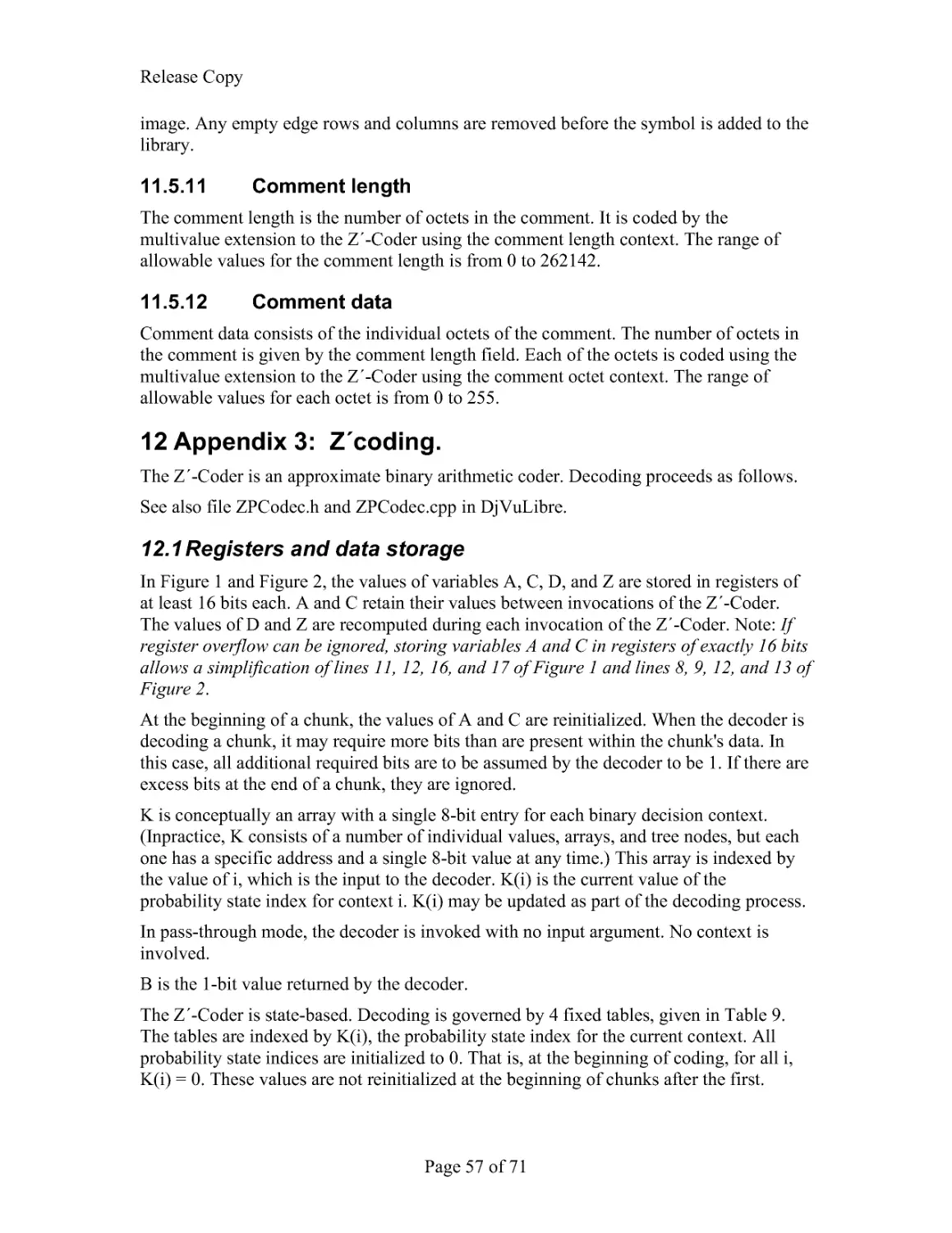
Теги: computer science computer engineering computer systems computer technologies
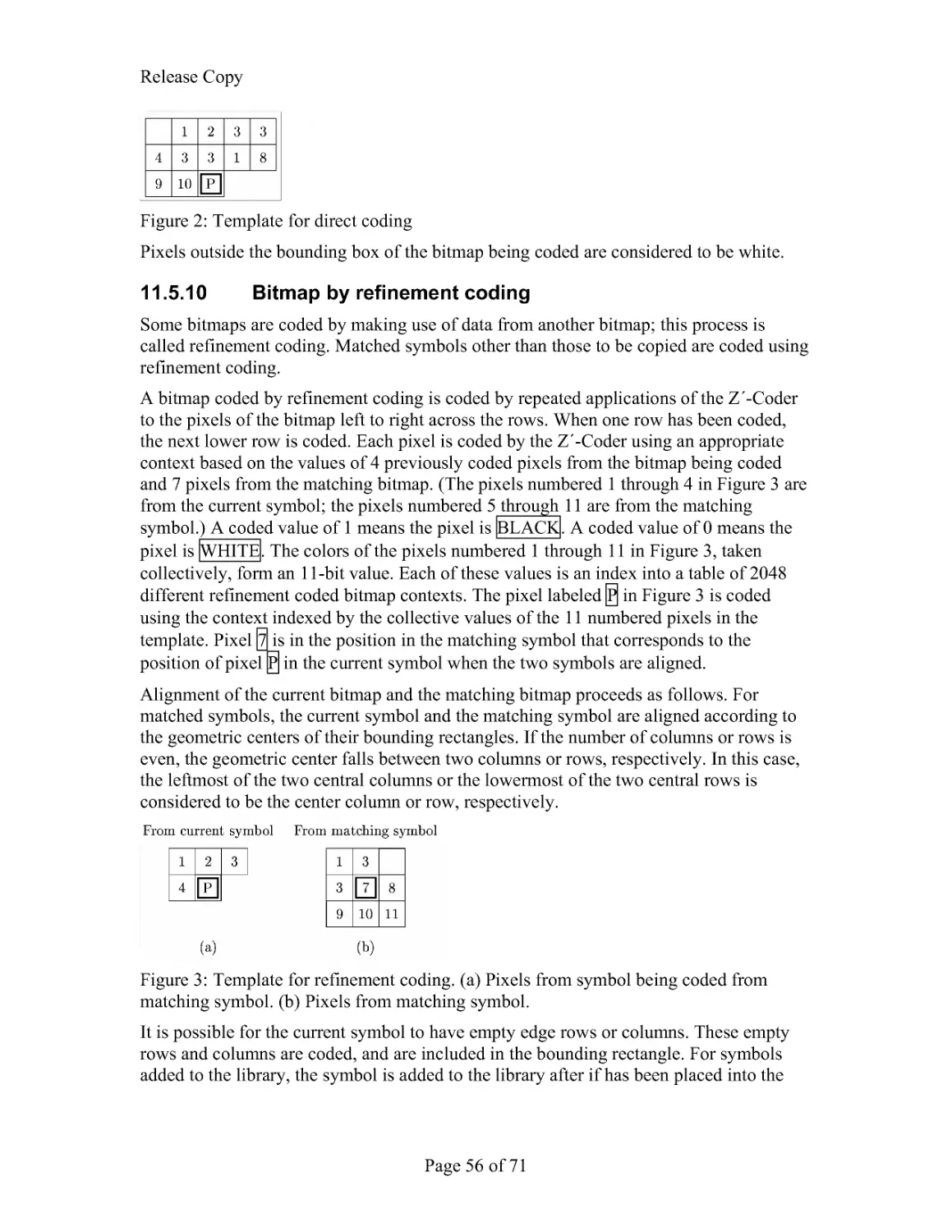
Год: 2005


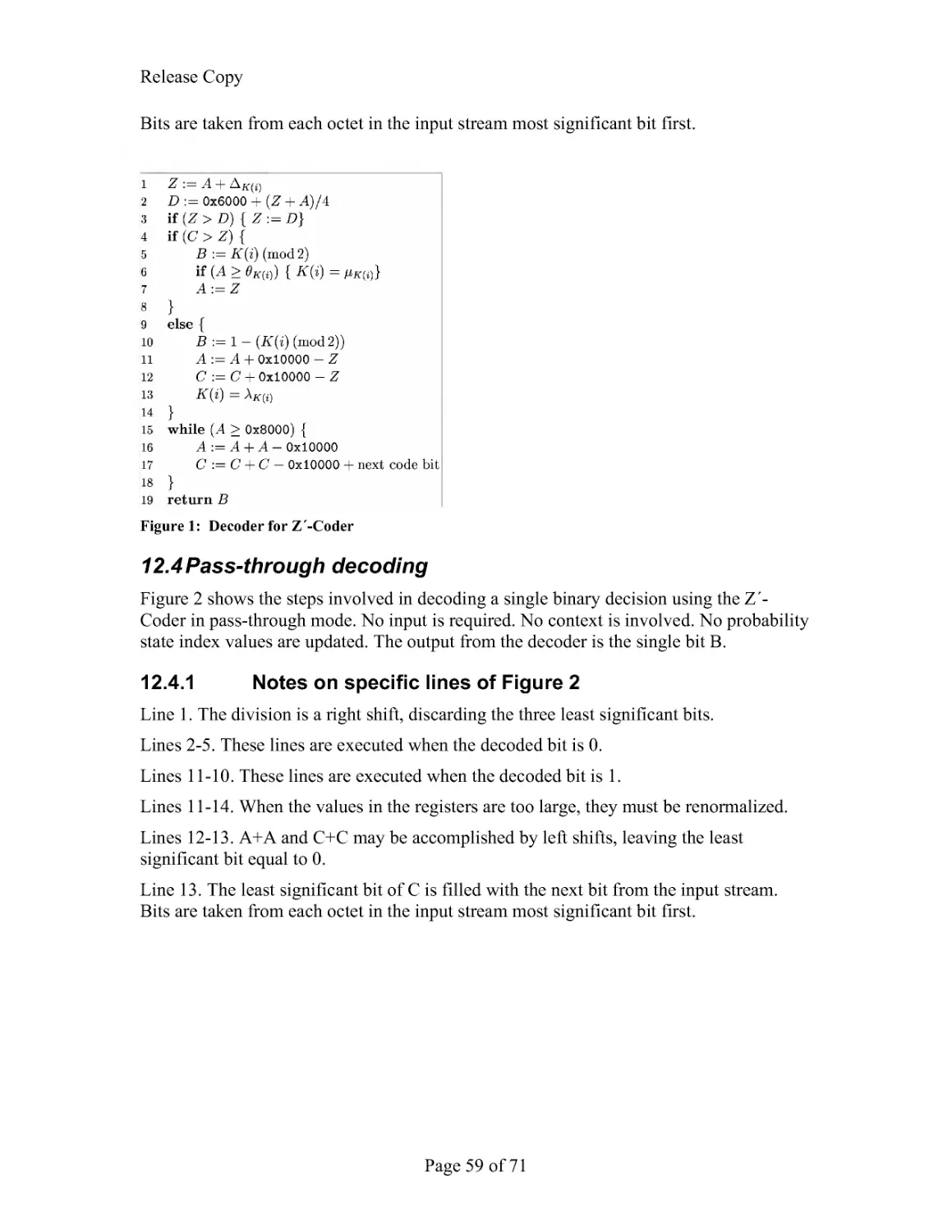
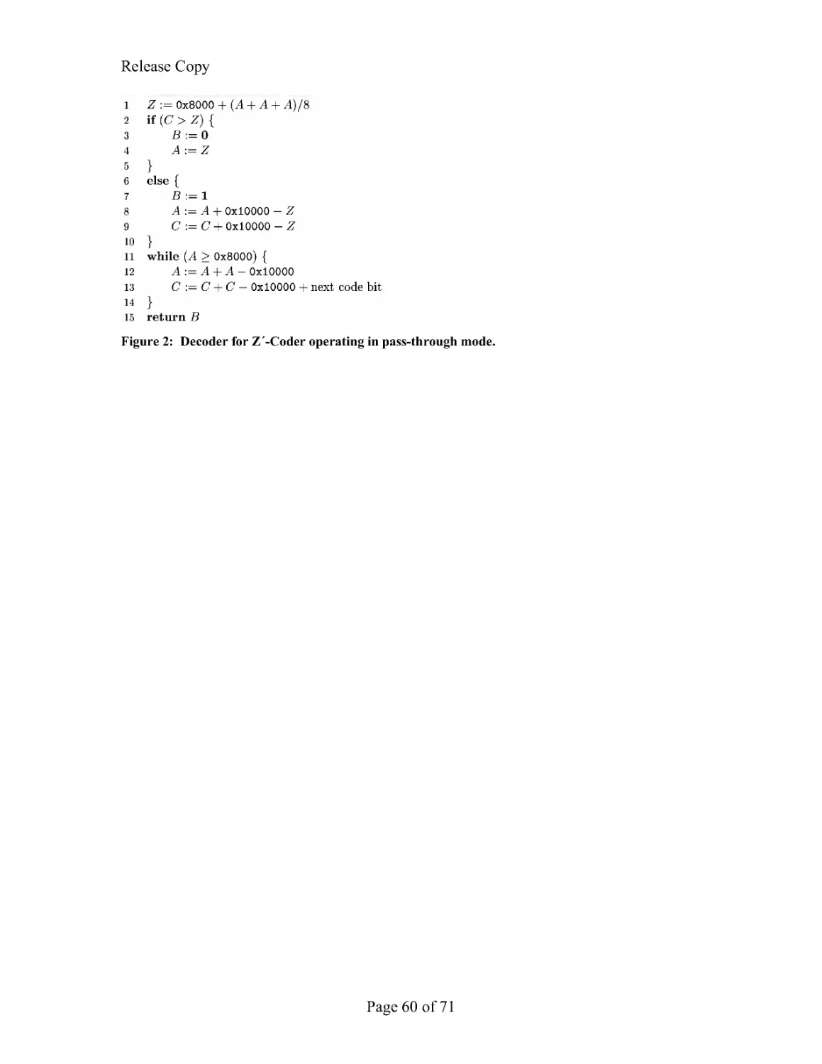
Текст
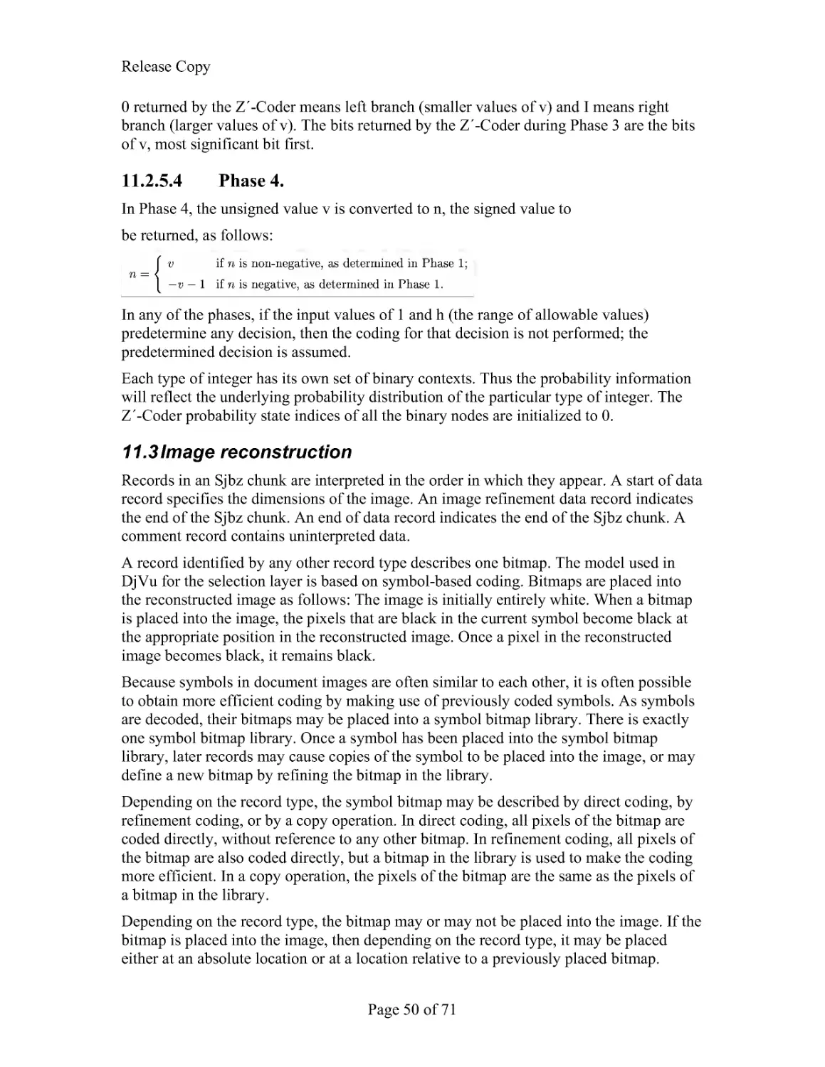
Release Copy
Page1of71
Lizardtech DjVu Reference
DjVu v3
Document Date: November 2005
From:
Lizardtech, a Celartem Company
Status of Standard: Released
1 Introduction
Although the Internet has given us a worldwide infrastructure on which to build the
universal library, much of the world knowledge, history, and literature is still trapped on
paper in the basements of the world's traditional libraries. Many libraries and content
owners are in the process of digitizing their collections. While many such efforts involve
the painstaking process of converting paper documents to computer-friendly form, such
as SGML based formats, the high cost of such conversions limits their extent. Scanning
documents and distributing the resulting images electronically is not only considerably
cheaper, but also more faithful to the original document because it preserves its visual
aspect.
Despite the quickly improving speed of network connections and computers, the number
of scanned document images accessible on the Web today is relatively small. There are
several reasons for this.
The first reason is the relatively high cost of scanning anything else but unbound sheets
in black and white. This problem is slowly going away with the appearance of fast and
low-cost color scanners with sheet feeders.
The second reason is that long-established image compression standards and file formats
have proved inadequate for distributing scanned documents at high resolution,
particularly color documents. Not only are the file sizes and download times impractical,
the decoding and rendering times are also prohibitive. A typical magazine page scanned
in color at 100 dpi in JPEG would typically occupy 100 KB to 200 KB, but the text
would be hardly readable: insufficient for screen viewing and totally unacceptable for
printing. The same page at 300 dpi would have sufficient quality for viewing and printing,
but the file size would be 300 KB to 1000 KB at best, which is impractical for remote
access. Another major problem is that a fully decoded 300 dpi color images of a letter-
size page occupies 24 MB of memory and easily causes disk swapping.
The third reason is that digital documents are more than just a collection of individual
page images. Pages in a scanned document have a natural serial order. Special provision
must be made to ensure that flipping pages be instantaneous and effortless so as to
maintain a good user experience. Even more important, most existing document formats
force users to download the entire document first before displaying a chosen page.
However, users often want to jump to individual pages of the document without waiting
for the entire document to download. Efficient browsing requires efficient random page
access, fast sequential page flipping, and quick rendering. This can be achieved with a
combination of advanced compression, pre-fetching, pre-decoding, caching, and
progressive rendering. DjVu decomposes each page into multiple components (text,
Release Copy
Page2of71
backgrounds, images, libraries of common shapes...) that may be shared by several pages
and downloaded on demand. This allows a suitably designed DjVu-viewing application
to to handle on-demand downloading, pre-fetching, decoding, caching, and progressive
rendering of the page images.
2 Document Organization
This document describes the DjVu File Format. It is written "from top down" providing
first a high-level understanding of the features and techniques used in DjVu (see
Overview), then a mid-level view at the IFF85 level (see Component pieces), and finally a
very detailed decription of the underlying algorithms and and byte-by-byte makeup of
DjVu files (see Low-level chunk structure and the Appendices).
3 Overview
This section describes the DjVu file format at a high level: how DjVu uses the Mixed
Raster Content model, how images are composed into documents and the non-raster data
that such documents can also contain.
3.1 DjVu Images
The principal imaging model used in DjVu is the "Mixed Raster Content" (MRC) model
described in ITU-T Recommendation T.44, ISO/IEC 16485. In this model, an image is
decomposed into foreground and background layers. To select whether a particular pixel
comes from the foreground or background a bitonal "selection" or "mask" layer is
provided. These three layers are compressed separately using techniques which are
optimized for each type of data.
The foreground and background layers are compressed using a wavelete-based continous-
tone image compression technique known as IW44.
The mask layer is compressed using a bitonal image compression technique that takes
advantage of repetitions of nearly identical shapes on the page (such as characters) to
efficiently compress text images.
A DjVu image need not contain all three layers and alternative compression techniques
are available for each layer.
3.2 DjVu Documents
DjVu Documents can be single- or multi-page. Each page consists of a DjVu image as
described above (photo, bitonal or an MRC-based composition). Such a page, by itself is
a valid DjVu Document. Multipage Documents can take either of two forms: Bundled or
Indirect.
3.2.1 Bundled multi-page documents
Bundled multi-page DjVu document uses a single file to represent the entire document.
This single file contains all the pages as well as ancillary information (e.g. the page
directory, data shared by several pages, thumbnails, etc.). Using a single file format is
very convenient for storing documents or for sending email attachments.
Release Copy
Page3of71
3.2.2 Indirect multi-page documents
There are problems inherent to storing multiple pages in a single file. A viewer may not
be able to utilize a byte-serving mechanism such that that available in HTTP1.1.
Therefore any request for any page of such a file will necessarily result in the entire
document being transmitted. Furthermore, a reasonable work pattern is to read the first
few pages (perhaps a Table of Contents) and then navigate to a page much further into
the document. However, in such a file, data for page 100 can not be viewed until after
data for pages 1-99 have been downloaded.
Indirect multipage documents address these problems. Such a document is composed of
several files. The main file is named the index file. You can view document using the
URL of the index file, just like you do with a bundled multi-page document. However, the
index file is very small. It simply contains the document directory and the URLs of
secondary files containing the page data. When you view an indirect multi-page
document, the viewer only needs to download the files corresponding to the pages you
are viewing.
3.3 Non-raster Data
3.3.1 Annotations
Every DjVu image optionally includes several different kinds of annotations. These
annotations are often used to define hyper-links to other document pages or to arbitrary
web pages. They can also be used for other purposes such as setting the initial viewing
mode of a page and defining highlighted zones.
3.3.2 Hidden text
Every DjVu image optionally includes a hidden text layer that associated graphical
features with the corresponding text. The hidden text layer is usually generated by
running Optical Character Recognition software. This textual information provides for
indexing DjVu documents and copying/pasting text from DjVu page images.
3.3.3 Thumbnails
DjVu documents sometimes contain pre-computed page thumbnails. These allow a
viewer to display a graphical representation of many pages by downloading a very small
"thumbnail" file instead of the actual pages themselves.
4 What's new in DjVu File Format
Since the last update to the file format documentation, Reference 1, the file format has
been extended to include
Multipage formats. DjVu documents can span more than one page. There are
two multipage formats available: bundled (single file) and indirect (separate files
for each page; see DjVu Documents and Multipage Documents)
Release Copy
Page4of71
Annotations. Both initial viewing parameters (background color, initial zoom)
and overlayed annotations (hyperlinks, text boxes) can be specified either at the
document level ("shared") or at the page level. See Annotation Chunk.
Hidden Text. Text and the associated layout information can be stored as with
each image. This allows documents to be searched and indexed. See Text Chunk.
Document Outline. A heirarchical outline can be specified at the document level.
This allows the document to contain present an integrated outline for overview
and navigation. See Document Outline Chunk.
Colorized JB2. A palettized extension is provided for the bitonal encoder. See
Foreground Color JB2 Chunk.
5 Acknowledgements
This work is significantly based on Reference 1 and the summary of file format changes
described in the DjVuLibre project maintained by Leon Bottou and others.
6 References
6.1 DjVu 2
The DjVu File Format specification that was originally released by AT&T in 1999.
http://www.djvuzone.org/djvu/djvu/djvuspec/001.djvu
6.2 IFF
EA IFF 85 format, Electronic Arts' public domain IFF standard for Interchange File
Format, released in January, 1985.
http://www.dcs.ed.ac.uk/home/mxr/gfx/2d/IFF.txt
6.3 JPEG
JPEG File Interchange Format, Version 1.02 (ISO DIS 10918-1, JPEG JFIF). The
specification is located at http://www.w3.org/Graphics/JPEG/jfif.txt.
6.4 Tiff
http://partners.adobe.com/public/developer/en/tiff/TIFF6.pdf.
6.5 G4
ITU-T (CCITT) T.6. Facsimile Coding Schemes and Coding Control Functions for
Group 4 Facsimile Apparatus
6.6 UTF8
All text in DjVu files is Unicode encoded using the UTF8 encoding.
http://www.unicode.org/versions/Unicode4.0.0/ch03.pdf
Release Copy
Page5of71
6.7 DjVuLibre
An open source reference implementation of this file format specification is available at
http://sourceforge.net/projects/djvu/. Throughout this specification, there are numerous
references to source files in this implementation.
7 Component pieces (IFF chunks) of DjVu documents
and images
This section describes the DjVu file format at a middle level. This includes types of
chunks which can go into various types of documents but not a detailed layout of the
contents of those chunks.
DjVu documents are IFF85 files (see reference 2 for details). The IFF85 structure
provides a hierarchy of containers which hold various types of information in a DjVu file.
The containers are called "chunks." How the chunk is used (what it holds) can be
determined by its "chunk type" or "chunk id." For example, the list of files contained in a
multipage document is held in the "DIRM" ("directory") chunk, annotations are held in a
"ANTz" chunk.
"FORM" chunks are composite (contain other chunks). Their specific use is exposed by
a secondary chunk ID. For example a single page consists of several different chunks all
contained within a single "FORM:DJVU" chunk. A multipage document consists of
several pages (and other chunks) all contained in a "FORM:DJVM" chunk.
This section discusses the various kinds of DjVu documents and the corresponding
chunks of which they consist.
7.1 Single Page Documents
A Single Page Document is composed of a single "FORM:DJVU" composite chunk. This
composite chunk always begins with one "INFO" chunk describing the image size,
resolution and related information (see Document Info Chunk). The document containts
exactly one DjVu Image whose content varies as described below.
7.1.1 Photo DjVu Image
Photo DjVu Image files are best used for encoding photographic images in colors or in
shades of gray. The data compression model relies on the IW44 wavelet representation.
This format is designed such that the IW44 decoder is able to quickly perform
progressive rendering of any image segment using only a small amount of memory. One
or more additional "BG44" chunks contain the image data encoded with the IW44
representation. The image size specified in the "INFO" chunk and the image size
specified in the IW44 data must be equal.
7.1.2 Bi-level DjVu Image
Bilevel DjVu Image files are used to compress black and white images representing text
and simple drawings. The JB2 data compression model uses the soft pattern matching
technique, which essentially consists of encoding each character by describing how it
Release Copy
Page6of71
differs from a well-chosen already-encoded character. A "Sjbz" chunk contains the
bilevel data encoded with the JB2 representation (see appendix 2). The image size
specified in the "INFO" chunk and the image size specified in the JB2 data must be equal.
7.1.3 Compound DjVu Image
Compound DjVu Files are an extremely efficient way to compress high resolution
Compound document images containing both pictures and text, such as a page of a
magazine. Compound DjVu Files represent the document images using two layers. The
background layer is used for encoding the pictures and the paper texture.
The foreground layer is used for encoding the text and the drawings. Additional chunks
hold the components of either the foreground or the background layers.
The main component of the foreground layer is a bilevel image named the foreground
mask. The pixel size of the foreground mask is equal to the size of the DjVu image. It
contains a black-on-white representation of the text and the drawings. This image is
encoded by a "Sjbz" chunk using the JB2 representation. There may also be a companion
chunk "Djbz" containing a shape dictionary that defines bilevel shapes referenced by the
"Sjbz" chunk.
7.1.3.1 Foreground Encoding
The foreground colors can be encoded according to two models:
The foreground colors may be encoded using a small color image, the foreground color
image, encoded as a single "FG44" chunk using the IW44 representation (see
IW44Image.h). Such compound DjVu images are rendered by painting the foreground
color image on top of the background color image using the foreground mask as a stencil.
The pixel size of the foreground color image is computed by rounding up the quotient of
the mask size by an integer sub-sampling factor ranging from 1 to 12. Most Compound
DjVu Images use a foreground color sub-sampling factor of 12. Smaller sub-sampling
factors produce very slightly better images.
The foreground colors may be encoded by specifying one solid color per object described
by the JB2 encoded mask. These JB2 colors are color-quantized and stored in a single
"FGbz" chunk (see section 6.3.10). Such compound DjVu images are rendered by
painting each foreground object on top of the background color image using the solid
color specified by the "FGbz" chunk.
7.1.3.2 Background Encoding
The background layer is a color image, the background color image encoded by an
arbitrary number of "BG44" chunks containing successive IW44 refinements (see
appendix 1). The size of this image is computed by rounding up the quotient of the mask
size by an integer sub-sampling factor ranging from 1 to 12. Most Compound DjVu
Images use a background sub-sampling factor equal to 3. Smaller sub-sampling factors
are adequate for images with a very rich paper texture. Larger sub-sampling factors are
adequate for images containing no pictures.
Release Copy
Page7of71
There are no ordering or interleaving constraints on these chunks except that (a) the
"INFO" chunk must appear first, and (b) the successive "BG44" refinements must appear
with their natural order. The chunk order simply affects the progressive rendering of
DjVu images on a web browser.
7.1.3.3 Alternative encodings
Besides the JB2 and IW44 encoding schemes, the DjVu format supports alternative
encoding methods for its components.
The foreground mask may be represented by a single "Smmr" chunk instead of "Sjbz".
The "Smmr" chunk contains a bilevel image encoded with the Fax-G4/MMR method.
Although the resulting files are typically six times larger, this capability can be useful
when DjVu is used as a front-end for fax machines and scanners with embedded Fax-
G4/MMR capabilities.
The background color image may be represented by a single "BGjp" chunk instead of
several "BG44" chunks. The "BGjp" chunk contains a JPEG encoded color image (see
JPEGDecoder.cpp). The resulting files are significantly larger and lack the progressivity
of the usual DjVu files. This is useful because some scanners have embedded JPEG
capabilities.
The foreground color image may be represented by a single "FGjp" chunk instead of a
single "FG44" chunk. This is useful because some scanners have embedded JPEG
capabilities.
7.1.3.4 Annotations and Textual Information
All types of DjVu images may contain annotation chunks. Annotation chunks are used to
describe hyperlinks, to specify more viewer settings (page background, initial zoom, etc),
and to hold metadata information. Annotations are contained in "ANTa" or "ANTz"
chunks.
All types of DjVu image files may also contain a computer readable description of the
text appearing on the page. This information is contained by either a "TXTa" chunk or
"TXTz" chunk.
7.2 Multipage Documents
A multipage document is composed of a "FORM:DJVM" whose first chunk is a "DIRM"
chunk containing the document directory. This directory lists all component files
composing the given document, helps to access every component file and identify the
pages of the document.
In a bundled multipage file, the component files are stored immediately after the "DIRM"
chunk, within the "FORM:DJVM" composite chunk.
In an indirect multipage file, the component files are stored in different files whose URLs
are composed using information stored in the "DIRM" chunk.
Release Copy
Page8of71
7.2.1 Component files
A multipage DjVu document necessarily references other FORM (composite) chunks.
Specifically
Each page is single page document (FORM:DJVU chunk).
Embedded thumbnails (if any) are contained in one or more FORM:THUM
chunks
Shared annotations (if any) and shape dictionaries (if any) are contained in one or
more FORM:DJVI chunks.
Each of these composite chunks (FORM:DJVU, FORM:THUM, FORM:DJVI) is a well-
formed IFF bytestream in its own right and can be held in a separate disk file. In the
context of a multipage -- either bundled or indirect -- document, we refer to these
composite chunks as component files.
7.2.2 Including shared information
In many cases, efficiencies can be achieved by sharing JB2 shape definitions and/or
annotations across pages. To facilitate this, any DjVu image file contained in a multipage
file may contain an "INCL" chunk containing the ID of a shared component file. The
decoder processes the chunks contained in the shared component file as if the DjVu
image file contained them. All relevant pages include this shared component file.
Although they appear in several pages, these shared shapes are encoded only once in the
document.
A shared component file is composed of a single "FORM:DJVI" potentially containing
any information otherwise allowed in a DjVu image file (except for the "INFO" chunk of
course).
8 Low-level chunk structure and definition
This section describes the DjVu file format at a low level. This includes the binary
layout of the IFF85 wrapper and, of course, the layout of each contained chunk.
8.1 Header
The first four bytes of a DjVu file are 0x41 0x54 0x26 0x54. This preamble is not part of
the EA IFF 85 format, but it is required in order to identify DjVu files.
8.2 DjVu File structure
8.2.1 IFF Wrapper
An IFF file consists of a number of chunks. Each chunk is laid out in 3 fields:
BYTE*4
Chunk ID. Describes the use of the chunk. The strings that identify
the types of chunks used in DjVu are listed below.
INT32
Length (MSB first). The length of the Data
Release Copy
Page9of71
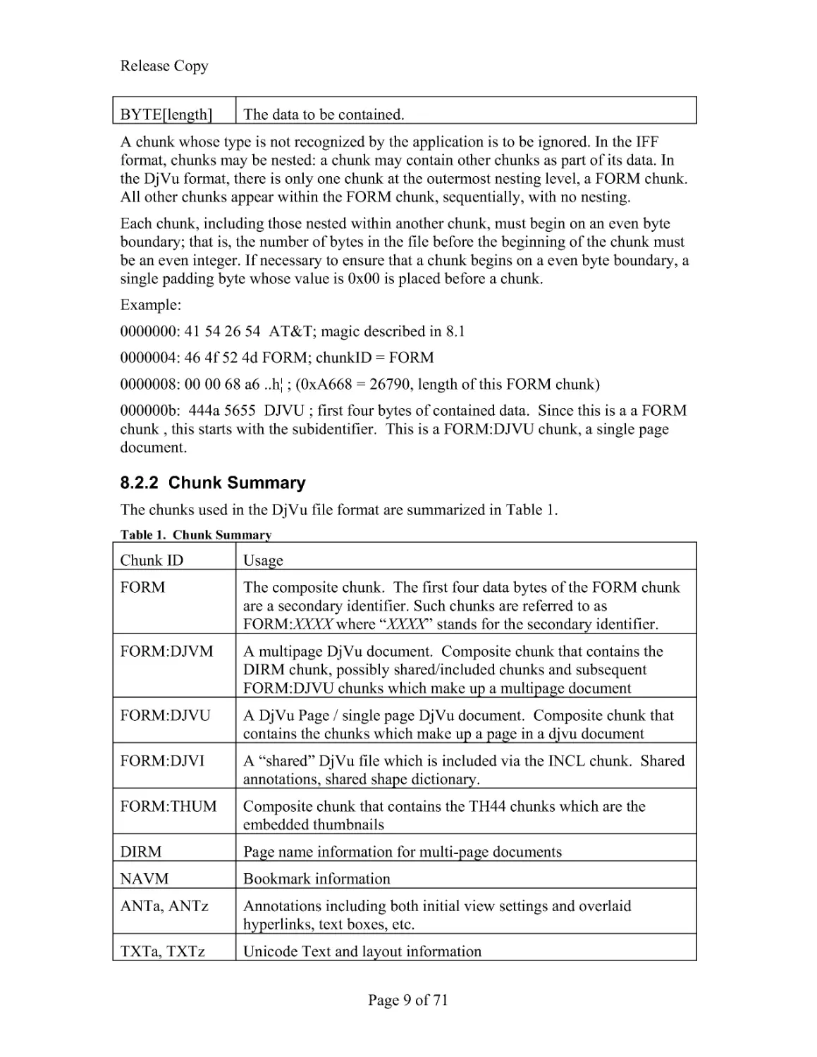
BYTE[length] The data to be contained.
A chunk whose type is not recognized by the application is to be ignored. In the IFF
format, chunks may be nested: a chunk may contain other chunks as part of its data. In
the DjVu format, there is only one chunk at the outermost nesting level, a FORM chunk.
All other chunks appear within the FORM chunk, sequentially, with no nesting.
Each chunk, including those nested within another chunk, must begin on an even byte
boundary; that is, the number of bytes in the file before the beginning of the chunk must
be an even integer. If necessary to ensure that a chunk begins on a even byte boundary, a
single padding byte whose value is 0x00 is placed before a chunk.
Example:
0000000: 41 54 26 54 AT&T; magic described in 8.1
0000004: 46 4f 52 4d FORM; chunkID = FORM
0000008: 00 00 68 a6 ..h¦ ; (0xA668 = 26790, length of this FORM chunk)
000000b: 444a 5655 DJVU ; first four bytes of contained data. Since this is a a FORM
chunk , this starts with the subidentifier. This is a FORM:DJVU chunk, a single page
document.
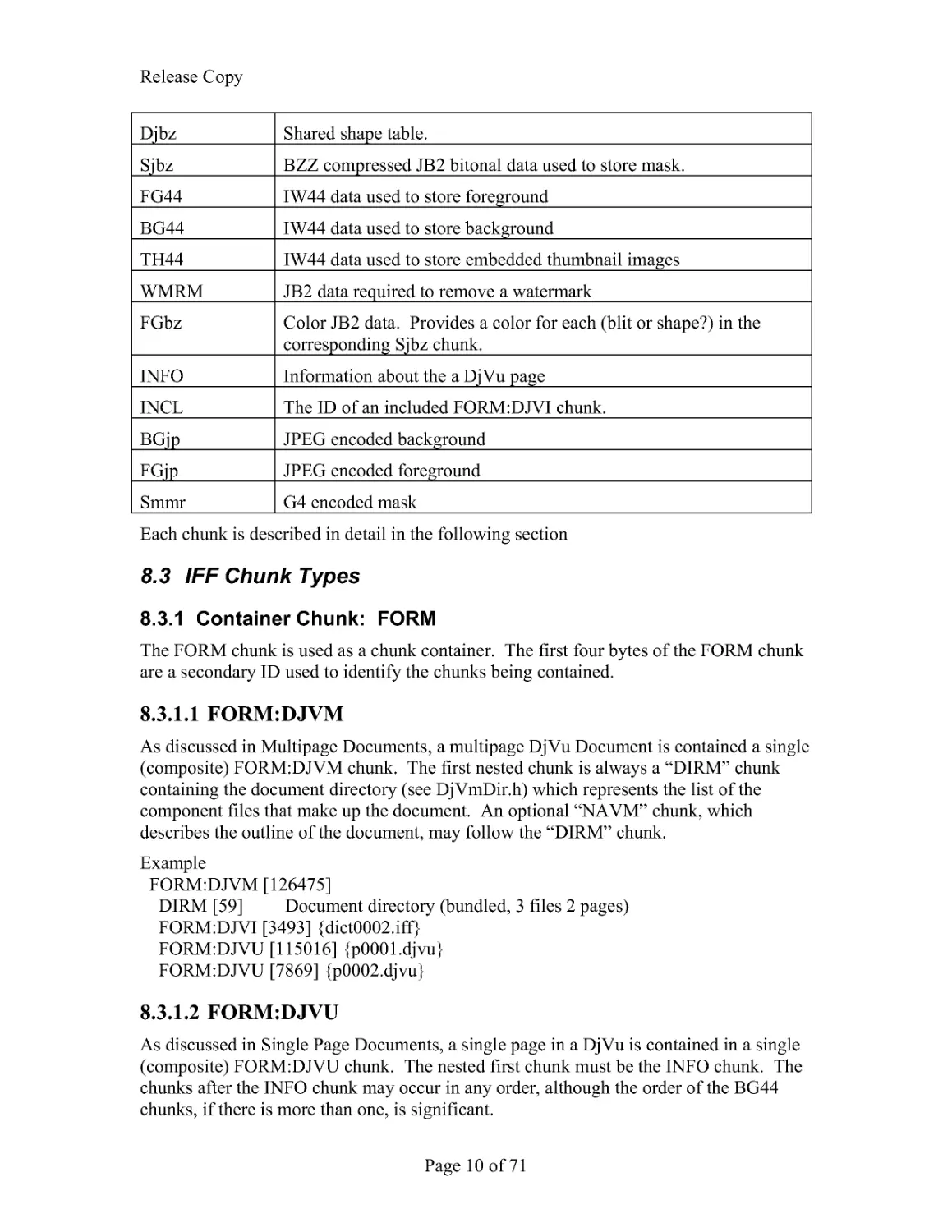
8.2.2 Chunk Summary
The chunks used in the DjVu file format are summarized in Table 1.
Table 1. Chunk Summary
Chunk ID
Usage
FORM
The composite chunk. The first four data bytes of the FORM chunk
are a secondary identifier. Such chunks are referred to as
FORM:XXXX where "XXXX" stands for the secondary identifier.
FORM:DJVM A multipage DjVu document. Composite chunk that contains the
DIRM chunk, possibly shared/included chunks and subsequent
FORM:DJVU chunks which make up a multipage document
FORM:DJVU A DjVu Page / single page DjVu document. Composite chunk that
contains the chunks which make up a page in a djvu document
FORM:DJVI A "shared" DjVu file which is included via the INCL chunk. Shared
annotations, shared shape dictionary.
FORM:THUM Composite chunk that contains the TH44 chunks which are the
embedded thumbnails
DIRM
Page name information for multi-page documents
NAVM
Bookmark information
ANTa, ANTz Annotations including both initial view settings and overlaid
hyperlinks, text boxes, etc.
TXTa, TXTz Unicode Text and layout information
Release Copy
Page 10 of 71
Djbz
Shared shape table.
Sjbz
BZZ compressed JB2 bitonal data used to store mask.
FG44
IW44 data used to store foreground
BG44
IW44 data used to store background
TH44
IW44 data used to store embedded thumbnail images
WMRM
JB2 data required to remove a watermark
FGbz
Color JB2 data. Provides a color for each (blit or shape?) in the
corresponding Sjbz chunk.
INFO
Information about the a DjVu page
INCL
The ID of an included FORM:DJVI chunk.
BGjp
JPEG encoded background
FGjp
JPEG encoded foreground
Smmr
G4 encoded mask
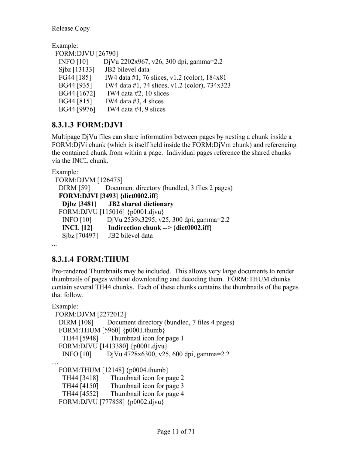
Each chunk is described in detail in the following section
8.3 IFF Chunk Types
8.3.1 Container Chunk: FORM
The FORM chunk is used as a chunk container. The first four bytes of the FORM chunk
are a secondary ID used to identify the chunks being contained.
8.3.1.1 FORM:DJVM
As discussed in Multipage Documents, a multipage DjVu Document is contained a single
(composite) FORM:DJVM chunk. The first nested chunk is always a "DIRM" chunk
containing the document directory (see DjVmDir.h) which represents the list of the
component files that make up the document. An optional "NAVM" chunk, which
describes the outline of the document, may follow the "DIRM" chunk.
Example
FORM:DJVM [126475]
DIRM [59] Document directory (bundled, 3 files 2 pages)
FORM:DJVI [3493] {dict0002.iff}
FORM:DJVU [115016] {p0001.djvu}
FORM:DJVU [7869] {p0002.djvu}
8.3.1.2 FORM:DJVU
As discussed in Single Page Documents, a single page in a DjVu is contained in a single
(composite) FORM:DJVU chunk. The nested first chunk must be the INFO chunk. The
chunks after the INFO chunk may occur in any order, although the order of the BG44
chunks, if there is more than one, is significant.
Release Copy
Page 11 of 71
Example:
FORM:DJVU [26790]
INFO [10] DjVu 2202x967, v26, 300 dpi, gamma=2.2
Sjbz [13133] JB2 bilevel data
FG44 [185] IW4 data #1, 76 slices, v1.2 (color), 184x81
BG44 [935] IW4 data #1, 74 slices, v1.2 (color), 734x323
BG44 [1672] IW4 data #2, 10 slices
BG44 [815] IW4 data #3, 4 slices
BG44 [9976] IW4 data #4, 9 slices
8.3.1.3 FORM:DJVI
Multipage DjVu files can share information between pages by nesting a chunk inside a
FORM:DjVi chunk (which is itself held inside the FORM:DjVm chunk) and referencing
the contained chunk from within a page. Individual pages reference the shared chunks
via the INCL chunk.
Example:
FORM:DJVM [126475]
DIRM [59] Document directory (bundled, 3 files 2 pages)
FORM:DJVI [3493] {dict0002.iff}
Djbz [3481] JB2 shared dictionary
FORM:DJVU [115016] {p0001.djvu}
INFO [10] DjVu 2539x3295, v25, 300 dpi, gamma=2.2
INCL [12] Indirection chunk --> {dict0002.iff}
Sjbz [70497] JB2 bilevel data
...
8.3.1.4 FORM:THUM
Pre-rendered Thumbnails may be included. This allows very large documents to render
thumbnails of pages without downloading and decoding them. FORM:THUM chunks
contain several TH44 chunks. Each of these chunks contains the thumbnails of the pages
that follow.
Example:
FORM:DJVM [2272012]
DIRM [108] Document directory (bundled, 7 files 4 pages)
FORM:THUM [5960] {p0001.thumb}
TH44 [5948] Thumbnail icon for page 1
FORM:DJVU [1413380] {p0001.djvu}
INFO [10] DjVu 4728x6300, v25, 600 dpi, gamma=2.2
...FORM:THUM [12148] {p0004.thumb}
TH44 [3418] Thumbnail icon for page 2
TH44 [4150] Thumbnail icon for page 3
TH44 [4552] Thumbnail icon for page 4
FORM:DJVU [777858] {p0002.djvu}
Release Copy
Page 12 of 71
...
8.3.2 Directory Chunk: DIRM
As described in Multipage Documents, a multipage document will contain "component
files" such as individual pages (FORM:DJVU) or shared annotations (FORM:DJVI).
The first contained chunk in a FORM:DJVM composite chunk is the DIRM chunk
containing the document directory. It contains information the decoder will need to
access the component files (see Multipage Documents).
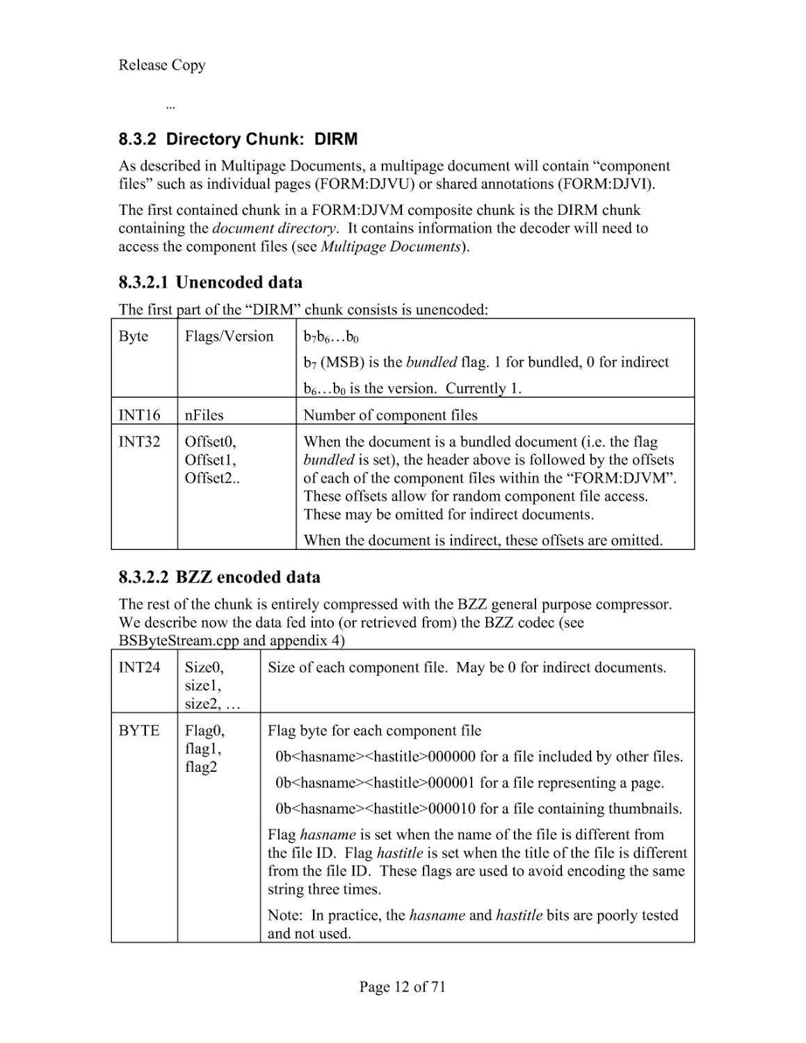
8.3.2.1 Unencoded data
The first part of the "DIRM" chunk consists is unencoded:
Byte Flags/Version b7b6...b0
b7 (MSB) is the bundled flag. 1 for bundled, 0 for indirect
b6...b0 is the version. Currently 1.
INT16 nFiles
Number of component files
INT32 Offset0,
Offset1,
Offset2..
When the document is a bundled document (i.e. the flag
bundled is set), the header above is followed by the offsets
of each of the component files within the "FORM:DJVM".
These offsets allow for random component file access.
These may be omitted for indirect documents.
When the document is indirect, these offsets are omitted.
8.3.2.2 BZZ encoded data
The rest of the chunk is entirely compressed with the BZZ general purpose compressor.
We describe now the data fed into (or retrieved from) the BZZ codec (see
BSByteStream.cpp and appendix 4)
INT24 Size0,
size1,
size2, ...
Size of each component file. May be 0 for indirect documents.
BYTE Flag0,
flag1,
flag2
Flag byte for each component file
0b<hasname><hastitle>000000 for a file included by other files.
0b<hasname><hastitle>000001 for a file representing a page.
0b<hasname><hastitle>000010 for a file containing thumbnails.
Flag hasname is set when the name of the file is different from
the file ID. Flag hastitle is set when the title of the file is different
from the file ID. These flags are used to avoid encoding the same
string three times.
Note: In practice, the hasname and hastitle bits are poorly tested
and not used.
Release Copy
Page 13 of 71
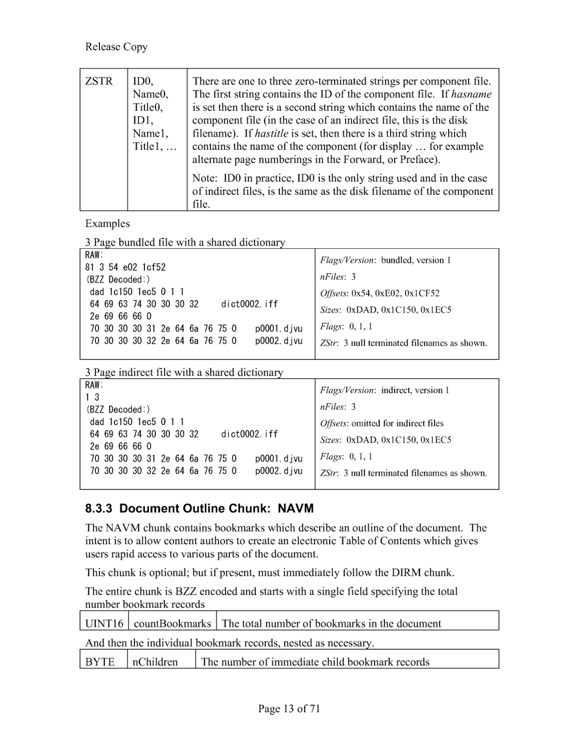
ZSTR ID0,
Name0,
Title0,
ID1,
Name1,
Title1, ...
There are one to three zero-terminated strings per component file.
The first string contains the ID of the component file. If hasname
is set then there is a second string which contains the name of the
component file (in the case of an indirect file, this is the disk
filename). If hastitle is set, then there is a third string which
contains the name of the component (for display ... for example
alternate page numberings in the Forward, or Preface).
Note: ID0 in practice, ID0 is the only string used and in the case
of indirect files, is the same as the disk filename of the component
file.
Examples
3 Page bundled file with a shared dictionary
Flags/Version: bundled, version 1
nFiles: 3
Offsets: 0x54, 0xE02, 0x1CF52
Sizes: 0xDAD, 0x1C150, 0x1EC5
Flags: 0, 1, 1
ZStr: 3 null terminated filenames as shown.
3 Page indirect file with a shared dictionary
Flags/Version: indirect, version 1
nFiles: 3
Offsets: omitted for indirect files
Sizes: 0xDAD, 0x1C150, 0x1EC5
Flags: 0, 1, 1
ZStr: 3 null terminated filenames as shown.
8.3.3 Document Outline Chunk: NAVM
The NAVM chunk contains bookmarks which describe an outline of the document. The
intent is to allow content authors to create an electronic Table of Contents which gives
users rapid access to various parts of the document.
This chunk is optional; but if present, must immediately follow the DIRM chunk.
The entire chunk is BZZ encoded and starts with a single field specifying the total
number bookmark records
UINT16 countBookmarks The total number of bookmarks in the document
And then the individual bookmark records, nested as necessary.
BYTE nChildren The number of immediate child bookmark records
Release Copy
Page 14 of 71
INT24 nDesc
size of description text
UTF8 sDesc
the description text.
INT24 nURL
Size of the URL text
UTF8 sURL
the URL text. This may (and typically does) use the syntax
described for the URLs in the Annotation chunk (and similarly,
is not URL-encoded)
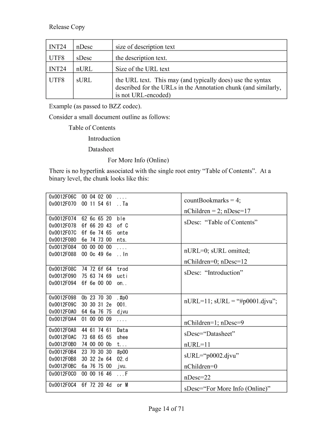
Example (as passed to BZZ codec).
Consider a small document outline as follows:
Table of Contents
Introduction
Datasheet
For More Info (Online)
There is no hyperlink associated with the single root entry "Table of Contents". At a
binary level, the chunk looks like this:
countBookmarks = 4;
nChildren = 2; nDesc=17
sDesc: "Table of Contents"
nURL=0; sURL omitted;
nChildren=0; nDesc=12
sDesc: "Introduction"
nURL=11; sURL = "#p0001.djvu";
nChildren=1; nDesc=9
sDesc="Datasheet"
nURL=11
sURL="p0002.djvu"
nChildren=0
nDesc=22
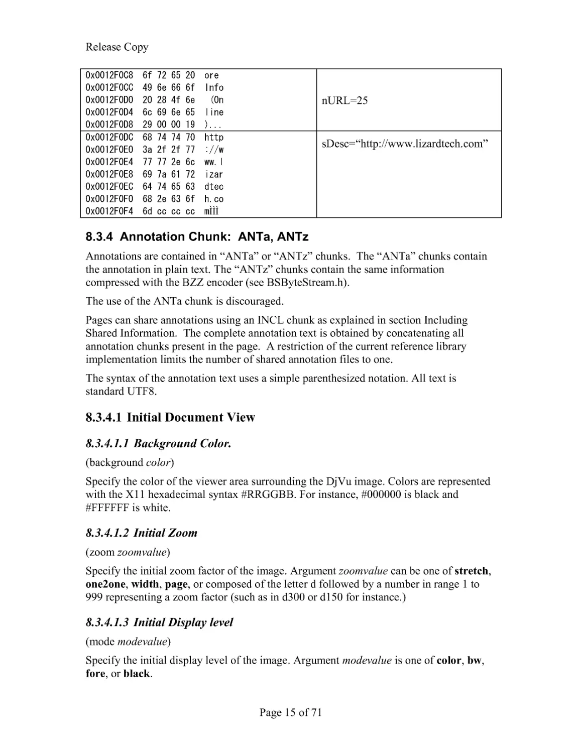
sDesc="For More Info (Online)"
Release Copy
Page 15 of 71
nURL=25
ÌÌÌ
sDesc="http://www.lizardtech.com"
8.3.4 Annotation Chunk: ANTa, ANTz
Annotations are contained in "ANTa" or "ANTz" chunks. The "ANTa" chunks contain
the annotation in plain text. The "ANTz" chunks contain the same information
compressed with the BZZ encoder (see BSByteStream.h).
The use of the ANTa chunk is discouraged.
Pages can share annotations using an INCL chunk as explained in section Including
Shared Information. The complete annotation text is obtained by concatenating all
annotation chunks present in the page. A restriction of the current reference library
implementation limits the number of shared annotation files to one.
The syntax of the annotation text uses a simple parenthesized notation. All text is
standard UTF8.
8.3.4.1 Initial Document View
8.3.4.1.1 Background Color.
(background color)
Specify the color of the viewer area surrounding the DjVu image. Colors are represented
with the X11 hexadecimal syntax #RRGGBB. For instance, #000000 is black and
#FFFFFF is white.
8.3.4.1.2 Initial Zoom
(zoom zoomvalue)
Specify the initial zoom factor of the image. Argument zoomvalue can be one of stretch,
one2one, width, page, or composed of the letter d followed by a number in range 1 to
999 representing a zoom factor (such as in d300 or d150 for instance.)
8.3.4.1.3 Initial Display level
(mode modevalue)
Specify the initial display level of the image. Argument modevalue is one of color, bw,
fore, or black.
Release Copy
Page 16 of 71
8.3.4.1.4 Alignment
(align horzalign vertalign)
Specify how the image should be aligned on the viewer surface. By default the image is
located in the center. Argument horzalign can be one of left, center, or right. Argument
vertalign can be one of top, center, or bottom.
Example (Typical Shared Annotation)
(background #FFFFFF ) (zoom page ) (mode bw ) (align center default )
8.3.4.2 Maparea (overprinted annotations)
(maparea url comment area ...)
A "Maparea annotation" defines an overprinted annotation (one that is drawn on top of
the rendered image). These annotations are used to draw Lines, Text boxes, Highlight
areas with optional hyperlinking capability. The area parameter distinguishes among
several different forms of mapareas. For convenience, we will sometimes refer to "rect
mapareas" when we mean "mapareas whose area attribute is rect" and similarly "line
mapareas", etc.
A note about escape sequences. The only currently-accepted escape sequence is for a
single quote: \". All other string characters are written in UTF8 (ascii-compatible).
Specifically, where needed, spaces, ampersands ("&"), backslashes ("\") and parentheses
("(", ")") are written directly. Erroneous and unrecognized constructs are silently
ignored.
8.3.4.2.1 url
Argument url takes either of these forms
href
(url href target)
href can be an arbitrary URL or can be composed of the hash character (#) followed by
either a component file identifier or a page number. Page numbers may be prefixed with
an optional sign to represent a page displacement. For instance the strings #-1 and #+1
can be used to access the previous page and the next page. href is not URL-encoded.
target is a string representing the target frame for the hyper-link, as defined by the HTML
anchor tag <A>
8.3.4.2.2 comment
Argument comment is a string that might be displayed by the viewer when the user
moves the mouse over the maparea.
8.3.4.2.3 area
Argument area defines the shape and the location of the maparea. The following forms
are recognized:
Release Copy
Page 17 of 71
(rect xmin ymin width height) // defines a rectangle
(oval xmin ymin width height) // defines an oval
(text xmin ymin width height) // defines a text box
(polyx0y0x1y1...)
// defines a polygon
(line x0 y0 x1 y1)
// defines a line with optional arrow head
All parameters are numbers representing coordinates. Coordinates are measured in pixels
and have their origin at the bottom left corner of the rotated (this for historical reasons;
see Document Info Chunk) page.
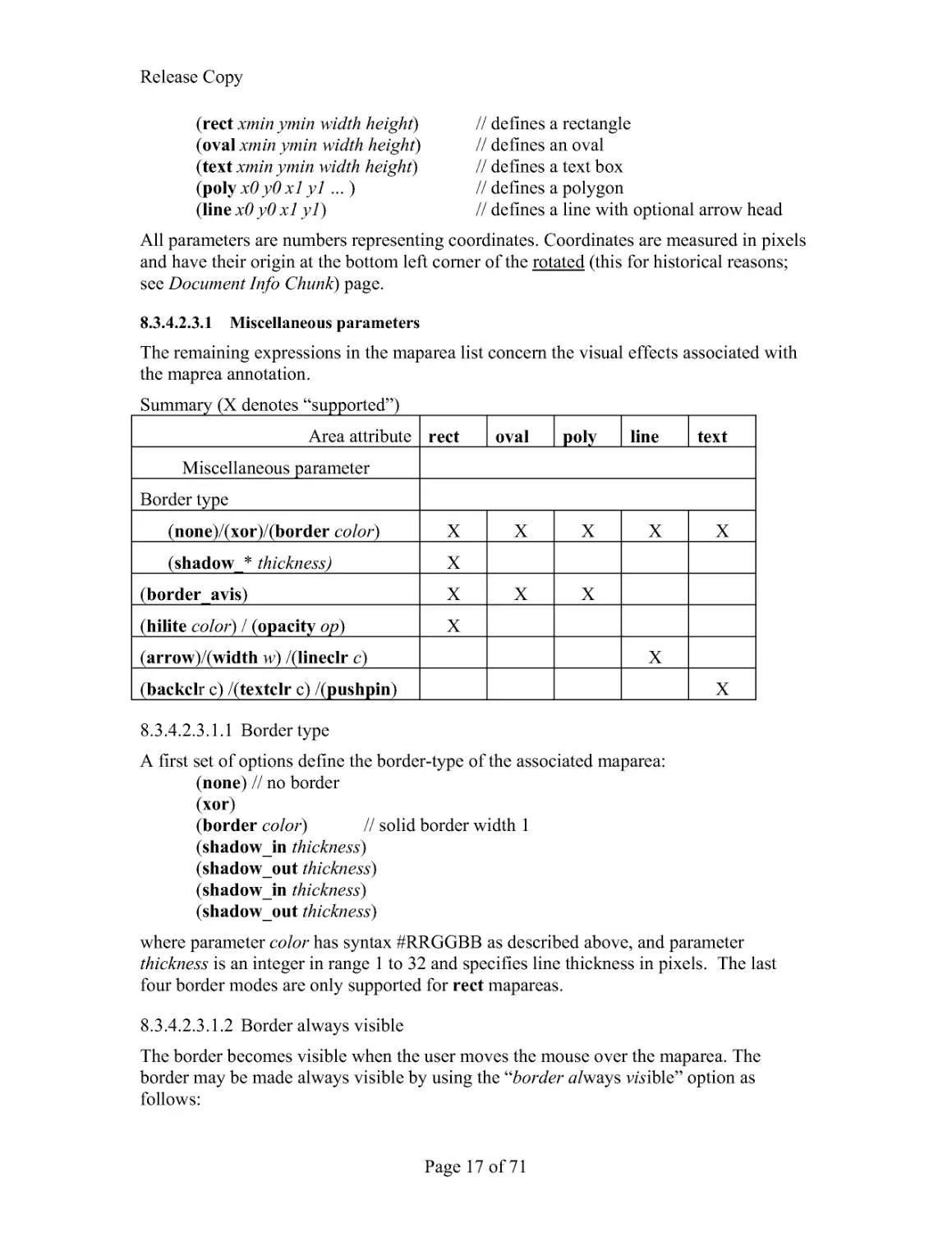
8.3.4.2.3.1 Miscellaneous parameters
The remaining expressions in the maparea list concern the visual effects associated with
the maprea annotation.
Summary (X denotes "supported")
Area attribute rect oval poly line text
Miscellaneous parameter
Border type
(none)/(xor)/(border color) X
X
X
X
X
(shadow_* thickness)
X
(border_avis)
X
X
X
(hilite color) / (opacity op) X
(arrow)/(width w) /(lineclr c)
X
(backclr c) /(textclr c) /(pushpin)
X
8.3.4.2.3.1.1 Border type
A first set of options define the border-type of the associated maparea:
(none) // no border
(xor)
(border color) // solid border width 1
(shadow_in thickness)
(shadow_out thickness)
(shadow_in thickness)
(shadow_out thickness)
where parameter color has syntax #RRGGBB as described above, and parameter
thickness is an integer in range 1 to 32 and specifies line thickness in pixels. The last
four border modes are only supported for rect mapareas.
8.3.4.2.3.1.2 Border always visible
The border becomes visible when the user moves the mouse over the maparea. The
border may be made always visible by using the "border always visible" option as
follows:
Release Copy
Page 18 of 71
(border_avis)
8.3.4.2.3.1.3 Highlight color and opacity
The following options may be used with rect mapareas. The complete area will be
highlighted using the specified color at the specified opacity (0-100, default of 50).
(hilite color)
(opacity op)
8.3.4.2.3.1.4 Line and Text parameters
The following options may be used with line mapareas to specify an optional ending
arrow, the line width and color:
(arrow) --- default (not present) means "no ending arrow"
(width w) --- default (not present) means w == 1
(lineclr color) --- default (not present) means color==black
The following options may be used with text mapareas:
(backclr bkcolor) --- default (not present) means transparent
(textclr txtcolor) --- default (not present) means black
(pushpin) --- not default (not present) means "not push pin"
If any border type non-"none" is specified, the border is drawn "solid", (as if "(color c)"
were specified).
Where
bkcolor specifies the background text color
txtcolor specifies the text color
pushpin specifies that the text box is collapsible. This allows the text box to expand into
view when needed but not obscure the image otherwise..
Examples (typical page-level annotation):
(maparea "http://www.lizardtech.com/" "Here is a rectangular hyperlink"
(rect 543 2859 408 183 ) (xor ) )
(maparea "http://www.lizardtech.com/" "Here is an oval hyperlink"
(oval 1068 2853 429 195 ) (xor )
(maparea "" "Here is a text box"(text 1635 2775 423 216 )
(pushpin ) (backclr #FFFF80 ) (border #000000 ) )
(maparea "" "Arrow" (line 591 3207 1512 3138 ) (arrow ) (none ) )
8.3.4.3 Printed headers and footers
User-specified strings may be added to printed output.
(<phead | pfoot> position_string1, position_string2, ...)
Where position_string is of the form: <left|center|right>::<string>
Example
(phead "left::Sept 20, 2005" "right::Today's Menu " ) (pfoot "center::Chez Dominique" )
Release Copy
Page 19 of 71
8.3.5 Text Chunk: TXTa, TXTz
Text is contained in "TXTa" or "TXTz" chunks. The "TXTa" chunks contain the text
unencoded. The "ANTz" chunks contain the same information compressed with the BZZ
encoder (see BSByteStream.h).
The use of the TXTa chunk is discouraged.
The chunk begins with the UTF8-encoded text of the page:
INT24 lenText
size of the text string in bytes
UTF8 strText
UTF8 encoded string
BYTE Version
Version is currently 1
[Implemenation Note]. The text may optionally contain separators between text blocks
corresponding to various zones. These may be simple CR/LF and <space>, terminating
NULL, or the more arcane cases such as VT (vertical tab, ascii 0xB) GS (group separator,
0x1D), RS (record separator 0x1E) and US (unit separator 0x1F),. Such separators can
have a significant impact on searching and exporting implementations. Decoding
applications should be prepared to address this.
Following this is a list of 0 or more zones which define the bounding rectangles of the
text above. Zones may contain heirachically smaller zones (e.g. columns contain regions,
words contain characters) and zones at the same hierarchical level should not overlap.
Zones are listed in reading order with parents preceeding children.
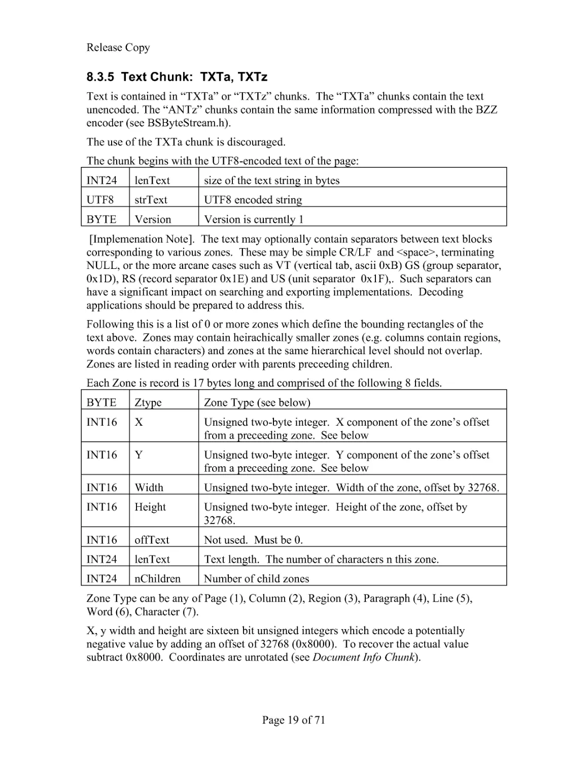
Each Zone is record is 17 bytes long and comprised of the following 8 fields.
BYTE Ztype
Zone Type (see below)
INT16 X
Unsigned two-byte integer. X component of the zone's offset
from a preceeding zone. See below
INT16 Y
Unsigned two-byte integer. Y component of the zone's offset
from a preceeding zone. See below
INT16 Width
Unsigned two-byte integer. Width of the zone, offset by 32768.
INT16 Height
Unsigned two-byte integer. Height of the zone, offset by
32768.
INT16 offText
Not used. Must be 0.
INT24 lenText
Text length. The number of characters n this zone.
INT24 nChildren Number of child zones
Zone Type can be any of Page (1), Column (2), Region (3), Paragraph (4), Line (5),
Word (6), Character (7).
X, y width and height are sixteen bit unsigned integers which encode a potentially
negative value by adding an offset of 32768 (0x8000). To recover the actual value
subtract 0x8000. Coordinates are unrotated (see Document Info Chunk).
Release Copy
Page 20 of 71
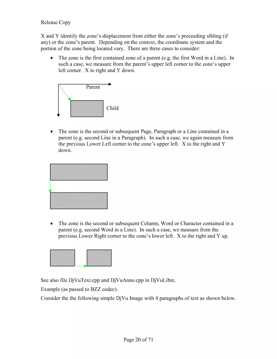
X and Y identify the zone's displacement from either the zone's preceeding sibling (if
any) or the zone's parent. Depending on the context, the coordinate system and the
portion of the zone being located vary. There are three cases to consider:
The zone is the first contained zone of a parent (e.g. the first Word in a Line). In
such a case, we measure from the parent's upper left corner to the zone's upper
left corner. X to right and Y down.
The zone is the second or subsequent Page, Paragraph or a Line contained in a
parent (e.g. second Line in a Paragraph). In such a case, we again measure from
the previous Lower Left corner to the zone's upper left. X to the right and Y
down.
The zone is the second or subsequent Column, Word or Character contained in a
parent (e.g. second Word in a Line). In such a case, we measure from the
previous Lower Right corner to the zone's lower left. X to the right and Y up.
See also file DjVuText.cpp and DjVuAnno.cpp in DjVuLibre.
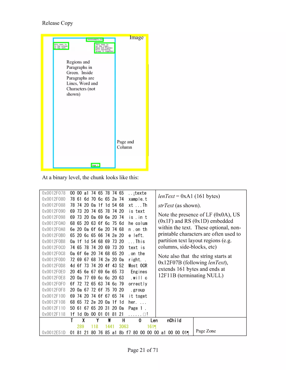
Example (as passed to BZZ codec).
Consider the the following simple DjVu Image with 4 paragraphs of text as shown below.
Child
Parent
Release Copy
Page 21 of 71
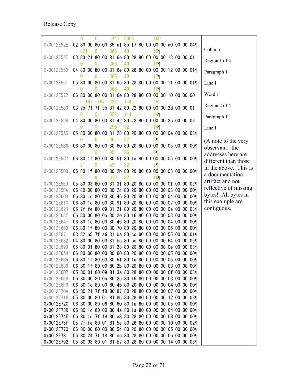
At a binary level, the chunk looks like this:
¡
lenText = 0xA1 (161 bytes)
strText (as shown).
Note the presence of LF (0x0A), US
(0x1F) and RS (0x1D) embedded
within the text. These optional, non-
printable characters are often used to
partition text layout regions (e.g.
columns, side-blocks, etc)
Note also that the string starts at
0x12F07B (following lenText),
extends 161 bytes and ends at
12F11B (terminating NULL)
¶ PageZone
Image
Page and
Column
Regions and
Paragraphs in
Green. Inside
Paragraphs are
Lines, Word and
Characters (not
shown)
Release Copy
Page 22 of 71
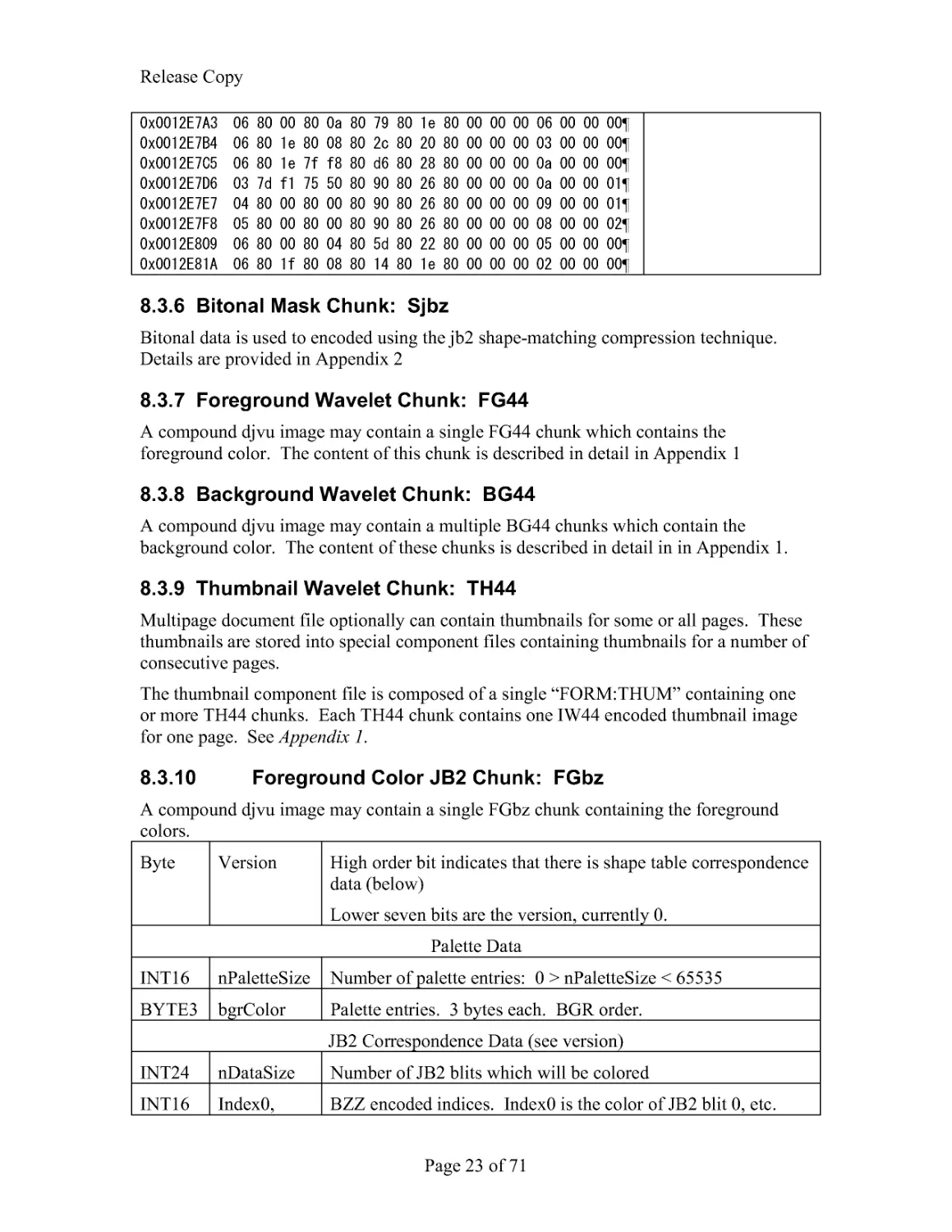
Column
Region 1 of 4
Paragraph 1
Line 1
Word 1
Region 2 of 4
Paragraph 1
Line 1
(A note to the very
observant: the
addresses here are
different than those
in the above. This is
a documentation
artifact and not
reflective of missing
bytes! All bytes in
this example are
contiguous.
Release Copy
Page 23 of 71
8.3.6 Bitonal Mask Chunk: Sjbz
Bitonal data is used to encoded using the jb2 shape-matching compression technique.
Details are provided in Appendix 2
8.3.7 Foreground Wavelet Chunk: FG44
A compound djvu image may contain a single FG44 chunk which contains the
foreground color. The content of this chunk is described in detail in Appendix 1
8.3.8 Background Wavelet Chunk: BG44
A compound djvu image may contain a multiple BG44 chunks which contain the
background color. The content of these chunks is described in detail in in Appendix 1.
8.3.9 Thumbnail Wavelet Chunk: TH44
Multipage document file optionally can contain thumbnails for some or all pages. These
thumbnails are stored into special component files containing thumbnails for a number of
consecutive pages.
The thumbnail component file is composed of a single "FORM:THUM" containing one
or more TH44 chunks. Each TH44 chunk contains one IW44 encoded thumbnail image
for one page. See Appendix 1.
8.3.10 Foreground Color JB2 Chunk: FGbz
A compound djvu image may contain a single FGbz chunk containing the foreground
colors.
Byte Version
High order bit indicates that there is shape table correspondence
data (below)
Lower seven bits are the version, currently 0.
Palette Data
INT16 nPaletteSize Number of palette entries: 0 > nPaletteSize < 65535
BYTE3 bgrColor Palette entries. 3 bytes each. BGR order.
JB2 Correspondence Data (see version)
INT24 nDataSize Number of JB2 blits which will be colored
INT16 Index0,
BZZ encoded indices. Index0 is the color of JB2 blit 0, etc.
Release Copy
Page 24 of 71
index1, ...
See also file DjVuPalette.cpp in DjVuLibre.
8.3.11 Document Info Chunk: INFO
As discussed in Single Page Documents, every DjVu image requires an INFO chunk and
this must be the first (non-container) chunk. The INFO chunk data consists of seven
fields in 10 bytes:
INT16 Width A two-byte unsigned integer, most significant byte first, specifying the
width of the image in pixels.
INT16 Height A two-byte unsigned integer, most significant byte first, specifying the
height of the image in pixels.
BYTE Minor
Version A one-byte unsigned integer, specifying the minor version number of
the encoder being used. Currently 26
BYTE Major
Version A one-byte unsigned integer, specifying the major version number of
the encoder being used. Currently 0.
INT16 Dpi
A two-byte unsigned integer, least significant byte first, specifying the
spatial resolution of the image in dots per inch (dots per 2.54 cm).
BYTE Gamma A one-byte unsigned integer, equal to 10 times the gamma of the device
on which the image is expected to be rendered
BYTE Flags Mask to be interpretted as follows:
The first 5 bits are reserved for future implementations
The last 3 bits specify the image's rotation. The following 4 patterns
are recognized:
1 -- 0° (rightside up)
6 -- 90° Counter Clockwise
2 -- 180° (unside down)
5 -- 90° Clockwise
Note that the rotation affects the any coordinates in the Annotation
chunk.
Any additional data in the INFO chunk is to be ignored.
Example:
0000010: 494e 464f IFF Chunk ID="INFO";
0000014: 0000 000a IFF Size=10 bytes
0000018: 089a 03c7 width=2202; height=967
000001c: 1a00 2c01 version=26; resolution=300dpi (LSB)
0000020: 1601 536a gamma*10=22; flags=0x01;
See also file DjVuInfo.cpp in DjVuLibre.
A note about the version field.
Release Copy
Page 25 of 71
The intent of the version field is to allow decoders to recognized files based on later
versions of the file format (and which they may, therefore, not be completely prepared to
interpret). An approximate history of changes follows:
Minor Version Date
Notes
20
1999 April
DjVu version 3. "old indirect format" (initial
Multipage support), DjVuAnno chunk
21
1999 September "new indirect format" DjVuText chunk
22
2001 April
Orientation
Color JB2
23
2002 July
CID chunk (obsolete)
24
2003 February LTAnno chunk (obsolete)
25
2003 May
NAVM chunk
26
2005 April
Text / Line annotations
8.3.12 INCL
This is the counterpart to the FORM:DjVi chunk which provides document-level
("shared") information. The INCL chunk simply contains the (unencoded) UTF8
encoded ID of the included component file. To obtain the data for this chunk, the
decoder should look for this ID at in the governing DIRM chunk. The corresponding
chunk must be of type FORM:DJVI and contain the shared chunk.
8.3.13 Background JPEG Chunk: BGjp
The background in DjVu file is typically stored in one or more BG44 chunks. As an
alternative, the background can be stored using the traditional JPEG encoding. Simply
write the JPEG bytestream to the contents of the chunk. See Reference 3 for details of
this stream.
8.3.14 Foreground JPEG Chunk: BFjp
The foreground in DjVu file is typically stored in one or more BG44 chunks. As an
alternative, the foreground can be stored using the traditional JPEG encoding. Simply
write the JPEG bytestream to the contents of the chunk. See Reference 3 for details of
this stream.
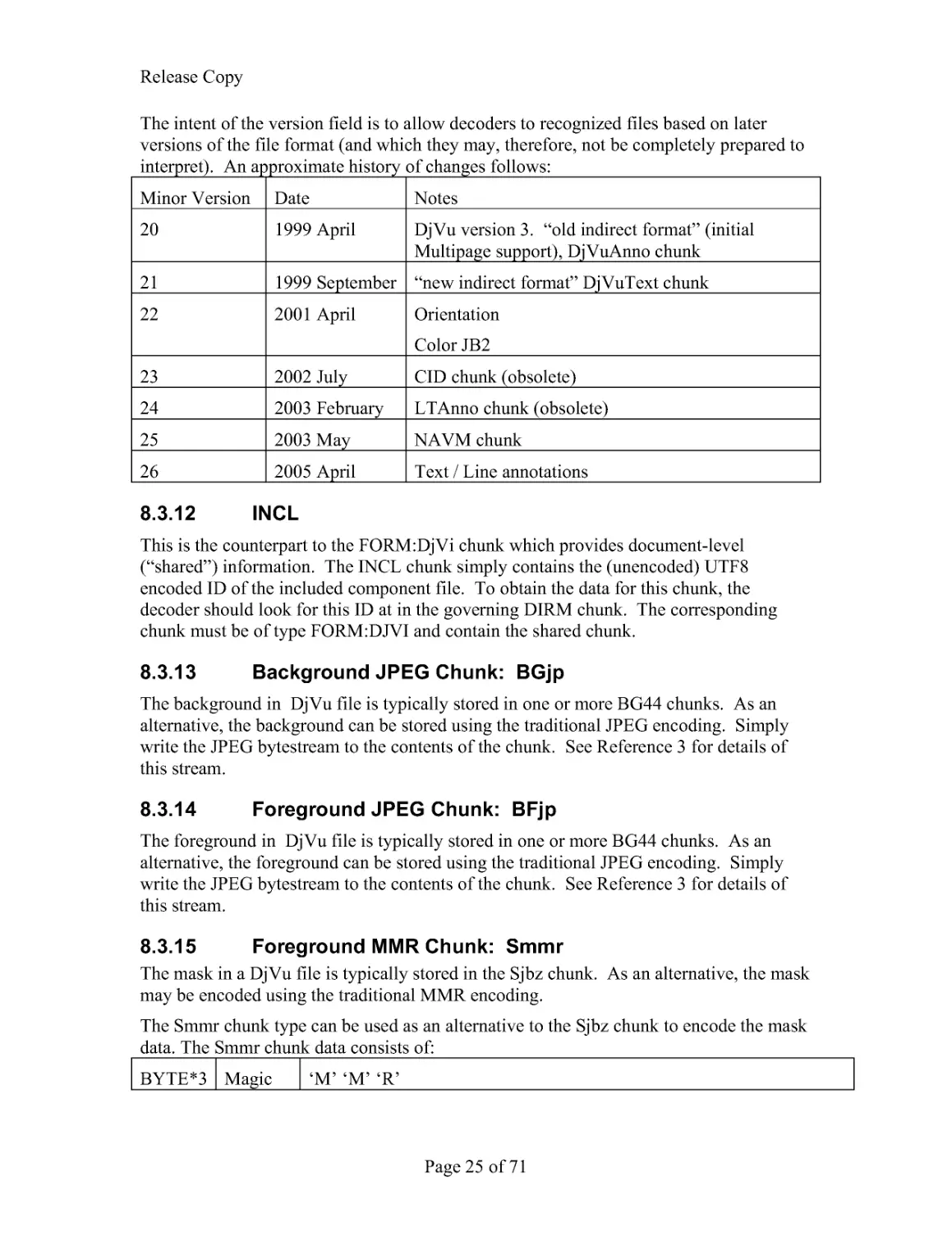
8.3.15 Foreground MMR Chunk: Smmr
The mask in a DjVu file is typically stored in the Sjbz chunk. As an alternative, the mask
may be encoded using the traditional MMR encoding.
The Smmr chunk type can be used as an alternative to the Sjbz chunk to encode the mask
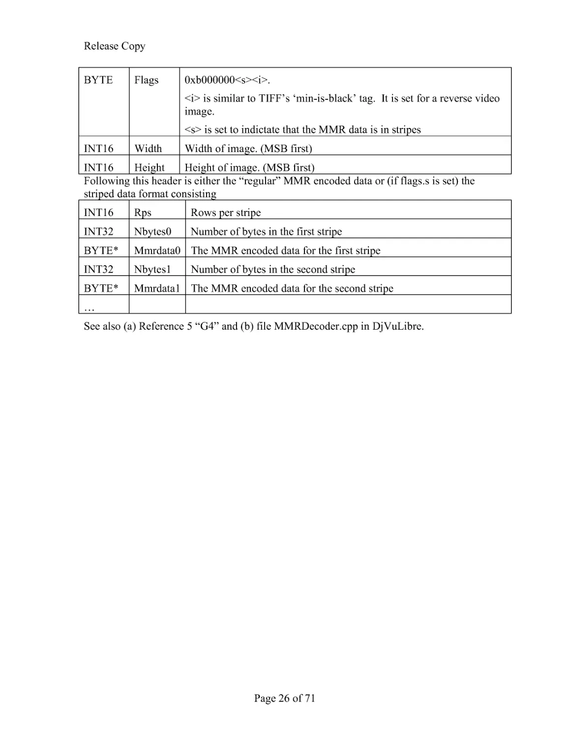
data. The Smmr chunk data consists of:
BYTE*3 Magic
'M' 'M' 'R'
Release Copy
Page 26 of 71
BYTE Flags 0xb000000<s><i>.
<i> is similar to TIFF's 'min-is-black' tag. It is set for a reverse video
image.
<s> is set to indictate that the MMR data is in stripes
INT16 Width Width of image. (MSB first)
INT16 Height Height of image. (MSB first)
Following this header is either the "regular" MMR encoded data or (if flags.s is set) the
striped data format consisting
INT16 Rps
Rows per stripe
INT32 Nbytes0 Number of bytes in the first stripe
BYTE* Mmrdata0 The MMR encoded data for the first stripe
INT32 Nbytes1 Number of bytes in the second stripe
BYTE* Mmrdata1 The MMR encoded data for the second stripe
...
See also (a) Reference 5 "G4" and (b) file MMRDecoder.cpp in DjVuLibre.
Release Copy
Page 27 of 71
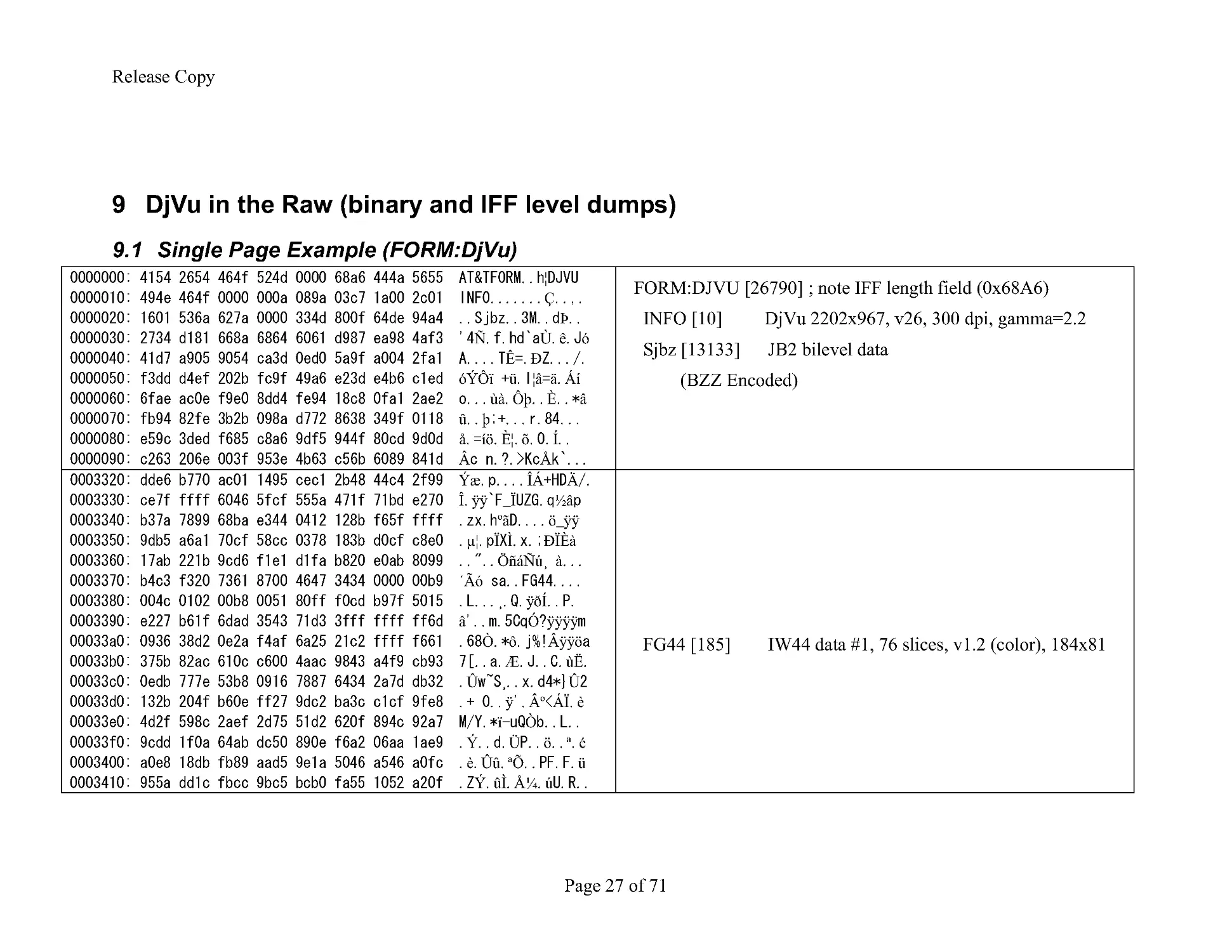
9 DjVu in the Raw (binary and IFF level dumps)
9.1 Single Page Example (FORM:DjVu)
¦
Ç
Þ
Ñ Ù ê ó
Ê Ð
óÝÔï ü ¦â ä Áí
ùà Ôþ È â
û þ
å íö Ȧ õ Í
 Å
FORM:DJVU [26790] ; note IFF length field (0x68A6)
INFO [10] DjVu 2202x967, v26, 300 dpi, gamma=2.2
Sjbz [13133] JB2 bilevel data
(BZZ Encoded)
Ýæ ÎÁ Ä
Î ÿÿ Ï ½â
ºã ö ÿÿ
μ¦ Ï Ì ÐÏÈà
ÖñáÑú¸ à
´Ãó
¸ ÿðÍ
â Ó ÿÿÿÿ
Ò ô Âÿÿö
Æ ùË
Û ¸ Û
ÿ º ÁÏ è
ï Ò
Ý Ü ö ª é
è Ûû ªÕ ü
Ý ûÌ Å¼ ú
FG44 [185] IW44 data #1, 76 slices, v1.2 (color), 184x81
Release Copy
Page 28 of 71
è Ûû ªÕ ü
Ý ûÌ Å¼ ú
ì þ ¾ û
Öè Âíʼ
Þ ú Ô
Ï Ó Êë Æ
ÿÿÿÿÿ ¸
ÿÿÿÿÿÿÿÿÿÿÿÿÿÿÿ
ÿÿÿÿ ü Ê û Ü
Ò¦ æ öî Ë
ä
ô ó ßé
É ¨ À ÿ
ÿÿ
ÿü óì ú
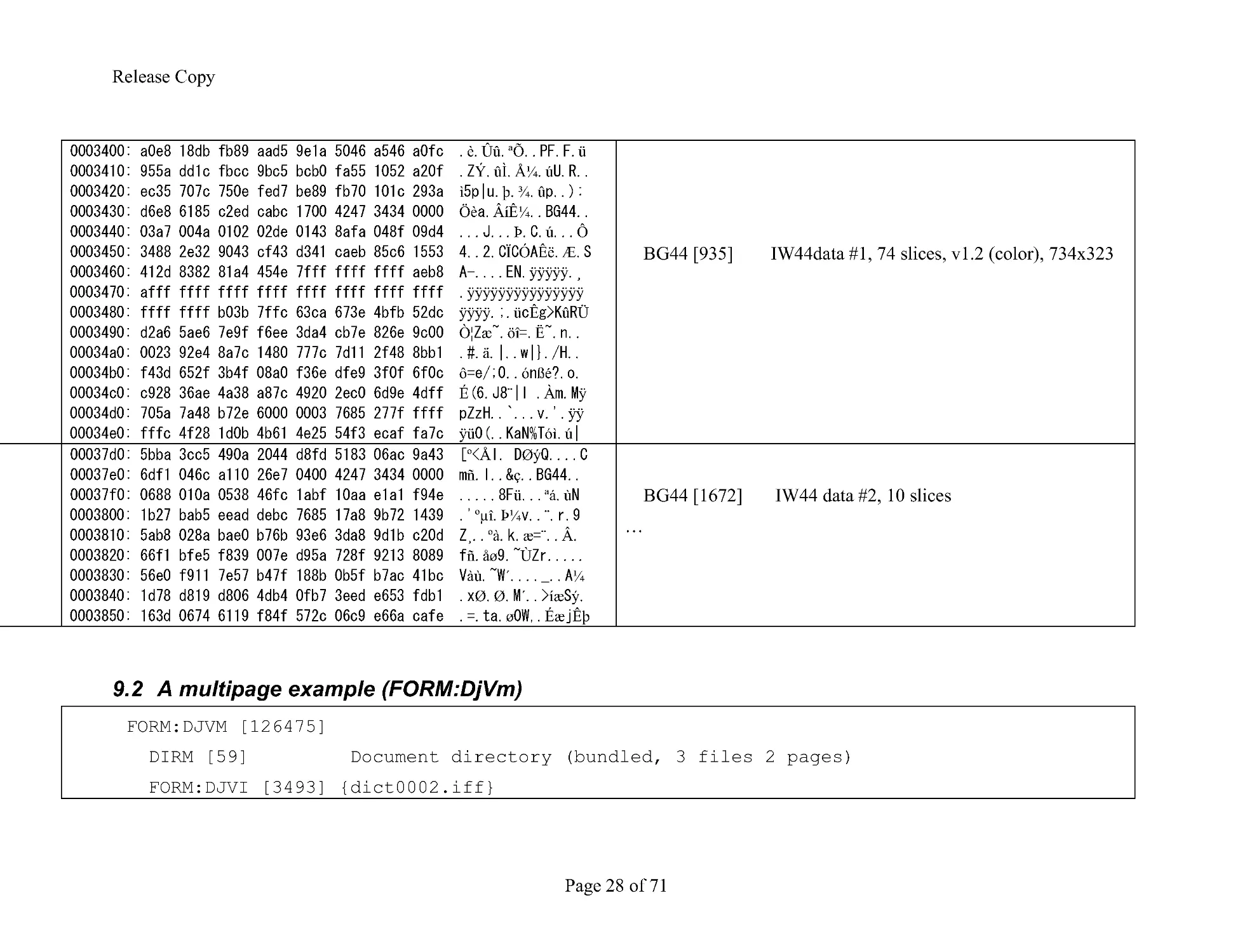
BG44 [935] IW44data #1, 74 slices, v1.2 (color), 734x323
º Å Øý
ñ ç
ü ªá ù
ºμî Þ¼ ¨
¸ ºà æ ¨ Â
ñ åø Ù
àù ´ ¼
Ø Ø ´ íæ ý
ø Éæ Êþ
BG44 [1672] IW44 data #2, 10 slices
...
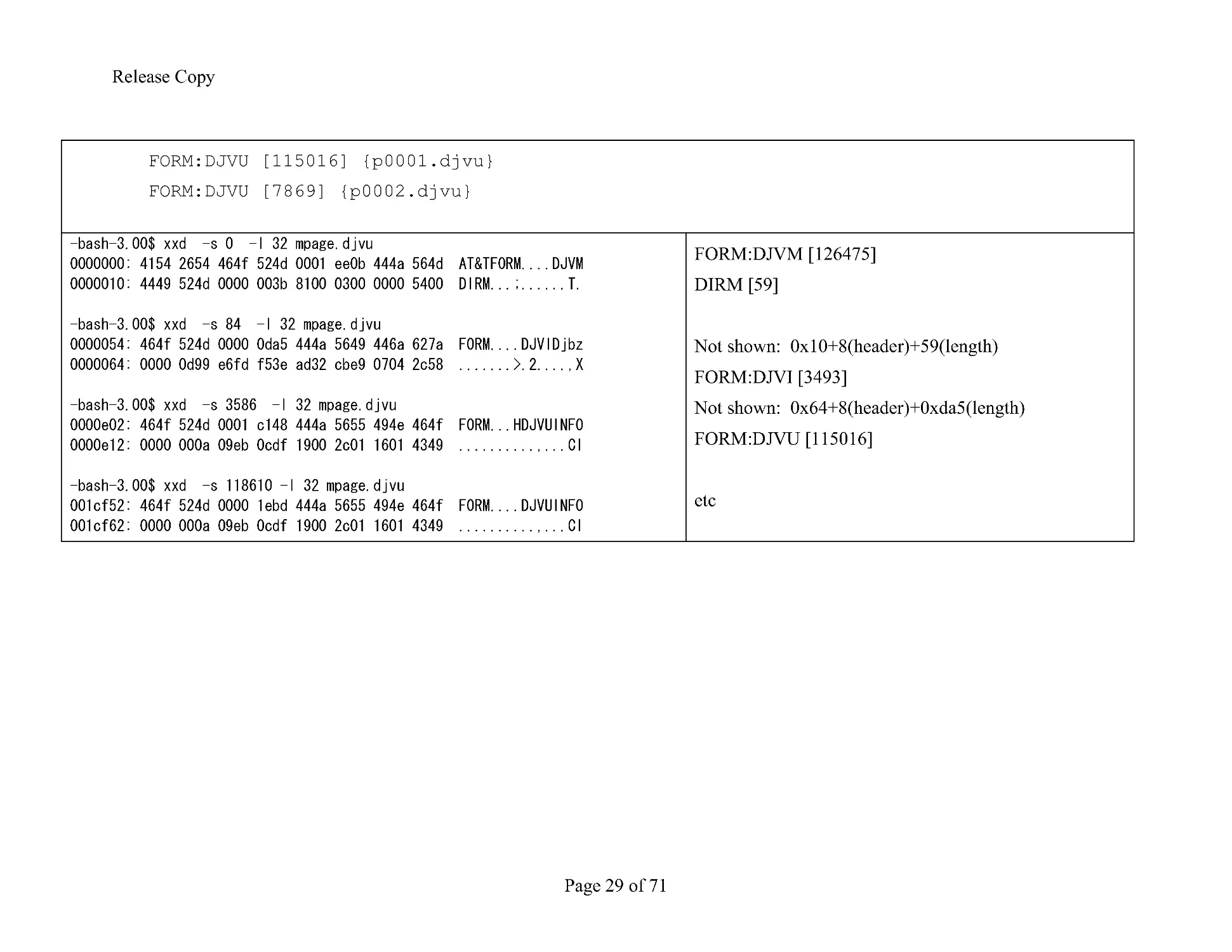
9.2 A multipage example (FORM:DjVm)
FORM:DJVM [126475]
DIRM [59]
Document directory (bundled, 3 files 2 pages)
FORM:DJVI [3493] {dict0002.iff}
Release Copy
Page 29 of 71
FORM:DJVU [115016] {p0001.djvu}
FORM:DJVU [7869] {p0002.djvu}
FORM:DJVM [126475]
DIRM [59]
Not shown: 0x10+8(header)+59(length)
FORM:DJVI [3493]
Not shown: 0x64+8(header)+0xda5(length)
FORM:DJVU [115016]
etc
Release Copy
Page 30 of 71
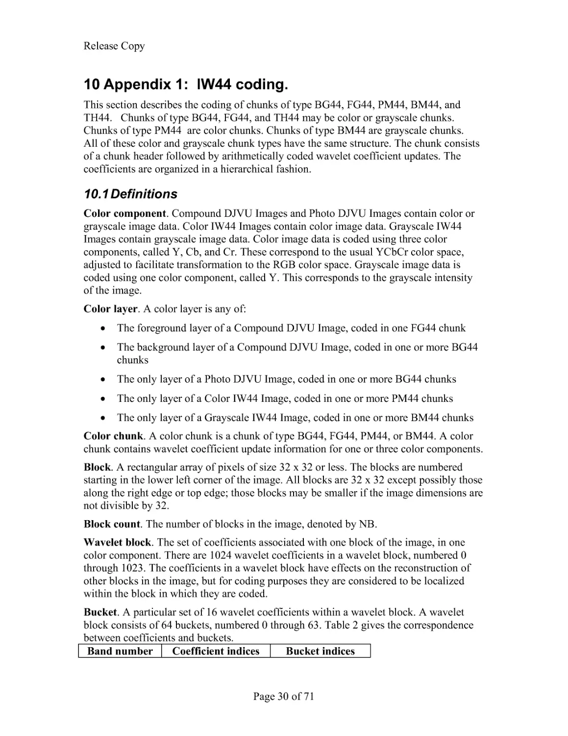
10 Appendix 1: IW44 coding.
This section describes the coding of chunks of type BG44, FG44, PM44, BM44, and
TH44. Chunks of type BG44, FG44, and TH44 may be color or grayscale chunks.
Chunks of type PM44 are color chunks. Chunks of type BM44 are grayscale chunks.
All of these color and grayscale chunk types have the same structure. The chunk consists
of a chunk header followed by arithmetically coded wavelet coefficient updates. The
coefficients are organized in a hierarchical fashion.
10.1 Definitions
Color component. Compound DJVU Images and Photo DJVU Images contain color or
grayscale image data. Color IW44 Images contain color image data. Grayscale IW44
Images contain grayscale image data. Color image data is coded using three color
components, called Y, Cb, and Cr. These correspond to the usual YCbCr color space,
adjusted to facilitate transformation to the RGB color space. Grayscale image data is
coded using one color component, called Y. This corresponds to the grayscale intensity
of the image.
Color layer. A color layer is any of:
The foreground layer of a Compound DJVU Image, coded in one FG44 chunk
The background layer of a Compound DJVU Image, coded in one or more BG44
chunks
The only layer of a Photo DJVU Image, coded in one or more BG44 chunks
The only layer of a Color IW44 Image, coded in one or more PM44 chunks
The only layer of a Grayscale IW44 Image, coded in one or more BM44 chunks
Color chunk. A color chunk is a chunk of type BG44, FG44, PM44, or BM44. A color
chunk contains wavelet coefficient update information for one or three color components.
Block. A rectangular array of pixels of size 32 x 32 or less. The blocks are numbered
starting in the lower left corner of the image. All blocks are 32 x 32 except possibly those
along the right edge or top edge; those blocks may be smaller if the image dimensions are
not divisible by 32.
Block count. The number of blocks in the image, denoted by NB.
Wavelet block. The set of coefficients associated with one block of the image, in one
color component. There are 1024 wavelet coefficients in a wavelet block, numbered 0
through 1023. The coefficients in a wavelet block have effects on the reconstruction of
other blocks in the image, but for coding purposes they are considered to be localized
within the block in which they are coded.
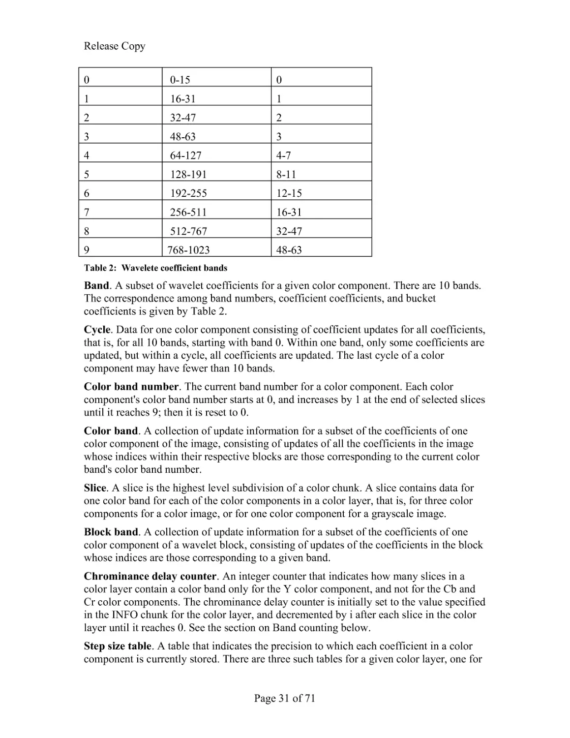
Bucket. A particular set of 16 wavelet coefficients within a wavelet block. A wavelet
block consists of 64 buckets, numbered 0 through 63. Table 2 gives the correspondence
between coefficients and buckets.
Band number Coefficient indices Bucket indices
Release Copy
Page 31 of 71
0
0-15
0
1
16-31
1
2
32-47
2
3
48-63
3
4
64-127
4-7
5
128-191
8-11
6
192-255
12-15
7
256-511
16-31
8
512-767
32-47
9
768-1023
48-63
Table 2: Wavelete coefficient bands
Band. A subset of wavelet coefficients for a given color component. There are 10 bands.
The correspondence among band numbers, coefficient coefficients, and bucket
coefficients is given by Table 2.
Cycle. Data for one color component consisting of coefficient updates for all coefficients,
that is, for all 10 bands, starting with band 0. Within one band, only some coefficients are
updated, but within a cycle, all coefficients are updated. The last cycle of a color
component may have fewer than 10 bands.
Color band number. The current band number for a color component. Each color
component's color band number starts at 0, and increases by 1 at the end of selected slices
until it reaches 9; then it is reset to 0.
Color band. A collection of update information for a subset of the coefficients of one
color component of the image, consisting of updates of all the coefficients in the image
whose indices within their respective blocks are those corresponding to the current color
band's color band number.
Slice. A slice is the highest level subdivision of a color chunk. A slice contains data for
one color band for each of the color components in a color layer, that is, for three color
components for a color image, or for one color component for a grayscale image.
Block band. A collection of update information for a subset of the coefficients of one
color component of a wavelet block, consisting of updates of the coefficients in the block
whose indices are those corresponding to a given band.
Chrominance delay counter. An integer counter that indicates how many slices in a
color layer contain a color band only for the Y color component, and not for the Cb and
Cr color components. The chrominance delay counter is initially set to the value specified
in the INFO chunk for the color layer, and decremented by i after each slice in the color
layer until it reaches 0. See the section on Band counting below.
Step size table. A table that indicates the precision to which each coefficient in a color
component is currently stored. There are three such tables for a given color layer, one for
Release Copy
Page 32 of 71
each color component. Each such table has 16 entries. Each entry specifies the current
step size for 1, 4, 16, 64, or 256 different coefficient indices, according to Table 3.
10.2 Color chunks within an DjVu file
There may be more than one BG44 or PM44 or BM44 chunks in a DjVu file. If there is
more than one such color chunk, the coefficient updating is continuous across the chunks,
and the data is taken from the chunks in the order in which they appear in the file.
Nothing is reinitialized at the beginning of chunks after the first color chunk of these
types, except for the low level arithmetic coder. The probability estimates for the
arithmetic coder are not reinitialized.
In a Compound DJVU Image file, in which both an FG44 chunk and one or more BG44
chunks appear in the same file, the coding of the foreground layer, using the FG44 chunk,
is independent of the coding of the background layer, using the BG44 chunks.
Each color layer is coded using a Dubuc- Deslauriers - Lemire (4, 4) Interpolative
Wavelet Transform. Each layer of the image is transformed into a set of wavelet
coefficients, one wavelet coefficient for each pixel in the original image. This transform
is especially effective for coding images at high compression ratios.
The value of each coefficient is coded in a distributed fashion, through a number of
cycles. Within one cycle, each coefficient is updated once (that is, in only one of the l0
bands), and receives approximately one additional bit of information. Specifically, from
cycle to cycle the absolute value of a coefficient is first narrowed down by eliminating
possible values for the most significant non-zero bit until the correct most significant
non-zero bit is found. The sign is coded in the same cycle in which the most significant
non-zero bit is found. Then in each subsequent cycle, one additional bit of the value is
coded.
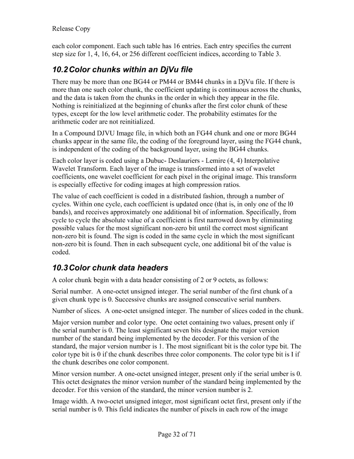
10.3 Color chunk data headers
A color chunk begin with a data header consisting of 2 or 9 octets, as follows:
Serial number. A one-octet unsigned integer. The serial number of the first chunk of a
given chunk type is 0. Successive chunks are assigned consecutive serial numbers.
Number of slices. A one-octet unsigned integer. The number of slices coded in the chunk.
Major version number and color type. One octet containing two values, present only if
the serial number is 0. The least significant seven bits designate the major version
number of the standard being implemented by the decoder. For this version of the
standard, the major version number is 1. The most significant bit is the color type bit. The
color type bit is 0 if the chunk describes three color components. The color type bit is I if
the chunk describes one color component.
Minor version number. A one-octet unsigned integer, present only if the serial umber is 0.
This octet designates the minor version number of the standard being implemented by the
decoder. For this version of the standard, the minor version number is 2.
Image width. A two-octet unsigned integer, most significant octet first, present only if the
serial number is 0. This field indicates the number of pixels in each row of the image
Release Copy
Page 33 of 71
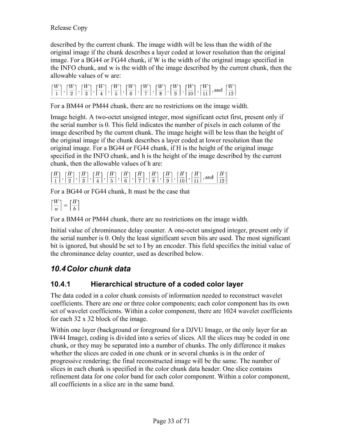
described by the current chunk. The image width will be less than the width of the
original image if the chunk describes a layer coded at lower resolution than the original
image. For a BG44 or FG44 chunk, if W is the width of the original image specified in
the INFO chunk, and w is the width of the image described by the current chunk, then the
allowable values of w are:
For a BM44 or PM44 chunk, there are no restrictions on the image width.
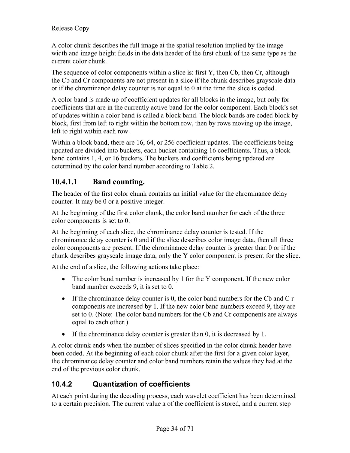
Image height. A two-octet unsigned integer, most significant octet first, present only if
the serial number is 0. This field indicates the number of pixels in each column of the
image described by the current chunk. The image height will be less than the height of
the original image if the chunk describes a layer coded at lower resolution than the
original image. For a BG44 or FG44 chunk, if H is the height of the original image
specified in the INFO chunk, and h is the height of the image described by the current
chunk, then the allowable values of h are:
For a BG44 or FG44 chunk, It must be the case that
For a BM44 or PM44 chunk, there are no restrictions on the image width.
Initial value of chrominance delay counter. A one-octet unsigned integer, present only if
the serial number is 0. Only the least significant seven bits are used. The most significant
bit is ignored, but should be set to I by an encoder. This field specifies the initial value of
the chrominance delay counter, used as described below.
10.4 Color chunk data
10.4.1 Hierarchical structure of a coded color layer
The data coded in a color chunk consists of information needed to reconstruct wavelet
coefficients. There are one or three color components; each color component has its own
set of wavelet coefficients. Within a color component, there are 1024 wavelet coefficients
for each 32 x 32 block of the image.
Within one layer (background or foreground for a DJVU Image, or the only layer for an
IW44 Image), coding is divided into a series of slices. All the slices may be coded in one
chunk, or they may be separated into a number of chunks. The only difference it makes
whether the slices are coded in one chunk or in several chunks is in the order of
progressive rendering; the final reconstructed image will be the same. The number of
slices in each chunk is specified in the color chunk data header. One slice contains
refinement data for one color band for each color component. Within a color component,
all coefficients in a slice are in the same band.
Release Copy
Page 34 of 71
A color chunk describes the full image at the spatial resolution implied by the image
width and image height fields in the data header of the first chunk of the same type as the
current color chunk.
The sequence of color components within a slice is: first Y, then Cb, then Cr, although
the Cb and Cr components are not present in a slice if the chunk describes grayscale data
or if the chrominance delay counter is not equal to 0 at the time the slice is coded.
A color band is made up of coefficient updates for all blocks in the image, but only for
coefficients that are in the currently active band for the color component. Each block's set
of updates within a color band is called a block band. The block bands are coded block by
block, first from left to right within the bottom row, then by rows moving up the image,
left to right within each row.
Within a block band, there are 16, 64, or 256 coefficient updates. The coefficients being
updated are divided into buckets, each bucket containing 16 coefficients. Thus, a block
band contains 1, 4, or 16 buckets. The buckets and coefficients being updated are
determined by the color band number according to Table 2.
10.4.1.1 Band counting.
The header of the first color chunk contains an initial value for the chrominance delay
counter. It may be 0 or a positive integer.
At the beginning of the first color chunk, the color band number for each of the three
color components is set to 0.
At the beginning of each slice, the chrominance delay counter is tested. If the
chrominance delay counter is 0 and if the slice describes color image data, then all three
color components are present. If the chrominance delay counter is greater than 0 or if the
chunk describes grayscale image data, only the Y color component is present for the slice.
At the end of a slice, the following actions take place:
The color band number is increased by 1 for the Y component. If the new color
band number exceeds 9, it is set to 0.
If the chrominance delay counter is 0, the color band numbers for the Cb and C r
components are increased by 1. If the new color band numbers exceed 9, they are
set to 0. (Note: The color band numbers for the Cb and Cr components are always
equal to each other.)
If the chrominance delay counter is greater than 0, it is decreased by 1.
A color chunk ends when the number of slices specified in the color chunk header have
been coded. At the beginning of each color chunk after the first for a given color layer,
the chrominance delay counter and color band numbers retain the values they had at the
end of the previous color chunk.
10.4.2 Quantization of coefficients
At each point during the decoding process, each wavelet coefficient has been determined
to a certain precision. The current value a of the coefficient is stored, and a current step
Release Copy
Page 35 of 71
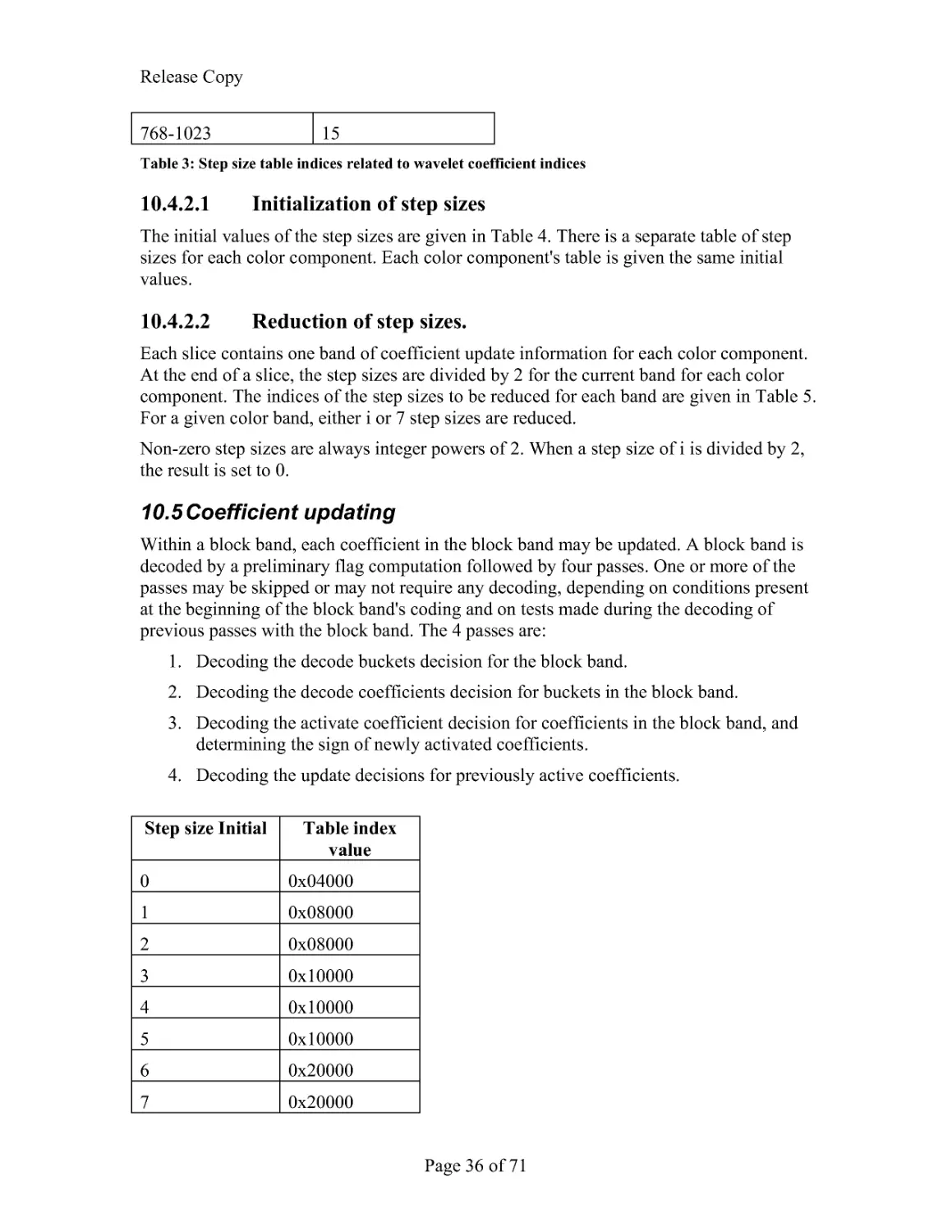
size S is associated with the coefficient. The current step size for each coefficient is
governed by a step size table. The index of the entry in the step size table that contains
the step size for a given coefficient is given in Table 3.
If a 0, the coefficient is said to be "active". If a > 0, the range of possible actual values of
the coefficient is [a - S, a + S). If a < 0, the range of possible actual values of the
coefficient is (a - S, a + S]. If a = 0, the coefficient is not active, and the range of possible
actual values of the coefficient is (-2S, 2S).
When the value of a given coefficient is updated, there are three cases.
1. If the coefficient is not active (a = 0), then there are three possibilities for the next
current interval: (-2S,-S], (-S,S), or [S, 2S). If the coefficient remains not active,
then the next interval is (-S, S). Otherwise, the sign of the coefficient is decoded
to choose between the other two intervals.
2. If the coefficient is active and a > 0, then there are two possibilities for the next
current interval: [a - S, a) or [a, a + S). The next decision for the coefficient is the
increase coefficient absolute value decision. If this decision is YES, then [a, a +
S) is the next interval. If the decision is NO, then [a - S, a) is the next interval.
3. If the coefficient is active and a < 0, then there are two possibilities for the next
current interval: (a - S, a] or (a, a + S]. The next decision for the coefficient is the
increase coefficient absolute value decision. If this decision is YES, then (a - S, a]
is the next interval. If the decision is NO, then (a, a + S] is the next interval.
Coefficient index Index into step size
table
0
0
1
1
2
2
3
3
4-7
4
8-11
5
12-15
6
16-31
7
32-47
8
48-63
9
64-127
10
128-191
11
192-255
12
256-511
13
512-767
14
Release Copy
Page 36 of 71
768-1023
15
Table 3: Step size table indices related to wavelet coefficient indices
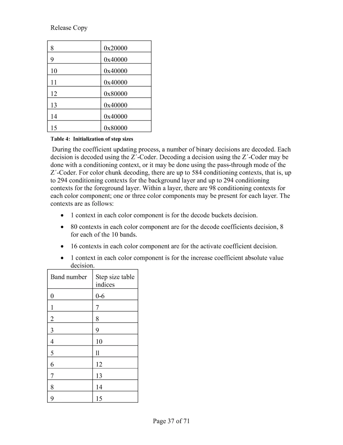
10.4.2.1 Initialization of step sizes
The initial values of the step sizes are given in Table 4. There is a separate table of step
sizes for each color component. Each color component's table is given the same initial
values.
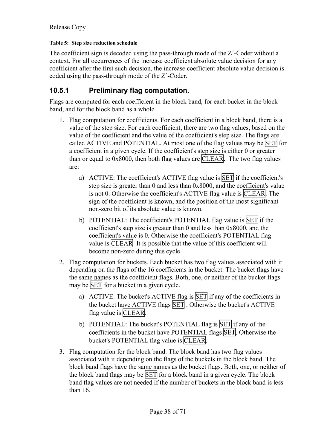
10.4.2.2 Reduction of step sizes.
Each slice contains one band of coefficient update information for each color component.
At the end of a slice, the step sizes are divided by 2 for the current band for each color
component. The indices of the step sizes to be reduced for each band are given in Table 5.
For a given color band, either i or 7 step sizes are reduced.
Non-zero step sizes are always integer powers of 2. When a step size of i is divided by 2,
the result is set to 0.
10.5 Coefficient updating
Within a block band, each coefficient in the block band may be updated. A block band is
decoded by a preliminary flag computation followed by four passes. One or more of the
passes may be skipped or may not require any decoding, depending on conditions present
at the beginning of the block band's coding and on tests made during the decoding of
previous passes with the block band. The 4 passes are:
1. Decoding the decode buckets decision for the block band.
2. Decoding the decode coefficients decision for buckets in the block band.
3. Decoding the activate coefficient decision for coefficients in the block band, and
determining the sign of newly activated coefficients.
4. Decoding the update decisions for previously active coefficients.
Step size Initial Table index
value
0
0x04000
1
0x08000
2
0x08000
3
0x10000
4
0x10000
5
0x10000
6
0x20000
7
0x20000
Release Copy
Page 37 of 71
8
0x20000
9
0x40000
10
0x40000
11
0x40000
12
0x80000
13
0x40000
14
0x40000
15
0x80000
Table 4: Initialization of step sizes
During the coefficient updating process, a number of binary decisions are decoded. Each
decision is decoded using the Z´-Coder. Decoding a decision using the Z´-Coder may be
done with a conditioning context, or it may be done using the pass-through mode of the
Z´-Coder. For color chunk decoding, there are up to 584 conditioning contexts, that is, up
to 294 conditioning contexts for the background layer and up to 294 conditioning
contexts for the foreground layer. Within a layer, there are 98 conditioning contexts for
each color component; one or three color components may be present for each layer. The
contexts are as follows:
1 context in each color component is for the decode buckets decision.
80 contexts in each color component are for the decode coefficients decision, 8
for each of the 10 bands.
16 contexts in each color component are for the activate coefficient decision.
1 context in each color component is for the increase coefficient absolute value
decision.
Band number Step size table
indices
0
0-6
1
7
2
8
3
9
4
10
5
ll
6
12
7
13
8
14
9
15
Release Copy
Page 38 of 71
Table 5: Step size reduction schedule
The coefficient sign is decoded using the pass-through mode of the Z´-Coder without a
context. For all occurrences of the increase coefficient absolute value decision for any
coefficient after the first such decision, the increase coefficient absolute value decision is
coded using the pass-through mode of the Z´-Coder.
10.5.1 Preliminary flag computation.
Flags are computed for each coefficient in the block band, for each bucket in the block
band, and for the block band as a whole.
1. Flag computation for coefficients. For each coefficient in a block band, there is a
value of the step size. For each coefficient, there are two flag values, based on the
value of the coefficient and the value of the coefficient's step size. The flags are
called ACTIVE and POTENTIAL. At most one of the flag values may be SET for
a coefficient in a given cycle. If the coefficient's step size is either 0 or greater
than or equal to 0x8000, then both flag values are CLEAR. The two flag values
are:
a) ACTIVE: The coefficient's ACTIVE flag value is SET if the coefficient's
step size is greater than 0 and less than 0x8000, and the coefficient's value
is not 0. Otherwise the coefficient's ACTIVE flag value is CLEAR. The
sign of the coefficient is known, and the position of the most significant
non-zero bit of its absolute value is known.
b) POTENTIAL: The coefficient's POTENTIAL flag value is SET if the
coefficient's step size is greater than 0 and less than 0x8000, and the
coefficient's value is 0. Otherwise the coefficient's POTENTIAL flag
value is CLEAR. It is possible that the value of this coefficient will
become non-zero during this cycle.
2. Flag computation for buckets. Each bucket has two flag values associated with it
depending on the flags of the 16 coefficients in the bucket. The bucket flags have
the same names as the coefficient flags. Both, one, or neither of the bucket flags
may be SET for a bucket in a given cycle.
a) ACTIVE: The bucket's ACTIVE flag is SET if any of the coefficients in
the bucket have ACTIVE flags SET . Otherwise the bucket's ACTIVE
flag value is CLEAR.
b) POTENTIAL: The bucket's POTENTIAL flag is SET if any of the
coefficients in the bucket have POTENTIAL flags SET. Otherwise the
bucket's POTENTIAL flag value is CLEAR.
3. Flag computation for the block band. The block band has two flag values
associated with it depending on the flags of the buckets in the block band. The
block band flags have the same names as the bucket flags. Both, one, or neither of
the block band flags may be SET for a block band in a given cycle. The block
band flag values are not needed if the number of buckets in the block band is less
than 16.
Release Copy
Page 39 of 71
a) ACTIVE: The block band's ACTIVE flag is SET if any of the buckets in
the block band have ACTIVE flags SET. Otherwise the block band's
ACTIVE flag value is CLEAR .
b) POTENTIAL: The block band's POTENTIAL flag is SET if any of the
buckets in the block band have POTENTIAL flags SET. Otherwise the
block band's POTENTIAL flag value is CLEAR .
10.5.2 Block-band-decoding pass.
If the block band contains fewer than 16 buckets, the block-band-decoding pass is
skipped and the bucket decoding pass is performed. If the block band's ACTIVE flag is
SET, the block-band-decoding pass is skipped and the bucket decoding pass is performed.
If the block band contains 16 buckets, and if the block band's ACTIVE flag is CLEAR,
and if the block band's POTENTIAL flag is SET, then the decode buckets decision is
decoded. If the decode buckets decision is YES, the bucket-decoding pass is performed
for the block band. If the decode buckets decision is NO, the bucket-decoding pass and
the newly-active-coefficient-decoding pass are skipped for the block band.
10.5.2.1 Arithmetic decoding.
For each color component, there is a single context for use in decoding the decode
buckets decision. If the value returned by the Z´-Coder for the decode buckets decision is
1, then the value of the decode buckets decision is YES . If the value returned by the Z´-
Coder is 0, then the value of the decode buckets decision is NO.
The Z´-Coder context for the decode buckets decision for each color component is
initially set to 0.
10.5.3 Bucket-decoding pass.
Each bucket has a flag called the coefficient-decoding flag. If the bucket-decoding pass is
not skipped, then for each bucket in the block band, if the bucket's POTENTIAL flag is
SET, then the decode coefficients decision for the bucket is decoded. If the the decode
coefficients decision is YES, then the bucket's coefficient-decoding flag is SET;
otherwise it is CLEAR.
10.5.3.1 Arithmetic decoding.
For each color component, there are 80 contexts for use in decoding the decode
coefficients decision. For each of the l0 bands in a color component, there are 8 contexts.
There are four contexts that may be used if the block band's ACTIVE
flag is SET, and four contexts that may be used if the block band's ACTIVE flag is
CLEAR. The index of the context to be used among the 4 possible contexts is computed
as follows.
If the band number is 0, then no -- 0. Otherwise, the value of no is computed as follows:
1. The bucket number is multiplied by 4, giving a result t.
Release Copy
Page 40 of 71
2. The coefficients numbered t, t+1, t+2, t+3 are examined, and the number n0 of
coefficients with value 0 among the four coefficients is counted.
3. Ifn0=4,n0isreducedto3.
Then the value of n0 is used as the index to one of the four contexts, for the given color
component, band, and block band ACTIVE flag value. If the value returned by the Z´-
Coder for the decode coefficients decision is 1, then the value of the decode coefficients
decision is YES . If the value returned by the Z´-Coder is 0, then the value of the decode
coefficients decision is NO
Each of the 80 Z´-Coder contexts for the decode coefficients decision for each color
component is initially set to 0.
10.5.4 Newly-active-coefficient-decoding pass.
If the newly-active-coefficient-decoding pass is not skipped, then for each bucket in the
block band, the coefficient-decoding flag is tested. For a given bucket, if the bucket's
coefficient- decoding flag is SET, then the following procedure is followed for each
coefficient in the bucket: If the coefficient's POTENTIAL flag is SET, then the activate
coefficient decision is decoded. If the the activate coefficient decision is YES, then the
sign of the coefficient s± with value +1 or -1, is decoded. Then the coefficient is set equal
to
10.5.4.1 Arithmetic decoding.
For each color component, there are 16 contexts for use in decoding the activate
coefficient decision. There are eight contexts that may be used if the block's ACTIVE flag
is SET and eight contexts that may be used if the block's ACTIVE flag is
CLEAR.The index of the context to be used from among the 8 possible contexts is
computed as follows:
1. The coefficients in the bucket are examined, and the number np of them whose
POTENTIAL flag is SET is computed.
2. Loop through the coefficients whose POTENTIAL flag is SET.
a. Compute ip = min(7, np).
b. Use ip as the index into the set of 8 possible contexts, given the color
component and value of the block's ACTIVE flag.
c. Decode the activate coefficient decision using the context; if the activate
coefficient decision is YES, decode the sign using the pass-through mode
of the Z´-Coder, and set np = 0.
d. If np> 0, decrement np by 1.
If the value returned by the Z´-Coder for the activate coefficient decision is 1, then the
value of the activate coefficient decision is YES. If the value returned by the Z´-Coder is
Release Copy
Page 41 of 71
0, then the value of the activate coefficient decision is NO. The decoding of the sign s± of
a newly activated coefficient uses the pass-through mode of the Z´-Coder. If the value
returned by the Z´-Coder is 1, then s± = -1. If the value returned by the Z´-Coder is 0, then
s± =+1.
Each of the 16 Z´-Coder contexts for the activate coefficients decision for each color
component is initially set to 0.
10.5.5 Previously-active-coefficient-decoding pass.
For all coefficients in the block band, the following procedure is followed: If the
coefficient's ACTIVE flag is SET , the increase coefficient absolute value decision is
decoded. If the decision is NO, the absolute value of the coefficient is reduced by half of
the coefficient's step size. If the decision is YES, the absolute value of the coefficient is
increased by half of the coefficient's step size. A step size of i is a special case. If the step
size is i and the decision is NO, the absolute value of the coefficient is reduced by 1. If
the step size is 1 and the decision is YES, the value of the coefficient is unchanged.
10.5.5.1 Arithmetic decoding.
For each color component, there is a single context for use in decoding the increase
coefficient absolute value decision. This context is used to decode the increase coefficient
absolute value decision if the absolute value of the coefficient is less than or equal to 3
times the value of the step size for the coefficient. Otherwise, the pass-through mode of
the Z´-Coder is used. (Note: the effect of this test is that only the second most significant
bit of a coefficient's value is decoded using this context; other less significant bits are
decoded using the pass-through mode of the Z´-Coder, with no context.)
Whether the context or the pass-through mode is used, if the value returned by the Z´-
Coder for the increase coefficient absolute value decision is 1, then the value of the
increase coefficient absolute value decision is YES. If the value returned by the Z´-Coder
is 0, then the value of the increase coefficient absolute value decision is NO.
The Z´-Coder context for the increase coefficient absolute value decision for each color
component is initially set to 0.
10.6 Image reconstruction
At any time during the decoding process, an image may be reconstructed from the current
values of the wavelet coefficients already decoded. The wavelet coefficients are stored in
three two-dimensional arrays one for each of the Y, Cb, and Cr color components. Each
array has one entry for each image block. Each entry itself is a 1024-element one-
dimensional array. The elements of each one-dimensional array are the wavelet
coefficients. The wavelet coefficients are signed fixed-point numbers with six fractional
bits.
10.6.1 Sequence of operations
To reconstruct the image from the coefficients, the following steps must be performed:
Release Copy
Page 42 of 71
1. Reordering coefficients. For each color component, each of the 1024-element
coefficient arrays is converted into a 32 x 32 coefficient array. These square
coefficient arrays are embedded into a larger reconstruction array whose size is
the size of the image.
2. Inverse wavelet transform. For each color component, the inverse wavelet
transform is applied to the larger reconstruction array. The inverse transform is
applied at progressively finer scales, and within each scale in each of the two
directions, first vertically, then horizontally.
3. Precision reduction. For each color component, the data values in the
reconstruction array are reduced to eight bits. Conversion to RGB color space. For
color images, the eight-bit values of each pixel in the YCbCr color space are
converted to the corresponding eight-bit values in the RGB color space.
10.6.2 Coordinate system
For indexing the blocks within a color component, the origin (0, 0) is at the lower left
corner of the image. Horizontal indices increase rightward, and vertical indices increase
upward.
For indexing the coefficients within a 32 x 32 block coefficient array, the origin (0, 0) is
at the lower left corner of the block. Horizontal indices increase rightward, and vertical
indices increase upward.
For indexing the coefficients and color values within the image in the reconstruction
array, the origin (0, 0) is at the lower left corner of the image. Horizontal indices increase
rightward, and vertical indices increase upward.
When the array of coefficients for a block is embedded into the reconstruction array, the
origin of the block coefficient array is placed into the lower left corner of the section of
the reconstruction array that corresponds to the block.
10.6.3 Reordering coefficients
Within each color component, the coefficients in each block are moved from a 1024-
element linear array into a 32 x 32 square array. The square array from each block is
embedded in a reconstruction array the size of the full image.
The mapping from indices in the linear array to indices in the square array is as follows:
if the ten bits of the index in the linear array are b9b8b7b6b5b4b3b2b1b0, b9 being the most
significant bit of the index, then the bits of the row index of the square array are
b1b3b5b7b9, b1 being the most significant bit of the row index, and the bits of the column
index of the square array b0b2b4b6b8, b0 being the most significant bit of the column
index.
If the number of rows in the image is not a multiple of 32, then blocks along the top edge
of the image have fewer than 32 rows. If the number of columns in the image is not a
multiple of 32, then blocks along the right edge of the image have fewer than 32 columns.
For all such blocks, all coefficients are coded; however, coefficients that fall outside the
Release Copy
Page 43 of 71
boundary of the image after the coefficient mapping described above are never used,
regardless of their value.
10.6.4 Inverse wavelet transform
The inverse transformation from wavelet coefficients to color values is done
independently for the three color components. Within a color component the
transformation is done for a decreasing sequence of scale parameters s. For a given scale
parameter s, the transformation is done first for columns, then for rows. Within a column
or row, the transformation is done in two passes, a lifting pass and then a prediction pass.
The scale parameter's initial value is s = 16. After the vertical and horizontal
transformations have been done with a given value of s, the value of s is divided by 2 and
the next pair of transformations is performed. After the vertical and horizontal
transformations have been performed with s = 1, the inverse wavelet transform for the
color component is complete.
The pair of transformations for a given value of s involve only rows and columns whose
indices are multiples of s. The vertical transformation involves transforming the
coefficients in column 0 whose row indices are multiples of s, then repeating the
transformation for all other columns whose column indices are multiples of s. Some of
the coefficients transformed by the vertical transformation will already have been
transformed during earlier iterations with larger values of the scale parameter s.
The horizontal transformation involves transforming the coefficients in row 0 whose
column indices are multiples of s, then repeating the transformation for all other rows
whose row indices are multiples of s. The coefficients transformed by the horizontal
transformation will have been transformed by the vertical transformation during the first
pass for the current scale parameter s. Some of the coefficients transformed by the
horizontal transformation will already have been transformed during earlier iterations
with larger values of the scale parameter s.
To transform one column or row of coefficients:
1. If transforming a column, select the coefficients in the current column that come
from rows whose indices are multiples of s. The coefficient from the row whose
index is ks is referred to as ck. The largest value of k is referred to as kmax.
2. If transforming a row, select the coefficients in the current row that come from
columns whose indices are multiples of s. The coefficient from the row whose
index is ks is referred to as ck. The largest value of k is referred to as kmax.
3. Lifting. For each even-numbered subscript k, 0 k kmax, replace coefficient ck
with
Specialcases:Ifk-3<0,useck-3=0.Ifk-1<0,useck-1=0.Ifk+1>kmax,
useck+` =0.Ifk+3>kmax,useck+3=0
3. Prediction. For each odd-numbered subscript k, 0 k kmax, replace coefficient ck
Release Copy
Page 44 of 71
as follows:
a) If k-3 0 and k+3 kmax, replace ck with
b) Otherwise if k+1 kmax, replace ck with
c) Otherwise, replace ck with ck + ck-1
10.6.5 Precision reduction for color image data
After the inverse transformation, a color value in the reconstruction array for each color
component is a signed fixed-point value with 6 fractional bits. This value is to be rounded
to the nearest integer V. Then if V < -128, V is set to -128. If V 128, V is set to 127.
Finally, in the luminance (Y) color component only, V is increased by 128.
10.6.6 Precision reduction for grayscale image data
After the inverse transformation, a grayscale value in the reconstruction array is a signed
fixed-point value with 6 fractional bits. This value is to be rounded to the nearest integer
V. Then if V<-128, V is set to -128. If V 128, V is set to 127. Finally, V is replaced by
127- V.
10.6.7 Conversion from YCbCr color space to RGB color space
For a color image, each pixel has a value in each of the color component reconstruction
buffers. To convert a pixel's YCbCr values to the corresponding RGB values, perform the
following transformation:
R=Y
+(3/2)Cr
G = Y -(1/4)Cb
-(3/4)Cr
B = Y +(7/4)Cb
11 Appendix 2: JB2 coding.
11.1 General considerations.
Selection layer coding is used in Compound DJVU Images. In such images, there are
three layers. The foreground layer is coded in one FG44 chunk, and is rendered as
described in Appendix 1. The background layer is coded in one or more BG44 chunks,
and is rendered as described in Appendix 1. The selection layer is coded using one Sjbz
chunk. Black pixels in the selection layer specify those pixels that are to be rendered
using the foreground color. All other pixels are to be rendered using the background
color.
Black and white coding is used in Bi-level DJVU Images. In such images, there are three
layers. The foreground layer is black. The background layer is white. The selection layer
Release Copy
Page 45 of 71
is coded using one Sjbz chunk. The selection layer specifies those pixels that are to be
rendered in black. All other pixels are to be rendered in white.
An Sjbz chunk contains a single arithmetically encoded data stream, coded using the Z´-
Coder (Appendix 3). All data, including headers and record types, is coded in this
arithmetically coded stream.
11.2 Arithmetic coding
The arithmetically coded data in an Sjbz chunk consists logically of records. The record
types are listed in Table 6, and described in Section 8.4. The records consist of fields. The
fields present for records of each record type are listed in Table 6. The fields within a
record are coded in the order listed in Table 6 for records of that type. Details of the
coding for each field appear in Section 8.5.
A field may contain one or more data elements. The data elements consist of flags, pixel
colors, and integers. Because of the nature of arithmetic coding, the records, fields, and
data elements are not of fixed sizes, and do not necessarily begin on bit boundaries within
the data stream.
Flags are binary decisions, each coded using the Z´-Coder with a particular context.
There are two different contexts for flags, the eventual image refinement context and the
offset type context.
Pixel colors are binary decisions, coded using the Z´-Coder with a particular context. For
pixel colors, there are 3072 different contexts. There are 1024 contexts used for direct
coding of bitmaps; these correspond to the 210 = 1024 different combinations of values
that the pixels in the direct coding template can assume. There are 2048 contexts used for
refinement coding of bitmaps; these correspond to the 211 = 2048 different combinations
of values that the pixels in the refinement coding template can assume.
Integers are coded using the multivalue extension to the Z´-Coder, described below.
There are 15 contexts for coding multivalued integers, as described in Table 7.
11.2.1 Initialization of the Z´-Coder
All Z´-Coder contexts are initialized to the value 0. This applies both to contexts used to
encode single bit values, including pixel colors, and to contexts that are part of an integer
context used by the multivalue extension to the Z´-Coder.
11.2.2 The multivalue extension to the Z´-Coder for coding of
numeric data
Quantities that can take on multiple values are coded as integers using the multivalue
extension to the Z´-Coder. This extension of the Z´-Coder allows all data in the bitstream
to be coded using the same coder, the Z´-Coder. There are 15 integer contexts, specified
in Table 7. A single integer context includes a number of binary contexts.
One integer context consists of a binary decision tree. See Figure 1 for an example of part
of such a tree. The root node of the tree corresponds to the decision about the sign of the
number n being decoded. Each of the two sub trees under the root corresponds to a set of
decisions that eventually identify a range in which n lies. The sub trees under the nodes
Release Copy
Page 46 of 71
corresponding to identified ranges are complete binary trees that identify the exact value
of n.
Each node of the binary decision tree for an integer context maintains its own binary
probability estimation context for the Z´-Coder. The trees for different integer contexts
are completely independent. Thus each node of a tree contains probability information
conditioned on a conditioning context. The conditioning context consists of both the type
of value being coded (i.e., the selection of the integer context), and of the values of the
decisions coded so far when encoding the current integer.
11.2.3 Record Types
Record type
coded value
Record type
Fields coded
0
Start of image
Record type Image size
Eventual image refinement flag
1
New symbol, add to image and
library
Record type Absolute symbol
size Bitmap by direct coding
Location relative to a previous
symbol
2
New symbol, add to library only
Record type Absolute symbol
size Bitmap by direct coding
3
New symbol, add to image only
Record type Absolute symbol
size Bitmap by direct coding
Location relative to a previous
symbol
4
Matched symbol with refinement,
add to image and library
Record type Index of matching
symbol in bitmap library
Relative symbol size Bitmap by
refinement coding Location
relative to a previous symbol
5
Matched symbol with refinement,
add to library only
Record type Index of matching
symbol in bitmap library
Relative symbol size Bitmap by
refinement coding
6
Matched symbol with refinement,
add to image only
Record type Index of matching
symbol in bitmap library
Relative symbol size Bitmap by
refinement coding Location
relative to a previous symbol
7
Matched symbol, copy to image
without refinement
Record type Index of matching
symbol in bitmap library
Location relative to a previous
symbol
8
Non-symbol data
Record type Absolute symbol
size Bitmap by direct coding
Release Copy
Page 47 of 71
Absolute location
9
Shared dictionary or numcoder reset Record type Shared dictionary
size
10
Comment
Record type Comment length
Comment data
11
End of data
Record type
Table 6: Record types and fields coded for each record type
11.2.4 Fields / Contexts
Context name
Integer data coded using this context
Record type
record type
Image size
image height and image width
matching symbol
index
index within the symbol library of the symbol
matching the
symbol width
current symbol
symbol height
number of pixels in the width of the current symbol
symbol width
difference
number of pixels in the height of the current symbol
symbol height
difference
number of pixels that must be added to the width of
the matching symbol to obtain the width of the
current symbol
symbol column
number
number of pixels that must be added to the height of
the matching symbol to obtain the height of the
current symbol column number of the absolute
location of the left edge of the current symbol
(leftmost column of the image is column number 1)
symbol row number row number of the absolute location of the top edge
of the current symbol (bottom row of the image is
row number 1)
same line column
offset
number of pixels that must be added to the column
number of the right edge of the previous symbol on
the current text line to obtain the column number of
the left edge of the current symbol
same line row offset number of pixels that must be added to the row
number of the current baseline on the current text line
to obtain the row number of the bottom edge of the
current symbol
new line column
offset
number of pixels that must be added to the column
number of the left edge of the first symbol on the
current text line to obtain the column number of the
left edge of the current symbol
new line row offset number of pixels that must be added to the row
number of the bottom edge of the first symbol on the
current text line to obtain the row number of the top
edge of the current symbol
Release Copy
Page 48 of 71
comment length
the number of octets in the current comment
comment octet
one octet in the current comment
dictionary size
Number of shapes in the shared dictionary.
Table 7: Multivalued integer contexts for arithmetic coding
11.2.5 Coding Phases
Figure 1: Part of the coding tree for multisymbol arithmetic coding. Each internal node
represents one context with its own probability information, to be used by the Z´-Coder.
The square node at the root of the tree represents the Phase 1 decision, whether the
integer n being coded is negative. The filled circles are the Phase 2 nodes, moving down
the tree in ever-increasing ranges. The open circles represent Phase 3 decisions,
traversing a complete binary subtree to reach the specific value of n. A decoded value of
0 indicates a left branch in this tree. A decoded value of 1 indicates a right branch.
This method allows high compression efficiency by allowing the coder to adapt to the
statistics of the data. In effect, the binary probability information stored collectively in
the nodes of the decision tree closely approximates the probability distribution of the
underlying multi-valued integer.
The allowable range of values for n is always specified. The smallest value that n could
possibly take is denoted by 1. The largest number that n could possibly take is denoted by
h. When 1 and h are equal, n is equal to both of them, and no Z´-Coder decoding is
performed.
The decoder maintains a non-negative intermediate value v, defined as follows:
At the end of the process of decoding an integer, v is converted to n, the value of the
decoded integer.
The value of an integer is coded by making a sequence of binary decisions, each one
narrowing the set of possible values that the integer can possibly take. The decisions are
based on traversing a binary decision tree to one of its leaves. Note: although the tree
conceptually has a large number of nodes, it is possible in an implementation to allocate
memory only for those nodes actually traversed. Decoding proceeds in four phases.
Release Copy
Page 49 of 71
11.2.5.1 Phase 1.
Phase 1 determines the sign of n. A value of 0 returned by the Z´-Coder means that n < 0.
A value of 1 returned by the Z´-Coder means that n _> 0.
11.2.5.2 Phase 2.
Phase 2 determines a range of possible values for v. The Z´-Coder is invoked repeatedly
to answer the question "Is the value of v in the range being tested?" The sequence of
ranges tested is given in Table 8. A value of 0 returned by the Z´-Coder means that v is
not in the specified range, and the next range in the sequence must be tested. A value of 1
returned by the Z´-Coder means that v is in the specified range, and decoding is to
proceed to Phase 3.
0
1-2
3-6
7-14
15-30
31-62
63-126
127-254
255-510
511-1022
1023-2046
2047-4094
4095-8190
8191-16382
16383-32766
32767-65534
65535-131070
131071-262142
Table 8: Sequence of ranges in which v may fall.
11.2.5.3 Phase 3.
Phase 3 consists of determining the exact value of v within the range determined in Phase
2. If Phase 2 determined that v -- 0, then Phase 3 is skipped. Otherwise, since the size of
the range is a power of 2, the corresponding subtree is a complete binary tree. The
sequence of coding decisions is based directly on traversing the binary tree. At each node,
Release Copy
Page 50 of 71
0 returned by the Z´-Coder means left branch (smaller values of v) and I means right
branch (larger values of v). The bits returned by the Z´-Coder during Phase 3 are the bits
of v, most significant bit first.
11.2.5.4 Phase 4.
In Phase 4, the unsigned value v is converted to n, the signed value to
be returned, as follows:
In any of the phases, if the input values of 1 and h (the range of allowable values)
predetermine any decision, then the coding for that decision is not performed; the
predetermined decision is assumed.
Each type of integer has its own set of binary contexts. Thus the probability information
will reflect the underlying probability distribution of the particular type of integer. The
Z´-Coder probability state indices of all the binary nodes are initialized to 0.
11.3 Image reconstruction
Records in an Sjbz chunk are interpreted in the order in which they appear. A start of data
record specifies the dimensions of the image. An image refinement data record indicates
the end of the Sjbz chunk. An end of data record indicates the end of the Sjbz chunk. A
comment record contains uninterpreted data.
A record identified by any other record type describes one bitmap. The model used in
DjVu for the selection layer is based on symbol-based coding. Bitmaps are placed into
the reconstructed image as follows: The image is initially entirely white. When a bitmap
is placed into the image, the pixels that are black in the current symbol become black at
the appropriate position in the reconstructed image. Once a pixel in the reconstructed
image becomes black, it remains black.
Because symbols in document images are often similar to each other, it is often possible
to obtain more efficient coding by making use of previously coded symbols. As symbols
are decoded, their bitmaps may be placed into a symbol bitmap library. There is exactly
one symbol bitmap library. Once a symbol has been placed into the symbol bitmap
library, later records may cause copies of the symbol to be placed into the image, or may
define a new bitmap by refining the bitmap in the library.
Depending on the record type, the symbol bitmap may be described by direct coding, by
refinement coding, or by a copy operation. In direct coding, all pixels of the bitmap are
coded directly, without reference to any other bitmap. In refinement coding, all pixels of
the bitmap are also coded directly, but a bitmap in the library is used to make the coding
more efficient. In a copy operation, the pixels of the bitmap are the same as the pixels of
a bitmap in the library.
Depending on the record type, the bitmap may or may not be placed into the image. If the
bitmap is placed into the image, then depending on the record type, it may be placed
either at an absolute location or at a location relative to a previously placed bitmap.
Release Copy
Page 51 of 71
Depending on the record type, the bitmap may or may not be placed into the symbol
bitmap library. The first symbol placed into the library has index 0. Subsequent symbols
are assigned consecutive integer indices.
The pixels of the reconstructed image are arranged in a rectangular coordinate system.
For the pixel in the lower left corner of the image, the column number is i and the row
number is 1. All coordinates refer to the pixels themselves, not to the edges between
pixels.
11.4 Records
Records in Sjbz chunks have the following interpretations.
11.4.1 Start of image
A start of image record is the first record in an Sjbz chunk. the image. It specifies the
dimensions of the image
11.4.2 New symbol, add to image and library
A new symbol, add to image and library record specifies the bitmap of a symbol that is
coded directly and placed into the reconstructed image and into the symbol bitmap library.
11.4.3 New symbol, add to library only
A new symbol, add to library only record specifies the bitmap of a symbol that is coded
directly and placed into the symbol bitmap library but not into the image.
11.4.4 New symbol, add to image only
A new symbol, add to image only record specifies the bitmap of a symbol that is coded
directly and placed into the reconstructed image but not into the symbol bitmap library.
11.4.5 Matched symbol with refinement, add to image and library
A matched symbol with refinement, add to image and library record specifies the bitmap
of a symbol that is coded by refinement of a symbol in the symbol bitmap library and
placed into the reconstructed image and into the symbol bitmap library.
11.4.6 Matched symbol with refinement, add to library only
A matched symbol with refinement, add to library only record specifies the bitmap of a
symbol that is coded by refinement of a symbol in the symbol bitmap library and placed
into the symbol bitmap library, but not into the reconstructed image.
11.4.7 Matched symbol with refinement, add to image only
A matched symbol with refinement, add to image only record specifies the bitmap of a
symbol that is coded by refinement of a symbol in the symbol bitmap library and placed
into the reconstructed image, but not into the symbol bitmap library.
Release Copy
Page 52 of 71
11.4.8 Matched symbol, copy to image without refinement
A matched symbol, copy to image without refinement record specifies the location at
which the bitmap of a symbol in the symbol bitmap library is to be placed into the
reconstructed image.
11.4.9 Non-symbol data
A non-symbol data record specifies a direct coded bitmap to be placed at an absolute
location in the reconstructed image. A bitmap of non-symbol data is not placed into the
symbol bitmap library.
11.4.10 Shared dictionary or reset
This record is overloaded and its meaning depends on its context. If the record occurs
before a START_OF_DATA, then this ia a REQUIRED_DICT records. If the record
occurs after a START_OF_DATA record then this is a NUMCODER_RESET record.
11.4.10.1 Shared Shape Dictionaries
Starting with version 21, the JB2 format provides support for sharing symbol definitions
between the pages of a document. To achieve this objective, the JB2 image data chunk
must be able to address symbols defined elsewhere by a JB2 dictionary data chunk shared
by all the pages of a document.
A #REQUIRED_DICT_OR_RESET# (9) record type can appear before the
#START_OF_DATA# (0) record. The record type field is followed by a single number
arithmetically encoded using the sixteenth "dictionary size" context. This record appears
when the JB2 data chunk requires symbols encoded in a separate JB2 dictionary data
chunk. The number (the dictionary size) indicates how many symbols should have been
defined by the JB2 dictionary data chunk. The decoder should simply load these symbols
in the symbol library and proceed as usual. New symbols potentially defined by the
subsequent JB2 image data records will therefore be numbered with integers greater or
equal than the dictionary size.
11.4.10.2 Numcoder Reset
The encoding of numbers potentially uses an unbounded number of binary coding
contexts. These contexts are normally allocated when they are used for the first time (see
ICFDD informative note, page 27).
Starting with version 21, a #REQUIRED_DICT_OR_RESET# (9) record type can appear
after the #START_OF_DATA# (0) record. The decoder should proceed with the next
record after clearing all binary contexts used for coding numbers. This operation implies
that all binary contexts previously allocated for coding numbers can be deallocated.
Starting with version 21, the JB2 encoder should insert a
#REQUIRED_DICT_OR_RESET# record type whenever the number of these allocated
binary contexts exceeds #20000#. Only very large documents ever reach such a large
number of allocated binary contexts (e.g large maps). Hardware implementation
however can benefit greatly from a hard bound on the total number of binary coding
Release Copy
Page 53 of 71
contets. Old JB2 decoders will treat this record type as an #END_OF_DATA# record
and cleanly stop decoding (see ICFDD page 30, Image refinement data).
11.4.10.3 Record Types in a Shared Dictionary
The shared JB2 dictionary data format is a pure subset of the JB2 image data format:
REQUIRED_DICT (9)
START_OF_DATA (0)
NEW_MARK_LIBRARY_ONLY (2)
MATCHED_REFINE_LIBRARY_ONLY (5)
NUMCODER_RESET (9)
PRESERVED_COMMENT (10)
END_OF_DATA (11)
Note that each shared dictionary can itself include another shared dictionary.
The JB2 dictionary data is usually located in an Djbz chunk. Each page FORM:DJVU
may directly contain a Djbz chunk, or may indirectly point to such a chunk using an
INCL chunk (see Multipage DjVu documents.)
11.4.11 Comment
A comment record contains data whose interpretation is not specified by the standard.
11.4.12 End of data
An end of data record is the last record of an Sjbz chunk.
11.5 Fields
The following fields are coded in records of types specified in Table 6 and in Section 8.4.
11.5.1 Record type
The record type is coded by the multivalue extension to the Z´-Coder using the record
type context. The range of allowable record types is from 0 to 11. The coded values are
specified in the first column of Table 6.
11.5.2 Image size
The width and height of the image are coded by the multivalue extension to the Z´-Coder
using the image size context. The width is coded first, then the height. The range of
allowable values is from 0 to 262142. The width and height of a Compound DJVU Image
or Bilevel DJVU Image must be the same as the width and height of the image specified
in the INFO chunk.
11.5.3 Eventual image refinement flag
The EVENTUAL IMAGE REFINEMENT flag is coded once, in the start of image
record, to notify the decoder whether image refinement data will eventually be provided.
It is a binary value, coded by the Z´-Coder using the eventual image refinement context.
Release Copy
Page 54 of 71
The coded value 1 means TRUE and the coded value 0 means FALSE. Note: This flag is
always FALSE in the current version of the standard, but it may be TRUE in later
versions.
11.5.4 Index of matching symbol in bitmap library
The index of the matching symbol in the bitmap library is coded with the multivalue
extension to the Z´-Coder, using the matching symbol index context. The range of
allowable values is from 0 to one less than the number of symbols currently in the bitmap
library.
11.5.5 Absolute symbol size
The width of a symbol is coded by the multivalue extension to the Z´-Coder, using the
symbol width context. Then the height of a symbol is coded by the multivalue extension
to the Z´-Coder, using the symbol height context. The range of allowable values for both
of these data elements is from 0 to 262142.
11.5.6 Relative symbol size
The signed differences between the width and height of the current symbol and the width
and height respectively of the matching symbol are coded by the multivalue extension to
the Z´-Coder using the symbol width difference context for the width and using the
symbol height difference context for the height. The width difference is coded first, then
the height difference. The coded signed difference is added to the width or height of the
matching symbol to obtain the width or height respectively of the current symbol. The
range of allowable values for both of these data elements is -262143 to 262142.
11.5.7 Absolute location
The horizontal and vertical positions of the upper left corner of the bitmap are coded by
the multivalue extension to the Z´-Coder using the symbol column number context for
the horizontal position and the symbol row number context for the vertical position. The
horizontal position is coded first, then the vertical position. The range of allowable values
for the horizontal position is from i to the number of pixels in the width of the image. The
range of allowable values for the vertical position is from i to number of pixels in the
height of the image.
11.5.8 Location relative to a previous symbol
The OFFSET TYPE flag is coded by the Z´-Coder using the offset type context. It
indicates the reference symbol for coding the offset of the location of the current symbol.
The coded value 1 means FIRST, which means that the location of the current symbol is
being specified relative to the first symbol on the current text line. The value 0 means
PREVIOUS, which means that the location of the current symbol is being specified
relative to the most recently coded symbol on the current text line.
If the OFFSET TYPE flag is FIRST,then the reference symbol is the first symbol on the
current text line. The horizontal offset is the signed difference between the left edge of
the current symbol and the left edge of the reference symbol. It is coded with the
Release Copy
Page 55 of 71
multivalue extension to the Z´-Coder using the new line column offset context. The
coded signed difference is added to the column number of the left edge of the reference
symbol to obtain the column number of the left edge of the current symbol. The vertical
offset is the signed difference between the top edge of the current symbol and the bottom
edge of the reference symbol. It is coded by the multivalue extension to the Z´-Coder
using the new line row offset context. The coded signed difference is added to the row
number of the bottom of the reference symbol to obtain the row number of the top edge
of the current symbol. The current symbol is then treated as the first symbol of a new text
line. In this case, the horizontal offset is coded first, then the vertical offset.
If the OFFSET TYPE flag is PREVIOUS, then the reference symbol is the most recently
coded symbol on the current text line. The horizontal offset is the signed difference
between the left edge of the current symbol and the right edge of the reference symbol. It
is coded by the multivalue extension to the Z´-Coder using the same line column offset
context. The coded signed difference is added to the column number of the right edge of
the reference symbol to obtain the column number of the left edge of the current symbol.
The vertical offset is the signed difference between the bottom edge of the current symbol
and the current baseline. The current baseline is the median of the bottom edges of the
three most recently coded symbols on the current line, if there are at least three symbols
on the current line. If there are fewer than three previously coded symbols on the current
line, the baseline is the bottom edge of the first symbol on the current line. The vertical
offset is coded by the multivalue extension to the Z´-Coder using the same line row offset
context. The coded signed difference is added to the row number of the current baseline
to obtain the row number of the bottom edge of the current symbol. In this case, the
horizontal offset is coded first, then the vertical offset.
The first symbol in the image is coded as if it were relative to the first symbol on the
current text line. The pixel in the upper left corner of the image is taken to be the bottom
left corner of this "first symbol." Then the first symbol in the image is treated as the first
symbol of a new text line.
11.5.9 Bitmap by direct coding
Non-symbol bitmaps and symbol bitmaps with no sufficiently closely matching symbol
in the symbol library are coded directly. A directly coded bitmap is coded by repeated
applications of the Z´-Coder to the pixels of the bitmap left to right across the rows,
starting with the top row. When one row has been coded, the next lower row is coded.
Each pixel is coded by the Z´-Coder using an appropriate context based on the values of
10 previously coded pixels. A coded value of 1 means the pixel is BLACK. A coded
value of 0 means the pixel is WHITE. The colors of the pixels numbered 1 through 10 in
Figure 2, taken collectively,
form a 10-bit value. Each of these values is an index into a table of 1024 different direct
coded bitmap contexts. The pixel labeled P in Figure 2 is coded using the context indexed
by the collective values of the other 10 numbered pixels in the template.
Release Copy
Page 56 of 71
Figure 2: Template for direct coding
Pixels outside the bounding box of the bitmap being coded are considered to be white.
11.5.10 Bitmap by refinement coding
Some bitmaps are coded by making use of data from another bitmap; this process is
called refinement coding. Matched symbols other than those to be copied are coded using
refinement coding.
A bitmap coded by refinement coding is coded by repeated applications of the Z´-Coder
to the pixels of the bitmap left to right across the rows. When one row has been coded,
the next lower row is coded. Each pixel is coded by the Z´-Coder using an appropriate
context based on the values of 4 previously coded pixels from the bitmap being coded
and 7 pixels from the matching bitmap. (The pixels numbered 1 through 4 in Figure 3 are
from the current symbol; the pixels numbered 5 through 11 are from the matching
symbol.) A coded value of 1 means the pixel is BLACK. A coded value of 0 means the
pixel is WHITE. The colors of the pixels numbered 1 through 11 in Figure 3, taken
collectively, form an 11-bit value. Each of these values is an index into a table of 2048
different refinement coded bitmap contexts. The pixel labeled P in Figure 3 is coded
using the context indexed by the collective values of the 11 numbered pixels in the
template. Pixel 7 is in the position in the matching symbol that corresponds to the
position of pixel P in the current symbol when the two symbols are aligned.
Alignment of the current bitmap and the matching bitmap proceeds as follows. For
matched symbols, the current symbol and the matching symbol are aligned according to
the geometric centers of their bounding rectangles. If the number of columns or rows is
even, the geometric center falls between two columns or rows, respectively. In this case,
the leftmost of the two central columns or the lowermost of the two central rows is
considered to be the center column or row, respectively.
Figure 3: Template for refinement coding. (a) Pixels from symbol being coded from
matching symbol. (b) Pixels from matching symbol.
It is possible for the current symbol to have empty edge rows or columns. These empty
rows and columns are coded, and are included in the bounding rectangle. For symbols
added to the library, the symbol is added to the library after if has been placed into the
Release Copy
Page 57 of 71
image. Any empty edge rows and columns are removed before the symbol is added to the
library.
11.5.11 Comment length
The comment length is the number of octets in the comment. It is coded by the
multivalue extension to the Z´-Coder using the comment length context. The range of
allowable values for the comment length is from 0 to 262142.
11.5.12 Comment data
Comment data consists of the individual octets of the comment. The number of octets in
the comment is given by the comment length field. Each of the octets is coded using the
multivalue extension to the Z´-Coder using the comment octet context. The range of
allowable values for each octet is from 0 to 255.
12 Appendix 3: Z´coding.
The Z´-Coder is an approximate binary arithmetic coder. Decoding proceeds as follows.
See also file ZPCodec.h and ZPCodec.cpp in DjVuLibre.
12.1 Registers and data storage
In Figure 1 and Figure 2, the values of variables A, C, D, and Z are stored in registers of
at least 16 bits each. A and C retain their values between invocations of the Z´-Coder.
The values of D and Z are recomputed during each invocation of the Z´-Coder. Note: If
register overflow can be ignored, storing variables A and C in registers of exactly 16 bits
allows a simplification of lines 11, 12, 16, and 17 of Figure 1 and lines 8, 9, 12, and 13 of
Figure 2.
At the beginning of a chunk, the values of A and C are reinitialized. When the decoder is
decoding a chunk, it may require more bits than are present within the chunk's data. In
this case, all additional required bits are to be assumed by the decoder to be 1. If there are
excess bits at the end of a chunk, they are ignored.
K is conceptually an array with a single 8-bit entry for each binary decision context.
(Inpractice, K consists of a number of individual values, arrays, and tree nodes, but each
one has a specific address and a single 8-bit value at any time.) This array is indexed by
the value of i, which is the input to the decoder. K(i) is the current value of the
probability state index for context i. K(i) may be updated as part of the decoding process.
In pass-through mode, the decoder is invoked with no input argument. No context is
involved.
B is the 1-bit value returned by the decoder.
The Z´-Coder is state-based. Decoding is governed by 4 fixed tables, given in Table 9.
The tables are indexed by K(i), the probability state index for the current context. All
probability state indices are initialized to 0. That is, at the beginning of coding, for all i,
K(i) = 0. These values are not reinitialized at the beginning of chunks after the first.
Release Copy
Page 58 of 71
The more probable symbol is denoted by MPS. The MPS is 1 if the probability state
index is an odd integer, and 0 if the probability state index is an even integer. The less
probable symbol is denoted by LPS. The LPS is 0 if the probability state index is an odd
integer, and 1 if the probability state index is an even integer.
k is the amount by which the current arithmetic coding interval is reduced if the decoded
symbol is the MPS. k is the threshold above which an MPS triggers a probability state
update. μk is the next probability state index for context k after an MPS triggers a
probability state index update. An LPS always triggers a probability state index update.
k is the next probability state index for context k after an LPS.
12.2 Initialization
Initially, A is set to 0x0000. Two octets are read from the input data stream into the
lowest 16 bits of C. If the bits of C are numbered such that bit 15 is the most significant
bit and bit 0 is the least significant bit, then the first input octet is stored in bits 15
through 8, and the second input octet is stored in bits 7 through 0.
12.3 Decoding
Figure 1 shows the steps involved in decoding a single binary decision. The input to the
decoder is the index i of the appropriate context for the binary decision being decoded.
The output from the decoder is a single bit B.
12.3.1 Notes on specific lines of Figure 1
Line 2. The division is a right shift, discarding the two least significant bits.
Lines 4-8. These lines are executed when the decoded bit is the MPS.
Line 5. This line determines the value of MPS from the odd/even parity of the probability
state index.
Line 6. Sometimes an MPS event triggers an update of the probability state index, based
on the value of k. Note that when the probability state index k = 0 or k 83, k = 0, so an
MPS will trigger an update of the probability state index. All probability state indices are
initialized to 0, but the first coded decision for a context causes the index to become
larger than 83. When k = 0 or k 83, the probability estimate for the context is in its
early estimation phase. When 0 k 83, the probability estimate for the context is in its
steady state phase, which it never leaves.
Lines 9-14. These lines are executed when the decoded bit is the LPS.
Line 10. This line determines the value of LPS from the odd/even parity of the
probability state index.
Line 13. An LPS always triggers an update of the probability state index.
Lines 15-18. When the values in the registers are too large, they must be renormalized.
Lines 1ti-17. A+A and C+C may be accomplished by left shifts, leaving the least
significant bit equal to 0.
Line 17. The least significant bit of C is filled with the next bit from the input stream.
Release Copy
Page 59 of 71
Bits are taken from each octet in the input stream most significant bit first.
Figure 1: Decoder for Z´-Coder
12.4 Pass-through decoding
Figure 2 shows the steps involved in decoding a single binary decision using the Z´-
Coder in pass-through mode. No input is required. No context is involved. No probability
state index values are updated. The output from the decoder is the single bit B.
12.4.1 Notes on specific lines of Figure 2
Line 1. The division is a right shift, discarding the three least significant bits.
Lines 2-5. These lines are executed when the decoded bit is 0.
Lines 11-10. These lines are executed when the decoded bit is 1.
Lines 11-14. When the values in the registers are too large, they must be renormalized.
Lines 12-13. A+A and C+C may be accomplished by left shifts, leaving the least
significant bit equal to 0.
Line 13. The least significant bit of C is filled with the next bit from the input stream.
Bits are taken from each octet in the input stream most significant bit first.
Release Copy
Page 60 of 71
Figure 2: Decoder for Z´-Coder operating in pass-through mode.
Release Copy
Page 61 of 71
k
k
kμ
k k
0 0x8000 0x0000 84 145
1 0x8000 0x0000 3 4
2 0x8000 0x0000 4 3
3 0x6BBD 0x10A5 5 1
4 0x6BBD 0x10A5 6 2
5 0x5D45 0x1F28 7 3
6 0x5D45 0x1F28 8 4
7 0x51B9 0x2BD3 9 5
8 0x51B9 0x2BD3 10 6
9 0x4813 0x36E3 11 7
10 0x4813 0x36E3 12 8
11 0x3FD5 0x408C 13 9
12 0x3FD5 0x408C 14 10
13 0x38B1 0x48FD 15 11
14 0x38B1 0x48FD 16 12
15 0x3275 0x505D 17 13
16 0x3275 0x505D 18 14
17 0x2CFD 0x56D0 19 15
18 0x2CFD 0x56D0 20 16
19 0x2825 0x5C71 21 17
20 0x2825 0x5C71 22 18
21 0x23AB 0x615B 23 19
22 0x23AB 0x615B 24 20
23 0x1F87 0x65A5 25 21
24 0x1F87 0x65A5 26 22
25 0x1BBB 0x6962 27 23
26 0x1BBB 0x6962 28 24
27 0x1845 0x6CA2 29 25
28 0x1845 0x6CA2 30 26
29 0x1523 0x6F74 31 27
30 0x1523 0x6F74 32 28
31 0x1253 0x71E6 33 29
32 0x1253 0x71E6 34 30
33 0x0FCF 0x7404 35 31
k
k
kμ
k k
34 0x0FCF 0x7404 36 32
35 0x0D95 0x75D6 37 33
36 0x0D95 0x75D6 38 34
37 0x0B9D 0x7768 39 35
38 0x0B9D 0x7768 40 36
39 0x09E3 0x78C2 41 37
40 0x09E3 0x78C2 42 38
41 0x0861 0x79EA 43 39
42 0x0861 0x79EA 44 40
43 0x0711 0x7AE7 45 41
44 0x0711 0x7AE7 46 42
45 0x05F1 0x7BBE 47 43
46 0x05F1 0x7BBE 48 44
47 0x04F9 0x7C75 49 45
48 0x04F9 0x7C75 50 46
49 0x0425 0x7DOF 51 47
50 0x0425 0x7DOF 52 48
51 0x0371 0x7D91 53 49
52 0x0371 0x7D91 54 50
53 0x02D9 0x7DFE 55 51
54 0x02D9 0x7DFE 56 52
55 0x0259 0x7E5A 57 53
56 0x0259 0x7E5A 58 54
57 0x01ED 0x7EA6 59 55
58 0x01ED 0x7EA6 60 56
59 0x0193 0x7EE6 61 57
60 0x0193 0x7EE6 62 58
61 0x0149 0x7F1A 63 59
62 0x0149 0x7F1A 64 60
63 0x010B 0x7F45 65 61
64 0x010B 0x7F45 66 62
65 0x00D5 0x7F6B 67 63
66 0x00D5 0x7F6B 68 64
67 0x00A5 0x7F8D 69 65
Release Copy
Page 62 of 71
k
k
kμ
k k
68 0x00A5 0x7F8D 70 66
69 0x007B 0x7FAA 71 67
70 0x007B 0x7FAA 72 68
71 0x0057 0x7FC3 73 69
72 0x0057 0x7FC3 74 70
73 0x003B 0x7FD7 75 71
74 0x003B 0x7FD7 76 72
75 0x0023 0x7FE7 77 73
76 0x0023 0x7FE7 78 74
77 0x0013 0x7FF2 79 75
78 0x0013 0x7FF2 80 76
79 0x0007 0x7FFA 81 77
80 0x0007 0x7FFA 82 78
81 0x0001 0x7FFF 81 79
82 0x0001 0x7FFF 82 80
83 0x5695 0x0000 9 85
84 0x24EE 0x0000 86 226
85 0x8000 0x0000 5 6
86 0x0D30 0x0000 88 176
87 0x481A 0x0000 89 143
88 0x0481 0x0000 90 138
89 0x3579 0x0000 91 141
90 0x017A 0x0000 92 112
91 0x24EF 0x0000 93 135
92 0x007B 0x0000 94 104
93 0x1978 0x0000 95 133
94 0x0028 0x0000 96 100
95 0xl0CA 0x0000 97 129
96 0x000D 0x0000 82 98
97 0x0BSD 0x0000 99 127
98 0x0034 0x0000 76 72
99 0x0Y8A 0x0000 101 125
100 0x00A0 0x0000 70 102
101 0x050F 0x0000 103 123
k
k
kμ
k k
102 0x0117 0x0000 66 60
103 0x0358 0x0000 105 121
104 0x01EA 0x0000 106 110
105 0x0234 0x0000 107 119
106 0x0144 0x0000 66 108
107 0x0173 0x0000 109 117
108 0x0234 0x0000 60 54
109 0x00F5 0x0000 111 115
110 0x0353 0x0000 56 48
111 0x00A1 0x0000 69 113
112 0x05C5 0x0000 114 134
113 0x011A 0x0000 65 59
114 0x03CF 0x0000 116 132
115 0x01AA 0x0000 61 55
116 0x0285 0x0000 118 130
117 0x0286 0x0000 57 51
118 0x01AB 0x0000 120 128
119 0x03D3 0x0000 53 47
120 0x011A 0x0000 122 126
121 0x05C5 0x0000 49 41
122 0x00BA 0x0000 124 62
123 0x0SAD 0x0000 43 37
124 0x007A 0x0000 72 66
125 0x0CCC 0x0000 39 31
126 0x01EB 0x0000 60 54
127 0x1302 0x0000 33 25
128 0x02E6 0x0000 56 50
129 0x1B81 0x0000 29 131
130 0x045E 0x0000 52 46
131 0x24EF 0x0000 23 17
132 0x0690 0x0000 48 40
133 0x2865 0x0000 23 15
134 0x09DE 0x0000 42 136
135 0x3987 0x0000 137 7
Release Copy
Page 63 of 71
k
k
kμ
k k
136 0x0DC8 0x0000 38 32
137 0x2C99 0x0000 21 139
138 0x10CA 0x0000 140 172
139 0x3B5F 0x0000 15 9
140 0x0B5D 0x0000 142 1?0
141 0x5695 0x0000 9 85
142 0x078A 0x0000 144 168
143 0x8000 0x0000 141 248
144 0x050F 0x0000 146 166
145 0x24EE 0x0000 147 247
146 0x0358 0x0000 148 164
147 0x0D30 0x0000 149 197
148 0x0234 0x0000 150 162
149 0x0481 0x0000 151 95
150 0x0173 0x0000 152 160
151 0x01?A 0x0000 153 173
152 0x00F5 0x0000 154 158
153 0x007B 0x0000 155 165
154 0x00A1 0x0000 70 156
155 0x0028 0x0000 157 161
156 0x011A 0x0000 66 60
157 0x000D 0x0000 81 159
158 0x01AA 0x0000 62 56
159 0x0034 0x0000 75 71
160 0x0286 0x0000 58 52
161 0x00A0 0x0000 69 163
162 0x03D3 0x0000 54 48
163 0x011? 0x0000 65 59
164 0x05C5 0x0000 50 42
165 0x01EA 0x0000 167 171
166 0x08AD 0x0000 44 38
167 0x0144 0x0000 65 169
168 0x0CCC 0x0000 40 32
169 0x0234 0x0000 59 53
k
k
kμ
k k
170 0x1302 0x0000 34 26
171 0x0353 0x0000 55 47
172 0x1B81 0x0000 30 174
173 0x05C5 0x0000 175 193
174 0x24EF 0x0000 24 18
175 0x03CF 0x0000 177 191
176 0x2B74 0x0000 178 222
177 0x0285 0x0000 179 189
178 0x201D 0x0000 180 218
179 0x01AB 0x0000 181 187
180 0x1715 0x0000 182 216
181 0x011A 0x0000 183 185
182 0x0FB7 0x0000 184 214
183 0x00BA 0x0000 69 61
184 0x0A67 0x0000 186 212
185 0x01EB 0x0000 59 53
186 0x06E7 0x0000 188 210
187 0x02E6 0x0000 55 49
188 0x0496 0x0000 190 208
189 0x045E 0x0000 51 45
190 0x030D 0x0000 192 206
191 0x0690 0x0000 47 39
192 0x0206 0x0000 194 204
193 0x09DE 0x0000 41 195
194 0x0155 0x0000 196 202
195 0x0D½8 0x0000 37 31
196 0x00E1 0x0000 198 200
197 0x2B74 0x0000 199 243
198 0x0094 0x0000 72 64
199 0x201D 0x0000 201 239
200 0x0188 0x0000 62 56
201 0x1715 0x0000 203 237
202 0x0252 0x0000 58 52
203 0x0FB7 0x0000 205 235
Release Copy
Page 64 of 71
k
k
kμ
k k
204 0x0383 0x0000 54 48
205 0x0A67 0x0000 207 233
206 0x0547 0x0000 50 44
207 0x06E7 0x0000 209 231
208 0x07E2 0x0000 46 38
209 0x0496 0x0000 211 229
210 0x0BC0 0x0000 40 34
211 0x030D 0x0000 213 227
212 0x1178 0x0000 36 28
213 0x0206 0x0000 215 225
214 0x19DA 0x0000 30 22
215 0x0155 0x0000 217 223
216 0x24EF 0x0000 26 16
217 0x00E1 0x0000 219 221
218 0x320E 0x0000 20 220
219 0x0094 0x0000 71 63
220 0x432A 0x0000 14 8
221 0x0188 0x0000 61 55
222 0x447D 0x0000 14 224
223 0x0252 0x0000 57 51
224 0x5ECE 0x0000 8 2
225 0x0383 0x0000 53 47
226 0x8000 0x0000 228 87
227 0x0547 0x0000 49 43
228 0x481A 0x0000 230 246
k
k
kμ
k k
229 0x07E2 0x0000 45 37
230 0x3579 0x0000 232 244
231 0x0BC0 0x0000 39 33
232 0x24EF 0x0000 234 238
233 0x1178 0x0000 35 27
234 0x1978 0x0000 138 236
235 0x19DA 0x0000 29 21
236 0x2865 0x0000 24 16
237 0x24EF 0x0000 25 15
238 0x3987 0x0000 240 8
239 0x320E 0x0000 19 241
240 0x2C99 0x0000 22 242
241 0x432A 0x0000 13 7
242 0x3B5F 0x0000 16 10
243 0x447D 0x0000 13 245
244 0x5695 0x0000 10 2
245 0x5ECE 0x0000 7 1
246 0x8000 0x0000 244 83
247 0x8000 0x0000 249 250
248 0x5695 0x0000 10 2
249 0x481A 0x0000 89 143
250 0x481A 0x0000 230 246
13 Appendix 4: BZZ coding
Numerous streams in the DjVu file format are compressed using the general purpose
compressor described here called BZZ. BZZ transforms the input data using the well
documented Burrows-Wheeler Transform. However, the traditional "Move To Front"
permutation table is augmented with a frequency estimation provided by the ZPCoder.
See also file BSByteStream.cpp.
13.1 Encoding
BZZ first takes as input a 24 bit integer as block size between 10K and 4M and an input
stream (to be compressed). The stream is partitioned into blocks terminated with a
Release Copy
Page 65 of 71
special <EOB> symbol. It is then transformed using the well-documented Burrows-
Wheeler (BW or "block sorting") transform. Then, one block at a time, the block size
and resulting output stream are then passed as input to the compressed using the Z´-Coder
(Appendix 3).
13.2 Decoding
We describe the decoding algorithm by means of pseudo-code.
13.2.1 Decoding pseudo code
13.2.1.1 Z´-Coder utilities
// --------------------------------------
// decode one bit with the pass-thru mode
FUNCTION decode_passthru()
// see section 12.4,Pass-through decoding
....
// --------------------------------------
// decode one bit using context i
// out of an array of 260 arithmetic contexts // initialized to zero
before decoding the first block.
FUNCTION decode( i:integer )
// see section 12.4,Decoding
....
// --------------------------------------
// decode a b-bit integer using the pass-thru encoder
FUNCTION decode_raw( b:integer )
var n: integer
n:=1
while n < (2^b)
n := (n*2) + decode_passthru()
return n - (2^b)
// --------------------------------------
// decode a b-bit integer using 2^b-1 arithmetic // contexts
k[cxoffset] to k[cxoffset+2^b-2]
FUNCTION decode_bin(cxoffset, b)
var n: integer
n:=1
while n < (2^b)
n := (n*2) + decode(cxoffset+n-1)
return n - (2^b)
13.2.1.2 Decode a block
// --------------------------------------
// decode a data block from a bzz encoded file
Release Copy
Page 66 of 71
FUNCTION decode_block
var blocksize : integer
markerpos : integer
mtf
: array [0..255] of bytes
data
: array [0..blocksize-1] of byte
fshift
: integer
fadd
: integer
mtfno
: integer
freq
: array [0..3] of integer
posn
: array [0..blocksize-1] of integer
posc
: array [0..blocksize-1] of byte
count
: array [0..255] of integer
last
: integer
k
: integer
/////// PHASE1 - arithmetic decoding
// decode block size
blocksize := decode_raw(24);
// decode estimation speed
fshift := 0
if (decode_passthru())
if (decode_passthru())
fshift := 2;
else
fshift := 1;
// fill mtf array
fori:=0to255
mtf[i] = i
// decode
mtfno := 3
markerpos := -1
fadd := 4;
for i:=0 to 3
freq[i] = 0;
fori:=0toblocksize-1
var ctxid : integer
fc
: integer
if (mtfno <= ctxid)
ctxid = mtfno
else
ctxid := 2
assert( ctxid=0 or ctxid=1 or ctxid=2 )
if (decode(ctxid))
mtfno := 0;
data[i] := mtf[mtfno];
else if (decode(ctxid+3))
mtfno := 1;
data[i] := mtf[mtfno];
Release Copy
Page 67 of 71
else if (decode(6))
mtfno := 2 + decode_bin(7, 1);
data[i] := mtf[mtfno];
else if (decode(8))
mtfno := 4 + decode_bin(9, 2);
data[i] := mtf[mtfno];
else if (decode(12))
mtfno := 8 + decode_bin(13, 3);
data[i] := mtf[mtfno];
else if (decode(20))
mtfno := 16 + decode_bin(21, 4);
data[i] := mtf[mtfno];
else if (decode(36))
mtfno := 32 + decode_bin(37, 5);
data[i] := mtf[mtfno];
else if (decode(68))
mtfno := 64 + decode_bin(69, 6);
data[i] := mtf[mtfno];
else if (decode(132))
mtfno := 128 + decode_bin(133, 7);
data[i] := mtf[mtfno];
else
mtfno := 256; // EOB symbol
data[i] := 0;
markerpos := i;
if mtfno < 256
// update frequencies
fadd := fadd + shiftright(fadd, fshift)
if (fadd > 0x10000000)
fadd = shiftright(fadd, 24)
for j:=0 to 3
freq[j] = shiftright(freq[j], 24)
if (mtfno < 4)
fc := fadd + freq[mtfno]
else
fc := fadd
// rotate mtf
k := mtfno
whilek>3
mtf[k] := mtf[k-1]
k:=k-1
while k > 0 and fc>=freq[k-1]
mtf[k] := mtf[k-1]
freq[j] := freq[k-1]
k:=k-1
mtf[k] := data[i]
freq[k] := fc
13.2.1.3 Reverse Burrows Wheeler Transform
/////// PHASE2 - inverse burrows wheeler transform
assert( markerpos>0 and markerpos<blocksize )
fori:=0to255
Release Copy
Page 68 of 71
count[i] := 0
for i := 0 to blocksize-1
k := data[i]
posc[i] := k
if i = markerpos
posn[i] := 0
else
posn[i] := count[k]
count[k] := count[k] + 1
last := 1
fori:=0to255
k := count[i]
count[i] := last
last:=last+k
assert( last = blocksize )
k:=0
last := blocksize -1
while last > 0
last:=last-1
data[last] := posc[k]
k := count[posc[k]] + posn[k]
assert(k = markerpos)
/////// FIN - return blocksize-1 decoded bytes
return data[0 ... blocksize-2]
13.2.2 Notes
13.2.2.1 Overview of decoding a block
For each block, one must decode
the blocksize (with decode_raw)
the estimation speed FSHIFT=0,1,2 (two bits with the passthru decoder)
the sequence of symbols representing the Burrows-Wheeler transform of the
block. At this point, the sequence of symbols is logically encoded as a sequence
of numbers representing the position of each symbol in the MTF array.
Then one must perform the inverse Burrows-Wheeler transform to recover the decoded
block.
The following points are significant when recovering the BWT and discussed below:
The MTF array is reordered after decoding each number.
The numbers themselves are arithmetically encoded.
13.2.2.2 MTF array reordering:
The MTF array contains 256 bytes initialized with the identity mapping, that is
MTF[0]=0, MTF[1]=1, ... MTF[255]=255.
Release Copy
Page 69 of 71
Whenever one decodes a number MTFNO, the corresponding symbol to store in the
Burrows-Wheeler buffer is MTF[MTFNO] (except, for the EOB symbol -- see 13.2.2.3
Decoding the number MTFNO) and the contents of the MTF array are rotated. The
rotation moves the symbol that was at position MTF[MTFNO] to a position M that can
be 0, 1, 2, or 3. Meanwhile the symbols MTF[M] to MTF[MTFNO-1] are moved to
positions M+1 to MTFNO.
The position M is chosen using an estimate of the frequency of the symbol
MTF[MTFNO]. One strives to position the most frequent symbols at the beginning of
the MTF array. To that end, one maintains an array FREQ[0..3] that contains numbers
representative of the instantaneous frequencies of the symbols MTF[0...3].
Of course this array must also be "rotated" when the rotation of the MTF array affects its
first four elements.
Consider the frequency F(T) of a particular symbol S measured after decoding the T-th
symbol. Ideally,
F(T)= *F(T-1)+D
Where
0 < <= 1. This models how quickly one forgets past information and
D=1 if the T-th symbol is S, and D=0 otherwise. This allows F(T) to grow
each time the symbol S occurs
To avoid multiplying all the frequencies by , the FREQ array contains instead
G(T)=F(T)/ T
It is then easy to see that
G(T)=G(T-1)+D/ T.
Therefore we only need to update the G corresponding to the symbol being decoded (i.e.
D=1), since the G for the other symbols does not change.
A dedicated variable FADD contains T. Before each rotation we divide FADD by T.
This is accomplished by the line
FADD = FADD + SHIFTRIGHT(FADD, FSHIFT)
The values 0, 1 or 2 of variable FSHIFT correspond the = 1/2, 2/3 or 4/5. To avoid
overflows we divide everything (FADD and FREQ[0..3]) by 0x10000000 whenever
FADD becomes bigger than 0x10000000. This happens rarely enough to take very little
time.
The G(T) of the freshly decoded symbol is therefore G(T-1) + FADD. We can only
compute this exactly when S is one of the first four symbols of the MTF because we only
store FREQ[0..3]. If the decoded number MTFNO is greater than 3, we assume that G(T-
1)=0 simply consider G(T)=FADD.
The number M is then chosen to make sure the array FREQ remains sorted in decreasing
order after the rotation.
Release Copy
Page 70 of 71
13.2.2.3 Decoding the number MTFNO
Now we can discuss how the numbers MTFNO are stored. There are 262 arithmetic
coding contexts. These are initialized to zero at the beginning of the stream decoding
process. They should not be reset to zero at the beginning of the block decoding process.
Because the most frequently used symbols should appear near the front of the array, we
expect small values for MTFNO (the index into MTF array). By design, the number of
bits and the number of contexts required to decode increases for larger values of
MTFNO:
A first bit is decoded using context 0, 1 or 2.
Context 0 or 1 are used if the previous MTFNO was 0 or 1. Otherwise context 2 is
used, If this bit is set, the new MTFNO is 0.
Otherwise a second bit is decoded using context 3, 4, or 5. Context 3 or 4 are
used if the previous MTFNO was 0 or 1. Otherwise context 5 is used. If this bit is
set, the new MTFNO is 1
Otherwise a third bit is decoded using context 6. If this bit is set, the new
MTFNO is obtained by adding 2 to a 1 bit number decoded with DECODE_BIN
using context 7.
Otherwise a fourth bit is decoded using context 8. If this bit is set, the new
MTFNO is obtained by adding 4 to a 2 bit number decoded with DECODE_BIN
using context 9..11.
And so forth until ...
Otherwise a ninth bit is decoded using context 132. If this bit is set, the new
MTFNO is obtained by adding 128 to a 7 bit number decoded with
DECODE_BIN using context 133..261.
Otherwise the next symbol is the EOB symbol. Since there is only one EOB
symbol, we store a zero in the Burrows-Wheeler buffer and record its position in
variable MARKERPOS.
13.2.2.4 Inverse Burrows-Wheeler transform
After decoding the BLOCKSIZE symbols composing the Burrows-Wheeler buffer, we
need to perform the inverse Burrows-Wheeler transform to recover the BLOCKSIZE-1
decoded bytes followed by the EOB symbol.
To start, we
copy the buffer into an array POSC[0...BLOCKSIZE-1],
prepare an array COUNT[0..255] that counts how many occurences of each
symbol are found,
prepare an array POSN[0..BLOCKSIZE-1] that indicates the rank of each
occurence of a symbol in the buffer.
Release Copy
Page 71 of 71
Imagine that we are sorting the buffer in symbol order (EOB being the smallest symbol).
The buffer would be composed of a single EOB, followed by a run of COUNT[0]
symbols 0, followed by a run of COUNT[1] symbols 1, etc.
Using the COUNT array, we compute the position SORTEDPOS[0..255] of each run of
symbol in this array.
To perform the inverse Burrows-Wheeler transform, it is now sufficient to follow the
thread backwards:
k:=0
last := blocksize -1
while last > 0
last:=last-1
data[last] := posc[k]
k := sortedpos[posc[k]] + posn[k]
The array DATA[0...BLOCKSIZE-2] then contains the decoded bytes of the block.