/
Теги: weapons military affairs patent
Год: 2002
Текст
(12) United States Patent
Rescigno et al.
IIIIIIIIIIIIIIIIIIIIIIIIIIIIIIIIIIIIIIIIIIIIIIM^
US006374718B1
(io) Patent No.: US 6,374,718 Bl
(45) Date of Patent: Apr. 23, 2002
(54) SILENCER FOR SHOTGUNS AND A
METHOD OF MAKING THE SAME
(75) Inventors: Michael Rescigno; Philip Lebow, both
of Los Angeles, CA (US)
(73) Assignee: Tactical Operations Inc., Los Angeles,
CA (US)
( * ) Notice: Subject to any disclaimer, the term of this
patent is extended or adjusted under 35
U.S.C. 154(b) by 0 days.
(21) Appl. No.: 09/616,966
(22) Filed: Jul. 14, 2000
(51) Int. Cl.7.......................... F41A 21/00
(52) U.S. Cl.............................. 89/14.4
(58) Field of Search .................89/14.2, 14.3,
89/14.4, 14.6; 181/223
(56) References Cited
U.S. PATENT DOCUMENTS
1,017,003 A * 2/1912 Kenney ............. 417/364
1,111,202 A * 9/1914 Westfall ........... 89/14.4
2,829,742 A * 4/1958 Wallace ........... 52/655.1
3,748,956 A * 7/1973 Hubner ............. 89/14.4
4,291,610 A * 9/1981 Waiser ............. 89/14.4
4,576,083 A 3/1986 Seberger et al.
4,588,043 A 5/1986 Finn
4,869,151 A * 9/1989 Chahin 89/14.3
4,928,573 A 5/1990 Fansler et al.
4,974,489 A 12/1990 Fishbaugh
5,078,043 A 1/1992 Stephens
5,136,923 A 8/1992 Walsh, Ji.
5,164,535 A 11/1992 Leasure
5,315,914 A 5/1994 Schumacher
5,355,765 A * 10/1994 Rogers 89/14.4
5,415,073 A * 5/1995 Ciluffo 89/14.3
5,679,916 A * 10/1997 Weichert 89/14.4
5,883,328 A 3/1999 A’Costa
* cited by examiner
Primary Examiner—Charles T. Jordan
Assistant Examiner—Jordan Lofdahl
(74) Attorney, Agent, or Firm—Blank Rome Comisky &
McCauley LLP
(57) ABSTRACT
A silencer for a shotgun firearm comprises a metal body
tube, a front end closure having a projectile exit guide, and
a rear end closure having a barrel mounting element. A
plurality of conical baffles with metal guide bushings are
serially positioned in the body and arranged coaxially with
the bore of the shotgun barrel. The guides are spaced apart
a distance less than the axial length of the shot cup of the
shotgun projectile. An expansion chamber is provided in the
body rearwardly of the muzzle where the muzzle gasses are
initially discharged into the body.
17 Claims, 1 Drawing Sheet
P IO
U.S. Patent
Apr. 23, 2002
US 6,374,718 Bl
US 6,374,718 Bl
1
SILENCER FOR SHOTGUNS AND A
METHOD OF MAKING THE SAME
FIELD OF THE INVENTION
The present invention relates to a sound suppressor and
flash attenuator for shotguns and to a method of making the
same.
BACKGROUND OF THE INVENTION
Silencers for firearms are well known in the art and are
typically designed for use with rifles and pistols. Heretofore,
many different designs have been proposed and manufac-
tured for firearms that use single projectiles, that is, con-
ventional one-piece bullets, the discharge velocities of
which are either supersonic or subsonic. Supersonic projec-
tiles typically require silencers with expansion chambers
serially disposed inside a gas tight housing along the path of
travel of the bullet beyond the firearm muzzle to contain and
allow expansion of the gaseous propellant charge and
thereby reduce the expansion noise and often the visible
flash from the burning propellant. Such expansion chambers
usually include baffles arranged more or less transversely to
the firearm bore, the spaces between them providing the
required expansion chamber volumes.
The central bore of the silencer provided for passage of
the projectile is somewhat larger than the projectile diameter
to avoid damage to the silencer in the event of a deflection
in the path of the projectile. Typically, the tighter the
clearance between the silencer bore and the projectile
diameter, the greater the noise attenuation achieved.
However, attenuation must be balanced against manufactur-
ing tolerances of the silencer, to avoid internal collisions
with the projectile discharged from the muzzle.
Ported barrel silencer designs perform better where gasses
and projectile velocities are near or below the speed of sound
and total gas volumes are relatively low. These designs
frequently depend on turbulence chambers and different
density damping materials to enhance turbulence. Such
designs are well proven, especially in small caliber firearms.
These designs normally comprise a jacket tube and inner
dividers composed of screen mesh, sometimes attached by a
screw thread fitting, or integrally formed with a ported barrel
of reduced outer diameter, with layers of screen mesh rolled
around the ported section. Many of the designs use
compliant, washer-like “wipers” which have a central hole
for passage of the projectile that has a smaller diameter than
the actual diameter of the projectile. See, for example, U.S.
Pat. No. 4,974,489. This arrangement provides momentary
gas sealing during the passage of the projectile through the
series of wipers and chambers. While such designs are
effective silencer/suppressors, the combination of the rigid
projectile and hot gasses wearing on the compliant wipers
results in a relatively short life of the silencer components.
Replacement is required, in some cases, in a few as thirty
firings.
In most designs of silencers/suppressors, the solid pro-
jectile is driven through or past chambers or compliant
wipers, and gasses are stripped away and delayed by various
mechanisms. Examples of such silencers/suppressors are
disclosed in U.S. Pat. Nos. 1,482,805; 4,576,083; 4,588,043;
4,928,573; 5,078,043; 5,136,923; and 5,164,535.
Shotguns have never been easily quieted, due to the
problem of the multipart projectiles composed of wads,
cards, disks, and loose shot separating in the silencer body,
in designs where the projectile flies free. The standard
solution for shotgun silencing has been to utilize a ported
5
10
15
20
25
30
35
40
45
50
55
60
65
2
barrel to contain the shot column and surround the barrel
with a layer of material to cause turbulence in the trapped
gasses, and delay their release back into the barrel after
discharge of the projectile. Shotguns deliver their projectiles
and gasses at supersonic speeds. Therefore, silencer designs
more suited for sonic and subsonic projectiles are not
particularly successful when used on shotguns. Nor are
baffle-type silencer designs suitable for shotguns. Lack of
safe containment of the shot and wad mass flying freely in
the baffle section precludes close clearances. With greater
projectile to baffle clearance, attenuation is very poor. U.S.
Pat. No. 5,315,914 describes some of the problems associ-
ated with shotgun silencing and discloses one prior art
solution to shotgun silencing.
It would be desirable to employ techniques for silencing
shotguns that are consistent with existing technology for
silencing single projectile firearms. The adoption of new
shotgun ammunition technology makes possible the
silencer/suppressor of the present invention.
SUMMARY OF THE INVENTION
The present silencer/suppressor invention has been spe-
cifically designed to attenuate the flash and blast of a
shotgun firearm. An additional benefit of the invention is
recoil reduction owing to the large interior surface area
against which the muzzle gasses act in the forward direction.
The circumstance that makes possible the effectiveness of
the present invention is the nearly universal adoption by
modem shotgun ammunition manufacturers of a high-
density polyethylene shot cup and wad assembly. The shot
cup of such ammunition is designed to contain the shot
during its passage down the bore of the barrel and to cushion
the shot against deformation because of contact with the
barrel wall. To effect easier loading, the filler wads and
overpowder gas seal are made integral with the shot cup. In
some designs, the shot holding cup portion of the wad
assembly is slit longitudinally so as to open in a petal-like
manner upon exit of the wad assembly from the shotgun
muzzle. Therefore, until the wad assembly/projectile exits
from the muzzle, it exists as a compliant, somewhat elon-
gated projectile.
Some typical examples of shotgun ammunition that are
suitable for use with the silencer/suppressor of the present
invention include: Federal 12 ga shells loaded with the “12s”
series plastic wads and Federal sabotted slugs; Remington
12 ga shot shells loaded with the “Power Piston” wad and
Remington sabotted slugs; Winchester shot shells using the
WAA12F114 heavy load wad; Brenneke 12 ga slugs with
attached wad; any specialty 12 ga shot shells with unitized
wads loaded by Choke Mfg.; handloaded specialty 12 ga
shells loaded with unitized wads known as “LBC” or
“Ranger Plus” from Ballistic Products Inc.; and specialty
police door-breaching shot shells with powdered metal
frangible slugs. It should be understood that the foregoing
listing of suitable shotgun ammunition does not include all
presently available shotgun ammunition that will function
properly with the silencer/suppressor of the present inven-
tion. In addition, of course, newly developed shotgun
ammunition may also be suitable for use with the silencer/
suppressor of the present invention.
The present invention takes advantage of the foregoing
features of modem shotgun ammunition in the following
manner. First, the compliant nature of the wad assembly/
projectile permits the use of non-compliant or non-resilient
wad guides or wipes along the projectile bore, without the
need for clearance beyond the bore diameter of the shotgun
US 6,374,718 Bl
3
barrel itself. This is the converse of the conventional com-
pliant seal or wipe and rigid projectile combination for gas
sealing during projectile passage through a silencer that has
been used in many previous designs.
Secondly, by spacing the guides and their mounting
baffles close enough to one another in the axial direction, the
need for a continuous barrel through the baffles is eliminated
allowing the use of a silencer design more suited to the
supersonic nature of a shotgun discharge. The wad assembly
spans at least two guides at all times, and engages three
guides for most of its travel through the silencer baffles. This
arrangement provides excellent sealing and maintains the
wad assembly in a closed, single-projectile-like condition.
Accordingly, the attenuation level for the silencer of the
present invention is very high and is comparable to that of
the better silencers available for single projectile firearms.
Thirdly, because the traveling compliant seal formed by
the wad assembly is replaced with every shot, the interior
components of the silencer of the present invention have a
long life when compared with conventional sealing wiper
designs. Maintenance is simplified to rinsing out carbon and
errant power grains from the silencer interior. The use of a
lubricating coolant or coupling fluid also reduces wear of the
guide bores or wipes from passage of the projectile.
Previous baffle cone silencer designs have been expensive
because of the high cost of the stamping dies necessary for
manufacturing the inner partitions. Other prior art designs
use complicated machined parts with complex angle cuts
and close tolerances. The present invention has been sim-
plified and optimized for inexpensive manufacture on screw
machines, robotic lathes and high volume computer-
controlled machines. Stock material sizes can be utilized for
all components.
With the foregoing and other objectives, features and
advantages of the invention that will become hereinafter
apparent, the invention may be more clearly understood by
reference to the following detailed description of the
invention, the appended claims and the several views illus-
trated in the drawings attached hereto.
BRIEF DESCRIPTION OF THE DRAWINGS
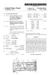
FIG. 1 is a cross-sectional view of an embodiment of the
shotgun silencer/suppressor of the present invention.
DETAILED DESCRIPTION OF THE
INVENTION
Referring to FIG. 1, there is shown a shotgun silencer/
suppressor according to the invention which is designated
generally by reference numeral 10, hereinafter referred to
simply as silencer 10. The silencer 10 comprises a cylindri-
cal body tube 12 having front end closure or cap 14 and rear
end closure or cap 16. The silencer 10 is of generally robust
construction, the body 12 being mill graded 1/8 inch wall
stainless steel tubing, or equivalent aluminum tubing. The
front and rear end closures 14,16 are made of bar stock from
the same material as the body tube, and are preferably
welded to the body. Preferably, the front and rear end caps
14,16 are provided with annular concentric flanges or rims
15,17 over which the silencer body 12 is fitted and centered.
The front end closure 14 has a central bore 13 with an
externally threaded fitting 19 on the forward face of the
closure. The rear end closure 16 is provided with an inter-
nally threaded central bore 18 for screw thread mounting to
a threaded adaptor 20 affixed to the barrel В of a shotgun
(not shown). Alternatively, the rear end closure 16 may be
5
10
15
20
25
30
35
40
45
50
55
60
65
4
provided with a flange to facilitate welding the silencer to
the shotgun barrel B. The rear body closure 16 centers the
silencer body 12 over the shotgun barrel B. The silencer 10
extends rearwardly over the barrel В to the screw thread
mounting adaptor 20 or to the location where the rear closure
is to be permanently affixed to the barrel. Centering of the
silencer body relative to the barrel В is further accomplished
by one or more support disks 22 (only one shown) that
extends from the inside wall of the body tube 12 radially
inwardly to the outside diameter of the barrel B, immedi-
ately axially rearwardly of the point where the muzzle M
discharges. The support disk 22 is provided with a plurality
of holes 23.
This arrangement of the support disk 22 with holes 23 and
a cylindrical spacer provides a primary expansion chamber
24 for propellant gasses which surrounds approximately the
last four inches of the shotgun barrel В between the rear end
closure 16 and the support disk 22. Advantageously, this
construction provides a substantial volume for the primary
expansion chamber 24 without unduly extending the silencer
10 beyond the muzzle M of the shotgun.
Immediately forward of the muzzle M of the shotgun
barrel is a first conical baffle 26 which is spaced from the
muzzle M and support disk 22 by a cylindrical spacer 25.
Guide bushing 28 is spaced approximately 0.375 inch away
from the muzzle M and is held coaxially with the bore of
barrel В by baffle 26. Aplurality of additional baffles 30, 32,
34, 36, 38, 40, 42, 44, 46 and bushings 48, 50, 52, 54, 56,
58, 60, 62, 64 are serially located in a coaxial arrangement
between baffle 26 and bushing 28 and front end closure 14.
A final bushing 66 is located in an annular rim 68 formed
integrally with front end closure 14 and concentrically to the
central bore 13. Each bushing is spaced approximately 0.375
inch away from the next adjacent bushing and the inside
diameter of the guide bushings is substantially the same as
the inside diameter of the barrel В of the shotgun.
On the forward face of the front body closure 14 threaded
to fitting 19 is a tube 70 with openings or perforations 72 in
the sidewall thereof and crenellations 73 cut into the forward
end thereof. Perforated tube 70 forms a “standoff’ for use
with police door breaching cartridges and allows muzzle
gasses to vent from the interior of the tube without over-
stressing the silencer body construction, such as may occur
if the silencer 10 were pressed against a solid object with no
escape path for the gasses.
Referring now to the baffle 26 as representative of all the
baffles, the baffle components are preferably fabricated from
aluminum with a minimum thickness of Vs inch sections.
The baffles may also be made of composite plastic materials.
Suitable composite plastics include thermosetting resins,
e.g., phenolics, or thermosetting epoxy-amine resins with
carbon fiber mat reinforcement (carbon-phenolic or carbon-
epoxy), or carbon strand reinforced high density polyethyl-
ene. Other composite plastic materials may be suitable as
will be evident to those skilled in the art.
Each baffle comprises a conical portion 74 formed inte-
grally with a cylindrical portion 76 by casting, welding or
any other suitable manufacturing process. Referring now to
the bushing 28 as representative of all the bushings, the
bushing components are preferably fabricated from stainless
steel and are provided with a flange or shoulder 78 which
retains the bushings in place when they are press-fitted or
adhesively bonded into the baffles and prevents the bushings
from being driven through the baffle by the force of the
projectile and propellant. Each bushing has a conical portion
80 facing rearwardly toward the muzzle M for guiding the
US 6,374,718 Bl
5
shot cup of the shotgun projectile and maintaining the shot
cup in its cylindrical condition until it passes out the bore 13.
Each set of adjacent baffles forms an additional expansion
chamber for the propellant gasses so that a plurality of
secondary expansion chambers (ten in the embodiment
shown) further reduce noise and flash from the shot.
Although the conical shape of the baffles is preferred for
the present invention, it is also possible to form the baffles
in other shapes. For example, the conical portions of the
baffles may be replaced by flat, concave or convex disks or
toroidal elements without departing from the scope of the
invention.
In one arrangement of the invention, the primary expan-
sion chamber 24 is empty except for the ambient air or a
vaporizable coupling fluid in the chamber. In order to
optimize silencer performance, in a second arrangement, the
primary expansion chamber 24 contains a conventional
machined element (not shown) for increasing the turbulence
of both the precursor and propellant gasses that expand into
the chamber and for providing a larger conductive surface
for impingement of hot propellant gasses. The use of such a
turbulence enhancer is determined by the burn characteris-
tics of the propellant powder of the individual brand of
shotgun ammunition being used. Propellants providing
higher temperatures at the muzzle, that is, with slower bum
rates, require the use of the primary expansion chamber
turbulence labyrinth for best attenuation. Lower temperature
gasses resulting from faster burning propellants or heavier
projectiles causing complete propellant combustion, require
little or no additional turbulence for good attenuation.
The turbulence enhancer may be as simple as a series of
perforated aluminum plates installed between the rear end
closure 16 and the support disk 24 or as complex as a piece
machined into a form with tangential slots propagating
spirally around the outside diameter of the barrel В from the
end of the muzzle M rearwardly to the rear end closure 16.
All perform similarly to increase turbulence and function as
a simple heat sink. Low density wire meshes will also
perform the task, except that cleaning such meshes in a
sealed unit is more difficult.
A shotgun projectile P is shown is dash-dot lines passing
along the axis of the silencer 10 extending between bushings
28, 48 and 50. The projectile P is of a type having a
compliant shot cup which retains its substantially cylindrical
unitary form until the shot cup passes through bushing 66
and bore 13 at the front end closure 14 of the silencer 10
when it spreads into a petal-like form as described above.
A vaporizable coupling fluid in the primary expansion
chamber and the aluminum interior construction also func-
tion as flash suppressors. The mechanism of cooling burning
propellant particles and incandescent gasses occurs through
heat conduction and the absorption of significant numbers of
calories of heat out of the gasses through vaporization of the
fluid. Quenching of flame and powder granules also occurs
from simple contact with unvaporized fluid. The fluid may
be an aqueous solution with conventional additives to
enhance heat transfer to the interior metallic components of
the silencer, lubricate the guide bushings, and quench burn-
ing ejecta from the barrel. Moreover, the water component
of the aqueous fluid further cools the muzzle gasses through
vaporization and expansion into steam. Suitable coupling
fluids include, for example, a synthetic soluble oil cutting
fluid with water, a wetting agent, such as Kodak Photo-Flow,
and rust inhibitors. The high caloric absorption for vapor-
ization results in effective gas cooling and the wetting of the
baffles provides excellent heat transfer from the hot gasses.
5
10
15
20
25
30
35
40
45
50
55
60
65
6
Although certain presently preferred embodiments of the
invention have been specifically described herein, it will be
apparent to those skilled in the art to which the invention
pertains that variations and modifications of the various
embodiments shown and described herein may be made
without departing from the spirit and scope of the invention.
Accordingly, it is intended that the invention be limited only
to the extent required by the appended claims and the
applicable rules of law.
What is claimed is:
1. A shotgun silencer for a shotgun projectile having a
compliant shot cup comprising;
a closed body having front and rear ends, an interior wall
and a longitudinal axis;
a front end closure having a projectile exit guide bushing;
a rear end closure having a mounting element for mount-
ing the body to the barrel of a shotgun having a muzzle
disposed within the body; and
a plurality of baffles arranged in the body coaxially with
the muzzle and each other and being spaced axially
along the longitudinal axis of the body, each baffle
supporting a metal guide bushing, said guide bushings
being spaced apart less than the length of the shot cup
and having a diameter substantially the same as the
inside diameter of the barrel of the shotgun.
2. A shotgun silencer as defined in claim 1, wherein said
body extends rearwardly past the muzzle, a perforated
support disk arranged between the interior wall of the body
and the barrel of the shotgun adjacent the muzzle so as to
form a primary expansion chamber extending coaxially from
the muzzle to the rear end closure and surrounding the
forward end of the barrel.
3. A shotgun silencer as defined in claim 1, wherein said
guide bushings are made of stainless steel and said baffles
are made of aluminum.
4. A shotgun silencer as defined in claim 1, wherein said
baffles comprise a conical portion and a cylindrical portion
integrally formed with one another, said cylindrical portion
having a diameter substantially the same as the interior wall
of the body.
5. A shotgun silencer as defined in claim 4, wherein the
guide bushings are press-fitted into the conical portions,
each guide bushing having a flange for retaining the guide
bushing in the conical portion into which it is fitted.
6. A shotgun silencer as defined in claim 1, wherein said
baffles are spaced apart to form a plurality of expansion
chambers along said body.
7. A shotgun silencer as defined in claim 1, wherein the
body and front and rear end closures are made of aluminum
and are welded together.
8. A shotgun silencer as defined in claim 1, including a
perforated standoff tube mounted to the front end closure,
said tube having a forward edge with a plurality of crenel-
lations therein.
9. A shotgun silencer as defined in claim 1, including an
aqueous vaporizable fluid in the body.
10. A shotgun silencer as defined in claim 1, wherein the
axial distance between the guide bushings at the ends of a
series of three adjacent guide bushings is less than the length
of the shot cup.
11. A shotgun silencer as defined in claim 1, wherein the
body and front and rear end closures are made of stainless
steel and are welded together.
12. A shotgun silencer as defined in claim 1, wherein a
threaded adapter is mounted to the barrel of the shotgun
rearwardly of the muzzle, the mounting element comprising
a threaded bore in the rear end closure.
US 6,374,718 Bl
7
13. A shotgun silencer as defined in claim 2, wherein the
primary expansion chamber has a length of about four
inches.
14. A shotgun silencer as defined in claim 1, wherein
baffles are made of a composite plastic material. 5
15. A method of making a shotgun silencer for a shotgun
projectile having a compliant shot cup, the silencer includ-
ing a cylindrical body, comprising the steps of:
providing a plurality of identically formed baffles each
supporting a metal guide bushing and having a cylin- 10
drical portion with opposite annular surfaces, each
metal guide bushing having a diameter substantially the
same as the inside diameter of a shotgun barrel to which
the silencer is adapted to be attached; and
8
inserting at least three of the baffles into the body in
end-to-end relation such that the annular surfaces of the
cylindrical portions bear against one another and the
guide bushings of at least two adjacent baffles are
spaced apart less than the length of the shot cup.
16. The method of making a shotgun silencer as defined
in claim 15, including the steps of providing an end closure
for the body and sealing the end closure to the body after
inserting the baffles into the body.
17. The method of making a shotgun silencer as defined
in claim 15, wherein the guide bushings of three baffles are
spaced apart less than the length of the shot cup.