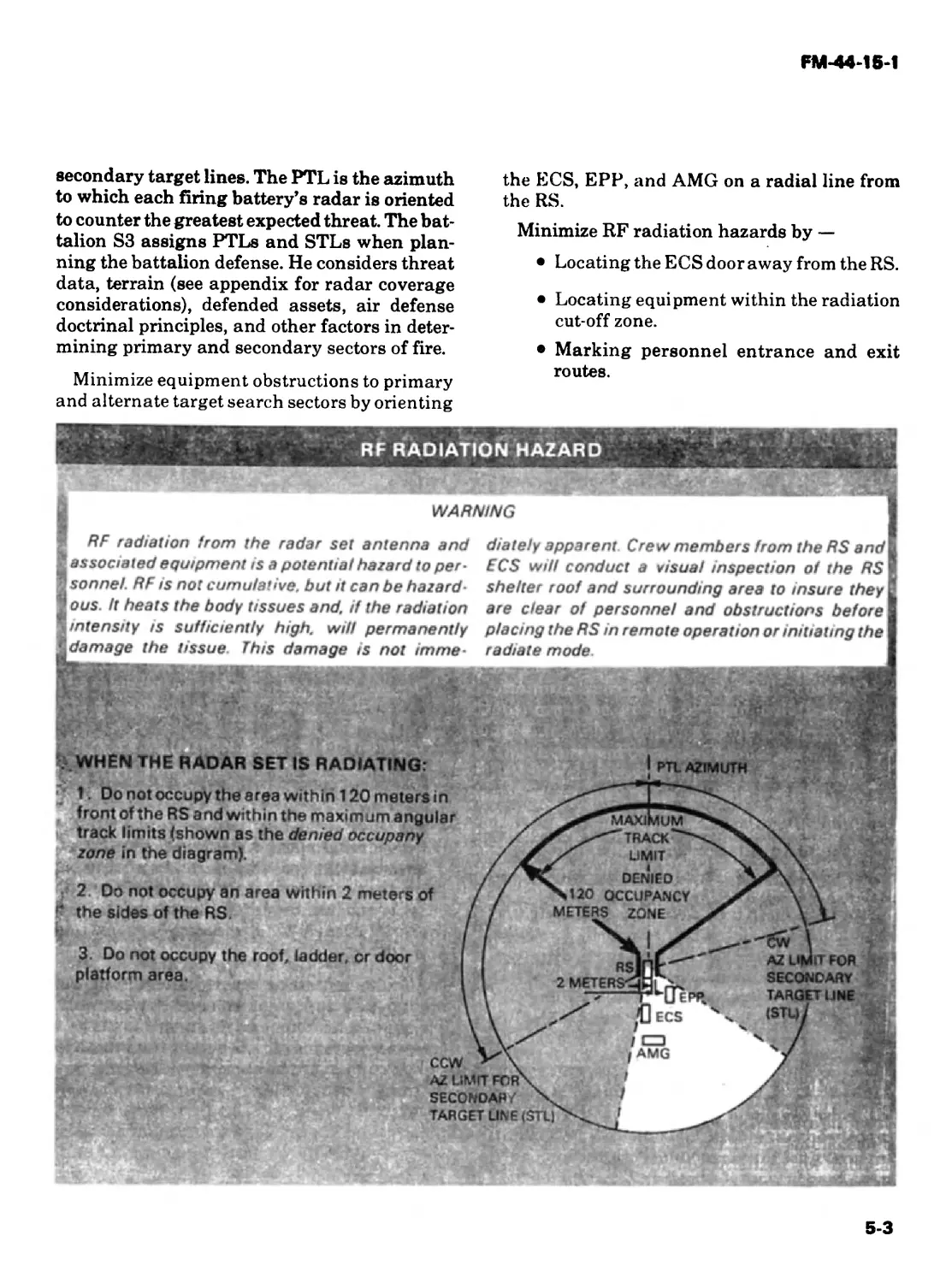
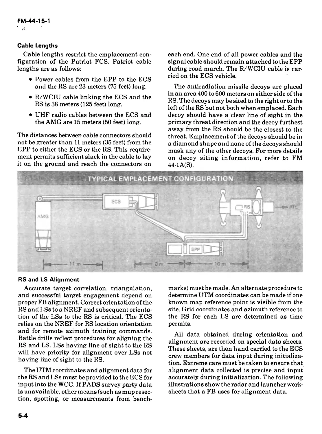
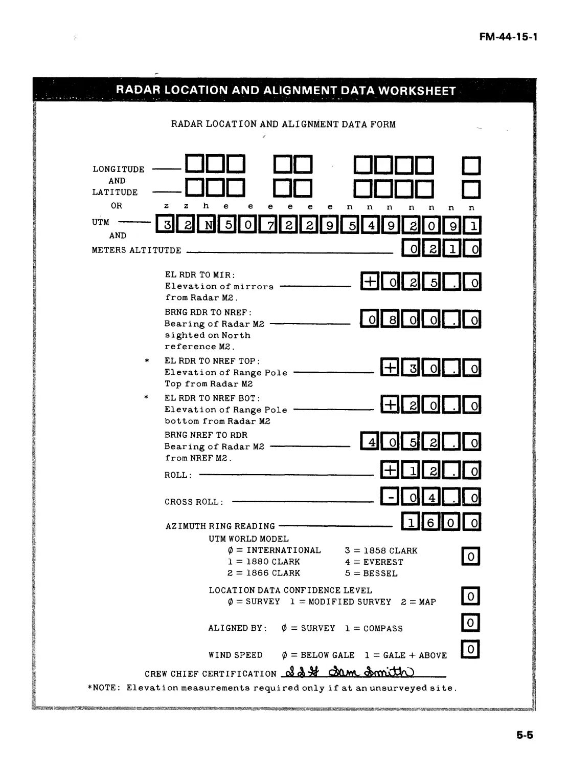
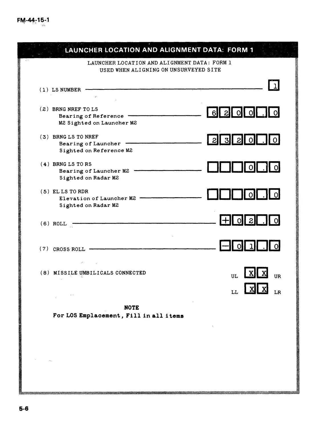
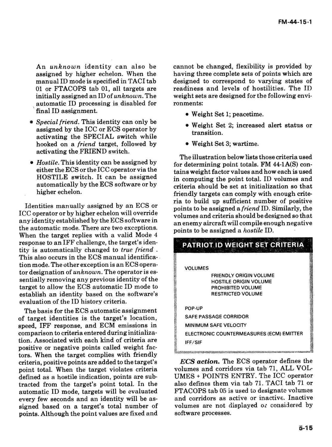
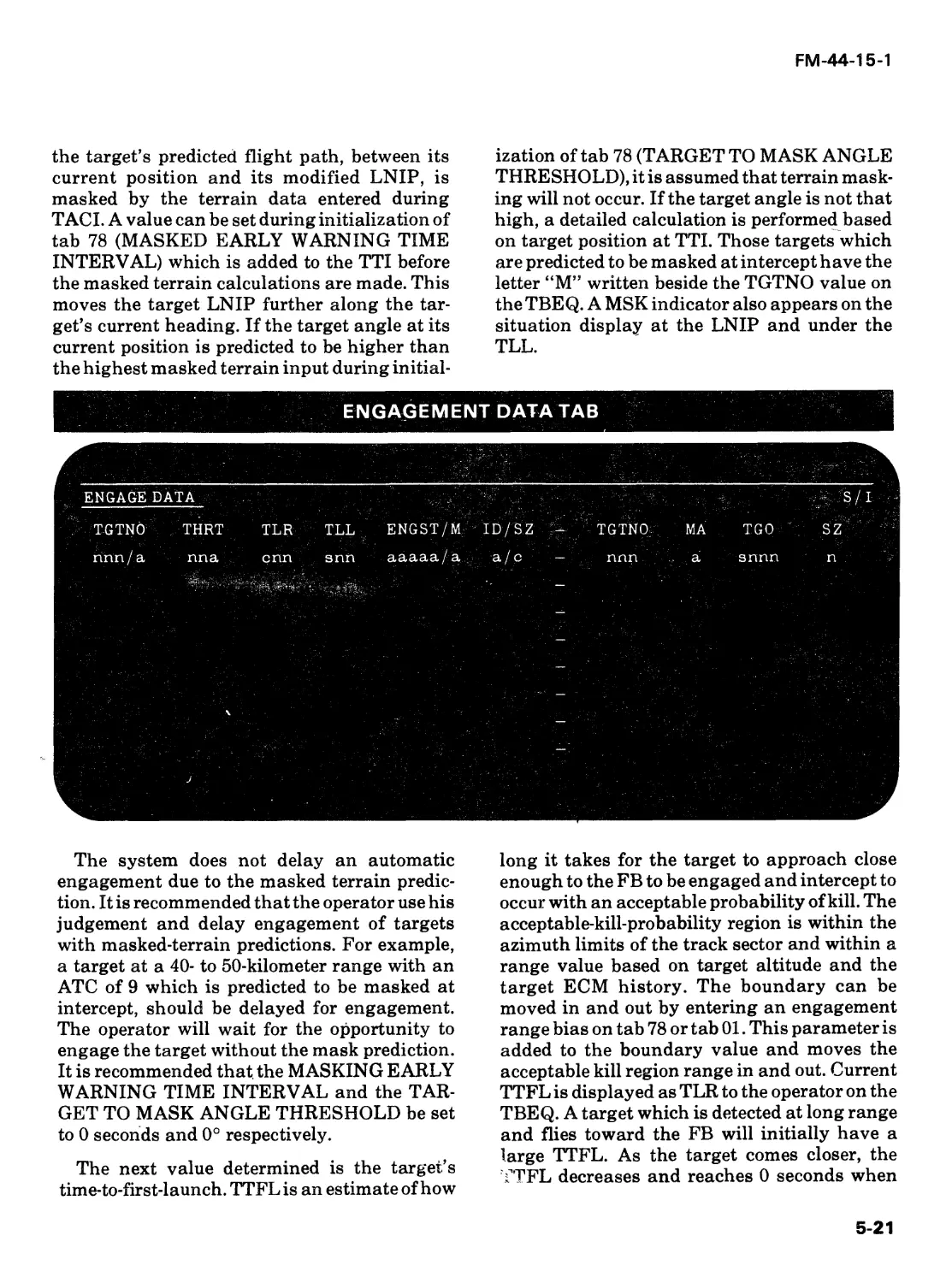
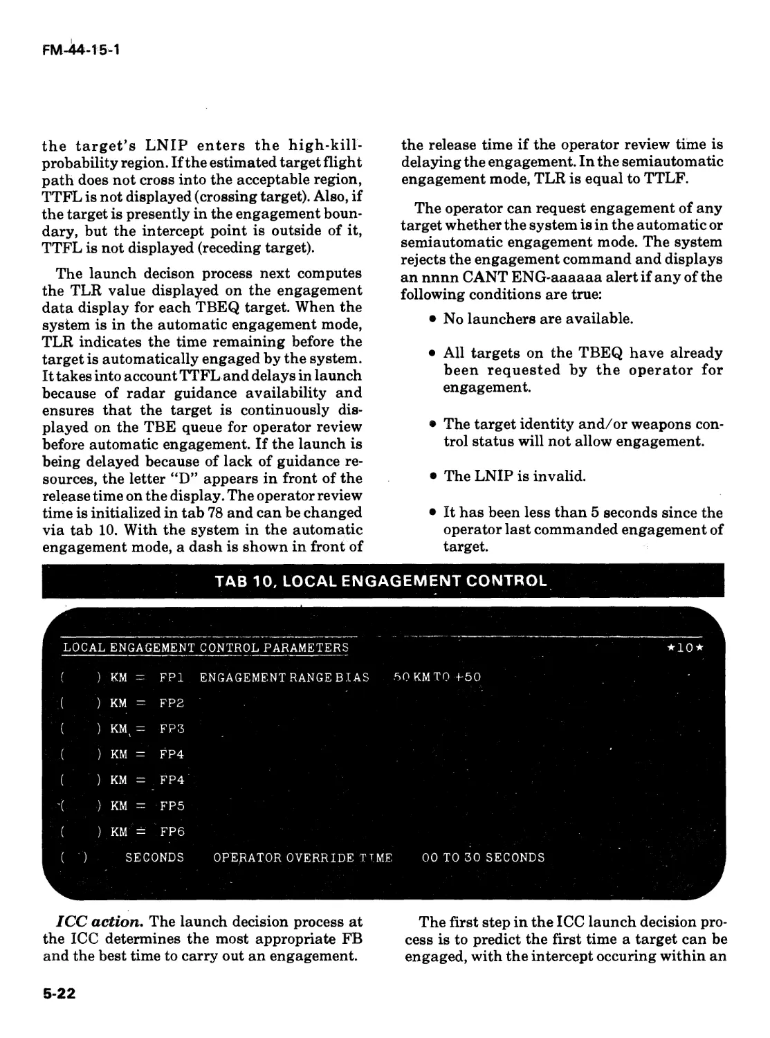
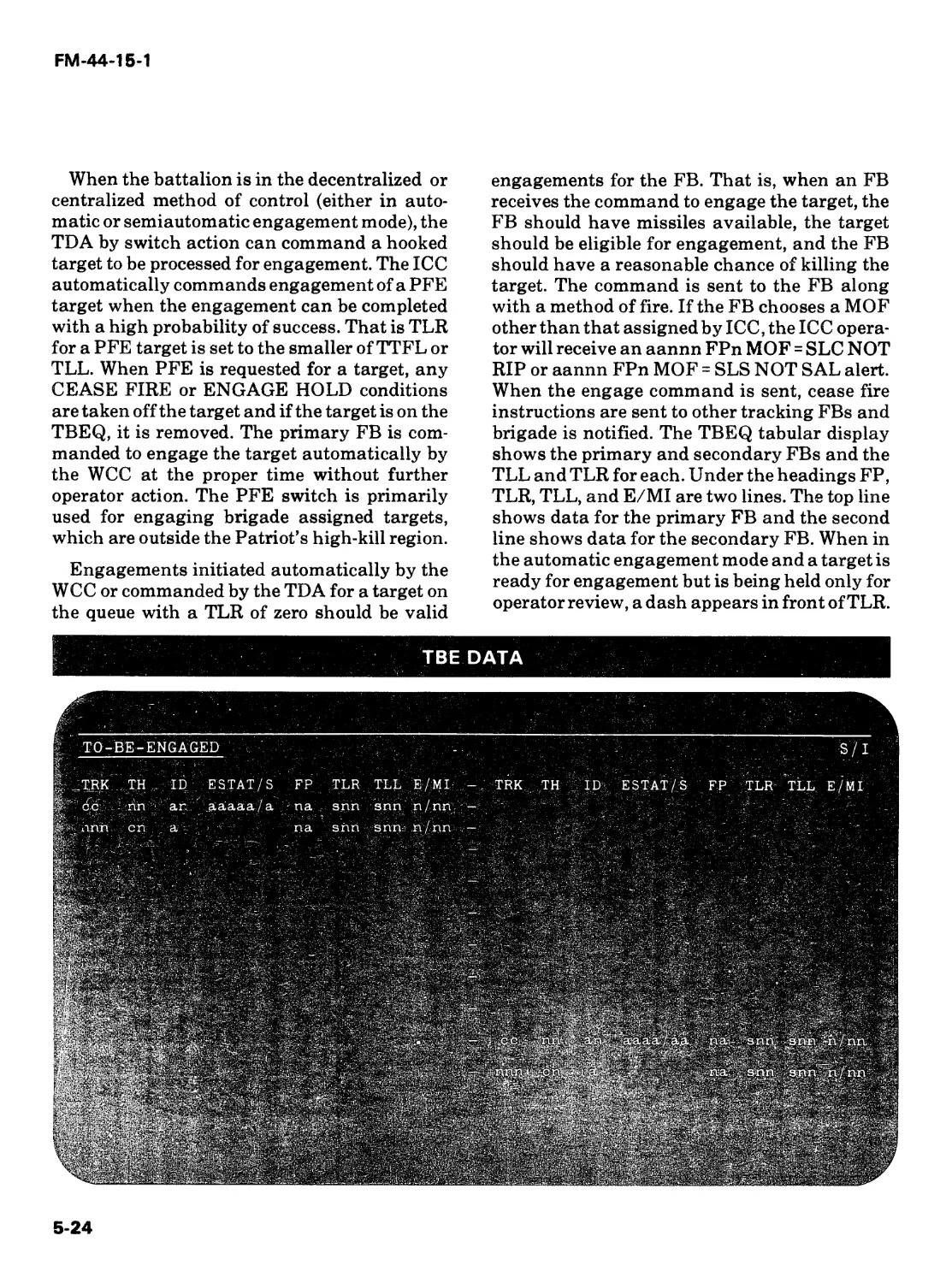
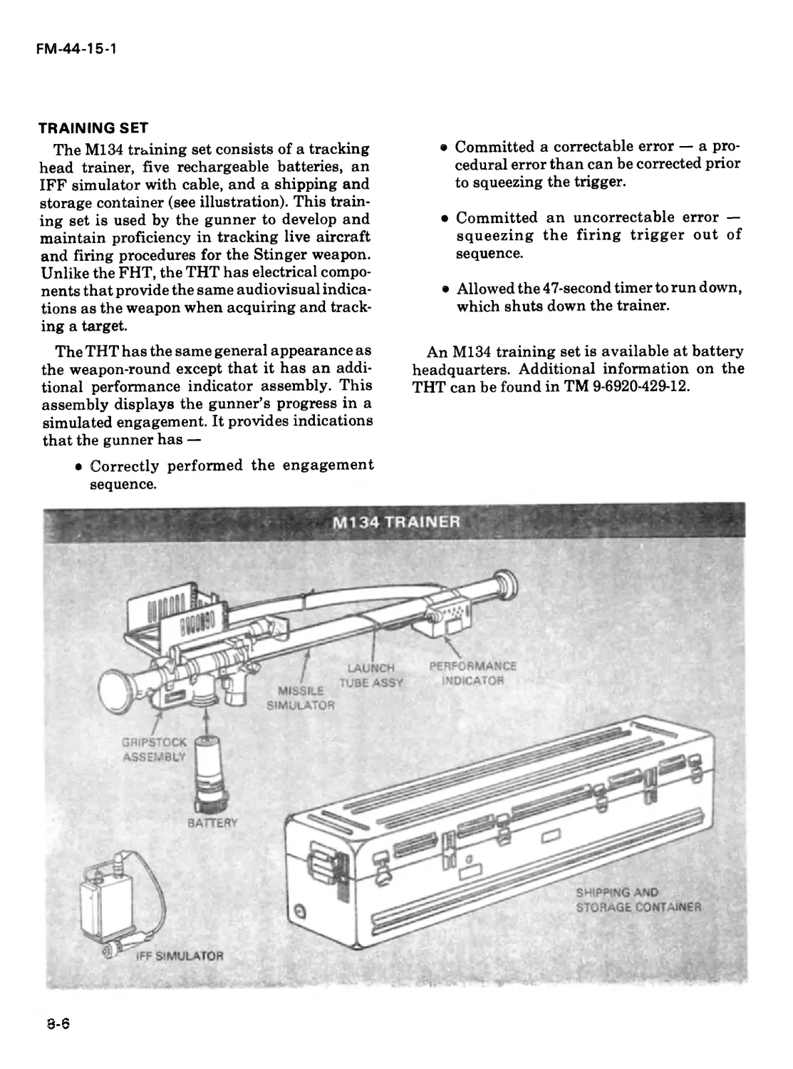
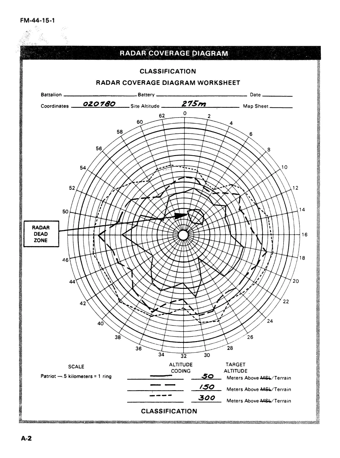
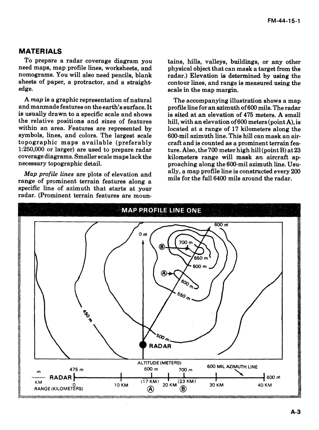
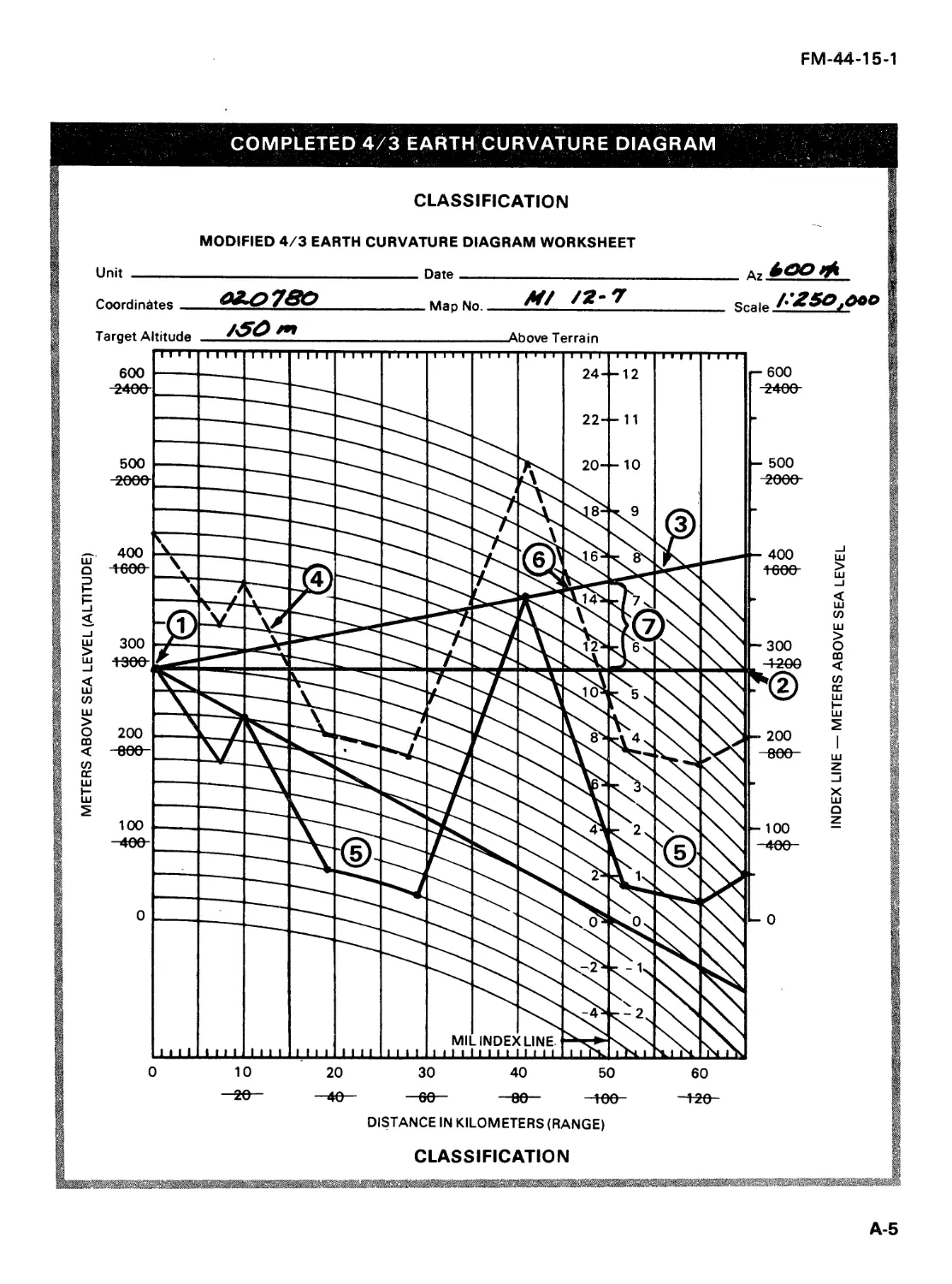
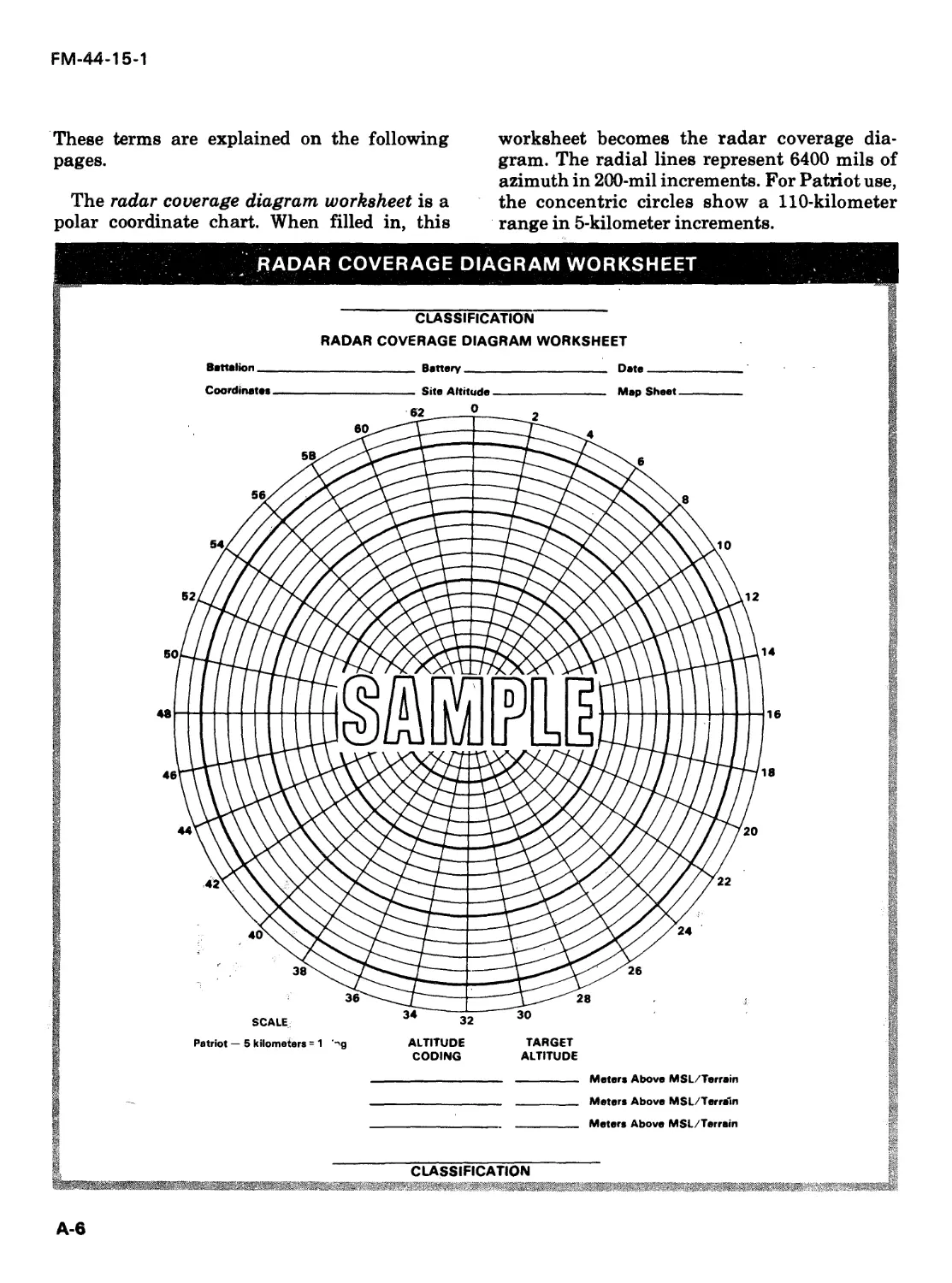
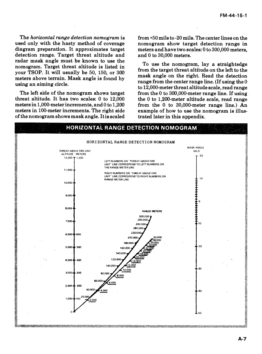
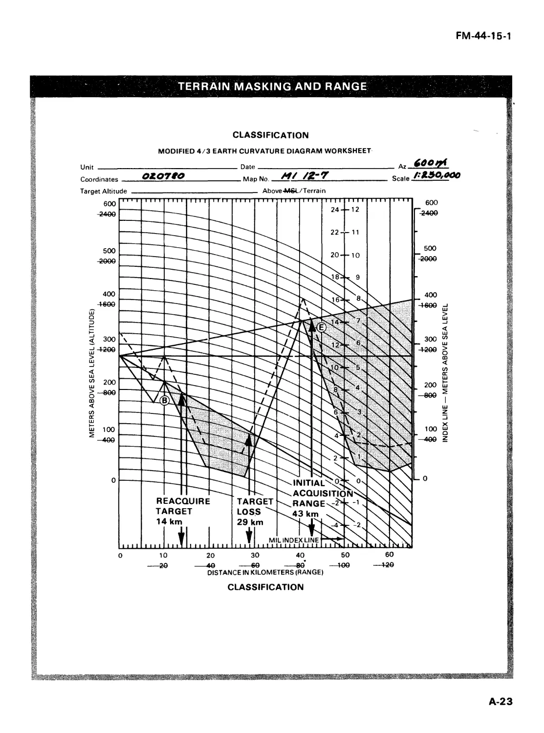
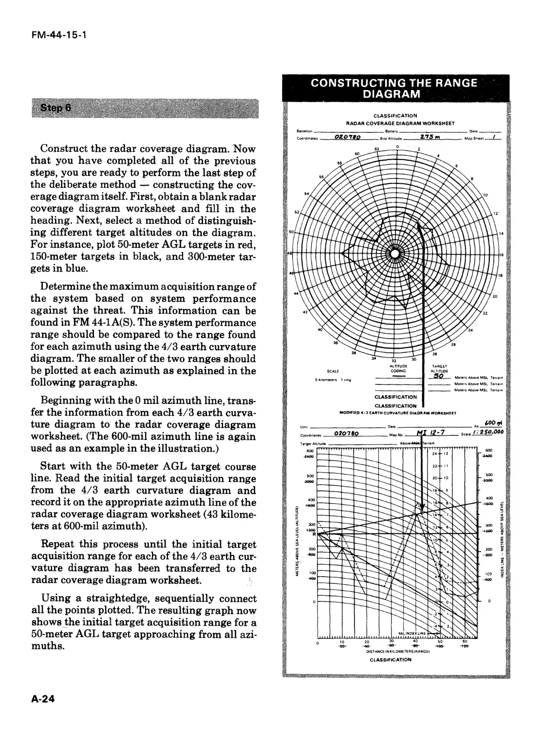
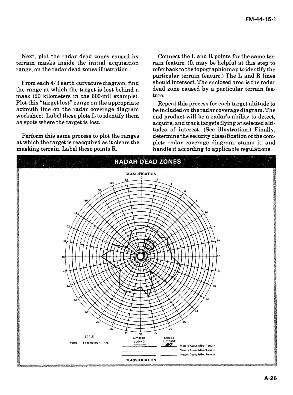
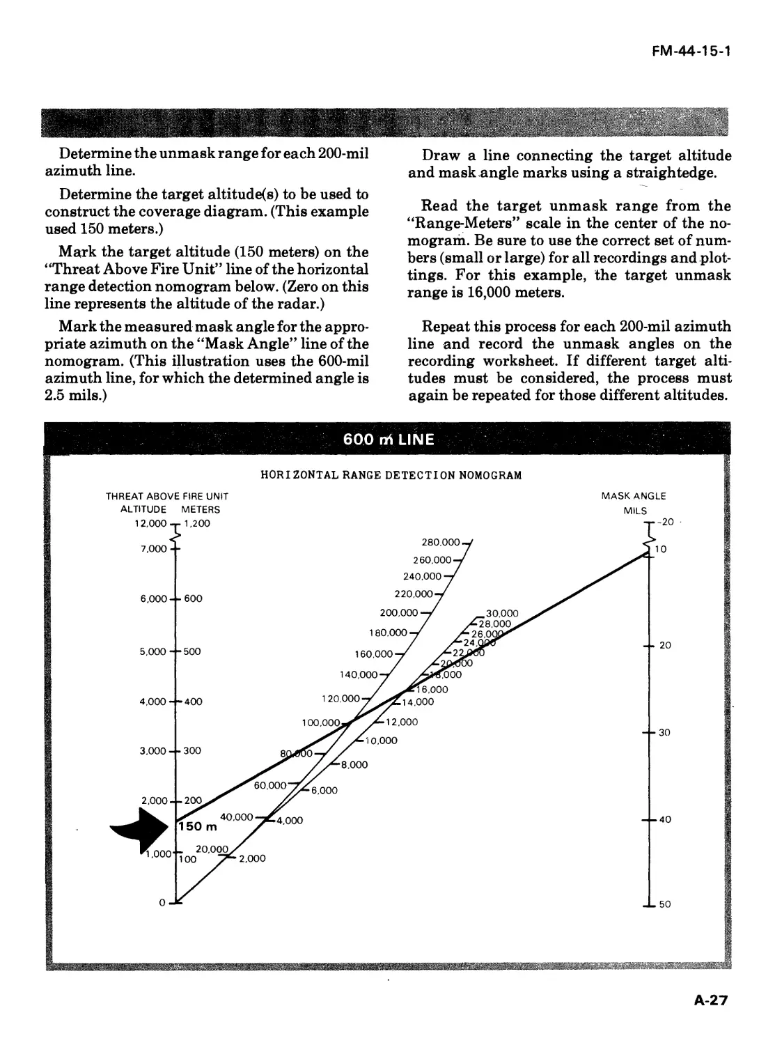
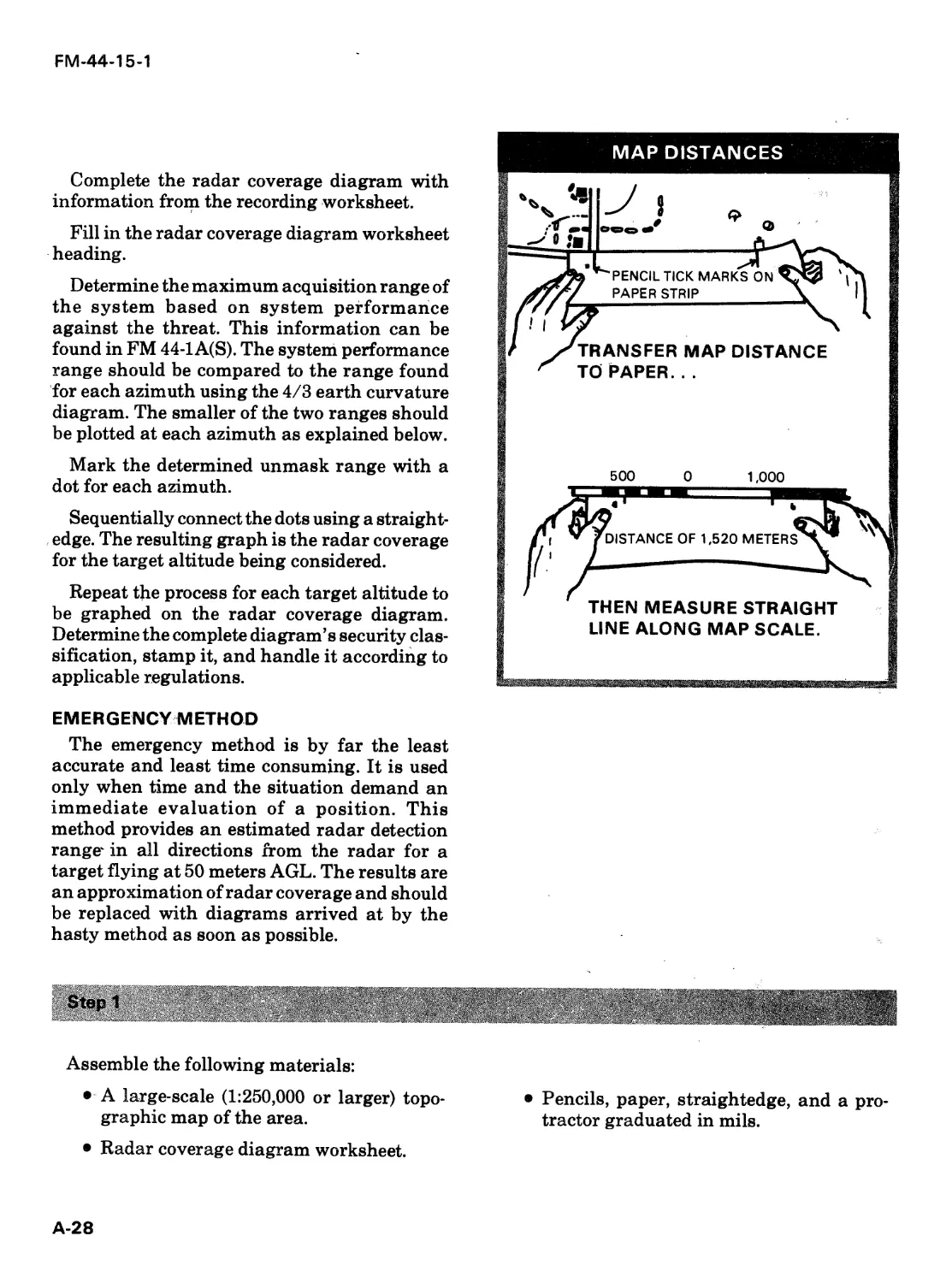
/


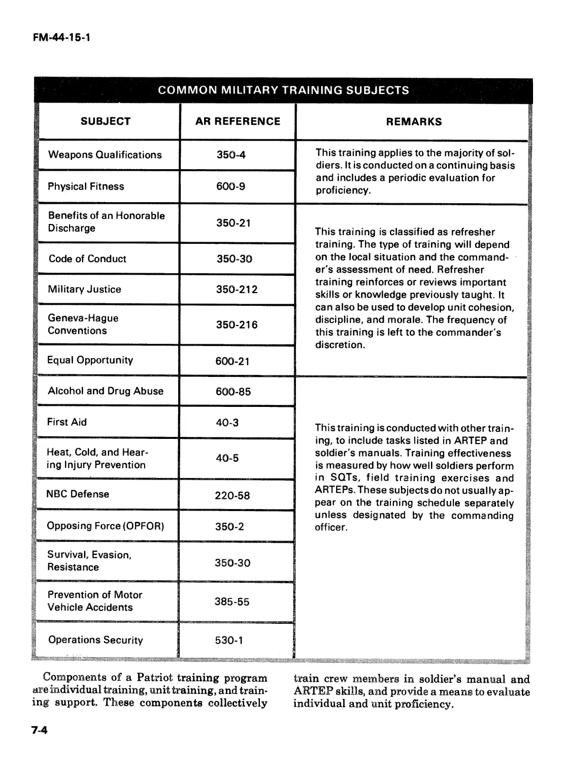


Теги: weapons
Год: 1987


Текст
FM 44-15-1
HEADQUARTERS
DEPARTMENT OF THE ARMY
Operations
and Training
Patriot;
DISTRIBUTION RESTRICTION: Distribution authorized to U.S. Government agencies only to prevent
automatic dissemination of technical or operational information. This determination was made on 20
November 1986. Refer other requests for this document to Commandant, USAAD AS, ATTN: ATZC-DS,
Fort Bliss, TX 79902-5500.
DESTRUCTION NOTICE: Destroy by any method that will prevent disclosure of contents or
reconstruction of the document.
FIELD MANUAL
NO. 44-15-1
*FM 44-15-1
HEADQUARTERS
DEPARTMENT OF THE ARMY
WASHINGTON, DC, 17 February 1987
Operations
and Training
Patriot;
DISTRIBUTION RESTRICTION: Distribution authorized to U.S. Government agencies only to prevent automatic dissemination of
technical or operational information. This determination was made on 20 November 1936. Refer other requests for this documentto
Commandant, USAADAS, ATTN: ATZC-DS, Fort Bliss, TX 79902-5500.
DESTRUCTION NOTICE: Destroy by any method that will prevent disclosure of contents or reconstruction of the document.
'This publication supersedes FM 44-15-1, 13 June 1984.
FM 44-15-1
PREFACE
This manual describes operations and training applications of the
Patriot air defense missile system. This manual does not cover routine
and detailed maintenance tasks. Consult the appropriate technical
manual for these requirements. This manual is written for Patriot
battalion personnel. However, emphasis is on the Patriot firing
battery. As such, the firing battery personnel and their training
receive considerable attention.
FM 44-15-1 is a companion manual to FM 44-15. FM 44-15 deals with
unclassified doctrinal and tactical aspects of employing the Patriot
system. FM 44-1 A(S) contains classified information on Patriot, in-
cluding system effectiveness performance data.
The proponent of this publication is HQ TRADOC. Submit changes
for improving this publication on DA Form 2028 (Recommended
Changes to Publications and Blank Forms) and forward it to
Commandant, USA AD ASCH, ATTN: ATSA-PD, Fort Bliss, Texas
79916-7180.
ii
FM 44-15-1
Operations
and Training
Patriot
Table of Contents
CHAPTER
□ Patriot Air Defense Missile System........................
Organization
APPENDIX
GLOSSARY
Support.....................................
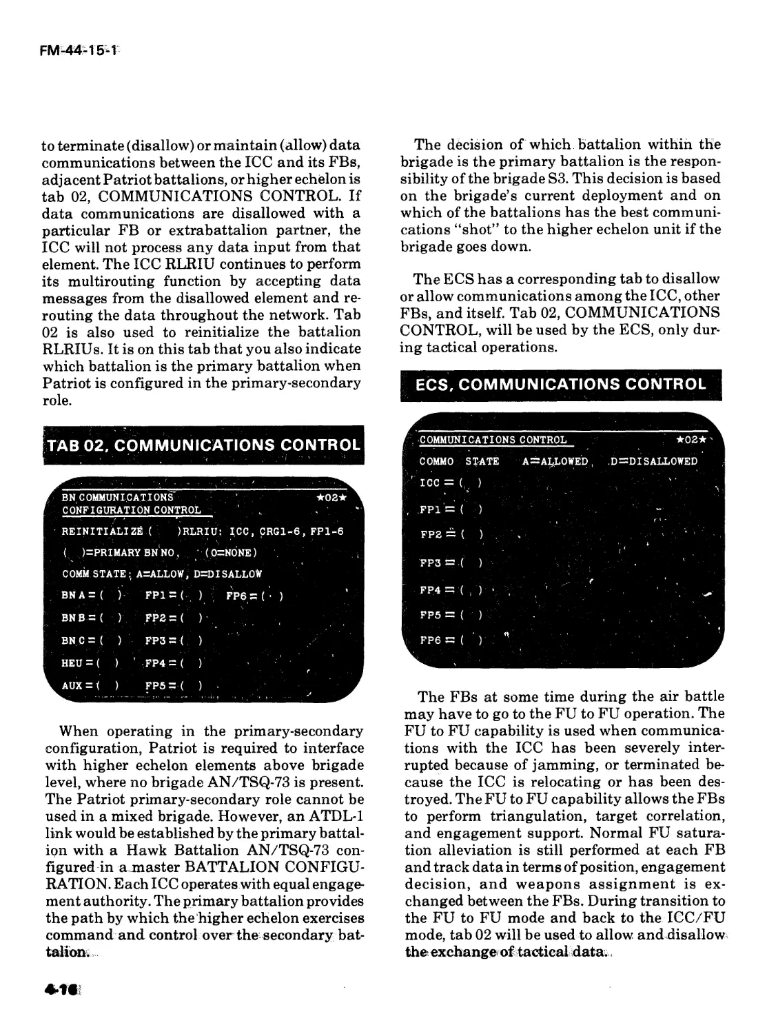
Communications.............................
Operations.....................................
Nuclear, Biological and Chemical
* Environments................................
в Training Development...........................
Training Materials.................................
1-1
2-1
3-1
4-1
5-1
6-1
7-1
8-1
Radar Coverage Diagrams.................... A-1
GLOSS AR Y-1
REFERENCES ......................................... REFERENCES-1
INDEX
INDEX-1
iii
FM-44-15-1
The provisions of this publication are the subject of international agreements:
NATO STANAGS
2002 Warning signs for the Marking of Contaminated or Dangerous Land Areas,
Complete Equipments, Supplies and Stores
2047 Emergency Alarms of Hazard or Attack (NBC and Air Attack Only)
2103 Reporting Nuclear Detonations, Biological and Chemical Attacks, and
Predicting and Warning of Associated Hazards and Hazard Areas
2112 Radiological Surveys
2889 The Marking of Hazardous Areas and Routes Through Them
Unless otherwise stated, whenever the masculine gender is used, both men and
women are included.
iv
Patriot Air Defense
Missile System
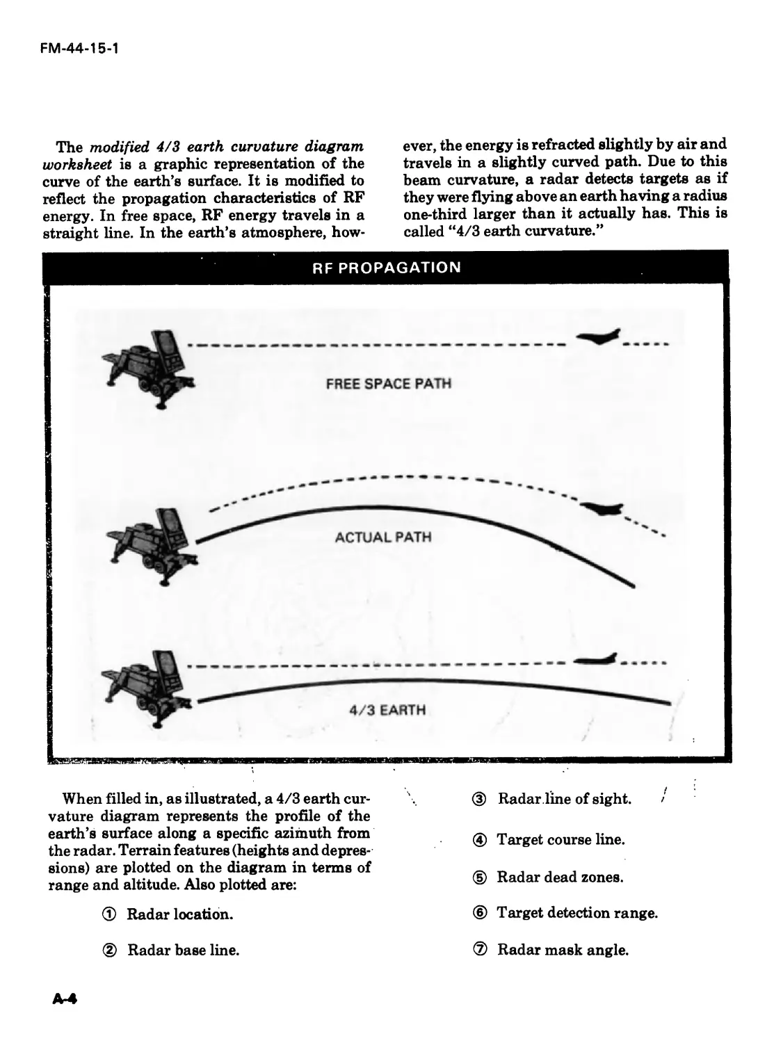
Patriot is an air defense missile system designed to counter
the air threat of the 1980s and beyond. This chapter discusses
the role of the Patriot system, the mission of the Patriot firing
batteries, and the major items of Patriot equipment. It also
discusses the Patriot system’s operational features.
MISSION AND ROLE
The Patriot system’s role is to function
against targets within the very low- to very
high- altitude boundaries. The Patriot firing
battery’s mission is to provide very low- to very
high-altitude air defense for ground combat
forces and high value assets. Patriot performs
this mission with less tactical equipment, im-
proved technology, greater firepower, improved
ECCM capability, simplified supply and main-
tenance, and high mobility.
Patriot requires fewer major items of equip-
ment and personnel than other high- to medium-
altitude air defense systems. For example, the
Patriot phased-array radar performs the func-
tions that nine HIMAD radars perform in other
systems.
Patriot is the first fully automated, software-
driven US air defense artillery weapon system.
Software — a combination of associated com-
puter programs and data — enables the Patriot
computers to perform computational and con-
trol functions. These computers also regulate
engagement actions and monitor the opera-
tional status of equipment subsystems. The
Patriot system operates in an automatic or
semiautomatic engagement mode and in an
automatic or manual identification mode.
A maximum of 192 ready-to-fire missiles are
in a Patriot battalion. These missiles provide
the needed firepower to counter large numbers
of attacking enemy aircraft. These missiles also
perform well individually against single,
highly maneuverable jet aircraft. The missile
has a unique guidance system which uses a
^rack-via-missile mode\TVM provides greater
accufacyto^the missile ih flight. TVM guidance
is discussed in the missile description part of
this chapter.
The Patriot system is highly effective in an
ECM environment. Special pulsing of the
phased array radar transmitter is automati-
cally selected to counter enemy ECM. Addition-
ally, the connecting cables to the Patriot shel-
ters, and the shelters themselves, are shielded
against electromagnetic and radio frequency
interference.
1-1
FM-44-15-1
Standardized electronic modules simplify sup-
ply and maintenance functions. These multiple-
use modules reduce the number and types of
required repair parts and are quickly replace-
able. BITE, system status monitor, and diag-
nostics aid in isolating equipment faults to
major assemblies, thereby reducing repair time.
Patriot’s high mobility minimizes its suscep-
tibility to targeting and attack. This mobility
also enables the battalion to keep pace with
rapidly flowing air and ground force oper-
ations.
FIRING BATTERY
Patriot fights as a battalion; however, its bas-
ic operational element is the firing battery.
Normally, there are six FBs in a Patriot battal-
ion. (The FB is also referred to as a FU or FP in
the software).
The firing battery consists of an engagement
control station, radar set, electric power plant,
and antenna mast group. These items make up
the fire control section of the firing battery. The
firing battery also has up to eight launching
stations.
The firing battery is capable of —
• Searching a designated volume of air space
to detect and place targets under track.
• Identifying targets as friend, true friend,
assumed friend, special friend, unknown, or
hostile.
• Arranging targets in priority order for
engagement.
• Selecting and launching missiles.
• Guiding missiles to intercept and arming
the proximity fuse.
• Evaluating and recording the results of
each engagement.
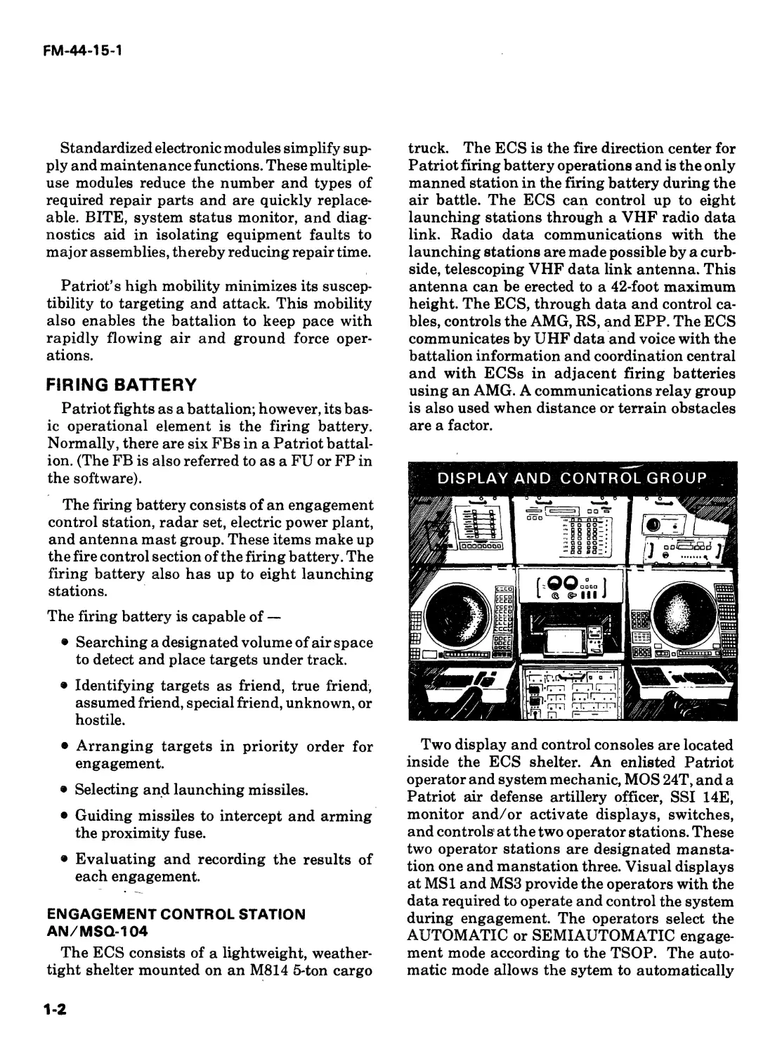
ENGAGEMENT CONTROL STATION
AN/MSQ-104
The ECS consists of a lightweight, weather-
tight shelter mounted on an M814 5-ton cargo
truck. The ECS is the fire direction center for
Patriot firing battery operations and is the only
manned station in the firing battery during the
air battle. The ECS can control up to eight
launching stations through a VHF radio data
link. Radio data communications with the
launching stations are made possible by a curb-
side, telescoping VHF data link antenna. This
antenna can be erected to a 42-foot maximum
height. The ECS, through data and control ca-
bles, controls the AMG, RS, and EPP. The ECS
communicates by UHF data and voice with the
battalion information and coordination central
and with ECSs in adjacent firing batteries
using an AMG. A communications relay group
is also used when distance or terrain obstacles
are a factor.
Two display and control consoles are located
inside the ECS shelter. An enlisted Patriot
operator and system mechanic, MOS 24T, and a
Patriot air defense artillery officer, SSI 14E,
monitor and/or activate displays, switches,
and controls at the two operator stations. These
two operator stations are designated mansta-
tion one and manstation three. Visual displays
at MSI and MS3 provide the operators with the
data required to operate and control the system
during engagement. The operators select the
AUTOMATIC or SEMIAUTOMATIC engage-
ment mode according to the TSOP. The auto-
matic mode allows the sytem to automatically
1-2
FM-44-15-1
select and engage targets. In this mode, the op-
erators primarily monitor engagements but
have the capability to manually override this
mode and engage targets. In the semiautomatic
engagement mode, the operators manually
select and engage targets that the system has
detected and processed. These modes are
further described in Chapter 5.
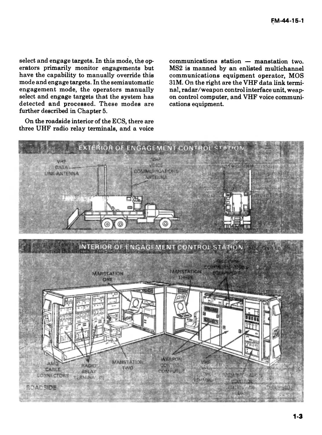
On the roadside interior of the ECS, there are
three UHF radio relay terminals, and a voice
communications station — manstation two.
MS2 is manned by an enlisted multichannel
communications equipment operator, MOS
31M. On the right are the VHF data link termi-
nal, radar/weapon control interface unit, weap-
on control computer, and VHF voice communi-
cations equipment.
1-3
FM-44-15-1
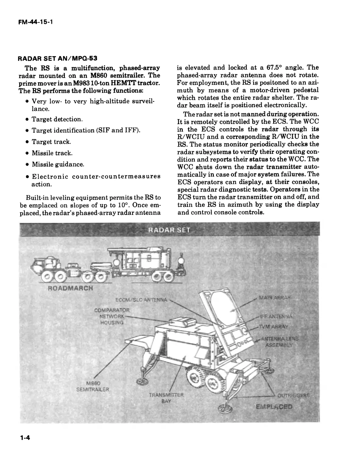
RADAR SET AN/MPQ-53
The RS is a multifunction, phased-array
radar mounted on an M860 semitrailer. The
prime mover is an M98310-ton HEMTT tractor.
The RS performs the following functions:
• Very low- to very high-altitude surveil-
lance.
• Target detection.
• Target identification (SIF and IFF).
• Target track.
• Missile track.
• Missile guidance.
• Electronic counter-countermeasures
action.
Built-in leveling equipment permits the RS to
be emplaced on slopes of up to 10°. Once em-
placed, the radar’s phased-array radar antenna
is elevated and locked at a 67.5° angle. The
phased-array radar antenna does not rotate.
For employment, the RS is positoned to an azi-
muth by means of a motor-driven pedestal
which rotates the entire radar shelter. The ra-
dar beam itself is positioned electronically.
The radar set is not manned during operation.
It is remotely controlled by the ECS. The WCC
in the ECS controls the radar through its
R/WCIU and a corresponding R/WCIU in the
RS. The status monitor periodically checks the
radar subsystems to verify their operating con-
dition and reports their status to the WCC. The
WCC shuts down the radar transmitter auto-
matically in case of major system failures. The
ECS operators can display, at their consoles,
special radar diagnostic tests. Operators in the
ECS turn the radar transmitter on and off, and
train the RS in azimuth by using the display
and control console controls.
1-4
FM-44-15-1
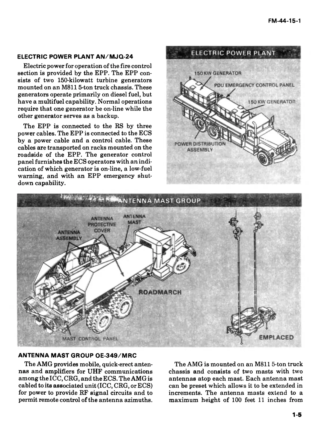
ELECTRIC POWER PLANT AN/MJQ-24
Electric power for operation of the fire control
section is provided by the EPP. The EPP con-
sists of two 150-kilowatt turbine generators
mounted on an M811 5-ton truck chassis. These
generators operate primarily on diesel fuel, but
have a multifuel capability. Normal operations
require that one generator be on-line while the
other generator serves as a backup.
The EPP is connected to the RS by three
power cables. The EPP is connected to the ECS
by a power cable and a control cable. These
cables are transported on racks mounted on the
roadside of the EPP. The generator control
panel furnishes the ECS operators with an indi-
cation of which generator is on-line, a low-fuel
warning, and with an EPP emergency shut-
down capability.
ELECTRIC POWER PLANT
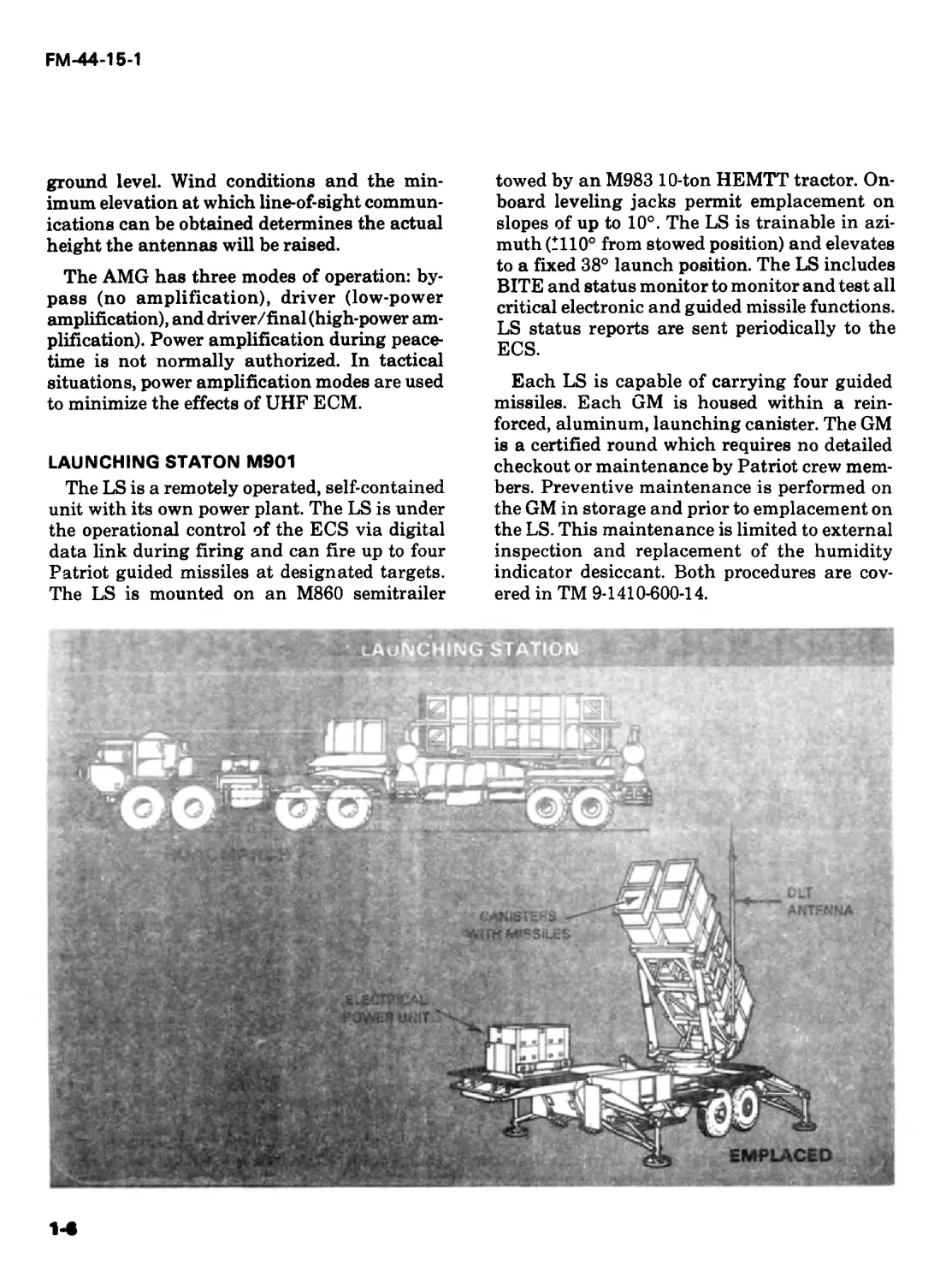
ANTENNA MAST GROUP OE-349/MRC
The AMG provides mobile, quick-erect anten-
nas and amplifiers for UHF communications
among the ICC, CRG, and the ECS. The AMG is
cabled to its associated unit (ICC, CRG, or ECS)
for power to provide RF signal circuits and to
permit remote control of the antenna azimuths.
The AMG is mounted on an M811 5-ton truck
chassis and consists of two masts with two
antennas atop each mast. Each antenna mast
can be preset which allows it to be extended in
increments. The antenna masts extend to a
maximum height of 100 feet 11 inches from
1-5
FM-44-15-1
ground level. Wind conditions and the min-
imum elevation at which line-of-sight commun-
ications can be obtained determines the actual
height the antennas will be raised.
The AMG has three modes of operation: by-
pass (no amplification), driver (low-power
amplification), and driver/final (high-power am-
plification). Power amplification during peace-
time is not normally authorized. In tactical
situations, power amplification modes are used
to minimize the effects of UHF ECM.
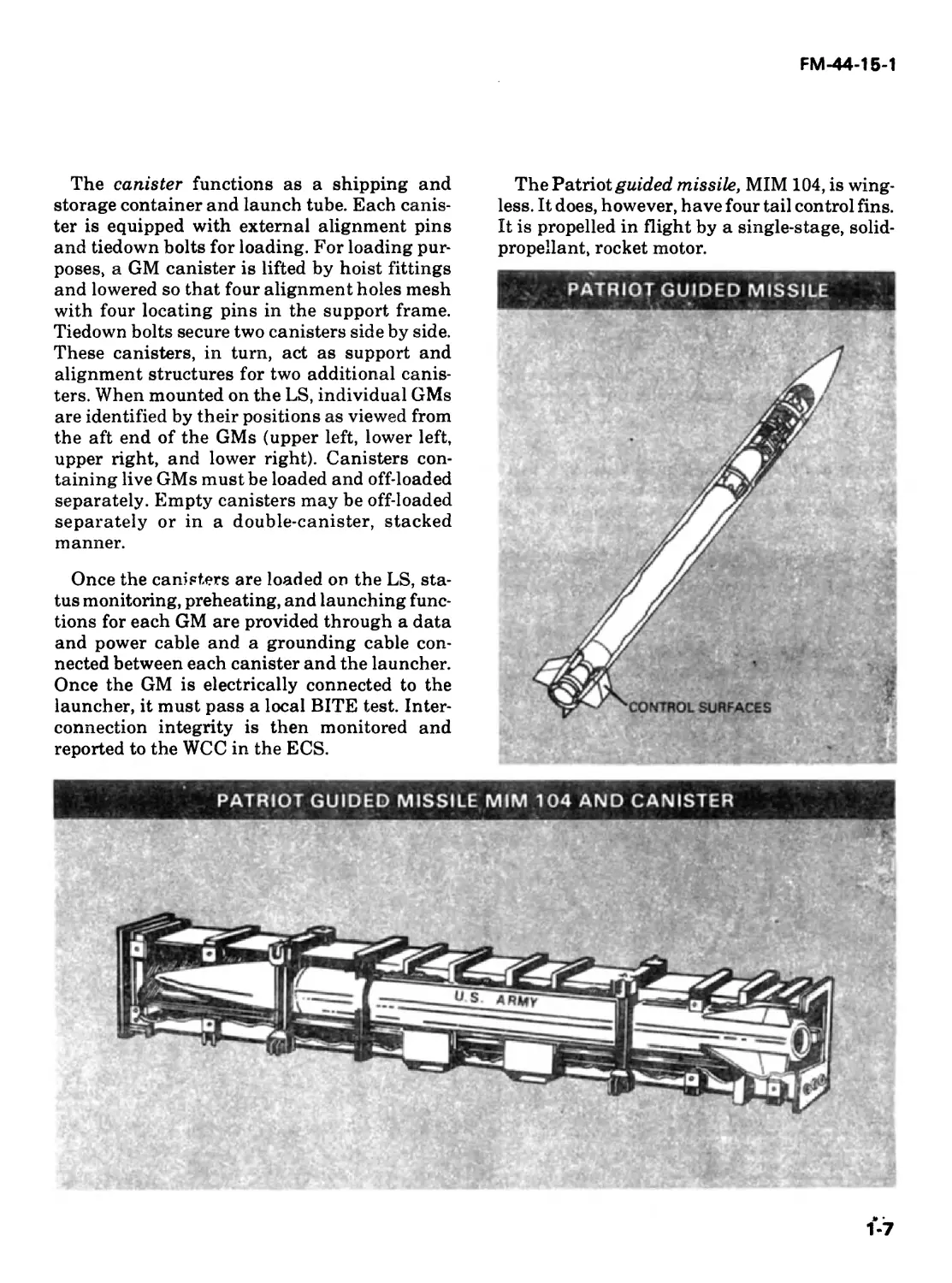
LAUNCHING STATON M901
The LS is a remotely operated, self-contained
unit with its own power plant. The LS is under
the operational control of the ECS via digital
data link during firing and can fire up to four
Patriot guided missiles at designated targets.
The LS is mounted on an M860 semitrailer
towed by an M983 10-ton HEMTT tractor. On-
board leveling jacks permit emplacement on
slopes of up to 10°. The LS is trainable in azi-
muth (1110° from stowed position) and elevates
to a fixed 38° launch position. The LS includes
BITE and status monitor to monitor and test all
critical electronic and guided missile functions.
LS status reports are sent periodically to the
ECS.
Each LS is capable of carrying four guided
missiles. Each GM is housed within a rein-
forced, aluminum, launching canister. The GM
is a certified round which requires no detailed
checkout or maintenance by Patriot crew mem-
bers. Preventive maintenance is performed on
the GM in storage and prior to emplacement on
the LS. This maintenance is limited to external
inspection and replacement of the humidity
indicator desiccant. Both procedures are cov-
ered in TM 9-1410-600-14.
FM-44-15-1
The canister functions as a shipping and
storage container and launch tube. Each canis-
ter is equipped with external alignment pins
and tiedown bolts for loading. For loading pur-
poses, a GM canister is lifted by hoist fittings
and lowered so that four alignment holes mesh
with four locating pins in the support frame.
Tiedown bolts secure two canisters side by side.
These canisters, in turn, act as support and
alignment structures for two additional canis-
ters. When mounted on the LS, individual GMs
are identified by their positions as viewed from
the aft end of the GMs (upper left, lower left,
upper right, and lower right). Canisters con-
taining live GMs must be loaded and off-loaded
separately. Empty canisters may be off-loaded
separately or in a double-canister, stacked
manner.
Once the canisters are loaded on the LS, sta-
tus monitoring, preheating, and launching func-
tions for each GM are provided through a data
and power cable and a grounding cable con-
nected between each canister and the launcher.
Once the GM is electrically connected to the
launcher, it must pass a local BITE test. Inter-
connection integrity is then monitored and
reported to the WCC in the ECS.
The Patriot guided missile, MIM 104, is wing-
less. It does, however, have four tail control fins.
It is propelled in flight by a single-stage, solid-
propellant, rocket motor.
FM-44-15-1
The ECS sends missile prelaunch guidance
messages and launch timing instructions to the
LS via the data link. Upon receipt of these
instructions, the LS initiates an automatically
sequenced missile countdown. During the count-
down sequence, prelaunch guidance messages
are loaded into the missile memory. After the
missile is launched, it is electronically captured
by radar. Any missiles failing to launch due to
misfire or missile hazard conditions should be
referred to the unit commander and personnel
should await further direction from that com-
mander.
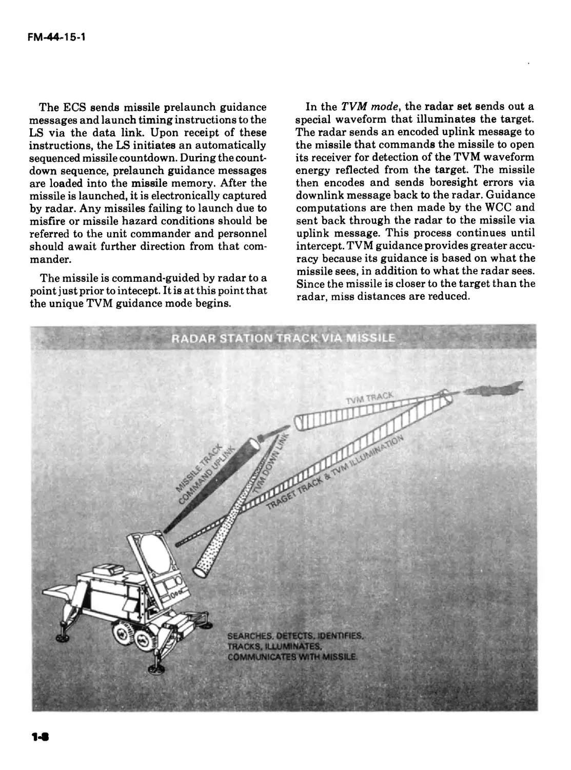
The missile is command-guided by radar to a
point just prior to intecept. It is at this point that
the unique TVM guidance mode begins.
In the TVM mode, the radar set sends out a
special waveform that illuminates the target.
The radar sends an encoded uplink message to
the missile that commands the missile to open
its receiver for detection of the TVM waveform
energy reflected from the target. The missile
then encodes and sends boresight errors via
downlink message back to the radar. Guidance
computations are then made by the WCC and
sent back through the radar to the missile via
uplink message. This process continues until
intercept. TVM guidance provides greater accu-
racy because its guidance is based on what the
missile sees, in addition to what the radar sees.
Since the missile is closer to the target than the
radar, miss distances are reduced.
FM-44-15-1
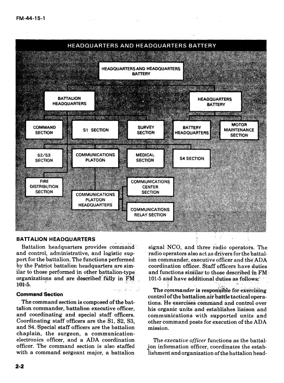
HEADQUARTERS AND
HEADQUARTERS BATTERY
Headquarters and headquarters battery con-
trols and supports up to six firing batteries in a
Patriot battalion. Patriot peculiar items of the
HHB consist of an information and coordina-
tion central, four communications relay groups,
five antenna mast groups, six guided missile
transporters, and five electrical power units.
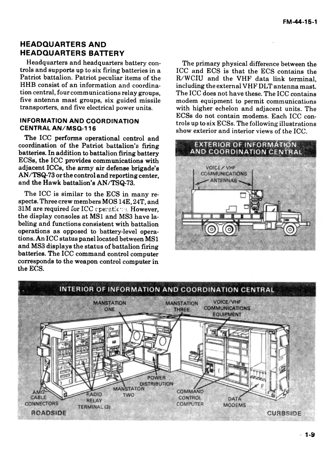
INFORMATION AND COORDINATION
CENTRAL AN/MSQ-116
The ICC performs operational control and
coordination of the Patriot battalion’s firing
batteries. In addition to battalion firing battery
ECSs, the ICC provides communications with
adjacent ICCs, the army air defense brigade’s
AN/TSQ-73 or the control and reporting center,
and the Hawk battalion’s AN/TSQ-73.
The ICC is similar to the ECS in many re-
spects. Three crew members MOS 14E,24T, and
31M are required for ICC operatic*: 3. However,
the display consoles at MSI and MS3 have la-
beling and functions consistent with battalion
operations as opposed to battery-level opera-
tions. An ICC status panel located between MSI
and MS3 displays the status of battalion firing
batteries. The ICC command control computer
corresponds to the weapon control computer in
the ECS.
The primary physical difference between the
ICC and ECS is that the ECS contains the
R/WCIU and the VHF data link terminal,
including the external VHF DLT antenna mast.
The ICC does not have these. The ICC contains
modem equipment to permit communications
with higher echelon and adjacent units. The
ECSs do not contain modems. Each ICC con-
trols up to six ECSs. The following illustrations
show exterior and interior views of the ICC.
EXTERIOR OF INFORMATION
ANO COORDINATION CENTRAL
ROADSIDE
CURBSIDE
1-9
FM-44-15-1
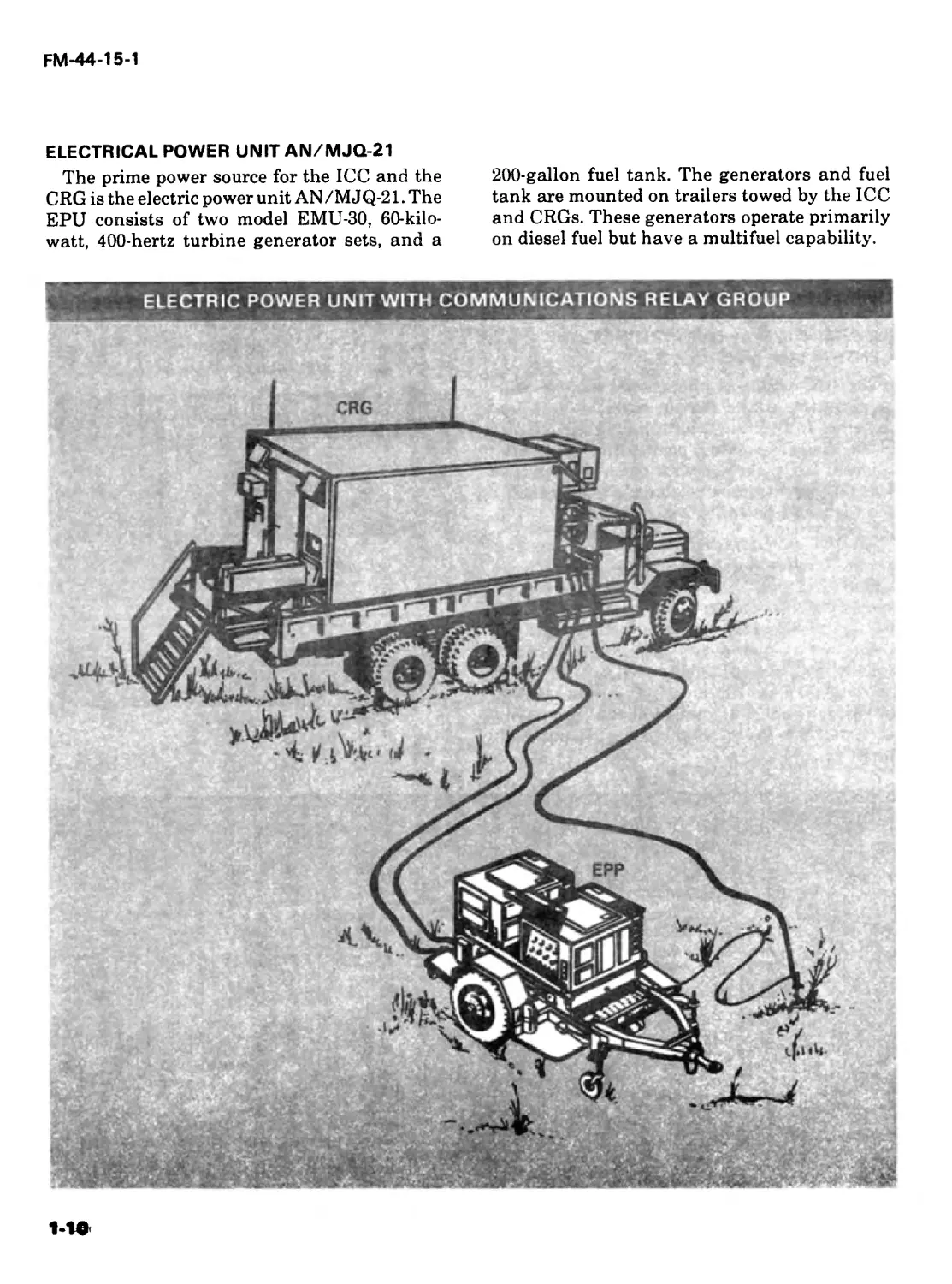
ELECTRICAL POWER UNIT AN/MJQ-21
The prime power source for the ICC and the
CRG is the electric power unit AN/MJQ-21. The
EPU consists of two model EMU-30, 60-kilo-
watt, 400-hertz turbine generator sets, and a
200-gallon fuel tank. The generators and fuel
tank are mounted on trailers towed by the ICC
and CRGs. These generators operate primarily
on diesel fuel but have a multifuel capability.
ELECTRIC POWER UNIT WITH COMMUNICATIONS RELAY GROUP
FM-44-15-1
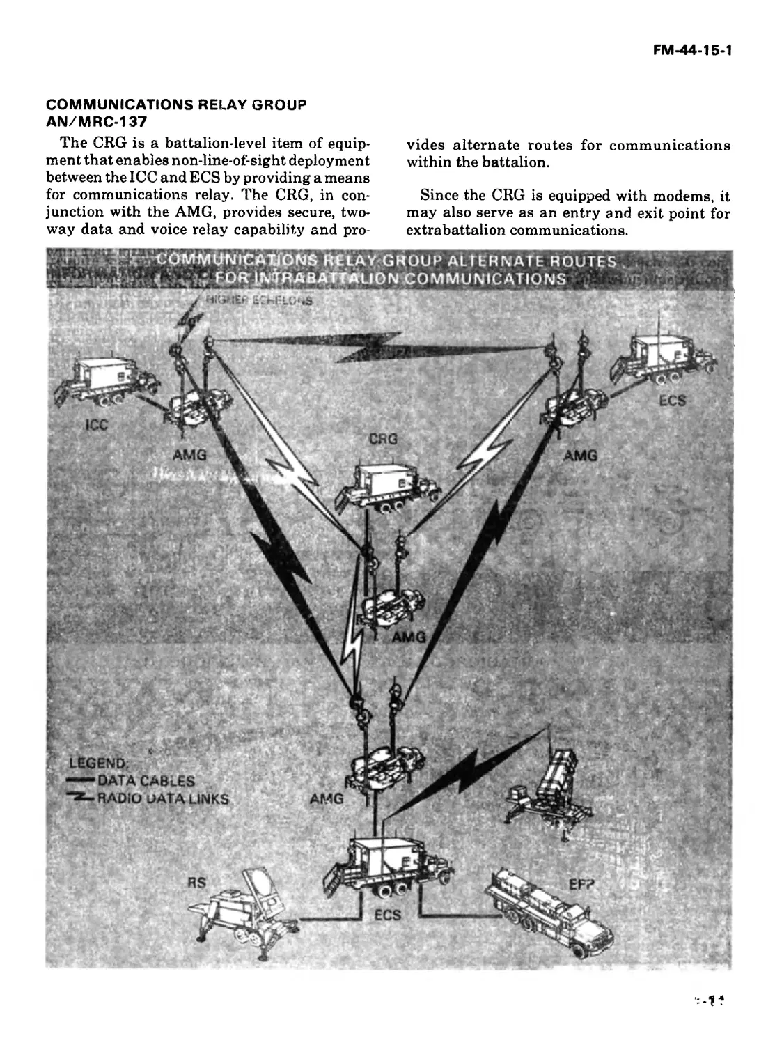
COMMUNICATIONS RELAY GROUP
AN/MRC-137
The CRG is a battalion-level item of equip-
ment that enables non-line-of-sight deployment
between the ICC and ECS by providing a means
for communications relay. The CRG, in con-
junction with the AMG, provides secure, two-
way data and voice relay capability and pro-
vides alternate routes for communications
within the battalion.
Since the CRG is equipped with modems, it
may also serve as an entry and exit point for
extrabattalion communications.
FM-44-15-1
The CRG interior is arranged differently from
that of the ICC or the ECS. The CRG does not
have a computer nor does it have the two
fordward-end operator stations. As shown be-
low the forward end of the CRG has been re-
arranged, thus creating additional work space.
There are four UHF radio relay terminals in the
CRG and one spare.
1-12
Ong an i z a t i on
This chapter provides an overview of the Patriot organiza-
tion. Every Patriot crew member performs a task, function, or
mission that is vital to the success of the Patriot battalion’s
mission. By knowing how the Patriot battalion is organized,
crew members can better understand how their individually
assigned duties contribute to the overall mission.
Since required and authorized strength figures are subject to
change, they are not reflected here. Refer to the latest TOE
44-635L, 44-636L, or 44-637L to determine current strength
figures.
BATTALION
The Patriot battalion consists of a headquar-
ters and headquarters battery and six firing
batteries. The Patriot battalion is normally as-
signed to an air defense artillery brigade at
theater level.
HEADQUARTERS AND
HEADQUARTERS BATTERY
The HHB is both a tactical and an adminis-
trative organization and is organized with a
battalion headquarters and a headquarters bat-
tery. Whenever tactically feasible, the HHB will
be centrally located in relation to lower battal-
ion elements. This enables it to provide respon-
sive and timely support.
2-1
FM-44-15-1
St SECTION
S4 SECTION
COMMAND
SECTION
S2/S3
SECTION
MEDICAL
SECTION
SURVEY
SECTION
BATTALION
HEADQUARTERS
MOTOR
MAINTENANCE
SECTION
BATTERY
HEADQUARTERS
HEADQUARTERS
BATTERY
COMMUNICATIONS
PLATOON
HEADQUARTERS
COMMUNICATIONS
PLATOON
COMMUNICATIONS
CENTER
SECTION
FIRE
DISTRIBUTION
SECTION
HEADQUARTERSAND HEADQUARTERS
BATTERY
COMMUNICATIONS
RELAY SECTION
HEADQUARTERS AND HEADQUARTERS BATTERY
BATTALION HEADQUARTERS
Battalion headquarters provides command
and control, administrative, and logistic sup-
port for the battalion. The functions performed
by the Patriot battalion headquarters are sim-
ilar to those performed in other battalion-type
organizations and are described fully in FM
101-5. v .
Command Section
The command section is composed of the bat-
talion commander, battalion executive officer,
and coordinating and special staff officers.
Coordinating staff officers are the Si, S2, S3,
and S4. Special staff officers are the battalion
chaplain, the surgeon, a communication-
electronics officer, and a ADA coordination
officer. The command section is also staffed
with a command sergeant major, a battalion
signal NCO, and three radio operators. The
radio operators also act as drivers for the battal-
ion commander, executive officer and the ADA
coordination officer. Staff officers have duties
and functions similar to those described in FM
101-5 and have additional duties as follows:
The commander is responsible for exercising
control of the battalion air battle tactical opera-
tions. He exercises command and control over
his organic units and establishes liaison and
communications with supported units and
other command posts for execution of the ADA
mission.
The executive officer functions as the battal-
ion information officer, coordinates the estab-
lishment and organization of the battalion head-
2-2
FM-44-15-1
quarters area and provides overall staff super-
vision of the battalion tactical operations cen-
ter. The executive officer is required to com-
mand the battalion in the event the commander
becomes a casualty or is not available to exer-
cise command functions.
The S3 supervises the day-to-day operation of
the battalion operations center including the
ICC.
The ADA coordination officer is the battalion
representative (liaison) at the supported unit or
unit in whose area the Patriot battalion is
operating.
The C-E staff officer plans and manages the
battalion communications networks. He is also
custodian of the battalion COMSEC account,
(The battalion signal NCO assists with these
duties.)
SI Section
The Si section has coordinating responsibili-
ties for maintenance of unit strength, personnel
management, development and maintenance of
discipline, law and order, and chaplain support.
Five enlisted personnel are provided to assist
the Si officer.
S2/S3 Section
The S2 element is responsible for security and
the collection, evaluation, and distribution of
intelligence data in support of the battalion
mission. The S3 element is responsible for the
planning, organization, training, and opera-
tions of the battalion.The S3 develops the tacti-
cal operations data used in the initialization of
the ICC and the firing battery ECSs. The S3
also supervises a system-evaluation team. This
team conducts tactical and technical evalua-
tions of the firing batteries and the battalion
fire direction center. The system evaluation
team also assists the S3 in developing and eval-
uating operator and maintenance training pro-
grams.
Fire Distribution Section
The fire distribution section exercises direct
control and supervision of up to six firing bat-
teries during the conduct of the air battle. The
ICC exchanges data and voice information
with the ADA brigade tactical operations center
as well as each firing battery, adjacent Patriot
battalions, and adjacent Hawk battalions. If
the brigade AN/TSQ-73 is out of action, or the
battalion is deployed to an area beyond the con-
trol of an ADA brigade, the ICC has the capabil-
ity of establishing data-link communications
directly with the control and reporting center.
Communications Platoon
The communications platoon is made up of a
platoon headquarters, a communications cen-
ter section, and a communications relay sec-
tion. The communications platoon executes the
battalion communications plan prepared by the
C-E staff officer. The communications center
section is responsible for battalion wire com-
munications, operations and maintenance (less
teletypewriters) of the radio teletypewriter set,
control of COMSEC material, and unit mainte-
nance of HHB communications equipment (less
multichannel radio). The communications
relay section operates up to four CRGs.
S4 Section
The S4 section is responsible for planning
and coordinating supply, maintenance, move-
ments, missile supply to the firing batteries,
and other logistical services required by the bat-
talion. This section has six guided missile trans-
porters for missile resupply and reload. The S4
section provides unit maintenance support for
the battalion’s quartermaster and chemical
equipment.
Medical Section
The medical section provides emergency med-
ical treatment and operates the battalion aid
station. An ambulance and two aid men from
this section are provided to each FB.
Survey Section
The survey section provides survey data to
the FB’s and supporting elements for equip-
ment emplacement. A survey information cen-
ter and two survey teams make up the survey
2-3
FM-44-15-1
section. Each team has a position and azimuth
determining system as primary survey equip-
ment.
HEADQUARTERS BATTERY
Headquarters battery provides support to the
battalion. Headquarters battery provides the
resources to support the entire headquarters for
food service, and unit supply. It also provides
refueling and unit maintenance support for
vehicles, power generators, and engineer mis-
sile equipment. Headquarters battery is organ-
ized with a battery headquarters section and a
motor maintenance section.
Battery Headquarters Section
The battery headquarters section is composed
of the battery command element, unit supply
element, and battery food service element. The
battery commander also functions as the motor
officer. MANPAD equipment is provided for
one Stinger team. Stinger team duties are per-
formed as an additional duty by selected bat-
tery headquarters personnel. Radiac meters,
radiac chargers and chemical alarms are pro-
vided to the headquarters section.
Motor Maintenance Section
The motor maintenance section provides unit
maintenance for HHB vehicles, power genera-
tion equipment and air conditioners. The sec-
tion refuels all HHB fuel consuming equipment
and provides vehicle recovery for HHB vehicles.
DECOY
SECTION
LAUNCHER
SECTION
LAUNCHER
PLATOON
ADA BATTERY
PATRIOT
FIRE CONTROL
PLATOON
MAINTENANCE
PLATOON
FIRE CONTROL
SECTION
FIRE CONTROL
PLATOON
HEADQUARTERS
LAUNCHER
PLATOON
HEADQUARTERS
MOTOR
MAINTENANCE
SECTION
BATTERY
HEADQUARTERS
COMMUNICATIONS
SECTION
SYSTEM
MAINTENANCE
SECTION
i MAINTENANCE
PLATOON
£ HEADQUARTERS
FIRING BATTERY ORGANIZATION
FIRING BATTERY
Each Patriot firing battery is capable of
detecting and identifying targets and launch-
ing missiles to destroy hostile aircraft. Patriot
firing batteries are deployed to form a battalion
air defense network for a specified volume of
airspace. The firing battery is highly mobile.
Mobility allows for rapid emplacement, prepa-
ration for road march, and frequent moves to
alternate positions, depending on the tactical
situation and theater SOP.
2-4
FM-44-15-1
Patriot firing batteries operate continuously,
except for obvious nonoperational periods: such
as during road march or emplacement.
MANPAD equipment for two Stinger teams is
authorized to deter close-in, low-altitude air
attacks. Battery personnel are selected to per-
form as Stinger team members as an additional
duty.
The Patriot battery consists of a headquar-
ters section, a maintenance platoon, a fire con-
trol platoon, and a launcher platoon.
HEADQUARTERS SECTION
A battery headquarters section provides the
battery with command, unit administration,
unit supply, and food service functions. Because
of the amount of time spent on RSOPactivities
and battery relocation, the commander and ex-
ecutive officer are each provided a vehicle. Due
to frequent movement, rapid road march, and
emplacement capabilities of the Patriot system,
a 2 1/2-ton shop van is used as a mobile
battery CP.
MAINTENANCE PLATOON
Effective communications, motor, and sys-
tem maintenance are essential to the firing bat-
tery’s mission. The maintenance platoon is
organized to fill these needs. It consists of a
maintenance platoon headquarters section, com-
munications section, motor maintenance sec-
tion, and systems maintenance section.
Maintenance Platoon Headquarters Section
The maintenance platoon headquarters sec-
tion exercises command and control over the
maintenance platoon. The platoon leader and
platoon sergeant ensure that unit level mainte-
nance is furnished in a timely and coordinated
manner. The platoon leader is the battery motor
officer and also performs duties as a tactical
control officer in the ECS.
Communications Section
The communications secton supports the bat-
tery’s wire communications requirements and
performs unit level maintenance on field C-E
equipment. Three tactical wire operator special-
ists operate two switchboards at the battery CP
on a 24-hour basis to support the battery admi-
nistrative, logistics, and operational wire re-
quirements. They also lay, maintain and re-
trieve field wire.
Motor Maintenance Section
The motor maintenance section provides unit
maintenance on all organic vehicles and gener-
ators (except turbine generators), vehicle recov-
ery, and refueling. The section maintains the
PLL for motor maintenance support. The sec-
tion performs maintenance to the maximum
extent possible at individual vehicle locations.
This is because the vehicles are required at their
deployed locations for tactical mission needs.
Systems Maintenance Section
The system maintenance section performs
unit maintenance for Patriot system peculiar equip-
ment — ECS, RS, LS, AMG, electronics, and
maintenance test equipment. The section also
maintains a PLL for the Patriot system.
FIRE CONTROL PLATOON
The fire control platoon is organized with a
platoon headquarters and fire control section.
Fire Control Platoon Headquarters
This section exercises command and control
of the fire control platoon and works with the
maintenance and launcher platoons.
The platoon leader and assistant platoon
leader serve as tactical control officers for the
ECS, and, along with the platoon sergeant, also
perform RSOP activities. A 1 1/4-ton vehicle
serves as a mobile platoon CP. This truck pulls a
3/4-ton trailer containing Stinger equipment.
Fire Control Section
The fire control section is composed of the
following major items of the firing battery:
ECS, RS, EPP, and AMG.
2-5
FM-44-15-1
The ECS is similar to the battalion ICC and
requires three full-time positions manned by
crew members in SSI 14E and MOSs 24T and
31M. The tactical control officer position at MS3
is manned by the platoon leader or assistant
platoon leader of either the fire control, mainte-
nance, or launcher platoon. The TCO position
in the ECS corresponds to the tactical director
position in the ICC. The tactical control assis-
tant position at MSI is manned by a Patriot
operator and system mechanic. A multichannel
communications operator mans the MS2 posi-
tion and performs unit maintenance on the
UHF equipment. He also aids in performing
road march and emplacement duties on the
AMG.
Although the RS is not manned during opera-
tion, four Patriot crew members are required for
its emplacement and road march. These four
crew members are the vehicle drivers for the
ECS, RS, and platoon leader vehicles. They per-
form duties as RSOP team members when
required and are designated as Stinger team
members.
Two turbine generator mechanics road
march, emplace, and operate the EPP as well as
performing unit maintenance on the turbine
generators.
LAUNCHER PLATOON
The launcher platoon consists of a launcher
platoon headquarters, decoy section, and four
launcher sections.
Launcher Platoon Headquarters
Launcher platoon headquarters is the com-
mand and control element for the launcher sec-
tions. The platoon leader and platoon sergeant
are provided a 1 1/4-ton truck and a 3/4-ton
trailer. The truck is used as a mobile platoon
command post. It is also used for RSOP activi-
ties and to shuttle launching crews. The 3/4-ton
trailer contains Stinger equipment and two por-
table chemical agent alarms.
Decoy Section
The decoy section consists of personnel as-
signed by the Launcher Platoon headquarters.
Launcher Sections
There are four launcher sections in the
launcher platoon. Each section.is supervised by
a section chief and has two LSs. Each LS has
three crew members for emplacement, GM re-
load, road march, RSOP activities, and sus-
tained operations. The section chiefs perform
duties as senior crew members.
2-6
Support;
System support provides the facilities^ equipment, trained
personnel, and procedures required to maintain the Patriot
system in an operationally ready condition. This chapter pro-
vides an overview of support concepts and equipment used to
supply and maintain the Patriot system.
MAINTENANCE CONCEPT
The Patriot System’s on-site maintenance
concept is enhanced by certified guided missile
rounds, battery replaceable units, BITE and
diagnostics, display-aided maintenance, and
maintenance levels.
CERTIFIED GUIDED MISSILE
The Patriot guided missile is certified by the
manufacturer and requires no detailed checkout
or field maintenance by Patriot crew members.
A defective missile is handled per local SOP and
is sent to the Patriot missile facility for repair.
The PMF is an automated missile test facility
designed to test the Patriot missile to the same
specifications that were used during produc-
tion. The facility is capable of disassembly, test-
ing, repairing as required, retesting, reassem-
bling, final testing and recanning of the missile
to bring it back to an operational certified round
status.
BATTERY REPLACEABLE UNITS
Most of the Patriot-peculiar firing battery
repair parts consist of plug-in assemblies called
BRUs. After faulty BRUs have been isolated,
the Patriot operator and system mechanic re-
moves the defective BRUs and replaces them
with working spares on site.
BITE
The BITE lamps, located throughout the
Patriot equipment, assist in alerting crew mem-
bers of equipment malfunctions. Through
BITE, operator-mechanics can detect and local-
ize a fault to the BRU needing replacement.
During air defense operations, the WCCs in the
firing batteries’ ECSs and CCC at the battalion
ICC monitor critical operational BITE circuits
to assess equipment status. This is done by a
software program called status monitor.
DIAGNOSTICS
The WCC and CCC are used primarily for air
defense operations; however, they can also be
used for maintenance diagnostics. The ECS or
ICC operator at MSI or MS3 selects a mainte-
nance control software program to replace the
3-1
FM-44-15-1
operational program. Diagnostic programs
within this system test the ECS, ICC, or RS
equipment subassemblies to detect and locate
faults. Once the faults are determined, a display-
aided, maintenance feature is selected to aid in
correcting the faults.
DISPLAY-AIDED MAINTENANCE
DAM eliminates the use of some manuals to
perform routine maintenance tasks. DAM pro-
vides step-by-step procedures for an entire
maintenance action. The procedures appear on
either the MSI or MS3 CRT display in the ECS
or ICC. The program lists the method for remov-
ing and replacing the BRU as well as the tools
required. The operator-mechanic reads the step
aloud over his headset-microphone. The operator-
mechanic at the site of the equipment fault per-
forms the corrective maintenance as the instruc-
tions are read to him. Each completed step is
acknowledged by an operator keyboard action
before the next step is displayed. At the operator-
mechanic option, the procedures may be printed
by the hard copy unit. Maintenance procedures
not covered by display-aided means are covered
in Patriot technical manuals.
MAINTENANCE LEVELS
Patriot’s system design makes extensive use
of BITE, and BRUs. These features reduce the
number of maintenance levels of Patriot-
peculiar equipment to three: unit, intermediate,
and depot.
Unit
Most of the expected failures in Patriot equip-
ment are in BRUs which can be removed and
replaced by unit level maintenance without sol-
dering, complicated tools, or test equipment.
Malfunctions beyond the capability of the
operator-mechanic (MOS 24T) are referred to
the missile system technician (MOS 222C) from
the battery system maintenance section. If the
malfunctions are beyond the capability or re-
sources of unit level maintenance, they are
referred to intermediate support element teams.
Intermediate
Intermediate maintenance repair is done by
intermediate support elements. The ISE com-
pletes actions that cannot be performed at the
unit level. A Patriot field army support center
provides the base for the ISE maintenance
operations. The PFASC provides support for
Patriot-peculiar items, such as BRU screening,
repairing, and maintaining operational readi-
ness float equipment. Special PFASC interme-
diate support elements teams provide respon-
sive intermediate support to the firing batteries.
These mobile teams are dispatched to points of
failure to provide on-site maintenance and assis-
tance.
Depot
Patriot equipment requiring depot level main-
tenance, extensive rebuild, or repair is evacu-
ated through PFASC to prime contractor facili-
ties.
SUPPLY CONCEPT
The Patriot supply concept demands that
repair parts support be provided at the point of
failure by the fastest possible means. Many of
the Patriot assemblies in the ASL and PLL are
essential repair parts stockage list items be-
cause they are both mission-essential and re-
quired for unit level maintenance. A typical fir-
ing battery PLL will have these repair parts to
correct the problems on-site. Intermediate main-
tenance will also maintain stocks of selected
repair parts.
A maintenance support company provides
support for each Patriot battalion. This Patriot
maintenance support company provides one-
stop DS maintenance for non-Patriot peculiar
equipment such as engineer, signal, and auto-
motive equipment. It also provides for a techni-
cal supply and direct exchange for selected
items, maintains an ASL, has maintenance
support teams for supported batteries, and sup-
plies operational readiness float equipment.
Patriot missile resupply starts with the FB
submitting a requisition for missiles. This re-
quisition is then passed to the battalion S4 and
then to the supporting special ammunition
3-2
FM-44-15-1
supply point. The theatre Army supplies the
missiles directly to the battalion ammunition
transfer point. The battalion’s guided missile
transporters are then used to reload the FB
launching stations.
BATTALION SUPPLY
AND MAINTENANCE EQUIPMENT
Battalion supply and maintenance equip-
ment supports the Patriot maintenance and
logistics concepts. BSME consists of battery
supply and maintenance equipment, battalion
supply and maintenance equipment, and cali-
bration equipment.
BATTERY
Battery maintenance equipment consists of
the following items:
A Maintenance Center. The MC is a semi-
trailer van with a 5-ton truck tractor as a prime
mover. The MC is manned by system mainte-
nance section personnel. It provides space for
the control, coordination, and scheduling of
unit level maintenance functions for the Patriot
battery. The MC provides storage for repair
parts, test equipment, tools, and maintenance
and inventory documentation. A work area is
provided for the performance of light mechani-
cal repair and assembly by system mainte-
nance personnel. A voice radio provides com-
munications for maintenance matters, while a
remote terminal in the vehicle cab allows for
communications during road march. Electrical
power for the MC is provided by a trailer-
mounted 15-kilowatt, 400-hertz, diesel genera-
tor set.
A small repair parts transporter. The SRPT is
a semitrailer van towed by a 5-ton truck tractor.
It stores and transports the small PLL repair
parts for the firing battery.
33
FM-44-15-1
A large repair parts transporter. The LRPT is
a HEMTT, M977 cargo truck. The LRPT is used
to store, transport, and handle the large, heavy
repair parts of the PLL.
BATTALION
Battalion maintenance equipment consists of
the following items:
A maintenance center with generator and 1
1/4-ton truck. The MC is required for unit level
maintenance of the ICC, CRG, and AMG. It also
provides storage and transportation for HHB
Patriot system PLL. The 1 1/4-ton truck is pro-
vided for maintenance team mobility to remote
relay sites.
A Guided missile transporter. A GMT con-
sists of a 10-ton HEMTT, M985 with a crane.
The S4 section at HHB operates six GMTs.
Each GMT can transport four Patriot missiles.
The missiles are delivered and transferred by
GMTs to the individual LSs in the firing batter-
ies as needed.
CALIBRATION EQUIPMENT
Calibration equipment consists of cables and
adapters to connect portable test equipment
with those assemblies of the Patriot system
requiring calibration.
3-4
This chapter describes UHF communications for Patriot
battalions. Patriot relies heavily on effective radio communi-
cations for proper command and control. The key to battalion
operations is the UHF data multirouting communications net
that ties the ICC to the FB ECSs and the UHF data link from
the ICC to the brigade AN/TSQ 73. Data communications over
the UHF data link are handled by computers at the ICC and
ECS, and include track data and other input necessary for
target engagement, as well as system status information. Tac-
tical radios are also used between the ICC and ECSs and a
radio teletypewriter, organic to the battalion, links the battal-
ion with the brigade. Other radio communications nets and
wire circuits are available throughout the battalion for com-
mand, administration and logistics, and are diagrammed in
FM 44-15.
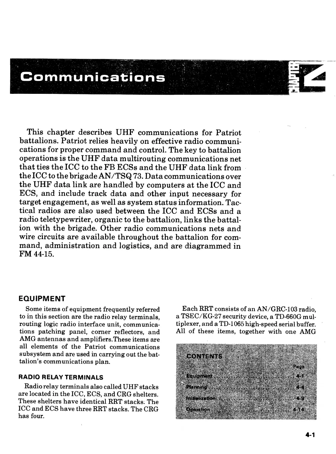
EQUIPMENT
Some items of equipment frequently referred
to in this section are the radio relay terminals,
routing logic radio interface unit, communica-
tions patching panel, corner reflectors, and
AMG antennas and amplifiers.These items are
all elements of the Patriot communications
subsystem and are used in carrying out the bat-
talion’s communications plan.
RADIO RELAY TERMINALS
Radio relay terminals also called UHF stacks
are located in the ICC, ECS, and CRG shelters.
These shelters have identical RRT stacks. The
ICC and ECS have three RRT stacks. The CRG
has four.
Each RRT consists of an AN/GRC-103 radio,
a TSEC/KG-27 security device, a TD-660G mul-
tiplexer, and a TD-1065 high-speed serial buffer.
All of these items, together with one AMG
4-1
FM-44-15-1
antenna or shelter corner reflector antenna,
form one terminal of a UHF line-of-sight radio
link providing 12 communications channels.
Each channel may be either voice or data. One
channel of each UHF radio is dedicated for data
and is connected via the patch panel to the
RLRIU. The remaining 11 channels of each
RRT are terminated on the CPP. These circuits
can thus be interconnected to party-line hy-
brids, or to external wire lines by means of
patch cords.
ROUTING LOGIC RADIO INTERFACE UNIT
RLRIUs are located within each ICC, ECS,
and CRG shelter. The RLRIU serves as a digital
message (not voice) interface among the WCC/
CCC, RRTs, DLT, and up to five modems.
The main function of the RLRIU is to provide
parallel routing of data traffic being transmit-
ted over the battalion UHF network. When the
RLRIU transfers a message to the RRT, it does
so to all available RRTs in that shelter. The
message is thus transmitted over every UHF
link and ultimately transmitted over every avail-
able route (multirouted) within the battalion to
its destination. A “first good message” check
performed by the RLRIU prevents messages
from circulating endlessly through the UHF
network. Data messages are transferred from
the WCC to the RLRIU via a block transfer
mechanism that contains the source of the mes-
sage, the RLRIU address, and instructions, as
well as the text. In additon to performing multi-
routing, the RLRIU tests each message for er-
rors and discards messages with errors. It pro-
cesses messages by reformatting incoming and
outgoing extrabattalion messages into the ap-
propriate data transfer language. The
RLRIU also acts as a central reporting point for
alarm and BITE information concerning the
communications equipment within the shelter.
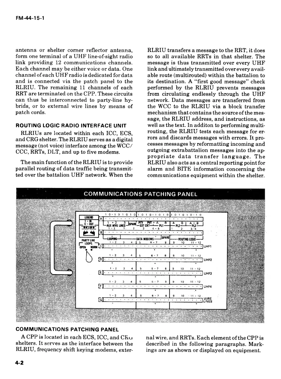
COMMUNICATIONS PATCHING PANEL
A CPP is located in each ECS, ICC, and CRo
shelters. It serves as the interface between the
RLRIU, frequency shift keying modems, exter-
nal wire, and RRTs. Each element of the CPP is
described in the following paragraphs. Mark-
ings are as shown or displayed on equipment.
4-2
FM-44-15-1
A UX WIRE LINES are connected by binding
post connections to the landline communica-
tions panel at the rear of the ECS, ICC, or CRG
shelters. An example of the use of an AUX
WIRE LINE would be the coordinating wire line
circuit to the battalion or battery maintenance
section. The spare ports are not connected.
The PTY EXT CKT port is tied to the three
communications system control panels. Two of
which are located at the control keyboard assem-
blies at MSI and MS2 and the other one is
located behind and above the MS3 chair. When
the operator places the circuit selector to the
EXT CKT position, he will get whatever has
been patched into this port. An example of this
would be a voice only landline to the battalion
TOC at the ICC or to the CP at the battery.
The PVT EXT CKT port is tied to the com-
munications system control panel at MS2.
When the operator places the circuit selector to
the EXT CKT position, he will get whatever has
been patched into this port. An example of this
would be a voice only landline to the battalion
C-E officer or NCO at the ICC.
PL1, PL2, and PL3 are voice party lines selec-
table at each CCP. The A and В on the CPP
represent the ports at which the party lines are
patched to the radios.
LOOPING ports are primarily used for sys-
tem troubleshooting. They allow an operator to
loop back a channel or port.
ROUTING LOGIC ports are wired to the
RLRIU and provide the interface for multirout-
ing. A scheme is developed in patching the rout-
ing logic (data channels). This scheme is ex-
plained further under planning standardiza-
tion.
DATA modems ports are wired to the analog
side of the five data modems within the ICC or
CRG. They may be patched to wire lines or
RRTs. Brigade or CRC and adjacent battalion
traffic is routed over these modems. The patch-
ing is from the DATA MODEMS port to a chan-
nel of one of the RRT, through or to, wire lines
depending on the relay device used.
UHF1, UHF2, UHF3, and UHF4 ports are in
rows C through F and are connected to RRTs 1
through 4 in the CRG and RRTs 1 through 3 in
the ICC and ECS. In the ECS and ICC, UHF
row F is not used. The three remaining rows
provide for 36 full duplex channels capable of
32,000 bits per second data or voice communica-
tions at the ICC and ECS and for 48 channels at
the CRGs.
The WIRE LINES ports of row G provide the
capability to patch 12 external wire lines into
the UHF network. These 12 full duplex ports are
connected through the CV-1548 telephone con-
verter to channel 1 through channel 12 termi-
nals at the LLCP mounted at the outside rear of
the ECS, ICC or CRG. Wire lines connected to
the LLCP may be two-wire or four-wire.
Switches on the appropriate channels of the
CV-1548 must be set accordingly: that is, two-
wire or four-wire.
NOTE: И using the two-wire configuration (that
is, a telephone set TA-312/PT at both ends), the
patch cords at the originating and terminating
stations must not be placed in reverse polarity to
allow for ring-down capability.
PARTY LINE LOOPS consists of a switch
that allows the serial aspects of the party line
network to operate. It also prevents the voice
circuit from going completely throughout the
link and returning to the originator. To do this,
all switches must be in the NORM position
except the one at the ICC — it must be in the
OPEN position. When used in an intrabattalion
relay configuration, the CRG’s PARTY LINE
LOOPS switch must be in the OPEN position.
CORNER REFLECTORS AND
AMG ANTENNAS AND AMPLIFIERS
Two corner reflectors are provided with each
ECS, ICC, and CRG shelter for close-in com-
munications. Comer reflectors have less gain
and higher side lobes than the AMG antennas;
they are, therefore, more susceptible to ECM
jamming. Comer reflectors are not intended for
normal tactical use. They are reserved for spe-
cial emergency situations such as to replace a
nonoperational AMG. If one of the UHF links is
10 kilometers or less and there is line of sight, a
4-3
FM-44-15-1
comer reflector can be used for that link. How-
ever, the AMG should normally be used. The
capability also exists of using comer reflectors
in lieu of an AMG; that is, a comer reflector
paired with a distant AMG. This procedure,
however, is not recommended as there is con-
siderable signal loss. Comer reflectors may be
mounted in a vertical or horizontal position and
must be adjusted for maximum signal strength.
A compass is used to ensure that the antennas
are properly positioned in azimuth.
The AMG has four antennas and amplifiers
with three basic modes of operation that are
used for UHF communications. The three basic
types of operation are bypass, driver, and driv-
ver/final. The bypass mode has no amplifica-
tion and will be the normal mode used in peace-
time. The driver mode has low amplification
and is used to overcome distance. The driver/fi-
nal mode has high amplification and is used to
combat the effects of UHF ECM jamming.
The three modes of operation for each an-
tenna and amplifier are set at the AMG distri-
bution box 7A1A1. For the bypass mode, the
power, driver, and final switches are set to OFF.
To use the driver mode, the operator must set the
power and driver switches to ON and leave the
final switch to OFF. For the driver/final mode,
the operator would have the power, driver, and
final switches set to ON.
PLANNING
The C-E officer, in conjunction with the S3,
and by coordinating with the brigade staff and
adjacent battalion communications officers, de-
velops a communications plan prior to each
move. A well-developed communications plan
minimizes confusion and indecision and results
in predictable actions. The C-E officer prepares
the communications plan using the C-E annex
to the TSOP, the CEOI, and frequency man-
agement personnel as primary sources of in-
formation. Within the ICC software, tab 62
(CRG/COMMUNICATIONS ASSIGNMENT+
SUMMARY) can assist him in developing sev-
eral areas of the plan. Tab 62 is described later
in this section.
CONSIDERATIONS
When developing the communications plan,
the C-E officer must consider the following
action items. (Note that the list is not all inclu-
sive and will vary depending on the situation.)
Identify all network units — intrabattalion (1
to 6 fire units, 1 to 4 CRGs, the ICC), interbattal-
ion (other ICCs), and extrabattalion (brigade
AN/TSQ-73) elements — and their UTM coor-
dinates. The system can utilize up to six CRGs.
Assign battalion identification numbers that
cause system software to generate RLRIU ad-
dresses for local battalion elements. The
RLRIU address defines the RLRIU that deliv-
ers the data block. RLRIU addresses are in two
octal digits (00 through 77). The numbers 8 and
9 or any combination of 8 and/or 9 cannot be
used. For each transfer received by the RLRIU
(except those from the DLT), the RLRIU will
compare the address code with the setting of the
switches on the front panel of the RLRIU. If
they do not agree, the message will be routed to
the UHF network. If they agree, the RLRIU
delivers the message in accordance with the
routing word and does not pass it to the UHF
network. Two restrictions that apply to assign-
ing RLRIU addresses are that system software
will not repeat RLRIU addresses within a bat-
talion and it will not repeat RLRIU addresses
for Patriot battalions communicating with each
other by modem.
Evaluate site terrain for line-of-sight emplace-
ment of AMGs or corner reflectors. For plan-
ning purposes, 40-kilometers is the effective
line-of-sight range between AMGs in the bypass
mode. The planning range for the comer reflec-
tor antennas on the ECS, ICC, and CRG shel-
ters is 10-kilometers.
Consider antenna polarization as a vital part
of link planning. Comer reflectors and AMG
antennas must be properly polarized. Ultra-
high-frequency radio waves transmitted from a
vertical antenna are said to be vertically polar-
ized and those from a horizontal antenna are
said to be horizontally polarized.
The horizontal or vertical orientation of the
receiving antenna should be the same as that of
the transmitting antenna (horizontal to horiz-
4-4
FM-44-15-1
ontal, vertical to vertical). Significant signal
loss may result if polarization is not correct.
Either horizontal or vertical polarization may
be used, but the performance of each is different
under certain situations (see TM 11-5820-
540-12).
Cross polarization of comer reflectors on the
same shelter (one horizontal, one vertical) is
recommended to create greater isolation be-
tween antennas and to reduce the possibility of
mutual interference between systems. Cross polar-
ization is also recommended for the AMG anten-
nas but note that cross polarization for the
AMG refers to the two antennas on the same
mast.
Assign the AMG antennas to specific RRTs at
each location (ICC, ECS, CRG).
Identify the active RRTs at each location
(ICC/ ECS/CRG) and assign UHF links and
frequencies between them. UHF frequencies
and channels for use by a Patriot battalion are
limited to the frequencies allocated by the desig-
nated frequency manager in the theater of
operations. Once frequencies have been allo-
cated, the C-E officer or NCO assigns frequen-
cies and channels to units within the battalion.
Once assigned, the frequencies and channels
are classified. In addition to the frequency res-
trictions imposed by the frequency manager,
there are also inherent AN/GRC-103 frequency
limitations. These are harmonic frequencies
and minimum separation between send and
receive channels (a minimum of 33 channels,
16.5 MHz) and between RRTs to prevent cross
interference. TM 11-5820-540-12 provides radio
propagation and system planning guidance
that should be used by the battalion C-E officer
or NCO.
Define the patching scheme for each battal-
ion element (ICC, firing batteries 1 through 6,
and CRGs 1 through 4).
Assign the antenna azimuths for each link.
Identify the interbattalion or extrabattalion
exit/entry port (ICC or CRGs 1 through 4) and
shelter modem (1 through 5) to be used for each
interbattalion or extrabattalion link.
Include the ATDL-1 (tab display or printout
will read ATDL-1 or ATDL1) address as as-
signed by brigade.
Identify the following circuits to be put on the
network:
• Digital data.
• Party lines 1, 2, and 3.
• Internal point-to-point voice including
PVT and PTY lines and external land
lines to battalion or firing battery switch
board.
• Adjacent battalion circuits (voice and
modem).
• Higher echelon circuits (voice and
modem).
Define each circuit (except digital data) by:
• Route.
• Channel on the links.
• Modem and modem location (if needed).
Develop contingency plans for reallocating
and reconfiguring communications resources.
STANDARDIZATION
Standardization of communications tasks is
essential for rapid system emplacement and
operations. To the maximum extent possible,
basic and redundant communications func-
tions should be standarized as in the following
areas.
CPP. Standardization at the CPP is achieved
by the way the voice party lines and data chan-
nels are patched. PL1 is patched to channel 1,
PL2 to channel 2, and PL3 to channel 3 of whi-
chever RRT is being used. Data channels within
the battalion would be patched; RLRIU port 1 to
channel 4 of RRT 1, RLRIU port 2 to channel 4
of RRT 2, RRLIU port 3 to channel 4 of RRT 3,
and at the CRG, if required, RLRIU port 4 to
channel 4 of RRT 4. Remember, only the CRG is
equipped with a fourth RRT.
4-5
FM-44-15-1
Data Channel. Dedicate 1 of the first 11
channels (channels 1 through 11) as a data
channel for intrabattalion data transmissions.
Channel 12 should not be used for data trans-
mission since a synchronized pulse is routinely
sampled from this channel. Channel 12, howev-
er, may be used for voice communications.
Extra and Interbattalion Communications.
The modems at the ICC and CRG (five each) are
used for extrabattalion communications with
brigade and interbattalion communiications
with adjacent battalions. Standardization is
achieved here by assigning MODEM 5 to chan-
nel 5 of whichever RRT is used by the ICC or
CRG. If a wire line is used to link the battalion to
brigade using a radio terminal set AN/TRC-
145, the wire line from the AN/TRC-145, is con-
nected to channel 5 at the landline filter box
located at the rear of the CRG or ICC and then
patched to MODEM 5 on the CPP. The incom-
ing signal is routed through the CV-1548 tele-
phone converter. The operator should turn off
the ringer circuit for channel 5 so that the fre-
quency shift keying produced by the modem
will not activate the ringer circuit.
Remaining modems and channels are as-
signed for interbattalion communications.
RLRIUand voice communications addresses.
The RLRIU address is entered by a thumbwheel
switch on the front panel of the RLRIU. Voice
communications address is entered by a
thumbwheel switch behind the front panel of
the CPP. To the maximum extent possible, both
addresses should be the same; that is, FBI
RLRIU address 01, voice communications ad-
dress 01; FB2 RLRIU address 02, voice com-
munications address 02, ICC RLRIU address
07, voice communications address 07 and so
forth.
Party Line Loops. Party line loops switch lo-
cated on the front of the CPP is also considered
in communications standardizing. Keep it in
the NORM position at all FBs and in the OPEN
position at the ICC and CRGs.
RRT. Use the same RRT at both ends of a link;
for example, RRT1 at the ICC to RRT1 at FBI.
By setting up links in this manner, trouble-
shooting the links using the communications
Fault Data tab at the ICC is made easier.
PLANNING
Communications network planning is a coor-
dinated effort by the C-E officer and the S3 sec-
tion. The S3 informs the C-E officer or NCO of
proposed unit locations as determined by
RSOP. The C-E officer or NCO, working with
the command planners in the ICC, determines
the need for CRGs based on the distance be-
tween units and terrain. Once the UTM coordi-
nates of the deployed units are known, the C-E
officer or NCO plots their locations on a map,
again noting the elevation of each unit and ter-
rain between units. The C-E officer or NCO
should use the system planning guidance pro-
vided in TM 11-5820-540-12. Once the communi-
cations links and CRG deployment require-
ments have been completed, a battalion UHF
communications link diagram is prepared for
issue to all units (see illustration). The diagram
should contain the UTM and elevation infor-
mation for deployed ECSs, ICC, CRGs, and
extrabattalion elements.
It should also contain the communications
links between units listing —
• RRT assignments 1, 2, 3, (and 4 for
CRGs).
• Send and receive channels.
• Alternate routes (altroutes).
• Antenna azimuth (in degrees) and polar-
ity.
• Party line routing.
Along with the diagram, each station is given
individual specific instructions including an-
tenna height, patching instructions, and wire
line interface. A separate worksheet is prepared
for each individual station with these instruc-
tions. A suggested format for recording this
information is shown in the illustration on page
4-8.
4-6
FM-44-15-1
ill Id
4-7
FM-44-15-1
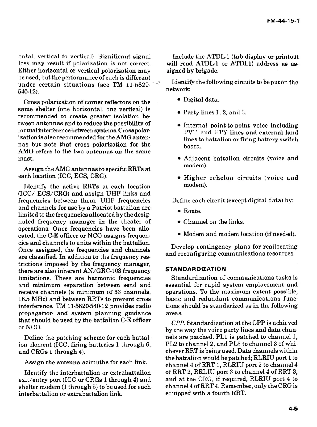
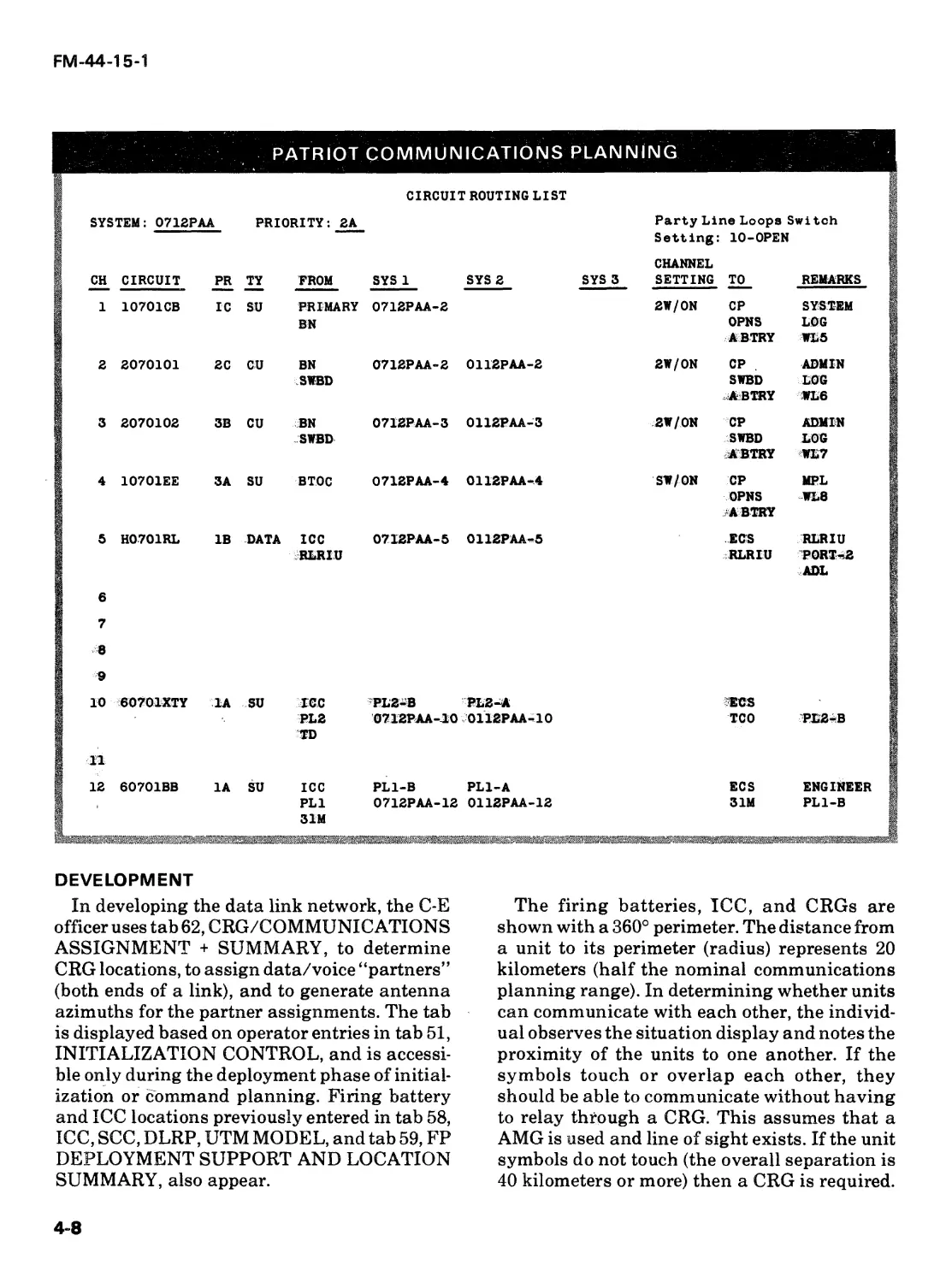
PATRIOT COMMUNICATIONS PLANNING
CIRCUIT ROUTING LIST
SYSTEM: 0712PAA PRIORITY: 2A CH CIRCUIT PR TY PROM Party Line Loops Switch Setting: 10-0PEN CHANNEL SYS 1 SYS 2 SYS 3 SETTING TO REMARKS
1 10701CB IC SU PRIMARY BN 2 2070101 2C CU BN 0712PAA-2 2W/0N CP SYSTEM OPNS LOG ABTRY WL5 0712PAA-2 0112РАА-2 2W/0N CP ADMIN
SWBD 3 2070102 3B CU BN SWBD LOG ABTRY WL6 0712PAA-3 0112PAA-3 2W/0N CP ADMIN
SWBD 4 10701EE SA SU BTOC SWBD LOU ABTRY WL7 0712PAA-4 0112PAA-4 SW/0N CP MPL
5 H0701RL IB DATA ICC RLRIU 6 7 8 9 10 60701XTY 1A SU ICC PL2 TD 11 12 60701BB 1A SU ICC PL1 SIM OPNS WL8 ABTRY 07I2PAA-5 0112PAA-5 ECS MLRIU RLRIU PORT-2 ADL PL2-B PL2-A ECS 0712PAA--10 0112PAA-10 TCO PL2-B PL1-B PL1-A ECS ENGINEER 0712PAA-12 0112PAA-12 31M PL1-B
DEVELOPMENT
In developing the data link network, the C-E
officer uses tab 62, CRG/COMMUNICATIONS
ASSIGNMENT + SUMMARY, to determine
CRG locations, to assign data/voice “partners”
(both ends of a link), and to generate antenna
azimuths for the partner assignments. The tab
is displayed based on operator entries in tab 51,
INITIALIZATION CONTROL, and is accessi-
ble only during the deployment phase of initial-
ization or command planning. Firing battery
and ICC locations previously entered in tab 58,
ICC, SCC, DLRP, UTM MODEL, and tab 59, FP
DEPLOYMENT SUPPORT AND LOCATION
SUMMARY, also appear.
The firing batteries, ICC, and CRGs are
shown with a 360° perimeter. The distance from
a unit to its perimeter (radius) represents 20
kilometers (half the nominal communications
planning range). In determining whether units
can communicate with each other, the individ-
ual observes the situation display and notes the
proximity of the units to one another. If the
symbols touch or overlap each other, they
should be able to communicate without having
to relay through a CRG. This assumes that a
AMG is used and line of sight exists. If the unit
symbols do not touch (the overall separation is
40 kilometers or more) then a CRG is required.
4-8
FM-44-15-1
The CRG’s location is then determined by using
the “floating” cursor and hook trial method or
by map reconnaissance. In either case, the loca-
tion must be checked on a map for accessibility
and adequacy in terms of elevation and terrain
to support line of sight.
CRG UTM coordinates (software or map recon-
naissance generated) are then entered in the
appropriate LOCATION UTM data field. Once
the UTM locations and link identifiers (numeric
or alpha) have been entered, the communica-
tions partners are assigned by the software. The
software also computes the azimuth required by
each partner to point the UHF antennas toward
each other. It enters this data in the antenna
fields of the display.
To clear the data for a CRG or link partner,
place zeroes (0) in the data field. To delete the
data associated with the CRG location, place
the cursor under the first numeral of the CRG’s
UTM coordinate and press the CANCL HOOK
Key. Data on that CRG will be deleted. Data
that is not deleted will reappear whenever the
tab is entered and displayed.
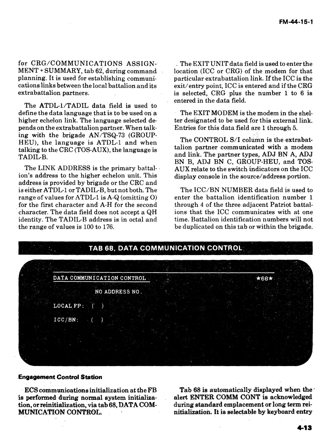
TAB 62, CRG/COMMUNICATIONS ASSIGNMENT + SUMMARY
INITIALIZATION
Once a communications plan is developed, it
is implemented. Manstation two operators at
the ICC, CRG, and ECS use the previously dis-
cussed battalion UHF communications link
diagram and Patriot communications planning
worksheets as guides in their emplacement
procedures.
4-9
FM-44-15-1
CHANNEL ALIGNMENT
RRT initialization loop back channel align-
ment procedures are now performed to allow for
the immediate setup of UHF links. The TSEC/
KG-27 KOK cards should be set per CEOI before
emplacement. They are visually checked at the
time they are set. As soon as power is provided
to the ECSs, ICC, and CRGs, loop back may be
performed on each RRT. The procedure is as
follows:
• Set loop back frequencies on AN/GRC-
103 (receiver must be set 50 channels
above transmitter; for example, trans-
mitter-1065 receiver-1115.
• Connect loop back antenna (ensure loop
back circuit breaker is ON).
• Tune transmitter-receiver. Check order
wire; the receive signal should be quiet.
• Connect handset to TD-660/G. check to
ensure channels are quiet. If a loud rush-
ing sound is heard, recheck KOK cards.
Channel alignment of the TD-660/G must be
accomplished after the UHF link is established
and prior to attempting data transfer. (Ensure
patch cords are removed from the appropriate
RRT at the CPP. The procedure is as follows:
• After order wire communications have
been established with the distant station,
meet on channel 1 of the TD-660/G.
• Coordinate with the distant station as to
sending and receiving of tone to accomp-
lish channel gain adjustment.
(This is done each time an RRT is initial-
ized with a distant station. Improper gain
adjustment affects party line conditions
and data transfer.)
® After channel gain adjustment has been
accomplished, finish patching in accor-
dance with the communications plan and
meet the distant station on party lines.
COMMUNICATIONS INITIALIZATION
Software communications initialization is
done within the Patriot system by the computer,
which is programmed with numerous data
items. Computers within the battalion have to
know who is in the battalion and external bat-
talion nets, what their battalion identification
numbers are, who the external stations are, and
how to communicate with them. All this infor-
mation is input during initialization at the ICC
with a lesser set being input at each ECS. This
section addresses the tab entries at each loca-
tion and the interaction of this data.
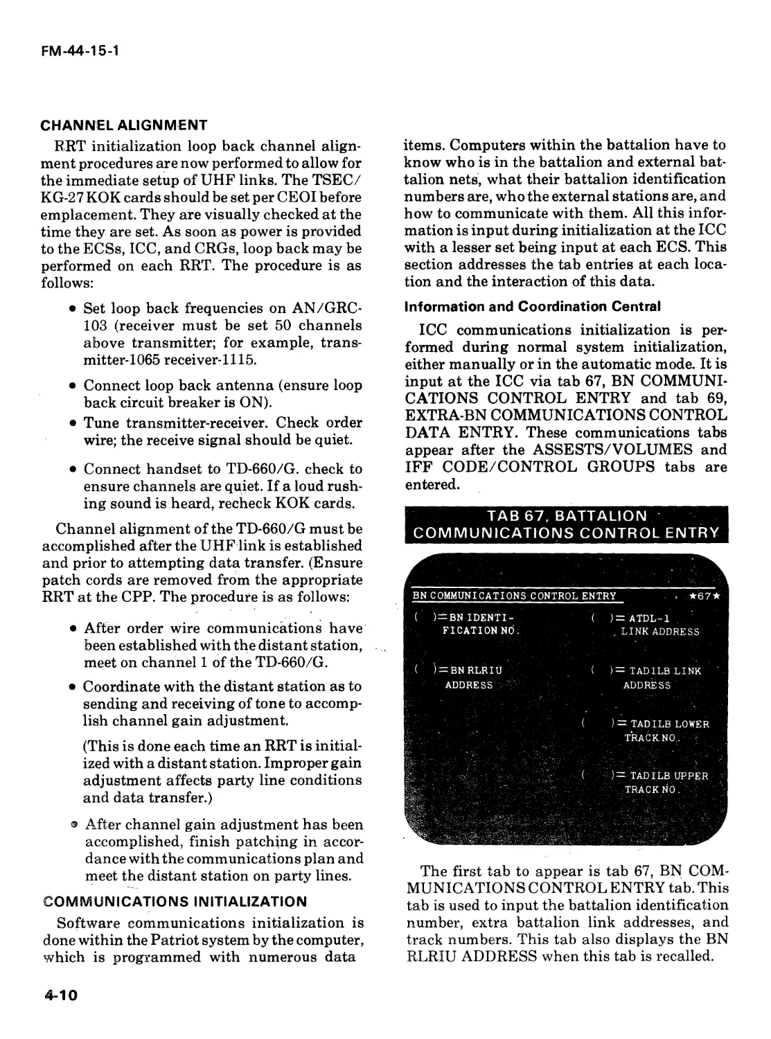
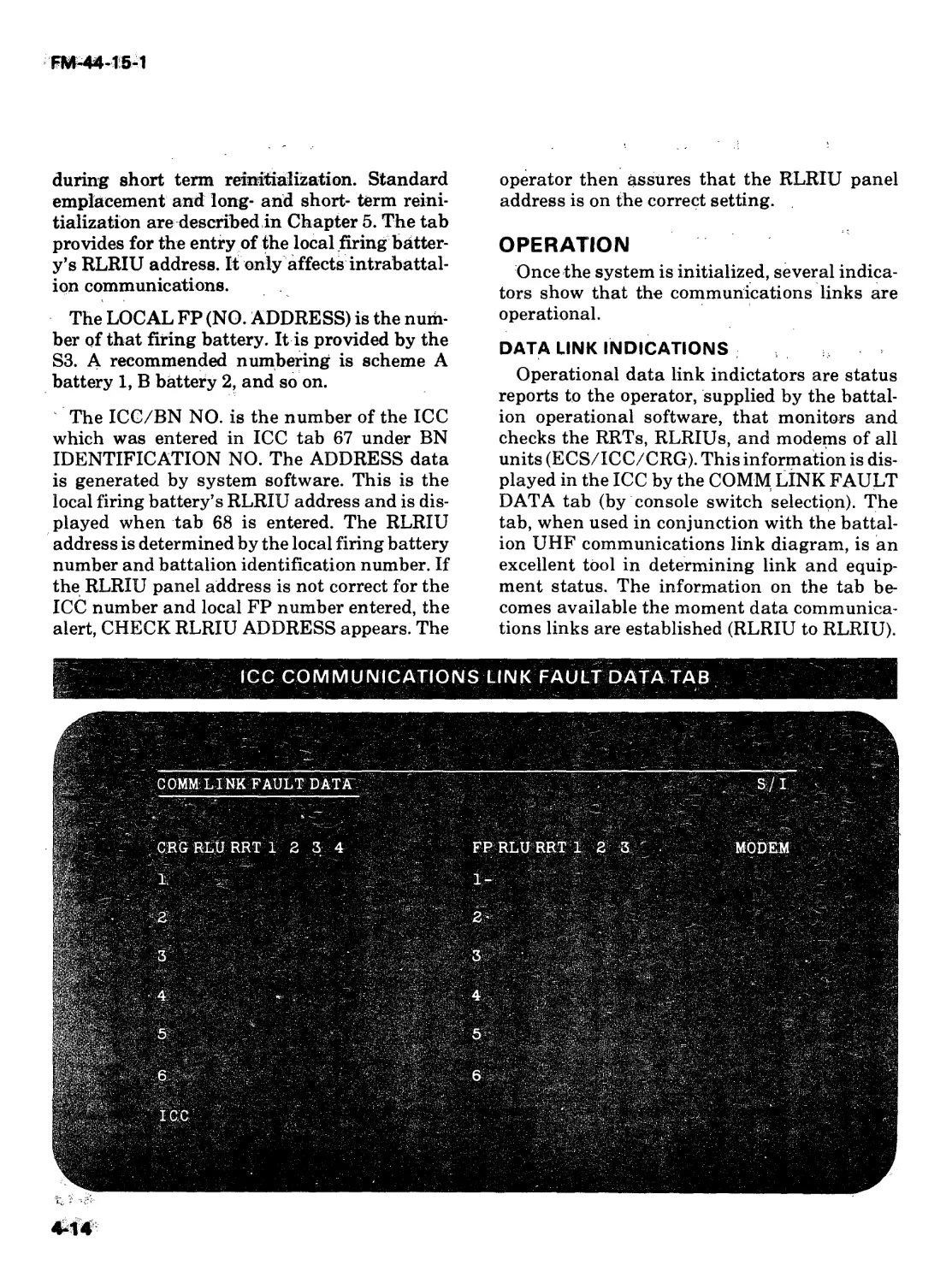
Information and Coordination Central
ICC communications initialization is per-
formed during normal system initialization,
either manually or in the automatic mode. It is
input at the ICC via tab 67, BN COMMUNI-
CATIONS CONTROL ENTRY and tab 69,
EXTRA-BN COMMUNICATIONS CONTROL
DATA ENTRY. These communications tabs
appear after the ASSESTS/VOLUMES and
IFF CODE/CONTROL GROUPS tabs are
entered.
TAB 67, BATTALION
COMMUNICATIONS CONTROL ENTRY
BN COMMUNICATIONS CONTROL ENTRY . *67*
( )—BN IDENTI-
FICATION NO.
( )= ATDL-1
. LINK ADDRESS
( ) —BN RLRIU
ADDRESS
' ' (
)= TADILB LINK
ADDRESS
) = TADILB LOWER
TRACK NO, :
)= TADILB UPPER
TRACK NO.
The first tab to appear is tab 67, BN COM-
MUNICATIONS CONTROL ENTRY tab. This
tab is used to input the battalion identification
number, extra battalion link addresses, and
track numbers. This tab also displays the BN
RLRIU ADDRESS when this tab is recalled.
4-10
FM-44-15-1
The battalion identification number is pro-
vided by brigade with an input of 1 to 4. This
battalion identification number is also entered
in ECS TACI tab 68, DATA COMMUNICA-
TION CONTROL, in the ICC/BN field. When
tab 67 is entered into the system by the operator,
system software generates the BN RLRIU AD-
DRESS that is displayed on tab 67 based upon
the battalion identification number. System
software also generates all the battalion source
codes and RLRIU addresses based upon the
battalion number entered.
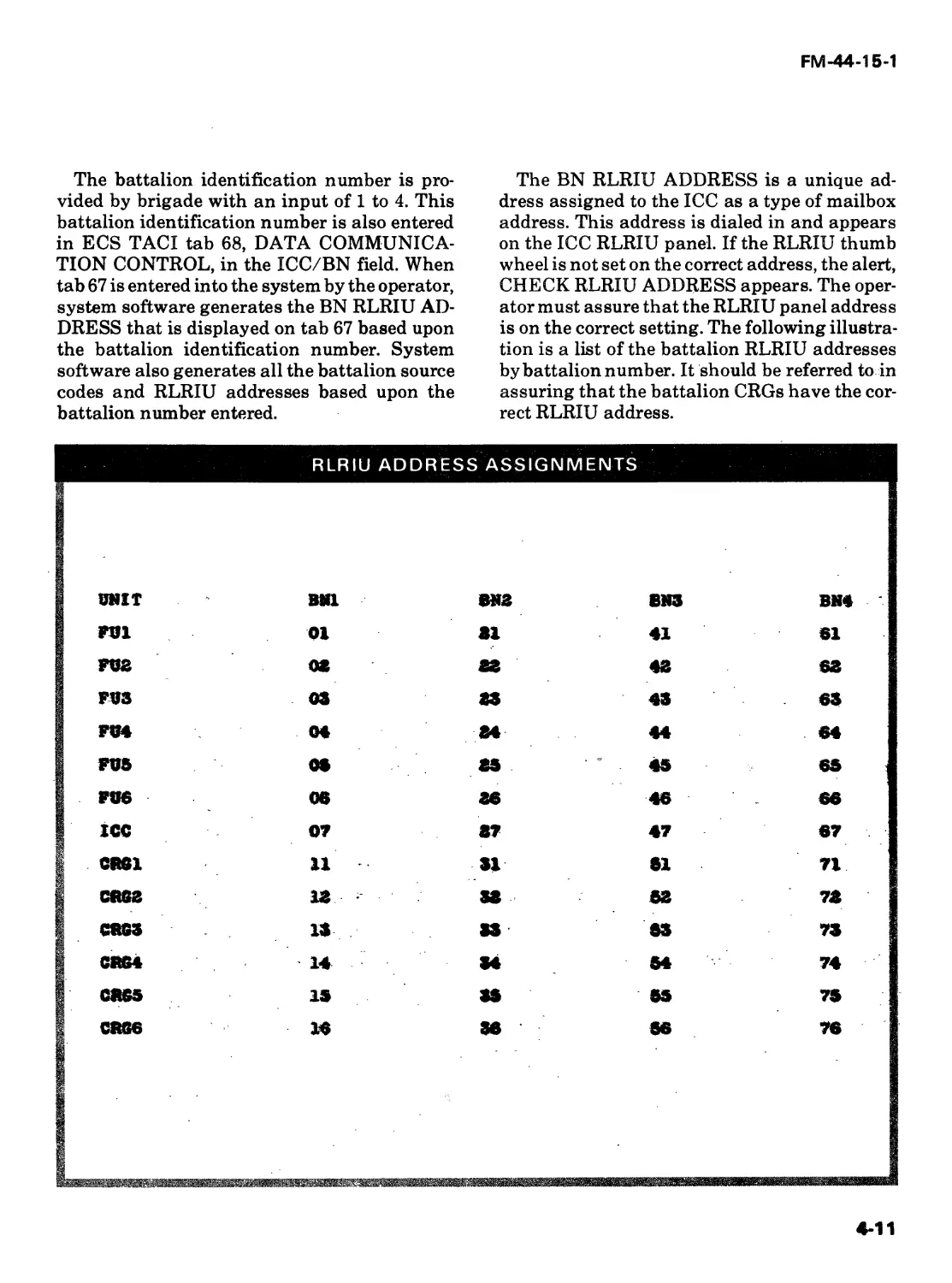
The BN RLRIU ADDRESS is a unique ad-
dress assigned to the ICC as a type of mailbox
address. This address is dialed in and appears
on the ICC RLRIU panel. If the RLRIU thumb
wheel is not set on the correct address, the alert,
CHECK RLRIU ADDRESS appears. The oper-
ator must assure that the RLRIU panel address
is on the correct setting. The following illustra-
tion is a list of the battalion RLRIU addresses
by battalion number. It should be referred to in
assuring that the battalion CRGs have the cor-
rect RLRIU address.
RLRIU ADDRESS ASSIGNMENTS
UNIT BN1 BN2 333 BH4
FVl 01 31 41 61
FU2 02 83 43 63
FU3 03 83 43 63
FV4 04 84 44 64
FU5 OS 85 45 65
FU6 06 36 46 66
ICC 07 87 47 67
CR81 n 31 51 71
cftsa аз 38 52 78
C3G3 аз 33 3& 73
C864 14 34 54 74
CRG5 is 35 65 75
CRG6 16 36 56 76
4-11
FM-44-15-1
The ATDL-1 LINK ADDRESS and the
TADIL—В LINK ADDRESS (tab display or
printout may read TADIL-B or TADILB) are
the extrabattalion data link addresses assigned
by brigade. The ICC must always have an
ATDL-1 LINK ADDRESS. This address is in-
put even if the battalion is operating autono-
mously. The range of values for the first charac-
ter is A to Q (omitting O) and the second
character A to H. The pairing of Q and H is not
accepted. The TADIL-B LINK ADDRESS is in
octal, and the restriction of not using 8s an’ct 9s
also applies. This data field does not need an
entry unless the TADIL-B link is established.
The TADIL-B lower and upper track numbers
are assigned by CRCs operating with the
TADIL-B link. These numbers are also octal
and the restriction associated with the use of 8s
and 9s applies.
TAB 69, EXTRA-BATTALION COMMUNICATIONS CONTROL DATA ENTRY
EXTRA—BN COMMUNICATIONS CONTROL DATA ENTRY ★69*
CONTROL ICC/BN COMM POINT , ATDL1/ LINK EXIT EXIT
S/I NUMBER LOCATION TADIL ADDRESS UNIT MODEM
AD J BN A ( ) ( ) • ( )
AD J BN В ( ) ; ( ) ( ) ( )
ADJ BN C ( . f ( ) ( ) ( ) '
GROUP-HEU ( ; ( L (\ ) - ( ) ( )
TOS-AUX ( ) ( ) ( ) ( ) (• )-
The Йех! tab to appear isSb&b 69, EXTRA-BN
COMMUNICATIONS CONTROL DATAr_.
ENTRY.'This tab is used for defining the exit ""
and entry points for extrabattalion communi-H
cations. It is the last ICC communications
initialisation tab. Each roW^represents one of
the fivenjodem ports that ca^be handled simulta- я/
neously by a battalion. These are normally one
port to higher echelon and three ports to Patriot
battalion. If there is no extra Patriot battalion
communications, this tab is entered with no
data entries.
A Patriot battalion cannot “talk” with two-
higher echelon units simultaneously. It can
“talk” ATDL-lStb a higher echelon and-LJatriot
language to acy^cent Patriot battaliomp^But it
cannot “talk” ADTL-1 to one higher echelon
unit and ATDI^l or TADIL-B to anoth^ribigher
echelon unit. In the latter case, the software
does not kno$x which higher echef<ft?Ainit’s
commands to accept and process.
The COMM POINT LOCATION data field is
used to enter the UTM coordinates of the loca-
tion of the extrabattalion’s communications
element through which it is linked to the local
battalion exit/entry point. The position of the
extrabattalion’s communications element will
appear as a CRG symbol on the display console
4-12
FM-44-15-1
for CRG/COMMUNICATIONS ASSIGN-
MENT + SUMMARY, tab 62, during command
planning. It is used for establishing communi-
cations links between the local battalion and its
extrabattalion partners.
The ATDL-l/TADIL data field is used to
define the data language that is to be used on a
higher echelon link. The language selected de-
pends on the extrabattalion partner. When talk-
ing with the brigade AN/TSQ-73 (GROUP-
HEU), the language is ATDL-1 and when
talking to the CRC (TOS-AUX), the language is
TADIL-B.
The LINK ADDRESS is the primary battal-
ion’s address to the higher echelon unit. This
address is provided by brigade or the CRC and
is either ATDL-1 or TADIL-B, but not both. The
range of values for ATDL-1 is A-Q (omitting O)
for the first character and A-H for the second
character. The data field does not accept a QH
identity. The TADIL-B address is in octal and
the range of values is 100 to 176.
. The EXIT UNIT data field is used to enter the
location (ICC or CRG) of the modem for that
particular extrabattalion link. If the ICC is the
exit/entry point, ICC is entered and if the CRG
is selected, CRG plus the number 1 to 6 is
entered in the data field.
The EXIT MODEM is the modem in the shel-
ter designated to be used for this external link.
Entries for this data field are 1 through 5.
The CONTROL S/I colurnn is the extrabat-
talion partner communicated with a modem
and link. The partner types, ADJ BN A, ADJ
BN B, ADJ BN C, GROUP-HEU, and TOS-
AUX relate to the switch indicators on the ICC
display console in the source/address portion.
The ICC/BN NUMBER data field is used to
enter the battalion identification number 1
through 4 of the three adjacent Patriot battal-
ions that the ICC communicates with at one
time. Battalion identification numbers will not
be duplicated on this tab or within the brigade.
Engagement Control Station
ECS communications initialization at the FB
is performed during normal system initializa-
tion, or reinitialization, via tab 68, DATA COM-
MUNICATION CONTROL.
Tab 68 is automatically displayed when ther
alert ENTER COMM CONT is acknowledged
during standard emplacement or long term rei-
nitialization. It is selectable by keyboard entry
4-13
FM-44-15-1
during short term reinitialization. Standard
emplacement and long- and short- term reini-
tialization are described in Chapter 5. The tab
provides for the entry of the local firing batter-
y’s RLRIU address. It only affects intrabattal-
ion communications.
The LOCAL FP (NO. ADDRESS) is the num-
ber of that firing battery. It is provided by the
S3. A recommended numbering is scheme A
battery 1, В battery 2, and so on.
The ICC/BN NO. is the number of the ICC
which was entered in ICC tab 67 under BN
IDENTIFICATION NO. The ADDRESS data
is generated by system software. This is the
local firing battery’s RLRIU address and is dis-
played when tab 68 is entered. The RLRIU
address is determined by the local firing battery
number and battalion identification number. If
the RLRIU panel address is not correct for the
ICC number and local FP number entered, the
alert, CHECK RLRIU ADDRESS appears. The
operator then assures that the RLRIU panel
address is on the correct setting.
OPERATION
Once the system is initialized, several indica-
tors show that the communications links are
operational.
DATA LINK INDICATIONS
Operational data link indictators are status
reports to the operator, supplied by the battal-
ion operational software, that monitors and
checks the RRTs, RLRIUs, and modems of all
units (ECS/ICC/CRG). This information is dis-
played in the ICC by the COMM LINK FAULT
DATA tab (by console switch selection). The
tab, when used in conjunction with the battal-
ion UHF communications link diagram, is an
excellent tool in determining link and equip-
ment status. The information on the tab be-
comes available the moment data communica-
tions links are established (RLRIU to RLRIU).
ICC COMMUNICATIONS LINK FAULT DATA TAB
4-14
FM-44-15-1
As a general rule, if secure voice communica-
tions have been established over the UHF line
(that is, party lines), the mechanical aspects of
the circuit are correct; that is, radios aligned,
codes correct, antenna azimuth correct, et
cetera. If data transfer does not follow, trouble-
shooting should begin by checking the patching
connections on the communications patching
panel.
In addition to the ICC COMM LINK FAULT
DATA tab, the COMM lights on the BN and FP
status indicator panels are excellent indicators
of the status of the data link. When the lights
illuminate, they indicate that the software has
been initialized properly and the link has been
established. The color of the lights is a further
indication as to the status of the link. Green is
go, amber is degraded, red is no-go, and no light
means inactive. The colors or status of the light
indicators are triggered by status monitor and
are combinations of several items, such as the
status of RRTs, RLRIUs, and the percentage of
messages acknowledged. This monitoring is
done automatically by status monitor, and the
results are displayed on the COMM light indi-
cator, FP FAULT DATA tab, ICC COMM LINK
FAULT DATA tab the ICC STATUS tab, and
FP STATUS tab.
When the COMM light comes on, it indicates
that data is being transferred over the link. Sta-
tus monitor automatically transfers data from
the ECS to the ICC as soon as the link is estab-
lished. The color of the COMM light is an indi-
cator of what percentage of messages sent is
properly ackowledged. Green indicates 90 per-
cent plus, of all messages sent are being ac-
knowledged. Amber indicates 50 percent to 90
percent of all messages are being acknowl-
edged. Red indicates less than 50 percent of all
messages sent are acknowledged. A data trans-
fer should not be attempted with a red COMM
light.
Although the COMM light is an excellent
indicator of the status of the communications
links, a green light does not give the total com-
munications network picture. Currently, the
only mechanism to expediently isolate a link
problem to a shelter, RLRIU, or an RRT is the .
ICC tactical software, as displayed on the ICC
COMM LINK FAULT DATA tab Using this
tab display in conjunction with the battalion
UHF communications link diagram greatly
assists personnel in troubleshooting and isolat-
ing UHF communications problems. This tab
also provides the tactical director with the cur-
rent status (go, degraded, no-go, inactive) of the
major communications components of each
ECS, CRG, and ICC in the battalion.
NET CONTROL
The net control for the Patriot battalion’s
UHF communications links is the responsibil-
ity of the battalion C-E officer and NCO. They
are individuals who, together with the S3 sec-
tion and the ICC command planners, establish
the UHF communications link requirements.
During a battalion emplacement, one or both
should be available at the ICC and on the FM
administration/logistics net, supervising the
establishment of the links. Alternate routes,
which are planned for contingency purposes,
can be implemented by the C-E officer or NCO
in the event a battery or CRG cannot, for some
reason, come on line; that is, delayed emplace-
ment or generator problems.
It is conceivable that the net control respon-
sibility could be delegated for a short period of
time. For example, if a battalion march order
called for ICC relocation but not the CRG, then
the CRG would assume net control until the ICC
was emplaced and its UHF links established. In
summary, the primary responsibility of the
Patriot battalion UHF net control is to direct
immediate establishment of the UHF commun-
ications links, ensuring that all elements are
following the communications plan and, if nec-
essary, to direct alternate route links.
Once the links are established, the net control
(BN C-E officer or NCO) monitors the opera-
tions through MS2 and the COMM LINK
FAULT DATA tab at the ICC.
TACTICAL COMMUNICATIONS
Once the system is initialized for tactical
communications, the only tactical tab available
4rTS^
FM-44-T5-T
to terminate (disallow) or maintain (allow) data
communications between the ICC and its FBs,
adjacent Patriot battalions, or higher echelon is
tab 02, COMMUNICATIONS CONTROL. If
data communications are disallowed with a
particular FB or extrabattalion partner, the
ICC will not process any data input from that
element. The ICC RLRIU continues to perform
its multirouting function by accepting data
messages from the disallowed element and re-
routing the data throughout the network. Tab
02 is also used to reinitialize the battalion
RLRIUs. It is on this tab that you also indicate
which battalion is the primary battalion when
Patriot is configured in the primary-secondary
role.
TAB 02, COMMUNICATIONS CONTROL
BN COMMUNICATIONS' ★02*
CONFIGURATION CONTROL
REINITIALIZE ( )RLRIU: ICC, CRG1-6, FP1-6
( )=PRIMARY BN NO , ’ (0=N0NE)
COMM STATE: A=ALL0W,D=DISALLOW
BNA=( ) FP1 = ( ) ' FP6 = (
BNB=( ) FP2 = ( )
BN C = ( ) FP3 = ( )
) ’ -FP4= ( )
) FP5=( )
When operating in the primary-secondary
configuration, Patriot is required to interface
with higher echelon elements above brigade
level, where no brigade AN/TSQ-73 is present.
The Patriot primary-secondary role cannot be
used in a mixed brigade. However, an ATDL-1
link would be established by the primary battal-
ion with a Hawk Battalion AN/TSQ-73 con-
figured in ajmaster BATTALION CONFIGU-
RATION. Each ICC operates with equal engage-
ment authority. The primary battalion provides
the path by which the higher echelon exercises
command and control over the secondary bat-
talion.
The decision of which battalion within the
brigade is the primary battalion is the respon-
sibility of the brigade S3. This decision is based
on the brigade’s current deployment and on
which of the battalions has the best communi-
cations “shot” to the higher echelon unit if the
brigade goes down.
The ECS has a corresponding tab to disallow
or allow communications among the ICC, other
FBs, and itself. Tab 02, COMMUNICATIONS
CONTROL, will be used by the ECS, only dur-
ing tactical operations.
The FBs at some time during the air battle
may have to go to the FU to FU operation. The
FU to FU capability is used when communica-
tions with the ICC has been severely inter-
rupted because of jamming, or terminated be-
cause the ICC is relocating or has been des-
troyed. The FU to FU capability allows the FBs
to perform triangulation, target correlation,
and engagement support. Normal FU satura-
tion alleviation is still performed at each FB
and track data in terms of position, engagement
decision, and weapons assignment is ex-
changed between the FBs. During transition to
the FU to FU mode and back to the ICC/FU
mode, tab 02 will be used to allow and disallow
the exchange of tactical data..
Operations
To be effective in combat, Patriot units must accomplish
basically the same tasks required for other air defense weapon
systems. In this chapter, the procedures used to prepare the
Patriot system to perform its air defense role are summarized.
FM 44-15 presents a complete description of planning consid-
erations. Emphasis in this chapter is focused on the series of
computer and crew member actions directing the system’s air
defense operations — in particular, the engagement sequence.
PREPARATION FOR ACTION
To accomplish the mission, the Patriot com-
mander must know the geographical area. Posi-
tions must be evaluated and selected with care
because of the unique size, weight, and firing
characteristics of the Patriot sytem. Emplace-
ment, activation and initialization actions
must be taken to make the fire unit operational
once the position has been selected.
POSITION EVALUATION AND SELECTION
Patriot firing batteries must move frequently
to support movements of major maneuver for-
ces. Patriot fires may disclose firing battery
locations. Movements are also made to enhance
the unit’s survivability. Positions are evaluated
and selected to provide a tactical position from
which the units can deliver effective fire and
accomplish their missions.
Proper RSOP facilitates the orderly, rapid,
and safe movement of Patriot units. Battery,
platoon, and section headquarters personnel
are provided vehicles for RSOP activities.
RSOP teams are normally designated and led
by the executive officer. They accomplish RSOP
by reconnoitering designated position areas
and the routes thereto. The best march routes to,
and tentative equipment sites within the posi-
tions are then selected and marked off. Because
of the size, weight, and height of Patriot equip-
ment and prime movers, care is taken when
determining march routes. Special consider-
ations must be given to road conditions,
bridges, tunnels, arches, and other elements
that might prevent passage. Planners as well as
vehicle drivers must be conscious of the bridge
classification system described in.FM 5-36.
The RSOP party determines the site and
north reference azimuth for the RS. This is
necessary because the RS is normally the first
major equipment item in the fire control section
5-1
FM-44-15-1
to be emplaced. Other major equipment items
are emplaced in reference to it. Whenever possi-
ble, the survey section sends a position and
azimuth determining system survey party to
accompany the battery RSOP party. The PADS
party provides timely survey control for UTM
coordinates, height, and a true north orienta-
tion azimuth. This true north reference is then
used to align the RS by using the М2 aiming
circle. This gives the FB a more accurate azi-
muth reference. PADS should be the primary
source for determining the NREF while the М2
aiming circle can be used as a secondary source.
After the NREF and the RS site are deter-
mined, radar coverage diagrams are made (see
appendix). Sites for the AMG, EPP, and ECS
are determined by cabling requirements or unit
SOP. Cover and concealment are taken into
consideration when choosing equipment sites.
The RS and LS can be placed near woodlines as
long as openings exist for tactical operation.
Equipment in clearings should be placed near
the edges to blend the camouflage with the
woodline. Equipment should be parked and
camouflaged where shrubbery would normally
be found. Launcher sites are determined at this
time and marked by the survey party in concert
with the RSOP. The survey party provides the
UTM location and true north reference for each
LS.
Fire Control Section
The principal criteria for position selection
are —
• Radar field of view for PTL and STLs.
• A 30- by 35-meter or 1,050-meter2 area
(98.4 by 114.8 feet).
• Level terrain for RS (a slope of not more
than 10°).
• Accessibility.
• Location data (13-digit UTM coordi-
nates).
• AMG has line of sight to ICC, CRG, or FB
as appropriate.
• Cable restriction of 23 meters (75 feet)
from EPP.
• AMG can be leveled to within one half
degree in both pitch and roll.
Launching Station
Launching station position requirements
are —
• A 6- by 15-meter area (20 by 50 feet). If
missile reload is conducted or planned at
the site, an additional 10- by 15-meter
area at the side of the launcher is re-
quired.
• Level terrain (a slope of not more than
10°).
• Launching station deployed to support
primary sector.
• Backblast area of approximately 90
meters — clear of personnel and equip-
ment — behind the LS.
• Separation of from 120 to 1,000 meters
between LSs and the RS.
• Separation distance of at least 90 meters
between LSs.
• Site inside a vector no greater than 20° on
each side of RS track sector.
EMPLACEMENT
Emplacement is defined as those tasks re-
quired to convert a fire unit from a road march
configuration to a tactical configuration. Basi-
cally, emplacement consists of positioning vehi-
icles at predetermined sites selected by the
RSOP and/or survey teams, connecting the
associated equipment cables, and aligning the
RS and LS.
Fire Control Section
Once the firing battery has arrived at the
position, care must be taken to ensure that vehi-
cles are sited and oriented to line up exactly on
RSOP and/or survey team markers. Vehicles
are oriented to afford the RS the maximum field
of view to support the primary target line and
5-2
FM-44-15-1
secondary target lines. The PTL is the azimuth
to which each firing battery’s radar is oriented
to counter the greatest expected threat. The bat-
talion S3 assigns PTLs and STLs when plan-
ning the battalion defense. He considers threat
data, terrain (see appendix for radar coverage
considerations), defended assets, air defense
doctrinal principles, and other factors in deter-
mining primary and secondary sectors of fire.
Minimize equipment obstructions to primary
and alternate target search sectors by orienting
the ECS, EPP, and AMG on a radial line from
the RS.
Minimize RF radiation hazards by —
• Locating the ECS door away from the RS.
• Locating equipment within the radiation
cut-off zone.
• Marking personnel entrance and exit
routes.
5-3
FM-44-15-1
Cable Lengths
Cable lengths restrict the emplacement con-
figuration of the Patriot FCS. Patriot cable
lengths are as follows:
• Power cables from the EPP to the ECS
and the RS are 23 meters (75 feet) long.
• R/WCIU cable linking the ECS and the
RS is 38 meters (125 feet) long.
• UHF radio cables between the ECS and
the AMG are 15 meters (50 feet) long.
The distances between cable connectors should
not be greater than 11 meters (35 feet) from the
EPP to either the ECS or the RS. This require-
ment permits sufficient slack in the cable to lay
it on the ground and reach the connectors on
each end. One end of all power cables and the
signal cable should remain attached to the EPP
during road march. The R/WCIU cable is car-
ried on the ECS vehicle.
The antiradiation missile decoys are placed
in an area 400 to 600 meters on either side of the
RS. The decoys may be sited to the right or to the
left of the RS but not both when emplaced. Each
decoy should have a clear line of sight in the
primary threat direction and the decoy furthest
away from the RS should be the closest to the
threat. Emplacement of the decoys should be in
a diamond shape and none of the decoys should
mask any of the other decoys. For more details
on decoy siting information, refer to FM
44-lA(S).
RS and LS Alignment
Accurate target correlation, triangulation,
and successful target engagement depend on
proper FB alignment. Correct orientation of the
RS and LSs to a NREF and subsequent orienta-
tion of the LSs to the RS is critical. The ECS
relies on the NREF for RS location orientation
and for remote azimuth training commands.
Battle drills reflect procedures for aligning the
RS and LS. LSs having line of sight to the RS
will have priority for alignment over LSs not
having line of sight to the RS.
The UTM coordinates and alignment data for
the RS and LSs must be provided to the ECS for
input into the WCC. If PADS survey party data
is unavailable, other means (such as map resec-
tion, spotting, or measurements from bench-
marks) must be made. An alternate procedure to
determine UTM coordinates can be made if one
known map reference point is visible from the
site. Grid coordinates and azimuth reference to
the RS for each LS are determined as time
permits.
All data obtained during orientation and
alignment are recorded on special data sheets.
These sheets, are then hand carried to the ECS
crew members for data input during initializa-
tion. Extreme care must be taken to ensure that
alignment data collected is precise and input
accurately during initialization. The following
illustrations show the radar and launcher work-
sheets that a FB uses for alignment data.
5-4
FM-44-15-1
RADAR LOCATION AND ALIGNMENT DATA WORKSHEET
RADAR LOCATION AND ALIGNMENT DATA FORM
LONGITUDE
AND
LATITUDE
OR
UTM
AND
□□□ □□
□□□ □□
z z h e
e
e e e
e
METERS ALTITUTDE
*
*
□□□□
□□□□
ЕНЕИШШШЫПЛиШЫШШСИБЗШШ
□□□□
EL RDR TO MIR:
Elevation of mirrors
from Radar М2 .
BRNG RDR TO NREF ;
Bearing of Radar М2
sighted on North
reference М2.
EL RDR TO NREF TOP :
Elevation of Range Pole
Top from Radar М2
EL RDR TO NREF ВОТ :
Elevation of Range Pole
bottom from Radar М2
BRNG NREF TO RDR
Bearing of Radar М2
from NREF М2 .
ROLL:
CROSS ROLL:
AZIMUTH RING READING--------
UTM WORLD MODEL
0 = INTERNATIONAL
1 = 1880 CLARK
2 = 1866 CLARK
3
4
5
[о][8|[о1[о|П[о]
□□□□□
_ □□□□I
= 1858 CLARK
= EVEREST
= BESSEL
О
LOCATION DATA CONFIDENCE LEVEL
0 = SURVEY
1 = MODIFIED SURVEY 2 = MAP
0
ALIGNED BY:
0
= SURVEY 1 =COMPASS
0
WIND SPEED
= BELOW GALE 1 = GALE + ABOVE
0
CREW CHIEF CERTIFICATION
♦NOTE : Elevat ion measurements required only i f at an unsurveyed site.
5-5
FM-44-15-1
LAUNCHER LOCATION AND ALIGNMENT DATA: FORM 1
j LAUNCHER LOCATION AND ALIGNMENT DATA: FORM 1 I USED WHEN ALIGNING ON UNSURVEYED SITE
(1) LS NUMBER □
(2) BRNG NREF TO LS Bearing of Reference М2 Sighted on Launcher М2
(3) BRNG LS TO NREF Bearing of Launcher Sighted on Reference М2 [ЦЕОЕиБППОЗ
(4) BRNG LS TO RS Bearing of Launcher М2 Sighted on Radar М2 UUULdLU
(5) EL LS TO RDR Elevation of Launcher М2 Sighted on Radar М2 UUULoILJQ
1 (6) ROLL 1+1Го1Гг1Г~1Го1
1 (7) CROSS ROLL □□□□□
(8) MISSILE UMBILICALS CONNECTED UL E3L-X| UR
LL 0101 LR
NOTE
For LOS Emplacement, Fill in all items
5-6
FM-44-15-1
LAUNCHER LOCATION AND ALIGNMENT DATA: FORM 2
LAUNCHER LOCATION AND ALIGNMENT DATA: FORM 2
USED WHENLS UTM ALTITUDE AND ORIENTING LINE ARE PROVIDED AT A SURVEYED SITE
(1) LS NUMBER ----—--- LXi
zzhe eeeeennnnnnn
(2) UTM — □□□□□□□□□□□□□□□□
(3) METERS ALTITUDE
(4) ORIENTING AZIMUTH -----------
AZ М2 Stake to position stake
(5) BRNG NREF TO LS
Bearing of Reference------------
(6) TRUE AZ OF LS ---------
AZ from Launcher М2
thru canister alignment pins
( 7) BRNG LS TO NREF ------
Subtract (6) from 6400
and enter here
( 8 ) ROLL ---------------------
□□□□□Il
□□□□□□
□□□□□□
□□□□□□
□□□□□□
_□□□□□
(9) CROSS ROLL
□□□□□
(10) MISSILE UMBILICALS CONNECTED
Note:
For UTM Emplacement, fill in
UL UU UR
LL Ljdljd LR
i terns 1 thru 9
5-7
FM-44-15-1
ACTIVATION
Once the fire unit is emplaced it must be acti-
vated. Activation consists of starting the gen-
erators, applying power, and enabling remote
operation of the LSs and RS.
The Patriot system requires 208 or 120 volts,
3-phase, 4-wire, 400-hertz power. Power for the
ECS and RS is provided by the EPP and vehicle
batteries. The AMG draws its power indirectly
from the EPP through the ECS. LSs obtain their
power from on-board, 15-kilowatt generators.
System power must be applied in the proper
voltages and phases and in the proper sequence
to prevent damage to electronic components
and equipment. Therefore, it is essential that
ECS, EPP, and RS crew members coordinate
and communicate with each other during power
application procedures.
Launching stations emplaced with the fire
control section are synchronized into the digital
data link after each launcher crew has per-
formed its own activation actions (less enabling
remote operation). The launching station DTL
is set to synchronize on the ECS DLT at the
earliest possible time consistent with crew check-
outs. Once the DLT link is established, the WCC
in the ECS automatically performs periodic sta-
tus checks of the LSs, including simulated
launch tests. When each LS crew has completed
its tasks, and when authorized by the com-
mander, the crew places the LS LOCAL/RMT
switch in the RMT position, after this key-type
switch is activated, the LS is under control of
the ECS.
WARNING
Launcher crew members have one minute after
the LS LOCAL/RMT switch is switched to RMT to
evacuate the area and move to a safe distance (90
meters minimum).
INITIALIZATION
Initialization is the computer-controlled se-
quence of ICC and ECS operator actions, hard-
ware operations, and software processes re-
quired to advance the FB to a tactically opera-
tional state. When the ICC or ECS is said to be
initializing, the MSI and/or MS3 operator(s)
are entering data values (parameters) in re-
sponse to system cues displayed on their CRT
consoles or from information generated within
the FB or within the battalion. Data values
entered at the ICC represent data common to all
battalion units such as weapons control areas,
defended assets, and target identification crite-
ria. Values entered at the ECSs represent site-
specific data such as radar site and orientation.
The collection of all data is called the data base.
The preferred manner of initialization is for
data common to all the FBs and the ICC to be
entered at the ICC and sent by digital data link
to each ECS. This is referred to as data buffer
transfer. If the ICC is not on-line at the same
time an FB has to initialize, then the ECS oper-
ators) manually enter the data. In this case,
voice communications with the ICC is neces-
sary for coordination and information.
Initialization at the battalion level is called
battalion initialization, or BATI. Initialization
at the battery level is termed tactical initializa-
tion, or TACI. Tab is the abbreviation for
tabular-displays which appear on the ICC or
ECS MSI and MS3 consoles. Certain tabs are
reserved for BATI and others for TACI: still
others are used during battalion tactical opera-
tions or firing battery tactical operations. Tabs
used in this chapter are identified as BATI,
TACI, BTACOPS, or FTACOPS as appro-
priate.
Engagement Control Station
The three methods used in Patriot ECS initial-
ization are standard emplacement, long-term
reinitialization, or short-term reinitialization.
All three methods can be augmented by data
buffer transfer from the ICC.
Standard emplacement must be done after a
move to a new location and is used to develop a
data base tape.
Long-term reinitializaton is used if no move-
ment was involved but a new radar map is
desired, or if significant portions of the data
base have changed. Long-term reinitialization
is used after extended periods of maintenance or
downtime to update the data base tape.
5-8
FM-44-15-1
Short-term reinitialization is normally used
after brief periods of maintenance or after short
downtime when minor data changes are neces-
sary, or when radar-mapping updates are not
required. Data buffer transfer can be done as
part of the initialization, reinitialization pro-
cesses or during tactical operations.
Although not considered an initialization
method, recovery may be used in special situa-
tions to reinitialize system operation. If the sys-
tem experiences a program halt, keyboard lock-
out, or electromagnetic pulse, recovery may be
performed by using the procedures in TM 9-1430-
600-10-1.
Information and Coordination Central
Three initialization methods also are used to
initialize the ICC: manual, automatic, and re-
trieve and compare. Like the ECS, recovery can
be used to reinitialize the system following a
program halt, keyboard lockout, or EMP.
Manual data input is used when minor
changes to the existing data base are required.
New volumes can be entered during tactical opera-
tions.
Automatic data input is used when a complete
new data base is to be entered or major changes
to the existing data base are required.
Retrieve and compare is used to develop an
ICC data base by retrieving each FB’s data
base. However, its main purpose is to assure
that each FB is operating with the correct data
base.
Radar Mapping
When the RS is capable of radiating, and as
part of TACI, the TCO and TCA perform radar
mapping. This is a critical process in establish-
ing the lowest level that the system will search.
Radar mapping instructions are furnished by
the battery commander. The extent of mapping
to be performed is determined by battlefield
conditions and time available. Guidance also
includes the type of display to be used.
As a general rule, when the terrain is level, C
display type mapping should be used. If the
terrain is rolling hills and valleys, A display
type mapping should be used to contour the
lower search beams with the terrain.
During TACI, the TCO or TCA estabishes the
initial search lower bound by entering the
search elevation angle in tab 95. Care must be
taken in establishing this initial angle. The
value entered by the TCO or TCA must be based
on a map reconnaissance and terrain observa-
tion.The ISLB is where the system will begin
the lowest search when the mapping process is
started. During mapping, the TCO or TCA can
tailor the ISLB to the terrain (such as a small
valley) and, by so doing, establish the opera-
tional search lower bound. This is the lowest
point that the system will search during tactical
operations. The objective of ISLB and OSLB is
to ensure adequate low-level search coverage to
detect pop-up and low-level targets, reduce clut-
ter, and conserve radar resources by not at-
tempting search into terrain obstacles.
Masked terrain areas are defined at this time.
These areas are used during tactical operations
to indicate that an engagement might be unsuc-
cessful because the target may maneuver and
enter a masked region before intercept. Proper
setting of masked terrain will help to eliminate
engagement aborts because of terrain masking.
Presently, TACI tabs 92, 93, 95, and 97 control
the mapping of masked terrain, as well as defin-
ing lower search limits, and generating clutter
maps.
If the battlefield situation allows sufficient
time, the TCA may perform the terrain map-
ping functions over the full azimuth coverage,
PTL, and STL. The PTL-centered coverage
must be mapped last. The clutter-mapping func-
tion (only at the PTL-centered coverage) is done
automatically and in conjunction with the ter-
rain mapping process.
Under imminent combat conditions, when
the fire unit must become operational in min-
imum time, the mapping function can be omit-
ted. When the system is allowed to radiate in
tactical operations, the OSLB is whatever was
set in tab 95 as the ISLB. If mapping was omit-
ted and no clutter map generated, as soon as the
5-9
FM-44-15-1
system transitions to tactical operations and
out of passive surveillance, a clutter map is
automatically generated.
AIR BATTLE OPERATIONS
Once the tactical data is loaded into the
memory, the WCC becomes the focal point for
air defense operations at the FB level. Stored
computer programs within the WCC guide the
entire sytem’s operations. Tactical software
implements air defense firing doctrine based on
specific values and weights assigned during
initialization. These parameters enable the
WCC to correctly classify, identify, and engage
hostile aircraft. However, the WCC does allow
for human intervention from either MSI or
MS3. Generally speaking, the MSI and MS3’s
actions during the engagement sequence fall
into two distinct categories. The operator at
MSI initiates and monitors engagements. The
operator at MS3 ensures that friendly aircraft
are not engaged. This division of labor within
the ICC and ECS is described further in FM
44-15.
ENGAGEMENT MODES
Two engagement modes based on the extent
of computer and human element involvement
are used in Patriot. These are the automatic
mode and the semiautomatic mode.
Automatic
In the automatic mode, the system automati-
cally engages targets from a list of the most
threatening targets eligible for engagement —
the to-be-engaged queue. Both the ECS and the
ICC have TBEQs. TBEQs are displayed on both
the MSI and MS3 consoles. If the target at the
top of the TBEQ cannot be engaged imme-
diately, the next lower one on the TBEQ may be
engaged. The TCA can still manually engage
targets while the system is in the automatic
mode. For the ICC to engage targets in the
automatic mode, the ECS must be in the auto-
matic mode and in the centralized method of
control.
Semiautomatic
In the semiautomatic mode, the system de-
fines the most threatening targets to the battal-
ion, the defended asset, or firing battery via the
TBEQ. However, each target must be engaged
manually, primarily in the order of the TBEQ.
At the ICC, the TDA may press the ENGAGE
S/I or the PFE S/I. This action causes an nnn
ENGAGE SCI alert to appear on the TCA con-
sole display at the appropriate ECS. The TCA
ackowledges the alert which hooks the target.
He engages each target by pressing the
ENGAGE S/I.
ENGAGEMENT SEQUENCE
The following paragraphs describe the nine
major events in the engagement sequence from
search through kill assessment. Specific
weight values and other classified information
have been omitted from this discussion. Consult
FM 44-1 A(S) for a description of the engage-
ment sequence in a detailed classified format.
Search
In the search process the software systemati-
cally directs each FB’s RS to look for targets in
its assigned search sector. Search processing
can also be modified by the TCO or TCA during
tactical operations. Since the ICC has no radar,
the search process is an FB function. After the
search process detects a target, the track is
maintained in a target data record for the track
process. Once the target has been detected and
placed under stable track by the FB, the ICC is
notified of that track.
The Patriot system provides the capability to
search and track certain ECM targets in the
passive surveillance mode. The FB search sec-
tors are scanned in their normal frametimes,
passively with no active radiation being trans-
mitted. The receiver is open and processes ex-
ternal energy received (continuous jamming).
The passive search capability provides the
Patriot battalion the ability to remain RF silent
and provide track data on ECM continuous
jammers. This data is then triangulated at the
ICC and target positions provided to the FBs.
Normal system processing is performed on the
target.
5-10
FM-44-15-1
Passive search should be used when moving
into a new position and the state of emission
level is such that the FB is not to radiate. The
passive search process is performed at the FB
and is controlled via the passive search switch
indicator. Whenever an FB goes to passive
search, the ICC receives the alert, FPn
SEARCH PASSIVE. The ICC operator may
use the “TOLD IN” function to select a FB in
passive search to engage a triangulated strobe
track. The “TOLD IN” function can also be used
to engage individual nonjamming tracks.
When the ICC operator hooks a track, presses
the TRK DOWN TELL switch indicator, and
selects an FB for this function, it causes the
selected FB’s RS to automatically radiate and
send out an active search beam in the location
of the told-in track. If the RS acquires the track,
it is displayed on the CRT and processed by the
FB software programs. All these functions are
accomplished with no actions required by the
FB operator. If the track is not acquired with a
few search actions, the “TOLD-IN” function is
terminated and the FB goes back to passive
search.
ECS action. Normally, FBs should not mod-
ify their search sectors. Modifications can only
reduce the search coverage from the nominal
and may result in delayed target detections or
no target detection. Modifications to search
processing are done by TCA console switch
action during tactical operations.
The ICC normally initializes the drop short-
range, drop long-range and alternate search
sector data or В ATI tab 55 and sends it via data
buffer transfer to the ECS. It appears as TACI
tab 55 at the ECS. During tactical operations,
the TCA can select drop short-range, drop long-
range, and two alternate search sectors by
switch action. Alternate sector 1 and alternate
sector 2 cannot be selected at the same time.
However, any combination of one alternate sec-
tor, drop long-range, and drop short-range can
be selected. Search boundary lines on the ECS
consoles situation displays will then change in
response to the search sector modification. Note
that these actions affect only search coverage.
Once a target is detected by search, it will be
tracked at the track boundary. The ICC will
automatically forward targets to other firing
batterys that can acquire the target in their
track sector.
The RADIATE DISABLE S/I is an addi-
tional search control measure at the ECS. By
deactivating the RADIATE DISABLE S/I, all
radar actions are turned off (including search,
track, and IFF). Any missiles in flight will be
destroyed. The radiate mode may be resumed by
activating the RADIATE DISABLE S/I once
again.
ICC action. The ICC initializes search con-
trol parameters on BATI tab 55 for data buffer
transfer to the FBs during their TACI (tab 55). It
can also, by voice communications, direct an
FB to change or alter its search sector based on
a changing tactical environment. When a
tracked target is dropped by all of the FBs re-
porting the track, the ICC determines if the
target is within the track coverage of any other
FB. If there is an eligible FB, it will direct that
FB to search and attempt track on the target. By
means of specific alerts or tabs, the TD and or
TDA can monitor the following FB search
actions:
• FPn SEARCH NOMINAL alert tells the
ICC that an FB has selected a different
search sector or has dropped long- or
short-range search.
• FPn RADIATION alert notifies the ICC
that an FB has enabled or disabled
radiation.
• FPn REORIENTING alert tells the ICC
that an FB is reorienting from its PTL,
STL, or assigned azimuth.
• BN STATUS SEARCH MODE tab shows
an FB’s operational mode, radiation
status, search status, current azimuth,
and hot and cold missile count for review.
5-11
FM-44-15-1
• TRACK SUMMARY ofFP STATUS tabs
indicate the status of each FBs search
process and shows the current FBs
search sector.
The FB sector bounds displayed on the ICC
situation displays do not change with FB-
initiated changes. Thus, the situation displays
at the ICC do not reflect reduced FB search
coverage.
Track
After a target has been detected, the software
begins track processing. Track selects the opti-
mal radar track rate and radar waveform to
continue track on that target until it leaves the
FB track coverage. When a good stable track
has been obtained on a target, its position and
status are reported to the ICC by data link. The
ICC then attempts to correlate the target with
targets from other FBs, adjacent battalions,
and the brigade. If the track correlates with
other track information, the available target
identification history and other status are sent
to the FB. If the target does not correlate, a new
target track file is established. The track corre-
lation process provides continuity of track bet-
ween battalion, FBs, and adjacent battalions.
This gives the FB the identification, identifica-
tion history, and current engagement status on
a new FB track.
If the FB cannot determine the target’s range
(strobe track) because of ECM, the target’s azi-
muth and elevation are sent to the ICC. The ICC
attempts to compute the target’s range based on
data from other FBs tracking the same target. If
successful, it periodically sends the computed
range to the FB. This process is called triangu-
lation, because at least three FBs must have
strobe tracks on the target for the ICC to reli-
ably establish the target range. Once triangu-
lated, the range computation is maintained
with strobe track from two or more FBs. If the
target is not range resolved or triangulated, it
may be strobe correlated by the TD. If no range
estimate is determined, a jammer symbol ap-
pears (see FM 44-lA(S)) with a strobe display-
ing the azimuth of the jammar from the FB. The
TD at the ICC uses the JAMMER CORRELA-
TION + TRACK NUMBER CHANGE, tab 15, if
there is a jamming strobe from two FBs that
intersect; or a jamming strobe from one FB and
a skin track from another FB that intersect.
The TD inputs the track numbers on tab 15 and
enters the tab. If the two tracks that are entered
on the tab meet the criteria for triangulation,
the range resolved track appears and the strobe
or strobes disappear. If they do not meet the
criteria, the operator receives a FUNCTION
REJECT message. The operator should use tab
15 on a jammer symbol only when the jamming
strobes can be clearly defined as intersecting.
The track management process at the ICC
performs automatic saturation alleviation.
When the number of tracks at the ICC exceeds
the track file capacity, track management be-
gins dropping the least threatening tracks and
continues until the track file is no longer satu-
rated. It drops the remote tracks and then
targets which have been identified as friends or
low threat hostiles beyond the range limit. The
automatic saturation alleviation level is shown
to the left of the tabular display.
ECS action. The operator can influence the
tracking process by dropping track on a target
or by turning off the radar. During tactical
operations, a hooked track can be dropped using
the console DROP TRACK S/I. All information
on the target is discarded at the FB. If the FB is
searching and the target is in the search cover-
age, it will probably be redetected and placed
back under track. If other FBs have been track-
ing the target during this time, the ICC will
have retained all of the target status and identi-
fication history and will send it to the FB which
dropped the target. (Note: The RADIATE DIS-
ABLE S/I also turns off all search and track
actions resulting in the loss of all targets and
any missiles in flight from that FB.)
А-scope operations can be used by the opera-
tor to assist him in determining target track
type. The А-scope display presents two dig-
itized, range versus amplitude traces on the
tabular display area. The А-scope display is
5-12
FM-44-15-1
associated with the nnn USE A SCOPE alert
and the A-scope S/I. For an nnn USE A SCOPE
alert to be displayed at a particular manstation,
the operator must enable the ECCM ASSIST
S/I on the console mode group. The nnn USE A
SCOPE alert is generated when surveillance
detects and tracks a jammer as a repeater track.
The alert informs the operator that assistance is
required to classify the jamming target. The
alert appears once every minute if no action is
taken. The operator should hook the target,
acknowledge the alert, and select the A-SCOPE
S/I. A dual trace will appear in the tab display
area with a TGT definition data field. The oper-
ator reviews the dual trace and decides if the
target is a quiet track, a repeater, or one that the
operator does not know.
If the upper and lower traces are the same and
the separation distance is the same, the track is
probably quiet and an “O” should be entered in
the data field. This causes the system to attempt
to track the target as a quiet track.
If the upper and lower traces are the same and
the separation distance is different, the target is
probably a repeater and a “1” should be entered
in the data field. The system will continue to
track the target as a repeater. The alert nnn
USE A SCOPE is displayed every two minutes
on that track.
If the operator cannot determine what the
target is (that is, quiet or repeater), then a “2”
should be entered in the data field. The system
continues as before but the alert is displayed
every minute.
If a mass of many traces appears on both
lines it is probably clutter and the operator
should enter a “2” in the data field and should
press the DROP TRACK S/I on that target.
Any target may be hooked and А-scope select-
ed. If only a single trace appears, the target is
being tracked as either a quiet, continuous, or
non continuous jammer track. If a dual trace
appears, the target is being tracked as a re-
peater. If a dual trace appears, an entry of 0,1,
or 2 must be made in the data field. To clear the
А-scope, press the ENTER key, do not make any
entries.
When А-scope is selected, it is mutually exclu-
sive of the tab displays and static data dis-
played on the situation display. Volumes, as-
sets, corridors, et cetera, if displayed, are not
shown. If the clutter map update CMUP S/I is
selected by the operator, the clutter map process
is terminated. When the А-scope is cleared, the
static data previously displayed will automati-
cally be displayed. The tab area remains clear
until a tab display is selected. If CMUP was
previously selected and is to be continued, the
TCA should press the CMUP S/I. The CMUP
process begins where it was terminated.
А-scope is used to force the system to attempt
a quiet track of a target being tracked as a
repeater by the system. If numerous nnn USE A
SCOPE alerts appear and the TCA’s effective-
ness is hampered by responding to these alerts,
deactivate the ECCM ASSIST S/I. The sys-
tem’s capability is not degraded if the A-scope
process is not used.
ICC action. Periodically, track management
checks all target tracks to ensure that the corre-
lation is correct. The TDA can, by activating the
DECOR/RECOR S/I, while hooked on the tar-
get, cause a specific target to be checked for
correct correlation. The result might be that
nothing changes, two or more tracks might be
correlated and merge, or a track might split into
two separate tracks. Since track management is
periodically checking correlation, normally the
TDA should not intervene in this process. The
track amplifying data tab shows which FBs are
currently tracking a target, indicating that the
FB tracks were correlated by track manage-
ment.
Site calibration. This process is performed
at the ICC to correct differences in position for a
track reported by two or more FBs. These differ-
ences result from radar measurement errors,
emplacement position and alignment errors,
and computational errors. The process is ini-
tiated after an FB has completed emplacement
5-13
FM-44-15-1
or reorientation and is performed on FBs that
have large target azimuth errors. These errors
are affected by the type of entries made on TACI
tab 81 RADAR LOCATION/ALIGNMENT
DATA ENTRY. Consequently, caution should
be taken to ensure that the correct LOCATION
DATA CONFIDENCE LEVEL and ALIGNED
BY entries are entered. Site calibration will not
be performed if a confidence level of survey and
alignment of survey are input on tab 81.
Site calibration is performed by selecting two
FBs that are tracking the same single, quiet
track. The corrected-FB azimuth angle and
accuracy level are transmitted to each FB for
which the site calibration process has gener-
ated a change. The alert, FPn AZIMUTH
CHNG, appears at the ICC informing the oper-
ator that a site calibration for that FB has been
completed. The ICC operator can call up tab 12,
FP LOCATION/BOUNDARIES, and observe
the site calibration corrections in the CURR AZ
data field.
If a large azimuth error correction is required
at an FB, the alert SITE ERROR FP nnn and
FP nnn appears at the ICC. The operator should
contact the affected FBs and have them verify
their alignment and emplacement data. This
may require that the units perform a short-term
reinitialization and verify the data entries on
tab 81.
Identification
Once a target has been placed under stable
track by the ECS and reported to the ICC, the
target ID process begins. Target IDs can be
assigned manually by MSI or MS3 console
switch actions at the ECS or ICC, automatically
by the WCC, or automatically by the ICC in
response to digital data link commands from
brigade. The automatic identification mode is
the preferred method of operation for Patriot.
When ID criteria are employed properly, auto-
matic IDs are made more rapidly, reliably, and
consistently than manual IDs. This frees opera-
tors from performing the majority of IDs and
allows them to devote their attention to identifi-
cation of special situations and monitoring of
the automatic IDs. When the ECS is in the
automatic identification mode, target IDs are
established by the ECS, evaluated for conflicts
at the ICC, and then sent to higher echelons.
Even whenhigher echelonshaveidentificationauthor-
ity, Patriot should be in the automatic ID mode.
In the manual ID mode, the operator must
assign an identity to each track. The FBs man-
ually assign target IDs which are relayed to the
brigade by the battalion.
Possible target identities for the Patriot sys-
tem include the following:
• True friend. In both automatic and
manual ID modes, this ID is assigned to a
target which gives a valid Mode 4 IFF
response when challenged. This ID
cannot be assigned manually. However,
once it is automatically assigned it can be
manually revoked.
• Friend. This identity is assigned by either
the ICC or ECS operator via the FRND
switch. It can also be assigned automati-
cally, in the automatic ID mode, by the
ECS software if the target has accumu-
lated enough positive points to be identi-
fied as a friend. The friend identity is
assigned by higher echelon via the digital
data link.
• Assumed friend. This identity is assigned
by the ECS software (in the automatic
identification rhode) when a target has
accumulated enough positive points to
make it an asssumed friend. It can also be
assigned by a higher echelon message or
by the ICC or ECS operator by activating
the SPECIAL switch while hooked on an
unknown target and then activating the
UNKNOWN switch.
• Unknown. This identity can be assigned
by either the ECS or ICC operator via the
UNKNOWN switch. It is assigned auto-
matically by the ECS software for targets
which have not accumulated enough
negative points to be a hostile nor enough
positive points to be an assumed friend.
5-14
FM-44-15-1
An unknown identity can also be
assigned by higher echelon. When the
manual ID mode is specified in TACI tab
01 or FTACOPS tab 01, all targets are
initially assigned an ID of unknown. The
automatic ID processing is disabled for
final ID assignment.
• Special friend. This identity can only be
assigned by the ICC or ECS operator by
activating the SPECIAL switch while
hooked on a friend target, followed by
activating the FRIEND switch.
• Hostile. This identity can be assigned by
either the ECS or the ICC operator via the
HOSTILE switch. It can be assigned
automatically by the ECS software or by
higher echelon.
Identities manually assigned by an ECS or
ICC operator or by higher echelon will override
any identity established by the ECS software in
the automatic mode. There are two exceptions.
When the target replies with a valid Mode 4
response to an IFF challenge, the target’s iden-
tity is automatically changed to true friend .
This also occurs in the ECS manual identifica-
tion mode. The other exception is an ECS opera-
tor designation of unknown. The operator is es-
sentially removing any previous identity of the
target to allow the ECS automatic ID mode to
establish an identity based on the software’s
evaluation of the ID history criteria.
The basis for the ECS automatic assignment
of target identities is the target’s location,
speed, IFF response, and ECM emissions in
comparison to criteria entered during initializa-
tion. Associated with each kind of criteria are
positive or negative points called weight fac-
tors. When the target complies with friendly
criteria, positive points are added to the target’s
point total. When the target violates criteria
defined as a hostile indication, points are sub-
tracted from the target’s point total. In the
automatic ID mode, targets will be evaluated
every few seconds and an identity will be as-
signed based on a target’s total number of
points. Although the point values are fixed and
cannot be changed, flexibility is provided by
having three complete sets of points which are
designed to correspond to varying states of
readiness and levels of hostilities. The ID
weight sets are designed for the following envi-
ronments:
• Weight Set 1; peacetime.
• Weight Set 2; increased alert status or
transition.
• Weight Set 3; wartime.
The illustration below lists those criteria used
for determining point totals. FM 44-1 A(S) con-
tains weight factor values and how each is used
in computing the point total. ID volumes and
criteria should be set at initialization so that
friendly targets can comply with enough crite-
ria to build up sufficient number of positive
points to be assigned a friend ID. Similarly, the
volumes and criteria should be designed so that
an enemy aircraft will compile enough negative
points to be assigned a hostile ID.
PATRIOT ID WEIGHT SET CRITERIA
POP-UP
SAFE PASSAGE CORRIDOR
MINIMUM SAFE VELOCITY
ELECTRONIC COUNTERMEASURES
VOLUMES
FRIENDLY ORIGIN VOLUME
HOSTILE ORIGIN VOLUME
PROHIBITED VOLUME
RESTRICTED VOLUME
IFF/SIF
ECS action. The ECS operator defines the
volumes and corridors via tab 71, ALL VOL-
UMES + POINTS ENTRY. The ICC operator
also defines them via tab 71. TACI tab 71 or
FTACOPS tab 05 is used to designate volumes
and corridors as active or inactive. Inactive
volumes are not displayed or considered by
software processes.
o-15
FM-44-15-1
The remaining target ID criteria are entered
in tab 79. Using tab 79, the ID mode and weight
set to be initially used during TACOPS can be
specified. ECM emission and pop-up violations
can be authorized as a hostile identity criteria
via tab 79. Minimum safe velocity is entered as
a friendly indicator on this tab. During
TACOPS, the TCO or TCA can change ID
modes, change weight sets, and revoke or auth-
orize hostile criteria using FTACOPS tab 01,
and activate and deactivate assets and volumes
using FTACOPS tab 05, ASSET/VOLUME
STATUS.
The FBs should all use the same identifica-
tion weight set and hostile declaration authori-
zation. Active identification volumes within the
tracking coverage of more than one FB should
be the same. The possibility exists that numer-
ous ID conflicts will result if these guidelines
are not followed.
The TCO or TCA can control IFF/SIF inter-
rogations by using the SIF ENABLE, MODE 4
ENABLE, and HIGH THRESH/LOW
THRESH S/Is. Tabs affecting IFF/SIF actions
include TACI tabs 06,73, and 74. FTACOPS tab
06 is also used to further define IFF/SIF data.
Procedures for using these S/Is and tabs are
described in FM 44-1 A(S). If a system generated
hostile or unknown ID responds with a positive
Mode 3, it may require the TCO or TD to manu-
ally override the ID and identify the track as a
friend.
ICC action. The ICC’s role in identification
is to resolve any conflicts between the ID data
among FBs and between the Patriot battalion
and the brigade. It then disseminates the re-
solved identification throughout the battalion,
to adjacent battalions, and the brigade.
The battalion can initialize all ID volumes,
hostile authorizations, and ID modes for battal-
ion use and transfer this data to the FBs. Dur-
ing BTACOPS, the battalion operator uses
BTACOPS tab 05 to activate and deactivate ID
volumes and weapon control volumes at any or
all FBs during FTACOPS. The TD or TDA uses
tab 05 to change ID mode, weight set, and hos-
tile authorization.
There are a number of IFF-related and ID-
related alerts which can be generated at the
battalion. The TD or TDA can be requested by
voice from brigade to interrogate a target. After
receiving the IFF REQUEST, the TD or TDA
determines from the track amplification data
tab which FBs are tracking the target. He then
requests, via the IFF and SOURCE ADDRESS
S/Is, that one of the FBs interrogate the target.
The operator receives an_____IFF COMPLETE
alert if the FB has successfully challenged the
target, or an_____IFF INCOMPLETE alert if,
after four seconds, the interrogation has not
been successfully completed. In addition, the
TD orTDA receives an IFF EMERGENCY
alert or GARBLED IFF alert if the result of
any FB interrogation (whether requested by the
ICC or independently initiated by the FB) indi-
cates these conditions.
In the manual ID mode, the operator receives
an_____ID HIS CHNG alert each time that addi-
tional ID history data is received from a FB or
adjacent battalions. The operator will generally
be required to intercede when a target has a
previously established ID (other than un-
known) and a FB, adjacent battalion, or higher
echelon reports a different ID. When an ID con-
flict occurs between the different units which
the system cannot automatically resolve, the
TD or TDA receives aa nnn CONFLICT aaaa
AT bbb alert and is required to decide which
identity is correct and to direct the appropriate
subordinate unit changes.
Engagement Eligibility
Once a target has an identity assigned, it is
then processed for engagement eligibility.
Based on its identity and location, the target
may be considered eligible for automatic engage-
ment and, if so, another process called threat
assessment is performed.
Any target is eligible for manual engage-
ment. However, the operator is required to
change all forms of friend to hostile, and in
certain instances, some unknown targets to
5-16
FM-44-15-1
hostile, which implies that all hostile targets
are manually engageable regardless of where
they are located.
Weapons control statuses have an effect on
target eligibilty. Of the three statuses, WEA-
PONS HOLD is the most restrictive and WEA-
PONS FREE the least restrictive. Weapons con-
trol statuses are applied to the entire FB area of
coverage (called the residual zone) and to spe-
cific volumes within the FB’s area. The specific
volumes are input during initialization in tab
71. All active weapons control volumes are con-
sidered when the AREAS ENABLE switch is
activated either during TACOPS by the opera-
tor, or by the battalion via the data link. An FB
may have a residual zone of WEAPONS
TIGHT and have several volumes of WEAP-
PONS HOLD or WEAPONS FREE. The resid-
ual zone is the entire track sector, excluding the
area contained in active weapons control
volumes.
General engagement eligibility rules which
apply to the various states are as follows:
• Friends (special friend, true friend,
assumed friend, or friend) are never
eligible for threat assessment and conse-
quently are not engaged.
• Unknowns are eligible for automatic
engagement only in a WEAPONS FREE
area and will be threat assessed if this
condition exists.
• Hostiles are eligible for automatic en-
gagement in WEAPONS FREE or
WEAPONS TIGHT volumes and are
always threat assessed.
• No targets are automatically engaged in
a WEAPONS HOLD area; however,
hostile targets may be manually engaged
in a WEAPONS HOLD area.
The weapons control status for the battalion
and the FB overall (residual) areas are directed
by higher echelons. In this regard, considera-
tion is given to the protection of friendly aircraft
by establishing WEAPONS HOLD volumes.
These are used to cover aircraft refueling areas,
combat air patrols, or no-fire zones for Patriot.
Thus, for maximum protection of friendly or
possibly friendly aircraft, a WEAPONS HOLD
residual is recommended with few or no active
WEAPONS FREE and/or WEAPONS TIGHT
areas in the battalion’s coverage. If the envi-
ronment is not rich in enemy aircraft and a high
degree of protection for friendly aircraft is
desired, a WEAPONS TIGHT residual is recom-
mended. To gain the maximum engagement
potential against hostile and unknown targets,
a free-fire zone is designated and a WEAPONS
FREE volume is used. Using the general en-
gagement eligibility rules provided, the battal-
ion S3 can accommodate the weapons control
status imposed by higher echelons and develop
protective measures for friendly aircraft.
ECS action. Three switches on the system
control group of the display console affect wea-
pons control statuses for the FB’s residual area.
These switches are marked HOLD,
TIGHT, and FREE. Activating the HOLD
switch causes the overall FB area (residual
area) to be assigned a WEAPONS HOLD sta-
tus. Activating the TIGHT or FREE switches
results in WEAPONS TIGHT or WEAPONS
FREE weapons control statuses. The weapons
control status in effect is displayed on the FB
status panel. One status is in effect at all times.
If no switch is selected, the system will be in a
WEAPONS TIGHT status. The switches are
mutally exclusive (activating one state deacti-
vates the other).
The AREAS ENABLE switch activates and
deactivates the weapons control volumes’ input
during initialization. The status of each of these
volumes is set during initialization, but may be
changed during TACOPS. For example, if a
WEAPONS HOLD volume is defined during
initialization, it may be changed to WEAPONS
FREE during TACOPS. Individual weapons
control volumes can be activated or deactivated
via FTACOPS tab 05. When AREAS ENABLE
is activated, that status is displayed on the FB
status panel just below the FBs residual wea-
pons control status. The AREAS ENABLE S/I
5-17
FM-44-15-1
can be activated with any one of the weapons
control switches. The weapons control volumes
are considered by system software if they are
activated via tab 05 and are turned on by the
AREAS ENABLE switch. If they are deacti-
vated via tab 05, the system will not consider or
display them when AREAS ENABLE is
selected.
ICC action. The battalion processes engage-
ment eligibility independently, but in the same
manner as described for the FB. The TDA, via
switch action or BTACOPS tab 05, can change
the weapons control status of any or all FBs, as
well as activate or deactivate weapons control
volumes. The FB automatically accepts the
weapons control status and volume changes
and alerts the ICC by an FBn WC AREAS
ENABLED or an FBn WPN FREE, TIGHT,
HOLD alert. The battalion and individual FB
weapons control states are displayed on the bat-
talion status panel. Weapons control status
commands from higher echelons are relayed by
the ICC to the FBs.
Threat Assessment
After a target is detected, placed under track,
identified as unknown or hostile, and deter-
mined to be eligible for engagement based on
weapons control restrictions, it undergoes a
detailed threat assessment. The purpose of the
threat assessment process is to evaluate wheth-
er the target is close enough to any of the FBs (or
battalion, in the case of the ICC) defended
assets to be considered a threat. At the FB up to
16 defended assets can be defined with 6 active
at each FB. Each asset is assigned a priority
from 1 to 8 with priority 1 being the most impor-
tant and 8 the least (more than one asset can
have the same priority). Once a target is found
to be a threat to one or more assets, it is assigned
a threat value equal to the priority of the most
important asset threatened. A threat value is
called the target’s asset threat category. A
target may have an АТС of 9 or 10 and is not
considered a threat to an asset at that time. A
target’s АТС is used along with other factors to
determine the order of engagement. The АТС
can change as a target threatens different
assets. If the missile fly-out time is subtracted
from the time for the target to reach the asset,
the difference is the time left to engage the
target and defend the asset. This time is called
time-to-last-launch. A positive TLL means there
is a finite number of seconds left before the
target must be engaged. A TLL equal to zero
means that an engage command executed im-
mediately just allows the missile to intercept the
target at the asset boundary (assuming the
target actually turns to attack the asset). A neg-
ative TLL indicates that the target could pene-
trate the asset before a missile could reach the
target.
ECS action. Assets are defined to the FB by
entries on tab 70. Assets can only be entered
using a center point and radius. Assets are dis-
played as squares on the CRT, with sides equal
to the diameter of the asset, but are considered
as cylindrical volumes by the threat assessment
process. If zero radius is entered by an asset, a
small rectangle similar to the square for a gen-
eral point is displayed. The PRI column is used
to designate the priority (1 to 8) of the asset
which is used to determine the target АТС.
Assets only can be activated or deactivated dur-
ing TACOPS by FTACOPS tab 05. Only active
assets are displayed and considered in the
threat assessment evaluation.
The FB will not defend itself as an asset
unless it is defined as one on tab 70. The FB
should be defined as the same priority as the
highest asset priority. The FB will receive a
self-defense threat alert if a target threatens the
FB. Asset priorities are used for ordinal ranking
only. That is, if assets A and В are active and
are defined with A having priority of 2 and В a
priority of 6, asset A is more important than В
but is not 3 times more important. Assigning
asset В a priority of 3 would result in the same
threat assessment.
ICC action. The battalion independently
assesses the threat level of each target using a
process similar to that of the FB, but considers
from 1 to 16 assets, in the coverage of any of its 6
FBs.
The TDA, using tab 05, page 1, can activate or
deactivate ID volumes for any one of the FBs.
5-18
FM-44-15-1
The FB automatically accepts the volume
change and receives an ASSET ACTIVE or
INACTIVE alert.
The threat assessment process is also per-
formed for the hooked target or targets at either
or both display consoles. The track amplifying
data tab shows the asset threatened, АТС, and
the TLL. The first time a target has a TLL less
than 10 seconds against any asset, an aannn
THREAT TO ASSET alert is generated.
Threat Prioritization
A target that is being tracked by at least one
FB, which has been identified as eligible for
engagement based on its identity and which
has been threat assessed, is now ready to be priori-
tized. This means that it is placed in its appro-
priate position along with all other threats to
determine the recommended order of engage-
ment. If the queue is full, the target is added
only if it is of higher priority than the least
threatened target currently on the queue.
In the automatic engagement mode, the sys-
tem will attempt to engage targets in the order
of the TBEQ. If the target cannot be engaged
immediately, the next one lower on the TBEQ
may be engaged. In the semiautomatic engage-
ment mode, the TCA should also engage targets
in the order of the TBEQ when TLR (this is
when intercept offering high kill probability
can first occur) equals zero and before TLL
reaches zero.
All targets on the queue are evaluated once
per second and the queue is reordered if neces-
sary. Part of the evaluation process is to com-
pute the launch-now-intercept-point for each
target. The LNIP is the prediction of the inter-
cept location if the missile was launched imme-
diately and is based on the target’s current
speed and heading. If the LNIP falls outside of
the FB track sector, the target is removed from
the queue.
There are two orders of targets on the TBEQ.
At the top of the queue are those targets which
have been manually designated by the operator
for engagement (ENGAGE switch) but which
have not yet had a missile launched. If there are
more than one of these targets, the one desig-
nated first is on top, the second one designated
is second, et cetera.
The remainder of the targets are ordered by
АТС with the lower-numbered categories (more
important) above higher-numbered categories.
Targets which have the same АТС are further
ordered by the estimated missile fly-out time to
engagement with short-time-of-flight targets
above longer ones. However, if a target’s TLL is
below 10 seconds (representing a critical en-
gagement), it is ordered above the short-time-of-
flight targets with smaller TLL targets first.
The ordering of the queue may also be modified
by the engagement status of the targets. Final-
ly, targets with negative TLLs are ordered last
within their АТС.
ECS action. The TCA can observe the TBEQ
targets and parameters on the FB engage-
ment data display. This display consists of two
portions. The left side shows the TBEQ targets
in priority order. The right side shows those
targets currently under engagement (missile
fired). The TCA calls up the engagement data
display by activating the ENG DATA switch.
This action causes a display of the TBEQ. The
system continues to update and re-order the
queue, but the TCA will not see the new order
until he again activates the ENG DATA switch.
He is notified by a blinking target number that
the order of the queue he is observing is not the
same as the current one. This indicates that the
target and those below it are not in the correct
order. TLR and TLL of 10 or less are automati-
cally updated once per second for those targets
on the queue.
ICC action. The battalion prioritizes targets
in a similar fashion as the FB except it consid-
ers up to 16 battalion assets. The battalion does
not know what targets are on each FB queue nor
their order. Each ECS maintains its own prior-
ity ordered TBEQ based on active ECS assets
and the targets being tracked by that FB.
5-19
FM-44-15-1
The TBEQ is the primary source of informa-
tion for the TDA to use in determining the order
in which targets should be engaged. The order
of the targets on the queue reflects the active
assets and their priority. The TBEQ is dis-
played to the TDA when he activates the TBE 1
or TBE 2 S/I.
The data displayed for each target on the
queue is automatically updated each second.
However, the order of the targets on the queue is
not changed until the TDA again activates the
S/I. The ICC maintains a correctly ordered
queue in the software and, if this is different
from that being shown currently on the display,
the TDA is notified by a blinking track number.
The blinking track number indicates that the
particular track, and possibly those below it, are
in the wrong order. It is a signal for the TDA to
activate the S/I again to see the proper order.
The target in the tenth position on the TBE
queue display (bottom right) is TBE data for the
hooked target (if any) at that console.
Targets eligible for engagement are placed in
priority order on the TBEQ by АТС. Within a
group of targets having the same АТС, the
ordering is based upon the target’s TLL and the
predicted missile fly-out time. All targets with
negative TLLs are placed below those with posi-
tive TLLs. Among the targets with negative
TLLs, those with the least negative are above
those which are more negative. The targets with
positive TLL are ordered by missile time of
flight. Positive TLL targets having a critical
TLL (less than 10 seconds) are ordered by TLL
above other positive TLL targets which are in
WEAPONS HOLD areas and those targets with
CEASE FIRE or ENGAGE HOLD conditions.
Within this group of targets, the ordering is the
same as described above with respect to АТС,
TLL, and missile time of flight.
Targets are taken off the TBEQ for the follow-
ing reasons:
• The target is engaged by an FB.
• An identity or weapons control change
makes the target ineligible for
engagement.
• The target cannot be intercepted within
the boundary of any FB.
• A confirmed kill or probable kill is
reported on the target.
• A higher priority target bumps it off the
queue.
• The TDA commands the target be pro-
cessed for engagement by activating the
PFE S/I.
Launch Decision
The purpose of the launch-decison process is
to determine the best time to engage the target
and to determine the LNIP. At the ICC, the
launch decision determines which FB should
carry out the engagement. The launch decision
process determines which targets are ready to
be engaged based on consideration of engage-
ment authority, probability of successful kill,
and urgency to protect an asset. The launch
decision process calculations are performed on
each TBEQ target once each second using the
newest target data each time.
ECS action. The engagement data tab dis-
play is activated by the ENG DATA switch and
is shown at right.
The first decision made by the launch-
decision process is the prediction of the LNIP.
The LNP is calculated for each of the TBEQ
targets and for any hooked target. It is dis-
played on the situation display when the con-
sole LNIP switch is ON and when the LNIP
switch is OFF, the hooked track only shows the
LNIP. If the intercept point does not fall within
the FB’s track coverage, the target is not en-
gaged and is removed from the TBEQ. The
LNIP calculation also yields the missile’s fly-
out time to the LNIP and the time-to-intercept.
TTI is equal to the missile fly-out time plus addi-
tional time allowed for system reaction.
The next launch decision process evaluation
determines if it is possible for the target, based
on its current speed and heading, to become
masked from the radar by terrain before inter-
cept can occur. Essentially, the masked terrain
prediction determines whether any portion of
5-20
FM-44-15-1
the target’s predicted flight path, between its
current position and its modified LNIP, is
masked by the terrain data entered during
TACI. A value can be set during initialization of
tab 78 (MASKED EARLY WARNING TIME
INTERVAL) which is added to the TTI before
the masked terrain calculations are made. This
moves the target LNIP further along the tar-
get’s current heading. If the target angle at its
current position is predicted to be higher than
the highest masked terrain input during initial-
ization of tab 78 (TARGET TO MASK ANGLE
THRESHOLD), it is assumed that terrain mask-
ing will not occur. If the target angle is not that
high, a detailed calculation is performed based
on target position at TTI. Those targets which
are predicted to be masked at intercept have the
letter “M” written beside the TGTNO value on
the TBEQ. A MSK indicator also appears on the
situation display at the LNIP and under the
TLL.
The system does not delay an automatic
engagement due to the masked terrain predic-
tion. It is recommended that the operator use his
judgement and delay engagement of targets
with masked-terrain predictions. For example,
a target at a 40- to 50-kilometer range with an
АТС of 9 which is predicted to be masked at
intercept, should be delayed for engagement.
The operator will wait for the opportunity to
engage the target without the mask prediction.
It is recommended that the MASKING EARLY
WARNING TIME INTERVAL and the TAR-
GET TO MASK ANGLE THRESHOLD be set
to 0 seconds and 0° respectively.
The next value determined is the target’s
time-to-first-launch. TTFL is an estimate of how
long it takes for the target to approach close
enough to the FB to be engaged and intercept to
occur with an acceptable probability of kill. The
acceptable-kill-probability region is within the
azimuth limits of the track sector and within a
range value based on target altitude and the
target ECM history. The boundary can be
moved in and out by entering an engagement
range bias on tab 78 or tab 01. This parameter is
added to the boundary value and moves the
acceptable kill region range in and out. Current
TTFL is displayed as TLR to the operator on the
TBEQ. A target which is detected at long range
and flies toward the FB will initially have a
large TTFL. As the target comes closer, the
TTFL decreases and reaches 0 seconds when
5-21
FM-44-15-1
the target’s LNIP enters the high-kill-
probability region. If the estimated target flight
path does not cross into the acceptable region,
TTFL is not displayed (crossing target). Also, if
the target is presently in the engagement boun-
dary, but the intercept point is outside of it,
TTFL is not displayed (receding target).
The launch decison process next computes
the TLR value displayed on the engagement
data display for each TBEQ target. When the
system is in the automatic engagement mode,
TLR indicates the time remaining before the
target is automatically engaged by the system.
It takes into account TTFL and delays in launch
because of radar guidance availability and
ensures that the target is continuously dis-
played on the TBE queue for operator review
before automatic engagement. If the launch is
being delayed because of lack of guidance re-
sources, the letter “D” appears in front of the
release time on the display. The operator review
time is initialized in tab 78 and can be changed
via tab 10. With the system in the automatic
engagement mode, a dash is shown in front of
the release time if the operator review time is
delaying the engagement. In the semiautomatic
engagement mode, TLR is equal to TTLF.
The operator can request engagement of any
target whether the system is in the automatic or
semiautomatic engagement mode. The system
rejects the engagement command and displays
an nnnn CANT ENG-aaaaaa alert if any of the
following conditions are true:
• No launchers are available.
• All targets on the TBEQ have already
been requested by the operator for
engagement.
• The target identity and/or weapons con-
trol status will not allow engagement.
• The LNIP is invalid.
• It has been less than 5 seconds since the
operator last commanded engagement of
target.
TAB 10, LOCAL ENGAGEMENT CONTROL
F
LOCAL ENGAGEMENT CONTROL PARAMETERS
★ 10*
( ) KM = FP1 ENGAGEMENT RANGE BIAS 50 KM TO -1-50
.( ) KM = FPS '
( ) KMv = FPS
( ) KM = FP4
( ) KM = FP4
' ( ) KM = FP5
( ) KM — FP6
( ) SECONDS OPERATOR OVERRIDE TIME
00 TO 30 SECONDS
ICC action. The launch decision process at
the ICC determines the most appropriate FB
and the best time to carry out an engagement.
The first step in the ICC launch decision pro-
cess is to predict the first time a target can be
engaged, with the intercept occuring within an
5-22
FM-44-15-1
acceptable range from the FB. The acceptable
range represents a high probability of kill for
intercepts occurring within the boundary de-
fined by the FB track sector and the range from
the FB. The time computed is called the TTFL.
If a target is presently outside the boundary,
TTFL is the time remaining for the target LNIP
to cross the boundary based on the target’s cur-
rent speed and heading. If the estimated target
flight path does not cross the boundary, TTFL
is not computed. If the LNIP is presently within
the boundary, TTFL is set to zero indicating
that the target can be engaged and intercepted
with a reasonable kill probability. If the target
is within the boundary but its LNIP is outide
(an outbound target for example), TTFL is not
displayed. The range boundary for each FB can
be moved in or out by adjusting the engagement
range bias. The value of the engagement range
bias is added to the high-kill-probability bound-
ary. Notice that the bias is set separately for
each individual FB. The engagement range
bias is set on tab 10. The operator override time
is also set on this tab.
The next step is to determine which FB is the
best (primary) candidate for engagement assign-
ment. If there are two or more FBs able to
engage the target, they are compared against
factors that decrease the probability of a succes-
ful engagement. The factors are listed in FM
44-lA(S). From this comparison, the best FB is
selected as the primary FB and the next best as
the secondary.
The launch decision process computes the
time a target should be engaged in the semiau-
tomatic mode and when the system will engage
the target in the automatic mode. This time is
called the TLR and is computed separately for
the primary and secondary FBs. In the semiau-
tomatic engagement mode, target engagements
must be commanded by TDA switch action. For
this condition, TLR is set equal to TTFL. That
is, the TDA must perform the engagement and
TLR is set to TTFL to indicate to the TDA when
the engagement can be initiated and to expect a
high probability of success.
Because of the anticipated intensity of future
conflicts, the preferred engagement mode for
Patriot is the automatic engagement mode. In
the automatic engagement mode, targets will be
engaged automatically. TLR for these targets
indicates the time remaining before the target
will be automatically engaged and is based
upon the following considerations:
• The target remains on the TBEQ prior to
being engaged for at least as long as the
operator override time set in ВАТ1/
BTACOPS tab 10.
• The target is engaged in time to defend a
threatened asset.
• The target is engaged when its LNIP is
within the acceptable-kill-probability
boundary.
Notice that the target is not automatically
engaged if the missile cutoff threshold is not
met. Missile cutoff thresholds are defined in tab
78.
When the battalion is in the decentralized
method of control and semiautomatic engage-
ment mode (with the FBs centralized), the TDA
initiates all engagements. The TDA should
command engagements in the order given by
the TBEQ when TLR goes to zero. He should
normally use the primary FB as recommended
by the system. The number of missiles each FB
has is a factor in FB selection and the system
tends to choose an FB with more missiles over
one with fewer missiles. However, the TDA is
responsible, in the semiautomatic engagement
mode, for implementing the missile cutoff as a
function of target АТС, if it is required. When
the system is conducting automatic engage-
ments, it obeys the missile cutoff thresholds set
on BATI tab 78. Normally, the engagement
range bias should be set to zero for all FBs.
Selecting small positive values or zero for some
FBs and negative values for others causes the
positive range bias FBs to be selected for engage-
ments more often than the negative range bias
FBs.
5-23
FM-44-15-1
When the battalion is in the decentralized or
centralized method of control (either in auto-
matic or semiautomatic engagement mode), the
TDA by switch action can command a hooked
target to be processed for engagement. The ICC
automatically commands engagement of a PFE
target when the engagement can be completed
with a high probability of success. That is TLR
for a PFE target is set to the smaller of TTFL or
TLL. When PFE is requested for a target, any
CEASE FIRE or ENGAGE HOLD conditions
are taken off the target and if the target is on the
TBEQ, it is removed. The primary FB is com-
manded to engage the target automatically by
the WCC at the proper time without further
operator action. The PFE switch is primarily
used for engaging brigade assigned targets,
which are outside the Patriot’s high-kill region.
Engagements initiated automatically by the
WCC or commanded by the TDA for a target on
the queue with a TLR of zero should be valid
engagements for the FB. That is, when an FB
receives the command to engage the target, the
FB should have missiles available, the target
should be eligible for engagement, and the FB
should have a reasonable chance of killing the
target. The command is sent to the FB along
with a method of fire. If the FB chooses a MOF
other than that assigned by ICC, the ICC opera-
tor will receive an aannn FPn MOF = SLC NOT
RIP or aannn FPn MOF = SLS NOT SAL alert.
When the engage command is sent, cease fire
instructions are sent to other tracking FBs and
brigade is notified. The TBEQ tabular display
shows the primary and secondary FBs and the
TLL and TLR for each. Under the headings FP,
TLR, TLL, and E/MI are two lines. The top line
shows data for the primary FB and the second
line shows data for the secondary FB. When in
the automatic engagement mode and a target is
ready for engagement but is being held only for
operator review, a dash appears in front of TLR.
TBE DATA
5-24
FM-44-15-1
Weapons Assignment
Weapons assignment performs a final engage-
ment eligibility check: selects a launcher, as-
signs the exact times for guidance uplink, down-
link, and TVM; requests a final IFF check; and
initiates missile launch.
ECS action. The engagement eligibility
check includes consideration of recent target
changes such as CEASE FIRE, ENGAGE
HOLD, HOLD FIRE, and identity changes to
other than hostile or unknown. The target is not
processed further for engagement if any of these
conditions are true.
For those targets still eligible for immediate
engagement, weapons assignment selects the
best available launcher. If the engagement has
a very shot-range intercept, the launcher point-
ing most directly toward the intercept point is
selected. For normal engagements, the launcher
is selected to fulfill the launcher depletion pol-
icy, which was designated during initialization
on tab 78 or 85. During initialization on tab 78,
the operator selects the missile depletion policy;
depletion evenly across all launchers or deple-
tion of one launcher at a time. In tab 85 the
operator can select which launcher to deplete
first, second, and so forth if he has selected
deplete by launcher.
The weapons assignment process next at-
tempts to determine the times for guidance
uplink, downlink, and TVM for the engage-
ment. If sufficient time cannot be found because
of other engagements, weapons assignment
determines if the engagement can be completed
if the engagement initiation is delayed. If the
engagement can be successfully delayed, the
delay time can be reflected in the TLR column in
the FTACOPS engagement data tab and the
letter “D” will precede the time, indicating that
the launch is delayed for guidance. Engage-
ments are not delayed past the TLL.
For example, if a target has a TLL of 8
seconds and cannot be engaged for 10 seconds,
the engagement is cancelled. The target is
removed from the TBEQ and if the operator has
engaged the target, he receives an nnn NO
ENG-KILL RCVD, or CEASE FIRE, or MULT
MSL, or NO TVM alert.
Weapons assignment then performs a final
IFF check of those targets ready for engage-
ment. A valid Mode 4 response cancels the
engagement and changes the target ID to true
friend. A valid Mode 1 and/or Mode ЗА res-
ponse sets an ENGAGE HOLD on the target. If
the IFF equipment is unavailable, the IFF
check is skipped.
Finally, a target passing all the preceding
evaluations is engaged. The target then moves
from the TBE side of the engagement data dis-
play to the engaged side. Also, the target modi-
fier symbol will change from a broken hexagon
(TBEQ target) to a solid hexagon. If the opera-
tor has selected display of predicted intercept
points via the PIP S/I or if the target is hooked,
the missile symbol appears and begins moving
away from the FB, target-to-missile pairing
lines are shown and time-to-intercept will be
displayed alongside the intercept point.
When missile launch occurs, the ICC is noti-
fied by a data link message. For engagements
initiated by the FB, the ICC then sends CEASE
FIRE messages to other FBs tracking the target
and to adjacent Patriot battalions that might be
tracking the target. If the ICC commands the
engagement, CEASE FIRE messages are sent
to subordinate FBs tracking the target when the
ENGAGE order is sent to the engaging FB. It
also notifies higher echelons of the engage-
ment. If the engagement fails, a no-kill message
is sent to the battalion which relays it to
appropriate units.
ICC action. The battalion has no input to the
launcher selection of the weapons assignment
process. Once an engagement is commanded by
the battalion TDA and initiated by the TCA, the
weapons assignment program in the FB carries
out the engagement.
Kill Assessment
During the kill assessment process, the mis-
sile and target are monitored to determine if the
engagement was successful.
ECS action. If communications with the
missile are terminated (indicating detonation)
5-25
FM-44-15-1
when TGO reaches 00, the target display sym-
bol is marked as a probable kill and the approp-
riate message is sent to the ICC. The message
appears until a kill or no-kill determination is
made. The TCA can designate a confirmed kill
or no-kill by console switch action. However, he
should not intervene in the kill assessment pro-
cess unless he has definite information on the
target’s status.
If a positive kill or no-kill has not been estab-
lished after a specified time delay (see FM 44-
1A(S), a no-kill is automatically set on the
target, the ICC is notified, and the target is
reevaluated for engagement. Probable kill and
no-kill messages are sent to the battalion and
relayed to other tracking FBs and adjacent bat-
talions. Symbols on the consoles will change
accordingly.
ICC action. At battalion level, the kill assess-
ment process is actually an engagement moni-
toring process. This monitoring begins with the
FB engagement command and follows through
to engagement termination. The following kill
assessment functions are performed:
• Determines if FB engagements have not
been initiated, informing the operator,
and updating engagement status para-
meter s.
• Processes engagement announcements
from other Patriot battalions and engage-
ment reports from higher echelon and
maintaining target engagement.
• Updates target/FB engagement status
and initiating operator alerts for engage-
ment failures or rejections.
• Processes kill assessment announce
ments from FBs or adjacent battalions
and from higher echelon.
The target is removed from the battalion
TBEQ when an engagement has been com-
manded by the TDA or upon receipt of an
engagement announcement message from an
FB or adjacent battalion. If an engagement has
been commanded and an FB does not respond
within a specified period of time, the battalion
operator is notified by the aannn FPn — NO
ENGAGE alert and the target is reconsidered
for engagement. If appropriate, a probable kill
symbol will be placed on the target, as deter-
mined by FB messages.
5-26
Nuclear, Biological,
I and Chemical Environments
All nuclear, biological, and chemical weapons have an
inherent residual effect that presents a hazard to both threat
and friendly forces. Nuclear bursts create local contamination
of an area around ground zero and may produce radioactive
fallout which can contaminate thousands of square kilome-
ters. Some chemical and biological agents create airborne
hazards which can be carried downwind for long distances
while others create long-term terrain contamination. Areas
affected by airborne residual effects are determined primarily
by the speed and direction of the wind in the target area and the
persistency of the agent used.
It is expected that threat forces will use NBC weapons on the
battlefield. Patriot personnel must be able to minimize NBC
effects and continue to fight, not only for air defense mission
continuity, but also for personnel safety and survival. Failure
to prepare for NBC warfare will result in severe losses of men
and equipment when threat forces employ NBC weapons. This
chapter provides methods used by Patriot personnel to en-
hance their survivability in an NBC environment.
NUCLEAR
No treaty or international agreement prohib-
its the use of nuclear weapons in warfare. The
threat might use such weapons from the start,
or might attack in a conventional manner first,
and use nuclear weapons later on. The threat
has nuclear weapons and, if they are employed,
you must be prepared to fight on a nuclear
battlefield.
NUCLEAR WARFARE
Threat forces plan for the use of nuclear weap-
pons in both offensive and defensive opera-
tions. According to threat doctrine, nuclear
attacks may be combined with conventional
fires and air attacks, and exploited rapidly by
ground forces. Nuclear weapons can also be
used in conjunction with chemical and biologi-
cal agents.
6-1
FM-44-15-1
Primary targets for threat attacks are —
• Committed units and reserves.
• Nuclear systems and field artillery.
• Selected command and control elements.
Patriot units in a nuclear environment fight
essentially the same as in a conventional envi-
ronment. Combat service support and commun-
ications may be disrupted more than in a con-
ventional environment. The FB may also be
isolated for extended periods of time. Otherwise,
conventional Patriot tactics are unchanged for
use in a nuclear environment.
NUCLEAR WEAPONS EFFECTS
Even when used in low yields, nuclear weap-
ons can quickly and decisively change combat
power ratios and the course of a battle. Yield is a
term that refers to the energy released when a
nuclear weapon explodes. It is measured in
terms of kilotons or megatons of TNT needed to
produce the same effect. A single KT equals
2,000,000 pounds of TNT and 1 MT equals
2,000,000,000 pounds of TNT.
6-2
FM-44-15-1
Nuclear yields are classified by NATO as
follows:
• Very low — less then 1 KT.
• Low — 1 to 10 KT.
• Medium — 10 to 50 KT.
• High — over 50 KT.
A 1-KT nuclear weapon has about the same
killing power against troops in the open as a
single volley of improved conventional muni-
tions from seven artillery battalions. However,
a 1-KT weapon is much more effective against
troops in individual fighting positions or tanks
than conventional artillery. In this case, a 1-KT
weapon has 20 to 30 times the lethal area cover-
age of an artillery volley.
Nuclear weapons achieve such tremendous
killing power five ways. The five effects of
nuclear weapons are shown in the illustration
on page 6-2.
Blast
A fraction of a second after a nuclear detona-
tion, the blast, a high-pressure wave, develops
and moves outward from the fireball. This wave
causes the most destruction from the nuclear
blast. The front of the wave travels quickly
away from the fireball, acting like a moving
wall of highly compressed air. After the burst,
when the fireball is no longer visible, the blast
wave is still moving faster than the speed of
sound. Strong winds are associated with the
blast wave. These winds can have peak veloci-
ties of several hundred miles per hour. The
overpressure (pressure more than normal air
pressure) and the winds are the major causes of
blast damage. The crushing overpressure can
cause death or injury to unprotected personnel
and damage to equipment. High-speed winds
can pick up and propel objects such as tree
limbs, people, and debris, turning them into
lethal missiles.
Thermal Radiation
Thermal radiation consists of extreme heat
and a bright light generated from the great
amount of energy produced.
Heat. Less than a millionth of a second after
a nuclear burst, extreme heat generated by the
nuclear fission or fusion process forms the fire-
ball — a hot, bright, round mass of air and
nuclear residue. The heat radiated from the
fireball adds to the damage of the nuclear burst
by igniting buidlings, forests, and fields. These
fires spread quickly in the debris produced by
the blast. At a distance from ground zero where
blast and nuclear radiation are minor, thermal
radiation from the fireball can still bum ex-
posed skin. This distance, however, is highly
dependent on terrain and weather.
Light. The fireball is also a source of ex-
tremely bright light. To an observer 80 kilome-
ters away, the fireball would seem many times
brighter than the sun at noon. This light can
cause temporary blindness. At night the tem-
porary loss of vision will last longer. Persons
looking directly at the fireball will likely suffer
permanent blindness caused by burns within
the eye itself.
Radiation
Nuclear radiation is also produced with the
detonation of a nuclear weapon. It consists of
initial and residual radiation.
Initial. Initial nuclear radiation is emitted
within the first minute after burst and primar-
ily consists of neutrons and gamma rays. Initial
radiation is very hard to protect against be-
cause personnel may receive lethal or incapaci-
tating doses before they can take protective
actions. Initial radiation effects depend on the
amount (dose) of radiation received. The term
cGy has replaced the term RAD and has the
same value. Centigray is used to express radia-
tion dose levels. For example, an active soldier
suddenly exposed to 650 cGys at first shows no
symptoms but loses some of his effectiveness in
about two hours. He may die in a few weeks.
Conversely, exposure in the 100 cGy region has
little effect. Other radiation effects based on
cGy dose levels are shown in the illustration.
Residual. Residual radiation lasts beyond
the first minute following burst. It can be fall-
6-3
FM-44-15-1
out, rainout, snowout, or neutron-induced radi-
ation. Fallout is the primary residual hazard. It
is produced when material from the earth is
drawn into the fireball and vaporized. This
material then combines with nuclear wastes
and condenses into particles that fall back to
earth. The fallout area can be very small or may
cover thousands of square kilometers. The fall-
out dose rate can vary from a minor level to one
extremely dangerous for unprotected personnel.
Note: Symptoms include vomiting, propulsive diarrhea, dry heaving, nausea, lethargy, depression, and mental disorien-
tation. At lower dose levels, incapacitation is a simple slowing down of the rate of performance due to a loss of physical
mobility and/or mental disorientation. At the high dose levels shock and coma may be the early symptoms.
INITIAL RADIATION EFFECTS
DOSE IN cGys EARLY SYMPTOMS PERSONNEL EFFECTIVENESS DEATHS I
150 ABOUT 5% IN 6 HOURS. Й^Я REDUCED EFFECTIVENESS. DEPENDING ON TASK. COM- PLETELY INEFFECTIVE IF HOSPITALIZED. NONE. ।
2,000 TO 3,000 шшш ИМИ 100% WITHIN 5 MINUTES. ^•T4d6^Wft^5'ilXlNiJTES4" •йй|Ж 1 «к? > r' jSSVk-AГГГ?SMT 1 Kt 1 D^tei№FP1ANTLY F0' IZATI0N REQUIRED.' "l*•'’; IMMEDIATE, TEMPORARY INCAPACITATION FOR 30-40 MINUTES, FOLLOWED BY A RECOVERY PERIOD DURING WHICH EFFICIENCY IS IMPAIRED. ,М^?'АТ»тТМ1пЕ=« SiCALLY HARD TASKS Л40:- J PE.RIOO OF LATENT HE- COVEHY. .. •ЖТ -iP-K'j 100% IN ABOUT 7 DAYS. , мИМВИЦ
18,000 100% IMMEDIATELY. PERMANENT INCAPACITA- TION REGARDLESSOFTASK. 100% IN 24 HOURS. |
6-4
FM-44-15-1
Electromagnetic Pulse
The nuclear burst releases gamma rays caus-
ing a short-duration radio-frequency EMP. The
strength and extent of the EMP field depends on
the amount of gamma radiation, nuclear burst
height, and atmospheric conditions. EMP does
not affect personnel. However, most radio and
radar equipment can be damaged by EMP,
because its energy is higher than the circuit and
component capabilities. The EMP damage can
be temporary or permanent. It can range from
burned-out fuses, transistors, and coils to the
destruction of complete power supplies.
The frequencies generated by the EMP cover
most of the usable freuency band. Most EMP
engergy is in the HF and VHF ranges.
Based on its EMP vulnerability, Army tacti-
cal equipment is divided into four categories, as
shown below. This illustration can be used as a
general guide.
VERY LOW
EQUIPMENT VULNERABILITY CATEGORIES <
EQUIPMENT
CATEGORIES
PROBABILITY OF
DAMAGE
LOW
111
MEDIUM
high
FIRE DIRECTION CON
HEADS MISSILES
EQUIPMENT INCLUDED IN CATEGORY
ARTILLERY. TACTICAL EQUIPMENT (EXCLUDING COMM
EQUIPMENT).
EAR WAR
LONG RANGE COMMUNICATIONS EQUIPMENT (GREAT-
ER THAN 100 KM|. AIR DEFENSE RADARS.
TARGET ACQUISITION RADARS. SHORT RANGE COM
MUNICATIONS EQUIPMENT (I ESS THAN 100 KM}. COM
MAND ANO CONTROL EQUIPMENT
Blackout
Nuclear weapons produce one last pheno-
menon known as nuclear blackout. Nuclear
blackout is the result of the blast fireball and of
large dust clouds which may also be created.
The effects of nuclear blackout can last from a
few seconds to many hours, depending on the
6-5
FM-44-15-1
altitude, yield of burst, and the operating fre-
quency of affected equipment.
Blackout affects radio and radar by —
• Refraction (bending of the waves).
• Absorption (consuming waves).
• Scattering (waves scattered in all
directions).
These effects result in partial or total loss of
voice and data being transmitted or received.
For the Patriot radar set, this creates a blind
area on the D+C console which prevents the
operator from seeing any targets in that air-
space.
PROTECTION AGAINST NUCLEAR EFFECTS
Nuclear weapons, although tremendously
powerful, are not weapons against which there
is no defense. The more individual soldiers
know about nuclear weapons, the greater their
chances for effectiveness and survival on the
nuclear battlefield. Three classes of nuclear pro-
tective measures are; actions before, during,
and after the attack.
Before
Finding shelter and protecting equipment
against damage are two things that must be
done before a nuclear attack.
The best defense against an attack is to dig in.
Unit defensive positions must be prepared when-
ever possible. These can vary from individual
fighting positions to improved defensive posi-
tions.
A well-built fighting position gives good pro-
tection against both initial and residual radia-
tion. A deep fighting position gives more protec-
tion than a shallow one. A fighting position
with overhead covering is even better. This
reduces the amount of thermal and initial radi-
ation that reaches you and also prevents the
entrance of fallout. The fighting position cover
6-6
should be strong enough to withstand the blast
wave.
Tunnels, caves, and storm drains also provide
good shelter unless there is a subsurface col-
lapse. Culverts and ditches can be used in an
emergency, but they offer only partial protec-
tion. Buildings are usually not strong enough to
provide effective shelter. However, the base-
ment of a reinforced concrete or steel-framed
building provides good protection against all
the effects. If taking shelter in a building, avoid
the areas around windows and other openings.
Individual clothing, equipment, and other
items must be kept in the fighting position or in
a separate, covered hole. None of this equip-
ment can be left unsecured because the blast
wave will convert it into deadly missiles. Unit
supplies, especially explosives and flammables,
must be dispersed within the area and protected
or shielded. Debris must be kept to a minimum
and not be allowed to collect where it could
catch fire. Objects such as radios, generators,
tools, and fuel cans must always be secured to
reduce the danger of casualties from flying
objects.
Protective EMP measures taken before a nu-
clear attack are critical to unit survival. Cables,
wires, antenna systems, and metal structures
are good electrical conductors; all absorb EMP
energy. The term used to describe this process is
“coupling.” Material that couples electromag-
netic energy can absorb enough EMP energy to
induce voltage and currents. The key to protec-
tion is to develop techniques of equipment instal-
lation and operation that reduce EMP coupling.
f EMP can enter electrical systems through
intentional antennas, unintentional antennas,
or direct penetration (see following illustration).
j Intentional antennas are standard radio and
radar antennas. Unintentional antennas can
be any device (masts, wiring loops, cables, et
cetera) that can act as an antenna even though
it is not meant to be one. In direct penetration,
internal electronic components act as loop anten-
nas, allowing strong electromagnetic fields to
be created inside equipment.
FM-44-15-1
EMPPROTECTIVE MEASURES
FOR INTENTIONAL ANTENNAS—
• Disconnect the antenna.
• Use the highest possible frequency and horizontally polarized antennas.
• Disconnect all antennas/ power sources, cables, and wires from spare
equipment.
FOR UNINTENTIONAL ANTENNAS—
• Keep cable and wire lengths as short as possible. The amount of energy
collected by a cable or wire is directly related to its length.
• Bury all cables and wires at least 18 inches deep.
• Never leave cable or wire, that is connected to equipment, coiled on a reel.
The "coil" will pick up more EMP than a straight cable run.
• Use a common ground for all equipment whenever possible.
• Insure that antenna guy lines are properly insulated.
• Never use commercial sources of power. Studies have shown that commer-
cial power sources are extremely susceptible to EMP.
FOR DIRECT PENETRATION—
• Shield all C-E equipment with iron or steel if available, any other metal if not.
• Close all enclosure doors, vents, access panels, and ducts. (Vents that must
remain open during equipment operation should be covered with honeycomb
metal screens.)
• Line access panels, cabinet walls, enclosure doors, et cetera, with aluminum
foil.
6-7
FM-44-15-1
During
Threat nuclear attacks can come without
warning. The first indication of an attack will
be a bright flash of light. Heat and initial radia-
tion arrive with the light and the blast follows
in a few seconds. There will be little time; protec-
tive actions must be automatic and instinctive.
Unit activities will be suspended for a short
time while personnel take cover. Personnel out
in the open when a nuclear burst occurs must —
• Immediately drop face down flat on the
ground or to the bottom of a fighting posi-
tion. Face away from the fireball. Any
depression in the ground will provide
some protection if gotten into imme-
diately.
• Close eyes. Protect exposed skin by put-
ting your hands and arms under the
body. Keep the helmet on because it will
be protection from flying debris.
• Remain down until the blast wave has
passed and debris has stopped falling.
Remain protected until the negative
phase of the blast wave has also passed.
As the blast wave passes a position, there
is a resulting decrease in air pressure to a
point below atmospheric pressure. This
creates a vacuum. Air will rush in to fill
this volume, causing high winds from the
direction opposite that of the direction of
travel of the blast wave.
• Stay calm, check for injury and equip-
ment damage, and prepare to continue
the mission.
• Count the number of seconds between the
flash of light and bang, if possible, for
inclusion in an NBC 1 report.
After
After a nuclear attack, secure and organize
the equipment, help any casualties, and to pro-
tect against fallout, begin to prepare or improve
your position. Designated persons will begin
radiological monitoring. When warned of fall-
out, take cover and remain protected until the
fallout has stopped or until further orders are
received. It may be necessary for the unit to
6-8
enter and/or remain in an area receiving fall-
out. If so, quickly dig in, sweep the fallout away
from the fighting position, and use a poncho for
cover until fallout is complete. If dust particles
make breathing difficult, a handkerchief or
cloth can be worn over the nose and mouth. The
Ml 7 series protective mask cannot be used as a
dust respirator. When the dust stops falling,
scrape or brush the dust away from the edges of
the shelter. Stay in the shelter for at least 24
hours, and then move to a friendly position as
fast as possible. If separated from your unit, try
to rejoin it or another friendly unit as soon as
possible. Upon reaching an area where trees
have been blown down, where there is a large
crater, or where an area of ground looks glassy,
change course and stay away from that area.
Keep in mind that radiologically contaminated
areas cannot be detected without radiac equip-
ment.
REMEDIAL ACTIONS
FOR NUCLEAR BLACKOUT
Nuclear blackout actions are extremely
limited and are as shown in the following illus-
tration. Remember, however, that nuclear black-
out only affects certain areas and lasts for only
a limited time.
NUCLEAR BLACKOUT
REMEDIAL ACTIONS
RADAR BLACKOUT
• If the blackout is caused by dust clouds only,
it may be possible for the MTI circuitry and CW
equipment to "see through" the affected area.
This will not be possible if blackout is caused by
ionization.
• If the blackout is caused by ionization, it may
be possible to maintain coverage through early
warning relay from non-affected units.
RADIO BLACKOUT
• Nuclear blackout does not affect wire sys-
tems; using wire might be a simple solution.
Remember however, that wire systems are ex-
tremely susceptible to EMP.
• Alternate routing through a manual relay or
retra nsmission station might be used to bypass
the affected region.
• Assigned alternate frequencies might be
used. Use higher frequencies if the blackout is
caused by ionization. If dust appears to be the
problem, use lower frequencies.
FM-44-15-1
FALLOUT PREDICTION
Fallout prediction is used to estimate fallout
areas from a nuclear burst before the actual
arrival of the fallout. The two types of fallout
prediction procedures are detailed and simpli-
fied. A detailed fallout prediction is prepared at
the major command headquarters. It will be
sent to your unit in the NBC 3 report format.
Simplified fallout prediction is usually prepared
at battery level using the M5A2 radiological
fallout area predictor (see FM 3-3 and TM 3-
6665-304-10). Fallout predictions are used by
commanders to —
• Warn or alert subordinate units of
expected fallout.
• Aid in tactical planning.
• Plan radiological surveys.
Units may be ordered to move to less hazard-
ous areas if the radiation doses reach dangerous
levels after fallout is complete. However, move-
ment to another area is never based solely on a
fallout prediction, because the exact location of
fallout cannot be reliably forecast.
RADIOLOGICAL MONITORING
AND SURVEY
Radiation can cause sickness or perhaps
death. Radiation cannot be seen, felt, tasted,
smelled, or heard. Special instruments must be
used to detect it. This detection is known as
radiological monitoring and is performed to
detect radiation and measure its dose rate. The
radiac instruments used in radiological moni-
toring are shown in the illustration.
IM-93 (|/UD DOSIMETER. Pockets.zedev.ee that
measures the total nuclear radiation (gamma! dose received
by an individual It must be recharged using the PP-
1 578/PD cnarger at battery Hq. after not more than 2 or 3
days of use and when'he total dose reaches or exceeds 500
cGys on the scale
RADIACMETER IM-185 ( }/UD Pocket sue
dosimeter for measuring cumulative exposure to X-ra.,
gamma ray. and neutron radiation The dosimeter contains
3 high-vacuum chamber which must be pumped periodi-
cally, and an electrometer which must be electrically
charged at regular intervals The IM-185 will replace the
ACTUAL LENGTH—11 5CM (4’4 IN.)
AN/PDR-27 ( ) RADIAC SET
Low range dose rate meter used
to detect radioactivity on person-
nel, food, and equipment
RADIAC DETECTOR CHARGER PP 4370
Charger for the IM-185 ()/UD
It is lightweight and portable
and can be operated from
three different power sources
an internal rechargeable bat-
tery. a source of 115v 60-1,600
Hz ac power, or a vehicular source
of 24-vdc power
High range dose rate meter
used to detect, measure,
and display the dose rate of
radioactivity m an area
Gamma readings are indi-
cated m units from 0 to 500
cGys per hour.
IM-174/PD RADIAC METER
6-9
FM-44-T5-1
The commander is responsible for having his
unit’s operating area checked for radiation.
Battery-size units have at least two trained
monitors for each dose rate meter. These per-
sonnel use their equipment to detect any radia-
tion and measure the dose rates. The com-
mander then indicates the defensive measures
that must be taken. Monitoring techniques,
correlation factor data, and recording forms are
described in FM 3-3.
Radiac equipment is also used to perform
radiological surveys. These surveys are per-
formed to find the extend and degree of radio-
logical contamination. Commanders at all lev-
els are responsible for training survey per-
sonnel and performing surveys and resurveys
when directed. Detailed guidance is provided in
FM 3-3 and STAN AG 2112 on how to conduct or
request a radiological survey.
FIRST AID FOR NUCLEAR CASUALTIES
First aid measures for nuclear casualties are
limited to those for burns caused by thermal
radiation and injuries caused by the blast wave.
There are no immediate lifesaving measures for
radiation sickness or blindness. Detailed proce-
dures for the first aid treatment of specific types
of injuries are given in FM 21-11.
EQUIPMENT DECONTAMINATION
Nuclear fallout is solid material and is not
absorbed by equipment. The most rapid method
of decontaminating vehicles, weapons, and
other equiment is by brushing off the loose par-
ticles and then washing the equipment. Vehi-
cles can be washed with steam or water and
scrubbed with detergent. Decontamination sta-
tions may also be made available at battery or
battalion level for mass decontamination of
vehicles.
BIOLOGICAL AND CHEMICAL
In terms of chemical warfare, the threat is the
best-equipped, best-trained, and most heavily
armed force in the world. It is fully capable of
producing and employing biological agents on
a massive scale. Threat forces can operate in
either toxic areas imposed on them, or in areas
where they themselves have used chemical
agents. Their troops are trained and equipped
for chemical warfare as if it were inevitable —so
must ours\
BIOLOGICAL AND CHEMICAL WARFARE
Threat doctrine describes chemical agents as
“weapons of mass destruction” and treats their
use as a basic part of warfare. It emphasizes the
use of chemical weapons in close coordination
with conventional and nuclear weapons.
The threat will use chemical strikes to para-
lyze our defensive capacity and logistical sup-
port. Specific areas may be attacked to the point
of saturation especially in the rear area. Likely
targets will probably include artillery and ADA
units, troops in reserve, airfields, and supply
depots. In order to maintain their high-speed
advance, threat forces will attempt to bypass or
cross contaminated areas in sealed tanks and
personnel carriers.
The threat may use biological strikes to sup-
plement other types of attacks. Biological
agents may also be used to cause death or long-
term incapacitation for strategic purposes or
may be used to cause casualties at a specific
time for tactical purposes.
PROTECTION AGAINST BIOLOGICAL
AND CHEMICAL AGENT EFFECTS
Patriot crew members at the FB with the
exception of those crew members at the ECSs,
may be directly exposed to biological or chemi-
cal agents. For those soldiers assigned to oper-
ate the ECS, ICC, and CRG, survival chances
are based on the environmental control unit.
The ECU consists of an air conditioner, a gas-
particulate filter, and a collapsible, pressurized,
protective entrance for the shelter.
The air conditioning system maintains a
higher than atmospheric pressure within the
shelter. Air leakage then is from inside to out-
side preventing contaminated air seepage into
the operator compartment from an NBC envi-
ronment. However, since outside ambient air is
drawn in to cool equipment assemblies, crew
6-10
FM-44-15-1
members must take precautions when opening
closed equipment bay panels in a contaminated
environment. The module rack assemblies and
other hardware housed behind the closed pan-
els may be contaminated and crew members
must don their protective clothing, MOPP 4,
before handing the equipment. Protective
clothing must be worn until the equipment is
decontaminated. As long as the bay doors are
closed, they form an airtight seal and present no
problem.
In a CB environment, the gas-particulate fil-
ter unit mounted on the outside front wall of the
shelter is turned on to provide purified air to the
crew compartment and the protective entrance.
The protective entrance is mounted and sealed
over the ECS entry door. It is employed not only
as an air lock but also as an air shower to purge
incoming personnel of CB agents. The crew
enters the lock, receives an air shower, removes
protective clothing, changes to sterile clothing,
and then enters the ECS through the normal
crew access door.
The battalion ICC and CRG are similarly
equipped with ECU equipment. Protective
actions against biological and chemical agents
depend on the threat, mission, situation, and
weather.
Before
Unit commanders designate to each unit a
mission oriented protective posture. Essen-
tially, each of the MOPP levels tells how much
preparation to take for an attack and indicates
what protective clothing and equipment to wear
(see following illustration). However, if the unit
is attacked with CB agents without warning, go
immediately to the highest state of prepared-
ness —MOPP 4.
The MOPP balances mission requirements
against CB protection requirements and other
factors; such as, temperature and work rate.
Heavy work-rate activities while wearing pro-
tective clothing should be done in the coolest
part of the day.
6-11
FM-44-15-1
Equipment and supplies must be protected
against liquid agents. Keep them organized and
covered with brush, ponchos, shelter halves, or
any other covering material. Before sleeping
cover equipment and fighting positions. Wear
MOPP level 4 while sleeping.
Have an alert and questioning attitude to-
ward any indication of a biological attack.
Although respect for biological agents is impor-
tant, do not have an unreasonable fear of dis-
ease. Do not repeat or exaggerate rumors about
biological warfare. To reduce the effects of
exposure to biological agents —
• Practice good hygiene.
• Clean all wounds and cuts.
• Keep your immunization shots up-
to-date.
• Practice area sanitation.
• Maintain physical fitness.
NBC training is the key. Trained soldiers can
perform the survival tasks needed to combat a
CB strike. A well-trained and well-equipped unit
is not a good target for CB weapons. It can
survive, fight, and win on a contaminated battle-
field.
During
When alerted to a chemical or biological
attack you should:
• Put on your protective mask and clothing
if not already in MOPP.
• Give the alarm (per SOP).
• Keep all protective clothing buttoned and
wear mask until the ALL CLEAR signal
is given.
• Continue the mission.
® Take cover if the situation permits.
Biological contamination symptoms consist
of the onset of unexplained illness. Take biologi-
ical or toxin casualties to medical treatment
facilities as soon as possible.
Chemical casualties present special situa-
tions. Symptoms should be readily recognized
so proper treatment can be administered. Their
primary route of attack upon the body is
through the respiratory system or skin. Chemi-
cal agents are grouped into four major catego-
ries — nerve, blister, blood, and choking agents.
Chemical agents are designed to kill or inca-
pacitate personnel. Immediate self-aid or buddy-
aid is needed by personnel —
• If symptoms of nerve agent poisoning
appear, use the Mark I Nerve Agent
Antidote Kit. Individual soldiers carry
three of them in their protective mask
carriers. In very cold weather, however,
the injectors must be carried inside
clothing to prevent them from freezing.
® If skin becomes contaminated, use the
individual decontamination kit M258A1
on skin and selected personal equipment.
Do not use the M258A1 on your protective
overgarments.
® If eyes are contaminated, flush them with
water from a canteen.
6-12
FM-44-15-1
• If the attack is a spray attack, protect
body and equipment with a poncho,
shelter half, or any other covering
material.
• If the agent is identified, follow other
first-aid and decontamination actions
prescribed for the type of agent used (see
illustration below).
MAJOR CHEMICAL AGENTS, SYMPTOMS, FIRST AID. AND DECONTAMINATION
; . * t *
TYPE OF AGENT SYMBOL/NAME US AGENTS EQUIVALENT SYMPTOMS IN MAN INDIVIDUAL
FIRST AID DECONTAM- INATION
NERVE (AEROSOL OR VAPOR) NERVE (LIQUID DROPLETS} GA/TABUN CB/SARIN GD/SOMAN VX THICKENED G AGENTS DIFFICULT BREATH- ING. DROOUNG. NAUSEA. VOMIT- ING. CONVUL- SIONS. ANO SOMETIMES DIM VISION. GIVE 2 PAM. CHLOR- IDE AND ATROPINE INJECTIONS AR- TIFICIAL RESPI- RATION MAY BE NECESSARY NONE NEEDED * FLUSH EYES WITH WATER DECONTAMI- NATE SKIN USING M258A1 KIT
BUSTER (LIQUID DROPLETS) HD/MUSTARD HN/NITROGEN MUSTARD L/LEWISITE HL/MUSTARD- LEWISITE CX/PHOSGENE OXIME MUSTARD. NITRO GEN MUSTARD-NO EARLY SYMPTOMS LEWISITE. MUSTARD LEWISITE—SEARING OF EYES AND STING- ING OF SKIN PHOSGENE OXIME— IRRITAION OF EYES AND NOSE NONE FLUSH EYES WITH WATER. DECONTAMI-1 NATE SKIN WITH M2SSA1 KIT OR WASH WITH SOAP AND WATER I
BLOOD (VAPOR-GAS) AC/HYDROGEN CYANIDE CKVCY ANOGEN CHLORIDE CONVULSIONS AND COMA •_ - f < •’* Г ARTIFICIAL RESPIRATION MAY BE NECESSARY. NONE A '*Ui ЯЖг'ЖЙ
CHOKING (VAPOR GAS) CG/PHOSGENE COUGHING. CHOK- ING. NAUSEA. AND HEADACHE FOR SEVERE SYMP- TOMS, AVOID MOVE- MENT AND KEEP WARM. NONE 1
> . '•’f ’ *—/ - - | Г • • - . J. . _ WW i „ 3—
6-13
FM-44-15-1
After
After the attack, remain masked and con-
tinue your mission. Give first aid to any casual-
ties in your immediate area and report to your
immediate supervisor. If exposed skin was con-
taminated, decontaminate it immediately. As
time permits, check clothing and equipment for
possible contamination and decontaminate
equipment and replace clothing as required. Do
not unmask after an attack until authorized by
the unit commander! If no leader is present,
follow the unmasking procedures in the SOP.
These include the use of a chemical agent detec-
tor kit and are also applicable to situations
where no such kit is available. How* much de-
contamination you do will depend on the tacti-
cal situation and the mission, the decontamina-
tion resources available, and how much contam-
ination. As a rule decontaminate only what you
need to continue the mission.
The three types of decontamination that can
be done after the attack are basic skills, hasty,
and deliberate. The basic skills type of decon-
tamination are simple skills for soldier survi-
val. This type is conducted using supplies and
equipment carried by each individual or unit
vehicle. Basic skills decontamination calls for
skin decontamination and personnel wipedown
of equipment such as weapons and protective
clothing using the M258A1 decontamination
kit, and operator spray down of equipment
using the Ml 1 M13 with DS2.
If time permits, the unit could perform a hasty
decontamination operation. This type of decon-
tamination calls for MOPP gear exchange, and
the mask hand wiped down, individual gear
brushed with decontaminant, and complete vehi-
cle wash down by special decontamination
teams with power driven decontamination equip-
ment within the battalion.
The third type of decontamination, a deliber-
ate decontamination operation, requires de-
tailed planning, and more manpower and re-
sources than the hasty decontamination.
Usually, company size or larger units conduct
this type of decontamination which calls for
detailed troop and equipment decontamination.
All equipment and personnel are thoroughly
decontaminated and monitored for contamina-
tion. More information on personnel and equip-
ment decontamination can be found in TM 3-5.
EMERGENCY WARNINGS
The United States, along with other NATO
nations, has adopted a standard method of dis-
seminating emergency warnings to its land for-
ces. These emergency warnings are listed in FM
3-100 and STAN AG 2047.
ALARM SYSTEM
NBC ALARMS
Vocal, visual, and/or audible alarms are
given in all cases as soon as an NBC attack or
hazard is detected. These alarms are —
• Rapid and continuous beating on any
metal object or any other object which
produces a loud noise.
• A succession of short blasts on a vehicle
horn or any other suitable device.
• A broken warbling siren; for example, 10
seconds on, 10 seconds off, 10 seconds on,
10 seconds off.
• Sounding of automatic chemical alarms
such as the M8 alarm system.
• Shouts of “gas, gas, gas” or “fallout,
fallout, fallout” or other sound signals as
described in SOP.
• Extending both arms horizontally side-
ways with doubled fists facing up and
rapidly moving fists to the head and back
to the horizontal position and repeat
this movement at least three times.
6-14
FM-44-15-1
EMERGENCY REPORTS
The warning and reporting of threat or uni-
dentified NBC attacks and resulting hazardous
areas are made by telephone or message accord-
ing to the provision of STANAG 2103. NBC
reports are as follows:
• NBC 1 Observer’s Initial Report, used for
giving basic data.
• NBC 2 Report, used for passing evaluated
data.
• NBC 3 Report, used for immediate warn-
ing of expected contamination.
• NBC 4 Report, used for radiation dose-
rate measurements.
• NBC 5 Report, used for areas of contamina-
tion.
The following illustrations show STANAG
NBC reporting system samples and the mean-
ing of lettered items.
NBC WARNING AND REPORTING SYSTEM
TYPE OF NBC 1 (OBSERVERS) REPORT NBC 3 REPORT (continued) LB206310 t и I
REPORT B. C. 0. E NUCLEAR B. TU440810 C. Grid 242 degrees D. 270400 local CHEMICAL BIOLOGICAL B. MARBERG C. Magnetic 2650 mils D. 270400 ZULU D. 270400 local E. 270410 ZULU E. 270412 local LB204310 Y. Y. 02700310 Z. Z. 01902505 or 011 Note: Items D, F, and P shown for chemical and biological reports must always be reported; other items are optional. 1
I F. F. TI459830 est. F. OBERG actual G. G. Rocket G. Aerial spray H. * H. Unknown H. Nerve H. Biological 1. 1. 135 J. J. 65 K. L L. 100 mils M. S. S. 270445 ZULU S. 270430 local Notes. 1. Items 0 and H, and either В and C or F. must always be reported; other items are optional. 2. For nuclear reports only — a. Items В, C. 0. H, J. and К are normal for initial reports. b. Items В, C, D, and H, and either L or M, are normal for follow-up reports. NBC 4 REPORT (RADIATION DOSE-RATE MEASUREMENTS) TYPEOE REPORT NUCLEAR Q. Q. LB123987 Q. LB123978 R. R. 1 initial R. 27 increasing S. S. 201735 local S. 201750 local 0. LB123978 Q.LB123987 R. 60 peak R. 41 decreasing S. 201805 local S. 201815 local Notes: 1. This report is not used for chemical or biological reporting. 2. Items 0. R, and S may be repeeted as often as necessary. J 1 1 в 1 I 1 1 Й
NBC 5 REPORT (AREAS OF CONTAMINATION) TYPE OF
I I 8 I 1 NBC 2 REPORT (EVALUATED DATA) TYPE OF REPORT NUCLEAR CHEMICAL AND BIOLOGICAL A. A. 24 A. 1 D D. 270400 local D. 270400 ZULU F. F. TU429950 actual F. TU465829 actual G. G. Rocket H. H. Surface H. Nerve N. N. 20 Notes: 1. Normally based on two or more NBC 1 reports. Items A, 0, F. H. and N may be repeated as often as necessary to produce a summary report. 2. Used in conjuntion with the effective downwind message to prepare a simplified fallout prediction. REPORT NUCLEAR A. A. 24 0. S. T. T. 201505 local U. V. V. N0651455 ND810510 ND821459 ND651455 W. W. ND604718 ND991686 ND114420 ND595007 CHEMICAL AND BIOLOGICAL A. 1 S. 20800 local T. 201045 local 1 B 1 1 ||
1 1 1 NBC 3 REPORT (IMMEDIATE WARNING OF EXPECTED CONTAMINATION) TYPE OF REPORT NUCLEAR CHEMICAL AND BIOLOGICAL A. A. 54-1 A. 23 D^ D. 270400 local D. 270400 ZULU F. F. LB187486 actual F. LB206300 actual P. P. LB208320 LB210320 X. X. CHEMICAL ND206991 ND201575 ND200787 ND206991 Notes: 1. This form is best sent by an overlay if time and distance permit. 2. It is not necessary to report all four radiological contours. Four are given to provide flexibility. When a contour closes to form a complete ring, the first coordinate is repeated. [See 300 rad/hr line.) I
s
6-15
FM-44-15-1
LETTER ITEMS IN NBC REPORTING
LETTER NUCLEAR FORMS
ALFA STRIKE SERIAL NUMBER(S).
BRAVO POSITION OF OBSERVER (UTM OR
PLACE).
CHARLIE DIRECTION OF ATTACK FROM
OBSERVER IN DEGREES OR MILS
(STATE WHICH) FROM GRID OR
MAGNETIC NORTH (STATE WHICH)
DELTA DATE/TIME OF DETONATION (LOCAL
OR ZULU TIME, STATE WHICH).
ECHO ILLUMINATION TIME (DURATION RE-
PORTED IN SECONDS).
FOXTROT LOCATION OF ATTACK (UTM OR
" PLACE) (ACTUAL OR ESTIMATED,
STATE WHICH).
GOLF MEANS OF DELIVERY, IF KNOWN.
HOTEL TYPE OF BURST—AIR, SURFACE, OR
UNKNOWN (STATE WHICH)—
INCLUDING HEIGHT, IF KNOWN.
INDIA NA ’•> ;
JULIET FLASH-TO-BANG TIME (SECONDS).
KILO CRATER PRESENT OR ABSENT, AND DIAMETER, IF KNOWN (METERS).
LIMA CLOUD WIDTH AT H+5 MIN (DEGREES OR MILS, STATE WHICH).
MIKE CT OR CB ANGLE OR CLOUD HEIGHT, TOP OR BOTTOM (STATE WHICH) AT H+10 MIN. (DEGREES, MILS, METERS, OR FEET).
NOVEMBER ESTIMATED YIELD (KT).
OSCAR REFERENCE DATE/TIME FOR ESTI- MATED CONTOURS WHEN NOT H+1 HR.
PAPA FOR RADAR PURPOSES ONLY:
PA UTM COORDINATES OF POINTS TO OUTLINE EXTERNAL CONTOURS OF CLOUD.
PB WIND DIRECTION (FROM) (DE-
GREES OR MILS, STATE WHICH).
QUEBEC LOCATION OF READING (UTM).
CHEMICAL OR BIOLOGICAL FORMS
SAME.
SAME.
SAME.
DATE/TIME ATTACK STARTED (LOCAL OR ZULU TIME',
STATE WHICH).
DATE/TIME ATTACK ENDED (LOCAL OR ZULU TIME,
STATE WHICH).
AREA ATTACKED (ACTUAL OR ESTIMATED, STATE
WHICH).
MEANS OF DELIVER.
TYPE OF AGENT, IF KNOWN (CHEMICAL OR BIOLOGI-
CAL). TYPE OF ATTACK (CHEMICAL OR BIOLOGICAL).
TYPE AND NUMBER OF MUNITIONS OR AIRCRAFT
(STATE WHICH).
NA
NA
NA
NA
NA
NA
AREA OF EXPECTED CONTAMINATION (UTM).
NA
6-16
FM-44 16-1
LETTER ITEMS IN NBC REPORTING (continued)
LETTER ROMEO NUCLEAR FORMS DOSE-RATE (RAD/HR). THE WORDS "INITIAL,” "INCREASING,” "PEAK," OR "DECREASING" MAY BE ADDED. WHEN DECAY RATE IS REPORTED, THE WORDS "DECAY NORMAL," "DECAY FAST," OR "DECAY SLOW" OR THE ACTUAL VALUE OF DECAY EXPONENT MAY BE INSERTED. CHEMICAL OR BIOLOGICAL FORMS NA
SIERRA DATE/TIME OF READING (LOCAL OR ZULU TIME). DATE/TIME CONTAMINATION INITIALLY DETECTED (CHEMICAL OR BIOLOGICAL).
TANGO H+1 DATE/TIME (LOCAL OR ZULU TIME). DATE/TIME OF LATEST SURVEY OF CONTAMINATION (CHEMICAL OR BIOLOGICAL). 1
UNIFORM 1,000 RAD/HR CONTOUR LINE COORDINATES (UTM) (RED). Я NA
VICTOR 300 RAD/HR CONTOUR LINE COORDINATES (UTM) (GREEN). NA
WHISKEY 100 RAD/HR CONTOUR LINE COORDINATES (UTM) (BLUE). NA
XRAY 20 RAD/HR CONTOUR LINE COORDINATES (UTM) (BLACK). AREA OF MEASURED CONTAMINATION (UTM) (YELLOW) (CHEMICAL OR BIOLOGICAL).
YANKEE BEARING OR AZIMUTH OF LEFT THEN RIGHT RADIAL LINES (4 DIGITS EACH) (STATE DEGREES OR MILS). NA ।
ZULU EFFECTIVE WIND SPEED (KMPH), 3 DIGITS: DOWNWIND DISTANCE OF ZONE 1 (KM), 3 DIGITS; CLOUD RADIUS (KM), 2 DIGITS. (WHEN EFFECTIVE WIND SPEED IS LESS THAN 8 KMPH, 3 DIGITS ONLY FOR RADIAL DISTANCE OF ZONE 1.) EFFECTIVE WIND SPEED (KMPH). n
1 1
6-17
FM-44-15-1
WARNING SIGNS
Chemically, biologically, and radiologically
contaminated areas and chemical minefields
are marked by triangular signs as illustrated,
unless the area is to be abandoned to threat
forces. The nature of the contamination or
danger of the considered area is to be indicated
by the colors of the signs. The signs will be
right-angled, isosceles triangles.
MARKERS OF CONTAMINATED LAND AREAS
CHEMICAL
BIOLOGICAL
RADIOLOGICAL
-------11 m <28 CM»
CHEMICAL
MINEFIELD
(UNEXPLODED MINES!
PRIMARY
COLORS
WHITE
BLUE
VELLOW
RED
(AGENT)
(DATE!
(TIME)
(AGENT)
(DATE)
(TIME)
(DOSE RATE)
(DATE)
(TIME)
(BURST TIME)
(BURST DATE)
(OPTIONAL)
(TYPE OF AGENT)
(DATE EMPLACED)
_________DANGER
RADIOLOGICAL CONTAMINATION
BIOLOGICAL CONTAMINATION
CHEMICAL CONTAMINATION
CHEMICAL MINEFIELDS
SECONDARY COLORS
MARKINGS INSCRIPTIONS
NONE BLACK
NONE RED
NONE RED
VELLOW VELLOW
STRIPE
NBC CONTAMINATED LAND AREAS
As soon as possible following an NBC attack,
units mark off areas where contamination is
still on the ground, plants, or bushes. Markers
indicating the type of contamination are used.
These markers are different colored triangles
for each type of contamination with ATOM,
GAS, or BIO printed in large letters on the front
side only. Units indicate on the front (side of
marker away from the contaminated area) of
GAS and BIO markers the contamination agent
and the date and time of contamination, if
known. ATOM markers may indicate the dose-
rate and the time the dose-rate was measured
and, if known, the burst date and time. If you
come to one of these signs — STOP! If you can
read the information, don’t go any further.
Conversely, if you do not see any written infor-
mation on the sign, you have just walked
through a contaminated area. Check the other
side of the marker to determine the contamina-
tion agent, check yourself for contamination
and decontaminate yourself.
6-18
Training
I Development;
This chapter discusses concepts used by commanders and
trainers to establish and conduct a training program. Patriot
training is designed to prepare crew members for combat. It
emphasizes Patriot missile system procedures that develop
and maintain crew proficiency at a high level. A number of
training techniques and methods have been developed to sup-
port these training requirements. These techniques and methods
are summarized in this chapter and, if properly used, can add
realism and form a viable training program.
RESPONSIBILITY
The battalion commander has overall respon-
sibility and authority fortraining his firing bat-
teries. Through his officers, warrant officers,
and NCOs, the commander strives to achieve
the Army’s overall training goal — to develop a
combat ready force that is physically and psy-
chologically prepared to fight and win a global
war.
ASSESSMENT
Battalion commanders base their assessment
of the unit and individual training proficiency
on —
® Their Performance on tactical and simu-
lator equipment.
• The Results of tests and exercises.
• His Personal observation.
• Sampling techniques.
• Subordinate input and estimates.
Training assessment is essential to the suc-
cess of the training program for Patriot crew
members. The assessment identifies crew
and/or crew member weak points and identifies
further training requirements.
EACH INDIVIDUAL'S
CURRENT PROFICIENCY
To determine individual proficiency, the bat-
talion commander analyzes —
• SQT scores which serve as the prinicipal
means for measuring individual profi-
ciency.
7-1
FM-44-15-1
• The amount of cross-training received on
other crew, operator and mechanic
positions and proficiency level.
• Crew member and operator-mechanic
demonstrated skill level, including any
crew and operator-mechanic position
training as recorded in the job book for
each soldier.
• Crew member and operator-mechanic
contributions and performance in crew or
unit exercises. These include, but are not
limited to, equipment maintenance inspec-
tions, field exercises, ARTEPs, and crew
drills.
CREW OR UNIT PROFICIENCY
An estimate of crew or unit proficiency may
be based on results obtained from —
• ARTEP training; ARTEP training
is the principal means of evaluating
unit proficiency.
• Other exercises; such as, equipment
maintenance inspections, field
exercises, and battle drills.
• SQTs; scores may be used to identify
deficiencies in specific areas of
individual performance.
• Troop proficiency trainer scores.
TRAINING STANDARDS
Compare the proficiency level of crew mem-
bers with soldier’s manual standards. This
identifies the need for additional training.
TIME AVAILABLE
FOR TRAINING PROFICIENCY
Compare time spent for training with time
devoted to unit mission requirements and other
obligations.
RESOURCES AVAILABLE
Differences between required and available
resources should be reconciled. They affect both
the time required for training and the unit’s
ability to meet required performance standards.
Resources to be considered for training are —
• Unit equipment and its readiness.
• Other available resources, such as
training devices.
• Any assistance (material and/or person
nel) furnished by supporting units and
higher headquarters.
PLANNING
Planning is the transition from unit training
management to the conducting of the training.
To conduct effective performance-oriented train-
ing, activities must be planned in accordance
with guidance from higher commanders. Plans
begin with training objectives which are de-
rived from the unit’s mission. These objectives
normally are taken from the soldier’s manual or
the unit’s ARTEP. The ARTEP states the task
to be done, under what conditions it is to be
performed, and the standards, which state how
well the task is to be completed. An example of
an ARTEP training objective is shown at right.
PROGRAMS
The Patriot training program must consider
the primary objective for training — to prepare
crew members for combat. Units must train as
they expect to fight. Therefore, training condi-
tions must be as close to a realistic combat
environment as resources, time, soldier expe-
rience and other factors permit. Techniques to
simulate a battle situation, such as performing
battle drills under blackout conditions, simulat-
ing an air-land battlefield (to include nuclear,
chemical, electronic warfare, noise, and smoke),
and using live-fire exercises, are encouraged.
NBC protective measures, including attaching
the ICC and ECS environment control unit,
donning protective clothing, and practicing
individual chemical and biological decontami-
nation actions, should be emphasized.
The training program must also consider
Army common military training subjects.
7-2
FM-44-15-1
These subjects augment broad mission training
and provide a specific individual or collective
skill or knowledge. Common military training
subjects to be considered are provided in the
illustration on page 7-4.
i,4 Ik ' it м & r < Я- - 1* „ ' A;NARTi=P TRAINING OBJECTIVE ' к ч Ь Л-
|ECHELON I Battalion Headquarters I Command Section | Patriot Battalion 1 MISSION: Support Combat Operations TRAINING AND EVALUATION OUTLINE 1 MISSION | {TRADOC Reg 310-2) I Support Combat | Operations
I TASK CONDITIONS TRAINING/EVALUATION STANDARDS REFERENCES SMTASK | NUMBER i
I Plan, coor- 1 dinate, and I conduct dis- I placements at night or I during I daylight. i 1 1 The tactical situation requires the battalion to move in order to continue to provide fire support. General position locations and' a specified time by which the unit must be in position ready to fire have been disseminated. Establish and disseminate the movement control measures necessary for the method of dis- placement used. Brief key personnel on tactical situation. Unit is in place and ready to oper- ate at the specified time. Insure movement time (SP, HP) are met if specified by higher headquarters. Select and coordinate routes which facilitate movement and maximize defensibility of convoy. Identify battery position areas which provide maximum defensibil- ity while allowing adequate fire support. Identify a battalion CP which opti- mizes communications capabilities. Coordinate the use of selected positions with the appropriate headquarters. Notify ICC of new position locations to faci litate necessary s upport activi - ties, if ICC is not collocated with the CP. Reconnoiter (air, ground, map) new positions and routes as time permits. Maintain light and noise discipline. Prepare and disseminate contin- gency plans appropriate to the tac- tical situation. Assemble RSOP personnel. FM 24-1 FM 24-20 FM 25-3 FM 44-1 FM 44-8 FM 44-1 5 FM 44-18 FM 44-18-1 FM 44-30 FM 55-30 Й 1 h 1 8 ц a И | В F |
7-3
FM-44-15-1
COMMON MILITARY TRAINING SUBJECTS
SUBJECT AR REFERENCE REMARKS
Weapons Qualifications 350-4 This training applies to the majority of sol- 1 diers. It is conducted on a continuing basis 1
Physical Fitness 600-9 and includes a periodic evaluation for proficiency.
Benefits of an Honorable Discharge 350-21 This training is classified as refresher training. The type of training will depend on the local situation and the command- er's assessment of need. Refresher
Code of Conduct 350-30
Military Justice 350-212 training reinforces or reviews important skills or knowledge previously taught. It can also be used to develop unit cohesion, discipline, and morale. The frequency of this training is left to the commander's discretion.
Geneva-Hague Conventions 350-216
Equal Opportunity 600-21
Alcohol and Drug Abuse 600-85
First Aid 40-3 Thistraining is conducted with other train- ing, to include tasks listed in ARTEP and soldier's manuals. Training effectiveness is measured by how well soldiers perform in SQTs, field training exercises and ARTEPs. These subjectsdo not usually ap- pear on the training schedule separately
i Heat, Cold, and Hear- 1 mg Injury Prevention 40-5
1 g NBC Defense g- 220-58
и i Opposing Force (OPFOR) 350-2 unless designated by the commanding officer.
;i Survival, Evasion, Resistance 350-30
Prevention of Motor Vehicle Accidents 385-55
Operations Security 530-1
Components of a Patriot training program
are individual training, unit training, and train-
ing support. These components collectively
train crew members in soldier’s manual and
ARTEP skills, and provide a means to evaluate
individual and unit proficiency.
FM44-15-1
INDIVIDUAL TRAINING
Individual training is an integral part of the
battalion’s training program. Patriot personnel
are taught individual skills not provided during
basic or advanced individual training, as well
as refresher training to sharpen skills pre-
viously learned.
Training managers and trainers are provided
guidance in meeting their training responsibili-
ties for soldiers in particular MOSs in the train-
er’s guide. The TG is a field manual that indi-
cates where the soldier’s tasks were initially
trained and where additional training is con-
ducted.
NCOs are the principal trainers of individual
soldiers. Each NCO must be capable of perform-
ing every task required of his immediate subor-
dinates. NCOs must be particularly aware of
the importance of job books, SQTs, and soldier’s
manuals.
Job Books
NCOs identify individual training needs by
ensuring that the job books are kept current and
complete. Entries are made as soon as the sol-
dier has demonstrated his ability to perform the
tasks of his duty position.
Skill Qualification Tests
Results of these annual SQTs provide the
basis for remedial training. However, training
should not be structured solely to prepare sol-
diers to pass the SQT. Training must be a con-
tinuous, year-round process.
Soldier's Manuals
Soldier common tasks are provided in soldier
training publications, for skill levels 1,2,3, and
4. Other SMs are developed for critical tasks
within specific MOSs. All tasks tested in the
SQT are based on both common task and MOS
soldier’s manuals.
Eventually, Patriot personnel should be able
to —
• Proficiently perform the soldier’s manual
tasks to prescribed standards.
• Cross-train, as much as possible, to effec-
tively perform the duties of other crew
positions.
• Develop professionally, consistent with
individual duty and unit mission re-
quirements, through available educa-
tional and self-study programs such as
the Training Extension Course system or
through the Army Correspondence
Course Program.
• Merge with others into a cohesive combat
crew capable of rapid and correct
responses to mission requirements.
UNIT TRAINING
Patriot battalion training for field units is
primarily centered on ARTEP 44-635. This doc-
ument establishes training objectives critical to
unit survival and performance in combat. It is a
training tool used for diagnosing unit strengths
and weaknesses. As such, it indicates unit
requirements for further training.
Since the battalion ARTEP is divided into
section, platoon, battery, and battalion ele-
ments, individual portions of the ARTEP may
be performed separately. Each level of com-
mand trains its units to mission proficiency.
The ARTEP is a continuous train, evaluate,
train, diagnostic process that allows platoon
leaders, battery commanders, and battalion
commanders to evaluate their unit’s capabili-
ties against certain tasks, conditions, and stan-
dards. It determines where the unit is and where
they should be. Differences are then translated
into training requirements.
Section Training
During section training, each section chief
familiarizes himself and his people with all of
the MTOE in his section. Using the Patriot
ARTEP, TMs, and soldier’s manuals provided
to the battalion, he familiarizes himself with
the missions and tasks which his section must
perform. The section chief selects the tasks or
mission to be trained and assigns personnel to
do them. He monitors their performance
7-5
FM-44-15-1
• 4..; г’’-'
against the standards provided in the ARTEP,
soldier’s manuals, drill books and TMs. After a
particular task or mission is successfully per-
formed, the section chief elects either to repeat
the task with personnel of the same MOS per-
forming at different positions or selects another
task or mission. His overall goal is to train peo-
ple of the same MOS to be interchangeable and
able to perform all of the tasks and missions
required of the section. The following are some
of the section-level activities or training that are
emphasized:
• Drivers training.
• Conduct of daily checks.
• March order and emplacement of
equipment.
• Training in equipment operation.
• Air battle training.
• For support personnel, training in those
tasks taught through extension training
material courses.
Platoon Training
The platoon leader and platoon sergeant super-
vise and coordinate platoon training. Examples
of training at this level include perimeter de-
fense and, for designated platoon RSOP teams,
RSOP considerations.
Battery Training
During battery training, the battery trains as
a cohesive unit, emphasizing shared survial
tasks. RSOP, reaction force (perimeter defense),
and NBC teams are created from personnel
within the battery and trained to accomplish
their specific tasks. The battery fights as a unit,
and trains to perform its mission in a tactical envi-
ronment. Battery level training may include —
• Battle drill training.
• Battery RSOP training.
• Convoy procedures.
® NBC team training.
• NBC individual training.
• Reaction force training.
• Battery command post training.
• Night deployment.
• Small unit self-defense against air
attack.
• Practice of firing phase.
Battalion Training
Patriot battalion training integrates the fire
units with HHB and practices information trans-
fer, support operations, and air defense mis-
sions (air battles). A battalion FTX determines
the unit’s combat readiness by evaluating its
ability to survive and perform its air defense
mission.
BATTALION TRAINING
MANAGEMENT SYSTEM
The Battalion Training Management System
is an Armywide program designed to improve
training within battalions. The BTMS consists
of a series of workshops that teaches manage-
ment techniques to all battalion personnel in-
volved in directing the training effort — from
the training manager (battalion commander)
down to the individual soldier trainer (NCO).
BTMS workshops are scheduled on a regular
basis and develop an instructor cadre of BTMS-
trained “experts.” These personnel, in turn,
train other trainers to plan, conduct, and eval-
uate training.
The BTMS training managers and trainers
apply the performance-oriented training con-
cept. Under this concept, training revolves
around precise training objectives. Training
objectives are developed for individual, crew, or
unit tasks. These objectives are furnished in
soldier’s manuals and in ARTEP 44-635.
By scheduling, planning, and narrowing train-
ing efforts to clear-cut, definitive objectives, bet-
ter and more efficient use is made of limited
resources.
SUPPORT
Training support includes developing and
providing manuals, audiovisual aids, devices,
7-6
FM-44-15-1
ranges, facilities, ammunition, and other re-
sources necessary for good training.
Training literature includes technical and
field manuals that provide guidance on tactical,
doctrinal, and maintenance procedures. Of spe-
cial interest to Patriot battalion and battery
commanders is FM 44-15, which provides infor-
mation on the air threat, defense design, struc-
ture, and mission of RSOP teams, command
and control, combat service support, and other
doctrinal and tactical matters.
FM 44-1 A(S) is the source document for classi-
fied information on Patriot. It benefits the bat-
talion and battery commanders in planning
their Patriot defenses based on maximum effec-
tive range for the missile and other system
capabilities. For personnel assigned to the ECS
and ICC, FM 44-1 A(S) provides detailed guid-
dance on engaging aircraft and tactical appli-
cation of MSI and MS3 controls and displays.
Technical manuals describe operating proce-
dures and maintenance actions for major end
items and associated equipment for the Patriot
system. These manuals are listed under Refer-
ences. Other Army field and technical manuals
are indexed in DA Pamphlet 310-1.
Training devices are excellent instructor aids
and help to make training more realistic and
interesting for students. Patriot-peculiar train-
ing devices include mock-ups, computer tape
programs, and simulators. Those intended for
field use are described in chapter 8. Training
and audiovisual support centers are also good
sources for trainers. They provide audiovisual
products and make training devices. They also
acquire, loan, issue, and control instructional
aids.
A limited number of ranges are available for
Patriot training. Careful planning and coordi-
nation must be exercised to ensure that maxi-
mum benefit is derived from range exercises.
7-7
ю «э
Training Materials
This chapter provides a brief description of the training
materials associated with the Patriot system. The training
materials described include printed text lessons, films, tele-
vision tapes, and training devices. Most of the training mate-
rials are under development or are projected to be completed
later.
TRAINING EXTENSION COURSE
The TEC program is designed to assist indi-
vidual soldiers to increase job proficiency. The
program consists of audiovisual lessons, using
audiovisual projectors and cassette tape play-
ers; audio-only lessons; and printed text les-
sons. These TEC lessons provide performance-
oriented training on common Army skills, as
well as those operations and maintenance skills
necessary for the Patriot system. The use of
TEC lessons provides flexibility in the training
program. It allows the command to concentrate
on those skills required by the individual sol-
diers. TEC lessons can be presented —
• In unit learning centers, classrooms, or in
the field.
• To individuals or small groups.
• As self-paced instruction.
• To correct a specific shortcoming.
AUDIOVISUAL
Audiovisual products, such as motion picture
films and television tapes, add variety to a
Patriot training program. Films and television
tapes teach and reinforce key procedures and
concepts. Generally speaking, soldiers find the
films and television tapes very appealing.
Trainers should capitalize on this receptiveness
and include training films and television tapes
whenever possible in their training programs.
DoD 5040.2-C-l is an index of Army motion
pictures and related audiovisual products. Con-
sult the index for available training films and
other audiovisual materials. Films, television
tapes, and projection equipment can be ob-
tained from training and audiovisual support
centers.
Patriot motion pictures include the following:
• TF 44-6332. Introduction to Patriot
System (color-20 min).
• TF 44-6333. Introduction to Patriot Air
Defense Phased-Array Radar (color-20
min).
8-1
FM-44-15-1
CORRESPONDENCE COURSES
The Army Correspondence Course Program
consists of courses of instruction developed by
US Army service schools but centrally adminis-
tered by the Army Institute for Professional
Development. They are available to individual
soldiers for self-study and allow them to study
at their leisure, and choose their study envi-
ronment. Like TEC lessons, ACCP’s are de-
signed to improve the individual’s MOS and job
proficiency. Promotion points are awarded for
couse completion. These points increase promo-
tion potential for soldiers. Army corres-
pondence courses are listed in DA Pam 351-20.
TRAINING DEVICES
Presently, four Patriot-peculiar training de-
vices are projected for Patriot units in the field.
Other training devices for the Patriot system
include mock-ups and simulator/trainers, but
they are available only at the air defense and
missile munitions service schools.
MISSILE-ROUND TRAINER
The MRT is a training device that duplicates
the external physical features and handling
characteristics of the Patriot guided missile
canister. The canister ballast is permanently
secured inside to simulate a missile-round’s
weight and center of gravity. It is capable of
producing all electrical responses (less launch)
and has the mechanical connections of a tacti-
cal guided missile. The MRT enables Patriot
crew members to transport, handle, load, and
reload a Patriot guided missile without the
hazards of handling live explosives.
FM-44-15-1
TROOP PROFICIENCY TRAINER
The TPT is a software program used to train
new ICC and ECS operators on the MSI and
MS3 consoles. The TPT is also used to evaluate
or maintain the proficiency level of current
operators.
The TPT uses tactical equipment within the
ICC and ECS (see illustration). It consists of
two tape cartridges that are loaded into the
mass storage unit or the signal data recorder-
reproducer set of the ECS or ICC. One cartridge
serves as a control program while the other pro-
vides the scenarios (tactical setting, conditions,
and aircraft) for the exercise. During a TPT
exercise, the ICC or ECS enters a training mode.
As such, tactical communications data transfer
and tactical operations are inhibited (non-
netted mode).
The TPT uses the computers within the ICC
and ECS to present a simulated air defense bat-
tle environment for the operator. During an
exercise, operators perform actions and tactics
as they would during an actual air defense mis-
sion. The TPT can be run as a battalion exercise
(netted mode) which includes the ICC and ECS,
or it can be run by isolating the ICC or ECS
(stand-alone mode).
At the ICC, the TPT allows the operator to
practice command and coordination of his fire
units and communications with adjacent bat-
talions and with brigade. Operators must allo-
cate resources to defend assets under attack by
hostile aircraft. To add to the realism, attacking
aircraft perform defense suppression and con-
fusion tactics.
At the ECS, the TPT requires the operator to
engage aircraft and to defend assigned de-
fended areas and/or vital assets. Included in
the simulated environment are friendly and
hostile aircraft; electronic countermeasures by
hostile aircraft; loss of target tracks because of
terrain masking and/or evasive maneuvers;
and the destruction of hostile aircraft, defended
areas, and/or vital assets.
Scenarios designed to fit some of the battal-
ion’s or firing battery’s actual positions are
available. Because the scenarios are based on
the geographic environment peculiar to the
area, a realistic battle is shown to the operator.
When comparing the operators’ performances
from different ECSs and ICCs, tactical training
officers may choose to run scenarios from areas
with which the operators are not familiar. In
this case, one operator will not have an advan-
tage over another because he is more familiar
with the terrain than another operator.
8-3
FM-44-15-1
The TPT has the capability of simulating
engagements in both automatic and semiauto-
matic modes. The automatic mode is duplicated
in the TPT benchmark exercise mode. In this
mode, no operator inputs are used to control the
equipment operation. Once initiated in this
mode, the program is allowed to run to comple-
tion. A final score is then displayed to indicate
how well the equipment responded to the simu-
lated air attack. The semiautomatic mode is
duplicated by the TPT operator input exercise
mode. Operators respond to simulated air at-
tacks using actions and tactics in the same way
they would during an actual air defense battle.
Once the scenario has been completed, the TPT
program computes and displays a final score.
At the completion of the TPT run, a hard copy
printout of the exercise may be requested for
further analysis. Additionally, the evaluator
may replay the entire exercise, allowing him to
review all actions taken by the operator during
the exercise.
Step-by-step procedures for initiating and con-
ducting a TPT exercise are provided in TM
9-6920-600-14.
LIVE AIR TRAINER
The live air trainer is a special cassette avail-
able at the ECS and ICC. It is used as a training
device to track live targets and simulate their
engagement. The training exercise uses a live
air trainer, a complete FB, an ICC, and the
remaining FBs in the battalion to track and
simulate the engagement of live tracks in a
simulated battalion air defense battle. The ECS
operator employs FB air defense TSOP during
this training exercise.
The live air trainer performs the following:
• Replaces the FB operational K7 cassette.
• Displays “TRAINER” on lower right
hand comer of CRT.
• Disables MISSILE INVENTORY tab,
KILL and NO KILL S/Is, and communi-
cations with LSs.
• Inhibits display of PIPs.
• Destroys all targets in formation with a
single engagement.
• Displays a confirmed kill, fault alerts
and indications, and hot missile count.
• Allows ICC to correlate tracks and
receive or send confirmed kills.
8-4
FM-44-15-1
PATRIOT CONDUCT OF FIRE TRAINER
The PCOFT is a computer driven group of
student consoles that duplicates the ECS and
ICC operator hardware. The PCOFT provides
simulations of the Patriot system displays, con-
trols, communications, and data processing
systems. The eight student operator consoles
are controlled and monitored by the instructor’s
control group console. The student consoles are
designed to allow students to perform all
actions related to initialization, automatic and
semiautomatic operation, monitoring, the pro-
per use and response to weapon displays, con-
trols, communications, and data processing
systems.
STINGER FIELD HANDLING TRAINER
The FHT is used to train Stinger gunners.lt is
a passive, dummy round that duplicates an
actual weapon-round in size, weight, and exter-
nal appearance. Controls and mechanical oper-
ation are the same as the weapon-round except
that target acquisition indications are not
provided.
Stinger gunners use the FHT to familiarize
themselves on basic weapon handling and oper-
ation procedures without handling live explo-
sives. Such mechanical actions as mating and
removing the gripstock assembly and battery
coolant unit can be practiced. FHTs are used to
train Stinger gunners on tracking and ranging
techniques when live aircraft or radio-con-
trolled miniature aerial targets are available.
These FHTs are available at launcher and fire
control platoon headquarters.
8-5
FM-44-15-1
TRAINiNG SET
The Ml 34 training set consists of a tracking
head trainer, five rechargeable batteries, an
IFF simulator with cable, and a shipping and
storage container (see illustration). This train-
ing set is used by the gunner to develop and
maintain proficiency in tracking live aircraft
and firing procedures for the Stinger weapon.
Unlike the FHT, the THT has electrical compo-
nents that provide the same audiovisual indica-
tions as the weapon when acquiring and track-
ing a target.
The THT has the same general appearance as
the weapon-round except that it has an addi-
tional performance indicator assembly. This
assembly displays the gunner’s progress in a
simulated engagement. It provides indications
that the gunner has —
• Correctly performed the engagement
sequence.
• Committed a correctable error — a pro-
cedural error than can be corrected prior
to squeezing the trigger.
• Committed an uncorrectable error —
squeezing the firing trigger out of
sequence.
• Allowed the 47-second timer to run down,
which shuts down the trainer.
An Ml34 training set is available at battery
headquarters. Additional information on the
THT can be found in TM 9-6920-429-12.
8-6
Radar Coverage
Diagrams
How effective you are in defending against air attack
depends, naturally enough, on what your radars “see”. Blind
areas caused by terrain masking are undefended areas. There-
fore, to establish an effective defense, it is first necessary to
determine the impact of terrain on radar tracking and detec-
tion capabilities. This terrain analysis is done by preparing a
radar coverage diagram.
This appendix provides detailed procedures for preparing
radar coverage diagrams. It presents three methods of prep-
aration (deliberate, hasty, and emergency) and describes the
circumstances under which each may be used.
PURPOSE
Radar coverage diagrams are graphic repre-
sentations of the target detecting and tracking
capabilities of a radar positioned at a specific
site. A radar coverage diagram shows the alti-
tude and range at which targets become visible
to a radar, considering terrain masking and
earth curvature. Radar coverage diagrams are
prepared for 360° around the radar so that
primary and secondary sectors can be eval-
uated. An example of a radar coverage diagram
is shown on the following page.
The radar is located at the center of the dia-
gram. The concentric rings indicate range from
the radar and the radial lines indicate azimuth.
The outer plot (- -) shows the range at which a
target flying 300 meters above the terrain will
first unmask and become visible to the radar.
The middle plot (-------) shows the range at
which a target flying 150 meters above the ter-
rain would unmask, and the inner plot (—)
shows the range targets unmask which are fly-
ing 50 meters above the terrain.
A-1
FM-44-15-1
RADAR COVERAGE DIAGRAM
CLASSIFICATION
RADAR COVERAGE DIAGRAM WORKSHEET
Battalion Battery Date
Coordinates 02.0 7&O Site Altitude 2 75tn Map Sheet
62 ______2—___ 2
SCALE ALTITUDE TARGET
CODING ALTITUDE
Patriot — 5 kilometers = 1 ring " $>O Meters AboveM&L/Terrain
JSO Meters Above M&L/Terrain
Meters Above A4S4s/Ter rain
CLASSIFICATION
FM-44-15-1
MATERIALS
To prepare a radar coverage diagram you
need maps, map profile lines, worksheets, and
nomograms. You will also need pencils, blank
sheets of paper, a protractor, and a straight-
edge.
A map is a graphic representation of natural
and manmade features on the earth’s surface. It
is usually drawn to a specific scale and shows
the relative positions and sizes of features
within an area. Features are represented by
symbols, lines, and colors. The largest scale
topographic maps available (preferably
1:250,000 or larger) are used to prepare radar
coverage diagrams. Smaller scale maps lack the
necessary topographic detail.
Map profile lines are plots of elevation and
range of prominent terrain features along a
specific line of azimuth that starts at your
radar. (Prominent terrain features are moun-
tains, hills, valleys, buildings, or any other
physical object that can mask a target from the
radar.) Elevation is determined by using the
contour lines, and range is measured using the
scale in the map margin.
The accompanying illustration shows a map
profile line for an azimuth of600 mils. The radar
is sited at an elevation of 475 meters. A small
hill, with an elevation of600 meters (point A), is
located at a range of 17 kilometers along the
600-mil azimuth line. This hill can mask an air-
craft and is counted as a prominent terrain fea-
ture. Also, the 700 meter high hill (point B) at 23
kilometers range will mask an aircraft ap-
proaching along the 600-mil azimuth line. Usu-
ally, a map profile line is constructed every 200
mils for the full 6400 mils around the radar.
MAP PROFILE LINE ONE
600 MIL AZIMUTH LINE
30 KM
40 KM
10 KM
ALTITUDE (METERS)
600 m 700 m
475 m
---- RADAR |—
km--’
RANGE (KILOMETERS)
(17 KM) 1 (23 KM)
' 20 KM
A-3
FM-44-15-1
The modified 4/3 earth curvature diagram
worksheet is a graphic representation of the
curve of the earth’s surface. It is modified to
reflect the propagation characteristics of RF
energy. In free space, RF energy travels in a
straight line. In the earth’s atmosphere, how-
ever, the energy is refracted slightly by air and
travels in a slightly curved path. Due to this
beam curvature, a radar detects targets as if
they were flying above an earth having a radius
one-third larger than it actually has. This is
called “4/3 earth curvature.”
When filled in, as illustrated, a 4/3 earth cur-
vature diagram represents the profile of the
earth’s surface along a specific azimuth from
the radar. Terrain features (heights and depres-
sions) are plotted on the diagram in terms of
range and altitude. Also plotted are:
Ф Radar location.
(5) Radar line of sight. /
(4) Target course line.
(5) Radar dead zones.
® Target detection range.
(2) Radar base line.
® Radar mask angle.
FM-44-15-1
COMPLETED 4/3 EARTH CURVATURE DIAGRAM
CLASSIFICATION
MODIFIED 4/3 EARTH CURVATURE DIAGRAM WORKSHEET
Unit _——-----------------------------Date Az too*
Coordinates УДО Map No Mt t%“ *7 sraiP /'750^0
Target Altitude -t&0 **_________________________Above Terrain
INDEX LINE — METERS ABOVE SEA LEVEL
METERS ABOVE SEA LEVEL (ALTITUDE)
A-5
FM-44-15-1
These terms are explained on the following
pages.
The radar coverage diagram worksheet is a
polar coordinate chart. When filled in, this
worksheet becomes the radar coverage dia-
gram. The radial lines represent 6400 mils of
azimuth in 200-mil increments. For Patriot use,
the concentric circles show a 110-kilometer
range in 5-kilometer increments.
HADAR COVERAGE DIAGRAM WORKSHEET
CLASSIFICATION
RADAR COVERAGE DIAGRAM WORKSHEET
Battalion.___________________ Battery Date
----------- Meters Above MSL/Terrain
Meters Above MSL/Terra'm
Meters Above MSL/Terrain
CLASSIFICATION
A-6
FM-44-15-1
The horizontal range detection nomogram is
used only with the hasty method of coverage
diagram preparation. It approximates target
detection range. Target threat altitude and
radar mask angle must be known to use the
nomogram. Target threat altitude is listed in
your TSOP. It will usually be 50, 150, or 300
meters above terrain. Mask angle is found by
using an aiming circle.
The left side of the nomogram shows target
threat altitude. It has two scales: 0 to 12,000
meters in 1,000-meter increments, and 0 to 1,200
meters in 100-meter increments. The right side
of the nomogram shows mask angle. It is scaled
from +50 mils to -20 mils. The center lines on the
nomogram show target detection range in
meters and have two scales: 0 to 300,000 meters,
and 0 to 30,000 meters.
To use the nomogram, lay a straightedge
from the target threat altitude on the left to the
mask angle on the right. Read the detection
range from the center range line. (If using the 0
to 12,000-meter threat altitude scale, read range
from the 0 to 300,000-meter range line. If using
the 0 to 1,200-meter altitude scale, read range
from the 0 to 30,000-meter range line.) An
example of how to use the nomogram is illus-
trated later in this appendix.
HORIZONTAL RANGE DETECTION NOMOGRAM
HORIZONTAL RANGE DETECTION NOMOGRAM
THREAT ABOVE FIRE UNIT
ALTITUDE METERS
1 2,000 -Г 1.200
MASK ANGLE
MILS
T -20
11,000
10.000 < •
LEFT NUMBERS ON "THREAT ABOVE FIRE
UNIT" LINE CORRESPOND TO LEFT NUMBERS ON
THE RANGE-METER LINE
RIGHT NUMBERS ON THREAT ABOVE FIRE
UNIT" LINE CORRESPOND TO RIGHT NUMBERS ON
RANGE METER LINE
9.OOO1 >
8.000 - >
RANGE-METERS
A-7
FM-44-15-1
PREPARING DIAGRAMS
The three methods of preparing radar cover-
age diagrams are the deliberate method, hasty
method, and emergency method. These meth-
ods differ in the accuracy of the final product
and time used in preparation.
Listed below are step-by-step procedures show-
ing how to prepare radar coverage diagrams
using each method.
DELIBERATE METHOD
The deliberate method is used to evaluate a
potential position prior to occupying that posi-
tion. It is as accurate as the maps of the area
allow. It cannot account for clbse-in masking
caused by trees, buildings, or other features not
included on the map. The deliberate method is
used primarily by the S3 section in planning
defenses.
Assemble the necessary materials:
• Map of the area (scale of 1:250,000 or
larger). 1
• Modified 4/3 ehrth curvatrure diagrams
(one for each azimutp line to be plotted, usually
32). I % '
Radar coverage diagram worksheet.
4 •
• Pencils, paper, ^straightedge, and protrac-
tor (graduated in mile).
Step 2
i
...
Prepare the map as illustrated. Reading .
“right and up” plot the radar’s site on the map.
For this example, the coordinates of the pro-
posed site are 0207801 Using a protractor, orient
on north (grid or true, as specified in your
TSOP) and place a pencil dot every 200 mils
around the radar. Next, use a straightedge to
draw radial lines froiji the radar through each
dot. Label each radial line with its azimuth in
mils (for example, north is 0 mils, the next line
clockwise ^200 mils, and so forth.
A-8
FM-44-15-1
A-9
FM-44-15-1
Step3
Identify the prominent terrain features. Look
for high and low points along each radial line.
Draw a circle around each prominent terrain
feature you identify, and label them with a letter
(А, В, C, et cetera) beginning with the circle
nearest to the radar. If a prominent terrain fea-
ture is missed by a normal radial line, draw an
additional radial line to intersect that feature.
(An additional radial line had to be drawn at
2300 mils to include Stedt mountain in the fol-
lowing illustration.)
A-10
FM-44-15-1
Step 4
Prepare a map profile line for each radial line
drawn on the map. Use a blank sheet of paper
for each radial line drawn on the map, a straight-
edge, and a pencil. Label each sheet of paper
with the azimuth of the radial line it represents.
(In this exercise, the 600-mil radial line is used.)
Label the map profile line with the data you
are going to plot (range in kilometers below the
line, altitude in meters above the line).
Determine the altitude of the radar from the
map contour lines. Label the left end of the map
profile line R for radar, and enter the radar alti-
tude above the line.
Measure the range from the radar to the first
prominent terrain feature circled on the 600-mil
line, using the distance scale in the map mar-
gin. Make a tick mark on the map profile line
and label it with the range and the letter of the
terrain feature “A”.
Determine the altitude of the same terrain
feature (again using the map contour lines) and
enter it above the first range tick mark.
Repeat these procedures for each prominent
terrain feature circled on the radial line. When
you finish, the map profile line should look like
the illustration below.
Next, construct a map profile line for each
radial line drawn on the map, using the same
procedure. Keep each sheet for future use.
A-11
FM-44-15-1
Construct a 4/3 curvature diagram, as illus-
trated, for each map profile line prepared in step
4. Obtain a blank modified 4/3 earth curvature
diagram worksheet for each of the map profile
lines you prepared. Look at the form and notice
that —
• Two sets of numbers are along the verti-
cal line at the left side of the form. These
numbers show the altitude of the radar
above sea level in two scales: 0 to 600
meters and 0 to 2,400 meters.
• Two sets of numbers are along the hori-
zontal line at the bottom of the form.
These numbers show range in two scales:
0 to 60 kilometers and 0 to 120 kilometers.
(Always use the smaller set of numbers
on the range and altitude scales when-
ever possible, as this represents the pri-
mary area of interest. However, which-
ever set of numbers you use for one scale
must be used for the other scale. In other
words, if you use small numbers on one
scale, you must use small numbers on the
other scale.)
• At the 50/100 kilometer range mark is
a vertical line labeled “Mil Index Line”. It
has two mil scales, -4 mils to 24 mils and
-2 mils to 12 mils. This scale is used to
determine mask angle. Use the same set
of numbers (large or small) as previously
selected for altitude and range.
• A vertical line is at the right side of the
form labeled “Index Line-Meters Above
Sea Level.” The divisions of this index
line have the same scale of those used for
the “Meters Above Sea Level” line on the
other side of the form. Depending on
which altitude scale you select (small or
large numbers), each index division, on
the right-hand scale, shows either 50 or
200 meters above sea level.
Fill in the heading of each form with the
required information. Next, assemble all the
map profile line sheets you prepared earlier. Put
them in numerical order, working clockwise
from 0 mils azimuth (0 mils, 200 mils, 400 mils,
et cetera).
Decide which set of scales (small or large
numbers ) to use on the 4/3 earth curvature
diagram. If it is necessary to plot altitudes over
600 meters or ranges over 65 kilometers, use the
large set of numbers. If not, use the small set of
numbers. (In this example, the small set of
numbers is used.) Mark through the numbers
not used with a dash.
Plot the radar on the 4/3 earth curvature dia-
gram as follows (look back to the map profile
line sheet):
• The radar is the starting point, so its
range will always be 0 kilometers.
• Read the radar’s altitude (in this case, 275
meters).
• Find the point on your 4/3 earth curvature
diagram that corresponds to the 0-kilo-
meter range and the 275 meters altitude.
Label this point R for radar.
After you have plotted the radar, plot the posi-
tion of each terrain feature recorded on the map
profile line. (Look again at the 600-mil profile
line.)
The first prominent terrain feature, A, is at
7.5-kilometers range and 175-meters altitude.
Find the point corresponding to this altitude
and range on the 4/3 earth curvature diagram.
Mark it with a dot. (See following illustration)
FM-44-15-1
4/3 EARTH CURVATURE DIAGRAM ONE
METERS ABOVE SEA LEVEL (ALTITUDE)
INDEX LINE — METERS ABOVE SEA LEVEL
A-13
FM-44-15-1
In the same way, mark and label the re-
mainder of the prominent terrain features from
the map profile line to the 4/3 earth curvature
diagram.
Next use a straightedge to draw a line con-
necting all of your points in sequence (R to A, A
to В. В to C, et cetera); (see illustration.)
Construct a radar base line by drawing a line
from R (275) meters on the Meters Above Sea
Level (Altitude line) to 275 on the Index Line
—Meters Above Sea Level lines. Label this line
Z.
Using R as a pivot point, rotate your straight-
edge clockwise until you cross the highest ter-
rain feature visible from the radar (terrain fea-
ture E). Draw a line from R to this first terrain
feature and extend it through the “Index-Line-
Meters Above Sea Level. The line you have just
drawn represents the radar’s line of sight.
The distance between the points where the
radar base line (RZ) and the radar line of sight
cross the “Mil Index Line ” is read as the mask
angle. To determine the mask angle in miles,
measure the same distance along the Mil Index
Line using zero mils as the starting point. If the
radar’s line of sight is above the base line, the
mask angle is positive (+). (In the example the
mask angle is + 1.8.)
A-14
FM-44-15-1
RADAR BASE LINE, LINE OF SIGHT, AND MASK ANGLE
CLASSIFICATION
MODIFIED 4/3 EARTH CURVATURE DIAGRAM WORKSHEET
Unit
Az _______
Scale
Date________________
Map No
Coordinates O£O 790
CLASSIFICATION
LINE OF
SIGHT
MASK
ANGLE
RADAR
BASE
LINE
A-15
FM-44-15-1
Now you will construct target course lines.
First, determine the target altitudes for which
your coverage diagrams are to be drawn. As
stated before, target altitudes are usually 50,
150, and 300 meters. These altitudes can be
stated as above mean sea level or as above
ground level. (This example uses altitudes of 50,
150, and 300 meters AGL.)
On the Meters Above Sea Level line on the left
of the chart, locate the point corresponding to
target altitude. Assume, for example, an alti-
tude of 50 meters AGL. Assume, for example, an
altitude of 50 meters AGL. Target altitude is
then 50 meters above the radar R or, in this case,
325 meters above MSL (275 + 50 = 325 meters).
Mark the target’s altitude with a tick mark
above each of the prominent terrain features. In
this case, add 50 to the altitudes of each of the
lettered points to get each target altitude.
Using a straightedge, connect each of the tick
marks in sequence with a dashed line. This is
your first target course line. It represents an
aircraft flying at a constant altitude above ter-
rain (50 meters AGL) on a constant heading (in
this example, 600 mils). (See illustration.)
Next, draw target course lines for each target
altitude to be shown. The 150 and 300 meter
target altitude course lines can be drawn on the
same diagram as the 50 meter AGL line as long
as the same altitude scale can be used. The 300
meter target altitude course line is drawn on a
separate diagram. Because of the nature of the
terrain, the target course line was too high to be
plotted using the smaller scale.
A-16
FM-44-15-1
50 AND 150 METER TARGET COURSE LINE
CLASSIFICATION
MODIFIED 4/3 EARTH CURVATURE DIAGRAM WORKSHEET
METERS ABOVE SEA LEVEL (ALTITUDE)
Date
Unit
A,
INDEX LINE — METERS ABOVE SEA LEVEL
.50 METERS
.150 METERS
CLASSIFICATION
A-17
FM-44-15-1
300 METER THREAT ALTITUDE COURSE LINES
CLASSIFICATION
MODIFIED 4/3 EARTH CURVATURE DIAGRAM WORKSHEET
Unit
Date
600^
_ Az
Spal> t: 250,000
020730
MI 12-7
METERS ABOVE SEA LEVEL (ALTITUDE)
Map No.
Coordinates
DISTANCE IN KILOMETERS (RANGE)
CLASSIFICATION
300 METERS
A-18
FM-44-15-1
The previous examples have shown target
course lines for aircraft flying at fixed altitudes
above terrain, or constant AGL. How would you
draw target course lines for an aircraft flying at
fixed altitudes above mean sea level or constant
MSL? In this case, the target course line is the
curved line on the 4/3 earth curvature diagram
at the altitude of the target. In the illustration
below, the target is flying at 550 meters MSL.
550 METER MISSILE TARGET COURSE LINE
CLASSIFICATION
MODIFIED 4/3 EARTH CURVATURE DIAGRAM WORKSHEET
~Scale/‘
Unit -___—______
Coordinates вЛОТУО
Date , ,
. Map No..
DISTANCE IN KILOMETERS (RANGE)
CLASSIFICATION
A-19
FM-44-15-1
After drawing the target course lines, you are
able to determine the target acquisition range.
Find the point on the 4/3 earth curvature dia-
gram where the radar line of sight crosses the
target course line.
Read the acquisition range from the range
scale at the bottom of the chart (remember to use
the correct scale of numbers). This is the acqui-
sition range for a target flying at a specific alti-
tude, either AGL or MSL, on the fixed heading
(for the 600-mil azimuth example). At 50 meters
AGL the target acquisition range is 43 kilome-
ters, and at 150 meters AGL, 47 kilometers.
Acquisition at 300 meters AGL is 52 kilometers,
and 550-meters MSL, on the same heading,
target acquisition is at 54 kilometers.
A-20
FM-44-15-1
TARGET ACQUISITION RANGE
CLASSIFICATION
MODIFIED 4/3 EARTH CURVATURE DIAGRAM WORKSHEET
Unit Date Az *9^
Coordinates Map No. Scale
INDEX LINE — METERS ABOVE SEA LEVEL
CLASSIFICATION
A-21
FM-44-15-1
The last procedure you must perform in using
the deliberate method, prior to constructing the
coverage diagram itself, is to identify radar
dead zones. Radar dead zones ar£ volumes of
airspace which are masked from the radar’s
view by terrain features. Here is how they are
determined.
Aircraft flying at 50 meters AGL are hidden
from the radar’s view by terrain feature E at
ranges beyond 43 kilometers, or beyond the
target acquisition range.
Next, using R as a pivot point, pivot a straight-
edge clockwise from the radar line of sight until
it intersects the next terrain feature (point B).
Draw a line from this terrain feature to point R
and extend it to the right side of the chart.
Repeat this procedure for all other prominent
terrain features along the azimuth line. Shade
in the areas hidden from the radar’s view. These
shaded areas represent radar dead zones pro-
duced by terrain features along a particular
azimuth line.
Read the range scale at the bottom of the
chart to find the ranges at which the target will
be lost and then reacquired. In the following
illustration (600-mils azimuth, 50-meters AGL),
the aircraft will first be detected at 43 kilometers
as it clears feature E. It will remain visible until
it enters the radar dead zone caused by feature В
at 29 kilometers. It will not be visible until it
emerges from this dead zone at 14 kilometers,
but will then remain visible until it crosses over
the radar’s site.
Finally, repeat this entire process for each of
the 4/3 earth curvature diagrams (representing
each of the azimuths originally plotted).
A-22
FM-44-15-1
TERRAIN MASKING AND RANGE
CLASSIFICATION
MODIFIED 4/3 EARTH CURVATURE DIAGRAM WORKSHEET
Unit ------------------------------ Date-----------------------------
Coordinates 090*790 Map No. /9/ /Z ____________
Scale /•
CLASSIFICATION
A-23
FM-44-15-1
CONSTRUCTING THE RANGE
DIAGRAM
Step 6
Construct the radar coverage diagram. Now
that you have completed all of the previous
steps, you are ready to perform the last step of
the deliberate method — constructing the cov-
erage diagram itself. First, obtain a blank radar
coverage diagram worksheet and fill in the
heading. Next, select a method of distinguish-
ing different target altitudes on the diagram.
For instance, plot 50-meter AGL targets in red,
150-meter targets in black, and 300-meter tar-
gets in blue.
Determine the maximum acquisition range of
the system based on system performance
against the threat. This information can be
found in FM 44-1 A(S). The system performance
range should be compared to the range found
for each azimuth using the 4/3 earth curvature
diagram. The smaller of the two ranges should
be plotted at each azimuth as explained in the
following paragraphs.
Beginning with the 0 mil azimuth line, trans-
fer the information from each 4/3 earth curva-
ture diagram to the radar coverage diagram
worksheet. (The 600-mil azimuth line is again
used as an example in the illustration.)
Start with the 50-meter AGL target course
line. Read the initial target acquisition range
from the 4/3 earth curvature diagram and
record it on the appropriate azimuth line of the
radar coverage diagram worksheet (43 kilome-
ters at 600-mil azimuth).
Repeat this process until the initial target
acquisition range for each of the 4/3 earth cur-
vature diagram has been transferred to the
radar coverage diagram worksheet.
Using a straightedge, sequentially connect
all the points plotted. The resulting graph now
showsJhe initial target acquisition range for a
50-meter AGL target approaching from all azi-
muths.
CLASSIFICATION
RADAR COVERAGE DIAGRAM WORKSHEET
Battalion — . - . Battery - - ___ Date----------
Coordinates Site Altitude - Map Sheet .... _
DISTANCE IN KILOMETERS (RANGE)
CLASSIFICATION
A-24
FM-44-15-1
Next, plot the radar dead zones caused by
terrain masks inside the initial acquisition
range, on the radar dead zones illustration.
From each 4/3 earth curvature diagram, find
the range at which the target is lost behind a
mask (20 kilometers in the 600-mil example).
Plot this “target lost” range on the appropriate
azimuth line on the radar coverage diagram
worksheet. Label these plots L to identify them
as spots where the target is lost.
Perform this same process to plot the ranges
at which the target is reacquired as it clears the
masking terrain. Label these points R.
Connect the L and R points for the same ter-
rain feature. (It may be helpful at this step to
refer back to the topographic map to identify the
particular terrain feature.) The L and R lines
should intersect. The enclosed area is the radar
dead zone caused by a particular terrain fea-
ture.
Repeat this process for each target altitude to
be included on the radar coverage diagram. The
end product will be a radar’s ability to detect,
acquire, and track targets flying at selected alti-
tudes of interest. (See illustration.) Finally,
determine the security classification of the com-
plete radar coverage diagram, stamp it, and
handle it according to applicable regulations.
A-25
FM-44-15-1
HASTY METHOD
The hasty method of radar coverage diagram
construction is used by the unit reconnaissance
party. It is the normal method used by Patriot
firing batteries. The hasty method provides the
most accurate on-site evaluation of terrain mask-
ing. However, it should be used with the delib-
erate method when considering a nap-of-the-
earth threat, because the hasty method does not
alone depict radar dead zones. Hasty coverage
diagrams are forwarded by messenger to the
battalion S3 section to update and validate that
section’s deliberate coverage diagrams for de-
fense planning purposes.
Obtain the following materials:
• М2 aiming circle.
• Horizontal range detection nomogram.
• Hasty coverage recording worksheet.
• Pencils, paper, and a straightedge.
Step 2
Emplace the aiming circle on the site selected
for the radar. Orient the aiming circle to the
north reference. FM 6-2 provides instructions on
the use of the aiming circle.
Sight through the telescope and, using the
elevation micrometer knob, adjust the aiming
circle in elevation until the telescope crosshairs
intersect at the top of the highest terrain feature
visible at that azimuth.
Read and record the mask angle, as shown on
the aiming cirice’s elevation scale. Repeat this
measuring process every 200 mils for the full
6400 mils around the radar. A sample recording
worksheet is shown below. As with the deliber-
ate method, if a high terrain feature is missed by
your normal 200-mil terrain measurements,
shoot another azimuth to intersect this point.
HASTY COVERAGE RECORDING WORKSHEET
A-26
FM-44-15-1
Determine the unmask range for each 200-mil
azimuth line.
Determine the target altitude(s) to be used to
construct the coverage diagram. (This example
used 150 meters.)
Mark the target altitude (150 meters) on the
“Threat Above Fire Unit” line of the horizontal
range detection nomogram below. (Zero on this
line represents the altitude of the radar.)
Mark the measured mask angle for the appro-
priate azimuth on the “Mask Angle” line of the
nomogram. (This illustration uses the 600-mil
azimuth line, for which the determined angle is
2.5 mils.)
Draw a line connecting the target altitude
and mask angle marks using a straightedge.
Read the target unmask range from the
“Range-Meters” scale in the center of the no-
mogram. Be sure to use the correct set of num-
bers (small or large) for all recordings and plot-
tings. For this example, the target unmask
range is 16,000 meters.
Repeat this process for each 200-mil azimuth
line and record the unmask angles on the
recording worksheet. If different target alti-
tudes must be considered, the process must
again be repeated for those different altitudes.
600 ni LINE
HORIZONTAL RANGE DETECTION NOMOGRAM
THREAT ABOVE FIRE UNIT
ALTITUDE METERS
1 2,000 т 1,200
MASK ANGLE
MILS
-Г-20
0
J
280,000
7,000
260,000
240.000
220,000
600
6,000
200,000
1 80.000
500
5,000
160,000
140,000
1 20,000
4,000--400
100,000
300
3,000
200
2,000
1,000'
30.000
10
20
12,000
30
10,000
8,000
60,000
6,000
40
4.000
16,000
14,000
28,000
40.000
2,000
150 m
20.000
50
A-27
FM-44-15-1
Complete the radar coverage diagram with
information from the recording worksheet.
Fill in the radar coverage diagram worksheet
heading.
Determine the maximum acquisition range of
the system based on system performance
against the threat. This information can be
found in FM 44-1 A(S). The system performance
range should be compared to the range found
for each azimuth using the 4/3 earth curvature
diagram. The smaller of the two ranges should
be plotted at each azimuth as explained below.
Mark the determined unmask range with a
dot for each azimuth.
Sequentially connect the dots using a straight-
edge. The resulting graph is the radar coverage
for the target altitude being considered.
Repeat the process for each target altitude to
be graphed on the radar coverage diagram.
Determine the complete diagram’s security clas-
sification, stamp it, and handle it according to
applicable regulations.
EMERGENCY METHOD
The emergency method is by far the least
accurate and least time consuming. It is used
only when time and the situation demand an
immediate evaluation of a position. This
method provides an estimated radar detection
range in all directions from the radar for a
target flying at 50 meters AGL. The results are
an approximation of radar coverage and should
be replaced with diagrams arrived at by the
hasty method as soon as possible.
Assemble the following materials:
• A large-scale (1:250,000 or larger) topo-
graphic map of the area.
• Radar coverage diagram worksheet.
• Pencils, paper, straightedge, and a pro-
tractor graduated in mils.
A-28
FM-44-15-1
ивкшн-шмань; . <
Identify prominent terrain features.
Plot your radar’s location on the map.
Inspect the map and identify and mark prom-
inent terrain features that could mask an ap-
proaching aircraft from the radar.
Measure the azimuth and range of each
marked terrain feature.
Draw a line from the radar to each marked
terrain feature using a straightedge.
Measure and record the azimuth of each ter-
rain feature radar line on the map using a
protractor.
Measure the range from the radar to each
terrain feature using the map scale. Add three
kilometers to each measured range and record.
This will give you the approximate initial acqui-
sition range (see illustration).
Step 4
Construct the coverage diagram.
Transfer the information just obtained to the
radar coverage diagram worksheet by placing a
dot at the appropriate location on the azimuth
line.
Determine the security classification of the
completed radar coverage diagram, stamp it,
and handle it according to applicable reg-
ulations.
Sequentially connect the dots with a straight
line using a straightedge.
A-29
Glossary
ABBREVIATIONS AND ACRONYMS
ac alternating current BRU battery replacement unit
ACCP Army correspondence course BSME battalion supply and
program maintenance equipment
ADA air defense artillery BTACOPS battalion tactical operations
ADJ adjacent BTOC battalion tactical operations center
ADL automatic data link
admin administrative BTMS battalion training management system
AGL above ground level btry battery
AMG antenna mast group (BTRY)
ant (ANT) antenna CANCL cancel
ARTEP army training and CANT cannot
evaluation program CB cloud bottom
ASL authorized stockage list CCC command control computer
АТС asset threat category ccw (CCW) counterclockwise
ADTL-1 Army tactical data link-1 C-E communications-electronics
ATOM radiological CEOI communications-electronics
aux (AUX) auxiliary operation instructions
az (AZ) azimuth cGy centigray
BATI battalion initialization CH channel
BCU battery coolant unit CHNG change
BIO biological ckt (CRT) circuit
BITE built-in test equipment CM centimeter
bn (BN) battalion CMUP clutter map update
ВОТ bottom comm (COMM)
BRNG bearing (COMMO) communications
BRU battery replacement unit COMSEC communications security
Glossary 1
FM-44-15-1
CONT control ENG engagement
CP command post ENGST engagement status
CPP communications patching panel EPP electric power plant
EPU elecric power unit
CRG communications relay
group ESTAT engagement status
CRT cathode ray tube ext (EXT) external
CT' cloud top FB firing battery
CURR current FHT field handling trainer
cw clockwise FM field manual; frequency
DA Department of the modulated
Army FP firing platoon
DAM display-aided maintenance FPn firing platoon number
DECOR decorrelation FRND friend
DLRP data link reference point FTACOPS firing battery tactical operations
DLT data link terminal Department of Defense FTX
field training exercise
DoD FU
direct support fire unit
DS
ECCM electronic counter- gas chemical
countermeasures GM guided missile
ECM electronic counter- measures engagement control GMT HCU guided missile transporter hard copy unit
ECS
station HEMTT heavy expanded mobility
ECU environment control unit tactical truck
EL (ELEV) elevation HEU higher echelon unit
E/MI engagement/missile HF high frequency
inventory HHB headquarters and head-
EMP electromagnetic pulse quarters battery
Glossary 2
FM-44-15-1
HIMAD high- to medium-altitude air defense MANPAD MC man-portable air defense maintenance center
HIS history MCHAN multichannel
HP halt point MHz megahertz
HR hour MI missile inventory
Hz hertz min minute
ICC information and coordination central MIR mirror
ID (ident) identification MOF method of fire
IFF in identification, friend or foe MOPP mission-oriented protective posture
inch
intermediate support MOS military occupational
ISE specialty
elements
MRCTS missile-round cable test
ISLB initial search lower bounds set
kilometer MRT missile round trainer
KM
KMPH kilometers per hour MSI manstation one (two, or
(2,or3) three)
KOK cryptographic operating MSE multiple simultaneous
key engagement
KT kiloton MSK masked
LL lower left MSL mean sea level
LLCP landline communications panel MT megaton
LNIP launch-now-intercept-point MTOE modification table of organization and
LOG logistical equipment
LOS line of sight MULT multiple
LR lower right NA nonapplicable
LRPT large repair parts NATO North Atlantic Treaty
transporter Organization
LS launching station NBC nuclear, biological,
m meter chemical
MA mask angle NCO noncommissioned officer
Glossary 3
FM-44-15-1
NO. NORM NREF number normal north reference RCVD RDR RECOR received radar recorrelation
OPFOR opposing forces * reg regulation '
OPNS operations
RF radio frequency
OPSEC operations security
RIP ripple
OSLB operational search lower
bounds RLRIU routing logic radio
interface unit
PADIL Patriot language
PADS position and azimuth RMT remote
determining system RPSTL repair parts and special
pam pamphlet tools list
PAT Patriot RRT radio relay terminal
PCOFT Patriot conduct of fire RS radar set
trainer
RSOP reconnaissance,
PDU power distribution unit selection, and
PFASC Patriot field army support occupation of position
center R/WCIU radar/weapon control
PFE process for engagement interface unit
PIP predicted intercept point SI administrative
PL party line S2 intelligence
PLL prescribed load list
S3 operations
Pit platoon
PMF Patriot maintenance facility S4 supply
PPU prime power unit see system center coordinate
PRI priority SCI special control instruction
PTL primary target line S/I switch indicator
pty (PTY) party SIF selective identification
pvt (PVT) private feature
RAD radiation absorbed dose SLC side lobe canceller
RATT radio teletypewriter SM soldier’s manual
Glossary 4
FM-44-15-1
SOP standing operating procedure TH THRESH threat threshold
SP start point THRT threat
SRPT small repair parts THT tracking head trainer
transporter
TLL time-to-last-launch
SQT skill qualification test
TLR time to launch release
SSI secondary skill indicator
TM technical manual
STANAG Standardization agreement
TNT trinitrotoluene
STL secondary target line
TOC tactical operations
su single user center
SWBD switchboard TOE table(s) of organization
sys system and equipment
SZ size TOS tactical operations
system
tab tabular display TPT troop proficiency trainer
TAC tactical trk (TRK) track
TACI tactical initialization TSEC telecommunications
TACOPS tactical operations security
TADIL-B Joint Service Tactical TSOP tactical standing
(TADILB) Digital Link-B operating procedure
TBE to be engaged TTFL time-to-first launch
TBEQ to-be-engaged queue TTI time-to-intercept
TCA tactical control assistant TVM track-via-missile
TCO tactical control officer TY type
TD tactical director UHF ultrahigh frequency
TDA tactical director assistant UL upper left
TEC Training Extension Course UR upper right
USAADASCH US Army Air Defense
TF training film Artillery School
TG trainer’s guide UTM universal transverse
TGO time to go mercator (grid)
tgt target V volts
TGTNO target number vdc volts direct current
Glossary 5
FM-44-15-1
VHF very high frequency
WC weapons control
WCC weapons control
computer
WL with (restrictive) language
TERMS
Air Defense — all measures designed to nul-
lify or reduce the effectiveness of attack by
hostile aircraft or guided missiles after they
are airborne.
Air Defense Artillery—ground-based surface-
to-air weapons, including guns and surface-
to-air missile and support equipment for
engaging air targets from the ground.
E lectromagnetic Interference (E Ml) — disrup-
tion of electronic data transmission due to
jamming of other electronic equipment or
(primarily) nuclear detonation in the prox-
imity of the equipment shielded against
EMP.
Electromagnetic Pulse (EMP) — an “elec-
tronic wave” generated by a nuclear deto-
nation which induces a current in any elec-
trical conductor. EMP can temporarily dis-
rupt or overload and damage components
of electronic equipment if improperly pro-
tected. ' ' '
Fire Control Orders — Commands which are
used to control air defense engagements on
a case-by-case basis, regardless of the pre-
vailing weapons control status. These com-
mands are most often used by higher con-
trol echelons when monitoring the decen-
tralized operations of subordinate units.
HIMAD Systems — high- to medium-altitude
air defense systems (currently includes
Hawk and Patriot weapon systems).
Hook — a process by which a target is
selected through operator console action
initiated either by (a) moving a joystick-
directed cursor over a target video, (b) typ-
ing in the track number on the keyboard, or
(c) performing sequential designation of
target through successive pushbutton ac-
tions. This selection of track allows the
operator to execute a number of specific
actions on that track (for example, assign
weapon control conditions, assign/change
identity, or initiate engagement, display
track, et cetera).
Mission Oriented Protective Posture (MOPP)
— a flexible system for protection against a
chemical attack, devised to maximize the
unit’s ability to accomplish its mission in a
toxic environment. This posture requires
personnel to wear individual protective
clothing and equipment consistent with the
chemical threat, work rate imposed by their
mission, temperature, $nd humidity with-
out excessive mission degradation.
Operator Input Parameters — those initiali-
zation values which the console operators)
at the ECS (or ICC) are allowed to enter into
the WCC (or CCG) memory through key-
board entry. These values, when combined
with constants entered during initializa-
tion, make up the data base which config-
ures the computer software for tactical
operations.
Glossary 6
FM-44-15-1
Operations Security (OPSEC) — those
actions that are necessary and appropriate
to deny the enemy information about
planned, ongoing, and completed oper-
ations.
Patriot— acronym for phase array tracking
to intercept of target.
Position— the exact area within the operat-
ing area for the employment of ADA fire
units.
Restricted Area — an airspace of defined
dimensions above the land areas or terri-
torial waters of the state within which the
flight of aircraft is restricted in accordance
with certain specified conditions. May also
refer to land or sea areas to which access is
restricted (JCS Pub. 1, NATO).
SHORAD Systems — short range air defense
systems. Currently includes all MANPAD
(Redeye, Stinger), Vulcan, Roland, and
Chaparral systems.
Site — the placement of individual items of
equipment on selected spots within the
position.
Tab — an abbreviation for the tabular dis-
plays which appear on the ICC or ECS con-
soles (manstations). Some of the tabs are
used only in initialization, some only in
TACOPS, and some of the tabs are common
to both.
Glossary 7
References
REQUIRED PUBLICATIONS
Required publications are sources that users must read in order to understand this
publication.
ARMY TRAINING AND EVALUATION PROGRAM
44-635 44-635-11 Drill Air Defense Artillery Battalion, Patriot Patriot Battle Drills for Electric Power Unit (EPU), Electric Power Plant (EPP), and Antenna Mast Group (AMG)
44-635-12 Drill Patriot Battle Drills for Information and Coordination Central (ICC) and Communications Relay Group (CRG)
44-635-13 Drill Patriot Battle Drills for Engagement Control Station (ECS) and Radar Set (RS)
44-635-14 Drill Patriot Battle Drills for Launching Station (LS) and Missile Reload
FIELD MANUALS 44-1A 44-15 (HTF) (S) Air Defense Artillery Operational Planning (U) Patriot Battalion Operations (How to Fight)
TECHNICAL MANUALS
5-6115-602-14&P 9-1425-602-12 9-1430-600-10-1 Operator’s Manual, Electric Power Plant II, AN/MJQ-24 Patriot Software User Guide Operator’s Manual, Engagement Control Station, Guided Missile, Truck Mounted, AN/MSQ-104
9-1430-601-10-1 Operator’s Manual, Radar Set, Semitrailer Mounted, AN/MPQ-53
9-1430-602-10-1 Operator’s Manual, Information and Coordination Central, Guided Missile System, Truck Mounted, AN/MSQ-116
9-1430-603-10 9-1440-600-10 Operator’s Manual, Antenna Mast Group, OA-9054(V)4/G Operator’s Manual, Launching Station, Guided Missile, Semitrailer Mounted, M901
9-6920-600-14 Troop Proficiency Trainer/Operator Training Instructions
REFERENCES 1
FM-44-15-1
RELATED PUBLICATIONS
Related publications are sources of additional information. They are not required in
order to understand this publication.
ARMY REGULATIONS
40-3 Medical, Dental, and Veterinary Care
40-5 Preventive Maintenance
220-58 Organization and Training for Nuclear, Biological, and Chemical Defense
350-1 Army Training
350-2 Opposing Force Program
350-4 Qualification and Instructional Firing with Weapons and Weapons Systems
350-21 Instruction in Benefits of an Honorable Discharge
350-30 Code of Conduct/Survival, Evasion, Resistance, and Escape (SERE) Training
350-212 Military Justice
350-216 The Geneva Convention of 1949 and Hague Convention No. IV of 1907
380-40 (C) Policy for Safeguarding and Controlling COMSEC Information (U)
385-55 Prevention of Motor Vehicle Accidents
530-1 Operations Security (OPSEC)
600-9 The Army Weight Control Program
600-21 Equal Opportunity in the Army
600-85 Alcohol and Drug Abuse Prevention and Control Program
DEPARTMENT OF DEFENSE
DoD 5040.2-C-l Catalog of Audiovisual Productions
DEPARTMENT OF THE ARMY PAMPHLETS
351-20 Army Correspondence Course Program Catalog
FIELD MANUALS 3-3 NBC Contamination Avoidance
3-4 NBC Protection
3-5 NBC Decontamination
3-100 NBC Operations
5-36 Route Reconnaissance and Classification
6-2 Field Artillery Survey
6-50 The Field Artillery Cannon Battery
21-11 First Aid for Soldiers
24-1 Combat Communications
REFERENCES 2
FM-44-15-1
24-20 25-3 44-1 (HTF) 44-8 44-18 (HTF) 44-18-1 44-30 55-30 101-5 Tactical Wire and Cable Techniques Training in Units US Arrrly Air Defense Artillery Employment (How to Fight) Small Unit Self-defense Against Air Attack Air Defense Artillery Employment, Stinger (How to Fight) Stinger Team Operations Visual Aircraft Recognition Army Motor Transport Units and Operations Staff Organizations and Operations
NATO STANAGs 2002 Warning Signs for the Marking of Contaminated or Dangerous Land Areas, Complete Equipment, Supplies, and Stores
2047 Emergency Alarms of Hazard of Attack (NBC and Air Attack Only)
2103 Reporting Nuclear Detonations, Biological and Chemical Attacks, and Predicting and Warning of Associated Hazards and Hazard Areas
2112 2889 Radiological Surveys The Marking of Hazardous Areas and Routes Through Them
TABLES OF ORGANIZATION AND EQUIPMENT
44-635L 44-636L 44-637L Air Defense Artillery Battalion, Patriot HQ and HQ Battery, ADA Battalion, Patriot Air Defense Artillery Battery, Patriot
TECHNICAL MANUALS
3-216 3-4230-216-10 3-4240-285-20 & P Technical Aspects of Biological Defense Operator’s Manual for Decontamination Kit, Skin, M358A1 Organizational Maintenance Manual, including RPSTL, for Collective Protection Equipment, Guided Missile System, Patriot
3-6665-225-12 Operator’s and Organizational Maintenance Manual: Alarm, Chemical Agent, Automatic
3-6665-304-10 Operator’s Manual: Area Predictor, Radiological Fallout, ABC-M5A2
5-6115-599-14 & P Operator’s Organizational Direct Support and General Support Manual, including RPSTL, for Electric Power Unit, AN/M JQ-21
9-1425-429-12 Operator’s and Organizational Maintenance Manual for Stinger Air Defense Guided Missile System
9-1425-600-12 Patriot System Description
REFERENCES 3
FM-44-15-1
9-1425-601-14 Operator’s Organizational and Intermediate Maintenance Manual for Patriot Painting and Marking Instructions
9-1430-600-10-2 Operator’s Manual for Display Aided Maintenance, Engagement Control Station
9-1430-600-20-1 Organizational Maintenance Manual for Engagement Control Station
9-1430-602-20-1 Organizational Maintenance Manual for Information and Coordination Central
9-1440-600-20-1 9-6920-429-12 Organizational Maintenance Manual for Launching Station Operator’s and Organizational Maintenance Manual for Training Set, Stinger Guided Missile
11-5810-256-12 11-5820-540-12 Operating Instructions TSEC/KY-57 Operator’s and Organizational Maintenance Manual, including RPSTL, for Radio Set AN/GRC-103
11-5820-540-12 43-0002-23 Operator’s Manual, Radio Set AN/GRC-103 Destruction to Prevent Enemy Use Instruction, Patriot System
TRAINING FILMS 44-6332 44-6333 Introduction to Patriot System Introduction to Patriot Air Defense Phased-Array Radar
REFERENCES 4
Index
Addresses...........................4-11
Aiming circle, М2 ...................5-2
Air defense artillery .............. 1-1
Alarms, NBC ........................6-14
Antenna mast group (AMG)
Description ........................ 1-5
Emplacement ...................... 5-2
Illustration ..................... 1-5
В
Battalion ........................ 2-1
Battalion organization ............2-1
Battalion maintenance ............... 3-1
Battalion supply and maintenance
equipment (BSME) .................3-13
Battalion training management
system (BTMS ......................7-6
Canister ....................... 1-7
Communications-electronics operations
instructions (CEOI) ............4-10
Chemical alarms ........... 2-6, 6-13
Command control computer
(CCC) ......................1-9, 4-6
Command section ................. 2-2
Communications operations ......4-10
Communications patch panel
(CPP) .......................... 4-2
Communications planning......... 4-4
Communications platoon ..........2-2
C
Modes of operation ............. 1-6
AN/TSQ-73................. 1-9, 4-4, 4-13
Army tactical data link
(ATDL-1) .........................4-12
Authorized stockage list
(ASL) ............................ 3-2
Automatic engagement mode ........ 1-2
Automatic identification mode ... 1-1, 5-14
Battalion UHF communications
link diagram...................... 4-7
Battery capability ............... 1-2
Battery headquarters section ......2-4
Battery organization Patriot ......2-4
Battery replaceable units (BRU) ...3-1
Built-in test equipment (BITE) .... 1-2, 3-1
Communications relay group (CRG)
Description ....................1-11
Illustration .................. 1-12
Communications security
(COMSEC) ......................... 4-1
Contaminated land area
markings .........................6-18
Corner reflectors ................. 4-3
INDEX 1
FM-44-15-1
D
Depot maintenance...................3-2
Diagnostics ....................... 3-1
Data link terminal
(DLT) .........................1-3, 4-2
ECS operations.....................5-11
Effects of nuclear weapons......... 6-2
Electric power plant (EPP)
AN/MJQ-24 ......................... 1-5
Description ..................... 1-5
Emplacement ..................... 5-3
Illustration .................... 1-5
Electric power unit AN/MJQ-21 .....1-10
Description .................... 1-10
Illustration ....................1-10
Electromagnetic pulse..........6-5, 5-9
Electronic counter-countermeasures
(ECCM)............................. 1-1
Electronic countermeasures
(ECM) .................... 1-1,4-3,5-10
Emergency radar coverage.....A-l, A-28
Equipment vulnerability (nuclear) .... 6-5
Emplacement
AMG.............................. 5-3
ECS ............................. 5-3
E
Decoy section..................... 2-6
Deliberate radar coverage......... A-8
Display aided maintenance (DAM) ... 3-2
EPP ............................ 5-3
RS ............................. 5-2
Engagement
Eligibility ......................5-10
Identification..................5-14
Mode....................... 1-1,5-10
Sequence .......................5-10
Track ..........................5-12
Engagement control station (ECS)
Communications ...................4-13
Description ................1-3, 2-6
Emplacement .................... 5-3
Illustration ................... 1-3
Initialization ............. 4-13, 5-8
Engagement modes
Automatic .................... 1-2, 5-10
Semiautomatic .............. 1-2,5-10
Engagement parameters ............5-14
F
Fire distribution center
(FDC) ........................... 1-2
Firing battery ................1-2, 2-1
Organization ................1-2, 2-1
Fire control platoon ...............2-5
Emplacement ......................5-3
Fire control section ............1-2, 5-2
Fire distribution section .......1-2, 2-3
FU to FU operations ................4-16
INDEX 2
FM-44-15-1
Guided missile, MIM 104 .............1-7, 3-1
Illustration ......................... 1-7
Hasty radar coverage ........ A-l, A-26
Headquarters battery ............ 2-4
Headquarters and headquarters battery
(H B) .......................... 1-9, 2-1
Organization.....................2-2
ICC operation ...................5-11
Identification
Manual ..........................5-14
Automatic .....................5-14
Identification
True friend .....................5-14
Friend ........................5-14
Assumed friend ............... 5-14
Unknown........................5-14
Special friend ................5-14
Hostile........................5-14
ECS action ................... 5-15
Kill assessment..................5-25
Reload.............................1-7
Guided missile transporter
(GMT) .............................. 3-4
Heavy equipment mobility tactical track
(HEMTT) ............................ 3-4
High- to medium-altitude air defense
(HIMAD) ............................ 1-1
Hostile criteria ...................5-14
ICC action........................5-15
ID weight ..........................5-15
Individual training................. 7-5
Information and coordination center (ICC)
Description ...................... 1-9
Illustation ...................... 1-9
Initialization .............. 4-14, 5-7
Initialization
Automatic ...................... 5-8
Manual ........................... 5-8
Long-term ........................ 5-8
Short-term ....................... 5-8
Large repair parts
transporter (LRPT) ................3-4
Launch ...........................5-20
Launcher platoon ................ 2-6
Section ....................... 2-6
INDEX 3
FM-44-15-1
Launching station (LS) M-901
Alinement ...................... 5-4
Decription .................. 1-6
Emplacement ................. 5-2
М2 aiming circle ................ 5-2
Maintenance concept.............. 3-1
Depot ....................... 3-2
Maintenance equipment ........... 3-3
Maintenance platoon.............. 2-5
Manstation (1-2-3) ...... 1-2, 4-10, 5-9
Medical station ................. 2-3
Methods of fire
Military occupational specialty
(MOS)............................ 1-2
MIM 104 .......................1-7, 3-1
Missiles number .................. 1-1
Missile round trainer.............8-2
Mission
Patriot battalion ............... 1-1
NBC report ......................6-15
Alarms ........................6-14
Party lines ..................... 4-3
Passive search...................5-10
Patriot
Battalion ....................... 2-1
Primary/secondary
Configuration .................4-16
Role........................... 1-1
N
Illustration .................. 1-6
Worksheet ...................... 5-6
Live air trainer ................. 8-4
Unit ............................3-2
Intermediate ............... 3-2
Patriot battery .................1-1
Mission-oriented protective posture
(MOPP) ............,..............6-11
Illustration ...................6-11
Mobility ........................... 1-1
Modes of control
Centralized .....................L.. 1-1
Decentralized................... 1-1
Modes of engagement
Automatic .................... 1-2, 5-10
Semiautomatic ............... 1-2,5-10
Motor maintenance section ...... 2-4
Illustration .................. 6-15
Nuclear weapon effect................ 6-2
Patriot peculiar equipment
Battery ........................... 1-2
Fire unit ....................... 1-2
Role............................. 1-1
Patriot field army support center
(PFASC) ........................... 3-2
Patriot conduct of fire trainer ... 8-5
INDEX 4
FM-44-15-1
P
Prescribed load list (PLL) ....2-5, 3-2
Primary target line (PTL) ........5-3
Protection against biological and
Queue ...........................5-19
ICS action ....................5-19
chemical agent effects..............6-10
Protection against nuclear effects .... 6-6
ICC action.......................5-19
Q
R
Radar dead zone.............. A-2, A-23
Radar line of sight ............... A-4
Radar mapping...................... 5-9
Radar set (RS) AN/MPQ-53........... 1-4
Alignment........................ 5-4
Description ..................... 1-4
Emplacement ..................... 5-2
Illustration ....................1-4
Radar weapon control interface unit
(R/WCIU) .......................... 1-3
Si section......................... 2-3
S2, S3 section .................... 2-3
S4 section......................... 2-3
Secondary skill indicator (SSI).... 1-2
Semiautomatic engagement
mode......................... 1-1, 5-10
Site selection .................... 5-2
Small repair parts transporter
(SRPT)..............................3-3
S
Radiation detection device ........ 6-9
Radio frequency
Hazard ............................ 5-3
Radio relay terminal (RRT) ........ 4-1
Initialization/alignment......... 4-6
Reconnaissance, selection and occupation
of position (RSOP)................. 5-2
Reflectors ........................ 4-3
Routing logic radio interface unit
(RLRIU) .......................... 4-2
Software ......................... 1-1
Status monitor .................1-2, 3-1
Standardization .................. 4-5
Stinger........................... 2-4
Training ....................... 8-5
Supply ........................... 3-2
Support .......................... 3-1
Survey section ................... 2-3
T
Tactical control officer
(TCO) .......................2-6, 5-14, 5-18
Tactical digital link ...............4-15
Tactical director (TD) ......... 2-5,5-12
INDEX 5
FM-44-15-1
Threat Air . 1-1, 5-18 Assessment 5-14 ECSaction 5-12,5-18 ICC action 5-3, 5-18 Prioritization 5-19 I Ultra high frequency (UHF) ...... 1-2, 4-1 Very high frequency (VHF) .. 1-2,1-9, 4-6 5 Weapons assignment 5-19 Wire lines 4-3 Track-via-missile (TVM) Description 1-1,1-8 Illustration 1-8 Troop proficiency trainer 8-3 J , Unit maintenance 3-2 Unit training ?.. 7-4 7 Volumes 5-15 ¥ Weapons control computer (WCC) 1-1,1-3
INDEX 6
FM 44-15-1
17 FEBRUARY 1987
By Order of the Secretary of the Army:
JOHN A. WICKHAM, JR.
General, United States Army
Chief of Staff
Official:
R. L. DILWORTH
Brigadier General, United States Army
The Adjutant General
DISTRIBUTION:
Active Army, USAR, and ARNG: To be distributed in accordance with DA Form 12-11 A,
Requirements for Operations and Training PATRIOT (Qty rqr block no. 488).
☆ U.S. GOVERNMENT PRINTING OFFICE: 1989 - 242-451/05047