/


Теги: weapons military affairs patent
Год: 1852

Текст
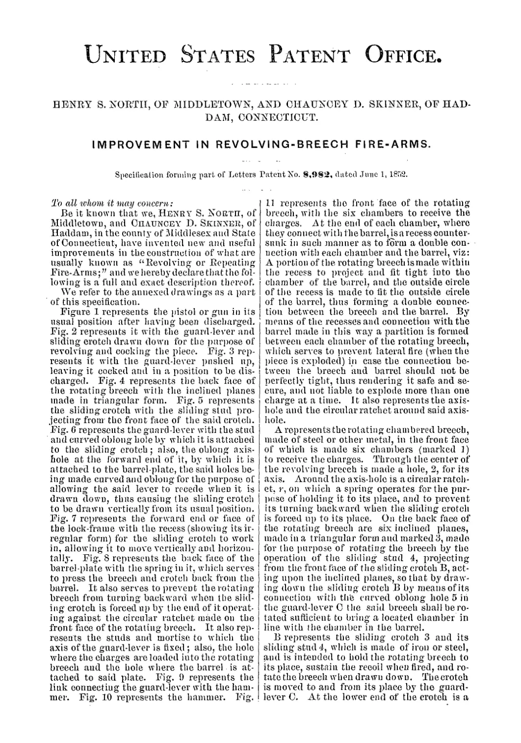
2 Sheets—Sheet 1
KGBTH & SKINNER.
Revolver.
No. 8.982.
Patented June 1, 1852.
Witnesses
Inve nloT
N. PETERS. PHOTO-LITHOGRAPHER. WASHINGTON. D C.
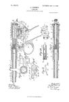
NORTH & SKINNER.
Sheets—-Sheet 2.
No 8,982.
Revolver.
Patented Jqne 1 1852.
N.PCTSftS. PHOTO-LITHOGRAPHER. WASHINGTON. О C.
United States Patent Office.
HENRY S. NORTH, OF MIDDLETOWN, AND CHAUNCEY D. SKINNER, OF HAD-
DAM, CONNECTICUT.
IMPROVEMENT IN REVOLVING-BREECH FIRE-ARMS.
Specification forming part of Letters Patent No. 8,982, dated June 1, 1852.
To all whom it may concern:
Be it known that we, Henry S. North, of
Middletown, and Chauncey D. Skinner, of
Haddam, in the county of Middlesex and State
of Connecticut, have invented new and useful
improvements in the construction of what are
usually known as “Revolving or Repeating
Fire-Arms;” and we hereby declare that the fol-
lowing is a full and exact description thereof.
We refer to the annexed drawings as a part
of this specification.
Figure 1 represents the pistol or gun in its
usual position after having been discharged.
Fig. 2 represents it with the guard-lever and
sliding crotch drawn down for the purpose of
revolving and cocking the piece. Fig. 3 rep-
resents it with the guard-lever pushed up,
leaving it cocked and in a position to be dis-
charged. Fig. 4 represents the back face of
the rotating breech with the inclined planes
made in triangular form. Fig. 5 represents
the sliding crotch with the sliding stud pro-
jecting from the front face of the said crotch.
Fig. 6 represents the guard-lever with the stud
and curved oblong hole by which it is attached
to the sliding crotch; also, the oblong axis-
hole at the forward end of it, by which it is
attached to the barrel-plate, the said holes be-
ing made curved and oblong for the purpose of
allowing the said lever to recede when it is
drawn down, thus causing the sliding crotch
to be drawn vertically from its usual position.
Fig. 7 represents the forward end or face of
the lock-frame with the recess (showing its ir-
regular form) for the sliding crotch to work
in, allowing it to move vertically and horizon-
tally. Fig. S represents the back face of the
barrel-plate with the spring in it, which serves
to press the breech and crotch back from the
barrel. It also serves to prevent the rotating
breech from turning backward when the slid-
ing crotch is forced up by the end of it operat-
ing against the circular ratchet made on the
front face of the rotating breech. It also rep-
resents the studs and mortise to which the
axis of the guard-lever is fixed ; also, the hole
where the charges are loaded into the rotating-
breech and the bole where the barrel is at-
tached to said plate. Fig. 1) represents the
link connecting the guard-lever with the ham-
mer. Fig. 10 represents the hammer. Fig.
11 represents the front face of the rotating
breech, with the six chambers to receive the
charges. At the end of each chamber, where
they connect with the barrel, is a recess counter-
sunk in such manner as to form a double con-
nection with each chamber and the barrel, viz:
A portion of the rotating breechismade within
the recess to project and fit tight into the
chamber of the barrel, and the outside circle
of the recess is made to fit the outside circle
of the barrel, thus forming a double connec-
tion between the breech and the barrel. By
means of the recesses and connection with the
barrel made in this way a partition is formed
between each chamber of the rotating breech,
which serves to prevent lateral fire (when the
piece is exploded) in case the connection be-
tween the breech and barrel should not be
perfectly tight, thus rendering it safe and se-
cure, and not liable to explode more than one
charge at a time. It also represents the axis-
hole and the circular ratchet around said axis-
hole.
A represents the rotating chambered breech,
made of steel or other metal, in the front face
of which is made six chambers (marked 1)
to receive the charges. Through the center of
the revolving breech is made a hole, 2, for its
axis. Around the axis-hole is a circular ratch-
et, r, on which a spring operates for the pur-
pose of holding it to its place, and to prevent
its turning backward when the sliding crotch
is forced up to its place. On the back face of
the rotating breech are six inclined plaues,
made in a triangular form and marked 3, made
for the purpose of rotating the breech by the
operation of the sliding stud 4, projecting
from the front face of the sliding crotch B, act-
ing upon the inclined planes, so that by draw-
ing down the sliding crotch В by means of its
connection with the curved oblong hole 5 in
the guard-lever C the said breech shall be ro-
tated sufficient to bring a located chamber in
line with the chamber in the barrel.
В represents the sliding crotch 3 and its
sliding stud 4, which is made of iron or steel,
and is intended to bold the rotating breech to
its place, sustain the recoil when fired, and ro-
tate the breech when drawn down. Tbecroteh
is moved to and from its place by the guard-
lever C. At the lower end of the crotch is a
8,982
2
mortise, 6, by which it is connected with the
guard-lever C by means of a pin or screw pass-
ingthroughaholein themortise and the curved
oblong hole 5 in said guard-lever.
C represents the guard-lever, the back part
whereof, 7, forms the bow of the guard which
covers the trigger S. At the forward end is
an oblong hole, 9, which serves for its axis
and to connect it with the barrel-plate. Back
from said axis, and near where the curve or
bow which covers the trigger commences, is
a stud and curved oblong hole, 5, made to fit
the mortise 6 in the sliding crotch, so that the
guard is made to operate as a lover to draw
the crotch from and to move it to its place.
Back from the curved oblong hole 5 is an axis-
hole, 10, to which a link, D, is attached, con-
necting it with the hammer E, thus causing
the mainspring 11 to hold the guard-lever and
crotch firmly up to their places, and also to
admit of the piece being cocked by drawing
down the guard-lever.
D represents a link, made of iron or steel, at
the lower end of which is made a hole, 10,
which serves as an axis and to connect it with
the guard-lever. The said link is designed to
connect the guard-lever and hammer together.
E represents the hammer, the back end, 12,
of which is formed in such a manner as to
keep the link from becoming detached, but
still allowing it to slide up and down freely
when the hammer is cocked.
F represents the lock-frame, made of iron or
other metal. In the forward end or face of it
is made a recess, 13, of irregular form, for the
sliding crotch to work in, the upper part
(marked s) projecting forward for the purpose
of inclining the crotch and rotating breech for-
ward, and connecting it with the barrel when
the crotch is pressed up. The lower part
(marked T) is sunk deeper into the face of the
back frame than the upper for the purpose of
allowing the sliding crotch and rotating breech
to recede when the said breech is retracted
from the barrel. A little distance back from
the front part of the lock-frame, and on the
lower side of it, is a. stud and mortise, 14, to
which the tiigger 8 is attached; also a long
mortise, 15, through which the link D passes.
On the upper side of the lock-frame, and over
the trigger, is a stud and mortise, 1(5, through
which the hammer passes, and to which it is
attached.
G represents the barrel-plate, to the upper
part, 17, of which the barrel is attached with
its back end projecting through it to meet the
chambers of the rotating breech. At the cen-
ter of the plate is a hole, 18, through which
the bolt which forms the axis of the rotating
breech passes. A little below and one side of
the center is a hole, 19, where the cartridges or
powder and balls are entered to the chambers
of the rotating breech. At the lower part of
it the studs and mortise 20 are made, to which
the axis of the guard-lever is attached. On the
back face of it and the part which comes next
to the chambers of the rotating breech is fixed
a spring, 21, the end of which presses against
the front face of the rotating breech, and which
serves to press the breech and crotch back
from the barrel, thus leaving the breech free
to be rotated. It also serves to prevent the
rotating breech from turning backward when
the sliding crotch is forced up by the end of
it operating against the circular ratchet made
on the front face of the rotating breech. On
the periphery and near the back end of the ro-
tating breech are six recesses, (marked 22,) iu
which are made the touch-holes leading to the
chambers of the rotating breech. The said
recesses are made to receive each a disk, one
side of which is covered with percassiou-pow-
der. The said disks are to be pressed into the
recesses with the side on which the percus-
sion-powder is placed to come in contact with
the touch holes for the purpose of priming.
By using disks for priming instead of per-
cussion-caps the rotating breech is not liable
to be clogged by particles of copper blowing
off from the priming, so that the breech will
not rotate, as is the case when caps are used,
and the recesses in which the disks are placed
will prevent lateral fire, so that when a disk
is exploded the fire from it cannot communi-
cate with those which are contiguous.
To load a fire arm thus constructed, draw
down the gnard-lever so as to bring the ham-
mer to the half-cock, which will cause the ro-
tating breech to be retracted from the barrel,
and left free to be rotated toward the right
by the hand, so that each chamber may be
loaded by turning it to the hole 19 in the bar-
rel plate. This being done and the chambers
loaded, place the disks iu the recesses and
press them in tight.
What we claim as our invention, and desire
to secure by Letters Patent, is—
The construction of the sliding crotch, sub-
stantially as described, to enable it to perform
the double purpose of revolving the breech
and wedging it up against the barrel, and the
combination of the sliding crotch and guard-
lever, constructed and arranged as specified,
by which the breeech is rotated, wedged for-
ward, and the gun cocked by one motion back
and forward of the trigger-guard or its equiv-
alent, substantially as above described.
Middletown, Connecticut, March 30, A. D.
1852.
HENRY S. NORTH.
CHAUNCEY D. SKINNER.
In presence of—
Enoch C. Ferre,
Jonathan Barnes.